project 5 - South Valley Water Reclamation Facility
564
PROJECT 5 CONTRACT DOCUMENTS BIDDING REQUIREMENTS, CONTRACT FORMS, CONDITIONS OF THE CONTRACT, TECHNICAL SPECIFICATIONS AND DRAWINGS VOLUME 2 of 5 DIVISIONS 09 to 15 Bids will be received at the office of South Valley Water Reclamation Facility located at 7495 South 1300 West, West Jordan, Utah 84084 until 2:00 PM Wednesday, May 1, 2019. Digitally signed by Brad D. Jeppson Contact Info: Carollo Engineers, Inc. Date: 2019.03.04 13:03:11-07'00'
-
Upload
khangminh22 -
Category
Documents
-
view
0 -
download
0
Transcript of project 5 - South Valley Water Reclamation Facility
PROJECT 5
CONTRACT DOCUMENTS
BIDDING REQUIREMENTS, CONTRACT FORMS,
CONDITIONS OF THE CONTRACT,
TECHNICAL SPECIFICATIONS AND DRAWINGS
VOLUME 2 of 5
DIVISIONS 09 to 15
Bids will be received at the office of South Valley Water Reclamation Facility located at
7495 South 1300 West, West Jordan, Utah 84084
until 2:00 PM Wednesday, May 1, 2019.
Digitally signed by Brad D. JeppsonContact Info: Carollo Engineers, Inc.
Date: 2019.03.04 13:03:11-07'00'

SOUTH VALLEY WATER RECLAMATION FACILITY TABLE OF CONTENTS PROJECT 5 PAGE 00020 - 1
SECTION 00020 CONTRACT DOCUMENTS TABLE OF CONTENTS
VOLUME 1
DIVISION 00 - BIDDING REQUIREMENTS, CONTRACT FORMS, AND CONDITIONS OF THE CONTRACT
SECTION PAGE(S)
PART 1 - BIDDING REQUIREMENTS
00010 Title Page ...................................................................................... 00001 - 1 to 1 00020 Contract Documents Table of Contents ........................................ 00020 - 1 to 6 00030 Notice Inviting Bids ....................................................................... 00030 - 1 to 2 00100 Instructions to Bidders .................................................................. 00100 - 1 to 5 00300 Bid Forms ...................................................................................... 00300 - 1 to 9 00310 Bid Schedules ............................................................................... 00310 - 1 to 6 00436 List of Equipment Manufacturers .................................................. 00436 - 1 to 2 00444 Experience Modification Rate ....................................................... 00444 - 1 to 1 00453 Bid Preferences ............................................................................ 00453 - 1 to 1 00454 Bid Certification for the Payment of State and Local Taxes .......... 00454 - 1 to 1 00458 Certification of Drug-Free Workplace Requirements .................... 00458 - 1 to 2
PART 2 - CONTRACT FORMS
00500 Agreement .................................................................................... 00500 - 1 to 6 00510 Notice of Award ............................................................................. 00510 - 1 to 2 00550 Notice to Proceed ......................................................................... 00550 - 1 to 1 00602 Escrow Agreement for Security Deposits in Lieu of Retention ..... 00602 - 1 to 3 00610 Surety's Agreement to Assignment ............................................... 00610 - 1 to 1 00620 Payment Bond .............................................................................. 00620 - 1 to 1 00632 Request for Information or Interpretation (RFI) ............................. 00632 - 1 to 1
PART 3 - CONTRACT CONDITIONS
00700 General Conditions ...................................................................... 00700 - 1 to 38 00800 Supplementary General Conditions ............................................. 00800 - 1 to 7 00810 Utah State Supplementary General Conditions ........................... 00810 - 1 to 4 00823 Escrow Bid Documents ................................................................ 00823 - 1 to 5
PART 4 - TECHNICAL SPECIFICATIONS
DIVISION 01 - GENERAL REQUIREMENTS
01110 Summary of Work ........................................................................ 01110 - 1 to 2 01116 Contract Document Language ..................................................... 01116 - 1 to 2 01140 Work Restrictions ......................................................................... 01140 - 1 to 12 01230 Alternates ..................................................................................... 01230 - 1 to 2 01260 Contract Modification Procedures ................................................ 01260 - 1 to 5 01292 Schedule of Values ...................................................................... 01292 - 1 to 2 01294 Applications for Payment ............................................................. 01294 - 1 to 2 01312 Project Meetings .......................................................................... 01312 - 1 to 4
SECTION PAGE(S)
SOUTH VALLEY WATER RECLAMATION FACILITY TABLE OF CONTENTS PROJECT 5 PAGE 00020 - 2
01322 Web Based Construction Document Management ...................... 01322 - 1 to 4 01324A Progress Schedules and Reports - Large Projects ................... 01324A - 1 to 15 01329 Safety Plan ................................................................................... 01329 - 1 to 2 01330 Submittal Procedures ................................................................... 01330 - 1 to 13 01340 Photographic and Videographic Documentation ......................... 01340 - 1 to 4 01353 Special Procedures for Locating and Verifying Concealed Existing Utilities ........................................................................... 01353 - 1 to 2 01354 Hazardous Material Procedures .................................................. 01354 - 1 to 4 01410 Regulatory Requirements ............................................................ 01410 - 1 to 1 01424 Abbreviations and Acronyms ....................................................... 01424 - 1 to 9 01450 Quality Control ............................................................................. 01450 - 1 to 6 01455B Special Tests and Inspections .................................................. 01455B - 1 to 15 01460 Contractor Quality Control Plan ................................................... 01460 - 1 to 4 01500 Temporary Facilities and Controls ............................................... 01500 - 1 to 8 01520 Security and Process Safety Management.................................. 01520 - 1 to 2 01530 Protection of Existing Facilities .................................................... 01530 - 1 to 5 01573 Erosion and Sediment Control ..................................................... 01573 - 1 to 6 01600 Product Requirements ................................................................. 01600 - 1 to 13 01610 Project Design Criteria ................................................................. 01610 - 1 to 1 01612 Seismic Design Criteria ............................................................... 01612 - 1 to 2 01614 Wind Design Criteria…………………………………………………01614 - 1 to 1 01722 Field Engineering ......................................................................... 01722 - 1 to 3 01738 Selective Alterations and Demolition ........................................... 01738 - 1 to 9 01756 Commissioning ............................................................................ 01756 - 1 to 23 01759 Water Leakage Test for Concrete Structures .............................. 01759 - 1 to 9 01770 Closeout Procedures ................................................................... 01770 - 1 to 6 01782 Operation and Maintenance Data ................................................ 01782 - 1 to 8 01783 Warranties and Bonds ................................................................. 01783 - 1 to 4 DIVISION 02 - SITE CONSTRUCTION
02050 Soils and Aggregates for Earthwork ............................................ 02050 - 1 to 5 02084 Precast Drainage Structures ....................................................... 02084 - 1 to 4 02085 Precast Concrete Vaults .............................................................. 02085 - 1 to 5 02200 Site Clearing ................................................................................ 02200 - 1 to 2 02240 Dewatering for Structures ............................................................ 02240 - 1 to 3 02260 Excavation Support and Protection ............................................. 02260 - 1 to 6 02300 Earthwork .................................................................................... 02300 - 1 to 9 02312 Controlled Low Strength Material (CLSM) ………………………...02312 - 1 to 7 02330 Trenching and Backfilling ............................................................ 02330 - 1 to 9 02553 Temporary Bypass Pumping ....................................................... 02553 - 1 to 7 02581 Soils and Aggregates for Earthwork ............................................ 02581 - 1 to 13 02742 Asphaltic Concrete Paving ………………………………………….02742 - 1 to 9 02772 Concrete Curbs, Gutters, and Sidewalks ..................................... 02772 - 1 to 4 02939 Seeding ....................................................................................... 02939 - 1 to 16 02952 Pavement Restoration and Rehabilitation ................................... 02952 - 1 to 3 DIVISION 03 - CONCRETE
03055 Adhesive-Bonded Reinforcing Bars and All Thread Rods in Concrete ...................................................................................... 03055 - 1 to 9 03071 Epoxies ........................................................................................ 03071 - 1 to 3 03072 Epoxy Resin/Portland Cement Bonding Agent ............................ 03072 - 1 to 3
SECTION PAGE(S)
SOUTH VALLEY WATER RECLAMATION FACILITY TABLE OF CONTENTS PROJECT 5 PAGE 00020 - 3
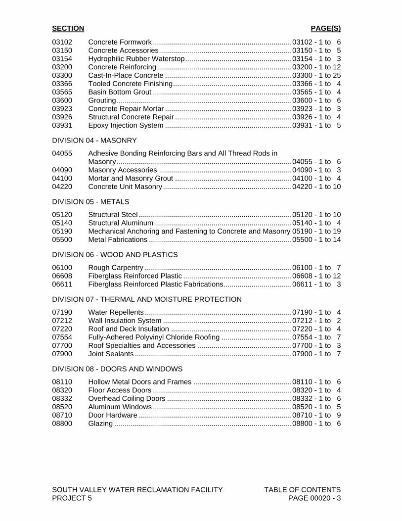
03102 Concrete Formwork ..................................................................... 03102 - 1 to 6 03150 Concrete Accessories .................................................................. 03150 - 1 to 5 03154 Hydrophilic Rubber Waterstop ..................................................... 03154 - 1 to 3 03200 Concrete Reinforcing ................................................................... 03200 - 1 to 12 03300 Cast-In-Place Concrete ............................................................... 03300 - 1 to 25 03366 Tooled Concrete Finishing ........................................................... 03366 - 1 to 4 03565 Basin Bottom Grout ..................................................................... 03565 - 1 to 4 03600 Grouting ....................................................................................... 03600 - 1 to 6 03923 Concrete Repair Mortar ............................................................... 03923 - 1 to 3 03926 Structural Concrete Repair .......................................................... 03926 - 1 to 4 03931 Epoxy Injection System ............................................................... 03931 - 1 to 5
DIVISION 04 - MASONRY
04055 Adhesive Bonding Reinforcing Bars and All Thread Rods in Masonry ....................................................................................... 04055 - 1 to 6 04090 Masonry Accessories .................................................................. 04090 - 1 to 3 04100 Mortar and Masonry Grout .......................................................... 04100 - 1 to 4 04220 Concrete Unit Masonry ................................................................ 04220 - 1 to 10
DIVISION 05 - METALS
05120 Structural Steel ............................................................................ 05120 - 1 to 10 05140 Structural Aluminum .................................................................... 05140 - 1 to 4 05190 Mechanical Anchoring and Fastening to Concrete and Masonry 05190 - 1 to 19 05500 Metal Fabrications ....................................................................... 05500 - 1 to 14
DIVISION 06 - WOOD AND PLASTICS
06100 Rough Carpentry ......................................................................... 06100 - 1 to 7 06608 Fiberglass Reinforced Plastic ...................................................... 06608 - 1 to 12 06611 Fiberglass Reinforced Plastic Fabrications.................................. 06611 - 1 to 3
DIVISION 07 - THERMAL AND MOISTURE PROTECTION
07190 Water Repellents ......................................................................... 07190 - 1 to 4 07212 Wall Insulation System ................................................................ 07212 - 1 to 2 07220 Roof and Deck Insulation ............................................................ 07220 - 1 to 4 07554 Fully-Adhered Polyvinyl Chloride Roofing ................................... 07554 - 1 to 7 07700 Roof Specialties and Accessories ............................................... 07700 - 1 to 3 07900 Joint Sealants .............................................................................. 07900 - 1 to 7
DIVISION 08 - DOORS AND WINDOWS
08110 Hollow Metal Doors and Frames ................................................. 08110 - 1 to 6 08320 Floor Access Doors ..................................................................... 08320 - 1 to 4 08332 Overhead Coiling Doors .............................................................. 08332 - 1 to 6 08520 Aluminum Windows ..................................................................... 08520 - 1 to 5 08710 Door Hardware ............................................................................ 08710 - 1 to 9 08800 Glazing ........................................................................................ 08800 - 1 to 6
SECTION PAGE(S)
SOUTH VALLEY WATER RECLAMATION FACILITY TABLE OF CONTENTS PROJECT 5 PAGE 00020 - 4
VOLUME 2
DIVISION 09 - FINISHES
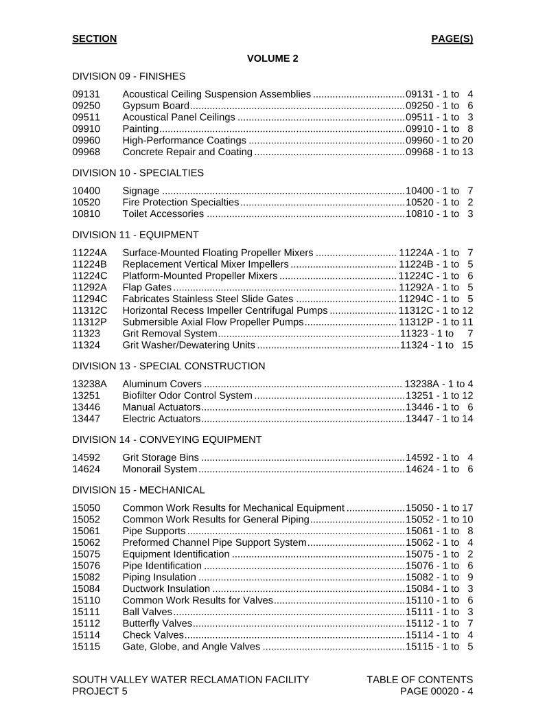
09131 Acoustical Ceiling Suspension Assemblies ................................. 09131 - 1 to 4 09250 Gypsum Board ............................................................................. 09250 - 1 to 6 09511 Acoustical Panel Ceilings ............................................................ 09511 - 1 to 3 09910 Painting ........................................................................................ 09910 - 1 to 8 09960 High-Performance Coatings ........................................................ 09960 - 1 to 20 09968 Concrete Repair and Coating ...................................................... 09968 - 1 to 13
DIVISION 10 - SPECIALTIES
10400 Signage ....................................................................................... 10400 - 1 to 7 10520 Fire Protection Specialties ........................................................... 10520 - 1 to 2 10810 Toilet Accessories ....................................................................... 10810 - 1 to 3
DIVISION 11 - EQUIPMENT
11224A Surface-Mounted Floating Propeller Mixers ............................. 11224A - 1 to 7 11224B Replacement Vertical Mixer Impellers ...................................... 11224B - 1 to 5 11224C Platform-Mounted Propeller Mixers .......................................... 11224C - 1 to 6 11292A Flap Gates ................................................................................ 11292A - 1 to 5 11294C Fabricates Stainless Steel Slide Gates .................................... 11294C - 1 to 5 11312C Horizontal Recess Impeller Centrifugal Pumps ........................ 11312C - 1 to 12 11312P Submersible Axial Flow Propeller Pumps ................................. 11312P - 1 to 11 11323 Grit Removal System ................................................................. 11323 - 1 to 7 11324 Grit Washer/Dewatering Units ................................................... 11324 - 1 to 15
DIVISION 13 - SPECIAL CONSTRUCTION
13238A Aluminum Covers ....................................................................... 13238A - 1 to 4 13251 Biofilter Odor Control System ...................................................... 13251 - 1 to 12 13446 Manual Actuators ......................................................................... 13446 - 1 to 6 13447 Electric Actuators ......................................................................... 13447 - 1 to 14
DIVISION 14 - CONVEYING EQUIPMENT
14592 Grit Storage Bins ......................................................................... 14592 - 1 to 4 14624 Monorail System .......................................................................... 14624 - 1 to 6
DIVISION 15 - MECHANICAL
15050 Common Work Results for Mechanical Equipment ..................... 15050 - 1 to 17 15052 Common Work Results for General Piping .................................. 15052 - 1 to 10 15061 Pipe Supports .............................................................................. 15061 - 1 to 8 15062 Preformed Channel Pipe Support System ................................... 15062 - 1 to 4 15075 Equipment Identification .............................................................. 15075 - 1 to 2 15076 Pipe Identification ........................................................................ 15076 - 1 to 6 15082 Piping Insulation .......................................................................... 15082 - 1 to 9 15084 Ductwork Insulation ..................................................................... 15084 - 1 to 3 15110 Common Work Results for Valves ............................................... 15110 - 1 to 6 15111 Ball Valves ................................................................................... 15111 - 1 to 3 15112 Butterfly Valves ............................................................................ 15112 - 1 to 7 15114 Check Valves ............................................................................... 15114 - 1 to 4 15115 Gate, Globe, and Angle Valves ................................................... 15115 - 1 to 5
SECTION PAGE(S)
SOUTH VALLEY WATER RECLAMATION FACILITY TABLE OF CONTENTS PROJECT 5 PAGE 00020 - 5
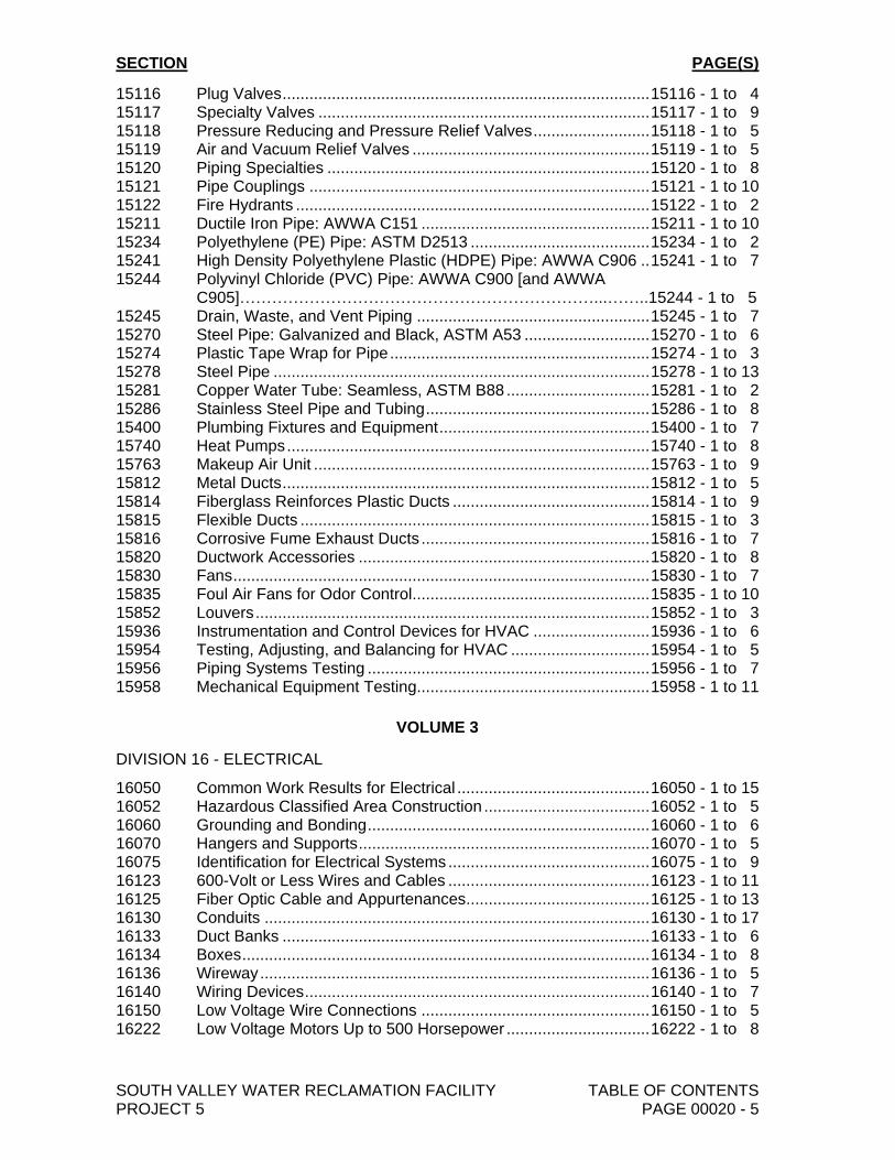
15116 Plug Valves .................................................................................. 15116 - 1 to 4 15117 Specialty Valves .......................................................................... 15117 - 1 to 9 15118 Pressure Reducing and Pressure Relief Valves .......................... 15118 - 1 to 5 15119 Air and Vacuum Relief Valves ..................................................... 15119 - 1 to 5 15120 Piping Specialties ........................................................................ 15120 - 1 to 8 15121 Pipe Couplings ............................................................................ 15121 - 1 to 10 15122 Fire Hydrants ............................................................................... 15122 - 1 to 2 15211 Ductile Iron Pipe: AWWA C151 ................................................... 15211 - 1 to 10 15234 Polyethylene (PE) Pipe: ASTM D2513 ........................................ 15234 - 1 to 2 15241 High Density Polyethylene Plastic (HDPE) Pipe: AWWA C906 .. 15241 - 1 to 7 15244 Polyvinyl Chloride (PVC) Pipe: AWWA C900 [and AWWA
C905]…………………………………………………………...……..15244 - 1 to 5 15245 Drain, Waste, and Vent Piping .................................................... 15245 - 1 to 7 15270 Steel Pipe: Galvanized and Black, ASTM A53 ............................ 15270 - 1 to 6 15274 Plastic Tape Wrap for Pipe .......................................................... 15274 - 1 to 3 15278 Steel Pipe .................................................................................... 15278 - 1 to 13 15281 Copper Water Tube: Seamless, ASTM B88 ................................ 15281 - 1 to 2 15286 Stainless Steel Pipe and Tubing .................................................. 15286 - 1 to 8 15400 Plumbing Fixtures and Equipment ............................................... 15400 - 1 to 7 15740 Heat Pumps ................................................................................. 15740 - 1 to 8 15763 Makeup Air Unit ........................................................................... 15763 - 1 to 9 15812 Metal Ducts .................................................................................. 15812 - 1 to 5 15814 Fiberglass Reinforces Plastic Ducts ............................................ 15814 - 1 to 9 15815 Flexible Ducts .............................................................................. 15815 - 1 to 3 15816 Corrosive Fume Exhaust Ducts ................................................... 15816 - 1 to 7 15820 Ductwork Accessories ................................................................. 15820 - 1 to 8 15830 Fans ............................................................................................. 15830 - 1 to 7 15835 Foul Air Fans for Odor Control..................................................... 15835 - 1 to 10 15852 Louvers ........................................................................................ 15852 - 1 to 3 15936 Instrumentation and Control Devices for HVAC .......................... 15936 - 1 to 6 15954 Testing, Adjusting, and Balancing for HVAC ............................... 15954 - 1 to 5 15956 Piping Systems Testing ............................................................... 15956 - 1 to 7 15958 Mechanical Equipment Testing.................................................... 15958 - 1 to 11
VOLUME 3
DIVISION 16 - ELECTRICAL
16050 Common Work Results for Electrical ........................................... 16050 - 1 to 15 16052 Hazardous Classified Area Construction ..................................... 16052 - 1 to 5 16060 Grounding and Bonding ............................................................... 16060 - 1 to 6 16070 Hangers and Supports ................................................................. 16070 - 1 to 5 16075 Identification for Electrical Systems ............................................. 16075 - 1 to 9 16123 600-Volt or Less Wires and Cables ............................................. 16123 - 1 to 11 16125 Fiber Optic Cable and Appurtenances......................................... 16125 - 1 to 13 16130 Conduits ...................................................................................... 16130 - 1 to 17 16133 Duct Banks .................................................................................. 16133 - 1 to 6 16134 Boxes ........................................................................................... 16134 - 1 to 8 16136 Wireway ....................................................................................... 16136 - 1 to 5 16140 Wiring Devices ............................................................................. 16140 - 1 to 7 16150 Low Voltage Wire Connections ................................................... 16150 - 1 to 5 16222 Low Voltage Motors Up to 500 Horsepower ................................ 16222 - 1 to 8
SECTION PAGE(S)
SOUTH VALLEY WATER RECLAMATION FACILITY TABLE OF CONTENTS PROJECT 5 PAGE 00020 - 6
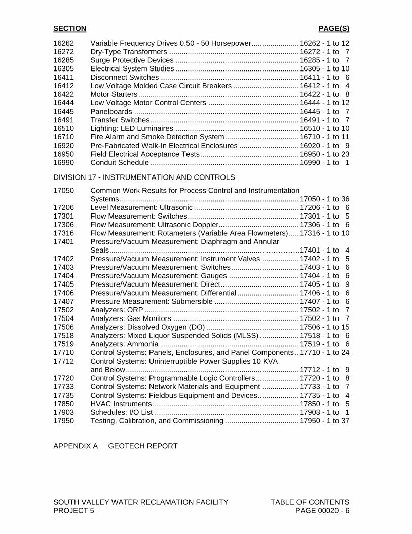
16262 Variable Frequency Drives 0.50 - 50 Horsepower ....................... 16262 - 1 to 12 16272 Dry-Type Transformers ............................................................... 16272 - 1 to 7 16285 Surge Protective Devices ............................................................ 16285 - 1 to 7 16305 Electrical System Studies ............................................................ 16305 - 1 to 10 16411 Disconnect Switches ................................................................... 16411 - 1 to 6 16412 Low Voltage Molded Case Circuit Breakers ................................ 16412 - 1 to 4 16422 Motor Starters .............................................................................. 16422 - 1 to 8 16444 Low Voltage Motor Control Centers ............................................ 16444 - 1 to 12 16445 Panelboards ................................................................................ 16445 - 1 to 7 16491 Transfer Switches ........................................................................ 16491 - 1 to 7 16510 Lighting: LED Luminaires ............................................................ 16510 - 1 to 10 16710 Fire Alarm and Smoke Detection System .................................... 16710 - 1 to 11 16920 Pre-Fabricated Walk-In Electrical Enclosures ............................. 16920 - 1 to 9 16950 Field Electrical Acceptance Tests ................................................ 16950 - 1 to 23 16990 Conduit Schedule ........................................................................ 16990 - 1 to 1
DIVISION 17 - INSTRUMENTATION AND CONTROLS
17050 Common Work Results for Process Control and Instrumentation Systems ....................................................................................... 17050 - 1 to 36 17206 Level Measurement: Ultrasonic ................................................... 17206 - 1 to 6 17301 Flow Measurement: Switches ...................................................... 17301 - 1 to 5 17306 Flow Measurement: Ultrasonic Doppler....................................... 17306 - 1 to 6 17316 Flow Measurement: Rotameters (Variable Area Flowmeters) ..... 17316 - 1 to 10 17401 Pressure/Vacuum Measurement: Diaphragm and Annular
Seals ........................................................................... …………..17401 - 1 to 4 17402 Pressure/Vacuum Measurement: Instrument Valves .................. 17402 - 1 to 5 17403 Pressure/Vacuum Measurement: Switches ................................. 17403 - 1 to 6 17404 Pressure/Vacuum Measurement: Gauges .................................. 17404 - 1 to 6 17405 Pressure/Vacuum Measurement: Direct ...................................... 17405 - 1 to 9 17406 Pressure/Vacuum Measurement: Differential .............................. 17406 - 1 to 6 17407 Pressure Measurement: Submersible ......................................... 17407 - 1 to 6 17502 Analyzers: ORP ........................................................................... 17502 - 1 to 7 17504 Analyzers: Gas Monitors ............................................................. 17502 - 1 to 7 17506 Analyzers: Dissolved Oxygen (DO) ............................................. 17506 - 1 to 15 17518 Analyzers: Mixed Liquor Suspended Solids (MLSS) ................... 17518 - 1 to 6 17519 Analyzers: Ammonia .................................................................... 17519 - 1 to 6 17710 Control Systems: Panels, Enclosures, and Panel Components .. 17710 - 1 to 24 17712 Control Systems: Uninterruptible Power Supplies 10 KVA and Below .................................................................................... 17712 - 1 to 9 17720 Control Systems: Programmable Logic Controllers ..................... 17720 - 1 to 8 17733 Control Systems: Network Materials and Equipment .................. 17733 - 1 to 7 17735 Control Systems: Fieldbus Equipment and Devices .................... 17735 - 1 to 4 17850 HVAC Instruments ....................................................................... 17850 - 1 to 5 17903 Schedules: I/O List ...................................................................... 17903 - 1 to 1 17950 Testing, Calibration, and Commissioning .................................... 17950 - 1 to 37
APPENDIX A GEOTECH REPORT
09131-1 10548A10 March 2019 pw://Carollo/Documents/Client/UT/SVWRF/10548A10/Specifications/09131 (100%)
SECTION 09131
ACOUSTICAL CEILING SUSPENSION ASSEMBLIES
PART 1 GENERAL
1.01 SUMMARY
A. Section includes: Ceiling suspension system for support of lay-in acoustical panels.
1.02 REFERENCE STANDARDS
A. ASTM International (ASTM):1. A641 - Standard Specification for Zinc-Coated (Galvanized) Carbon Steel
Wire.2. C635 - Standard Specification for the Manufacture, Performance, and Testing
of Metal Suspension Systems for Acoustical Tile and Lay-In Panel Ceilings.3. C636 - Standard Practice for Installation of Metal Ceiling Suspension Systems
for Acoustical Tile and Lay-In Panels.
1.03 SUBMITTALS
A. Product Data: Include installation instructions.
B. Shop drawings: Include reflected ceiling plan, details.
C. Samples: Include minimum 3-inch long main and cross members showingintersections, profile, and finish.
1.04 PRE-INSTALLATION CONFERENCE
A. Pre-Installation Conference: Conduct meeting with affected entities to coordinateacoustical ceiling system as specified in Sections 15820 - Ductwork Accessories.
1.05 PROJECT/SITE CONDITIONS
A. Environmental requirements: Areas to receive acoustical ceiling shall bepermanently enclosed prior to start of installation.
PART 2 PRODUCTS
2.01 MANUFACTURERS
A. Acoustical suspension system:1. One of the following or equal:
a. Armstrong.b. Chicago Metallic Corp.c. Donn Corp. (Flangekamp).d. National Rolling Mills, Inc.e. Roblin Building Products (Rigid Lock).
09131-2 10548A10 March 2019 pw://Carollo/Documents/Client/UT/SVWRF/10548A10/Specifications/09131 (100%)
2.02 SUSPENSION SYSTEM
A. Type: Exposed grid.
B. Material: Commercial quality cold steel, electro-zinc coated, and pre-painted.
C. Finish: Low sheen satin white.
D. Main components:1. Main runners: Double web with rectangular bulb, 15/16 inch lower exposed
flange width, rolled cap, cross tee holes at 6 inches on centers, hanger wireholes at 2 inches on centers, and integral reversible splice.
2. Cross tee: Double web with rectangular bulb and web extended to formpositive interlock between cross tee webs through intersecting tee web holes;15/16 inch lower exposed flange width extended and offset for flush levelintersection.
3. Wall molding: W-shape, shadow molding type.4. Hold-down clips: Manufacturer's standard.
E. Corners: Manufacturer's prefabricated inside and outside corner moldings.
F. Provision for Kerfed and Rabbeted Tile: White vinyl slip or trim molding to trimaround recessed light fixture openings.
2.03 ACCESSORIES
A. Attachment devices: Sized for 5 times design load in accordance with ASTM C635,Table 1, Direct Hung, with seismic restraints required by local governing agencies.
B. Hanger wire: ASTM A641, minimum 12-gauge soft temper, pre-stretched,galvanized steel wire with yield-stress load of minimum 3 times design load.
C. Hold down clips: Manufacturer's standard spring type and accessible type whereindicated on the Drawings.
PART 3 EXECUTION
3.01 EXAMINATION
A. Inspect locations to receive acoustical suspension system and check existingdimensions.
B. Verify completion of inspections of above suspension system construction,enclosure of building and proper condition of structure for receipt of acousticalmaterials.
C. Protect finished construction.
3.02 PREPARATION
A. Broom clean area and remove obstructions for free movement of scaffolding.
09131-3 10548A10 March 2019 pw://Carollo/Documents/Client/UT/SVWRF/10548A10/Specifications/09131 (100%)
B. Protect floor surfaces from damage by scaffolding.
C. Layout system for 24- by 48-inch panels as follows:1. Runners: 48 inches on center perpendicular to structural members.2. Hangers: Maximum 48 inches on center along runners.3. Cross tees between runners: 24 inches on center.
3.03 INSTALLATION OF HANGER WIRE
A. Install hanger wire in accordance with ASTM C636 and manufacturer's instructions.
B. Attach hanger wire to sound, secure structural members capable of carrying ceilingload within deflection tolerance.
C. At cast-in-place concrete, fasten hanger wire to cast-in-place inserts furnished andinstalled as specified in Section 03102 - Concrete Formwork.
D. When hanger wire is not tied to reinforcing or cast-in-place inserts are not provided,install expansion or power-actuated anchors into sides of beams and joists.1. Do not install anchors that will be in tension. Fasten hanger wire to anchors.
E. Wrap hanger wire around structural metal members and tightly twist wire arounditself at least 3 times.1. Do not attach hanger wire to bridging, steel decking, or other nonstructural
members.
F. Install additional hangers at each corner of lighting fixtures and equipment, andwhere needed to trapeze hangers because of obstructions.
G. Wrap hanger wire around steel members and tightly twist wire around itself at least3 times.
H. Install supplementary framing, blocking, and bracing where required to supportfixtures and equipment or by conditions of attachment where spacing of structuralsupports from which ceiling is to be suspended exceeds the maximum allowablehanger spacing.
I. When some hangers must be splayed, offset horizontal forces by bracing,counter-splaying, or other acceptable means.
J. Install hangers to be plumb and not press against insulation covering ducts or pipes.
3.04 INSTALLATION OF SUSPENSION SYSTEM
A. Install grid in accordance with ASTM C636 and manufacturer's instructions.
B. Install ceiling grid so grid is independent of walls, columns, and above ceilingnon-structural construction.
C. Directly suspend main runners with hanger wire:1. Thread hanger wire through runner slots and tightly twist wire around itself at
least 3 times.
09131-4 10548A10 March 2019 pw://Carollo/Documents/Client/UT/SVWRF/10548A10/Specifications/09131 (100%)
D. Interconnect main runners with locking cross tees.
E. Interconnect locking cross tees with locking cross tees.
F. Install wall moldings wherever suspension components meet vertical surfaces.
G. Accurately space and level main runners and cross tees with no visible twists orkinks in members.
3.05 TOLERANCES
A. Deflection: Maximum l/360 of span for entire ceiling assembly including electricaland mechanical fixtures and devices.
B. Flatness: Within 1/8 inch in 12 feet.
3.06 ADJUSTMENTS
A. Adjust sags or twists which develop in ceiling systems.
B. Do not kink or bend hanger wires to level main carriers.
C. Correct damaged or improperly installed components.
3.07 CLEANING
A. Correct construction damaged by installation of suspension system.
B. Clean dirty or discolored surfaces in accordance with manufacturer'srecommendations.
END OF SECTION
09250-1 10548A10 March 2019 pw://Carollo/Documents/Client/UT/SVWRF/10548A10/Specifications/09250 (100%)
SECTION 09250
GYPSUM BOARD
PART 1 GENERAL
1.01 SUMMARY
A. Section includes: Gypsum board and associated accessories.
1.02 REFERENCES
A. ASTM International (ASTM):1. C475 - Standard Specification for Joint compounds and Joint Tape for
Finishing Gypsum Board.2. C514 - Standard Specification for Nails for the Application of Gypsum
Wallboard.3. C557 - Standard Specification for Adhesives for Fastening Gypsum Wallboard
in Wood Framing.4. C840 - Standard Specification for Application and Finishing of Gypsum Board.5. C919 - Standard Practice for Use of Sealants in Acoustical Applications.6. C1002 - Standard Specification for Steel Self-Piercing Tapping Screws for the
Application of Gypsum Panel Products or Metal Plaster Based to Wood Studsor Steel Studs.
7. C1047 - Standard Specification for Accessories for Gypsum Wallboard andGypsum Veneer Base.
8. C1396 - Standard Specification for Gypsum Board.9. E84 - Standard Test Method for Surface Burning Characteristics of Building
Materials.
B. Gypsum Association:1. GA 216 - Application and Finishing of Gypsum Board.
C. Underwriters Laboratories, Inc. (UL).
1.03 SUBMITTALS
A. Product Data: Include manufacturer's instructions for sealing openings,penetrations, and cut edges of water-resistant gypsum board.
B. Samples: Include texture samples on minimum 6 inch square specified materials.
1.04 QUALITY ASSURANCE
A. Manufacturer qualifications: Provide gypsum board products from singlemanufacturer or from manufacturers recommended by manufacturer of gypsumboard.
B. Regulatory requirements: When indicated, provide UL listed and labeled fire-ratedcomponents or by other recognized rating service.
09250-2 10548A10 March 2019 pw://Carollo/Documents/Client/UT/SVWRF/10548A10/Specifications/09250 (100%)
C. Pre-installation conference: Convene with affected entities to review coordinationand sequencing of construction to ensure that everything that will be concealed bygypsum board has been installed, and that chases, openings, supplementaryframing and blocking have been completed.
1.05 DELIVERY, STORAGE, AND HANDLING
A. Store gypsum board under cover, stacked flat, off floor.
B. Store adhesives in dry place, protected against freezing.
1.06 ENVIRONMENTAL REQUIREMENTS
A. Maintain uniform room temperature between 55 and 70 degrees Fahrenheit in coldweather during application of wallboard and joint treatment until joint treatment iscompletely dry or building is occupied.
B. Provide adequate ventilation.
PART 2 PRODUCTS
2.01 GYPSUM BOARD
A. Regular board:1. ASTM C1396; 5/8 inches thick; tapered edge; Type X where required for fire
rating.
2.02 ACCESSORIES
A. Square corner bead reinforcement:1. Manufacturers: One of the following or equal:
a. USG, Dur-A-Bead.b. Gold Bond National Gypsum Co., Wallboard corner bead with 1-1/4 inch
flanges.
B. Metal casing bead:1. Manufacturers: One of the following or equal:
a. USG, No. 200A Metal Trim.b. Gold Bond National Gypsum Co., No. 100 wall board casing.
C. Control joints:1. Manufacturers: One of the following or equal:
a. USF, No. 093.b. Gold Bond National Gypsum Co., 0.093 zinc control joint.
2.03 FASTENERS
A. Screws for metal studs: ASTM C1002, Type S; self-drilling, self-tapping, bugle head,for use with power driven tool, minimum 1-1/4 inches long or length to suitapplication.
B. Screws for wood framing: ASTM C1002, Type W, minimum 1-1/4 inches.
09250-3 10548A10 March 2019 pw://Carollo/Documents/Client/UT/SVWRF/10548A10/Specifications/09250 (100%)
C. Nails: ASTM C514; minimum 1-1/4 inch long, 12-1/2 gauge, 1/4 inch diameter head.
D. Staples:1. Manufacturers: The following or equal:
a. Bostitch, Type G; 1/2 inch.
2.04 FINISHING MATERIALS
A. Joint compound and tape: ASTM C475:1. Manufacturers: One of the following or equal:
a. USG, Sheetrock joint system consisting of Sheetrock Reinforcement Tapeand Sheetrock All Purpose Ready Mixed Compound for embedding, fill,and finishing.
b. Gold Bond National Gypsum Co., Sta-Smooth HS tape and Sta-Smoothjoint compound.
B. Texturing compound for walls:1. Manufacturers: One of the following or equal:
a. USG, Spray Texture Finish.b. Gold Bond National Gypsum Co., Perfect Spray EM, orange peel finish.
PART 3 EXECUTION
3.01 INSTALLATION
A. Install gypsum board systems in accordance with ASTM C840 and GA 216.
3.02 GYPSUM BOARD INSTALLATION ON WALLS
A. Cut gypsum wallboard by scoring and breaking or by sawing, working from faceside.
B. Use boards of maximum practical length to minimize end joints.
C. Apply board with long dimension at right angles to framing or furring members withends on studs. Attach upper boards first.
D. Bring boards into contact with each other but do not force into place.
E. Do not place butt ends against tapered edges.
F. Stagger end joints. Locate joint on opposite sides of partition on different studs.
G. Do not align joints with edges of openings, except for control joints. Cut board neatlyto fit around openings. Locate joints at least 8 inches from openings. Center verticalend joints above openings.
H. Extend board to within 1/4 inch of floor.
I. Install fasteners proceeding from center portion of gypsum board toward edges andends.
09250-4 10548A10 March 2019 pw://Carollo/Documents/Client/UT/SVWRF/10548A10/Specifications/09250 (100%)
J. On non-fire rated walls, screw board to framing at maximum 12 inches on center infield of board at bearings and along abutting edges. Nail board to framing atmaximum 8 inches on center in field at bearings and along edges.
K. Drive fasteners home with maximum 1/32 inch dimple in wall surface. Avoidbreaking face paper of wallboard. Remove improperly driven nails.
3.03 INSTALLATION OF CASING AND CORNER BEADS
A. Install casing beads wherever board terminates against dissimilar materials orwhere edges of board are exposed. Provide:1. Type with face flange to receive joint compound except where semi-finishing is
indicated.2. L-type trim where gypsum board is tightly abutted to other construction.3. Special kerf-type where other construction is kerfed to receive long leg of
L-type trim.4. U-type trim where edge is exposed, revealed, gasketed, or sealant filled,
including expansion joints.
B. Install metal corner bead reinforcement at outside corners.
C. Where board partitions intersect masonry walls:1. Provide control joints no less than 1/4 inch nor more than 3/8 inch wide
between board and masonry.2. Finish exposed edges of board with square-nose metal casing bead and caulk
space between casing bead and masonry with continuous sealant.
D. Secure corner beads with same fasteners used for applying wallboard, spaced8 inches maximum apart on each flange of bead with nails opposite.
3.04 INSTALLATION OF CONTROL JOINTS
A. Discontinue gypsum board at control joints.
B. In ceiling construction, discontinue gypsum board and framing at control joints.
C. In partitions, discontinue gypsum board and install framing studs on each side ofcontrol joints.
D. Position control joints to intersect light fixtures, air diffusers, door openings andother areas of stress concentration.
E. Isolate gypsum board construction at following locations:1. Where partitions or ceilings of dissimilar construction meet and remain in same
plane.2. Where wings of "L," "U," and "T" shaped ceiling areas are joined.3. When expansion or control joints occur in base building construction.
F. Space control joints at following maximum distances:1. Partitions: 30 feet in either direction.2. Interior ceilings with perimeter relief: 50 feet in either direction.3. Interior ceilings without perimeter relief: 30 feet in either direction.4. Exterior ceilings: 30 feet in either direction.
09250-5 10548A10 March 2019 pw://Carollo/Documents/Client/UT/SVWRF/10548A10/Specifications/09250 (100%)
G. Extend control joints to ceiling from both corners of door frames where control jointsare required.
H. Cut end joints square, align to provide neat fit.
I. Staple control joint to board at maximum 6 inches on center in each flange.
3.05 JOINT COMPOUND
A. Mix joint and topping compound in accordance with instructions on package.
B. Apply thin layer of joint compound uniformly approximately 4 inches wide over eachjoint.
C. Center tape over joint and embed into compound, leaving sufficient joint compoundunder tape to provide proper bond.
D. Reinforce wall angles and inside corner angles with tape folded to conform to angleand embedded into compound.
E. Apply skim coat of compound immediately after embedding tape.
F. After compound is thoroughly dry, cover tape with coat of joint compound or toppingcompound. Spread over tape and approximately 3 inches beyond edges of tape.Feathered out edge.
G. After compound is thoroughly dry, cover tape with coat of joint compound or toppingcompound. Spread over tape and approximately 3 inches beyond edges of previouscoat. Feathered out edge.
H. Coat inside corners with minimum of one coat of joint compound or toppingcompound with edges feathered out.
I. Apply 3 coats of compound to nail and screw head dimples.
J. Conceal flanges of wallboard corner beads with minimum of 2 coats of compound:1. Apply joint compound for first coat.2. Apply joint compound or topping compound for second coat.
a. Feathered out second coat approximately 9 inches on both sides ofexposed metal nose of corner bead.
K. Clean excess compound from board surface.
L. Sand coats as necessary after each application of compound has dried.1. Leave board uniformly smooth ready to receive texturing, to extent that after
painting, board shows no distinguishable difference in appearance betweentaped and untapped surfaces.
3.06 TEXTURING
A. Verify that gypsum board surfaces have been primed in accordance withSection 09910 - Painting.
09250-6 10548A10 March 2019 pw://Carollo/Documents/Client/UT/SVWRF/10548A10/Specifications/09250 (100%)
B. Clean surfaces of dust, dirt, and oil before application.
C. Mix and apply specified materials in accordance with manufacturer'srecommendation to produce texture similar to accepted sample.
D. Apply orange peel or sprayed knockdown, texture to interior walls.
E. Remove texture droppings or overspray from adjacent completed construction.
3.07 TOLERANCES
A. Offsets between planes of board faces: Maximum 1/16 inch.
B. Flatness: Maximum 1/8 inch in 96 inches.
C. Variation from plumb: Maximum 1/8 inch in 96 inches.
END OF SECTION
09511-1 10548A10 March 2019 pw://Carollo/Documents/Client/UT/SVWRF/10548A10/Specifications/09511 (100%)
SECTION 09511
ACOUSTICAL PANEL CEILINGS
PART 1 GENERAL
1.01 SUMMARY
A. Section includes: Lay-in acoustical ceiling panels.
1.02 REFERENCES
A. Federal Specifications (FS):1. SS-S-118 - Sound Controlling (Acoustical) Tiles and Panels.
1.03 SUBMITTALS
A. Product data.
B. Samples: Include nominal 12-inch square acoustical panels.
C. Manufacturer's installation instructions.
1.04 QUALITY ASSURANCE
A. Pre-installation conference: Conduct meeting with affected entities to coordinateacoustical ceiling system with work of Sections 09131 - Acoustical CeilingSuspension Assemblies and 15820 - Ductwork Accessories.
1.05 ENVIRONMENTAL REQUIREMENTS
A. Install acoustical ceilings when building is enclosed, sufficient heat is provided, dustgenerating activities have terminated, and overhead mechanical work is completed,tested, and approved.
B. Permit wet work to dry prior to commencement of installation.
C. Maintain uniform temperatures of minimum 60 degrees Fahrenheit and 20 to40 percent humidity prior to, during, and after installation.
1.06 EXTRA MATERIALS
A. One unopened carton of each size and color acoustical panel installed.
PART 2 PRODUCTS
2.01 LAY-IN ACOUSTICAL PANELS
A. Manufacturers: One of the following or equal:1. Armstrong World Industries, Inc.
09511-2 10548A10 March 2019 pw://Carollo/Documents/Client/UT/SVWRF/10548A10/Specifications/09511 (100%)
2. Conwed Corp.3. National Gypsum, Gold Bond Building Products Division.4. U.S.Gypsum Co.
B. Type: FS SS-S-118, Class 25, with following characteristics:1. Material: Fire-retardant mineral board.2. Style: Fissured tegular: Angled tegular.3. Face size: 24 by 48 inches.4. Thickness: 15/16 inch.5. Edges: Square cut.6. Finish: Factory-applied washable white finish.7. NRC range: 0.50 0.60 for Number 7 mounting.8. Light reflectance: 75 percent.
2.02 ACCESSORIES
A. Escutcheons: Metal with thickness and finish to match ceiling grid.
PART 3 EXECUTION
3.01 EXAMINATION
A. Inspect locations to receive acoustical suspension system and check existingdimensions.
B. Verify completion of construction above suspension system, including inspections,enclosure of building, and proper installation of suspension system.
C. Protect finished construction.
3.02 PREPARATION
A. Broom clean area and remove obstructions for free movement of scaffolding.
B. Protect floor surfaces from damage by scaffolding.
3.03 INSTALLATION
A. Neatly cut panels to fit spaces so panel edges are supported by suspension system.
B. Install lay-in panels level, in uniform plane without twists, warps, or dents.
C. Leave no visible gaps or openings.1. Discard panels with cracks or chipped edges.
D. Leave no scrap above ceiling.
E. Install panels with apparent grain running in same direction.
F. Install escutcheons around openings for pipes, supports, and ducts through ceiling.
G. Install hold-down clips on panels within 20 feet of exterior doors.
09511-3 10548A10 March 2019 pw://Carollo/Documents/Client/UT/SVWRF/10548A10/Specifications/09511 (100%)
3.04 CLEANING
A. Clean dirty and discolored exposed surfaces of panels in accordance withmanufacturer's instructions.
B. Remove damaged panels that cannot be properly cleaned and replace withacceptable panels.
END OF SECTION

09910-1 10548A10 March 2019 pw://Carollo/Documents/Client/UT/SVWRF/10548A10/Specifications/09910 (100%)
SECTION 09910
PAINTING
PART 1 GENERAL
1.01 SUMMARY
A. Section includes:1. Field applied paints and coatings for normal exposures.2. Painting Accessories.
1.02 DEFINITIONS
A. Paints: Manufacturer's best ready-mixed coatings, except when field catalyzed, withfully ground pigments having soft paste consistency and capable of being readilyand uniformly dispersed to complete homogeneous mixture, having good flowingand brushing properties, and capable of drying or curing free of streaks or sags.
B. Volatile Organic Compound (VOC): Content of air polluting hydrocarbons in uncuredcoating product measured in units of grams per liter or pounds per gallon.
1.03 SUBMITTALS
A. General: Submit as specified in Section 01330 - Submittal Procedures.
B. Shop drawings: Include schedule of where and for what use coating materials areproposed in accordance with requirements for Product Data.
C. Product data: Include description of physical properties of coatings including solidscontent and ingredient analysis, VOC content, temperature resistance, typicalexposures and limitations, and manufacturer's standard color chips.
D. Samples: Include 8-inch square draw-downs or brush-outs of topcoat finish whenrequested. Identify each sample as to finish, formula, color name and number andsheen name and gloss units.
E. Manufacturer's instructions: Submit in accordance with requirements for ProductData. Include:1. Special requirements for transportation and storage.2. Mixing instructions.3. Shelf life.4. Pot life of material.5. Precautions for applications free of defects.6. Surface preparation.7. Method of application.8. Recommended number of coats.9. Recommended thickness of each coat.10. Recommended total thickness.11. Drying time of each coat, including prime coat.12. Required prime coat.
09910-2 10548A10 March 2019 pw://Carollo/Documents/Client/UT/SVWRF/10548A10/Specifications/09910 (100%)
13. Compatible and non-compatible prime coats.14. Recommended thinners, when recommended.15. Limits of ambient conditions during and after application.16. Time allowed between coats.17. Required protection from sun, wind and other conditions.18. Touch-up requirements and limitations.
1.04 QUALITY ASSURANCE
A. Products: First line or best grade.
B. Materials for each paint system: By single manufacturer.
C. Applicator qualifications: Applicator of products similar to specified products withminimum 3 years’ experience.
D. Regulatory requirements: Comply with by using paints that do not exceed governingagency's VOC limits or do not contain lead.
E. Field samples:1. Paint 1 complete surface of each color scheme to show colors, finish texture,
materials, and workmanship.2. Obtain approval before painting other surfaces.
1.05 PRODUCT DELIVERY, STORAGE, AND HANDLING
A. Deliver, store, and handle products as specified in Section 01600 - ProductRequirements.
B. Remove unspecified and unapproved paints from Project site immediately.
C. Deliver containers with labels identifying:1. Manufacturer's name.2. Brand name.3. Product type.4. Batch number.5. Date of manufacturer.6. Expiration date or shelf life.7. Color.8. Mixing and reducing instructions.
D. Store coatings in well-ventilated facility that provides protection from the sunweather, and fire hazards.1. Maintain ambient storage temperature between 45 and 90 degrees
Fahrenheit, unless otherwise recommended by the manufacturer.
E. Take precautions to prevent fire and spontaneous combustion.
09910-3 10548A10 March 2019 pw://Carollo/Documents/Client/UT/SVWRF/10548A10/Specifications/09910 (100%)
1.06 ENVIRONMENTAL CONDITIONS
A. Surface moisture contents: Do not paint surfaces that exceed manufacturerspecified moisture contents, or when not specified by the manufacturer, thefollowing moisture contents:1. Plaster and gypsum wallboard: 12 percent.2. Masonry, concrete and concrete block: 12 percent.3. Interior located wood: 15 percent.4. Concrete floors: 7 percent.
B. Do not paint or coat:1. Under dusty conditions.2. When light on surfaces measures less than 15 foot-candles.3. When ambient or surface temperature is less than 50 degrees Fahrenheit or
unless manufacturer allow a lower temperature.4. When relative humidity is higher than 85 percent, unless manufacturer allows
a higher relative humidity.5. When surface temperature is less than 5 degrees Fahrenheit above dew point.6. When surface temperature exceeds the manufacturer's recommendation.7. When ambient temperature exceeds 90 degrees Fahrenheit, unless
manufacturer allows a higher temperature.8. Apply clear finishes at minimum 65 degrees Fahrenheit.
C. Provide fans, heating devices, or other means recommended by coatingmanufacturer to prevent formation of condensate or dew on surface of substrate,coating between coats and within curing time following application of last coat.
D. Provide adequate continuous ventilation and sufficient heating facilities to maintainminimum 50 degrees Fahrenheit for 24 hours before, during and 48 hours afterapplication of finishes.
1.07 PROTECTION
A. Protect adjacent surfaces from paint and damage. Repair damage resulting frominadequate or unsuitable protection.
B. Furnish sufficient drop cloths, shields, and protective equipment to prevent spray ordroppings from fouling surfaces not being painted and in particular, surfaces withinstorage and preparation area.
C. Place cotton waste, cloths, and material that may constitute fire hazard in closedmetal containers and remove daily from site.
D. Remove electrical plates, surface hardware, fittings and fastenings, prior to paintingoperations.1. Carefully store, clean and replace on completion of painting in each area.2. Do not use solvent or degreasers to clean hardware that may remove
permanent lacquer finish.
09910-4 10548A10 March 2019 pw://Carollo/Documents/Client/UT/SVWRF/10548A10/Specifications/09910 (100%)
1.08 EXTRA MATERIALS
A. Extra materials: Deliver as specified in Section 01770 - Closeout Procedures.Include minimum 1 gallon of each type and color of coating applied:1. When manufacturer packages material in gallon cans, deliver unopened
labeled cans as comes from factory.2. When manufacturer does not package material in gallon cans, deliver material
in new gallon containers, properly sealed and identified with typed labelsindicating brand, type, and color.
PART 2 PRODUCTS
2.01 MANUFACTURERS
A. Paints: One of the following or equal:1. Carboline: Carboline, St. Louis, MO.2. ICI/Devoe: ICI/Devoe/AkzoNobel, Strongsville, OH.3. Rustoleum: Rustoleum Corp., Sommerset, NJ.4. S/W: Sherwin-Williams Co., Cleveland, OH.5. Tnemec: Tnemec Co., Kansas City, MO.
B. Submit requests for substitutions as specified in Section 01600 - ProductRequirements:1. Include certified ingredient analyses.2. Provide colors that match specified colors.
2.02 PRETREATMENT, PRIMERS, AND PRIMER-SEALERS
A. Aluminum primer:1. Manufacturers: One of following or equal:
a. Carboline Co.: Carbocrylic 120.b. ICI: Devflex 4020 DTM.c. Sherwin-Williams Co.: DTM Wash Primer.
B. Ferrous metal primer:1. Manufacturers: One of following or equal:
a. Carboline Co.: Carbocrylic 890.b. ICI: Barrust 233.c. Sherwin-Williams Co.: Macropoxy 646.d. Tnemec: Series 104.
C. Galvanized metal surface pretreatment materials:1. Manufacturers: One of following or equal:
a. Carboline Co.: Surface Cleaner 3.b. ICI: Devprep 88.
D. Galvanized metal surface primer:1. Manufacturers: One of following or equal:
a. Carboline Co.: Carbocrylic 890.b. ICI: Barrust 233.c. Sherwin-Williams Co.: Macropoxy 646.d. Tnemec: Series 104.
09910-5 10548A10 March 2019 pw://Carollo/Documents/Client/UT/SVWRF/10548A10/Specifications/09910 (100%)
2.03 PAINTS, INTERIOR EXPOSURE
A. Acrylic, semi-gloss:1. Manufacturers: One of following or equal:
a. Carboline Co.: Carbocrylic 3359.b. ICI:
1) Dulux Ultra 1407.c. Sherwin-Williams Co.: Promar 200, B77W3402D.d. Tnemec: Series 1029, Enduratone.
2.04 PAINTS, EXTERIOR EXPOSURE
A. Acrylic latex, semi-gloss:1. Manufacturers: One of following or equal:
a. Carboline Co.: Carbocrylic 3359MC flat.b. ICI:
1) Dulux Professional 2406V.c. Sherwin-Williams Co.: A-100, Flat Exterior Latex A6-100.d. Tnemec: 1028 Enduratone.
PART 3 EXECUTION
3.01 INSPECTION
A. Thoroughly examine surfaces scheduled to be painted before starting work.
B. Start painting when unsatisfactory conditions have been corrected.
3.02 SURFACE PREPARATION
A. Prepare surfaces in accordance with paint manufacturer's instructions or whennone, the following:1. Aluminum:
a. Remove surface contamination by steam, high-pressure water, ordegreasers.
b. Abrade surface by abrasive blasting, power tool cleaning or hand toolcleaning.
c. Apply etching primer.2. Reinforced concrete panels:
a. Remove dirt, powdery residue, and foreign matter.b. Paint immediately; both sides when applicable.
3. Canvas and cotton insulation coverings: Remove dirt, grease, and oil.4. Concrete floors:
a. Remove contamination, abrasive blast or acid etch and rinse with clearwater.
b. Ensure required acid-alkali balance is achieved. Allow to dry thoroughly.5. Copper for paint finish:
a. Remove contamination by steam, high-pressure water, or degreasers.b. Abrade surface by abrasive blasting, power tool cleaning or hand tool
cleaning.c. Apply vinyl etch primer.
09910-6 10548A10 March 2019 pw://Carollo/Documents/Client/UT/SVWRF/10548A10/Specifications/09910 (100%)
6. Copper for oxidized finish:a. Remove contamination.b. Apply oxidizing solution of copper acetate and ammonium chloride in
acetic acid.c. Rub on repeatedly for correct effect.d. Once attained rinse surfaces well with clear water and allow to dry.
7. Gypsum wallboard:a. Remove contamination and prime to show defects.b. Repair and prime defects.
8. Galvanized surfaces:a. Remove surface contamination and oils and wash with degreasers.b. Apply coat of etching type primer.
9. Zinc coated surfaces: Remove surface contamination and oils and prepare forpriming in accordance with metal manufacturer's recommendations.
10. Unprimed steel and iron: Remove grease, rust, scale, dirt and dust by wirebrushing, sandblasting or other necessary method.
11. Shop primed steel:a. Sand and scrape to remove loose primer and rust.b. Feather out edges to make touch-up patches inconspicuous.c. Clean surfaces.d. Prime bare steel surfaces.
3.03 APPLICATION
A. Apply each coat at proper consistency.
B. Tint each coat of paint slightly darker than preceding coat.
C. Sand lightly between coats to achieve required finish.
D. Do not apply finishes on surfaces that are not sufficiently dry.
E. Allow each coat of finish to dry before following coat is applied, unless directedotherwise by manufacturer.
3.04 MECHANICAL AND ELECTRICAL EQUIPMENT
A. Identify equipment, ducting, piping, and conduit in accordance with RelatedSections.
B. Remove grilles, covers, and access panels for mechanical and electrical systemfrom location and paint separately.
C. Finish paint primed equipment with color selected by the Engineer.
D. Prime and paint insulated and bare pipes, conduits, boxes, insulated and bareducts, hangers, brackets, collars, and supports, except where items are plated orcovered with prefinished coating.
E. Replace identification markings on mechanical or electrical equipment when paintedover or spattered.
09910-7 10548A10 March 2019 pw://Carollo/Documents/Client/UT/SVWRF/10548A10/Specifications/09910 (100%)
F. Paint interior surfaces of air ducts, convector, and baseboard heating cabinets thatare visible through grilles and louvers with 1 coat of flat black paint, to limit of sightline.
G. Paint dampers exposed immediately behind louvers, grilles, convector, andbaseboard cabinets to match face panels.
H. Paint exposed conduit and electrical equipment occurring in finished areas withcolor and texture to match adjacent surfaces.
I. Paint both sides and edges of plywood backboards for electrical equipment beforeinstalling backboards and mounting equipment on them.
J. Color code equipment, piping, conduit, exposed ductwork, and apply color bandingand identification, such as flow arrows, naming and numbering, in accordance withthe Contract Documents.
3.05 SURFACES NOT REQUIRING FINISHING
A. Stainless steel, brass, bronze, copper, Monel®, chromium, anodized aluminum:Specially finished articles such as porcelain enamel, plastic coated fabrics, andbaked enamel.
B. Finished products such as ceramic tile, windows, glass, brick, resilient flooring,acoustical tiles, board and metal tees; other architectural features, such as finishhardware, furnished in aluminum, bronze or plated ferrous metal, prefinishedpanels, or other items that are installed prefinished.
C. Items completely finished at factory, such as preformed metal roof and wall panels,aluminum frames, toilet compartments, sound control panels, acoustical tiles,shower compartments, folding partition, and flagpole.
3.06 CLEANING
A. As work proceeds and upon completion, promptly remove paint where spilled,splashed, or spattered.
B. During progress of work, keep premises free from unnecessary accumulation oftools, equipment, surplus materials, and debris.
C. Upon completion of work, leave premises neat and clean.
3.07 INTERIOR PAINT SCHEDULE
A. Aluminum: 2 coats of following finish paints over specified primer:1. Acrylic, semi-gloss:
a. Surfaces not scheduled otherwise.
B. Gypsum board: 2 coats of following finish paints:1. Acrylic, semi-gloss:
a. Walls.
09910-8 10548A10 March 2019 pw://Carollo/Documents/Client/UT/SVWRF/10548A10/Specifications/09910 (100%)
C. Metal, galvanized: 2 coats of following finish paints over specified primer:1. Acrylic, semi-gloss:
a. Surfaces not scheduled otherwise.
D. Metal, non-galvanized ferrous: 2 coats of following finish paints over specifiedprimer:1. Acrylic, semi-gloss:
a. Surfaces not scheduled otherwise.
3.08 EXTERIOR PAINT SCHEDULE
A. Aluminum: 2 coats of following finish paints over specified primer:1. Acrylic, semi-gloss:
a. Surfaces not scheduled otherwise.
B. Metal, ferrous: Following finish coat over specified primer:1. Acrylic, semi-gloss:
a. Surface not scheduled otherwise.
C. Metal, galvanized: 2 coats of following finish paints over pretreatment and specifiedprimer:1. Acrylic, semi-gloss:
a. Surface not scheduled otherwise.
END OF SECTION

09960-1 10548A10 March 2019 pw://Carollo/Documents/Client/UT/SVWRF/10548A10/Specifications/09960 (100%)
SECTION 09960
HIGH-PERFORMANCE COATINGS
PART 1 GENERAL
1.01 SUMMARY
A. Section includes: Field-applied coatings.
1.02 REFERENCES
A. ASTM International (ASTM):1. D16 - Standard Terminology for Paint, Related Coatings, Materials, and
Applications.2. D4541 - Standard Test Method for Pull-Off Strength of Coatings Using
Portable Adhesion Testers.
B. International Concrete Repair Institute (ICRI):1. Guideline 310.2R - Selecting and Specifying Concrete Surface Preparation for
Sealers, Coatings, Polymer Overlays, and Concrete Repair.
C. NACE International (NACE):1. SP0178 - Design, Fabrication, and Surface Finish Practices for Tanks and
Vessels to Be Lined for Immersion Service.2. SP0188 - Discontinuity (Holiday) Testing of Protective Coatings.
D. National Association of Pipe Fabricators (NAPF):1. 500-03 - Surface Preparation Standard for Ductile Iron Pipe and Fittings
Receiving Special External Coatings and/or Special Internal Linings.
E. NSF International (NSF):1. 61 - Drinking Water System Components - Health Effects.
F. Society for Protective Coatings (SSPC):1. SP COM - Surface Preparation Commentary for Steel and Concrete
Substrates.2. SP 1 - Solvent Cleaning.3. SP 2 - Hand Tool Cleaning.4. SP 3 - Power Tool Cleaning.5. SP 5 - White Metal Blast Cleaning.6. SP 6 - Commercial Blast Cleaning.7. SP 7 - Brush-Off Blast Cleaning.8. SP 10 - Near-White Blast Cleaning.9. SP 13 - Surface Preparation of Concrete.
G. United States Environmental Protection Agency (EPA):1. Method 24 - Surface Coatings.
09960-2 10548A10 March 2019 pw://Carollo/Documents/Client/UT/SVWRF/10548A10/Specifications/09960 (100%)
1.03 DEFINITIONS
A. Submerged metal: Steel or iron surfaces below tops of channel or structure wallsthat will contain water even when above expected water level.
B. Submerged concrete and masonry surfaces: Surfaces that are or will be:1. Underwater.2. In structures that normally contain water.3. Below tops of walls of water-containing structures.
C. Exposed surface: Any metal or concrete surface, indoors or outdoors, that isexposed to view.
D. Dry film thickness (DFT): Thickness of fully cured coating, measured in mils.
E. Volatile organic compound (VOC): Content of air polluting hydrocarbons in uncuredcoating product measured in units of grams per liter or pounds per gallon, asdetermined by EPA Method 24.
F. Ferrous: Cast iron, ductile iron, wrought iron, and all steel alloys except stainlesssteel.
G. Where SSPC surface preparation standards are specified or implied for ductile ironpipe or fittings, the equivalent NAPF surface preparation standard shall besubstituted for the SSPC standard.
1.04 PERFORMANCE REQUIREMENTS
A. Coating materials shall be especially adapted for use in wastewater treatmentplants.
B. Coating materials used in contact with potable water supply systems shall becertified to NSF 61.
1.05 SUBMITTALS
A. General: Submit as specified in Section 01330 - Submittal Procedures.
B. Shop drawings:1. Schedule of proposed coating materials.2. Schedule of surfaces to be coated with each coating material.
C. Product data: Include description of physical properties of coatings including solidscontent and ingredient analysis, VOC content, temperature resistance, typicalexposures and limitations, and manufacturer's standard color chips:1. Regulatory requirements: Submit data concerning the following:
a. VOC limitations.b. Coatings containing lead compounds and polychlorinated biphenyls.c. Abrasives and abrasive blast cleaning techniques, and disposal.d. NSF certification of coatings for use in potable water supply systems.
09960-3 10548A10 March 2019 pw://Carollo/Documents/Client/UT/SVWRF/10548A10/Specifications/09960 (100%)
D. Samples: Include 8-inch square drawdowns or brush-outs of topcoat finish whenrequested. Identify each sample as to finish, formula, color name and number,sheen name, and gloss units.
E. Certificates: Submit in accordance with requirements for Product Data.
F. Manufacturer's instructions: Include the following:1. Special requirements for transportation and storage.2. Mixing instructions.3. Shelf life.4. Pot life of material.5. Precautions for applications free of defects.6. Surface preparation.7. Method of application.8. Recommended number of coats.9. Recommended DFT of each coat.10. Recommended total DFT.11. Drying time of each coat, including prime coat.12. Required prime coat.13. Compatible and non-compatible prime coats.14. Recommended thinners, when recommended.15. Limits of ambient conditions during and after application.16. Time allowed between coats (minimum and maximum).17. Required protection from sun, wind, and other conditions.18. Touch-up requirements and limitations.19. Minimum adhesion of each system submitted in accordance with ASTM
D4541.
G. Manufacturer's Representative’s Field Reports.
H. Operations and Maintenance Data: Submit as specified in Section 01770 - CloseoutProcedures:1. Reports on visits to project site to view and approve surface preparation of
structures to be coated.2. Reports on visits to project site to observe and approve coating application
procedures.3. Reports on visits to coating plants to observe and approve surface preparation
and coating application on items that are “shop coated.”
I. Quality Assurance Submittals:1. Quality assurance plan.2. Qualifications of coating applicator including List of Similar Projects.
J. Certifications:1. Submit notarized certificate that:
a. All paints and coatings to be used on this project comply with currentfederal, state, and local VOC regulations.
09960-4 10548A10 March 2019 pw://Carollo/Documents/Client/UT/SVWRF/10548A10/Specifications/09960 (100%)
1.06 QUALITY ASSURANCE
A. Applicator qualifications:1. Minimum of 5 years of experience applying specified type or types of coatings
under conditions similar to those of the Work:a. Provide qualifications of applicator and references listing 5 similar projects
completed in the past 2 years.2. Manufacturer-approved applicator when manufacturer has approved applicator
program.3. Approved and licensed by polymorphic polyester resin manufacturer to apply
polymorphic polyester resin coating system.4. Approved and licensed by elastomeric polyurethane (100-percent solids)
manufacturer to apply 100-percent solids elastomeric polyurethane system.5. Applicator of off-site application of coal-tar epoxy shall have successfully
applied coal-tar epoxy on similar surfaces in material, size, and complexity ason the Project.
B. Regulatory requirements: Comply with governing agencies regulations by usingcoatings that do not exceed permissible VOC limits and do not contain lead:1. Do not use coal-tar epoxy in contact with drinking water or exposed to
ultraviolet radiation.
C. Certification: Certify that applicable pigments are resistant to discoloration ordeterioration when exposed to hydrogen sulfide and other sewage gases andproduct data designates coating as suitable for wastewater service.
D. Field samples:1. Prepare and coat a minimum 100-square-foot area between corners or limits
such as control or construction joints of each system.2. Approved field sample may be part of the Work.3. Obtain approval before painting other surfaces.
E. Pre-installation conference: Conduct as specified in Section 01312 - ProjectMeetings.
F. Compatibility of coatings: Use products by same manufacturer for prime coats,intermediate coats, and finish coats on same surface, unless specified otherwise.
G. Services of coating manufacturer’s representative: Arrange for coatingmanufacturer’s representative to attend pre-installation conferences. Make periodicvisits to the project site to provide consultation and inspection services duringsurface preparation and application of coatings, and to make visits to coating plantsto observe and approve surface preparation procedures and coating application ofitems to be “shop-primed and coated.”
1.07 PRODUCT DELIVERY, STORAGE, AND HANDLING
A. Deliver, store, and handle products as specified in Section 01600 - ProductRequirements.
B. Remove unspecified and unapproved paints from Project site immediately.
09960-5 10548A10 March 2019 pw://Carollo/Documents/Client/UT/SVWRF/10548A10/Specifications/09960 (100%)
C. Deliver new unopened containers with labels identifying the manufacturer's name,brand name, product type, batch number, date of manufacturer, expiration date orshelf life, color, and mixing and reducing instructions.1. Do not deliver materials aged more than 12 months from manufacturing date.
D. Store coatings in well-ventilated facility that provides protection from the sunweather, and fire hazards. Maintain ambient storage temperature between 45 and90 degrees Fahrenheit, unless otherwise recommended by the manufacturer.
E. Take precautions to prevent fire and spontaneous combustion.
1.08 PROJECT CONDITIONS
A. Surface moisture contents: Do not coat surfaces that exceed manufacturer-specified moisture contents, or when not specified by the manufacturer, with thefollowing moisture contents:1. Plaster and gypsum wallboard: 12 percent.2. Masonry, concrete, and concrete block: 12 percent.3. Interior located wood: 15 percent.4. Concrete floors: 7 percent.
B. Do not apply coatings:1. Under dusty conditions or adverse environmental conditions, unless tenting,
covers, or other such protection is provided for structures to be coated.2. When light on surfaces measures less than 15 foot-candles.3. When ambient or surface temperature is less than 55 degrees Fahrenheit
unless manufacturer allows a lower temperature.4. When relative humidity is higher than 85 percent.5. When surface temperature is less than 5 degrees Fahrenheit above dew point.6. When surface temperature exceeds the manufacturer's recommendation.7. When ambient temperature exceeds 90 degrees Fahrenheit, unless
manufacturer allows a higher temperature.8. Apply clear finishes at minimum 65 degrees Fahrenheit.
C. Provide fans, heating devices, dehumidifiers, or other means recommended bycoating manufacturer to prevent formation of condensate or dew on surface ofsubstrate, coating between coats and within curing time following application of lastcoat.
D. Provide adequate continuous ventilation and sufficient heating facilities to maintainminimum 55 degrees Fahrenheit for 24 hours before, during, and 48 hours afterapplication of finishes.
E. Dehumidification and heating for coating of digester interiors, wet wells, and highhumidity enclosed spaces:1. Provide dehumidification and heating of digester interior spaces in which
surface preparation, coating application, or curing is in progress according tothe following schedule:a. October 1 to April 30: Provide continuous dehumidification and heating as
required to maintain the tanks within environmental ranges as specified inthis Section and as recommended by the coating material manufacturer.For the purposes of this Section, “continuous” is defined as 24 hours perday and 7 days per week.
09960-6 10548A10 March 2019 pw://Carollo/Documents/Client/UT/SVWRF/10548A10/Specifications/09960 (100%)
b. May 1 to September 30: Provide temporary dehumidification and heatingas may be required to maintain the tanks within the specifiedenvironmental ranges in the event of adverse weather or other temporarycondition. At Contractor’s option and at his sole expense, Contractor maysuspend work until such time as acceptable environmental conditions arerestored, in lieu of temporary dehumidification and heating. Repair orreplace any coating or surface preparation damaged by suspension ofwork, at Contractor’s sole expense.
2. Equipment requirements:a. Capacity: Provide dehumidification, heating, and air circulation equipment
with minimum capacity to perform the following:1) Maintain the dew point of the air in the tanks at a temperature at least
5 degrees Fahrenheit less than the temperature of the coldest part ofthe structure where work is underway.
2) Reduce dew point temperature of the air in the tanks by at least10 degrees Fahrenheit in 20 minutes.
3) Maintain air temperature in the tanks at 60 degrees Fahrenheitminimum.
b. Systems:1) Site electrical power: available for Contractor’s use.2) Dehumidification: Provide desiccant or refrigeration drying. Desiccant
types shall have a rotary desiccant wheel capable of continuousoperation. No liquid, granular, or loose lithium chloride dryingsystems will be allowed.
3) Heating: Electric, indirect combustion, or steam coil methods may beused. Direct-fired combustion heaters will not be allowed duringabrasive blasting, coating application, or coating cure time.
3. Design and submittals:a. Contractor shall prepare dehumidification and heating plan for this project,
including all equipment and operating procedures.b. Suppliers of services and equipment shall have not less than 3 years of
experience in similar applications.1) Manufacturers: The following or equal:
a) Cargocaire Corp. (Munters).c. Submit dehumidification and heating plan for Engineer’s review.
4. Monitoring and performance:a. Measure and record relative humidity and temperature of air, and
structure temperature twice daily (beginning and end of work shifts) toverify that proper humidity and temperature levels are achieved inside thework area after the dehumidification equipment is installed andoperational. Test results shall be made available to the Engineer uponrequest.
b. Interior space of the working area and tank(s) shall be sealed, and a slightpositive pressure maintained as recommended by the supplier of thedehumidification equipment.
c. The filtration system used to remove dust from the air shall be designedso that it does not interfere with the dehumidification equipment’s ability tocontrol the dew point and relative humidity inside the reservoir.1) The air from the tank, working area, or dust filtration equipment shall
not be recirculated through the dehumidifier during coatingapplication or when solvent vapors are present.
09960-7 10548A10 March 2019 pw://Carollo/Documents/Client/UT/SVWRF/10548A10/Specifications/09960 (100%)
1.09 MAINTENANCE
A. Extra materials: Deliver as specified in Section 01770 - Closeout Procedures.Include minimum 1 gallon of each type and color of coating applied:1. When manufacturer packages material in gallon cans, deliver unopened
labeled cans as comes from factory.2. When manufacturer does not package material in gallon cans, deliver material
in new gallon containers, properly sealed and identified with typed labelsindicating brand, type, and color.
PART 2 PRODUCTS
2.01 MANUFACTURERS
A. Special coatings: One of the following or equal:1. Carboline: Carboline.2. Ceilcote: International Protective Coatings.3. Dampney: The Dampney Co.4. Devoe: International Protective Coatings.5. Dudick: Dudick, Inc.6. GET: Global Eco Technologies.7. Henkel: Henkel North America.8. IET: Integrated Environmental Technologies.9. PPC: Polymorphic Polymers Corp.10. PPG Amercoat: PPG Protective & Marine Coatings.11. Rustoleum: Rustoleum Corp.12. Sanchem: Sanchem.13. Superior: Superior Environmental Products, Inc.14. S-W: Sherwin-Williams Co.15. Tnemec: Tnemec Co.16. Wasser: Wasser High Tech Coatings.17. ZRC: ZRC Worldwide Innovative Zinc Technologies.
2.02 PREPARATION AND PRETREATMENT MATERIALS
A. Metal pretreatment:1. Manufacturers: One of the following or equal:
a. Henkel, Galvaprep 5.b. International, AWLGrip Alumiprep 33.
B. Surface cleaner and degreaser:1. manufacturers: One of the following or equal:
a. Carboline Surface Cleaner No. 3.b. Devoe, Devprep 88.c. S-W, Clean and Etch.
2.03 COATING MATERIALS
A. Alkali-resistant bitumastic:1. Manufacturers: One of the following or equal:
a. Carboline, Bitumastic No. 50.b. S-W, Targuard.

09960-8 10548A10 March 2019 pw://Carollo/Documents/Client/UT/SVWRF/10548A10/Specifications/09960 (100%)
c. Wasser, MC-Tar.
B. High solids epoxy (self-priming) not less than 72 percent solids by volume:1. Manufacturers: One of the following or equal:
a. Carboline, Carboguard 891.b. Devoe, Bar Rust 233H.c. PPG Amercoat: Amerlock 2.d. S-W, Macropoxy 646.e. Tnemec, HS Epoxy Series 104.
C. Aliphatic or aliphatic-acrylic polyurethane:1. Manufacturers: One of the following or equal:
a. Carboline, Carbothane 134 VOC.b. Devoe, Devthane 379.c. PPG Amercoat: Amershield VOC.d. Non-submerged: S-W High Solids Polyurethane (CA).e. Tnemec, Endura-Shield II Series 1075 (U).
D. Polymorphic polyester resin coating system: 2-component, modified styrene basedthermoset resin, EPA approved for potable water, with 100 percent solids andmaximum 10 grams per liter VOC.1. Manufacturers: One of the following or equal:
a. IET: IET Prime Coat DS-101, Intermediate Coat DS-301, and Finish CoatDS 401.
b. PPC: PPC Prime Coat, IC-Filler Coat, and FC-Final Coat.
E. Asphalt varnish: AWWA C 500.
F. Protective coal tar:1. Manufacturers: One of the following or equal:
a. Carboline, Bitumastic No. 50.b. PPG Amercoat: 78HB
G. Vinyl ester: Glass mat reinforced, total system 125 mils DFT:1. Manufacturers: One of the following or equal:
a. Carboline, Semstone 870.b. Ceilcote, 6640 Ceilcrete.c. Dudick, Protecto-Flex 800.d. Tnemec, Chembloc Series 239SC.
H. Elastomeric polyurethane, 100-percent solids, ASTM D16, Type V, (Urethane P):1. Manufacturers: The following or equal:
a. GET, Endura-Flex EF-1988.b. Polybrid Coating, Inc: 705c. United Coatings: Elastuff 120d. Dudick, Inc.: Primaer 67/67C, Protectorcoat 100 XT.
I. Concrete floor coatings:1. Manufacturers: One of the following or equal:
a. Carboline, Semstone 140SL.b. Devoe, Devran 124.c. Dudick, Polymer Alloy 1000.d. Tnemec, Tneme-Glaze Series 282.
09960-9 10548A10 March 2019 pw://Carollo/Documents/Client/UT/SVWRF/10548A10/Specifications/09960 (100%)
J. Waterborne acrylic emulsion:1. Manufacturers: One of the following or equal:
a. S-W, DTM Acrylic B66W1.b. Tnemec, Tneme-Cryl Series 6.
K. Galvanizing zinc compound:1. Manufacturers: One of the following or equal:
a. ZRC, Cold Galvanizing Compound.
2.04 MIXES
A. Mix in accordance with manufacturer's instructions.
PART 3 EXECUTION
3.01 GENERAL PROTECTION
A. Protect adjacent surfaces from coatings and damage. Repair damage resulting frominadequate or unsuitable protection.
B. Protect adjacent surfaces not to be coated from spatter and droppings with dropcloths and other coverings:1. Mask off surfaces of items not to be coated or remove items from area.
C. Furnish sufficient drop cloths, shields, and protective equipment to prevent spray ordroppings from fouling surfaces not being coated and, in particular, surfaces withinstorage and preparation areas.
D. Place cotton waste, cloths, and material that may constitute a fire hazard in closedmetal containers and remove daily from site.
E. Remove electrical plates, surface hardware, fittings, and fastenings prior toapplication of coating operations. Carefully store, clean, and replace on completionof coating in each area. Do not use solvent or degreasers to clean hardware thatmay remove permanent lacquer finish.
3.02 GENERAL PREPARATION
A. Prepare surfaces in accordance with coating manufacturer's instructions, unlessmore stringent requirements are specified in this Section.
B. Protect the following surfaces from abrasive blasting by masking or other means:1. Threaded portions of valve and gate stems, grease fittings, and identification
plates.2. Machined surfaces for sliding contact.3. Surfaces to be assembled against gaskets.4. Surfaces of shafting on which sprockets are to fit.5. Surfaces of shafting on which bearings are to fit.6. Machined surfaces of bronze trim, including slide gates.7. Cadmium-plated items except cadmium-plated, zinc-plated, or sherardized
fasteners used in assembly of equipment requiring abrasive blasting.8. Galvanized items, unless scheduled to be coated.
March 2019 09960-10 10548A10 pw://Carollo/Documents/Client/UT/SVWRF/10548A10/Specifications/09960 (100%)
C. Protect installed equipment, mechanical drives, and adjacent coated equipmentfrom abrasive blasting to prevent damage caused by entering sand or dust.
D. Concrete:1. Allow new concrete to cure for minimum of 28 days before coating.2. Clean concrete surfaces of dust, mortar, fins, loose concrete particles, form
release materials, oil, and grease. Fill voids so that surface is smooth. Prepareconcrete surface for coating in accordance with SSPC SP 13. Provide ICRI310.2 CSP-3 surface profile, or as recommended by coating manufacturer. Allconcrete surfaces shall be vacuumed clean prior to coating application.
E. Ferrous metal surfaces:1. Remove grease and oil in accordance with SSPC SP 1.2. Remove rust, scale, and welding slag and spatter, and prepare surfaces in
accordance with appropriate SSPC standard as specified.3. Abrasive blast surfaces prior to coating.
a. When abrasive blasted surfaces rust or discolor before coating, abrasiveblast surfaces again to remove rust and discoloration.
b. When metal surfaces are exposed because of coating damage, abrasiveblast surfaces and feather in to a smooth transition before touching up.
c. Ferrous metal surfaces not to be submerged: Abrasive blast inaccordance with SSPC SP 10, unless blasting may damage adjacentsurfaces, prohibited, or specified otherwise. Where not possible toabrasive blast, power tool clean surfaces in accordance with SSPC SP 3.
d. Ferrous metal surfaces to be submerged: Unless specified otherwise,abrasive blast in accordance with SSPC SP 5 to clean and provideroughened surface profile of not less than 2 mils and not more than 4 milsin depth when measured with Elcometer 123, or as recommended by thecoating manufacturer.
4. All abrasive blast cleaned surfaces shall be blown down with clean dry airand/or vacuumed.
F. Ductile iron pipe and fittings to be lined or coated: Abrasive blast clean inaccordance with NAPF 500-03.
G. Sherardized, aluminum, copper, and bronze surfaces: Prepare in accordance withcoating manufacturer's instructions.
H. Galvanized surface:1. Degrease or solvent clean (SSPC SP 1) to remove oily residue.2. Power tool or hand tool clean or whip abrasive blast.3. Test surface for contaminants using copper sulfate solution.4. Apply metal pretreatment within 24 hours before coating galvanized surfaces
that cannot be thoroughly abraded physically, such as bolts, nuts, orpreformed channels.
I. Shop-primed metal:1. Certify that primers applied to metal surfaces in the shop are compatible with
coatings to be applied over such primers in the field.2. Remove shop primer from metal to be submerged by abrasive blasting in
accordance with SSPC SP 10, unless greater degree of surface preparation isrequired by coating manufacturer’s representative.
March 2019 09960-11 10548A10 pw://Carollo/Documents/Client/UT/SVWRF/10548A10/Specifications/09960 (100%)
3. Correct abraded, scratched, or otherwise damaged areas of prime coat bysanding or abrasive blasting to bare metal in accordance with SSPC SP 2,SP 3, or SP 6, as directed by the Engineer. When entire shop priming fails orhas weathered excessively (more than 25 percent of the item), or whenrecommended by coating manufacturer’s representative, abrasive blast shopprime coat to remove entire coat and prepare surface in accordance withSSPC SP 10.
4. When incorrect prime coat is applied, remove incorrect prime coat by abrasiveblasting in accordance with SSPC SP 10.
5. When prime coat not authorized by Engineer is applied, remove unauthorizedprime coat by abrasive blasting in accordance with SSPC SP 10.
6. Shop applied bituminous paint or asphalt varnish: Abrasive blast clean shopapplied bituminous paint or asphalt varnish from surfaces scheduled to receivenon-bituminous coatings.
J. Cadmium-plated, zinc-plated, or sherardized fasteners:1. Abrasive blast in the same manner as unprotected metal when used in
assembly of equipment designated for abrasive blasting.
K. Abrasive blast components that are to be attached to surfaces that cannot beabrasive blasted before components are attached.
L. Grind sharp edges to approximately 1/16-inch radius before abrasive blast cleaning.
M. Remove and grind smooth all excessive weld material and weld spatter before blastcleaning in accordance with NACE SP0178.
N. Polyvinyl chloride (PVC) and FRP surfaces:1. Prepare surfaces to be coated by light sanding (de-gloss) and wipe-down with
clean cloths, or by solvent cleaning in strict accordance with coatingmanufacturer's instructions.
O. Cleaning of previously coated surfaces:1. Utilize cleaning agent to remove soluble salts such as chlorides and sulfates
from concrete and metal surfaces:a. Cleaning agent: Biodegradable non-flammable and containing no VOC.b. Manufacturer: The following or equal:
1) CHLOR*RID International, Inc.2. Steam clean and degrease surfaces to be coated to remove oils and grease.3. Cleaning of surfaces utilizing the decontamination cleaning agent may be
accomplished in conjunction with abrasive blast cleaning, steam cleaning,high-pressure washing, or hand washing as approved by the coatingmanufacturer's representative and the Engineer.
4. Test cleaned surfaces in accordance with the cleaning agent manufacturer'sinstructions to ensure all soluble salts have been removed. Additional cleaningshall be carried out as necessary.
5. Final surface preparation prior to application of new coating system shall bemade in strict accordance with coating manufacturer's printed instructions.
3.03 MECHANICAL AND ELECTRICAL EQUIPMENT PREPARATION
A. Identify equipment, ducting, piping, and conduit as specified in Section 15075 -Equipment Identification and Section 16075 - Identification for Electrical Systems.
March 2019 09960-12 10548A10 pw://Carollo/Documents/Client/UT/SVWRF/10548A10/Specifications/09960 (100%)
B. Remove grilles, covers, and access panels for mechanical and electrical systemfrom location and coat separately.
C. Prepare and finish coat primed equipment with color selected by the Engineer.
D. Prepare and prime and coat insulated and bare pipes, conduits, boxes, insulatedand bare ducts, hangers, brackets, collars, and supports, except where items arecovered with prefinished coating.
E. Replace identification markings on mechanical or electrical equipment when coatedover or spattered.
F. Prepare and coat interior surfaces of air ducts, and convector and baseboardheating cabinets that are visible through grilles and louvers with 1 coat of flat blackpaint, to limit of sight line.
G. Prepare and coat dampers exposed immediately behind louvers, grilles, andconvector and baseboard heating cabinets to match face panels.
H. Prepare and coat exposed conduit and electrical equipment occurring in finishedareas with color and texture to match adjacent surfaces.
I. Prepare and coat both sides and edges of plywood backboards for electricalequipment before installing backboards and mounting equipment on them.
J. Color code equipment, piping, conduit, and exposed ductwork and apply colorbanding and identification, such as flow arrows, naming, and numbering, inaccordance with the Contract Documents.
3.04 GENERAL APPLICATION REQUIREMENTS
A. Apply coatings in accordance with manufacturer's instructions.
B. Coat metal unless specified otherwise:1. Aboveground piping to be coated shall be empty of contents during application
of coatings.
C. Verify metal surface preparation immediately before applying coating in accordancewith SSPC SP COM.
D. Allow surfaces to dry, except where coating manufacturer requires surface wettingbefore coating.
E. Wash coat and prime sherardized, aluminum, copper, and bronze surfaces, orprime with manufacturer's recommended special primer.
F. Prime shop-primed metal surfaces. Spot prime exposed metal of shop-primedsurfaces before applying primer over entire surface.
G. Multiple coats:1. Apply minimum number of specified coats.2. Apply additional coats when necessary to achieve specified thicknesses.3. Apply coats to thicknesses specified, especially at edges and corners.
March 2019 09960-13 10548A10 pw://Carollo/Documents/Client/UT/SVWRF/10548A10/Specifications/09960 (100%)
4. When multiple coats of same material are specified, tint prime coat andintermediate coats with suitable pigment to distinguish each coat.
5. Lightly sand and dust surfaces to receive high-gloss finishes, unless instructedotherwise by coating manufacturer.
6. Dust coatings between coats.
H. Coat surfaces without drops, overspray, dry spray, runs, ridges, waves, holidays,laps, or brush marks.
I. Remove spatter and droppings after completion of coating.
J. Apply coating by brush, roller, trowel, or spray, unless particular method ofapplication is required by coating manufacturer's instructions or theseSpecifications.
K. Plural component application: Drums shall be premixed each day. All gauges shallbe in working order prior to the start of application. Ratio checks shall be completedprior to each application. A spray sample shall be sprayed on plastic sheeting toensure set time is complete prior to each application. Hardness testing shall beperformed after each application.
L. Spray application:1. Stripe coat edges, welds, nuts, bolts, and difficult-to-reach areas by brush
before beginning spray application, as necessary, to ensure specified coatingthickness along edges.
2. When using spray application, apply coating to thickness not greater than thatrecommended in coating manufacturer's instructions for spray application.
3. Use airless spray method, unless air spray method is required by coatingmanufacturer's instruction or these Specifications.
4. Conduct spray coating under controlled conditions. Protect adjacentconstruction and property from coating mist, fumes, or overspray.
M. Drying and recoating:1. Provide fans, heating devices, or other means recommended by coating
manufacturer to prevent formation of condensate or dew on surface ofsubstrate, coating between coats and within curing time following applicationof last coat.
2. For submerged service, the Contractor shall provide a letter to the Engineerthat the lining system is fully cured and ready to be placed into service.
3. Limit drying time to that required by these Specifications or coatingmanufacturer's instructions.
4. Do not allow excessive drying time or exposure, which may impair bondbetween coats.
5. Recoat epoxies within time limits recommended by coating manufacturer.6. When time limits are exceeded, abrasive blast clean and de-gloss clean prior
to applying another coat.7. When limitation on time between abrasive blasting and coating cannot be met
before attachment of components to surfaces that cannot be abrasive blasted,coat components before attachment.
8. Ensure primer and intermediate coats of coating are unscarred and completelyintegral at time of application of each succeeding coat.
March 2019 09960-14 10548A10 pw://Carollo/Documents/Client/UT/SVWRF/10548A10/Specifications/09960 (100%)
9. Touch-up suction spots between coats and apply additional coats whererequired to produce finished surface of solid, even color, free of defects.
10. Leave no holidays.11. Sand and feather in to a smooth transition and recoat scratched,
contaminated, or otherwise damaged coating surfaces so damages areinvisible to the naked eye.
N. Concrete:1. Apply first coat (primer) only when surface temperature of concrete is
decreasing in order to eliminate effects of off-gassing on coating.
3.05 ALKALI-RESISTANT BITUMASTIC
A. Preparation:1. Prepare surfaces in accordance with general preparation requirements.
B. Application:1. Apply in accordance with general application requirements and as follows:
a. Apply at least 2 coats, 8 to 14 mils DFT each.
3.06 HIGH SOLIDS EPOXY SYSTEM
A. Preparation:1. Prepare surfaces in accordance with general preparation requirements and as
follows:a. Abrasive blast ferrous metal surfaces to be submerged at jobsite in
accordance with SSPC SP 5 prior to coating. When cleaned surfaces rustor discolor, abrasive blast surfaces in accordance with SSPC SP 10.
b. Abrasive blast non-submerged ferrous metal surfaces at jobsite inaccordance with SSPC SP 10, prior to coating. When cleaned surfacesrust or discolor, abrasive blast surfaces in accordance with SSPC SP 6.
c. Abrasive blast clean ductile iron surfaces at jobsite in accordance withSSPC SP 7.
B. Application:1. Apply coatings in accordance with general application requirements and as
follows:a. Apply minimum 2-coat system with minimum total DFT of 12 mils.b. Recoat or apply succeeding epoxy coats within time limits recommended
by manufacturer. Prepare surfaces for recoating in accordance withmanufacturer's instructions.
c. Coat metal to be submerged before installation when necessary, to obtainacceptable finish, and to prevent damage to other surfaces.
d. Coat entire surface of support brackets, stem guides, pipe clips, fasteners,and other metal devices bolted to concrete.
e. Coat surface of items to be exposed and adjacent 1 inch to be concealedwhen embedded in concrete or masonry.

March 2019 09960-15 10548A10 pw://Carollo/Documents/Client/UT/SVWRF/10548A10/Specifications/09960 (100%)
3.07 HIGH SOLIDS EPOXY AND POLYURETHANE COATING SYSTEM
A. Preparation:1. Prepare surfaces in accordance with general preparation requirements and as
follows:a. Prepare concrete surfaces in accordance with general preparation
requirements.b. Touch up shop-primed steel and miscellaneous iron.c. Abrasive blast ferrous metal surfaces at jobsite prior to coating. Abrasive
blast clean rust and discoloration from surfaces.d. Degrease or solvent clean, whip abrasive blast, power tool, or hand tool
clean galvanized metal surfaces.e. Lightly sand (de-gloss) fiberglass and PVC pipe to be coated and wipe
clean with dry cloths, or solvent clean in accordance with coatingmanufacturer's instructions.
f. Abrasive blast clean ductile iron surfaces.
B. Application:1. Apply coatings in accordance with general application requirements and as
follows:a. Apply a 3-coat system consisting of:
1) Primer: 4 to 5 mils DFT high solids epoxy.2) Intermediate coat: 4 to 5 mils DFT high solids epoxy.3) Topcoat: 2.5 to 3.5 mils DFT aliphatic or aliphatic-acrylic
polyurethane topcoat.2. Recoat or apply succeeding epoxy coats within 30 days or within time limits
recommended by manufacturer, whichever is shorter. Prepare surfaces forrecoating in accordance with manufacturer's instructions.
3.08 POLYMORPHIC POLYESTER RESIN SYSTEM
A. Preparation:1. Prepare surfaces in accordance with general preparation requirements and as
follows:2. Prepare concrete to obtain clean, open pore with exposed aggregate in
accordance with manufacturer's instructions.3. Prepare ferrous metal surfaces in accordance with SSPC SP 5, with coating
manufacturer's recommended anchor pattern.4. Complete abrasive blast cleaning within 6 hours of applying prime coat. Dew
point shall remain 5 degrees above dew point 8 hours after application ofcoating. When cleaned surfaces rust or discolor, abrasive blast surfaces inaccordance with SSPC SP 5.
5. When handling steel, wear gloves to prevent hand printing.6. Adjust pH of concrete to within 5.5 to 8.0 before applying prime coat.
B. Application:1. Apply coatings in accordance with general application requirements and as
follows:a. Apply minimum DFT system consisting of primer, tie coat and top coat in
accordance with manufacturer's instructions as follows:1) Steel: 35 mils.2) Concrete: 45 mils.
March 2019 09960-16 10548A10 pw://Carollo/Documents/Client/UT/SVWRF/10548A10/Specifications/09960 (100%)
3.09 ASPHALT VARNISH
A. Preparation:1. Prepare surfaces in accordance with general preparation requirements.
B. Application:1. Apply coatings in accordance with general application requirements and as
follows:a. Apply minimum 2 coats.
3.10 PROTECTIVE COAL TAR
A. Preparation:1. Prepare surfaces in accordance with general preparation of coal-tar
requirements.
B. Application:1. Apply coatings in accordance with general application requirements and as
follows:a. Apply minimum 20 mils DFT coating.
3.11 VINYL ESTER
A. Preparation:1. Prepare surfaces in accordance with coating manufacturer's recommendations
and as directed and approved by coating manufacturer's representative.
B. Application:1. Apply prime coat, as required by coating manufacturer, base coat, glass mat,
and topcoat to total dry film thickness of 125 mils minimum:a. Final topcoat on floors shall include non-skid surface, applied in
accordance with manufacturer's instructions.2. Perform high-voltage holiday detection test in accordance with NACE SP0188,
over 100 percent of coated surface areas to ensure pinhole-free finishedcoating system.
3. All work shall be accomplished in strict accordance with coatingmanufacturer's instructions and under direction of coating manufacturer'srepresentative.
3.12 ELASTOMERIC POLYURETHANE (100 PERCENT SOLIDS)
A. Preparation:1. Prepare surfaces in strict accordance with coating manufacturer's instructions
and as directed and approved by coating manufacturer's representative.
B. Application:1. Apply epoxy primer at DFT of 1 to 2 mils, in strict accordance with
manufacturer's instructions.2. Apply polyurethane coating at minimum total DFT as follows:
a. Steel: 60 mils DFT.b. Ductile iron and ductile iron pipe coating and lining: 30 mils DFT.c. Concrete: 120 mils DFT.

March 2019 09960-17 10548A10 pw://Carollo/Documents/Client/UT/SVWRF/10548A10/Specifications/09960 (100%)
d. Or as recommended by the coating manufacturer and accepted by theEngineer.
3. For concrete application, provide saw cutting for coating terminations in strictaccordance with manufacturer's instructions.
4. Perform high voltage holiday detection test in accordance with NACE SP0188,over 100 percent of coated surface areas to ensure pinhole free finishedcoating system.
3.13 CONCRETE FLOOR COATINGS
A. Preparation:1. Prepare surfaces in accordance with general application requirements and in
strict accordance with coating manufacturer’s instructions.
B. Application:1. Apply primer if required by coating manufacturer.2. Apply 1 or more coats as recommended by coating manufacturer to receive a
minimum total DFT of 25 mils; color as selected by the Owner.
C. Final topcoat shall include non-skid surface, applied in strict accordance withcoating manufacturer's instructions.
3.14 WATERBORNE ACRYLIC EMULSION
A. Preparation:1. Remove all oil, grease, dirt, and other foreign material by solvent cleaning in
accordance with SSPC SP 1.2. Lightly sand all surfaces and wipe thoroughly with clean cotton cloths before
applying coating.
B. Application:1. Apply 2 or more coats to obtain a minimum DFT of 5.0 mils.
3.15 FIELD QUALITY CONTROL
A. Each coat will be inspected. Strip and remove defective coats, prepare surfaces,and recoat. When approved, apply next coat.
B. Control and check DFT and integrity of coatings.
C. Measure DFT with calibrated thickness gauge.
D. DFT on ferrous-based substrates may be checked with Elcometer Type 1 MagneticPull-Off Gauge or PosiTector® 6000.
E. Verify coat integrity with low-voltage sponge or high-voltage spark holiday detector,for submerged service, in accordance with NACE SP0188. Allow Engineer to usedetector for additional checking.
F. Check wet film thickness before coal-tar epoxy coating cures on concrete ornonferrous metal substrates.
March 2019 09960-18 10548A10 pw://Carollo/Documents/Client/UT/SVWRF/10548A10/Specifications/09960 (100%)
G. Arrange for services of coating manufacturer's field representative to provideperiodic field consultation and inspection services to ensure proper surfacepreparation of facilities and items to be coated, and to ensure proper applicationand curing:1. Notify Engineer 24 hours in advance of each visit by coating manufacturer's
representative.2. Provide Engineer with a written report by coating manufacturer's
representative within 48 hours following each visit.
3.16 SCHEDULE OF ITEMS NOT REQUIRING COATING
A. General: Unless specified otherwise, the following items do not require coating:1. Items that have received final coat at factory and are not listed to receive
coating in field are still required to receive a final coat of color preferenced byOwner, See paragraph 3.17 B in this section.
2. Aluminum, brass, bronze, copper, plastic (except PVC pipe), rubber, stainlesssteel, chrome, Everdur, or lead.
3. Buried or encased piping or conduit.4. Exterior concrete.5. Galvanized steel wall framing, galvanized electrical conduits, galvanized pipe
trays, galvanized cable trays, and other galvanized items:a. Areas on galvanized items or parts where galvanizing has been damaged
during handling or construction shall be repaired as follows:1) Clean damaged areas by SSPC SP 1, SP 2, SP 3, or SP 7 as
required.2) Apply 2 coats of a galvanizing zinc compound in strict accordance
with manufacturer’s instructions.6. Grease fittings.7. Fiberglass ducting or tanks in concealed locations.8. Steel to be encased in concrete or masonry.
3.17 SCHEDULE OF SURFACES TO BE COATED IN THE FIELD
A. In general, apply coatings to steel, iron, galvanized surfaces, and wood surfacesunless specified or otherwise indicated on the Drawings. Coat concrete surfacesand anodized aluminum only when specified or indicated on the Drawings. Colorcoat all piping as specified in Section 15075 - Equipment Identification.
B. All factory finished mechanical equipment shall receive a final field coat, along withall piping, per Owner’s color selection and as specified in Section 15075 -Equipment Identification.
C. The following schedule is incomplete. Coat unlisted surfaces with same coatingsystem as similar listed surfaces. Verify questionable surfaces.
D. Concrete:1. High solids epoxy:
a. Safety markings.2. Concrete floor coating:
a. Concrete sealer on all interior exposed concrete floors as perSection 03300 - Cast-in-Place Concrete.
March 2019 09960-19 10548A10 pw://Carollo/Documents/Client/UT/SVWRF/10548A10/Specifications/09960 (100%)
3. Elastomeric polyurethane, 100-percent solids:a. Grit Handling Facility:
1) Influent channels:a) Interior channel, floor and side walls full height and underneath
of concrete deck.2) Grit basins:
a) Side walls full height on all interior walls.3) Effluent channel:
a) Interior channel, floor and side walls full height and underneathof concrete deck.
E. Metals:1. Alkali-resistant bitumastic:
a. Aluminum surfaces to be placed in contact with wood, concrete, ormasonry.
2. High solids epoxy and polyurethane system: exterior non immersed ferrousmetal surfaces including:a. Doors, doorframes, ventilators, louvers, grilles, exposed sheet metal, and
flashing.b. Pipe, valves, pipe hangers, supports and saddles, conduit, cable tray
hangers, and supports.c. Motors and motor accessory equipment.d. Drive gear, drive housing, coupling housings, and miscellaneous gear
drive equipment.e. Valve and gate operators and stands.f. Structural steel including galvanized structural steel.g. Crane and hoist rails.h. Exterior of tanks and other containment vessels.i. Mechanical equipment supports, drive units, and accessories.j. Pumps not submerged.k. Degritters, grit classifiers, frames, supports, and associated equipment.l. Other miscellaneous metals.m. Grit separation and washer, frames, supports, and associated equipment.
3. High solids epoxy system:a. Field priming of ferrous metal surfaces with defective shop-prime coat
where no other prime coat is specified; for non-submerged service.b. Bell rings, underside of manhole covers and frames.c. Sump pumps and grit pumps, including underside of base plates and
submerged suction and discharge piping.d. Chlorine diffuser supports.e. Exterior of submerged piping and valves other than stainless steel or PVC
piping.f. Submerged pipe supports and hangers.g. Stem guides.h. Vertical shaft mixers and aerators below supports.i. Other submerged iron and steel metal unless specified otherwise.j. Interior surface of suction inlet and volute of submersible influent pumps.
Apply coating prior to pump testing.k. Submerged piping.l. Exterior of influent pumps and influent pump submerged discharge piping.
4. Polymorphic polyester resin system:a. Surfaces where indicated on the Drawings following a short cure time.
March 2019 09960-20 10548A10 pw://Carollo/Documents/Client/UT/SVWRF/10548A10/Specifications/09960 (100%)
5. Asphalt varnish:a. Underground valve boxes.
6. Protective coal tar:a. Underground pipe flanges, excluding pipe, corrugated metal pipe
couplings, flexible pipe couplings and miscellaneous underground metalsnot otherwise specified to receive another protective coating.
F. Fiberglass and PVC pipe surfaces:1. Waterborne acrylic emulsion.
a. Exterior of fiberglass ducting and fan housings.b. Fiberglass expose to sunlight.c. PVC piping exposed to view.d. ABS piping as determined by Engineer.
END OF SECTION
09968-1 10548A10 March 2019 pw://Carollo/Documents/Client/UT/SVWRF/10548A10/Specifications/09968 (100%)
SECTION 09968
CONCRETE REPAIR AND COATING
PART 1 GENERAL
1.01 SUMMARY
A. Section includes: Field repair and coating of existing concrete.
1.02 REFERENCES
A. ASTM International (ASTM):1. C109 - Standard Test Method for Compressive Strength of Hydraulic Cement
Mortars (Using 2-in. or [50-mm] Cube Specimens).2. C882 - Standard Test Method for Bond Strength of Epoxy-Resin Systems
Used With Concrete By Slant Shear.3. C827 - Standard Test Method for Change in Height at Early Ages of Cylindrical
Specimens of Cementitious Mixtures.4. C942 - Standard Test Method for Compressive Strength of Grouts for
Preplaced-Aggregate Concrete in the Laboratory.5. D16 - Standard Terminology for Paint, Related Coatings, Materials, and
Applications.6. D624 - Standard Test Method for Tear Strength of Conventional Vulcanized
Rubber and Thermoplastic Elastomers.7. D638 - Standard Test Method for Tensile Properties for Plastic.8. D1107 - Standard Test Method for Ethanol-Toluene Solubility of Wood.9. D1653 - Standard Test Methods for Water Vapor Transmission of Organic
Coating Films.10. D2240 - Standard Test Method for Rubber Property - Durometer Hardness.11. D2794 - Standard Test Method for Resistance of Organic Coatings to the
Effects of Rapid Deformation (Impact).12. D4060 - Standard Test Method for Abrasion Resistance of Organic Coatings
by the Taber Abraser.13. D4263 - Standard Test Method for Indicating Moisture in Concrete by the
Plastic Sheet Method.
B. NACE International (NACE):1. SP0188 - Discontinuity (Holiday) Testing of New Protective Coatings on
Conductive Substrates.
C. The Society for Protective Coatings (SSPC):1. SP-2 - Hand Tool Cleaning.2. SP-3 - Power Tool Cleaning.3. SP-10 - Near-White Blast Cleaning.
D. United States Department of Agriculture (USDA).
09968-2 10548A10 March 2019 pw://Carollo/Documents/Client/UT/SVWRF/10548A10/Specifications/09968 (100%)
1.03 DESCRIPTION OF WORK
A. Furnish all labor, tools, equipment, materials, and other items required to:1. Repair damaged/deteriorated concrete as determined necessary and as
required by Engineer; if required.2. Repair cracks in concrete by epoxy injection, as specified in Section 03931 -
Epoxy Injection System as determined necessary and as required byEngineer; if required, it will be added as change order.a. Do not include in Total Bid Amount.
3. Apply 100 percent solids Elastomeric Polyurethane coating to all concretesurfaces as specified in this Section.
B. As determined necessary by Engineer, remove piping, fittings, and associated itemswhere work is to be accomplished.1. Replace and coat such items upon completion of work.
1.04 AREAS OF WORK
A. Interior surfaces of existing Wet Well A, Wet Well B, Wet Well Inlet Box, andJunction Box No. 4 as indicated on the Drawings and described in this Section:1. Prepare, repair, and coat all interior surfaces.
1.05 SEQUENCE OF WORK
A. Prepare interior surfaces of Wet Well A, Wet Well B, Wet Well Inlet Box, andJunction Box No. 4 in preparation for viewing by Owner, Engineer, ConstructionManager, Contractor, and coating manufacturer’s technical representative:1. Steam clean and degrease all interior surfaces.2. Remove any items as required by Engineer, such as piping, brackets, prior to
abrasive blast cleaning of concrete surfaces.3. Abrasive blast cleaning of concrete surfaces includes cleaning items, such as
piping and brackets, in place.4. Abrasive blast clean all concrete surfaces to remove loose concrete and
provide a “broom” type finish similar to 60-grit sandpaper.5. Work shall be completed within 7 days after structure is taken out of service.
B. Complete all modification work in Wet Well A, Wet Well B, Wet Well Inlet Box, andJunction Box No. 4 as specified in Contract Documents:1. Replace all items previously removed and prepare for coating application.
C. Complete all concrete repair work, necessary epoxy injection work, additionalabrasive blast cleaning, and coating application as specified and required byEngineer and in this Section.
D. Perform inspection and necessary repairs to coating as specified in this Section.
1.06 SUBMITTALS
A. Shop drawings: Submit prior to start of work.
B. Product data (general): Submit prior to start of work.
09968-3 10548A10 March 2019 pw://Carollo/Documents/Client/UT/SVWRF/10548A10/Specifications/09968 (100%)
C. Product data for 100 percent solids polyurethane coating:1. Manufacturer’s literature including installation procedure and warranty for
coating system.2. Manufacturer’s letter of declaration to maintain local permanent inventory and
field technical services during coating application and Warranty period.3. Test results of product from approved material testing laboratory certifying that
product meets or exceeds required physical properties.4. Certification of manufacturer’s technical services representative.
D. Testing procedure in accordance with ASTM D4263.
E. Coating repair procedures.
F. Coating applicator licensing:1. Approval and licensing by manufacturer of 100 percent solids elastomeric
polyurethane coating for coating applicator to apply this system.2. Certification from patent holder of Eco System expansion process for
100 percent solids elastomeric polyurethane coating that coating applicator iscertified to utilize this process.
G. Manufacturer's instructions: Submit in accordance with requirements for productdata.
H. Manufacturer's technical representative’s field reports.
1.07 QUALITY ASSURANCE
A. Qualifications of concrete repair Contractor:1. Manufacturer of specified concrete repair products shall have in existence, for
a minimum of 10 years, a program of training, certifying, and technicallysupporting a nationally organized approved Contractor program with annualrecertification of its participants.
2. Provide list of at least 5 job references where Contractor has successfullyrepaired spalled concrete surfaces.
B. Qualifications of 100 percent solids elastomeric polyurethane coating applicator:1. At least 5 years of experience applying type of coating under conditions similar
to the Work specified in this Section:a. Submit list of 5 references for similar projects completed.
C. Qualifications of 100 percent solids elastomeric polyurethane coatingmanufacturer’s technical services representative:1. Minimum 3 years of experience involving applications of 100 percent solids
elastomeric polyurethane epoxy.2. Shall be available as required to support application of specified product.
D. Regulatory requirements: Include requirements concerning the following:1. Abrasives and abrasive blast cleaning techniques and disposal.
09968-4 10548A10 March 2019 pw://Carollo/Documents/Client/UT/SVWRF/10548A10/Specifications/09968 (100%)
E. Pre-installation conference:1. Conduct prior to start of work at mutually agreed time by Owner and
Contractor.2. Coating manufacturer’s technical services representative shall attend
pre-installation conference.
F. Certification: Certify that coatings to be applied are resistant to discoloration ordeterioration when exposed to hydrogen sulfide and other sewage gases andproduct data fails to designate coating as “fume resistant.”
G. Field samples: Prepare and coat a minimum 100 square foot area between cornersor limits such as control or construction joints of each system.1. Accepted field sample may be part of Work.
H. Compatibility of coatings: Use products by same manufacturer for prime coats,intermediate coats, and finish coats on same surface, unless specified otherwise.
I. Services of coatings manufacturer’s technical representative: Arrange for coatingmanufacturer’s technical representative to attend pre-installation conferences and tomake periodic visits to the project site to provide consultation and inspectionservices during surface preparation and application of coatings.
1.08 DELIVERY, STORAGE, AND HANDLING
A. Remove unspecified and unapproved materials from Project site immediately.
B. Deliver containers with labels identifying the manufacturer’s name, brand name,product type, batch number, date of manufacturer, expiration date or shelf life, color,and mixing and reducing instructions.
C. Store materials in a well-ventilated facility that provides protection from the sun,weather, and fire hazards.1. Maintain ambient storage temperature between 45 and 90 degrees
Fahrenheit, unless otherwise recommended by the manufacturer.
D. Take precautions to prevent fire and spontaneous combustion.
1.09 PROJECT CONDITIONS
A. Surface moisture contents: Do not coat surfaces that exceed coating manufacturerspecified moisture contents.
B. Do not coat:1. Under dusty conditions.2. When light on surfaces measures less than 15 foot-candles.3. When ambient or surface temperature is less than 45 degrees Fahrenheit.4. When relative humidity is higher than 85 percent.5. When surface temperature is less than 5 degrees Fahrenheit above dewpoint.6. When surface temperature exceeds coating manufacturer’s recommendation.7. When ambient temperature exceeds 90 degrees Fahrenheit, unless coating
manufacturer allows a higher temperature.
09968-5 10548A10 March 2019 pw://Carollo/Documents/Client/UT/SVWRF/10548A10/Specifications/09968 (100%)
C. Provide fans, heating devices, dehumidification equipment, or other meansrecommended by manufacturer to prevent formation of condensate or dew onsurface of substrate, coating between coats, and within curing time followingapplication of last coat.
1.10 WARRANTY
A. As specified in Section 01783 - Warranties and Bonds.
B. Special warranty:1. Duration: 3 years warranty on concrete repair and coating work accomplished
under this Contract stating that Contractor will provide all labor and materialsto repair any defects that occur after completion and acceptance date of workat no cost to Owner.
PART 2 PRODUCTS
2.01 MANUFACTURERS
A. Concrete repair material:1. Polymer-modified portland cement mortar: The following or equal:
a. Five-Star Grout.2. Epoxy grout: The following or equal:
a. Global Eco-Technologies, Inc. 1200-FP.
B. 100 percent solids polyurethane coating materials:1. The following or equal:
a. Global Eco-Technologies, Inc. EnduraFlex EF-1988.
2.02 MATERIALS
A. Repair mortar:1. Non-shrink cementitious grout shall be flowable, pre-packed, cement-based
grout requiring addition of potable water.2. Conforming to performance requirements of ASTM C1107 Grades A, B, C for
45 minutes at 40 degrees Fahrenheit to 90 degrees Fahrenheit (4 degreesCelsius to 32 degrees Celsius).
3. Grout material shall meet the following typical performance criteria when curedat 73 degrees Fahrenheit (23 degrees Celsius):a. Grout shall not contain metallic aggregate, expansive cement, or gas
generating additives.b. Grout shall contain an air release aggregate to generate positive
expansion.c. Early height change, ASTM C827: 0.0 to 0.4 percent.d. Hardened height change, ASTM C190: 0.0 to 0.3 percent.e. Effective bearing area: 95 percent.f. Compressive strength, ASTM C942:
1) 1 Day: 2,500 pounds per square inch.2) 7 Days: 5,000 pounds per square inch.3) 28 Days: 6,500 pounds per square inch.
g. 28 days bond strength, ASTM C882: 2,000 pounds per square inch(13.8 MPa).
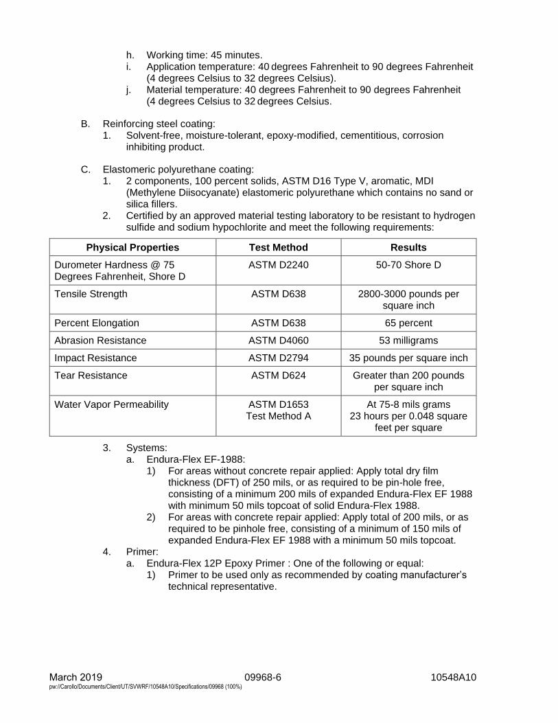
09968-6 10548A10 March 2019 pw://Carollo/Documents/Client/UT/SVWRF/10548A10/Specifications/09968 (100%)
h. Working time: 45 minutes.i. Application temperature: 40 degrees Fahrenheit to 90 degrees Fahrenheit
(4 degrees Celsius to 32 degrees Celsius).j. Material temperature: 40 degrees Fahrenheit to 90 degrees Fahrenheit
(4 degrees Celsius to 32 degrees Celsius.
B. Reinforcing steel coating:1. Solvent-free, moisture-tolerant, epoxy-modified, cementitious, corrosion
inhibiting product.
C. Elastomeric polyurethane coating:1. 2 components, 100 percent solids, ASTM D16 Type V, aromatic, MDI
(Methylene Diisocyanate) elastomeric polyurethane which contains no sand orsilica fillers.
2. Certified by an approved material testing laboratory to be resistant to hydrogensulfide and sodium hypochlorite and meet the following requirements:
Physical Properties Test Method Results
Durometer Hardness @ 75 Degrees Fahrenheit, Shore D
ASTM D2240 50-70 Shore D
Tensile Strength ASTM D638 2800-3000 pounds per square inch
Percent Elongation ASTM D638 65 percent
Abrasion Resistance ASTM D4060 53 milligrams
Impact Resistance ASTM D2794 35 pounds per square inch
Tear Resistance ASTM D624 Greater than 200 pounds per square inch
Water Vapor Permeability ASTM D1653 Test Method A
At 75-8 mils grams 23 hours per 0.048 square
feet per square
3. Systems:a. Endura-Flex EF-1988:
1) For areas without concrete repair applied: Apply total dry filmthickness (DFT) of 250 mils, or as required to be pin-hole free,consisting of a minimum 200 mils of expanded Endura-Flex EF 1988with minimum 50 mils topcoat of solid Endura-Flex 1988.
2) For areas with concrete repair applied: Apply total of 200 mils, or asrequired to be pinhole free, consisting of a minimum of 150 mils ofexpanded Endura-Flex EF 1988 with a minimum 50 mils topcoat.
4. Primer:a. Endura-Flex 12P Epoxy Primer : One of the following or equal:
1) Primer to be used only as recommended by coating manufacturer’stechnical representative.
09968-7 10548A10 March 2019 pw://Carollo/Documents/Client/UT/SVWRF/10548A10/Specifications/09968 (100%)
PART 3 EXECUTION
3.01 GENERAL PREPARATION
A. As required, remove all existing piping, pipe hangers, concrete inserts, and otheritems as necessary from areas where repair and coating of concrete is required tofacilitate repair and coating work, and acceptable to Engineer.
B. Steam clean and degrease all surfaces prior to abrasive blasting.
C. Utilize abrasive blast cleaning to remove surface contaminants and loose materialfor preparation of concrete surfaces.1. Remove debris from structure and dispose of material off site:
a. Compressed air used for blasting or blow downs must be clean and freeof oil particles.
b. Air compressors must be equipped with efficient oil and water traps.
D. Utilize SSPC SP2 and SSPC SP3 standards to remove damaged and deterioratedconcrete for repair and coating:1. For areas with less than 1/2-inch concrete deterioration, provide the expanded
polyurethane coating as specified in this Section.2. For areas of concrete deterioration between 1/2 inch and 3 inches, provide
repair mortar with polyurethane topcoat.3. For area with concrete deterioration beyond 3 inches, with exposed reinforcing
bars, the concrete must be chipped back to 4-1/2 inches and reinforcing barsrepaired as required.
E. Remove loose concrete from spalled areas and cracks:1. In areas where concrete deterioration dovetails to original concrete surface,
make entire cavity to be repaired at least 1/2-inch deep from original concretesurface by means of saw-cutting.
2. Provide straight edges, a minimum of 1/2-inch deep in sound concrete2-inches away from deterioration.
3. Repair with concrete repair mortar so as to provide a minimum of 1/2 inch ofconcrete repair material at all locations.
4. Prepare surface edges of cavity by grinding.5. Remove dust, dirt, and loosely bonded material resulting from cleaning.6. Ensure cavity surfaces are dry.
F. Use following procedures where reinforcing steel with active corrosion isencountered:1. Clean exposed reinforcing bars to SSPC SP10 standard.2. Determine reinforcement bar section loss, splice new reinforcing bars where
there is more than 15 percent loss as determined by Engineer.a. If more than half the diameter of reinforcing steel is exposed, chip out
behind reinforcing steel a minimum of 1/2 inch.b. Cut reinforcing bars, butt weld new reinforcing bars to undamaged
existing reinforcing bars and place repair mortar to original surface.3. Coat all exposed reinforcing steel with high solids epoxy immersed service, as
specified in Section 09960 - High-Performance Coatings, before installation offinal concrete repair material.
09968-8 10548A10 March 2019 pw://Carollo/Documents/Client/UT/SVWRF/10548A10/Specifications/09968 (100%)
G. Restore damaged and deteriorated edges with approved concrete repair materialand in accordance with manufacturer’s recommendations.
H. For all concrete repair areas:1. Provide smooth steel towel finish free from trowel marks and depressions
greater than 1/4 inch.2. Allow concrete repair areas to cure for minimum of 48 hours before application
of elastomeric polyurethane coating, or as recommended by manufacturer ofelastomeric polyurethane coating.
3. Sweep blast all concrete repair areas, followed by air blow-down andvacuuming of all areas to remove all dust and debris before the application ofcoating.
4. Provide heaters, fans, or dehumidification equipment as required to allowconcrete surfaces to cure and be dry, as recommended by manufacturer ofelastomeric polyurethane coating, prior to application of coating.
I. Allow repaired areas to cure for minimum of 48 hours before application ofelastomeric polyurethane coating, or as recommended by manufacturer ofelastomeric polyurethane coating.1. Provide necessary heaters, fans, or dehumidification equipment to allow
concrete to cure and to be surface dry for coating application.
J. Cleanliness:1. At the direction of the coating manufacturer’s technical representative or the
Owner, all surfaces shall be pressure cleaned with clean, potable water at aminimum pressure of 1,500 pounds per square inch to remove all dust, dirt,and other debris prior to the application of the elastomeric polyurethanecoating.
K. Expansion joints:1. Seal expansion joints with bond breaker tape.
a. Polyethylene-backed adhesive tape is acceptable.2. Prior to installation of bond breaker tape, round-off sharp edges, remove
debris/dust, and inspect to assure that joint compound is reasonably flush withtop edge of expansion joint.
3. Apply a tack coat of elastomeric polyurethane coating material to adjacentareas, followed immediately with installation of the tape.
4. Install tape centered over the joint and be of sufficient width to extend aminimum of 1 inch onto the concrete on both sides of the joint.
5. Tape thickness should be no more than 50 percent of the specified coatingthickness.
6. Topcoat bond breaker tape with elastomeric polyurethane coating material tothe minimum specified thickness.
L. Inspection:1. After completion of surface preparation Owner, Engineer, and coating
manufacturer’s technical representative, will inspect all surfaces to be coatedprior to coating.
2. Specified cleanliness shall be verified through the use of accepted practice inaccordance with SSPC or NACE standards.
3. Utilize visual comparators to verify the specified level of cleanliness.
09968-9 10548A10 March 2019 pw://Carollo/Documents/Client/UT/SVWRF/10548A10/Specifications/09968 (100%)
M. Abrasive-blast and concrete debris:1. Remove debris generated from the preparation operations from the structures.2. Haul and dispose of debris in accordance with all federal, State, and local
regulations.
3.02 COATING APPLICATION
A. Equipment requirements:1. Utilize plural component proportioning equipment capable of pumping
2 separate streams of polyurethane components at the required ratiovolumetrically.
2. Have capability to heat the 2 different liquid components to a processtemperature range from 100 to 125 degrees Fahrenheit depending on theset-up.a. Do not use of band heaters.
3. Have capability to maintain process temperature to spray through a gun orpour through the nozzle.a. The use of insulated heat-trace fluid lines is mandatory.
4. Have capability to pump at pressures ranging from 1,200 pounds per squareinch to 3,000 pounds per square inch.
5. Have capability to bring the 2 separately proportioned streams together as onestream and mix them together to provide a homogenous mixture for reactinginto a solid polymer of known properties.
6. Provide spray atomization tip sizes matched to the pumping equipment outputwhich provides a fully atomized spray pattern, free of “fingers” without theaddition of solvents of any kind.
7. For applications requiring expanded films, Contractor must be licensed for theuse of the ECOSYSTEM expansion technology, to include trained personnel,and have the equipment capabilities to apply the ENDURA-FLEX® 1988material using the ECOSYSTEM technology.
B. Before start of application and at such times when long breaks are involved orapplication of equipment malfunctions, the following 4 material quality tests arerecommended:1. A ratio check to verify required volumetric proportioning.2. A mixed material check to verify proper mixing of components.3. Curing cycle test to verify the proper reaction is under way.
a. At least a pint sample is to be utilized.b. First Durometer results should be determined within 15 minutes.
4. A weight check (10 ounces. Container with solid material and a 10 ounces.Container with expanded material) to verify proper expansion rate.
C. All surfaces receiving the coating shall be visually dry and at least 5 degreesFahrenheit (3 degrees Centigrade) above the dew point prior to starting theinstallation to prevent moisture entrapment:1. The relative humidity must be below 85 percent.2. Test surfaces to be coated in accordance with ASTM D4263.
a. Test method for indicating moisture in concrete is by the plastic sheetmethod.
D. Compressed air used for coating application shall be clean and free of oil and water.
March 2019 09968-10 10548A10 pw://Carollo/Documents/Client/UT/SVWRF/10548A10/Specifications/09968 (100%)
E. Use primer only at direction of, and as recommended by coating manufacturer’stechnical representative.
F. Mix polyurethane base component thoroughly with a power mixer.1. Heat base and activator to 100 to 110 degrees Fahrenheit prior to use.
G. Materials conditioning:1. Perform in accordance with manufacturer’s latest published data.2. Control temperature in order to produce a repeatable finished product on each
application.
H. Deposition of materials: Apply coating to be monolithic and cohesive in nature andto minimize hand work repair.
I. Leading edges: Install a mechanical anchor for the leading edge of the appliedcoating material:1. Leading edge mechanical anchor shall consist of a saw cut to a minimum
depth of 1/4 inch and width of 1/8 inch.2. Sharp edges of the saw cut shall be rounded, dried, and cleaned of debris.3. After cleaning, solid base elastomeric polyurethane coating shall be applied
into the saw cut, taking care to penetrate to full depth. The use of a trowel orputty knife might be required.
4. After installation of the leading edge, topcoat the area with compositeelastomeric polyurethane coating material.a. Tape-off adjacent areas not scheduled for coating and protected from
overspray.
J. Curing:1. Protect finished coating from damage during curing.2. Cure coatings as recommended by coating manufacturer for a minimum of
3 days before coated areas are placed in service.
K. Cleanup: Clean spillage and overspray from adjacent surfaces as recommended bycoating system manufacturer.
3.03 INSPECTION AND TESTING
A. The following inspection equipment (or engineer accepted equal) shall be providedand utilized for performing quality control testing:1. Sling psychrometer.2. Surface temperature thermometer.3. Ambient temperature thermometer.4. Psychrometric charts for determining relative humidity and dew point.5. High range wet and dry film thickness gauges.6. Micrometer.7. Durometer: A scale.8. Sample cans.9. Inspection glass: 30 power minimum.10. High voltage holiday detector.
B. The following quality control tests shall be performed, with results recorded andmade available to Engineer:1. Compressed air quality in accordance with blotter test.
March 2019 09968-11 10548A10 pw://Carollo/Documents/Client/UT/SVWRF/10548A10/Specifications/09968 (100%)
2. Environmental conditions prior to coating application, including substratetemperature, ambient temperature, relative humidity, and dew point.
3. Observation of surface preparation, including anchor pattern prior to coatingapplication.
4. Results of ratio check of plural component proportioning equipment.5. Wet and dry film thickness measurements.
C. Owner, Engineer, and coating manufacturer’s technical representative shall begiven sufficient notice so as to be present when the following hold points arereached:1. Completion of surface preparation.2. Prior to coating application.3. During wet and dry film thickness measurements.4. During holiday detection testing.5. During coating repairs.
D. Surface cleanliness, pH condition:1. Use either pH paper or a pH meter to determine the pH of the concrete
surface.2. A pH range of 5 to 9 is considered acceptable.
E. Enlist the aid of various tests and implement those tests to verify the integrity of theapplied coating.1. Permit Owner, Engineer, and coating manufacturer’s technical representative
full access at all times to observe and be satisfied that the specification isbeing followed.
F. Wet film thickness shall be monitored throughout the coating installation by meansof frequent measurements with a high-range wet film thickness gauge.
G. All layers of material (expanded and solid) shall be applied the same day. Thisprocedure is to ensure minimization of contamination of the coating:1. If project is not completed, then at the end of the workday, a 3- to 12-inch
“returning edge” of material will be left tapered to the substrate for the start ofthe next working day.
2. The “returning edge” shall be cleaned with MEK before proceeding to spray onstart up to the following workday.
H. Coating shall be 100 percent electronically tested using high voltage in accordancewith NACE procedure SP0188 inspected for discontinuities to include pinholes,voids, and mechanically damaged areas.1. Any damaged areas, faulty areas, or discontinuities (pinholes) found during
holiday detection within a 24-hour (within recoat window) period of applicationshall be corrected as follows:a. Damaged or faulty areas (i.e., impact damage, off-ratio application):
1) Clean area thoroughly, extending at least 6 inches beyond damagedarea with MEK dampened cloth.
2) Do not apply excessive MEK to repair area, the intent is to cleanonly.
3) Allow MEK to thoroughly dry.4) When thoroughly dry to touch, spray area with coating to the
specified thickness, feathering material into existing coating.
March 2019 09968-12 10548A10 pw://Carollo/Documents/Client/UT/SVWRF/10548A10/Specifications/09968 (100%)
5) In the event that the damaged area exhibits a discolored substratesubstandard to the specified requirements, these areas shall receivethe same degree of surface preparation required by the originalproject specifications prior to application of the coating material.
b. Discontinuity (pinhole) repair:1) Clean the immediate area around the detected discontinuity with
MEK dampened cloth (do not apply excessive MEK to pinhole area,the intent is to clean only), allow MEK to thoroughly dry.
2) Hand apply (putty knife, etc.) a small amount of mixed materialdirectly to the pinhole.
3) For pinhole repairs, hand mix and thoroughly blend a small amount(normally 2 or 3 ounces at a time, for each applicator) of Part A andPart B in correct ratios.
2. Any damaged areas, faulty areas, or discontinuities (pinholes) found duringholiday detection inspection after 24 hours of coating installation (exceedingrecoat window) shall be corrected as follows:a. Damaged or faulty areas (i.e., impact damage, off-ratio application, etc.):
1) Abrade the surface using a power grinder and/or power steel grindingbrush down to and including exposed bare concrete to roughen thesurface and to prepare the substrate to the original standard.
2) Abraded areas shall extend at least 6 inches (15 centimeter.) beyonddamaged or faulty area.
3) After abrading the surface, vacuum or blow down with clean, drycompressed air thoroughly to remove all loose particles.
4) Clean the area thoroughly, extending at least 6 inches(15 centimeter) beyond the damaged area with MEK dampened cloth(do not apply excessive MEK to pinhole area, the intent is to cleanonly), allow MEK to thoroughly dry.
5) When thoroughly dry to touch, spray area with coating to thespecified thickness, feathering the material into the existing preparedcoating.
b. Discontinuity (pinhole) repair:1) Abrade (hand sand or power tool clean) the immediate areas around
the detected pinhole (1/2-inch radius from edge of discontinuity) toestablish a roughed surface, and to prepare the substrate to theoriginal standard, followed with vacuuming or blow down with clean,dry compressed air to remove loose particles.
2) After dust removal, wipe abraded area with MEK dampened cloth.3) Do not apply excessive MEK to pinhole area.4) The intent is to clean only. Allow MEK to thoroughly dry.5) Hand apply (putty knife, etc.) a small amount of mixed material
directly to the pinhole.6) For pinhole repairs, hand mix and thoroughly blend a small amount
(normally 3 ounces at a time for each applicator) or Part A and Part Bin correct ratios.
3.04 REPLACEMENT OF REMOVED ITEMS
A. Clean and recoat items removed from work areas prior to commencing work suchas piping, pipe hangers, and associated equipment replace in like manner asremoved.
March 2019 09968-13 10548A10 pw://Carollo/Documents/Client/UT/SVWRF/10548A10/Specifications/09968 (100%)
3.05 FINAL INSPECTION AND ACCEPTANCE
A. Final inspection:1. Following replacement of previously removed items, a final inspection of the
repaired and coated structures shall be made by Engineer, Owner, Contractor,and the coating manufacturer’s technical representative.
2. Any damage that has occurred to the coating shall be repaired in accordancewith the coating manufacturer’s instructions.
B. Final acceptance:1. Written final acceptance of the concrete repair and coating work accomplished
to the interiors of the structures, as specified in the Contract Documents, shallbe prepared by the Engineer or Owner and issued to the Contractor, with acopy to the coating manufacturer.
END OF SECTION

10400-1 10548A10 March 2019 pw://Carollo/Documents/Client/UT/SVWRF/10548A10/Specifications/10400 (100%)
SECTION 10400
SIGNAGE
PART 1 GENERAL
1.01 SUMMARY
A. Section includes: Plastic and metal signs for building and site use.
1.02 REFERENCES
A. National Fire Protection Association (NFPA):1. 704 - Standard System for the Identification of the Hazards of Materials for
Emergency Response.
B. Occupational Safety and Health Administration (OSHA).
1.03 SUBMITTALS
A. Product data:
B. Shop drawings: Include lists of sign types, sizes, text, and colors; mounting details;locations; and cast metal plaque rubbings and templates.
C. Samples: Include actual materials.
D. Manufacturer's installation instructions.
1.04 QUALITY ASSURANCE
A. Manufacturer qualifications: Manufacturer of proposed products for minimum5 years with satisfactory performance record of minimum 5 years.
B. Installer qualifications: Manufacturer approved installer of products similar tospecified products on minimum 10 projects of similar scope as Project withsatisfactory performance record.
C. Regulatory requirements: Provide signage in accordance with Americans withDisabilities Act as published in the Federal Register, Volume 56, No. 144, Friday,July 26, 1991.
PART 2 PRODUCTS
2.01 PLASTIC SIGNAGE SYSTEM
A. Manufacturers:1. One of the following or equal:
a. Best Manufacturing Sign Systems, System 900013.b. Andco Industries Corp., equivalent product.
10400-2 10548A10 March 2019 pw://Carollo/Documents/Client/UT/SVWRF/10548A10/Specifications/10400 (100%)
c. Vomar Products, Inc., equivalent product.
B. Attachment:1. Vinyl tape, self-adhering.
C. Lettering:1. Helvetica medium, 3/4 inches high.
D. Material for interior use:1. Plastic 1/8-inch thick raised letters.
E. Material for exterior use:1. Fiberglass 1/4 inch thick with high gloss finish, raised letters, blasted from
single piece of fiberglass for integral letter and background.2. No adhesive as mechanical fastening of letters shall be allowed.
F. Colors:1. As selected by Engineer from manufacturer's standard colors.
G. See Schedule A for specific sign size, location, text, pictogram, and quantity.
2.02 METAL SAFETY SIGNS
A. Manufacturer: Meeting OSHA Requirements; 40-mil thick aluminum with bakedenamel finish. One of the following or equal:1. Seton Name Plate Co., Special Wording.2. Emedco.
B. Danger sign colors:1. Background: White.2. Heading: White lettering on red oval with white border in black rectangular
panel.3. Message: Black lettering on white.4. Size: As scheduled.
C. Caution sign colors:1. Background: Yellow.2. Heading: Yellow lettering on black rectangular panel.3. Message: Black lettering on yellow.4. Size: As scheduled.
D. Safety instruction signs:1. Background: White.2. Heading: White lettering on green rectangular panel.3. Message: Black lettering.4. Size: As scheduled.
E. Warning sign colors:1. Background: Orange.2. Heading: Black lettering on orange diamond in black rectangular panel.3. Message: Flack lettering on orange.4. Size: As scheduled.
10400-3 10548A10 March 2019 pw://Carollo/Documents/Client/UT/SVWRF/10548A10/Specifications/10400 (100%)
F. Notice information signs:1. Background: White.2. Heading: White lettering on blue rectangular panel.3. Message: Black lettering.4. Size: As scheduled.
G. Fasteners: Round head stainless steel bolts or screws.
H. See Schedule B for specific sign size, location, text, and quantity.
PART 3 EXECUTION
3.01 PREPARATION
A. Protect adjacent surfaces which may be damaged by installation of signs.
B. Prepare substrates in accordance with sign manufacturer's instructions.
C. Remove scale, dirt, grease, and other contaminates from substrates.
3.02 INSTALLATION
A. Install signs in accordance with sign manufacturer's instructions.
B. Fasten signs securely in level, plumb, and true to plane positions.
C. Install signs where as indicated in the following schedules.
3.03 SCHEDULES
A. Plastic Signage System Schedule.
B. Metal Safety Sign Schedule.
END OF SECTION
10400-4 10548A10 March 2019 pw://Carollo/Documents/Client/UT/SVWRF/10548A10/Specifications/10400 (100%)
SCHEDULE A
PLASTIC SIGNAGE SYSTEM SCHEDULE
A. Room Numbers:1. Location: On wall outside room adjacent to latch side of doors or when not enough
space on latch side, on nearest adjacent wall. 2. Height: 60 inches above floor to center of sign. 3. Size: 6 inches square. 4. Colors: As selected by the Engineer. 5. Text: Room number as indicated on the Drawings.
B. Room Names:1. Location: On wall outside room adjacent to latch side of doors or when not enough
space on latch side, on nearest adjacent wall. 2. Height: 60 inches above floor to center or sign. 3. Size: 6 inches square. 4. Colors: As selected by Engineer.
C. Toilet Doors: Sign per door describing room function as indicated on the Drawings. 1. Location: On wall outside room adjacent to latch side of doors or when not enough
space on latch side, on nearest adjacent wall. 2. Height: 60 inches above floor to center of sign. 3. Size: 6 inches wide by 8 inches high. 4. Colors: As selected by Engineer. 5. Pictogram: International symbol for men or women to suit application. 6. Text: Braille Characters and MEN or WOMEN as appropriate.
D. Stair Doors:1. Location: On wall outside room adjacent to latch side of doors or when not enough
space on latch side, on nearest adjacent wall. 2. Height: 60 inches above floor to center of sign. 3. Size: 6 inches square. 4. Colors: As selected by Engineer. 5. Pictogram: Means of egress indication.
E. Stair Landings:1. Location: At each floor landing in stairwells. 2. Height: 60 inches above floor to center of sign. 3. Size: 6 inches square. 4. Colors: As selected by Engineer. 5. Text: Stair number, access or no access to roof to suit application, and floor
level, as follows:
F. Fire Extinguishers:1. Location: Adjacent to fire extinguishers. 2. Height: 60 inches above floor to center of sign. 3. Size: 6 inches square. 4. Colors: White letters on OSHA Red background. 5. Text: FIRE EXTINGUISHER.
10400-5 10548A10 March 2019 pw://Carollo/Documents/Client/UT/SVWRF/10548A10/Specifications/10400 (100%)
G. Slip Hazard:1. Location: As determined by the Owner. 2. Height: 60 inches above grade to center of sign. 3. Size: 10 inches wide by 7 inches high. 4. Heading: CAUTION 5. Text: SLIP HAZARD AREA
H. Nonpotable Water:1. Location: At impure water and nonpotable water hose valves in accordance with
Typical Detail M276. 2. Height: In accordance with Typical Detail. 3. Size: 10 inches wide by 7 inches high. 4. Heading: CAUTION 5. Text: IMPURE WATER
DO NOT DRINK
END OF SCHEDULE A PLASTIC SIGNAGE SYSTEM SCHEDULE
10400-6 10548A10 March 2019 pw://Carollo/Documents/Client/UT/SVWRF/10548A10/Specifications/10400 (100%)
SCHEDULE B
METAL SAFETY SIGN SCHEDULE
A. EMERGENCY EXIT:1. Location: Exterior side of building doors. 2. Height: As shown in the drawings. 3. Size: 20 inches wide by 14 inches high 4. Heading: DANGER 5. Wording: BEFORE ENTERING
TURN ON EXTERIOR VENTILATION AND LIGHT SWITCHES
ALLOW BUILDING TO VENTILATE WAIT 5 MINUTES BEFORE ENTERING
TWO PEOPLE MUST BE PRESENT WEAR SELF-CONTAINED AIR SYSTEM WHEN CHANGING OR MOVING CHLORINE CYLINDERS
B. CONFINED SPACE:1. Location: Entrance to all confined space areas. 2. Height: 60 inches above grade to center of sign. Mounted on handrail or stand. 3. Size: 20 inches wide by 14 inches high. 4. Heading: DANGER 5. Wording: CONFINED SPACE
PERMIT REQUIRED FOR ENTRY
C. NONPOTABLE WATER:1. Location: At impure water and nonpotable water hose valves in accordance with
Typical Detail M276. 2. Height: In accordance with Typical Detail. 3. Size: 10 inches wide by 7 inches high. 4. Heading: DANGER 5. Wording: DO NOT DRINK THIS WATER
D. HIGH PRESSURE HOSE VALVES:1. Location: At designated hose valves. 2. Height: As shown in the drawings. 3. Size: 20 inches wide by 14 inches high 4. Heading: DANGER 5. Wording: HIGH PRESSURE
E. REMOTELY CONTROLLED AUTOMATIC EQUIPMENT:1. Location: On front and back of equipment that starts automatically by remote
control. 2. Height: As shown in the drawings. 3. Size: 20 inches wide by 14 inches high 4. Heading: DANGER 5. Wording: THIS EQUIPMENT STARTS AUTOMATICALLY
BY REMOTE CONTROL
10400-7 10548A10 March 2019 pw://Carollo/Documents/Client/UT/SVWRF/10548A10/Specifications/10400 (100%)
F. HIGH VOLTAGE WARNING:1. Location: On front and back of equipment, adjacent to doors to rooms containing
devices, and devices that operate at 600 volts or greater. 2. Height: As shown in the drawings. 3. Size: 20 inches wide by 14 inches high 4. Heading: DANGER 5. Wording: HIGH VOLTAGE
KEEP OUT
G. NO SMOKING INFORMATIONAL SIGNS:1. Location: On exterior face of wall, adjacent to each entry point (exterior door) to
all buildings. 2. Height: 60 inches above floor to center of sign. Where metal safety signs are
also located adjacent to entry points, place no smoking signs below these signs.
3. Size: 6 inches square. 4. Heading: None. 5. Wording: None. 6. Pictogram: International “No Smoking” symbol.
END OF SCHEDULE B METAL SAFETY SIGN SCHEDULE

10520-1 10548A10 March 2019 pw://Carollo/Documents/Client/UT/SVWRF/10548A10/Specifications/10520 (100%)
SECTION 10520
FIRE PROTECTION SPECIALTIES
PART 1 GENERAL
1.01 SUMMARY
A. Section includes: Fire extinguishers.
1.02 REFERENCES
A. National Fire Protection Association (NFPA).
B. Underwriters Laboratories, Inc. (UL).
1.03 SUBMITTALS
A. Product Data.
B. Manufacturer's Installation Instructions.
1.04 QUALITY ASSURANCE
A. Manufacturer qualifications: Manufacturer of proposed products for minimum5 years with satisfactory performance record of minimum 5 years.
B. Regulatory requirements:1. Comply with UL requirements for classification type.
1.05 SEQUENCING AND SCHEDULING
A. Coordinate installation of blocking for anchoring of accessories in accordance withSection 04220 - Concrete Unit Masonry.
PART 2 PRODUCTS
2.01 MANUFACTURERS
A. Fire extinguisher: One of the following or equal:1. J.L. Ind.2. Larsen's Manufacturing Co.3. Modern Metal Products by Muckle.4. Watrous, Inc.
2.02 FIRE EXTINGUISHERS
A. Type FX: 10:UL 4A:60B:C with 10-pound capacity of dry chemical with ammoniumphosphate base for extinguishing ABC fires.
10520-2 10548A10 March 2019 pw://Carollo/Documents/Client/UT/SVWRF/10548A10/Specifications/10520 (100%)
B. Type FXE: 10:UL 1A:10B:C with 10-pound capacity of colorless, odorless,electrically non-conductive liquefied gas, or clean agent as defined by NFPA , forextinguishing electrical fires without leaving residue.
2.03 WALL BRACKETS
A. Type: Standard as manufactured by fire extinguisher manufacturer.
2.04 ACCESSORIES
A. Extinguisher brackets: Formed steel, corrosion resistant finish, size and type to suitextinguisher.
PART 3 EXECUTION
3.01 INSTALLATION
A. Install products in accordance with manufacturer's recommendations.
B. Install products plumb, square, and level.
C. Place extinguishers: Locate extinguishers as indicated on Drawings.
3.02 SCHEDULE
A. Install fire extinguisher on wall brackets when fire extinguisher are indicated withoutcabinets.
END OF SECTION
10810-1 10548A10 March 2019 pw://Carollo/Documents/Client/UT/SVWRF/10548A10/Specifications/10810 (100%)
SECTION 10810
TOILET ACCESSORIES
PART 1 GENERAL
1.01 SUMMARY
A. Section includes: Toilet accessories.
1.02 REFERENCES
A. Americans with Disabilities Act (ADA).
B. ASTM International (ASTM):1. A240 - Standard Specification for Chromium and Chromium-Nickel Stainless
Steel Plate, Sheet, and Strip for Pressure Vessels and for GeneralApplications.
1.03 SUBMITTALS
A. Shop drawings: Include schedule of proposed products.
B. Product data: Include dimensions gauge, profiles, materials, fabrication details,manufacturer's installation instructions including setting drawings where cutouts arerequired, templates, substrate preparation instructions and directions for preparingcutouts for installation of accessories.
C. Special samples:1. Include 1 of each accessory type.2. Special samples acceptable to Engineer may be installed in the Work.
1.04 QUALITY ASSURANCE
A. Manufacturer qualifications: Manufacturer of proposed products for minimum5 years with satisfactory performance record of minimum 5 years.
B. Installer qualifications:1. Manufacturer-approved installer of products similar to specified products on
minimum 5 projects with satisfactory performance record.2. Furnish toilet accessories by 1 manufacturer, unless scheduled otherwise.
C. Requirements of regulatory agencies: In accordance with ADA for provisions for thephysically handicapped; materials and installation.
1.05 DELIVERY, STORAGE, AND HANDLING
A. Maintain protective coatings or coverings on units until installation is complete.
10810-2 10548A10 March 2019 pw://Carollo/Documents/Client/UT/SVWRF/10548A10/Specifications/10810 (100%)
PART 2 PRODUCTS
2.01 MANUFACTURERS
A. Toilet accessories: One of following or equal:1. Bobrick Washroom Equipment Co., Inc.2. General Accessory Manufacturing Co.3. McKinney/Parker, Essex Ind., Inc.4. Watrous, Div. of Lansbrie Corp.
2.02 MATERIALS
A. Stainless steel: ASTM A240, Type 304 or 316; minimum 28 gauge.
2.03 TOILET ACCESSORIES
A. Manufacturers: The following or equal:1. Bobrick Washroom Equipment Co., Inc.
B. Types:1. Grab bars: B6806 (concealed fasteners), sizes and shapes indicated, with
appropriate anchors.2. Mirror with 3/4- by 3/4-inch frame: B-290, sizes as indicated on the Drawings.3. Paper towel dispenser/waste receptacle, surface mounted, plastic liner:
B-3949.4. Soap dispenser, counter mounted, liquid soap: B-8221, with 16 fluid ounce
polyethylene container.5. Toilet paper holder, double, surface mounted: B-2888.
C. Fasteners: Concealed or tamperproof, sized to suit application.
2.04 FABRICATION
A. Weld and grind smooth joints of fabricated components.
B. Form exposed surfaces from single sheet of stock, free of joints.
C. Form surfaces flat without distortion.1. Maintain flat surfaces without scratches or joints.
D. Shop assemble components and package complete with anchors and fittings.
PART 3 EXECUTION
3.01 EXAMINATION
A. Verify that conditions are satisfactory for the installation of accessory items.
B. Verify that supports and reinforcements are in place and proper for accessoryinstallation.
C. Do not begin installation until conditions are satisfactory.
10810-3 10548A10 March 2019 pw://Carollo/Documents/Client/UT/SVWRF/10548A10/Specifications/10810 (100%)
1. Beginning installation means acceptance of existing conditions.
3.02 PREPARATION
A. Deliver inserts and rough-in frames to site at the appropriate time for building-in.
B. Provide templates and rough-in measurements as required.
3.03 INSTALLATION
A. Install products in accordance with manufacturer's instructions.
B. Install units plumb and level.1. Firmly anchor accessories.
C. Install grab bar connectors or support angles between studs securely enough towithstand horizontal pull of 300 pounds.
D. Accurately position grab bar connector assemblies and tighten to support anglesbefore application of wall finish.1. After completion of wall surface, secure concealed mounting plate to
connector assembly with stainless steel machine screws.
E. Use through-bolted connection for grab bars on toilet compartments.
3.04 ADJUSTING
A. Adjust accessories for proper operation and verify that mechanisms operatesmoothly.
B. Replace damaged or defective products with good products.
END OF SECTION

March 2019 11224A-1 10548A10 pw://Carollo/Documents/Client/UT/SVWRF/10548A10/Specifications/11224A (100%)
SECTION 11224A
SURFACE-MOUNTED FLOATING PROPELLER MIXERS
PART 1 GENERAL
1.01 SUMMARY
A. Section includes: Floating-style propeller mixer for use in anoxic zone of biologicalwastewater treatment reactor. Manufacturer shall design and supply all supports,anchors, and final mixer locations as specified here and as shown in the drawings.
1.02 COST OF PRE-NEGOTIATED ITEMS
A. Cost for some items in this section of the Specifications has been pre-negotiatedwith specified manufacturer and is included in one of the bid items in the biddingsheet. Refer to bidding sheet and applicable pre-negotiated proposal included inAppendix A for more details. Contractor shall provide additional items as indicatedin applicable pre-negotiated proposal included in Appendix A, even if they are notincluded in Specifications and/or Drawings. Contractor is very strongly cautioned tocarefully review applicable pre-negotiated proposal, because the pre-negotiatedproposal does not include all items included in Specifications and Drawings. Inaddition to cost indicated for applicable bid item in bidding sheet, Contractor shallinclude in his bid the costs for the following:1. All items not specifically mentioned in the scope of supply of pre-negotiated
proposal, but required per Specifications and Drawings and required tocomplete the installation to provide an operational system.
2. All other items indicated in the pre-negotiated proposal to be provided byothers, by customer, by Owner, or any other similar designation:a. All freight and applicable taxes, unless specifically included in
pre-negotiated proposal.b. All labor, materials, and all other associated costs not included in the
pre-negotiated proposal but required per Specifications and Drawings andrequired to complete the installation to provide an operational system.
c. The Contractor and Manufacturer shall ensure that the other obligationsdefined in the pre-negotiated proposal (Memorandum of Agreement/MOA)are complied with. These include, but are not limited to, delivery,inspections, start-up, training, testing, and payment.
B. Schedule:1. Contractor shall coordinate with the equipment supplier’s delivery schedule to
issue a purchase order at such time that equipment delivery will be completedat least 8 weeks in advance of the required date, as indicated in theContractor’s approved construction schedule.
2. Negotiated price included in the Bid Schedule is based on a delivery per theMOA Section VI-3. If the Contractor elects to have delivery after this time, thepurchase price shall be adjusted in accordance with the MOA and theContractor shall be responsible for such additional costs.
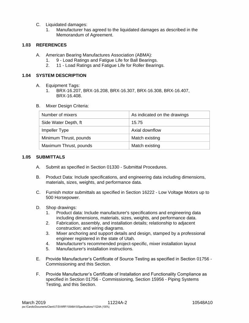
March 2019 11224A-2 10548A10 pw://Carollo/Documents/Client/UT/SVWRF/10548A10/Specifications/11224A (100%)
C. Liquidated damages: 1. Manufacturer has agreed to the liquidated damages as described in the
Memorandum of Agreement.
1.03 REFERENCES
A. American Bearing Manufactures Association (ABMA): 1. 9 - Load Ratings and Fatigue Life for Ball Bearings. 2. 11 - Load Ratings and Fatigue Life for Roller Bearings.
1.04 SYSTEM DESCRIPTION
A. Equipment Tags: 1. BRX-16.207, BRX-16.208, BRX-16.307, BRX-16.308, BRX-16.407,
BRX-16.408.
B. Mixer Design Criteria:
Number of mixers As indicated on the drawings
Side Water Depth, ft 15.75
Impeller Type Axial downflow
Minimum Thrust, pounds Match existing
Maximum Thrust, pounds Match existing
1.05 SUBMITTALS
A. Submit as specified in Section 01330 - Submittal Procedures.
B. Product Data: Include specifications, and engineering data including dimensions, materials, sizes, weights, and performance data.
C. Furnish motor submittals as specified in Section 16222 - Low Voltage Motors up to 500 Horsepower.
D. Shop drawings: 1. Product data: Include manufacturer's specifications and engineering data
including dimensions, materials, sizes, weights, and performance data. 2. Fabrication, assembly, and installation details; relationship to adjacent
construction; and wiring diagrams. 3. Mixer anchoring and support details and design, stamped by a professional
engineer registered in the state of Utah. 4. Manufacturer's recommended project-specific, mixer installation layout 5. Manufacturer's installation instructions.
E. Provide Manufacturer’s Certificate of Source Testing as specified in Section 01756 - Commissioning and this Section.
F. Provide Manufacturer’s Certificate of Installation and Functionality Compliance as specified in Section 01756 - Commissioning, Section 15956 - Piping Systems Testing, and this Section.
March 2019 11224A-3 10548A10 pw://Carollo/Documents/Client/UT/SVWRF/10548A10/Specifications/11224A (100%)
G. Operation and maintenance manuals: Submit as specified in Section 01782 -Operation and Maintenance Data.
H. Submit testing results as specified in Section 15958 - Mechanical EquipmentTesting
1.06 QUALITY ASSURANCE
A. Manufacturer qualifications: Manufacturer of proposed product for the following:1. Minimum 10 similar projects with satisfactory performance record.2. Minimum 5 municipal wastewater treatment projects with minimum 2 years
satisfactory performance.
1.07 PROJECT CONDITIONS
A. As specified in Section 15050 - Common Work Results for Mechanical Equipment.
1.08 WARRANTY
A. As specified in Section 01783 - Warranties and Bonds.
1.09 EXTRA MATERIALS
A. Spare parts: Deliver the following spare parts to Owner when and were directed byEngineer:1. 1 complete set of bearings.
PART 2 PRODUCTS
2.01 MANUFACTURERS
A. Surface-mounted direct drive mixers: Provide the following:1. Aqua Aerobics SS Endura Series, Aqua DDM Mixer.
2.02 SURFACE-MOUNTED PROPELLER MIXERS
A. Type:1. Surface-mounted, motor-driven propeller, specifically intended for use in
aeration basin anoxic zones. Each mixer shall consist of a motor, direct driveimpeller driven at a constant speed, an integral flotation unit, mooring system,and impeller volute, as further described below.
2. Mixers with submersible motors, submerged bearings, sleeves, and wearrings; or that rely on motor bearings to take loads will not be acceptable.
2.03 COMPONENTS
A. Motor:1. 5 horsepower, totally enclosed, fan cooled, TEFC, 230/460-volt, 60 cycle,
3-phase motor; rated for 40 degrees Centigrade ambient; maximum nominal1,200 revolutions per minute motor speed; the mixer motor shall have a onepiece motor shaft continuous from the top motor bearing, through the lowerbearing and down to and through the propeller.; with the following:
March 2019 11224A-4 10548A10 pw://Carollo/Documents/Client/UT/SVWRF/10548A10/Specifications/11224A (100%)
a. NEMA Premium efficiency. b. Insulation: Class F insulation, Class B temperature rise. c. Service factor: 1.15.
1) The service factor shall not be used to provide the power required under normal operating conditions.
d. Motor junction box with stainless steel relief grip that protects cable to motor connection.
e. Each motor shall have a rain cap constructed of 304 stainless steel. Painted or plated carbon steel rain caps will not be acceptable.
f. Motor base and intake volute assemblies shall be 304 stainless steel. g. Motor end bells shall be deep registered and Permatex sealed. h. Bolts, nuts, and screws shall be of type 18-8 stainless steel.
2. Conform to the requirements of Section 16222 - Low Voltage Motors up to 500 Horsepower.
B. Bearings: 1. Motor bearings shall be regreasable. Top bearing shall be shielded on the
bottom side only. Bottom bearing shall be open. 2. Top and bottom motor bearings shall be of the combined radial and axial thrust
type. 3. Lower motor bearing inner race shall be locked to the motor shaft via a washer
and locking nut arrangement. The shaft shall be threaded just below the lower bearing and shall have a keyway cut into the motor shaft. This key shall accept a tab from the I.D. of the locking washer, and the locking nut shall have recesses to accept a tab from the O.D. of the locking washer to prevent the nut from backing off.
4. Bearings shall have minimum L-10 life of 100,000 hours in accordance with ABMA 9 or ABMA 11.
C. Impeller shaft: 1. One-piece 17-4 PH stainless steel motor shaft. 2. Diameter shall be 2 inches. 3. Maximum allowable full length shaft run out shall be limited to
0.006 inches T.I.R. 4. Mixer motor shaft shall operate freely without contacting any bearings or
bushings other than the motor bearings.
D. Motor base assembly: 1. Motor shall be securely mounted onto a solid 304 stainless steel base that is
integral with the motor base extension. All submersed wetted motor mounting base components to be constructed of 304 stainless steel.
2. Motor base shall contain a machined recess to permit the use of a free running, anti-deflection insert. The anti-deflection insert shall not require lubrication. The provision for this insert shall be located in the lower extremity of the motor base extension immediately above the impeller.
3. The journal insert shall be machined from Delrin or molded from moly-filled urethane and shall be a minimum of .060-inch diameter or larger through the bore than the diameter of the motor shaft.
4. The motor end bell alignment pilot on the motor base shall be machined concentric with the machined recess that houses the free running, anti-deflection insert.
March 2019 11224A-5 10548A10 pw://Carollo/Documents/Client/UT/SVWRF/10548A10/Specifications/11224A (100%)
5. The upper portion of the motor mounting base, immediately below the lowermotor bearing, shall include 2 independent acting air seals. These 2 sealsshall be capable of sealing off the flow of air from the suction action of thepumped flow and prevent back flow of liquid during impeller reversal. Thelower end of the motor base extension shall be provided with a rotatingbackflow seal that will prevent grit from being introduced into theanti-deflection insert reservoir, but shall allow liquid to contact the shaft. Thebackflow seal shall not require scheduled lubrication or maintenance.
E. Propeller:1. Two-blade marine type, 11.5 inches in diameter, constructed of type 316
stainless steel.2. Designed to pump the liquid from near the surface and directed down toward
the basin floor.3. Streamlined to prevent cavitation and reduce drag. 180-degree trailback
blades to ensure non-clog operation.4. Capable of being reversed to cause back flow liquid movement without
causing damage to the mixer chassis and without causing upflow liquiddamage to the motor bearing and windings.
5. Securely attached to the motor shaft in such a manner so that reversaloperation for liquid backflushing will not loosen its connection.
6. Impeller shall be "pitch balanced" to ensure equalization of load under full flowoperation. Each blade's pitch and rake shall not vary more than 2.0 percentfrom the other.
F. Float:1. Type 304 stainless steel, 14 gauge, filled with closed cell polyurethane foam.
Sealed to prevent foam from being in contact with the external environment.2. 900 pounds reserve buoyancy, 70 inches in diameter, 12-inch thickness.3. Center structure of the float shall be integral to the float cover and shall
transmit all mooring stress from 1 mooring line to another.4. Center structure shall contain rigid vertical support gussets that connect the
top and bottom alignment flanges that support and connect the motor supportbase and the submerged impeller volute assembly.
5. Connecting bolts shall be 316 stainless steel and have drilled heads, and shallbe safety wired in place with stainless steel safety wire.
G. Intake volute assembly:1. The impeller shall operate in a volute made of 304 stainless steel plate with a
minimum volute diameter of 12 inches.2. Volute shall be welded to and aligned concentrically with the motor base and
float without shims or external adjustment.
H. Pivotal mooring system:1. Provide 304 stainless steel mooring arm, which extends from the basin
sidewall to the unit. Provide 2 mooring cables complete with clips, thimbles,and quick disconnects. Mooring arm assemblies shall include reinforcementsrecently added to manufacturer’s standard design to help prevent the bodybrackets from bending.
March 2019 11224A-6 10548A10 pw://Carollo/Documents/Client/UT/SVWRF/10548A10/Specifications/11224A (100%)
I. Other accessories: 1. 25 feet, continuous length flexible service cable per mixer. Cable shall have
3 power conductors and an insulated ground conductor assembled together with a non-hygroscopic filler material. a. Outer jacket shall be CPE, PVC, TPE, or equal, and shall be rated at a
conductor operating temperature of not less than 90 degrees Celsius. 2. Provide 2 of the following per mixer: 2 eye, wire mesh strain relief cord grip
assembly.
2.04 FINISHES
A. Prime motors, drives, brackets, baseplates, and appurtenances with primer, compatible with top coatings as specified in Section 09960 - High-Performance Coatings.
B. Coat machined, polished, and non-ferrous surfaces with corrosion prevention coating.
PART 3 EXECUTION
3.01 INSTALLATION
A. Verify that structures, pipes, and equipment are compatible.
B. Install products in accordance with manufacturer's instructions.
C. Make adjustments required to place system in proper operating condition.
3.02 FIELD QUALITY CONTROL
A. Manufacturer shall check and approve mixer installation before field operation, verify conformance with Contract requirements, and test operate mixers in presence of Engineer.
B. Demonstrate that power demand of each drive motor does not exceed nameplate horsepower or nameplate full load ampere rating.
C. Demonstrate each mixer to be capable of operation without undue noise or vibration. 1. Adjust, repair, or replace defective equipment.
D. Furnish necessary equipment required for testing, properly calibrated.
3.03 COMMISSIONING
A. As specified in Section 01756 - Commissioning and this Section.
B. Manufacturer services: 1. Provide Manufacturer’s Certificate of Source Testing. 2. Provide Manufacturer’s Certificate of Installation and Functionality
Compliance. 3. Training and other on-site services.
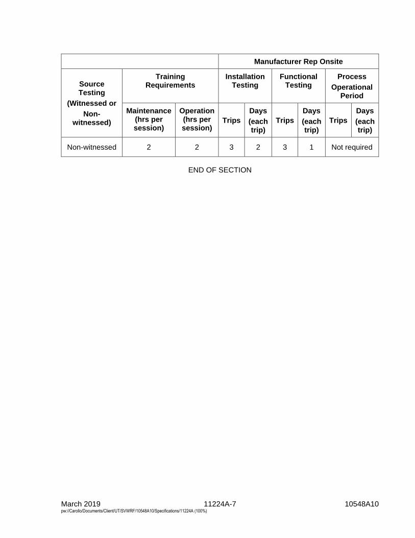
March 2019 11224A-7 10548A10 pw://Carollo/Documents/Client/UT/SVWRF/10548A10/Specifications/11224A (100%)
Manufacturer Rep Onsite
Source Testing
(Witnessed or
Non-witnessed)
Training Requirements
Installation Testing
Functional Testing
Process
Operational Period
Maintenance (hrs per session)
Operation (hrs per session)
Trips
Days
(each trip)
Trips
Days
(each trip)
Trips
Days
(each trip)
Non-witnessed 2 2 3 2 3 1 Not required
END OF SECTION

Section 11224A - Surface-Mounted Propeller Mixers
APPENDIX A - MEMORANDUM OF AGREEMENT FORSURFACE-MOUNTED PROPELLER MIXERS

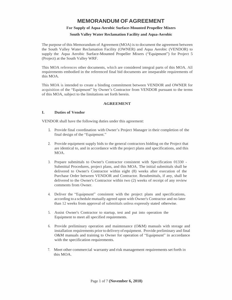
MEMORANDUM OF AGREEMENT
For Supply of Aqua-Aerobic Surface-Mounted Propeller Mixers
South Valley Water Reclamation Facility and Aqua-Aerobic
Page 1 of 7 (November 6, 2018)
The purpose of this Memorandum of Agreement (MOA) is to document the agreement between
the South Valley Water Reclamation Facility (OWNER) and Aqua Aerobic (VENDOR) to
supply the Aqua Aerobic Surface-Mounted Propeller Mixers (“Equipment”) for Project 5
(Project) at the South Valley WRF.
This MOA references other documents, which are considered integral parts of this MOA. All
requirements embodied in the referenced final bid documents are inseparable requirements of
this MOA.
This MOA is intended to create a binding commitment between VENDOR and OWNER for
acquisition of the “Equipment” by Owner’s Contractor from VENDOR pursuant to the terms
of this MOA, subject to the limitations set forth herein.
AGREEMENT
I. Duties of Vendor
VENDOR shall have the following duties under this agreement:
1. Provide final coordination with Owner’s Project Manager in their completion of the
final design of the “Equipment.”
2. Provide equipment supply bids to the general contractors bidding on the Project that
are identical to, and in accordance with the project plans and specifications, and this
MOA.
3. Prepare submittals to Owner's Contractor consistent with Specification 01330 -
Submittal Procedures, project plans, and this MOA. The initial submittals shall be
delivered to Owner's Contractor within eight (8) weeks after execution of the
Purchase Order between VENDOR and Contractor. Resubmittals, if any, shall be
delivered to the Owner's Contractor within two (2) weeks of receipt of any review
comments from Owner.
4. Deliver the “Equipment” consistent with the project plans and specifications,
according to a schedule mutually agreed upon with Owner's Contractor and no later
than 12 weeks from approval of submittals unless expressly stated otherwise.
5. Assist Owner's Contractor to startup, test and put into operation the
Equipment to meet all specified requirements.
6. Provide preliminary operation and maintenance (O&M) manuals with storage and
installation requirements prior to delivery of equipment. Provide preliminary and final
O&M manuals and training to Owner for operation of “Equipment” in accordance
with the specification requirements.
7. Meet other commercial warranty and risk management requirements set forth in
this MOA.
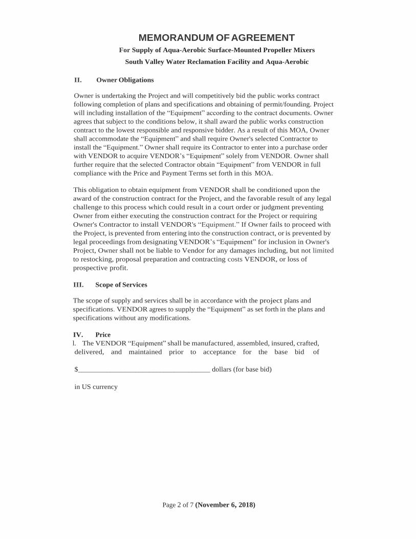
MEMORANDUM OF AGREEMENT
For Supply of Aqua-Aerobic Surface-Mounted Propeller Mixers
South Valley Water Reclamation Facility and Aqua-Aerobic
Page 2 of 7 (November 6, 2018)
II. Owner Obligations
Owner is undertaking the Project and will competitively bid the public works contract
following completion of plans and specifications and obtaining of permit/founding. Project
will including installation of the “Equipment” according to the contract documents. Owner
agrees that subject to the conditions below, it shall award the public works construction
contract to the lowest responsible and responsive bidder. As a result of this MOA, Owner
shall accommodate the “Equipment” and shall require Owner's selected Contractor to
install the “Equipment.” Owner shall require its Contractor to enter into a purchase order
with VENDOR to acquire VENDOR’s “Equipment” solely from VENDOR. Owner shall
further require that the selected Contractor obtain “Equipment” from VENDOR in full
compliance with the Price and Payment Terms set forth in this MOA.
This obligation to obtain equipment from VENDOR shall be conditioned upon the
award of the construction contract for the Project, and the favorable result of any legal
challenge to this process which could result in a court order or judgment preventing
Owner from either executing the construction contract for the Project or requiring
Owner's Contractor to install VENDOR's “Equipment.” If Owner fails to proceed with
the Project, is prevented from entering into the construction contract, or is prevented by
legal proceedings from designating VENDOR’s “Equipment” for inclusion in Owner's
Project, Owner shall not be liable to Vendor for any damages including, but not limited
to restocking, proposal preparation and contracting costs VENDOR, or loss of
prospective profit.
III. Scope of Services
The scope of supply and services shall be in accordance with the project plans and
specifications. VENDOR agrees to supply the “Equipment” as set forth in the plans and
specifications without any modifications.
IV. Price
l. The VENDOR “Equipment” shall be manufactured, assembled, insured, crafted,
delivered, and maintained prior to acceptance for the base bid of
$_____________________________________ dollars (for base bid)
in US currency

MEMORANDUM OF AGREEMENT
For Supply of Aqua-Aerobic Surface-Mounted Propeller Mixers
South Valley Water Reclamation Facility and Aqua-Aerobic
Page 3 of 7 (November 6, 2018)
a. The price set forth herein shall reflect shipping D.A.P. to OWNER. Owner's
Contractor will not accept C.O.D. shipments. VENDOR shall be responsible for
payment of all charges for handling, shipping, packaging, wrapping, bags,
container, boxing, crating, labeling, customs and duties, taxes (including all sales
tax), insurance and other related matters. VENDOR shall cause all VENDOR
“Equipment” to be insured for the full value during all phases of packaging and
delivery and such insurance shall remain in place until such time as Owner’s
Contractor has accepted products. The Contractor must notify VENDOR within
five (5) working days of delivery if there were any apparent shipment shortages
or damages incurred in shipment. This notification requirement does not release
VENDOR of responsibility from material shortages or damages that are
discovered upon full inventory and installation of the equipment.
VENDOR agrees to offer all responsible bidders on the Project the equipment
and services in accordance with scope of services and supply set forth herein,
and as more specifically set forth in the specifications, at the proposed price and
without additional terms and conditions inconsistent with this MOA. Any such
additional terms and conditions offered to proposing contractors, not inconsistent
with the terms of this MOA, shall be those customary to the public works
marketplace in Utah and offered at no additional cost.
V. Payment Terms
VENDOR shall agree to the conditions for payment as outlined in Article 15 of Section 00700. Prior
to payment, but after delivery of the “Equipment” to the site, VENDOR shall visually inspect and
certify in writing to Owner and Contractor that all pieces of the VENDOR “Equipment” have
arrived on site undamaged and are in good working order.
VENDOR agrees to provide the scope of services and supply at the proposed price on the
following payment terms:
• 10% upon delivery of submittals (net 30 days)
• 70% upon delivery of equipment (net 30 days)
• 20 % upon start-up of equipment (net 30 days)
The partial payments set forth above shall be due only upon full and complete performance of
each benchmark task listed above for all equipment and services required pursuant to the
specifications.
A 5% retention will be withheld by Owner from each of the payments listed above. Such 5%
retention shall be provided to Owner's Contractor for payment following substantial
completion of the Project as defined in Specification Section 00700.
VI. Terms and Conditions
1. Owner’s Contractor will visually inspect shipment(s) from VENDOR upon receipt at
construction site to determine whether they conform to the requirements of this MOA.
Notwithstanding these provisions for inspection, VENDOR acknowledges that the
“Equipment” is not reasonably subject to mere visual inspections to ascertain whether the
equipment fully conforms to the specifications and that testing after installation is required
MEMORANDUM OF AGREEMENT
For Supply of Aqua-Aerobic Surface-Mounted Propeller Mixers
South Valley Water Reclamation Facility and Aqua-Aerobic
Page 4 of 7 (November 6, 2018)
prior to final acceptance of the equipment. Owner's Contractor shall be required to schedule
performance testing to provide for presence of VENDOR.
2. Operations Manual and Training: VENDOR shall be responsible to provide an operations
and maintenance manual and training to Owner's employees as is set forth in Specification
Sections 01782 (O&M Data) and 01330 (Submittal Procedures). All costs associated with
provision of the operations and maintenance manual and employee training shall be
included in the price set forth above.
3. Price Escalation: The costs included in this MOA shall remain in effect and are not subject
to escalation unless Owner's Contractor does not accept delivery of equipment prior to
6 months after NTP has been issued to the Contractor. After such time, pricing is subject
to an escalation clause based on the Metal Miner's Stainless Steel Index, at the expense of
the contractor, computed from 6 months after NTP until the accepted delivery date.
4. Warranty: VENDOR expressly warrants that all goods and services included in
VENDOR's proposal shall conform to all specifications, drawings and samples. In case of
inconsistencies between documentation, specification details shall prevail. Goods and
services shall be free from material defects of workmanship and made to the specifications
and requirements of this agreement. For purposes of this warranty, any parts not meeting
the foregoing quality shall be deemed defective. VENDOR and its supplier(s) shall provide
warranties on all equipment provided as set forth in the specifications. The foregoing
warranty provisions shall also be applicable to equipment or software supplied to
VENDOR by a third party entity and provided to Owner's Contractor via this MOA. Any
warranties provided by third party equipment or software supplier shall be assigned to the
Owner after final acceptance. All equipment or software supplied under this MOA shall
have a one (1) year warranty from Final Acceptance Date as detailed in Specification
Section 01740 - Warranties and Bonds.
5. Liens, Claims And Encumbrances: VENDOR warrants and represents that all the goods
when delivered will be free and clear of all liens, claims, encumbrances and infringements
of any patents, trademarks, copyrights or franchise rights.
6. Independent Contractor: VENDOR or persons under contract to VENDOR in the
performance of services on this MOA, including services provided on OWNER property,
shall perform work as independent contractors. VENDOR shall provide insurance to cover
its work and its employees as required by the OWNER’s Contractor. Further, neither party
to this MOA is the agent or legal representative of the other party for any purpose, nor
shall the actions of either party under this MOA create a partnership, joint venture or
relationship of principal and agent between the parties. VENDOR shall maintain the
following forms of insurance coverage for all work done on OWNER property, and
similarly require its subcontractors doing work on OWNER properly to maintain similar
insurance, including: (1) Public Liability and Property Damage Insurance, including
contractual liability, both general and automobile, in the amount of at least $1,000,000 per
occurrence for general liability, and $1,000,000 per occurrence combined single limit for
bodily injury and property damage for automobile liability (2) Workers’ Compensation
Insurance as required by law and for not less than $1,000,000. With the exception of
Worker's Compensation Insurance Owner and Owner's Contractor shall be added as
additional insureds to such policies.
MEMORANDUM OF AGREEMENT
For Supply of Aqua-Aerobic Surface-Mounted Propeller Mixers
South Valley Water Reclamation Facility and Aqua-Aerobic
Page 5 of 7 (November 6, 2018)
7. Indemnification: VENDOR agrees to indemnify, protect, hold harmless and defend Owner
and Owner's Contractor, and their officers, agents, employees, volunteers. and boards,
from any and all claims or liabilities arising from any liability imposed for injury, as
defined in Specification 00700-7.18, Indemnification, whether arising during or after
completion of the work hereunder, or in any manner, directly or indirectly caused, claimed
occasioned or contributed to, by reason of any negligent act or omission of VENDOR,
excepting for claims or liabilities arising from active negligence of Owner or Owner's
Contractor. VENDOR shall also indemnify, protect, hold harmless and defend Owner and
Owner's Contractor for claims or liabilities arising by reason of claimed infringements of
any patents, trademarks, copyrights or franchise rights, in connection with or incident to
or arising out of the performance of this contract.
8. Assignment: Assignment by VENDOR of its responsibilities under this MOA, will not be
binding upon Owner or Owner’s Contractor unless such assignment has had prior written
approval of Owner, which approval shall be solely within the discretion of Owner. Failure
to obtain approval of any assignment, including an involuntary assignment to creditors,
shall constitute a breach of this MOA, which may lead to termination.
9. Modifications: No modification to this MOA, nor any waiver of any rights, shall be
effective unless agreed to in writing by both Parties.
10. Liquidated Damages: Owner’s Contractor will include liquidated damage penalties in the
Purchase Order agreement with VENDOR. Such damages are only applicable if directly
related to VENDOR's failure to deliver the equipment within the time period stipulated in
this MOA, failure to support the startup of the equipment, or failure of the equipment
during the startup where any such failures result in a delay to the critical path of the
construction project schedule. If VENDOR’s delivery or performance is late and it has no
impact on Owner’s Contractors overall schedule, then VENDOR shall not be liable for
liquidated damages. If more than one party is responsible for assessment of liquidated
damages, then VENDOR shall be liable only for its portion of the total liquidated damages.
VENDOR shall be required to pay liquidated damages only if the Owner requires the
Owner's Contractor to pay liquidated damages. The amount of such damages shall not
exceed twenty-five (25) percent of the total equipment contract price as listed in Article
IV- Price of this MOA.
11. Notices: All notices under this MOA shall be in writing and shall be considered delivered
and effective on the earlier of actual receipt or (i) the day following transmission if sent by
facsimile when followed by written confirmation by overnight carrier or certified United
States mail; or (ii) one (1) day after dispatch if sent by private overnight carrier (e.g., DHL,
Federal Express); or (iii) five (5) days after posting if sent by certified mail. Notice shall
be sent to the following persons:
MEMORANDUM OF AGREEMENT
For Supply of Aqua-Aerobic Surface-Mounted Propeller Mixers
South Valley Water Reclamation Facility and Aqua-Aerobic
Page 6 of 7 (November 6, 2018)
VENDOR
Contact Name: Paul Mora
Address: Davidson Sales & Engineering
2441 South 3850 West, Site ‘B’
West Valley City, Utah 84120
Phone: 801-977-9200
E-mail: [email protected]
Contractor:
Contact Name: Unknown
Address
Phone:
E-Mail:
Owner:
Contact Name: Taigon Worthen, P.E.
Address South Valley Water Reclamation Facility
7495 South 1300 West
West Jordan, UT 84084
Phone: (801) 566-7711
E-Mail: [email protected]
12. Severability: If any portion of this MOA is held invalid, the Parties agree that such
invalidity shall not affect the validity of the remaining portions of this MOA and the Parties
shall seek in good faith to agree to substitute for the invalid provision a valid provision that
most closely approximates its terms.
13. Entire Agreement: This MOA supersedes all proposals, oral or written, all negotiations,
conversations or discussions between the Parties and contains the entire understanding and
agreement of the Parties relating to this subject matter. In the event of a conflict between the
terms and conditions of this MOA and its attachments, this MOA shall control.
This Memorandum of Agreement is hereby entered into between the Owner and VENDOR. By
signing this Memorandum of Agreement, the undersigned asserts that they have the authority to
enter into this agreement.
MEMORANDUM OF AGREEMENT
For Supply of Aqua-Aerobic Surface-Mounted Propeller Mixers
South Valley Water Reclamation Facility and Aqua-Aerobic
Page 7 of 7 (November 6, 2018)
Owner Manufacturer
South Valley Water Reclamation Facility Aqua-Aerobic
_______________________________________ ________________________________________
Date Date
_______________________________________ _________________________________________
Name/Title Name/Title
Approved as to Form:
____________________________________
Attorney

March 2019 11224B-1 10548A10 pw://Carollo/Documents/Client/UT/SVWRF/10548A10/Specifications/11224B (100%)
SECTION 11224B
REPLACEMENT VERTICAL MIXER IMPELLERS
PART 1 GENERAL
1.01 SUMMARY
A. Section Includes: Replacement impellers for the existing deck-mounted verticalshaft propeller mixers.
1.02 COST OF PRE-NEGOTIATED ITEMS
A. Cost for some items in this section of the Specifications has been pre-negotiatedwith specified manufacturer and is included in one of the bid items in the biddingsheet. Refer to bidding sheet and applicable pre-negotiated proposal included inAppendix A for more details. Contractor shall provide additional items as indicatedin applicable pre-negotiated proposal included in Appendix A, even if they are notincluded in Specifications and/or Drawings. Contractor is very strongly cautioned tocarefully review applicable pre-negotiated proposal, because the pre-negotiatedproposal does not include all items included in Specifications and Drawings. Inaddition to cost indicated for applicable bid item in bidding sheet, Contractor shallinclude in his bid the costs for the following:1. All items not specifically mentioned in the scope of supply of pre-negotiated
proposal, but required per Specifications and Drawings and required tocomplete the installation to provide an operational system.
2. All other items indicated in the pre-negotiated proposal to be provided byothers, by customer, by Owner, or any other similar designation:a. All freight and applicable taxes, unless specifically included in
pre-negotiated proposal.b. All labor, materials, and all other associated costs not included in the
pre-negotiated proposal but required per Specifications and Drawings andrequired to complete the installation to provide an operational system.
c. The Contractor and Manufacturer shall ensure that the other obligationsdefined in the pre-negotiated proposal (Memorandum of Agreement/MOA)are complied with. These include, but are not limited to, delivery,inspections, start-up, training, testing, and payment.
B. Schedule:1. Contractor shall coordinate with the equipment supplier’s delivery schedule to
issue a purchase order at such time that equipment delivery will be completedat least 8 weeks in advance of the required date, as indicated in theContractor’s approved construction schedule.
2. Negotiated price included in the Bid Schedule is based on a delivery per theMOA Section VI-3. If the Contractor elects to have delivery after this time, thepurchase price shall be adjusted in accordance with the MOA and theContractor shall be responsible for such additional costs.
C. Liquidated damages:1. Manufacturer has agreed to the liquidated damages as described in the
Memorandum of Agreement.
March 2019 11224B-2 10548A10 pw://Carollo/Documents/Client/UT/SVWRF/10548A10/Specifications/11224B (100%)
1.03 SYSTEM DESCRIPTION
A. General:1. Platform mounted, vertical shaft motor driven propeller mixers complete with
all necessary appurtenances for the complete, operational assembly asindicated on the Drawings and as specified herein.
2. Specifically intended for use in raw wastewater applications.3. Mixers with submersible motors, submerged bearings, sleeves, and wear
rings; or that rely on motor bearings to take loads will not be acceptable.
B. Equipment:
2. Six (6) new impellers in accordance with this specification to replace impellerson existing mixers.
3. Equipment Tags:a. New 99-inch HE-R Impellers on existing mixers (6 total): BRXA-602,
BRXB-602, BRXA-603, BRXB-603, BRXA-604, BRXB-604.
C. Mixer Design Criteria:
Side Water Depth, ft 15.75
Impeller Type Axial downflow
Number of Blades 3
Minimum Impeller Diameter, inches 99
Maximum Output Shaft Speed, rpm 30
Minimum Thrust, pounds 450
Maximum Thrust, pounds 1,600
1.04 SUBMITTALS
A. In addition to the requirements of Sections 01330 - Submittal Procedures, and15050 - Common Work Results for Mechanical Equipment, submit informationspecified herein.
B. Product Data: Include specifications, and engineering data including dimensions,materials, sizes, weights, and performance data.
C. Shop Drawings: Include fabrication, assembly, layout, and installation details;relationship to adjacent construction; and wiring diagrams.
D. Manufacturer’s Qualifications to substantiate compliance with Section 1.05.
E. Manufacturer's Installation Instructions: Submit with Product Data and ShopDrawings.
F. Operation and Maintenance Manual: Submit as specified in Section 01782 -Operation and Maintenance Data.
G. Certification demonstrating compliance with all structural and process piping criteriaand the requirements of this Specification.
March 2019 11224B-3 10548A10 pw://Carollo/Documents/Client/UT/SVWRF/10548A10/Specifications/11224B (100%)
H. Sufficiently detailed drawings to clearly describe the sizes, dimensions, andarrangement of all major components.
I. Technician Qualifications Resume: Submit resume of technician to performManufacturer’s Field Services.
1.05 SOURCE QUALITY CONTROL
A. Manufacturer Qualifications:1. Minimum 10 similar projects, with a minimum impeller diameter of 100 inches,
with satisfactory performance record.2. Minimum 5 municipal wastewater treatment projects with minimum 5 years
satisfactory performance.
1.06 PROJECT CONDITIONS
A. As specified in Section 15050 - Common Work Results for Mechanical Equipment.
1.07 WARRANTY
A. As specified in Section 01783 - Warranties and Bonds.
1.08 MAINTENANCE
D. Special Tools: Furnish any special tools required for maintenance and disassemblyof furnished equipment.
B. Submit testing results as specified in Section 15958 - Mechanical EquipmentTesting.
PART 2 PRODUCTS
2.01 MANUFACTURERS
A. Mixers: One of the following:1. Enviropax, ANCO.
2.02 MATERIALS
A. All wetted parts, fasteners and hardware, except as specified herein: Type 316Stainless steel.
2.03 EQUIPMENT
A. Equipment shall be the standard product of the manufacturer, modified asnecessary to conform to the specifications.
2.04 COMPONENTS
A. Impeller:1. Material: Type 316 stainless steel.2. Impeller blades bolted to a central hub.
March 2019 11224B-4 10548A10 pw://Carollo/Documents/Client/UT/SVWRF/10548A10/Specifications/11224B (100%)
3. Central hub attached to impeller shaft by hooked key which allows for verticaladjustment of the impeller ±12 inches in 3-inch increments.
4. Designed and constructed to operate with dynamic and hydraulic stabilityduring minor fluctuations in liquid level.
5. Clearance between the impeller and the anoxic/aeration basin floor: not morethan 1/3 the side water depth, and not to exceed the impeller diameter.
E. Fasteners and Anchor Bolts:1. Manufacturer shall supply all fasteners and anchor bolts required for
installation.2. Material: 316 stainless steel.
PART 3 EXECUTION
3.01 INSTALLATION
A. Verify that structures, pipes, and equipment are compatible.
B. Install products in accordance with manufacturer's instructions.
C. Make adjustments required to place system in proper operating condition.
3.02 FIELD QUALITY CONTROL
A. Manufacturer shall check and approve impeller installation before field operation,verify conformance with Contract requirements, and test operate mixers in presenceof Engineer.
B. Demonstrate that power demand of each drive motor does not exceed nameplatehorsepower or nameplate full load ampere rating.
C. Demonstrate each mixer to be capable of operation without undue noise orvibration.1. Adjust, repair, or replace defective equipment.
D. Furnish necessary equipment required for testing, properly calibrated.
3.03 COMMISSIONING
A. As specified in Section 01756 - Commissioning and this Section.
B. Manufacturer services:1. Provide Manufacturer’s Certificate of Source Testing.2. Provide Manufacturer’s Certificate of Installation and Functionality
Compliance.3. Training and other on-site services.
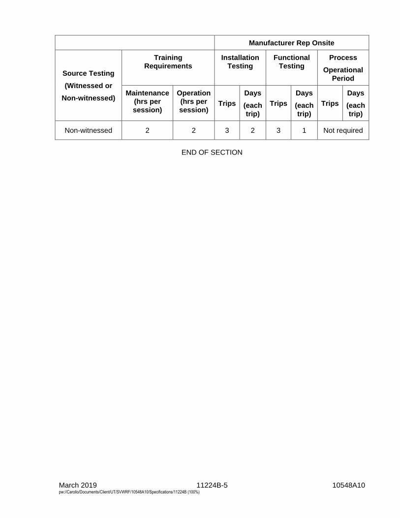
March 2019 11224B-5 10548A10 pw://Carollo/Documents/Client/UT/SVWRF/10548A10/Specifications/11224B (100%)
Manufacturer Rep Onsite
Source Testing
(Witnessed or
Non-witnessed)
Training
Requirements
Installation
Testing
Functional
Testing
Process
Operational
Period
Maintenance
(hrs per
session)
Operation
(hrs per
session) Trips
Days
(each
trip)
Trips
Days
(each
trip)
Trips
Days
(each
trip)
Non-witnessed 2 2 3 2 3 1 Not required
END OF SECTION


Section 11224B - Replacement Vertical Mixer Impellers
APPENDIX A - MEMORANDUM OF AGREEMENTFOR REPLACEMENT VERTICAL MIXER IMPELLERS

MEMORANDUM OF AGREEMENT
For Supply of Replacement Impellers for Existing Enviropax ANCO
Platform-Mounted Vertical Shaft Mixers
South Valley Water Reclamation Facility and Enviropax
Page 1 of 7 (November 6, 2018)
The purpose of this Memorandum of Agreement (MOA) is to document the agreement between
the South Valley Water Reclamation Facility (OWNER) and Enviropax (VENDOR) to supply
replacement impellers for existing Enviropax ANCO platform-mounted vertical shaft mixers
(“Equipment”) for Project 5 (Project) at the South Valley WRF.
This MOA references other documents, which are considered integral parts of this MOA. All
requirements embodied in the referenced final bid documents are inseparable requirements of
this MOA.
This MOA is intended to create a binding commitment between VENDOR and OWNER for
acquisition of the “Equipment” by Owner’s Contractor from VENDOR pursuant to the terms
of this MOA, subject to the limitations set forth herein.
AGREEMENT
I. Duties of Vendor
VENDOR shall have the following duties under this agreement:
1. Provide final coordination with Owner’s Project Manager in their completion of the
final design of the “Equipment.”
2. Provide equipment supply bids to the general contractors bidding on the Project that
are identical to, and in accordance with the project plans and specifications, and this
MOA.
3. Prepare submittals to Owner's Contractor consistent with Specification 01330 -
Submittal Procedures, project plans, and this MOA. The initial submittals shall be
delivered to Owner's Contractor within eight (8) weeks after execution of the
Purchase Order between VENDOR and Contractor. Resubmittals, if any, shall be
delivered to the Owner's Contractor within two (2) weeks of receipt of any review
comments from Owner.
4. Deliver the “Equipment” consistent with the project plans and specifications,
according to a schedule mutually agreed upon with Owner's Contractor and no later
than 16 weeks from approval of submittals unless expressly stated otherwise.
5. Assist Owner's Contractor to startup, test and put into operation the
Equipment to meet all specified requirements.
6. Provide preliminary operation and maintenance (O&M) manuals with storage and
installation requirements prior to delivery of equipment. Provide preliminary and final
O&M manuals and training to Owner for operation of “Equipment” in accordance
with the specification requirements.
7. Meet other commercial warranty and risk management requirements set forth in
this MOA.
MEMORANDUM OF AGREEMENT
For Supply of Replacement Impellers for Existing Enviropax ANCO
Platform-Mounted Vertical Shaft Mixers
South Valley Water Reclamation Facility and Enviropax
Page 2 of 7 (November 6, 2018)
II. Owner Obligations
Owner is undertaking the Project and will competitively bid the public works contract
following completion of plans and specifications and obtaining of permit/founding. Project
will including installation of the “Equipment” according to the contract documents. Owner
agrees that subject to the conditions below, it shall award the public works construction
contract to the lowest responsible and responsive bidder. As a result of this MOA, Owner
shall accommodate the “Equipment” and shall require Owner's selected Contractor to
install the “Equipment.” Owner shall require its Contractor to enter into a purchase order
with VENDOR to acquire VENDOR’s “Equipment” solely from VENDOR. Owner shall
further require that the selected Contractor obtain “Equipment” from VENDOR in full
compliance with the Price and Payment Terms set forth in this MOA.
This obligation to obtain equipment from VENDOR shall be conditioned upon the
award of the construction contract for the Project, and the favorable result of any legal
challenge to this process which could result in a court order or judgment preventing
Owner from either executing the construction contract for the Project or requiring
Owner's Contractor to install VENDOR's “Equipment.” If Owner fails to proceed with
the Project, is prevented from entering into the construction contract, or is prevented by
legal proceedings from designating VENDOR’s “Equipment” for inclusion in Owner's
Project, Owner shall not be liable to Vendor for any damages including, but not limited
to restocking, proposal preparation and contracting costs VENDOR, or loss of
prospective profit.
III. Scope of Services
The scope of supply and services shall be in accordance with the project plans and
specifications. VENDOR agrees to supply the “Equipment” as set forth in the plans and
specifications without any modifications.
IV. Price
l. The VENDOR “Equipment” shall be manufactured, assembled, insured, crafted,
delivered, and maintained prior to acceptance for the base bid of
$______________________________ dollars (for base bid)
in US currency
if any applicable additive bid item/bid alternate is selected. This total amount shall be
inclusive of all payments for the vendor's costs including those costs set forth below:
Base Bid Cost –
6 mixer impellers for
existing mixers
$ $40,500
Bid Alternate – N/A To be exercised at Owners option
$ N/A
MEMORANDUM OF AGREEMENT
For Supply of Replacement Impellers for Existing Enviropax ANCO
Platform-Mounted Vertical Shaft Mixers
South Valley Water Reclamation Facility and Enviropax
Page 3 of 7 (November 6, 2018)
a. The price set forth herein shall reflect shipping D.A.P. to OWNER. Owner's
Contractor will not accept C.O.D. shipments. VENDOR shall be responsible for
payment of all charges for handling, shipping, packaging, wrapping, bags,
container, boxing, crating, labeling, customs and duties, taxes (including all sales
tax), insurance and other related matters. VENDOR shall cause all VENDOR
“Equipment” to be insured for the full value during all phases of packaging and
delivery and such insurance shall remain in place until such time as Owner’s
Contractor has accepted products. The Contractor must notify VENDOR within
five (5) working days of delivery if there were any apparent shipment shortages
or damages incurred in shipment. This notification requirement does not release
VENDOR of responsibility from material shortages or damages that are
discovered upon full inventory and installation of the equipment.
VENDOR agrees to offer all responsible bidders on the Project the equipment
and services in accordance with scope of services and supply set forth herein,
and as more specifically set forth in the specifications, at the proposed price and
without additional terms and conditions inconsistent with this MOA. Any such
additional terms and conditions offered to proposing contractors, not inconsistent
with the terms of this MOA, shall be those customary to the public works
marketplace in Utah and offered at no additional cost.
V. Payment Terms
VENDOR shall agree to the conditions for payment as outlined in Article 15 of Section 00700. Prior
to payment, but after delivery of the “Equipment” to the site, VENDOR shall visually inspect and
certify in writing to Owner and Contractor that all pieces of the VENDOR “Equipment” have
arrived on site undamaged and are in good working order.
VENDOR agrees to provide the scope of services and supply at the proposed price on the
following payment terms:
• 10% upon delivery of submittals (net 30 days)
• 80% upon delivery of equipment (net 30 days)
• 10 % upon start-up of equipment (net 30 days)
The partial payments set forth above shall be due only upon full and complete performance of
each benchmark task listed above for all equipment and services required pursuant to the
specifications.
A 5% retention will be withheld by Owner from each of the payments listed above. Such 5%
retention shall be provided to Owner's Contractor for payment following substantial
completion of the Project as defined in Specification Section 00700.
VI. Terms and Conditions
1. Owner’s Contractor will visually inspect shipment(s) from VENDOR upon receipt at
construction site to determine whether they conform to the requirements of this MOA.
Notwithstanding these provisions for inspection, VENDOR acknowledges that the
MEMORANDUM OF AGREEMENT
For Supply of Replacement Impellers for Existing Enviropax ANCO
Platform-Mounted Vertical Shaft Mixers
South Valley Water Reclamation Facility and Enviropax
Page 4 of 7 (November 6, 2018)
“Equipment” is not reasonably subject to mere visual inspections to ascertain whether the
equipment fully conforms to the specifications and that testing after installation is required
prior to final acceptance of the equipment. Owner's Contractor shall be required to schedule
performance testing to provide for presence of VENDOR.
2. Operations Manual and Training: VENDOR shall be responsible to provide an operations
and maintenance manual and training to Owner's employees as is set forth in Specification
Sections 01782 (O&M Data) and 01330 (Submittal Procedures). All costs associated with
provision of the operations and maintenance manual and employee training shall be
included in the price set forth above.
3. Price Escalation: The costs included in this MOA shall remain in effect and are not subject
to escalation unless Owner's Contractor does not accept delivery of equipment prior to
20 months after NTP has been issued to the Contractor. After such time, pricing is subject
to an escalation clause of 3% per year, at the expense of the contractor, computed from
20 months after NTP until the accepted delivery date.
4. Warranty: VENDOR expressly warrants that all goods and services included in
VENDOR's proposal shall conform to all specifications, drawings and samples. In case of
inconsistencies between documentation, specification details shall prevail. Goods and
services shall be free from material defects of workmanship and made to the specifications
and requirements of this agreement. For purposes of this warranty, any parts not meeting
the foregoing quality shall be deemed defective. VENDOR and its supplier(s) shall provide
warranties on all equipment provided as set forth in the specifications. The foregoing
warranty provisions shall also be applicable to equipment or software supplied to
VENDOR by a third party entity and provided to Owner's Contractor via this MOA. Any
warranties provided by third party equipment or software supplier shall be assigned to the
Owner after final acceptance. All equipment or software supplied under this MOA shall
have a one (1) year warranty from Final Acceptance Date as detailed in Specification
Section 01740 - Warranties and Bonds.
5. Liens, Claims And Encumbrances: VENDOR warrants and represents that all the goods
when delivered will be free and clear of all liens, claims, encumbrances and infringements
of any patents, trademarks, copyrights or franchise rights.
6. Independent Contractor: VENDOR or persons under contract to VENDOR in the
performance of services on this MOA, including services provided on OWNER property,
shall perform work as independent contractors. VENDOR shall provide insurance to cover
its work and its employees as required by the OWNER’s Contractor. Further, neither party
to this MOA is the agent or legal representative of the other party for any purpose, nor
shall the actions of either party under this MOA create a partnership, joint venture or
relationship of principal and agent between the parties. VENDOR shall maintain the
following forms of insurance coverage for all work done on OWNER property, and
similarly require its subcontractors doing work on OWNER properly to maintain similar
insurance, including: (1) Public Liability and Property Damage Insurance, including
contractual liability, both general and automobile, in the amount of at least $1,000,000 per
occurrence for general liability, and $1,000,000 per occurrence combined single limit for
bodily injury and property damage for automobile liability (2) Workers’ Compensation
Insurance as required by law and for not less than $1,000,000. With the exception of
MEMORANDUM OF AGREEMENT
For Supply of Replacement Impellers for Existing Enviropax ANCO
Platform-Mounted Vertical Shaft Mixers
South Valley Water Reclamation Facility and Enviropax
Page 5 of 7 (November 6, 2018)
Worker's Compensation Insurance Owner and Owner's Contractor shall be added as
additional insureds to such policies.
7. Indemnification: VENDOR agrees to indemnify, protect, hold harmless and defend Owner
and Owner's Contractor, and their officers, agents, employees, volunteers. and boards,
from any and all claims or liabilities arising from any liability imposed for injury, as
defined in Specification 00700-7.18, Indemnification, whether arising during or after
completion of the work hereunder, or in any manner, directly or indirectly caused, claimed
occasioned or contributed to, by reason of any negligent act or omission of VENDOR,
excepting for claims or liabilities arising from active negligence of Owner or Owner's
Contractor. VENDOR shall also indemnify, protect, hold harmless and defend Owner and
Owner's Contractor for claims or liabilities arising by reason of claimed infringements of
any patents, trademarks, copyrights or franchise rights, in connection with or incident to
or arising out of the performance of this contract.
8. Assignment: Assignment by VENDOR of its responsibilities under this MOA, will not be
binding upon Owner or Owner’s Contractor unless such assignment has had prior written
approval of Owner, which approval shall be solely within the discretion of Owner. Failure
to obtain approval of any assignment, including an involuntary assignment to creditors,
shall constitute a breach of this MOA, which may lead to termination.
9. Modifications: No modification to this MOA, nor any waiver of any rights, shall be
effective unless agreed to in writing by both Parties.
10. Liquidated Damages: Owner’s Contractor will include liquidated damage penalties in the
Purchase Order agreement with VENDOR. Such damages are only applicable if directly
related to VENDOR's failure to deliver the equipment within the time period stipulated in
this MOA, failure to support the startup of the equipment, or failure of the equipment
during the startup where any such failures result in a delay to the critical path of the
construction project schedule. If VENDOR’s delivery or performance is late and it has no
impact on Owner’s Contractors overall schedule, then VENDOR shall not be liable for
liquidated damages. If more than one party is responsible for assessment of liquidated
damages, then VENDOR shall be liable only for its portion of the total liquidated damages.
VENDOR shall be required to pay liquidated damages only if the Owner requires the
Owner's Contractor to pay liquidated damages. The amount of such damages shall not
exceed ten (10) percent of the total equipment contract price as listed in Article IV- Price
of this MOA.
11. Notices: All notices under this MOA shall be in writing and shall be considered delivered
and effective on the earlier of actual receipt or (i) the day following transmission if sent by
facsimile when followed by written confirmation by overnight carrier or certified United
States mail; or (ii) one (1) day after dispatch if sent by private overnight carrier (e.g., DHL,
Federal Express); or (iii) five (5) days after posting if sent by certified mail. Notice shall
be sent to the following persons:
MEMORANDUM OF AGREEMENT
For Supply of Replacement Impellers for Existing Enviropax ANCO
Platform-Mounted Vertical Shaft Mixers
South Valley Water Reclamation Facility and Enviropax
Page 6 of 7 (November 6, 2018)
VENDOR
Contact Name: Dave Ritter
Address: Goble Sampson & Associates, Inc.
3500 S. Main St., Suite 200 Salt Lake City, UT 84115
Phone: 801-268-8790
E-mail: [email protected]
Contractor:
Contact Name: Unknown
Address
Phone:
E-Mail:
Owner:
Contact Name: Taigon Worthen, P.E.
Address South Valley Water Reclamation Facility
7495 South 1300 West
West Jordan, UT 84084
Phone: (801) 566-7711
E-Mail: [email protected]
12. Severability: If any portion of this MOA is held invalid, the Parties agree that such
invalidity shall not affect the validity of the remaining portions of this MOA and the Parties
shall seek in good faith to agree to substitute for the invalid provision a valid provision
that most closely approximates its terms.
13. Entire Agreement: This MOA supersedes all proposals, oral or written, all negotiations,
conversations or discussions between the Parties and contains the entire understanding and
agreement of the Parties relating to this subject matter. In the event of a conflict between
the terms and conditions of this MOA and its attachments, this MOA shall control.
This Memorandum of Agreement is hereby entered into between the Owner and VENDOR. By
signing this Memorandum of Agreement, the undersigned asserts that they have the authority
to enter into this agreement.
MEMORANDUM OF AGREEMENT
For Supply of Replacement Impellers for Existing Enviropax ANCO
Platform-Mounted Vertical Shaft Mixers
South Valley Water Reclamation Facility and Enviropax
Page 7 of 7 (November 6, 2018)
Owner Manufacturer
South Valley Water Reclamation Facility Enviropax
_______________________________________ ________________________________________
Date Date
_______________________________________ _________________________________________
Name/Title Name/Title
Approved as to Form:
____________________________________
Attorney

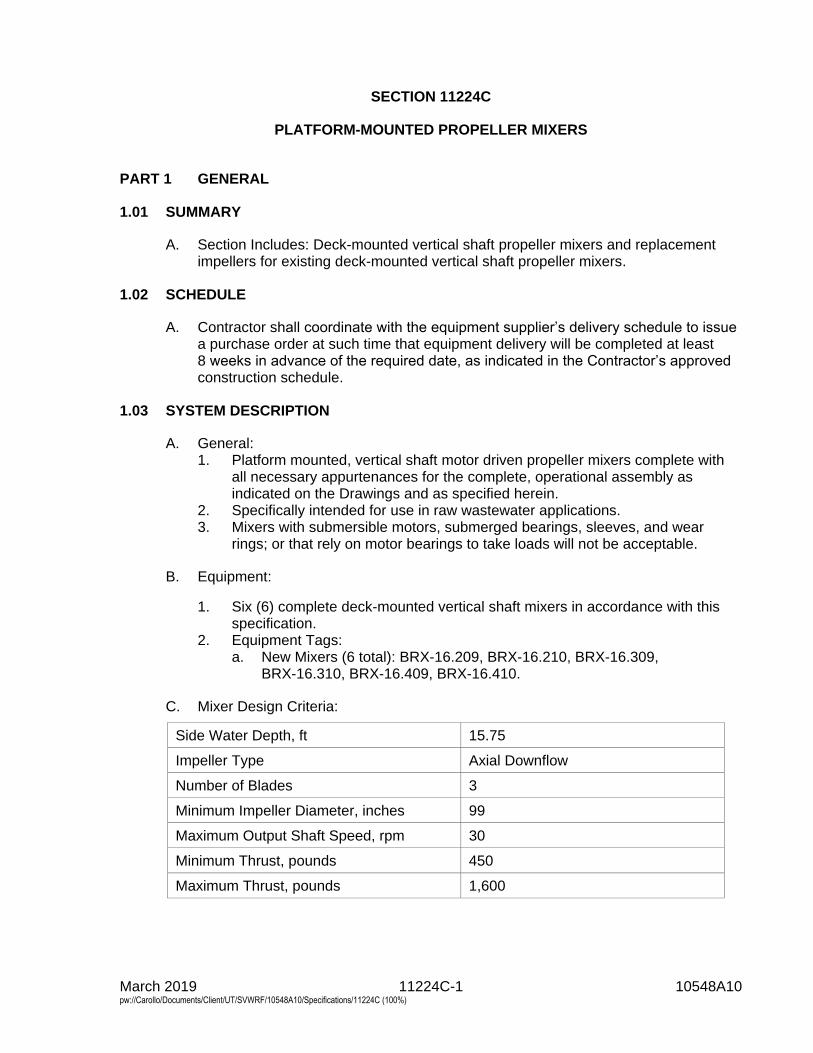
March 2019 11224C-1 10548A10 pw://Carollo/Documents/Client/UT/SVWRF/10548A10/Specifications/11224C (100%)
SECTION 11224C
PLATFORM-MOUNTED PROPELLER MIXERS
PART 1 GENERAL
1.01 SUMMARY
A. Section Includes: Deck-mounted vertical shaft propeller mixers and replacementimpellers for existing deck-mounted vertical shaft propeller mixers.
1.02 SCHEDULE
A. Contractor shall coordinate with the equipment supplier’s delivery schedule to issuea purchase order at such time that equipment delivery will be completed at least8 weeks in advance of the required date, as indicated in the Contractor’s approvedconstruction schedule.
1.03 SYSTEM DESCRIPTION
A. General:1. Platform mounted, vertical shaft motor driven propeller mixers complete with
all necessary appurtenances for the complete, operational assembly asindicated on the Drawings and as specified herein.
2. Specifically intended for use in raw wastewater applications.3. Mixers with submersible motors, submerged bearings, sleeves, and wear
rings; or that rely on motor bearings to take loads will not be acceptable.
B. Equipment:
1. Six (6) complete deck-mounted vertical shaft mixers in accordance with thisspecification.
2. Equipment Tags:a. New Mixers (6 total): BRX-16.209, BRX-16.210, BRX-16.309,
BRX-16.310, BRX-16.409, BRX-16.410.
C. Mixer Design Criteria:
Side Water Depth, ft 15.75
Impeller Type Axial Downflow
Number of Blades 3
Minimum Impeller Diameter, inches 99
Maximum Output Shaft Speed, rpm 30
Minimum Thrust, pounds 450
Maximum Thrust, pounds 1,600
March 2019 11224C-2 10548A10 pw://Carollo/Documents/Client/UT/SVWRF/10548A10/Specifications/11224C (100%)
1.04 SUBMITTALS
A. In addition to the requirements of Sections 01330 - Submittal Procedures, and15050 - Common Work Results for Mechanical Equipment, submit informationspecified herein.
B. Product Data: Include specifications, and engineering data including dimensions,materials, sizes, weights, and performance data.
C. Furnish motor submittals as specified in Section 16222 - Low Voltage Motors up to500 Horsepower.
D. Shop Drawings: Include fabrication, assembly, layout, and installation details;relationship to adjacent construction; and wiring diagrams.
E. Bearing Life Calculations.
F. Manufacturer’s Qualifications to substantiate compliance with Section 1.05.
G. Manufacturer's Installation Instructions: Submit with Product Data and ShopDrawings.
H. Operation and Maintenance Manual: Submit as specified in Section 01782 -Operation and Maintenance Data.
I. Certification demonstrating compliance with all structural and process piping criteriaand the requirements of this Specification.
J. Certification substantiating the continuous running torque rating, thermal rating, andoverload torque rating of all major motor components.
K. Certification demonstrating that all bearings meet the life requirements of thisSpecification.
L. Sufficiently detailed drawings to clearly describe the sizes, dimensions, andarrangement of all major components.
M. Technician Qualifications Resume: Submit resume of technician to performManufacturer’s Field Services.
1.05 SOURCE QUALITY CONTROL
A. Manufacturer Qualifications:1. Minimum 10 similar projects, with a minimum impeller diameter of 100 inches,
with satisfactory performance record.2. Minimum 5 municipal wastewater treatment projects with minimum 5 years
satisfactory performance.
1.06 PROJECT CONDITIONS
A. As specified in Section 15050 - Common Work Results for Mechanical Equipment.
March 2019 11224C-3 10548A10 pw://Carollo/Documents/Client/UT/SVWRF/10548A10/Specifications/11224C (100%)
1.07 WARRANTY
A. As specified in Section 01783 - Warranties and Bonds.
1.08 MAINTENANCE
A. Spare Parts: one complete set of bearings for the gearbox and one complete set ofbearings for the motor.
B. Special Tools: Furnish any special tools required for maintenance and disassemblyof furnished equipment.
C. Submit testing results as specified in Section 15958 - Mechanical EquipmentTesting.
PART 2 PRODUCTS
2.01 MANUFACTURERS
A. Mixers: One of the following, or equal:1. Enviropax, ANCO.2. Chemineer,3. Philadelphia,4. SPX, Lightnin
2.02 MATERIALS
A. All wetted parts, fasteners and hardware, except as specified herein: Type 316Stainless steel.
2.03 EQUIPMENT
A. Equipment shall be the standard product of the manufacturer, modified asnecessary to conform to the specifications.
B. All components, including gearbox, shall be supplied by the mixer manufacturer asa complete unit.
2.04 COMPONENTS
A. Motor:1. Constant speed, continuous duty, squirrel-cage induction type electric motor.
Designed, manufactured and tested in accordance with NEMA MG1.2. Attached to separate cast iron coupling and bearing housing by flexible
coupling that takes operating loads off motor.3. Conform to the requirements of Section 15050 - Common Work Results for
Mechanical Equipment and Section 16222 - Low Voltage Motors up to500 Horsepower.
March 2019 11224C-4 10548A10 pw://Carollo/Documents/Client/UT/SVWRF/10548A10/Specifications/11224C (100%)
4. Motor Characteristics:
Horsepower 5.0 NEMA Premium efficiencyVolts 460 Phase 3 Frequency, hertz 60 Enclosure TEFC Synchronous Speed, rpm 1,800 Service Factor, 40 degrees C ambient temperature 1.15 Insulation Class F Temperature Rise NEMA Class B
5. The 1.15 service factor shall not be used to provide the power required undernormal operating conditions.
6. Motor junction box with stainless steel relief grip that protects cable to motorconnection.
7. Bearings with common lubrication type and frequency requirements, and withminimum B-10, 100,000-hour life.
8. Provide lifting rings on motor.
B. Impeller Shaft:1. Material: Type 316 stainless steel.2. Shaft Stress: Maximum 8,000 pounds per square inch under maximum
operating loads.3. Shaft Tolerance: Shaft straightness, coupling squareness shall not exceed
1/8 inch for every 10 feet of shaft length measured at lower end of shaft whenrotated by hand. Rotational speed shall not exceed 50 percent of the firstcritical speed.
4. Submerged water lubricated bearings or submerged close-tolerance steadyrests will not be acceptable.
5. Shaft Bearings: Grease lubricated. Provide lipseal to retain grease.
C. Gear Drive:1. General: In accordance to AGMA Standard 6010-E88:
a. AGMA calculated drive HP rating shall be stamped on drive nameplate.b. Service Factor: Minimum 3.5 based on nameplate HP at design RPM.
2. Material: Cast iron or fabricated steel with lifting lugs or holes.3. Gearing: In accordance AGMA Quality 10 per AGMA Standard 390.03a or
ANSI/AGMA 2000-A88.c. Type: Helical or combination of helical and spiral bevel. Worm gears are
not acceptable.d. Housing: All gearing contained in single housing.e. Lubrication: Oil bath.
4. Motor Support: Flange mounted to gear drive.5. Encloses flexible high-speed coupling.6. Bearings:
f. Type: Antifriction ball or roller.g. Design: Main gear reducer bearings shall have AFBMA L-10 lives of
100,000 hours when operating at full motor nameplate horsepower atdesign speed.
h. Submit bearing calculations.
March 2019 11224C-5 10548A10 pw://Carollo/Documents/Client/UT/SVWRF/10548A10/Specifications/11224C (100%)
7. Speed Reducer Lubrication: Oil splash or integral oil pump. Pump must beaccessible without requiring disassembly of the speed reducer.
8. Provide dipstick or sight glass to observe oil level.9. All oil fill, drain lines and grease fittings shall be easily accessible from top
decking.
D. Impeller:1. Material: Type 316 stainless steel.2. Impeller blades bolted to a central hub.3. Central hub attached to impeller shaft by hooked key which allows for vertical
adjustment of the impeller ± 12 inches in 3 inch increments.4. Designed and constructed to operate with dynamic and hydraulic stability
during minor fluctuations in liquid level.5. Clearance between the impeller and the anoxic/aeration basin floor: not more
than 1/3 the side water depth, and not to exceed the impeller diameter.
E. Fasteners and Anchor Bolts:1. Manufacturer shall supply all fasteners and anchor bolts required for
installation.2. Material: 316 stainless steel.
F. Mounting Base:1. Manufacturer shall supply mixer mounting base appropriate for application
shown on the Drawings, which shall be of the pedestal type allowing access tothe low speed impeller shaft coupling.
2. Submit design and installation details with shop drawings.
2.05 CONTROL SYSTEM
A. Controls: None.
2.06 FINISHES
A. Prime and finish coat motors, drives, brackets, baseplates, and appurtenances asspecified in Section 09960 - High-Performance Coatings.
2.07 FACTORY TESTING
A. Speed reducer: Assembled and prepared for testing.
B. Run at full speed and with no load for a minimum of 2 hours after the oiltemperature has stabilized.
C. Record the overall sound level and lubricant temperatures during steady-stateoperation.
D. Speed reducer requirements:1. Leakage:
a. Check speed reducer housing and shaft seals for leakage of lubricant.Correct any leaks.
2. Overall sound level:b. Record in accordance with AGMA 297.02.c. Not to exceed 85 dBA.
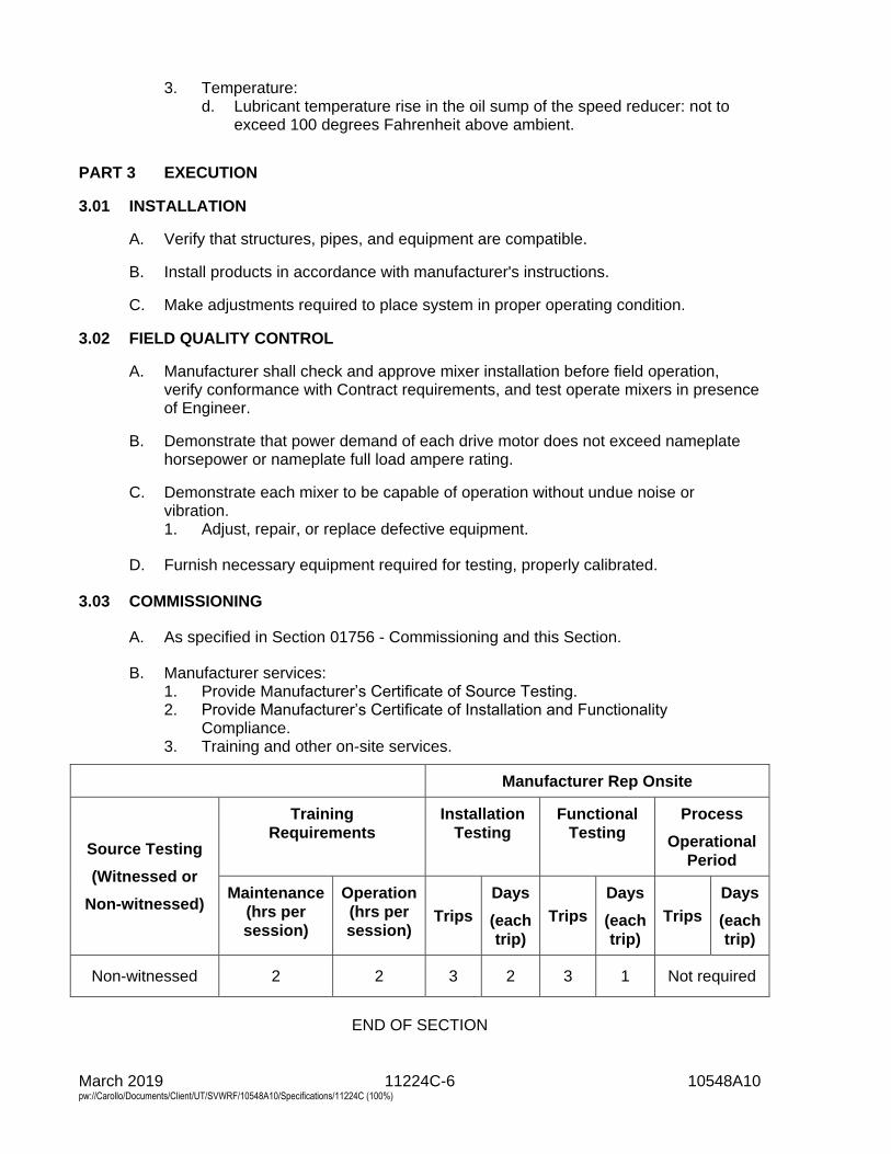
March 2019 11224C-6 10548A10 pw://Carollo/Documents/Client/UT/SVWRF/10548A10/Specifications/11224C (100%)
3. Temperature:d. Lubricant temperature rise in the oil sump of the speed reducer: not to
exceed 100 degrees Fahrenheit above ambient.
PART 3 EXECUTION
3.01 INSTALLATION
A. Verify that structures, pipes, and equipment are compatible.
B. Install products in accordance with manufacturer's instructions.
C. Make adjustments required to place system in proper operating condition.
3.02 FIELD QUALITY CONTROL
A. Manufacturer shall check and approve mixer installation before field operation,verify conformance with Contract requirements, and test operate mixers in presenceof Engineer.
B. Demonstrate that power demand of each drive motor does not exceed nameplatehorsepower or nameplate full load ampere rating.
C. Demonstrate each mixer to be capable of operation without undue noise orvibration.1. Adjust, repair, or replace defective equipment.
D. Furnish necessary equipment required for testing, properly calibrated.
3.03 COMMISSIONING
A. As specified in Section 01756 - Commissioning and this Section.
B. Manufacturer services:1. Provide Manufacturer’s Certificate of Source Testing.2. Provide Manufacturer’s Certificate of Installation and Functionality
Compliance.3. Training and other on-site services.
Manufacturer Rep Onsite
Source Testing
(Witnessed or
Non-witnessed)
Training
Requirements
Installation
Testing
Functional
Testing
Process
Operational
Period
Maintenance
(hrs per
session)
Operation
(hrs per
session) Trips
Days
(each
trip)
Trips
Days
(each
trip)
Trips
Days
(each
trip)
Non-witnessed 2 2 3 2 3 1 Not required
END OF SECTION
March 2019 11292A-1 10548A10 pw://Carollo/Documents/Client/UT/SVWRF/10548A10/Specifications/11292A (100%)
SECTION 11292A
FLAP GATES
PART 1 GENERAL
1.01 SUMMARY
A. Section includes: Framed flap gates.
1.02 REFERENCES
A. American Welding Society (AWS):1. D1.1 - Structural Welding.
B. ASTM International (ASTM):1. A48 - Standard Specification for Gray Iron Castings.2. A126 - Standard Specification for Gray Iron Castings for Valves, Flanges, and
Pipe Fittings.3. A276 - Standard Specification for Stainless Steel Bars and Shapes.4. B139 - Standard Specification for Phosphor Bronze Rod, Bar, and Shapes.5. B584 - Standard Specification for Copper Alloy Sand Castings for General
Application.6. D2000 - Standard Classification System for Rubber Products in Automatic
Applications.
1.03 DESIGN REQUIREMENTS
A. As specified in Section 01600 - Product Requirements.
B. Flap gates shall open when there is a differential pressure across the flap of 0.1 feetor less.
C. With the flap gate submerged, the head loss shall not exceed 0.2 feet at all existingvelocities for gates 60 inches or smaller.
D. Design to meet seating pressures listed in Flap Gate Schedule.
E. Allowable leakage through the flap gate, due to seating load, shall not exceed0.1 gallons per minute per foot of wetted perimeter.
1.04 SUBMITTALS
A. Submit as specified in Section 01330 - Submittal Procedures.
B. Product data: As specified in Section 15050 - Common Work Results forMechanical Equipment.
C. Shop drawings: As specified in Section 15050 - Common Work Results forMechanical Equipment.
March 2019 11292A-2 10548A10 pw://Carollo/Documents/Client/UT/SVWRF/10548A10/Specifications/11292A (100%)
D. Vendor operation and maintenance manuals: As specified in Section 01782 - Operation and Maintenance Data.
E. Commissioning submittals: 1. Provide Manufacturer’s Certificate of Installation and Functionality Compliance
as specified in Section 01756 - Commissioning.
1.05 WARRANTY
A. Provide warranty as specified in Section 01783 - Warranties and Bonds.
PART 2 PRODUCTS
2.01 MANUFACTURERS
A. One of the following or equal: 1. Hydro Gate Corp. 2. Waterman Ind., PF-25F.
B. Flange Mounting Bolts: Provided by flap gate manufacturer.
2.02 MATERIALS
A. Cast iron: ASTM A126, Class B ASTM, A48, Class 30.
B. Bronze: 1. Bronze subject to submersion or splash: Not more than 6 percent zinc and no
aluminum. 2. Manganese bronze: ASTM B584, UNS No. C86500. 3. Phosphor bronze: ASTM B139, UNS No. C51000. 4. Silicon bronze: ASTM B584 UNS No. C87200.
C. Stainless steel: ASTM A276, Type 304, 304L, 316, or 316L.
D. Neoprene: ASTM D2000, BC 615 to 625.
2.03 GATE COMPONENTS
A. Body frame and cover: Material as specified in Flap Gate Schedule. 1. Frame:
a. Size(s) as indicated on the Drawings. b. Mount as specified in the Flap Gate Schedule.
2. Cover: a. Cast in one piece or welded and shall be of a dished or reinforced design
to maximize strength, rigidity, and minimize weight. b. Cast a lifting eye at the top of the cover for manual operation.
B. Seats: Material(s) shall be compatible with sanitary wastewater.
March 2019 11292A-3 10548A10 pw://Carollo/Documents/Client/UT/SVWRF/10548A10/Specifications/11292A (100%)
C. Hinge arms: 1. Double pivot-point design:
a. The lower pivot shall allow the cover and the frame to lie in the same plane.
b. The upper pivot shall be adjustable to vary sensitivity to unseating heads. 2. Materials: Material as specified in Flap Gate Schedule.
D. Hinge pins: Material as specified in Flap Gate Schedule.
E. Bolts, nuts, and fittings: Type 316 stainless steel.
2.04 MOUNTING
A. Flap gate shall be directly flange-mounted.
B. Flange bolts shall be provided by the Manufacturer. 1. Material: Type 316 stainless steel.
2.05 COATING
A. Coat flap gates in the factory prior to testing.
B. Coat with surface tolerant high solids epoxy. As specified in Section 09960 - High-Performance Coatings.
C. Repair or touch-up damaged areas of the factory applied coating in the field.
PART 3 EXECUTION
3.01 INSTALLATION
A. Install in accordance with manufacturer's instructions.
B. Mount thimbles and gates plumb in both vertical planes and level in horizontal plane.
C. Coat seating surfaces between frame and wall thimble with a waterproof plastic compound prior to tightening of frame studs.
3.02 COMMISSIONING
A. As specified in Section 01756 - Commissioning and this Section.
B. Manufacturer services: 1. Provide certificates:
a. Manufacturer’s Certificate of Installation and Functionality Compliance. 2. Manufacturer’s Representative onsite requirements:
a. Installation: 1 trip, 0.5 day minimum. b. Functional Testing: 1 trip, 0.5 day minimum each.
March 2019 11292A-4 10548A10 pw://Carollo/Documents/Client/UT/SVWRF/10548A10/Specifications/11292A (100%)
C. Functional testing: 1. Flap gate:
a. Test witnessing: Witnessed. b. Leakage tests: Demonstrate compliance with allowable leakage limits set
forth in this Section. c. After the gate installation and checking, exercise each gate from the
closed position to fully open position and back to the closed position at least twice and verify gate is properly seated.
d. Conduct Level 2 General Equipment Performance Test.
3.03 FLAP GATE SCHEDULE
A. The Flap Gate Schedule is not a gate take-off list.
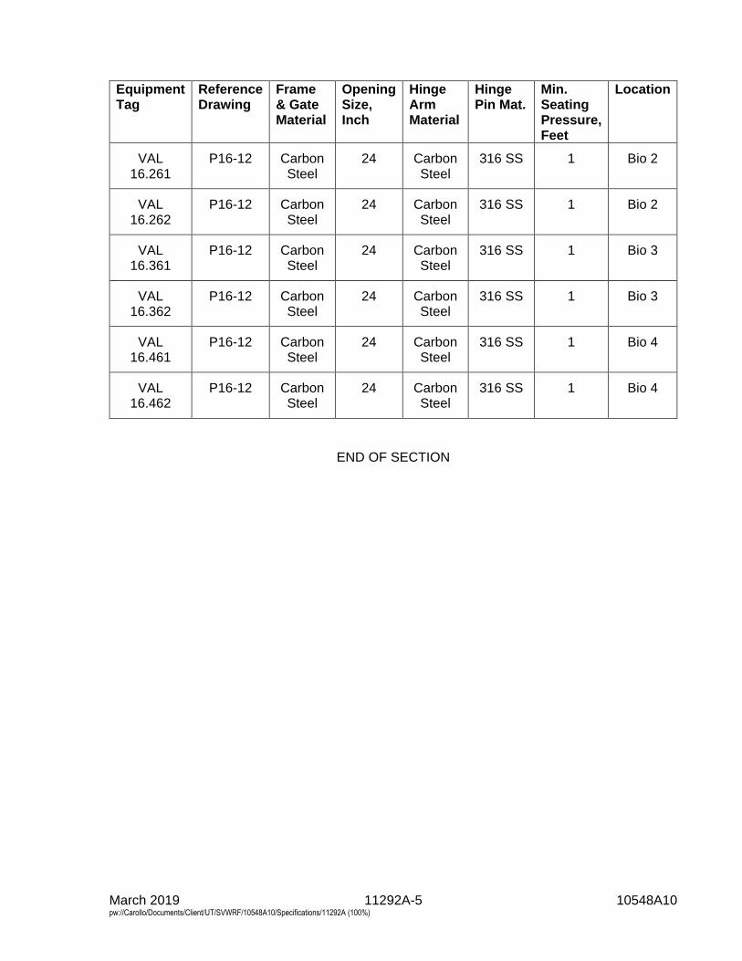
March 2019 11292A-5 10548A10 pw://Carollo/Documents/Client/UT/SVWRF/10548A10/Specifications/11292A (100%)
Equipment Tag
Reference Drawing
Frame & Gate Material
Opening Size, Inch
Hinge Arm Material
Hinge Pin Mat.
Min. Seating Pressure, Feet
Location
VAL 16.261
P16-12 Carbon Steel
24 Carbon Steel
316 SS 1 Bio 2
VAL 16.262
P16-12 Carbon Steel
24 Carbon Steel
316 SS 1 Bio 2
VAL 16.361
P16-12 Carbon Steel
24 Carbon Steel
316 SS 1 Bio 3
VAL 16.362
P16-12 Carbon Steel
24 Carbon Steel
316 SS 1 Bio 3
VAL 16.461
P16-12 Carbon Steel
24 Carbon Steel
316 SS 1 Bio 4
VAL 16.462
P16-12 Carbon Steel
24 Carbon Steel
316 SS 1 Bio 4
END OF SECTION

March 2019 11294C-1 10548A10 pw://Carollo/Documents/Client/UT/SVWRF/10548A10/Specifications/11294C (100%)
SECTION 11294C
FABRICATED STAINLESS STEEL SLIDE GATES
PART 1 GENERAL
1.01 SUMMARY
A. Section includes: Slide gates and accessories.
B. As specified in Section 01600 - Product Requirements
1.02 REFERENCES
A. American Water Works Association (AWWA):1. C560 - Cast-Iron Slide Gates.2. C561 - Fabricated Stainless Steel Slide Gates.
B. American Welding Society (AWS):1. D1.6 - Structural Welding Code-Stainless Steel.
C. ASTM International (ASTM):1. A276 - Standard Specification for Stainless Steel Bars and Shapes.2. D1248 - Standard Specification for Polyethylene Plastics Extrusion Materials
for Wire and Cable.3. D2000 - Standard Classification System for Rubber Products in Automotive
Applications.
1.03 DESIGN REQUIREMENTS
A. Except as modified or supplemented in this Section, all gates and operators shallconform to the requirements of AWWA C561, latest edition.
B. Gates:1. Design gate slides, frames, and yokes with a minimum safety factor of 5 for
tensile, compressive, and shear stresses under design seating and unseatingheads specified.
2. Design gates to meet seating and unseating heads specified in the Slide GateSchedule. Modify gates as necessary to meet specified design requirements.
3. Gates shall meet leakage requirements of AWWA C 561 latest edition.
C. Slide: Maximum deflection under design seating and unseating head shall equall/320 of span.
D. Yoke: Maximum deflection under design seating and unseating head and at fulloperating load shall equal l/360 of span.
E. Stem:1. Maximum slenderness ratio shall not exceed 200.2. Maximum diameter: Provide stem guides at a spacing to maintain stem
diameter of 2 inches or less.
March 2019 11294C-2 10548A10 pw://Carollo/Documents/Client/UT/SVWRF/10548A10/Specifications/11294C (100%)
3. Compressive strength shall equal a minimum of 2 times the rated output of thebench stand.
1.04 SUBMITTALS
A. Submit as specified in Section 01330 - Submittal Procedures.
B. Product data: As specified in Section 15050 - Common Work Results forMechanical Equipment.
C. Shop drawings: As specified in Section 15050 - Common Work Results forMechanical Equipment.
D. Vendor operation and maintenance manuals: As specified in Section 01782 -Operation and Maintenance Data.
E. Commissioning submittals:1. Provide Manufacturer’s Certificate of Installation and Functionality Compliance
as specified in Section 01756 - Commissioning.
F. Product data:1. Wall thimbles.2. Manufacturer's installation instructions.
a. Include installation and adjustment instructions from gate manufacturer forevery type of gate.
3. Layout and installation drawings for each gate size and type.4. Complete bill of materials.
G. Calculations:1. Calculations and design data substantiating conformance with the drawings
and specifications.2. Gate operators: As specified in Sections 13446 - Manual Actuators and 13447
- Electric Actuators.3. Provide certification from both the motorized operator manufacturer and the
gate manufacturer confirming that the proposed gate stem configuration hasbeen coordinated with motorized operator selection.a. Confirm that the proposed gate stem configuration provides the most
efficient combination of stem diameter, pitch, and lead.b. Confirm the design will keep the operating temperature at the stem nut to
a minimum during operation.c. Confirm the design will meet the specified motorized operator operating
speed requirements.4. For coordination purposes, gate manufacturer shall supply calculations
verifying the suitability of the selected motorized operator for the application.For each gate include:a. Open/close speed as specified in Section 13447 - Electric Actuators.b. The maximum torque required for operation of the gate (including
breakaway from seat) with a safety factor of 1.4.c. The torque supplied by the motorized operator scheduled in
Section 13447 - Electric Actuators for the operating speed specified inSection 13447 - Electric Actuators.
d. The thrust output capacity of the motorized operator with the furnishedmotor.
March 2019 11294C-3 10548A10 pw://Carollo/Documents/Client/UT/SVWRF/10548A10/Specifications/11294C (100%)
5. Submit calculations and design data substantiating conformance with thedrawings and Specifications.a. Gate opening and closing thrust forces that will be transmitted to the
support structure with operator at extreme positions and load.b. Torque required to open and close the gate, including maximum torque at
any point along gate travel. Indicate thrust valve and stem factor.c. Breakaway torque from seat. Indicate thrust valve and stem factor.
H. Factory markings:1. Mark gates according to the schedule numbers when such numbers are used.2. Where thimbles, frames, and other components are not interchangeable,
match mark components.3. Assembled gates: Shop inspected and adjusted before shipping.
1.05 WARRANTY
A. Provide warranty as specified in Section 01783 - Warranties and Bonds.
PART 2 PRODUCTS
2.01 MANUFACTURERS
A. One of the following or equal:1. Waterman Ind., Inc., Model R.2. Rodney Hunt Co., Series 700.3. H. Fontaine, Series 20.
B. Operators and anchor bolts: Provided by slide gate manufacturer.
2.02 MATERIALS
A. Stainless steel, ASTM A276, Type 316:1. Components or structural shapes which are welded:
a. Materials: Type 316L stainless steel.b. Manufacturer's shop welds, welding procedures, and welders:
1) Qualified and certified in accordance with the requirements ofAWS D1.6.
B. Neoprene, ASTM D2000, Grade 2 BC 510.
C. Ultra-high molecular weight polyethylene, ASTM D1248.
2.03 COMPONENTS
A. Gate slide: Fabricate using Type 316 stainless steel plate with welded structuralshapes reinforcement.
B. Frames: Guides, invert members and yokes welded to form 1-piece:1. Material:
a. Type: 316 stainless steel.b. Capable of providing true dimensions within tolerances and preventing
binding and excessive wear of sliding parts.
March 2019 11294C-4 10548A10 pw://Carollo/Documents/Client/UT/SVWRF/10548A10/Specifications/11294C (100%)
2. Mounting: Embedded or face-mounted as scheduled in Slide Gate Scheduleon drawings.
3. Guide length: Sufficient to retain at least 2/3 of gate slide when gate is in fullyopen position.
4. Additional supports: Not required in members above operating floor.5. Yoke to support bench stand operator: Form by 2 angles welded to gate
frame.6. Yoke arrangement: Capable of allowing removal of slide.
C. Stem:1. Material: Type 316 stainless steel.2. Diameter: Capable of withstanding anticipated opening and closing thrusts
under head as indicated on the Drawings.3. Length: Capable of permitting easily installation and removal.
D. Frame seals:1. Self-adjusting, ultra-high molecular weight polyethylene or adjustable J-bulb
seals around perimeter of gate slide.a. Use only J-bulb seals when an unseating head condition exists.
2. Hold seals in place by Type 316 stainless steel bar and fasteners.3. Set seals to be slightly compressed with slide in closed position.4. Seals shall be fully field adjustable and replaceable.5. Provide invert seal for all downward (weir) gates.6. Provide top seal for all standard upward opening gates.
E. Bottom seal:1. Resilient neoprene or Buna N seal compressed by closing action of gate slide
against stop plate for all standard upward opening gates.2. Fasteners: Type 316 stainless steel.
F. Operators: As scheduled in Slide Gate Schedule on drawings and as specified inSection 13446 - Manual Actuators.
G. Anchor bolts: Type 316 stainless steel of sufficient quantity and length to anchor thegate.
PART 3 EXECUTION
3.01 EXAMINATION
A. Inspect all components for shipping damage, conformance to specifications, andproper torques and tightness of fasteners, as specified in Section 15050 - CommonWork Results for Mechanical Equipment.
3.02 INSTALLATION
A. Install equipment as indicated on the Drawings and as specified in Section 15050 -Common Work Results for Mechanical Equipment and the manufacturer's writteninstallation instructions.
March 2019 11294C-5 10548A10 pw://Carollo/Documents/Client/UT/SVWRF/10548A10/Specifications/11294C (100%)
3.03 COMMISSIONING
A. As specified in Section 01756 - Commissioning, and this Section.
B. Manufacturer services:1. Provide certificates:
a. Manufacturer’s Certificate of Installation and Functionality Compliance.2. Manufacturer’s Representative onsite requirements:
a. Installation: 1 trip, 1 day minimum.b. Functional Testing: 1 trips, 1 day minimum each.
3. Training:a. Maintenance: 2 hours per session, 2 sessions.b. Operation: 2 hours per session, 2 sessions.
4. Process operational period:a. As required by Owner or Contractor.
C. Functional testing:1. Slide gate:
a. Test witnessing: Witnessed.b. After installation and checking, run each gate through at least 2 full cycles
from closed position to fully open and back to closed position.c. Conduct leak test in accordance with AWWA C560.d. Verify functionality of all switches and controls.
3.04 SLIDE GATE SCHEDULE
3.05 SCHEDULE
A. The Slide Gate Schedule is indicated on the Drawings. The Slide Gate Schedule isnot a take-off list. Contractor shall provide additional gates per specifications and asindicated on the Drawings.
END OF SECTION

March 2019 11312C-1 10548A10 pw://Carollo/Documents/Client/UT/SVWRF/10548A10/Specifications/11312C (100%)
SECTION 11312C
HORIZONTAL RECESS IMPELLER CENTRIFUGAL PUMPS
PART 1 GENERAL
1.01 SUMMARY
A. Section includes:1. Pump systems including horizontal cup type recessed impeller centrifugal
pumps, flexibly coupled with fixed speed motor drives.
B. This specification refers to:1. Grit Pump #1 - PMP 21.210.2. Grit Pump #2 - PMP 21.220.3. Grit Pump #3 - PMP 21.230.4. Grit Pump #4 - PMP 21.240.5. Grit Pump #5 - PMP 21.250 (Bid Alternate).6. Grit Pump #6 - PMP 21.260 (Bid Alternate).
1.02 REFERENCES
A. American Bearing Manufacturers Association (ABMA):1. 9 - Load Ratings and Fatigue Life for Ball Bearings.2. 11 - Load Ratings and Fatigue Life for Roller Bearings.
B. American Iron and Steel Institute (AISI).
C. American Society of Mechanical Engineers (ASME):1. B16.1 - Cast Iron Pipe Flanges and Flanged Fittings, Class 25, 125, and 250.
D. ASTM International (ASTM):1. A48 - Standard Specification for Gray Iron Castings.2. A108 - Standard Specification for Steel Bars, Carbon and Alloy, Cold-Finished.3. A283 - Standard Specification for Low and Intermediate Tensile Strength
Carbon Steel Plates.4. A532 - Standard Specification for Abrasion-Resistant Cast Irons.5. A582 - Standard Specification for Free-Machining Stainless Steel Bars.6. A743 - Standard Specification for Castings, Iron-Chromium, Iron-Chromium-
Nickel, Corrosion Resistant, for General Application.7. E10 - Standard Test Method for Brinell Hardness of Metallic Materials.
E. Hydraulic Institute (HI):1. 1.1-1.2 - Centrifugal Pumps for Nomenclature and Definitions.2. 1.3 - Rotodynamic (Centrifugal) Pumps for Design and Application.3. 1.6 - Centrifugal Pump Tests.4. 9.1-9.5 - Pumps - General Guidelines for Types, Definitions, Application, and
Sound Measurement and Decontamination.
March 2019 11312C-2 10548A10 pw://Carollo/Documents/Client/UT/SVWRF/10548A10/Specifications/11312C (100%)
1.03 DEFINITIONS
A. Pump head (total dynamic head, TDH), flow capacity, pump efficiency, net positive suction head available (NPSHa), and net positive suction head required (NPSHr): As defined in HI 1.1-1.2, 1.3, 1.6, and 9.1-9.5 and as modified in this Section.
B. Suction head: Gauge pressure available at pump intake flange or bell in feet of fluid above atmospheric; average when using multiple suction pressure taps, regardless of variation in individual taps.
1.04 SYSTEM DESCRIPTION
A. Recessed impeller pumps with components: Pump, driver, motors, and drive arrangements as specified or as scheduled with shafts, seals or packing, couplings, base plates, guards, supports, anchor bolts, necessary valves, gauges, taps, lifting eyes, stands, and other items as required for a complete and operational system.
B. Fluid service: Provide pumps that are capable of continuous operation while pumping grit containing up to 5 percent solids, hair, and other fibrous materials typically found in municipal wastewater streams. Fluid expected to be heterogeneous mixtures of inorganic and organic solids with grease and oil present.
C. Design requirements: 1. Pump performance characteristics:
a. As specified in the Pump Schedule. b. Performance tolerances shall be the same as the test tolerances specified
in Section 15958 - Mechanical Equipment Testing. 2. Motor characteristics: As specified in the Pump Schedule. 3. Design the direct drive system to provide the required pump speed and to
meet the specified performance conditions. 4. Provide pumps as clockwise or counter-clockwise flow as show on the
drawings.
1.05 SUBMITTALS
A. Submit as specified in Section 15050 - Common Work Results for Mechanical Equipment.
B. Torsional analysis: Submit as specified in Section 15050 - Common Work Results for Mechanical Equipment when scheduled.
C. Furnish motor submittals as specified in Section 16222 - Low Voltage Motors up to 500 Horsepower.
D. Manufacturer’s Representatives qualifications as specified in Section 01756 - Commissioning.
E. Provide vendor operation and maintenance manual as specified in Section 01782 - Operation and Maintenance Data.
March 2019 11312C-3 10548A10 pw://Carollo/Documents/Client/UT/SVWRF/10548A10/Specifications/11312C (100%)
1.06 QUALITY ASSURANCE
A. As specified in Section 15050 - Common Work Results for Mechanical Equipment.
B. References: Provide references for a minimum of 5 installations currently operating the same model of equipment in continuous service for a minimum of 5 years under similar operating conditions. Reference information shall include location, service, contact person and contact phone number.
C. Provide pumps in this Section from same manufacturer.
D. Manufacture’s Certificate of Installation and Functionality Compliance as specified in Section 01756 - Commissioning.
E. Motor and electrical components suitable for installation in intended electrical area classified defined in Section 16050 - Common Work Results for Electrical.
1.07 DELIVERY, STORAGE, AND HANDLING
A. As specified in Section 15050 - Common Work Results for Mechanical Equipment.
1.08 PROJECT CONDITIONS
A. Environmental requirements: As specified in Section 01610 - Project Design Criteria.
1.09 SEQUENCING AND SCHEDULING
A. Coordinate work with restrictions as specified in Section 01140 - Work Restrictions.
B. Coordinate work with Commissioning and Start-up as specified in Section 01756 - Commissioning.
1.10 WARRANTY
A. As specified in Section 01783 - Warranties and Bonds.
1.11 MAINTENANCE
A. Special tools: For each type or size of pump specified, provide 1 set of all special tools required for complete assembly or disassembly of the pump system components.
B. Spare parts: Deliver the following as specified in Section 01600 - Product Requirements: None.
PART 2 PRODUCTS
2.01 MANUFACTURERS
A. Pump: One of the following or equal: 1. Wemco, Model C.
March 2019 11312C-4 10548A10 pw://Carollo/Documents/Client/UT/SVWRF/10548A10/Specifications/11312C (100%)
2. Grundfos; Model Morris 6100.
2.02 MATERIALS
A. General: Materials in the Pump Schedule shall be the type and grade as specified below.
B. Cast iron: ASTM A48, Class 25A minimum.
C. Ni-hard: Abrasion resistant cast iron, ASTM A532, Class I, Type A; minimum Brinell Hardness Number of 650.
D. High chrome cast iron: ASTM A532, Class III, Type A; minimum Brinell Hardness Number of 450.
E. Iron-chromium alloy: ASTM A743, Grade CA40; minimum Brinell Hardness Number of 450.
F. Type 416 stainless steel: ASTM A582, Type 416 stainless steel; minimum Brinell Hardness Number of 650.
G. Steel: ASTM A108, Grade as scheduled.
2.03 GENERAL PUMP CONSTRUCTION
A. Type: Heavy-duty recessed impeller, centrifugal type pumps.
B. Other requirements: 1. Vibration: As specified in Section 15958 - Mechanical Equipment Testing.
2.04 PUMP CASINGS
A. Material: As scheduled.
B. Provide 2-piece, split-type pump casing with separate removable suction cover.
C. Design to permit removal of impeller assembly without disturbing discharge casing or piping connections.
D. Design to withstand a design working pressure not less than 1.10 times the maximum shutoff total dynamic head with the maximum diameter impeller at the maximum operating speed plus the maximum suction static head.
E. Design to withstand a 5-minute hydrostatic test pressure not less than 1.5 times the design working pressure.
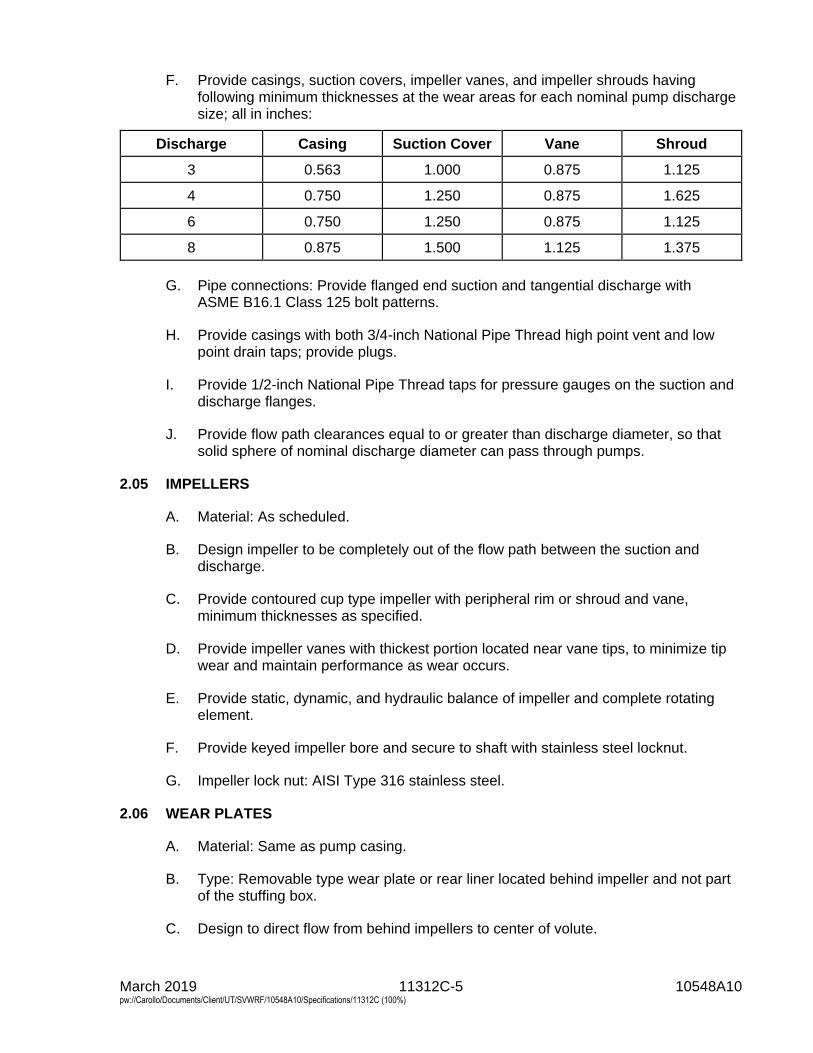
March 2019 11312C-5 10548A10 pw://Carollo/Documents/Client/UT/SVWRF/10548A10/Specifications/11312C (100%)
F. Provide casings, suction covers, impeller vanes, and impeller shrouds having following minimum thicknesses at the wear areas for each nominal pump discharge size; all in inches:
Discharge Casing Suction Cover Vane Shroud
3 0.563 1.000 0.875 1.125
4 0.750 1.250 0.875 1.625
6 0.750 1.250 0.875 1.125
8 0.875 1.500 1.125 1.375
G. Pipe connections: Provide flanged end suction and tangential discharge with ASME B16.1 Class 125 bolt patterns.
H. Provide casings with both 3/4-inch National Pipe Thread high point vent and low point drain taps; provide plugs.
I. Provide 1/2-inch National Pipe Thread taps for pressure gauges on the suction and discharge flanges.
J. Provide flow path clearances equal to or greater than discharge diameter, so that solid sphere of nominal discharge diameter can pass through pumps.
2.05 IMPELLERS
A. Material: As scheduled.
B. Design impeller to be completely out of the flow path between the suction and discharge.
C. Provide contoured cup type impeller with peripheral rim or shroud and vane, minimum thicknesses as specified.
D. Provide impeller vanes with thickest portion located near vane tips, to minimize tip wear and maintain performance as wear occurs.
E. Provide static, dynamic, and hydraulic balance of impeller and complete rotating element.
F. Provide keyed impeller bore and secure to shaft with stainless steel locknut.
G. Impeller lock nut: AISI Type 316 stainless steel.
2.06 WEAR PLATES
A. Material: Same as pump casing.
B. Type: Removable type wear plate or rear liner located behind impeller and not part of the stuffing box.
C. Design to direct flow from behind impellers to center of volute.
March 2019 11312C-6 10548A10 pw://Carollo/Documents/Client/UT/SVWRF/10548A10/Specifications/11312C (100%)
2.07 PUMP SHAFTS
A. Material: As scheduled, turned, ground, and polished.
B. Strength: Able to withstand minimum 1.5 times maximum operating torque and other loads.
C. Resonant frequency: As specified in Sections 15050 - Common Work Results for Mechanical Equipment and 15958 - Mechanical Equipment Testing.
D. Deflection: Maximum 0.002 inches under operating conditions.
E. Impeller attachment: Taper fitted at impeller with key and bolt for securing impeller.
F. Pump shaft sleeve: 1. Material: As scheduled with minimum Brinell Hardness Number of 450 when
tested in accordance with ASTM E 10. 2. Renewable, key locked in stuffing box, gland area, and bearings. 3. Able to protect shaft from pumped liquid and wear.
2.08 STUFFING BOXES
A. Size: As specified in Section 15050 - Common Work Results for Mechanical Equipment.
B. Materials: As scheduled.
C. Provide separate stuffing box housing (not integral to the rear liner or wear plate) suitable for shaft seal type scheduled, arranged for clean water lubrication from an outside source.
D. Shaft seal type: As scheduled and as specified in Section 15050 - Common Work Results for Mechanical Equipment.
2.09 BEARINGS AND BEARING FRAME
A. Bearing type: Anti-friction meeting ABMA standards; self-aligning spherical roller type radial bearings; angular contact ball type, or tapered roller for thrust bearings.
B. Bearing lubrication: 1. When grease lubrication scheduled, provide:
a. External grease fittings with grease relief pipe. b. Lip type grease seals and labyrinth type grease deflectors at both ends of
bearing housings, able to prevent entrance of contaminants. 2. When oil lubrication scheduled, provide:
a. Pressure lubricating system or separate oil reservoir type system. b. Oil filler pipe. c. External level indicator gauge.
3. Size sufficiently to safely absorb heat energy normally generated in bearing under maximum ambient temperature of 60 degrees Celsius.
C. Bearing life: Minimum L10 life of 100,000 hours at rated design point or 24,000 hours in accordance with ABMA 9 or 11 at bearing design load imposed by pump shutoff
March 2019 11312C-7 10548A10 pw://Carollo/Documents/Client/UT/SVWRF/10548A10/Specifications/11312C (100%)
with maximum sized impeller at rated speed, whichever provides longest bearing life in intended service.
D. Pump bearing frames: 1. Material: As scheduled. 2. Provide a 1-piece rigid construction with bearing housing at outboard (pump)
end, and end cover or housing at inboard (driver) end.
E. Inboard bearing frame drain hole: Tapped, 3/4-inch NPT, located as low as possible to drain leakage when adjacent to packing or seal.
2.10 COUPLINGS
A. Types: As scheduled and as specified in Section 15050 - Common Work Results for Mechanical Equipment.
B. Flexible coupling life: Infinite at up to 0.3-degree misalignment angle total or per disk for disk type at maximum operating loads.
C. Design coupling to withstand a minimum of 1.5 times the maximum operating torque and other imposed loads.
2.11 BELT DRIVES
A. Types: As scheduled and as specified in Section 15050 - Common Work Results for Mechanical Equipment.
B. Layout: As indicated on the Drawings.
2.12 SUPPORTS, PEDESTALS, AND BASEPLATES
A. Materials: Same as pump casing or ASTM A283 steel, hot-dip galvanized after fabrication and coated as specified in Section 09960 - High-Performance Coatings.
B. Pump and driver support strength: Able to withstand minimum 1.5 times maximum imposed operating loads or imposed seismic loads, whichever is greater.
C. Configuration: Allow easy access to stuffing boxes, bearing frames, and couplings.
D. Design a structural steel base and support system for the drive arrangement specified and as schematically indicated on the Drawings.
E. Anchor bolts: As specified in Section 05190 - Mechanical Anchoring and Fastening to Concrete and Masonry.
2.13 EQUIPMENT GUARDS
A. Provide safety guards as specified in Section 15050 - Common Work Results for Mechanical Equipment.
March 2019 11312C-8 10548A10 pw://Carollo/Documents/Client/UT/SVWRF/10548A10/Specifications/11312C (100%)
2.14 DRIVERS
A. Horsepower: 1. As scheduled. 2. Listed driver horsepower is the minimum to be supplied.
a. Increase driver horsepower if required to prevent driver overload while operating at any point of the supplied pump operating head-flow curve including runout.
b. When scheduled driver is a motor, increase motor horsepower if required to prevent operation in the service factor.
c. Make all structural, mechanical, and electrical changes required to accommodate increased horsepower.
B. Motors: Provide motors in accordance with Section 16222 - Low Voltage Motors up to 500 Horsepower and 16050 - Common Work Results for Electrical and as specified in this Section. 1. RPM: As scheduled. 2. Enclosure: As scheduled. 3. Electrical characteristics: As scheduled. 4. Efficiency, service factor, insulation, and other motor characteristics: As
specified in Section 16222 - Low Voltage Motors up to 500 Horsepower. 5. Motor accessories: As specified in Section 16222 - Low Voltage Motors up to
500 Horsepower and as specified in this Section. 6. Coordinate motors with the variable frequency drive manufacturer to ensure
compatibility between the motor and variable frequency drive. 7. Enclosure rating and hazardous area classification: Suitable for installation in
intended location per in 16050 - Common Work Results for Electrical.
C. Other drivers: As specified and scheduled, including Sections listed in the Schedule.
2.15 FINISHES
A. Finishes: Prepare surfaces and apply protective finishes as specified in Section 09960 - High-Performance Coatings.
PART 3 EXECUTION
3.01 INSTALLATION
A. Installation shall be as indicated on the Drawings, in accordance with written instructions of the manufacturer, and as specified in Section 15050 - Common Work Results for Mechanical Equipment.
3.02 COMMISSIONING
A. As specified in Section 01756 - Commissioning and this Section.
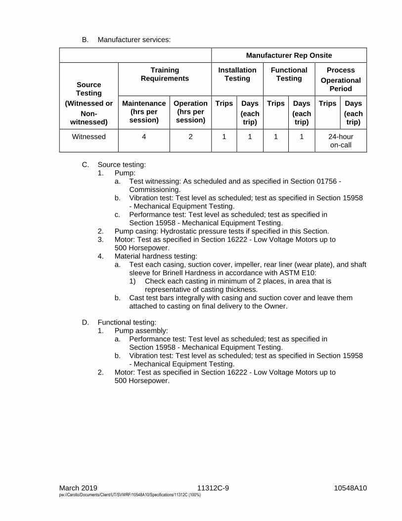
March 2019 11312C-9 10548A10 pw://Carollo/Documents/Client/UT/SVWRF/10548A10/Specifications/11312C (100%)
B. Manufacturer services:
Manufacturer Rep Onsite
Source Testing
(Witnessed or
Non-witnessed)
Training Requirements
Installation Testing
Functional Testing
Process
Operational Period
Maintenance (hrs per session)
Operation (hrs per session)
Trips Days
(each trip)
Trips Days
(each trip)
Trips Days
(each trip)
Witnessed 4 2 1 1 1 1 24-hour on-call
C. Source testing: 1. Pump:
a. Test witnessing: As scheduled and as specified in Section 01756 - Commissioning.
b. Vibration test: Test level as scheduled; test as specified in Section 15958 - Mechanical Equipment Testing.
c. Performance test: Test level as scheduled; test as specified in Section 15958 - Mechanical Equipment Testing.
2. Pump casing: Hydrostatic pressure tests if specified in this Section. 3. Motor: Test as specified in Section 16222 - Low Voltage Motors up to
500 Horsepower. 4. Material hardness testing:
a. Test each casing, suction cover, impeller, rear liner (wear plate), and shaft sleeve for Brinell Hardness in accordance with ASTM E10: 1) Check each casting in minimum of 2 places, in area that is
representative of casting thickness. b. Cast test bars integrally with casing and suction cover and leave them
attached to casting on final delivery to the Owner.
D. Functional testing: 1. Pump assembly:
a. Performance test: Test level as scheduled; test as specified in Section 15958 - Mechanical Equipment Testing.
b. Vibration test: Test level as scheduled; test as specified in Section 15958 - Mechanical Equipment Testing.
2. Motor: Test as specified in Section 16222 - Low Voltage Motors up to 500 Horsepower.
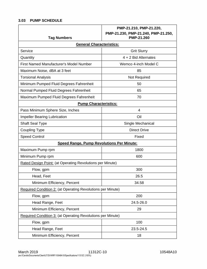
March 2019 11312C-10 10548A10 pw://Carollo/Documents/Client/UT/SVWRF/10548A10/Specifications/11312C (100%)
3.03 PUMP SCHEDULE
Tag Numbers
PMP-21.210, PMP-21.220,
PMP-21.230, PMP-21.240, PMP-21.250, PMP-21.260
General Characteristics:
Service Grit Slurry
Quantity 4 + 2 Bid Alternates
First Named Manufacturer's Model Number Wemco 4-inch Model C
Maximum Noise, dBA at 3 feet 85
Torsional Analysis Not Required
Minimum Pumped Fluid Degrees Fahrenheit 50
Normal Pumped Fluid Degrees Fahrenheit 65
Maximum Pumped Fluid Degrees Fahrenheit 70
Pump Characteristics:
Pass Minimum Sphere Size, Inches 4
Impeller Bearing Lubrication Oil
Shaft Seal Type Single Mechanical
Coupling Type Direct Drive
Speed Control Fixed
Speed Range, Pump Revolutions Per Minute:
Maximum Pump rpm 1800
Minimum Pump rpm 600
Rated Design Point: (at Operating Revolutions per Minute)
Flow, gpm 300
Head, Feet 26.5
Minimum Efficiency, Percent 34.58
Required Condition 2: (at Operating Revolutions per Minute)
Flow, gpm 200
Head Range, Feet 24.5-26.0
Minimum Efficiency, Percent 29
Required Condition 3: (at Operating Revolutions per Minute)
Flow, gpm 100
Head Range, Feet 23.5-24.5
Minimum Efficiency, Percent 18
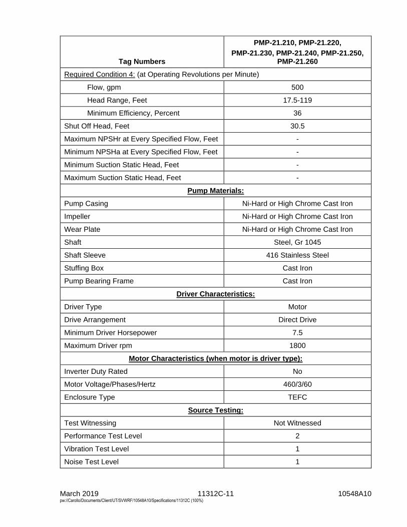
March 2019 11312C-11 10548A10 pw://Carollo/Documents/Client/UT/SVWRF/10548A10/Specifications/11312C (100%)
Tag Numbers
PMP-21.210, PMP-21.220,
PMP-21.230, PMP-21.240, PMP-21.250, PMP-21.260
Required Condition 4: (at Operating Revolutions per Minute)
Flow, gpm 500
Head Range, Feet 17.5-119
Minimum Efficiency, Percent 36
Shut Off Head, Feet 30.5
Maximum NPSHr at Every Specified Flow, Feet -
Minimum NPSHa at Every Specified Flow, Feet -
Minimum Suction Static Head, Feet -
Maximum Suction Static Head, Feet -
Pump Materials:
Pump Casing Ni-Hard or High Chrome Cast Iron
Impeller Ni-Hard or High Chrome Cast Iron
Wear Plate Ni-Hard or High Chrome Cast Iron
Shaft Steel, Gr 1045
Shaft Sleeve 416 Stainless Steel
Stuffing Box Cast Iron
Pump Bearing Frame Cast Iron
Driver Characteristics:
Driver Type Motor
Drive Arrangement Direct Drive
Minimum Driver Horsepower 7.5
Maximum Driver rpm 1800
Motor Characteristics (when motor is driver type):
Inverter Duty Rated No
Motor Voltage/Phases/Hertz 460/3/60
Enclosure Type TEFC
Source Testing:
Test Witnessing Not Witnessed
Performance Test Level 2
Vibration Test Level 1
Noise Test Level 1
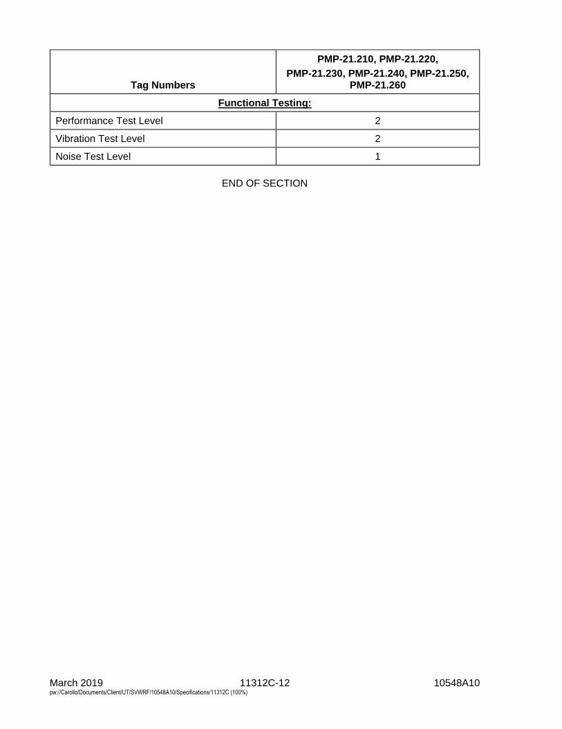
March 2019 11312C-12 10548A10 pw://Carollo/Documents/Client/UT/SVWRF/10548A10/Specifications/11312C (100%)
Tag Numbers
PMP-21.210, PMP-21.220,
PMP-21.230, PMP-21.240, PMP-21.250, PMP-21.260
Functional Testing:
Performance Test Level 2
Vibration Test Level 2
Noise Test Level 1
END OF SECTION
March 2019 11312P-1 10548A10 pw://Carollo/Documents/Client/UT/SVWRF/10548A10/Specifications/11312P (100%)
SECTION 11312P
SUBMERSIBLE AXIAL FLOW PROPELLER PUMPS
PART 1 GENERAL
1.01 SUMMARY
A. Section includes: The requirements for vertically suspended, submersible, axial,centrifugal, propeller pumps.
B. Tag numbers: As specified in Pump Schedule.
1.02 REFERENCES
A. American Bearing Manufacturers Association (ABMA):1. 9 - Load Ratings and Fatigue Life for Ball Bearings.2. 11 - Load Ratings and Fatigue Life for Roller Bearings.
B. American Society of Mechanical Engineers (ASME):1. B16.1 - Cast Iron Pipe Flanges and Flanged Fittings, Class 25, 125, 250, and
800.2. B16.5 - Pipe Flanges and Flanged Fittings.
C. ASTM International (ASTM):1. A48 - Standard Specification for Gray Iron Castings.2. A108 - Standard Specification for Steel Bars, Carbon and Alloy, Cold-Finished.3. A276 - Standard Specification for Stainless Steel Bars and Shapes.4. A582 - Standard Specification for Free-Machining Stainless Steel Bars.5. B148 - Standard Specification for Aluminum-Bronze Sand Castings.6. B505 - Standard Specification for Copper-Base Alloy Continuous Castings.7. B584 - Standard Specification for Copper Alloy Sand Castings for General
Applications.8. F593 - Standard Specification for Stainless Steel Bolts, Hex Cap Screws, and
Studs.9. F594 - Standard Specification for Stainless Steel Nuts.
D. American Water Works Association (AWWA):1. C200 - Steel Water Pipe 6 Inch and Larger.
E. FM Global (FM).
F. Hydraulic Institute (HI):1. 1.1-1.5 - Rotodynamic (Centrifugal) Pumps - Nomenclature and Definitions.2. 9.1-9.5 - General Pump Standards for Types, Definitions, Application, and
Sound Measurements and Decontamination.
G. National Electrical Code (NEC).
H. National Electrical Manufacturers Association (NEMA).
March 2019 11312P-2 10548A10 pw://Carollo/Documents/Client/UT/SVWRF/10548A10/Specifications/11312P (100%)
I. Underwriters Laboratories, Inc. (UL).
1.03 DEFINITIONS
A. Pump head (Total Dynamic Head, TDH), flow capacity, pump efficiency, net positive suction head available (NPSHa), and net positive suction head required (NPSHr): As defined in HI 1.1-1.5, and 9.1-9.5 and as modified in the Specifications.
B. Suction head: Gauge pressure available at pump intake flange or bell in feet of fluid above atmospheric; average when using multiple suction pressure taps, regardless of variation in individual taps.
1.04 SYSTEM DESCRIPTION
A. Submersible pumps and components: 1. Submersible non-clog vertical axial flow pump. 2. Submersible electric motor. 3. Motor drive. 4. Bearings. 5. Seals. 6. Pump discharge column pipe including discharge elbow supports. 7. Submersible cable. 8. Submersible cable support and protection. 9. Necessary controls and instrumentation. 10. Taps. 11. Lifting eyes. 12. Lifting cable. 13. Similar type items as specified and as required for complete operational units
ready for use as specified and installed as indicated on the Drawings.
B. Pump is installed by lowering the 1-piece motor/pump unit into the discharge column pipe supplied by the manufacturer and onto the mounting plate or coupling ring device.
C. Design requirements: 1. Pump performance characteristics:
a. As specified in the Pump Schedule. b. Performance tolerances shall be the same as the test tolerances specified
in Section 15958 - Mechanical Equipment Testing. 2. Motor characteristics: As specified in Pump Schedule.
D. Maintenance and repair shall be performed by lifting the pump/motor unit out of the discharge column pipe. It shall not be necessary for maintenance personnel to enter the wet well.
E. Product requirements as specified in Section 01600 - Product Requirements and Section 15050 - Common Work Results for Mechanical Equipment.
1.05 SUBMITTALS
A. Submit as specified in Section 01330 - Submittal Procedures.
March 2019 11312P-3 10548A10 pw://Carollo/Documents/Client/UT/SVWRF/10548A10/Specifications/11312P (100%)
B. Product data: As specified in Section 15050 - Common Work Results for Mechanical Equipment.
C. Shop drawings: As specified in Section 15050 - Common Work Results for Mechanical Equipment.
D. Calculations: As specified in Section 15050 - Common Work Results for Mechanical Equipment: 1. Torsional analysis: Submit when scheduled and as specified in Section 15050
- Common Work Results for Mechanical Equipment.
E. Vendor operation and maintenance manuals: As specified in Section 01782 - Operation and Maintenance Data.
F. Commissioning submittals: 1. Provide Manufacturer’s Certificate of Source Testing as specified in
Section 01756 - Commissioning. 2. Provide Manufacturer’s Certificate of Installation and Functionality Compliance
as specified in Section 01756 - Commissioning.
1.06 WARRANTY
A. As specified in Section 01783 - Warranties and Bonds.
PART 2 PRODUCTS
2.01 MANUFACTURERS
A. Pump: One of the following or equal: 1. KSB, Amaline series.
2.02 MATERIALS
A. General: When materials are referenced in this Section or on the pump schedule, the compositions shall be the UNS Alloys, Types or Grades in this article unless specified or scheduled otherwise.
B. Carbon steel: C 1035.
C. Cast Iron: ASTM A48, Class 35 B minimum.
D. Nickel cast iron: ASTM A48, Class 35 minimum with 3 percent nickel added.
E. Steel: ASTM A108, Grade or UNS Alloy as specified or scheduled.
F. Stainless steel: ASTM A276 or ASTM A582, Type or UNS Alloy as specified or scheduled.
G. Bronze: ASTM B505 or ASTM B584, UNS Alloy C83600.
H. Zincless bronze: ASTM B505 or ASTM B584, Leaded Tin Bronze, UNS Alloy C92700.
March 2019 11312P-4 10548A10 pw://Carollo/Documents/Client/UT/SVWRF/10548A10/Specifications/11312P (100%)
I. Aluminum bronze: ASTM B148, ASTM B505 or ASTM B584, UNS Alloy C95200.
J. Fasteners: Stainless Steel, ASTM F593 or ASTM F594, type or grade as specified.
2.03 PUMP CASINGS
A. Type: 2-piece; pump and motor casing bolted together; machined seal faces with Nitrile or Buna N rubber O-ring seal; Type 304 stainless steel bolting.
B. Material: As scheduled.
C. Construction: Of sufficient strength, weight, and thickness to provide accurate alignment and water tightness.
D. Design working pressure: Minimum 1.10 times maximum shutoff total dynamic head with maximum installable impeller diameter at maximum operating speed plus maximum suction static head; suitable for submergence in up to 65 feet of water.
2.04 IMPELLERS
A. Type: As scheduled.
B. Material: Cast iron, Class 35B.
C. Maximum number of vanes: As scheduled.
D. Water passages: Smooth, able to prevent clogging by stringy or fibrous materials and to pass a minimum 4-inch diameter solid.
E. Method of securing to shafts: Keyed and secured by bronze nut or Allen head bolt locked in place, but readily removable without use of special tools.
F. Rotation: Clockwise looking from driver, unless otherwise indicated on the Drawings.
G. Balance: As specified in Section 15050 - Common Work Results for Mechanical Equipment to meet the vibration criteria as specified in Section 15958 - Mechanical Equipment Testing.
2.05 WEAR RINGS
A. Provide one of the following systems: 1. Wear ring system:
a. General: Used to provide efficient sealing between the volute and suction inlet of the impeller.
b. Volute wear ring: 1) Material: Steel coated with Nitrile rubber. 2) Fitted to the volute inlet.
c. Impeller wear ring: 1) Material: Type 316 stainless steel. 2) Heat-shrunk fitted onto the suction inlet of the impeller.
March 2019 11312P-5 10548A10 pw://Carollo/Documents/Client/UT/SVWRF/10548A10/Specifications/11312P (100%)
2.06 PUMP SHAFTS
A. Material: As scheduled in this Section, turned, ground, and polished. Shall be completely isolated from the pumped liquid.
B. Strength: Able to withstand minimum 1.5 times maximum operating torque and other loads.
C. Resonant frequency: As specified in Sections 15050 - Common Work Results for Mechanical Equipment and 15958 - Mechanical Equipment Testing.
D. Deflection: Maximum 0.002 inches under operating conditions.
E. Construction: 1. Pump and motor shaft shall be a solid continuous shaft. 2. Couplings shall not be accepted. 3. The use of intermediate gear boxes or gear speed reducers shall not be
accepted.
2.07 PUMP DISCHARGE COLUMN PIPE (CAN)
A. Pump discharge column pipe: Diameter and material as scheduled.
B. Shall be permanently mounted and allow pump to be installed within the column by lowering it to the bottom until it rests on a pump base plate or coupling ring device.
C. Design working pressure: Design to withstand a design working pressure not less than 1.20 times the maximum shutoff total dynamic head with the maximum diameter impeller at the maximum operating speed plus the maximum suction static head.
D. Lengths and connections: Design discharge column length and connections as indicated on the Drawings.
E. Construction: 1. In accordance with AWWA C200 with minimum 0.25 inch thick wall. 2. Discharge column top shall be capped with Standard ASME B16.1 Class 125
flange. 3. ASME B16.5 blind flange shall be provided with minimum 1 lifting eye and all
required taps to accommodate power cable and gauges as well as a means to secure the pump lifting chain.
2.08 MECHANICAL SEALS
A. Provide dual tandem mechanical seal system consisting of 2 totally independent seal assemblies with oil for seal lubrication and cooling. 1. Shaft sealing system shall be capable of withstanding volute pressure up to
1.5 times pump shutoff head. 2. No seal damages shall result from operating the pumping unit in its liquid
environment, from running pump dry, or from reverse pump operation. 3. Seals shall be maintenance free and shall not require adjustment.
March 2019 11312P-6 10548A10 pw://Carollo/Documents/Client/UT/SVWRF/10548A10/Specifications/11312P (100%)
B. Oil chamber: 1. Provide oil chamber for shaft sealing system. Design oil chamber to ensure
that air is left in the oil chamber to absorb the expansion of the oil due to temperature variations.
2. Provide drain and inspection plug, with positive anti-leak seal, easily accessible from the outside.
3. Oil in oil chamber shall be FDA approved, paraffin type, colorless, odorless, and non-toxic.
4. Provide capacitive type leakage sensor for the detection of water in the oil chamber or a moisture sensor in the lower motor chamber to detect any fluid in the motor.
C. Upper seal: 1. Tungsten carbide positively-driven rotating seal and tungsten carbide
stationary seal as specified in Section 15050 - Common Work Results for Mechanical Equipment.
2. Located between the oil chamber and motor housing.
D. Lower seal: 1. Located between pump and oil chamber. Shall be independent of the impeller
hub. 2. Tungsten Carbide rotating and stationary seals as specified in Section 15050 -
Common Work Results for Mechanical Equipment.
E. Springs and other hardware: Stainless steel, 300 or 400 series.
2.09 BEARINGS
A. Pump shaft shall rotate on a minimum of 3 permanently sealed, grease lubricated bearings: 1. Upper bearing for radial forces. 2. Two lower bearings for combined axial and radial forces.
B. Bearing type: Anti-friction meeting ABMA standards.
C. For pumps 50 horsepower and larger, provide lower bearing with independent thermal sensor to monitor the bearing temperature. If a high temperature occurs, the sensor shall activate an alarm and shut down the motor.
D. Bearing lubrication system shall be sized sufficiently to safely absorb heat energy normally generated in bearing under maximum ambient temperature of 60 degrees Celsius when pump scheduled for dry running. 1. Bearing Life: Minimum L10 life of 100,000 hours at rated design point or
24,000 hours in accordance with ABMA 9 or 11 at bearing design load imposed by pump shutoff with maximum sized impeller at rated speed, whichever provides longest bearing life in intended service.
2.10 MOTORS AND POWER CABLES
A. Motors: Features as specified and as scheduled. 1. Provide motors that are rated suitable for continuous operation in 40 degrees
Celsius ambient temperature at project site altitude.
March 2019 11312P-7 10548A10 pw://Carollo/Documents/Client/UT/SVWRF/10548A10/Specifications/11312P (100%)
2. Horsepower: a. As scheduled. b. Listed motor horsepower is the minimum to be supplied.
1) Increase motor horsepower if required to prevent motor overload while operating at any point on the supplied pump operating head-flow curve, including runout.
2) However, variable frequency drives, generator, and other electrical equipment are sized for scheduled motor horsepower.
3. The motor shall be capable of continuous operation under load with the motor submerged, partially submerged or exposed, without derating the motor.
4. The motor shall be designed for continuous duty handling pumped media of 40 degrees Celsius and capable of a minimum of 15 evenly spaced starts per hour.
5. Motor cooling system: a. Design to provide adequate cooling:
1) At the maximum operating speed. 2) With motor submerged. 3) With motor dry.
b. Pump/motor shall be cooled by the passage of the pumped fluid past the motor housing within the discharge column.
c. Provide capability to relieve entrapped air from the system. d. Spray systems, air moving equipment or other secondary cooling systems
are not acceptable. 6. Motor sealing: Design motor case and seals to withstand 65 feet of
submergence. 7. Provide a moisture detection sensor in the stator chamber and the cable entry
chamber. If leakage is detected, the sensor shall activate an alarm and shut down the motor.
8. Thermal protection: a. Automatic reset motor stator temperature detectors, 1 switch in each
phase. b. If any detector is activated, the sensor shall activate an alarm and shut
down the motor. c. The thermal detectors shall activate when the stator temperature exceeds
135 degrees Celsius. 9. Explosion proof motors:
a. Squirrel cage induction motor, moisture resistant, UL or FM listed for Class 1, Groups C and D, Division 1 service, whether submerged or un-submerged.
b. Insulation: Class H, moisture resistant, able to withstand 40 degrees Celsius ambient temperature plus 80 degrees Celsius temperature rise.
c. All electrical parts in air filled water tight housing. 10. Other requirements as scheduled.
B. Power cables: 1. Submersible to same water depth as motor casing. 2. Type SPC with Hypalon/Buna N jacket. 3. Insulation rated for 90 degrees Celsius. 4. Non-wicking fillers. 5. Length: Sufficient to connect to junction box (without the need of splices) as
indicated on the Drawings or 30 feet, whichever is greater. 6. Sized to conform to NEC, ICEA, and CSA specifications.
March 2019 11312P-8 10548A10 pw://Carollo/Documents/Client/UT/SVWRF/10548A10/Specifications/11312P (100%)
7. Provide stainless steel cable and stainless steel wire braid sleeve to support power cable from underside of wet well roof slab or access frame.
C. Cable entry seal and junction chamber: 1. Cable entry seal design shall not require specific torque requirements to insure
a watertight and submersible seal. 2. Cable entry seal shall consist of dual cylindrical elastomer grommets, flanked
by stainless steel washers. 3. The cable entry seal shall provide strain relief for the cable. 4. The cable entry junction chamber shall be separate from the motor chamber to
prevent foreign material from gaining access to the top of the pump. 5. Provide a moisture detection sensor in the cable junction chamber. If leakage
is detected, the sensor shall activate an alarm and shut down the pump/motor.
2.11 LIFTING DEVICES
A. General: Provide lifting devices suitable for discharge can installation as scheduled in this Section and as indicated on the Drawings.
B. Materials: 1. Wet pit: Square Type 304 stainless steel guide rails, lifting cable or chain and
wall supports; Type 316 stainless steel anchor bolts and fasteners.
C. Lifting device: 1. Type: Chain or cable attached to lifting eye on the pump casing. 2. Length: Able to lower pump from top of wet well to operating position as
indicated on the Drawings plus 5 additional feet of length. 3. Retainer: Provide Type 316 stainless steel locking hook or clasp at top of wet
well to securely retain the upper end of the lifting chain or cable during pump operation.
2.12 ANTI VORTEX CONE
A. Each submersible pump shall have an anti-vortex cone provided by the manufacturer to provide proper flow conditions to the pump inlet. 1. The cone:
a. Sized and designed properly by the manufacturer for each pump installation.
b. Constructed of Type 316 stainless steel, minimum thickness of 1/4-inch. c. Anchored to the floor of the basin under the pump by a minimum of four
1/2-inch stainless steel anchor bolts. 2. The pump supplier shall submit the design of the anti-vortex cones for
approval. a. However, the pump supplier will accept full responsibility for the design of
the cone.
2.13 CONTROLS
A. Control module: 1. Each pump shall be provided with its own pump protection relay module,
furnished by the pump supplier, with contacts rated 5A at 120 VAC. Provide relay with both normally open and normally closed contacts to change state upon detection of moisture or temperature. Relay shall accept 120 VAC power.
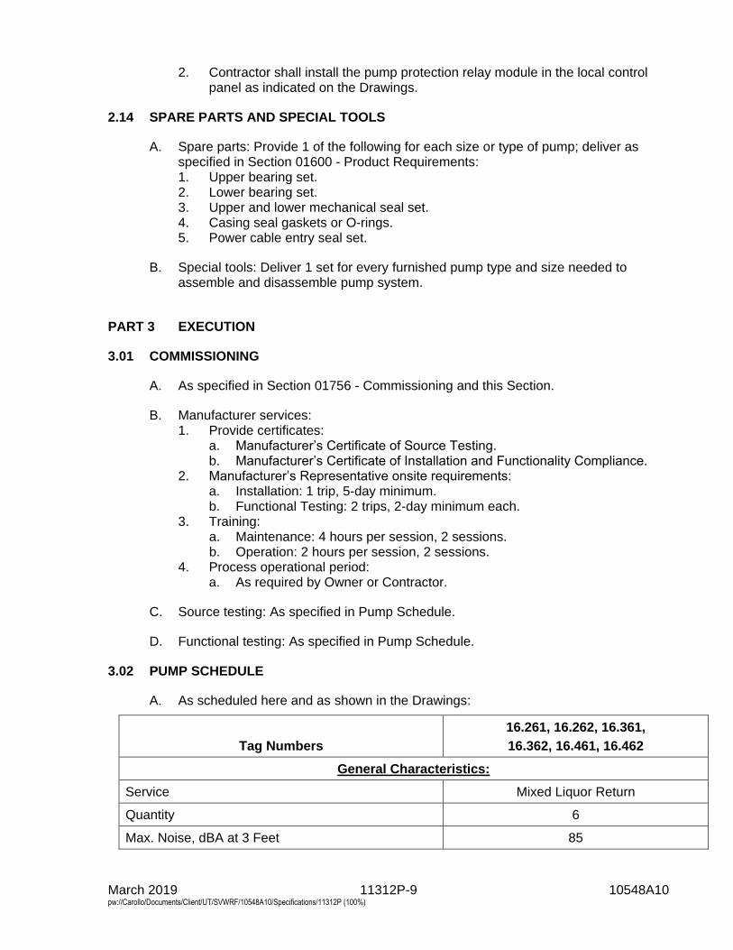
March 2019 11312P-9 10548A10 pw://Carollo/Documents/Client/UT/SVWRF/10548A10/Specifications/11312P (100%)
2. Contractor shall install the pump protection relay module in the local control panel as indicated on the Drawings.
2.14 SPARE PARTS AND SPECIAL TOOLS
A. Spare parts: Provide 1 of the following for each size or type of pump; deliver as specified in Section 01600 - Product Requirements: 1. Upper bearing set. 2. Lower bearing set. 3. Upper and lower mechanical seal set. 4. Casing seal gaskets or O-rings. 5. Power cable entry seal set.
B. Special tools: Deliver 1 set for every furnished pump type and size needed to assemble and disassemble pump system.
PART 3 EXECUTION
3.01 COMMISSIONING
A. As specified in Section 01756 - Commissioning and this Section.
B. Manufacturer services: 1. Provide certificates:
a. Manufacturer’s Certificate of Source Testing. b. Manufacturer’s Certificate of Installation and Functionality Compliance.
2. Manufacturer’s Representative onsite requirements: a. Installation: 1 trip, 5-day minimum. b. Functional Testing: 2 trips, 2-day minimum each.
3. Training: a. Maintenance: 4 hours per session, 2 sessions. b. Operation: 2 hours per session, 2 sessions.
4. Process operational period: a. As required by Owner or Contractor.
C. Source testing: As specified in Pump Schedule.
D. Functional testing: As specified in Pump Schedule.
3.02 PUMP SCHEDULE
A. As scheduled here and as shown in the Drawings:
Tag Numbers
16.261, 16.262, 16.361,
16.362, 16.461, 16.462
General Characteristics:
Service Mixed Liquor Return
Quantity 6
Max. Noise, dBA at 3 Feet 85
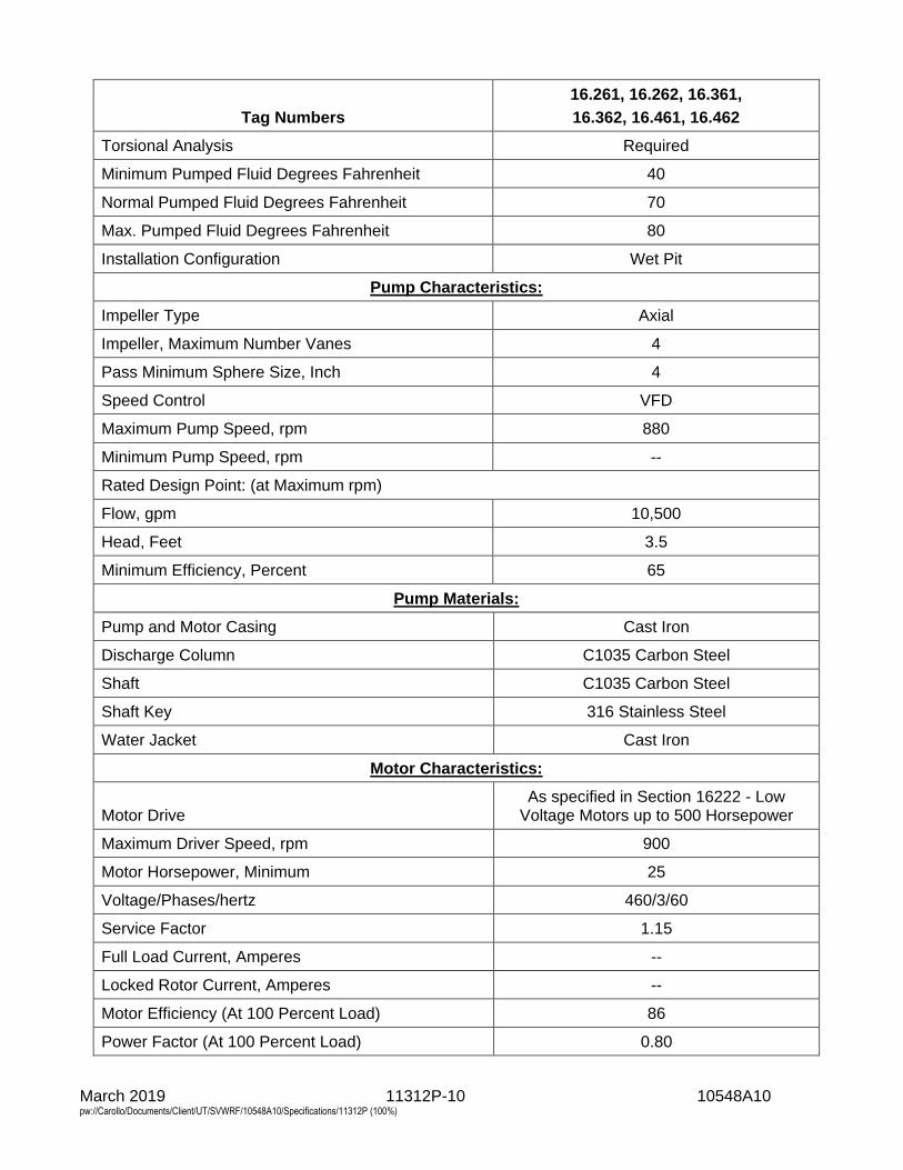
March 2019 11312P-10 10548A10 pw://Carollo/Documents/Client/UT/SVWRF/10548A10/Specifications/11312P (100%)
Tag Numbers
16.261, 16.262, 16.361,
16.362, 16.461, 16.462
Torsional Analysis Required
Minimum Pumped Fluid Degrees Fahrenheit 40
Normal Pumped Fluid Degrees Fahrenheit 70
Max. Pumped Fluid Degrees Fahrenheit 80
Installation Configuration Wet Pit
Pump Characteristics:
Impeller Type Axial
Impeller, Maximum Number Vanes 4
Pass Minimum Sphere Size, Inch 4
Speed Control VFD
Maximum Pump Speed, rpm 880
Minimum Pump Speed, rpm --
Rated Design Point: (at Maximum rpm)
Flow, gpm 10,500
Head, Feet 3.5
Minimum Efficiency, Percent 65
Pump Materials:
Pump and Motor Casing Cast Iron
Discharge Column C1035 Carbon Steel
Shaft C1035 Carbon Steel
Shaft Key 316 Stainless Steel
Water Jacket Cast Iron
Motor Characteristics:
Motor Drive As specified in Section 16222 - Low
Voltage Motors up to 500 Horsepower
Maximum Driver Speed, rpm 900
Motor Horsepower, Minimum 25
Voltage/Phases/hertz 460/3/60
Service Factor 1.15
Full Load Current, Amperes --
Locked Rotor Current, Amperes --
Motor Efficiency (At 100 Percent Load) 86
Power Factor (At 100 Percent Load) 0.80
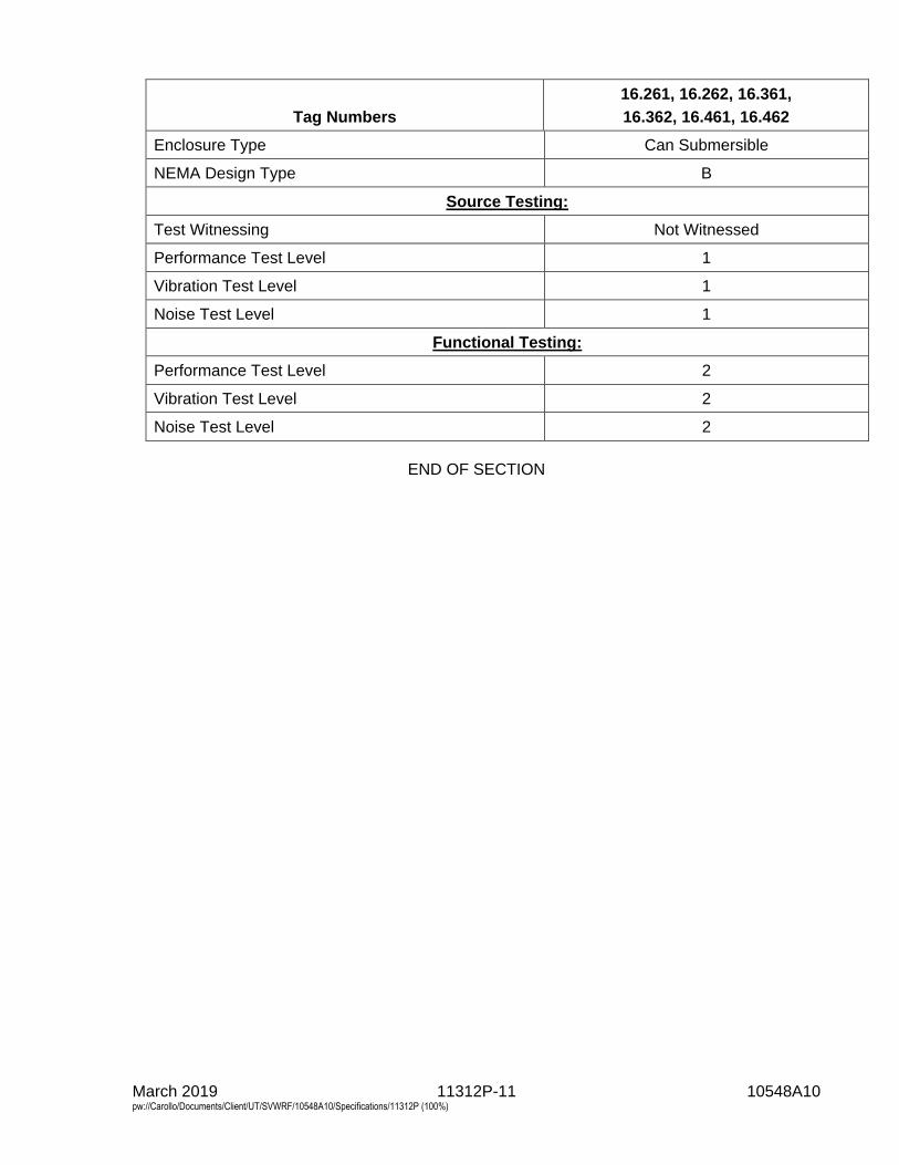
March 2019 11312P-11 10548A10 pw://Carollo/Documents/Client/UT/SVWRF/10548A10/Specifications/11312P (100%)
Tag Numbers
16.261, 16.262, 16.361,
16.362, 16.461, 16.462
Enclosure Type Can Submersible
NEMA Design Type B
Source Testing:
Test Witnessing Not Witnessed
Performance Test Level 1
Vibration Test Level 1
Noise Test Level 1
Functional Testing:
Performance Test Level 2
Vibration Test Level 2
Noise Test Level 2
END OF SECTION

March 2019 11323-1 10548A10 pw://Carollo/Documents/Client/UT/SVWRF/10548A10/Specifications/11323 (100%)
SECTION 11323
GRIT REMOVAL SYSTEM
PART 1 GENERAL
1.01 SUMMARY
A. Section includes: Grit removal system: 1. Grit Basin No. 1. 2. Grit Basin No. 2. 3. Grit Basin No. 3 (Bid Alternate).
1.02 COST OF PRE-NEGOTIATED ITEMS
A. Cost for some items in this section of the Specifications has been pre-negotiated with specified manufacturer and is included in one of the bid items in the bidding sheet. Refer to bidding sheet and applicable pre-negotiated proposal included in Appendix A for more details. Contractor shall provide additional items as indicated in applicable pre-negotiated proposal included in Appendix A, even if they are not included in Specifications and/or Drawings. Contractor is very strongly cautioned to carefully review applicable pre-negotiated proposal, because the pre-negotiated proposal does not include all items included in Specifications and Drawings. In addition to cost indicated for applicable bid item in bidding sheet, Contractor shall include in his bid the costs for the following: 1. All items not specifically mentioned in the scope of supply of pre-negotiated
proposal, but required per Specifications and Drawings and required to complete the installation to provide an operational system.
2. All other items indicated in the pre-negotiated proposal to be provided by others, by customer, by Owner, or any other similar designation: a. All freight and applicable taxes, unless specifically included in
pre-negotiated proposal. b. All labor, materials, and all other associated costs not included in the
pre-negotiated proposal but required per Specifications and Drawings and required to complete the installation to provide an operational system.
c. The Contractor and Manufacturer shall ensure that the other obligations defined in the pre-negotiated proposal (Memorandum of Agreement/MOA) are complied with. These include, but are not limited to, delivery, inspections, start-up, training, testing, and payment.
B. Schedule: 1. Contractor shall coordinate with the equipment supplier’s delivery schedule to
issue a purchase order at such time that equipment delivery will be completed at least 8 weeks in advance of the required date, as indicated in the Contractor’s approved construction schedule.
2. Negotiated price included in the Bid Schedule is based on a delivery per the MOA Section VI-3. If the Contractor elects to have delivery after this time, the purchase price shall be adjusted in accordance with the MOA and the Contractor shall be responsible for such additional costs.
March 2019 11323-2 10548A10 pw://Carollo/Documents/Client/UT/SVWRF/10548A10/Specifications/11323 (100%)
C. Liquidated damages: 1. Manufacturer has agreed to the liquidated damages as described in the
Memorandum of Agreement.
1.03 REFERENCES
A. American Welding Society (AWS).
B. ASTM International (ASTM): 1. A 380 - Standard Practice for Cleaning, Descaling, and Passivation of
Stainless Steel Parts, Equipment, and Systems.
1.04 DEFINITIONS
A. Sand equivalent size (SES): The sand particle size, measured in microns, having the same settling velocity as the selected grit particle.
1.05 DESIGN REQUIREMENTS
A. All hydraulic, self-activating and not require internal moving parts.
B. Parts of mechanism shall be amply proportioned for stresses which might occur during, fabrication, erection, operation, or maintenance.
C. Suitable and intended for permanent installation in a concrete tank. All materials shall be either pickled and passivated Type 316 stainless steel or other non-corrosive material. All flow passages shall be self-cleaning and free of sharp projections or fittings that may snag stringy or fibrous materials. All items shall be suitable for installation in Class 1, Division 1, Group D hazardous location.
D. Geometry of grit removal system as indicated on the Drawings. The degritted effluent shall be discharged over an effluent weir as indicated on the Drawings.
E. Provide sufficient surface area to remove the specified grit particles from the specified flow rates.
1.06 PERFORMANCE REQUIREMENTS
A. General: Compatible for permanent installation and long-term operation with the downstream grit handling equipment specified in Sections 11312C - Recessed Impeller Pumps and 11324 - Grit Washer/Dewatering Units and in accordance with design intent.
B. Hydraulic Capacity: Maximum permissible headloss of 12 inches (from upstream of the inlet duct to immediately upstream of the effluent weir) at a peak flow rate of 36 million gallons per day per grit basin, or 66 million gallons per day with two grit basins in service.
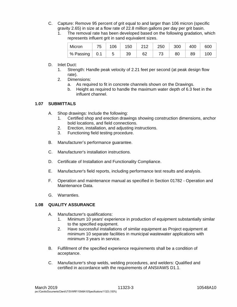
March 2019 11323-3 10548A10 pw://Carollo/Documents/Client/UT/SVWRF/10548A10/Specifications/11323 (100%)
C. Capture: Remove 95 percent of grit equal to and larger than 106 micron (specific gravity 2.65) in size at a flow rate of 22.8 million gallons per day per grit basin. 1. The removal rate has been developed based on the following gradation, which
represents influent grit in sand equivalent sizes.
Micron 75 106 150 212 250 300 400 600
% Passing 0.1 5 39 62 73 80 89 100
D. Inlet Duct: 1. Strength: Handle peak velocity of 2.21 feet per second (at peak design flow
rate). 2. Dimensions:
a. As required to fit in concrete channels shown on the Drawings. b. Height as required to handle the maximum water depth of 6.3 feet in the
influent channel.
1.07 SUBMITTALS
A. Shop drawings: Include the following: 1. Certified shop and erection drawings showing construction dimensions, anchor
bold locations, and field connections. 2. Erection, installation, and adjusting instructions. 3. Functioning field testing procedure.
B. Manufacturer’s performance guarantee.
C. Manufacturer's installation instructions.
D. Certificate of Installation and Functionality Compliance.
E. Manufacturer's field reports, including performance test results and analysis.
F. Operation and maintenance manual as specified in Section 01782 - Operation and Maintenance Data.
G. Warranties.
1.08 QUALITY ASSURANCE
A. Manufacturer's qualifications: 1. Minimum 10 years' experience in production of equipment substantially similar
to the specified equipment. 2. Have successful installations of similar equipment as Project equipment at
minimum 10 separate facilities in municipal wastewater applications with minimum 3 years in service.
B. Fulfillment of the specified experience requirements shall be a condition of acceptance.
C. Manufacturer's shop welds, welding procedures, and welders: Qualified and certified in accordance with the requirements of ANSI/AWS D1.1.
March 2019 11323-4 10548A10 pw://Carollo/Documents/Client/UT/SVWRF/10548A10/Specifications/11323 (100%)
1.09 DELIVERY, STORAGE, AND HANDLING
A. As specified in Section 15050 - Common Work Results for Mechanical Equipment.
1.10 WARRANTY
A. Provide warranty to correct defects in material, workmanship, or design for minimum of 2 years from the date specified in Section 01783 - Warranties and Bonds.
PART 2 PRODUCTS
2.01 MANUFACTURERS
A. Grit removal system: 1. Manufacturers: The following:
a. Hydro International, HeadCell®.
2.02 GRIT REMOVAL SYSTEMS
A. Design requirements: 1. Number of Grit Basins: 2 and 1 bid alternate . 2. Size: 12 feet in diameter. 3. Number of Trays per Basin: 12. 4. Surface Area per Basin: 1,356 square feet. 5. Loading Rate: The following surface loading rates are required to achieve the
intended particle size removal. No exceptions will be allowed: a. Peak Flow Rate of 36 million gallons per day per Grit Basin: 18.4 gallons
per minute per square foot. b. Average Flow Rate of 15.5 million gallons per day per Grit Basin:
7.9 gallons per minute per square foot. 6. Influent Duct Opening: As indicated on the Drawings. 7. Discharge: Weir. 8. Continuous Underflow (Grit Slurry) Rate: 250 to 300 gallons per minute. 9. Underflow (Grit Slurry) Connection: 6-inch flanged, with ANSI B16.1 bolt
pattern. 10. Plant Water Connection: 1-inch threaded.
B. Material of Construction: 1. Support structure: Type 316 stainless steel, per Section 05500 - Metal
Fabrications. 2. Influent duct and transition manifold: Type 316 stainless steel, per
Section 05500 - Metal Fabrications. 3. Grit Collector (underflow): Type 316 Stainless steel, per Section 05500 - Metal
Fabrications. 4. Tray pans and sidewalls: Minimum 1/4-inch thick polyethylene.
C. Securely fit the stack of trays into a support frame designed and furnished by the manufacturer.
D. For each grit removal system, provide a grit collector for collection and removal of settled solids to the downstream grit handling equipment.
March 2019 11323-5 10548A10 pw://Carollo/Documents/Client/UT/SVWRF/10548A10/Specifications/11323 (100%)
2.03 PLANT UTILITY WATER REQUIREMENTS
A. Provide a dedicated fluidizing system that injects water into the bottom of the grit hopper to keep collected grit in suspension, using non-potable plant utility water.
B. Fluidizing System Components: 1. Items To be Supplied by Equipment Manufacturer:
a. 1-inch Acrylic Rotameters: 1 per basin. 2. Items To be Supplied by Contractor:
a. All items indicated on the P&ID Drawings but not listed above as items to be supplied by equipment manufacturer.
C. Utility water requirements per grit basin: 1. Flow rate: 20 gallons per minute, continuous. 2. Pressure: 50 pounds per square inch gauge.
2.04 FASTENERS
A. All fasteners and anchor bolts shall be Type 316 stainless steel and be in accordance with Section 05190 - Mechanical Anchoring and Fastening to Concrete and Masonry. Provide seismic anchorage calculations to confirm the required sizes of the fasteners and anchor bolts.
B. All threaded fasteners shall be coated with a nickel-based anti-seize thread lubricant prior to assembly.
2.05 PROTECTIVE COATINGS
A. Pickle and passivate all stainless steel components in the factory as follows: 1. Pickling and passivation per miscellaneous stainless steel provisions of
Specification Section 05500 - Metal Fabrications. 2. Wash welds with hydrofluoric acid solutions. 3. Inspect visually for degradation.
B. Do not paint stainless steel and plastic components.
PART 3 EXECUTION
3.01 INSTALLATION
A. Install equipment in strict accordance with the Contract Documents and the manufacturer’s written instructions and shop drawings.
B. Identify limit of piping being supplied by the equipment manufacturer and provide additional piping to provide a complete functional system.
C. Grout grit basin floor in accordance with the manufacturer's instructions illustrated in Appendix B of this section.
D. Contractor shall verify all necessary dimensions as required for successful installation and to facilitate operation and maintenance.
March 2019 11323-6 10548A10 pw://Carollo/Documents/Client/UT/SVWRF/10548A10/Specifications/11323 (100%)
3.02 FIELD QUALITY CONTROL
A. Testing, Training, and Startup: As specified in Section 01756 - Commissioning as described below.
B. Testing and startup: 1. Performance Testing to be performed during Commissioning Phase as part of
Installation Testing specified in Section 01756 - Commissioning: a. Conduct performance tests to substantiate conformance with the specified
performance requirements. Submit detailed testing procedures for the Engineer's review and approval.
b. The manufacturer shall bear all costs associated with performance testing.
c. Conduct tests in presence of the Engineer and Owner. The tests shall be conducted by an independent testing laboratory or firm approved by the Engineer, their services paid for by the manufacturer. 1) Tests will be conducted with plant influent flow at flow rates ranging
from 20 to 36 million gallons per day per unit. The performance at 20 million gallons per day will be 95 percent removal of all grit (SG 2.65) greater than or equal to 106 microns.
2) Engineer will select one grit basin for the testing. Pre-wet seed sand (Granusil Mineral Fillers, Gradation 5010) in accordance with the equipment manufacturer's instructions. Add sufficient quantity of the seed sand into the grit basin influent channel. Samples shall be taken at grit basin influent channel and grit basin effluent channel.
3) Samples of the grit basin influent and effluent shall be collected with an isokinetic vertically-integrated sampler.
4) The influent and effluent samples shall each be fed tangentially and continuously into separate settling barrels with an overflow rate of no more than 3.2 gallons per minute per square foot of surface area, which is intended to capture of 50 micron and larger, 2.65 SG grit particles in the samples. At the end of the test interval, allow a quiescent settling period of 2.3 minutes per foot of barrel depth and then decant the barrels. Collect the settled solids for analysis. Where there is insufficient endemic grit in the influent feed, seeding may be used. Seed material shall be of a gradation and settling velocity to match the characteristics of the endemic grit and be mutually agreeable to the Engineer and manufacturer.
5) The settled solids samples shall be analyzed to determine Total Solids (TS), Volatile Solids (VS) and Fixed Solids (FS). Laboratory testing of the dewatered grit samples shall include wet sieve analysis of the settled solids using 75, 106, 150, 212, and 300 micron (200, 140, 100, 70 and 50 mesh) sieves. Measurement of the solids retained on each sieve including pan dry weights before and after muffle furnace burning of the organics shall be documented. The analytical testing shall be performed in accordance with established protocols as follows: a) Total Solid per Standard Methods 2540G. b) Volatile Solids per Standard Methods 2540G. c) Sand Equivalent Size (SES).
6) The percent grit removal of grit particles 75, 106, 150, 212, and 300 micron shall be determined from SES and sieve analysis data
March 2019 11323-7 10548A10 pw://Carollo/Documents/Client/UT/SVWRF/10548A10/Specifications/11323 (100%)
collected from the composite influent and effluent samples, according to the following:
Removal efficiency %=Total Mass - Effluent Mass Total Mass
7) Submit a final report summarizing all test data and results. The report shall include a mass balance calculation of the grit removal efficiency of the grit basin. It shall allow for ±5-percent margin of error at the specified removal efficiency of 95 percent removal of all grit (SG 2.65) greater than or equal to 106 microns at the flow rates up to 20 million gallons per day. This margin of error for removal percentages is to allow for variation in site conditions and sampling errors. If necessary, the equipment will be modified and retested until the total average removal efficiency is satisfactory.
d. In the event that the equipment does not meet the performance testing requirements, the manufacturer shall make all necessary changes and retest at no additional cost to the Owner.
e. If the second test does not successfully demonstrate compliance with the specified performance requirements, the manufacturer shall take additional, concrete steps to rectify the situation until the specified performance is achieved.
2. Upon completion of installation and successful performance testing, the Manufacturer shall provide certificate of installation and functional compliance.
C. Require manufacturer’s representative to perform the following services as described below and as specified in Section 01756 - Commissioning. The specified durations are the minimum required time on the job site. Additional services and/or longer durations shall be provided as needed at no cost to the Owner to meet the required quality of work. Work to be done in a minimum of 3 trips: 1. Installation assistance: 1 trip; 2 workday:
a. Advise/observe the Contractor on the installation of the equipment. b. Provide additional assistance as required.
2. Installation inspection: 2 workdays. 3. Start-up/performance testing assistance: 1 trip; 4 workdays:
a. Prior to start-up, the equipment shall be inspected for proper alignment, operation, and satisfactory performance.
b. Provide additional start-up/testing assistance as required. c. Provide Certificate of Installation and Functionality Compliance per
Section 01756 - Commissioning. 4. Training: As defined in Section 01756 - Commissioning and this Section:
a. Maintenance: 4 hours per session, 2 session. b. Operation: 2 hours per session, 2 sessions.
5. Final acceptance checkout: 2 workdays. 6. Process operational period:
a. As required by Owner or Contractor.
END OF SECTION

Section 11323 - Grit Removal System
APPENDIX A - MEMORANDUM OF AGREEMENT FOR GRIT REMOVAL SYSTEM

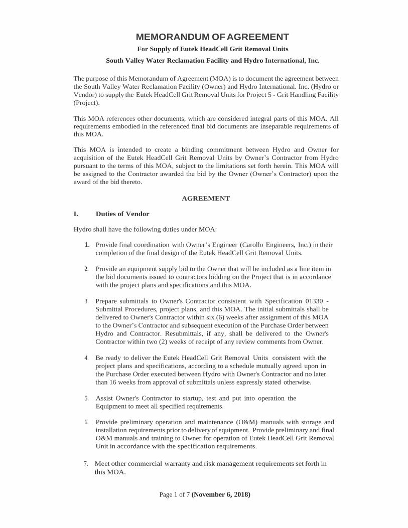
MEMORANDUM OF AGREEMENT
For Supply of Eutek HeadCell Grit Removal Units
South Valley Water Reclamation Facility and Hydro International, Inc.
Page 1 of 7 (November 6, 2018)
The purpose of this Memorandum of Agreement (MOA) is to document the agreement between
the South Valley Water Reclamation Facility (Owner) and Hydro International. Inc. (Hydro or
Vendor) to supply the Eutek HeadCell Grit Removal Units for Project 5 - Grit Handling Facility
(Project).
This MOA references other documents, which are considered integral parts of this MOA. All
requirements embodied in the referenced final bid documents are inseparable requirements of
this MOA.
This MOA is intended to create a binding commitment between Hydro and Owner for
acquisition of the Eutek HeadCell Grit Removal Units by Owner’s Contractor from Hydro
pursuant to the terms of this MOA, subject to the limitations set forth herein. This MOA will
be assigned to the Contractor awarded the bid by the Owner (Owner’s Contractor) upon the
award of the bid thereto.
AGREEMENT
I. Duties of Vendor
Hydro shall have the following duties under MOA:
1. Provide final coordination with Owner’s Engineer (Carollo Engineers, Inc.) in their
completion of the final design of the Eutek HeadCell Grit Removal Units.
2. Provide an equipment supply bid to the Owner that will be included as a line item in
the bid documents issued to contractors bidding on the Project that is in accordance
with the project plans and specifications and this MOA.
3. Prepare submittals to Owner's Contractor consistent with Specification 01330 -
Submittal Procedures, project plans, and this MOA. The initial submittals shall be
delivered to Owner's Contractor within six (6) weeks after assignment of this MOA
to the Owner’s Contractor and subsequent execution of the Purchase Order between
Hydro and Contractor. Resubmittals, if any, shall be delivered to the Owner's
Contractor within two (2) weeks of receipt of any review comments from Owner.
4. Be ready to deliver the Eutek HeadCell Grit Removal Units consistent with the
project plans and specifications, according to a schedule mutually agreed upon in
the Purchase Order executed between Hydro with Owner's Contractor and no later
than 16 weeks from approval of submittals unless expressly stated otherwise.
5. Assist Owner's Contractor to startup, test and put into operation the
Equipment to meet all specified requirements.
6. Provide preliminary operation and maintenance (O&M) manuals with storage and
installation requirements prior to delivery of equipment. Provide preliminary and final
O&M manuals and training to Owner for operation of Eutek HeadCell Grit Removal
Unit in accordance with the specification requirements.
7. Meet other commercial warranty and risk management requirements set forth in
this MOA.
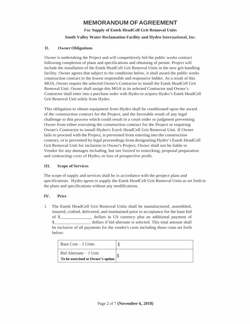
MEMORANDUM OF AGREEMENT
For Supply of Eutek HeadCell Grit Removal Units
South Valley Water Reclamation Facility and Hydro International, Inc.
Page 2 of 7 (November 6, 2018)
II. Owner Obligations
Owner is undertaking the Project and will competitively bid the public works contract
following completion of plans and specifications and obtaining of permit. Project will
include the installation of the Eutek HeadCell Grit Removal Units in the new grit handling
facility. Owner agrees that subject to the conditions below, it shall award the public works
construction contract to the lowest responsible and responsive bidder. As a result of this
MOA, Owner require the selected Owner's Contractor to install the Eutek HeadCell Grit
Removal Unit. Owner shall assign this MOA to its selected Contractor and Owner’s
Contractor shall enter into a purchase order with Hydro to acquire Hydro’s Eutek HeadCell
Grit Removal Unit solely from Hydro.
This obligation to obtain equipment from Hydro shall be conditioned upon the award
of the construction contract for the Project, and the favorable result of any legal
challenge to this process which could result in a court order or judgment preventing
Owner from either executing the construction contract for the Project or requiring
Owner's Contractor to install Hydro's Eutek HeadCell Grit Removal Unit. If Owner
fails to proceed with the Project, is prevented from entering into the construction
contract, or is prevented by legal proceedings from designating Hydro’s Eutek HeadCell
Grit Removal Unit for inclusion in Owner's Project, Owner shall not be liable to
Vendor for any damages including, but not limited to restocking, proposal preparation
and contracting costs of Hydro, or loss of prospective profit.
III. Scope of Services
The scope of supply and services shall be in accordance with the project plans and
specifications. Hydro agrees to supply the Eutek HeadCell Grit Removal Units as set forth in
the plans and specifications without any modifications.
IV. Price
l. The Eutek HeadCell Grit Removal Units shall be manufactured, assembled,
insured, crafted, delivered, and maintained prior to acceptance for the base bid
of $_______________ dollars in US currency plus an additional payment of
$_________________ dollars if bid alternate is selected. This total amount shall
be inclusive of all payments for the vendor's costs including those costs set forth
below:
Base Cost – 2 Units $
Bid Alternate – 1 Unit
To be exercised at Owner’s option $
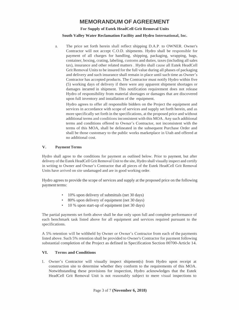
MEMORANDUM OF AGREEMENT
For Supply of Eutek HeadCell Grit Removal Units
South Valley Water Reclamation Facility and Hydro International, Inc.
Page 3 of 7 (November 6, 2018)
a. The price set forth herein shall reflect shipping D.A.P. to OWNER. Owner's
Contractor will not accept C.O.D. shipments. Hydro shall be responsible for
payment of all charges for handling, shipping, packaging, wrapping, bags,
container, boxing, crating, labeling, customs and duties, taxes (including all sales
tax), insurance and other related matters . Hydro shall cause all Eutek HeadCell
Grit Removal Units to be insured for the full value during all phases of packaging
and delivery and such insurance shall remain in place until such time as Owner’s
Contractor has accepted products. The Contractor must notify Hydro within five
(5) working days of delivery if there were any apparent shipment shortages or
damages incurred in shipment. This notification requirement does not release
Hydro of responsibility from material shortages or damages that are discovered
upon full inventory and installation of the equipment.
Hydro agrees to offer all responsible bidders on the Project the equipment and
services in accordance with scope of services and supply set forth herein, and as
more specifically set forth in the specifications, at the proposed price and without
additional terms and conditions inconsistent with this MOA. Any such additional
terms and conditions offered to Owner’s Contractor, not inconsistent with the
terms of this MOA, shall be delineated in the subsequent Purchase Order and
shall be those customary to the public works marketplace in Utah and offered at
no additional cost.
V. Payment Terms
Hydro shall agree to the conditions for payment as outlined below. Prior to payment, but after
delivery of the Eutek HeadCell Grit Removal Unit to the site, Hydro shall visually inspect and certify
in writing to Owner and Owner’s Contractor that all pieces of the Eutek HeadCell Grit Removal
Units have arrived on site undamaged and are in good working order.
Hydro agrees to provide the scope of services and supply at the proposed price on the following
payment terms:
• 10% upon delivery of submittals (net 30 days)
• 80% upon delivery of equipment (net 30 days)
• 10 % upon start-up of equipment (net 30 days)
The partial payments set forth above shall be due only upon full and complete performance of
each benchmark task listed above for all equipment and services required pursuant to the
specifications.
A 5% retention will be withheld by Owner or Owner’s Contractor from each of the payments
listed above. Such 5% retention shall be provided to Owner's Contractor for payment following
substantial completion of the Project as defined in Specification Section 00700-Article 14.
VI. Terms and Conditions
1. Owner’s Contractor will visually inspect shipment(s) from Hydro upon receipt at
construction site to determine whether they conform to the requirements of this MOA.
Notwithstanding these provisions for inspection, Hydro acknowledges that the Eutek
HeadCell Grit Removal Unit is not reasonably subject to mere visual inspections to
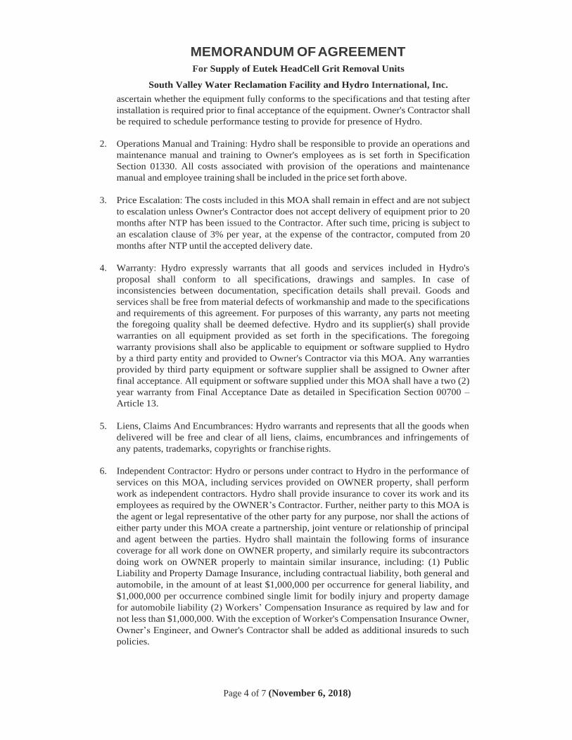
MEMORANDUM OF AGREEMENT
For Supply of Eutek HeadCell Grit Removal Units
South Valley Water Reclamation Facility and Hydro International, Inc.
Page 4 of 7 (November 6, 2018)
ascertain whether the equipment fully conforms to the specifications and that testing after
installation is required prior to final acceptance of the equipment. Owner's Contractor shall
be required to schedule performance testing to provide for presence of Hydro.
2. Operations Manual and Training: Hydro shall be responsible to provide an operations and
maintenance manual and training to Owner's employees as is set forth in Specification
Section 01330. All costs associated with provision of the operations and maintenance
manual and employee training shall be included in the price set forth above.
3. Price Escalation: The costs included in this MOA shall remain in effect and are not subject
to escalation unless Owner's Contractor does not accept delivery of equipment prior to 20
months after NTP has been issued to the Contractor. After such time, pricing is subject to
an escalation clause of 3% per year, at the expense of the contractor, computed from 20
months after NTP until the accepted delivery date.
4. Warranty: Hydro expressly warrants that all goods and services included in Hydro's
proposal shall conform to all specifications, drawings and samples. In case of
inconsistencies between documentation, specification details shall prevail. Goods and
services shall be free from material defects of workmanship and made to the specifications
and requirements of this agreement. For purposes of this warranty, any parts not meeting
the foregoing quality shall be deemed defective. Hydro and its supplier(s) shall provide
warranties on all equipment provided as set forth in the specifications. The foregoing
warranty provisions shall also be applicable to equipment or software supplied to Hydro
by a third party entity and provided to Owner's Contractor via this MOA. Any warranties
provided by third party equipment or software supplier shall be assigned to Owner after
final acceptance. All equipment or software supplied under this MOA shall have a two (2)
year warranty from Final Acceptance Date as detailed in Specification Section 00700 –
Article 13.
5. Liens, Claims And Encumbrances: Hydro warrants and represents that all the goods when
delivered will be free and clear of all liens, claims, encumbrances and infringements of
any patents, trademarks, copyrights or franchise rights.
6. Independent Contractor: Hydro or persons under contract to Hydro in the performance of
services on this MOA, including services provided on OWNER property, shall perform
work as independent contractors. Hydro shall provide insurance to cover its work and its
employees as required by the OWNER’s Contractor. Further, neither party to this MOA is
the agent or legal representative of the other party for any purpose, nor shall the actions of
either party under this MOA create a partnership, joint venture or relationship of principal
and agent between the parties. Hydro shall maintain the following forms of insurance
coverage for all work done on OWNER property, and similarly require its subcontractors
doing work on OWNER properly to maintain similar insurance, including: (1) Public
Liability and Property Damage Insurance, including contractual liability, both general and
automobile, in the amount of at least $1,000,000 per occurrence for general liability, and
$1,000,000 per occurrence combined single limit for bodily injury and property damage
for automobile liability (2) Workers’ Compensation Insurance as required by law and for
not less than $1,000,000. With the exception of Worker's Compensation Insurance Owner,
Owner’s Engineer, and Owner's Contractor shall be added as additional insureds to such
policies.
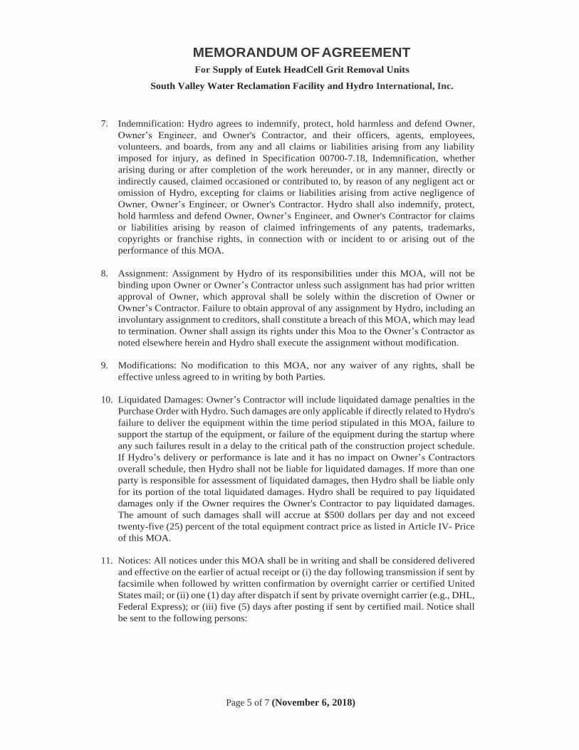
MEMORANDUM OF AGREEMENT
For Supply of Eutek HeadCell Grit Removal Units
South Valley Water Reclamation Facility and Hydro International, Inc.
Page 5 of 7 (November 6, 2018)
7. Indemnification: Hydro agrees to indemnify, protect, hold harmless and defend Owner,
Owner’s Engineer, and Owner's Contractor, and their officers, agents, employees,
volunteers. and boards, from any and all claims or liabilities arising from any liability
imposed for injury, as defined in Specification 00700-7.18, Indemnification, whether
arising during or after completion of the work hereunder, or in any manner, directly or
indirectly caused, claimed occasioned or contributed to, by reason of any negligent act or
omission of Hydro, excepting for claims or liabilities arising from active negligence of
Owner, Owner’s Engineer, or Owner's Contractor. Hydro shall also indemnify, protect,
hold harmless and defend Owner, Owner’s Engineer, and Owner's Contractor for claims
or liabilities arising by reason of claimed infringements of any patents, trademarks,
copyrights or franchise rights, in connection with or incident to or arising out of the
performance of this MOA.
8. Assignment: Assignment by Hydro of its responsibilities under this MOA, will not be
binding upon Owner or Owner’s Contractor unless such assignment has had prior written
approval of Owner, which approval shall be solely within the discretion of Owner or
Owner’s Contractor. Failure to obtain approval of any assignment by Hydro, including an
involuntary assignment to creditors, shall constitute a breach of this MOA, which may lead
to termination. Owner shall assign its rights under this Moa to the Owner’s Contractor as
noted elsewhere herein and Hydro shall execute the assignment without modification.
9. Modifications: No modification to this MOA, nor any waiver of any rights, shall be
effective unless agreed to in writing by both Parties.
10. Liquidated Damages: Owner’s Contractor will include liquidated damage penalties in the
Purchase Order with Hydro. Such damages are only applicable if directly related to Hydro's
failure to deliver the equipment within the time period stipulated in this MOA, failure to
support the startup of the equipment, or failure of the equipment during the startup where
any such failures result in a delay to the critical path of the construction project schedule.
If Hydro’s delivery or performance is late and it has no impact on Owner’s Contractors
overall schedule, then Hydro shall not be liable for liquidated damages. If more than one
party is responsible for assessment of liquidated damages, then Hydro shall be liable only
for its portion of the total liquidated damages. Hydro shall be required to pay liquidated
damages only if the Owner requires the Owner's Contractor to pay liquidated damages.
The amount of such damages shall will accrue at $500 dollars per day and not exceed
twenty-five (25) percent of the total equipment contract price as listed in Article IV- Price
of this MOA.
11. Notices: All notices under this MOA shall be in writing and shall be considered delivered
and effective on the earlier of actual receipt or (i) the day following transmission if sent by
facsimile when followed by written confirmation by overnight carrier or certified United
States mail; or (ii) one (1) day after dispatch if sent by private overnight carrier (e.g., DHL,
Federal Express); or (iii) five (5) days after posting if sent by certified mail. Notice shall
be sent to the following persons:
MEMORANDUM OF AGREEMENT
For Supply of Eutek HeadCell Grit Removal Units
South Valley Water Reclamation Facility and Hydro International, Inc.
Page 6 of 7 (November 6, 2018)
VENDOR
Contact Name: Dara Rolfe
Address: Hydro International
2925 NW Alocek Drive - Suite 140
Hillsboro, OR 97124
Phone: (866) 615-8130
E-mail: [email protected]
Contractor:
Contact Name: NAME
Address ADDRESS
Phone: PHONE
E-Mail: EMAIL
Owner:
Contact Name: Taigon Worthen, P.E.
Address South Valley Water Reclamation Facility
7495 South 1300 West
West Jordan, UT 84084
Phone: (801) 566-771
E-Mail: [email protected]
12. Severability: If any portion of this MOA is held invalid, the Parties agree that such
invalidity shall not affect the validity of the remaining portions of this MOA and the Parties
shall seek in good faith to agree to substitute for the invalid provision a valid provision
that most closely approximates its terms.
13. Entire Agreement: This MOA supersedes all proposals, oral or written, all negotiations,
conversations or discussions between the Parties and contains the entire understanding and
agreement of the Parties relating to this subject matter. In the event of a conflict between
the terms and conditions of this MOA and its attachments, this MOA shall control.
This Memorandum of Agreement is hereby entered into between the Owner and Hydro. By
signing this Memorandum of Agreement, the undersigned asserts that they have the authority
to enter into this MOA.
MEMORANDUM OF AGREEMENT
For Supply of Eutek HeadCell Grit Removal Units
South Valley Water Reclamation Facility and Hydro International, Inc.
Page 7 of 7 (November 6, 2018)
Owner Vendor
South Valley Water Reclamation Facility Hydro International, Inc.
_______________________________________ ________________________________________
Date Date
_______________________________________ _________________________________________
Name/Title Name/Title
Approved as to Form:
____________________________________
Attorney
End of MOA


March 2019 11324-1 10548A10 pw://Carollo/Documents/Client/UT/SVWRF/10548A10/Specifications/11324 (100%)
SECTION 11324
GRIT WASHER/DEWATERING UNITS
PART 1 GENERAL
1.01 SUMMARY
A. Section includes: Grit washer/dewatering units: 1. Grit Washer Unit No. 1 - GRW-21.310. 2. Grit Washer Unit No. 2 - GRW-21.320. 3. Grit Washer Unit No. 3 - GRW-21.330: Bid Alternate.
1.02 COST OF PRE-NEGOTIATED ITEMS
A. Cost for some of the items in this Section of the Specifications has been pre-negotiated with the specified manufacturer and is included in one of the bid items in the bidding sheet. Refer to the bidding sheet and applicable pre-negotiated proposal included in Appendix A of this section for more details. The Contractor shall provide additional items as indicated in the applicable pre-negotiated proposal included in Appendix A, even if they are not included in the Specifications and/or Drawings. The Contractor is very strongly cautioned to carefully review the applicable pre-negotiated proposal, because the pre-negotiated proposal does not include all the items included in the Specifications and Drawings. In addition to the cost indicated for the applicable bid item in the bidding sheet, the Contractor shall include in his bid the costs for the following: 1. All items not specifically mentioned in the scope of supply of the
pre-negotiated proposal, but required per Specifications and Drawings and required to complete the installation to provide an operational system.
2. All other items indicated in the pre-negotiated proposal to be provided by others, by customer, by Owner, or any other similar designation: a. All freight and applicable taxes, unless specifically included in
pre-negotiated proposal. b. All labor, materials, and all other associated costs not included in the
pre-negotiated proposal but required per Specifications and Drawings and required to complete the installation to provide an operational system.
c. The Contractor and Manufacturer shall ensure that the other obligations defined in the pre-negotiated proposal (Memorandum of Agreement/MOA) are complied with. These include, but are not limited to, delivery, inspections, start-up, training, testing, and payment.
B. Schedule: 1. The Contractor shall coordinate with the equipment supplier’s delivery
schedule to issue a purchase order at such time that equipment delivery will be completed at least 8 weeks in advance of the required late date, as indicated in the Contractor’s approved construction schedule.
C. Liquidated damages: 1. The manufacturer has agreed to the liquidated damages as described in the
Memorandum of Agreement.
March 2019 11324-2 10548A10 pw://Carollo/Documents/Client/UT/SVWRF/10548A10/Specifications/11324 (100%)
1.03 REFERENCES
A. American Welding Society (AWS).
B. ASTM International (ASTM).
C. National Electrical Manufacturers Association (NEMA): 1. 250 - Enclosures for Electrical Equipment (1000 V Maximum).
1.04 DEFINITIONS
A. Grit washer/dewatering unit: A complete grit washer/dewatering system that consists of a grit washing tank and screw conveyor.
1.05 SYSTEM DESCRIPTION
A. The Contractor shall be responsible for providing fully functioning grit washer/dewatering units, which include but are not limited to: 1. Process and utility water (UW) piping and valves connected to all components. 2. All electrical and control equipment and connections for a complete and
functional system.
B. Demonstrate ability to classify and dewater grit removed by grit separation system. Required characteristics are as follows: 1. Ability to classify (wash) grit from lighter organic material to meet specified
organic solids content. 2. Ability to handle continuous flow while meeting specified grit removal
efficiency. 3. Ability to capture and dewater grit from grit slurry removed by the grit removal
system specified in Section 11323 - Grit Removal System.
C. Grit washer/dewatering units shall receive grit slurry pumped by recessed impeller pumps specified in Sections 11312C - Horizontal Recessed Impeller Centrifugal Pumps.
D. Discharge dewatered solids to a bin through grit discharge chutes and grit discharge chute extensions as indicated on the Drawings.
1.06 DESIGN REQUIREMENTS
A. Equipment shall be suitable for installation in unclassified areas.
B. Parts of mechanism shall be amply proportioned for stresses that might occur during, fabrication, erection, or operation: 1. Duplicate parts shall be interchangeable.
C. Equipment geometry as indicated on the Drawings. Note that there are variations in the location of the following features, between the three units: 1. Connection flange for inlet piping. 2. Connection flanges for outlet piping and organic discharges. 3. Connection flanges for foul air piping. 4. Inspection cover.
March 2019 11324-3 10548A10 pw://Carollo/Documents/Client/UT/SVWRF/10548A10/Specifications/11324 (100%)
D. Equipment shall be made up of parts that are designed to act as a unit. When component parts are assembled into final unit, parts shall fit and operate satisfactorily.
E. Inspection cover: Sufficiently sized for removal of internal elements from inside each unit and to allow personnel entry into washing tank as part of a confined space entry. On the inspection cover add an 18 inch by 18 inch viewing hatch as shown on the drawings.
F. Self-standing on legs that are designed and furnished by equipment manufacturer: 1. Seismic design criteria: As specified in Section 01612 - Seismic Design
Criteria.
G. Wash water feed connection: Not to exceed one 1-inch connection for each grit washer/dewatering unit.
1.07 PERFORMANCE REQUIREMENTS
A. General: Compatible for permanent installation and long-term operation with the upstream grit handling equipment specified in Sections 11312C - Horizontal Recessed Impeller Centrifugal Pumps and 11323 - Grit Removal System and in accordance with design intent.
B. Hydraulic: Capable of operation at a continuous flow rate of up to 300 gallons per minute per unit.
C. Capture: 1. Remove minimum 93 percent of 105 micron and larger seed sand in size at a
flow rate of 300 gallons per minute. 2. Remove minimum 95 percent of 105 micron and larger seed sand in size at a
flow rate of 250 gallons per minute.
D. Dewatering: 1. Product shall contain no more than 5 percent organic material by weight for
continuous flow rates of 250 gallons per minute and 300 gallons per minute. 2. Product shall contain no more than 15 percent water content for continuous
flow rates of 250 gallons per minute and 300 gallons per minute.
E. Grit processing capacity of 1.5 tons per hour per unit.
1.08 SUBMITTALS
A. Submit product data and other items specified herein in accordance with Section 01330 - Submittal Procedures.
B. Shop drawings: Include the following: 1. Certified shop and erection drawings showing construction dimensions, anchor
bold locations, and field connections. 2. Erection, installation, and adjusting instructions. 3. Detailed field testing procedures. 4. Wiring and schematic diagrams. 5. Scaled, detailed exterior control panel (front and side views) and interior panel
layout showing equipment arrangement and dimensional information.
March 2019 11324-4 10548A10 pw://Carollo/Documents/Client/UT/SVWRF/10548A10/Specifications/11324 (100%)
6. Design and fabrication details for grit discharge chute extensions.
C. Manufacturer’s performance guarantee.
D. Manufacturer’s installation instructions.
E. Design data: 1. Include seismic calculations and details prepared by a Professional Engineer
registered in the state where the Project is located.
F. Test reports.
G. Certificates.
H. Manufacturer’s field reports
I. Operation and maintenance manual as specified in Section 01782 - Operation and Maintenance Data.
J. Warranties.
1.09 QUALITY ASSURANCE
A. Single source responsibility: All equipment, instruments, and other products specified in this Section shall be furnished by one supplier.
B. Manufacturer's qualifications: 1. Minimum 10 years' experience in production of equipment substantially similar
to the specified equipment. 2. Have successful installations using the COANDA tulip principle at 10 or more
separate facilities with minimum 5 installations in successful operation for minimum 2 years in municipal wastewater treatment and 3 installations with minimum capacity of 200 gallons per minute continuous flow.
C. Fulfillment of the specified experience requirements shall be a condition of acceptance.
D. Manufacturer's shop welds, welding procedures, and welders: Qualified and certified in accordance with the requirements of ANSI/AWS D1.1.
1.10 DELIVERY, STORAGE, AND HANDLING
A. As specified in Section 15050 - Common Work Results for Mechanical Equipment.
1.11 WARRANTY
A. Provide warranty to correct defects in material, workmanship, or design for minimum of 2 years from the date specified in Section 01783 - Warranties and Bonds.
March 2019 11324-5 10548A10 pw://Carollo/Documents/Client/UT/SVWRF/10548A10/Specifications/11324 (100%)
1.12 EXTRA MATERIALS
A. Spare Parts: 1. One perforated diaphragm (membrane). 2. One pressure probe. 3. One complete set of bearings for one unit. 4. One set of all special tools, if required.
PART 2 PRODUCTS
2.01 MANUFACTURERS
A. Grit washing/dewatering units: 1. Manufacturers: The following and no equal:
a. COANDA Fine Grit Washer Unit, Model RoSF4, by Huber Technology.
2.02 MATERIALS
A. Unless otherwise specified, construct all components from Type 316L stainless steel shapes (rods, angles, and channels), pipes, and sheets. Design all parts to handle the forces that may be exerted on them during fabrication, shipping, erection, and proper operation according to the O&M manual.
B. Manufacture the entire equipment in a stainless steel only factory to prevent contamination of the stainless steel with foreign contaminants.
C. The equipment, after fabrication, shall undergo a passivation (pickling) process to ensure maximum resistance to corrosion. Submerge all stainless steel components and structures in a chemical bath of nitric acid and hydrofluoric acid to remove any residues that may be present on the material as a result of forming, manufacture, or handling. After removal from the pickling bath, wash the equipment with a high-pressure wash of cold water to remove any remaining surface debris and promote the formation of an oxidized passive layer that is critical to the long life of the stainless steel: 1. Submergence insures complete coverage. Spray on chemical treatments and
glass bead blasting are specifically not acceptable due to their inability to provide complete and uniform corrosion protection.
2. Stainless steel assemblies that have not been submerged in an acid bath or that do not have a uniform oxidized surface, free from rust spots, stains or blemishes will not accepted until removed from the Project site and re-submerged
2.03 GRIT WASHING/DEWATERING UNITS
A. Grit washing tank: 1. Grit slurry from a grit basin shall be pumped through a 6-inch inlet into the
vortex chamber, creating a rotating flow pattern, and through the COANDA tulip into the grit washer tank. The grit slurry mixture shall be fed directly to the equipment without the need for additional screening. As such, designs requiring a screen to meet the performance requirements shall not be allowed.
2. The water flow shall be directed by the equipment from an axial flow to a radial flow towards the overflow weir that is provided at the circumference of the grit
March 2019 11324-6 10548A10 pw://Carollo/Documents/Client/UT/SVWRF/10548A10/Specifications/11324 (100%)
washer tank. This change of the flow direction leads to effective sedimentation of the grit towards the bottom of the grit washer tank.
3. The classified water shall pass over the overflow weir and discharge out of a single 8-inch clean water outlet.
4. Effective stratification of particles, depending on their specific density, but not depending on their particle size and weight, shall be achieved within the conical portion of the grit washer tank.
5. Provide a 4-inch connection with a one quarter-turn ball valve equipped with a motorized actuator for removal of organic material out of the conical section of the tank. The stirrer shall move organic matter toward this connection: a. Ball valve:
1) Body and ball: Constructed of PVC to prevent binding when in contact with abrasive materials. Metallic ball valves that can bind in highly abrasive applications shall not be acceptable.
2) Directly flange to the conical tank without any adapter or connection pieces to avoid clogging.
b. Motorized Actuator: 1) Manufacturer: AUMA. 2) Power feed: 110VAC, single phase.
6. Provide devices to prevent elastic objects from catching and accumulating on the ends of the stirrer arms: a. Weld round stock stainless steel that has been made into arcs to the ends
of the stirrer arms or other similar devices that do not interfere with the operation of the equipment while preventing collection of elastic materials on the stirrer arms.
7. Provide a 6-inch flange connection on top of the tank for foul air withdrawal. 8. Level Monitoring:
a. Mount a single-phase pressure probe in the bottom of the grit settling area to monitor the grit level within the tank.
b. Use the signal to control the operation of the grit stirrer and grit removal screw.
c. 1.5-inch connection for installation of pressure probe.
B. Fluidized bed: 1. A fluidized grit bed shall be maintained in the bottom portion of the grit washer
tank. Within this fluidized bed, the grit is intensively washed and organic material is effectively removed from mineral particles.
2. Design for a water supply of 22 gallons per minute with a minimum pressure of 30 pounds per square inch with a single 1-inch connection point for connecting to a utility water source.
3. Introduce wash water into the bottom of the grit washer and disperse through a perforated diaphragm to generate the fluidized bed in the bottom portion of the grit washer. This wash water shall also effectively flush the organic components out of the fluidized bed towards the overflow weir.
4. Wash water components: a. Variable area flow meter with a transparent PVC casing to allow visual
inspection of the internal float for manual flow rate confirmation. b. 1-inch 110V, 60Hz solenoid valve.
C. Grit screw: 1. Remove washed grit through a central tube at the bottom of the grit washer.
The stirrer shall move washed grit to the central tube. The grit to be removed
March 2019 11324-7 10548A10 pw://Carollo/Documents/Client/UT/SVWRF/10548A10/Specifications/11324 (100%)
shall drop into an inclined auger. This auger shall dewater and convey the grit above the level of the overflow weir. The washed and dewatered grit is discharged at the upper end of the auger.
2. Inlet hopper: a. Flange-connected to the grit discharge tube. b. Provide a 3-inch diameter (DN 80) drain connection with a ball valve. c. Provide a 3/4-inch flush connection with ball valve (provided by the
manufacturer) on the 3-inch drain connection. 3. Auger discharge height: 117 inches above the floor. 4. Screw conveyor trough: made of minimum 10/64-inch (4-mm) thick stainless
steel. 5. Screw:
a. Shafted and made of stainless steel. A shaftless screw is not acceptable. b. Inclination angle: 45 degrees from horizontal. c. Support the lower end of the screw shaft with a chilled cast-iron stub
bearing with a maintenance-free ceramic sleeve. Wear strips are not acceptable.
6. Screw Motor: a. Located at the upper end of the auger. b. Continuous duty rated and sized to match the duty of the particular grit
conveying screw. c. Direct coupled to the grit conveying screw drive shaft.
D. Motors: 1. Grit Screw:
a. Maximum Motor Speed: 1,800 rpm. b. Service Factor: 1.15. c. Torque: Must be sufficient to start and operate grit washer without
exceeding nameplate ratings for current and power. d. Rating: 230/460V, 3-phase, 60 Hz. e. Location Rating: Unclassified. f. Nominal power screw drive motor: 1.5 hp. g. Enclosure: Totally enclosed, fan cooled.
2. Grit Stirrer: a. Maximum Motor Speed: 1800 rpm. b. Service Factor: 1.15. c. Torque: Must be sufficient to start and operate grit washer without
exceeding nameplate ratings for current and power. d. Rating: 230/460V, 3-phase, 60 Hz. e. Location Rating: Unclassified. f. Nominal power stirrer motor: 0.75 hp. g. Assembly bolts for stirrer motor: Type 304 stainless steel. h. Enclosure: Totally enclosed, fan cooled.
E. Anchor bolts: Comply with Section 05190 - Mechanical Anchoring and Fastening to Concrete and Masonry.
F. Brackets for Guardrail: 1. Provide welded 316 stainless steel side mounted brackets for Contractor-
provided guardrail on the top side of each COANDA unit (see drawings for extent). The bracket locations must be coordinated with Contractor and be placed to avoid any gaps that would provide potential for falling.
March 2019 11324-8 10548A10 pw://Carollo/Documents/Client/UT/SVWRF/10548A10/Specifications/11324 (100%)
2.04 CONTROL SYSTEM
A. Provide a complete fully functional control system for operation of the grit washer.
B. Vendor control panels: One per unit. 1. General:
a. Provide separate control panels for each grit washer that provides fully independent control.
b. Control panel shall consist of, but not be limited to, the following to provide a complete and operable system: 1) Preprogrammed Programmable Logic Controller (PLC) to control
operation of the grit washer that receives commands from the plant control system: a) PLC shall be manufactured by General Electric and conform to
specifications in Section 17720 - Control Systems: Programmable Logic Controllers.
2) Motor starter for grit screw motor. 3) Motor starter for grit stirrer motor.
c. Control panel shall carry a UL label certifying the assembled industrial control panel complies with UL 508.
d. Control panel shall be completely prewired, preprogrammed, and factory tested for proper operation prior to shipment. Refer to Section 17950 - Testing, Calibration, and Commissioning for additional testing requirements.
e. Communicate with the plant control system over Ethernet via Modbus TCP protocol.
f. Provide separate alarm and emergency shutdown functions. g. Provide local operator interface (LOI) unit for adjustment of setpoints,
timers, and alarms. 2. Panel enclosure and components:
a. VCP enclosure type: 1) Wall-mount. If floor mounting is required, Contractor shall modify the
support framing and grating for the mezzanine to adequately support the VCPs from the mezzanine at no additional cost to the City.
2) NEMA 4X rated with continuous hinge and lockable door latch as specified in Section 17710 - Control Systems: Panels, Enclosures, and Panel Components: a) Type 316 stainless steel.
3) The VCP enclosure shall be adequately sized and designed to dissipate the heat generated inside the enclosure. Provide heating/cooling as specified in Section 17710 - Control Systems: Panels, Enclosures, and Panel Components as needed.
4) Each VCP enclosure shall not exceed the following dimensions: 84 inches high by 60 inches wide by 36 inches deep.
5) Panel wiring as described in Section 16075. b. Components including enclosures shall conform with requirements of
Section 17710 - Control Systems: Panels, Enclosures, and Panel Components: 1) Design controls such that the equipment cannot operate unless
controls are energized. 2) Instruments mounted on the face of the panel and components
located within the panel shall meet the requirements specified in
March 2019 11324-9 10548A10 pw://Carollo/Documents/Client/UT/SVWRF/10548A10/Specifications/11324 (100%)
Section 17710 - Control Systems: Panels, Enclosures, and Panel Components.
3) Controls and instruments shall fail into a safe condition. 4) Provide necessary interlocks and time delays (operator adjustable)
for system control. 5) Indicators and Alarms in accordance with Sections 17710 - Control
Systems: Panels, Enclosures, and Panel Components. c. Power systems:
1) Power supply to panel: 480-volt, 60-Hz, 3-phase. 2) Control power transformer with 120 VAC surge protection device
(SPD) and fused primary and secondary. 3) Provide main circuit breaker flange-mounted power disconnect
interlocked to the enclosure door: a) VCP shall be labeled and rated to withstand the available fault
current as to be determined in the study per Section 16305 - Electrical System Studies.
b) In accordance with Section 16412 - Low Voltage Molded Case Circuit Breakers.
4) 600 VAC terminal block. 5) Provide surge protection device.
d. NEMA motor starter and Circuit Breaker Branch Circuit Protection for grit screw motor.
e. NEMA motor starter and Circuit Breaker Branch Circuit Protection for grit stirrer motor.
f. Local Operator Interface (LOI): 1) NEMA 4X rated. 2) 10-inch configurable color LCD touchscreen with a minimum
resolution of 640 by 480 pixels. 3) Minimum 32 MB Flash EPROM Memory. 4) Ethernet communication via Modbus TCP.
g. Programmable logic controller for automatic control of devices in accordance with Section 17720 - Control Systems: Programmable Logic Controllers: 1) The PLC programming software system shall be manufactured by
PLC hardware manufacturer: 2) Control Function includes, but is not limited to, the following logic:
a) Each grit tank is equipped with two dedicated grit pumps (1 duty, 1 standby). The grit washer starts when one of its associated grit pumps is running. Grit pumps continuously feed grit slurry to the grit washers.
b) Normal Duty mode: The equipment normally operates in Normal Duty mode. This mode represents that all grit washer devices are in AUTO mode and have not been faulted. If grit pump running signal is maintained for the setpoint proving time, the following steps (1) through (4) will begin simultaneously: Open the grit washer water valve and continuously cycle per on and off timers. (1) Activate the pressure sensor to measure grit level. It will
remain activated when the grit washer water valve is open. (2) Start the stirrer on delay timer. When it expires, start the
stirrer and cycle on/off per timers.
March 2019 11324-10 10548A10 pw://Carollo/Documents/Client/UT/SVWRF/10548A10/Specifications/11324 (100%)
(3) Close the grit washer organics valve, if not already closed, and continuously cycle closed and opened per valve closed timer and valve open timer:
(4) The grit washer organics valve will never be open while the grit screw is operating. If the grit screw is called to run when the organics valve is open, the organics valve will close immediately.
c) Grit Screw operation: (1) When grit level rises and stays above Grit Level B setpoint
for a setpoint proving time, grit screw cycles on and off based on timers.
(2) When grit level rises and stays above Grit Level C setpoint for a setpoint proving time, grit screw cycles on and off based on timers.
(3) When grit level rises and stays above Grit Level D setpoint for a setpoint proving time, grit screw runs continuously.
(4) When grit level drops below Grit Level D setpoint for a setpoint proving time, grit screw cycles on and off based on timers.
(5) When grit level drops below Grit Level C setpoint for a setpoint proving time, grit screw cycles on and off based on timers.
(6) When grit level drops below Grit Level A setpoint, grit screw stops running.
d) Automatic Shutdown mode: (1) When all grit pump running signals to a grit washer have
stopped, begin Automatic Shutdown mode: (a) If a grit pump running signal is restored during the
Automatic Shutdown sequence, stop Automatic Shutdown sequence and switch grit washer to Normal Duty mode operation.
(2) Automatic Shutdown mode follows this sequence: (a) Start pressure sensor off delay timer. When the timer
has reached its setpoint, deactivate pressure sensor: (b) Grit screw will continue to operate per Normal Duty
mode while the pressure sensor is activated. (c) If the grit screw is in the middle of a cycle at the time
when the pressure sensor off delay timer expires, the pressure sensor will remain active until the current grit screw cycle is complete.
(d) When the pressure sensor has deactivated: (e) The grit screw will no longer operate. (f) Open the grit washer organics valve for the duration of
valve open timer. When the timer has expired, close the valve.
(g) After the grit washer organics valve closes, start the stirrer off delay timer. When the timer expires, stop the stirrer and close the grit washer water valve.
March 2019 11324-11 10548A10 pw://Carollo/Documents/Client/UT/SVWRF/10548A10/Specifications/11324 (100%)
e) Equipment Faulted mode: (1) If any of the following faults occur, switch grit washer
operation to Equipment Faulted mode, and send Equipment Faulted signal to SCADA: (a) If stirrer high current is measured, stop the stirrer,
activate stirrer fault alarm, and illuminate stirrer overload indication light.
(b) If the grit washer organics valve is called to close and does not reach the closed position within the time set in the grit washer organics valve fail-to-close timer, activate organics valve fault alarm and illuminate grit washer organics valve fault indication light.
(2) Equipment Faulted mode follows this sequence: (a) The grit washer will operate in this mode only until the
Equipment Faulted mode duration timer has expired: (b) Operate per Normal Duty mode, overriding the stirrer
and/or grit washer organics valve faults: (c) If the SYSTEM RESET pushbutton is pressed, the grit
washer returns to the Normal Duty mode. (d) If the SYSTEM RESET pushbutton is pressed and the
fault condition recurs, the grit washer returns to the Equipment Faulted mode.
(e) When Equipment Faulted mode duration timer has reached its setpoint:
(f) Activate grit washer fail alarm. (g) Begin Automatic Shutdown cycle of the grit washer. (h) Open the associated grit tank drain valves. (i) Send a signal to SCADA to stop the associated grit
pumps. f) Immediate Shutdown:
(1) If any of the following occurs, shut down grit washer equipment immediately: (a) If grit screw motor high current is detected, activate grit
screw fault alarm and illuminate grit screw overload indication light.
(b) If EMERGENCY STOP pushbutton is pressed. (2) Immediate shutdown procedure:
(a) Stop the stirrer and grit screw immediately. (b) Activate grit washer fail alarm. (c) Close the grit washer organics valve. (d) Open the associated grit tank drain valves. (e) Send a signal to DCS to stop the associated grit
pumps. g) Pressing the SYSTEM RESET pushbutton on the VCP resets
any of the fault conditions. h. Wiring:
1) Factory assemble and wire the control panel such that field wiring shall consist only of connections to terminals.
i. Remote output for the following: 1) Grit Washer E-stop (in VCP2).
March 2019 11324-12 10548A10 pw://Carollo/Documents/Client/UT/SVWRF/10548A10/Specifications/11324 (100%)
j. Pilot devices: 1) Pilot lights for: Refer to Section 17710 - Control Systems: Panels,
Enclosures, and Panel Components pilot light colors. a) Control power on. b) Grit Screw running. c) Grit Screw not running. d) Grit Stirrer running. e) Grit Stirrer not running. f) Organic Valve open. g) Organic Valve closed. h) Grit Screw fault. i) Grit Stirrer fault. j) Organic valve fault. k) Bin change mode indication.
2) Control devices: a) Mixer:
(1) HAND-OFF-AUTO (HOA) selector switch. b) Grit screw:
(1) HAND-OFF-AUTO (HOA) selector switch. (2) FOR-OFF-REV selector switch.
c) Organics valve: (1) OPEN-CLOSE-AUTO selector switch.
d) Wash water valve: (1) HOA selector switch.
e) E-stop pushbutton. f) System reset pushbutton.
3) Door mounted elapsed time meters for the following: a) Screw drive. b) Stirrer drive.
4) Flashing alarm light and alarm horn with silencer-reset button: a) Plastic Nameplates.
k. Panel instruments as shown on the Drawings, as specified in Section 17710 - Control Systems: Panels, Enclosures, and Panel Components, and as recommended by the equipment manufacturer to provide a complete operational system.
3. Indicators, alarms, and controls accessible through VCP Operator Interface Unit: a. Elapsed time meter. b. Alarm indication providing description of specific faults.
4. Provide Uninterruptible Power Supply as specified in Section 17712 - Control Systems: Uninterruptible Power Supplies 10 kVA and Below.
5. Provide managed process floor Ethernet switch as specified in Section 17733 - Control Systems: Network Materials and Equipment.
6. Vendor equipment programming meetings: Attend a meeting with the Programmer to coordinate with the owners control system. The meeting discussion point will include the following at a minimum: a. Tag Naming Conventions. b. PLC to PLC global data mapping. c. All PLCs to HMI tags mapping. d. LOI screen colors and navigation. e. Interlock and Permissive definitions. f. Communication Methods.
March 2019 11324-13 10548A10 pw://Carollo/Documents/Client/UT/SVWRF/10548A10/Specifications/11324 (100%)
g. Standard code blocks for common control functionality. h. Alarms - clearing, formats, colors, and status.
C. Grit washer local control stations (VCP2): 1. Control devices:
a. EMERGENCY STOP maintained mushroom head pushbutton.
2.05 PROTECTIVE COATINGS
A. Passivate all stainless steel components in the factory as described in this Section.
B. Do not paint stainless steel components.
C. Surface preparation, factory prime, field prime, and finish coat of non stainless steel components as specified in Section 09960 - High-Performance Coatings.
PART 3 EXECUTION
3.01 EXAMINATION
A. Coordinate and verify actual dimensions required to construct discharge chute extensions. Verify all dimensions and elevations.
3.02 INSTALLATION
A. Install equipment in strict accordance with the contract documents and requirements of the Manufacturer’s written instructions and shop drawings.
B. Contractor shall verify all necessary dimensions as required for successful installation and to facilitate operation and maintenance.
3.03 FIELD QUALITY CONTROL
A. Testing, Training, and Startup: As specified in Section 01756 - Commissioning
B. Testing and startup: 1. The Owner shall bear the costs associated with the performance testing and
conduct tests in presence of the Engineer, except in the event that the equipment does not meet the performance testing requirements, the manufacturer shall make necessary changes at no additional cost to the Owner. The tests shall be conducted by an independent testing laboratory or firm approved by the Engineer, their services paid for by the Owner. The following is a written test procedure for the Performance Test:
1) Perform and complete field performance testing of grit pumps prior to commencing grit washer performance testing. Calibrate flowmeters on the discharge of grit pumps prior to commencing grit washer performance testing.
2) Perform two separate grit tests, one at a grit withdrawal rate of 250 gallons per minute and another at 300 gallons per minute: a) Engineer will select one grit washer for the testing. Contractor
shall isolate the associated grit basin for the testing and fill it to its normal operating level with utility water.
March 2019 11324-14 10548A10 pw://Carollo/Documents/Client/UT/SVWRF/10548A10/Specifications/11324 (100%)
b) Add minimum 50 gallons of seed sand (Granusil Mineral Fillers, Gradation 5010) directly into the grit basin. Simultaneously, start the associated grit pump and pump settled material continuously to the grit washer. At the same time, open (or partially open) the associated fluidizing valve for the duration of the test, in order to keep sufficient water volume in the grit basin while avoiding overflowing. Throughout the test duration, monitor the level in the grit basin and record the pump flow rate at a minimum 10-minute interval. Maintain the level at or higher than 10 feet throughout the testing to protect the pump.
c) Starting at a 1-hour mark, add minimum 10 gallons of seed sand every hour. Continue the addition of seed sand until the grit level in the associated grit washer reaches steady state and the grit washer is able to maintain that grit level/weight through its normal automatic operation.
d) This will mark the beginning of the actual performance testing. Record start time and grit level in the grit washer, and place an empty grit bin at this time. Continue with the addition of seed sand (10 gallons per hour) for 5 additional hours, such that 50 gallons of seed sand has been cumulatively added. Continue running the pump and the grit washer until the grit level in the associated grit washer reaches the grit level at the beginning of the actual performance testing, which will mark the conclusion of the performance testing. At this time, measure the volume of sand in the grit bin and send samples to the testing laboratory for water content. Comparing the volume of sand in the bin to the 50 gallons added during the actual performance testing provides the capture rate. Perform analyses by a third party laboratory to determine capture rate at different sizes of seed sand.
3) After the grit basins and grit washers have been placed in normal operation (and after the test sand in the grit washer has been displaced by the plant grit), grit samples shall be collected in a 2-week period for organic content and moisture tests. Contractor shall take 3 random 2-cup samples taken any 3 days within a consecutive 2-week period for a total of 9 samples. Samples shall be collected immediately upon discharge from the tested grit washer, sealed in a vapor-tight container, and sent to the testing laboratory the same day. a) Sample collection shall take place on two completely separate
occasions, one at a grit withdrawal rate of 250 gallons per minute and another at 300 gallons per minute.
b. If the second test does not successfully demonstrate compliance with the specified performance requirements, the independent testing laboratory or firm shall take additional, concrete steps to rectify the situation until the specified performance is achieved.
2. Upon completion of installation and successful performance testing, the independent testing laboratory or firm shall provide certificate of installation and functional compliance.
C. Require manufacturer’s representative to perform the following services as described below and as specified in Section 01756 - Commissioning and Process
March 2019 11324-15 10548A10 pw://Carollo/Documents/Client/UT/SVWRF/10548A10/Specifications/11324 (100%)
Start-Up. The specified durations are the minimum required time on the job site. Additional services and/or longer durations shall be provided as needed at no cost to the Owner to meet the required quality of work. Work to be done in a minimum of 3 trips: 1. Installation assistance: 1 trip; 2 workday:
a. Advise/observe the Contractor on the installation of the equipment. b. Provide additional assistance as required.
2. Start-up assistance: 1 trip; 1 workday: a. Prior to start-up, the equipment shall be inspected for proper alignment,
operation, and satisfactory performance. b. Provide additional start-up/testing assistance as required.
3. Training: As defined in Section 01756 - Commissioning and this Section: a. Maintenance: 4 hours per session, 1 session. b. Operation: 2 hours per session, 1 session.
4. Process operational period: a. As required by Owner or Contractor.
D. Refer to Specification 17950 - Testing, Calibration, and Commissioning for additional requirements.
END OF SECTION

Section 11324 - Grit Washer/Dewatering Units
APPENDIX A - MEMORANDUM OF AGREEMENT FOR GRIT WASHER/DEWATERING UNITS

MEMORANDUM OF AGREEMENT
For Supply of Huber Coanda Fine Grit Washers
South Valley Water Reclamation Facility and Huber Technology, Inc.
Page 1 of 7 (February 21, 2018)
The purpose of this Memorandum of Agreement (MOA) is to document the agreement between
the South Valley Water Reclamation Facility (Owner) and Huber Technology, Inc. (Huber or
Vendor) to supply the Coanda Fine Grit Washers for Project 5 - Grit Handling Facility (Project).
This MOA references other documents, which are considered integral parts of this MOA. All
requirements embodied in the referenced final bid documents are inseparable requirements of
this MOA.
This MOA is intended to create a binding commitment between Huber and Owner for
acquisition of the Coanda Fine Grit Washers by Owner’s Contractor from Huber pursuant to
the terms of this MOA, subject to the limitations set forth herein. This MOA will be assigned
to the contractor awarded the bid by the Owner (Owner's Contractor) upon the award of the bid
thereto.
AGREEMENT
I. Duties of Vendor
Huber shall have the following duties under this MOA:
1. Provide final coordination with Owner’s Engineer (Carollo Engineers, Inc.) in their
completion of the final design of the Coanda Fine Grit Washers.
2. Provide an equipment supply bid to the Owner that will be included as a line item in
the bid documents issued to general contractors bidding on the Project that is in
accordance with the project plans and specifications and this MOA.
3. Prepare submittals to Owner's Contractor consistent with Specification 01330 -
Submittal Procedures, project plans, and this MOA. The initial submittals shall be
delivered to Owner's Contractor within six (6) weeks after assignment of this MOA
to the Owner's Contractor and subsequent execution of the Purchase Order between
Huber and Contractor. Resubmittals, if any, shall be delivered to the Owner's
Contractor within two (2) weeks of receipt of any review comments from Owner.
4. Be ready to deliver the Coanda Fine Grit Washers consistent with the project plans
and specifications, according to a schedule mutually agreed upon in the Purchase
Order executed between Huber with Owner's Contractor and no later than 30 weeks
from approval of submittals unless expressly stated otherwise.
5. Assist Owner's Contractor to startup, test and put into operation the
Equipment to meet all specified requirements.
6. Provide preliminary operation and maintenance (O&M) manuals with storage and
installation requirements prior to delivery of equipment. Provide preliminary and final
O&M manuals and training to Owner for operation of Coanda Fine Grit Washers in
accordance with the specification requirements.
7. Meet other commercial warranty and risk management requirements set forth in
this MOA.
MEMORANDUM OF AGREEMENT
For Supply of Huber Coanda Fine Grit Washers
South Valley Water Reclamation Facility and Huber Technology, Inc.
Page 2 of 7 (February 21, 2018)
II. Owner Obligations
Owner is undertaking the Project and will competitively bid the public works contract
following completion of plans and specifications and obtaining of permit. Project will
include the installation of the Coanda Fine Grit Washers in the new grit handling facility.
Owner agrees that subject to the conditions below, it shall award the public works
construction contract to the lowest responsible and responsive bidder. As a result of this
MOA, Owner shall require the selected Owner's Contractor to install the Coanda Fine Grit
Washers. Owner shall assign this MOA to its selected Contractor and Owner's Contractor
shall enter into a purchase order with Huber to acquire Huber’s Coanda Fine Grit Washers
solely from Huber.
This obligation to obtain equipment from Huber shall be conditioned upon the award
of the construction contract for the Project, and the favorable result of any legal
challenge to this process which could result in a court order or judgment preventing
Owner from either executing the construction contract for the Project or requiring
Owner's Contractor to install Huber's Coanda Fine Grit Washers. If Owner fails to
proceed with the Project, is prevented from entering into the construction contract, or is
prevented by legal proceedings from designating Huber’s Coanda Fine Grit Washers for
inclusion in Owner's Project, Owner shall not be liable to Vendor for any damages
including, but not limited to restocking, proposal preparation and contracting costs of
Huber, or loss of prospective profit.
III. Scope of Services
The scope of supply and services shall be in accordance with the project plans and
specifications. Huber agrees to supply the Coanda Fine Grit Washers as set forth in the plans
and specifications without any modifications.
IV. Price
l. The Coanda Fine Grit Washers shall be manufactured, assembled, insured,
crafted, delivered, and maintained prior to acceptance for the base bid of
$___________ dollars in US currency plus an additional payment of $_________
dollars if bid alternate is selected. This total amount shall be inclusive of all
payments for the vendor's costs including those costs set forth below:
Base Cost – 2 Units $
Bid Alternate – 1 Unit
To be exercised at Owner’s option $

MEMORANDUM OF AGREEMENT
For Supply of Huber Coanda Fine Grit Washers
South Valley Water Reclamation Facility and Huber Technology, Inc.
Page 3 of 7 (February 21, 2018)
a. The price set forth herein shall reflect shipping D.A.P. to OWNER. Owner's
Contractor will not accept C.O.D. shipments. Huber shall be responsible for
payment of all charges for handling, shipping, packaging, wrapping, bags,
container, boxing, crating, labeling, customs and duties, taxes (including all sales
tax), insurance and other related matters. Huber shall cause all Coanda Fine Grit
Washers to be insured for the full value during all phases of packaging and
delivery and such insurance shall remain in place until such time as Owner’s
Contractor has accepted products. The Contractor must notify Huber within five
(5) working days of delivery if there were any apparent shipment shortages or
damages incurred in shipment. This notification requirement does not release
Huber of responsibility from material shortages or damages that are discovered
upon full inventory and installation of the equipment.
Huber agrees to offer all responsible bidders on the Project the equipment and
services in accordance with scope of services and supply set forth herein, and as
more specifically set forth in the specifications, at the proposed price and without
additional terms and conditions inconsistent with this MOA. Any such additional
terms and conditions offered to Owner's Contractor, not inconsistent with the
terms of this MOA, shall be delineated in the subsequent Purchase Order and
shall be those customary to the public works marketplace in Utah and offered at
no additional cost.
V. Payment Terms
Huber shall agree to the conditions for payment as outlined below. Prior to payment, but after
delivery of the Coanda Fine Grit Washers to the site, Huber shall visually inspect and certify in
writing to Owner and Owner's Contractor that all pieces of the Coanda Fine Grit Washers have
arrived on site undamaged and are in good working order.
Huber agrees to provide the scope of services and supply at the proposed price on the following
payment terms:
• 10% upon delivery of submittals (net 30 days)
• 80% upon delivery of equipment (net 30 days)
• 10 % upon start-up of equipment (net 30 days)
The partial payments set forth above shall be due only upon full and complete performance of
each benchmark task listed above for all equipment and services required pursuant to the
specifications.
A 5% retention will be withheld by Owner or Owner's Contractor from each of the payments listed
above. Such 5% retention shall be provided to Owner's Contractor for payment following
completion of the Project as defined in Specification Section 00700-Article 14.
VI. Terms and Conditions
1. Owner’s Contractor will visually inspect shipment(s) from Huber upon receipt at
construction site to determine whether they conform to the requirements of this MOA.
Notwithstanding these provisions for inspection, Huber acknowledges that the Coanda
Fine Grit Washers are not reasonably subject to mere visual inspections to ascertain
MEMORANDUM OF AGREEMENT
For Supply of Huber Coanda Fine Grit Washers
South Valley Water Reclamation Facility and Huber Technology, Inc.
Page 4 of 7 (February 21, 2018)
whether the equipment fully conforms to the specifications and that testing after installation
is required prior to final acceptance of the equipment. Owner's Contractor shall be required
to schedule performance testing to provide for presence of Huber.
2. Operations Manual and Training: Huber shall be responsible to provide an operations and
maintenance manual and training to Owner's employees as is set forth in Specification
Section 01782. All costs associated with provision of the operations and maintenance
manual and employee training shall be included in the price set forth above.
3. Price Escalation: The costs included in this MOA shall remain in effect and are not subject
to escalation unless Owner's Contractor does not accept delivery of equipment prior to 20
months after NTP has been issued to the Contractor. After such time, pricing is subject to
an escalation clause of 3% per year, at the expense of the contractor, computed from 20
months after NTP until the accepted delivery date.
4. Warranty: Huber expressly warrants that all goods and services included in Huber's
proposal shall conform to all specifications, drawings and samples. In case of
inconsistencies between documentation, specification details shall prevail. Goods and
services shall be free from material defects of workmanship and made to the specifications
and requirements of this agreement. For purposes of this warranty, any parts not meeting
the foregoing quality shall be deemed defective. Huber and its supplier(s) shall provide
warranties on all equipment provided as set forth in the specifications. The foregoing
warranty provisions shall also be applicable to equipment or software supplied to Huber
by a third party entity and provided to Owner's Contractor via this MOA. Any warranties
provided by third party equipment or software supplier shall be assigned to Owner after
final acceptance. All equipment or software supplied under this MOA shall have a two (2)
year warranty from Final Acceptance Date as detailed in Specification Section 00700 –
Article 13.
5. Liens, Claims And Encumbrances: Huber warrants and represents that all the goods when
delivered will be free and clear of all liens, claims, encumbrances and infringements of
any patents, trademarks, copyrights or franchise rights.
6. Independent Contractor: Huber or persons under contract to Huber in the performance of
services on this MOA, including services provided on Owner property, shall perform work
as independent contractors. Huber shall provide insurance to cover its work and its
employees as required by the Owner’s Contractor. Further, neither party to this MOA is
the agent or legal representative of the other party for any purpose, nor shall the actions of
either party under this MOA create a partnership, joint venture or relationship of principal
and agent between the parties. Huber shall maintain the following forms of insurance
coverage for all work done on Owner property, and similarly require its subcontractors
doing work on Owner properly to maintain similar insurance, including: (1) Public
Liability and Property Damage Insurance, including contractual liability, both general and
automobile, in the amount of at least $1,000,000 per occurrence for general liability, and
$1,000,000 per occurrence combined single limit for bodily injury and property damage
for automobile liability (2) Workers’ Compensation Insurance as required by law and for
not less than $1,000,000. With the exception of Worker's Compensation Insurance Owner,
Owner's Engineer, and Owner's Contractor shall be added as additional insureds to such
policies.
MEMORANDUM OF AGREEMENT
For Supply of Huber Coanda Fine Grit Washers
South Valley Water Reclamation Facility and Huber Technology, Inc.
Page 5 of 7 (February 21, 2018)
7. Indemnification: Huber agrees to indemnify, protect, hold harmless and defend Owner,
Owner's Engineer, and Owner's Contractor, and their officers, agents, employees,
volunteers. and boards, from any and all claims or liabilities arising from any liability
imposed for injury, as defined in Specification 00700-6.14, Indemnification, whether
arising during or after completion of the work hereunder, or in any manner, directly or
indirectly caused, claimed occasioned or contributed to, by reason of any negligent act or
omission of Huber, excepting for claims or liabilities arising from active negligence of
Owner, Owner's Engineer, or Owner's Contractor. Huber shall also indemnify, protect, hold
harmless and defend Owner, Owner's Engineer, and Owner's Contractor for claims or
liabilities arising by reason of claimed infringements of any patents, trademarks, copyrights
or franchise rights, in connection with or incident to or arising out of the performance of
this MOA.
8. Assignment: Assignment by Huber of its responsibilities under this MOA, will not be
binding upon Owner or Owner’s Contractor unless such assignment has had prior written
approval of Owner, which approval shall be solely within the discretion of Owner or
Owner's Contractor. Failure to obtain approval of any assignment by Huber, including an
involuntary assignment to creditors, shall constitute a breach of this MOA, which may lead
to termination. Owner shall assign its rights under this MOA to the Owner's Contractor as
noted elsewhere herein and Huber shall execute the assignment without modification.
9. Modifications: No modification to this MOA, nor any waiver of any rights, shall be
effective unless agreed to in writing by both Parties.
10. Liquidated Damages: Owner’s Contractor will include liquidated damage penalties in the
Purchase Order with Huber. Such damages are only applicable if directly related to Huber's
failure to deliver the equipment within the time period stipulated in this MOA, failure to
support the startup of the equipment, or failure of the equipment during the startup where
any such failures result in a delay to the critical path of the construction project schedule.
If Huber’s delivery or performance is late and it has no impact on Owner’s Contractors
overall schedule, then Huber shall not be liable for liquidated damages. If more than one
party is responsible for assessment of liquidated damages, then Huber shall be liable only
for its portion of the total liquidated damages. Huber shall be required to pay liquidated
damages only if the Owner requires the Owner's Contractor to pay liquidated damages.
The amount of such damages will accrue at $500 dollars per day and shall not exceed
twenty-five (25) percent of the total equipment contract price as listed in Article IV- Price
of this MOA.
11. Notices: All notices under this MOA shall be in writing and shall be considered delivered
and effective on the earlier of actual receipt or (i) the day following transmission if sent by
facsimile when followed by written confirmation by overnight carrier or certified United
States mail; or (ii) one (1) day after dispatch if sent by private overnight carrier (e.g., DHL,
Federal Express); or (iii) five (5) days after posting if sent by certified mail. Notice shall
be sent to the following persons:
MEMORANDUM OF AGREEMENT
For Supply of Huber Coanda Fine Grit Washers
South Valley Water Reclamation Facility and Huber Technology, Inc.
Page 6 of 7 (February 21, 2018)
VENDOR
Contact Name: Josey Chan
Address: Huber International, Inc
9375 North Cross Center Court, Suite A
Huntsville, NC 28078
Phone: (704) 990-2052
E-mail: [email protected]
Owner's Contractor:
Contact Name: NAME
Address ADDRESS
Phone: PHONE
E-Mail: EMAIL
Owner:
Contact Name: Taigon Worthen, P.E.
Address South Valley Water Reclamation Facility
7495 South 1300 West
West Jordan, UT 84084
Phone: (801) 566-771
E-Mail: [email protected]
12. Severability: If any portion of this MOA is held invalid, the Parties agree that such
invalidity shall not affect the validity of the remaining portions of this MOA and the Parties
shall seek in good faith to agree to substitute for the invalid provision a valid provision
that most closely approximates its terms.
13. Entire Agreement: This MOA supersedes all proposals, oral or written, all negotiations,
conversations or discussions between the Parties and contains the entire understanding and
agreement of the Parties relating to this subject matter. In the event of a conflict between
the terms and conditions of this MOA and its attachments, this MOA shall control.
This Memorandum of Agreement is hereby entered into between the Owner and Huber. By
signing this Memorandum of Agreement, the undersigned asserts that they have the authority
to enter into this MOA.
MEMORANDUM OF AGREEMENT
For Supply of Huber Coanda Fine Grit Washers
South Valley Water Reclamation Facility and Huber Technology, Inc.
Page 7 of 7 (February 21, 2018)
Owner Vendor
South Valley Water Reclamation Facility Huber International, Inc.
_______________________________________ ________________________________________
Date Date
_______________________________________ _________________________________________
Name/Title Name/Title
Approved as to Form:
____________________________________
Attorney
End of MOA

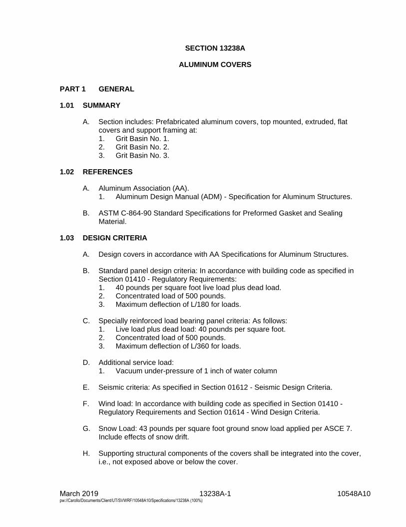
March 2019 13238A-1 10548A10 pw://Carollo/Documents/Client/UT/SVWRF/10548A10/Specifications/13238A (100%)
SECTION 13238A
ALUMINUM COVERS
PART 1 GENERAL
1.01 SUMMARY
A. Section includes: Prefabricated aluminum covers, top mounted, extruded, flatcovers and support framing at:1. Grit Basin No. 1.2. Grit Basin No. 2.3. Grit Basin No. 3.
1.02 REFERENCES
A. Aluminum Association (AA).1. Aluminum Design Manual (ADM) - Specification for Aluminum Structures.
B. ASTM C-864-90 Standard Specifications for Preformed Gasket and SealingMaterial.
1.03 DESIGN CRITERIA
A. Design covers in accordance with AA Specifications for Aluminum Structures.
B. Standard panel design criteria: In accordance with building code as specified inSection 01410 - Regulatory Requirements:1. 40 pounds per square foot live load plus dead load.2. Concentrated load of 500 pounds.3. Maximum deflection of L/180 for loads.
C. Specially reinforced load bearing panel criteria: As follows:1. Live load plus dead load: 40 pounds per square foot.2. Concentrated load of 500 pounds.3. Maximum deflection of L/360 for loads.
D. Additional service load:1. Vacuum under-pressure of 1 inch of water column
E. Seismic criteria: As specified in Section 01612 - Seismic Design Criteria.
F. Wind load: In accordance with building code as specified in Section 01410 -Regulatory Requirements and Section 01614 - Wind Design Criteria.
G. Snow Load: 43 pounds per square foot ground snow load applied per ASCE 7.Include effects of snow drift.
H. Supporting structural components of the covers shall be integrated into the cover,i.e., not exposed above or below the cover.
March 2019 13238A-2 10548A10 pw://Carollo/Documents/Client/UT/SVWRF/10548A10/Specifications/13238A (100%)
1.04 SUBMITTALS
A. Shop drawings: Include the following:1. Dimensions, sizes, thicknesses, gauges, materials, finishes.2. Details of connections, supports, anchorage, penetrations, flashing, and
sealants.3. Attachment and erection procedures.4. Number and location of penetrations.5. Penetration details.6. Access hatch locations.7. Special details not specifically indicated on the Drawings.
B. Product data: Include standard details and specifications.
C. Calculations: Include for flat cover, signed by qualified Registered ProfessionalStructural Engineer in the state of Utah.
D. Evidence of manufacturer qualifications: Include personnel experience, physicalfacilities, management capacity, and minimum 5 letters of reference from owners ofwastewater facilities similar to Project.
E. Operations and Maintenance Manual:1. Include drawings, maintenance instructions, and removal/replacement
instructions for installed covers.
1.05 QUALITY ASSURANCE
A. Manufacturer qualifications: Manufacturer of aluminum covers for minimum 10 yearswith minimum 5 installations under satisfactory operation at wastewater treatmentfacilities for minimum 3 years.
B. Erector qualifications: Mechanics skilled and experienced in fabrication and erectionof aluminum structures with minimum 5 installations under satisfactory operation.
PART 2 PRODUCTS
2.01 MANUFACTURERS
A. Aluminum covers: One of the following or equal:1. CTS Covers: Extruded Flat Covers (EFC).2. Temcor.3. Hallsten Corp.
2.02 MATERIALS
A. Aluminum sheet: 6061-T6 alloy or 6063-T6 mill finished. Load supporting surfacesshall be 0.1-inch minimum thickness.
B. Aluminum extrusions: 6061-T6 alloy, mill-finished.
C. Closure-flashing-to-panel seals: 3/8-inch Hypalon, Santoprene, or Neoprenegaskets.
March 2019 13238A-3 10548A10 pw://Carollo/Documents/Client/UT/SVWRF/10548A10/Specifications/13238A (100%)
D. Gaskets: All gaskets shall be Neoprene conforming to ASTM C-864-90, resistant toozone and shielded from exposure to ultraviolet light. The gaskets must have a1/4-inch minimum thickness.
E. Sealant: Silicone as specified in Section 07900 - Joint Sealants.
F. Bitumastic coating: As specified in Section 09960 - High-Performance Coatings.
G. Threaded fasteners and concrete anchors: Type 316 stainless steel as specified inSection 05120 - Structural Steel.
H. Closure flashing anchors and hardware: Type 316 stainless steel, 3/8-inch diameterwith 1/4-inch by 2-inch-by-2-inch minimum stainless steel washer, as specified inSection 05120 - Structural Steel.
I. Access hatch hinges, handles, prop rods, and latches: Aluminum.
J. Nameplates, manufacturer's name, or other identifications: Maximum 6 inches by6 inches in size.
2.03 FABRICATION
A. Cover configuration: Free-standing, flat, 1-piece, interlocking, supported at each endonly, without intermediate supports, removable, arranged as indicated on theDrawings, with flat, planar surface exposed and welded reinforcing ribs andstiffeners facing downward toward water surface.
B. Covers components: Standard and specially reinforced panels, able to safelysustain specified loads without permanent deformation or evidence of failure.
C. Joints between panels: Horizontal tongue and groove type.
D. Construction and clearances between adjacent panels: as required for panels to beairtight at up to 1-inch water column vacuum.
E. Panels size and weight: Able to be lifted by 2 workers, maximum 140 pounds,unless otherwise indicated on the Drawings. Each panel shall have one liftinghandle at each end to enable cover removal.
F. Penetration reinforcement: Minimum 1/4-inch thick aluminum stiffeners, able toprevent bowing, sagging, warping, or other distortions.
G. Penetration flashing and sealant: Manufacturer's standard, able to prevent intrusionof air and allow for removal of covers with minimum disassembly of equipment,piping, or duct.
H. Pressure and vacuum relief: By non-latching access hatches, able to open andallow escape of water or air when covered areas become pressurized.
I. Cable retainer system: Provided on one end of covers, able to prevent covers fromfalling in tanks during earthquakes, composed of the following:1. Retainer: Aluminum, welded to cover, able to withstand stress caused by
hanging full weight of cover section from cable with safety factor of 3.0.
March 2019 13238A-4 10548A10 pw://Carollo/Documents/Client/UT/SVWRF/10548A10/Specifications/13238A (100%)
2. Cable: Stainless steel, 3/8-inch diameter, run through retainer, with additional3-foot long coiled section to allow movement of covers during seismic-inducedsloshes.
J. Provide hole openings for ultrasonic levels as indicated on the Drawings.
K. Hatches:1. Flat or raised on curbs.2. Hinged and with lifting handles made from extruded 6061-T6.3. Possess identical properties as the rest of the aluminum cover including loads,
deflection, and slip resistance specifications.4. Gasketed to minimize air leakage.5. Locate as indicated on the Drawings.6. Size indicated on the Drawings is the minimum required.
L. Panel top surface: Non-slip, manufactured as part of panels or applied to surfaces.
PART 3 EXECUTION
3.01 ERECTION
A. Erect covers in accordance with manufacturer's instructions.
B. Plumb and erect flat covers in proper alignment.
C. Install closure flashing, including seal between flashing lip and tops of panelscontinuously around entire perimeter of cover assembly.
D. Secure closure flashing to new concrete with cast-in-place anchor bolts as specifiedin Section 05120 - Structural Steel.
E. Place anchors at each corner of each panel and at 16 inches on center alongconcrete walls.
F. Anchor embedments: Minimum 4 inches.
G. Isolate panel bearing ends, closure flashing, and other aluminum from concrete anddissimilar metals with bitumastic coating.
END OF SECTION
March 2019 13251-1 10548A10 pw://Carollo/Documents/Client/UT/SVWRF/10548A10/Specifications/13251 (100%)
SECTION 13251
BIOFILTER ODOR CONTROL SYSTEM
PART 1 GENERAL
1.01 SCOPE OF WORK
A. This section covers the work necessary to provide and install all air plenum and activated organic media, air header and distribution pipe, foul air fan, grease filter and housing, humidification system, irrigation system, lava rock pipe-bedding, containment liner, startup and performance testing services. These components represent a complete and properly functioning 3,000 cubic feet per minute biofilter odor control system.
B. Product Data: Submit data completely describing products and listings of all components of materials of construction, characteristics and Specifications, operation and installation instructions, including but not limited to: 1. Biofilter Media and Lava rock. 2. Air Piping System. 3. Biofilter Liner. 4. Humidification system (Atomizers). 5. Irrigation system. 6. Media Containment Liner. 7. Grease Filter. 8. Exhaust Fan (Specified in Section 15835 - Foul Air Fans for Odor Control). 9. Hydrogen sulfide monitoring system. 10. Instrumentation. 11. Controls. 12. Other required accessories for a complete operational system.
C. The scope of supply associated with the work, in addition to equipment and material supply, shall include the following services: 1. Excavation and installing of all components by the Contractor.
D. System to be installed at the West Jordan, Utah, South Valley Water Reclamation Facility for the Project 5 Grit Handling Facility.
1.02 SYSTEM AND PROCESS DESCRIPTION
A. General: Provide a biofilter scrubber system with accessories to treat foul air collected from the grit building, as indicated on the Drawings and specified herein.
B. Biofiltration is a process to remove hydrogen sulfide (H2S) and other odorous compounds from the air utilizing naturally occurring bacteria. Air will be collected from various plant processes and forced into the bottom of the biofilter. The air will then get distributed across the bottom of the biofilter using perforated piping. The biofilter media is a source of nutrients and a surface for the bacteria that break down the odorous compounds. As the air passes up through the media the odorous compounds are removed via adsorption, absorption, and biological oxidation. The
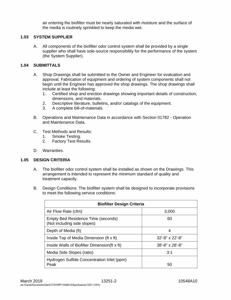
March 2019 13251-2 10548A10 pw://Carollo/Documents/Client/UT/SVWRF/10548A10/Specifications/13251 (100%)
air entering the biofilter must be nearly saturated with moisture and the surface of the media is routinely sprinkled to keep the media wet.
1.03 SYSTEM SUPPLIER
A. All components of the biofilter odor control system shall be provided by a single supplier who shall have sole-source responsibility for the performance of the system (the System Supplier).
1.04 SUBMITTALS
A. Shop Drawings shall be submitted to the Owner and Engineer for evaluation and approval. Fabrication of equipment and ordering of system components shall not begin until the Engineer has approved the shop drawings. The shop drawings shall include at least the following: 1. Certified shop and erection drawings showing important details of construction,
dimensions, and materials. 2. Descriptive literature, bulletins, and/or catalogs of the equipment. 3. A complete bill-of-materials.
B. Operations and Maintenance Data in accordance with Section 01782 - Operation and Maintenance Data.
C. Test Methods and Results: 1. Smoke Testing. 2. Factory Test Results.
D. Warranties.
1.05 DESIGN CRITERIA
A. The biofilter odor control system shall be installed as shown on the Drawings. This arrangement is intended to represent the minimum standard of quality and treatment capacity.
B. Design Conditions: The biofilter system shall be designed to incorporate provisions to meet the following service conditions:
Biofilter Design Criteria
Air Flow Rate (cfm) 3,000
Empty Bed Residence Time (seconds) (Not including side slopes)
60
Depth of Media (ft) 4
Inside Top of Media Dimension (ft x ft) 32'-8" x 22'-8"
Inside Walls of Biofilter Dimension(ft x ft) 38'-8" x 28'-8"
Media Side Slopes (ratio) 3:1
Hydrogen Sulfide Concentration Inlet (ppm) Peak
50
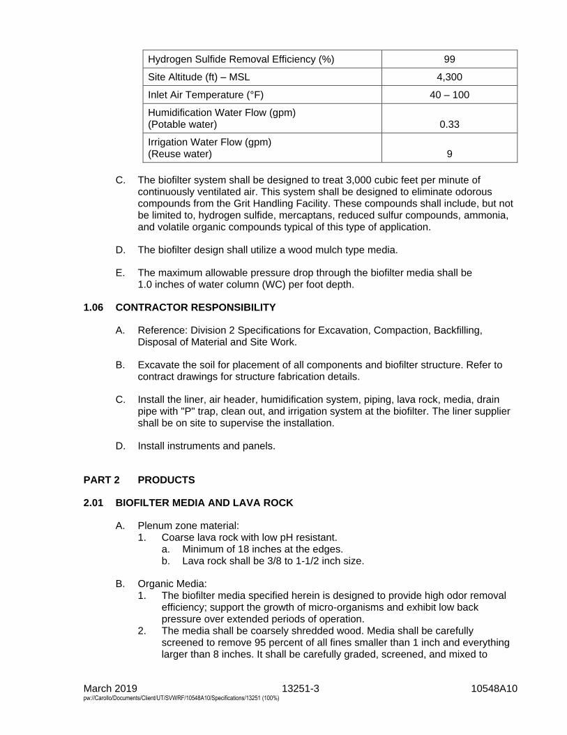
March 2019 13251-3 10548A10 pw://Carollo/Documents/Client/UT/SVWRF/10548A10/Specifications/13251 (100%)
Hydrogen Sulfide Removal Efficiency (%) 99
Site Altitude (ft) – MSL 4,300
Inlet Air Temperature (°F) 40 – 100
Humidification Water Flow (gpm) (Potable water)
0.33
Irrigation Water Flow (gpm) (Reuse water)
9
C. The biofilter system shall be designed to treat 3,000 cubic feet per minute of continuously ventilated air. This system shall be designed to eliminate odorous compounds from the Grit Handling Facility. These compounds shall include, but not be limited to, hydrogen sulfide, mercaptans, reduced sulfur compounds, ammonia, and volatile organic compounds typical of this type of application.
D. The biofilter design shall utilize a wood mulch type media.
E. The maximum allowable pressure drop through the biofilter media shall be 1.0 inches of water column (WC) per foot depth.
1.06 CONTRACTOR RESPONSIBILITY
A. Reference: Division 2 Specifications for Excavation, Compaction, Backfilling, Disposal of Material and Site Work.
B. Excavate the soil for placement of all components and biofilter structure. Refer to contract drawings for structure fabrication details.
C. Install the liner, air header, humidification system, piping, lava rock, media, drain pipe with "P" trap, clean out, and irrigation system at the biofilter. The liner supplier shall be on site to supervise the installation.
D. Install instruments and panels.
PART 2 PRODUCTS
2.01 BIOFILTER MEDIA AND LAVA ROCK
A. Plenum zone material: 1. Coarse lava rock with low pH resistant.
a. Minimum of 18 inches at the edges. b. Lava rock shall be 3/8 to 1-1/2 inch size.
B. Organic Media: 1. The biofilter media specified herein is designed to provide high odor removal
efficiency; support the growth of micro-organisms and exhibit low back pressure over extended periods of operation.
2. The media shall be coarsely shredded wood. Media shall be carefully screened to remove 95 percent of all fines smaller than 1 inch and everything larger than 8 inches. It shall be carefully graded, screened, and mixed to

March 2019 13251-4 10548A10 pw://Carollo/Documents/Client/UT/SVWRF/10548A10/Specifications/13251 (100%)
produce a homogeneous product which will provide consistent odor removal. The media shall be resistant to decomposition and cured prior to use. Contractor shall submit a sample of the media for approval by Engineer before delivering it to the job site. Media with excessive fines or consisting of small chips/wafers will not be accepted. In general, the engineer is looking for media that is shredded (not chipped) and in the 2-inch to 6-inch range. Wood species will not be judged but hardwoods are preferred.
3. Contractor shall provide enough media to maintain 4 feet of depth after the initial 60 days of settlement. Contractor may assume the media will settle 12 inches during the 60 days following installation therefore the initial installation depth shall be 5 feet.
4. Product: a. Ambio Biofiltration Ltd. b. Casella Waste Sytems, Inc. c. Or equal.
2.02 AIR PIPING SYSTEM
A. Main inlet air header manifold pipes: 1. Main air header manifold pipes shall be HDPE pipe meeting all requirements
of AASHTO M294, Type S, designed for the loading from a front loader if the media is replaced so it is not crushed.
2. Manufacturer shall weld stubs onto the air header manifold pipes for the 6-inch HDPE lateral connections. a. Stubs shall consist of a short length of 6-inch SDR 32.5 HDPE welded
flush into the header manifold pipe and a short length of 6-inch corrugated HDPE welded onto the other end.
b. Total length of the stub shall not exceed 12 inches. c. No stubs shall be welded at a bell and spigot joint. d. Stub spacing shall be approximately 2 feet on center, as per System
Supplier's requirements. 3. Joints: HDPE water-tight bell and spigot couplings.
B. Air distribution laterals: 1. Laterals shall be 6-inch diameter corrugated and slotted PVC pipe meeting all
requirements of AASHTO M252, Type CD. The slotted pipe spacing and size shall be designed by the manufacturer to allow equal air flow distribution.
2. Slot size and quantity shall be as recommended by the System Supplier and shall not be uniform throughout the bed. Slot size and spacing shall provide equal pressure drop based on specific design calculations.
3. Joints: HDPE snap couplings. 4. Provide cleanouts on each lateral at each end as shown on the Drawings.
C. Fittings: Snap type or factory welded with HDPE welds per manufacturer's standard procedures and requirements.
2.03 GEONET LINER
A. Provide and install geonet liner between biofilter media and lava rock. The geonet liner shall be constructed of HDPE.
B. Provide biplanar geonet with 2 sets of diagonally crossing parallel strands with a heat-laminated nonwoven needle-punched geotextile on 1 side.
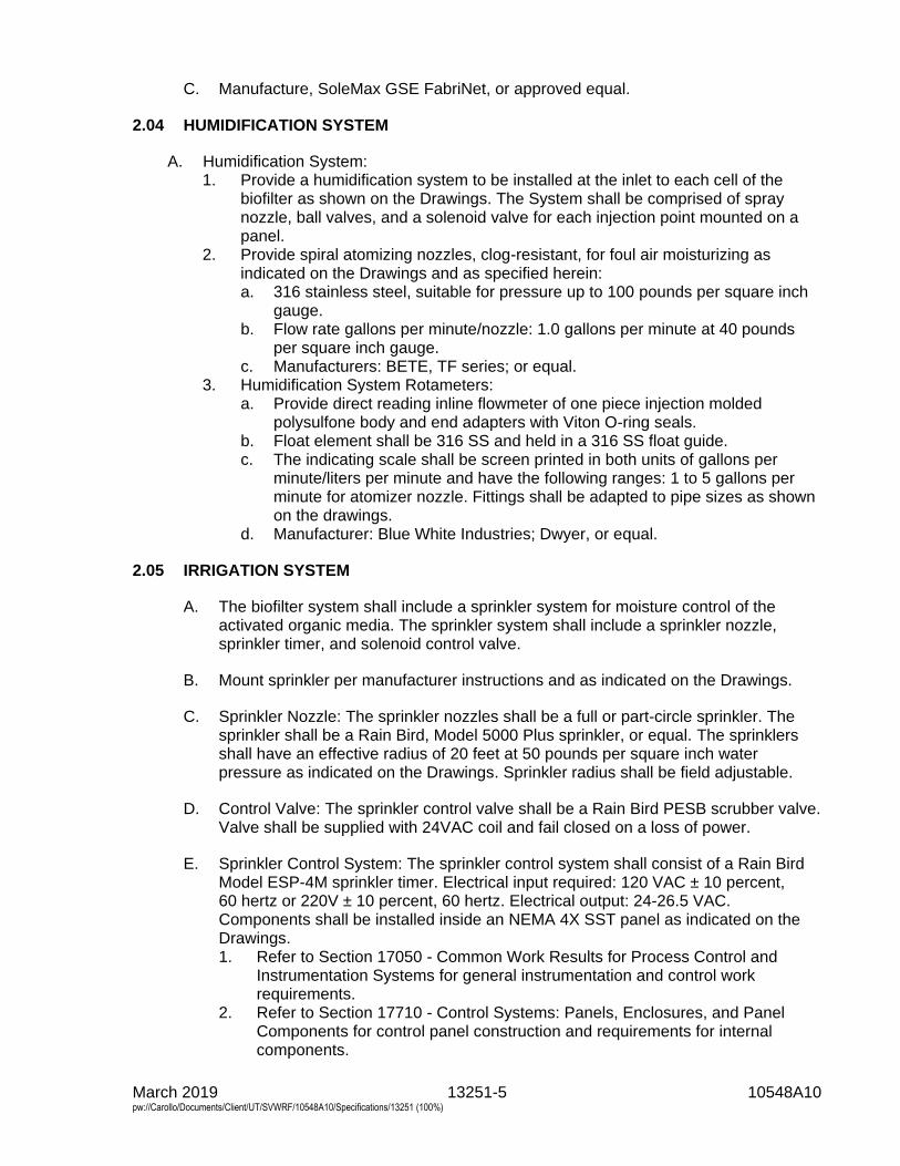
March 2019 13251-5 10548A10 pw://Carollo/Documents/Client/UT/SVWRF/10548A10/Specifications/13251 (100%)
C. Manufacture, SoleMax GSE FabriNet, or approved equal.
2.04 HUMIDIFICATION SYSTEM
A. Humidification System: 1. Provide a humidification system to be installed at the inlet to each cell of the
biofilter as shown on the Drawings. The System shall be comprised of spray nozzle, ball valves, and a solenoid valve for each injection point mounted on a panel.
2. Provide spiral atomizing nozzles, clog-resistant, for foul air moisturizing as indicated on the Drawings and as specified herein: a. 316 stainless steel, suitable for pressure up to 100 pounds per square inch
gauge. b. Flow rate gallons per minute/nozzle: 1.0 gallons per minute at 40 pounds
per square inch gauge. c. Manufacturers: BETE, TF series; or equal.
3. Humidification System Rotameters: a. Provide direct reading inline flowmeter of one piece injection molded
polysulfone body and end adapters with Viton O-ring seals. b. Float element shall be 316 SS and held in a 316 SS float guide. c. The indicating scale shall be screen printed in both units of gallons per
minute/liters per minute and have the following ranges: 1 to 5 gallons per minute for atomizer nozzle. Fittings shall be adapted to pipe sizes as shown on the drawings.
d. Manufacturer: Blue White Industries; Dwyer, or equal.
2.05 IRRIGATION SYSTEM
A. The biofilter system shall include a sprinkler system for moisture control of the activated organic media. The sprinkler system shall include a sprinkler nozzle, sprinkler timer, and solenoid control valve.
B. Mount sprinkler per manufacturer instructions and as indicated on the Drawings.
C. Sprinkler Nozzle: The sprinkler nozzles shall be a full or part-circle sprinkler. The sprinkler shall be a Rain Bird, Model 5000 Plus sprinkler, or equal. The sprinklers shall have an effective radius of 20 feet at 50 pounds per square inch water pressure as indicated on the Drawings. Sprinkler radius shall be field adjustable.
D. Control Valve: The sprinkler control valve shall be a Rain Bird PESB scrubber valve. Valve shall be supplied with 24VAC coil and fail closed on a loss of power.
E. Sprinkler Control System: The sprinkler control system shall consist of a Rain Bird Model ESP-4M sprinkler timer. Electrical input required: 120 VAC ± 10 percent, 60 hertz or 220V ± 10 percent, 60 hertz. Electrical output: 24-26.5 VAC. Components shall be installed inside an NEMA 4X SST panel as indicated on the Drawings. 1. Refer to Section 17050 - Common Work Results for Process Control and
Instrumentation Systems for general instrumentation and control work requirements.
2. Refer to Section 17710 - Control Systems: Panels, Enclosures, and Panel Components for control panel construction and requirements for internal components.
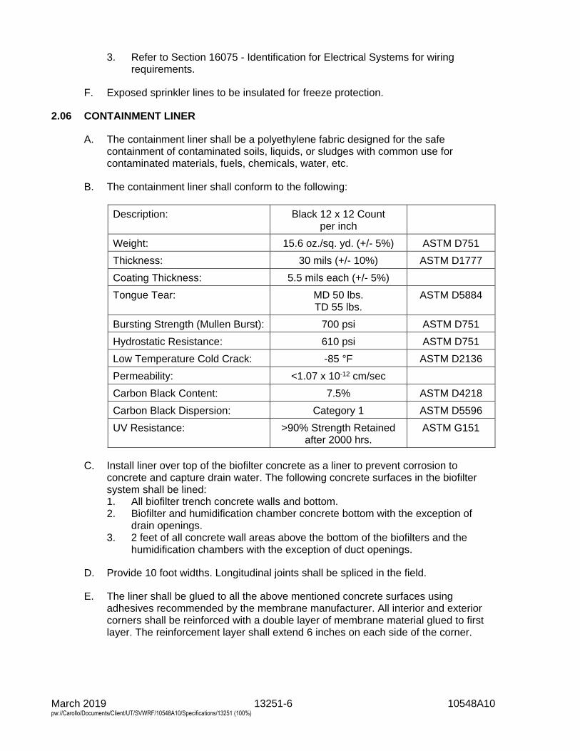
March 2019 13251-6 10548A10 pw://Carollo/Documents/Client/UT/SVWRF/10548A10/Specifications/13251 (100%)
3. Refer to Section 16075 - Identification for Electrical Systems for wiring requirements.
F. Exposed sprinkler lines to be insulated for freeze protection.
2.06 CONTAINMENT LINER
A. The containment liner shall be a polyethylene fabric designed for the safe containment of contaminated soils, liquids, or sludges with common use for contaminated materials, fuels, chemicals, water, etc.
B. The containment liner shall conform to the following:
Description: Black 12 x 12 Count per inch
Weight: 15.6 oz./sq. yd. (+/- 5%) ASTM D751
Thickness: 30 mils (+/- 10%) ASTM D1777
Coating Thickness: 5.5 mils each (+/- 5%)
Tongue Tear: MD 50 lbs. TD 55 lbs.
ASTM D5884
Bursting Strength (Mullen Burst): 700 psi ASTM D751
Hydrostatic Resistance: 610 psi ASTM D751
Low Temperature Cold Crack: -85 °F ASTM D2136
Permeability: <1.07 x 10⁻¹² cm/sec
Carbon Black Content: 7.5% ASTM D4218
Carbon Black Dispersion: Category 1 ASTM D5596
UV Resistance: >90% Strength Retained after 2000 hrs.
ASTM G151
C. Install liner over top of the biofilter concrete as a liner to prevent corrosion to concrete and capture drain water. The following concrete surfaces in the biofilter system shall be lined: 1. All biofilter trench concrete walls and bottom. 2. Biofilter and humidification chamber concrete bottom with the exception of
drain openings. 3. 2 feet of all concrete wall areas above the bottom of the biofilters and the
humidification chambers with the exception of duct openings.
D. Provide 10 foot widths. Longitudinal joints shall be spliced in the field.
E. The liner shall be glued to all the above mentioned concrete surfaces using adhesives recommended by the membrane manufacturer. All interior and exterior corners shall be reinforced with a double layer of membrane material glued to first layer. The reinforcement layer shall extend 6 inches on each side of the corner.
March 2019 13251-7 10548A10 pw://Carollo/Documents/Client/UT/SVWRF/10548A10/Specifications/13251 (100%)
F. The ends of the liner shall be doubled up and shall be anchored to the concrete using an aluminum batten bar. The bar shall be anchored to the concrete at 18 inches on-center using 316 SS anchors.
G. Liner shall be installed in accordance with membrane manufacturer instructions.
H. The entire liner shall be air and water tight. Liner shall be inspected and approved by the engineer prior to installation of the biofilter air distribution panels.
I. Liner shall be placed on corners where the biofilter slab meets the walls in accordance to manufacturer's instructions so as to prevent liner from pulling away from the corner.
J. Liner shall not be too tight and bridge across the corner so as to prevent air distribution panel legs from puncturing liner.
K. Liner shall be left loose in the corners to allow for temperature expansion and contraction of the liner.
L. A representative of the liner manufacturer shall be on site to supervise installation of liner.
2.07 GREASE FILTER
A. Housing: 1. Housing shall be manufactured using fiberglass reinforced plastic.
Manufacturer shall confirm the demisting filter has been manufactured in accordance with this specification and all FRP work meets or exceed ASME RTP-1 level 2 visual inspection criteria.
2. Housing shall have machined UMHW guides to prevent stainless frame on filter pad from scratching or damaging the corrosion liner.
3. Filter housing shall be designed for 12 inches positive and negative pressure with a maximum of 1/8-inch deflection.
4. Housing shall have an access door for pad removal complete with EPDM gasket and 316 stainless hinges / quick latches. For filter housings larger than 3 feet across, 2 access doors shall be provided. Access doors shall have stainless toggle clamps for easy pad access. Bolt-on access doors are not acceptable.
5. Housing shall be provided with a 2-inch drain connection at the base, and come from the manufacturer complete with ball valve.
6. For installation, housing shall have two 8-inch diameter FRP legs. Length of legs shall be coordinated with the contractor. Housing shall be supported by these legs independent of the connecting ductwork, anchored with stainless steel HILTI bolts.
B. Housing shall have a differential gauge bracket and be supplied with a Dwyer magnehelic pressure gauge and connections for gauge on either side of filter pad. Unit shall come complete from factory with all DP equipment pre-assembled and installed. Gauges shall have a 4-inch dial. The tubing to the gauges shall be 316SS with 316SS valves and condensate drain trap.
March 2019 13251-8 10548A10 pw://Carollo/Documents/Client/UT/SVWRF/10548A10/Specifications/13251 (100%)
C. Filter Pad: 1. Pad shall have 2 inches of stainless mesh followed by 4 inches of poly mesh.
Mesh shall be held together by a stainless steel frame. Total pad width including pads and frame shall be 8 inches.
2. Maximum pad segment width of pads is 24 inches. Pads larger than 24 inches wide must be segmented to allow easy removal by the owner. Segment width should not exceed 24 inches.
D. Dimensions / Design: 1. Flange dimensions shall match the connecting ductwork. Flange thickness
shall not be less than that listed in ASTM 3982. 2. Inlet cone shall be designed so that the airstream can spread evenly over the
pad surface. Cone angle shall be no less than 60 degrees. 3. Housing shall be sized so that air velocity through the filter pad is less than
400 feet per minute.
2.08 EXHAUST FAN
A. As specified in Section 15835 - Foul Air Fans for Odor Control and this Section.
B. Odor Control Fan: 1. Manufacturer's Inspection and Startup: Bid prices for equipment furnished
shall include the cost of a competent representative of the manufacturer to perform functional testing, startup, and training of Owner's operating personnel on operation and maintenance.
2. Installation Supervision, Start-up, and Operator Training: a. Contractor shall electrically ground all fan parts. b. Upon completion of the installation, the services of the manufacturer's
factory trained representative shall be provided at the project site. During the checkout and start-up phase, the manufacturer's representative shall inspect all system components for proper connection and alignment and assist the installation contractor in placing the equipment in a proper operating condition.
c. Upon satisfactory completion of the start-up and calibration, the representative of the manufacturer shall instruct Owner's personnel in the proper operation and maintenance of the equipment. The manufacturer's representative who will be providing the instruction shall have prior operation, maintenance, and instructing experience acceptable to the Engineer.
2.09 INSTRUMENTATION AND CONTROLS
A. Provide and install differential pressure indicating transmitters (Dwyer, 0.00 to 3.00 inches w.c.) across the grease/mist eliminator, with stainless steel tubing and manifold to drain water.
2.10 DRAIN PIPE
A. Water will flow to the center and rear trench on the slope.
B. A 6-inch drain pipe shall be installed with a "P" trap 2 inches to 6 inches deep on center with clean out outside the biofilter boundary, as shown on drawings. Access shall be provided to the trap and clean out at the ground level.
March 2019 13251-9 10548A10 pw://Carollo/Documents/Client/UT/SVWRF/10548A10/Specifications/13251 (100%)
PART 3 EXECUTION
3.01 BIOFILTER INSTALLATION
A. General:
B. Elevations shall be surveyed at the biofilter floor, top of plenum zone, and top of media to establish correct slope and correct thickness of each layer. Biofilter Media: 1. Install media loose by methods as approved by the Engineer that will result in
uniformly mixed, uncompacted, and uniform density installation. 2. After placement, finish smoothing of the surface to the specified grade. Do not
drive heavy equipment on media. When it is necessary to walk on the biofilter media for maintenance, do so only when media is relatively dry to prevent excessive compaction.
3. After the media is placed on top of the air distribution panels it shall be leveled out by hand using rakes or other hand tools.
4. Plywood boards shall be placed upon the media to provide a base for Contractor to work from to distribute loading and minimize point loads on the biofilter media.
5. The media shall be kept moist at all times after installation. Use sprinkler system or media moistening through humidification system.
6. Upon request by Owner, the additional 6 inches depth of media shall be installed by the Contractor at no additional cost.
C. Sprinkler system: Support sprinkler risers to permit operation without vibrations or movement of the head and piping and as shown on the plans. Individual sprinklers shall connect to 3/4-inch risers, which extend 3-inch minimum above top of media.
D. Humidification System: Install as shown on the plans.
E. Field Finishes: 1. Apply touch up finishes in the field per Sections 09910 - Painting and 09960 -
High-Performance Coatings requirements. Colors shall be as selected by the Owner.
2. Metals within the biofilter areas shall be primed and finished with high solid epoxy coating.
3.02 PLACING FILTER/LAVA ROCK MATERIALS
A. Placement Into Bed: 1. Lava rock zone shall be placed in a manner that will limit displacement of the
HDPE lateral pipes. 2. Lava rock shall be leveled and undisturbed prior to bed media placement. Do
not permit workers to walk or stand directly on media; use boards that will sustain workers' weight without displacing materials.
3. Use placement devices as approved by System Supplier; for example front end loaders, excavators, and/or concrete conveyors.
4. Contractor shall be responsible to avoid contamination of materials by native fill dirt or other.
5. If stockpiling media for longer than 1 week, make provisions for windbreaks, shading, fog spraying, sprinkling, wet cover, or other means to maintain media with a wet surface.
6. Addition of chemical wetting agents or other additives are not allowed.
March 2019 13251-10 10548A10 pw://Carollo/Documents/Client/UT/SVWRF/10548A10/Specifications/13251 (100%)
7. Place in layers as specified below and in coordination with the contract drawings:
Layer Layer Thickness Size Limits
Lava Rock Zone 18 inches minimum 3/8 inch – 1-1/2 inch
Filter Media 4 feet (place to prevent compaction)
8. Complete each layer before next layer above is started. 9. Level by hand using plywood platform and level with a laser. 10. Use only clean lava rock. Contractor shall be responsible to avoid
contamination of materials by native fill dirt or other.
3.03 ODOROUS AIR DISTRIBUTION PIPING INSTALLATION
A. Examination: Verify size, material, joint types, elevation, horizontal location, and pipe service of existing pipelines to be connected to new pipelines or new equipment.
B. Preparation: Inspect pipe and fittings before installation, clean ends thoroughly, and remove foreign matter and dirt from inside.
C. Installation - General: 1. Joint pipe and fittings in accordance with manufacturer's instructions, unless
otherwise shown or specified.
D. Placement: 1. Keep trench dry until pipe laying and joining are completed. 2. Exercise care when lowering pipe into trench to prevent twisting or damage to
pipe and stubs. 3. Measure for grade at pipe invert not at crown. 4. Excavate trench bottom and sides of ample dimensions to permit visual
inspection and testing of entire flange, valve, or connection. 5. Prevent foreign material from entering pipe during placement. 6. Close and block open end of last laid pipe section when placement operations
are not in progress and at close of day's work. 7. Lay pipe upgrade with bell ends pointing in direction of laying. 8. After joint has been made, check pipe elevation at pipe ends and corners of
filter piping network.
3.04 SMOKE TESTING
A. Contractor shall perform a smoke test after the lava rock and air distribution piping are placed to confirm equal air flow distribution as witnessed by the Engineer and Owner.
B. A second smoke test shall be performed with the system fully complete before startup to confirm equal air flow distribution.
C. Contractor and supplier shall make adjustments as necessary to provide equal air flow distribution.
March 2019 13251-11 10548A10 pw://Carollo/Documents/Client/UT/SVWRF/10548A10/Specifications/13251 (100%)
3.05 PERFORMANCE TESTING
A. Performance testing shall not commence until the Manufacturer, Engineer, and Owner agree that the system has been satisfactorily started-up and sufficient time has been allowed for the acclimation of the bacteria.
B. After the biofilter has been satisfactorily started-up and switched to normal operation, the Contractor and Owner shall conduct a performance test to verify that the system performs as specified below. 1. The Contractor shall supply, install, and operate all testing equipment,
sensors, and instrumentation required to complete the performance test, and the Contractor shall be responsible for operating the biofilter and all associated equipment during the test.
C. H2S Testing procedure: 1. In general, the following procedure will be followed by the Contractor and
Owner while conducting the performance test. a. Measure airflow into the biofilter. If necessary, the Contractor shall adjust
balancing dampers to achieve the design airflow of 3,000 cubic feet per minute +/- 10 percent. Airflow shall be measured at the beginning of the test period. The set position on the damper(s) will be marked or noted.
b. Measure pressure drop through the biofilter at beginning of test period. c. Measure temperature of the inlet, outlet, and ambient air. d. The performance test period will begin at a noted time and last for
4 hours. H2S data from the inlet location and from the outlet of the odor control system will be measured and logged once every 10 minutes or less to demonstrate performance during the test period.
e. The inlet H2S data will be logged with a pre-calibrated OdaLog gas data logger with appropriate range and accuracy for the inlet air stream (0 to 1000 parts per million by volume or 0 to 200 parts per million by volume range, 1 ppm display resolution or 0.0 to 50.0 parts per million by volume range, 0.1 parts per million by volume display resolution).
f. The outlet H2S data will be logged with a pre-calibrated Jerome 631X H2S Analyzer with a range of 0 to 50 parts per million by volume and an accuracy of +/- 0.003 parts per million by volume or a Low Range OdaLog with a range of 0 to 2 parts per million and an accuracy of 0.01 parts per million.
D. H2S Acceptance criteria: 1. The System's H2S removal efficiency shall be determined by calculating the
average inlet H2S concentration and the average outlet H2S concentration using the following formula: H2S removal efficiency (%) = (1 - average outlet H2S concentration/average inlet H2S concentration) x 100. The system shall have passed the H2S performance test if the H2S removal efficiency is 99 percent or more for inlet air H2S concentrations ≥ 50 parts per million by volume. If the average inlet H2S concentration is less than 50 parts per million, then the outlet air H2S concentration must be ≤ 0.5 parts per million by volume to pass the test.
March 2019 13251-12 10548A10 pw://Carollo/Documents/Client/UT/SVWRF/10548A10/Specifications/13251 (100%)
3.06 MANUFACTURERS' SERVICES
A. A representative for the Contractor/Manufacturer shall be present at the jobsite for the minimum person-days listed for the services herein under, travel time excluded: 1. 6 person-days for installation assistance, inspection, and certification of the
installation. Provide certificate. 2 separate trips. 2. 2 person-days for both operator training, and performance testing. 2 separate
2 day trips each.
3.07 MANUFACTURERS' CERTIFICATE(S)
A. Provide manufacturers' certificate(s) of proper installation.
END OF SECTION
13446-1 10548A10 March 2019 pw://Carollo/Documents/Client/UT/SVWRF/10548A10/Specifications/13446 (100%)
SECTION 13446
MANUAL ACTUATORS
PART 1 GENERAL
1.01 SUMMARY
A. Section includes:1. Valve and gate actuators.2. Handwheel actuators.3. Hand-cranked geared actuators.4. Floor Boxes.5. Floor stands.6. Key operated valves.7. Bench stands.8. Accessory equipment and floor boxes.
1.02 REFERENCES
A. Aluminum Association (AA):1. DAF-45 - Designation System for Aluminum Finishes.
B. American Water Works Association (AWWA).
C. National Electrical Manufacturers Association (NEMA):1. 250 - Enclosures for Electrical Equipment (1000 V Maximum).
D. National Electrical Code (NEC).
1.03 DEFINITIONS
A. NEMA:1. Type 4X enclosure in accordance with NEMA 250.2. Type 7 enclosure in accordance with NEMA 250.
1.04 SUBMITTALS
A. Shop drawings: Include shop drawings and product data with associated gate orvalve as an integrated unit.
1.05 QUALITY ASSURANCE
A. Provide valve actuators integral with valve or gate, except for valve actuatorsutilizing T-wrenches or keys, and portable gate actuators intended to operate morethan 1 valve.
B. Provide similar actuators by 1 manufacturer.
C. Provide gates and hand operating lifts by 1 manufacturer.
13446-2 10548A10 March 2019 pw://Carollo/Documents/Client/UT/SVWRF/10548A10/Specifications/13446 (100%)
D. Provide hydraulic gate lifts by 1 manufacturer.
E. Provide hydraulic valve actuators and motorized actuators by 1 manufacturer.
1.06 MAINTENANCE
A. Extra materials:1. Key operated valve keys or wrenches: Furnish a minimum 4 keys with 4-foot
shafts and 3-foot pipe handles or wrenches with 4-foot shafts and 3-foothandles for operating key operated valves.
PART 2 PRODUCTS
2.01 VALVE AND GATE ACTUATORS
A. Valve actuators:1. Cylinder actuators, motorized actuators, and portable gate actuators are
specified in Sections 13447 - Electric Motorized Actuators2. Manual actuators:
a. Material: Type 316 stainless steel.b. Design: Hand lever.c. Spring release handle: 12-inch.d. Notch plate: 10 position.e. Secure with mounting bolts.f. Locking device so that valve can be locked in any position with a wing nut.
3. Stem and cover:a. For submerged valves, provide extension stem as indicated on the
Drawings.4. Limit switches: Provide limit switches on manually actuated valves where
indicated on the Drawings:a. Limit switches: Heavy-duty, industrial grade, oiltight, with not less than
2 auxiliary contacts.b. Rating: Rated for 10 amps, 120 volts alternating current.c. Enclosure: NEMA Type 4X enclosure and with stainless steel levers and
arms. Provide switch with NEMA Type 7 enclosure when switch is locatedwithin areas with NEC Class 1, Division 1 or Class 1, Division 2designations as indicated on the Drawings.
B. Stem covers:1. Aluminum pipe:
a. Threaded cap on top.b. Bolted aluminum flange on bottom.c. Slots cut 1- by 12-inch at 18 inches on center in front and back of pipe.d. Capable of covering threaded portion of greased stems that project above
actuators when gates or valves are opened or closed.2. Ultraviolet light resistant, clear butyrate plastic or polycarbonate pipe:
a. Capped on the upper end.b. Either threaded into the top of the gate operators or held in place by
bolt-down aluminum brackets.c. Capable of covering threaded portion of greased stems that project above
actuators when gates or valves are opened or closed.
13446-3 10548A10 March 2019 pw://Carollo/Documents/Client/UT/SVWRF/10548A10/Specifications/13446 (100%)
3. Staff gauges:a. Adhesive-backed Mylar, suitable for outdoor service.b. Calibrated in hundredths of feet.c. Read the weir crest elevations directly.d. Gauge range: 1.5 feet minimum.e. Indicate the following elevations on each staff gauge:
1) -0.75, -0.50, -0.25, 0.0, 0.25, 0.50, 0.75.f. Supplement with a stem-mounted pointer or indicator that permits direct
observation of the weir gate crest elevation.g. Apply staff gauges to each stem cover after installation of the cover and
after calibration and testing of the weir gates.h. Set gauges precisely by a survey crew using instruments acceptable to
the Engineer.
C. Stem cover flanges, pipes and caps:1. After fabrication, etch and anodize to produce the following chemical finishes
in accordance with AA publication DAF-45:a. A 41 - Clear Anodic Coating.b. C 22 - Medium Matte Finish.
D. Gate stem covers: Concentric with stem.
E. Position indicators:1. For all aboveground worm gear or traveling nut manual actuators, provide
position indication on the actuator enclosure.2. Tail rods on hydraulic cylinders, or dial indicators with clear full-open and
closed position indicators, calibrated in number of turns or percentage ofopening.
F. Manual or power actuator size:1. Sized to deliver maximum force required under most severe specified
operating condition, including static and dynamic forces, seat and wedgefriction, and seating and unseating forces with safety factor of 5, unlessotherwise specified.
G. Actuator size: Capable of supporting weight of suspended shafting unless carried bybottom thrust bearings; shaft guides with wall mounting brackets.
H. Provisions for alternate operation: Where specified or indicated on the Drawings,position and equip crank or handwheel operated geared valve actuators or lifts foralternate operation with tripod mounted portable gate actuators.
I. Operation: Counterclockwise to open with suitable and adequate stops, capable ofresisting at least twice normal operating force to prevent overrun of valve or gate inopen or closed position.
J. Open direction indicator: Cast arrow and legend indicating direction to rotateactuator on handwheel, chain wheel rim, crank, or other prominent place.
K. Buried actuator housing: Oil and watertight, specifically designed for buried service,factory packed with suitable grease, completely enclosed space between actuatorhousing and valve body so that no moving parts are exposed to soil; provideactuators with 2-inch square AWWA operating nut.
13446-4 10548A10 March 2019 pw://Carollo/Documents/Client/UT/SVWRF/10548A10/Specifications/13446 (100%)
L. Worm gear actuators: Provide gearing on worm gear actuators that is self-lockingwith gear ratio such that torque in excess of 160 foot-pounds will not need to beapplied to operate valve at most adverse conditions for which valve is designed.
M. Traveling nut actuators: Capable of requiring maximum 100 foot-pounds of torquewhen operating valve under most adverse condition; limit stops on input shaft ofmanual actuators for fully open and closed positions; non-moving vertical axis ofoperating nut when opening or closing valve.
2.02 HANDWHEEL ACTUATORS
A. Manufacturers: One of the following or equal:1. Rodney Hunt Co.2. Waterman Industries, Inc.
B. Coating: Handwheel as specified in Section 09960 - High-Performance Coatings.
C. Mounting: Floor stand or bench stand. Unless otherwise indicated on the Drawingsposition actuator 36 inches (nominal) above top of walkway surface.
D. Bearings above and below finished threaded bronze operating nut: Ball or roller.
E. Wheel diameter: Minimum 24 inches.
F. Indicator: Counterclockwise opening with arrow, and word OPEN cast on top ofhandwheel indicating direction for opening.
G. Pull to operate: Maximum 40 pounds pull at most adverse design condition.
H. Stem travel limiting device: Setscrew locked stop nuts above and below lift nut.
I. Grease fittings: Suitable for lubrication of bearings.
2.03 HAND-CRANKED GEARED ACTUATORS
A. Type: Single removable crank; fully enclosed.
B. Mounting: Floor and bench stand. Unless otherwise indicated on the Drawingsposition actuator 36 inches (nominal) above top of walkway surface.
C. Operating nut: When scheduled for portable gate actuators.
D. Geared lifts: 2-speed with minimum ratio of 4 to 1.
E. Teeth on gears, spur pinions, bevel gears, and bevel pinions: Cut.
F. Lift nuts: Cast manganese bronze.
G. Exterior surfaces on cast-iron lift parts: Smooth.
H. Bearings above and below flange on lift nuts: Ball or roller; capable of taking thrustdeveloped by opening and closing of gates under maximum operating head; with
13446-5 10548A10 March 2019 pw://Carollo/Documents/Client/UT/SVWRF/10548A10/Specifications/13446 (100%)
bronze sleeve bearings and sufficient grease fittings for lubrication of moving parts, including bearings and gears.
I. Crank rotation indicator: Cast arrow with word OPEN in prominent location readilyvisible indicating correct rotation of crank to open gate.
J. Hand cranks: 15-inch radius; requiring maximum 25 pounds pull to operate gate atmaximum operating head; with:1. Revolving brass sleeves.2. Gears, spur pinions, bevel gears, and bevel pinions with cut teeth.3. Cast manganese bronze lift nuts.4. Cast-iron lift parts with smooth exterior surfaces.
K. Indicator: Dial position type mounted on gear actuator; enclosed in cast-iron oraluminum housing with clear plastic cover; marked with fully open, 3/4, 1/2, 1/4, andclosed positions.
2.04 FLOOR BOXES
A. Manufacturers: The following or equal:1. Waterman Industries, Inc.
B. Floor boxes: Cast-iron; with:1. Counter type indicator.2. Hinged, lockable lid with directional arrow.3. 2-inch square AWWA operating nut.4. Packing gland providing drip-tight seal around valve shaft.
2.05 FLOOR STAND
A. Manufacturers: One of the following or equal:1. Rodney Hunt Co.2. Waterman Industries, Inc.
B. Floor stand assemblies: Heavy-duty cast-iron, suitable for mounting specifiedactuator.
2.06 BENCH STANDS
A. Manufacturers: One of the following or equal:1. Rodney Hunt Co.2. Waterman Industries, Inc.
B. Bench stands: Handwheel actuators or hand crank, geared actuators conforming tohand-cranked geared actuator requirements, except capacity to be mounted onhaunch, wall bracket, or self-contained gate yoke.
2.07 ACCESSORY EQUIPMENT
A. Wall brackets or haunches: As indicated on the Drawings.
B. Stems: Stainless steel; sized to match output of actuator; minimum gate or valveoperating stem diameter; maximum 200 slenderness ratio.

March 2019 13446-6 10548A10 pw://Carollo/Documents/Client/UT/SVWRF/10548A10/Specifications/13446 (100%)
C. Stem couplings: Stainless steel; internally threaded to match stem; lockable to stemby set screw.
D. Stem guides: Cast-iron with silicon bronze bushing; maximum 200 slendernessratio; capable of being mounted with wall bracket; adjustable in 2 directions.
E. Wall brackets: Cast-iron, capable of withstanding output of actuator, adjustable in2 directions.
F. Stem stuffing boxes: Cast-iron, with adjustable gland and packing.
G. Fasteners: Type 316 stainless steel.
H. Anchor bolts: As specified in Section 05190 - Mechanical Anchoring and Fasteningto Concrete and Masonry except that the material shall be Type 316 stainless steel.
I. Geared valve actuators: Provided with cut gears, either spur or worm; sized tooperate valves at most adverse design condition; with maximum 40-pound pull athandwheel or chain wheel rim.
J. Geared valve traveling nut actuators: Acceptable only where specified or indicatedon the Drawings.
K. Accessory equipment for valves and gates requiring remote actuators: Operatingstems, stem couplings, stem guides, wall brackets, and stem stuffing boxes.
PART 3 EXECUTION
3.01 INSTALLATION
A. Install floor boxes in concrete floor with lid flush with floor.
B. After installation of gate and stem covers, mark stem covers at point where top ofstems are at full-open position and at closed position.
C. Attach floor stand to structure with anchor bolts.
D. Install stem stuffing boxes where operating stems pass through intermediateconcrete floor slabs.
3.02 SCHEDULES
A. Geared actuators: Provide geared actuators for following valves:1. Butterfly valves larger than 6 inches, nominal size, on liquid service.2. Butterfly valves larger than 10 inches, nominal size, on gas and air service.3. Plug valves 6 inches, nominal size, and larger.
B. Handwheel actuators: Provide handwheel actuators for valves mounted 6 feet orless above floors.
C. Chain wheel actuators: Provide chain wheel actuators for valves mounted morethan 6 feet to centerline above floors.
END OF SECTION
March 2019 13447-1 10548A10 pw://Carollo/Documents/Client/UT/SVWRF/10548A10/Specifications/13447 (100%)
SECTION 13447
ELECTRIC ACTUATORS
PART 1 GENERAL
1.01 SUMMARY
A. Section includes: Electric motor-driven actuators for valves and gates as identified in the valves and gates schedule as EAM, EDM, OR EDR.
1.02 REFERENCES
A. American Water Works Association (AWWA): 1. C504 - Standard for Rubber-Seated Butterfly Valves. 2. C542 - Standard for Electric Motor Actuators for Valves and Slide Gates.
B. National Electrical Manufacturers Association (NEMA): 1. 250 - Enclosures for Electrical Equipment (1000 V Maximum).
1.03 DEFINITIONS
A. NEMA: 1. Type 4X enclosure in accordance with NEMA 250. 2. Type 7 enclosure in accordance with NEMA 250.
1.04 SUBMITTALS
A. Submit as specified in Section 01330 - Submittal Procedures and Section 15050 - Common Work Results for Mechanical Equipment.
B. Provide a complete list/schedule of all actuators being provided with their associated tag names as indicated on the design drawings and/or specifications, service process area and the size of the valve they are actuating.
C. Product data: 1. Electrical ratings:
a. Voltage and number of phases. b. Starting and running current. c. Voltage levels and source for control and status.
2. Description of integral control interface. 3. Environmental ratings, including NEMA enclosure rating and submergence
capabilities. 4. Gear ratios for both manual and motorized actuation. 5. Opening and closing directions. 6. Allowable starts per hour. 7. List of all included options and accessories. 8. Full travel times. 9. Gearbox data including gear ratio, and gearbox efficiency.
March 2019 13447-2 10548A10 pw://Carollo/Documents/Client/UT/SVWRF/10548A10/Specifications/13447 (100%)
D. Shop drawings: 1. Wiring diagrams:
a. Include all options and expansion cards furnished with each actuator. 2. Dimensioned drawings of each valve and actuator combination. 3. Dimensioned drawings of each valve gearbox. 4. Electric motor data.
E. Calculations: 1. Operating torque. 2. Maximum torque calculations for seating and unseating. 3. Maximum operating torque at starting and normal operation. 4. Signed by Profession Engineer.
F. Provide draft vendor operation and maintenance manual as specified in Section 01782 - Operation and Maintenance Data: 1. Include a list of all configurable parameters, and the final values for each. 2. Include a troubleshooting chart covering the complete valve and
controls/electrical power systems, showing description of trouble, probable cause, and suggested remedy.
G. Commissioning submittals: 1. Provide Manufacturer’s Certificate of Source Testing as specified in
Section 01756 - Commissioning. a. Affidavit in accordance with AWWA C542.
2. Provide Manufacturer’s Certificate of Installation and Functionality Compliance as specified in Section 01756 - Commissioning.
H. Project closeout documents: 1. Provide final vendor operation and maintenance manual as specified in
Section 01782 - Operation and Maintenance Data.
1.05 WARRANTY
A. Provide warranty as specified in Section 01783 - Warranties and Bonds.
PART 2 PRODUCTS
2.01 MANUFACTURERS
A. Manufacturers for lines 3 inch and smaller: 1. The following or equal:
a. Rotork Controls Inc.: 1) ROMpak (Quarter-Turn). 2) CMA Range:
a) CMR - Multi-Turn. b) CMQ - Quarter-Turn.
B. Manufacturers for lines 4 inch and larger: 1. Provide the following, no equal:
a. Rotork Controls Inc.: 1) IQT (Quarter-turn).

March 2019 13447-3 10548A10 pw://Carollo/Documents/Client/UT/SVWRF/10548A10/Specifications/13447 (100%)
2.02 CHARACTERISTICS FOR ACTUATORS ON LINES 3 INCHES AND SMALLER
A. Actuators for valves 3 inches and smaller: 1. Provide actuators complete and operable with all components and accessories
required for operation. 2. Power supply:
a. Valve motion independent of power supply phase rotation. b. As shown on the Drawings.
3. Size actuator to move valves from full open to closed position within the time indicated in the Motorized Actuator Schedule: a. If an operating time is not indicated on the Motorized Actuator Schedule,
size the actuator to move valves at minimum 12 inches per minute under maximum load. Measure rate of closure for valves at maximum diameter of disc, plug, or ball.
4. For all outdoor or vault installations, provide an integral anti-condensation heater when available as an option.
5. Control inputs: a. Capable of control via Profibus DP b. Controls the valve when local-stop-remote is in REMOTE. c. Material: Type 316 stainless steel. d. Provide the following inputs at the actuator:
1) OPEN. 2) CLOSE.
6. Status outputs: a. Dry contact outputs configured for the functions indicated on the
Drawings. Provide the following outputs for all actuators: 1) FULLY CLOSED. 2) FULLY OPEN. 3) REMOTE.
b. All output contacts rated for 5 amps, 120 VAC. 7. Analog input:
a. Provide a 4-20 milliamp analog input for analog modulating valves when indicated on the Drawings.
b. Modulate valve to maintain position based on analog input value. c. Maximum input impedance 250 ohms.
8. Analog output: a. Provide an isolated 4-20 milliamp analog output when indicated on the
Drawings. 9. Materials:
a. Construct motorized actuators of materials suitable for the environment in which the valve or gate is to be installed.
10. Components: a. Motors:
1) Torque ratings equal to or greater than that required for valve seating and dynamic torques with a 25 percent factor of safety.
2) Rated for operating under the following conditions without exceeding temperature limits with ambient temperature of 40 degrees Celsius. a) Continuous operation for 15 minutes or twice the open-to-close
operating time (whichever is greater) at normal operating torque or 33 percent of maximum torque (whichever is greater).
b) 60 starts per hour minimum for open/close service.
March 2019 13447-4 10548A10 pw://Carollo/Documents/Client/UT/SVWRF/10548A10/Specifications/13447 (100%)
b. Enclosures: 1) Actuator housing ratings as indicated in the Motorized Actuator
Schedule. 2) Stainless steel external fasteners.
c. Manual actuation: 1) Hand wheel for manual operation.
d. Gearing: Self-locking, high-alloy steel gears. 11. Communication options:
a. Profibus DP.
2.03 CHARACTERISTICS FOR ACTUATORS ON LINES 4 INCHES AND LARGER
A. Provide actuators complete and operable with all components and accessories required for operation.
B. Power supply: 1. Voltage and phases as indicated in the Schedule. 2. Valve or gate motion independent of power supply phase rotation. 3. Provide an internal backup power source or mechanical indicator to maintain
settings and track valve position when main power is off. 4. The actuators shall incorporate all major components such as the motor,
starter, local controls, terminals etc. housed within a self-contained, sealed enclosure.
C. Size actuator to move gates or valves from full open to closed position within the time indicated in the Schedule: 1. If an operating time is not indicated on the Schedule, size the actuator to move
gates or valves at minimum 12 inches per minute under maximum load. Measure rate of closure for valves at maximum diameter of disc, plug, or ball.
2. Size actuators so that gear boxes are not required where possible.
D. Control interface: 1. Configuration:
a. Provide a non-intrusive, non-contacting interface for configuring all input and output settings, control values, ranges, torque switch settings, valve positions switch settings, and options. 1) Configurable from a hand-held configuring tool or input devices on
the actuator. 2. Local interface, integral to actuator:
a. Non-intrusive, non-contacting selector switches: 1) LOCAL-STOP-REMOTE:
a) Motor actuator operation is prevented with the switch in STOP. 2) OPEN-CLOSE:
a) Controls the valve when LOCAL-STOP-REMOTE is in LOCAL. b) Spring return to center. c) Configurable between maintained (actuator runs until end of
travel, high torque, or a LOCAL-STOP-REMOTE is switched to STOP) and momentary (actuator stops when lever is released).
b. Local display: 1) Valve fully open and fully closed indicators. 2) Numerical display showing actual valve or gate position in percent of
travel.
March 2019 13447-5 10548A10 pw://Carollo/Documents/Client/UT/SVWRF/10548A10/Specifications/13447 (100%)
3. Network communications: a. Communications and control between the actuator and plant’s control
system shall utilize the following protocol: 1) Profibus DP.
a) Provide Profibus disconnect module.
E. Features: 1. Time delay on reversal: Incorporate time delay between stopping actuator and
starting in opposite direction to limit excessive current, torque, and heating from instantaneous reversal.
2. Data logging: a. Store diagnostic data and reference data. b. Time-stamped historical operating data, including number of operations
and most recent operations. c. Torque profiles showing actual torque at each valve position through the
operating range. 1) Store reference data (recorded during commissioning) and data from
last operation. 3. Provide display of logged data on the actuator, or provisions to download to a
personal computer.
F. Materials: 1. Construct motorized actuators of materials suitable for the environment in
which the valve or gate is to be installed.
G. Components: 1. Motors: 2. Specifically designed for valve actuator service with high starting torque, totally
enclosed non-ventilated construction. 3. Torque ratings equal to or greater than that required for valve seating and
dynamic torques with a 25 percent factor of safety. a. Design requirements for rubber-seated AWWA butterfly valves:
1) Design actuators for maximum gate or valve operating torque, in accordance with and using safety factors required in AWWA C504 and AWWA C542. a) Valve actuator torque requirement for open-close service: Not
less than the required valve-seating and dynamic torques under design operating conditions in accordance with AWWA C504.
b) Valve actuator torque requirement for modulating service: Not less than twice the required valve dynamic torque under design operating conditions in accordance with AWWA C504.
b. Design requirements for slide gates, gate valves, knife gate valves, globe valves, and diaphragm valves: 1) Design valves and actuators for maximum operating torque, in
accordance with and using safety factors required in AWWA C542. 2) Design for the maximum torque and thrust running load over the full
cycle. 3) Maximum torque or thrust rating: The actuator stall torque or
maximum thrust output shall not exceed the torque or thrust capability of the valve or gate, as determined by the valve or gate manufacturer.
March 2019 13447-6 10548A10 pw://Carollo/Documents/Client/UT/SVWRF/10548A10/Specifications/13447 (100%)
4. Capable of being removed and replaced without draining the actuator gear case.
5. Motor bearings shall be amply proportioned of the anti-friction type and permanently lubricated.
6. Rated for operating under the following conditions without exceeding temperature limits with ambient temperature of 40 degrees Celsius. a. Continuous operation for 15 minutes or twice the open-to-close operating
time (whichever is greater) at normal operating torque or 33 percent of maximum torque (whichever is greater).
b. 60 starts per hour for open/close service or 1,200 starts per hour for modulating service.
7. Provide the following motor protection features: a. Jammed valve (no valve motion detected through a time delay). b. High motor temperature (sensed by an embedded thermostats). c. High torque. d. Single phasing protection.
H. Enclosures: 1. Actuator housing ratings as indicated in the Schedule. 2. Stainless steel external fasteners. 3. Provide O-ring seals for each of the following areas:
a. Between the terminal compartment and the internal electrical elements. b. Between the mechanical and electrical portions to protect from the ingress
of oil, and to protect the mechanical components of oil from dust and moisture when the electrical terminal is open.
4. Provide the following minimum enclosure ratings: a. NEMA Type 4X enclosure for general applications.
I. Position sensing: 1. Electronic and adjustable using a solid-state encoder wheel.
a. Mechanical limit switches and potentiometers are not acceptable. 2. Capable of retaining position and monitoring valve or gate motion when valve
is manually actuated and when main power is not present. 3. Valve range and position switch outputs field adjustable.
J. Torque sensing: 1. Capable of interrupting control circuit during both opening and closing and
when valve torque overload occurs. 2. Electrical or electronic torque sensing:
a. Extrapolating torque from mechanically measured motor speed is not acceptable due to response time.
3. Independent of variations in frequency, voltage, or temperature. 4. The actuator shall store actual operational torque curves for retrieval by plant
maintenance staff. 5. Provide a temporary inhibit of the torque sensing system during unseating or
during starting in mid-travel against high inertia loads. 6. Provide visible verification of torque switch status without any housing
disassembly.
K. Manual actuators: 1. Hand wheel for manual operation.
March 2019 13447-7 10548A10 pw://Carollo/Documents/Client/UT/SVWRF/10548A10/Specifications/13447 (100%)
a. Maximum 80 pound pull on rim when operating gate or valve under maximum load.
b. Provide pull chain when motorized actuator is located more than 6 feet above floor surface. 1) Chain shall be of sufficient length to reach approximately 4 feet
above the operating level. 2) Where the chain obstructs an aisle or walkway, provide holdback or
other means to ensure chain does not create a nuisance or hazard to operating personnel.
2. Declutch lever: Padlockable, capable of mechanically disengaging motor and related gearing and freeing hand wheel for manual operation.
L. Gearing: Hardened alloy steel spur or helical gears and self-locking, alloy bronze worm gear set. 1. Accurately cut to ensure minimum backlash.
M. Bearings: 1. Anti-friction bearing with caged balls or rollers throughout. 2. Sealed-for-life type thrust bearings housed in a separate thrust base.
N. Drive bushing: 1. Easily detachable for machining to suit the valve stem or gearbox input shaft. 2. Positioned in a detachable base of the actuator.
O. Lubrication: 1. Provide totally enclosed actuator gearing with oil or grease filled gear case
suitable for operation at any angle. 2. Actuators requiring special or exotic lubricants are not acceptable.
2.04 ACCESSORIES
A. Software: 1. Furnish PC-based diagnostic and configuration software to display diagnostic
data and configure actuators. 2. Provide software communications to the valve actuator and hand-held setting
tool using Bluetooth wireless communications. a. Provide all accessories and drivers required for operation and
communications with a standard personal computer running Microsoft Windows.
B. Termination module cover: 1. For actuators on a valve network provide a means to keep the valve network in
service, in the event where the actuator must be removed. 2. Provide sunshades for all outdoor installations of remote control stations that
use a LCD or similar screen. Regular pushbutton, sector switches, and pilot light control stations will not require a sunshade.
2.05 SPARE PARTS AND SPECIAL TOOLS
A. As specified in Section 01600 - Product Requirements.
March 2019 13447-8 10548A10 pw://Carollo/Documents/Client/UT/SVWRF/10548A10/Specifications/13447 (100%)
B. Spare parts: 1. Provide the following (minimum 10 percent of total number of actuators of
each model type furnished, but not less than 1 for each model of actuator furnished): a. Stem nut. b. Worm shaft subassembly. c. Drive sleeve subassembly. d. Complete actuator seal kit. e. Actuator gearbox oil (sufficient quantity to fill 4 gearboxes). f. Encoder. g. Control module.
2. Provide 1 spare motor for each size motor furnished.
C. Setting tool: 1. If required for setting or configuring the actuator, provide a hand-held setting
tool. Provide a hand-held setting tool capable of non-intrusive calibration and interrogation of the actuator. a. Furnish 1 setting tool for every 10 actuators. b. Capable of communicating with PC-based configuration software, and
transferring the following in either direction between the computer and programmer and setting tool, and between the setting tool and actuator.
c. Actuator configurations. 1) Capable of storing up to 10 different configurations.
d. Diagnostic data: 1) Capable of storing 4 complete sets of diagnostic data.
PART 3 EXECUTION
3.01 GENERAL
A. As specified in Section 15050 - Common Work Results for Mechanical Equipment.
B. Position visual indicators so that they are most easily visible.
3.02 COMMISSIONING
A. As specified in Section 01756 - Commissioning, 15958 - Mechanical Equipment Testing, and this Section.
B. Manufacturer services: 1. Provide certificates:
a. Manufacturer’s Certificate of Source Testing: 1) Proof-of-Design and Performance Test Reports in accordance with
AWWA C542. b. Manufacturer’s Certificate of Installation and Functionality Compliance.
2. Manufacturer’s Representative onsite requirements: a. Installation: 2 trip, 2 day minimum each. b. Functional Testing: 2 trips, 2 day minimum each.
3. Training: a. Maintenance: 4 hours per session, 2 sessions. b. Operation: 2 hours per session, 2 sessions.
March 2019 13447-9 10548A10 pw://Carollo/Documents/Client/UT/SVWRF/10548A10/Specifications/13447 (100%)
C. Source testing: 1. Design and Performance Test Reports in accordance with AWWA C542. 2. Test each actuator with a simulated load.
a. Simulate a typical valve load. 3. Electrical Instrumentation and Controls:
a. Test witnessing: not witnessed. b. Conduct testing as specified in Section 17950 - Testing, Calibration, and
Commissioning.
D. Functional testing: 1. Installed actuator:
a. Test witnessing: Witnessed. b. Conduct Level 2 General Equipment Performance Test. c. Conduct Level 2 Vibration Test. d. Conduct Level 2 Noise Test.
2. Electrical Instrumentation and Controls: a. Test witnessing: Witnessed. b. Conduct testing as specified in Section 17950 - Testing, Calibration, and
Commissioning.
3.03 MOTORIZED ACTUATOR SCHEDULE
A. Provide all actuators indicated on the Drawings: 1. Major process actuators are listed in the Intelligent Actuator Schedule in this
Section. 2. The schedule does not include all number and types of actuators required for
the Project.
B. Abbreviations relating to type: 1. BFV = Butterfly Valve. 2. BV = Ball Valve. 3. PV = Plug Valve. 4. SG = Slide Gate.
C. Abbreviations relating to actuator type: 1. O/C = Open and Close Service. 2. MOD = Modulating Service.
D. Abbreviations relating to controls: 1. DP = Profibus DP.
END OF SECTION

March 2019 13447-10 10548A10 pw://Carollo/Documents/Client/UT/SVWRF/10548A10/Specifications/13447 (100%)
INTELLIGENT ACTUATOR SCHEDULE
Item Reference
DWG Zone Type Size Actuator
Type NEMA Rating
Voltage /Phase
/Hz Notes Open Time Controls
EAM-16.221 E16-3 OX-4 BFV 8” MOD 4X 480/3/60 5s DP
EAM-16.222 E16-3 OX-5A BFV 6” MOD 4X 480/3/60 5s DP
EAM-16.223 E16-3 OX-5B BFV 6” MOD 4X 480/3/60 5s DP
EAM-16.224 E16-3 OX-6A BFV 6” MOD 4X 480/3/60 5s DP
EAM-16.225 E16-3 OX-6B BFV 6” MOD 4X 480/3/60 5s DP
EAM-16.226 E16-3 OX-6C BFV 6” MOD 4X 480/3/60 5s DP
EAM-16.227 E16-3 OX-7A BFV 6” MOD 4X 480/3/60 5s DP
EAM-16.228 E16-3 OX-7B BFV 6” MOD 4X 480/3/60 5s DP
EAM-16.229 E16-3 OX-7C BFV 6” MOD 4X 480/3/60 5s DP
EAM-16.230 E16-3 OX-8A BFV 4” MOD 4X 480/3/60 5s DP
EAM-16.231 E16-3 OX-8B BFV 6” MOD 4X 480/3/60 5s DP
EAM-16.232 E16-3 OX-8C BFV 6” MOD 4X 480/3/60 5s DP
EAM-16.233 E16-3 OX-9A BFV 6” MOD 4X 480/3/60 5s DP
EAM-16.234 E16-3 OX-9B BFV 6” MOD 4X 480/3/60 5s DP
EAM-16.235 E16-3 OX-10A BFV 4” MOD 4X 480/3/60 5s DP
EAM-16.236 E16-3 OX-10B BFV 4” MOD 4X 480/3/60 5s DP
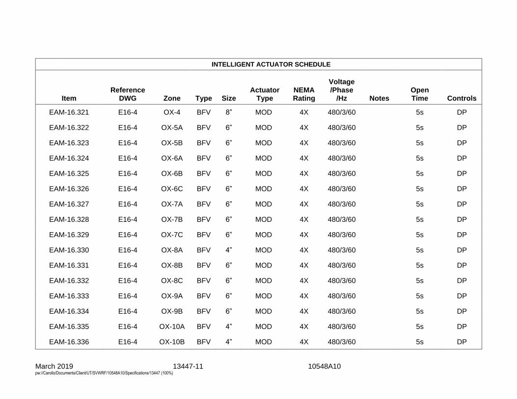
March 2019 13447-11 10548A10 pw://Carollo/Documents/Client/UT/SVWRF/10548A10/Specifications/13447 (100%)
INTELLIGENT ACTUATOR SCHEDULE
Item Reference
DWG Zone Type Size Actuator
Type NEMA Rating
Voltage /Phase
/Hz Notes Open Time Controls
EAM-16.321 E16-4 OX-4 BFV 8” MOD 4X 480/3/60 5s DP
EAM-16.322 E16-4 OX-5A BFV 6” MOD 4X 480/3/60 5s DP
EAM-16.323 E16-4 OX-5B BFV 6” MOD 4X 480/3/60 5s DP
EAM-16.324 E16-4 OX-6A BFV 6” MOD 4X 480/3/60 5s DP
EAM-16.325 E16-4 OX-6B BFV 6” MOD 4X 480/3/60 5s DP
EAM-16.326 E16-4 OX-6C BFV 6” MOD 4X 480/3/60 5s DP
EAM-16.327 E16-4 OX-7A BFV 6” MOD 4X 480/3/60 5s DP
EAM-16.328 E16-4 OX-7B BFV 6” MOD 4X 480/3/60 5s DP
EAM-16.329 E16-4 OX-7C BFV 6” MOD 4X 480/3/60 5s DP
EAM-16.330 E16-4 OX-8A BFV 4” MOD 4X 480/3/60 5s DP
EAM-16.331 E16-4 OX-8B BFV 6” MOD 4X 480/3/60 5s DP
EAM-16.332 E16-4 OX-8C BFV 6” MOD 4X 480/3/60 5s DP
EAM-16.333 E16-4 OX-9A BFV 6” MOD 4X 480/3/60 5s DP
EAM-16.334 E16-4 OX-9B BFV 6” MOD 4X 480/3/60 5s DP
EAM-16.335 E16-4 OX-10A BFV 4” MOD 4X 480/3/60 5s DP
EAM-16.336 E16-4 OX-10B BFV 4” MOD 4X 480/3/60 5s DP

March 2019 13447-12 10548A10 pw://Carollo/Documents/Client/UT/SVWRF/10548A10/Specifications/13447 (100%)
INTELLIGENT ACTUATOR SCHEDULE
Item Reference
DWG Zone Type Size Actuator
Type NEMA Rating
Voltage /Phase
/Hz Notes Open Time Controls
EAM-16.421 E16-5 OX-4 BFV 8” MOD 4X 480/3/60 5s DP
EAM-16.422 E16-5 OX-5A BFV 6” MOD 4X 480/3/60 5s DP
EAM-16.423 E16-5 OX-5B BFV 6” MOD 4X 480/3/60 5s DP
EAM-16.424 E16-5 OX-6A BFV 6” MOD 4X 480/3/60 5s DP
EAM-16.425 E16-5 OX-6B BFV 6” MOD 4X 480/3/60 5s DP
EAM-16.426 E16-5 OX-6C BFV 6” MOD 4X 480/3/60 5s DP
EAM-16.427 E16-5 OX-7A BFV 6” MOD 4X 480/3/60 5s DP
EAM-16.428 E16-5 OX-7B BFV 6” MOD 4X 480/3/60 5s DP
EAM-16.429 E16-5 OX-7C BFV 6” MOD 4X 480/3/60 5s DP
EAM-16.430 E16-5 OX-8A BFV 4” MOD 4X 480/3/60 5s DP
EAM-16.431 E16-5 OX-8B BFV 6” MOD 4X 480/3/60 5s DP
EAM-16.432 E16-5 OX-8C BFV 6” MOD 4X 480/3/60 5s DP
EAM-16.433 E16-5 OX-9A BFV 6” MOD 4X 480/3/60 5s DP
EAM-16.434 E16-5 OX-9B BFV 6” MOD 4X 480/3/60 5s DP
EAM-16.435 E16-5 OX-10A BFV 4” MOD 4X 480/3/60 5s DP
EAM-16.436 E16-5 OX-10B BFV 4” MOD 4X 480/3/60 5s DP
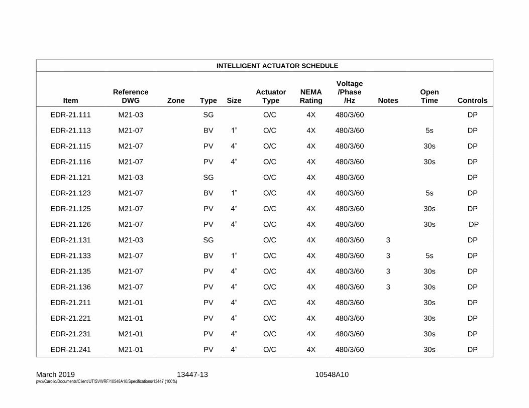
March 2019 13447-13 10548A10 pw://Carollo/Documents/Client/UT/SVWRF/10548A10/Specifications/13447 (100%)
INTELLIGENT ACTUATOR SCHEDULE
Item Reference
DWG Zone Type Size Actuator
Type NEMA Rating
Voltage /Phase
/Hz Notes Open Time Controls
EDR-21.111 M21-03 SG O/C 4X 480/3/60 DP
EDR-21.113 M21-07 BV 1” O/C 4X 480/3/60 5s DP
EDR-21.115 M21-07 PV 4” O/C 4X 480/3/60 30s DP
EDR-21.116 M21-07 PV 4” O/C 4X 480/3/60 30s DP
EDR-21.121 M21-03 SG O/C 4X 480/3/60 DP
EDR-21.123 M21-07 BV 1” O/C 4X 480/3/60 5s DP
EDR-21.125 M21-07 PV 4” O/C 4X 480/3/60 30s DP
EDR-21.126 M21-07 PV 4” O/C 4X 480/3/60 30s DP
EDR-21.131 M21-03 SG O/C 4X 480/3/60 3 DP
EDR-21.133 M21-07 BV 1” O/C 4X 480/3/60 3 5s DP
EDR-21.135 M21-07 PV 4” O/C 4X 480/3/60 3 30s DP
EDR-21.136 M21-07 PV 4” O/C 4X 480/3/60 3 30s DP
EDR-21.211 M21-01 PV 4” O/C 4X 480/3/60 30s DP
EDR-21.221 M21-01 PV 4” O/C 4X 480/3/60 30s DP
EDR-21.231 M21-01 PV 4” O/C 4X 480/3/60 30s DP
EDR-21.241 M21-01 PV 4” O/C 4X 480/3/60 30s DP
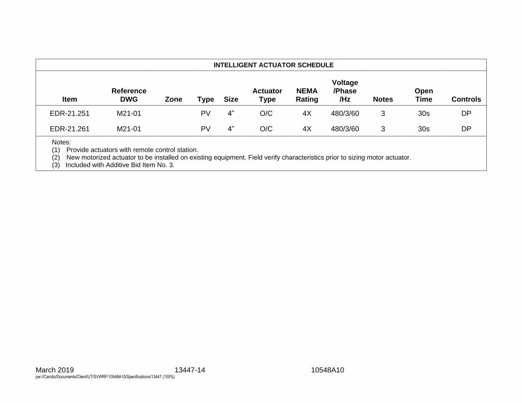
March 2019 13447-14 10548A10 pw://Carollo/Documents/Client/UT/SVWRF/10548A10/Specifications/13447 (100%)
INTELLIGENT ACTUATOR SCHEDULE
Item Reference
DWG Zone Type Size Actuator
Type NEMA Rating
Voltage /Phase
/Hz Notes Open Time Controls
EDR-21.251 M21-01 PV 4” O/C 4X 480/3/60 3 30s DP
EDR-21.261 M21-01 PV 4” O/C 4X 480/3/60 3 30s DP
Notes: (1) Provide actuators with remote control station. (2) New motorized actuator to be installed on existing equipment. Field verify characteristics prior to sizing motor actuator. (3) Included with Additive Bid Item No. 3.
March 2019 14592-1 10548A10 pw://Carollo/Documents/Client/UT/SVWRF/10548A10/Specifications/14592 (100%)
SECTION 14592
GRIT CHUTES AND STORAGE BINS
PART 1 GENERAL
1.01 SUMMARY
A. Section includes: 1. Stainless steel chutes and accessories. 2. Grit storage bins.
1.02 SYSTEM DESCRIPTION
A. General: 1. Grit chutes and bins shall be furnished by the same manufacturer. 2. Grit chutework as indicated on the drawings with diverter gates, rubber chute
connections to the dumpster, covers, connections and supports. a. Base Bid:
1) All chutework, diverter gates (3), limit switches, connections and inspection covers for dewatered grit conveyance from Grit Washer No. 1 and No. 2 as indicated on the drawings.
b. Alternative Bid Item No. 3: 1) All chutework, diverter gate (1), limit switches, connections and
inspection cover for dewatered grit conveyance from Grit Washer No. 3 as indicated on the drawings.
3. Two 15-cubic yard roll-off steel bins designed to receive and store dewatered grit. Lid to be sealed onto bin, with end hatch opening for removal of grit.
4. Manufacturer to coordinate with Owner and grit bin removal service company, Republic Services, for truck connection for proper roll off bin removal.
B. Design requirements: 1. Operation: The grit storage bin shall continuously receive dewatered grit from
the grit washers. 2. The storage capacity of dewatered grit shall be a minimum of 18,000 pounds
per bin.
1.03 REFERENCES
A. ASTM International (ASTM): 1. A36 - Standard Specification for Carbon Structural Steel. 2. A242 - Standard Specification for High-Strength Low-Alloy Structural Steel.
B. National Electrical Manufacturers Association (NEMA): 1. 250 - Enclosures for Electrical Equipment (1000 V Maximum).
1.04 SUBMITTALS
A. General: Submit as specified in Section 01330 - Submittal Procedures.
B. Calculations: Submit structural and seismic calculations.
March 2019 14592-2 10548A10 pw://Carollo/Documents/Client/UT/SVWRF/10548A10/Specifications/14592 (100%)
C. Operation and Maintenance manuals.
D. Special shipping, storage, protection and handling instructions where applicable.
E. Manufacturer’s installation instructions.
1.05 QUALITY ASSURANCE
A. Supplier qualifications: The successful supplier shall prove to have a minimum of 3 years successful experience producing bins and chutes similar to that specified in this Section.
PART 2 PRODUCTS
2.01 MANUFACTURERS
A. Sludge storage bin: One of the following or equal: 1. Custom Conveyor Corp. 2. JDV.
2.02 DUMPSTER AND LID
A. General: 1. Two 15-cubic yard rectangular roll off dumpsters, 11 feet long by 6 feet high by
8 feet wide. 2. Sealed tailgate with sliding hinge and ratchet latch. 3. End connection for truck removal to be coordinated with Owner and Republic
Services.
B. Construction: 1. The bin shall be constructed of ASTM A36-steel plate of minimum 3/16-inch
thickness and shall be reinforced with ASTM A36 structural steel.
C. Lid: 1. Cover enclosure:
a. 10 gauge 304 stainless steel cover enclosure. b. Lid Openings:
1) Two 12-inch by 12-inch square openings for grit entrance. 2) One 12-inch circular opening for foul air duct connection. 3) One 18-inch by 36-inch rectangle inspection hatch as indicated on
the drawings. 4) One 8-inch circular opening for air intake.
2. Lid to be hard mounted on the dumpster and air tight for odor control.
2.03 GRIT DISCHARGE CHUTES
A. Diverter Gates: 1. Fabricated from #10 gauge 316 stainless steel shapes and plates with a
1/4-inch 316 stainless steel UHMWP lined flap gate, with two 120-vac position limit switches.
2. All diverter gate locations shall have a removal chute cover for maintenance and inspection of diverter gates.
March 2019 14592-3 10548A10 pw://Carollo/Documents/Client/UT/SVWRF/10548A10/Specifications/14592 (100%)
3. Provide limit switches for diverter gates to indicate gate position. 4. Provide manual pull levers for operators to switch gate location.
B. Chutework: 1. Fabricated from #10 gauge 316 stainless steel, minimum 57 degree slope,
with 3/8-inch UHMWP bolted liner on sloped surfaces and designed as indicated on the drawings.
2. Manufacture to coordinate with grit washer manufacturer for chute flange connection to grit washing units.
3. Provide access openings at all diverter gates for maintenance and inspection of gates.
C. Supports: 1. Manufacturer shall design all supports and hangers for chutework. 2. Fabricated from 304 stainless steel shapes and plates.
D. Assembly: 1. Diverter gate, chute work and supports will be shipped loose for field
installation by contractor.
E. Finish: 1. Components hardware will have manufacturer’s standard finish. Fabricated
stainless steel items will be shop glass or sand brush blasted after fabrication to remove heat tint scale and provide a uniform finish. The equipment, after fabrication, shall undergo a passivation (pickling) process to ensure maximum resistance to corrosion. Submerge all stainless steel components and structures in a chemical bath of nitric acid and hydrofluoric acid to remove any residues that may be present on the material as a result of forming, manufacture, or handling. After removal from the pickling bath, wash the equipment with a high-pressure wash of cold water to remove any remaining surface debris and promote the formation of an oxidized passive layer that is critical to the long life of the stainless steel: a. Stainless steel assemblies that have not been submerged in an acid bath
or that do not have a uniform oxidized surface, free from rust spots, stains or blemishes will not accepted until removed from the Project site and re-submerged.
PART 3 EXECUTION
3.01 INSTALLATION
A. Install the Grit Chutes and Storage Bins as indicated on the Drawings and manufacturer's recommendations.
3.02 MANUFACTURER'S FIELD SERVICE
A. Manufacturer shall provide 2 days of field service for installation, inspection equipment, start-up and operation and maintenance training. 1. Start-up assistance: 1 trip; 1 workday:
a. Prior to start-up, the equipment shall be inspected for proper alignment, operation, and satisfactory performance.
b. Provide additional start-up/testing assistance as required.
March 2019 14592-4 10548A10 pw://Carollo/Documents/Client/UT/SVWRF/10548A10/Specifications/14592 (100%)
2. Training: As defined in Section 01756 - Commissioning and this Section: a. Maintenance: 4 hours per session, 1 session. b. Operation: 2 hours per session, 1 session.
END OF SECTION

March 2019 14624-1 10548A10 pw://Carollo/Documents/Client/UT/SVWRF/10548A10/Specifications/14624 (100%)
SECTION 14624
MONORAIL SYSTEM
PART 1 GENERAL
1.01 SUMMARY
A. Section includes: Monorail system, including trolley, hoist, monorail beam, restraint bracing, end stops, hangers and hanger connections to beams, and accessories.
1.02 REFERENCES
A. American Society of Mechanical Engineers (ASME): 1. B30.11 - Monorails and Underhung Cranes. 2. B30.16 - Overhead Hoists (Underhung).
B. American Institute of Steel Construction (AISC): 1. Specifications for Design, Fabrication, and Erection of Structural Steel for
Buildings.
C. American Welding Society (AWS).
D. Occupational Safety and Health Administration (OSHA).
E. Monorail Manufacturers' Association (MMA): 1. MH27.1 - Specifications for Underhung Cranes and Monorail Systems.
F. National Electrical Code (NEC): 1. Article 610 - Cranes and Hoists.
G. National Electrical Manufacturer's Association (NEMA): 1. 250 - Enclosures for Electrical Equipment (1000 V Maximum).
1.03 DEFINITIONS
A. NEMA 4X enclosure in accordance with NEMA 250.
1.04 SYSTEM DESCRIPTION
A. Design requirements: 1. Hoisting system: In accordance with ASME B30.11, ASME B30.16, and OSHA
standards. 2. Design monorail crane system for seismic design criteria as specified in
Section 01612 - Seismic Design Criteria. 3. Structural steel construction: In accordance with AISC Specifications. 4. Safety factor of castings, forgings, and stampings: Minimum 5 with regard to
ultimate strength. 5. Perform welding in accordance with AWS Standards. 6. Electrification in accordance with NEC 610. 7. Design equipment in accordance with MMA MH27.1.
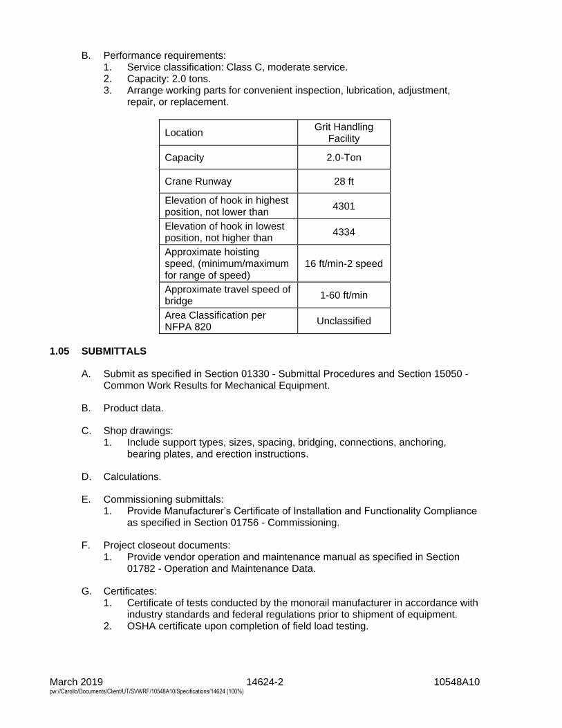
March 2019 14624-2 10548A10 pw://Carollo/Documents/Client/UT/SVWRF/10548A10/Specifications/14624 (100%)
B. Performance requirements: 1. Service classification: Class C, moderate service. 2. Capacity: 2.0 tons. 3. Arrange working parts for convenient inspection, lubrication, adjustment,
repair, or replacement.
Location Grit Handling
Facility
Capacity 2.0-Ton
Crane Runway 28 ft
Elevation of hook in highest position, not lower than
4301
Elevation of hook in lowest position, not higher than
4334
Approximate hoisting speed, (minimum/maximum for range of speed)
16 ft/min-2 speed
Approximate travel speed of bridge
1-60 ft/min
Area Classification per NFPA 820
Unclassified
1.05 SUBMITTALS
A. Submit as specified in Section 01330 - Submittal Procedures and Section 15050 - Common Work Results for Mechanical Equipment.
B. Product data.
C. Shop drawings: 1. Include support types, sizes, spacing, bridging, connections, anchoring,
bearing plates, and erection instructions.
D. Calculations.
E. Commissioning submittals: 1. Provide Manufacturer’s Certificate of Installation and Functionality Compliance
as specified in Section 01756 - Commissioning.
F. Project closeout documents: 1. Provide vendor operation and maintenance manual as specified in Section
01782 - Operation and Maintenance Data.
G. Certificates: 1. Certificate of tests conducted by the monorail manufacturer in accordance with
industry standards and federal regulations prior to shipment of equipment. 2. OSHA certificate upon completion of field load testing.
March 2019 14624-3 10548A10 pw://Carollo/Documents/Client/UT/SVWRF/10548A10/Specifications/14624 (100%)
1.06 DELIVERY, HANDLING, AND STORAGE
A. Assemble, paint, test, and adjust monorail system in manufacturer's shop before shipment as far as practical.
1.07 WARRANTY
A. Provide warranty as specified in Section 01783 - Warranties and Bonds.
PART 2 PRODUCTS
2.01 GENERAL
A. As specified in Section 15050 - Common Work Results for Mechanical Equipment.
2.02 MONORAIL
A. Manufacturers: One of the following or equal: 1. Cleveland Tramrail. 2. Trambeam Corp.
B. Maximum vertical deflection of monorail beam: Maximum span of monorail beam divided by 600.
C. Maximum lateral deflection of monorail beam: Maximum span of monorail beam divided by 360 when subjected to a lateral load of 20 percent of the lifted load.
D. Stops and bumpers: Adequate to absorb energy of and stop moving trolley at end of permitted travel.
E. Hangers: Adjustable, able to level and accurately align system within 1/8-inch tolerance, able to support monorail from building structure.
F. Labeling: Paint hoist capacity on monorail with minimum 4-inch high letters and numbers where clearly visible from operating floor.
G. Coating: Provide prime coat, intermediate coat, and finish coat as specified in Section 09960 - High-Performance Coatings.
2.03 TROLLEY HOISTS
A. Manufacturers: One of the following or equal: 1. Cleveland Tram Rail. 2. P&H Hevi-Lift. 3. Yale.
B. Type: Combination electric motor-driven trolleys and hoists, single-speed with trolley cushioned start, including mechanical brake, electrical brake, and upper hoist limit stop and load limiting device, low headroom.
C. Distance from bottom of rail to inside of hook: Maximum 25 inches with hook in fully raised position.
March 2019 14624-4 10548A10 pw://Carollo/Documents/Client/UT/SVWRF/10548A10/Specifications/14624 (100%)
D. Trolleys wheels: Single-flanged; forged steel, hardened to 425 Brinell; fitted with anti-friction bearings with lifetime seals; suitable for adjustment to monorails.
E. Safety lugs: Add safety lugs to manufacturer's standard design.
F. Motors: 460 volt, 3 phase, 60 hertz, totally enclosed non-ventilated (TENV), squirrel-cage induction type operating at maximum 1,800 revolutions per minute, with Class B or F insulation, horsepower as follows: 1. Hoist: 3. 2. Trolley: 3/4.
a. Actual horsepower requirement not to exceed the specified motor horsepower.
G. Drive units: Specially designed for monorail service with cushioned stop holding brakes.
H. Hoisting drum: Steel or cast iron with machined, 1/2 rope diameter deep grooves; adequate to provide minimum 2 complete rope wraps on drum with hook in lowest position, and to accommodate full length of rope without overlapping when in highest position.
I. Hoist drive speed reducer: With heat-treated steel helical gears; oil-lubricated with oiltight cases; shafts running in anti-friction bearings.
J. Limit switches and overload device: Manufacturer's standard.
K. Hoisting rope: Specifically designed for specified service loads; preformed, improved plow steel with fiber core; double-reeved.
L. Hoisting block: Steel with forged or cast steel hook supported on ball or roller bearings for true vertical lift.
M. Hook: Safety type, able to rotate freely on bearing support with heavy-duty type safety latches.
N. Bottom block: Shrouded.
O. Coating: Provide prime coat, intermediate coat, and finish coat in as specified in Section 09960 - High-Performance Coatings.
2.04 ELECTRIFICATION AND CONTROL
A. Electrification type: Cable and spring-loaded swiveled cable reel-mounted on structure.
B. Cable run: From junction box to cable reel, then to control unit.
C. Control unit: Pendant pushbutton station hanging from hoist to maximum 4 feet above operation floor.
D. Control voltage: 120 volts alternating current, supplied from transformer on hoist.
March 2019 14624-5 10548A10 pw://Carollo/Documents/Client/UT/SVWRF/10548A10/Specifications/14624 (100%)
E. Pushbuttons: Momentary-contact, maintain-pressure, automatically de-energizing upon relaxation of pressure; number and functions as follows: 1. Pushbuttons for hoisting: Two, 1 for each direction. 2. Pushbuttons for trolley: Two, 1 for each direction.
F. Enclosures for control unit, electrical control, and reel: NEMA 4X and to meet the requirements as specified in Sections 17050 - Common Work Results for Process Control and Instrumentation Systems and 17710 - Control Systems: Panels, Enclosures, and Panel Components.
G. Control unit support: Steel cable.
H. Control accessories: 1. Geared limit switch able to limit up and down travel with second switch
operated by hook to stop hoist when highest safe point is reached. 2. Magnetic contactors for up and down operation and control.
I. Junction boxes: Suitable for connection of field services with ground pads.
PART 3 EXECUTION
3.01 GENERAL
A. As specified in Section 15050 - Common Work Results for Mechanical Equipment.
B. Do not use monorail crane system for construction.
3.02 LOAD TESTING
A. Perform test in presence of OSHA certified manufacturer's representative and Engineer.
B. Test equipment with minimum load of 25 percent above rated capacity.
C. Provide load and slings for test: 1. Remove when tests are completed.
D. Operate equipment through complete lift and lowering cycle and through complete travel of trolley to demonstrate quiet, smooth, and safe hoisting, braking, and traveling.
3.03 COMMISSIONING
A. As specified in Section 01756 - Commissioning and this Section.
B. Manufacturer services: 1. Provide certificates:
a. Manufacturer’s Certificate of Installation and Functionality Compliance. 2. Manufacturer’s Representative onsite requirements:
a. Installation: 1 trip, 1 day minimum. b. Functional Testing: 1 trip, 1 day minimum each.
March 2019 14624-6 10548A10 pw://Carollo/Documents/Client/UT/SVWRF/10548A10/Specifications/14624 (100%)
3. Training: a. Maintenance: 4 hours per session, 1 session. b. Operation: 2 hours per session, 1 session.
C. Functional testing: 1. Perform test in presence of OSHA certified manufacturer's representative and
Engineer. 2. Test equipment with minimum load of 25 percent above rated capacity. 3. Provide load and slings for test:
a. Remove when tests are completed. 4. Operate equipment through complete lift and lowering cycle and through
complete travel of trolley to demonstrate quiet, smooth, and safe hoisting, braking, and traveling.
END OF SECTION
15050-1 10548A10 March 2019 pw://Carollo/Documents/Client/UT/SVWRF/10548A10/Specifications/15050 (100%)
SECTION 15050
COMMON WORK RESULTS FOR MECHANICAL EQUIPMENT
PART 1 GENERAL
1.01 SUMMARY
A. Section includes: Basic design and performance requirements for buildingmechanical equipment and process mechanical equipment.
1.02 REFERENCES
A. American Gear Manufacturer's Association (AGMA) Standards:1. 6001-E08 - Design and Selection of Components for Enclosed Gear Drives.
B. American Bearing Manufactures Association (ABMA) Standards:1. 9 - Load Ratings and Fatigue Life for Ball Bearings.2. 11 - Load Ratings and Fatigue Life for Roller Bearings.
C. American Petroleum Institute (API):1. 682 - Shaft Sealing Systems for Centrifugal and Rotary Pumps.
D. ASTM International (ASTM):1. A36 - Standard Specification for Carbon Structural Steel.2. A48 - Standard Specification for Gray Iron Castings.3. A125 - Standard Specification for Steel Springs, Helical, Heat-Treated.4. A193 - Standard Specification for Alloy-Steel and Stainless Steel Bolting for
High Temperature or High Pressure Service and Other Special PurposeApplications.
5. A194 - Standard Specification for Carbon and Alloy Steel Nuts for Bolts forHigh Pressure or High Temperature Service, or Both.
6. A320 - Standard Specification for Alloy-Steel and Stainless Steel Bolting forLow-Temperature Service.
7. A536 - Standard Specification for Ductile Iron Castings.8. A653 - Standard Specification for Steel Sheet, Zinc-Coated (Galvanized) or
Zinc-Iron Alloy-Coated (Galvannealed) by the Hot-Dip Process.9. B61 - Standard Specification for Steam or Valve Bronze Castings.10. B62 - Standard specification for Composition Bronze or Ounce Metal Castings.11. B505 - Standard Specification for Copper Alloy Continuous Castings.12. B584 - Standard Specification for Copper Alloy Sand Castings for General
Applications.13. F593 - Standard Specification for Stainless Steel Bolts, Hex Cap Screws, and
Studs.14. F594 - Standard Specification for Stainless Steel Nuts.
E. Hydraulic Institute (HI).
F. Occupational Safety and Health Administration (OSHA).
G. Unified Numbering System (UNS).
15050-2 10548A10 March 2019 pw://Carollo/Documents/Client/UT/SVWRF/10548A10/Specifications/15050 (100%)
1.03 DEFINITIONS
A. Resonant frequency: That frequency at which a small driving force produces anever-larger vibration if no dampening exists.
B. Rotational frequency: The revolutions per unit of time usually expressed asrevolutions per minute.
C. Critical frequency: Same as resonant frequency for the rotating elements or theinstalled machine and base.
D. Peak vibration velocity: The root mean square average of the peak velocity of thevibrational movement times the square root of 2 in inches per second.
E. Rotational speed: Same as rotational frequency.
F. Maximum excitation frequency: The excitation frequency with the highest vibrationvelocity of several excitation frequencies that are a function of the design of aparticular machine.
G. Critical speed: Same as critical frequency.
H. Free field noise level: Noise measured without any reflective surfaces (an idealizedsituation); sound pressure levels at 3 feet from the source unless specifiedotherwise.
I. Operating weight: The weight of unit plus weight of fluids or solids normallycontained in unit during operation.
1.04 DESIGN REQUIREMENTS
A. General:1. Product requirements as specified in Section 01600 - Product Requirements.2. Project conditions as specified in Section 01610 - Project Design Criteria.3. Provisions specified under each technical equipment specification prevail over
and supersede conflicting provisions specified in this Section.4. Equipment manufacturer's responsibility extends to selection and mounting of
gear drive units, motors or other prime movers, accessories, and auxiliariesrequired for proper operation.
5. Vibration considerations:a. Resonant frequency:
1) For single-speed equipment, ensure there are no natural resonantfrequencies within 25 percent above or below the operating rotationalfrequencies or multiples of the operating rotational frequencies thatmay be excited by the equipment design.
2) For variable-speed equipment, ensure there are no natural resonantfrequencies within 25 percent above or below the range of operatingfrequencies.
b. Design, balance, and align equipment to meet the vibration criteriaspecified in Section 15958 - Mechanical Equipment Testing.
6. Equipment units weighing 50 pounds or more: Provide with lifting lugs or eyesto allow removal with hoist or other lifting device.
15050-3 10548A10 March 2019 pw://Carollo/Documents/Client/UT/SVWRF/10548A10/Specifications/15050 (100%)
B. Power transmission systems:1. V-belts, sheaves, shaft couplings, chains, sprockets, mechanical
variable-speed drives, variable frequency drives, gear reducers, open andenclosed gearing, clutches, brakes, intermediate shafting, intermediatebearings, and U-joints are to be rated for 24 hour-a-day continuous service orfrequent stops-and-starts intermittent service, whichever is most severe, andsized with a service factor of 1.5 or greater in accordance with manufacturerrecommendations:a. Apply service factor to nameplate horsepower and torque of prime source
of power and not to actual equipment loading.b. Apply service factors in accordance with AGMA 6001-E08, other
applicable AGMA standards, or other applicable referenced standards.
C. Equipment mounting and anchoring:1. Mount equipment on cast-iron or welded-steel bases with structural steel
support frames.a. Utilize continuous welds to seal seams and contact edges between steel
members.b. Grind welds smooth.
2. Provide bases and supports with machined support pads, dowels for alignmentof mating of adjacent items, adequate openings to facilitate grouting, andopenings for electrical conduits.
3. Provide jacking screws in bases and supports for equipment weighing over1,000 pounds.
4. Design equipment anchorage, supports, and connections for dead load,running loads, loads during start-up, seismic load specified in Section 01612 -Seismic Design Criteria, and other loads as required for proper operation ofequipment.a. For equipment with an operating weight of 400 pounds or greater and all
equipment that is supported higher than 4 feet above the floor, providecalculations for:1) The operating weight and location of the centroid of mass for the
equipment.2) Forces and overturning moments.3) Shear and tension forces in equipment anchorages, supports, and
connections.4) The design of equipment anchorage, supports, and connections
based on calculated shear and tension forces.5. Anchorage of equipment to concrete or masonry:
a. Perform calculations and determine number, size, type, strength, andlocation of anchor bolts or other connections.
b. Unless otherwise indicated on the Drawings, select and provide anchorsfrom the types specified in Section 05190 - Mechanical Anchoring andFastening to Concrete and Masonry.
c. Provide bolt sleeves around cast-in anchor bolts for 400 pounds or greaterequipment.1) Adjust bolts to final location and secure the sleeve.
6. Anchorage of equipment to metal supports:a. Perform calculations and determine number, size, type, strength, and
location of bolts used to connect equipment to metal supports.7. Unless otherwise indicated on the Drawings, install equipment supported on
concrete over non-shrink grout pads as specified in this Section.
15050-4 10548A10 March 2019 pw://Carollo/Documents/Client/UT/SVWRF/10548A10/Specifications/15050 (100%)
1.05 SUBMITTALS
A. As specified in Section 01600 - Product Requirements.
B. Product data:1. For each item of equipment:
a. Design features.b. Load capacities.c. Efficiency ratings.d. Material designations by UNS alloy number or ASTM Specification and
Grade.e. Data needed to verify compliance with the Specifications.f. Catalog data.g. Nameplate data.h. Clearly mark submittal information to show specific items, materials, and
accessories or options being furnished.2. Gear reduction units:
a. Engineering information in accordance with applicable AGMA standards.b. Gear mesh frequencies.
C. Shop drawings:1. Drawings for equipment:
a. Drawings that include cut-away drawings, parts lists, material specificationlists, and other information required to substantiate that proposedequipment complies with specified requirements.
2. Outline drawings showing equipment, driver, driven equipment, pumps, seal,motor(s) or other specified drivers, variable frequency drive, shafting, U-joints,couplings, drive arrangement, gears, base plate or support dimensions, anchorbolt sizes and locations, bearings, and other furnished components.
3. Installation instructions including leveling and alignment tolerances, grouting,lubrication requirements, and initial Installation Testing procedures.
4. Wiring, control schematics, control logic diagrams and ladder logic or similarfor computer-based controls.
5. Recommended or normal operating parameters such as temperatures andpressures.
6. Alarm and shutdown setpoints for all controls furnished.
D. Calculations:1. Structural:
a. Substantiate equipment base plates, supports, bolts, anchor bolts, andother connections meet minimum design requirements specified andseismic design criteria as specified in Section 01612 - Seismic DesignCriteria.
2. Mechanical:a. ABMA 9 or ABMA 11 L10 life for bearings calculation methods for drivers,
pumps, gears, shafts, motors, and other driveline components withbearings.
b. Substantiate that operating rotational frequencies meet the requirementsof this Section.
15050-5 10548A10 March 2019 pw://Carollo/Documents/Client/UT/SVWRF/10548A10/Specifications/15050 (100%)
c. Torsional analysis of power transmission systems: When torsionalanalysis specified in the equipment sections, provide:1) Sketch of system components identifying physical characteristics
including mass, diameter, thickness, and stiffness.2) Results of analysis including first and second critical frequencies of
system components and complete system.d. Calculations shall be signed and stamped by a licensed engineer.
3. Drinking water:a. If applicable, conform to the requirements of Section 01600 - Product
Requirements for materials in contact with drinking water.
E. Operation and maintenance manuals:1. As specified in Section 01782 - Operating and Maintenance Data.2. Equipment with bearings:
a. Include manufacturer and model number of every bearing.b. Include calculated ball pass frequencies of the installed equipment for
both the inner and outer raceways.
F. Commissioning submittals: As specified in Section 01756 - Commissioning.
G. Project closeout documents: As specified in Section 01770 - Closeout Procedures.
PART 2 PRODUCTS
2.01 MATERIALS
A. Materials as specified in Section 01600 - Product Requirements including specialrequirements for materials in contact with drinking water.
B. Ferrous materials:1. Steel for members used in fabrication of assemblies: ASTM A36.2. Iron castings: ASTM A48, tough, close-grained gray iron, free from blowholes,
flaws, and other imperfections.3. Ductile iron castings: ASTM A536, Grade 65-45-12, free from flaws and
imperfections.4. Galvanized steel sheet: ASTM A653, minimum 0.0635-inch (16-gauge).5. Expanded metal: ASTM A36, 13-gauge, 1/2-inch flat pattern expanded metal.6. Stainless steel:
a. As specified in Section 05120 - Structural Steel.b. In contact or within 36 inches of water: Type 316 or 316L. Provide L grade
where welding is required.c. Other locations: Type 304 or 304L. Provide L grade where welding is
required.d. Source cleaning and passivation as specified in Section 05120 - Structural
Steel.
C. Non-ferrous materials:1. Bronze in contact with drinking water: Composition of not more than 2 percent
aluminum nor more than 6 percent zinc; UNS Alloy C89833 in accordance withASTM B61, B62, B505, or B584, when not specified otherwise.
15050-6 10548A10 March 2019 pw://Carollo/Documents/Client/UT/SVWRF/10548A10/Specifications/15050 (100%)
2. Bronze in contact with wastewater: Composition of not more than 2 percentaluminum nor more than 6 percent zinc; UNS Alloy C83600 in accordance withASTM B61, B62, B505, or B584, when not specified otherwise.
3. Aluminum: As specified in Section 05140 - Structural Aluminum.
D. Dielectric materials for separation of dissimilar metals:1. Neoprene, bituminous impregnated felt, heavy bituminous coatings,
nonmetallic separators or washers, or other materials as specified.
E. Non-shrink grout and epoxy non-shrink grout: As specified in Section 03600 -Grouting.
2.02 ANCHORS AND FASTENERS
A. General:1. Material: As specified in the individual specifications.2. Where fasteners are specified to be galvanized, shall be galvanized in
accordance with ASTM A153 or ASTM F2329.
B. Mechanical anchoring to concrete and masonry:1. As specified in Section 05190 - Mechanical Anchoring and Fastening to
Concrete and Masonry:a. Type 316 stainless steel.
2. Design as specified in Section 01612 - Seismic Design Criteria.3. Secure products in place with positive anchorage devices designed and sized
to withstand stresses, vibration, and racking.
C. High-strength fasteners:1. As specified in Section 05120 - Structural Steel.
D. Flange bolts:1. As specified in Section 15052 - Common Work Results for General Piping.
E. Mechanical assembly fasteners:1. Stainless steel:
a. High-temperature service or high-pressure service:1) Bolts: ASTM A193, Grade B8 (Type 304) or Grade B8M (Type 316),
Class 1, heavy hex.2) Nuts: ASTM A194, Grade 8, heavy hex.3) Washers: Alloy group matching bolts and nuts.
b. Low-temperature service:1) Bolts: ASTM A320, Grade B8 (Type 304) or Grade B8M (Type 316),
Class 1, heavy hex.2) Nuts: ASTM A194, Grade 8 (Type 304) or Grade B8M (Type 316),
heavy hex.3) Washers: Alloy group matching bolts and nuts.
c. General service:1) Bolts: ASTM F593, Alloy Group 1 (Type 304) or Alloy Group 2
(Type 316).2) Nuts: ASTM F594, Alloy Group 1 (Type 304) or Alloy Group 2
(Type 316).3) Washers: Alloy group matching bolts and nuts.
15050-7 10548A10 March 2019 pw://Carollo/Documents/Client/UT/SVWRF/10548A10/Specifications/15050 (100%)
2.03 SHAFT COUPLINGS
A. General:1. Type and ratings: Provide non-lubricated type, designed for not less than
50,000 hours of operating life.2. Sizes: Provide as recommended by manufacturer for specific application,
considering horsepower, speed of rotation, and type of service.
B. Shaft couplings for close-coupled electric-motor-driven equipment:1. Use for:
a. Equipment 1/2 horsepower or larger.b. Reversing equipment.c. Equipment subject to sudden torque reversals or shock loading:d. Examples:
1) Reciprocating pumps, blowers, and compressors.2) Conveyor belts.
2. Manufacturers: One of the following or equal:a. Lovejoy, S-Flex.b. T.B. Woods, Dura Flex, L-Jaw C-Jaw or G-Jaw.
3. Provide flexible couplings designed to accommodate angular misalignment,parallel misalignment, and end float.
4. Manufacture flexible component of coupling from synthetic rubber or urethane.5. Provide service factor of 2.5 for electric motor drives and 3.5 for engine drives.6. Do not allow metal-to-metal contact between driver and driven equipment.
C. Shaft couplings for direct-connected electric-motor-driven equipment:1. Use for 1/2 horsepower or larger and subject to normal torque, non-reversing
applications.2. Manufacturers: One of the following or equal:
a. Rexnord - Falk.b. T.B. Woods, Dura-Flex, Sure-Flex or Form Flex.
3. Provide flexible couplings designed to accommodate shock loading, vibration,and shaft misalignment or offset.
4. Provide flexible connecting element of rubber and reinforcement fibers.5. Provide service factor of 2.0.6. Connect stub shafts through collars or round flanges, firmly keyed to their
shafts with neoprene cylinders held to individual flanges by through pins.
D. Spacer couplings: Where cartridge-type mechanical seals or non-split seals arespecified, provide a spacer-type coupling of sufficient length to remove the sealwithout disturbing the driver or driven equipment unless noted otherwise in theindividual equipment specifications.
E. Specialized couplings: Where requirements of equipment dictate specializedfeatures, supply coupling recommended for service by manufacturer:1. Includes any engine-driven equipment.
2.04 STUFFING BOX, SEAL CHAMBER, AND SHAFT SEALS
A. General:1. Unless otherwise noted in the equipment section, provide cartridge-type,
double mechanical shaft seals for pumps.2. Provide a stuffing box large enough for a double mechanical seal.
15050-8 10548A10 March 2019 pw://Carollo/Documents/Client/UT/SVWRF/10548A10/Specifications/15050 (100%)
3. Where packing is specified, provide stuffing box large enough to receive adouble mechanical seal.
4. Provide seal or packing flush connections, (3/4-inch size unless another size isindicated on the Drawings).
5. Provide and route leakage drain line to nearest equipment floor drain indicatedon the Drawings.
6. For pumps with packing, design packing gland to allow adjustment andrepacking without dismantling pump except to open up packing box.
7. Seal or packing flush requirements shall be in accordance with APIStandard 682 requirements. Unless otherwise indicated, specified or requiredby the equipment and seal manufacturers, the following API flushing Planarrangements shall be utilized as appropriate for the application:a. Single seal, clean water applications: Plan 11 (Discharge bypass to seal).b. Single seal, vertical pump applications: Plan 13 (Seal bypass to suction).c. Single seal, clean hot water (greater than 180 degrees Fahrenheit)
applications: Plan 23 (Seal cooler and pumping ring).d. Single seal, solids, or contaminants containing water applications: Plan 32
(External seal water).e. Double seal applications: Plan 54 (External seal water).
B. Packing: When specified in the equipment section of the specifications, provide thefollowing type of packing:1. Wastewater, water, and sludge applications:
a. Asbestos free.b. PTFE (Teflon) free.c. Braided graphite.d. Manufacturers: One of the following or equal:
1) Chesterton, 1400.2) John Crane, equivalent product.
e. Drinking water service:f. Asbestos free.g. Material: Braided PTFE (Teflon).h. Manufacturers: One of the following or equal:
1) Chesterton, 1725.2) John Crane, equivalent product.
C. Mechanical seals: Provide seal types specified in the equipment sections and asspecified.1. Provide seal types meeting the following requirements:
a. Balanced hydraulically.b. Spring: Stationary, out of pumping fluid, Hastelloy C; Type Elgiloy or
17-7 PH stainless steel for split seals.c. O-ring: Viton 747.d. Gland: Type 316L stainless steel.e. Set screws: Type 316L stainless steel.f. Faces: Reaction bonded, silicon carbide.g. Seal designed to withstand 300 pounds per square inch gauge minimum
differential pressures in either direction; no requirement for seal bufferpressure to be maintained when pump is not operational even thoughprocess suction head may be present in pump.
15050-9 10548A10 March 2019 pw://Carollo/Documents/Client/UT/SVWRF/10548A10/Specifications/15050 (100%)
2. Cartridge-type single mechanical:a. Manufacturers: One of the following or equal:
1) Chesterton, S10.2) John Crane, 5610 Series.
3. Cartridge-type double mechanical: Manufacturers:a. One of the following or equal:
1) Chesterton, S20.2) John Crane, 5620 Series.
4. Split-face single mechanical: Manufacturers:a. One of the following or equal:
1) Chesterton, 442.2) John Crane, 3740.
2.05 GEAR REDUCTION UNITS
A. Type: Helical or herringbone, unless otherwise specified.
B. Design:1. Made of alloys treated for hardness and for severe service.2. AGMA Class II service:
a. Use more severe service condition when such is recommended by unit'smanufacturer.
3. Cast-iron housing with gears running in oil.4. Anti-friction bearings.5. Thermal horsepower rating based on maximum horsepower rating of prime
mover, not actual load.6. Manufactured in accordance with applicable AGMA standards.
C. Planetary gear units are not to be used.
2.06 BELT DRIVES
A. Sheaves:1. Separately mounted on bushings by means of at least 3 pull-up bolts or cap
tightening screws.2. When 2 sheave sizes are specified, provide separate belts sized for each set
of sheaves.3. Statically balanced for all; dynamically balanced for sheaves that operate at a
peripheral speed of more than 5,500 feet per minute.4. Key bushings to drive shaft.
B. Belts: Anti-static type when explosion-proof equipment or environment is specified.1. When spare belts are specified, furnish 1 spare belt for every different type
and size of belt-driven unit:a. Where 2 or more belts are involved, furnish matched sets.b. Identify as to equipment, design, horsepower, speed, length, sheave size,
and use.c. Package in boxes labeled with identification of contents.

March 2019 15050-10 10548A10 pw://Carollo/Documents/Client/UT/SVWRF/10548A10/Specifications/15050 (100%)
C. Manufacturers: One of the following or equal:1. Dodge, Dyna-V belts with matching Dyna-V sheaves and Taper-Lock
bushings.2. T.B. Woods, Ultra-V belts with matching Sure-Grip sheaves and Sure-Grip
bushings.
2.07 BEARINGS
A. Type: Oil or grease lubricated, ball or roller antifriction type, of standardmanufacture.
B. Oil-lubricated bearings: Provide either pressure lubricating system or separate oilreservoir splash-type system:1. Size oil-lubrication systems to safely absorb heat energy generated in
bearings when equipment is operating under normal conditions and with thetemperature 15 degrees Fahrenheit above the maximum design temperatureas specified in Section 01610 - Project Design Criteria.
2. Provide an external oil cooler when required to satisfy the specified operatingconditions:a. Provide air-cooled system if a water-cooling source is not indicated on the
Drawings.b. Equip oil cooler with a filler pipe and external level gauge.
C. Grease lubricated bearings, except those specified to be factory sealed: Fit witheasily accessible grease supply, flush, drain, and relief fittings.1. Lubrication lines and fittings:
a. Lines: Minimum 1/4-inch diameter stainless steel tubing.b. Multiple fitting assemblies: Mount fittings together in easily accessible
location.c. Use standard hydraulic-type grease supply fittings:
1) Manufacturers: One of the following or equal:a) Alenite.b) Zerk.
D. Ratings: Rated in accordance with ABMA 9 or ABMA 11 L10 life for bearings ratinglife of not less than 50,000 hours.1. Higher ratings, when specified in other Sections, supersede preceding
requirements.
2.08 MOTORS
A. As specified in Section 16222 - Low Voltage Motors Up to 500 Horsepower.
2.09 GEAR MOTORS
A. Motors as specified in Section 16222 - Low Voltage Motors Up to 500 Horsepower.
B. Helical gearing for parallel shaft drives and worm gearing for right-angle drives.
C. Manufactures: One of the following or equal:1. Baldor Electric Company.2. Bodine Electric Company.
March 2019 15050-11 10548A10 pw://Carollo/Documents/Client/UT/SVWRF/10548A10/Specifications/15050 (100%)
2.10 EQUIPMENT SUPPORT FRAMES
A. Bolt holes shall not exceed bolt diameter by more than 25 percent, up to a limitingmaximum diameter oversize of 1/4-inch.
2.11 PIPING AND VALVES
A. Piping as specified in Section 15052 - Common Work Results for General Piping.
B. Valves as specified in Section 15110 - Common Work Results for Valves.
2.12 SAFETY EQUIPMENT
A. Safety guards:1. Provide guards that protect personnel from rotating shafts or components
within 7.5 feet of floors or operating platforms.2. Requirements:
a. Allow visual inspection of moving parts without removal.b. Allow access to lubrication fittings.c. Prevent entrance of rain or dripping water for outdoor locations.d. Size belt and sheave guards to allow for installation of sheaves 15 percent
larger and addition of 1 belt.3. Materials:
a. Sheet metal: Carbon steel, 12-gauge minimum thickness, hot-dipgalvanized after fabrication.
b. Fasteners: Type 304 stainless steel.
B. Insulation:1. Insulate all surfaces with normal operating temperatures above 120 degrees
Fahrenheit when surface is within 7.5 feet height from any operating floor orlevel.
2. Insulation thickness such that temperature is below 120 degrees Fahrenheit.3. Insulation Type 3 and cover Type 5 as specified in Section 15082 - Piping
Insulation.
C. Warning signs:1. Provide warning signs in accordance with OSHA requirements for equipment
that starts automatically or remotely.2. Material, sign size, and text: As specified in Section 10400 - Signage.3. Mount warning signs with stainless steel fasteners at equipment.
2.13 SPRING VIBRATION ISOLATORS
A. Design requirements:1. Telescopic top and bottom housing with vertical stabilizers to resist lateral and
vertical forces.2. Use steel coil springs.3. Design vibration isolators in accordance with seismic design criteria as
specified in Section 01612 - Seismic Design Criteria.
B. Performance requirements: Minimum spring deflection of 1-inch under static loadand capable of limiting transmissibility to 10 percent maximum at design operatingload.
March 2019 15050-12 10548A10 pw://Carollo/Documents/Client/UT/SVWRF/10548A10/Specifications/15050 (100%)
C. Manufacturers: One of the following or equal:1. California Dynamics Corporation, Type RJSD.2. Mason Industries, equivalent product.
D. Materials:1. Fabricate isolators using welded-steel or shatterproof ductile iron in
accordance with ASTM A536 Grade CS-45-12.2. Spring steel: ASTM A125.
2.14 NAMEPLATES
A. Fastened to equipment at factory in an accessible and visible location.
B. Stainless steel sheet engraved or stamped with text, holes drilled or punched forfasteners.
C. Fasteners: Number 4 or larger oval head stainless steel screws or drive pins.
D. Text:1. Manufacturer’s name, equipment model number and serial number, motor
horsepower when appropriate, and identification tag number.2. Indicate the following additional information as applicable:
a. Maximum and normal rotating speed.b. Service class per applicable standards.
3. Include for pumps:a. Rated total dynamic head in feet of fluid.b. Rated flow in gallons per minute.c. Impeller, gear, screw, diaphragm, or piston size.
4. Include for gear reduction units:a. AGMA class of service.b. Service factor.c. Input and output speeds.
2.15 SHOP FINISHES
A. Provide appropriate factory coatings as specified in Section 09960 -High-Performance Coatings.1. Motors and gear reducers: Shop finish paint with manufacturer's standard
coating, unless otherwise specified in the individual equipment specification.
2.16 SPECIAL TOOLS
A. Supply 1 set of special tools as specified in Section 01600 - Product Requirements.
2.17 SOURCE TESTING
A. Testing requirements unless specified otherwise in the individual equipmentspecifications:1. Mechanical equipment: Level 1 General Equipment Performance Test as
specified in Section 15958 - Mechanical Equipment Testing.2. Motors: As specified in Section 16222 - Low Voltage Motors Up to
500 Horsepower.
March 2019 15050-13 10548A10 pw://Carollo/Documents/Client/UT/SVWRF/10548A10/Specifications/15050 (100%)
3. Vendor control panels: As specified in Section 17950 - Testing, Calibration,and Commissioning.
2.18 SHIPPING
A. As specified in Section 01600 - Product Requirements.
B. Prior to shipment of equipment:1. Bearings (and similar items):
a. Pack separately or provide other protection during transport.b. Greased and lubricated.
2. Gear boxes:a. Oil filled or sprayed with rust preventive protective coating.
3. Fasteners:a. Inspect for proper torques and tightness.
PART 3 EXECUTION
3.01 DELIVERY, HANDLING, STORAGE, AND PROTECTION
A. As specified in Section 01600 - Product Requirements.
B. Inspect fasteners for proper torques and tightness.
C. Storage:1. Bearings:
a. Rotate units at least once per month or more often as recommended bythe manufacturer to protect rotating elements and bearings.
2. Gear boxes:a. Inspect to verify integrity of protection from rust.
D. Protection:1. Equipment Log shall include description of rotation performed as part of
maintenance activities.
3.02 INSTALLATION
A. Field measurements:1. Prior to shop drawings preparation, take measurements and verify dimensions
indicated on the Drawings.2. Ensure equipment and ancillary appurtenances fit within available space.
B. Sequencing and scheduling:1. Equipment anchoring: Obtain anchoring material and templates or setting
drawings from equipment manufacturers in adequate time for anchors to becast-in-place.
2. Coordinate details of equipment with other related parts of the Work, includingverification that structures, piping, wiring, and equipment components arecompatible.
C. Metal work embedded in concrete:1. Accurately place and hold in correct position while concrete is being placed.
March 2019 15050-14 10548A10 pw://Carollo/Documents/Client/UT/SVWRF/10548A10/Specifications/15050 (100%)
2. Clean surface of metal in contact with concrete immediately before concrete isplaced.
D. Concrete surfaces designated to receive non-shrink grout:1. Heavy sandblast concrete surface in contact with non-shrink grout.2. Clean concrete surfaces of sandblasting sand, grease, oil, dirt, and other
foreign material that may reduce bond to non-shrink grout.3. Saturate concrete with water. Concrete shall be saturated surface damp at
time non-shrink grout is placed.
E. Install equipment in accordance with manufacturer's installation instructions andrecommendations.
F. Lubrication lines and fittings:1. Support and protect lines from source to point of use.2. Fittings:
a. Bring fittings to outside of equipment in manner such that they are readilyaccessible from outside without necessity of removing covers, plates,housings, or guards.
b. Mount fittings together wherever possible using factory-mounted multiplefitting assemblies securely mounted, parallel with equipment lines, andprotected from damage.
c. Fittings for underwater bearings: Bring fittings above water surface andmount on edge of structure above.
G. Alignment of drivers and equipment:1. Where drive motors or other drivers are connected to driven equipment by
flexible coupling, disconnect coupling halves and align driver and equipmentafter complete unit has been leveled on its foundation.
2. Comply with procedures of appropriate HI, AGMA Standards, alignmenttolerances of equipment manufacturers and the following requirements to bringcomponents into angular and parallel alignment:a. Maximum total coupling offset (not the per-plane offset): Not to exceed
0.5 mils per inch of coupling length for spacer couplings based oncoupling length (not dial separation).
b. Utilize jacking screws, wedges, or shims as recommended by theequipment manufacturer and as specified in the equipment sections.
3. Use reverse-indicator arrangement dial-type or laser-type alignment indicators:Mount indicators on the driver/coupling flange and equipment/coupling flange.Alignment instrumentation accuracy shall be sufficient to read angular andradial misalignment at 10 percent or less of the manufacturer's recommendedacceptable misalignment.
4. Alignment and calculations shall include measurement and allowance forthermal growth, spacer coupling length, indicator separation, and axial spacingtolerances of the coupling.
5. When alignment satisfies most stringent tolerance of system components,grout between base and foundation.a. Allow minimum 48 hours for grout to harden.b. After grout hardens, remove jacking screws, tighten anchor bolts and
other connections, and recheck alignment.c. Correct alignment as required.
March 2019 15050-15 10548A10 pw://Carollo/Documents/Client/UT/SVWRF/10548A10/Specifications/15050 (100%)
6. After functional testing is complete, dowel motor or drivers and drivenequipment:a. Comply with manufacturer's instructions.
H. Grouting under equipment bases, baseplates, soleplates, and skids:1. Unless otherwise indicated on the Drawings, grout with non-shrink grout as
specified in Section 03600 - Grouting.a. Non-shrink epoxy grout required only when indicated on the Drawings.
2. Comply with equipment manufacturer's installation instructions for groutingspaces, and tolerances for level and vertical and horizontal alignment.
3. Install grout only after:a. Equipment is leveled and in proper alignment.b. Piping connections are complete and in alignment with no strain
transmitted to equipment.4. Do not use leveling nuts on equipment anchors for supporting and leveling
equipment bases, baseplates, soleplates, and skids for grouting.5. Use jack screws for supporting and leveling equipment bases, baseplates,
soleplates, and skids for grouting following the procedure defined below:a. Drill and tap equipment base plates, sole plates, and skids for jack
screws.b. Use suitable number and size of jack screws.c. End of jack screws shall bear on circular steel plates epoxy bonded to
equipment foundation.d. Jack screw threads that will be in contact with grout: Wrap with multiple
layers of tape or other material, acceptable to Engineer, to prevent groutfrom bonding to threads.
e. Place and cure grout as specified in Section 03600 - Grouting.f. After grout is cured, remove jack screws and material used to prevent
bonding to grout.1) Provide jack screws to Owner for future use.
g. Tighten equipment anchors in accordance with equipment manufacturerrequirements.
h. Fill holes where jack screws have been removed with grout.i. Cure as specified in Section 03600 - Grouting.
6. For equipment bases, baseplates, soleplates, and skids where it is notpractical to use jack screws, use steel wedges and shims.a. Wrap wedges and shims that contact grout with multiple layers of tape or
other material, acceptable to Engineer, to prevent grout from bonding.b. Place and cure grout as specified in Section 03600 - Grouting.c. Remove wedges or shims.d. Tighten equipment anchors to in accordance with equipment
manufacturer requirements.e. Fill voids where wedges and shims have been removed with grout.f. Cure as specified in Section 03600 - Grouting.
7. Preparation of equipment bases, baseplates, soleplates, and skids forgrouting:a. Metal in contact with grout: Grit blast to white metal finish.b. Clean surfaces of equipment bases, baseplates, soleplates, and skids in
contact with grout of dirt, dust, oil, grease, paint, and other material thatwill reduce bond.
8. Preparation of concrete equipment foundation for grouting:a. Rough concrete surfaces in contact with grout.
March 2019 15050-16 10548A10 pw://Carollo/Documents/Client/UT/SVWRF/10548A10/Specifications/15050 (100%)
b. Concrete contact surface shall be free of dirt, dust, laitance, particles,loose concrete, or other material or coatings that will reduce bond.
c. Saturate concrete contact surface area with water for minimum of24 hours prior to grouting.
d. Remove standing water just prior to grout placement, using clean rags oroil-free compressed air.
9. Forms and header boxes:a. Build forms for grouting of material with adequate strength to withstand
placement of grouts.b. Use forms that are rigid and liquid tight. Caulk cracks and joints with an
elastomeric sealant.c. Line forms with polyethylene film for easy grout release. Forms carefully
waxed with 2 coats of heavy-duty paste wax will also be acceptable.10. Grout placement requirements:
a. Minimum ambient and substrate temperature: 45 degrees Fahrenheit andrising:1) Conform to grout manufacturer’s temperature requirements.
b. Pour grout using header box.c. Keep level of grout in header box above bottom of equipment bases,
baseplates, soleplates, and skids at all times to prevent air entrapment.d. Grout shall flow continuously from header box to other side of forms
without trapping air or forming voids.e. Vibrate, rod, or chain grout to facilitate grout flow, consolidate grout, and
remove entrapped air.f. After grout sets, remove forms and trim grout at 45-degree angle from
bottom edge of equipment bases, baseplates, soleplates, and skids.g. Cure as specified in Section 03600 - Grouting.
I. Field welding:1. Use welding procedures, welders, and welding operators qualified and certified
in accordance with AWS D1.1.2. Shielded arc welding.
J. Field finishes:1. Protect motors.2. Clean equipment.3. Apply primer and coating systems as specified in Section 09960 -
High-Performance Coatings requirements.
K. Special techniques:1. Use applicable special tools and equipment, including precision machinist
levels, dial indicators, and gauges as required in equipment installations.
L. Tolerances:1. Completed equipment installations: Comply with requirements for intended use
and specified vibration and noise tolerances.
M. Warning signs:1. Mount securely with stainless fasteners at equipment that can be started
automatically or from remote locations.
March 2019 15050-17 10548A10 pw://Carollo/Documents/Client/UT/SVWRF/10548A10/Specifications/15050 (100%)
3.03 COMMISSIONING
A. As specified in Section 01756 - Commissioning.
B. Functional testing requirements unless specified otherwise in the individualequipment specifications:1. Mechanical equipment: Level 1 tests as specified in Section 15958 -
Mechanical Equipment Testing.2. Motors: As specified in Sections 16222 - Low Voltage Motors Up to
500 Horsepower and 16950 - Field Electrical Acceptance Tests.3. Vendor control panels: As specified in Section 17950 - Testing, Calibration,
and Commissioning.
END OF SECTION

15052-1 10548A10 March 2019 pw://Carollo/Documents/Client/UT/SVWRF/10548A10/Specifications/15052 (100%)
SECTION 15052
COMMON WORK RESULTS FOR GENERAL PIPING
PART 1 GENERAL
1.01 SUMMARY
A. Section includes: Basic materials and methods for metallic and plastic pipingsystems.
1.02 REFERENCES
A. American Society of Mechanical Engineers (ASME):1. B16.5 - Pipe Flanges and Flanged Fittings: NPS 1/2 Through 24.2. B16.47 - Large Diameter Steel Flanges: NPS 26 Through NPS 60 Metric/Inch
Standard.
B. American Water Work Association (AWWA):1. C105 - Standard for Polyethylene Encasement for Ductile-Iron Pipe Systems.2. C207 - Standard for Steel Pipe Flanges for Waterworks Services-Size 4 In.
Through 144 In.
C. ASTM International (ASTM):1. A193 - Standard Specification for Alloy-Steel and Stainless Steel Bolting for
High Temperature or High Pressure Service and Other Special PurposeApplications.
2. A194 - Standard Specification for Carbon Steel, Alloy Steel, and StainlessSteel Nuts for Bolts for High Pressure or High Temperature Service, or Both.
3. A307 - Standard Specification for Carbon Steel Bolts, Studs, and ThreadedRod 60,000 PSI Tensile Strength.
4. A563 - Standard Specification for Carbon and Alloy Steel Nuts.5. F37 - Standard Test Methods for Sealability of Gasket Materials.6. F2329 - Standard Specification for Zinc Coating, Hot-Dip, Requirements of
Application to Carbon and Alloy Steel Bolts, Screws, Washers, Nuts, andSpecial Threaded Fasteners.
D. NSF International (NSF).
1.03 DEFINITIONS
A. Buried pipes: Pipes that are buried in the soil with or without a concrete pipeencasement.
B. Exposed pipe: Pipes that are located above ground, or located inside a structure,supported by a structure, or cast into a concrete structure.
C. Underground pipes: Buried pipes - see A. above.
D. Underwater pipes: Pipes below the top of walls in basins or tanks containing water.
15052-2 10548A10 March 2019 pw://Carollo/Documents/Client/UT/SVWRF/10548A10/Specifications/15052 (100%)
E. Wet wall: A wall with water on at least 1 side.
PART 2 PRODUCTS
2.01 GENERAL
A. Materials as specified in Section 01600 - Product Requirements including specialrequirements for materials in contact with drinking water.
2.02 ESCUTCHEONS
A. Material: Chrome-plated steel plate.
B. Manufacturers: One of the following or equal:1. Dearborn Brass Co., Model Number 5358.2. Keeney Manufacturing Co., Model Number 102 or Number 105.
2.03 LINK TYPE SEALS
A. Characteristics:1. Modular mechanical type, consisting of interlocking neoprene or synthetic
rubber links shaped to continuously fill the annular space between the pipeand wall opening.
2. Links to form a continuous rubber belt around the pipe.3. Provide a nylon polymer pressure plate with Type 316 stainless steel
hardware. Isolate pressure plate from contact with wall sleeve.4. Hardware to be Type 316 stainless steel.
a. Provide anti-galling lubricant for threads.
B. One of the following or equal:1. Link-Seal.2. Pipe Linx.
2.04 FLANGE BOLTS AND BOLTS
A. General:1. Provide a washer for each nut. Washer shall be of the same material as the
nut.2. Nuts shall be Heavy hex-head.3. Cut and finish flange bolts to project a maximum of 1/4-inch beyond outside
face of nut after assembly.4. Tap holes for cap screws or stud bolts when used.5. Lubricant for stainless steel bolts and nuts:
a. Chloride-free.b. Manufacturers: One of the following or equal:
1) Huskey FG-1800 Anti-Seize.2) Weicon Anti-Seize High-Tech.
B. For ductile iron pipe:1. On exposed pipes with pressures equal to or less than 150 psig:
a. Bolts: ASTM A307, Grade B.b. Nuts: ASTM A563, Grade A.
15052-3 10548A10 March 2019 pw://Carollo/Documents/Client/UT/SVWRF/10548A10/Specifications/15052 (100%)
c. Bolts and Nuts: Hot-dip galvanized in accordance with ASTM F2329.2. On exposed pipes with pressures greater than 150 psig:
a. Bolts: ASTM A193, Grade B.b. Nuts: ASTM A194, Grade 2H.c. Bolts and nuts: Hot-dip galvanized in accordance with ASTM F2329.
3. On underwater pipes and pipes adjacent to wet walls:a. Bolts: ASTM A193, Grade B8M.b. Nuts: ASTM A194, Grade 8M.
4. On buried pipes:a. Bolts: ASTM A193, Grade B8M.b. Nuts: ASTM A194, Grade 8M for nuts.c. Encase in 2 layers of loose polyethylene wrap in accordance with AWWA
C105.
C. Plastic pipe:1. On exposed pipes:
a. Bolts: ASTM A307, Grade B.b. Nuts: ASTM A563, Grade A.c. Bolts and Nuts: Hot-dip galvanized in accordance with ASTM F2329.
2. On underwater pipes and pipes adjacent to wet walls:a. Bolts: ASTM A193, Grade B8M.b. Nuts: ASTM A194, Grade 8M.
D. Steel pipe:1. On exposed pipes:
a. For ASME B16.5 Class 150 flanges and AWWA C207 Class D flanges:1) Bolts: ASTM A307, Grade B.2) Nuts: ASTM A563, Grade A.3) Bolts and Nuts: Hot-dip galvanized in accordance with ASTM F2329.
b. For ASME B16.5 and B16.47 Class 300 flanges and AWWA C207 ClassE and F flanges:1) Bolts: ASTM A193, Grade B7.2) Nuts: ASTM A194, Grade 2H.
2. On underwater pipes and pipes adjacent to wet walls:a. Bolts: ASTM A193, Grade B8M.b. Nuts: ASTM A194, Grade 8M.
2.05 GASKETS
A. General.1. Gaskets shall be suitable for the specific fluids, pressure, and temperature
conditions.
B. Gaskets for non-steam cleaned ductile iron and steel piping:1. Suitable for pressures equal to and less than 150 pounds per square inch
gauge, temperatures equal to and less than 150 degrees Fahrenheit, and rawsewage service.
2. Gasket material:a. Neoprene elastomer with minimum Shore A hardness value of 70.b. Reinforcement: Cloth or synthetic fiber.c. Thickness: Minimum 3/32-inch thick for less than 10-inch pipe; minimum
1/8-inch thick for 10-inch and larger pipe.

15052-4 10548A10 March 2019 pw://Carollo/Documents/Client/UT/SVWRF/10548A10/Specifications/15052 (100%)
3. Manufacturers: One of the following or equal:a. Pipe less than 48 inches in diameter:
1) Garlock, Style 7797.2) John Crane, similar product.
b. Pipe 48 inches in diameter and larger:1) Garlock, Style 3760.2) John Crane, similar product.
C. Gaskets for non-steam cleaned grooved end ductile iron and steel piping:1. Suitable for pressures equal to the encapsulating coupling or flange adapter.2. Material: Pressure responsive elastomer.
a. Ductile iron piping: FlushSeal® type.1) Halogenated Butyl: Grade M; for temperatures to 200 degrees
Fahrenheit.2) Nitrile: Grade S; for temperatures to 180 degrees Fahrenheit.
b. Steel piping:1) EPDM: Grade E; for temperatures to 230 degrees Fahrenheit.2) EPDM-HP: Grade EHP, for temperatures to 250 degrees Fahrenheit.3) Nitrile: Grade T, for temperatures to 180 degrees Fahrenheit.
3. Gaskets shall be verified as suitable for the intended service.a. Temperature ratings may vary depending on the fluid/media.
4. Gaskets shall be of the same manufacturer as the encapsulatingcouplings/flange adapters.
D. Gaskets for steam cleaned non glass-lined ductile iron and steel piping:1. Suitable for pressures equal to and less than 150 pounds per square inch
gauge, temperatures equal to and less than 360 degrees Fahrenheit, and rawsewage service.
2. Material:a. Neoprene elastomer, compressed, non-asbestos fiber reinforcement.
3. Manufacturers: One of the following or equal:a. Garlock, Bluegard 3300.b. John Crane, similar product.
E. Gaskets for steam cleaned glass lined ductile iron piping:1. Suitable for pressures equal to and less than 150 pounds per square inch
gauge, temperatures equal to and less than 360 degrees Fahrenheit, andsludge service.
2. Material:a. Teflon gasketing with 1/16-inch sheet thickness each side (1/8-inch total
sheet thickness), filled with corrugated or perforated Type 316 stainlesssteel ring and non-asbestos filler material with minimum 5/16-inch overallthickness.
3. Manufacturers: One of the following or equal:a. Garlock, Style HP3561.b. John Crane, similar product.
F. Gaskets for flanged joints in polyvinyl chloride and polyethylene piping:1. Suitable for pressures equal to and less than 150 pounds per square inch
gauge, with low flange bolt loadings, temperatures equal to and less than120 degrees Fahrenheit, and polymer, chlorine, caustic solutions, and other
15052-5 10548A10 March 2019 pw://Carollo/Documents/Client/UT/SVWRF/10548A10/Specifications/15052 (100%)
chemicals, except chemicals which liberate free fluorine including fluorochemicals and gaseous fluorine.
2. Material: 0.125-inch thick Viton rubber.3. Manufacturers: One of the following or equal:
a. Garlock.b. John Crane, similar product.
G. Gaskets for flanged joints in low pressure air piping:1. Suitable for pressures equal to and less than 100 pounds per square inch
gauge, temperatures equal to and less than 300 degrees Fahrenheit, andcompressed air service.
2. Material: EPDM elastomer, 1/8-inch thick, 60 Shore hardness, smooth surface.3. Manufacturers: One of the following or equal:
a. Garlock, Style 8314.b. John Crane, similar product.
H. Gaskets for flanged joints in ductile iron or steel water piping:1. Suitable for hot or cold water, pressures equal to and less than 150 pounds
per square inch gauge, and temperatures equal to and less than 160 degreesFahrenheit.
2. Material:a. Neoprene elastomer, compressed, with non-asbestos fiber reinforcement.
3. Manufacturers: One of the following or equal:a. Garlock, Bluegard 3300.b. John Crane, similar product.
I. Gaskets for flanged joints in ductile iron or steel drinking water piping meeting NSFrequirements:1. Suitable for hot or cold water, pressures equal to or less than 150 pounds per
square inch gauge, and temperatures equal to or less than 160 degreesFahrenheit.
2. Material:a. EPDM material with 80 Shore A durometer rating.
3. Manufacturers: One of the following or equal:a. Garlock, 98206.b. John Crane, similar product.
PART 3 EXECUTION
3.01 INSTALLATION
A. General:1. Piping drawings:
a. Except in details, piping is indicated diagrammatically. Not every offsetand fitting, or structural difficulty that may be encountered has beenindicated on the Drawings. Sizes and locations are indicated on theDrawings.
b. Perform minor modifications to piping alignment where necessary to avoidstructural, mechanical, or other type of obstructions that cannot beremoved or changed.
15052-6 10548A10 March 2019 pw://Carollo/Documents/Client/UT/SVWRF/10548A10/Specifications/15052 (100%)
1) Modifications are intended to be of minor scope, not involving achange to the design concept or a change to the Contract Price orContract Times.
2. Piping alternatives:a. Provide piping as specified in this Section, unless indicated on the
Drawings or specified otherwise.b. Alternative pipe ratings:
1) Piping with greater pressure rating than specified may be substitutedin lieu of specified piping without changes to the Contract Price.
2) Piping of different material may not be substituted in lieu of specifiedpiping.
c. Valves in piping sections: Capable of withstanding specified testpressures for piping sections and fabricated with ends to fit piping.
d. For grooved joints, use couplings, flange adapters, and fittings of thesame manufacturer.1) The grooved joint manufacturer’s factory trained representative shall
provide on-site training for Contractor’s field personnel.2) The representative shall periodically visit the jobsite and review
Contractor is following best recommended practices in groovedproduct installation.
3) A distributor’s representative is not considered qualified to conductthe training or jobsite visit(s).
e. For flanged joints, where 1 of the joining flanges is raised face type,provide a matching raised face type flange for the other joining flange.
3. Unless otherwise indicated on the Drawings, piping at pipe joints, fittings,couplings, and equipment shall be installed without rotation, angular deflection,vertical offset, or horizontal offset.
B. Wall and slab penetrations:1. Provide sleeves for piping penetrations through aboveground masonry and
concrete walls, floors, ceilings, roofs, unless specified or otherwise indicatedon the Drawings.
2. For piping 1 inch in nominal diameter and larger, provide sleeves withminimum inside diameters of 1 inch plus outside diameter of piping. For pipingsmaller than 1 inch in nominal diameter, provide sleeve of minimum twice theoutside diameter of piping.a. Arrange sleeves and adjacent joints so piping can be pulled out of sleeves
and replaced without disturbing the structure.b. Cut ends of sleeves flush with surfaces of concrete, masonry, or plaster.c. Conceal ends of sleeves with escutcheons where piping runs through
floors, walls, or ceilings of finished spaces within buildings.d. Seal spaces between pipes and sleeves with link-type seals when not
otherwise specified or indicated on the Drawings.3. Provide flexibility in piping connecting to structures to accommodate
movement due to soil settlement and earthquakes. Provide flexibility usingdetails indicated on the Drawings.
4. Core drilled openings:a. Do not damage or cut existing reinforcing bars, electrical conduits, or
other items embedded in the existing concrete without acceptance byEngineer.
b. Determine location of reinforcing bars or other obstructions with anon-destructive indicator device.
15052-7 10548A10 March 2019 pw://Carollo/Documents/Client/UT/SVWRF/10548A10/Specifications/15052 (100%)
c. Remove dust and debris from hole using compressed air.
C. Exposed piping:1. Install exposed piping in straight runs parallel to the axes of structures, unless
otherwise indicated on the Drawings:a. Install piping runs plumb and level, unless otherwise indicated on the
Drawings.1) Slope plumbing drain piping with a minimum of 1/4-inch per foot
downward in the direction of flow.2) Slope digester gas piping to drip traps or low-point drains at a
minimum of 1/2-inch per foot where condensate flows against thegas, or at a minimum of 1/4-inch per foot where condensate flowswith gas.
2. Install exposed piping after installing equipment and after piping and fittinglocations have been determined.
3. Support piping: As specified in Sections 15061 - Pipe Supports, 15062 -Preformed Channel Pipe Support System:a. Do not transfer pipe loads and strain to equipment.
4. In addition to the joints indicated on the Drawings, provide unions, flexiblecouplings, flanged joints, flanged coupling adapters, and other types of jointsor means which are compatible with and suitable for the piping system, andnecessary to allow ready assembly and disassembly of the piping.
5. Assemble piping without distortion or stresses caused by misalignment:a. Match and properly orient flanges, unions, flexible couplings, and other
connections.b. Do not subject piping to bending or other undue stresses when fitting
piping.c. Do not correct defective orientation or alignment by distorting flanged
joints or subjecting flange bolts to bending or other undue stresses.d. Flange bolts, union halves, flexible connectors, and other connection
elements shall slip freely into place.e. Alter piping assembly to fit, when proper fit is not obtained.f. Install eccentric reducers or increasers with the top horizontal for pump
suction piping.
D. Buried piping:1. Bury piping with minimum 3-foot cover without air traps, unless otherwise
indicated on the Drawings.2. Where 2 similar services run parallel to each other, piping for such services
may be laid in the same trench.a. Lay piping with sufficient room for assembly and disassembly of joints, for
thrust blocks, for other structures, and to meet separation requirements ofpublic health authorities having jurisdiction.
3. Laying piping:a. Lay piping in finished trenches free from water or debris. Begin at the
lowest point with bell ends up slope.b. Place piping with top or bottom markings with markings in proper position.c. Lay piping on an unyielding foundation with uniform bearing under the full
length of barrels.d. Where joints require external grouting, banding, or pointing, provide space
under and immediately in front of the bell end of each section laid withsufficient shape and size for grouting, banding, or pointing of joints.
15052-8 10548A10 March 2019 pw://Carollo/Documents/Client/UT/SVWRF/10548A10/Specifications/15052 (100%)
e. At the end of each day's construction, plug open ends of pipingtemporarily to prevent entrance of debris or animals.
4. Concrete encase all buried pipe installed under concrete slabs or structures.
E. Venting piping under pressure:1. Lay piping under pressure flat or at a continuous slope without air traps, unless
otherwise indicated on the Drawings.2. Install plug valves as air bleeder cocks at high points in piping.
a. Provide 1-inch plug valves for water lines, and 2-inch plug valves forsewage and sludge lines, unless otherwise indicated on the Drawings.
3. Provide additional pipe taps with plug cocks and riser pipes along piping asrequired for venting during initial filling, disinfecting, and sampling.
4. Before piping is placed into service, close plug valves and install plugs. Protectplugs and plug valves from corrosion in as specified in Section 09960 -High-Performance Coatings.
F. Restraining piping:1. Restrain piping at valves and at fittings where piping changes direction,
changes sizes, and at ends:a. When piping is underground, use concrete thrust blocks, mechanical
restraints, or push-on restraints.b. When piping is aboveground or underwater, use mechanical or structural
restraints.c. Determine thrust forces by multiplying the nominal cross-sectional area of
the piping by design test pressure of the piping.2. Provide restraints with ample size to withstand thrust forces resulting from test
pressures:a. During testing, provide suitable temporary restraints where piping does
not require permanent restraints.3. Place concrete thrust blocks against undisturbed soil.4. Place concrete so piping joints, fittings, and other appurtenances are
accessible for assembly and disassembly.5. Provide underground mechanical restraints where specified in the Piping
Schedule.
G. Connections to existing piping:1. Expose existing piping to which connections are to be made with sufficient
time to permit, where necessary, field adjustments in line, grade, or fittings:a. Protect domestic water/potable water supplies from contamination:
1) Make connections between domestic water supply and other watersystems in accordance with requirements of public health authorities.
2) Provide devices approved by Owner of domestic water supplysystem to prevent flow from other sources into the domestic supplysystem.
2. Make connections to existing piping and valves after sections of new piping tobe connected have been tested and found satisfactory.
3. Provide sleeves, flanges, nipples, couplings, adapters, and other fittingsneeded to install or attach new fittings to existing piping and to makeconnections to existing piping.
4. For flanged connections, provide stainless steel bolts with isolation bushingsand washers, and full-face flange gaskets.
15052-9 10548A10 March 2019 pw://Carollo/Documents/Client/UT/SVWRF/10548A10/Specifications/15052 (100%)
H. Connections to in-service piping:1. As specified in Section 01140 - Work Restrictions.
I. Connections between ferrous and nonferrous metals:1. Connect ferrous and nonferrous metal piping, tubing, and fittings with dielectric
couplings especially designed for the prevention of chemical reactionsbetween dissimilar metals.
2. Nonferrous metals include aluminum, copper, and copper alloys.
J. Flanged connections between dissimilar metals such as ductile iron pipe and steelpipe:1. Provide stainless steel bolts with isolation bushings and washers, and full-face
flange gaskets.
3.02 CLEANING
A. Piping cleaning:1. Upon completion of installation, clean piping interior of foreign matter and
debris.2. Perform special cleaning when required by the Contract Documents.
B. Cleaning air piping:1. Perform special cleaning of filtered air piping from the intake clean air plenums
to the discharge points and high-pressure air piping.a. Protect surfaces from contamination.
2. Special cleaning shall include wire brushing, power tool cleaning, wiping downwith lint-free cloths, brooming, and vacuuming to remove rust, scale, weldspatter, dust, dirt, oil, and other matter deleterious to operation of the airsystem:a. Do not sandblast installed piping.
3. To the greatest extent possible, clean piping immediately prior to final closureof piping systems:a. Enter piping, clean and wipe down surfaces, and vacuum out residue.b. Clean surfaces not accessible to this cleaning operation after installation
within 6 hours preceding installation.4. Subsequent to cleaning, protect surfaces from contamination by dust, dirt,
construction debris, and moisture, including atmospheric moisture:a. Whether or not pipe upstream has been cleaned, temporarily seal
openings in partially completed work except when installation is actively inprogress.
b. When installation is actively in progress, seal openings at the end of eachday's construction or when construction is temporarily stopped.
5. Suspend cleaning and seal openings when inclement weather, including duststorms, is imminent.
6. Use clean, dry air for testing the piping and other elements of the system.7. Prior to introduction of air to the system, blow piping clean.
a. Blow with maximum discharge rate possible for minimum 4 hours, usingnew blowers or compressors and filters.
8. Clean surfaces that become contaminated prior to acceptance.
C. Conduct pressure and leak test, as specified.
March 2019 15052-10 10548A10 pw://Carollo/Documents/Client/UT/SVWRF/10548A10/Specifications/15052 (100%)
3.03 PIPING SCHEDULE
A. See drawings for piping schedule.
END OF SECTION
15061-1 10548A10 March 2019 pw://Carollo/Documents/Client/UT/SVWRF/10548A10/Specifications/15061 (100%)
SECTION 15061
PIPE SUPPORTS
PART 1 GENERAL
1.01 SUMMARY
A. Section includes: Supports for pipe, fittings, valves, and appurtenances.
1.02 REFERENCES
A. ASTM International (ASTM):1. A123 - Standard Specification for Zinc (Hot-Dip Galvanized) Coatings on Iron
and Steel Products.2. A380 - Standard Practice for Cleaning, Descaling, and Passivation of Stainless
Steel Parts, Equipment, and Systems.3. A967 - Standard Specification for Chemical Passivation Treatments for
Stainless Steel Parts.
B. Manufacturer's Standardization Society (MSS):1. SP-58 - Pipe Hangers and Supports - Materials, Design, and Manufacture.
1.03 SUBMITTALS
A. Submit as specified in Section 01330 - Submittal Procedures
B. Shop drawings: Include schedule, indicating where supports will be installed, anddrawings of pipe support system components.
C. Anchorage Calculations for all pipe supports supporting pipes 6-inches in diameterand greater.1. At a minimum, the calculations are to include the following:
a. All design forces and anchor demand forces in the vertical and lateraldirections.
b. The capacity of the anchor rods.c. The capacity of the concrete as calculated per ACI 318.d. The capacity for any reinforcing bars in the support system.e. Calculations for any supplemental reinforcement required by the
contractor. NOTE: The contract documents and drawings do NOT includesupplemental reinforcement and the reinforcement shown on all drawingsshall NOT be used as supplemental reinforcement.
f. The stamp and signature of a registered engineer in the State of Utah.
D. Product data.1. Design features.2. Load capacities.3. Material designations by UNS alloy number or ASTM Specification and Grade.4. Data needed to verify compliance with the Specifications.5. Catalog data.
15061-2 10548A10 March 2019 pw://Carollo/Documents/Client/UT/SVWRF/10548A10/Specifications/15061 (100%)
6. Clearly mark submittal information to show specific items, materials, andaccessories or options being furnished.
1.04 WARRANTY
A. Provide warranty as specified in Section 01783 - Warranties and Bonds.
PART 2 PRODUCTS
2.01 GENERAL
A. As specified in Section 01600 - Product Requirements.
2.02 MATERIALS
A. General:1. Hot dip galvanized:
a. Fabricate as specified in Section 05120 - Structural Steel.b. Hot dip after fabrication of support in accordance with ASTM A123.c. Repair galvanized surface as specified in Section 05120 - Structural Steel.
2. Stainless steel.a. Fabricate as specified in Section 05120 - Structural Steel.b. Finish requirements: Remove free iron, heat tint oxides, weld scale, and
other impurities, and obtain a passive finished surface.c. At the shop, perform pickling and passivation on all surfaces inside and
out in accordance with ASTM A380 or A967.1) Passivation treatments using citric acid are not allowed.
d. Field welding is prohibited unless specifically allowed by the Owner. Allfield welds shall be passivated.
B. Outdoor areas: Areas exposed to the natural outdoor environment:1. Hot Dip Galvanized.
C. Indoor areas: Areas exposed to an indoor environment including galleries andtunnels:1. Type 304 Stainless Steel.
D. Submerged, 3 feet or less above water level in a structure, or inside a water bearingstructure:1. Type 316 Stainless Steel.
E. Stainless steel piping system:1. Type 316 Stainless Steel.
F. Chemical containment areas and chemical piping:1. Type 316 Stainless Steel.
G. Fasteners:1. As specified in Section 05120 - Structural Steel.
15061-3 10548A10 March 2019 pw://Carollo/Documents/Client/UT/SVWRF/10548A10/Specifications/15061 (100%)
2.03 PIPE SUPPORTS
A. Hanger rods: Sized to match suspended pipe hanger, or as indicated on theDrawings:1. Manufacturers: One of following or equal:
a. For stainless steel piping:1) Bergen-Power, Figure 133.2) Nibco-Tolco, Figure 103.
b. For all other piping, unless indicated on the Drawings:1) Anvil International, Figure 140.2) Bergen-Power, Figure 133.3) Cooper B-Line Systems, Inc., Figure B3205.
B. Hanger rods, continuously threaded: Sized to match suspended pipe hanger, or asindicated on the Drawings:1. Manufacturers: One of the following or equal:
a. For stainless steel piping:1) Bergen-Power, Figure 94.2) FM Stainless Fasteners.
b. For steel and ductile iron piping:1) Anvil International, Figure 146.2) Bergen-Power, Figure 94.
C. Adjustable ring hangers: MSS SP-58, Type 7 or Type 9 (system dependent):1. Manufacturers: One of the following or equal:
a. For stainless steel piping:1) Nibco-Tolco, Figure 1C.I.2) Bergen-Power, Figure 100SS.
b. For all other piping, unless indicated on the Drawings:1) Anvil International, Figure 97.2) Cooper B-Line Systems, Inc., Figure B3172.
D. Adjustable clevis hangers: MSS SP-58, Type 1:1. Manufacturers: One of the following or equal:
a. For stainless steel piping:1) Cooper B-Line Systems, Inc., Figure B3100 or B3102.2) FM Stainless Fasteners, Figure 60.
b. For all other piping, unless indicated on the Drawings:1) Anvil International, Figure 260 or Figure 590.2) Bergen-Power, Figure 100.3) Cooper B-Line Systems, Inc., Figure B3100 or B3102.
E. Adjustable clevis hangers for insulated pipe: Oversize:1. Manufacturers: One of the following or equal:
a. For stainless steel piping:1) Nibco-Tolco, Figure 1A.
b. For all other piping, unless indicated on the Drawings:1) Anvil International, Figure 300.2) Bergen-Power, Figure 100EL.3) Cooper B-Line Systems, Inc. Figure B3108.
15061-4 10548A10 March 2019 pw://Carollo/Documents/Client/UT/SVWRF/10548A10/Specifications/15061 (100%)
F. Single rod hangers for steam pipe: MSS SP-58, Type 43; malleable iron or steelyoke and roller hangers; swivel to allow rotation of yoke on rod:1. Manufacturers: One of the following or equal:
a. For stainless steel piping:1) Nibco-Tolco, Figure 324.2) Cooper B-Line Systems, Inc., Figure B3110.3) FM Fasteners, Figure 81.
b. For all other piping, unless indicated on the Drawings:1) Anvil International, Figure 181.2) Cooper B-Line Systems, Inc., Figure B3110.
G. Double rod hangers for steam pipe: MSS SP-58, Type 41:1. Manufacturers: One of the following or equal:
a. For stainless steel piping:1) FM Stainless Fasteners, Figure 71.
b. For all other piping, unless indicated on the Drawings:1) Anvil International, Figure 171.2) Cooper B-Line Systems, Inc., Figure B3114.
H. Brackets: MSS SP-58, Type 32 with back plate; rated for 1,500 pounds:1. Manufacturers: One of the following or equal:
a. For stainless steel piping:1) Nibco-Tolco, Figure 30M.2) Cooper B-Line Systems, Inc., Figure B3066.3) FM Stainless Fasteners, Figure 98.
b. For all other piping, unless indicated on the Drawings:1) Anvil International, Figure 195.2) Cooper B-Line Systems, Inc., Figure B3066.
I. Standard U-bolt: MSS SP-58, Type 24:1. Manufacturers: One of the following or equal:
a. For stainless steel piping:1) Nibco-Tolco, Figure 110.2) Cooper B-Line Systems, Inc., Figure B3188.3) FM Stainless Fasteners, Figure 37.
b. For all other piping, unless indicated on the Drawings:1) Anvil International, Figure 137.2) Bergen-Power, Figure 283.3) Cooper B-Line Systems, Inc., Figure B3188.
J. Riser clamps: MSS SP-58, Type 8:1. Manufacturers: One of the following or equal:
a. For stainless steel piping:1) Cooper B-Line Systems, Inc., Figure B3373.2) FM Stainless Fasteners, Figure 61.
b. For all other piping, unless indicated on the Drawings:1) Anvil International, Figure 261.2) Bergen-Power, Figure 126.3) Cooper B-Line Systems, Inc., Figure B3373.
15061-5 10548A10 March 2019 pw://Carollo/Documents/Client/UT/SVWRF/10548A10/Specifications/15061 (100%)
K. Pipe clamps: MSS SP-58, Type 4:1. Manufacturers: One of the following or equal:
a. For stainless steel piping:1) Nibco-Tolco, Figure 4.2) Cooper B-Line Systems, Inc., Figure 3140.
b. For all other piping, unless indicated on the Drawings:1) Anvil International, Figure 212.2) Bergen-Power, Figure 175.3) Cooper B-Line Systems, Inc., Figure B3140.
L. Adjustable offset pipe clamp:1. Manufacturers: One of the following or equal:
a. For stainless steel piping:1) Nibco-Tolco, Figure 4.2) Cooper B-Line Systems, Inc., Figure B3149.3) FM Stainless Fasteners, Figure 63.
b. For all other piping, unless indicated on the Drawings:1) Anvil International, Figure 100.2) Cooper B-Line Systems, Inc., Figure B3149.
M. Offset pipe clamp:1. Manufacturers: One of the following or equal:
a. For stainless steel piping:1) Nibco-Tolco, Figure 8.2) Cooper B-Line Systems, Inc., Figure 3148.
b. For all other piping, unless indicated on the Drawings:1) Anvil International, Figure 103.2) Cooper B-Line Systems, Inc., Figure B3148.
N. Floor stand or stanchion saddles: MSS SP-58, Type 37. Provided with U-bolt holddown yokes:1. Manufacturers: One of the following or equal:
a. For stainless steel piping:1) Nibco-Tolco, Figure 318.2) FM Stainless Fasteners, Figure 59.
b. For all other piping, unless indicated on the Drawings:1) Anvil International, Figure 259.2) Bergen-Power, Figure 125.3) Cooper B-Line Systems, Inc., Figure B3090.
c. Threaded pipe stand support stanchion. Match pipe support material.1) Anvil International, Figure 63T.2) Bergen-Power, Figure 138.3) Cooper B-Line Systems Inc., Figure B3088ST.
O. Spring hangers:1. Manufacturers: One of the following or equal:
a. For stainless steel piping:1) Bergen-Power, Figure 920.
b. For all other piping, unless indicated on the Drawings:1) Anvil International, Figure B-268, Type G.2) Bergen-Power, Figure 920.
15061-6 10548A10 March 2019 pw://Carollo/Documents/Client/UT/SVWRF/10548A10/Specifications/15061 (100%)
P. Heavy pipe clamp: MSS SP-58, Type 4:1. Manufacturers: One of the following or equal:
a. For stainless steel piping:1) Nibco-Tolco, Figure 4H.
b. For all other piping, unless called out otherwise on the drawings:1) Anvil International, Figure 216.2) Bergen-Power, Figure 298.
Q. PTFE pipe slide assembly: MSS SP-58, Type 35 with lateral and vertical restraint:1. Manufacturers: One of the following or equal:
a. For stainless steel piping:1) Nibco-Tolco, Figure 426.
b. For all other piping, unless indicated on the Drawings:1) Anvil International, Figure 257, Type 3.2) Cooper B-Line Systems, Inc., Figure B3893.
R. Anchor bolts, concrete anchors, concrete inserts, powder-actuated fasteners, andsleeve anchors: As specified in Section 05120 - Structural Steel.
PART 3 EXECUTION
3.01 INSTALLATION
A. Support, suspend, or anchor exposed pipe, fittings, valves, and appurtenances toprevent sagging, overstressing, or movement of piping; and to prevent thrusts orloads on or against connected pumps, blowers, and other equipment.
B. Field verify support location, orientation, and configuration to eliminate interferencesprior to fabrication of supports.
C. Carefully determine locations of inserts. Anchor to formwork prior to placingconcrete.
D. Use flush shells only where indicated on the Drawings.
E. Do not use anchors relying on deformation of lead alloy.
F. Do not use powder-actuated fasteners for securing metallic conduit or steel pipelarger than 1-inch to concrete, masonry, or wood.
G. Suspend pipe hangers from hanger rods and secure with double nuts.
H. Install continuously threaded hanger rods only where indicated on the Drawings.
I. Use adjustable ring hangers or adjustable clevis hangers for 4-inch and smallerdiameter pipe.
J. Use adjustable clevis hangers for pipe larger than 4 inches in diameter.
K. Secure pipes with double nutted U-bolts or suspend pipes from hanger rods andhangers.1. For stainless steel piping, use stainless steel U-bolts.
15061-7 10548A10 March 2019 pw://Carollo/Documents/Client/UT/SVWRF/10548A10/Specifications/15061 (100%)
2. For all other piping, use galvanized U-bolts.
L. Support spacing:1. Support 2-inch and smaller piping on horizontal and vertical runs at maximum
5 feet on center, unless otherwise specified.2. Support larger than 2-inch piping on horizontal and vertical runs at maximum
10 feet on center, unless otherwise specified.3. Support exposed polyvinyl chloride and other plastic pipes at maximum 5 feet
on center, regardless of size.4. Support tubing, PVC pipe 1-inch and smaller, copper pipe and tubing,
fiber-reinforced plastic pipe or duct, and rubber hose and tubing at intervalsclose enough to prevent sagging greater than 1/4-inch between supports.
5. Do not suspend or support valves, pipe and fittings from another pipe orconduit.
M. Install supports at:1. Any change in direction.2. Both sides of flexible pipe connections.3. Base of risers.4. Floor penetrations.5. Connections to pumps, blowers, and other equipment.6. Valves and appurtenances.
N. Securely anchor plastic pipe, valves, and headers to prevent movement duringoperation of valves.
O. Anchor plastic pipe between expansion loops and direction changes to prevent axialmovement through anchors.
P. Provide elbows or tees supported from floors with base fittings where indicated onthe Drawings.
Q. Support base fittings with metal supports or when indicated on the Drawingssupport on concrete piers.
R. Do not use chains, plumbers' straps, wire, or similar devices for permanentlysuspending, supporting, or restraining pipes.
S. Support plumbing drainage and vents in accordance with plumbing code asspecified in Section 01410 - Regulatory Requirements.
T. Supports, clamps, brackets, and portions of support system bearing against copperpipe: Copper plated, copper throughout, or isolated with neoprene or polyvinylchloride tape.
U. Where pipe is insulated, install over-sized supports and hangers.
V. Install insulation shield in accordance with MSS SP-58, Type 40. Shield shall begalvanized steel unless otherwise specified or indicated on the Drawings.
W. Install riser clamps at floor penetrations and where indicated on the Drawings.
15061-8 10548A10 March 2019 pw://Carollo/Documents/Client/UT/SVWRF/10548A10/Specifications/15061 (100%)
X. Coat support system components as specified in Section 09960 - High-PerformanceCoatings.
END OF SECTION
15062-1 10548A10 March 2019 pw://Carollo/Documents/Client/UT/SVWRF/10548A10/Specifications/15062 (100%)
SECTION 15062
PREFORMED CHANNEL PIPE SUPPORT SYSTEM
PART 1 GENERAL
1.01 SUMMARY
A. Section includes: Preformed channel pipe support system consisting of preformedchannels, fittings, straps, and fasteners engineered to support piping.
1.02 REFERENCES
A. American Institute of Steel Construction (AISC).
B. American Iron and Steel Institute (AISI).
C. Manufacturer's Standardization Society (MSS):1. SP-58 - Pipe Hangers and Supports - Materials, Design, and Manufacture.2. SP-69 - Pipe Hangers and Supports - Selection and Application.
1.03 SYSTEM DESCRIPTION
A. Design responsibility:1. The manufacturer of the preformed channel pipe support system is
responsible for the design of the support system.2. Prepare design calculations utilizing the design criteria included in these
Specifications.3. Prepare detailed shop drawings illustrating the layout of the support system
and identifying the components of the support system.
B. Design criteria:1. Include live, dead, and seismic loads associated with piping, valves, and
appurtenances. Consider the content of the pipes in load calculations.2. Minimum gauge thickness: 12-gauge.3. Allowable stress of channels:
a. Steel channels: The lesser of 25,000 pounds per square inch, or0.66 times yield stress of steel.
b. Stainless steel channels: 0.66 times the yield stress of the stainless steelalloy.
4. Maximum deflection: 1/240 of span.5. Allowable column loads: As recommended by manufacturer in published
instruction for column's unsupported height and "K" value for calculatingeffective column length of not less than 1.0.
6. Future loads:a. Support systems indicated on the Drawings may include spaces intended
to accommodate future pipes.b. Assume such spaces are occupied by 6-inch diameter ductile iron pipes.
Only the number of pipes that would physically fit into the space need beconsidered.
15062-2 10548A10 March 2019 pw://Carollo/Documents/Client/UT/SVWRF/10548A10/Specifications/15062 (100%)
c. Include the weight of the pipe contents in determining future loads.Assume pipe contents are water.
7. Seismic design criteria: As specified in Section 01612 - Seismic DesignCriteria as specified for mechanical equipment.
8. Spacing of supports: As required to comply with design requirements but notmore than 5 feet.
C. Supports below the top of walls of water bearing structures: Use Type 316 stainlesssteel for support system components.1. Supports in other locations: Use hot-dipped galvanized components unless
other materials are specifically indicated on the Drawings.
1.04 SUBMITTALS
A. Submit as specified in Section 01330 - Submittal Procedures.
B. Product data.
1.05 QUALITY ASSURANCE
A. Design preformed channel pipe support system for loads in accordance withapplicable provisions of:1. AISC Manual of Steel Construction.2. AISI Cold-Formed Steel Design Manual.
B. Product standards:1. Pipe support components: In accordance with MSS SP-69.2. Pipe support materials: In accordance with MSS SP-58.
PART 2 PRODUCTS
2.01 MANUFACTURERS
A. Fabricate preformed channel pipe support system using, as a minimum, partsspecified below and meeting the requirements specified under Design Criteria.1. Manufacturers: One of the following or equal:
a. Unistrut, Series P1000 or P1001; P5500 or P5501.b. Allied Support Systems, Power Strut, Figure PS-200 or PS-200 2TS;
PS-150 or PS-150 2TS.c. Cooper Ind., B-Line, Channel Type B22 or B22A; B12 or B12A.
2.02 ACCESSORIES
A. Preformed channel concrete inserts: Minimum 12 inches long:1. Manufacturers: One of the following or equal:
a. Unistrut, Series P-3200.b. Allied Support Systems, Figure 282.c. Cooper Ind., B-Line Series B32I.
B. 90-degree angle fittings:1. Manufacturers: One of the following or equal:
a. Unistrut, P1026.

15062-3 10548A10 March 2019 pw://Carollo/Documents/Client/UT/SVWRF/10548A10/Specifications/15062 (100%)
b. Allied Support Systems, Power Strut, P603.
C. Pipe straps:1. For pipes 8 inches in diameter and smaller: Use 2-piece universal strap with
slotted hex head screw and nut.a. Manufacturers: One of the following or equal:
1) Unistrut, Series P1109 through P1126.2) Allied Support Systems, PS1100.3) Cooper Ind., B-Line Series B2000.
2. For pipes greater than 8 inches in diameter: Unless different material isotherwise indicated on the Drawings use 1-piece 1-inch wide by 1/8-inch thicksteel strap, hot-dip galvanized after fabrication.
3. For stainless steel pipes: Use type of strap required for the pipe sizes specifiedabove, but use Type 316 stainless steel materials.
D. Prefabricated double channel bracket:1. Manufacturers: One of the following or equal:
a. Unistrut, P2542-P2546.b. Cooper Ind., B-Line Series B297.
E. Touch-up paint for galvanized surfaces:1. Manufacturers: The following or equal:
a. Galvinox, Galvo-Weld.
F. Touch-up paint for painted surfaces: Same formulation as factory paint.
G. Cushion strip:1. For solvent welded plastic pipes in elevated temperatures, use a thermoplastic
elastomer, cushion wrap designed for use from -50 degrees Fahrenheit to275 degrees Fahrenheit. Contractor to add a cushion strip at each pipesupport strap that meets this criteria.a. Manufacturers: One of the following or equal:
1) Anvil, AS 3795.2) Unistrut, P2600 Unicushion.
2.03 FABRICATION
A. Hot-dip galvanize support system components after fabrication to required lengthand shape.
B. Do not galvanize or paint stainless steel components.
PART 3 EXECUTION
3.01 INSTALLATION
A. Install preformed channel concrete inserts for vertical support, quantity based onmanufacturer's structural design calculations.
B. Fasten preformed channel pipe supports to existing walls using Z-fittings andconcrete anchors as indicated on the Drawings.
15062-4 10548A10 March 2019 pw://Carollo/Documents/Client/UT/SVWRF/10548A10/Specifications/15062 (100%)
C. Fasten preformed channel pipe supports to preformed channel concrete insertsembedded in ceiling using U-shaped fittings.
D. Suspend threaded rods from concrete inserts embedded in ceiling. Supportpreformed channel pipe supports with threaded rods.
E. Touchup cut or damaged galvanized surfaces.
F. Prevent contact between pipes and support components of dissimilar metals. Utilizerubber coated, plastic coated, or vinyl coated components, stainless steelcomponents, or wrap pipe with PVC or polyethylene tape.
G. Install support as near as possible to concentrated loads.
H. Install support within 2 feet of horizontal and vertical changes in pipe alignment.
I. Adjust supports or install shims to obtain specified slope or elevation.
END OF SECTION
15075-1 10548A10 March 2019 pw://Carollo/Documents/Client/UT/SVWRF/10548A10/Specifications/15075 (100%)
SECTION 15075
EQUIPMENT IDENTIFICATION
PART 1 GENERAL
1.01 SUMMARY
A. Section includes:1. Equipment nameplates.2. Special items.
1.02 SUBMITTAL
A. Submit as specified in Section 01330 - Submittal Procedures.
B. Shop drawings:1. Product data.2. Installation instructions.
C. Samples.
1.03 QUALITY ASSURANCE
A. Regulatory requirements: Comply with all applicable federal and local requirements.
PART 2 PRODUCTS
2.01 EQUIPMENT NAMEPLATES
A. Material and fabrication:1. Stainless steel sheet engraved or stamped with text, holes drilled, or punch for
fasteners.
B. Fasteners:1. Number 4 or larger oval head stainless steel screws or drive pins.
C. Text:1. Manufacturer’s name, equipment model number and serial number,
identification tag number; and when appropriate, drive speed, motorhorsepower with rated capacity, pump rated total dynamic head, and impellersize.
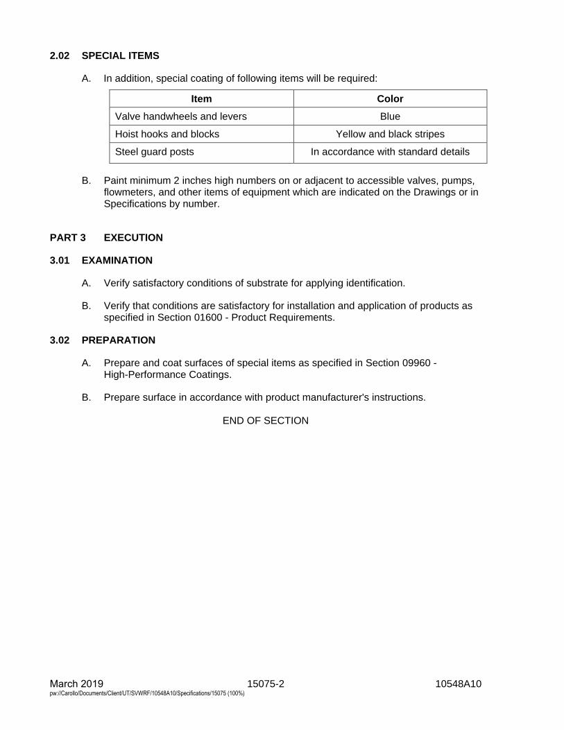
15075-2 10548A10 March 2019 pw://Carollo/Documents/Client/UT/SVWRF/10548A10/Specifications/15075 (100%)
2.02 SPECIAL ITEMS
A. In addition, special coating of following items will be required:
Item Color
Valve handwheels and levers Blue
Hoist hooks and blocks Yellow and black stripes
Steel guard posts In accordance with standard details
B. Paint minimum 2 inches high numbers on or adjacent to accessible valves, pumps,flowmeters, and other items of equipment which are indicated on the Drawings or inSpecifications by number.
PART 3 EXECUTION
3.01 EXAMINATION
A. Verify satisfactory conditions of substrate for applying identification.
B. Verify that conditions are satisfactory for installation and application of products asspecified in Section 01600 - Product Requirements.
3.02 PREPARATION
A. Prepare and coat surfaces of special items as specified in Section 09960 -High-Performance Coatings.
B. Prepare surface in accordance with product manufacturer's instructions.
END OF SECTION
15076-1 10548A10 March 2019 pw://Carollo/Documents/Client/UT/SVWRF/10548A10/Specifications/15076 (100%)
SECTION 15076
PIPE IDENTIFICATION
PART 1 GENERAL
1.01 SUMMARY
A. Section includes: Pipe identification including the following:1. Pipe identification by color and legend.2. Underground warning tape.3. Tracer wire.4. Witness markers.5. Valve identification.
1.02 REFERENCES
A. American Society of Mechanical Engineers (ASME):1. A13.1 - Scheme for the Identification of Piping Systems.
1.03 SUBMITTALS
A. Submit as specified in Section 01330 - Submittal Procedures.
B. Submit following:1. Product data.2. Samples.3. Manufacturer's installation instructions.4. Submit following as specified in Section 01770 - Closeout Procedures:
a. Operation and Maintenance Data.b. Warranty.
PART 2 PRODUCTS
2.01 ABOVE GROUND AND IN-CHASE PIPE IDENTIFICATION
A. Manufacturers:1. One of the following or equal:
a. Seton, Opti Code Pipe Markers.b. Lab Safety Supply.c. Marking Services, Inc.
B. Materials:1. Pipe markers: Self-adhesive vinyl, suitable for outdoor application
from -40 degrees to 180 degrees Fahrenheit; in accordance with ASME A13.1requirements.
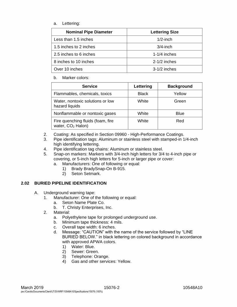
15076-2 10548A10 March 2019 pw://Carollo/Documents/Client/UT/SVWRF/10548A10/Specifications/15076 (100%)
a. Lettering:
Nominal Pipe Diameter Lettering Size
Less than 1.5 inches 1/2-inch
1.5 inches to 2 inches 3/4-inch
2.5 inches to 6 inches 1-1/4 inches
8 inches to 10 inches 2-1/2 inches
Over 10 inches 3-1/2 inches
b. Marker colors:
Service Lettering Background
Flammables, chemicals, toxics Black Yellow
Water, nontoxic solutions or low hazard liquids
White Green
Nonflammable or nontoxic gases White Blue
Fire quenching fluids (foam, fire water, CO2 Halon)
White Red
2. Coating: As specified in Section 09960 - High-Performance Coatings.3. Pipe identification tags: Aluminum or stainless steel with stamped-in 1/4-inch
high identifying lettering.4. Pipe identification tag chains: Aluminum or stainless steel.5. Snap-on markers: Markers with 3/4-inch high letters for 3/4 to 4-inch pipe or
covering, or 5-inch high letters for 5-inch or larger pipe or cover:a. Manufacturers: One of following or equal:
1) Brady BradySnap-On B-915.2) Seton Setmark.
2.02 BURIED PIPELINE IDENTIFICATION
A. Underground warning tape:1. Manufacturer: One of the following or equal:
a. Seton Name Plate Co.b. T. Christy Enterprises, Inc.
2. Material:a. Polyethylene tape for prolonged underground use.b. Minimum tape thickness: 4 mils.c. Overall tape width: 6 inches.d. Message: “CAUTION” with the name of the service followed by “LINE
BURIED BELOW.” in black lettering on colored background in accordancewith approved APWA colors.1) Water: Blue.2) Sewer: Green.3) Telephone: Orange.4) Gas and other services: Yellow.
15076-3 10548A10 March 2019 pw://Carollo/Documents/Client/UT/SVWRF/10548A10/Specifications/15076 (100%)
B. Tracer wire:1. Manufacturers: One of the following or equal:
a. Kris-Tech Wire.b. Corrpro.
2. Materials: One of the following or equal:a. Solid copper conductor with 30 mil HMWPE.b. 10 gauge or thicker wire.c. Match insulation color to the color of the pipe being installed.
C. Witness markers:1. Manufacturers: One of the following or equal:
a. Carsonite Composites, Utility Marker.b. Hampton Technical Associates, Inc.
2. Materials:a. Glass fiber and resin reinforced thermosetting composite material.b. UV resistant.
3. Constructed as a single piece.4. Pointed at the bottom end.5. Information to be included on the marker:
a. “Caution” (type of service) “Pipeline”.b. Offset:
1) Only provide offset if marker is not directly over the pipe.c. Name of appurtenance or fitting (e.g. 45, BO, ARV, etc.)
2.03 VALVE AND GATE IDENTIFICATION
A. The Contractor shall furnish and install tags for all valves and gates required for theWork. Provide valve and gate schedule for each valve and gate in the Work with thefollowing information:1. Identification number.2. Location.3. Type.4. Function.5. Normal operating position.
B. Identification tag requirements.1. Diameter: 2-inches.2. Material:
a. Buried applications: Stainless steelb. Buried applications with concrete marker: Brass.c. Above ground and in-chase applications: 19 gauge aluminum or PVC.
3. Stamp tags in 1/4-inch high letter:4. Provide non-corrosive metal wire suitable for attaching the tag to the operator
base.5. Secure tags to valve or gate:
a. Attach tags in such a way as to allow free and full operation of the valve orgate.
6. Buried applications with concrete marker: Secure tags to concrete marker.
C. Submittal requirements:1. Submit 2 samples of the type of tag proposed and the manufacturer’s standard
color chart and letter styles to the Engineer for review.
15076-4 10548A10 March 2019 pw://Carollo/Documents/Client/UT/SVWRF/10548A10/Specifications/15076 (100%)
D. Manufacturer: The following or equal:1. Seton Name Plate Co.
PART 3 EXECUTION
3.01 EXAMINATION
A. Verify satisfactory conditions of substrate for applying identification.
B. Verify that conditions are satisfactory for installation and application of products asspecified in Section 01600 - Product Requirements.
3.02 PREPARATION
A. Prepare and coat surfaces as specified in Section 09960 - High-PerformanceCoatings.
B. Prepare surface in accordance with product manufacturer's instructions.
3.03 ABOVE GROUND AND IN-CHASE PIPING IDENTIFICATION
A. Identify exposed piping, valves, and accessories, and piping in accessible chaseswith lettering or tags designating service of each piping system with flow directionalarrows and color code.
B. Color code:1. Paint piping with colors as selected by Owner.
C. Lettering and flow direction arrows:1. Stencil lettering on painted bands or use Snap-On markers on pipe to identify
pipe. When stenciling, stencil 3/4-inch high letters on 3/4 through 4-inch pipeor coverings, or 5-inch high letters on 5-inch and larger pipe or coverings.
2. Provide lettering and flow direction arrows near equipment served, adjacent tovalves, both sides of walls and floors where pipe passes through, at eachbranch or tee, and at intervals of not more than 50 feet in straight runs of pipe.
D. Where scheduled, space 6-inch wide bands along stainless steel pipe at 10-footintervals and other pipe at 5-foot intervals.
E. Label chemical tank fill pipelines at locations which are visible from chemical fillstations.
F. Metal tags:1. Where outside diameter of pipe or pipe covering is 5/8-inch or smaller, provide
metal pipe identification tags instead of lettering.2. Fasten pipe identification tags to pipe with chain.3. Where tags are used, color code pipe as scheduled.
3.04 BURIED PIPING IDENTIFICATION
A. Underground warning tape:1. Place continuous run of warning tape in pipe trench, 12 inches above the pipe.

15076-5 10548A10 March 2019 pw://Carollo/Documents/Client/UT/SVWRF/10548A10/Specifications/15076 (100%)
B. Tracer wire:1. Install on all non-metallic pipe.2. Install an electrically continuous run of tracer wire along the entire length of the
pipe with wire terminations in valve boxes, vaults, or structures.3. Install tracer wire on top of the pipe and secure to pipe with tape a minimum of
every 10 feet.4. Where approved by the Engineer, splice sections of wire together using
approved direct bury wire nuts.a. Twisting the wires together is not acceptable.
C. Witness markers:1. Install over pipe in unpaved open-space areas at intervals not greater than
200 feet.2. Place markers at appurtenances located in unpaved areas.3. Embed markers at least 18 inches into the soil.
3.05 APPLICATION
A. Identify piping with legend markers, directional arrow markers, and number markers;use self-adhesive arrow roll tape to secure ends of piping markers and indicate flowdirection.
B. Provide legend markers, directional arrow markers, and number markers wherepiping passes through walls or floors, at piping intersections and at maximum15-foot spacing on piping runs.
C. Provide piping marker letters and colors as scheduled.
D. Place markers on piping so they are visible from operator's position in walkway orworking platform near piping. Locate markers along horizontal centerline of pipe,unless better visibility is achieved elsewhere.
3.06 PIPING COLOR CODE AND MARKER SCHEDULE
Service Fluid Pipe Color Marker Legend
Domestic Cold Water Light Blue DOMESTIC COLD WATER
Domestic Hot Water Light Blue DOMESTIC HOT WATER
Drain Charcoal DRAIN
Exhaust Gas Yellow EXHAUST GAS
Grit Black GRIT
Instrumental Air Purple INSTRUMENTATION AIR
Raw Wastewater Buff NONE USED
Sample Green FLUID BEING SAMPLED
Sanitary Drain Charcoal SANITARY DRAIN
Service Air Green SERVICE AIR
Tank Drain Charcoal TANK DRAIN
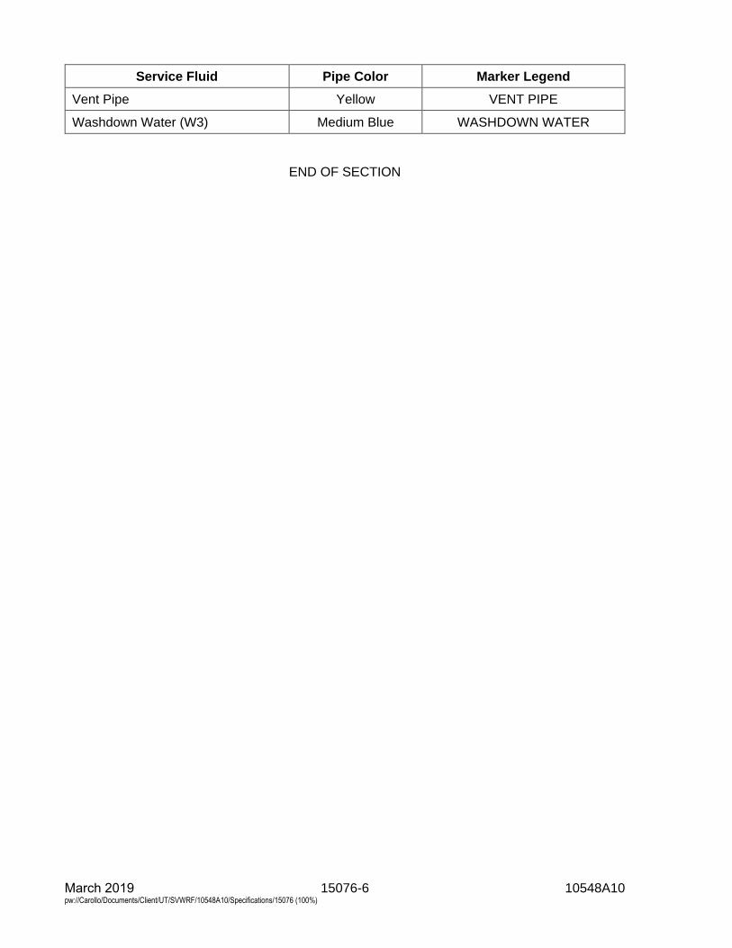
15076-6 10548A10 March 2019 pw://Carollo/Documents/Client/UT/SVWRF/10548A10/Specifications/15076 (100%)
Service Fluid Pipe Color Marker Legend
Vent Pipe Yellow VENT PIPE
Washdown Water (W3) Medium Blue WASHDOWN WATER
END OF SECTION
15082-1 10548A10 March 2019 pw://Carollo/Documents/Client/UT/SVWRF/10548A10/Specifications/15082 (100%)
SECTION 15082
PIPING INSULATION
PART 1 GENERAL
1.01 SUMMARY
A. Section includes: Insulation for piping and related systems.
1.02 REFERENCES
A. ASTM International (ASTM):1. A53 - Standard Specification for Pipe, Steel, Black and Hot-Dipped,
Zinc-Coated, Welded, and Seamless.2. C177 - Standard Test Method for Steady-State Heat Flux Measurements and
Thermal Transmission Properties by Means of the Guarded-Hot-PlateApparatus.
3. C518 - Standard Test Method for Steady-State Thermal TransmissionProperties by Means of the Heat Flow Meter Apparatus.
4. C533 - Standard Specification for Calcium Silicate Block and Pipe ThermalInsulation.
5. C547 - Standard Specification for Mineral Fiber Pipe Insulation.6. C552 - Standard Specification for Cellular Glass Thermal Insulation.7. C795 - Standard Specification for Thermal Insulation for Use in Contact with
Austenitic Stainless Steel.8. C929 - Standard Practice for Handling, Transporting, Shipping, Storage,
Receiving, and Application of Thermal Insulation Materials for Use in Contactwith Austenitic Stainless Steel.
9. C1136 - Standard Specification for Flexible, Low Permeance Vapor Retardersfor Thermal Insulation.
10. D1784 - Standard Specification for Rigid Poly(Vinyl Chloride) (PVC)Compounds and Chlorinated Poly(Vinyl Chloride) (CPVC) Compounds.
11. D2310 - Standard Classification of Machine-Made "Fiberglass"(Glass-Fiber-Reinforced-Thermosetting-Resin) Pipe.
12. E84 - Standard Test Method for Surface Burning Characteristics of BuildingMaterials.
13. E96 - Standard Test Methods for Water Vapor Transmission of Materials.
1.03 DEFINITIONS
A. Buried: Piping that is installed below buildings, foundations, or finish grade, either insoil or encased in concrete in soil.
B. Concealed: Piping above suspended ceilings and within walls, partitions, shafts, orservice spaces and spaces not normally exposed to view but not buried.
C. Exterior: Piping that is installed outside a building or within a pipe trench or tunnel.
D. Flame spread and smoke density: Burning characteristics determined in accordancewith ASTM E84. No units apply to value.
15082-2 10548A10 March 2019 pw://Carollo/Documents/Client/UT/SVWRF/10548A10/Specifications/15082 (100%)
E. Interior: Piping that is installed inside a building.
F. K factor: Thermal conductivity determined in accordance with ASTM C177 or C518and expressed in units of BTU-inch/hour-square feet -degrees Fahrenheit.
G. Mineral fiber: Fibers manufactured of glass, rock, or slag processed from a moltenstate, with or without a binder.
H. Water vapor permeance: Water vapor transmission determined in accordance withASTM E96 and expressed in units of perm-inch.
1.04 SUBMITTALS
A. Submit as specified in Section 01330 - Submittal Procedures.
B. Product data: As specified in Section15050 - Common Work Results for MechanicalEquipment.1. Insulation properties: Include K factor, thickness, density, operating
temperature limits, tensile strength, compressive strength, moistureabsorption, flame spread, and smoke developed in accordance withASTM E84 and corrosivity to stainless steel piping in accordance withASTM C795.
2. Jacket properties: Include covering material, cover thickness, tensile strength,tear strength, permeability in accordance with ASTM E96, flame spread, andsmoke developed in accordance with ASTM E84, closure type or devices, andaccessories.
3. Insulating blankets: Include materials, performance characteristics, method ofattaching to equipment, listing of locations where insulating blankets will beinstalled.
4. Manufacturer's application instructions: Include assembly and applicationdrawings and detailed instructions.
5. Laboratory report: Provide certified laboratory report stating that insulation isnot manufactured using chlorinated polymers and does not contain chlorides,bromides, sulfates, or fire-rated materials.
C. Provide warranty as specified in Section 01783 - Warranties and Bonds.
1.05 REGULATORY REQUIREMENTS
PART 2 PRODUCTS
2.01 PIPE INSULATION, GENERAL REQUIREMENTS
A. As specified in Section 01600 - Product Requirements.
B. Insulation thicknesses: Provide insulation thickness in inches in accordance with thefollowing table. Insulation thickness shown is nominal. Manufacturing tolerance of15 percent variation is permissible.
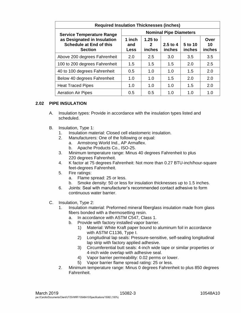
15082-3 10548A10 March 2019 pw://Carollo/Documents/Client/UT/SVWRF/10548A10/Specifications/15082 (100%)
Required Insulation Thicknesses (inches)
Service Temperature Range as Designated in Insulation
Schedule at End of this Section
Nominal Pipe Diameters
1 inch and Less
1.25 to 2
inches 2.5 to 4 inches
5 to 10 inches
Over 10
inches
Above 200 degrees Fahrenheit 2.0 2.5 3.0 3.5 3.5
100 to 200 degrees Fahrenheit 1.5 1.5 1.5 2.0 2.5
40 to 100 degrees Fahrenheit 0.5 1.0 1.0 1.5 2.0
Below 40 degrees Fahrenheit 1.0 1.0 1.5 2.0 2.0
Heat Traced Pipes 1.0 1.0 1.0 1.5 2.0
Aeration Air Pipes 0.5 0.5 1.0 1.0 1.0
2.02 PIPE INSULATION
A. Insulation types: Provide in accordance with the insulation types listed andscheduled.
B. Insulation, Type 1:1. Insulation material: Closed cell elastomeric insulation.2. Manufacturers: One of the following or equal:
a. Armstrong World Ind., AP Armaflex.b. Apache Products Co., ISO-25.
3. Minimum temperature range: Minus 40 degrees Fahrenheit to plus220 degrees Fahrenheit.
4. K factor at 75 degrees Fahrenheit: Not more than 0.27 BTU-inch/hour-squarefeet-degrees Fahrenheit.
5. Fire ratings:a. Flame spread: 25 or less.b. Smoke density: 50 or less for insulation thicknesses up to 1.5 inches.
6. Joints: Seal with manufacturer’s recommended contact adhesive to formcontinuous water barrier.
C. Insulation, Type 2:1. Insulation material: Preformed mineral fiberglass insulation made from glass
fibers bonded with a thermosetting resin.a. In accordance with ASTM C547, Class 1.b. Provide with factory installed vapor barrier.
1) Material: White Kraft paper bound to aluminum foil in accordancewith ASTM C1136, Type I.
2) Longitudinal lap seals: Pressure-sensitive, self-sealing longitudinallap strip with factory applied adhesive.
3) Circumferential butt seals: 4-inch wide tape or similar properties or4-inch wide overlap with adhesive seal.
4) Vapor barrier permeability: 0.02 perms or lower.5) Vapor barrier flame spread rating: 25 or less.
2. Minimum temperature range: Minus 0 degrees Fahrenheit to plus 850 degreesFahrenheit.
15082-4 10548A10 March 2019 pw://Carollo/Documents/Client/UT/SVWRF/10548A10/Specifications/15082 (100%)
3. K factor at 75 degrees Fahrenheit: Not more than 0.23 BTU-inch/hour-squarefeet degrees Fahrenheit.
4. Maximum moisture absorption, volume percent: 5.5. Manufacturers: One of the following or equal:
a. Owens-Corning Fiberglas Corp.b. Johns Manville.c. Knauf Fiber Glass.
D. Insulation, Type 3:1. Insulation material: Rigid cellular glass in accordance with ASTM C552,
Type II.2. Temperature range: Minus 450 degrees Fahrenheit to plus 900 degrees
Fahrenheit.3. K factor at 75 degrees Fahrenheit: Not more than 0.32 BTU-inch/hour-square
feet-degrees Fahrenheit.4. Minimum average density: 7.5 pounds per cubic foot.5. Maximum moisture absorption, volume percent: 5.6. Minimum compressive strength: 87 pounds per square inch.7. Moisture permeability: 0.00 perm-inch.8. Manufacturers: One of the following or equal:
a. Pittsburgh Corning Corp., Foamglas.b. Cell-U-Foam Corp., Ultra-CUF.
2.03 INSULATION JACKETS
A. Jacket, Type 1:1. Material: 28 ounces per square yard polyvinyl chloride on polyester fabric; total
thickness 0.028-inch minimum.2. Fire rating: 25 maximum flame spread, smoke developed 50 or less.3. Color: As selected by the Engineer from manufacturer's standard colors.4. Overlap: 1-inch minimum at joints and fittings.5. Joint seal: Self-sealing lap tape.6. Fittings: Factory made with full thickness insulation.7. Manufacturers: The following or equal:
a. Accessible Products, Techlite Insulation, 379 SSL Series.
B. Jacket, Type 2:1. Material: Ultraviolet-resistant polyvinyl chloride jacketing, 20 mil minimum
thickness.2. Fire rating: 25 maximum flame spread, smoke developed 50 or less.3. Color: White.4. Overlap: 1-inch minimum at joints and fittings.5. Joint seal: PVC solvent welded or adhesive as recommended by the
manufacturer.6. Fittings: Factory made with full thickness insulation.7. Manufacturers: One of the following or equal:
a. Johns Manville, Zeston 2000 PVC.b. Proto Corp., LoSMOKE PVC.c. Speedline Smoke Safe PVC Jacketing System.d. Knauf Covering System.
15082-5 10548A10 March 2019 pw://Carollo/Documents/Client/UT/SVWRF/10548A10/Specifications/15082 (100%)
C. Jacket, Type 3:1. Material: Aluminum, Alloy 5005; 0.016-inch (26-gauge) minimum thickness.2. Overlap: Overlap circumferential joints 4 inches minimum; overlap longitudinal
joints 1-inch minimum; longitudinal joints oriented to minimize water entry.3. Bands: 0.5-inch wide, 0.0508-inch (16-gauge) thick aluminum, same alloy as
jacket or 0.0179-inch thick Type 304 stainless steel; install on 18-inch centers,uniformly spaced and at all fitting joints.
4. Joint seal: Apply waterproof adhesive at joints and overlaps.5. Fittings: Custom fit of same materials.6. Manufacturers: One of the following or equal:
a. Childers Products.b. Premetco International.
D. Jacket, Type 4:1. Material: Three layer polymer-modified, bituminous compound separated by
glass reinforcement and aluminum foil with a polyester film outer layer.2. Joint Seal: 2-inch overlap on all insulation butt joints. 3-inch overlap on all
jacket lap joints. Heat-seal as per manufacturer recommendation.3. Manufacturers: One of the following or equal:
a. Pittsburgh Corning, PITTWRAP.
2.04 VAPOR BARRIERS
A. Vapor barrier, Type 1:1. Material: White Kraft paper bound to aluminum foil in accordance with
ASTM C1136, Type 1.2. Permeability: 0.02 perms or lower.3. Maximum flame spread rating: 25.4. Edge seal: Pressure-sensitive tape lap seal.5. Circumferential joints: 4-inch wide tape or 4-inch overlap with adhesive seal.
B. Vapor barrier, Type 2:1. Material: Mastic.2. Manufacturers: One of the following or equal:
a. Benjamin Foster, No. 30-76.b. Insul-Coustic, No. I.C.-580.c. Foster Products, 36-10/46-10 Weatherite.d. Childers Products CP10/11 Vi-Acryl.
2.05 RELATED MATERIALS
A. Cover adhesive: Premium adhesive as recommended by the insulation coversupplier for heavy-duty service in corrosive, wet environments. Standard-dutyadhesives are not permitted.
2.06 REMOVABLE INSULATING BLANKETS
A. In piping systems specified to be insulated, use removable insulating blankets forvalves, meters, strainers, filters, catalytic converters, engine exhaust silencers, andother in-line piping appurtenances and equipment requiring periodic servicing.
B. Size limits: Use removable insulating blankets for equipment and pipingappurtenances 3 inches in nominal size and larger. Insulate equipment and piping
15082-6 10548A10 March 2019 pw://Carollo/Documents/Client/UT/SVWRF/10548A10/Specifications/15082 (100%)
appurtenances less than 3 inches with molded sections of insulation or by field cutting insulation to conform to the shape of the component and to fit tightly around the component.
C. Manufacturers: One of the following, or equal:1. Pittsburgh Corning, Temp-Mat.2. Accessible Products, Thermazip 2000 Jacket.3. Thermal Energy Products, Inc., Energy Wrap.
D. Low temperature insulating blankets rated up to 800 degrees Fahrenheit:1. Use: For service temperatures up to 800 degrees Fahrenheit.2. Insulation: Fiberglass fiber, K factor 0.27 at 75 degrees Fahrenheit.3. Cover: 17-ounce fabric with both sides covered with silicone-impregnated
glass cloth suitable for temperatures up to 800 degrees Fahrenheit.4. Cover fasteners: Use one of the following systems:
a. Grommets in the blanket and stainless steel wire.b. 1-inch wide straps with stainless steel rectangular ring buckles and Velcro
on strap tail.
2.07 SHIPPING
A. As specified in Section 01600 - Product Requirements.
PART 3 EXECUTION
3.01 DELIVERY, STORAGE, AND HANDLING
A. As specified in Section 01600 - Product Requirements.
B. Store insulation materials and accessories under cover and protected frommoisture.
C. Handle and store insulation for use on stainless steel in accordance withASTM C929.
3.02 PREPARATION
A. Pressure test piping and complete application of coating system before applyinginsulation.
B. When piping is to be heat traced, install and functionally test heat tracing beforeinstallation of insulation.
C. Before beginning installation of piping insulation, verify that the Engineer hasaccepted piping tests, pipe coating applications, and heat tracing tests.
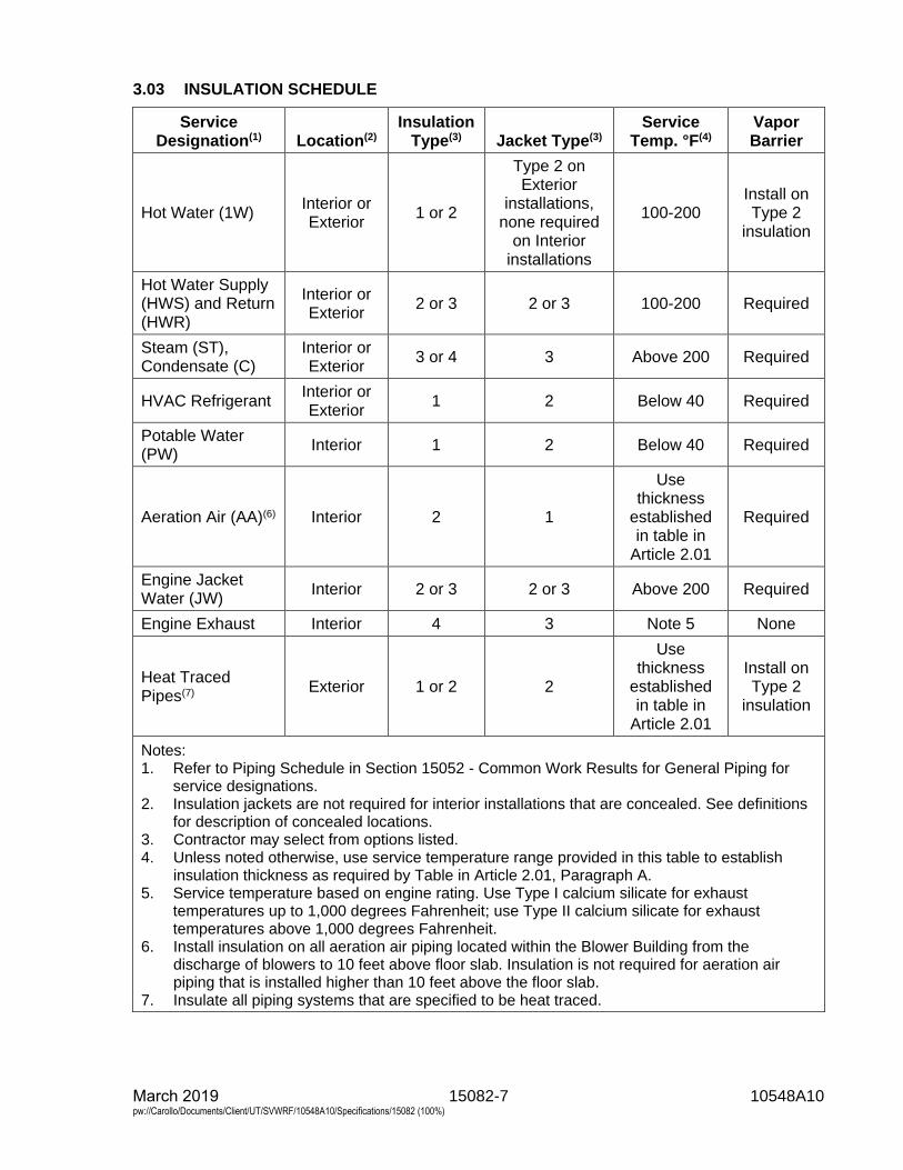
15082-7 10548A10 March 2019 pw://Carollo/Documents/Client/UT/SVWRF/10548A10/Specifications/15082 (100%)
3.03 INSULATION SCHEDULE
Service Designation(1) Location(2)
Insulation Type(3) Jacket Type(3)
Service Temp. °F(4)
Vapor Barrier
Hot Water (1W) Interior or Exterior
1 or 2
Type 2 on Exterior
installations, none required
on Interior installations
100-200Install on Type 2
insulation
Hot Water Supply (HWS) and Return (HWR)
Interior or Exterior
2 or 3 2 or 3 100-200 Required
Steam (ST), Condensate (C)
Interior or Exterior
3 or 4 3 Above 200 Required
HVAC Refrigerant Interior or Exterior
1 2 Below 40 Required
Potable Water (PW)
Interior 1 2 Below 40 Required
Aeration Air (AA)(6) Interior 2 1
Use thickness
established in table in
Article 2.01
Required
Engine Jacket Water (JW)
Interior 2 or 3 2 or 3 Above 200 Required
Engine Exhaust Interior 4 3 Note 5 None
Heat Traced Pipes(7) Exterior 1 or 2 2
Use thickness
established in table in
Article 2.01
Install on Type 2
insulation
Notes: 1. Refer to Piping Schedule in Section 15052 - Common Work Results for General Piping for
service designations.2. Insulation jackets are not required for interior installations that are concealed. See definitions
for description of concealed locations.3. Contractor may select from options listed.4. Unless noted otherwise, use service temperature range provided in this table to establish
insulation thickness as required by Table in Article 2.01, Paragraph A.5. Service temperature based on engine rating. Use Type I calcium silicate for exhaust
temperatures up to 1,000 degrees Fahrenheit; use Type II calcium silicate for exhausttemperatures above 1,000 degrees Fahrenheit.
6. Install insulation on all aeration air piping located within the Blower Building from thedischarge of blowers to 10 feet above floor slab. Insulation is not required for aeration airpiping that is installed higher than 10 feet above the floor slab.
7. Insulate all piping systems that are specified to be heat traced.
15082-8 10548A10 March 2019 pw://Carollo/Documents/Client/UT/SVWRF/10548A10/Specifications/15082 (100%)
3.04 INSTALLATION
A. Install insulation and jacket materials in accordance with manufacturer's writteninstructions.
B. Apply insulation in smooth, clean manner with tight and finished smooth joints. Fitinsulation tightly against surfaces. Insulate each continuous run of pipe withfull-length sections of insulation with a single piece cut to length to complete the runof pipe. Do not use cut pieces or scraps to complete the installation.
C. Butt longitudinal and circumferential insulation joints firmly together.
D. Maintain the integrity of vapor barrier jacketing. Do not use staples to hold vaporbarrier overlaps in place.
E. Apply sealant or cement when previous applications of adhesives and cement havethoroughly dried.
F. Apply insulation to permit expansion or contraction of pipelines without damage toinsulation or jacketing.
G. Fittings:1. Insulate fittings by covering with mitered sections of insulation or utilize
factory-made prefabricated fitting shapes.2. Terminate preformed pipe jackets or covering at sufficient distance from
flanges to permit removal of bolts.3. Overlap flange and flanged fitting insulation on adjacent pipe covering by at
least 2 inches.
H. Valves:1. Insulate valves 3 inches in nominal size and larger with removable insulating
blankets.2. Size blanket to extend up to packing gland only so that replacement of packing
does not require removal of insulating blanket.
I. Provide continuous insulation through and over pipe supports and provideprotection saddles at supports.
J. Extend insulation against insulation end protection shields or covers so thatinsulation voids do not exist and provide watertight end seals and covers whereinsulation terminates.
K. Insulate pipeline strainers to permit removal of strainer basket without disturbinginsulation on strainer body.
L. Provide continuous pipe insulation and covering through sleeves or openings inwalls and floors. When buried pipe enters a building through a below grade wall orslab penetration, begin insulation system on interior side of penetration.
M. Apply pre-molded pipe insulation with extended legs when used on pipe traced witheither tubing or electric cable type.
15082-9 10548A10 March 2019 pw://Carollo/Documents/Client/UT/SVWRF/10548A10/Specifications/15082 (100%)
N. Thermally isolate all insulation closure locations (end caps, transitions, etc.) Type 1or 2 jacket installation on piping with potential reach temperatures greater than150 degrees Fahrenheit.1. Apply piping identification on jackets as specified in Section 15076 - Pipe
Identification.
END OF SECTION


15084-1 10548A10 March 2019 pw://Carollo/Documents/Client/UT/SVWRF/10548A10/Specifications/15084 (100%)
SECTION 15084
DUCTWORK INSULATION
PART 1 GENERAL
1.01 SUMMARY
A. Section includes: Internal acoustical insulation and external thermal insulation formetal air ductwork systems.
1.02 REFERENCES
A. ASTM International (ASTM):1. E84 - Standard Test Method for Surface Burning Characteristics of Building
Materials.2. G21 - Standard Practice for Determining Resistance of Synthetic Polymeric
Materials to Fungi.
B. Sheet Metal and Air Conditioning Contractor's National Association (SMACNA).
1.03 SUBMITTALS
A. Submit as specified in Section 01330 - Submittal Procedures.
B. Product data: As specified in Section 15052 - Common Work Results for GeneralPiping.
C. Provide installation instructions.
D. Provide Manufacturer’s Certificate of Source Testing as specified in Section 01756 -Commissioning and Process Start-Up.
E. Provide Manufacturer’s Certificate of Installation and Functionality Compliance asspecified in Section 01756 - Commissioning and Process Start-Up.
1.04 QUALITY ASSURANCE
A. Comply with SMACNA ducting construction standards and the specifiedrequirement, whichever is more stringent.
PART 2 PRODUCTS
2.01 EXTERNAL DUCTWORK INSULATION
A. Manufacturers: One of the following or equal:1. Owens Corning, SoftR Duct Wrap.2. Johns Manville Microlite Duct Wrap.
15084-2 10548A10 March 2019 pw://Carollo/Documents/Client/UT/SVWRF/10548A10/Specifications/15084 (100%)
B. External ductwork insulation: Flexible blanket type glass fiber factory-laminated toreinforced foil Kraft vapor barrier facing with 2-inch stapling and topping flange onone edge, conforming to the following requirements:1. Thickness: As required to achieve the following R-values:
a. For ducting exterior to weather protected spaces 2 inches minimumthickness to meet an installed value of R6.3; provide additionalweatherproof exterior barrier covering.
b. For interior ducting in ceiling plenums, attics or other unconditionedspaces provide 1-1/2 inches minimum thickness to meet an installed valueof R4.8.
2. Temperature range: 40 to 250 degrees Fahrenheit.3. Density: 1.5 pounds per cubic foot.4. Moisture absorption: Less than 3 percent.5. Thermal conductivity: 0.25 Btu-inch per hour per square foot per degree
Fahrenheit at 75 degrees Fahrenheit.6. Fire hazard classification in accordance with ASTM E84:
a. Flame spread: 25.b. Smoke developed: 50.
C. Seaming tape: UV-resistant with properties in accordance with mechanical code asspecified in Section 01410 - Regulatory Requirements.
2.02 INTERNAL DUCTWORK INSULATION
A. Manufacturers: One of the following or equal:1. Owens Corning, QuietR flexible duct liner or Fiberglass rigid duct liner.2. Johns Manville, Linacoustic RC flexible duct liner or Permacoat Linacoustic
R-300 rigid duct liner.
B. Type: Flexible or board type duct liner with 1 coated surface meeting the following:1. Thickness: As required to achieve the following R-values:
a. For ducting exterior to weather protected spaces provide 2 inchesminimum thickness to meet an installed value of R6; provide additionalweatherproof exterior barrier covering.
b. For interior ducting in ceiling plenums, attics or other unconditionedspaces provide 1 inch minimum thickness to meet an installed value ofR4.2.
2. Temperature range: 40 to 250 degrees Fahrenheit.3. Density: 1.5 pounds per cubic foot.4. Thermal conductivity: 0.25 Btu-inch per hour per square foot per degree
Fahrenheit at 75 degrees Fahrenheit.5. Fire hazard classification in accordance with ASTM E84:
a. Flame spread: 25.b. Smoke developed: 50.
6. Service conditions: Velocities to 2,500 feet per minute.7. Acoustical performance: NRC of 0.55 minimum.8. Bacterial growth: None in accordance with ASTM G21.
C. Edge treatment: Provide leading edges with galvanized metal nosing; seal otheredges with manufacturer's recommended edge treatment.

15084-3 10548A10 March 2019 pw://Carollo/Documents/Client/UT/SVWRF/10548A10/Specifications/15084 (100%)
PART 3 EXECUTION
3.01 EXTERNAL DUCTWORK INSULATION
A. Provide external ductwork insulation on round ducts carrying conditioned air passthrough outdoor or unconditioned spaces or as indicated on the Drawings.
B. Apply external duct insulation with edges tightly butted and secure by 3 wraps of1/2-inch wide polypropylene strapping tape every 12 inches.
C. Seal seams with 4 inches wide tape with ends of the tape overlapping at least4 inches.
D. When underside of horizontal ducts exceeds 24 inches in width, additionally secureinsulation by mechanical fasteners. Install 1 mechanical fastener for every 2 squarefeet of duct surface.
E. Seal duct penetrations with a piece of the same facing material as the duct andinstall with the same vapor barrier adhesive. Extend external insulation and vaporbarrier through all duct sleeves.
3.02 INTERNAL DUCTWORK INSULATION
A. Provide rigid insulation on rectangular ducts carrying conditioned air to and from theACUs. Install 2 inch thick insulation in all outside air intake duct or plenums fromwall louver to unit intake for all ACUs and MAUs. Install 1 inch think insulation in allthe exhaust plenums attached to wall louvers.
B. Install with coated surface facing inside of duct; attach with adhesive to duct andprovide fasteners spaced at not to exceed 12 inches transverse (perpendicular) toflow and 18 inches parallel (longitudinal) to flow; provide fasteners within 3 inches oftransverse edges and 4 inches of longitudinal edges.
C. Follow Manufacturer's published installation instructions.
D. Install metal nosing on leading edges and seal other exposed edges withmanufacturer's edge treatment.
3.03 COMMISSIONING AND PROCESS START-UP REQUIREMENTS
A. As specified in Section 01756 - Commissioning and Process Start-Up and thisSection.
B. Manufacturer services:1. Provide Manufacturer’s Certificate of Source Testing.2. Provide Manufacturer’s Certificate of Installation and Functionality
Compliance.
END OF SECTION

15110-1 10548A10 March 2019 pw://Carollo/Documents/Client/UT/SVWRF/10548A10/Specifications/15110 (100%)
SECTION 15110
COMMON WORK RESULTS FOR VALVES
PART 1 GENERAL
1.01 SUMMARY
A. Section includes: Basic requirements for valves.
1.02 REFERENCES
A. American Water Works Association (AWWA):1. C111/A21.11 - Standard for Rubber-Gasket Joints for Ductile-Iron Pressure
Pipe Fittings.
B. ASTM International (ASTM):1. A126 - Standard Specification for Gray Iron Casting for Valves, Flanges, and
Pipe Fittings.2. A167 - Standard Specification for Stainless and Heat-Resisting
Chromium-Nickel Steel Plate, Sheet, and Strip.3. A536 - Standard Specification for Ductile Iron Castings.
C. NSF International (NSF):1. 61 - Drinking Water System Components - Health Effects.
D. Society for Protective Coatings (SSPC):1. SP7 - Brush-Off Blast Cleaning.2. SP10 - Near-White Blast Cleaning.
1.03 DESIGN REQUIREMENTS
A. Pressure rating:1. Suitable for service under minimum working pressures of 150 pounds per
square inch gauge.2. When a piping system is specified in the Piping Schedule to be tested at a
pressure greater than 150 pounds per square inch gauge, provide valves forthat piping system with design working pressure which is sufficient towithstand the test pressure.
B. Valve to piping connections:1. Valves 3 inches nominal size and larger: Flanged ends.2. Valves less than 3 inches nominal size: Screwed ends.3. Plastic valves in plastic piping:
a. Up to 2.5 inches: Provide solvent or heat welded unions.b. 3 inches and above: Provide solvent or heat-welded flanges.
1.04 SUBMITTALS
A. Submit as specified in Section 01330 - Submittal Procedures.
15110-2 10548A10 March 2019 pw://Carollo/Documents/Client/UT/SVWRF/10548A10/Specifications/15110 (100%)
B. Product data:1. Submit the following information for each valve:
a. Valve type, size, pressure rating, Cv factor.b. Coatings.c. Power valve actuators:
1) Information on valve actuator including size, manufacturer, modelnumber, limit switches, mounting; and motor enclosure, seating andunseating torque coefficient, dynamic torque, and bearing friction forcalculation of maximum operating torque.
2) Complete wiring diagrams and control system schematics.d. Manual valve actuators:
1) Information on valve actuator including size, manufacturer, modelnumber.
e. Certified drawings with description of component parts, dimensions,weights, and materials of construction.
f. Certifications of reference standard compliance:1) Submit certification that the valves and coatings are suitable in
potable water applications in accordance with NSF 61.g. Clearly mark submittal information to show specific items, materials, and
accessories or options being furnished.h. Factory test data.
C. Provide vendor operation and maintenance manual as specified in Section 01782 -Operation and Maintenance Data.1. Furnish bound sets of installation, operation, and maintenance instructions for
each type of manual valve 4 inches in nominal size and larger, and allnon-manual valves. Include information on valve operators.
D. Provide Manufacturer’s Certificate of Source Testing as specified in Section 01756 -Commissioning.
E. Provide Manufacturer’s Certificate of Installation and Functionality Compliance asspecified in Section 01756 - Commissioning.
1.05 QUALITY ASSURANCE
A. Manufacturer qualifications:1. Valves manufactured by manufacturers whose valves have had successful
operational experience in comparable service.
1.06 DELIVERY STORAGE AND HANDLING
A. Protect valves and protective coatings from damage during handling andinstallation; repair coating where damaged.
PART 2 PRODUCTS
2.01 MATERIALS
A. Stainless steel: In accordance with ASTM A167, Type 316, or Type 304,UNS Alloy S31600 or S30400.

15110-3 10548A10 March 2019 pw://Carollo/Documents/Client/UT/SVWRF/10548A10/Specifications/15110 (100%)
B. Valve and operator bolts and nuts:1. Fabricated of stainless steel for the following installation conditions:
a. Submerged in sewage or water.b. In an enclosed space above sewage or water.c. In structures containing sewage or water, below top of walls.d. At openings in concrete or metal decks.
2. Where dissimilar metals are being bolted, use stainless steel bolts withisolation bushings and washers.
3. Underground bolts: Low-alloy steel in accordance with AWWA C111/A21.11.
C. Bronze and brass alloys: Use bronze and brass alloys with not more than 6 percentzinc and not more than 2 percent aluminum in the manufacture of valve parts;UNS Alloy C83600 or C92200 unless specified otherwise.
D. Valve bodies: Cast iron in accordance with ASTM A126, Class 30 minimum orductile iron in accordance with ASTM A536, Grade 65-45-12 minimum unlessspecified otherwise.
2.02 INTERIOR PROTECTIVE LINING
A. When specified in the particular valve specification, provide valves with type ofprotective lining specified in the particular valve Specification.
B. Apply protective lining to interior, non-working surfaces, except stainless steelsurfaces.
C. Lining types:1. Fusion bonded epoxy:
a. Manufacturers: The following or equal:1) 3-M Company, ScotchKote 134; certified to NSF 61 for drinking water
use.b. Clean surfaces in accordance with SSPC SP 7 or SP 10, as
recommended by epoxy manufacturer.c. Apply in accordance with manufacturer's published instructions.d. Lining thickness: 0.010 to 0.012-inch, except that:
1) Lining thickness in grooves for gaskets: 0.005-inch.2) Do not coat seat grooves in valves with bonded seat.
e. Quality control:1) Lining thickness: Measured with a non-destructive magnetic type
thickness gauge.2) Verify lining integrity with a wet sponge-testing unit operating at
approximately 60 volts, or as recommended by the liningmanufacturer.
3) Consider tests successful when lining thickness meets specifiedrequirements and when no pinholes are found.
4) Correct defective lining disclosed by unsuccessful tests, and repeattest.
5) Repair pinholes with liquid epoxy recommended by manufacturer ofthe epoxy used for lining.
2. High solids epoxy:a. Product equivalent to high solids epoxy specified in Section 09960 -
High-Performance Coatings.
15110-4 10548A10 March 2019 pw://Carollo/Documents/Client/UT/SVWRF/10548A10/Specifications/15110 (100%)
1) Certified in accordance with NSF 61 for drinking water use.2) Interior: Coat valve interior with manufacturer's equivalent high
performance high solids epoxy coating system with a certifiableperformance history for the service conditions and as approved bythe Engineer. Manufacturer shall provide for approval, coatinginformation sufficient to allow Engineer to assess equivalence to thespecified high solids epoxy coating specified in Section 09960 -High-Performance Coatings.
b. Clean surfaces to meet SP-7 or SP-10, or as recommended by coatingmanufacturer.
c. Quality control: After coating is cured, check coated surface for porositywith a holiday detector set at 1,800 volts, or as recommended by coatingmanufacturer.1) Repair holidays and other irregularities and retest coating.2) Repeat procedure until holidays and other irregularities are
corrected.
2.03 UNDERGROUND VALVES
A. Provide underground valves with flanged, mechanical, or other type of joint requiredfor the type of pipe to which the valve is to be connected.
B. Coating and wrapping:1. Prior to installation, coat buried valves with 2 coats of protective coal tar as
specified in Section 09960 - High-Performance Coatings.2. After installation, encase valves in 2 layers of polyethylene wrap as specified
for ductile iron piping in Section 15211 - Ductile Iron Pipe: AWWA C151.a. Ascertain that polyethylene wrapping does not affect operation of valve.
2.04 VALVE BOXES
A. Provide cast-iron valve boxes at each buried valve to access valve and valveoperators.
B. Do not support boxes on valve, valve operator, or pipe.
C. Boxes:1. 2-piece, fabricated of cast iron; provide cover, with asphalt varnish or enamel
protective coating.2. Adjustable to grade, install centered around the upper portions of the valve
and valve operator.
D. Manufacturers: One of the following or equal:1. Tyler Pipe Industries, Inc.2. Neenah Foundry Co.
2.05 VALVE OPERATORS
A. Valve operator "Open" direction: Open counterclockwise.
B. Provide valves located below operating level or deck with extensions for keyoperation or floor stands and handwheels.
15110-5 10548A10 March 2019 pw://Carollo/Documents/Client/UT/SVWRF/10548A10/Specifications/15110 (100%)
C. Provide manually operated valves located not more than 6 feet above the operatinglevel with tee handles, wrenches, or handwheels.1. Make the valve operator more conveniently accessible by rolling valves,
located more than 5 feet but less than 6 feet above the operating level, towardthe operating side.
2. Secure tee handles and wrenches to the valve head or stem, except where ahandle or wrench so secured constitutes a hazard to personnel; in which case,stow handle or wrench immediately adjacent to the valve on or in a suitablehanger, bracket, or receptacle.
D. Fit valves located more than 6 feet above operating level with chain operatedhandles or valve wheels.1. Chains: Sufficient length to reach approximately 4 feet above the operating
level.2. Where chains constitute a nuisance or hazard to operating personnel, provide
holdbacks or other means for keeping the chains out of the way.
E. Provide an operator shaft extension from valve or valve operator to finished gradeor deck level when buried valves, and other valves located below the operatingdeck or level, are specified or indicated on the Drawings to be key operated; provide2 inches square AWWA operating nut, and box and cover as specified, or a coverwhere a box is not required.
PART 3 EXECUTION
3.01 EXAMINATION
A. Preparation prior to installation:1. Install valves after the required submittal on installation has been accepted.2. Determine after flanged valves and flanged check valves are selected, the
face-to-face dimensions of flanged valves and flanged check valves.
B. Fabricate piping to lengths taking into account the dimensions of flanged valves andflanged check valves.
3.02 INSTALLATION
A. Provide incidental work and materials necessary for installation of valves includingflange gaskets, flange bolts and nuts, valve boxes and covers, concrete bases,blocking, and protective coating.
B. Where needed, furnish and install additional valves for proper operation andmaintenance of equipment and plant facilities under the following circumstances:1. Where such additional valves are required for operation and maintenance of
the particular equipment furnished by Contractor.2. Where such additional valves are required as a result of a substitution or
change initiated by Contractor.
C. Install valves with their stems in vertical position above the pipe, except as follows:1. Butterfly valves, gate valves aboveground, globe valves, ball valves, and angle
valves may be installed with their stems in the horizontal position.2. Install buried plug valves with geared operators with their stems in a horizontal
position.
15110-6 10548A10 March 2019 pw://Carollo/Documents/Client/UT/SVWRF/10548A10/Specifications/15110 (100%)
D. Install valves so that handles clear obstructions when the valves are operated fromfully open to fully closed.
E. Place top of valve boxes flush with finished grade or as otherwise indicated on theDrawings.
F. Valves with threaded connections:1. Install valves by applying wrench on end of valve nearest the joint to prevent
distortion of the valve body.2. Apply pipe joint compound or Teflon tape on external (male) threads to prevent
forcing compound into valve seat area.
G. Valves with flanged connections:1. Align flanges and gasket carefully before tightening flange bolts.2. When flanges are aligned, install bolts and hand tighten.3. Tighten nuts opposite each other with equal tension before moving to next pair
of nuts.
H. Valves with soldered connections:1. Do not overheat connection to prevent damage to resilient seats and metal
seat rings.2. Position valves in full open position before starting soldering procedure.3. Apply heat to piping rather than to valve body.
3.03 FIELD APPLIED COATING OF VALVE EXTERIOR
A. Match color and be compatible with manufacturer’s coating system and as specifiedin Section 09960 - High-Performance Coatings.1. When shop applied finish coating matches field applied coating on adjacent
piping, touch up shop coating in damaged areas in accordance withinstructions recommended by the paint manufacturer.
2. When shop applied coating does not match field coating on adjacent piping, orwhen damage has occurred to the shop applied coating that requires morethan touchup, blast clean valve surfaces or utilize other surface preparationrecommended by the manufacturer of the coating material and apply thecoating system used for coating adjacent piping.
3.04 COMMISSIONING
A. As specified in Section 01756 - Commissioning and this Section.
B. Manufacturer services from each manufacturer for all valves supplied:1. Provide Manufacturer’s Certificate of Source Testing.2. Provide Manufacturer’s Certificate of Installation and Functionality
Compliance.
C. As specified elsewhere for specific valve types, sizes or actuators.1. Source testing.2. Manufacturers on site services for Owner Training, Installation Testing,
Functional Testing, and during the Process Operational Period.
END OF SECTION
15111-1 10548A10 March 2019 pw://Carollo/Documents/Client/UT/SVWRF/10548A10/Specifications/15111 (100%)
SECTION 15111
BALL VALVES
PART 1 GENERAL
1.01 SUMMARY
A. Section includes: Ball valves.
B. As specified in Section 15110 - Common Work Results for Valves.
1.02 REFERENCES
A. American Society of Mechanical Engineers (ASME):1. B16.1 - Gray Iron Pipe Flanges and Flanged Fittings: Classes 25, 125, and
250.2. B16.5 - Pipe Flanges and Flanged Fittings: NPS 1/2 through 24.
B. American Water Works Association (AWWA):1. C507 - Standard for Ball Valves 6 Inch Through 48 Inch.
C. ASTM International (ASTM):1. A48 - Standard Specification for Gray Iron Castings.2. A216 - Standard Specification for Steel Castings, Carbon, Suitable for Fusion
Welding, for High-Temperature Service.3. A351 - Standard Specification for Castings, Austenitic, for Pressure-Containing
Parts.
1.03 SYSTEM DESCRIPTION
A. General: Unless otherwise indicated on the Drawings use:1. Metal body ball valves on metallic pipelines.2. Plastic body ball valves on plastic pipelines.
1.04 SUBMITTALS
A. Submit as specified in Section 01330 - Submittal Procedures.
B. Product data: As specified in Section 15110 - Common Work Results for Valves:1. Metal body ball valves: 6 inches and larger only: Submit affidavit of compliance
in accordance with AWWA C507.2. Operation and maintenance manual.
C. Commissioning submittals:1. Provide Manufacturer’s Certificate of Installation and Functionality Compliance
as specified in Section 01756 - Commissioning.
1.05 WARRANTY
A. Provide warranty as specified in Section 01783 - Warranties and Bonds.
15111-2 10548A10 March 2019 pw://Carollo/Documents/Client/UT/SVWRF/10548A10/Specifications/15111 (100%)
PART 2 PRODUCTS
2.01 METAL BODY BALL VALVES, LESS THAN 6-INCH SIZE
A. Manufacturers: One of the following, or equal:1. Conbraco Industries, Inc., Apollo Valves.2. Flow-Tek, Inc.3. Metso Automation/Jamesbury.4. NIBCO, Inc.
B. General:1. Type: Non-lubricated, full port and capable of sealing in either direction.2. End connections:
a. Threaded or solder ends for sizes 3-inch and smaller.b. Class 150 flanged for sizes larger than 3 inches.
1) Flanges: In accordance with ASME B16.1 standards.3. Stem packing: Manually adjustable while valve is under pressure.4. Shafts:
a. Rigidly connected to the ball by a positive means.1) Design connection to transmit torque equivalent to at least
75 percent of the torsional strength of the shaft.5. Handles: Stainless steel latch lock handle with vinyl grip and stainless steel nut
designed to open and close the valve under operating conditions.6. Temperature limits: Suitable for operation between minus 20 and 350 degrees
Fahrenheit.
C. Materials:1. Valves in copper lines: Bronze body.2. Valves in steel and ductile iron piping: Ductile iron or cast steel body.3. Valves in stainless steel piping: Stainless steel body, material type to match
piping material as specified in Section 15052 - Common Work Results forGeneral Piping.
4. Ball: Type 304 or 316 stainless steel, Type 316 in digester gas applications.5. Seats: PTFE.6. Stem seals: PTFE or Viton.7. Bearings: Self-lubricated, corrosion resistant material that will not contaminate
potable water.8. Valves for combustible fluid applications (digester gas, natural gas, fuel oil,
etc.) must be of fire safe design.
2.02 PLASTIC BODY BALL VALVES
A. Manufacturers: One of the following or equal:1. Asahi America.2. Chemtrol Division, NIBCO, Inc.3. Georg Fischer Piping Systems.4. Hayward Flow Control.5. Plast-O-Matic Valves, Inc.
B. General:1. Type: Non-lubricated and capable of sealing in either flow direction.2. End connections: True union; solvent or heat welded to piping.3. Operator handle: Lever.
15111-3 10548A10 March 2019 pw://Carollo/Documents/Client/UT/SVWRF/10548A10/Specifications/15111 (100%)
C. Materials:1. Body: Polyvinyl chloride (PVC).2. Ball: Polyvinyl chloride (PVC).3. Seats: PTFE (Teflon).4. O-rings: EPDM.
PART 3 EXECUTION
3.01 INSTALLATION
A. General: Install each type of valve in accordance with manufacturers' printedinstructions.
B. Special techniques:1. PVC ball valves for hypochlorite service:
a. Provide valve with factory drilled 0.125-inch hole in the upstream side ofthe ball.
b. Provide an engraved plastic tag permanently attached to the valve stemstating "One side of ball drilled for hypochlorite service.”
3.02 FIELD APPLIED COATING OF VALVE EXTERIOR
A. Match color and be compatible with manufacturer’s coating system and as specifiedin Section 09960 - High-Performance Coatings.1. When shop applied finish coating matches field applied coating on adjacent
piping, touch up shop coating in damaged areas in accordance withinstructions recommended by the paint manufacturer.
2. When shop applied coating does not match field coating on adjacent piping, orwhen damage has occurred to the shop applied coating that requires morethan touchup, blast clean valve surfaces or utilize other surface preparationrecommended by the manufacturer of the coating material and apply thecoating system used for coating adjacent piping.
3.03 COMMISSIONING
A. As specified in Section 01756 - Commissioning and this Section.
B. Manufacturer services:1. Provide certificates:
a. Manufacturer's Certificate of Installation and Functionality Compliance.
C. Functional testing:1. Valves:
a. Test witnessing: Witnessed.b. Conduct pressure and leak test, as specified in Section 15110 - Common
Work Results for Valves.
END OF SECTION

15112-1 10548A10 March 2019 pw://Carollo/Documents/Client/UT/SVWRF/10548A10/Specifications/15112 (100%)
SECTION 15112
BUTTERFLY VALVES
PART 1 GENERAL
1.01 SUMMARY
A. Section includes: Butterfly valves:1. As specified in Section 15110 - Common Work Results for Valves.
1.02 REFERENCES
A. American Society of Mechanical Engineers (ASME):1. B16.1 - Cast Iron Pipe Flanges and Flanged Fittings, Classes 25, 125 and
250.2. B16.5 - Pipe Flanges and Flanged Fittings, NPS 1/2 through NPS 24.
B. American Water Works Association (AWWA):1. C110 - Standard for Ductile-Iron and Gray-Iron Fittings.2. C504 - Rubber-Seated Butterfly Valves.3. C540 - Standard for Power-Actuating Devices for Valves and Sluice Gates.4. C550 - Protective Interior Coatings for Valves & Hydrants.5. C606 - Standard for Grooved and Shouldered Joints.
C. ASTM International (ASTM):1. A126 - Standard Specification for Gray Iron Castings for Valves, Flanges, and
Pipe Fittings.2. A216 - Standard Specification for Steel Castings, Carbon, Suitable for Fusion
Welding, for Higher-Temperature Service.3. A276 - Standard Specification for Stainless Steel Bars and Shapes.4. A351 - Standard Specification for Castings, Austenitic, for Pressure-Containing
Parts.5. A395 - Standard Specification for Ferritic Ductile Iron Pressure-Retaining
Castings for Use at Elevated Temperatures.6. A479 - Standard Specification for Stainless Steel Bars and Shapes for Use in
Boilers and Other Pressure Vessels.7. A515 - Standard Specification for Pressure Vessel Plates, Carbon Steel, for
Intermediate - and Higher-Temperature Service.8. A516 - Standard Specification for Pressure Vessel Plates, Carbon Steel, for
Moderate - and Lower-Temperature Service.9. A536 - Standard Specification for Ductile Iron Castings.10. A564 - Standard Specification for Hot-Rolled and Cold-Finished Age-
Hardening Stainless Steel Bars and Shapes.
15112-2 10548A10 March 2019 pw://Carollo/Documents/Client/UT/SVWRF/10548A10/Specifications/15112 (100%)
11. A743 - Standard Specification for Castings, Iron-Chromium, Iron-Chromium-Nickel, Corrosion Resistant, for General Application.
12. A890 - Standard Specification for Castings, Iron-Chromium-Nickel-Molybdenum Corrosion-Resistant, Duplex (Austenitic/Ferritic) for GeneralApplication.
13. B462 - Standard Specification for Forged or Rolled UNS N06030, UNSN06022, UNS N06035, UNS N06200, UNS N06059, UNS N10362, UNSN06686, UNS N08020, UNS N08024, UNS N08026, UNS N08367, UNSN10276, UNS N10665, UNS N10675, UNS N10629, UNS N08031, UNSN06045, UNS N06025, UNS R20033 Alloy Pipe Flanges, Forged Fittings, andValves and Parts for Corrosive High-Temperature Service.
14. B584 - Standard Specification for Copper Alloy Sand Castings for GeneralApplications.
15. B691 - Standard Specification for Iron-Nickel-Chromium-Molybdenum Alloys(UNS N08366 and UNS N08367) Rod, Bar, and Wire.
16. D429 - Standard Test Methods for Rubber Property-Adhesion to RigidSubstrate.
D. Compressed Gas Association (CGA):1. Standard G-4.1 - Cleaning Equipment for Oxygen Service.
E. NSF International (NSF):1. Standard 61 - Drinking Water System Components - Health Effects.
F. United States Code of Federal Regulations (CFR):1. 21 - Food and Drugs.
1.03 SYSTEM DESCRIPTION
A. Design requirements:1. General purpose AWWA butterfly valves:
a. Design standard: Provide valves designed and manufactured inaccordance with AWWA C504.
b. Class:1) Provide butterfly valves in accordance with AWWA Class 150B,
unless otherwise specified.2) Provide butterfly valves in accordance with AWWA Class 250B in
piping systems with test pressure greater than 150 pounds persquare inch and less than 250 pounds per square inch.
2. Industrial class butterfly valves:a. Industrial class butterfly valves capable of 150 pounds per square inch
leak tight shut off.3. Stainless steel butterfly valves:
a. Stainless steel butterfly valves capable of a minimum of 100 pounds persquare inch leak tight shut off and with special cleaning, packaging, andhandling.
B. Usage:1. Provide and install butterfly valve types as outlined in the Butterfly Valve
Schedule in the Drawings.

15112-3 10548A10 March 2019 pw://Carollo/Documents/Client/UT/SVWRF/10548A10/Specifications/15112 (100%)
C. Design requirements for all butterfly valves with power actuating devices:1. Design valves and actuators for maximum operating torque, in accordance
with and using safety factors required in AWWA C540, using the followingvalues:a. Maximum water velocity: 16 feet per second with valve fully open.b. Maximum pressure differential across the closed valve equal to the
pressure class designation.c. Coefficient for seating and unseating torque, dynamic torque, and bearing
friction in accordance with valve manufacturer's publishedrecommendations.
2. Valve disc: Seat in an angular position of 90 degrees to the pipe axis androtate an angle of 90 degrees between fully open and fully closed positions:a. Do not supply valves with stops or lugs cast with or mechanically secured
to the body of the valve for limiting the disc travel.3. Unacceptable thrust bearings: Do not provide valves with thrust bearings
exposed to the fluid in the line and consisting of a metal bearing surface inrubbing contact with an opposing metal bearing surface.
4. Where valves will be submerged, torque tubes shall be used to installactuators at deck or walkway level. Torque tubes shall be made by the valvemanufacturer and shall be designed to maintain torsion at the valve and nottransfer it into the walkway.
D. Performance requirements:1. Tight shutoff at the pressure rating of the valve with pressure applied in either
direction.2. Suitable for the following service conditions:
a. Throttling.b. Frequent operation.c. Operation after long periods of inactivity.d. Installation in any position and flow in either direction.
1.04 SUBMITTALS
A. Submit as specified in Section 01330 - Submittal Procedures.
B. Product data: 15110 - Common Work Results for Valves:1. For general purpose AWWA butterfly valves, include description of the method
of attachment of the disc edge to the valve disc.2. Interior epoxy coatings: Affidavit of compliance attesting that epoxy coatings
applied to interior surfaces of butterfly valves comply with all provisions inaccordance with AWWA C550.
3. Certification, for valves and coatings in contact with potable water, that theproducts used are suitable for contact with drinking water in accordance withNSF Standard 61.
C. Commissioning submittals:1. Provide Manufacturer’s Certificate of Installation and Functionality Compliance
as specified in Section 01756 - Commissioning.
1.05 WARRANTY
A. Provide warranty as specified in Section 01783 - Warranties and Bonds.
15112-4 10548A10 March 2019 pw://Carollo/Documents/Client/UT/SVWRF/10548A10/Specifications/15112 (100%)
PART 2 PRODUCTS
2.01 GENERAL PURPOSE AWWA BUTTERFLY VALVES
A. Manufacturers: One of the following or equal:1. DeZURIK/Sartell Model BAW.2. Henry Pratt Co., Modell 2FII.
B. Valve body:1. Material: Ductile iron, ASTM A536, Grade 65-45-12.2. Body design:
a. Flanged body valves:1) Usage: Comply with limitations specified in the Butterfly Valve
Application Schedule.2) Flanges: In accordance with ASME B16.1 Class 125 flanges for
Class 150B valves, in accordance with ASME B16.1 Class 250flanges for Class 250B valves.
b. Mechanical joint body valves:1) Usage: Comply with limitations specified in the Butterfly Valve
Application Schedule.2) Mechanical joint design: In accordance with AWWA C110.3) When mechanical joint body valves are used, incorporate valve into
thrust restraint analysis as specified in Section 15211 - Ductile IronPipe: AWWA C151. Utilize test pressure on one side of valve andzero pressure on the opposite side of the valve. Restrain pipe jointson both sides of valve as determined by thrust analysis calculations.
c. Grooved end body valves:1) Usage: Butterfly valves with grooved ends may be used in piping
systems specified in the Piping Schedule to have grooved end joints.Comply with additional limitations specified in the Butterfly ValveApplication Schedule.
2) Grooved end joint design: In accordance with AWWA C606.
C. Disc:1. Material: Type 316 stainless steel.2. Secure valve disc to shaft by means of smooth-sided, taper or dowel pins,
Type 316 stainless steel, or Monel.3. Extend pins through shaft and mechanically secure in place.
D. Shaft and bearings:1. Shaft design:
a. Valves 20-inches and less: 1-piece, through disc design.b. Valves greater than 20-inch size: 2-piece, stub shaft design.
2. Shaft seal: Vee type, chevron design.3. Shaft material for Class 150B valves: Type 316 stainless steel, ASTM A276.4. Shaft material for Class 250B valves: Type 17-4 pH stainless steel,
ASTM A564.5. Shaft bearings: Self-lubricating sleeve type:
a. Valves 20 inches and less: Nylatron.b. Valves greater than 20-inch size: Teflon with stainless steel or fiberglass
backing.
15112-5 10548A10 March 2019 pw://Carollo/Documents/Client/UT/SVWRF/10548A10/Specifications/15112 (100%)
E. Seats:1. Seat materials:
a. In low-pressure air applications: EPDM.b. In all other applications: EPDM.
2. For valves 20 inches in nominal size and smaller, bond or vulcanize seat intothe valve body.
3. For valves 24 inches in nominal size and larger, retain seats mechanically orby adhesive:a. Mechanical retainage: Retain seat by a clamping ring with segmented
clamping ring locks with adjusting locking screws.1) Clamping ring, ring locks, and adjusting locking screws: Type 316
stainless steel.2) Provide means to prevent ring locks and screws used to retain seats
from loosening due to vibration or cavitation.b. Adhesive retainage: Inset the seat within a groove in the valve body and
retain in place with epoxy injected behind the seat so that the seatexpands into the body.
c. Do not provide valves with seats retained by snap rings or spring-loadedretainer rings.
4. Resilient seat: Withstand 75 pound per inch pull when tested in accordancewith ASTM D429, Method B.
F. Valve packing:1. Valves 4 inches to 48 inches nominal size: Self-adjusting V-type packing or
chevron-type packing. NBR or EPDM to match seat material.2. Valves 54 inches nominal size and larger: Adjustable V-type packing with
bronze packing gland or self-adjusting V-type packing. NBR or EPDM to matchseat material.
2.02 COATING
A. Shop coat interior and exterior metal surfaces of valves, except as follows:1. Interior machined surfaces.2. Surfaces of gaskets and elastomeric seats and stem seals.3. Bearing surfaces.4. Stainless steel surfaces and components.
B. Coating material for potable water applications:1. Formulate interior coating material from materials in accordance with CFR 21,
AWWA C550, and NSF 61.2. Submit affidavit of compliance attesting that epoxy coatings applied to interior
surfaces of butterfly valves in accordance with CFR 21, AWWA C550, andNSF 61.
C. Interior surfaces:1. Interior surfaces, except for valves used in low-pressure air service: High
solids epoxy.2. Interior surfaces of valves used in low-pressure air service: High temperature
coating for range of 150 to 350 degrees Fahrenheit.

15112-6 10548A10 March 2019 pw://Carollo/Documents/Client/UT/SVWRF/10548A10/Specifications/15112 (100%)
D. Exterior surfaces:1. Exterior surfaces of valves, actuators, and accessories coating in accordance
with Section 09960 - High-Performance Coatings with the following coatingtypes:a. Submerged valves: High solids epoxy.b. Buried valves: Coal tar epoxy.c. Other valves: High solids epoxy with polyurethane topcoat.
2. Polished and machined surfaces: Apply rust-preventive compound,a. Manufacturers: One of the following or equal:
1) Houghton, Rust Veto 344.2) Rust-Oleum, R-9.
E. Coating materials:1. High solids epoxy and coal tar epoxy:
a. Products: As specified in Section 09960 - High-Performance Coatings:1) Coating product in contact with potable water must be in accordance
with AWWA C550 and NSF 61.2. High temperature coating: As specified in Section 09960 - High-Performance
Coatings and in accordance with AWWA C550.3. Rust-preventive compound:
a. Manufacturers: One of the following or equal:1) Houghton, Rust Veto 344.2) Rust-Oleum, R-9.
F. Field applied coatings of valve exterior:1. Match color and be compatible with manufacturer’s coating system and as
specified in Section 09960 - High-Performance Coatings.a. When shop applied finish coating matches field applied coating on
adjacent piping, touch up shop coating in damaged areas in accordancewith instructions recommended by the paint manufacturer.
b. When shop applied coating does not match field coating on adjacentpiping, or when damage has occurred to the shop applied coating thatrequires more than touchup, blast clean valve surfaces or utilize othersurface preparation recommended by the manufacturer of the coatingmaterial and apply the coating system used for coating adjacent piping.
PART 3 EXECUTION
3.01 INSTALLATION
A. Install valves with valve shafts horizontal, unless a vertical shaft is required to suit aparticular installation, and unless a vertical shaft is indicated on the Drawings.
B. Install pipe spools or valve spacers in locations where butterfly valve disc travel maybe impaired by adjacent pipe lining, pipe fittings, valves, or other equipment.
3.02 BUTTERFLY VALVE APPLICATION SCHEDULE
A. Acceptable butterfly valve types and body styles are listed in the Valve Scheduleprovided in the Drawings. Furnish and install butterfly valves in accordance with thisSchedule.

15112-7 10548A10 March 2019 pw://Carollo/Documents/Client/UT/SVWRF/10548A10/Specifications/15112 (100%)
3.03 COMMISSIONING
A. As specified in Section 01756 - Commissioning and this Section.
B. Manufacturer services:1. Provide certificates:
a. Manufacturer’s Certificate of Installation and Functionality Compliance.
C. Functional testing:1. Valves:
a. Test witnessing: Witnessed.b. Conduct pressure and leak test, as specified in Section 15110 - Common
Work Results for Valves.
END OF SECTION

15114-1 10548A10 March 2019 pw://Carollo/Documents/Client/UT/SVWRF/10548A10/Specifications/15114 (100%)
SECTION 15114
CHECK VALVES
PART 1 GENERAL
1.01 SUMMARY
A. Section includes: Check valves.
B. As specified in Section 15110 - Common Work Results for Valves.
1.02 REFERENCES
A. American Society of Mechanical Engineers (ASME):1. B16.1 - Gray Iron Pipe Flanges and Flanged Fittings: Classes 25, 125, and
250.2. B16.5 - Pipe Flanges and Flanged Fittings: NPS 1/2 through NPS 24 Inch
Standard.
B. American Water Works Association (AWWA):1. C508 - Standard for Swing-Check Valves for Waterworks Service 2 Inch
Through 24 Inch NPS.
C. ASTM International (ASTM):1. A126 - Standard Specification for Gray Iron Castings for Valves, Flanges, and
Pipe Fittings.2. A313 - Standard Specification for Stainless Steel Spring Wire.3. A536 - Standard Specification for Ductile Iron Castings.4. B582 - Standard Specification for Nickel-Chromium-Iron-Molybdenum-Copper
Alloy Plate, Sheet, and Strip.5. B584 - Standard Specification for Copper Alloy Sand Castings for General
Applications.
1.03 SYSTEM DESCRIPTION
A. Design requirements:1. Check valves: When not otherwise specified as indicated on the Drawings,
provide check valves suitable for service as follows:a. In either horizontal or vertical position.b. Suitable for service working pressures up to 150 pounds per square inch
gauge.
1.04 SUBMITTALS
A. Submit as specified in Section 01330 - Submittal Procedures.
B. Product data: As specified in Section 15110 - Common Work Results for Valves.
15114-2 10548A10 March 2019 pw://Carollo/Documents/Client/UT/SVWRF/10548A10/Specifications/15114 (100%)
C. Commissioning submittals:1. Provide Manufacturer’s Certificate of Installation and Functionality Compliance
as specified in Section 01756 - Commissioning.
1.05 WARRANTY
A. Provide warranty as specified in Section 01783 - Warranties and Bonds.
PART 2 PRODUCTS
2.01 SWING CHECK VALVES
A. Valves 1/4-inch through 3 inches:1. Manufacturers: One of the following or equal:
a. Crane Valve Co., Number 36.b. Lunkenheimer Co., Figure 554Y.
2. Valve design:a. Threaded joints.b. Y-pattern body with integral seat.c. Hinged disc.d. Access to valve seat for regrinding without disassembly of piping.
3. Materials:a. Body, cap, hinge, and disc: Bronze.
B. Valves 4 inches through 24 inches:1. Manufacturers: One of the following or equal:
a. Kennedy, Figure 106LW or M&H, Model 159.b. Mueller Co., Model A-2600.c. APCO Model 250.d. Crispin SWL Series.
2. Valve design:a. In accordance with AWWA C508.b. Constructed to permit top entry and removal of internal components
without removing the valve.c. Equipped with outside lever and weight.
3. Materials:a. Body: Cast iron, ASTM A126 Class B or ASTM A536 Grade 65-45-12
Ductile Iron.b. Disc:
1) Valve disc shall be ASTM A126 cast iron, ASTM A536 ductile iron, orASTM B584 bronze.
2) 4-inch valves: Bronze or stainless steel rings and seats.3) 6 inches and larger valves: Bronze-faced or stainless steel rings and
seats.4) Rubber seat Buna-N or EPDM.
c. Hinge pins: Stainless steel.
2.02 PLASTIC BALL CHECK VALVES
A. Manufacturers: One of the following or equal:1. Chemtrol Division of Nibco.2. Georg Fischer Piping Systems.
15114-3 10548A10 March 2019 pw://Carollo/Documents/Client/UT/SVWRF/10548A10/Specifications/15114 (100%)
3. Plast-O-Matic Valves, Inc.4. Hayward Flow Control.
B. Valves: Ball type:1. Material: Polyvinyl chloride.2. End connection: Double-or single-union-type.3. Seals: Viton.
C. Valve body material:1. Polyvinyl chloride (PVC), chlorinated polyvinyl chloride (CPVC), Polypropylene
(PP) or polyvinylidene fluoride (PVDF), as best suited for each individualservice condition.
D. Union connections material:1. NPT or socket ends conforming to ASME B16.5 pipe flanges and flange
fittings, Class 150.
E. Seats and seals material:1. EPDM, Buna-N, or Viton.
F. Maximum inlet pressure rating:1. PVC, CPVC, or PVDF: 150 pound per square inch at 77 degrees Fahrenheit.2. PP: 100 pounds per square inch at 77 degrees Fahrenheit.
2.03 DUCKBILL CHECK VALVES
A. Manufacturers: One of the following or equal:1. Tide Flex, Series TF-1.
B. Design:1. Maximum downstream head: 0 feet.2. With internal pressure 2 inches w.c. above backpressure, bill of valve opens,
allowing flow.3. With backpressure 2 inches w.c. above internal pressure, bill of valve closes,
preventing backflow.4. Flat bottom, flared top.
C. End connection:1. Slip-on with Type 316 stainless steel clamp.
D. Materials of construction:1. Single piece elastomer construction with internal polyester fabric reinforcing all
vulcanized into a composite material.a. Internal reinforcing sufficient to maintain structural integrity under the
specified operating conditions.b. Exterior applications require coating for UV protection and to resist pest
gnawing.2. Elastomeric material: EPDM.
15114-4 10548A10 March 2019 pw://Carollo/Documents/Client/UT/SVWRF/10548A10/Specifications/15114 (100%)
PART 3 EXECUTION
3.01 FIELD APPLIED COATING OF VALVE EXTERIOR
A. Match color and be compatible with manufacturer’s coating system and as specifiedin Section 09960 - High-Performance Coatings.1. When shop applied finish coating matches field applied coating on adjacent
piping, touch up shop coating in damaged areas in accordance withinstructions recommended by the paint manufacturer.
2. When shop applied coating does not match field coating on adjacent piping, orwhen damage has occurred to the shop applied coating that requires morethan touchup, blast clean valve surfaces or utilize other surface preparationrecommended by the manufacturer of the coating material and apply thecoating system used for coating adjacent piping.
3.02 COMMISSIONING
A. As specified in Section 01756 - Commissioning and this Section.
B. Manufacturer services:1. Provide certificates:
a. Manufacturer's Certificate of Installation and Functionality Compliance.
C. Functional testing:1. Valves:
a. Test witnessing: Witnessed.b. Conduct pressure and leak test, as specified in Section 15110 - Common
Work Results for Valves.
END OF SECTION
15115-1 10548A10 March 2019 pw://Carollo/Documents/Client/UT/SVWRF/10548A10/Specifications/15115 (100%)
SECTION 15115
GATE, GLOBE, AND ANGLE VALVES
PART 1 GENERAL
1.01 SUMMARY
A. Section includes: Gate, globe, angle, plug disc and plain hose valves, and yardhydrants.
B. As specified in Section 15110 - Common Work Results for Valves.
1.02 REFERENCES
A. American Water Works Association (AWWA):1. C515 - Standard for Reduced-Wall, Resilient-Seated Gate Valves for Water
Supply Services.2. C 550 - Protective Interior Coatings for Valves and Hydrants.
B. ASTM International (ASTM):1. B98 - Standard Specification for Copper-Silicon Alloy Rod, Bar, and Shapes.
1.03 SUBMITTALS
A. Submit as specified in Section 01330 - Submittal Procedures.
B. Product data: As specified in Section 15110 - Common Work Results for Valves.
C. Commissioning submittals: For valves larger than 16 inches:1. Provide Manufacturer’s Certificate of Installation and Functionality Compliance
as specified in Section 01756 - Commissioning.
1.04 WARRANTY
A. Provide warranty as specified in Section 01783 - Warranties and Bonds.
B. Interior epoxy coatings: Affidavit of compliance attesting that epoxy coatings appliedto interior surfaces of valves comply in accordance with all provisions of AWWAC550.
PART 2 PRODUCTS
2.01 GATE VALVES
A. Gate valves aboveground:1. Valves less than 3 inches in size for clean water and air service:
a. Manufacturers: One of the following or equal:1) Crane, Figure 431.2) Jenkins, Figure 47.
15115-2 10548A10 March 2019 pw://Carollo/Documents/Client/UT/SVWRF/10548A10/Specifications/15115 (100%)
3) Lunkenheimer Co., Figure 2151.b. Design:
1) Size and configuration: Indicated on the Drawings.2) Manufacturer's standard bronze, solid wedge disc, rising stem,
screwed end, Class 150 pounds.2. Valves 3 inches in size and larger:
a. Manufacturers: One of the following or equal:1) M&H/Kennedy Valve Co.2) Mueller.3) American Flow Control, Series 2500.
b. Design:1) Size, material, configuration: Indicated on the Drawings.2) Resilient wedge type in accordance with AWWA C515.3) Flange, iron body, and bonnet rated for 200 pound working pressure.
a) Provide O-ring seal between valve body and bonnet.4) Ductile or cast iron wedge encapsulated in nitrile rubber and capable
of sealing in either flow direction.5) Bronze stem with double or triple O-ring or braided packing stem
seals.6) Rising stem configuration with handwheel diameter sized to allow
opening of valve with no more than a 40-pound pull.7) Coat interior and exterior surfaces of valve body and bonnet with
fusion-bonded epoxy in accordance with AWWA C550.
B. Gate valves underground:1. Manufacturers: One of the following or equal:
a. M&H/Kennedy Valve Co.b. Mueller Co.c. American Flow Control.
2. Design:a. Size, material, configuration: Indicated on the Drawings.b. Resilient wedge type in accordance with AWWA C515.c. Stem:
1) Iron body, resilient seat, non-rising stem, double O-ring stem seal.2) Rising stem configuration with handwheel diameter sized to allow
opening of valve with no more than a 40-pound pull.d. Ductile or cast iron wedge encapsulated in nitrile rubber and capable of
sealing in either flow direction.e. Bronze stem with double or triple O-ring or braided packing stem seals.f. Coat interior and exterior surfaces of valve body and bonnet with
fusion-bonded epoxy in accordance with AWWA C550.g. Valve operator: Provide standard AWWA 2-inch operating nut, matching
valve key, and valve box for operating stem.
C. Steam and condensate gate valves:1. Valves 3 inches and smaller in size:
a. Manufacturers: One of the following or equal:1) Crane, No. 428.2) Jenkins, Figure 47U.3) Lunkenheimer Co., Figure 2127.
b. Design:1) Size and configuration: Indicated on the Drawings.
15115-3 10548A10 March 2019 pw://Carollo/Documents/Client/UT/SVWRF/10548A10/Specifications/15115 (100%)
2) Bronze, screwed, rising stem, solid wedge, screwed bonnet, suitablefor service under pressures equal to and less than 125 pounds persquare inch gauge, steam working pressure (SWP).
2. Valves larger than 3 inches in size:a. Manufacturers: One of the following or equal:
1) Crane No. 465-1/2.2) Jenkins, Figure 651C.3) Lunkenheimer Co., Figure 1430.
b. Design:1) Size and configuration: Indicated on the Drawings.2) Suitable for service under pressures equal to and less than
125 pounds per square inch gauge, steam working pressure (SWP),flanged, iron body, bronze mounted, solid wedge, outside screw andyoke (OS&Y).
2.02 GLOBE AND ANGLE VALVES
A. General purpose globe and angle valves:1. Valves 3 inches and smaller:
a. Manufacturers: One of the following or equal:1) Except in welded steel piping:
a) Crane, No. 1 Globe or No. 2 Angle.b) Lunkenheimer Co. Figure No. 2140 Globe or No. 2141 Angle.
2) In Welded steel piping:a) Crane, No. 351.b) Lunkenheimer Co., Figure No. 1123; or equal with flanged ends.
b. Design:1) Size and configuration: Indicated on the Drawings.2) Valve: Class 125 threaded ends, rated for 250 degrees Fahrenheit at
pressure of 170 pounds per square inch.2. Valves larger than 3 inches:
a. Manufacturers: One of the following or equal:1) Crane, No. 351.2) Lunkenheimer Co., Figure No. 1123.
b. Design:1) Size and configuration: Indicated on the Drawings.
3. Plug disc globe valves: for throttling or for severe service.a. Manufacturers: One of the following or equal:
1) Crane, No. 212P or No. 384P.2) Lunkenheimer Co., 72-PS or 73-PS1.
b. Design:1) Size and configuration: Indicated on the Drawings.2) Material: Iron body stainless steel trimmed plug type seat and disc.
2.03 HOSE VALVES AND YARD HYDRANTS
A. Hose valves:1. Manufacturers:
a. Globe threaded valve: One of the following or equal:1) Crane, No. 7TF.2) Stockham, Figure No. B22T.
15115-4 10548A10 March 2019 pw://Carollo/Documents/Client/UT/SVWRF/10548A10/Specifications/15115 (100%)
b. Angle threaded valve: One of the following or equal:1) Crane, No. 17TF.2) Stockham, Figure No. B222T.
2. Design:a. Size and configuration: Indicated on the Drawings.b. Valve: Globe or angle valve with threaded ends.c. Disc: Renewable, made of Teflon or Buna-N.d. Threaded ends rated for a pressure of 200 pounds per square inch.
B. Freezeless yard hydrant:1. Manufacturers: One of the following or equal:
a. Kupferle Foundry Co.1) #1 Total Eclipse Yard Hydrant - 3/4-inch and 1-inch.
b. Murdock Company:1) #M-75 - 3/4-inch or #M100 – 1-inch.
c. Zurn Company:1) #1385 - 3/4-inch or 1-inch.
2. Design:a. Self-draining, non-freezing, compression type.
1) Inlet connection size: Indicated on the Drawings.2) Outlet connection size: Indicated on the Drawings.3) Materials:
a) Exterior casing pipe material: brassb) Interior operating rod material: brassc) Casing guard material: cast irond) Principal interior operating parts material: brass and/or bronze
and removable from yard hydrant for servicing withoutexcavation.
4) Provide 4-spoke, ball wheel handle operated.
PART 3 EXECUTION
3.01 INSTALLATION
A. Mount yard hydrants on minimum 1-inch supply pipe or size indicated on theDrawings.
B. Mount Post hydrants on minimum 2-inch supply pipe or size indicated on theDrawings.
C. Set yard and post hydrants in 4 cubic feet of 3/4-inch minimum crushed stonesurrounding valve body to allow for proper drainage.1. Install in accordance with AWWA recommendations for hydrants.
3.02 FIELD APPLIED COATING OF VALVE EXTERIOR
A. Match color and be compatible with manufacturer’s coating system and as specifiedin Section 09960 - High-Performance Coatings.1. When shop applied finish coating matches field applied coating on adjacent
piping, touch up shop coating in damaged areas in accordance withinstructions recommended by the paint manufacturer.
15115-5 10548A10 March 2019 pw://Carollo/Documents/Client/UT/SVWRF/10548A10/Specifications/15115 (100%)
2. When shop applied coating does not match field coating on adjacent piping, orwhen damage has occurred to the shop applied coating that requires morethan touchup, blast clean valve surfaces or utilize other surface preparationrecommended by the manufacturer of the coating material and apply thecoating system used for coating adjacent piping.
3.03 COMMISSIONING
A. As specified in Section 01756 - Commissioning and this Section.
B. Manufacturer services: For valves larger than 16-inches.1. Provide certificates:
a. Manufacturer’s Certificate of Installation and Functionality Compliance.
C. Functional testing:1. Valves:
a. Test witnessing: Witnessed.b. Conduct pressure and leak test as specified in Section 15110 - Common
Work Results for Valves.
END OF SECTION

15116-1 10548A10 March 2019 pw://Carollo/Documents/Client/UT/SVWRF/10548A10/Specifications/15116 (100%)
SECTION 15116
PLUG VALVES
PART 1 GENERAL
1.01 SUMMARY
A. Section includes:1. Non-lubricated plug valves.2. Multi-port plug valves.
1.02 REFERENCES
A. American Water Works Association (AWWA):1. C517 - Resilient-Seated Cast Iron Eccentric Plug Valves.2. C606 - Grooved and Shouldered Joints.
B. ASTM International (ASTM):1. A126 - Standard Specification for Gray Iron Castings for Valves, Flanges, and
Pipe Fittings.2. A536 - Standard Specification for Ductile Iron Castings.
1.03 SUBMITTALS
A. Submit as specified in Section 01330 - Submittal Procedures and 15110 - CommonWork Results for Valves.
B. Product data.
C. Shop drawings.
D. Calculations.
E. Vendor operation and maintenance manual as specified in Section 01782 -Operation and Maintenance Data.
F. Commissioning submittals:1. Provide Manufacturer’s Certificate of Source Testing as specified in
Section 01756 - Commissioning:a. Interior coating.
2. Provide Manufacturer’s Certificate of Installation and Functionality Complianceas specified in Section 01756 - Commissioning.
1.04 WARRANTY
A. Provide warranty as specified in Section 01783 - Warranties and Bonds.
15116-2 10548A10 March 2019 pw://Carollo/Documents/Client/UT/SVWRF/10548A10/Specifications/15116 (100%)
PART 2 PRODUCTS
2.01 GENERAL
A. As specified in Section 15110 - Common Work Results for Valves.
2.02 NON-LUBRICATED PLUG VALVES
A. Manufacturers: One of the following or equal:1. Val-Matic.2. DeZurik, "PEC".3. Clow Valve.
B. Design:1. Type: Non-lubricated eccentric type, in accordance with AWWA C517.2. Plug face: Resilient material that operates satisfactorily at a temperature of
180 degrees Fahrenheit continuous and 215 degrees Fahrenheit intermittent,except for valves in compressed air or digester gas service.a. Valves in compressed air service: Resilient material suitable for
continuous duty at 250 degrees Fahrenheit.b. Valves in digester gas service: Resilient material suitable for petroleum or
digester gas at continuous duty at 180 degrees Fahrenheit.3. Compression washer: Provide flat compression washer made of Teflon, or of a
material having equal physical characteristics on valve stem between plug andbonnet.
4. Stem seals: Provide stem seals serviceable without unbolting the valve bonnetassembly.
5. Grit excluders: Provide PTFE grit excluders at upper plug journals to prevententry of foreign solids in bearing area.
6. Clearly mark valves to indicate their open and closed positions.7. Provide valves with ends as required by piping details indicated on the
Drawings.a. Grooved end body valves:
1) Usage: Plug valves with grooved ends may be used in pipingsystems specified in the Piping Schedule to have grooved end jointsand as indicated on the Drawings.
2) Grooved end joint design: In accordance with AWWA C606.8. Provide glass-lined valves for plug valves on grit piping.
C. Exposed Valve - Materials:1. Body and plug: ASTM A126, Class B, cast-iron with plug face of neoprene or
EPDM material suitable for the intended service as specified under paragraph"Design" above.
2. Body seats in valves 3 inch size and larger: Provide with overlay of not lessthan 90-percent nickel and minimum thickness of 1/8-inch on surfacescontacting the plug face.
3. Stem bearing and bottom bearing: Type 316 stainless steel.4. Internal parts, except the body and plug: Type 316 stainless steel.
D. Exposed nuts, bolts, and washers: Zinc plated. Exception: Exposed nuts, bolts, andwashers for buried service: Stainless steel.
15116-3 10548A10 March 2019 pw://Carollo/Documents/Client/UT/SVWRF/10548A10/Specifications/15116 (100%)
E. Direct Buried Valve - Materials:1. Body and plug: Type 316 Stainless Steel with plug face of neoprene or EPDM
material suitable for the intended service as specified under paragraph"Design" above.
2. Body seats in valves 3 inch size and larger: Provide with overlay of not lessthan 90 percent nickel and minimum thickness of 1/8-inch on surfacescontacting the plug face.
3. Stem bearing and bottom bearing: Type 316 stainless steel.4. Internal parts, except the body and plug: Type 316 stainless steel.5. Exposed nuts, bolts, and washers: Zinc plated. Exception: Exposed nuts,
bolts, and washers for buried service: Stainless steel.
2.03 VALVE OPERATORS
A. Furnish valves with an operating wrench or worm gear operator:1. Equip valves 4 inch nominal size and smaller with a lever operator.2. Equip valves 6 inch nominal size and larger with a worm gear operator.
2.04 COATING
A. Coat and test interior metal surfaces as specified in Section 15110 - Common WorkResults for Valves.
B. Coat exterior metal surfaces as specified in Section 09960 - High-PerformanceCoatings.
C. Field applied coating of valve exterior:1. Match color and be compatible with manufacturer’s coating system and as
specified in Section 09960 - High-Performance Coatings.a. When shop applied finish coating matches field applied coating on
adjacent piping, touch up shop coating in damaged areas in accordancewith instructions recommended by the paint manufacturer.
b. When shop applied coating does not match field coating on adjacentpiping, or when damage has occurred to the shop applied coating thatrequires more than touchup, blast clean valve surfaces or utilize othersurface preparation recommended by the manufacturer of the coatingmaterial and apply the coating system used for coating adjacent piping.
2.05 SHIPMENT, SPARE PARTS, MAINTENANCE PRODUCTS, AND SPECIAL TOOLS
A. As specified in Section 01600 - Product Requirements.
PART 3 EXECUTION
3.01 INSTALLATION
A. Install valves as specified in Section 15110 - Common Work Results for Valves andthe manufacturer’s instructions.1. Unless differently indicated on the Drawings install valves so that in the closed
position the pressure in the pipeline applies a seating head on the valves.2. Install valves so that in the open position the plug is located in the top half of
the valve body.

15116-4 10548A10 March 2019 pw://Carollo/Documents/Client/UT/SVWRF/10548A10/Specifications/15116 (100%)
B. For valves requiring lubrication: Lubricate and fill extended lubricant pipes withlubricant suitable for service intended.
3.02 COMMISSIONING
A. As specified in Section 01756 - Commissioning and this Section.
B. Manufacturer services:1. Provide certificates:
a. Manufacturer’s Certificate of Installation and Functionality Compliance.
C. Functional testing:1. Valves:
a. Test witnessing: Witnessed.b. Conduct pressure and leak test as specified in Section 15110 - Common
Work Results for Valves.
END OF SECTION
15117-1 10548A10 March 2019 pw://Carollo/Documents/Client/UT/SVWRF/10548A10/Specifications/15117 (100%)
SECTION 15117
SPECIALTY VALVES
PART 1 GENERAL
1.01 SUMMARY
A. Section includes: Specialty valves.
B. As specified in Section 15110 - Common Work Results for Valves.
1.02 REFERENCES
A. American Society of Civil Engineers (ASCE):1. 25 - Earthquake-Actuated Automatic Gas Shutoff Devices.
B. American Society of Mechanical Engineers (ASME):1. B16.42 - Ductile Iron Pipe Flanges and Flanged Fittings: Classes 150 and 300.
C. American Water Works Association (AWWA):1. C511 - Standard for Reduced Pressure-Principle Backflow-Prevention
Assembly.2. C800 - Underground Service Line Valves & Fittings (Also Included: Collected
Standards For Service Line Materials).
D. ASTM International (ASTM):1. A48 - Standard Specification for Gray Iron Castings.2. A126 - Standard Specification for Gray Iron Casting for Valves, Flanges, and
Pipe Fittings.3. A276 - Standard Specification for Stainless Steel Bars and Shapes.4. A536 - Standard Specification for Ductile Iron Castings.5. B584 - Standard Specification for Copper Alloy Sand Castings for General
Application.
E. National Electrical Manufacturers Association (NEMA):1. 250 - Enclosures for Electrical Equipment (1000 V Maximum).
1.03 DEFINITIONS
A. NEMA Type 4 enclosure in accordance with NEMA 250.
1.04 SUBMITTALS
A. Submit as specified in Section 01330 - Submittal Procedures.
B. Product data: As specified in Section 15110 - Common Work Results for Valves.
C. Commissioning submittals:1. Backflow preventer certification.
15117-2 10548A10 March 2019 pw://Carollo/Documents/Client/UT/SVWRF/10548A10/Specifications/15117 (100%)
2. Provide Manufacturer’s Certificate of Installation and Functionality Complianceas specified in Section 01756 - Commissioning.
1.05 WARRANTY
A. Provide warranty as specified in Section 01783 - Warranties and Bonds.
PART 2 PRODUCTS
2.01 FLOW CONTROL VALVES
A. Flow control valves:1. Manufacturers: One of the following, or equal:
a. Cla-Val Model 43-01.b. Watts, equivalent mode.c. Golden Anderson, equivalent model.
2. Design:a. Pilot controlled, hydraulically operated, single diaphragm actuated, globe
patterned valve with remote mounted orifice plate.b. Valve shall have solenoid shut off feature energize to close.c. Valve shall modulate to maintain desired flow through remote mounted
orifice plate.1) Flow rate shall be adjustable.
d. Rated for 125 pounds per square inch gauge.e. Pilot line: Equipped with a strainer and with isolation valves to facilitate
pilot system maintenance without removing valve from service.f. Solenoid valve electrical characteristics as indicated on the Drawings.g. End connections:
1) 3 inch and smaller: Screwed.2) 4 inch and larger: 150 pound rated flanges in accordance with
ASME B16.42.3. Materials:
a. Body and cover: Cast Iron ASTM A48 or Ductile Iron ASTM A536.b. Valve trim: Series Type 303 stainless steel.c. Stem: Series Type 303 stainless steel.d. Pilot control and trim: Series Type 303 stainless steel.e. Diaphragm: EDPM.f. Orifice: Series Type 303 stainless steel.
2.02 BACKFLOW PREVENTERS
A. Manufacturers: One of the following or equal:1. Febco backflow prevention:
a. Model 860 all sizes.2. Zurn/Wilkins:
a. Model 975XL for 1/2-inch through 2-inch.b. Model 375AST for sizes 2 1/2 inch, 3 inch, 8 inch, and 10 inch.c. Model 375 and 375DA for sizes 4 inch and 6 inch.
3. Watts regulator: Series LF909.
B. Design: Reduced pressure chamber type in accordance with AWWA C511.
15117-3 10548A10 March 2019 pw://Carollo/Documents/Client/UT/SVWRF/10548A10/Specifications/15117 (100%)
C. Include shutoff valves at each end of backflow preventer with properly located testcocks.
D. Shutoff valves:1. Backflow preventers 2-inch and smaller: Provide with full-port, quarter turn,
resilient seated ball valves.2. Backflow preventers larger than 2-inch: Provide with resilient seated, outside
stem and yoke gate valves.
2.03 FIELD IRRIGATION VALVES
A. Manufacturers: One of the following or equal:1. Waterman Industries, Inc., Red Top Alfalfa valves.2. Snow gates and valves:
a. Valves: Similar to Waterman Type 3 when used with cement-motor linedand coated steel pipe fittings.
B. Design: Provide valve with through-arm removable arch.
C. Materials:1. Valves: Fabricated with high strength close-grained gray iron with EPDM ring
backing.2. Screw: Low zinc bronze with square head for wrench operation, with Acme
threads.
2.04 HYDROSTATIC PRESSURE RELIEF VALVES
A. Flap gate type:1. Manufacturers: One of the following or equal:
a. Clow Corp.b. Neenah Foundry Co.
2. Design:a. Provide valves with vertical seat design and offset single pivoted hinge.b. Valve components: Flap gate, body with flanged end, hinge pin, and gate
seat ring.c. Design valve so that flap gate begins to open at a head of 1/3 the inner
diameter of the valve body.d. Cement and mechanically retain gate seat ring in place.
3. Materials:a. Flap gate and body: Cast iron in accordance with ASTM A126 Class B or
bronze in accordance with ASTM B584 UNS Number C84400.b. Hinge pin: Bronze of the type specified in the preceding subparagraph or
stainless steel in accordance with ASTM A276 Type 304.c. Gate seat ring: EPDM
B. Pop-up type:1. Manufacturers: One of the following or equal:
a. Clow Corp.b. Neenah Foundry Co.
2. Design:a. Design valve to begin opening at a maximum head of 9 inches.b. Integrally cast locking lugs into body.

15117-4 10548A10 March 2019 pw://Carollo/Documents/Client/UT/SVWRF/10548A10/Specifications/15117 (100%)
1) Prevent groundwater pressure from separating the cover and strainerfrom the body.
c. The cover and the strainer shall be easily removed by release from thelocking lugs.
d. Provide lead seats, poured and peened into grooves on the underside ofcover and top of body.1) Machine seats to form lead-to-lead contact when the cover is in
closed position.3. Materials:
a. Cover, body, and strainer: Cast-iron in accordance with ASTM A126,Class B.
2.05 PUMP CONTROL VALVES
A. Manufacturers: One of the following or equal:1. Cla-Val Co., Model 60-11.2. GA Industries, Inc., Model 1730-D.
B. Operation:1. Opening and closing rates: Adjustable over a minimum range of 30 seconds to
2 minutes.2. Suitable at rated working pressure of 250 psi.3. Function as a check valve during power failure.
C. Design:1. Pilot valve strainer.2. Adjustable pilot valve with stainless steel trim.3. Flanged ends.4. Valve position indicator.5. Solenoid valve: 120 volts alternating current, Class F coil, NEMA Type 12
enclosure.6. Limit switch: 120 volts alternating current, NEMA Type 12 enclosure.
D. Materials:1. Valve body: Cast or ductile iron.2. Body trim: Bronze.3. Diaphragm: Buna-N rubber.
2.06 SOLENOID VALVES
A. 2-way solenoid valves:1. Manufacturers: One of the following or equal:
a. Automatic Switch Co., Series 8210.b. Skinner Electric Valve Division, Series C.
B. 3-way solenoid valves:1. Manufacturers: One of the following or equal:
a. Automatic Switch Co., Series 8320.b. Skinner Electric Valve Division, Type A4.
C. 4-way solenoid valves:1. Manufacturers: One of the following or equal:
a. Automatic Switch Co., Bulletin 8344.
15117-5 10548A10 March 2019 pw://Carollo/Documents/Client/UT/SVWRF/10548A10/Specifications/15117 (100%)
b. Skinner Electric Valve Division, Series V9.
D. Design:1. Valves: Suitable for service under the following conditions:
a. Fluid utility water.b. Temperature of fluid: 40 degrees Fahrenheit.c. Piping test pressure: 120 pounds per square inch gauge.
2. Unless otherwise indicated on the Drawings, provide valves that meet thefollowing requirements:a. Minimum NEMA Type 4 enclosure.b. 120 VAC operation.c. Suitable for use as indicated on the Drawings.d. Minimum Class F coil insulation.
3. 2-way valves: Furnish with openings of size equal to or larger than the nominalsize designation of the valve.
4. Furnish with manual/bypass operators.
E. Materials:1. Body: Brass or bronze.2. Seats: Resilient material.
2.07 METAL BODY DIAPHRAGM VALVES
A. Manufacturers: One of the following or equal:1. Hill-McCanna.2. ITT Engineered Valves.
B. Design:1. Body: Cast iron, weir type, flanged ends.
C. Materials:1. Diaphragm: Unless otherwise specified below, provide Teflon® diaphragm or
other material suitable for the intended service.2. Bonnet: Cast iron.3. Compressor: Cast iron.4. Handwheel: Cast iron.5. Sleeve: Cast iron.6. Stem: Carbon steel.7. Bolt, nut, and washer: Carbon steel.8. Thrust bearing: Carbon.9. End connector: Cast iron flange.10. Position indicator: Carbon steel.11. Special valve applications:
a. For chlorine solution service, line valves with Teflon® or Kynar®.
D. Electro-hydraulic actuator:1. Manufacturers: The following or equal:
a. Barton/ITT Fluid Technology Corporation.
2. Actuator type:a. Control valve with 2-position spring return.b. Pump: Single piston, positive displacement with internal check valve.c. Seals: Buna-N.
15117-6 10548A10 March 2019 pw://Carollo/Documents/Client/UT/SVWRF/10548A10/Specifications/15117 (100%)
3. Materials:a. Cylinder housing: Aluminum.b. Output shaft: Stainless steel.c. Yoke: Aluminum.d. Electrical housing: NEMA Type 4.e. Enclosure: NEMA Type 4.
2.08 PLASTIC BODY DIAPHRAGM VALVES
A. Type of service: Use plastic body diaphragm valves in the following services:1. Sodium hypochlorite.2. Sodium bisulfite.3. Polymer solutions.4. Neat polymer.
B. Manufacturers: One of the following or equal:1. Simtech.2. Chemtrol.3. Asahi-America (2-1/2 inch and less only for sodium hypochlorite service).4. Georg Fischer Piping Systems.5. Hayward Flow Control.
C. Materials:1. Body: PVC with reinforcing ribs at body and end connections.2. Diaphragm: Unless otherwise specified below, provide 2 diaphragm layers -
Teflon® diaphragm with EPDM backing or other material suitable for theintended use.a. For sodium hypochlorite service: 3 diaphragm layers, Teflon® (PTFE),
PVDF, and ethylene propylene diene (EPDM) or Viton backing cushion.3. Bonnet: PVC with cast iron or silicon bronze drive nut, double lead acme stem
threads, acrylic protective cap and visual position indicator.a. Adjustable travel stop: Stainless steel.b. Compressor: PVDF or cast iron.
4. Handwheel: Polypropylene.5. Sleeve: Bronze or cast iron.6. Stem: Stainless steel.7. Bolt, nut, and washer: Stainless steel.8. Thrust bearing: Teflon® disc or carbon steel.9. End connector: PVC.10. End connector seal (flange gasket): Suitable for the intended use unless
otherwise specified below.a. For sodium hypochlorite and sodium bisulfite solution service: Hypalon
1/8-inch thick gaskets.11. O-rings: Viton.12. Position indicator: Carbon steel.
D. Valve design:1. End connections: Flanged.2. Operator handle: Handwheel, with position indicator and adjustable travel stop
to prevent overtightening. Provide acrylic stem cap.3. Diaphragm valves: Weir type.4. Pressure: 150 pound per square inch gauge at 70 degrees Fahrenheit.
15117-7 10548A10 March 2019 pw://Carollo/Documents/Client/UT/SVWRF/10548A10/Specifications/15117 (100%)
E. Electric actuator:1. Manufacturers: One of the following or equal:
a. Asahi/America.b. Barton/ITT Fluid Technology Corporation.c. Gemu.
2. General:a. Reversing type motor.b. Suitable for 115 volt, 1 phase, 60 hertz power supply.c. Travel stop limit switches with remote valve open and closed status
indication.d. Brushless, capacitor-run motors with integral thermal overload protection
and auto reset.e. Permanently lubricated gear train.f. Visual position indicator.g. Declutchable manual override.
3. Materials:a. Actuator housing: Aluminum.b. Output shaft: Stainless steel.c. Electrical housing: NEMA Type 4.d. Enclosure: NEMA Type 4.e. Thermally bonded epoxy powder coating with stainless steel trim.
2.09 PINCH VALVES
A. Manufacturers: One of the following or equal:1. Red Valve Company, Series 75 with Type DW sleeves.2. RKL Controls, Inc., Series KEFR.3. Onyx Valve, equivalent product.
B. Design: Open frame handwheel type.
C. Materials:1. Sleeve material: Suitable for operation requiring continuous opening and
closing of the valve.2. Sleeves: Teflon® reinforced with butyl nylon or other equivalent reinforcing
material.
2.10 TELESCOPING VALVES
A. Manufacturers: One of the following or equal:1. Troy Valve.2. Trumbull Manufacturing.
B. Design:1. Slip tube:
a. Cone2. Operator:
a. Rack and pinion rising stem with worm gear:1) Covers and indicators to show position.2) Adjustable in 1/4-inch nominal increments.3) Stops on travel.
b. Mounted on a pedestal as indicated on the Drawings.

15117-8 10548A10 March 2019 pw://Carollo/Documents/Client/UT/SVWRF/10548A10/Specifications/15117 (100%)
c. Gear box:1) Self-locking worm gear.2) With handwheel.
3. Seal assembly:a. Standard class 125# drill pattern.b. Allow gasket replacement without valve disassembly.
4. Stem guides:a. Locate when and where recommended by manufacturer.b. Adjustable in 2 directions.
C. Materials:1. Tube and lifting bail: Schedule 40, Type 316 stainless steel,2. Stem guides and wall brackets: Cast Type 316 stainless steel.3. Slip Tube: Type 316 stainless steel.4. Seal assembly:
a. Flanges and retainers: Type 316 stainless steel.b. Gasket: Buna-N.
5. Operator: Type 316 stainless steel with bronze bushings.a. Pedestal and handwheel: Cast Type 316 stainless steel.
PART 3 EXECUTION
3.01 INSTALLATION
A. Install as specified in Section 15110 - Common Work Results for Valves inaccordance with manufacturer's published instructions.
B. Install sensing line insulation as specified in Section 15082 - Piping Insulation andas indicated on the Drawings.
C. Plastic body diaphragm valves for sodium hypochlorite service:1. When valves are installed horizontally, install valves with valve stem position
rotated as necessary such that no internal valve obstruction prevents thepassage of vapors traveling along the top of adjacent piping from travelingthrough the valve.
3.02 COMMISSIONING
A. As specified in Section 01756 - Commissioning and this Section.
B. Manufacturer services:1. Provide certificates:
a. Manufacturer’s Certificate of Installation and Functionality Compliance.2. Manufacturer’s Representative onsite requirements:
a. For the following valves:1) Flow control valves, backflow preventer, pump control valves, metal
body diaphragm valves, and plastic body diaphragm valves.b. Installation: 1 trip, 1 day minimum.c. Functional Testing: 1 trip, 1 day minimum.d. Training:
1) Maintenance: 2 hours per session, 2 sessions.2) Operations: 2 hours per session, 2 sessions.
15117-9 10548A10 March 2019 pw://Carollo/Documents/Client/UT/SVWRF/10548A10/Specifications/15117 (100%)
C. Functional testing:1. Flow control valves:
a. Test witnessing: Witnessed.b. Conduct pressure and leak test as specified in Section 15110 - Common
Work Results for Valves.2. Backflow preventer:
a. Test witnessing: Witnessed.b. Conduct pressure and leak test as specified in Section 15110 - Common
Work Results for Valves.c. Backflow preventer certification.
3. Pump control valves:a. Test witnessing: Witnessed.b. Conduct pressure and leak test as specified in Section 15110 - Common
Work Results for Valves.4. Metal body diaphragm valves:
a. Test witnessing: Witnessed.b. Conduct pressure and leak test as specified in Section 15110 - Common
Work Results for Valves.5. Plastic body diaphragm valves:
a. Test witnessing: Witnessed.b. Conduct pressure and leak test as specified in Section 15110 - Common
Work Results for Valves.
END OF SECTION

15118-1 10548A10 March 2019 pw://Carollo/Documents/Client/UT/SVWRF/10548A10/Specifications/15118 (100%)
SECTION 15118
PRESSURE REDUCING AND PRESSURE RELIEF VALVES
PART 1 GENERAL
1.01 SUMMARY
A. Section includes: Pressure reducing and pressure relief valves for water, air, sludgeand chemical service.
B. As specified in Section 15110 - Common Work Results for Valves.
1.02 REFERENCES
A. American Society of Mechanical Engineers (ASME):1. B16.42 - Ductile Iron Pipe Flanges and Flanged Fittings: Classes 150 and 300.
B. ASTM International (ASTM):1. A48 - Standard Specification for Gray Iron Castings.2. A536 - Standard Specification for Ductile Iron Castings.
C. Underwriters Laboratories, Inc. (UL).
1.03 SUBMITTALS
A. Submit as specified in Section 01330 - Submittal Procedures.
B. Product data: As specified in Section 15110 - Common Work Results for Valves.
C. Commissioning submittals:1. Provide Manufacturer’s Certificate of Installation and Functionality Compliance
as specified in Section 01756 - Commissioning.
1.04 WARRANTY
A. Provide warranty as specified in Section 01783 - Warranties and Bonds.
PART 2 PRODUCTS
2.01 WATER PRESSURE REDUCING VALVES
A. Water pressure reducing valves, 2 1/2 inches and smaller:1. Manufacturers: One of the following or equal:
a. Watts Regulator, Series LF223.b. Wilkins, 500 Series.
2. Direct operated, single seat type pressure reducing valve.3. Materials:
a. Body and spring cover: Bronze.b. Valve seat: Series 300 stainless steel.
15118-2 10548A10 March 2019 pw://Carollo/Documents/Client/UT/SVWRF/10548A10/Specifications/15118 (100%)
c. Diaphragm: Buna Nitrile or EPDM.d. Disk: Buna Nitrile or EPDM.
B. Water pressure reducing valves, 3 inches and larger:1. Manufacturers: One of the following, or equal:
a. Watts ACV Series 115.b. Cla-Val Model 90-01.
2. Design:a. Pilot controlled, hydraulically operated, diaphragm actuated, globe
patterned valve.b. Rated for 125 pounds per square inch gauge.c. Pilot line: Equipped with a strainer.d. Flanges: 150 pound rating, in accordance with ASME B16.42.
3. Materials:a. Body and cover: Cast iron ASTM A48 or Ductile Iron ASTM A536.b. Valve trim: Bronze.c. Pilot control: Cast bronze with Series 303 stainless steel trim.d. Diaphragm: Nylon reinforced Buna N or EPDM.
2.02 WATER PRESSURE RELIEF VALVES
A. Water pressure relief valves:1. Manufacturers: One of the following, or equal:
a. Watts ACV Series 116.b. Cla-Val Model 50-01.
2. Design:a. Pilot controlled, hydraulically operated, diaphragm actuated, globe
patterned valve.b. Rated for 125 pounds per square inch gauge.c. Pilot line: Equipped with a strainer.d. End connections:
1) 2 1/2 inch and smaller: Screwed.2) 3 inch and larger: 150 pound rated flanges in accordance with
ASME B16.42.3. Materials:
a. Body and cover: Cast iron ASTM A48 or Ductile Iron ASTM A536.b. Valve trim: Bronze.c. Pilot control: Cast bronze with Series 303 stainless steel trim.d. Diaphragm: Nylon reinforced Buna N or EPDM.
2.03 AIR PRESSURE REGULATING VALVES
A. Air pressure regulating valves:1. Manufacturers: The following or equal:
a. Fisher Controls Co., Series 95.2. Type: Self-operated air pressure regulator for high capacity installations.3. Design:
a. Size: Same size as pipe size indicated on the Drawings.b. Inlet pressure rating: Not less than 600 pounds per square inch gauge.c. End connections: Screwed or flanged, compatible with joint type specified
for the piping system.d. Internal pressure relief capability for minor seat leakage.
15118-3 10548A10 March 2019 pw://Carollo/Documents/Client/UT/SVWRF/10548A10/Specifications/15118 (100%)
4. Materials:a. Body: Cast iron.b. Diaphragm and disc: Fluoroelastomer suitable to 300 degrees Fahrenheit.c. Valve trim: Type 416 stainless steel.
5. Output pressure: 80 pounds per square inch gauge.a. Spring range: Provide lowest spring range that will allow adjustment to the
specified output pressure.
B. Air pressure regulating valves for instrument air systems:1. Manufacturers: One of the following, or equal:
a. Fisher Controls Company, Series 67CFR.b. Fairchild Industrial Products Company, Model 65A.
2. Design:a. Inlet pressure rating: Not less than 250 pounds per square inch gauge.b. Inlet and outlet ports: Tapped, 1/4-inch diameter.c. Internal pressure relief capability for minor seat leakage.d. Integral 40 micron filter.e. Drain valve at low point of body.f. Provide pressure gauge integrally mounted on the valve:
1) Gauge units: Pounds per square inch gauge.2) Gauge range: Upper end of range approximately 150 percent of
output pressure.3. Materials:
a. Body: Aluminum.b. Diaphragm and O-rings: Nitrile.c. Filter element: Stainless steel.
4. Output pressure:a. As required for the application as determined by the manufacturer of the
instrument receiving the regulated air.b. Pressure range: As follows for the required output pressure:
1) Output pressure 20 pounds per square inch gauge, range 1 to 30.2) Output pressure 30 pounds per square inch gauge, range 1 to 60.3) Output pressure 40 pounds per square inch gauge, range 1 to 60.
2.04 PRESSURE RELIEF VALVES FOR CHEMICAL SERVICE
A. Manufacturers: One of the following or equal:1. Plast-O-Matic, Series RVT, RVDT or TRVDT.2. Asahi/America.3. Georg Fischer Piping Systems.
B. Materials:1. Valve body: CPVC or PVC.2. U-cup seals:
a. Polymer service: Viton.b. Hypochlorite service: Viton.c. Caustic service: EPDM.d. Sodium Bisulfite: EPDM.
3. Adjusting bolt, locknut, control spring and fasteners: stainless steel.
C. Design:1. Pressure rating: Not less than 150 pounds per square inch.
15118-4 10548A10 March 2019 pw://Carollo/Documents/Client/UT/SVWRF/10548A10/Specifications/15118 (100%)
2. In-line or angle pattern design, size as indicated on the Drawings.3. End connections:
a. 1 inch and smaller: Threaded.b. Larger than 1 inch: Flanged.
4. Relief set point:a. Externally adjustable without removing valve from piping system.b. Set valve to open at 10 pounds per square inch more than pump
discharge pressure at operating point, or as indicated on the Drawings.
2.05 NG PRESSURE REGULATING VALVES
A. NG pressure regulating valves:1. Manufacturers: One of the following, or equal:
a. Maxitrol 325 series.2. Type:
a. ANSI Z21.18 natural gas appliance pressure regulators.b. ANSI Z21.80 natural gas line pressure regulators.
3. Design:a. Size: Same size as pipe size indicated on the Drawings.b. Inlet pressure rating: Not greater than 10 pounds per square inch gauge.c. End connections: Screwed, compatible with joint type specified for the
piping system.d. Medium Pressure (MP) Regulators
1) The MP regulator shall maintain a reduced outlet pressure underlockup (no-flow) conditions. The Z21.80 standard requires the use ofan over-pressure protection device (OPD) for supply pressure above22 psi tested and approved with the regulator.
2) The MP pressure regulator shall be accessible for servicing. Wherelocated indoors, the regulator shall be vented to the outdoors or shallbe equipped with a leak limiting device.
4. Materials:a. Body: Aluminum
5. Output pressure: 7-14 inches of water column unless otherwise indicated onthe Drawings.
6. Spring range: Provide lowest spring range that will allow adjustment to thespecified output pressure.
PART 3 EXECUTION
3.01 INSTALLATION
A. Install as specified in Section 15110 - Common Work Results for Valves.
3.02 FIELD APPLIED COATING OF VALVE EXTERIOR
A. Match color and be compatible with manufacturer’s coating system and as specifiedin Section 09960 - High-Performance Coatings:1. When shop applied finish coating matches field applied coating on adjacent
piping, touch up shop coating in damaged areas in accordance withinstructions recommended by the paint manufacturer.
2. When shop applied coating does not match field coating on adjacent piping, orwhen damage has occurred to the shop applied coating that requires more
15118-5 10548A10 March 2019 pw://Carollo/Documents/Client/UT/SVWRF/10548A10/Specifications/15118 (100%)
than touchup, blast clean valve surfaces or utilize other surface preparation recommended by the manufacturer of the coating material and apply the coating system used for coating adjacent piping.
3.03 COMMISSIONING
A. As specified in Section 01756 - Commissioning and this Section.
B. Manufacturer services:1. Provide certificates:
a. Manufacturer's Certificate of Installation and Functionality Compliance.
C. Functional testing:1. Valves:
a. Test witnessing: Witnessed.b. Conduct pressure and leak test as specified in Section 15110 - Common
Work Results for Valves.
END OF SECTION

15119-1 10548A10 March 2019 pw://Carollo/Documents/Client/UT/SVWRF/10548A10/Specifications/15119 (100%)
SECTION 15119
AUTOMATIC AIR AND VACUUM VALVES
PART 1 GENERAL
1.01 SUMMARY
A. Section includes: Air release valves, air/vacuum valves, and combination air valves.
B. As specified in Section 15110 - Common Work Results for Valves.
1.02 REFERENCES
A. American Society of Mechanical Engineers (ASME):1. B16.1 - Gray Iron Pipe Flanges and Flanged Fittings: Classes 25, 125, and
250.2. B16.5 Pipe Flanges and Flanged Fittings: NPS 1/2 through 24.
B. American Water Works Association (AWWA).
C. ASTM International (ASTM):1. A126 - Standard Specification for Gray Iron Castings for Valves, Flanges, and
Pipe Fittings.2. A240 - Standard Specification for Chromium and Chromium-Nickel Stainless
Steel Plate, Sheet, and Strip for Pressure Vessels and for GeneralApplications.
3. A270 - Standard Specification for Seamless and Welded Austenitic StainlessSteel Sanitary Tubing.
4. B584 - Standard Specification for Copper Alloy Sand Castings for GeneralApplications.
1.03 SUBMITTALS
A. Submit as specified in Section 01330 - Submittal Procedures.
B. Product data: As specified in Section 15110 - Common Work Results for Valves.
C. Commissioning submittals:1. Provide Manufacturer’s Certificate of Installation and Functionality Compliance
as specified in Section 01756 - Commissioning.
1.04 WARRANTY
A. Provide warranty as specified in Section 01783 - Warranties and Bond.
15119-2 10548A10 March 2019 pw://Carollo/Documents/Client/UT/SVWRF/10548A10/Specifications/15119 (100%)
PART 2 PRODUCTS
2.01 AIR RELEASE VALVES, WATER SERVICE
A. Manufacturers: One of the following or equal:1. Valve and Primer Corp., DeZURIK/APCO Series 200.2. Multiplex Manufacturing Co., Crispin PL Series.
B. Design:1. Pressure rating: 150 pounds per square inch gauge.2. Inlet: Screwed, 2-inch.3. Orifice size: 1/4-inch diameter.
C. Materials:1. Valve body: Cast iron.2. Float and internal trim: Type 316 stainless steel.3. Seat or valve plunger: Buna-N.
2.02 AIR/VACUUM VALVES, WATER SERVICE
A. Manufacturers: One of the following or equal:1. Valve and Primer Corp., DeZURIK/APCO Series 140/150.2. Multiplex Manufacturing Co., Crispin AL Series.
B. Design:1. Minimum performance requirements:
a. Air in-flow through valve: Not less than 30 standard cubic feet per second.b. Air exhaust through valve: Not less than 30 standard cubic feet per
second.2. Pressure rating: Suitable for service under operating pressures equal to and
less than 125 pounds per square inch gauge.3. Inlet: Screwed, 1-inch size or Flanged 4-inch size.
C. Materials:1. Body: Cast iron.2. Float: Type 316 stainless steel.
2.03 COMBINATION AIR VALVES, WATER SERVICE
A. Manufacturers: One of the following or equal:1. Valve and Primer Corp., DeZURIK/APCO, Series 140C.2. Multiplex Manufacturing Co., Crispin, UL Series.
B. Design:1. Single body, double orifice.2. Inlet baffled for float protection.3. Mushroom cap on outlet.4. Pressure rating: 125 pounds per square inch.5. Inlet: Screwed, 1-inch size or Flanged 4-inch size.
C. Materials:1. Body: Cast iron.2. Float: Type 316 stainless steel.
15119-3 10548A10 March 2019 pw://Carollo/Documents/Client/UT/SVWRF/10548A10/Specifications/15119 (100%)
3. Seat: Buna-N.4. Lever frame: Cast iron or Delrin.
2.04 AIR RELEASE VALVES, SEWAGE SERVICE
A. Manufacturers: One of the following or equal:1. Valve and Primer Corp., DeZURIK/APCO, Series 400 & 450.2. Multiplex Manufacturing Co., Crispin Series S.
B. Design:1. Elongated body using a needle on a compound lever to operate release valve.2. Release air under pressure without spilling liquid.3. Pressure rating: 50 pounds per square inch.4. Orifice size: 1/2-inch diameter.5. Connections: Threaded, 2-inch diameter inlet and threaded, 1/2-inch diameter
outlet.
C. Accessories:1. Inlet eccentric plug shutoff valve.2. Blowoff valve.3. Backflushing shutoff valve.4. Backflush hose with quick disconnect couplings - 10 feet.
D. Materials:1. Body: Ductile or cast iron.2. Float: Type 316 stainless steel.3. Needle: Buna-N.
2.05 AIR/VACUUM VALVES, SEWAGE SERVICE
A. Manufacturers: One of the following or equal:1. Crispin SA Series.2. APCO, Series 401.
B. Design:1. 2 float with stem providing air gap between them.2. Internals removal thru top cover.3. Internal baffle protects float from direct air flow.4. Minimum performance requirements:
a. Air in-flow through valve: Not less than 1 standard cubic feet per second.b. Air exhaust through valve: Not less than 1 standard cubic feet per second.
5. Pressure rating: Suitable for service under operating pressures equal to andless than 50 pounds per square inch gauge.
6. Inlet: Screwed, 1-inch size
C. Materials:1. Body: Ductile or cast iron.2. Floats: Type 316 stainless steel.3. Seat: Burn-N.
D. Accessories:1. Inlet eccentric plug shutoff valve.2. Blowoff valve.
15119-4 10548A10 March 2019 pw://Carollo/Documents/Client/UT/SVWRF/10548A10/Specifications/15119 (100%)
3. Backflushing shutoff valve.4. Backflush hose with quick disconnect couplings - 10 feet.
2.06 COMBINATION AIR VALVES - SEWAGE SERVICE
A. Manufacturers: One of the following or equal:1. APCO, Series 440.2. Crispin Series US.
B. Design:1. Design: Utilize compound lever system in conjunction with large and small
orifices.2. Internal parts removable through top cover without removing valve from
pipeline.3. Pressure rating: 50 pounds per square inch.4. Connections: 2-inch threaded inlet and 1-inch threaded outlet.
C. Materials:1. Body: Cast iron.2. Float: Type 316 stainless steel.3. Needle: Buna-N.
D. Accessories:1. Inlet eccentric plug shutoff valve.2. Blowoff valve.3. Backflushing shutoff valve.4. Backflush hose with quick disconnect couplings - 10 feet.
PART 3 EXECUTION
3.01 INSTALLATION
A. Install as specified in Section 15110 - Common Work Results for Valves andmanufacturer’s instructions.
B. Install air release valves and air and vacuum valves with suitable discharge lines tonearest equipment drain.
3.02 FIELD APPLIED COATING OF VALVE EXTERIOR
A. Match color and be compatible with manufacturer’s coating system and as specifiedin Section 09960 - High-Performance Coating.1. When shop applied finish coating matches field applied coating on adjacent
piping, touch up shop coating in damaged areas in accordance withinstructions recommended by the manufacturer.
2. When shop applied coating does not match field coating on adjacent piping, orwhen damage has occurred to the shop applied coating that requires morethan touchup, remove existing coating by abrasive blast cleaning and applythe coating system used for coating adjacent piping in accordance withSection 09960 - High-Performance Coating.a. Submerged valves: SP-5 White Metal Blast cleaning.b. Other valves: SP-10 Near-white blast cleaning.
15119-5 10548A10 March 2019 pw://Carollo/Documents/Client/UT/SVWRF/10548A10/Specifications/15119 (100%)
3.03 COMMISSIONING
A. As specified in Section 01756 - Commissioning and this Section.
B. Manufacturer services:1. Provide certificates:
a. Manufacturer's Certificate of Installation and Functionality Compliance.
C. Functional testing:1. Valves:
a. Test witnessing: Witnessed.b. Conduct pressure and leak test as specified in Section 15110 - Common
Work Results for Valves.
END OF SECTION

15120-1 10548A10 March 2019 pw://Carollo/Documents/Client/UT/SVWRF/10548A10/Specifications/15120 (100%)
SECTION 15120
PIPING SPECIALTIES
PART 1 GENERAL
1.01 SUMMARY
A. Section includes: Piping specialties including:1. Flexible rubber connections.2. Bellows type expansion joints.3. Slip type expansion joints.4. Rubber expansion joints.5. Ball-type flexible joint pipe.6. Vibration control joints.7. Transition fittings.8. Pipe saddles.9. Tapping sleeves.10. Surge cushions.11. Sight glasses.12. Spray nozzles.13. Washdown monitors.14. Chemical injector/diffuser.
1.02 REFERENCES
A. American Society of Mechanical Engineers (ASME):1. B16.5 - Pipe Flanges and Flanged Fittings: NPS 1/2 through NPS 24.
B. American Water Works Association (AWWA):1. C110 - Standard for Ductile-Iron and Gray-Iron Fittings.2. C151 - Standard for Ductile-Iron Pipe, Centrifugally Cast.
C. ASTM International (ASTM):1. A148 - Standard Specification for Steel Castings, High-Strength, for Structural
Purposes.2. A193 - Standard Specification for Alloy-Steel and Stainless Steel Bolting for
High Temperature or High Pressure Service and Other Special PurposeApplications.
3. A194 - Standard Specification for Carbon Steel, Alloy Steel, and StainlessSteel Nuts for Bolts for High Pressure or High Temperature Service, or Both.
4. A536 - Standard Specification for Ductile Iron Castings.
D. NSF International (NSF):1. 61 - Drinking Water System Components - Health Effects, Includes Errata.2. 372 - Drinking Water System Components - Lead Content.
1.03 SUBMITTALS
A. Submit as specified in Section 01330 - Submittal Procedures.
15120-2 10548A10 March 2019 pw://Carollo/Documents/Client/UT/SVWRF/10548A10/Specifications/15120 (100%)
B. Product data:1. For each piping product in this Section as applicable:
a. Design features.b. Load capacities.c. Material designations by UNS alloy number or ASTM Specification and
Grade.d. Data needed to verify compliance with the Specifications.e. Catalog data.f. Clearly mark submittal information to show specific items, materials, and
accessories or options being furnished.
C. Calculations:1. Provide calculations in accordance with NSF 372 for materials in contact with
drinking water.
D. Manufacturer’s Certificate of Installation and Functionality Compliance as specifiedin Section 01756 - Commissioning:1. Provide as specified in this Section.
1.04 WARRANTY
A. Provide warranty as specified in Section 01783 - Warranties and Bonds.
PART 2 PRODUCTS
2.01 GENERAL
A. As specified in Section 01600 - Product Requirements.
B. Materials in contact with drinking waters: In accordance with NSF 61 and NSF 372.
2.02 FLEXIBLE RUBBER CONNECTIONS
A. Manufacturers: One of the following or equal:1. Mercer Rubber Co., Type 150 Vibraflex.2. Red Valve Co., Inc., Part Number P-5.
B. Provide flexible rubber connections with 3/8 inch thick EPDM rubber tube withfull-faced flanged ends suitable to withstand a pressure of 150 pounds per squareinch gauge.
C. Provide complete flexible rubber connections, including galvanized retaining ringsand control rods.
2.03 BELLOWS TYPE EXPANSION JOINTS
A. Expansion joints for general service:1. Expansion joints: Flexible bellows type, or as otherwise specified or indicated
on the Drawings.2. Manufacturers:
a. Expansion joints: One of the following or equal:1) Senior Flexonics Pathway, Inc., Controlled Flexing Expansion Joint.
15120-3 10548A10 March 2019 pw://Carollo/Documents/Client/UT/SVWRF/10548A10/Specifications/15120 (100%)
2) Flex-Weld, Inc., Keflex, Series 308.3) Victaulic, Depend-o-Lok, Omniflex stainless bellows expansion joint.
b. Pipe alignment guides: One of the following or equal:1) Senior Flexonics Pathway, Inc.2) Flex-Weld, Inc.
c. Intermediate supports: Provide with protective saddles. One of thefollowing or equal:1) Unistrut Corporation, Roller-type.2) Bergen-Paterson Pipe Support Corp.
3. Design:a. Expansion joint rating: 150 pounds per square inch gauge, at 300 degrees
Fahrenheit.b. Bellows: Multi-ply (3 ply minimum) stainless steel, equipped with a
self-draining liner guide.c. Axial travel of expansion joints: Not less than 1.50 inches.d. Ends: 150 pound ASME flanges, Victaulic, Depend-o-Lok
Airmaster/Fluidmaster coupled ends, or plain suitable for weldingconnections, as required for piping in which installed.
B. Expansion joints for steam and hot water:1. Manufacturers: One of the following or equal:
a. Flex-Weld, Inc., Keflex, Series 308-1215.b. Senior Flexonics Pathway, Inc., Controlled Flexing Expansion Joint.c. Victaulic, Depend-o-Lok Omniflex Expansion Join.
2. Design:a. Single reinforced bellows type or Victaulic mechanical couplings.b. Pressure and temperature ratings: 150 pounds per square inch gauge,
and 500 degrees Fahrenheit service.c. Bellows: Multi-ply (3 ply minimum) Type 321 stainless steel, equipped with
a Type 321 stainless steel liner.d. Axial travel of expansion joints: 3 inches minimum.e. Ends: 150 pound ASME flanges.
C. Copper piping expansion joints:1. Expansion joints for copper pipe: As specified before, except externally
guided, and provide for 3-1/4 inch expansion per 100 feet of piping.
D. Roof drain expansion joints:1. Neoprene bellows between roof drain fitting and drain piping.2. Up to 12-inch static head.3. Complete with Type 316 stainless steel clamps.4. Manufacturers: One of the following or equal:
a. Watts, Model RD-900.b. Flexicraft Industries, DWV.
2.04 SLIP TYPE EXPANSION JOINTS
A. Expansion joints for steam cleaned piping:1. Manufacturers: One of the following or equal:
a. Smith-Blair, Inc., Number 612 with slip pipe and without limit rods.b. Dresser Industries, Inc., Style 63, Type 2.
15120-4 10548A10 March 2019 pw://Carollo/Documents/Client/UT/SVWRF/10548A10/Specifications/15120 (100%)
2. Line and coat slip pipe and interior of body with fusion-bonded epoxy ofminimum 0.012-inch thickness.
3. Packing: Suitable for temperatures greater than 212 degrees Fahrenheit.
B. PVC expansion joints:1. Flexible bellows type.2. Manufacturers: One of the following or equal:
a. NDS Flow Management, Quik-Fix.b. Chemtrol.
3. Materials: PVC with EPDM O-ring.4. Design:
a. 150 pound per square inch pressure rating.b. Double O-ring seal.c. Axial travel: Not less than 1.5 inches.d. Ends: 150 pound ASME flanges, or plain end suitable for solvent welding
connections.
2.05 RUBBER EXPANSION JOINTS
A. Manufacturers: One of the following or equal:1. Mercer Rubber Co., Style 500 or 700.2. Red Valve Co., Inc., Type J-1.3. Proco Products, Inc., Series 230 or 240.
B. Provide rubber expansion joints complete with control units and split retaining rings.
C. Design:1. Material: Neoprene rubber, reinforced with embedded steel rings, and a strong
synthetic fabric.2. Expansion rings, suitable for pressures of at least 125 pounds per square inch
gauge, except as follows:a. Expansion joints in pump suction piping and where indicated on the
Drawings suitable for minimum 90 pounds per square inch gaugepressure, and minimum 30 inches mercury vacuum.
b. Ends of expansion joints, 150 pound ASME flanges with drilling to matchthat of the piping.
3. Bolts, nuts, control rods/plates, and retaining rings shall be galvanized steelunless otherwise specified.
4. Bolts, nuts, control rods/plates, and retaining rings for low pressure airsystems provide materials matching the piping system.
5. Bolts, nuts, control rods/plates, and retaining rings submerged in water orwastewater, buried, in wet vaults or structures, adjacent to wet walls, or aboveopen water-containing structures shall be Type 316 stainless steel inaccordance with ASTM A193, Grade B8M for bolts and in accordance withASTM A194, Grade 8M for nuts.
D. Rubber expansion joints for blowers: Butyl type rubber formulated for serviceapplication and for maximum temperature of 250 degrees Fahrenheit, suitable forminimum 40 pounds per square inch gauge pressure, and minimum 15 inchesmercury vacuum.
15120-5 10548A10 March 2019 pw://Carollo/Documents/Client/UT/SVWRF/10548A10/Specifications/15120 (100%)
2.06 VIBRATION CONTROL JOINTS
A. Manufacturers:1. Braided bronze flexible vibration joints 2 inches and less in size: One of the
following or equal:a. Senior Flexonics Canada, Inc., Type BRC bronze connectors.b. Flex-Weld, Inc., Keflex, Type KFCB.
2. Flexible vibration joints larger than 2 inches: One of the following or equal:a. Senior Flexonics Canada, Inc., Type TCS.b. Flex-Weld, Inc., Keflex, Series 151-TR-1215.
3. Corrugated stainless steel with stainless steel braid flexible vibration joints:One of the following or equal:a. Senior Flexonics Canada, Inc., Type BSFS stainless steel connectors.b. Flex-Weld, Inc., Keflex, Type USFNSS-31.
B. Design:1. Flexible vibration joints 2 inches and smaller: Braided bronze, suitable for
pressures of not less than 250 pounds per square inch gauge.2. Flexible vibration joints larger than 2 inches: Flexible bellows type, suitable for
pressures of not less than 150 pounds per square inch gauge, at 70 degreesFahrenheit, except as follows:a. Provide vibration joints in piping subject to test pressures higher than
150 pounds per square inch gauge, suitable for such higher pressures.b. Bellows: Stainless steel, equipped with a stainless steel liner.c. Ends: ASME Class 150 flanges.
3. Vibration joints in high-pressure air piping and in digester gas piping:Corrugated Type 316 stainless steel with stainless steel braid, suitable forpressures of not less than 150 pounds per square inch gauge.a. Ends: ASME Class 150 flanges.
C. Protection: Protect vibration absorbers against end loading and torsional stressesby anchoring attached piping.
2.07 TRANSITION FITTINGS
A. Manufacturers: One of the following or equal:1. Spears.
B. Materials:1. Slip socket: Schedule 80 PVC.2. Collar: Type 316 stainless steel.3. Threaded insert: Type 316 stainless steel.
2.08 PIPE SADDLES
A. Manufacturers: One of the following or equal:1. Smith-Blair, Inc., Style 317.2. Romac Industries, Inc., Style 202S.
B. Materials:1. Pipe saddles: Ductile iron.2. Straps, bolts, and nuts: Type 304 stainless steel with Teflon coating on nuts.3. Gaskets: EPDM.
15120-6 10548A10 March 2019 pw://Carollo/Documents/Client/UT/SVWRF/10548A10/Specifications/15120 (100%)
2.09 TAPPING SLEEVES
A. Manufacturers: One of the following or equal:1. Smith-Blair, Inc., Style 622.2. Romac Industries, Inc., Style FTS 420.
B. Materials:1. Tapping sleeves: Steel construction.2. Bolts and nuts: Type 304 stainless steel.3. Nuts: Teflon coated.4. Gaskets: EPDM.5. Size of tapped boss: As indicated on the Drawings.
2.10 SHIPPING
A. As specified in Section 01600 - Product Requirements.
PART 3 EXECUTION
3.01 GENERAL
A. As specified in Section 01600 - Product Requirements.
B. Drawings supersede conflicts with this Section.
C. Bellows type expansion joints and vibration control joints:1. Protect joints against damage during pressure test.
3.02 INSTALLATION
A. Expansion control joints:1. Install bellows type expansion control joints at piping connections to
mechanical equipment to prevent damaging stresses due to normal expansionand contraction with temperature changes in piping and connected equipment.
2. Install bellows type expansion joints so as to allow 2-1/4 inch expansion per100 linear feet of piping.
3. Install expansion joints adjacent to an anchor, and provide 1 concentric guideon piping within 12 pipe diameters, but not more than 5 feet, from the end ofthe joint opposite the anchor.a. Locate a similar guide approximately 30 diameters but not more than
10 feet from the first.4. For expansion joints not installed adjacent to an anchor provide 2 concentric
guides similarly located at each end of the joint.5. Provide control rods and additional guides where indicated on the Drawings,
but at no greater intervals than recommended by the joint manufacturer inpublished instructions.
6. Space intermediate supports a minimum of 10 feet, and tack weld theprotective saddles to the pipe.
B. Expansion joints for steam cleaned piping:1. Install no less than 1 expansion joint in a run of steam cleaned piping which
exceeds 20 feet in length.
15120-7 10548A10 March 2019 pw://Carollo/Documents/Client/UT/SVWRF/10548A10/Specifications/15120 (100%)
a. Do not exceed 200 feet in spacing of expansion joints.2. Install expansion joints in steam cleaned piping between anchors.
C. Bellows type expansion joints for steam and hot water:1. Install not less than 1 expansion joint in a run of steam or hot water piping
which exceeds 20 feet in length.a. Do not exceed 150 feet spacing of expansion for steam piping and
200 feet for hot water piping.2. Where possible, install expansion joints adjacent to an anchor; provide piping
with 2 concentric guides, the first being within 2 feet of the end of the jointopposite the anchor.
3. At expansion joints not installed adjacent to an anchor, provide 2 concentricguides on piping within 2 feet off both ends of the expansion joint.
4. Lock expansion joint against movement until pressure test is completed.
D. Vibration control joints:1. Install vibration control joints at piping connections to or from mechanical
equipment to prevent transmitting equipment vibration through the pipingsystem.
E. Transition couplings:1. Application:
a. Use transition couplings with function and design similar to flexiblecouplings and flanged coupling adapters for connecting piping havingdifferent outside diameters.
2. Install transition-coupling products specifically designed and manufactured forthat application.
F. Pipe saddles:1. Coat threads on bolts with anti-gall coating prior to installation.
G. Tapping sleeves:1. Verify existing pipe material and outer diameter prior to ordering materials.2. Large diameter pipe:
a. Verify the existence of lining material.b. Verify lining material type.c. Repair lining after hot tap operations are complete with similar lining or
equal.d. Demonstrate ability to accomplish hot tap by staging a dry run simulation
of the procedure prior to the initiation of the hot tap procedure.1) Walk through each step of the hot tap installation, and show the
Engineer every component needed to install the hot tap, including butnot limited to, tools and materials, to ensure that all the requiredcomponents are on-site and in place prior to beginning theprocedure.
3. Coat threads on bolts with anti-gall coating prior to installation.
3.03 COMMISSIONING
A. As specified in Section 01756 - Commissioning and this Section.
15120-8 10548A10 March 2019 pw://Carollo/Documents/Client/UT/SVWRF/10548A10/Specifications/15120 (100%)
B. Manufacturer services:1. Required only for:
a. Transition couplings.b. Tapping sleeves for large diameter pipe.
2. Provide Manufacturer’s Certificate of Installation and FunctionalityCompliance.
3. Provide Manufacturer’s Representative Onsite:a. Installation: 1 trip / 1 day each:
1) Installation consultation and advice.2) Installation inspection.
C. Field testing:1. As specified in Section 15052 - Common Work Results for General Piping.2. Protect bellows type expansion joints and vibration control joints.
END OF SECTION

15121-1 10548A10 March 2019 pw://Carollo/Documents/Client/UT/SVWRF/10548A10/Specifications/15121 (100%)
SECTION 15121
PIPE COUPLINGS
PART 1 GENERAL
1.01 SUMMARY
A. Section includes:1. Pipe couplings for ductile iron piping.2. Pipe couplings for carbon steel piping.3. Pipe couplings for stainless steel piping.
1.02 REFERENCES
A. American National Standards Institute (ANSI).
B. American Society of Mechanical Engineers (ASME):1. B31.1 - Power Piping.2. B31.9 - Building Services Piping.
C. American Water Works Association (AWWA):1. C111 - Standard for Rubber-Gasket Joints for Ductile-Iron Pressure Pipe and
Fittings.2. C207 - Standard for Steel Pipe Flanges for Waterworks Service - Sizes 4 In.
Through 144 In.3. C606 - Standard for Grooved and Shouldered Joints.
D. ASTM International (ASTM):1. A36 - Standard Specification for Carbon Structural Steel.2. A53 - Standard Specification for Pipe, Steel, Black and Hot-Dipped,
Zinc-Coated, Welded and Seamless.3. A193 - Standard Specification for Alloy Steel and Stainless Steel Bolting
Materials for High Temperature or High Pressure Service and Other SpecialPurpose Applications.
4. A325 - Standard Specification for Structural Bolts, Steel, Heat Treated,120/105 ksi Minimum Tensile Strength.
5. A351 - Standard Specification for Castings, Austenitic, for Pressure-ContainingParts.
6. A449 - Standard Specification for Hex Cap Screws, Bolts and Studs, Steel,Heat Treated, 120/105/9 ksi Minimum Tensile Strength, General Use.
7. A536 - Standard Specification for Ductile Iron Castings.8. A563 - Standard Specification for Carbon and Alloy Steel Nuts.9. A576 - Standard Specification for Steel Bars, Carbon, Hot-Wrought, Special
Quality.10. D2000 - Standard Classification System for Rubber Products in Automotive
Applications.11. F593 - Standard Specification for Stainless Steel Bolts, Hex Cap Screws, and
Studs.12. F594 - Standard Specification for Stainless Steel Nuts.
15121-2 10548A10 March 2019 pw://Carollo/Documents/Client/UT/SVWRF/10548A10/Specifications/15121 (100%)
E. NSF International (NSF):1. 61 - Drinking Water System Components - Health Effects.2. 372 - Drinking Water System Components - Lead Content.
1.03 SUBMITTALS
A. Submit as specified in Section 01330 - Submittal Procedures.
B. Product data:1. For each product in this Section as applicable:
a. Design features.b. Load capacities.c. Material designations by UNS alloy number or ASTM Specification and
Grade.d. Data needed to verify compliance with the Specifications.e. Catalog data.f. Clearly mark submittal information to show specific items, materials, and
accessories or options being furnished.
C. Calculations:1. Provide calculations in accordance with NSF 372 for materials in contact with
drinking water.
1.04 WARRANTY
A. Provide warranty as specified in Section 01783 - Warranties and Bonds.
PART 2 PRODUCTS
2.01 GENERAL
A. As specified in Section 01600 - Product Requirements:1. Materials in contact with drinking waters: In accordance with NSF 61 and
NSF 372.
B. Known acceptable manufacturers are listed by specific products.
C. Provide references as specified in this Section by specific product.
D. Manufacturer’s representative’s requirements as specified in Section 01756 -Commissioning and this Section by specific product.
E. Gaskets for flexible couplings and flanged coupling adapters:1. Provide gasket materials for piping applications as follows:
a. Low-pressure and high-pressure air, steam, hot water: EPDM.b. All other piping applications: Neoprene rubber or Buna-N.
F. Exterior coatings for underground and submerged applications:1. Manufacturers: One of the following or equal:
a. Tapecoat Co., Inc., T.C. Mastic.b. Kop-Coat Co., Inc., Bitumastic Number 50.
2. Thickness: Minimum 0.040 inch.
15121-3 10548A10 March 2019 pw://Carollo/Documents/Client/UT/SVWRF/10548A10/Specifications/15121 (100%)
2.02 PIPE COUPLINGS FOR DUCTILE IRON PIPING
A. Dismantling joints:1. Manufacturers: One of the following or equal:
a. Romac Ind., Inc., Style DJ400.b. Smith-Blair, Inc., Series 975.
2. Materials:a. Flanged spool: AWWA C207 steel pipe:
1) ASTM A53 for sizes 3 inches to 12 inches.2) ASTM A36 for sizes 14 inches to 72 inches.
b. End ring and body:1) For sizes 3 inches to 12 inches, ductile iron in accordance with
ASTM A536.2) For sizes 14 inches to 72 inches, steel in accordance with ASTM A36
or A53.c. Follower ring: Ductile iron in accordance with ASTM A536.d. Bolts and hex nuts:
1) Aboveground: High strength, low alloy steel in accordance withAWWA C111.
2) Buried and underwater: Type 316 stainless steel bolts in accordancewith ASTM F593.
e. Tie rods: High tensile steel in accordance with ASTM A193 Grade B7.3. Flange design: Class D steel ring flange in accordance with AWWA C207,
compatible with ANSI Class 125 and 150 bolt circles.4. Coating and lining: Manufacturer’s standard fusion bonded epoxy, NSF 61
certified.
B. Flanged coupling adapters: 12-inch size and smaller:1. Manufacturers: One of the following or equal:
a. Dresser, Inc., Style 227.b. Romac Ind., Inc., Style FCA501.c. Smith-Blair, Inc., Series 912.
2. Materials:a. Flanged body: Ductile iron in accordance with ASTM A536.b. Follower ring: Ductile iron in accordance with ASTM A536.c. Bolts and hex nuts:
1) Aboveground: High strength, low alloy steel in accordance withAWWA C111.
2) Buried and underwater: Type 316 stainless steel bolts in accordancewith ASTM F593.
3. Flange design: Class D steel ring flange in accordance with AWWA C207compatible with ANSI Class 125 and 150 bolt circles.
4. Coating and lining: Manufacturer’s standard fusion bonded epoxy, NSF 61certified.
C. Flanged coupling adapters: Greater than 12-inch size:1. Manufacturers: One of the following or equal:
a. Dresser, Inc., Style 128-W.b. Romac Ind., Inc., Style FC400.c. Smith-Blair, Inc., Series 913.

15121-4 10548A10 March 2019 pw://Carollo/Documents/Client/UT/SVWRF/10548A10/Specifications/15121 (100%)
2. Materials:a. Flange and flanged body: Ductile iron or low carbon steel having a
minimum yield strength of 30,000 pounds per square inch.b. Follower ring: Low carbon steel having a minimum yield strength of
30,000 pounds per square inch.c. Bolts and hex nuts:
1) Aboveground: High strength, low alloy steel in accordance withAWWA C111.
2) Buried and underwater: Type 316 stainless steel bolts in accordancewith ASTM F593.
3. Flange design: Class D steel ring flange in accordance with AWWA C207compatible with ANSI Class 125 and 150 bolt circles.
4. Coating and lining: Manufacturer’s standard fusion bonded epoxy, NSF 61certified.
D. Flexible couplings:1. Manufacturers: One of the following or equal:
a. Dresser, Inc., Style 253.b. Romac Ind., Inc., Style 501.c. Smith-Blair, Inc., Series 441.
2. Materials:a. Center rings: Ductile iron in accordance with ASTM A536.b. Follower rings: Ductile iron in accordance with ASTM A536.c. Bolts and hex nuts:
1) Aboveground: High strength, low alloy steel in accordance withAWWA C111.
2) Buried and underwater: Type 316 stainless steel in accordance withASTM F593.
3. Coating and lining: Manufacturer’s standard fusion bonded epoxy, NSF 61certified.
4. Center sleeve dimensions: Provide center sleeves with lengths in accordancewith following table:
Nominal Pipe Size Sleeve Length
3 inch and smaller Manufacturer’s standard
4 inch through 8 inch 7 inches
10 inch through 14 inch 12 inches
Greater than 16 inch Use steel flexible coupling per Pipe Couplings for Steel Piping
E. Restrained flange coupling adapter:1. Manufacturers: One of the following or equal:
a. Romac Ind., Inc., Style RFCA.b. Star Pipe Products, 3200 StarFlange™.
2. Materials:a. Flange and flanged body: Ductile iron in accordance with ASTM A536.b. Follower ring: Lug type restraint system.
1) Follower ring: Ductile iron in accordance with ASTM A536.2) Restraining lugs: Ductile iron in accordance with ASTM A536.
a) Designed to contact the pipe and apply forces evenly.
15121-5 10548A10 March 2019 pw://Carollo/Documents/Client/UT/SVWRF/10548A10/Specifications/15121 (100%)
3) Restraining bolts:a) Ductile iron in accordance with ASTM A536.b) Bolt heads shall be designed to twist off when the proper torque
has been applied.c. Bolts and hex nuts:
1) Aboveground: High strength, low alloy steel in accordance withAWWA C111.
2) Buried and underwater: Type 316 stainless steel bolts in accordancewith ASTM F593.
3. Flange design: Class D steel ring flange in accordance with AWWA C207compatible with ANSI Class 125 and 150 bolt circles.
4. Coating and lining: Manufacturer’s standard fusion bonded epoxy, NSF 61certified.
5. Angular deflection: Restrained flange coupling adapter must allow angulardeflection after assembly.
F. Grooved joint couplings:1. Manufacturers: The following or equal:
a. Victaulic Co., Series 31 or equal.2. Materials:
a. Housings: Ductile iron in accordance with ASTM A536.b. Gasket:
1) FlushSeal® type, or equal. Elastomer in accordance withASTM D2000.
2) Neoprene or BUNA-N.c. Bolts and nuts: Electroplated steel in accordance with ASTM A449.d. Coating: As specified in Section 09960 - High-Performance Coatings.
3. For use with rigid or flexible radius grooved components in accordance withAWWA C606.
4. For connection to IPS steel pipe sizes, Victaulic Style 307.
2.03 PIPE COUPLINGS FOR CARBON STEEL PIPING
A. Dismantling joints:1. Manufacturers: One of the following or equal:
a. Romac Ind., Inc., Style DJ400.b. Smith-Blair, Inc., Series 975.
2. Materials:a. Flanged spool:
1) C207 Schedule 40 pipe in accordance with ASTM A53 for sizes3 inches to 12 inches.
2) Steel for pipe in accordance with ASTM A36 or A53 for sizes14 inches to 72 inches.
b. End ring and body:1) For sizes 3 inches to 12 inches, ductile iron in accordance with
ASTM A536.2) For sizes 14 inches to 72 inches, steel in accordance with
ASTM A36.c. Follower ring: Ductile iron in accordance with ASTM A536 or steel in
accordance with ASTM A36 or A576.
15121-6 10548A10 March 2019 pw://Carollo/Documents/Client/UT/SVWRF/10548A10/Specifications/15121 (100%)
d. Bolts and hex nuts:1) Aboveground: High strength, low alloy steel in accordance with
AWWA C111.2) Buried and underwater: Type 316 stainless steel bolts in accordance
with ASTM F593.e. Tie rods: High tensile steel in accordance with ASTM A193 grade B7.
3. Flange design: Class D steel ring flange in accordance with AWWA C207compatible with ANSI Class 125 and 150 bolt circles.
4. Coating and lining: Fusion bonded epoxy certified in accordance with NSF 61.
B. Flanged coupling adapters:1. Manufacturers: One of the following or equal:
a. Dresser, Inc., Style 128-W.b. Romac Ind., Inc., Style FCA501 (10 inch and smaller) or Style FC400
(12 inch and larger).c. Smith-Blair, Inc., Series 913.
2. Materials:a. Flange and flanged body: Ductile iron or low carbon steel having a
minimum yield strength of 30,000 pounds per square inch.b. Follower ring: Low carbon steel having a minimum yield strength of
30,000 pounds per square inch.c. Bolts and hex nuts:
1) Aboveground: High-strength, low-alloy steel in accordance withAWWA C111.
2) Buried and underwater: Type 316 stainless steel bolts in accordancewith ASTM F593.
3. Flange design: Class D steel ring flange in accordance with AWWA C207compatible with ANSI Class 125 and 150 bolt circles.
4. Coating and lining: Manufacturer’s standard fusion bonded epoxy, NSF 61certified.
C. Flexible couplings:1. Manufacturers: One of the following or equal:
a. Dresser, Inc., Style 38.b. Smith-Blair, Inc., Series 411.c. Romac Ind., Inc., Style 511 or Style 400.
2. Materials:a. Center sleeve and follower flanges: Ductile iron or low carbon steel having
a minimum yield strength of 30,000 pounds per square inch.b. Bolts and hex nuts:
1) Aboveground: High strength, low alloy steel in accordance withAWWA C111.
2) Buried and underwater: Type 316 stainless steel bolts in accordancewith ASTM F593.
3. Coating and lining: Manufacturer’s standard fusion bonded epoxy, NSF 61certified.
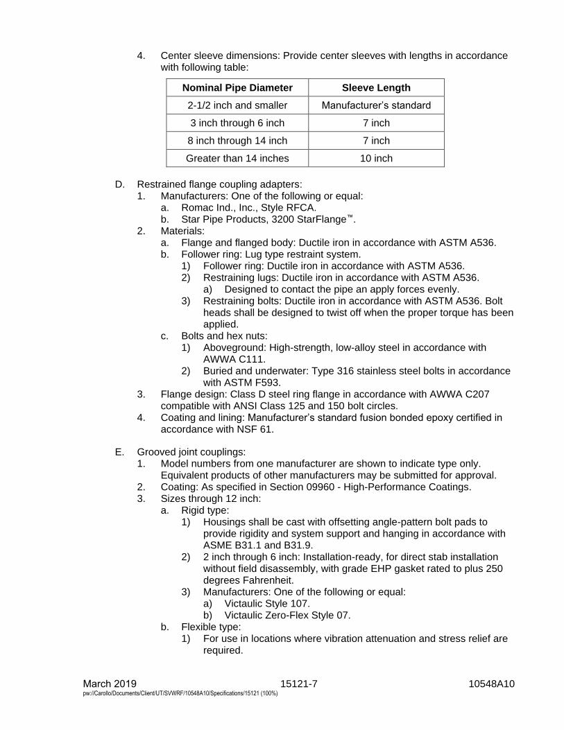
15121-7 10548A10 March 2019 pw://Carollo/Documents/Client/UT/SVWRF/10548A10/Specifications/15121 (100%)
4. Center sleeve dimensions: Provide center sleeves with lengths in accordancewith following table:
Nominal Pipe Diameter Sleeve Length
2-1/2 inch and smaller Manufacturer’s standard
3 inch through 6 inch 7 inch
8 inch through 14 inch 7 inch
Greater than 14 inches 10 inch
D. Restrained flange coupling adapters:1. Manufacturers: One of the following or equal:
a. Romac Ind., Inc., Style RFCA.b. Star Pipe Products, 3200 StarFlange™.
2. Materials:a. Flange and flanged body: Ductile iron in accordance with ASTM A536.b. Follower ring: Lug type restraint system.
1) Follower ring: Ductile iron in accordance with ASTM A536.2) Restraining lugs: Ductile iron in accordance with ASTM A536.
a) Designed to contact the pipe an apply forces evenly.3) Restraining bolts: Ductile iron in accordance with ASTM A536. Bolt
heads shall be designed to twist off when the proper torque has beenapplied.
c. Bolts and hex nuts:1) Aboveground: High-strength, low-alloy steel in accordance with
AWWA C111.2) Buried and underwater: Type 316 stainless steel bolts in accordance
with ASTM F593.3. Flange design: Class D steel ring flange in accordance with AWWA C207
compatible with ANSI Class 125 and 150 bolt circles.4. Coating and lining: Manufacturer’s standard fusion bonded epoxy certified in
accordance with NSF 61.
E. Grooved joint couplings:1. Model numbers from one manufacturer are shown to indicate type only.
Equivalent products of other manufacturers may be submitted for approval.2. Coating: As specified in Section 09960 - High-Performance Coatings.3. Sizes through 12 inch:
a. Rigid type:1) Housings shall be cast with offsetting angle-pattern bolt pads to
provide rigidity and system support and hanging in accordance withASME B31.1 and B31.9.
2) 2 inch through 6 inch: Installation-ready, for direct stab installationwithout field disassembly, with grade EHP gasket rated to plus 250degrees Fahrenheit.
3) Manufacturers: One of the following or equal:a) Victaulic Style 107.b) Victaulic Zero-Flex Style 07.
b. Flexible type:1) For use in locations where vibration attenuation and stress relief are
required.
15121-8 10548A10 March 2019 pw://Carollo/Documents/Client/UT/SVWRF/10548A10/Specifications/15121 (100%)
2) Three flexible couplings may be used in lieu of a flexible connector.3) The couplings shall be placed in close proximity to the source of the
vibration.4) Manufacturers: The following or equal:
a) Victaulic Style 77.c. Flange adapter:
1) Flat face, ductile iron housings with elastomer pressure responsivegasket, for direct connection to ANSI Class 125 or 150 flangedcomponents.
2) Manufacturers: The following or equal:a) Victaulic Style 741.
4. Sizes 14 inch through 24 inch:a. Victaulic AGS series with lead-in chamfer on housing key and wide width
FlushSeal® gasket.b. Rigid type:
1) Housing key shall fill the wedge shaped AGS groove and providerigidity and system support and hanging in accordance withASME B31.1 and B31.9.
2) Manufacturers: The following or equal:a) Victaulic Style W07.
c. Flexible type:1) Housing key shall fit into the wedge shaped AGS groove and allow
for linear and angular pipe movement.2) Manufacturers: The following or equal:
a) Victaulic Style W77.d. Flange adapter:
1) Flat face, ductile iron housings with elastomer pressure responsivegasket, for direct connection to ANSI Class 125 or 150 flangedcomponents.
2) Manufacturers: The following or equal:a) Victaulic Style W741.
5. For sizes 30 inch and larger:a. Manufacturers: The following or equal:
1) Victaulic Style AGS multiple-segment housing may be used.
2.04 PIPE COUPLINGS FOR STAINLESS STEEL PIPING
A. Flexible couplings:1. Manufacturers: The following or equal:
a. Dresser, Inc., Style 38.
B. Grooved joint couplings:1. Manufacturers: The following or equal:
a. Victaulic Co.2. Materials:
a. Housings:1) Ductile iron in accordance with ASTM A536.2) Stainless steel in accordance with ASTM A351.
b. Gasket: Elastomer in accordance with ASTM D2000.c. Bolts and nuts:
1) Electroplated steel in accordance with ASTM A449.2) Stainless steel in accordance with ASTM F593.
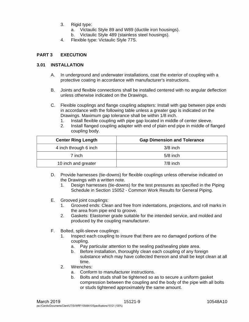
15121-9 10548A10 March 2019 pw://Carollo/Documents/Client/UT/SVWRF/10548A10/Specifications/15121 (100%)
3. Rigid type:a. Victaulic Style 89 and W89 (ductile iron housings).b. Victaulic Style 489 (stainless steel housings).
4. Flexible type: Victaulic Style 77S.
PART 3 EXECUTION
3.01 INSTALLATION
A. In underground and underwater installations, coat the exterior of coupling with aprotective coating in accordance with manufacturer's instructions.
B. Joints and flexible connections shall be installed centered with no angular deflectionunless otherwise indicated on the Drawings.
C. Flexible couplings and flange coupling adapters: Install with gap between pipe endsin accordance with the following table unless a greater gap is indicated on theDrawings. Maximum gap tolerance shall be within 1/8 inch.1. Install flexible coupling with pipe gap located in middle of center sleeve.2. Install flanged coupling adapter with end of plain end pipe in middle of flanged
coupling body.
Center Ring Length Gap Dimension and Tolerance
4 inch through 6 inch 3/8 inch
7 inch 5/8 inch
10 inch and greater 7/8 inch
D. Provide harnesses (tie-downs) for flexible couplings unless otherwise indicated onthe Drawings with a written note.1. Design harnesses (tie-downs) for the test pressures as specified in the Piping
Schedule in Section 15052 - Common Work Results for General Piping.
E. Grooved joint couplings:1. Grooved ends: Clean and free from indentations, projections, and roll marks in
the area from pipe end to groove.2. Gaskets: Elastomer grade suitable for the intended service, and molded and
produced by the coupling manufacturer.
F. Bolted, split-sleeve couplings:1. Inspect each coupling to insure that there are no damaged portions of the
coupling.a. Pay particular attention to the sealing pad/sealing plate area.b. Before installation, thoroughly clean each coupling of any foreign
substance which may have collected thereon and shall be kept clean at alltime.
2. Wrenches:a. Conform to manufacturer instructions.b. Bolts and studs shall be tightened so as to secure a uniform gasket
compression between the coupling and the body of the pipe with all boltsor studs tightened approximately the same amount.
March 2019 15121-10 10548A10 pw://Carollo/Documents/Client/UT/SVWRF/10548A10/Specifications/15121 (100%)
c. Final tightening shall be done by hand (no air impact wrenches) and iscomplete when the coupling is in uniform contact with the outside surfaceof the pipe all around the circumference of the pipe.
3. No joint shall be misfit in any plane.4. On the fixed ends of bolted, split-sleeve couplings, the shoulders shall bear on
the restraint rings all around with no visible gap.5. Ends of piping where coupler are installed shall be smooth and free of defects.
a. Remove weld splatter and grind smooth.b. Grind pipe seam welds flush with pipe wall and smooth.
END OF SECTION
15122-1 10548A10 March 2019 pw://Carollo/Documents/Client/UT/SVWRF/10548A10/Specifications/15122 (100%)
SECTION 15122
FIRE HYDRANTS
PART 1 GENERAL
1.01 SUMMARY
A. Section includes: Barrel type fire hydrants.
1.02 REFERENCES
A. American Water Works Association (AWWA):1. C 502 - Standard for Dry-Barrel Fire Hydrants.
PART 2 PRODUCTS
2.01 MANUFACTURERS
A. One of the following or equal:1. Mueller Co., Number A-421.2. Kennedy, Model K81D.3. Clow Valve Co., Medallion Hydrant.
2.02 MATERIALS
A. Fire hydrants:1. Dry barrel in accordance with type AWWA C 502, as complemented and
modified in this Section.2. Provide hydrants with ground level break-off feature and manufactured such
that the valve stem will not be bent when the hydrant is damaged or broken ator near the ground level.
3. When shut, provide valves that remain reasonably tight when the upper portionof the barrel is broken off.
4. Diameter of the main valve opening: Not less than 4 inches.5. Inlet connection: 6-inch diameter mechanical joint for ductile iron pipe.6. Provide two 2-1/2-inch hose nozzles and one 4-inch pumper nozzle facing the
street.a. Provide nozzles with hose caps chained to the hydrant barrel.b. Nozzle threads: National standard hose thread.
7. Hydrants: Furnish with drain valve.8. Color of hydrant above ground.
PART 3 EXECUTION
3.01 INSTALLATION
A. Install hydrants with proper extension so that branch pipe to hydrant and supplymain are at the same elevation.
15122-2 10548A10 March 2019 pw://Carollo/Documents/Client/UT/SVWRF/10548A10/Specifications/15122 (100%)
B. Attach auxiliary 6-inch gate valves by mechanical joint at 18 inches from the hydrantjoint, and attach piping ductile-iron to the supply.
C. Firmly set hydrants on a bed of coarse gravel.
END OF SECTION
15211-1 10548A10 March 2019 pw://Carollo/Documents/Client/UT/SVWRF/10548A10/Specifications/15211 (100%)
SECTION 15211
DUCTILE IRON PIPE: AWWA C151
PART 1 GENERAL
1.01 SUMMARY
A. Section includes: Ductile iron pipe, joints, fittings, gaskets, and pipe linings andcoatings.
1.02 REFERENCES
A. American Society of Mechanical Engineers (ASME):1. B16.1 - Gray Iron Pipe Flanges and Flanged Fittings: Classes 25, 125, and
250.
B. American Water Works Association (AWWA):1. C104 - Standard for Cement-Mortar Lining for Ductile-Iron Pipe and Fittings.2. C105 - Polyethylene Encasement for Ductile-Iron Pipe Systems.3. C110 - Standard for Ductile-Iron and Gray-Iron Fittings.4. C111 - Standard for Rubber-Gasket Joints for Ductile-Iron Pressure Pipe and
Fittings.5. C115 - Flanged Ductile Iron Pipe with Ductile-Iron or Gray-Iron Threaded
Flanges.6. C150 - Standard for Thickness Design of Ductile-Iron Pipe.7. C151 - Standard for Ductile-Iron Pipe, Centrifugally Cast.8. C600 - Installation of Ductile Iron Water Mains and Their Appurtenances.9. C606 - Standard for Grooved and Shouldered Joints.
C. American Welding Society (AWS):1. D11.2 - Guide for Welding Iron Castings.
D. ASTM International (ASTM):1. A47 - Standard Specifications for Ferritic Malleable Iron Castings.2. A183 - Standard Specifications for Carbon Steel Track Bolts and Nuts.3. A536 - Standard Specifications for Ductile Iron Castings.4. C283 - Standard Test Methods for Resistance of Porcelain Enameled Utensils
to Boiling Acid.5. D792 - Standard Test Methods for Density and Specific Gravity (Relative
Density) of Plastics by Displacement.
E. Ductile Iron Pipe Research Association (DIPRA):1. Thrust Restraint Design Manual.
F. NACE International (NACE):1. SP0188 - Discontinuity (Holiday) Testing of New Protective Coatings on
Conductive Substrates.
15211-2 10548A10 March 2019 pw://Carollo/Documents/Client/UT/SVWRF/10548A10/Specifications/15211 (100%)
G. National Association of Pipe Fabricators, Inc. (NAPF):1. 500-03 - Surface Preparation Standard for Ductile Iron Pipe and Fittings in
Exposed Locations Receiving Special External Coatings and/or SpecialInternal Linings.
H. Society for Protective Coatings (SSPC):1. PA-2 - Measurement of Dry Coating Thickness with Magnetic Gages.
1.03 SYSTEM DESCRIPTION
A. Thrust restraint system design:1. Design restrained joint thrust restraint system.2. Determine the length of pipe that must be restrained on each side of the focus
of a thrust load in accordance with the procedures and criteria established bythe DIPRA Thrust Restraint Design Manual as specified in Piping Schedule inSection 15052 - Common Work Results for General Piping and the followingadditional criteria:a. Design pressure: Test pressure.b. Laying condition: Type 5 in accordance with AWWA C150.c. Soil designation: Silt 1 as defined by DIPRA.d. Unit friction resistance: Based upon polyethylene encasement of pipe.e. Safety factor: 1.5 (for thrust restraint calculations only).
1.04 SUBMITTALS
A. Submit as specified in Section 01330 - Submittal Procedures.
B. Product data: As specified in Section 15052 - Common Work Results for GeneralPiping.
C. Shop drawings:1. Detailed layout drawings showing alignment of pipes, location of valves,
fittings, and appurtenances, types of joints, and connections to pipelines orstructures.
2. Thrust restraint systems layouts.3. Photographs, drawings, and descriptions of fittings, gaskets, couplings,
grooving of pipe and fittings, pipe linings, and coatings.
D. Calculations:1. Calculations for thrust restraint system design.
E. Provide manufacturer’s test reports:1. On glass lining certifying successful performance of holiday detection tests.
a. This documentation shall identify each piece by mark designation, andshow the actual test results during the final inspection by the manufacturerprior to shipment.
b. Acceptance criteria for glass lining shall be as specified under FieldQuality Control.
2. On glass-lined pipe certifying compliance with specified material requirementsfor glass-lining.
3. Include Coating Manufacturer’s Technical Representative’s reports.4. At the request of the Engineer, perform a maximum of 2 jobsite test
verifications on 12 randomly selected segments per test verification.
15211-3 10548A10 March 2019 pw://Carollo/Documents/Client/UT/SVWRF/10548A10/Specifications/15211 (100%)
1.05 QUALITY ASSURANCE
A. Qualifications:1. Lining manufacturers: For piping specified to receive glass or epoxy lining, use
only a lining manufacturer having a minimum of 5 years' experience supplyingthis type of product to the wastewater and water industry.
2. Welded on outlets: The pipe manufacturer shall have a minimum of 5 years'experience in the fabrication and testing of outlets of similar size andconfiguration similar to those used on the Project.
B. Pre-installation meeting:1. Arrange for Coating Manufacturer’s Technical Representative to attend
preconstruction conferences, and to make periodic visits to factory or shop toinspect surface preparation of pipe, fittings, and accessories; and to inspectapplication of linings to interior and coatings to exterior of pipe, fittings, andaccessories.
1.06 DELIVERY, STORAGE, AND HANDLING
A. Block piping and associated fittings for shipment to prevent damage to coatings andlinings.
B. Carefully handle piping and associated fittings during loading, unloading, andinstallation:1. Do not drop piping material from cars or trucks.2. Lower piping by mechanical means.3. Do not drop or pound pipe to fit grade.
C. Glass lined pipe and fittings must be handled only from the outside:1. No forks, chains, straps, hooks, or other lifting device shall be placed inside
the pipe or fittings for lifting, positioning, or laying.
D. Protect gaskets and polyethylene encasement from long-term exposure to sunlight.
E. Store piping, fittings, and other accessories such that they do not accumulate andhold rainwater, dirt, and debris.
PART 2 PRODUCTS
2.01 MANUFACTURED UNITS
A. Ductile iron piping:1. Manufacturers meeting qualifications as specified in this Section.2. Typical type:
a. In accordance with AWWA C150 and AWWA C151.b. Pressure class or special thickness class as indicated in the Piping
Schedule provided in Section 15052 - Common Work Results for GeneralPiping.
c. Manufactured from greater than 90 percent recycled material.3. Type with screw-on flanges:
a. In accordance with AWWA C115 with minimum special thicknessClass 53 wall thickness as required for screw-on flanges.
15211-4 10548A10 March 2019 pw://Carollo/Documents/Client/UT/SVWRF/10548A10/Specifications/15211 (100%)
b. Special thickness class as indicated in the Piping Schedule as specified inSection 15052 - Common Work Results for General Piping.
c. Manufactured from greater than 90 percent recycled material.4. Type with grooved couplings:
a. Special thickness class as indicated in the Piping Schedule as specified inSection 15052 - Common Work Results for General Piping.
b. Manufactured from greater than 90 percent recycled material.
B. Joints:1. Flanged joints:
a. Screw-on flanges: Comply with the diameter, thickness, drilling, and othercharacteristics in accordance with ASME B16.1. In addition, comply withthe following requirements:1) Ductile iron.2) Long hub, threaded, and specially designed for ductile iron pipe.3) After attaching to pipe, machine flange face to make pipe end and
flange even and perpendicular to the axis of the pipe.b. Bolt holes on flanges: 2-holed and aligned at both ends of pipe.c. Cap screw or stud bolt holes: Tapped.d. Bolts and nuts: As specified in Section 15052 - Common Work Results for
General Piping.e. Gaskets: Standard styrene butadiene copolymer (SBR) unless specified
otherwise in Section 15052 - Common Work Results for General Piping.2. Grooved joints: In accordance with AWWA C606, as complemented and
modified below, radius-cut type, with following components:a. Couplings: Rigid type, cast from ductile iron in accordance with
ASTM A536, Grade 65-45-12, or malleable iron in accordance withASTM A47, Grade 32510.
b. Bolts and nuts: In accordance with ASTM A183, Grade 2.c. Gaskets: Capable of being applied on surface of piping with cavities to
provide for an improved seal with the internal piping pressure. Material tobe used for following services:1) For liquid service: NBR.2) For air service: Fluoroelastomer.3) For hot water service: EPDM.
d. Fittings: In accordance with AWWA C606, rigid radius-cut groove:1) Center-to-center dimensions: In accordance with AWWA C110.2) Wall thickness and other characteristics: In accordance with
AWWA C606.e. Flanged unit connections: Flanged to grooved joint adapters or a long
enough spool with one end flanged and the other end grooved to preventinterference with the operation of adjacent valves, pumps, or other items.
3. Mechanical joints: In accordance with AWWA C111.4. Push-on rubber gasket joints: In accordance with AWWA C111.5. Integrally restrained mechanical joints:
a. Application:1) Where designation for RMJ, Mech Rest, or restrained mechanical
joints.2) Mechanical joint is specified in the Piping Schedule provided as
indicated on the Drawings, supply a restrained mechanical jointpiping system, which includes restrained mechanical joints wherenecessary based upon thrust calculations.
15211-5 10548A10 March 2019 pw://Carollo/Documents/Client/UT/SVWRF/10548A10/Specifications/15211 (100%)
3) Standard mechanical joints as specified above can be used wherethrust calculations demonstrate restraint is not required.
b. Design:1) Integral retainer weldment type or lugged type joint with Type 304
stainless steel rods and nuts.2) Restrained mechanical joints of the configuration which utilizes a
gripping or friction force for restraint will not be acceptable.c. Manufacturers: Where restrained mechanical joints are required, use one
of the following or equal:1) American Cast Iron Pipe Co., MJ Coupled Joint.2) Pacific States Cast Iron Pipe Co., Lock Mechanical Joint.3) U.S. Pipe, Bolt-Lok.4) U.S. Pipe, Mech-Lok.
6. Integrally restrained push-on joints:a. Application:
1) Where designation restrained push-on is specified in the PipingSchedule provided as indicated on the drawings, supply a restrainedpush-on joint piping system, which includes restrained push-on jointswhere necessary based upon thrust calculations.
2) Standard push-on rubber gasket joints as specified above can beused where thrust calculations demonstrate restraint is not required.
b. Design:1) Restrained push-on joints of the configuration which utilizes a
gripping or friction force for restraint will not be acceptable.2) Suitable for the following working pressures:
a) For 4- through 24-inch pipe: 350 pounds per square inch gauge.b) For 30- through 54-inch pipe: 250 pounds per square inch
gauge.c. Manufacturers: One of the following or equal:
1) U.S. Pipe, TR Flex.2) McWane Ductile, TR Flex.3) American Cast Iron Pipe Co., Flex Ring or Lok-Ring.
d. Limit buried joints to half the manufacturer’s published allowable angularjoint deflection for purposes of pipeline alignment and elimination offittings.
C. Fittings:1. Ductile iron in accordance with AWWA C110. AWWA C153 fittings are not
permissible2. Joint type: Same as that of the associated piping as specified in Section 15052
- Common Work Results for General Piping.3. Plain end-to-flanged joint connectors using setscrews are not acceptable.
D. Pipe and fitting linings:1. Cement-mortar lining:
a. In accordance with AWWA C104, apply cement-mortar on clean baremetal surfaces. Extend to faces of flanges, ends of spigots, and shouldersof hubs.
b. Minimum lining thickness: Standard in accordance with AWWA C104.c. Type of cement: Type II.
15211-6 10548A10 March 2019 pw://Carollo/Documents/Client/UT/SVWRF/10548A10/Specifications/15211 (100%)
2. Asphaltic seal coat:a. Apply over cement mortar linings and to outside surface of pipes that will
not receive another coating. Apply in accordance with AWWA C151.3. Elastomeric polyurethane (100 percent solids) lining:
a. As specified in Section 09960 - High-Performance Coatings.4. Ceramic epoxy lining:
a. Manufacturers: One of the following or equal:1) PROTECTO 401.2) SP-2000W.
b. Material: Amine cured Novolac epoxy containing at least 20 percent byvolume of ceramic quartz pigment.
c. Minimum dry film thickness (DFT): 40 mills.d. Application:
1) The lining shall only be applied by a manufacturer-authorizedrepresentative with no less than 5 years of experience in applying thespecified material.
2) The application of the lining shall be performed in accordance withmanufacturer’s published specifications.
3) Pipe and fittings shall be delivered to application facility with nointerior lining.
4) Interior of pipe shall be abrasive blasted per manufacturer’sspecifications.
e. Coverage:1) Gasket and spigot ends-on joints: Provide 6 mils minimum and
10 mils maximum coverage using joint compound as specified by themanufacturer for the gasket area and spigot ends.
2) Mechanical joints: Extend lining from spigot end to edge of gaugingring.
3) Number of coats: As recommended by the lining manufacturer.f. Source quality control:
1) Test pipe and fitting lining with a magnetic film thickness gauge.Perform testing in accordance with the method outlined inSSPC PA-2 Film Thickness Rating.
2) Test lining integrity of pipes using a holiday detection testinginstrument set at the voltage as specified by the coatingmanufacturer:a) Repair all holidays with joint compound in accordance with the
recommendations of the coating manufacturer, and re-test.3) Discard piping or reline piping when pinholes or discontinuities are
found.5. Glass lining:
a. Manufacturers: One of the following or equal:1) Water Works Manufacturing, Ferrock MEH-32 Lining.2) Vitco Corp., SG-14 Lining.
b. Material: Special glasses and inorganic materials suited for lining ofsewage, sludge, and scum piping with the following characteristics:1) Thickness: 0.008 to 0.012 inch.2) Hardness: 5 to 6 on the Mohs scale.3) Density: 2.5 to 3.0 grams per cubic centimeter, measured in
accordance with ASTM D792.
15211-7 10548A10 March 2019 pw://Carollo/Documents/Client/UT/SVWRF/10548A10/Specifications/15211 (100%)
4) Thermal shock resistance: Capable of withstanding 350 degreesFahrenheit change from 430 degrees Fahrenheit to 80 degreesFahrenheit without crazing, blistering, or spalling.
5) Gloss retention: Capable of retaining gloss after immersion in an8 percent sulfuric acid solution at 148 degrees Fahrenheit for10 minutes.
6) Weight loss: Maximum 3 milligrams per square inch when tested inaccordance with ASTM C283.
c. Fabrication:1) Use piping that is suitable for glass lining with minimum Class 53 wall
thickness after application of glass lining.2) Machine interior of pipe. Bore or grit blast in accordance with
NAPF 500-03 prior to application of glass lining.3) Screw factory assembled flanges on pipe, align boltholes, and flange
faces, unless otherwise specified.4) Apply lining to surfaces free of chemicals.5) Place piping in furnaces specially designed for heating piping until
glass melts and fuses with an integral molecular bond to the basemetal.
E. Coatings:1. Asphalt varnish: Factory applied.2. Primer:
a. Factory applied for field coating.b. Compatible with materials as specified in Section 09960 -
High-Performance Coatings.
2.02 POLYETHYLENE ENCASEMENT
A. General:1. Polyethylene encasement shall be supplied by the pipe manufacturer.
B. Materials: Supply one of the following polyethylene encasements:1. 2 layers of linear low-density polyethylene (LLDPE) film, minimum thickness of
8 mils in accordance with AWWA C105; or,2. Single layer of high-density, cross-laminated polyethylene (HDCLPE) film,
minimum thickness of 4 mils in accordance with AWWA C105.3. Single layer of V-Bio® enhanced polyethylene encasement (3 layers of
co-extruded LLDPE film with anti-microbial additive and volatile corrosioninhibitor infused on the inside surface), meeting all requirements of AWWAC105.
PART 3 EXECUTION
3.01 INSTALLATION
A. General:1. Install ductile iron piping in accordance with AWWA C600, modified as
specified in Section 15052 - Common Work Results for General Piping.2. For underground piping, the trenching, backfill, and compaction: As specified
in Section 02330 - Trenching and Backfilling.
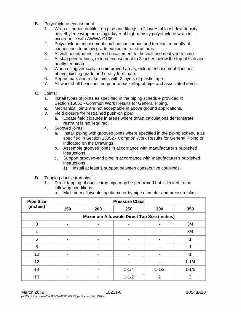
15211-8 10548A10 March 2019 pw://Carollo/Documents/Client/UT/SVWRF/10548A10/Specifications/15211 (100%)
B. Polyethylene encasement:1. Wrap all buried ductile iron pipe and fittings in 2 layers of loose low density
polyethylene wrap or a single layer of high-density polyethylene wrap inaccordance with AWWA C105.
2. Polyethylene encasement shall be continuous and terminated neatly atconnections to below grade equipment or structures.
3. At wall penetrations, extend encasement to the wall and neatly terminate.4. At slab penetrations, extend encasement to 2 inches below the top of slab and
neatly terminate.5. When rising vertically in unimproved areas, extend encasement 6 inches
above existing grade and neatly terminate.6. Repair tears and make joints with 2 layers of plastic tape.7. All work shall be inspected prior to backfilling of pipe and associated items.
C. Joints:1. Install types of joints as specified in the piping schedule provided in
Section 15052 - Common Work Results for General Piping.2. Mechanical joints are not acceptable in above ground applications.3. Field closure for restrained push-on pipe:
a. Locate field closures in areas where thrust calculations demonstraterestraint is not required.
4. Grooved joints:a. Install piping with grooved joints where specified in the piping schedule as
specified in Section 15052 - Common Work Results for General Piping orindicated on the Drawings.
b. Assemble grooved joints in accordance with manufacturer's publishedinstructions.
c. Support grooved-end pipe in accordance with manufacturer's publishedinstructions.1) Install at least 1 support between consecutive couplings.
D. Tapping ductile iron pipe:1. Direct tapping of ductile iron pipe may be performed but is limited to the
following conditions:a. Maximum allowable tap diameter by pipe diameter and pressure class:
Pipe Size (inches)
Pressure Class
150 200 250 300 350
Maximum Allowable Direct Tap Size (inches)
3 - - - - 3/4
4 - - - - 3/4
6 - - - - 1
8 - - - - 1
10 - - - - 1
12 - - - - 1-1/4
14 - - 1-1/4 1-1/2 1-1/2
16 - - 1-1/2 2 2
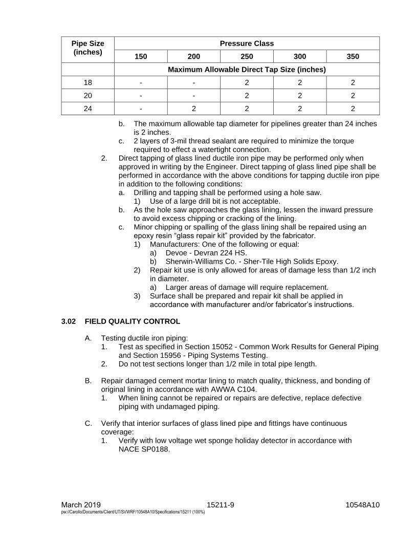
15211-9 10548A10 March 2019 pw://Carollo/Documents/Client/UT/SVWRF/10548A10/Specifications/15211 (100%)
Pipe Size (inches)
Pressure Class
150 200 250 300 350
Maximum Allowable Direct Tap Size (inches)
18 - - 2 2 2
20 - - 2 2 2
24 - 2 2 2 2
b. The maximum allowable tap diameter for pipelines greater than 24 inchesis 2 inches.
c. 2 layers of 3-mil thread sealant are required to minimize the torquerequired to effect a watertight connection.
2. Direct tapping of glass lined ductile iron pipe may be performed only whenapproved in writing by the Engineer. Direct tapping of glass lined pipe shall beperformed in accordance with the above conditions for tapping ductile iron pipein addition to the following conditions:a. Drilling and tapping shall be performed using a hole saw.
1) Use of a large drill bit is not acceptable.b. As the hole saw approaches the glass lining, lessen the inward pressure
to avoid excess chipping or cracking of the lining.c. Minor chipping or spalling of the glass lining shall be repaired using an
epoxy resin “glass repair kit” provided by the fabricator.1) Manufacturers: One of the following or equal:
a) Devoe - Devran 224 HS.b) Sherwin-Williams Co. - Sher-Tile High Solids Epoxy.
2) Repair kit use is only allowed for areas of damage less than 1/2 inchin diameter.a) Larger areas of damage will require replacement.
3) Surface shall be prepared and repair kit shall be applied inaccordance with manufacturer and/or fabricator’s instructions.
3.02 FIELD QUALITY CONTROL
A. Testing ductile iron piping:1. Test as specified in Section 15052 - Common Work Results for General Piping
and Section 15956 - Piping Systems Testing.2. Do not test sections longer than 1/2 mile in total pipe length.
B. Repair damaged cement mortar lining to match quality, thickness, and bonding oforiginal lining in accordance with AWWA C104.1. When lining cannot be repaired or repairs are defective, replace defective
piping with undamaged piping.
C. Verify that interior surfaces of glass lined pipe and fittings have continuouscoverage:1. Verify with low voltage wet sponge holiday detector in accordance with
NACE SP0188.
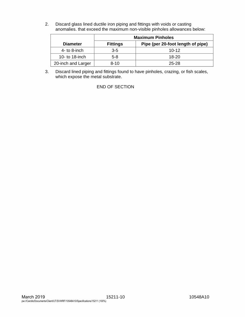
March 2019 15211-10 10548A10 pw://Carollo/Documents/Client/UT/SVWRF/10548A10/Specifications/15211 (100%)
2. Discard glass lined ductile iron piping and fittings with voids or castinganomalies. that exceed the maximum non-visible pinholes allowances below:
Diameter
Maximum Pinholes
Fittings Pipe (per 20-foot length of pipe)
4- to 8-inch 3-5 10-12
10- to 18-inch 5-8 18-20
20-inch and Larger 8-10 25-28
3. Discard lined piping and fittings found to have pinholes, crazing, or fish scales,which expose the metal substrate.
END OF SECTION
15234-1 10548A10 March 2019 pw://Carollo/Documents/Client/UT/SVWRF/10548A10/Specifications/15234 (100%)
SECTION 15234
POLYETHYLENE (PE) PIPE: ASTM D2513
PART 1 GENERAL
1.01 SUMMARY
A. Section includes: ASTM D2513 polyethylene piping and fittings.
1.02 REFERENCES
A. ASTM International (ASTM):1. D1248 - Standard Specification for Polyethylene Plastics Extrusion Materials
for Wire and Cable.2. D2513 - Standard Specification for Polyethylene (PE) Gas Pressure Pipe,
Tubing and Fittings.3. D2683 - Standard Specification for Socket-Type Polyethylene Fittings for
Outside Diameter-Controlled Polyethylene Pipe and Tubing.4. D3261 - Standard Specification for Butt Heat Fusion Polyethylene (PE) Plastic
Fittings for Polyethylene (PE) Plastic Pipe and Tubing.5. F645 - Standard Guide for Selection, Design and Installation of Thermoplastic
Water-Pressure Piping Systems.
1.03 ABBREVIATIONS
A. NPS: Nominal pipe size followed by the size designation.
B. PE: Polyethylene.
C. SDR: Standard dimension ratio; the outside diameter divided by the pipe wallthickness.
1.04 SUBMITTALS
A. Submit as specified in Section 01330 - Submittal Procedures.
B. Product data: As specified in Section 15052 - Common Work Results for GeneralPiping.
C. Shop drawings.
D. Calculations.
1.05 DELIVERY, STORAGE, AND HANDLING
A. Protect from sunlight, scoring, and distortion.
B. Do not allow surface temperatures to exceed 120 degrees Fahrenheit.
C. Store and handle as recommended by manufacturer in published instructions.
15234-2 10548A10 March 2019 pw://Carollo/Documents/Client/UT/SVWRF/10548A10/Specifications/15234 (100%)
PART 2 PRODUCTS
2.01 MATERIALS
A. Extruding and molding material:1. Virgin material containing no scrap, regrind, or rework material except where
permitted in the referenced standards.2. Fittings shall be same material as the pipe and of equal or greater pressure
rating.
B. Manufacturers: One of the following or equal:1. DuPont.2. Amsted Ind., Inc., Plexco.
C. Manufactured in accordance with ASTM D2513 using a compound in accordancewith ASTM D1248, PE 2306/2406:
D. SDR: Maximum of 11.
E. Fittings: In accordance with ASTM D2683 for socked fusion joints, andASTM D3261 for butt fusion joints.
2.02 SOURCE QUALITY CONTROL
A. Mark pipe and fittings in accordance with ASTM D2513.
PART 3 EXECUTION
3.01 INSTALLATION
A. General:1. Install piping in accordance with ASTM F645, or manufacturer's published
instructions for installation of piping, as applicable to the particular type ofpiping.
2. For open cut installations, install underground warning tape as specified inSection 15076 - Pipe Identification.
3. Socket fuse joints for piping equal or less than NPS 2.4. Butt fuse joints for piping larger than NPS 2.
3.02 FIELD QUALITY CONTROL
A. Test pipe as specified in Section 15052 - Common Work Results for General Pipingand Section 15956 - Piping Systems Testing.
END OF SECTION
15241-1 10548A10 March 2019 pw://Carollo/Documents/Client/UT/SVWRF/10548A10/Specifications/15241 (100%)
SECTION 15241
HIGH DENSITY POLYETHYLENE PLASTIC (HDPE) PIPE: AWWA C906
PART 1 GENERAL
1.01 SUMMARY
A. Section includes: High Density Polyethylene Pipe (HDPE), and fittings.
1.02 REFERENCES
A. ASTM International (ASTM):1. D1238 - Standard Test Method for Melt Flow Rates of Thermoplastics by
Extrusion Plastometer.2. D1505 - Standard Test Method for Density of Plastics by the Density-Gradient
Technique.3. D1599 - Standard Test Method for Resistance to Short-Time Hydraulic
Pressure of Plastic Pipe, Tubing, and Fittings.4. D1603 - Standard Test Method for Carbon Black Content in Olefin Plastics.5. D2122 - Standard Test Method for Determining Dimensions of Thermoplastic
Pipe and Fittings.6. D2290 - Standard Test Method for Apparent Hoop Tensile Strength of Plastic
or Reinforced Plastic Pipe by Split Disk Method.7. D3261 - Standard Specification for Butt Heat Fusion Polyethylene (PE) Plastic
Fittings for Polyethylene (PE) Plastic Pipe and Tubing.8. D3350 - Standard Specification for Polyethylene Plastic Pipe and Fittings
Material.9. F645 - Standard Guide for Selection, Design, and Installation of Thermoplastic
Water-Pressure Piping Systems.10. F714 - Standard Specification for Polyethylene (PE) Plastic Pipe (SDR-PR)
Based on Outside Diameter.11. F2164 - Standard Practice for Field Leak Testing of Polyethylene (PE) and
crosslinked Polyethylene (PEX) Pressure Piping Systems Using HydrostaticPressure
12. F2620 - Stand Practice for Heat Fusion Joint of Polyethylene Pipe and Fittings
B. Plastic Pipe Institute (PPI):1. PE 4710.2. Bolt Torque For Polyethlene Flanged Joints.
a. TN-38/July 2011.
1.03 ABBREVIATIONS
A. HDPE: High-density polyethylene pipe.
B. ID: Inside diameter of piping or tubing.
C. OD: Outside diameter.
D. SDR: Standard dimension ratio.
15241-2 10548A10 March 2019 pw://Carollo/Documents/Client/UT/SVWRF/10548A10/Specifications/15241 (100%)
1.04 SUBMITTALS
A. Submit as specified in Section 01330 - Submittal Procedures.
B. Product data: As specified in Section 15052 - Common Work Results for GeneralPiping:1. Describe materials and installation equipment including fusion machine.
Include optimum range of fusion conditions such as fusion temperature,interface pressure, and cooling time Pipe loads and structural calculations.
2. Installation instructions.
C. Qualifications of installation crew for high-density polyethylene pipe includingqualifications of the fusion machine technician. Furnish proof of training in the use offusion equipment.
1.05 QUALITY ASSURANCE
A. Markings on the pipe shall be in accordance with AWWA C906.
1.06 DELIVERY, STORAGE, AND HANDLING
A. Protect piping materials from sunlight, scoring, and distortion.
B. Do not allow surface temperatures on pipe and fittings to exceed 120 degreesFahrenheit.
C. Store and handle PE pipe and fittings as recommended by manufacturer inpublished instructions.
PART 2 PRODUCTS
2.01 MATERIALS
A. Extruding and molding material: Virgin material containing no scrap, regrind, orrework material except where permitted in the referenced standards.
B. Fittings: Same material as the pipe and of equal or greater pressure rating.
2.02 HDPE PIPING
A. General:1. Pipe and fittings: High-density polyethylene.2. Dimensions of pipe and fittings: Based on controlled outside diameter in
accordance with ASTM F714:a. SDR: As given in Piping Schedule, Section 15052 as indicated on the
drawings.b. Pipe Diameter: IPS dimensions as specified in the Pipe Schedule included
in the Drawings.3. Pipe, fittings, and adapters: Furnished by the same manufacturer, or
compatible with components in the same system and with components ofother systems to which connected.
15241-3 10548A10 March 2019 pw://Carollo/Documents/Client/UT/SVWRF/10548A10/Specifications/15241 (100%)
B. Materials:1. Manufacturers: One of the following or equal:
a. Performance Pipe.b. Isco Ind.c. JM Eagle.
2. Polyethylene: As listed by the PPI under the designation PE 4710; and have aminimum cell classification, in accordance with ASTM D3350, of 445574C:a. Pipe and fittings: Manufactured from material with the same cell
classification.b. Manufacturer shall certify that pipe and fittings meet the above
classifications.3. Polyethylene fittings and custom fabrications:
a. Molded or fabricated.b. Butt fusion outlets shall be made to the same outside diameter, wall
thickness, and tolerances as the mating pipe.c. All fittings and custom fabrications shall be fully rated for the same internal
pressure as the mating pipe.d. Pressure de-rated fabricated fittings are prohibited.
4. Molded fittings:a. Manufactured in accordance with ASTM D3261, Butt Heat Fusion
Polyethylene (PE) Plastic Fittings for Polyethylene (PE) Plastic Pipe andTubing, and shall be so marked.
b. Each production lot of molded fittings shall be subjected to the testsrequired under ASTM D3261.
5. X-ray inspection: The Manufacturer shall submit samples from each moldedfittings production lot to x-ray inspection for voids, and shall certify that voidswere not found.
6. Fabricated fittings:a. Made by heat fusion joining specially machined shapes cut from pipe,
polyethylene sheet stock, or molded fittings.b. Rated for internal pressure service at least equal to the full service
pressure rating of the mating pipe.7. Polyethylene flange adapters:
a. Flange adapters shall be made with sufficient through-bore length to beclamped in a butt fusion joining machine without the use of a stub-endholder.
b. The sealing surface of the flange adapter shall be machined with a seriesof small v-shaped grooves to provide gasketless sealing, or to restrain thegasket against blowout.
c. Gaskets for HDPE flanges to ductile iron, steel, or PVC pipe flanges are tobe full faced red SBR rubber gaskets, Garlock 22 or equal.
8. Back-up rings and flange bolts:a. Flange adapters shall be fitted with Type 316 stainless steel back-up rings
pressure rated equal to or greater than the mating pipe.b. The back-up ring bore shall be chamfered or radiused to provide
clearance to the flange adapter radius.c. Flange bolts and nuts shall be the same material as backing flange.
15241-4 10548A10 March 2019 pw://Carollo/Documents/Client/UT/SVWRF/10548A10/Specifications/15241 (100%)
2.03 SOURCE QUALITY CONTROL
A. HDPE piping:1. Manufacturer's quality control: The pipe and fitting manufacturer shall have an
established quality control program responsible for inspecting incoming andoutgoing materials.
2. Incoming polyethylene materials:a. Inspected for density, melt flow rate, and contamination.b. The cell classification properties of the material shall be certified by the
supplier, and verified by manufacturer's quality control.c. Approved by quality control before processing into finished goods.
3. Outgoing materials shall be checked for:a. Outside diameter, wall thickness, and eccentricity in accordance with
ASTM D2122 at a frequency of at least once per hour.b. Out of roundness at a frequency of at least once per hour.c. Straightness, inside and outside surface finish, markings and end cuts
shall be visually inspected in accordance with ASTM F714 on every lengthof pipe:1) Quality control shall verify production checks and test for:
a) Density in accordance with ASTM D1505 at a frequency of atleast once per extrusion lot.
b) Melt Index in accordance with ASTM D1238 at a frequency of atleast once per extrusion lot.
c) Carbon content in accordance with ASTM D1603 at a frequencyof at least once per day in accordance with extrusion line.
d) Quick burst pressure in accordance with ASTM D1599 at afrequency of at least once per day per line.
e) Ring Tensile Strength in accordance with ASTM D2290 at afrequency of at least once per day per line.
d. X-ray inspection shall be used to inspect molded fittings for voids, and knitline strength shall be tested. All fabricated fittings shall be inspected forjoint quality and alignment.
4. Permanent records: The manufacturer shall maintain permanent QC and QArecords.
5. Compliance tests:a. Manufacturer's inspection and testing of the materials.
1) In case of conflict with manufacturer's certifications, the Contractor,Engineer, or Owner may request retesting by the manufacturer orhave retests performed by an outside testing service.
2) All retesting shall be at the requestor's expense, and shall beperformed in accordance with this Section.
PART 3 EXECUTION
3.01 INSTALLATION
A. General:1. Where not otherwise specified, install piping in accordance with ASTM F645,
or manufacturer's published instructions for installation of piping, as applicableto the particular type of piping.

15241-5 10548A10 March 2019 pw://Carollo/Documents/Client/UT/SVWRF/10548A10/Specifications/15241 (100%)
2. Provide molded transition fittings for transitions from HDPE to metal or IPSpipe. Do not thread or solvent weld HDPE pipe.
B. Installation of HDPE piping:1. Joining:
a. Electrofusion welding is prohibited without prior approval by the Engineerb. Heat fusion joining:
1) Joints between plain end pipes and fittings shall be made by buttfusion, and joints between the main and saddle branch fittings shallbe made utilizing saddle fusion employing only procedures that arerecommended by the pipe and fitting manufacturer.
2) The Contractor shall certify, in writing, that persons making heatfusion joints have received training in the manufacturer'srecommended procedure and have had at least 5 years currentexperience in the heat fusion butt welding process.
3) The Contractor shall maintain records of trained personnel, and shallcertify that training was received not more than 12 months beforecommencing construction.
4) External and internal beads shall not be removed.5) Heat fusion joining in accordance with ASTM F26206) Install pipe when ambient temperatures are between 40 to
80 degrees Fahrenheit.c. Heat fusion training services: The manufacturer shall provide training in
the manufacturer's recommended butt fusion and saddle fusionprocedures to the Contractor's installation personnel, and to theinspector(s) representing the Owner, prior to the start of construction.
d. Mechanical joining:1) Polyethylene pipe and fittings may be joined together or to other
materials by means of flanged connections (flange adapters andback-up rings) or, where specifically indicated on the Drawings,flexible couplings designed for joining polyethylene pipe or for joiningpolyethylene pipe to another material.
2) Flexible couplings shall be fully pressure rated and fully thrustrestrained such that when installed in accordance withmanufacturer's recommendations, a longitudinal load applied to themechanical coupling will cause the pipe to yield before themechanical coupling disjoins.
2. Installation:a. General:
1) The Manufacturer shall package products for shipment in a mannersuitable for safe transport by commercial carrier.
2) When delivered, a receiving inspection shall be performed, and anyshipping damage shall be reported to the Manufacturer within 7 days.
3) Damaged pipe shall be promptly removed from the job site.4) Installation shall be in accordance with Manufacturer's
recommendations, and this specification.5) Prior to making a terminal connection of each individual run of HDPE
pipe, the temperature of the pipe should be allowed to approach theservice temperature at which the pipe is intended to operate.
6) All necessary precautions shall be taken to ensure a safe workingenvironment in accordance with applicable codes and standards.
15241-6 10548A10 March 2019 pw://Carollo/Documents/Client/UT/SVWRF/10548A10/Specifications/15241 (100%)
b. Large diameter fabricated fittings: Fabricated fittings shall be butt fused tothe end of a pipe.
c. Mechanical joint and flange installation:1) Mechanical joints and flange connections shall be installed in
accordance with the manufacturer's recommended procedure.2) Flange faces shall be centered and aligned to each other before
assembling and tightening bolts.3) Every effort shall be made to ensure that the opposing faces of the
flange assemblies mate up securely at a temperature approximatelythe same as the service temperature.
4) In no case shall the flange bolts be used to draw the flanges intoalignment.
5) Bolt threads shall be lubricated, and flat washers shall be fitted underthe flange nuts.
6) Bolts shall be evenly tightened according to the tightening patternand torque step recommendations as stated in Plastic Pipe Institute -Bolt Torque For Polyethylene Flanged Joints and per manufacturer’srecommendations.
7) At least 1 hour after initial assembly, flange connections shall bere-tightened following the tightening pattern and torque steprecommendations of the manufacturer.
8) The final tightening torque shall be 100 feet-pounds or less asrecommended by the manufacturer.
d. Pipe handling:1) Lift, move, or lower pipe and fittings only with wide fabric choker
slings.2) Wire rope or chain shall not be used.3) Slings shall be of sufficient capacity for the load, and shall be
inspected before use.4) Worn or defective equipment shall not be used.
e. Excavation, backfill material and backfilling and compacting:
3.02 FIELD QUALITY CONTROL
A. Testing:1. Butt fusion testing:
a. Pipe size 14 inches and larger:1) The first fusion of each day shall be a trial fusion.
a) The trial fusion shall be allowed to cool completely.b) Fusion test straps shall be cut out.
(1) The test strap shall be 12 inches (minimum) or 30 times thewall thickness in length with the fusion in the center, and1 inch (minimum) or 1.5 times the wall thickness in width.
c) Bend the test strap until the ends of the strap touch.2) If the fusion fails at the joint, a new trial fusion shall be made, cooled
completely and tested.3) Butt fusion of pipe to be installed shall not commence until a trial
fusion has passed the bent strap test.b. Pipe size smaller than 14 inch:
1) Test daily using ultrasonic time-of-flight diffraction (TOFD) perISO/DIS 10863, Welding - Use of time-of-flight diffraction technique.
15241-7 10548A10 March 2019 pw://Carollo/Documents/Client/UT/SVWRF/10548A10/Specifications/15241 (100%)
B. Data logging and test data:1. A data logger shall be installed on the fusion heated joining machine. Data on
each joint shall be recorded by the data logger. Data to be recorded shall beminimum temperature of joint fusion and interface pressure of the fused joint.
2. Recorded data from the fusion data logger and the TOFD shall be transmittedto the Owner daily.
C. Pressure testing:1. Test pressures as specified in the Piping Schedule as indicated on the
drawings.2. Field leak testing procedure in accordance with ASTM F2164.3. Temperature of test water shall be no more than 73 degrees Fahrenheit.
END OF SECTION

15244-1 10548A10 March 2019 pw://Carollo/Documents/Client/UT/SVWRF/10548A10/Specifications/15244 (100%)
SECTION 15244
POLYVINYL CHLORIDE (PVC) PIPE: AWWA C900
PART 1 GENERAL
1.01 SUMMARY
A. Section includes:1. AWWA C900 PVC pipe and fittings.
1.02 REFERENCES
A. American Water Works Association (AWWA):1. C111 - Standard for Rubber-Gasket Joints for Ductile-Iron Pressure Pipe and
Fittings.2. C605 - Standard for Underground Installation of PVC and PVCO Pressure
Pipe and Fittings for Water.3. C900 - Standard for Polyvinyl Chloride (PVC) Pressure Pipe and Fabricated
Fittings, 4 Inches to 12 Inches, for Water Transmission Distribution.4. M23 - PVC Pipe - Design and Installation Manual.
B. ASTM International (ASTM):1. A536 - Standard Specification for Ductile Iron Castings.2. D1784 - Standard Specification for Rigid Poly(Vinyl Chloride) (PVC)
Compounds and Chlorinated Poly(Vinyl Chloride) (CPVC) Compounds.3. D3139 - Standard Specification for Joints for Plastic Pressure Pipes Using
Flexible Elastomeric Seals.4. F477 - Standard Specification for Elastomeric Seals (Gaskets) for Joining
Plastic Pipe.5. F645 - Standard Guide for Selection, Design and Installation of Thermoplastic
Water-Pressure Piping Systems.
C. NSF International (NSF):1. 61 - Drinking Water System Components - Health Effects.
1.03 ABBREVIATIONS
A. DR: Dimension ratio.
B. NPS: Nominal pipe size followed by the size designation.
1.04 SUBMITTALS
A. Submit as specified in Section 01330 - Submittal Procedures.
B. Product data: As specified in Section 15052 - Common Work Results for GeneralPiping.
C. Shop drawings: As specified in Section 15052 - Common Work Results for GeneralPiping.
15244-2 10548A10 March 2019 pw://Carollo/Documents/Client/UT/SVWRF/10548A10/Specifications/15244 (100%)
1. Describe materials, pipe, fittings, and gaskets.2. Manufacturer’s product handling and installation instructions.
1.05 QUALITY ASSURANCE
A. Pipe in potable water applications: Provide pipe bearing NSF 61 seal.
B. Mark plastic pipe with date of extrusion, nominal size, class, manufacturer and allmarkings required in accordance with ASTM and AWWA standards.
1.06 DELIVERY, STORAGE, AND HANDLING
A. Protect from sunlight, scoring, and distortion.
B. Do not allow surface temperatures to exceed 120 degrees Fahrenheit.
C. Deliver, offload, handle, and store pipe in accordance with manufacturer’s or pipesupplier’s recommendations and best practices provided by AWWA M23 andAWWA C605, including compliance with minimum recommended bending radiusand maximum safe pulling forces for each specific pipe.
PART 2 PRODUCTS
2.01 PIPE
A. General:1. Extruding and molding material: Virgin material containing no scrap, regrind, or
rework material except where permitted in the referenced standards.2. In accordance with AWWA C900.3. Made from a PVC compound conforming to cell classification 12454 in
accordance with ASTM D1784.4. Marked verifying suitability for potable water service in accordance with
NSF 61.
B. Pipe:1. Bell and spigot:
a. Pipe with integral bell.b. Pressure Class as scheduled the Piping Schedule as indicated on the
Drawings with a minimum DR of 25.c. Manufacturers: One of the following or equal:
1) Diamond Plastics Corp.2) CertainTeed.3) North American Pipe Corp.
2.02 FITTINGS
A. Material:1. Cast or ductile iron fittings as specified in Section 15211 - Ductile Iron Pipe:
AWWA C151, sized for the dimensions of the pipe being used.2. Same material as the pipe, sized for the dimensions of the pipe being used.
B. Equal to or greater pressure rating than the pipe.
15244-3 10548A10 March 2019 pw://Carollo/Documents/Client/UT/SVWRF/10548A10/Specifications/15244 (100%)
2.03 JOINTS
A. Bell and spigot joints:1. Push-on or mechanical joint type as identified in the Piping Schedule in
Section 15052 - Common Work Results for General Piping.2. Gasketed joint assembly: Meet or exceed the requirements in accordance with
ASTM D3139.3. Factory installed gaskets: EPDM in accordance with ASTM F477.4. Joint restraint at fittings.
B. Mechanical wedge action joint restraints:1. Manufacturers: One of the following or approved equal:
a. EBAA Iron, Inc.:1) For pipes 3 to 36-inch: Series 2000PV.2) For pipes 42 and 48-inch: Series 2200.
b. Star Pipe Products, Series 4000.c. Sigma Corp.:
1) For pipes 3 to 36-inch: One-Lok Model SLCE.2) For pipes 42 and 48-inch: PV-Lok Model PWM.
2. Materials:a. Gland body: Ductile iron in accordance with ASTM A536.b. Wedge and wedge actuating components: Ductile iron in accordance with
ASTM A536.c. Wedges: Heat-treated to a minimum of 370 BHN.d. Actuating bolts and nuts: Ductile iron in accordance with ASTM A536.e. Provide torque-limiting twist off components to ensure proper installation.
3. Coatings:a. Provide a manufacturer applied coating system.
1) Manufacturers: One of the following or equal:a) EBAA Iron Inc., Mega-Bond.b) Star Pipe Products, Star-Bond.c) Sigma Corp., CorrsafeTM Electro-Deposition Coating.
b. Consist of multiple gripping wedges incorporated into a follower glandmeeting the requirements in accordance with AWWA C111.
c. Allow post assembly angular deflection that is a minimum of 50 percent ofthe angular deflection allowed by the mechanical joint.
d. Pressure rating equal to or greater than that of the pipe on which it isbeing used and a minimum safety factor of 2:1 for all sizes.
e. Push-on joint restraint harnesses:1) Manufacturers: One of the following or approved equal:
a) EBAA Iron, Inc.:(1) For pipes 4 to 12-inch: Series 1500.(2) For pipes 14 to 48-inch: Series 2800.
b) Star Pipe Products, Series 4100P.c) Sigma Corp., PV-Lok Model PWP.
2) Materials:a) Restraint and backup rings: Ductile iron in accordance with
ASTM A536.b) Wedge and wedge actuating components: Ductile iron in
accordance with ASTM A536.c) Tie rods: Low alloy steel in accordance with AWWA C111.
15244-4 10548A10 March 2019 pw://Carollo/Documents/Client/UT/SVWRF/10548A10/Specifications/15244 (100%)
3) Coatings:a) Provide manufacturer applied coating system.b) Manufacturers: One of the following or equal:
(1) EBAA Iron Inc., Mega-Bond.(2) Star Pipe Products, Star-Bond.(3) Sigma Corp., CorrsafeTM Electro-deposition coating.
4) Consist of a backup ring behind the PVC bell and a restraint ringconsisting of multiple gripping wedges connected with number andtype of tie rods as recommended by the manufacturer.
5) Allow post assembly angular deflection that is a minimum of50 percent of the angular deflection allowed by the push-on joint.
6) Pressure rating equal to or greater than that of the pipe on which it isbeing used and a minimum safety factor of 2:1 for all sizes.
2.04 SOURCE QUALITY CONTROL
A. Bell and spigot piping:1. Hydrostatic proof testing in accordance with AWWA C900: Test pipe and
integral bell to withstand, without failure, 2 times the pressure class of the pipefor a minimum of 5 seconds.
PART 3 EXECUTION
3.01 INSTALLATION
A. General:1. Install piping in accordance with ASTM F645, AWWA C605, the Appendix of
AWWA C900 and manufacturer's or pipe supplier’s published installationinstructions.
2. For open cut installations, install underground warning tape as specified inSection 15076 - Pipe Identification.
3. Install pipe with tracer wire as specified in Section 15076 - Pipe Identification.
B. Tapping:1. Direct tapping:
a. Direct taps are allowed for AWWA C900 Class 235 and Class 305 pipe,NPS 6-inch through 12-inch only.
b. 1-inch is the maximum allowable outlet size for performing a direct tap.2. Saddle tapping:
a. Saddle taps are allowable on all sizes and classes of AWWA C900 pipe.b. 2-inch is the maximum allowable outlet size for performing a saddle tap.c. As specified in Section 15120 - Piping Specialties for allowable service
saddles.3. Tapping sleeves:
a. Tapping sleeves are allowable on all sizes and classes of PVCAWWA C900.
b. As specified in Section 15120 - Piping Specialties for allowable tappingsleeves.
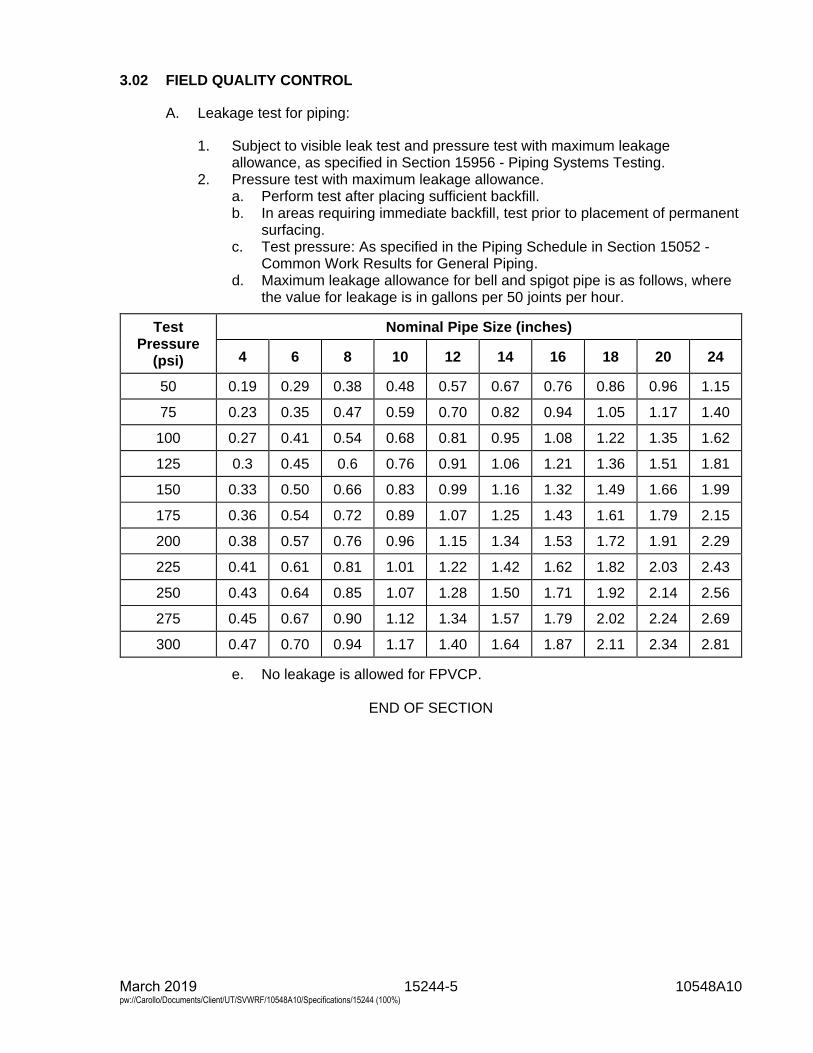
15244-5 10548A10 March 2019 pw://Carollo/Documents/Client/UT/SVWRF/10548A10/Specifications/15244 (100%)
3.02 FIELD QUALITY CONTROL
A. Leakage test for piping:
1. Subject to visible leak test and pressure test with maximum leakageallowance, as specified in Section 15956 - Piping Systems Testing.
2. Pressure test with maximum leakage allowance.a. Perform test after placing sufficient backfill.b. In areas requiring immediate backfill, test prior to placement of permanent
surfacing.c. Test pressure: As specified in the Piping Schedule in Section 15052 -
Common Work Results for General Piping.d. Maximum leakage allowance for bell and spigot pipe is as follows, where
the value for leakage is in gallons per 50 joints per hour.
Test Pressure
(psi)
Nominal Pipe Size (inches)
4 6 8 10 12 14 16 18 20 24
50 0.19 0.29 0.38 0.48 0.57 0.67 0.76 0.86 0.96 1.15
75 0.23 0.35 0.47 0.59 0.70 0.82 0.94 1.05 1.17 1.40
100 0.27 0.41 0.54 0.68 0.81 0.95 1.08 1.22 1.35 1.62
125 0.3 0.45 0.6 0.76 0.91 1.06 1.21 1.36 1.51 1.81
150 0.33 0.50 0.66 0.83 0.99 1.16 1.32 1.49 1.66 1.99
175 0.36 0.54 0.72 0.89 1.07 1.25 1.43 1.61 1.79 2.15
200 0.38 0.57 0.76 0.96 1.15 1.34 1.53 1.72 1.91 2.29
225 0.41 0.61 0.81 1.01 1.22 1.42 1.62 1.82 2.03 2.43
250 0.43 0.64 0.85 1.07 1.28 1.50 1.71 1.92 2.14 2.56
275 0.45 0.67 0.90 1.12 1.34 1.57 1.79 2.02 2.24 2.69
300 0.47 0.70 0.94 1.17 1.40 1.64 1.87 2.11 2.34 2.81
e. No leakage is allowed for FPVCP.
END OF SECTION

15245-1 10548A10 March 2019 pw://Carollo/Documents/Client/UT/SVWRF/10548A10/Specifications/15245 (100%)
SECTION 15245
DRAIN, WASTE, AND VENT PIPING
PART 1 GENERAL
1.01 SUMMARY
A. Section includes: Plastic drain, waste, and vent pipe and fittings.
1.02 REFERENCES
A. American Society of Mechanical Engineers (ASME):1. B16.12 - Cast Iron Threaded Drainage Fittings.
B. International (ASTM):1. B117 - Standard Practice for Operating Salt Spray (Fog) Apparatus.2. D635 - Standard Test Method for Rate of Burning and/or Extent and Time of
Burning of Plastics in a Horizontal Position.3. D1248 - Standard Specification for Polyethylene Plastics Extrusion Materials
for Wire and Cable.4. D1784 - Standard Specification for Rigid Poly(Vinyl Chloride) (PVC)
Compounds and Chlorinated Poly(Vinyl Chloride) (CPVC) Compounds.5. D1785 - Standard Specification for Poly(Vinyl Chloride) (PVC) Plastic Pipe,
Schedules 40, 80, and 120.6. D2235 - Specification for Solvent Cement for Acrylonitrile-Butadiene-Styrene
(ABS) Plastic Pipe and Fittings.7. D2321 - Standard Practice for Underground Installation of Thermoplastic Pipe
for Sewers and Other Gravity-Flow Applications.8. D2412 - Standard Test Method for Determination of External Loading
Characteristics of Plastic Pipe by Parallel-Plate Loading.9. D2466 - Standard Specification for Poly(Vinyl Chloride) (PVC) Plastic Pipe
Fittings, Schedule 40.10. D2467 - Standard Specification for Poly(Vinyl Chloride) (PVC) Plastic Pipe
Fittings, Schedule 80.11. D2564 - Standard Specification for Solvent Cements for Poly(Vinyl Chloride)
(PVC) Plastic Piping Systems.12. D2657 - Standard Practice for Heat Fusion Joining of Polyolefin Pipe and
Fittings.13. D2661 - Standard Specification for Acrylonitrile-Butadiene-Styrene (ABS)
Schedule 40 Plastic Drain, Waste, and Vent Pipe and Fittings.14. D2665 - Standard Specification for Poly(Vinyl Chloride) (PVC) Plastic Drain,
Waste, and Vent Pipe and Fittings.15. D2683 -Standard Specification for Socket-Type Polyethylene Fittings for
Outside Diameter-Controlled Polyethylene Pipe and Tubing.16. D2843 - Standard Test Method for Density of Smoke from the Burning of
Decomposition of Plastics.17. D2863 - Standard Test Method for Measuring the Minimum Oxygen
Concentration to Support Candle-Like Combustion of Plastics (Oxygen Index).18. D2855 - Standard Practice for Making Solvent-Cemented Joints with Poly
(Vinyl Chloride)(PVC) Pipe and Fittings.
15245-2 10548A10 March 2019 pw://Carollo/Documents/Client/UT/SVWRF/10548A10/Specifications/15245 (100%)
19. D3035 - Standard Specification for Polyethylene (PE) Plastic Pipe (DR-ProjectRepresentative) Based on Controlled Outside Diameter.
20. D3138 - Standard Specification for Solvent Cements for Transition JointsBetween Acrylonitrile-Butadiene-Styrene (ABS) and Poly(Vinyl Chloride)(PVC) Non-Pressure Piping Components.
21. D3222-Standard Specification for Unmodified Poly(Vinylidene Fluoride)(PVDF)Molding Extrusion and Coating Materials.
22. D3261 -Standard Specification for Butt Heat Fusion Polyethylene (PE) PlasticFittings for Polyethylene (PE) Plastic Pipe and Tubing.
23. D3350 - Standard Specification for Polyethylene Plastic Pipes and FittingsMaterials.
24. D3965 - Specification for Rigid Acrylonitrile-Butadiene-Styrene (ABS) Materialsfor Pipe and Fittings.
25. D4101 - Standard Specification for Polypropylene Injection and ExtrusionMaterials.
26. D6713 - Standard Specification for Extruded and Compression MoldedShapes Made from Poly(Vinylidene Fluoride) (PVDF).
27. E84 - Standard Test Method for Surface Burning Characteristics of Building.28. F402 - 05 Standard Practice for Safe Handling of Solvent Cements, Primers,
and Cleaners Used for Joining Thermoplastic Pipe and Fittings.29. F628 - Standard Specification for Acrylonitrile-Butadiene-Styrene (ABS)
Schedule 40 Plastic Drain, Waste, and Vent Pipe With a Cellular Core.30. F645 - Standard Guide for Selection, Design, and Installation of Thermoplastic
Water-Pressure Piping Systems.31. F714 - Standard Specification for Polyethylene (PE) Plastic Pipe (SDR-PR)
Based on Outside Diameter.32. F1055 - Standard Specification for Electrofusion Type Polyethylene Fittings for
Outside Diameter Controlled Polyethylene Pipe and Tubing.33. F1056 - Standard Specification for Socket Fusion Tools for Use in Socket
Fusion Joining Polyethylene Pipe or Tubing and Fittings.34. F1290 - Standard Practice for Electrofusion Joining Polyolefin Pipe and
Fittings.35. F1412 - Standard Specification for Polyolefin Pipe and Fittings for Corrosive
Waste Drainage Systems.36. F1673 - Standard Specification for Polyvinylidene Fluoride (PVDF) Corrosive
Waste Drainage Systems.37. F1668 - Standard Guide for Construction Procedures for Buried Plastic Pipe.38. F2620 - Standard Practice for Heat Fusion Joining of Polyethylene Pipe and
Fittings.
C. CSA International (CSA).
D. NSF International (NSF):1. 61 - Drinking Water System Components - Health Effects.
E. Underwriters Laboratories, Inc. (UL):1. 94 - Standard for Tests for Flammability of Plastic Materials for Parts in
Devices and Appliances.
1.03 ABBREVIATIONS
A. ABS: Acrylonitrile-butadiene-styrene.
15245-3 10548A10 March 2019 pw://Carollo/Documents/Client/UT/SVWRF/10548A10/Specifications/15245 (100%)
B. DWV: Drain, waste, and vent.
C. PE: Polyethylene.
D. PP: Polypropylene.
E. PVC: Polyvinyl chloride.
F. PVDF: Unmodified Poly(Vinylidene Fluoride).
1.04 SUBMITTALS
A. Submit as specified in Section 01330 - Submittal Procedures.
B. Product data: As specified in Section 15052 - Common Work Results for GeneralPiping.
C. Shop drawings: As specified in Section 15052 - Common Work Results for GeneralPiping.1. Describe materials, pipe, fittings, gaskets, and solvent cement.2. Installation instructions.
D. Polyethylene pipe submittals:1. Product data.2. Installation equipment including details on fusion machine used to join
polyethylene pipe sections.3. Qualifications of installation crew for use of the fusion machine used for joining
polyethylene pipe.
1.05 QUALITY ASSURANCE
A. Install drain system in accordance with all local and national plumbing codes.
B. Fusion machine technician qualifications: 1-year experience in the installation ofsimilar PE piping systems from the same manufacturer.
C. Plastic pipe in potable water applications: Provide pipe and tubing bearing NSF 61seal:1. Mark plastic pipe with nominal size, type, class, schedule, or pressure rating,
manufacturer and all markings required in accordance with AS™ standards.
1.06 SOURCE QUALITY CONTROL
A. PVC piping, Schedule Type:1. Mark pipe and fittings in accordance with ASTM D1785.
B. PP piping:1. Test samples and testing: Cut test samples of pipe, 6 inches long, from full
length sections and test by the method outlined in accordance withASTM D2412:a. Deflect pipe at least 35 percent without failure. Stiffness at 5 percent
deflection equals or exceeds 55 pounds per square inch after the test
15245-4 10548A10 March 2019 pw://Carollo/Documents/Client/UT/SVWRF/10548A10/Specifications/15245 (100%)
samples have been immersed in a 5 percent solution by weight of sulfuric acid and n-Heptain for a period of 24 hours prior to testing.
b. Failure is defined as rupture of the pipe wall.c. Stiffness factor may be computed by the method outlined in accordance
with ASTM D2412 or by dividing the load in pounds per linear inch by thedeflection in inches and 5 percent deflection.
1.07 DELIVERY, STORAGE, AND HANDLING
A. Protect piping materials from sunlight, scoring, and distortion.
B. Do not allow surface temperatures on pipe and fittings to exceed 120 degreesFahrenheit.
C. Store and handle PE pipe and fittings as recommended by manufacturer inpublished instructions.
PART 2 PRODUCTS
2.01 MATERIALS
A. Extruding and molding material: Virgin material containing no scrap, regrind, orrework material except where permitted in the referenced standards.
B. Fittings: Same material as the pipe.
C. Unions 2-1/2 inches and smaller: Socket end screwed unions. Make unions3 inches and larger of socket flanges with 1/8-inch full-face soft neoprene gasket.
2.02 PVC PIPING
A. Materials:1. PVC Pipe: Designation PVC 1120 in accordance with ASTM D1785 and
appendices:a. Pipe and fittings: Extruded from Type I, Grade 1, Class 12454-B material
in accordance with ASTM D1784.b. PVC Pipe: Schedule 40 in accordance with ASTM D1866 unless
otherwise indicated on the Drawings.2. Fittings:
a. Supplied by pipe manufacturer.b. Pressure fittings: In accordance with ASTM D2466 or ASTM D2467.c. DWV fittings: In accordance with ASTM D2665.
3. Solvent cement: In accordance with ASTM D2564:a. Chemical service: For CPVC or PVC pipe in chemical service, provide the
following primer and cement, or equal:1) Primer: IPS Corp Type P-70™.2) Cement: IPS Corp Type 724™ cement or cement certified by the
manufacturer for chemical service.
15245-5 10548A10 March 2019 pw://Carollo/Documents/Client/UT/SVWRF/10548A10/Specifications/15245 (100%)
2.03 POLYPROPYLENE PIPING
A. General:1. Pipe and fittings: Polypropylene.2. Dimensions of pipe and fittings: Based on controlled outside diameter in
accordance with ASTM F1412.3. All pipe is supplied in 10-foot sections.4. All pipe is to be pre-grooved at factory (for mechanical joints).
B. Materials:1. Pipe: Schedule 40 dimensions, extruded from Type I-19509 material in
accordance with ASTM D4101.2. Chemical and Acid resistant PP piping in accordance with ASTM F1412.3. Flame retardant polypropylene shall be in accordance with ASTM D635,
D2843, D2863, and UL 94.4. Fittings: Molded from the same PP Type I - 19509 material and have and
equivalent laying length as Cast Iron fittings, in accordance with ASMEB16.12:a. Fittings: Manufactured by pipe manufacturer.
C. Manufacturers: One of the following or equal:1. Acid waste and vent piping is to be IPEX.2. Zurn.3. Orion Fittings.
D. Polypropylene Joining Systems:1. IPEX:
a. Labline™ Mechanical Joining System.b. Enfield™ Electrofusion.c. Plenumline™ PVDF mechanical Joint.
2. Orion Fittings:a. No Hub: metal clamp and bolts shall be of 300 series stainless steel and
in accordance with ASTM B117.b. Socket Fusion (heat fusion joining).c. Rionfuse CF™ Electrofusion.
3. Zurn:a. Mechanical Joining.b. Fusion Lock™.
2.04 ABS PIPING
A. General:1. Pipe and fittings: Acrylonitrile-butadiene-styrene.2. Dimensions of pipe and fittings: Based on controlled outside diameter in
accordance with ASTM F628.3. Piping shall be provided in lengths of 10 feet or 20 feet as required.4. Pipe shall be tested and listed in accordance with NSF Standard 14.
B. Materials:1. Cellular core co-extruded ABS drain, waste and vent pipe shall be made in
accordance with ASTM F628 from a compound conforming to a minimum cellclassification of 42222 as defined by ASTM D3965 or,a. PVC Pipe: Schedule 40 unless otherwise indicated on the Drawings.
15245-6 10548A10 March 2019 pw://Carollo/Documents/Client/UT/SVWRF/10548A10/Specifications/15245 (100%)
2. Fittings:a. Shall conform to ASTM D2661 and be manufactured from virgin rigid ABS
compounds with a Cell class of 32222 as identified in ASTM D3965.b. Supplied by pipe manufacturer.
3. Solvent cement: In accordance with ASTM D2235:a. E-Z Weld ABS or similar.
C. Manufacturers: One of the following or equal:1. Charlette Pipe.2. IPEX Drainaway®.
PART 3 EXECUTION
3.01 INSTALLATION
A. General:1. Where not otherwise specified, install piping in accordance with ASTM F645,
or manufacturer's published instructions for installation of piping, as applicableto the particular type of piping.
2. Provide molded transition fittings for transitions from plastic to metal orIPS pipe. Do not thread plastic pipe.
3. Locate unions where indicated on the Drawings, and elsewhere whererequired for adequate access and assembly of the piping system.
4. Provide serrated nipples for transition from plastic pipe to rubber hose.5. Heat fusion joining shall be in accordance with ASTM D2657.6. Underground installation shall be installed in accordance with ASTM D2321
and ASTM F1668.7. Solvent cements shall be handled in accordance with ASTM F402.
B. Installation of PVC piping, Schedule Type:1. Solvent weld joints in accordance with ASTM D2855:
a. For PVC pipe in chemical service use IPS Corp. Type 724™ cement inaccordance with manufacturer's instructions.
2. Install piping in accordance with manufacturer's published instructions.
C. Installation of Polypropylene piping:1. General:
a. Electrofusion joining shall be in accordance with ASTM F1290.2. Above grade acid waste and vent piping shall be NSF listed CSA certified,
flame retardant, schedule 40 polypropylene and be joined by IPEX Lablinefitting.a. Manufacturers: The following or equal:
1) Zurn.b. Installation and testing shall be in accordance with the Contract
Documents, the manufactures’ recommendations, and the 2010 CaliforniaPlumbing Code.
c. Test sections shall not be longer than 1,000 feet.3. Below grade acid waste and vent piping shall be of NSF listed, CSA certified
schedule 40, flame retardant polypropylene joined by IPEX Enfield™
electrofusiona. Manufacturers: The following or equal:
1) Zurn, Fusion Lock™.

15245-7 10548A10 March 2019 pw://Carollo/Documents/Client/UT/SVWRF/10548A10/Specifications/15245 (100%)
b. Installation and testing shall be in accordance with the ContractDocuments, the manufacture’s recommendations, and the PlumbingCode.
4. Install piping in accordance with manufacturer's published instructions.
D. Installation of ABS Pipe:1. Install piping as recommended in the manufactures’ published instructions and
local code requirements.a. Buried pipe shall be installed in accordance with ASTM D2321 and
ASTM F1668.2. The system shall be protected from chemical agents, fire stopping materials,
tread sealant, or other aggressive chemical agents not compatible with ABScompounds.
3. Transition joints between ABS and PVC shall be in accordance withASTM D3138.
3.02 FIELD QUALITY CONTROL
A. Test piping as specified in Section 15052 - Common Work Results for GeneralPiping.
END OF SECTION

15270-1 10548A10 March 2019 pw://Carollo/Documents/Client/UT/SVWRF/10548A10/Specifications/15270 (100%)
SECTION 15270
STEEL PIPE: GALVANIZED AND BLACK, ASTM A53
PART 1 GENERAL
1.01 SUMMARY
A. Section includes: Steel pipe: Galvanized and black, ASTM A53.
1.02 REFERENCES
A. American Society of Mechanical Engineers (ASME):1. B16.3 - Malleable-Iron Threaded Fittings: Classes 150 and 300.2. B16.5 - Pipe Flanges and Flanged Fittings.3. B16.9 - Factory-Made Wrought Buttwelding Fittings.
B. American Water Works Association (AWWA):1. C110 - Ductile-Iron and Gray-Iron Fittings.2. C203 - Coal-Tar Protective Coatings and Linings for Steel Water
Pipelines-Enamel and Tape-Hot Applied.3. C205 - Standard for Cement-Mortar Protective Lining and Coating for Steel
Water Pipe-4 Inches and Larger-Shop Applied.4. C206 - Field Welding of Steel Water Pipe.5. C602 - Standard for Cement-Mortar Lining of Water Pipelines in
Place - 4 inches and Larger.6. C606 - Standard for Grooved and Shouldered Joints.
C. ASTM International (ASTM):1. A47 - Standard Specification for Ferritic Malleable Iron Casting.2. A53 - Standard Specification for Pipe, Steel, Black and Hot-Dipped,
Zinc-Coated, Welded and Seamless.3. A105 - Standard Specification for Carbon Steel Forgings for Piping
Applications.4. A153 - Standard Specification for Zinc Coating (Hot-Dip) on Iron and Steel
Hardware.5. A183 - Standard Specification for Carbon Steel Track Bolts and Nuts.6. A536 - Standard Specification for Ductile Iron Castings.7. C150 - Standard Specification for Portland Cement.8. D2000 - Standard Classification System for Rubber Products in Automotive
Applications.
1.03 SUBMITTALS
A. Submit as specified in Section 01330 - Submittal Procedures.
B. Product data: As specified in Section 15052 - Common Work Results for GeneralPiping.
15270-2 10548A10 March 2019 pw://Carollo/Documents/Client/UT/SVWRF/10548A10/Specifications/15270 (100%)
PART 2 PRODUCTS
2.01 MATERIALS
A. Portland cement: In accordance with ASTM C150, Type II, low alkali.
2.02 MANUFACTURED UNITS
A. Steel pipe:1. General:
a. In accordance with ASTM A53.1) Type: Type E - electric-resistance welded or Type S - seamless.2) Grade: Grade A or B.
b. Schedule:1) As indicated on the Drawings or as specified in Section 15052 -
Common Work Results for General Piping pipe schedule.2) Minimum Schedule unless otherwise indicated on the Drawings or as
specified in Section 15052 - Common Work Results for GeneralPiping pipe schedule:a) Pipe 6 inches and smaller: Schedule 40.b) Pipe greater than 6 inch to 12 inch: Schedule 20.c) Pipe greater than 12 inch: 0.25 inches.
B. Pipe fittings:1. Flanged and welding fittings:
a. Butt-weld fittings in accordance with ASME B16.9.b. Schedule of fittings: Same class or thickness as the pipe to which it
connects.2. Screwed fittings:
a. Malleable iron:1) Class 150 or Class 300 in accordance with ASME B16.3, as
specified in Section 15052 - Common Work Results for GeneralPiping pipe schedule.
2) Galvanized in accordance with ASTM A153 where used withgalvanized pipe.
3. Grooved joint fittings:a. Fittings for grooved joint steel piping: Rigid-grooved type.b. Fittings for grooved joint piping:
1) Manufacturers: One of the following or equal:a) Victaulic Co. of America.b) Grinnell.c) Anvil.
2) Ductile iron fittings:a) Larger than 4 inches in diameter: In accordance with
ASTM A536, Grade 65-45-12, long radius, per AWWA C110.b) Less than 4 inches in diameter: Malleable iron conforming to
ASTM A47, Grade 32510.3) Where cast fittings are not made, forged steel in accordance with
ASME B 16.9, ASTM A105, Grade B with 0.375 inch minimum wallthickness.a) Bends: Long radius.
15270-3 10548A10 March 2019 pw://Carollo/Documents/Client/UT/SVWRF/10548A10/Specifications/15270 (100%)
4) Fittings for grooved joint piping shall be furnished by themanufacturer of the grooved joint coupling.
5) Fittings for grooved joint piping shall be for rigid-grooved type joints.Connection to flanged units shall be by means of a spool with oneend flanged and the other grooved, long enough to preventinterference with adjacent valves, pumps, or other items, minimumlength, 4 inches.
C. Pipe joints:1. General:
a. Use type of pipe joints as indicated on the Drawings or as specified inSection 15052 - Common Work Results for General Piping pipe schedule.
b. In addition to the type of pipe joints indicated on the Drawings or asspecified in Section 15052 - Common Work Results for General Pipingpipe schedule, use flexible couplings, unions or flanged joints to allowready assembly and disassembly of the piping.
2. Flanged joints:a. In accordance with ASME B16.5, steel, 300 pounds, slip-on or weld neck,
galvanized in accordance with ASTM A153 where used with galvanizedpipe.
b. Companion flanges:1) In accordance with ASME B16.5, steel.2) Class 300 pounds, slip-on or welding neck.
c. Weld flanges to pipe or fittings before applying lining.d. Machine flanges or provide tapered filler for changes in grade or to slope
lines for drainage.e. Match pipe flanges to the valve flanges.f. Flange bolts: As specified in Section 15052 - Common Work Results for
General Piping.g. Gaskets: As specified in Section 15052 - Common Work Results for
General Piping.3. Grooved joints:
a. Grooves: Cut grooves. Rolled grooves are not acceptable.b. Couplings housing: Cast in 2 or more segments of ductile iron in
accordance with ASTM A536, Grade 65-45-12 or malleable iron inaccordance with ASTM A47, Grade 32510.
c. Bolts and nuts: In accordance with ASTM A183, Grade 2.d. Gaskets: Composition water sealing designed so that the internal piping
pressure serves to increase the seal's watertightness.1) Gaskets for water service and oil-free air systems at temperatures
less than 230 degrees Fahrenheit shall be made of ethylenepropylene diene monomers (EPDM) in accordance withASTM D2000 Line Call Out 2CA615A25B24.
e. Perform grooving of the pipe wall only on standard or heavier scheduleweight pipe.1) For pipe with wall thickness less than standard weight, weld a
shouldered end on the pipe in accordance with AWWA C606.2) Shoulder: Type B or D in accordance with AWWA C606.
f. Couplings and grooving:1) Manufacturers: One of the following or equal:
a) Victaulic Co.b) Grinnell.
15270-4 10548A10 March 2019 pw://Carollo/Documents/Client/UT/SVWRF/10548A10/Specifications/15270 (100%)
c) Anvil.g. Grooved joint piping shall not be used in the following installations:
1) In underground and underwater installations.2) In piping subject to test pressures of 150 pounds per square inch
gauge, or more.3) In steam and gas piping.4) In sludge and scum piping designed to be steam cleaned.
4. Welded joints: Butt welds, 2 pass, full depth with beveled ends and no backingrings.
D. Pipe lining and coating:1. General:
a. Lining and coating shall be as indicated on the Drawings or as specified inSection 15052 - Common Work Results for General Piping.
2. Pipe coating:a. Extend pipe coating for underground piping 6 inches above finish grade or
finish floor, and neatly terminate.b. Field paint aboveground steel pipe as specified in Execution of this
Section.c. Coat exposed piping as specified in Section 09960 - High-Performance
Coatings.d. Coat submerged piping as specified in Section 15052 - Common Work
Results for General Piping pipe schedule and Section 09960 -High-Performance Coatings.
e. Cement-mortar coating:1) Cement-mortar coating: In accordance with AWWA C205, modified
as follows:a) Sand: In accordance with AWWA C205 except that the total
percentage of deleterious material shall not exceed 3 percent.f. Plastic tape wrap: As specified in Section 15274 - Plastic Tape Wrap for
Pipe.1) For buried pipe, wrap fittings, valves, and other odd shaped
components in the pipeline with first and finish wrapping over theprime coat, total thickness of tape 80 mils.
3. Pipe lining:a. Cement-mortar lining:
1) Shop apply cement-mortar lining in accordance with AWWA C205. Atthe option of Contractor, field apply with a pipe lining machine.
b. Coal-tar enamel lining:1) Coal-tar enamel lining for interior of steel pipe: In accordance with
AWWA C203.c. Coal-tar epoxy lining:
1) Coal-tar epoxy lining: Epoxy bituminous coating as specified forsubmerged metal in Section 09960 - High-Performance Coatings.
d. High solids epoxy:1) High solids epoxy as specified for submerged metal or exposed
metal in Section 09960 - High-Performance Coatings.e. Polyurethane lining:
1) Polyurethane as specified for submerged metal in Section 09960 -High-Performance Coatings.
15270-5 10548A10 March 2019 pw://Carollo/Documents/Client/UT/SVWRF/10548A10/Specifications/15270 (100%)
2.03 FABRICATION
A. Shop coat of primer:1. Flanges and portions of pipe not covered with cement-mortar shall be given a
shop coating of primer.2. Primer compatible with finish coating system.
PART 3 EXECUTION
3.01 INSTALLATION
A. Pipe joints:1. General:
a. Steel pipe joints shall be screwed, welded, flanged, grooved, or made withflexible joints. The type of joint for piping is as specified in Section 15052 -Common Work Results for General Piping pipe schedule or as indicatedon the Drawings.
b. In addition to the joints indicated on the Drawings, provide unions, flexiblecouplings, flanged joints, and other types of joints or means necessary toallow ready assembly and disassembly of the piping.
c. Unless otherwise indicated on the Drawings or as specified inSection 15052 - Common Work Results for General Piping pipe schedule,pipe joints shall be as follows:1) Pipe smaller than 2 inches in nominal diameter shall have screwed
joints, welded joints, unions, or flexible couplings.2) Pipe 2 inches to 4 inches in nominal diameter shall have screwed
joints, flanged joints, welded joints, or joints made with flexiblecouplings.
3) Pipe larger than 4 inches in nominal diameter shall have flangedjoints, welded joints, or joints made with flexible couplings.
2. Flanged joints:a. Flanges shall come together at the proper orientation with no air gaps
between the flanges after the gaskets are in place.b. Secure welding neck flanges with full penetration butt welds without
backing rings.c. Secure slip-on flanges with both internal and external welds.d. After welding in place, the faces of flanges shall be perpendicular to the
axis of the pipe, or, in the case of fittings, at the proper angle to eachother, and bolt holes shall be in proper alignment.
3. Grooved joints:a. Assemble in accordance with manufacturer's published instructions.b. Support grooved joint pipe in accordance with manufacturer's
recommendations. In addition, provide at least 1 support betweenconsecutive couplings.
4. Screwed joints:a. Perform threading with clean, sharp dies.
1) Wavy, rough, or otherwise defective pipe threads are not acceptable.b. Make screwed joints tight and clean with an application of Teflon tape or
paste compound applied to the male threads only, except as follows:1) Make up liquid and liquefied petroleum gas lines, with litharge and
glycerin.

15270-6 10548A10 March 2019 pw://Carollo/Documents/Client/UT/SVWRF/10548A10/Specifications/15270 (100%)
c. Provide railroad type unions with bronze-to-iron seat. Galvanized whereused with galvanized pipe.1) Flanged joints may be used instead of unions.
5. Welded joints:a. Field welded joints: Electric arc welded in accordance with AWWA C206.b. Welder’s qualification: Qualified in accordance with AWWA C206.
1) Welders' testing shall be at the Contractor's expense, including costof test nipples, welding rods, and equipment.
c. Do not weld galvanized pipe.
B. Pipe lining and coating:1. Pipe lining:
a. Field applied cement-mortar lining shall be of the same density,smoothness, and thickness as shop applied lining, and in accordance withAWWA C602.
2. Pipe Coating:a. Plastic tape wrap application:
1) Wrap fittings, valves, and other odd shaped components in thepipeline with first and finish wrapping over the prime coat.
2) Wrap joints, fittings, valves, and other irregular shapes of piping withextruded coatings with tape as specified in this subparagraph.
b. Field coat aboveground steel pipe as specified in Section 09960 -High-Performance Coatings.
3.02 FIELD QUALITY CONTROL
A. Field test fabricated steel manifolds with the pipe to which they connect.
END OF SECTION
15274-1 10548A10 March 2019 pw://Carollo/Documents/Client/UT/SVWRF/10548A10/Specifications/15274 (100%)
SECTION 15274
PLASTIC TAPE WRAP FOR PIPE
PART 1 GENERAL
1.01 SUMMARY
A. Section includes: Plastic tape wrap for pipe.
1.02 REFERENCES
A. American Water Works Association (AWWA):1. C209 - Standard for Cold-Applied Tape Coating for the Exterior of Special
Sections, Connections, and Fittings for Steel Water Pipelines.2. C214 - Standard for Tape-Coating Systems for the Exterior of Steel Water
Pipelines.
B. National Association of Corrosion Engineers (NACE):1. RP0274-74 - Standard Recommended Practice.
1.03 SUBMITTALS
A. Submit as specified in Section 01330 - Submittal Procedures.
B. Product data.
PART 2 PRODUCTS
2.01 MANUFACTURED UNITS
A. Plastic tape wrap for exterior of steel pipe, fittings and specials:1. In accordance with AWWA C209 and AWWA C214.2. Tape coating system:
a. Consist of the following:1) Primer.2) First layer of spirally applied 20 mil inner wrap.3) Middle layer of spirally applied 30 mil outer wrap.4) Finish layer of spirally applied 30 mil outer wrap.5) Minimum total coating thickness of 80 mils.
b. All materials shall be of products of the same manufacturer.3. Primer:
a. Manufacturers: The following or equal:1) Polyken Pipeline Coatings, Number 1019 or 1027 Primer.2) The Tapecoat Co., TC Omniprime Primer.
4. Pipe wrap:a. First wrap:
1) Manufacturers: The following or equal:a) Polyken Pipeline Coatings, Number 980-20 (932-50 for fittings).
15274-2 10548A10 March 2019 pw://Carollo/Documents/Client/UT/SVWRF/10548A10/Specifications/15274 (100%)
b. Middle wrap:1) Manufacturers: The following or equal:
a) Polyken Pipeline Coatings, Number 955-30.c. Finish wrap:
1) Manufacturers: The following or equal:a) Polyken Pipeline Coatings, Number 955-30 White.
5. Filler tape:a. Manufacturers: The following or equal:
1) Polyken, Number 939.6. Joint wrap:
a. Manufacturers: The following or equal:1) Polyken, Number 932-50, white Hi-Tack Joint Wrap tape.
PART 3 EXECUTION
3.01 INSTALLATION
A. Plastic tape wrap application procedures shall be in accordance with manufacturer'spublished instructions.1. Apply plastic tape wrap in accordance with AWWA C209.2. Apply primer with brush, without runs and drips.3. Lap wrapping not less than 1/2-inch. A single wrap lapped 50 percent or more
will not be acceptable.4. Application on welded joints:
a. Remove sharp edges of weld spatter and slag with a file or ball peenhammer before wrapping welded joints.
b. Clean and prime all surfaces:1) Then apply a wrap of 0.125-inch thick by 2 inches wide filler tape
centered on the weld.2) Push and knead the tape into all voids.3) Start first wrapping 4 inches back on the pipe wrap, spiral wrap tape
over the welded joint holding the proper tension and overlap, andfinish 4 inches back on the pipe wrap on the other side of the joint.
c. Apply 2 wraps of 30 mil joint tape, or the tape may be half lapped to obtainthe double thickness.
d. Apply finish wrapping in same manner.5. Wrap fittings, valves, and other odd shaped components in the pipeline with
first and finish wrapping over the prime coat for a total thickness of 80 mils.
3.02 FIELD QUALITY CONTROL
A. Holiday detection testing:1. Perform a complete high voltage electrical inspection (holiday detection
testing) of all steel piping systems and fittings coated with plastic tape wrapprior to burying.a. Perform high voltage electrical inspection in accordance with
NACE RP0274-74.b. Test voltage used for the electrical inspection of the piping and fittings
shall be in accordance with the recommendations given by the tapecoating manufacturer in their published literature.
15274-3 10548A10 March 2019 pw://Carollo/Documents/Client/UT/SVWRF/10548A10/Specifications/15274 (100%)
c. Repair all holidays and defects found in the coating system by highvoltage electrical inspection in accordance with the tape coatingmanufacturer's recommendations.
d. Retest repaired areas in the coating prior to burial of the piping.2. Before conducting holiday detection testing on any piping systems, submit
technical literature and data describing the testing instrumentation, equipment,electrodes, and other accessories that will be used.a. The literature and data shall include complete information covering the
operation and use of the testing equipment, including operational voltageranges.
3. All holiday detection testing and coating repair work shall be witnessed andinspected by the Engineer.
END OF SECTION

15278-1 10548A10 March 2019 pw://Carollo/Documents/Client/UT/SVWRF/10548A10/Specifications/15278 (100%)
SECTION 15278
STEEL PIPE
PART 1 GENERAL
1.01 SUMMARY
A. Section includes: Steel piping, joints, fittings, pipe lining and coating, and fabricatedsteel piping fittings and specials.
1.02 REFERENCES
A. American Association of State Highway and Transportation Officials (AASHTO):1. Standard H-20.
B. American Society of Mechanical Engineers (ASME):1. B16.1 - Gray Iron Pipe Flanges and Flanged Fittings: Classes 25, 125, and
250.2. B16.3 - Malleable-Iron Threaded Fittings: Classes 150 and 300.3. B16.5 - Pipe Flanges and Flanged Fittings.4. B16.9 - Factory-Made Wrought Buttwelding Fittings.5. B16.12 - Cast Iron Threaded Drainage Fittings.
C. American Water Works Association (AWWA):1. C200 - Steel Water Pipe 6 Inches and Larger.2. C203 - Coal-Tar Protective Coatings and Linings for Steel Water Pipelines-
Enamel and Tape-Hot Applied.3. C205 - Standard for Cement-Mortar Protective Lining and Coating for Steel
Water Pipe-4 Inches and Larger-Shop Applied.4. C206 - Field Welding of Steel Water Pipe.5. C207 - Standard for Steel Pipe Flanges for Waterworks Service-Sizes 4 inches
through 144 inches.6. C208 - Standard for Dimensions for Fabricated Steel Water Pipe Fittings.7. C209 - Standard for Cold-Applied Tape Coating for the Exterior of Special
Sections, Connections, and Fittings for Steel Water Pipelines.8. C214 - Standard for Tape-Coating Systems for the Exterior of Steel Water
Pipelines.9. C602 - Standard for Cement-Mortar Lining of Water Pipelines in Place-
4 inches and Larger.10. C606 - Standard for Grooved and Shouldered Joints.11. M11 - Steel Pipe: A Guide for Design and Installation.
D. ASTM International (ASTM):1. A47 - Standard Specification for Ferritic Malleable Iron Casting.2. A53 - Standard Specification for Pipe, Steel, Black and Hot-Dipped,
Zinc-Coated, Welded and Seamless.3. A105 - Standard Specification for Carbon Steel Forgings for Piping
Applications.4. A106 - Standard Specification for Seamless Carbon Steel Pipe for
High-Temperature Service.
15278-2 10548A10 March 2019 pw://Carollo/Documents/Client/UT/SVWRF/10548A10/Specifications/15278 (100%)
5. A153 - Standard Specification for Zinc Coating (Hot-Dip) on Iron and SteelHardware.
6. A183 - Standard Specification for Carbon Steel Track Bolts and Nuts.7. A536 - Standard Specification for Ductile Iron Castings.8. C150 - Standard Specification for Portland Cement.9. D297 - Standard Test Methods for Rubber Products-Chemical Analysis.10. D395 - Standard Test Methods for Rubber Property-Compression Set.11. D412 - Standard Test Methods for Vulcanized Rubber and Thermoplastic
Elastomers-Tension.12. D429 - Standard Test Methods for Rubber Property-Adhesion to Rigid
Substrates.13. D471 - Standard Test Methods for Rubber Property-Effect of Liquids.14. D573 - Standard Test Methods for Rubber -Deterioration in an Air Oven.15. D2000 - Standard Classification System for Rubber Products in Automotive
Applications.16. D2240 - Standard Test Method for Rubber Property-Durometer Hardness.
E. NACE International (NACE):1. RP0274-74 - Standard Recommended Practice.
1.03 SYSTEM DESCRIPTION
A. Design requirements:1. Design criteria for pipe and pipe fittings: In accordance with AWWA
Manual M11 with the following modifications:a. Wall thickness: As designed or minimum 1/4 inch for pipe from 12 inches
in diameter to, and including, 72 inches in diameter or minimum 5/16 inchfor pipe larger than 72 inches in diameter, whichever is thicker.
b. Inside diameter of unlined pipe: Nominal.c. Inside diameter of lined pipe: As measured from face to face of liner, but
not less than nominal.d. Deflection of underground pipe inside diameter: Maximum 2 percent
under trench load of H-20 live load in accordance with AASHTOspecifications.
e. Working stress of steel: Maximum 50 percent of yield stress.
1.04 SUBMITTALS
A. Submit as specified in Section 01330 - Submittal Procedures.
B. Product data: As specified in Section 15052 - Common Work Results for GeneralPiping.
C. Shop drawings:1. Details of fittings and specials showing thickness and dimensions of plates.2. Detail of welds and materials.3. Listing of proposed services and locations for use of grooved joint type piping.4. Tabulated layout schedules for cement-mortar lined and coated steel pipe.5. Details of fittings and specials showing thickness and dimensions of plates.6. Grooved joint piping fittings, gaskets, and couplings.7. Grooving of pipe and fittings.
15278-3 10548A10 March 2019 pw://Carollo/Documents/Client/UT/SVWRF/10548A10/Specifications/15278 (100%)
8. Design calculations:a. Wall thicknesses for external loading, special loading, and internal
pressure.
A. Calculations:1. Submit calculations prepared and stamped by a professional engineer
licensed in the State of Utah.
1.05 QUALITY ASSURANCE
A. Applicable standards:1. Cement-mortar lined and coated steel pipe shall conform to the following
standards, as complemented and modified in this Section:a. Steel pipe: AWWA C200.b. Cement-mortar lining and coating: AWWA C205.c. Fittings and specials: AWWA C208.d. Reinforcement of fittings and specials: AWWA M11.
PART 2 PRODUCTS
2.01 MATERIALS
A. Steel pipe:1. Type, pipe 6 inches and smaller: ASTM A53, black or galvanized, seamless or
straight seam electric resistance welded. Minimum Schedule 40.2. Type, from 6 to 12 inches: ASTM A53, black or galvanized pipe, seamless or
straight seam electric resistance welded. Minimum Schedule 20.3. Type, larger than 12 inches: AWWA C200, without butt strap, riveted, or
swaged joints; wall thickness as indicated on the Drawings.4. Type, 24 inches and larger, with grooved type couplings and wall thickness
less than 1/2-inch: Provided with stub ends, sized as follows, for grooves.a. Thickness: As recommended by coupling manufacturer, but not less than
1/2-inch.b. Length: Width of coupling plus 1 inch, but not less than 6 inches.
5. Type for liquid or gaseous dry chlorine: ASTM A106, Grade A, Schedule 80,assembled with 300 pounds per square inch malleable iron fittings andammonia type flanges.
B. Steel pipe fittings:1. Screwed fittings:
a. Malleable iron: ASME B16.3, 150 pounds; galvanized in accordance withASTM A153 where used with galvanized pipe.
b. Cast iron drainage: ASME B16.12, galvanized in accordance withASTM A153 where used with galvanized pipe.
2. Flanged fittings:a. Type for 12-inch and smaller pipe: ASME B16.1, cast iron or ductile iron,
125 pounds; or ASME B16.5, steel, 150 pounds, galvanized inaccordance with ASTM A153 where used with galvanized pipe.
b. Type for larger than 12-inch pipe: ASME B16.5, steel, 150 pounds;galvanized in accordance with ASTM A153 where used with galvanizedpipe; or AWWA C207 and AWWA C208, fabricated from flanges and steelpipe, respectively.
15278-4 10548A10 March 2019 pw://Carollo/Documents/Client/UT/SVWRF/10548A10/Specifications/15278 (100%)
c. Companion flanges for 4 inches and smaller pipe: ASME B16.1, cast ironor ductile iron, 125 pounds; ASME B16.5, steel, 150 pounds, slip-on orwelding neck; or ammonia type for use on chlorine liquid or gas piping.
d. Companion flanges for larger than 4 inch to and including 12-inch pipe:ASME B16.5, slip-on or welding neck type.
e. Companion flanges for larger than 12-inch pipe: ASME B16.5, steel,150 pounds; galvanized in accordance with ASTM A153 where used withgalvanized pipe; or AWWA C207, steel plate or raised hub type.
f. Weld flanges to pipe or fittings before applying lining.g. Machine flanges or provide tapered filler for changes in grade or to slope
lines for drainage.h. Flange bolts: As specified in Section 15052 - Common Work Results for
General Piping.i. Gaskets: As specified in Section 15052 - Common Work Results for
General Piping.3. Welding fittings:
a. Welding fittings for piping 8 inches and less in nominal diameter:Butt-welding fittings in accordance with ASME B16.9, standard wall, orstandard weight.
b. Welding fittings for piping larger than 8 inches in nominal diameter:Butt-welding fittings in accordance with ASME B16.9, or, at the option ofthe Contractor, made up out of sections of pipe welded together, exceptwhere smooth bends are indicated for air lines.
c. Fittings made up of sections of pipe welded together shall be made ofpipe of at least the same wall thickness as the pipe with which used, andbends shall be miter bends, fabricated in accordance with AWWA C208and as supplemented by AWWA Manual M11. Welding of these made-upfittings shall be in accordance with AWWA C206.1) Design and fabricate outlets and 4 branch fittings in accordance with
AWWA Manual M11.2) Bends may be welded to adjacent pipe sections.
a) Bends shall be manufactured of the following number of pieces:(1) Bends from 0 to 30 degrees angle, 2 pieces.(2) Bends from 30 to 45 degrees angle, 3 pieces.(3) Bends from 45 to 67-1/2 degrees angle, 4 pieces.(4) Bends from 67-1/2 to 90 degrees angle, 5 pieces.
4. Grooved joint fittings:a. Fittings for grooved joint steel piping: Rigid-grooved type, and as follows:
1) Grooves: Cut; rolled grooves are not acceptable.2) Couplings: Cast in 2 or more segments of ductile iron in accordance
with ASTM A536, Grade 65-45-12 or malleable iron in accordancewith ASTM A47, Grade 32510.
3) Bolts and nuts: ASTM A183, Grade 2.4) Gaskets: Composition water sealing designed so that the internal
piping pressure serves to increase the seal's watertightness.a) Gaskets for water service and oil-free air systems at
temperatures less than 230 degrees Fahrenheit shall be madeof ethylene propylene diene monomers (EPDM) in accordancewith ASTM D2000 Line Call Out 2CA615A25B24.
b) Gaskets for use with cement-mortar lined steel piping shall becaptured between the ends of the pipe to protect exposed metal
15278-5 10548A10 March 2019 pw://Carollo/Documents/Client/UT/SVWRF/10548A10/Specifications/15278 (100%)
from corrosion, and shall be made of nitrile in accordance with ASTM D2000, Line Call Out 2CA615A25B24.
5) Perform grooving of the pipe wall only on standard or heavierschedule weight pipe.a) For pipe with wall thickness less than standard weight, weld a
shouldered end on the pipe in accordance with AWWA C606.b) Fabricated pipe, pipe in accordance with AWWA C200, shall
have shouldered ends welded onto the pipe.c) Shoulder: Type B or D in accordance with AWWA C606.
6) Couplings and grooving:a) Manufacturers: One of the following or equal:
(1) Gustin-Bacon Piping Products.(2) Victaulic Co.
b. Fittings for grooved joint piping: Ductile iron in accordance withASTM A536, Grade 65-45-12, or malleable iron in accordance withASTM A47, Grade 32510, and as follows:1) Where cast fittings are not made, standard fittings including large
diameter elbows shall be made of forged steel in accordance withASTM A105, Grade B with 0.375 inch wall thickness, or shall bestandard segmentally welded fittings fabricated of Schedule 40carbon steel pipe.a) Grooves:
(1) Manufacturers: One of the following or equal:(a) Gustin-Bacon Piping Products.(b) Victaulic Co.
2) Fittings for grooved joint piping shall be furnished by themanufacturer of the grooved joint material.
3) Fittings for grooved joint piping shall be for rigid-grooved type joints.4) Connection to flanged units shall be by means of flange to grooved
joint adapters.a) Where the flanged to grooved joint adapters interfere with the
operation of adjacent valves, pumps, or other items, theconnection shall be by means of a spool with one end flangedand the other grooved, long enough to prevent interference withadjacent valves, pumps, or other items.
C. Steel pipe lining and coating:1. General:
a. Except where otherwise specified in the Specifications and indicated onthe Drawings, lining and coating for steel pipe shall be as specified.
b. Pipe coating:1) Except as otherwise specified or indicated on the Drawings, provide
underground steel piping with one of the coatings specified.2) Extend pipe coating for underground piping 6 inches above finish
grade or finish floor, and neatly terminate.3) Field paint aboveground steel pipe as specified in Execution of this
Section.2. Cement-mortar lining and coating:
a. Lining:1) Shop apply cement-mortar lining for steel pipe, interior, in
accordance with AWWA C205; or, at the option of Contractor, fieldapply with a pipe lining machine.
15278-6 10548A10 March 2019 pw://Carollo/Documents/Client/UT/SVWRF/10548A10/Specifications/15278 (100%)
b. Coating:1) Cement-mortar coating for steel pipe exterior: In accordance with
AWWA C205, modified as follows:a) Portland cement: ASTM C150, Type II, low alkali.b) Sand: AWWA C205 except that the total percentage of
deleterious material shall not exceed 3 percent.3. Coal-tar enamel lining:
a. Coal-tar enamel lining for interior of steel pipe: In accordance withAWWA C203.
4. Coal-tar epoxy lining:a. Coal-tar epoxy lining for interior of steel pipe: Epoxy bituminous coating as
specified for submerged metal in Section 09960 - High-PerformanceCoatings.
b. Polyurethane lining for interior of steel pipe: Polyurethane as specified forsubmerged metal in Section 09960 - High-Performance Coatings.
5. Plastic tape wrap:a. Plastic tape wrap for exterior of steel piping shall consist of a prime coat
followed with spirally applied tape layers to a minimum system thicknessof 80 mils.
b. Plastic tape wrap coating: Plastic tape wrap for exterior of steel pipe,fittings and specials, in accordance with AWWA C209 and AWWA C214as applicable.
6. General: The tape coating system shall consist of primer, 1 layer of 20 milinner wrap, 1 layer of 30 mil outer wrap and a second layer of 30 mil outerwrap, for a total coating thickness of 80 mils. All materials shall be of productsof the same manufacturer.a. Primer:
1) Manufacturers: One of the following or equal:a) Polyken Pipeline Coatings, Number 1029 or 1039 Primer.b) The Tapecoat Co., TC Omniprime Primer.
b. Pipe wrap:1) First wrap:
a) Manufacturers: One of the following or equal:(1) Polyken Pipeline Coatings, Number 989-20 (932-50 for
fittings).(2) The Tapecoat Co., Tapecoat 1020B.
2) Middle wrap:a) Manufacturers: One of the following or equal:
(1) Polyken Pipeline Coatings, Number 955-30.(2) The Tapecoat Co., Tapecoat 2030B.
3) Finish wrap:a) Manufacturers: One of the following or equal:
(1) Polyken Pipeline Coatings, Number 956-30 White.(2) The Tapecoat Co., Tapecoat CT 2030B.
7. Filler tape:a. Manufacturers: The following or equal:
1) Polyken 939.8. Joint wrap:
a. Manufacturers: One of the following or equal:1) Polyken 932-50, white Hi-Tack Joint Wrap tape.2) Tapecoat Co., Joint Tape.
15278-7 10548A10 March 2019 pw://Carollo/Documents/Client/UT/SVWRF/10548A10/Specifications/15278 (100%)
9. Application on welded joints:a. Remove sharp edges of weld spatter and slag with a file or ball peen
hammer before wrapping joints.b. Apply plastic tape wrap in accordance with AWWA C209.
1) Clean and prime all surfaces, then apply a wrap of 0.125 thick by2-inch wide filler tape centered on the weld. Push and knead the tapeinto all voids.
c. Apply 2 wraps of 50 mil joint tape; or the tape may be half lapped to obtainthe double thickness.
d. Finish wrap: Apply final wrapping in same manner.e. Wrap fittings, valves, and other odd shaped components in the pipeline
with first and finish wrapping over the prime coat, total thickness of tape80 mils.
10. Extruded coatings:a. Coat pipe with a film of high-density polyethylene, plant extruded onto the
pipe over a thermoplastic adhesive primer.1) Coating thickness: In accordance with the extruder's standards but
not less than 6 pounds per diameter inch per 100 feet of pipe.2) Coating:
a) Manufacturers: One of the following or equal:(1) Plexco (Pipe Line Service Co.).(2) Extrucoat.
D. Rubber lined piping:1. General:
a. Rubber lined piping for abrasion resistant services: Black steel piping inaccordance with ASTM A53, Schedule 40, lined as specified in thisSection.
2. Fittings and couplings:a. Fittings: Grooved joint type, machined for rubber lining.b. Couplings: Grooved type.
3. Lining material:a. Rubber for rubber lined piping: Neoprene compounded to provide
maximum resistance to abrasion, temperature variations, and aging, andshall have a Durometer A hardness of 60 within 5.
4. Lining application:a. Preparation:
1) Immediately before application of adhesive for rubber lining,sandblast metal surfaces to obtain a bright, clean, and dry surface.
2) The interior of the piping shall be free of sunken seams or otherdefects that may detract from the rubber lining quality.
b. Application:1) Prepare the metal and apply the lining to provide a uniform thickness
of rubber and a uniform finished diameter.a) Rubber lining: Not less than 1/4-inch thick, applied to provide a
smooth and continuous surface.b) Apply such that lining does not have circumferential seams.
2) Return rubber lining at ends of pipe and openings in fittings over theend as recommended by the lining manufacturer.
3) Apply rubber lining in a manner that provides continuous anduninterrupted adhesion to the piping walls.
15278-8 10548A10 March 2019 pw://Carollo/Documents/Client/UT/SVWRF/10548A10/Specifications/15278 (100%)
a) Air pockets, blisters, and similar defects shall be cause forrejection of the item wherein such defects are found.
5. Testing lining adhesion:a. Testing for adhesion: In accordance with ASTM D429, Method B.
1) Conduct pull test with not less than 35 pounds at 45 degree angle.b. Do not install items which fail the pull test.
E. Fabricated steel piping fittings and specials:1. General: Specified in this Section are the design and fabrication of fabricated
steel piping fittings and specials, which include elbows, branches, nozzles,manifolds, headers, heads, collars, stiffeners, reinforcements, and other steelfabrications relating to steel piping, but shall not include steel pipe.
2. Design:a. Contractor shall design and detail fittings and specials:
1) Design: In accordance with the recommended procedures in AWWAManual M11, as complemented and modified in this Section.
2) Nozzles: Reinforced in accordance with recommended practice inAWWA M11, Steel Pipe Manual.
3) Design reinforcing for fittings and specials for the specified testpressure.
4) Fittings shall conform in dimension to AWWA C208, complementedwith the provisions specified in this Section.
5) The working stress for steel used for fabrication of pipe shall notexceed 50 percent of the yield stress.
b. The thickness of pipe, large elbows, and headers, except header nozzles,shall be the thicker of:1) The thickness designed in accordance with the design methods
specified in the preceding paragraph “Fabricated Steel Piping Fittingsand Specials.”
2) The thickness indicated on the Drawings.3) The following thicknesses:
a) For pipes smaller than 72 inches in diameter: Minimum 1/4 inch.b) For pipes 72 inches in diameter and larger: Minimum 5/16 inch.
c. Elbows shall be of the number of pieces specified under paragraph SteelPipe Fittings, “Welding and Fittings”, and thickness of material shallconform to thickness of pipe or manifold shells specified.
d. Ends of fittings to be welded to pipe shall be beveled for welding.3. Fabrication:
a. Shop fabricate steel piping fittings and specials in units as long aspracticable for safe hauling and installation. Minimize number of fieldwelds.
b. Fabricate fittings and specials to uniform lengths with proper endclearance for the specified types of joint or attachment.
c. Fabricate fittings and specials to allow field assembly without cutting orspecial work.
d. Where specified in the Piping Schedule in Section 15052 - Common WorkResults for General Piping or indicated on the Drawings, the inside offabricated steel manifolds and other fittings and specials shall receive acement-mortar lining in accordance with AWWA C205.1) Reinforce lining for piping 24 inches in diameter and larger with wire
fabric.

15278-9 10548A10 March 2019 pw://Carollo/Documents/Client/UT/SVWRF/10548A10/Specifications/15278 (100%)
e. Do not weld flanges to nozzles until the nozzles and reinforcements arecompletely welded to the header.1) Accurately space and align flanges so that when connections have
been made there will be no stress on the header, piping, orequipment. Properly locate and align equipment.
4. Dished heads:a. Dished heads on 84 inch diameter and smaller manifolds: 1 piece
(seamless) spherically dished (torispherical) heads.1) Larger heads may be seamed.
b. Dish radius: Same dimension as the outside diameter of the headmeasured at skirt.
c. Skirt face length: Not less than 3 inches.d. Design heads in accordance with recommended practice in AWWA M11,
Steel Pipe Manual.5. Testing: No shop testing will be required for manifolds or piping connected
thereto.
F. Steel pipe, cement-mortar lined and coated:1. General:
a. Applicable standards: Cement-mortar lined and coated steel pipe shallconform to the standards specified in General of this Section.
b. Identification marks: Provide identification marks in accordance withAWWA C200. These marks shall be stenciled or otherwise shown at thetop of the piping items exterior, including the following information:1) Name or trademark of the manufacturer.2) Date of manufacture of the item.3) Internal diameter in inches.4) Number of the item, sequential from initial to end station.
c. Diameter designation: The pipe diameter specified in the Specificationsand indicated on the Drawings shall be the clear inside diameter afterapplication of the cement-mortar lining with a tolerance of plus 0 inch andminus 1/4-inch.
2. Design:a. Pipe and fittings shall be designed by Contractor.b. Design: In accordance with the recommended procedures in AWWA
Manual M11, as complemented and modified in this Section.c. Thicknesses of pipe, fittings and specials shall be the thicker of:
1) The thickness designed in accordance with the design methodsspecified in the preceding subparagraph below.
2) The thickness indicated on the Drawings.3) The following thicknesses:
a) For pipes 26 inches and less in nominal diameter, not less than1/4-inch.
b) For pipes more than 26 inches and less than 38 inches innominal diameter, not less than 5/16 inch.
c) For pipes 38 inches to and including 54 inches in nominaldiameter, not less than 3/8-inch.
d. The working stress for steel used for fabrication of pipe shall not exceed50 percent of the yield stress.
e. Break longitudinal and girth seams for straight seam pipe shall be nogreater in number than would be required for the fabrication of pipe with96-inch by 120-inch steel plates.
March 2019 15278-10 10548A10 pw://Carollo/Documents/Client/UT/SVWRF/10548A10/Specifications/15278 (100%)
1) Break longitudinal seams at the girth seams.f. Calculate earth loads using the following formula:
W = [X] x H x B
wherein the various terms shall have the following meaning:
W: Earth load, pounds per linear foot of pipe. H: Height of fill over the pipe, feet. B: Outside diameter of the pipe, feet. x: Mathematical symbol for multiplication.
g. Add AASHTO's H-20 loading to earth loads.h. Design pipe, fittings and specials for a deflection, under external loads,
not to exceed 2 percent of the diameter.1) Stiffness computations shall not consider the effect of the
cement-mortar lining and coating.2) Calculate deflection using the Spangler formula and the following
values:a) Bedding constant K = 0.100.b) Modulus of soil reaction E' = 700 pounds per square inch.c) Deflection lag constant D1 = 1.00.
i. Where piping is designated to be flanged or welded in order to restrainthrust, the design of the cylinder and flange or welded joint shall take intoaccount the effect of stresses caused by thrust loads.
j. Steel cylinder shall be subject to no more than the lesser of15,000 pounds per square inch or 50 percent of the steel yield stress.
3. Materials:a. Cement: ASTM C150, Type II, low alkali.b. Gaskets shall be as specified in Section 15052 - Common Work Results
for General Piping and meet the following requirements:1) Minimum tensile strength, tested in accordance with ASTM D412,
between 2,000 and 2,700 pounds per square inch.2) Minimum elongation, tested in accordance with ASTM D412,
between 350 and 400 percent.3) Shore A durometer hardness, tested in accordance with
ASTM D2240, between 50 and 65.4) Specific gravity, tested in accordance with ASTM D297, between
0.90 and 1.50.5) Maximum compression set, tested in accordance with Method B of
ASTM D395, 20 percent.6) Maximum tension strength loss, tested in accordance with
ASTM D573 at 96 hours, 70 degrees Centigrade, in air, 20 percent.7) Maximum elongation loss, tested in accordance with ASTM D573 at
96 hours, 70 degrees Centigrade, in air, 20 percent.8) Maximum absorption, tested in accordance with ASTM D471 at
48 hours, 70 degrees Centigrade, in air, 5 percent.4. Fabrication:
a. Joints: Except as otherwise specified or indicated on the Drawings,provide bell and spigot type joints with rubber gaskets.1) Bell and spigot rings: Rolled Carnegie shape M-3516.
March 2019 15278-11 10548A10 pw://Carollo/Documents/Client/UT/SVWRF/10548A10/Specifications/15278 (100%)
b. Flanges: AWWA C207, Class D, steel ring, and as follows:1) Match pipe flanges to the valve flanges.
a) At flanged joints connecting to valves, provide a steel pipesection without rod reinforcing and not less than 24 inches inlength.
b) Apply cement-mortar lining and coating to the steel pipe section.c. Shop coat of primer: Flanges and portions of pipe not covered with
cement-mortar shall be given a shop coating of primer.d. Bend radii of fittings: Not less than 2.5 times the nominal diameter.
PART 3 EXECUTION
3.01 INSTALLATION
A. Joints:1. Steel pipe joints shall be screwed, welded, flanged, grooved, or made with
flexible joints. The type of joint for piping is specified in the Piping Schedule inSection 15052 - Common Work Results for General Piping.
2. In addition to the joints indicated on the Drawings, provide unions, flexiblecouplings, flanged joints, and other types of joints or means necessary to allowready assembly and disassembly of the piping.
3. Unless otherwise indicated on the Drawings or specified in the PipingSchedule, pipe joints shall be as follows:a. Pipe smaller than 2 inches in nominal diameter shall have screwed joints
or flexible couplings.b. Pipe 2 inches to 4 inches in nominal diameter shall have screwed joints,
flanged joints, welded joints, or joints made with flexible couplings.c. Pipe larger than 4 inches in nominal diameter shall have flanged joints,
welded joints, or joints made with flexible couplings.
B. Screwed joints:1. Perform threading with clean, sharp dies.
a. Wavy, rough, or otherwise defective pipe threads are not acceptable.2. Make screwed joints tight and clean with an application of Teflon tape or
approved paste compound applied to the male threads only, except as follows:a. Make up liquid and dry chlorine lines, and liquefied petroleum gas lines,
with litharge and glycerin.3. Provide railroad type unions with bronze-to-iron seat, galvanized where used
with galvanized pipe.a. Flanged joints may be used instead of unions.
C. Flanged joints:1. In flanged joints, flanges shall come together at the proper orientation with no
air gaps between the flanges after the gaskets are in place.2. Attach slip-on flanges to pipe by 2 fillet welds, in accordance with
AWWA C207.3. Secure welding neck flanges with full penetration butt welds without backing
rings.a. After welding in place, the faces of flanges shall be perpendicular to the
axis of the pipe, or, in the case of fittings, at the proper angle to eachother, and bolt holes shall be in proper alignment.
March 2019 15278-12 10548A10 pw://Carollo/Documents/Client/UT/SVWRF/10548A10/Specifications/15278 (100%)
D. Welded joints:1. Welded joints shall be electric welded in accordance with AWWA C206.2. Welders shall be qualified pursuant to the provisions of AWWA C206.
a. Welders' testing shall be at the Contractor's expense, including cost oftest nipples, welding rods, and equipment.
3. Do not weld galvanized pipe.
E. Grooved joints:1. Piping with grooved joints shall be installed where indicated on the Drawings
and may be installed in place of flanged piping and screwed piping, except thatgrooved joint piping shall not be used in the following installations:a. In underground and underwater installations.b. In piping subject to test pressures of 150 pounds per square inch gauge,
or more.c. In steam and gas piping.d. In sludge and scum piping designed to be steam cleaned.
2. Assemble in accordance with manufacturer's published instructions.3. Support grooved-end pipe in accordance with manufacturer's
recommendations. In addition, provide at least 1 support between consecutivecouplings.
F. Lining and coating:1. Field paint aboveground steel pipe as specified in Section 09960 -
High-Performance Coatings.2. Field applied cement-mortar lining shall be of the same density, smoothness,
and thickness as shop applied lining, and in accordance to applicable portionsof AWWA C602.
3. Plastic tape wrap application procedures shall be in accordance withmanufacturer's published instructions.a. Apply primer with brush, without runs and drips.b. Lap wrapping not less than 1/2-inch. A single wrap lapped 50 percent or
more will not be acceptable.c. Application on welded joints:
1) Remove sharp edges of weld spatter and slag with a file or ball peenhammer before wrapping welded joints.
2) Apply a single thickness of tape base wrap over the primer, aroundthe weld.
3) Start first wrapping 4 inches back on the pipe wrap, spiral wrap tapeover the joint holding the proper tension and overlap, and finish4 inches back on the pipe wrap on the other side of the joint.
4) Apply final wrapping in same manner.d. Wrap fittings, valves, and other odd shaped components in the pipeline
with first and finish wrapping over the prime coat.e. Wrap joints, fittings, valves, and other irregular shapes of piping with
extruded coatings with tape as specified in this subparagraph.4. Protect lining of fabricated steel piping fittings and specials during hauling,
installation, and operation.5. Finish joints of fabricated steel piping fittings and specials as specified for pipe
lining after field welding is done.6. After final field welding of fabricated steel piping fittings and specials, complete
the lining and exterior painting at and near the welded connections.
March 2019 15278-13 10548A10 pw://Carollo/Documents/Client/UT/SVWRF/10548A10/Specifications/15278 (100%)
a. Repair or replace lining damaged as a result of welding heat, handling, orother causes.
3.02 FIELD QUALITY CONTROL
A. Testing: Fabricated steel manifolds shall be field tested with the pipe to which theyconnect.
B. Holiday detection testing of plastic tape wrap coatings:1. Perform a complete high voltage electrical inspection (holiday detection
testing) of all steel piping systems and fittings coated with plastic tape wrapprior to burying.a. Perform high voltage electrical inspection in strict accordance with
NACE RP0274-74.b. Test voltage used for the electrical inspection of the piping and fittings
shall be in accordance with the recommendations given by the tapecoating manufacturer in their published literature.
c. Repair all holidays and defects found in the coating system through thehigh voltage electrical inspection in strict accordance with the tape coatingmanufacturer's recommendations.
d. Retest repaired areas in the coating prior to burial of the piping to ensurethat all holidays and defects in the coating have been properly repaired.
2. Before conducting holiday detection testing on any piping systems, submit tothe Engineer for review and approval technical literature and data describingthe testing instrumentation, equipment, electrodes, and other accessories thatwill be used.a. The literature and data shall include complete information covering the
operation and use of the testing equipment, including operational voltageranges.
3. All holiday detection testing and coating repair work shall be witnessed,inspected and approved by the Engineer.
C. Holiday detection testing of extruded coatings:1. Perform a complete high voltage electrical inspection (holiday detection
testing) of all steel piping systems and fittings coated with extruded high-density polyethylene prior to burial of the pipe.
2. Perform the high voltage electrical testing as specified under the precedingparagraph “Holiday Detection Testing of Plastic Tape Wrap Coatings.”
END OF SECTION

15281-1 10548A10 March 2019 pw://Carollo/Documents/Client/UT/SVWRF/10548A10/Specifications/15281 (100%)
SECTION 15281
COPPER WATER TUBE: SEAMLESS, ASTM B88
PART 1 GENERAL
1.01 SUMMARY
A. Section includes: Copper water tube-seamless, ASTM B88.
1.02 REFERENCES
A. ASTM International (ASTM):1. B32 - Standard Specification for Solder Metal.2. B88 - Standard Specification for Seamless Copper Water Tube.3. B813 - Standard Specification for Liquid and Paste Fluxes for Soldering of
Copper and Copper Alloy Tube.4. B828 - Standard Practice for Making Capillary Joints by Soldering of Copper
and Copper Alloy Tube and Fitting.
B. International Association of Plumbing and Mechanical Officials (IAPMO):1. IS 3 - Installation Standard for Copper Plumbing Tube, Pipe and Fittings.
1.03 SUBMITTALS
A. Submit as specified in Section 01330 - Submittal Procedures.
B. Product data: As specified in Section 15052 - Common Work Results for GeneralPiping.
PART 2 PRODUCTS
2.01 MATERIALS
A. Seamless copper water tube:1. Type: ASTM B88:
a. Exposed copper piping or tubing: Type L hard-drawn, rigid.b. Copper tubing buried in the ground or in plastic conduit: Type K
soft-annealed.2. Fittings: Solder type forged, or wrought copper.
a. Manufacturers: One of the following or equal:1) Hoke, Gyrolok.2) Crawford Fitting Co., Swagelok.3) Parker.
3. Solder: ASTM B32, Alloy Grade Sb5.4. Flux: ASTM B813.5. Dielectric insulating unions or fittings:
a. Manufacturers: One of the following or equal:1) Mueller Co.2) Watts Series 3001A.
15281-2 10548A10 March 2019 pw://Carollo/Documents/Client/UT/SVWRF/10548A10/Specifications/15281 (100%)
6. Special thread to tube adapters:a. Manufacturers: One of the following or equal:
1) Crawford Fitting Co., Swagelok.2) Hoke, Gyrolok.3) Parker.
PART 3 EXECUTION
3.01 INSTALLATION
A. General:1. Support copper piping and tubing as specified in Sections 15061 - Pipe
Supports and 15062 - Preformed Channel Pipe Support System.2. Clean copper lines with high-pressure air after first disconnecting piping at
instruments, filters, pressure reducers, valve operators, and other specialdevices.
3. Install copper pipe in accordance with IAPMO IS 3.
B. Installation of copper piping:1. Connect copper pipe connected to ferrous pipe or valves, or other non-copper
items, by means of dielectric insulating unions or fittings.2. Where connections are made to meters or other devices having iron pipe size
threaded fittings, provide special thread to tube adapters.
C. Installation of copper tubing:1. Install copper tubing in accordance with ASTM B828 and IAPMO IS 3.2. Install copper tubing in straight runs, supported at intervals close enough to
avoid sagging.3. Make cuts square with a tubing cutter or with a 32-tooth hacksaw.
a. Provide a sizing tool to correct distortions.4. Ream the inside of the tubing and remove burrs from the outside, holding the
end of the tubing downward and preventing chips and fillings from entering thetubing.
5. Perform flaring with a flare block and yoke type screw feed flaring tool:a. After removing the tubing from the flare block, inspect both surfaces of the
flare for splits, cracks, or other imperfections.b. Where there are imperfections, cut off the imperfect flare, and prepare a
new flare.
3.02 FIELD QUALITY CONTROL
A. Testing: Test copper lines in the same manner as the piping system to which theyconnect.
END OF SECTION
March 2019 15286-1 10548A10 pw://Carollo/Documents/Client/UT/SVWRF/10548A10/Specifications/15286 (100%)
SECTION 15286
STAINLESS STEEL PIPE AND TUBING
PART 1 GENERAL
1.01 SUMMARY
A. Section includes: Stainless steel piping and tubing.
1.02 REFERENCES
A. American Society of Mechanical Engineers (ASME): 1. B16.1 - Gray Iron Pipe Flanges and Flanged Fittings: Classes 25, 125, and
250. 2. B16.5 - Pipe Flanges and Flanged Fittings: NPS 1/2 through 24. 3. B16.11 - Forged Fittings, Socket-Welded and Threaded. 4. B31.3 - Process Piping. 5. B36.19 - Stainless Steel Pipe.
B. American Welding Society (AWS): 1. D1.6 - Structural Welding Code - Stainless Steel.
C. ASTM International (ASTM): 1. A182 - Standard Specification for Forged or Rolled Alloy and Stainless Steel
Pipe Flanges, Forged Fittings, and Valves and Parts for High-Temperature Service.
2. A193 - Standard Specification for Alloy-Steel and Stainless Steel Bolting for High Temperature or High Pressure Service and Other Special Purpose Applications.
3. A194 - Standard Specification for Carbon and Alloy Steel Nuts and Bolts for High Pressure or High Temperature Service, or Both.
4. A240 - Standard Specification for Chromium and Chromium-Nickel Stainless Steel Plate, Sheet, and Strip for Pressure Vessels and for General Applications.
5. A269 - Standard Specification for Seamless and Welded Austenitic Stainless Steel Tubing for General Service.
6. A276 - Standard Specification for Stainless Steel Bars and Shapes. 7. A312 - Standard Specification for Seamless, Welded, and Heavily Cold
Worked Austenitic Stainless Steel Pipes. 8. A351 - Standard Specification for Castings, Austenitic, for Pressure-Containing
Parts. 9. A380 - Standard Practice for Cleaning, Descaling, and Passivation of Stainless
Steel Parts, Equipment, and Systems. 10. A403 - Standard Specification for Wrought Austenitic Stainless Steel Piping
Fittings. 11. A743 - Standard Specification for Castings, Iron-Chromium, Iron-Chromium-
Nickel, Corrosion Resistant, for General Application. 12. A744 - Standard Specification for Castings, Iron-Chromium-Nickel, Corrosion
Resistant, for Severe Service.
March 2019 15286-2 10548A10 pw://Carollo/Documents/Client/UT/SVWRF/10548A10/Specifications/15286 (100%)
13. A774 - Standard Specification for As-Welded Wrought Austenitic Stainless Steel Fittings for General Corrosive Services at Low and Moderate Temperatures.
14. A778 - Standard Specification for Welded, Unannealed Austenitic Stainless Steel Tubular Products.
15. A789 - Standard Specification for Seamless and Welded Ferritic/Austenitic Stainless Steel Tubing for General Service.
16. A790 - Standard Specification for Seamless and Welded Ferritic/Austenitic Stainless Steel Pipe.
17. A928 - Standard Specification for Ferritic/Austenitic (Duplex) Stainless Steel Pipe Electric Fusion Welded with Addition of Filler Metal.
18. A967 - Standard Specification for Chemical Passivation Treatments for Stainless Steel Parts.
19. B622 - Standard Specification for Seamless Nickel and Nickel-Cobalt Alloy Pipe and Tube.
20. B912 - Standard Specification for Passivation of Stainless Steels Using Electropolishing.
21. F593 - Standard Specification for Stainless Steel Bolts, Hex Cap Screws, and Studs.
D. Compressed Gas Association (CGA): 1. G-4.1 - Cleaning Equipment for Oxygen Service.
E. NSF International (NSF): 1. Standard 61 - Drinking Water System Components - Health Effects.
1.03 DESIGN REQUIREMENTS
A. Piping layout: Lay out and fabricate piping systems with piping sections as long as possible, while still allowing shipment, so that joints are minimized. 1. Piping design indicated on the Drawings illustrates piping layout and
configuration and does not indicate the location of every joint and flexible coupling that may be needed to connect piping sections fabricated in the shop.
2. Add joints and flexible couplings in a manner that achieves intent of maximizing size of individual piping sections.
B. Shop fabrication: Fabricate piping sections in the shop and pickle and passivate at point of manufacture.
C. Field assembly: 1. Field welding is prohibited except where specifically identified in the drawings.
a. Field welded flanges shall use a backing ring to ensure alignment of bolt holes as shown in the drawings.
2. Assemble shop-fabricated piping in the field using the joints designed into the piping layout or by using flexible couplings.
1.04 SUBMITTALS
A. Submit as specified in Section 01330 - Submittal Procedures.
B. Product data: As specified in Section 15052 - Common Work Results for General Piping.
March 2019 15286-3 10548A10 pw://Carollo/Documents/Client/UT/SVWRF/10548A10/Specifications/15286 (100%)
C. Shop drawings: 1. Detailed layout drawings:
a. Dimensions and alignment of pipes. b. Location of valves, fittings, and appurtenances. c. Location of field joints. d. Location of pipe hangars and supports. e. Connections to equipment and structures. f. Location and details of shop welds. g. Method for field pickling and passivation.
2. Thickness and dimensions of fittings and gaskets. 3. Photographs, drawings, and descriptions of pipe, fittings, welding procedures,
and pickling and passivating procedures. 4. Material specifications for pipe, gaskets, fittings, and couplings. 5. Data on joint types and components used in the system including, flanged
joints and screwed joints.
D. Field welding references: 1. Welder and weld operator qualification certificates and welding procedures.
PART 2 PRODUCTS
2.01 STAINLESS STEEL PIPE
A. General: 1. Pipe sizes specified in the Specifications and indicated on the Drawings are
nominal.
B. Wall thickness: 1. As specified in the piping schedule included in the Drawings. 2. Piping 3 inches in nominal diameter and greater:
a. For general service applications with pressures less than 250 pounds per square inch gauge, pipe diameter 24-inches or less, minimum wall thickness corresponding to Schedule 10S.
3. Piping less than 3 inches in nominal diameter: a. Piping with threaded or grooved joints:
1) Minimum wall thickness corresponding to Schedule 40S. 4. Piping with threaded joints:
a. For general service applications with pressures less than 250 pounds per square inch gauge, minimum wall thickness corresponding to Schedule 40S.
March 2019 15286-4 10548A10 pw://Carollo/Documents/Client/UT/SVWRF/10548A10/Specifications/15286 (100%)
C. Piping material and manufacturing: 1. Comply with the requirements outlined in the following table:
Service Stainless Steel Grade Pipe Manufacturing
Process
For low chloride water service with chloride concentrates below 200 parts per million and/or free chlorine less than 2 parts per million at ambient temperatures.
Piping 3 inches in nominal diameter and larger
Type 304L stainless steel in accordance with
ASTM A240
In accordance with ASTM A778
Piping less than 3 inches in nominal diameter
Type 304L stainless steel in accordance with
ASTM A240
In accordance with ASTM A312
D. Fittings for piping 3 inches in nominal diameter and greater: 1. Material: In accordance with ASTM A240 stainless steel, grade to match the
pipe. 2. Manufacturing standard: In accordance with ASTM A774. 3. Wall thickness of fitting: In accordance with ASME B36.19 for the schedule of
pipe specified. 4. End configuration: As needed to comply with specified type of joint. 5. Dimensional standards:
a. Fittings with weld ends: In accordance with ASME B16.11. b. Fittings with flanged ends: In accordance with ASME B16.5, Class 150.
E. Fittings for piping less than 3 inches in diameter: 1. Material: In accordance with ASTM A240 stainless steel, grade to match the
pipe. 2. Manufacturing standard: In accordance with ASTM A403, Class WP. 3. Wall thickness and dimensions of fitting: In accordance with ASME B16.11 and
as required for the schedule of pipe specified. 4. End configuration: As needed to comply with specified type of joint. 5. Forgings in accordance with ASTM A182, or barstock in accordance with
ASTM A276. Match forging or barstock material to the piping materials.
F. Piping joints: 1. Joint types, piping greater than 2 inches in diameter, general:
a. Where type of joint is specifically indicated on the Drawings or specified, design and shop-fabricate piping sections utilizing type of joint illustrated or scheduled.
b. Where type of joint is not specifically indicated on the Drawings or as specified in Section 15052 - Common Work Results for General Piping, Piping Schedule, design and shop-fabricate piping sections utilizing any of the following joint types: 1) Flanged joints. 2) Grooved joints. 3) Threaded joints.
c. Joints at valves and pipe appurtenances: 1) Provide flanged valves and flanged pipe appurtenances in stainless
steel piping systems with flanged ends.
March 2019 15286-5 10548A10 pw://Carollo/Documents/Client/UT/SVWRF/10548A10/Specifications/15286 (100%)
2) Design and fabricate piping sections to make connections with flanged valves and pipe appurtenances using flanged coupling adapters or flanged joints. a) Flexible couplings and flanged coupling adapters: Provide
stainless steel construction with materials matching the piping system, and conforming to requirements as specified in Section 15121 - Pipe Couplings and External Joint Restraints.
3) Aboveground piping: Welded, flanged, or grooved,. 4) Underwater piping: Welded or flanged. 5) Buried piping: Welded or mechanically restrained.
2. Joints in piping 2 inches in diameter and smaller: Flanged, grooved, or screwed with Teflon tape thread lubricant, as specified in Section 15052 - Common Work Results for General Piping.
3. Welded joints: a. Pipe 12 inches and larger in diameter: Automatically weld joints using gas
tungsten-arc procedures. b. Piping 4 inches through 12 inches in diameter: Double butt welded joints. c. Piping less than 4 inches in diameter: Single butt-welded joints. d. Mark each weld with a symbol that identifies the welder.
4. Flanged joints: Conforming to the requirements in accordance with ASME B16.5, Class 150.
5. Flanges for Schedule 40S and Schedule 80S pipe: a. Provide forged stainless steel (type matching piping system) welding neck
flanges or slip-on flanges in accordance with ASME B16.5 Class 150. b. Material: In accordance with ASTM A182.
6. Grooved joints: a. Pressure less than 500 pounds per square inch:
1) Cut grooves from Schedule 40 or higher. b. Heavier schedule pipe sections used for cut groove ends:
1) Tapered inside diameter to transition from the inside diameter of the lighter schedule pipe.
c. Butt welds connecting pipes of different schedules that leave an abrupt change in inside diameter are not allowed.
d. Couplings: 1) Rigid type, cast from ductile iron, Victaulic Style 07 or equal.
High-performance coating as specified in Section 09960 - High-Performance Coatings.
2) Type 316 (Grade CF-8M) stainless steel in accordance with ASTM A351, A743, and A744. a) Bolts: Stainless steel in accordance with ASTM F593, Group 2,
Condition CW. b) Nuts: Stainless steel. c) Manufacturers: One of the following or equal:
(1) Piedmont Pacific Corp. (2) Victaulic Style 489 Rigid Coupling.
G. Gaskets: 1. Compressed air service: As specified in Section 15052 - Common Work
Results for General Piping. 2. All other service applications: EPDM, nitrile, or other materials compatible with
the process fluid. a. Drinking water applications: NSF Standard 61 compliant materials only.
March 2019 15286-6 10548A10 pw://Carollo/Documents/Client/UT/SVWRF/10548A10/Specifications/15286 (100%)
H. Bolts for flanges : 1. Bolts and nuts: Type 316 stainless steel in accordance with ASTM A193 heavy
hex head. a. Bolt length such that after installation, end of bolt projects 1/8-inch to
3/8-inch beyond outer face of nut. b. Nuts: In accordance with ASTM A194 heavy hex pattern.
I. Fabrication of pipe sections: 1. Welding: Weld in accordance with ASME B31.3. 2. Weld seams:
a. Full penetration welds, free of oxidation, crevices, pits and cracks, and without undercuts.
b. Provide weld crowns of 1/16 inch with tolerance of plus 1/16 inch and minus 1/32 inch.
c. Where internal weld seams are not accessible, use gas tungsten-arc procedures with internal gas purge.
d. Where internal weld seams are accessible, weld seams inside and outside using manual shielded metal-arc procedures.
e. Field welded joints shall be cleaned and passivated inside and out. 1) Heat tint from the welds shall be less than 3 per AWS D18.2:2009.
J. Cleaning (pickling) and passivation: 1. Following shop fabrication of pipe sections, straight spools, fittings, and other
piping components, clean (pickle) and passivate fabricated pieces. 2. Clean (pickle) and passivate in accordance with ASTM A380 or A967.
a. If degreasing is required before cleaning to remove scale or iron oxide, cleaning (pickling) treatments with citric acid are permissible. 1) However, these treatments must be followed by inorganic cleaners
such as nitric acid/hydrofluoric acid. b. Passivation treatments with citric acid are not allowed.
3. Finish requirements: Remove free iron, heat tint oxides, weld scale, and other impurities, and obtain a passive finished surface.
2.02 SOURCE QUALITY CONTROL
A. Visually inspect pipe for welding defects such as crevices, pits, cracks, protrusions, and oxidation deposits.
B. Provide written certification that the pipe as supplied are in accordance with ASTM A778. Supplemental testing is not required.
C. Provide written certification that the fittings as supplied are in accordance with ASTM A774. 1. Supplementary testing is not required.
D. Examine at least 3 field welds by radiography. If any weld fails, inspect all remaining field welds using the same methods: 1. Radiographic methods: In accordance with standards of AWS Standard D1.6
(Chapter 6). 2. Provide interpretation of radiographic pictures by an independent testing
laboratory acceptable to Engineer, and submit written report of the findings issued by the laboratory.
3. Repair or replace defective joints.
March 2019 15286-7 10548A10 pw://Carollo/Documents/Client/UT/SVWRF/10548A10/Specifications/15286 (100%)
E. Thoroughly clean any equipment before use in cleaning or fabrication of stainless steel.
F. Storage: Segregate location of stainless steel piping from fabrication of any other piping materials.
G. Shipment to site: 1. Protect all flanges and pipe ends by encapsulating in dense foam. 2. Securely strap all elements to pallets with nylon straps. Use of metallic straps
is prohibited. 3. Cap ends of tube, piping, pipe spools, fittings, and valves with non-metallic
plugs. 4. Load pallets so no tube, piping, pipe spools, fittings, or valves bear the weight
of pallets above. 5. Notify Engineer when deliveries arrive so Engineer may inspect the shipping
conditions. 6. Engineer may reject material due to improper shipping methods or damage
during shipment.
PART 3 EXECUTION
3.01 INSTALLATION
A. Install piping in such a manner as not to impart strain to connected equipment.
B. Slope horizontal lines so that they can be drained completely.
C. Provide valve drains at low points in piping systems.
D. Install eccentric reducers where necessary to facilitate draining of piping system.
E. Provide access for inspection and flushing of piping systems to remove sediment, deposits, and debris.
3.02 FIELD ASSEMBLY OF SHOP-FABRICATED PIPING SECTIONS
A. Join shop-fabricated piping sections together using backing flanges, flexible couplings, flanged coupling adapters, grooved couplings, or flanges.
3.03 FIELD QUALITY CONTROL
A. Test piping to pressure and by method as specified in Section 15052 - Common Work Results for General Piping. 1. If pressure testing is accomplished with water:
a. Use only potable quality water. b. Piping: Thoroughly drained and dried or place immediately into service.
B. Visually inspect pipe for welding defects such as crevices, pits, cracks, protrusions, and oxidation deposits.
March 2019 15286-8 10548A10 pw://Carollo/Documents/Client/UT/SVWRF/10548A10/Specifications/15286 (100%)
3.04 PROTECTION
A. Preserve appearance and finish of stainless steel piping by providing suitable protection during handling and installation and until final acceptance of the Work. 1. Use handling methods and equipment to prevent damage to the coating,
include the use of wide canvas slings and wide padded skids. 2. Do not use bare cables, chains, hooks, metal bars, or narrow skids. 3. Store stainless steel piping and fittings away from any other piping or metals.
Storage in contact with ground or outside without projection from bad weather is prohibited.
4. Protect stainless steel piping and fittings from carbon steel projections (when grinding carbon steel assemblies in proximity) and carbon steel contamination (do not contact stainless steel with carbon steel wire brush or other carbon steel tool).
END OF SECTION
15400-1 10548A10 March 2019 pw://Carollo/Documents/Client/UT/SVWRF/10548A10/Specifications/15400 (100%)
SECTION 15400
PLUMBING FIXTURES AND EQUIPMENT
PART 1 GENERAL
1.01 SUMMARY
A. Section includes: Materials and installation of plumbing system.
1.02 REFERENCES
A. American Society of Mechanical Engineers (ASME).
B. ASTM International (ASTM).
C. National Electrical Manufacturers Association (NEMA):1. 250 - Enclosures for Electrical Equipment (1000 V Maximum).
D. Plumbing and Drainage Institute (PDI):1. PDI-WH 201 - Water Hammer Arresters Standard.
1.03 DEFINITIONS
A. NEMA Type 3 enclosure in accordance with NEMA 250.
1.04 SYSTEM DESCRIPTION
A. System requirements:1. Include in plumbing system fixtures; soil, drain, vent, and water piping;
connections; cleanouts, fittings, accessories, and testing for complete andfunctional system.
2. Except in details, piping is indicated on the Drawings in diagrammatic form.Sizes and locations are indicated on the Drawings; however, not every offsetand fitting, nor every structural difficulty that will be encountered in the Workhas been indicated.
3. As part of the Work, modify piping alignment indicated on the Drawings asnecessary to avoid structural or mechanical obstructions and to clear the workof other trades.
4. Furnish such parts and pieces necessary to provide a complete andoperational system.
1.05 SUBMITTALS
A. Submit as specified in Section 01330 - Submittal Procedures.
B. Product data: As specified in Section 15052 - Common Work Results for GeneralPiping.
15400-2 10548A10 March 2019 pw://Carollo/Documents/Client/UT/SVWRF/10548A10/Specifications/15400 (100%)
1.06 QUALITY ASSURANCE
A. Regulatory requirements: Perform work under this Section in accordance with theplumbing code specified in Section 01410 - Regulatory Requirements, and inaccordance with applicable laws and regulations, including requirements foraccessibility, energy, water conservation, and health including related requirementsfor water fountains and coolers.1. Where provisions specified in these Specifications or the design indicated on
the Drawings are in conflict with the plumbing code specified in Section 01410- Regulatory Requirements or laws or regulations, the Code and the laws orregulations take precedence over the specified provisions and design.
PART 2 PRODUCTS
2.01 MATERIALS
A. General:1. Manufactured units: Fixture fittings and piping which are exposed shall be
heavy-duty chrome.2. Accessories:
a. Stops:1) Fixtures, except showers, shall have stops at the fixtures' service.2) Stops for laboratory equipment, and for other equipment or fixtures
for which stops have not been otherwise specified in this Section,shall be chrome-plated straight pattern compression stops orchrome-plated angle pattern compression stops.
b. Supply faucets, traps, and waste piping for laboratory equipment with theequipment unless otherwise specified.
B. Drain, waste, and vent piping:1. Piping:
a. Piping for drain, waste and vent: As specified in Section 15052 - CommonWork Results for General Piping.
2. Joints:a. Threaded joints: American standard taper screw threads, clean cut, and
made up with graphite and oil or other suitable pipe compounds.b. Slip joints permitted only in trap seals or on the inlet side of the traps.
1) Do not use long screws or bushings.c. Other types of joints: As specified in the piping sections.
3. Fittings:a. Fittings for screwed waste and vent piping: Cast iron drainage pattern
fittings.b. Additional provisions for fittings specified within piping section.
4. Flashing:a. Roof vent, roof drain, and pipe flashing: Minimum 4-pound lead sheet.
C. Plumbing piping accessories:1. Cleanouts:
a. Wall-mounted cleanouts (WCO) for concealed piping: Provide completeincluding cast-iron tapped tee, round smooth stainless steel access cover,and securing screw.

15400-3 10548A10 March 2019 pw://Carollo/Documents/Client/UT/SVWRF/10548A10/Specifications/15400 (100%)
1) Manufacturers: One of the following or equal:a) Josam Co., 58910-19 (Tee & Plug) and 58600 (Access Cover).b) Zurn Ind., Z1446-BP.
b. Floor cleanouts (FCO) in finished floor areas: Provide complete includingcast-iron ferrule, countersunk plug, gastight and watertight seal,adjustable cleanout head extension, scoriated nickel-bronze top, andsecuring screw.1) Manufacturers: One of the following or equal:
a) Josam Co., 56070.b) Zurn Ind., Inc., ZN-1400.
c. Floor cleanouts (FCO) in unfinished floor areas: Same as floor cleanoutsspecified for finished floor areas, except heavy-duty scoriatednickel-bronze top suitable for heavy traffic conditions.1) Manufacturers: One of the following or equal:
a) Josam Co., 55000.b) Zurn Ind., Inc., Z-1400-HD.
d. Yard cleanouts (YCO) in asphalt or ground areas: Floor cleanouts inunfinished floor areas specified before, for encasement in a concrete padas indicated on the Drawings and flush with grade.
2. Traps:a. Furnish traps with the fixtures.
1) Do not provide double trapped fixtures.b. Traps installed on bell-and-spigot pipe: Cast iron.c. Traps installed on threaded pipe: Recessed drainage pattern or as
specified with the fixture.3. Floor drainage:
a. Floor drainage piping: Cast iron soil pipe and fittings.b. Equipment and floor drains.
1) Provide with adjustable strainer head, floor level grate, 4-inchdiameter funnel extension and provided with no-hub outlet and nickelbronze top.
2) Manufacturers: One of the following or equal:a) Floor drain:
(1) Josam Co., 30000-A, combination drip drain, less clampingcollar.
(2) Zurn Ind., Inc., ZN-415 strainer.b) Funnel extension:
(1) Josam Co., E-2.(2) Zurn Ind., Inc., ZN-328.
c) Other floor drains with no-hub outlet and nickel bronze Type Bstrainer:(1) Josam Co., 30000-A universal floor drain with adjustable
strainer, less clamping collar.(2) Zurn Ind., Inc., ZN-415.
3) Strainer sizing:a) 3-inch drain strainers: 6-inch diameter.b) 4-inch drain strainers: 8-inch diameter.
c. Heavy-duty floor drains with sedimentation bucket:1) 12 inches square with coated cast-iron body, grate, and slotted
sediment bucket.2) Manufacturers: One of the following or equal:
a) Josam Co., 37810.
15400-4 10548A10 March 2019 pw://Carollo/Documents/Client/UT/SVWRF/10548A10/Specifications/15400 (100%)
b) Zurn Ind., Inc., Z-610.d. Floor sinks for indirect wastes:
4. Roof drains:a. Main roof drains:
1) Provide complete, including coated cast-iron body, combined flashingcollar and gravel stop, bronze dome strainer, underdeck clamp whererequired, and pipe of size indicated on the Drawings.
2) Manufacturers: One of the following or equal:a) Josam Co., Series 21520-23.b) Zurn Ind., Inc., ZRB-100.
b. Overflow roof drains: Provide same as main roof drains but with a 2-inchwater dam.1) Manufacturers: One of the following or equal:
a) Josam Co., 26010-23.b) Zurn Ind., Inc., ZRB-100-89.
c. Scupper roof drains: Provide complete, including coated cast-iron body,coated cast-iron or bronze angle strainer, 90-degree or 45-degreethreaded outlet where required, and pipe of size indicated on theDrawings.1) Manufacturers: One of the following or equal:
a) Josam Co., 24700.b) Zurn Ind., Inc., Z-187.
d. Downspout nozzles: Provide complete, including nickel-bronze body andwall flange.1) Pipe size: As indicated on the Drawings.2) Manufacturers: One of the following or equal:
a) Josam Co., 25010-50-SF.b) Zurn Ind., Inc., ZANB-199.
5. Air gaps:a. Provide fixed air gaps with threaded outlets:
1) Manufacturers: One of the following or equal:a) Josam Co., 1800.b) Zurn Ind., Inc. Z-1025.
D. Toilets, urinals, lavatories, and showers:1. Tank type water closets:
a. Floor-mounted water closets:1) Provide vitreous china, elongated bowl, siphon jet action, close
coupled 1.7-gallon tank, freestanding, white solid plastic seat withopen front, seat cover, tank fittings including flush valve, float valve,and trip lever, copper water supply tube, and shutoff valve. Provideflush valve with maximum delivery of 1.28 gallons per flush.
2) Provide water closets indicated on the Drawings meeting ADAaccessibility standards in accordance with related requirements ofLaws and Regulations.
3) Manufacturers: One of the following or equal:a) American Standard, Inc.b) Crane Co.
2. Lavatories:a. Provide lavatories complete with wall mounted 20-inch by 18-inch vitreous
china bowl with backsplash and front overflow; concealed arms andconcealed wall hanger; with soap depression and 1-inch diameter drilling
15400-5 10548A10 March 2019 pw://Carollo/Documents/Client/UT/SVWRF/10548A10/Specifications/15400 (100%)
for soap dispenser; with 4-inch center inlets, faucet, 4-inch centers, single-lever handle, 1/2-inch male IP connectors, chrome finish, 3/8-inch supply assemblies, 3/8-inch angle valve, loose key handles, escutcheon drain with integral perforated grid, 1-1/4-inch diameter by 4-inch tail piece, adjustable cast brass "P" trap with 1-1/4-inch inlet, 1-1/4-inch outlet, escutcheon and chrome finish.
b. Provide lavatories indicated on the Drawings meeting ADA accessibilitystandards in accordance with related requirements of Laws andRegulations.
c. Provide self-closing faucets that deliver not more than 0.5 gallons perminute at 60 pounds per square inch gauge inlet pressure.
d. Manufacturers: One of the following or equal:1) Lavatory:
a) American Standard, Inc.b) Crane Co.c) Eljer Ind.d) Kohler Co.
2) Carrier:a) Josam Co.b) Jay R. Smith Manufacturing Co.c) Zurn Ind., Inc.
E. Water heaters:1. Tankless electric water heaters:
a. Provide tankless electric water heater with the following characteristics:1) Provide with high temperature limit switch with automatic reset.2) Provide with compression fittings.3) Maximum operating pressure of 150 pounds per square inch.4) Flow switch activated:
a) Heating coils activate at .3 gallons per minute.5) Heating coils: Ni Chrome.
b. Single lavatory:1) Manufacturers: One of the following or equal:
a) Keltech, HL Series.b) Eemax, single point series, Model SP48.
2. Temperature limiting device:a. Provide water heater with temperature limiting device meeting ASSE 1070
for all public lavatories.
F. Surge arresters:1. Water hammer arresters:
a. Provide water hammer arresters with stainless steel shell,hydro-pneumatic cushion of argon gas, elastomer bellows, stainless steeladapter, and female threaded plug.
b. Size arresters for each fixture supply branch: Determined in accordancewith the PDI Standard PD1-WH201.
c. Manufacturers: One of the following or equal:1) Jay R. Smith Manufacturing Co., Series 5000.2) Josam Co. 75000.3) Zurn Ind., Inc., Series Z-1700.
15400-6 10548A10 March 2019 pw://Carollo/Documents/Client/UT/SVWRF/10548A10/Specifications/15400 (100%)
G. Trap primers:1. Provide automatic trap primer valve with distribution unit and air gap.2. Manufacturer: One of the following or equal:
a. Precision Plumbing Products (PPP) Prime Rite.b. J.R. Smith Model 2699.
PART 3 EXECUTION
3.01 PREPARATION
A. Rough-in fixtures and accessories in accordance with the dimensions supplied bythe manufacturers of the fixtures.
3.02 INSTALLATION
A. General:1. Mount fixtures and accessories without cutting of finish surface.2. Make cross connections between piping for domestic water supply and piping
for contaminated sources only by means of appropriate connection devicesthat prevent backflow from the contaminated sources to the domestic watersupply.a. Provide connection devices approved by the Public Health authorities
having jurisdiction over the Work.3. Conceal plumbing piping unless otherwise indicated on the Drawings or
specified in the specifications.4. Furnish and install vents required in drainage piping as part of the plumbing
system, in accordance with Laws and Regulations.5. Insulate hot water piping.
B. Drain, waste, and vent piping:1. Where not specified otherwise, install horizontal piping with a grade of 1/4 inch
per foot.2. Provide vents, roof drains, and pipes flashed and made watertight at the roof
with lead sheet flashings.3. Extend flashing not less than 6 inches up the pipes, and counterflash with
standard cast iron or malleable iron recessed roof couplings.4. Extend flashing for vents up to the top of the vent and turn down into the pipe.5. Extend flashing shields not less than 8 inches from vent and pipe in all
directions.
C. Plumbing piping accessories:1. Provide cleanouts of the same size as the size of the waste and drain piping
on which cleanouts are installed, up to 4 inches in diameter. Provide cleanouts4 inches in diameter on waste and drain piping larger than 4 inches diameter.
2. Provide traps at all fixture and equipment connections to the sanitary drainagesystem. Install traps as near to the fixtures as possible.
3. Sizes of equipment drains and of floor drains shall be as indicated on theDrawings.
4. When indicated on the Drawings, cut holes in heavy-duty floor drain grate for adrainpipe from equipment or other source.
15400-7 10548A10 March 2019 pw://Carollo/Documents/Client/UT/SVWRF/10548A10/Specifications/15400 (100%)
3.03 FIELD QUALITY CONTROL
A. Testing:1. Test soil, waste, drain, and vent lines as specified and in accordance with
plumbing code as specified in Section 01410 - Regulatory Requirements.2. Test water piping with water under a pressure of 100 pounds per square inch.3. Repair and correct defective work disclosed by testing. Repeat testing until
defective work is corrected.
B. As specified in Section 01756 - Commissioning and this Section.
C. Functional testing:1. Pipe:
a. Test witnessing: Witnessed.b. Conduct pressure and leak test, as specified.
3.04 CLEANING
A. Flush piping and leave clean, as required by public health authorities havingjurisdiction over the Work.
3.05 SCHEDULES
A. Tankless Water Heater Schedule:
Tankless Water Heater Schedule
Equip No. Location Flow
(GPM)
Temp Rise
(F)Element
kW Amps Volts/
Phases
See Notes at end of
Schedule for Requirements
TWH-001 Grit Handling Facility - Restroom
0.5 41 3 14.4 208/1
END OF SECTION

15740-1 10548A10 March 2019 pw://Carollo/Documents/Client/UT/SVWRF/10548A10/Specifications/15740 (100%)
SECTION 15740
HEAT PUMPS
PART 1 GENERAL
1.01 SUMMARY
A. Section includes:1. Mini-split system heat pumps:
a. Ducted vertical cabinet type.
1.02 REFERENCES
A. As specified in Section 16050 - Common Work Results for Electrical.
B. Air-Conditioning, Heating, and Refrigeration Institute (AHRI):1. 210-240 - Performance Rating of Unitary Air-Conditioning and Air-Source Heat
Pump Equipment.2. 270 - Sound Rating of Outdoor Unitary Equipment.
C. Air Movement and Control Association International, Inc. (AMCA):1. 210 - Laboratory Methods for Testing Fans for Certified Aerodynamic
Performance Rating.
D. American Society of Heating, Refrigerating, and Air-Conditioning Engineers(ASHRAE):1. 15 - Safety Standard for Refrigeration Systems.2. 52.2 - Method of Testing General Ventilation Air-Cleaning Devices for
Removal Efficiency by Particle Size.3. 62.1 - Ventilation for Acceptable Indoor Air Quality.
E. Federal Specification (FS):1. Standard 141 - Paint, Varnish, Lacquer and Related Materials: Methods of
Inspection, Sampling and Testing.
F. National Fire Protection Association (NFPA):1. 54 - National Fuel Gas Code.2. 90A - Standard for the Installation of Air Conditioning and Ventilating Systems.
G. National Roofing Contractors Association (NRCA).
1.03 SYSTEM DESCRIPTION
A. Design requirements:1. Seismic supports: Design supports to comply with the criteria specified in
Section 01612 - Seismic Design Criteria.2. Wind supports: Design supports to comply with the criteria specified in
Section 01614 - Wind Design Criteria.3. Electrical components: UL listed and meeting the design and installation
requirements of the NEC.
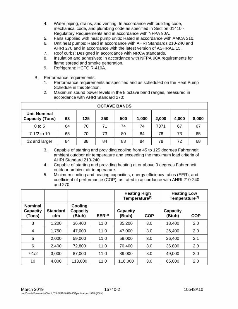
15740-2 10548A10 March 2019 pw://Carollo/Documents/Client/UT/SVWRF/10548A10/Specifications/15740 (100%)
4. Water piping, drains, and venting: In accordance with building code,mechanical code, and plumbing code as specified in Section 01410 -Regulatory Requirements and in accordance with NFPA 90A.
5. Fans supplied with heat pump units: Rated in accordance with AMCA 210.6. Unit heat pumps: Rated in accordance with AHRI Standards 210-240 and
AHRI 270 and in accordance with the latest version of ASHRAE 15.7. Roof curbs: Designed in accordance with NRCA standards.8. Insulation and adhesives: In accordance with NFPA 90A requirements for
flame spread and smoke generation.9. Refrigerant: HCFC R-410A.
B. Performance requirements:1. Performance requirements as specified and as scheduled on the Heat Pump
Schedule in this Section.2. Maximum sound power levels in the 8 octave band ranges, measured in
accordance with AHRI Standard 270:
OCTAVE BANDS
Unit Nominal Capacity (Tons) 63 125 250 500 1,000 2,000 4,000 8,000
0 to 5 64 70 71 74 74 7871 67 67
7-1/2 to 10 65 70 73 80 84 78 73 65
12 and larger 84 88 84 83 84 78 72 68
3. Capable of starting and providing cooling from 45 to 125 degrees Fahrenheitambient outdoor air temperature and exceeding the maximum load criteria ofAHRI Standard 210-240.
4. Capable of starting and providing heating at or above 0 degrees Fahrenheitoutdoor ambient air temperature.
5. Minimum cooling and heating capacities, energy efficiency ratios (EER), andcoefficient of performance (COP), as rated in accordance with AHRI 210-240and 270:
Heating High Temperature(1)
Heating Low Temperature(2)
Nominal Capacity
(Tons) Standard
cfm
Cooling Capacity
(Btuh) EER(3) Capacity
(Btuh) COP Capacity
(Btuh) COP
3 1,200 36,400 11.0 35,200 3.0 18,400 2.0
4 1,750 47,000 11.0 47,000 3.0 26,400 2.0
5 2,000 59,000 11.0 59,000 3.0 26,400 2.1
6 2,400 72,800 11.0 70,400 3.0 36.800 2.0
7-1/2 3,000 87,000 11.0 89,000 3.0 49,000 2.0
10 4,000 113,000 11.0 116,000 3.0 65,000 2.0
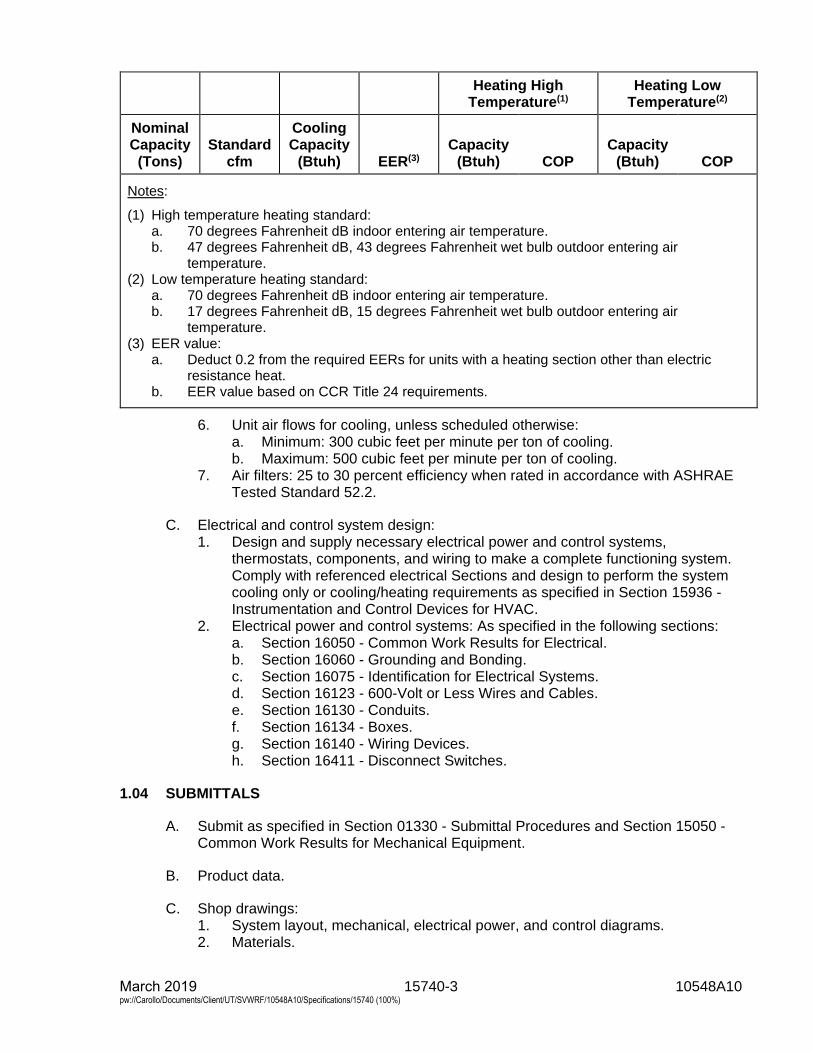
15740-3 10548A10 March 2019 pw://Carollo/Documents/Client/UT/SVWRF/10548A10/Specifications/15740 (100%)
Heating High Temperature(1)
Heating Low Temperature(2)
Nominal Capacity
(Tons) Standard
cfm
Cooling Capacity
(Btuh) EER(3) Capacity
(Btuh) COP Capacity
(Btuh) COP
Notes:
(1) High temperature heating standard:a. 70 degrees Fahrenheit dB indoor entering air temperature.b. 47 degrees Fahrenheit dB, 43 degrees Fahrenheit wet bulb outdoor entering air
temperature.(2) Low temperature heating standard:
a. 70 degrees Fahrenheit dB indoor entering air temperature.b. 17 degrees Fahrenheit dB, 15 degrees Fahrenheit wet bulb outdoor entering air
temperature.(3) EER value:
a. Deduct 0.2 from the required EERs for units with a heating section other than electricresistance heat.
b. EER value based on CCR Title 24 requirements.
6. Unit air flows for cooling, unless scheduled otherwise:a. Minimum: 300 cubic feet per minute per ton of cooling.b. Maximum: 500 cubic feet per minute per ton of cooling.
7. Air filters: 25 to 30 percent efficiency when rated in accordance with ASHRAETested Standard 52.2.
C. Electrical and control system design:1. Design and supply necessary electrical power and control systems,
thermostats, components, and wiring to make a complete functioning system.Comply with referenced electrical Sections and design to perform the systemcooling only or cooling/heating requirements as specified in Section 15936 -Instrumentation and Control Devices for HVAC.
2. Electrical power and control systems: As specified in the following sections:a. Section 16050 - Common Work Results for Electrical.b. Section 16060 - Grounding and Bonding.c. Section 16075 - Identification for Electrical Systems.d. Section 16123 - 600-Volt or Less Wires and Cables.e. Section 16130 - Conduits.f. Section 16134 - Boxes.g. Section 16140 - Wiring Devices.h. Section 16411 - Disconnect Switches.
1.04 SUBMITTALS
A. Submit as specified in Section 01330 - Submittal Procedures and Section 15050 -Common Work Results for Mechanical Equipment.
B. Product data.
C. Shop drawings:1. System layout, mechanical, electrical power, and control diagrams.2. Materials.
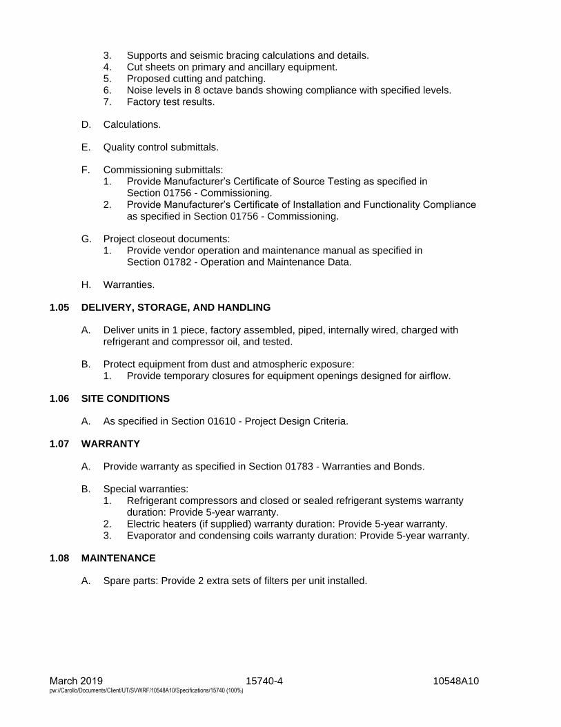
15740-4 10548A10 March 2019 pw://Carollo/Documents/Client/UT/SVWRF/10548A10/Specifications/15740 (100%)
3. Supports and seismic bracing calculations and details.4. Cut sheets on primary and ancillary equipment.5. Proposed cutting and patching.6. Noise levels in 8 octave bands showing compliance with specified levels.7. Factory test results.
D. Calculations.
E. Quality control submittals.
F. Commissioning submittals:1. Provide Manufacturer’s Certificate of Source Testing as specified in
Section 01756 - Commissioning.2. Provide Manufacturer’s Certificate of Installation and Functionality Compliance
as specified in Section 01756 - Commissioning.
G. Project closeout documents:1. Provide vendor operation and maintenance manual as specified in
Section 01782 - Operation and Maintenance Data.
H. Warranties.
1.05 DELIVERY, STORAGE, AND HANDLING
A. Deliver units in 1 piece, factory assembled, piped, internally wired, charged withrefrigerant and compressor oil, and tested.
B. Protect equipment from dust and atmospheric exposure:1. Provide temporary closures for equipment openings designed for airflow.
1.06 SITE CONDITIONS
A. As specified in Section 01610 - Project Design Criteria.
1.07 WARRANTY
A. Provide warranty as specified in Section 01783 - Warranties and Bonds.
B. Special warranties:1. Refrigerant compressors and closed or sealed refrigerant systems warranty
duration: Provide 5-year warranty.2. Electric heaters (if supplied) warranty duration: Provide 5-year warranty.3. Evaporator and condensing coils warranty duration: Provide 5-year warranty.
1.08 MAINTENANCE
A. Spare parts: Provide 2 extra sets of filters per unit installed.
15740-5 10548A10 March 2019 pw://Carollo/Documents/Client/UT/SVWRF/10548A10/Specifications/15740 (100%)
PART 2 PRODUCTS
2.01 MINI-SPLIT SYSTEM HEAT PUMPS
A. Manufacturers: One of the following or equal:1. Mitsubishi, Series PUZ Outdoor Unit, Series PVA Indoor Unit.2. Samsung, similar series.3. Daikin, similar series.4. Trane, similar series.
B. Compressors:1. Fully hermetically-sealed, high-efficiency, reciprocating or rotary or scroll-type,
with rubber grommet vibration isolation.
C. Fans:1. Indoor air fan:
Single, statically and dynamically balanced direct drive fan. Fan shall havehigh efficiency DC motor with bearings: permanently sealed ball bearing type and permanently lubricated.
2. The fan shall have 3 speeds, with the ability to operate between 0.3 and0.8 inch WG selectable.
3. Outdoor condenser fan:a. Propeller type, direct drive, aluminum blades, dynamically balanced.b. Bearings: Permanently sealed ball bearing type and permanently
lubricated.c. Provide wind baffles and low ambient cooling/heating.
D. Coils:1. The indoor coil shall be of nonferrous construction with smooth plate fins on
copper tubing.2. The tubing shall have inner grooves for high efficiency heat exchange.3. All tube joints shall be brazed with phos-copper or silver alloy.4. The coils shall be pressure tested at the factory.5. Provide corrosion resistant coating on outdoor coils suitable for marine
environment.
E. Refrigerant components: Refrigerant circuit including:1. Accumulator and filter/drier.2. Expansion device.3. Reversing valve.4. Flow control valves.5. Service and gauge connections on compressor suction and discharge, and
liquid lines to charge, evacuate, and contain refrigerant.
F. Controls and equipment safety features:1. Provide system controls for a complete functioning system:
a. High and low evaporator fan speed control for cooling and heating modes.b. Fan only operation.c. Space temperature condition setting.d. Vapor bellows thermostat to cycle unit to maintain space condition.
2. Equipment safety features:a. Thermostatic base pan drain to prevent freeze up of the fan in collected
condensate.
15740-6 10548A10 March 2019 pw://Carollo/Documents/Client/UT/SVWRF/10548A10/Specifications/15740 (100%)
3. Provide with a low ambient cooling option.
G. Electrical:1. Provide for single external power connection of voltage and phases as
scheduled; control power wiring internal to the unit.
H. Unit casing:1. Indoor unit casing shall be cabinet style with slide out design, manufactured of
pre-painted 22 gauge galvanized steel.a. The cabinet shall be positive pressure with air leakage of less than
1 percent.b. The cabinet shall be insulated with at least 1 inch of R4.2 fiberglass free
insulation.2. Outdoor unit casing shall be constructed from galvanized steel plate, finished
with an electrostatically applied, polyester powder coating for corrosionprotection.
3. Weatherproof design, reinforced and braced for maximum rigidity.4. Provided with:
a. Filter rack for filters accessible through the front of the unit.b. Non-corrosive drain pan in accordance with ASHRAE Standard 62.1.c. Horizontal drain connection.d. Provide mini condensate pump suitable to be powered from
indoor/outdoor unit.e. Knockouts for power connections.f. Provide wall sleeve of galvanized steel coated similar to unit casing.g. Manufactured air handling unit floor stand, 24-inch height.
PART 3 EXECUTION
3.01 EXAMINATION
A. Inspect all components for shipping damage, conformance to specifications, andproper torques and tightness of fasteners, as specified in Section 15050 - CommonWork Results for Mechanical Equipment.
B. Examine and verify that Work is in condition to receive installation specified in thisSection.1. Take measurements and verify dimensions to ascertain fit of installation.2. Ascertain structural sufficiency to support installation.3. Ascertain that supports and openings are correctly located; otherwise cut new
openings where required.a. Submit details of proposed cutting and patching.
4. Confirm specified thermostat or other controls are compatible with specifiedequipment.
C. Examine and verify structural details and sections indicated on the Drawings,ascertain adequacy, and determine conflicts in dimensions and clearances.
3.02 PREPARATION
A. Before installation remove dust and debris from equipment and ducts.
15740-7 10548A10 March 2019 pw://Carollo/Documents/Client/UT/SVWRF/10548A10/Specifications/15740 (100%)
B. During installation and until equipment is operated, protect equipment and ductsfrom dust and debris by covering openings.
3.03 INSTALLATION
A. Install equipment as indicated on the Drawings and as specified in Section 15050 -Common Work Results for Mechanical Equipment and the manufacturer's writteninstallation instructions.
B. Adjust alignment of ducts where necessary to resolve conflicts with architecturalfeatures or to resolve conflicts with the work of other trades.
C. Install NRCA approved flashing and counterflashing.
D. Provide venting in accordance with building code, mechanical code, and plumbingcode as specified in Section 01410 - Regulatory Requirements, and in accordancewith NFPA 54.
E. Upon completion of installation, remove debris from ductwork and equipment andclean ducts.
3.04 COMMISSIONING
A. As specified in Section 01756 - Commissioning and this Section.
B. Manufacturer services:1. Provide certificates:
a. Manufacturer’s Certificate of Source Testing.b. Manufacturer’s Certificate of Installation and Functionality Compliance.
2. Manufacturer’s Representative onsite requirements:a. Installation: 1 trip, 1 day minimum.b. Functional Testing: 1 trip, 1 day minimum each.
3. Training:a. Maintenance: 2 hours per session, 1 session.b. Operation: 1 hour per session, 1 session.
4. Process operational period:a. As required by Owner or Contractor.
C. Source testing:1. Test as specified in Section 15958 - Mechanical Equipment Testing.2. Equipment:
a. Test witnessing: Not witnessed.b. Conduct Level 1 General Equipment Performance Test.c. Conduct Level 1 Vibration Test.d. Conduct Level 1 Noise Test.e. Factory test in cooling and heating modes including economizer
operation. Evacuate coils and refrigerant system for 30 minutes prior tofinal charging of unit before shipment.
3. Electrical Instrumentation and Controls:a. Test witnessing: Not witnessed.b. Conduct testing as specified in Section 17950 - Testing, Calibration, and
Commissioning.
15740-8 10548A10 March 2019 pw://Carollo/Documents/Client/UT/SVWRF/10548A10/Specifications/15740 (100%)
D. Functional testing:1. Equipment:
a. Test witnessing: Witnessed.b. Conduct Level 2 General Equipment Performance Test.c. Conduct Level 2 Vibration Test.d. Conduct Level 2 Noise Test.e. Test equipment and installation to verify tightness, operation, and unit
heat pump vibration is within manufacturer's submitted maximum.f. Test equipment performance and balance equipment as specified in
Section 15954 - Testing, Adjusting, and Balancing for HVAC.2. Electrical Instrumentation and Controls:
a. Test witnessing: Witnessed.b. Conduct testing as specified in Section 17950 - Testing, Calibration, and
Commissioning.
3.05 SCHEDULES
A. Heat Pump Schedule as provided on the contract drawings.
END OF SECTION
15763-1 10548A10 March 2019 pw://Carollo/Documents/Client/UT/SVWRF/10548A10/Specifications/15763 (100%)
SECTION 15763
MAKEUP AIR UNIT
PART 1 GENERAL
1.01 SUMMARY
A. Section includes:1. Makeup Air Unit.
B. Related sections:1. Section 01140 - Work Restrictions.2. Section 01330 - Submittal Procedures.3. Section 01410 - Regulatory Requirements4. Section 01612 - Seismic Design Criteria.5. Section 01614 - Wind Design Criteria.6. Section 01756 - Commissioning and Process Start-Up.7. Section 01782 - Operation and Maintenance Data.8. Section 05190 - Mechanical Anchoring And Fastening To Concrete And
Masonry.9. Section 15050 - Common Work Results for Mechanical Equipment.10. Section 15936 - Instrumentation and Control Devices for HVAC.11. Section 15958 - Mechanical Equipment Testing.12. Section 16222 - Low Voltage Motors up to 500 Horsepower
C. Inclusion of a specific manufacturer’s name in the Specifications does not mean thatthe specific manufacturer’s standard product will be acceptable. Specifiedmanufacturer’s or other manufacturer’s standard product shall be modified asrequired to meet the Specifications.
1.02 REFERENCES
A. Air-Conditioning, Heating, and Refrigeration Institute (AHRI):1. Standard 410 - Forced Circulation Air Cooling Air Heating Coils.
B. American National Standards Institute (ANSI):1. Z83.4/CSA 3.7 - Non-Recirculating Direct Gas-Fired Industrial Air Heaters.
C. Institute of Electrical and Electronics Engineers (IEEE):1. 841 - IEEE Standard for Petroleum and Chemical Industry-Premium-
Efficiency, Severe-Duty, Totally Enclosed Fan-Cooled (TEFC) Squirrel CageInduction Motors--Up to and Including 370 kW(500hp).
D. National Electrical Manufacturers Association (NEMA).
E. Underwriters Laboratories, Inc. (UL).
F. Air Moving Air Conditioning Association International, Inc. (AMCA):1. Standard 210 - Laboratory Methods for Testing Fans for Certified Aerodynamic
Performance Rating.
15763-2 10548A10 March 2019 pw://Carollo/Documents/Client/UT/SVWRF/10548A10/Specifications/15763 (100%)
G. American Bearing Manufacturer’s Association (ABMA):1. 9 - Load Ratings and Fatigue Life for Ball Bearings.
H. American Society of Heating, Refrigeration, and Air Conditioning Engineers(ASHRAE):1. 52.2 - Method of Testing General Ventilation Air Cleaning Devices for Removal
Efficiency by Particle Size.
I. National Fire Protection Association (NFPA):1. NFPA 90A - Standard for the Installation of Air Conditioning and Ventilating
Systems.2. NFPA 90B - Standard for the Installation of Warm Air Heating and Air
Conditioning Systems.
J. American Society of Mechanical Engineers (ASME).
K. American Society for Testing and Materials (ASTM):1. ASTM C581 - Standard Practice for Determining Chemical Resistance of
Thermosetting Resins Used in Glass-Fiber-Reinforced Structures Intended forLiquid Service.
2. ASTM C1071 - Standard Specification for Thermal and Acoustical Insulation(Glass Fiber, Duct Lining Materials).
L. National Electric Code (NEC).
M. National Roofing Contractors Association (NRCA).
N. Factory Mutual (FM).
O. Where reference is made to one of the above standards, the revision in effect at thetime of bid opening shall apply.
1.03 DEFINITIONS
A. NEMA:1. Type 3R enclosure in accordance with NEMA 250.2. Type 4X enclosure in accordance with NEMA 250.
1.04 SYSTEM DESCRIPTION
A. Design requirements:1. Provide seismic supports as specified in Section 01612 - Seismic Design
Criteria.2. Provide wind supports for exterior units as specified in Section 01614 - Wind
Design Criteria.3. Electrical components: UL listed and meet the design and installation
requirements of the NEC.4. In accordance with building code, mechanical code, and plumbing code as
specified in Section 01410 - Regulatory Requirements.5. Motor supplied with evaporative units: As specified in Section 16222 - Low
Voltage Motors up to 500 Horsepower.6. Roof curbs: Designed in accordance with NRCA Standards.7. Insulation: In accordance with NFPA 90A.
15763-3 10548A10 March 2019 pw://Carollo/Documents/Client/UT/SVWRF/10548A10/Specifications/15763 (100%)
8. Maximum filter face velocity: 300 feet per minute.
B. Performance requirements:1. Supply and return fans: Rated in accordance with AMCA 210.2. Air filters: 45 to 50 percent dust spot efficiency when rated per ASHRAE Test
Standard 52.2.
C. Electrical and control system design requirements:1. Design and supply electrical power and control systems, components, and
wiring to make a complete functioning system.a. Design to perform system heating functions as specified in Section 15936
- Instrumentation and Control Devices for HVAC.
1.05 SUBMITTALS
A. Submit as specified in Section 01330 - Submittal Procedures and Section 15050 -Common Work Results for Mechanical Equipment.
B. Operation and maintenance manuals: Submit as specified in Section 01782 -Operation and Maintenance Data.
C. Shop drawings:1. System layout, mechanical, electrical power, and control diagrams.2. Materials.3. Supports and seismic bracing calculations and details.4. Cut sheets on primary and ancillary equipment.5. Proposed cutting and patching, when required.6. Maximum recommended equipment vibration levels and field-testing method.7. Copy of factory test results.
D. Warranties.
1.06 DELIVERY, STORAGE, AND HANDLING
A. As specified in Section 15050 - Common Work Results for Mechanical Equipment.
B. Deliver units in 1 piece (or modular, if required), factory assembled, piped, internallywired, and factory tested.
C. Protect equipment from dust and atmospheric exposure as recommended by theunit manufacturer.1. Provide temporary closures for equipment openings designed for airflow.
1.07 PROJECT CONDITIONS
A. Provide equipment suitable for project conditions specified in Section 15050 -Common Work Results for Mechanical Equipment.
B. All equipment furnished shall be designed to be located outdoors.
C. MAU shall be installed in a limited space as indicated on the Drawings.
15763-4 10548A10 March 2019 pw://Carollo/Documents/Client/UT/SVWRF/10548A10/Specifications/15763 (100%)
D. Orientation is indicated on the Drawings. MAU manufacturer shall design MAUpackage to fit within the space indicated on the Contract Drawings, oriented asindicated on the Contract Drawings.
1.08 SEQUENCING AND SCHEDULING
A. Coordinate with work restrictions specified in Section 01140 - Work Restrictions.
1.09 WARRANTY
A. Special warranties: Start warranty period at time of acceptance of the project orbeneficial use of the equipment by the Owner:1. 1 year: All components.2. 5 years: Indirect gas heat furnace.
1.10 MAINTENANCE
A. Extra materials: Provide 2 extra (3 total) sets of filters per unit installed.
B. Provide one set of sheaves and belts for change-out, if required, for final balanceper unit installed.
C. After final balance, provide one extra set of belts for each unit installed.
D. Special tools: Deliver 1 set of special tools needed to assemble and disassemblethe components of the MAU requiring regular maintenance.
1.11 QUALITY ASSURANCE
A. Regulatory requirements:1. MAU shall meet all local manufacturing and safety codes.
PART 2 PRODUCTS
2.01 MAKEUP AIR UNIT
A. One of the following or approved equal:1. Engineered Air.2. Absolut-Aire.
B. General:1. In general, units shall be factory assembled with cabinet fan, heating section,
filters, dampers, access sections with hinged access doors, motor base, driveguard and vibration isolators.
2. Units shall be designed to provide and integrated assembly when all of thecomponents are assembled. All transition sections and filler pieces requiredbetween sections are to be provided as part of the unit.
3. Units not mounted on vibration isolators shall have all rotating componentsinternally isolated from the main unit with vibration isolators.
15763-5 10548A10 March 2019 pw://Carollo/Documents/Client/UT/SVWRF/10548A10/Specifications/15763 (100%)
C. Casing:1. Exterior Casing: Aluminum suitable for outdoor installation in a marine
environment. Minimum panel thickness to be 0.04 inch for aluminum. Allfasteners to match panel material.
2. Interior Casing: Aluminum suitable for outdoor installation in a marine environment.Minimum panel thickness to be 0.02 inch. All fasteners to match panel material.
3. Base Rails: Aluminum, formed or extruded, or Stainless Steel.4. Pressure class rating shall be for the total fan static pressure. All sections of
the unit shall be of the same pressure class.5. Silicon caulked and watertight joints and seams.6. Outdoor-Air Intake: Provide ducted outside air intake connection to duct size
specified on drawing. Provide flexible connector at equipment location.7. Service panels to be hinged with neoprene gasketing for an airtight fit. All
doors to be designed to maintain an airtight fit while in operation. All doors tohave locking handles.
8. Ductwork connections to units that require corrosion-resistant coatings shall bemade with flanges. Flanges shall be factory drilled before coating. Resilientwashers suitable for the environment shall be used to protect the coating fromthe bolts in the flange. The use of self-tapping screws or other fasteningmethods that will damage the coating are not acceptable.
D. Insulation:1. One-inch Fibrous-glass duct lining applied with adhesive, contained between
interior and exterior casing.
E. Supply air blower:1. Blower shall be SWSI or DWDI Class I or Class II all aluminum construction
and shall have backward inclined flat or airfoil blades.2. V-belt drive as specified in Section 15050 - Common Work Results for
Mechanical Equipment.3. Mounted on adjustable, spring isolated, epoxy painted, welded structural steel
base. Provide seismically restrained isolators with 1” deflection.4. Dynamically balanced.5. Pillow block grease lubricated, self-aligning bearings with ABMA 9, L10 life of
200,000 hours minimum.a. High pressure lube lines shall be internally located at a common point on
the drive side.6. Automatic reset thermal overload protection.7. Motor shall be inverter duty type capable of operating with a variable
frequency drive.
F. Indirect gas furnace:1. Heat exchanger construction shall consist of a primary drum and multi-tube
secondary assembly constructed of titanium stainless steel with multi-planemetal turbulators and shall be of a floating stress relieved design.
2. Installation and venting provisions must be in accordance with CAN/CSAStandard B149.1, ANSI Z223.1-NFPA 54, and local authorities havingjurisdiction. Indoor units which require installation and condensing ventprovisions must be in accordance with CAN/CSA Standard B149.1,ANSI.1-NFPA 54, and local authorities having jurisdiction. Type "BH" categoryII venting is required on condensing indoor units.

15763-6 10548A10 March 2019 pw://Carollo/Documents/Client/UT/SVWRF/10548A10/Specifications/15763 (100%)
3. Burner shall be a blow through, positive pressure type, including cast iron oraluminum manifold and stainless steel burner plates.
4. The unit shall be provided with fully modulating output. An automatic valve inseries with the modulating valve shall be provided. Ignition shall be at full fire(100 percent rated output) and modulate the gas input from 100 percent to7 percent rated input. The modulating valve shall operate in response to thedischarge temperature sensor which shall be set at the unit and reset by roomthermostat or 0-10v input signal.
5. Provide a solid state ignition control system which ignites the pilot by sparkduring each cycle of operation. When pilot flame is proven, main burner valveshall open to allow flow to burners. Pilot and burners must be extinguishedduring the off cycle. Ignition system shall be 100% lockout type.
6. Furnace shall be factory tested after complete final unit assembly, inaccordance with the equipment standard to which the unit is certified. Gasmanifold shall be clocked with a dedicated calibrated gas meter. High and lowinput combustion analysis shall be performed using a calibrated combustionanalyzer including O2 and CO.
2.02 ACCESSORY SECTIONS
A. General:1. Accessory sections shall be as called for on the Drawings and schedules and
as required for the unit type.
B. Sensors:1. Pressure loss gage across the filter section shall be equal to Dwyer
Series 605.2. Discharge air temperature transmitter.3. Outside air temperature transmitter.4. Vapor-proof service lights and switches in all major compartments requiring
possible field service.
C. Flexible duct connectors:1. As indicated in plans and specified in Section 15820 - Ductwork Accessories.2. Provide flexible duct connectors for all ducts connections to unit.
D. Condensate drain pan:1. Pan shall be formed of welded austenitic stainless steel sheet material.2. Provide with welded drain connection at the front for connection to a P trap.3. Pan shall be sloped in two directions to provide positive draining.
E. P trap:1. Provide engineered P trap assembly for each unit, to include cleanout ports,
cleanout tool, vacuum break device.
F. Filters:1. 2-inch pleated cotton batting, with an average atmospheric dust spot efficiency
of 30 percent.2. Filter frame supports: 18 gauge, aluminum.3. Slide out frame with hinged access door.4. Manufacturers: The following or equal:
a. American Air Filter.
15763-7 10548A10 March 2019 pw://Carollo/Documents/Client/UT/SVWRF/10548A10/Specifications/15763 (100%)
G. Dampers:1. Shall be opposed blade type with blades mounted on 1/2-in minimum steel
rods.2. Shall be provided with low friction bushings and edge gaskets to reduce air
leakage.3. Blades shall be sectionalized to limit unsupported blade length and warping at
full system fan static pressures. Maximum damper blade width shall notexceed 6-in.
4. Automatic dampers shall be provided with a positive locking device.5. Dampers for all units shall be constructed of corrosion resistant materials and
will not be coated.
H. Face and by-pass sections:1. Shall be of the type specified on the schedule.2. Deflection plates shall be provided if required to maintain even air flow over
coils and prevention of stratification.
2.03 CONTROLS
A. Controls and equipment safety features:1. Provide system controls for a complete functioning system that operates as
specified in Section 15936 - Instrumentation and Control Devices for HVAC.Include, as a minimum:a. Fan controls:
1) VFD capable of remote control from SCADA.b. Motor contactors.c. 24-volt control circuit and transformer when 24-volt control is specified in
the evaporative cooler unit schedule.d. Manually resettable circuit breaker.e. Filter differential pressure transmitter suitable for field connection to
provide pressure readings to SCADA.f. Outside air temperature transmitter suitable for field connection to provide
outside air temperature reading to SCADA.g. Discharge air temperature transmitter suitable for field connection to
provide outside air temperature reading to SCADA.h. Unit discharge air setpoint shall be adjustable from SCADA.i. Control panel.
B. Electrical control panel:1. Supply NEMA Type 3R single source control panel. Panel shall have a
through-the-door, fused main disconnect switch.2. Unit power and control wiring to enter control panel at 1 location.3. UL labeled.4. Hinged cover.5. Interlock controls.6. Off-Vent-Heat switch.7. Terminal strips for power and control.8. Control transformer.9. Unit disconnect power terminals for smoke detector signal.10. See control description in Section 15936 - Instrumentation and Control
Devices for HVAC for required operational controls in ventilation and heatingmodes. Provide heating thermostats.
15763-8 10548A10 March 2019 pw://Carollo/Documents/Client/UT/SVWRF/10548A10/Specifications/15763 (100%)
11. Provide VFD with the following features as a minimum:a. VFD shall be UL listed, and CSA approved, with 40-character multilingual
alphanumeric display.b. Ethernet IP protocol.c. Shall have the following inputs and outputs: 2 analog inputs,
6 programmable digital inputs, 2 programmable analog outputs,3 programmable Form C relay outputs, all inputs isolated from ground andpower.
d. Protection circuits for overcurrent, ground fault, overvoltage, undervoltage,overtemperature and adaptable electronic overload.
e. Input Line Fuses.
C. Electrical:1. Internal wiring to be enclosed inside weatherproof flexible UL listed conduit.
D. The high-to-low voltage transformer shall be provided to power control circuits. Allprimary and secondary transformer circuits shall be fused as required per NEC.
2.04 EXTRA MATERIALS
A. Anchor bolts: As specified in Section 05190 - Mechanical Anchoring and Fasteningto Concrete and Masonry.
B. Provide 2 extra sets (3 sets total) of filters per installed MAU.
C. Provide 1 extra set of belts per installed fan for fans specified with belt drives.
2.05 PERFORMANCE
A. See Schedule at the end of this Section.
2.06 SOURCE QUALITY CONTROL
A. Quality assurance: Firms regularly engaged in the manufacture of units of types andcapacities required whose products have been in satisfactory use in similar servicefor not less than 5 years.
PART 3 EXECUTION
3.01 EXAMINATION
A. Examine and verify that conditions are suitable for installation.1. Take measurements and verify dimensions to ascertain fit of installation.2. Verify structural sufficiency to support installation.3. Verify that chassis, shafts, and openings are correctly located.
a. Otherwise cut new openings where required.4. Confirm specified thermostat and other controls are compatible with specified
equipment.
B. Examine and verify structural details and sections indicated on the Drawings, verifyadequacy, and determine possible conflicts in dimensions and clearances.
15763-9 10548A10 March 2019 pw://Carollo/Documents/Client/UT/SVWRF/10548A10/Specifications/15763 (100%)
3.02 INSTALLATION
A. Anchoring and support: Provide anchoring and support designed in accordance withcurrent engineering practice for equipment and appurtenances by attaching orconnecting to supporting members or by providing other supports.
B. Install and wire makeup air unit, controls, and thermostats in accordance withmanufacturer's recommendations.
C. Provide drains and venting in accordance with plumbing code as specified, and theUniform Mechanical Code.
D. Upon completion of installation, clean dust and debris from ductwork andequipment.
3.03 FIELD QUALITY CONTROL
A. Witnessing: All field-testing shall be witnessed by the Construction Manager orOwner when indicated; provide advanced notice of source testing as specified inSection 15958 - Mechanical Equipment Testing.
B. Inspection and checkout: As specified in Section 15958 - Mechanical EquipmentTesting and Section 15050 - Common Work Results for Mechanical Equipment.
C. Equipment performance test: Test Level 1; test as specified in Section 15958 -Mechanical Equipment Testing.
D. Operational testing: As specified in Section 01756 - Commissioning.
E. Field performance testing shall be conducted and reported in accordance withASME Performance Test Code.
F. Contractor shall furnish and install all materials and any special equipment requiredto accomplish the performance test.
3.04 MANUFACTURER’S FIELD SERVICES
A. The MAU manufacturer shall inspect the MAU before initial start-up and certify theunit has been correctly installed and prepared for start-up.
B. Training: As specified in Section 01756 - Commissioning.
3.05 SCHEDULE
A. See Contract Drawings for schedules.
END OF SECTION

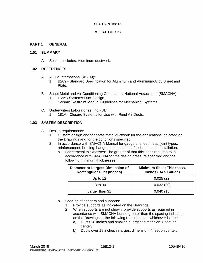
15812-1 10548A10 March 2019 pw://Carollo/Documents/Client/UT/SVWRF/10548A10/Specifications/15812 (100%)
SECTION 15812
METAL DUCTS
PART 1 GENERAL
1.01 SUMMARY
A. Section includes: Aluminum ductwork.
1.02 REFERENCES
A. ASTM International (ASTM):1. B209 - Standard Specification for Aluminum and Aluminum-Alloy Sheet and
Plate.
B. Sheet Metal and Air Conditioning Contractors' National Association (SMACNA):1. HVAC Systems-Duct Design.2. Seismic Restraint Manual Guidelines for Mechanical Systems.
C. Underwriters Laboratories, Inc. (UL):1. 181A - Closure Systems for Use with Rigid Air Ducts.
1.03 SYSTEM DESCRIPTION
A. Design requirements:1. Custom design and fabricate metal ductwork for the applications indicated on
the Drawings and for the conditions specified.2. In accordance with SMACNA Manual for gauge of sheet metal, joint types,
reinforcement, bracing, hangers and supports, fabrication, and installation.a. Sheet metal thicknesses: The greater of that thickness required to in
accordance with SMACNA for the design pressure specified and thefollowing minimum thicknesses:
Diameter or Largest Dimension of Rectangular Duct (Inches)
Minimum Sheet Thickness, Inches (B&S Gauge)
Up to 12 0.025 (22)
13 to 30 0.032 (20)
Larger than 31 0.040 (18)
b. Spacing of hangers and supports:1) Provide supports as indicated on the Drawings.2) When supports are not shown, provide supports as required in
accordance with SMACNA but no greater than the spacing indicatedon the Drawings or the following requirements; whichever is less:a) Ducts 18 inches and smaller in largest dimension: 8 feet on
center.b) Ducts over 18 inches in largest dimension: 4 feet on center.
15812-2 10548A10 March 2019 pw://Carollo/Documents/Client/UT/SVWRF/10548A10/Specifications/15812 (100%)
c. Support connections:1) Provide as indicated on the Drawings.2) When not indicated on the Drawings, provide in accordance with
SMACNA.3) As a minimum, all support connections to metal or wood roofs shall
be located at roof framing members only.4) No penetrations through roof deck, roof membrane, or connections to
roof membrane are acceptable.3. Design pressure: 2 inches water column unless otherwise indicated on the
Drawings or specified.4. Seismic design criteria: As specified in Section 01612 - Seismic Design
Criteria and in accordance with SMACNA Seismic Restraint ManualGuidelines for Mechanical Systems.
5. Hanger reinforcement:a. Ducts 18 inches and smaller in largest dimension: None.b. Ducts over 18 inches and under 30 inches in largest dimension:
1-1/2 inches by 1-1/2 inches by 1/8-inch angles, 8 feet on center.c. Ducts 30 inches and larger in largest dimension: 1-1/2 inches by
1-1/2 inches by 1/8-inch angles, 4 feet on center.6. When ducts are specified with insulation on interior walls, size duct to provide
clear inside dimensions indicated on the Drawings.
B. Miscellaneous design details:1. Changes in duct size:
a. Use uniformly tapering sections.b. Taper not more than 1 inch in 5 inches of run unless otherwise indicated
on the Drawings.2. Bends: With the exception of miter bends, design bends with inside radii equal
to duct width or diameter.a. Install turning vanes at all 90 degree beds.
3. Duct sleeves: Install duct sleeve when ducts pass through concrete ormasonry walls, slabs, or ceilings.
4. Access openings: Install in locations that allow access to dampers, fusiblelinks, controllers, and similar devices.
5. Flexible connections: Install at connections to air handling equipment and atlocations indicated on the Drawings.
1.04 SUBMITTALS
A. Submit as specified in Section 01330 - Submittal Procedures.
B. Product data:1. Duct and component material and details of construction.2. System layout including floor and wall penetrations.3. Supports and anchoring details.4. Components used in the duct system including turning vanes, dampers,
flexible connections, and access doors.
C. Design data: Seismic design calculations:1. Design calculations for duct construction as specified in Section 01612 -
Seismic Design Criteria and in accordance with SMACNA.
15812-3 10548A10 March 2019 pw://Carollo/Documents/Client/UT/SVWRF/10548A10/Specifications/15812 (100%)
D. Provide Manufacturer’s Certificate of Source Testing as specified in Section 01756 -Commissioning.
PART 2 PRODUCTS
2.01 MATERIALS
A. Ducts: Aluminum alloy 3003 H14 in accordance with ASTM B209.
B. Flexible connectors: As specified in Section 15084 - Ductwork Insulation.
C. Turning vanes: Match duct material.
D. Reinforcing: Formed or extruded aluminum angles.
E. Ductwork insulation: As specified in Section 15084 - Ductwork Insulation.
2.02 COMPONENTS
A. Duct sleeves:1. Sleeve flanges: 4 inches wide.2. Size: 2 inches larger than the duct or duct with external insulation.
B. Access openings:1. Size: 2 inches less than duct size.2. Doors:
a. Gauge not less than duct sheet.b. Provide continuous hinge and latch on outside.
3. Gasket: Along door periphery.4. Visual panel: 1/8-inch thick, clear plexiglass.
C. Turning vanes:1. Material: Same as ductwork.2. Type:
a. Single-blade vanes for duct widths less than 36 inches.b. Airfoil type vanes for duct widths of 36 inches and greater:
1) No trailing edge.3. Mounted in side rails.4. Provide turning vanes for square-turn elbows, smooth radius elbows, and
splitters.5. Size: 2-inch blades for ducts up to 18 inches, 4-1/2 inch blades for larger
ducts.
D. Splitter dampers: Provide at branch take-offs where necessary for balancingsystem.
E. Extractors:1. Components:
a. Synchronized steel curved blades.b. Heavy side rails.c. Screw operator.
15812-4 10548A10 March 2019 pw://Carollo/Documents/Client/UT/SVWRF/10548A10/Specifications/15812 (100%)
2. Provide extractors at take-off from main supply duct adjacent to diffusers,registers, or grilles where splitter is not used.
2.03 FABRICATION
A. Fabricate ductwork to the configuration and dimensions indicated on the Drawings.
B. Dimensions indicate net free area. Increase duct dimensions by thickness ofinsulation when internal insulation is specified.
C. Do not utilize S clips, duct tape, or externally applied mastic on medium pressureduct systems.
D. Do not use snap lock seams.
E. Provide flexible duct connectors at all connections to fans and other air movementequipment.
PART 3 EXECUTION
3.01 EXAMINATION
A. Examine and verify that Work is in condition to receive metallic ductwork asspecified in this Section.1. Take measurements and verify dimensions on shop drawings to verify fit of
installation.2. Verify that supports and openings are correctly located.
B. Examine and verify structural details and determine conflicts in dimensions andclearances.
3.02 INSTALLATION
A. Cover ductwork openings with tape, plastic, or sheet metal to reduce the amount ofdust or debris which may collect in the system at each of the following times:1. At the time of rough installation.2. During storage on the construction site.3. Until final start-up of the heating and cooling equipment.
B. Before installation remove dust and debris from ducts.
C. Adjust duct alignment where necessary to resolve conflicts with architecturalfeatures or to resolve conflicts with the work of other trades.
D. Install ductwork to provide a system free of buckling, warping, or vibration.
E. Hangers:1. Install hangers as indicated on the Drawings.
15812-5 10548A10 March 2019 pw://Carollo/Documents/Client/UT/SVWRF/10548A10/Specifications/15812 (100%)
2. When hangers are not detailed, conform to SMACNA HVAC System DuctDesign and Seismic Restraint Manual standards and the followingrequirements:a. Rectangular ducts concealed in ceiling spaces:
1) Use metal strap hangers.2) Fasten to sides of duct with 2 screws.3) Fasten to bottom of duct with 1 screw.
b. Rectangular ducts in exposed areas:1) Install shelf angle trapeze hangers or Unistrut type hangers.2) Install sway bracing as required by seismic calculations, minimum
1 brace at right angle to each duct run.c. Round ducts in exposed areas:
1) Install 2 half-round bands with rods bolted to panels.2) Install sway bracing as required by seismic calculations, minimum
1 brace at right angle to each duct run.3. Flexible connections: As specified in Section 15084 - Ductwork Insulation.
F. Provide closed-cell neoprene gaskets at flanged joints.
G. Tapes and mastics used to seal ductwork shall be listed and labeled in accordancewith UL 181A and shall be marked.
3.03 FIELD QUALITY CONTROL
A. Inspect ductwork under operating conditions.1. Correct audible leaks and leaks that can be felt with the hand.
B. Test and balance ducting systems as specified in Section 15954 - Testing,Adjusting, and Balancing for HVAC.
END OF SECTION

15814-1 10548A10 March 2019 pw://Carollo/Documents/Client/UT/SVWRF/10548A10/Specifications/15814 (100%)
SECTION 15814
FIBERGLASS REINFORCED PLASTIC DUCTS
PART 1 GENERAL
1.01 SUMMARY
A. Section includes: Fiberglass reinforced plastic ductwork system, consisting ofducting and including fasteners, field joints, expansion joints, and supports.
1.02 REFERENCES
A. American Society of Mechanical Engineers (ASME):1. B16.5 - Pipe Flanges and Flanged Fittings.2. RTP-1 - Reinforced Thermoset Plastic Corrosion-Resistant Equipment.
B. American Water Works Association (AWWA):1. M45 - Fiberglass Pipe Design.
C. ASTM International (ASTM):1. C582 - Standard Specification for Contact-Molded Reinforced Thermosetting
Plastic (RTP) Laminates for Corrosion-Resistant Equipment.2. D792 - Standard Test Methods for Density and Specific Gravity (Relative
Density) of Plastics by Displacement.3. D2105 - Standard Test Method for Longitudinal Tensile Properties of
Fiberglass (Glass-Fiber-Reinforced Thermosetting-Resin) Pipe and Tube.4. D2344 - Standard Test Method for Short-Beam Strength of Polymer Matrix
Composite Materials and Their Laminates.5. D2412 - Standard Test Method for Determination of External Loading
Characteristics of Plastic Pipe by Parallel-Plate Loading.6. D2992 - Standard Practice for Obtaining Hydrostatic or Pressure Design Basis
for “Fiberglass” (Glass-Fiber-Reinforced Thermosetting-Resin) Pipe andFittings.
7. D2996 - Standard Specification for Filament-Wound “Fiberglass” (Glass-Fiber-Reinforced Thermosetting-Resin) Pipe.
8. D3982 - Standard Specification for Contact Molded “Fiberglass” (Glass-Fiber-Reinforced Thermosetting-Resin) Ducts.
9. E84 - Standard Test Method for Surface Burning Characteristics of BuildingMaterials.
D. National Bureau of Standards Voluntary Product Standards (PS):1. 15-69 - Custom Contact-Molded Reinforced-Polyester Chemical-Resistant
Process Equipment.
E. National Fire Protection Association (NFPA):1. 91 - Standard for Exhaust Systems for Air Conveying of Vapors, Gases, Mists,
and Particulate Solids.
F. Sheet Metal and Air Conditioning Contractors' National Association (SMACNA).
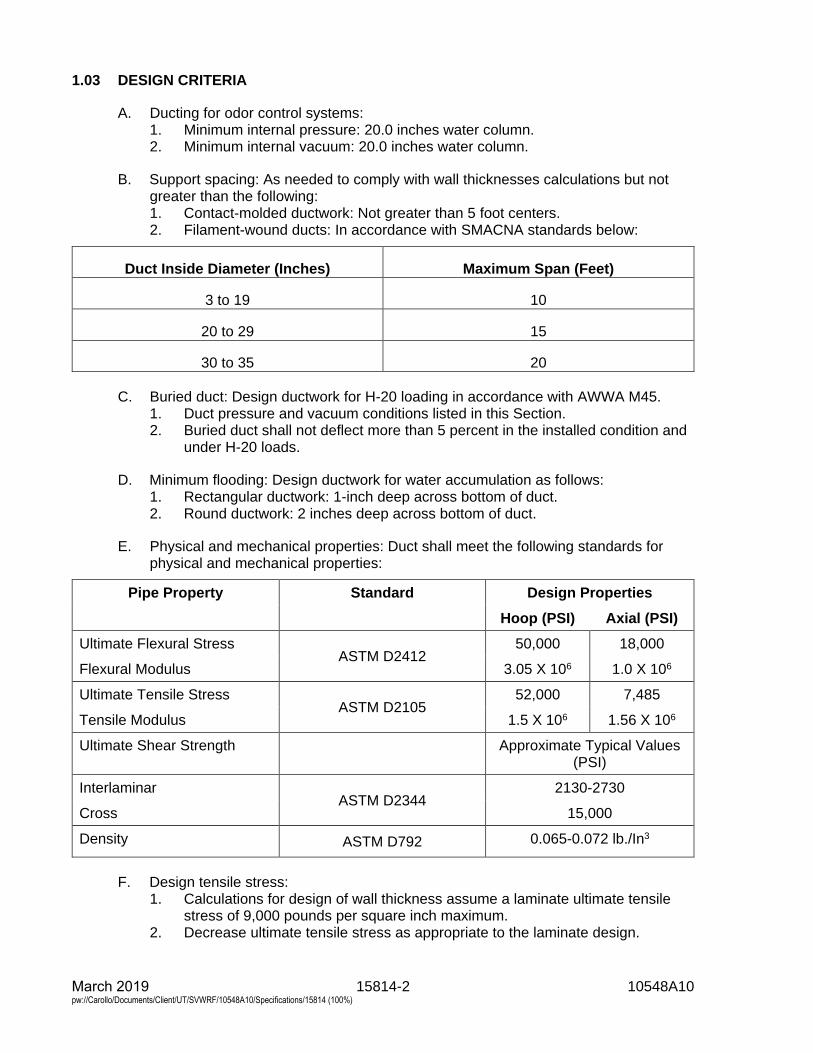
15814-2 10548A10 March 2019 pw://Carollo/Documents/Client/UT/SVWRF/10548A10/Specifications/15814 (100%)
1.03 DESIGN CRITERIA
A. Ducting for odor control systems:1. Minimum internal pressure: 20.0 inches water column.2. Minimum internal vacuum: 20.0 inches water column.
B. Support spacing: As needed to comply with wall thicknesses calculations but notgreater than the following:1. Contact-molded ductwork: Not greater than 5 foot centers.2. Filament-wound ducts: In accordance with SMACNA standards below:
Duct Inside Diameter (Inches) Maximum Span (Feet)
3 to 19 10
20 to 29 15
30 to 35 20
C. Buried duct: Design ductwork for H-20 loading in accordance with AWWA M45.1. Duct pressure and vacuum conditions listed in this Section.2. Buried duct shall not deflect more than 5 percent in the installed condition and
under H-20 loads.
D. Minimum flooding: Design ductwork for water accumulation as follows:1. Rectangular ductwork: 1-inch deep across bottom of duct.2. Round ductwork: 2 inches deep across bottom of duct.
E. Physical and mechanical properties: Duct shall meet the following standards forphysical and mechanical properties:
Pipe Property Standard Design Properties
Hoop (PSI) Axial (PSI)
Ultimate Flexural Stress ASTM D2412
50,000 18,000
Flexural Modulus 3.05 X 10⁶ 1.0 X 10⁶
Ultimate Tensile Stress ASTM D2105
52,000 7,485
Tensile Modulus 1.5 X 10⁶ 1.56 X 10⁶
Ultimate Shear Strength Approximate Typical Values (PSI)
Interlaminar ASTM D2344
2130-2730
Cross 15,000
Density ASTM D792 0.065-0.072 lb./In3
F. Design tensile stress:1. Calculations for design of wall thickness assume a laminate ultimate tensile
stress of 9,000 pounds per square inch maximum.2. Decrease ultimate tensile stress as appropriate to the laminate design.
15814-3 10548A10 March 2019 pw://Carollo/Documents/Client/UT/SVWRF/10548A10/Specifications/15814 (100%)
a. Round ducting: The maximum allowable design tensile stress shall be theultimate tensile stress divided by 5.
b. Rectangular ducting: The maximum allowable design tensile stress shallbe the ultimate tensile stress divided by 10.
1.04 SUBMITTALS
A. As specified in Sections 01330 - Submittal Procedures.
B. Product data: Composition of materials, configuration of external stiffeners, andflexible connections.
C. Shop drawings:1. Drawings showing ductwork layout, dimensions, joint types, and support
locations.2. Locations of external stiffeners and expansion joints.3. Fabrication details.4. Support locations, types, and details.
D. Sealed calculations:1. Wall thickness calculations based upon design criteria.2. Stresses and reaction loads at supports.
E. Submit duct burial procedure and details.
F. Manufacturer's Installation Instructions.1. Detailed instructions for field butt joints including lay-up sequence, width of
each reinforcement layer, and total number of layers.
1.05 QUALITY ASSURANCE
A. Qualification of ducting manufacturer: Manufacturer with experienced personnel,physical facilities, and management capacity sufficient to produce custom-made,corrosion resistant fiberglass reinforced plastic products of quality and size specifiedwith a minimum 5 years satisfactory performance record.
B. Submit test results as specified in Section 06608 - Fiberglass Reinforced Plasticverifying that ductwork meets standards specified.1. Also, in accordance with Section 06608 - Fiberglass Reinforced Plastic as to
the requirements of FRP manufacturing and standard testing.2. If there is a conflict between this Section and Section 06608 - Fiberglass
Reinforced Plastic, the more stringent requirements shall govern.a. Test methods by the manufacturer shall be in accordance with
ASTM 2996 and ASTM 2992 (buried pipe).
C. Manufacturer shall provide design calculations for FRP ductwork design andconstruction. Calculations shall be signed and sealed by licensed engineerregistered in the state of the project location.
D. Warranty:1. As specified in Section 01783 - Warranties and Bonds.
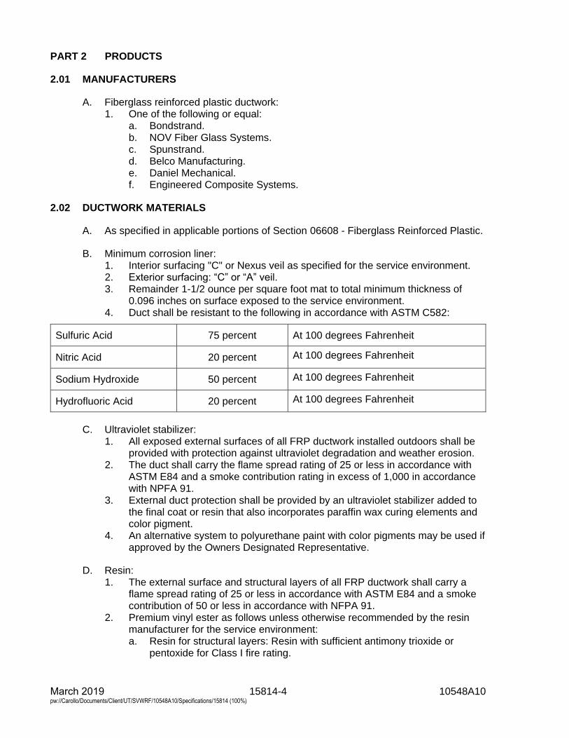
15814-4 10548A10 March 2019 pw://Carollo/Documents/Client/UT/SVWRF/10548A10/Specifications/15814 (100%)
PART 2 PRODUCTS
2.01 MANUFACTURERS
A. Fiberglass reinforced plastic ductwork:1. One of the following or equal:
a. Bondstrand.b. NOV Fiber Glass Systems.c. Spunstrand.d. Belco Manufacturing.e. Daniel Mechanical.f. Engineered Composite Systems.
2.02 DUCTWORK MATERIALS
A. As specified in applicable portions of Section 06608 - Fiberglass Reinforced Plastic.
B. Minimum corrosion liner:1. Interior surfacing "C" or Nexus veil as specified for the service environment.2. Exterior surfacing: “C” or “A” veil.3. Remainder 1-1/2 ounce per square foot mat to total minimum thickness of
0.096 inches on surface exposed to the service environment.4. Duct shall be resistant to the following in accordance with ASTM C582:
Sulfuric Acid 75 percent At 100 degrees Fahrenheit
Nitric Acid 20 percent At 100 degrees Fahrenheit
Sodium Hydroxide 50 percent At 100 degrees Fahrenheit
Hydrofluoric Acid 20 percent At 100 degrees Fahrenheit
C. Ultraviolet stabilizer:1. All exposed external surfaces of all FRP ductwork installed outdoors shall be
provided with protection against ultraviolet degradation and weather erosion.2. The duct shall carry the flame spread rating of 25 or less in accordance with
ASTM E84 and a smoke contribution rating in excess of 1,000 in accordancewith NPFA 91.
3. External duct protection shall be provided by an ultraviolet stabilizer added tothe final coat or resin that also incorporates paraffin wax curing elements andcolor pigment.
4. An alternative system to polyurethane paint with color pigments may be used ifapproved by the Owners Designated Representative.
D. Resin:1. The external surface and structural layers of all FRP ductwork shall carry a
flame spread rating of 25 or less in accordance with ASTM E84 and a smokecontribution of 50 or less in accordance with NFPA 91.
2. Premium vinyl ester as follows unless otherwise recommended by the resinmanufacturer for the service environment:a. Resin for structural layers: Resin with sufficient antimony trioxide or
pentoxide for Class I fire rating.
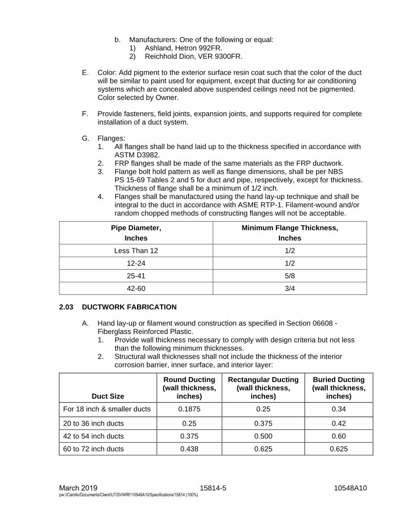
15814-5 10548A10 March 2019 pw://Carollo/Documents/Client/UT/SVWRF/10548A10/Specifications/15814 (100%)
b. Manufacturers: One of the following or equal:1) Ashland, Hetron 992FR.2) Reichhold Dion, VER 9300FR.
E. Color: Add pigment to the exterior surface resin coat such that the color of the ductwill be similar to paint used for equipment, except that ducting for air conditioningsystems which are concealed above suspended ceilings need not be pigmented.Color selected by Owner.
F. Provide fasteners, field joints, expansion joints, and supports required for completeinstallation of a duct system.
G. Flanges:1. All flanges shall be hand laid up to the thickness specified in accordance with
ASTM D3982.2. FRP flanges shall be made of the same materials as the FRP ductwork.3. Flange bolt hold pattern as well as flange dimensions, shall be per NBS
PS 15-69 Tables 2 and 5 for duct and pipe, respectively, except for thickness.Thickness of flange shall be a minimum of 1/2 inch.
4. Flanges shall be manufactured using the hand lay-up technique and shall beintegral to the duct in accordance with ASME RTP-1. Filament-wound and/orrandom chopped methods of constructing flanges will not be acceptable.
Pipe Diameter,
Inches
Minimum Flange Thickness,
Inches
Less Than 12 1/2
12-24 1/2
25-41 5/8
42-60 3/4
2.03 DUCTWORK FABRICATION
A. Hand lay-up or filament wound construction as specified in Section 06608 -Fiberglass Reinforced Plastic.1. Provide wall thickness necessary to comply with design criteria but not less
than the following minimum thicknesses.2. Structural wall thicknesses shall not include the thickness of the interior
corrosion barrier, inner surface, and interior layer:
Duct Size
Round Ducting (wall thickness,
inches)
Rectangular Ducting (wall thickness,
inches)
Buried Ducting (wall thickness,
inches)
For 18 inch & smaller ducts 0.1875 0.25 0.34
20 to 36 inch ducts 0.25 0.375 0.42
42 to 54 inch ducts 0.375 0.500 0.60
60 to 72 inch ducts 0.438 0.625 0.625
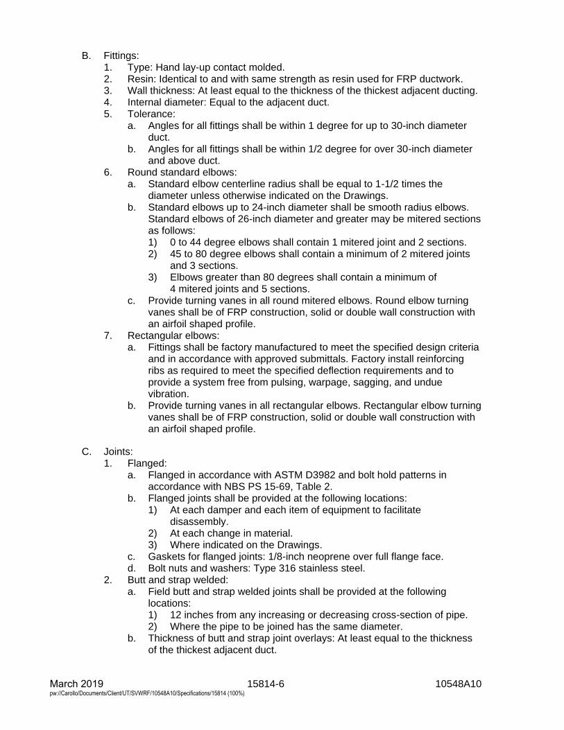
15814-6 10548A10 March 2019 pw://Carollo/Documents/Client/UT/SVWRF/10548A10/Specifications/15814 (100%)
B. Fittings:1. Type: Hand lay-up contact molded.2. Resin: Identical to and with same strength as resin used for FRP ductwork.3. Wall thickness: At least equal to the thickness of the thickest adjacent ducting.4. Internal diameter: Equal to the adjacent duct.5. Tolerance:
a. Angles for all fittings shall be within 1 degree for up to 30-inch diameterduct.
b. Angles for all fittings shall be within 1/2 degree for over 30-inch diameterand above duct.
6. Round standard elbows:a. Standard elbow centerline radius shall be equal to 1-1/2 times the
diameter unless otherwise indicated on the Drawings.b. Standard elbows up to 24-inch diameter shall be smooth radius elbows.
Standard elbows of 26-inch diameter and greater may be mitered sectionsas follows:1) 0 to 44 degree elbows shall contain 1 mitered joint and 2 sections.2) 45 to 80 degree elbows shall contain a minimum of 2 mitered joints
and 3 sections.3) Elbows greater than 80 degrees shall contain a minimum of
4 mitered joints and 5 sections.c. Provide turning vanes in all round mitered elbows. Round elbow turning
vanes shall be of FRP construction, solid or double wall construction withan airfoil shaped profile.
7. Rectangular elbows:a. Fittings shall be factory manufactured to meet the specified design criteria
and in accordance with approved submittals. Factory install reinforcingribs as required to meet the specified deflection requirements and toprovide a system free from pulsing, warpage, sagging, and unduevibration.
b. Provide turning vanes in all rectangular elbows. Rectangular elbow turningvanes shall be of FRP construction, solid or double wall construction withan airfoil shaped profile.
C. Joints:1. Flanged:
a. Flanged in accordance with ASTM D3982 and bolt hold patterns inaccordance with NBS PS 15-69, Table 2.
b. Flanged joints shall be provided at the following locations:1) At each damper and each item of equipment to facilitate
disassembly.2) At each change in material.3) Where indicated on the Drawings.
c. Gaskets for flanged joints: 1/8-inch neoprene over full flange face.d. Bolt nuts and washers: Type 316 stainless steel.
2. Butt and strap welded:a. Field butt and strap welded joints shall be provided at the following
locations:1) 12 inches from any increasing or decreasing cross-section of pipe.2) Where the pipe to be joined has the same diameter.
b. Thickness of butt and strap joint overlays: At least equal to the thicknessof the thickest adjacent duct.
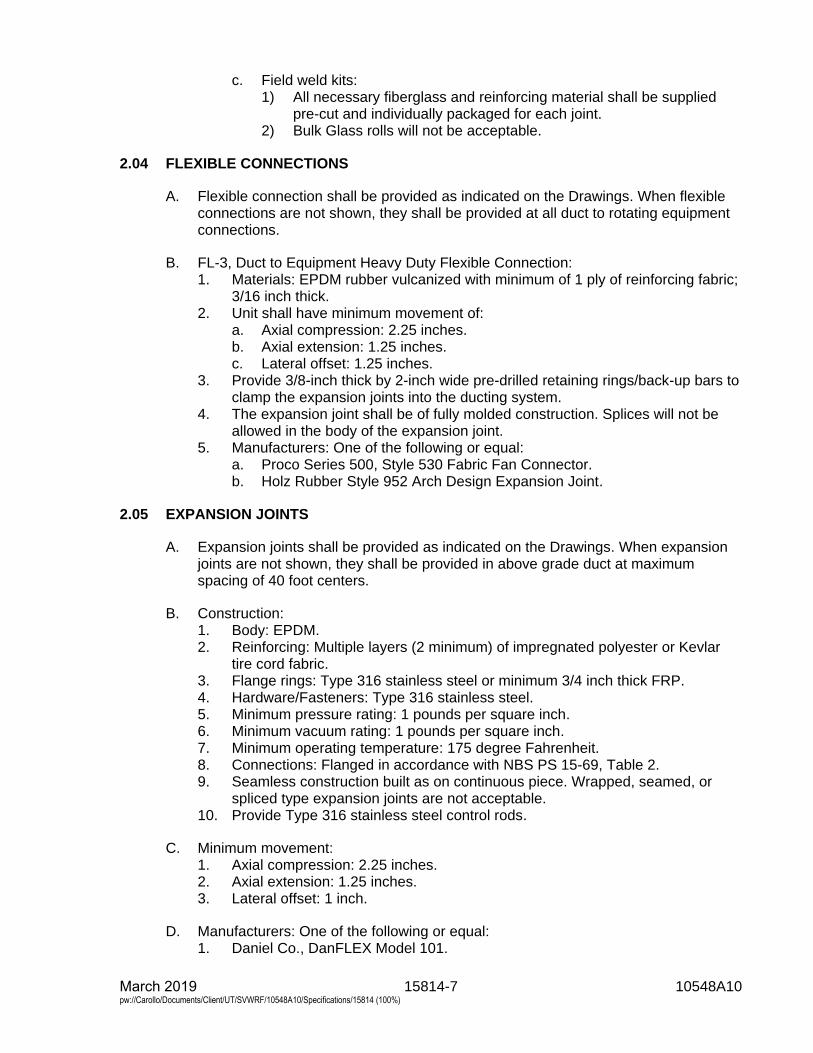
15814-7 10548A10 March 2019 pw://Carollo/Documents/Client/UT/SVWRF/10548A10/Specifications/15814 (100%)
c. Field weld kits:1) All necessary fiberglass and reinforcing material shall be supplied
pre-cut and individually packaged for each joint.2) Bulk Glass rolls will not be acceptable.
2.04 FLEXIBLE CONNECTIONS
A. Flexible connection shall be provided as indicated on the Drawings. When flexibleconnections are not shown, they shall be provided at all duct to rotating equipmentconnections.
B. FL-3, Duct to Equipment Heavy Duty Flexible Connection:1. Materials: EPDM rubber vulcanized with minimum of 1 ply of reinforcing fabric;
3/16 inch thick.2. Unit shall have minimum movement of:
a. Axial compression: 2.25 inches.b. Axial extension: 1.25 inches.c. Lateral offset: 1.25 inches.
3. Provide 3/8-inch thick by 2-inch wide pre-drilled retaining rings/back-up bars toclamp the expansion joints into the ducting system.
4. The expansion joint shall be of fully molded construction. Splices will not beallowed in the body of the expansion joint.
5. Manufacturers: One of the following or equal:a. Proco Series 500, Style 530 Fabric Fan Connector.b. Holz Rubber Style 952 Arch Design Expansion Joint.
2.05 EXPANSION JOINTS
A. Expansion joints shall be provided as indicated on the Drawings. When expansionjoints are not shown, they shall be provided in above grade duct at maximumspacing of 40 foot centers.
B. Construction:1. Body: EPDM.2. Reinforcing: Multiple layers (2 minimum) of impregnated polyester or Kevlar
tire cord fabric.3. Flange rings: Type 316 stainless steel or minimum 3/4 inch thick FRP.4. Hardware/Fasteners: Type 316 stainless steel.5. Minimum pressure rating: 1 pounds per square inch.6. Minimum vacuum rating: 1 pounds per square inch.7. Minimum operating temperature: 175 degree Fahrenheit.8. Connections: Flanged in accordance with NBS PS 15-69, Table 2.9. Seamless construction built as on continuous piece. Wrapped, seamed, or
spliced type expansion joints are not acceptable.10. Provide Type 316 stainless steel control rods.
C. Minimum movement:1. Axial compression: 2.25 inches.2. Axial extension: 1.25 inches.3. Lateral offset: 1 inch.
D. Manufacturers: One of the following or equal:1. Daniel Co., DanFLEX Model 101.
15814-8 10548A10 March 2019 pw://Carollo/Documents/Client/UT/SVWRF/10548A10/Specifications/15814 (100%)
2. Mercer Rubber Co., Model ME for Rectangular, Model MI-9 for Round.
2.06 DUCT SUPPORTS
A. Provide duct supports as indicated on the Drawings.
B. Protect the duct from clamping force of strap hangers with a 1/8-inch thick layer ofneoprene pad.
C. When anchors are required, they shall be externally bonded to the duct. Drivescrews or other penetrations of the duct linter are not permitted.
D. When duct supports are not indicated on the Drawings provide supports andseismic bracing in accordance with the SMACNA Design Manual.
PART 3 EXECUTION
3.01 INSTALLATION
A. All ductwork shall be fabricated and erected where indicated on the Drawings or asspecified in this Section. Ductwork shall be rigidly supported and secured in anapproved manner.
B. Install ductwork parallel to walls and/or roof and vertically plumb.
C. Bracing and vibration isolators shall be installed, where necessary, to eliminatevibration, rattle and noise.1. Hangers shall be installed plumb and securely suspended from supplementary
steel or inserts in concrete slabs.2. Lower ends of hanger rods shall be sufficiently threaded to allow for adequate
vertical adjustment.3. Building siding and metal decking shall not be used to hang ductwork.
D. Contractor shall not install any equipment or materials until the Owners DesignatedRepresentative has approved all submittals. If any equipment or materials areinstalled prior to approval of the submittals, it shall be at the Contractor's risk.
E. Wherever ducts are divided, the cross-sectional area shall be maintained. All suchchanges must be approved and installed as directed by the Owners DesignatedRepresentative or as approved on shop or erection drawings.
F. Do not remove or alter factory installed duct reinforcing ribs except as required toaccommodate duct alterations due to unexpected field conditions.1. Notify the Owners Designated Representative prior to starting any field
modifications involving ductwork structural reinforcing members.2. Submit additional design calculations to demonstrate structural design integrity
of ductwork and fittings requiring reinforcing modifications in the field.
G. Direct buried duct:1. Grade trench so it will be 1.5 times wider than the diameter of the duct.2. Fill bottom of trench with a minimum of 6 inches of back fill (sand or pea
gravel).
15814-9 10548A10 March 2019 pw://Carollo/Documents/Client/UT/SVWRF/10548A10/Specifications/15814 (100%)
3. Slope Trench with a 1/8 inch per foot pitch back to the start of the system.4. Backfill in 6 inches lift increments compacting 80 to 90 percent.5. A minimum of 4 inches of backfill overtop the duct system is required.6. Follow manufacturer's burial procedures.
H. No ductwork or components shall be shipped prior to complete resin cure.
I. Cover ductwork openings with tape, plastic, or sheet metal to reduce the amount ofdust or debris which may collect in the system at each of the following times:1. At the time of rough installation.2. During storage on the construction site.3. Until final start-up of the heating and cooling equipment.
J. Before installation remove dust and debris from ducts.
K. Install products in accordance with shop drawings and manufacturer's instructions.Drawings indicate general routing only and shall be modified as necessary.
END OF SECTION

15815-1 10548A10 March 2019 pw://Carollo/Documents/Client/UT/SVWRF/10548A10/Specifications/15815 (100%)
SECTION 15815
FLEXIBLE DUCTS
PART 1 GENERAL
1.01 SUMMARY
A. Section includes: Flexible ductwork.
1.02 REFERENCES
A. National Fire Protection Association (NFPA):1. 90A - Standard for the Installation of Air-Conditioning and Ventilating Systems.
B. Sheet Metal and Air Conditioning Contractors' National Association (SMACNA):1. HVAC Duct Construction Standards - Metal and Flexible.2. Seismic Restraint Manual: Guidelines for Mechanical Systems.
C. Underwriters Laboratories. Inc. (UL).1. 181 - Factory-Made Air Ducts and Air Connectors.
1.03 SYSTEM DESCRIPTION
A. Design requirements:1. Spacing of hangers and supports: As required in accordance with SMACNA
and as required to maintain UL listing for the ducting but no greater than thespacing indicated on the Drawings or recommended by the manufacturer.
2. Changes in duct size: Use uniformly tapering aluminum connector sections;taper not more than 1 inch in 5 inches of run unless otherwise indicated on theDrawings.
3. Connections to registers: Support registers independently from ducting; collarsto be 2 inches minimum length; attach duct to collar with stainless steel drawband.
4. Duct dimensions on the Drawings indicate net inside diameter; increase ductdimensions as required to obtain indicated diameter.
5. Meet UL 181 and be listed as Class 1 air duct in accordance with NFPA 90A.
1.04 SUBMITTALS
A. Shop drawings:1. Duct material and details of construction.2. System layout.3. Supports and anchoring details.4. Other materials and components for duct systems.
B. Product data: Products and components used in the duct system including turningvanes, dampers, flexible connections, and access doors.
15815-2 10548A10 March 2019 pw://Carollo/Documents/Client/UT/SVWRF/10548A10/Specifications/15815 (100%)
C. Design data - seismic design calculations:1. Design calculations for duct support construction as specified in Section 01612
- Seismic Design Criteria and in accordance with SMACNA.
PART 2 PRODUCTS
2.01 METALLIC FLEXIBLE DUCTING
A. Uninsulated stainless steel flexible ducting:1. Manufacturers: The following or equal:
a. Flexmaster USA, Type SS-NI-TL.2. Characteristics:
a. Duct: Type 316 Stainless Steel, mechanically joined without the use ofadhesives.
b. Design pressure: Positive 12 inches and negative 12 inches water columnunless otherwise indicated on the Drawings or specified.
c. Air velocity: Rated for up to 5,500 feet per minute continuous operation.d. Friction loss: not more than 0.6 inches water column per 10 feet at
500 cubic feet per minute for 8 inch diameter duct.
PART 3 EXECUTION
3.01 EXAMINATION
A. Examine and verify that Work is in condition to receive ductwork as specified in thisSection.1. Take measurements and verify dimensions on shop drawings to ascertain fit of
installation.2. Ascertain that supports and openings are correctly located.
B. Examine and verify structural details and determine conflicts in dimensions andclearances.
3.02 INSTALLATION
A. Before installation remove dust and debris from ducts.
B. Adjust duct alignment where necessary to resolve conflicts with architecturalfeatures or to resolve conflicts with the work of other trades.
C. Length of flexible duct between the rigid ductwork and air distribution terminal shallnot exceed 5 feet unless otherwise indicated on the Drawings.
D. Hangers: Install hangers as indicated on the Drawings. When hangers are notdetailed, in accordance with SMACNA Duct Design, and Seismic Restraint Manualstandards and the following requirements:1. Ducts concealed in ceiling spaces:
a. Use galvanized steel strap hangers.
E. Bends: Minimum bend radius to duct centerline, 1 duct diameter.
15815-3 10548A10 March 2019 pw://Carollo/Documents/Client/UT/SVWRF/10548A10/Specifications/15815 (100%)
F. Provide non-metallic flexible ducting as indicated on the drawings.
3.03 FIELD QUALITY CONTROL
A. Inspect ductwork under operating conditions. Correct audible leaks and leaks thatcan be felt with the hand.
B. Test and balance ducting systems as specified in Section 15954 - Testing,Adjusting, and Balancing for HVAC.
END OF SECTION

15816-1 10548A10 March 2019 pw://Carollo/Documents/Client/UT/SVWRF/10548A10/Specifications/15816 (100%)
SECTION 15816
CORROSIVE FUME EXHAUST DUCTS
PART 1 GENERAL
1.01 SUMMARY
A. Section includes: Duct for corrosive fume exhaust.
1.02 REFERENCES
A. American Society of Heating, Refrigeration, and Air Conditioning Engineers(ASHRAE):1. ASHRAE Handbook.
B. Sheet Metal and Air Conditioning Contractor’s National Association (SMACNA):1. HVAC Duct Construction Standards: Metal & Flexible.2. Round Industrial Duct Construction Standards.
C. National Fire Protection Association (NFPA):1. 90A - Standard for the Installation of Air-Conditioning and Ventilating Systems.2. 90B - Standard for the Installation of Warm Air Heating and Air-Conditioning
Systems.3. 91 - Standard for Exhaust Systems for Air Conveying of Vapors, Gases, Mists,
and Noncombustible Particulate Solids.
1.03 QUALITY ASSURANCE
A. Manufacturer’s qualifications:1. Firms regularly engaged in the manufacture of coated stainless steel duct
products of types, materials, and sizes required for a period of not less than8 years.
2. Manufacturer shall have metal and coating capabilities within their ownmanufacturing facility.
3. Manufacturer must have available supply for video training for Contractors.
B. The Owner and/or his representatives shall have the right to tour the manufacturer’splant any time that fabrication is being performed on duct intended for this Project.
C. Codes and standards:1. Duct shall have a certified flame spread of 0 and a smoke generation rate
under 25.2. SMACNA standards: Comply with SMACNA’s HVAC Duct Construction
Standards, Metal and Flexible for fabrication and installation of metal duct andSMACNA’s Round Industrial Duct Construction Standards intended for use bydesigners of industrial ventilation systems.
D. Installer qualifications: Installation contractors shall have at least 3 years ofsuccessful experience on duct projects, specifically industrial exhaust systems.
15816-2 10548A10 March 2019 pw://Carollo/Documents/Client/UT/SVWRF/10548A10/Specifications/15816 (100%)
1. Codes and standards:a. ASHRAE Standards: Comply with ASHRAE Handbook, Equipment
Volume, Chapter 1 Duct Construction, for fabrication and installation ofmetal duct.
b. NFPA Compliance: Comply with NFPA 90A, NFPA 90B, and NFPA 91.c. Field Reference Manual: Have available for reference at project field
office, copy of SMACNA Round Industrial Duct Construction Standards.
1.04 SUBMITTALS
A. Submit manufacturer’s technical product data and installation instructions for coatedstainless steel duct.
B. Shop drawings:1. Submit scaled layout drawings of coated duct and fittings including, but not
limited to, duct sizes, locations, elevations, and slopes of horizontal runs, wallsand floor penetrations, and connections.
2. Show interface and spatial relationships between coated duct and adjacentequipment.
3. Show modifications of indicated requirements and how those modificationsensure that free area, materials, and rigidity are not reduced.
1.05 DELIVERY, STORAGE, AND HANDLING
A. Protect coated duct from damage due to normal handling during shipment andstorage.1. Cover duct openings with tape or plastic to prevent dirt and moisture from
entering ducts and fittings.
B. Consignee must inspect shipment upon delivery and note any and all damages anddiscrepancies on bill of lading and notify manufacturer within 24 hours.
C. Coated duct should not be stored in an area where it will have a chance to bedamaged from traffic and debris.
D. All coated duct should be stored on cardboard, styrofoam, or similar materials.
E. Where possible, store inside and protect from dirt and debris.
F. Where necessary to store outside, store above grade and enclose with waterproofwrapping to protect from dirt and debris.
G. If coating is scratched during shipping or handling it must be inspected using themethods described in this Section.1. Contact the manufacturer for approved repair procedures.
15816-3 10548A10 March 2019 pw://Carollo/Documents/Client/UT/SVWRF/10548A10/Specifications/15816 (100%)
PART 2 PRODUCTS
2.01 MANUFACTURERS
A. Coated stainless steel exhaust duct and fittings:1. The following or equal:
a. PSP® and PSP-EZ™ (PermaShield Pipe) as manufactured by Fab-Tech,Inc.
B. Coating:1. The following or equal:
a. PermaShield fluoropolymer barrier coating: Fab-Tech, Inc.
C. Duct joint sealant, joint tape, and die-cut sheet gasket:1. The following or equal:
a. Gore-Tex® (Fully Expanded 100-percent PTFE) as manufactured byW.L. Gore and Associates, Inc.
Part Number Description (inch)
0000C-FAB 3/16 by 1/8 Joint Sealant
0000D-FAB 1/4 by 1/8 Joint Sealant
KK-FAB 1/4 by 3/16 Joint Sealant
0100100.75 0.010 Gasket Tape
2.02 DUCT CONSTRUCTION MATERIALS
A. Coated stainless steel duct shall be constructed in full accordance with thespecifications below:1. Base metal shall be AISI 300 series stainless steel, constructed to a duct
gauge and reinforcing system in accordance with SMACNA Round IndustrialDuct Construction Standards with a Class 1, 6-inch WG schedule.a. Longitudinal seams shall be fusion welded.b. Transverse seams shall be butt welded, no dissimilar filler materials
allowed.2. The coating shall be PermaShield fluoropolymer barrier thermoplastic resin.
The average coating thickness shall not exceed 12 mils (0.012 inch).Complete and uniform coating coverage is required.
3. The manufacturer shall perform dielectric testing of the coating on all pieces ofduct.a. All coated surfaces will be subjected to 2,500 volts DC with no failures
(sparks or audible alarms) indicated.4. Duct joints:
a. Cast stainless steel ring is the preferred method for connecting coatedduct smaller than 16-inch diameter.
b. Companion (Van Stone) flange is the preferred method for connectingcoated duct 16-inch diameter and larger.
c. PSP-EZ™ clamp (V-ring insert band clamps) is the alternate method forconnecting duct smaller than 16-inch diameter.1) Gasket: Form-in-place, fully expanded, 100 percent PTFE.
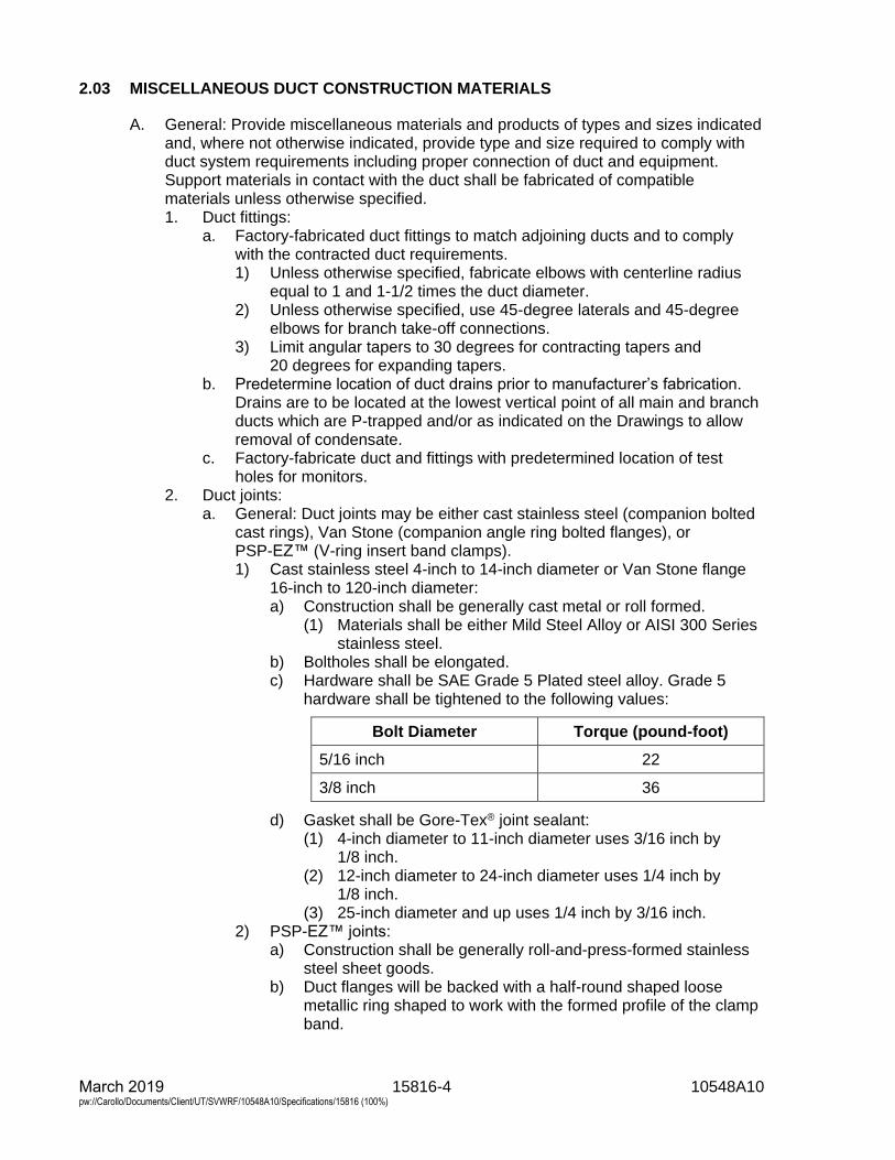
15816-4 10548A10 March 2019 pw://Carollo/Documents/Client/UT/SVWRF/10548A10/Specifications/15816 (100%)
2.03 MISCELLANEOUS DUCT CONSTRUCTION MATERIALS
A. General: Provide miscellaneous materials and products of types and sizes indicatedand, where not otherwise indicated, provide type and size required to comply withduct system requirements including proper connection of duct and equipment.Support materials in contact with the duct shall be fabricated of compatiblematerials unless otherwise specified.1. Duct fittings:
a. Factory-fabricated duct fittings to match adjoining ducts and to complywith the contracted duct requirements.1) Unless otherwise specified, fabricate elbows with centerline radius
equal to 1 and 1-1/2 times the duct diameter.2) Unless otherwise specified, use 45-degree laterals and 45-degree
elbows for branch take-off connections.3) Limit angular tapers to 30 degrees for contracting tapers and
20 degrees for expanding tapers.b. Predetermine location of duct drains prior to manufacturer’s fabrication.
Drains are to be located at the lowest vertical point of all main and branchducts which are P-trapped and/or as indicated on the Drawings to allowremoval of condensate.
c. Factory-fabricate duct and fittings with predetermined location of testholes for monitors.
2. Duct joints:a. General: Duct joints may be either cast stainless steel (companion bolted
cast rings), Van Stone (companion angle ring bolted flanges), orPSP-EZ™ (V-ring insert band clamps).1) Cast stainless steel 4-inch to 14-inch diameter or Van Stone flange
16-inch to 120-inch diameter:a) Construction shall be generally cast metal or roll formed.
(1) Materials shall be either Mild Steel Alloy or AISI 300 Seriesstainless steel.
b) Boltholes shall be elongated.c) Hardware shall be SAE Grade 5 Plated steel alloy. Grade 5
hardware shall be tightened to the following values:
Bolt Diameter Torque (pound-foot)
5/16 inch 22
3/8 inch 36
d) Gasket shall be Gore-Tex® joint sealant:(1) 4-inch diameter to 11-inch diameter uses 3/16 inch by
1/8 inch.(2) 12-inch diameter to 24-inch diameter uses 1/4 inch by
1/8 inch.(3) 25-inch diameter and up uses 1/4 inch by 3/16 inch.
2) PSP-EZ™ joints:a) Construction shall be generally roll-and-press-formed stainless
steel sheet goods.b) Duct flanges will be backed with a half-round shaped loose
metallic ring shaped to work with the formed profile of the clampband.
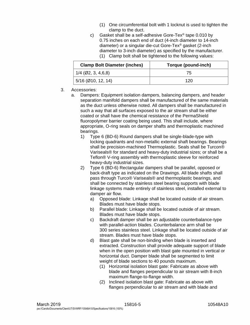
15816-5 10548A10 March 2019 pw://Carollo/Documents/Client/UT/SVWRF/10548A10/Specifications/15816 (100%)
(1) One circumferential bolt with 1 locknut is used to tighten theclamp to the duct.
c) Gasket shall be a self-adhesive Gore-Tex® tape 0.010 by0.75 inches on each end of duct (4-inch diameter to 14-inchdiameter) or a singular die-cut Gore-Tex® gasket (2-inchdiameter to 3-inch diameter) as specified by the manufacturer.(1) Clamp bolt shall be tightened to the following values:
Clamp Bolt Diameter (inches) Torque (pound-inch)
1/4 (Ø2, 3, 4,6,8) 75
5/16 (Ø10, 12, 14) 120
3. Accessories:a. Dampers: Equipment isolation dampers, balancing dampers, and header
separation manifold dampers shall be manufactured of the same materialsas the duct unless otherwise noted. All dampers shall be manufactured insuch a way that all surfaces exposed to the air stream shall be eithercoated or shall have the chemical resistance of the PermaShieldfluoropolymer barrier coating being used. This shall include, whereappropriate, O-ring seals on damper shafts and thermoplastic machinedbearings.1) Type 6 (BD-6) Round dampers shall be single-blade-type with
locking quadrants and non-metallic external shaft bearings. Bearingsshall be precision-machined Thermoplastic. Seals shall be Turcon®Variseals® for standard and heavy-duty industrial sizes; or shall be aTeflon® V-ring assembly with thermoplastic sleeve for reinforcedheavy-duty industrial sizes.
2) Type 6 (BD-6) Rectangular dampers shall be parallel, opposed orback-draft type as indicated on the Drawings. All blade shafts shallpass through Turco® Variseals® and thermoplastic bearings, andshall be connected by stainless steel bearing supports with bladelinkage systems made entirely of stainless steel, installed external todamper air flow.a) Opposed blade: Linkage shall be located outside of air stream.
Blades must have blade stops.b) Parallel blade: Linkage shall be located outside of air stream.
Blades must have blade stops.c) Backdraft damper shall be an adjustable counterbalance-type
with parallel-action blades. Counterbalance arm shall be300 series stainless steel. Linkage shall be located outside of airstream. Blades must have blade stops.
d) Blast gate shall be non-binding when blade is inserted andextracted. Construction shall provide adequate support of bladewhen in the open position with blast gate mounted in vertical orhorizontal duct. Damper blade shall be segmented to limitweight of blade sections to 40 pounds maximum.(1) Horizontal isolation blast gate: Fabricate as above with
blade and flanges perpendicular to air stream with 8-inchmaximum flange-to-flange width.
(2) Inclined isolation blast gate: Fabricate as above withflanges perpendicular to air stream and with blade and
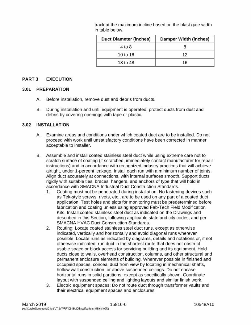
15816-6 10548A10 March 2019 pw://Carollo/Documents/Client/UT/SVWRF/10548A10/Specifications/15816 (100%)
track at the maximum incline based on the blast gate width in table below.
Duct Diameter (inches) Damper Width (inches)
4 to 8 8
10 to 16 12
18 to 48 16
PART 3 EXECUTION
3.01 PREPARATION
A. Before installation, remove dust and debris from ducts.
B. During installation and until equipment is operated, protect ducts from dust anddebris by covering openings with tape or plastic.
3.02 INSTALLATION
A. Examine areas and conditions under which coated duct are to be installed. Do notproceed with work until unsatisfactory conditions have been corrected in manneracceptable to installer.
B. Assemble and install coated stainless steel duct while using extreme care not toscratch surface of coating (if scratched, immediately contact manufacturer for repairinstructions) and in accordance with recognized industry practices that will achieveairtight, under 1-percent leakage. Install each run with a minimum number of joints.Align duct accurately at connections, with internal surfaces smooth. Support ductsrigidly with suitable ties, braces, hangers, and anchors of type that will hold inaccordance with SMACNA Industrial Duct Construction Standards.1. Coating must not be penetrated during installation. No fastening devices such
as Tek-style screws, rivets, etc., are to be used on any part of a coated ductapplication. Test holes and slots for monitoring must be predetermined beforefabrication and coating unless using approved Fab-Tech Field ModificationKits. Install coated stainless steel duct as indicated on the Drawings anddescribed in this Section, following applicable state and city codes, and perSMACNA HVAC Duct Construction Standards.
2. Routing: Locate coated stainless steel duct runs, except as otherwiseindicated, vertically and horizontally and avoid diagonal runs whereverpossible. Locate runs as indicated by diagrams, details and notations or, if nototherwise indicated, run duct in the shortest route that does not obstructusable space or block access for servicing building and its equipment. Holdducts close to walls, overhead construction, columns, and other structural andpermanent enclosure elements of building. Wherever possible in finished andoccupied spaces, conceal duct from view by locating in mechanical shafts,hollow wall construction, or above suspended ceilings. Do not encasehorizontal runs in solid partitions, except as specifically shown. Coordinatelayout with suspended ceiling and lighting layouts and similar finish work.
3. Electric equipment spaces: Do not route duct through transformer vaults andtheir electrical equipment spaces and enclosures.
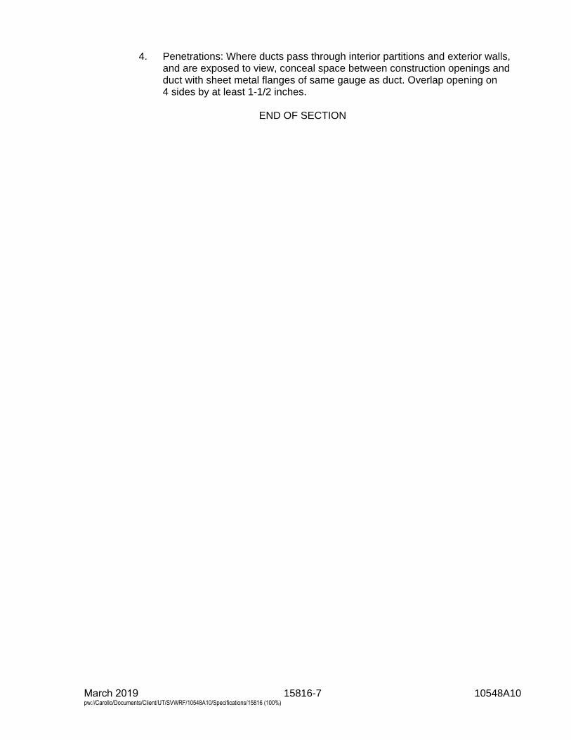
15816-7 10548A10 March 2019 pw://Carollo/Documents/Client/UT/SVWRF/10548A10/Specifications/15816 (100%)
4. Penetrations: Where ducts pass through interior partitions and exterior walls,and are exposed to view, conceal space between construction openings andduct with sheet metal flanges of same gauge as duct. Overlap opening on4 sides by at least 1-1/2 inches.
END OF SECTION

15820-1 10548A10 March 2019 pw://Carollo/Documents/Client/UT/SVWRF/10548A10/Specifications/15820 (100%)
SECTION 15820
DUCTWORK ACCESSORIES
PART 1 GENERAL
1.01 SUMMARY
A. Section includes:1. Dampers and damper operators.2. Diffusers, grilles, and registers.3. Screens.4. Flexible duct connectors.5. Other ductwork accessories.
1.02 REFERENCES
A. National Electrical Manufacturers Association (NEMA):1. 250 - Enclosures for Electrical Equipment (1000 V Maximum).
B. National Fire Protection Association (NFPA):1. 90B - Standard for the Installation of Warm Air Heating and Air-Conditioning
Systems.2. 255 - Standard Method of Test of Surface Burning Characteristics of Building
Materials.
C. Uniform Building Code (UBC).
D. Underwriters Laboratories, Inc. (UL):1. 555 - Fire Dampers.2. 555S - Smoke Dampers.
1.03 DEFINITIONS
A. Dampers, diffusers, grilles, and registers specified are indicated on the Drawings bythe abbreviations listed below. Each abbreviation is followed by a hyphen and anumber to designate the required style of unit:1. BD: Balancing Damper.2. BDD: Backdraft Damper.3. DG: Door Grille.4. FD: Fire Damper.5. FL: Flexible Duct Connector.6. RR: Return Register or Grille.7. SD: Smoke Damper.8. SFD: Smoke and Fire Damper combination.9. SR: Supply Register, Grille, or Diffuser.
B. NEMA Type 1 enclosure in accordance with NEMA 250.
15820-2 10548A10 March 2019 pw://Carollo/Documents/Client/UT/SVWRF/10548A10/Specifications/15820 (100%)
C. Return registers:1. RR designation includes wall, ceiling, and duct mounted air exhaust or return
devices including diffusers and grilles with or without control dampers.2. When no return register style is indicated on the Drawings, provide Style RR-3;
provide 4 inch flanged drop frame when duct mounting indicated.
D. Supply registers:1. SR designation includes wall, ceiling, and duct mounted air supply devices
including diffusers and grilles with or without control dampers.2. When no supply register style is indicated on the Drawings, provide Style
SR-3; provide 4 inch flanged drop frame when duct mounting indicated.
1.04 SUBMITTALS
A. Submit as specified in Section 01330 - Submittal Procedures.
B. Product data: As specified in Section 15050 - Common Work Results forMechanical Equipment.
PART 2 PRODUCTS
2.01 DAMPERS
A. Manufacturers:1. Provide dampers manufactured by the same manufacturer.2. Dampers:
a. Manufacturers: One of the following or equal:1) One manufacturer's model is listed with each style, similar models
from other listed vendors are acceptable:a) Ruskin Manufacturing.b) American Warming and Ventilating.c) Swartwout.
B. Materials:1. Metallic ductwork: Aluminum for aluminum duct work; aluminum or galvanized
steel for galvanized steel ductwork unless specified otherwise with styles.2. Fiberglass reinforced plastic ductwork: Fiberglass reinforced plastic where not
otherwise specified.
C. Components: Include specified damper type with frame actuators, clips, connectors,and other accessories necessary for mounting; provide locking quadrant manualactuator or electric actuator as indicated on the Drawings.
D. Volume control and balancing dampers (BD):1. BD-2, Style 2 Balancing Damper, Commercial Round Manual Balancing
Damper:a. Service: Manual balancing of office or laboratory air distribution systems;
suitable for up to 1,500 feet per minute velocity and 3 inch water columnpressure.
b. Size and installation: Size as indicated on the Drawings suitable for in-linemounting in round ducting.
c. Frame: 20 gauge minimum galvanized steel.
15820-3 10548A10 March 2019 pw://Carollo/Documents/Client/UT/SVWRF/10548A10/Specifications/15820 (100%)
d. Blade: 20 gauge minimum galvanized steel.e. Blade axle: Square plated steel with molded synthetic bearings; provide
factory mounted locking hand quadrant.f. Finish: Mill galvanized.g. Manufacturers: One of the following or equal:
1) Ruskin, Model MDRS25.2) Greenheck, similar model.
2. BD-3, Style 3 Balancing Damper, Commercial Rectangular Control Damper:a. Service: Office or laboratory air distribution systems; suitable for up to
6,000 feet per minute velocity and 13 inches water column pressure.b. Size and installation: Size as indicated on the Drawings suitable for
mounting in rectangular ducting.c. Frame: 0.125-inch thick 6063T5 aluminum with mounting flanges on both
sides.d. Blades: Opposed airfoil shape 6063T5 aluminum.e. Blade axles: Hexagonal plated steel with molded synthetic bearings.f. Seals: Extruded vinyl blade edge; flexible metal compressible type for
jamb as required.g. Finish: Mill Aluminum.h. Manufacturers: One of the following or equal:
1) Ruskin, Model CD50.2) Greenheck, similar model.
3. BD-7, Style 7 Balancing Damper, Fiberglass Heavy Duty Industrial RoundDamper:a. Service: Air systems up to 10 inches water column; up to 6,000 feet per
minute velocity and up to 72 inches diameter.b. Size and installation: Size as indicated on the Drawings suitable for flange
mounting in round ducting.c. Frame: Vinyl ester resin fiberglass construction conforming to ASME
RTP1 with 30 mil resin rich interior corrosion layer; flanges integral to theweb layup.
d. Blade: Vinyl ester resin fiberglass, stiffened as required; provide 30 milresin rich corrosion layer on both sides; provide Viton elastomer edgeseal.
e. Blade axle: Vinyl ester resin fiberglass rod with PTFE bearings and axleshaft seal.
f. Manufacturers: The following or equal:1) Swartwout, Model 912.
4. BD-8, Style 8 Balancing Damper, Fiberglass Heavy Duty IndustrialRectangular Damper:a. Service: Air systems up to 2.5 inches water column; up to 2,000 feet per
minute velocity and up to 72 by 48 inches size.b. Size and installation: Size as indicated on the Drawings suitable for flange
mounting in rectangular ducting.c. Frame: 0.25 inch thick vinyl ester resin fiberglass construction conforming
to ASME RTP1 with 30 mil resin rich interior corrosion layer; flangesintegral to the web layup.
d. Blade: Airfoil shape opposed blade action, vinyl ester resin fiberglass;provide 30 mil resin rich corrosion layer on both sides; provide fiberglasslinkage with Monel rivets in the airstream; provide Viton blade edge seal.
e. Blade axle: Vinyl ester resin fiberglass rod with PTFE bearings.
15820-4 10548A10 March 2019 pw://Carollo/Documents/Client/UT/SVWRF/10548A10/Specifications/15820 (100%)
f. Manufacturers: One of the following or equal:1) Swartwout, Model 1108.2) Hartzell Fan, Model D840.
E. Backdraft dampers (BDD):1. BDD-3, Style 3 Backdraft Damper, Heavy Duty Counterbalanced Backdraft
Damper:a. Service: Low pressure opening at 0.01 inches water column in rectangular
ducts or wall mounting for spot air velocities up to 2,500 feet per minute;weather resistant for exhaust applications.
b. Size and installation: Size as indicated on the Drawings and suitable formounting as indicated.
c. Frame: 2.25 inches deep, 0.125-inch minimum thickness 6063T5aluminum with insect screen and water stop.
d. Blades: 0.070-inch minimum thickness 6063T5 aluminum with Zytelbearings, elastomer edge seals, and aluminum tie-bar; blades require nomore than 4.25 inches clearance beyond frame when fully open.
e. Counterbalance: Zinc plated bar on blades; adjustable down to 0.01 inchwater column opening.
f. Finish: Kynar in manufacturer's standard colors to be selected by theEngineer.
g. Manufacturers: The following or equal:1) Ruskin, Model CBD6.
F. Damper operators:1. General: Provide manual or electric damper operator for each damper
furnished; type as indicated on the Drawings.2. Manual operators:
a. Gears or mechanical, to operate damper manually with a force notexceeding 20 pounds.
b. Provide manual operators with locking quadrant.c. Provide 3/8 inch, or larger, square double-ended drive shaft adequate for
required damper torque.d. Provide sufficient number of operators for torque required to operate
damper.3. Electric damper operators:
a. Manufacturers: One of the following or equal:1) Honeywell, Model M445A.2) Johnson Controls, Model M100.
b. 2-position spring return.c. 1 internal single pole double throw auxiliary switch rated 5 ampere,
120 volt, single phase, and 60 hertz.d. Housed in die-cast aluminum case with mounting flange.e. Motor and gear train components immersed in oil.f. When required, provide auxiliary transformers factory wired to damper
operator and installed in NEMA Type 1 enclosure fastened to motorhousing.
15820-5 10548A10 March 2019 pw://Carollo/Documents/Client/UT/SVWRF/10548A10/Specifications/15820 (100%)
2.02 DIFFUSERS, GRILLES, AND REGISTERS
A. Manufacturers:1. Provide diffusers, grilles, and registers manufactured by the same
manufacturer.2. Diffusers, grilles, and registers: One of the following or equal. One
manufacturer's model is listed with each style, similar models from other listedvendors are acceptable:a. Titus Manufacturing Corp.b. Tuttle and Bailey.c. Kees, Inc.d. Metal Industries, Inc., (MetalAire).e. Krueger.
B. Materials:1. For metallic ductwork: Aluminum for aluminum duct work; aluminum or
galvanized steel for galvanized steel ductwork unless specified otherwise withstyles.
2. For fiberglass reinforced plastic ductwork: Fiberglass reinforced plastic wherenot otherwise specified.
C. Components: Include specified style with frame, clips, connectors, and otheraccessories necessary for mounting.
D. Appearance: Similar for units in same room or space.
E. Supply diffuser, grille, and register styles:1. SR-3, Supply Register Style 3:
a. Size and installation: Rectangular grille size as indicated on the Drawingsframed for surface mounting on gypsum or directly mounted on exposedducting; provide 4 inch flanged drop frame when duct mounted.
b. Faceplate: Removable grille with double deflection blades spaced at3/4 inch; front blades parallel to long dimension; provide gasket at framefor sealing.
c. Core: Adjustable vanes with rectangular or round neck to match ducting.d. Damper: Provide opposed blade volume control damper suitable for use
with ducting type; damper to be adjustable through the face of the unit.e. Materials: Aluminum frame, core, damper, and faceplate.f. Manufacturers: One of the following or equal:
1) Titus, Model 272FL.2) Krueger, Model 5880H.
2. SR-9, Supply Register Style 9:a. Size and installation: High capacity, high throw drum louver suitable for
ceiling or side wall surface mounting on gypsum or direct duct mounting;size and mounting as indicated on the Drawings; provide 4-inch flangeddrop frame with shoe tap when duct mounted.
b. Face: Flanged with sponge rubber gasket.c. Blades: Split vane design to produce diverging airstreams.d. Core: Adjustable drum with felt side seals; 25- to 30-degree drum rotation
from the centerline.e. Damper: Provide opposed blade volume control damper; damper to be
adjustable from the face of the grille.
15820-6 10548A10 March 2019 pw://Carollo/Documents/Client/UT/SVWRF/10548A10/Specifications/15820 (100%)
f. Materials: Aluminum extruded border, blades, and damper; providebaked enamel finish. Coating shall be rated to withstand a 500-hour saltspray test.
g. Manufacturers: The following or equal:1) Titus, Model US-DL-SV grille with AG-50-HD damper.
F. Return diffuser, grille, and register styles:1. RR-3, Return Register Style 3:
a. Size and installation: Rectangular grille with size as indicated on theDrawings framed for surface mounting on gypsum or directly mounted onexposed ducting; provide 4 inch flanged drop frame when duct mounted.
b. Faceplate: Removable grille with fixed blades spaced at 3/4 inch; frontblades parallel to long dimension with 35 degree deflection; providegasket at frame for sealing.
c. Core: When connected to ducting, provide suitable rectangular or roundneck to match ducting; when filter indicated on the Drawings, provide1-inch deep filter frame and hinged face with 1/4-turn fasteners.
d. Damper: When connected to ducting, provide opposed blade volumecontrol damper suitable for use with ducting type; damper to be adjustablethrough the face of the unit.
e. Materials: Aluminum frame, core, damper, and faceplate.f. Manufacturers: The following or equal:
1) Titus, Model 350FL or Model 350FF1.
2.03 SCREENS
A. Characteristics and features:1. Bird screen: 1/2-inch mesh by 14 gauges.2. Insect screens: 18 by 14 mesh.3. Screens and frames, same material as ductwork, hood, louver, fan, or
equipment connected to screen.4. Screens secured in frames.
2.04 FLEXIBLE CONNECTIONS
A. Provide flexible duct connectors at all connections to fans and other air movementequipment as indicated on the Drawings.
B. FL-1, Duct to Duct Flexible Connection:1. Fabric shall be fire resistant, waterproof, mildew-resistant, and airtight. At least
4 inches of fabric shall be exposed. Flexible connections shall be inaccordance with the requirements of UL and NFPA.
2. Interior locations:a. Fabric for flexible connections installed inside office areas shall be
Neoprene coated glass fabric suitable for a temperature rangeof -20 degrees Fahrenheit to 180 degrees Fahrenheit and shall have aweight of at least 27 ounces per square yard and a thickness of0.024 inches.
b. Manufacturers: The following or equal:1) Ventfabrics, “Ventglas”.
15820-7 10548A10 March 2019 pw://Carollo/Documents/Client/UT/SVWRF/10548A10/Specifications/15820 (100%)
C. FL-2, Duct to Duct Flexible Connection, Corrosive Environment:1. Fabric for flexible connections exposed to chemicals shall be glass fabric
coated with Teflon and suitable for a temperature range of -10 degreesFahrenheit to 500 degrees Fahrenheit and shall have a weight of at least14 ounces per square yard and a thickness of 0.014-inch.
2. Manufacturers: The following or equal:a. Ventfabrics, “Ventel”.
D. FL-3, Duct to Equipment Heavy Duty Flexible Connection:1. Materials: EPDM rubber vulcanized with minimum of 1-ply of reinforcing fabric;
3/16-inch thick.2. Unit shall have minimum movement of:
a. Axial compression: 2.25 inches.b. Axial extension: 1.25 inches.c. Lateral offset: 1.25 inches.
3. Provide 3/8-inch thick by 2-inch wide pre-drilled retaining rings/back-up bars toclamp the expansion joints into the ducting system.
4. The expansion joint shall be of fully molded construction. Splices will not beallowed in the body of the expansion joint.
5. Manufacturers: One of the following or equal:a. Proco, Series 500, Style 530 Fabric Fan Connector.b. Holz Rubber, Style 952 Arch Design Expansion Joint.
PART 3 EXECUTION
3.01 PREPARATION
A. Before installation, remove dust and debris from ducts and accessories.
3.02 INSTALLATION
A. Install items in accordance with manufacturer’s instructions.
B. FL-3, Flexible Connections: Install at connections between duct and air handlingequipment and at locations indicated on the Drawings.
C. FL-1 and FL-2, Flexible Connections:1. Install at building expansion joints and as indicated on the Drawings.2. Install with collar and metal band to form airtight joints.3. Install with minimum 4 inches of slack in fabric.4. Exterior locations: Install sheet metal weather cover over fabric.5. Duct alignment shall be a maximum of 1/2-inch offset.6. The minimum/maximum gap shall be 2 inches and 6 inches.7. Lap longitudinal joints and glue per manufacturer’s recommendations.
15820-8 10548A10 March 2019 pw://Carollo/Documents/Client/UT/SVWRF/10548A10/Specifications/15820 (100%)
3.03 FIELD QUALITY CONTROL
A. Set grilles, dampers, and diffusers to achieve flows and flow patterns indicated onthe Drawings and test finished system as specified in Section 15954 - Testing,Adjusting, and Balancing for HVAC.
B. Mark final balance positions on all manual damper actuators with paint pen in adistinctive color.
END OF SECTION
15830-1 10548A10 March 2019 pw://Carollo/Documents/Client/UT/SVWRF/10548A10/Specifications/15830 (100%)
SECTION 15830
FANS
PART 1 GENERAL
1.01 SUMMARY
A. Section includes: Fans, including:1. Type 2 - Up-blast centrifugal roof exhausters.2. Type 5 - Centrifugal ceiling exhaust fans.3. Type 14 - Centrifugal sidewall exhaust fans.
1.02 REFERENCES
A. American Bearing Manufacturers Association (ABMA):1. 9 - Load Ratings and Fatigue Life for Ball Bearings.2. 11 - Load Ratings and Fatigue Life for Roller Bearings.
B. Air Movement and Control Association International, Inc. (AMCA):1. 210 - Laboratory Methods of Testing Fans for Certified Aerodynamic
Performance Rating.2. 211 - Certified Rating Program- Product Rating Manual for Fan Air
Performance.3. 300 - Reverberant Room Method for Sound Testing of Fan.4. 301 - Methods for Calculating Fan Sound Ratings from Laboratory Test Data.
C. American Society of Heating, Refrigerating, and Air-Conditioning Engineers(ASHRAE):1. 52.2 - Method of Testing General Ventilation Air-Cleaning Devices for
Removal Efficiency by Particle Size.2. 68 - Laboratory Methods of Testing to Determine Sound Power in a Duct.
D. ASTM International (ASTM):1. A108 - Standard Specification for Steel Bar, Carbon and Alloy, Cold-Finished.2. D4167 - Standard Specification for Fiber Reinforced Plastic Fans and Blowers.3. E84 - Standard Test Method for Surface Burning Characteristics of Building
Materials.
E. National Electrical Code (NEC).
F. National Electrical Manufacturers Association (NEMA):1. 250 - Enclosures for Electrical Equipment (1000 V Maximum).
G. National Fire Protection Association (NFPA):1. 90A - Standard for Installation of Air Conditioning and Ventilating Systems.2. 820 - Standard for Fire Protection in Wastewater Treatment and Collection
Facilities.
H. National Roofing Contractors Association (NRCA).
15830-2 10548A10 March 2019 pw://Carollo/Documents/Client/UT/SVWRF/10548A10/Specifications/15830 (100%)
I. Occupational Safety and Health Administration (OSHA).
J. Underwriters' Laboratories, Inc. (UL).
1.03 DEFINITIONS
A. As used in this Section and on the drawings, abbreviations and Fan Scheduleheadings have the following meaning:1. SF or SPF: Supply Fan.2. EF or EXF: Exhaust Fan.3. Type: Fan type as specified in this Section.4. SP or ESP: Fan External Static Pressure in inches water column.5. Size: Nominal fan blade or wheel diameter in inches.6. Hp: Fan motor horsepower.7. V/Ph: Fan motor voltage and power phases.
B. Institute of Electrical and Electronics Engineers (IEEE):1. 841 - IEEE Standard for Petroleum and Chemical Industry-
Premium-Efficiency, Severe-Duty, Totally Enclosed Fan-Cooled (TEFC)Squirrel Cage Induction Motors--Up to and Including 370 kW(500hp).
C. NEMA:1. Type 1 enclosure in accordance with NEMA 250.2. Type 3R enclosure in accordance with NEMA 250.
1.04 SYSTEM DESCRIPTION
A. Design requirements:1. Provide fans that have sharply rising pressure characteristics which extend
throughout the operating range and continue to rise beyond the efficiencypeak.
2. Provide fans that peak as close as possible to the maximum efficiency andwhose operating range is within the normal fan selection range.
3. When scheduled, provide guided vibration isolator for fans, so that not morethan 10 percent of the vibration amplitude of the fan and motor is transmittedto the supporting structure.
4. Design fan inner scroll and air stream surfaces to maintain smoothness forentire fan service life.
5. Seismic supports: Seismic design criteria as specified in Section 01612 -Seismic Design Criteria.
6. Wind supports for exterior units: Wind design criteria as specified inSection 01614 - Wind Design Criteria.
7. Electrical components: UL listed and meeting the design and installationrequirements of the NEC.
8. Applicable portions as specified in Section 15050 - Common Work Results forMechanical Equipment.
9. Motors supplied with fans: TEFC, IEEE 841 Compliant, NEMA premiumefficiency, Class F insulation, Class B temperature rise, 1.15 service factor;provide motor voltage phases and speed as scheduled; non-overloading onany point of the fan curve including belt losses.
10. Roof curbs: Designed in accordance with NRCA standards.11. Insulation and adhesives: Meet NFPA 90A requirements for flame spread and
smoke generation.
15830-3 10548A10 March 2019 pw://Carollo/Documents/Client/UT/SVWRF/10548A10/Specifications/15830 (100%)
12. Belt drive systems: Adjustable for minimum within 5 percent speed change,rated for 1.5 times maximum horsepower motor available for the scheduled fansize or model.
13. Screens: Provide bird or insect screen as specified with the fan type or aslisted on the Fan Schedule:a. Bird screen: Stainless steel; 0.5-inch mesh 18-gauge.b. Insect screen: Stainless steel mesh and frame.
14. Finishes: When not specified with fan type, coat ferrous metals as specified inSection 09960 - High-Performance Coatings.
15. Accessories: Provide accessories specified and those scheduled.16. Provide fans with fire/smoke control system as specified under paragraph
Fire/Smoke Control System Design Requirements.
B. Performance requirements:1. Performance requirements are included in the Fan Schedule located at the
end of this Section.2. Fan performance: Rated and licensed to bear the AMCA label in accordance
with AMCA 210 and AMCA 211.3. Total sound power levels in the 8 octave band range as measured in
accordance with ASHRAE 68, AMCA 301, or AMCA 300 as appropriate foreach fan: Not to exceed the lesser of the following or the Sones levels on theFan Schedule.
Sound Power Level, decibel levels referenced to 10-12 watts
Frequency, Hz 63 125 250 500 1,000 2,000 4,000 8,000
General 100 98 94 88 84 84 78 75
4. Air filters supplied with fans: 25 to 30 percent dust spot efficiency when ratedper ASHRAE Testing Standard 52.2.
5. Bearings: Rated per ABMA 9 or 11 for a L10 life rating of not less than50,000 hours; provide greater life when specified with each fan type.
C. Electrical and control system design:1. Design and supply necessary electrical power and control systems,
components, and wiring to make a complete functioning system. Design toperform the system ventilating functions with the control systems as specifiedin Section 15936 - Instrumentation and Control Devices for HVAC or asindicated on the Drawings and as specified in the following Sections:a. Section 16050 - Common Work Results for Electrical.b. Section 16060 - Grounding and Bonding.c. Section 16075 - Identification for Electrical Systems.d. Section 16123 - 600-Volt or Less Wires and Cables.e. Section 16130 - Conduits.f. Section 16134 - Boxes.g. Section 16140 - Wiring Devices.h. Section 16222 - Low Voltage Motors up to 500 Horsepower.i. Section 16411 - Disconnect Switches.
1.05 SUBMITTALS
A. Submit as specified in Section 01330 - Submittal Procedures.
15830-4 10548A10 March 2019 pw://Carollo/Documents/Client/UT/SVWRF/10548A10/Specifications/15830 (100%)
B. Product data:1. Materials.2. Primary and ancillary equipment.3. Sound Power Level in each of 8 octave bands and overall Sones.4. Fan system layout, mechanical, electrical power, and control diagrams.5. Supports, vibration isolators, and seismic bracing calculations and details.6. Calculated fan vibration levels and field-testing method.7. Bearing life.8. Fan performance curves showing specified operating condition.
C. Provide vendor operation and maintenance manual as specified in Section 01782 -Operation and Maintenance Data.1. Furnish bound sets of installation, operation, and maintenance instructions for
each type fan.
D. Provide Manufacturer’s Certificate of Source Testing as specified in Section 01756 -Commissioning.
1.06 QUALITY ASSURANCE
A. Provide fans:1. Listed by UL.2. Rated in accordance with AMCA.
1.07 DELIVERY, STORAGE, AND HANDLING
A. Deliver units in 1 piece, factory assembled, internally wired, and lubricated.
B. Protect equipment from dust and atmospheric exposure as recommended by theunit manufacturer.1. As a minimum provide temporary closures for equipment openings designed
for airflow.
1.08 EXTRA MATERIALS
A. Provide 2 extra sets (3 sets total) of filters per installed fan for fans specified withfilters.
B. Provide 1 extra set of belts per installed fan for fans specified with belt drives.
PART 2 PRODUCTS
2.01 TYPE 2, UP-BLAST CENTRIFUGAL ROOF EXHAUSTERS
A. Manufacturers: One of the following or equal:1. Greenheck, Model CUBE.2. Loren Cook, Model ACRU.3. Penn Ventilator, Model Fumex.
B. Characteristics:1. Roof-mounted, upblast circular exhaust fan unit.
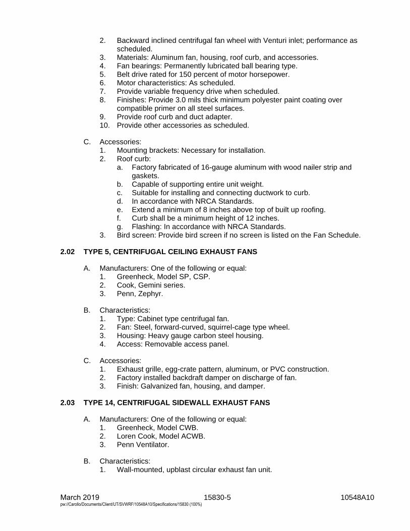
15830-5 10548A10 March 2019 pw://Carollo/Documents/Client/UT/SVWRF/10548A10/Specifications/15830 (100%)
2. Backward inclined centrifugal fan wheel with Venturi inlet; performance asscheduled.
3. Materials: Aluminum fan, housing, roof curb, and accessories.4. Fan bearings: Permanently lubricated ball bearing type.5. Belt drive rated for 150 percent of motor horsepower.6. Motor characteristics: As scheduled.7. Provide variable frequency drive when scheduled.8. Finishes: Provide 3.0 mils thick minimum polyester paint coating over
compatible primer on all steel surfaces.9. Provide roof curb and duct adapter.10. Provide other accessories as scheduled.
C. Accessories:1. Mounting brackets: Necessary for installation.2. Roof curb:
a. Factory fabricated of 16-gauge aluminum with wood nailer strip andgaskets.
b. Capable of supporting entire unit weight.c. Suitable for installing and connecting ductwork to curb.d. In accordance with NRCA Standards.e. Extend a minimum of 8 inches above top of built up roofing.f. Curb shall be a minimum height of 12 inches.g. Flashing: In accordance with NRCA Standards.
3. Bird screen: Provide bird screen if no screen is listed on the Fan Schedule.
2.02 TYPE 5, CENTRIFUGAL CEILING EXHAUST FANS
A. Manufacturers: One of the following or equal:1. Greenheck, Model SP, CSP.2. Cook, Gemini series.3. Penn, Zephyr.
B. Characteristics:1. Type: Cabinet type centrifugal fan.2. Fan: Steel, forward-curved, squirrel-cage type wheel.3. Housing: Heavy gauge carbon steel housing.4. Access: Removable access panel.
C. Accessories:1. Exhaust grille, egg-crate pattern, aluminum, or PVC construction.2. Factory installed backdraft damper on discharge of fan.3. Finish: Galvanized fan, housing, and damper.
2.03 TYPE 14, CENTRIFUGAL SIDEWALL EXHAUST FANS
A. Manufacturers: One of the following or equal:1. Greenheck, Model CWB.2. Loren Cook, Model ACWB.3. Penn Ventilator.
B. Characteristics:1. Wall-mounted, upblast circular exhaust fan unit.
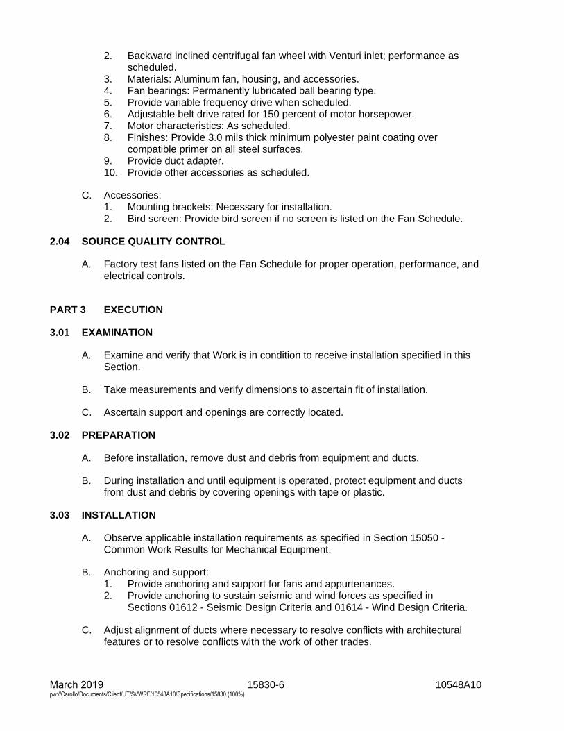
15830-6 10548A10 March 2019 pw://Carollo/Documents/Client/UT/SVWRF/10548A10/Specifications/15830 (100%)
2. Backward inclined centrifugal fan wheel with Venturi inlet; performance asscheduled.
3. Materials: Aluminum fan, housing, and accessories.4. Fan bearings: Permanently lubricated ball bearing type.5. Provide variable frequency drive when scheduled.6. Adjustable belt drive rated for 150 percent of motor horsepower.7. Motor characteristics: As scheduled.8. Finishes: Provide 3.0 mils thick minimum polyester paint coating over
compatible primer on all steel surfaces.9. Provide duct adapter.10. Provide other accessories as scheduled.
C. Accessories:1. Mounting brackets: Necessary for installation.2. Bird screen: Provide bird screen if no screen is listed on the Fan Schedule.
2.04 SOURCE QUALITY CONTROL
A. Factory test fans listed on the Fan Schedule for proper operation, performance, andelectrical controls.
PART 3 EXECUTION
3.01 EXAMINATION
A. Examine and verify that Work is in condition to receive installation specified in thisSection.
B. Take measurements and verify dimensions to ascertain fit of installation.
C. Ascertain support and openings are correctly located.
3.02 PREPARATION
A. Before installation, remove dust and debris from equipment and ducts.
B. During installation and until equipment is operated, protect equipment and ductsfrom dust and debris by covering openings with tape or plastic.
3.03 INSTALLATION
A. Observe applicable installation requirements as specified in Section 15050 -Common Work Results for Mechanical Equipment.
B. Anchoring and support:1. Provide anchoring and support for fans and appurtenances.2. Provide anchoring to sustain seismic and wind forces as specified in
Sections 01612 - Seismic Design Criteria and 01614 - Wind Design Criteria.
C. Adjust alignment of ducts where necessary to resolve conflicts with architecturalfeatures or to resolve conflicts with the work of other trades.
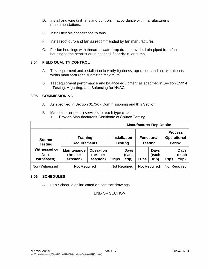
15830-7 10548A10 March 2019 pw://Carollo/Documents/Client/UT/SVWRF/10548A10/Specifications/15830 (100%)
D. Install and wire unit fans and controls in accordance with manufacturer'srecommendations.
E. Install flexible connections to fans.
F. Install roof curb and fan as recommended by fan manufacturer.
G. For fan housings with threaded water trap drain, provide drain piped from fanhousing to the nearest drain channel, floor drain, or sump.
3.04 FIELD QUALITY CONTROL
A. Test equipment and installation to verify tightness, operation, and unit vibration iswithin manufacturer's submitted maximum.
B. Test equipment performance and balance equipment as specified in Section 15954- Testing, Adjusting, and Balancing for HVAC.
3.05 COMMISSIONING
A. As specified in Section 01756 - Commissioning and this Section.
B. Manufacturer (each) services for each type of fan.1. Provide Manufacturer’s Certificate of Source Testing.
Manufacturer Rep Onsite
Source Testing
(Witnessed or
Non-witnessed)
Training
Requirements
Installation
Testing
Functional
Testing
Process
Operational
Period
Maintenance (hrs per session)
Operation (hrs per session) Trips
Days (each trip) Trips
Days (each trip) Trips
Days (each trip)
Non-Witnessed Not Required Not Required Not Required Not Required
3.06 SCHEDULES
A. Fan Schedule as indicated on contract drawings.
END OF SECTION

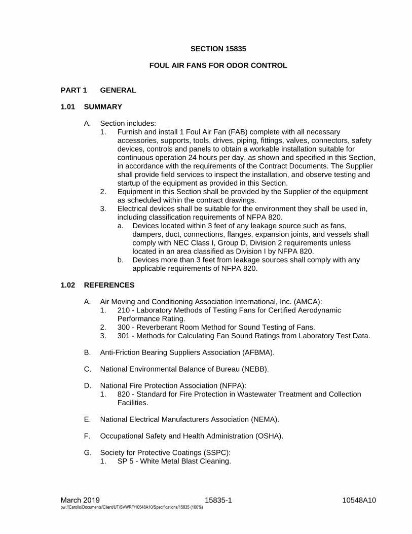
15835-1 10548A10 March 2019 pw://Carollo/Documents/Client/UT/SVWRF/10548A10/Specifications/15835 (100%)
SECTION 15835
FOUL AIR FANS FOR ODOR CONTROL
PART 1 GENERAL
1.01 SUMMARY
A. Section includes:1. Furnish and install 1 Foul Air Fan (FAB) complete with all necessary
accessories, supports, tools, drives, piping, fittings, valves, connectors, safetydevices, controls and panels to obtain a workable installation suitable forcontinuous operation 24 hours per day, as shown and specified in this Section,in accordance with the requirements of the Contract Documents. The Suppliershall provide field services to inspect the installation, and observe testing andstartup of the equipment as provided in this Section.
2. Equipment in this Section shall be provided by the Supplier of the equipmentas scheduled within the contract drawings.
3. Electrical devices shall be suitable for the environment they shall be used in,including classification requirements of NFPA 820.a. Devices located within 3 feet of any leakage source such as fans,
dampers, duct, connections, flanges, expansion joints, and vessels shallcomply with NEC Class I, Group D, Division 2 requirements unlesslocated in an area classified as Division I by NFPA 820.
b. Devices more than 3 feet from leakage sources shall comply with anyapplicable requirements of NFPA 820.
1.02 REFERENCES
A. Air Moving and Conditioning Association International, Inc. (AMCA):1. 210 - Laboratory Methods of Testing Fans for Certified Aerodynamic
Performance Rating.2. 300 - Reverberant Room Method for Sound Testing of Fans.3. 301 - Methods for Calculating Fan Sound Ratings from Laboratory Test Data.
B. Anti-Friction Bearing Suppliers Association (AFBMA).
C. National Environmental Balance of Bureau (NEBB).
D. National Fire Protection Association (NFPA):1. 820 - Standard for Fire Protection in Wastewater Treatment and Collection
Facilities.
E. National Electrical Manufacturers Association (NEMA).
F. Occupational Safety and Health Administration (OSHA).
G. Society for Protective Coatings (SSPC):1. SP 5 - White Metal Blast Cleaning.
15835-2 10548A10 March 2019 pw://Carollo/Documents/Client/UT/SVWRF/10548A10/Specifications/15835 (100%)
H. Underwriter’s Laboratories, Inc. (UL):1. 508 - Standard for Industrial Control Panels.
1.03 SYSTEM DESCRIPTION
A. Design requirements:1. All equipment including controls and drives specified in this Section shall be
specifically designed for this service and the environment encountered in thisinstallation.a. Provide a control panel consisting of a disconnect switch, alarms,
indicator lights, push-buttons, and related controls.1) This control panel shall be combined with a common control panel for
the equipment specified within the contract documents.2) Control Panels shall bear a UL 508 label.
1.04 PERFORMANCE REQUIREMENTS
A. Refer to the schedule in the Contract Drawings for specific requirements for theFAB.
B. Structural performance:1. All equipment, supports, anchors and fasteners shall be of adequate size and
strength to withstand loads associated with starting, turbulence, debris, thrustsfrom liquid movement, thermal expansion and contraction and other loadsencountered under operating conditions.
C. Operation: Equipment shall be designed and capable of either continuous orintermittent operation.
1.05 SUBMITTALS
A. Submit as specified in Section 01330 - Submittal Procedures and Section 15050 -Common Work Results for Mechanical Equipment.
B. Product data:1. Special shipping, storage and protection, and handling instructions.2. Supplier’s instructions for installation.3. Qualification Data: For Supplier and Supplier’s representative, if applicable.4. Location of nearest stocking distributor of spare parts.5. Suggested spare parts list to maintain the equipment in service for a period of
1 year. Include a list of special tools required for checking, testing, partsreplacement, and maintenance with current pricing information.a. Provide construction details, material descriptions, dimensions of
individual components and profiles, rated capacities, operatingcharacteristics, electrical characteristics, and furnished specialties andaccessories.
6. Complete motor nameplate data, in accordance with NEMA, motor supplier,and include any motor specifications.
C. Shop drawings:1. Provide plans, elevations, sections, details, and attachments to other work.2. Detail equipment assemblies and indicate dimensions, weights, loads,
required clearances, method of field assembly, components, and location and
15835-3 10548A10 March 2019 pw://Carollo/Documents/Client/UT/SVWRF/10548A10/Specifications/15835 (100%)
size of each field connection. Layout, sizes, types and materials for anchor bolts to be furnished.
3. Location of auxiliary instrumentation furnished with equipment and associatedmounting brackets and hardware.
4. Wiring diagrams: For power, signal, and control wiring diagrams, includingterminals and numbers.
D. Calculations:1. Vibration calculations.2. AFBMA Bearing Life calculations showing an L-10 life of 100,000 hours.3. Specific design parameters for this project as specified in this Section.
E. Commissioning submittals:1. Provide Manufacturer’s Certificate of Source Testing as specified in
Section 01756 - Commissioning.2. Provide Manufacturer’s Certificate of Installation and Functionality Compliance
as specified in Section 01756 - Commissioning.
F. Project closeout documents:1. Provide vendor operation and maintenance manual as specified in
Section 01782 - Operation and Maintenance Data.
1.06 DELIVERY, STORAGE, AND HANDLING
A. Fans shall be fully assembled and mounted on the skid at the factory.
B. Equipment shall be crated and delivered to protect against damage during shipping.1. Flange faces shall be protected from damage.2. Openings shall be covered to prevent entrance of dirt, water, and debris.
C. Properly protect parts so that no damage or deterioration shall occur during aprolonged delay from the time of shipment until installation is completed and untilthe units and equipment are ready for operation.
D. Properly protect finished iron or steel surfaces to prevent rust and corrosion.
E. Protect equipment, delivered and designated for storage, from the weather(humidity and temperature), dirt and dust, and other contaminants.
F. Electrical equipment, panels, and instrumentation shall be stored indoors andprotected from corrosion (including ambient hydrogen sulfide corrosion).1. Motors shall have power connected to the motor heater.
1.07 PROJECT CONDITIONS
A. System arrangement:1. The equipment, sizes, materials, and arrangements described in this Section
are typically based on recommendations by equipment Suppliers and shall beconsidered minimum limits of acceptability. The equipment Supplier shall beresponsible for design, arrangement, and performance of all equipmentsupplied under this Section.
2. Modifications to structural design due to a Supplier’s varying spacerequirements, foundation requirements, or dimension changes to fit Supplier
15835-4 10548A10 March 2019 pw://Carollo/Documents/Client/UT/SVWRF/10548A10/Specifications/15835 (100%)
specific requirements shall be coordinated by Contractor and included in the Bid.
3. The Contractor shall be responsible for any modifications to the piping,electrical, structural, and mechanical layouts to accommodate, as wellreimbursement to Owner for additional charges by Engineer for additional workrequired accomplishing changes.
1.08 ENVIRONMENTAL CONDITIONS
A. All equipment including controls and drives specified herein shall be specificallydesigned for this service and the environment encountered in this installation.
B. When installed in wastewater treatment areas, the environment shall be moist, andcorrosive, exhibiting hydrogen sulfide and other corrosive gases encountered inmunicipal wastewater treatment plants.
C. Designed and capable of operation at ambient temperatures of 0 degreesFahrenheit to 110 degrees Fahrenheit.
1.09 WARRANTY
A. Provide warranty as specified in Section 01783 - Warranties and Bonds.
PART 2 PRODUCTS
2.01 SUPPLIERS
A. Subject to compliance with requirements, provide products by one of the followingor approved equal:1. New York Blower2. Hartzell Fan.
2.02 GENERAL REQUIREMENTS
A. Foul Air Fans shall be of the single-stage, single width, single inlet backwardinclined centrifugal type (Minimum Class II), suitable for continuous operation24 hours per day. All equipment shall be in accordance with NFPA 820 and Class IDiv. 1 or 2 requirements depending on installation location.
B. Refer to schedule in the contract drawings for specific fans requirements.1. Provide odor control fan complete with controls, dampers, vibration isolation,
motor, drive, guards, baseplate and sub-base.2. The fan shall be constructed of Type 316 stainless steel.3. All nuts, bolts and fasteners in contact with the gas stream shall be Type 316
stainless steel.
C. Odor control fan’s mounting shall be AMCA standard Arrangement 9 for up to15 horsepower.1. 20 horsepower and above shall be Arrangement 1 with fabricated channel
base and slide rail type motor mounting.
15835-5 10548A10 March 2019 pw://Carollo/Documents/Client/UT/SVWRF/10548A10/Specifications/15835 (100%)
2. Fans sub-base shall be bolted directly to equipment slab with an intermediategrout pad and shop painted with an epoxy coating for outside/corrosiveapplication.
3. Arrangement 4, which places the motor shaft in the corrosive gas stream, isunacceptable.
D. Motor:1. Premium efficiency TEFC 460/3/60.2. Provide winding temperature switch and motor heater.3. Provide motor rated for 50 degrees Celsius ambient air temperature.4. Motor shall be rated and labeled Class I, Division 2.
E. Base:1. Each fans and drive unit shall be mounted on a common unitary base provided
by the fans Supplier.2. The base shall have all exposed seams and contact surfaces of steel plates
and shapes continuously welded and ground smooth.3. An opening shall also be provided, if necessary, for electrical conduit to the
drive unit.4. Base shall be constructed from Type 316 stainless steel or from carbon steel
factory coated as specified in Section 09960 - High-Performance Coatings.
F. Performance:1. Each fans shall be factory tested in accordance with AMCA 210 and shall bear
the AMCA Certified Ratings Seal for Air Performance and shall be tested forvibration and sound.
2. Fans not licensed to bear the AMCA Seal for performance shall be tested, atSupplier’s expense, in an AMCA Registered Laboratory.
3. Fans shall have a sharply rising pressure characteristic extending throughoutthe operating range to ensure quiet and stable operation.
4. Fans brake horsepower shall be equal to or less than the BHP specified in theschedule at the listed static pressure and CFM.
G. Sound:1. Supplier shall provide a sound power level rating for fans tested and rated in
accordance with AMCA 300 and 301.2. Sound power ratings shall be in decibels (reference 10-12 watts) in 8 octave
bands.3. The maximum radiated sound pressure level shall be at or below 80 dBA
(reference 20 mPa) at 5 feet.
H. Construction: Fans shall be constructed of Type 316 stainless steel.1. Housing:
a. Fans housing shall have flanged discharge and inlet drilled connectionand companion flanges.1) Fans shall be separated from ductwork at inlet and outlet by flanged
flexible connections.2) Contractor shall coordinate flange drilling with duct.3) Flexible connectors shall be supplied by the fans Supplier.
b. Constructed from stainless steel and electrically grounded.c. Fans housing shall be designed so that air leakage through joints and
seals is negated.
15835-6 10548A10 March 2019 pw://Carollo/Documents/Client/UT/SVWRF/10548A10/Specifications/15835 (100%)
d. All bolted pieces shall be EPDM gasketed for air tightness.e. Stainless steel nameplates giving the name of the Supplier, serial number,
model number, rated capacity in cubic feet per minute, head in inches ofwater (gage), fans in revolutions per minute, and any other pertinent datashall be permanently affixed to each fans with stainless steel hardware.
2. Fan’s wheel:a. Type 316 stainless steel wheel, backward curved non-loading, high
efficiency, 1-piece, resin transfer mold.3. Fan’s shaft:
a. Fans impeller and driving pulley shall be secured to shaft with keys andset screws.
b. Shaft shall be of Type 316 stainless steel designed to operate at25 percent below first critical speed.
c. Shaft and impeller shall be statically and dynamically balanced at normaloperating speed listed in schedule.
d. Provide double-lip Teflon or equivalent seal with Type 316 stainless steelmounting plate between shaft and fans housing.
e. Seal shall positively prevent liquid and gas leakage and shall fieldreplaceable.
4. Fan’s bearings:a. Each fans shaft shall be supported by approved, grease lubricated,
self-aligning ball or roller bearings made of vacuum degassed 52100steel.1) Ball or roller bearings shall be made by Supplier’s who are members
of the AFBMA and shall be selected for a minimum rating life (L-10)of 100,000 hours at the fans maximum rated speed and based onBasic Dynamic Load Ratings calculated from AFBMA formulas(AFBMA Standards, Section No. 9, and Section No. 11, LatestRevisions).
2) Material factors used in formula calculations shall be based onvalues assuming a conventional good quality, hardened bearing steelwithout benefit of vacuum degassing.
3) Specifically, for pound and inch units, factor "f" shall be as given inthe tables of AFBMA Standards cited above.
I. Accessories and miscellaneous:1. Access doors: Raised type, stud mounted access doors with gaskets.2. Drains: Provide drains at low point of scroll, 1-inch pipe coupling affixed to
housing with threaded corrosion resistant plug for connection to PVC ball valveduring installation.
3. Drive: Matched V-belts and fixed sheave pulleys shall be cast iron, sized forminimum 1.2 service factor.
4. Belt and shaft guard:a. Stainless steel screen or stainless steel construction, painted with
tachometer hole, OSHA approved.b. Provide shaft and bearing guard.c. Guards in excess of 40 pounds shall be provided with an expanded metal
screen on the vertical surface to reduce weight.d. Fans having a wheel diameter of 40-inches or larger shall have belt and
shaft guards provided with 2 lifting handles.
15835-7 10548A10 March 2019 pw://Carollo/Documents/Client/UT/SVWRF/10548A10/Specifications/15835 (100%)
5. Provide fans with flanged inlet and outlet flexible connections:a. Constructed of Type 316 stainless steel flanges drilled to match fans bolt
pattern and an EPDM corrosion resistant sleeve min. of 3/16-inch thick.b. Face to face dimension of 4 inch minimum to 6 inch maximum with
1/4-inch lateral motion in any direction.6. Backdraft damper:
a. If required, provide a round backdraft damper at the discharge of eachFAB after the transition to circular duct.
b. Backdraft dampers are specified in Section 15816 - Corrosive FumeExhaust Ducts.
7. Fan Inlet Box:a. Provide inlet box specifically designed by the fan manufacturer to optimize
fan inlet conditions.b. Maximum pressure loss through inlet box shall be 1.0 inches water
column at specified design flow rate.c. Inlet box shall be mounted and supported from integral fan/motor/inlet box
base with rigid structural Type 316 stainless steel supports.d. Inlet box shall be of Type 316 stainless steel construction.e. Inlet box shall have a 1-inch drain connection at the lowest point in the
orientation indicated on the Drawings; provide PVC ball valve andthreaded plug.
8. Lifting lugs: Individual equipment and/or each field disassemble part weighingover 100 pounds shall be provided with lifting lugs.
9. Anchor bolts:a. Provide template and Type 316 stainless steel anchors as specified in
Section 05190 - Mechanical Anchoring and Fastening to Concrete andMasonry and as indicated on the Drawings.
b. Anchor bolts may be provided by others however the Supplier shallprovide the anchor bolt size.
J. Coatings:1. Metal fans parts:
a. Prepare metal surfaces in accordance with SSPC SP 5.b. Baked epoxy phenolic or "cold set" epoxy-phenolic amine cured, brush or
spray coats in accordance with Supplier’s specifications.
PART 3 EXECUTION
3.01 INSTALLATION
A. Install and adjust equipment as indicated on the Drawings, approved shopdrawings, and the Supplier's instructions. Do not operate the equipment until theinstallation is approved by the Supplier’s representative.
B. Odor control fan equipment shall be installed as specified in this Section and asindicated on the Drawings, and in accordance with the supplier’s recommendationsand instructions.1. Equipment shall be installed in such manner that connecting duct work or
piping shall not impose any strain whatever on any equipment.2. Add additional supports if necessary at no additional cost to the Owner.
15835-8 10548A10 March 2019 pw://Carollo/Documents/Client/UT/SVWRF/10548A10/Specifications/15835 (100%)
3. Equipment shall be set upon grouted foundations, level or perpendicular, asthe case may be, so that connecting flanges, screwed connections, or flexibleconnections shall meet without strain or distortion.
4. Base leveling nuts shall be blocked out during grouting of foundations, thegrout allowed to set for not less than 3 days, leveling nuts loosened andfollowed by grouting of block-outs, with non-shrink grout.
C. Install equipment with Type 316 stainless fasteners.
D. Contractor shall ensure that all equipment furnished under this Section shall besuitable for installation as specified.1. The Contractor shall be responsible for determining the necessary clearances
and headroom required to move all equipment to its final location.
E. In every case where a drive motor is connected to a driven piece of equipment by aflexible coupling, the coupling halves shall be disconnected and alignment betweenmotor and equipment checked and corrected.1. Machinery shall first be perfectly aligned and leveled by means of Type 316
stainless steel wedges and shims near anchor bolts.2. Anchor bolts shall be tightened against shims on wedges and equipment shall
again be checked for level and alignment before placing grout.
F. Equipment bases shall not be grouted nor foundation bolts finally tightened until allpiping connections are complete and in satisfactory alignment with no straintransmitted to the equipment.
G. Examine pads or supports to receive Foul Air Fans for:1. Proper anchor bolt locations.2. Unevenness, irregularities, and incorrect dimensions.
H. Supervise installation in accordance with odor control fan Supplier's instructions andrecommendations.
I. All equipment shall be installed on concrete bases and secured with anchor bolts inaccordance with the Supplier's recommendations.1. Contractor shall accurately shim base to grade and spaces between shims
filled with an approved non-shrink grout.2. After grout has reached its initial set, exposed edges shall be cut back 1/2-inch
and edges neatly finished with 1:2 cement mortar.
J. Installation shall include furnishing and applying an initial supply of grease and oil,recommended by the Supplier.
K. Connect all duct, piping, valves, and accessories as necessary to complete theinstallation.
L. Install all conduit and wiring and complete all connections.
3.02 INSPECTION OF FOUL AIR FANS
A. Owner or Owner’s representative reserves right to reject any and all items ofequipment found to have following: blisters, chips, crazing, exposed glass, drycracks, burned areas, dry spots, foreign matter, or entrapped air at the laminate
15835-9 10548A10 March 2019 pw://Carollo/Documents/Client/UT/SVWRF/10548A10/Specifications/15835 (100%)
surfaces which does not satisfy the tolerances specified in ASTM D2563 Table 1, Acceptance Level II for inside and outside surfaces or meet the specified requirements.
3.03 INSPECTION AND START-UP ADJUSTMENTS
A. Contractor shall perform the following inspection of equipment with the equipmentSupplier’s representative:1. Verify proper equipment mounting and setting.2. Verify that power wiring is complete.3. Verify alignment of each motor and drive.4. Verify proper piping connections and accessories.5. Verify that lubrication is completed.6. Verify direction of rotation.7. Monitor heat build-up in bearings.8. Check motor loads against nameplate data.9. Verify proper operation of equipment.10. Remove all loose materials and obstructions from interior of ducts and fans.11. Remove debris and waste materials resulting from installation.
B. The Contractor shall conduct the following Start-up Adjustments with the Supplier’srepresentative:1. Adjust fan for proper alignment and flow.2. Set volume control devices for approximate positions in preparation for final
testing and balancing.3. Balance system for CFM indicated on the Drawings and in accordance with
this Section.4. Utilize the services of an NEBB balancing firm to balance the odor control
system.
3.04 COMMISSIONING
A. As specified in Section 01756 - Commissioning, 15958 - Mechanical EquipmentTesting, and this Section.
B. Manufacturer services:1. Provide certificates:
a. Manufacturer’s Certificate of Source Testing.b. Manufacturer’s Certificate of Installation and Functionality Compliance.
2. Manufacturer’s Representative onsite requirements:a. Installation: 1 trip, 1-day minimum.b. Functional Testing: 1 trip, 1-day minimum each.
3. Training:a. Maintenance: 4 hours per session, 2 sessions.b. Operation: 2 hours per session, 2 sessions.
4. Process operational period:a. As required by Owner or Contractor.
C. Source testing:1. Test as specified in Section 15958 - Mechanical Equipment Testing.2. Fans:
a. Test witnessing: Not witnessed.b. Conduct Level 1 General Equipment Performance Test.
March 2019 15835-10 10548A10 pw://Carollo/Documents/Client/UT/SVWRF/10548A10/Specifications/15835 (100%)
c. Conduct Level 1 Vibration Test.d. Conduct Level 1 Noise Test.
3. Equipment:a. Test witnessing: Not witnessed.b. Conduct Level 1 General Equipment Performance Test.c. Conduct Level 1 Vibration Test.d. Conduct Level 1 Noise Test.
4. Electrical Instrumentation and Controls:a. Test witnessing: Not witnessed.b. Conduct testing as specified in Section 17950 - Testing, Calibration, and
Commissioning.
D. Functional testing:1. Equipment:
a. Test witnessing: Witnessed.b. Conduct Level 2 General Equipment Performance Test.c. Conduct Level 2 Vibration Test.d. Conduct Level 2 Noise Test.
2. Electrical Instrumentation and Controls:a. Test witnessing: Witnessed.b. Conduct testing as specified in Section 17950 - Testing, Calibration, and
Commissioning.3. Fan system:
a. Test witnessing: Witnessed.b. Conduct Level 2 General Equipment Performance Test.c. Conduct Level 2 Vibration Test.d. Conduct Level 2 Noise Test.
3.05 SCHEDULES
A. Fan Schedule as indicated on contract drawings.
END OF SECTION
15852-1 10548A10 March 2019 pw://Carollo/Documents/Client/UT/SVWRF/10548A10/Specifications/15852 (100%)
SECTION 15852
LOUVERS
PART 1 GENERAL
1.01 SUMMARY
A. Section includes:1. Stationary weather louvers.
1.02 REFERENCES
A. Air Movement and Control Association International, Inc. (AMCA):1. 500-L - Laboratory Methods of Testing Louvers for Rating.2. 500-D - Laboratory Methods of Testing Dampers for Rating.3. 511 - Certified Ratings Program - Product Rating Manual for Air Control
Devices.
B. ASTM International (ASTM):1. D2584 - Standard Test Method for Ignition Loss of Cured Reinforced Resins.
C. Underwriters Laboratories, Inc. (UL).
1.03 PERFORMANCE REQUIREMENTS
A. Performance: In accordance with AMCA 511 when tested in accordance withAMCA 500.
B. Designed for 20 pounds per square foot wind load.
1.04 SUBMITTALS
A. Shop drawings: Include dimensions, anchorage details, and relationships toadjacent materials.
B. Product data.
1.05 QUALITY ASSURANCE
A. Provide louvers with the following, unless otherwise specified:1. AMCA certification and rating in accordance with AMCA 511 for air
performance and water penetration.
15852-2 10548A10 March 2019 pw://Carollo/Documents/Client/UT/SVWRF/10548A10/Specifications/15852 (100%)
PART 2 PRODUCTS
2.01 GENERAL
A. Louver types: Louvers are marked on the drawings with a letter L followed by anumber referring to a louver type in this Section. Individual louver size and airflowrates are as indicated on the Drawings.
B. Accessories:1. Provide installation clips and flanged or jamb-mounting styles suitable for the
mounting locations as indicated on the Drawings.2. Provide extended sills for louvers indicated as installed recessed from the
exterior wall surface.3. Provide stainless steel fasteners unless noted otherwise.4. Corrosion protection.5. Provide gravity damper for all outside air intake and exhaust louvers unless
noted otherwise.
C. Protective coatings for aluminum in contact with concrete or masonry:1. Manufacturers: One of the following or equal:
a. Koppers Co., Inc.b. Tarmastic 100.c. Porter Coatings.
2.02 STATIONARY WEATHER LOUVERS, TYPE L-1
A. Manufacturers: One of the following or equal:1. Greenheck, Model ESD-603.2. Ruskin, Model ELF 6375DXH.3. Airolite Co., equivalent product.
B. Requirements:1. Type: Stationary louver with drainable blades.2. Frame: 6 inches deep, minimum 0.125-inch thick, Type 6063-T5 aluminum
with downspouts and caulking channel provided.3. Blades: Minimum 0.125-inch thick, Type 6063-T5 aluminum drainable blades
spaced at 6-inch centers, stationary mounted at 37.5 degrees.4. Screens: Removable aluminum frame with aluminum wire; insect screens on
intakes and bird screens on exhausts.5. Pressure drop (without screen): Maximum 0.15-inch water column for exhaust
service and 0.15-inch water column for intake service at 1,000 feet per minutefree area velocity.
6. Water penetration: Maximum 0.01-ounce water per square foot at 1,027 feetper minute free area velocity.
7. Mullions: Hidden.8. Finish: Kynar finish; color as selected.
15852-3 10548A10 March 2019 pw://Carollo/Documents/Client/UT/SVWRF/10548A10/Specifications/15852 (100%)
PART 3 EXECUTION
3.01 INSTALLATION
A. Install louvers in accordance with manufacturer's instructions; caulk all frames tomake weathertight.
B. Install louvers for machinery, engines, and similar equipment to allow easy louverremoval for machinery or engine removal through the louver opening space withoutlouver projections on floors or walls.
C. Anchor louvers to concrete or masonry with concrete anchors through jambs.
D. Corrosion protection:1. Aluminum in contact with concrete or masonry: Apply 2 coats bitumastic black
solution.2. Aluminum in contact with dissimilar metal, except stainless steel: Isolate from
dissimilar metal with neoprene gaskets, sleeves, or washers. Utilize stainlesssteel fasteners.
3. Field-testing: As specified in Section 15954 - Testing, Adjusting, and Balancingfor HVAC.
END OF SECTION

15936-1 10548A10 March 2019 pw://Carollo/Documents/Client/UT/SVWRF/10548A10/Specifications/15936 (100%)
SECTION 15936
INSTRUMENTATION AND CONTROL DEVICES FOR HVAC
PART 1 GENERAL
1.01 SUMMARY
A. Section includes: Controls for Heating, Ventilating, and Air Conditioning (HVAC)Systems:1. Duct mounted smoke detectors.2. HVAC control descriptions.
1.02 REFERENCES
A. CSA International (CSA).
B. National Electrical Code (NEC).
C. National Electrical Manufacturers Association (NEMA):1. 250 - Enclosures for Electrical Equipment (1,000 Volts Maximum).
D. National Fire Protection Association (NFPA):1. 90A - Standard for the Installation of Air-Conditioning and Ventilating Systems.
E. Underwriters' Laboratories, Inc. (UL):1. 268A - Standard for Smoke Detectors for Duct Application.2. 1479 - Fire Tests of Through-Penetration Firestops.
1.03 SYSTEM DESCRIPTION
A. General requirements:1. All electrical components shall be UL-listed and meet the design and
installation requirements of the NEC.2. Complete, functional system: Provide all necessary electrical power and
control systems, components, and wiring to make a complete functioningsystem.
3. Comply with electrical Sections for electrical power and control systems.4. System control functions to perform as described in Products.5. Materials: New, free from defects, and of the quality specified.6. Common manufacturer: Provide components, component accessories, and
devices, as much as possible, by the same manufacturer throughout the work.7. Mounting: Mount control components and devices in accessible locations for
maintenance and as recommended by the manufacturer; provide necessarymanufacturer-approved mounting and configuration hardware for mountingand operation of control components and devices.
1.04 SUBMITTALS
A. Submit as specified in Section 01330 - Submittal Procedures.
15936-2 10548A10 March 2019 pw://Carollo/Documents/Client/UT/SVWRF/10548A10/Specifications/15936 (100%)
B. Product data: As specified in Section 15050 - Common Work Results forMechanical Equipment.
C. Shop drawings:1. Manufacturer's information including:
a. Catalog information clearly marked to show specific products, models,and sizes being furnished.
b. Component cut sheets.
D. Provide vendor operation and maintenance manual as specified in Section 01782 -Operation and Maintenance Data.
1.05 QUALITY ASSURANCE
A. The control system shall be designed in accordance with UL and CSA standards.
1.06 DELIVERY, STORAGE, AND HANDLING
A. The system control products shall be stored and handled per manufacturer'srecommendations.
1.07 SITE CONDITIONS
A. Elevation and ambient conditions as specified in Section 01610 - Project DesignCriteria.
1.08 WARRANTY
A. Special warranties: Warranty period begins at date of Project Acceptance or firstdate of Beneficial Use by the Owner:1. 1 year: Parts and on-site labor for components, systems, and programming.
PART 2 PRODUCTS
2.01 DUCT MOUNTED SMOKE DETECTORS
A. Explosion Proof Smoke Detector:1. Manufacturers: The following or equal:
a. Det-Tronics Model U5015 with U5016 mount.2. General:
a. Provide duct mounted smoke detectors in air ducting with flows greaterthan 2,000 cubic feet per minute whether or not smoke detectors areindicated on the Drawings.1) Supply ducting: Locate smoke detectors downstream of fans and
ahead of branch connections or as indicated on Drawings.2) Exhaust/Return ducting: Locate smoke detectors after branch
connections and upstream of fans or as indicated on Drawings.b. Smoke detectors shall be UL listed for use in air distribution systems and
in accordance with NFPA 90A.c. Connect the smoke detector to:
1) Fan control circuit to shut down respective fan upon detection ofsmoke.
15936-3 10548A10 March 2019 pw://Carollo/Documents/Client/UT/SVWRF/10548A10/Specifications/15936 (100%)
2) Damper control circuits to close respective air dampers to preventspread of smoke.
3. Characteristics:a. Photoelectric type.
1) Explosion proof detector enclosure rated for Class I, Division 1locations.
b. Operating temperature range of -4 degrees Fahrenheit to 149 degreesFahrenheit.
c. Operate at airflow velocities of 300 to 4,000 feet per minute.d. Power supply voltage 24 Vdc.e. Capable of mounting to rectangular or round ducts.f. Integral filter to reduce dust.g. Comply in accordance with UL 268A for air handling systems.
4. Accessories:a. Provide metal sampling tube and end cap to match duct width. Sampling
tube shall be able to be installed without use of tools.b. Provide mounting base and hardware.c. Provide duct access door as specified in Section 15812 - Metal Ducts.
Provide similar for nonmetallic ducting.d. Provide a 30 VDC 10 amp DPDT auxiliary contact.e. Provide remote annunciator with alarm and power LEDs.f. Provide remote test station.
B. HVAC Equipment Duct Smoke Detector:1. Manufacturers: The following or equal:
a. System Sensor Series D4120.2. General:
a. Provide duct mounted smoke detectors in air ducting with flows greaterthan 2,000 cubic feet per minute whether or not smoke detectors areindicated on the Drawings.1) Supply ducting: Locate smoke detectors downstream of fans and
ahead of branch connections.2) Exhaust ducting: Locate smoke detectors after branch connections
and upstream of fans.b. Smoke detectors shall be UL listed for use in air distribution /collection
systems and in accordance with NFPA 90A.c. Connect the smoke detector to:
1) Building fire alarm system.2) Fan control circuit to shut down respective fan upon detection of
smoke.3) Damper control circuits to close respective air dampers to prevent
spread of smoke.3. Characteristics:
a. Photoelectric type.b. Operating temperature range of 32 degrees Fahrenheit to 150 degrees
Fahrenheit.c. Operate at airflow velocities of 100 to 4,000 feet per minute.d. Power supply voltage 120 volts alternating current, 60 hertz.e. Capable of mounting to rectangular or round ducts.f. Integral filter to reduce dust.g. Comply in accordance with UL 268A for air handling systems.
15936-4 10548A10 March 2019 pw://Carollo/Documents/Client/UT/SVWRF/10548A10/Specifications/15936 (100%)
4. Accessories:a. Provide metal sampling tube and end cap to match duct width. Sampling
tube shall be able to be installed without use of tools.b. Provide mounting base and hardware.c. Provide duct access door as specified in Section 15812 - Metal Ducts.
Provide similar for non-metallic ducting.d. Provide a 120 volt 10 amp DPDT auxiliary contact and a 30 VDC 10 amp
DPDT auxiliary contact.e. Provide remote annunciator with alarm and power LEDs.f. Provide remote test station.
2.02 HVAC CONTROL DESCRIPTIONS
A. General: Provide control systems that will maintain room or area comfort underchanging ambient conditions and varying use; descriptions in this Section aregeneral in nature and do not cover every mode of operation.
B. Grit Building HVAC Control Descriptions:1. Grit Dumpster Room (Lower Level):
a. Makeup Air Unit (MAU-21.810) shall operate continuously to providesupply air ventilation to the grit dumpster room.1) MAU-21.810 shall be equipped with controls and contacts for the unit
to be remote operated from SCADA. The plant SCADA system willbe able to control the following MAU functions:a) Start and stop commands.b) Speed command (increase output airflow CFM)c) Heating discharge air temperature setpoint. Setpoint shall
initially be at 70 degrees Fahrenheit.2) MAU-21.810 shall be equipped with the following controls and
contacts to send the following signals to SCADA.a) Speed feedback (analog signal)b) Running status (discrete signal)c) Fault status (discrete signal)d) Outside air temperature (analog signal)e) Discharge air temperature (analog signal)f) Filter differential pressure with alarm setpoint for "dirty filter"
(analog signal)3) MAU-21.810 shall has a duct mounted smoke detector on the supply
air duct. Upon sensing smoke the smoke detector shall shut downthe MAU and send an alarm to the FACP and to SCADA.
4) MAU-21.810 shall be interlocked with exhaust fans EF-21.830 andEF-21.840 so that the exhaust fans energize when MAU-21.810energizes and the exhaust fans de-energize when MAU-21.810de-energizes.
b. Exhaust Fans EF-21.830 and EF-21.840 shall run continuously to exhaustair from the grit dumpster room.1) EF-21.830 and EF-21.840 shall be equipped with controls and
contacts to be remote operated from SCADA. The plant SCADAsystem will control the fans via Modbus TCP network connection.
2) EF-21.830 and EF-21.840 shall be interlocked with MAU-21.810 sothat they energize with MAU-21.810 energizes and de-energize whenMAU-21.810 de-energizes.
15936-5 10548A10 March 2019 pw://Carollo/Documents/Client/UT/SVWRF/10548A10/Specifications/15936 (100%)
c. A space differential pressure transmitter shall measure the pressuredifference between the grit dumpster room and outdoors. The pressuredifferential shall be transmitted to SCADA.
d. A space temperature transmitter shall measure the grit dumpster roomtemperature. The temperature shall be transmitted to SCADA.
2. Grit Washer Room (Upper Level):a. Makeup Air Unit (MAU-21.820) shall operate continuously to provide
supply air ventilation to the grit washer room.1) MAU-21.820 shall be equipped with controls and contacts for the unit
to be remote operated from SCADA. The plant SCADA system willbe able to control the following MAU functions:a) Start and stop commands.b) Speed command (increase output airflow CFM)c) Heating discharge air temperature setpoint. Setpoint shall
initially be at 70 degrees Fahrenheit.2) MAU-21.820 shall be equipped with the following controls and
contacts to send the following signals to SCADA:a) Speed feedback (analog signal)b) Running status (discrete signal)c) Fault status (discrete signal)d) Outside air temperature (analog signal)e) Discharge air temperature (analog signal)f) Filter differential pressure with alarm setpoint for "dirty filter"
(analog signal)3) MAU-21.820 shall has a duct mounted smoke detector on the supply
air duct. Upon sensing smoke the smoke detector shall shut downthe MAU and send an alarm to the FACP and to SCADA.
4) MAU-21.820 shall be interlocked with exhaust fans EF-21.850 andEF-21.860 so that the exhaust fans energize when MAU-21.820energizes and the exhaust fans de-energize when MAU-21.820de-energizes.
b. Exhaust Fans EF-21.850 and EF-21.860 shall run continuously to exhaustair from the grit dumpster room.1) EF-21.850 and EF-21.860 shall be equipped with controls and
contacts to be remote operated from SCADA. The plant SCADAsystem will control the fans via Modbus TCP network connection
2) EF-21.850 and EF-21.860 shall be interlocked with MAU-21.820 sothat they energize with MAU-21.820 energizes and de-energize whenMAU-21.820 de-energizes.
c. A space differential pressure transmitter shall measure the pressuredifference between the grit washer room and outdoors. The pressuredifferential shall be transmitted to SCADA.
d. A space temperature transmitter shall measure the grit washer roomtemperature. The temperature shall be transmitted to SCADA.
3. Electrical Room and Restroom:a. Mini-split system heat pump AHU-21.880/HP-21.880 shall provide heating
and cooling to the electrical room and bathroom.1) AHU-21.880/HP-21.880 shall be controlled by a manufacturer
provided thermostat. The cooling setpoint shall be 60 degreesFahrenheit and the heating setpoint shall be 55 degrees Fahrenheit.
b. Exhaust fan EXF-21.870 shall exhaust air from the restroom. The exhaustfan shall be interlocked with the light switch in the restroom.
15936-6 10548A10 March 2019 pw://Carollo/Documents/Client/UT/SVWRF/10548A10/Specifications/15936 (100%)
c. A space temperature transmitter shall measure the electrical roomtemperature. The temperature shall be transmitted to SCADA.
d. A space temperature transmitter shall measure the restroom temperature.The temperature shall be transmitted to SCADA.
PART 3 EXECUTION
3.01 PREPARATION
A. Before installation remove dust and debris from equipment and accessories.
B. During installation and until equipment is operated, protect equipment andaccessories from dust and debris.
3.02 INSTALLATION
A. Install as indicated on the Drawings, in accordance with NFPA 90A, and per themanufacturer’s written instructions.
B. Coordinate installation of HVAC control systems with other trades.1. Prior to installation, coordinate wiring and conduit requirements with electrical
subcontractor.
C. Mount remote annunciator and test station on wall near smoke detector.1. Devices shall be easily accessible from floor level.2. Label annunciator and test station.
D. Provide all electrical work to support smoke detector.1. Coordinate with electrical subcontractor.
E. Sensor and control station mounting:1. Where not otherwise indicated, mount 5 feet above floor or walking level.2. Provide insulating back plates when mounting is on an exterior wall or a wall
adjoining an unconditioned space.3. Shield outside thermostats or sensors from the sun; provide thermostats with
remote bulb and compensated capillary.4. Install locking covers where indicated on the Drawings.
3.03 COMMISSIONING
A. As specified in Section 01756 - Commissioning and this Section.
B. Functional testing:1. HVAC Instrumentation and Controls:
a. Test witnessing: Witnessed.b. Test each control component and system as part of HVAC system testing,
adjusting, and balancing as specified in Section 15954 - Testing,Adjusting, and Balancing for HVAC.
END OF SECTION
15954-1 10548A10 March 2019 pw://Carollo/Documents/Client/UT/SVWRF/10548A10/Specifications/15954 (100%)
SECTION 15954
TESTING, ADJUSTING, AND BALANCING FOR HVAC
PART 1 GENERAL
1.01 SUMMARY
A. Section includes:1. Heating, ventilation, and air conditioning systems testing, adjusting, and
balancing.
1.02 REFERENCES
A. Associated Air Balance Council (AABC):1. National Standards for Field Measurements and Instrumentation, Total System
Balance, Air Distribution-Hydronic Systems.
B. National Environmental Balancing Bureau (NEBB):1. Procedural Standards for Testing, Adjusting, and Balancing Environmental
Systems.
C. Sheet Metal and Air Conditioning Contractors' National Association (SMACNA):1. Heating, Ventilating, and Air Conditioning Systems - Testing, Adjusting, and
Balancing.
D. Testing, Adjusting, and Balancing Bureau (TABB):1. International Standards for Environmental Systems Balance.
1.03 TESTING, ADJUSTING, AND BALANCING WORK REQUIREMENTS
A. Procure the services of an independent air balance and testing agency belonging toand in good standing with the AABC, NEBB, or the TABB to perform air balancing,testing, and adjustment of building and process air conditioning, heating, andventilating air systems.
B. The Work includes: Balancing new air systems installed as part of this contract andexisting air systems affected by the installation of new equipment.
C. Perform testing of heating, ventilating, and air conditioning equipment, balancing ofdistribution systems, and adjusting of air terminal units and ductwork accessories toensure compliance with Specifications and Drawings. Perform tests for following:1. Air conditioning units.2. Heat pump units.3. Central station air handlers.4. Evaporative coolers.5. Heating units.6. Fans.7. Odor scrubber fans.8. Condensers.9. Air terminal units.
15954-2 10548A10 March 2019 pw://Carollo/Documents/Client/UT/SVWRF/10548A10/Specifications/15954 (100%)
10. Ductwork accessories.11. Ducting.12. HVAC controls.13. Other specified HVAC equipment.
D. Test each mode of operation of thermostats, electronic controllers, and pneumatic,electric or electronic heating, ventilating, and air conditioning instruments to ensureoperation as specified.
E. Test and adjust room distribution patterns at air outlets.
F. Provide instruments required for testing, adjusting, and balancing operations; retainpossession of instruments; remove instruments from site at completion of services.
G. Make instruments available to the Engineer to facilitate spot checks during testing.
H. Provide test holes for pressure and pitot flow measurements; provide plugs for alltest holes after testing.
1.04 QUALITY ASSURANCE
A. Test, balance, and adjust environmental systems in accordance with either:1. AABC: National Standards for Field Measurements and Instrumentation, Total
Systems Balance, Air Distribution-Hydronic System.2. NEBB: Procedural Standards for Testing, Adjusting, and Balancing of
Environmental Systems.3. TABB: International Standards for Environmental Systems Balance.
B. Perform services under direction of AABC, NEBB, or TABB certified supervisor.
C. Calibrate and maintain instruments in accordance with requirements of standards.Make calibration histories of instruments available for examination.
D. Make measurements in accordance with accuracy requirements of standards.
E. Testing, adjusting, and balancing performance requirements:1. Comply with procedural standards of certifying association.2. Execute each step of prescribed testing, balancing, and adjusting procedures
without omission.3. Accurately record required data.4. Make measurements in accordance with recognized procedures and practices
of certifying association.5. Measure air volume discharged at each outlet and adjust air outlets to design
air volumes within 5 percent over.
1.05 SUBMITTALS
A. Resumes of proposed supervisor and personnel showing training and qualifications.
B. Interim reports: At least 30 days prior to starting field work, submit the following:1. Set of report forms filled out as to design flow values and installed equipment
pressure drops, and required cubic feet per minute for air terminals.
15954-3 10548A10 March 2019 pw://Carollo/Documents/Client/UT/SVWRF/10548A10/Specifications/15954 (100%)
2. Develop heating, ventilating, and air conditioning system schematic similar toFigure 6-1 in SMACNA Testing, Adjusting, and Balancing.
3. Complete list of instruments proposed to be used, organized in appropriatecategories, with data sheets for each showing:a. Manufacturer and model number.b. Description and use when needed to further identify instrument.c. Size or capacity range.d. Latest calibration date.
C. Final report: At least 15 days prior to Contractor's request for final inspection, submit3 copies of final reports, on applicable reporting forms. Include:1. Identify instruments which were used and last date of calibration of each.2. Procedures followed to perform testing, adjusting, and balancing.3. Identification and succinct description of systems included in report.4. Initial balance test results made with all dampers and air control devices in full
open positions.5. Description of final locations and sizes, including opening area and
dimensioned configuration of orifices and other restrictions used to achievefinal balanced flows.
6. Description of final location and opening positions of dampers, registers,louvers, and valves.
7. Schematics of systems included in report; use schematics as part of testing,adjusting, and balancing report to summarize design and final balanced flows.
8. Testing, adjusting, and balancing report forms.9. Final field results established for system balancing including airflow, fan
speeds, and fan static pressures at the fan inlet and outlet.10. Appendices.11. Include appendices for:
a. Raw field data taken during testing.b. Sample calculation sheet for each type of calculation made to convert raw
field data to final results.c. Initial air balance results with dampers and registers in full open position;
include airflow at all inlets and outlet, initial fan speed and fan suction anddischarge pressures.
D. Proposed schedule for testing and balancing.
E. Provide Manufacturer’s Certificate of Installation and Functionality Compliance asspecified in Section 01756 - Commissioning.
1.06 SITE CONDITIONS
A. Prior to start of testing, adjusting, and balancing, verify that:1. Systems installation is complete and in full operation.2. Outside conditions are within reasonable range relative to design conditions.3. Lighting fixtures are energized.4. Special equipment such as computers, laboratory equipment, and electronic
equipment are in full operation.5. Requirements for preparation for testing and balancing have been met for
elements of each system which require testing.
15954-4 10548A10 March 2019 pw://Carollo/Documents/Client/UT/SVWRF/10548A10/Specifications/15954 (100%)
PART 2 PRODUCTS
Not Used.
PART 3 EXECUTION
3.01 FIELD QUALITY CONTROL
A. Perform Functional Tests as specified in Section 01756 - Commissioning.
B. Testing, adjusting, and balancing acceptance criteria: Consider testing, adjusting,and balancing procedures successful and complete when heating, ventilating, andair conditioning systems and components are functioning properly and system airand water flows are within specified tolerances of design flows.
3.02 TESTING, ADJUSTING, AND BALANCING
A. Test, adjust, and balance separate complete heating, ventilating, and airconditioning systems.
B. Include in testing, adjusting, and balancing related existing heating, ventilating, andair conditioning components.
C. Perform testing, adjusting, and balancing cycles until airflows meet acceptancecriteria.1. Ascertain airflow balance between overall requirements and flow in individual
supply and exhaust grilles.
D. Initial testing, adjusting, and balancing: Perform first test on each system withdampers, grilles, orifices, and other variable airflow devices in their full openposition; measure and report initial airflows, fan speed, and fan static pressures atfan inlet and outlet.1. Adjust total system flow downward or upward by adjusting fan speed until
1 inlet or outlet is at indicated flow and all other flows exceed indicated flows.2. Adjust fan speed by changing fan drives or sheaves as necessary.
E. Subsequent testing, adjusting, and balancing: Perform adjustments in subsequenttesting, adjusting, and balancing by adjusting dampers, louvers, or size of orifices orplates.1. Measure and record air volume discharged at each inlet and outlet and adjust
air inlets and outlets to design air volumes within 0 to 5 percent over designrates.
2. Adjust fan speeds and motor drives within drive limitations, for required airvolume.
3. Measure cubic feet per minute and static pressures and adjust air supply andexhaust fan units to deliver at least 100 to 105 percent of the design airvolume.
4. Measure and record static air pressure conditions on fans, including filter andcoil pressure drops, and total pressure across the fan.
5. Evaluate building and room pressure conditions to determine adequate supplyand return air conditions.
15954-5 10548A10 March 2019 pw://Carollo/Documents/Client/UT/SVWRF/10548A10/Specifications/15954 (100%)
6. Evaluate space and zone temperature of conditions to determine adequateperformance of the systems to maintain temperatures without draft.
7. Permanently mark final balance positions of balancing dampers.
F. Develop heating, ventilating, and air conditioning system schematics similar toFigure 6-1 in SMACNA Testing, Adjusting, and Balancing.
G. Accurately record the required data on AABC, NEBB, or TABB test and balancereport forms.
H. Measure amperage draw of fan and pump motors for final balance.
I. Test primary source equipment in accordance with AABC, NEBB, or TABBprocedures:1. Primary source equipment includes items listed in this Section not previously
tested as part of this testing, adjusting, and balancing work.2. Complete appropriate AABC, NEBB, or TABB equipment test forms for each
piece of equipment.3. Calculate cooling and heating capacities to show conformance with specified
capacities.4. Adjust equipment as needed to deliver specified cooling and heating loads.5. Record final equipment performing characteristics and adjustment settings in
the final design report.
END OF SECTION

March 2019 15956-1 10548A10 pw://Carollo/Documents/Client/UT/SVWRF/10548A10/Specifications/15956 (100%)
SECTION 15956
PIPING SYSTEMS TESTING
PART 1 GENERAL
1.01 SUMMARY
A. Section includes: Test requirements for piping systems.
1.02 REFERENCES
A. American Society of Mechanical Engineers (ASME): 1. B31.1 - Power Piping. 2. B31.3 - Process Piping. 3. B31.8 - Gas Transmission and Distribution Piping Systems.
B. Underwriters Laboratories Inc. (UL).
1.03 TESTING REQUIREMENTS
A. General requirements: 1. Testing requirements are stipulated in Laws and Regulations; are included in
the Piping Schedule in Section 15052 - Common Work Results for General Piping; are specified in the specifications covering the various types of piping; and are specified in this Section.
2. Requirements in Laws and Regulations supersede other requirements of Contract Documents, except where requirements of Contract Documents are more stringent, including higher test pressures, longer test times, and lower leakage allowances.
3. Test plumbing piping in accordance with Laws and Regulations, the plumbing code, as specified in Section 01410 - Regulatory Requirements, and UL requirements.
4. Test natural gas or digester gas piping: a. For less than 125 pounds per square inch gauge working pressure, test in
accordance with mechanical code, as specified in Section 01410 - Regulatory Requirements, or the National Fuel Gas Code, whichever is more stringent.
b. For 125 pounds per square inch gauge or greater working pressure, test per ASME B31.3 or ASME B31.8, whichever is more stringent.
5. When testing with water, the specified test pressure is considered to be the pressure at the lowest point of the piping section under test. a. Lower test pressure as necessary (based on elevation) if testing is
performed at higher point of the pipe section.
B. Furnish necessary personnel, materials, and equipment, including bulkheads, restraints, anchors, temporary connections, pumps, water, pressure gauges, and other means and facilities required to perform tests.
March 2019 15956-2 10548A10 pw://Carollo/Documents/Client/UT/SVWRF/10548A10/Specifications/15956 (100%)
C. Water for testing, cleaning, and disinfecting: 1. Water for testing, cleaning, and disinfecting will be provided as specified in
Section 01500 - Temporary Facilities and Controls.
D. Pipes to be tested: Test only those portions of pipes that have been installed as part of this Contract. Test new pipe sections prior to making final connections to existing piping. Furnish and install test plugs, bulkheads, and restraints required to isolate new pipe sections. Do not use existing valves as test plug or bulkhead.
E. Unsuccessful tests: 1. Where tests are not successful, correct defects or remove defective piping and
appurtenances and install piping and appurtenances that comply with the specified requirements.
2. Repeat testing until tests are successful.
F. Test completion: Drain and leave piping clean after successful testing.
G. Test water disposal: Dispose of testing water at the existing headworks in accordance with requirements of federal, state, county, and city regulations governing disposal of wastes in the location of the Project and disposal site.
1.04 SUBMITTALS
A. Submit as specified in Section 01330 - Submittal Procedures.
B. Schedule and notification of tests: 1. Submit a list of scheduled piping tests by noon of the working day preceding
the date of the scheduled tests. 2. Notification of readiness to test: Immediately before testing, notify Engineer in
writing of readiness, not just intention, to test piping. 3. Have personnel, materials, and equipment specified in place before submitting
notification of readiness.
1.05 SEQUENCE
A. Clean piping before pressure or leak tests.
B. Test gravity piping underground, including sanitary sewers, for visible leaks before backfilling and compacting.
C. Underground pressure piping may be tested before or after backfilling when not indicated or specified otherwise.
D. Backfill and compact trench, or provide blocking that prevents pipe movement before testing underground piping with a maximum leakage allowance.
E. Test underground piping before encasing piping in concrete or covering piping with slab, structure, or permanent improvement.
PART 2 PRODUCTS
Not Used.
March 2019 15956-3 10548A10 pw://Carollo/Documents/Client/UT/SVWRF/10548A10/Specifications/15956 (100%)
PART 3 EXECUTION
3.01 TESTING ALIGNMENT, GRADE, AND DEFLECTION
A. Alignment and grade: 1. Visually inspect the interior of gravity piping with artificial light, reflected light,
or laser beam. 2. Consider inspection complete when no broken or collapsed piping, no open or
poorly made joints, no grade changes that affect the piping capacity, or no other defects are observed.
B. Deflection test: 1. Pull a mandrel through the clean piping section under test. 2. Perform the test not sooner than 30 days after installation and not later than
60 days after installation. 3. Use a 9-rod mandrel with a contact length of not less than the nominal
diameter of the pipe within 1 percent plus or minus. 4. Consider test complete when the mandrel can be pulled through the piping
with reasonable effort by 1 person, without the aid of mechanical equipment.
3.02 AIR TESTING METHOD FOR PRESSURE PIPING
A. Air test piping, indicated with "AM" in the Piping Schedule, with air or another nonflammable or inert gas.
B. Test gas, air, liquefied petroleum gas, liquid chlorine, and chlorine gas piping by the air test method: 1. Test chlorine piping with dry air or nitrogen having a dew point of minus
40 degrees Fahrenheit or less. Supply temporary air dryers as necessary.
C. Test at pressure as specified in Piping Schedule in Section 15052 - Common Work Results for General Piping: 1. Provide temporary pressure relief valve for piping under test:
a. Set at the lesser of 110 percent of the test pressure or 50 pounds per square inch gauge over the test pressure.
2. Air method test pressures shall not exceed 110 percent of the piping maximum allowable working pressure calculated in accordance with the most stringent of ASME B31.1, ASME B31.3, ASE B31.8, or the pipe manufacturer's stated maximum working pressure.
3. Gradually increase test pressure to an initial test pressure equal to the lesser of 1/2 the test pressure or 25 pounds per square inch gauge.
4. Perform initial check of joints and fittings for leakage. 5. Gradually increase test pressure in steps no larger than the initial pressure.
Check for leakage; at each step increase until test pressure reached. 6. At each step in the pressure, examine and test piping being air tested for leaks
with soap solution. 7. Consider examination complete when piping section under test holds the test
pressure for 15 minutes without losses.
March 2019 15956-4 10548A10 pw://Carollo/Documents/Client/UT/SVWRF/10548A10/Specifications/15956 (100%)
3.03 TESTING GRAVITY FLOW PIPING
A. Test gravity flow piping indicated with "GR" in the Piping Schedule, as follows: 1. Unless specified otherwise, subject gravity flow piping to the following tests:
a. Alignment and grade. b. For plastic piping test for deflection. c. Visible leaks and pressure with maximum leakage allowance, except for
storm drains and culverts. 2. Inspect piping for visible leaks before backfilling. 3. Provide temporary restraints when needed to prevent movement of piping. 4. Pressure test piping with maximum leakage allowance after backfilling. 5. With the lower end plugged, fill piping slowly with water while allowing air to
escape from high points. Keep piping full under a slight head for the water at least 24 hours: a. Examine piping for visible leaks. Consider examination complete when no
visible leaks are observed. b. Maintain piping with water, or allow a new water absorption period of
24 hours for the performance of the pressure test with maximum leakage allowance.
c. After successful completion of the test for visible leaks and after the piping has been restrained and backfilled, subject piping to the test pressure for minimum of 4 hours while accurately measuring the volume of water added to maintain the test pressure: 1) For polyvinyl chloride (PVC) gravity sewer pipe: 25 gallons per day
per inch diameter per mile of piping under test: a) Consider the test complete when leakage is equal to or less
than the following maximum leakage allowances: (1) For concrete piping with rubber gasket joints: 80 gallons per
day per inch of diameter per mile of piping under test: (a) Advise manufacturer of concrete piping with rubber
gasket joints of more stringent than normal maximum leakage allowance.
(2) For vitrified clay piping: 500 gallons per day per inch of diameter per mile of piping under test.
(3) For other piping: 80 gallons per day per inch diameter per mile of piping under test.
3.04 TESTING HIGH-HEAD PRESSURE PIPING
A. Test piping for which the specified test pressure in the Piping Schedule is 20 pounds per square inch gauge or greater, by the high head pressure test method, indicated "HH" in the Piping Schedule.
B. General: 1. Test connections, hydrants, valves, blowoffs, and closure pieces with the
piping. 2. Do not use installed valves for shutoff when the specified test pressure
exceeds the valve's maximum allowable seat differential pressure. Provide blinds or other means to isolate test sections.
3. Do not include valves, equipment, or piping specialties in test sections if test pressure exceeds the valve, equipment, or piping specialty safe test pressure allowed by the item's manufacturer.
March 2019 15956-5 10548A10 pw://Carollo/Documents/Client/UT/SVWRF/10548A10/Specifications/15956 (100%)
4. During the performance of the tests, test pressure shall not vary more than plus or minus 5 pounds per square inch gauge with respect to the specified test pressure.
5. Select the limits of testing to sections of piping. Select sections that have the same piping material and test pressure.
6. When test results indicate failure of selected sections, limit tests to piping: a. Between valves. b. Between a valve and the end of the piping. c. Less than 500 feet long.
7. Test piping for minimum 2 hours for visible leaks test and minimum 2 hours for the pressure test with maximum leakage allowance.
C. Testing procedures: 1. Fill piping section under test slowly with water while venting air:
a. Use potable water for all potable waterlines and where noted on the Piping Schedule.
2. Before pressurizing for the tests, retain water in piping under slight pressure for a water absorption period of minimum 24 hours.
3. Raise pressure to the specified test pressure and inspect piping visually for leaks: a. Consider visible leakage testing complete when no visible leaks are
observed.
D. Pressure test with maximum leakage allowance: 1. Leakage allowance is zero for piping systems using flanged, National Pipe
Thread threaded and welded joints. 2. Pressure test piping after completion of visible leaks test. 3. For piping systems using joint designs other than flanged, threaded, or welded
joints, accurately measure the makeup water necessary to maintain the pressure in the piping section under test during the pressure test period: a. Consider the pressure test to be complete when makeup water added is
less than the allowable leakage and no damage to piping and appurtenances has occurred.
b. Successful completion of the pressure test with maximum leakage allowance shall have been achieved when the observed leakage during the test period is equal or less than the allowable leakage and no damage to piping and appurtenances has occurred.
c. When leakage is allowed, calculate the allowable leakage by the following formula:
L = S x D x P1/2 x 133,200-1
wherein the terms shall mean:
L = Allowable leakage in gallons per hour.
S = Length of the test section in feet.
D = Nominal diameter of the piping in inches.
P = Average observed test pressure in pounds per square inches gauge, at the lowest point of the test section, corrected for elevation of the pressure gauge.
x = The multiplication symbol.
March 2019 15956-6 10548A10 pw://Carollo/Documents/Client/UT/SVWRF/10548A10/Specifications/15956 (100%)
3.05 TESTING LOW-HEAD PRESSURE PIPING
A. Test piping for which the specified test pressure is less than 20 pounds per square inch gauge, by the low head pressure test method, indicated "LH" in the Piping Schedule.
B. General: 1. Test pressures shall be as scheduled in Section 15052 - Common Work
Results for General Piping. 2. During the performance of the tests, test pressure shall not vary more than
plus or minus 2 pounds per square inch gauge with respect to the specified test pressure.
3. Test connections, blowoffs, vents, closure pieces, and joints into structures, including existing bell rings and other appurtenances, with the piping.
4. Test piping for minimum 2 hours for visible leaks test and minimum 2 hours for the pressure test with maximum leakage allowance.
C. Visible leaks test: 1. Subject piping under test to the specified pressure measured at the lowest
end. 2. Fill piping section under test slowly with water while venting air:
a. Use potable water for all potable waterlines and where noted on the Piping Schedule.
3. Before pressurizing for the tests, retain water in piping under slight pressure for the water absorption period of minimum 24 hours.
4. Raise pressure to the specified test pressure and inspect piping visually for leaks. Consider testing complete when no visible leaks are observed.
D. Pressure test with maximum leakage allowance: 1. Pressure test piping after completion of visible leaks test. 2. Accurately measure the makeup water necessary to maintain the pressure in
the piping section under test during the pressure test period: a. Consider the pressure test to be complete when makeup water added is
less than the allowable leakage of 80 gallons per inch of nominal diameter, per mile of piping section under test after 24 hours, and no damage to piping and appurtenances has occurred.
b. Successful completion of the leakage test shall have been achieved when the observed leakage is equal or less than the allowable leakage and no damage to piping and appurtenances has occurred.
E. Optional joint test: 1. When joint testing is allowed by note in the Piping Schedule, the procedure
shall be as follows: a. Joint testing will be allowed only for low head pressure piping. b. Joint testing does not replace and is not in lieu of any testing of the piping
system or trust restraints. 2. Joint testing may be performed with water or air. 3. Joint test piping after completion of backfill and compaction to the top of the
trench.

March 2019 15956-7 10548A10 pw://Carollo/Documents/Client/UT/SVWRF/10548A10/Specifications/15956 (100%)
4. Joint testing with water: a. Measure test pressure at the invert of the pipe. Apply pressure of 4 feet
plus the inside diameter of the pipe in water column within 0.20 feet in water column.
b. Maintain test pressure for 1 minute. c. Base the allowable leakage per joint on 80 gallons per inch nominal
diameter, per mile of piping, per 24 hours equally distributed to the actual number of joints per mile for the type of piping.
d. Consider the pressure test to be complete when makeup water added is less than the allowable leakage.
e. Successful completion of the joint test with water shall have been achieved when the observed leakage is equal or less than the allowable leakage.
5. Joint testing with air: a. Apply test pressure of 3 pounds per square inch gauge with a maximum
variation of plus 0.20 and minus 0.00 pounds per square inch. b. Maintain test pressure for 2 minutes. c. Consider the pressure test to be complete when the test pressure does
not drop below 2.7 pounds per square inch for the duration of the test.
END OF SECTION

March 2019 15958-1 10548A10 pw://Carollo/Documents/Client/UT/SVWRF/10548A10/Specifications/15958 (100%)
SECTION 15958
MECHANICAL EQUIPMENT TESTING
PART 1 GENERAL
1.01 SUMMARY
A. Section includes: Testing of mechanical equipment and systems.
1.02 REFERENCES
A. American National Standards Institute (ANSI): 1. S1.4 Specification for Sound Level Meters.
B. Hydraulic Institute (HI).
C. National Institute of Standards and Technology (NIST).
1.03 SUBMITTALS
A. Project closeout documents: 1. Provide vendor operation and maintenance manual as specified in
Section 01782 - Operation and Maintenance Data. a. Include motor rotor bar pass frequencies for motors larger than
500 horsepower.
PART 2 PRODUCTS
Not Used.
PART 3 EXECUTION
3.01 GENERAL
A. Commissioning of equipment as specified in: 1. This Section. 2. Section 01756 - Commissioning. 3. Equipment sections:
B. If testing requirements are not specified, provide Level 1 Tests.
C. Test and prepare piping as specified in Section 15956 - Piping Systems Testing.
D. Operation of related existing equipment: 1. Owner will operate related existing equipment or facilities necessary to
accomplish the testing. 2. Schedule and coordinate testing as required by Section 01756 -
Commissioning.
March 2019 15958-2 10548A10 pw://Carollo/Documents/Client/UT/SVWRF/10548A10/Specifications/15958 (100%)
E. Provide necessary test instrumentation that has been calibrated within 1 year from date of test to recognized test standards traceable to the NIST or approved source. 1. Properly calibrated field instrumentation permanently installed as a part of the
Work may be utilized for tests. 2. Prior to testing, provide signed and dated certificates of calibration for test
instrumentation and equipment.
F. Test measurement and result accuracy: 1. Use test instruments with accuracies as recommended in the appropriate
referenced standards. When no accuracy is recommended in the referenced standard, use 1 percent or better accuracy test instruments. a. Improved (lower error tolerance) accuracies specified elsewhere prevail
over this general requirement. 2. Do not adjust results of tests for instrumentation accuracy. 3. Measured values and values directly calculated from measured values shall be
the basis for comparing actual equipment performance to specified requirements.
3.02 VARIABLE SPEED EQUIPMENT TESTS
A. Establish performance over the entire speed range and at the average operating condition.
B. Establish performance curves for the following speeds: 1. The speed corresponding to the rated maximum capacity. 2. The speed corresponding to the minimum capacity. 3. The speed corresponding to the average operating conditions.
3.03 PUMP TESTS, ALL LEVELS OF TESTING
A. Test in accordance with the following: 1. Applicable HI Standards. 2. This Section. 3. Equipment sections.
B. Test tolerances: In accordance with appropriate HI Standards, except the following modified tolerances apply: 1. From 0 to plus 5 percent of head at the specified flows. 2. From 0 to plus 5 percent of flow at the rated design point head. 3. No negative tolerance for the efficiency at the specified flows. 4. No positive tolerance for vibration limits. Vibration limits and test methods in HI
Standards do not apply, use limits and methods specified in this or other Sections of the Specifications.
3.04 DRIVERS TESTS
A. Test motors as specified in Section 16222 - Low Voltage Motors up to 500 Horsepower.
B. Test other drivers as specified in the equipment section.
March 2019 15958-3 10548A10 pw://Carollo/Documents/Client/UT/SVWRF/10548A10/Specifications/15958 (100%)
3.05 NOISE REQUIREMENTS AND CONTROL
A. Perform noise tests in conjunction with vibration test analysis.
B. Make measurements in relation to reference pressure of 0.0002 microbar.
C. Make measurements of emitted noise levels on sound level meter meeting or exceeding ANSI S1.4, Type II.
D. Set sound level meter to slow response.
E. Unless otherwise specified, maximum free field noise level not to exceed 85 dBA measured as sound pressure level at 3 feet from the equipment.
3.06 PRESSURE TESTING
A. Hydrostatically pressure test pressure containing parts at the appropriate standard or code required level above the equipment component specified design pressure or operating pressure, whichever is higher.
3.07 INSPECTION AND BALANCING
A. Statically and dynamically balance each of the individual rotating parts as required to achieve the required field vibration limits.
B. Statically and dynamically balance the completed equipment rotating assembly and drive shaft components.
C. Furnish copies of material and component inspection reports including balancing reports for equipment system components and for the completed rotating assembly.
D. Critical speed of rotating equipment: 1. Satisfy the following:
a. The first lateral and torsional critical speed of all constant, variable, and 2-speed driven equipment that is considered rigid such as horizontal pumps, all non-clog pumps, blowers, air compressors, and engines shall be at least 25 percent above the equipment’s maximum operating speed.
b. The first lateral and torsional critical speed of all constant, variable, and 2-speed driven equipment that is considered flexible or flexibly mounted such as vertical pumps (vertical in-line and vertical non-clog pumps excluded) and fans shall at least 25 percent below the equipment’s lowest operating speed.
c. The second lateral and torsional critical speed of all constant, variable, and 2-speed equipment that is considered flexible or flexibly mounted shall be at least 25 percent above the maximum operating speed.
E. Vibration tests: 1. Definitions:
a. Root mean square: for pumps operating at speeds greater than 600 rpm, the vibration measurement shall be measured as the overall velocity in inches per second root mean square (RMS).
b. Peak-to-peak displacement: The root means squared average of the peak-to-peak displacement multiplied by the square root of 2.
March 2019 15958-4 10548A10 pw://Carollo/Documents/Client/UT/SVWRF/10548A10/Specifications/15958 (100%)
c. Peak velocity: The root mean squared average of the peak velocity multiplied by the square root of 2.
d. Peak acceleration: The root mean squared average of the peak acceleration multiplied by the square root of 2.
e. High frequency enveloping: A process to extract very low amplitude time domain signals associated with impact or impulse events such as bearing or gear tooth defects and display them in a frequency spectrum of acceleration versus frequency. 1) Manufacturers: One of the following or equal:
a) Rockwell Automation, Entek Group, "Spike Energy" analysis. b) CSI, "PeakVue."
f. Low speed equipment: Equipment or components of equipment rotating at less than 600 revolutions per minute.
g. High speed equipment: Equipment and equipment components operating at or above 600 revolutions per minute.
h. Preferred operating range: Manufacturer’s defined preferred operating range (POR) for the equipment.
i. Allowable operating range: Manufacturer’s defined allowable operating range (AOR) for the equipment.
2. Vibration instrumentation requirements: a. Analyzers: Use digital type analyzers or data collectors with anti-aliasing
filter, 12-bit A/D converter, fast fourier transform circuitry, phase measurement capability, time wave form data storage, high-frequency enveloping capabilities, 35 frequency ranges from 21 to 1,500,000 cycles per minute, adjustable fast fourier transform resolution from 400 to 6,400 lines, storage for up to one hundred 3,200 line frequency spectra, data output port, circuitry for integration of acceleration data to velocity or double integration to displacement. 1) Manufacturers: One of the following or equal:
a) Computational Systems Inc., (CSI) Division of Emerson Process Management, Model 2120A, Data Collector/analyzer with applicable analysis software.
b) Pruftechnik, VIBXPERT II. b. Analyzer settings:
1) Units: English, inches/second, mils, and gravitational forces. 2) Fast fourier transform lines: Most equipment 1,600 minimum; for
motors, enough lines as required to distinguish motor current frequencies from rotational frequencies, use 3,200 lines for motors with a nominal speed of 3,600 revolutions per minute; 3,200 lines minimum for High Frequency Enveloping; 1,600 lines minimum for low speed equipment.
3) Sample averages: 4 minimum. 4) Maximum frequency (Fmax): 40 times rotational frequency for rolling
element bearings, 10 times rotational frequency for sleeve bearings. 5) Amplitude range: Auto select but full scale not more than twice the
acceptance criteria or the highest peak, whichever is lower. 6) Fast fourier transform windowing: Hanning Window. 7) High pass filter: Minus 3 dB at 120 cycles per minute for high speed
equipment. Minus 3 dB at 21 cycles per minute for low speed equipment.
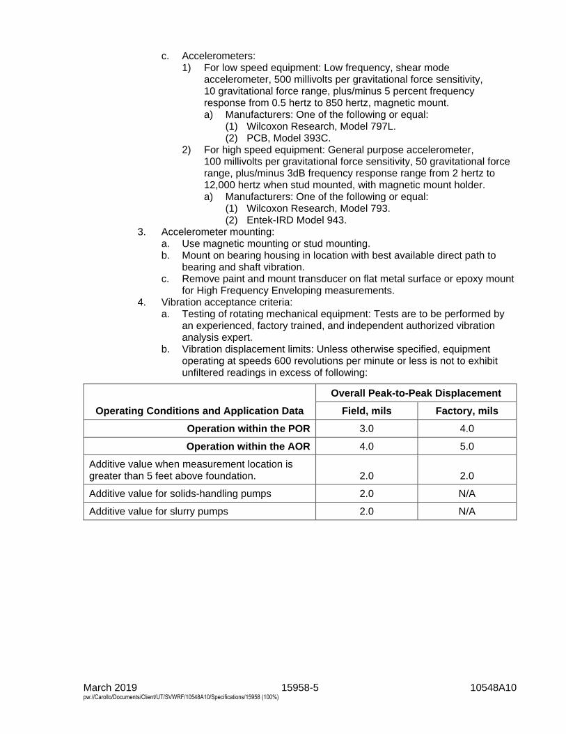
March 2019 15958-5 10548A10 pw://Carollo/Documents/Client/UT/SVWRF/10548A10/Specifications/15958 (100%)
c. Accelerometers: 1) For low speed equipment: Low frequency, shear mode
accelerometer, 500 millivolts per gravitational force sensitivity, 10 gravitational force range, plus/minus 5 percent frequency response from 0.5 hertz to 850 hertz, magnetic mount. a) Manufacturers: One of the following or equal:
(1) Wilcoxon Research, Model 797L. (2) PCB, Model 393C.
2) For high speed equipment: General purpose accelerometer, 100 millivolts per gravitational force sensitivity, 50 gravitational force range, plus/minus 3dB frequency response range from 2 hertz to 12,000 hertz when stud mounted, with magnetic mount holder. a) Manufacturers: One of the following or equal:
(1) Wilcoxon Research, Model 793. (2) Entek-IRD Model 943.
3. Accelerometer mounting: a. Use magnetic mounting or stud mounting. b. Mount on bearing housing in location with best available direct path to
bearing and shaft vibration. c. Remove paint and mount transducer on flat metal surface or epoxy mount
for High Frequency Enveloping measurements. 4. Vibration acceptance criteria:
a. Testing of rotating mechanical equipment: Tests are to be performed by an experienced, factory trained, and independent authorized vibration analysis expert.
b. Vibration displacement limits: Unless otherwise specified, equipment operating at speeds 600 revolutions per minute or less is not to exhibit unfiltered readings in excess of following:
Operating Conditions and Application Data
Overall Peak-to-Peak Displacement
Field, mils Factory, mils
Operation within the POR 3.0 4.0
Operation within the AOR 4.0 5.0
Additive value when measurement location is greater than 5 feet above foundation. 2.0 2.0
Additive value for solids-handling pumps 2.0 N/A
Additive value for slurry pumps 2.0 N/A
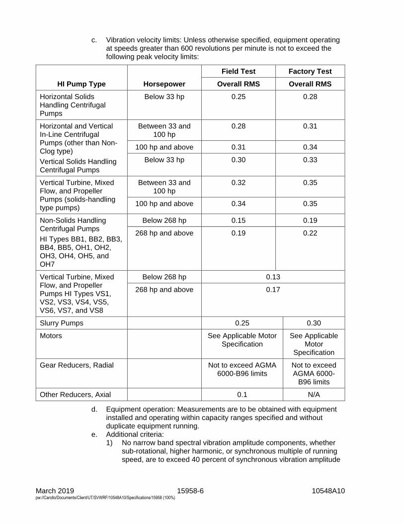
March 2019 15958-6 10548A10 pw://Carollo/Documents/Client/UT/SVWRF/10548A10/Specifications/15958 (100%)
c. Vibration velocity limits: Unless otherwise specified, equipment operating at speeds greater than 600 revolutions per minute is not to exceed the following peak velocity limits:
HI Pump Type Horsepower
Field Test Factory Test
Overall RMS Overall RMS
Horizontal Solids Handling Centrifugal Pumps
Below 33 hp 0.25 0.28
Horizontal and Vertical In-Line Centrifugal Pumps (other than Non-Clog type)
Vertical Solids Handling Centrifugal Pumps
Between 33 and 100 hp
0.28 0.31
100 hp and above 0.31 0.34
Below 33 hp 0.30 0.33
Vertical Turbine, Mixed Flow, and Propeller Pumps (solids-handling type pumps)
Between 33 and 100 hp
0.32 0.35
100 hp and above 0.34 0.35
Non-Solids Handling Centrifugal Pumps
HI Types BB1, BB2, BB3, BB4, BB5, OH1, OH2, OH3, OH4, OH5, and OH7
Below 268 hp 0.15 0.19
268 hp and above 0.19 0.22
Vertical Turbine, Mixed Flow, and Propeller Pumps HI Types VS1, VS2, VS3, VS4, VS5, VS6, VS7, and VS8
Below 268 hp 0.13
268 hp and above 0.17
Slurry Pumps 0.25 0.30
Motors See Applicable Motor Specification
See Applicable Motor
Specification
Gear Reducers, Radial Not to exceed AGMA 6000-B96 limits
Not to exceed AGMA 6000-
B96 limits
Other Reducers, Axial 0.1 N/A
d. Equipment operation: Measurements are to be obtained with equipment installed and operating within capacity ranges specified and without duplicate equipment running.
e. Additional criteria: 1) No narrow band spectral vibration amplitude components, whether
sub-rotational, higher harmonic, or synchronous multiple of running speed, are to exceed 40 percent of synchronous vibration amplitude
March 2019 15958-7 10548A10 pw://Carollo/Documents/Client/UT/SVWRF/10548A10/Specifications/15958 (100%)
component without manufacturer's detailed verification of origin and ultimate effect of such excitation.
2) The presence of discernable vibration amplitude peaks in Test Level 2 or 3 vibration spectra at bearing inner or outer race frequencies shall be cause for rejection of the equipment.
3) For motors, the following shall be cause for rejection: a) Stator eccentricity evidenced by a spectral peak at 2 times
electrical line frequency that is more than 40 percent of the peak at rotational frequency.
b) Rotor eccentricity evidenced by a spectral peak at 2 times electrical line frequency with spectra side bands at the pole pass frequency around the 2 times line frequency peak.
c) Other rotor problems evidenced by pole pass frequency side bands around operating speed harmonic peaks or 2 times line frequency side bands around rotor bar pass frequency or around 2 times the rotor bar pass frequency.
d) Phasing problems evidenced by 1/3 line frequency side band spectral peaks around the 2 times electrical line frequency peak.
4) The presence of peaks in a High Frequency Enveloping spectra plot corresponding to bearing, gear or motor rotor bar frequencies or harmonics of these frequencies shall be cause for rejection of the equipment; since inadequate lubrication of some equipment may be a cause of these peaks, lubrication shall be checked, corrected as necessary and the high frequency envelope analysis repeated.
5. Vibration testing results presentation: a. Provide equipment drawing with location and orientation of measurement
points indicated. b. For each vibration measurement take and include appropriate data on
equipment operating conditions at the time vibration data is taken; for pumps, compressors, and blowers record suction pressure, discharge pressure, and flow.
c. When Vibration Spectra Data required: 1) Plot peak vibration velocity versus frequency in cycles per minute. 2) Label plots showing actual shaft or part rotation frequency, bearing
inner and outer race ball pass frequencies, gear mesh frequencies and relevant equipment excitation frequencies on the plot; label probable cause of vibration peaks whether in excess of specification limits or not.
3) Label plots with equipment identification and operating conditions such as tag number, capacity, pressure, driver horsepower, and point of vibration measurement.
4) Plot motor spectra on a log amplitude scale versus frequency. d. For low speed equipment, plot peak vibration displacement versus
frequency as well as velocity versus frequency. e. Provide name of manufacturer and model number of the vibration
instrumentation used, including analyzer and accelerometer used together with mounting type.
March 2019 15958-8 10548A10 pw://Carollo/Documents/Client/UT/SVWRF/10548A10/Specifications/15958 (100%)
3.08 TESTING LEVELS
A. Level 1 Tests: 1. Level 1 General Equipment Performance Test:
a. For equipment, operate, rotate, or otherwise functionally test for 15 minutes minimum after components reach normal operating temperatures.
b. Operate at rated design load conditions. c. Confirm that equipment is properly assembled, equipment moves or
rotates in the proper direction, shafting, drive elements, and bearings are installed and lubricated in accordance with proper tolerances, and that no unusual power consumption, lubrication temperatures, bearing temperatures, or other conditions are observed.
2. Level 1 Pump Performance Test: a. Measure flow and head while operating at or near the rated condition; for
factory testing, testing may be at reduced speeds with flow and head corresponding to the rated condition when adjusted for speed using the appropriate affinity laws.
b. Use of a test driver is permitted for factory tests when actual driver is given a separate test at its point of manufacture as specified in Section 16222 - Low Voltage Motors up to 500 Horsepower or the applicable equipment section. Use actual driver for field tests.
c. Record measured flow, suction pressure, discharge pressure, and make observations on bearing temperatures and noise levels.
3. Level 1 Vibration Test: a. Test requirement:
1) Measure filtered vibration spectra versus frequency in 3 perpendicular planes at each normally accessible bearing housing on the driven equipment, any gears and on the driver; 1 plane of measurement to be parallel to the axis of rotation of the component.
2) Vibration spectra versus frequency shall be in accordance with Vibration Acceptance Criteria.
b. Equipment operating condition: Test at specified maximum speed. 4. Level 1 Noise Test:
a. Measure unfiltered overall A-weighted sound pressure level in dBA at 3 feet horizontally from the surface of the equipment and at a mid-point of the equipment height.
B. Level 2 Tests: 1. Level 2 General Performance Test:
a. For equipment, operate, rotate, or otherwise functionally test for at least 2 hours after components reach normal operating temperatures.
b. Operate at rated design load conditions. c. Confirm that equipment is properly assembled, equipment moves or
rotates in the proper direction, shafting, drive elements, and bearings are installed and lubricated in accordance with proper tolerances, and that no unusual power consumption, lubrication temperatures, bearing temperatures, or other conditions are observed.
2. Level 2 Pump Performance Test: a. Test 2 hours minimum for flow and head at the rated condition; for factory
testing, testing may be at a reduced speeds with flow and head

March 2019 15958-9 10548A10 pw://Carollo/Documents/Client/UT/SVWRF/10548A10/Specifications/15958 (100%)
corresponding to the rated condition when adjusted for speed using the appropriate affinity laws.
b. Use of a test driver is permitted for factory tests when actual driver is given a separate test at its point of manufacture as specified in Section 16222 - Low Voltage Motors up to 500 Horsepower. Use actual driver for field tests.
c. Test for flow and head at 2 additional conditions; 1 at 25 percent below the rated flow and 1 at 10 percent above the rated flow.
d. Record measured flow, suction pressure, discharge pressure, and observations on bearing temperatures and noise levels at each condition.
3. Level 2 Vibration Test: a. Test requirement:
1) Measure filtered vibration spectra versus frequency and measure vibration phase in 3 perpendicular planes at each normally accessible bearing housing on the driven equipment, any gears and on the driver; 1 plane of measurement to be parallel to the axis of rotation of the component; measure actual rotational speeds for each vibration spectra measured using photometric or other tachometer input connected directly to the vibration data collector.
2) Vibration spectra versus frequency shall be in accordance with Vibration Acceptance Criteria.
b. Equipment operating condition: Repeat test requirements at design specified maximum speed and at minimum speed for variable speed equipment.
c. Natural frequency test of field installed equipment: 1) Excite the installed equipment and support system in 3 perpendicular
planes, use same planes as operating vibration measurement planes, and determine the as-installed natural resonant frequency of the driven equipment, the driver, gears, and supports.
2) Perform test at each bearing housing, at each support pedestal, and for pumps on the suction and discharge piping.
3) Perform with equipment and attached piping full of intended service or process fluid.
4. Level 2 Noise Test: a. Measure filtered A-weighted overall sound pressure level in dBA for each
of 8 octave band mid-points beginning at 63 hertz measured at 3 feet horizontally from the surface of the equipment at mid-point height of the noise source.
C. Level 3 Tests: 1. Level 3 General Equipment Performance Tests:
a. For equipment, operate, rotate, or otherwise functionally test for at least 4 hours after components reach normal operating temperatures.
b. Operate at rated design load conditions for 1/2 the specified time; operate at each of any other specified conditions for a proportionate share of the remaining test time.
c. Confirm that equipment is properly assembled, equipment rotates in the proper direction, shafting and bearings are installed and lubricated in accordance with proper tolerances, and that no unusual noise, vibration, or temperatures are observed.
d. Take appropriate capacity, power or fuel consumption, torque, revolutions per minute, pressure, and temperature readings using appropriate test
March 2019 15958-10 10548A10 pw://Carollo/Documents/Client/UT/SVWRF/10548A10/Specifications/15958 (100%)
instrumentation to confirm equipment meets specified performance requirements at the design rated condition.
e. Bearing temperatures: During maximum speed or capacity performance testing, measure and record the exterior surface temperature of each bearing versus time.
2. Level 3 Pump Performance Test: a. Test 4 hours minimum for flow and head at or near the rated condition; for
factory testing, testing may be at a reduced speeds with flow and head corresponding to the rated condition when adjusted for speed using the appropriate affinity laws.
b. Use of a test driver is permitted for factory tests when actual driver is given a separate test at its point of manufacture as specified in Section 16222 - Low Voltage Motors up to 500 Horsepower. Use actual driver for field tests.
c. Test each specified flow and head condition at the rated speed and test at minimum as well as maximum specified speeds; operate at each test condition for a minimum of 15 minutes; for factory testing, test at other speeds may be omitted if test driver at reduced speeds is used for rated condition testing.
d. Record measured shaft revolutions per minute, flow, suction pressure, discharge pressure; record measured bearing temperatures (bearing housing exterior surface temperatures may be recorded when bearing temperature devices are not required by the equipment section) and record observations on noise levels.
3. Level 3 Vibration Test: a. Requirements: Same as Level 2 vibration test except data taken at each
operating condition tested and with additional requirements below. b. Perform High Frequency Enveloping Analysis for gears and bearings.
1) Measure bearing element vibration directly on each bearing cap in a location close as possible to the bearing load zone that provides a smooth surface and direct path to the bearing to detect bearing defects.
2) Report results in units of acceleration versus frequency in cycles per minute.
c. Perform Time Wave Form analysis for gears, low speed equipment and reciprocating equipment; plot true peak amplitude velocity and displacement versus time and label the period between peaks with the likely cause of the periodic peaks (relate the period to a cause).
d. Plot vibration spectra on 3 different plots; peak displacement versus frequency, peak acceleration versus frequency and peak velocity versus frequency.
4. Level 3 Noise Test: Measure filtered, un-weighted overall sound pressure level in dB at 3 feet horizontally from the surface of the equipment at mid-point height and at 4 locations approximately 90 degrees apart in plan view; report results for each of 8 octave band mid-points beginning at 63 hertz.
D. Level 4 Tests: 1. Level 4 General Equipment Performance Test:
a. For equipment, operate, rotate, or otherwise functionally test for at least 8 hours after components reach normal operating temperatures.

March 2019 15958-11 10548A10 pw://Carollo/Documents/Client/UT/SVWRF/10548A10/Specifications/15958 (100%)
b. Operate at rated design load conditions for 1/2 the specified time; operate at each of any other specified conditions for a proportionate share of the remaining test time.
c. Confirm that equipment is properly assembled, equipment rotates in the proper direction, shafting and bearings are installed and lubricated in accordance with proper tolerances, and that no unusual noise, vibration, or temperatures are observed.
d. Take appropriate capacity, power or fuel consumption, torque, revolutions per minute, pressure and temperature readings, using appropriate test instrumentation to confirm equipment meets specified performance requirements at the design rated condition.
e. Bearing temperatures: During maximum speed or capacity testing, measure and record the exterior surface temperature of each bearing versus time.
2. Level 4 Pump Performance Test: a. Test 8 hours minimum for flow and head; begin tests at or near the rated
condition; for factory and field-testing, test with furnished motor at full speed.
b. Test each specified flow and head condition at the rated speed and test at minimum as well as maximum specified speeds; operate at each test condition for a minimum of 20 minutes or longer as necessary to measure required performance, vibration, and noise data at each test condition.
c. Record measured shaft revolutions per minute, flow, suction pressure, discharge pressure; record measured bearing temperatures (bearing housing exterior surface temperatures may be recorded when bearing temperature devices not required by the equipment section) and record observations on noise levels.
d. Bearing temperatures: During maximum speed or capacity testing, measure and record the exterior surface temperature of each bearing versus time.
e. Perform efficiency and/or Net Positive Suction Head Required (NPSHr) and/or priming time tests when specified in the equipment section in accordance with the appropriate HI standard and as follows: 1) Perform NPSHr testing at maximum rated design speed, head and
flow with test fluids at ambient conditions; at maximum rated speed, test at 15 percent above rated design flow, and 25 percent below rated design flow.
2) Perform efficiency testing with test fluids at maximum rated speed. 3) Perform priming time testing with test fluids at maximum rated speed.
3. Level 4 Vibration Test: Same as Level 3 vibration test. 4. Level 4 Noise Test: Same as Level 3 Noise Test except with data taken at
each operating condition tested.
END OF SECTION