User requirements and preparedness for User requirements and ...
Upload
khangminh22Category
view
0download
0
INTERNATIONAL
CHAPTER THREE: FACILITY REQUIREMENTS

3-1
INTERNATIONAL
Chapter ThreeChapter Three Facility RequirementsFacility Requirements
Airport Master PlanAirport Master Plan
Chapter Three
FACILITY REQUIREMENTS
To properly plan for the future of Laughlin/Bullhead
International Airport, it is necessary to translate
forecast aviation demand into the specifi c types
and quantities of facilities that can adequately serve
this identifi ed demand. This chapter uses the results
of the forecasts conducted in Chapter Two, as well
as established planning criteria, to determine the
airfi eld (i.e., runways, taxiways, navigational aids,
marking and lighting) and landside (i.e., hangars,
terminal building, cargo buildings, aircraft parking
apron) facility requirements.
The objective of this eff ort is to identify, in general
terms, the adequacy of the existing airport facilities
and outline what new facilities may be needed
and when these may be needed to accommodate
forecast demands. Having established these
facility requirements, alternatives for providing
these facilities will be evaluated in Chapter Four
to determine the most cost-eff ective and effi cient
means for implementation.
The cost-eff ective, effi cient, and orderly develop-
ment of an airport should rely more upon actual
demand at an airport than on a time-based
forecast fi gure. In order to develop a master plan
that is demand-based rather than time-based, a
series of planning horizon milestones have been
established for Laughlin/Bullhead International
Airport that take into consideration the reasonable
range of aviation demand projections prepared
in Chapter Two. It is important to consider that
actual activity at the airport may be higher or
lower than projected activity levels. By planning
according to activity milestones, the resultant plan
can accommodate unexpected shifts or changes
in the area’s aviation demand.
The most important reason for utilizing milestones
is that they allow the airport to develop facilities
according to need generated by actual demand
levels. The demand-based schedule provides
fl exibility in development, as development
schedules can be slowed or expedited according to
actual demand at any given time over the planning
period. The resultant plan provides airport offi cials
with a fi nancially responsible and needs-based
program. Table 3A presents the planning horizon
milestones for each activity demand category.
AIRFIELD CAPACITY
An airport’s airfi eld capacity is expressed in
terms of its annual service volume (ASV).
Annual service volume is a reasonable estimate
of the maximum level of aircraft operations
that can be accommodated in a year without
incurring signifi cant delay factors. As aircraft
operations surpass the ASV, delay factors increase
exponentially. Annual service volume accounts
for annual diff erences in runway use, aircraft mix,
and weather conditions. The airport’s annual
service volume was examined utilizing Federal
Aviation Administration (FAA) Advisory Circular
(AC) 150/5060-5, Airport Capacity and Delay.
A number of factors are included in the calculation
of an airport’s ASV. These include the airfi eld
characteristics, meteorological conditions, aircraft
mix, and demand characteristics (aircraft operations).
The following describes the input factors as they
relate to Laughlin/Bullhead International Airport.

3-2
INTERNATIONAL
Chapter ThreeChapter Three
AIRFIELD LAYOUT
RUNWAY CONFIGURATION
A single runway confi guration with a full-length
parallel taxiway is available at the airport. Instrument
approach procedures are available to Runway 34.
RUNWAY USE
Runway use is normally dictated by wind
conditions. The direction of takeoffs and landings
are generally determined by the speed and
direction of wind. It is generally safest for aircraft
to takeoff and land into the wind, avoiding a
crosswind (wind that is blowing perpendicular to
the travel of the aircraft) or tailwind components
during these operations. Winds dictate using
Runway 16 the majority of the time.
EXIT TAXIWAYS
Exit taxiways have a signifi cant impact on airfi eld
capacity since the number and location of exits
directly determines the occupancy time of an
Table 3A
PLANNING HORIZON ACTIVITY LEVELS
BASE YEAR PLANNING HORIZONS
2007
Short
Term
Intermediate
Term
Long
Term
Airline Activity
Enplaned Passengers 113,796 145,000 200,000 375,000
Annual Operations 1,944 5,200 7,200 12,600Cargo Activity
Enplaned Cargo (pounds) 1,278,400 1,530,000 1,840,000 2,640,000
Annual Operations 1,052 1,200 1,400 2,000General Aviation Activity
Based Aircraft 49 80 110 170
Air Taxi Operations 2,139 2,500 2,700 3,100Annual Operations
Local 5,638 8,200 12,000 24,600
Itinerant 16,597 22,300 30,500 53,300
Total General Aviation Operations 22,235 30,500 42,500 77,900Military Activity
Local 109 100 100 100
Itinerant 216 200 200 200
Total Military Operations 325 300 300 300Total Airport Operations 27,695 39,700 54,100 95,900
Annual Instrument Approaches NA 188 252 427
3-3
Facility RequirementsFacility Requirements
Airport Master PlanAirport Master Plan
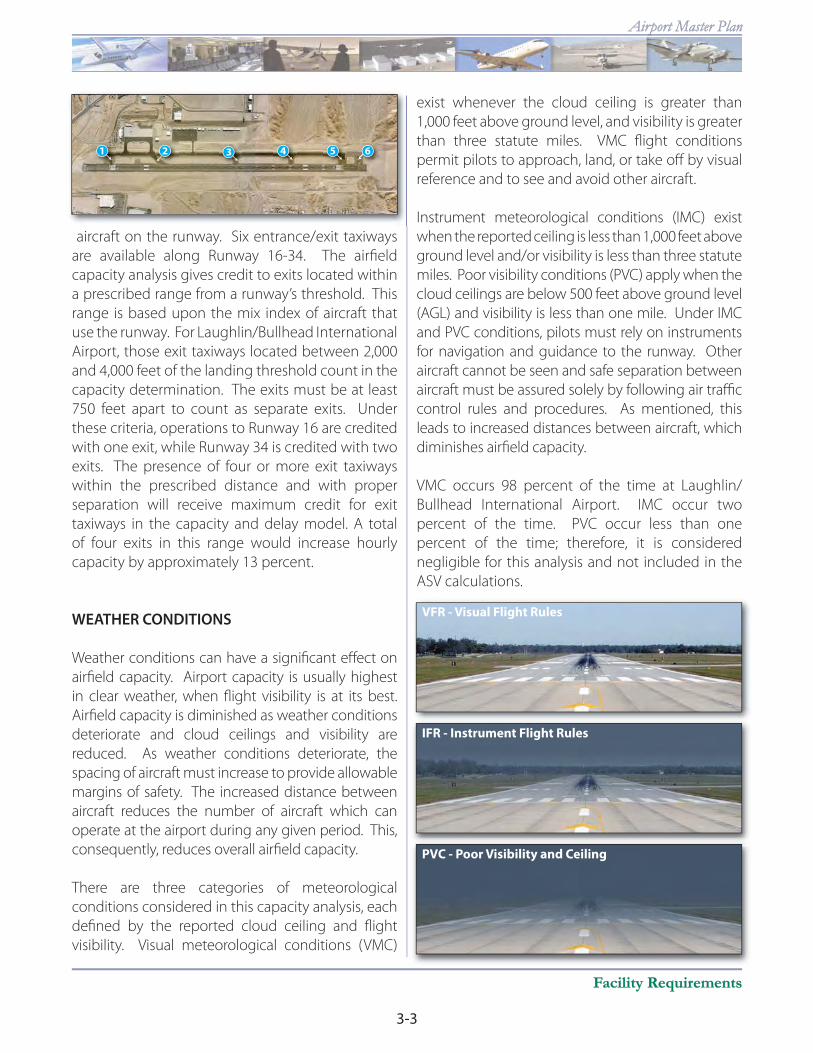
aircraft on the runway. Six entrance/exit taxiways
are available along Runway 16-34. The airfi eld
capacity analysis gives credit to exits located within
a prescribed range from a runway’s threshold. This
range is based upon the mix index of aircraft that
use the runway. For Laughlin/Bullhead International
Airport, those exit taxiways located between 2,000
and 4,000 feet of the landing threshold count in the
capacity determination. The exits must be at least
750 feet apart to count as separate exits. Under
these criteria, operations to Runway 16 are credited
with one exit, while Runway 34 is credited with two
exits. The presence of four or more exit taxiways
within the prescribed distance and with proper
separation will receive maximum credit for exit
taxiways in the capacity and delay model. A total
of four exits in this range would increase hourly
capacity by approximately 13 percent.
WEATHER CONDITIONS
Weather conditions can have a signifi cant eff ect on
airfi eld capacity. Airport capacity is usually highest
in clear weather, when fl ight visibility is at its best.
Airfi eld capacity is diminished as weather conditions
deteriorate and cloud ceilings and visibility are
reduced. As weather conditions deteriorate, the
spacing of aircraft must increase to provide allowable
margins of safety. The increased distance between
aircraft reduces the number of aircraft which can
operate at the airport during any given period. This,
consequently, reduces overall airfi eld capacity.
There are three categories of meteorological
conditions considered in this capacity analysis, each
defi ned by the reported cloud ceiling and fl ight
visibility. Visual meteorological conditions (VMC)
exist whenever the cloud ceiling is greater than
1,000 feet above ground level, and visibility is greater
than three statute miles. VMC fl ight conditions
permit pilots to approach, land, or take off by visual
reference and to see and avoid other aircraft.
Instrument meteorological conditions (IMC) exist
when the reported ceiling is less than 1,000 feet above
ground level and/or visibility is less than three statute
miles. Poor visibility conditions (PVC) apply when the
cloud ceilings are below 500 feet above ground level
(AGL) and visibility is less than one mile. Under IMC
and PVC conditions, pilots must rely on instruments
for navigation and guidance to the runway. Other
aircraft cannot be seen and safe separation between
aircraft must be assured solely by following air traffi c
control rules and procedures. As mentioned, this
leads to increased distances between aircraft, which
diminishes airfi eld capacity.
VMC occurs 98 percent of the time at Laughlin/
Bullhead International Airport. IMC occur two
percent of the time. PVC occur less than one
percent of the time; therefore, it is considered
negligible for this analysis and not included in the
ASV calculations.
1 3 4 52 6
VFR - Visual Flight Rules
IFR - Instrument Flight Rules
PVC - Poor Visibility and Ceiling

3-4
INTERNATIONAL
Chapter ThreeChapter Three
AIRCRAFT MIX
Aircraft mix refers to the speed, size, and fl ight
characteristics of aircraft operating at the airport. As
the mix of aircraft operating at an airport increases
to include larger aircraft, airfi eld capacity begins to
diminish. This is due to larger separation distances
that must be maintained between aircraft of
diff erent speeds and sizes.
Aircraft mix for the capacity analysis is defi ned in
terms of four aircraft classes. Classes A and B consist
of single and multi-engine aircraft weighing less than
12,500 pounds. Aircraft within these classifi cations
are primarily associated with piston-powered general
aviation operations, but does include some business
turboprop and business jet aircraft (e.g., the Cessna
500 Citation business jet and Beechcraft King Air).
Class C consists of multi-engine aircraft weighing
between 12,500 and 300,000 pounds. This broad
classifi cation includes business jets, turboprops, and
large commercial airline aircraft. Most of the business
jets in the national fl eet are included within this
category. Class D includes all aircraft over 300,000
pounds and includes wide-bodies and jumbo jets.
There are no Class D aircraft currently operating or
forecast to operate from the airport.
For the capacity analysis, the percentage of Class
C aircraft operating at the airport is critical in
determining the annual service volume as this
class includes the larger and faster aircraft in
the operational mix. The existing and projected
operational fl eet mix for the airport is summarized
in Table 3B. Consistent with projections prepared
in the previous chapter, the percentage of Class C
aircraft in the operational fl eet mix at the airport
is expected to slightly decrease through the
planning period as its small general aviation aircraft
operations are expected to grow slightly faster than
commercial aviation.
Category A & B
Single Piston Twin PistonSmall Turboprop
Category C
Business Jet Commuter Regional Jet Commercial Jet
Category D
Wide Body Jet
Table 3B
AIRCRAFT OPERATIONAL MIX - CAPACITY ANALYSIS
Aircraft Classifi cation Current
Short
Term (± 5)
Intermediate
Term (± 10)
Long
Term (± 20)
VFR
Classes A & B
Class C
Class D
80%
20%
0%
77%
23%
0%
79%
21%
0%
81%
19%
0%
Percent Local Operations
(Touch-and-Go’s) 20% 21% 22% 26%
Defi nitions:
Class A: Small single-engine aircraft with gross weights of 12,500 pounds or less.
Class B: Small twin-engine aircraft with gross weights of 12,500 pounds or less.
Class C: Large aircraft with gross weights over 12,500 pounds up to 300,000 pounds.
Class D: Large aircraft with gross weights over 300,000 pounds.

3-5
Facility RequirementsFacility Requirements
Airport Master PlanAirport Master Plan
OPERATIONAL CHARACTERISTICS
Operations, not only the total number of annual
operations, but the manner in which they are
conducted, have an important eff ect on airfi eld
capacity. Peak operational periods, touch-and-go
operations, and the percent of arrivals impact the
number of annual operations that can be conducted
at the airport.
PEAK PERIOD OPERATIONS
For the airfi eld capacity analysis, average daily
operations and average peak hour operations during
the peak month are calculated. These operational
levels were calculated previously in Chapter Two for
existing and forecast levels of operations. Typical
operational activity is important in the calculation
of an airport’s annual service level as “peak demand”
levels occur sporadically. The peak periods used in
the capacity analysis are representative of normal
operational activity and can be exceeded at various
times through the year.
TOUCH-AND-GO OPERATIONS
A touch-and-go operation involves an aircraft
making a landing and an immediate take-off
without coming to a full stop or exiting the
runway. These operations are normally associated
with general aviation training operations and are
included in local operations data recorded by the
air traffi c control tower.
Touch-and-go activity is counted as two operations
since there is an arrival and a departure involved.
A high percentage of touch-and-go traffi c normally
results in a higher operational capacity because
one landing and one takeoff occurs within a shorter
time period than individual operations. Touch-and-
go operations currently account for approximately
20 percent of total operations.
PERCENT ARRIVALS
The percentage of arrivals as they relate to the
total operations in the design hour is important
in determining airfi eld capacity. Under most
circumstances, the lower the percentage of arrivals,
the higher the hourly capacity. However, except in
unique circumstances, the aircraft arrival-departure
split is typically 50-50. At the airport, traffi c
information indicated no major deviation from this
pattern, and arrivals were estimated to account for
50 percent of design period operations.
HOURLY RUNWAY CAPACITY
Based upon the input factors described above,
current and future hourly capacities for the various
operational scenarios at Laughlin/Bullhead
International Airport were determined. As the mix
of aircraft operating at an airport changes and peak
periods become more spread out through the
planning period, the hourly capacity of the system
increases slightly. The current and future hourly
capacities are depicted in Table 3C. At Laughlin/
Bullhead International Airport, the current hourly
capacity is 80 operations. This is expected to increase
to 84 operations by the long term planning horizon.
Arrivals and Departures Total Annual Operations
Touch-and-Go Operations
J F M A M J J A S O N D
7
6
5
4
3
2
1
3-6
INTERNATIONAL
Chapter ThreeChapter Three
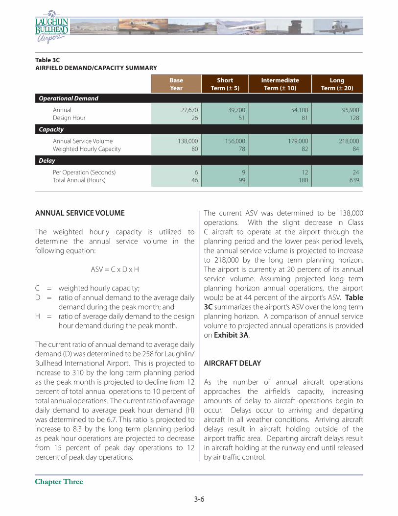
ANNUAL SERVICE VOLUME
The weighted hourly capacity is utilized to
determine the annual service volume in the
following equation:
ASV = C x D x H
C = weighted hourly capacity;
D = ratio of annual demand to the average daily
demand during the peak month; and
H = ratio of average daily demand to the design
hour demand during the peak month.
The current ratio of annual demand to average daily
demand (D) was determined to be 258 for Laughlin/
Bullhead International Airport. This is projected to
increase to 310 by the long term planning period
as the peak month is projected to decline from 12
percent of total annual operations to 10 percent of
total annual operations. The current ratio of average
daily demand to average peak hour demand (H)
was determined to be 6.7. This ratio is projected to
increase to 8.3 by the long term planning period
as peak hour operations are projected to decrease
from 15 percent of peak day operations to 12
percent of peak day operations.
The current ASV was determined to be 138,000
operations. With the slight decrease in Class
C aircraft to operate at the airport through the
planning period and the lower peak period levels,
the annual service volume is projected to increase
to 218,000 by the long term planning horizon.
The airport is currently at 20 percent of its annual
service volume. Assuming projected long term
planning horizon annual operations, the airport
would be at 44 percent of the airport’s ASV. Table
3C summarizes the airport’s ASV over the long term
planning horizon. A comparison of annual service
volume to projected annual operations is provided
on Exhibit 3A.
AIRCRAFT DELAY
As the number of annual aircraft operations
approaches the airfi eld’s capacity, increasing
amounts of delay to aircraft operations begin to
occur. Delays occur to arriving and departing
aircraft in all weather conditions. Arriving aircraft
delays result in aircraft holding outside of the
airport traffi c area. Departing aircraft delays result
in aircraft holding at the runway end until released
by air traffi c control.
Table 3C
AIRFIELD DEMAND/CAPACITY SUMMARY
Base
Year
Short
Term (± 5)
Intermediate
Term (± 10)
Long
Term (± 20)
Operational Demand
Annual
Design Hour
27,670
26
39,700
51
54,100
81
95,900
128
Capacity
Annual Service Volume
Weighted Hourly Capacity
138,000
80
156,000
78
179,000
82
218,000
84
Delay
Per Operation (Seconds)
Total Annual (Hours)
6
46
9
99
12
180
24
639

3-7
Facility RequirementsFacility Requirements
Airport Master PlanAirport Master Plan
Table 3C also summarizes the aircraft delay
analysis conducted for Laughlin/Bullhead
International Airport. Current annual delay is
negligible and estimated at approximately 46
hours total. Analysis of delay factors for the long
range planning horizon indicate that annual delay
can be expected to reach over 639 hours. This is
only 24 seconds per aircraft operation.
CAPACITY ANALYSIS CONCLUSIONS
FAA Order 5090.3C, Field Formulation of the National
Plan of Integrated Airport Systems (NPIAS), indicates
that improvements for airfi eld capacity purposes
should begin to be considered once operations
reach 60 to 75 percent of the annual service
volume. From the analysis above, Laughlin/
Bullhead International Airport is not expected to
exceed 60 percent of annual service volume within
the planning period of this master plan.
Typically, a parallel runway is considered when
additional capacity is needed at an airport. The
current plan for Laughlin/Bullhead International
Airport includes a parallel runway south of Runway
16-34 for use by small general aviation aircraft. A
parallel runway for small general aviation aircraft
maximizes airfi eld capacity as large and small
aircraft are segregated and simultaneous operations
can occur at the airport. While the analysis above
indicated that a parallel runway may not be needed
during the planning period of this master plan,
a parallel runway will continue to be planned
at Laughlin/Bullhead International Airport. This
reserves the property south of the airport for this
ultimate use and also allows the City of Bullhead
City to continue to properly plan appropriate land
uses adjacent to the airport that are compatible
with this ultimate use.
CRITICAL DESIGN AIRCRAFT
The selection of appropriate Federal Aviation
Administration (FAA) design standards for the
development and location of airport facilities is
based primarily upon the characteristics of the
aircraft which are currently using, or are expected
to use, the airport. The critical design aircraft
is used to defi ne the design parameters for the
airport. The critical design aircraft is defi ned
as the most demanding category of aircraft, or
family of aircraft, which conducts at least 500
operations per year at the airport. Planning for
future aircraft use is of particular importance since
design standards are used to plan many airside
and landside components. These future standards
must be considered now to ensure that short term
development does not preclude the long range
potential needs of the airport.
The FAA has established a coding system to relate
airport design criteria to the operational and
physical characteristics of aircraft expected to use
the airport. This airport reference code (ARC) has
two components. The fi rst component, depicted
50,000
100,000
150,000
OPERATIO
NS
200,000
250,000
LongTerm
IntermediateTerm
ShortTerm
Existing
Exhibit 3A
AIRFIELD DEMAND/CAPACITY
DEMAND
ANNUAL SERVICE VOLUME
DEMAND
ANNUAL SERVICE VOLUME
95,90095,900
218,000
179,000
156,000
139,000
218,000
179,000
156,000
139,000
54,100
39,700
27,670
54,100
39,700
27,670

3-8
INTERNATIONAL
Chapter ThreeChapter Three
by a letter, is the aircraft approach category and
relates to aircraft approach speed (operational
characteristic). The second component, depicted by
a Roman numeral, is the airplane design group and
relates to aircraft wingspan (physical characteristic).
Generally, aircraft approach speed applies to
runways and runway-related facilities, while aircraft
wingspan primarily relates to separation criteria
involving taxiways, taxilanes, and landside facilities.
According to FAA Advisory Circular (AC) 150/5300-
13, Change 12, Airport Design, an aircraft’s approach
category is based upon 1.3 times its stall speed in
landing confi guration at the certifi ed maximum fl ap
setting and maximum landing weight at standard
atmospheric conditions. The fi ve approach
categories used in airport planning are as follows:
Category A: Speed less than 91 knots.
Category B: Speed 91 knots or more, but less than
121 knots.
Category C: Speed 121 knots or more, but less than
141 knots.
Category D: Speed 141 knots or more, but less than
166 knots.
Category E: Speed greater than 166 knots.
The airplane design group (ADG) is based upon
either the aircraft’s wingspan or tail height,
whichever is greater. For example, an aircraft may
fall in ADG II for wingspan at 70 feet, but ADG III for
tail height at 33 feet. This aircraft would be classifi ed
under ADG III. The six ADGs used in airport planning
are as follows:
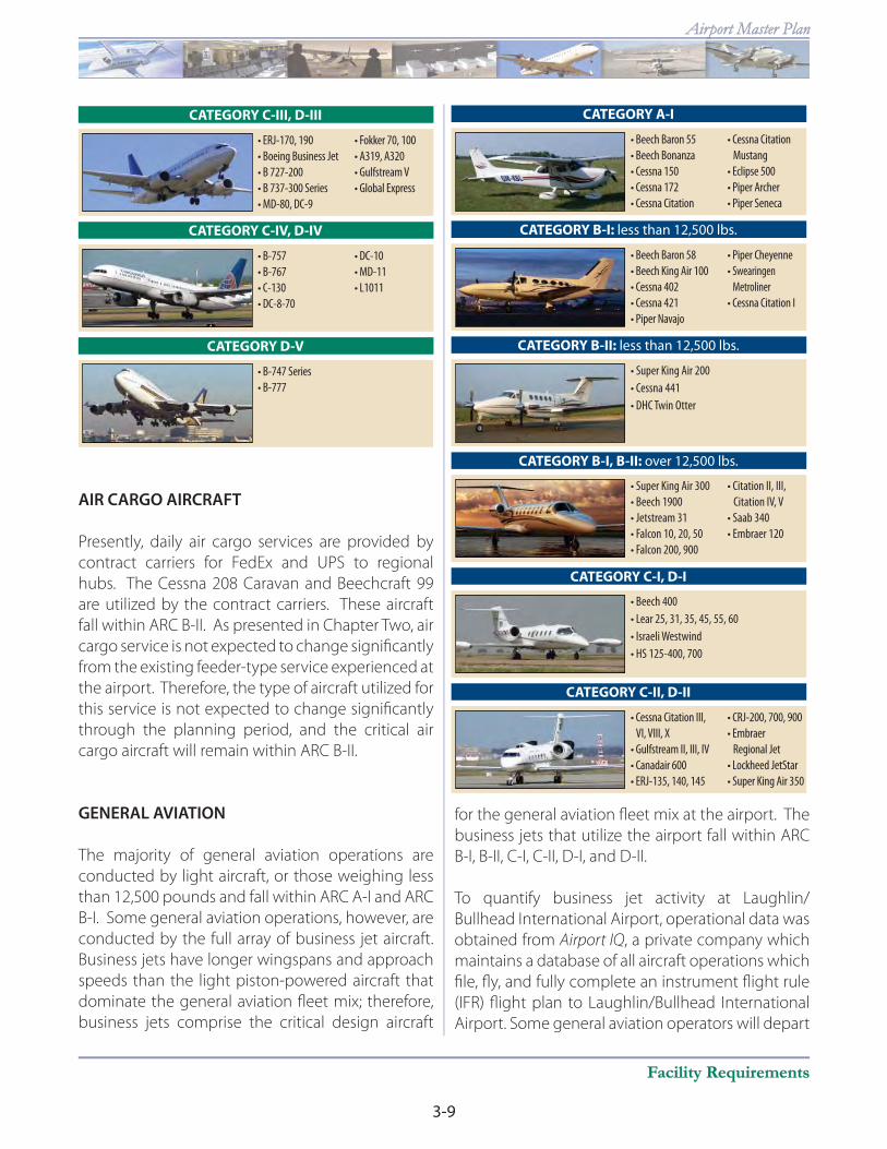
Representative aircraft by ARC are shown on the
following pages. [Chris Riffl e distribute ARC pictures
in this area.] The airport currently serves an array of
aircraft in ARCs up to and including C-III. The aircraft
operating at the airport range by operational type
from small single engine piston-powered aircraft,
such as the Cessna 152, to commercial airline
transport aircraft, such as the Boeing 737-800.
The FAA recommends designing airport functional
elements to meet the requirements for the most
demanding civilian ARC for that airport. In order
to determine airfi eld design requirements, the
critical aircraft and critical ARC should fi rst be
determined, and then appropriate airport design
criteria can be applied. This process begins with
a review of aircraft currently using the airport and
those expected to use the airport through the
long term planning period.
PASSENGER AIRLINE
AND CHARTER AIRCRAFT
As outlined in the previous chapter, Laughlin/
Bullhead International Airport is served by three air
carrier airlines providing charter services supporting
the gaming/resort activities in Laughlin, Nevada.
Sun Country utilizes the Boeing 737-800 aircraft.
Allegiant Airlines utilizes the Boeing (McDonnell-
Douglas) MD-83 and MD-88 aircraft. Canadian
Northern utilizes the Boeing 737-200. Each of these
aircraft falls within ARC C-III. Future facility planning
should consider a potential transition to larger air
carrier aircraft for charter services. Potential larger
charter aircraft would include the Boeing 757 which
falls within ARC C-IV.
In the future, regularly scheduled airline service is
expected to be provided with regional jet aircraft
such as the Embraer regional jet (ERJ) 135 and 145
or Canadair CRJ-200 regional jet. These regional jets
fall within ARC C-II. Larger regional jets in the 70-
and 90-seat ranges fall within the ARC C-III.
ADG Tail Height (feet) Wingspan (feet)
I <20 <49
II 20-<30 49-<79
III 30-<45 79-<118
IV 45-<60 118-<171
V 60-<66 171-<214
VI 66-<80 214-<262
Source: FAA AC 150/5300-13, Change 12
3-9
Facility RequirementsFacility Requirements
Airport Master PlanAirport Master Plan
AIR CARGO AIRCRAFT
Presently, daily air cargo services are provided by
contract carriers for FedEx and UPS to regional
hubs. The Cessna 208 Caravan and Beechcraft 99
are utilized by the contract carriers. These aircraft
fall within ARC B-II. As presented in Chapter Two, air
cargo service is not expected to change signifi cantly
from the existing feeder-type service experienced at
the airport. Therefore, the type of aircraft utilized for
this service is not expected to change signifi cantly
through the planning period, and the critical air
cargo aircraft will remain within ARC B-II.
GENERAL AVIATION
The majority of general aviation operations are
conducted by light aircraft, or those weighing less
than 12,500 pounds and fall within ARC A-I and ARC
B-I. Some general aviation operations, however, are
conducted by the full array of business jet aircraft.
Business jets have longer wingspans and approach
speeds than the light piston-powered aircraft that
dominate the general aviation fl eet mix; therefore,
business jets comprise the critical design aircraft
for the general aviation fl eet mix at the airport. The
business jets that utilize the airport fall within ARC
B-I, B-II, C-I, C-II, D-I, and D-II.
To quantify business jet activity at Laughlin/
Bullhead International Airport, operational data was
obtained from Airport IQ, a private company which
maintains a database of all aircraft operations which
fi le, fl y, and fully complete an instrument fl ight rule
(IFR) fl ight plan to Laughlin/Bullhead International
Airport. Some general aviation operators will depart
CATEGORY C-III, D-III
CATEGORY C-IV, D-IV
CATEGORY D-V
CATEGORY A-I
CATEGORY B-I: less than 12,500 lbs.
CATEGORY B-II: less than 12,500 lbs.
CATEGORY B-I, B-II: over 12,500 lbs.
CATEGORY C-I, D-I
CATEGORY C-II, D-II

3-10
INTERNATIONAL
Chapter ThreeChapter Three
under visual fl ight rules (VFR) and open an IFR fl ight
plan enroute, or close their IFR fl ight plan prior to
arriving at Laughlin/Bullhead International Airport.
In either case, those operations are not attributed
to Laughlin/Bullhead International Airport and are
not included in the table. Experience with this data
in comparison to actual observed fl ights at other
airports indicates that the AirportIQ data could be
lower than actual by as much as 50 percent due
to the exclusions as explained above. This data
does provide valuable information such as aircraft
type, origination, destination, and aircraft owner.
Thus, the data collected through AirportIQ serves
to highlight the absolute minimum number of
operations as many pilots will open or close a fl ight
plan in the air when visual conditions allow. This is
not typically true of air carrier operators and most
air taxi operators which are required to fl y the full
fl ight plan.
A review of AirportIQ data for calendar year 2007
reveals a minimum of 459 private business jet
operations at Laughlin/Bullhead International
Airport. The largest groupings, or family of jets,
were the business jets in ARC B-I and B-II, with
330 operations which represented 72 percent
of all private jet operations reported. The next
largest group was ARC C-I and C-II, with 101
operations representing 22 percent of total private
jet operations. In total, aircraft in ARC D-I and D-II
conducted 28 operations at the airport in 2007.
CRITICAL AIRCRAFT SUMMARY
It is evident from the discussion above that the
aircraft used in passenger airline service comprise
the current critical design aircraft at Laughlin/
Bullhead International Airport. As discussed above,
the aircraft used in passenger airline service fall
within ARC C-III. In the future, larger aircraft could be
used in passenger airline service and include aircraft
in ADG IV. Therefore, long term facility planning
should account for these larger wingspans. Thus,
the future critical airplane design group is ADG IV.
The previous master plan had indicated that
business jets within Approach Category D may
conduct more than 500 operations at the airport in
the future and become the critical design aircraft
for defi ning the approach category portion of
the ARC. Presently, aircraft in Approach Category
D conduct less than 30 annual operations at the
airport. While this is signifi cantly below the 500
operations annual threshold, facility planning
should still consider Approach Category D
operations increasing in the future.
Combining the commercial airline ADG IV with the
general aviation Approach Category D indicates
that the most appropriate ARC for long term
planning remains ARC D-IV. As the primary runway,
which accommodates all aircraft operations,
Runway 16-34 should be planned to this ARC. A
future parallel runway should be planned to ARC
B-II as this runway would be designed only for
small aircraft operations.
The design of taxiway and apron areas should
consider the wingspan requirements of the most
demanding aircraft to operate within that specifi c
functional area on the airport. The passenger
terminal apron should consider ADG IV. General
aviation transient apron and aircraft maintenance
and repair hangar areas should consider ADG III
requirements to accommodate the largest transient
business jets. T-hangar and small conventional
hangar areas should consider ADG I requirements
as these commonly serve smaller single and multi-
engine piston aircraft.
AIRFIELD DESIGN STANDARDS
The FAA has established several imaginary surfaces
to protect aircraft operational areas and keep them
free from obstructions or incompatible land uses
that could aff ect an aircraft’s safe operation. These
include the runway safety area (RSA), object free
area (OFA), obstacle free zone (OFZ), and runway
protection zone (RPZ).
3-11
Facility RequirementsFacility Requirements
Airport Master PlanAirport Master Plan
The entire RSA, OFA, and OFZ should be under
the direct control of the airport sponsor to ensure
these areas remain free of obstacles and can be
readily accessed by maintenance and emergency
personnel. It is not required that the RPZ be under
airport ownership, but it is strongly recommended.
An alternative to outright ownership of the RPZ is
the purchase of avigation easements (acquiring
control of designated airspace within the RPZ)
or having suffi cient land use control measures in
place which ensure that the RPZ remains free of
incompatible development.
Dimensional standards for the various safety areas
associated with the runways are a function of the
ARC as well as the approach visibility minimums. At
Laughlin/Bullhead International Airport, presently
Runway 16-34 should meet design standards for ARC
C-III and one mile visibility minimums. Ultimately,
Runway 16-34 should meet design standards for
ARC D-IV and one-half mile visibility minimums. A
future parallel runway should be designed to ARC B-II
design standards with one mile visibility minimums.
RUNWAY SAFETY AREA
The runway safety area (RSA) is “a defi ned surface
surrounding the runway prepared or suitable for
reducing the risk of damage to airplanes in the event
of an undershoot, overshoot, or an excursion from the
runway.” The RSA must be free from any obstructions
and be graded and stabilized to accommodate the
weight of the airport’s critical aircraft.
The dimension of the RSA is dependent upon
the critical aircraft at the airport. For ARC D-IV,
the RSA is 500 feet wide, centered on the runway
centerline, and extends 1,000 feet beyond both
ends of the runway. The FAA has placed a premium
on maintaining and protecting adequate RSA at
airports, especially at Title 14 of the Code of Federal
Regulations (CFR) Part 139 certifi cated airports such
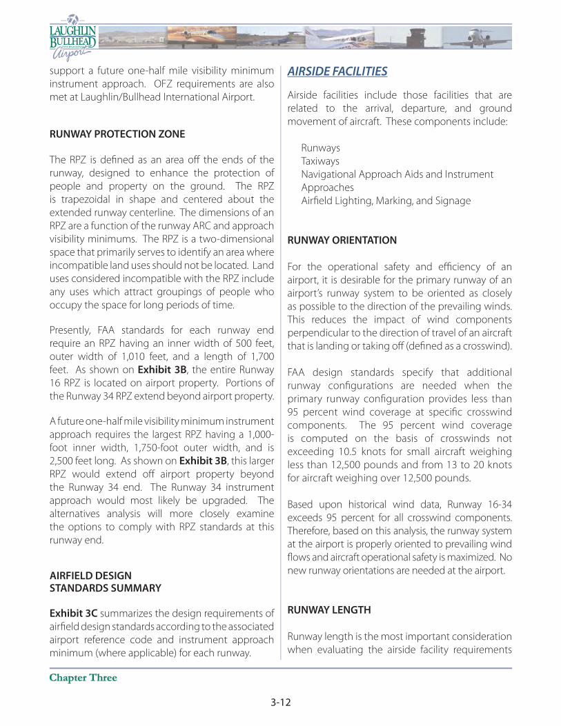
as Laughlin/Bullhead International Airport. Exhibit
3B illustrates the required RSA for Laughlin/Bullhead
International Airport. As depicted, the airport
maintains adequate RSA and should continue
maintaining the RSA in the future.
OBJECT FREE AREA
The object free area (OFA) is an area centered on
the runway and taxiway centerlines, provided to
enhance the safety of aircraft operations. Only
those objects that need to be located in the OFA
for air navigation or aircraft ground maneuvering
purposes are allowed.
Of particular interest is the runway OFA, which is
designed to ensure that the wings of an aircraft
traversing the RSA will not impact obstructions
outside the RSA. Its dimensions are also based on
the airport’s critical aircraft. For ARC D-IV, the runway
OFA is 800 feet wide (centered on the runway
centerline) and extends 1,000 feet beyond the ends
of the runway. As shown on Exhibit 3B, a portion
of the perimeter service road extends through the
northeast corner of the OFA. The remainder of the
OFA meets FAA standards. The alternatives analysis
will examine options available to comply with
standards in the northeast portion of the OFA.
OBSTACLE FREE ZONE
An obstacle free zone (OFZ) is a volume of airspace
that is required to be clear of objects, except for
frangible items required for navigation of aircraft.
The OFZ for Runway 16-34 is 400 feet wide, centered
along the runway, and extends 200 feet beyond the
runway ends. It is bolstered by the precision OFZ,
or POFZ, which requires no obstructions in an area
800 feet wide (centered on the runway) beginning
at the ends of each runway, having a vertically
guided approach, then extending out 200 feet. The
POFZ standard would only apply to future runway
ends with an instrument approach with one-half
mile visibility minimums. As shown on Exhibit 3B,
Runway 34 meets POFZ requirements and could

ARIZONANEVADA
Perimeter Service RoadPerimeter Service Road
Airport CenterAirport Center
Highway 95Highway 95
High
way
163
High
way
163
Bullhe
ad Pa
rkway
Bullhe
ad Pa
rkway
Date of Photo: February 2007Date of Photo: February 2007
00 10001000 20002000
SCALE IN FEETSCALE IN FEET
NORTH
RUNWAY 16-34RUNWAY 16-34
High
land W
ash
High
land W
ash
COLORADO RIVER
LEGENDAirport Property Line
Existing Runway Protection Zone (RPZ)
1/2 Mile Visibility RPZ
Object Free Area (OFA)
Runway Safety Area (RSA)
Obstacle Free Zone (OFZ)
Precision OFZ
Laug
hlin
Ran
ch B
oulev
ard
Laug
hlin
Ran
ch B
oulev
ard
Exhibit 3BAIRFIELD DESIGN STANDARDS
Airport Master Plan
INTERNATIONAL
3-12
INTERNATIONAL
Chapter ThreeChapter Three
support a future one-half mile visibility minimum
instrument approach. OFZ requirements are also
met at Laughlin/Bullhead International Airport.
RUNWAY PROTECTION ZONE
The RPZ is defi ned as an area off the ends of the
runway, designed to enhance the protection of
people and property on the ground. The RPZ
is trapezoidal in shape and centered about the
extended runway centerline. The dimensions of an
RPZ are a function of the runway ARC and approach
visibility minimums. The RPZ is a two-dimensional
space that primarily serves to identify an area where
incompatible land uses should not be located. Land
uses considered incompatible with the RPZ include
any uses which attract groupings of people who
occupy the space for long periods of time.
Presently, FAA standards for each runway end
require an RPZ having an inner width of 500 feet,
outer width of 1,010 feet, and a length of 1,700
feet. As shown on Exhibit 3B, the entire Runway
16 RPZ is located on airport property. Portions of
the Runway 34 RPZ extend beyond airport property.
A future one-half mile visibility minimum instrument
approach requires the largest RPZ having a 1,000-
foot inner width, 1,750-foot outer width, and is
2,500 feet long. As shown on Exhibit 3B, this larger
RPZ would extend off airport property beyond
the Runway 34 end. The Runway 34 instrument
approach would most likely be upgraded. The
alternatives analysis will more closely examine
the options to comply with RPZ standards at this
runway end.
AIRFIELD DESIGNSTANDARDS SUMMARY
Exhibit 3C summarizes the design requirements of
airfi eld design standards according to the associated
airport reference code and instrument approach
minimum (where applicable) for each runway.
AIRSIDE FACILITIES
Airside facilities include those facilities that are
related to the arrival, departure, and ground
movement of aircraft. These components include:
• Runways
• Taxiways
• Navigational Approach Aids and Instrument
Approaches
• Airfi eld Lighting, Marking, and Signage
RUNWAY ORIENTATION
For the operational safety and effi ciency of an
airport, it is desirable for the primary runway of an
airport’s runway system to be oriented as closely
as possible to the direction of the prevailing winds.
This reduces the impact of wind components
perpendicular to the direction of travel of an aircraft
that is landing or taking off (defi ned as a crosswind).
FAA design standards specify that additional
runway confi gurations are needed when the
primary runway confi guration provides less than
95 percent wind coverage at specifi c crosswind
components. The 95 percent wind coverage
is computed on the basis of crosswinds not
exceeding 10.5 knots for small aircraft weighing
less than 12,500 pounds and from 13 to 20 knots
for aircraft weighing over 12,500 pounds.
Based upon historical wind data, Runway 16-34
exceeds 95 percent for all crosswind components.
Therefore, based on this analysis, the runway system
at the airport is properly oriented to prevailing wind
fl ows and aircraft operational safety is maximized. No
new runway orientations are needed at the airport.
RUNWAY LENGTH
Runway length is the most important consideration
when evaluating the airside facility requirements

3-13
Facility RequirementsFacility Requirements
Airport Master PlanAirport Master Plan
for future aircraft serving Laughlin/Bullhead
International Airport. Runway length requirements
are based upon fi ve primary elements: airport
elevation, the mean daily maximum temperature of
the hottest month, runway gradient, critical aircraft
type expected to use the runway, and the stage
length of the longest non-stop trip destination.
Exhibit 3C
RUNWAY REQUIREMENTS
EXISTING SHORT TERM NEED
RUNWAY 16-34
INTERMEDIATE TERM NEED LONG TERM NEED
ARC C-III ARC C-III ARC C-III ARC D-IV 7,500' x 150' 8,500' x 150' 8,500' x 150' 8,500' x 150' 75,000 SWL 75,000 SWL 75,000 SWL 75,000 SWL 200,000 DWL 200,000 DWL 200,000 DWL 200,000 DWL 400,000 DTWL 400,000 DTWL 400,000 DTWL 400,000 DTWL
Runway Safety Area (RSA) Runway Safety Area (RSA) Runway Safety Area (RSA) Runway Safety Area (RSA)250' each side of runway centerline 250' each side of runway centerline 250' each side of runway centerline 250' each side of runway centerline 1,000' beyond each runway end 1,000' beyond each runway end 1,000' beyond each runway end 1,000' beyond each runway end
Object Free Area (OFA) Object Free Area (OFA) Object Free Area (OFA) Object Free Area (OFA) 400' each side of runway centerline 400' each side of runway centerline 400' each side of runway centerline 400' each side of runway centerline 1,000' beyond each runway end 1,000' beyond each runway end 1,000' beyond each runway end 1,000' beyond each runway end
Obstacle Free Zone (OFZ) Obstacle Free Zone (OFZ) Obstacle Free Zone (OFZ) Obstacle Free Zone (OFZ) 200' each side of runway centerline 200' each side of runway centerline 200' each side of runway centerline 200' each side of runway centerline 200' beyond each runway end 200' beyond each runway end 200' beyond each runway end 200' beyond each runway end
Runway Protection Zone (RPZ) - Each End Runway Protection Zone (RPZ) - Each End Precision Object Free Area (POFA) Precision Object Free Area (POFA) Inner Width - 500' Inner Width - 500' Runway 34 Runway 34 Outer Width - 1,010' Outer Width - 1,010' 400' each side of runway centerline 400' each side of runway centerline Length - 1,700' Length - 1,700' 200' beyond each runway end 200' beyond each runway end
Runway Protection Zone (RPZ) - Runway 16 Runway Protection Zone (RPZ) - Runway 16 Inner Width - 500' Inner Width - 500' Outer Width - 1,010' Outer Width - 1,010' Length - 1,700' Length - 1,700'
Runway Protection Zone (RPZ) - Runway 34 Runway Protection Zone (RPZ) - Runway 34 Inner Width - 1,000' Inner Width - 1,000' Outer Width - 1,750' Outer Width - 1,750' Length - 2,500' Length - 2,500'
PARALLEL RUNWAY
ARC B-II4,700' x 75'
700' from Runway 16-34 centerline12,500 pounds SWL
Runway Safety Area (RSA)150' each side of runway centerline300' beyond each runway end
Object Free Area (OFA)200' each side of runway centerline300' beyond each runway end
Obstacle Free Zone (OFZ)200' each side of runway centerline200' beyond each runway end
Runway Protection Zone (RPZ) - Each EndInner Width - 500'Outer Width - 700'Length - 1,000'
Note: Items in bold represent future requirementSWL - Single Wheel LoadingDWL - Dual Wheel LoadingDTWL - Dual Tandem Wheel Loading

3-14
INTERNATIONAL
Chapter ThreeChapter Three
Aircraft performance declines as elevation,
temperature, and runway gradient factors increase.
For calculating runway length requirements, the
airport is at an elevation of 694 feet above mean
sea level (MSL), and the mean daily maximum
temperature of the hottest month is 108.2 degrees
Fahrenheit (F). The maximum eff ective gradient is
0.96 percent.
A 1,000-foot extension of Runway 16-34 to the south
is currently under environmental review. As required
by FAA regulations, an Environmental Assessment
(EA) is presently being conducted to determine
compliance with the National Environmental
Policy Act (NEPA). The 1,000-foot extension to the
south is being considered to eliminate take-off
weight restrictions on commercial airline aircraft
that currently operate at the airport. Based upon
coordination with Allegiant Airlines and Sun Country
Airlines in 2006, the existing 7,500 feet of length on
Runway 16-34 does not meet the runway length
needs of either airline operating at the airport.
Allegiant Airlines notes that the high summertime
temperatures experienced at the airport restricts
fuel loading. During the warmest summer months,
Allegiant Airlines has to make unscheduled fueling
stops as they were not able to fully fuel the aircraft
at Laughlin/Bullhead International Airport to reach
the intended destination. During other times of
the year, a longer runway would increase the range
of the aircraft operating from Laughlin/Bullhead
International Airport. Sun Country Airlines requires
a runway length of at least 8,000 feet to fully load
their aircraft with passengers and fuel to reach their
longest nonstop destination.
Once extended 1,000 feet south, any further
extension of Runway 16-34 is unlikely, given current
and planned land uses adjacent to the airport.
Primarily, an extension of Runway 16-34 any farther
south is limited by the location of Laughlin Ranch
Boulevard. The current FAA Western-Pacifi c Region
Airports Division’s position is that public roadways
are not compatible with the RPZ. Therefore, Laughlin
Ranch Boulevard cannot cross the Runway 34
RPZ. Considering these requirements, the longest
runway length achievable at Laughlin/Bullhead
International Airport is 8,500 feet. As detailed
above, this length would meet the requirements of
the existing airlines using the airport. Based upon
FAA planning standards, 8,500 feet of length also
exceeds the 7,700 feet of length needed to meet
the requirements of the full mix of general aviation
aircraft projected to use the airport through the
planning period. According to FAA AC 150/5325-
4B, Runway Length Requirements for Airport Design,
7,700 feet of runway length is suffi cient to serve 100
percent of the general aviation fl eet at 60 percent
useful loading. According to the same AC, a runway
length of 4,700 feet is appropriate for a future parallel
runway. Existing and future runway length needs at
Laughlin/Bullhead International Airport are shown
on Exhibit 3C.
RUNWAY WIDTH
Runway width is primarily determined by the
planning ARC for the particular runway. FAA design
standards specify a minimum width of 150 feet
for ARC D-IV. Runway 16-34 currently meets the
standard established by the FAA and should satisfy
future needs with normal maintenance. The future
parallel runway should be 75 feet wide to conform
to ARC B-II standards.
PAVEMENT STRENGTH
The most important feature of airfi eld pavement is
its ability to withstand repeated use by aircraft of
signifi cant weight. The current strength rating on
Runway 16-34 is 75,000 pounds single wheel loading
(SWL), 200,000 pounds dual wheel loading (DWL),
and 400,000 pounds dual tandem wheel loading
(DTWL). The current runway strength rating is
suffi cient to accommodate all existing and potential
future aircraft that may operate at the airport. A
pavement strength rating of 12,500 pounds SWL
should be planned for the future parallel runway.
3-15
Facility RequirementsFacility Requirements
Airport Master PlanAirport Master Plan
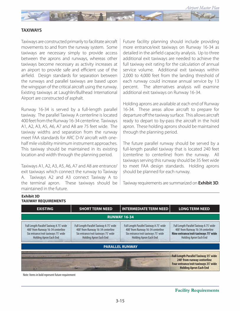
TAXIWAYS
Taxiways are constructed primarily to facilitate aircraft
movements to and from the runway system. Some
taxiways are necessary simply to provide access
between the aprons and runways, whereas other
taxiways become necessary as activity increases at
an airport to provide safe and effi cient use of the
airfi eld. Design standards for separation between
the runways and parallel taxiways are based upon
the wingspan of the critical aircraft using the runway.
Existing taxiways at Laughlin/Bullhead International
Airport are constructed of asphalt.
Runway 16-34 is served by a full-length parallel
taxiway. The parallel Taxiway A centerline is located
400 feet from the Runway 16-34 centerline. Taxiways
A1, A2, A3, A5, A6, A7 and A8 are 75 feet wide. The
taxiway widths and separation from the runway
meet FAA standards for ARC D-IV aircraft with one-
half mile visibility minimum instrument approaches.
This taxiway should be maintained in its existing
location and width through the planning period.
Taxiways A1, A2, A3, A5, A6, A7 and A8 are entrance/
exit taxiways which connect the runway to Taxiway
A. Taxiways A2 and A3 connect Taxiway A to
the terminal apron. These taxiways should be
maintained in the future.
Future facility planning should include providing
more entrance/exit taxiways on Runway 16-34 as
detailed in the airfi eld capacity analysis. Up to three
additional exit taxiways are needed to achieve the
full taxiway exit rating for the calculation of annual
service volume. Additional exit taxiways within
2,000 to 4,000 feet from the landing threshold of
each runway could increase annual service by 13
percent. The alternatives analysis will examine
additional exit taxiways on Runway 16-34.
Holding aprons are available at each end of Runway
16-34. These areas allow aircraft to prepare for
departure off the taxiway surface. This allows aircraft
ready to depart to by-pass the aircraft in the hold
apron. These holding aprons should be maintained
through the planning period.
The future parallel runway should be served by a
full-length parallel taxiway that is located 240 feet
(centerline to centerline) from the runway. All
taxiways serving this runway should be 35 feet wide
to meet FAA design standards. Holding aprons
should be planned for each runway.
Taxiway requirements are summarized on Exhibit 3D.
Exhibit 3D
TAXIWAY REQUIREMENTS
EXISTING SHORT TERM NEED
RUNWAY 16-34
INTERMEDIATE TERM NEED LONG TERM NEED
PARALLEL RUNWAY
Full Length Parallel Taxiway A 75' wide Full Length Parallel Taxiway A 75' wide Full Length Parallel Taxiway A 75' wide Full Length Parallel Taxiway A 75' wide 400' from Runway 16-34 centerline 400' from Runway 16-34 centerline 400' from Runway 16-34 centerline 400' from Runway 16-34 centerline Six entrance/exit taxiways 75' wide Six entrance/exit taxiways 75' wide Six entrance/exit taxiways 75' wide Nine entrance/exit taxiways 75' wide Holding Apron Each End Holding Apron Each End Holding Apron Each End Holding Apron Each End
Full Length Parallel Taxiway 35' wide 240' from runway centerline Four entrance/exit taxiways 35' wide Holding Apron Each End
Note: Items in bold represent future requirement

3-16
INTERNATIONAL
Chapter ThreeChapter Three
NAVIGATIONAL AND APPROACH AIDS
Electronic and visual guidance to arriving aircraft
enhance the safety and capacity of the airfi eld.
Such facilities are vital to the success of the airport
and provide additional safety to passengers using
the air transportation system. While instrument
approach aids are especially helpful during poor
weather, they are often used by commercial pilots
when visibility is good.
Instrument approaches have historically been
categorized as either precision or nonprecision.
Precision instrument approach aids provide an
exact course alignment and vertical descent path
for an aircraft on fi nal approach to a runway, while
nonprecision instrument approach aids provide
only course alignment information. Most existing
precision instrument approaches in the United
States are instrument landing systems (ILS), although
the Global Positioning System (GPS) is now used
to provide both vertical and lateral navigation for
pilots. In early 2008, there were over 1,030 published
GPS approaches that provided both exact course
alignment and vertical descent path information
to pilots (precision approach), including one at
Laughlin/Bullhead International Airport.
There are currently two published instrument
approaches to Laughlin/Bullhead International
Airport. This includes the Area Navigation (RNAV)
GPS approach to Runway 34 and the very high
frequency omnidirectional range (VOR)/distance
measuring equipment (DME) approach to Runway
34. Both approaches allow for circling to land on
Runway 16, although with increased minimums.
The RNAV GPS approach to Runway 34 provides
both course alignment and vertical descent
information. The localizer performance with vertical
guidance (LPV) minimums allow for an approach to
landing when visibility is restricted to two miles and
cloud ceilings are as low as 700 feet and visibility
is restricted to two miles for Approach Categories
A through D. Lateral Navigation (LNAV) (course
guidance) minimums allow for landings when the
cloud ceilings are as low as 1¼ miles for aircraft
within Approach Category A, 1½ miles for aircraft
within Approach Category B, and three miles for
aircraft in Approach Categories C and D. The cloud
ceiling minimum for Approach Categories A through
C is 1,000 feet AGL. The cloud ceiling minimum for
Approach Category D is 1,100 feet AGL.
The VOR/DME approach provides only course
guidance information to the pilot. This approach
procedure allows for landings when the cloud
ceilings are as low as 1¼ miles for aircraft within
Approach Category A, 1½ miles for aircraft within
Approach Category B, and three miles for aircraft
in Approach Categories C and D. The cloud ceiling
minimum for all approaches is 1,800 feet AGL.
The capabilities of the RNAV (GPS) LNAV approach
and the VOR/DME approach are very limited. For
each of these approaches, the cloud ceiling is very
high and the visibility minimums for Approach
Categories C and D are the same for visual fl ight.
While the LPV approach has lower minimums, the
visibility minimums are still two miles.
Future facility planning should include lowering
approach minimums to the extent practicable.
Ultimately, it would be preferable to provide
landings to Category I minimums – ½ mile visibility
and 200-foot cloud ceilings at Laughlin/Bullhead
International Airport. Many factors aff ect the
instrument approach minimums. Most notably,
the terrain features surrounding the airport
may ultimately impact the visibility and cloud
ceiling minimums. Lower approach and visibility
minimums may ultimately only be achieved with
additional lighting aids described below. Only the
FAA can change the approach visibility minimums
at the airport.
An RNAV (GPS) approach procedure was available
to Runway 16; however, this approach was
3-17
Facility RequirementsFacility Requirements
Airport Master PlanAirport Master Plan
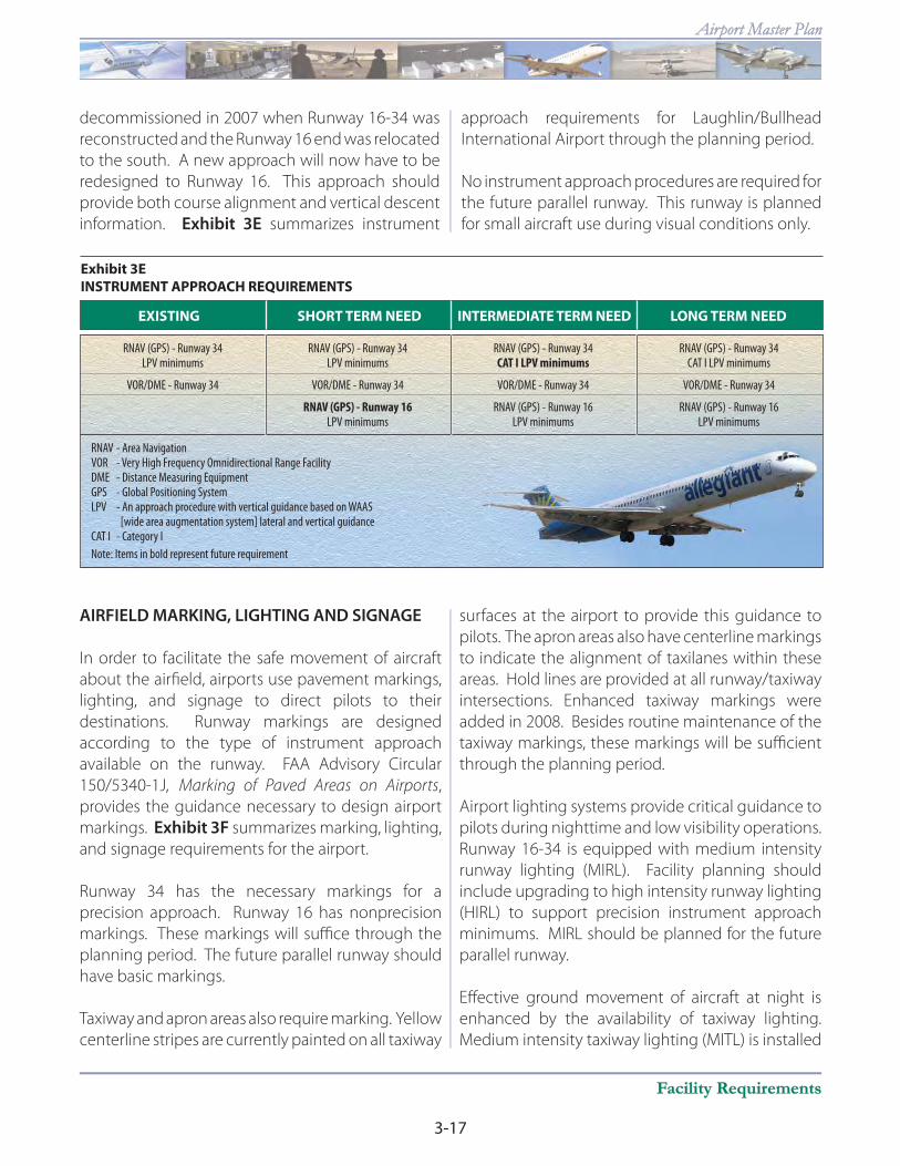
decommissioned in 2007 when Runway 16-34 was
reconstructed and the Runway 16 end was relocated
to the south. A new approach will now have to be
redesigned to Runway 16. This approach should
provide both course alignment and vertical descent
information. Exhibit 3E summarizes instrument
approach requirements for Laughlin/Bullhead
International Airport through the planning period.
No instrument approach procedures are required for
the future parallel runway. This runway is planned
for small aircraft use during visual conditions only.
Exhibit 3E
INSTRUMENT APPROACH REQUIREMENTS
EXISTING SHORT TERM NEED INTERMEDIATE TERM NEED LONG TERM NEED
RNAV (GPS) - Runway 34 RNAV (GPS) - Runway 34 RNAV (GPS) - Runway 34 RNAV (GPS) - Runway 34 LPV minimums LPV minimums CAT I LPV minimums CAT I LPV minimums
VOR/DME - Runway 34 VOR/DME - Runway 34 VOR/DME - Runway 34 VOR/DME - Runway 34
RNAV (GPS) - Runway 16 RNAV (GPS) - Runway 16 RNAV (GPS) - Runway 16 LPV minimums LPV minimums LPV minimums
RNAV - Area NavigationVOR - Very High Frequency Omnidirectional Range FacilityDME - Distance Measuring EquipmentGPS - Global Positioning SystemLPV - An approach procedure with vertical guidance based on WAAS [wide area augmentation system] lateral and vertical guidanceCAT I - Category I
Note: Items in bold represent future requirement
AIRFIELD MARKING, LIGHTING AND SIGNAGE
In order to facilitate the safe movement of aircraft
about the airfi eld, airports use pavement markings,
lighting, and signage to direct pilots to their
destinations. Runway markings are designed
according to the type of instrument approach
available on the runway. FAA Advisory Circular
150/5340-1J, Marking of Paved Areas on Airports,
provides the guidance necessary to design airport
markings. Exhibit 3F summarizes marking, lighting,
and signage requirements for the airport.
Runway 34 has the necessary markings for a
precision approach. Runway 16 has nonprecision
markings. These markings will suffi ce through the
planning period. The future parallel runway should
have basic markings.
Taxiway and apron areas also require marking. Yellow
centerline stripes are currently painted on all taxiway
surfaces at the airport to provide this guidance to
pilots. The apron areas also have centerline markings
to indicate the alignment of taxilanes within these
areas. Hold lines are provided at all runway/taxiway
intersections. Enhanced taxiway markings were
added in 2008. Besides routine maintenance of the
taxiway markings, these markings will be suffi cient
through the planning period.
Airport lighting systems provide critical guidance to
pilots during nighttime and low visibility operations.
Runway 16-34 is equipped with medium intensity
runway lighting (MIRL). Facility planning should
include upgrading to high intensity runway lighting
(HIRL) to support precision instrument approach
minimums. MIRL should be planned for the future
parallel runway.
Eff ective ground movement of aircraft at night is
enhanced by the availability of taxiway lighting.
Medium intensity taxiway lighting (MITL) is installed

3-18
INTERNATIONAL
Chapter ThreeChapter Three
on all taxiways on the airfi eld. The existing airfi eld
lighting systems, while adequate in intensity, will
require routine maintenance and upgrades during
the planning period. MITL should be planned for all
future taxiways, including those serving the future
parallel runway.
Airfi eld signage provides another means of notifying
pilots of their location on the airport. A system of
signs placed at several airfi eld intersections on the
airport is the best method available to provide this
guidance. Signs located at intersections of taxiways
provide crucial information to avoid confl icts
between moving aircraft. Directional signage
instructs pilots as to the location of taxiways and
terminal aprons. Mandatory hold signs are also
installed at the airport. These signs alert the pilot of
the proper location to stop and hold prior to taxiing
to the runway. At Laughlin/Bullhead International
Airport, all signs are lit. These signs are required for
certifi cation at the airport and must be maintained
through the planning period. Directional signage
will also be required for the future parallel runway.
In most instances, the landing phase of any fl ight
must be conducted in visual conditions. To
provide pilots with visual guidance information
during landings to the runway, a four-box
precision approach slope indicator (PAPI-4) system
has been installed at the Runway 16 and Runway
34 ends. The PAPI-4s are located on the east side
of the runway approximately 700 feet south of
the runway end. The PAPI consists of a series of
lights that, when interpreted by the pilot, give him
Exhibit 3F
AIRFIELD LIGHTING AND MARKING REQUIREMENTS
EXISTING SHORT TERM NEED
RUNWAY 16-34
INTERMEDIATE TERM NEED LONG TERM NEED
PARALLEL RUNWAY
Rotating Beacon Rotating Beacon Rotating Beacon Rotating Beacon
Pilot Controlled Lighting (PCL) Pilot Controlled Lighting (PCL) Pilot Controlled Lighting (PCL) Pilot Controlled Lighting (PCL)
Medium Intensity Runway Edge Lighting (MIRL) Medium Intensity Runway Edge Lighting (MIRL) High Intensity Runway Edge Lighting (HIRL) High Intensity Runway Edge Lighting (HIRL)
Medium Intensity Taxiway Edge Lighting (MITL) Medium Intensity Taxiway Edge Lighting (MITL) Medium Intensity Taxiway Edge Lighting (MITL) Medium Intensity Taxiway Edge Lighting (MITL)
Lighted Runway/Taxiway Directional Signage Lighted Runway/Taxiway Directional Signage Lighted Runway/Taxiway Directional Signage Lighted Runway/Taxiway Directional Signage
Precision Approach Path Indicator (PAPI-4) Precision Approach Path Indicator (PAPI-4) Precision Approach Path Indicator (PAPI-4) Precision Approach Path Indicator (PAPI-4) Each Runway End Each Runway End Each Runway End Each Runway End
Runway End Identifier Lights (REILs) Runway End Identifier Lights (REILs) Runway End Identifier Lights (REILs) Runway End Identifier Lights (REILs) Each Runway End Each Runway End Each Runway End Each Runway End
Distance Remaining Signs Distance Remaining Signs Distance Remaining Signs Distance Remaining Signs
Precision Runway Markings - Runway 34 Precision Runway Markings - Runway 34 Precision Runway Markings - Runway 34 Precision Runway Markings - Runway 34
Nonprecision Runway Markings - Runway 16 Nonprecision Runway Markings - Runway 16 Nonprecision Runway Markings - Runway 16 Nonprecision Runway Markings - Runway 16
Medium Intensity Approach Lighting Medium Intensity Approach Lighting System with Runway Alignment Indicator System with Runway Alignment Indicator Lighting (MALSR) - Runway 34 Lighting (MALSR) - Runway 34
Medium Intensity Runway Edge Lighting (MIRL)
Medium Intensity Taxiway Edge Lighting (MITL)
Lighted Runway/Taxiway Directional Signage
Precision Approach Path Indicator (PAPI-2) Each Runway End
Runway End Identifier Lights (REILs) Each Runway End
Basic Runway Markings
Note: Items in bold represent future requirement

3-19
Facility RequirementsFacility Requirements
Airport Master PlanAirport Master Plan
or her an indication of being above, below, or on
the designed descent path to the runway. The
PAPIs should be maintained through the planning
period. PAPI-2s should be planned for each end of
the future parallel runway.
Runway end identifi cation lights (REILs) provide
rapid and positive identifi cation of the approach
ends of a runway. An REIL system has been
installed at each runway end. An REIL consists of
two synchronized fl ashing lights, located laterally
on each side of the runway threshold, facing
the approaching aircraft. The REILs should be
maintained through the planning period. REILs
should be planned for each end of the future
parallel runway.
To improve instrument approach minimums at the
airport, an approach lighting system may ultimately
be required. Therefore, a medium intensity approach
lighting system with runway alignment indicator
lights (MALSR) should be planned for Runway 34. An
MALSR provides visual guidance to landing aircraft
by radiating light beams in a directional pattern by
which the pilot aligns the aircraft with the extended
centerline of the runway.
The location of an airport at night is universally
indicated by a rotating beacon which projects
two beams of light, one white and one green, 180
degrees apart. The rotating beacon at Laughlin/
Bullhead International Airport is located atop a
metal tower northeast of the Runway 16 end. The
rotating beacon should be maintained through
the planning period.
Runway 16-34 is equipped with distance remaining
signs. These signs are set in 1,000-foot increments
to notify the pilot of the remaining runway length.
These signs should be maintained through the
planning period.
The MIRL system on Runway 16-34 is connected
to the pilot-controlled lighting system (PCL). This
system allows pilots to turn on or increase the
intensity of the MIRL from the aircraft with the use
of the aircraft’s radio transmitter. Future facility
planning should include connecting the PAPIs,
REILS, and future MALSR to the PCL.
Weather Reporting
The airport has a lighted wind cone and segmented
circle. A lighted wind cone provides information to
pilots regarding wind conditions. The segmented
circle surrounds the lighted wind cone and provides
traffi c pattern information to pilots. A lighted wind
sock is also available between the runway and
Taxiway A adjacent to Taxiway A2, while another
is located approximately 1,000 feet north of the
Runway 34 threshold. The segmented circle and
lighted wind cone are required by regulation as the
airport traffi c control tower (ATCT) is not open 24
hours a day. As shown on Exhibit 3G, these systems
should be maintained through the planning period.
An Automated Weather Observation System III
(AWOS-III) was installed at the airport in 2007. The
AWOS automatically records weather conditions
such as wind speed, wind gusts, wind direction,
Lighted Wind Indicator Lighted Wind Indicator Lighted Wind Indicator Lighted Wind Indicator
Segmented Circle Segmented Circle Segmented Circle Segmented Circle
Automated Weather Automated Weather Automated Weather Automated Weather Observing System (AWOS) Observing System (AWOS) Observing System (AWOS) Observing System (AWOS)
Remote Transmitter/Receiver Remote Transmitter/Receiver Remote Transmitter/Receiver Remote Transmitter/Receiver
Airport Traffic Control Tower (ATCT) Airport Traffic Control Tower (ATCT) Airport Traffic Control Tower (ATCT) Airport Traffic Control Tower (ATCT)
Exhibit 3G
WEATHER/COMMUNICATION FACILITY REQUIREMENTS
EXISTING SHORT TERM NEED INTERMEDIATE TERM NEED LONG TERM NEED

3-20
INTERNATIONAL
Chapter ThreeChapter Three
variable wind direction, temperature, dew point,
altimeter setting, density altitude, visibility, variable
visibility, precipitation, sky condition, and cloud
height. This information is then transmitted at
regular intervals. The AWOS is located adjacent to
the segmented circle and should be maintained
through the planning period.
Communication Facilities
The ATCT is located east of the runway approximately
at midfi eld. The ATCT is staff ed through a contract
with the FAA from 8:00 a.m. to 6:00 p.m. local time.
Remote transmitter/receiver (RTR) equipment at
the airport provides for contacting the Los Angeles
ARTCC after the ATCT is closed for opening and
closing fl ight plans. The ATCT and RTR enhance
safety at the airport and should be maintained
through the planning period.
LANDSIDE REQUIREMENTS
Landside facilities are those necessary for handling
aircraft, passengers, and freight while on the ground.
These facilities provide the essential interface
between air and ground transportation modes. The
capacities of the various components of each area
were examined in relation to projected demand to
identify future landside facility needs.
AIRLINE TERMINAL
Components of the terminal area complex include
the terminal building, gate positions, and apron area.
This section identifi es the facilities required to meet
the airport’s needs through the planning period.
The existing airline terminal area facilities were
evaluated based on planning guidelines relating to
the major functional elements of the terminal area
as presented in AC 150/5360-9, Planning and Design
of Airport Terminal Facilities at Non-hub Locations, the
consultant’s database of terminal planning criterion,
and information collected during the inventory
element to prepare estimates of various terminal
building requirements.
Facility requirements were updated to refl ect the
planning horizon for enplanement milestones.
This included the enplanement levels of 145,000,
200,000, and 375,000 annual enplaned passengers.
Peak hour enplaned passenger levels dictate many
of the terminal requirements. The peak hour
enplaned passenger levels are forecast at 286,
310, and 508 passengers for each future planning
horizon. These peak hour passengers refl ect the
introduction of regularly scheduled passenger
services at the airport and the continuation of
charter services supporting the gaming/resort
activities in Laughlin, Nevada.
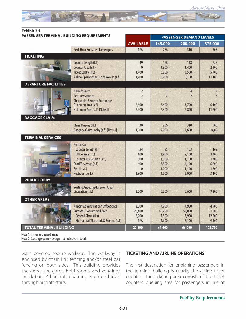
Airline terminal capacity and requirements were
developed for the following functional areas as
shown on Exhibit 3H.
• Airline Ticketing and Operations
• Departure Facilities
• Baggage Claim
• Terminal Services
• Public Use Areas and Security
• Administration/Support
Commercial airline terminal functions are provided
in two separate single-level buildings located in
the northeast portion of the airport. The main
terminal building provides space for ticketing,
airline operations, checked baggage screening
and make-up, secure screening, rental cars, airport
administration, and Transportation Security
Administration (TSA) offi ces. Baggage claim is
located at the far western end of the building. The
baggage claim shelf and lobby are located outside
in a covered area.
Departure functions are contained in a second
separate building located southeast of the main
terminal building. Access to this building is
3-21
Facility RequirementsFacility Requirements
Airport Master PlanAirport Master Plan
via a covered secure walkway. The walkway is
enclosed by chain link fencing and/or steel bar
fencing on both sides. This building provides
the departure gates, hold rooms, and vending/
snack bar. All aircraft boarding is ground level
through aircraft stairs.
TICKETING AND AIRLINE OPERATIONS
The fi rst destination for enplaning passengers in
the terminal building is usually the airline ticket
counter. The ticketing area consists of the ticket
counters, queuing area for passengers in line at
PASSENGER DEMAND LEVELS
200,000145,000AVAILABLE
TICKETING
DEPARTURE FACILITIES
BAGGAGE CLAIM
TERMINAL SERVICES
PUBLIC LOBBY
OTHER AREAS
TOTAL TERMINAL BUILDING
375,000
Exhibit 3H
PASSENGER TERMINAL BUILDING REQUIREMENTS
Peak Hour Enplaned Passengers N/A 286 310 508
Counter Length (l.f.) 49 128 138 227
Counter Area (s.f.) 0 1,300 1,400 2,300
Ticket Lobby (s.f.) 1,400 3,200 3,500 5,700
Airline Operations/ Bag Make-Up (s.f.) 1,400 6,900 8,100 11,100
22,800 61,600 66,000 102,700
Airport Adminstration/ Office Space 2,300 4,900 4,900 4,900
Subtotal Programmed Area 20,600 48,700 52,000 81,200
General Circulation 2,200 7,300 7,900 12,200
Mechanical/Electrical, & Storage (s.f.) N/A 5,600 6,100 9,300
Seating/Greeting/Farewell Area/Circulation (s.f.) 2,200 5,200 5,600 9,200
Rental Car
Counter Length (l.f.) 24 95 103 169
Office Area (s.f.) 600 1,900 2,100 3,400
Counter Queue Area (s.f.) 300 1,000 1,100 1,700
Food/Beverage (s.f.) 400 3,800 4,100 6,800
Retail (s.f.) 0 1,000 1,100 1,700
Restrooms (s.f.) 1,600 1,900 2,000 3,100
Claim Display (l.f.) 30 286 310 508
Baggage Claim Lobby (s.f.) [Note 2] 1,200 7,900 7,600 14,00
Aircraft Gates 2 3 4 7
Security Stations 2 2 2 3
Checkpoint Security Screening/Quequing Area (s.f.) 2,900 3,400 3,700 6,100
Holdroom Area (s.f.) [Note 1] 6,300 6,300 6,800 11,200
Note 1: Includes unused areasNote 2: Existing square-footage not included in total.
3-22
INTERNATIONAL
Chapter ThreeChapter Three
the counters, and the ticket lobby which provides
circulation. Presently, there are up to four separate
ticketing areas at Laughlin/Bullhead International
Airport. Four airline offi ces are provided behind
and adjacent to the ticket counters. The TSA has
installed an explosive detections system (EDS) for
checked baggage screening.
The ticket lobby should be arranged so that
the enplaning passenger has immediate access
and clear visibility to the individual airline ticket
counters upon entering the building. Circulation
patterns should allow the option of bypassing the
counters with minimum interference. Provisions for
seating should be minimal to avoid congestion and
to encourage passengers to proceed to the gate
area. Airline ticket counter frontage, counter area,
counter queuing area, ticketing lobby, and airline
offi ce and operations area requirements for each
potential enplanement level have been calculated.
The current arrangement of the ticketing area
meets these functional requirements.
The analysis of the airline ticketing functional areas
at the airport indicates that additional area will be
needed through the planning period. This includes
additional counter length, ticket lobby space, and
airline operations/baggage make-up.
DEPARTURE GATES AND HOLDROOMS
There are two ground level departure gates at the
airport. While ground level loading and unloading
of passengers can be used by regional jets which
may provide scheduled airline service in the future,
ground level boarding is more complicated for the
large transport jets that utilize the airport for charter
services. Long term facility planning should include
second-level boarding capabilities with loading
bridges. Furthermore, as shown on Exhibit 3H,
long term planning anticipates the need for up to
seven departure gates for peak periods.
The number of gates required to accommodate
the combined peak hour activity and the aircraft
seating capacities determines holdroom capacity
requirements. Holdrooms should be sized to provide
adequate space and area for the largest group of
people that can use each gate. Currently, there is one
large holdroom for passengers. Forecasts indicate
that the existing holdroom area will need to be
increased to meet peak passenger levels. Additional
unused space is available in the departure facility for
additional holdroom area, although this area will not
meet projected long term needs.
PASSENGER SCREENING
Current security screening is positioned in the main
terminal building. The size of the existing security
areas, however, is not fully adequate to facilitate
effi ciency. The existing secure station queuing area
is undersized for future peak passenger levels. Future
areas should be planned to fully accommodate not
only the needs of the security stations, but also
increase queuing space.
BAGGAGE CLAIM
The passenger arrival process consists primarily
of those facilities and functions that reunite the
arriving passengers with their checked baggage.
The existing claim device at the airport consists
of a single display shelf located outside the main
terminal building in a covered patio area. The bags
are loaded onto the shelf via the baggage tug carts
from the apron.
Short term planning should consider enclosing the
baggage claim area. Forecasts call for an increase in
the size of the current baggage claim area through
the planning period. Future consideration would
include a mechanized device to display baggage.
The location of the baggage claim area will be more
fully explored within the alternatives.

3-23
Facility RequirementsFacility Requirements
Airport Master PlanAirport Master Plan
TERMINAL SERVICES
Similar to airline ticketing, rental car counter facilities
include offi ce, counter area, and queue areas. There
are currently three counters identifi ed for rental car
services. The forecasts show a need for additional
rental car area through the planning period.
Additional space may be required sooner should
additional rental car providers initiate service at the
airport.
As shown on Exhibit 3H, additional space for food
and beverages may be required through the long
term. Retail space is also projected to be needed
through the planning period. Public restroom space
will need to increase through the planning period.
PUBLIC-USE AREA
The public lobby is where passengers or visitors
may comfortably relax while waiting for arrivals or
departures. In today’s environment, visitors must
remain out of the secure departure areas, so a
public lobby is important. The terminal building
provides more than 2,200 square feet of space for
this purpose. Within the main terminal building,
circulation space is particularly limited as most
areas are dedicated for ticketing and passenger
screening queuing. Additional circulation space will
be needed through the long term planning period.
BUILDING SUPPORT
AND ADMINISTRATION
Building support facilities include all miscellaneous
spaces at the airport, including mechanical,
telephone, business centers, walls/structures, and
general circulation. As other components of the
airport increase in size, so will supporting spaces.
The administrative offi ces are located within the
terminal building. This includes space for airport
management. The space needed for these
facilities will be dependent upon the Mohave
County Airport Authority’s (MCAA) needs through
the planning period.
TERMINAL APRON
The existing terminal apron encompasses
approximately 43,100 square yards. Space is
available to park up to three large transport jet
aircraft. Depending upon future boarding gate
design, more than 35,000 square yards of apron will
be needed for aircraft parking. While the existing
apron exceeds this space requirement, this apron is
also used by the air cargo carriers.
TERMINAL ACCESS ROADWAY
Principal access to the terminal is from Laughlin
View Drive. Laughlin View Drive is a two-lane road
intersecting with Bullhead Parkway, north of the
airport across the Highland Wash as well as to the
east. The northern connection can be closed when
there is high water present in the Highland Wash.
Bullhead Parkway connects to the regional highway
network. Access to the main terminal building is via
a one-way loop road. The expansion of the terminal
parking area eliminated the need to cross in front of
the terminal. A new two-way access road extends
along the northern section of the parking area.
Access to the departure facility is via Aston Drive.
Future access needs will be dependent upon the
fi nal location of the terminal.
TERMINAL CURB FRONTAGE
The curb element is the interface between the
terminal building and the ground transportation
system. The length of curb required for the loading
and unloading of passengers and baggage is
determined by the type and volume of ground
vehicles anticipated in the peak period on the
design day.

3-24
INTERNATIONAL
Chapter ThreeChapter Three
A typical problem for terminal curb capacity is the
length of dwell time for vehicles utilizing the curb.
At airports where the curb front has not been strictly
patrolled, vehicles have been known to be parked at
the curb while the driver and/or riders are inside the
terminal checking in, greeting arriving passengers,
or awaiting baggage pick-up. Since most curbs are
not designed for vehicles to remain curbside for
more than two to three minutes, capacity problems
can ensue. Since the events of 9/11, most airports
police the curb front much more strictly for security
reasons. This alone has reduced the curb front
capacity problems at most airports.
At the airport, the terminal roadway provides one
lane for loading and unloading of passengers and
two through lanes for automobile fl ow. The curb
frontage totals approximately 330 feet in length. As
shown on Exhibit 3J, additional curb length may
be needed through
the planning period
as peak passenger
levels increase. This
will avoid situations of
double-parking near
the bag claim or tick-
eting areas
VEHICLE PARKING
Vehicle parking in the
airline passenger termi-
nal area of the airport
includes those spaces
utilized by passengers,
visitors, and employ-
ees of the airline ter-
minal facilities. Parking
spaces are classifi ed as
public, employee, and
rental car. Most vehicle
parking is located in a
surface lot immediately
north of the terminal
building and is used for public, employee, and some
rental car parking. A second rental car parking area is
located east of the terminal building.
Exhibit 3J presents the parking requirements for
the planning horizons. Public parking requirements
were based upon design hour (short term) and
design day (long term) passenger levels. Public
parking will need to be signifi cantly expanded
through the planning period. Rental car parking
needs depend upon the operational requirements
of the rental car agencies. However, it appears that
additional rental car spaces will be required through
the planning period.
TERMINAL REQUIREMENTS SUMMARY
The existing space dedicated to passenger airline
functions is insuffi cient to effi ciently serve project-
PASSENGER DEMAND LEVELS
200,000145,000AVAILABLE 375,000
Exhibit 3J
AUTOMOBILE PARKING AND TERMINAL CURB REQUIREMENTS
Public Parking 310 207 270 493
Employee NA 58 80 150
Rental Car 90 103 142 266
Total Auto Parking 400 368 492 909
Length (ft) 330 560 610 990
AUTO PARKING
TERMINAL CURB

3-25
Facility RequirementsFacility Requirements
Airport Master PlanAirport Master Plan
ed airline passenger levels. Additional space will
be needed to accommodate growth in passenger
levels at the airport. This can only be accomplished
through expansion of the existing buildings or new
building construction. Additional parking areas
will also be needed. The previous master plan re-
located long term terminal functions to the south
end of the airport to accommodate long term pas-
senger levels. This will be reexamined within this
Master Plan.
AIR CARGO
The two primary cargo-related facilities requiring
analysis include the cargo apron and building
space. Presently, there is no single building or
facility dedicated solely to air cargo on the airport.
Air cargo is presently transferred directly from
aircraft to vehicles on the apron area. This practice
is expected to continue through the planning
period. The cargo carriers are currently located in
temporary facilities along the southern edge of the
apron. Facility planning should include relocating
these carriers to the east edge of the apron so that
the vehicles do not cross the entire apron and
Taxiway A2 to reach the aircraft.
GENERAL AVIATION
General aviation facilities are those necessary for
handling general aviation aircraft and passengers
while on the ground. This section is devoted to
identifying future general aviation facility needs
during the planning period for the following
types of facilities normally associated with general
aviation terminal areas.
GENERAL AVIATION TERMINAL SERVICES
The general aviation facilities are often the fi rst
impression of the community that corporate
offi cials and other visitors will encounter. General
aviation terminal facilities at an airport provide
space for passenger waiting, pilots’ lounge, pilot
fl ight planning, concessions, management, storage,
and various other needs. Landmark Aviation plans
the construction of a new 3,000-square-foot general
aviation terminal in 2008.
The methodology used in estimating general
aviation terminal facility needs was based upon
the number of airport users expected to utilize
general aviation facilities during the design hour.
Space requirements for terminal facilities were
based on providing 120 square feet per design
hour itinerant passenger. Exhibit 3K outlines the
space requirements for general aviation terminal
services at Laughlin/Bullhead International Airport
through the long term planning horizon. As
shown in the table, up to 10,800 square feet of
space should be provided in the long term for
general aviation passengers.
HANGARS
Utilization of hangar space varies as a function of
local climate, security, and owner preferences. The
trend in general aviation aircraft, whether single or
multi-engine, is toward more sophisticated aircraft
(and, consequently, more expensive aircraft);
therefore, many aircraft owners prefer enclosed
hangar space to outside tie-downs.
The demand for aircraft storage hangars is
dependent upon the number and type of aircraft
expected to be based at the airport in the future.
For planning purposes, it is necessary to estimate
hangar requirements based upon forecast
operational activity. However, hangar development
should be based upon actual demand trends and
fi nancial investment conditions.
Laughlin/Bullhead International Airport has a
number of individual T-hangar spaces. T-hangars
are popular with aircraft owners having only one
small aircraft as they provide space for a single
aircraft. Commonly, large T-hangar structures
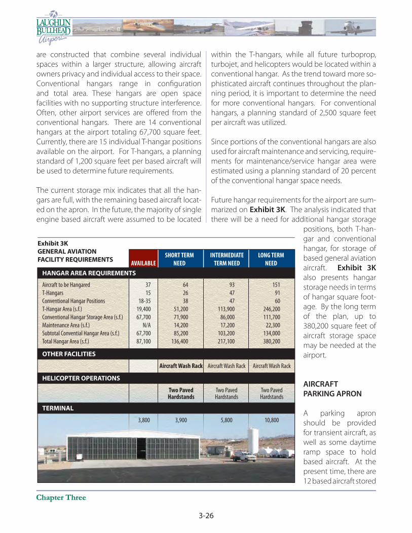
3-26
INTERNATIONAL
Chapter ThreeChapter Three
are constructed that combine several individual
spaces within a larger structure, allowing aircraft
owners privacy and individual access to their space.
Conventional hangars range in confi guration
and total area. These hangars are open space
facilities with no supporting structure interference.
Often, other airport services are off ered from the
conventional hangars. There are 14 conventional
hangars at the airport totaling 67,700 square feet.
Currently, there are 15 individual T-hangar positions
available on the airport. For T-hangars, a planning
standard of 1,200 square feet per based aircraft will
be used to determine future requirements.
The current storage mix indicates that all the han-
gars are full, with the remaining based aircraft locat-
ed on the apron. In the future, the majority of single
engine based aircraft were assumed to be located
within the T-hangars, while all future turboprop,
turbojet, and helicopters would be located within a
conventional hangar. As the trend toward more so-
phisticated aircraft continues throughout the plan-
ning period, it is important to determine the need
for more conventional hangars. For conventional
hangars, a planning standard of 2,500 square feet
per aircraft was utilized.
Since portions of the conventional hangars are also
used for aircraft maintenance and servicing, require-
ments for maintenance/service hangar area were
estimated using a planning standard of 20 percent
of the conventional hangar space needs.
Future hangar requirements for the airport are sum-
marized on Exhibit 3K. The analysis indicated that
there will be a need for additional hangar storage
positions, both T-han-
gar and conventional
hangar, for storage of
based general aviation
aircraft. Exhibit 3K
also presents hangar
storage needs in terms
of hangar square foot-
age. By the long term
of the plan, up to
380,200 square feet of
aircraft storage space
may be needed at the
airport.
AIRCRAFT
PARKING APRON
A parking apron
should be provided
for transient aircraft, as
well as some daytime
ramp space to hold
based aircraft. At the
present time, there are
12 based aircraft stored
INTERMEDIATE
TERM NEED
SHORT TERM
NEEDAVAILABLE
LONG TERM
NEED
Exhibit 3K
GENERAL AVIATION
FACILITY REQUIREMENTS
HANGAR AREA REQUIREMENTS
OTHER FACILITIES
Aircraft to be Hangared 37 64 93 151
T-Hangars 15 26 47 91
Conventional Hangar Positions 18-35 38 47 60
T-Hangar Area (s.f.) 19,400 51,200 113,900 246,200
Conventional Hangar Storage Area (s.f.) 67,700 71,900 86,000 111,700
Maintenance Area (s.f.) N/A 14,200 17,200 22,300
Subtotal Convential Hangar Area (s.f.) 67,700 85,200 103,200 134,000
Total Hangar Area (s.f.) 87,100 136,400 217,100 380,200
Aircraft Wash Rack Aircraft Wash Rack Aircraft Wash Rack
HELICOPTER OPERATIONS
Two Paved Two Paved Two Paved Hardstands Hardstands Hardstands
TERMINAL
3,800 3,900 5,800 10,800

3-27
Facility RequirementsFacility Requirements
Airport Master PlanAirport Master Plan
on the ramp. With a total
of 67 tiedown positions,
approximately 82 percent
of tiedowns are available
for based and transient
aircraft use. In the future,
up to 25 based aircraft
positions on the apron
are forecast. Although
some aircraft are stored
in conventional hangars,
they may be moved to
the ramp during the day
to provide hangar area for
aircraft maintenance.
FAA Advisory Circular
150/5300-13, Airport
Design, suggests a
methodology by
which transient apron
requirements can be determined from knowledge
of busy-day operations. At Laughlin/Bullhead
International Airport, the number of itinerant
spaces required was estimated to be approximately
15 percent of the busy-day itinerant operations. A
planning criterion of 800 square yards was used for
single and multi-engine itinerant aircraft, while a
planning criterion of 1,600 square yards was used
to determine the area for transient jet aircraft. As
shown in Exhibit 3L, the existing general aviation
apron and parking positions should be adequate
through the planning period. The existing available
apron area meets or exceeds all demand forecast
requirements.
VEHICULAR PARKING
General aviation vehicular parking demands have
also been determined for Laughlin/Bullhead Interna-
tional Airport. Space determinations were based on
an evaluation of existing airport use, as well as indus-
try standards. Terminal automobile parking spaces
required to meet general aviation itinerant and fi xed
base operator (FBO) demands were calculated by
multiplying design hour itinerant passengers by the
industry standard of 1.9 in the short term, increasing
to 2.5 for the long term as corporate operations in-
crease. The parking requirements of based aircraft
owners should also be considered. Although some
owners prefer to park their vehicles in their hangar,
safety can be compromised when automobile and
aircraft movements are intermixed. For this reason,
separate parking requirements, which consider one-
half of based aircraft at the airport, were applied to
general aviation automobile parking space require-
ments. Utilizing this methodology, parking require-
ments for general aviation activity is for 72 spaces in
the Short Term Planning Horizon, 103 spaces in the
Intermediate Term Planning Horizon, and 175 spaces
in the Long Term Planning Horizon.
Presently, there are no existing paved general avi-
ation parking areas. Access to the hangar area is
along the apron. Facility planning should include
developing paved parking areas at the airport
and including segregated vehicle access to the
aircraft hangars.
INTERMEDIATE
TERM NEED
SHORT TERM
NEEDAVAILABLE
LONG TERM
NEED
Exhibit 3L
AIRCRAFT PARKING
APRON REQUIREMENTS
Single, Multi-engine Transient Aircraft Positions 11 15 29
Apron Area (s.y.) 9,000 12,200 23,000
Transient Business Aircraft Positions 5 7 10
Apron Area (s.y.) 8,000 11,200 16,000
Locally-Based Aircraft Positions 20 22 25
Apron Area (s.y.) 10,000 11,000 12,500
Total Positions 67 36 44 64
Total Apron Area (s.y.) 95,400 27,000 34,400 51,500
3-28
INTERNATIONAL
Chapter ThreeChapter Three
SUPPORT REQUIREMENTS
Various facilities that do not logically fall within
classifi cations of airfi eld, terminal building, or
general aviation facilities have been identifi ed for
inclusion in this master plan. Facility requirements
have been identifi ed for these remaining facilities:
• Aircraft Wash Facilities
• Helicopter Operations
• Airport Rescue and Firefi ghting Facilities
• Airport Maintenance Facilities
• Fuel Storage
AIRCRAFT WASH FACILITY
Presently, there are no designated aircraft wash
facilities on the airport. Consideration should be
given to establishing an aircraft wash facility at the
airport to collect aircraft cleaning fl uids used during
the cleaning process.
HELICOPTER PARKING
Presently, there are eight helicopter parking areas
on the airport. Helicopters operate on the apron
areas shared by fi xed-wing aircraft. Helicopter
operations should be segregated to the extent
practicable. Long term facility planning should
consider establishing helicopter hardstands for
segregating helicopter parking.
AIRCRAFT RESCUE AND FIREFIGHTING
Requirements for aircraft rescue and fi refi ghting
(ARFF) services at an airport are established under
Title 14 of the Code of Federal Regulations (CFR)
Part 139, which applies to the certifi cation and
operation of land airports served by any scheduled
or unscheduled passenger operation of an air carrier
using an aircraft with nine or more passenger seats.
Paragraph 139.315 establishes ARFF index ratings
based on the length of the largest aircraft with an
average of fi ve or more daily departures.
The following indicates the requirements for
each ARFF Index and the associated equipment
requirements:
Index A - Includes aircraft less than 90 feet in
length (Saab 340, Regional Jet).
Index B - Includes aircraft at least 90 feet but less
than 126 feet in length (Boeing 737).
Index C - Includes aircraft at least 126 feet but less
than 159 feet in length (Boeing 757).
Index D - Includes aircraft at least 159 feet but less
than 200 feet in length (Boeing 767).
Index E - Includes aircraft at least 200 feet in
length (Boeing 747).
The Laughlin/Bullhead International Airport ARFF
facility currently maintains Index B capability. To
meet Index B requirements, at least one vehicle able
to carry 500 pounds of sodium-based dry chemical
or Halon 1211, 1,500 gallons of water, and the
commensurate quantity of aqueous fi lm forming
foams AFFF for foam production is required. If
two ARFF vehicles are used, one must carry those
agents listed for Index A requirements, and the
other vehicle must carry an amount of water and
the commensurate quantity of AFFF so that the
total quantity of water for foam production carried
by both vehicles is at least 1,500 gallons.
The requirement to meet any higher index would
need to be based on the number of daily operations
of aircraft within that index. Regional jet aircraft are
anticipated to be used through the planning period
for scheduled passenger service. With the exception
of the Embraer 145, all existing regional jets with
less than 50 seats are less than 90 feet in length and
fall within Index A. Larger seating capacity regional
jets fall within Index B.
While Index B should be adequate through the
planning period, Index C may become necessary if
larger aircraft such as the Boeing 757 are utilized at

3-29
Facility RequirementsFacility Requirements
Airport Master PlanAirport Master Plan
the airport. Index C requires either of the following:
(1) Three vehicles, one vehicle carrying 500 pounds
of sodium-based dry chemical or halon 1211; or
450 pounds of potassium-based dry chemical and
water with a commensurate quantity of AFFF to to-
tal 100 gallons for simultaneous dry chemical and
AFFF foam application, and two vehicles carrying
an amount of water and the commensurate quan-
tity of AFFF so that the total quantity of water for
foam production carried by all three vehicles is at
least 3,000 gallons, or (2) Two vehicles, one vehicle
carrying 500 pounds of sodium-based dry chemical
or halon 1211; or 450 pounds of potassium-based
dry chemical and water with a commensurate
quantity of AFFF to total 100 gallons for simultane-
ous dry chemical and AFFF foam application, and
one vehicle carrying an amount of water and the
commensurate quantity of AFFF so that the total
quantity of water for foam production carried by
both vehicles is at least 3,000 gallons. Replacement
of the existing ARFF vehicle should be considered
in the short term.
The existing ARFF facility at Laughlin/Bullhead
International Airport is located on the north end
of the airfi eld, providing quick response capability.
Regulations require that at least one vehicle must
be capable of reaching the midpoint of the farthest
runway within three minutes from the time of the
alarm to the time of initial agent application. The
existing location is well-suited to meet this criterion.
AVIATION FUEL STORAGE
All fuel storage and dispensing facilities at the airport
are privately owned and operated. Presently, all
Landmark fuel storage is in aboveground tanks
located at the terminus of Aston Drive as shown
previously on Exhibit 1C. Jet fuel storage totals 40,000
gallons. 100LL fuel storage totals 12,000 gallons. All
fuel is dispensed via mobile fueling trucks. Tri-State
Care Flight maintains a 12,000 gallon above ground
fule storage tank between hangars 31 and 32 for
self-fueling. Any future fuel storage needs should be
determined by the FBOs providing fueling services
and will be dependent upon delivery schedules.
The existing consolidated fuel storage area should
be maintained through the planning period, as this
area provides ease of access for both the fuel delivery
vehicles as well as the mobile fuel trucks.
AIRPORT MAINTENANCE FACILITIES
All equipment necessary to maintain the airport to
Part 139 standards is available at the airport. The
present airport maintenance facility is west of the
passenger terminal building in the same building
that stores the ARFF equipment. The alternatives
analysis will examine alternative locations for an
airport maintenance facility to provide more area
and segregate from ARFF functions should that be
desired by the MCAA in the future.
UTILITIES
Electrical, water, natural gas, and sanitary sewer
services are available at the airport. No information
collected during the inventory eff ort revealed
any defi ciencies in providing electrical, water, or
sanitary sewer services at the airport. Therefore, it
is assumed that all future infrastructure needs for
these services will be suffi ciently met.
SUMMARY
The intent of this chapter has been to outline
the facilities required to meet aviation demands
projected for Laughlin/Bullhead International
Airport through the long term planning horizon.
Following the facility requirements determination,
the next step is to develop a direction for
development to best meet these projected needs.
The remainder of the Master Plan will be devoted to
outlining this direction, its schedule, and its costs.
Copyright © 2022 FDOKUMEN