Startup problem rept for facility.
143
- - - . -.._ ,, / , u .. , ,' ~ f J g TARTUP PR0nt.EM REPOP.T 0RGANIZATION SERIAL NU Utn - . " ' " " ? c ,,,,. gc s TP NO. MTX NO. I47 PROBLEM DESCRIPTION: 9- G /C M NM -! bb:. 5 k M p* I '~b c mCbM .fc .1 h .%m :A u aa o cA ~ - \ c'aEm<b- T-ti s \ Q . & ?. J .Le A s A = | u n ch b BY: %, - Fw''. V ORGANIZATICN:_ 6 ['J DATE: 3 .$b Yj _ ._. . . _ _ ._ . - _ 3-36-7( I '(d' R. W _ _ . q. A . r vt . , i . 'yt FOR RESCLUTI^*; E':._ - - '5 M - ---- ..-.. .._. . - . _ . . . _ . . _ . . . . . . . . k ' ROP 03ED E5:LUTIO::: . h SEE ATTA;H_r i u- .. i | BY. Q C. - .- _.r. ... . i i i DATE: b . . - - . e v. J n /, /} t} .m . r i mm Oro " ' -er | ), t., FC ' t.:TIO:. cy: i-p.n. m x c, 97, c sr37 hs.>>p EC T < 1 e. ax crnn.Ca ! k| _1 '' -e> _ . _ _ _ . . _ _ 4 / '' $[ Q ' ' s -~ ) A ' , t01. C ' M'" . t - jb4 AcTio:: n ! ' " ' Y Sid lj,! ::. U ('f,p,K f % ' S- C i. 801105ON C4 .c ra ,h ~4e, . L. . ./. T __ .2.. . c.as .- . - _ . - . - -, _ _ , - - . - - - - - - - - . . . . _ . _ , - - -
-
Upload
khangminh22 -
Category
Documents
-
view
1 -
download
0
Transcript of Startup problem rept for facility.

- - - . -.._ ,, / , u.. ,,' ~
fJ g TARTUP PR0nt.EM REPOP.T 0RGANIZATION SERIAL NU Utn-
.
" ' " " ?c ,,,,.gc s
TP NO. MTX NO. I47
PROBLEM DESCRIPTION: 9- G /C M NM
-! bb:. 5 kM p* I '~b c mCbM .fc .1h
.%m :A u aa o cA~-
\
c'aEm<b- T-tis
\
Q . & ?. J .Le A s A = | u n ch b BY: %, - Fw''.V
ORGANIZATICN:_ 6 ['JDATE: 3 .$b Yj
_ ._. . . _ _._ .
- _3-36-7(I '(d' R. W _ _ . q. A . r vt . , i .'yt FOR RESCLUTI^*; E':._
- -
'5 M-
-- ---- ..-.. .._. . - . _ . . . _ . . _ . . . . . .
. .
k ' ROP 03ED E5:LUTIO:::
.
h
SEE ATTA;H_r
iu-..
i
| BY. Q C. - .-_.r. ....
i ii DATE: b . .
- -
.
e v. Jn /, /} t} .m
. r i mmOro "' -er| ), t., FC ' t.:TIO:. cy: i-p.n. m x c, 97, c sr37
hs.>>p EC T < 1 e. ax crnn.Ca !k| _1'' -e> _ . _ _ _ . . _ _
4
/ ''
$[ Q' ' s-~
) A'
,
t01. C ' M'" .
t-
jb4 AcTio:: n ! ' "'
Y Sid lj,! ::. U('f,p,K f %'
S-
Ci.
801105ON C4.c ra ,h ~4e, . L. .
./. T__ .2.. .c.as .-
. - _ . - . - -, _ _ , - - . - - - - - - - - . . . . _ . _ , - - -_

.
. - .
- ,r. . . . . . ,
,, ...... .
*. .. .
-. . . - .. 9 . . . -
.. .,
L j, PPOPOSET) RICOI.UTIO t.
I B&W has reviewed the electromatic relief valve logic and a6 recs to theconcept of having relief valve fail closed on locs of IIiI power supplyto the Hi-Low Monitor (3-10-12). To achieve thic. condition, uvitch C-1should be in the dcenergi cd modo and the viring modification be madeas indicated in the attached sketch. Per your request,a formal field
change will follew.i
To provide an indication that the electromatic relief valve has an open~ signal, a review of the construction schc=atics indicates that a centrol-
room indicating light operated frem power to the solenoid can be aadedwithout additional cabling. (Refer to MR drawing //3079, sheet lb. )
i This light coula be actuated by the same auxiliary relay in the powerdistribution panel that supplies power to the valve solenoid.
t
9
,
1
i
I
|
|<
|
;
v
!l
. , -

_. - -.
- o-
e
__ - A:.m .-
.. _ _._ m . _ _ . _ - ~
m.___ _ _ _ _-
-
. . _ . . _ - . _ - . . . .- . . . . . .
- b.,
.
1. Chn: ge D. itch S-1 ponition to deenergized in module 3-10-12
2. Lift lead from pin 23 or module 3-10-12 and connect to pin 21 '
.
3 Lir: lead from pin 27 or module 3-10-12 und connect to pin 29.
.
.
.,
.
.. _ s p . - Tb Nc. - -' |5 j . ... . , , j ,, i gg . ; j _
~-
;.
S 'asn I- ..'-== ,
..,a : .,, .-
..
.
__ j 5- 1%s r,ac. rc 35;, , ., .
_e __ 4. < e ,r, . . '
.) - -e 3,
28 .9 g sN t..4,.
* ,
*-
s..' -(13 ftx Ce sdatt, , w ;. ,,
OA (Of C"i *'l ,
|,
! u u | - ' nuty ._. ___ -.g ,a (.- yy . ___. ; - [ j:__p___ r] i is C. r. r r, , + .,4 . . cc
, ".
(88''*6 ~*'1 s .: . ;';* /licrcwit ,- e yq. ;. . ,
~, p .(-
. _ _ _ _
, - ~ _ . . _--_._e.
-o.l.- .o. ~,
..a 1,. . - ,,. .:..._
O | '-.. ,
,($,.,$',(. , * ,'
.. '2- _ . 3- . d 1 - {.
. ;v m-LO AL AV.! t.CMO3 ' c,! ,,
^~su.._.- ,.. d y t- -; c,., g .,
. . .-- - --._< - . - - - - - -_._..% . . . , , . ,,
) L-', (. T 8'..'t*-.- ..N' :'* "'- ' -. ' .,
" -. t e* r..c *7( >-]. . ! .] [ _ f .{..- , ,, s,. ' , {, . ,i, . .,.4.
I._.__----.'_,'* .1.
,,
' ,,' -
4 ..
., .J ;
- . . . _ _..
- s_,,'- . .
' u .; : tu .1-t , \ ...E' ,'C'.-
: | .- te .c; ' ~:n. . .. '- .
|',i p,1 +I '*-- 'CI._. , ; * ' '. . -~~ ' ' ' '-b' '.
;js -:-e., ,s,' ..
'' > c. r tr i r. f t 2-
~~-
,t_"
'
..,b,Ga u. :, | . '' ?? si.' Co T)' !>
.9.
i t. .-
* r--- J ; 71 . |' , *' . .
-
'T? c * -
_____I*.l....._ to i . e.*
. e . s e - 62. -- I ; ,, , , , , , _ _ . . . . .
' --. --,
8 . . . . . . . , . . , g,., .' .. .'
-
8
:.,*[/ h f f * .~ I E~-
f __i
j ' T * .S . ) ) .: - . :. .
;
cc y, a. : a cys,oy , , g et, c. :y.,, :. . .n : u.m
rm; ; .f ;. ,y,. .
. . j;_. - i,i-to Av u e w.x 3.,-- .. w g
g n.sr, r ,, : 1e n;s: : . , :-a: . :-~ nn'* 5"- -
'p,! ) :i< f ,+ ' ' ' ' - - - - - .
. .- : :.:-
1 .;.- ca..,x t.e c.o.<. t. - ' ~. - -
o ,, ce ;,n ,:1 . cesi. cs:ta e.: sa ::.(<>.. .* 2 - .
..* -- .
. - -
.. i 19 j. . . , < .. r, ,;.
,
.;___ : _ -
- --
-| L. L ., *
- - o . .,1 yC, L, . , g ;i ' ' ' ' ire
s,L ,. '*
*
', ,'.g ) 3 ,.
.;.I /'A -_.e.,,, |tJ
. , , . , , ,.s..,---j. t ,-
, . I - - ,* -.
,n . ,, - ,- .
'> < l -- o- 4, .e |, .y , *; ', ,:s._ ''i . 1. s v c, tLEY f.*GE.t CO .1*'ANY,
, . | s , ; ' ., s-
.- , - -., . ,
,.- . ' * *--|' .fs J 4 .v - 10.- e . . -r- : g t ;h , _.
''6C F L'8 8 f. #488,,. .- :--
. { . )?,. i__ . ,'i- |
.
3..
..
..
1 ._.I.| in r .. .i > 3, . _.
, m . ,.i 1n .

. .
_
.
} SERIAL !!O. [-893f Q'f.
..
t // j, .j)y;DISCIP1.I:iC 6t. reg.ic,tt .
COSTET.[fCC.7" SUBJECT (C-tyt *cdf,...,u. 4<ur. ..-
,
TML U:{IT NO. 2 B&RF8 4/[/ DATE //p:/U -
DUR:;5 AND ROE, INC.CPUM /i ef DATE ti nJ n
~~'# ' " ^ITAUlMENIS U-E:iCIITEERI:!C CHA: ICE ME 0
~ /)i /U -.
(REV 12/75) DISTRU;lTIT C:!..
UELCAREA:E .sCES,-
RCVJ . PrL 2'/31.J03 E':cINEER(2)
'
*
gggcri st. T.7 R. 2718 snumo : TSLTT. C;IT 2
f 3o79_. g ,e./z. QC SPVSR.(3M /- 2 2. C /f f gyg
E wtS9 77L'fj ASST. P20J. MCR.F 7- on - co :- (d17* 9M'i l c - 5/,0 Co::ST. 2;c. (2)0
f M'^9 - 3 $ QA SPVSR./2
* DM- 6 DD 36RSE IE-N
t 49 As ucTCo ou A r ;- g ( , 2 [(fCHANCE: 8
REvi sE W t2.5% o u PA uGL. ! E wScc e ATE D1 ND ICATieM L t4 HT (6 E. Er16), r A% Pc AT . A 9 o
ADD RED A-:-T . E. 5, 4 f 7c rvtu t c.5% As wereoo5 c ^ 6 ' G. r-4 4 2. c c. A- s Aio r c u o ,v 4 n ,c,3 c d
g E v fS E. T E c. N * " A'ri c V
c Evts to T E C 4. C '' P ./.f.p',fg,,,[gja.gg
kV.S 'Sc N c V- CHAR #rE., CAtt M. c og, o g- g , _ c,, o y a ,y , 7c
!
I
.
fDESIG:;ER >.FF F.T.c_ CATE t
iFIASC:: 700 C1. _ : 32 :
C O U- A L N b-* ^
cy" fNDI C AT i C rJTO O c c vic e. ' c p g N g,4 p a t.C L c '; C.
o ., L c cs of Ww C k,S.E v i G C L o c. i C. ro 4AV6 c.c 9_vtL 3o CAn
i fC **v'0 7- A r." Q V o l f 0 k G /--|*' 'h '' 5 t
[[,N | - D,0Yb SelG |!C O t ,,, $r-4 1 A/.', d. /C.<,*.*
C f4x's n c,~' CC .r ff t;'s,s ,
.
b . ,, ,,1 , ,. .
~ z' * Q, ', a ,,, , /,|,.~ ' " ' , . 'w. ...- .
/- ,.
, gf, ' ,. '
.. 's. *| ' / ',? f, ?*;<L o.ps,,'.h f( [~,C y* ^/ v o-
*~ ' i' " ' ' e . ' * *,2 -- < i 3,.,
f[ /*r i . . . 7m fj jv ~
[zRu..,.~
'?,7. m.--- I, RO J '.1. . %. c. a .s-..v..... .s
DI S C! ? LI'- S UJ '' '-.
AG2:C*ltIFFF""::T*- pI;pc;q :::L: b -'..3'- .
TOf.T.C*J-t;? 3CT CI 'D f ', d ' I P :. . .
Pl'.V I S C S P LC. 4 0 UELC - ! A!. . 3, . . ,. ..'
, _r . - r ,-* ' ~pg ,, g ; p. g,.,,.(., . y7 ,, f C. t!.>*- 2. 7 Tc vi &arc
. _ - . - --_

- - - - - - - - - - -
--. a u tc t m. u..
s---
e. .... .
.
.. .... .. . ... .. . .
. e. . . . .. . ,. .
EdlF ECid NO. 5 -5934 P 62.4 - k,9 g t . :.
';g. .:. .
,. . ..
.ATT. l 0F R3- E,
. '
: f. - t g:.,'
... -
.
N. . REF. DWG,-' '- -
L.nem r.=u non -..
f *f k,...
E&V has revier.;;d the clectrc= ~c reli # r:17 - Icgic ct:1 et;rees t4) t'. -
' ~g i'i,.- .,
4. r,
~ cc ::pt cf hari:.; rciicf v lve fail cl0sel cn 103.1; of 2iI prr.r s:) ply M,
to the Ei 's.: - I criter (3-10-12). To schieve this cer.ditic:, :n-itch 3-1. - k-*
shculd te in th:: dec=crgi: i =cde and the virir.3 =ci2.fication be r.r.de , . hno indiccte l in the attachel sketch. Fcr. ycur req:c:t,a for- il fic.Li . M.'
- '. h..chc. ge vil2. folicv.-
... .,.
.. p. . .
.
.-
,,, ,
[To 'r.ra.ide r, indi:stic: th .t the elect---tic relie ve._lve tas c= o72
cignal, a rcTicv of the cos t:.:: tic: Sche 2. tic:s indier.te: that a c tr:1. - E-EIoca: ir_lic: tin;; licht ep . ated frc pver to the r.,01c=oi1 cc te ::1de.1b.~e . ), ,. . ,
*
m. .
z,--- .s. ..- :e-- >o . 3. .
y$ n...... . . , n . : ,. . c - -_,., . (~ c - u, , , , - s _ r . ., . _- , s a y ,
Thi0 1.Q.ht c0:Li bO r.:t.::tei by th0 C,T.22 &ci.110.-"g* rclay in the pO c'
4. . .~ ...
E
.--
.. ..- . . .; -
t'.?distrit; tic: .n:cl th- t surelica wr.c- to the vcive sele:cid.- p-- .
,-p
- ,~ -- - - - -
. , , : t . .- ,. . . ..
*-w -
d-- .~>z"" . _ _. ;\
*
t C' " d "' ~ " " ' - ' - # a f'~- 5 , . ../**$cl'_' ''''T S i
-% -
(3 d P._ C.O M \ Z.4 i_ ^- - -
- ..
I
J me c. ea t.s m o m =.= ., s ,- - 4.w u.c % e.a1c,- e.cc su c t e s.s c, c pc.c = n -e gc.g_ps, ; e cu as.
Cp\t) ;g '.- - t - T-m - .c . ._ c., c., o M ,% . - _ , . ' .;. r N ,. 5._ .-T.u. cs .s- s- s s3- , , . ... , - '. , . -s c: 9 *,,,, !, b D ' C". . ' .*e
a .*...s T-ChbC sO k N, h h,D\\, (% ~
O 6
- . . _ . . _-
. -
e' k~ t- w c_.. g4 ' 0. -o p.g e p g, q 'Q.-.' c t.,
R c. %- T s s s c. 7a ~ __ _ g ,., ,, ., ,1,% 73, g
\. C. V A N (.:. - 5 vs N T C.% 51 io 9 -- = s', E ' '. l C Si. -- s.
0 5 G '. e ? - 1M Mc D U: f 4 - 4 - \ 7._ (_ ^ C 'a ' s - l' '' '':.
$. A - * -\' C R C 5 rN - T 5 \ 32 C, C W s R E, i ra c v ( ,2. 5 t - /, 1 ;. 3;. 4''I'~ '
5.yt c s-) t.) T'. O s.c.
:
. , , .. .-7-G.,.e., (oC : r._ . .. .-
- .a .. ,,
? h1I -7' ,', ;, " -- : '::.- , ' .
2.-i o -i.\s - ,
.
...-,[,,,,
.. -7^ ,c_-
,-G,' yT ;,- - ' ' -'
g. . . ;.*. . <. C. n, n; i , .,
.. . n ,=
4-4 h _\.'at N1 '' ?st 7 o\ e ,':,* - w s -
/,.- --. --- % ,, s
(f "6.*~
.-o
0 V. .* 4% 1 t . . . .f. . . , 'g * ff. . . . . _ . . _ . - - .
. - . \ - t .\-
Il1-
- O ___h____ __
____j

- . . . - . . , . . , .. a ' t. . . .t:.. : >* 1 - .
s. .y. . ,
i s .
a. -*~.. .- . .; e .u., .l, ..
. , . =. . .. .
. . .' . . b..
*.,
.u.r. ... . . . ' . * .*
n,. ;5, <*. ... . . ;- 1
.
,..- - .
,I .%. :. .+
D, r -.Ir . ... * .;,, , i,.
.n :. x-..,- *
r. I . 4. h.," .'.'. I !,: '.. . gt
.
'.
.
,
.a. .,-, . n,._ .i,. ., . . . ..
*,..
..v.v. . .. u u*'. .v. . . , I 7
.%S,, ._. ..
.....sg. |
..i . ,. ... . .
..4 v.,.
. . . _.- .
. . t.. s.. , ,
i
s. .. 3 4 .. i..
. .
..
. , , . . . ._..
. . .. . . . . . . .. . . . ,....
D. hy. c ,.r .. o. . ,
r|. . .
- . .% . . . .
..e...3e~
... .
..
.. i: 2 r:. .
.s,. 5 - Scl 34. /Zu . c
.,
. ..
EC.. hi0.- - ... .
9 . ATT. - _2_ -- r .. 5. ' , ' M. . s, .'. f.i .-.Td 2- .
.-
i. i ". '. n. . - , a e.-
- -9 o* . -
. a.
r ..,- ,
r--
. . . . e .,..
8 e.
%'. 7 9 .,. . se u - i
**n d-:
. ,
sa - t.a-,+ e s
. c 'o.
- t .
.-- .: *
-QR . >. 5
A * h. , us*- 2- .
. . .- . ~
., Oe r . <*,,.t~
uo~gf.'1- 4- .. ' - , * * .;* .
.
_ _ _ . , .. g p .4:: .'... _
.. ,.
.- v- ...-
- G e v .2* . _._... . _ _ _ . --. .-.
' . i.*
*. .
. .l'-
J~ ,
.4
-
h. a''S ,.s . . ,3.a Y s. - -y ss 8
' h.-, - - V.
,.4 cs -r.
.. -. ..s u.
. <0 cu c.1 y;p ,3y1 CJ .. :: . . . .*
-3e4 C :* n' -r .
~ f. c . . ':-- - - .a.v* G- : c. u -. S - .,.t .e 7.e.
.
3, 2 ; ; -" e. -:?. ! " $ 1 --
O r. 7 ' r. ;,.*a = y =, m. .z. u. o :. , ,nr o o .g..q 9 ~"? U ,. ?'S 5 5
''."I,-
. . . - a -- a
:: ,n a e s ,., -} _ '
v3f C ?. R ;; r. 't C C ~'. 5. ; . = - m3 :. .
w
,1.l ' rli. h b.. ../*,
- ~ ~ - - .
0s.? ..;
. . . e . '.i # 7.: -2 :--
MOT, je ,O +' +2'J , ,,
S. . .e.,bs}.
<""'*m .a.Q. e a ...f . ... . .i.."...".-..-. ,.0 0 .
~, -
;f- 'O c. .-*
.%..y -
- -* " . ,,
,- - . ,.>. .o l / a v . .3 me ..e.,
.- . . ,
vl ,. , g , .Jn, . ..s. O t.,
d. c. n - . .ut ;o ol 1-;- .*,3 vg i-,-= 5'' . --
f -J L. ~. .f . -t : -
-~,2~..a..ac-. '. 2
< ., <2 ,,:: .,rd, -5 e e 6 3 i
. , , Im a~2,o, . m _2 2 . ,a' . y
o.a ca, c4 .. .,- ,; , o u-A to ai .
L. 4. i:
u.s. o.3 1.4...N7 a._1.' i
s. .w. . 7 m3 4.c ..
.
.n e e . ,. .,< ..
.s . )-,.
Ib I'b.c i 3n *.,~ .% c y,
,, v.m,-=$E'I NbP. - . e.'
u a E2a.-m--I .--i ;* [
P.r 5> ec.*:t | E " -Ii .
.
ii: i.e 1a -k ;i !. =!' -ir :N | , .' e . g
.'I-;I i j.- 'o s g;*.=t :. .: .-
.,r,.,*! ,,*?.".,.-.5 -- -- ....i is5
IS: o .- -s ,, ,.*'~' % . ; , a .s, , I.r 1 .-.
- ,.. !.st !j y O*-*e co o ..,,,r... - .t -*; j. - ,j e{ . .d. .
i . 7 <5 . -- . <s , -s .
. . - o. . \ ly e. =-4 o c. r.
z r y-
u- ) .o.4 . r' :. = .c.
.;1 e - . .:,
1, *
e u 4 e.
{o{ -l. t.' '.
.g 23 e o pa .'- *. c. 'wQ C.. {<.',. |
* .q{ . .N. 4 e s,.
.i | O .. . . _ .*4 3
. ---,
C .; - ;%Ts-
.=4. s. e 1e, o
' M:*
*-.
e .e
'~4 -~ ..i r/* ,t < .4 .- *- >. .2 i p r., - . > ". '..
,
., :, u. . . .
. ' .n, 1r.. .- 1 f
.
i L; . |
'. c1 t1 G.
1; ;' '*
a . %
, ..A, C r,,
. ..v.w . . . , .. i r--- -
L3 . . , .p .c o. , c.4.
.
. ; IJ, . ,::.
. !es :.*
t 1 . ..,u,.......,p.,-...-..,., - :, , , , -
i . .. ,,. . , < >m.,t3 . 7.} 's 'o . { - ., - ae .' .*'y t . 3.... . .-.
.?.. . , . ,, , .
*, ,../ ,- ,t .y
| ( . , . sa a 3 .. --. ..
}y .,l *{
i
a. . .*. 3 .
; 0 ,-4 e, -. . y-. >e : <; a
}' - T-'
. M., . i6 . 'L--.'.,I' *
', - ' ' ' - - - ' -
..' ./ es s(.-t l O, ' i. ., ,
to *.
*
e.s ,f.- '
- . s'I C 4 4 'sti n.;: . > t-**<J..
, -< a ,w;. *.., .. ;i <
A" \ ~,..
-.. i.m***L-- o''
i ,
M, ,F.. . ,1, , e ,
]q...f ;. . , . .{' . . , . . 3
-- ..rt A*: . ..o , ,~,4 I 2 f
I.''(* |I * i J' { {{' ' ',,. . . ..
t. : ..{.
.
*J [-
. .. . .__ -
d CJ O ,, . / . ., p/' I,|,
-
,
g; .i,. 's. \ %. .,. .>e~-.ri !
- .
3 - - w .!. ,*,
,
gL .;.,.
m...
(.. m . . ......|* , ,
; r .., ! t,.t.
: '6.., ,
.
t . . .,,. i, ct, | . .I( . , . . -j .
1 .t .i.y .. . .* g .I l
.. *-
-. ..
f 4 '. j., '| . . . .-1,. , \,,. '. )
f * *.
...f i . ].,2
.e..,s. '. .o|el*, J * . .
.e
.\ .\-
., r... - - * - ~ ' , ,'....e *. ,. .- '
, '% ~=* .nr* . ..e .3 . | ... '-- .. .a * . i t. .,r ,
l ) , . %, .,
.,
t ...*
1 .

1 .,.
' .* .
, . .. . . . . .. .
. ,. .
.
.). . . .. .
..
y , - , -y ., '-
.- .
,. vg
(.3 g */ ** v, ,
g.*
/ 0: m,Cr
c -;N7..
. ,. &o--
*- | n3.. ~,
d,py , > I
I'1. I~ Vet , e
d.,V,c z| ? .Lisd=e?,
*
Vi s0 -
8-
o e 'Li,
6Q r , -=
f 8 J, |O Q | *-- ' r-- -* \.
8 % .
| UI b 8 -b | 9 32 ? F_J y .].1 G ,.
t U-~~<e) |.7 -
g----| p
- --
' ? i? t4-
!! i t d!@ " n'If i'
' .i"-i G2 .,.*z e
** tS < IN 2- < r.[ .gj | | Q *-* .#-
F Q .
I.*
- .' C' %_ -'1 .~ < & g 3 ,ks. 3N t ~'>
Nb'-
r'k h
-
|,5 05
~ ~~*|~ 962
--
- > i'gm e4 O a _ ~ ! 1 Nc"
! 3,_; ,4 -- '
dba ' 2. 2 ":'. .)6w o *c C I . ,
Z dI O! | /
-
s r., -
j , __
i ,. *g ; ,._ *
" ' " > - --
|'
]1 . oO1 H@ .
y 6' 2 . OdH.Q' .f I
|g /.4
g /,O r- *' [*-
\-
\~ -
t- - J
.
f E l,,yI t a. 4' I-
e --C- .d Q! :/ . i'',~ ./ \ -
.g.a ' '
*
c_ , ! C - i i> O /: .s/,:, , >. 1g 4 c 8 * i 4
f |t.u\4- ! l .Z .) g ''."i
'! v |
... Q. N d-' , *l' <si %
.),
Y f) ' >g . --|
s%.
| n 'l -t k' , ,
| w . . p_in. vj gdl c. a p.!
-
f 5j~
\un
<h-.g . <~..O
L. * ! a|
_' :p \: : ~, 2|
- ) i:: i fi*.,
a.- .r \''f
* "
|c- k 7 [- f. B
.
! s ' ' N y -- . -b'' ! ..f Q.- ,
e
I @'F,69 - | >35- u in O ,f
--
2.
.% m\/,/I /*.
I *jt ;.
j'
1 > , r ' ID I/ \' i, / hy. i
- .
, y @ 4'
k ri.
m" fp *M --
!
- J- - a-- ' ' __a4 ; j
y|,- 'C, h,, d D I
s ,c, .; ,
i cj |
-,s .1-
' I j u))
i4 i ,Si _,
l
6 i.tr. , ._ tt'. v / | u
.J|-
(C% d i. . ' -T W..-
f h| i .' , - ! I f .
i- #
''-'* (~~T~ - Q~: '
/. \ f ;/ ., } ii1 N| 2 | O }N Iju > ;2g/9 pl
r[M j i
<r _ r. 'y jp9 y- ,
.o!,,q a h.'' __"' . - ; : - ..s,
t a't .
.' *fi, i"1 ,,,- m ;0 s ; :/ W] '' , m
c = g .:in ~~
<;?
7 p ,, f g
" J. rJ ,p , | i?. I a7'
* ' T % L., ,I ag
I'. Pf'Of* p F 1 ffn O ~~ w _': ; -*T ;'
u1,,4 |
. .4 \
I.U. w ~ aL| LO 0 [> 1 s' L u ne!
;I tvf ) -<- A ) -
nrrr 3,
q y [*[ |, -
C-N- - -. , _
t . 2. ,~* g__g, 4 ,,O
REF. DUG, m '/ - j // 'r > J"-'.__;* e' - . . .)...,-
Q.T~ > M P G,% Q.
!. . . . . . .

. . ' . * . . . .. ... * .., . . . . .. . . . ..
..
..
. .. .. . . . .., ..
.-. .
. . .
mg 3- ..
.
.n ,n .- .- * .. ggt-00 g* '
.~ :. . -'*-. .
. .. . . .
. .. .. . ... . . .a . ' ... .; . . . . s . . . .. . . . ..... ..
. ..
. ..
TfL NU''Tu ST.1-'*CN - Ci!! 12' .
*
.. 5,. . .., .7.:. , a.. ... . .C. u . , - 1.,a. as Jw - - . . . .
. . . . .... - .Bl?L,L,2 u.. .. . .:.. .. .-. .
.- . .. .. .. .
. . . . . . . .
. - . . . . . . *
AITA N IT TO: PC71 FI7 DA~2
TC3.1 22 7 CA~-'.. , i
ECl2 S - G '?.6 U ? .'7 1 N ~~' 6/M M
I:21 72'7 CAIZ ' /''
.. . __
'...-.a_.-5 g -v _2 o,.t. . de31,_ .__ .., .cs e_ e._ c.__,_ _ dire.-. > '.; 'e cc,'.a_a_' .~, . _
. _ __
A. -- . .
ide ~' " cd de ve, '..:.s b ec re-ie-red and fc==d :: 12iclve de cuclen; safc:7 ef the p'.:::as f all:-es : . .
.
..
Dses 1: - '-- a ch rge := cc:dizi::s s.s sc-/ des cribed in ISA7.'' No f1. TZ3 /-.
I.f "NC", isla:e J2, 3 2=d I. s=d c::ple:2 15.; -re me_. o , ___,..; ._
.. . . .. .. ,,,- _
. . . . . _. . _.,..p..J_._._., .b.=_. J_.e. %.f. . . ' e 9 .4|* , J s i.. . =
..-_- .-_.;{. *g* cs .J.. _d __ _ * a ._ .e. _ ,. , c_ m._ ._.._ . ...
*40*
.
"Jp1,e. 47- .
T."_*..|*.-
* 1-,._,=.a.- 7.C .F*%** * f , J e T. a _. .a .} * .J * -J .. nI2 . -.m . . . , -
): .. .r*-- .. a , ., . :-\._
. .. - .,_- ,
.c es . . . - , _ a. -
__.-
.n. . r a. . . . _ . . , . . _ . _ .~.*
. (A) P c.e .,_ e _. . , e .,.1 NC - .,.--
. - . . . .
(.2 ) . ;.__. , _ ., ~_ ._. _ e _ , . a a. s _- _a _ 4 g. o f ., -- 3.
r . ... . .
(C) C:das :: 5 : :d::is! 50 v' ; TI5 -
(D, .:.. n. , sJO ., v. - : ./ _
. . .-
-s . . __ e , e. .: .,oa.Le, a.,,_ :._.._._ ._ ~.~w .s , , , .. . . . . .- - . . .r -*
.. . ,
.n .<. ._ : ,: : e_ u_ - _ . , n.-.~, .,._n,-- . - . - - _.. ,s- . -, - - .. .---.x_s - -- _ <-:
,
. ._,: : , . . c.___. - _, ... =- -- - ..: .: _4._2. c_= s_ ..___ _._ :_e_,___._--,._.t. a . _ _ _ . . , ... ..
- -_
.._:,._ . _ ._. _ _ , .- - - , ( ____ _ ._,_:,.. . . - - . _ _ , . .
e- .,_. 3 e - - , - . . _ .: _._..__.: -...;. ..-- - . ..
, . '.. ~* .. ..' c. .1 ~.; ...<_...____:.-..=_-..--'.- '.
c. '' 0 _- ~- ) . - . . - ~ ' .,
. . . . ..-- _ ..
.ua c _.u. c c . . - . _ _ .__ ._. . . , _ _-....- . . _ .
M //$d. I'~ld/b E I k J/'05.3 7 b ''*[ M ~ h!"' r:. cbiw '' cr.'&b.;x.s!. gr g'kxt.!) <:bb.$~.e'r$:W f.40N .
,.
'
v- *-
'CD%nis:a cuwa' mmf c :.CL no/ :.v ':"C: M'.:d :g, .
-
. , , si !.1c~ FiA C .
f. h. | | 6 I.
.
S. I - ' a .' .~. ~ '_ ~._'_. . . '_ . c . c.. _ . . s c' m. _. ., c_' , ..__-..._c---.~.~.;, . " - _ _ ' _ - _ _ _~ .* '' ' '.- .
. -
. a . _ _ n . _. ._. .,.a_ _._.c c _, Q . . , ._: _ a ( .,. c . . n. u . . . t,. . . :. ,, .. - - . - -
> :. .:, - -- . .. .,
w e, . ,. '. ,..- .,/'
/; ~ e
, w > y / +f ' ,.
, ,*- w ., ).,;a,.c,,, y .a
..
'h 2kcv_c .cer ,/
A::p itc.
. . r .. ., . c e ) (p.a;acc :. a c .).
( @e e. _.__,_ . . . ..
, ._
| A.c .i.e s..., . c. n , c . . . .. . a . d .a, .. o. - e'.,~,.. ''#.- #.~._.. T. a '. * * ~. . . ". h '' F C ~ i .~ 'se . . ... . . . .. . . . . .. .
'"71 package t: Project I .:;incer eno . rill c nvene deui:n rev.c. cc.:2:en;2
pro j ec: per:ccee2. = ceded to c: ple:c 'ur:'.e: actica.-
o+.
-
Dis :-ib u tion : Per ?Cf/?C UIC'VII" require:en:s cnd.
.
P.iO b 4'a r._:.m Mec-Ed, Ts e a .f i . r .., _
, - - _ -

_ _.
f(kC. ) % p/k d do [c =jo v'* *Ufg If1SPECT10tl 0F EMERGErlCY RESPIRATORY EQUIPMEt1T
1616.1OMonth Yearw
a
f Kit ~
# Mask llarness Cylinder functional Cleanedriumber 1ocation Assembly Assembly ~ Pressure CheckOUnit I$ 1 Control Bldg. Kitchen (Recorder Chart Shelves)4 Unit 1
4 2 Control Bldg. Kitchen (Recorier Chart Shelves)Unit I
_3 Control Bldg. Ki tchen (Recorder Chart Shelves)Unit i
4 338' Elev. of Control Bldg. (Stairway at Ent. to ESSwitchgear Room)Unit 1
5 338' Elev. of Control BiJg. (Stairway at Ent. to ESSwitchgear Room)Unit I
6 Turbine Building 322' (Elevator Door)Unit i
7 lurbine Building 322' (Elevator Door)Unit 1
8 Turbine Building 305' (Elevator Door)Unit I
|! Turbine Building 305' (Elevator Door)9|; Unit I
10 ' Health Physics Lab (Locker Room Area), Un i tT ~
:11 ' Health Phssics Lab (Locker Room Area) |
> liiii t 112 ! Reactor Building - Personnel Access flatch
'
,' Unit I
13 |Rez.ctor Building - Personnel Access Hatch
! nit IU
Auxiliary Bldg. 305' ( Auxiliary Operator's Station) |14aI
Unit 114b Auxiliary Bldg. 305' ( Auxiliary Operator's Station)
Unit II14e Auxiliary Bldg. 305' (Auxiliary Operator's Station) j
.
Inspection Performed By inspection Report Reviewed By FORM 1616.1-1,
40.0

__ . __ _ _ _ - _ _ - _ _ - - - _ _ _ _ - - - - _ _ _ - _ - - - -
1616.1
INSPECTION OF EMERGENCY RESPIR TORY EQUIPMENT evision 3
Month Year
Kit Mask Harness Cylinder FunctionalNumber Location Assembly Assembly Pressure Check Cleaned
Unit I15a Aux. Bldg. 281' (Wall Outside l'ake-up Pump "B" Cubicle)
Unit I i15b Aux. Bldg. 281' (Wall Outside Make-up Pump "B" Cubicle)
Unit I _
|15c Aux. Bldg. 381' (Wall Outside Make-up Pump "B" Cubicle)
Unit I16 Reactor Bldg. - Equipment Access
Unit Ii
17 Reactor Building - Equipment AccessUnit I
18 305' Turbine Building (North Wall)Unit I
19 305' Turbine Building (North Wall)Unit I
20 Warehouse (South Wall Near Office)Unit I
21 Warehouse (South Wall Near Office)Unit I
22 Circ. Water House (West Wall Center Column)Unit I
23 Circ. Water House (West Wall Center Column)Unit I
24 Screen House (South Wall, Inside Ent. Passaceway)Unit I
25 Screen House (South Wall, Inside Ent. Passaaeway)_
26a Unit II Control Room
26b Unit II Control Room
26c Unit II Control Room_.
Inspection Performed By Inspection Report Reviewed By FORM 1616.1-1
41.0
.

lilSPECi! Oft OF EMERGEilCY RESPIRA10RY EQUIPMErlT1616.1
Month Year sion 3
Kit'
ilumber | Mask ifarness Cylinder functional Cleaned1.ocation Assembly Assembly Pressure Check
[Unitil27 Entrance to Turbine Bldg., from Control Tower 331'| Unit'll28 . Entrance to Turbine Oldg. , From Control Tower 331'
! Unit II'29 Ent rance to Turbine Bldg. , fi am Control Bldg. 305'
Unit 11! 30 Entrance to Turbine Bldg., From Control Bldg. 305'
.--. .. - -.-
- ---
31 ! Turbine Bldg. 305' flear Elevatortirift il-
.! Turbine Bldg. , 305' flear Elevator32.
.
- - .. - - -
-
33 Outside Ba ttery Room at Base of East StairwayjUnit IT
34 i Ou ts ide Ba t tery Room a t Base of Eas t Stairway_| Unit I'l
|35 ' Ou ts ide Relay Room (Control Bldg. )- i; Unit IT'
36 I Ou tside Relay Room (Control Bldg. )liiift71
37 Rx. Bldg. Entrance - Personnel AccessUnit fl ~
38 Rx. Bldg. Entrance - Personnel Access
|diiitl139 Rx. Bldg. Equipment Access Hatchlhiftl1
40 'Rx. Bldg. Equipment Access Hatch !
i
, Unit II|41 r Aux. Bldg. 305' (Outside Elevator) ,
' IUnit 11
42 Aux. Bldg. 305' (Outside Elevator) i
inspection Performed By insperiion Report Reviewed ByFORM 1616.1-1
42.0

_ _ _ _ _ _ _ _ _ _ _ _ _ _ _ _ - _ _ _ _ _ _ _ _ _ - _ _ _ _ _ _ _ _ _ _ _ _ - _ _ _ _ _ _ - _ _ _ . . .-_ _ - -
. 1616.1
INSPECTION OF EPERGENCY RESPIRATORY EOUIPMENT Revision 3
Month Year
Kit Mask Harness ' Cylinder Functional CleanedNumber Location Asser.bly Assembly Pressure Check
Unit II__
43 Aux. Bldg. 280' (Outside Eleva+or)Unit II
-
44 Aux. Bldg. 280' (Outside Elevator)Unit II
45 Aux. Bldg. 328' (Outside Elevator)Unit Il
46 Auy._ Bldg. 328' (Outside Elevator)Unit II
47 HP Lab - Outside RWP officeUnit II
48 HP Lab - Outside RWP officeUnit II
49 HP Lab - Outside RWP officeUrit II Entrance to
50 Aux. Bldg. 305' (Rad. : acte Panel Tent )Unit II Entrar.ce'ic
51 Aux. Bldg. 305' Rad. Waste Panel Tent52 Fire Brigade Truck
[ 53 Fire Brigade Truck,
54 Firo Brigade Truck55 Fire Brigade Truck56 Fire Brigade Truck57 Fire Brigade Truck58 Fire Brigade Truck59 Fire Brigade Truck
i
Inspection Performed By Inspection Report Reviewed By
FORM 1616.1-1
43.0
--...- . - --
_

_
W'
'
-1.'
, , . , . -, . - .;y - - - - -
-
. , . . .'
, , _?''
.{~ ' ~. ''
' '# ' *..,
*- 9
.-
.
.
4 G'-
- . .
y - - -
_
MCROFILM -
- l_lAu_
iDOCUMENT INDEX TARGET
4
I-_ ESCRIPTION 8 -L
*E MEX 2 " d&L111&r1_ -
111111111 svszz2__LL
J 1.c .rt i_ c.s. c------_ a - m.imum, g_
_
Il -DATE
-
_ _ M [ ~ 2 b _ _ _ _ _ _ _ _ _ _ _ (18 spaces _"
n .iximum)
DESCRIPTION CONTINUATION-
1 ______.______________
_ - _ _ _ _ _ _ _ _ _ _ _ _ _ _ _ _ _ _ n_
- _ _ _ _ _ _ _ _ _ _ _ . _ _ _ . _ _ _ _ _ _ _ _ _ _
___
_ _ _ _ _ _ _ _ _ . _ _ _ _ _ _ _ _ _ _ _ _ _ . _ _ __ _ .-
-
FILE NUMBER _
.
~
o_21.4.__11 . :1 .2- _ .l. 2 e-.at ' e_d L !'
tao comeximum g 1_
-
MHE: Memwmm secos indude all punctuatori marks, dennes and spaces beraeon h -
-, ^
z =Description conta uaton soculd only be used when abbrwiatene are rntapprognate.
REEL NO. BLIP NO..
1. ... m .
s1 .
} '
L..- - e------==-- - ===.----==a====2-137 % ~l30 i%
8 0110 5 0 d _. i= 4
i1-N _-
- -- - - - - - - _ _ _ - _ _ _ _ _

- - _ _ _ _ _ _ _ _ _ _ _ _
'
g .
METROPOLITAN EDISON COMPANY % c % w c.,,_
'
Lasseen TMI lasclear StatfmSebpet SIGNIFICMT ITEMS AT TIME OF MhM'ER Middletown. PA 17057
* 78Te igt. L. L. UMYER
,
SYSTEM TURNOVER ,Coen Smox. _ @-24-
|
1. @di5
.
2.
3.
4.
-
,
5.
OFFICIAL. COP 1f
2 128
INTER-OFFICE FAEMORAf4DU'.1:KWM
- - - - _ - _ - _ _ .

I
_
e~ r.
..
used engineers.___ '
:sJNCCNFI.ETE VCE I.IST'
O o=J D . austh & MT% 4 Sheet I of- ' t er.
|--re - > ce and ot.po.teton
|
3. k%at t
I
- .
em
;---
f- . - .
!
-
|..
.
.-
'.
e
_ OFFICIAL COPY
:
2 129-
: I1
._ .
-- - - - - - - _ _ _ _ _

. _ _ _ _ _ _ _ _ . . _ _ _ _ _ _ _ _ _ _ _ _ _ _ _ _ _ _ _ _ _ _ _ _ _ _ _ _ _ _ ___ _
l! 3,_ .
.
J,gg1 M p friETION_ REPORT ''
|sulf 3 -
.
T11U ?JLIEWINC E0'11FIENT OR SYSTDi MAS BEEN CllECKED MID TESTED AS OUTLINED IN Tha MANUAL AND IS READYTO BE ENERClZEh 'ANY EXCEPTIONS TO BE CLEARLY ITD!! ZED PFLOW.)
NAME OF SYSTEM OR EQUITHENT CawlM 9e C0 -2 4- (CADI.C CHECK)
l CIRCULT OR I CitiMA!!C TEST NUNDERS 1EST FER- TEST WIT- CO?CtENTS ORi TEEDER OR DRAWING P = PASS r = FAII, FORIED BY NESSED BY EXCEPTIONSj*
EQUIPMENT NO. NO. & REY. & DATE & DATE
} 02 ,09 to
! u 43 o c_. So sv N i P P P S% Nf4y ,-
,,,c 3e e s e~i e e p- - -
se,
1I elni g g g 2., So S V Al f P P
~
f kM-
,
yacinT r 3 3 2 3.f A 3D 65 bl f I b [g "g'['I T 3 O M 'f C 30W PNI f f f b
,,
- . . - - - - . -.. . - - , . _ _ . _ ..
. f*I y 3 o t o c- 'h o S V A l ?> ' P P-
% T 309 f C- 3eC6Puf p p p~
6
r 1 3 o 9 2. c. a o s'V Fu f P P P-
5:M.fi1X,
'
:ammagnedt N ? i- C E--\_kh -
i17- 3 5 S i c- 3o W favi (f f S j,^,-[
'
~!~ T 'A ct '7 C_ o sv 6'u l P P f 5
1 7 '5 5 3 3 C.,, sr; mg p p p, s. li .4 y| 1
2bein< 2
1EsCRIPTRS OF T13LNOS.
i 7 ,
02 - Integrity'6f Field Erection, installation Assembly & Dolted Connection Check.04 - hinati Ir.tegrity Check10 - CMtinui t heck k# ' b._ C' '# " ' ~j O *~ w c.!,4 <A 44 Aa M h- T4A &
hvcah bg- Md EA g.
.
y ,,n-
_ _ _ _ _ ___

- - - - - ._. .
mmmannaud
!
Ca
bs@@ MICROFILM
: LE
i Lt DOCUMENT INDEX TARGET g| @ 5B 5'
& @
$-C 2SCRIPTION 5
5 BEL _21 2. LAALLR SsrL_ yg* _E_LL_s.1 J_a_.x_s._a - 1.z_L r-.x m _E i=_ 8
IIb1A1Li--.--___ _ t55 soaces maximum) S :.
'SDATE g ,
6 _ _ _ _ _ _ _ _ _ (18 spaces ;/_.I " j "
maximum) @*
{ SEDESCRIPTION CONTtNUATION
5.
1 g ;_ _ _ _ . _ _ _ _ _ _ _ _ _ _ _ _ _ _ _ _ _ _ _ _
8_ _ _ _ _ _ _ _ _ _ _ _ _ _ _ _ _ _ _ _ _ _ _ _ _ _ _ _ _ _ _ g .
S_ _ _ . _ _ . _ _ _ _ _ _ _ _ _ _ _ _ _ _ _ . _ _ _ _ _ _ . . _ _ g,-
$ _ _ _ _ _ _ _ _ _ _ _ _ _ _ _ _ _ _ _ _ _ _ _ _ _ . . _ _ _88 FILE NUMBER gg
$'0 $$A ~O A l i _ _0 l A _AAR(20 spaces maximum)21
t Maximum spaces include aii punctuation marks, cashes ar<s soaces between gNOTF.:g OI B$ o.cnotion continuat.on snouw on v b. us.o on.n aee
.i.om a,. ~ t
S& acomonste. 9$g REEL NO. BLIP NO. @
55 3, ..:...e,r.'
4
Ei r ~T / u,.sn,,

_ _ _ _ _ _ _ _ _ _ _ _ _ __ _
'? .i
< .,
f
.f"" ' @mited engineeis.--
MOTOR CCNTROL CENTER TEST MTA--.. .
|; mrE n/ntn .
SY [ ' [_ d
MCC fA4.L 7 _<.
UNIT hJ Circuit (Lef t) 4 Alf .?__
,'
t
._MFC. Ae37 (Right)
_ nJ ?
!'
| 91 02 33Breaker Size /( Asup Long T :me at 3X . j j 58C-
A " AA1r.a c. A :pshn ps pH
Breaker Size Al Amp Lt.ng T:re at 3X j 4c.,, ,, gright Inst.
,' ha /* 4A=:: s
*A ,2
Starter Size / I
Mechanical NW ,,j
/ h ~ !/ 4 sAux. Cantacts
Continuity r_ ht O -
Aux. Transformer A <.
Control ;'use 3'i
Heater Size M3$_.|
Currenc Rating i 1 - d . Z d~p
Tinne at 3X Ave. 1 el 6 /4. 82 44 83
: 'tring to ground 200 Megs.|
Rama r't a :_
| _ _ _
|
. _ TEST Er)UIPMF.NT. Mt'l.TI. AM P pf. I A Serial - f
1 :
/s!/171.,__> DateTest Performed ny:f
,.
Test witn.. d ny: #4 Dste
L __ A -l _ . _

. .
-
_
ME - 4-
-
MT 1 M },,,,,,g,,,,,,_
MOTOR 51t(? ING CHECX LIST .h-
=,
Svsten W .!.
Motor Name //dr.4..n [, . o - ;umbe r __ AM - /*-/d'
a - -,
Powr Source (SitC$esed [m .3 c 5 $
Cubicle mamber Od la a- 14_
.
Protection Devices I3
i;'. Switchgear Raf. Design Data M4
_ yi
);De siCn \ctual4
L. T. D. 4/ A #d
S. T. D. N4 4d T
INST. NO MJ
Motor Control Center Ref. Design Data..
Molded Case Breaker Design A_tual
WW S3E , $4 l _( A- w'
;AMP Rating 6
i
Trip Settins M4 M8,
! Thermal Overloading
Mfg /Mumber N 33 833
anting + 71 - fi l + L- M 71 "bd Y dwI e
Control Circuits Checked Jfy./f g g,f .
Date c'
Lubrication Checked A/8* Da e
Megger Records Con 91ste 3/f y/gg h ",.
hDate
Motor heedy for Simping I=_
)'
ennV-- _ . . .
Performed By: onto: 3/14//(.~
W
Witnessed ty: M8 Date: 3mat-b _
~
-

- - _ -- -_
,._
.-
1. ..
,
|.
E 06' {,
$mmedengmeersy,-- ;-
!at' 1 -
.
.
MOToit CONTRCL CENTE5 TEST %TA|
t'
-
- -
|; , - ,
| mzf tib i i * | '_'
',
*
? 11 Y 8' n! ' [';
'
MCC 8 4 6 L. bo-f,
,
,
UNIT NA Circuit (1.a f t) /Nr /*/6 . - G_
MTC. ACsT (Right) Ad fI~
'
,
'
|- , ,. ,
'
,e
kc.Breaker Size /( Amp Long ime at 3X AA Ad
" A/ 4'I gg,
\ MA bd 94 |
Breaker Size gd Asp Lons ?.me at 3X gj 4,4 | g ~ ,[5ec. j,iAm g
|ps,
,
Irst. kJright A4* Ad g'7 1 r*.
Starter Size I g,''
! #
Mechsaical NN
Aux. Contacts ' 4 ? / ' t L-,
. Y
I )
|Continuity C I' &!
i,, b
Aux. Transformer 4 4i!
I 1A7 4 T-Contro's Fuse
#3S fHoa ter Sizej '
Currert Rating 5. / ~ 6' A h'+ r U'
?
T' w at 3X Ave. I c170 W 92 8J 03 #4.i
fJiring to greemd __ _ 10J Megs.
fj Remarks:
b
TEST EQUIPMENT. M11TI-AMP MS.1A Serial - 27/1. -
..
1|
s-
,MV -i|
'
//!/i/$'
I- Date'
I Test Performed By:/' '
| Date -
Test Witnessed 37:_bA : .
'
m.
-~ ~ ~<-- - - - - _ _ _ _ - . . _ _ . _ _ _ . _ _ _ _ . _ _ _ _ _ _ _ _ __
_

__
<
i
*
-~
d
'f ME 'p -,
~ I a - ce,
M Bi"M 'ING CHECK LIST~
,
,,.
u l~System
Mgdr st mc d-y .su:nbe r / M -/ '-/dMotor Name- aL
,
(M fk es_ ' .S c 5Power Source
Cubicle Number AM 2s- 13
Protection Devices
Switchgeer Ref. lesign Data _ A' 4
i
|Design Actual i
n-"
L . T. D. W4 h4 __
S. T. D. N4 h4..
O - -
INST. .4' d
,-
Motor Control Center Raf. Design Data
Molded Case Breaker Design ual
iSci %4 fWp4 /6L /f Ag= Axe antingi
M4 V4Trip Setting
Thermal Overtoedingi
nig/ Number #33 #3L
nating 511 ~ Sd4 L 4. LE ~ 5. 0 % Amu
-
o,
,
Control Circuits Checksd 3qy/fg pf"Date'
Lebricat!on Checked y3Da te
|Messer tscords Complete 3/.Lt//w ///
Data',
'
Motor.P M for M ing
O *[ _ Date: Sfg7//c
OFFICIAL COPY- Perferned py:
'~
Witnessed By: M Da te:
A4-- -- _ _ _ _

. _ . _ _ _ _ _ _ - _ - . - _ _ . _ . _ _ . _ . - _ - . . __ - _ . _ _ . ..
|
e e-
p g . __e_'-.
MOTOR COURot. CEWER TEST IATA
!
DATE 1r // % /fL|
|
[N II3Y
I 365 yMC:
|UNIT Md Circuit (Lect) ./ d - / ' l ;
f_
i
MFC. (Right) AS ,F
$a
91 f 83 3'N*- j f
j j 3g j gf Breaker Size /4 Aq Long T se at 3X ' "D 5 r,
: .a c.40 | >% .* | Ahi
T*:. 'I! treaker Size gj Amy Long ilme at 3X 3j j g | jg We $'!,at.
right no | n | s, y''
Starter Size / | |-
Mechat. cal NIV ;__
1 A _ ./r N tAux. Contactsi
i CS+ 6 / _[;Contim.ity
<
Aux. Transformer l"? 4 i'
l''
l
Control f\tse A "*i'
.,
| 89> ||,
Bester Size _,_
Current Ra ting I, I - C- - A-m |,
Time at 3X Ave. I el M x4 82 _ ev _4 f3 fJ .
i|t
M Mega. |Wiring to gtosahdI.
Te.as tia : kj_t
i - a
.I
|TEST EQUIPNE.TT. MI't.TI. AMP M S- 1 A Seria1 - 1/ / 7 |,
*i
V:
_-
a|
omug COPY#/''h.1 "A Ao.te -.
| .t ,,,, - ,,. --
.
i
*A once! rest viene..ea ny:
A -f'

- - - -- . _ _ _ _
'.
.
ME 4
UNIT 1 , ,
MOTot ttMPIK,CHECI LISTt
f1.
L '!Systen LT
~
b es as . x [{ D ysaber A Af*(- 2.Hotor Name
Power So arce (M) ei 3cif'.
Cubicle Number k fd7-
,
Protection Devices
Switchgear Asf. Design Data _ . 642*
Actua'Design
L. T. D. N4 M4 ,
N$ ffh) _____
S. T. D.l INM ,_./ ,_'
INST. e.
[dMotor Control Caster Ref. Design *ata s,
h,, .Molded Case treaker Design Actual.
/S /I,
_AMP hating'
h3 M8 'yTrip Setting
, . .
6I |l Thersal OverIoeding
D, ~2, g 3_q ,( ',
Mfg / Number
'f $1 - E I 'l /N 7E - Se i 5 M- y 7Rstiy
Control Circuits Checked 33. ty [ {l '.Date ..
.fdLubrication Checked "'
<
Date
N [Megger Records Complete g jyY,
Dates
' ,,
Motor heady for Susping'
,\
- |_.s
|Performed By: h 4 [_ Date: 4/1'1//c p
g"
bitmeeeed By: Ad Dete:
1-4'
L
__- - - - _

__
LTNIT .1_ M ,
g ,
MOTOR B?,'INC CHECK LIST ysI
hI
Ud
hla/ TSystem
Numbe r d4f - A 3 kMotor Name $mam m-- N-/re* dt N m,o ._ _
inV *
Power Source W ^k & k ul k fo"~lA
Cubicle leuaber So I3y
( Protection DevicesM4Switchgear Ref. Design Data __ _
+
l '~.'Aetua1Design,
L. T. D. 84 N4 _
f#d ##5. T. D. C_
NO ENA I
_: inst.
fMotor Control Center bef. Design Datab
ctualMolded Case Breaker Design
AMP hating M- A' - f. _ _
| tM4 47 j'
Trip Setting!
Thersel Overloadiss
Mfg /MusberCN ///CM // 128 f(
Y ^FRating M 88"f# ,,
i g1
Control Circuits Checked A/gf/h N f;5*Date t
Luhrication C5ecked g4 /./ f'
Date
Megger Records Complete ggfyg g/, _
Da t e
* Actor Ready for Bumpingtf
/t.[f[/4. _ (b~
Date :Performed By:
# OVY\"~
Date:Witnessed By:
2-7'
_
-- - _ _ _ _ _ _ _ _ _ _ . _ . . _ _ _ . _ __ _ - - - - - - - - - - - , . - -

_ _ . . . - . - - .
.
*
G S' ~
g7 e. __._r -1
MOTOR CONTRCL CzNTER TEST MTAI
1
DATE |1/, y : 1 u ?
i'
BY M_ k 2 Ye,ti
MCC 4e dt S T a, r.- r: !?
fUNIT 4d Circuit (left) MA* 4 # *fgh m. re. , r' , , ,. 44r.j J,., s$r
MFC. Od (Right) Ad j!-
M r ,~ ~ ut 91 C2 03 L
NC- IBreaksr Size J e 4,f' Amp Long Time at 3X | *# Aspe [**' us t .
t
12 | NA N4 jI
]Sec. L'
| Breaker Size Ad Amp long Tiw at 3X 4g ', gg ,j| right : st. ,
4 Aays iA4 *| ha 44 f
| .
'
Starter Size f | gw
Mec ha r.ical NE*J E-,,
1
Aux. Contacts 14 // +
Coattir.u: ty C^ 6(..
I-
. . .
;
Aux. Transform r A*er
Control Fuse ^ + ' ;;
Heater Size // / d i L
l|1 -
Current Ra ting // A p U
]'
| Time at 3X Ave. I el 33 i- $2 AA 93 si ;
|
Viring to ground -2. > Mess.
j .emarks:1 C
i
,
, _TEST EQUIPMENT. M11TI. AM P M S. I A Seria1 ,2 7/ 2 h
!!
! _Mk Ta at Perforward By: I. 1 nate /M/X/fie efb
c up ' - ,
Tast Vitnessed By: A,3 Dete,
2-8,
.

- - - - = - - . _ . _ - - - - - -
..
|'
i
""E 4
a corumactors cc
MOTOR BL't. ING CMECK LIST
(v s t ers _,
AM'A~4A {M., tor Name 14/tf0H/A AV41A Number
N~ E O e!Power Source (SWC
N ;. .Cubicle Number ki
.
?rotection Devices 5
M4'
I Swit c h sa r As f. De s i gn "u.ta _. _
Ct
.i
Desigia .sc t ua l-
r
L. T. D. M4 #d _ (|p.(t
S. T. 3. E4 #4 - I
| 'NST. N4 *J ,
eM*or Control Center Ref. De s ign I'a ta MS .94 Il 8i
_
Nided Case Breaner De si gn Ac*ual [AMP tattog
I
b'Trip Se c t .ag i
Therm l Overloadin' y
I~I6 0_ hMft/ Number 5*
*Ita ting#
Control Circuits Ch yked 5; 3-7f, #4r<
Da t e
$'t'L25rication Checkea gA$Date4
Me t ta - Records Cmplete S-3-76204 t_.
itDate
'40COr Ragdy ''Jr Susping ,
ro?% i'.
.
g gC. P ' [ref - =: #J44. aste: ream
M4Witnessed 33: Da te :
M
. . _ _._ -_ - - - - -- . _ _ _ _ -

_. _ _ _. .
|'
. . _. .
pocoDai-secog_,
.. _ _ - ,. _ . , _ _
; .
ICTOR CONTICL CENTER TEST DATA |i
j a4- "'- *. *
u ow==e 1) flee MILE ISt#C PICJECT~ .
' OATE 12-4-75-
*
bT 3. Raos |
ICC 2-nn.
IJMIT &a ClFCJ1T (LEFT) Ammonis ha > AM.P-4A.
IEG. ITs (RIGHT) EA ._
$1 $2 03
Breaker Site EE3-4015 % Long Time at 3X 31 24 24.5 Sec.Amos.Inst.Main or Left -
n n nsec.
Sreaker Size EA Aug Long Time at 3X.Amos.Inst.(Right)
Starter Size 1 Mechanical New
( masc. ConTects 2 0 - 23C.
;'.
CentInulty Chechad.
Aacc. Transfonese .100 ETA
Control Fuse unt3
Hester Size T-16
Cirrrent Rating .89A
Time et 3X Ave. I fl44.5 SecG2 3! Seef3 51 Sec. .
200 Megs.Wiring to Ground _
FEMARKS: Set Per Drawing %84 Sh. 22 Aev. 1 Citerent earve 1274 ,,,
SEMAL 30. TooTEST ECUIRENT C3-25 _
ASSOCI ATED RESEARO4 1000 TOLT 0.' . MEG-OECK Serial 962
' ==st 1* s 5. w_ - 1 g.O,;1 -/0m^tsco TtsT rom 23-4
s ..-- - - -- - - - - -

__ _ _ _ _ _ ._. -
_
Ogan120Oampmes_
-.
.. . . - - . - - . . . . - -
|
!
.
480V INTERMAL POdER WITTING CHECKLIST
-
MCC 2-31D IMIT 43 _ __CtWONDtT M-P-'A MFR r3_
_
1. Power wiring meets unufacturnrs spec. I sat. unsat.~
2. All screws and bolted connecticns are tight. I Sat. Unsat.
3. All lugs are procerly installed. I Sat. tbsat.
.
4. Physical condition of insulatio.1. I Sat. Unsat.
5. Eglanaticn of ary unsatisfactory condition or other irregular! ties:
naa r.q. n.. sS4 Tus-to,
.
1
.
|
S. Ref. dwg. 3064, Sh.22, aav.1
Perfor:ned By J. Inax Date 12-4-73
QC (w%re appi. .' EA Os te,
| N/A 235 k'
og C * {Q'
Jt-//'

. - _ _ _ _ . _ - - _ - - - _ .- - - _
'.
-
Ii
e e ;'
: , . .
'. a crywaructors nc
*MOTOR B.y 'ING CHT.C1: LIST ;
,
-
7
T5. ste 2
o:or Name A#DN#d 4 41 Mw ~~;r5er
'7?cser %urce (SWCR . .CC '
- _
Caoicle Nu-ber N_
*
. rotsc.'on Devices|
| Switchgear .Re f. Design Da ta _ _ A/4__ _
heigrn ,2,
I
L. T. D. N4_ _ _
mj_ _
S. T. D. #4 44I
i 'NST. #4 NA_ - -..
otor Control Center Def. De s i gn .a t a 3<.,3 i QAt _ *j_w
! "oided Case Breaser 'e s i gt. t an ;_
AMP uting_ _
_
Trio Sett.ag 4__
The r:n.a l Ne r l u d in g
T-/ 6 T/M f g / Nu=ce r_
*b *bARa ting___
Control Circuits Checked g, 3 - 76 4@Date
!.ubrication Checked
Date
Megger Records Omrplete f- 3- 7(, p pjDate"
Motor Ready for Sumping
- rf''
Performed By: 4-[ Da te : f[~J[/6 O
OtIN IU" '
Witnessed By: //8 Da te : C
| A -st- '
|(
. - _ _ _ _ _ _ _ _ _ _ _ _ _ _ . _ _ - _ _ _ _ _ _ _ _ _ _ _ _ _ _ _ _ _ _ -- -... - .- - _ _ _ _ - _ _ _ _ _ _ - _ _ . _ _ _ _ .

_ ___ __
--
f- ... .,, - *
assmaces=
- mm| |
erri m wump.osame.T*= Tues7 .(sta)zas smot. .
,,__
MOTOR (%)MTROL CENTER TEST. DATA .*
THE MILE ISLNC PROJECT.
DATE 12-4-75 !,
.
SY J. Itaar
MCO 2-31D
UN T 4C CIRCulT (LEFT) Assoasta Pumo AM-P-48 , . .
MFG. IN (RIGHT) na!.
.
SI 62 63
Brooker Size HE3-5015 49 Lon] Time at 3X 23 l 27 2s_5 Sec.inst.
Args.Mein or Left
,
EA NA NA Sec.| Breaker Size NA _ hug Long Time at 3X | Augs.
inst. .|(Right).I
Starter Size 1 Mechanicsi New.
_
Aux. Centacts 250 - % ".s'
.
Checked 3Continuity
IAux. Transformer ,,.100ftVA
Contrei Fuse NDI3
Heats,r Size T-16
Current Rating .891. _,
Time at 3X Ave. I 6138 Sec.92 35 SecD3 37.5 S c.,,
..;
200 Mege .}Wiring to Ground
REMARKS:Set Per Orawing 3031. Sh. 22 Rev. 1 Current c w 1974
!
I2
SME E - 200 i
TEST EQUIPMENT C3-25
I ASSOCIATED RESEARCH 1000 90LT 0.t. MEG-CHECK Seria!962 j'
\ ,
| p -'
| '. vr.A m a 14 oc ss unCP
MAESCO TEST FORM 23-A -/j
. . . . .... - ... ........... ...... . . . . . . . - . . . . . . . = . . . . . . . . - .

1 _ _ _ _
s w n s - , =_ _,_ - -
.an e-= == === w. nmar . == man . = 9_
.
.
M10V INTERMAt NNER 'dIRING OECKLIST
.
m: 2-31D IMIT 4C CG90 NEAT _ m-P-43 NF1t ITE
1. Power wiring meets manufacturers spec. I sat. thisat._
2. All screws and bolted connections are tight. I Sat. tkts at.t
3. All lugs are procerly instal'ed. I Sa*. (M at.,
4. Physical condition of imulation. I Sa t. Unsat. -
5. Esplanation of any unsatisfactory codition or other irregulari ties:
MEL F.Q. Ee. 894 TEP-10
-
. .
6. Ref. 6tg. 3064, sh.22. Rev.1..
-
Perfa med By J. Ensu Date 12-4-75 :
QC (where appl.) E4 Date_
-
N/A 23s
iCO? -
og#k3-Jd
.
- - - - - - - - - - - _ _ - - _ _ _ _ _ . _ _-_- ___

_
. .._
h~ UII n osesumanure nc
MOTUR StPi'INf' CHECK LIST-
,
F s t e-s
Motor Nase A D M/d OM Na:r.be r O#~ j
2 ~~ 3 #Pever Souree (SVCR/MCC)
Tubicle Number
Protection Devices
Switchgear Ref. De s ign Da t a _ 4/I
i
Design Actual
1. . r. D. #4 ##
| s. t. D. M4 W4_
#4 #8ins;._
Motor Control Center Ref. Design .ss ta ja! ? .34 24 (I - -
!
oldei Case Breaker De sign Actualw
'A.MP 4 ting,, __
kA NfA_. rip Setting
The r:al Nerloading
T'/b T~/* 'Mf g/ Number
** *Ra ting *_
.
Cont rol Circuits Checked f-3-76 [Q~
U
1.ubrication Checked N4Da te
" egger Records Complete g,7.Jc //f4_
, Da te|
;g Motor Re.edy for Sumping
| A
Performed By: [i Da te : ,f////c 1
oxn tnessa n. u D.t..
.A -/S p-
. -._

. _ _ _ .- _ -
,
;
i
. - -
-
,. ,, Wc Tusinesg,-.c
f.
I~
is71 ansas. % cm tween Tees? (sts)333 3s0sy
-..
MOTOR CONTROL CENTER TEST MTA-
.
,_
~
TWtEE MILE ISLAND PROJECT
OATE 12-a-75|'1
sy J. Esas
f.MCC 2-31D
tNIT en ClRCuiT (LEFT) = =f. p - Au-n-ac j-
''
MFG. ns (RIGHT) MA ;, ;
'
91 62 93I
Broeker Size HK3-5015 Apg Long Time at 3X 23 20 11.5 Sec.
Main or left Inst. Amps..
-
Breaker Size EA Asp Long Time at 3X u n n Sec. ,
(Right) Inst, hops. |4
Starter Size 1 Mechani c,s l New y
Aux. Contacts 2NO - 2BC -
' '
Continuity checked
Aux. Transf or nor .100EVA $._
Control Fuse MDx3
Hester Size T16
Current Rating .39A_
Time et 3X Ave. I SI 38.$ 92 1 93 .43.5Sec. Sec. Sec.
WIeing to Ground 200 Megs
5REMARKS: Set Per Orawing 3084 Sh. 22 Rev. 1 Current curve 1774
TEST EQUIPMENT C3-25 SERIAL 30. 200
ASSCCI ATED RESEAmi 1000 VOLT C.C WEG-CHECK Serial 962
'
VEATFER 14 OC 58 %HR ,,
| MAESCO TEST FJW 23-A j-ge .e .. a i.. .... p. .. w a ae.a . a < . n,. .e = a a s -= = a * 5 * ***
m.-...., _ -.
_M_ _ _ - - _ ____.-_.__ _ _ , _ . . . _ . , _ _ _ _ . . _ , ,__.._ ___._ _______ . _ _ _ .

__
. .. .: :.
.
..
[3311]]5=B17)}|1"~_'"2 -
ane.- =em = ===.emsneau.nn - ,_
, gi
. ,
i |1
*] .
'
.
40V INTERNAL 73fEK !dIRIMG CHECKLIN_.
.
MCC 2-31D tary AD COWCt!Ehi N MFR ITE
E
i
I sat. Unsat.1. Ptwer wiring meets sanufactum-s spec.
2. All screws and bolted connections are tight. I Sat. Unsat.-
I| I Sat. __Uns a t.
=
'
3. All lugs are properly installed. ,
4. Physical condition of insulation. _
Uns at.' :I sat.'
,
|5. Eglanaticn of an unsatis factory condition or other irregularities:
'
u t F.4. no. 814 Tse-10
.
6. Ref. &eg. 3064, sh.22, new.1
Performed By J. Encz Cate 12-4-75
QC (where appl.) h Date
CON:.,
|M/A 238'
],
A-/7.
._
~- - - - - - - - - - - _ _ _ _ _ _ _ _ _ _ _ _ _ _ _ . _ _ _ _ _ _ _ _ _ _

__ _ ___ _ _ _ ___ _
4"
ME 4;
1311T 1 M g ,
MMUt itMPING CHECK LIST
.
W I~Systen
hr 8 /3bb g Q J. ' [wMotor Name
Power Sourt.4 M MCC) M( J 1 .5JO' Cubicle Itamber 3D
>
Protectice Dnices
Switchgear Anf. Design Data __ WA ,_ . .
Actual :Design ,
L. T. D. #4 N4
W5. T. D. #d
INST. #4 *e __
Motor Coa ,rol Center Mef. Design 3ata _ 3CIY *A 21 4I ._
,
Molded Case Ernakar Design sctual f,
( Solf 8"#II AMP Rating _ ,,
D 3 {* rip Setting!
Thersel Overloading
Mfg /Itu eer T 2,+ Te i
/ N M# /. T f bonating 'I
_,/21/2/ jft/Control Circuits Checked /
Date
Lubricatien Checked Ap g
1Date
k=/Megger hacords Complete ff,qf y _
Date
Motor Assey for Bumping
_&
/ Date : //48///Performed By: 1
o'dNn Dat.:m n.se.d ,,.
2-ir
- _. _ __ .. - _ - -

__ _ _ . _
l --
.
*grnats-afkp'ges_'
--~- --<--- ,
O';
M3 TOR CONTROL CDITER TEST DATA.
THEE MILE ISLAND PROJECT',
DATE J .;,.75
IFf J. Itaan
C 1-31D Water Treetsent .
*;r.y.13. Camdensate Strona caertic PameLMIT 30 CIRCulT (LEFT) _ _
MFG. DE (PlGHT) u_
$1 22 63
Lreaker Size 3015/3 % L,ng Tl = at 3x 29 2s 26 Sec.
Mein or Left inst. Amos.
'~
Besaker Size MA hre Loc.; Time at M MA n n Sec.
(Right) Inst. knos . <
,
Starter Size 1 % ant al ww
G Aux. Contacts 2-No. 2-Mc,
Cm tinuity Checked
Aux. Transformer 1007A
Cor.irol Fuse M)x3
Heater SI:e T2a ,
Current Rating 1.85_ _ _
Time at 3X Avs. 1 Of 36 02 48 02 29
;eg q3,wiring to Ground
osv. 1 Current curve 1274REMARK $: Sei Per Orsvicq 3c 34 sw _ 22
|-
SERIAL MO. 1848_ 26378TEST EQJIPWENT MS-1. Weston Ammeter
ASSOCIATED PESEARCH 1000 VOLT D.C. L'EG-CHECK Serial962
f$ VDT7EJr 1&C 58 %wn( -?
2. . .. 8. . ... . ... . . . . .MAESCO TEST FC5N 23-A
. . .....>. ..... ........... ....- e......r,....,t . . . e ...r. ..
.__
--m-~
__

, _ _ _ _ _ _ _ _ _ _ _ _ _ _ _ _ _ _ _ _ _ _ _ _ _ _ _ _ _ _ _ _ _ _ _ _ _ _ _ _ _ _ _ _ _ _ _ _ _ _ _ _ _ _ _ _ _ _ _ _ _ _ _ _ _ _ _ . _ _ _ _ _ _ _ _ _ _
__
P,ws.h =. * "'
O r - ~ ~ - z~ ~ ~~ -
.~
480V INTERNA. PC.4ER '4I9fNG CHECKLIST
MCC 2-31D LMIT 3D COPPONE1T vr-P-13 gyp t7e,
1. Power wiring meets manufactuers speo _x__ Sat. Unsat.
2. All screws and bolted connect ons are tight. I Sa t. Unsat.i -
3. All lugs are properly instal'd. I Sat Uns at.
4. Physica'l cistition of insula:lon. I _Sa . Ur.s at.3
5. Eglanatien of arty unsatisf3: tory ecndition or other irregularities:B&R F.Q. No. SM THIf-10
$;
6. Ref. dwg. 3084, sh.22, nev.1..
Perfomed By J. Inom Cute 12-5-73
QC (where up1.) MA 03te
O chma~
~
m_ ~
- - - - - - - - - - - - - - -

__ .. _ __ _ _
i
e e; ...
Svendangneuse__[ =tr
NDTOR BtMFIEC CH3CK LIST
.
System l# #
S/ rag A* / [ -y Number M/ YMotor Name
Power Source M MCC) AfC4 2- A #D
Cubicle Number AI
Protection Devices,
|
|Switchgear Ref. Design Data Nd __
il
Design Actual'
L. T. D. ar A #4
S. T. D. Me We,
1BST. M& W&_,,
Motor Control Center Ref. Design 3ta Tc *f t. M 22 4i
Molded Case Breaker Design .ctual
AMP hating b if 8-* / [[
Trip Setting D 3, __
'
lhermal Overloading
t
TO TJ &'
Mfg /Itambert
hating /. I5 M /.I$ /*sgCentrol Circuits Checked f/jg/J/ [
Date
Lubrication Checked pgData
Magger Records Complete g7 fjysf
j- Date
Motor 3medy for Dumping
bt
Date : f/,g//7 j\bPerkstood By: M/_4 /_
Witnessed By: #M Dats:
A ~Al

_. _ _ _ . _ _ . . _ _ . _ __ _ __
~
M -
t
e '
O'
|P_ _ ,_ . __f02 m :
_e., . :l
M3 TOR CONTROL. CENTER TEST DATA[
'
4 .
TIME MILE ISLAND PROJECT[
l DATE 12-5-75 ,
BY J. Knox
MCC 2-31D Water Treatment
LMIT 3E CIRCUIT (LEFT) c.-P-14 Com!. Strone Ac id Pm _ _ _
hfG. ITE (RICNT) .n,,
61 62 63I
Brooker Size 3013/3 App Lo.y Time at 3X 27 26 29 Sec.~ ~~
Pain or left Inst. Aces .
Breaker Size EA App Lono Time at 3X MA 4A MA Sec.
(Right) Inst. Amos.
Starter Size 1 Mechanical New
O Aux. Ccnta-tS 2-NO - 2-MC
Continuity Chec'end
I Aux. Transformer 100VA
Control Fuse mx3
Hester Size T24j
Current Rating 1.85| __
Time at 3X Ave. I el 47 32 34 33 31
yno Megs.Wiring to Ground,
RD4 ARKS: Set Per Drawi g 30th Sh. 22 Dev. 1 Current curve 1276I
i
SERTAL 30. 1848, 26378TEST ECUlFNENT Mg-1. Veston .* ter
ASSOCIATED RESEARCH 1000 WLT 0.C. ?'EGEM See:al 962
VEAT!!7:R 14 C 58 \4R
%~ d@*-smES1
....... ........ ..... .......... ..... . . . . . . . . . . , . . . . . . .T'esess stel T e e a.. A g
- A ,;ut., . . . , . . . . . . . .
.
-- * ~ ' " - - - * - - - . - _ _ _ _ _ _ _ _ _ . _ . , _ _ _ _ , . , _.

6
i e -
_; sem ess
NTON
.
g *' m = === w ww . m. mmm w m. .
.
a!j.
d
i
+
L,
h.:
J'
480V INTERNAL PCWER WIRING TECKL!ST I|
.MCC 2-31D UNIT JE CD*90Ni1T wr-P-14 MFR m\
L| *
1. Power wiring reets sum.factuts.rs spec. I Sa t. Unsat. )
; 2. All screws and bolted connections are tiy.t. I Sat. Unsat. g
i; 3. All lugs are properly install- d. I Sat. Unsat. #
i e it4. Physical condition of insulaticn. I Sat. Uns at.
~
!
5. Explanatien of any unsatisfactory conditien er other irregula : ties: [344 F.Q. No. 8% T1tW-10 g
Iii!
ti. I: |
h|
s1
6. Ref. 6,g. 30s4, sb.22 an t {Il
Perfor M Bf J. Inox 03te 1*-5-75 .
QC (whare appl.) NA Cate__ ;!
iIO xe4 22 .:!
N !cO
of !|a .u-
. . _ _ _ _ _ _ _ _ _ _ _ _ _ - - - - _ . -- - _ - - -- - - - - - -.

__
E mM l-q
O O,.r
'
'3IT- aopennare ec-
MOTOR SIMPING CHECK LIST
svate s
otor NameNWA MdM5@ 60 0M? unber WY- ?~ $ AMv
Povar Source M NCC) MC C 2- S80
Cubicle Number -Y .-
i
Protection Devices
M4 !Switcna . Ref. Des;en Deta
De e ign Actua1
NA N ''L . T. D. ..
s. T. D. Ad NA -
N NINST.
Ntor Control Center Re f. De sign Da ts 32Y+ A4 LL fI
m eamer De sign Actualwdd c=** e
AMo =attne _ _ _ .
Ahip Setting
D -'' Overloading
M f g/ Mur.Agr~
_ O.
!*30M 0#hting
BContro. . .uits Checked S - 4 - 76 S # 43
__
Date
Lubrication Checked gdI
Date
|Megger Racer'* Conclete 8 - 4 - 76
Date
Motor neady for M ing
Performed py: ( De ta : (M/f(., )
CDa-
iditneesed By: 84 Data: k
.a-4 6
- - - - - - - - ---- --- - - -- --- -- -

_ _ _ _ _ _ _ _ _ _ _ _ _ _ _ _ _ _ - _ _ _ _ _ _ _ _ _ _ _ _ _ _ _ _ _ _ _ _ _ _ _ _ _ _ _ _ _ _ _ _ _ _ _
. .
[
-
3. |.d. --
.
E 11c w .
4:m a aae % h waae Tees? Czig ass-anot."
MOTOR C0hiend. WRER TEST DATA ,
T)aEE MILE ISUN) PRMECT
_ DATE 12-5-75
SY J. Emes
MCC 2-31D Watee Treatment-
W-P-15A Sulphite Reseneratton Ptamp1. NIT 3F circuli (LEFT)
y
(RIGHT) EAMFG ITE
-
91 92 63-
21 21 $ sec. j'
Brooker *,1ze 30l$/3 @ Long Time at 3X 27iAmos.
:nst.Main or Left ,
NA MA MA $9C.._ ,_ Asp Long Time at 3XBreaker S!ze EA
Inst. I | | 1 Amps.
(Right)
Starter 3Ize 1 Mechanical New. j
,
2-NO, 2.NCAux. Ctxttacts _*
$
CheckedContinuity
A;cc. Transfewr 100 VA
Controi Fuse MM3 ,,
Hester SIz1 T20 _
Cur-ent Rating 1.304
Time at 3X Ave. I $1 36 82 _30 93 26
200 .Megs.
Wiring to GrT.,....
REMAows .Set per Orsving 3084 Sh. 22 Rav. 1 Current curve 1274
,
rSERIAL N0. 1848, 26378,
iTEST ECUIP9ENT MS-1. Weston Aareter
962ASSOCI Alto dSEARCH 1000 VOLT D.C_ MrG-CHECX Serial.
a
,-
.EATHER la oc SS WR cp '
MAESCO Test FORM 23 ' j.gr a, .. .. a a se ..s = =
a m e .. e.. ns. ..... m ....J
- - _ - _ _ _ _ _ _ _ _ _ _ - - - _ _ _ _ _ _ _ _ . _ _ - - _ _ ___ _ _

- _. . - _ _ _ _ _ _ -
?j
__ _
.--
h h- ~
gm712E-ampias_an = = o== % sine.m.= =..,w. .
:
'
$:s-F
s
:
.
I:
!
| - t,. , ,
|'
480V INTER'ut FWER WIRING DiECXLIST:t.
MCC 2-31D WIT 3F COPPONENT_ WT-P-15A MFR ITE &,
! !:,
C
1. Power w'. ring seats sanufacturers spec. I Sat. _ _ Unsat. #',
'| :
2. All scrvws and bolted connections are tight. I Sat. Uns at. I-L'
3. All lugs are preparly installed. I Sat. IJnsi t. (,
4. Physical condition of insulation. I Sat. Unsat. i)(t
5. Emlanatien of any unsatisfactory condition or other irregularities: iI
u m F.Q. Bo. 894 TitW-10 g
iisi|
.
.
6. Ref. dwg. 3084, sh.22, tev.1
Perfor:ned By J. Enox Date 12-!-75
QC (where appl.) MA Date
'
M/A 22
ggfr\Ose -4 C

'
;
P
:-j 'Iq. .
* !. = 4
M' t"S I T _. , ,
MOTOR BtN?IMC CHECK 1.157_
|
- Y/m ste i.,,
ctor same .$G'WMord $dkwnck Sm/sumser nTP1SB, , .u .-
3 '' 3?cr.er Source ($EMi/MCC)
MACabicle Number , , ,
Trotection Devices|
| Svitchgear Ref. Design Mea .__ N4 _ ,. .
!Ac LualDe sigt
1. . T. D. N4 N41
-.
J . I. D.
MA ##'NST.
| Motor Control Center Ref. De sign Da ta _)iTY d ll -
I
Mc'.ded Case Breaner De sign Ac .41
AMP httng _ . _
Trip Setting _
'nermal Overloadtng~
Mfg / Number .._
n30A /. 30/,,,1,,
Control Circuits Checked 8-I-76 [@Date
gLubrication Checked 4g
Date
Megner Records Complete h"4* 76 ,$djDate
P.oror Ready for Sumping
[[p[/LPerforued By Da ta :
N Date: , 4\' '
Witnessed By: ors,U
A-29~'' -- - - - - - - - . - -- -_

i
I?
*
]23-9$fli5iin- O ' '
, .yw w w 7ses? * m*4 MW
(
e m CONTP0(. CD,TER TEST DATA,
T) flee MI1.E ISLM O N M-
DATE 12-4-75
igy J . r-
.
| MCC 2-31D -
--"
:
sulphite Regenerseion Pup W-155 >
_ CIRculT ( g )mlT 4A
(RIGHT) MA'
m. m-33 02 63
#
g3-3015 _ 49 Lon9 se at R ! 24.5 M5 C' 3,,;,g , $3r,i in y t et
'
Breaker Size NA - M W ' ** l $*l
t.(R!ght)
*"'Starter Size 1
M~*( Aux. Contacts ,,,__i
"Continu:ty ;
.100EVAe.1x. Transformer _ -.
# '
Control Fuse _T-20;5m tse $ ire _ _
1.30ACurrent Rating _
- -I - 1 W*Time at 3X Ave. I OI36 8'**02'E 8 *
-"
200 M*98-
Wirtry +o e d -
Set Per Orawl M 3 :34 $b. 22 Rev. 1Current c:rve 1274 .
.
- . -
_ :suuAL N0. 2M _
TEST EQUlFNENT C5-25962 !
ASSOCI ATED RESEABO4 1000 MLT 0.C. MEG-CHECX Seri al )' ,,
COOSa RI WEATIER 14 oc
e\00- !
f |
MAESCO TEST FORN 23-A y, .
i........e.......e . . v,. . . ,t
.. . . .... ~ ... .. ....... .... . . '- *- ~ ~I,
-- __
-_ _ _ - ___ - _ -__ - . __ _

-- . _ . . _ _ . - - _ _ . __ . _ - -
t,.
..
) vesmas
M'9My4 -
w new.==unem .vonso w ee_s_'j e === = e m
.
.
.
40V INTERMAl. J'NER WIRING CHEtxtIST,
*
W -P-155 MFR_ _ ITE_
4A COWONEMTt ..
2-31D tmIT_MCC_ J'
I Sat. _!!.wat.
i Power wiring unets manufacturers spec.1.| I Sat. _ Orts at.'
All screes and bolted connectians are tight.2.| I Sat. Unsat. ;
All lugs are procerly installed.i 3.'
I I Sat. unsat.
Physical condition of insulation. t4. *
Esplanaticn of arty unsatisfactory condition or other irregularities:-
5. Tse-10ME F.4. No. 894 .
l.[,
|. .
t
i-
-
inef. M . m . sh.22. um.1 .
6.Date 12-4-73Performed By J.L~n
NA Cate_QC (whert appl.)_!<
COP- "
( ;VA 238
~
|M *M .
-

.-_ .__ _ _ _ - . _ _ _ ._.- - - _ - . - - - _ - _ __ ___ . _ - _ .
. ., . .
**a curuewttre ev.,
-
MOTOR BlNLINC CIECK 1.IST,
|
||
|
% stem Ctwilt w$ A [G |ul t $ H6 K
Mot Name __ MT w/Afd 74 ers' Number C 4 - T- Y
Pove" source M MCC) 2 - 3 IO
Cubicle Nuesber_, 6A
| Protection DevicesI
.
Switchgear Ref. Design Da ta NJ
| Design Actual
L T. D. ##,_
gg
S. T. D. N Md
INST. h4 4d
.otor Contro' Center Ref. De s i gn Da t i 3 01 + 5'I 71 A*e . , 1"
Molded Case Breaker *4 sign Actu :
AMP Rating # E 3 - AJeg u(3 - steo
Trip Setting NA /44
Thermal Overloading
Mf g/ Nud>er iA 4/d
Rating I4 88
Control Circuits Checked f g/j,f g g- .
Site
Labrication Checked A*4_
Date
egger Records Complete gjjg gw
Da t e .:Motor Ready for Bumping
.n O'(r
Pe ormed By: Date: /th/h \bb41tnessed By: 4'$ Date:
A -30-_- ___ _

- -__ ___ - - ____ .-
t_
a]
, '
y]ff-b . ;m. O.
g 4371 m way 0.nas reme. 75237 (214) 333 3201_
;
ICTOR CONTROL CENTER TEST DAl'A
THREE MILE ISLN C PRGJECT
DATE 12-5-75
By J. Kacz'
i ,
j MCC 2-31Dl
| LMIT SD CifCUli (LEFT) Caustic Dilution Hester Polisher CC-T-4I
WFG. ITE (RIGHT) IIA
61 02 03Bruker Size RE3-3100 8190 Lor; Time at 3X 52.5 52 37.5 _ Sec.Main or Left inst. n n n Acos.
Breaker Size MA tep tec; Time at 3X NA n n See.(Right) Inst. A. 9 s .
Starter Size 3 %chenic al New
G :Aux. Contacis 2NO - 2NC '
}|Continuity _Chec ked i'
,''
;IAux. Transfomer .150KvA jk'
,
Ccatrol Fuss 3A
Heate 3'Ze NA,
Current Rating MA,_
Ylee at 3X Ave. ! 61 MA G2 MA i3 NA
Wiring to Ground 200 _ _ Megs.
REMARKS: Set Per Draw;ng 3034 sh. 22 Dav. 1 Current cu ve NA
--, .
TEST E0ulF"eENT C3-25 STRIAL 2. 200 I1
ASSOCI ATED RESE4U 1000 Wh.T 0.C. WEG-CEECK Serial 189
VCATHrR 13 oC 76 SNR
Ofp\C N CO<' |'I_,1
-
MAESCO TEST FCR4 23-A
e...... .,.... ..... u.......... n , ... c a .a . . . .- , s....<..c........r,..,.,.,,
T.me Ee..p=.ae
_ . _ _ _ - . _ - , . _ _ _ - _ . . . . . . - - - - _ - - - . - - - - - - - - - - - - - - - - - - - - - - - - - - -
-

. -_ _ _ _ - - - - - _ _ _ _ _ _ . _ _ _ _ _ _ _ . _ _ _ _ _ _ _ _ _ _ _ _ .. _ __ .._
,-_ - - - -
-
o - - ~ ~ - - - - --
-
.
'
,
|.
| ,.
480V INTRNAL OC6iER 'JIRI'iG CHICKLISTI
MCC 2-31D UNIT SD COMPONE.C co-r-4 Hp ryg
1. Poher wiring meets ruraf acturers spec.I _ Sat. Unsat.
2. All scrws and bolted connections are tight. I _ Sat. Unsat.
3. All lugs are properly inta11er. I Sag, gns,g,
4. Physical condition of insulation. I Sa t. Unsat.
5. Explanatica of ary unsatisfac:ory condition er other irregular ties:M R F.Q. So. 894 m
6. Ref. dwg. 3084, sh.22. Rev.1s
Performed By J.ran Cate U d::Z5QC (wnere appl.) NA _ Data ,
IVA 238ic?o,
o#W'
A-JP
- . - - - - . - - - - -

_ _ _ _ . . _ . _ .
5 -
= _a
t? NIT - 3_"a
.
-1
I qc,s t Record / Acceptance Form EAF-1) - ]Tests and Checks Scheduled to Start
';
IJ bey O3N a cor structors av.- 8
t -L ELECTRICAL EQUlilENT/ SYSTD4 TEST AND CHFCX RECORD ANS ACCE?TANCE FO*M-
:
a.
- * [. c
M Netre politan Edison Comparty Equipment /Syseem)_b /sm d a a /aIass fg Three ! tile Island Name and Nu,ber ) C o - 2 d/ F
1: nit No. 22- J. O. 9459 02 Refer to Equip:ent/Sys en ruta Sheet
- ,
-(Not required for Nters or Wire & Cable q
-
m-
-f-y f5- ''
:" The test and check forms indicated are attached 1:creto and are a part of this? Electrical Equipment /Systen Test at .1 Check Record and Acceptance Form: {
,
3
Q--
aJ_ _ Electrical Test and Check Fo-m J g'~ ' ~"
, i,
01 06 11 16 21 20 4_-
a- M __02 07 12 17 22 27 % ;
03 08 13 - t8 23 2i $-
- 04 va 09 I t. 19 24 29 Y /05 # 10 13 20 25 30 { k= > %
T i-
$7'
3-- CERTIFICA* ION - is hereby made thtt the Electrical tests and checks indicated . f'g
_above have been perfoe d as directed, in acccrdance with the "Frocedures"; that 4
( all of the Electrical tests an.t cheeks, required by the " Procedures", have been 5 1!g made; that the results were as stated in the attached records; that the equipment / : -i__ system is installed in accordance with the contract doeurents ; and t;.at said ;E
'"_ equipment / system is secured and ready for service. ,'
-
t._ . - .__
=[ BY:[ /// Ja/ 74-. UE4C inc. (Date) 1 4
-- 2 #-
/")| Y/) :s-_1
APPRO',ID BY A h / N 7
-$ dE4C Startup Eng. / (Os te ) ' t,b.33 ;
g IN |-- : .
b h
-n ?
= >- ot ;-
.
.
in 4-ss |$ )s

-- --__ _ ___ _ ' * - -
m.,
r 8=3d :.
A '
i ' >'
$ -- 9Ch
g u| gm < < *
g<<g a g * <, (!N < < <x < sa w = w , , g.
g ag 9-
m
{N{OsjkM @s}s jdkh_ shh$4 ji 4 ffi
h '$ f j'
s,
gh it N 6k B 5 jIc l=qq g NE $ k
'ig
o$ 5 :
52 5 :no
'h-
I $h a
g'= .<
d :gg~ 3 3 Y'as
t ca ,
& cd xe '=
m2 N B s-
~
I =2 E :*
Bo" := 4M
8$i N
5 @EE d 5E-
sg g S A A L -( (s rt A A c., a_ ( ( 3-u-
8=
4|
,-
g5 "g $ A A A A k L L A (L n_ o. A.-,
_ Ej |$ ~
'' g- L L L L : c L :t R a c A o>.a
gugg ;o ,
- - ~ ~ ~ ~ _~ s
g.0 0T3 o , ,.
1 1*
: : ; J re:-
Ed Cod c4 m 4 m c2 ,;, ,-C3 g 55. 4 re = c4-
L i 'o i, = -ww .- to < f92gw wa ., ,
k b .hk O - :"i
,
NE 31
t :s30id
= 4 W 4 h Hq k :"1= ..
s,_tssosa 4 4 4 h 4 u o * o- o s. u-u- :4 ts o a o o ~
g.- ~
R E"5 |2 ts % 'u 'e aM "gm Q m % 4 4 s s s % w
wU 3 3 b b S 3 3 b h |
1H:oK x~o.c io-
. !
*
-- - - -
);}

f .
.
_m
.-
*I3
I>-c6
U'M Osea vr,
uE.: N ;5 4
. | At S h$ $$ 5| (II |.I Ni $i ib
-
.- g ee. s a 4 a_
aga 55Ug *3
- 3w
'l[ t'
[ $ g! Sd. ! 3 $
,
a
! g;i as-a 'Y-g *
/ 5 80' m' ,3
I 8 $ i, 5 l.~~
- g g ,b e :- = :--
- N N.
$~
i a L L ct 3g=
b ko
is- : 2 m < m-
$d * Ud.
:-.a a a : - -- ga yI* el 3 1 ; "':" .
E 3aM "E w
g" = g!i 1 i i B . ail-- 2,v
u$$0 io
g li k 4 5 :ada $ $ S [ f!!g#DIE --"
3 a a e
I pus .E.'1;-.
.
I'

_ _.
. -
L3IT 2
4
(Test hord/Acceptsace Fors RAF-1)
seats and Checks Scheduled to Start h*
a a yuer..secre cc
EI.ECTRICAL EQUIFTENT/STSTEM TEST AND CHECE RECORD AND ACCEPTANCE F08|Pt<
-
Metropolitan Edison Company Equipment /Systen) N ~ sate A * - "1Three Mile Island Name and Number )Unit 100. 2 -
J. O. 9459-02 Refer to Equipment /Sy..can Data Sheet(Not required for Motors or Wire & Cable)
The test and check forms indicated are attached hereto and are a part of thisElectrical Equipment / System het and " heck Record and Acceptance Form:
Electrical Test and Check Fbru
01 06 A 11 16 21 26X 02 Y 07 12 17 22 27
03 4 08 A 13 18 4 23 X 2804 1 09 r 14 X 19 24 ( 29
A 05 10 l '; 20 25 30
CE;;TIFICATION - is hereby ende that the Electrical tests and checks indicated| above have been performed as directed, in c.ccordance with the " Procedures"; that| all of the Electrical testa and check.i, required by the " Procedures", I ave been
made; that the results were as stated in the attached records; that ther equipment /system is lastalled in accordaa:e ei th the cont rac t document s ; and t i.a t saidequipuest/ system is secured and ready for service.
'ET . .2, / /1 /11
BE6C fac. g (Dateb
/A_- -
APPROVED BY [//I/ ,
UE&C Startup Eng. / (Data)
6c
f,.

:v;w . ; .}'
{ MFIPMEhf COMPLE7f0ft |"'70RTggy 7
Tl 3 FOLLOllING EQUIPMENT OR SYSTEN HAS BEEN CllECKED AND TESTED AS OUTLINED 11 '.IS ?fANUAL AND IS REANTO BE ENERGIZED. (ANY EXCEPTIONS TO BE Cl"ARLY ITEMIZED BELOW.)
WAME OF SYSTEH OR EQUIP!'ENT COnitWMf6 ) n Ma gi (CABI.E CHECK).
CIRCUIT OR SCllE!!ATIC TEST NUMBERS TEbT rdR- TEST WIT- Colemif$ 01~ ~
FIEls.1 01 LhAW1:iG P = PASS F = FATI, FOR1!ED BY WESSID BY RECEPT!WSEQUlFHENT WO. NO. & TEV.*
& EATE & DATE
,AA IL 02 09 10
' N ( F t_ _S ' 8 31 4 f' f' p' //'/tfB 61 888 M4
h2 sa c [ l' |' j' M tg ct | I..
m cs PA 03v i: 1 l' l' (* py * t h__
M a c, ) c- p b; x r . I' /' /' #f ' -__
fPts 75*l' , M. s K L l'_ s' j '_ __
ptFEB 6 11 11
st? fMs 9) c. OhH C1 I.t '-- p' p} r k :-
- M4 to l' D 31 i A I l'/' [_ N' i fi : b'
M 1 b l. L O h-s 8 i l'l' P Y| . s . h-
-. -
/ts 7 0 l' Ds,.; n ''i' r K/FEB. 6 *1 v
__wM t 4.%. l Oh s i R[ l' j' f) )QFLU b QIl fff(*}$1' 0 3 6 - 5 h*[ l' l' {} W' ' '''
M t 91 L D is - > CE l' S' (' $ O- 0; t/DF.$CRIPTIO:I 0F TF.Sf NOS. )//~, .
02 - Integrity of Field Erection, Installatica Assembly & Bolted Connection Check. KA-09 - Terriin tion Integrity Check,10 - Continuity Check
,
. .
.
._
_ _ _ . . . . . . . . -

..
V
'
o e
.
od es
"5g .-,
| Ado 3 pd.juo-
x n -
*$
_ an .__
- - _ _
\- .
-
gmg -
c.me n .e ~
g 5 I E N '- $ D*
2 - 5 a a- 1 5 : . ,__
g 4 . 4 -i c 3 c 4:4 ,. ., ..
a ,
S d $ 2 O d S 6 6 eE*"gg..
% a - - --
r s 5 t R st it it R .is e3 _5
- -
g 5 I I 3.
NN 5 11'
Ngon3-.'
. .
-- yE 5 S.2-
2 < . - "U E 3 *
$~ %g ! e! **- -
2s l l l i.G <: a. g.
ud E e: wnu = ?-
: "M E j l. - |'
- m, _
hH H |.w
g. 0 | | t-.e
3 iJ 5 % i i-,
w 8 4C 4; I ;'
' " "2 - "| : Ia 33 g g ,, g; s|,
. gy g ( g A g ( .s 3 ,g*
,*= . t
. g5 $ s A s k t |% % A A A A A "
.{g -*: . -
.! :,
y g , g s . s|x s s s. s s s.
"E Ed td- .. 'on*$
: !S * -sM V i53 yg ,,; == ...-
gd a @s* ? E 3a"
d 5 S!N ) E $)ys- 2.m-
NS d % 30'- =s o 341, = s s ; ., e ; a, . , ..
.
[ jjO 9 y ,, J , y 9 m-o~1-,
.M t, a a # J a J 9 #c
.E k E- n t 35;'
$ ,
ogt 3 k 1 3 ) E d i g Syy*
-5 d"ME
__
" = M .ii
| | t > E~o.ou
o~
__

MPHFiff COMPLETION REPORT 2:artTA j
i
THE TOL14 WING EQUIPMENT OR SYSTEM ltAS BEEN CalECKED AND TESTED As OttfLINED IM T ' l'Of"AL AND IS SSADF'
TO BE ENERGIZED. (ANY EXCEPTIONS TO BE CLEARLY ITEMIZED BELOW.) -"
.
NAHE OF SYSTEH OR EQU1F}D.HT CO*.n_tV,$ ATC /' LJMt43 (CABLE CIIECK) ji
-
CIRCULT Ok SCitrt!ATIC TEST nut 1DERS TLET PER- TEST WIT- C000 LINTS ORTEEDER OR DRAWING P = PASS F = FAII, FORHED T.Y MESSED BY EXCEPT1(RIS-
EQU1FHENT NO. NO. & REV. & DATE & DATE'
02 09 10-_
- __ _ _
' Af 4 10(- l' D u, 3 4' l f' J' j' jyygg g |1|77 jgh
flB U \i |ftA JO L L O h. , ;t [' j' j?__
M M lJi l' Oh- n L' s l' j' j' g@'
f ,
fti n o l L O b s - > l' 1 l' }' |' g fib. 6| n't? -
M4 e.a s t n 34 . 4' J. l' J' {~---_
-
g F[g S 1 977:- ~ ~--- ~ _ , , ,
ffU is I |ft A ||| j' L)) s.i 21 l' f f g ;
hM1 II1 C l' .I < - i < s* l' l' f gin i :.,
Af ( II $ I- #_) n .1 A' I~ [ f [ gEB. 6 h III7
8 7v7 (fl /' [ f g [[B S Ib77?10 g 's C- 1
w,y c us -3 sr /' /' (' gG p'i
Wkl C Laf M <4 ? $' f g fB. 6 OIIk
W L l. C. 3 M - ki <+ f f f $flB 6' dII f,
DESCRIPTION OF TI:ST NOS.02 - Integrity of Field Erection. Installation Assembly & Bolted Connection (AO k. -
09 - Tern! nation Integrity Check* =
10 - Continuity Check'i*
.
:,
).49-

'- ?| . L ' '',
relof EC1EQUIPMENT COMPIETTON REPORT ,
UNIT i
TI'E FOLLOWING EQUIPMENT OK SYSTEM ILLS BELN CllECKED AND TESTED AS OUTLINI ~ '.N SHIS MANUAL AND IS READTTO EE ENERCIZED. (ANY EXCEPTIONS TO BE CLEAI1Y ITEMIZED BELOW.)
NA!G OF SYSTEM OR EQUIP!ENTGat'c '9/* /l * ft/c (* 1_ (CABLE CHECK)e
CIRCUIT OR 5 GI.'!ATIC 'IEST nut:15ERS TEST PER- TEST WIT- CL:iMENTS 01
FEEDER OR DRAWING P = PA..S F = FAIL FOR}ID BY NESSED BY EXCEPIIONS
EQUIP 115r NO. NO. & REV. & DATE & LATE
.12 09 10.__ _ _ _ _
hl7ft 2.83 * O l' / /'.= _---
#fFFA R O 'N M'
eo q b t i l',l' / oK * t V .' ' ' '' *,
i
''
fw l i t- j'. /* l' f *J
FEB 5 1877w J i t. .I ' /' /' M
#1 " } |' '
.- win ,o' .i s'_ ___ _
k: 'y r l' l' /* Ji'J * - 'aw ( g (_ /' /' /'
.
M EB. 6W/7* ? 'll
u.: \ u _l ' l' l' b * L L'" ~,
A
Mh/ 5' 3 r ._/* /' /' /k/ -*
q4( j' j' j' fjFlo E' 611 QF f i- ! H'M l
_ je j f, ge
wf]L 3** 5 * % I A' '' I' |' |' f-| b'n
9 <
PF.SC'tIPTIO:4 OF Yl:!.T 1:0S.b - Integrity of field Erection. Installation Assembly & Bolted Connection Check.C) - L o . r.a: ! en Ir.t egrity C1.cck
_| '. ) - C..ntinuity Check
'Yt~ p.40
.
.. . . ..

-
.
3 g . hk .'
'
. , :.; - , - . - h, . *'
' :. _
. ; q qug r .- - <.9 ,, ,. . . +,A,, z q9. |+- ;4t . ~. i g,;< _ z. . y .~ ,q . _,. , y ;f . g . ,.?_
,
. . x ,,, . , , , +....
. , . , , . .. . . . ,
..- - ; .
., ..,c...
30 set 501E0tIIPHENT COMPLETION RFFORT
UNIT
Tl!E FOLLOWING EQUIPIENI OR SYSTDI !!AS BEEN CHECKED AND TESTED AS OUTLINED 7" 'f1(IS MANUAI, AND IS REAINTO BE ENERCIZED. (ANY EXCEPTIONS TO BE CLEAP.I.Y ITEMlZED BELOW.)
NAME OF SYSTEH OR EQUIPHENT Ccwn'6awf fG l' 'u sc NJ (CABLE CilECK)
CIRCUIT OR ' icilf:'.\ TIC 'IEST NUMBERS Tkli .'ER- TE01 WIT- C0 :AINTS ORFEEDER OR DRAWING P = PASS F = FAff. FORlID BY NESSED BY EXCEPTICH3_
EQUIP)2:;r NO. NO. 6 KEV. & DATE & DATE
,02 ,09 10-
-
WWL has-SI C4 f_ l' t'. _ _
#1F(B S 1 371 AA>
w pt c |, j' ,* f) rt u :.1 . . .
W 90t f* /' f f' ''
j' j' j' pgJ n g ew;p4 9 s t_ ,,
}w%n wa- > r a l' t' t' $/ ttF .n
f./' d' /'__ ._
dca L '
'n1 fwpt f f j' gj Ft.B t,
_
'' ' f k& wut _t ' /* j' ff HH '- '
!_ /* l' N ***ou t Li i
t vw<tJC j' f j' Al FtB. b '9T
,,
pg9%c j' f ,, f) It b n. ~. f*,
[ , .f {' h * ,' -N 'i9[ % a< \
CI~ SCRIPTION OF TI:ST I;0S. Q02 - Integrity of Field Erection. Ins.a13ation Assembly & Bolted Connection Check. .d. LC9 ";e rr. inn ion Ir.ttcrity Cl.eck
13 - Continuity Check
. }~h: r a. n.
. _ ...-._.-

'' ' ~ - - - - - - - - _ _ _ _ _ _ _ _ _ _ _ _ _ _ _ _ _ _ _ , _ _ _ _ _ _ _ _ _ _ _ _ _ _ _ _ _ _ _ _ _ _ _ _ _ _ _ _ _ _ _ _
Me
6 em o
A g,
| I C #--
M=.
q
I
|E'
n :=
t-
.N AM 1
se2'M E!p 'Q3 $ -
%2r sm. r -
k E =0 ~ *
A = -
p o - e . .- 0 3 "' d'
,= = -
'' *-
@D Y .
3.
$ C W- -
3, . ..t!*OW as e - .zi .r. -
$.H g g g g .- w i- w '- --
g -
3 ,h $ 1 ) N i 5 A % k k 4 $.
:I3 I 8- m
a 5#ti tw ona a
C
% *u ~ 84E i5E' .a
@M9 4 .- 3M -
{ aa wt; a ,
emg .
5 $%; _.
I b5*a-g w. .
= Ng(j.- *y , j $a :q
'
*W,9 *yo g *y
nu> k -g M* ~ *~c
F. ' ;, / h @ v3g .t - 3w* >
- mt.; p g pp 6 E; ,
*W W ;""'
. '. gW g s 1 ; L A L ( 's A A A 5.* c
.,.
A "gsi * e . W g's ( 'k k k S.k
m $. $ '% - k#'' * ss g
ce- a . . ,, . _ .. . .. . .
N: I N N %"'t. =enn
_
UUOEd >.
* >.od 5 S Bl1 1
wa-
z. s nex_
,
b M U'w,5 >= 4
\ a .,--- sagm .
3 m, :, g g ; i s o
; \ G "- 5 2t fu.ao -> a x .
vd :- ger - ,
a - go 3 1 u 2 >..
U N O a u9
Y J t t 2. .E-[ .- es y s
f"AJ s -** s
oge : .sc-
-. - .- a - , - m., __ ,
J B agd 3 a i 2 3. 2 a 2 x 2.
;$$ b c*1 2 3 b 2 2
'
. Ugh h .'M --
3 ;; ,3 ; 3'
3Me wuwox m , 8 ,' j
'
R t* * E I | - I ti.~e +m -sa
o
~
,
. . ,:, - . -

@ TC
Mh
--
_ .. - - -
b,.,
Og Q
1 "N$a ,
d "!c!a 'a4
il . -m u-_
E angN N N- y 3
" r
e - .y g e e-
f 2 L . = ?: y n
0 '
4g c: c C e > 3( 5 w q s
e = o= s . @ x. -. ,d" E * * ' s5 *4SNb D . % A 1 N eL O e
ga d e d w .a 4 k k k k 6Ef d s gVg- aS v
.M Mga,m . o
j Q -
| 9
% ! "5 ga oa u au
< m. :
# ! g ;i !- -
ae ,
c<*-
g b *A $ ,
-
.
h- 3v ~ w=w e 1
m d B *
b I- ! su e = !, s
Ma i >--
k at 0 2 4-
u u ~
o m % % % % % %~
$ s b ~. ~ ~~!A Agh ~,
C .at- we w g a i .; il N,\ 3y_
g , --
UUEd . c.w x o > w 2,
,. Ed M Mod a wa
_
i GE E -55 7-
- 3 3a-
= es a-_
--a oouSw GIdE [ ["%"m
1..:- $w 4 g .5" '* *
N ,. - ..@ m3 5o <GH 2 9 .J .g g www
v .; -4 e
g tEg%
5 Yi 3 i Essi= :
~ pe 2 2|- - --v
- {l cHR 1 > 0 E |Q O -1;
I

. lJ.. ,,* 8 J CDg eg
/J- ~
G..g , -
.n _. ,
3 <$ H
I sa=as %
# ::a e-s
h a MM.. p 6 E =
.: ~
,i=
..
1 - "-
w - 2 .a.
o a5 e o .
-, , , J- == g
- 2 J d5 . m_
E %mg am :g= 2 mn -
|m
@t - ' -ygg g : :s -.
20 g < aq e E tt t t 3 e,a =n e-
f l )- ma3
. .#. d| | 8. t. 4. .<
a ,4
0 !! 3 5[g hB . s -4 :i | | | -u
: :::g4i i I IU
-.
-
E e -.00 L kC%y 4
[en n N
.-.. -~ 's
b <o 3_
's 's 's \ 's( , s % %A %
, 5\ #$ ,
's ' ' 's 's 's \ 's % A% s ,
u
s M$ 5; : e x - s st 1 x 1- js s
' --* "* b %a , 1
-. .sj . -
, ,. 1 -: tgg g s s -- s ,.
y" " *
2: .g 8 -~ . i .s~
.| ~ x . 3;'
' = !3 g~ ~ . !. ,-
gj[_~q.I.lJ.-
, .
6 1- --
- , .J .. . |
iI. g,e3' - - -- ~ ~g ,
1 $$5I[s Hj - is -, - -
3 m-en ; .s .; 4 x < g en3a : . - -
25- _,
'' ~' ~ '
;.' ~^ = w =--=a w ~ . .
|' .bNo0U . ,,
g c _ ; ; -: 7 2_,33*
, ,
g IU 8 g.au ' x :' -
E ^s a = m - c ~ : 3 .,'g ,
7 oAC |,& o .~ =a og , o .c
~} % T { $ *%%'d '' ''
N 1. 5 | jtC i E 0432 |4 s .i s s '' '-
s
3:El '
2 gge { ( ( t-
.. - '. ,.t rt * t * * d 3 ~<-"
, , ==e ,Mgg w w :: we 8:

. a
* *
.
- .
l *.'
i1MW g
e .
- 3 Q-
..
y .
A g '
^i f = | [ N s
"is a % ;-
,
]-
;6
'A .
W De
&- n="A A m!!E
% s,w' y um
_
~" 85 * e.
D E 3 $ b I E \,|l Nn-m
w* 3 9I3 3! 4 c.e a
$e ,a_, ,.
,
J: d. d Y. $3e . '_yU -* a w e 22 f.; L oo
e.- - = ~ w ~
? % Ss u es* N c'. a $ N ~R R R R w, A i : 13 :M2. A 4 o3- oo C
| O | |M
.oy=. 9Ae * ?
CNbc h- Q - y: .a :-n% u w .D at s== m t.
i i ==s C C -= 3* M M# % om G e n
M aI .
14322'".*,n
ou N|.( 'g =aQQ 1.=
m t
"_ E - e * uS 4L LO- -
N g , ,, \ %-
N | % \ *% C 2 e . :*C Sn.
M m -1 s s ..,..o
e ~" *": En $. : A A. A ( 1% *
|9 3 mMNNmmgMM v
- gN , 1
4,y ,
_ | f' | lu s xs - --s s s s-
s9 M. W 0 L \ \ 's - d N "s
.-s M* -
a. m;\ - k j
I h %,o - -- oM
- <- !,_ .. 3.
~-.-
M e, .2. .-. . '5 s
. g~$ al v q u si w N si w
--'
. .
s cc .a
CP * Q oQ = vQ H -- -WQ .
ma r u > w w :ON w w y .
.
E.13.*
a. c v -O = w= =..
O :
~. l J"-
CE* se .e -,. * , '= c .
O ha se .a.s "*-3 =U .a ;
4q =4 . ,e pa '
~_? m '' ' ~D4 De u eg o
hO UG&na ; 1, ~ .. . :_p
- _gs
D 3-
*
d a v .,. -,z -X ,\ A =XT T'4' *g fd %e **" w 4 C.dP t% 'A e >Cd m Ua ~I* \W \. w- .' * J
''" D '"i '*- ax -
g .s e m Aw g .a* *
c . SIw e -
G ,,.4' - - g' 3 - ..
e , .M <u - -
-
Ie, ( [g .a 2: 1- cr ~ ~ , ~ ,.-
n o m Q a o--
** . L
'__
t
-.

E a sc- - -
y_W.E tt" TT.ST y, y , 7g
? Tv/8ihi D)e 5% ret I'
. .o g
Ifis')lti*2IV: /**' E AM -PIklB Eastus Tested
Eer vita:~
]? [ L //\ Ws. (- hype % Frame " M Y4 | H. P/4f M:..
kreq. 6e | V./, /* 2, | R.P.M./ /J r |A:3c sf.,t/s y QC- dise | Code | S. F. E'
%ise s/ Instr.d/ |Si N $y(fje-Ak. | N. P. ' E-
Caste Da t.(- LA,'/4-/*
Conducto- No. & Site #2*'- Jo'ts / 20 | Engineer Safegu.ards (.
Nature or Circuit: [8fD/2 t. ( o,e 1 KJL | System J,.. /l - ,, T', 4, |Yes |Md 'Jf !
Remarks-
S-
-
Multialiar J500 x 1 1000 x 2 j
Megger Type:Megger Serial No: E 7y | Test V 9-c 500 x 10 2*00 x 5 ];
f c.m mur.
|/fJ7*sL #1 ,Yeat //JIA # 6 '
-74 3*19 7GDate -
'YIm t i se d**i
.g_ Ie'ep . , (; p ..__ q ye g-Humidity 1 ,= ud, | };
j'Weather gg
8
i - ""
i6 . .
.mosi10 MinI j
l Min l V u
i 1'
m - es 3 .s. h! ! -|
_ _
m - OC jI
08 - OC
) co T | |6' - Cad 200 T '
Q Gnd Joo f j o o t- |1
'
'
fC - Gnd j
- - - - - _ - _____
l
* "MECCE*4" TES* ,,].J$-7[
. ,
,LTi< I? | N E' %g"
, . ,
/4 / >I/k7 0 N / N O' O 7f# A Ab"P"A-'
it a lested *,
!
I -
o r . An t .n :~
// /. e , 3 e s t. . Type > Fr l v i5 | H. ?. /s,e IiI ireq. 6O |V. / ' ,7J 4 * | R. ?. M. f *) J - ! A"09_ Q ,5 6 y C - 41se iCode | S. F. E...
'' _
| ' chase / jinstr. }S N p, g I Ju - d v ; N. i. ' I:
Cab le Da t.a : LV /.3 C $Conduc tor No. & Sin / ~/ 2 ~ / 2 b.*o l t s /20 , En.g irc er Sa f e cuards !
L. NE~
|No/ f ff)i2 y co-, T a g . ' System ADI r '. e sNature or Circuit: -pm
Rem rk s : I' ;
I ,t;
! Multiplier s''
i __
i 500 x 1 1r 50 x 2 ['Megger Type: .
/-
[:es t 'l *DA' 1 500 x 10 25 4 x 5 kc
Meager serial No: f,if'
fest M1M | | | hI
:f
Nte 'l *76 ! | {--
O>
--
g og | ;r ::ae 'i
.
Hu:n -,
| Wea*her qqg i ! | }l
-'
I
' .m oe s ' i ! | 3*
! i10 win ! | |
ii | j j |1 Min y
fM ~ OB 3 ch,e '
_
oc ; j ,
.__T-
OE " " | ! J l
_t
| ! |M - Cnd goa d *
| | | | || CB - Gud y p. g,
IOC - Gnd | | | -
.
'
-
I ! !
| | INP -
ii irN i .- 3e_-
ska k
P - Jnd QQM 'Cnd ) | ;
N -;- - . - - - - - - - - - - - . - - - -
--
:N- Cnd | | ; | ,
Test By: jM [ Witnessed Bv: // js- ' t.

,. |
:, ;-
-
a arm'r.mears nr.
.--.
'T CGER" TF.ST Sate _ /J 77;
..Ts.} Al $., E| =E W I Sheet |s'
|<..
' - ett> *ested. A M - [~ $ A m m .-e.. /$, [s / .~ / |#_.
_
|J
|- _
.ita: ii
~
@ A s. p,. st 'ype > Fra:ne ?? W3 ! H. P. /(,_ . 1
-req. (p | V. sar/A s.a |R.?.M. 17 4 , i Anos %/J.o i "C - Rsse e i.CcJe M | S. F., base | | Instr.d g 5N 34 3_fyf ( N. P. " M )
Cable Da ta : M f 3.a c. j
!".'o l t s /Jc. Ergineer Safes uards )Conduct'r No. & Size / 2-/4,
| Yes No 4 E|Nature of Circuit: f_q } Sys t ate -m
Efw a rk s :,
M|e
?
EI Multipli.r E
MegRer Type: # .?Ja a 500 x1 '00x2.'
$ 7 | Test V ga 50, x 10 2500 x 5 '
Mener Serial No:i
_
-,
'
sest A Llwa| | E;
! Date,
R8'fim 9 3 *.eG,
Kiemp. O g*g-Humadity (cy. _ _
,
S'Meather CLfM
M;
| |s . .
imors
10 win __
1 Min j s ;
| '.M - CB |.
! ! : B,
:
m - ec ! -
CB - OC i !_
||'M Cnd ',.. _
OB - Cnd i | | |_- -
i | | |"OC - Cnd ,. ::
! !
__________.!|> N.
|IPN aP .
-
{ 2a CGir i 3NP .
UN |.ndP -
|Gad |t
N .
|[ |8
?N . Cnd,
.[ h. j_[ MN ' Witnessed By: Ay |.Test Sy:amms,
- .
- ' m --
"~~~"'"'"'1vm'pommsy- , , , ,

.
F
12- a - 7$__ 'CCE R '' TEST ' t e b 3C' -76.
' (CAGUJ Tc i 50 Y ~ C_ _
Sheet _m
kMcas4 Vi11i' A dY -F 4.h _W
stus Tested -
- m
. . . . )I - - uta: _
| n. P. Jdr. ]f .5 4 MNCcf bye & Fr 1. e_ D db~e C
~~(o O efid IV.1}c/440 l R. P.M. / 7J 6 i AT 5 2- 2/s. e "C - R se 40 |CWe 4f I S. F.._
t e ''
SN } N . P. ' )ise .J { Instr.d
$:.nble :se s. 2 . NX 3C P s
k& Size / h!/ 2. , l'/o !] [C'' _ .4.neer Safeau.ards f, .
e-futor No.
Nat are of Circuit: pgy ,5yst~- WT fes I.so 7 ['|'
=c~urks: & m e sc i g u.% peg,s as gccraw r,re a n Mcc
R.
b.Multiplier ).__ _ _____
500 x 1 1000 x : )Megaer T e:
e uer Serial No: K72 - tres 5m 5 .1 x to 125 a x 5 i''
w-.
- - -_ - . ,
!.,_ ' ! {.
,e.:
5-5-76 I T2- asT6 I i 1 -
'
- w.i e e .
Time //0 0 f44 II i
,
Ie@. 7 |'
{~
j|i f'
!IHumidity /d % p fe i
Weather C44R/#Y e/$d % f* I l'
! ! __
1j'
-
. . . . . 'I i !10 win
M | |.I win --. - - - . - - . - - -
(A - CB 33s1 # 3 .M | ! l-__ _ '
fA - Oc 5 3 >$- 33 0- t ! I'
33 s" z 3 .o. I i jes - ece.. - cna 1 2oot f he Y ! I |
'es - cnd foo# ) J0d M |
' !,
(C - Cnd face gA'
1
' '
NPI f(N-
PNP -
o b,.f d b #| - PN i .
| ;w--
,, .d ..
\
cnd | ,' -
I~ /u f/.A NM_
atnessed $v: 4 /aest sy. hQu ( G f // P ' 7 j f ,,q-_ - - _ _ _ _ _ _ _ _ . _ _ __- --

:
a nr.,
t -_-
't crt" ns7: 4 y g.. g
(C4(rusdiJ~ S .** - O Stiee t ['
., ,,ea spew A,W A m- P-4B_ _____
~Exit wc 2
'
'H__
.te
ype s F r a e d # 77 3 t> (-
,_
c pa;iir I s. J- b/wwol R. P. M. / 72 i | Ams S 2./// / '. W I - e .as . (Cor e per S. F._| .
d
i,e sf ; instr.* nN / i N. '
~.n s . e T.n t s . M/ 95t'**olis NC , ?.n.:ineer Sa f e uards.
i
__
.
Na t ure 0: Circuit: rJrd44!"4 15cstem leT t :es I. No P* mc:22 / C4ggc,A* m es, c, , .'s 2 or ca ,r ua,as , 4 .pu mcc|
Re 1r<s:|
|-
| : --_
! Mu1 t Lyg_'
A/k l Svt x1 # ILOG x 2__we ne r :pe:
M e tt.te r Seria l No: 4 '7 7 | Test So ' 500 x to a2500 t 5.
I ! |I
!.~e s t i
".s t e | 5- 3 7c IQhj24 ! I I I | |w-
5 : LN ie/ Of | 11 4 _5_
! e I'
'
~e4 | 8 "puuntdity I /$ rr, I go f e t | |
_ _
'
E weither -c-v ouu r i i t-
''
| 1M J \ s
1 |E'
n' ok's | | i |*
i to -in i i i_ __
'
'
1 uin '| | | |
m - es 33 4 * =
'I ' im - cC i nn ux -
E i Ies - * I 33 ^ ^ nr !
| m aa | 2-oo r >wM I I I._
| ca - cnd | 2ect ).2poM ! ! !
OC - ' "d | Zeef hjpg | | |i|'
| | | I |
_
'
_
| i |r - s |'
___
| FN | | !'.
_ h _.F -
l I
_
| .N I !'
-_ . ,
_ , _ _
|_ GM i
_| i i- cn.-
Ih u. L"| ,'
'- -- -
i.
W _ igp n.. 3g- s ..tnes ee o: ~
.- - _ _ _

.
/2-A-7G:[ W gg g, p h $
|1"csea anre s: Jo S g[ gn,,t t.
_
4 tu- Tested O N#d b'# ~ ~ '
Ihr ut n:
_ _
sC'd//W M 8 vpe 4 Fr w m $~t-C | 11. P. f2., F.'_ ,.
@ g/ | V. 290/@ |R.P.M. /728, | A:ne s 2.. .*//. / e ~ C - 41,e fc CAe M | S. F.' 1;'a.i S
'
IAh ase,y | Instr dCa3!c :*i t a . M /00 <#
& Size / b [/2. !'.*ol r s 49fC n. in. er uiccu.irdsCeiJuctor No.
N.ature ot s'ircuit: 745f'# d%* ;,stee W T" !';o V~
i>
0 Me s ga xA tv G e r sM haf *t MCC Wde Mrks: ' /t107 sa* y en dcarn F fogo# CMk f~nnM o r ow rat o p t.,
_
j;
. f'.
! Mul.iplie- 6e gge r Type: A/4 50x 1 i i 'O' x2 [w
"c z ae r dertil No: 6i77 | Test 3I c vo x 10 ' ?$N <$ f.
,
I I_
i
.e2 \'hft I'
L' e c . f- 3 4 \ \1111, to ||t2/u 2 &-
i~I.
E ~ t'e ! /e a c' ibvf fi itd i i e~
Te r. ; og# 1 taY / 1 f n'G i i ! ihHumidity j */ 3' * 4 j { / h#/6 I i
! t''.ie s t b e r k*.<., n lwed stuarr i i
i \ / i
-
T:n'
E v. -t n \]~
j'" '.: d'J ' " \/ t,
!!..
win i 1 M _ ]v. .
hM MAi $:O\ - *N IM ##
_
I * - " I M m j 33.3 !-es - n:35^ ' $ w\ j 33 A ! _ j lqv i
- .
.w . . . a iw ./- \ ; g, n i y'
s.s.~ .w, / - jw , _,tE - . . .m a 2. <. >w-
, . ,
I !! I I i |
_
i
: s I v4 i I !'
. .
i,|
, (Em . rs 1 6r i -
-
. ,
[* ~ *3
! I ! irak # .I'E ~ - " -
'< na i
, in_o OYV i i.s -
N " " '- . . w. a i i . .
} _: / r _ ! _ _ _'
[ 'Mc bY iltnes%ed 'b & [A'
#
'est t- g usg
h
. _ _ - - . _ _ - - - - _ , _ - . . - - _ - , - , . _ _ _ . _ _ . - _ . . - - - - . _ -.

, - _-_.- _ - - _ __
.
_
i _
=, .e. CER'' H STDate /2/s/74 m+
--'
f._ . _ u blk Sheet /.: et
a -
-r 4: as Tested 5 Ir'a w (' E [ ,' d ~/ /3I4
h't o ta :
"3 dt |%a._t .Ype s ''rJine / fr M 5qt. ! 54 P. Y1 E.
! Amr i 2 2 /, g j "C - a;se w ICode M | S. F. l.e B'ren. (a | V. n./w | R. P.M. s 7 25 , ,Ng4
.
i N. P, s pg g." ase } | Instr.J qgA
Cenductor No. & Size | .5 - / A Volts '+ b fen.gineer S.a f e a uird s
!ies No y] ture of Circuit: pe g jiystem u7
n,|n eu ru s :
<
|
i| Multiptis.
egger Type: d[ 72al i 500 x 1 | 1X.i x 2 hw
Megger serial Mo: T 7 Aq ! Test V&; I 500 x to | 500 x 5 [:i V
1iS *' ' ' O b l L.,d.a '
l ESue tt)3/7w I | ^ ' +>i
-fTW [
.
! i ! Qfl
i i t'
'~P- Gt*F \ _ ''
*_ _ _
=fo-L { j_ Mwn1 di t v . . _ y.
rWatther ,
I_
i i ,
| ---- re rrrv s= ; i,
, ,
gi !,
mers.
10 Min I \ j ;-+
1 Min / f | } [
- es m, g4 j e,..
.
M - OC 3i M2 | I | [__
es - x Kh | ; I ,
I | | ,tA - und pes - cna .x= N ! | : j ! !
| (cc nd 'uN ! jm
d
|_- - - -
i I )s i_= .
,
Ab :$_____ h !
'_gfgd (V'
ji ? - PN i
UT rw g( d |? - .
[-__y|N - ced________
Test 3y- [ [ Witnessed By: j'gM_
v W
%
--w'--vw -w--rww,w.e-wy_.---m--,y, -,_r- p ,_ m m,-,wp ,m,,_w-m-m-,----,m-em- - - - - - - - - - , - - - - - - -

mammesi.
T*.
.-'~
_ .L _ g , ,
.
_
Istccru" n sTcate ir / T/x. E
Cu EIL Sheet Ina a
sus Tested T'fr+ u E c/ [_* " T-F- / Ys i
~
T~~ ut.: E.
Tm t, /, . _ , i !.we s rra= r Er msc c I H. p. IA Erec. Lo | V.J 3 V% a | R. P. M. / 7M | Amps 2.1/A ( | "C - Rise % (Code M |S.r. t.. E
;
h ase J | Instra # y 6 y g t ,2, v IN gA | N. F. d g jC.able Data: Af A 75FConductor No. & Size J - 3 -/ 4 Volts .c re Engineer Safspiards
Yes No /Nacure of Circuit: p_y i astez ,. 7
[Re aa rk s :
IE
ultipliae Ii w
'degger Type: 4 9 ,2 p i 500 x 1 100 x2 ]Megger Serial No: 91st | Test V & 500 x 10 25(M x 5 | .
_
I j i l-rest _b t.14ca t e tils/A i j i I
| M :i= r.wc= | ; # ji 1.m re'9- c,cv '
,
Huntdity {e *T, j |-i
| Weather cgm | i {.! ! I
' ' en"" I i J,
I |'
10 Mini
| j1 Min pm - es (; A } | i [',
m - oc 3q ,L, | ],1-ri - oc n&
| | jM- Ond s. ,
c5 _w a= % I ! IN - G.14 g ,g | |
g.s Y 1
| CUT .'s |-N'.
- PN p / I '{!
Q"ip |r''
' - PNl-
f Cnd* I,
__
Gnd1 -, ,
I 'N - C' J g *jj ,
/,', h /< witnessed ay: a'a 1E est s-
| c 3t -,
[ l_ _ _ _

$7
'$ CCEtt" TE57 -
3 ,47g
|.0% Vs.4 79 E #2'in 30S '-c "_ suaae
Sc/G AM/ 7 E dd"Lvi.W.:K*4 s~70 A/ fy /MP HY" P- /SA.,ta, e,ged
- mei 3_,_1 _ ype i Fraw % /+3T I H. P. M _ _._Je: 60 Nd |V2*/fev IitPM .301.o j A x s 2 f//,g. . ;>C - 4 se 40 |Cpfe M I S. F. 4 Q
tsse 3 | Instr." : N ; N. 4 euo. ggj4 saga)4o' '
[ Cab.e :sta: N/ /C4 8i ,
9 80.
l'Cenductor No. 5 Siz. /- 3-/1 !.otes |rneineer sa fegu a rdsfMture of Circuit: f~ggo44 ;ystem WT }* .M [ |.'
I Heu ru s . * MQ 70 A / Ce ns s MdGGdA'c~/' T1Ga'Tx&X fg4 M inC L ||I'
| E
| | Mul:1 plier l',
i Seg er *ype: A/AR I 500 x 1 |1000 x 2 ]Me w r Serial No: E 72- jrest v .$ v ci j Sor x 10 (2:M x 5 <
-- ,_
| |#.e>t ;
N ee 18-4-76. |i t ! [
_
TLM i /80 0 | ! j j }Eie~P. Go* | | ! \_
Hu:9tdity foM j !'
Weather (sev#V l |
E I I__
'" ', d '. " " | !
| E to -tn i ! i
| E : "ta i i !_
| M - 08 2.34 | 1*
| M-M Z34 |#
c3 - rc 2 3 4. *
| M - Ct.d Joe # | |
| | OP - Gnd 1 2ec, j !
| | K - Cnd smo
I
| ? N-
| P N _g-
CV'| PN _,e -
jgh%| " Gnc ,-
Y'' '
r.ndN_
,-
1- | j /a$ i jc '. - . :n d
,
[ [[g Witnessed Bv: A '/A '' **! Sv-
1--

;,
,
d4
a ac-
, __
g.,pgyrfcER" TESTSheet
CCMrM ils' koor77 3C S 'C
'ested SU N 17 f S50 AhEOM''' PL MA 'V~ / ~ /Y- stus
er ,a t - H. P.'
l Amo s 2.4 /,2 'C- ktse , 1 Code S. 7. 2
~ b.rc. Gy A/2 | V.2 Sc /400 | R.?.y. W 2 a _ _'N ! N. P. inqsan'. Spt/93 e4124(f-m? | Instr.* je
* -.tase__
/ffA' /// 8 !EncincerSafeguardsCaile Data:'* >1 t s ./8C5 Size /- 3 -/ 2 No /.
_ Cosductor No. ,Ys-vstem gNature of Circuit: p"g;pg;-g m* /P477A:" f (4 egs ggggi) yg g n , 9 - gg, ,, ,m
"2 e su rk s :
I. -
i Multiplie. E'100'. x 2 %500 x 1 t<
Me uer type: A[d |4es: Vg | 500 x 10 |2500 x 5-
ve uer Serial No: ff f7
'
| I I'St_d
s n% | | "EE a, u. 7 }; 2"
N :i:me /co a e!
I c AD . fic ='- ! |! | Er
4t.mi d ity @% | | | |;,'
|,
'
{'
E Weather % fy I'
,!
-
,_
|m:ar " iI '
E 10 Min \ j,
'
| f.i Min '
|I l
'
*! m - e5 23 4
! ) i
|FMM j LS Ai
dB . eT, 134 I
.- e,
l M - Gnd JGt7 # j;ji
oa - cud 12.ccr | -3,
J.| OC - Gnd i.2. cat i
,_
I|1 ,
f= OY ' j'N IP - ' ("
| kkP - PN ,
P - PN I ! {p -( :d j ..
_.
!und | , fN -
;,,4 -so _
|_. - cneWitnessed By: y[A
h [] f pt (1.Jest By-- - - - - - - - _ _ _ _ _ _ _ _ ^ ^ ~ ^ - . , . . . , _ , _

..
,Ie
a es
__;
' w cct r Ttsr , , , ,,3a
' suetTURK MDG El fit'
a u,
met wdft4 7~A ar d N - T- T _ _ir4tus Tested _
"-_
! _
f.cf asta- | H. P. NA _
|IYpe & Frame 44''! 4 EMJ Eg6 m' EQvy ce
vrec. V.WTe | R. P. M. 44 | Amos M }'C - Rise Je Code Aar | S. F.se| N. P. v gy -g5 7 , g.yg (,'/N gg
~. h ase J | Instr.# y
Aff G68ACa)le Data.& Size (-3-4 Volts 4to Engineer Safeguards _
ICo,ductorNo.Na:ure of Circuit: Powc< Isvete= wT JYes No scg
9ew rks: EE
Multiplie- En{ ' 500 x 1 | 100, x 2 R500 x 10 _]250Cx5 I'E Me uer Type: J # .1,2. t
Me Ge r Seria l No: 77A1 | Test V Soa_ r[a J
ne <timly, I _
g-
B| i
6E rim if,e m!'
3 re.p. 1e* F )'
1|
E %=idity G ST. I y'
E Weather c i mggyI
- ',
jE I!
i
| * * ' of * * ]..
E .c Min f
| 1 Min / 'i',
| E a - en i u&
f | os - oc ge .L,
\ E e' - k e cm ~
tm-: 4 .a &rII ei - cnd .t "- -
E ec - cnd .g
I w~'
__
I'
g,g (@Ne -
I PN - gymP ''--
3 /N -e -
; '
1g e -a
I s - cnd ,
g -@G| j ,;"3 - cnd
Witnessed 3v: g,f p''y s t My-/
_ .. ._ __

9 O |; '~
[ MDDLU C ;r
(L.A. Drg. D4050) a
INITIAL CNDITICBIS
1. Set the followins timers: #10 IC minutes; #17 5 minutes; #12 6 minutes;#13 2 minutes; #14 4 minutes; and #15 6 minutes.
2. Set STOP & A N D sel. sw. in SIDP & ALAW. position.
3. Set MANUEL-ACTO sel. sw. in MAN.'.L position.
4. Set TDE-g2TIND sei. sw. in TDC position.
PASSPMW
1. Depress and release pushbutton "C" and verify that timer #10, the amberMODULE "C" light and relay C1-1 are energized.
2. Verify that the following valves' red OPDi lights are energized:*
2.1 Valve C10 dilute sulfite intet! 2.2 Valve C13 sulfite ad backwash outlet .F|
2.3 Valve 19 strong sulfite I2.4 Valve 110 sulfite dilution water
3. Af ter the allocated time for timer #10 has elapsed, verify that t wr ill Nand ec'.ay C12 are energized.
f[Je 4. Verify that all valves are closed.
|
| 5. Af ter the allocated time for tirer #11 has elspeed, verify that #:timer #12 and relay CR-3 are energized.
6. Verify that the follawing valves' red OPEN lights ace energized:MI/6.1 valve C5C backwash inlet
6.2 valve C10 dilute sulfite inlet [p/6.3 Valve Cl3 sulfite and backwash outlet
6.4 Valve 110 sulfite dilution water i
7. Af ter the allocated time for t rer #12 has elapsed, verif y thattimer #13 and relay C1-4 are energized. ,
8. Verify that the following valves' red OPEI lights are energized:
8.1 Valve 14A rinse inlet9.2 valve C4 waste outlet
9. Af ter the allocated time for t.aer #13 has elapsed, varify that _kgtimer f14 and relay C1-5 are e argized.
QYAn e
I
- ' - - .

u
|*
'
; 9 9:
P10CEDURE PASS
13. Verify that the following velves' red OPEN lights are energized-
10.1 Valve C55 backwash inlet4 10.2 Valve Cl3 sulfite backvash and outlet # .;
11. Af ter the allocated time for timer #14 has elapsed, verify that .
timer #15 and relay CR-4 are energiz6d. [l
12. Verify that the following red li;ats are energized:.
12.1 val w CSA backwash inlet12.2 Valve C12 vent
! 12.2 T1hester!I
13. Af ter the allocated time for tiaer f15 has elapsed, verif that :he
| green TOU1R C C2fLETE light is energized af ter a 3 second delay and [;i the alarm is energized. 511ence the alarm.I
14 Verify that REFEAT STEPS 13,14 sad 15 pushbutton initiates[/steps 13, 14, 15.
I
f,I !15. Verify that REPEAT STEPS 14 and 15 puabbutton initiates steps 14 ar.d 15. )#/
16. Verify that REVERSE ORIER 14-15 or 15-14 sel. sv. reverses E l
/ |.stape 14 ar.d 15.'|
17. Set STDP & ALAIM-D sal . av. in D position and MANUAL-ACTO sel. sw. i|in AUTO position. Verify that N DCLE "D" is initiated. {;
|;.rixAL countTroms ,
'
1. Set all switches in AUTO posicion. j,
op liii
Lr
i
n
..
0'I
cM IA=W u
_ _ .
V' 2Dw-MN-----y 9gw-. , , , , , , _, _ _

.
|M _
. . - . . '\
. ,*
4 O'
-
i
i
!. 'ODCLE D|'
(L.A. Deg. D-4050)
ISITIAL CCitDITICHS
1. Set the following tieers: #16 15 minutes; dI6A 6 minutes; #17 15 minutas;818 10 minutes; #19 20 minstas; and #20 1 minute. 1
2. Set STOP & AIAIM-F-E switch in STC? 6 ALAEM position.)'
3. Set MANUAL-AUTO sol. sw. in MA.WAL position.
PROCEDCE PASS'
'
,
,1 Depresa and release pushbutton '0" and verify that timer #16 the
( amber ICDULZ "D" Light and rel.. DR1 are energized..
I
1. Verify that the following valves' red OPEN lights are energized: ,
A"
; 2.1 valve C4 waste outlet2.2 Valve C9 dilute esustic inlet2.3 Valve 15 & ST-t-6 caustic b*ock se
i
2.4 valve R8 Caustic Dilution .ater ] jl,
. 3. Af ter the allocated time for timr #16 has elapsed. verify that'
if
'.C
timer 16A and relay DR2 is energtzed. N j'
2.,
4. Verify that the following valves' red CPEN lights are energized: Q,:, i
4.1 Valve C13 aulphice and bacxwash outist ,,i '*' 4.2 Valve C55 backwash inlet l'.0CPF
F
d5. Af ter the allocated time for timer 16 has elapsed. verify%. fi ,that timer 17 and relay DR3 are energized.
6. Verify that the following valves' red OPEN lights are energized: |
| 6.1 Valve C4 wasta outlet L' 16.2 Valve C9 dilute caustic inlet i#t7 gI6.3 Valve 18 caustic dilution water 4 N)
and relay IN are energized. N }[ |7. Af ter the. allocated time for timer 17 bas elapsed verif y that t1:ner 18
;i
8. Verify that the following valves' red OPEN lights are energized: '
[ T8.1 Valve C4 waste odet8.2 Valve Cl&A rinse inlet [
9. Af ter the allocated time for timer 18 has elapsed verify that
timer 19 and relay DES are enmixed. [_ i
Ioggcn cod i
Aest [.
' ' ' ' - - - - -- - ~ , . - _ , - . - , . . , _ _ . , , , , _ _ _ _ _ _ , _ _ __ __ _ _ _ _____ _ _ _

;
'
. .I\ >
i PROCEDURE PASS
'
l' J IC. Verify that the following valvea' red OPEN lights are energised:
} '10.1 val"e C3 dilute acid inlet 1l 10.2 Valve C4 waste outlet _' 10.3 V alus R1/2 acid block
10.4 Valve R4 acid dilution water . . _
11. After :he allocated time for ticer 19 has elapsed, verify thattimer 20 ed relay DR6. are ener . zed. M
12. Verify that the following valvd red OPEN light are energized:
12.1 valve C3 dilute acid inle!
' 12.2 valve C4 waste outlet12.3 Valve R4 acid dilutien wate r
_-
13. 'Af ter the allocated ties for ti er 20 has elapsed. verify that the
green MDCULE "D" COMPLETE light is energized af ter 3 second:. delav|
and the slars is energized. 51?vnce the alarm. g,_~
in F position, ..AN1'AL- ACTO switch in At*TO position, andw14 Set sel. sw.|
verify that PODCLE F is energizec. N_l
| 15. tapet sequence. Set sel. sv. in E position and verify that NEDULE E is initiate i. ,
l~
|TINAL CDEDITIOtBS1
-1 1. See all 3eritches in AUTO position.|
// M/A,
i
i,
(
|,
(:
|
A-do: -

1
1
|i ,
|lMODUtz g
(L.A. Dws. D4050)|
if
INiTI AL CONDITIONS
1. Set timer 28 for 10 minutes and timer 29 for 2 minutes.2, Set SW P & ALAJIM-T sel. sv. in STOP & ALARM position.3. Set MANUAL-AUTO sel. sw. in MAYEAL position.
'
PASSPROCEDURE
1 Depress and release pushbutten "E" and verify that timer 28, the taberI
PODCLE E light and relay ERl are energized.|
Verify that the following valve * red OPEN lights are energized:2.
2.1 Valve C17 full bed ammonia inlet,
[_2.2 Valve C4 waste outlet. di!
2.3 Valve R11 strong ammonia| b
, i2.4 Valve 112 mmeocia dilution watert* wr 29 'I
Af ter the allocated time for timer 28 has elasted, verify that]
'
3.and relay E12 are energized.
Verify that the following valves red OPEN lights are energized:4
4.1 valve C17 full bed ammonis inlet[
4.2 Valve C4 weste outletk__
! 4.3 Valve 112 ar senia dilut!.m water
4.4 Valve Clas rinae inlet 60 CPM
Af ter the allocated time-for timer 29 has elasoed. verify that tneI 5gream WDULE E C00fLETE 11ths is energized siter i 3 second delayand the alarm is emergized. ailence alary.
Set sel. sw. to "T" positten and MANUAL-AUTO switch in AUTO position_ . .6.
and verify that WDCLE F is initiated.
FINAL CGFDITICES .'
L ," .
1. Set all switches in AUTO pos' tion. v4..|
..L|A|h'
o#,1-4/
- - _ - ___ _ __ - _ _ _ _ _ _ _ __ _ _

- -- - - - __ _ _ _ _ _ _ _ _ _
i
l F-1
1
O O .
1-
#_
MCDULZ F. . _ ,
,,
LL.A. Dvs. D4050),
:41TIAL CONDITIONSg
1. Set the following timers: #12 20 minutes; #21A 4 minutes; f215 3 minutes; -
c
f22 4 minutes.
2. Set STOP & ALARM-C sel.at. in ST " & ALARM Position.
3. Set MAN 1'AL-AL*"O switch in MX.TAL resition. 4
PASS
d <EDURZtime r 21, t':e [
1. Depress and rolesas pushbuttcr. "F*' and verify that [, . [amber .TDULE F light and relay F'11 are energized.c.g
2. Verify that the following valves' red lights are energized: ,
,[,
2.1 valve C7 sluice water "
2.2 Valve C8 resin outlet2.3 Valve C11 transfer air g2.4 Valve S6 rinse outlet2.5 Valve S2 vont
Af ter the allocated time for tirar 21 has elapsed, verify that tis..r 21 %, {,.,
,3.
and relaT T12 are energised.'
fVerify that the following valves' red lights are energized: i4.I--
4.1 Valve $2 vent " I
4.2 Valve S11 sluice water
Af ter the allocated time for tieer 21A hss elapred, verify that M5.timer 213 and rein FR3 are energized.
6. Verify that the following valves' red lights are energised:f|*
,
6.1 valve S2 vent j;6.2 Valve S7 mixing air
,
Af ter the allocated time for tiumr 215 has elapsed, verify that timer 22 //7.and relay "44 are energized.
.
Verify that the following valwe' red ' Aghts are energized:8.
8.1 Valve $2 vent >8.2 Valve S4 waste outlet f__8.3 Valve 57 mixies air
Af ter the allocated time for t ser 22 has elapsed, verify that the9. .
and thegreen IODCLE F CCD7LETE ligne is energized af ter 3 seconde dela,alarm is energised. Silence the alarm.
OMof-42

_ - . - _ - - _ _ _ _ _ _ _ _ _ - . - _ - _ - - - _ . . . . _ . . ._ __ _. - . - _ - _ _ _ _ _ _ _ _ . - - -
.m _
.
O Ol'ROCEDURE pagg
-.,
IJ. Verify that the REPIAT STEPS 21A. 215. 22 pushbatton is capable ofrepeating steps 3 to 9. .
11. Set STOP & AIAtM-G sal. sw. in the C position and the MANI*AL-AL~f0Switch in the AUTO positten. Verify that MODULI C is initiatef. M/,
FINAL CDND!TIONS
1. Set all switches in the AUTC pcsition.
. .
i$$co
|
|
ot:'
i
|
|
|
i
|
..
!,
OYrf.
.
.
-- .- . - , - - ,_ _ _ _ _ - _ , . _ .

- - - - .. _ _ _ _ ' ^ ' - - - , _
Lt6
9 0
mDLU C,
' :. . A . Des. D4050) )
,
!SITI AL CCMDITIONS,'
>23 3 minutes; *24 e ninutes.1. Set the f ollowing timers :
Set bl. EASE-STOP & ALAR"-RE.' EAT CTCLE switch in STOP & ALutM p 3sition.2.;
Set AUTO-MANUAL Switch in M WUAI. positien.3
PASS _
F 90CCCRE'
Depress and release pushbut:en '';'' ted verify that timer #23, the d er Nl. energized.MODCLE G light and relay CR-1 a e
Verify that the follwing valws' red lights are energized:2.
2.1 Valve S2 vent. MfJ
' 2.2 Valve SSA refill and rinse#23 has elapsed, verify that timer N-
,
'
Af ter the allocated time f cr tim. t3.#26 and relay CR2 are energized.
;
Verify that the following valves' red lights are energized:t
4. b4.1 Valve SSA refill and rinse
[] ,
Valve 56 rinse catlet-.;
Af ter the allocated time fer ti:mer #24 has elapsed, verify thatis energized after a 3 second dela andthe
a
5.green MODCLE C CCMPLETE Light __
the alarm is energized. S*lence the alarm..n A!!TO position and RELEASE-STP& ALAR *.-
AUTO -NANUAL sel. sv. Verify that M0tULE J k[ [Set6EEPEAT CTCLE sol. sw. in REPE*T CTCLE position.is initiated vben poahbutton J is pressed and released.
!
FINAL CCKDITlGis,
-
Set all switches in AITTO posi:im. /h]s'|$.'
1. i
No#,
ud

-_ _ _ _ _ _ _ _
' '
** 6 . . . _
i 9 92DLU R
CL. A. Dvss D4050 and D6051)
I
:NITIAL CONDITIONS
1. Set ciners 25, 26. 27 f er 5 minut: s.
2. Set S?)F & ALARM -F-D-C selector 3vitch in STOF & AIR psition.3. Set %WAL-Atic sel. sv. in MA.WAL position.a. All switches in Ali0 position.
PROCZDCRE pg33
i
1. Depresa and release pushbutton "h" and verify that timer 25 the ajamber PODULI H light, and relay 'RI are energized. #4
2. Verify that the following red OPL lights are energized: ..
2.1 Velve C6 lancing air [f'<
2.2 Valve C12 vent jf*/ y
3. After the allocated time for time - 25 ha. elaaped, verify that L|timer 26 and relay H12 ar e ene rgiz ed . [f
4. Verify that the following red OPE.i l'ighs are energized:.
.; ;
4.1 valve C12 vent // '
;
4.2 Valve CSB Backwast Inlet 110 OPM [ +
24.3 Vibrator emersized. -
5. Af ter the allocated time for timer 26 has elapsed, verify that timer 27N. 3
-
,
I and relay E13 are energized. fi
il, ,_ [6. Verify that the following rea GTIN lights are energ'. zed:
ki 6.1 Valve C4 Waste OutletI
|~N.
e,
6.2 Valva ' 16 Strainer flush |
ci
f,6.3 Valve I Riese/ Recovery (Dwg. 33835)
6.4 Conductivity circuit ene rgi ei. /r . . . .| -
17 Verify that the green PODCLZ H CCt'1 LITE light is energistJ after a .
.
3 second delay and the alaru is energized. Silence the aJ aru.'_
4 i
.
cv* s1
ju

a
i
G Gl
| g[
e r r-rvarSet Sol. Sw. to F 5:osition and A;;10-:"ANCAL switch in AUTO position. -
! q.
[Verify that N DCLE F is initiated.
9. Reset sequence. Set sel. sw. in D position and verify that MDt,U. D [[
is in'tiated._
in C position and verify that %M1E C pf#/10. Raset sequence. Set sel. sv.is initiated.
FINAL CCND!-'Offt_
Set all switches in AUTO pcsitir' .1.
|/ r;.
.s..
.,
+h
.
*
E
I "%.-
i-
f
!.
|
*
#(o*Cj
A -4 4-~ - _ - _ _

.
e e-4
; MIX 4 StoitACE TAIIK
I (!.. A. Intas. D4051 and D4088)j,
i
| I:ilTIAL COrtDITIC3(S!
'i
1. Set the following electrical swit:hes in the OFF position: '
~
1.1 Vent J1.2 Waste Outlet1.3 Rafill & Rinse1.4 Rinse Outlet1.5 Mixing Air
;
i 1.6 Motive Air In,
'
1. 7 Sluice water j, 4
| 1.8 Acid block and bleed valve 3 R1/2/3r1.9 Acid Dilution water'
|1.13 Strong Caustic Block and 31eed valves R 5/6/7
| 1.11 Caustic dilution watert
h1.12 Strons Ameonia1.13 Amenais Dilutien Water1.14 Sulphite dilution water g
i
| 1.15 Vibrator on
2. Set the following electrical switches in the CLOSED position: |
2.1 Backwash water inlet !2.2 Backwash outlat
i
3. 12CVAC applied to circuit L95.; i
4. Air pres- are applied to the above valves and the air valve!s selector f'o
switch a the ACTO position.-
iPAS 3_ i<
PROCIDCREj
1. Verify that ths ;;r=#n CIASE l'.shts are energized on the above val ms withthe exception that the red CPC1 Lights are energized for SVR 3 e.d 7
2. Vent valve SYS2,
| 2.1 Set the sel. ev. in the P>ND position and verify that the radOPEN light is enstgized.
|
f 2.2 Set the sel. sv. in the Am resi: ten and verify that the edOPLN light is energized when:
M[.~2.2.1 Relay FR4 is energized.2.2.2 Relay IR1 is energized.
2.2.3 Ralay TR3 is ene g; zed.2.2.4 Relay TR2 is enettized. a
2.2.5 Relay C11 is enei gized. g
3-n
- __ _

_ _ . -
.: _
PMWPASS
1. Waste Outlet valve STS4
3.1 Set sel, sw. in the BAND pcsition and verify that the red OPEN/ light is eoergized. [
! a1 3.2 Set t.ie sel. sv. in the AUTC position and verify that the red
OPEN light is energized when relay TR4 is energized.
4 Refil and R.inse valve SYS5A
l. 1 Set sw. in MANUAL A 200 CPM position and wrify that the redOPEN light is energized. N
4.2 Set sv. in AUTO pcsition a J verify that the rec OPEN lightis energized when
4.2.1 Relay C11 is energize!. -
4.2.1 Relay GR2 is energire?.. //
5. Rinae Outlet Valve SYS6
5.1 Set sel ow in the HAND positdon and verifs that tr.e red CPENj
light is energized. ,y,,
5.2 Set sv. in the AUTO position and verif ' that the red CPENlight is energized when
5.2.1 Ralay F11 is energized.5.2.2 Relay CR2 is energized. //
6. Mixing Air valve SYS7
6.1 Set sel. sw. in the BAND position and verify that the red OPENflight is energized. M,
6.2 Set sw. in the AUTO position and verify that the red OPEN lirPis energized when
6. 2.1 Relay th is energized.6.2.2 2alay FR3 is energized.
7. Motive Air In valve SVS1
7.1 Set sel. sw. is the HAND nesition ed verify that the red CPEN .a
light is energized. Y,_
7.2 Se t sv. in All positien and verify that the red OPEN lightis energized when Relay JR1 is energized. /,gv
9. Backwash Water Inlet valve bVS9
8.1 Set sel. sw. in the OPER position and serify that the redCPEN light is energized.
9. Backwash Outlet valve SYS10
9.1 Set sel. .mr. in the Orut position and verify that the red '
light is energized.,
MT

- - _ . _ _ _ _ _ _ _ . . _ _ _ _ _ _ _ _ _ _ _ _ _ _ . _. _ _ _ _ _
,A u
P ROCEm yA33
410. Sluice Water velve SYS11q
.
10.1 Set sel. sv. in the RO*D pcs tion and verify that the red CPEN, light is energized.
'
10.2 Set sel. sw. in the At*:0 positien and ver.fv that the reo CPENi light is energized when
~
10.2.1 Relav FR2 is energi:ed. [/10.2.2 Relay .'R1 is energi ed. re
..
11. Acid Slock and Bleed valws SVR1.'/3
11.1 Energize rel ay APCR and se sw. in the HX;D ; esit ten an ! fverify thn:
11.1.1 The green CLCSE lis t is energize f fer s elw R3 //.11.1.2 The red CPCI light' are energized for alves R1 and #2 /'/
11.2 Set sei. sv. in the A1!O positten and verifv that valve 13red light and valves R1 and R2 green lights are enerrizedwhen relay DRS is energize h,
q
11.3 De-energize relay APCR [12. Strong Caustic Block and Bleed valves SVR 5/6/7
9U+12.1 Energize relay CNR and set sel. sv. in the 'tTs po s it t en
and verify that:
$12.1.1 The green C14SE light is energi:ed for valve R,
312.1.2 The red CPEN lights are energi:ed for valves R$ .md 16,
\12.2 Set sel. sw. in the ALTO pcaition and verif y that valve R7 i
green light and valves R3 ard R6's red lights are energized '
when ruley DR-1 is energized. //
12.3 De-energisa relay CPC2. [! ..
13. Caustic Dilution Watervalw SVR8
13.1 Set sel. sv. in the HAND position and verify that the red CuEN,
light is energized.,
13.2 Sel sel. sw. in the ALTO position and veri!v that the red CPEN113ht is energized when
y
M13.2.1 Relay EL is energized.13.2.2 talay I"12 is enertised. 7 t
i
J-am

._ _ _ _ _ _ _ . _ _ _ ,_ . _ _ _ . . . .. . ._ _ _
..
* <_ _ ,
.A.
h h PASS/ROCEDURE
! 1.. Sulphate Dilution Water valve SV110.
14.1 Set sel. sw. in the RAND position and verify that the red OPEN /.d.light is emersised.'
,
1.*. 2 Set sel. sw. in the ALT positi.m and verif y that the red CPENlight is euergized when
[//14.2.1 Relay CRI is energized.14.2.2 Relay CR3 is energized.
15. Vibrator on R ienoid SSV5a
15.1 Set sel. sw. in the RWD r sitien and verif y that the red CPENlight is energized. /'Q" i
'
15.2 Set sel. sv. in the Kr0 e r sition anc verify that tre red CPf3light is energized vben
.
'l15.2.1 Balay C16 is energi zed. ,
15.2.2 Relay ER2 is enerrired. f_ - ;,
,
FINAL CONDITIONS
5.. all switches in OFF or CLOSD pocition. .[
'. ,
yp :/ 7' ;': .
W
r.
r
,
|
L
_

- - - - - - - - _ _ _ . - _ _ _ _
3 '
'[ ..
.
o
9.
f t,
RECEIVIPC TAE CO-T-3r
(L.A. Degn. D6051 and D6084)+
INITIAL CONDITIOW3
Set the following electrical switches in the Orr position:1.
1.1 Dilute Acid Inlet1.2 Waste Outlet1.3 Rackwesh inlet1.4 Lancing Mr1.5 Sluice water1.6 1ssin outlet1.7 Dilute Caustic inlet1. 8 Dilute sulphite inlet1.9 Transfer air1. 7,0 Vent1.11 Sulphite 4 backwash outlet1.12 Einse inist1.13 Rasin inist f rom M&S can)1.14 Strainer Flush1.15 Fui bed assnonia inist1.16 Catica bed asmonia inlet
120 VAC applied to circuit L98.2.
Air pressure applied to the valwe and the above air valves' <
3.selector switch in the AUTO position.
M -
,
PNVerify that the green CLOSE lights are energized on the above valves.1.
DILDTE ACID 13LET VALVE SV-C-3'.
the rer.in the BAND position and verify that k2.1 Set the sel. sw.CPEN light is energized.
AUTO pcsition and verify that th.2.2 Set the sal. sw. in the
red OFIN light is energized when:
2.1.1, Balay Dt5 is enerpised.2.1.2 Relay DE6 is ener ,1 red.
WASTE OUTLET VALVE SV-C-43.in the M positen and verify that the red N3.1 Set the sel. sv.
OPEN light is energized.p'
AL"r0 position and verify that the red3.2 Set the sel. sw. in the
0 FIN light is energized . hen:
J-7/
s-__ _

-_. _.
) ,
i e e; - Pa = = .
IMI.3.2.1 telay J11 is energired. g3.2.2 Dal" " "
3.2.3 DR.:" " "
3.2.4 DE4" " "
3.2.5 DR5" " "
3.2.6 DE4" " "
3.2.7 E11" " "
3.2.8 ER2" " " -
3.2.9 CR4" " "
3.1.10 H13" " "
4 BACK1 DASH IN1ET VAI.YE SV-C-5A/B /C
4.1 Set the sel, sv. in the %WAL A 100 CPM position and 19rifythat the red OPEN and green CLOSE lights are energizec. [r
4.2 See the sel. sv. in the W UAL B 110 CPM position and verifythat the red and treen 1.shes are energized. d
4.3 Set the sel. sw. i, the %NUAL C 28 CPM >osition and verifythat both lights are enertized. [f
; 4.4 Set the sel. sv. in the I';TO position ''
4.4.1 Verify that soleneid SV-C-5A and both 'ight s areenergiace tion:
,
(a) nels.y CR6 is energized.* " **(b) E15
(c)- - - 4.4.2 Verify that solenoid SV-C-5B and both lights are
energized when:
(s) Falay M is e-a rgize<*.(b) CR5
" " "
(c) L22 [ |," " "
4.4.3 verify that solenoid SV-C-SC and both lights are -
energised when: ''
(a) nelay C13 is energized. ,M_
!
5. LADCING AIX YALVE SV-C-6 '
5.1 Set sal. sw. in HAND pos; tion and verif:s that red OPEN i11;.h! la energized. N, '
5.2 Set sel. sw. in ACTO p sition and verify that the red OPE'' -Ilight is lit when relay H11 is energiaed. [
Ofi\@.
A -71.-
'
!1 -
. - . _- -_______ _ _ _ _ _ _ _ _ _ _ _ _ _ _ _ _ _ _ _ _ _ _ _ _ _ _ _ _ _ _ _ _ _ _ _ . . . . _ _ _ _ _ . . . , _ _ _ -

. -m .-
O O:
,e Ptoqt y _tI,
6. SLUICE Haft 1 VALVE SV-C-?,
6.1 Set sel. sw. in HAND posit *.on et.d verify that red OPD 113bt//
'
is energised.
6.2 Set sel. sw. in ALio position and verif y that the red CPEN Nlight is lit when relay TRI is energized.
7. IESU OUTLET VAL \T. SV-C-8I
! 7.1 Set sel. sw. in HAND position sr.d verify that red CPEN k/|
light is energized.
!l 7.2 Set sel. sw. in ALio position and verify that the red N0 FEM light is lit when r my Mll is energized.'
8. DILUTE CAUSTIC INLET VALVE SV-8.-9
k8.1 Set sel. sv. In HAND pcsi. ion and verify that red CP UN/ !light is energized.
f8.2 Set sel. sw. in ALTO post *.icn and verify that the red i'
CPIN 11the is lit d en j
8.2.1 Ralsv DR1 is energized.
8.2.2 Relay DE3 is enerptred. /J'
|
| 9. DILCTE 3CLPHITE INLET VALVE SV-C-10I
9.1 Set sel. sw. in HAND position and verify that red OPEN M -ilight is energized.
9.2 Set sel. sw. in AL70 position and verify that the red0FE3 light is lit when
i
9.2.1 Ralay c11 is energized.9.2.2 Ialef 'R3 is energized. # .
10. TRANSTER AIR VALVE SV-C-11m10.1 Set sel. sw. in HAND position and verif y that red OPD 3
[flight is energized.
10.2 Set sel, sw. in ALTO position and verify that the redOPE 3 light is lit when relay PRI is enerf.ited. N
11. TINT YALVE SV-C-12
11.1 Set wl. sv. in HAN') position and ver'.fy that red OPEN [e light is energized.
11.2 Set sel. sw. in AUTO pesition and verif'.< that the redCFD light is energized when: ,
4u, -
'
.2-73 ,
-- -- - -__..________ _ _ _ _ __ _ __

-_ -- _ . - ~ __
..
i
gPtoCENES
l{11.2.1 talay CR5 is energized." " "
11.2.2 E12"
11.2.3 E11"
"11.2.4 J&l".
12. SU12HITE & BACKWASH OCTLET VALVE SV-C-13
Set sel. sw. in HAND position and verify that red 0FDi [12.1light is energized.
12.2 Set sal. sw. in AUTO po-ition and verif y that red OPENlight is lit when
12.2.1 Raley HR5 is onergired.*" "
12.2.2 C11" "
12.2.3 C13'" "
12.2.4. C15" "
12.2.5 22
13. RESDI INLET TO RECEIVIPC TANK VALVE SV-C-.1
13.1 Set sel. w. in the CI4SLD position and 'rerify th.2t N ;the
green QDSE light is energized. i'
Set sel, sw. in the CFEN position and verify that the red //13.2OPEI light is lit when relay 14R-1 is not energf red.
13.3 verify that the green C'.0SE light is lit when LOR-1 is g_.energized.
}
14. RIRSE INLET VALVE SV-C-l&A/'fC
in the 17*G7M position and verify the red OPLN N_14.1 Set sel. sw.and green CLOSE lights are energiz.J.
%14.2 Set sel. sw. in 60 CFM position tad w "y that the red JPDE
and green CLOSI lightu are energized.
14.3 Set sel. sv. in the AUTO position
14.3.1 Verify that :..ianoid SV-C-14A is energized wher.
(a) Relay DRI. is energized. *f(b) Relay CR4 is energized.
14.3.2 Verify that solenoid 5V-C-l!.S is energized when /k.relay ER2 is energried.
IISIN INLZT FROM M45 TANI VAlvF SV-C-1515.
in HAND position and verify that red OPEN N15.1 Set sel. sw.light is energized.
in Atm) position and verify that the red ' PENSet sel. sv.15.2light is energized when relay J11 is energized.
,.y gao-

- _ _ . - _ . - - - - - __ - .. -- _ _ .
L
h 16. STRADEIR FLUSH VALTE SV-C-16
i 16.1 Set sel, sw. in HAND post. ten and verify that the red 0Fh38,
r ,-
[light is energized.
-
16.2 Set sel. sv. in ALTO position and verify that the red "FE!flight is energized when relay HRJ is energized.
17. FULL RED Alm 0NIA CELET VALVE S'.'-C-17|
17.1 Set sel, sw. in HAND position and verify that the red OPEN' "
light is energized. _
17.2 Set sel. sw, in AL70 pot,ition and verify that the red OPENlight is ensigized when celay LR1 is not energized andi
17.2.1 Relay ER2 is energized.
N.17.2.2 Relay ER1 is energized.
|18. CATI 0tt RED AMONIA INLET VALVE SV-C-2 -
18.1 See sel. sv. in HAND position and verify that the red OPEN:
,[ , ,i
light is energized.| _
18.2 Set sei. sv. in AUTO pi r, tion and veri f y that the re c'?OPEN light is energized sten relay LR1 is energized av
I
18.7.1 Relay E12 is esorgized. Wl 18.2.2 2 1,7 E=1 is -ergized.
.
FIXAL CENDITIGIS
1. Set all switches is AUTO position.
.
L f
Is-
3 9/'

_ _ _ _ _ _ _ - _ _ _ _ _ - - -- _ _
da'
|~. "bi
W Perv w ee '
|h !,' APMM1A HTDMKIDE POfP AM-P-2
,
D N CN
The followiaq test procedure is to deterntne if the control and interlock systemL.A. Owg. D3801 Re v. F
performs as indicated by Dwg. D4714 Sh. Bay. D Satisfactory perfor-.
mance of the system is based upon successful ccepletion of the following test and is I
iadiemted by the toater's initials in .he pass column.I
PREEECUISIM |
All start up checks, as cutlined ts " Testing and N king of Mechanical and i-
!
Electrical sqni = mat *, TP 250/2, acss be cempleted price tT performing the following ;tI'
tests.
P O fE R maagw i n.su.a l s
anel at control pace. 2051. 120 VAC power is obtained free distribution r
2. Ekrs 5 & 7 AN P-2
; INITIAL CONDITIWSl
I 1. Open power ifnha at Aammonia Mydroxide Tank contrcl box.2. Set RC5-STOP selector switch at pol 305 in the STOP rasition.3. No liquid in tank.
PAS $P'!OCEDUBE
Verify that be green STOP light .s energized at pal 305. //4.
2. Verif y that the amber Ammonia Hydrczide TANK LOW LEVEL light is et.e : c.f ze d. /fl
3. Verify that annunciator window 1-2 is glowing brightly and the alarx is .
energised. SLlance the alarm. f/
4. Fill tank with liquid and verify:
4.1 The amber LDELEVIL light is not energized. f/-
4.2 Window 1-2 is flashing dimly. L94.3 Clear window 1-2 alarm. N
5. Set both psamp set, sv. in RUN po ition . and verif i that the red RUM Mlight is energized.
T'NAL C3DITINS1 Set pump sel. sw. in STOP position.2. Close power links fcr ptmp.
? _/ < b $!DUt& C rest 5. Start Up EnFr. DATE
M 4#
- _ . _ _ _ _ _ - - _ _ _ . . . - - , __ . _ _ _ _ _ _ . _ . _ _ _ _ _ _ _ _ _ , _ _ _ ,-_

. _- - - _ _ -- _ _ __
'
""7 [*'
-
W PROCEDURE
I. HYDABZDfE FtK S AM-P-1A/B l1 PrTRcotC-:CNc.
b The following test procedure is to determine if the control and interlock systemq Rev. FL.A.Dwg. 03801
Sh. Rev. F Satisfactory perfor- -
perfor:ss as indicated by Dwg. DI.650 .
sance of the system is based upon successful completion of the folleviaq test and isYindicated by the tester's initials in the pass column.
-
:t
;?
PRERECCTSI""EL-
All start up checks, tu outlined :.3 " Testing arl, Checking of Mechinical and
Electrical Equigment", TP 250/2, mast :e ccepleted prior to perfermir4 the following [
tests.
\:PCNER iu.vviiu.-XtTS
1. 120 VAC power is obtained free distribution pnl at Control pal 305.i
'
Bkr 10 and 12 AMPP-1A;
Skr 21 and 23 AM-P-13
INITIAL CDMDITIONS
1. OPen p,wer links at Hydrazine tank control box.['
2. Set IDI-STOP selector switch at pol 305 in the STOP position for both pumps.,
t
3. No liquid in tank.
PASSPROCEDCIE I
1. Verift that the green STOP lights are energized at pul 305: ;
1.1 AM-P-1A ,,
[b {1.2 AM-P-1B
2. Verify that the amber it?DRAZINE TA'E ICU LEVEL light is energized. f/#
Verify that annunciator window 1-1 is glowing brightly and the alarm N_1
1 3is energized. Silence the ala.s. !
I
gsg-- ,
at-77
I

-- - - - - - - - - _ _ ~ - _ _ _ _ - . _ _ _ _ _ _ _ _ _ _ _ _ _
-
. ._ _
.
'i Energise Hydrazine tank low level rr..ay R1 and verify:4
4.1 The amber LN t.IVEL light is not energized. Nf*
4.2 Window 1-1 is flashing dimly. [. 4.3 Clear window 1-1 alarm. [
| 5. Sc* both pumps selector switches is RL5 position and energize hydrazineescap starter cutof f relay Kl. Ver: f < that the red Ft.3 light is energized.
M'5.1 AM-P-1A
5.2 AM-P-15
FINAL COffDITIONS
1. S9e p g Sel. Switches in STOP position.
I 2. De-energize R1 relays.
3. Close power linka for both pumps.
1
.
_
-|2Sh?DE(C Test & Start $p Engr. MTE
o-19

_ _ --
"
_
,
. -'
HCT WATER TANK CD-T-4
::r": 00' JCT:CH
The following test procedure is '.o determine if the centrol and interlock system
perferus as indicated by Dwg.!A D3205 Sh. Rav. ! Satisfactory perfer--
.
mance of the system is based upon successful coctpletlen of the follcwing test and is
indicated by the testar's initials in tne pass column.
PRZFIOUISI*E
All start up checks, as outlined an * Testing and Checking cf . Mechanical and
Electrical Equipment", TP 250/2, must t.e ccepleted crier to perferning the follewlag
,tests. '
I
pC4i!R REOUIREMENTSW!'
.
1. 460 VAC power is obtained fren MCC-3;D Unit 3D.n(!
riITIAL CCNDITICBIS k7'
l 1. No liquid in tank. d-1
;J'
2. Heater leads lifted at MCC..
3. Thermostat set at 20007.
:'ROCEDCRE PASS
1. Verify that the heater's green CFF light is energized. M/2. Set HEATIE switch to che ON position and verify that the green OF7 light is
energised. N_| 3. Fill tadt with liquid and verify that:
) 3.1 Red HEATER On light on panel 304 is energized. N<
| 3.2 Imd indicating light on low 1, vel switch is energized. //_.
** rify that thermostat is capasle of de-energizing he.cers. 4(l _ .6. .e>'
I circuits| S. Verify that the green EZATER OFF light is scargized when heaters,are
de-ene rgized - (thermostat set below ambient t.eaurat.6 ate.s A/ . .FINAL CCFDITIONS
COPi !1. uotaia li,id tn t.ni. tOfi\C
2. -t heater le.da .t m.'
. /-, k.. ' AL }/4 }7(,e
'.
Tl/ ,
k&C Test & Yart Up Engr. DATT
J-71
. _ - - _ - - - - .. - _ . - .. .- _____---

. _ . __ _ . _ . . .- _ _ . _ . . _ _
e id
1
CAL CCMTROL Als
. TEST PROCEDUREI
A',HEIA HYDeCII!E MIX TANK PCMP AM-P-3
::.7ECDecT10t;
The following test procedure is tc .etermine if the control and interlock syntas
rerforms as indicated by Dwg. 3077 Sh. 20A Rev .1 Satisfactory perfor-.
mance of the system is based upon successful ccapletien of the follewing test and is
ind:.cated by the tester's isi..als in t.'s pass column.
i
PRERIOCIS *E
711 start up checks, as outlu.ed in "Testu:q and Checking of Nehanical and
Electrical Equipment", TP 250/2. essst :- eempleted prior to perferming the following
tests-
PCWER REQUIRE 2*E.YFS
120VI.C is obtained from panel MPT-1A bkr. 13
INITIAL COttDITIONS,
1. Immove theraal overload at starter.
PRCCEDCRE PASS
k1. Verify that green STOP light is energized t.t starter,
2 Press STARI button and va. ' 'f that red RLM light is energized. N_TINAL CGtDITIGr$
1. Rey & ace tharsal overloed.
J f d' A . L t/uln. - - - - . . , mo r. 2:
-
.a-ro
.- - _ . - _ _ _- - _ - - . - - - _ - - - - . - - -

--- -- .-. _ - _ _ - _ _ . -
_
. . .. . , i. *.,*}; ' . . .J. ' .- .s .- .gg yggggg... . , ... . '- *
'. , ;- .'. .' . ,
, - . . . .s. .> . . . **
m age +-d , . . . .. * -. . , . , . . ,, .
* . r.* - .,. . .. .. .
. . **. *. . .* ' *S ** s* -
*. .:,
TNTP.0DUCTIO:1_ ., , ' . * - . , , ," ..,
The folletting test procedars is' to datiarmina if the control and ine=e1~+ system.
Rev. T Estisfactory perforv'
performs as indicated by Dug.u o 3s'esSh..
mance of the system is based upon s=re===ful completion of the followtag test and is ,,
Itsas efeh do not meet testindicated by the taster's initials in the pass coluca..~
'
in fail colann and it vill be resolved byrequirements will be fadfenced by 4= "4=1 - ,
_
.'
established precedure as out11and in Testing and CharWe of Meewfcal and Electrical h. .
c~
: .-- -
- - -.
..- ..q ,.e.t n a1. . ,, ;. n.. . . . , -
. . . . . .. - .. . ,
.. . .
.' " . . ' .~. . . . ' i'; _
* '', ...-
PararQUts'TE. . .
... -
*. .. .-
A11. start up checks, as a *14aad in " Testing and Checking of Yaebie=f and.
Ii
.
! !*
| Electrical ::quipment". TP 250/2, aust be completed prior to performing the following,
..
.- >.
-. .- . .
toets. .-t .,
_ '-
-],..
' .:, ;. . . .r,-- n . ~ . . . ..,
__ -
-
<so vac Po or 1. en,utood erc. nee 2-un curr 1 -,
... u-
. . . . . ..-- . f
.'
. - - :IIITIAL rvamtTIce._ , "
,,, ..
. -
. .- -
1. neme== noter Leeds from T===4--i niock in uce .
~ .,
.. '. *
-,
2. Amonia Tank Ingty .. .
I~
3. . Salays JCR and ER1 act -@ I, , ,
PASS - FAII, ;,'
N .*' . 4 -
-.
>
1. haap Made Selector Switch in' OFF Pots. tion..
. 5
f*
A. i Terify that maither tae had KIN or Green STCP light 4 ,
- *./g --- p:
.
is.emergiaod. .,
, . . -
r1.2 1 mu - -. Acx 1., c. . m re ,k,- -
paus - w w 3. 1,*
/%) {,verify ht the creen sToP I.igt is Energized. ;
s
2. Pu.y Mode Selector Switch in IAIO Position ..
2.1 Tarify ht the red EDE Light is Energized. . J ,'-
op.3* h89 Mode Selector Switch.in AUTC Position -
cogsOWa-n- .
- -- ._- - - --------__._-_._-________ ___ __ _ _ _ _ _ _ _ _ _ _ _ _

__ - -- - - - - > - . - - - -sa - -----m- - - - - , - xm -- - - + - - - -- -
duk-- ----,---- .. . ,,4 . ,, ,
, **
G.* - % ,
$ NO ' '*
raccr:xntz (CGrt'O) - ..,
. . .
3.1 verify thus en mesa suce usta is amargiana." 8/ ['
__.
v.. .. c~
_ _ ";3.2 Asemees antar sat w varier est the ama mar ught"
..
As Energiaod. -. ts -
., ..a - 4
- ~ -
FDEA.I. COIEN --
. . , .. . .
'e ge e e
, W. - c .
* -*
..\ .
-;' ::... '.. , ,. ,'
1. ammm 'aca anlay Jumper ' ..- .- - -. - '.. . .+ 2,. - .y .
1. anoommect motor Leeds. . . ^ ",.
.'
,...
* .(
.,
*.
e. .
. O g*
G* -
- ..
.* 6
*e
*
.
O .e8 . . ,
L.
l .
,. . .
,
.T ,
.
l .~ r
. ..
.
. . _
y
| eem . 6 = = ==.- _ _ _ _ _ .
._
|-
...
,|* -
( .
|
*
1l *
I
| =| *
( '
I .
lI
(&'
i
6
.
,.0%..
oA16
N. -

--- -.- _ . - - -- - - _ _ _
_
. .. ' *
* .
e TEST FWM:EMIEE-e. .. .
.. . :. .. .
i ..- - .
- ,_ o . ..
- . . . , - .
. .- '
'.*
~7 ..'
-
| .._y;:rocucito:t
The following test procedure is to detetuina if the control and interlock system~
.
Eev.__ Z_. Satisfactory perfor-
performs as indicated by Dvs.u o 3aos sh. following test and isr.ance of the system is based upon successful completion of the
Itaas daich do not aset testindicated by the tester's initials la the pass column. .
requirements will be indicated by initial la fail columi sad it will be resolved bycetablished procedure as em lfmad la Testlug and Onecking of Meehmatem1 and Electrical-e
.
; .-
.. . .- . . ,
I p at n--1. . ' .-. .. ~
,.
r sw.RLyu ISITI ..
A11. start up checks, as outlined ir " Testing and Checking of E h-ical and'
>
;
Electrical Eq=fp===t". TF 150/2 aust be empleted prict to performing the following. ..,
tcsts. "
'.
-
N'.R- N~ ~ - .+*
480 VAC Power is CR* mined J.rtum NCC 2-31D UNTT 4 C..
-
.. ,
INITIAL Ctstn7tItar-
1. memove sester toads from T==4=1 Riock 8a MCC .
.-,
! .,,
r 2. amonia Tank anyty '
,
3.' helays ACE and ERl not W,rAss- FAII,
..PROCEDURE
Pue, Made selecter switch in' orf Position.1./
Verify that amither the 2nd EUu or Creen stCP light ' -
1.1 '_
in = mi-". v' .
.
.
1.2 Instal r Across AC3t Relay contacts (wire marks f/ifff'2G40 2 /).
k_verify that the Green STOP Light is E.nargized.
[Pump Moda selector Switch in MAND Position2.
2.1 verify That the red XM Light in Energized. $ ,Mv V
''
Pump Itkle Selector Switch .in AITTO Position ,3.'
\
A -73i
! :-.
E - - - - -

- . -
t'
r'
9 e ||- ,n, < z, .-
3.1 verify that the Green affW LLpht is Mised.
'
3.2 Actuate anlay IR1 and Terify that tb Bad IEEE lightis Energized.
TIMAL commITrans
.
1. norme act anley w
3. % motor smeds.
l!
1-
l
-
t
E-S-R,,
asse Tttr s staar W Elms, ness
d & M 7/_
'.
.
4
1|
| .
.
I
e
ogtMP
-
a-r/-
-----------r-r-- -w w -w w .r,-- _ . _ _ - - - _ . _ _ - .-

.- - _-
_ - .- __ _ _ _. _ _ . _ _
. .... ..
' ' *
9 TES! PEN 251RE- q. .i- .-..
. s.. ....__ ..-_ .
' ---
. .;..
* "p;;nont:cTIO:t .- -
-- - -
. .
The following test pr9eedure is' to determine if the control and interlock system
performs as indicated by Dvs.IA D 1aos sk. Rev. T .' Satisfactory perfor,i!
r.ance of the uystem is based upon suce===ful completion of the following test and is
indicated by the tester's initials la the pesa column. Itans which 54 act meet test
r:quirements will be indicated by faitia. in fail coluem and it will be resolved by
established proceenre as est11and in testing and Checking of Mechanical and Electrical.
Etel eset Wasmal. , , ,, , .,P .
f-
. ..
, ,
PREREQUISITE . *,
?-. . .
. .
All-start g ekach=. as oue14=ad in " Testing end hHas of Machmaical and "
. t.,
Electrical Equipment". TP 250/2. seast be completed prior to performing the following |
tests.' ||'
N.
.,
PG=3 w r*~ d' *
- . .g..
480 VAC Power is Chemin *2 from sa3:' 2-31D CETT 4M -,
+ -
.s
. .
',|
rumxz. crammes . .-
-
, . .
1. ammove lector teeds from Terminal tiaek in se::c .
- . ,
2. Hamin Tak thyty ,,
'
|.
3. m.iny. Acm as at noe p ts.d| ,
~.
P R0t"IDURE pass yarg,..
1. Pump Made Selector Britch is' OFF Position. (
1.1 verify that neither the med .2s or Gr.en STty 11,atIsis emergised. -.
_ -
i.
1.2 Install Jumper Across ACR Relay contacts (wir. marksi 2f 46 - 2411C. ) . {/[,[[[ ,
v.ricy at es. c, s:ce usat 1. en.rsia.a. COO - -
,
gg[9p2. Pump .oa. se1.etor switch in aAmo Po.: tion i
22.1 m ity m t ts I u at 1. r,1..a. 2
3. Pump Mode Selector Switch ,in AIMO Po91 tion,
A-L4 .
-.- -__---__- - - .-

_ . _ _ _ _ _ _ _ _ _ _ _ . _ _ . _ _ . . . _ _ . _ _ . . _ _ _ _ _ . _ _ . _ _ _ . _ . . _ . _ _ _ _ .. _ _ . _
___
.. t.
O e.
,
r kOCEDUltE (CtBT'D) PAN Ph1'L
3.1 verify that the Green stcr Lagtet is anergised.
3.2 ue=ce n.1.y Emi .a v.etry that s:= nw == u,aie Energia ad.
r! MAL CaseITIGuS
1. Rance act asiar Jumper
2. % noter zaads.
r
.
.
.t-
t-7
5c
>
I
. 3;
|{l-i
dec. a tK, s-s-a 3'
.
2case ?!6s? a staar cP zus, tars
p,
', )d & }[
-f/fh&_i
.
i.-k,-
.
3-
cod I
ON L
,
; -7(, -4-
|
__ _

_ _ _ __ . _ - - _ - _ - -. - -_. . _ _ .
.-
, _ _ _ _ _ ,TEST PROCIOURE
MIIED BED A 'ID PLW WT-P-11'
-
I'tracot.cION,
it.e following test procedure is to determine if the control armi interlock system
Sh. Rev. Satisfactory perfst-*performs as ir41cated by Ctag. .
sance of the system is based upon sue:essful complet;cn of the following test ard is
indicated by the tester's initials in .he pass coluem. e* L.A. Dvs. D3805 Rev. I L.A. Dwg. 476/ Rev.
L.A. Jws. D3804 Rev. I
All start up caecks, ac outlined in * Testing and Checking of Mechanical and|
Electrical Eqni = mat'', TP 250/2, east be completed prict to perferaing the following .jt
tents.Ed
U'PCMER REQUIREMENTS
4
1. 480VAC power is obtained f rom MCC 2-31D unit 2D. W;7
INITIAL CONDITICES [,*
1. Disconnect wirs 1633 at Acid and Caustic Dilution Weter Flow recordt.: (Penel 304).yi
-
2. Energize 120 TAC circuit L9A (penel 304).f/-
3. Lift motor leads at MCC 2-31D.
WT-P-11 selector switch in PC1.ISHER ACTO position (Penel 305) .4.
5. W!-P-14 selector switch in OFT position (Penel 304) .
NOTE:
This procedure portaine only to the .MLISHER AUTO position on Wr-P-ll s= lectorswitch as Panel 305. The other sect:ans of the selector switch were checked
,
?under NTI-49. t
rAss ;t MX2DC12
-
1. Verify that the following lights are energised:! [
1.1 Amber MIIED BED 0r7 NORMA 1 (P ael 305).M I
1.2 And SPARE PUMP IN USE (Pane _ 304) .
3Al1.3 WT-P-11 3reen STOP (Panel 305) .
Ml1.4 WT-P-14 grees STOP (Panel 304).
I
> T7 :

- - - _ _ - - _ _ _ _ _ _ _ _ _ _ _ _ _ _ _ _ _ _ _ _ _ _ _ _ _ _ _ _ _ _ _ _ _ _
i 9 9PROCEDURE
2. Verify that the follocas red IDN Mahts are lit only when relays AFCRand DES are energiaed (VT-F-14 sel. sw. La CFF position):
2.1 VT-P-11
%2.2 ki-P-14
3. Verify that both 7ampe green CICSE lights are lit when relays APCR andORS are energized ad WT-F-14 sel. Sw. (panel M4) is in either 'UTO or kHAND position.
4. Verify tne follewfag lights are de--nergized when relay 12 (panel M5) isenergisoir
h4.1 WT-P-11 gren SEF
4.2 VT-P-14' greta STOP M
4.3 Amber MIZED BED FUMP Of f NCitKE. (Panel 305) %_4.4 Red SPAEE FCIf DI USE (?anel 3t4) p*j
FLML CD'JDITICMS
1. Ezcocoact wire 1633 at recorder.
. . 2. Reconnect actor leads.
tfhL|||.-
UE4C' Tea t & Sta $ Up Eng 7' ~
MTE
!
'8
,
c 5\0Ac .
m
-
''''' - -- ~ . _ - _ _ _ . _ _ _ , _ _ . _ _ _ _ . , _

__
CAL CCSITROL Alm
'lTEST PItOCEDCREt-
MIIID RED STRONG CAUSTIC PUNP VT-P-12,
I!r!RCDCC*ICtl
The followiM test procedure is to determine if th.a control and interlock systassE
performs as indicated by t=g. Sh. Rev._*
Satisfactory perfor-.
sAnce of t2w cystem is bared upon successful :cmpletion of the following test and is
indicated by the tester's inicials is the pass col.=n.*L.A. Dwg. J 2 804 Rev. IL.A. Dwg. %767 Rev. B
h
All start up checks, as castlinec in " Testing and checking cf Mechan :a1 and
Electrical Equi;sment", TP 25c/2, sust he ccepleted prier to cerforming the following ;tests.
=,
PCNER REQUIREME5FFS :1. 480VAC power is obtsined f rom 'CC 2-31D Unit 3C
:
INITIAL CINDITIONS s
y1. Energise 1207AC Circuit L9A (pul *.04).
2. Lif t actor le&de at MCC 2-31D.
3. WT-P-12 sel. sw. in Polisher AUIO W ,ition._
,
.- 4. W-P-13 sel. sw. in OFT positico.
NOTE:}
This procedure pertains only to the Polisher AliTO position on '*"-P-12 Se.ectorSwitch located on Panel 305. The other sections of the Selector Switch were checked
_
runder MTI-49,m,
71tocEpc1E es-
.
,1. Verify that the following lights are energized: S
'
1.1 Amber MI2ZD BED PtMP OFT NORPAL (Panel 305). /fM }1.2 Red SPARI FUMP IN USE (Panel 304). M
m 1.3 WT-P-12 green STOP (Panel 305). M
OhL #- \1.4 - - ,e n .r.e. m , ( , 1 w .>.
dB
'
> -17_
_ -_- --- - - -

._ __ _ ... . -
~
_.
~
O O|
#dlCEDCRI
PgVerify that the following red RI3I lights are lit only when relays CPCR..
and DR1 and emersized. (WT-P-13 sei. sv. in the OFF position.)'
:.1 kT-P-12 (Penel 305) . b''
2.2 kT-P-13 (panel 104) .< _ M I
i3. Verify that both pumps green C'.4SE lights are lit . ten relays CPC' ard.
ORI are ene rgized and *.T-P-13 sel . sw. is in either the F.AND or AUTO-
-
positice.(i4. Verify that the following lights a _ de-energized when relay 13 'Pacel 105) jis energized:
|. t*.1 kT-P-12 green STOP FJ (
k, 1) '4.2 VT-P-13 green STOP
'
.3 Amber MIIED SED Pt'MP OFT NORM *.i. /d.
j
| 4.4 End SPABX PCMP IN USE MU .,.
||i rim. cc=Dmans
'
3h1. Esconnect actor leads.})>d.,
:t
hV 1' 4 % ilnh7Y|'
.
LT&c Test & s @ Up Engr. Erz
it-
,f
pt (Qf- k?
2 - 90,
.
_ _ _ . - - - - -

_ ~- - - - -
I
|,~
|
.
CAL CCET3OL Age DS
2.
C'JillENSATE PLANT STBottG CES!!C PCMP~ WT-P-13
IN . CDCC-IO*!t l and interlock systemThe following ust procedure is te determine if the centro!
i I Satisfactory perfor-D3804 sh, Rev.- .
*
performs as indicated by f the following test and is.
mance of t .e system is based upon sucesssful completion ol n.
tr.dtcated by the tester's initials in -te pass co ur:
pFIRECCISITT_f Mec.anical and6
All start up checks, as outlined .n " Testing a .d Check r.g oze c:apleted prior to perforsing the following
Electrical Eqaipment", TP 250/2, mast,
tests.
i
PC*ER RICUIREMENTS 3D.j 480VAC power is obtained f rom MCC 2- 31D Unit1. .. j,
FMMiINITIAL CMDITIONS
Lift motor leads at MCC. | 9t,
1. itT-P-13 selector switch in OFT position. j|
2.f Relay SCFR (pal 3041 not energized.3. PASS
Ij
"
PROCEDURE isis lit culy W en relay CPCR (pol 3C%) h_ ,
Verify that the green STOP light !'I
} 1. 'energized.'
| Verify that the green 5'OP lignt is not lit when W f2i
%1ays 113 (pol 305) and CPLR (pnl 304) are energized.e,
i'ff_2.1
delay SCPR (pal 304) is energized.2.2 is
in HAND positir n and verify that the red RUN light[d ;3. Set p op sel, sw.
energized wheng' A. _ __f
,
Raiay SCFR is not energizac.3.1Relay R13 is not energized.3.2Relay CFCR is energized.3.3 the red RUN ligt* b
*
in ACTO position and verify thatpsamp sal, sv.Set4. lit when relay DR1 is energize d.
!J' L CCKDITI0tt3Reconnect actor leads.1.
hh4 i L du/t1 -,
DN.i'CI&C Test &5[ art Up Eeyr.
A -9/-

.
CAL CCarTROL Alt I
*TEST pit 0CEDCRE
,,
CCitDE3 SATE PLANT STMONG ACI3 PUNP WT-F-14'
[ ::.mCtt*CICU
m e followi g test procedure is ta determine if tt.e control and interlock systemL.A.
D3804 Sh. Rev. I Satisfactory perfor--
performs as indicated by twg. .
ma. ace of the system is based upon successful completion of the following test and is
indicated by the taster's initials in '.he pass column.
PRER V ISI"E
AJl start up checks, as outlined i . " Testing and Checking of Mechanical and
Electrical Equd.peant", TP 250/2, must he completed prior to perfening the following
tests.
POfER REQUIRI2E?rTS
1. 480VAC power is obtained f rom EC 2 31D unit 3E.
INITI AL CCIIDITIONS1. Lift actor leads at E C.2. WT- A 14 sel. sw. in OPF position.3. Relay SAPR (pal 304) not energized.
PASS
1. "erify that the green STOP light is. lit only when relay APCR is energized. [PROCEDURE
2. Verify that the green STOP light is not lit when i
2.1 Relays R12 (pol 305) and APCR (pul 304) are energized. gLAd _2.2 Relay SAPR (pni 304) is energi:ed.
3. Set pump sal, sw. in EAND positi.m and verify enat the red REN litht isenergised when3.1 Ralev SAPR is not energized.3.2 Relay 112 is not energized. #3.3 Ralay AFC1 is energized.
Set pump sal. sw. in AUTO positi2n and verify that the red RI'N light is N.
lit when relay DR5 is energized.
COPjrLuL CCNDITIBIS1. Reconnect actor leads.
OfYNWJLL duin
UEK I'est '& Stard Up Engr. DATE
h A
- - -

~ - - - - - - - - - . _ _ _ . _ _
_
*|
TES'. FEOCENERpD- SULPREfB IECC H EATION FCMP
RM:A,
INTRODUCTION d
The following taat procedure is to determine if the ccetrol and interlock systemRev. I Satisfactory perfor=380A Sh.- .-
perforse as indicated by Dvs. O
mance of the syetas is based gas stacceaaful complation of the folloering test and is9Itame which do not meet testindicated by the tester's initials in tia pass calves.
requireenst4 will be fadie= red by initial in fail column and it will be resolved by;.
established procadore as a=*H==d in Testias and M*== of Nachmeical and Electrical
g
Equipaset Mancal.
PREREGTISITI
All start g eh=,h=, as a-.*ua-d in '' Testing and Checking of Mechaeical and
Electrical Eq=4p===t", TP 250/2, amet be :ompleted prior to performing tbs follaertag
testa.p
FWER N [3F .480 VAC power from Mcc 2-31D Iktitf
INITIAL COWDITI.S p
1. Circuit Breaker off. -.
2. htor leads removed.3. Relay CR1 de-mergised.4. hamp mode selector 077 .
| , PASS FAIL y
F30CEDURE
STUF light is energized. h k1. Turn on circuit breaker and verify the green ') |
Fump mode selector la EAND positice and verify the red IW 11the is || 2.
energised. tA
Actuate CR1 relay and verify the3 hamp mode selector in AUTO position. a3 :
_ ,a e.e .
hkt 'OPI,, _ m . ,
C1. Fus, mode selector OFF.2. Ci m it nr r Orr.
3. Ma w t actor leads.
Of'
5-4-7cvgDCT,UE4C Gat & Start Up Engr.
A-Umr o

- -. _ _ __ _ _ _ _ _ .
ammumesmos
""'TetCAL GMTML AND INTIELOCK
# 9TEST FMCIINTRE
SULPMITE RECEIERATION FCMPWT-P-15)
:moxcTton.T The following test procedere is to cietermine if the control and intarlock systes
Bev. I Setisfactory perfor-3804 Sh. .
([ parf oras as indicattJ by Dwg.-
I mance of the system is based upon soccessful completion of the following test med is
Items which do not meet testindicated by the tester's initials in the pass column.
requirements will be fMicaeed by initial in fail celues and it will be resolved by
establiah? , tedare as v14--f in Tes:ing and M*as of unehmaical med Electrical'
Equipment Manna 1-'
FE11EQUIS C| ni start up checks, as omelined in "Teet*as and war of Nochemical and
;Electrical Eq=4p===t". TF 150/2, aest be -ompleted prior to performing the following
$'taats.
M M Lamr~maa '
4710 VAC power fm MCC 2-31D Unit 4A .'
INITIn 03rDITtoNS.1. Circuit Breaker of f. 'p
.
2. Notot leede . - . . y3. Balay C11 de-emergised, ! u
4. Pump made selector OFF .PASS FAIL .
FEDCEDURE
SIDF light is energized.1. Turn on circuit breaker and verify the green
i
Pump mode selector la BAND position and verify tbs red itM light is !2.energi:co
I '
Actuate C11 relay and verify the3. Pump mode s4 ector in AUTC position.
RID rum light is energised.'
rnu casomons k1. Pump mode selector 0FF. +
ti 2. Circuit Breaker OFF. (
~"
3. Reconnect actor leads.
DQ o-4-vcUEM; tjst & Start Up Engr. DAIX
h*.
- - - - - - - - _ - _ . _ _ _ _ . _ . , _ . _ _ _ . _ _ . __

_ _ _ _ _ _ _ _ _ _ _ _ _ _ _ _ _ _
*3
I
-
- o 1 '
,- (t..A. Des. 0-3a3'l now. 3)~ IstTuL ctaroITross;
- 1. Set the following electrical switchee in the CIC5ED position:e
1.1 lalat and bypene velve, '
1.2 Catlet
1.3 Yest
1.4 Air inlet
1.5 Resia inlac
1.6 Recycle j
i1.7 31 mice water inlat
[.j1.3 Ensis cotiat
2. 120 VAC applied to circuit 7A.
3. Air prosaurs applied to the valvsa and the above air valve's selector 1switch in the AUTO position.FASS
_F30CIDtm1
:r
Verify that the green CLOSE lights are anergized on the following valves:' 1. t.
[b .'1.1 lalat
M/1.2 lalat bypase
Al1. 3 OseletN
1.4 Yeat
M/1.5 Air talet .
1.6 Eseia islat[1.7 Encycla
I/1.8 51 nice unter inistY)1.9 Santa outlet# 52 verity that tua *it. suxo r titbe is u.r:12.a.
I
oftC * cO93!L
!
_

'a
9
0 O 'na. 0==
. 3. Set the II'R valve's electrical switch is the WEB position redverify thaus
j 3.1 Bypees lalet valve's red OPER light is energised. Ni; 3.2 Inlet valve's red OPEN light is energised approx.180y seconde af ter step 3.1. M-
3.3 White STAND BT light is de-emersized. N4 Set the 0:TTLET valve's electrical switch in the OPEN position and
verify that:
4.1 Red OPEN light is energized.
4.2 Red SERVICE lieht is energ.:ed. N- 5. Set the YENT velve's electrical svtich in the OPEN position and
verify that the red OPEN light is energized. M-
__ 6. Set the AIR INLET valve's electrical switch in the OPEN pcsitionand verify that the red OPLN lisht is energized. Me
7. Set the IESIN INLET valve's electrical = witch in the 0?ZN pasition
i and verify that the red OPEN lig..t is energized. k8. Set the NZCTCLZ valve's switch 41ectrical in the OFEN position
and verify ttat the red OPEN light is energized.,
9. Set the SLUICE WATER INLET valve's electrical switch in the OPENposition and verify that the red OPEN light .is energized. N
!_ 10. Set the RESU OUTLET valve's electrical switch in the OPEN kE positice and verify that the red OPEN light is energized.
11. Set the INLZT OUTLET. AIR INLIT, SLUICE WATEI INLET, and RESIN CUTI electrical switches in the CLOSE position. Set the RECTCLE, VEE , and
| IF*tN IN electric 41 switches in the OPEN position. Verify that thewhite TRANSTER IN light is energized.
12. Set the INLET and RICTCLE electrical switches in the CPI 3 posi. ion.Set the OUILET electrical switch in the CLOSE position. Verif that Nthe green RECTCLE light is energized.
P| 13. Set the AIR INLET. SLUICE WATTR IN, RESIN OUILET, electrical switches_
in the OPEN position. Set th. RESIN IN, INLET, CUTLET, VENT, RE ~TCLEi
electrical switches in the CIDSI positiu.,. Verify thatthe amberTRANSFER OUT light is enstgized.
~ k.i
i
p 14. KINSE POLISHER TO WASTE valve l'Cl:
in CLOSED position and verify that greehn CO?i14.1 Set selector sv. uindicating light is energized.
j 14.2 Set selector sw. in OFD position and verify red indicating
light is emergized.
;-%
_
____. -

d#. . .
- ma m
15. EECft2.E valve E2:.
-
15.1 set sal. sw. in M e posities and verity that gream indicacias j - .
be ! {light is energized.
15.2 Set sal. ev. in CFM position and verify that red indicating ,
.
light is emergized. y
-
Iii:
N.
i
e4ALAlpt SECTION i
1. 2d POLISHER EIBACSTED alarm vindw IT-1. (dvs. $-3435 line LM
1.1 set valve's electrical sel. switches so that the amber TRANSTER i
OUT light is energized. Set gallonage counter to the OFT .[pcsition. Verify that the sists vindow and the red POLISHER ,
g
133AUSTED lights are flashing brightly. .
2
51.2 Depress Annunicator alarm SILENCE button and verify that al a t
lights have a bright steady glow. /.
1.3 Set countar to read 10 conats. Verify that the alatu lights are g iff rfi--M =! dimly.
1.4 Verify that alaru lights can be extinguished by depressing the=
- annunciator ES.-* button.
2. 2JNx.lsxEn Im FLCV alarm vindov / f - 2. (dvs. D-3835 line 3 afJ
2.1 Circuit L9A not energized and OCTLET valve's electrical sel. sv.in ths CFEN position. Energize circuit L9A and verify that afterapprox. 3 minutes the alt.ra window and the red LOW n,0W lights are af s
furflashing brightly.'
+2.2 Depresa annunciator MM SILENCE button and verify that thealars lights have a bright steady gicv. -,
7.
2.3 Set OUTLET valve electrical svtich in the CLOSED positien.Deprees the annunciator *1 ARM SILENCE button and verify that ?
-the alarm lights are flashing dimly.
3.4 Yerify that the alarm linhts can be extinguished by depre ising kthe menunciator ESIT button. _ f
Opy\C g C Y=
:=
a2-91 :
-- - _ - _ _ _ - _ _ _ _

i
- .
9 9A ,I.C maa.s$ 3. 2L Pm.mn Rim conDCTITITY alais windse $-1 (Dsg. D408811me6-fl.) )
.I 3.1 Terify that there is no costir.uity between contacta L-C on M[_ polimber # 7 in rear of Becham-Boneywell conductivity recorder.:
d 3.2 Install jumper acrosa coetacts L-C ad set c'.TLET valve switchin OPEN position. Remove jumper and verify that alatz window k.
and red RICE CCND. lighs are flashing brightly,
3.3 Deprese ALA328 SILENCE button and verify that the alara lightshave a bright steady slow.
'
_
3.4 Set CUTLET valve's electrica . sw. in the CIDSE position. Verify N"that the alaru lights are flahing dimly.
3.5 Verify that the alarm lights can be extinguished by depressingtb IISIT button. ddd
4. t d. FoLisaxn aI2 PRESSL*RE DROP IESIN TIAF alatz window /1-1(dvs. D4767 line ? -e s )
4.1 Open contacta th2.1 -16 h at dif ferential pressure switch.
Yorify that alarm vindow and red HICH D/P lights are flashingbrf@tly, _
4.2 Deprese ALAIM SILEICE butten and verify that the alaru lights- have a bright steady slow.
4. 3 Close contacts and verify that the alars lights are flashingdimly.
4.4 Yes'ly that the alarm lighta can be extinguirbd bydept =matag the IESET button. -
M b\ >
ge'\. . C
&aL

,_..
k
,_. . - .-
=
g gs
m.lsama e /'
(L. A. Ihrg. D-343(a Eev. D)
DrITIAL CGrDIT153
Set the following electrical switches in the CLOSED positica:1.
1.1 Islat and bypass valve
1.2 Outlet
1.3 Yeat
1.4 Air inlat
1.5 Emmis 2 mist '
1.6 Recycla
1.7 Sluica unter inlet
1.8 Basta omelet
2. 120 VAC applied to circuit 7A.
Air pressure applied to the valves and the above air valve's selsetor3.evitch in the AUTO position.
'
PASS'
PROCZDCII
Verify that the green 0451 lights are energized on the following valves: ',1.
N1.1 1alat
Jdr/1.2 lalat 1rypase
#1. 3 Outlet
N1.4 Vest
f/1.5 Air inletf) f
1.6 Easin taletAl
1.7 Encycle_
A*/1.8 31 mica 'ater inist
#/ .,
1.9 Esaia ootistN
2. Verify that the dite STMED BY light is energized.
j
A -?9 E_ - . .
* + , . ,-

,.
O Oneams. .tus.. .
j 3. Set the IELET velve's electrical switch la tbc WEB posittaa and *
O verify thet
3.1 Bypass lalet valve's red W EN 11sht is energised. AW
3.2 Inlet velve's red OPEN light is emergised approx.180seceeJs af ter step 3.1. [
3.3 White STAND BY light is de-energized. Mf.
4. Set the OrrfLET valve's electrical switch in the OPEN position andverify that:
4.1 Bad OPEN light is energizer /Af j
i
4.2 Red SERVICE light is energ:-ed. 4 4
5. Set the VENT valve's electrical svtich in the OPEN position andverify that the red OPEN light is energized. j
6. Set the AIR INLET valve's electrical switc)- in the OPEN positionand verify that the red OPEN lignt is energtzt4 N
7. Set the IESIN INLET valve's electrical switch in the OPEN position,
and verify that the red CFEN light is energized. 4.,
8. Set the RICTCLE valve's switch alectrical in the OPEN positionand verify tLat the red CFEN light is energized. W ]
,
s
9. Set the SLUICE WATER INLET vain's electric.al switch in the OPEN ",
,__
j'positica and verify that the rej OPEN light is energized.
10. Set the LESD OUILIT valve's electrical svitch in the OPEN )position and verify that the red OPEN light is energized. M/ 3
1
11. Set thu INLET, OUILET, AIR INLET, SLUICE WATER INLET, and RESLJ 01Telectrical e "-' ee in the CLOSE position. Set the EECTCLE, VIE, and jIISIE II electrical switches in the CFEN posit on. Verify that the 4white TRANSFER IX light is ent.rgized, k
| ;
! 12. Set the INLET and IECTCLE electrical switches in the OPD posi".ica. iSet the OUTLET electrical switch in the CIDSE position. Verify thatthe green RECTCLE light is enarrAzed. N
s
13. Set the AIR DLET, SLUICE WATIA IN, RESIN OUTLET, electrical switches ~
in the OPEN position. Set the 3ESIN IN, INLIT, OCTLET, VENT, RICTCLE j,electrical switches in the CIDSZ position. Verify thatthe caberTEANSFIR OUT 1.she is energized.
~' N'
14. XIIII POLISE1 TO WASTE valve MC1:1'
14.1 set selector sw. in CL SED position and verify that greent=Jfesting light is energized. ,N
{ 14.2 Set selector sw. 10 0FU position and verify that to 8 4 b a+ gC| light is emergized.
| >:.
H oo.1
| \
-- - _ _ _ _ _ _

-
, . '~
9 o gPROCEDDS.
-
15 EECICLE velve IC2:
Set sei. ev. in absID posit as and ver.1fy that gream indicacias b)15.1] light is energised.
gSet sal. sw. in L.iEN position and verify that red indicacias k& 15.2
1 light is energised.i
.
a_T3ew SECTION
2A POLISEIR EIRAUSTID alarm vincow 3.1 (chrg. $-38% line 3_-I)
1.
set valve's electrical sel. witches so that the amber TRNTSTERSet gallonage ceunter to the OTT1.1OUT light is energized.
Verify that the alarm window and the red POLISER bposition.EIRAC37ZD lights are flashiss brightly.
Depress Amaunicator alara 3ILENCE button and verify that ala 4 [l1.2 ,
lights have a bright stea.ty glow.J'
Verify that the alaru 11shes are[. g1.3 Set counter to read 10 counts. k
f1 " ing dimly.
Tsrify that alarm lights can be extinguished '>ydepressing tau MM1.4
aannaciator RESET button.1
(dvs. D-3335 line 3 -, s )241mLISEIR LOW FLOW alarm windcw 1- A2.
Circuit L9A not energized and OCT1IT valve's electrical sel. sv.afterEnargize circuit L9A and verify that i2.1in the OFEB positten.approx. 3 minutes the ala.a window and the red LOW FLOW ligLts are , [2 (
-
flaahing brightly.
Depress annunciator ALARh SILENCZ uutton and verify that the N2.2, alara lights have a bright steady glow. '
|
See CUTLET valve electrical svtich in the CLOSED positica.,
Depress the annunciator /f>JM SILENCE but cu and verify that ,
2.3
the alarn lights are flasi:ing dimly.
Tarify that the alarm lights can be extinguished by depres sing { _3.4the intor IISIT button.
k /d/,
m
--,.-n-.----,e.----,y - - , - - - - . _ . - - . , - - . - - - - . _ , , , , , - _ --
_._ _- _ - - - _ _ _ _ _-

_ _ _ _ _
* * -P-;
h 3. 21 POLTEMER IIG GMIRKTIVITY alass window 4.-1 (Dus. D6000 lineW ') $|3.1 Yorify that there is no contiaatty between contacts L-C on
polisher # 1 ic rear of Beckman-Boneywell eenductivity recorder. M,
3.2 Install jssaper across cetacts L-C and set CUTLET valve switchin 0 FEE position. Amte*,e justper and verify that alarm window j
and red ElGR CCND. lighs are f!== Man b rightly. N '
3.3 Depress ALAIN SILINCE button and verify that the alarm lights N |have a bright steady glow.
3. 4 Set OCT1.ET valve's electrica' sw. in the CLOSE position. Verify M.
that the alarm lights are flashing dimly.
3.5 Yerify that the alarm 11shes an be ' extinguished by depressingtb EESET button. 1 I
,
4. 2 L FOLISHED HIGE FEESSIIEE CROP IESIN TRAP alarm window 3 -1(dvs. D4767 line 'l - t )
-
4.1 open contacts Mr.4t - the2. at dif farential pressure switch.
Yarify that alarm vindow and red HICH D/P lights are flashing'
M E.:s
briShtly.'
4.2 Depress ALAIN SILENCE butan and verify that the alara lights Nhave a bright steady gicw.
4. 3 Close contacts and verify that the alars lights are flashing 5[,,,,,dimly., .-
Nl 4.4 Yorify that the alare lights can be extinguished by N )deprv 4ims the IESET button.
til
/t-|6|1b
Ifa1hE
t
hj_w
of-/41_- e. -
_.
"'WNWvv Nv--wy*w-w.r-w- ,,,_ , , _ , _ __
,_

- _ _ _ _ _ _ _ __ -
O O'
,0us- , 2.; (I..A. Des. D-343(e tee. D),
INITIAL CONDITICES
1. Set the following elar.tricid swite.1es in the CLOSED position:
1.1 lalet .1ad bypasa vals=
1.2 Outlet"
1.3 Test
1.4 Air inlat
| 1.3 Emaia inist<
1.6 Encycle g
'
1.7 Sluice water inlet .
yU,
1.8 Basin outlet
2. 120 VAC applied to circuit 7A.
3. Air pressure applied to the valves and the above air valve's selector i*
:i switch in the AFIO position.
.tOCEIEEE PASS
1. Vari *f that the green CLOSE lights are energized on the following tives:
h{.Md1.1 Inlet
A/ .
'31.2 Inist bypass
:
1.3 Outlet M )
N1.4 Yeat .
M/1.5 Air inlet
#[1.& Bauin ialst ,
/)_ }1.7 Recycle
jY1.8 3141ce Water inlet
_N_ _1.9 Essin ottlet
2. Yorify that the white STxtD BT 11the is energized. M
).Q Q,'
,
- _ . _ _ _ . _ . _ _ . _ _ . - . - - _ _ _ _ _ . . _ _ _ _ _ _ _ _ _ _ _ _ _ _ _ _ - _ _ , , , _ _ _ _ _ _ _ . _ _ _ _ _ _ _, _

,,
. e -F-i ::-
| 3. Set the DELET valve's electrical switch in the OFIN position andt verify that:I
i
: 3.1 Bypass lalat valve's red OPEE light is energized. W' 3.2 Inlet valve's red OPEN light is energized approx.180
eeconda af ter step 3.1. Me
.
;
3.3 White STAND BY light is de-energized. M'
4. Set the OnTLET valve's electrica' switch in the OPEN position and.
verify that:-
-
-
N-
4.1 End OPEN light is energized.
F
|4.2 Red SERVICE light 1s energittd. M
S. Set the VENT valve's electrical estich in the OPES positica and kverify that the red 0?E3 light it energized.
6. Set the AIR INLET valve's electri al switch in the OPEN positionc
,
and verify that the red OPCI light is energized. ,
:i 7. Set the RES D DLET valve's electrical switch in the OPCi position kand verify that the red OPDi light is energized.'
e
- 8. Set the RECTCLE valve's switch electrical in the OPEN position N[ and verify Clat the red OPCi light is energized.
, 9. Set the SLUICE WATER INI.ET valve's electrical vitch in the OPEN N[ position and verify that the red OPCi light is energized.e-
10. Set the RESIX OCTLIT valve's electrical switch in the OPEN| position and verify that the red OPEN light is energized. N
*
k
11. Set the INLET, Om ET. AIR INLE*, SLUICE VATER INL''T, and RESIN Ot"Ii
electrical switches in the CLOSE position. Set the PICYCI.E, VEN ' andf RESIN IX electrical switches in the OPDi position. Verify that e.
h( wta:e TRANSFER Di light is energized.
12. Set the INLET and RECTCLE electrical switches in the CPCI positio :.j Set the OUTIEI electrical svite.. in the CLOSE positien. Verify that g
the green RECJCI.E light is energized. j
! 13. Set the AIR INLET SLUICE WATER IN, PISIN OLTLET, electrical svi: hesI in the OPCI position. Set the TJSIN IN, INLET, OUTLE", VE.7, RECYC'* E
[electrical switches in the CIASE position. Verify tnatthe ascerTRANSFER QUI light is energized.3
14. RINSE POLISHIR TO WASTE valve & 1:k
i 14.1 Set selector sw. in CLOSED positien and verify that green M,f
indicating light la energized.b14.2 Set selecto: sw. in 0FU position and verify that red indi
light is energized. {gP
hY-
,- Mh
_ _

_ _ - .
O O,moc. ,
15. RICTCLE velve IE|2:-
4 15.1 set sel. sw. La c.0 SED posittaa and vanfy that green indicating Nlight is energised.:
15.2 set sei. sw. in CFIN positier and verify that red indicatinglight is energized. .,
i
,
iALAIN CZCTION
$,
1. 2J POLISIER EIRAUSTED alarm vindow 6-2, (dvs. D'3835 line 1 4 )~
1.1 Set valve's electrical sel. Switches so that the amber UANSFER !'
OUT light is energiaed. Sei gallonage counter to the OFFposition. Verify that the alarm window and the red POLISER MIIIACSTED lights are flashing brightly.
N
[/ h[1.2 Dspress Aamunicator alars SILENCE butten and verify that alaru?.ignts have a bright steady glow.
!
1.3 set counter to read 10 counts. Verify that the alarm lights z.re[2f1 * =! dimly.
1.A Verify that clarm lights can be extinguished by depressing the d_' annunciator ESrr button.
2. 2ROLISHER LOW FLOW alarm window M-A (dvs. D-3835 line 3 @
2.1 Circuit L9A not energized and OUTLET valve's electrical se! sv.in the OPEN position. Energize circuit L9A and verify that afterapprox. 3 minutes the alarm vindew and the red LOW FLOW li,ntJ gare
flashing brightly. ,_
2.2 Depress annunciator ALARM SILENCE button and verify that thealarm lights have a bright sceady glow. ,Y
2.3 Set OUTLET valve electrical svtich in the CIISED position.Depress the annunciator AL\RM SILENCE button and verify th tthe alsru lights are flashing dimly. _id*'l
gi ,3.4 Verify that the alarm lights can be extinguished by deptessing [.p '
fthe samunciator IESET but on.
OEYN ',at- d .,
f
.
~*'~ ~ - - - - - - - - -, _ - , , _ _ , , , _ _ _ _ _ _ _ _ _ _ ____ _ _.

___ ____ _ __
..
e e .p_
21.Pe remum EIGE CDEDDCTIVITT alarm window f -1 (Des. D408811me64 )3.
3.1 Verify that there is no contin. ity between contacts L-C onWitt#2 in rear of Bechamn-Geneywe'.1 conductivity recorder. N
3.2 Imetall jumper acrosa contacts L-C and i et OCT2T valve switchim OPEN position. Remove jumper and we tify that alarm window
Iland red ElCE COND. lighus are flashing b rightly.
3.3 Depress ALAIM SILENCI buttaa and verify that the alars liants Mhave a bright steady glow.
3.4 Set OUTLET valve's electrica, sv. in the CLOSE position. Verify 3
that the alara 11shes are flashing dimly. M
3.5 verify that the alaru lights -an be extinguished by depressingtb EESIT buttaa. A/
4. 2 d PM.TtEnn HIGE PRESSUIE DROP RESIN TRAF alarm window {-1 b
(des. D6767 line 7- 3 )
4.1 open contacts I(.*5 . f(.=C. at differential pressure switch.
Verify that alarm window and red HIGE D/P lights are flashing'
brightly. ,
f4.2 Depress AMEM SILENCE buttoo and verify that the alarm lights N -
have a bright steady glow.1
4.3 Close contar.cs ad verify that the alarm lights are flashing N -
dimly.+
| 4.4 verify that .12 alarm lights can be extiaguished by N'
depressing the IESET button. .,
,
-
<
.
,
$
.
d
-,
i )CO?A LogCJ -fg(,
,
. . . . . , . _
. - . _ _ - __ _ - _ _ _ _ _ _ _ _ _ _ _ _ _ _ _ _ __ _ _ ___

_ _ _ _ ___
_M c
O O
POLISEER f O-.
(L. A. msg. D-343fe now. D)
IxtTIAL CONDITIONSj
Set the followtas electrical suite.h w in the CLOSED position:1.
1.1 Inlet and bypees valve
1.2 Outisti
1.3 Yest
1.4 Air inlet
1.5 Benia inisti|
- 1.6 Encycle
i
1.7 Sluies water inist
1.8 Boeim outist
2. 120 YAC applied to circuit 7A.
Air yrmosure applied to the valves ad the above sir valve's selector3.switch in the AUTO position. .
18EiF30CEDURI
Yarffy that the grmir CLOSE lights are energized ou the following valves:1.
1.1 1alat N1.2 1alat dypass
N ---1. 3 estlet
1.4 Vest b1.5 Air islat #11.. a aat
.#. :/ _1.7 nee 7el.
1.8 51mics Water inist #1i.; nesa eut
[.Yerify that the white STAND BY light is energized. .2.h ,.
1-
opgC4|
'
_ " - - - - _ - - - - -''

. .._ .
-m. . , 5
PROCI E R, g -
,.
: 3. Set the IEEST valwe's electrical switch in the (E'IE posities and .''
verify that:
3.1 Bypeos Inlet valve's red Orp light is energised. ,k '
3.2 Inlet valve's red OPER light is emergised approx.180 .
w= after step 3.1. N3.3 Mite STAND BY light is de-emergiaod. A/
4. Set the OrtTLET valve's electrical switch in the OPEN position andverify that:
4.1 Bad OPEN light is energized. 8 Y
4.2 Red SERVIG light is energized. N jW
5. Set the VENT valve's electrical sw:ich in the OPEN position andverify that the red OPEN light is emergized. A#l !.
46. Set the AIR INLET valve's electrical switch in the OPEN positica '
and verify that the red OPEN light is energized. N| 7. Set the RESIN DLIT valve's electrical sh ',tch in the OPEN po:rition I
and verify that the red OPE 3 light is anergized. N 1
-
| 8. Set the EECTCIZ valve's switch electrical in the OFZ3 position j.|
and serify %st the red CFEI light is energized. N?y
9. Set the SLUICE WATER INLII valve's electrical switch in the OFINposition and vertfy that the red OPEX light is energized. N
10. Set the RESIM OUTLET valve's electrical switch in the OPE 3 $
position and verify that the red 0FD light is energized. N5
11. Set the IILET, OUTLET, AIR INLET SLUICE VATER INLET, and IESD OUT i
electrical switches in the CLOSE position. Set the RECYCLE, VENT, d 4IIS H D electrical switches in the OPEN position. Verify that the /
'white TIANSFIR D light is energized.
d'12. Set the DLET and EZCTCLZ electrical switches in the OPE 3 position.
Set the OUTLET electrical switch in the CLOSE position. Verify thatthe green 32 CYCLE 11bbt is enerJiz=d. j
-i
13. See the AIR IILET, SLUICE WATER Is, IESD OUTLET electrical switches jin the W'E5 position. Set the IESIN IN, INLIT, OUTLET, VENT, IECTCLE gelectrical switches in the CIASE position. D rify taatthe amber
;
TIAESFER OUT light is energized.
k14. RIESE POLISEZ1 TO WASTE valw. MC1:1 i
| 14.1 Set selector sv. in CLost D position and verify that greenl t=Jtenting light is energ. zed. N I
|.
14.2 set eelector ow. in OPEN positica sed verify that red indf. >
light is caergized. Mplot Off |
2
- ._

_
-
'=,
O e un :n====
| 15. EECfG.E verve 1E:12
15.1 Set sel, sw. in GAEED position and verify that green indicatias =
=
light is energised.
15.2 Set sal. sw. is ans positica and verify that red indieaetag -__
light is emergized. 3
.
i_
-
b_=_
%
yAL&IN SECTICE
1. 2C. POL 15EIR E2EAUSTED alarm windo" 7- 2. (drs. D 3835 line 3 -2h 4'
1.1 set valve's electrical sel. rwitches so that the saber TRANSFER2
00T lisht is energized. Set gallonage counter to the offposition. Verify that the alarm vindow and the red PCLISHER .
IIIAUSTED lights are flashing brightly. _ _ _ .
-11.2 Depress A-icator alarm SILINCE button and verify that ala. k *
lights have a bright steady slow.
1.3 Set counter to read 10 counta. Verify that the alarm lights are '
flashing dimly.
1.4 Yorify that alarm lights can be extir.sviahed by depressing the -
assusciator CSET button.
2. 2tFCL15EER LOW FIAW alarm winds ( - 2. (dvs. D-3835 line 3 ~.1.5
2.1 Circuit L9A not energized and OUTLET valve's electrical su. sw.in the OFII position. Energize circuit L9A and verify that afterapprox. 3 minutes the alarn window and the red LOW FLOW lights a n k _flaakir; brightly,
i2.2 Depress annunciator ALARM SILENCE button and verify that the J
alarm lights have a bright steady glow. ;
[2.3 set OUILIT valve electrical svtich in the CLosID positten.Depress the annunciato- ALARM SILZ3CZ button and verify that kthe alarm lights are flashing dimly.
.
3.4 Perify that the alara lisSts can be extinguiched by depressing_
the ammusciator RESET button.
).'
~-

. . - .
'l
iO O annema3. 24,ymma Elm GENCTITITT alman waados(o-1 (Bas. MOSS 11am6-1I)
3.1 Terify that there is ao esatisuity between esatacts L-C enpaliahar # 3 is rear of Bec.ase-Emmeysell comenetivity recoster.
3.2 Install jumper across contacts leC and sec OUTLET valve switchin OpEN position. Remove jumper and verify that alarm windowand red EIGE CWD. lighs are flaahing brightly.
3.3 Dupress ALAan SILENCE button and verify that the alarm lights ddehave a bright steady slow. EM
3.4 set OUTLET valve's electric al sw. in the C1DSE position. Verifythat the alazu lights are flashias dimly. [j
|
3.5 Verify that the alarm lights can be mi===i=hed by 6apressing eatb EESET bottom. F#
4. 2 FW,1 SEED EIM FEISSURE ISW EISIN TRAF alarm window L-1(ess. D6767 line.7-S )
4.1 Open contacts it.mq - N86 at differential pressure swites.
Verify that alare wind:nr and red IIG D/P lights are flashing Mbrightly.
| 4.2 Depress AI.AEK SILDCE button and verify that the alarm lights/)
'
have a bright steady slow.;
4.3 Close contacts and verity that the alarm lights are flashing Ndialy.j
4.4 Yarify that the alarm lights can be extinguished bydepressing the EESET button.
..
C ^
, ,
oW.
| p-//0_.
_- _______. - --- _

__ . _ _ _ . - - _ - _ __ _ _ .
'
,; 9 eT|
J- pnrramen p $ '
'? (L.A. Dag. D-343(e Rev. D)
,
.
IMITIAL CoptDITIGES
"
1. Set the falleering eleetrical switches in the C14 SED pasition: '
1.1 Inlet and bypass valve
-
1.2 Outist
1.3 Yeat
1. 4 Air ialst
1. 5 ansia salac1
1. 6 Recycle
1.7 $1 mica unter inlet'
1.8 Beefs outlet 31-
',2. 120 YAC applied to circuit 7A. i
'I3. Air pressure applied to the valves and the above air valve's selec or 2j ~
switch ta the AUID positico.7
780CIDimE PASS
| 1. Verify that the green CLOSE lights are energized on the following valves:,
1'
1.1 Inlet $_ |
1.2 Inlet bypese N#l ;1. 3 **1=e
I1.4 Yeat M |
1.5 Air inlet Al 1
1. 6 Resta talet ji ;|1
1.7 3ecycle MJ - '
1.8 Simice Vcter islet d, 2|
1.9 Besia outlet N2. Yerify that the idtite STAND ST light is energized. M
COPIOEVCOA-|||
m _ _ _ . _.-- - - - - - -
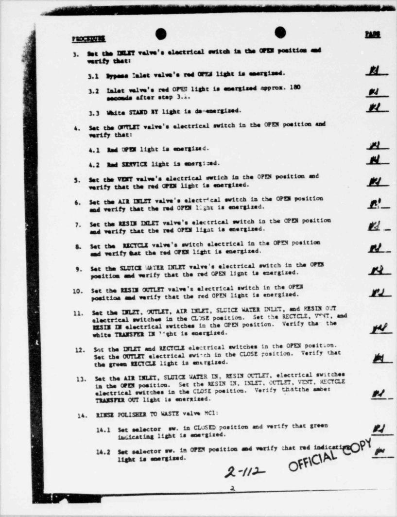
*
|~ G O amusema,,
l; bt thB M Ve19e's elettrical Switch is the 6 peetti m e d3."
f. wority thet
U3.1 Bypees '.alet velve's red CF M liskt is emergiand.
- 3.2 Inlet valve's red 0FT2 light is emergiaed approx.180 Nessende after step 3.1.8/
i 3.3 Mite STAND BY liskt is de-emergised.
{ Set the OffTLET valve's electrical switch in the OPEN positice and4.verify that
#l4.1 Bad CFW light is emergized.M4.2 Bed SIRTIG light is energi::ed.
5. Set the TIET valve's electrical swtich in the OPEN position and N_
verify that the red 0 FIN light is energized.
t 6. Set the AIR INLET valve's electedcal switch in the OF 5 position [_f
and verify that the red 0FM 14ht is energized.,
'
l7. Set the RESM IMLET valve's electrical switch in the OPEN position [_-
and verify that the red CFE3 ligst is energized.
8. Set the RICTCLE valve's switch electrical in the OPEN position d_sad verify hat the red CP U light is energized.
1 9. Set the SLUIG 'JATER INLET valve's electrical switch in the OPEI Npositica and verify that the red CPCI lignt is energized.
10. Set the RESIE OUTLET valve's electrical switch in the OPEN M)position and verify that the red OPEN light is energized.
Set the IELZT, GUILET. AIR INLET, SLUICE WATER INIIT, and RESU OUT11.electrical switches in the CL75E position. Set the RECTCLE, V M . andEISIE II electrical switches in the OPEN position. Verify tha~ the kwhite TRAISFER IN * *ght is energized.
Sot the DLET and RECTCLE electrical switches in the OPIN position.12.Set the OUTLIT electrical switch in the CLOSE position. Verify that kthe green IICICLE light is ent.rgized.
13. Set the AIR IMLET. SLUICE WATER IN, RESIN OCTLET. electrical switchesin the 02 5 position. Set the RESIN IN. I5LET CCTLET. VENT. HECYCLEelectrical switches in the CLOSE position. Verify thatche amber~ M ,,TRANSyER OUT light is energized.
14. RIESE ICLISHER TO WASTE valve MC1:
14.1 set selector sv. in CLOSED position and verify that greentw.tcating light is energized.'
14.2 Set selector sw. in OPEN position and verify that red indicat blight is soorgised. YJL -H2--1
.1
____- - - ._ - _ - _ _ - - .. _ -_.

paccgggg g
}13. ESCTCLE valva E 21
15.1 Ses set. se. in GAEED peel * tan and verify that gream indtenging-
light is energised. M15.2 Set sal. sw. La WER position and verify that red indiciting M11$ t is amerE sed.i
||
| A1/W SECTIGt'
1. 2D Pm tture EIRAUSTED alars wird:w 'T-a. (dvs. D 3835 line L-Jf)
1.1 See valve's electrical sal. switches so that the aser TRANSTEROUT light is energized. Set gallonage counter to the CTTpositice. Verify that the alaru window and the red PCLISifEF.EIMAUSTED lights are flashing brightly.
| 1. 2 Depress Annonicator alaru SII2NCE butt:e and verify that ala:n! 11$ts have a bright steady slow.
1.3 Set counter to read 10 conats. Verify that the alaru lighta areD " 4== dimly.
1.4 verify that alaru 11shes can be extinguished by depressing tre- riator RZ5ET button. N
|
2. 3 ?CL15EIR LOW FLOW alars windcw T -1, dvs. D-3835 line 3 77)*'
2.1 Circuit L9A not emergized and OUTLET valve's electrical seJ . sw.La the OPEN position. Energize circuit L9A and verify that af terapprez. 3 minutes the al tra window and the red LOW FI5=' lights are NC amhing brightly.
2.2 Deprese ====ristor ALARM SILENCZ button and verify that thealare lights have a bright steady glow. b
2.3 Set OUTLIT valve electrical svtich in the CLOSED position.Depress the annaciator ALARM SILENCE button and verify thatthe alaru lights are fis rains dimly.
3.4 Yorify that the alare lights can be awia=uished by depressingthe aannonciator E15ET button. .,,,,
OFF\C\^\ 'Q W,.y
. _ - . _ _ _ _ _ _ _ __ -- -. .--
_

.
e ePantvmagip.- g*c
f- 3. 28 POL 15EER EIGE CCEDUCT1Y1TT alarm window I-l (Deg. D4088 lime &*l*I )'
3.1 Verify that there is no contianity between contacts L-C on-
| poliaLar i t in rear of Beckman-Boneywell conductivity recorar. W!
; 3.2 Install jtaper across cantacts L-C ad set CCTLET valve switch'
' im OFEN positico. Remove jumper and verify that alarm windowand red RICE Card. lighs are flaahing brightly. A/'
3.3 Depress ALAIN SILENCI button ad verify that the alarm lights-
have a bright steady glow. Afl 1
!
J.4 Set CCTLIT valve's electrical sw. in the CLOSI position. Verify $that the alaru lights are f1== hine dialv M/
3.5 Verify that the alars lights can be extinguished by depressingtjne EESET buttoe. N ;
,
i 4. 2 4. Pnr.Turan RIGE FRESSURE DROP IESIN TRAF alarm window i -11 (dug. P1767 line 1-7 ) 4|
~
' d,4.1 Open contacts /fot) /48Y at differential pressure switch. I
Verify that alarm window and rad HICH D/P lights are flashing jbrightly.
-_],
'
| 4.2 Depress ALAEM SILENCE butten and verify that the alarn lights ?
=
have a bright staady slow. M/ '?
4. 3 Close cr ct c4ts artd va.rify that, the alarm lights are flashingi
| dimly. [2 -
|
{ 4.4 Verify that the alars lights can be extinguished by a,,i| depressing the EESIT buttcu. Av 1
l'
, , Y 'Yba
lli
~| \f
v
s.
.
6.
n
off\C#t co 1o
\ A-u/__

_ . . _ - _ _ _ - _ _ _ - - - - -
g
_
O e'
pW.1S M # I(L.A. Ihg. D-3431 Bev. D)
- tymAL conDmass
1. Set the following electrical switches in the CLOSED positice:
1.1 Inlet and bypase v tve,
1.2 Deciet
| 1.3 Yeati
1.4 Air inlet
1.5 Resia islet
__1.6 Encycle [
4
1. 7 sluice votar inlet,
1.8 Emeia ostlet f9
2. 120 YAC applied tc tircuit 7A. ,
..
,
I 3. Air prosaure applied to the valvse and the above air valve's selector V| evitch in the AUTO position. JJ '
?
{FWXEDUllE PASS
1. Verify that the green CLOSE lights are energized on the followiag valves:i
N1.1 lulat t
#2| 1.2 Inlet bypassl
1.3 Decle Ml
N1.4 Yetji
,[W1.5 Air islet
N1.& Emsin talatf ^ N ''
1.7 Becycle
_N NL8 Slaice Water inlet
M/ /1.9 nasia outist11
2 Verify that the white STAND BY light is an.: sized. FJ $'
offCA ' "
d-//S--
- - . - -- _ . _ _ _ _ _ _ - _ _ _ _ _ _ _ _ _ _ _ _ _ - _

- -- - _--
,
l'DC M U|L,
!,
3. Set t:aa 20LET Talve's electrical switch in the OFIE peeition andverify thatt
3.1 Bypes lalet valve's red 0Ff26 light is emersized. (,
3.2 Inlet enlve's red OPEN light is energized approx. ISO Af;
seconds aftar stop 3.1.,
[!
|3.3 White STAND BY light is de-energiand.
4. Set the Ot4LET valve's electrical switch in the OP D position andverify that:
Mf/4.1 Eed OPEN light is energizei.
4.2 Red SERICE light is enerEf zed. L| 5. Set the VENT valve's electrical svtich in the OPEN position and Mverify that the reti OPEN light te energized.
6. Set the AIR INLET valve's electrital switch in the OPEN position [_( and verify that the rad OPD li.;ht is energized.4
7. Set the RESIN IELZT valve's electrical switch in the OPEN position N, ,and verify that the red OPEN ligte is esorgizac. h
8. Set the RICTCLE valve's switch electrical .c che OPEN position 1d$ fand verify that the red OPEN light is energized.
I~
9. Set the SLUICE '4ATER INLIT valve's e1eetrical svitch in the OPEN [positice and verify that the red CPEN light is energized. | \
10. Set the RESIN OCTLET valve's electrical switch in the OPEI kposition and verify that the red CPU light is energized.
11. Set the INLET, OCLET Ali DLZT SLUICE 'JATER INLET, and RESlN OtTelectrical switches in tu CLC3E position. Set the PICTCLE. VZ''T, and
|E31N IN electrical switches in the OPD positien. Verify that :he g
Nj wtitte T3ANSPIX IN light is energized.|| 12. Set the INLZT and RECTCLE elec:rical switches in the OPD positicn.|
Set the OUTLET electrical swit-h in the ''LOSI position. Vatify thatthe green IZCTCLE light is enecgized. ,
13. Set the AIR DLET. SLUICZ VATER IN, RESIN OCTLET, electrical svi:chesIin the OPEN position. Set the ZESIN IN. INLET, OUTLE!, VENT, RCCLE
electrical switches in ths CLOSE position. Verify t.hatthe amber [N ITRANSFER OUT light is energized.| t
i
j 14. RINSE POLISHIR TO WASTE valve 'Cl: j
in CLO5ED position and verify that green #M|
14.1 Set selector sv.
indicating light is energized. ..
,
I
14.2 Set selector ew. in OFEN position and verify that red indicating h ~
light is energized.
dA-//6 Ofi\O'2
___ _ _ _ _ _ . . . . _ _ _ _ _ _ _ . _ _ _ _ _ _ _ . _ _ _ _ . . _ _ . _ _ . . _ _ . - . . _ ,-

e
. .__ .15 BBCfCLE valve E 2:
15.1 set sal. ev. in CLosID posit taa and verify that green indicatingMllight la energised.
15.2 5et sel, sw. in OPEll position and verify that red ind1CAtlag klight is energized.
.
ALARM SECTIout
1. 2450LISEER E:DIAUSTED alarm vinC v 13 *1 (dwg. D' 3*M line 2 ,N )
1.1 Set valve's electrical sel, switches so that the amber TRMSTYROUT light is energized. Set gallonage emnter to the OFFposition. Verify that the alars window and the red POLISEEREISAUSTED lights are flasbiss brightly. [_
1.2 Depress Annunicator alars 3II.ENCE butten and verify that al.rulights have a bright steady glow.
1.3 set counter to read 10 count 2. Verify that the alarm lights are [fi-* g dimly .
1.4 Yorify that alarm lights can be artinguished by depressing t!4 Nammunciatcr ':Zi!T button.
2. 3Sf0LISEZ1 LOW F1/N alarm vindov 11 2. (dvs. D-3835 line 3 'T;
2.1 Circuit L9A not energized and CUTLET valve's electrical sel. ev.La the OPE 3 position. Energize circuit L9A and verify that afterapprox. 3 minutes the alors window end tne red LOW FLOW lights are kflashing brightly.
2.2 Depress annunciator ALAM SILDECZ butten and verify that thealars lights bave a bright steady glow.
2.3 Set OtTTLIT valve electrical svtich in the CLOSED position.Depnse the annurgiatur ALAM SILEICE button and verify that ,
the alars lights are fl. Shing dimly.
3.4 Terify that the alarm liAts can be extinguished by depressingthe annunciator RESIT button. \
()kk//7
,;m ._ _ _ _ ._ _
- - _ - - _ _ _ _ -
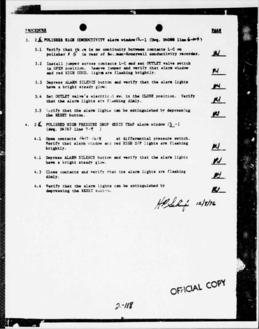
- - _ _ . . - -. - - - -_. - - - _ _ _ - ._
..
PROCEDURE g
3. 21 Por.tturn 113 CENDUCTIVITY alars window (1.-l 0>g. D600511am 6-4*i)
3.1 Verify that tir ee is no contiimity between contacts L-C aoPolisher # 6 is rear of anc_: man-Ecosywell condectivity recorder. M/
3.2 Install jumper across contacts L-C and set OCTLET valve switchin CFEN position. 1tanove jumper and verify that alars window band red HICH CD:iD. Lighs are f1-ahias brightly.
!
|
3.3 Depress ALAIM SILENCE button and verify that the alara lightshave a bright steady glow. N
3. 4 Se'. OUTLET valve's electric d sw. in the CI4SE position. Verifythat the alarm lights a * fiaahing dimly. N
3.5 %:ify that the alare lighta can be extinguished by depressingth EESET button. _
o. 2 ( FCLISHED HIGE FRESSUIZ DRCF 'fESIU TEAF alaru vindow |L-1(dvs. D6767 line 7-T )
4.1 open contacts if=87 - la at at dif forantial pressure switch.
Verify that alarm vindow ard red HIGE D/F lights are flashing .gbrightly. Fri _
4.1 Depress ALAIM SILENCE button and verify that the alaru lights ,jhave a bright steady gicw. F4
4.3 Close contacts and verify that the alaru lights are flashingdimly.
4.4 Terify that the alaru lights can be extinguished bydayreesing the RISET button. k
}{K/n nNn.p
o
ofac g c #p.-Ilf
a

- - - - _ _
.-.
,
4 - , _ , .(L.A. Bug. D-3437 aav. 3)
' DrtTIAL conDITtans
1. Set the following electrical switches in the CLOSED position:
1.1 Ialat and bypass valve
1.2 Detiet
1.3 Yeat
1. 4 Air inlet
1.3 aasia talat
1.6 nacycia
1.7 51 mice water inlet
1.s ansia outist| 2. 120 YAC applied to circuit 7A.
3. Af ? pressure applied to the valves and the above air valve's selectorsettch in the AUTO position.
fBDCIlPCS PASS
1. Verify that the green CLOSE lights are emersized on the fo11owin6 valves:
1.1 Inlet 131.1 Ialat bypese M
'
1.3 Declee W..t ve.t _W1.5 Air islet N
(1.6 ansia imist
1.7 mecycle JW/__
d1.s sistem unter inlet
f;_1., m ia .etiet
2. veruy that the .ite suno i. u.ht 1. .mer.1 a. ft_
p -j19 ofVW,
. _ _
l'_ _ _ _ _ _ _ _ _ _ _ _ _ _ _ _ _ _ _ _ . _ . . _ _ _ _ _ . _ . _ _ _ _ _ _ _ _ _ _ _ _ _ _ _ _ _ _ _ _ _ _

. _ . - _ _ _ _ _. . - _ -
,
F.0CEw. G 9 nai 3. Set the IMLET valve's electrical swit & in the OFII posities and
verify that:
3.1 Bypase talet valve's red ot!!. light is energized. Ni~
3.2 Islat valve's red CFEN lisht is energized approx. 180ha a.f ter step 3.1. b}
i 3.3 thite STAhD IT light is de-seergized. //_
4. Set the G~TI.ZT valve's electrical switch in the CFD position andverify that:
;1 4.1 and OPEI light is energized. kl
'( 4.2 Red SEI'i' ICE light is energirsd. N5. Set the TEXT valva's electrical n etich in the OPD position and
verify that the red CPEN 11the it, energized. NIl 6. Set the AIR INLET valve's electrical switch in the OPEN poc'. tion
M wrify that the red CPU 11ekt is energized. M_|'I 7. Set the RZ5D DLET valve's electrical switch in the OFD position ~'
and verify that the red CPD ligrt is energized. M ,)1
-
! 8. Set the RICTCI.E valve's switch electrical in the OPEN position 4sad verify hat the red CFD light is energized. k #'
.s
9. Set the SLUICE WATER DLET valve's electrical switch in the OPEN iposition and verify that the red CPD 117,ht is energized. N f
10. Set the RES D OC'' IT valve's electrical switch in the OPEN -
positico and verify that the red OPD light is energized. [11. Set the INLIT, OCTLET. AIR INLET, SLCICE WATER LP ET, and RESIN CC"
electrical switches in the CLCSE position. Set the RICYCI., VD T. andIISIN II electrical switches ic the CPEN position. Verify that thewhite TRANSFER IN light is energized. M
12. Set the INLET and RECTCLE electrical switches in the OPD positien.i
| Set the OCTIJ.T electrical switch in the CLOSE position. Verify that'
,
the green RECTCLE light is ene :gized.
13. Set the AIR INLET. SLCICE VATER IN, RE3"* OL":" LIT. electrical sut :ches'iin the OF D positioc. Set the RESI' 12 . IE ET. CCTLIT, VE'l , PE |"7CI?'
electrical switches in the CLCSE position. Verify thatthe aaber '
TIANSTER OUT light is energized.~ N
14. RIESI POLISHE2 TO WASTE valve P.Cl:
14.1 Set selector sw. in CLCJD position and verify that greenfadicating light is energized. [_ . .y
14.2 Set sele: tor sv. in OPEN position and verify that red indicating
light is energized. N
7'/Ao Off.t
_.
- - _ _ _ _ _ __ - _ . _ _ _ _ _ _ _ _ -

- __
.,_
.
'
6 ey FS CEDURE g
13. merna v.1,. n .;
15.1 set as1. ow. La CLDEED position and varify that gream indicettag11she is emersised. 28
.
'
15.2 Set sal. sw. La CREE poettian and verify that red indientinglight is ener31and. M
,
A1Algt SECTIOM
1. 2[F"nn HBACSTED alarm winew 15-2. (e.s. $ was lin A_- 2)
1.1 Set valve's electrical sel. switches so that the amber TRANSTTIOUT light is energized. Set tallonage counter to the OFFpositice. Veriff that the alarm vindow and the red PCLISHERIIIACSTED lights are flashi.tg brightly, k
1. 2 Depress Annuaicator alarm SILINCE button and verify char alars glighta have a bright steady slow.
1.3 Set countar to read 10 counts. Yority that the alarm lights are Nflashfas dimly.
1 1.4 Yarify that alare lights ca: % extinguished by depressing *he| - riator IESET button.
2. 2PrcLissEn Im FLou alarm window if.1 (erg. D-3835 line 3 -to
2.1 Circuit L9A not emerstred % d OCTLET valve's electrical sel. sv.in the OPEI position. Energize circuit L9A and verify that afterapprox. 3 minutes the alarm window and the red LOW FLOW lights are gf'=M at brightly.
,
2.2 Depress annunciator ALARM S*.II5CY button and verify thet thealarm lights have a brt @ t steady glow. k
2.3 Set GUTLET valve electrica1 svtich in the CLOSED position.Depress the annunciator Ai GM SILENCE button and verify that
: the alarm lights are flashing dimly. N3.4 Verify that the alarm lights w be extinguished by depressing
the assenciator IESET butten.
ym offCA'--
- - _ _ - _ _ - - _ _ _ _ _ _ _ _ - _ _ _ _ _ _ _ _ ______________-_________-_______________-_________________________i

-- - - - ------- - ___ __ _ _ _, _
e
e e ,-2.f.yer men IIM N alarm windse if-l (Dus. D600011as6-M1 )3.
i 3.1 Perify that there is no esatimity becomen eastacts L-C en...
polisher # $ is rear of Ber-- -- " n-,- -H conductivity recorder. M __
3.2 Isotall juper across contacta L-c and set ctm.ET valve esitch..
is W U position. Ramese jgr and verify that alarm window WA)and red HIG CND. Lisha are f1 main, brightly.
3.3 Depress ALAIN SILDG button and verify that the alarm lights N-,
have a bright steady glow.
3. 4 Set OUIUT valve's electrical sw. in the CLOSE position. Verify A*/that the alarm lights as a f14ahias dimly.
3.5 Verify that the alare lights can be =ringuished by depressingtb ESIT bottoa.
I f wir vtsrn RIG FIESSGZ DROF MESM TRAF alarm window /[-}' I4. ~'~
(Ot- D6767 line 7-11 )i
open contacta (Ql- lhit, at dif fersatial pressure switch.4.1 j|Verify that alarm window and red IIG D/F 11;; hts are flashina ,
}:brightly.
4.2 Depress ALAIM SILENCE button and verify that the alarm lightshans a bright steady slow. j
I4. 3 Close contacts and verify that the alarm lights are f1== hine
dimly.
4.4 Verify that the alarm lights can be aztinsuf M by m'
FVdepreseing the ESET buttaa.
'
f'ff'' 6 f 11Nic.y
!
, I'
!
cO93 d
M\0 )j-fg OH

_ _ .. _ _. . -.. __ _ _ --_
. 3je
f._
!! O e- , 1(L.A. 255. D-3831 Ba'. B)
artTIAL cosmmans
i 1. Set the follmaring electrical switches la the CLOSED position:
'- 1.1 Ialat and bypees salva
1.2 Outisti
1.3 Test*'
1.4 Air inlet
1.5 Reais inlet r
1. 6 Becycle;
1.7 Slaica water inlac
|,
1.8 Beata antistt
2. 120 VAC applied to cirenit 71.
Air pressere applied to the valtus and the above air valve's selectore,
3.suitch in the AUTO position.
~
FASSFN -
Verify that the green CLOSE lights are energized on the following valves: ,
1.k
1.1 InletN
1.2 Inlet bypees
N1. 3 Outlet
N1.4 Yeat
( '
1.5 Air talet
M1.6 Esata salme
N1.7 Encycle
// f| 1. 8 11 mice Matar inlet 1
[I h-1.9 Basis omelet r,
N hTerify that the Mte TIAND H light is energized.2.
1
'
\S p
i
I
A-/A3 o
- _-
--, - . - - - . . . . - - - - - - - . . - . . - - - - -

._
.-
. . .__Set the IILIT valve's electrical switch ta the OPEN posities and3.verify thett
M3.1 Bypese Inlet valve's red 0FD liebt is energized.
Inlet velve's red 0FE5113'at is energised approx.180 N3.2seconde after step 3.1.
If/3.3 ikite STAND IT light is de-energiand.
Set the OffTLET valve's electrical switch in the CFEN position and4.verify that:
8/ j4.1 and OPER light is amargised.
IO-
4.2 Red SE d 3 light is energi ed..
Set the VENT valve's electrical svtich in the OPEN position and N5.verify that the red 0FU light is enerTited.
Set the AIX MLET calve's electr' cal switch in the OPEN position [_I
6.and verify that the red CTEN ligst is energized.
Set the IESF. ?3LET valve's electrical switch in the OPEN position [_Land verify tLe the red CPEN light is energized.
IECTC12 valve's switch alectrical in the OPEN position8. Set theand verify hat the red CPEN light is energized.
,
Set the SLUIG MATER INLET valve's electrical switch in the OPEN N,
I 9. is energized.positiae and verify that the red OPEN light'
Set t a RESIE OUTLET valve's electrical switch in the OPEN [10.positi.am M verify the- the red CPEN light is energized.|
Set the 3!IT. OCLET. AIX IXLET. SLCICE WATER ITLET. and RESIN OtTTSet the RECTCLE. V""T* . and11.electrical s;sitches in the CLaSE position. Verify tha' tae3133 M electrical switches in the OPD position.white TRANSTER D light is energized.
Set the IILET and RECTCLE electrical switches in the OPEN position.12. Verify thatSet the OUTLET electrical swirta in the CLOSE position. kthe grwee EECTCLE light is energized.
.
Set the AIR INLET. SLUICE VATER D. RESTN OCLET. electrical switches13. Set the RESI.N IN. INLET. CLT ET. VE'TT, RECYCLEin the OFE3 position. Verify thatche ance k_electrical switches in the CIASE position. '
TEANSTER OUT light is energized.
14 XIIII POLISEEE TO WASTE valve MCl:
sv. in CLcSED position and verify that green g14.1 Set relector
indicating light is energized.
Set selector av. in 0FZ3 position and verify that. red indfeating j14.2
light is energized.
A-/M OffN,
-- -- . _ - _ _ "''"# 7 me % - - ,

..
-
O O na ,
> ==a;gi;
13. BBCCLE velve IC2s '-
Set sol. es. La GASED positna and verify that green indicattag Ni i
: 15.1light ta energised.
usSet sei. sw. in ons positiae ed verify that red indie-r4== F415.2
( light is emergised.|
,
i(
f'
't
fII
||
|
|| "A SECTTtm(
26tPm.r arra IIIAD5TED alara vinc,ow II 2. (Arg. D' 3835 line L-S) .
|1.
m .alve's electrical sel. switches so that the amber TRA337ERI
Set gallonage counter to the OFF1.1OC * iabt is energized. Aj
Yorify that the alarm window and the red POLISHIR F1 _position.EIRAUSTED lights are fimhiog brightly.
l
Depasas Ammunicator alarm SILZNCE buttas ed verify that als- s1.2lights have a bright steady slow.
| Verify that the alarm lights are_1.3 Set countar to read 10 counts.
flaahing dimly.'
h
Yorify that alare lights can be aztinguished by depressing t e1.4aumenciator IESZT button.
f(e-1 (dvs. D-3835 line 3-34)2h5EZ1 LOW FLOW alarm window2.
Circuit L9A not energized and OUTLET Salve's electrical sel. sw.Erergize circuit L9 A and verif y that after2.1is the WEI position.appros. 3 minutes the alam vindow and the red LDW FLOW ligt ts are-
flamhtne brightly.
Dar reas anunciator ALARM SILENCE button and verify that the2.2 al. ara lights have a bright steady slow.
Set OUTLET valve electrical svtich in the CLOSED position.Depress the annunciator ALAFJi SILENCE button and verify that
I 2.3
the alara lights are fla.' ting dimly.j
Verify that the alarm lights can be artinguished by depressing_3.4
_
'he annunciator IESIT bu;too.
COPiOfB
#1AS
.
_. . . _ ..___ __ __

- _ _ _ _ _ _ _ _
1
g4
\FEDCIpqER
28,PKNEn E12 6 alaza wtadsub-1 Chrg. D64# 11ae6 lit )3.
verify that there is no contianity between contacts L-C en aFW3.1
polisher # 1 is rear of factman-Goesywall conductivity recorder.
Install jumper acrose contacta L-C and eet ocTLET valve switch3.2 Remove jumper and verify that alarm windowis CFEM position.and red EXCE CIND.113ha are flaahtag brightly.
Depress % AIDE SILENG button and verify that the alarm lights3.3have a bright steady 31cw.
VerifySet OUTLIT valve's electrical sw. in the CLOSE position.3. 4 that the alare lights are finsking dialy.
Verify that the alarm lights un be re--irauip%i by depressing /f
3.5th EESIT buttoa.
2 j POLISEID EIGE PIISSUIE WE' IISIN TRAF alarm window ff -1~
4.(ess. D6767 lias 7-13 )
opea contacts /r.15- 141r. at differential pressure switch.4.1 <
Verify that alarm window and md RIGE D/P lights are flashing N_brightly.
Depress ALAIK SILZBCE button and verify that the alarm lightsgjFv14.2
have a bright steady glow. i
Close contacts and verify that the alare lights are flashing4. 3 .
42217
Verify that the alarm lights can be ex*4=rtahed by4.4depressing the EISIT buttoe.
/4 M
oppy3Al. COPY
Jt-/Alo.
~~-----.__-__.m__ . _ _ _ _ _ _ _ - - - - - - - - - - . _ _ _ _ _ _ _ _ _ _ _ _ _ _ _ . ___