flow in closed conduits - Bureau of Reclamation
26
w i. - w, :..1~+~1y~t : ~.a~t .c._a.....:. _~ • ' ~ua -... .'iiL4YFiWiv~ ... :~:_._ ~itY> r +Ni~^'~` ' `+` _ • .,,.rapt y~.._ —` — ... .... ....__ _ .~.... _ --- - CD '-' HYDRAULICS BRANCH OFFICIAL FILE COPY C.). Q a. BUREAU OF RECLAMATION HYDRAULIC LABORATORY ~ IF "E F P WHEN BORROWED RETURN PROMPTLY FLOW IN CLOSED CONDUITS by W. P. Simmons A paper presented at the Seminar sponsored by the Southern Idaho Section, ASCE, in Boise, Idaho, November 18_19 , 1965 .
-
Upload
khangminh22 -
Category
Documents
-
view
0 -
download
0
Transcript of flow in closed conduits - Bureau of Reclamation

w i. - w, :..1~+~1y~t: ~.a~t .c._a.....:. _~ • ' ~ua -....'iiL4YFiWiv~ ... :~:_._ ~itY> r +Ni~^'~` ' `+` _ • .,,.rapt y~.._—` — ... .... ....__ _ .~.... _ --- -
CD '-' HYDRAULICS BRANCH
OFFICIAL FILE COPY
C.). Q a.
BUREAU OF RECLAMATION HYDRAULIC LABORATORY
~ IF "E
F P
WHEN BORROWED RETURN PROMPTLY
FLOW IN CLOSED CONDUITS by
W. P. Simmons
A paper presented at the Seminar sponsored by the Southern Idaho Section, ASCE, in Boise, Idaho, November 18_19, 1965
.

FLOW IN CLOSED CONDUITS
Problems involving flow in closed conduits may occupy a considerable portion of a practicing engineer's time. Because of this, and be-cause the problems may be quite different from those of open-channel flow, an understanding of the principal differences and some im-portant factors involved in closed-conduit flow is important.
Closed-conduit flow may be defined as flow in completely filled conduits where no free water surface exists, or flow (relative motion) deep enough in a body of water that surface effects are not significant. Flow in pumping plant discharge lines and municipal water supply systems are examples of the first portion of the def-inition, and deeply submerged submarines may be examples of the second portion. In this paper only the case of completely filled pipelines and other closed conveyances will be considered. Also, the paper will be limited to flow with liquids such as water, and will apply only to incompressible flow.
As has been suggested, closed-conduit flow is in some respects very different from open-channel flow. For example, the fluid is com-pletely constrained by the conduit walls and this constraint is mani-fested as a pressure force on the walls and within the fluid. No free water surface will normally exist and thus no hydraulic jump occurs. Similarly, there will be no backwater curves and no significant changes in conveyance size and shape with changes in hydraulic gradient or rate of flow.
For an engineer who has been working with all the complications of open-channel flow equations, backwater curves, subcritical and super-critical flows, hydraulic jumps, etc., the simple, straightforward concepts of closed-conduit flow are welcome. But unfortunately, this apparent simplicity may be an illusion, and if no further thought is given to closed-conduit flow problems, the results can be surprising and sometimes devastating. For instead of being simple, flow in closed conduits often involves a wide range of special problems which require careful analytical attention. Professor Peeble has already presented the basic concepts of flow and the forms of energy involved. In the present paper, examples drawn from experiences of the Bureau of Reclamation will be used to illustrate special problems.
Entrapped Air
An outlet works is provided at Navajo Dam on the San Juan River in northwestern New Mexico to release waters to meet downstream demands. This outlet works consists of a 127-foot-high trashrack, a bellmouth inlet, a 133-foot-high 10-foot-diameter vertical shaft, a bend, a
10

----------------------------- ~.<..,. .« ~r.~r.~•.a...,,..~...,..~.a r...a,.,,t.Y..:..::.: w.,.wnawris..-rui.~w~+.wxarwraa.~ 1W
gently sloping 18-foot 9-inch-diameter tunnel 584 feet long, an emergency control gate, and 125 feet of 9-foot 2-inch-diameter steel conduit (Figure 1). The conduit bifurcates at the downstream end and supplies two 72-inch hollow jet valves which discharge into a stilling basin. The upstream portion of the intake shaft and tunnel can be closed for inspection and maintenance by a stopper-like elliptical bulkhead which is stored at the top of the unusually high trashrack structure. The bulkhead weighs 17 tons.
During early operation at the dam, and contrary to definite operating criteria, relatively large releases were made through the hollow-jet valves. For a time, the releases were greater than the flow that could be supplied at the bellmouth entrance with the reservoir level only about 4 feet above the crest. As a result the water level lowered in the intake shaft and flow spilled over the top of the bell-mouth to fall a considerable distance to this pool. Air was entrained and carried into the horizontal tunnel by the flowing water. Here it accumulated into one or more large bubbles. At about this time, and while the opening of one of the two valves was being reduced from 90 percent to 40 percent, the pressure in the conduit suddenly dropped. The valves were then closed completely and the cause of the abrupt pressure drop was investigated. Visual inspection of the intake structure revealed that the elliptical bulkhead, which was normally suspended about 100 feet above the inlet, had been momentarily forced upward, its holding brackets forced open, and the bulkhead had sub-sequently dropped downward along its tracks and sealed the intake.
Analysis of the sequence of events indicated that the large accumulations of air in the downwardly sloping, 18-foot 9-inch-diameter tunnel had traveled upstream when the flow was reduced by the reduction in valve opening, and had then risen with explosive force up the 133-foot-high intake shaft, driving a column of water ahead of it. The column continued upward inside the trashrack to the elevation of the bulkhead, where it forced the bulkhead upward sufficiently to damage the top of the tower and then allowed the bulkhead to fall to the closed position on the intake.
Considerable work was involved in obtaining work platforms and appropriate equipment to repair the hinged brackets that secured the bulkhead at the top of the tower, raise the bulkhead to the storage position, and resecure it. This work was complicated by the fact that the reservoir level was rising because no other sig-nificant flow releases could be made from the dam.
The same action involving entrapped air has occurred on other structures with perhaps the greatest damage occurring at Paonia Dam in Colorado. In all cases, releases through the control gates were,for a time, in excess of the flows that could pass over the intake crests at low reservoir elevations, and were greater than the flows specified by operating instructions. More specific and
F
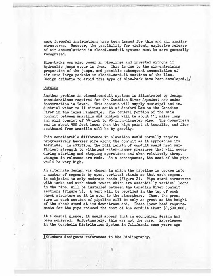
moms forceful instructions have been issued for this and all similar structures. However, the possibility for violent, explosive release of air accumulations in closed-conduit systems must be more generally recognized.
Blow-backs can'also occur in pipelines and inverted siphons if hydraulic jumps occur in them. This is due to the air-entraining properties of the jumps, and possible subsequent accumulation of air into large pockets in closed-conduit sections of the line. Design criteria to avoid this type of blow-back have been developed.1/
Surging
Another problem in closed-conduit systems is illustrated by design considerations required for the Canadian River Aqueduct now under construction in Texas. This conduit will supply municipal and in-dustrial water to 11 cities south of Sanford Dam on the Canadian River in the Texas Panhandle. The central portion of the main conduit between Amarillo and Lubbock will be about 115 miles long and will consist of 54-inch to 96-inch-diameter pipe. The downstream end is about 400 feet lower than the high point at Amarillo, and flow southward from Amarillo will be by gravity.
This considerable difference in elevation would normally require progressively heavier pipe along the conduit as it approaches its terminus. In addition, the full length of conduit would need suf-ficient strength to withstand water-hammer pressures that will occur during starting and stopping operations and when relatively abrupt changes in releases are made. As a consequence, the cost of the pipe would be very high.
An alternate design was chosen in which the pipeline is broken into a number of segments by open, vertical stands so that each segment is subjected to only moderate heads (Figure 2). Pipe stand structures with tanks and with check towers which are essentially vertical loops in the pipe, will be installed between the Canadian River conduit sections (Figure 3). A vent will be provided in the top of each check structure so it is open to the atmosphere. Thus, the pres-sure in each section of pipeline will be only as great as the height of the check stand at its downstream end. These lower head require-ments for the pipe reduced the cost of the conduit about $2,500,000.
At a casual glance, it would appear that an economical design had been achieved. Unfortunately, this was not the case. Experiences in the Coachella Distribution System in California some years ago
1/Numbers designate references in the Bibliography.
03
r

showed that serious surging can occur in this type of open-stand system.2/ I/ The surges appeared as near-periodic variations of flow in the pipeline with periods ranging from 60 to 100 seconds. In their most violent form, the surges caused the pipe stands to completely empty when the water receded and overflow when they re-turned (Figure 4). Principal factors involved in analyzing the problem were inertia of the water in the pipe reaches, frictional resistance, changes of level, Y1 and Y2, in the connecting halves of the stands at the upstream and downstream ends of the reach, and the reach length (Figure 2). For conditions where the stands do not empty, individual reaches have natural periods of oscillation given approximately by
Tn = 2 Tr~;RgL
where F is water surface area in the halves of the stands, ft
L is length of the reach in feet, and
A is cross-sectional area of the pipe, ft
The following excerpt from Reference 3 discusses the nature of the surging:
"If the flow coming into a reach is separated into two parts, consisting of a steady average flow, Qo, and a superimposed sinusoidal variation, q sin 2TT t/ To, the sinusoidal variation will attempt to set the reach into oscillation at the incoming frequency. If the period of the incoming flow variation and the natural period of the reach are widely separated, the amplitude of the resulting oscillation will be small. However, as the period of the incoming flow approaches the natural period of the reach, resonance occurs and a resulting oscillation of large amplitude can be produced. Resonance in vibrating systems is well known, but in thewpipe reach it produces a surprising result. Because the baffle in the pipe stand at the lower end of the reach acts as a weir and can therefore accommodate considerable flow variation with only minor changes of level, the flow variations induced in the reach are readily carried over it. Because resonance generates flow variations in the pipe reach greater than those fed into it, the reach behaves as an amplifier in the sense that the amplitude of the flow variation discharged at its lower end is greater than the amplitude coming into it. The ratio of the outgoing to the incoming amplitudes is controlled by friction, but the friction losses in pipelines are proportional to the square of the velocity and at low flows friction is considerably reduced and amplification factors of six or more can be realized."
4

Analytical methods for studying these surge characteristics and predicting their effects in future designs were developed and con-firmed in the Coachella investigations. Basically, resonant condi-tions caused the difficulties, and the effects of various schemes such as surge tanks, unequal lengths of lines, orifices, coupled lines, etc., to'break up resonance were studied. Air entrainment was also investigated. Application of the basic concepts of natural frequency and resonance to the design of the Canadian River Aqueduct was attempted by hand calculation, but immediately was seen to be nearly impossible due to the magnitude of the aqueduct. The method was therefore programmed for solution on electronic computers.
The program was first prepared using the rigid water column theory. In order to keep calculations within the capacity of the computer available at the time, certain simplifications and assumptions were necessary. To determine the reliability and accuracy of the re-sulting program, hydraulic model studies were made (Figure 5). The first portion of the studies has been completed in the Denver Lab-oratories of the Bureau, and fair correlation was achieved between results predicted by the program and results actually encountered in the model.
Since these studies were made, a much larger capacity computer has become available, and a procedure for analytically determining surge characteristics using elastic water column theory has been outlined._4/ This procedure has been expanded and adapted to the surge problem and - a new computer program has been developed. Further model studies are now pending.
Water-hammer
Pressure waves of much greater violence than the above are not unusual in closed conduits, and most engineers are familiar with them as water-hammer. *J/ The laws governing the changes. of pressure with discharge in a completely liquid filled pipeline depend upon the conditions under which the flow occurs. If the liquid is considered incompressible and the velocity of flow passing through any section of the pipe remains constant, Bernoulli's energy equation applies. However, if the motion is unsteady, that is, if the discharge at each section is varying rapidly from one instant to the next, rapid pressure changes occur inside the pipe. Compression and expansion of the fluid and stretching and shrinking of the conduit occur and Bernoullits equation is no longer applicable. The latter pressure changes are called "water-hammer" because of the characteristic hammering sound which sometimes occurs.
Because excessive pressures may result from rapid changes in rate of flow, large conduits and long lines are usually designed to pre-vent rapid changes in rates of flow by insuring that the effective
*J Also see bibliography in Reference 5.
5
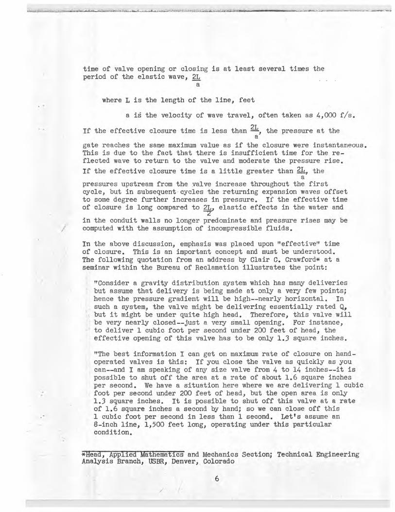
time of valve opening or closing is at least several times the period of the elastic wave, 2L
a
where L is the length of the line, feet
a i6 the velocity of wave travel, often taken as 4,000 f/s.
If the effective closure time is less than 2L, the pressure at the a
gate reaches the same maximum value as if the closure were instantaneous. This is due to the fact that there is insufficient time for the re-flected wave to return to the valve and moderate the pressure rise.
If the effective closure time is a little greater than 2L, the a
pressures upstream from the valve increase throughout the first cycle, but in subsequent cycles the returning expansion waves offset to some degree further increases in pressure. If the effective time of closure is long compared to 2L elastic effects in the water and
in the conduit walls no longer predominate and pressure rises may be computed with the assumption of incompressible fluids.
In the above discussion, emphasis was placed upon "effective" time of closure. This is an important concept and must be understood. The following quotation from an address by Clair C. Crawford* at a seminar within the Bureau of Reclamation illustrates the point:
"Consider a gravity distribution system which has many deliveries but assume that delivery is being made at only a very few points; hence the pressure gradient will be high--nearly horizontal. In such a system, the valve might be delivering essentially rated Q. but it might be under quite high head. Therefore, this valve will be very nearly closed--just a very small opening. For instance, to deliver 1 cubic foot per second under 200 feet of head, the effective opening of this valve has to be only 1.3 square inches.
ItThe best information I can get on maximum rate of closure on hand-operated valves is this: If you close the valve as quickly as you can--and I am speaking of any size valve from 4 to 14 inches--it is possible to shut off the area at a rate of about 1.6 square inches per second. We have a situation here where we are delivering 1 cubic foot per second under 200 feet of head, but the open area is only 1.3 square inches. It is possible to shut off this valve at a rate of 1.6 square inches a second by hand; so we can close off this 1 cubic foot per second in less than 1 second. Let's assume an 8-inch line, 1,500 feet long, operating under this particular condition.
*Head, pp ie a ema cs and Mechanics Section; Technical Engineering Analysis Branch, USBR, Denver, Colorado
I

an,w:~f~+~7kxFncs~wsrxi...::~r,~Mr~..aa~.e..~~r,.~anwr'ro+.~a7wa.:~ue_. ,., a~...uc~:raw.:+uNt:utns:~.;aa..~eneswwalKmo~L.a:—* - ... ....... ... r.y.a......•.~..rr:,w.>~ ,.:......tyw,.e... ... .........„ «+.ro,
rate and head rise above static is (over) 300 feet--real pressure.* On this demand-type system, when the water user himself operates the valves we subject ourselves to this phenomenon and must design for it."
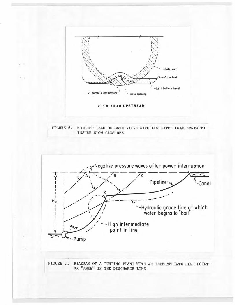
As a consequence of the above considerations, a number of irrigation distribution conduits having great length have been provided with specially designed slow-closing valves so that, no matter how ener-getically the operator turns the hand wheel, the rate of closure will be sufficiently slow to prevent destructive water-hammer pressures. In certain cases it has been necessary to provide specially shaped gate leaves with notches in the bottom to achieve very slow effective closures (Figure 6).
In pumping plants, careful attention must be given to the effects of starting and stopping the pumps, power interruptions, operation of control and check valves in the line, initial filling of the line, and release of high-pressure air. The effects of high points at intermediate stations between the pumping plant and the end of the discharge line may also be critical (Figure 7). The violent negative, and subsequent positive pressure waves produced by sep- aration of the water column at such high points during emergency shutdown of the pump could destroy much of the line if no precautions were taken. The actions that occur are described in a second quotation by Mr. Crawford:
"Now, let us consider downsurge and water-column separation. Figure 7 shows the profile of a pump discharge line. This profile has a distinct knee at "K." The dashed line below the profile represents the absolute vapor pressure head of the water. It will be about 30 feet below the top of the pipe. Now, we have a power interruption. At a very short time after the interruption,
* 1 = 0.81 seconds for closure 1.
$L, where a = 3,750 f1s (Reference 5, Figure 11, 1/8-inch wall)
= 2 (1,500) = 0.80 3,750
since aL < closure time, head rise
7
H = g ( d V) = g (!t_ A
= 33 0 750 (- 9)
= 334 feet
YM7M9~~ ~ `~=.J("T'~'~iH a#ss»-_ur...t. -. .. ~ .s'`iuw ha .r.@~.~~aaa+e~~;u:1~6i..Ly$aEA'°r-- - ~. .,r.r. -,__-.. .....r.».-. .•~M~..~. # w~.s~ei:.~<< «. ...hM•~vV~u
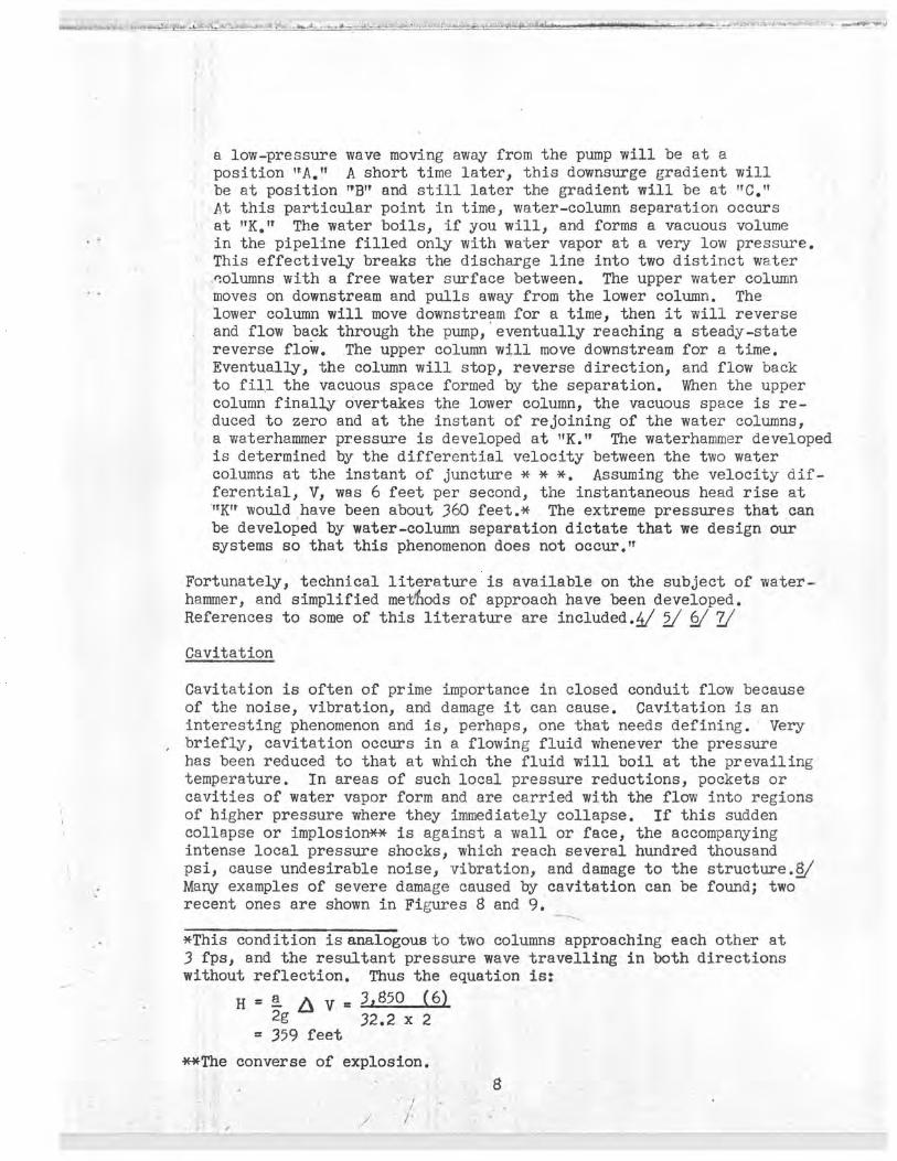
a low-pressure wave moving away from the pump will be at a position "A." A short time later, this downsurge gradient will be at position "B" and still later the gradient will be at "C." At this particular point in time, water-column separation occurs at "K." The water boils, if you will, and forms a vacuous volume in the pipeline filled only with water vapor at a very low pressure. This effectively breaks the discharge line into two distinct water nolumns with a free water surface between. The upper water column moves on downstream and pulls away from the lower column. The lower column will move downstream for a time, then it will reverse and flow back through the pump, eventually reaching a steady-state reverse flow. The upper column will move downstream for a time. Eventually, the column will stop, reverse direction, and flow back to fill the vacuous space formed by the separation. When the upper column finally overtakes the lower column, the vacuous space is re-duced to zero and at the instant of rejoining of the water columns, a waterhammer pressure is developed at "K." The waterhammer developed is determined by the differential velocity between the two water columns at the instant of juncture * * *. Assuming the velocity dif-ferential, V, was 6 feet per second, the instantaneous head rise at 'IK" would have been about 360 feet.* The extreme pressures that can be developed by water-column separation dictate that we design our systems so that this phenomenon does not occur.,,
Fortunately, technical literature is available on the subject of water-hammer, and simplified meAods of approach have been developed. References to some of this literature are included./. 1 f
Cavitation
Cavitation is often of prime importance in closed conduit flow because of the noise, vibration, and damage it can cause. Cavitation is an interesting phenomenon and is, perhaps, one that needs defining. Very briefly, cavitation occurs in a flowing fluid whenever the pressure has been reduced to that at which the fluid will boil at the prevailing temperature. In areas of such local pressure reductions, pockets or cavities of water vapor form and are carried with the flow into regions of higher pressure where they immediately collapse. If this sudden collapse or implosion** is against a wall or face, the accompanying intense local pressure shocks, which reach several hundred thousand psi, cause undesirable noise, vibration, and damage to the structure.f Many examples of severe damage caused by cavitation can be found; two recent ones are shown in Figures 8 and 9.
*This condition is analogous to two columns approaching each other at 3 fps, and the resultant pressure wave travelling in both directions without reflection. Thus the equation is:
H = 2g A V - 3,850 (6) 32.2 x 2
= 359 feet
**The converse of explosion.

Much study has been devoted to flow conditions which cause cavitation, and toward developing designs which are free or relatively free from the problem.s/ A relationship commonly used in evaluating the cavi-tation potential of a system is:
H2 _ H K = Ht _ H2
where
K is the wavitation index,
H2 is the pressure downstream from the structure, feet of water
H is the vapor pressure of water relative to the atmosphere, and
Ht is the total head in the conduit ,just upstream from the structure, feet of water
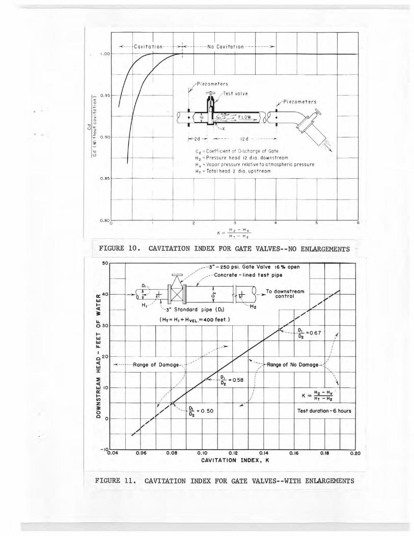
Model and prototype studies have been made to determine the cavitation indices, K, for a number of gate valve designs (Figure 10). Using this information, proposed installations of gate valves may be ex-amined to determine if cavitation would occur and changes in operating conditions that might be needed to avoid it. It is usually desirable to provide a modest margin of safety above the critical index value so that local variations and turbulences within the flow will not trigger unexpected damage.
Studies have been made to determine other geometric arrangements in which control valves may be used so that more severe operating con-ditions can be met without cavitation damage. A good example is found in the use of gate valves (Figure 11). If such valves are used in pipelines with the same diameter upstream and downstream from the valve, the cavitation index where damage starts will be 1.0 (Figure 10). If, on the other hand, an enlarged section about two times the valve diameter is provided immediately downstream from the valve for a dis-tance of about 5 enlargement diameters (5 D2), the cavitation index decreases to about 0.08. Thus, where serious damage might occur with a gate valve in a conventional pipeline, the modified design with an enlarged section may permit safe operation.
The success of placing sudden enlargement sections downstream from gate valves has been demonstrated by years of experience in field installations. Serious attention is now being given to extending the use of sudden enlargements to energy dissipator applications on large structures operating at heads of 300, 400, and 500 feet. Careful attention must be given to factors such as cavitation ef-fects on the control gates, pressure fluctuations on the walls, and effectiveness of energy dissipation.
0

Diffuser Sections
Closed conduits offer the possibility of achieving more orderly and complete expansion and slowing of flows, with consequent recovery of velocity head, than do open channel systems. Despite this advantage, flow in diffuser sections is still basically unstable and the ef-fective transitioning must be accomplished slowly. Factors involved in the diffusion process are stated in the following excerpt:12/
"In expanding transitions or diffusers, wherein kinetic energy is converted into potential energy, it is even more essential. that separation be avoided. The slowly moving fluid near the wall, which is retarded by surface resistance, is also retarded by the adverse pressure gradient due to the general flow expansion. If the adverse pressure gradient acts over a sufficient length * * *, it is certain even in turbulent flow to result in boundary layer separation. Once separation occurs, with the backflow and eddies which accompany it, the losses become high."
Advantage was taken of closed conduits in developing expanding transitions or diffuser sections for small canal structures where flow enters or leaves canals from pipelines, such as at road under-crossings.13/ The most effective design was a transition from a circular section to a rectangular section having dimensions 1 conduit diameter high by 2 conduit diameters wide, and was 6 diameters long. The rate of divergence of even the most rapidly flaring elements of the passage (from 450 points on the circular end to the corners at the rectangular end) was only 6.30. The average divergence was much less. Losses of only about 0.1 times the difference in velocity head from the circular inlet to the rectangular outlet were obtained. The usefulness of this design for small structures is, of course, dic-tated by how expensive unnecessary losses of head are in a system, and the relative cost of this design as compared to conventional canal=type transitions.
Other studies also demonstrated the necessity for slow effective rates of divergence (Figure 13).14/ Velocity distribution and head loss measurements were made with 150 and 50 (total included angle) conic diffusers with and without conduits downstream. Severe flow separation and a high head loss occurred with the 150 cone when no conduit was used downstream. As longer and longer conduits were added, the velocity distribution at the conduit outlets became more uniform and t e head loss deareased (Figure 13, C and D). With 5 diameters of tduit, the outlet flow distribution was fairly good. The more slowly expanding 50 cone produced the best results, with a fairly uniform velocity distribution at its outlet, and a low loss. A 2-diameter length of conduit downstream further improved the flow.
10

W An interesting point of comparison is the 150 cone with a 3.1 D conduit and the 50 cone without a conduit. The length of these systems is about the same (Figure 13, A and B). The velocity distribution at the system outlets is also about the same (Figure 13C). However, the loss for the 150 system is significantly greater than for the 50 cone (Figure 13D). This indicates that separation still occurs within the 150 cone, and that measurement of the velocity distribution at the outlet of the system is not sufficient to define the system's performance.
A very well-known and important use of gradually expanding or diffusing closed-conduit sections is in the form of draft tubes for hydraulic turbines. A less well-known but interesting use is found at the terminus of the discharge lines of several large pumping plants. For example, in the Dos Amigos* pumping plant now under construction in central California, six pumps lift water about 120 feet through six 18-foot-diameter discharge lines which discharge into the San Luis Canal. To prevent backflow from occurring through these lines whenever the pumps are stopped, the lines go to a Slightly higher elevation than the water surface in the canal and then bend downward to discharge under submerged conditions (Figure 14). In effect, this forms a siphon which will prevent backflow if air is admitted at the highest point when the pumps stop. During pumping, the siphon re-duces the pressure at the high point, and the pumping head is es-sentially that from the forebay water surface to the canal water surface, plus line losses and kinetic energy. To improve the per-formance of the system and regain as much of the kinetic energy as possible, thereby reducing pumping head, the downstream end of each siphon diverges to serve as a diffuser.
The necessity for a carefully controlled rate of expansion for this type of diffuser was compounded by the presence of a bend where the downsloping lines level off to enter the canal, and by other hydraulic conditions. Studies for similar siphon-diffuser combinations for the Grand Coulee pumping plant gave design parameters for these conditions. U/
In general, it was necessary to place the invert of the bend and diffuser low enough so a hydraulic jump would form during initial filling of the canal at partial capacity (three of the pumps are variable speed units). This setting of the bend placed the low point of the crown of the bend sufficiently low so that it seals the passage and starts priming the siphon before the canal is filled to the minimum operating water surface. In addition, the crown of the diffuser down-stream from the bend was sloped upward a few degrees so air pumped from the siphon downleg could exhaust freely to the atmosphere. An upslope greater than about 7 or 8 degrees should be avoided to mini-mize the amount of bending in the elbow, and minimize flow disturbances.
*Previously designated Mile 18 pumping plant.
11
i

Also, the crown of the diffuser should not rise above the canal water surface. Finally, expansion of the flow and recovery of velocity head should occur. This is partly done by a gradual round-to-square transition in the downleg of the siphon. A 12.7 percent area increase is thus achieved. The remainder is done in the passage downstream from the lower bend by divergence of the roof relative to the invert. This must be limited to about 100 to avoid separation and attendant losses. Five degrees was used in the Dos Amigos diffusers. No lateral expansion was used due to requirements for keeping the canal headworks as com-pact as possible.
Discharge siphons are used on Grand Coulee, Tracy, Granby, Forebay, and Dos Amigos pumping plants. Although Grand Coulee, Tracy, and Granby differ from one another in several respects, all use diffuser sections.
Pump Intake Designs
A final example of the need for careful design in closed conduits is found in the suction inlet tubes for the big pumps in Dos Amigos and Forebay pumping plants. The need for minimizing head losses and avoiding deposition of sediment in the forebays indicated that fairly uniform flow velocities should be maintained through the forebay and into the pump suction ]pines. This was accomplished by maintaining the normal canal depth to the pumping plant headwall and by restricting to the minimum the widening of the section as it joined the plant. For good priming characteristics and for maintaining adequate pressure head at the impellers, the pumps were set well below the minimum canal.water surface. To connect the forebay to the pumps it was necessary for the suction lines to slope downward 450, and then turn upward 1350 to enter the pumps vertically (Figure 15). In the usual case, the angle of turning is about 900.
Engineers in the Hydraulic Machinery Branch laid out a carefully proportioned design which achieved a smooth rate of area decrease and corresponding velocity increase, and which accomplished most of the bending where the passage was wide relative to its height (Figure 16). Model studies verified that excellent performance resulted.16/ There were no zones of separation, no adverse eddy patterns, and no detrimental swirling or spiralling flows. With a hood in place over the inlet to eliminate entrance vortices, the loss for the elbow was only 0.060 times the velocity head at the location of the impeller (pump eye). In addition, tests indicated that the bend was self-cleaning and sand and gravel that enter it will be carried through by the flows. Finally, the bend was calibrated as a flowmeter and may be used as such in the prototype structure.
12

...r:.~..ww.€:r«k~.wa-:«.-,n•...our.~..,.........~..vs..w.x,i..~...m..M..s_,c_..s....~~..._.._.,.r.,....~.~-sa -.cia.ra~u..:a:_ ,e: ---. ,. -... .ewe..wa.s~+cr++rawwrt.na...,~..w-+w
Conclusions
No attempt has been made to provide an all-inclusive review of design problems in connection with flow in closed conduits. Obviously, this would require a tome of considerable proportion, if it were possible at all. Instead, an attempt has been made to discuss and illustrate some of the more serious and more vexing problems likely to be encountered in design work. An awareness of these problems should help designers to recognize some of the potentially dangerous situations, to avoid them if practicable, and to design for them when necessary. However, it should be pointed out that in the interests of good design, and in accord with sound engineering judgment, there will be instances where consultations with specialists will be desired. By this careful, enlightened design work, sound and economical closed-conduit flow systems will be achieved.
13

~d~4~M.ir K~iR.1t +:..~.....~.,~.. M, ~.~Zwli'.'1~r~ , . ~ 70~ ~._a►_t ......~.i.u:eti~+Y(~c~M' urt`Y..:il:-az::.zeYfisSt.:m.~. 1rka+Gls~ _ . ~ -__ .~ . -._..._..._ ..._., __...._. _ ..... - ~ _. ... s~ii~h.ks` w_ _ _.~__.
BIBLIOGRAPHY
1. Sailer, Robert E., "San Diego Aqueduct," Civil Engineering, May 1955•
2. Hale, C. S., P. W. Terrell, R. E. Glover, and W. P. Simmons, "Surge Control on the Coachella Pipe Distribution System," Engineering Monograph No. 17, Bureau of Reclamation, January 1954.
3. Simmons, W. P., "Experiences with Flow-.Induced Vibrations," Journal of the Hydraulic Division, ASCE Vol. 91, No. HY4, July 1965.
4. Streeter, Victor L., and Chintu Lai, "Water Hammer Analysis Including Fluid Friction," Vol. 128, Part 1, Transactions, ASCE, 1963.
5. Parmakian, John, "Waterhammer Analysis," Dover Publications, Inc., New York, Copyright 1955, 1963•
6. Streeter, Victor L., "Valve Stroking to Control Waterhammer," Journal of the Hydraulics Division, ASCE, Vol. 89, No. HY2, March 1963.
7. Streeter, Victor L., "Waterhammer Analysis in Pipelines," Journal of the Hydraulics Division, ASCE, Vol. 90, No. HY4, July 1964.
8. Knapp, R. T., and Hollander, A., "Laboratory Investigations of the Mechanism of Cavitation," Transactions of the ASME, Paper No. 47-A-150, July 1948.
9. Ball, J. W., "Cavitation Characteristics of Gate Valves and Globe Valves Used as Flow Regulators Under Heads Up to About 125 Feet," Transactions, ASME, Paper No. 56-F-10, Vol. ?9, No. 6, August 1957•
10. Wilson, L. V., "Hydraulic Studies of a Pressure Reducing System for the Transformer Cooling Water--Grand Coulee Powerplant," USBR Hydraulic Laboratory Report No. Hyd 308, March 30, 1951.
11. Ball, J. W., and W. P. Simmons, "Progress Report on Hydraulic Characteristics of Pipeline Orifices and Sudden Enlargements Used for Energy Dissipation," USBR Report No. HID 519, December 17, 1963.
12. Rouse, Hunter, "Engineering Hydraulics," John Wiley and Sons, Inc., 1950, p 417.

13. Simmons, W. P., "Hydraulic Design of Transitions for Small Canals," USBR Engineering Monograph No. 33, April 1964.
14. Simmons, W. P., "Hydraulic Model Studies of the San Jacinto-San Vicente Turnout and Metering Structure--San Diego Aqueduct," USBR Report No. Hyd 365, January 26, 1953•
15. Kotz, S. E., and W. P. Simmons, "Hydraulic Model Studies of the Siphon and Feeder Canal Transition for the Grand Coulee Pumping Plant," USBR Report No. Hyd 224, March 1949.
16. Isbester, T. J., "Model Studies of Suction Tubes for Mile 18 and Forebay Pumping Plants--San Luis Unit, Central Valley Project, California," USBR Report No. Hyd 513, June 28, 1963•
~e

IN
-Intake Bulkhead in suspended position (17 tons) NAVAJO DAM
OUTLET WORKS
intake
Diameter of Intake Shaft - l0' Diameter of Intake Bulkhead - 15'
18'-9" Dia tunnel Stilling Basin,
.Emergency Gate
o _4-2" Sfeel conduit
t- ----
-- ---------- 584 - -----y _,------------- 112 5'-----y~----rl
FIGURE 1. OUTLET WORKS FOR NAVAJO DAM, NEW MEXICO

.Qo +q Sin 2TF
T. t
FIGURE 2. PIPELINE SYSTEM WITH OPEN STANDS
FIGURE 3. TYPICAL CHECK TOWER--CANADIAN RIVER AQUEDUCT, TEXAS

~ y
in
FIGURE 4. OVERFLOWING PIPE STAND--COACHELLA DISTRIBUTION SYSTEM, CALIFORNIA
FIGURE 5. HYDRAULIC MODEL OF A LONG PIPELINE WITH OPEN CHECK STANDS
'\ -Left bottom bevel
-Gate opening V- notch in leaf bottom-'
--Gate seat
--Gate leaf
VIEW FROM UPSTREAM
FIGURE 6. NOTCHED LEAF OF GATE VALVE WITH LOW PITCH LEAD SCREW TO INSURE SLOW CLOSURES
?-Negative pressure waves after power interruption
-TT ;.fir 8 --~
" Pipeline— -Canal
~- K01,
•
Ho -Hydraulic grade line at which
water begins to "boil"
/*" --High intermediate V point in line
FIGURE 7. DIAGRAM OF A PUMPING PLANT WITH AN INTERMEDIATE HIGH POINT OR "KNEE" IN THE DISCHARGE LINE

FIGURE 8. CAVITATION EROSION CAUSED BY MISALINEMENT OF THE CROWN LINING DOWNSTREAM FROM THE GUARD GATE--GLEN CANYON TUNNEL PLUG OUTLET WORKS
FIGURE 9. CAVITATION EROSION IN CONCRETE AT THE JUNCTION OF OUTLET 7, FOLSOM DAM, CALIFORNIA
50
W40
U. 030
F W W W
p 20 a W
W 10
N z 3 O c 0
I.0c
0.85
<--- Cavitation--- - -------- No Cavitation--- ----~
Piezometers
-Test valve i
"Piezometers
L FLOW
X
' I ' I
2d y K---- 12d - ------~
Cd =Coefficient of Discharge of Gate H 2 =Pressure head 12 dia. downstream H v = Vapor pressure relative to atmospheric pressure H T =Total head 2 dia. upstream
~
i
b 0.800
2 3 4 5
K = H2 — H v
H T — H 2
FIGURE 10. CAVITATION INDEX FOR GATE VALVES--NO ENLARGEMENTS
---3" — 250 psi. Gate Valve 16 % open
--Concrete-lined test pipe
~To downstream I? — control
'-3" Standard pipe (DI)
(HT= HI+HVFL; 400 feet.) .01
--- ~~ =0.67 D2 ,
41
< ---Range of Damage-, r_
-_ -Range of No Damage—,
-- 0
-!- = 0.58 D2
f ~
' KH2 Hv —
HT — H2
13 -0.50 Test duration-6 hours 2
0.06 0.05 0.10 0.12 0.14 0.16 0.16 0.20
CAVITATION INDEX, K
FIGURE 11. CAVITATION INDEX FOR GATE VALVES--WITH ENLARGEMENTS

(}NALLVVE
E
`
r2.086" DIA. ORIFICES 3" STD. PIPE (-VALVE
- F LO W -~-
P3 P4 P5 P6 P7
160
-40 30
I I
x I
1 I I
I I
T I
I I T_ t -
I - -
I I - ---~ --- -- -
I
I I j I
I
I I
i
I
I I I
- t + I I
I I }—
I
I } I
I I I I I
fi } - I I I I I I
T I I I
II I
I X
III t
I
I i I I I I
1
I I I
-
I
I I I
I I
I I I
}.
I
- I 0— I
I I I I
I I I
I
k --rte--
I I
40 50 60 70 LENGTH IN INCHES
120
W w
a 3 80
0 H W
t
z 40 0
Q W 2
C
EXPLANATION
7CALCULATED CURVES
OBSERVED POINTS-o - 0 = 1.32 C. F. S. x - 0 = 1.36 C. F. S. 0 - 0 = 0.222 C. F. S.
A. Hydraulic Gradient for Fixed Orifices in Tandem in Pipelines
B. Possible Pressure Reducer for Turbine Bypass, Adjustable Orifices (Needle Valves) in Series
FIGURE 12. MULTIPLE ORIFICES IN SERIES

I.0
0.6
0.6
VID
0.4
0.2
00 0.4 as 1.2 1.6 2.0 2.4
V/V AVERAGE
C. VELOCITY DISTRIBUTION
AT CONDUIT OUTLET
--3.1 D Conduit
-5• Cone -No conduit
15• Cone -~
A No Conduit-
S.OD Conduit-- 1 '2 .0 Conduit
3.e
3.4
3.a
K
2.6
2.2
1.8 1 2 3 4 5
LENGTH OF PIPE DOWNSTREAM FROM CONE - DIAMETERS
D. HEAD LOSS
K Loss from cone entrance to atmos. Velocity head in outlet pipe
x.15° Cone
\~ -5° Cone
Piezometer.
- i 0.6 D
I I I I K---- - 2.4 D ---------1r-- 4D-----siF--1.52 D - -
I _J I
I I I ---- 2.0 D ----y1--3.1 D- I
K---------5. D D -------- - ~1
A. 15' DIFFUSING GONE (TOTAL INCLUDED ANGLE)
----------
~
I I
I r i 1t------2.4D------al-~---Jr--4D-----+ ic------------4.58D -------------~
1-----2.OD --- ~I
B. 5 0 DIFFUSING CONE (TOTAL INCLUDED ANGLE)
FIGURE 13. FLAW CHARACTERISTICS IN CONIC DIFFUSERS

-Air inlet and vacuum pump
-Crown low enough to create seal to enable siphon to prime
t '-Crest elevation slightly
higher than on water surface
Invert low enough to cause jump to form at startup
-Normal water surface
Canal
FIGURE 14. SCHEMATIC VIEW OF SIPHON DISCHARGE ELBOW AND DIFFUSER
FIGURE 15. 1:9 SCALE MODEL OF 1350 SUCTION INLET ELBOW FOR PUMPING PLANT

Max. W.S. EL. 173.00 (4200 cfs)
Min. W . EL. 172.00 (3800 cfs)-,7 r Sheet -Metal Plastic Plastic
~- - -
--------------
---- - --- - -------------- - - - ----------------- - ------- T
- Transition Transition Elbow
Plastic Cone
-.-Headwall
X2 y2
\ El .160.70-,
(19.754) 2+ (3.856)2 ,,~,
i y PC %
End of center pier------- Kok 4
E1.156.08- 1`---5.04'--> --3.56
\yb
? y, i Y -Axis,
(E1.152.52-- P. T
0
Max. W. S. EL. 173.00 (4200 cfs)_, e CPS /9
Min
/El.
0 (3800 cfs)--- 2~ ,B
-------8.60' ------'}<---- ---8.17''-----"1
A. INITIAL INLET DESIGN VERTICAL HEADWALL
-̀ --Hood a
\i -End of center pier
L ,
0 1 ~ ice----5.04'--~-3.56~ 0
cP /
~881- N
3 Four piezometers located at Sta 11------ ".
47
4
9 5 E1, 130.67 8 ---6 ------ - -- -------------y--- y~ 7
-__r-Two p,ezometers located
--9 Spaces @ 15'-135e
midway between Sta. 5and 6
----------------------------------36.7'----------------------------------
B. FINAL DESIGN WITH HOOD
I i i
i , ' I ,
i o 'o -' d
O ,6 N = C; m 7
T 3 I'S~,i 91
i i i 22 21 20
i I i i i I I I I I I I I I I —STATIONS—> 18 17 16 15 14 13 12 11 10 9 8 7 6 5 4 3 2, 1 A-g
DEVELOPED PLAN ALONG CENTER LINE
20C
NOTE Dotted line from Sta.18to Sta.22 indicates Area-Velocity for inlet with vertical headwall. 250 --
_--_ e5
100 2 O u W N
5 K W 6 W W W W
10 '
u O J
S >
0
AREA -VELOCITY CURVES
NOTE: All dimensions are prototype
, , 1 11 FIGURE 16. 135-DEGREE SUCTION INLET ELBOW SCALE OF FEET
YODEL Ai;D PROTOTYPE NOTATION.:
~ I
i o i o ~ O~ I
,--End of center pier
o
b m
-g I ,
i
W 15C C a
a E Im pelle r- _-,, y y i Pa PI - Primar y VEIO[It 'n
traverse location m a loo
- 6~ El. 153.00- lE1.152.52 ~' ~~_;- -------
D3=6- -
a 1 \ 'hb 125' 'T
P ' ~ ee ,CJe 0 Location of intermediate o
velocity traverses -
------- 8.60' ----- 0 __-_- --- -- - i
i --------
19