Nonlinear closed-loop control theory
21
Ann. nucL Energy, Vol. 19, No. 3, pp. 123-143, 1992 0306-4549/92 $5.00+0.00 Printed in Great Britain Pergamon Press ple. NONLINEAR CLOSED-LOOP CONTROL THEORY R. B. PEREZ, I P. J. OTADUY 2 and M. ABDALLA ] ~Department of Nuclear Engineering, The University of Tennessee, Knoxville and Instrumentation and Controls Division, Oak Ridge National Laboratory, P.O. Box 2008, Oak Ridge, TN 37831-6285, U.S.A. :Engineering Technology Division, Oak Ridge National Laboratory, P.O. Box 2008, Oak Ridge, TN 37831-6285, U.S.A. ~Department of Nuclear Engineering, The University of Tennessee, Knoxville, TN 37996, U.S.A. (Received for publication 21 August 1991) I. INTRODUCTION Traditionally, the control of nuclear power plants has been implemented by the use of proportional-integral (PI) control systems. PI controllers are both simple and, within their calibration range, highly reliable. However, PIs provide little performance information that could be used to diagnose out-of-range events or the nature of unanticipated transients that may occur in the plant. Spare part unavailability and the advent of micro- processors and digital sensors are forcing the nuclear industry to retrofit their analog control systems with digital hardware (Divakaruni et al., 1985). At this juncture, it appears opportune to search for innovative digital algorithms that, in addition to providing optimal control, facilitate plant diagnostics. To generate diagnostics information, a controller needs to incorporate in its algorithm a model of the physical plant processes. However, "Models of realistic systems are seldom completely known and if known, they are seldom linear" (Levis et at,., 1987). Consequently, one must deal with uncertain nonlinear systems whereby only a portion of the system's dynamics is known to the analyst. Hence, to go beyond the PI controller, the new control algorithms must deal with the physical system nonlinearities and with the reality of uncertain dynamics terms in its mathematical model. The tool to develop a new kind of control algorithm is provided by Optimal Control Theory and, in particular, by the application of Pontryagin's Maximum Principle (PMP) (Pontryagin, 1962). In this theory, a norm is minimized which incorporates the constraint that the model equations should be satisfied at all times by means of the Lagrange multipliers (Brockett, 1977; Sage and White, 1977; Loenberger, 1979). Optimal control algorithms consist of two sets of coupled equations: (I) the model equations, integrated forward in time; and (2) the equations for the Lagrange multipliers (adjoints), integrated backwards in time. There are two challenges : dealing with large sets of coupled nonlinear equations and with a two-point boundary value problem that must be solved iteratively. These challenges were probed recently by March-Leuba (1989) and March-Leuba and Perez (1987) who developed a general algorithm for parameter tracking and filtering, and by Brittain (1990) and Rovere et al. (1988) in the development of hierarchical distributed control algorithms. In this paper, the rigorous conversion of the two-point boundary value problem into an initial value problem is presented. In addition, the incorporation into the control algorithm of "real world" constraints such as sensors and actuators, dynamic response functions and time lags introduced by the digitalization of analog signals is presented. This paper is organized as follows: Section 2 contains the mathematical foundations for the current Lagrangian-based control and diagnostics algorithms. The control and diagnostics of uncertain nonlinear systems is developed in Section 3. The effect of the control-driving mechanism response function is studied in Section 4 and an algorithm for sensor diagnostics is developed in Section 5. Section 6 presents an application to a simplified nonlinear reactor model and a discussion on the stability and robustness of the Lagrangian algorithm developed in this work. Section 7 contains a discussion and summary of the results. The parameters of the reactor model are given in Appendix A, and a proof of the equivalence between fonvard and backward time integration is presented in Appendix B. 123
-
Upload
independent -
Category
Documents
-
view
1 -
download
0
Transcript of Nonlinear closed-loop control theory

Ann. nucL Energy, Vol. 19, No. 3, pp. 123-143, 1992 0306-4549/92 $5.00+0.00 Printed in Great Britain Pergamon Press ple.
NONLINEAR CLOSED-LOOP CONTROL THEORY
R. B. PEREZ, I P. J. OTADUY 2 and M. ABDALLA ]
~Department of Nuclear Engineering, The University of Tennessee, Knoxville and Instrumentation and Controls Division, Oak Ridge National Laboratory, P.O. Box 2008,
Oak Ridge, TN 37831-6285, U.S.A. :Engineering Technology Division, Oak Ridge National Laboratory, P.O. Box 2008,
Oak Ridge, TN 37831-6285, U.S.A. ~Department of Nuclear Engineering, The University of Tennessee, Knoxville,
TN 37996, U.S.A.
(Received for publication 21 August 1991)
I. INTRODUCTION
Traditionally, the control of nuclear power plants has been implemented by the use of proportional-integral (PI) control systems. PI controllers are both simple and, within their calibration range, highly reliable. However, PIs provide little performance information that could be used to diagnose out-of-range events or the nature of unanticipated transients that may occur in the plant. Spare part unavailability and the advent of micro- processors and digital sensors are forcing the nuclear industry to retrofit their analog control systems with digital hardware (Divakaruni et al., 1985). At this juncture, it appears opportune to search for innovative digital algorithms that, in addition to providing optimal control, facilitate plant diagnostics.
To generate diagnostics information, a controller needs to incorporate in its algorithm a model of the physical plant processes. However, "Models of realistic systems are seldom completely known and if known, they are seldom linear" (Levis et at,., 1987). Consequently, one must deal with uncertain nonlinear systems whereby only a portion of the system's dynamics is known to the analyst. Hence, to go beyond the PI controller, the new control algorithms must deal with the physical system nonlinearities and with the reality of uncertain dynamics terms in its mathematical model.
The tool to develop a new kind of control algorithm is provided by Optimal Control Theory and, in particular, by the application of Pontryagin's Maximum Principle (PMP) (Pontryagin, 1962). In this theory, a norm is minimized which incorporates the constraint that the model equations should be satisfied at all times by means of the Lagrange multipliers (Brockett, 1977; Sage and White, 1977; Loenberger, 1979). Optimal control algorithms consist of two sets of coupled equations: (I) the model equations, integrated forward in time; and (2) the equations for the Lagrange multipliers (adjoints), integrated backwards in time. There are two challenges : dealing with large sets of coupled nonlinear equations and with a two-point boundary value problem that must be solved iteratively. These challenges were probed recently by March-Leuba (1989) and March-Leuba and Perez (1987) who developed a general algorithm for parameter tracking and filtering, and by Brittain (1990) and Rovere et al. (1988) in the development of hierarchical distributed control algorithms. In this paper, the rigorous conversion of the two-point boundary value problem into an initial value problem is presented. In addition, the incorporation into the control algorithm of "real world" constraints such as sensors and actuators, dynamic response functions and time lags introduced by the digitalization of analog signals is presented.
This paper is organized as follows: Section 2 contains the mathematical foundations for the current Lagrangian-based control and diagnostics algorithms. The control and diagnostics of uncertain nonlinear systems is developed in Section 3. The effect of the control-driving mechanism response function is studied in Section 4 and an algorithm for sensor diagnostics is developed in Section 5. Section 6 presents an application to a simplified nonlinear reactor model and a discussion on the stability and robustness of the Lagrangian algorithm developed in this work. Section 7 contains a discussion and summary of the results. The parameters of the reactor model are given in Appendix A, and a proof of the equivalence between fonvard and backward time integration is presented in Appendix B.
123
124 R.B. PrREZ et al.
2. GENERAL TIIEORY
Let xt (i = 1, . . . , I) be the set ofstate variables characterizing a given physical system, and let mt (i = 1, . . . , I) be the set of variables describing a mathematical model of the physical systems by means of the set of nonlinear coupled ordinary differential equations:
lili = M,(mj ,u , ) , [mi(t = 0) = m,0]; ( j = 1,2 . . . . . /), (1)
where ttk (k = 1 . . . . . K) is a set of controls. Then we define the load-following, free terminal time (LFFTT) (Loenberger, 1979) control problem as the search for that control set uk, which will drive the physical system
(plant) along prescribed trajectories in state space (demands), d~ (i = I , . . . , F) between equilibrium states at loosely specified initial and final times To and Tr, respectively.
The solution of this LFFTT problem is equivalent to the problem of finding the extremals of the cost function (Lagrangian functional) (Brockett, 1977; Sage and White, 1977; Loenberger, 1979) :
L = d t.LP(mi, fili, u,, w,). (2) o
In equation (2), the Lagrangian density ~ is given by:
= - V(m,, u , ) + w~[,i~:- M~(mj, uk)], (3)
where V is a "potential" function and the Lagrange multipliers w~ have been introduced to impose the constraints that the model equations [equation (1)] be satisfied at all times.
By definition, the extremals of the variational principle, equation (2), arc those trajectories in state space which make it stationary vs their arbitrary variations 6mi, 5Uk and &v, Therefore, we take variations in equation (2) to get :
r~ 0Le ~w 6,,,,+ ~fizi6m,) + - - (4)
Integrating by parts :
d t ~ ~Sm, = [p,6m,]r~ - ~miPi, (5)
where we introduced the conjugate momenta :
and inserting equation (5) into (4) yields :
0 ~ p i - - ~ l h l - - wi, (6)
To arrive at the set of equations for the cxtremals of the variational principle, equation (2), (the Euler- Lagrange equations of motion), one must satisfy the transversality condition:
~ (T F ) rT F -- ~ ( r o ) 6 To + ~, [P,S,,,,]~ = O. (8)
The state of the system is fixed at the beginning and end of the transients, viz. 6m,(Tv) and 5m,(T0) both vanish, therefore the initial and final values of the conjugate momenta are arbitrary. To cancel the remaining terms, one must have the conditions :
c-£¢(To) = ~..~(TF) = 0. (9)
Next we invoke the fundamental lemma of the calculus of variations to obtain the following set of Euler- Lagrange equations :

Nonlinear closed-loop control theory 125
0z -,--,d"°m= Or,,, dt\OH,i] 0 ; - ~ - / = 0 ; d-~t = 0 . (I0)
The first set of equations in equation (10) yields the necessary relations for the calculation of the conjugate momenta p,- (also known in the literature as Lagrange multipliers or the set of adjoint variables), the second set in equation (10) recovers the equations of motion [equation (1)] and the third relation defines the control set.
The relationship between the current Lagrangian formalism and the Pontryagin Hamiltonian formalism (Pontryagin, 1962) is easily found by means of the Legendre relation:
H (m~, p~, ttk) = ~ Pi till - - "~( tnj , Pi , Ztk, rhi), (11) i
yielding the Hamiltonian:
H (ml, Pl, Uk ) = V(mi, lt~ ) -I- ~ Pi A/l (nlj, uk ) (12) i
and the Hamilton-Jacobi equations of motion
OH OH dH Ihi ~-" ~Pi; Pi = - - Omi; Ouk - O, (13)
of which the last set in equation (13) contains the well-known PMP (Pontryagin, 1962). As a consequence of equation (13), when the Hamiltonian is not an explicit function of the time variable, one obtains the con- servation relation :
d ~ a = 0. (14)
Hence, the Hamiltonian becomes a constant of motion. At both ends of the trajectory, the system is at equilibrium, and because the relations in equation (9) must hold, it follows that the Hamiltonian for a LFFTT- problem must satisfy the conditions :
H(To) = H(Tr) = 0. (15)
Now we make a few comments on the integration of the equations of motion, either the Euler-Lagrange equations [equations (10)] or the Hamilton-Jacobi equations [equations (13)]. In principle, the equations for the conjugate moments p~ are to be solved backwards in time with arbitrarily set final conditions p~(TF). These conditions when coupled with the solution of the equations of motion [equation (1)] define a two-point boundary value problem which must be solved iteratively. The difficulty of timely solution of this two-point boundary value problem is the main obstacle in the implementation of "optimal" control algorithms for on- line control applications. Although this difficulty can be circumvented for linear systems by using the Bellman (Loenberger, 1979) approach, it has always presented a serious obstacle for the development of practical control applications.
3. CONTROL AND DIAGNOSTICS OF UNCERTAIN NONLINEAR SYSTEMS
3.1. Statement o f the problem
Analytical models of physical systems are almost always incomplete because of the impracticability of detail and/or the analyst's lack of knowledge to accurately describe the dynamical processes involved in the behavior of the system. In this section, we discuss a control scenario which considers: (1) that there is a subset x,- (i = 1 . . . . . Io) of plant state variables which are available to the control algorithm by measurement; (2) that for each measured state variable there is an associated prescribed demand, PRD~, and (3) that there is a reduced model of the plant dynamics dealing with only the description of those state variables that are measured. Hence, to each measured plant variable Xj, one can associate its model counterpart m~ which obeys the equation :
titi = C,(u,)Fi(mi)+yi, [mi(t = 0) = mi0], (16)

126 R.B. PEREZ et aL
where F~ is a known function of the model variable mi and C, is a known function of the ith control ui. The unknown part of the system's dynamics (containing possibly other states and controls) as well as the dynamics governed by the set of nonmeasured state variables not represented by the set mi are lumped into the uncertain term g,..
The subset X~ of measured state variables must follow prescribed trajectories (demands) in phase space. The signals available to the control algorithm are the outputs X~ of the sensors which are described by first-order response functions, that is:
3[" a = ct,,(X,-X,,), [X,,(O) = X,(0)], (17)
where the rate constants ct~, are the inverse of the sensors time constants z~s- Because the information provided to the control algorithm is distorted in both amplitude and phase, after passing through the first-order lag [equation (17)], one must pass both the model variables m~ and the demands PRD~ through models of the sensors to provide the similarly distorted signals mis and da, that is :
lil/~ = oc,-~(mi--m,~), [m,-s(0) = m,(0)], (18)
d,s = ct,s(PRD,--dis), d,,(0) = PRD,(0). (19)
Our task is two-fold : to determine the set of controls for the desired objective of trajectory following by the state variables and to determine the set of uncertain terms by matching the model variables to the plant signals.
3.2. Development o f the Lagrangian control algorithm
We start by constructing the control Lagrangian density :
.We, = -- Vc, + m? (d),-- C,F,--g,), (20)
where m + is the adjoint ith model variable (Lagrange multiplier) and where the uncertain term gt is taken to be a parameter of the system (i.e. tSg; -- 0). The potential function V~,- is then selected as follows :
V~, = R , t ( m , - X , ) ( X , , - d ~ ) + R ,p ( , i l , - 2 , ) (X , . s -de )+ {(ui--u,r) 2. (21)
The first two terms in equation (21) for the potential function are related to the desired objectives of the model state variables to match the state variables and for the latter to follow the prescribed trajectories. The last term in equation (21) is related to the desired objective of minimizing control actions with respect to a dynamic control action u~v which is an as yet undetermined function of lhc ith model variable and which satisfies the initial condition :
u~F(O) = U,o. (22)
where ,tao is the initial value o f the ith control. Finally, the quantities R~t and R~e are adjustable parameters (gains) which can be either positive or negative. The Euler-Lagrange equations associated with the Lagrangian density [equation (20)] for the controls and the adjoint variables are :
ac, u, = UiF- Fimi + 0-~t/' (23)
( (OCi~ [OU,F'~ OFt) + p~i= -R. (X, , - -d , , ) - F,.\Oui # t ~ ) + C , ~ m i ~ m i , (24)
where we introduced the conjugate momenta :
- m + - Rle(Xn -d , , ) , (25) Pci Olhi
with initial conditions to be determined later. Because the model equations [equation (16)] contain odd-order time derivative terms, then the associated
adjoint functions m~ + (and also the conjugate momenta p¢~) are time reversed. Because of this property, the eigenvalues of the adjoint stystem have the opposite sign to the eigenvalues of the linearized model equations [equation (16)]. This well-known feature of the adjoint system (Loenberger, 1979) implies that the adjoint equations must be integrated backwards in time for the integration process to be stable. This process when

Nonlinear closed-loop control theory 127
coupled with the integration of the model equations forward in time defines an iterative two-point boundary value problem which makes difficult the use of optimal control algorithms for on-line applications. This difficulty can be circumvented for linear systems by postulating a linear relationship between the forward and adjoint state variables (Loenberger, 1979). In the next section, a method is developed which also circumvents this difficulty for nonlinear systems.
3.3. Conversion o f the two-pohlt boundary vahte problem into an hdtial vahte problem
The conversion of the two-point boundary value problem to an initial value problem is achieved by eliminating the homogeneous terms in the equation [equation (24)] for the conjugate momenta. This elimination is implemented by demanding the condition :
F,. OC, Ou,~ OFi t3uj Om~ + C / ~ = O, (26)
which, upon integration, leads to the following expression for the freedom function U~F :
u,r = Q~i - In (7/ In Fj, (27)
where Q~,. is the integration constant which is a function independent of the model variable m,-. In view of the condition [equation (26)], the differential equation for the conjugate momenta pci becomes the inhomogeneous equation :
p¢, = -- R,,(X,~ -- d,~), (28)
which can be integrated either forward or backward in time with identical rcsuIts (see Appendix B).
3.4. Derivation o f the controller equations
The controls u~ are obtained from equations (23) and (25), upon integration of equation (28), yielding successively:
Pci =PciO -- R i IZ iB (29)
with
and
where
Z,8 = f0 t dt, [X/~(t,)-d/~(tt)] (30)
oc, ui = uir - F/-;-- C~T, (31)
oui
CiT = P¢,o -- R~IZ~B + R,e (Xn -- dis). (32)
It now remains to determine the integration constant Pc~o. To this end, note that to satisfy the condition [equation (9)] for the Lagrangian density, this quantity was constructed such that each of its terms should vanish identically at the initial time, hence the initial condition [equation (22)] for the freedom function u,r. Now because neither F~ nor OCi/aUi is assumed to be zero initially and because the quantity Zi8 vanishes and X~ is equal to d~ at the initial time, it follows from equation (31) that pcj0 must be zero.
3.5. Derivation o f the uncertain dynandcs terms
The Lagrangian density for the determination of the uncertain dynamics terms g~ must include the constraint that equation (28) for the conjugate momenta Pc~ must hold at all times. We then write •
c~'9, = -- Vg, + a + Oil, -- C,F, --9,) + n~ + [Pc, + Ril( Xi$ - - d/~)], (33)
with
128 R.B. PE~z el aL
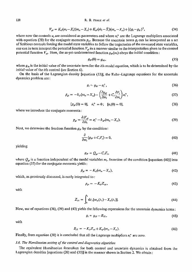
Vg, = Ka(m, - X,) (m~ -- X~) + Kie(dz, -- x,)Cm~ - Xi~) + 12 (g,--g,~)2, (34)
where now the controls u,. are considered as parameters and where n + are the Lagrange multipliers associated with equation (28) for the conjugate momenta p~;. Because the uncertain terms g, can be interpreted as a set of fictitious controls forcing the model state variables to follow the trajectories of the measured state variables, one can in turn interpret the potential function Vg; in a manner similar to the interpretation given to the control potential function V~. Here, the as-yet-undetermined function g,r(mi) obeys the initial condition :
g,r(O) = g,o, (35)
where g,0 is the initial value of the uncertain term for the ith model equation, which is to be determined by the initial value of the i th control (see Section 6).
On the basis of the Lagrangian density [equation (33)], the Euler-Lagrange equations for the uncertain dynamics problem are :
g ~ = g , ~ - a, . + '
(@,~ OFt\ + :, , =
[ p . , ( 0 ) = 0 ] .
where we introduce the conjugate momenta:
Pg~ 8:hl
~: = o ; [n,(O) = o],
= - - = a, + - k , A m , , - X , J .
Next, we determine the freedom function g~F by the condition:
3 am~ O,~ + C , E ) = O,
yielding
(36)
(37)
(38)
(39)
(40)
O Zi,~ = J0 dt, [mis(! ,) --Xi~(t,)]. (44)
Now, use of equations (36), (39) and (43) yields the following expressions for the uncertain dynamics terms:
gi = g,~-- BiT, (45)
with
B,T = -- K,.,Z,A + K , . ( m ~ -- X~ ). (46)
Finally, from equation (38) it is concluded that all the Lagrange multipliers n [ are zero.
3.6. The Hamil tonian set t ing o f the control and diagnostics algorithm
The equivalent Hamiltonian formalism for both control and uncertain dynamics is obtained from the Lagrangian densities [equations (20) and (33)] in the manner shown in Section 2. We obtain :
with
g,~ = Q,,- c,F,, (41)
where Qg~ is a function independent of the model variables m~. Insertion of the condition [equation (40)] into equation (37) for the conjugate momenta yields:
p . , = - K.( ,n,~ - X,~), (42)
which, as previously discussed, is easily integrated to :
p., = -- K a Z , A, (43)

Nonlinear closed-loop control theory 129
with the equations of motion
H¢, = V¢, + [ P a - R,e (Xa -- 4~)1 ( C~ F~ + g,),
Ha, = Vg, + [pg,-- Ka.(ri~. -- f(~ )] (C,F~ + g,),
(47)
(48)
OH,i . OH¢i OHm, lil, = O p t , , Pci = -- Omi ; O,t----~ = O, (49)
OHgi, . O H g , aHai til~ = Ops " Pgi = O m i ' Og~ O. (50)
It is interesting to compare the Hamiltonians [equations (47) and (48)] with those used in the linear quadratic (LQ) version of the PMP formulation of optimal control (Pontryagin, 1962):
H'~, = V ~ , + p a ( G ~ + g , ) , (51)
H'a, = V; ,+pa,(C,F,+g,) , (52)
with the potential functions
V~, = R~l(tT| i - d / ) 2 --1- J2(ui-/./io) 2, (53)
F~i = K'I(m,--X~) 2 + ~(g,--g,o) 2, (54)
and with their corresponding set of equations of motion, identical to equations (49) and (50). Comparison of the two sets of Hamiltonians shows that, for both R;t and K'~ positive, the Hamiltonians in
the PMP methodology are positive definite, whereas for the Hamiltonians [equations (47) and (48)], this property cannot be established a priori. Moreover, these Hamiltonians are both functions of the "velocities" the. It is then seen, on account of the equation of motion [equations (49) and (50)], that the total time derivatives of the PMP Hamiltonians will vanish, according to the conservation relation [equation (14)], whereas those for the Lagrangian control algorithm, in view of their dependence on the velocities, become :
dHa 0He, dHg, ¢9Hgl - - = - " " = - - - t i ' ~ , ( 5 5 )
dt OIh, m, , dt glili
which, on account of equations (47) and (48), become:
dH¢, = R,e(X,s -d~s)ff~,; dHg, = Kip(m~--Xi~),fi,. (56) dt dt
Hence, the Hamiltonians [equations (47) and (48)] are not conserved quantities of motion. This property was introduced for the following reason : if and when He, and He are positive definite, these functions can be viewed as representing the total energy of the system. Their nonconservative properties may thus allow for the elimination of excessive amounts of energy that the onset of unstable solutions of the equations of motion would introduce in the system. In fact, whenever the Hamiltonians Ha and Hgi are definite positive, they assume the roles of functions of the Lyapunov type, hence providing information on the global stability of the algorithm.
3.7. Comparison o f the Lagrangian control algorithm to the proportional integral algorithm
Because PI algorithms are the most widely used controllers in the nuclear industry, it is of interest to compare the result [equation (31)] for the Lagrangian control u, with the corresponding expression for the PI control u;,
U/ = U,o+ R~,Z,n+ R~e(X,s--d,~). (57)
It is seen that in the present formation Ui0 is replaced by the freedom function ux(mi) and that the integral and proportional constants R~r and R~e, respectively, in the PI controller are replaced by the adaptive constants :
0c, ac, R;'t = F,------=" R,,; Rw (58) Oui " = -- F, ~ R,e.

130 R.B. PEREZ et al.
Hence, one expects substantial differences between the control motions from the Lagrangian algorithm and those dictated by the PI algorithm when (1) the functions C~ are nonlinear functions of the controls; and (2) the functions F~ change considerably during the plant transient.
4. EFFEC-'F OF T i l e CON'TROL MECIIANISM RESPONSE FUNCI'ION AND CONSTRAhNTS
The control signals generated by the control algorithm are constrained by the physical limits of the controller's driving mechanisms in both value and rate of change.
Most driving mechanisms in nuclear power plants, such as control rod drivers and valves, exhibit a linear behavior in their rate of changes vs error signals within a given bandwidth around zero input. Outside their bandwidth, they become fixed-rate mechanisms for either positive or negative error inputs. This results in a sigmoid-type functional behavior that can be represented by :
0; : R,0 tan-I ( ~ ) , (59)
where Or and It are the output and input signals, respectively; Biw is the mechanism bandwidth ; and
R,0 : ( 2 ) ~ , (60)
where the rate constant ~,~ is the inverse of the time constant ~ of the control-driving mechanism. Calling ui¢ the input signals to the driver's mechanism, the control supplied to the plant irp from equation
(59) is given by the expression :
l~/p = Rio tan- i ( ~ ) . u i ¢ - l rp (61)
The target is to find that input u= which will generate, via equation (61), an output trip matching the control function ui [from equation (31)]. This u~ is the solution of the demand-following problem considered in Section 3. Thus, in accordance with the previously developed formalism, we introduce the model control variable ui~ a s :
ti/~ = Rio tan- t (n~), (62)
with
ui¢ -- uis (63) n , - n~
and recast the problem as that of finding the "control" u= necessary for "the state variable" uip to follow the "demand" un. We then construct the Lagrangian density :
.LP~= - L i ~ ( u s - u i p ) ( u ~ p - u l ) - L ~ p ( f i ~ - f % ) ( u i p - u i ) - ] ( u = - u x F ) 2 + b i + [ ~ - R ~ o t a n - ' (n~)], (64)
where we introduced the freedom function u~v(ui~) with the initial condition :
. ~ ( 0 ) = tr0 (65)
and where the demand ui is constrained to have values within the upper and lower physical limits of the control system. From the Euler-Lagrange equations derived from the Lagrangian density [equation (64)], one obtains :
ui~ = ui~v -- N~Rb +, (66)
p., = - L i , ( , , i , . - , , D + / l - ~..IN,.b,. [p,~(O) = 0], (67) \ t,,u~ /
with
O.,~Rj Psi = O[li s : hi + - - L i p ( f l i p - - I l l ) , (68)

Nonlinear closed-loop control theory 131
Rio NiR = Bi~(l +n~)" (69)
The freedom function tt~¢V is determined by the condition :
yielding
OllicF = 1, (70)
Ollbs
ukv = Qcv+uis, (71)
where Q,v is independent of uis. Insertion of the condition [equation (70)] into equation (67) for the conjugate momenta p~, yields :
/~,J = -- Lil(t% -- ut), (72)
which integrates to
with
Psi ~- -- Lit Ym, (73)
Y0 Yin = d t , [u~ , ( t , ) -u i (G)] . (74)
Next from equations (66), (68), (71) and (73) one obtains:
ulc = Q , v + u i s - N , ROir, (75)
with
D,-r = - Lil)'~B + L~p (t% -- u~). (76)
Because Dlr vanishes at t = 0 and both ui~ and u~ become tlio , the function QcF is zero, and one obtains for u~ the expression :
ttie= uis-- NIRD:T. (77)
On account of equation (63), equation (77) can be rearranged in the form:
n? + n, + Bi = 0, (78)
with
The real root of equation (78) is given by:
with
f Rio'~ Bi = ~ - ~ ) D t T . (79)
n I = Gia + Gib , (80)
[ B' 7'" ~ [ ~ 7~/~ - +so_,J ; - - s o _ , j , (81)
SQ, J_ a 2 = (2, + 4Bi ). (82)
Because nl is usually much less than unity, one can iterate equation (78) to give the simple, yet accurate approximation :
Bi ni ~ (83)
( B , ' ~ 2" 1 + kl+ U

132 R . B . P~R~z e t a l .
One then obtains the input control u~¢ from either equation (80) or (83) and the definition ofn~ from equation (63).
Whenever the control demand u,. exceeds the physical limits of the control system and/or moves faster than the allowed system rates, the plant will not be able to follow the prescribed trajectory in state space faithfully. Appropriate action would involve reducing the sharpness of the prescribed plant transient.
5. SENSOR DIAGNOSTICS
In this section, we develop an algorithm for the tracking of the rate constant associated with a given sensor. We start from equation (18) rewritten in the form:
Ih~ = ~,o 0hi-- mt~) + 7~, (84)
with
~, = A ~ ( m ~ - m ~ 0 , [~,(0) = 01, (85)
where A ~ is the change experienced by the sensor's rate constant over its nominal value ~o- Our goal is to determine the uncertain term ~,~ so that the model signal m~s matches the sensor output X,.~. We form the Lagrangian density :
• . ~ = - - Qi l (mi~ - Xi~) z - ~(7, -) '~)2 + e + [,iz/~ - ctio(m i-m/~ ) -),,], (86)
where ~,,r(m~) is the freedom function and where the signal X~ is constrained within preset upper and lower limits to avoid the insertion of unrealistic sensor signals to the control algorithm.
The Euler-Lagrange equations associated with the Lagrangian density [equation (86)] are:
and
(7,-~',~) = - c , + (87)
/
The freedom function ~'~F is determined from the condition :
aT~v O l n i s = O{iO
yielding
(88)
(89)
with
c+ = - - Q u y ~ a , (92)
0 Y~a = J0 dtlIms(tl)--X'is(t,)]. (93)
The uncertain dynamics term ~, is given from equations (87) , (90) a n d (92) by the expression :
~'i = ~i0m/, + Q r i + Q , y ~ . (94)
Because ~(0) is zero, one obtains
"~i = O~io(mis - - DT/so) "Jr" Qit y i~ . (95)
One can then run the control algorithm without the exact knowledge of the rate constants a~, provided that
which is easily integrated to
y,r = a~om~ + Qrt- (90)
Insertion of the condition [equation (89)] into equation (88) for the conjugate momenta c~ + yields:
c~+ = - - O,IOn,s - - X~) , (91)

Nonlinear closed-loop control theory 133
the uncertain dynamics terms ),~ are calculated. However, once y~ is known, one can also track the rate constants by calculating A,~. To this end, we operate on both sides of equation (85) with ~',~dt to get:
A~t~ = ~ , (96)
with
N~,= dhyi(t¢); D~,= dtl[m,(tO-m~(h)], (97)
where t¢ is a time which is set larger than zero because, initially, both ),; and the difference (171i--Dlis) a r e zero. In view of the result [equation (96)], the estimate u,r of the rate constant 0~ is given by :
U,T = u,o + -~---. ( 9 8 )
6. APPLICATION TO A NONLINEAR REACTOR MODEL
6.1. Plant simulation
In this section, we illustrate the use of the control algorithm with an application to a nonlinear reactor plant. The plant is modeled by a one-point reactor kinetics model with a single group of delayed neutrons and fuel and coolant temperature feedback terms. Enthalpy'balances in the core and coolant lumps determine the core and coolant temperatures as a function of the inlet coolant temperature and the coolant flowrate. Power XI and delayed neutron concentrations X2 are normalized to their respective equilibrium values, whereas core A" 3 and average coolant temperatures X4 are normalized at the steady-state value of the inlet temperature. We then simulate the plant by the following set of equations (see notation and values of parameters in Appendix A) :
X'l = XI + -~- - If0 (X4 - X4o) + f , (X3 - X30)]X,, (99)
~'2 = ~d(-¢~l---~x2), (100)
-~'3 = ) .reX,--2:e(X3--X4), (101)
~'4 = '~-C('¢~:3 --X4)--II4~R(X4 - - 1). (102)
The system is to be controlled by core reactivity changes ut and by regulating the coolant flowrate by means of the valve control u4.
The subset of measured state variables are power X~ and average coolant temperature X4. Hence, we consider only two model equations with two-model state variables mt (power) and m2 (average coolant temperature). We then write :
dh = Cl(ut)Ft(m,)+gt, (103)
fiz4 = C4(u4)F4(m4)+g4, (I04)
with
11l I Cl(,q) = ut -- 1 ; F t ( m 0 = - A ; Cio = Ulo-- I, (105)
C 4 ( u 4 ) = - - | 1 4 " ~ F4 = -2R(m4-- 1); C4o = -U4o, (106)
where the uncertain terms g~ and g4 must match the terms chk, and chk4 given from equations (99) and (102) by :
X2 chk i = ~ - [fo (X4 - X4 o) --~fl (X3 - X3 o)]Xi (107)
and
AHE ~-3-'9

134 R.B. PEREZ et aL
chk4 = 2 c ( X 3 - - X 4 ) . (108)
The freedom functions uw and U4F are obtained from equations (27), (105) and (106) and the initial conditions [equation (22)] :
zzzv zz,o(l + l n F,o) +In (F~ot) = - z q In Ft , (109)
t14F = Z/40(1 +In F40)--l/4 In F4, (I 10)
where F,o and F40 are the initial values of the known terms of the plant dynamics. Also, in performing the integration over the variables m ~ and m4, we made use of the fact that controls u,- are independent state variables in the Lagrangian density.
Insertion of equations (109) and (110) into equation (31) for the controls yields:
zq = R l . u l o + R i b - - R , ~ C i T , (111)
II 4 = R4all4o-~ R4cC4T , (112)
where
1 +In (/740). F4 (113" 114) R4a= l + l n ( F 4 ) ' R , ~ - I + l n ( F 4 ) ,
with the quantities C~r and C4r given by equation (32) (i = I or 4). The uncertain dynamics terms gz (i = 1 or 4) are from equation (45) :
or from the initial condition g~(O) = g~0,
g, = Qaz - CzFj - BiT (115)
gi = gio + Cio Fio - CjFi - BiT, (116)
with B,-r given by equation (46) (i = 1 or 4). The initial values for the uncertain dynamics are obtained by using the condition of equilibrium at the
beginning of the transient. Setting to zero the derivatives in the model [equations (103) and (104)], we have, on account of equations (105) and (106):
(U,o- I) "q '°= A re,o; g4o = u402R(m40-1), (117)
where u~o and u4o are the known initial values of the controls. The prescribed demands for the power and average coolant temperature trajectories PRD, and PRD4,
respectively, are given by :
PRDz = dreamt--AI exp ( - - 2 , 0 , (I 18)
PRD4 = dm~a--A4 exp ( - 2 4 0 , (119)
with
A, = d~o-dm~, ; A2 = d40-dma,4, (120)
where d~o and d4o are the initial values of the demand which are set equal to the initial values of the power and average coolant temperature and where clm~x~ and dmax4 are their respective equilibrium values at the end of the transient.
To simulate a "real-world" implementation of a digital control system, the plant equations, model equations and control algorithm were run in separate blocks within the ACSL program (Advanced Continuous Simu- lation Language), where communication between blocks took place through signal-sampling blocks.
6.2. Con t ro l a n d d iagnost ics resul ts
Two control and diagnostics scenarios were examined. In scenario A, the sensor time constants z~ and z4~ and the controller time constants z ~ and ~4¢ were set to 1 and 20 s, respectively. In scenario B, all time constants

Nonlinear closed-loop control theory
Table 1. Parameters for the control and diagnostics of scenarios A and B
135
ctl, :t4s Clu c4ss BI~ B4.~ Rll Rip R+, R. , Kit Kle K~, K~p
Scenario A i 1 0.05 0.05 0.015 0.015 -0.1 0.01 -0.001 0.001 -0.5 0.1 -4.2 0.1 Scenario B 0.001 0.001 0.001 0.001 0.015 0.015 -0.01 10 -10 -4 I -0.01 500 -0.5 1000
were set to the unrealistic value of I000 s to check the robustness o f the a lgor i thm under degraded sensor and cont ro l ler condi t ions. Table 1 presents the parameters and adjus table set of cons tants (gains) used in these two scenarios.
We first examine scenario A. Table 2 presents a per formance compar i son with a PI cont ro l lcr for seven different s imulated plant transients. T he compar i son rules were the r.m.s, errors in demand fol lowing:
i,r~ ' 7112 l J0 dt(X'-PRD')2J (121) R M i =
and the r.m.s, e r ror in the devia t ion o f the controls u+ from their initial equi l ibr ium values u~0 :
fr,, 7'z~ 1 Jo d t ( u / - u / o ) Z J , (122) Rr,,=
where TM is the dura t ion of the t rans ient and i = l or 4. Shown in Table 2 are the rat ios RD,. and RC; of the d e m a n d and cont ro l r.m.s, values ob ta ined for the current Lagrang ian control a lgor i thm to the respective values for the PI controller . Both a lgor i thms were tuncd for t ransient 1, which is the least severe o f the t ransients in Table 2. For this t ransient , the gains were adjusted so tha t one could not graphical ly perceive any flaws in the d e m a n d following for b o t h algori thms. The remainder t ransients in Table 2 were run with the same set of gains. Fo r all t ransients , the Lagrangian a lgor i thm shows improved per fo rmance in d e m a n d following, as i l lustrated in Figs la and b for t ransient 7. Bo th a lgor i thms behave asymptot ical ly in the same m a n n e r in every transient . The pa ths between the initial and final equi l ibr ium points differ. The behav ior o f the cont ro l mot ions , described by the rat ios RCI and RC4, varies among the var ious t rans ients examined in Table 2. Fo r instance, Fig. 2 shows the mot ion o f the reactivity controls for bo th a lgor i thms for t ransient 3. However , for most o f the t ransients invest igated in Table 2, the cont ro l mot ion prescribed by b o t h a lgor i thms were practically the same.
The behav io r o f t ransient 6 in Tab le 2 is shown in Figs 3-5. Figure 3 shows power and average coolant t empera ture d e m a n d following. Figure 4 shows the uncer ta in dynamics terms Gt and Ga, ma tch ing the u n k n o w n parts o f the plant dynamics . The cont ro l mot ions are shown in Fig. 5. Note that , for this t ransient , mos t o f the cont ro l is performed by the reactivity control U~p. Similar in fo rmat ion for t rans ient 2 in Table 2 is presented in Figs 6-8.
Next , we examine the cont ro l and diagnostics per formance in scenario B. Figures 9 and 10 show power
Table 2. Ratios of the root-mean-square (r.m.s.) demand errors and control deviations of the Lagrangian control algorithm to the corresponding quantities for a PI controller, scenario A
Transient tot* t°+ b RD~: RD~ RC~ + RC4 f droax I dm,,~ 4
I 3370 2823 0.07 0.14 0.78 0.22 1.41 2.38 2 461 351 0.31 0.13 1.00 1.5 0.5 1.49 3 380 140 0.30 0.53 0.82 1.0 1.81 2.06 4 337 178 0.16 0.56 0.89 1.0 1.41 2.10 5 34 28 0.43 0.71 1.0 0.90 1.41 2.38 6 337 282 0.26 0.32 1.0 0.67 1.41 2.38 7 461 351 0.32 0.64 !.0 1.00 0.5 1.29
"to~ = time required for the power demand curve to reach 99% of maximum value (d~l~) (s). bto4 = time required for the power demand curve to reach 99% of maximum average coolant tem-
perature demand (dm~,~) (s). RD~ = ratio of r.m.s, errors in power demand.
d RD~ = ratio of r.m.s, errors in average coolant temperature demand. c RCI = ratio of r.m.s, deviations in the reactivity control motion. r RC4 = ratio of r.m.s, deviations in the flow control motion. See text for the definition of r.m.s, errors and deviations.

136 R.B. PEREZ et al.
c~ rr (18 n
7 o
- 0 . 7 X
1.0
(a) 0.9
X t
0.6
(15 I I I 0 1 2 3 4 5
T x 10 =
(b}
Xl
PRD t
, I 0 I 2 3 4 5
Fig. I. Power demand following: (a) by the Lagrangian algorithm; and (b) by the PI controller. X, = dimensionless power and PRD~ = power demand for transient 7 in Table 2.
demand following and average coolant temperature demand following, respectively. The good performance by the control algorithm was achieved despite the large lags exhibited by the input signals X,~ (power) and X4s (coolant temperature) upon passing through their respective sensors. The behavior of the uncertain dynamics terms Gt and Ga are shown in Fig. l I. The reactivity control UIp and the flow control U4p provided to the plant are shown in Figs 12 and 13, respectively. Also shown in these figures are the inputs U,c and U4c to the control-driving mechanisms. Note that the current control algorithm automatically either advances or delays the input to the driving mechanisms to compensate for their response functions.
6.3. Stability and robustness of the Lagrangian control algorithm
The stability in the small of a nonlinear system depends on the location of the eigenvalues of its linearized version (i.e. the system will be stable if all the eigenvalues have negative real parts) [Lyapunov's first method
0.20 F 2.0 - 2.4
/
I ~ U,o (PI) 0"16 I L ~ - - 1.8 - 2.3
i/ o,c o.la (~ t . e - ~ z z rY' I,L a. (1.
2 ~ 7 o
0.04 ~ 1.2 - 2.0
! I I I I I t . O - 1 . 9 0 0.8 t.G 2.4 3.2 4.0 0
T x 10 z
Fig. 2. Motion of the reactivity control for the Lagrangian algorithm UtD (LC) and for the PI controller U,o (PI) for
transient 3 in Table 2.
X4 and PRD4
X I ond PRD I
I I I I I 0.6 1.2 1.fl 2.4 3.0
I" x I 0 ~
Fig. 3. Power demand and average coolant temperature demand following by the Lagrangian algorithm for transient 6 in Table 2. XI = dimensionless power, .I"4 = dimensionless average coolant temperature and PRDI and PRD4 = the
corresponding demands.

Nonlinear closed-loop control theory ! 37
8.3 1.0 - -
8 . 1 0 , 9 - -
7.9 - 0.8 "~v f G4 und chk4
o 7 . 7 - 0.7
(.9
7.3 - 0 .5 l I I I 0 0.6 1.2 1.8 2.4 3.0
T x 103
Fig. 4. Uncertain terms G~ and G4 tracking of the unknown dynamic terms chkj and chk4, respectively [equations (107)
and (108) in text], for transient 6 in Table 2.
0.40 - 5.00
0.32 - 4.96
0.24 - ~ 4.92
_:3 0 , 1 6 4 . 8 8
0.08 - 4.84
0 - 4.0C
r U4P
I I 1 I 0 0.6 1.2 1.8 2.4 3.0
T x IO s
Fig. 5. Reactivity control motion U~e and flow control motion U4e for transient 6 in Table 2.
(Lyapunov, 1949; Hartman, 1964)]. The global stability can be determined by the use of Lyapunov's second method (Lyapunov, 1949; Hartman, 1964) provided that a suitable Lyapunov function can be found. In practice though, both methods become purely academic because a complete analytical description of the plant is usually not available. However, some useful information on the stability in the small can still be acquired on the basis of a plant simulation. The first column in Table 3 presents the eigenvalues of the iinearized plant simulation [equations (99-102)], and the second column the eigenvalues of the plant plus the model set of linearized equations [equations (99-104)]. Because all the eigenvalues are negative, there is stability in the small.
1 .0
0 . 9
0.8
(1.
o ~ 0 . 7
X
0.6 - 1.2
0 . 5 -
2o f 1.8
-O_~ 1.6
\ 1.0
0 Q 6
X 4 and PRD 4
X t and PRD t I I ! I
1.2 1.8 2 A 3.0
T x 103
Fig. 6. Power demand and average coolant temperature demand following by the Lagrangian algorithm for transient 2 in Table 2. I t = dimensionless power, X4 = dimensionless average coolant temperature, PRDt = power demand and
PRD4 = average coolant temperature demand.
10 - 1.0
9 - 0.8
% -~: 8 _ x 0.6 J~ u I
(9-7 - ~ o.4
6 - 0 . 2
G 1 and chk I
G4 and chk 4
Fig. 7. Uncertain terms G~ and G4 tracking of the unknown dynamic terms chk, and chk4, respectively [equations (107)
and (108) in text], for transient 2 in Table 2.
5 - I I I ~ I 0 0.6 1.2 1.8 2.4 3.0
T x 103

138 R . B . PEREZ et al.
- 0 . !
-0 .2
o.
-0.3
-0.4
- 5.20
- 5.16
-~Z) 5,12
x
- : ~ 5 . o 8
- 5.04
UIp
-o.5 - 5.00 I u4p I I I 0 0.6 1.2 1.8 2.4 3.0
T x 103
Fig. 8. Reactivity control motion U~p and flow control motion U4p for transient 2 in Table 2.
o f 1.8
m
X- 1.6
O-O X I and PRD w
1.2 ~
t.o I I I I 0 1.6 3.2 4.8 6.4 8.0
T x 10 3
Fig. 9. Power demand following for the transient in scenario B in text. Xi = dimensionless power and P R D , = demand. The time constant for the power sensor was set at I000 s.
,V~, = input signal to the control algorithm.
As we previously discussed, information on the global stability of the algorithm might be obtained for positive definite Hamiltonians by inspection of their asymptotic behavior, that is if the conditions below:
lim Hc~(t) --* 0, lim Hg,(t) ~ 0, (123) I~oo t~oo
are satisfied, then the system exhibits asymptotic stability in the mean (Joseph, 1976). Clearly for the conditions [equation (123)] to occur, the time derivatives of the Hamiltonians must asymptotically become negative and vanishingly small.
2.4
2.3
X 2.2
d n.- 2.1 n.
2,0
1 . 9 0 0.6 1.2 1.8 2.4 3.0
T x 103
Fig. 10. Average coolant temperature demand following for the transient in scenario B in text. X4 = dimensionless aver- age coolant temperature and PRD4 = demand. The time constant for the temperature sensor was set at 1000 s.
X41 = input signal to the control algorithm.
8.:3 -- 1.0 F
ctlk I
8.1 NOx 0.9 I ~
i -- "~ G 4 and chk 4 7.9 ~ 0.8 ~
7 . 7 - ~ 0 0.7
1<
7.5 06 l
7.3 - 0.5 0 1.6 3.2 4.8 6.4 13.0
T x 103
Fig. l 1. Uncertain terms Gi and G 4 tracking o f the unknown dynamic terms chk~ and chk4, respectively [equations (107)
and (108) in text], for the transient in scenario B.

Nonlinear closed-loop control theory 139
0.40
0 .32
0 .24 - / Q. :50.t6 / c
0.08
I I I I I 0 0.32 0.64 0.96 1.28 1.60
T x 1 0 3
Fig. 12. Reac t iv i t y c o n t r o l m o t i o n U,p fo r the t r ans i en t in s c e n a r i o B. U,c = i n p u t to the c o n t r o l d r i v ing m e c h a n i s m . T h e t ime c o n s t a n t fo r the d r i v i n g m e c h a n i s m w a s set a t
I000 s.
5.00
4 . 9 8 7 o
4.96 :=)
7 0 4 . 9 4
J 4.92
J4c
/ u4a
4.90 I I I I I 0 0.32 0.64 0.86 1.28 1.60
Tx I 0 ~
Fig . 13. F l o w c o n t r o l m o t i o n U4p fo r the t r a n s i e n t in scena r io B. U4c = i n p u t to the c o n t r o l d r i v ing m e c h a n i s m . T h e t ime
c o n s t a n t fo r the d r iv ing m e c h a n i s m w a s set a t 1000 s.
This is the case for all the transients shown in Table 2, as illustrated in Fig. 14 for transient 6. The Hamiltonian H~, grows from its initial value of zero because the derivative DERHg, is positive. Afterward, DERH~, becomes negative and vanishes at the new equilibrium position, hence driving the Hamiltonian to its final value of zero in accordance with the condition expressed by equation (15). Along the transient, the Hamiltonian remains positive. We then infer from this behavior that the control algorithm exhibits asymptotic stability in the mean, at least for the set of gains and parameters in Table I.
The robustness of a control algorithm can be qualified by the range of operating conditions that can be covered without having to readjust the set of gains. The current control algorithm performed well for all the transients shown in Table 2, which range from very fast to slow transients, with sensors and control drivers time constants ranging from 0.I to 10 s and sampling times up to I s. For the operating conditions in scenario B, though, the gains had to be substantially readjusted (see Table I).
6.4. Diagnostics capabilities
The tracking by the uncertain dynamic terms G~ of the unknown plant dynamics affords the capability of diagnosing unanticipated plant transients or changes in plant parameters by comparing current trends of the uncertain terms with known signatures of normal plant behavior. Figure 15 shows the tracking of the unknown terms in the power and average coolant temperature terms upon the insertion of 10 cents of positive reactivity at several times during transient 6 in Table 2. Comparison with the results for Gi and G4 shown in Fig. 4 for the unperturbed plant operation shows that the perturbation did affect the G4 term very little and must then
Table 3. Eigenvalues of the linearized plant and control algorithm"
Plant Plant and control algorithm
- 0 . 1 4 - 5.23
- 0.02 - 30.06 -- 11.74 - 34.37
--107.30 -57 .91 --1016.00 -1014 .00
"The eigenvalues were calculated for t = 3000 s in the transient.

140 R.B. PEe.EZ et al.
4.0 - 2.0 --
3.2 1.2
• 0 2"4 - 0 0.4
0
0.8 - 1 . 2
0 - ? - 0
DERHG,
/ I D E R H G I DERHG I
HG I
~ 1 l I I I 0 0.2 0,4 0 6 0.8 1.0
T x 10 3
Fig. 14. The evolution of the Hamiltonian, HGm [equation (48)] and of its derivative, DERHG], for transient 6 in Table 2. The Hamiltonian remains positive definite along the transient and goes to zero at
both ends of the transient.
be related to a change in the core reactivity because it drastically affects the G,, which represents the unknown dynamics in the equation for the reactor power [equation (103)]. In another example, Fig. 16 shows the large change experienced by the uncertain term G, when the fuel temperature coefficient of reactivity was changed from negative to positive in transient 6. The sensors diagnostic methods developed in Section 5 are illustrated in Fig. 17, which shows the tracking of the rate constant ~,s. The initial value guessed for this constant was
10.0
9.2
_ 8.4
o
~- 7.6
6.8
6.0
o
1.o 0.10
0.9 0.08
0.8 0.06
0.7 0.04
0.6 0.02
0.5 0
G 4 ond chk 4
~G tond chk t
DELUt~
I 0.6 1.2
Tx 10 3
jDELUt~
I l
1.8 2.4 3.0
Fig. 15. Uncertain terms G~ and G4 tracking of the unknown dynamic terms chk, and chk4, respectively [equations (107) and (108) in text], upon insertion of 10 cents of positive reactivity during transient 6 in
Table 2. DELU~ is the inserted reactivity.

Nonlinear closed-loop control theory 141
9.0
8.6
8 2
u
o Z8
d
Z4
f ' - G! and cl~k ; aF>O
- - ~ G t ond chk ; G F < O
7.0 I I I I I 0 0.6 1.2 1.8 ::'.4 3.0
T x 10 s
Fig. 16. Changes in shape and magnitude of the uncertain term G, for transient 6 in Table 2 upon the insertion of a positive value for the fuel temperature coefficient of reactivity
c¢~. Top curve aF > 0, bottom curve ~F < 0.
i o )<
03 _.J
~o g
to i o
x I - _.J
4.0
3.2
2 . 4
1.6
0 .8
~ . A L I T
ALIS
I I I I J 0 |.6 3.2 4.8 6,4 8,0
T x 10 3
Fig. 17. Sensor diagnostics capabilities of the Lagrangian algorithm. ALIS = actual value of the sensor rate constant (10 -3 s-i) and ALIT = tracking of the sensor constant by
the algorithm.
half of its true value. The algorithm after a time interval of hesitation finds the exact value along the entire transient.
7. SUMMARY AND DISCUSSION
This work presents a new, advanced Lagrangian-based algorithm providing closed-loop control and diag- nostics information. The basis of the current formalism has been the setting of the control problem as the problem of finding the allowed trajectories in phase space o f a nonconservative, constrained mechanical system. The Hamiltonian version of the algorithm (Section 3.6), although similar in structure to the Hamiltonian functional in Pontryagin's optimal control theory, differs in two important properties. First, the potential functions Vc/and Vg~ [see equations (20 and (34), respectively], which play the role of cost functions, may not be definite positive; and second, the Hamiltonians in the current formalism are not conserved quantities of motion. There are, however, definite advantages in using the cost functions constructed in this work. Indeed, the cost function dependence on the "velocities" lil,- allows the introduction of proportional terms in the expression for the control motion, whereas if one uses quadratic cost functions, only the equivalent to the integral term in a PI controller is obtained. We have observed that the proportional term is needed to stabilize the control algorithm upon introduction of sampled input-output signals. This situation may be described as the one faced by a man racing along a razor edge. As far as he receives continuous information, he is able to perform the appropriate corrections to maintain equilibrium. However, delays in the information-control action sequence may prove fatal unless the man includes, as we did in our formalism, proportional terms in a clearimitation of the reliable PI controller.
The comparison shown in Table 2, of the current control algorithm with a PI controller, shows a consistently improved performance in demand following. However, the control motions dictated by the Lagrangian algorithm differ very little from those prescribed by the PI controller. The reason for this is that in the particular case studied in this work, the functions Ci(U~), are linear functions of the controls, and the known dynamic terms F~ do not generally vary too much during the transient. Then, as seen by inspection of equation (58), there are not large differences between the adaptive constants R~l and R~ and the corresponding PI-controller gains.
The Lagrangian control algorithm proved to be stable in the small. A criterion for global stability could be found in equation (56), provided that the Hamiltonian functions involved were positive definite. We have not

142 R.B. PEREZ et al.
attempted to use the possible predictive properties of those relations but have used them as an a posteriori check on global stability.
Upon extensive running of the algorithm, we have observed wide regions of algorithm robustness in the sense that the gains remained valid for a large variety of transients. However, increasing the signal sampling time or the sensors time constants destabilizes the algorithm, and new sets of gains must be found.
The diagnostic capabilities of the algorithm could be exploited to implement an expert system for plant diagnostics by first establishing the plant signature (i.e. the normal behavior of the uncertain terms) and then correlating their changed behavior with observed plant anomalies.
Because we have not investigated the properties of the second variation of the Lagrangian functional [equation (2)], we cannot make statements about the optimality of the current algorithm. Most probably though, the controls obtained correspond to saddle points or local minima in parameter space. The Lagrangian control algorithm can deal with nonlinear systems, and by virtue of the conversion of the usual two-point boundary problem into an initial value problem, it can be used as an on-line control algorithm. Uncommonly, this control algorithm rigorously accounts for the response functions of both sensors and control-driving mechanisms. It is hoped that, in view of these properties and of its diagnostics capabilities, the current control algorithm may make a useful contribution to the nuclear industry.
Acknowledgements--The authors express their gratitude for the support and advice provided by J. White, ACTO-ORNL manager, during the performance of this work. We thank L. H. Rovere, C. R. Brittain, C. March-Leuba and J. March- Leuba for their illuminating discussions about control problems and for their help in the use of the ACSL program. This paper was based on work performed at the Oak Ridge National Laboratory, managed for the U.S. Department of Energy under Contract DE-ACOS-84OR21400 with Martin Marietta Energy Systems, Inc.
REFERENCES
Adcanced Continuous Simulation Language (A CSL). Mitchell & Gauthier, Concord, MA. Brittain C. R. (1990) Ph.D. Dissertation, The University of Tennessee, Knoxville. Brockett R. W. (1977) Control Theory and Analytical Mechanics, Vol. II. Math. Sci. Press, Brookline, MA. Divakaruni M., Hammer M. and Penland J. (1985) Proe. Semhl. Power Plant Digital Control Fault-Tolerant Microcomput.,
EPRI-NP-4769-SR, Electric Power Institute, Palo Alto, CA. Hartman P. (1964) Ordinao' Differential Equations. Wiley, New York. Joseph D. D. (1976) Springer Tracts in Natural Philosophy, Vol. 27. Springer-Verlag, Berlin. Levis A. H. et al. (Eds) (1987) IEEE Trans. Autmn. Control AC-32, 275. Loenberger D. G. (1979) Introduction to Dynamic Systems. Wiley, New York. Lyapunov A. M. (1949) Tire General Problems of the Stability of Motion. Princeton Univ. Press, NJ. March-Leuba C. (1989) Ph.D. Dissertation, The University of Tennessee, Knoxville. March-Leuba C. and Perez R. B. (1987) Report ORNL/TM-10662, Oak Ridge National Laboratory, TN. Pontryagin L. S. (1962) Tire Mathematical Theory of Optimal Processes. Wiley, New York. Rovere L. A., Otaduy P. J. and March-Leuba C. (1988) IEEE 1988 Nucl. Sci. Syrup., Orlando, FL. Sage A. P. and White C. C. (1977) Optimum Systems Control. Prentice-Hall, Englewood Cliffs, NJ.
APPENDIX A
Parameters for the Plant Simulation
The parameters entering in the plant simulation, equations (99)-(102), are given by the expressions:
).le = C~;~Tm (s-'),
Avhv 1 ).~ = C--~-~ ( s - ) ,
Arhv I ;-~ = C~/~(s- ),
2c6 _, ;.,, = ~ ( s ),
fo = ~ ( S - ' ) ,
(AI)
(A2)
(a3)
(An)
(AS)

Nonlinear closed-loop control theory 143
where
~T,,, _,), f , = - - ~ - - (S
uj = reactivity control (S), u4 = flow control (dimensionless),
C F ~
c , = M,= M v = A v = O~ F
h v = tb = p=
2n= A =
specific heat capacity (fuel) = 0.565 J (kg" °C)- ~, specific heat capacity (coolant) = 4.1845 J (kg- °C)- ~, coolant mass = 24.163 kg, fuel mass = 6.785 kg, effective heat transfer area = 27.6 m 2, absolute value of the fuel temperature coefficient o f reactivity = 1.10- 5 ° C - ~, overall heat transfer coefficient = I3.5 J (s- m 2- °C)- ~, coolant flow = 1400 kg s - i , effective delayed neutron fraction = 0.00721, delayed neutrons decay constant = 0.0686 s - i, neutron generation time = 0.1218 s,
(A6)
Po = reference power = 280 MW (t).
The above parameters describe a small, high-power-density nuclear reactor. The initial values for the normalized power and delayed-neutron concentration are Xi0 = I ; )(2o = 1, respectively. From
the enthalpy balances at equilibrium, one obtains for the normalized equilibrium core and coolant temperatures
D.,A X,o = X4o+ ~)~e2)Xio, (A7)
/)-o).,~\ x40 : i + (A8)
The initial conditions for the model state variables and demands are:
m lo = dlo = Xl0, (A9)
t/14 0 = d4o = X 4 o . (A10)
A P P E N D I X B
Equh'alence o f the Backward and Forward bltegration o f the Equations for the Conjugate Monwnta
Equations (28), (42), (67) and (86) in the text, for the various conjugate momenta, can be written in the general form :
p(t) = -- Q(t), (B 1)
where Q(t) is a source function independent of the conjugate momenta. Integrating equation (BI), first backward in time and later forward in time, we obtain:
f, p6(t) = P M - d t , Q ( t , ) , (B2) J r u
pv(t) = P o - - fo' d t jQ( t , ) , (B3)
where P~I is the final value ofp( t ) and Po, its initial value and TM the final time. Subtracting equation (B2) from equation (B3), one obtains :
pv(t)--pn(t) = Po--PM-- d t ,Q( t , ) . (B4)
Next, note that from equation (B3) for t = TM, one obtains :
pF(TM) = Po-- J f u dtl Q(t l ) = PM. (B5)
I
Insertion of equation (B5) into equation (B4) yields:
Pv = PB, (B6)
which proves the equivalence sought. Consequently, one can use forward integration with the general result :
p(t) = Po - dt j Q(t , ) . (B7)