
CENTRIFUGAL COMPRESSORS FOR OXYGEN ... - CiteSeerX
75
CENTRIFUGAL COMPRESSORS FOR OXYGEN SERVICE Code of Practice IGC Doc 27/01/E EUROPEAN INDUSTRIAL GASES ASSOCIATION AVENUE DES ARTS 3-5 • B – 1210 BRUSSELS Tel : +32 2 217 70 98 • Fax : +32 2 219 85 14 E-mail : [email protected] • Internet : http://www.eiga.org
-
Upload
khangminh22 -
Category
Documents
-
view
0 -
download
0
Transcript of CENTRIFUGAL COMPRESSORS FOR OXYGEN ... - CiteSeerX

CENTRIFUGAL COMPRESSORS FOR
OXYGEN SERVICE
Code of Practice
IGC Doc 27/01/E
EUROPEAN INDUSTRIAL GASES ASSOCIATION
AVENUE DES ARTS 3-5 • B – 1210 BRUSSELS Tel : +32 2 217 70 98 • Fax : +32 2 219 85 14
E-mail : [email protected] • Internet : http://www.eiga.org


EIGA 2001 - EIGA grants permission to reproduce this publication provided the Association is acknowledged as the source
EUROPEAN INDUSTRIAL GASES ASSOCIATION
Avenue des Arts 3-5 B 1210 Brussels Tel +32 2 217 70 98 Fax +32 2 219 85 14 E-mail: [email protected] Internet: http://www.eiga.org
IGC Doc 27/01/E
CENTRIFUGAL COMPRESSORS FOR
OXYGEN SERVICE
Code of Practice Prepared by the members of Working Group I.5: A. Bockisch Linde Technische Gase GmbH T. Hemming BOC Gases Group S. King Air Products Plc F-X. Lemant Air Liquide M. Meurer AGA AB J-M. Torres-Javier Praxair W. Sielschott Messer Griesheim GmbH And participating experts K. Boddenburg Mannesman Demag Delaval E Gmeiner Sulzer Turbo GmbH C. Schwarz Atlas Copco Comptec Inc
Disclaimer of warranty
All technical publications of EIGA or under EIGA's name, including Codes of practice, Safety procedures and any other technical information contained in such publications were obtained from sources believed to be reliable and are based on technical information and experience currently available from members of EIGA and others at the date of their issuance. While EIGA recommends reference to or use of its publications by its members, such reference to or use of EIGA's publications by its members or third parties are purely voluntary and not binding. Therefore, EIGA or its members make no guarantee of the results and assume no liability or responsibility in connection with the reference to or use of information or suggestions contained in EIGA's publications. EIGA has no control whatsoever as regards, performance or non performance, misinterpretation, proper or improper use of any information or suggestions contained in EIGA's publications by any person or entity (including EIGA members) and EIGA expressly disclaims any liability in connection thereto. EIGA's publications are subject to periodic review and users are cautioned to obtain the latest edition.

IGC DOC 27/01/E
Table of Contents
1. Introduction ...................................................................................................................................... 1
1.1 General ..................................................................................................................................... 1 1.1.1 Objective............................................................................................................................ 1 1.1.2 Philosophy......................................................................................................................... 1 1.1.3 Common Interest............................................................................................................... 2 1.1.4 Other Specifications .......................................................................................................... 2 1.1.5 Terminology....................................................................................................................... 2 1.1.6 Oxygen Compatibility - BAM approval .............................................................................. 2
1.2 Application of the Code ............................................................................................................ 2 1.2.1 Oxygen Purity .................................................................................................................... 2 1.2.2 Oxygen Enriched Gases ................................................................................................... 3 1.2.3 Moisture............................................................................................................................. 3 1.2.4 Axial Turbo Compressors.................................................................................................. 3 1.2.5 Discharge Pressure........................................................................................................... 3 1.2.6 Suction Pressure ............................................................................................................... 3 1.2.7 Driver ................................................................................................................................. 3 1.2.8 Maximum Operating Temperature .................................................................................... 3 1.2.9 Maximum Continuous Speed ............................................................................................ 4
1.3 Definition of Terms ................................................................................................................... 4 1.3.1 Speeds .............................................................................................................................. 4 1.3.2 Normal Operating Range .................................................................................................. 5 1.3.3 Hundred-Percent Speed ................................................................................................... 5
2. Compressor Installation ................................................................................................................... 5
2.1 Hazard Area.............................................................................................................................. 5 2.1.1 Description ........................................................................................................................ 5 2.1.2 Enclosure of the Hazard Area by a Safety Barrier ............................................................ 6 2.1.3 Access to the Hazard Area ............................................................................................... 6 2.1.4 Equipment Location........................................................................................................... 6 2.1.5 Service Pipes and Electric Cables within the Hazard Area .............................................. 7 2.1.6 Oil Pipework within the Hazard Area................................................................................. 7
2.2 Safety Barrier............................................................................................................................ 7 2.2.1 Purpose ............................................................................................................................. 7 2.2.2 Responsibilities ................................................................................................................. 7 2.2.3 The Nature of “Burn Through”........................................................................................... 7 2.2.4 Strength & Burn Through Criteria...................................................................................... 8 2.2.5 Materials of Construction................................................................................................... 8 2.2.6 Layout of the Safety Barrier............................................................................................... 9 2.2.7 Safety Barrier Miscellaneous Design Features............................................................... 10
2.3 Location .................................................................................................................................. 10 2.3.1 Compressor House ......................................................................................................... 10 2.3.2 Safety of Personnel and Plant......................................................................................... 10 2.3.3 Erection and Maintenance .............................................................................................. 10 2.3.4 Overhead Cranes ............................................................................................................ 10
2.4 Fire Protection and Precautions ............................................................................................. 11 2.4.1 Introduction...................................................................................................................... 11 2.4.2 Isolation and Quick Venting Systems.............................................................................. 11 2.4.3 Flammable Material......................................................................................................... 11 2.4.4 Liaison with Local Fire Authority ..................................................................................... 11 2.4.5 Special Precautions......................................................................................................... 11 2.4.6 Protection of Personnel ................................................................................................... 12
3. Compressor Design ....................................................................................................................... 12
3.1 Machine Configuration............................................................................................................ 12 3.2 Design Criteria........................................................................................................................ 12
3.2.1 Service Life...................................................................................................................... 12 3.2.2 Possible Causes of an Oxygen Compressor Fire ........................................................... 12
3.3 Materials, General .................................................................................................................. 13

IGC DOC 27/01/E
3.3.1 Construction Materials..................................................................................................... 13 3.3.2 Other Criteria................................................................................................................... 13 3.3.3 Use of Aluminium ............................................................................................................ 13
3.4 Casings, Diaphragms, Diffusers and Inlet Guide Vanes........................................................ 13 3.4.1 Casings............................................................................................................................ 13 3.4.2 Diaphragms and Diffusers............................................................................................... 15 3.4.3 Variable Inlet Guide Vanes.............................................................................................. 15
3.5 Rotating Assembly.................................................................................................................. 16 3.5.1 Impellers .......................................................................................................................... 16 3.5.2 Shafts .............................................................................................................................. 16 3.5.3 Rotor Assembly ............................................................................................................... 16
3.6 Seals....................................................................................................................................... 17 3.6.1 Internal Rotor Seals......................................................................................................... 17 3.6.2 Atmospheric Rotor Seals................................................................................................. 17
3.7 Bearings and Bearing Housings............................................................................................. 18 3.7.1 Bearing Type ................................................................................................................... 18 3.7.2 Thrust Bearing Size......................................................................................................... 18 3.7.3 Atmospheric Air Gap ....................................................................................................... 19 3.7.4 Provision for Vibration Probes......................................................................................... 19 3.7.5 Bearing failure - Resultant Rubs ..................................................................................... 19
3.8 Drivers, Gears and Couplings ................................................................................................ 19 3.8.1 Drivers and Gears in Hazard Area .................................................................................. 19 3.8.2 Failure in Gear Box or Coupling...................................................................................... 20
3.9 Rotor Dynamic Analysis, Verification Tests and Data to be provided.................................... 20 3.9.1 Summary ......................................................................................................................... 20 3.9.2 Introduction...................................................................................................................... 20 3.9.3 Lateral Vibration of the Rotor in Response to Forced Excitation .................................... 22 3.9.4 Lateral Vibration of a Damped Rotor Resulting from Self Excitation Forces .................. 26 3.9.5 Torsional Vibrations......................................................................................................... 28 3.9.6 Data ................................................................................................................................. 30
3.10 Balancing and Vibration.......................................................................................................... 31 3.10.1 Balancing......................................................................................................................... 31 3.10.2 Vibration Limits................................................................................................................ 32
3.11 Electrical Discharge................................................................................................................ 33 3.11.1 Insulation and Earthing.................................................................................................... 33 3.11.2 Code Requirements ........................................................................................................ 33
4. Auxiliaries Design .......................................................................................................................... 34
4.1 Coolers ................................................................................................................................... 34 4.1.1 Scope of Supply .............................................................................................................. 34 4.1.2 Types of Cooler ............................................................................................................... 34 4.1.3 Vents and Drains............................................................................................................. 36
4.2 Process Pipework................................................................................................................... 36 4.2.1 Extent .............................................................................................................................. 36 4.2.2 Connections .................................................................................................................... 36 4.2.3 Welding............................................................................................................................ 36 4.2.4 Prefabrication .................................................................................................................. 36 4.2.5 Velocity ............................................................................................................................ 36 4.2.6 Vents to Atmosphere....................................................................................................... 37 4.2.7 Special Piping.................................................................................................................. 37 4.2.8 Bellows ............................................................................................................................ 38 4.2.9 Gaskets ........................................................................................................................... 38 4.2.10 Acoustic and Thermal Insulation ..................................................................................... 38 4.2.11 Silencers.......................................................................................................................... 38 4.2.12 Vaned Elbows ................................................................................................................. 38
4.3 Manual Valves ........................................................................................................................ 38 4.3.1 Manually Operated Main Isolation Valves....................................................................... 38 4.3.2 Manual Valves which form part of the Oxygen Containing Envelope ............................. 38
4.4 Main Suction Filter .................................................................................................................. 39 4.4.1 Rating .............................................................................................................................. 39 4.4.2 Materials .......................................................................................................................... 39

IGC DOC 27/01/E
4.4.3 Design Strength............................................................................................................... 39 4.4.4 Flow Direction.................................................................................................................. 39 4.4.5 Free Area......................................................................................................................... 39 4.4.6 Precaution against Installation Errors ............................................................................. 39 4.4.7 Inspection ........................................................................................................................ 39
4.5 Lubricating Oil System............................................................................................................ 39 4.5.1 General............................................................................................................................ 39 4.5.2 Pumps ............................................................................................................................. 40 4.5.3 Filter................................................................................................................................. 40 4.5.4 Oil Heater ........................................................................................................................ 40 4.5.5 Oil Vapour Extractor System........................................................................................... 40 4.5.6 Oil Tank ........................................................................................................................... 41 4.5.7 Control ............................................................................................................................. 41
4.6 Seal Gas System.................................................................................................................... 41 4.6.1 Compressor Seal Gas System........................................................................................ 41 4.6.2 Bearing Seal Gas System ............................................................................................... 41 4.6.3 Schematic Diagram......................................................................................................... 41
4.7 Controls and Instrumentation ................................................................................................. 44 4.7.1 General............................................................................................................................ 44 4.7.2 Control System................................................................................................................ 44 4.7.3 Anti Surge System........................................................................................................... 44 4.7.4 High Oxygen Temperature Protection............................................................................. 46 4.7.5 High Bearing Temperature Protection............................................................................. 46 4.7.6 Vibration and Shaft Position ............................................................................................ 46 4.7.7 “Safety Shutdown System” Valves.................................................................................. 47 4.7.8 Oxygen Humidity ............................................................................................................. 48 4.7.9 Minimum Instrumentation of Oxygen Compressors........................................................ 48 4.7.10 Failure Modes and Operating Speeds of System Valves ............................................... 49 4.7.11 Centrifugal Oxygen Compressor System flow diagram .................................................. 50
5. Inspection and Shipping ................................................................................................................ 51
5.1 Introduction - Code ................................................................................................................. 51 5.2 Responsibility.......................................................................................................................... 51 5.3 Inspection and Cleanliness Standards ................................................................................... 51
5.3.1 Extent .............................................................................................................................. 51 5.3.2 Inspection ........................................................................................................................ 51 5.3.3 Parts “Clean for Oxygen Service” ................................................................................... 52 5.3.4 Check Methods ............................................................................................................... 52
5.4 Preservation of Oxygen Cleanliness during Shipping and Storage ....................................... 53 5.4.1 Equipment ....................................................................................................................... 53 5.4.2 Individual Components.................................................................................................... 53 5.4.3 Subassemblies which can be made Pressure Tight ....................................................... 53 5.4.4 Arrival on Site .................................................................................................................. 54
6. Erection and Commissioning ......................................................................................................... 54
6.1 Erection................................................................................................................................... 54 6.1.1 Responsibility .................................................................................................................. 54 6.1.2 Clearances and Alignment .............................................................................................. 55 6.1.3 Prevention of Undue Forces ........................................................................................... 55 6.1.4 Tools................................................................................................................................ 55 6.1.5 Hazard Area .................................................................................................................... 55 6.1.6 Oil Flushing...................................................................................................................... 55 6.1.7 Foundation Sealing ......................................................................................................... 55 6.1.8 Purging after Assembly ................................................................................................... 55
6.2 Testing and Commissioning ................................................................................................... 55 6.2.1 Introduction...................................................................................................................... 55 6.2.2 General............................................................................................................................ 56 6.2.3 Testing Objectives........................................................................................................... 56 6.2.4 Demonstration of Mechanical Integrity............................................................................ 56 6.2.5 Verification of the Rotordynamics Prediction and the Stability of the Rotor.................... 57 6.2.6 Verification of the Predicted Thermodynamic Performance ........................................... 57

IGC DOC 27/01/E
6.2.7 Functional Demonstration of the Instruments ................................................................. 58 6.2.8 Verification that the Compression System is Clean for Oxygen Service ........................ 58 6.2.9 Test Programme.............................................................................................................. 59 6.2.10 Commissioning on Oxygen ............................................................................................. 60
7. Operation ....................................................................................................................................... 60
7.1 General ................................................................................................................................... 60 7.1.1 Combustible Matter ......................................................................................................... 61 7.1.2 Machine Rubs ................................................................................................................. 61 7.1.3 Rotor/Bearing Instability .................................................................................................. 61 7.1.4 Machine Vibrations.......................................................................................................... 61 7.1.5 Leaking Cooler Tubes ..................................................................................................... 61 7.1.6 Gas Leakage Hazard ...................................................................................................... 61 7.1.7 Compressor Surge .......................................................................................................... 61
7.2 Safety Certificates .................................................................................................................. 61 7.3 Qualifications and Training for Operating Personnel ............................................................. 61 7.4 Hazard Area............................................................................................................................ 61 7.5 Fire Drills................................................................................................................................. 62 7.6 Emergency Purge and Vent Systems .................................................................................... 62 7.7 Record of Machine Operation ................................................................................................ 62 7.8 Tripping Devices..................................................................................................................... 62
7.8.1 Operating Checks............................................................................................................ 62 7.8.2 Trip Override ................................................................................................................... 62
7.9 Interlock Systems ................................................................................................................... 62 7.10 Oil Strainers ............................................................................................................................ 62 7.11 Start-up Procedures ............................................................................................................... 63
7.11.1 Mandatory Requirements................................................................................................ 63 7.11.2 Discretionary Requirements............................................................................................ 63
8. Maintenance .................................................................................................................................. 63
8.1 General ................................................................................................................................... 63 8.1.1 Method............................................................................................................................. 63 8.1.2 Functional Test................................................................................................................ 64
8.2 Cleanliness During Maintenance............................................................................................ 64 8.3 Rotor Checks.......................................................................................................................... 64
8.3.1 Compressor Open for Overhaul ...................................................................................... 64 8.3.2 Check Balance of Spare Rotors...................................................................................... 64
8.4 Spare Parts............................................................................................................................. 64 8.4.1 Vendor Replacements..................................................................................................... 64 8.4.2 Replacement Bearings .................................................................................................... 64 8.4.3 Oxygen Components....................................................................................................... 65
9. Instruction Manual.......................................................................................................................... 65
9.1 General ................................................................................................................................... 65 9.1.1 Vendor / User Input ......................................................................................................... 65
9.2 List of Minimum Information ................................................................................................... 65 9.2.1 Instruction Manual ........................................................................................................... 65 9.2.2 Additional Information...................................................................................................... 66
10. References ................................................................................................................................. 66
Appendix A - Aspects Requiring Consideration for Open Wheels and Integrally Geared Compressors


IGC DOC 27/01/E
1
1. Introduction
1.1 General
1.1.1 Objective
The objective of this Code of Practice is to provide general guidance on the design, manufacturer, installation and operation of centrifugal oxygen compressors, thereby safeguarding personnel and equipment. Fire in an oxygen compressor can be caused by a variety of reasons which include, for example, mechanical deterioration resulting in excessive vibration and/or loss of running clearances within the compressor; ingress of oil (e.g. through the seal system) or foreign bodies passing through the machine.
An oxygen compressor shall be provided with a safety support system that will minimise the development of a potentially dangerous operating condition. In the event of an incident on the compressor, which results in combustion of the materials of construction, the safety support system shall be designed to minimise the effect of the fire.
1.1.2 Philosophy
The safe and reliable compression of oxygen using centrifugal compressors can only be achieved by the successful combination of many factors. The Code identifies and addresses these factors:-
1.1.2.1 Design of the compressor system (Sections 3 & 4)
• Robust and well proven compressor design • Stable rotor system • Safe materials in critical areas • Comprehensive instrumentation • Safety shutdown system
1.1.2.2 Cleaning, Preservation and Inspection (Section 5)
• Correct and properly enforced procedures Well trained personnel.
1.1.2.3 Erection, Testing and Commissioning (Section 6)
• Skilled and well trained erection personnel • Comprehensive testing programme to verify the design.
1.1.2.4 Operation (Section 7)
• Well trained and experienced personnel • Correct procedures 1.1.2.5 Additional guidance on installation and operation can be found in CGA G-4.6. The CGA and EIGA are aligned in their aims and values and the CGA document shall be regarded as complementary to this one.
1.1.2.6 Planned Maintenance (Section 8)
• Condition monitoring • Planned preventive maintenance • Well trained and experienced personnel

IGC DOC 27/01/E
2
1.1.2.7 Personnel Protection (Section 2)
• Identification of the hazard • Safety barriers • Location of the compressor • Emergency procedures
1.1.3 Common Interest
1.1.3.1 The Code has made a significant contribution to the safe compression of oxygen primarily because the vendors and purchasers have fully and frankly shared their philosophies and experiences. It is recognised by the Working Group members that the feed back of operating experiences makes a powerful contribution to safe operation and design. The Code requires that all those who build and operate centrifugal oxygen compressors that have been specified to comply with the Code should contribute towards it by fully reporting the circumstances surrounding oxygen fires.
1.1.3.2 For the purpose of safe operation of the compressor and its auxiliaries the purchaser and the vendor shall establish full agreement on the possible and expected modes of compressor operation (e.g. specified operating points, normal operating range, start-up and shut-down, etc).
1.1.4 Other Specifications
In case of conflict between this Code and the purchaser’s specification the information included in the order shall be the more stringent. The supply shall be in conformity with the rules of the country of the user and/or of the manufacturer.
1.1.5 Terminology
Although EIGA working group documents have no mandatory character, a clear distinction must be made between “should” and “shall”.
“Shall” indicates a very strong concern or instruction.
(French: “doit”; German: “muss”).
“Should” indicates a recommendation.
(French: “devrait”; German: “sollte”).
1.1.6 Oxygen Compatibility - BAM approval
Non metallic materials that have been approved by B.A.M. (Federal Institute for Material Testing, Berlin) for the relevant oxygen duty are acceptable to the Code. This does not preclude other methods of determining compatibility such as by other independent bodies, customers and vendors.
1.2 Application of the Code
1.2.1 Oxygen Purity
This Code of Practice is based on experience in manufacturing and operating centrifugal oxygen compressors and it is applicable to those machines operating on dry gases containing more than 90% oxygen and less than 10 ppm water (volume basis).

IGC DOC 27/01/E
3
1.2.2 Oxygen Enriched Gases
Experience in compressing oxygen enriched gases containing less than 90% oxygen is very limited at this time. In the absence of such experience or established data, the working group members recommend that this Code shall be considered for centrifugal compressors operating on oxygen enriched gases, and the degree of implementation shall be agreed between vendor and purchaser.
1.2.3 Moisture
Experience in compressing oxygen containing moisture is limited. Special precautions need to be taken particularly with reference to the materials of construction. Additional requirements shall be agreed between vendor and purchaser.
1.2.4 Axial Turbo Compressors
At the time of the 6th revision of this Code there is still no experience with axial turbo compressors in oxygen service. The working group members feel that the design of an axial compressor results in it representing a significantly greater hazard than a centrifugal compressor when used in oxygen service. The use of axial compressors is not permitted by this code.
1.2.5 Discharge Pressure
The recommendations in this Code are based on the experience gained in the compression of oxygen up to 50 bars. At the time of the 6th revision there now exists significant operating experience at pressures between 50 and 85 bar using compressors with split line casings. The requirements of the code have been shown to be adequate for these higher pressures. However above 50 bar it is recommended that special attention should be paid to the use of the most compatible materials and a most detailed rotor dynamics analysis conducted. The additional requirements shall be agreed between vendor and purchaser.
1.2.6 Suction Pressure
Traditional experience is with gas produced from Air Separation units, i.e. a compressor suction pressure of less than 2 bar g. This is the application that has been considered when putting forward the best design of ancillary systems. If the compressor has an elevated suction pressure it is possible that some ancillary systems may need modification, e.g. the seal gas return system.
1.2.7 Driver
The majority of experience has been with the use of constant speed electric motor drivers. The code has been written giving the best solution for this type of driver. However where another type of driver, e.g. steam turbine requires a different solution this has been clearly pointed out in the code.
1.2.8 Maximum Operating Temperature
This is the highest temperature, which can be measured anywhere in the main gas stream, under the most severe operating conditions. It shall not exceed 200°C.
Note: Temperatures up to 60°C greater than the maximum main gas stream temperature can be found in certain parts of the compressor. These are normally areas where low gas velocities and high rotational speeds are found (e.g. behind the impellers). However, since, in production machines, it is not practicable to measure these temperatures they are not used as limiting parameters.

IGC DOC 27/01/E
4
1.2.9 Maximum Continuous Speed
The upper speed limit for continuous operation of variable speed compressors. As the gas properties of oxygen are very well known the maximum continuous operating speed of 1.03n100 has been chosen.
1.3 Definition of Terms
1.3.1 Speeds
ns = 1.19n100 impeller overspeed test nr = 1.10n100 assembled rotor overspeed nt = 1.10n100 trip nmax = 1.03n100 maximum cont. operating n100 = 100% speed nmin = minimum cont. operating
= specified operating point //// = normal operating range ---- = surge flow plus 8%
Figure 1 Single shaft turbine drive
ns = 1.15n100 impeller test nr = 1.05n100 assembled rotor overspeed nt = 1.10n100 trip n100 = 100% speed (synchronous motor speed minus slip)
= specified operating point ---- = surge flow plus 8%
Figure 2 Electric motor drive

IGC DOC 27/01/E
5
ns = 1.19n100 impeller overspeed test nr = 1.08n100 assembled rotor overspeed nt = 1.08n100 trip nmax = 1.03n100 maximum cont. operating n100 = 100% speed nmin = minimum cont. operating
= specified operating point //// = normal operating range ---- = surge flow plus 8%
Figure 3 Split shaft turbine drive
1.3.2 Normal Operating Range
The normal operating range is the range for which the compressor was specified and ordered.
1.3.3 Hundred-Percent Speed
The highest speed to meet all specified operating points.
2. Compressor Installation
2.1 Hazard Area
2.1.1 Description
2.1.1.1 The Hazard Area is defined as the area where an incident is most likely to occur and as a consequence is capable of causing danger and/or injury to personnel.
2.1.1.2 The hazards that may result from a compressor fire, are:-
• Jets of molten metal • Projectiles • flash • blast and overpressure • energy release in the gear case (if situated within the hazard area).
2.1.1.3 It is the responsibility of the purchaser to specify the extent of the hazard area on a case by case basis.
Note: The term hazard area should not be confused with Electrical Hazardous Area Classification.

IGC DOC 27/01/E
6
2.1.2 Enclosure of the Hazard Area by a Safety Barrier
2.1.2.1 In most instances the hazard produced by a centrifugal oxygen compressor is such that the resultant hazard area would be so large as to be impracticable unless its extent is reduced by enclosing the compressor within a safety barrier. It is recognised that the extent of the hazard area is specific to the size and pressure of each application.
2.1.2.2 If the purchaser proposes not to enclose the hazard area within a safety barrier then the code requires that the purchaser shall analyse the hazard, shall determine the extent of the hazard area, and then, using a recognised procedure, demonstrate to the operating authority that the required safety criteria can be met without the use of a barrier.
2.1.2.3 There is not a great deal of operating experience with centrifugal oxygen compressors with discharge pressures between 1 bar g and 5 bar g. It has been the practice of most of the working group members to fit safety barriers at discharge pressure of 4 barg and above. German regulations require a safety barrier for 1 bar g and above.
2.1.3 Access to the Hazard Area
2.1.3.1 When the compressor is operating on oxygen, access to the hazard area is not permitted and warning notices to this effect shall be posted.
2.1.3.2 Before entering the hazard area, after the compressor has been shutdown or changed over to dry air or nitrogen, the atmosphere within the enclosure shall be analysed to ensure that it is safe to enter. It is recommended that the oxygen concentration should be between 19% and 22%.
2.1.4 Equipment Location
2.1.4.1 Equipment that shall be within the Hazard Area
a) Compressor casings/volutes b) All compressor interstage pipework including inter and after coolers. c) Suction filter d) Recycle valve, emergency vent valve(s) purge valve, relief valves.
2.1.4.2 Equipment that shall be Outside the Hazard Area
a) All instrumentation except, primary sensing elements, vibration and position proximitors, and temperature measurement junction boxes.
Note: Direct acting locally mounted instruments viewed via windows in the safety barrier are not permitted by the code.
b) All valves and controls that require adjustment while the unit is operating on oxygen service shall be capable of operation from outside the safety barrier.
2.1.4.3 Equipment that may be either inside or outside the Hazard Area
2.1.4.3.1 Automatic Isolation Valves
The code requires that the power operated isolation valves and the discharge non-return valve shall be protected from the effects of a fire so that they will function correctly and thus cut off the supply of oxygen and put out the fire. The required protection can be achieved by either putting the valves outside the hazard area or by putting them inside the hazard area with their own shields.
IGC DOC 27/01/E
7
2.1.4.3.2 Speed Increasing Gears and Lube Oil Reservoir
These should be outside the hazard area. However, the design and/or layout of the equipment may make this impracticable in which case due precautions shall be taken to shield the gears from the hazard and due consideration should be given to the added risk of:-
a) The releases of high pressure gas into the lubrication system. b) Ignition of the oil vapour.
2.1.4.3.3 The Driver
If the driver is not an electric motor then it shall be outside the hazard area. In the case of an electric motor drive it is preferred that it should be located outside the hazard area. If the motor is located within the hazard area, it is recommended that the following precautions are taken:
a) If the motor is fitted with hydrodynamic bearings then migration from the bearings should be prevented.
b) The safety barrier ventilation should be arranged in such a way that air from outside the enclosure is drawn across the motor to ensure that in the event of an oxygen leak a concentration build up around the motor is not allowed to occur.
2.1.5 Service Pipes and Electric Cables within the Hazard Area
If it is not possible to avoid the routing of service pipes and cables through the hazard area then they should be protected against fire as far as practicable.
2.1.6 Oil Pipework within the Hazard Area
All oil piping should enter and leave the hazard area by the shortest possible route. Flanged connections or other possible sources of leaks in the oil piping within the enclosure should be minimised.
2.2 Safety Barrier
2.2.1 Purpose
The primary purpose of a safety barrier is to prevent injury to personnel. It has a secondary function in that it lessens damage to adjacent equipment. A safety barrier achieves the above by preventing flames, jets of molten metal or projectiles from penetrating or collapsing the barrier in the event of an oxygen fire, which has caused “burn through” of any of the oxygen containing equipment within the hazard area.
2.2.2 Responsibilities
It is the responsibility of the purchaser to design and specify the safety barrier. The vendor shall supply any necessary information as required.
2.2.3 The Nature of “Burn Through”
2.2.3.1 Likely Burn Through Positions
The majority of fires start in areas of high component or gas velocity, therefore the area around the impeller or recycle valve are likely sites. “Burn Through” is most likely to occur at places close to the

IGC DOC 27/01/E
8
seat of the fire where the gas pressure is high and the thermal mass small therefore the primary risk areas are:
a) The compressor casing b) The compressor shaft seals c) Expansion bellows adjacent to the casing/volute d) The first and second bends in the process pipework immediately upstream and downstream of the
compressor flanges. e) The recycle valve and its associated outlet pipe and the first downstream bend.
2.2.3.2 The Results of “Burn Through”
2.2.3.2.1 A jet of flame and molten metal
This will burn through equipment, on to which it impacts directly, unless this equipment is of large thermal mass or is protected by a fire resistant heat shield. The barrier shall also be strong enough to withstand the impact of the jet.
2.2.3.2.2 A spray of molten metal
Accompanying the jet is a widening spray of molten metal which spatters equipment over a wide area.
2.2.3.2.3 A blast and overpressure effect
This is caused by the release of high pressure gas. This will cause the barrier to collapse unless it has been allowed for in the design. Normally the barrier is designed to withstand a certain overpressure and a sufficient vent area is provided to ensure that the design overpressure is not exceeded. This is a particularly difficult design problem in the case where the safety barrier is also an acoustic shield.
2.2.3.2.4 High velocity projectiles
The release of pressure and the rotational energy of the rotor accelerate projectiles which either pass through holes burnt in the casing or rip holes in the casing and go on to hit the safety barrier. The barrier shall be strong enough to withstand the impact.
2.2.4 Strength & Burn Through Criteria
2.2.4.1 Two models are currently used to determine the forces that the barrier has to withstand.
2.2.4.1.1 The force resulting from the impact of a jet of molten metal issuing from a hole burnt in the compressor casing or pipework, hitting the safety barrier, plus the overpressure due to the release of the stored inventory of the oxygen. The above requires calculation on a case by case basis because it varies with the size and the discharge pressure of the compressor.
2.2.4.1.2 The force resulting from the impact of a steel projectile travelling at an estimated velocity. The result of practical experience by a working group member has led to his use of 30 kg at 50 m/s irrespective of the compressor duty.
2.2.4.2 The barrier shall be designed to resist the effect of a jet of molten steel for 30 seconds without being breached. (See 2.2.5 - materials of construction).
2.2.5 Materials of Construction
2.2.5.1 Concrete safety barriers are a very effective way of meeting the strength and burn through criteria and have been used successfully. (See 2.2.4 - strength and burn through criteria). Experience has shown that the concrete can be badly damaged - but not breached by the direct

IGC DOC 27/01/E
9
impact of molten metal and flame.
2.2.5.2 Steel structures have been used successfully. Great care is needed in the detail design to ensure that a homogenous structure is provided which has no weak points that can be breached by the overpressure or the impact from jets of molten metal or projectiles. Structural steel members, carbon steel walls, doors and closure plates that are likely to be exposed to the impact of a jet of molten metal shall be protected by a fire resistant heat shield
2.2.5.3 The fire resistant heat shield may be a plaster like material which is trowelled on or it can be in the form of panels. Calcium silicate or shale board has been found to be effective. Not only shall the material form an effective heat shield but it shall also be mechanically strong enough to resist the scouring effect of the jet of molten steel. It is for this reason that the rockwool used in acoustic shields is not acceptable as a heat shield in this application. The fire resistant heat shield shall be supported in such a way that it is prevented from being broken up by the force of the jet. Field trials by one of the working group members has shown that a layer of heat resistant material 20mm thick will satisfy the required burn through criteria.
2.2.5.4 Inspection ports, if provided, shall be covered with reinforced glass or equal and shall meet the required strength criteria:
2.2.6 Layout of the Safety Barrier
The barrier shall meet the following criteria:
2.2.6.1 Vertical sides shall extend 1m above the height of any part of the compressor or piping that contains oxygen and no less than 2.5m above the walking area.
2.2.6.2 The barrier shall block any line of sight to permanently installed platforms or buildings within 30m that have normal traffic or occupancy.
2.2.6.3 There shall be a roof over the compressor casing unless it can be shown that, even without one, the safety requirements can still be met (see 2.1.2.2 - enclosure of hazard area).
2.2.6.4 There should be space inside the barrier to allow for normal maintenance.
2.2.6.5 The design of the safety barrier shall be such that, when all the closure plates are in place and the doors shut and locked, the wall shall provide a complete unbroken barrier with no weak spots. Access doors which have latches shall be provided with anti panic bars.
2.2.6.6 Ventilation ports shall be located at high level pointing in a safe direction.
2.2.6.7 The safety barriers shall be designed to cope with the inventory of high pressure gas that is released when burn through occurs. If the barrier has an open top or a partial roof this does not represent a problem. If the compressor is fully enclosed - normally for acoustic reasons then sufficient open area shall be provided to avoid overpressuring the enclosure. The following ways of achieving the required open area are recommended:
a) A permanently open area with acoustic splitters. b) Acoustic louvres which are self opening. These can be bought as proprietary items. c) Acoustic doors, which are self opening, hinged so as to have a small angular moment of inertia. d) Concrete or steel caps, which are lifted by the gas pressure, provided that the caps are adequately
restrained.

IGC DOC 27/01/E
10
The above open area shall be sited away from the compressor where the hazard is least. The open area shall be sited in a position such that the operation of the doors and the blast of hot gas shall not cause a hazard to personnel.
2.2.7 Safety Barrier Miscellaneous Design Features
2.2.7.1 Oxygen Accumulation
Since oxygen is denser than air it tends to accumulate in depressions or enclosed spaces. It is preferred that trenches or pits are avoided. When trenches are used inside the hazard area for cable routing they should be filled with sand. The safety barrier shall be provided with sufficient ventilation to prevent a build up of oxygen around the compressor. If the barrier is open topped this is normally adequate, however if it is enclosed then forced ventilation should be provided at the rate of not less than 6 air changes per hour.
2.2.7.2 Nitrogen Asphyxiation Hazard
If the compressor has the facility for being test run on Nitrogen or Nitrogen is being used for the seal gas then an asphyxiation hazard can exist. The barrier should be designed with at least two outward opening exit doors at each level and sufficient walkways to allow quick exit.
2.3 Location
2.3.1 Compressor House
If the safety barrier is within a compressor house then the compressor house design shall take into account the overpressure from the release of high pressure gas which will occur in the event of a fire.
2.3.2 Safety of Personnel and Plant
It is preferred that oxygen compressors are located away from, main walkways, normally occupied areas - especially elevated ones, and other hazardous or critical equipment. It is important that there are good and clear evacuation routes from the vicinity of the oxygen compressor installation.
2.3.3 Erection and Maintenance
The location shall be such that the equipment can be kept clean and dry during installation and maintenance. During the design phase attention should be paid to the craneage and lay down areas that will be required for erection and maintenance. Different styles of compressor have different requirements.
2.3.4 Overhead Cranes
Precautions shall be taken to prevent oil or grease from, overhead or mobile cranes, entering the oxygen clean areas or contaminating the hazard area during erection, maintenance and operation. The layout should preclude the need for cranes to transit over operating oxygen compressors, if this is not possible the cranes should be pendant operated and their movement and load strictly controlled. When not in use the crane should be located away from the hazard area.

IGC DOC 27/01/E
11
2.4 Fire Protection and Precautions
2.4.1 Introduction
Fires in oxygen compressors, once started, are nearly impossible to extinguish until all the contained oxygen gas is consumed in the fire or vented to atmosphere. While it is true that once the oxygen supply is cut off and the inventory reduced the actual oxygen fire will be over quickly, extensive damage is likely and sometimes other combustible material, such as oil, is ignited and continues to burn after the actual oxygen promoted fire is out. For the above reasons, it is imperative that oxygen compressor systems shall be designed to prevent the initiation of any fires and to vent the oxygen inventory as quickly as possible in case of a fire or potential ignition. These are the most effective ways of reducing the chance of personal injury and minimising equipment damage.
Fire protection should also include a strict housekeeping policy, developing an emergency plan with local fire officials and supplying the proper fire fighting equipment.
2.4.2 Isolation and Quick Venting Systems
Isolation and quick venting of the oxygen inventory have been found to be the most effective methods of minimising the extent of an oxygen fire. In case of a compressor trip due to an emergency, the primary consideration should be to isolate the compressor from the oxygen supply and immediately dump the oxygen inventory so that the pressure in the entire compressor system falls to 1 barg in not more than 20 seconds. To achieve this, automatic and quick operation of isolation and vent valves is required. A vent valve at an intermediate stage may be required in addition to the discharge vent valve.
2.4.3 Flammable Material
The presence of flammable materials in the hazard area constitutes a hazard and should be avoided wherever possible. Where this cannot be avoided, for example, during maintenance operations, then any flammable materials introduced into the hazard area should be removed before oxygen is introduced to the compressor.
2.4.4 Liaison with Local Fire Authority
Fire fighting should be agreed with the local Fire Authority. It is recommended that the operator of oxygen compressor systems should have an emergency plan for shutting down the oxygen system and evacuating personnel. This plan should be agreed with the local Fire Authority and should as a minimum cover the following emergencies:
a) Fire b) Pressure release c) Oil spillage
2.4.5 Special Precautions
In addition to the normal fire fighting equipment appropriate for a process plant installation, the following precautions should be taken:
a) Water hoses should be available at suitable locations. b) CO2 extinguishers or other approved extinguishers should be available near the hazard area for
dealing with fires of electrical or oil origin. c) Foam or powder extinguishers of the trolley or portable type should be located adjacent to the
lubricating oil tank, to be available for fighting fires in the lubricating oil system.

IGC DOC 27/01/E
12
2.4.6 Protection of Personnel
2.4.6.1 Entry into an area of fire is to be discouraged and may only be justified where human life is at risk. In this case the clothes of personnel must be thoroughly drenched with water or fire proof clothes must be worn.
2.4.6.2 When a person has been in contact with an oxygen enriched atmosphere his clothes may have become saturated with oxygen and even when he has returned to a safe area he shall be careful not to approach any source of ignition (e.g. matches or an electric fire) until he has changed his clothes.
3. Compressor Design
3.1 Machine Configuration
Long operating experience exists with in-line compressors with closed wheels built in accordance with this code.
In the last 8 years prior to this revision integral gear compressors with open and closed wheels have become more commonly used. These have design differences which are considered in the appendix.
3.2 Design Criteria
3.2.1 Service Life
The equipment, including the auxiliaries, covered by this Code shall be designed and constructed for a minimum service life of 20 years and at least 3 years of uninterrupted operation.
3.2.2 Possible Causes of an Oxygen Compressor Fire
It is normally very difficult to ascertain precisely the cause of a fire in an oxygen compressor because the material at and around the ignition site are completely burnt up. Therefore during the design and manufacture of a centrifugal oxygen compressor both active and passive safety measures must be taken to guard against all of the causes of ignition listed below.
Cause of Ignition: Source of Friction or Foreign Material:
• Mechanical rub: Design, clearances, vibration, etc. operating pressure, assembly errors, bearing failure, thrust, alignment, improper intercooling, start-up/shut down instability (may include shock, adiabatic compression and surge).
• Large Debris Impact: Screens - sizing or break-up, weld debris or slag, (friction/shock) maintenance debris, shot, sand.
• Debris: Rub in areas, screens, weld debris or slag, oxides such as rust, high gas velocity maintenance, debris, shot, sand.
• Oil: Faulty design of bearings/seals and/or faulty design of associated vents and drains.
• Resonance: Debris in dead areas.

IGC DOC 27/01/E
13
3.3 Materials, General
3.3.1 Construction Materials
When selecting materials of construction for an oxygen compressor the usual criteria apply viz, For cast materials (casing, casing inserts, etc.) adequate strength good casting properties linked with high homogenity of the material good welding properties - where appropriate. For highly stressed, rotating parts: high strength and ductility good machining properties good welding properties- where appropriate.
3.3.2 Other Criteria
In addition to the above, however, there are other criteria to be considered because of the problems encountered in an oxygen enriched atmosphere. It is desirable that compressor components that come into contact with oxygen shall have a good oxygen compatibility. Materials that fulfil this criteria usually have the following properties: high ignition temperature; high thermal conductivity; high specific heat; low heat of combustion.
As a guide, materials which the working group members have approved as being suitable for this service are listed in the following sections. These lists are not in any preferred sequence.
3.3.3 Use of Aluminium
Because of its high heat of combustion the use of aluminium is not permitted for O2 wetted or potential O2 wetted parts. In addition the maximum permitted aluminium content in a Cu alloy is 2.5%.
3.4 Casings, Diaphragms, Diffusers and Inlet Guide Vanes
3.4.1 Casings
3.4.1.1 Casing Allowable Working Pressure
Calculations shall be carried out to determine the maximum pressure that the casing may experience during operation. It shall be the highest pressure of the following options that can be reached in the casing (or subdivision of casings into chambers): multiplied by an agreed safety factor.
a) the maximum operating pressure, being the pressure at the surge limit resulting from the maximum specified suction pressure at the maximum continuous operating speed. Agreed deviations from gas properties and suction temperature are to be considered.
Note: In some instances a rotor stability test at greater than the maximum design operating pressure is specified. If this is the case it should be taken into account when specifying the casing allowable working pressure. (See 3.9. - rotor dynamics).
b) the maximum operating pressure being the pressure that results from the maximum specified suction pressure and the greatest pressure rise possible with the given maximum drive power at the maximum continuous operating speed. Agreed deviations from gas properties and suction temperature are to be considered.
c) The maximum equilibrium pressure reached in the compressor system under certain running or shutdown conditions.
d) if the casing pressure is limited by a safety device set to a pressure agreed between the purchaser and vendor then this pressure can be used as the casing allowable working pressure. The casing may also be sub-divided into chambers for calculation and testing. In this case, the maximum

IGC DOC 27/01/E
14
possible pressure in these chambers is then to be used as a basis, taking into consideration the aforementioned aspects.
3.4.1.2 Pressure Tests
3.4.1.2.1 Strength Test
The compressor main casing or volutes shall be hydrostatically tested in the shop with potable water at a minimum test pressure of 1.3 times the allowable working pressure of each portion of the casing. The casing allowable working pressure is defined in 3.3.1.1 of this code.
The test pressure shall be held for a least 30 minutes to permit complete examination of the casing under pressure. Castings that leak under hydrostatic test shall not be acceptable.
3.4.1.2.2 Porosity Test
It is recommended that all compressor casings or volutes be subjected to an internal gas pressure not lower than the allowable working pressure and thoroughly examined for porosity by suitable methods as agreed between purchaser and vendor in the order.
3.4.1.3 Casing Material
The following materials have proved satisfactory with regard to the criteria listed under section 3.3:
• grey cast iron • nodular cast iron • high alloy steel - cast or fabricated. • Welding of cast-steel and fabricated steel casings is permitted if the execution and heat treatment
are properly conducted.
3.4.1.4 Casing Repairs
All internal spaces of the casing should be easily accessible for cleaning and inspection. Hard soldering or metal locking repairs to cast-iron casings are not permitted unless agreed between vendor and purchaser. Minor defects in cast casings may be repaired with screwed plugs. The code requires that these plugs be positively prevented from falling into the compressor. The preferred way is to use positively locked, taper plugs from the outside only. Welding repairs to grey cast iron is forbidden, but, with the permission of the purchaser, may be carried out on the other materials listed above. The use of plastics for repair work is forbidden.
3.4.1.5 Casing Sealing Material
If non-metallic materials are employed for sealing the casing, they shall be oxygen compatible and agreed by the vendor and purchaser. Liquid sealant shall be applied so as to prevent it from creeping and projecting into the inside of the machine. If required, threads shall also be sealed by materials that are compatible with oxygen.
3.4.1.6 Anti-galling Compound
If an anti-galling compound is to be applied to centering fits, bolts, studs, etc. only compounds compatible with oxygen service shall be used. Molybdenum disulphides in powder form have proved their value for oxygen service. Compounds shall be mutually agreed.
3.4.1.7 External Forces and Moments
The compressor manufacturer shall specify the nozzle displacements due to thermal movements of the compressor. It is preferred that the permissible forces and moments on the flanges/nozzles to which the purchaser has to connect are 1.85 x the values calculated in accordance with NEMA SM23. If this is not possible then they shall be mutually agreed between vendor and purchaser.

IGC DOC 27/01/E
15
3.4.2 Diaphragms and Diffusers
3.4.2.1 Materials of Interstage Diaphragms and Diffusers Associated with Closed Impellers
The diaphragms shall be designed to withstand the maximum possible differential pressures. The following materials have proved satisfactory with regard to the criteria listed under 3.3: grey cast iron and nodular cast iron: these materials have been widely used up to 50 bar. High alloy steel; Cu-alloys; Ni-alloys; Cu-Ni-alloys: it is recommended that these more compatible materials be used above 50 bar.
3.4.2.2 Materials of Shrouds (Diaphragms) and Diffusers associated with Open Impellers
It is not permitted to use open impellers with shrouds made of materials less compatible than copper alloys or nickel alloys.
3.4.2.3 Diffuser - design features
3.4.2.3.1 Vaneless diffuser with Spiral Collector
Diffuser exit velocities, which are too high, should be avoided because they cause the pressure variation around the circumference of the diffuser to become powerful enough to excite the covers and backplates of the impellers. This phenomena becomes more pronounced at “surge” and at “stonewall” conditions and more powerful at high pressures. If the diffuser is long enough the above danger is avoided. The diffuser diameter therefore shall be greater than 1.4 x the impeller diameter.
3.4.2.3.2 Fixed Diffuser Vanes
a) The use of fixed diffuser vanes in oxygen service has been proven over several years of operation. Their use is permitted by the code.
b) The vanes are subject to strong excitation forces being close to the impeller and in an area of high velocity and changing density. The vanes shall therefore be subject to careful analysis to ensure that resonant modes are not excited. A fire is likely to be the result of diffuser vane failure.
c) Diffuser vanes shall have no high energy excitation frequencies corresponding to multiples of the number of impeller blades and the rotating speed. The number of diffuser blades and the number of impeller blades shall have no common denominator and should preferably be prime numbers.
d) The use of vaned diffusers is not permitted unless resonance calculations have been carried out. These calculations shall be based upon test data.
3.4.2.3.3 Variable Diffuser Vanes
Variable diffuser vanes involve very small angular movements, tight side clearances, blades with long unsupported lengths and complex operating mechanisms; when the above are combined with high excitation forces and their physical position in the compressor they represent a considerable additional risk. Because of the above and the relatively small operating experience, the use of variable diffuser vanes is not permitted by the Code.
3.4.3 Variable Inlet Guide Vanes
3.4.3.1 The use of inlet guide vanes is permitted. Experience exists with their use on the inlet of each casing of in-line compressors and before each stage of integral gear compressors.
3.4.3.2 The design of the variable inlet guide vanes shall take into account the following:-
a) excitation due to the flow disturbances caused by the stage inlet pipework. b) Excitation of the impeller.

IGC DOC 27/01/E
16
c) The design shall be such that either it is physically impossible for the vanes to go to the fully shut position or, if the vanes are permitted to go to the fully shut position, there shall be sufficient flow area to prevent the vanes being overloaded and to dissipate the heat caused by windage.
d) They shall be of a non lubricated design. e) The design shall avoid the risk of oxygen leakage to the atmosphere - the use of a seal gas
system is recommended.
3.5 Rotating Assembly
3.5.1 Impellers
3.5.1.1 Materials
High alloy steels (not austenitic) are the materials normally used for impellers. For impellers above 50 bar consideration should be given to the use of materials which have been proven to be substantially more oxygen compatible.
3.5.1.2 Manufacture
Impellers may be cast, forged, milled, brazed or welded. Riveted impellers are not permitted by the Code. The impellers shall be subjected to an overspeed test for 3 minutes at the speeds stated in 1.3.1 - speeds. Following this test, the impellers shall to be crack-tested and checked for dimensional changes. Two diameters, on the impeller, should be marked and the dimensional change for each diameter is to be found by comparing the length before and after the overspeed test. Impellers shall also be dye penetrant or magnetic particle tested. All dye and other penetrants shall be carefully removed after the test. Acceptance criteria shall be agreed between the vendor and the purchaser.
3.5.2 Shafts
The shafts of centrifugal compressors shall be forged from one piece and checked for defects using ultrasonic tests. The electrical and mechanical runouts in the planes of the vibration probes shall be reduced to 6 micron peak to peak during the course of the manufacturing programme.
3.5.3 Rotor Assembly
3.5.3.1 Shaft sleeves are permissible. Components shrunk on or fitted to the shaft shall be carefully degreased before fitting.
3.5.3.2 Assembled rotors with shrunk on components shall be submitted to an overspeed run prior to the final rotor balance in order to release all unequal “settings” of components on the shaft. It should be remembered that a good balance quality is equivalent to a displacement of the centre of mass of 1-2 microns. During the assembly of the components on the rotor the displacement of the centre of mass of the components may be up to 50 microns. Whenever a rotor is rebuilt it shall be oversped followed by balancing. (See 3.10.1 - balancing)
3.5.3.3 Thrust collars shall be machined out of solid or positively retained using a locknut, shear ring or grip enhancement method. The use of a simple interference fit alone is not permitted by the Code.

IGC DOC 27/01/E
17
3.6 Seals
3.6.1 Internal Rotor Seals
3.6.1.1 The internal rotor sealing has the function of keeping as low as possible the amount of gas leaking between impeller outlet and impeller inlet and between adjacent stages. Adequate clearances shall be provided between sealing tips and sealing faces, so that contact is limited to an amount agreed between vendor and purchaser under all operating conditions.
3.6.1.2 The internal seals of an oxygen compressor shall be of the labyrinth type, which is the only type of seal permitted by the Code. The design and the choice of materials for the tips and sealing faces shall be such that in the event of contact the least possible amount of heat is developed and the resulting heat is readily dissipated. The use of the following materials shall be used.
3.6.1.3
Rotating Tip vs Stationary Face:
Cu alloy or Ni alloy
Silver layer bonded to a Cu alloy or Ni alloy backing
Note 1 The thickness of the silver layer shall, as a minimum, take into account the shaft movement that will occur in the event of
a) a total bearing failure b) the rotor being excited in resonance
The silver shall be of such a thickness that the rotating tip will not cut through the silver layer and touch the Cu alloy or Ni alloy backing.
The above criteria applies to both radial and axial labyrinths.
Note 2 It is important with this type of seal that the tips and the silver are designed in a way that ensures that the tips cut satisfactorily into the silver face.
Note 3 Silver has shown itself to be a very safe material for use in seals. Experience has shown that it is safe to permit the rotating tips to cut into the stationary silver face during rotor excursions that occur during start-up and surge. The amount of cut in shall be agreed between vendor and purchaser.
3.6.1.4
Stationary Tip vs Rotating Face
Silver mounted High alloy steel,
on Cu alloy or Ni alloy base. Cu alloy or Ni alloy
Note 1 The stationary tip shall be of sufficient width to provide adequate strength and of sufficient height to prevent contact between the rotating shaft and the stationary Cu or Ni alloy base in the event of a rotor excursion due either to a bearing failure or rotor instability. The above criteria applies to both radial and axial labyrinths.
3.6.2 Atmospheric Rotor Seals
3.6.2.1 Function
3.6.2.1.1 The function of the atmospheric sealing is to preclude the possibility of any escape of

IGC DOC 27/01/E
18
oxygen out of the compressor as well as the possibility of the introduction of air or oil via the seal.
3.6.2.1.2 The seal must be effective during all operating conditions including standstill, start-up and run down (see 1.1.3 - common interest and 4.6 - seal gas system).
3.6.2.2 Compressor Atmospheric Rotor Seals - Labyrinth type
3.6.2.2.1 The atmospheric rotor seals shall be of the labyrinth type which is the only type of seal permitted by the Code except under exceptional circumstances (see 3.6.2.3). With respect to design, materials and clearances this type of seal shall comply with 3.6.1 - internal rotor seals.
3.6.2.2.2 At least 3 sealing chambers shall be provided. The inner chambers are connected to the suction in order to reduce the differential pressure across the seal to a minimum. The centre chamber is for venting or exhausting. The outer chamber is for the supply of seal gas.
3.6.2.2.3 It is an important safety feature and therefore a requirement of the Code that the internal pressure of outer and centre seal chambers can be measured. The method of achieving this should be to provide separate measuring connections close to the seal chambers and so ensure that the pressure measurement is affected as little as possible by the gas flow in the seal system. If the design of the compressor makes it impossible to fit separate measuring connections then, when that it is agreed between vendor and purchaser, it is acceptable to measure the pressure away from the seal chambers provided that the pressure drop due to flow between the seal chamber and the measuring point is insignificant compared to the pressure being measured. The vendor shall provide pressure drop calculations at seal clearances which are 4 times design. In the case of design clearances which are zero or negative the above calculation shall be based upon on clearances agreed between the vendor and purchaser.
3.6.2.3 Compressor Atmospheric Rotor Seals - Alternative types
There are certain applications such as pipe line compressors where the use of labyrinth seals presents operating difficulties. Other types of seals may be considered as agreed between the vendor and the purchaser.
3.6.2.4 Bearing Housing Seal
The function of this seal is to prevent oxygen getting into the oil system and to prevent oil vapour escaping from the oil system. There are no special oxygen requirements. A labyrinth seal using normal seal materials has proved satisfactory.
3.7 Bearings and Bearing Housings
3.7.1 Bearing Type
Radial and thrust bearings shall be of the hydrodynamic type, designed to damp out self excited or externally excited vibration and designed to accept backward rotation. Radial bearings for high speed shafts shall be of the tilting pad design.
3.7.2 Thrust Bearing Size
The thrust bearings shall be sized for continuous operation under the most adverse specified operating conditions. Calculation of the thrust force shall include but shall not be limited to the following factors:-
a) Seal minimum design internal clearances and twice the maximum design internal clearances. b) Pressurised rotor diameter step changes. c) Stage maximum differential pressures.

IGC DOC 27/01/E
19
d) Specified extreme variations in inlet, interstage, and discharge pressures. e) External thrust forces transmitted through the couplings. f) The maximum thrust force from the sleeve-bearing-type drive motor if the motor is directly
connected. g) Thrust forces for diaphragm-type couplings shall be calculated on the basis of the maximum
allowable deflection permitted by the coupling manufacturer. Note: The thrust forces for gear type couplings have not been included since the compressor manufacturers prefer to use other types of coupling.
h) If two or more rotor thrust forces are to be carried by one thrust bearing (such as in a gear box), the resultant of the forces shall be used provided the directions of the forces make them numerically additive; otherwise, the largest of the forces shall be used.
3.7.3 Atmospheric Air Gap
An open air space between the compressor casing and bearing housing shall be provided. This shall have an arc width at least equal to the shaft diameter and large enough to guarantee atmospheric pressure in the gap and enable the shaft to be clearly viewed. Weather protection may be necessary in outdoor installations. No restriction or pipe will be fitted to this opening. A continuously falling drain should be led from the bottom of the chamber in order to remove oil and detect leaks. The size of the drain shall be as large as possible to avoid the risk of blockage.
3.7.4 Provision for Vibration Probes
Bearing housings shall be designed to incorporate the following vibration measuring instruments. Two non contacting shaft vibration probes at right angles to one another on or near each high speed bearing and one key phaser probe per high speed shaft speed.
3.7.5 Bearing failure - Resultant Rubs
3.7.5.1 During normal operational procedures an agreed amount of limited contact is permitted in the seal (See 3.6 - seals). The vendor shall carry out an analysis to determine what parts of the compressor will rub in the event of a catastrophic rotor excursion such as would be caused by an axial or radial bearing failure. The vendor shall make every effort to ensure that the resulting rubs that occur during the compressor run down shall meet the following criteria:
a) The partners in the rub shall be any combination of silver, Cu alloy, Ni alloy, high alloy steel. e.g. A cast iron to low alloy steel rub is not permitted.
b) At the rub site there is high heat capacity and good heat transfer.
3.7.5.2 At the design stage the vendor shall supply a table of clearances and materials that demonstrates that the above requirements have been complied with.
Note: In the event of a thrust bearing failure it is preferred that safety shoulders located outside the oxygen stream are used to limit the axial movement of the rotor in such a way as to prevent axial touching in the oxygen stream. Rubbing between the partners stated in 3.7.5 (a) may cause ignition.
3.8 Drivers, Gears and Couplings
3.8.1 Drivers and Gears in Hazard Area
It is permitted for the drivers and gears to be in the hazard area (See 2.1.4.3 - hazard area equipment location). If they are then they shall be designed in such a way that oil or oil vapour is prevented from
IGC DOC 27/01/E
20
escaping therefrom. It is good practice to have a fire barrier erected between the compressors and the gears.
3.8.2 Failure in Gear Box or Coupling
A failure in the gear box or coupling can cause a severe upset in the compressor. Due note should be taken of this when specifying these items and their protective systems.
3.9 Rotor Dynamic Analysis, Verification Tests and Data to be provided
3.9.1 Summary
3.9.1.1 Degree of Importance
An important contributor to the safe compression of oxygen is a well designed compressor and an important aspect of the compressor design is a stable and well damped rotor system. An unstable rotor results in high vibrations and large rotor deflections, which in turn cause high speeds rubs which are a prime cause of oxygen fires. It is for this reason that the code emphasises the need for detailed mathematical modelling of the rotor system over the whole range of expected operating parameters followed by tests in the workshop or field to verify that the rotor system is satisfactory.
3.9.1.2 Areas of Concern
The areas of concern affecting any centrifugal compressor are as follows:
a) The Lateral Vibration of the Rotor in Response to Forced Excitation b) The Lateral Vibration of a Damped Rotor Resulting from Self Exciting Forces c) Torsional Resonances d) Transient Torsional Load Cases
3.9.2 Introduction
Note: This code basically follows internationally recognised standards and practices. Parts of the standard API-617, 5th edition, Para 2.9 “Dynamics” were issued in the 5th revision of this code. The 6th revision of this code is consistent with API-617 6th edition for those parts used.
3.9.2.1 Due to their physical nature any responding shaft vibrations that occur can always be related either to forced, to self excited or to parameter excited vibrations. The sources of these vibrations and their effects on the rotor system shall be analysed by calculations, if they are expected to occur in the actual design.
3.9.2.2 Sources of forced vibrations can be but are not limited to:
• unbalances in the rotor system • blade, vane and diffuser passing frequencies • gear-tooth meshing and side bands • coupling misalignment
3.9.2.3 Sources of self excited vibrations can be but are not limited to:
• aerodynamic cross-coupling forces caused by labyrinth seals • oil film instabilities
3.9.2.4 Furthermore, sources of parameter excited vibrations exist but they are not amenable to

IGC DOC 27/01/E
21
calculation however some of them are of interest and therefore listed below:
• internal rubs • loose rotor system components • hysteretic and friction whirls

IGC DOC 27/01/E
22
3.9.3 Lateral Vibration of the Rotor in Response to Forced Excitation
3.9.3.1 Introduction and Definition of Terms
3.9.3.1.1 When the frequency of a periodic lateral forcing phenomenon (exciting frequency) applied to a rotor-bearing support system corresponds to a lateral natural frequency of that system, the system is in a state of resonance.
3.9.3.1.2 A rotor-bearing support system in resonance will have its normal vibration displacement amplified. The magnitude of amplification and the rate of phase angle change are related to the amount of damping in the system and the mode shape taken by the rotor.
Note: The mode shapes for an elastic support system are commonly referred to as the first rigid (translatory or bouncing) mode, the second rigid (conical or rocking) mode, and the first, second, third, ......... nth bending mode.
3.9.3.1.3 When the rotor amplification factor at resonance, as measured at the vibration probes, is greater than or equal to 2.5, the frequency is called critical and the corresponding shaft rotational speed is called a “critical speed”. For the purpose of this standard, a critically damped system is one in which the amplification factor is less than 2.5.
3.9.3.1.4 Resonant peaks shall be determined analytically by means of a damped unbalance rotor response analysis and shall be confirmed by test data.
3.9.3.1.5 Resonances of support systems within the vendor’s scope of supply shall not occur within the specified operating speed range or the specified separation margins, unless the resonances are critically damped.
c1 = Rotor first critical, centre
frequency, cycles per minute
Ncn= = Critical speed. nth
Nmc= = Maximum continuous speed, 103%
N1 = Initial (lesser) speed at 0.707° x peak amplitude (critical)
N2 = Final (greater) speed at 0.707° x peak amplitude (critical)
N2 - N1 = Peak width at the half power point
Figure 4 Rotor Response Plot

IGC DOC 27/01/E
23
AFc1 = Amplification factor = Nc1/(N2-N1)
SM = Separation margin
CRE = Critical response envelope
Ac1 = Amplitude at Nc1
Acn = Amplitude at NCn
Note: The shape of the curve is for illustration only and does not necessarily represent any actual rotor response plot.
3.9.3.1.6 The vendor who is specified to have the unit responsibility shall determine that the drive-train resonances (rotor lateral, system torsional, blading modes, and the like) are compatible with the critical speeds of the machinery being supplied and that the combination is suitable for the specified operating speed range, including any starting-speed detent (hold points) requirements of the train.
3.9.3.1.7 A list of all undesirable speeds from zero to trip shall be submitted to the purchaser for his review and be included in the instruction manual for his guidance.
3.9.3.2 Lateral Vibration of the Rotor in Response to Out of Balance Forces
3.9.3.2.1 The vendor shall provide a damped unbalance response analysis for each machine to provide assurance that out of balance will result in acceptable amplitudes of vibration at any speed from zero to trip.
3.9.3.2.2 The damped unbalanced response analysis shall include but shall not be limited to the following considerations:
a) Support (base, frame, and bearing-housing) stiffness, mass and damping characteristics, including effects of rotational speed variation.
b) Bearing lubricant-film stiffness and damping changes due to speed, load, pre-load, oil temperatures and maximum to minimum clearances.
c) Rotational speed, including the various starting-speed detents, operating speed and load ranges (including agreed-upon test conditions if different from those specified), trip speed and coast down conditions
d) Rotor masses and stiffness, weights of coupling halves.
3.9.3.2.3 If applicable, the effects of other equipment in the train shall be included in the damped unbalance response analysis. If the type of coupling used causes the individual shafts of the train to be treated as one continuous shaft then a lateral train analysis is required. However, if the type of coupling used allows the individual shafts of the train to be treated separately then experience has shown that a lateral train analysis is not required. It is the responsibility of the purchaser to inform the vendor of any other equipment on the plant that might affect this analysis. Its effect shall be included in the damped unbalance response analysis.
3.9.3.2.4 As a minimum, the damped unbalanced response analysis shall include items a) through d) below:
a) A plot and identification of the mode shape at each resonant speed (critically damped or not) from zero to trip, as well as the next mode occurring above the trip speed.
b) Frequency, phase, and response amplitude data indicating the major-axis at each coupling engagement plane, the centre lines of the bearings and the locations of the vibration probes through the range of each critical speed, using the following arrangement of unbalance for the particular mode: The unbalance weight or weights shall be placed at the location or locations that have been analytically determined to affect the particular mode most adversely, (for example, at midspan for translatory and 1st bending modes or near both ends and 180° out-of-phase for conical modes. For bending modes with maximum deflections at the shaft ends, the amount of unbalance shall be

IGC DOC 27/01/E
24
based on the overhung mass rather than the static bearing loading). Based on the fact that there exists a linear relationship between the unbalance weight added to the shaft and the rotor response amplitude, one calculation with the amount of unbalance defined by the following equation:
U = 6,350 x m/Nmax
where:
U = residual unbalance, [g-mm]
m = journal static weight load, [kg]
Nmax = maximum continuous speed, [rpm]
is sufficient to determine the unbalance weights to be actually added to the shaft to meet the requirement defined below: The amount of unbalance shall be sufficient to raise the displacement of the rotor at the maximum continuous speed at the probe locations to the vibration limit defined by the following equation:
Lv = 25.4 x (12,000/Nmax)½
where:
Lv = vibration limit, [micron]
Nmax = maximum continuous speed, [rpm]
c) The minimum design diametrical running clearance of the labyrinth seals shall be indicated. d) A “Lateral Critical Speed Map” shall be supplied. This plot shall show the undamped natural
frequencies versus support-system stiffness, with the calculated critical speeds, derived from the unbalance response analysis, Item b) above, superimposed.
3.9.3.3 Acceptance Criteria for the Damped Rotor Response Analysis
3.9.3.3.1 The damped unbalance response analysis shall indicate that the machine in the unbalanced condition described in 3.9.3.2.4, Item b), will meet the following acceptance criteria (see also 3.9.3.1.3):
a) If the amplification factor is less than 2.5, the response is considered critically damped and no separation margin is required.
b) If the amplification factor is 2.5 - 3.55, a separation margin of 15% above the maximum continuous speed and 5% below the minimum operating speed is required.
c) If the amplification factor is greater than 3.55 and the critical response peak is below the minimum operating speed, the required separation margin (a percentage of minimum speed) is equal to the following: SM = 100 - {84 + [6/(AF-3)]}
d) If the amplification factor is greater than 3.55 and the critical response peak is above the trip speed, the required separation margin (a percentage of maximum continuous speed) is equal to the following: SM = {126 - [6/(AF - 3)]} - 100 Note: Starting-speed detents (hold-points) shall be defined such that the above defined separation margins are met as well. The amplification factor AF shall be calculated for the relevant critical speed.
3.9.3.3.2 The calculated unbalanced peak-to-peak rotor amplitudes (see 3.9.3.2.4, Item B) at any speed from zero to trip shall not exceed 0.75 x minimum design diametrical running clearances throughout the machine.
3.9.3.3.3 If, after the purchaser and the vendor have agreed that all practical design efforts have

IGC DOC 27/01/E
25
been exhausted, the analysis indicates that the separation margins still cannot be met or that a critical response peak falls within the operating speed range, acceptable amplitudes shall be mutually agreed upon by the purchaser and the vendor, subject to the requirements of 3.9.3.3.2. The vendor shall also demonstrate that the rotor system is insensitive to out of balance forces (see 3.9.3.4, - verification tests).
3.9.3.4 Verification Tests
3.9.3.4.1 If the calculated response meets the criteria laid down above (see 3.9.3.3 - acceptance criteria) then the verification may be carried out during the mechanical running test by plotting the rotor response during the compressor run down.
3.9.3.4.2 Provided that the critical speeds and the amplification factors agree well with the predicted values the rotor response is deemed to have been verified.
Note: It is recognised that the dynamic response of the rotor will be a function of the agreed-upon test conditions and that unless the test results are obtained at the conditions of pressure, temperature, speed and load expected in the field, they may not be the same as the results expected in the field.
3.9.3.4.3 If the rotor response does not meet the criteria set out above, then the manufacturer must demonstrate that the rotor is insensitive to out of balance forces. This can be done either on the high speed balancing machine or on the test stand.
3.9.3.4.4 If the verification test is done on the balancing machine additional unbalance response calculations shall be done if it is necessary to take special balancing machine conditions into account.
3.9.3.4.5 Test runs shall be carried out to enable the vendor to calculate the influence of the test weight (or weights) defined by 3.9.3.2.4, Item b) on the shaft by vectorial amplitude subtraction:
A = (A residual + trial) - A residual where: A = Influence vector of unbalance weight (or weights)
A residual = displacement vector of balanced rotor A residual + trial = displacement vector of additionally unbalanced rotor.
3.9.3.4.6 The measurements from this test shall indicate that the following acceptance criteria for the machine are met:
a) At no speed do the shaft deflections exceed 0.9 x minimum design running clearance. b) At no speed within the operating speed range do the shaft deflections exceed 0.55 x the minimum
design running clearances or 1.5 x the allowable vibration limit at the probes (see 3.10.2 - vibration limits).
3.9.3.4.7 The internal deflection limits specified in 3.9.3.4.6 Items a) and b), shall be based on the calculated displacement ratios between the probe locations and the areas of concern identified in 3.9.3.2.4, Item b). Actual internal displacements for theses tests shall be calculated by multiplying these ratios by the major-axis amplitudes. Acceptance will be based on these calculated displacements, not on inspection of seals after testing; however, damage to any portion of the machine as a result of the testing shall constitute failure of the test. Minor internal seal rubs that do not cause clearance changes outside the vendor’s new-part tolerance do not constitute damage.
3.9.3.5 Parameters to be Measured During the Verification Tests
3.9.3.5.1 The parameters to be measured during the tests shall be speed and shaft vibration amplitudes with corresponding phases. The filtered vibration amplitudes (1 per revolution) and phases from each pair of x-y vibration probes shall be vectorial summed at each response peak to determine the maximum amplitude of vibration (major axis of the shaft orbit).
IGC DOC 27/01/E
26
Note 1: The phase on each vibration signal x or y, is the angular measure, in degrees of the phase difference (lag) between a phase reference signal (from a phase transducer sensing a once-per-revolution mark on the rotor, as described in API Standard 670) and the next positive peak, in time, of the synchronous (1 per revolution) vibration signal. (When proximity probes are used, this is the lag angle between the vibration probe and the high spot on the rotor).
Note 2: The major axis amplitude is properly determined from a lissajous (orbit) display on an oscilloscope, oscillograph or equivalent. When the phase angle between the x and y signals is not 90 degrees, the major-axis amplitude can be approximated by (x2 + y2)½. When the phase angle between the x and y signals is 90 degrees, the major-axis value is the greater of the two vibration signals. The major axis can be calculated precisely according to the following formula:
Major axis = 0.5 {[(A + D)² + (B - C)²]½ + [(A - D)² + (B + C)²]½}
where: Equation: x(t) = Xo sin (ωt + Ø) y(t) = Yo sin(ωt + Ψ) from Measurement:Xo, Ø , Yo, Ψ with: A = Xo cos Ø B = Xo sin Ø C = Yo cos ΨD = Yo sin Ψ follows: x(t) = A sin ωt + B cos ωt y(t) = C sin ωt + D cos ωt
3.9.4 Lateral Vibration of a Damped Rotor Resulting from Self Excitation Forces
3.9.4.1 Definition of Terms
3.9.4.1.1 In a shaft system exposed to self excited vibrations the alternating force that sustains the motion is created or controlled by the motion itself. A characteristic of self excited vibrations is that there exists always an external source of energy, from which, depending on its motion, energy is fed into the system usually significantly amplifying the mechanism. In deviation to unbalance excited vibrations the frequency of the self excited vibration is subsynchronous and, in most practical cases, coincides with the lowest natural frequency of the system.
3.9.4.1.2 Aerodynamic cross coupling or excitation of the rotor by gas flow through the labyrinth seals can be a significant destabilising factor. It is dependent upon the density, the labyrinth geometry, and the amount of swirl in the labyrinths. Its effect on the rotor depends also upon whether the effect coincides with a part of the rotor which is sensitive to destabilising effects.
3.9.4.2 Stability Analysis of a Damped Rotor and Acceptance Criteria
3.9.4.2.1 It is the vendor’s responsibility to perform an adequate analysis of the destabilising effects and to make sure that the machine has sufficient system damping to over-come these effects.
3.9.4.2.2 The vendor shall carry out the following stability analysis:
a) Calculate the damped eigen values (eigen frequencies and log decrements) for all modes (rigid and flexible) from zero up to and including the mode above the maximum operating speed. The calculation shall be done both at the “design” and “worst case” sommerfeld number and bearing preload. The destabilising effects of the gas in the labyrinth seals shall not at this stage be taken into account.
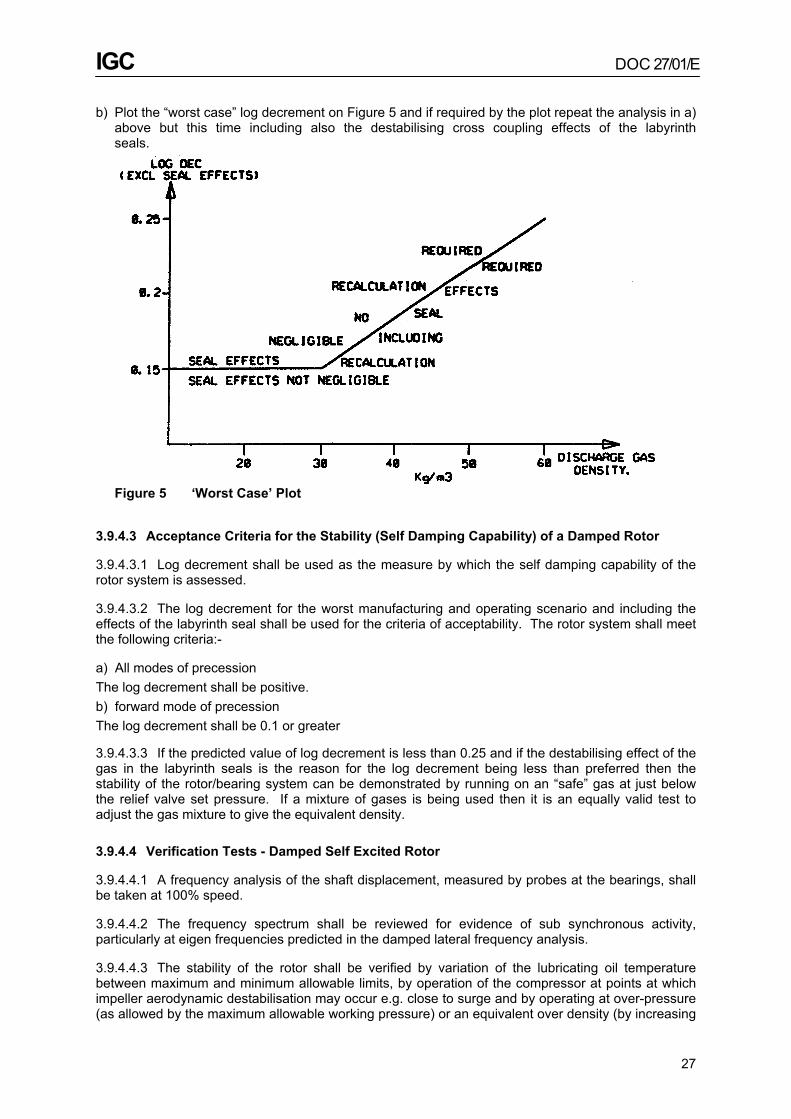
IGC DOC 27/01/E
27
b) Plot the “worst case” log decrement on Figure 5 and if required by the plot repeat the analysis in a) above but this time including also the destabilising cross coupling effects of the labyrinth seals.
Figure 5 ‘Worst Case’ Plot
3.9.4.3 Acceptance Criteria for the Stability (Self Damping Capability) of a Damped Rotor
3.9.4.3.1 Log decrement shall be used as the measure by which the self damping capability of the rotor system is assessed.
3.9.4.3.2 The log decrement for the worst manufacturing and operating scenario and including the effects of the labyrinth seal shall be used for the criteria of acceptability. The rotor system shall meet the following criteria:-
a) All modes of precession The log decrement shall be positive. b) forward mode of precession The log decrement shall be 0.1 or greater
3.9.4.3.3 If the predicted value of log decrement is less than 0.25 and if the destabilising effect of the gas in the labyrinth seals is the reason for the log decrement being less than preferred then the stability of the rotor/bearing system can be demonstrated by running on an “safe” gas at just below the relief valve set pressure. If a mixture of gases is being used then it is an equally valid test to adjust the gas mixture to give the equivalent density.
3.9.4.4 Verification Tests - Damped Self Excited Rotor
3.9.4.4.1 A frequency analysis of the shaft displacement, measured by probes at the bearings, shall be taken at 100% speed.
3.9.4.4.2 The frequency spectrum shall be reviewed for evidence of sub synchronous activity, particularly at eigen frequencies predicted in the damped lateral frequency analysis.
3.9.4.4.3 The stability of the rotor shall be verified by variation of the lubricating oil temperature between maximum and minimum allowable limits, by operation of the compressor at points at which impeller aerodynamic destabilisation may occur e.g. close to surge and by operating at over-pressure (as allowed by the maximum allowable working pressure) or an equivalent over density (by increasing

IGC DOC 27/01/E
28
the molecular weight of the test gas to a value >32.
3.9.4.4.4 For the rotor to be acceptable the sum of the amplitudes of all the non synchronous frequency components shall not be more than 25.4/4 x (12000/Nmax)½.
3.9.5 Torsional Vibrations
3.9.5.1 Definition of Terms
Excitation of torsional resonances may come from many sources, which should be considered in the analysis. These sources may include but are not limited to the following: a) Gear problems such as unbalance and pitch line run-out. b) Start-up conditions such as speed detents and other torsional oscillations. c) Torsional transients such as switch on and terminal short circuits of all kind of conventional
electric-motors, start-up of synchronous electric motors, etc. d) Oscillating torque from converter fed electric motors.
3.9.5.2 Torsional Resonances and Acceptance Criteria
3.9.5.2.1 When the frequency of a periodic torsional forcing phenomenon (exciting frequency) applied to the shaft train corresponds to a torsional natural frequency of that system, the system is in a state of resonance.
3.9.5.2.2 The natural torsional frequencies shall be determined analytically by means of an undamped eigenvalue analysis of the complete shaft train.
3.9.5.2.3 The following acceptance criteria shall be met:
a) The fundamental torsional frequency of the complete train shall be at least 10% above or 10% below any possible excitation frequency within the specified operating speed range (from min to max cont. speed).
Note: Starting-speed detents (hold-points) shall be defined such that the above defined separation margins are met as well.
b) If higher modes occur within the specified speed range there are two acceptance options: either - The vendor shall show with the help of reference machines that this design is well within his experience.
or - The vendor shall provide excitation data and show with the help of a Goodman diagram that these higher modes have no adverse effect on the complete train.
c) Torsional criticals at two times running speed as well as one and two times the line frequency for motor driven systems shall preferably be avoided or, in systems in which corresponding excitation frequencies occur, shall be shown to have no adverse effect. In addition to the above, torsional excitations that are not a function of operating speeds or that are non-synchronous in nature shall be considered in the torsional analysis when applicable. Identification of these frequencies shall be the mutual responsibility of the purchaser and the vendor.
3.9.5.2.4 The study shall consider the effect of:
• torque amplitude • harmonic excitation • frequencies of concern • dynamic amplifier • torque acting point (most sensitive node point of the system).

IGC DOC 27/01/E
29
The stress analysis shall be based on SMITH (GOODMAN) diagrams created for the weakest shaft parts of each system component. The diagrams shall be based on minimum strength requirements according to international material standards taking additionally the corresponding notch factor into account.
3.9.5.3 Transient Torsional Load Cases and Acceptance Criteria
3.9.5.3.1 For motor-driven units the vendor, who has the unit responsibility, shall provide references of similar machines to demonstrate that the transient occurrences in the motor have no adverse effect on the complete shaft train. If references can not be made available the vendor shall perform a transient vibration analysis.
3.9.5.3.2 The analysis shall consider but shall not be limited to the following transient load cases of electric motors:
a) Switch on from standstill. b) 2- and 3-phase terminal short circuits. c) Asychronous run-up of synchronous motors. d) Re-acceleration after “pullout” due to voltage dip or after transient breaker opening and closing. e) Oscillating torque from converter fed electric motors
3.9.5.3.3 The transient torsional vibration analysis shall be based on the following boundary conditions:
• load cases as mutually agreed upon by the purchaser and the vendor (basically as defined in 3.9.5.3.2).
• transient torque to be defined by the motor manufacturer • dynamic amplifier to be defined by the vendor • torque acting point motor core
3.9.5.3.4 For systems exposed to a high number of starts the permissible start number shall be calculated based on:
a) stress-cycle diagrams created for the weakest shaft parts of each system component. The diagrams shall be based on minimum strength requirements according to international material standards taking additionally the corresponding notch factor into account.
b) Cumulative damage theory according the PALMGREN-MINER hypothesis for fatigue analysis.
3.9.5.3.5 The stress analysis is to be carried out to prove whether the shaft system is short circuit proof (re-acceleration proof) or not. It shall be acceptable if:-
either - the responding peak torque amplitude in a particular shaft part shall not exceed the yield limit of the corresponding material.
or - if the calculation indicates that this limit will be exceeded then the shrink fit of the coupling is designed such that it will slip and limit the stress to 0.85 of the yield limit.
3.9.5.4 Verification Tests - Torsional Vibrations
Verification tests are usually only carried out either when the circumstances are outside the previous experience of the vendor/purchaser or there is reason to believe that the prediction may be in error. (e.g. 3 pinion integral gear compressor driven by a 0.7 leading power factor synchronous motor. A suitable method of verifying the prediction is to take strain gauge readings during run up at key positions in the train.

IGC DOC 27/01/E
30
3.9.6 Data
The vendor shall make the following information available to the purchaser:
3.9.6.1 Lateral Analysis
a) Sketch of the system arrangement, indicating all relevant data. b) If required, detailed information concerning the lateral modelling to enable the purchaser to do an
independent analysis: • a graphic display of the mass elastic system. • sketch of journal bearing geometry, indicating pad or lobe angles, • pad or lobe arrangements, arrangement of pivot points, load • direction, bearing length and diameter , bearing clearance, preload, static bearing load, lube oil
condition. • support (base, frame and bearing housing) stiffness. • mass, and damping characteristics, including effects of rotational • speed variation. • sketch indicating the unbalance arrangement. • journal bearing stiffness and damping coefficients vs speed. c) Acceptance criteria as mutually agreed upon by the purchaser and the vendor. d) A complete description of the method used to determine the “critical speeds”. e) Results of the damped unbalance response calculations: • unbalance response plots and shaft deformation lines as defined in 3.9.3.2.4 Item b). • tabulated results in comparison with the acceptance criteria as defined in 3.9.3.3.1. • tabulated results in comparison with the acceptance criteria as defined in 3.9.3.3.2. f) Vendor’s conclusion. g) A “lateral critical speed map” shall be made available as defined in 3.9.3.2.4 Item d). h) Tabular listing of the damped eigenvalues (eigen frequencies and log decrements) calculated for
the minimum and the maximum Sommerfeld Numbers, indicating additionally the corresponding precession mode (forward, mixed, backward).
i) Results of the stability analysis.
3.9.6.2 Torsional Analysis
a) Sketch of the system arrangement, indicating all relevant data. b) Detailed information including the damping factor concerning the torsional modelling to enable the
purchaser to do an independent analysis: • a graphic display of the mass elastic system. c) Acceptance criteria as mutually agreed upon by the purchaser and the vendor. d) A complete description of the method used to determine the “critical speeds”. e) Results of the torsional calculations: • a graphic display of torsional critical speeds (CAMPBELL diagram) and deflections (mode shape
diagram). f) Vendor’s conclusion. When required by 3.9.5.3.1 the following information shall be made available:
• Above b) shall be completed by adding a description of the sources of excitation, including formula or graphic displays of the transient torque amplitudes versus time.
• Above e) shall be completed by graphic displays showing the exciting torques as well as the corresponding excited shaft torques versus time.

IGC DOC 27/01/E
31
3.10 Balancing and Vibration
3.10.1 Balancing
3.10.1.1 Major parts of the rotating elements such as shafts, balancing drums and impellers shall be dynamically balanced, as dictated by the vendor’s protocol. Single plane balancing is only acceptable for narrow impellers.
3.10.1.2 The acceptance criteria to be met for the low speed balancing shall be as follows:
a) Single components such as impellers: Quality grade according to VDI 2060, (ISO 1940) Q = 1.0 mm/s b) Assembled couplings: Quality grade according to VDI 2060, (ISO 1940) Q = 1.6 mm/s c) Assembled rotors: Quality grade according to VDI 2060, (ISO 1940) Q = 2.5 mm/s
3.10.1.3 High speed balancing shall be performed on all rotors running above their first bending critical. The first bending critical is the mode in the real rotor system corresponding to the first critical of the same rotor in rigid bearings. See Figure 6 for the equivalent API definition. The assembled rotors shall be balanced at their maximum operating speed. Balance corrections shall be done according to the mode shapes without any unallowable influence of the low speed balanced quality as defined in 3.10.1.2.
3.10.1.4 The acceptance criteria to be met for the high speed balancing shall be as follows:
a) Low speed, see 3.10.1.2 ( C ) b) High speed: i) The bearing pedestal vibrations shall be in accordance with VDI 2056 (ISO 2372) and shall not
exceed the following limits: • At critical speeds v rms = 4.5 mm/s • within the operating speed range (from minimum operating speed to maximum continuous speed)
v rms = 1.8 mm/s • up to and including trip speed v rms = 4.5 mm/s ii) the relative shaft vibrations shall be in accordance with 3.10.2 -vibration limits of this Code.

IGC DOC 27/01/E
32
Figure 6 Typical Mode Shapes
3.10.2 Vibration Limits
3.10.2.1 Vibration Limits - Normal Operation
3.10.2.1.1 During testing of the machine assembled with the balanced rotor, operating at its maximum continuous speed or at any other speed within the specified operating speed range, the peak-to-peak amplitude of unfiltered vibration in any plane, measured on the shaft adjacent and relative to each radial bearing, shall not exceed the following value or 50 micron, whichever is less. This test can either be in the shop or in the field.
A = 25.4 x (12,000/Nmax)½ where : A = amplitude of unfiltered vibration
(micron)
Nma = maximum continuous speed (rpm)
3.10.2.1.2 At any speed greater than the maximum continuous speed, up to and including the trip speed of the driver, the vibration shall not exceed 1.5 x of the above defined value.
3.10.2.1.3 The combined electrical and mechanical runout shall be determined and recorded by rolling the rotor in V-blocks or at low speed in its original bearings while measuring the runout with a non-contacting vibration probe. The combined electrical and mechanical runout shall not exceed 0.25 x the level calculated from the equation above, or 6 micron whichever is greater.

IGC DOC 27/01/E
33
3.10.2.2 Vibration Limits - Alarm and Trip
There is no recognised rule for setting alarm and trip levels. Many operators base the setting upon the actual running levels achieved in operation. The values set out below should be regarded as maximum levels.
a) Maximum Permissible Alarm Setting A = 2.5 x [25.4 x (12,000/Nmax)½]
where: Nmax = max continuous speed [rpm]
or 0.65 x the actual journal bearing clearance, whichever is less. b) Maximum Permissible Trip Setting A = 3.5 x [25.4 x (12,000/Nmax)½]
where: Nmax = max continuous speed [rpm]
or 0.8 x the actual journal bearing clearance, whichever is less.
3.11 Electrical Discharge
3.11.1 Insulation and Earthing
Great care shall be taken to insulate and earth the electric drive motor correctly to prevent currents circulating through the compressor which, experience has shown, can damage the bearings, couplings, and gear teeth. This phenomenon can occur in all types of compressor but special care is required in the case of oxygen compressors because the consequence of bearing damage could be a fire.
3.11.2 Code Requirements
In the past it has been a mandatory requirement of the code that each compressor shaft be earthed. A re-examination of the problem has led the majority of the Code members to doubt the effectiveness of the earthing bushes and to believe that the solution to the problem lies in the correct insulation and earthing of the drive motor. As a result of the above, earthing of the compressor shafts is now only an optional requirement of the code.
Figure 7 Earthing of Compressor Shafts

IGC DOC 27/01/E
34
4. Auxiliaries Design
4.1 Coolers
4.1.1 Scope of Supply
It is recommended that the coolers be supplied by the compressor vendor as it is his ultimate responsibility to ensure that the whole of the machine be constructed under clean conditions. The purchaser is responsible for ensuring that the vendor has been given sufficient information about the water quality to enable the correct materials to be selected.
4.1.2 Types of Cooler
4.1.2.1 The following types of cooler are acceptable
a) Gas in the shell with externally finned tubes. Water in the tubes. b) Gas in the tubes with plain tubes, water in the shell.
4.1.2.2 Design features - Specific to Coolers with gas in the Shell
This type of cooler has “water boxes”, containing the water return channels, in the oxygen side of the cooler, due care shall be taken with the jointing to minimise the risk of leaks between the oxygen and water sides.
4.1.2.3 Design features - Specific to Coolers with Gas in the Tubes
This type of cooler has a single gas pass through plain tubes and shall have an “outside packed” floating head (e.g. TEMA B.E.P.). If the cooler has a side gas entry then the gas will impinge on carbon steel and care shall be taken to ensure that the gas velocity is within the limits prescribed in 4.2.5 - velocity.
4.1.2.4 Design features common to both types of cooler
4.1.2.4.1 Care shall be taken that components, e.g. bolts, are positively secured so as to avoid the danger of them coming loose and being carried into the oxygen stream.
4.1.2.4.2 They shall have removable tube bundles.
4.1.2.4.3 All the fittings and fixtures on the water side shall be of corrosion resistance materials.
4.1.2.4.4 Care shall be taken to ensure that the cooler tubes are properly supported and are not susceptible to machine or fluid induced vibration. The tube supports shall be of a suitable design and materials to ensure that they do not do damage to the tubes. Experience has shown that to achieve this it is advisable that the support material that is in contact with the tube should be softer than the tube material.
4.1.2.4.5 When the tubes are expanded into the tube plates the lubricant used shall be oxygen compatible. (See 5.3.3.4 - Parts “clean for oxygen service”).
4.1.2.5 Material Selections that are common to both types of Cooler - Oxygen side only
4.1.2.5.1 The materials of the cooler bundles, in contact with the oxygen, shall be copper alloy or stainless steel.
4.1.2.5.2 The tubes shall be more positive in the electro chemical scale than the tube plates.

IGC DOC 27/01/E
35
4.1.2.5.3 Provided that the cooling water is of a suitable quality the most commonly used materials are Muntz metal for the tube plates and admiralty brass for the tubes. The fins are normally made of copper.
4.1.2.5.4 Carbon steel tube plates are not acceptable due to the high corrosion potential of carbon steel.
4.1.2.6 Establishment and Maintenance of Oxygen Cleanliness - Gas in Shell Type
4.1.2.6.1 One of the concerns with this type of cooler is the oxygen cleanliness of the cooler bundle because:
a) It requires specialist equipment to clean it after assembly or reclean it if it becomes contaminated. b) There is no a simple way of checking its cleanliness in the field.
4.1.2.6.2 The following procedure has been found to work well and is recommended:
a) Make all the material in contact with oxygen non-rusting. b) Clean for oxygen service, assemble the cooler complete and seal with heavy blanks in the
vendor’s works. c) Ensure that the blanks are only removed under the supervision of the “designated” engineer, (see
6.1 - erection).
4.1.2.6.3 If the cooler shell is made of carbon steel those parts which are in contact with oxygen shall be made non-rusting.
a) Paint is not permitted. b) Zinc coating, in this application is permitted by the Code, because of the low oxygen velocities
involved and with the proviso that good adherence is assured by compliance with the following conditions:
• Hot dipping is the only acceptable process • The cooler design shall be suitable for hot dipping • The carbon steel of the shell shall contain Si 0.1 - 0.3%. • The preferred thickness of the zinc is between 200-600 micron but a greater thickness is
acceptable if good adherence has been demonstrated. c) Surface passivation by the use of phosphoric acid is permitted.
4.1.2.7 Establishment and Maintenance of Oxygen Cleanliness - Gas In Tube Type
4.1.2.7.1 It is easy to establish oxygen cleanliness in this type of cooler, because the oxygen side of tubes are straight and smooth and the gas header can be detached for easy cleaning and inspection.
No special cleaning equipment is needed and this type of cooler is easy to check for oxygen cleanliness in the field.
4.1.2.7.2 In order to ensure that the cooler remains oxygen clean during shipping and erection it is recommended that:
a) All the materials in contact with oxygen are non-rusting. b) The unit is sealed with heavy blanks which are only removed under the supervision of the
“designated engineer”, (see 6.1 - erection). Note: If the above precautions are not taken or they fail it is relatively simple to reclean the unit see 4.1.2.7.1.
4.1.2.7.3 If the cooler heads are made of carbon steel and it is required to make them non rusting the permitted methods are given in 4.1.2.6.3.

IGC DOC 27/01/E
36
4.1.3 Vents and Drains
4.1.3.1 Suitable means shall be provided to vent all high points and to drain all low points on the water side.
4.1.3.2 It shall be possible to check for cooling water leaks prior to starting and thereafter if the compressor is stopped with cooling water circulating. If the oxygen side drains can be operated on oxygen then they shall be led into a well ventilated area which it is preferred is outside the safety barrier.
4.1.3.3 The minimum size of the vent and drain connections shall be 20mm.
4.2 Process Pipework
4.2.1 Extent
The recommendations contained in this section shall be limited to the piping directly associated with the oxygen compressor and included within the oxygen compressor unit. In general terms this is limited to the piping downstream of the suction isolating valve and will include the inlet filter system, all piping between the compressor and non-integral coolers, by-pass valves and associated piping and discharge piping from the compressor through to the outlet shut-off valve.
4.2.2 Connections
All connections 40mm nominal bore or larger shall be flanged or welded.
4.2.3 Welding
4.2.3.1 The use of back-up welding rings shall be forbidden. The root runs of all butt welds shall be made by a method that will minimise slag formation: a suitable method would be gas shielded arc welding. The welds shall be smooth and of regular form. Any slag or weld icicles shall be removed.
4.2.3.2 Welding checks shall be carried out. The methods and extent shall be agreed between vendor and purchaser.
4.2.4 Prefabrication
To reduce the possibility of contamination on site due to ingress of moisture and dirt, oxygen piping should preferably be prefabricated except for the closing ends. All ends shall be suitably capped prior to despatch to site.
4.2.5 Velocity
Piping materials should be selected in accordance with the velocity requirements of the latest version of the IGC document ‘The Transportation and Distribution of Oxygen by Pipelines. Recommendation for the design construction, operation and maintenance’.
4.2.5.1 Application
The above method may also be used to determine whether the use of carbon steel is permitted in other equipment besides pipework within the compressor package, e.g. coolers, silencers, filter
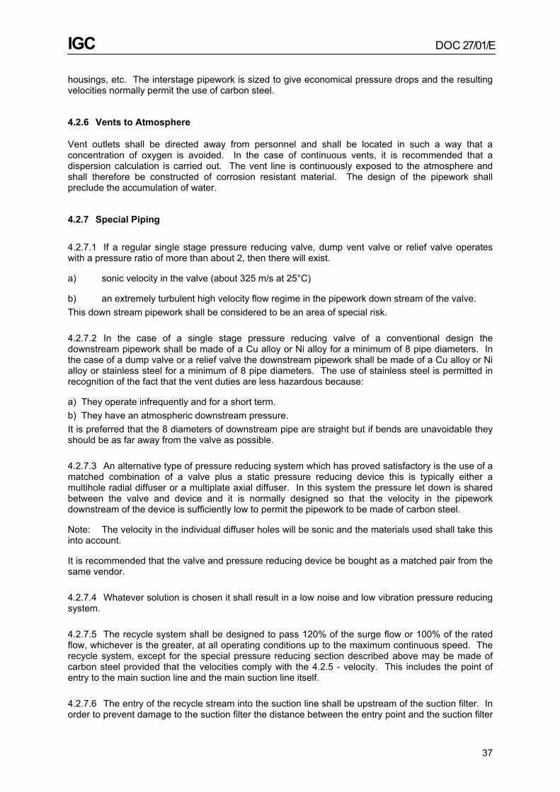
IGC DOC 27/01/E
37
housings, etc. The interstage pipework is sized to give economical pressure drops and the resulting velocities normally permit the use of carbon steel.
4.2.6 Vents to Atmosphere
Vent outlets shall be directed away from personnel and shall be located in such a way that a concentration of oxygen is avoided. In the case of continuous vents, it is recommended that a dispersion calculation is carried out. The vent line is continuously exposed to the atmosphere and shall therefore be constructed of corrosion resistant material. The design of the pipework shall preclude the accumulation of water.
4.2.7 Special Piping
4.2.7.1 If a regular single stage pressure reducing valve, dump vent valve or relief valve operates with a pressure ratio of more than about 2, then there will exist.
a) sonic velocity in the valve (about 325 m/s at 25°C)
b) an extremely turbulent high velocity flow regime in the pipework down stream of the valve. This down stream pipework shall be considered to be an area of special risk.
4.2.7.2 In the case of a single stage pressure reducing valve of a conventional design the downstream pipework shall be made of a Cu alloy or Ni alloy for a minimum of 8 pipe diameters. In the case of a dump valve or a relief valve the downstream pipework shall be made of a Cu alloy or Ni alloy or stainless steel for a minimum of 8 pipe diameters. The use of stainless steel is permitted in recognition of the fact that the vent duties are less hazardous because:
a) They operate infrequently and for a short term. b) They have an atmospheric downstream pressure. It is preferred that the 8 diameters of downstream pipe are straight but if bends are unavoidable they should be as far away from the valve as possible.
4.2.7.3 An alternative type of pressure reducing system which has proved satisfactory is the use of a matched combination of a valve plus a static pressure reducing device this is typically either a multihole radial diffuser or a multiplate axial diffuser. In this system the pressure let down is shared between the valve and device and it is normally designed so that the velocity in the pipework downstream of the device is sufficiently low to permit the pipework to be made of carbon steel.
Note: The velocity in the individual diffuser holes will be sonic and the materials used shall take this into account.
It is recommended that the valve and pressure reducing device be bought as a matched pair from the same vendor.
4.2.7.4 Whatever solution is chosen it shall result in a low noise and low vibration pressure reducing system.
4.2.7.5 The recycle system shall be designed to pass 120% of the surge flow or 100% of the rated flow, whichever is the greater, at all operating conditions up to the maximum continuous speed. The recycle system, except for the special pressure reducing section described above may be made of carbon steel provided that the velocities comply with the 4.2.5 - velocity. This includes the point of entry to the main suction line and the main suction line itself.
4.2.7.6 The entry of the recycle stream into the suction line shall be upstream of the suction filter. In order to prevent damage to the suction filter the distance between the entry point and the suction filter

IGC DOC 27/01/E
38
shall be not less than twice the diameter of the suction piping.
4.2.8 Bellows
Bellows shall be entirely of metallic construction and made from corrosion resistant materials. They shall have a smooth inner sleeve to reduce turbulence and dust accumulation. Before assembly of the sleeve the inside of the corrugations shall be inspected for cleanliness.
4.2.9 Gaskets
Gasket material in contact with the oxygen stream shall be compatible with oxygen service and agreed between the vendor and purchaser (see 1.1.6 - B.A.M. approval). Gaskets shall not protrude into the gas stream.
4.2.10 Acoustic and Thermal Insulation
Pipe external acoustic and thermal insulation material shall be compatible with oxygen at atmospheric pressure. Care shall be taken to ensure that the pipe insulation is sealed against the ingress of oil vapour. The material used shall be agreed by the vendor and the purchaser. Pipe internal insulation is not permitted by the Code.
4.2.11 Silencers
Silencers are forbidden in the recycle or interstage pipework. It is preferred that silencing of the suction is achieved by insulating the suction pipe but if this is not practical then the use of suction silencers is permitted. Suction silencers, if fitted, shall be located upstream of the suction filter. The silencer shall be manufactured using oxygen compatible materials and the design shall be such that the possibility of the internals breaking up is prevented.
4.2.12 Vaned Elbows
Vaned elbows are permitted by the code. They shall be treated as impingement sites and therefore if fabricated in carbon steel shall comply with the impingement site velocity criteria given in 4.2.5. The formation of internal slag shall be precluded by the use of a welding procedure that uses inert gas shielding. The design of the vaned section shall be such as to facilitate post fabrication oxygen cleaning and inspection.
4.3 Manual Valves
4.3.1 Manually Operated Main Isolation Valves
The manually operated main isolation valves are not covered by this Code.
4.3.2 Manual Valves which form part of the Oxygen Containing Envelope
Manual valves which form part of the oxygen containing envelope, but which cannot be operated whilst on oxygen and which therefore will not experience high velocity oxygen may be made of carbon or low alloy steel. Valves which can be operated on oxygen shall be made of Cu alloy, Ni alloy or stainless steel, e.g. low point drains and instrument root valves.

IGC DOC 27/01/E
39
4.4 Main Suction Filter
A filter shall be provided in the main suction line as close as practicable to the machine inlet flange. It shall be installed before start-up and remain throughout the life of the machine.
4.4.1 Rating
The filter rating shall be 150 micron maximum.
4.4.2 Materials
The filter element shall be manufactured from corrosion resistant materials which are suitable for oxygen service, e.g. Cu-alloy, Ni-alloy or stainless steel. If non metallic materials are used then they shall be oxygen compatible (See 1.1.6 - B.A.M. approval) . In both cases the materials used and shall be approved by both vendor and purchaser.
4.4.3 Design Strength
In designing the filter, due regard shall be given to providing adequate strength so as to avoid failure of the filter element by the following causes:
• differential pressure through partial or total blockage. • pressure pulsations through surging, rapid operation of recycle or vent valve, etc.
4.4.4 Flow Direction
The filter unit shall be designed so that all attachments are upstream of the filter elements so as to be contained within the elements should failure occur.
4.4.5 Free Area
The filter element shall provide a mesh open area of at least the area of the main suction pipe.
4.4.6 Precaution against Installation Errors
The filter unit shall be designed so as to prevent incorrect installation. An external indicator, such as an arrow, shall be provided to indicate the direction of flow.
4.4.7 Inspection
The filter element shall be easy to remove for inspection and cleaning. During removal it should fully retain all foreign particles.
4.5 Lubricating Oil System
4.5.1 General
Parts requiring operator attention or on-line maintenance should be outside the enclosure. Lubricating oil pipes within the hazard area shall be kept as short as possible and be routed clear of oxygen pipework where possible. The number of joints shall be kept to a minimum and, where their

IGC DOC 27/01/E
40
use is unavoidable, they shall be easily accessible and located so as to avoid the possibility of lubricating oil dripping onto pipework or other equipment.
4.5.2 Pumps
4.5.2.1 Motor Driven Units
A mechanically driven main oil pump which provides adequate lubrication during run down, caused by total loss of power, is the method preferred by the code for motor driven units. All other methods are more complex and require careful consideration. However, if in a particular design the mechanically driven oil pump is not able to provide sufficient lubrication during the run down period, accumulators or tanks should be provided to supply the required oil. Care shall be taken to keep the amount of stored oil to the minimum required so that, in the event of a seal gas failure, the likelihood of oil contamination is still negligible.
4.5.2.2 Steam Turbine Driven Units
Experience with steam turbine driven oxygen compressors is limited and the solution is more complex due to the requirement of the turbine bearings to be fed with oil during the cool down period. In the case where the compressor is shut down and the seal supply has failed a method of automatically isolating the compressor from the lube system shall be provided (see 4.6 - seal gas supply system).
4.5.2.3 The mechanically driven main oil pump system shall be such that it will provide positive lubrication even in the event of reverse rotation of the pump due to backflow of gas through the compressor.
4.5.2.4 Severe damage, which may result in a fire, will be caused if a compressor runs down without lube oil. It is therefore considered unsafe to continue to run the compressor on the auxiliary lube oil pump if the main mechanically driven pump has failed. In order to ensure that the above is complied with it is recommended that it is the action of the compressor tripping that starts the auxiliary lube oil pump.
4.5.2.5 In the event of a fire the operation of the auxiliary lube oil pump shall either be stopped by the manual intervention of the operator or be inhibited by the action of automatic fire sensors.
4.5.3 Filter
Dual oil filters should be provided. Switch-over during normal operation of the compressor without interrupting the oil flow to the bearings shall be possible. The filters shall be of a 10 micron rating and shall be installed downstream of the cooler. All the lube oil supply pipework downstream of the filter shall be stainless steel.
4.5.4 Oil Heater
The surface area of the oil heater, if provided, shall be such that no local over heating or cracking of the oil can occur.
4.5.5 Oil Vapour Extractor System
The lube oil tank shall be fitted with an oil vapour extractor complete with oil demister system. The design shall be such that it shall not be possible to exceed a predetermined negative pressure in the lube oil tank.

IGC DOC 27/01/E
41
4.5.6 Oil Tank
4.5.6.1 The lube oil tank shall be installed in such a way that oil spillages during filling are limited to a specific area from which the oil can easily be removed.
4.5.6.2 In order to protect the oil tank from over pressure, resulting from hot gases generated by a compressor fire, a bursting disc vented away from personnel areas should be fitted in the top of the lube oil tank. It should be the same size as the lube oil return line and should have a burst pressure commensurate with the allowable pressure in the lube oil tank.
4.5.7 Control
The temperature and pressure of the oil supply shall be controlled automatically.
4.6 Seal Gas System
4.6.1 Compressor Seal Gas System
4.6.1.1 The seal gas shall be dry oil free air or nitrogen. The compressor seal system shall maintain proper pressure differentials between sealing chambers under all possible operating conditions. Special attention in this regard shall be paid to the transient pressures during start-up and shut-down periods where adverse pressure differentials might occur.
4.6.1.2 High grade differential pressure switches shall be installed at each shaft end seal location to signal adverse pressure distributions, and to shut down the compressor automatically in case of an unsafe seal chamber pressure distribution. (See Figure 4.6.3 - compressor seal gas system and section 3.6.2 - atmospheric rotor seals).
4.6.1.3 In order to protect the compressor from the possibility of oil contamination when the seal gas supply has failed the seal gas and lube oil systems shall be suitably interlocked. (See section 4.6.3 Note 2 - compressor seal system and 3.6.2 - atmospheric rotor seals.
4.6.1.4 The pipework downstream of the compressor seal gas filter shall be made of non rusting material normally copper or stainless steel.
4.6.2 Bearing Seal Gas System
This system has the simple function of preventing atmospheric air, which might be enriched with oxygen ,from getting into the oil system. It does not have to have the same high integrity as the compressor seal gas system - nor is it subject to process variations, it is therefore a much simpler system.
4.6.3 Schematic Diagram
The attached schematic diagram and the accompanying notes show both of the above systems in detail. These systems have been proved to work well for electric motor driven compressors with low suction pressures. The systems for booster, or turbine driven compressors may require modification and shall be agreed between the vendor and purchaser.

IGC DOC 27/01/E
42
Figure 9 Seal Gas Supply Schematic Diagram

IGC DOC 27/01/E
43
Note 1 Sources of Seal Gas
a) The schematic shows both the compressor seals and the bearing seals being fed from the same supply. In order to be sure that there is no possibility of oil vapour back flowing along the bearing seal gas line and then being pushed in to the compressor seal gas line, the bearing seal system shall be supplied with a separate non return valve and pressure regulator. The pipe run from the branch off the compressor seal gas system to the nearest bearing shall be at least 5 metres. The compressor seal gas supply shall also be supplied with a non return valve to ensure that there is no possibility of oxygen getting into the seal gas supply header.
b) An equally acceptable option is for the bearing seal gas and the compressor seal gas to be supplied from separate sources, e.g. Nitrogen for the compressor seal gas and instrument air for the bearing seal gas. In this case the bearing seal gas does not have to be oxygen clean, nor is a minimum length of line between the supply point and the nearest bearing required.
Note 2 Interlock with Auxiliary Lube Oil Pump.
The interlock shown (where by low differential pressure between the seal centre chamber and seal outer chamber causes the compressor to trip and prevents the aux lube oil pump from starting) is the best system for motor driven compressors with mechanically driven oil pumps.
The system for a turbine driven compressor is more complex and has to be agreed between vendor and purchaser.
Note 3 Control of the pressure in the seal inner chambers of the compressor shaft seal system
a) In normal operation the process pressure to the suction of an oxygen compressor varies very little. b) If the inner chambers of the seal system are connected to the suction pipework up stream of the
suction throttle device (if fitted) then pressure in them will remain constant. c) If the seal inner chambers are connected downstream of the throttle device then the pressure in
them will vary according to the amount of suction throttling. In extreme cases this could cause the pressure in some of the seal inner chambers to become sub atmospheric.
d) When starting up on total recycle with the suction and discharge isolation valves shut, the suction pressure will often drop well below atmospheric pressure for a period of several minutes and there is thus a risk of dirt and damp air being sucked into the compressor via the vent and the seal centre chambers.
If this ingress of dirt and air is considered to be a hazard or a represent a product purity problem then it is recommended that a back pressure valve is fitted in the line between the seal inner chambers and the suction thus ensuring that the seal inner chamber pressures are always kept positive and constant. Experience has shown that a self acting control valve is not accurate enough for this application.
If the problem only occurs during start up then a power operated valve, which is shut during start-up and trip - but open during normal operation, is an effective solution. This system has the advantage over the back pressure valve in that it maintains the seal inner chambers at the lowest possible pressure and therefore minimises the leakage of oxygen to atmosphere via the seal centre chambers.
Note 4 Seal Pressure Sensing Points.
The actual position at which the seal chamber pressures are sensed is very important and is discussed fully in 3.6.2 - compressor atmospheric rotor seals.
Note 5 Optional Additional Seal Instrumentation
The mandatory protection of low differential pressure between seal outer chamber and seal centre chamber at each seal location - protects against failure of the seal gas supply and dangerous failure of any of the seal components. It has been proved to be effective. However, failure of the inner section of the labyrinth seal will only be detected when it causes the seal centre chamber pressure to

IGC DOC 27/01/E
44
rise; by this time there will be a large flow back to suction. It may be of advantage to detect this leakage early. There are two methods:
a) Monitor the differential pressure between the seal inner chamber and seal centre chambers. b) Monitor the flow in the return line to suction.
Note 6 Gears
If the gears are situated within the hazard area then the bearing seal gas system shall be connected to the gear case and the gas used shall be Nitrogen. Consideration should also be given to the fitting of a differential pressure indication, alarm and trip between the gear case pressure and the bearing gas supply pressure.
4.7 Controls and Instrumentation
4.7.1 General
4.7.1.1 Protective controls and instrumentation shall be provided for every oxygen compressor in accordance with but not necessarily limited to those described in the following paragraphs. The minimum alarm, and trip requirements are tabulated in paragraph 4.7.9. All measurements taken inside the hazard areas whilst the machine is on oxygen service shall be remotely read in a safe environment.
4.7.1.2 The trip system may be executed by computer software provided that the reliability, integrity and security is not less than the equivalent hard wired system.
4.7.1.3 The speed of the tripping system should be as fast as possible therefore the slowing down of the system to avoid trips due to transient voltage dips, etc. should be kept to an absolute minimum commensurate with the engineering of a reliable system.
4.7.1.4 If a fluid is used in a pressure transducer then it shall be oxygen compatible.
4.7.1.5 A “first up” alarm system is recommended.
4.7.2 Control System
The control may be pneumatic, electrical or hybrid.
4.7.3 Anti Surge System
4.7.3.1 Introduction
A compressor in surge is subject to flow reversal, thrust reversal, rotor vibration and heating. All the compressors built by the vendors represented on this working group are built to withstand a certain amount of surging without damage; however, if the compressor is allowed to surge continuously then severe damage may well result. The consequences of an internal rub can be much more severe in oxygen service than other gases therefore much more care is taken in the design of the anti surge system.
Protection against damage due to surge takes two forms:
a) A modulating anti surge system to keep the compressor out of surge; b) A surge detector to shut down the compressor in the event of surge.

IGC DOC 27/01/E
45
4.7.3.2 Modulating Anti-Surge Control
4.7.3.2.1 The compressor is prevented from going into surge by the action of an automatically controlled recycle valve which allows gas to flow from the discharge (via a cooler) to the suction.
4.7.3.2.2 It shall be impossible to override the automatic anti surge controller when operating the anti surge valve in the remote manual mode.
4.7.3.2.3 The anti surge control shall be designed to prevent the compressor going into surge under all foreseen operating conditions and upset conditions. It is recognised that if there is a sudden failure in the system the compressor may surge and then be shutdown by the surge detector system. (see 4.7.3.3 - surge detection shutdown device).
4.7.3.2.4 When the compressor anti surge system is being specified the following points should be considered:-
a) Operation of quick acting valves downstream of the compressor may be a potential cause of surge and for this reason the entire anti-surge control system shall have a fast response time.
b) The recycle valve and its associated downstream pipework shall be designed for continuous operation.
c) If operation close to surge is required the effects of changes of pressure and temperature (gas and cooling water) on the surge characteristic should be considered.
d) The position of the suction throttling device relative to the recycle line (see diagram 4.7.11). If the device is positioned downstream of the recycle line then it shall be equipped with a mechanical minimum opening stop such that there is still sufficient flow area to allow the antisurge system to be effective.
e) There is no simple algorithm which describes the position of the surge line of a multistage, intercooled centrifugal compressor under varying conditions of capacity control, suction and cooling water temperature. The complexity of the modulating anti surge system depends upon how close to surge it is intended to operate, how wide the variation in operating conditions are, and how severe the potential system upsets are. The actual system to be used shall be agreed between the vendor and the purchaser on a case by case basis.
f) The anti surge control line shall be set at least 8% by flow (at the design operating pressure) from the surge line. If it is required to operate with minimum separation from the surge line then the following has to be done:
• The vendor shall calculate the surge points over the entire operating range for varying inlet and cooling water temperatures. These predicted surge points shall be checked on site over as wide a range as possible.
• When the surge map has been produced an anti-surge controller shall be designed to fit the surge map.
• Consideration should be given to fitting a device which senses the rate at which the compressor is approaching surge and, if this is greater than a predetermined value then the recycle valve is opened a preset amount. The subsequent action depends upon the design of the system.
g) The time between surges depends upon the pressures and volumes involved but it is normally of the order of 1 second. This means that for the antisurge control system to be effective the following requirements shall be met:
• The antisurge controller shall either be analogue or digital. If digital, the calculation be made at least every 100 milliseconds. The shorter the calculation interval the quicker the possible system speed of response. An interval of 10 milliseconds is commercially available.
Note: It is considered acceptable to use the main plant control computer to carry out the anti surge control functions provided that it can meet the above speed requirements and that it is as secure as a separate stand alone controller.
• The recycle valve shall have a controlled stroking time from fully shut to fully open of 5 secs. Note: This valve is specified to trip open in less than 2 seconds see table 4.7.10.
IGC DOC 27/01/E
46
• No delays, other than those required to combat transient electrical disturbances, shall be permitted.
4.7.3.3 Surge Detection Shut Down Device
4.7.3.3.1 It is mandatory that a surge detection shutdown device be fitted. This will trip the compressor after a maximum of 4 surges, thus safeguarding it from damage in the event of failure of the anti-surge control.
4.7.3.3.2 This device and the modulating anti surge control shall have no common modes of failure.
4.7.4 High Oxygen Temperature Protection
4.7.4.1 Fast response sensors shall be installed in the oxygen path at each process stage outlet. They shall be positioned as close as practicable to the discharge nozzle and they shall be before the first elbow.
4.7.4.2 The alarm and trip set points shall be agreed between the vendor and purchaser.
4.7.4.3 If, for reasons of production reliability, the sensors are specified to fail “down scale” - so as not to trip the compressor, the above failure shall bring up an alarm.
4.7.5 High Bearing Temperature Protection
The temperature of all bearings shall be monitored with suitable sensing devices located in or close to the babbit metal. The measurement of the oil temperature leaving the bearing is not acceptable.
Note: In the case of tilting pad bearings it is important:
(a) to measure the temperature of the correct pad; (b) to ensure that the sensing device does not restrict the movement of the pad.
4.7.6 Vibration and Shaft Position
4.7.6.1 Compressor
4.7.6.1.1 Radial Vibration
2 vibration probes shall be fitted at 90° from each other at each high speed bearing location.
4.7.6.1.2 Axial Position
a) The use of non contacting probes to monitor the axial position of high speed shafts is mandatory for shafts with high speed thrust bearings but only recommended for shafts with thrust collars. If axial probes are not fitted to high speed shafts with thrust collars then the axial position of the relevant slow speed shaft shall be monitored with a non contacting probe.
b) The measurement point shall form an integral part of the shaft.
4.7.6.1.3 Key Phaser
Provision shall be made to fit a key phaser probe per high speed shaft speed.
4.7.6.2 Gear Box
4.7.6.2.1 A failure in the gears can cause a severe upset in the compressor. Parallel shafted gear boxes shall have the same probes and monitors as the compressor (see 4.7.6.1).

IGC DOC 27/01/E
47
4.7.6.2.2 Epicyclic gearboxes shall be fitted with an accelerometer based alarm and trip system.
4.7.6.3 Vibration Probe Monitoring System
4.7.6.3.1 The unfiltered output of at least one radial probe per location and the output of all axial probes shall be monitored continuously.
4.7.6.3.2 The time delays built into the alarm and trip system shall be reduced to a practicable minimum.
4.7.6.3.3 Failure of the system shall bring up an alarm.
4.7.6.3.4 Provision shall be made for the connection of vibration frequency analysis and phase displacement measurement equipment.
4.7.6.3.5 Start-up Override - if required. If starting on inert gas then a manual or time delay override is acceptable. If starting on oxygen then the trip system shall remain live and starting can be achieved using a ‘trip multiplier’ during the run up period.
4.7.7 “Safety Shutdown System” Valves
4.7.7.1 Purpose
The purpose of the safety shutdown system is to isolate the oxygen compressor and dump the oxygen inventory.
4.7.7.1.1 The system consists of the following valves:
• Automatic suction isolation valve • Discharge non return valve • Automatic discharge isolation valve • HP and LP (if required) dump vent • Recycle valve
4.7.7.1.2 The failure modes and operating speeds are given in the attached table (4.7.10) and their position in the system is shown in the attached schematic (4.7.11).
4.7.7.1.3 A safety shutdown system is a mandatory requirement of the code and all the valves shall operate on every trip.
4.7.7.1.4 If the LP coolers are gas in shell then an LP dump vent is sometimes required to meet the requirement of reducing the discharge pressure to 1 barg in 20 seconds. (see 2.4 - fire protection and precautions).
4.7.7.2 Selection of Valve Material by Degree of Risk
Valve Velocity Duration Pressure Degree of Risk Material
Recycle2) Sonic Continuous High High Cu alloy Ni alloy
HP Dump Vent LP Dump Vent Discharge isolation valve
Sonic Sonic possibly
20 secs max20 secs maxShort
High Medium High
Medium
Medium
Medium
Cu alloy Ni alloy or stainless steel
Suction isolation valve subsonic 1) Short Low Low Carbon steel body with stainless steel or Cu alloy trim
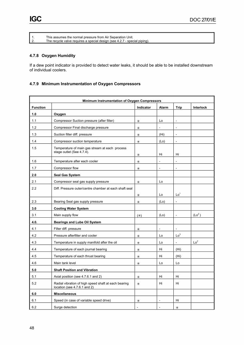
IGC DOC 27/01/E
48
1. This assumes the normal pressure from Air Separation Unit. 2. The recycle valve requires a special design (see 4.2.7 - special piping).
4.7.8 Oxygen Humidity
If a dew point indicator is provided to detect water leaks, it should be able to be installed downstream of individual coolers.
4.7.9 Minimum Instrumentation of Oxygen Compressors
Minimum Instrumentation of Oxygen Compressors
Function Indicator Alarm Trip Interlock
1.0 Oxygen
1.1 Compressor Suction pressure (after filter) ✳ Lo -
1.2 Compressor Final discharge pressure ✳ - -
1.3 Suction filter diff. pressure ✳ (Hi) -
1.4 Compressor suction temperature ✳ (Lo) -
1.5 Temperature of main gas stream at each process stage outlet (See 4.7.4).
✳
Hi
Hi
1.6 Temperature after each cooler ✳ - -
1.7 Compressor flow ✳ - -
2.0 Seal Gas System
2.1 Compressor seal gas supply pressure ✳ Lo
2.2 Diff. Pressure outer/centre chamber at each shaft seal
✳
Lo
Lo1
2.3 Bearing Seal gas supply pressure ✳ (Lo) -
3.0 Cooling Water System
3.1 Main supply flow (✳ ) (Lo) - (Lo2 )
4.0. Bearings and Lube Oil System
4.1 Filter diff. pressure ✳ - -
4.2 Pressure afterfilter and cooler ✳ Lo Lo3
4.3 Temperature in supply manifold after the oil ✳ Lo - Lo2
4.4 Temperature of each journal bearing ✳ Hi (Hi)
4.5 Temperature of each thrust bearing ✳ Hi (Hi)
4.6 Main tank level ✳ Lo Lo
5.0 Shaft Position and Vibration
5.1 Axial position (see 4.7.6.1 and 2) ✳ Hi Hi
5.2 Radial vibration of high speed shaft at each bearing location (see 4.7.6.1 and 2)
✳ Hi Hi
6.0 Miscellaneous
6.1 Speed (in case of variable speed drive) ✳ - Hi
6.2 Surge detection - - ✳

IGC DOC 27/01/E
49
- = not required 1. interlock with auxiliary oil pump (seeFigure 9 - Seal gas supply system)
✳ Hi, Lo = mandatory 2. interlock to prevent start-up
(✳ ), (Hi), (Lo) = recommended 3. starts auxiliary pump (see 4.5.2.4 - lube oil system)
4.7.10 Failure Modes and Operating Speeds of System Valves
VALVE ACTION
VALVE DUTY
On Compressor Shutdown
On Loss of Control Signal
On Loss ofElectrical
Signal
On Loss of Motive Power
SPEED OF ACTION
Automatic Suction isolation valve
Shut
Not Applicable
Shut
Shut
10 secs maxa
Automatic Discharge isolation valve
Shut
Not Applicable
Option 1b
Option 2b Shut Open
Shut Open
10 secs maxa
Final Dump Vent
Open
Not Applicable
Open
Open
2 secs. max. auto reclose after 1 min.
Intermediate dump vent (if fitted)
Open
Not Applicable
Option 1b
Option 2b Open Shut
Open Shut
2 secs. max. auto reclose after 1 min.
Recycle valve Open Open Open Open 2 secs max.
a) The relatively slow closing of the isolation valves is to ensure that the dump vent valves have opened first.
b) Under Option 1 if the valve looses supply it will fail into the correct position for isolating the compressor and dumping the inventory, it will, however, give the compressor a severe shock and drive it into surge. If this option is adopted the valves shall trip the compressor when they reach their “shutdown” position.
Under Option 2 if the valve looses supply it will not cause an upset to the compressor. The valve will not move when the compressor shuts down. The discharge isolation valve is merely a back up to the non return valve so this will not affect the dumping of the inventory. The failure of the intermediate dump vent to move will have little affect on the time taken for the discharge pressure to fall. It will mainly affect the time taken for the intermediate pressure to drop.

IGC DOC 27/01/E
50
4.7.11 Centrifugal Oxygen Compressor System flow diagram

IGC DOC 27/01/E
51
5. Inspection and Shipping
5.1 Introduction - Code
When this code was first written centrifugal oxygen compressors were shipped from the vendor’s works as separate components and erected on site. The pipe work was often site fabricated. Compressor systems can now be shipped from the vendor’s works as fully assembled, and tested, oxygen clean units. It is also possible to have any combination between the two above extremes.
In view of the above it has been necessary to modify this part of the code and also Section 6 (erection, testing and commissioning) to take into account the varying amounts of prefabrication and testing carried out in the vendor’s works.
5.2 Responsibility
The code requires that the vendor provides from his staff an experienced oxygen compressor erector, who will be in charge of the unit. This person shall be designated in the erection contract. This concept of making a “designated” person responsible for building a compressor system, which is in all respects suitable for oxygen compression, is still a mandatory requirement of the code. It can be seen however that, if units or subassemblies are brought to site cleaned, tested and sealed, then the “designated” person’s responsibilities extend back to the vendor’s and major subsupplier’s works.
Whatever the extent of prefabrication the concept of a “designated” person, who is ultimately responsible for ensuring that the compressor is correctly built, continues to be a mandatory requirement of the code. It is a management responsibility to ensure that it happens.
5.3 Inspection and Cleanliness Standards
Note: IGC 33/97 “Cleaning of equipment for oxygen service” deals in detail with cleaning methods and acceptance criteria. Given below are:
a) Some comments on topics that are specific to centrifugal oxygen compressors. b) A summary for the convenience of code users.
5.3.1 Extent
5.3.1.1 The following shall meet the criteria “clean for oxygen service”.
a) All parts that come in contact with oxygen; b) Systems that supply gas to the oxygen compressor (eg seal gas and start up gas) shall comply to
the extent that the gas supplied is free of particles and hydrocarbons.
5.3.2 Inspection
5.3.2.1 The cleanliness standards used are valid irrespective of the method of cleaning, the type and material of the component or how the equipment is shipped.
5.3.2.2 The ability to successfully inspect a piece of equipment once it has been shipped, or reclean it if required depends very much on the nature of the equipment. The following rules shall apply.
5.3.2.2.1 Equipment may only be sent to site to be “cleaned on site for oxygen service” if it has been manufactured and assembled in such away that cleaning and inspection on site is practicable. The equipment shall also be accompanied by a fully approved cleaning and inspection procedure. Examples of equipment that are not suitable for cleaning on site are: cast components, components

IGC DOC 27/01/E
52
with shrink fits, cooler bundles with extended surfaces on the gas side, pressure gauges.
5.3.2.2.2 Components which are sent to site with preservation, which does not comply with the requirements of the code, shall be defined as not “clean for oxygen service”.
5.3.2.2.3 Components which have been sent to site “clean for oxygen service” and which arrive with the preservation arrangements clearly and visibly intact need not be inspected again for cleanliness. Examples:- An Inlet filter assembly filled with nitrogen which arrives still holding the pressure or a vacuum packed labyrinth seal.
5.3.2.2.4 Components which have been sent to site “clean for oxygen service” and which arrive with the preservation arrangements not intact or which have been opened again on site for some unplanned reason shall be inspected and recleaned as required by the “designated” person (see 5.2 - responsibility).
5.3.2.2.5 If the component or assembly is difficult to inspect and especially if the shipping/storage is of long duration then moisture detectors shall be placed in appropriate positions so that the effectiveness of the preservation can be demonstrated thus avoiding further inspection.
5.3.3 Parts “Clean for Oxygen Service”
5.3.3.1 All parts covered under 5.3.1 - extent shall be “clean for oxygen service”. “Clean for oxygen service” means: dry and free from any loose or potentially loose constituents such as slag, heavy rust, (small amounts of rust powder are permitted), weld residues and blasting materials and with no detectable traces of hydrocarbon or other materials incompatible with oxygen. It should be noted that, though the acceptance criteria are well agreed, considerable experience and judgement is required in their interpretation especially on rough and inaccessible surfaces.
5.3.3.2 Before mounting subassemblies, where it would be impossible or very difficult to check afterwards whether all parts in direct or indirect contact with oxygen are free from oil, such as impellers and shaft sleeves mounted on the compressor shaft, fitted labyrinth inserts and guide vane adjusting devices, etc the individual parts shall be checked immediately before assembly to confirm that they are “clean for oxygen service”.
5.3.3.3 The heating of impellers, shaft sleeves, sealing bushes or any other parts in an oil bath before they are shrunk onto the shaft is not permitted.
5.3.3.4 If a lubricant or adhesive is used to aid assembly, it shall be oxygen compatible. (See 1.1.6 - B.A.M. approval).
5.3.4 Check Methods
In order to determine whether the surfaces in contact with oxygen are “clean for oxygen service”, the following checks shall be carried out.
5.3.4.1 Direct Inspection
Surfaces allowing direct inspection shall be examined.
The following are suitable methods:
• Bright, white light and wiping. • Ultraviolet light with a wave length between 32 to 40 x 10-8 metres (3200 - 4000 Angstrom units).

IGC DOC 27/01/E
53
5.3.4.2 Indirect Inspection
5.3.4.2.1 Wiping with a lint free cloth followed by an examination of the cloth with white and ultra violet light.
5.3.4.2.2 Inaccessible surfaces (eg finned cooler bundles) can be examined by flushing with a suitable and permitted solvent which can be analysed for impurity either by checking for colour change or by evaporating a sample and examining the residue with white and ultra violet light. No reside of the solvents shall be left on the surfaces.
The use of large volumes of hot water based detergent with a rust inhibitor would appear to be the method which will be used more commonly in the future.
5.3.4.2.3 When setting up a rig to handle solvent for oxygen cleaning, care shall be taken to ensure that any plastic used is compatible with the solvent. Certain plastics including PVC have the plasticiser taken into solution when used with solvents commonly used for oxygen cleaning. If this happens the plasticiser will be deposited on the surface being oxygen cleaned. Nylon and PTFE are satisfactory with normal solvents.
5.4 Preservation of Oxygen Cleanliness during Shipping and Storage
5.4.1 Equipment
All equipment sent to site “clean for oxygen service”, (see 5.3.2 - inspection), shall be protected against contamination and corrosion. A label stating “cleaned for oxygen service” shall be visible from outside the package. The size and complexity of the equipment being shipped dictates the appropriate method of preservation. The only methods of preservation which are acceptable to the code follow.
5.4.2 Individual Components
Individual items such as rotors, labyrinths seals, regulators, filters etc which are being shipped separately shall be protected, either by sealing within a strong clean plastic bag or for smaller components by vacuum wrapping.
Note: If the component requires protection against rusting then the plastic bag shall contain bags of desiccant with a colour change additive to detect moisture.
5.4.3 Subassemblies which can be made Pressure Tight
5.4.3.1 Rust Protection NOT required
Subassemblies that do not require protection against rusting shall have their openings sealed with full face gaskets of oxygen compatible material and substantial covers of wood or metal. Plastic plugs or gaskets secured with tape are not permitted.
Example: Gas in shell cooler with a zinc coated shell.
5.4.3.2 Rust protection required
Subassemblies that require protection against rusting shall have their openings sealed with gaskets and metallic covers. Their integrity shall be demonstrated before leaving the vendors works by leak checking against a small internal pressure. All spaces shall be blown out with dry oil free air or nitrogen before the subassembly is sealed.
Rust protection can be provided by one of the following means:
IGC DOC 27/01/E
54
a) Bags of desiccant, which contain colour change additive to detect moisture, shall be attached to the inside of appropriate opening covers and elsewhere within the subassembly as required. The number and position of the desiccant bags shall be painted on the subassembly.
b) Pressurising the subassembly with dry oil free nitrogen. The subassembly shall be fitted with a pressure gauge and have a notice painted on it warning that it is pressurised. Colour change type moisture detectors shall be fixed to the inside of selected opening covers to give confirmation that the preservation measures have been effective. Examples: Compressor casing shipped without the rotor.
5.4.3.3 Subassemblies that cannot be made Pressure Tight
If a compressor is shipped with the rotor in place it is not possible to eliminate leakage along the shaft. The preparations and precautions shall be as in 5.4.3.2 b) above with exception that a nitrogen purge with sufficient capacity to last the journey shall be provided. The system should be specified with care and a leakage rate trial shall be done before the compressor leaves the vendor’s works.
5.4.4 Arrival on Site
5.4.4.1 When oxygen clean components and subassemblies arrive on site the preservation arrangements shall only be altered/broken with the approval of the “designated” person.
5.4.4.2 If the preservation is found not to be intact and if the moisture detectors, if fitted, have changed colour then the subassembly shall be opened for inspection and recleaned until the “designated” person is satisfied that the equipment is “clean for oxygen service”.
6. Erection and Commissioning
Note: With the increased emphasis on packaged compressors it Is probable that some of the work described in this section will be done in the vendor’s works.
6.1 Erection
6.1.1 Responsibility
(see 5.1 and 5.2 - inspection and shipping).
6.1.1.1 The increased emphasis on packaged compressors means that the responsibility for the correct erection and the maintenance of cleanliness of the compressor system may well extend back to the vendor’s and major sub-suppliers works. The statement under 5.3 - inspection and cleanliness standards applies to the cleanliness standards throughout the erection of the compressor unit. The “designated” person shall keep a chronological record showing who carried out the main assembly work and who took the “as built” measurements and carried out the testing. This applies even if the person concerned came from another firm. It is also recommended that he keeps an “Oxygen Cleanliness Log” which records the time, the person and the place that each part of the oxygen circuit, including the gas feeds to the compressor were approved as “clean for oxygen service”. It should also record the inspection method used, e.g. ultra violet light, solvent analysis, etc.
6.1.1.2 The compressor should remain under the direction of the vendor until the provisional handing over has occurred. This normally takes place after a successful initial oxygen run.
IGC DOC 27/01/E
55
6.1.2 Clearances and Alignment
All axial and radial clearances between stationary and rotating parts of the compressor shall be measured and the results carefully recorded.
6.1.3 Prevention of Undue Forces
To prevent undue forces being imposed on the compressor all joints shall be assembled without undue stress. Flanges shall be parallel and correctly aligned. This requirement applies to each flange of the compressor and the pipe work.
6.1.4 Tools
The tools, appliances and measuring devices used during installation and assembly of the compressor and auxiliary equipment which come into contact with oxygen shall be cleaned with a suitable cleaning agent. Tools for the lubricating oil system or other parts of the machine shall not be used for oxygen carrying components. Only lint free cleaning cloth shall be used. When using lifting tackle, any contamination by oil from the ropes, gears or other sources of lubrication shall be prevented.
6.1.5 Hazard Area
At an appropriate stage of erection the hazard area shall be declared a clean area and access restricted to that of authorised personnel only. All personnel entering the clean area should wear clean shoes or overshoes and clean overalls without pockets. Personnel shall be instructed in the need for cleanliness.
6.1.6 Oil Flushing
Flushing of the lube oil system shall not be carried out unless the seal gas system and its associated interlocks with the lube oil system are fully functional. It is recommended that the lube oil system should be checked for leaks during flushing by raising the temperature of the oil slightly above its normal operating point.
6.1.7 Foundation Sealing
In order to prevent oil impregnation, the foundation of the compressor and associated equipment should be properly sealed prior to the commissioning of the lube oil system.
6.1.8 Purging after Assembly
Once the compressor has been closed up, an oil-free, dry, non-flammable gas purge shall be maintained in the compressor via the labyrinth seals and at other points (e.g. coolers, piping, gaseous drain points) as necessary to ensure that a non-corrosive atmosphere is maintained in the machine.
6.2 Testing and Commissioning
6.2.1 Introduction
6.2.1.1 High energy costs and high site costs and the ability of vendors to test at full power in their works complete compressor assemblies in their contract configuration has meant that in some instances the best option is to ship from the vendor’s works a complete fully tested, oxygen clean

IGC DOC 27/01/E
56
compressor system. However, in other instances the best option is still to site erect and site fabricate the compressor system.
6.2.1.2 It can be seen from the above that the section on testing must be flexible enough to cope with widely different circumstances. It is for this reason that the code now stipulates what objectives the testing shall achieve, and the type of test and readings that shall be taken to meet the objective. It does not stipulate where and in what order the testing shall be done.
6.2.2 General
Any instrumentation required for testing the machine, e.g. pressure gauges, flow meters should only be used for this duty. When they are used on site they shall be specifically cleaned and marked “for oxygen use only”. All parts which are normally under pressure including the instrumentation, gas and oil pipe work shall be subjected to a pressure test, unless specified elsewhere in the code. The type of test and test pressure shall be agreed between vendor and purchaser.
6.2.3 Testing Objectives
It is not permitted to put the compressor into oxygen service unless the testing has achieved the following objectives:-
a) Demonstration of the mechanical integrity of the complete compressor system over the predicted operating range.
b) Verification of the rotor dynamic prediction and the stability of the rotor. c) Verification of the predicted thermodynamic performance. d) Functional demonstration of the instruments and controls. e) Verification that the compression system is “clean for oxygen service”.
6.2.4 Demonstration of Mechanical Integrity
6.2.4.1 Acceptable test conditions
For the test to be valid it shall meet the following criteria:-
Gas - Mol Wt. 28-32
Flow - Design massflow
Suction Pressure - design
Speed - nominal design speed
Discharge pressure - As close to design as the test gas permits
Duration of the test - Total of 12 hours not necessarily in one continuous test
6.2.4.2 Tests to be carried out
• Logs every 30 minutes. • Surge at “Full Power” • Soapy water leak check of the flanged joints of all compressor casings, coolers, piping systems,
etc. • Visual leak check of lube oil system.

IGC DOC 27/01/E
57
6.2.4.3 Post Test Inspection
After surge at “Full Power” the compressor shall be opened and the seals and impellers inspected for rubs. Touching is not acceptable except in the seal area where by design it is permitted to happen. (see 3.6 - seals).
6.2.5 Verification of the Rotordynamics Prediction and the Stability of the Rotor
6.2.5.1 Acceptable Test Conditions
For the test to be valid it shall meet the following criteria:
Gas -
Mol Wt. 28-32
Flow -
Min. to Max.
Suction pressure -
design
Discharge pressure -
as close to design on the test gas permits*
Speed -
Min. to max.
Oil temp - Max. to min.
Duration - As required
*Note: To test the stability of the rotor it might be required to run on a safe gas just below the relief valve set pressure or at a higher molecular weight to give an equivalent density.
6.2.5.2 Test to be carried out
The test requirements and the data that shall be taken is set out in detail in (see 3.9 - rotor dynamics).
6.2.5.3 Post Test Inspection
None planned as a normal part of the test.
6.2.6 Verification of the Predicted Thermodynamic Performance
6.2.6.1 Acceptable Test Conditions
• Site test using plant instruments. In this instance the acceptable conditions will be whatever can be achieved during plant start-up.
• Thermodynamic performance test to an internationally recognised standard. This could be in the works or on site but the acceptable conditions will be set by the test protocol.
6.2.6.2 Tests to be carried out
At several suction throttle valve/guide vane settings run the compressor from surge to stonewall and log, flow, power and stage temperatures and pressure so that the surge line and performance of the compressor can be compared with that predicted for the test gas being used.
6.2.6.2.1 Plant instrumentation is used for this test the purpose of which is to confirm that the compressor is operating satisfactorily.
6.2.6.2.2 If the guaranteed thermodynamic performance of the compressor has to be checked then

IGC DOC 27/01/E
58
special test accuracy instruments are required and an internationally recognised test procedure followed.
6.2.6.2.3 The tests may be carried out using a dry gas mixture of molecular weight and thermodynamic behaviour similar to oxygen. In this case the results predict more accurately the behaviour of the compressor on oxygen. In some applications this can be an advantage. A mixture of 75% N
2 and 25% CO2 is considered suitable.
6.2.6.3 Post Test Inspection
None planned as a normal part of this test.
6.2.7 Functional Demonstration of the Instruments
6.2.7.1 Acceptable Test Conditions
No special test conditions are required to demonstrate the instrument controls so this can be done when the compressor is being run to achieve other test objectives.
6.2.7.2 Tests to be carried out with compressor stopped
Put the breaker into the “test” position and “start” the compressor. This means that although the compressor is stopped as far as the protection and trip system is concerned it appears to be running.
Carry out functional checks of the following:
a) Alarm and trips b) All interlocks c) The dump vent and power operated isolation valves. It is assumed that all the instruments have already been calibrated and loop checked.
6.2.7.3 Test to be carried out with the compressor running
a) Check the function of the control and anti-surge system. b) Check the operation of the dump vent and isolation system and check that the discharge pressure
falls to 1 bar g in 20 seconds.
6.2.7.4 Post Test Inspection
None planned as a normal part of this test.
6.2.8 Verification that the Compression System is Clean for Oxygen Service
6.2.8.1 Acceptable test conditions
As for the other test objectives but with the compressor oxygen clean and fully completed in the final configuration.
6.2.8.2 Tests to be carried out
The dump system to be operated - this creates high flows in the system and will ensure that any debris lying in areas of low velocity will be dislodged before the compressor is put on oxygen.
6.2.8.3 Post Test Inspection
Examine the suction filter and the recycle valve for particulate contamination.

IGC DOC 27/01/E
59
6.2.9 Test Programme
The code does not require any specific test programme provided that all the test objectives are achieved. The three likely programmes are set out below, but the actual programme will be agreed on a case by case basis.

IGC DOC 27/01/E
60
Low evaluation of the cost of power and low site erection costs:
Vendor’s works - trial fit of the compressor rotor
Site - build the compressor oxygen clean, all test objectives achieved on site.
High evaluation of the cost of power and low site erection costs: Vendor’s works - thermodynamic performance test
and rotor dynamic and rotor stability verification.
Site - build the machine oxygen clean.
- complete the remaining test objectives.
High evaluation of the cost of power and high site erection costs: Vendor’s works - build the compressor oxygen
clean - all test objectives achieved in the works. Ship as a complete module.
Site - no further testing.
6.2.10 Commissioning on Oxygen
6.2.10.1 Preparation for the initial run on oxygen
Before running the compressor on oxygen the “designated” person shall satisfy himself that:
a) All the test objectives have been met. b) That the entire compressor system has been certified “clean for oxygen service”. c) That there is satisfactory proof that the pipeline upstream of the compressor has been cleaned for
oxygen service. In addition this can be demonstrated by blowing through with dry air upstream of the filter at a velocity not less than normal operating velocity for a period of several hours. This “blow through” shall be vented upstream of the suction filter and as close to it as possible.
d) That the hazard area is clean and tidy and free from all combustible materials and that the safety barrier that surrounds the hazard area is complete and fully functional.
6.2.10.2 Initial Run on Oxygen
When the compressor is running to the satisfaction of the “designated” person engineer, the hazard area shall be cleared of all personnel and the doors shut and locked. Oxygen should first be introduced to the running machine slowly over a period of at least two hours. During the start-up and until establishment of constant operation all indicating instruments should be constantly watched, with special attention devoted to the gas pressures and temperatures and the vibration levels. The values indicated should be logged at short intervals (about every 15 minutes). After about four hours of operation readings may be taken and logged at hourly intervals.
7. Operation
7.1 General
Factors requiring specific attention in the operation of an oxygen compressor can be tabulated as follows

IGC DOC 27/01/E
61
7.1.1 Combustible Matter
Dust, oil, grease and other forms of combustible matter readily ignite in oxygen.
7.1.2 Machine Rubs
Rubs in a machine can cause ignition, due to localised high temperatures being generated.
7.1.3 Rotor/Bearing Instability
Rotor or bearing instability may cause large shaft deflection leading to dangerous rubs.
7.1.4 Machine Vibrations
Machine vibrations stemming from misalignment, rotor unbalance, gearing defects, etc. can cause bearing failures, subsequently leading to rotor rubs.
7.1.5 Leaking Cooler Tubes
Leaking cooler tubes result in rusting in the casing, forming a dust nucleus for ignition.
7.1.6 Gas Leakage Hazard
Leakage and accumulations of gases can occur without operators being aware of this. Any source of naked light or ignition, can cause a conflagration in operators clothes which may be impregnated with oxygen. Oxygen deficiency can cause asphyxiation..
7.1.7 Compressor Surge
Surge is a cause of strong vibrations and excitation of the shaft and impellers, these can lead to rubs and mechanical failure which in turn can cause a fire.
7.2 Safety Certificates
When the responsibility for the machine changes hands, from machine vendor to operator, operator to maintenance personnel, etc., a certificate is required confirming that the machine is in a suitable condition.
7.3 Qualifications and Training for Operating Personnel
The operating personnel should have special training in machine operation and should be fully aware of the special significance to be attached to variation in instrumentation readings.
Certain knowledge of the machine construction is necessary to fully understand the importance of oxygen safety. Every opportunity should be given for operating personnel to maintain close liaison with the machine vendor’s engineers during erection and maintenance.
7.4 Hazard Area
If it is considered necessary to enter the hazard area for the analysis of defects when the machine is operating it must first be changed over to dry clean air or inert gas. It should be noted that, in the vicinity of the hazard area, both an oxygen enrichment and an oxygen deficiency can occur, due to,

IGC DOC 27/01/E
62
for example leaking flanges or defective seal systems. For safe working the oxygen concentration should be between 19% and 22%.
7.5 Fire Drills
All personnel whose work is associated with an oxygen compressor installation should be instructed in the special hazards involved. The difference between fire in an oxygen enriched atmosphere (more than 21% oxygen) in contrast to fire in ordinary air, should be emphasised. The person in charge in the event of an incident should be known. Instructions should be augmented by frequent drills so that proper action can be taken immediately on the occurrence of a hazard condition. The local fire fighting authority should also be aware of these considerations (See 2.4 - Fire Protection & Precautions).
7.6 Emergency Purge and Vent Systems
If an emergency N2 or CO2 purge system that may be operated from pressurised storage systems is fitted then it should be regularly checked to ensure that adequate gas supplies are available.
7.7 Record of Machine Operation
The vendor’s commissioning engineer shall prepare a log of normal operating conditions, derived from commissioning and design data, and this shall form the basis of the log sheet for use by operating personnel.
Log sheets should be regularly compiled for the machine. If automatic logging is used it is still essential that the log sheet be regularly scrutinised at least once per shift by the supervisor.
A record of the number of machine starts and hours run shall be kept.
7.8 Tripping Devices
7.8.1 Operating Checks
The proper operation of tripping devices, control valves and check valves, should be checked on routine shut-downs, by actuating such trips, valves, etc. where this can be done without affecting the safety of the machine and/or installation.
7.8.2 Trip Override
It is not permitted to run the compressor on oxygen with any trip by-passed. Where a machine is shutdown by one of its protective trip functions it is not to be restarted until the reasons have been fully investigated.
7.9 Interlock Systems
Operators must be conversant with the principles and operations of any interlock system that may be fitted.
7.10 Oil Strainers
Regular attention must be paid to routine examination of oil strainers and magnetic filters - if installed. All oil spillage occurring from filter examination, should be thoroughly cleaned up immediately and prevented from spreading.

IGC DOC 27/01/E
63
7.11 Start-up Procedures
Routine operation of an oxygen compressor may require shut-down and subsequent start-up as a normal procedure. The decision as to whether to start up directly on oxygen or on dry clean air or inert gas must be taken by the user. No discretion is permitted for the circumstances listed under 7.11.1.
7.11.1 Mandatory Requirements
Start-up on dry clean air or inert gas is mandatory on the following occasions:
• start-up of a new machine after erection • start-up of a machine after maintenance of the following type: − maintenance that has necessitated the purging of the machine with dry clean air or inert gas − replacement of bearings − resetting of the anti-surge control system − start-up of a machine after prolonged standstill.
7.11.2 Discretionary Requirements
Start-up on dry clean air or inert gas, or on oxygen is permissible at the discretion of the user for the following occasions:
• start-up as a normal procedure after a planned shut-down • start-up of an operational stand-by machine previously on oxygen service • start-up after trip or malfunction shown on investigation not to be dangerous. • start-up of a machine after maintenance, except the types of maintenance under 7.11.1 - start-up
on dry clean air or inert gas.
8. Maintenance
8.1 General
8.1.1 Method
Because of the possible consequence of a break-down whilst a centrifugal compressor is on oxygen service, its maintenance should be to the highest possible standards. To achieve these standards maintenance personnel should be properly trained and careful records should be kept of all maintenance work undertaken.
8.1.1.1 The frequency and content of maintenance work should be agreed between vendor and operator, but in the event of adverse trends being observed in machine operation the machine should be shutdown for examination and remedial action taken. Regular and detailed analysis of the running data is of the utmost importance in ensuring the safe operation of the compressor. This data can be used as a guide in establishing the period between major overhauls.
8.1.1.2 It is not possible to state a precise period between major overhauls which covers all circumstances. The period will depend upon the following:
• The vendor’s recommendations; • The number of hours run; • The number of starts, since the last overhaul;

IGC DOC 27/01/E
64
• The previous operating behaviour and history.
8.1.1.3 It is recommended that the vendor is involved in major maintenance or repair work. The requirements and standards covered in section 6 - erection, testing and commissioning must be complied with.
Note: It has been noted that a number of fires have occurred immediately after overhauls. It is therefore recognised that internal inspections could also be the cause of an increased risk.
8.1.2 Functional Test
The correct operation of the compressor trip system and the dump and isolation valves is an important contributor to the safe operation of oxygen compressors. In order to ensure correct operation, all the components shall be recalibrated and the system subjected to a full functional test every 3 years at least.
8.2 Cleanliness During Maintenance
During maintenance of the compressor the standards of cleanliness specified in 5.3 - inspection and cleanliness standards should be observed.
8.3 Rotor Checks
8.3.1 Compressor Open for Overhaul
When the compressor is open for overhaul or inspection, it is recommended that the impellers are inspected for cracks.
8.3.2 Check Balance of Spare Rotors
8.3.2.1 It is recommended that spare rotors be subjected to a check balance before installation. This precaution is important for rotors that have been in store for more than 1 year and particularly so for rotors with shrunk on components.
8.3.2.2 The check balance if required is to be carried out to the limits given by the vendor for specific rotors. Should an unbalance be noted at the check balance, no correction is permitted to be undertaken without reference to the vendor. It must always be established whether the rotor check balance has to be carried out with the coupling keys attached. (see 3.10.1 - balancing).
8.4 Spare Parts
8.4.1 Vendor Replacements
It is recommended that replacements for all parts originally manufactured by the machine vendor should be purchased from the vendor. All other replacement parts shall be in strict accordance with the vendor’s specification.
8.4.2 Replacement Bearings
All replacement bearings should be supplied by the vendor and fitted in accordance with his instructions. Under no circumstances are bearing clearances to be altered without reference to the vendor.

IGC DOC 27/01/E
65
8.4.3 Oxygen Components
All components that come into contact with oxygen gas should be preserved as specified in 5.4 - preservation of oxygen cleanliness during shipping an storage. Balancing certificates, etc., included with spare rotors should be transferred to the operator’s maintenance records, when a change of rotors takes place.
9. Instruction Manual
9.1 General
The instruction manual must highlight the specific safety aspects in operating and maintaining oxygen compressors and the need for a high standard of cleanliness. The instruction manual must cite this code of practice as a reference.
9.1.1 Vendor / User Input
Within the framework of the preparations made by the user for a major overhaul it is recommended that the user invites the vendor to talks with the following objectives.
• Exchange of information between the vendor and user with the objective of ensuring that the highest safety standards are maintained.
• Review the operating manual taking into consideration operating experience gained by the user and the latest standards of the vendor.
The minutes of the meeting should then form part of the Instruction Manual.
9.2 List of Minimum Information
9.2.1 Instruction Manual
The instruction manual should contain the following information as a minimum:
a) Compressor design data and performance characteristics including the surge line b) Description of the following items, placing emphasis on the details which are special for oxygen
service: • Compressor • Lube oil system and frequency of oil check • Seal system • Controls and instrumentation with set points of alarms and trip • Associated equipment • Installation c) Operation with starting, shut-down and restarting procedures to safeguard the compressor d) Maintenance with disassembly and assembly procedure and spare parts stocking conditions e) Protection of the compressor unit during prolonged standstill f) List of materials of construction g) Overall drawing with seal and bearing clearances and tolerances h) Trouble shooting guide i) Overall drawing or table which shows the site where the compressor will rub if a bearing failure
occurs and the materials of contact at the potential rub sites.
IGC DOC 27/01/E
66
9.2.2 Additional Information
Information that shall be supplied but which may be separate from the instruction manual:
• Detailed list of the spare parts with sectional view, subject and reference numbers. • Records of balancing and overspeed tests. • Records of crack tests of the impellers. • Records of all the tests carried out by the manufacturers.
10. References
[1] IGC Doc 04/00 ‘Fire hazards of oxygen and oxygen enriched atmosphere’. [2] IGC Doc 13/82 ‘Code of Practice - Transportation and distribution of oxygen by pipeline’. [3] IGC Doc 33/97 ‘Cleaning of Equipment for Oxygen Service’. [4] Compressed Gas Association Document G4.6 Oxygen Compressor Installation and Operation
Guide.

IGC DOC 27/01/E
67
APPENDIX A Aspects Requiring Consideration for Open Wheels and
Integrally Geared Compressors A.1 Integrally Geared Compressors: i) Greater number of seals letting down to atmospheric pressure and in close proximity to the
gearbox. ii) More complex assembly. iii) In general the stable rotordynamic design of integrally geared compressors is more difficult to
achieve than in in-line compressors. Therefore additional consideration in the rotordynamic design must be taken to provide acceptable rotor stability in oxygen service.
iv) Greater sensitivity to upset condition, such as surge or interstage pressure release. A.2 Open wheels: i) Open impellers have a smaller clearance between the rotating and stationary part of the stage,
which leads to an increased risk of a high speed rub. This small clearance has to be set with the compressor cold. During transient operation and particularly start-up different parts of the compressor heat up at varying rates and there is a danger that this will cause the impeller to touch. (The risk associated with this can be reduced by ensuring that the compressor is always started up using a safe gas and brought close to operating temperature before changing over to oxygen.)
ii) Open impellers are normally used in an overhung configuration. The seal system required for oxygen is quite long. The result is that the amplitude of vibration of the impeller can be large when a resonant mode of the rotor is excited. The smaller impeller to stator clearances used with open impellers results in a greater risk of a high speed rub.
iii) Impeller stress levels permit open impellers to be run at higher tip speeds with a resultant higher rubbing velocity.
iv) The blades on an open impeller are only supported at their base, there is therefore a greater likelihood of them being excited at a resonant frequency and failing in consequence. A careful frequency analysis of the individual impellers is of the utmost importance. The vendor shall demonstrate the location of the first three natural frequencies of the impeller and that these do not correspond to known existing frequencies due to, for example, diffuser vanes.
A.2.1 Considerable experience now exists with open wheel designs using bronze shrouds. The
benefits of a silver counterface are well established in seal design, but cannot yet be made a requirement of this code until it has been demonstrated that in the event of a rub the relatively soft silver does not cause violent rotor excursions.
A.2.2 The committee agree open wheels are acceptable subject to the following conditions: i) Note is made of the current maximum operating experience of 40 bar. Experience, at the time of
writing this code revision, is small at this pressure. ii) Pinion rotordynamic analysis as required in this code shall show a minimum log decrement of 0.3
or per para 3.9.4 et al, whichever is greater, in a forward precessing mode. This requirement is to reduce the risk of violent rotor excursions in the event of a light rub.
iii) Pinions shall incorporate a secondary thrust bearing, or shoulder, designed to provide run down time after an axial trip and prevent an impeller to shroud touch.