Regenerative Desiccant Dryers - Air Compressors
10
KAD, KED and KBD Series Regenerative Desiccant Dryers
-
Upload
khangminh22 -
Category
Documents
-
view
0 -
download
0
Transcript of Regenerative Desiccant Dryers - Air Compressors

KAD, KED and KBD Series
Regenerative Desiccant Dryers

Why Desiccant Air Dryers?Desiccant dryers provide extremely dry air. For applications where ambient conditions require dew points below freezing and as low as -100°F, Kaeser Compressors has the right solution.
Kaeser’s desiccant dryers are twin tower regenerative dryers. Standard sizes range from 5 cfm to 5400 cfm with larger models also available.These highly-effective units combine an adsorption drying process using activated alumina with choices in the regen-eration method. Our desiccant dryer line includes:
• Heatless desiccant dryers (KAD and KADW series)
• Heated purge desiccant dryers (KED series)
• Heated blower purge desiccant dryers (KBD series)
Careful evaluation and planning is essential for an efficient clean air treatment system. Desiccant dryer selection should be based on specified dew points and energy saving capabilities. These dryers should only be applied to portions of the com-pressed air system that require dew points below 35°F. Because desiccant dryers require a higher initial investment and higher overall operating costs, Kaeser strongly recommends using refrigerated dryers whenever practical. However, when desiccant dryers are needed, evaluate all three designs with respect to initial cost vs. electrical operating cost. Significant energy savings are possible in many applications.
Basic OperationKaeser desiccant dryers employ the
principles of adsorption and desorp-
tion to produce a continuous supply of
dry compressed air.
Desiccant materials have a high
surface-to-volume ratio and great
affinity for water vapor. Adsorption
occurs until the vapor pressure of
water on the desiccant and the com-
pressed air reaches equilibrium. The
water vapor condenses on the desic-
cant surface and heat is released.
During regeneration, “purge air”
flowing through the tower of wet
desiccant evaporates water on the
desiccant and carries it out of the
tower as vapor.
There are three basic sources of
purge air for regenerating a wet
desiccant bed, they are:
• KAD - dried compressed air
reduced to near atmospheric
pressure (14.4% of dryer capacity
when operating at 100 psig)
• KED - dried compressed air
reduced to near atmospheric
pressure and heated to 375°F
(6% to 7% of dryer capacity when
operating at 100 psig)
• KBD - ambient air heated to 375°F
Total Cost to Dry 3000 cfm(includes purchase and yearly electrical costs)
Year
$400k
$350k
$300k
$250k
$200k
$150k
$100k
$50k
$0
Based on $0.10/kWh, 24 hr/day, 365 days/yr operation
Heatless Desiccant Dryer (KAD)
Heated Purge Desiccant Dryer (KED)
Blower Purge Desiccant Dryer (KBD)
Crossover
The chart above compares the combined purchase and electrical costs for three types of desiccant dry-ers sized to dry 3000 cfm. It shows that the efficiencies of heated dryers quickly pay back their initially higher investment (within 2 to 3 years). The crossover point between heated dryers (KED and KBD) occurs within 3 years. Payback calculations are directly tied to the volume of air being dried. Generally, the larger the volume being dried the shorter the payback period. The operating cost for regeneration in the KAD, KED and KBD are approximately $54,000, $41,000 and $37,000 respectively. 2
1 2 3 4 5

Desiccant SelectionAll Kaeser desiccant dryers use
spherical activated alumina desiccant
for adsorption. Activated alumina has
a high static adsorption capacity (42%
by weight), a high abrasion resistance
and crush strength and maintains its
physical integrity in the presence of
liquid water. These characteristics
allow for long service life and minimize
dusting. Because the desiccant is not
altered by the adsorption process, the
cycle of adsorption and desorption can
be repeated many thousands of times
before the desiccant needs replacing.
Desiccant Bed DesignKaeser regenerative dryers have large
desiccant beds to ensure consistent
outlet dew point performance and
compensate for the effects of natu-
ral desiccant aging (which reduces
adsorptive capacity). Desiccant bed
symmetry is selected to assure uni-
form flow distribution and maximize
contact time.
Counterflow RegenerationKaeser’s up flow drying and down flow regen-
eration extends desiccant service life and
assures consistent outlet dew points.
This counter flow arrangement also
controls the accumulation of liquid water in the
desiccant beds. Regardless of design, liquid
water will accumulate in the piping between the
prefilters and the dryer inlet. Eventually, the air
stream will carry a “slug” of water into the
desiccant bed. In down-flow dryers this water
percolates down through the desiccant toward
the “dry” end of the bed resulting in degrada-
tion and poor dryer performance.
In the countercurrent design, gravity and
low velocities allow moisture to settle in the
bottom of the desiccant vessel, where it is safe-
ly discharged from the system when the tower
depressurizes for regeneration. This design
also ensures that the driest portion of the
desiccant bed is nearest the dryer outlet at
switchover, and allows purge air to be evenly
distributed throughout the desiccant bed,
providing more effective regeneration.
Quality ValvesDesiccant dryer performance and reli-
ability are driven by component qual-
ity. Kaeser dryers are fitted with the
most reliable valves and actuators.
Designed to hold up under the harsh-
est operating conditions year after
year, these leak-free switching valves
ensure consistent dew point perfor-
mance and low pressure drop.
Direct acting solenoid switching valve
Butterfly valve with rack and pinion actuator
How it WorksThe dryer alternately cycles the compressed
air flow through twin desiccant towers. As the
vapor-laden air enters and flows upward through
one tower, the moisture is adsorbed onto the
desiccant. Clean, dry air flows from the dryer
downstream into the compressed air system.
While one desiccant chamber is in the
drying cycle, the other chamber goes through a
regeneration cycle. Three methods of regenera-
tion are available.
KAD dryers use a portion of the dry outlet
air (about 15%), which is reduced in pressure
through an orifice, further reducing its dew
point. This extremely dry air, aided by the heat of
adsorption, regenerates the desiccant.
KED dryers use a smaller portion of dry
outlet air (about 7%), which is also reduced in
pressure through an orifice and then heated to
375°F. This hot, extremely dry, air is passed
through the bed regenerating the desiccant.
Nylon shuttle valve
KBD dryers use a regenerative blower to
move ambient air through a heater where its
temperature is increased to 375°F, and then
through the bed, regenerating the desiccant.
In all cases, after regeneration is com-
plete, the desiccant chamber is gradually re-
pressurized and put on-line for another drying
cycle.
3

Structural steel frame com-plete with floor stand for ease of installation
• Lifting lugs for easy handling
• Optional factory mounting of pre- and after-filters
9
Standard stainless steel support screens and air diffusers
• Located at top and bottom of each vessel
• Easy to remove and clean
• Efficiently filters out large contaminants and protects outlet shuttle valve
• Effectively prevents channeling
8
Standard pressure relief valve
• Meets ASME Section VIII
7
Heatless Desiccant Dryer (KAD)
Outstanding Features
Nylon shuttle valve • Corrosion resistant aluminum
housing
• Only one moving part-very long life
• No maintenance
• No check valves
• Tested to over 500,000 cycles
6
Controls and instrumentation • Tower pressure gauges
• Tower status lights
• Switch failure alarm*
• Purge flow indicator
• NEMA 4
• RS232 comm port*
*Not available on KAD E
1 Standard moisture indicator • Color change indicates elevated outlet
dew point
2
Standard purge flow valve • Offers convenient purge rate adjust-
ment
3
Separate top fill and bottom drain ports
• Easy desiccant replacement
4
ASME stamped pressure vessels rated for 150 psig at 450°F
5
1
4
5
9
5
4
6
3
2
7
8
590-3000 cfm design
6
40 to 450 cfm design
4
Kaeser adsorption desiccant dryers use approximately 15% of their dry air output to
regenerate the saturated tower. KADs are initially less expensive than heat reactivat-
ed dryers, but they have the highest overall operating costs. KADs produce pressure
dewpoints as low as -100°F at rated conditions (see Dew Point Options on page 5).
Sizes: 40 – 5400 scfm

Kaeser Heatless Desiccant Dryers (KAD) (Table 1)
Note 1: KAD dryer inlet flow capacities are established in accordance with CAGI (Compressed Air and Gas Institute) Standard ADF-200: Inlet air pressure 100 psig, inlet air temperature 100°F, saturated.Note 2: The purge flow rate of any pressure swing (heatless) desiccant dryer is not constant throughout the purge cycle. The purge cycle consists of a maximum purge flow period when the purge valve is open and a reduced flow period during repressurization. The total purge flow during the purge flow cycle is the product of the average purge flow times the purge cycle time.Note 3: Maximum working pressure: 150 psig standard; 250 psig optional.
Specifications are subject to change without notice.
Flow Capacities
Maximum inlet flow capacities at various pressures:
To determine a dryer’s inlet flow capacity
at inlet pressures other than 100 psig,
multiply the dryer’s rated inlet flow (found
in Table 1) by the multiplier from Table 2
that corresponds to the system pressure
at the dryer inlet.
Outlet flow capacities:
For dryers operating at less than
maximum flow and using the Purge
Economizer feature and/or operating at
pressures other than 100 psig, contact
factory for correct purge flow.
KAD Inlet Pressure Correction Factor (Table 2) Inlet Inlet Pressure Multiplier Pressure Multiplier (psig) (psig)
60* 0.65 130 1.12 70 0.74 140 1.16 80 0.83 150 1.20 90 0.91 175 1.29 100 1.00 200 1.37 110 1.04 225 1.45 120 1.08 250 1.52
KAD Dew Point Options Meet ISO 8573.1 Air Quality Standards (Table 3)Models KAD and KAD PS allow the
user to select outlet pressure dew points
corresponding to the four different ISO
8573.1 air quality classes.
KAD E models are preset to deliver
the commonly used ISO 8573.1 Class 2
outlet pressure dew point.
* This performance exceeds Quality Class 1 set at -94°F (-70°C)** At 100 psig (7 bar)*** The Purge Saver controller also offers fixed cycle settings
*For operation at pressures lower than 60 psig, please contact factory.
ISO 8573.1 Class Dew Point
Remaining Moisture** Cycle Time and Mode
ppmw mg/m3 Standard with Optional Purge Saver#
1 -100°F (-73°C) 0.12 0.16 4 min. fixed N/A
2 -40°F (-40°C) 10 14 10 min. fixed Yes
3 -4°F (-20°C) 81 110 16 min. fixed Yes
4 +38°F (+3°C) 611 823 24 min. fixed Yes
ModelInlet Flow
@ 100 psigPurge Rate @ 100 psig
(scfm)Outlet Air Flow Rate
(scfm) PowerSupply
DimensionsW x D x H
Inlet and Outlet
ConnectionWeight
Filter Package Capacity
Total Replacement
Desiccant(scfm) Avg Max Avg Min (inches) (inches) (lbs) (scfm) (lbs)
KAD 40 40 5.8 7 34.2 33.0
KAD and KAD PS:
100-240 V1 Ph
50 or 60 Hz
KAD E:100-120 V
1 Ph50 or 60 Hz
32 x 32 x 46
1 NPT
365 60 52
KAD 60 60 8.6 10.5 51.4 49.5 32 x 32 x 61 445 60 80
KAD 90 90 13 15.8 77.0 74.2 32 x 32 x 78 575 100 110
KAD 115 115 16.6 20.1 98.4 94.644 x 38 x 54
685 170 210
KAD 165 165 23.8 28.9 141 136 685 170 210
KAD 260 260 37.4 45.5 223 215 48 x 38 x 72
2 NPT
1010 375 318
KAD 370 370 53.3 64.8 317 305 55 x 38 x 63 1215 375 457
KAD 450 450 64.8 78.8 385 371 55 x 38 x 71 1350 485 542
KAD 590 590 85 103 505 487 52 x 48 x 101 1473 625 708
KAD 750 750 108 131 642 619 54 x 48 x 104 2134 780 906
KAD 930 930 134 163 796 767 59 x 56 x 109 2414 1000 1180
KAD 1130 1130 163 198 967 932 63 x 56 x 1123 FLG
2875 1250 1420
KAD 1350 1350 194 236 1156 1114 65 x 56 x 117 3722 1875 1846
KAD 1550 1550 223 271 1327 1279 71 x 56 x 115
4 FLG
4167 1875 2064
KAD 2100 2100 302 368 1798 1732 79 x 56 x 116 4417 2500 2520
KAD 3000 3000 432 525 2565 2475 78 x 65 x 122 9010 3125 3734
KAD 4100 4100 590 718 3510 3382 93 x 85 x 1226 FLG
9900 5000 5398
KAD 5400 5400 778 945 4622 4455 102 x 86 x 122 12,000 6875 7200
5
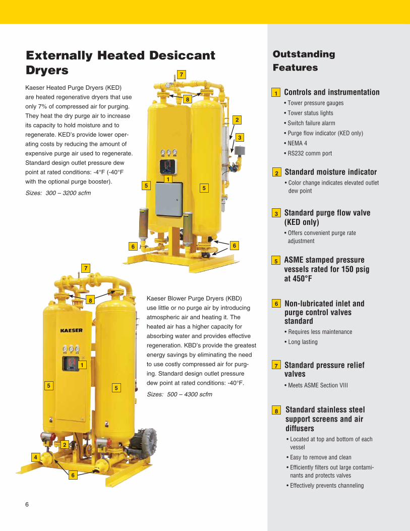
Standard stainless steel support screens and air diffusers
• Located at top and bottom of each vessel
• Easy to remove and clean
• Efficiently filters out large contami-nants and protects valves
• Effectively prevents channeling
8
Non-lubricated inlet and purge control valves standard
• Requires less maintenance
• Long lasting
6
Standard pressure relief valves
• Meets ASME Section VIII
7
Externally Heated Desiccant Dryers
OutstandingFeatures
Controls and instrumentation • Tower pressure gauges
• Tower status lights
• Switch failure alarm
• Purge flow indicator (KED only)
• NEMA 4
• RS232 comm port
1
Standard moisture indicator • Color change indicates elevated outlet
dew point
2
Standard purge flow valve (KED only)
• Offers convenient purge rate adjustment
3
ASME stamped pressure vessels rated for 150 psig at 450°F
5
Kaeser Blower Purge Dryers (KBD)
use little or no purge air by introducing
atmospheric air and heating it. The
heated air has a higher capacity for
absorbing water and provides effective
regeneration. KBD’s provide the greatest
energy savings by eliminating the need
to use costly compressed air for purg-
ing. Standard design outlet pressure
dew point at rated conditions: -40°F.
Sizes: 500 – 4300 scfm
Kaeser Heated Purge Dryers (KED)
are heated regenerative dryers that use
only 7% of compressed air for purging.
They heat the dry purge air to increase
its capacity to hold moisture and to
regenerate. KED’s provide lower oper-
ating costs by reducing the amount of
expensive purge air used to regenerate.
Standard design outlet pressure dew
point at rated conditions: -4°F (-40°F
with the optional purge booster).
Sizes: 300 – 3200 scfm
1
8
5
2
5
4
6
7
7
8
66
5 5
3
1
2
6

Inlet FlowInlet Flow capacities shown in the
Specifications Table have been established
at an inlet pressure of 100 psig (7 bar)
and a saturated inlet temperature of 100°F
(38°C). To determine maximum inlet flow
at other conditions, multiply the inlet flow
from the Specifications Table by the multi-
plier from Table 6 that corresponds to your
operating conditions.
Important:For inlet temperatures above
100°F, we strongly recommend
the installation of a trim cooler.
Please note that for every 20°F
inlet temperature increase, mois-
ture load/dryer size doubles!
Kaeser Heated Purge Dryers (KED) (Table 4)
Kaeser Blower Purge Dryers (KBD) (Table 5)
KED/KBD Inlet Conditions Correction Factors (Table 6)
Average Heater kW (fixed cycle) = [kW required to produce 2800F temperature rise] x [235 min. max heat time] / [240 min. drying time]Actual kW is normally much lower and proportional with the average annual water load presented to the dryer.
Average Heater kW (fixed cycle) = [kW required to produce 280°F temperature rise] x [235 min. max heat time] / [240 min drying time]Average Blower kW (fixed cycle) = [Blower kW] x [235 min. max heat time] / [240 min dryer time]Average Dryer kW (fixed cycle) = [Average Heater kW] + [Average Blower kW]Actual kW is normally much lower and proportional with the average annual water load presented to the dryer.
60 (4.2) 1.03 1.01 0.99 0.80 0.58 0.43 0.32 70 (4.9) 1.10 1.08 1.07 0.94 0.68 0.50 0.37 80 (5.6) 1.17 1.15 1.14 1.08 0.79 0.58 0.43 90 (6.3) 1.24 1.22 1.20 1.18 0.89 0.66 0.49 100 (7.0) 1.30 1.28 1.26 1.24 1.00 0.74 0.55 110 (7.0) 1.36 1.34 1.32 1.30 1.11 0.82 0.61 120 (8.4) 1.42 1.40 1.38 1.36 1.22 0.90 0.67 130 (9.1) 1.48 1.46 1.44 1.42 1.33 0.99 0.74 140 (9.8) 1.53 1.51 1.49 1.47 1.44 1.07 0.80 150 (10.6) 1.58 1.56 1.54 1.52 1.50 1.16 0.87
Pressure Inlet Temperature °F (°C) psig 60 70 80 90 100 110 120 (bar/cm2) (15.6) (21.1) (26.7) (32.2) (37.8) (43.3) (48.9)
Specifications are subject to change without notice. 7
KED Model
Number
Inlet flow @ 100 psig
100°F
Purge Flow Rate
Air Available Average
Heater DimensionsW x D x H
Approx. Weight
In/Out Connection Pre-filter High-Temp
After-filterDesiccantper Tower
(scfm) (scfm) (scfm) (nom kW) (Avg kW) (in) (lb) (in) (KOR Series) (HTA Series) (lb)
300 300 21 279 5 2.0 48 x 46 x 98 13601.5 NPT
375 400 210
400 400 28 372 7 2.7 53 x 52 x 104 1776 625600
354
500 500 35 465 7 3.3 53 x 52 x 105 17762 NPT
625 354
600 600 42 558 8 4.0 55 x 53 x 108 1978 780
1200
453
750 750 53 697 10 5.0 60 x 59 x 114 2323
3 FLG
1000P590
900 900 63 837 12 6.0 60 x 59 x 114 2323 590
1050 1050 74 976 14 7.0 64 x 62 x 113 2816 1250P 710
1300 1300 91 1209 17 8.7 66 x 63 x 118 3326
1875P 1800
923
1500 1500 105 1395 19 10.0 80 x 66 x 116 5094 1259
1800 1800 126 1674 23 12.0 80 x 66 x 116 5094 1259
2200 2200 154 2046 28 14.7 85 x 73 x 128 7753
4 FLG
2500P3000
1867
2600 2600 182 2418 33 17.4 85 x 73 x 128 7753 3125P 1867
3200 3200 224 2976 40 21.4 85 x 82 x 125 8963 5000P 4800 2377
KBD Model
Number
Inlet flow @ 100 psig
100°F
Blower Flow Rate Blower Heater Dimensions
W x D x HApprox. Weight
In/Out Connection Pre-filter High-Temp
After-filterDesiccantper Tower
(scfm) (scfm) (nom kW) (Avg kW) (nom kW) (Avg kW) (in) (lb) (in) (KOR Series) (HTA Series) (lb)
500 500 94 2.5 1.6 10 6.4 53 x 52 x 105 17762 NPT
625 600 354
600 600 113
4
2.5 12 7.7 55 x 60 x 108 1861 780
1200
453
750 750 140 2.2 14 9.6 60 x 68 x 114 2429
3 FLG
1000P590
900 900 158 2.0 17 10.8 60 x 68 x 114 2445 590
1050 1050 183 5 2.6 19 12.5 64 x 62 x 113 2966 1250P 710
1300 1300 227 7.5 4.9 23 15.5 66 x 73 x 118 3576
1875P 1800
923
1500 1500 281
10
7.8 28 19.3 80 x 79 x 116 5359 1259
1800 1800 317 7.3 33 21.7 80 x 79 x 116 5359 1259
2200 2200 403 5.9 40 27.6 85 x 86 x 128 80184 FLG
2500P3000
1867
2600 2600 449 15 9.8 45 30.7 85 x 89 x 128 8123 3125P 1867
3200 3200 552 5 2.4 54 37.7 85 x 107 x 128 9243
6 FLG 5000P 4800
2377
3600 3600 6147.5
3.1 60 42.0 85 x 116 x 134 12,095 2610
4300 4300 732 4.2 70 50.1 109 x 123 x 130 13,245 3544

Controls and InstrumentationHeatless Desiccant DryersStandard Control (KAD)The standard controller with its process
flow schematic and LED’s makes status
checks of control sequence, valves and
filters simple, and allows the user to
program reminders for routine main-
tenance intervals. A diagnostic mode
steps through the dryer’s operational
sequence to verify proper function and
performance. The display clearly notifies
the user if a malfunction occurs.
This controller has four fixed cycle
operating modes corresponding to ISO
8573.1 air quality classes for mois-
ture content. In addition, the standard
controller includes a manually select-
able purge saving feature. The Purge
Economizer Switches allow the user
to reduce purge consumption, in incre-
ments of 10% of full purge requirement
and down to 30% of dryer
capacity, to closely match a constant,
fixed load.
Purge Saver Control (KAD PS)To precisely, and automatically, match
purge air consumption to a changing
load, Kaeser offers the Purge Saver
Control. Having the same features as the
Standard Control (excepting the Purge
Economizer Switches) the Purge Saver
monitors temperature changes within
the desiccant bed when the dryer is
operating at less than its full capacity
and keeps the towers on-line until the full
drying capacity is reached. This reduces
the number of purge cycles and assures
that only the necessary volume of purge
air is consumed.
In the event of a malfunction with
the Purge Saver Control, standard fixed
cycle operation is automatically initiated.
Dryer operating status is displayed on a
two-line vacuum fluorescent text display
with choice of three languages: English,
Spanish or French.
Purge Saver controller shown with gauges.
Standard controller
Basic Timer Control (KAD E) The Basic Timer Control is a reliable
fixed cycle timer with LED’s indicating
which tower is drying. This controller
maintains a fixed 10-minute cycle
delivering an ISO Class 2 pressure dew
point (-40°F). Choose this controller
when air demand is uniform and closely
matches dryer capacity.
Fixed Cycle controller
Energy savings of Purge SaverEnergy savings of Purge Economizer
8

Energy Management Control (KED and KBD)The Energy Management Control for
heated dryers monitors the moisture
level in the desiccant bed and keeps a
tower on-line drying compressed air until
the desiccant’s full adsorptive capacity
has been utilized. Regeneration is then
initiated and completed in the following
four hours. The regenerated tower then
sits idle until the Energy Management
Control detects full use of the adsorptive
capacity of the drying tower and brings
the regenerated tower back on-line. For
operation at less than full capacity the
Energy Management Control will match
power requirement to demand by
reducing the frequency of regeneration.
Heater operation is terminated when
temperature sensors detect that desic-
cant bed heating is complete. The stan-
dard controller’s process flow schematic
and LED’s make status checks of con-
trol sequence, valves and filters simple,
and allow the user to program remind-
ers for routine maintenance intervals.
A diagnostic mode steps through the
dryer’s operational sequence to verify
proper function and performance. The
display clearly notifies the user if a mal-
function occurs. Dryer operating status
is displayed on a two-line vacuum fluo-
rescent text display with choice of three
languages: English, Spanish or French.
Heated Purge (KED)Purge BoosterWithout increasing the use of com-
pressed air, purge flow can be increased
from 7% to
12% with the
optional Purge
Booster.
This device
reduces
compressed
air consump-
tion from 7%
to 6% and draws in an equal volume of
ambient air mixing it with the purge air.
The increased purge airflow produces
lower outlet dew points and eliminates
dew point spikes.
Heated Purge and Blower Purge (KED and KBD)Energy SaverThe Energy Saver Option integrates
moisture and temperature sensors to
monitor the humidity level near the outlet
end of the desiccant beds. During peri-
ods of reduced flow the Energy Saver
extends the drying cycle thereby reduc-
ing the number of regeneration cycles,
saving energy. For KED models, the
Energy Saver Option also includes the
Purge Booster.
Energy ManagementThe Energy Management Option
includes the Energy Saver Option above
and a digital dew point monitor. This
feature displays the dryer’s outlet dew
point and allows the user to prevent
tower changeover until a user specified
outlet dew point has been achieved,
or let the Energy Saver determine the
length of the drying period. For KED
models the Energy Management Option
also includes the Purge Booster.
Externally Heated Desiccant DryersStandard Control (KED and KBD)The standard controller for heated dry-
ers operates the dryer on a fixed eight-
hour cycle. A tower is on-line (drying
compressed air) for four hours and then
taken off-line to be regenerated during
the remaining four hours.
Heater operation is terminated when
temperature sensors detect that desic-
cant bed heating is complete. The stan-
dard controller’s process flow schematic
and LED’s make status checks of con-
trol sequence, valves and filters simple,
and allow the user to
program reminders for routine main-
tenance intervals. A diagnostic mode
steps through the dryer’s operational
sequence to verify proper function and
performance. The display clearly notifies
the user if a malfunction occurs. Dryer
operating status is displayed on a two-
line vacuum fluorescent text display with
choice of three
languages: English, Spanish or French.
P1
P3
P2
RS232
Fixed Cycle controller
Optional Controls
9

Corporate Headquarters:P.O. Box 946Fredericksburg, Virginia 22404Phone 540-898-5500Fax 540-898-5520www.kaeser.com
© 2007 Kaeser Compressors, Inc. All rights reserved. 04/07
USDESDRYERS
The Air Systems SpecialistWith over 85 years of experience, Kaeser is the air systems specialist. Our extensive 100,000 square foot facility allows us to provide unequaled product availability. With ser-vice centers nationwide and our 24-hour emergency parts guarantee, Kaeser customers can rely on the best after-sales support in the industry. Kaeser stands committed to provid-ing the highest quality air system for your specific compressed air needs.
OptionsInsulation for heated desiccant air dryers (KED and KBD)Insulation with protective jacket for
heater and heater discharge piping is
standard; however, insulation for the
desiccant vessels is optional. Vessel
insulation offers protection for person-
nel and reduces operating costs. Vessel
insulation is flexible open-cell melamine
foam having a permanently bonded PVC
film laminated polyester fabric jacket.
This insulating system absorbs impacts
and returns to its original shape thus
maintaining its insulating qualities.
Other options• High humidity alarm
• Dew point monitor
• Stainless steel or copper pilot and
instrument air tubing and fittings
• NEMA 4 low ambient protection pack-
ages
• NEMA 7 Explosion-proof electrical
packages (KAD only)
• Parallel piped pre-filters and after-filters
Wall-mounted heatless des-iccant air dryers (KADW)Compact and convenient, these wall-
mounted dryers are available in five
models from 5 to 25 scfm all with factory
supplied filter packages. Ten-minute
cycles (-40°F pressure dew point) and
4-minute cycles (-100°F pressure dew
point) are standard and user selectable.
Filtration
All desiccant dryers require proper
filtration. Coalescing pre-filters prevent
contamination of desiccant beds by
hydrophobic aerosols. Particulate after-
filters collect traces of desiccant dust
that may exit the dryer. Maintaining
these filters extends service intervals
and provides excellent air quality. All
Kaeser desiccant dryers offer optional
filter packages with or without block and
bypass valves.
KED with optional vessel insulation.