Type 441, 442 ANSI Flanged Safety Relief Valves - Armatec
11
21 Type 442 ANSI Plain lever H3 Open bonnet Conventional design Type 441 ANSI Packed lever H4 Closed bonnet Conventional design Type 441, 442 ANSI Flanged Safety Relief Valves Contents Page Materials • Conventional design 22 • Balanced bellows design 24 Article numbers 26 Dimensions and weights • Metric Units 27 • US Units 28 Pressure temperature ratings • Metric Units 29 • US Units 30 Flange drillings and facings 31 Series 441, Series 441 Full nozzle Approvals 48 Available options 49 LESER Original Spare Parts Kits 50 Type 441, 442 ANSI
-
Upload
khangminh22 -
Category
Documents
-
view
3 -
download
0
Transcript of Type 441, 442 ANSI Flanged Safety Relief Valves - Armatec

21
Type 442 ANSI
Plain lever H3
Open bonnet
Conventional design
Type 441 ANSI
Packed lever H4
Closed bonnet
Conventional design
Type 441, 442 ANSI
Flanged Safety Relief Valves
Contents Page
Materials
• Conventional design 22
• Balanced bellows design 24
Article numbers 26
Dimensions and weights
• Metric Units 27
• US Units 28
Pressure temperature ratings
• Metric Units 29
• US Units 30
Flange drillings and facings 31
Series 441, Series 441 Full nozzle
Approvals 48
Available options 49
LESER Original Spare Parts Kits 50
Typ
e 4
41
, 4
42
AN
SI

22
Type 441, 442 ANSI
Conventional design
40 Cap H2
18 Adjusting screw
19 Lock nut
16 Upper spring plate
9 Bonnet
12 Spindle
54 Spring
17 Lower spring plate
55 Stud
56 Nut
14 Split ring
60 Gasket
8 Guide with bushing
57 Pin
61 Ball
7 Disc
5 Seat
1 Body
Typ
e 4
41
, 4
42
AN
SI

23
Item Component Type 4412 / 4422 ANSI Type 4414 ANSI
1 Body1.0619 1.4408
SA 216 WCB SA 351 CF8M
5 Seat1.4404 1.4404
316L 316L
7 Disc1.4122 1.4404
Hardened stainless steel 316L
8
Guide
with bushing
1.4104, 1.0501, 0.7040 1.4404
Chrome or carbon steel 316L
1.4104 tenifer –
Chrome steel tenifer –
9 Bonnet
0.7040, 0.7043, 1.0619 1.4408, 1.4404, 1.4571
Ductile Gr. 60-40-18,
SA 216 WCB
SA 351 CF8M, SA 479 316L,
SA 479 316Ti
12 Spindle 1.4021 1.4404
420 316L
14 Split ring1.4104 1.4404
Chrome steel 316L
16 / 17 Spring plate 1.0718 1.4404
Steel 316L
18Adjusting screw
with bushing
1.4104 PTFE 1.4404 PTFE
Chrome steel PTFE 316L PTFE
19 Lock nut1.0718 1.4404
Steel 316L
40 Cap H21.0460 or 0.7043 1.4404
SA 105 or Gr. 60-40-18 316L
54
Spring standard1.1200, 1.8159, 1.7102 1.4310
Carbon steel Stainless steel
Spring optional1.4310 –
Stainless steel –
55 Stud1.1181 1.4401
Steel B8M
56 Nut1.0501 1.4401
2H 8M
57 Pin1.4310 1.4310
Stainless steel Stainless steel
60 GasketGraphite / 1.4401 Graphite / 1.4401
Graphite / 316 Graphite / 316
61 Ball1.3541 1.4401
Hardened stainless steel 316
Type 441, 442 ANSI
Conventional design
Materials
Please notice:
- Modifi cations reserved by LESER
- If several materials are specifi ed LESER defi nes the material.
- LESER can upgrade materials without notice.
- Every part can be replaced by other material acc. to customer specification.
Typ
e 4
41
, 4
42
AN
SI

24
40 Cap H2
18 Adjusting screw
19 Lock nut
16 Upper spring plate
9 Bonnet
12 Spindle
54 Spring
14 Split ring
17 Lower spring plate
55 Stud
56 Nut
8 Guide with bushing
11 Bonnet spacer
60 Gasket
60 Gasket
22 Lift stopper
15 Bellows
57 Pin
61 Ball
7 Disc
5 Seat
1 Body
Type 441, 442 ANSI
Balanced bellows design
Typ
e 4
41
, 4
42
AN
SI
25
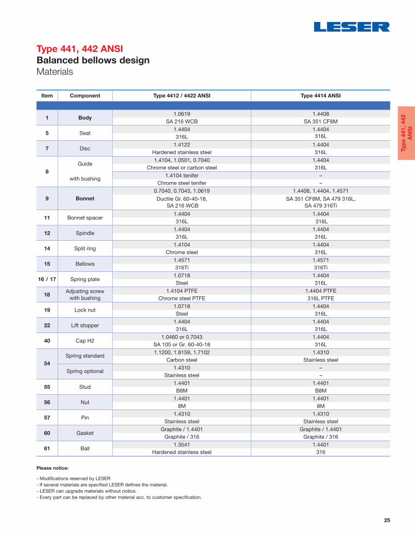
Item Component Type 4412 / 4422 ANSI Type 4414 ANSI
1 Body1.0619 1.4408
SA 216 WCB SA 351 CF8M
5 Seat1.4404 1.4404
316L 316L
7 Disc1.4122 1.4404
Hardened stainless steel 316L
8
Guide
with bushing
1.4104, 1.0501, 0.7040 1.4404
Chrome steel or carbon steel 316L
1.4104 tenifer –
Chrome steel tenifer –
9 Bonnet
0.7040, 0.7043, 1.0619 1.4408, 1.4404, 1.4571
Ductile Gr. 60-40-18,
SA 216 WCB
SA 351 CF8M, SA 479 316L,
SA 479 316Ti
11 Bonnet spacer 1.4404 1.4404
316L 316L
12 Spindle 1.4404 1.4404
316L 316L
14 Split ring1.4104 1.4404
Chrome steel 316L
15 Bellows 1.4571 1.4571
316Ti 316Ti
16 / 17 Spring plate1.0718 1.4404
Steel 316L
18Adjusting screw
with bushing
1.4104 PTFE 1.4404 PTFE
Chrome steel PTFE 316L PTFE
19 Lock nut1.0718 1.4404
Steel 316L
22 Lift stopper 1.4404 1.4404
316L 316L
40 Cap H2 1.0460 or 0.7043 1.4404
SA 105 or Gr. 60-40-18 316L
54
Spring standard 1.1200, 1.8159, 1.7102 1.4310
Carbon steel Stainless steel
Spring optional1.4310 –
Stainless steel –
55 Stud 1.4401 1.4401
B8M B8M
56 Nut1.4401 1.4401
8M 8M
57 Pin1.4310 1.4310
Stainless steel Stainless steel
60 GasketGraphite / 1.4401 Graphite / 1.4401
Graphite / 316 Graphite / 316
61 Ball1.3541 1.4401
Hardened stainless steel 316
Type 441, 442 ANSI
Balanced bellows design
Materials
Please notice:
- Modifi cations reserved by LESER
- If several materials are specifi ed LESER defi nes the material.
- LESER can upgrade materials without notice.
- Every part can be replaced by other material acc. to customer specification.
Typ
e 4
41
, 4
42
AN
SI

26
Valve size 1" x 2" 1½" x 2" 1½" x 2½" 2" x 3" 3" x 4" 4" x 6"
Actual Orifi ce diameter d0 [mm] 23 29 37 46 60 92
Actual Orifi ce area A0 [mm2] 416 661 1075 1662 2827 6648
Body material: 1.0619 (WCB)
Bonnet H2 Art. No. 4412. 4812 4822 4832 4842 4862 4872closed H3 Art. No. 4412. 4813 4823 4833 4843 4863 4873
H4 Art. No. 4412. 4814 4824 4834 4844 4864 4874
open H3 Art. No. 4422. 4815 4825 4835 4845 4865 4875
Body material: 1.4408 (CF8M)
Bonnet H2 Art. No. 4414. 7912 – 7932 7942 7962 7972closed H4 Art. No. 4414. 7914 – 7934 7944 7964 7974
Type 441, 442 ANSI
Article numbers
Type 441
Cap H2
Closed bonnet
Conventional design
Type 442
Plain lever H3
Bonnet open
Conventional design
Type 441
Packed lever H4
Closed bonnet
Conventional design
Type 441
Plain lever H3
Closed bonnet
Conventional design
Type 441
Cap H2
Closed bonnet
Balanced bellows design
Typ
e 4
41
, 4
42
AN
SI

27
Valve size 1" x 2" 1½" x 2" 1½" x 2½" 2" x 3" 3" x 4" 4" x 6"
Actual Orifi ce diameter d0 [mm] 23 29 37 46 60 92
Actual Orifi ce area A0 [mm2] 416 661 1075 1662 2827 6648
Weight 10 13 16 22 33 75[kg] with bellows 11 14 17 24 37 83
Center to face Inlet a 105 124 124 136 156 181[mm] Outlet b 114 121 121 124 165 229
Height (H4) Standard H max. 339 455 496 556 685 844[mm] Bellows H max. 378 497 534 602 741 902
Support brackets A 280
[mm] B 160
(drilled only on request, C Ø 18option code H42) D 250 E 25
Body material: 1.0619 (WCB)
ANSI Flange Inlet CL150 or CL300
Class1) Outlet CL150
Body material: 1.4408 (CF8M)
ANSI Flange Inlet CL150 or CL300 – CL150 or CL300
Class1) Outlet CL150 – CL150
Type 441, 442 ANSI
Dimensions and weights
Metric Units
Support brackets
D
E
B
C
A
Balanced bellows designConventional design
1)Standard fl ange rating. For other fl ange drillings and facings please refer to page 31.
Typ
e 4
41
, 4
42
AN
SI

28
Valve size 1" x 2" 1½" x 2" 1½" x 2½" 2 x 3" 3 x 4" 4 x 6"
Actual Orifi ce diameter d0 [inch] 0.91 1.14 1.46 1.81 2.36 3.62
Actual Orifi ce area A0 [inch2] 0.644 1.024 1.667 2.576 4.383 10.304
Weight 22 29 35 49 73 165[lbs] with bellows 23 30 38 52 81 183
Center to face Inlet a 4 1/8 4 7/8 4 7/8 5 3/8 6 1/8 7 1/8[inch] Outlet b 4 1/2 4 3/4 4 3/4 4 7/8 6 1/2 9
Height (H4) Standard H max. 13 11/32 17 29/32 19 17/32 21 1/16 26 31/32 33 7/32[inch] Bellows H max. 14 7/8 19 9/16 21 1/32 23 11/16 29 3/16 35 1/2
Support brackets A 11[inch] B 6 1/4
(drilled only on request, C Ø 3/4option code H42) D 9 7/8
E 25
Body material: 1.0619 (WCB)
ANSI Flange
Class1)
Inlet CL150 or CL300
Outlet CL150
Body material: 1.4408 (CF8M)
ANSI Flange
Class1)
Inlet CL150 or
CL300– CL150 or CL300
Outlet CL150 – CL150
Type 441, 442 ANSI
Dimensions and weights
US Units
Support brackets
D
E
B
C
A
Balanced bellows designConventional design
1)Standard fl ange rating. For other fl ange drillings and facings please refer to page 31.
Typ
e 4
41
, 4
42
AN
SI
29
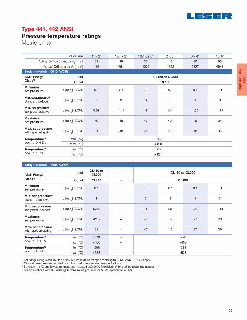
Valve size 1" x 2" 1½" x 2" 1½" x 2½" 2 x 3" 3 x 4" 4 x 6"
Actual Orifi ce diameter d0 [mm] 23 29 37 46 60 92
Actual Orifi ce area A0 [mm2] 416 661 1075 1662 2827 6648
Body material: 1.0619 (WCB)
ANSI Flange Inlet CL150 or CL300Class1)
Outlet CL150
Minimum p [bar
g] S/G/L 0.1 0.1 0.1 0.1 0.1 0.1 set pressure
Min. set pressure2)
p [barg] S/G/L 3 3 3 3 3 3 standard bellows
Min. set pressure p [bar
g] S/G/L 0.98 1.41 1.11 1.81 1.50 1.18low press. bellows
Maximum p [bar
g] S/G/L 49 48 46 404) 40 34set pressure
Max. set pressure p [bar
g] S/G/L 51 48 46 404) 40 34 with special spring
Temperature3) min. [°C] -85acc. to DIN EN max. [°C] +450
Temperature3) min. [°C] -29acc. to ASME max. [°C] +427
Body material: 1.4408 (CF8M)
ANSI Flange
Inlet CL150 or
CL300– CL150 or CL300
Class1)
Outlet CL150 – CL150
Minimum p [bar
g] S/G/L 0.1 – 0.1 0.1 0.1 0.1set pressure
Min. set pressure2)
p [barg] S/G/L 3 – 3 3 3 3standard bellows
Min. set pressure p [bar
g] S/G/L 0.98 – 1.11 1.81 1.50 1.18low press. bellows
Maximum p [bar
g] S/G/L 42.5 – 40 32 27 20 set pressure
Max. set pressure p [bar
g] S/G/L 51 – 40 40 27 25with special spring
Temperature3) min. [°C] -270 – -270 acc. to DIN EN max. [°C] +400 – +400
Temperature3) min. [°C] -268 – -268acc. to ASME max. [°C] +538 – +538
Type 441, 442 ANSI
Pressure temperature ratings
Metric Units
1) For fl ange rating class 150 the pressure temperature ratings according to ASME ANSI B 16.34 apply. 2) Min. set pressure standard bellows = Max. set pressure low pressure bellows. 3) Between -10 °C and lowest temperature indicated „AD 2000-Merkblatt“ W10 shall be taken into account.4) For applications with CE marking. Maximum set pressure for ASME application 49 bar.
Typ
e 4
41
, 4
42
AN
SI

30
Valve size 1" x 2" 11/2" x 2" 11/
2" x 21/
2" 2 x 3" 3 x 4" 4 x 6"
Actual Orifi ce diameter d0 [inch] 0.91 1.14 1.46 1.81 2.36 3.62
Actual Orifi ce area A0 [inch2] 0.644 1.024 1.667 2.576 4.383 1.304
Body material: 1.0619 (WCB)
ANSI Flange Inlet CL150 or CL300Class1)
Outlet CL150
Minimump [psig] S/G/L 1.5 1.5 1.5 1.5 1.5 1.5 set pressure
Min. set pressure2)
p [psig] S/G/L 43.5 43.5 43.5 43.5 43.5 43.5 standard bellows
Min. set pressurep [psig] S/G/L 14 20 16 26 22 17 low press. bellows
Maximump [psig] S/G/L 711 696 667 5804) 580 493 set pressure
Max. set pressurep [psig] S/G/L 740 696 667 5804) 580 493 with special spring
Temperature3) min. [°F] -121 acc. to DIN EN max. [°F] +842
Temperature3) min. [°F] -20 acc. to ASME max. [°F] +800
Body material: 1.4408 (CF8M)
ANSI Flange
Inlet CL150 or
CL300– CL150 or CL300
Class1)
Outlet CL150 – CL150
Minimump [psig] S/G/L 1.5 – 1.5 1.5 1.5 1.5set pressure
Min. set pressure2)
p [psig] S/G/L 43.5 – 43.5 43.5 43.5 43.5standard bellows
Min. set pressurep [psig] S/G/L 14 – 16 26 22 17low press. bellows
Maximump [psig] S/G/L 616 – 580 464 392 290 set pressure
Max. set pressurep [psig] S/G/L 740 – 580 580 392 363with special spring
Temperature3) min. [°F] -454 – -454 acc. to DIN EN max. [°F] +752 – +752
Temperature3) min. [°F] -450 – -450acc. to ASME max. [°F] +1000 – +1000
Type 441, 442 ANSI
Pressure temperature ratings
US Units
1) For fl ange rating class 150 the pressure temperature ratings according to ASME ANSI B 16.34 apply. 2) Min. set pressure standard bellows = Max. set pressure low pressure bellows. 3) Between -10 °C and lowest temperature indicated „AD 2000-Merkblatt“ W10 shall be taken into account.4) For applications with CE marking. Maximum set pressure for ASME application 711 psig.
Typ
e 4
41
, 4
42
AN
SI
31
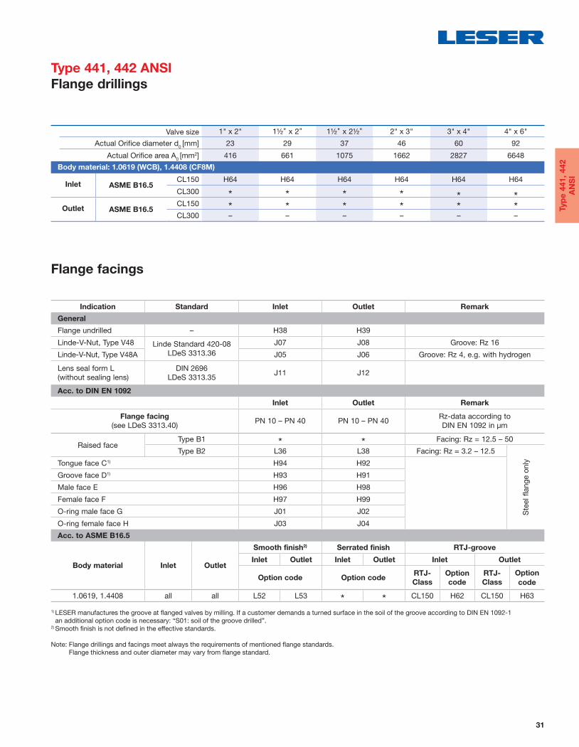
Valve size 1" x 2" 1½" x 2" 1½" x 2½" 2" x 3" 3" x 4" 4" x 6"
Actual Orifi ce diameter d0 [mm] 23 29 37 46 60 92
Actual Orifi ce area A0 [mm2] 416 661 1075 1662 2827 6648
Body material: 1.0619 (WCB), 1.4408 (CF8M)
Inlet ASME B16.5 CL150 H64 H64 H64 H64 H64 H64
CL300 * * * * * *Outlet ASME B16.5
CL150 * * * * * *CL300 – – – – – –
Indication Standard Inlet Outlet Remark
General
Flange undrilled – H38 H39
Linde-V-Nut, Type V48 Linde Standard 420-08
LDeS 3313.36
J07 J08 Groove: Rz 16
Linde-V-Nut, Type V48A J05 J06 Groove: Rz 4, e.g. with hydrogen
Lens seal form L
(without sealing lens)
DIN 2696
LDeS 3313.35J11 J12
Acc. to DIN EN 1092
Inlet Outlet Remark
Flange facing
(see LDeS 3313.40)PN 10 – PN 40 PN 10 – PN 40
Rz-data according to
DIN EN 1092 in μm
Raised faceType B1 * * Facing: Rz = 12.5 – 50
Type B2 L36 L38 Facing: Rz = 3.2 – 12.5
Ste
el flang
e o
nlyTongue face C1) H94 H92
Groove face D1) H93 H91
Male face E H96 H98
Female face F H97 H99
O-ring male face G J01 J02
O-ring female face H J03 J04
Acc. to ASME B16.5
Body material Inlet Outlet
Smooth finish2) Serrated finish RTJ-groove
Inlet Outlet Inlet Outlet Inlet Outlet
Option code Option codeRTJ-
Class
Option
code
RTJ-
Class
Option
code
1.0619, 1.4408 all all L52 L53 * * CL150 H62 CL150 H63
Type 441, 442 ANSI
Flange drillings
Flange facings
1) LESER manufactures the groove at fl anged valves by milling. If a customer demands a turned surface in the soil of the groove according to DIN EN 1092-1
an additional option code is necessary: “S01: soil of the groove drilled”. 2) Smooth fi nish is not defi ned in the effective standards.
Note: Flange drillings and facings meet always the requirements of mentioned fl ange standards.
Flange thickness and outer diameter may vary from fl ange standard.
Typ
e 4
41
, 4
42
AN
SI