Polyethylene Flanged Joints TN-38 2021 - Plastics Pipe Institute
27
i POLYETHYLENE FLANGED JOINTS TN-38 2021
-
Upload
khangminh22 -
Category
Documents
-
view
1 -
download
0
Transcript of Polyethylene Flanged Joints TN-38 2021 - Plastics Pipe Institute

i
POLYETHYLENE FLANGED JOINTS
TN-38
2021

ii
Foreword This technical note was developed and published with the technical help and financial support of the members of the Plastics Pipe Institute. The members have shown their interest in quality products by assisting independent standard-making and user organizations in the development of standards, and also by developing reports on an industry-wide basis to help engineers, code officials, specifying groups, and users. The Plastics Pipe Institute, Inc. has prepared this technical note as a service to the industry. The information in this note is offered in good faith and believed to be accurate at the time of its preparation, but is offered without any warranty, express or implied. Additional information may be needed in some areas, especially about unusual or special applications. Consult the manufacturer or material supplier for more detailed information. A list of member manufacturers is available from PPI. PPI does not endorse the proprietary products or processes of any manufacturer and assumes no responsibility for compliance with applicable laws and regulations. PPI intends to revise this report from time to time, in response to comments and suggestions from users of this note. Please send suggestions for improvements to PPI. Information on other publications can be obtained by contacting PPI directly or visiting the web site.
The Plastics Pipe Institute, Inc.
www.plasticpipe.org
This Technical Note, TN-38 was first issued in July 2008 and was updated in 2010, 2012, 2019 and December 2021.
© 2021 The Plastics Pipe Institute, Inc.

iii
DISCLAIMERS Due to the wide variation in service conditions, quality of installations, etc, no warranty or guarantee, expressed or implied, is offered nor given in conjunction with the use of this Plastic Pipe Institute Technical Note. All data and formulae and example values presented here-in should be independently verified and validated by the end-user, reader, designer, engineer, field installer, technician, etc, for a specific HDPE pipeline flange installation or project. The ‘engineer-of-record’ is responsible for complete assessment and definition of the components and installation specification of flanged joints including flanged joint assemblies with polyethylene components. Mention of a Company Name or a Name-Brand Product does not constitute an endorsement by PPI nor its members, of that company nor of any product. Mention of Companies or Name-Brand Products are simply EXAMPLES of the technical issues and concepts presented for consideration by flange-set designers, specifiers, and contractors. Other producers offer similar products. Due diligence is recommended.

iv
Table of Contents 1.0 Executive Summary .................................................................................................. 1
2.0 Preface ..................................................................................................................... 2
3.0 PE Flanged Joint Pressure Ratings .......................................................................... 2
4.0 Flanged Joint Components ....................................................................................... 4
4.1. Flange Adapters ................................................................................................. 4
4.2. Backup Rings (Lap Joint Flange) ....................................................................... 6
4.3. ASME B16.5/16.47 Series A Flanged Fittings / Valves ...................................... 7
4.4. Spacer Rings / Butterfly Flange Adapters .......................................................... 8
4.5. Low Pressure Plastic & FRP Flanges ................................................................ 8
4.6. Bolts or Studs and Nuts ..................................................................................... 8
5.0 Gaskets .................................................................................................................. 10
6.0 Bolt Torque Calculation Methodology ..................................................................... 13
6.1. Rationale for Change in Methodology .............................................................. 13
6.2. Nut Factors....................................................................................................... 14
6.3. Calculation of Target Bolt Torque ..................................................................... 15
6.4. Example Bolt Torque Calculations ................................................................... 16
7.0 Installation Instructions ........................................................................................... 19
7.1. Alignment of Flanged Joints ............................................................................. 19
7.2. Lubrication of ‘Working Surfaces’ ..................................................................... 19
7.3. Installation of Bolts ........................................................................................... 19
7.4. Tightening of Bolts ........................................................................................... 19
7.5. Tightening Sequence of Bolts .......................................................................... 20
8.0 Hydro-Testing & Leak Closure Guideline ............................................................... 21
9.0 Flange Disassembly ............................................................................................... 21
References .................................................................................................................... 23

1
1.0 EXECUTIVE SUMMARY
The design and selection of components for flanged joints connecting PE pipe to PE pipe, or PE pipe to metal pipe are based on lower interfacial pressures than those used for metal flanged joints. The initial interfacial pressure is limited by the allowable short duration stress of the PE flange adapter. To establish higher long term interfacial stress, retorquing is suggested to compensate for the visco-elastic stress relaxation in the PE flange adapter. The mating interfacial surface area of a metal flange to PE flange adapter is significantly less than that between PE-to-PE flange adapters since the bore of the metal flange / pipe is larger than the bore of the PE flange adapter. The bore of PE flange adapters can also vary depending on whether or not a pipe ‘toe-in’ allowance has been included in the bore of the flange adapter. Regardless, the required bolt and nut ‘proof’ strength of a PE-to- PE flanged joint is more than for PE to metal flanged joints due to the larger interfacial surface area. See Section 6.2 for additional discussion about this topic. The lower flange face interfacial pressures associated with PE flange adapters necessitates careful selection of the gasket materials. Compressed fiber gaskets (CFG) and PTFE gaskets tend to be the better option with HDPE flanged connections. Not only do these products have much higher crush and extrusion resistance than elastomeric materials, but the products are also designed to handle higher pressures. While retightening of the bolts is recommended for all flanged joints, the creep relaxation of the PE flange adapter can significantly reduce the stress between the mating faces and loosen the bolts. Consequently, retightening is more important with PE flanged joints. When the PE flanged joint is mated to a flanged butterfly valve, it may be necessary to provide a spacer ring with a tapered bore to provide clearance for the disk. Hydrotesting of PE piping systems is described in ASTM F2164 (ASTM F2164 Standard Practice for Field Leak Testing).
2
2.0 PREFACE
Polyethylene pressure pipe is usually joined by butt fusion or electrofusion. Flanged connections are used as transitions to pipes of other materials, connections to flanged fittings, or as ‘end connections’ on fused PE pipe strings. Flanged joints prevent leakage by compressing a deformable material into irregularities in a less deformable material to ‘seal’ possible leak paths. The ‘mating faces’ of flanged joints are the surface area that needs to be sealed. The deformation characteristics of the deformable material are the primary determinant of the amount of compression (force per unit area) required to seal a flanged joint. It is desirable to utilize common bolting patterns in order to facilitate connections to readily available flanged fittings and valves. Flanges used in North America generally conform to ASME B16.5 (ASME B16.5 ), ASME B16.47 Series A (ASME B16.47 ), or AWWA C207 (AWWA C207-18 STEEL PIPE FLANGES FOR WATERWORKS SERVICE—SIZES 4 IN. THROUGH 144 IN. (100 MM THROUGH 3,600 MM)) bolting patterns.
3.0 PE FLANGED JOINT PRESSURE RATINGS
ASME B16.5/B16.47 provides pressure ratings for metal flanges that vary by flange material type. The standard does not provide pressure ratings for flanges made of non-metallic materials such as polyethylene (PE). Class 150 ASME B16.5 and B16.47 Series A flanges made of forged carbon steel (material group 2-1.1), are rated for a maximum operating pressure of 285 psi at temperatures ranging from ambient up to 38°C (100°F). 304(L) & 316(L) stainless steel flanges (material group 2-2.3) are rated for a maximum operating pressure of 235 psi at service temperatures from ambient up to 38°C (100°F). The pressure-temperature ratings of ASME Class 150 metal flanges usually exceeds that which is permissible for most PE pressure pipe. For example, PE4710 pressure pipe with bore of DR 9 has a pressure rating of 250 psi at service temperatures up to 80°F. Consequently, ASME B16.5 / B16.47 Series A Class 150 flanges in material group 2-1.1 (A105 or A350LF2) are suitable for connection to this pipe. However, low DR PE pipe with high pressure ratings may exceed the pressure rating of the ASME B16.5 / B16.47 Series A metal flange. For example, Class 150 flanges in material group 2-2.3 (e.g., 304(L), 316(L)), are theoretically not suitable since they are limited to pressures of 235 psi. Class 150 flanges in material group 2-1.1 (A105 and A350 LF2) are theoretically limited to service pressures of 285 psi. This is less than the 335 psi pressure rating of a DR 7 PE4710 pipe. In a metal piping system with flanged connections, Class 300 flanges would be used at ‘higher’ service conditions. The geometry of a Class 300 flange has a bolt circle

3
diameter (BCD) that is larger than the Class 150 BCD. The geometry of a Class 300 rated metal flange makes sense with metal flanges because of the rigidity of these materials. However, the increase in BCD with a Class 300 pattern will make it more difficult to seal a flanged joint involving a PE flange adapter. Deformation of the flange face reduces the interfacial pressure near the ID. In some instances, deformation of the flange face will separate the faces (Jacobsson, 2011). Consequently, the designer should consider using ASME B16.5 or B16.47 Series A Class 150 flanges when the service pressures exceed the pressure rating of the metal flange since there is a high factor of safety associated with metal flanges. Other flange standards use the face dimension and BCD’s of ASME Class 150 flanges. For example, AWWA C207 flanges used extensively in the waterworks industry makes use of the ASME B16.5 and B16.47 Series A bolting patterns. When welded to metal pipe, pressure ratings of 86 psi (Class B flanges), 175 psi (Class D ≤12”), 150 psi (Class D >12”), and 275 psi (Class E) have been established by AWWA for these waterworks’ flanges. AWWA C207 Class D or E geometries are often used as Backup Rings (BUR) with PE flange adapters at lower working pressures. Determination of the pressure ratings of flanged joints with AWWA C207 geometry BUR’s is beyond the scope of this document. A ‘PE pressure pipe to PE pressure pipe flanged joint’ will consist of: (see figure 1)
• Two Polyethylene flange adapters or stub-ends. • Two Loose metal backup rings (BUR) often called Lap-Joint Flanges (LJF). • Optional gasket • Bolt set (bolts or studs and nuts).
A ‘flanged PE pressure pipe to metal flange joint’ will consist of: (see figure 2) • One Polyethylene flange adapter or stub-end. • One loose metal backup rings (BUR) often called a Lap-Joint Flange (LJF). • PE spacer (if valve disk requires clearance) • Optional gasket • Metal flange or flanged fitting • Bolt set (bolts or studs and nuts).
4
A ‘flanged PE pressure pipe to flanged plastic or FRP flanged joint’ will consist of: • One Polyethylene flange adapter or stub-end. • One loose metal backup ring (BUR) often called a Lap-Joint Flange (LJF). • Optional gasket • Plastic or FRP flange or flanged fitting • Bolt set (bolts or studs and nuts). • Flange Spacer (if plastic or FRP flange is full flat face)
The interfacial (mating) surface of a ‘PE to PE’ flanged joint is significantly larger than the interfacial surface of the ‘PE to Metal raised face (RF) mating flange face. This is because the bore of a PE pipe and a PE flange adapter are smaller than a metal pipe with the same OD and pressure rating. The short-term allowable stress of PE determines the force required to seat/seal the flange. Consequently, a ‘PE to PE’ flanged joint requires significantly more bolt torque to ‘seat’ than a ‘PE to Metal RF’ flanged joint. This will be discussed further in the section describing bolt torque calculations.
4.0 FLANGED JOINT COMPONENTS
4.1. Flange Adapters
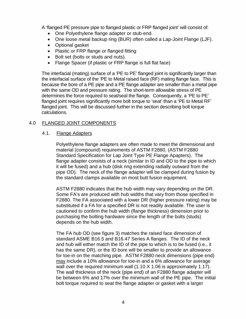
Polyethylene flange adapters are often made to meet the dimensional and material (compound) requirements of ASTM F2880. (ASTM F2880 Standard Specification for Lap Joint Type PE Flange Apapters). The flange adapter consists of a neck (similar in ID and OD to the pipe to which it will be fused) and a hub (disk ring extending radially outward from the pipe OD). The neck of the flange adapter will be clamped during fusion by the standard clamps available on most butt fusion equipment. ASTM F2880 indicates that the hub width may vary depending on the DR. Some FA’s are produced with hub widths that vary from those specified in F2880. The FA associated with a lower DR (higher pressure rating) may be substituted if a FA for a specified DR is not readily available. The user is cautioned to confirm the hub width (flange thickness) dimension prior to purchasing the bolting hardware since the length of the bolts (studs) depends on the hub width. The FA hub OD (see figure 3) matches the raised face dimension of standard ASME B16.5 and B16.47 Series A flanges. The ID of the neck and hub will either match the ID of the pipe to which is to be fused (i.e., it has the same DR), or the ID bore will be smaller to provide an allowance for toe-in on the matching pipe. ASTM F2880 neck dimensions (pipe end) may include a 10% allowance for toe-in and a 6% allowance for average wall over the required minimum wall (1.10 X 1.06 is approximately 1.17). The wall thickness of the neck (pipe end) of an F2880 flange adapter will be between 6% and 17% over the minimum wall of the PE pipe. The initial bolt torque required to seat the flange adapter or gasket with a larger
5
surface seating area (due to toe-in allowance) is higher than a FA with a wall thickness and gasket seating area based on the usual 6% allowance for average wall over minimum wall. Note: Not all FA’s are produced with a bore that includes the toe-in allowance indicated in F2880.
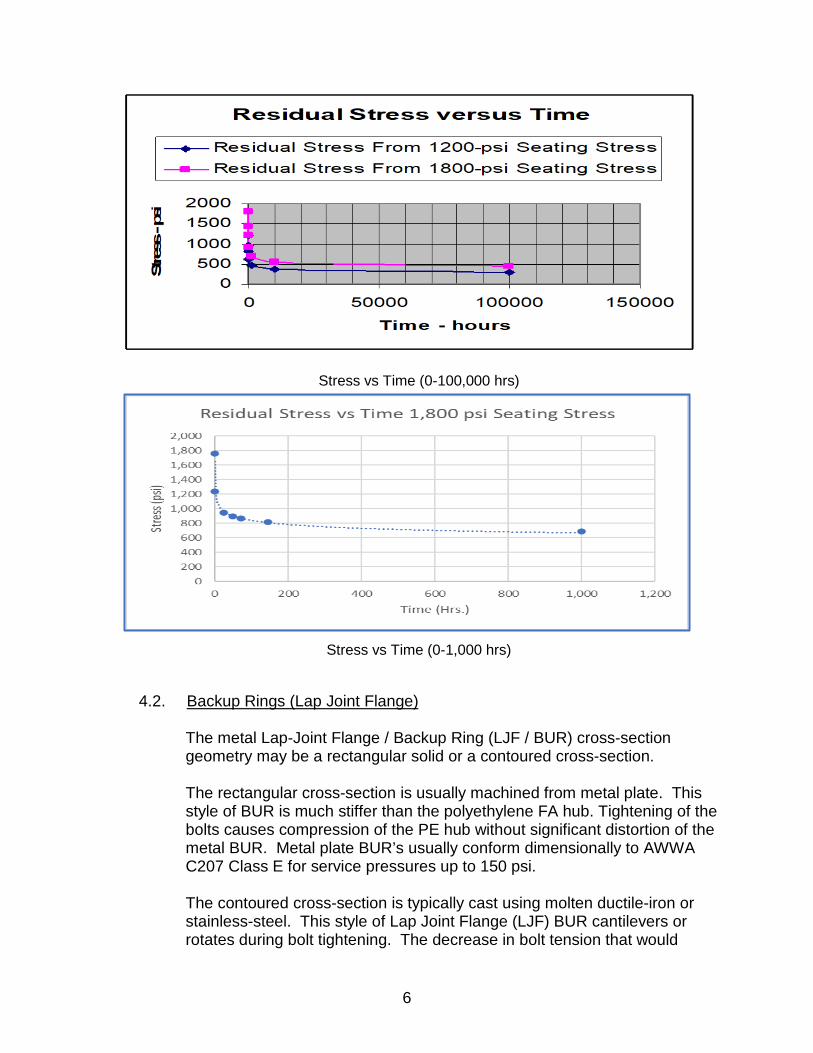
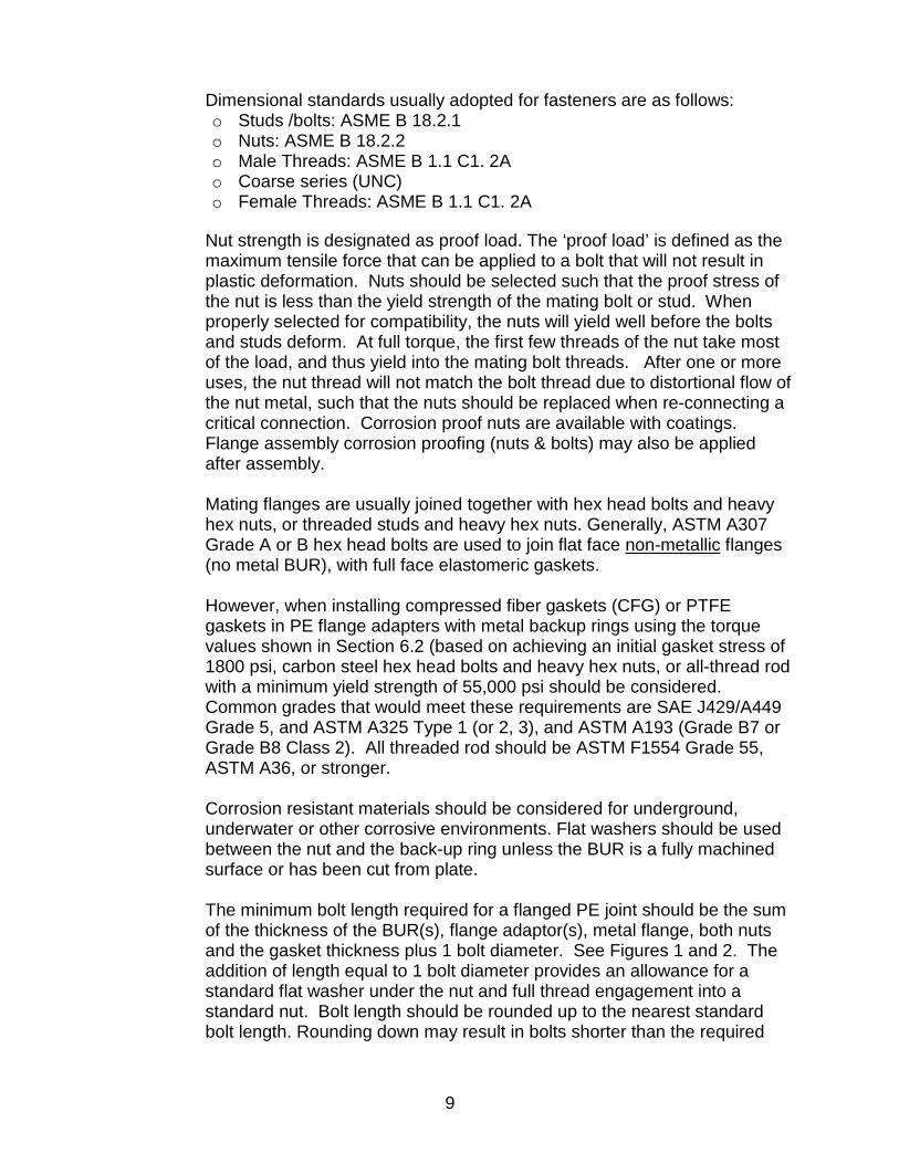
The material (compound) requirements for flange adapters are similar to those of the pipe to which it is to be fused. Polyethylene has an apparent modulus that is ‘duration-under-load’ dependent. Stress in polyethylene that is caused by straining the material (compression due to tightening of the flange joint bolts), will ‘relax’ over time. If strain and temperature are constant, the compression stress in the flange adapter hub will decrease to about 50% of the originally applied stress in 60 hours, and approximately 35% in 1,000 hours. There is only a small loss in assembly stress thereafter. A number of sources for the determination of power law exponents for the relaxation of PE stresses are given in the final report of the PPI commissioned study Thermal Stress in HDPE Water Pipes (Bilgin, 2020). The HDPE flange faces should be inspected to ensure they are free from radial gouges across no more than 1/3rd of the face width. Some surface marring or denting is acceptable. The flange sealing faces should be free from rust, weld spatter, dirt, debris, etc. HDPE flange-adapter faces exhibiting surface marring or dents should limit such defects to not more than 1/16” deep. Contact the supplier for assistance when minor defects are observed in HDPE adapter faces. The flange faces should be cleaned and installed per the manufacturer’s recommendation. Flange faces should be uniformly flat and in consistent 90 degree orientation to the neck of the flange adapter.
6
Stress vs Time (0-100,000 hrs)
Stress vs Time (0-1,000 hrs)
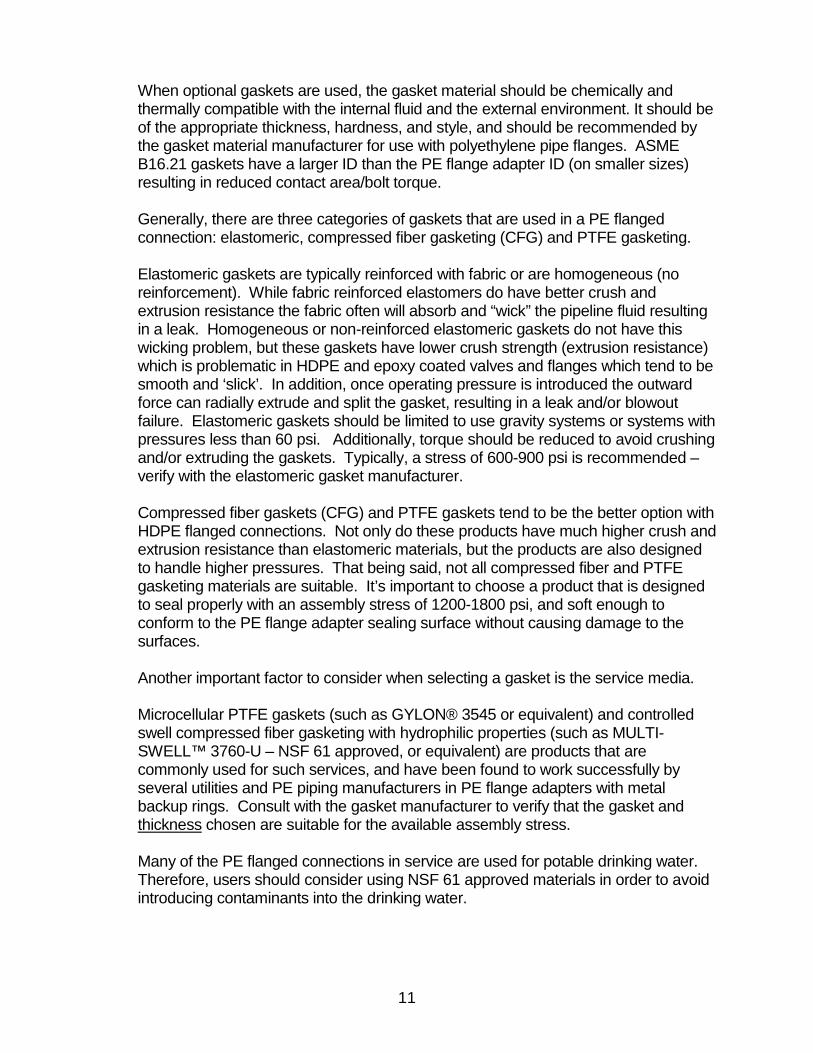
4.2. Backup Rings (Lap Joint Flange) The metal Lap-Joint Flange / Backup Ring (LJF / BUR) cross-section geometry may be a rectangular solid or a contoured cross-section. The rectangular cross-section is usually machined from metal plate. This style of BUR is much stiffer than the polyethylene FA hub. Tightening of the bolts causes compression of the PE hub without significant distortion of the metal BUR. Metal plate BUR’s usually conform dimensionally to AWWA C207 Class E for service pressures up to 150 psi. The contoured cross-section is typically cast using molten ductile-iron or stainless-steel. This style of Lap Joint Flange (LJF) BUR cantilevers or rotates during bolt tightening. The decrease in bolt tension that would

7
otherwise occur with distortion of the FA hub is therefore reduced with use of this flexible BUR. The effect is similar to that which occurs with Belleville washers. There are several producers of this product and none provides any quantitative information about the relationship between the bolt load force and the associated with BUR deformation. These BUR’s are an elastic, resilient, flexible “plate-spring” engineered to work with HDPE flange adapters. When the bolts are torqued, the LJF BUR flexes and applies a uniform compression to the flange adapters.
On an assembled joint, the BUR/LJF is in contact with the underside of polyethylene flange adapter hub and has a radius which mates with the fillet radius of the matching flange-adapter (stub-end). The BUR/LJF slips over the pipe prior to its’ fusion to the FA. It is free to rotate so that it can be aligned with the bolt holes of the mating flange or BUR. Bolting patterns for BUR’s are discussed in section 2. (Preface) of this document.
4.3. ASME B16.5/16.47 Series A Flanged Fittings / Valves Fittings and valves with integral ASME B16.5 & B16.47 Series A Class 150 flanged ends are designed to be attached to steel pipe with a wall thickness that has a pressure rating equal to or greater than the pressure rating of the matching PE pipe. The bore of the flanged metal end is usually a ‘standard’ bore. For example, an IPS 16 flange could have a bore of 15.25”. However, the bore of a DR 11 PE pipe would have a bore of 12.92”. The bore of an F2880 16” DR 11 flange adapter with a 10% allowance for toe-in would have a bore of 12.60”. Regardless of the bore of the PE flange adapter, the contact surface between the PE flange adapter and the raised face of the flanged end of the fitting would be based on the 15.25” bore of the 16” metal flange. As noted previously, the bolt torque required to seat a flange increases as the bore diameter decreases. Polyethylene flanged joints where one side

8
is a ASME B16.5 or B16.47 Series A metal flange require a lower bolt torque than a PE to PE flanged joint. This will be discussed further in the section describing bolt torque calculations.
Note: In US jurisdictional installations, any metallic pipeline components must be
protected from corrosion as prescribed in US CFR Title 49, Part 192, Subpart I, sections 451-491 and Part 195 Subpart H, sections 551-589.
4.4. Spacer Rings / Butterfly Flange Adapters
When mating a metal flanged butterfly valve to a PE FA the valve disk may physically interfere with the smaller bore of the FA. A spacer ring with a taper on the ID may be used as a transition piece to avoid this physical interference. For low pressure applications, the spacer ring may be machined from polyethylene, or the hub width of the flange adapter may be increased to provide sufficient thickness to machine a taper on the FA for valve disk clearance. For higher pressures, it is recommended that the spacer ring should be machined from a suitable metal. When a PE spacer ring or a BFV modified FA is used, visco-elastic creep will occur making it more difficult to maintain appropriate interfacial pressure at the sealing surface.
4.5. Low Pressure Plastic & FRP Flanges Low pressure plastic (PVC, CPVC) flanges are used on pipes and fittings made of these materials. These flanges are usually used on NPS 24 and smaller pipe with service pressures less than 60 psi. The flanges are often flat face (FF) and the mating flange should be flat face as well to avoid creating bending moments. Over-tightening, misalignment, or mating these flanges to flanges with raised face contact surfaces can potentially damage these non-metallic flanges. Extreme care is advised. Consult with the non-metallic flange manufacturer to determine the maximum torque limits, and if spacers are required when bolting them to PE flange adapters.
4.6. Bolts or Studs and Nuts
Since bolting material does not come in contact with fluid, its material compatibility with fluid in the pipe is not important. The selection of bolt material is determined based on service conditions. However, if the flange bolting will be exposed to corrosive environments (i.e., exposed to elements such as salt water), corrosion resistant fasteners should be used. It is important for the bolting material to have sufficient yield strength to achieve the desired torque.
9
Dimensional standards usually adopted for fasteners are as follows: o Studs /bolts: ASME B 18.2.1 o Nuts: ASME B 18.2.2 o Male Threads: ASME B 1.1 C1. 2A o Coarse series (UNC) o Female Threads: ASME B 1.1 C1. 2A
Nut strength is designated as proof load. The ‘proof load’ is defined as the maximum tensile force that can be applied to a bolt that will not result in plastic deformation. Nuts should be selected such that the proof stress of the nut is less than the yield strength of the mating bolt or stud. When properly selected for compatibility, the nuts will yield well before the bolts and studs deform. At full torque, the first few threads of the nut take most of the load, and thus yield into the mating bolt threads. After one or more uses, the nut thread will not match the bolt thread due to distortional flow of the nut metal, such that the nuts should be replaced when re-connecting a critical connection. Corrosion proof nuts are available with coatings. Flange assembly corrosion proofing (nuts & bolts) may also be applied after assembly. Mating flanges are usually joined together with hex head bolts and heavy hex nuts, or threaded studs and heavy hex nuts. Generally, ASTM A307 Grade A or B hex head bolts are used to join flat face non-metallic flanges (no metal BUR), with full face elastomeric gaskets. However, when installing compressed fiber gaskets (CFG) or PTFE gaskets in PE flange adapters with metal backup rings using the torque values shown in Section 6.2 (based on achieving an initial gasket stress of 1800 psi, carbon steel hex head bolts and heavy hex nuts, or all-thread rod with a minimum yield strength of 55,000 psi should be considered. Common grades that would meet these requirements are SAE J429/A449 Grade 5, and ASTM A325 Type 1 (or 2, 3), and ASTM A193 (Grade B7 or Grade B8 Class 2). All threaded rod should be ASTM F1554 Grade 55, ASTM A36, or stronger. Corrosion resistant materials should be considered for underground, underwater or other corrosive environments. Flat washers should be used between the nut and the back-up ring unless the BUR is a fully machined surface or has been cut from plate. The minimum bolt length required for a flanged PE joint should be the sum of the thickness of the BUR(s), flange adaptor(s), metal flange, both nuts and the gasket thickness plus 1 bolt diameter. See Figures 1 and 2. The addition of length equal to 1 bolt diameter provides an allowance for a standard flat washer under the nut and full thread engagement into a standard nut. Bolt length should be rounded up to the nearest standard bolt length. Rounding down may result in bolts shorter than the required

10
minimum length. A gasket may or may not be present so gasket thickness should be included only when a gasket is used. Many companies require a minimum number of threads (often 3) and/or maximum number of threads (often 6) to be visible above the nut to ensure full thread engagement. If threaded studs are used, then washers and nuts are installed on both sides. The calculation of bolt torque depends on the ‘Nut Factor’ or ‘k-factor’ used to calculate to the target torque. Appendix K of PPC-1, (PCC-1 ASME Guidelines for Pressure Boundary Bolted Flange Joint Assembly), defines ‘nut factor’ as an experimentally determined dimensionless constant related to the coefficient of friction. The k-factor in most applications at ambient temperature is generally considered to be approximately equal to the coefficient of friction plus 0.04. Table 1 (of PCC-1-2000) indicates that nut factors of 0.20 to 0.16 are appropriate for non-coated and coated bolts, respectively. An expanded list of nut factors may be found in Table 7.1 of Bickford’s Text (Bickford, 2008) Introduction to the Design and Behavior of Bolted Joints. It should also be noted that recent research has shown that nut factors, or ‘k’ factors, can vary based on bolt material, bolt diameter, and assembly temperature. These factors can significantly impact the torque and resulting force calculations and should not be ignored when selecting a thread lubricant. The end-user is advised to seek test results conducted on similar bolt and thread lubricant specifications or to conduct nut factor trials with their own conditions. Nut factor trials can be conducted relatively easily by tightening a bolt using known torque and measuring the obtained bolt load by calibrated ultrasonic measurement, use of a calibrated load cell, or measuring pressure rise on a hydraulic tensioner.
Note: PPI recommends that each flanged joint be independently analyzed by the
responsible project engineer for sealing capacity when subjected to all expected operating, environmental and installation loads.
5.0 GASKETS
It is possible to assemble a PE flange adapter or stub end with a metal backup ring to metal flange connections without a gasket because the hardness of the PE flange adapter or stub end adapter is only about 65-70 Durometer A. The ‘hub face will conform to the serrations in the metal flange face. Doing so will likely cause permanent deformation of the flange adapter sealing faces. Therefore, a gasket is highly recommended if the customer anticipates disassembling and reassembling the flanges in the future.
11
When optional gaskets are used, the gasket material should be chemically and thermally compatible with the internal fluid and the external environment. It should be of the appropriate thickness, hardness, and style, and should be recommended by the gasket material manufacturer for use with polyethylene pipe flanges. ASME B16.21 gaskets have a larger ID than the PE flange adapter ID (on smaller sizes) resulting in reduced contact area/bolt torque. Generally, there are three categories of gaskets that are used in a PE flanged connection: elastomeric, compressed fiber gasketing (CFG) and PTFE gasketing. Elastomeric gaskets are typically reinforced with fabric or are homogeneous (no reinforcement). While fabric reinforced elastomers do have better crush and extrusion resistance the fabric often will absorb and “wick” the pipeline fluid resulting in a leak. Homogeneous or non-reinforced elastomeric gaskets do not have this wicking problem, but these gaskets have lower crush strength (extrusion resistance) which is problematic in HDPE and epoxy coated valves and flanges which tend to be smooth and ‘slick’. In addition, once operating pressure is introduced the outward force can radially extrude and split the gasket, resulting in a leak and/or blowout failure. Elastomeric gaskets should be limited to use gravity systems or systems with pressures less than 60 psi. Additionally, torque should be reduced to avoid crushing and/or extruding the gaskets. Typically, a stress of 600-900 psi is recommended – verify with the elastomeric gasket manufacturer. Compressed fiber gaskets (CFG) and PTFE gaskets tend to be the better option with HDPE flanged connections. Not only do these products have much higher crush and extrusion resistance than elastomeric materials, but the products are also designed to handle higher pressures. That being said, not all compressed fiber and PTFE gasketing materials are suitable. It’s important to choose a product that is designed to seal properly with an assembly stress of 1200-1800 psi, and soft enough to conform to the PE flange adapter sealing surface without causing damage to the surfaces. Another important factor to consider when selecting a gasket is the service media. Microcellular PTFE gaskets (such as GYLON® 3545 or equivalent) and controlled swell compressed fiber gasketing with hydrophilic properties (such as MULTI-SWELL™ 3760-U – NSF 61 approved, or equivalent) are products that are commonly used for such services, and have been found to work successfully by several utilities and PE piping manufacturers in PE flange adapters with metal backup rings. Consult with the gasket manufacturer to verify that the gasket and thickness chosen are suitable for the available assembly stress. Many of the PE flanged connections in service are used for potable drinking water. Therefore, users should consider using NSF 61 approved materials in order to avoid introducing contaminants into the drinking water.

12
Gaskets used on flange assemblies on some industrial and wastewater systems and on potable water systems may be exposed to chemicals such as chlorine or chloramines. The gasket materials should be selected to ensure there is chemical compatibility and to provide long term usefulness and minimum degradation of the gasket specified (swelling, loss of elasticity, or softening). The gasket should be self-centering, which is accomplished by either using a RING or FULL-FACE gasket. A RING gasket will have an outer diameter equal to the bolt circle diameter minus the bolt diameter. This will allow the gasket to center itself by contacting the bolts once installed in the backup ring. A FULL-FACE gasket will have the same outer diameter, bolt circle and bolt hole dimensions as the backup ring or flange. Therefore, once the bolts are installed through the backup ring and gasket, the gasket is properly positioned in the flange. NOTE: FULL FACE gaskets are often preferred when working with larger flanges as installers can hang/position the gasket on the bolts/studs which holds the gasket in place while the other flange assembly is brought into place. ASME NM-1 (ASME, 2018), recommends that metallic gaskets should not be used with non-metallic flanged joints, and that gaskets should not be reused with non-metallic flanged joints.

13
6.0 BOLT TORQUE CALCULATION METHODOLOGY The recommended procedure for determination of appropriate bolt loads (bolt torques) is a simplified approach from that recommended in previous versions of TN-38. The methodology is to determine the load (force) required to produce an initial theoretically uniform stress of 1,800 psi cross the mating interfacial surface area. This load is due to the accumulated axial load from the torqued bolts. The accumulated bolt load is the ‘bolt stress’ times ‘the number of bolts’ times ‘the effective cross-sectional area of each threaded bolt’. The torque on the bolts is based on the ‘nut factor’ … the efficiency with which torque is converted to axial bolt load. Details of the methodology are found in Sections 6.2 and 6.3. 6.1. Rationale for Change in Methodology
Calculation of the bolt torque for flanged joints in metal piping systems is based on “the ASME design philosophy for flanged joints. The method involves determining the load on the flange bolts and ensuring that the selected flange bolts (size and material) can withstand the bolt load without exceeding Code allowable stress values. For the determination of bolt load, two cases are considered: the required blot load for design conditions, Wml, and the required bolt load for gasket seating,” (The ASME Boiler and Pressure Vessel Code, Section III, Appendices, 2015)
o the bolt load (Wml) that is required to resist the operating pressure,
surge pressure, pipe-line axial thermal contraction, and pipe bending strain from soil settlement, and flange angular alignment; all with an applied safety factor. It is the maximum operating bolt load (MOBL), or
o the bolt load (Wm2) that is required to provide the appropriate seating force required for the interfacial sealing surface stress. This is the minimum seating force (MSF).
An EPRI report, Capacity Testing of High-Density Bolted Flanged Joints (J. D. Stevenson and Associates, Inc. & Munson and Associates, 2010) concluded that the minimum operating bolt load never becomes a factor in the analysis at the working pressures considered in their report (150 psi) and never produces a MOBL requiring an interfacial pressure greater than that required to seal the joint assembly. The same report used FEA to determine the target interfacial pressure required to seal a PE pipe to metal pipe connection. As noted in the discussion in Section 4.1, PE stresses will relax over time and reduce to about 35% of the initial stress value in 1,000 – 4,000 hrs. In addition, the relatively thick PE FA will strain by an amount that eliminates the strain that occurs in the bolts during initial bolt tightening. Retightening

14
is suggested to compensate for the initial PE stress relaxation / PE straining. In addition to the strain occurring along the axis of the pipe, there is deformation of the FA caused by eccentric loading of the bolts, backing ring and gasket seating. In their FEA based assessment of flanged joints for large pipes (Jacobsson, 2011) the authors concluded that due to deformation of the PE FA “the contact (along the interfacial sealing surfaces) is lost along a large part of the joint already from the beginning of pressurization of the pipe”. The authors concluded as well that the most efficient way to improve the joint is to increase the bolt torque and to keep by re-tightening or by (use of) flexible backing rings. After consideration of the conflicting information in these reports, the PPI task group assessing this information has concluded that determination of the appropriate bolt torque for sealing flanged joints involving PE FA/SE cannot be assessed by employing the ASME methodology applicable to metal flanged joints.
Note: Industry experience has been that determination of bolt torque using the
Maximum Seating Force (MSF) approach, based on a target interfacial pressure is the best practical way to determine the target bolt torque. The target interfacial pressure for most applications is 1,800 psi. An appropriate ‘nut factor, K’ should be selected to determine the bolt torque. For low pressure application (<60 psi) using an elastomeric gasket, a maximum interfacial pressure of 1,200 psi may be used. The appropriate approach is to use computed bolt torques with the adoption of good bolt torquing routines that include retorquing after several hours.
6.2. Nut Factors
Table1 of the Guideline document (PCC-1 ASME Guidelines for Pressure Boundary Bolted Flange Joint Assembly) indicates that ‘nut factors’ correspond approximately to 0.20 and 0.16 for noncoated and coated bolts respectively. The report notes that “…recent research has shown there to be nut factor dependence on bolt material, bolt diameter, and assembly temperature. These factors can be significant and should not be ignored when selecting the nut factor or anti-seize compound. The end user is advised to seek test results conducted on similar bolt and anti-seize specifications or to conduct nut factor trials with their own conditions. Nut factor trials can be conducted relatively easily by tightening a bolt using torque and measuring

15
the obtained bolt load by calibrated ultrasonic measurement, use of a calibrated load cell, or measuring pressure rise on a hydraulic tensioner”. TN-38 recommends a nut factor (K) of 0.16 for non-plated bolts and studs that are lightly greased. The table of calculated bolt torque presented in this Technical Note are based on a K of 0.16 and 0.20.
6.3. Calculation of Target Bolt Torque
The ‘target torque’ values in the following Tables, are those required to provide an initial seating stress of 1,800 psi. The nut factor used to convert bolt load to bolt torque is either 0.16 or 0.20. Both are shown. If nut factors other than these values are determined to be suitable, the target torque may be determined by applying a factor that is the ratio of the ‘desired nut factor / 0.16’ times the values in the ‘0.16’ column in the Table. For flange assemblies consisting of two (2) PE FA’s when the bore is based on wall thickness other than 1.06 X minimum PE pipe wall, these torque values should be amended by the ratio of ‘the actual surface seating area / seating area based on bore associated with a wall ‘t’ equal to 1.06 X minimum wall’. The seating area for flange assemblies consisting of a PE FA mating to a metal flange are based on the seating area of a metal RF diameter for a ASME B16.5 flange (24” and smaller diameter), or a ASME B16.47 Series A flange (larger than 24”). Bore diameters are as indicated in the notes to the table. When bolting to fiberglass, cast iron, PVC pipe flanges, or PVC flanged valves, the “brittle” flange typically bolts to a special HDPE full-face flange adapter using lower bolt torque. Hence an elastomeric full-face gasket is frequently used with “brittle” flanges. Lower seating stresses than those used in this table may be appropriate for ‘brittle flanges’. Consult the PVC flange or valve manufacturer to verify their maximum allowable torque for the given flange.
16
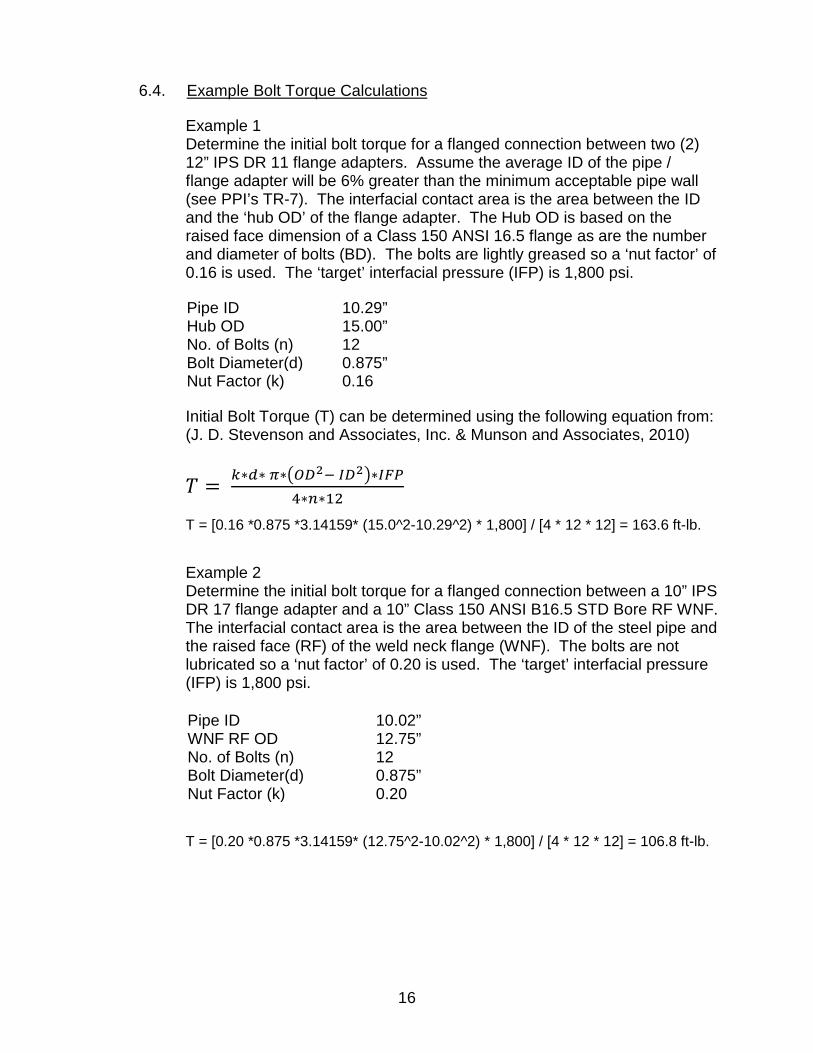
6.4. Example Bolt Torque Calculations
Example 1 Determine the initial bolt torque for a flanged connection between two (2) 12” IPS DR 11 flange adapters. Assume the average ID of the pipe / flange adapter will be 6% greater than the minimum acceptable pipe wall (see PPI’s TR-7). The interfacial contact area is the area between the ID and the ‘hub OD’ of the flange adapter. The Hub OD is based on the raised face dimension of a Class 150 ANSI 16.5 flange as are the number and diameter of bolts (BD). The bolts are lightly greased so a ‘nut factor’ of 0.16 is used. The ‘target’ interfacial pressure (IFP) is 1,800 psi.
Pipe ID 10.29” Hub OD 15.00” No. of Bolts (n) 12 Bolt Diameter(d) 0.875” Nut Factor (k) 0.16
Initial Bolt Torque (T) can be determined using the following equation from: (J. D. Stevenson and Associates, Inc. & Munson and Associates, 2010)
𝑇𝑇 = 𝑘𝑘∗𝑑𝑑∗ 𝜋𝜋∗�𝑂𝑂𝑂𝑂2− 𝐼𝐼𝑂𝑂2�∗𝐼𝐼𝐼𝐼𝐼𝐼4∗𝑛𝑛∗12
T = [0.16 *0.875 *3.14159* (15.0^2-10.29^2) * 1,800] / [4 * 12 * 12] = 163.6 ft-lb.
Example 2 Determine the initial bolt torque for a flanged connection between a 10” IPS DR 17 flange adapter and a 10” Class 150 ANSI B16.5 STD Bore RF WNF. The interfacial contact area is the area between the ID of the steel pipe and the raised face (RF) of the weld neck flange (WNF). The bolts are not lubricated so a ‘nut factor’ of 0.20 is used. The ‘target’ interfacial pressure (IFP) is 1,800 psi.
Pipe ID 10.02” WNF RF OD 12.75” No. of Bolts (n) 12 Bolt Diameter(d) 0.875” Nut Factor (k) 0.20
T = [0.20 *0.875 *3.14159* (12.75^2-10.02^2) * 1,800] / [4 * 12 * 12] = 106.8 ft-lb.

17
Torque Values to Develop 1800 psi Initial Gasket Seating Stress, DR 17 PE Pipe 2 PE Flange Adapters PE FA & Std Bore RF Flange
IPS Pipe Size
PE DR 17 Flange
Adapter
Torque based on 1,800 psi Interfacial
Seating Stress Metal Flange
Torque based on 1,800 psi Interfacial
Seating Stress RF OD ID k=0.16 k-0.20 ID k=0.16 k-0.20
(inch) (inch) (ft.lbs.) (ft.lbs.) (inch) (ft.lbs.) (ft.lbs.) 3 5.00 3.06 36.8 46.0 3.07 36.7 45.9
3.5 5.50 3.50 26.5 33.1 3.55 26.0 32.5 4 6.19 3.94 33.6 42.0 4.03 32.6 40.7 5 7.31 4.55 57.8 72.3 5.05 49.4 61.8 6 8.50 5.42 75.8 94.8 6.07 62.7 78.3 8 10.62 7.55 98.6 123.2 7.98 86.7 108.4
10 12.75 9.41 101.7 127.2 10.02 85.4 106.8 12 15.00 11.16 138.1 172.6 12.00 111.3 139.2 16 18.50 14.00 172.1 215.2 15.25 129.2 161.5 18 21.00 15.76 255.5 319.4 17.25 190.1 237.6 20 23.00 17.51 236.0 295.0 19.25 168.0 210.0 22 25.25 19.26 314.3 392.8 21.25 219.1 273.9 24 27.50 21.01 371.0 463.8 23.25 254.1 317.6 26 29.50 22.76 415.1 518.9 25.54 256.8 321.0 28 31.50 24.51 329.5 411.9 27.50 198.6 248.2 30 33.75 26.26 378.3 472.9 29.25 238.6 298.2 32 36.00 28.01 516.5 645.6 31.44 310.5 388.2 36 40.25 31.51 554.1 692.7 35.36 326.7 408.4 40 44.25 35.01 575.1 718.9 39.28 326.1 407.6 42 47.00 36.76 673.5 841.9 41.25 398.5 498.2 48 53.50 42.01 705.0 881.2 47.14 411.3 514.1 54 59.50 47.27 979.2 1,224.1 53.00 548.2 685.3 60 66.00 52.52 1,013.6 1,267.1 59.00 555.1 693.8
All torque values are rounded to 0.1 ft.-lb. Pattern inconsistencies are generally due to a change in the number of bolts. ID of the PE Flange Adapter is based on average wall = 1.06 X minimum wall with no toe-in allowance.
18
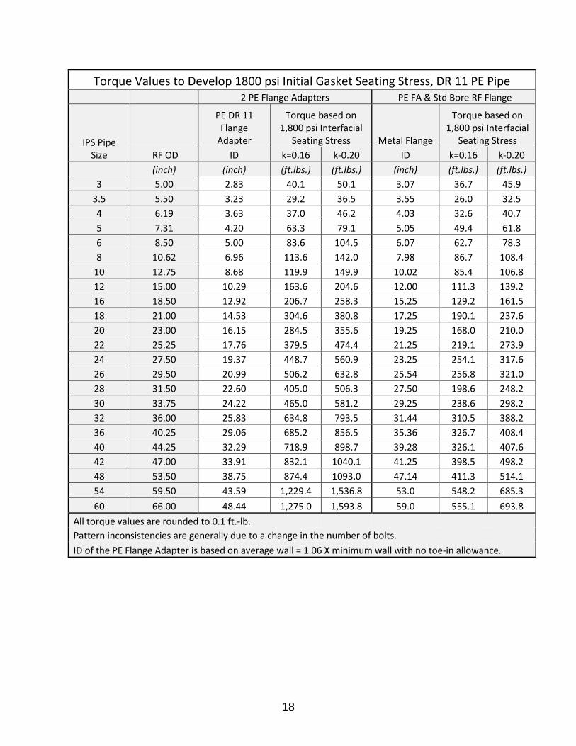
Torque Values to Develop 1800 psi Initial Gasket Seating Stress, DR 11 PE Pipe 2 PE Flange Adapters PE FA & Std Bore RF Flange
IPS Pipe Size
PE DR 11 Flange
Adapter
Torque based on 1,800 psi Interfacial
Seating Stress Metal Flange
Torque based on 1,800 psi Interfacial
Seating Stress RF OD ID k=0.16 k-0.20 ID k=0.16 k-0.20
(inch) (inch) (ft.lbs.) (ft.lbs.) (inch) (ft.lbs.) (ft.lbs.) 3 5.00 2.83 40.1 50.1 3.07 36.7 45.9
3.5 5.50 3.23 29.2 36.5 3.55 26.0 32.5 4 6.19 3.63 37.0 46.2 4.03 32.6 40.7 5 7.31 4.20 63.3 79.1 5.05 49.4 61.8 6 8.50 5.00 83.6 104.5 6.07 62.7 78.3 8 10.62 6.96 113.6 142.0 7.98 86.7 108.4
10 12.75 8.68 119.9 149.9 10.02 85.4 106.8 12 15.00 10.29 163.6 204.6 12.00 111.3 139.2 16 18.50 12.92 206.7 258.3 15.25 129.2 161.5 18 21.00 14.53 304.6 380.8 17.25 190.1 237.6 20 23.00 16.15 284.5 355.6 19.25 168.0 210.0 22 25.25 17.76 379.5 474.4 21.25 219.1 273.9 24 27.50 19.37 448.7 560.9 23.25 254.1 317.6 26 29.50 20.99 506.2 632.8 25.54 256.8 321.0 28 31.50 22.60 405.0 506.3 27.50 198.6 248.2 30 33.75 24.22 465.0 581.2 29.25 238.6 298.2 32 36.00 25.83 634.8 793.5 31.44 310.5 388.2 36 40.25 29.06 685.2 856.5 35.36 326.7 408.4 40 44.25 32.29 718.9 898.7 39.28 326.1 407.6 42 47.00 33.91 832.1 1040.1 41.25 398.5 498.2 48 53.50 38.75 874.4 1093.0 47.14 411.3 514.1 54 59.50 43.59 1,229.4 1,536.8 53.0 548.2 685.3 60 66.00 48.44 1,275.0 1,593.8 59.0 555.1 693.8
All torque values are rounded to 0.1 ft.-lb. Pattern inconsistencies are generally due to a change in the number of bolts. ID of the PE Flange Adapter is based on average wall = 1.06 X minimum wall with no toe-in allowance.

19
7.0 INSTALLATION INSTRUCTIONS
7.1. Alignment of Flanged Joints Proper alignment of all joint members is an essential element of proper flange joint assembly. When aligning requires more force that can be exerted by hand or common hand and hammer alignment tools, consult an engineer.
7.2. Lubrication of ‘Working Surfaces’
The lubrication for the initial use of bolts and nuts is that provided by the coating of polyamide/amide and is considered to be the sole source of working surface lubrication. The nut factor 0.16 is appropriate for coated bolts, and 0.2 for non-coated bolts. Torque values (tabled in this document) only apply for the initial tightening of new coated bolts.
7.3. Installation of Bolts
Bolts and nuts should be installed so that they are hand tight with the marked end of the bolts and nuts located on the same side of the joint and facing outward to facilitate inspection.
7.4. Tightening of Bolts
Multiple rounds of tightening should be used to ensure uniform bolt tightness. After hand-tightening, a minimum of three (3) rounds of incremental tightening is suggested, tightening to approximately 30% of the target torque value on the first round. Tighten to 50-70% on the second round, and to 100% on the third round. After the third round, it is recommended that all of the bolts should be tested / retorqued to 100% in a circular pattern to ensure that no bolts were inadvertently missed during the tightening sequence. In addition to performing the final torque tightening pass at 100%, measurements of the gaps between the flanges should be taken to verify that the flanges are being brought together evenly. Measurements at eight (8) equally spaced locations are recommended.
NOTE: When the target torque is extremely high (for example 1,000 ft-lbs.) additional
rounds should be considered to avoid tipping the flanges and creating misalignment.

20
7.5. Tightening Sequence of Bolts
The tightening sequence is based on use of a single tightening tool. The ‘Legacy’ cross-pattern tightening sequence and bolt numbering system when using a single tool is shown in Table 4 of PCC-1. It is included here for convenience. Only the portion of the table indicating the number of bolt holes up to 52 has been included since that is the number of bolt holes associated with a 60” pipe size.
There have been successful implementations of joint assembly patterns and torque-increment combinations that require less efforts than the ‘Legacy PCC-1’ method. The reader is referred to Appendix F of PCC-1 (PCC-1 ASME Guidelines for Pressure Boundary Bolted Flange Joint Assembly) for these alternative patterns.
PCC-1 Legacy Cross-Pattern Tightening Sequence and Bolt Numbering System When Using a Single Tool

21
8.0 HYDRO-TESTING & LEAK CLOSURE GUIDELINE Normally, after initial torque and the optional re-torque 12-24 hours after initial installation (recommended), a hydrotest is applied. The test pressure is usually up to 1.5 times operating pressure or 1.5 times the pipe working pressure rating. Experience has shown that if the above procedures have been followed, virtually none of the flange joints will leak. For appropriate hydrostatic testing procedures refer to ASTM F2164. (ASTM F2164 Standard Practice for Field Leak Testing), and PPI’s TN-46 (Plastics Pipe Institute) If drip or spray leaks are discovered during hydrotest, the principle corrective action is to measure the existing bolt torque with a torque wrench, increase it by 10% to 15%, and apply that larger torque to the bolt(s) in the center of the leak, and to each side of the leak. Tighten, slightly-more, each bolt adjacent to those bolts. Repeat, slightly increasing the torque on the bolts neighboring the leak, until the leakage stops and the pipeline remains sealed. Do not loosen the bolts on a pressurized pipe system! However, if 150% of the specified torque value is reached and the flange assembly still leaks, stop the hydrotest, de-pressurize, and safely disassemble the flange joint. Something else is probably wrong.
NOTE: Safety in the ditch or, around pressurized pipelines is of primary concern.
Strategies for fixing leaking pipelines must always include the safety manager, and possibly the corporate OSHA representative to ensure the maximum safety and the minimum chance of an injury or accident. Procedures should be sufficiently thought through and rehearsed, and re-checked by project management before performing the work-plan, so as to avoid accidents, injury, or even death.
9.0 FLANGE DISASSEMBLY
Warning: When working on pipelines that transport pressurized fluids, the contained
energy may be dangerous to workers. Typically, a pipeline is depressurized before it is worked on to avoid injury in the event of a leak. Generally speaking, never tighten nor loosen a flange joint while the pipeline is pressurized. Always de-pressurize the pipe section before tightening or loosening flange bolts.
The assembled flange is under tremendous compression. The HDPE flange adapter face wants to recover to its pre-compression thickness. If, one bolt is removed, its compressive load is transferred to the two adjacent bolts, increasing their tension by 1/3rd. If a second adjacent bolt is removed, the additional compressive load is transferred to the remaining two adjacent bolts, increasing their tensile load by 50%. Very quickly, one can see that loosening multiple bolts completely will over-load adjacent bolts which can result in one or more of the following situations 1) bent bolts/studs, 2) permanently stretched (yielded) bolts/studs, 3) permanently distorted/damaged metal backup lap-joint flanges and/or 4) permanently distorted/damaged HDPE flange-adapter face.

22
The correct disassembly protocol is to reverse the assembly process. Using the tightening sequence rotate each nut in sequence, to loosen the fasteners by about 10 to 30 degrees (less than one-half of a flat on a six-sided nut.) Repeat this several times until the assembly torque is gradually and evenly diminished, and the HDPE flange face is gradually and evenly unloaded. Once the fasteners are loose, the HDPE flange-adapter should drop loose or pull free from the mating flange by its own self weight. DO NOT USE WEDGE TOOLS to separate the HDPE Flange Adapters or the FA from the mating metal flange, as such tools will damage the sealing surface area. DO NOT HAMMER the pipe wall to “shake” the pipe loose. Lifting straps may be used on the HDPE pipe further back from the flange to lift the pipe, changing its effective lay length, and causing the flange face to pull-back from the mating flange, and then lift up. Once loosened, the HDPE flange adapter’s face seal surface should be protected from gouging or marring in a manner acceptable to the maintenance/project superintendent. The un-bolted pipeline pipe invert should be cradled to bear the weight of the pipe, flange, and BUR/LJF. The BUR should not rest on the ground bearing the weight of the pipeline on the “thin” ID edge of the lap-joint flange. The nuts and bolts (or studs) should be cleaned and oiled, and examined to see if they may be re-used, as corrosion may have damaged them. They may need to be replaced, as required, upon flange re-assembly. Corroded threads are not only potentially weakened, but the corrosion will also create excessive friction that will dramatically reduce the amount of bolt-load (sealing force) generated on the gasket. While new fasteners are highly recommended, if used fasteners are used installers should take the time to fully clean the threads of the studs/bolts/nuts, inspect for damage (and replace as necessary) and properly lubricated the threads to achieve optimum loading.

23
REFERENCES American Society of Mechanical Engineers. (2019). PCC-1, Guidelines for Pressure Boundary
Bolted Flange Joint Assembly. New York, New York. ASME. (2018). Thermoplastic Piping Systems, Standards for Non Metallic Piping Systems. In A.
S. Engineers (Ed.). (p. 130). New York: ASME. ASME B16.47 . (2017). Large Diameter Steel Flanges: NPS 26 through NPS 60 Metric/Inch
Standard. New York, NY, United States of America. ASME B16.5 . (2017). B16.5 Pipe Flanges and Flanged Fittings: NPS 1/2 through NPS 24
Metric/Inch Standard. New York, NY, United States of America. ASTM F2164 Standard Practice for Field Leak Testing. (2013). Standard Practice for Field Leak
Testing of Polyethyelene (PE) and Crosslinked Polyethylene (PEX) Pressure Piping Systems Using Hydrostatic Pressure. West Conshocken, Pennsylvannia, United States.
ASTM F2880 Standard Specification for Lap Joint Type PE Flange Apapters. (n.d.). F2880 Standard Specification for Lap-Joint Type Flange Adpaters forPolyethylene Pressure Pipe in Nominal Sizes 3/4 in. to 65 in. West Conshocken, Pennsylvannia, United States.
AWWA C207-18 STEEL PIPE FLANGES FOR WATERWORKS SERVICE—SIZES 4 IN. THROUGH 144 IN. (100 MM THROUGH 3,600 MM). (n.d.). Denver, CO, United States of America.
Bickford, J. H. (2008). Introduction to the Design and Behavior of Bolted Joints, fourth Edition. Boca Raton, Fl: CRC Press, Taylor & Francis Group.
Bilgin, S. a. (2020). Thermal Stresses in HDPE Water Pipes., (p. 66). Irving. Gaskets for Flange Adapters and Stub End Connections. (2017). Gaskets for Flange Adapters
and Stub End Connections. Palmyra, NY: Garlock Sealing Technologies. J. D. Stevenson and Associates, Inc. & Munson and Associates. (2010). Capacity Testing of
High-Density Polyethylene Bolted Flanged Joints. Palo Alto, Calif.: Electric Power Research Institute.
Jacobsson, A. a. (2011). SP Report 2011:49, Tightness of Flange Joints for large Pilyethylene Pipes-Part 1. Goteborg: Technical Esearch Institute of Sweden.
PCC-1 ASME Guidelines for Pressure Boundary Bolted Flange Joint Assembly. (2019). PCC-1, Guidelines for Pressure Boundary Bolted Flange Joint Assembly. New York: Americal society of Mechanical Engineers.
Plastics Pipe Institute. (2021). Guidance for Field Hydrostatic Testing Of High Density Polyethylene Pressure Pipelines:. Irving, TX, United States of America.
The ASME Boiler and Pressure Vessel Code, Section III, Appendices. (2015). ASME Boiler and Pressure Vessel Code, Section III, Appendices. New York.