Do flexible acrylic resin lingual flanges improve retention of ...
Upload
khangminh22Category
view
0download
0
A N A M E R I C A N N A T I O N A L S T A N D A R D
Cast Copper Alloy Pipe Flanges and Flanged FittingsClasses 150, 300, 600, 900, 1500, and 2500
ASME B16.24-2011(Revision of ASME B16.24-2006)
Copyright ASME International Provided by IHS under license with ASME Licensee=Purdue University/5923082001
Not for Resale, 04/10/2012 20:09:04 MDTNo reproduction or networking permitted without license from IHS
--`,`,,`,`,``,,`,````,,`,````-`-`,,`,,`,`,,`---

Copyright ASME International Provided by IHS under license with ASME Licensee=Purdue University/5923082001
Not for Resale, 04/10/2012 20:09:04 MDTNo reproduction or networking permitted without license from IHS
--`,`,,`,`,``,,`,````,,`,````-`-`,,`,,`,`,,`---

ASME B16.24-2011(Revision of ASME B16.24-2006)
Cast CopperAlloy PipeFlanges andFlanged FittingsClasses 150, 300, 600, 900,1500, and 2500
A N A M E R I C A N N A T I O N A L S T A N D A R D
Three Park Avenue • New York, NY • 10016 USA
Copyright ASME International Provided by IHS under license with ASME Licensee=Purdue University/5923082001
Not for Resale, 04/10/2012 20:09:04 MDTNo reproduction or networking permitted without license from IHS
--`,`,,`,`,``,,`,````,,`,````-`-`,,`,,`,`,,`---
Date of Issuance: November 14, 2011
The next edition of this Standard is scheduled for publication in 2016.
ASME issues written replies to inquiries concerning interpretations of technical aspects of thisStandard. Periodically certain actions of the ASME B16 Committee may be published as Cases.Cases and interpretations are published on the ASME Web site under the Committee Pages athttp://cstools.asme.org as they are issued, and will be published within the next edition of thestandard.
ASME is the registered trademark of The American Society of Mechanical Engineers.
This code or standard was developed under procedures accredited as meeting the criteria for American NationalStandards. The Standards Committee that approved the code or standard was balanced to assure that individuals fromcompetent and concerned interests have had an opportunity to participate. The proposed code or standard was madeavailable for public review and comment that provides an opportunity for additional public input from industry, academia,regulatory agencies, and the public-at-large.
ASME does not “approve,” “rate,” or “endorse” any item, construction, proprietary device, or activity.ASME does not take any position with respect to the validity of any patent rights asserted in connection with any
items mentioned in this document, and does not undertake to insure anyone utilizing a standard against liability forinfringement of any applicable letters patent, nor assumes any such liability. Users of a code or standard are expresslyadvised that determination of the validity of any such patent rights, and the risk of infringement of such rights, isentirely their own responsibility.
Participation by federal agency representative(s) or person(s) affiliated with industry is not to be interpreted asgovernment or industry endorsement of this code or standard.
ASME accepts responsibility for only those interpretations of this document issued in accordance with the establishedASME procedures and policies, which precludes the issuance of interpretations by individuals.
No part of this document may be reproduced in any form,in an electronic retrieval system or otherwise,
without the prior written permission of the publisher.
The American Society of Mechanical EngineersThree Park Avenue, New York, NY 10016-5990
Copyright © 2011 byTHE AMERICAN SOCIETY OF MECHANICAL ENGINEERS
All rights reservedPrinted in U.S.A.
Copyright ASME International Provided by IHS under license with ASME Licensee=Purdue University/5923082001
Not for Resale, 04/10/2012 20:09:04 MDTNo reproduction or networking permitted without license from IHS
--`,`,,`,`,``,,`,````,,`,````-`-`,,`,,`,`,,`---
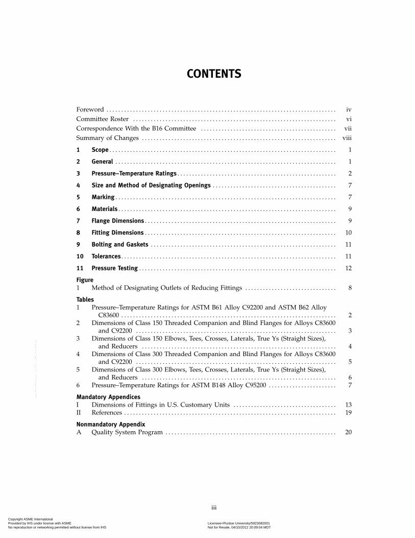
CONTENTS
Foreword . . . . . . . . . . . . . . . . . . . . . . . . . . . . . . . . . . . . . . . . . . . . . . . . . . . . . . . . . . . . . . . . . . . . . . . . . . . . . . ivCommittee Roster . . . . . . . . . . . . . . . . . . . . . . . . . . . . . . . . . . . . . . . . . . . . . . . . . . . . . . . . . . . . . . . . . . . . . viCorrespondence With the B16 Committee . . . . . . . . . . . . . . . . . . . . . . . . . . . . . . . . . . . . . . . . . . . . . . viiSummary of Changes . . . . . . . . . . . . . . . . . . . . . . . . . . . . . . . . . . . . . . . . . . . . . . . . . . . . . . . . . . . . . . . . . . viii
1 Scope . . . . . . . . . . . . . . . . . . . . . . . . . . . . . . . . . . . . . . . . . . . . . . . . . . . . . . . . . . . . . . . . . . . . . . . . . . . . . 1
2 General . . . . . . . . . . . . . . . . . . . . . . . . . . . . . . . . . . . . . . . . . . . . . . . . . . . . . . . . . . . . . . . . . . . . . . . . . . . 1
3 Pressure–Temperature Ratings . . . . . . . . . . . . . . . . . . . . . . . . . . . . . . . . . . . . . . . . . . . . . . . . . . . . . . 2
4 Size and Method of Designating Openings . . . . . . . . . . . . . . . . . . . . . . . . . . . . . . . . . . . . . . . . . . 7
5 Marking . . . . . . . . . . . . . . . . . . . . . . . . . . . . . . . . . . . . . . . . . . . . . . . . . . . . . . . . . . . . . . . . . . . . . . . . . . . 7
6 Materials . . . . . . . . . . . . . . . . . . . . . . . . . . . . . . . . . . . . . . . . . . . . . . . . . . . . . . . . . . . . . . . . . . . . . . . . . . 9
7 Flange Dimensions . . . . . . . . . . . . . . . . . . . . . . . . . . . . . . . . . . . . . . . . . . . . . . . . . . . . . . . . . . . . . . . . . 9
8 Fitting Dimensions . . . . . . . . . . . . . . . . . . . . . . . . . . . . . . . . . . . . . . . . . . . . . . . . . . . . . . . . . . . . . . . . . 10
9 Bolting and Gaskets . . . . . . . . . . . . . . . . . . . . . . . . . . . . . . . . . . . . . . . . . . . . . . . . . . . . . . . . . . . . . . . 11
10 Tolerances . . . . . . . . . . . . . . . . . . . . . . . . . . . . . . . . . . . . . . . . . . . . . . . . . . . . . . . . . . . . . . . . . . . . . . . . . 11
11 Pressure Testing . . . . . . . . . . . . . . . . . . . . . . . . . . . . . . . . . . . . . . . . . . . . . . . . . . . . . . . . . . . . . . . . . . . 12
Figure1 Method of Designating Outlets of Reducing Fittings . . . . . . . . . . . . . . . . . . . . . . . . . . . . . . . 8
Tables1 Pressure–Temperature Ratings for ASTM B61 Alloy C92200 and ASTM B62 Alloy
C83600 . . . . . . . . . . . . . . . . . . . . . . . . . . . . . . . . . . . . . . . . . . . . . . . . . . . . . . . . . . . . . . . . . . . . . . . . . 22 Dimensions of Class 150 Threaded Companion and Blind Flanges for Alloys C83600
and C92200 . . . . . . . . . . . . . . . . . . . . . . . . . . . . . . . . . . . . . . . . . . . . . . . . . . . . . . . . . . . . . . . . . . . . 33 Dimensions of Class 150 Elbows, Tees, Crosses, Laterals, True Ys (Straight Sizes),
and Reducers . . . . . . . . . . . . . . . . . . . . . . . . . . . . . . . . . . . . . . . . . . . . . . . . . . . . . . . . . . . . . . . . . . 44 Dimensions of Class 300 Threaded Companion and Blind Flanges for Alloys C83600
and C92200 . . . . . . . . . . . . . . . . . . . . . . . . . . . . . . . . . . . . . . . . . . . . . . . . . . . . . . . . . . . . . . . . . . . . 55 Dimensions of Class 300 Elbows, Tees, Crosses, Laterals, True Ys (Straight Sizes),
and Reducers . . . . . . . . . . . . . . . . . . . . . . . . . . . . . . . . . . . . . . . . . . . . . . . . . . . . . . . . . . . . . . . . . . 66 Pressure–Temperature Ratings for ASTM B148 Alloy C95200 . . . . . . . . . . . . . . . . . . . . . . . 7
Mandatory AppendicesI Dimensions of Fittings in U.S. Customary Units . . . . . . . . . . . . . . . . . . . . . . . . . . . . . . . . . . . 13II References . . . . . . . . . . . . . . . . . . . . . . . . . . . . . . . . . . . . . . . . . . . . . . . . . . . . . . . . . . . . . . . . . . . . . . . . 19
Nonmandatory AppendixA Quality System Program . . . . . . . . . . . . . . . . . . . . . . . . . . . . . . . . . . . . . . . . . . . . . . . . . . . . . . . . . . 20
iii
Copyright ASME International Provided by IHS under license with ASME Licensee=Purdue University/5923082001
Not for Resale, 04/10/2012 20:09:04 MDTNo reproduction or networking permitted without license from IHS
--`,`,,`,`,``,,`,````,,`,````-`-`,,`,,`,`,,`---
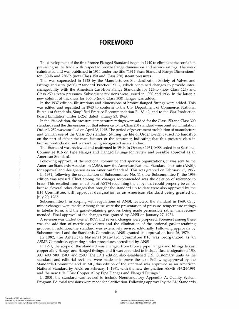
FOREWORD
The development of the first Bronze Flanged Standard began in 1910 to eliminate the confusionprevailing in the trade with respect to bronze flange dimensions and service ratings. The workculminated and was published in 1914 under the title “1914 Brass Standard Flange Dimensions”for 150-lb and 250-lb (now Class 150 and Class 250) steam pressures.
This was superseded in 1928 by the Manufacturers Standardization Society of Valves andFittings Industry (MSS) “Standard Practice” SP-2, which contained changes to provide inter-changeability with the American Cast-Iron Flange Standards for 125-lb (now Class 125) andClass 250 stream pressures. Subsequent revisions were issued in 1930 and 1936. In the latter, anew column of thickness for 300-lb (now Class 300) flanges was added.
In the 1937 edition, illustrations and dimensions of bronze-flanged fittings were added. Thiswas edited and reprinted in 1943 to conform to the U.S. Department of Commerce, NationalBureau of Standards, Simplified Practice Recommendation R-183-42, and to the War ProductionBoard Limitation Order L-252, dated January 23, 1943.
In the 1946 edition, the pressure–temperature ratings were added for the Class 150 and Class 300standards and the dimensions for that reference to the Class 250 standard were omitted. LimitationOrder L-252 was cancelled on April 28, 1945. The period of government prohibition of manufactureand civilian use of the Class 250 standard (during the life of Order L-252) caused no hardshipon the part of either the manufacturer or the consumer, indicating that this pressure class inbronze products did not warrant being recognized as a standard.
This Standard was reviewed and reaffirmed in 1949. In October 1951, MSS ceded it to SectionalCommittee B16 on Pipe Flanges and Flanged Fittings for review and possible approval as anAmerican Standard.
Following approval of the sectional committee and sponsor organizations, it was sent to theAmerican Standards Association (ASA), now the American National Standards Institute (ANSI),for approval and designation as an American Standard. This was granted on February 27, 1953.
In 1961, following the organization of Subcommittee No. 11 (now Subcommittee J), the 1953edition was revised. Chief among the changes recommended was the deletion of reference tobrass. This resulted from an action of ASTM redefining the alloys that could properly be calledbronze. Several other changes that brought the standard up to date were also approved by theB16 Committee, with approval designation as an American Standard being granted onJuly 20, 1962.
Subcommittee J, in keeping with regulations of ANSI, reviewed the standard in 1969. Onlyminor changes were made. Among these were the presentation of pressure–temperature ratingsin tabular form, and the gasket-retaining grooves being made permissible rather than recom-mended. Final approval of the changes was granted by ANSI on January 27, 1971.
A revision was undertaken in 1977, and several changes were proposed. Foremost among thesewas the addition of metric equivalents and the elimination of the optional gasket-retaininggrooves. In addition, the standard was extensively revised editorially. Following approvals bySubcommittee J and the Standards Committee, ANSI granted its approval on June 26, 1979.
In 1982, the American National Standard Committee B16 was reorganized as anASME Committee, operating under procedures accredited by ANSI.
In 1991, the scope of the standard was changed from bronze pipe flanges and fittings to castcopper alloy flanges and flanged fittings, and it was expanded to include class designations 150,300, 600, 900, 1500, and 2500. The 1991 edition also established U.S. Customary units as thestandard, and editorial revisions were made to improve the text. Following approval by theStandards Committee and ASME, this edition of the standard was approved as an AmericanNational Standard by ANSI on February 1, 1991, with the new designation ASME B16.24-1991and the new title “Cast Copper Alloy Pipe Flanges and Flanged Fittings.”
In 2001, the standard was revised to include Nonmandatory Appendix A, Quality SystemProgram. Editorial revisions were made for clarification. Following approval by the B16 Standards
iv
Copyright ASME International Provided by IHS under license with ASME Licensee=Purdue University/5923082001
Not for Resale, 04/10/2012 20:09:04 MDTNo reproduction or networking permitted without license from IHS
--`,`,,`,`,``,,`,````,,`,````-`-`,,`,,`,`,,`---
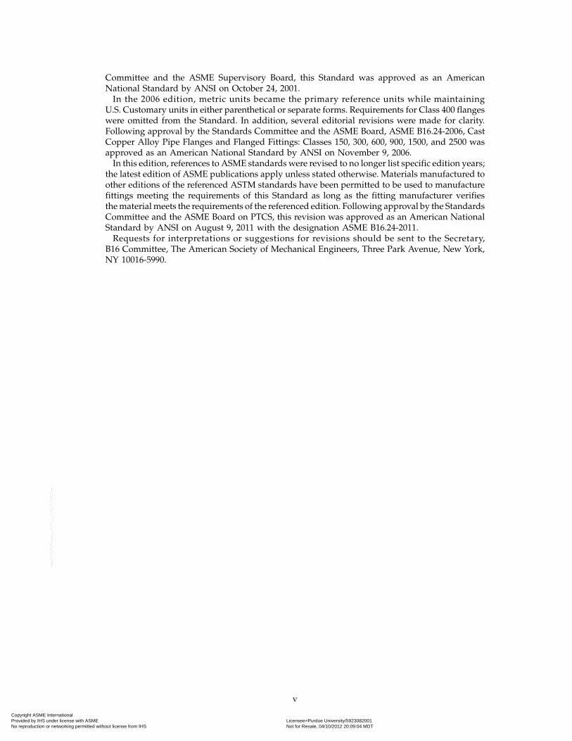
Committee and the ASME Supervisory Board, this Standard was approved as an AmericanNational Standard by ANSI on October 24, 2001.
In the 2006 edition, metric units became the primary reference units while maintainingU.S. Customary units in either parenthetical or separate forms. Requirements for Class 400 flangeswere omitted from the Standard. In addition, several editorial revisions were made for clarity.Following approval by the Standards Committee and the ASME Board, ASME B16.24-2006, CastCopper Alloy Pipe Flanges and Flanged Fittings: Classes 150, 300, 600, 900, 1500, and 2500 wasapproved as an American National Standard by ANSI on November 9, 2006.
In this edition, references to ASME standards were revised to no longer list specific edition years;the latest edition of ASME publications apply unless stated otherwise. Materials manufactured toother editions of the referenced ASTM standards have been permitted to be used to manufacturefittings meeting the requirements of this Standard as long as the fitting manufacturer verifiesthe material meets the requirements of the referenced edition. Following approval by the StandardsCommittee and the ASME Board on PTCS, this revision was approved as an American NationalStandard by ANSI on August 9, 2011 with the designation ASME B16.24-2011.
Requests for interpretations or suggestions for revisions should be sent to the Secretary,B16 Committee, The American Society of Mechanical Engineers, Three Park Avenue, New York,NY 10016-5990.
v
Copyright ASME International Provided by IHS under license with ASME Licensee=Purdue University/5923082001
Not for Resale, 04/10/2012 20:09:04 MDTNo reproduction or networking permitted without license from IHS
--`,`,,`,`,``,,`,````,,`,````-`-`,,`,,`,`,,`---
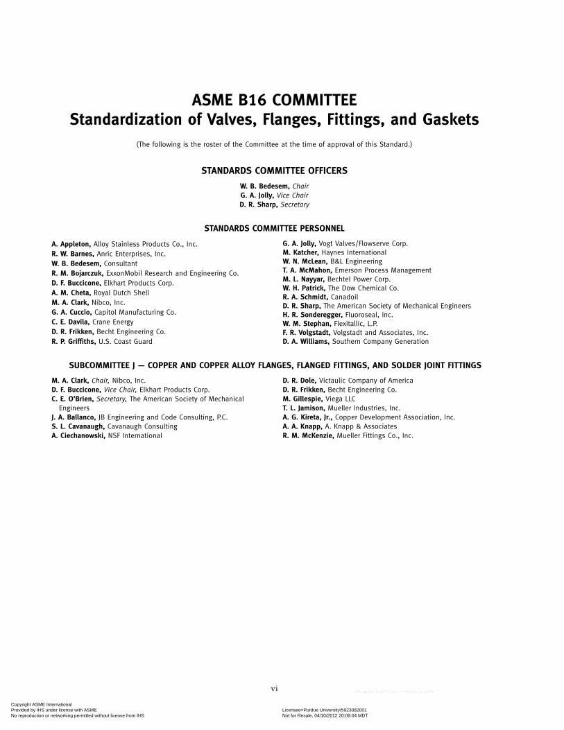
ASME B16 COMMITTEEStandardization of Valves, Flanges, Fittings, and Gaskets
(The following is the roster of the Committee at the time of approval of this Standard.)
STANDARDS COMMITTEE OFFICERS
W. B. Bedesem, ChairG. A. Jolly, Vice ChairD. R. Sharp, Secretary
STANDARDS COMMITTEE PERSONNEL
A. Appleton, Alloy Stainless Products Co., Inc.R. W. Barnes, Anric Enterprises, Inc.W. B. Bedesem, ConsultantR. M. Bojarczuk, ExxonMobil Research and Engineering Co.D. F. Buccicone, Elkhart Products Corp.A. M. Cheta, Royal Dutch ShellM. A. Clark, Nibco, Inc.G. A. Cuccio, Capitol Manufacturing Co.C. E. Davila, Crane EnergyD. R. Frikken, Becht Engineering Co.R. P. Griffiths, U.S. Coast Guard
SUBCOMMITTEE J — COPPER AND COPPER ALLOY FLANGES, FLANGED FITTINGS, AND SOLDER JOINT FITTINGS
M. A. Clark, Chair, Nibco, Inc.D. F. Buccicone, Vice Chair, Elkhart Products Corp.C. E. O’Brien, Secretary, The American Society of Mechanical
EngineersJ. A. Ballanco, JB Engineering and Code Consulting, P.C.S. L. Cavanaugh, Cavanaugh ConsultingA. Ciechanowski, NSF International
vi
G. A. Jolly, Vogt Valves/Flowserve Corp.M. Katcher, Haynes InternationalW. N. McLean, B&L EngineeringT. A. McMahon, Emerson Process ManagementM. L. Nayyar, Bechtel Power Corp.W. H. Patrick, The Dow Chemical Co.R. A. Schmidt, CanadoilD. R. Sharp, The American Society of Mechanical EngineersH. R. Sonderegger, Fluoroseal, Inc.W. M. Stephan, Flexitallic, L.P.F. R. Volgstadt, Volgstadt and Associates, Inc.D. A. Williams, Southern Company Generation
D. R. Dole, Victaulic Company of AmericaD. R. Frikken, Becht Engineering Co.M. Gillespie, Viega LLCT. L. Jamison, Mueller Industries, Inc.A. G. Kireta, Jr., Copper Development Association, Inc.A. A. Knapp, A. Knapp & AssociatesR. M. McKenzie, Mueller Fittings Co., Inc.
Copyright ASME International Provided by IHS under license with ASME Licensee=Purdue University/5923082001
Not for Resale, 04/10/2012 20:09:04 MDTNo reproduction or networking permitted without license from IHS
--`,`,,`,`,``,,`,````,,`,````-`-`,,`,,`,`,,`---
CORRESPONDENCE WITH THE B16 COMMITTEE
General. ASME Standards are developed and maintained with the intent to represent theconsensus of concerned interests. As such, users of this Standard may interact with the Committeeby requesting interpretations, proposing revisions, and attending Committee meetings. Corre-spondence should be addressed to:
Secretary, B16 Standards CommitteeThe American Society of Mechanical EngineersThree Park AvenueNew York, NY 10016-5990
As an alternative, inquiries may be submitted via email to: [email protected] Revisions. Revisions are made periodically to the Standard to incorporate changes
that appear necessary or desirable, as demonstrated by the experience gained from the applicationof the Standard. Approved revisions will be published periodically.
The Committee welcomes proposals for revisions to this Standard. Such proposals should beas specific as possible, citing the paragraph number(s), the proposed wording, and a detaileddescription of the reasons for the proposal, including any pertinent documentation.
Proposing a Case. Cases may be issued for the purpose of providing alternative rules whenjustified, to permit early implementation of an approved revision when the need is urgent, or toprovide rules not covered by existing provisions. Cases are effective immediately uponASME approval and shall be posted on the ASME Committee Web page.
Requests for Cases shall provide a Statement of Need and Background Information. The requestshould identify the Standard, the paragraph, figure or table number(s), and be written as aQuestion and Reply in the same format as existing Cases. Requests for Cases should also indicatethe applicable edition(s) of the Standard to which the proposed Case applies.
Interpretations. Upon request, the B16 Committee will render an interpretation of any require-ment of the Standard. Interpretations can only be rendered in response to a written request sentto the Secretary of the B16 Standards Committee.
The request for interpretation should be clear and unambiguous. It is further recommendedthat the inquirer submit his/her request in the following format:
Subject: Cite the applicable paragraph number(s) and the topic of the inquiry.Edition: Cite the applicable edition of the Standard for which the interpretation is
being requested.Question: Phrase the question as a request for an interpretation of a specific requirement
suitable for general understanding and use, not as a request for an approvalof a proprietary design or situation. The inquirer may also include any plansor drawings that are necessary to explain the question; however, they shouldnot contain proprietary names or information.
Requests that are not in this format will be rewritten in this format by the Committee priorto being answered, which may inadvertently change the intent of the original request.
ASME procedures provide for reconsideration of any interpretation when or if additionalinformation that might affect an interpretation is available. Further, persons aggrieved by aninterpretation may appeal to the cognizant ASME Committee or Subcommittee. ASME does not“approve,” “certify,” “rate,” or “endorse” any item, construction, proprietary device, or activity.
Attending Committee Meetings. The B16 Standards Committee regularly holds meetings, whichare open to the public. Persons wishing to attend any meeting should contact the Secretary ofthe B16 Standards Committee.
vii
Copyright ASME International Provided by IHS under license with ASME Licensee=Purdue University/5923082001
Not for Resale, 04/10/2012 20:09:04 MDTNo reproduction or networking permitted without license from IHS
--`,`,,`,`,``,,`,````,,`,````-`-`,,`,,`,`,,`---
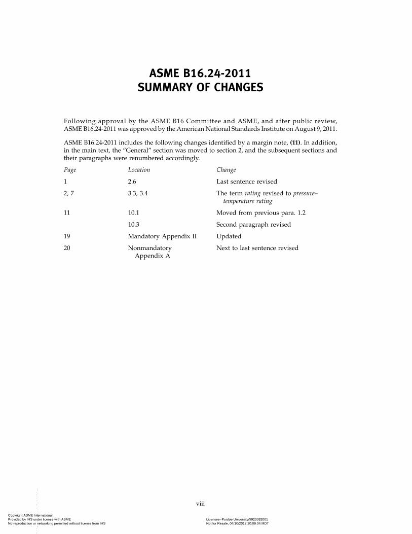
ASME B16.24-2011SUMMARY OF CHANGES
Following approval by the ASME B16 Committee and ASME, and after public review,ASME B16.24-2011 was approved by the American National Standards Institute on August 9, 2011.
ASME B16.24-2011 includes the following changes identified by a margin note, (11). In addition,in the main text, the “General” section was moved to section 2, and the subsequent sections andtheir paragraphs were renumbered accordingly.
Page Location Change
1 2.6 Last sentence revised
2, 7 3.3, 3.4 The term rating revised to pressure–temperature rating
11 10.1 Moved from previous para. 1.2
10.3 Second paragraph revised
19 Mandatory Appendix II Updated
20 Nonmandatory Next to last sentence revisedAppendix A
viii
Copyright ASME International Provided by IHS under license with ASME Licensee=Purdue University/5923082001
Not for Resale, 04/10/2012 20:09:04 MDTNo reproduction or networking permitted without license from IHS
--`,`,,`,`,``,,`,````,,`,````-`-`,,`,,`,`,,`---
ASME B16.24-2011
CAST COPPER ALLOY PIPE FLANGES AND FLANGED FITTINGS
CLASSES 150, 300, 600, 900, 1500, AND 2500
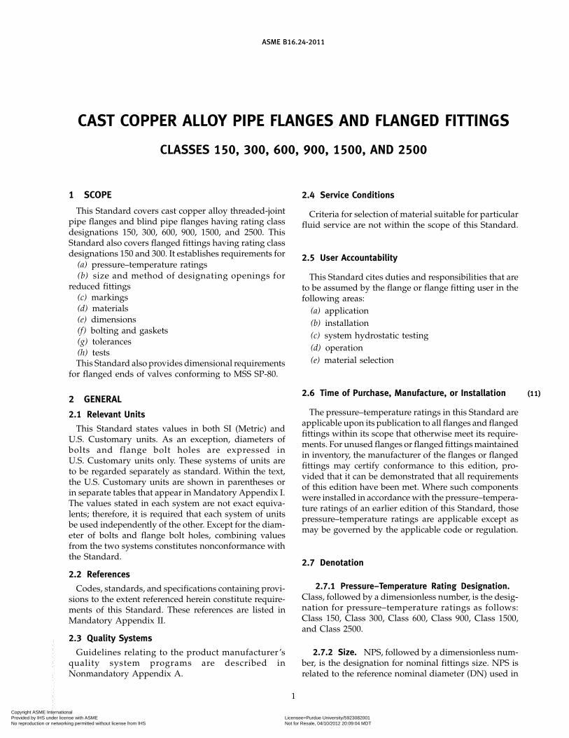
1 SCOPE
This Standard covers cast copper alloy threaded-jointpipe flanges and blind pipe flanges having rating classdesignations 150, 300, 600, 900, 1500, and 2500. ThisStandard also covers flanged fittings having rating classdesignations 150 and 300. It establishes requirements for
(a) pressure–temperature ratings(b) size and method of designating openings for
reduced fittings(c) markings(d) materials(e) dimensions(f) bolting and gaskets(g) tolerances(h) testsThis Standard also provides dimensional requirements
for flanged ends of valves conforming to MSS SP-80.
2 GENERAL
2.1 Relevant Units
This Standard states values in both SI (Metric) andU.S. Customary units. As an exception, diameters ofbolts and flange bolt holes are expressed inU.S. Customary units only. These systems of units areto be regarded separately as standard. Within the text,the U.S. Customary units are shown in parentheses orin separate tables that appear in Mandatory Appendix I.The values stated in each system are not exact equiva-lents; therefore, it is required that each system of unitsbe used independently of the other. Except for the diam-eter of bolts and flange bolt holes, combining valuesfrom the two systems constitutes nonconformance withthe Standard.
2.2 References
Codes, standards, and specifications containing provi-sions to the extent referenced herein constitute require-ments of this Standard. These references are listed inMandatory Appendix II.
2.3 Quality Systems
Guidelines relating to the product manufacturer ’squality system programs are described inNonmandatory Appendix A.
1
2.4 Service Conditions
Criteria for selection of material suitable for particularfluid service are not within the scope of this Standard.
2.5 User Accountability
This Standard cites duties and responsibilities that areto be assumed by the flange or flange fitting user in thefollowing areas:
(a) application(b) installation(c) system hydrostatic testing(d) operation(e) material selection
2.6 Time of Purchase, Manufacture, or Installation
The pressure–temperature ratings in this Standard areapplicable upon its publication to all flanges and flangedfittings within its scope that otherwise meet its require-ments. For unused flanges or flanged fittings maintainedin inventory, the manufacturer of the flanges or flangedfittings may certify conformance to this edition, pro-vided that it can be demonstrated that all requirementsof this edition have been met. Where such componentswere installed in accordance with the pressure–tempera-ture ratings of an earlier edition of this Standard, thosepressure–temperature ratings are applicable except asmay be governed by the applicable code or regulation.
2.7 Denotation
2.7.1 Pressure–Temperature Rating Designation.Class, followed by a dimensionless number, is the desig-nation for pressure–temperature ratings as follows:Class 150, Class 300, Class 600, Class 900, Class 1500,and Class 2500.
2.7.2 Size. NPS, followed by a dimensionless num-ber, is the designation for nominal fittings size. NPS isrelated to the reference nominal diameter (DN) used in
(11)
Copyright ASME International Provided by IHS under license with ASME Licensee=Purdue University/5923082001
Not for Resale, 04/10/2012 20:09:04 MDTNo reproduction or networking permitted without license from IHS
--`,`,,`,`,``,,`,````,,`,````-`-`,,`,,`,`,,`---
ASME B16.24-2011
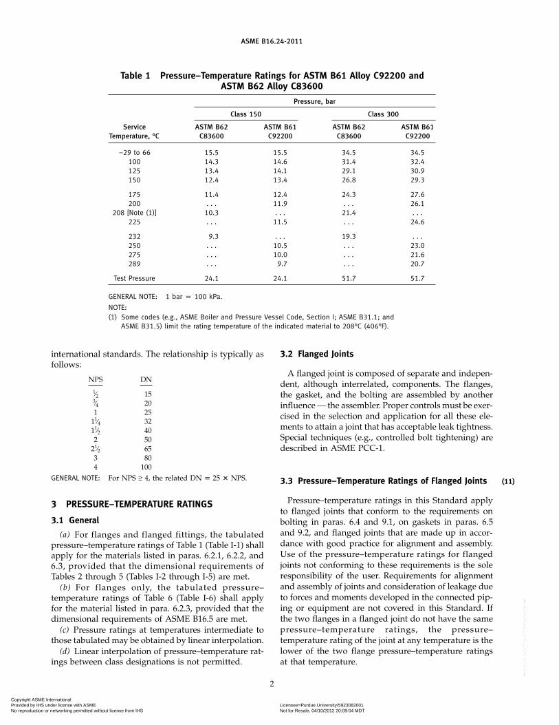
Table 1 Pressure–Temperature Ratings for ASTM B61 Alloy C92200 andASTM B62 Alloy C83600
Pressure, bar
Class 150 Class 300
Service ASTM B62 ASTM B61 ASTM B62 ASTM B61Temperature, °C C83600 C92200 C83600 C92200
−29 to 66 15.5 15.5 34.5 34.5100 14.3 14.6 31.4 32.4125 13.4 14.1 29.1 30.9150 12.4 13.4 26.8 29.3
175 11.4 12.4 24.3 27.6200 . . . 11.9 . . . 26.1
208 [Note (1)] 10.3 . . . 21.4 . . .225 . . . 11.5 . . . 24.6
232 9.3 . . . 19.3 . . .250 . . . 10.5 . . . 23.0275 . . . 10.0 . . . 21.6289 . . . 9.7 . . . 20.7
Test Pressure 24.1 24.1 51.7 51.7
GENERAL NOTE: 1 bar p 100 kPa.
NOTE:(1) Some codes (e.g., ASME Boiler and Pressure Vessel Code, Section I; ASME B31.1; and
ASME B31.5) limit the rating temperature of the indicated material to 208°C (406°F).
international standards. The relationship is typically asfollows:
NPS DN
1⁄2 153⁄4 201 25
11⁄4 3211⁄2 402 50
21⁄2 653 804 100
GENERAL NOTE: For NPS ≥ 4, the related DN p 25 � NPS.
3 PRESSURE–TEMPERATURE RATINGS
3.1 General
(a) For flanges and flanged fittings, the tabulatedpressure–temperature ratings of Table 1 (Table I-1) shallapply for the materials listed in paras. 6.2.1, 6.2.2, and6.3, provided that the dimensional requirements ofTables 2 through 5 (Tables I-2 through I-5) are met.
(b) For flanges only, the tabulated pressure–temperature ratings of Table 6 (Table I-6) shall applyfor the material listed in para. 6.2.3, provided that thedimensional requirements of ASME B16.5 are met.
(c) Pressure ratings at temperatures intermediate tothose tabulated may be obtained by linear interpolation.
(d) Linear interpolation of pressure–temperature rat-ings between class designations is not permitted.
2
3.2 Flanged Joints
A flanged joint is composed of separate and indepen-dent, although interrelated, components. The flanges,the gasket, and the bolting are assembled by anotherinfluence — the assembler. Proper controls must be exer-cised in the selection and application for all these ele-ments to attain a joint that has acceptable leak tightness.Special techniques (e.g., controlled bolt tightening) aredescribed in ASME PCC-1.
3.3 Pressure–Temperature Ratings of Flanged Joints
Pressure–temperature ratings in this Standard applyto flanged joints that conform to the requirements onbolting in paras. 6.4 and 9.1, on gaskets in paras. 6.5and 9.2, and flanged joints that are made up in accor-dance with good practice for alignment and assembly.Use of the pressure–temperature ratings for flangedjoints not conforming to these requirements is the soleresponsibility of the user. Requirements for alignmentand assembly of joints and consideration of leakage dueto forces and moments developed in the connected pip-ing or equipment are not covered in this Standard. Ifthe two flanges in a flanged joint do not have the samepressure–temperature ratings, the pressure–temperature rating of the joint at any temperature is thelower of the two flange pressure–temperature ratingsat that temperature.
(11)
Copyright ASME International Provided by IHS under license with ASME Licensee=Purdue University/5923082001
Not for Resale, 04/10/2012 20:09:04 MDTNo reproduction or networking permitted without license from IHS
--`,`,,`,`,``,,`,````,,`,````-`-`,,`,,`,`,,`---
ASME B16.24-2011
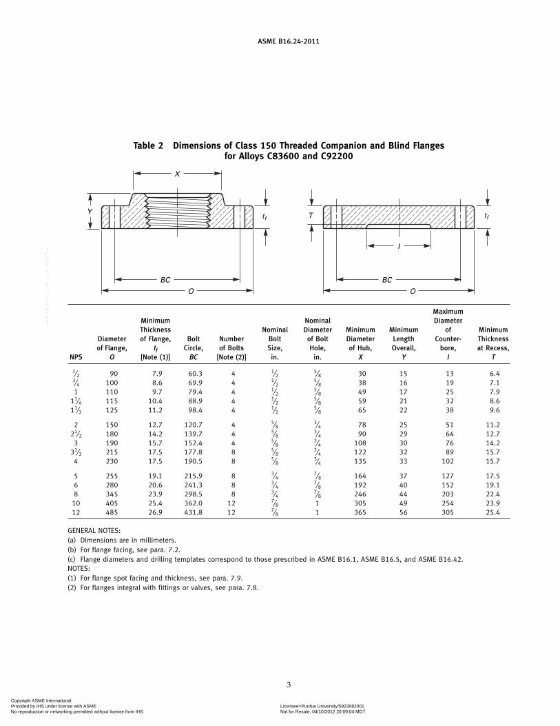
Table 2 Dimensions of Class 150 Threaded Companion and Blind Flangesfor Alloys C83600 and C92200
Y
X
BC
O
BC
O
I
Ttf tf
MaximumMinimum Nominal DiameterThickness Nominal Diameter Minimum Minimum of Minimum
Diameter of Flange, Bolt Number Bolt of Bolt Diameter Length Counter- Thicknessof Flange, tf Circle, of Bolts Size, Hole, of Hub, Overall, bore, at Recess,
NPS O [Note (1)] BC [Note (2)] in. in. X Y I T
1⁄2 90 7.9 60.3 4 1⁄25⁄8 30 15 13 6.4
3⁄4 100 8.6 69.9 4 1⁄25⁄8 38 16 19 7.1
1 110 9.7 79.4 4 1⁄25⁄8 49 17 25 7.9
11⁄4 115 10.4 88.9 4 1⁄25⁄8 59 21 32 8.6
11⁄2 125 11.2 98.4 4 1⁄25⁄8 65 22 38 9.6
2 150 12.7 120.7 4 5⁄83⁄4 78 25 51 11.2
21⁄2 180 14.2 139.7 4 5⁄83⁄4 90 29 64 12.7
3 190 15.7 152.4 4 5⁄83⁄4 108 30 76 14.2
31⁄2 215 17.5 177.8 8 5⁄83⁄4 122 32 89 15.7
4 230 17.5 190.5 8 5⁄83⁄4 135 33 102 15.7
5 255 19.1 215.9 8 3⁄47⁄8 164 37 127 17.5
6 280 20.6 241.3 8 3⁄47⁄8 192 40 152 19.1
8 345 23.9 298.5 8 3⁄47⁄8 246 44 203 22.4
10 405 25.4 362.0 12 7⁄8 1 305 49 254 23.912 485 26.9 431.8 12 7⁄8 1 365 56 305 25.4
GENERAL NOTES:(a) Dimensions are in millimeters.(b) For flange facing, see para. 7.2.(c) Flange diameters and drilling templates correspond to those prescribed in ASME B16.1, ASME B16.5, and ASME B16.42.NOTES:(1) For flange spot facing and thickness, see para. 7.9.(2) For flanges integral with fittings or valves, see para. 7.8.
3
Copyright ASME International Provided by IHS under license with ASME Licensee=Purdue University/5923082001
Not for Resale, 04/10/2012 20:09:04 MDTNo reproduction or networking permitted without license from IHS
--`,`,,`,`,``,,`,````,,`,````-`-`,,`,,`,`,,`---
ASME B16.24-2011
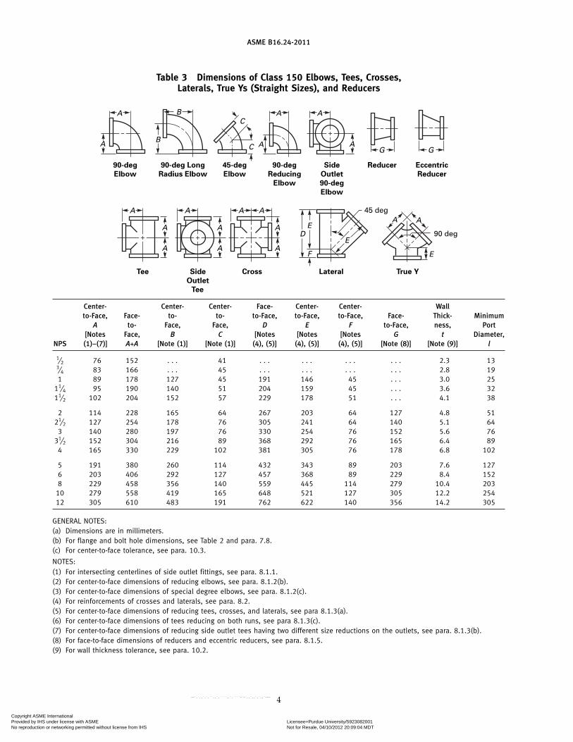
Table 3 Dimensions of Class 150 Elbows, Tees, Crosses,Laterals, True Ys (Straight Sizes), and Reducers
90 deg
45 deg
Tee Side
Outlet
Tee
90-deg
Elbow
90-deg Long
Radius Elbow
45-deg
Elbow
90-deg
Reducing
Elbow
Side
Outlet
90-deg
Elbow
Reducer Eccentric
Reducer
Cross Lateral True Y
DE
F
E
A
A
A A
A
A B
A BAC
C
G G
AAAA
AE
A
A
A
A
A
Center- Center- Center- Face- Center- Center- Wallto-Face, Face- to- to- to-Face, to-Face, to-Face, Face- Thick- Minimum
A to- Face, Face, D E F to-Face, ness, Port[Notes Face, B C [Notes [Notes [Notes G t Diameter,
NPS (1)–(7)] A+A [Note (1)] [Note (1)] (4), (5)] (4), (5)] (4), (5)] [Note (8)] [Note (9)] l
1⁄2 76 152 . . . 41 . . . . . . . . . . . . 2.3 133⁄4 83 166 . . . 45 . . . . . . . . . . . . 2.8 191 89 178 127 45 191 146 45 . . . 3.0 25
11⁄4 95 190 140 51 204 159 45 . . . 3.6 3211⁄2 102 204 152 57 229 178 51 . . . 4.1 38
2 114 228 165 64 267 203 64 127 4.8 5121⁄2 127 254 178 76 305 241 64 140 5.1 64
3 140 280 197 76 330 254 76 152 5.6 7631⁄2 152 304 216 89 368 292 76 165 6.4 89
4 165 330 229 102 381 305 76 178 6.8 102
5 191 380 260 114 432 343 89 203 7.6 1276 203 406 292 127 457 368 89 229 8.4 1528 229 458 356 140 559 445 114 279 10.4 203
10 279 558 419 165 648 521 127 305 12.2 25412 305 610 483 191 762 622 140 356 14.2 305
GENERAL NOTES:(a) Dimensions are in millimeters.(b) For flange and bolt hole dimensions, see Table 2 and para. 7.8.(c) For center-to-face tolerance, see para. 10.3.
NOTES:(1) For intersecting centerlines of side outlet fittings, see para. 8.1.1.(2) For center-to-face dimensions of reducing elbows, see para. 8.1.2(b).(3) For center-to-face dimensions of special degree elbows, see para. 8.1.2(c).(4) For reinforcements of crosses and laterals, see para. 8.2.(5) For center-to-face dimensions of reducing tees, crosses, and laterals, see para 8.1.3(a).(6) For center-to-face dimensions of tees reducing on both runs, see para 8.1.3(c).(7) For center-to-face dimensions of reducing side outlet tees having two different size reductions on the outlets, see para. 8.1.3(b).(8) For face-to-face dimensions of reducers and eccentric reducers, see para. 8.1.5.(9) For wall thickness tolerance, see para. 10.2.
4
Copyright ASME International Provided by IHS under license with ASME Licensee=Purdue University/5923082001
Not for Resale, 04/10/2012 20:09:04 MDTNo reproduction or networking permitted without license from IHS
--`,`,,`,`,``,,`,````,,`,````-`-`,,`,,`,`,,`---
ASME B16.24-2011
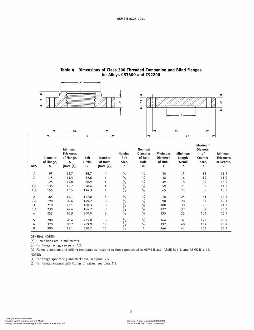
Table 4 Dimensions of Class 300 Threaded Companion and Blind Flangesfor Alloys C83600 and C92200
Y
X
BC
O
BC
O
I
Ttf tf
MaximumMinimum Nominal DiameterThickness Nominal Diameter Minimum Minimum of Minimum
Diameter of Flange, Bolt Number Bolt of Bolt Diameter Length Counter- Thicknessof Flange, tf Circle, of Bolts Size, Hole, of Hub, Overall, bore, at Recess,
NPS O [Note (1)] BC [Note (2)] in. in. X Y I T
1⁄2 95 12.7 66.7 4 1⁄25⁄8 30 15 13 11.2
3⁄4 115 13.5 82.6 4 5⁄83⁄4 38 16 19 11.9
1 125 15.0 88.9 4 5⁄83⁄4 49 18 25 13.5
11⁄4 135 15.7 98.4 4 5⁄83⁄4 59 21 32 14.2
11⁄2 155 17.5 114.3 4 3⁄47⁄8 65 22 38 15.7
2 165 19.1 127.0 8 5⁄83⁄4 78 25 51 17.5
21⁄2 190 20.6 149.2 8 3⁄47⁄8 90 28 64 19.1
3 210 23.1 168.3 8 3⁄47⁄8 108 30 76 21.3
31⁄2 230 24.6 184.2 8 3⁄47⁄8 122 32 89 23.1
4 255 26.9 200.0 8 3⁄47⁄8 135 33 102 25.4
5 280 28.4 235.0 8 3⁄47⁄8 164 37 127 26.9
6 320 30.2 269.9 12 3⁄47⁄8 192 40 152 28.4
8 380 35.1 330.2 12 7⁄8 1 246 44 203 33.3
GENERAL NOTES:(a) Dimensions are in millimeters.(b) For flange facing, see para. 7.2.(c) Flange diameters and drilling templates correspond to those prescribed in ASME B16.1, ASME B16.5, and ASME B16.42.
NOTES:(1) For flange spot facing and thickness, see para. 7.9.(2) For flanges integral with fittings or valves, see para. 7.8.
5
Copyright ASME International Provided by IHS under license with ASME Licensee=Purdue University/5923082001
Not for Resale, 04/10/2012 20:09:04 MDTNo reproduction or networking permitted without license from IHS
--`,`,,`,`,``,,`,````,,`,````-`-`,,`,,`,`,,`---
ASME B16.24-2011
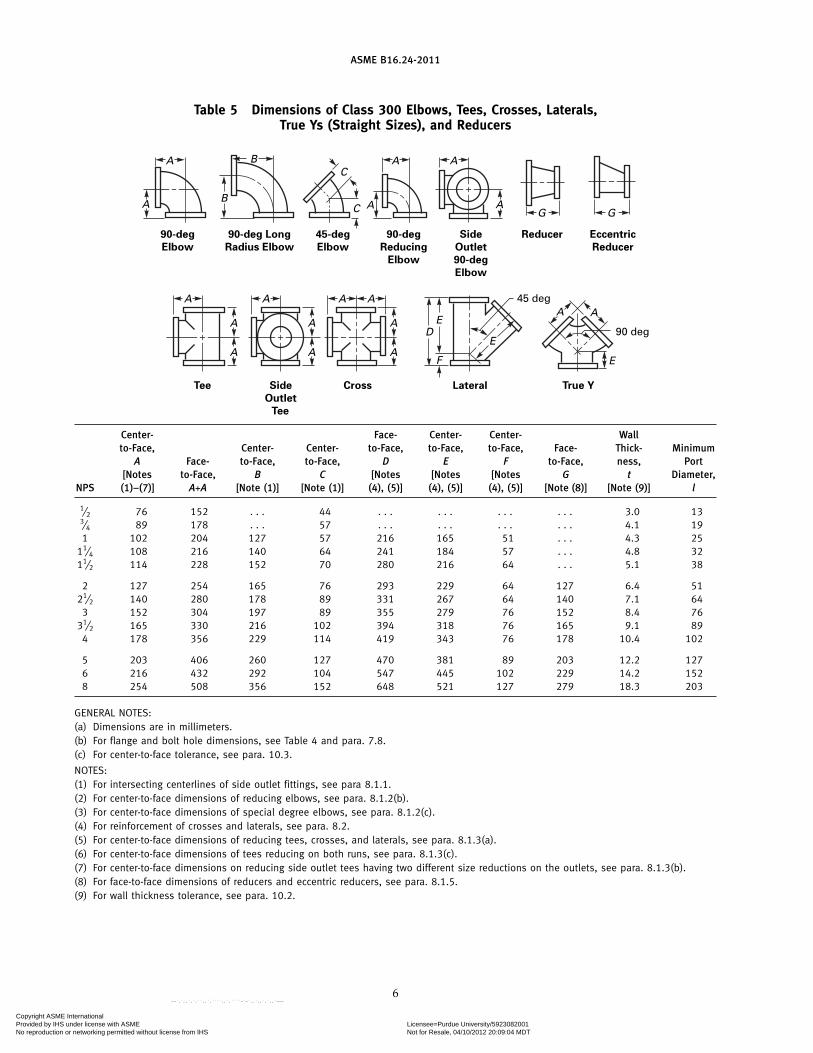
Table 5 Dimensions of Class 300 Elbows, Tees, Crosses, Laterals,True Ys (Straight Sizes), and Reducers
90 deg
45 deg
Tee Side
Outlet
Tee
90-deg
Elbow
90-deg Long
Radius Elbow
45-deg
Elbow
90-deg
Reducing
Elbow
Side
Outlet
90-deg
Elbow
Reducer Eccentric
Reducer
Cross Lateral True Y
DE
F
E
A
A
A A
A
A B
A BAC
C
G G
AAAA
AE
A
A
A
A
A
Center- Face- Center- Center- Wallto-Face, Center- Center- to-Face, to-Face, to-Face, Face- Thick- Minimum
A Face- to-Face, to-Face, D E F to-Face, ness, Port[Notes to-Face, B C [Notes [Notes [Notes G t Diameter,
NPS (1)–(7)] A+A [Note (1)] [Note (1)] (4), (5)] (4), (5)] (4), (5)] [Note (8)] [Note (9)] l
1⁄2 76 152 . . . 44 . . . . . . . . . . . . 3.0 133⁄4 89 178 . . . 57 . . . . . . . . . . . . 4.1 191 102 204 127 57 216 165 51 . . . 4.3 25
11⁄4 108 216 140 64 241 184 57 . . . 4.8 3211⁄2 114 228 152 70 280 216 64 . . . 5.1 38
2 127 254 165 76 293 229 64 127 6.4 5121⁄2 140 280 178 89 331 267 64 140 7.1 64
3 152 304 197 89 355 279 76 152 8.4 7631⁄2 165 330 216 102 394 318 76 165 9.1 89
4 178 356 229 114 419 343 76 178 10.4 102
5 203 406 260 127 470 381 89 203 12.2 1276 216 432 292 104 547 445 102 229 14.2 1528 254 508 356 152 648 521 127 279 18.3 203
GENERAL NOTES:(a) Dimensions are in millimeters.(b) For flange and bolt hole dimensions, see Table 4 and para. 7.8.(c) For center-to-face tolerance, see para. 10.3.
NOTES:(1) For intersecting centerlines of side outlet fittings, see para 8.1.1.(2) For center-to-face dimensions of reducing elbows, see para. 8.1.2(b).(3) For center-to-face dimensions of special degree elbows, see para. 8.1.2(c).(4) For reinforcement of crosses and laterals, see para. 8.2.(5) For center-to-face dimensions of reducing tees, crosses, and laterals, see para. 8.1.3(a).(6) For center-to-face dimensions of tees reducing on both runs, see para. 8.1.3(c).(7) For center-to-face dimensions on reducing side outlet tees having two different size reductions on the outlets, see para. 8.1.3(b).(8) For face-to-face dimensions of reducers and eccentric reducers, see para. 8.1.5.(9) For wall thickness tolerance, see para. 10.2.
6
Copyright ASME International Provided by IHS under license with ASME Licensee=Purdue University/5923082001
Not for Resale, 04/10/2012 20:09:04 MDTNo reproduction or networking permitted without license from IHS
--`,`,,`,`,``,,`,````,,`,````-`-`,,`,,`,`,,`---
(11)
ASME B16.24-2011
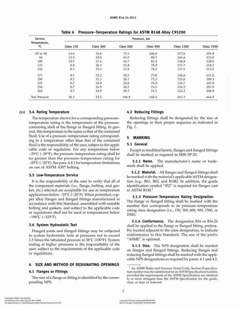
Table 6 Pressure–Temperature Ratings for ASTM B148 Alloy C95200
Service Pressure, barTemperature,
°C Class 150 Class 300 Class 600 Class 900 Class 1500 Class 2500
−29 to 38 13.4 35.6 71.1 106.6 177.6 295.850 12.5 33.0 65.7 98.7 164.4 273.9
100 10.5 27.4 54.7 82.2 136.9 228.0125 9.9 26.3 52.8 78.9 131.7 219.5150 9.7 25.5 51.0 76.5 127.5 212.6
175 9.7 25.2 50.7 75.8 126.6 211.0200 9.7 25.2 50.1 75.3 125.6 209.3225 9.7 24.9 50.0 74.9 124.7 207.9250 9.7 24.9 49.7 74.5 124.2 207.0260 9.7 24.9 49.7 74.5 124.2 206.9
Test Pressure 20.7 53.5 106.9 160.4 267.2 444.8
3.4 Rating Temperature
The temperature shown for a corresponding pressure–temperature rating is the temperature of the pressure-containing shell of the flange or flanged fitting. In gen-eral, this temperature is the same as that of the containedfluid. Use of a pressure–temperature rating correspond-ing to a temperature other than that of the containedfluid is the responsibility of the user, subject to the appli-cable code or regulation. For any temperature below−29°C (−20°F), the pressure–temperature rating shall beno greater than the pressure–temperature rating for−29°C (−20°F). See para. 6.4.1 for temperature limitationson use of ASTM A307 bolting.
3.5 Low-Temperature Service
It is the responsibility of the user to verify that all ofthe component materials (i.e., flange, bolting, and gas-ket, etc.) selected are acceptable for use in temperatureapplications below −29°C (−20°F). When permitted, cop-per alloy flanges and flanged fittings manufactured inaccordance with this Standard, assembled with suitablebolting and gaskets, and subject to the applicable codeor regulations shall not be used at temperatures below−198°C (−325°F).
3.6 System Hydrostatic Test
Flanged joints and flanged fittings may be subjectedto system hydrostatic tests at pressures not to exceed1.5 times the tabulated pressure at 38°C (100°F). Systemtesting at higher pressures is the responsibility of theuser, subject to the requirements of the applicable codeor regulations.
4 SIZE AND METHOD OF DESIGNATING OPENINGS
4.1 Flanges or Fittings
The size of a flange or fitting is identified by the corres-ponding NPS.
7
4.2 Reducing Fittings
Reducing fittings shall be designated by the size ofthe openings in their proper sequence as indicated inFig. 1.
5 MARKING
5.1 General
Except as modified herein, flanges and flanged fittingsshall be marked as required in MSS SP-25.
5.1.1 Name. The manufacturer’s name or trade-mark shall be applied.
5.1.2 Material. All flanges and flanged fittings shallbe marked with the material’s applicable ASTM designa-tion (e.g., B61, B62, and B148). In addition, the gradeidentification symbol “952” is required for flanges castto ASTM B148.1
5.1.3 Pressure–Temperature Rating Designation.The flange or flanged fitting shall be marked with thenumber that corresponds to its pressure–temperaturerating class designation (i.e., 150, 300, 600, 900, 1500, or2500).
5.1.4 Conformance. The designation B16 or B16.24shall be applied to the flange or flanged fitting, prefera-bly located adjacent to the class designation, to indicateconformance to this Standard. The use of the prefix“ASME” is optional.
5.1.5 Size. The NPS designation shall be markedon flanges and flanged fittings. Reducing flanges andreducing flanged fittings shall be marked with the appli-cable NPS designations as required by paras. 4.1 and 4.2.
1 An ASME Boiler and Pressure Vessel Code, Section II specifica-tion number may be substituted for an ASTM Specification number,provided the requirements of the ASME Specification are identicalto or more stringent than the ASTM Specification for the grade,class, or type of material.
Copyright ASME International Provided by IHS under license with ASME Licensee=Purdue University/5923082001
Not for Resale, 04/10/2012 20:09:04 MDTNo reproduction or networking permitted without license from IHS
--`,`,,`,`,``,,`,````,,`,````-`-`,,`,,`,`,,`---
ASME B16.24-2011
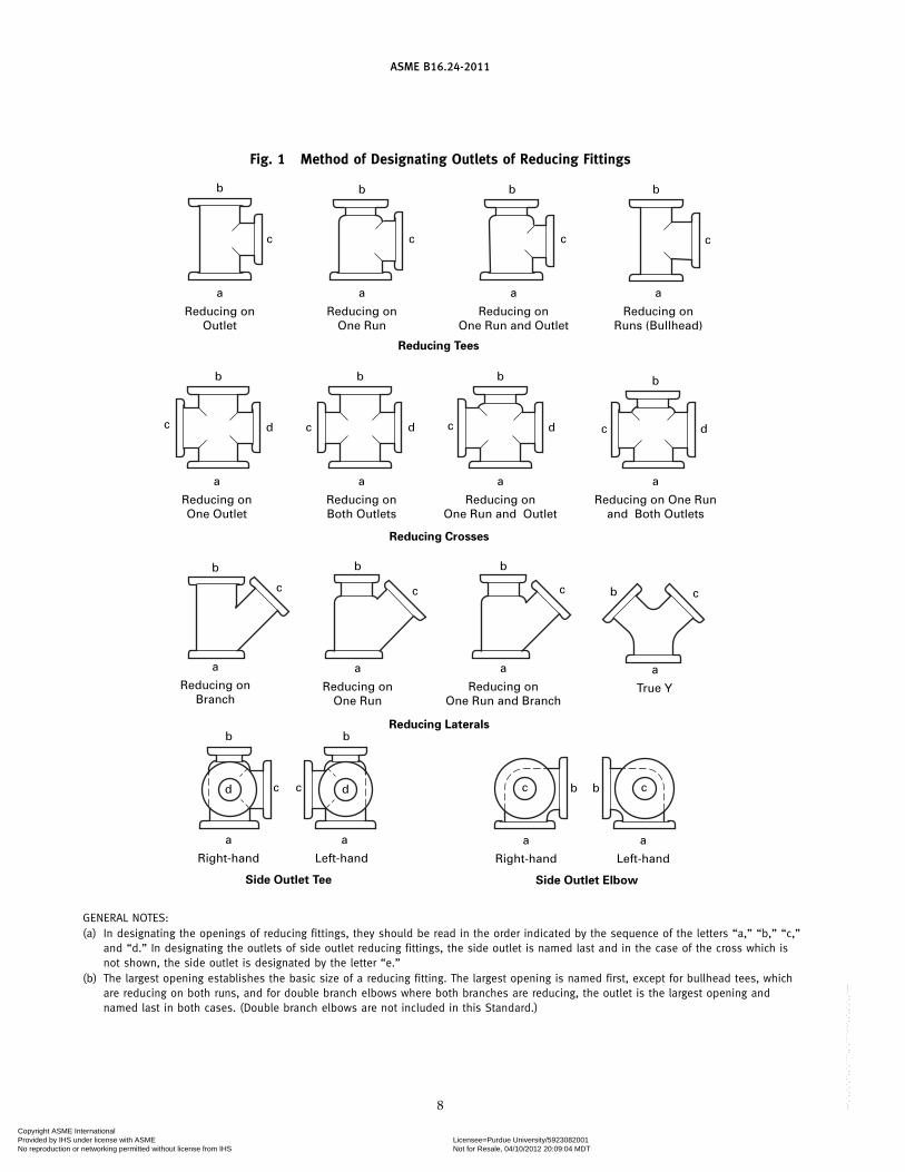
Fig. 1 Method of Designating Outlets of Reducing Fittings
a
Reducing onOutlet
c
b
a
Reducing onBoth Outlets
dc
b
a
Reducing onOne Outlet
dc
b
a
Reducing onBranch
c
b
a
Reducing onOne Run and Outlet
dc
b
c
b
a
Reducing onOne Run
c
b
a
Reducing onOne Run and Outlet
a
Reducing onRuns (Bullhead)
c
b
a
Reducing on One Runand Both Outlets
dc
b
a
Reducing onOne Run
c
b
a
Reducing onOne Run and Branch
c
b
a
True Y
b c
a
Left-hand
a
bb
Right-hand
c
a
Left-hand
Side Outlet Tee Side Outlet Elbow
Reducing Laterals
Reducing Crosses
Reducing Tees
cc
b
a
Right-hand
b
dd c
GENERAL NOTES:(a) In designating the openings of reducing fittings, they should be read in the order indicated by the sequence of the letters “a,” “b,” “c,”
and “d.” In designating the outlets of side outlet reducing fittings, the side outlet is named last and in the case of the cross which isnot shown, the side outlet is designated by the letter “e.”
(b) The largest opening establishes the basic size of a reducing fitting. The largest opening is named first, except for bullhead tees, whichare reducing on both runs, and for double branch elbows where both branches are reducing, the outlet is the largest opening andnamed last in both cases. (Double branch elbows are not included in this Standard.)
8
Copyright ASME International Provided by IHS under license with ASME Licensee=Purdue University/5923082001
Not for Resale, 04/10/2012 20:09:04 MDTNo reproduction or networking permitted without license from IHS
--`,`,,`,`,``,,`,````,,`,````-`-`,,`,,`,`,,`---
ASME B16.24-2011
6 MATERIALS
6.1 General
Products covered by this Standard shall be made ofcastings produced to the requirements of para. 6.2 or 6.3.
6.2 Flanges
Flanges shall be in accordance with the materialrequirements specified in para. 6.2.1, 6.2.2, or 6.2.3.
6.2.1 ASTM B61. Castings shall meet the require-ments of ASTM B61 alloy UNS C92200.
6.2.2 ASTM B62. Castings shall meet the require-ments of ASTM B62 alloy UNS C83600.
6.2.3 ASTM B148. Castings shall meet the require-ments of ASTM B148 alloy UNS C95200, and the addi-tional requirements specified in paras. 6.2.3.1 through6.2.3.5.
6.2.3.1 Ordering Information. Ordering informa-tion for ASTM B148 castings shall include tests on eachlot and the form of the test bar.
6.2.3.2 Test Bars. For ASTM B148 castings, a mini-mum of three test bars shall be poured from each lotof cast metal. Chemical composition and mechanicalproperty tests shall be performed using the test barsfrom each lot.
6.2.3.3 Sampling. For ASTM B148 castings, thesample for chemical analysis shall be taken from thetest bar casting or other casting sample in such a manneras to be representative of each casting lot.
6.2.3.4 Weld Repair Approval. For ASTM B148castings, a flange casting shall not be repaired, plugged,welded, or burned-in unless permission from the userof the flange has been previously secured. This will berequested of the user upon the manufacturer’s determi-nation that casting defects are such that after theapproved repair, the usefulness and the strength of thecasting will not be impaired.
6.2.3.5 Weld Repair. For ASTM B148 castings,preparation for repair welding shall include inspectionto ensure complete removal of the defect. Repairs shallbe made utilizing welding procedures qualified in accor-dance with Section IX of the ASME Boiler and PressureVessel Code. Repair welding shall be done by weldersor welding operators meeting the qualification require-ments of that Code.
6.3 Flanged Fittings
Material for flanged fittings shall be in accordancewith either para. 6.2.1 or 6.2.2.
6.4 Bolting
Bolting materials recommended for use with copperalloy flanges and flanged fittings are described inparas. 6.4.1 and 6.4.2.
9
6.4.1 Steel Bolting. Carbon steel bolting conform-ing to ASTM A307 is not recommended to be used below−29°C (−20°F) nor above 204°C (400°F) and is limitedto use with Classes 150 and 300 flanges and flangedfittings.
6.4.2 Nonferrous Boltings. The following nonfer-rous bolting materials are recommended for Classes 150and 300 flanges and flanged fittings within the tempera-ture limitation stated. Other bolting materials that havea specified minimum yield strength of at least 206 MPa(30 ksi) may be used when permitted by the applicablecode or regulation.
ASTM AlloySpecification UNS No. Condition Notes
B98 C65100 Half hard (1)C65500 Half hard (1)C66100 Half hard (1)
B150 C61400 . . . (2)C63000 . . . (2)C64200 . . . (2)
B164 N04400 Hot finishN04400 Cold drawn (2)N04400 Cold drawn, (2)
stress relievedN04400 Cold drawn, (2)
stress equalizedN04405 Hot finishN04405 Cold drawn (2)
NOTES:(1) Maximum operating temperature is 177°C (350°F).(2) Maximum operating temperature is 288°C (550°F).
6.5 Gaskets
Materials for gaskets are described in ASME B16.5.The user is responsible for selection of gasket materialsthat will withstand the expected bolt loading withoutinjurious crushing and that are suitable for the serviceconditions. Particular attention needs to be given togasket selection if a hydrostatic test approaches orexceeds the test pressure specified in para. 3.6.
6.6 Materials Selection
Criteria for the selection of materials are not withinthe scope of this Standard. The possibility of materialdeterioration in service should be considered by theuser. A discussion of precautionary considerations canbe found in Appendix F of ASME B31.3.
7 FLANGE DIMENSIONS
7.1 General
Flange dimensions are dependent upon the flangecasting material.
Copyright ASME International Provided by IHS under license with ASME Licensee=Purdue University/5923082001
Not for Resale, 04/10/2012 20:09:04 MDTNo reproduction or networking permitted without license from IHS
--`,`,,`,`,``,,`,````,,`,````-`-`,,`,,`,`,,`---
ASME B16.24-2011
7.1.1 ASTM B61 and B62. For castings made ofASTM B61 alloy UNS C92200 or ASTM B62 alloy UNSC83600, the flange dimensions shall be in accordancewith Tables 2 and 4 (Tables I-2 and I-4) with alternativefacings as permitted in para. 7.2.
7.1.2 ASTM B148. For castings made of ASTM B148alloy C95200, the flange dimensions shall be in accor-dance with the dimensional requirements ofASME B16.5.
7.2 End-Flange Facings
Unless otherwise specified by the purchaser,Classes 150 and 300 blind and companion flanges shallbe furnished with a flat face. Unless otherwise specifiedby the purchaser, Class 600 and higher companionflanges shall be furnished with a 7-mm (0.25-in.) raisedface, with the exception of the small male face (on endof pipe) and the small female face (on end of pipe).When using straight pipe threads, any of the flange pipethreads shown in ASME B16.5 may be used with copperalloy flanges. When flanges of ASTM B61 or ASTM B62are furnished with one of the alternative ASME B16.5facings, any required raised-face dimension shall be inaddition to the basic flange thickness, tf, of Tables 2 and4 (Tables I-2 and I-4).
7.3 Threaded Flanges
Threaded flanges shall have a taper pipe thread inaccordance with ASME B1.20.1. Variations in alignmentof the thread with the axis of the flange shall not exceed5 mm/m (0.06 in./ft) (0.5%).
7.4 Thread Chamfer
All flanges of ASTM B61 and B62 materials shall bemade without a counterbore. The threads shall be cham-fered approximately to the major diameter of the threadat the pipe end of the flange at an angle approximately45 deg with the axis of the thread. The chamfer shall beconcentric with the thread and shall be included in themeasurement of the thread length.
7.5 Thread Length
The length of the thread shall include the chamfer.
7.6 Thread Gaging
The gaging notch of the thread gage shall come flushwith the bottom of the chamfer in all threaded flanges,and shall be considered the intersection of the chamfercone and the pitch cone of the thread. This depth ofchamfer is approximately equal to one-half the pitch ofthe thread. The maximum allowable thread variation isone turn large or small from the gaging notch.
7.7 Threaded Flange Assembly
External pipe threads used with higher-pressureflanges shall be longer than normal to bring the end of
10
the pipe close to the face of the flange when parts areassembled by power equipment. The additional lengthand number of turns are shown in MandatoryAppendix I of ASME B16.5 for ASME B1.20.1 threads.
7.8 Flanged Bolt Holes
Bolt holes are in multiples of four. Bolt holes shall beequally spaced, and pairs of bolt holes shall straddlefitting or valve centerlines.
7.9 Spot and Back Facing
Flanges and flanged fittings covered by this Standardshall have bearing surfaces for bolting that shall be paral-lel to the flange face within 1 deg. Any spot or backfacing shall not reduce the flange thickness, tf, belowthe dimension required by para. 7.1. The spot facingdiameter shall be in accordance with MSS SP-9. Whencutting into the hub of flanges or flanged fittings withback facing tools, the intersection shall have a radiusnot less than 1.5 mm (0.06 in.).
8 FITTING DIMENSIONS
8.1 Center-to-Face Dimensions
8.1.1 Side Outlet Fittings. Side outlet elbows andside outlet tees shall have all openings on intersectingcenterlines.
8.1.2 Elbows(a) The center-to-face dimensions for straight size
90-deg elbows, 90-deg long radius elbows, 45-degelbows, and side outlet 90-deg elbows are shown inTables 3 and 5 (Tables I-3 and I-5).
(b) Reducing 90-deg elbows and reducing side outlet90-deg elbows shall have the same center-to-face dimen-sions as straight size fittings shown in Tables 3 and 5(Tables I-3 and I-5), corresponding to the size of thelargest opening.
(c) Special degree elbows ranging from 1 deg to45 deg, inclusively, shall have the same center-to-facedimensions given for 45-deg elbows, and those over45 deg and up to 90 deg, inclusively, shall have the samecenter-to-face dimensions given for 90-deg elbows. Theangle designation of an elbow is its deflection fromstraight line flow and is the angle between the flangefaces.
8.1.3 Tees, Crosses, and Laterals(a) The center-to-face dimensions for straight size
tees, with or without side outlet, crosses, and lateralsare shown in Tables 3 and 5 (Tables I-3 and I-5).
(b) Reducing tees, with or without side outlet, reduc-ing crosses, and reducing laterals shall have the samecenter-to-face dimensions as straight size fittings shownin Tables 3 and 5 (Tables I-3 and I-5), corresponding tothe size of the largest opening. Tees, crosses, and laterals,
Copyright ASME International Provided by IHS under license with ASME Licensee=Purdue University/5923082001
Not for Resale, 04/10/2012 20:09:04 MDTNo reproduction or networking permitted without license from IHS
--`,`,,`,`,``,,`,````,,`,````-`-`,,`,,`,`,,`---
ASME B16.24-2011
reducing on the run only, shall have the same center-to-face dimensions as straight size fittings shown inTables 3 and 5 (Tables I-3 and I-5), corresponding to thesize of the largest opening.
(c) Tees reducing on both runs are generally knownas bullhead tees and have the same center-to-face dimen-sions as straight size fittings corresponding to the sizeof the outlet.
8.1.4 True Ys. Center-to-face dimensions for straightsize true Ys are shown in Tables 3 and 5 (Tables I-3 andI-5). Reducing sizes are considered special and shouldbe made to suit conditions.
8.1.5 Reducers and Eccentric Reducers. The face-to-face dimensions for all combinations of reducers andeccentric reducers shall be the same as given in Tables 3and 5 (Tables I-3 and I-5) for the larger opening.
8.1.6 Interchangeability. Class 150 flanged fittingsin NPS 1 and larger sizes have a bolting pattern that isdimensionally interchangeable with ASME B16.1,Class 125 Cast Iron Flanged Fittings; ASME B16.5,Class 150 Steel Flanged Fittings; and ASME B16.42,Class 150 Ductile Iron Flanged Fittings. Class 300flanged fittings in NPS 1 and larger have a bolting pat-tern that is dimensionally interchangeable withASME B16.1, Class 250 Cast Iron Flanged Fittings;ASME B16.5, Class 300 Steel Flanged Fittings; andASME B16.42, Class 300 Ductile Iron Flanged Fittings.
8.2 Wall Thickness
For inspection purposes, the minimum wall thickness,t, of flanged fittings at the time of manufacture shall beas shown in Tables 3 and 5 (Tables I-3 and I-5), exceptas provided in para. 10.2. Additional metal thicknessneeded to withstand assembly stresses, shapes otherthan circular, and stress concentrations shall be deter-mined by the manufacturer. In particular, 45-deg laterals,true Ys, and crosses may require additional reinforce-ment to compensate for inherent weaknesses in theseshapes.
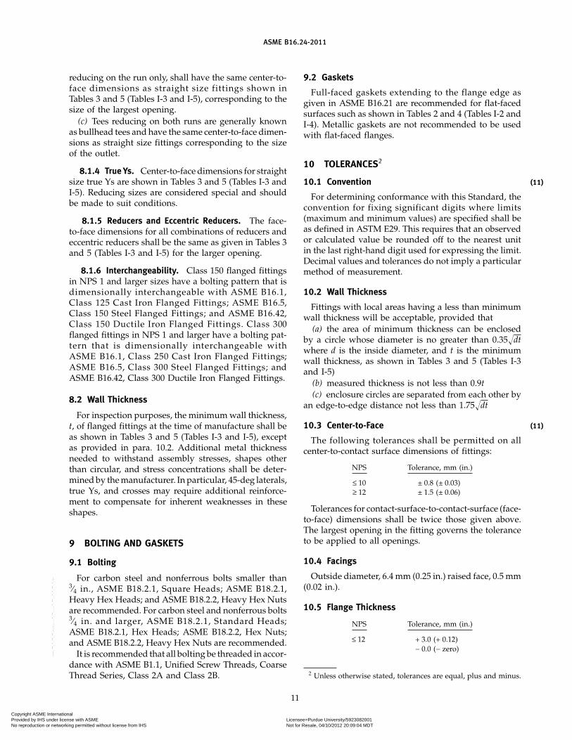
9 BOLTING AND GASKETS
9.1 Bolting
For carbon steel and nonferrous bolts smaller than3⁄4 in., ASME B18.2.1, Square Heads; ASME B18.2.1,Heavy Hex Heads; and ASME B18.2.2, Heavy Hex Nutsare recommended. For carbon steel and nonferrous bolts3⁄4 in. and larger, ASME B18.2.1, Standard Heads;ASME B18.2.1, Hex Heads; ASME B18.2.2, Hex Nuts;and ASME B18.2.2, Heavy Hex Nuts are recommended.
It is recommended that all bolting be threaded in accor-dance with ASME B1.1, Unified Screw Threads, CoarseThread Series, Class 2A and Class 2B.
11
9.2 Gaskets
Full-faced gaskets extending to the flange edge asgiven in ASME B16.21 are recommended for flat-facedsurfaces such as shown in Tables 2 and 4 (Tables I-2 andI-4). Metallic gaskets are not recommended to be usedwith flat-faced flanges.
10 TOLERANCES2
10.1 Convention
For determining conformance with this Standard, theconvention for fixing significant digits where limits(maximum and minimum values) are specified shall beas defined in ASTM E29. This requires that an observedor calculated value be rounded off to the nearest unitin the last right-hand digit used for expressing the limit.Decimal values and tolerances do not imply a particularmethod of measurement.
10.2 Wall Thickness
Fittings with local areas having a less than minimumwall thickness will be acceptable, provided that
(a) the area of minimum thickness can be enclosedby a circle whose diameter is no greater than 0.35�dtwhere d is the inside diameter, and t is the minimumwall thickness, as shown in Tables 3 and 5 (Tables I-3and I-5)
(b) measured thickness is not less than 0.9t(c) enclosure circles are separated from each other by
an edge-to-edge distance not less than 1.75�dt
10.3 Center-to-Face
The following tolerances shall be permitted on allcenter-to-contact surface dimensions of fittings:
NPS Tolerance, mm (in.)
≤ 10 ± 0.8 (± 0.03)≥ 12 ± 1.5 (± 0.06)
Tolerances for contact-surface-to-contact-surface (face-to-face) dimensions shall be twice those given above.The largest opening in the fitting governs the toleranceto be applied to all openings.
10.4 Facings
Outside diameter, 6.4 mm (0.25 in.) raised face, 0.5 mm(0.02 in.).
10.5 Flange Thickness
NPS Tolerance, mm (in.)
≤ 12 + 3.0 (+ 0.12)− 0.0 (− zero)
2 Unless otherwise stated, tolerances are equal, plus and minus.
(11)
(11)
Copyright ASME International Provided by IHS under license with ASME Licensee=Purdue University/5923082001
Not for Resale, 04/10/2012 20:09:04 MDTNo reproduction or networking permitted without license from IHS
--`,`,,`,`,``,,`,````,,`,````-`-`,,`,,`,`,,`---
ASME B16.24-2011
10.6 Counterbore, Threaded Flanges
NPS Tolerance, mm (in.)
≤ 10 + 0.8 (+ 0.03)− 0.0 (− zero)
≥ 12 + 1.5 (+ 0.06)− 0.0 (− zero)
10.7 Drilling and Facing
(a) Bolt circle diameter, ± 1.5 mm (± 0.06 in.)(b) Center-to-center of adjacent bolt holes, ± 0.8 mm
(± 0.03 in.)
11 PRESSURE TESTING
11.1 Flange Test
Flanges are not required to be pressure-tested.
11.2 Flanged Fitting Test
11.2.1 Shell Pressure Test. Each flanged fitting shallbe given a shell pressure test.
12
11.2.2 Test Conditions. The shell pressure test forflanged fittings shall be at a pressure no less than1.5 times the 38°C (100°F) pressure–temperature ratingrounded off to the next higher 0.5-bar (10-psi) increment.
11.2.3 Test Fluid. The pressure test shall be madeusing water, which may contain a corrosion inhibitor orkerosene, as the test fluid. Other suitable test fluids maybe used, provided their viscosity is not greater than thatof water. The test-fluid temperature shall not exceed50°C (125°F).
11.2.4 Test Duration. The minimum test durationshall be as follows:
Fitting Size Duration, s
NPS ≤ 2 6021⁄2 ≤ NPS ≤ 8 120NPS ≥ 10 180
11.2.5 Acceptance. No visible leakage is permittedthrough the pressure boundary wall.
Copyright ASME International Provided by IHS under license with ASME Licensee=Purdue University/5923082001
Not for Resale, 04/10/2012 20:09:04 MDTNo reproduction or networking permitted without license from IHS
--`,`,,`,`,``,,`,````,,`,````-`-`,,`,,`,`,,`---
ASME B16.24-2011
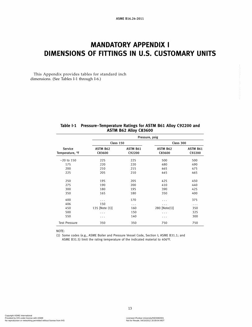
MANDATORY APPENDIX IDIMENSIONS OF FITTINGS IN U.S. CUSTOMARY UNITS
This Appendix provides tables for standard inchdimensions. (See Tables I-1 through I-6.)
Table I-1 Pressure–Temperature Ratings for ASTM B61 Alloy C92200 andASTM B62 Alloy C83600
Pressure, psig
Class 150 Class 300
Service ASTM B62 ASTM B61 ASTM B62 ASTM B61Temperature, °F C83600 C92200 C83600 C92200
−20 to 150 225 225 500 500175 220 220 480 490200 210 215 465 475225 205 210 445 465
250 195 205 425 450275 190 200 410 440300 180 195 390 425350 165 180 350 400
400 . . . 170 . . . 375406 150 . . . . . . . . .450 135 [Note (1)] 160 280 [Note(1)] 350500 . . . 150 . . . 325550 . . . 140 . . . 300
Test Pressure 350 350 750 750
NOTE:(1) Some codes (e.g., ASME Boiler and Pressure Vessel Code, Section I; ASME B31.1; and
ASME B31.5) limit the rating temperature of the indicated material to 406°F.
13
Copyright ASME International Provided by IHS under license with ASME Licensee=Purdue University/5923082001
Not for Resale, 04/10/2012 20:09:04 MDTNo reproduction or networking permitted without license from IHS
--`,`,,`,`,``,,`,````,,`,````-`-`,,`,,`,`,,`---
ASME B16.24-2011
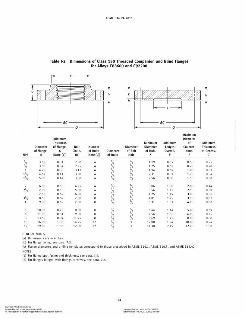
Table I-2 Dimensions of Class 150 Threaded Companion and Blind Flangesfor Alloys C83600 and C92200
Y
X
BC
O
BC
O
I
Ttf tf
MaximumMinimum DiameterThickness Minimum Minimum of Minimum
Diameter of Flange, Bolt Number Diameter Diameter Length Counter- Thicknessof Flange, tf Circle, of Bolts Diameter of Bolt of Hub, Overall, bore, at Recess,
NPS O [Note (1)] BC [Note (2)] of Bolts Hole X Y I T
1⁄2 3.50 0.31 2.38 4 1⁄25⁄8 1.19 0.59 0.50 0.25
3⁄4 3.88 0.34 2.75 4 1⁄25⁄8 1.25 0.62 0.75 0.28
1 4.25 0.38 3.12 4 1⁄25⁄8 1.94 0.69 1.00 0.31
11⁄4 4.62 0.41 3.50 4 1⁄25⁄8 2.31 0.81 1.25 0.34
11⁄2 5.00 0.44 3.88 4 1⁄25⁄8 2.56 0.88 1.50 0.38
2 6.00 0.50 4.75 4 5⁄83⁄4 3.06 1.00 2.00 0.44
21⁄2 7.00 0.56 5.50 4 5⁄83⁄4 3.56 1.12 2.50 0.50
3 7.50 0.62 6.00 4 5⁄83⁄4 4.25 1.19 3.00 0.56
31⁄2 8.50 0.69 7.00 8 5⁄83⁄4 4.81 1.25 3.50 0.62
4 9.00 0.69 7.50 8 5⁄83⁄4 5.31 1.31 4.00 0.62
5 10.00 0.75 8.50 8 3⁄47⁄8 6.44 1.44 5.00 0.69
6 11.00 0.81 9.50 8 3⁄47⁄8 7.56 1.56 6.00 0.75
8 13.50 0.94 11.75 8 3⁄47⁄8 9.69 1.75 8.00 0.88
10 16.00 1.00 14.25 12 7⁄8 1 12.00 1.94 10.00 0.9412 19.00 1.06 17.00 12 7⁄8 1 14.38 2.19 12.00 1.00
GENERAL NOTES:(a) Dimensions are in inches.(b) For flange facing, see para. 7.2.(c) Flange diameters and drilling templates correspond to those prescribed in ASME B16.1, ASME B16.5, and ASME B16.42.
NOTES:(1) For flange spot facing and thickness, see para. 7.9.(2) For flanges integral with fittings or valves, see para. 7.8.
14
Copyright ASME International Provided by IHS under license with ASME Licensee=Purdue University/5923082001
Not for Resale, 04/10/2012 20:09:04 MDTNo reproduction or networking permitted without license from IHS
--`,`,,`,`,``,,`,````,,`,````-`-`,,`,,`,`,,`---
ASME B16.24-2011
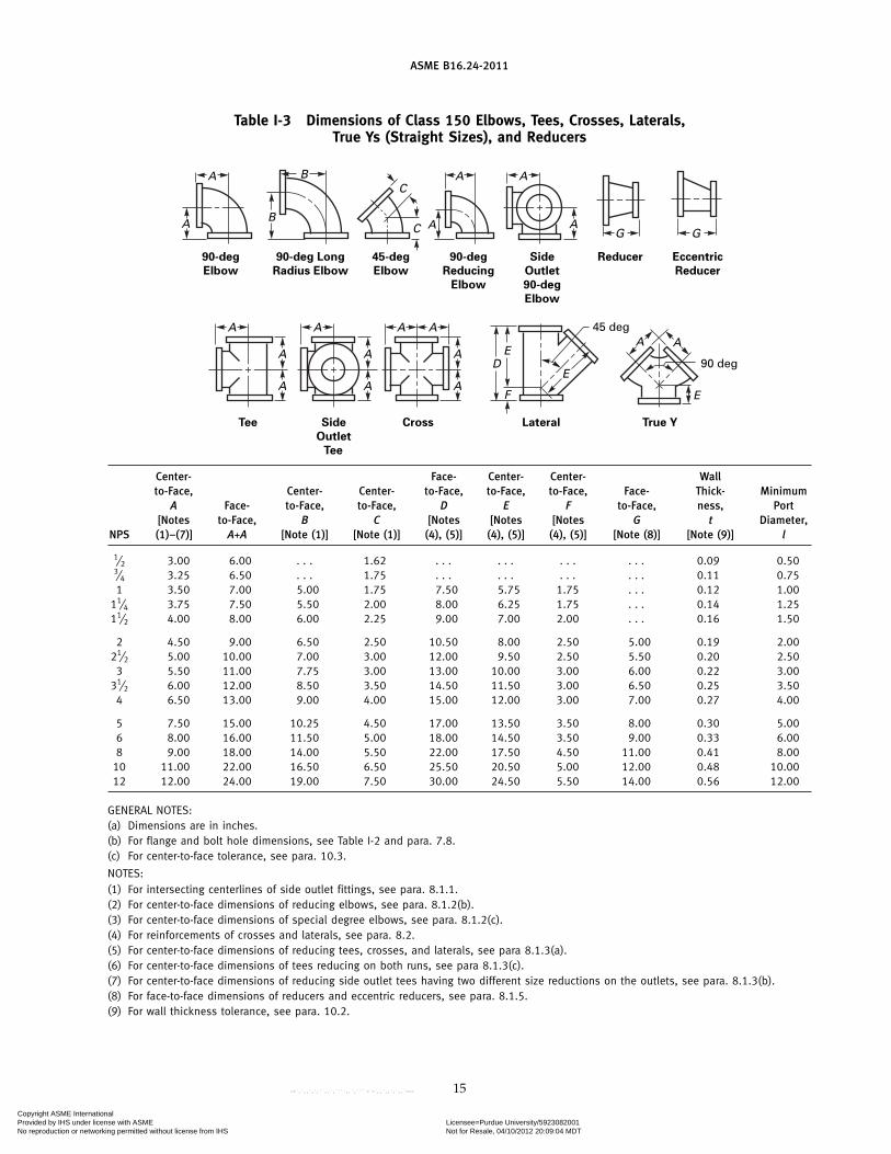
Table I-3 Dimensions of Class 150 Elbows, Tees, Crosses, Laterals,True Ys (Straight Sizes), and Reducers
90 deg
45 deg
Tee Side
Outlet
Tee
90-deg
Elbow
90-deg Long
Radius Elbow
45-deg
Elbow
90-deg
Reducing
Elbow
Side
Outlet
90-deg
Elbow
Reducer Eccentric
Reducer
Cross Lateral True Y
DE
F
E
A
A
A A
A
A B
A BAC
C
G G
AAAA
AE
A
A
A
A
A
Center- Face- Center- Center- Wallto-Face, Center- Center- to-Face, to-Face, to-Face, Face- Thick- Minimum
A Face- to-Face, to-Face, D E F to-Face, ness, Port[Notes to-Face, B C [Notes [Notes [Notes G t Diameter,
NPS (1)–(7)] A+A [Note (1)] [Note (1)] (4), (5)] (4), (5)] (4), (5)] [Note (8)] [Note (9)] l
1⁄2 3.00 6.00 . . . 1.62 . . . . . . . . . . . . 0.09 0.503⁄4 3.25 6.50 . . . 1.75 . . . . . . . . . . . . 0.11 0.751 3.50 7.00 5.00 1.75 7.50 5.75 1.75 . . . 0.12 1.00
11⁄4 3.75 7.50 5.50 2.00 8.00 6.25 1.75 . . . 0.14 1.2511⁄2 4.00 8.00 6.00 2.25 9.00 7.00 2.00 . . . 0.16 1.50
2 4.50 9.00 6.50 2.50 10.50 8.00 2.50 5.00 0.19 2.0021⁄2 5.00 10.00 7.00 3.00 12.00 9.50 2.50 5.50 0.20 2.50
3 5.50 11.00 7.75 3.00 13.00 10.00 3.00 6.00 0.22 3.0031⁄2 6.00 12.00 8.50 3.50 14.50 11.50 3.00 6.50 0.25 3.50
4 6.50 13.00 9.00 4.00 15.00 12.00 3.00 7.00 0.27 4.00
5 7.50 15.00 10.25 4.50 17.00 13.50 3.50 8.00 0.30 5.006 8.00 16.00 11.50 5.00 18.00 14.50 3.50 9.00 0.33 6.008 9.00 18.00 14.00 5.50 22.00 17.50 4.50 11.00 0.41 8.00
10 11.00 22.00 16.50 6.50 25.50 20.50 5.00 12.00 0.48 10.0012 12.00 24.00 19.00 7.50 30.00 24.50 5.50 14.00 0.56 12.00
GENERAL NOTES:(a) Dimensions are in inches.(b) For flange and bolt hole dimensions, see Table I-2 and para. 7.8.(c) For center-to-face tolerance, see para. 10.3.
NOTES:(1) For intersecting centerlines of side outlet fittings, see para. 8.1.1.(2) For center-to-face dimensions of reducing elbows, see para. 8.1.2(b).(3) For center-to-face dimensions of special degree elbows, see para. 8.1.2(c).(4) For reinforcements of crosses and laterals, see para. 8.2.(5) For center-to-face dimensions of reducing tees, crosses, and laterals, see para 8.1.3(a).(6) For center-to-face dimensions of tees reducing on both runs, see para 8.1.3(c).(7) For center-to-face dimensions of reducing side outlet tees having two different size reductions on the outlets, see para. 8.1.3(b).(8) For face-to-face dimensions of reducers and eccentric reducers, see para. 8.1.5.(9) For wall thickness tolerance, see para. 10.2.
15
Copyright ASME International Provided by IHS under license with ASME Licensee=Purdue University/5923082001
Not for Resale, 04/10/2012 20:09:04 MDTNo reproduction or networking permitted without license from IHS
--`,`,,`,`,``,,`,````,,`,````-`-`,,`,,`,`,,`---
ASME B16.24-2011
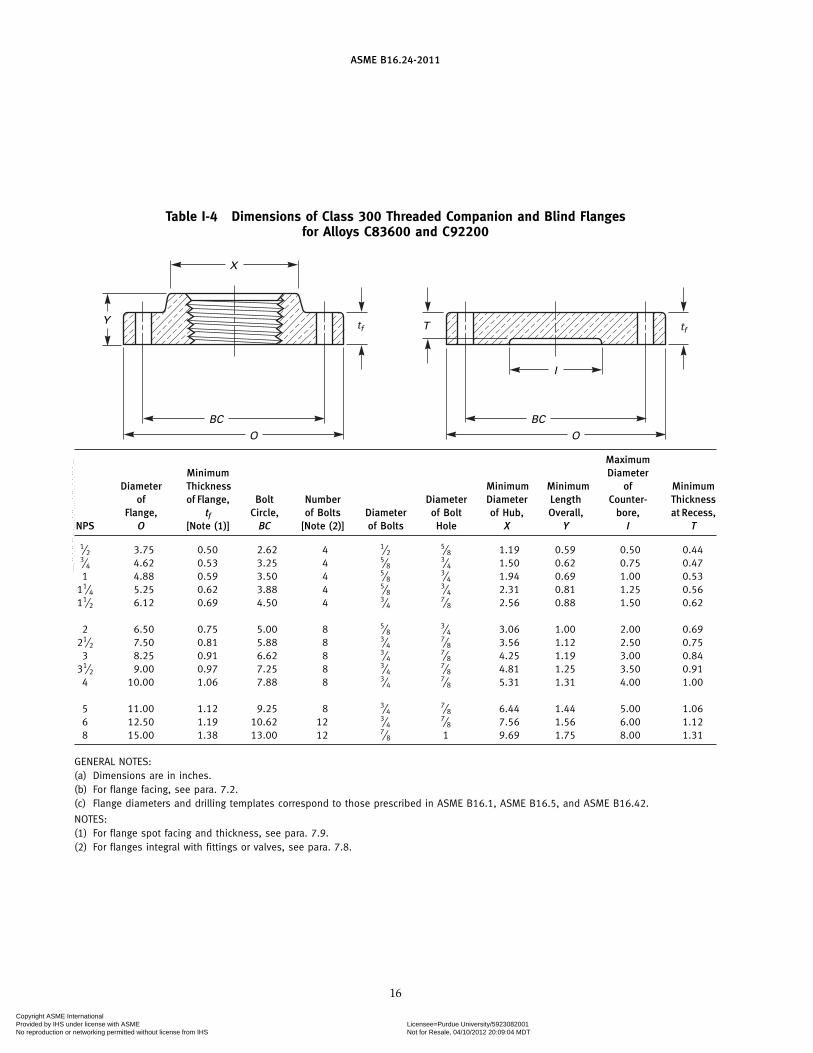
Table I-4 Dimensions of Class 300 Threaded Companion and Blind Flangesfor Alloys C83600 and C92200
Y
X
BC
O
BC
O
I
Ttf tf
MaximumMinimum Diameter
Diameter Thickness Minimum Minimum of Minimumof of Flange, Bolt Number Diameter Diameter Length Counter- Thickness
Flange, tf Circle, of Bolts Diameter of Bolt of Hub, Overall, bore, at Recess,NPS O [Note (1)] BC [Note (2)] of Bolts Hole X Y I T
1⁄2 3.75 0.50 2.62 4 1⁄25⁄8 1.19 0.59 0.50 0.44
3⁄4 4.62 0.53 3.25 4 5⁄83⁄4 1.50 0.62 0.75 0.47
1 4.88 0.59 3.50 4 5⁄83⁄4 1.94 0.69 1.00 0.53
11⁄4 5.25 0.62 3.88 4 5⁄83⁄4 2.31 0.81 1.25 0.56
11⁄2 6.12 0.69 4.50 4 3⁄47⁄8 2.56 0.88 1.50 0.62
2 6.50 0.75 5.00 8 5⁄83⁄4 3.06 1.00 2.00 0.69
21⁄2 7.50 0.81 5.88 8 3⁄47⁄8 3.56 1.12 2.50 0.75
3 8.25 0.91 6.62 8 3⁄47⁄8 4.25 1.19 3.00 0.84
31⁄2 9.00 0.97 7.25 8 3⁄47⁄8 4.81 1.25 3.50 0.91
4 10.00 1.06 7.88 8 3⁄47⁄8 5.31 1.31 4.00 1.00
5 11.00 1.12 9.25 8 3⁄47⁄8 6.44 1.44 5.00 1.06
6 12.50 1.19 10.62 12 3⁄47⁄8 7.56 1.56 6.00 1.12
8 15.00 1.38 13.00 12 7⁄8 1 9.69 1.75 8.00 1.31
GENERAL NOTES:(a) Dimensions are in inches.(b) For flange facing, see para. 7.2.(c) Flange diameters and drilling templates correspond to those prescribed in ASME B16.1, ASME B16.5, and ASME B16.42.
NOTES:(1) For flange spot facing and thickness, see para. 7.9.(2) For flanges integral with fittings or valves, see para. 7.8.
16
Copyright ASME International Provided by IHS under license with ASME Licensee=Purdue University/5923082001
Not for Resale, 04/10/2012 20:09:04 MDTNo reproduction or networking permitted without license from IHS
--`,`,,`,`,``,,`,````,,`,````-`-`,,`,,`,`,,`---
ASME B16.24-2011
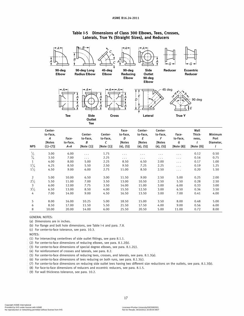
Table I-5 Dimensions of Class 300 Elbows, Tees, Crosses,Laterals, True Ys (Straight Sizes), and Reducers
90 deg
45 deg
Tee Side
Outlet
Tee
90-deg
Elbow
90-deg Long
Radius Elbow
45-deg
Elbow
90-deg
Reducing
Elbow
Side
Outlet
90-deg
Elbow
Reducer Eccentric
Reducer
Cross Lateral True Y
DE
F
E
A
A
A A
A
A B
A BAC
C
G G
AAAA
AE
A
A
A
A
A
Center- Face- Center- Center- Wallto-Face, Center- Center- to-Face, to-Face, to-Face, Face- Thick- Minimum
A Face- to-Face, to-Face, D E F to-Face, ness, Port[Notes to-Face, B C [Notes [Notes [Notes G t Diameter,
NPS (1)–(7)] A+A [Note (1)] [Note (1)] (4), (5)] (4), (5)] (4), (5)] [Note (8)] [Note (9)] l
1⁄2 3.00 6.00 . . . 1.75 . . . . . . . . . . . . 0.12 0.503⁄4 3.50 7.00 . . . 2.25 . . . . . . . . . . . . 0.16 0.751 4.00 8.00 5.00 2.25 8.50 6.50 2.00 . . . 0.17 1.00
11⁄4 4.25 8.50 5.50 2.50 9.50 7.25 2.25 . . . 0.19 1.2511⁄2 4.50 9.00 6.00 2.75 11.00 8.50 2.50 . . . 0.20 1.50
2 5.00 10.00 6.50 3.00 11.50 9.00 2.50 5.00 0.25 2.0021⁄2 5.50 11.00 7.00 3.50 13.00 10.50 2.50 5.50 0.28 2.50
3 6.00 12.00 7.75 3.50 14.00 11.00 3.00 6.00 0.33 3.0031⁄2 6.50 13.00 8.50 4.00 15.50 12.50 3.00 6.50 0.36 3.50
4 7.00 14.00 9.00 4.50 16.50 13.50 3.00 7.00 0.41 4.00
5 8.00 16.00 10.25 5.00 18.50 15.00 3.50 8.00 0.48 5.006 8.50 17.00 11.50 5.50 21.50 17.50 4.00 9.00 0.56 6.008 10.00 20.00 14.00 6.00 25.50 20.50 5.00 11.00 0.72 8.00
GENERAL NOTES:(a) Dimensions are in inches.(b) For flange and bolt hole dimensions, see Table I-4 and para. 7.8.(c) For center-to-face tolerance, see para. 10.3.
NOTES:(1) For intersecting centerlines of side outlet fittings, see para 8.1.1.(2) For center-to-face dimensions of reducing elbows, see para. 8.1.2(b).(3) For center-to-face dimensions of special degree elbows, see para. 8.1.2(c).(4) For reinforcement of crosses and laterals, see para. 8.2.(5) For center-to-face dimensions of reducing tees, crosses, and laterals, see para. 8.1.3(a).(6) For center-to-face dimensions of tees reducing on both runs, see para. 8.1.3(c).(7) For center-to-face dimensions on reducing side outlet tees having two different size reductions on the outlets, see para. 8.1.3(b).(8) For face-to-face dimensions of reducers and eccentric reducers, see para. 8.1.5.(9) For wall thickness tolerance, see para. 10.2.
17
Copyright ASME International Provided by IHS under license with ASME Licensee=Purdue University/5923082001
Not for Resale, 04/10/2012 20:09:04 MDTNo reproduction or networking permitted without license from IHS
--`,`,,`,`,``,,`,````,,`,````-`-`,,`,,`,`,,`---
ASME B16.24-2011
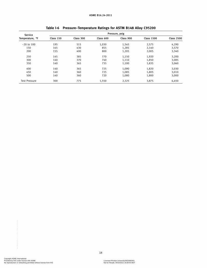
Table I-6 Pressure–Temperature Ratings for ASTM B148 Alloy C95200
Pressure, psigServiceTemperature, °F Class 150 Class 300 Class 600 Class 900 Class 1500 Class 2500
−20 to 100 195 515 1,030 1,545 2,575 4,290150 165 430 855 1,285 2,140 3,570200 155 400 800 1,205 2,005 3,340
250 145 385 770 1,150 1,920 3,200300 140 370 740 1,110 1,850 3,085350 140 365 735 1,100 1,835 3,060
400 140 365 725 1,090 1,820 3,030450 140 360 725 1,085 1,805 3,010500 140 360 720 1,080 1,800 3,000
Test Pressure 300 775 1,550 2,325 3,875 6,450
18
Copyright ASME International Provided by IHS under license with ASME Licensee=Purdue University/5923082001
Not for Resale, 04/10/2012 20:09:04 MDTNo reproduction or networking permitted without license from IHS
--`,`,,`,`,``,,`,````,,`,````-`-`,,`,,`,`,,`---
ASME B16.24-2011
MANDATORY APPENDIX IIREFERENCES
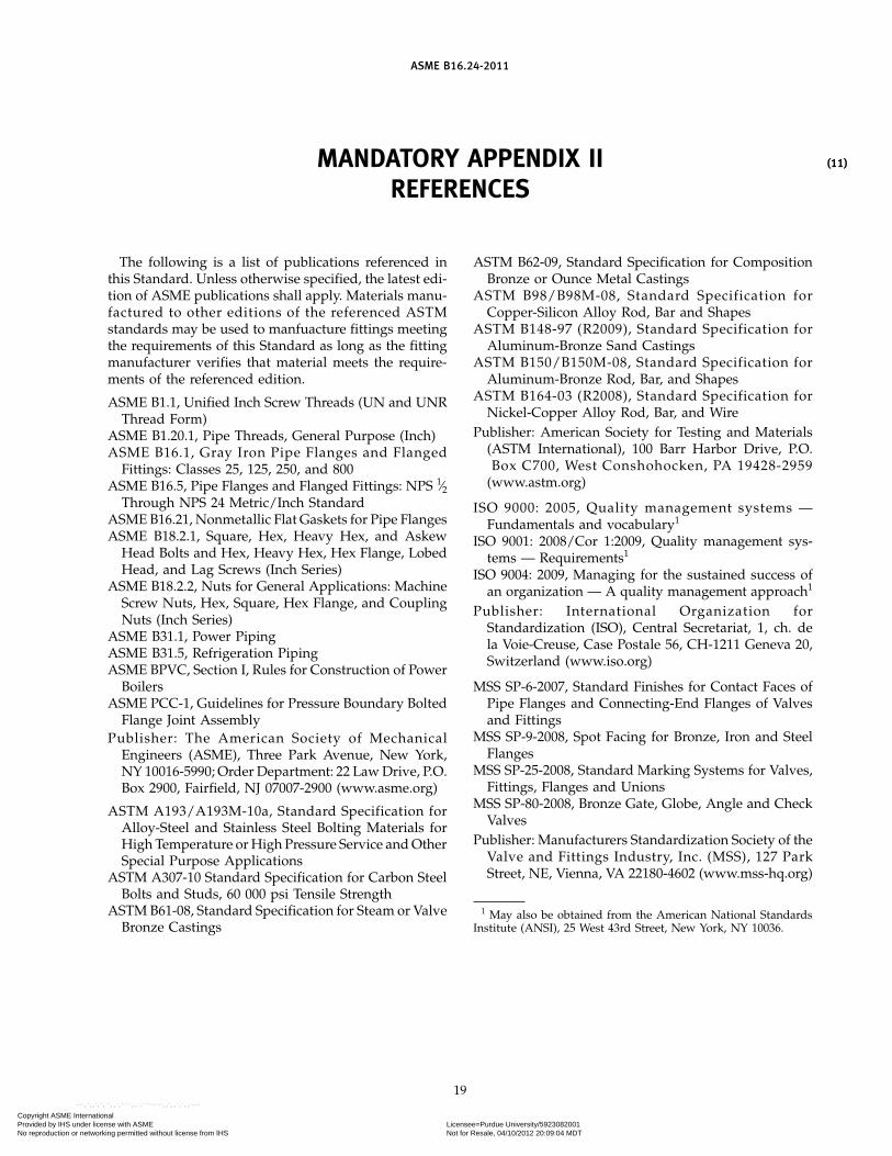
The following is a list of publications referenced inthis Standard. Unless otherwise specified, the latest edi-tion of ASME publications shall apply. Materials manu-factured to other editions of the referenced ASTMstandards may be used to manfuacture fittings meetingthe requirements of this Standard as long as the fittingmanufacturer verifies that material meets the require-ments of the referenced edition.
ASME B1.1, Unified Inch Screw Threads (UN and UNRThread Form)
ASME B1.20.1, Pipe Threads, General Purpose (Inch)ASME B16.1, Gray Iron Pipe Flanges and Flanged
Fittings: Classes 25, 125, 250, and 800ASME B16.5, Pipe Flanges and Flanged Fittings: NPS 1⁄2
Through NPS 24 Metric/Inch StandardASME B16.21, Nonmetallic Flat Gaskets for Pipe FlangesASME B18.2.1, Square, Hex, Heavy Hex, and Askew
Head Bolts and Hex, Heavy Hex, Hex Flange, LobedHead, and Lag Screws (Inch Series)
ASME B18.2.2, Nuts for General Applications: MachineScrew Nuts, Hex, Square, Hex Flange, and CouplingNuts (Inch Series)
ASME B31.1, Power PipingASME B31.5, Refrigeration PipingASME BPVC, Section I, Rules for Construction of Power
BoilersASME PCC-1, Guidelines for Pressure Boundary Bolted
Flange Joint AssemblyPublisher: The American Society of Mechanical
Engineers (ASME), Three Park Avenue, New York,NY 10016-5990; Order Department: 22 Law Drive, P.O.Box 2900, Fairfield, NJ 07007-2900 (www.asme.org)
ASTM A193/A193M-10a, Standard Specification forAlloy-Steel and Stainless Steel Bolting Materials forHigh Temperature or High Pressure Service and OtherSpecial Purpose Applications
ASTM A307-10 Standard Specification for Carbon SteelBolts and Studs, 60 000 psi Tensile Strength
ASTM B61-08, Standard Specification for Steam or ValveBronze Castings
19
ASTM B62-09, Standard Specification for CompositionBronze or Ounce Metal Castings
ASTM B98/B98M-08, Standard Specification forCopper-Silicon Alloy Rod, Bar and Shapes
ASTM B148-97 (R2009), Standard Specification forAluminum-Bronze Sand Castings
ASTM B150/B150M-08, Standard Specification forAluminum-Bronze Rod, Bar, and Shapes
ASTM B164-03 (R2008), Standard Specification forNickel-Copper Alloy Rod, Bar, and Wire
Publisher: American Society for Testing and Materials(ASTM International), 100 Barr Harbor Drive, P.O.Box C700, West Conshohocken, PA 19428-2959
(www.astm.org)
ISO 9000: 2005, Quality management systems —Fundamentals and vocabulary1
ISO 9001: 2008/Cor 1:2009, Quality management sys-tems — Requirements1
ISO 9004: 2009, Managing for the sustained success ofan organization — A quality management approach1
Publisher: International Organization forStandardization (ISO), Central Secretariat, 1, ch. dela Voie-Creuse, Case Postale 56, CH-1211 Geneva 20,Switzerland (www.iso.org)
MSS SP-6-2007, Standard Finishes for Contact Faces ofPipe Flanges and Connecting-End Flanges of Valvesand Fittings
MSS SP-9-2008, Spot Facing for Bronze, Iron and SteelFlanges
MSS SP-25-2008, Standard Marking Systems for Valves,Fittings, Flanges and Unions
MSS SP-80-2008, Bronze Gate, Globe, Angle and CheckValves
Publisher: Manufacturers Standardization Society of theValve and Fittings Industry, Inc. (MSS), 127 ParkStreet, NE, Vienna, VA 22180-4602 (www.mss-hq.org)
1 May also be obtained from the American National StandardsInstitute (ANSI), 25 West 43rd Street, New York, NY 10036.
(11)
Copyright ASME International Provided by IHS under license with ASME Licensee=Purdue University/5923082001
Not for Resale, 04/10/2012 20:09:04 MDTNo reproduction or networking permitted without license from IHS
--`,`,,`,`,``,,`,````,,`,````-`-`,,`,,`,`,,`---
(11)
ASME B16.24-2011
NONMANDATORY APPENDIX AQUALITY SYSTEM PROGRAM
The products manufactured in accordance with thisStandard shall be produced under a quality system pro-gram following the principles of an appropriate stan-dard from the ISO 9000 series.1 A determination of theneed for registration and/or certification of the product
1 The series is also available from the American NationalStandards Institute (ANSI) and the American Society for Quality(ASQ) as American National Standards that are identified by theprefix “Q” replacing the prefix “ISO.” Each standard of the seriesis listed under References in Mandatory Appendix II.
20
manufacturer’s quality system program by an indepen-dent organization shall be the responsibility of the man-ufacturer. Detailed documentation demonstratingprogram compliance shall be available to the purchaserat the manufacturer ’s facility. A written summarydescription of the program used by the product manu-facturer shall be available to the purchaser upon request.The product manufacturer is defined as the entity whosename or trademark appears on the product in accor-dance with the marking or identification requirementsof this Standard.
Copyright ASME International Provided by IHS under license with ASME Licensee=Purdue University/5923082001
Not for Resale, 04/10/2012 20:09:04 MDTNo reproduction or networking permitted without license from IHS
--`,`,,`,`,``,,`,````,,`,````-`-`,,`,,`,`,,`---

Copyright ASME International Provided by IHS under license with ASME Licensee=Purdue University/5923082001
Not for Resale, 04/10/2012 20:09:04 MDTNo reproduction or networking permitted without license from IHS
--`,`,,`,`,``,,`,````,,`,````-`-`,,`,,`,`,,`---
ASME B16.24-2011
J00911Copyright ASME International Provided by IHS under license with ASME Licensee=Purdue University/5923082001
Not for Resale, 04/10/2012 20:09:04 MDTNo reproduction or networking permitted without license from IHS
--`,`,,`,`,``,,`,````,,`,````-`-`,,`,,`,`,,`---
Copyright © 2022 FDOKUMEN