Pipes & Fittings - Who We Are
117
Pipes & Fittings
-
Upload
khangminh22 -
Category
Documents
-
view
0 -
download
0
Transcript of Pipes & Fittings - Who We Are
Pipes&Fittings

SHIELD

Introduction
SHIELD is a company created to cater to the infrastructure, fire
protection and building services industries with a comprehensive
range of products designed to be competitive and of assured
quality.
We stay ahead of today’s evolving market requirements
by committing to a program of continued research and
development.
We are able to maintain our high standards by ensuring that
our worldwide manufacturing networks are the most advanced
in the industry in Europe, Asia and America in terms of quality
and delivery lead time. Our fully experienced and professional
staff is there to provide engineering expertise and after sales
service exactly when you need it.
Combine this with highly responsive and customer focused
network of distribution centres around the world, you will find
that customer satisfaction is what we excel at.
We are justifiably proud of our global client base. With offices
and facilities in the UK and Middle East, we are able to comprehend
the specific needs of your particular region.

SHIELD
PIPING
SYSTEM
Trusted Worldwide

ContentsPipes PagePipes (BS 1387)Pipes (ASTM A53)
23
Threaded Fittings 4
Elbow 90° - SDT-100Reducing Elbow 90° - SDT-101Elbow 45° - SDT-200Tee - SDT-12Reducing Tee - SDT-53Reducing Coupling - SDT-30Cross - SDT-13Reducing Cross - SDT-51Straight Coupling - SDT-22Plug - SDT-55Cap - SDT-14Hex Bushing - SDT-57Union - SDT-59Hex Nipple - SDT-11Hex Reducing Nipple - SDT-111
555667778889999
Grooved Fittings 10
Pipe Support & Accessories 29
Rigid Coupling - Standard - SDG-22Rigid Coupling - Light - SDG-20Flexible Couplings - Heavy Duty - SDG-27Flexible Couplings - Standard - SDG-25Flexible Couplings - Light - SDG-21Reducing Couplings - SDG-30Elbows - 90° SDG-100, 45° SDG-200, 90° SDG-105Elbows - 22.5° SDG-225, 11.25° SDG-112Tee - SDG-12, Cross Tee - SDG-13, Tee - SDG-102Cap - SDG-14Grooved Flange - SDG-15, Adaptor Flange - SDG-16Reducing Tee - SDG-53Concentric Reducer Grooved - SDG-35, Threaded - SDG-37Eccentric Reducer Grooved - SDG-33Mechanical Tee Threaded Outlet - SDG-42Mechanical Tee Grooved Outlet - SDG-44Mechanical Cross Threaded - SDG-47Mechanical Cross Grooved - SDG-49Mechanical Tee U-Bolt - SDG-40Groove Specifications
1112121314151617181819202122232526272828
Swivel Hanger - SD-HBClevis Hanger - SD-HCPipe Clamp with Lining - SD-GE-RLCPipe Clamp - SD-GE-PPCU Strap Hanger with Lining - SD-GE-RUSU Strap Hanger - SD-GE-USRiser Hanger or Clamp with Lining - SD-GE-RRCRiser Hanger or Clamp - SD-GE-PRCU-Bolt - SD-UBRubber Support Insert - SD-RSIThreaded Rod - SD-TRBeam Clamp - SD-CBC
293031333435363738394041
1

Shield Pipes
Technical DataBlack and hot dipped galvanized steel welded pipesConforming to BS 1387:1985 (EN 10255)
2
1/2 15 0.843 21.4 0.827 21.0 0.079 2.00 0.947 1056 3465 0.956 1046 34323/4 20 1.059 26.9 1.039 26.4 0.091 2.30 1.380 725 2379 1.390 719 2359
1 25 1.331 33.8 1.307 33.2 0.102 2.60 1.980 505 1657 2.000 500 1640
11/4 32 1.673 42.5 1.650 41.9 0.102 2.60 2.540 394 1293 2.570 389 1276
11/2 40 1.906 48.4 1.882 47.8 0.114 2.90 3.230 310 1017 3.270 306 1004
2 50 2.370 60.2 2.346 59.6 0.114 2.90 4.080 245 804 4.150 241 791
21/2 65 2.991 76.6 2.961 75.2 0.124 3.20 5.710 175 574 5.830 172 564
3 80 3.492 88.7 3.461 87.9 0.124 3.20 6.720 149 489 6.890 145 476
4 100 4.484 113.9 4.449 113.0 0.142 3.60 9.750 103 338 10.000 100 328
1/2 15 0.854 21.7 0.831 21.1 0.102 2.60 1.210 826 2710 1.220 820 26903/4 20 1.071 27.2 1.047 26.6 0.102 2.60 1.560 641 2103 1.570 637 2090
1 25 1.346 34.2 1.315 33.4 0.124 3.20 2.410 415 1362 2.430 412 1352
11/4 32 1.689 42.9 1.657 42.1 0.124 3.20 3.100 323 1060 3.130 319 1047
11/2 40 1.921 48.8 1.890 48.0 0.124 3.20 3.570 280 919 3.610 277 909
2 50 2.394 60.8 2.354 59.8 0.142 3.60 5.030 199 653 5.100 196 643
21/2 65 3.016 76.6 2.969 75.4 0.142 3.60 6.430 156 512 6.550 153 502
3 80 3.524 89.5 3.469 88.1 0.157 4.00 8.370 119 390 8.540 117 384
4 100 4.524 114.9 4.461 113.3 0.177 4.50 12.200 82 269 12.500 80 262
5 125 5.535 140.6 5.461 138.7 0.197 5.00 16.600 60 197 17.100 58 190
6 150 6.539 166.1 6.461 164.1 0.197 5.00 19.70 51 167 20.300 49 161
1/2 15 0.854 21.7 0.831 21.1 0.124 3.20 1.440 694 2277 1.450 690 22643/4 20 1.071 27.2 1.047 26.6 0.124 3.20 1.870 535 1755 1.880 532 1745
1 25 1.346 34.2 1.315 33.4 0.157 4.00 2.940 340 1115 2.960 338 1109
11/4 32 1.689 42.9 1.657 42.1 0.157 4.00 3.800 263 863 3.830 261 856
11/2 40 1.921 48.8 1.890 48.0 0.157 4.00 4.380 228 748 4.420 226 741
2 50 2.394 60.8 2.354 59.8 0.177 4.50 6.190 162 531 6.260 160 525
21/2 65 3.016 76.6 2.969 75.4 0.177 4.50 7.930 126 413 8.050 124 407
3 80 3.524 89.5 3.469 88.1 0.197 5.00 10.300 97 318 10.500 95 312
4 100 4.524 114.9 4.461 113.3 0.213 5.40 14.500 69 226 14.800 68 223
5 125 5.535 140.6 5.461 138.7 0.213 5.40 17.900 56 184 18.400 54 177
6 150 6.539 166.1 6.461 164.1 0.213 5.40 21.300 47 154 21.900 46 151
1.000 1000 3281 1.009 991 3251 160
1.440 694 2277 1.460 690 2264 110
2.060 485 1591 2.090 478 1568 80
2.640 379 1243 2.680 373 1224 61
3.350 298 978 3.400 294 965 51
4.220 237 778 4.300 233 764 37
5.890 170 558 6.020 166 545 27
6.930 144 472 7.100 141 463 24
10.030 100 328 10.280 97 318 16
1.250 794 2605 1.260 787 2582 130
1.620 617 2024 1.640 610 2001 100
2.490 402 1319 2.510 398 1306 65
3.200 312 1024 3.230 310 1017 51
3.680 272 892 3.720 269 883 44
5.170 193 633 5.250 190 623 30
6.610 151 495 6.730 149 489 24
8.580 117 384 8.760 114 374 19
12.480 80 260 12.690 79 259 14
16.940 59 194 17.440 57 187 10
20.100 50 164 20.710 48 157 7
1.490 671 2202 1.500 667 2188 110
1.930 518 1700 1.950 513 1683 80
3.010 332 1089 3.040 329 1079 55
3.900 256 840 3.930 254 833 44
4.490 223 732 4.530 221 725 37
6.330 158 518 6.400 156 512 27
8.110 123 404 8.230 121 397 20
10.510 95 312 10.710 93 307 16
14.770 68 223 15.070 67 220 12
18.210 55 180 18.730 53 174 10
21.700 46 151 22.300 45 148 7
L
I
G
H
T
(A)
M
E
D
I
U
M
(B)
H
E
A
V
Y
(C)
Class
NominalBore
Max. Min.
Outside Diameter WallThickness
Weight of Black Pipes No. of pipespacked perstandardbundle
(1 TonneApprox.)
Plain Ended Screwed & Socketed Plain Ended
Weight of Galvanised Pipes (Calculated)
Screwed & Socketed
kg/mtr mtr/ton ft/tonkg/mtr mtr/ton ft/tonkg/mtr mtr/ton ft/tonkg/mtr mtr/ton ft/tonInch mmInch mmInch mmInch mm
Tolerances: THICKNESS: Light Tube -8%, Medium and Heavy Tubes -10%.WEIGHT: Single Tube +10% -8%, Quantity - 150 metres and above of one size & class ±4%.LENGTH: 6 metres ±0.05 metres
SHIELD reserves the right to change the contents without notice.

Shield reserves the right to change the contents without notice.
Seamless steel pipe & welded steel pipeto ASTM A53, Grade A & B (Sizes, Dimensions & Weights)
Shield
Pipes
Wall = Wall thickness in mmWt. = Weight in Kg / Mtr.Available in black & hot dipped galvanized* UL & FM details are available in their respective certificates.
**
3/8 17.1 2.31 0.84 2.31 0.84 3.20 1.101/2 21.3 2.77 1.27 2.77 1.27 3.73 1.623/4 26.7 2.87 1.69 2.87 1.69 3.91 2.21
33.4 3.38 2.50 1 3.38 2.50 4.55 3.25
11/4 42.2 3.56 3.39 3.56 3.39 4.85 4.47
11/2 48.3 3.68 4.05 3.68 4.05 5.08 5.39
60.3 3.91 5.44 2 3.91 5.44 5.54 7.48
21/2 73.0 5.16 8.63 5.16 8.63 7.01 11.41
88.9 5.49 11.29 5.49 11.29 7.62 15.27
31/2 101.6 5.74 13.57 5.74 13.57 8.08 18.63
114.3 6.02 16.07 6.02 16.07 8.56 22.32
141.3 6.55 21.77 6.55 21.77 9.52 30.94
168.3 7.11 28.26 7.11 28.26 10.97 42.56
219.1 6.35 33.31 7.04 36.31 8.18 42.55 8.18 42.55 10.31 53.08 12.70 64.64
273.0 6.35 41.75 7.80 51.01 9.27 60.29 9.27 60.29 12.70 81.52 15.09 95.97
323.8 6.35 49.71 8.38 65.18 9.52 73.78 10.31 79.70 14.27 108.92 17.48 132.04
355.6 6.35 54.69 7.92 67.9 9.52 81.25 9.52 81.25 11.13 94.55 15.09 126.71 19.05 158.10
406.4 6.35 62.64 7.92 77.83 9.52 93.17 9.52 93.17 12.70 123.30 16.66 160.12 21.44 203.53
457.2 6.35 70.60 7.92 87.75 11.13 122.43 9.52 105.10 14.27 155.87 19.05 205.83 23.83 254.67
508.0 6.35 78.55 9.52 117.02 12.70 155.12 9.52 117.02
660.0 7.92 127.43 12.70 202.85 9.52 152.80
15.09 183.42 20.62 247.83 26.19 311.17
610.0 6.35 94.46 9.52 140.88 14.27 209.50 9.52 140.88
3
4
5
6
8
10
12
14
16
18
20
26
24 17.48 255.24 24.61 355.02 30.96 441.78
NominalPipe size
Inch Wt.Wall Wt.Wall Wt.Wall Wt.Wall Wt.Wall Wt.Wall Wt.Wall
Schedule 10 Schedule 20 Schedule 30 Schedule 40 Schedule 60 Schedule 80StandardO.D.
mm
3Hydrostatic pressure test applied as per ASTM Standards
Tensile Requirements
Tensile Strength, Min, Psi [MPa] 48,000 [330] 60,000 [415]
Yield Strength, Min, Psi [MPa] 30,000 [205] 35,000 [240]
Grade A Grade B
Shield
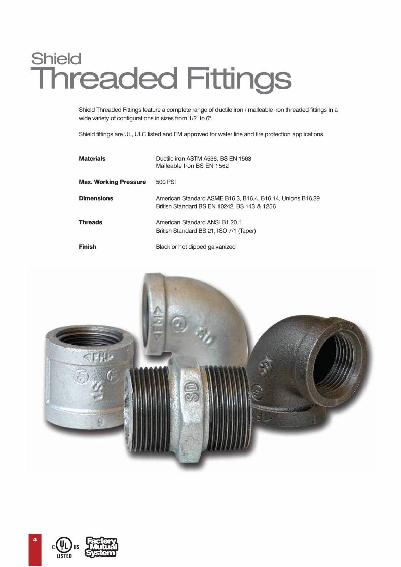
Threaded FittingsShield Threaded Fittings feature a complete range of ductile iron / malleable iron threaded fittings in a wide variety of configurations in sizes from 1/2" to 6".
Shield fittings are UL, ULC listed and FM approved for water line and fire protection applications.
Materials Ductile iron ASTM A536, BS EN 1563Malleable Iron BS EN 1562
Max. Working Pressure 500 PSI
Dimensions American Standard ASME B16.3, B16.4, B16.14, Unions B16.39 British Standard BS EN 10242, BS 143 & 1256
Threads American Standard ANSI B1.20.1 British Standard BS 21, ISO 7/1 (Taper)
Finish Black or hot dipped galvanized
4

Shield
Threaded Fittings
A
A
A
B
UL/FM : ½" to 4"
UL/FM : ¾" to 3"
UL/FM : ½" to 2-½"
A
A
5
SHIELD reserves the right to change the contents without notice.
SDT-100 ELBOW 90°
SDT-200 ELBOW 45°
SDT-101 REDUCING ELBOW 90°
Nominal Size
InchA
Inch
1/2 1.123/4 1.31
1 1.50
11/4 1.75
11/2 1.95
2 2.25
21/2 2.70
3 3.08
31/2 3.42
4 3.79
5 4.5
6 5.13
Nominal SizeInch
AInch
1/2 0.88
3/4 0.98
1 1.12
11/4 1.29
11/2 1.43
2 1.68
21/2 1.95
3 2.17
31/2 2.39
4 2.61
5 3.05
6 3.46
Nominal SizeInch
AInch
Nominal SizeInch
AInch
1
Nominal SizeInch
AInch
BInch
3/4 x 1/2 1.20 1.22
1 x 1/2 1.26 1.36
1 x 3/4 1.37 1.451/4 x 1/2 1.34 1.53
11/4 x 3/4 1.45 1.62
11/4 x 1 1.58 1.67
11/2 x 1/2 1.41 1.66
11/2 x 3/4 1.52 1.75
11/2 x 1 1.65 1.80
11/2 x 11/4 1.82 1.88
2 x 3/4 1.60 1.97
2 x 1 1.73 2.02
2 x 11/2 2.02 2.16
21/2 x 2 2.39 2.60
21/2 x 11/2 2.16 2.51
3 x 21/2 2.83 3.00
3 x 2 2.52 2.89
4 x 3 3.30 3.60

Shield
Threaded Fittings
UL/FM: ¾” to 2-½”
Inlet
Branch
Run
C
A B
SDT-12 TEE
UL/FM: ½" to 4"
A
A A
6
UL/FM: ¾” to 3”
C
A B
Inlet
Branch
Run
SDT-53 REDUCING TEE
Note: Sizes available upto 6" x 6" x 2"SHIELD reserves the right to change the contents without notice.
1/2 1.12
3/4 1.31
1 1.50
11/4 1.75
11/2 1.95
2 2.25
21/2 2.70
3 3.08
31/2 3.42
4 3.79
5
6 5.13
Nominal SizeInch
AInch
Nominal SizeInch
AInch
4.50
No
Inlet Run BranchInch Inch Inch
minal Size A B C
Inch Inch Inch
3/4 3/4 1/2 1.20 1.20 1.22 1/2 1 1.50 1.36 1.50 1 3/4 1/2 1.26 1.20 1.36 3/4 1.37 1.31 1.45 1 1.50 1.45 1.50 1 1/2 1.26 1.26 1.36 3/4 1.37 1.37 1.45 1/2 1.34 1.26 1.53 3/4 1.45 1.37 1.62 1 1 1.58 1.50 1.67 11/4 11/4 1.75 1.67 175 1/2 1.34 1.34 1.53 11/4 3/4 1.45 1.45 1.62 1 1.58 1.58 1.67 1/2 1.44 1.31 1.69 3/4 1.50 1.37 1.75 1 1 1.65 1.50 1.80 11/2 1.94 1.80 1.94 1/2 1.41 1.34 1.66 11/2 11/4 3/4 1.52 1.45 1.75 1 1.65 1.58 1.80 1/2 1.41 1.41 1.66 3/4 1.52 1.52 1.75 11/2 1 1.65 1.65 1.80 11/4 1.82 1.82 1.88 1 2 2.25 2.02 2.25 11/4 2 2.25 2.10 2.25 1/2 1.49 1.41 1.88 3/4 1.60 1.52 1.97 11/2 1 1.73 1.65 2.02 11/2 2.02 1.94 2.16 2 2.25 2.16 2.25 2 1/2 1.49 1.49 1.88 3/4 1.60 1.60 1.97 1 1.73 1.73 2.02 2 11/4 1.90 1.90 2.10 11/2 2.02 2.02 2.16 21/2 2 3/4 1.74 1.60 2.32

Shield
Threaded Fittings
UL/FM: ½" to 1-½"
ASDT-30 REDUCING COUPLING
Note: Sizes are available up to 6"
SHIELD reserves the right to change the contents without notice.
UL/FM : 1" to 2"
B
A
A
B
A A
B
B
UL/FM : 1-¼" to 2"
SDT-51 REDUCING CROSS
SDT-13 CROSS
7
3/4 x 1/2 1.52
1 x 1/2 1.67
1 x 3/4 1.67
11/4 x 3/4 1.93
11/4 x 1 1.93
11/2 x 1 2.18
11/2 x 11/4 2.18
2 x 1 2.53
2 x 11/4 2.53
2 x 11/2 2.53
21/2 x 2 2.68
Nominal SizeInch
AInch
AInch
Nominal SizeInch
1 1.50 1.50 11/4 57.1 57.1 11/2 59.1 59.1 2 2.25 2.25 21/2 07.2 07.2 3 3.08 3.08 31/2 24.3 24.3 4 3.79 3.79 5 4.50 4.50 6 5.13 5.13
Nominal SizeInch
AInch
BInch
11/4 x 11/4 x 1 x 1 1.67 1.58 l1/2 x 11/2 x 1 x 1 1.80 1.65 2 x 2 x 1 x 1 2.02 1.73 21/2 x 21/2 x 2 x 2 2.37 2.60 3 x 3 x 2 x 2 2.52 2.89
Nominal SizeInch
AInch
BInch

Shield
Threaded Fittings
Note: Sizes are available up to 6"
Note: Sizes are available up to 6"
SDT-14 CAP
UL/FM : ½" to 2"
A
BB
A
UL/FM : ½" to 2-½"
UL/FM : ½" to 2-½"
ASDT-22 STRAIGHT COUPLING
SDT-55 PLUG
SHIELD reserves the right to change the contents without notice.
8
1/2 1.34 3/4 1.52
1.67 1 11/4 1.93 11/2 2.18
Nominal SizeInch
Nominal SizeInch
AInch
AInch
2 2.53
21/2 2.683 3.184 3.69
1/2 83.0 65.0 3/4 44.0 36.0 1 0.75 0.50 11/4 65.0 08.0 11/2 26.0 38.0 2 0.88 0.58 21/2 47.0 70.1 3 1.13 0.80 31/2 68.0 81.1
Nominal SizeInch
AInch
BInch
1/2 0.87 3/4 0.97 1 1.16 11/4 1.28 11/2 1.33
2 1.45 21/2 1.70 3 1.80 4 2.08 6 2.55
Nominal SizeInch
Nominal SizeInch
AInch
AInch

Shield
Threaded Fittings
A
B
A
UL/FM: ¾" to 2"
SDT-11 HEX NIPPLE
1/2 89.0 75.1 3/4 81.1 77.1 1 2.05 1.45 11/4 18.1 02.2 11/2 50.2 82.2 2 2.56 2.52 21/2 51.3 38.2 3 3.15 3.70 4 3.62 4.65
Nominal SizeInch
AInch
BInch
UL/FM: 1" to 2"
A
9
SDT-57 HEX BUSHING
1 x 1/2 60.1 1 x 3/4 60.1 11/4 x 1 1.18 11/2 x 1 1.26 11/2 x 11/4 62.1 2x1 1.34 2 x 11/4 43.1 2 x 11/2 43.1
Nominal SizeInch
AInch
SDT-59 UNION
1/2 27.1 3/4 49.1 1 2.06 11/4 62.2 11/2 14.2 2 2.75 21/2 22.3 3 3.50 4 3.85
Nominal SizeInch
AInch
SDT-111 HEX REDUCING NIPPLE
31.0054.0057.0068.0075.0075.0075.0075.0083.0083.0083.00
3/4 1x1 x1/4 1/2
x1/4 1/8
x11/4 21/2 x121/2
x13 1/2
x23 1/2 x23
x2 11/2 1/2 x2 21/2
11/2 x2
Nominal SizeInch
Amm
A
SHIELD reserves the right to change the contents without notice.

Shield
Grooved Fittings
The Shield Grooved System provides an economical and efficient piping system solution and offers significant benefits when compared to conventional types of pipe connections including:• Faster Installation• Because there is no need for welding or heating, the Shield System ensures a safer and reliable working environment• Ensures easy alignment• Reduces noise and vibration• Easy to install and remove in case of any maintenance requirements
Feature a wide range of coupling and fittings for piping applications in Air Conditioning, Fire Fighting Systems and water pipe lines etc.
Shield Grooved Systems offer 3 types of couplings:High Pressure Couplings (Flexible) • Medium Pressure Couplings (Rigid, Flexible) • Light Pressure Couplings (Rigid, Flexible)
MaterialShield Grooved Coupling housing and other grooved fittings are cast from Ductile Iron to ASTM A536 Grade 65-45-12 in red paint or hot dipped galvanized, bolts are carbon steel to ISO 898 - 1 class 8.8 heat treated.
Gasket (C shaped)It is important to use the gasket that suits your application, use the table below to select the optimum gasket.
Material Temp Range Colour General Recommended Application
EPDM -34°C to +110°C Green Strip Hot water service, variety of diluted acid, oil free air, chemical. This is NOT recommended for Petroleum services.
Nitrile -29°C to +82°C Orange Strip Petroleum products, vegetable and mineral oils, air with oil vapours. This is NOT recommended for hot water +66°C or
for hot dry air over +60°C.
Silicone -34°C to +177°C Red Gasket Dry heat and air without hydrocarbons up to +177°C and certain chemicals
Shield Grooved Coupling Gaskets must be lubricated on the lips and outside back prior to assembly using Shield lubricant or equivalent for a wet system. However for a dry system Shield recommends using a silicone based lubricant. Note: Petroleum based lubricants should NOT be used at all.
10

Z
x
Y
Shield Rigid Coupling
provides rigid joints to prevent
linear movement of pipe
assembly. With a unique ends
locked design, SDG-22
coupling can be used when
the application or design calls
for rigid installations.
Shield
Rigid Coupling
11
NominalSize
Inch
Pipe O.D.
mm
MaximumWorkingPressure
PSI
Dimensions Bolt/NutNo. - Size
mmX
mmY
mmZ
mm
111/4 42.2 500 66 105 45.05 23/8 x 55
33.4 500 59 100 44 23/8 x 55
11/2 48.3 500 72 110 45.5 23/8 x 55
2 60.3 500 86 132.5 46.5 23/8 x 55
21/2 73.0 500 99 154 46.5 21/2 x 60
3 O.D 76.1 500 102.5 152.5 46.5 21/2 x 70
3 88.9 500 117 168.5 46.5 21/2 x 75
4 114.3 500 148 200 52.5 21/2 x 75
51/2 O.D 139.7 500 172 235 52.5 25/8 x 85
5 141.3 500 172 231.5 52.5 25/8 x 85
61/2 O.D 165.1 500 199.5 267.5 53.5 25/8 x 85
6 168.3 500 203 271.5 53.5 25/8 x 85
8 219.1 450 246.5 350 61.5 23/4 x 115
10 273.0 300 333 428 63 23/4 x 115
12 323.9 300 390 470 63 27/8 x 140
14 355.6 300 415 510 72 37/8 x 140
16 406.4 300 468 575 72 37/8 x 140
18 457.2 225 508 608 78 3
4
7/8 x 140
20 508.0 225 563 660 78 7/8 x 140
24 610.0 225 668 772 78 4-1 x 140
SHIELD reserves the right to change the contents without notice • Refer to UL/FM approvals for details.
SDG-22 Standard

Z
x
YShield Light
Rigid Coupling
Shield SDG-27 is a
high pressure
flexible coupling
can be used in
different
applications where
high pressure
service is required.
Shield
FlexibleCouplings
SHIELD reserves the right to change the contents without notice.Refer to UL/FM approvals for details.
x
Y Z
12
2 60.3 300 87.2 122.5 44 23/8 x 21/821/2 73.0 300 96.8 138.5 44 23/8 x 21/8
3 O.D 76.1 300 100.8 141.5 44 23/8 x 21/8
3 88.9 300 113.5 157.5 44 23/8 x 23/4
4 114.3 300 142.0 185.5 48 23/8 x 23/4
51/2 O.D 139.7 300 168.5 225.5 50 21/2 x 3
61/2 O.D 165.1 300 196.0 252.7 50 21/2 x 3
6 168.3 300 198.8 256.5 50 21/2 x 3
8 219.1 300 256.0 325.0 58 21/2 x 75
NominalSize
Inch
Pipe O.D.
mm
MaximumWorkingPressure
PSI
Dimensions Bolt/NutNo. - Size
mmX
mmY
mmZ
mm
SDG-20
2 60.3 750 91 133 46.5 21/2 x 7521/2 73.0 750 104 165 46.5 21/2 x 75
3 O.D 76.1 750 107 165 46.5 21/2 x 75
3 88.9 750 122 171 47.0 21/2 x 75
4 114.3 750 151.5 213 52.0 25/8 x 85
5 141.3 750 182 241 52.0 23/4 x 115
61/2 O.D 165.1 750 208 281 52.0 23/4 x 115
6 168.3 750 210 286 52.0 23/4 x 115
8 219.1 750 268 354 62.0 27/8 x 140
NominalSize
Inch
Pipe O.D.
mm
MaximumWorkingPressure
PSI
Dimensions Bolt/NutNo. - Size
mmX
mmY
mmZ
mm
SDG-27 Heavy Duty

Z
X
YShield
FlexibleCouplings
Shield Flexible
Couplings allow
controlled angular
movement of the pipe
to assist alignment
and installation. The
advantage of flexibility
must be considered
in the design for
hanger and support
spacing.
SHIELD reserves the right to change the contents without notice • Refer to UL/FM approvals for details.
13
1
11/4 42.2 500 66.5 103.0 45.5 2 3/8 x 5511/2 48.3 500 72.0 108.0 45.0 2 3/8 x 55
2 60.3 500 84 129.0 45.0 2 3/8 x 55
21/2 73.0 500 101 142.0 45.5 2 3/8 x 55
3 O.D 76.1 500 102 147.0 45.5 2 3/8 x 55
3 88.9 500 116.0 163.5 45.5 2 /2 x 75
4 114.3 500 145 197.0 50.0 2 1/2 x 75
51/2 O.D 139.7 500 169 237.5 51.0 2 5/8 x 80
5 141.3 500 169 230.0 51.0 2 5/8 x 80
61/2 O.D 165.1 500 196.5 261.5 51.0 2 5/8 x 85
6 168.3 500 201 268.0 51.0 2 5/8 x 85
8 219.1 450 260.5 349.5 58.5 2 3/4 x 115
10 273.0 300 318 395.0 65.0 2 3/4 x 120
12 323.9 300 368.7 458.2 65.0 2 7/8 x 140
14 355.6 300 402 493.0 72.0 3 7/8 x 140
16 406.4 300 458 547.0 72.0 3 7/8 x 140
18 457.2 300 505 598.0 78.0 3 7/8 x 14020 508.0 300 550 648.0 78.0 4 7/8 x 140
24 610.0 300 662 774.0 78.0 4 -1 x 140
NominalSize
Inch
Pipe O.D.
mm
MaximumWorkingPressure
PSI
Dimensions Bolt/NutNo. - Size
mmX
mmY
mmZ
mm
SDG-25 Standard

Shield Light
Flexible Coupling
Z
X
Y
14
SDG-21 is
designed for a
maximum working
pressure of 300psi.
The flexibility
benefits of this
coupling can be
used in
applications where
high pressure is
not required.
SDG-21
SHIELD reserves the right to change the contents without notice • Refer to UL/FM approvals for details.
2 60.3 300 85.0 124 46.0 23/8 x 5521/2 73.0 300 99.0 137 46.0 23/8 x 55
3 O.D 76.1 300 102 140 46.0 2 3/8 x 55
3 88.9 300 115.5 153 46.0 23/8 x 70
4 114.3 300 148 184 50.5 23/8 x 70
51/2 O.D 139.7 300 173 225 50.5 21/2 x 75
61/2 O.D 165.1 300 199.5 248 50.5 21/2 x 80
6 168.3 300 203 252 50.5 21/2 x 80
8 219.1 300 261 399 61.5 25/8 x 95
NominalSize
Inch
Pipe O.D.
mm
MaximumWorkingPressure
PSI
Dimensions Bolt/NutNo. - Size
mmX
mmY
mmZ
mm

Shield
ReducingCoupling
Z
X
Y
15
Shield SDG-30
Reducing Coupling
allows in line
reduction of the
pipe diameter
on a piping run.
SDG-30 can also
replace the need
for two couplings
as well as reducing
fittings.
SHIELD reserves the right to change the contents without notice • Refer to UL/FM approvals for details.
SDG-30
2 x 11/2 60.3 x 48.3 300 85 122 46.7 23/8 x 55
21/2 x 2 73.0 x 60.3 300 101 138 46.7 23/8 x 55
3 O.D x 2 76.1 x 60.3 300 102.5 144 46.7 23/8 x 55
3 x 2 88.9 x 60.3 300 117.5 168 46.7 21/2 x 55
3 x 21/2 88.9 x 73.0 300 117.5 168 46.7 21/2 x 55
3 x 3 O.D 88.9 x 76.1 300 117.5 168 46.7 21/2x 55
4 x 2 114.3 x 60.3 300 147.8 198 52.4 21/2 x 55
4 x 21/2 114.3 x 73.0 300 147.8 198 52.4 21/2 x 55
4 x 3 O.D 114.3 x 76.1 300 147.8 198 52.4 21/2 x 55
4 x 3 114.3 x 88.9 300 147.8 198 52.4 21/2 x 55
51/2 O.D x 4 139.7 x 114.3 300 172 250 52.4 25/8 x 85
61/2 O.D x 3 165.1 x 88.9 300 199.6 269 53.4 25/8 x 85
61/2 O.D x 4 165.1 x 114.3 300 199.6 269 53.4 25/8 x 85
6 x 3 168.3 x 88.9 300 202.8 275 53.4 25/8 x 85
6 x 4 168.3 x 114.3 300 202.8 275 53.4 25/8 x 85
8 x 61/2 O.D 219.1 x 165.1 300 260 334 61.7 23/4 x 115
8 x 6 219.1 x 168.3 300 260 334 61.7 23/4 x 115
NominalSize
Inch
Pipe O.D.
mm
MaximumWorkingPressure
PSI
Dimensions Bolt/NutNo. - Size
mmX
mmY
mmZ
mm

Shield
90° & 45°Elbows
C-E
C-E
C-E
C-E
C-E
C-E
90° SDG-100, 45° SDG-200, 90° SDG-105
SHIELD reserves the right to change the contents without notice • Refer to UL/FM approvals for details.
1 33.4 500 57 38.0
11/4 42.2 500 70 44.0
11/2 48.3 500 70 44.0
2 60.3 500 82.50 51.0 300 70.00
21/2 73.0 500 95 57.0 300 76.00
3 O.D 76.1 500 101.50 57.0 300 76.00
3 88.9 500 108 64.0 300 85.50
4 114.3 500 127 76.0 300 101.00
5 141.3 500 140 83.0 300 124.00
61/2 O.D 165.1 500 165 89.0 300 140.00
51/2 O.D 139.7 500 140 82.5 300 101.00
6 168.3 500 165 89.0 300 140.00
8 219.1 500 197 108.0 300 175.00
10 273.0 500 229 120.0
12 323.9 500 254 133.0
152.0
184.0
203.0
14 355.6 300 279
16 406.4 300 305
18 457.2 300 394
90° SDG-100Dimensions
45° SDG-200Dimensions
90° SDG-105Dimensions
C-E
mm
C-E
mm
C-E
mm
NominalSize
Inch
Pipe O.D.
mm
MaximumWorkingPressure
PSI
MaximumWorkingPressure
PSI
16

Shield
22.5° & 11.25°Elbows
C-E
C-E
C-E
C-E
SHIELD reserves the right to change the contents without notice.
17
22.5° SDG-225 & 11.25° SDG-112
2 60.3 500 51 35
21/2 73.0 500 51 38
3 O.D 76.1 500 51 38
3 88.9 500 57 38
4 114.3 500 73 44
5 141.3 500 73 51
6 168.3 500 79 51
61/2 O.D 165.1 500 79 51
8 219.1 500 98 51
22.5° ElbowDimensions
11.25° ElbowDimensions
C-E
mm
C-E
mm
NominalSize
Inch
Pipe O.D.
mm
MaximumWorkingPressure
PSI

Shield
Tees
E
Shield
Cap
C-E
C-E
C-E
C-E C-E
C-E
18
• Reducing cross (grooved, threaded) are also available contact sheild for details.
SDG-12 Tee, SDG-13 Cross Tee, SDG-102 TeeSDG-12 TeeDimensions
SDG-13 Cross TeeDimensions
SDG-102 Tee (Short)Dimensions
C-E
mm
C-E
mm
C-E
mm
1 33.4 500 57 5711/4 42.2 500 70 70
11/2 48.3 500 70 70
2 60.3 500 82.5 82.5 300 69.8
21/2 73.0 500 95 95 300 76.1
3 O.D 76.1 500 101.5 101.5 300 76.1
3 88.9 500 108 108 300 85.87
4 114.3 500 127 127 300 101.7
51/2 O.D 139.7 500 140 139.5 300 124.0
5 141.3 500 140 139.5 300 124.0
61/2 O.D 165.1 500 165 165 300 140.0
6 168.3 500 165 165 300 140.0
8 219.1 500 197 197 300 174.7
10 273.0 500 229 229
12 323.9 500 254 254
14 355.6 300 279
16 406.4 300 305
NominalSize
Inch
Pipe O.D.
mm
MaximumWorkingPressure
PSI
MaximumWorkingPressure
PSI
Cap Dimension
Emm
11/4 42.2 500 25.5011/2 48.3 500 25.50
2 60.3 500 25.50
21/2 73.0 500 25.50
3 O.D 76.1 500 25.50
3 88.9 500 25.50
4 114.3 500 27
51/2 O.D 139.7 500 27
5 141.3 500 27
61/2 O.D 165.1 500 27
6 168.3 500 27
8 219.1 500 30.2
10 273.0 500 32
12 323.9 500 32
NominalSize
Inch
Pipe O.D.
mm
MaximumWorkingPressurePSI/Mpa
SDG-14
• SHIELD reserves the right to change the contents without notice • Refer to UL/FM approvals for details.

Shield Grooved & Adaptor
FlangeX
E
Z
Z
LW
Y X
Y
SDG-16SDG-15
19
SHIELD reserves the right to change the contents without notice • Refer to UL/FM approvals for details.
234568
1012
1/2 73.088.9
114.3141.3168.3219.1273.0323.9
300300300300300300300300
178192229250285341406482
1919192222303030
140152191216241298362432
69.885.5110.5137.4164.3214.9268.9318.9
2-M10x502-M10x502-M10x552-M12x652-M12x652 3/8 x 702 3/8 x 702 3/8 x 70
4- 5/84 - 5/88 - 5/88 - 3/48 - 3/48 - 3/4
12 - 7/812 - 7/8
656570707080100102
185200229250282340406483
139.7152.4190.5216.0241.3298.5361.9431.8
1616161818192222
4 - 5/84 - 5/88 - 5/88 - 3/48 - 3/48 - 3/4
12 - 3/412 - 3/4
Grooved Flange Dimensions Adaptor Flange Dimensions
Xmm
Zmm
Ymm
Emm
Bolt / NutNo. - Size
InchL
mmX
mmY
mmZ
mm
Bolt / NutNo. - Size
Inch
NominalSize
Inch
Pipe O.D.
mm
Max.WorkingPressure
PSI
Grooved Flange Dimensions
73.088.9114.3168.3219.1
190210255320380
69.6084.60
110.20164.20214.93
24.628.031.535.541.0
149.2168.3200.0269.9330.2
244.0274.0310.0388.0470.4
8 - 3/4
8 - 3/4
8 - 3/4
12 - 3/4
12 - 7/8
Size
mm2 3468
1/2
Inch
O.D. of Flange
Xmm
I.D.
Emm
Thickness
Zmm
PCD
Ymm
O.D. Inc. Bolt
Wmm
BoltSize
Inch
11/22
3 O.D34
51/2 O.D61/2 O.D
681012
48.360.376.188.9
114.3139.7165.1168.3219.1273.0323.9
0000000000
30303030303030303030300
195220235252277318346346414481530
1919191919232324303030
150165185200229254280280340406483
110125145160180210240240295355410
45.457.572.785.5110.5135.5160.8164.3214.9268.9318.9
2-M10x502-M10x502-M10x502-M10x502-M10x552-M12x652-M12x652-M12x652 3/8 x 702 3/8 x 702 3/8 x 70
4-M164-M164-M168-M168-M168-M168-M208-M2012-M2012-M2412-M24
60.365656570707070808590
150165185200220250285285340406460
110125145160180210240240295355410
1616161616181818192125
4-M164-M164-M168-M168-M168-M168-M208-M2012-M2012-M2412-M24
Grooved Flange Dimensions Adaptor Flange Dimensions
Wmm
Zmm
Xmm
Ymm
Emm
Bolt / NutNo. - Size
mmL
mmX
mmY
mmZ
mm
Bolt / NutNo. - Size
mm
NominalSize
Inch
Pipe O.D.
mm
Max.WorkingPressure
PSI
Grooved Flange SDG-15 & Adaptor Flange SDG-16PN10/PN16
ANSI 125/150
Class 300

Shield Grooved
ReducingTee
C-EC
-E
C-E
20
SHIELD reserves the right to change the contents without notice • Please refer to UL/FM approvals for details.Reducing tee SDG-55 threaded outlet are also available, contact Shield for details.
SDG-53
2 x 1
2 x 1½
3O.D x 2
3 x 1
3 x 2
3 x 3 O.D
4 x 1
4 x 2
4 x 3 O.D
4 x 3
5½ O.D x 2
5½ O.D x 3 O.D
5½ O.D x 3
5½ O.D x 4
5 x 2
6 ½ O.D x 2
6 ½O.D x 3 O.D
6 ½ O.D x 3
6 ½ O.D x 4
6½ O.D x 51/2 O.D
6 x 2
6 x 2½
6 x 4
6 x 5
8 x 2
8 x 3 O.D
8 x 3
8 x 4
8 x 5½ O.D
8 x 6½ O.D
8 x 6
10 x 6½ O.D
10 x 8
12 x 8
12 x 10
60.3 x 33.4
60.3 x 48.3
76.1 x 60.3
76.1 x 33.4
88.9 x 60.3
88.9 x 76.1
114.3 x 33.4
114.3 x 60.3
114.3 x 76.1
114.3 x 88.9
139.7 x 60.3
139.7 x 76.1
139.7 x 88.9
139.7 x 114.3
141.3 x 60.3
165.1 x 60.3
165.1 x 76.1
165.1 x 88.9
165.1 x 114.3
165.1 x 139.7
168.3 x 60.3
168.3 x 73.0
168.3 x 114.3
168.3 x 141.3
219.1 x 60.3
219.1 x 76.1
219.1 x 88.9
219.1 x 114.3
219.1 x 139.7
219.1 x 165.1
219.1 x 168.3
273.0 x 165.1
273.0 x 219.1
323.9 x 219.1
323.9 x 273.0
500
500
500
500
500
500
500
500
500
500
500
500
500
500
500
500
500
500
500
500
500
500
500
500
500
500
500
500
500
500
500
500
500
500
500
82.5
82.5
101.5
108
108
108
127
127
127
127
139.5
139.5
139.5
139.5
139.5
165
165
165
165
165
165
165
165
165
197
197
197
197
197
197
197
229
229
254
254
C-E
mm
NominalSize
Inch
Pipe O.D.
mm
Maximum WorkingPressure
PSI

Shield
ConcentricReducer
E-EE-EE-EE-EE-EE-E
21
SHIELD reserves the right to change the contents without notice • Please refer to UL/FM approvals for details.
SDG-35Grooved
Dimensions
SDG-37 ThreadedDimensions
E-E
mm
E-E
mm
.D 139.7 x 76.1
.D 165.1 x 76.1
2 x 11/4 60.3 x 42.2 500 64 642 x 11/2 60.3 x 48.3 500 64 64
21/2 x 2 73.0 x 60.3 500 64 64
3 O.D x 2 76.1 x 60.3 500 64 64
3 x 1 88.9 x 33.4 500 64 64
3 x 11/2 88.9 x 48.3 500 64 64
3 x 2 88.9 x 60.3 500 64 64
3 x 21/2 88.9 x 73.0 500 64 64
3 x 3 O.D 88.9 x 76.1 500 64 64
4 x 11/4 114.3 x 42.2 500 76 76
4 x 11/2 114.3 x 48.3 500 76 76
4 x 2 114.3 x 60.3 500 76 76
4 x 21/2 114.3 x 73.0 500 76 76
4 x 3 O.D 114.3 x 76.1 500 76 76
4 x 3 114.3 x 88.9 500 76 76
51/2 O.D x 2 139.7 x 60.3 500 102 102
51/2 O.D x 3 O 500 102 102
51/2 O.D x 3 139.7 x 88.9 500 102 102
51/2 O.D x 4 139.7 x 114.3 500 102 102
61/2 O.D x 2 165.1 x 60.3 500 102 102
61/2 O.D x 3 O 500 102 102
61/2 O.D x 3 165.1 x 88.9 500 102 102
61/2 O.D x 4 165.1 x 114.3 500 102 102
61/2 O.D x 51/2 O.D 165.1 x 139.7 500 102 102
NominalSize
Inch
Pipe O.D.
mm
Maximum WorkingPressure
PSI
Grooved SDG-35 & Threaded SDG-37

Shield Grooved
Eccentric Reducer
E-E
Shield
ConcentricReducer(Continued)
22
Grooved SDG-35 & Threaded SDG-37
Grooved SDG-33
6 x 2 168.3 x 60.3 500 102 1026 x 21/2 168.3 x 73.0 500 102 102
6 x 3 O.D 168.3 x 76.1 500 102 102
6 x 3 168.3 x 88.9 500 102 102
6 x 4 168.3 x 114.3 500 102 102
6 x 51/2 O.D 168.3 x 139.7 500 102 102
6 x 5 168.3 x 141.3 500 102 102
8 x 21/2 219.1 x 73.0 500 127 127
8 x 3 219.1 x 88.9 500 127 127
8 x 4 219.1 x 114.3 500 127 127
8 x 51/2 O.D 219.1 x 139.7 500 127 127
8 x 5 219.1 x 141.3 500 127 127
8 x 61/2 O.D 219.1 x 165.1 500 127 127
8 x 6 219.1 x 168.3 500 127 127
10 x 61/2 O.D 373.0 x 165.1 500 152
10 x 8 273.0 x 219.1 500 152
12 x 8 323.9 x 219.1 500 178
12 x 10 323.9 x 273.0 500 178
16 x 12 406.4 x 323.9 300 229
16 x 14 406.4 x 355.6 300 229
18 x 14 457.2 x 355.6 300 241
18 x 16 457.2 x 406.4 300 241
152
152
178
178
229
229
241
241
SDG-35Grooved
Dimensions
SDG-37 ThreadedDimensions
E-E
mm
E-E
mm
NominalSize
Inch
Pipe O.D.
mm
MaximumWorkingPressure
PSI
Nominal SizeGrooved x Grooved
Inch
Pipe O.D.
mm
MaximumWorkingPressure
PSI
SDG-33 GroovedDimensions
E-E
mm
4 x 3 O.D 114.3 x 76.1 500 1024 x 3 114.3 x 88.9 500 102
51/2 O.D x 4 139.7 x 114.3 500 127
61/2 O.D x 3 165.1 x 88.9 500 140
61/2 O.D x 4 165.1 x 114.3 500 140
61/2 O.D x 51/2 O.D 165.1 x 139.7 500 140
8 x 4 219.1 x 114.3 500 215
SHIELD reserves the right to change the contents without notice • Please refer to UL/FM approvals for details.
ZWV
Y
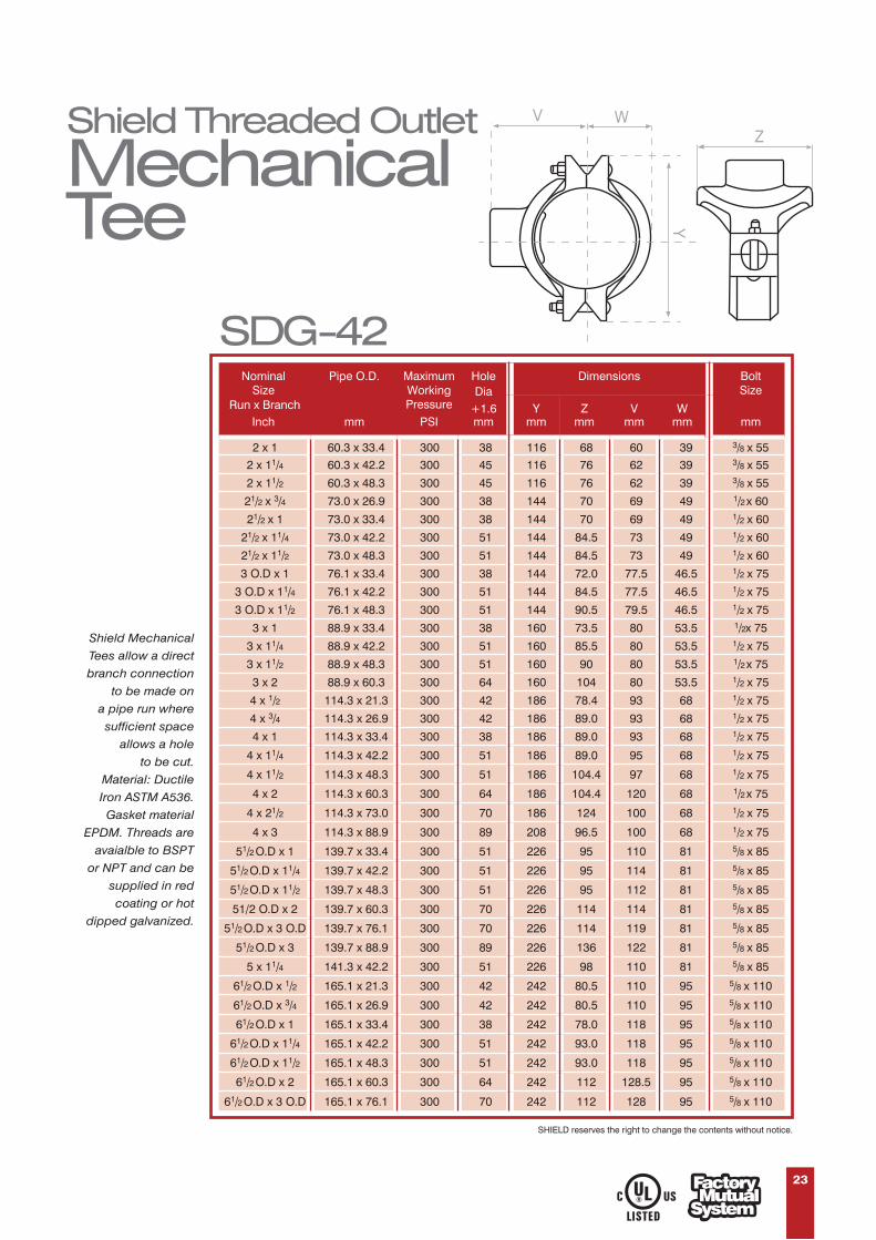
Shield Threaded Outlet
MechanicalTee
23
Shield Mechanical
Tees allow a direct
branch connection
to be made on
a pipe run where
sufficient space
allows a hole
to be cut.
Material: Ductile
Iron ASTM A536.
Gasket material
EPDM. Threads are
avaialble to BSPT
or NPT and can be
supplied in red
coating or hot
dipped galvanized.
SDG-42
Run x Branch
HoleDia
mm+1.6
Dimensions
Ymm
Zmm
Vmm
Wmm
2 x 1 60.3 x 33.4 300 38 116 68 60 39 3/8 x 552 x 11/4 60.3 x 42.2 300 45 116 76 62 39 3/8 x 55
2 x 11/2 60.3 x 48.3 300 45 116 76 62 39 3/8 x 55
21/2 x 3/4 73.0 x 26.9 300 38 144 70 69 49 1/2 x 60
21/2 x 1 73.0 x 33.4 300 38 144 70 69 49 1/2 x 60
21/2 x 11/4 73.0 x 42.2 300 51 144 84.5 73 49 1/2 x 60
21/2 x 11/2 73.0 x 48.3 300 51 144 84.5 73 49 1/2 x 60
3 O.D x 1 76.1 x 33.4 300 38 144 72.0 77.5 46.5 1/2 x 75
3 O.D x 11/4 76.1 x 42.2 300 51 144 84.5 77.5 46.5 1/2 x 75
3 O.D x 11/2 76.1 x 48.3 300 51 144 90.5 79.5 46.5 1/2 x 75
3 x 1 88.9 x 33.4 300 38 160 73.5 80 53.5 1/2x 75
3 x 11/4 88.9 x 42.2 300 51 160 85.5 80 53.5 1/2 x 75
3 x 11/2 88.9 x 48.3 300 51 160 90 80 53.5 1/2 x 75
3 x 2 88.9 x 60.3 300 64 160 104 80 53.5 1/2 x 75
4 x 1/2 114.3 x 21.3 300 42 186 78.4 93 68 1/2 x 75
4 x 3/4 114.3 x 26.9 300 42 186 89.0 93 68 1/2 x 75
4 x 1 114.3 x 33.4 300 38 186 89.0 93 68 1/2 x 75
4 x 11/4 114.3 x 42.2 300 51 186 89.0 95 68 1/2 x 75
4 x 11/2 114.3 x 48.3 300 51 186 104.4 97 68 1/2 x 75
4 x 2 114.3 x 60.3 300 64 186 104.4 120 68 1/2 x 75
4 x 21/2 114.3 x 73.0 300 70 186 124 100 68 1/2 x 75
4 x 3 114.3 x 88.9 300 89 208 96.5 100 68 1/2 x 75
51/2 O.D x 1 139.7 x 33.4 300 51 226 95 110 81 5/8 x 85
51/2 O.D x 11/4 139.7 x 42.2 300 51 226 95 114 81 5/8 x 85
51/2 O.D x 11/2 139.7 x 48.3 300 51 226 95 112 81 5/8 x 85
51/2 O.D x 2 139.7 x 60.3 300 70 226 114 114 81 5/8 x 85
51/2 O.D x 3 O.D 139.7 x 76.1 300 70 226 114 119 81 5/8 x 85
51/2 O.D x 3 139.7 x 88.9 300 89 226 136 122 81 5/8 x 85
5 x 11/4 141.3 x 42.2 300 51 226 98 110 81 5/8 x 85
61/2 O.D x 1/2 165.1 x 21.3 300 42 242 80.5 110 95 5/8 x 110
61/2 O.D x 3/4 165.1 x 26.9 300 42 242 80.5 110 95 5/8 x 110
61/2 O.D x 1 165.1 x 33.4 300 38 242 78.0 118 95 5/8 x 110
61/2 O.D x 11/4 165.1 x 42.2 300 51 242 93.0 118 95 5/8 x 110
61/2 O.D x 11/2 165.1 x 48.3 300 51 242 93.0 118 95 5/8 x 110
61/2 O.D x 2 165.1 x 60.3 300 64 242 112 128.5 95 5/8 x 110
61/2 O.D x 3 O.D 165.1 x 76.1 300 70 242 112 128 95 5/8 x 110
SHIELD reserves the right to change the contents without notice.
NominalSize
Inch
Pipe O.D.
mm
MaximumWorkingPressure
PSI
BoltSize
mm

24
Z
WV
Y
The mechanical tee and cross features a gap between thebolt pads. Do not attempt to bring bolt pads together whichwould result in metal to metal when tightening bolts and nuts.Note that excessive torque may cause joint failure - thefollowing table provides recommended bolt fastening torque.
Bolt Recommended Bolt TorqueSize N - m
3/8" 40 ~ 601/2" 110 ~ 1355/8" 135 ~ 1753/4" 175 ~ 2457/8" 245 ~ 325
SDG-42 (Continued)
SHIELD reserves the right to change the contents without notice.
61/2 O.D x 3 165.1 x 88.9 300 89 242 132 128.5 95 5/8 x 11061/2 O.D x 4 165.1 x 114.3 300 114 242 157 141 95 5/8 x 110
6 x 2 168.3 x 60.3 300 64 246 114 135 98.5 5/8 x 110
6 x 1 168.3 x 48.3 300 51 240 92.5 115 96.5 5/8 x 105
6 x 1 168.3 x 42.4 300 51 240 92.5 115 96.5 5/8 x 105
6 x 21/2 168.3 x 73.0 300 70 246 115 134 98.5 5/8 x 110
6 x 4 168.3 x 114.3 300 114 246 157 141 98.5 5/8 x 110
8 x 1 219.0 x 33.4 300 51 320 96.5 150 123 3/4 x 115
8 x 11/4 219.1 x 42.2 300 51 320 96.5 150 123 3/4 x 115
8 x 11/2 219.1 x 48.3 300 51 320 96.5 150 123 3/4 x 115
8 x 2 219.1 x 60.3 300 70 320 118 158.5 123 3/4 x 115
8 x 21/2 219.1 x 73.0 300 70 320 118 158.5 123 3/4 x 115
8 x 3 219.1 x 88.9 300 89 320 142 161 123 3/4 x 115
8 x 4 219.1 x 114.3 300 114 320 170 170 123 3/4 x 115
1/4
1/2
Run x Branch
HoleDia
mm+1.6
Dimensions
Ymm
Zmm
Vmm
Wmm
NominalSize
Inch
Pipe O.D.
mm
MaximumWorkingPressure
PSI
BoltSize
mm

25
Grooved Outlet
MechanicalTee
ZWV
Y
21/2 x 11/4 73.0 x 42.2 300 51 144 84.5 75 49 1/2 x 60
3 x 2 88.9 x 60.3 300 64 160 104 92 53.5 1/2 x 75
4 x 2 114.3 x 60.3 300 64 186 104.4 101.5 68 1/2 x 75
4 x 21/2 114.3 x 73.0 300 70 186 104.4 101.5 68 1/2 x 75
4 x 3 O.D 114.3 x 76.1 300 70 186 104.4 101.5 68 1/2 x 75
4 x 3 114.3 x 88.9 300 89 186 124 101.5 68 1/2 x 75
51/2 O.D x 2 139.7 x 60.3 300 70 226 114 119 81 5/8 x 85
51/2 O.D x 3 O.D 139.7 x 76.1 300 70 226 114 119 81 5/8 x 85
51/2 O.D x 3 139.7 x 88.9 300 89 226 136 122 81 5/8 x 85
61/2 O.D x 2 165.1 x 60.3 300 64 242 112 127.5 95 5/8 x 110
61/2 OD x 3 O.D 165.1 x 76.1 300 70 242 112 127.5 95 5/8 x 110
61/2 O.D x 3 165.1 x 88.9 300 89 242 142.6 141 95 5/8 x 110
61/2 O.D x 4 165.1 x 114.3 300 114 242 157 141 95 5/8 x 110
6 x 2 168.3 x 60.3 300 64 246 114 134 98.5 5/8 x 110
6 x 4 168.3 x 114.3 300 114 246 157 142 98.5 5/8 x 110
8 x 2 219.1 x 60.3 300 70 320 118 158 123 3/4 x 115
8 x 3 O.D 219.1 x 76.1 300 70 320 118 158 123 3/4 x 115
8 x 3 219.1 x 88.9 300 89 320 142 161 123 3/4 x 115
8 x 4 219.1 x 114.3 300 114 320 170 162 123 3/4 x 115
Run x Branch
HoleDia
mm+1.6
Dimensions
Ymm
Zmm
Vmm
Wmm
NominalSize
Inch
Pipe O.D.
mm
MaximumWorkingPressure
PSI
BoltSize
mm
SDG-44
SHIELD reserves the right to change the contents without notice.

26
Shield Threaded
MechanicalCross
ZVV
Y
2 x 1 60.3 x 33.4 300 38 116 68 60 3/8 x 552 x 11/4 60.3 x 42.2 300 45 116 76 62 3/8 x 55
2 x 11/2 60.3 x 48.3 300 45 116 76 62 3/8 x 55
21/2 x 3/4 73.0 x 26.9 300 38 144 70 69 1/2 x 75
21/2 x 1 73.0 x 33.4 300 38 144 70 69 1/2 x 75
21/2 x 11/4 73.0 x 42.2 300 51 144 84.5 73 1/2 x 75
21/2 x 11/2 73.0 x 48.3 300 51 144 84.5 73 1/2 x 75
3 O.D x 1 76.1 x 33.4 300 38 144 72.0 77.5 1/2 x 75
3 O.D x 11/4 76.1 x 42.2 300 51 144 84.5 77.5 1/2 x 75
3 O.D x 11/2 76.1 x 48.3 300 51 144 90.5 79.5 1/2 x 75
3 x 1 88.9 x 33.4 300 51 160 73.5 80 1/2 x 75
3 x 11/4 88.9 x 42.2 300 51 160 85.5 80 1/2 x 75
3 x 11/2 88.9 x 48.3 300 51 160 90 80 1/2 x 75
3 x 2 88.9 x 60.3 300 64 160 104 80 1/2 x 75
4 x 1/2 114.3 x 21.3 300 42 186 78.4 93 1/2 x 75
4 x 3/4 114.3 x 26.9 300 42 186 78.4 93 1/2 x 75
4 x 1 114.3 x 33.4 300 38 186 89.0 93 1/2 x 75
4 x 11/4 114.3 x 42.2 300 51 186 87.9 95 1/2 x 75
4 x 11/2 114.3 x 48.3 300 51 186 89 97 1/2 x 75
4 x 2 114.3 x 60.3 300 64 186 104.4 100 1/2 x 75
4 x 21/2 114.3 x 73.0 300 70 186 104.4 100 1/2 x 75
4 x 3 O.D 114.3 x 76.1 300 70 186 104.4 100 1/2 x 75
4 x 3 114.3 x 88.9 300 89 186 124 100 1/2 x 75
51/2 O.D x 1 139.7 x 33.4 300 51 226 95 110 5/8 x 85
51/2 O.D x 11/4 139.7 x 42.2 300 51 226 95 114 5/8 x 85
51/2 O.D x 11/2 139.7 x 48.3 300 51 226 95 112 5/8 x 85
51/2 O.D x 2 139.7 x 60.3 300 70 226 114 114 5/8 x 85
51/2 O.D x 3 O.D 139.7 x 76.1 300 70 226 114 119 5/8 x 85
61/2O.D x 3/4 165.1 x 26.9 300 42 242 80.5 120 5/8 x 110
61/2 O.D x 1 165.1 x 33.4 300 38 242 78 118 5/8 x 110
61/2 O.D x 11/4 165.1 x 42.2 300 51 242 93 118 5/8 x 110
61/2 O.D x 11/2 165.1 x 48.2 300 51 242 93 118 5/8 x 110
61/2 O.D x 2 165.1 x 60.3 300 64 242 112 128.5 5/8 x 110
61/2 O.D x 3 O.D 165.1 x 76.1 300 70 242 112 128.5 5/8 x 110
6 x 2 168.3 x 60.3 300 64 246 114 135 5/8 x 110
6 x 21/2 168.3 x 73.0 300 70 246 115 134 5/8 x 110
8 x 1 219.1 x 33.4 300 51 320 96.5 150 5/8 x 110
8 x 11/4 219.0 x 42.2 300 51 320 96.5 150 3/4 x 115
8 x 11/2 219.1 x 48.3 300 51 320 96.5 150 3/4 x 115
8 x 2 219.1x60.3 300 70 320 118 150 3/4 x 115
8 x 3 O.D 219.1x76.1 300 70 320 118 158.5 3/4 x 115
Run x Branch
HoleDia
mm+1.6
Dimensions
Ymm
Zmm
Vmm
NominalSize
Inch
Pipe O.D.
mm
MaximumWorkingPressure
PSI
BoltSize
mm
SDG-47
SHIELD reserves the right to change the contents without notice.

Shield Grooved
MechanicalCross
27
Run x Branch
HoleDia
mm+1.6
Dimensions
Ymm
Zmm
Vmm
NominalSize
Inch
Pipe O.D.
mm
MaximumWorkingPressure
PSI
BoltSize
mm
21/2
1/2
x 11/4 73.0 x 42.2 300 51 144 84.5 75 1/2 x 60
3 x 2 88.9 x 60.3 300 64 160 104 92 1/2 x 75
4 x 2 114.3 x 60.3 300 64 186 104.4 101.5 1/2 x 75
4 x 2 114.3 x 73.0 300 70 186 104.4 101.5 1/2 x 75
4 x 3 O.D 114.3 x 76.1 300 70 186 104.4 101.5 1/2 x 75
4 x 3 114.3 x 88.9 300 89 186 124 101.5 1/2 x 75
51/2 O.D x 2 139.7 x 60.3 300 70 226 114 119 5/8 x 85
51/2 O.D x 3 O.D 139.7 x 76.1 300 70 226 114 119 5/8 x 85
51/2 O.D x 3 139.7 x 88.9 300 89 226 136 122 5/8 x 85
61/2 O.D x 2 165.1 x 60.3 300 64 242 112 127.5 5/8 x 110
61/2 O.D x 3 O.D 165.1 x 76.1 300 70 242 112 127.5 5/8 x 110
61/2 O.D x 3 165.1 x 88.9 300 89 242 142.6 141 5/8 x 110
61/2 O.D x 4 165.1 x 114.3 300 114 242 157 141 5/8 x 110
6 x 2 168.3 x 60.3 300 64 246 114 134 5/8 x 110
6 x 4 168.3 x 114.3 300 114 246 157 142 5/8 x 110
8 x 2 219.1 x 60.3 300 70 320 118 158 3/4 x 115
8 x 3 O.D 219.1 x 76.1 300 70 320 118 158 3/4 x 115
8 x 3 219.1 x 88.9 300 89 320 142 161 3/4 x 115
8 x 4 219.1 x 114.3 300 114 320 170 162 3/4 x 115
SDG-49
SHIELD reserves the right to change the contents without notice.
ZVV
Y

Shield U-Bolt
MechanicalTee
Shield
Groove Specifications
28
Dimensions
Xmm
Ymm
Zmm
NominalSize
Inch
HoleDia
+1.6mm
MaximumWorkingPressure
PSI
U BoltSize
mm
11/4 x 1/2 30 300 53.0 89.0 56.0 3/8 x 6011/4 x 3/4 30 300 53.0 89.0 56.0 3/8 x 6011/4 x 1 30 300 56.0 89.0 56.0 3/8 x 6011/2 x 1/2 30 300 55.0 89.0 56.0 3/8 x 6711/2 x 3/4 30 300 55.0 89.0 56.0 3/8 x 6711/2 x 1 30 300 58.0 89.0 56.0 3/8 x 672 x 1/2 30 300 64.0 98.0 56.0 3/8 x 822 x 3/4 30 300 64.0 98.0 56.0 3/8 x 822 x 1 30 300 67.0 98.0 56.0 3/8 x 82
21/2 x 1/2 30 300 69.0 111.0 56.0 3/8 x 9521/2 x 3/4 30 300 69.0 111.0 56.0 3/8 x 9521/2 x 1 30 300 72.0 111.0 56.0 3/8 x 95
SDG-40
Minimum Pipe WallThickness ‘t’
NominalSize
Inch Inch Inch Inch Inch Inch
Pipe Outside Diameter GasketSeat ‘A’
Groove Diameter ‘C’ Groove Width ‘B’ GrooveDepth
‘d’
Max ‘F’Flare Dia.
Actual
Tolerance
MaximumTolerance(+)0.000
RollGroove
(+/-)0.030
CutGroove
(+/-)0.031(+/-)0.030Roll
GrooveCut
GrooveRoll
Groove(+) (-)
1 1.660 0.016 0.016 0.625 1.535 -0.015 0.281 0.312 0.063 0.065 0.140 1.77
1 1.900 0.019 0.019 0.625 1.775 -0.015 0.281 0.312 0.063 0.065 0.140 2.01
2 2.375 0.024 0.024 0.625 2.250 -0.015 0.344 0.312 0.063 0.065 0.154 2.48
2 2.875 0.029 0.029 0.625 2.720 -0.018 0.344 0.312 0.078 0.083 0.187 2.98
3 OD 3.000 0.030 0.030 0.625 2.845 -0.018 0.344 0.312 0.078 0.083 0.188 3.10
3 3.500 0.035 0.031 0.625 3.344 -0.018 0.344 0.312 0.078 0.083 0.188 3.60
4 4.500 0.045 0.031 0.625 4.334 -0.020 0.344 0.312 0.083 0.083 0.203 4.60
5 OD 5.500 0.056 0.031 0.625 5.334 -0.020 0.344 0.375 0.083 0.109 0.203 5.60
5 5.563 0.056 0.031 0.625 5.395 -0.022 0.344 0.375 0.084 0.109 0.203 5.66
6 6.625 0.063 0.031 0.625 6.445 -0.022 0.344 0.375 0.085 0.109 0.219 6.73
8 8.625 0.063 0.031 0.750 8.441 -0.025 0.469 0.375 0.092 0.109 0.238 8.80
10 10.750 0.063 0.031 0.750 10.562 -0.027 0.469 0.500 0.094 0.134 0.250 10.92
12 12.750 0.063 0.031 0.750 12.531 -0.030 0.469 0.500 0.109 0.156 0.279 12.92
1/41/2
1/2
1/2
• SHIELD reserves the right to change the contents without notice.
Y
X
Z
F
C
O.D
d
A Bt

Shield SwivelRing HangerModel : SD-HB
FUNCTION Designed for the suspension of non-insulated stationary pipe lines. The insert nut allows a vertical adjustment after installation, is tapped to NFPA reduced rod size standards. SD-HBF has a layer of felt which separates the pipe from the hanger to reduce vibration and sound.
APPROVALS Underwriters’ Laboratories listed and Factory Mutual approved ¾˝ to 8˝ sizes. Complies with Federal Specification WW-H-171E & A-A-1192 (Type 10), and Manufacturers’ Standardization Society MSS SP-69 & SP-58 (Type 10).
Material : Low Carbon Steel to ASTM A653
A
E
D
C
B
29
SD-HB
1/23/4
1
11/4
11/2
2
21/2
3
31/2
4
5
6
8
3/83/83/83/83/83/83/83/83/83/81/21/21/2
17/8
111/16
15/8
115/16
21/8
27/16
23/4
27/8
33/8
37/8
45/8
55/8
613/16
17/16
11/8
1
11/16
11/16
11/8
11/4
11/8
13/8
11/2
15/8
21/4
27/16
23/4
21/2
21/2
213/16
31/8
35/16
311/16
33/4
45/16
41/2
55/8
61/2
715/16
31/16
31/16
33/16
39/16
37/8
43/8
5
59/16
65/16
7
83/8
913/16
121/4
300
300
300
300
300
300
525
525
525
650
1000
1000
1000
Pipe Size Rod SizeA B
Adj.C D E
Max. Rec.Load/lbs.
Note: a) Swivel Nut is coming along with hanger .b) Swivel Nut is available for 10mm and 12mm Rod sizec) Hot Dipped Galvanized can be supplied upon request
:
:
Nut Electro Galvanized to ASTM B633
Finishing Galvanized
ShieldClevis Hanger
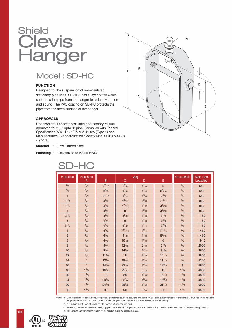
Model : SD-HCFUNCTION Designed for the suspension of non-insulated stationary pipe lines. SD-HCF has a layer of felt which separates the pipe from the hanger to reduce vibration and sound. The PVC coating on SD-HC protects the pipe from the metal surface of the hanger.
D
E
BC
A
APPROVALS Underwriters’ Laboratories listed and Factory Mutual approved for 2 ” upto 8” pipe. Complies with Federal Specification WW-H-171E & A-A-1192A (Type 1) and Manufacturers’ Standardization Society MSS SP-69 & SP-58 (Type 1).
Material : Low Carbon Steel
Finishing : Galvanized to ASTM B633
30
SD-HCPipe Size Rod Size
A B CAdj.
D ECross Bolt Max. Rec.
Load/lbs.1/2 3/8 27/16 27/8 11/8 2 1/4 6103/4 3/8 25/8 31/8 11/4 23/16 1/4 610
1 3/8 31/16 33/4 15/8 25/8 1/4 610
11/4 3/8 33/8 43/16 15/8 215/16 1/4 610
11/2 3/8 31/2 47/16 11/2 31/16 1/4 610
2 3/8 33/4 5 15/8 35/16 1/4 610
21/2 1/2 37/8 53/8 11/8 31/4 3/8 1130
3 1/2 41/4 6 11/8 35/8 3/8 1130
31/2 1/2 41/2 61/2 11/4 37/8 3/8 1130
4 5/8 51/2 711/16 13/4 411/16 3/8 1430
5 5/8 61/8 91/8 17/8 55/16 1/2 1430
6 3/4 67/8 101/8 15/8 6 1/2 1940
8 7/8 83/4 127/8 21/8 77/8 5/8 2000
10 7/8 91/4 145/8 13/4 81/8 3/4 3600
12 7/8 115/8 18 21/2 101/2 3/4 3800
14 1 123/4 193/4 25/8 111/4 7/8 4200
16 1 141/8 221/8 25/8 135/8 1 4600
18 11/8 161/2 251/2 31/2 15 11/8 4800
20 11/4 18 28 41/8 161/8 11/4 4800
24 11/4 201/4 321/4 43/4 183/8 11/4 4800
30 11/4 241/2 387/8 51/2 211/2 11/4 6000
36 11/2 32 50 83/4 30 11/2 9500
Note: a) Use of an upper locknut ensures proper performance. Pipe spacers provided on 30˝ and larger clevises. If ordering SD-HCF felt lined hangersfor pipe size of 3½˝ or under, order the next largest size to allow for the thickness of the felt lining.
b) “D” Adjustment (Top of cross bolt to bottom of hanger rod nut).
c) When an over-sized clevis is used, a pipe spacer should be placed over the clevis bolt to prevent the lower U-strap from moving inward.d) Hot Dipped Galvanized to ASTM A123 can be supplied upon request.
1/2
30

31
ShieldPipe ClampWith LiningModel : SD-GE-RLC
Material:
Finishing:
Features:
• Designed for Horizontal, vertical and suspended installations.• Suitable for Steel, copper and PVC pipes.• Welded Nut M8/M10 with option of M10/M12.• Connection thread with M8/M10 dual-tapped boss.• Side Screw: 6 x 20 – Phillip head with vicer.• High rigidity due to reinforcing rib.• With highly elastic vibration control lining, vibration control tested.
Mild Steel & EPDM Rubber.
Electro galvanized as per ASTM B633 Standards.
• Measurements are subject to 5% tolerance.• Other Sizes available on request.• Hot Dipped Galvanized can be supplied upon request.• SHIELD reserves the right to change the contents without notice.
Notes:
Size Dimensions MaximumLoad
PipeO.D
Inch Kgmm mm mm mm mm mm mmH E A B C D
Model No
SD-GE-RLC ⅜
SD-GE-RLC ½
SD-GE-RLC ¾
SD-GE-RLC 1
SD-GE-RLC 1¼
SD-GE-RLC 1½
SD-GE-RLC 1½-54
SD-GE-RLC 2
SD-GE-RLC 2-63
SD-GE-RLC 2-70
SD-GE-RLC 2½
SD-GE-RLC 2½-83
SD-GE-RLC 3
SD-GE-RLC 3½
SD-GE-RLC 3½-110
SD-GE-RLC 4
SD-GE-RLC 4-125
SD-GE-RLC 4-133
SD-GE-RLC 5
SD-GE-RLC 5-150
SD-GE-RLC 5-160
SD-GE-RLC 6
SD-GE-RLC 6-210
SD-GE-RLC 8
SD-GE-RLC 10
SD-GE-RLC 12
17.1
21.3
26.7
33.4
42.2
48.3
54.0
60.3
63.0
70.0
73.0
83.0
88.9
101.6
110.0
114.3
125.0
133.0
141.3
150.0
160.0
168.3
210.0
219.1
273.0
323.8
⅜”
½”
¾”
1”
1¼”
1½”
-
2”
-
-
2½”
-
3”
3½”
-
4”
-
-
5”
-
-
6”
-
8”
10”
12”
15
20
26
32
38
47
53
60
63
68
74
81
87
99
107
113
125
131
138
148
159
168
200
215
269
313
59
66
72
79
86
92
98
104
108
114
119
127
134
144
164
159
169
177
184
194
204
212
244
264
294
367
20
20
20
20
20
20
20
20
20
20
20
20
20
20
20
20
20
20
20
20
25
25
25
25
25
25
23
26
29
33
36
39
42
45
47
50
53
57
60
65
70
73
78
82
85
90
95
99
115
125
140
177
30
37
43
50
57
63
69
75
72
85
90
98
105
115
125
130
140
148
155
165
175
183
215
235
265
339
450
450
450
450
450
450
450
450
450
450
600
600
600
600
600
600
600
600
600
600
600
600
950
950
950
1200
19
25
30
36
43
51
58
64
66
72
80
86
92
105
112
118
130
137
142
153
166
172
212
220
274
318
H
E
D
C
A B

32
ShieldPipe ClampWith LiningModel : SD-GE-RLC
Selection of Lined Pipe Hangers for Different Types of Pipes:
Model No Copper
mm
UPVC / PE ABSSteel (SCH 40)
Inch mm
SD-GE-RLC ⅜
SD-GE-RLC ½
SD-GE-RLC ¾
SD-GE-RLC 1
SD-GE-RLC 1¼
SD-GE-RLC 1½
SD-GE-RLC 1½-54
SD-GE-RLC 2
SD-GE-RLC 2-63
SD-GE-RLC 2-70
SD-GE-RLC 2½
SD-GE-RLC 2½-83
SD-GE-RLC 3
SD-GE-RLC 3½
SD-GE-RLC 3½-110
SD-GE-RLC 4
SD-GE-RLC 4-125
SD-GE-RLC 4-133
SD-GE-RLC 5
SD-GE-RLC 5-150
SD-GE-RLC 5-160
SD-GE-RLC 6
SD-GE-RLC 6-210
SD-GE-RLC 8
SD-GE-RLC 10
SD-GE-RLC 12
15, 18
22
24, 28
35
42
-
54
64
-
67, 70
76
80
-
102, 105
108
-
125
-
-
-
159
167
206
-
-
-
16
22
28
35
42
48
-
60
-
-
75
-
90
-
-
115
-
-
140
-
-
168
-
219
-
-
-
20
25
32, 38
40, 43
45
54
60
-
70
75
83
90
102
110
115
125
135
140
152
160
-
200
220, 225
250
-
-
DN15 (21.4)
DN20 (26.8)
DN25 (33.6)
DN32 (42.3)
DN40 (48.3)
-
DN50 (60.4)
-
-
DN65 (75.4)
-
-
DN80 (88.9)
-
DN100 (114.3)
-
-
DN125 (21.4)
-
-
DN150 (168.3)
-
DN200 (225.0)
DN225 (250.4)
DN300 (315.5)
-
½”
¾”
1”
1¼”
1½”
-
2”
-
-
2½”
-
3”
-
-
4”
-
-
5”
-
-
6”
-
8”
-
-
• Measurements are subject to 5% tolerance• SHIELD reserves the right to change the contents without notice.
Notes:

33
ShieldPipe Clamp
Model : SD-GE-PPC
Material:
Finishing:
Features:
• Designed for Horizontal, vertical and suspended installations. • Welded Nut M8/M10 with option of M10/M12.• High - Strength round welded connecting nuts.• The two locking screws allow adjustment.• Can be used as a pipe anchor point.• Suitable for installations without vibration control requirements.
Mild Steel.
Electro galvanized as per ASTM B633 Standards.
SD-GE-PPC ⅜
SD-GE-PPC ½
SD-GE-PPC ¾
SD-GE-PPC 1
SD-GE-PPC 1 ¼
SD-GE-PPC 1 ½
SD-GE-PPC 1 ½-54
SD-GE-PPC 2
SD-GE-PPC 2-63
SD-GE-PPC 2-70
SD-GE-PPC 2 ½
SD-GE-PPC 2 ½-83
SD-GE-PPC 3
SD-GE-PPC 3 ½
SD-GE-PPC 3 ½-110
SD-GE-PPC 4
SD-GE-PPC 4-125
SD-GE-PPC 4-133
SD-GE-PPC 5
SD-GE-PPC 5-150
SD-GE-PPC 5-160
SD-GE-PPC 6
SD-GE-PPC 6-210
SD-GE-PPC 8
SD-GE-PPC 10
SD-GE-PPC 12
17.1
21.3
26.7
33.4
42.2
48.3
54.0
60.3
63.0
70.0
73.0
83.0
88.9
101.6
110.0
114.3
125.0
133.0
141.3
150.0
160.0
168.3
210.0
219.1
273.0
323.8
⅜”
½”
¾”
1”
1¼”
1½”
-
2”
-
-
2½”
-
3”
3½”
-
4”
-
-
5”
-
-
6”
-
8”
10”
12”
15
20
26
32
38
47
53
60
63
68
74
81
87
99
107
113
125
131
138
148
159
168
200
215
269
313
59
66
72
79
86
92
98
104
108
114
119
127
134
144
164
159
169
177
184
194
204
212
244
264
294
367
20
20
20
20
20
20
20
20
20
20
20
20
20
20
20
20
20
20
20
20
25
25
25
25
25
25
23
26
29
33
36
39
42
45
47
50
53
57
60
65
70
73
78
82
85
90
95
99
115
125
140
177
30
37
43
50
57
63
69
75
72
85
90
98
105
115
125
130
140
148
155
165
175
183
215
235
265
339
450
450
450
450
450
450
450
450
450
450
600
600
600
600
600
600
600
600
600
600
600
600
950
950
950
1200
19
25
30
36
43
51
58
64
66
72
80
86
92
105
112
118
130
137
142
153
166
172
212
220
274
318
Size Dimensions MaximumLoad
PipeO.D
Inch Kgmm mm mm mm mm mm mmH E A B C D
Model No
• Measurements are subject to 5% tolerance• Other Sizes available on request• Hot Dipped Galvanized can be supplied upon request• SHIELD reserves the right to change the contents without notice.
Notes:
D
C
A B
HE
3034
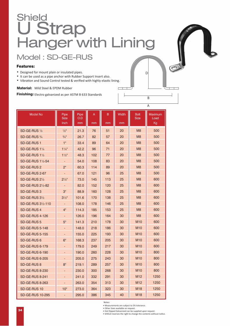
ShieldU StrapHanger with LiningFeatures:•••
Designed for mount plain or insulated pipes.It can be used as a pipe anchor with Rubber Support Insert also.Vibration and Sound Control tested & verified with highly elastic lining.
Model : SD-GE-RUS
Material:
Finishing:
Mild Steel & EPDM Rubber
Electro galvanized as per ASTM B 633 Standards
• Measurements are subject to 5% tolerance.• Other Sizes available on request.• Hot Dipped Galvanized can be supplied upon request.• SHIELD reserves the right to change the contents without notice.
Notes:
A
B
D
SD-GE-RUS ½
SD-GE-RUS ¾
SD-GE-RUS 1
SD-GE-RUS 1¼
SD-GE-RUS 1½
SD-GE-RUS 1½-54
SD-GE-RUS 2
SD-GE-RUS 2-67
SD-GE-RUS 2½
SD-GE-RUS 2½-82
SD-GE-RUS 3
SD-GE-RUS 3½
SD-GE-RUS 3½-110
SD-GE-RUS 4
SD-GE-RUS 4-126
SD-GE-RUS 5
SD-GE-RUS 5-148
SD-GE-RUS 5-155
SD-GE-RUS 6
SD-GE-RUS 6-179
SD-GE-RUS 6-190
SD-GE-RUS 6-205
SD-GE-RUS 8
SD-GE-RUS 8-230
SD-GE-RUS 8-241
SD-GE-RUS 8-263
SD-GE-RUS 10
SD-GE-RUS 10-295
½"
¾"
1"
1¼"
1½"
-
2"
-
2½"
-
3"
3½"
-
4"
-
5"
-
-
6"
-
-
-
8"
-
-
-
10"
-
21.3
26.7
33.4
42.2
48.3
54.0
60.3
67.0
73.0
82.0
88.9
101.6
108.0
114.3
126.0
141.3
148.0
155.0
168.3
179.0
190.0
205.0
219.1
230.0
241.0
263.0
273.0
295.0
76
82
89
96
102
108
114
121
145
152
160
170
178
185
196
210
218
225
237
249
260
275
289
300
332
354
364
386
51
57
64
71
77
83
89
96
113
120
128
138
146
153
164
178
186
193
205
217
228
243
257
268
291
313
323
345
20
20
20
20
20
20
20
25
25
25
25
25
25
25
30
30
30
30
30
30
30
30
30
30
30
30
30
40
M8
M8
M8
M8
M8
M8
M8
M8
M8
M8
M8
M8
M8
M8
M8
M10
M10
M10
M10
M10
M10
M10
M10
M10
M12
M12
M18
M18
500
500
500
500
500
500
500
500
600
600
600
600
600
600
600
600
600
600
600
600
800
800
800
800
1250
1250
1250
1250
A B Width BoltSize
MaximumLoad
PipeO.D
PipeSize
mm mm mm KgmmInch
Model No

35
ShieldU StrapHangerFeatures:• Designed for mount plain or insulated pipes.• U Strap Hangers can be used as a pipe anchor with rubber support inserts also.
Electrogalvanized as per ASTM B 633 Standards.
Material:
Finishing:
Mild Steel.
Model : SD-GE-US
A
B
D
• Measurements are subject to 5% tolerance.• Other Sizes available on request.• Hot Dipped Galvanized can be supplied upon request.• SHIELD reserves the right to change the contents without notice.
Notes:
Inch mm mm mm mm Kg
PaperSize
Model No PipeO.D
A B Width BoltSize
MaximumLoad
SD-GE-US ½
SD-GE-US ¾
SD-GE-US 1
SD-GE-US 1¼
SD-GE-US 1½
SD-GE-US 1½-54
SD-GE-US 2
SD-GE-US 2-67
SD-GE-US 2½
SD-GE-US 2½-82
SD-GE-US 3
SD-GE-US 3½
SD-GE-US 3½-108
SD-GE-US 4
SD-GE-US 4-126
SD-GE-US 5
SD-GE-US 5-148
SD-GE-US 5-155
SD-GE-US 6
SD-GE-US 6-179
SD-GE-US 6-190
SD-GE-US 6-205
SD-GE-US 8
SD-GE-US 8-230
SD-GE-US 8-241
SD-GE-US 8-263
SD-GE-US 10
SD-GE-US 10-295
½"
¾"
1"
1¼"
1½"
-
2"
-
2½"
-
3"
3½"
-
4"
-
5"
-
-
6"
-
-
-
8"
-
-
-
10"
-
21.3
26.7
33.4
42.2
48.3
54.0
60.3
67.0
73.0
82.0
88.9
101.6
108.0
114.3
126.0
141.3
148.0
155.0
168.3
179.0
190.0
205.0
219.1
230.0
241.0
263.0
273.0
295.0
76
82
89
96
102
108
114
121
145
152
160
170
178
185
196
210
218
225
237
249
260
275
289
300
332
354
364
386
51
57
64
71
77
83
89
96
113
120
128
138
146
153
164
178
186
193
205
217
228
243
257
268
291
313
323
345
20
20
20
20
20
20
20
25
25
25
25
25
25
25
30
30
30
30
30
30
30
30
30
30
30
30
30
40
M8
M8
M8
M8
M8
M8
M8
M8
M8
M8
M8
M8
M8
M8
M8
M10
M10
M10
M10
M10
M10
M10
M10
M10
M12
M12
M18
M18
500
500
500
500
500
500
500
500
600
600
600
600
600
600
600
600
600
600
600
600
800
800
800
800
1250
1250
1250
1250

36
ShieldRiser Hanger or Clamp
Model : SD-GE-RRC
D
Material:
Finishing:
Designed to act as a rigid support / guide for vertical pipes to control the suspension in pipeline.Equallly useable in most of the pipe types.
• Strengthened bolts for high load capacity. • Highly elastic lining for sound and vibrations control.• Manufactured as per MSS-SP58 - 2002 - Type 8.
Mild Steel & EPDM Rubber
Electrogalvanized as per ASTM B633 Standards.
A
Bolt Size
with Lining
Features:
• Measurements are subject to 5% tolerance.• Other Sizes available on request.• Hot Dipped Galvanized can be supplied upon request.• SHIELD reserves the right to change the contents without notice.
Notes:
Model No PipeSize
PipeO.D
A BoltSize
MaximumLoad
Inch mm mm Kg
SD-GE-RRC ½
SD-GE-RRC ¾
SD-GE-RRC 1
SD-GE-RRC 1¼
SD-GE-RRC 1½
SD-GE-RRC 2
SD-GE-RRC 2½
SD-GE-RRC 3
SD-GE-RRC 4
SD-GE-RRC 6
SD-GE-RRC 8
SD-GE-RRC 10
SD-GE-RRC 12
½"
¾"
1"
1¼"
1½"
2"
2½"
3"
4"
6"
8"
10"
12"
57
68
76
90
110
130
142
161
190
258
333
409
467
M10
M10
M10
M10
M10
M10
M12
M12
M12
M16
M16
M16
M20
1250
1250
1250
1250
1250
1850
1850
2250
3600
4500
4500
5800
7300
21.3
26.7
33.4
42.2
48.3
60.3
73.0
88.9
114.3
168.3
219.1
273.0
323.8

37
ShieldRiser Hanger or ClampModel : SD-GE-PRC
D
Material:
Finishing:
Designed to act as a rigid support for vertical pipes to control the suspension in pipeline. Equallly useable in most of the pipe types.
• Strengthened bolts for high load capacity. • Manufactured as per MSS-SP58 - 2002 - Type 8.
Mild Steel
Electrogalvanized as per ASTM B633 Standards.
Features:
• Measurements are subject to 5% tolerance.• Other Sizes available on request.• Hot Dipped Galvanized can be supplied upon request.• SHIELD reserves the right to change the contents without notice.
Notes:
A
Bolt Size
Model No PipeSize
PipeO.D
A BoltSize
MaximumLoad
Inch mm mm Kg
SD-GE-PRC ½
SD-GE-PRC ¾
SD-GE-PRC 1
SD-GE-PRC 1¼
SD-GE-PRC 1½
SD-GE-PRC 2
SD-GE-PRC 2½
SD-GE-PRC 3
SD-GE-PRC 4
SD-GE-PRC 6
SD-GE-PRC 8
SD-GE-PRC 10
SD-GE-PRC 12
½"
¾"
1"
1¼"
1½"
2"
2½"
3"
4"
6"
8"
10"
12"
57
68
76
90
110
130
142
161
190
258
333
409
467
M10
M10
M10
M10
M10
M10
M12
M12
M12
M16
M16
M16
M20
1250
1250
1250
1250
1250
1850
1850
2250
3600
4500
4500
5800
7300
21.3
26.7
33.4
42.2
48.3
60.3
73.0
88.9
114.3
168.3
219.1
273.0
323.8

3038
ShieldU-BoltModel : SD-UB
Material:
Finishing:
Mild Steel
Electro galvanized as per ASTM B 633 Standards.
D
Featuress:
• Designed to use as a support, anchor or guide for various types of pipes.• High load capacity due to one piece design.• Supplied with two Nuts & Washers.• Special U bolts with Longer Tangents and Threads can be furnished upon request.
½"
¾"
1"
1¼"
1½"
2"
2½"
3"
4"
6"
8"
10"
12"
14"
16"
18"
20"
24"
M8
M10
M10
M10
M10
M10
M10
M10
M10
M12
M12
M20
M20
M20
M20
M24
M24
M24
SD-UB ½
SD-UB ¾
SD-UB 1
SD-UB 1¼
SD-UB 1½
SD-UB 2
SD-UB 2½
SD-UB 3
SD-UB 4
SD-UB 6
SD-UB 8
SD-UB 10
SD-UB 12
SD-UB 14
SD-UB 16
SD-UB 18
SD-UB 20
SD-UB 24
31
39
45
54
60
72
86
102
128
184
239
273
324
356
406
457
508
610
35
40
45
55
55
60
75
80
95
130
155
370
420
455
505
555
605
710
35
38
40
45
45
45
55
55
55
70
70
100
100
100
100
100
100
100
NominalPipe Size
Inch
Model No
D C
Dimensions
F Gmm mm mm mm
• Measurements are subject to 5% tolerance.• Other Sizes available on request.• U Bolt sizes can be modified to match with Rubber support inserts.• Alternate rod sizes for different pipe sizes are also available.• Hot Dipped Galvanized can be supplied upon request.• SHIELD reserves the right to change the contents without notice.
Notes:

39
ShieldRubberSupport InsertModel : SD-RSI
Material:
Features:
• Very high load bearing capacity.• Dimensionally accurate as each piece is moulded.• Tongue and Groove design for small sizes.• Unique DOVETAIL lock for higher sizes.• Excellent resistance to Deterioration / Distortion.• Available with steel reinforcements for higher sizes.
EPDM Rubber
NominalPipe Sizes
Widthof RubberSupport
Insert
Schedule40 SteelPipe OD
mm
½” (13) ¾” (19) 1” (25) 1¼” (32) 1½” (38) 2” (50) 2½" (65) 3” (75)
Inch (mm) Inch (mm) Inch (mm) Inch (mm) Inch (mm) Inch (mm) Inch (mm) Inch (mm)
Part numbers for Rubber Support InsertThickness
Inch mm mm
½”
¾”
1”
1¼”
1½”
2”
2½”
3”
3½”
4”
5”
6”
8”
10”
12”
14”
16”
18”
20”
24”
15
20
25
32
40
50
65
80
90
100
125
150
200
250
300
350
400
450
500
600
21.3
26.7
33.4
42.2
48.3
60.3
73.0
88.9
101.6
114.3
141.3
168.3
219.1
273.0
323.8
355.6
406.4
457.2
508.0
610.0
25
25
25
25
25
25
38
38
38
38
38
50
50
50
50
50
50
50
50
50
SD-RSI13-01
SD-RSI13-02
SD-RSI13-03
SD-RSI13-04
SD-RSI13-05
SD-RSI13-06
SD-RSI13-07
SD-RSI13-08
SD-RSI13-09
SD-RSI13-10
SD-RSI13-11
SD-RSI13-12
SD-RSI13-13
SD-RSI13-14
SD-RSI13-15
SD-RSI13-16
SD-RSI13-17
SD-RSI13-18
SD-RSI13-19
SD-RSI13-20
SD-RSI19-01
SD-RSI19-02
SD-RSI19-03
SD-RSI19-04
SD-RSI19-05
SD-RSI19-06
SD-RSI19-07
SD-RSI19-08
SD-RSI19-09
SD-RSI19-10
SD-RSI19-11
SD-RSI19-12
SD-RSI19-13
SD-RSI19-14
SD-RSI19-15
SD-RSI19-16
SD-RSI19-17
SD-RSI19-18
SD-RSI19-19
SD-RSI19-20
SD-RSI25-01
SD-RSI25-02
SD-RSI25-03
SD-RSI25-04
SD-RSI25-05
SD-RSI25-06
SD-RSI25-07
SD-RSI25-08
SD-RSI25-09
SD-RSI25-10
SD-RSI25-11
SD-RSI25-12
SD-RSI25-13
SD-RSI25-14
SD-RSI25-15
SD-RSI25-16
SD-RSI25-17
SD-RSI25-18
SD-RSI25-19
SD-RSI25-20
SD-RSI32-01
SD-RSI32-02
SD-RSI32-03
SD-RSI32-04
SD-RSI32-05
SD-RSI32-06
SD-RSI32-07
SD-RSI32-08
SD-RSI32-09
SD-RSI32-10
SD-RSI32-11
SD-RSI32-12
SD-RSI32-13
SD-RSI32-14
SD-RSI32-15
SD-RSI32-16
SD-RSI32-17
SD-RSI32-18
SD-RSI32-19
SD-RSI32-20
SD-RSI38-01
SD-RSI38-02
SD-RSI38-03
SD-RSI38-04
SD-RSI38-05
SD-RSI38-06
SD-RSI38-07
SD-RSI38-08
SD-RSI38-09
SD-RSI38-10
SD-RSI38-11
SD-RSI38-12
SD-RSI38-13
SD-RSI38-14
SD-RSI38-15
SD-RSI38-16
SD-RSI38-17
SD-RSI38-18
SD-RSI38-19
SD-RSI38-20
SD-RSI50-01
SD-RSI50-02
SD-RSI50-03
SD-RSI50-04
SD-RSI50-05
SD-RSI50-06
SD-RSI50-07
SD-RSI50-08
SD-RSI50-09
SD-RSI50-10
SD-RSI50-11
SD-RSI50-12
SD-RSI50-13
SD-RSI50-14
SD-RSI50-15
SD-RSI50-16
SD-RSI50-17
SD-RSI50-18
SD-RSI50-19
SD-RSI50-20
SD-RSI65-01
SD-RSI65-02
SD-RSI65-03
SD-RSI65-04
SD-RSI65-05
SD-RSI65-06
SD-RSI65-07
SD-RSI65-08
SD-RSI65-09
SD-RSI65-10
SD-RSI65-11
SD-RSI65-12
SD-RSI65-13
SD-RSI65-14
SD-RSI65-15
SD-RSI65-16
SD-RSI65-17
SD-RSI65-18
SD-RSI65-19
SD-RSI65-20
SD-RSI75-01
SD-RSI75-02
SD-RSI75-03
SD-RSI75-04
SD-RSI75-05
SD-RSI75-06
SD-RSI75-07
SD-RSI75-08
SD-RSI75-09
SD-RSI75-10
SD-RSI75-11
SD-RSI75-12
SD-RSI75-13
SD-RSI75-14
SD-RSI75-15
SD-RSI75-16
SD-RSI75-17
SD-RSI75-18
SD-RSI75-19
SD-RSI75-20
• Measurements are subject to 5% tolerance.• Other Sizes available on request.• SHIELD reserves the right to change the contents without notice.• Self extinguishing ruber Inserts also available on request.
Notes:
WIDTH
I.D.

40
D
D
L
Finishing: Zinc Plated.
Standard: DIN 975, steel - Property Class 4.8
ShieldThreadedRodModel : SD-TR
Material: Low Carbon Steel
Features:
• Designed for use as a Double end Studs with a nut on either side or as studs.• Right Handed.• Coarse Threads.• Commercial Nut Fit.
• Measurements are subject to 5% tolerance.• Other Sizes available on request.• Left Handed is Available upon request.• Hot Dipped Galvanized can be supplied upon request.• SHIELD reserves the right to change the contents without notice.
Notes:
Diameter INCH 0.157 0.197 0.236 0.276 0.315 0.315 0.315 0.394 0.472 0.472
Pitch MM 0.700 0.800 1.000 1.000 1.000 1.250 1.250 1.500 1.250 1 1.750
Coarse & Fine ThreadLength (L) = 1000mm, 2000mm & 3000 mm
Thread (D) MM M4 M5 M6 M7 M8 M8 M10 M10 M12 M12
Thread (D) MM M14 M16 M16 M18 M20 M20 M22 M24 M27 M30
Diameter INCH 0.551 0.630 0.630 0.709 0.787 0.787 0.866 0.945 1.063 1.181
Pitch MM 2.000 1.500 2.000 2.500 1.500 2.500 2.500 3.000 3.000 3.500
Thread (D) MM M33 M36 M39 M42 M45 M48 M52 M56 M60 M64
Diameter INCH 1.299 1.417 1.535 1.654 1.772 1.890 2.047 2.205 2.362 2.520
Pitch MM 3.500 4.000 4.000 4.500 4.500 5.000 5.000 5.500 5.500 6.000

41
C
¾”
B
D
E
A
SD-CBC-110
SD-CBCA-115
21
30.2
40
46.1
49
55.6
42
46.5
4
8
250
750
Model No
⅜ (10)
½ (12)
Rod Size Dimensions Max. PipeSize
MaximumLoad
BA C D EmmInch (mm) mm mm mm Inch lbs.
ShieldBeamClamp
Material:
Finishing:
Features:
Beam Clamps are designed to clamp hanger rod to the beam’s top flange or bar joist. Universal open U design allows for adjustments and permissible to use in an inverted position on the bottom flange of the beam also.
Ductile iron ASTM A536, Grade 65-45-12
Electro galvanized as per ASTM B 633 Standards.
Model : SD-CBC
• Measurements are subject to 5% tolerance.• Other Sizes available on request.• Hot Dipped Galvanized can be supplied upon request.• SHIELD reserves the right to change the contents without notice.
Notes:


www.shieldglobal.com PF
-V.1
4-1
7
For further information on any aspect of the
Shield range of Pipes & Fittings please contact your nearest office.
United Kingdom
Redburn House, 2a Tonbridge Road
Romford, Essex - RM3 8qe, UK
Email: [email protected]
Tel: + 44 (0) 1708 377731
Fax: + 44 (0) 1708 347637
Middle East & Africa
Jebel Ali Free Zone, Dubai, U.A.E.
Email: [email protected]
Tel: + 971 4 881 2070
Fax: + 971 4 881 2198

4/12/2018 VIZY.EX15278 - Metallic Sprinkler Pipe
http://database.ul.com/cgi-bin/XYV/template/LISEXT/1FRAME/showpage.html?name=VIZY.EX15278&ccnshorttitle=Metallic+Sprinkler+Pipe&objid=1078973727&cfgid
VIZY.EX15278 Metallic Sprinkler Pipe
Page Bottom
Metallic Sprinkler Pipe See General Information for Metallic Sprinkler Pipe SHIELD FIRE SAFETY & SECURITY LTD EX15278REDBURN HOUSE2A TONBRIDGE ROADROMFORD, ESSEX RM3 8QE UNITED KINGDOM
Schedule 10 (black and galvanized) steel pipe in the 3/4, 1, 1-1/4, 1-1/2, 2, 2-1/2, 3, 4, 5, 6 and 8 in sizes.
Schedule 40 (black and galvanized), Grade B, Type S steel pipe in the 1/2, 3/4, 1, 1-1/4, 1-1/2, 2, 2-1/2, 3, 4, 5, 6, 8, 10 and 12 in. sizes.
Schedule 80 (black and galvanized), Grade B, Type S steel pipe in the 1/2, 3/4, 1, 1-1/4, 1-1/2, 2, 2-1/2, 3, 4, 5, 6, 8, 10 and 12 in. sizes.
Schedule 40 (black and galvanized), Grade B, Type E steel pipe in the 1/2, 3/4, 1, 1-1/4, 1-1/2, 2, 2-1/2, 3, 4, 5, 6, 8, 10 and 12 in. sizes.
Schedule 40 (black or galvanized) steel pipe in the 1/2, 3/4, 1, 1-1/4, 1-1/2, 2, 2-1/2, 3, 4, 5, 6, 8, 10, 12, 14 and 16 in. sizes
Weight Class STD (black or galvanized) steel pipe, 12 inch size
Schedule 30 (black or galvanized) steel pipe in the 14 and 16 in. sizes
Schedule 20 (black or galvanized) steel pipe in the 10 and 12 in. sizes
Schedule 10 (black or galvanized) steel pipe in the 2-1/2, 3, 4, 6, 8, 10, 14 and 16 in. sizes
Trademark and/or Tradename: , , ,
Last Updated on 2018-03-20
Questions? Print this page Terms of Use Page Top
© 2018 UL LLC
The appearance of a company's name or product in this database does not in itself assure that products so identified have been manufacturedunder UL's Follow-Up Service. Only those products bearing the UL Mark should be considered to be Certified and covered under UL's Follow-UpService. Always look for the Mark on the product.
UL permits the reproduction of the material contained in the Online Certification Directory subject to the following conditions: 1. The GuideInformation, Assemblies, Constructions, Designs, Systems, and/or Certifications (files) must be presented in their entirety and in a non-misleading manner, without any manipulation of the data (or drawings). 2. The statement "Reprinted from the Online Certifications Directorywith permission from UL" must appear adjacent to the extracted material. In addition, the reprinted material must include a copyright notice inthe following format: "© 2018 UL LLC".

4/12/2018 VIZA.EX6657 - Fittings, Grooved and Plain End
http://database.ul.com/cgi-bin/XYV/template/LISEXT/1FRAME/showpage.html?name=VIZA.EX6657&ccnshorttitle=Fittings,+Grooved+and+Plain+End&objid=1077505
VIZA.EX6657 Fittings, Grooved and Plain End
Page Bottom
Fittings, Grooved and Plain End See General Information for Fittings, Grooved and Plain End SHIELD FIRE SAFETY & SECURITY LTD EX6657REDBURN HOUSE2A TONBRIDGE ROADROMFORD, ESSEX RM3 8QE UNITED KINGDOM
Grooved
Model
Type
Size In.
RatedPressure
(psig)
SDG100
90 Degree Elbow 1-1/4, 1-1/2, 2, 2-1/2, 3 OD, 3, 4, 5, 5-1/2 OD, 6, 6-1/2 OD, 8 500
SDG100
90 Degree Elbow 33.7 mm 500
SDG100
90 Degree Elbow 133.0 mm, 267.4 mm, 318.5 mm 300
SDG100
90 Degree Elbow 10 300
SDG100
90 Degree Elbow 12 225
SDG100H
90 Degree Elbow 114.3mm x 88.9mm x 33.7mm, 165.1mm x 88.9mm x 33.7mm;
300
SDG105
90 Degree Short Elbow 2, 2-1/2, 3 OD, 3, 4, 5-1/2 OD, 6, 6-1/2 OD, 8 300
SDG105
90 Degree Short Elbow 108.0 mm 500
SDG105
90 Degree Short Elbow 159.0 mm, 216.3 mm 300
SDG101R
90 Degree Reducing Elbow 88.9 x 76.1mm; 114.3 x 76.1mm, 88.9mm;
165.1 x 114.3mm; 168.3 x 114.3mm
300
SDG200
45 Degree Elbow 1-1/4, 1-1/2, 2, 2-1/2, 3 OD, 3, 4, 5, 6, 6-1/2 OD, 8, 10, 12 500
SDG200
45 Degree Elbow 33.7 mm 500
SDG200
45 Degree Elbow 108.0 mm, 139.7 mm, 159.0 mm, 216.3 mm, 267.4 mm, 318.5 mm 300
SDG 12 Tee 1-1/4, 1-1/2, 2, 2-1/2, 3 OD, 3, 4, 5, 6, 6-1/2 OD, 8, 10, 12 500
SDG 53 Reducing Tee 2 x 1-1/2; 3 x 1, 1-1/2, 2, 2-1/2;
4 x 1, 2, 2-1/2, 3; 5 x 2, 3, 4;
6 x 2, 2-1/2, 3, 4, 5; 8 x 2, 3, 4, 5, 6
500
SDG 53 Reducing Tee 60.3 x 33.7 mm; 73.0 x 48.3 mm, 60.3 mm;
500

4/12/2018 VIZA.EX6657 - Fittings, Grooved and Plain End
http://database.ul.com/cgi-bin/XYV/template/LISEXT/1FRAME/showpage.html?name=VIZA.EX6657&ccnshorttitle=Fittings,+Grooved+and+Plain+End&objid=1077505
76.1 x 42.4 mm, 48.3 mm, 60.3 mm; 88.9 x 42.4 mm
SDG 53 Reducing Tee 88.9 x 76.1 mm; 108.0 x 60.3 mm, 73.0 mm, 88.9 mm;
114.3 x 48.3 mm, 76.1 mm; 133.0 x 60.3 mm, 76.1 mm, 108. 0mm, 114.3 mm;
139.7 x 48.3 mm, 60.3 mm, 76.1 mm, 88.9 mm, 114.3 mm; 159.0 x 60.3 mm, 76.1 mm, 88.9 mm, 108.0 mm, 114.3 mm, 133.0
mm; 165.1 x 60.3 mm, 76.1 mm, 88.9 mm, 114.3 mm, 133.0 mm, 139.7
mm, 159.0 mm; 168.3 x 76.1 mm, 139.7 mm;
216.3 x 165.1 mm; 219.1 x 76.1 mm, 108.0 mm, 133.0 mm, 139.7 mm, 159.0 mm,
165.1 mm; 273.0 x 165.1 mm, 168.3 mm, 219.1 mm;
323.9 x 165.1 mm, 219.1 mm, 273.0 mm
300
SDG 53A
Reducing Tee, Grooved 114.3mm x 88.9mm x 33.7mm, 165.1mm x 88.9mm x 33.7mm;
300
SDG 53B
Reducing Tee, Grooved 114.3mm x 88.9mm x 33.7mm, 165.1mm x 88.9mm x 33.7mm;
300
SDG102
Short Tee 2, 2-1/2, 3 OD, 3, 4, 5-1/2 OD, 6, 6-1/2 OD, 8 300
SDG102
Short Tee 108.0 mm 500
SDG102
Short Tee 159.0 mm, 216.3 mm 300
SDG 12TH
Tee 88.9mm, 114.3mm, 168.3mm 300
SDG 53TH
Reducing Tee 60.3 x 33.7mm, 48.3mm; 73.0 x 33.7mm, 42.4mm; 76.1 x 33.7mm, 42.4mm, 48.3mm,
60.3mm; 88.9 x 33.7mm, 42.4mm, 48.3mm,
60.3mm, 76.1mm
500
SDG 53TH
Reducing Tee 108.0 x 60.3mm, 76.1mm, 88.9mm; 114.3 x 33.7mm, 42.4mm, 48.3mm, 60.3mm, 76.1mm, 88.9mm;
133.0 x 60.3mm, 76.1mm, 88.9mm; 139.7 x 33.7mm, 42.4mm, 48.3mm, 60.3mm, 76.1mm, 88.9mm;
159.0 x 60.3mm, 76.1mm, 88.9mm; 165.1 x 33.7mm, 42.4mm, 48.3mm,
60.3mm, 76.1mm, 88.9mm, 114.3mm; 168.3 x 60.3mm, 76.1mm, 88.9mm
300
SDG 13 Cross 1-1/4, 1-1/2, 2, 2-1/2, 3 OD, 3, 4, 5, 6, 6-1/2 OD, 8, 10, 12 500
SDG 13 Cross 108.0 mm, 139.7 mm, 159.0 mm 300
SDG 13 Reducing Cross 88.9 x 60.3 mm 500
SDG 13 Reducing Cross 114.3 x 60.3 mm, 88.9 mm; 139.7 x 114.3 mm;
159.0 x 108.0 mm; 165.1 x 60.3 mm, 76.1 mm, 88.9 mm, 114.3 mm;
219.1 x 60.3 mm, 114.3 mm, 139.7 mm, 159.0 mm, 165.1 mm
300
SDG13R
Reducing Cross 88.9 x 60.3mm 500
SDG13R
Reducing Cross 114.3 x 60.3mm, 88.9mm; 139.7 x 114.3mm;
159.0 x 108.0mm; 165.1 x 60.3mm, 76.1mm, 88.9mm,
114.3mm; 219.1 x 60.3mm, 114.3mm, 139.7mm,
159.0mm, 165.1mm
300
SDG 13RTH
Cross 114.3 x 33.7mm, 42.4mm, 48.3mm, 60.3mm;
165.1 x 60.3mm
300

4/12/2018 VIZA.EX6657 - Fittings, Grooved and Plain End
http://database.ul.com/cgi-bin/XYV/template/LISEXT/1FRAME/showpage.html?name=VIZA.EX6657&ccnshorttitle=Fittings,+Grooved+and+Plain+End&objid=1077505
SDG 35 Grooved Concentric Reducer 2 x 3/4, 1, 1-1/4, 1-1/2; 2-1/2 x 1, 1-1/4, 1-1/2, 2;
3 x 3/4, 1, 1-1/2, 2, 2-1/2; 4 x 1, 1-1/2, 2, 2-1/2, 3;
5 x 3, 4; 6 x 1, 2, 2-1/2, 3, 4, 5;
8 x 2-1/2, 3, 4, 5, 6
500
SDG 35 Grooved Concentric Reducer 42.4 x 33.7 mm; 48.3 x 33.7 mm, 42.4 mm;
76.1 x 42.4 mm, 48.3 mm, 60.3 mm; 88.9 x 76.1 mm;
108.0 x 60.3 mm, 73.0 mm
500
SDG 35 Grooved Concentric Reducer 108.0 x 76.1 mm; 114.3 x 42.4 mm, 76.1 mm;
139.7 x 76.1 mm, 88.9 mm, 114.3 mm; 141.3 x 73.0 mm;
159.0 x 60.3 mm, 76.1 mm, 88.9 mm, 108.0 mm, 114.3 mm, 133.0mm;
165.1 x 60.3 mm, 76.1 mm, 88.9 mm, 114.3 mm, 139.7 mm; 168.3 x 76.1 mm, 139.7 mm;
216.3 x 114.3 mm, 165.1 mm; 219.1 x 108.0 mm, 139.7 mm, 159.0 mm, 165.1 mm;
273.0 x 159.0 mm, 165.1 mm, 168.3 mm, 219.1 mm; 323.9 x 219.1 mm, 273.0 mm
300
SDG 37 Concentric Reducer - FNPT 2 x 3/4, 1, 1-1/4, 1-1/2; 2-1/2 x 1, 1-1/4, 1-1/2, 2;
3 x 3/4, 1, 1-1/2, 2, 2-1/2; 4 x 1, 1-1/2, 2, 2-1/2, 3;
5 x 3, 4; 6 x 1, 2, 2-1/2, 3, 4, 5;
8 x 2-1/2, 3, 4, 5, 6
500
SDG 37 Concentric Reducer WithFemale Thread
76.1 x 21.3 mm, 26.9 mm, 33.7 mm, 42.4 mm, 48.3 mm, 60.3 mm 500
SDG 37 Concentric Reducer WithFemale Thread
88.9 x 42.4 mm, 76.1 mm; 108.0 x 33.7 mm, 42.4 mm, 48.3 mm, 60.3 mm, 76.1 mm, 88.9
mm; 114.3 x 21.3 mm, 26.9 mm, 42.4 mm, 76.1 mm;
159.0 x 26.9 mm, 33.7 mm, 42.4 mm, 48.3 mm, 60.3 mm, 88.9mm, 114.3 mm;
165.1 x 21.3 mm, 26.9 mm, 33.7 mm, 42.4 mm, 48.3 mm, 60.3mm, 76.1 mm, 88.9 mm, 114.3 mm;
219.1 x 48.3 mm, 60.3 mm, 76.1 mm
300
SDG 39 Concentric Reducer - MNPT 2 x 3/4, 1, 1-1/4, 1-1/2; 2-1/2 x 1, 1-1/4, 1-1/2, 2;
3 x 3/4, 1, 1-1/2, 2, 2-1/2; 4 x 1, 1-1/2, 2, 2-1/2, 3;
5 x 3, 4; 6 x 1, 2, 2-1/2, 3, 4, 5;
8 x 2-1/2, 3, 4, 5, 6
500
SDG 39 Concentric Reducer - MNPT 76.1 x 60.3 mm 500
SDG 14 Cap 1-1/4, 1-1/2, 2, 2-1/2, 3 OD, 3, 4, 5, 5-1/2 OD, 6, 6-1/2 OD, 8, 10,12
500
SDG 14 Cap 33.7 mm 500
SDG 14 Cap 108.0 mm, 133.0 mm, 139.7 mm, 159.0 mm, 216.3 mm 300
SDG 14 Cap 76.1 x 48.3 mm 500
SDG 14 Cap 88.9 x 21.3 mm, 33.7 mm, 48.3 mm; 114.3 x 21.3 mm, 33.7 mm, 48.3 mm; 165.1 x 21.3 mm, 33.7 mm;
168.3 x 48.3 mm
300
SDG14A
Cap 88.9 x 48.3mm, 60.3mm; 114.3 x 48.3mm, 60.3mm; 139.7 x 48.3mm, 60.3mm; 165.1 x 48.3mm;
168.3 x 48.3mm, 60.3mm
365
SDG14A
Cap 219.1 x 48.3mm, 60.3mm 300
SDG Flange Adapter 2, 2-1/2, 3 OD, 3, 4, 5, 5-1/2 OD, 6, 6-1/2 OD, 8 300

4/12/2018 VIZA.EX6657 - Fittings, Grooved and Plain End
http://database.ul.com/cgi-bin/XYV/template/LISEXT/1FRAME/showpage.html?name=VIZA.EX6657&ccnshorttitle=Fittings,+Grooved+and+Plain+End&objid=1077505
16B
SDG16B
Flange Adapter 10, 12 225
SDG16B
Flange Adapter 33.7mm, 42.4mm, 48.3mm, 60.3mm, 73.0mm, 76.1mm, 88.9mm, 108.0mm,
114.3mm, 133.0mm, 139.7mm, 141.3mm, 159.0mm, 165.1mm, 168.3mm
300
SDG16B
Flange Adapter 219.1mm, 273.1mm, 323.9mm 225
SDG 16C
Flange Adapter 108.0mm, 159.0mm 300
SDG 16A
Flange Adapter 219.1mm, 273.0mm 225
SDG 16 Flange Adapter 2, 2-1/2, 3 OD, 3, 4, 5, 6, 6-1/2 OD, 8 300
SDG 16 Flange Adapter 10, 12 225
SDG 16 Flange Adapter 33.7 mm, 42.4 mm, 48.3 mm, 108.0 mm, 133.0 mm, 159.0 mm 300
SDG112
11.25 Degree Elbow 42.4 mm, 48.3 mm, 60.3 mm, 76.1 mm, 88.9 mm 500
SDG112
11.25 Degree Elbow 108.0 mm, 114.3 mm, 139.7 mm, 159.0 mm, 165.1 mm, 168.3 mm,219.1 mm
300
SDG225
22.5 Degree Elbow 42.4 mm, 48.3 mm, 60.3 mm, 73.0 mm, 76.1 mm, 88.9 mm 500
SDG225
22.5 Degree Elbow 108.0 mm, 114.3 mm, 139.7 mm, 159.0 mm, 165.1 mm, 168.3 mm,219.1 mm
300
SDG 33 Grooved Eccentric Reducer 88.9 x 60.3 mm; 108.0 x 76.1 mm, 88.9 mm;
114.3 x 60.3 mm, 88.9 mm
500
SDG 33 Grooved Eccentric Reducer 114.3 x 76.1 mm; 139.7 x 114.3 mm; 159.0 x 108.0 mm, 114.3 mm;
165.1 x 88.9 mm, 114.3 mm, 139.7 mm; 168.3 x 88.9 mm, 114.3 mm, 139.7 mm; 219.1 x 114.3 mm, 168.3 mm;
273.1 x 219.1 mm
300
SDG 33TH
Grooved Eccentric ReducerWith FeMale Thread
108.0 x 76.1mm 500
SDG 33TH
Grooved Eccentric ReducerWith FeMale Thread
114.3 x 76.1mm; 139.7 x 88.9mm;
165.1 x 88.9mm
300
Trademark and/or Tradename: "SHIELD", , , ,
Last Updated on 2016-11-24
Questions? Print this page Terms of Use Page Top
© 2018 UL LLC
The appearance of a company's name or product in this database does not in itself assure that products so identified have been manufacturedunder UL's Follow-Up Service. Only those products bearing the UL Mark should be considered to be Certified and covered under UL's Follow-UpService. Always look for the Mark on the product.
UL permits the reproduction of the material contained in the Online Certification Directory subject to the following conditions: 1. The GuideInformation, Assemblies, Constructions, Designs, Systems, and/or Certifications (files) must be presented in their entirety and in a non-misleading manner, without any manipulation of the data (or drawings). 2. The statement "Reprinted from the Online Certifications Directorywith permission from UL" must appear adjacent to the extracted material. In addition, the reprinted material must include a copyright notice inthe following format: "© 2018 UL LLC".

4/12/2018 HHXX.EX6706 - Fittings, Cast Iron, Ductile Iron, Malleable Iron and Bronze
http://database.ul.com/cgi-bin/XYV/template/LISEXT/1FRAME/showpage.html?name=HHXX.EX6706&ccnshorttitle=Fittings,+Cast+Iron,+Ductile+Iron,+Malleable+Iron
HHXX.EX6706 Fittings, Cast Iron, Ductile Iron, Malleable Iron and Bronze
Page Bottom
Fittings, Cast Iron, Ductile Iron, Malleable Iron and Bronze See General Information for Fittings, Cast Iron, Ductile Iron, Malleable Iron and Bronze SHIELD FIRE SAFETY & SECURITY LTD EX6706REDBURN HOUSE2A TONBRIDGE ROADROMFORD, ESSEX RM3 8QE UNITED KINGDOM
Ductile Iron Fittings (ANSI/ASME B16.3)
Fittings fabricated with dimensional specifications in accordance with ANSI/ASME B16.3
Model
Configuration
Size, in.
Rated Pressure,
psig
SDT100
90° Elbow 1/2, 3/4, 1, 1-1/4, 1-1/2, 2, 2-1/2,
3, 4
500
SDT101
Reducing 90°Elbow
3/4, 1, 1-1/4, 1-1/2, 2, 2-1/2,
3x3/4
500
SDT200
45° Elbow 1/2, 3/4, 1, 1-1/4, 1-1/2, 2, 2-1/2
500
SDT12
Tee 1/2, 3/4, 1, 1-1/4, 1-1/2, 2, 2-1/2,
3, 4
500
SDT53
Reducing Tee 3/4, 1, 1-1/4, 1-1/2, 2, 2-1/2,
3/4x1/2x1/2, 3/4x1/2x3/4, 2-1/2x2-1/2x3/4, 2-1/2x2-1/2x1, 2-1/2x2-1/2x1-1/4, 2-1/2x2-1/2x1-1/2, 2-1/2x2-1/2x2, 2-1/2x2-1/2x3
500
SDT57
Hex Bushing 1, 1-1/4, 1-1/2, 2, 1-1/4x3/4
500
SDT22
StraightCouplingw/stop
1/2, 3/4, 1, 1-1/4, 1-1/2, 2, 2-1/2
500
SDT30
Reducing 1/2, 3/4, 1, 1-1/4 500
Coupling w/hex 1-1/4x1, 1-1/2x1, 1-1/2x1-1/4, 2x1-1/4, 2x1-1/2 —
SDT13
Cross 1, 1-1/4, 1-1/2, 2, 3/4
500
SDT51
Reducing Cross 1-1/4, 1-1/2, 2 500
SDT14
Cap 1/2, 3/4, 1, 1-1/4, 1-1/2, 2, 2-1/2
500
SDT55
Square HeadPlug
1/2, 3/4, 1, 1-1/4, 1-1/2, 2
500
SDT59
Union 1, 1-1/4, 1-1/2, 2 500
SDC100
90° Elbow 1/2, 3/4, 1, 1-1/4, 1-1/2, 2, 2-1/2,
3, 4
500

4/12/2018 HHXX.EX6706 - Fittings, Cast Iron, Ductile Iron, Malleable Iron and Bronze
http://database.ul.com/cgi-bin/XYV/template/LISEXT/1FRAME/showpage.html?name=HHXX.EX6706&ccnshorttitle=Fittings,+Cast+Iron,+Ductile+Iron,+Malleable+Iron
SDC101
Reducing 90°Elbow
3/4, 1, 1-1/4, 1-1/2, 2, 2-1/2,
3x3/4
500
SDC200
45° Elbow 1/2, 3/4, 1, 1-1/4, 1-1/2, 2, 2-1/2
500
SDC12
Tee 1/2, 3/4, 1, 1-1/4, 1-1/2, 2, 2-1/2,
3, 4
500
SDC53
Reducing Tee 3/4, 1, 1-1/4, 1-1/2, 2, 2-1/2,
3/4x1/2x1/2, 3/4x1/2x3/4,2-1/2x2-1/2x3/4, 2-1/2x2-1/2x1,2-1/2x2-1/2x1-1/4, 2-1/2x2-1/2x1-1/2,2-1/2x2-1/2x2, 2-1/2x2-1/2x3
500
SDC30
Reducing 1/2, 3/4, 1, 1-1/4 500
Coupling w/hex 1-1/4x1, 1-1/2x1, 1-1/2x1-1/4, 2x1-1/4, 2x1-1/2 —
SDC13
Cross 1, 1-1/4, 1-1/2, 2 300
SDC51
Reducing Cross 1-1/4x1, 1-1/2x1, 2x1 300
SDC55
Cored Plugs 3/4, 1, 1-1/4, 1-1/2, 2 300
SDC-55S
Solid Plugs 1/2 300
CAST IRON FITTINGS
Cast Iron Fittings (ANSI/ASME B16.4)
Model
Configuration
Size, in.
Rated Pressure,
psig
SDT100
90° Elbow 1, 1-1/4, 1-1/2, 2, 2-1/2, 3, 4
300
SDT101
Reducing 90°Elbow
1/2, 3/4, 1, 1-1/4, 1-1/2, 2, 2-1/2, 3/4x1/2, 3x2
300
SDT200
45° Elbow 1, 1-1/4, 1-1/2, 2, 2-1/2, 3, 4
300
SDT12
Tee 1, 1-1/4, 1-1/2, 2, 2-1/2, 3, 4
300
SDT53
Reducing Tee 1x1x1-1/2, 2x1/2x2, 2x1x1-1/2,2-1/2x1/2x2-1/2, 2-1/2x2x1/2,2-1/2x2x3/4, 2-1/2x2x1,2-1/2x2x1-1/4, 2-1/2x2x1-1/2,2-1/2x2x2, 2-1/2x2x2-1/2,3x3x1-1/4, 3x3x1-1/2, 3x3x2
300
SDT13
Cross 1, 1-1/4, 1-1/2, 2 300
SDT51
ReducingCross
1-1/4x1, 1-1/2x1, 2x1 300
SDT30
ReducingCouplingw/hex
1, 2, 1-1/4x1, 2x3/4
300
SDT55
Cored Plugs 3/4, 1, 1-1/4, 1-1/2, 2 300
SDC100
90° Elbow 1, 1-1/4, 1-1/2, 2, 2-1/2, 3, 4
300
SDC101
Reducing 90°Elbow
1/2, 3/4, 1, 1-1/4, 1-1/2, 2, 2-1/2, 3/4x1/2, 3x2
300
SDC200
45° Elbow 1, 1-1/4, 1-1/2, 2, 2-1/2, 3, 4
300
SDC12
Tee 1, 1-1/4, 1-1/2, 2, 2-1/2, 3, 4
300
SDC Reducing Tee 1x1x1-1/2, 2x1/2x2, 2x1x1-1/2, 2-1/2x1/2x2-1/2, 2-1/2x2x1/2, 2-1/2x2x3/4, 2- 300
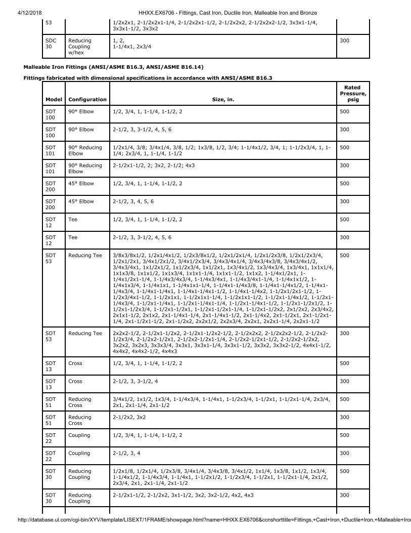
4/12/2018 HHXX.EX6706 - Fittings, Cast Iron, Ductile Iron, Malleable Iron and Bronze
http://database.ul.com/cgi-bin/XYV/template/LISEXT/1FRAME/showpage.html?name=HHXX.EX6706&ccnshorttitle=Fittings,+Cast+Iron,+Ductile+Iron,+Malleable+Iron
53 1/2x2x1, 2-1/2x2x1-1/4, 2-1/2x2x1-1/2, 2-1/2x2x2, 2-1/2x2x2-1/2, 3x3x1-1/4,3x3x1-1/2, 3x3x2
SDC30
ReducingCouplingw/hex
1, 2, 1-1/4x1, 2x3/4
300
Malleable Iron Fittings (ANSI/ASME B16.3, ANSI/ASME B16.14)
Fittings fabricated with dimensional specifications in accordance with ANSI/ASME B16.3
Model
Configuration
Size, in.
Rated Pressure,
psig
SDT100
90° Elbow 1/2, 3/4, 1, 1-1/4, 1-1/2, 2 500
SDT100
90° Elbow 2-1/2, 3, 3-1/2, 4, 5, 6 300
SDT101
90° ReducingElbow
1/2x1/4, 3/8; 3/4x1/4, 3/8, 1/2; 1x3/8, 1/2, 3/4; 1-1/4x1/2, 3/4, 1; 1-1/2x3/4, 1, 1-1/4; 2x3/4, 1, 1-1/4, 1-1/2
500
SDT101
90° ReducingElbow
2-1/2x1-1/2, 2; 3x2, 2-1/2; 4x3 300
SDT200
45° Elbow 1/2, 3/4, 1, 1-1/4, 1-1/2, 2 500
SDT200
45° Elbow 2-1/2, 3, 4, 5, 6 300
SDT12
Tee 1/2, 3/4, 1, 1-1/4, 1-1/2, 2 500
SDT12
Tee 2-1/2, 3, 3-1/2, 4, 5, 6 300
SDT53
Reducing Tee 3/8x3/8x1/2, 1/2x1/4x1/2, 1/2x3/8x1/2, 1/2x1/2x1/4, 1/2x1/2x3/8, 1/2x1/2x3/4,1/2x1/2x1, 3/4x1/2x1/2, 3/4x1/2x3/4, 3/4x3/4x1/4, 3/4x3/4x3/8, 3/4x3/4x1/2,3/4x3/4x1, 1x1/2x1/2, 1x1/2x3/4, 1x1/2x1, 1x3/4x1/2, 1x3/4x3/4, 1x3/4x1, 1x1x1/4,1x1x3/8, 1x1x1/2, 1x1x3/4, 1x1x1-1/4, 1x1x1-1/2, 1x1x2, 1-1/4x1/2x1, 1-1/4x1/2x1-1/4, 1-1/4x3/4x3/4, 1-1/4x3/4x1, 1-1/4x3/4x1-1/4, 1-1/4x1x1/2, 1-1/4x1x3/4, 1-1/4x1x1, 1-1/4x1x1-1/4, 1-1/4x1-1/4x3/8, 1-1/4x1-1/4x1/2, 1-1/4x1-1/4x3/4, 1-1/4x1-1/4x1, 1-1/4x1-1/4x1-1/2, 1-1/4x1-1/4x2, 1-1/2x1/2x1-1/2, 1-1/2x3/4x1-1/2, 1-1/2x1x1, 1-1/2x1x1-1/4, 1-1/2x1x1-1/2, 1-1/2x1-1/4x1/2, 1-1/2x1-1/4x3/4, 1-1/2x1-1/4x1, 1-1/2x1-1/4x1-1/4, 1-1/2x1-1/4x1-1/2, 1-1/2x1-1/2x1/2, 1-1/2x1-1/2x3/4, 1-1/2x1-1/2x1, 1-1/2x1-1/2x1-1/4, 1-1/2x1-1/2x2, 2x1/2x2, 2x3/4x2,2x1x1-1/2, 2x1x2, 2x1-1/4x1-1/4, 2x1-1/4x1-1/2, 2x1-1/4x2, 2x1-1/2x1, 2x1-1/2x1-1/4, 2x1-1/2x1-1/2, 2x1-1/2x2, 2x2x1/2, 2x2x3/4, 2x2x1, 2x2x1-1/4, 2x2x1-1/2
500
SDT53
Reducing Tee 2x2x2-1/2, 2-1/2x1-1/2x2, 2-1/2x1-1/2x2-1/2, 2-1/2x2x2, 2-1/2x2x2-1/2, 2-1/2x2-1/2x3/4, 2-1/2x2-1/2x1, 2-1/2x2-1/2x1-1/4, 2-1/2x2-1/2x1-1/2, 2-1/2x2-1/2x2,3x2x2, 3x2x3, 3x3x3/4, 3x3x1, 3x3x1-1/4, 3x3x1-1/2, 3x3x2, 3x3x2-1/2, 4x4x1-1/2,4x4x2, 4x4x2-1/2, 4x4x3
300
SDT13
Cross 1/2, 3/4, 1, 1-1/4, 1-1/2, 2 500
SDT13
Cross 2-1/2, 3, 3-1/2, 4 300
SDT51
ReducingCross
3/4x1/2, 1x1/2, 1x3/4, 1-1/4x3/4, 1-1/4x1, 1-1/2x3/4, 1-1/2x1, 1-1/2x1-1/4, 2x3/4,2x1, 2x1-1/4, 2x1-1/2
500
SDT51
ReducingCross
2-1/2x2, 3x2 300
SDT22
Coupling 1/2, 3/4, 1, 1-1/4, 1-1/2, 2 500
SDT22
Coupling 2-1/2, 3, 4 300
SDT30
ReducingCoupling
1/2x1/8, 1/2x1/4, 1/2x3/8, 3/4x1/4, 3/4x3/8, 3/4x1/2, 1x1/4, 1x3/8, 1x1/2, 1x3/4,1-1/4x1/2, 1-1/4x3/4, 1-1/4x1, 1-1/2x1/2, 1-1/2x3/4, 1-1/2x1, 1-1/2x1-1/4, 2x1/2,2x3/4, 2x1, 2x1-1/4, 2x1-1/2
500
SDT30
ReducingCoupling
2-1/2x1-1/2, 2-1/2x2, 3x1-1/2, 3x2, 3x2-1/2, 4x2, 4x3 300

4/12/2018 HHXX.EX6706 - Fittings, Cast Iron, Ductile Iron, Malleable Iron and Bronze
http://database.ul.com/cgi-bin/XYV/template/LISEXT/1FRAME/showpage.html?name=HHXX.EX6706&ccnshorttitle=Fittings,+Cast+Iron,+Ductile+Iron,+Malleable+Iron
SDT14
Cap 1/2, 3/4, 1, 1-1/4, 1-1/2, 2 500
SDT14
Cap 2-1/2, 3, 3-1/2, 4, 5, 6 300
SDC100
90° Elbow 1/2, 3/4, 1, 1-1/4, 1-1/2, 2 500
SDC100
90° Elbow 2-1/2, 3, 3-1/2, 4, 5, 6 300
SDC101
90° ReducingElbow
1/2x1/4, 3/8; 3/4x1/4, 3/8, 1/2; 1x3/8, 1/2, 3/4; 1-1/4x1/2, 3/4, 1; 1-1/2x3/4, 1, 1-1/4; 2x3/4, 1, 1-1/4, 1-1/2
500
SDC101
90° ReducingElbow
2-1/2x1-1/2, 2; 3x2, 2-1/2; 4x3 300
SDC200
45° Elbow 1/2, 3/4, 1, 1-1/4, 1-1/2, 2 500
SDC200
45° Elbow 2-1/2, 3, 4, 5, 6 300
SDC12
Tee 1/2, 3/4, 1, 1-1/4, 1-1/2, 2 500
SDC12
Tee 2-1/2, 3, 3-1/2, 4, 5, 6 300
SDC53
Reducing Tee 3/8x3/8x1/2, 1/2x1/4x1/2, 1/2x3/8x1/2, 1/2x1/2x1/4, 1/2x1/2x3/8, 1/2x1/2x3/4,1/2x1/2x1, 3/4x1/2x1/2, 3/4x1/2x3/4, 3/4x3/4x1/4, 3/4x3/4x3/8, 3/4x3/4x1/2,3/4x3/4x1, 1x1/2x1/2, 1x1/2x3/4, 1x1/2x1, 1x3/4x1/2, 1x3/4x3/4, 1x3/4x1, 1x1x1/4,1x1x3/8, 1x1x1/2, 1x1x3/4, 1x1x1-1/4, 1x1x1-1/2, 1x1x2, 1-1/4x1/2x1, 1-1/4x1/2x1-1/4, 1-1/4x3/4x3/4, 1-1/4x3/4x1, 1-1/4x3/4x1-1/4, 1-1/4x1x1/2, 1-1/4x1x3/4, 1-1/4x1x1, 1-1/4x1x1-1/4, 1-1/4x1-1/4x3/8, 1-1/4x1-1/4x1/2, 1-1/4x1-1/4x3/4, 1-1/4x1-1/4x1, 1-1/4x1-1/4x1-1/2, 1-1/4x1-1/4x2, 1-1/2x1/2x1-1/2, 1-1/2x3/4x1-1/2, 1-1/2x1x1, 1-1/2x1x1-1/4, 1-1/2x1x1-1/2, 1-1/2x1-1/4x1/2, 1-1/2x1-1/4x3/4, 1-1/2x1-1/4x1, 1-1/2x1-1/4x1-1/4, 1-1/2x1-1/4x1-1/2, 1-1/2x1-1/2x1/2, 1-1/2x1-1/2x3/4, 1-1/2x1-1/2x1, 1-1/2x1-1/2x1-1/4, 1-1/2x1-1/2x2, 2x1/2x2, 2x3/4x2,2x1x1-1/2, 2x1x2, 2x1-1/4x1-1/4, 2x1-1/4x1-1/2, 2x1-1/4x2, 2x1-1/2x1, 2x1-1/2x1-1/4, 2x1-1/2x1-1/2, 2x1-1/2x2, 2x2x1/2, 2x2x3/4, 2x2x1, 2x2x1-1/4, 2x2x1-1/2
500
SDC53
Reducing Tee 2x2x2-1/2, 2-1/2x1-1/2x2, 2-1/2x1-1/2x2-1/2, 2-1/2x2x2, 2-1/2x2x2-1/2, 2-1/2x2-1/2x3/4, 2-1/2x2-1/2x1, 2-1/2x2-1/2x1-1/4, 2-1/2x2-1/2x1-1/2, 2-1/2x2-1/2x2,3x2x2, 3x2x3, 3x3x3/4, 3x3x1, 3x3x1-1/4, 3x3x1-1/2, 3x3x2, 3x3x2-1/2, 4x4x1-1/2,4x4x2, 4x4x2-1/2, 4x4x3
300
SDC30
ReducingCoupling
1/2x1/8, 1/2x1/4, 1/2x3/8, 3/4x1/4, 3/4x3/8, 3/4x1/2, 1x1/4, 1x3/8, 1x1/2, 1x3/4,1-1/4x1/2, 1-1/4x3/4, 1-1/4x1, 1-1/2x1/2, 1-1/2x3/4, 1-1/2x1, 1-1/2x1-1/4, 2x1/2,2x3/4, 2x1, 2x1-1/4, 2x1-1/2
500
SDC30
ReducingCoupling
2-1/2x1-1/2, 2-1/2x2, 3x1-1/2, 3x2, 3x2-1/2, 4x2, 4x3 300
SDT110
90° StreetElbow
1/2, 3/4, 1, 1-1/4, 1-1/2, 2 500
SDT110
90° StreetElbow
2-1/2, 3, 4, 6 300
SDT-210
45° StreetElbow
1/2, 3/4, 1, 1-1/4, 1-1/2, 2 500
SDT-210
45° StreetElbow
2-1/2, 3, 4 300
SDT-12S
Street Tee 1/2, 3/4, 1, 1-1/4, 1-1/2, 2 500
SDT-28
45° Y-Branches
1/2, 3/4, 1, 1-1/4, 1-1/2, 2 500
SDT-28
45° Y-Branches
2-1/2, 3, 4 300
Fittings fabricated with dimensional specifications in accordance with ANSI/ASME B16.14
Model
Configuration
Size, in.
Rated Pressure,
psig

4/12/2018 HHXX.EX6706 - Fittings, Cast Iron, Ductile Iron, Malleable Iron and Bronze
http://database.ul.com/cgi-bin/XYV/template/LISEXT/1FRAME/showpage.html?name=HHXX.EX6706&ccnshorttitle=Fittings,+Cast+Iron,+Ductile+Iron,+Malleable+Iron
SDT57
Bushing 1/2x1/8, 1/2x1/4, 1/2x3/8, 3/4x1/8, 3/4x1/4, 3/4x3/8, 3/4x1/2, 1x1/8, 1x1/4, 1x3/8,1x1/2, 1x3/4, 1-1/4x1/4, 1-1/4x3/8, 1-1/4x1/2, 1-1/4x3/4, 1-1/4x1, 1-1/2x1/4, 1-1/2x3/8, 1-1/2x1/2, 1-1/2x3/4, 1-1/2x1, 1-1/2x1-1/4, 2x1/4, 2x3/8, 2x1/2, 2x3/4,2x1, 2x1-1/4, 2x1-1/2, 2-1/2x1/2, 2-1/2x3/4, 2-1/2x1, 2-1/2x1-1/4, 2-1/2x1-1/2, 2-1/2x2, 3x1/2, 3x3/4, 3x1, 3x1-1/4, 3x1-1/2, 3x2, 3x2-1/2, 3-1/2x2-1/2, 3-1/2x3,4x1-1/4, 4x1-1/2, 4x3, 4x3-1/2, 5x4, 6x5
300
SDT55
Cored Plugs 1/2, 3/4, 1, 1-1/4, 1-1/2, 2, 2-1/2, 3, 3-1/2 300
SDT-57
Bushing 1/2x1/8, 1/2x1/4, 1/2x3/8, 3/4x1/8, 3/4x1/4, 3/4x3/8, 3/4x1/2, 1x1/8, 1x1/4, 1x3/8,1x1/2, 1x3/4, 1-1/4x1/4, 1-1/4x3/8, 1-1/4x1/2, 1-1/4x3/4, 1-1/4x1, 1-1/2x1/4, 1-1/2x3/8, 1-1/2x1/2, 1-1/2x3/4, 1-1/2x1, 1-1/2x1-1/4, 2x1/4, 2x3/8, 2x1/2, 2x3/4,2x1, 2x1-1/4, 2x1-1/2, 2-1/2x1/2, 2-1/2x3/4, 2-1/2x1, 2-1/2x1-1/4, 2-1/2x1-1/2, 2-1/2x2, 3x1/2, 3x3/4, 3x1, 3x1-1/4, 3x1-1/2, 3x2, 3x2-1/2, 3-1/2x2-1/2, 3-1/2x3,4x1-1/4, 4x1-1/2, 4x3, 4x3-1/2, 5x4, 6x5
300
SDT-55S
Solid Plugs 1/2, 3/4, 1, 1-1/4, 1-1/2, 2, 2-1/2, 3, 3-1/2 300
SDT-56
Slotted HeadPlugs
4, 5, 6 300
SDT-55N
CountersunkPlugs
1/2, 3/4, 1, 1-1/4, 1-1/2, 2, 2-1/2, 3, 4 300
Malleable Iron Fittings, ISO 49/EN 10242 (threads manufactured in accordance with ISO 7-1):
Model
Configuration
Size, in.Rated
Pressure, psig
SDT 110 Street Elbow, 90 degree 1/8", 1/4", 3/8", 1/2", 3/4", 1", 1-1/4", 1-1/2", 2", 2-1/2", 3", 4", 6" 500
Trademark and/or Tradename: "SD", , , ,
Last Updated on 2016-11-12
Questions? Print this page Terms of Use Page Top
© 2018 UL LLC
The appearance of a company's name or product in this database does not in itself assure that products so identified have been manufacturedunder UL's Follow-Up Service. Only those products bearing the UL Mark should be considered to be Certified and covered under UL's Follow-UpService. Always look for the Mark on the product.
UL permits the reproduction of the material contained in the Online Certification Directory subject to the following conditions: 1. The GuideInformation, Assemblies, Constructions, Designs, Systems, and/or Certifications (files) must be presented in their entirety and in a non-misleading manner, without any manipulation of the data (or drawings). 2. The statement "Reprinted from the Online Certifications Directorywith permission from UL" must appear adjacent to the extracted material. In addition, the reprinted material must include a copyright notice inthe following format: "© 2018 UL LLC".

4/12/2018 VIZM.EX6660 - Fittings, Rubber Gasketed
http://database.ul.com/cgi-bin/XYV/template/LISEXT/1FRAME/showpage.html?name=VIZM.EX6660&ccnshorttitle=Fittings,+Rubber+Gasketed&objid=1077609232&c
VIZM.EX6660 Fittings, Rubber Gasketed
Page Bottom
Fittings, Rubber Gasketed See General Information for Fittings, Rubber Gasketed SHIELD FIRE SAFETY & SECURITY LTD EX6660REDBURN HOUSE2A TONBRIDGE ROADROMFORD, ESSEX RM3 8QE UNITED KINGDOM
Coupling
Model
Groove Type
Pipe
Size (in.)
Rated Pressure (psig)
SDG 22 Rolled 10 2, 3, 4, 5, 6 300
SDG 22 Rolled 1387-10 3 OD, 6-1/2 OD 300
SDG 22 Rolled, Cut 40 2, 2-1/2, 3, 4, 5, 6 300
SDG 22 Rolled, Cut 1387-40 3 OD, 6-1/2 OD 300
SDG 22 Rolled 10 1-1/4, 1-1/2, 2-1/2 500
SDG 22 Rolled 10 8 450
SDG 22 Rolled, Cut 40 8 450
SDG 22 Rolled 10 10, 12 300
SDG 22 Rolled, Cut 40 10, 12 300
SDG 20 Rolled 10 3, 6, 8 300
SDG 20 Rolled 40 3, 4, 6, 8 300
SDG 20 Rolled 1387-M 3 OD, 5-1/2 OD, 6-1/2 OD 300
SDG 20 Rolled 1387-H 3 OD, 5-1/2 OD, 6-1/2 OD 300
Flexible coupling
Model
Groove Type
Pipe
Size (in.)
Rated Pressure (psig)
SDG 25 Rolled 10 1-1/4, 1-1/2, 2, 2-1/2, 3, 4, 5, 6 300
SDG 25 Rolled 10 8 450
SDG 25 Rolled 1387-10 3 OD, 6-1/2 OD 300
SDG 25 Rolled 1387-M 5-1/2 OD 450
SDG 25 Rolled, Cut 1387-H 5-1/2 OD 450
SDG 25 Rolled, Cut 40 8 450
SDG 25 Rolled, Cut 40 1-1/4, 1-1/2, 2, 2-1/2, 3, 4, 5, 6 300
SDG 25 Rolled, Cut 1387-40 3 OD, 6-1/2 OD 300
SDG 30 Rolled 10 1-1/4, 1-1/2, 2, 2-1/2, 3, 4, 5, 6 300
SDG 30 Rolled 10 8 450
SDG 30 Rolled 1387-10 3 OD, 6-1/2 OD 300

4/12/2018 VIZM.EX6660 - Fittings, Rubber Gasketed
http://database.ul.com/cgi-bin/XYV/template/LISEXT/1FRAME/showpage.html?name=VIZM.EX6660&ccnshorttitle=Fittings,+Rubber+Gasketed&objid=1077609232&c
SDG 30 Rolled 1387-M 5-1/2 OD 450
SDG 30 Rolled 1387-M, 10 2-1/2 x 2; 3 OD x 1-1/2, 2;
3 x 2, 2-1/2, 3 OD; 4 x 2, 2-1/2, 3 OD, 3;
6-1/2 OD x 4; 6 x 4;
8 x 6-1/2 OD, 6
300
SDG 30 Rolled, Cut 40 1-1/4, 1-1/2, 2, 2-1/2, 3, 4, 5, 6 300
SDG 30 Rolled, Cut 40 8 450
SDG 30 Rolled, Cut 1387-40 3 OD, 6-1/2 OD 300
SDG 30 Rolled, Cut 1387-H 5-1/2 OD 450
SDG 30 Rolled, Cut 1387-H, 40 2-1/2 x 2; 3 OD x 1-1/2, 2;
3 x 2, 2-1/2, 3 OD; 4 x 2, 2-1/2, 3 OD, 3;
6-1/2 OD x 4; 6 x 4;
8 x 6-1/2 OD, 6
300
Side outlet
Model
Outlet Type
Pipe
Size (in.)
Rated Pressure (psig)
SDG 44 Grooved 10, 40 2 x 1-1/4, 1-1/2; 2-1/2 x 1-1/4, 1-1/2;
3 x 1-1/4, 1-1/2, 2; 4 x 1-1/4, 1-1/2, 2, 2-1/2, 3;
5 x 1-1/4, 1-1/2, 2, 2-1/2, 3; 6 x 1-1/4, 1-1/2, 2, 2-1/2, 3, 4
300
SDG 44 Grooved 1387-M, 1387-H 3 OD x 1-1/4, 1-1/2; 5-1/2 OD x 2, 2-1/2, 3;
6-1/2 OD x 2, 2-1/2, 3
300
SDG 42 Threaded 10, 40 2 x 1-1/4, 1-1/2; 2-1/2 x 1-1/4, 1-1/2;
3 x 1-1/4, 1-1/2, 2; 4 x 1-1/4, 1-1/2, 2, 2-1/2, 3;
5 x 1-1/4, 1-1/2, 2, 2-1/2, 3; 6 x 1-1/4, 1-1/2, 2, 2-1/2, 3, 4
300
SDG 42 Threaded 1387-M, 1387-H 3 OD x 1, 1-1/4, 1-1/2; 5-1/2 OD x 1, 1-1/4, 1-1/2, 2, 2-1/2, 3;
6-1/2 OD x 1, 1-1/4, 1-1/2, 2, 2-1/2, 3
300
SDG 49 Grooved 10, 40 2 x 1-1/4, 1-1/2; 2-1/2 x 1-1/4, 1-1/2;
3 x 1-1/4, 1-1/2, 2; 4 x 1-1/4, 1-1/2, 2, 2-1/2, 3;
5 x 1-1/4, 1-1/2, 2, 2-1/2, 3; 6 x 1-1/4, 1-1/2, 2, 2-1/2, 3, 4
300
SDG 49 Grooved 1387-M, 1387-H 3 OD x 1-1/4, 1-1/2; 5-1/2 OD x 2, 2-1/2, 3;
6-1/2 OD x 2, 2-1/2, 3
300
SDG 47 Threaded 10, 40 2 x 1-1/4, 1-1/2; 2-1/2 x 1-1/4, 1-1/2;
3 x 1-1/4, 1-1/2, 2; 4 x 1-1/4, 1-1/2, 2, 2-1/2, 3;
5 x 1-1/4, 1-1/2, 2, 2-1/2, 3; 6 x 1-1/4, 1-1/2, 2, 2-1/2, 3, 4
300
SDG 47 Threaded 1387-M, 1387-H 3 OD x 1, 1-1/4, 1-1/2; 5-1/2 OD x 1, 1-1/4, 1-1/2, 2, 2-1/2, 3;
6-1/2 OD x 1, 1-1/4, 1-1/2, 2, 2-1/2, 3
300
SDG 48 Threaded and Grooved 10, 40 2 x 1-1/4, 1-1/2; 2-1/2 x 1-1/4, 1-1/2;
3 x 1-1/4, 1-1/2, 2; 4 x 1-1/4, 1-1/2, 2, 2-1/2, 3;
5 x 1-1/4, 1-1/2, 2, 2-1/2, 3; 6 x 1-1/4, 1-1/2, 2, 2-1/2, 3, 4
300
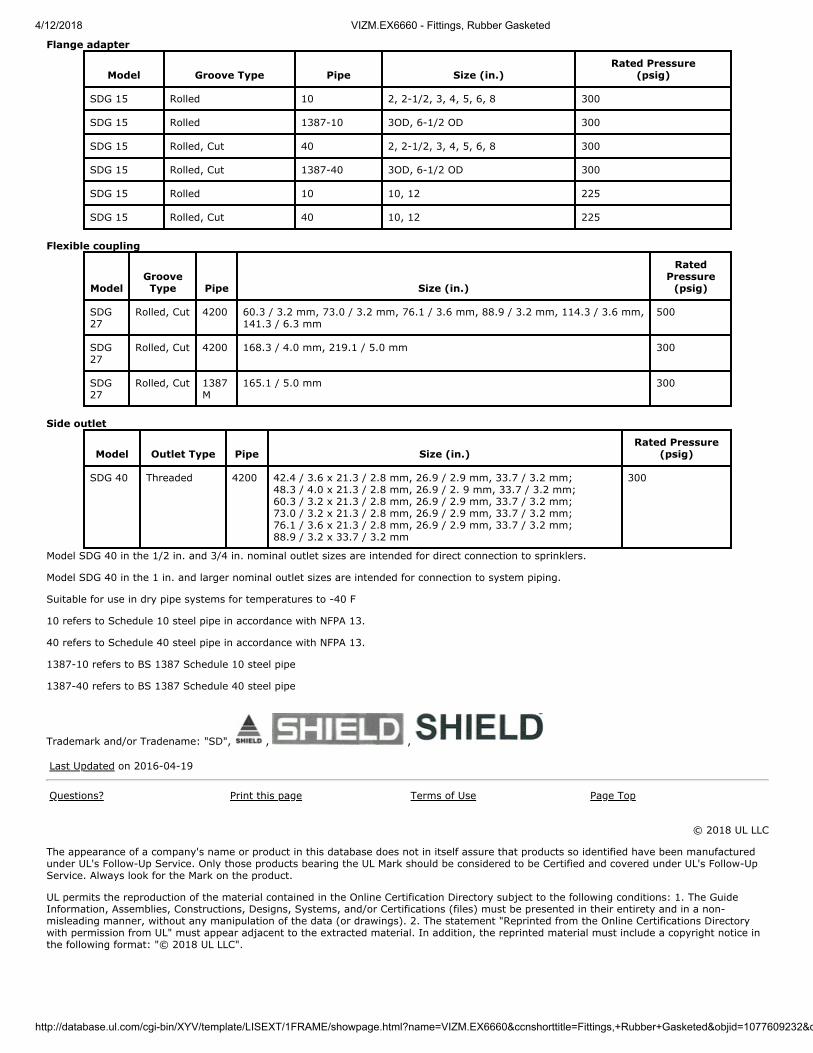
4/12/2018 VIZM.EX6660 - Fittings, Rubber Gasketed
http://database.ul.com/cgi-bin/XYV/template/LISEXT/1FRAME/showpage.html?name=VIZM.EX6660&ccnshorttitle=Fittings,+Rubber+Gasketed&objid=1077609232&c
Flange adapter
Model
Groove Type
Pipe
Size (in.)
Rated Pressure (psig)
SDG 15 Rolled 10 2, 2-1/2, 3, 4, 5, 6, 8 300
SDG 15 Rolled 1387-10 3OD, 6-1/2 OD 300
SDG 15 Rolled, Cut 40 2, 2-1/2, 3, 4, 5, 6, 8 300
SDG 15 Rolled, Cut 1387-40 3OD, 6-1/2 OD 300
SDG 15 Rolled 10 10, 12 225
SDG 15 Rolled, Cut 40 10, 12 225
Flexible coupling
Model
GrooveType
Pipe
Size (in.)
RatedPressure
(psig)
SDG27
Rolled, Cut 4200 60.3 / 3.2 mm, 73.0 / 3.2 mm, 76.1 / 3.6 mm, 88.9 / 3.2 mm, 114.3 / 3.6 mm,141.3 / 6.3 mm
500
SDG27
Rolled, Cut 4200 168.3 / 4.0 mm, 219.1 / 5.0 mm 300
SDG27
Rolled, Cut 1387M
165.1 / 5.0 mm 300
Side outlet
Model
Outlet Type
Pipe
Size (in.)
Rated Pressure (psig)
SDG 40 Threaded 4200 42.4 / 3.6 x 21.3 / 2.8 mm, 26.9 / 2.9 mm, 33.7 / 3.2 mm; 48.3 / 4.0 x 21.3 / 2.8 mm, 26.9 / 2. 9 mm, 33.7 / 3.2 mm; 60.3 / 3.2 x 21.3 / 2.8 mm, 26.9 / 2.9 mm, 33.7 / 3.2 mm;
73.0 / 3.2 x 21.3 / 2.8 mm, 26.9 / 2.9 mm, 33.7 / 3.2 mm; 76.1 / 3.6 x 21.3 / 2.8 mm, 26.9 / 2.9 mm, 33.7 / 3.2 mm; 88.9 / 3.2 x 33.7 / 3.2 mm
300
Model SDG 40 in the 1/2 in. and 3/4 in. nominal outlet sizes are intended for direct connection to sprinklers.
Model SDG 40 in the 1 in. and larger nominal outlet sizes are intended for connection to system piping.
Suitable for use in dry pipe systems for temperatures to -40 F
10 refers to Schedule 10 steel pipe in accordance with NFPA 13.
40 refers to Schedule 40 steel pipe in accordance with NFPA 13.
1387-10 refers to BS 1387 Schedule 10 steel pipe
1387-40 refers to BS 1387 Schedule 40 steel pipe
Trademark and/or Tradename: "SD", , ,
Last Updated on 2016-04-19
Questions? Print this page Terms of Use Page Top
© 2018 UL LLC
The appearance of a company's name or product in this database does not in itself assure that products so identified have been manufacturedunder UL's Follow-Up Service. Only those products bearing the UL Mark should be considered to be Certified and covered under UL's Follow-UpService. Always look for the Mark on the product.
UL permits the reproduction of the material contained in the Online Certification Directory subject to the following conditions: 1. The GuideInformation, Assemblies, Constructions, Designs, Systems, and/or Certifications (files) must be presented in their entirety and in a non-misleading manner, without any manipulation of the data (or drawings). 2. The statement "Reprinted from the Online Certifications Directorywith permission from UL" must appear adjacent to the extracted material. In addition, the reprinted material must include a copyright notice inthe following format: "© 2018 UL LLC".

Steel Pipe This pipe is FM Approved for use in automatic sprinkler systems. Unless otherwise noted in individual listings, pressure rating is 175psi (1205 kPa) and use is limited to wet-pipe systems.In addition to certain specific FM Approvals requirements, Approval is based upon conformance to American Society for Testing andMaterials (ASTM) Standards. ASTM A-53 and A-135 are used for Schedule 40 pipe (and Schedule 30 in larger sizes) and ASTMA-135 for Schedule 10 (0.188 in. (5 mm) wall pipe in larger sizes). Pipe meeting ASTM A-795 is also approvable.Generally, joining by threading or cut-grooving is limited to pipe of the "standard-weight" Schedules, 30 or 40. Schedule 10 pipe isusually joined by roll-grooving. "Lightwall" pipe is non-threadable, is close to Schedule 5 in size, but is non-standard in wall thickness."Thinwall" pipe is threadable, is close to Schedule 10 in size, but is also non-standard in wall thickness. The life expectancy of steelpiping products varies widely depending on characteristics such as the water conditions and pipe material, as well as wall thickness.Such factors should be considered when selecting piping products. Approval of any piping product is not confirmation of equivalentfield longevity to any pipe schedule or material identified in this introductory section.All FM Approved pipe is suitable for joining by welding or FM Approved plain end fittings where so listed. When welding pipe products,close adherence to recognized welding procedures and the use of welders certified under these procedures shall be followed. Pipe ofother schedules or unusual joint design may be FM Approved if shown to be of comparable performance to the traditional products.Approval of individual pipe fittings and couplings may limit them to use with specific schedules of pipe or at specific pressure ratings.Use caution to ensure that a given pipe fitting or coupling is FM Approved for use on a given schedule of pipe and that the ratedworking pressures are compatible. In all cases, the installation instructions of both the pipe manufacturer and the pipe fitting orcoupling manufacturer should be observed.
Please see individual listings for acceptability when used in hybrid sprinkler systems composed of steel and plastic piping.Pressure ratings of completed sprinkler systems are determined by the lowest pressure rated component in the system.
The following notations are used within the listings for Steel Pipe, and have been shown here for reference if searching for a particularfeature on a given product.
Note Description
a. FM Approved for use with FM Approved pipe couplings on rolled or cut grooves.
b. FM Approved for use with FM Approved pipe fittings when threaded.
c. FM Approved for use in welded systems when supplied with standard bevel on ends.
d. When hot dip galvanized by factory, the sprinkler pipe is FM Approved for dry systems.
e. Any FM Approved pipe coupling or fitting suitable for use with Schedule 10 pipe may be used with this product at the lowerrated pressure of the pipe or the fitting.
f. This product is not FM Approved for threaded connections.
g. FM Approved for use with FM Approved plain-end fittings.
h. FM Approved for use when the listings of the couplings or fittings make specific mention of their suitability with thissprinkler pipe.
i. FM Approved with a 12 ft (3.6m) maximum hanger spacing.
j. 3/4in (20mm) nominal size limited for use in valve trim.
k. FM Approved for use in dry sprinkler systems.
l. FM Approved for use when joined by FM Approved “Press-Fit” couplings.
m. FM Approved for use in all steel sprinkler systems when uncoated or coated (see individual listings for specific coatings).
n. FM Approved for use in hybrid sprinkler systems composed of uncoated steel and plastic piping.
o. FM Approved for use in hybrid sprinkler systems composed of coated steel and plastic piping (see individual listings forspecific coatings and plastic piping).
p. Manufactured out of ASTM A53 Grade B steel as an alternate material.
© 2007-2018 FM Approvals. All rights reserved. 1 of 2

Schedule 40-Normal connections are threaded, welded, rolled or cut groove or plain end
Schedule 40 a,b,c,d,e,j
Company Name: Shield Fire Safety and Security LtdCompany Address: Redburn House, 2a Tonbridge Rd, Romford, Essex, RM3 8QE, United KingdomCompany Website: http://shieldglobal.com
New/Updated Product Listing: NoNominal Pipe Size, mm(in.): 1/2, 3/4, 1, 1 1⁄4, 1 1⁄2, 2, 2 1/2, 3, 4, 5, 6, 8, 10, 12
Rated Working Pressure, psi: 300Rated Working Pressure, kPa: 2070
Listing Country: United KingdomCertification Type: FM Approved
Primary Class of Work: 1630-Steel Pipe Spklr Sys Serv
a - For use with FM Approved pipe couplings on rolled or cut grooves.b - For use with FM Approved pipe fittings when threaded.c - For use in welded systems when supplied with standard bevel on ends.d - Approved for Dry Systems when supplied with hot gipped galvanized from factory.e - Any FM Approved pipe coupling or fitting suitable for use with Schedule 40 pipe may be used with this product at the lowerrated pressure of the pipe or the fitting.j - 1/2 inch (15mm) and 3/4 inch (20mm) nominal pipe size is permitted for use as valve trim, gauge connections, and for otherperipheral service.
© 2007-2018 FM Approvals. All rights reserved. 2 of 2

Grooved Couplings or Fittings Grooved couplings are used to join pipe and fittings in both wet and dry sprinkler systems. Unless otherwise noted, these couplingsare intended to provide some flexibility in piping systems. Typical applications are in sprinkler risers, in feed mains passing throughwalls from one building area to another, in locations subject to earthquakes, in the discharge line from aboveground pump suctiontanks, in new connections to existing feed mains and in air or water fire service lines subject to excessive vibration or difficultalignment. Unless otherwise noted, these couplings are limited to use with rolled or cut groove-ended pipe, valves and fittings, at a minimumrated working pressure of 175 psi (1205 kPa) and are suitable for aboveground service. Higher rated pressures are noted in the textof the listing. Selection of pipe schedules for use with grooved pipe couplings should be made according to applicable FM GlobalProperty Loss Prevention Data Sheets installation standards. These pipe schedules determine system pressure ratings and may takeprecedence over the higher rated working pressures listed for some couplings. Installation must be made according to the manufacturer's instructions and requirements. Where couplings are used to join FMApproved pipe, the pipe manufacturer's installation instructions and requirements must also be observed. Grooves should be madeaccording to ANSI/AWWA C606 (latest edition), "Grooved and Shouldered Joints", unless otherwise specified. FM Approved grooved pipe couplings joining steel pipe may be used in underground service, subject to the installation restrictionsplaced upon the pipe and to the coupling manufacturer's recommendations and requirements. Unless otherwise stated in the listing, these couplings have been evaluated for a maximum ambient temperature of 225°F (107°C),suitable for use in normal warehouse protection. For special applications, temperatures, or environments, the manufacturer'srecommendations and requirements are to be followed.
Grooved Couplings, Reducing-Flexible These couplings join pipe, valves or fittings having different nominal pipe diameters.
SDG 30
ProductDesignation
Nominal PipeSize, in.
PipeEnds Remarks
Max WorkingPressure, psi
(kPa)
SDG 30 2 x 1 1⁄2 2 1⁄2 x 1, 2
3 x 1, 2, 2 1⁄24 x 1, 2
4 x 2 1⁄2, 36 x 3, 4
8 x 6
Cut GrooveRolled Groove
a, b, c, d 300(2070)
76.1 x 33.7, 1 1⁄2, 23 x 76.14 x 76.1165 x 48 x 165
Cut GrooveRolled Groove
a, b, c, d 300(2070)
Remarks:a. Minimum schedule cut groove pipe to be joined: 6 in. NPS and smaller – Schedule 40; 8 in. NPS and larger – Schedule 30.b. Minimum schedule rolled groove pipe to be joined: 6 in. NPS and smaller – Schedule 10S; 8 in. NPS and larger 0.188 in. (5mm) wall.c. Approved when supplied with EPDM gasket.d. Approved for use with GB/T3092 regular and extra heavy pipe, ISO 4200, and BS 1387 medium and heavy pipe.
Company Name: Shield Fire Safety and Security LtdCompany Address: Redburn House, 2a Tonbridge Rd, Romford, Essex, RM3 8QE, United KingdomCompany Website: http://shieldglobal.com
New/Updated Product Listing: NoListing Country: United Kingdom
Certification Type: FM ApprovedPrimary Class of Work: 1920-Coupling & Fitting, All Type
© 2007-2018 FM Approvals. All rights reserved. 1 of 1

Grooved Couplings or Fittings Grooved couplings are used to join pipe and fittings in both wet and dry sprinkler systems. Unless otherwise noted, these couplings are intended to provide some flexibility in piping systems. Typical applications are in sprinkler risers, in feedmains passing through walls from one building area to another, in locations subject to earthquakes, in the discharge line from aboveground pump suction tanks, in new connections to existing feed mains and in air or water fire service linessubject to excessive vibration or difficult alignment. Unless otherwise noted, these couplings are limited to use with rolled or cut groove-ended pipe, valves and fittings, at a minimum rated working pressure of 175 psi (1205 kPa) and are suitable for aboveground service. Higher rated pressuresare noted in the text of the listing. Selection of pipe schedules for use with grooved pipe couplings should be made according to applicable FM Global Property Loss Prevention Data Sheets installation standards. These pipe schedulesdetermine system pressure ratings and may take precedence over the higher rated working pressures listed for some couplings. Installation must be made according to the manufacturer's instructions and requirements. Where couplings are used to join FM Approved pipe, the pipe manufacturer's installation instructions and requirements must also be observed. Groovesshould be made according to ANSI/AWWA C606 (latest edition), "Grooved and Shouldered Joints", unless otherwise specified. FM Approved grooved pipe couplings joining steel pipe may be used in underground service, subject to the installation restrictions placed upon the pipe and to the coupling manufacturer's recommendations and requirements. Unless otherwise stated in the listing, these couplings have been evaluated for a maximum ambient temperature of 225°F (107°C), suitable for use in normal warehouse protection. For special applications, temperatures, or environments, themanufacturer's recommendations and requirements are to be followed.
Grooved Couplings, Standard-Rigid These couplings join pipe, valves or fittings having equal diameters.
SDG 22
Rated Working Pressures for Model SDG 22 Rigid Coupling by Pipe a, b, c
Nominal Pipe Size
PipeDescription
1(33.7)
1-1/4(42.7)
1-1/2(48.3)
2(60.3)
2-1/2(73.1)
(76.1)
3(88.9)
(108)
4(114.3)
(133)
(139.7)
5(141.3)
(159)
(165.1)
6(168.3)
(216.3)
8(219.1)
(267)
10(273)
(318)
12(323.9)
(356)
(377)
Schedule40,Cut Groove
500(3450)
500(3450)
500(3450)
500(3450)
500(3450)
500(3450)
500(3450) 500
(3450) 500(3450)
500(3450) 500
(3450)500(3450) 300
(2070) 300(2070)
300(2070)
300(2070)
300(2070)
300(2070)
Schedule40,RollGroove
500(3450)
500(3450)
500(3450)
500(3450)
500(3450)
500(3450)
500(3450) 500
(3450) 500(3450)
500(3450) 500
(3450)500(3450) 300
(2070) 300(2070) 300
(2070)
Schedule30,Cut Groove
300(2070) 300
(2070) 300(2070)
Schedule30,RolledGroove
500(3450)
500(3450)
500(3450)
500(3450)
500(3450)
500(3450)
500(3450) 500
(3450) 500(3450)
500(3450) 500
(3450)500(3450) 300
(2070) 300(2070) 300
(2070)
ThinwallPipes,RolledGroove
Schedule10,RolledGroove
500(3450)
500(3450)
500(3450)
500(3450)
500(3450)
500(3450)
500(3450) 500
(3450) 500(3450)
500(3450) 500
(3450)500(3450)
0.188”Wall,RolledGroove
300(2070) 300
(2070) 300(2070)
Schedule10,SwageGroove
LightwallPipes,RolledGroove
LightwallPipes,SwageGroove
Schedule 5Pipe,RolledGroove
EN 10220(ISO 4200),Cut Groove
Thickness F 500(3445) 500
(3445)500(3445)
500(3445)
500(3445)
300(2070)
500(3445)
300(2070)
500(3445)
500(3445)
300(2070)
500(3445)
500(3445)
300(2070)
300(2070) 300
(2070) 300(2070)
Thickness G500(3445)
500(3445)
500(3445)
500(3445)
500(3445)
500(3445)
500(3445)
300(2070)
500(3445)
300(2070)
500(3445)
500(3445)
300(2070)
500(3445)
500(3445)
300(2070)
300(2070) 300
(2070) 300(2070)
EN 10220(ISO 4200),RolledGroove
Thickness D 300(2070)
500(3445) 500
(3445)500(3445)
300(2070)
500(3445)
500(3445)
300(2070)
300(2070) 300
(2070) 300(2070)
Thickness E 500(3445) 500
(3445)300(2070)
500(3445) 500
(3445)500(3445)
300(2070)
500(3445)
500(3445)
300(2070)
300(2070) 300
(2070) 300(2070)
Thickness F500(3445)
500(3445)
500(3445)
500(3445)
500(3445)
500(3445)
500(3445)
300(2070)
500(3445) 500
(3445)500(3445)
300(2070)
500(3445)
500(3445)
300(2070)
300(2070) 300
(2070) 300(2070)
Thickness G500(3445)
500(3445)
500(3445)
500(3445)
500(3445)
500(3445)
500(3445)
300(2070)
500(3445) 500
(3445)500(3445)
300(2070)
500(3445)
500(3445)
300(2070)
300(2070) 300
(2070) 300(2070)
© 2007-2018 FM Approvals. All rights reserved. 1 of 4

Grooved Couplings or Fittings Grooved couplings are used to join pipe and fittings in both wet and dry sprinkler systems. Unless otherwise noted, these couplings are intended to provide some flexibility in piping systems. Typical applications are in sprinkler risers, in feedmains passing through walls from one building area to another, in locations subject to earthquakes, in the discharge line from aboveground pump suction tanks, in new connections to existing feed mains and in air or water fire service linessubject to excessive vibration or difficult alignment. Unless otherwise noted, these couplings are limited to use with rolled or cut groove-ended pipe, valves and fittings, at a minimum rated working pressure of 175 psi (1205 kPa) and are suitable for aboveground service. Higher rated pressuresare noted in the text of the listing. Selection of pipe schedules for use with grooved pipe couplings should be made according to applicable FM Global Property Loss Prevention Data Sheets installation standards. These pipe schedulesdetermine system pressure ratings and may take precedence over the higher rated working pressures listed for some couplings. Installation must be made according to the manufacturer's instructions and requirements. Where couplings are used to join FM Approved pipe, the pipe manufacturer's installation instructions and requirements must also be observed. Groovesshould be made according to ANSI/AWWA C606 (latest edition), "Grooved and Shouldered Joints", unless otherwise specified. FM Approved grooved pipe couplings joining steel pipe may be used in underground service, subject to the installation restrictions placed upon the pipe and to the coupling manufacturer's recommendations and requirements. Unless otherwise stated in the listing, these couplings have been evaluated for a maximum ambient temperature of 225°F (107°C), suitable for use in normal warehouse protection. For special applications, temperatures, or environments, themanufacturer's recommendations and requirements are to be followed.
Grooved Couplings, Standard-Rigid These couplings join pipe, valves or fittings having equal diameters.
SDG 22 Rated Working Pressures for Model SDG 22 Rigid Coupling by Pipe a, b, c
Nominal Pipe Size
(406)
(426)
300(2070)
300(2070)
© 2007-2018 FM Approvals. All rights reserved. 2 of 4

EN 10255(BS 1387)Medium,RolledGroove
500(3445)
500(3445)
500(3445)
500(3445) 500
(3445)500(3445) 500
(3445) 500(3445) 500
(3445)
EN 10255(BS 1387)Heavy,RolledGroove
500(3445)
500(3445)
500(3445)
500(3445) 500
(3445)500(3445) 500
(3445) 500(3445) 500
(3445)
ChineseStandardGB/T 3092,RegularRolledGroove
500(3445)
500(3445)
500(3445)
500(3445)
500(3445)
500(3445)
500(3445)
300(2070)
500(3445) 500
(3445)500(3445) 500
(3445)500(3445) 300
(2070) 300(2070) 300
(2070)
ChineseStandardGB/T 3092,ExtraHeavyRolledGroove
500(3445)
500(3445)
500(3445)
500(3445)
500(3445)
500(3445)
500(3445)
300(2070)
500(3445) 500
(3445)500(3445) 500
(3445)500(3445) 300
(2070) 300(2070) 300
(2070)
Remarks: a.) Minimum schedule cut groove pipe to be joined: 6 inch or smaller, Schedule 40; 8 inch or larger, Schedule 30b.) Minimum schedule rolled groove pipe to be joined: 6 inch or smaller, Schedule 10; 8, 10 or 12 inch - 0.188 inch (4.78 mm) wallc.) All couplings in table above, Approved when supplied with an EDPM gasket using standard gasket lubricant or dry lubricant
Company Name: Shield Fire Safety and Security Ltd
Company Address: Redburn House, 2a Tonbridge Rd, Romford, Essex, RM3 8QE, United Kingdom
Company Website: http://shieldglobal.com
New/Updated Product Listing: No
Listing Country: United Kingdom
Certification Type: FM Approved
Primary Class of Work: 1920-Coupling & Fitting, All Type
© 2007-2018 FM Approvals. All rights reserved. 3 of 4

Remarks: a.) Minimum schedule cut groove pipe to be joined: 6 inch or smaller, Schedule 40; 8 inch or larger, Schedule 30b.) Minimum schedule rolled groove pipe to be joined: 6 inch or smaller, Schedule 10; 8, 10 or 12 inch - 0.188 inch (4.78 mm) wallc.) All couplings in table above, Approved when supplied with an EDPM gasket using standard gasket lubricant or dry lubricant
© 2007-2018 FM Approvals. All rights reserved. 4 of 4

Grooved Couplings or Fittings Grooved couplings are used to join pipe and fittings in both wet and dry sprinkler systems. Unless otherwise noted, these couplings are intended to provide some flexibility inpiping systems. Typical applications are in sprinkler risers, in feed mains passing through walls from one building area to another, in locations subject to earthquakes, in thedischarge line from aboveground pump suction tanks, in new connections to existing feed mains and in air or water fire service lines subject to excessive vibration or difficultalignment.
Unless otherwise noted, these couplings are limited to use with rolled or cut groove-ended pipe, valves and fittings, at a minimum rated working pressure of 175 psi (1205kPa) and are suitable for aboveground service. Higher rated pressures are noted in the text of the listing. Selection of pipe schedules for use with grooved pipe couplingsshould be made according to applicable FM Global Property Loss Prevention Data Sheets installation standards. These pipe schedules determine system pressure ratingsand may take precedence over the higher rated working pressures listed for some couplings.
Installation must be made according to the manufacturer's instructions and requirements. Where couplings are used to join FM Approved pipe, the pipe manufacturer'sinstallation instructions and requirements must also be observed. Grooves should be made according to ANSI/AWWA C606 (latest edition), "Grooved and ShoulderedJoints", unless otherwise specified.
FM Approved grooved pipe couplings joining steel pipe may be used in underground service, subject to the installation restrictions placed upon the pipe and to the couplingmanufacturer's recommendations and requirements.
Unless otherwise stated in the listing, these couplings have been evaluated for a maximum ambient temperature of 225°F (107°C), suitable for use in normal warehouseprotection. For special applications, temperatures, or environments, the manufacturer's recommendations and requirements are to be followed.
Grooved Couplings, Standard-Rigid These couplings join pipe, valves or fittings having equal diameters.
SDG 20
Rated Working Pressures for Model SDG 20 Rigid Coupling by Pipe a, b, c
Nominal Pipe Size
PipeDescription
1(33.7)
1-1/4(42.7)
1-1/2(48.3)
2(60.3)
2-1/2(73.1)
(76.1)
3(88.9)
(108)
4(114.3)
(133)
(139.7)
5(141.3)
(159)
(165.1)
6(168.3)
(216.3)
8(219.1)
(267)
10(273)
Schedule40,Cut Groove
300(2070)
300(2070)
350(2415)
350(2415)
350(2415)
350(2415)
350(2415)
350(2415)
350(2415)
Schedule40,RollGroove
300(2070)
300(2070)
350(2415)
350(2415)
350(2415)
350(2415)
350(2415)
350(2415)
350(2415)
Schedule30,Cut Groove
Schedule30,RolledGroove
300(2070)
300(2070)
350(2415)
350(2415)
350(2415)
350(2415)
350(2415)
350(2415)
350(2415)
ThinwallPipes,RolledGroove
Schedule10,RolledGroove
300(2070)
300(2070)
350(2415)
350(2415)
350(2415)
350(2415)
350(2415)
350(2415)
0.188”Wall,RolledGroove
350(2415)
Schedule10,SwageGroove
LightwallPipes,RolledGroove
LightwallPipes,SwageGroove
Schedule5 Pipe,RolledGroove
EN 10220(ISO 4200),Cut Groove
© 2007-2018 FM Approvals. All rights reserved. 1 of 4

Grooved Couplings or Fittings Grooved couplings are used to join pipe and fittings in both wet and dry sprinkler systems. Unless otherwise noted, these couplings are intended to provide some flexibility inpiping systems. Typical applications are in sprinkler risers, in feed mains passing through walls from one building area to another, in locations subject to earthquakes, in thedischarge line from aboveground pump suction tanks, in new connections to existing feed mains and in air or water fire service lines subject to excessive vibration or difficultalignment.
Unless otherwise noted, these couplings are limited to use with rolled or cut groove-ended pipe, valves and fittings, at a minimum rated working pressure of 175 psi (1205kPa) and are suitable for aboveground service. Higher rated pressures are noted in the text of the listing. Selection of pipe schedules for use with grooved pipe couplingsshould be made according to applicable FM Global Property Loss Prevention Data Sheets installation standards. These pipe schedules determine system pressure ratingsand may take precedence over the higher rated working pressures listed for some couplings.
Installation must be made according to the manufacturer's instructions and requirements. Where couplings are used to join FM Approved pipe, the pipe manufacturer'sinstallation instructions and requirements must also be observed. Grooves should be made according to ANSI/AWWA C606 (latest edition), "Grooved and ShoulderedJoints", unless otherwise specified.
FM Approved grooved pipe couplings joining steel pipe may be used in underground service, subject to the installation restrictions placed upon the pipe and to the couplingmanufacturer's recommendations and requirements.
Unless otherwise stated in the listing, these couplings have been evaluated for a maximum ambient temperature of 225°F (107°C), suitable for use in normal warehouseprotection. For special applications, temperatures, or environments, the manufacturer's recommendations and requirements are to be followed.
Grooved Couplings, Standard-Rigid These couplings join pipe, valves or fittings having equal diameters.
SDG 20
Rated Working Pressures for Model SDG 20 Rigid Coupling by Pipe a, b, c
Nominal Pipe Size
(318)
12(323.9)
© 2007-2018 FM Approvals. All rights reserved. 2 of 4

Thickness F 300(2070)
300(2070)
300(2070)
350(2415)
300(2070)
350(2415)
350(2415)
350(2415)
300(2070)
350(2415)
350(2415)
300(2070)
350(2415)
ThicknessG 300
(2070)300(2070)
300(2070)
350(2415)
300(2070)
350(2415)
350(2415)
350(2415)
300(2070)
350(2415)
350(2415)
300(2070)
350(2415)
EN 10220(ISO 4200),RolledGroove
ThicknessD 300
(2070)350(2415)
350(2415)
350(2415)
300(2070)
350(2415)
350(2415)
300(2070)
350(2415)
Thickness E 300(2070)
350(2415)
300(2070)
350(2415)
350(2415)
350(2415)
300(2070)
350(2415)
350(2415)
300(2070)
350(2415)
Thickness F 300(2070)
300(2070)
300(2070)
350(2415)
300(2070)
350(2415)
350(2415)
350(2415)
300(2070)
350(2415)
350(2415)
300(2070)
350(2415)
ThicknessG 300
(2070)300(2070)
300(2070)
350(2415)
300(2070)
350(2415)
350(2415)
350(2415)
300(2070)
350(2415)
350(2415)
300(2070)
350(2415)
EN 10255(BS 1387)Medium,RolledGroove
300(2070)
300(2070)
350(2415)
350(2415)
350(2415)
350(2415)
EN 10255(BS 1387)Heavy,RolledGroove
300(2070)
300(2070)
350(2415)
350(2415)
350(2415)
350(2415)
ChineseStandardGB/T 3092,RegularRolledGroove
300(2070)
300(2070)
300(2070)
350(2415)
300(2070)
350(2415)
350(2415)
350(2415)
350(2415)
350(2415)
350(2415)
ChineseStandardGB/T 3092,ExtraHeavyRolledGroove
300(2070)
300(2070)
300(2070)
350(2415)
300(2070)
350(2415)
350(2415)
350(2415)
350(2415)
350(2415)
350(2415)
Remarks: a.) Minimum schedule cut groove pipe to be joined: 6 inch or smaller, Schedule 40; 8 inch or larger, Schedule 30b.) Minimum schedule rolled groove pipe to be joined: 6 inch or smaller, Schedule 10; 8, 10 or 12 inch - 0.188 inch (4.78 mm) wallc.) All couplings in table above, Approved when supplied with an EDPM gasket using standard gasket lubricant or dry lubricant
Company Name: Shield Fire Safety and Security Ltd
Company Address: Redburn House, 2a Tonbridge Rd, Romford, Essex, RM3 8QE, United Kingdom
Company Website: http://shieldglobal.com
New/Updated Product Listing: No
Listing Country: United Kingdom
Certification Type: FM Approved
Primary Class of Work: 1920-Coupling & Fitting, All Type
© 2007-2018 FM Approvals. All rights reserved. 3 of 4

Remarks: a.) Minimum schedule cut groove pipe to be joined: 6 inch or smaller, Schedule 40; 8 inch or larger, Schedule 30b.) Minimum schedule rolled groove pipe to be joined: 6 inch or smaller, Schedule 10; 8, 10 or 12 inch - 0.188 inch (4.78 mm) wallc.) All couplings in table above, Approved when supplied with an EDPM gasket using standard gasket lubricant or dry lubricant
© 2007-2018 FM Approvals. All rights reserved. 4 of 4

Pipe Fittings These fittings are suitable for interconnecting piping, valves and other components in both wet and dry automatic sprinkler systems.Installation should be according to applicable sprinkler system fabrication rules. These rules limit the minimum size of sprinkler pipingto 1 in., nominal. FM Approved pipe fittings of smaller sizes are intended for use as valve trim, gauge connections, and for otherperipheral service. The water flow path of the sprinkler system cannot be designed using smaller sizes than 1 in., nominal. Unlessotherwise noted in the listing, these fittings have 175 psi (1205 kPa) rated working pressure. Threaded connections on fittings can be made to FM Approved threadable thinwall pipe or to Schedule 40 pipe. Refer to the "SteelPipe" listings for a summary of the various types of FM Approved steel pipe suitable for threading or grooving." The fittings manufacturer's installation instructions must be observed in all cases. When connections are made to FM Approved pipe,the pipe manufacturer's installation instructions must also be followed. Unless otherwise stated below, the maximum ambient temperature to which these fittings should be subjected is 225°F (107°C).
Pipe Fittings
Shield Fire Safety, Pipe Fittings
ProductDesignation
FittingDescription
Nominal Pipe size, mm
Max Working Pressure, psi
(kPa)
Model SDG100 90° Elbow, Grooved Ends 1 1⁄4, 1 1⁄2, 2, 2 1⁄2,3, 4, 5, 6, 8
500(3450)
Model SDG200 45° Elbow, Grooved Ends 1 1⁄4, 1 1⁄2, 2, 2 1⁄2, 3,4, 5, 6, 8, 10, 12
500(3450)
Model SDG200 45° Elbow, Grooved Ends 76.1, 165 mm 500(3450)
Model SDG12 Equal Tee, Grooved Ends 1 1⁄4, 1 1⁄2, 2, 2 1⁄2, 3,4, 5, 6, 8, 10, 12
500(3450)
Model SDG12 Equal Tee, Grooved Ends 76.1, 165 mm 500(3450)
Model SDG53 Reducing Tee, Grooved Ends 2 x 1 1⁄2,3 x 1, 1 1⁄2, 2, 2 1⁄2,
4 x 1, 2, 2 1⁄2, 3,5 x 2, 3, 4,
6 x 2, 2 1⁄2, 3, 4, 5,8 x 2, 3, 4, 5, 6
500(3450)
Model SDG13 Equal Cross, Grooved Ends 1 1⁄4, 1 1⁄2, 2, 2 1⁄2, 3,4, 5, 6, 8, 10, 12
500(3450)
Model SDG13 Equal Cross, Grooved Ends 76.1, 165 mm 500(3450)
Model SDG35 Concentric Reducer, Grooved Ends 2 x 3⁄4, 1, 1 1⁄4, 1 1⁄2,2 1⁄2 x 1, 1 1⁄4, 1 1⁄2, 2,
3 x 3⁄4, 1, 1 1⁄2, 2, 21⁄2,
4 x 1, 1 1⁄2, 2, 2 1⁄2, 3,5 x 3, 4,
6 x 1, 2, 2 1⁄2, 3, 4, 5,8 x 2 1⁄2, 3, 4, 5, 6
500(3450)
Model SDG37 Concentric Reducer, Groove x Female NPT 2 x 3⁄4, 1, 1 1⁄4, 1 1⁄2,2 1⁄2 x 1, 1 1⁄4, 1 1⁄2, 2,
3 x 3⁄4, 1, 1 1⁄2, 2, 21⁄2,
4 x 1, 1 1⁄2, 2, 2 1⁄2, 3,5 x 3, 4,
6 x 2, 2 1⁄2, 3, 4, 5,8 x 2 1⁄2, 3, 4, 5, 6
500(3450)
© 2007-2018 FM Approvals. All rights reserved. 1 of 19

Model SDG39 Concentric Reducer, Groove x Male NPT 2 x 3⁄4, 1, 1 1⁄4, 1 1⁄2,2 1⁄2 x 1, 1 1⁄4, 1 1⁄2, 2,
3 x 3⁄4, 1, 1 1⁄2, 2, 21⁄2,
4 x 1, 1 1⁄2, 2, 2 1⁄2, 3,5 x 3, 4,
6 x 2, 2 1⁄2, 3, 4, 5,8 x 2 1⁄2, 3, 4, 5, 6
500(3450)
Model SDG14 Grooved End Cap 1 1⁄4, 1 1⁄2, 2, 2 1⁄2, 3,4, 5, 6, 8, 10, 12
500(3450)
Model SDG14 Grooved End Cap 76.1, 165 mm 500(3450)
Model SDG16 Flange x Groove Adapter 2, 2 1⁄2, 3, 4, 5, 6, 8 500(3450)
Model SDG16 Flange x Groove Adapter 76.1, 165mm 500(3450)
Model SDT14 D.I. Cap, Threaded 1⁄2, 3⁄4, 1, 1 1⁄4, 1 1⁄2,2, 2 1⁄2
500(3450)
Model SDT22 D.I. Straight Coupling, Threaded 1⁄2, 3⁄4, 1, 1 1⁄4, 1 1⁄2,2, 2 1⁄2
500(3450)
Model SDT100 D.I. 90° Elbow, Threaded 1⁄2, 3⁄4, 1, 1 1⁄4, 1 1⁄2,2, 2 1⁄2
500(3450)
Model SDT200 D.I. 45° Elbow, Threaded 1⁄2, 3⁄4, 1, 1 1⁄4, 1 1⁄2,2, 2 1⁄2
500(3450)
Model SDT57 D.I. Bushings, Threaded 1 x 1⁄2, 3⁄41 1⁄4 x 3⁄4
2 x 1
500(3450)
Model SDT30 D.I. Concentric Reducer, Threaded 1 x 1⁄2, 3⁄41 1⁄4 x 3⁄4
2 x 1
500(3450)
Model SDT101 D.I. 90° Reducing Elbow, Threaded 3⁄4 x 1⁄21 x 1⁄2, 3⁄4
1 1⁄4 x 1⁄2, 3⁄4, 11 1⁄2 x 3⁄4, 1, 1 1⁄4
2 x 3⁄4, 1, 1 1⁄4, 1 1⁄22 1⁄2 x 1 1⁄2, 2
500(3450)
Model SDT53 Reducing Tee,Threaded
3⁄4 x 3⁄4 x 1⁄2, 13⁄4 x 1⁄2 x 3⁄4, 1⁄2
1 x 1 x 1⁄2, 3⁄4, 1 1⁄4,1 1⁄2
1 x 3⁄4 x 3⁄4, 11 x 1⁄2 x 1
1 1⁄4 x 1 1⁄4 x 1⁄2, 3⁄4,1, 1 1⁄2, 2
1 1⁄4 x 1 x 1⁄2, 3⁄4, 1,1 1⁄4, 1 1⁄2
1 1⁄4 x 3⁄4 x 1 1⁄41 1⁄4 x 1⁄2 x 1 1⁄4
1 1⁄2 x 1 1⁄2 x 1⁄2, 3⁄4,1, 1, 1 1⁄4, 2
1 1⁄2 x 1 1⁄4 x 1⁄2, 3⁄4,1, 1 1⁄4, 1 1⁄2
1 1⁄2 x 1 x 1⁄2, 3⁄4, 1,1 1⁄4, 1 1⁄2
1 1⁄2 x 3⁄4 x 1 1⁄4, 1 1⁄21 1⁄2 x 1⁄2 x 1 1⁄4, 1 1⁄2
500(3450)
© 2007-2018 FM Approvals. All rights reserved. 2 of 19

2 x 2 x 1⁄2, 3⁄4, 1, 11⁄4, 1 1⁄2, 2 1⁄2
2 x 1 1⁄2 x 1⁄2, 3⁄4, 1,1 1⁄4, 1 1⁄2, 22 x 1 1⁄4 x 2
2 x 1 x 22 1⁄2 x 2 1⁄2 x 3⁄4, 1, 1
1⁄4, 1 1⁄2, 2, 3
Model SDT51 D.I. Reducing Cross, Threaded 1 1⁄4 x 1, 1 1⁄2 x 1, 2 x1
500(3450)
Model SDT55 D.I. Square Head Pipe Plug 1⁄2, 3⁄4, 1, 1 1⁄4, 1 1⁄2,2
500(3450)
Model SDT12 D.I. Equal Tee, Threaded 1⁄2, 3⁄4, 1, 1 1⁄4, 1 1⁄2,2, 2 1⁄2
500(3450)
Model SDT59 D.I. Union, Threaded 1, 1 1⁄4, 1 1⁄2, 2 500(3450)
Model SDT13 D.I. Cross, Threaded 1, 1 1⁄4, 1 1⁄2, 2 500(3450)
Model SDC100 C.I. 90° Elbow, Threaded 1⁄2, 3⁄4, 1, 1 1⁄4, 1 1⁄2,2, 2 1⁄2
300(2070)
Model SDC200 C.I. 45° Elbow, Threaded 1⁄2, 3⁄4, 1, 1 1⁄4, 1 1⁄2,2, 2 1⁄2
300(2070)
Model SDC30 C.I. Concentric Reducer, Threaded 1 x 1⁄2, 3⁄42 x 1
300(2070)
Model SDC101 C.I. 90° Reducing Elbow, Threaded 1 x 1⁄2, 3⁄4,1 1⁄4 x 1⁄2, 3⁄4, 1,
1 1⁄2 x 1⁄2, 3⁄4, 1, 1 1⁄4,2 x 1⁄2, 3⁄4, 1, 1 1⁄4, 1
1⁄2,2 1⁄2 x 3⁄4, 1, 1 1⁄4, 1
1⁄2, 2
300(2070)
Model SDC53 C.I. Reducing Tee, Threaded 1 x 1⁄2 x 1⁄2, 3⁄4, 1,1 x 3⁄4 x 1⁄2, 3⁄4, 1,
1 x 1 x 1⁄2, 3⁄4, 1 1⁄4,1 x 1 1⁄4 x 1,
1 1⁄4 x 1 1⁄4 x 1⁄2, 3⁄4,1, 1 1⁄2, 2,
1 1⁄4 x 1 x 1⁄2, 3⁄4, 1,1 1⁄4, 1 1⁄2,,
1 1⁄4 x 3⁄4 x 1 1⁄4,1 1⁄4 x 1⁄2 x 1 1⁄4,
1 1⁄2 x 1 1⁄2 x 1⁄2, 3⁄4,1, 1, 1 1⁄4, 2,
1 1⁄2 x 1 1⁄4 x 1⁄2, 3⁄4,1, 1 1⁄4, 1 1⁄2,
1 1⁄2 x 1 x 1⁄2, 3⁄4, 1,1 1⁄4, 1 1⁄2, 2,
1 1⁄2 x 3⁄4 x 1 1⁄4, 1 1⁄2,1 1⁄2 x 1⁄2 x 1 1⁄4, 1 1⁄2,
2 x 2 x 1⁄2, 3⁄4, 1, 11⁄4, 1 1⁄2,
2 x 1 1⁄2 x 1⁄2, 3⁄4, 1,1 1⁄4, 1 1⁄2, 2,
2 x 1 1⁄4 x 1⁄2, 1, 11⁄4, 1 1⁄2, 2,
2 x 1 x 3⁄4, 1, 1 1⁄4, 2,2 x 2 x 2 1⁄2,
2 1⁄2 x 2 x 1⁄2, 3⁄4, 1,
300(2070)
© 2007-2018 FM Approvals. All rights reserved. 3 of 19

1 1⁄4, 1 1⁄2, 2, 2 1⁄2,2 x 1 1⁄4 x 2 1⁄2,
2 x 1 x 2 1⁄2,2 x 3⁄4 x 2 1⁄2,
2 1⁄2 x 1⁄2 x 2, 2 1⁄2
Model SDC12 C.I. Equal Tee, Threaded 1⁄2, 3⁄4, 1, 1 1⁄4, 1 1⁄2,2
300(2070)
SD-UFLEX and SD-VFLEX Expansion Loops
ProductDesignation
FittingDescription
Nominal Pipe Size, in.
Rated WorkingPressure,psi (kPa)
Remarks
SD-UFLEXExpansion Loop
Type 1, Welded Ends,180° Return
1, 1-1/4, 1-1/2, 2,2-1/2, 3, 4, 5, 6, 8, 10
(25, 32, 40, 50, 65, 80,100, 125, 150, 200,
250 mm)
250(1725) —
Type 2, Flanged Ends,180° Return
1, 1-1/4, 1-1/2, 2,2-1/2, 3, 4, 5, 6, 8, 10
(25, 32, 40, 50, 65, 80,100, 125, 150, 200,
250 mm)
250(1725) —
Type 3,
Swivel Flanged Ends,180° Return
1, 1-1/4, 1-1/2, 2,2-1/2, 3, 4, 5, 6, 8, 10
(25, 32, 40, 50, 65, 80,100, 125, 150, 200,
250 mm)
250(1725) —
Type 4, Threaded
Ends,180° Return
1, 1-1/4, 1-1/2, 2,2-1/2, 3, 4, 5, 6, 8, 10
(25, 32, 40, 50, 65, 80,100, 125, 150, 200,
250 mm)
250(1725) —
Type 5, Sweat Ends,180° Return
1, 1-1/4, 1-1/2, 2(25, 32, 40, 50)
250(1725) —
Type 6, Sweat Ends,With intermediate pipe
1, 1-1/4, 1-1/2, 2(25, 32, 40, 50)
250(1725) —
Type 7,
Cut Groove Ends,180° Return
1, 1-1/4, 1-1/2, 2,2-1/2, 3, 4, 5, 6, 8, 10
(25, 32, 40, 50, 65, 80,100, 125, 150, 200,
250 mm)
250(1725) a,b
SD-VFLEXExpansion Loop
Type 7, Cut Groove Ends,
180° Return
1, 1-1/4, 1-1/2, 2,2-1/2, 3, 4, 5, 6, 8, 10
(25, 32, 40, 50, 65, 80,100, 125, 150, 200,
250 mm)
250(1725) a, b
Remarks:a. Min schedule cut groove pipe to be joined: 4 in. or smaller - Schedule 40.b. Min schedule rolled groove pipe to be joined: 4 in. or smaller - Schedule 10.
Product Designation
FittingDescription
EndConnection
NominalPipe
Size, in.
MaxWorking
Pressure,psi (kPa)
Remarks
© 2007-2018 FM Approvals. All rights reserved. 4 of 19

SDG 100 90° Elbow Grooved
1-1/4,1-1/2, 2,
2-1/2, 3, 4,5, 6, 8, 10,
12
500(3450) a
76, 139.7,165 mm
500(3445) a
176, 133 mm
500(3445) b
267.4,318.5 mm
300(2070) b
SDT 100 90° Elbow
NPT
1/2, 3/4, 1,1-1/4,
1-1/2, 2,2-1/2, 3, 4
500(3445) a
5, 6 300(2070) a
BSP
1/2, 3/4, 1,1-1/4,
1-1/2, 2,2-1/2, 3, 4
500(3445) a
5, 6 300(2070) a
SDT 10190°
Reducing Elbow
NPT
1/2 x 1/4,3/8
3/4 x 1/4,3/8, 1/2
1 x 1/4 x3/8, 1/2, 3/41-1/4 x 3/8,1/2, 3/4, 1
1-1/2 x 1/2,3/4, 1, 1-1/4
2 x 1/2,3/4, 1,
1-1/4, 1-1/22-1/2 x 1/2,
3/4, 1,1-1/4,1-1/2, 23 x 1/2,3/4, 1,1-1/4,
1-1/2, 2,2-1/2
4 x 1/2,3/4, 1,1-1/4,
1-1/2, 2,2-1/2, 3
500(3445) a
1/2 x 1/4,3/8
3/4 x 1/4,3/8, 1/2
1 x 1/4 x3/8, 1/2, 3/41-1/4 x 3/8,1/2, 3/4, 1
1-1/2 x 1/2,
© 2007-2018 FM Approvals. All rights reserved. 5 of 19

BSP
3/4, 1, 1-1/42 x 1/2,3/4, 1,
1-1/4, 1-1/22-1/2 x 1/2,
3/4, 1,1-1/4,1-1/2, 23 x 1/2,3/4, 1,1-1/4,
1-1/2, 2,2-1/2
4 x 1/2,3/4, 1,1-1/4,
1-1/2, 2,2-1/2, 3
500(3445) a
6 x 4 300(2070) a
SDG 10190°
Reducing Elbow
Grooved
6 x 488.9 x 76.1
mm114.3 x76.1 mm165.1 x
114.3 mm
500(3445) b
SDG 10590° Short
RadiusElbow
Grooved
2, 2-1/2, 3,4, 6, 8
76, 139.1,165mm
300(2070) a
108, 159,216.3 mm
300(2070) b
114, 165mm
365(2510) b
SDT 110 90° StreetElbow
NPT
1/2, 3/4, 1,1-1/4,1-1/2, 2
2-1/2, 3, 4
500(3445) a
6 300(2070) a
BSP
1/2, 3/4, 1,1-1/4,1-1/2, 2
2-1/2, 3, 4
500(3445) a
6 300(2070) a
SDT 10390°
ReducingStreetElbow
BSP 3/4 x 1/21 x 3/4
500(3445) a
SDG 112 11.25°Elbow
Grooved
1-1/4,1-1/2, 2, 3,
4, 676.1, 108,139.7, 159,165.1 mm
500(3445) b
© 2007-2018 FM Approvals. All rights reserved. 6 of 19

Grooved 8 300(2070) b
SDG 225 22.5° ElbowGrooved
1-1/4,1-1/2, 2, 3,
4, 673, 76.1,
108, 139.7,159, 165.1
mm
500(3445) b
Grooved 8 300(2070) b
SDG 200 45° Elbow Grooved
1-1/4,1-1/2, 2,
2-1/2, 3, 4,5, 6, 8, 10,
1276.1, 165
mm
500(3450) a
1108, 139.7,
159 mm500
(3450) a
216.3,267.4,
318.5 mm300
(2070) b
SDT 200 45° Elbow
NPT
1/2, 3/4, 1,1-1/4, 1-12,
22-1/2, 3, 4
500(3445) a
5, 6 300(2070) a
BSP
1/2, 3/4, 1,1-1/4, 1-12,
22-1/2, 3, 4
500(3445) a
5, 6 300(2070) a
SDG 12 Equal Tee Grooved
1-1/4,1-1/2,, 2,
2-1/2, 3, 4,5, 6, 8, 10,
1276/1. 165
mm
500(3450) a
176, 133,139.7 mm
500(3445) b
267.4 mm 300(2070) b
SDT 12 Equal Tee
NPT
1/2, 3/4, 1,1-1/4, 1-12,
22-1/2, 3, 4
500(3445) a
5, 6 300(2070) a
© 2007-2018 FM Approvals. All rights reserved. 7 of 19

SDT 12 Equal Tee
BSP
1/2, 3/4, 1,1-1/4, 1-12,
22-1/2, 3, 4
500(3445) a
5, 6 300(2070) a
SDG 53 ReducingTee Grooved
2 x 1-1/23 x 1,
1-1/2, 2,2-1/2
4 x 1, 2,2-1/2, 3
5 x 2, 3, 46 x 2,
2-1/2, 3, 4, 58 x 2, 3, 4,
5, 6
500(3450) a
2 x 12-1/2 x1-1/2, 23 x 1-1/44 x 1-1/2
60 x 48 mm76.1 x 42.4,48.3, 60.3
mm88.9 x 48,
60, 73, 76.1mm
108 x 60.3,73, 88.9 mm114.3 x 34,
60, 73,76.1, 88.9
mm133 x 60.3,76.1, 108,114.3 mm139.7 x
48.3, 60.3,76.1, 88.9,114.3, 141x 114.3 mm141 x 114.3
mm159 x 60.3,76.1, 88.9,114.3, 133
mm168 x 60,
73, 89, 114,141 mm
500(3450) b
10 x 6, 812 x 8, 10
165.1 x60.3, 76.1,
88.9,114.3, 133,139.7, 159
mm168.3 x
76.1, 139.7mm
216.3 x 300
© 2007-2018 FM Approvals. All rights reserved. 8 of 19

216.3 x165.1 mm
219.1 x 60,76.1, 89,
108, 114.3,133, 139.7,141.3, 159,165.1, 168
mm273 x 165.1
mm323.9 x
165.1 mm
300(2070) b
NPT
1/2 x 1/2 x1/4, 3/8
1/2 x 1/4 x1/2
1/2 x 3/8 x1/2
3/4 x 3/4 x1/4, 3/8, 1/23/4 x 1/2 x1/2 x 3/4
1 x 1 x 1/4,3/8, 1/2, 3/4
1 x 1/2 x1/2, 3/4, 11 x 3/4 x1/2, 3/4, 11-1/4 x 1/2x 1/2, 3/4,
1, 1-1/41-1/4 x 3/4
x 3/4, 1,1-1/4
1-1/4 x 1 x1/2, 3/4, 1,1-1/4, 1-1/2
1-1/4 x1-1/4 x 3/8,1/2, 3/4, 11-1/2 x 1/2x 3/4, 1-1/21-1/2 x 3/4x 1/2, 3/4,1, 1-1/4,
1-1/21-1/2 x 1 x1/2, 3/4, 1,1-1/4, 1-1/2
1-1/2 x1-1/4 x 1/2,
3/4, 1,1-1/4,1-1/2, 21-1/2 x
1-1/2 x 1/2,3/4, 1, 1-1/42 x 1/2 x 22 x 3/4 x 22 x 1 x 1,1-1/2, 2
2 x 1-1/4 x1, 1-1/4,1-1/2, 2
2 x 1-1/2 x1/2, 3/4, 1,
500(3445) a
© 2007-2018 FM Approvals. All rights reserved. 9 of 19

SDT 53
ReducingTee
1-1/4,1-1/2, 2
2 x 2 x 1/2,3/4, 1,
1-1/4, 1-1/22-1/2 x
1-1/2 x 2,2-1/2
2-1/2 x 2 x2, 2-1/22-1/2 x
2-1/2 x 1/2,3/4, 1,1-1/4,1-1/2, 2
3 x 2 x 2, 33 x 3 x 1/2,
3/4, 1,1-1/4,
1-1/2, 2,2-1/2
4 x 4 x 1/2,3/4, 1,1-1/4,
1-1/2, 2,2-1/2, 3
1/2 x 1/4,3/8
3/4 x 1/4,3/8, 1/21 x 1/4,
3/8, 1/2, 3/41-1/4 x 3/8,1/2, 3/4, 1
1-1/2 x 3/8,1/2, 3/4, 1,
1-1/42 x 3/8,
1/2, 3/4, 1,1-1/4, 1-1/22-1/2 x 3/4,
1/2, 1,1-1/4,1-1/2, 23 x 1/2,3/4, 1,1-1/4,
1-1/2, 2,2-1/2
4 x 1/2,3/4, 1,1-1/4,
1-1/2, 2,2-1/2, 3
1/2 x 1/2 x3/4, 1
3/4 x 3/4 x1, 1-1/41 x 1 x1-1/4 x
1-1/2, 2,2-1/2
1-1/4 x1-1/4 x1-1/2, 21-1/2 x
© 2007-2018 FM Approvals. All rights reserved. 10 of 19

BSP
1-1/2 x 2,2-1/2
2 x 2 x 2-1/22-1/2 x
2-1/2 x 3, 43/4, 1 x 1/2
x 1/21-1/4, 1-1/2x 3/4 x 3/4
1-1/4 x 1/2x 1/2
1-1/4 ,1-1/2, 2 x 1
x 11-1/2, 2 x
1-1/4 x 1-1/42 x 1-1/2 x
1-1/22-1/2, 3 x 2
x 23/4 x 1/2 x
3/41 x 1/2 x 1,1 x 3/4 x 1,1 x 1/4 x 11-1/4 x 1/2
x 1-1/4,1-1/4, 1-1/4
x 3/4 x1-1/4, 1-1/4x 1 x 1-1/41-1/2 x 1/2
x 1-1/2,1-1/2 x 3/4
x 1-1/2,1-1/2 x 1 x1-1/2, 1-1/2
x 1-1/4 x1-1/2
2 x 1/2 x 2,2 x 3/4 x 2,2 x 1 x 2, 2x 1-1/4 x 2,2 x 1-1/2 x 2
2-1/2 x1-1/2 x
2-1/2, 2-1/2x 2 x 2-1/23/4 x 1/2 x1, 1 x 1/2 x3/4, 1 x 3/4
x 1/21-1/4 x 1/2
x 3/4, 11-1/4 x 3/4
x 1/2, 11-1/4 x 1 x
1/2, 3/41-1/2 x 3/4x 1, 1-1/4
1-1/2 x 1 x1/2, 1-1/4
1-1/2 x1-1/4 x 1/2,
3/4, 22 x 1 x 1-1/22 x 1-1/4 x1, 1-1/22 x
500(3445) a
© 2007-2018 FM Approvals. All rights reserved. 11 of 19

1, 1-1/22 x1-1/2 x 3/4,
1, 1-1/42-1/2 x 2 x1/2, 1, 1-1/4
6 x 2, 3, 4 300(2070) a
BullheadTee NPT
3/8 x 3/8 x1/2
1/2 x 1/2 x3/4, 1
3/4 x 3/4 x 11 x 1 x1-1/4,1-1/2, 21-1/4 x1-1/4 x1-1/2, 21-1/2 x
1-1/2 x 22 x 2 x 2-1/2
500(3445) a
SDG 13 Equal Cross Grooved
1-1/4, 1-1/2,2, 2-1/2, 3,4, 5, 6, 8,
10, 1276.1, 165
mm
500(3445) a
60, 73, 76,89, 108,
114, 139.7,141, 159,165, 168
mm
500(3445) b
219 mm 300(2070) b
SDT 13 Equal Cross
NPT
1/2, 3/4, 1,1-1/4,
1-1/2, 2,2-1/2, 3, 4
500(3445) a
5, 6 300(2070) a
BSP1/2, 3/4, 1,
1-1/4,1-1/2, 2,2-1/2, 3, 4
500(3445) a
SDG 13R ReducingCross Grooved
3 x 24 x 2, 38 x 2, 4139.7 x
114.3 mm159 x 114.3
mm165.1 x
60.3, 76.1,88.9, 114.3
mm
500(3445) b
© 2007-2018 FM Approvals. All rights reserved. 12 of 19

219.1,139.7, 159,165.1 mm
300(2070) b
SDT 51 ReducingCross
NPT
3/4 x 1/21 x 3/4
1-1/4 x 3/4,1
1-1/2 x 3/4,1, 1-1/4
2 x 3/4, 1,1-1/4, 1-1/22 x 1/2 x 1,
1-1/4,1-1/2, 23 x 1,1-1/4,
1-1/2, 2,2-1/2
4 x 2-1/2, 3
500(3445) a
BSP
3/4 x 1/21-1/2 x 3/41-1/4 x 1/2,
3/4, 11-1/2 x 1/2,3/4, 1, 1-1/42 x 3/4, 1,1-1/4, 1-1/22 x 1/2 x 1,
1-1/4,1-1/2, 2
3 x 3/4, 1,1-1/4,1-1/2, 24 x 1,1-1/4,
1-1/2, 2,2-1/2, 3
500(3445) a
SDT 22 Coupling
NPT1/2, 3/4, 1,
1-1/4,1-1/2, 2,2-1/2, 3, 4
500(3445) a
BSP
1/2, 3/4, 1,1-1/4,
1-1/2, 2,2-1/2, 3, 4
500(3445) a
5, 6 300(2070) a
SDG 33 EccentricReducer Grooved
4 x 2, 36 x 3, 4
8 x 488.9 x 60.3
mm108 x 76.1,
88.9 mm114.3 x76.1 mm139.7 x
114.3 mm159 x 108,114.3 mm
165.1 x88.9,
300(2070) b
© 2007-2018 FM Approvals. All rights reserved. 13 of 19

88.9,114.3,
139.7 mm168.3 x
139.7 mm
219 x 168mm
273 x 219mm
365(2510) b
SDT 30 ReducingSocket
NPT
1/2 x 3/83/4 x 3/8,
1/21 x 3/8,1/2, 3/4
1-1/4 x 1/2,3/4, 1
1-1/2 x 1/2,3/4, 1, 1-1/4
2 x 1/2,3/4, 1,
1-1/4, -1/22-1/2 x1-1/2, 2
3 x 1-1/2,2, 2-1/24 x 2, 3
500(3445) a
BSP
1/2 x 1/4,3/8
3/4 x 1/4,3/8, 1/21 x 1/4,
3/8, 1/2, 3/41-1/4 x 1/4,
3/8, 1/2,3/4, 1
1-1/2 x /4,3/8, 1/2,
3/4, 1, 1-1/42 x 1/2,3/4, 1,
1-1/4, 1-1/22-1/2 x 1/2,
3/4, 1,1-1/4,1-1/2, 23 x 1/2,3/4, 1,1-1/4,
1-1/2, 2,2-1/2
500(3445) a
ConcentricReducer Grooved
2 x 3/4, 1,1-1/4, 1-1/22-1/2 x 1,
1-1/4,1-1/2, 2
3 x 3/4, 1,1-1/2, 2,
2-1/14 x 1,
1-1/2, 2,2-1/2, 35 x 3, 46 x 1, 2,
2-1/2, 3, 4, 5
500(3450) a
© 2007-2018 FM Approvals. All rights reserved. 14 of 19

SDG 35
8 x 2-1/2,3, 4, 5, 6
ConcentricReducer Grooved
1-1/4 x 11-1/2 x 1,
1-1/24 x 1-1/45 x 2-1/2
76 x 42, 48,60 mm
89 x 42, 76mm
108 x 60.3,73, 76 mm
114.3 x76.1 mm
133 x 108,114.3 mm
139.7 x60.3, 76.1,88.9, 114.3
mm141 x 89,114 mm
159 x 60.3,76.1, 88.9,108, 114.3,
133 mm165.1 x
60.3, 76.1,88.9,114.3,
139.7 mm168.3 x
76.1, 139.7mm
500(3450) b
216.3 x114.3,
165.1 mm219.1 x
108, 139.7,159, 165.1
mm273 x 159,
165.1,168.3,
219.1 mm322.9 x
219.1, 273mm
300(2070) b
2 x 3/4, 1,1-1/4, 1-1/22-1/2 x 1,
1-1/4,1-1/2, 2
3 x 3/4, 1,1-1/2, 2,
2-1/24 x 1,
1-1/2, 2,2-1/2, 35 x 3, 46 x 2,
2-1/2, 3, 4, 58 x 2-1/2,3, 4, 5, 6
500(3450) a
© 2007-2018 FM Approvals. All rights reserved. 15 of 19

SDG 37 ConcentricReducer
Grooved xFemale
NPT
4 x 1/2,3/4, 1-1/2
8 x 1-1/2, 276 x 21, 27,34, 42, 48,
60 mm 89 x 21, 76
mm 108 x 34,42, 48, 60,76, 89 mm114 x 76
mm133 x 48,
76 mm139.7 x 27,34, 42, 48,60, 76, 89,
114 mm141.3 x 89,
114 mm159 x 27,
34, 42, 48,60, 89, 114
mm165 x 21,
27, 34, 42,48, 60, 76,89, 114 mm
219 x 76mm
500(3450) b
SDT 57 Bushing
NPT
1/2 x 1/4,3/8
3/4 x 3/8,1/2
1 x 1/2, 3/41-1/4 x 1/2,
3/4, 11-1/2 x 3/8,1/2, 3/4, 1,
1-1/42 x 3/8,
1/2, 3/4, 1,1-1/4, 1-1/22-1/2 x 1/2,
3/4, 1,1-1/4,1-1/2, 23 x 1/2,3/4, 1,1-1/4,
1-1/2, 2,2-1/2
3-1/2 x2-1/2, 3
4 x 3/4, 1,1-1/4,
1-1/2, 2,2-1/2, 3,
3-1/2
500(3445) a
5 x 2, 3, 46 x 2,
2-1/2, 3,3-1/2, 4, 5
300(2070) a
© 2007-2018 FM Approvals. All rights reserved. 16 of 19

BSP
1/2 x 1/4,3/8
3/4 x 1/4,3/8, 1/21 x 1/4,
3/8, 1/2, 3/41-1/4 x 1/4,
3/8, 1/2,3/4, 1
1-1/2 x 1/4,3/8, 1/2,
3/4, 1, 1-1/42 x 1/4,3/8, 1,
1-1/4, 1-1/22-1/2 x 1/2,3/4, 1-1/2, 23 x 2, 2-1/2
3-1/2 x 34 x 3/4, 1,
1-1/4,1-1/2, 3
500(3445) a
5 x 3, 46 x 2,2-1/2, 5
300(2070) a
SDT 111 Hex NippleReducing BSP
1/2 x 1/4,3/8
3/4 x 1/4,3/8, 1/2
1 x 1/2, 3/41-1/4 x 1/2,
3/4, 11-1/2 x 1/2,3/4, 1, 1-1/4
2 x 1/2,3/4, 1,
1-1/4, 1-1/22-1/2 x 1,
1-1/4, 1-1/23 x 1-1/2,
2, 2-1/24 x 2, 4 x2-1/2, 4 x 3
500(3445) a
SDG 14 End Cap Grooved
1-1/4,1-1/2, 2,
2-1/2, 3, 4,5, 6, 8, 10,
1276.1, 165
mm
500(3450) a
1-1/4,1-1/2, 2,
2-1/2, 3, 4,5, 6, 8, 10,
1276.1, 89,114, 140,165 mm
500(3450) b
NPT
1/2, 3/4, 1,1-1/4,
1-1/2, 2,2-1/2, 3, 4
500(3445) a
© 2007-2018 FM Approvals. All rights reserved. 17 of 19

SDT 14 End Cap5, 6 300
(2070) a
BSP
1/2, 3/4, 1,1-1/4,
1-1/2, 2,2-1/2, 3, 4
500(3445) a
5, 6 300(2070) a
SDG 16 FlangeAdapter
Flanged xGrooved
2, 2-1/2, 3,4, 5, 6, 8
76.1, 165mm
500(3450) a
1, 1-1/4,1-1/2, 10, 12
108, 133,139.7, 159
mm
300(2070) a
60, 73,76.1, 89,114 mm
365(2510) b
139.7,141.3, 165,168, 219,273, 324
mm
225(1550) b
SDT 59FUnion Flat
Seatwithoutgasket
BSP1/2, 3/4, 1,
1-1/4,1-1/2, 2,2-1/2, 3, 4
500(3445) a
SDT 59CUnion
ConicalJoint Iron
to IronBSP
1/2, 3/4, 1,1-1/4,
1-1/2, 2,2-1/2, 3, 4
500(3445) a
SDG 102 ShortRadius Tee Grooved
2, 2-1/2, 3,4, 6, 8
76, 139.7,165 mm
300(2070) a
108, 159,216.3 mm
300(2070) b
114, 165mm
365(2510) b
NPT
1/2,3/4,1,
1-1/4,1-1/2,
2,2-1/2
500(3445) a
© 2007-2018 FM Approvals. All rights reserved. 18 of 19

SDT11
HexNipple
BSP
1/2,3/4,1,
1-1/4,1-1/2,
2,2-1/2,
3, 4
500(3445) a
5, 6 300(2070) a
Remarks:a. Malleable Iron Fittingsb. Ductile Iron Fittings
Company Name: Shield Fire Safety and Security LtdCompany Address: Redburn House, 2a Tonbridge Rd, Romford, Essex, RM3 8QE, United KingdomCompany Website: http://shieldglobal.com
New/Updated Product Listing: NoListing Country: United Kingdom
Certification Type: FM ApprovedPrimary Class of Work: 1920-Coupling & Fitting, All Type
© 2007-2018 FM Approvals. All rights reserved. 19 of 19

Pipe Fittings These fittings are suitable for interconnecting piping, valves and other components in both wet and dry automatic sprinkler systems.Installation should be according to applicable sprinkler system fabrication rules. These rules limit the minimum size of sprinkler pipingto 1 in., nominal. FM Approved pipe fittings of smaller sizes are intended for use as valve trim, gauge connections, and for otherperipheral service. The water flow path of the sprinkler system cannot be designed using smaller sizes than 1 in., nominal. Unlessotherwise noted in the listing, these fittings have 175 psi (1205 kPa) rated working pressure. Threaded connections on fittings can be made to FM Approved threadable thinwall pipe or to Schedule 40 pipe. Refer to the "SteelPipe" listings for a summary of the various types of FM Approved steel pipe suitable for threading or grooving." The fittings manufacturer's installation instructions must be observed in all cases. When connections are made to FM Approved pipe,the pipe manufacturer's installation instructions must also be followed. Unless otherwise stated below, the maximum ambient temperature to which these fittings should be subjected is 225°F (107°C).
Fittings, Side Outlet, Rigid These fittings allow installation of a perpendicular branch line of reduced size, while joining inline pipes of equal diameters. Thesefittings bolt over a hole in the run pipe, and allow installation of a perpendicular branch line of reduced size. The maximum branchline size is one pipe size reduced from the run pipe size.
SDG 44, SDG 40, SDG 42, SDG 49, SDG 47
ProductDesignation
FittingDescription
Nominal PipeSize, in. Remarks
Max RatedPressure, psi
(kPa)
SDG 44 Mechanical Tee,Grooved Outlet
2 x 1-1⁄4, 1-1⁄22-1⁄2 x 1-1⁄4, 1-1⁄2 76 x 1, 1-1⁄4, 1-1⁄2 3 x 1, 1-1⁄4, 1-1⁄2, 2
4 x 1, 1-1⁄4, 1-1⁄2, 2, 2-1⁄2, 3 133 x 3,
139.7 x 1-1/4, 1-1/2, 2, 2-1⁄2, 3, 4159 x 108, 4
5 x 1-1⁄4, 1-1⁄2, 2, 2-1⁄2, 3 165 x 2, 2-1⁄2, 3, 4
6 x 1-1⁄4, 1-1⁄2, 2, 2-1⁄2, 3, 4 8 x 2, 2, 2-1/2, 76, 3, 108, 4
10 x 108, 4
a, c 300(2070)
SDG 44 Mechanical Tee,Grooved Outlet
89 x 34, 42, 48, 60 mm a, c 365(2510)
114 x 34, 42, 48, 60, 73, 76, 89 mm 133 x 89 mm
140 x 42, 48, 60, 76, 89 mm 159 x 108, 114 mm
165 x 42, 48, 60, 76, 89, 108, 114 mm 168 x 42, 48, 60, 73, 76, 89, 114 mm
219 x 60, 73, 76, 89, 108, 114 mm
a, c 300(2070)
SDG 40 Mechanical Tee,Grooved Outlet
1-1/4 x 1/2, 3/4, 11-1/2 x 1/2, 3/4, 1
2 x 1/2, 3/4, 12-1/2 x 1/2, 3/4, 1
76 x 1/2, 3/4, 13 x 1
4 x 1, 1-1/4, 1-1/26 x 1, 1-1/4, 1-1/2
a, c 300(2070)
SDG 42 Mechanical Tee,Threaded Outlet
2 x 1/2, 3/42-1/2 x 1/2, 3/4
3 x 1/2, 3/4 76 x 1/2, 3/4 4 x 1/2, 3/4
108 x 1/2, 3/4, 1, 1-1/4, 1-1/2, 2, 76133 x 1/2, 3/4, 1, 1-1/4, 1-1/2, 2, 76, 3
139 x 1/2, 3/4 , 4
a, b, c 300(2070)
© 2007-2018 FM Approvals. All rights reserved. 1 of 3

159 x 1/2, 3/4, 1, 1-1/4, 1-1/2, 2219 x 1, 1-1/4, 1-1/2, 2, 2-1/2, 76, 3, 4
10 x 1-1/2, 2, 76, 3, 4
SDG 42 Mechanical Tee, Threaded Outlet
2 x 1, 1-1⁄4, 1-1⁄2 2-1⁄2 x 1, 1-1⁄4, 1-1⁄2
76 x 1, 1-1⁄4, 1-1⁄2 3 x 1, 1-1⁄4, 1-1⁄2, 2
4 x 1, 1-1⁄4, 1-1⁄2, 2, 2-1⁄2, 3 139.7 x 1, 1-1⁄4, 1-1⁄2, 2
5 x 1-1⁄4, 1-1⁄2, 2, 2-1⁄2, 3 165 x 1, 1-1⁄4, 1-1⁄2, 2, 2-1⁄2, 3
6 x 1-1⁄4, 1-1⁄2, 2, 2-1⁄2, 3, 4
a, b, c 300(2070)
SDG 42 Mechanical Tee, Threaded Outlet
89 x 21, 27, 34, 42, 48, 60 mm a, b, c, d 365(2510)
114 x 21, 27, 34, 42, 48, 60, 73, 76, 89mm
168 x 34, 42, 48, 60, 73, 76, 89, 114 mm219 x 34, 42, 48, 60, 73, 76, 89, 114 mm
a, b, c, d 300(2070)
108 x 21, 27, 34, 42, 48, 60, 76 mm 133 x 21, 27, 34, 42, 48, 60, 76, 89 mm
140 x 21, 27, 34, 42, 48, 60, 76, 89, 114mm
159 x 21, 27, 34, 42, 48, 60, 76, 89, 114mm
165 x 21, 27, 34, 42, 48, 60, 76, 89, 114mm
a, c, d 300(2070)
SDG 49Mechanical
Cross, Grooved Outlet
2 x 1-1⁄4, 1-1⁄22-1⁄2 x 1-1⁄4, 1-1⁄2
76 x 1-1⁄4, 1-1⁄2 3 x 1-1⁄4, 1-1⁄2, 2
4 x 1-1⁄4, 1-1⁄2, 2, 2-1⁄2, 3 139.7 x 2, 2-1⁄2, 3
5 x 1-1⁄4, 1-1⁄2, 2, 2-1⁄2, 3 165 x 2, 2-1⁄2, 3
6 x 1-1⁄4, 1-1⁄2, 2, 2-1⁄2, 3, 4
a, c 300(2070)
SDG 47Mechanical
Cross, Threaded Outlet
2 x 1, 1-1⁄4, 1-1⁄2 2-1⁄2 x 1, 1-1⁄4, 1-1⁄2
76 x 1, 1-1⁄4, 1-1⁄2 3 x 1, 1-1⁄4, 1-1⁄2, 2
4 x 1, 1-1⁄4, 1-1⁄2, 2, 2-1⁄2, 3 139.7 x 1, 1-1⁄4, 1-1⁄2, 2, 2-1⁄2, 3
5 x 1-1⁄4, 1-1⁄2, 2, 2-1⁄2, 3 165 x 1, 1-1⁄4, 1-1⁄2, 2, 2-1⁄2, 3
6 x 1-1⁄4, 1-1⁄2, 2, 2-1⁄2, 3, 4
a, b, c 300(2070)
Remarks:a. For use on Schedule 10 and heavier steel sprinkler pipe.b. Approved when supplied with NPT female threads.c. Approved when supplied with EPDM gasket.d. Approved when supplied with BSP or DIN female threads.
Company Name: Shield Fire Safety and Security LtdCompany Address: Redburn House, 2a Tonbridge Rd, Romford, Essex, RM3 8QE, United KingdomCompany Website: http://shieldglobal.com
New/Updated Product Listing: NoListing Country: United Kingdom
© 2007-2018 FM Approvals. All rights reserved. 2 of 3

Certification Type: FM ApprovedPrimary Class of Work: 1920-Coupling & Fitting, All Type
© 2007-2018 FM Approvals. All rights reserved. 3 of 3
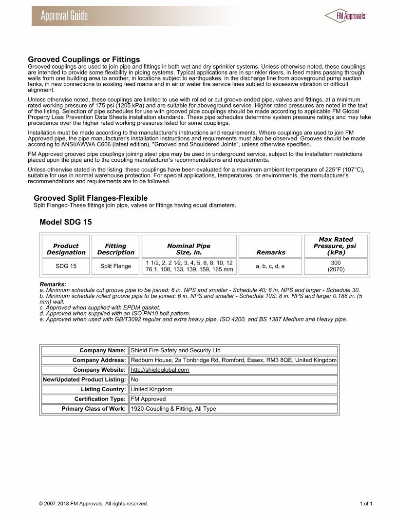
Grooved Couplings or Fittings Grooved couplings are used to join pipe and fittings in both wet and dry sprinkler systems. Unless otherwise noted, these couplingsare intended to provide some flexibility in piping systems. Typical applications are in sprinkler risers, in feed mains passing throughwalls from one building area to another, in locations subject to earthquakes, in the discharge line from aboveground pump suctiontanks, in new connections to existing feed mains and in air or water fire service lines subject to excessive vibration or difficultalignment. Unless otherwise noted, these couplings are limited to use with rolled or cut groove-ended pipe, valves and fittings, at a minimumrated working pressure of 175 psi (1205 kPa) and are suitable for aboveground service. Higher rated pressures are noted in the textof the listing. Selection of pipe schedules for use with grooved pipe couplings should be made according to applicable FM GlobalProperty Loss Prevention Data Sheets installation standards. These pipe schedules determine system pressure ratings and may takeprecedence over the higher rated working pressures listed for some couplings. Installation must be made according to the manufacturer's instructions and requirements. Where couplings are used to join FMApproved pipe, the pipe manufacturer's installation instructions and requirements must also be observed. Grooves should be madeaccording to ANSI/AWWA C606 (latest edition), "Grooved and Shouldered Joints", unless otherwise specified. FM Approved grooved pipe couplings joining steel pipe may be used in underground service, subject to the installation restrictionsplaced upon the pipe and to the coupling manufacturer's recommendations and requirements. Unless otherwise stated in the listing, these couplings have been evaluated for a maximum ambient temperature of 225°F (107°C),suitable for use in normal warehouse protection. For special applications, temperatures, or environments, the manufacturer'srecommendations and requirements are to be followed.
Grooved Split Flanges-Flexible Split Flanged-These fittings join pipe, valves or fittings having equal diameters.
Model SDG 15
ProductDesignation
FittingDescription
Nominal PipeSize, in. Remarks
Max RatedPressure, psi
(kPa)
SDG 15 Split Flange 1 1/2, 2, 2 1⁄2, 3, 4, 5, 6, 8, 10, 1276.1, 108, 133, 139, 159, 165 mm a, b, c, d, e 300
(2070)
Remarks:a. Minimum schedule cut groove pipe to be joined: 6 in. NPS and smaller - Schedule 40; 8 in. NPS and larger - Schedule 30.b. Minimum schedule rolled groove pipe to be joined: 6 in. NPS and smaller - Schedule 10S; 8 in. NPS and larger 0.188 in. (5mm) wall.c. Approved when supplied with EPDM gasket.d. Approved when supplied with an ISO PN10 bolt pattern.e. Approved when used with GB/T3092 regular and extra heavy pipe, ISO 4200, and BS 1387 Medium and Heavy pipe.
Company Name: Shield Fire Safety and Security LtdCompany Address: Redburn House, 2a Tonbridge Rd, Romford, Essex, RM3 8QE, United KingdomCompany Website: http://shieldglobal.com
New/Updated Product Listing: NoListing Country: United Kingdom
Certification Type: FM ApprovedPrimary Class of Work: 1920-Coupling & Fitting, All Type
© 2007-2018 FM Approvals. All rights reserved. 1 of 1
Pipe Hangers Pipe hangers are used to support a sprinkler piping system from the building structure. Two or more listed components may berequired to form a complete hanger assembly. The specific components required depend upon the type of building construction andthe pipe size.
Loop Hangers A type of pipe hanger which provides vertical adjustment that utilizes a formed strap looped around the pipe.
Shield Fire Safety, Loop Hangers
ProductDesignation
Hanger RodSize, in. (mm)
ComponentDescription
ForNominal PipeSizes, in.
Remarks
SD_HB 3/8(10) Loop Hanger 3/4 through 4 a
SD_HB 1/2(12) Loop Hanger 5 through 8 a
Remarks:a.) The SD-HB is FM Approved as a 200R when made with an O-ring in place of a flared nut and as a 200S with a modified ringnut.
Company Name: Shield Fire Safety and Security LtdCompany Address: Redburn House, 2a Tonbridge Rd, Romford, Essex, RM3 8QE, United KingdomCompany Website: http://shieldglobal.com
New/Updated Product Listing: NoListing Country: United Kingdom
Certification Type: FM ApprovedPrimary Class of Work: 1951-Pipe hangers For AS Sys
© 2007-2018 FM Approvals. All rights reserved. 1 of 1

Pipe Hangers Pipe hangers are used to support a sprinkler piping system from the building structure. Two or more listed components may berequired to form a complete hanger assembly. The specific components required depend upon the type of building construction andthe pipe size.
Clevis Hangers A type of pipe hanger which provides vertical adjustment, consisting of a clevis type top bolted to a formed steel bottom strap.
Shield Fire Safety, Clevis Hangers
ProductDesignation
Hanger RodSize, in.
(mm)ComponentDescription
ForNominal Pipe
Sizes, in.Remarks
SD-HC 3/8(10) Clevis Hanger 3/4 -
SD-HC 3/8(10) Clevis Hanger 1 -
SD-HC 3/8(10) Clevis Hanger 1 1/4 -
SD-HC 3/8(10) Clevis Hanger 1 1/2 -
SD-HC 3/8(10) Clevis Hanger 2 -
SD-HC 3/8(10) Clevis Hanger 2 1/2 -
SD-HC 3/8(10) Clevis Hanger 3 -
SD-HC 3/8(10) Clevis Hanger 3 1/2 -
SD-HC 3/8(10) Clevis Hanger 4 -
SD-HC ½(12) Clevis Hanger 5 -
SD-HC ½(120) Clevis Hanger 6 -
SD-HC ½(12) Clevis Hanger 8 -
SD-HC 5/8(20) Clevis Hanger 10 -
SD-HC 5/8(20) Clevis Hanger 12 -
SD-HC 1/2(12) Clevis Hanger 2 1/2 through 3 1/2 -
SD-HC 5/8(16) Clevis Hanger 4, 5 -
SD-HC 3/4(20) Clevis Hanger 6 -
SD-HC 7/8(22) Clevis Hanger 8 -
Company Name: Shield Fire Safety and Security LtdCompany Address: Redburn House, 2a Tonbridge Rd, Romford, Essex, RM3 8QE, United Kingdom
© 2007-2018 FM Approvals. All rights reserved. 1 of 2

Company Website: http://shieldglobal.comNew/Updated Product Listing: No
Listing Country: United KingdomCertification Type: FM Approved
Primary Class of Work: 1951-Pipe hangers For AS Sys
© 2007-2018 FM Approvals. All rights reserved. 2 of 2


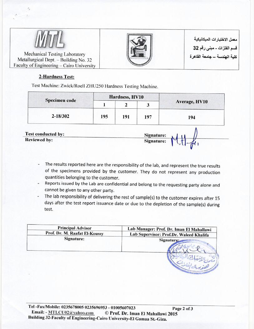


1. EXPORTER(NAME,ADDRESS,COUNTRY) TF.:CHNO PRO MIDDLE EAST FZCO
PO BOX: 261044
UNITED ARAB EMIRATES
JEBEL All FREE ZONE, DUBAI
TEL:50-4508135
UNITED ARAB EMIRATES ~~ a dJ ( ~UBAI CHAMBER
2. CONSIGNEE(NAME,ADDRESS,COUNTRY) (~ •ulft> '1""1~1 J.,j<ll NAFFCO ELECTROMECHANICAL
PO BOX: 4192
ABU DHABI
TEL:026904555 FAX:026904666
UNITED ARAB EMIRATES
,.. C e rtific ate o f O rigin •J!I Q
Certificate No. 17599748 Date 14-FEB-2018
ORIGINAL
3. Means of Transport: Vessel's Name/Flight No. Jill! ~.J 6. Country of Final Destination
: By Land United Arab Emirates
4. Estimated Date of Departure ;y\.L..Jl ~_,wt t;-'..JI...Jll 7. Invoice No. and Date
1 008-2018·03, 06-FEB-2018
5. Port of Discharge t'...foll u\S..o 1 .~ 8. Country of Origin of Goods
9. rli)~t_, ..:.WWI Marks & Numbers
United Kingdom
10. (.>o~l r)ljj u\SJWI .t.....l) ~w.,.ll u..._, .~1 f:Y.J = No. and Kind of Packages,Description of Goods (Include Brand Names if Necessary)
1 73071100 Tube & pipe fittings (for example, couplings. elbows or sleeves) of non·malleable cast iron.
Grooved and Threaded Fittings Shield
As per the attached invoice ················ ...... End of Description ,.,._ ...... .. .. .. .
11. ;;,._,!1_,~1
Quantity & Unit
12. CERTIFICATION BY THE COMPETENT AUTHORITY
We hereby certify that evidence has been produced to satisfy us that the goods
specified above originate in I were processed in the country shown in box 8. This
Certificate is, therefore; issued and certified to the best of our knowledge and
belief to be correct and without any liability on our part.
).>..a)'l~~
.illll_, .a '-'Wt ...' ~_,..Jt .ll;lt ...' ~ 1 c.y:.;.. ,)(r.l ;J_,s:,..tt ~w.,.Jt u~ 'JJ'it '"'.lil ~-" ...:.~.,....:..; .~<,.!_,_;....<;I uJJ ~ wJlU-1_, ~y... ~ 4-.;lc ~IJ IA).l...<o) ~ J! oJ~I ,:,., u~
~ I .,.
Authorized Signatory
Once this Certificate is issued. il shall be invalid should any alteration be made to
this Certificate, without the competent Authority's authorization.
....-+' ~~.J oJL_.;...; 4.........;..>-i' Dubai Chamber of Commerce & Industry P.O.Box 1457- Dubai. U.A.E. -".>1<-i>"-- I Tel (Wilhin UAE) 800 CHAMBER (800 2426237) I Tel (Outside UAE) (+971) 4 2280000 _.,,_. Fax (+971) 4 2028888 ....SU I Email: [email protected] ..'>fol1'-"-"'' I Website: www.dubaichamber.ae .,J,fol~ 1 c:i_,.l1
Servtce Requesl No· 1-5544092318 User Name- TECHNO_PRO Branch Name· 2
;,,UI ,:ll_,..lt,.i;};jo.rY-'"~' ~.:,. .>St.ll For online verification of this certificale.please visit.
hltp://www.dubaichamber.com/verify ileiiiY"io::213260siiiTPM"-······
hltps://certificates.iccwbo.org/
Page 1 of 1
MARINA
Highlight