FITTINGS CATALOG | Pexgol
30
93 FITTINGS CATALOG
-
Upload
khangminh22 -
Category
Documents
-
view
0 -
download
0
Transcript of FITTINGS CATALOG | Pexgol

93
FITTINGS CATALOG

OD Std Length Min Length
63 500.0 85.0
75 500.0 85.0
90 500.0 104.0
110 500.0 120.0
125 500.0 130.0
140 500.0 140.0
160 500.0 160.0
180 500.0 182.0
200 500.0 180.0
225 500.0 180.0
250 500.0 198.0
280 500.0 200.0
315 500.0 200.0
355 500.0 215.0
400 500.0 228.0
450 500.0 238.0
500 500.0 255.0
560 500.0 285.0
630 500.0 320.0
710 500.0 350.0
Length of Flared End Connectors (stub-ends)
The ends of the Pexgol pipe are heated and flared by a proprietary process, performed at Golan Plastic Products. The final pipe end is similar to a stub end.
The loose flange is usually mounted over the pipe during the flaring process. Alternatively, split flanges can be supplied to be mounted later. Golan prepares flanges conforming to different standards. Detailed drawings of flanges are supplied as requested. Plastic coated flanges are also available on request.
The pipes can be ordered in lengths according to customer specifications. Alternatively, they are available in lengths of 5.80 m to fit into 20ft containers or in lengths of 11.80m to fit into 40ft containers Pipes in lengths of 12-13 meters can be supplied upon a special order in 45ft containers. The catalog numbers in the table on the next page represent Pexgol pipe sections of standard length 500mm with a flared end on one side.
Flared End Connectors (Stub Ends)
Please specify according to the following example if:
• A longer section is required, or
• Flared ends on both sides are required, or
• Loose flanges are required for the pipe section
Example:
For a pipe section 160mm, wall thickness 14.6mm, length 2500mm with one flared end & flange:
FLA16014.6 2500mm with flared end and flange ASA 150 on one side.
The catalog number represents only the flared end and not the flange, which is ordered separately.
9594

OD Class 10 Class 12 Class 15 Class 19 Class 24 Class 30
63 FLA633.9 FLA634.7 FLA635.8 FLA-637.1 FLA638.6 FLA-6310.5
75 FLA754.7 FLA755.6 FLA756.8 FLA758.4 FLA7510.3 FLA7512.5
90 FLA905.6 FLA906.7 FLA908.2 FLA9010.1 FLA9012.3 FLA9015
110 FLA1106.8 FLA1108.1 FLA11010 FLA11012.3 FLA11015.1 FLA11018.3
125 FLA1257.7 FLA1259.2 FLA12511.4 FLA12514.1 FLA12517.1 FLA12520.8
140 FLA1408.7 FLA14010.3 FLA14012.7 FLA14015.7 FLA14019.2 FLA14023.3
160 FLA1609.9 FLA16011.8 FLA16014.6 FLA16017.9 FLA16021.9 FLA16027.3
180 FLA18011.1 FLA18013.3 FLA18016.3 FLA18020.1 FLA18024.6 FLA18029.9
200 FLA20012.4 FLA20014.7 FLA20018.1 FLA20022.4 FLA20027.4 FLA20033.2
225 FLA22513.9 FLA22516.6 FLA22520.4 FLA22525.0 FLA22530.8 FLA22537.4
250 FLA25015.2 FLA22516.6 FLA25022.7 FLA25027.9 FLA25034.2 FLA25041.5
280 FLA28017.3 FLA28020.6 FLA28025.4 FLA28031.3 FLA28037.7 FLA-28046.5
315 FLA31519.5 FLA31523.2 FLA31528.6 FLA31535.2 FLA31543.1 FLA31552.3
355 FLA35521.9 FLA35526.1 FLA35532.2 FLA35539.7 FLA35548.5 FLA35559
400 FLA40024.7 FLA40029.4 FLA40036.3 FLA440044.7 FLA40054.7 FLA40066.7
450 FLA45027.8 FLA45033.1 FLA45040.9 FLA45050.3 FLA45061.5 FLA45075
500 FLA50030.9 FLA50036.7 FLA50045.4 FLA50055.8 FLA50068.5 FLA50083.4
560 FLA56034.6 FLA56041.2 FLA56050.8 FLA56062.5 FLA56076.7 FLA56093.4
630 FLA63038.9 FLA63046.6 FLA63057.2 FLA63070.0 FLA63086.3 FLA630105
710 FLA71043.8 FLA71052.2 FLA71064.5 FLA71078.9 FLA71097.3 FLA710118.3
Flared Ends Catalog Numbers
9594

Loose Flanges for Flared End Connectors
Cat. No. StandardPipe
dia. (mm)Flange
dim. (inch)O.D
Wall thickness
Radius (mm)
Inside dia. (mm)
No. of Bolts
Weight (kg)
D2 T R D1 N
65003201 ASA/BSTD 32 1 108 14 1 34 4 0.9
65004012 ASA/BSTD 40 1.25 118 16 1 42 4 1.2
65005015 ASA/BSTD 50 1.5 127 17 6 52 4 1.4
65006302 ASA/BSTD 63 2 152 19 7 65 4 2.3
65007525 ASA/BSTD 75 2.5 178 22 8 78 4 3.5
65009003 ASA/BSTD 90 3 190 24 8 93 4 4.1
65011004 ASA/BSTD 110 4 228 24 10 116 8 5.8
65012504 ASA/BSTD 125 4 228 24 10 131 8 5.3
65014006 ASA/BSTD 140 6 279 25 10 146 8 8.9
65016006 ASA/BSTD 160 6 279 25 10 167 8 7.9
65018006 ASA/BSTD 180 6 279 25 10 187 8 6.7
65020008 ASA/BSTD 200 8 343 28 15 210 8 12.9
65022508 ASA/BSTD 225 8 343 28 15 236 8 10.9
64825010 ASA 250 10 406 30 17 262 12 18.2
64925010 BSTD 250 10 406 30 17 262 8 18.2
64828010 ASA 280 10 406 30 17 293 12 14.9
64928010 BSTD 280 10 406 30 17 293 8 14.9
65031512 ASA/BSTD 315 12 482 32 20 331 12 24.7
65035514 ASA/BSTD 355 14 533 35 20 371 12 32.2
64840016 ASA 400 16 597 36 22 417 16 41.3
64940016 BSTD 400 16 578 36 22 417 12 36.5
64845018 ASA 450 18 635 40 22 467 16 46.5
64945018 BSTD 450 18 641 40 22 467 12 48.5
64850020 ASA 500 20 698 43 25 518 20 59.1
64950020 BSTD 500 20 705 43 25 518 16 61.8
64863024 ASA 630 24 813 48 30 652 20 71.1
64963024 BSTD 630 24 826 48 30 652 16 78.0
The following table lists dimensions of flanges for Pexgol flared ends according to ASA 150 or B.S. table 10D.
Flanges according to other flange standards are available by special order. Split flanges of all flange standards are also supplied by special order.
Carbon Flange BSTD Carbon Flange ASA150
9796

Prefabricated elbows are produced from Pexgol pipes of all classes according to a proprietary process. The length of each leg of a Pexgol elbows is specified according to dimension A or dimension B in the table below. Prefabricated elbows with flared-ends are available in any length between the minimum and maximum values, dim.A. Prefabricated elbows with plain ends are available in minimum lengths according to dim.B.
Each leg can be supplied with plain ends or with flared ends with or without flanges. and in varying length for each leg.
Prefabricated Pexgol Elbows
For ordering please write the length A or B and describe the pipe ends.
For example:
ELB16014.6-453D one leg 550mm with flared end and flange ASA 150 , other leg 420mm plain end.
The weight of the elbow is calculated by adding the A or B values of the legs, dividing them by 1,000 (to get the total length of the elbow in meters) and then multiplying by the weight of the pipe per meter according to the pipe dimensions tables.
Dimensions of Pexgol Elbows
OD
1.5D 3D
45° 90° 45° 90°
A [mm] B [mm] A [mm] B [mm] A [mm] B [mm] A [mm] B [mm]
Min Max Min Min Max Min Min Max Min Min Max Min50 210 400 100 260 600 130 240 500 140 330 600 230
63 225 450 120 320 600 180 260 500 160 380 650 280
75 235 450 130 310 600 210 280 500 180 420 700 320
90 250 350 155 380 600 240 305 500 215 465 700 375
110 270 350 190 420 700 280 335 500 235 530 750 445
125 280 400 200 400 600 320 350 500 270 575 800 500
140 295 400 210 430 700 350 375 500 295 625 900 545
160 300 400 225 450 750 320 410 600 335 690 1000 620
180 300 400 225 450 750 400 430 610 360 720 950 650
200 350 550 350 635 900 450 450 620 450 800 1100 800
225 400 600 400 700 1000 500 500 800 500 900 1250 900
250 450 700 450 720 1000 500 550 800 550 1000 1250 100
280 480 700 480 820 1000 600 650 950 650 1100 1330 1100
315 550 800 550 900 1100 700 700 1100 700 1250 1500 1250
355 650 900 650 1000 1200 1000 800 1100 800 1400 1600 1400
400 700 1000 700 1080 1300 1080 900 1100 900 1500 2400 1500
450 800 1100 800 1200 1400 1200 1000 1150 1000 1900 1900 1900
500 850 1200 850 1350 1500 1350 1100 1100 1100 2000 200 2000
560 * * * * * * * * * * * *
630 1100 1300 1100 1650 1900 1650 1450 1700 1450 2400 2500 2400
710 * * * * * * * * * * * *
* Available on request
Notes:
1. Length of ebow also includes a straight section to makes connection to the elbow easier.
2. The dim.A is the length of the elbow with a flared end & flange.
3. Elbows with a plain end (for electrofusion or mechanical connector) can be ordered with a shorter length according to dim.B
4. Elbows with longer dimensions A or B can be specially ordered (after coordination with Golan Plastic Products).
5. Larger or smaller radii elbows are available by special order.
6. Elbows with angles not according to standard are supplied by special order.
9796

OD Class
1.5D 3D
45° 90° 45° 90°
Cat. No. Cat. No. Cat. No. Cat. No.
50 15 ELB504.6-451.5D ELB504.6-901.5D ELB504.6-453D ELB504.6-903D
50 19 ELB505.6-451.5D ELB505.6-451.5D ELB505.6-453D ELB505.6-453D
50 24 ELB506.9-451.5D ELB506.9-901.5D ELB506.9-453D ELB506.9-903D
50 30 ELB508.3-451.5D ELB508.3-451.5D ELB508.3-453D ELB508.3-453D
63 10 ELB633.9-451.5D ELB633.9-901.5D ELB633.9-453D ELB633.9-903D
63 12 ELB634.7-451.5D ELB634.7-451.5D ELB634.7-453D ELB634.7-453D
63 15 ELB635.8-451.5D ELB635.8-901.5D ELB635.8-453D ELB635.8-903D
63 19 ELB637.1-451.5D ELB637.1-901.5D ELB637.1-453D ELB637.1-903D
63 24 ELB638.6-451.5D ELB638.6-901.5D ELB638.6-453D ELB638.6-903D
63 30 ELB6310.5-451.5D ELB6310.5-901.5D ELB6310.5-453D ELB6310.5-903D
75 10 ELB754.6-451.5D ELB754.6-901.5D ELB754.6-453D ELB754.6-903D
75 12 ELB755.6-451.5D ELB755.6-451.5D ELB755.6-453D ELB755.6-453D
75 15 ELB756.8-451.5D ELB756.8-901.5D ELB756.8-453D ELB756.8-903D
75 19 ELB758.4-451.5D ELB758.4-901.5D ELB758.4-453D ELB758.4-903D
75 24 ELB7510.3-451.5D ELB7510.3-901.5D ELB7510.3-453D ELB7510.3-903D
75 30 ELB7512.5-451.5D ELB7512.5-901.5D ELB7512.5-453D ELB7512.5-903D
90 10 ELB905.6-451.5D ELB905.6-901.5D ELB905.6-453D ELB905.6-903D
90 12 ELB906.7-451.5D ELB906.7-451.5D ELB906.7-453D ELB906.7-453D
90 15 ELB908.2-451.5D ELB908.2-901.5D ELB908.2-453D ELB908.2-903D
90 19 ELB9010.1-451.5D ELB9010.1-901.5D ELB9010.1-453D ELB9010.1-903D
90 24 ELB9012.3-451.5D ELB9012.3-901.5D ELB9012.3-453D ELB9012.3-903D
90 30 ELB9015.0-451.5D ELB9015.0-901.5D ELB9015.0-453D ELB9015.0-903D
110 10 ELB1106.8-451.5D ELB1106.8-901.5D ELB1106.8-453D ELB1106.8-903D
110 12 ELB1108.1-451.5D ELB1108.1-451.5D ELB1108.1-453D ELB1108.1-453D
110 15 ELB11010-451.5D ELB11010-901.5D ELB11010-453D ELB11010-903D
110 19 ELB11012.3-451.5D ELB11012.3-901.5D ELB11012.3-453D ELB11012.3-903D
110 24 ELB11015.1-451.5D ELB11015.1-901.5D ELB11015.1-453D ELB11015.1-903D
110 30 ELB11018.3-451.5D ELB11018.3-901.5D ELB11018.3-453D ELB11018.3-903D
125 10 ELB1257.7-451.5D ELB1257.7-901.5D ELB1257.7-453D ELB1257.7-903D
125 12 ELB1259.2-451.5D ELB1259.2-451.5D ELB1259.2-453D ELB1259.2-453D
125 15 ELB12511.4-451.5D ELB12511.4-901.5D ELB12511.4-453D ELB12511.4-903D
125 19 ELB12514.1-451.5D ELB12514.1-901.5D ELB12514.1-453D ELB12514.1-903D
125 24 ELB12517.1-451.5D ELB12517.1-901.5D ELB12517.1-453D ELB12517.1-903D
125 30 ELB12520.8-451.5D ELB12520.8-901.5D ELB12520.8-453D ELB12520.8-903D
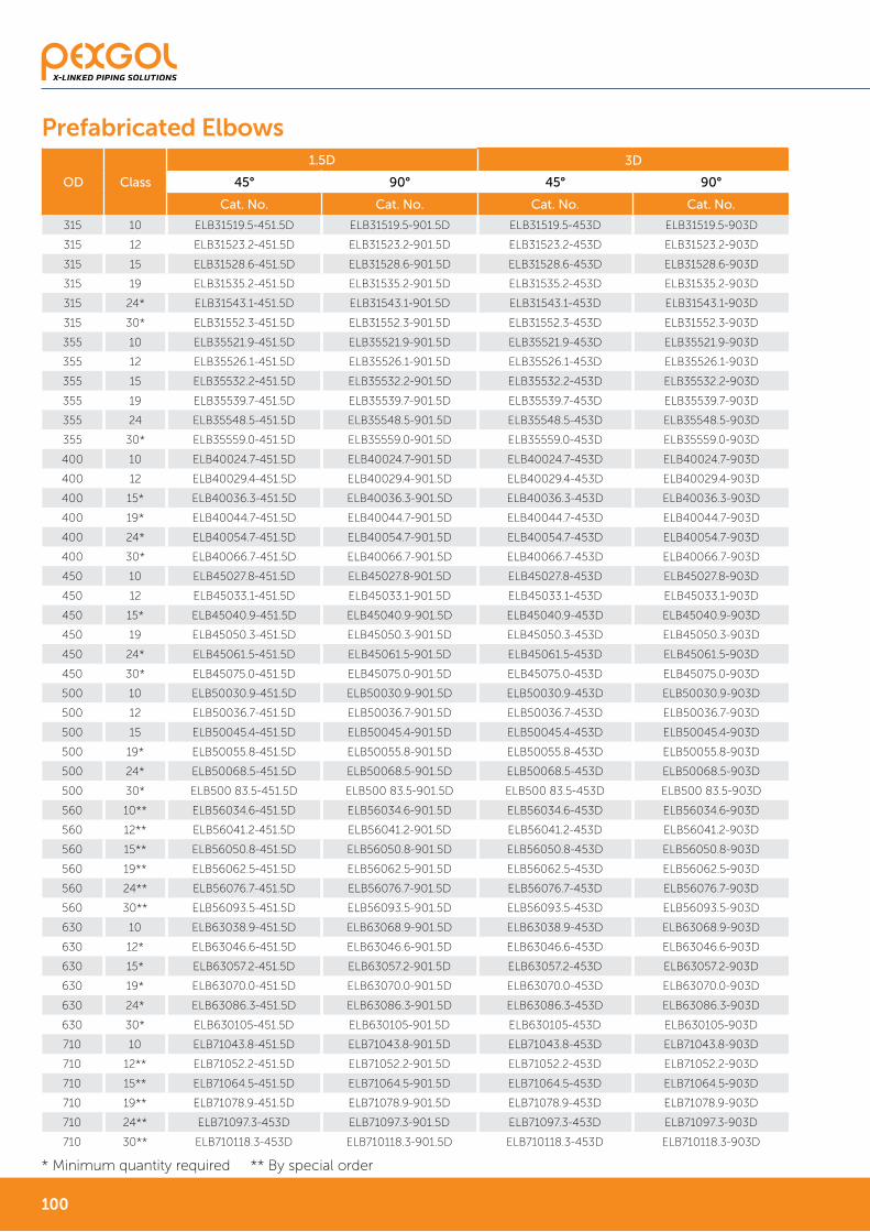
Prefabricated Elbows
9998

OD Class
1.5D 3D
45° 90° 45° 90°
Cat. No. Cat. No. Cat. No. Cat. No.
140 10 ELB1408.7-451.5D ELB1408.7-901.5D ELB1408.7-453D ELB1408.7-903D
140 12 ELB14010.3-451.5D ELB14010.3-451.5D ELB14010.3-453D ELB14010.3-453D
140 15 ELB14012.7-451.5D ELB14012.7-901.5D ELB14012.7-453D ELB14012.7-903D
140 19 ELB14015.7-451.5D ELB14015.7-901.5D ELB14015.7-453D ELB14015.7-903D
140 24 ELB14019.2-451.5D ELB14019.2-901.5D ELB14019.2-453D ELB14019.2-903D
140 30 ELB14023.3-451.5D ELB14023.3-901.5D ELB14023.3-453D ELB14023.3-903D
160 10 ELB1609.9-451.5D ELB1609.9-901.5D ELB1609.9-453D ELB1609.9-903D
160 12 ELB16011.8-451.5D ELB16011.8-451.5D ELB16011.8-453D ELB16011.8-453D
160 15 ELB16014.6-451.5D ELB16014.6-901.5D ELB16014.6-453D ELB16014.6-903D
160 19 ELB16017.9-451.5D ELB16017.9-901.5D ELB16017.9-453D ELB16017.9-903D
160 24 ELB16021.9-451.5D ELB16021.9-901.5D ELB16021.9-453D ELB16021.9-903D
160 30 ELB16026.6-451.5D ELB16026.6-901.5D ELB16026.6-453D ELB16026.6-903D
180 10 ELB18011.1-451.5D ELB18011.1-901.5D ELB18011.1-453D ELB18011.1-903D
180 12 ELB18013.3-451.5D ELB18013.3-451.5D ELB18013.3-453D ELB18013.3-453D
180 15 ELB18016.3-451.5D ELB18016.3-901.5D ELB18016.3-453D ELB18016.3-903D
180 19 ELB18020.1-451.5D ELB18020.1-901.5D ELB18020.1-453D ELB18020.1-903D
180 24 ELB18024.6-451.5D ELB18024.6-901.5D ELB18024.6-453D ELB18024.6-903D
180 30 ELB18029.9-451.5D ELB18029.9-901.5D ELB18029.9-453D ELB18029.9-903D
200 10 ELB20012.4-451.5D ELB20012.4-901.5D ELB20012.4-453D ELB20012.4-903D
200 12 ELB20014.7-451.5D ELB20014.7-453D ELB20014.7-453D ELB20014.7-453D
200 15 ELB20018.1-451.5D ELB20018.1-901.5D ELB20018.1-453D ELB20018.1-903D
200 19 ELB20022.4-451.5D ELB20022.4-901.5D ELB20022.4-453D ELB20022.4-903D
200 24 ELB20027.4-451.5D ELB20027.4-901.5D ELB20027.4-453D ELB20027.4-903D
200 30 ELB20033.2-451.5D ELB20033.2-901.5D ELB20033.2-453D ELB20033.2-903D
225 10 ELB22513.9-451.5D ELB22513.9-901.5D ELB22513.9-453D ELB22513.9-903D
225 12 ELB22516.6-451.5D ELB22516.6-451.5D ELB22516.6-453D ELB22516.6-453D
225 15 ELB22520.4-451.5D ELB22520.4-901.5D ELB22520.4-453D ELB22520.4-903D
225 19 ELB22525.0-451.5D ELB22525.0-901.5D ELB22525.0-453D ELB22525.0-903D
225 24 ELB22530.8-451.5D ELB22530.8-901.5D ELB22530.8-453D ELB22530.8-903D
225 30 ELB22537.4-451.5D ELB22537.4-901.5D ELB22537.4-453D ELB22537.4-903D
250 10 ELB25015.5-451.5D ELB25015.5-901.5D ELB25015.5-453D ELB25015.5-903D
250 12 ELB25018.4-451.5D ELB25018.4-901.5D ELB25018.4-453D ELB25018.4-903D
250 15 ELB25022.7-451.5D ELB25022.7-901.5D ELB25022.7-453D ELB25022.7-903D
250 19 ELB25027.9-451.5D ELB25027.9-901.5D ELB25027.9-453D ELB25027.9-903D
250 24 ELB25034.2-451.5D ELB25034.2-901.5D ELB25034.2-453D ELB25034.2-903D
250 30 ELB25041.5-451.5D ELB25041.5-901.5D ELB25041.5-453D ELB25041.5-903D
280 10 ELB28017.3-451.5D ELB28017.3-901.5D ELB28017.3-453D ELB28017.3-903D
280 12 ELB28020.6-451.5D ELB28020.6-901.5D ELB28020.6-453D ELB28020.6-903D
280 15 ELB28025.4-451.5D ELB28025.4-901.5D ELB28025.4-453D ELB28025.4-903D
280 19* ELB28031.3-451.5D ELB28031.3-901.5D ELB28031.3-453D ELB28031.3-903D
280 24 ELB28038.3-451.5D ELB28038.3-901.5D ELB28038.3-453D ELB28038.3-903D
280 30* ELB28046.5-451.5D ELB28046.5-901.5D ELB28046.5-453D ELB28046.5-903D
Prefabricated Elbows
* Minimum quantity required
9998
OD Class
1.5D 3D
45° 90° 45° 90°
Cat. No. Cat. No. Cat. No. Cat. No.
315 10 ELB31519.5-451.5D ELB31519.5-901.5D ELB31519.5-453D ELB31519.5-903D
315 12 ELB31523.2-451.5D ELB31523.2-901.5D ELB31523.2-453D ELB31523.2-903D
315 15 ELB31528.6-451.5D ELB31528.6-901.5D ELB31528.6-453D ELB31528.6-903D
315 19 ELB31535.2-451.5D ELB31535.2-901.5D ELB31535.2-453D ELB31535.2-903D
315 24* ELB31543.1-451.5D ELB31543.1-901.5D ELB31543.1-453D ELB31543.1-903D
315 30* ELB31552.3-451.5D ELB31552.3-901.5D ELB31552.3-453D ELB31552.3-903D
355 10 ELB35521.9-451.5D ELB35521.9-901.5D ELB35521.9-453D ELB35521.9-903D
355 12 ELB35526.1-451.5D ELB35526.1-901.5D ELB35526.1-453D ELB35526.1-903D
355 15 ELB35532.2-451.5D ELB35532.2-901.5D ELB35532.2-453D ELB35532.2-903D
355 19 ELB35539.7-451.5D ELB35539.7-901.5D ELB35539.7-453D ELB35539.7-903D
355 24 ELB35548.5-451.5D ELB35548.5-901.5D ELB35548.5-453D ELB35548.5-903D
355 30* ELB35559.0-451.5D ELB35559.0-901.5D ELB35559.0-453D ELB35559.0-903D
400 10 ELB40024.7-451.5D ELB40024.7-901.5D ELB40024.7-453D ELB40024.7-903D
400 12 ELB40029.4-451.5D ELB40029.4-901.5D ELB40029.4-453D ELB40029.4-903D
400 15* ELB40036.3-451.5D ELB40036.3-901.5D ELB40036.3-453D ELB40036.3-903D
400 19* ELB40044.7-451.5D ELB40044.7-901.5D ELB40044.7-453D ELB40044.7-903D
400 24* ELB40054.7-451.5D ELB40054.7-901.5D ELB40054.7-453D ELB40054.7-903D
400 30* ELB40066.7-451.5D ELB40066.7-901.5D ELB40066.7-453D ELB40066.7-903D
450 10 ELB45027.8-451.5D ELB45027.8-901.5D ELB45027.8-453D ELB45027.8-903D
450 12 ELB45033.1-451.5D ELB45033.1-901.5D ELB45033.1-453D ELB45033.1-903D
450 15* ELB45040.9-451.5D ELB45040.9-901.5D ELB45040.9-453D ELB45040.9-903D
450 19 ELB45050.3-451.5D ELB45050.3-901.5D ELB45050.3-453D ELB45050.3-903D
450 24* ELB45061.5-451.5D ELB45061.5-901.5D ELB45061.5-453D ELB45061.5-903D
450 30* ELB45075.0-451.5D ELB45075.0-901.5D ELB45075.0-453D ELB45075.0-903D
500 10 ELB50030.9-451.5D ELB50030.9-901.5D ELB50030.9-453D ELB50030.9-903D
500 12 ELB50036.7-451.5D ELB50036.7-901.5D ELB50036.7-453D ELB50036.7-903D
500 15 ELB50045.4-451.5D ELB50045.4-901.5D ELB50045.4-453D ELB50045.4-903D
500 19* ELB50055.8-451.5D ELB50055.8-901.5D ELB50055.8-453D ELB50055.8-903D
500 24* ELB50068.5-451.5D ELB50068.5-901.5D ELB50068.5-453D ELB50068.5-903D
500 30* ELB500 83.5-451.5D ELB500 83.5-901.5D ELB500 83.5-453D ELB500 83.5-903D
560 10** ELB56034.6-451.5D ELB56034.6-901.5D ELB56034.6-453D ELB56034.6-903D
560 12** ELB56041.2-451.5D ELB56041.2-901.5D ELB56041.2-453D ELB56041.2-903D
560 15** ELB56050.8-451.5D ELB56050.8-901.5D ELB56050.8-453D ELB56050.8-903D
560 19** ELB56062.5-451.5D ELB56062.5-901.5D ELB56062.5-453D ELB56062.5-903D
560 24** ELB56076.7-451.5D ELB56076.7-901.5D ELB56076.7-453D ELB56076.7-903D
560 30** ELB56093.5-451.5D ELB56093.5-901.5D ELB56093.5-453D ELB56093.5-903D
630 10 ELB63038.9-451.5D ELB63068.9-901.5D ELB63038.9-453D ELB63068.9-903D
630 12* ELB63046.6-451.5D ELB63046.6-901.5D ELB63046.6-453D ELB63046.6-903D
630 15* ELB63057.2-451.5D ELB63057.2-901.5D ELB63057.2-453D ELB63057.2-903D
630 19* ELB63070.0-451.5D ELB63070.0-901.5D ELB63070.0-453D ELB63070.0-903D
630 24* ELB63086.3-451.5D ELB63086.3-901.5D ELB63086.3-453D ELB63086.3-903D
630 30* ELB630105-451.5D ELB630105-901.5D ELB630105-453D ELB630105-903D
710 10 ELB71043.8-451.5D ELB71043.8-901.5D ELB71043.8-453D ELB71043.8-903D
710 12** ELB71052.2-451.5D ELB71052.2-901.5D ELB71052.2-453D ELB71052.2-903D
710 15** ELB71064.5-451.5D ELB71064.5-901.5D ELB71064.5-453D ELB71064.5-903D
710 19** ELB71078.9-451.5D ELB71078.9-901.5D ELB71078.9-453D ELB71078.9-903D
710 24** ELB71097.3-453D ELB71097.3-901.5D ELB71097.3-453D ELB71097.3-903D
710 30** ELB710118.3-453D ELB710118.3-901.5D ELB710118.3-453D ELB710118.3-903D
Prefabricated Elbows
* Minimum quantity required ** By special order
101100

Spigot Reducers
The sizes in the table are only a partial list and other sizes are available on request.
When using Spigot reducers to connect with electrofusion couplers, the end user can reduce the L1 or L2 dimensions.
To order Pexgol spigot reducers, referv to the order form on our website:
www.Pexgol.com/support
Cat. No. Size d1 x d2 Size L Size L1 Size L2Weight (kg)
Class 10Weight (kg)
Class 15Weight (kg)
Class 24RED75x63 75x63 405 205 175 0.20 0.3 0.43
RED90x75 90x75 420 215 180 0.34 0.49 0.7
RED90x63 90x63 420 215 175 0.35 0.49 0.71
RED110x90 110x90 580 280 270 0.55 0.79 1.14
RED110x75 110x75 580 280 255 0.56 0.8 1.16
RED110x63 110x63 580 280 240 0.57 0.81 1.17
RED125x110 125x110 620 280 280 0.73 1.04 1.48
RED125x90 125x90 620 280 270 0.78 1.12 1.59
RED140x125 140x125 700 360 290 0.98 1.38 1.98
RED140x110 140x110 700 360 280 1 1.41 2.03
RED160x140 160x140 720 355 360 1.32 1.88 2.68
RED160x125 160x125 720 355 350 1.4 2 2.85
RED160x110 160x110 720 355 340 1.43 2.04 2.9
RED180x160 180x160 580 260 255 2.1 3 4.2
RED180x140 180x140 580 260 245 1.5 2.2 3.1
RED180x125 180x125 580 260 235 1.6 2.3 3.3
RED200x160 200x160 580 260 255 2.45 3.46 4.97
RED200x110 200x110 580 260 255 2.68 3.8 5.46
RED225x200 225x200 590 250 270 3.23 4.6 6.58
RED225x180 225x180 590 260 260 3.1 4.35 6.2
RED225x160 225x160 590 260 260 3.45 4.92 7.03
RED250x225 250x225 680 330 320 4.25 6.02 8.74
RED250x200 250x200 680 330 320 4.41 6.24 9.07
RED250x160 250x160 680 330 320 4.68 6.63 9.63
RED280x250 280x250 700 340 330 5.72 8.15 15.57
RED280x225 280x225 700 300 320 5.98 8.51 16.26
RED315x280 315x280 770 340 330 7.82 11.14 18.87
RED315x250 315x250 770 340 330 8.13 11.58 19.62
RED355x315 355x315 795 350 340 10.7 15.25 23
RED355x280 355x280 795 350 340 11.31 16.12 24.3
RED400x355 400x355 815 355 350 15.02 21.44 28.58
RED400x315 400x315 815 355 350 15.72 22.43 29.91
RED450x400 450x400 865 275 355 21.1 30.17 36.76
RED450x355 450x355 865 400 355 21.96 31.4 38.26
RED500x450 500x450 631 302 275 28.4 40.7 43.22
RED500x400 500x400 659 302 249 29.66 42.51 45.14
RED630x500 630x500 782 340 302 55.94 79.49 67.52
RED630x450 630x450 809 340 275 57.87 82.24 69.85
Dimensions of Spigot Reducers
LL1
L2
d1
d2
101100

Pex 2 Pex Fittings
Pex2Pex electrofusion fittings for high temperature working conditions:
In addition to mechanical fittings, the Pexgol system
also offers a welding solution. Items with the brand
name PLASSON Pex2Pex, are suitable for Pexgol pipes
class 15 SDR11 in all the temperature and pressure ranges
of this pipe class.
The couplers are not UV resistant and must be protected
from UV light.
Special high temperature electrofusion couplers:
Golan offers special high temperature electrofusion
couplers for conditions requiring higher working
pressures or pipe dimensions for which Pex2Pex
couplers are not available. Please consult Golan's
application engineer.
Prior to using Pex2Pex fittings for the first time, please consult Golan regarding on site training.
Cat. No. Pipe D L L1 Weight (kg)
480100050 50 68 100 48.5 0.143
480100063 63 82 118 57 0.22
480100075 75 97 125 61 0.33
480100090 90 115 145 70.7 0.53
480100110 110 139 161 79 0.82
480100125 125 155 169 83 1.00
480100160 160 196 192 94.7 1.77
Pex 2 Pex Coupler
103102

Cat. No. Pipe D L L1 Weight (kg)
480500075 75 96 149.5 60.7 0.50
480500090 90 110.5 201.5 70 0.84
480500110 110 140 234 71 1.52
480500125 125 163.1 271 81 2.33
Cat. No. Pipe d G D L L1 Weight (kg)
482100050015 50 1.5" 38 136 48.5 0.53
482100063020 63 2" 48 160 57 0.9
482100075020 75 2" 59 166 61 1.3
482100075025 75 2 1/2" 59 171 61 1.5
Pex 2 Pex 90° Elbow
Dd
L1L
Pex 2 Pex Brass Connector
Cat. No. Nominal dia D1 D2 L L1 L2 A Weight (kg)
480400050 50 68 68 139 48.5 48.5 155 0.374
480400063 63 82 82 166 57.5 57.3 188 0.598
480400075 75 97 96 195 58.5 61 232 0.997
480400090 90 112 115 292 70.5 70.7 252 1.7
480400110 110 142.5 138.5 327.5 71.5 79 296 2.386
480400125 125 163 154.5 380 85 83 326 3.838
Pex 2 Pex Tees
103102

Flanged Coupler For Pexgol Pipes
Available sizes from diameters 63mm to 710mm.
The flange has oval holes designed to fit most international standards. See table 62.1.
The couplers can be used for the full range of temperatures and pressures, the same as Pexgol pipes. Pexgol flanged couplers consist of either two halves or four quarters, depending on the pipe size.
The body of the coupler is made of spheroidal (ductile) cast iron GGG40 (ASTM A-536). The standard gaskes are made of EPDM. Bolts to connect the two halves or four quarters are included.
Cat. No. Pipe OD (mm)
50806320 63
50807525 75
50809030 90
50811040 110
50812540 125
50814060 140
50816060 160
50818060 180
50820080 200
50822580 225
50825010 250
50928010 280 ASA
50828010 280 BS
50831512 315
50835514 355
50840016 400
50845018 450
50850020 500
50863024 630
50871028 710
For additional details and dimensions, please our Engineering & Applications Guide.
Cat. No. Size
85511004 110mm
Hydrant Connector
105104

Branch-off Saddles
Branch-off saddles are designed for side outlets with a maximum diameter equal to half of the main pipe’s diameter. Threaded or flanged outlets (according to ASA 150, BSTD or other standard requirements) are available.
Golan’s stainless steel saddles are supplied for diameters from 110mm to 710mm. They can be used for the full temperature and pressure ranges of Pexgol pipes.
For the installation of saddles, see instructions at:
www.pexgol.com/support
All stainless steel saddles are suitable for transporting drinking water. Saddles with internal rubber lining at the flange outlet are available for corrosive materials that might damage the stainless steel saddles. Golan supplies these saddles by special request.
Cat. No. OD [D] and flange size H (mm) L (mm) Weight (kg)
46811002 110x2" 120 225 5.5
46811003 110x3" 120 225 6.3
46812502 125x2" 120 225 7.0
46812503 125x3" 120 225 7.0
46814002 140x2" 120 300 7.0
46814003 140x3" 120 300 7.0
468916002 160x2" 120 300 7.0
46816003 160x3" 120 300 9.0
46816004 160x4" 120 300 9.5
468918002 180x2" 120 300 7.0
46818003 180x3" 120 300 9.0
46818004 180x4" 120 300 9.5
46820002 200x2" 120 375 14.0
46820003 200x3" 120 375 15.0
46820004 200x4" 120 375 15.0
46822502 225x2" 120 375 15.0
46822503 225x3" 120 375 15.6
46822504 225x4" 120 375 16.0
46822506 225x6" 150 375 19.0
46825002 250x2" 120 450 16.0
46825003 250x3" 120 450 17.0
46825004 250x4" 120 450 18.0
46825006 250x6" 150 450 20.0
46928002 280x2" 120 450 17.0
46928003 280x3" 120 450 18.0
46928004 280x4" 120 450 20.0
46828006 280x6" 150 450 23.0
Stainless Steel Branch-off Saddles/ASA 150 Flanged Outlet
D
H
L
105104

Stainless Steel Branch-off Saddles/ASA150 Flanged Outlet
Cat. No. OD [D] and flange size H (mm) L (mm) Weight (kg)
46831502 315x2" 120 450 18.0
46831503 315x3" 120 450 20.0
46831504 315x4" 120 450 21.0
46831506 315x6" 150 450 23.0
46831508 315x8" 150 450 28.0
46835502 355x2" 120 450 19.0
46835503 355x3" 120 450 21.0
46835504 355x4" 120 450 22.0
46835506 355x6" 150 450 25.0
46835508 355x8" 150 450 29.0
46840003 400x3" 120 525 23.0
46840004 400x4" 120 525 23.0
46840006 400x6" 150 525 26.0
46840008 400x8" 150 525 30.0
46845003 450x3" 120 525 24.0
46845004 450x4" 120 525 24.0
46845006 450x6" 150 525 27.0
46845008 450x8" 150 525 31.0
46850003 500x3" 120 525 26.0
46850004 500x4" 120 525 26.0
46850006 500x6" 150 525 28.0
46850008 500x8" 150 525 32.0
46863003 630x3" 120 525 29.0
46863004 630x4" 120 525 30.0
46863006 630x6" 150 525 32.0
46863008 630x8" 150 525 36.0
107106

Cat. No. OD [D] and flange size H (mm) L (mm) Weight (kg)
47011020 110x2" 120 225 5.5
47011030 110x3" 120 225 6.3
47016020 160x2" 120 300 7.0
47016030 160x3" 120 300 9.0
47018020 180x2" 120 300 7.0
47018030 180x3" 120 300 9.0
47020020 200x2" 120 375 14.0
47020030 200x3" 120 375 15.0
47022520 225x2" 120 375 15.0
47022530 225x3" 120 375 15.6
47025020 250x2" 120 450 16.0
47025030 250x3" 120 450 17.0
47028020 280x2" 120 450 17.0
47028030 280x3" 120 450 18.0
47031520 315x2" 120 450 18.0
47031530 315x3" 120 450 20.0
47035520 355x2" 120 450 19.0
47035530 355x3" 120 450 21.0
47040030 400x3" 120 525 23.0
47045030 450x3" 120 525 24.0
47050030 500x3" 120 525 26.0
47063030 630x3" 120 525 29.0
Stainless Steel Branch-off Saddles/Female Thread Outlet
107106

Cat. No. Pipe Class Male Thread D
29423210 32 x 2.9 15 1" 55
30473210 32 x 4.4 24 1" 55
29424012 40 x 3.7 15 1 1/4" 77
30474012 40 x 5.5 24 1 1/4" 77
29425015 50 x 4.6 15 1 1/2" 85
30475015 50 x 6.9 24 1 1/2" 85
29426320 63 x 5.8 15 2" 105
30476320 63 x 8.7 24 2" 105
29427525 75 x 6.8 15 2 1/2" 115
30477525 75 x 10.3 24 2 1/2" 115
29429030 90 x 8.2 15 3" 140
30479030 90 x 12.3 24 3" 140
29421104 110 x 10.0 15 4" 160
30471104 110 x 15.1 24 4" 160
294212504 125 x 11.4 15 4" 200
304712504 125 x 17.1 24 4" 200
29421606 160 x 14.6 15 6" 230
30471606 160 x 21.9 24 6" 230
Brass DZR Brass Thread
44203205 - 32 x 1/2" F
44403207 - 32 x 3/4" M
44204005 - 40 x 1/2" F
44404007 - 40 x 3/4" M
44205007 - 50 x 3/4" F
44405007 - 50 x 1" M
44206307 - 63 x 3/4" M
44206310 - 63 x 1" F
- 44506315 63 x 1 1/4" M
- 44506302 63 x 2" F
44207515 - 75 x 1 1/2"
- 44507502 75 x 2" F
- 44509002 90 x 2" F
- 44511002 110 x 2" F
- 44516002 160 x 2" F
Brass Fittings
Branch-Off Saddles - Male/Female Thread
Gp Bolt Connectors - Dzr Brass - Male/Female Bspt Thread
Golan’s brass fittings can be used for the full temperature and pressure ranges of Pexgol pipes. Brass saddles with threaded outlets are used for pipes with diameters from 32mm to 160mm.
D
109108

Cat. No. Pipe Class
91032001 32 x 2.9 15
91032002 32 x 4.4 24
91040001 40 x 3.7 15
91040002 40 x 5.5 24
91050001 50 x 4.6 15
91050002 50 x 6.9 24
91063001 63 x 5.8 15
91063002 63 x 8.7 24
91075001 75 x 6.8 15
91075002 75 x 10.3 24
91090001 90 x 8.2 15
91090002 90 x 12.3 24
91011001 110 x 10.0 15
91011002 110 x 15.1 24
91012501 125 x 11.4 15
91012502 125 x 17.1 24
91016001 160 x 14.6 15
91016002 160 x 21.9 24
91016000 160 x 14.6 stainless steel 15
Hela 8010 Pex Double Bolt Connector Class 15/24
Cat. No. Pipe Class Thread
42405405 40 x 5.5 24 1"
42506506 50 x 6.9 24 1 1/4"
42638638 63 x 8.7 24 1 1/4"
Hela 8045 Pex Double Connector with Side Outlet Class 24
Cat. No. Pipe Class Thread
42325323 25 x 3.5 / 32 x 4.4 24 3/4"
42332403 32 x 4.4 / 40 x 5.5 24 3/4"
42340501 40 x 5.5 / 50 x 6.9 24 1"
42350631 50 x 6.9 / 63 x 8.7 24 1 1/4"
Hela 8047 Reducing Connector with Side Outlet Class 24
109108

Cat. No. Cat. No. DZR Brass Thread (inch)
42250511 - 0.50
42250711 - 0.75
- 42251011 1.00
- 42231211 1.25
- 42231511 1.50
- 42232011 2.00
- 42232511 2.50
- 42233011 3.00
- 42234011 4.00
Cat. No. Cat. No. DZR Brass Thread (inch)
53320507 3/4" x 1/2"
- 53320510 1" x 1/2"
- 53320710 1" x 3/4"
- 53310712 1 1/4" x 3/4"
- 53310715 1 1/2" x 3/4"
- 53331012 1 1/4" x 1"
- 53331015 1 1/2" x 1"
- 53331215 1 1/2" x 1 1/4"
- 53330720 2" x 3/4"
- 53331020 2" x 1"
- 53331220 2" x 1 1/4"
- 53331520 2" x 1 1/2"
- 53332512 2 1/2" x 1 1/4"
- 53331525 2 1/2" x 1 1/2"
- 53332025 2 1/2" x 2"
- 53332030 3" x 2"
- 53333025 3" x 2 1/2"
- 53334020 4" x 2"
- 53334025 4" x 2 1/2"
- 53334030 4" x 3"
TEE Female DZR Brass
Bushing DZR Brass
Cat. No. Cat. No. DZR Brass Thread (inch)
57220511 - 0.50
57220711 - 0.75
- 57221011 1.00
- 57231211 1.25
- 57231511 1.50
- 57232011 2.00
- 57232015 2.50
- 57233011 3.00
- 57234011 4.00
Female Coupler DZR Brass
111110

Cat. No. Cat. No. DZR Brass Thread (inch)
55410511 - 1/2"
55410711 - 3/4"
- 55431011 1"
- 55431211 1 1/4"
- 55431511 1 1/2"
- 55432011 2"
- 55432511 2 1/2"
- 55433011 3"
- 55434011 4"
Cat. No. Cat. No. DZR Brass Thread (inch)
27420705 - 3/4" x 1/2"
- 27420710 1" x 3/4"
- 27411215 1 1/2" x 1 1/4"
- 27431220 2" x 1 1/4"
- 27431520 2" x 1 1/2"
- 27431525 2 1/2" x 1 1/2"
- 27432025 2 1/2" x 2"
- 27433020 3" x 2"
- 27434030 4" x 3"
Cat. No. Stand. Brass Cat.No. Dzr Brass Size
- 32310511 1/2"
- 32310711 3/4"
- 32331011 1"
- 32331211 1 1/4"
- 32331511 1 1/2"
- 32332011 2"
- 32332511 2 1/2"
- 32333011 3"
Cat. No. Stand. Brass Cat.No. Dzr Brass Size
32230511 - 1/2"32230711 - 3/4"
- 32231011 1"
- 32231211 1 1/3"- 32231511 1 1/2"- 32232011 2"
- 32232511 2 1/2"- 32233011 3"
- 32234011 4"
Nipple DZR Brass
Reducing Nipple DZR Brass
Male/Female Elbow 90° (Material Brass CuZn40Pb2/DZR Brass)
Female Elbow 90°
111110

L1
H1 A
Cat. No. Pipe Diameter (mm) Clamp width W Clamp size A Bolt size Total length L1 Height H1 Weight (kg)
301063 63 40 185 1/2" 260 290 6.14
301075 75 40 195 1/2" 270 300 6.32
301090 90 40 210 1/2" 320 350 7.31
301110 110 50 230 5/8" 360 380 8.86
301125 125 50 250 5/8" 360 380 8.83
301140 140 50 260 5/8" 380 480 10.14
301160 160 50 280 5/8" 380 480 10.11
301180 180 60 300 3/4" 400 480 11.5
301200 200 60 320 3/4" 420 480 13.09
301225 225 80 350 3/4" 460 500 19.20
301250 250 80 370 3/4" 510 560 18.25
301280 280 80 400 3/4" 520 560 19.01
301315 315 80 435 3/4" 580 650 21.14
301355 355 100 475 1" 650 700 26.64
301400 400 100 520 1" 750 750 29.47
301450 450 100 570 1" 750 800 31.48
301500 500 100 620 1" 800 850 34.03
301630 630 100 754 1" 800 950 38.87
Fixpoint Clamps
Fixpoint Bridge for Pexgol pipes
Cat. No. Pipe Diameter (mm) Length W (mm) Width A (mm) Weight (kg)
66206302 63 40 185 1.11
66207525 75 40 195 1.17
66209003 90 40 210 1.25
66211004 110 50 230 1.67
66212505 125 50 250 1.86
66214006 140 50 260 1.94
66216006 160 50 280 2.05
66218006 180 55 700 2.5
66220008 200 60 320 3.61
66222508 225 80 350 5.12
66225010 250 80 370 5.46
66228010 280 80 400 5.97
66231512 315 80 435 6.46
66235514 355 100 475 8.84
66240016 400 100 520 9.79
66245018 450 100 570 10.80
66250020 500 100 620 11.85
66263024 630 100 754 14.45
113112

Pex-Lined Fittings
These specifications cover materials, manufacturing, testing, inspection and packaging standards for standard and custom made Pex-lined fittings.
Pex-lined steel fittings consist of a steel flanged fitting
lined with thick black Pex coating which extends over
the full face of the flanges. This type of fitting is used
as a standard fitting (Tee, elbow, reducer, etc.). Non-
standard items can also be supplied, subject to approval
by Golan’s technical department.
Manufacturing materials
All materials used are traceable to origin and records
are maintained for a minimum of three years. When
specified, material and/or test certificates is supplied.
Pex lining
Pex lining is made from resin conforming to the
requirements of materials as defined in ASTM specification
D1998-04.
The lining is made from virgin resin, meeting the
requirements of ASTM D1998-04.
When tested in accordance with ASTM D638, the
minimum tensile strength is 23 N/mm2 and the minimum
elongation is 300%.
Fittings
Fabricated fittings are manufactured from the materials
stated above.
Cast fittings are manufactured from the following:
Ductile iron – ASTM A395, BS2789 grade 420/12 or
DIN 1693 Part 1 GGG40.
Cast steel – ASTM A216 WCB or equivalent.
Flanges and welding – neck collars are forged steel to
ASTM A105 N.
Slip on welding collars are steel plate to BS1501-161-
430A, DIN 17100 grades RSt 37-2 or NF A 35-501 grade
E24, EN 10025 or equivalent.
Fabrication standards
Qualification of welding procedures, welders and
welding operators are in accordance with section
IX of the ASME Boiler and Pressure Vessel Code or BS
4870: Part 1 and BS 4871: Part 1, DIN 8560 or EN-288-3.
All welds are visually examined and assessed in
accordance with ASME B31.3 or relevant code.
Dimensional standards
• Flanged cast steel fittings are in accordance with ANSI
B16.5 Class 150.
• Flanged ductile Iron fittings are in accordance with
ANSI B16.42 Class 150.
• Fabricated fittings are in accordance with the
dimensions shown in the following Tables.
• Pipe diameters and wall thicknesses are in accordance
with the dimensions in the following tables.
• Flanges for pipe and fittings are in accordance with
ANSI B16.5 Class 150.
• Flanges are slip on welding, socket welding or welding
neck types.
• Loose backing flanges are suitable for use with
welding collars.
• All relevant dimensions and tolerances are in
accordance with ANSI B16.5 Class 150.
• Threaded bolt holes are not permitted except for
reducing flanges. Threaded bolt holes in reducing
flanges are UNC unless specified otherwise.
• Welding collars for use with loose backing flanges are
slip on welding, socket welding or welding neck type.
113112

• The diameters and thicknesses are given in the following dimension table.
• The dimension table lists the outside diameters. The outside diameter of the instrument Tee bodies are the same as the lined space. The lining on the faces of flanges have uniform thickness, not less than 80% of the actual wall thickness.
• The Pex lining thickness in the following table is the standard. Higher thicknesses are available on request.
Construction of Flanged fittings
Completed fittings are one piece construction. Flanges are are fixed. The preparation and assembly of welded branch connections are in accordance with BS 2633 or ASME B31.3.
Attachment of flanges and collars
Attachment of flanges and collars are done by both back fillet and bore welds.Transition from the bore to the flanged face must incorporate a radius to prevent undue stressing of the liner.
Fabrication dimensional tolerances
Tolerances for flanges and fittings is in accordance with the relevant standards.Fabricated pipework are in accordance with the following tolerances:
Nom DT D G I B C S Pex Lining thick.
Size Mm mm mm n X i mm mm mm mm
1" 33.5 108 50.8 4X15.7 14.2 12 3.38 3.0
1 ¼" 42.2 117.3 63.5 4X15.7 15.7 12 3.56 3.0
1 ½" 48.3 127 73.2 4X19.1 17.5 12 3.68 3.0
2" 60.5 152.4 91.9 4X19.1 19.1 14 3.91 3.5
2 ½" 73.2 177.85 104.6 4X19.1 22.4 14 5.16 3.5
3" 88.9 190.5 127.0 4X19.1 23.9 16 5.49 4.0
3 ½" 101.6 215.9 139.7 8X19.1 23.9 16 5.74 4.0
4" 114.3 228.6 157.2 8X22.4 23.9 16 6.02 4.5
5" 141.3 254 185.7 8X22.4 23.9 18 6.55 4.5
6" 168.4 279.4 215.9 8X22.4 25.4 18 7.11 6.0
8" 219.2 342.9 269.7 8X22.4 28.4 20 8.18 6.0
10" 273.1 406.4 323.9 12X25.4 30.2 22 9.27 6.0
12" 323.9 482.6 381.0 12X25.4 31.8 22 9.53 7.0
14" 355.6 533.4 412.8 12X25.4 35.1 25 9.53 7.0
16" 406.4 596.9 469.9 12X28.4 36.6 25 9.53 7.0
18" 457.2 635 533.4 16X31.8 39.6 25 9.53 7.0
20" 508 698.5 584.2 20X31.8 42.9 25 9.53 7.0
24" 609.6 812.8 269.2 20X35.1 47.8 25 9.53 7.0
Dimension Table
• Squareness of flanges – Square to the axis of the pipe or fitting to within 0.05mm per 25mm measured across the face.
• Flange faces – Faces should not be uneven or concave. Convexity from the bore to the periphery must not exceed 0.4mm per 25mm width of face.
• Flange drilling – PCD +/- 1.5mm. c/c of bolt holes +/- 0.8mm. Eccentricity between PCD and RFD up to 2-½" +/- 0.8mm, 3" and greater +/- 1.5mm.
• Bolt holes – Bolt holes are off center and equally spaced about the center line to an accuracy of 1.5mm.
• Linear and angular dimensions – Linear dimensions +/- 1.5mm; angular dimensions +/- 0.25 degrees.
115114

Internal finish of housings
The interior surfaces and flange faces are clean and free of sharp corners, burrs, rust, scale, weld spatter or
other protrusions that could adversely affect the lining.
Lining
The method of lining and the fit of the lining ensures that
the lining is capable of withstanding the temperature,
pressure and vacuum ratings of the system.
All interference fit linings in straight pipes are normalized
prior to flaring.
Completed linings show no evidence of pinholes,
porosity, cracks or bad workmanship. Sealing surfaces
are free of surface defects that could impair sealing
effectiveness. Scratches, dents, nicks or tool marks on
the sealing face are not deeper than 0.15mm.
Any of these defect types less than 0.15mm but
extending across the face cause the product to be
rejected.
Blind flanges have linings firmly attached linings.
Production testing
For each batch, at least one representative sample
of each nominal size of fittings is selected; tests are
carried out to determine mechanical properties and
SG.
Where samples do not comply with the requirements
stated in this specification, each tube in the batch must
have samples cut from each end and the samples are
subjected to the same tests.
Any sample not meeting the specified requirements
leads to rejection of the whole tube.
The outside diameter and wall thickness are measured.
Tubes not complying with the standard are rejected.
Cracks found at the ends of tubes are cut off along
with at least 50mm of adjacent material.
When specified, each liner tube is subjected to a
flattening test. Each length of tube is passed through
a pre-set gap between two powered rollers. The gap
is set at 50% of the outside diameter of the tube. The
tube is rotated about the longitudinal axis through 90°
and then passed back through the roller gap.
The tube is examined for cracks. A crack, if found, is
cut out along with at least 50mm of adjacent material.
Hydrostatic pressure test
Hydrostatic pressure test is carried out at 16 Barg water
in air. Any evidence of leakage are cause for rejection.
Electrostatic test
Electrostatic testing is carried out at a minimum voltage
of 20,000V. The full surface of every lining is tested. Any pinholes are cause for rejection.
Final Examination
Each item is examined visually. Following satisfactory completion, the outside edge of the flange is stamped with a letter “I" to indicate compliance.
External finish
The outside surface of all pipe and fittings are finished as follows.Shot blast SA 2-½ and coated with one coat zinc phosphate, zinc epoxy or zinc silicate primer. After painting, blocked bolt holes and vents are cleared. Marking and identification: The following information is marked permanently on each fitting by casting into the body or by hard stamping the flange edge in letters at least 6mm high:• Manufacturer’s marking• Lining material
Packaging
All flanges are fitted with protective covers. These covers are removed just prior to installation.Fittings are fitted with medium density fiberboard blanks or alternatively, snap-on proprietary plastic blanks could be used.
Performance
All lined fittings meet the temperature, pressure, and vacuum ratings stated in the Lined Fittings manual.
Service limitations
For positive and negative pressure limitations versus temperature, see table next page. Service temperature limits, subject to compatibility with the fluid being handled are:• Pex: -50° to +115°CWhen lined fittings are exposed to very low temperatures (below -50°C) consideration must be given as to the suitability of the material used for the housings. See section below for further information.
115114

System design and supports
Pipe systems must be adequately supported to avoid excessive deflection of flanged joints, and supports should be installed close to flanges. The requirement for adequate support is critical in areas of high levels of concentration of valves and fittings.
Butterfly valves are usually designed for straight metallic or thermoplastic systems, with the diameter of the vane being defined as a function of the inner diameter of the pipe system under consideration. The inner diameter of lined steel pipe is considerably smaller than the actual steel pipe. Inner diameters of thermoplastic pipes tend to be considerably smaller due to their heavy wall thickness. Consequently, some interference between the inner liner of a lined pipe and the valve vane might be experienced.
The designer should consider this possibility early in the selection process for pipe systems and valves, and if required, incorporate adequate conical spacers between the flanges of plastic fittings and the valve.
Installation and maintenance instructions for lined fittings
• Lined products must not be welded, brazed or torch cut to prevent damaging the lining.
• Handle the material with due care and attention, avoiding all mechanical shocks.
• All flanges are covered to protect them from damage during shipment, storage and handling onsite. If covers are removed for inspection purposes prior to installation, replace them immediately after inspection of each item is completed.
• When joining PEX pipe and lined fittings together, the use of gaskets between the sealing faces is usually not necessary.
• Under normal conditions, remove covers only immediately prior to installation. As gaskets are often not required, utmost attention is required to avoid scratching or otherwise damaging the lining on flange faces.
• In case of leakage, inspect the sealing faces of each component for grooves or chips. Grooves or nicks not deeper than approximately 15% of the flare thickness can be removed with a fine-grade abrasive paper.
The pressure ratings for ANSI 150# and PN16 dimensioned fittings are based on ratings in ANSI B 16.5.The pressure ratings for ANSI 300# dimensioned fittings are based on the rating in ANSI B 16.5 300#, down rated to compensate for the decrease in mechanical properties at elevated temperatures of the lining materials.
Pressure
Temperature ANSI # 150 ANSI # 300
PSI BAR PSI BAR
20°C 250 17.2 450 31.0
50°C 244 17 425 29.3
100°C 235 16 390 26.9
Liner Temperature Diameter
25 40 50 80 100 150 200 250 300 350 400
Pex
20°C Full Full Full Full Full Full Full Full Full Full Full
50°C Full Full Full Full Full Full Full - - - -
80°C Full Full Full Full Full - - - - - -
Pressure/Temp. Rating
Vacuum/Temp. Rating
117116

Lined Fittings
Solid and Lined Spacers
ANSI B16.5 - Class 150#
Lined Swing Check Valve
Materials:
1 - Lining Pex ASTM D1998-04
2 - St 37.0 - DIN 1629
3 - Body St 37.0 - DIN 1629
Standard Version – two fixed flanges
Available on request:
• One or two loose flanges
• ANSI B16.5 Class 300 flanges
• Stainless steel body and flanges 304/316
• Different lengths (L)
Cat No. DN Inch L mm
Pex-SPC-15025 1" 55
Pex-SPC-15032 1 1/4" 68
Pex-SPC-15038 1 1/2" 75
Pex-SPC-15050 2" 95
Pex-SPC-15062 2 1/2" 108
Pex-SPC-15080 3" 130
Pex-SPC-150100 4" 162
Pex-SPC-150125 5" 190
Pex-SPC-150150 6" 218
Pex-SPC-150200 8" 273
Pex-SPC-150250 10" 336
Pex-SPC-150300 12" 406
Pex-SPC-150350 14" 447
Pex-SPC-150400 16" 511
Pex-SPC-150450 18" 546
Pex-SPC-150500 20" 603
Pex-SPC-150600 24" 714
To adjust the the Swing Check Valve to the ID of the Pexgol pipe, order the Pexgol special reducers/adaptors Cat. No. 65900040 (38) in custom-made dimensions. Please consult Golan's Application Engineer.
R B M A C L DN
50 43 26 140 100 62 65
80 46 45 170 135 65 85
100 52 65 208 170 65 55
150 56 104 270 220 65 70
200 60 145 320 275 65 90
250 68 185 400 335 65 70
300 78 230 470 405 65 95
350 78 252 510 445 65 95
400 102 300 575 510 65 95
117116

Lined Elbows
Lined Elbows 90° ANSI B16.5 - Class 150#
Lined Elbows 60°ANSI B16.5 - Class 150#
Lined Elbows 45° ANSI B16.5 - Class 150#
Lined Elbows 30° ANSI B16.5 - Class 150#
Cat No. DN(Inch)
L (mm)
Pex Lining Thickness
Weight (kg)
Pex-LE90-15025 1" 89 3.0 3.1
Pex-LE90-15032 1 ¼" 95 3.0 4.0
Pex-LE90-15038 1 ½" 102 3.0 4.5
Pex-LE90-15050 2" 114 3.5 6.5
Pex-LE90-15063 2 ½" 127 3.5 9.0
Pex-LE90-15080 3" 140 4.0 12.0
Pex-LE90-150100 4" 165 4.0 19.0
Pex-LE90-150125 5" 190 4.0 22.0
Pex-LE90-150150 6" 203 6.0 34.0
Pex-LE90-150200 8" 229 6.0 57.0
Pex-LE90-150250 10" 279 6.0 82.0
Pex-LE90-150300 12" 305 7.0 115.0
Pex-LE90-150350 14" 546 7.0 150.0
Pex-LE90-150400 16" 610 7.0 192.0
Pex-LE90-150450 18" 673 7.0 225.0
Pex-LE90-150500 20" 737 7.0 280.0
Pex-LE90-150600 24" 864 7.0 395.0
Cat No. DN(Inch)
L (mm)
Pex Lining Thickness
Weight (kg)
Pex-LE45-15025 1" 45 3.0 3.0
Pex-LE45-15032 1 ¼" 51 3.0 4.0
Pex-LE45-15038 1 ½" 57 3.0 6.0
Pex-LE45-15050 2" 64 3.5 9.0
Pex-LE45-15063 2 ½" 76 3.5 13.0
Pex-LE45-15080 3" 76 4.0 15.0
Pex-LE45-150100 4" 102 4.0 20.0
Pex-LE45-150125 5" 114 4.0 26.0
Pex-LE45-150150 6" 127 6.0 33.0
Pex-LE45-150200 8" 140 6.0 54.0
Pex-LE45-150250 10" 165 6.0 75.0
Pex-LE45-150300 12" 190 7.0 110.0
Pex-LE45-150350 14" 190 7.0 117.0
Pex-LE45-150400 16" 203 7.0 145.0
Pex-LE45-150450 18" 216 7.0 165.0
Pex-LE45-150500 20" 241 7.0 210.0
Pex-LE45-150600 24" 279 7.0 290.0
Cat No. DN(Inch)
L(mm)
Pex LiningThickness
Weight (kg)
Pex-LE60-15025 1" 45 3.0 2.7
Pex-LE60-15032 1 ¼" 51 3.0 3.6
Pex-LE60-15038 1 ½" 57 3.0 5.4
Pex-LE60-15050 2" 64 3.5 8.1
Pex-LE60-15063 2 ½" 76 3.5 11.7
Pex-LE60-15080 3" 76 4.0 13.5
Pex-LE60-150100 4" 102 4.0 18.0
Pex-LE60-150125 5" 114 4.0 20.5
Pex-LE60-150150 6" 127 6.0 26.1
Pex-LE60-150200 8" 140 6.0 42.7
Pex-LE60-150250 10" 165 6.0 59.3
Pex-LE60-150300 12" 190 7.0 86.9
Pex-LE60-150350 14" 190 7.0 92.4
Pex-LE60-150400 16" 203 7.0 114.6
Pex-LE60-150450 18" 216 7.0 130.4
Pex-LE60-150500 20" 241 7.0 165.9
Pex-LE60-150600 24" 279 7.0 229.1
Cat No. DN(Inch)
L(mm)
Pex LiningThickness
Weight (kg)
Pex-LE30-15025 1" 45 3.0 2.7
Pex-LE30-15032 1 ¼" 51 3.0 3.6
Pex-LE30-15038 1 ½" 57 3.0 5.4
Pex-LE30-15050 2" 64 3.5 8.1
Pex-LE30-15063 2 ½" 76 3.5 11.7
Pex-LE30-15080 3" 76 4.0 13.5
Pex-LE30-150100 4" 102 4.0 16.0
Pex-LE30-150125 5" 114 4.0 20.8
Pex-LE30-150150 6" 127 6.0 26.4
Pex-LE30-150200 8" 140 6.0 43.2
Pex-LE30-150250 10" 165 6.0 56.3
Pex-LE30-150300 12" 190 7.0 82.5
Pex-LE30-150350 14" 190 7.0 87.8
Pex-LE30-150400 16" 203 7.0 108.8
Pex-LE30-150450 18" 216 7.0 123.8
Pex-LE30-150500 20" 241 7.0 157.5
Pex-LE30-150600 24" 279 7.0 217.5
119118

Lined Equal Tee ANSI B16.5 - Class 150#
Cat No.DN
InchL mm
Pex Lining Thickness
Weight (kg)
Pex-LET-15025 1" 89 3.0 3.5
Pex-LET-15032 1 1/4" 95 3.0 4.6
Pex-LET-15038 1 1/2" 102 3.0 6.5
Pex-LET-15050 2" 114 3.5 10.0
Pex-LET-15063 2 1/2" 127 3.5 13.7
Pex-LET-15080 3" 140 4.0 21.0
Pex-LET-150100 4" 165 4.5 36.0
Pex-LET-150125 5" 190 4.5 43.0
Pex-LET-150150 6" 203 6.0 49.0
Pex-LET-150200 8" 229 6.0 75.0
Pex-LET-150250 10" 279 6.0 113.0
Pex-LET-150300 12" 305 7.0 153.0
Pex-LET-150350 14" 356 7.0 197.0
Pex-LET-150400 16" 381 7.0 263.0
Pex-LET-150450 18" 419 7.0 303.0
LET-150500 20" 457 7.0 330.0
LET-150600 24" 559 7.0 397.0
Lined Equal Cross ANSI B16.5 - Class 150#
Cat No.DN
InchL
mmPex LiningThickness
Weight (kg)
Pex-LC-15025 1" 89 3.0 5.5
Pex-LC-15032 1 1/4" 95 3.0 6.5
Pex-LC-15038 1 1/2" 102 3.0 8.2
Pex-LC-15050 2" 114 3.5 13.6
Pex-LC-15063 2 1/2" 127 3.5 16.5
Pex-LC-15080 3" 140 4.0 23.6
Pex-LC-150100 4" 165 4.5 33.0
Pex-LC-150125 5" 190 4.5 43.0
Pex-LC-150150 6" 203 6.0 52.3
Pex-LC-150200 8" 229 6.0 86.3
Pex-LC-150250 10" 279 6.0 124.0
Pex-LC-150300 12" 305 7.0 169.0
Pex-LC-150350 14" 356 7.0 300.0
Pex-LC-150400 16" 381 7.0 372.0
Pex-LC-150450 18" 419 7.0 427.0
Pex-LC-150500 20" 457 7.0 547.0
Pex-LC-150600 24" 559 7.0 713.0
Cat No.DN
InchL
mmL1
mmPex LiningThickness
Weight (kg)
Pex-LLT-15025 1" 146 45 3.0 4.0 7.0
Pex-LLT-15038 1 1/2" 178 51 3.0 9.0
Pex-LLT-15050 2" 203 64 3.5 19.5
Pex-LLT-15080 3" 254 76 4.0 36.0
Pex-LLT-150100 4" 305 76 4.5 53.0
Pex-LLT-150150 6" 368 89 6.0 80.0
Pex-LLT-150200 8" 445 115 6.0 13.0
Lined Lateral TeeANSI B16.5 - Class 150#
119118

Lined Reducing TeeANSI B16.5 - Class 150#
Cat No.DN
InchDN2Inch
Lmm
Pex LiningThickness
Weight (kg)
Pex-LRT-15032-19 1 ¼"
¾"95
x 5.3
Pex-LRT-15032-25 1" 3.0 5.5
Pex-LRT-15062-19 2 ½"
¾"127
x 5.3
Pex-LRT-15062-25 1" 3.0 5.5
Pex-LRT-150100-25
5"
1"
190 4.5 / 3
19.0
Pex-LRT-150100-38 1 ½" 19.8
Pex-LRT-150100-50 2" 21.5
Pex-LRT-150100-80 3" 23.5
Pex-LRT-15038-19 1 ½"
¾"102
x 5.3
Pex-LRT-15038-25 1" 3.0 5.5
Pex-LRT-15050-25 2"
1"114 3.0
7.9
Pex-LRT-15050-38 1 ½" 9.4
Pex-LRT-15080-25
3"
1"
140 4.0 / 3
13.8
Pex-LRT-15080-38 1 ½" 14.0
Pex-LRT-15080-50 2" 15.0
Pex-LRT-150100-25
4"
1"
165 4.5 / 3
19.0
Pex-LRT-150100-38 1 ½" 19.8
Pex-LRT-150100-50 2" 21.5
Pex-LRT-150100-80 3" 23.5
Pex-LRT-150150-25
6"
1"
203 4.5 / 3
28.2
Pex-LRT-150150-38 1 ½" 30.7
Pex-LRT-150150-50 2" 32.0
Pex-LRT-150150-80 3" 35.2
Pex-LRT-150150-100 4" 37.0
Pex-LRT-150200-25
8"
1"
2296.0 / 3
42.5
Pex-LRT-150200-38 1 ½" 45.6
Pex-LRT-150200-50 2" 47.0
Pex-LRT-150200-80 3" 54.0
Pex-LRT-150200-100 4" 57.0
Pex-LRT-150200-150 6" 6.0 63.0
Pex-LRT-150250-25
10"
1"
280
6.0 / 3
64.6
Pex-LRT-150250-38 1 ½" 66.3
Pex-LRT-150250-50 2" 68.3
Pex-LRT-150250-80 3" 75.3
Pex-LRT-150250-100 4" 79.3
Pex-LRT-150250-150 6"6.0
83.0
Pex-LRT-150250-200 8" 94.0
Pex-LRT-150300-25
12"
1"
305
6.0 / 3
127.0
Pex-LRT-150300-38 1 ½" 133.0
Pex-LRT-150300-50 2" 136.0
Pex-LRT-150300-80 3" 146.0
Pex-LRT-150300-100 4" 152.0
Pex-LRT-150300-150 6"6.0
165.0
Pex-LRT-150300-200 8" 219.0
Pex-LRT-150300-250 10" 7.0 223.0
Cat No.DN
InchDN2Inch
Lmm
Pex LiningThickness
Weight (kg)
Pex-LRT-150350-25
14"
1"
356
6.0 / 3
169.0
Pex-LRT-150350-38 1 ½" 173.0
Pex-LRT-150350-38 2" 175.0
Pex-LRT-150350-50 3" 186.0
Pex-LRT-150350-80 4" 191.0
Pex-LRT-150350-100 6"6.0
204.0
Pex-LRT-150350-150 8" 293.0
Pex-LRT-150350-200 10"7.0
299.0
Pex-LRT-150350-300 12" 307.0
Pex-LRT-150400-25
16"
1"
305
6.0 / 3
227.0
Pex-LRT-150400-38 1 ½" 231.0
Pex-LRT-150400-50 2" 233.0
Pex-LRT-150400-80 3" 244.0
Pex-LRT-150400-100 4" 250.0
Pex-LRT-150400-150 6"6.0
263.0
Pex-LRT-150400-200 8" 291.0
Pex-LRT-150400-250 10"
7.0
355.0
Pex-LRT-150400-300 12" 359.0
Pex-LRT-150400-350 14" 373.0
Pex-LRT-150450-25
18"
1"
419
6.0 / 3
303.0
Pex-LRT-150450-38 1 ½" 307.0
Pex-LRT-150450-50 2" 309.0
Pex-LRT-150450-80 3" 319.0
Pex-LRT-150450-100 4" 323.0
Pex-LRT-150450-150 6"6.0
338.0
Pex-LRT-150450-200 8" 372.0
Pex-LRT-150450-250 10"
7.0
443.0
Pex-LRT-150450-300 12" 455.0
Pex-LRT-150450-350 14" 465.0
Pex-LRT-150450-400 16" 473.0
Pex-LRT-150500-25
20"
1"
457
6.0 / 3
279.0
Pex-LRT-150500-38 1 ½" 283.0
Pex-LRT-150500-50 2" 286.0
Pex-LRT-150500-80 3" 294.0
Pex-LRT-150500-100 4" 299.0
Pex-LRT-150500-150 6"6.0
313.0
Pex-LRT-150500-200 8" 343.0
Pex-LRT-150500-250 10"
7.0
413.0
Pex-LRT-150500-300 12" 421.0
Pex-LRT-150500-350 14" 429.0
Pex-LRT-150500-400 16" 439.0
Pex-LRT-150500-450 18" 447.0
Pex-LRT-150600-25
24"
1"
500
6.0 / 3
363.0
Pex-LRT-150600-38 1 ½" 367.0
Pex-LRT-150600-500 2" 370.0
Pex-LRT-150600-80 3" 377.0
Pex-LRT-150600-100 4" 383.0
Pex-LRT-150600-150 6"6.0
396.0
Pex-LRT-150600-200 8" 427.0
Pex-LRT-150600-250 10"
7.0
533.0
Pex-LRT-150600-300 12" 543.0
Pex-LRT-150600-350 14" 553.0
Pex-LRT-150600-400 16" 567.0
Pex-LRT-150600-450 18" 577.0
Pex-LRT-150600-500 20" 589.0
121120

Lined Instrument Tee ANSI B16.5 Class 150#
Cat No.DN 1Inch
DN 2Inch
Lmm
Pex LiningThickness
Weight (kg)
Pex-LIT-15025-25 1" 1" 50 4.0
2.2 Pex-LIT-15038-25
1 ½"1" 2.8
Pex-LIT-15038-38 1 ½" 4.4 Pex-LIT-15050-25
2"1" 50
4.03.6
Pex-LIT-15050-38 1 ½" 75 6.2 Pex-LIT-15050-50 2" 90 8.1 Pex-LIT-15062-25
2 ½"1" 50
4.03.9
Pex-LIT-15062-38 1 ½" 75 7.2 Pex-LIT-15062-50 2" 90 9.8 Pex-LIT-15080-25
3"1" 50
4.04.7
Pex-LIT-15080-38 1 ½" 75 8.3 Pex-LIT-15080-50 2" 90 12.6 Pex-LIT-150100-25
4"
1" 50
4.0
5.9 Pex-LIT-150100-38 1 ½" 75 8.9 Pex-LIT-150100-50 2" 90 16.0 Pex-LIT-150100-80 3" 130 24.5 Pex-LIT-150150-25
6"
1" 50
4.0
8.2 Pex-LIT-150150-38 1 ½" 75 14.7 Pex-LIT-150150-50 2" 90 21.8 Pex-LIT-150150-80 3" 130 30.1 Pex-LIT-150200-25
8"
1" 50
4.0
10.5 Pex-LIT-150200-38 1 ½" 75 17.8 Pex-LIT-150200-50 2" 90 23.3 Pex-LIT-150200-80 3" 130 33.3 Pex-LIT-150100-25
10"
1" 50
4.0
13.7 Pex-LIT-150100-38 1 ½" 75 23.3 Pex-LIT-150100-50 2" 90 26.0 Pex-LIT-150100-80 3" 160 36.7 Pex-LIT-150100-25
12"
1" 50
4.0
43.0 Pex-LIT-150100-38 1 ½" 75 55.5 Pex-LIT-150100-50 2" 90 62.0 Pex-LIT-150100-80 3" 160 69.0 Pex-LIT-150100-25
14"
1" 50
4.0
53.1 Pex-LIT-150100-38 1 ½" 75 66.5 Pex-LIT-150100-50 2" 90 73.7 Pex-LIT-150100-80 3" 160 103.0 Pex-LIT-150100-25
16"
1" 90
4.0
59.0 Pex-LIT-150100-38 1 ½" 110 74.0 Pex-LIT-150100-50 2" 120 83.0 Pex-LIT-150100-80 3" 160 116.7
Cat No.DN 1Inch
DN 2Inch
Lmm
Pex LiningThickness
Weight (kg)
Pex-LIT-150100-25
18"
1" 90
4.0
68.5 Pex-LIT-150100-38 1 ½" 110 90.5 Pex-LIT-150100-50 2" 120 93.7 Pex-LIT-150100-80 3" 160 129.7 Pex-LIT-150100-19
20"
90
4.0
X Pex-LIT-150100-25 1" 72.0 Pex-LIT-150100-38 1 ½" 110 89.7 Pex-LIT-150100-50 2" 120 100.0 Pex-LIT-150100-80 3" 160 137.0 Pex-LIT-150100-25
24"
1" 90
4.0
79.1 Pex-LIT-150100-38 1 ½" 110 94.5 Pex-LIT-150100-50 2" 120 107.5 Pex-LIT-150100-80 3" 160 150.0
121120

Lined Concentric ReducerANSI B16.5 - Class 150#
Lined Eccentric ReducerANSI B16.5 - Class 150#
Cat No.DN 1Inch
DN 2Inch
Lmm
Pex LiningThickness
Weight (kg)
Pex-LCR-15032-25 1 ¼" 1" 114 3.0 3.0
Pex-LCR-15038-19 1 ½"
¾"114
X3.0
3.1 Pex-LCR-15038-25 1" 3.3 Pex-LCR-15050-25
2"1"
127 3.04.1
Pex-LCR-15050-38 1 ½" 4.8 Pex-LCR-15062-25
2 ½"1"
140 3.05.8
Pex-LCR-15062-50 2" 6.9 Pex-LCR-15080-25
3"1"
152 4.0 / 36.7
Pex-LCR-15080-38 1 ½" 6.2 Pex-LCR-15080-50 2" 6.9 Pex-LCR-150100-25
4"
1"
178 4.0 / 3
9.9 Pex-LCR-150100-38 1 ½" 9.3 Pex-LCR-150100-50 2" 9.8 Pex-LCR-150100-80 3" 12.4 Pex-LCR-150125-80
5"3"
203 4.5 / 3.512.7
Pex-LCR-150125-100 4" 15.0 Pex-LCR-150150-25
6"
1"
2294.5 / 3.05.0 / 4.0
18.9 Pex-LCR-150150-50 2" 19.9 Pex-LCR-150150-80 3" 17.4 Pex-LCR-150150-100 4" 18.3 Pex-LCR-150200-100
8"4"
279 6.022.0
Pex-LCR-150200-150 6" 25.3 Pex-LCR-150250-100
10"4"
305 6.033.0
Pex-LCR-150250-150 6" 37.5 Pex-LCR-150250-200 8" 44.7 Pex-LCR-150300-150
12"6"
356 7.045.9
Pex-LCR-150300-200 8" 47.8 Pex-LCR-150300-250 10" 52.5 Pex-LCR-150350-200
14"8"
406 7.069.0
Pex-LCR-150350-250 10" 73.5 Pex-LCR-150350-300 12" 80.0 Pex-LCR-150400-250
16"10"
457 7.098.0
Pex-LCR-150400-300 12" 105.0 Pex-LCR-150400-350 14" 115.0 Pex-LCR-150450-300
18"12"
483 7.0135.0
Pex-LCR-150450-350 14" 148.0 Pex-LCR-150450-400 16" 157.0 Pex-LCR-150500-300
20"
12"
508 7.0
185.0 Pex-LCR-150500-350 14" 198.0 Pex-LCR-150500-400 16" 210.0 Pex-LCR-150500-450 18" 218.0 Pex-LCR-150600-400
24"16"
610 7.0272.0
Pex-LCR-150600-450 18" 282.0 Pex-LCR-150600-500 20" 291.0
Cat No.DN 1Inch
DN 2Inch
Lmm
Pex LiningThickness
Weight (kg)
Pex-LECR-15038-25 1 ½" 1" 114 3.0 3.0
Pex-LECR-15050-25 2"
1"127 3.0
4.0
Pex-LECR-15050-38 1 ½" 4.3
Pex-LECR-15080-25
3"
1"
152 4.0 / 3
6.7
Pex-LECR-15080-38 1 ½" 6.2
Pex-LECR-15080-50 2" 6.9
Pex-LECR-150100-38
4"
1 ½"
178 4.5 / 3.5
9.3
Pex-LECR-150100-50 2" 9.8
Pex-LECR-150100-80 3" 12.4
Pex-LECR-150150-50
6"
2"
229 5.0 / 4.0
15.6
Pex-LECR-150150-80 3" 17.0
Pex-LECR-150150-100 4" 18.7
Pex-LECR-150200-100 8"
4"279 6.0
22.0
Pex-LECR-150200-150 6" 28.0
Pex-LECR-150250-100
10"
4"
305 6.0
33.0
Pex-LECR-150250-150 6" 37.5
Pex-LECR-150250-200 8" 44.7
Pex-LECR-150300-150
12"
6"
356 7.0
45.9
Pex-LECR-150300-200 8" 47.8
Pex-LECR-150300-250 10" 52.5
Pex-LECR-150350-200
14"
8"
406 7.0
69.0
Pex-LECR-150350-250 10" 73.5
Pex-LECR-150350-300 12" 80.0
Pex-LECR-150400-250
16"
10"
457 7.0
98.0
Pex-LECR-150400-300 12" 105.0
Pex-LECR-150400-350 14" 115.0
Pex-LECR-150450-300
18"
12"
483 7.0
135.0
Pex-LECR-150450-350 14" 148.0
Pex-LECR-150450-400 16" 157.0
Pex- LECR-150500-300
20"
12"
508 7.0
185.0
Pex- LECR-150500-350 14" 198.0
Pex- LECR-150500-400 16" 210.0
Pex- LECR-150500-450 18" 218.0
Pex- LECR-150600-500 24" 20" 610 7.0 291.0
122