Circular flanges for pipes, valves, fittings and accessories, PN ...
155
Irish Standard I.S. EN 1092-1:2018 Flanges and their joints - Circular flanges for pipes, valves, fittings and accessories, PN designated - Part 1: Steel flanges © CEN 2018 No copying without NSAI permission except as permitted by copyright law. This is a free 154 page sample. Access the full version online.
-
Upload
khangminh22 -
Category
Documents
-
view
0 -
download
0
Transcript of Circular flanges for pipes, valves, fittings and accessories, PN ...

Irish StandardI.S. EN 1092-1:2018
Flanges and their joints - Circular flanges forpipes, valves, fittings and accessories, PNdesignated - Part 1: Steel flanges
© CEN 2018 No copying without NSAI permission except as permitted by copyright law.
Thi
s is
a fr
ee 1
54 p
age
sam
ple.
Acc
ess
the
full
vers
ion
onlin
e.

I.S. EN 1092-1:2018I.S. EN 1092-1:2018
Incorporating amendments/corrigenda/National Annexes issued since publication:
The National Standards Authority of Ireland (NSAI) produces the following categories of formal documents:
I.S. xxx: Irish Standard — national specification based on the consensus of an expert panel and subject to public consultation.
S.R. xxx: Standard Recommendation — recommendation based on the consensus of an expert panel and subject to public consultation.
SWiFT xxx: A rapidly developed recommendatory document based on the consensus of the participants of an NSAI workshop.
This document replaces/revises/consolidates the NSAI adoption of the document(s) indicated on theCEN/CENELEC cover/Foreword and the following National document(s):
NOTE: The date of any NSAI previous adoption may not match the date of its original CEN/CENELECdocument.
This document is based on:
EN 1092-1:2018
Published:
2018-04-11
This document was publishedunder the authority of the NSAIand comes into effect on:
2018-04-30
ICS number:
23.040.60
NOTE: If blank see CEN/CENELEC cover page
NSAI1 Swift Square, Northwood, Santry Dublin 9
T +353 1 807 3800 F +353 1 807 3838 E [email protected] W NSAI.ie
Sales:T +353 1 857 6730 F +353 1 857 6729 W standards.ie
Údarás um Chaighdeáin Náisiúnta na hÉireann
Thi
s is
a fr
ee 1
54 p
age
sam
ple.
Acc
ess
the
full
vers
ion
onlin
e.

National ForewordNational Foreword
I.S. EN 1092-1:2018 is the adopted Irish version of the European Document EN 1092-1:2018, Flanges and theirjoints - Circular flanges for pipes, valves, fittings and accessories, PN designated - Part 1: Steel flanges
This document does not purport to include all the necessary provisions of a contract. Users are responsiblefor its correct application.
For relationships with other publications refer to the NSAI web store.
Compliance with this document does not of itse lf confer immunity from legal obligations .Compliance with this document does not of itse lf confer immunity from legal obligations .
In line with international standards practice the decimal point is shown as a comma (,) throughout thisdocument.
Thi
s is
a fr
ee 1
54 p
age
sam
ple.
Acc
ess
the
full
vers
ion
onlin
e.

This page is intentionally left blank
Thi
s is
a fr
ee 1
54 p
age
sam
ple.
Acc
ess
the
full
vers
ion
onlin
e.

EUROPEAN STANDARD NORME EUROPÉENNE EUROPÄISCHE NORM
EN 1092-1 April 2018
ICS 23.040.60 Supersedes EN 1092-1:2007+A1:2013English Version Flanges and their joints - Circular flanges for pipes, valves, fittings and accessories, PN designated - Part 1: Steel flanges Brides et leurs assemblages - Brides circulaires pour tubes, appareils de robinetterie, raccords et accessoires, désignées PN - Partie 1: Brides en acier Flansche und ihre Verbindungen - Runde Flansche für Rohre, Armaturen, Formstücke und Zubehörteile, nach PN bezeichnet - Teil 1: Stahlflansche
This European Standard was approved by CEN on 27 November 2017. CEN members are bound to comply with the CEN/CENELEC Internal Regulations which stipulate the conditions for giving this European Standard the status of a national standard without any alteration. Up-to-date lists and bibliographical references concerning such national standards may be obtained on application to the CEN-CENELEC Management Centre or to any CEN member. This European Standard exists in three official versions (English, French, German). A version in any other language made by translation under the responsibility of a CEN member into its own language and notified to the CEN-CENELEC Management Centre has the same status as the official versions. CEN members are the national standards bodies of Austria, Belgium, Bulgaria, Croatia, Cyprus, Czech Republic, Denmark, Estonia, Finland, Former Yugoslav Republic of Macedonia, France, Germany, Greece, Hungary, Iceland, Ireland, Italy, Latvia, Lithuania, Luxembourg, Malta, Netherlands, Norway, Poland, Portugal, Romania, Serbia, Slovakia, Slovenia, Spain, Sweden, Switzerland, Turkey and United Kingdom.
EUROPEAN COMMITTEE FOR STANDARDIZATION C O M I T É E U R O P É E N D E N O R M A L I S A T I O N E U R O P Ä I S C H E S K O M I T E E F Ü R N O R M U N G CEN-CENELEC Management Centre: Rue de la Science 23, B-1040 Brussels
© 2018 CEN All rights of exploitation in any form and by any means reserved worldwide for CEN national Members. Ref. No. EN 1092-1:2018 E
I.S. EN 1092-1:2018T
his
is a
free
154
pag
e sa
mpl
e. A
cces
s th
e fu
ll ve
rsio
n on
line.

EN 1092-1:2018 (E)
2
Contents Page
European foreword ....................................................................................................................................................... 5
Introduction .................................................................................................................................................................... 6
1 Scope .................................................................................................................................................................... 7
2 Normative references .................................................................................................................................... 7
3 Terms and definitions ................................................................................................................................ 10
4 Designation..................................................................................................................................................... 11 4.1 General ............................................................................................................................................................. 11 4.2 Standard designation .................................................................................................................................. 11
5 General requirements ................................................................................................................................ 13 5.1 Materials .......................................................................................................................................................... 13 5.1.1 General ............................................................................................................................................................. 13 5.1.2 Methods of manufacture related to base material ........................................................................... 13 5.2 Repairs by welding ...................................................................................................................................... 14 5.3 Bolting .............................................................................................................................................................. 14 5.4 Gaskets ............................................................................................................................................................. 15 5.5 Determination of p/T ratings .................................................................................................................. 15 5.6 Dimensions ..................................................................................................................................................... 15 5.6.1 Flanges and collars ...................................................................................................................................... 15 5.6.2 Hubs .................................................................................................................................................................. 16 5.6.3 Threaded flanges .......................................................................................................................................... 16 5.6.4 Bolt holes ......................................................................................................................................................... 16 5.6.5 Lapped joints ................................................................................................................................................. 16 5.6.6 Collar types ..................................................................................................................................................... 16 5.7 Facings .............................................................................................................................................................. 16 5.7.1 Types of facings ............................................................................................................................................. 16 5.7.2 Jointing face finish ....................................................................................................................................... 17 5.8 Surface finish of flanges and collars ...................................................................................................... 17 5.8.1 Surface finish ................................................................................................................................................. 17 5.8.2 Spot facing or back facing of flanges ..................................................................................................... 18 5.9 Tolerances ...................................................................................................................................................... 18 5.10 Marking ............................................................................................................................................................ 19 5.10.1 General marking requirements .............................................................................................................. 19 5.10.2 Stamping .......................................................................................................................................................... 19 5.10.3 Declaration of compliance ........................................................................................................................ 19 5.11 Welding ............................................................................................................................................................ 20 5.12 Inspection and testing ................................................................................................................................ 20 5.12.1 Inspection and testing of fusion welded joints .................................................................................. 20 5.12.2 Inspection and testing of bent and electric welded flanges or collars from formed
bars, sectional steel or band material .................................................................................................. 21 5.12.3 Inspection and testing of formed parts manufactured from base material other than
forgings ............................................................................................................................................................ 22 5.12.4 Inspection and testing of close die flanges.......................................................................................... 23 5.12.5 Inspection and testing of other materials ........................................................................................... 24 5.13 Certificates ...................................................................................................................................................... 24
I.S. EN 1092-1:2018T
his
is a
free
154
pag
e sa
mpl
e. A
cces
s th
e fu
ll ve
rsio
n on
line.

EN 1092-1:2018 (E)
3
Annex A (normative) Wall thickness and end preparation for flanges type 11, 34, 35, 36, 37 and pipe nominal thicknesses for the use with type 01 flanges .................................................. 83
A.1 Weld-end preparation for flanges types 11 and 34 .......................................................................... 83
A.2 Weld-end preparation for type 35 .......................................................................................................... 85
A.3 Weld end preparation for types 36 and 37 ......................................................................................... 87
Annex B (informative) Material groups ............................................................................................................. 89
Annex C (informative) Approximate masses of flanges and collars ........................................................ 91
Annex D (informative) Additional materials ................................................................................................ 101
Annex E (normative) Basis of flange calculation ......................................................................................... 103
E.1 General .......................................................................................................................................................... 103
E.2 Calculation method ................................................................................................................................... 103
E.3 Basic rules for calculation of flange connection ............................................................................. 103
E.3.1 General .......................................................................................................................................................... 103
E.3.2 Flanges ........................................................................................................................................................... 104
E.3.3 Pipes ............................................................................................................................................................... 104
E.3.4 Bolting/Tightening.................................................................................................................................... 105
E.3.5 Gasket ............................................................................................................................................................ 105
Annex F (normative) Determination of p/T ratings ................................................................................... 107
F.1 General .......................................................................................................................................................... 107
F.1.1 Reference temperature (RT) ................................................................................................................. 107
F.1.2 Application limits and formulae .......................................................................................................... 107
F.2 Symbols, descriptions and units........................................................................................................... 107
F.2.1 General .......................................................................................................................................................... 107
F.2.2 p/T ratings for materials with time independent nominal design stress ............................. 108
F.2.3 p/T ratings for materials with time dependent nominal design stress ................................. 108
F.2.4 Reference value for thickness (vR) ...................................................................................................... 108
F.2.5 Nominal design stresses and safety factors for mean creep rupture strength ................... 108
F.2.6 Flanges made from steel castings ........................................................................................................ 109
F.2.7 Rounding of maximum allowable pressure at temperature ...................................................... 109
Annex G (normative) p/T ratings for a selection of EN materials ......................................................... 110
G.1 General .......................................................................................................................................................... 110
G.1.1 p/T ratings ................................................................................................................................................... 110
G.1.2 Basics of determination of p/T ratings (see Annex F) .................................................................. 110
G.1.3 Application limits for creep range ....................................................................................................... 110
G.2 Non-austenitic steels ................................................................................................................................ 111
G.2.1 General .......................................................................................................................................................... 111
G.2.2 List of materials .......................................................................................................................................... 112
I.S. EN 1092-1:2018T
his
is a
free
154
pag
e sa
mpl
e. A
cces
s th
e fu
ll ve
rsio
n on
line.

EN 1092-1:2018 (E)
4
G.2.3 p/T ratings .................................................................................................................................................... 113
G.3 Austenitic and austenitic-ferritic steels ............................................................................................. 125
G.3.1 General ........................................................................................................................................................... 125
G.3.2 List of materials .......................................................................................................................................... 125
G.3.3 p/T ratings .................................................................................................................................................... 126
Annex H (informative) Rings for flanges with groove ................................................................................ 138
Annex I (informative) Flanges with fixed inner diameter ........................................................................ 139
I.1 General ........................................................................................................................................................... 139
I.2 Scope ............................................................................................................................................................... 139
Annex J (informative) Mating dimensions for flanges with higher DN ................................................ 144
Annex ZA (informative) Relationship between this European Standard and the Essential Requirements of EU Directive 2014/68/EU Pressure Equipment Directive aimed to be covered ..................................................................................................................................................... 146
Bibliography ............................................................................................................................................................... 147
I.S. EN 1092-1:2018T
his
is a
free
154
pag
e sa
mpl
e. A
cces
s th
e fu
ll ve
rsio
n on
line.

EN 1092-1:2018 (E)
5
European foreword
This document (EN 1092-1:2018) has been prepared by Technical Committee CEN/TC 74 “Flanges and their joints”, the secretariat of which is held by DIN.
This European Standard shall be given the status of a national standard, either by publication of an identical text or by endorsement, at the latest by October 2018 and conflicting national standards shall be withdrawn at the latest by October 2018.
Attention is drawn to the possibility that some of the elements of this document may be the subject of patent rights. CEN shall not be held responsible for identifying any or all such patent rights.
This document supersedes EN 1092-1:2007+A1:2013.
This document has been prepared under a mandate given to CEN by the European Commission and the European Free Trade Association, and supports essential requirements of EU Directive 2014/68/EU.
For relationship with EU Directive(s), see informative Annex ZA, which is an integral part of this document.
The major changes in comparison with EN 1092-1:2007+A1:2013 include:
a) standard references were updated;
b) several changes were made in some synoptic tables;
c) changes were implemented in thicknesses for types 36 and 37;
d) flanges Type 5 for PN 160 to PN 400 were implemented.
EN 1092, Flanges and their joints — Circular flanges for pipes, valves, fittings and accessories, PN designated, consists of the following four parts:
— Part 1: Steel flanges;
— Part 2: Cast iron flanges;
— Part 3: Copper alloy flanges;
— Part 4: Aluminium alloy flanges.
According to the CEN-CENELEC Internal Regulations, the national standards organizations of the following countries are bound to implement this European Standard: Austria, Belgium, Bulgaria, Croatia, Cyprus, Czech Republic, Denmark, Estonia, Finland, Former Yugoslav Republic of Macedonia, France, Germany, Greece, Hungary, Iceland, Ireland, Italy, Latvia, Lithuania, Luxembourg, Malta, Netherlands, Norway, Poland, Portugal, Romania, Serbia, Slovakia, Slovenia, Spain, Sweden, Switzerland, Turkey and the United Kingdom.
I.S. EN 1092-1:2018T
his
is a
free
154
pag
e sa
mpl
e. A
cces
s th
e fu
ll ve
rsio
n on
line.

EN 1092-1:2018 (E)
6
Introduction
When the Technical Committee CEN/TC 74 started its work of producing this European Standard, it took as its basis the International Standard ISO 7005-1, Steel flanges.
In taking this decision, CEN/TC 74, agreed that this standard would differ significantly from the ISO standard in respect of the following:
a) whereas ISO 7005-1 included in its scope both the original DIN based flanges and also the original ANSI/ASME based flanges, EN 1092-1 contains only the PN based flanges. CEN/TC 74 has produced a separate series of standards, EN 1759-1, EN 1759-3 and EN 1759-4, dealing with the ANSI/ASME based flanges in their original Class designations;
b) the opportunity was taken to revise some of the technical requirements applicable to the DIN origin flanges.
Consequently, while the mating dimensions, the flange and facing types and designations are compatible with those given in ISO 7005-1, it is important to take account of the following differences which exist in EN 1092-1:
1) the p/T ratings of this standard have been reduced in many cases by either limiting the lower temperature ratings which can no longer exceed the PN value, or by increasing the rate at which allowable pressures shall reduce with increase in temperature;
2) in addition to the range of PN 2,5 to PN 40 DIN origin flanges contained in the ISO standard, EN 1092-1 also includes flanges up to PN 400.
I.S. EN 1092-1:2018T
his
is a
free
154
pag
e sa
mpl
e. A
cces
s th
e fu
ll ve
rsio
n on
line.

EN 1092-1:2018 (E)
7
1 Scope
This European Standard for a single series of flanges specifies requirements for circular steel flanges in PN designations PN 2,5 to PN 400 and nominal sizes from DN 10 to DN 4000.
This European Standard specifies the flange types and their facings, dimensions, tolerances, threading, bolt sizes, flange jointing face surface finish, marking, materials, pressure/ temperature ratings and approximate flange masses.
For the purpose of this European Standard, “flanges” include also lapped ends and collars.
This European Standard applies to flanges manufactured in accordance with the methods described in Table 1.
Non-gasketed pipe joints are outside the scope of this European Standard.
2 Normative references
The following documents, in whole or in part, are normatively referenced in this document and are indispensable for its application. For dated references, only the edition cited applies. For undated references, the latest edition of the referenced document (including any amendments) applies.
EN 1514-1:1997, Flanges and their joints - Dimensions of gaskets for PN-designated flanges - Part 1: Non-metallic flat gaskets with or without inserts
EN 1514-2:2014, Flanges and their joints - Gaskets for PN-designated flanges - Part 2: Spiral wound gaskets for use with steel flanges
EN 1515-2:2001, Flanges and their joints - Bolting - Part 2: Classification of bolt materials for steel flanges, PN designated
EN 1515-4:2009, Flanges and their joints - Bolting - Part 4: Selection of bolting for equipment subject to the Pressure Equipment Directive 97/23/EC
EN 1591-1:2013, Flanges and their joints - Design rules for gasketed circular flange connections - Part 1: Calculation
EN 1708-1:2010, Welding - Basic welded joint details in steel - Part 1: Pressurized components
EN 10021:2006, General technical delivery conditions for steel products
EN 10028-2:2017, Flat products made of steels for pressure purposes - Part 2: Non-alloy and alloy steels with specified elevated temperature properties
EN 10028-3:2017, Flat products made of steels for pressure purposes - Part 3: Weldable fine grain steels, normalized
EN 10028-4:2017, Flat products made of steels for pressure purposes - Part 4: Nickel alloy steels with specified low temperature properties
EN 10028-7:2016, Flat products made of steels for pressure purposes - Part 7: Stainless steels
EN 10160:1999, Ultrasonic testing of steel flat product of thickness equal or greater than 6 mm (reflection method)
EN 10204:2004, Metallic products - Types of inspection documents
I.S. EN 1092-1:2018T
his
is a
free
154
pag
e sa
mpl
e. A
cces
s th
e fu
ll ve
rsio
n on
line.

EN 1092-1:2018 (E)
8
EN 10213:2007+A1:2016, Steel castings for pressure purposes
EN 10216-2:2013, Seamless steel tubes for pressure purposes - Technical delivery conditions - Part 2: Non-alloy and alloy steel tubes with specified elevated temperature properties
EN 10216-3:2013, Seamless steel tubes for pressure purposes - Technical delivery conditions - Part 3: Alloy fine grain steel tubes
EN 10216-4:2013, Seamless steel tubes for pressure purposes - Technical delivery conditions - Part 4: Non-alloy and alloy steel tubes with specified low temperature properties
EN 10216-5:2013, Seamless steel tubes for pressure purposes - Technical delivery conditions - Part 5: Stainless steel tubes
EN 10217-2:2002, Welded steel tubes for pressure purposes - Technical delivery conditions - Part 2: Electric welded non-alloy and alloy steel tubes with specified elevated temperature properties
EN 10217-3:2002, Welded steel tubes for pressure purposes - Technical delivery conditions - Part 3: Alloy fine grain steel tubes
EN 10217-7:2014, Welded steel tubes for pressure purposes - Technical delivery conditions - Part 7: Stainless steel tubes
EN 10220:2002, Seamless and welded steel tubes - Dimensions and masses per unit length
EN 10222-2:2017, Steel forgings for pressure purposes - Part 2: Ferritic and martensitic steels with specified elevated temperature properties
EN 10222-3:2017, Steel forgings for pressure purposes - Part 3: Nickel steels with specified low temperature properties
EN 10222-4:2017, Steel forgings for pressure purposes - Part 4: Weldable fine grain steels with high proof strength
EN 10222-5:2017, Steel forgings for pressure purposes - Part 5: Martensitic, austenitic and austenitic-ferritic stainless steels
EN 10226-3:2005, Pipes threads where pressure tight joint are made on the threads - Part 3: Verification by means of limit gauges
EN 10272:2016, Stainless steel bars for pressure purposes
EN 10273:2016, Hot rolled weldable steel bars for pressure purposes with specified elevated temperature properties
EN 12516-1:2014, Industrial valves - Shell design strength - Part 1: Tabulation method for steel valve shells
EN 13445-3:2014, Unfired pressure vessels - Part 3: Design
EN 13480-3:2017, Metallic industrial piping - Part 3: Design and calculation
EN 22768-1:1993, General tolerances - Part 1: Tolerances for linear and angular dimensions without individual tolerance indications (ISO 2768-1)
I.S. EN 1092-1:2018T
his
is a
free
154
pag
e sa
mpl
e. A
cces
s th
e fu
ll ve
rsio
n on
line.

EN 1092-1:2018 (E)
9
EN ISO 148-1:2016, Metallic materials - Charpy pendulum impact test - Part 1: Test method (ISO 148-1:2016)
EN ISO 887:2000, Plain washers for metric bolts, screws and nuts for general purposes - General plan (ISO 887:2000)
EN ISO 3452-1:2013, Non-destructive testing - Penetrant testing - Part 1: General principles (ISO 3452-1:2013)
EN ISO 4014:2011, Hexagon head bolts - Product grades A and B (ISO 4014:2011)
EN ISO 4287:1998, Geometrical product specifications (GPS) - Surface texture: Profile method - Terms, definitions and surface texture parameters (ISO 4287:1997)
EN ISO 5817:2014, Welding - Fusion-welded joints in steel, nickel, titanium and their alloys (beam welding excluded) - Quality levels for imperfections (ISO 5817:2014)
EN ISO 6892-1:2016, Metallic materials - Tensile testing - Part 1: Method of test at room temperature (ISO 6892-1:2016)
EN ISO 9606-1:2017, Qualification testing of welders - Fusion welding - Part 1: Steels (ISO 9606-1:2012, including Cor 1:2012 and Cor 2:2013)
EN ISO 9692-2:1998, Welding and allied processes - Joint preparation - Part 2: Submerged arc welding of steels (ISO 9692-2:1998)
EN ISO 9712:2012, Non-destructive testing - Qualification and certification of NDT personnel (ISO 9712:2012)
EN ISO 10675-1:2016, Non-destructive testing of welds - Acceptance levels for radiographic testing - Part 1: Steel, nickel, titanium and their alloys (ISO 10675-1:2016)
EN ISO 11666:2010, Non-destructive testing of welds - Ultrasonic testing - Acceptance levels (ISO 11666:2010)
EN ISO 14732:2013, Welding personnel - Qualification testing of welding operators and weld setters for mechanized and automatic welding of metallic materials (ISO 14732:2013)
EN ISO 15614-1:2017, Specification and qualification of welding procedures for metallic materials - Welding procedure test - Part 1: Arc and gas welding of steels and arc welding of nickel and nickel alloys (ISO 15614-1:2004)
EN ISO 15614-13:2012, Specification and qualification of welding procedures for metallic materials - Welding procedure test - Part 13: Upset (resistance butt) and flash welding (ISO 15614-13:2012)
EN ISO 17636-1:2013, Non-destructive testing of welds - Radiographic testing - Part 1: X- and gamma-ray techniques with film (ISO 17636-1:2013)
EN ISO 17636-2:2013, Non-destructive testing of welds - Radiographic testing - Part 2: X- and gamma-ray techniques with digital detectors (ISO 17636-2:2013)
EN ISO 17637:2016, Non-destructive testing of welds - Visual testing of fusion-welded joints (ISO 17637:2016)
EN ISO 17638:2016, Non-destructive testing of welds - Magnetic particle testing (ISO 17638:2016)
I.S. EN 1092-1:2018T
his
is a
free
154
pag
e sa
mpl
e. A
cces
s th
e fu
ll ve
rsio
n on
line.
EN 1092-1:2018 (E)
10
EN ISO 17640:2010, Non-destructive testing of welds - Ultrasonic testing - Techniques, testing levels, and assessment (ISO 17640:2010)
EN ISO 23277:2015, Non-destructive testing of welds - Penetrant testing of welds - Acceptance levels (ISO 23277:2006)
EN ISO 23278:2015, Non-destructive testing of welds - Magnetic particle testing of welds - Acceptance levels (ISO 23278:2006)
ISO 7-1:1994, Pipe threads where pressure-tight joints are made on the threads - Part 1: Dimensions, tolerances and designation
ISO 4200:1991, Plain end steel tubes, welded and seamless - General tables of dimensions and masses per unit length
3 Terms and definitions
For the purposes of this document, the following terms and definitions apply.
3.1 DN alphanumeric designation of size for components of a pipework system, which is used for reference purposes and which comprises the letters DN followed by a dimensionless whole number that is indirectly related to the physical size, in millimetres, of the bore or outside diameter of the end connections
Note 1 to entry: The number following the letters DN does not represent a measurable value and should not be used for calculation purposes except where specified in the relevant standard.
Note 2 to entry: In those standards which use the DN designation system, any relationship between DN and component dimensions should be given, e.g. DN/OD or DN/ID.
[SOURCE: EN ISO 6708:1995, 2.1]
3.2 PN alphanumeric designation which is used for reference purposes related to a combination of mechanical and dimensional characteristics of a component of a pipework system and which comprises the letters PN followed by a dimensionless number
Note 1 to entry: The number following the letters PN does not represent a measurable value and should not be used for calculation purposes except where specified in the relevant standard.
Note 2 to entry: The designation PN is not meaningful unless it is related to the relevant component standard number.
Note 3 to entry: The maximum allowable pressure of a pipework component depends on the PN number, the material and the design of the component, its maximum allowable temperature, etc. The relevant European Component standards include tables of specified pressure/temperature ratings or, in minimum, include rules how to determine pressure/temperature ratings.
Note 4 to entry: It is intended that all components with the same PN and DN designations have the same mating dimensions for compatible flange types.
[SOURCE: EN 1333:2006, 2.1]
I.S. EN 1092-1:2018T
his
is a
free
154
pag
e sa
mpl
e. A
cces
s th
e fu
ll ve
rsio
n on
line.

EN 1092-1:2018 (E)
11
3.3 maximum allowable pressure PS maximum pressure for which the equipment is designed, as specified by the equipment manufacturer
3.4 maximum allowable temperature TS maximum temperature for which the equipment is designed, as specified by the equipment manufacturer
3.5 pressure equipment manufacturer any natural or legal person who manufactures pressure equipment or an assembly or has such equipment or assembly designed or manufactured, and markets that pressure equipment or assembly under his name or trademark or uses it for his own purposes
3.6 flange manufacturer individual or organization that is responsible for the compliance of the flanges with the requirements of this European Standard
3.7 purchaser person or organization that orders products in accordance with this European Standard
Note 1 to entry: The purchaser is not necessarily, but may be, a manufacturer of pressure equipment in accordance with the EU Directive listed in Annex ZA. Where a purchaser has responsibilities under this EU Directive, this European Standard will provide a presumption of conformity with the essential requirements of the Directive so identified in Annex ZA.
4 Designation
4.1 General
Table 6 specifies the flange types and collar types.
Figures 1 and 2 show flange types and collar types with the relevant flange type numbers. Flanges shall be denoted with “flange type” and the “flange description”. Collar components shall be denoted with collar type and the collar description.
Figure 3 shows flange facing types, which may be used with the flanges or components shown in Figures 1 and 2. Flange facings shall be denoted with “type” and the relevant symbol.
The range of DN, applicable to each flange type and collar and to each PN, shall be as given in Table 7, however not all dimensions are existing for each type.
4.2 Standard designation
Flanges and collars in accordance with this standard shall be designated with the following:
a) designation, e.g. flange, lapped end or collar;
b) number of this European Standard, i.e. EN 1092-1;
c) number of flange type or collar type in accordance with Figures 1 and 2;
I.S. EN 1092-1:2018T
his
is a
free
154
pag
e sa
mpl
e. A
cces
s th
e fu
ll ve
rsio
n on
line.

EN 1092-1:2018 (E)
12
d) type of flange facing in accordance with Figure 3;
e) DN (nominal size);
f) bore diameter only if not according to this standard (for sizes greater than DN 600);
1) B1 (only for types 01, 12 and 32);
2) B2 (only for type 02);
3) B3 (only for type 04);
g) wall thickness S only if not according to this European Standard (only for types 11 and 34, 35, 36 and 37);
h) bevelled wall thickness Sp if required (only for types 11 and 34 to 37, see Annex A);
i) PN designation;
j) for type 13 flanges type of thread (Rp or Rc);
k) material and material standard (if necessary);
l) any heat treatment required;
m) type of material certificate, if required (see 5.13).
EXAMPLE 1 Designation of a flange type 11 with facing type B2 of nominal size DN 200, wall thickness 9 mm, PN 100, made of material P245GH:
Flange EN 1092–1/11/B2/DN 200 × 9/PN 100/P245GH
EXAMPLE 2 Designation of a flange type 01 of nominal size DN 800, with bore diameter B1 = 818 mm, PN 6, made of material P265GH:
Flange EN 1092–1/01/DN 800/818/PN 6/P265GH
EXAMPLE 3 Designation of a collar type 32 of nominal size DN 400, PN 10 and made of material P265GH:
Collar EN 1092–1/32/DN 400/PN 10/P265GH
EXAMPLE 4 Designation of a flange type 02 of nominal size DN 400, PN 10 and made of material 1.0425:
Flange EN 1092–1/02/DN 400/PN 10/1.0425
I.S. EN 1092-1:2018T
his
is a
free
154
pag
e sa
mpl
e. A
cces
s th
e fu
ll ve
rsio
n on
line.

EN 1092-1:2018 (E)
13
5 General requirements
5.1 Materials
5.1.1 General
Flanges and collars to be used in pressure equipment shall be manufactured from materials fulfilling the essential safety requirements of pressure equipment European legislation. Materials specifications which meet the requirements for this European Standard are given in Table 9 (see also Annex D).
Collars type 35 to 37 shall only be manufactured of austenitic/austenitic ferritic steel.
The fabricated flange shall fulfil the mechanical properties of the material standard.
WARNING — The restrictions of the different material standards shall be followed. NOTE 1 The materials given in Table 9 (see also Annex D) are tabulated in material groups containing materials of similar chemical/mechanical properties and corrosion resistance in order to facilitate an equivalent application of materials in a group depending on pressure, temperature and fluid.
NOTE 2 The materials of ancillary components (for example rings according to Annex H) are not within the scope of this European Standard.
5.1.2 Methods of manufacture related to base material
Methods of manufacture: see Table 1.
Mechanical properties are dependent from dimensions of unmachined parts („vR” for forgings, „t“ for flat products).
As the result of the machining this dimensions will be reduced. For machined flanges and collars the flange dimensions C1 to C4 or F shall not be less than 80 % of „vR” for forgings, and the flange dimensions C1 to C4 or F shall not be less than 80 % of t for flat products.
Any deviations from the above should be agreed between the manufacturer and purchaser.
I.S. EN 1092-1:2018T
his
is a
free
154
pag
e sa
mpl
e. A
cces
s th
e fu
ll ve
rsio
n on
line.

EN 1092-1:2018 (E)
14
Table 1 — Methods of manufacture
Type of Flange and Collar Forged a Cast
Made from flat products (plates)
Machined from rolled or
forged bars and forged
sectional steel
Bent and electric welded
form bars, sectional steel
or strip b, c, d, e
Pressed from
welded or seamless
pipes or flat products
01 (Plate flange for welding) yes no yes yes yes no
02 (Loose plate flange for Types 32—37)
yes no yes yes yes no
04 (Loose plate flange for Type 34) yes no yes yes yes no
05 (Blind flange) yes no yes yes no no
11 (Weld-neck flange) yes no no yes yes, for ≥ DN 700 no
12 (Hubbed slip-on flange for welding) yes no no yes no no
13 (Hubbed threaded flange) yes no no yes no no
21 (Integral flange) yes yes no yes no no
32 (Weld-on plate collar) yes no yes yes yes no
33 (Lapped end pipe) yes no yes no yes yes
34 (Weld-neck collar) yes yes no yes yes no
35 (Welding neck) yes no yes yes yes no
36 (Pressed collar with long neck) yes no no no yes yes
37 (Pressed collar) yes no yes yes yes yes
a Seamless rolled, pressed, forged. b Only one radial weld is allowed under DN 1800. If using cut strips for manufacturing, the through thickness direction of the strip for type 11 and 34 shall be perpendicular to the flange centerline, for Type 01, 02, 04 and 32 in the direction of the flange centreline. c For welding: see 5.11. d Welded flanges allowed only for an application up to 370 °C in conformance with EN 13480–3:2002, D.4.4. e In case flanges are made by cold forming of a base material e.g. flat product, some mechanical properties, like elongation after fracture (A) and impact energy (KV), will be impaired due to cold forming without subsequently heat treatment.
5.2 Repairs by welding
With the exception of weld repairs according to 5.11 repairs by welding are permitted only by written agreement of the purchaser.
Within the certificate for material or component relevant documents shall be noted, that approved welding procedure and welders qualification (see 5.11) have been applied.
5.3 Bolting
Flanges shall be suitable for use with the number and size of bolting as specified in Table 10 to Table 21. The bolting shall be chosen by the equipment manufacturer according to the pressure, temperature, flange material and gasket so that the flanged joint remains tight under the expected operating
I.S. EN 1092-1:2018T
his
is a
free
154
pag
e sa
mpl
e. A
cces
s th
e fu
ll ve
rsio
n on
line.

EN 1092-1:2018 (E)
15
conditions. For selection of bolting, see EN 1515-4, for combination of the materials of flanges and bolting see EN 1515-2, for information.
5.4 Gaskets
The various gasket types, dimensions, design characteristics and materials used are not within the scope of this European Standard. Dimensions of gaskets are given in the EN 1514 series.
5.5 Determination of p/T ratings
p/T ratings for flanges according to this standard shall be calculated in accordance with the rules given in Annex F.
p/T ratings for a selection of EN materials are given in Annex G.
5.6 Dimensions
5.6.1 Flanges and collars
The dimensions of flanges and collars shall be as given in Table 8 and Table 10 to Table 22 according to the PN designation. Dimension Gmax may be varied from the given value (see NOTE 1) which is a maximum limit. The wall thickness, S is a minimum value, selected according to pipe thickness T given in ISO 4200 (see NOTE 2). Outside diameter of neck (A) is selected according to EN 10220. The reduced wall thickness Sp is used in case of unequal S and T (type 34 see Table 12 to Table 15 and Annex A).
The following flange types have been re-calculated according to the calculation method in EN 1591-1 with the basic rules as described in Annex E of this European Standard:
— flanges type 11 for PN 2,5 to PN 400. Types 12 and 13 have been adjusted to the results for Type 11. As a result the thickness of some flanges above DN 500 had to be increased and the wall thickness had to be adjusted;
— flanges type 05;
— flanges type 01;
— flanges type 02 with 32 resp. 33 up to DN 600 for PN 2,5 to PN 40;
— flanges types 35 for PN 2,5 to PN 40;
— flanges types 36 and 37 for PN 2,5 to PN 16;
— types 21 and 04 with 34 have not been re-calculated according to EN 1591-1.
NOTE 1 The centre portion of the face of a flange type 05 need not be machined provided that the diameter of the un-machined portion does not exceed the recommended diameter for Gmax., given in Tables 10 to 21.
NOTE 2 When requested by the pressure equipment manufacturer/purchaser, wall thickness components/parts S, other than those given in this European Standard, can be supplied by agreement with the flange manufacturer, provided a calculation exists.
NOTE 3 A summary of the various types of flanges specified is given in Table 7 showing the nominal sizes applicable to each type and to each PN.
NOTE 4 Diameters N1, N2 and N3 of flange and collar types 11, 12, 13, 21 and 34 are the theoretical values permitting the use of ring spanners or the application of normal series plain washers without any additional machining, e.g. spot facing (see 5.8).
NOTE 5 The bore diameters of flanges type 21 are not specified in this standard, the effective bore diameters are usually given in the relevant component standard(s).
NOTE 6 Approximate masses of flanges and collars are given in Annex C.
I.S. EN 1092-1:2018T
his
is a
free
154
pag
e sa
mpl
e. A
cces
s th
e fu
ll ve
rsio
n on
line.

EN 1092-1:2018 (E)
16
NOTE 7 For the dimension of wall thickness S and beveled wall thickness Sp, see Annex A. For flange type 34, refer to Tables 12 to 15.
5.6.2 Hubs
The hubs of flange types 12, 13 and 34 shall be either:
a) parallel, or
b) for manufacturing purposes, taper with an angle not exceeding 7° on the outside surface for forging or casting purposes.
Details of the weld end preparation for flanges type 11 and collar types 34 to 37 shall be as given in Annex A. 5.6.3 Threaded flanges
5.6.3.1 The threads of flanges type 13 shall be parallel (symbol Rp) or tapered (symbol Rc) in accordance with ISO 7-1. Gauging shall be in accordance with EN 10226-3.
NOTE Parallel threads will be supplied unless otherwise requested by the purchaser.
5.6.3.2 The thread shall be concentric with the axis of the flange and misalignments shall not exceed 5 mm per metre.
Flanges type 13 shall be manufactured without a parallel counterbore, but to protect the thread they shall be chamfered to the major diameter of the thread at the hubbed side of the flange at an angle between 30° and 50° to the axis of the thread. The chamfer shall be concentric with the thread and shall be included in the measurement of the thread length provided that the chamfer does not exceed one pitch in length. 5.6.4 Bolt holes
Bolt holes shall be equally spaced on the pitch circle diameter. In the case of flanges type 21 they shall be positioned such that they are symmetrical to the principal axes and such that no holes fall on these axes i.e. positioned “off-centre”, see Figures 5 to 16. 5.6.5 Lapped joints
The dimensions of lapped joints to be used with flanges, type 02, are specified in Table 8 and Tables 10 to 14. 5.6.6 Collar types
The dimensions of collar types 35, 36 and 37 to be used with flanges type 02 are given in Tables 10 to 14. Type 33 thickness shall be at least the same as for type 37.
5.7 Facings
5.7.1 Types of facings
The types of facings shall be as given in Figure 3 and their dimensions shall be as given in Figure 4 and Table 8.
For facings types B, D, F and G, the transition from the edge of the raised face to the flange shall be:
a) radius, or
b) chamfer
at the choice of the flange manufacturer.
I.S. EN 1092-1:2018T
his
is a
free
154
pag
e sa
mpl
e. A
cces
s th
e fu
ll ve
rsio
n on
line.
EN 1092-1:2018 (E)
17
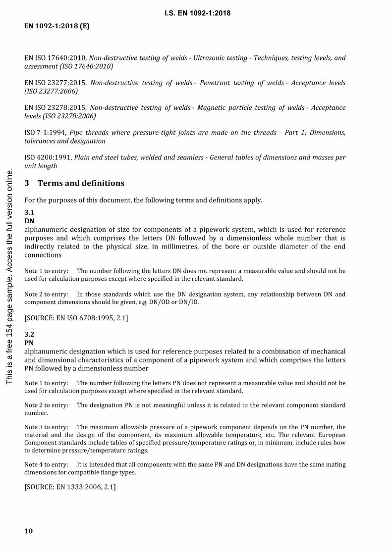
5.7.2 Jointing face finish
5.7.2.1 All flange and collar jointing faces, except types 33, 36 and 37, shall be machine finished and shall have a surface finish in accordance with the values given in Table 2 when compared with reference specimens by visual or tactile means.
NOTE It is not intended that instrument measurements be taken on the faces themselves; the Ra and Rz values as defined in EN ISO 4287 relate to the reference specimens.
5.7.2.2 For flanges and collars (except types 33, 36 and 37) with facing types A, B1, E and F, turning shall be carried out with a round nosed tool in accordance with Table 2.
5.7.2.3 If not otherwise agreed between the purchaser and the supplier type 01 and type 05 up to PN 40 and collars (except types 33, 36 and 37) shall have type A facing, other flanges shall have standard facing type B1 for all PN numbers.
Table 2 — Surface finish for jointing faces
Facing types Method of machining
Radius of round nosed tool Ra a Rz a
mm µm µm
min. min. max. min. max.
A, B1 b, E, F Turning c 1,0 3,2 12,5 12,5 50
B2 b, C, D, G, H Turning c — 0,8 3,2 3,2 12,5
NOTE For certain applications, e.g. low temperature gases, it can be necessary to stipulate closer control to the surface finish.
a Ra and Rz are defined in EN ISO 4287. b Types B1 and B2 are raised face (type B) flanges with different specified surface roughness values:
B1: Standard facing for all PN numbers. B2: Only if agreed between the purchaser and the flange manufacturer.
c The term 'turning' includes any method of machine operation producing either serrated concentric or serrated spiral grooves.
5.8 Surface finish of flanges and collars
5.8.1 Surface finish
The surface finish of flanges and collars shall be according to Table 3. The given surface roughness values apply to as-delivered condition, unless otherwise specified by the purchaser.
I.S. EN 1092-1:2018T
his
is a
free
154
pag
e sa
mpl
e. A
cces
s th
e fu
ll ve
rsio
n on
line.

EN 1092-1:2018 (E)
18
Table 3 — Surface finish
Flange type Outer diameter
Centre bore diameter Bolt
holes Spot
facing Ra max µm
Rz max µm
Ra max µm
Rz max µm
01 (Plate flange for welding) 25 160 25 160 b c
02 (Loose plate flange for Types 32—37)
25 160 25 160 b —
04 (Loose plate flange for Type 34) 25 160 25 160 b —
05 (Blind flange) 25 160 n.a. b c
11 (Weld-neck flange) 25 a 160 a 25 a 160 a b c
12 (Hubbed slip-on flange for welding) 25 a 160 a 25 a 160 a b c
13 (Hubbed threaded flange) 25 a 160 a See thread standard b c
21 (Integral flange) 25 a 160 a 25 a 160 a — c
32 (Weld-on plate collar) 25 160 25 160 — —
33 (Lapped end pipe) 25 a 160 25 a 160 — —
34 (Weld-neck collar) 25 a 160 a 25 a 160 a — —
35 (Weldring neck) 25 a 160 a 25 a 160 a — —
36 (Pressed collar with long neck) 25 a 160 a 25 a 160 a — —
37 (Pressed collar) 25 a 160 a 25 a 160 a — —
a Or up to PN 40 un-machined. b Bolt holes > PN 40 only drilled. c Chip machining spot facing for PN ≥ 63 (see 5.8.2).
5.8.2 Spot facing or back facing of flanges
Any spot facing or back facing shall not reduce the flange thickness to less than the flange thickness specified. When spot facing is used, the diameter shall be large enough to accommodate the outside diameter of the equivalent normal series of washers in accordance with EN ISO 887 for the bolt size being fitted. The bearing surfaces for the bolting shall be parallel to the flange face within the limits given in Table 22. When a flange is back faced a minimum fillet radius, R2 (see Figure 17) in accordance with Table 23 shall be maintained.
5.9 Tolerances
Tolerances on dimensions of flanges and collars shall be as given in Table 22.
General tolerances for dimensions without given tolerance: according to EN 22768-1:1993.
I.S. EN 1092-1:2018T
his
is a
free
154
pag
e sa
mpl
e. A
cces
s th
e fu
ll ve
rsio
n on
line.

EN 1092-1:2018 (E)
19
5.10 Marking
5.10.1 General marking requirements
All flanges, lapped ends and collars, other than type 21 flanges, should be marked as follows:
a) flange/collar manufacturer’s name or trade mark, e.g. XXX;
b) number of this European Standard, i.e. EN 1092-1;
c) flange/collar type number;
d) DN, e.g. DN 150;
e) PN designation, e.g. PN 40 (marking with lower PN numbers, by identical dimensions are possible);
f) wall thickness (S), if not according to this European Standard;
g) either the name or the number or the grade of the material, e.g. P245GH;
h) heat number of melt and/or suitable identification, such as code number, for the traceability e.g. A2345, when test certification is required;
EXAMPLE 1 XXX/EN 1092–1/11/DN 150/PN 40/P265GH/A2345;
i) additional marking (M) for flanges according to Annex I;
EXAMPLE 2 XXX/EN 1092–1/34M/...
If a part is too small to enable all the markings required then the minimum marking required shall be:
— flange/collar manufacturer’s name or trade mark;
— letters “EN”;
— PN designation, e.g. PN 40;
— either the name or the number or the grade of the material;
— heat number of melt and/or suitable identification, such as code number, for the traceability.
5.10.2 Stamping
Marking shall be visible and durable. Where hard stampings are used, the marking shall be positioned on the outer rim of the parts.
It should be ensured that hard stamping markings are not liable to cause cracks in the flange material. 5.10.3 Declaration of compliance
The marking EN 1092-1, together with the flange manufacturer's name or trademark on or in relation to a product, represents the flange manufacturer's declaration of compliance to this European Standard, i.e. a claim by or on behalf of the flange manufacturer that the product meets the requirements of this European Standard.
I.S. EN 1092-1:2018T
his
is a
free
154
pag
e sa
mpl
e. A
cces
s th
e fu
ll ve
rsio
n on
line.

EN 1092-1:2018 (E)
20
5.11 Welding
When producing flanges or collars by fusion welding or flanges or collars formed by bending from sections, bar steel or flat products and flash-butt welded the following criteria are valid:
— welding process/procedures shall be qualified and certified in accordance with EN ISO 15614-1 and EN ISO 15614-13;
Existing valid welding procedures for arc welding of steels may be used (see EN ISO 15614-1:2017, Introduction);
— welders and/or welding operators shall be qualified in accordance with EN ISO 9606-1:2017 and/or EN ISO 14732.
All welds shall have full penetration.
Local repair of weld seam with filler metal is permitted, provided that the repair procedure/welders are qualified in accordance with the relevant part of the above mentioned standards.
If heat treatment is required, the repair welding shall be carried out prior to that.
5.12 Inspection and testing
5.12.1 Inspection and testing of fusion welded joints
a) Welded joints shall be visually examined in accordance with EN ISO 17637 before any other NDT is performed.
b) The area to be examined shall include the weld metal and the heat affected zones.
c) The required surface examination shall be performed on all the surfaces.
d) Any type of non-destructive test (NDT) shall be performed after any forming or heat treatment operation. Where a material is not sensitive to PWHT cracking (e.g. material groups 1.1 and 8.1 (see CEN ISO/TR 15608)), NDT may be performed before PWHT.
e) In case of austenitic base or filler material, the method for surface testing shall be PT.
f) Welded pipe as base material shall conform to the relevant product (pipe) standard (see Table 9).
g) All other longitudinal welds of necks shall have 100 % volumetric (RT/UT) testing.
h) For type 35 only: Every 10th radial weld of rings shall have 100 % volumetric testing. Every 10th ring weld shall have surface crack detection (MT or PT) except in material groups 1.1, 1.2 or 8.1.
i) For type 35 only: Welding of neck to ring, every 10th flange shall have surface crack detection of welds (MT or PT).
I.S. EN 1092-1:2018T
his
is a
free
154
pag
e sa
mpl
e. A
cces
s th
e fu
ll ve
rsio
n on
line.

EN 1092-1:2018 (E)
21
Table 4 — NDT methods, techniques, characterization and acceptance criteria for fusion welded flanges or collars
NDT Methods (abbreviations)
Techniques Acceptance Criteria
Visual inspection (VT) EN ISO 17637 EN ISO 5817, surface imperfections, Acceptance level B
Radiography (RT) EN ISO 17636-1, class B and EN ISO 17636-2, class B
EN ISO 10675-1, Acceptance level 2 and Table 6.6.4–1
Ultrasonic Testing(UT) EN ISO 17640, min. class B a
EN ISO 11666, Acceptance level 2 + no planar imperfections accepted
Penetrant Testing (PT) EN ISO 3452-1 + test parameter to EN ISO 23277:2015, Table A.1 Acceptance level 1
EN ISO 23277, Acceptance level 1
Magnetic Particle Testing (MT)
EN ISO 17638 + test parameter to EN ISO 23278:2015, Table A.1 Acceptance level 1
EN ISO 23278, Acceptance level 1
a Thickness t < 40 mm class A is acceptable. By t > 100 mm class C is required.
NDT operators (Level 1) and supervisor (Level 2) shall be qualified and certified in accordance with EN ISO 9712. 5.12.2 Inspection and testing of bent and electric welded flanges or collars from formed bars, sectional steel or band material
a) Welded joints shall be visually examined in accordance with EN ISO 17637 before any other NDT is performed. Acceptance criteria in accordance with EN ISO 5817 surface imperfections level C.
b) The area to be examined shall include the weld metal and the heat affected zones.
c) All base material for these flanges, such as plates or flat products shall be inspected ultrasonically according to EN 10160. Scope of test according to EN 10160:1999, Table 3, acceptance criteria Class S2 and EN 10160:1999, Table 5, Class E3.
d) Flanges made of steels in Material Groups 1E0 and 1E1 (Annexes B and D) and 3E1 shall be subjected by the flange manufacturer to ultrasonic testing or to radiographic testing with reference to Table 5 to the extend defined in Table 5. As a rule, flanges that are produced by continuous welding with the same machine setting are grouped together to form a test batch.
e) Finished flanges of all other material groups shall be subjected by the flange manufacturer to ultrasonic inspection or to radiographic inspection in the weld zone according to Table 5 on each flange.
f) Flanges with unit weights > 300 kg shall be inspected ultrasonically or radiographically according to Table 5 in all material groups.
g) All welds shall be tested by the flange manufacturer for the presence of surface cracks with a suitable method as Penetrant Testing for austenitic base or filler material and Magnetic Particle Testing for Ferritic material according to Table 5. The following materials constitute exceptions: P 235 GH, P 265 GH and P 250 GH.
I.S. EN 1092-1:2018T
his
is a
free
154
pag
e sa
mpl
e. A
cces
s th
e fu
ll ve
rsio
n on
line.

EN 1092-1:2018 (E)
22
h) The non-destructive testing shall be carried out after completion of possible post-weld heat treatment (PWHT). Where a material is not sensitive to PWHT cracking e.g. material groups 1.1 and 8.1 (see CEN ISO/TR 15608), NDT may be performed before PWHT.
Table 5 — Scope of non-destructive testing for flanges or collars formed by bending and electric welded formed bars, sectional steel or band material
Number of flanges per test unit
Scope of non-destructive
testing Minimum of
≥ 1 to ≤ 20 100 % —
> 20 to ≤ 50 50 % 20 flanges
> 50 to ≤ 200 25 % 25 flanges
> 200 to ≤ 1 000 15 % 50 flanges
> 1 000 10 % 150 flanges
5.12.3 Inspection and testing of formed parts manufactured from base material other than forgings
5.12.3.1 Non-destructive testing
The testing of formed parts shall include on each component or batch of identical components (dependent on the material and size of flange), if appropriate:
— wall thickness measurements;
— dimensional checks
— hardness tests (e.g. carbon and low alloy steels);
— ultrasonic testing for internal imperfections in longitudinal and transversal direction (e.g. for thickness above 8 mm);
— examination for surface or near surface imperfections (MT or PT).
Material, heat treatment conditions, heat treatment lot, degree of deformation shall be considered in the definition of the batch (see e.g. the EN 10253 series). 5.12.3.2 Destructive testing for heat treated or hot formed components
Testing shall be performed to verify the heat treatment of the formed parts, and shall include the tests required by the base material specification, e.g.:
— tensile test;
— notch impact test;
— micrographs (e.g. 9 % or 12 % Cr steels).
One set of test per cast, wall thickness range and heat treatment lot shall be performed for flanges and collars with PN × DN > 1 000 bar and DN > 25. The tests shall be performed on test pieces from the component itself, or from test pieces placed together with the components in the heat treatment furnaces. The test results shall fulfil the mechanical properties of the material standard.
I.S. EN 1092-1:2018T
his
is a
free
154
pag
e sa
mpl
e. A
cces
s th
e fu
ll ve
rsio
n on
line.

EN 1092-1:2018 (E)
23
5.12.4 Inspection and testing of close die flanges
5.12.4.1 Tests to be carried out
Unless otherwise agreed between the manufacturer and the purchaser close die steel forgings for flanges shall be tested as follows:
a) Mandatory tests to be carried out:
1) tensile test at room temperature;
2) impact test.
Tests may be carried out on simultaneous heat treated test samples upon agreement.
b) Optional tests:
1) product analysis (where specified, including residual element content);
2) tensile test at elevated temperatures (verification of one, all, or any combination of Rp0,2, Rp1,0 and Rm at elevated temperatures, without requirement Rp0,2 will be verified;
3) additional impact test at different temperatures (detected values are valid for higher temperatures, if the therefore determined nominal values are obtained);
4) further additional tests as ultrasonic testing, penetrant testing, magnetic particle inspection, test for resistance to intergranular corrosion.
NOTE Additional tests need to be agreed between the manufacturer and the purchaser.
5.12.4.2 Test units for mandatory tests
For testing batches, forgings of similar dimensions of the same cast, made by the same forging procedure and of the same heat treatment charge; shall be divided into test units.
The maximum weight of test units shall be:
— 6 000 kg (finished flanges) for non-alloyed steels according to EN 10222-2, steels according to EN 10222-4 and austenitic steels according to EN 10222-5;
— 3 000 kg (fnished flanges) for other steels.
The number of test units of batches shall be limited to 4 units.
For each test unit one tensile test at room temperature and one impact test shall be carried out. 5.12.4.3 Preparation of samples and test pieces
Samples shall be provided by one of the following methods:
— from additional forgings;
— from separately forged samples; nominally, the samples shall receive the same hot working reduction and shall have the same equivalent diameter;
— from centre section of forgings; the thickness of centre section shall have minimum 75 % of the forging thickness.
I.S. EN 1092-1:2018T
his
is a
free
154
pag
e sa
mpl
e. A
cces
s th
e fu
ll ve
rsio
n on
line.

EN 1092-1:2018 (E)
24
For forgings with a thickness of forging t ≥ 30 mm the samples shall be taken in a way, that the axis of the test specimen shall be at a distance of t/4 from the heat treated surface (with a minimum of 10 mm and a maximum of 80 mm), and t/2 from the end.
The direction of test specimen shall be tangential. The direction of V-notch of impact test specimen shall be axially. 5.12.4.4 Test methods
Tensile tests at room temperature shall be carried out in accordance with the requirements of EN ISO 6892-1. The yield strength to be determined shall be the upper yield strength (ReH) or if this is not pronounced, the 0,2 % proof strength (Rp0,2); for austenitic steels in accordance with EN 10222-5 additionally Rp1,0.
The impact test shall be carried out in accordance with EN ISO 148-1 at a temperature of 20 °C (unless otherwise agreed), on V-notched test pieces and by using a 2 mm striker (KV2). The specifications of the individual parts of EN 10222 shall apply. 5.12.4.5 Repeated tests
Repeated tests shall be carried out in accordance with EN 10021. 5.12.4.6 Repeated heat treatment
The manufacturer shall have the right to repeat the heat treatment of any material, also for material having not fulfilled the test requirements in a former test, and resubmit it for testing. No forging shall be fully heat treated more than twice. 5.12.5 Inspection and testing of other materials
Flanges made of forgings; casts, bars, pressed and seamless rolled materials shall be inspected and tested by the material manufacturer in accordance with the appropriate material standard.
5.13 Certificates
The flange manufacturer shall use respective procedures to ensure traceability of material and to avoid material exchange and shall be able to provide respective documentation for the base material used. Under consideration of EN 764-5, the purchaser of the flange may require a test certificate according to EN 10204 (2.1, 3.1 or 3.2), applicable for the respective category. The rules of pressure equipment European legislation and the product specification, which includes the technical delivery conditions, shall be applied. If an inspection certificate 3.1 is required, the quality system of the material manufacturer shall fulfil the requirements of the European legislation for pressure equipment.
I.S. EN 1092-1:2018T
his
is a
free
154
pag
e sa
mpl
e. A
cces
s th
e fu
ll ve
rsio
n on
line.

EN 1092-1:2018 (E)
25
a) Type 01 Plate flange for welding
b) Type 02 Loose plate flange with weld-on collar (see type 32) or
lapped pipe end (see type 33)
c) Type 02
Loose plate flange with weld ring neck (see type 35)
d) Type 02 Loose plate flange
with pressed collar with long neck (see type 36)
e) Type 02 Loose plate flange
with pressed collar (see type 37)
f) Type 04 Loose plate flange with weld-neck collar
(see type 34)
g) Type 05 Blind flange
h) Type 11 Weld-neck flange
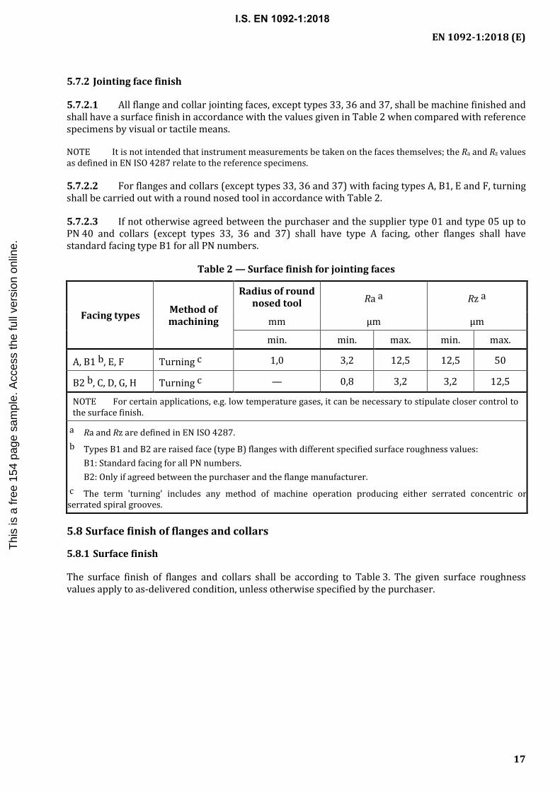
i) Type 12 Hubbed slip-on flange for welding
j) Type 13 Hubbed threaded flange
k) Type 21 Integral flange
NOTE These sketches are diagrammatic only; in particular no detail is shown for the mating surfaces (see Figure 3).
Figure 1 — Flange types
I.S. EN 1092-1:2018T
his
is a
free
154
pag
e sa
mpl
e. A
cces
s th
e fu
ll ve
rsio
n on
line.

EN 1092-1:2018 (E)
26
a) Type 32 Weld-on collar plate
b) Type 33 Lapped pipe end
c) Type 34 Weld-neck collar
d) Type 35 Weldring neck
e) Type 36 Pressed collar with long neck
f) Type 37 Pressed collar
NOTE These sketches are diagrammatic only.
Figure 2 — Collars types 32 to 37
Table 6 — Types of steel flanges and collars
Type No Description
01 Plate flange for welding
02 Loose plate flange with weld-on plate collar or for lapped pipe end
04 Loose plate flange with weld-neck collar
05 Blind flange
11 Weld-neck flange
12 Hubbed slip-on flange for welding
13 Hubbed threaded flange
21 a Integral flange
32 b Weld-on plate collar
33 a, b Lapped pipe end
34 b Weld-neck collar
35 b Weldring neck
36 b Pressed collar with long neck
37 b Pressed collar
NOTE Type numbers have been made non-consecutive to permit possible future additions.
a This is an integral part of a pressure equipment or a component. b Type numbers 32, 33, 35, 36 and 37 are for use with type 02 flanges and type number 34 for use with type 04 flanges.
I.S. EN 1092-1:2018T
his
is a
free
154
pag
e sa
mpl
e. A
cces
s th
e fu
ll ve
rsio
n on
line.

EN 1092-1:2018 (E)
27
a) Type A Flat face
b) Type B Raised face
B1 and B2 (see Table 2)
c) Type C Tongue
d) Type D Groove
e) Type E
Spigot f) Type F
Recess g) Type G
O-ring spigot h) Type H
O-ring groove
NOTE 1 The transition from the edge of the raised face to the flange face can be by radius or chamfer for types B, D, F and G only (see 5.7.1).
NOTE 2 B1 and B2 are raised face (type B) for different applications (see 5.7.2.2, 5.7.2.3 and Table 2).
NOTE 3 For the dimensions of flange facings, see Figure 4 and Table 8.
Figure 3 — Flange facing types
I.S. EN 1092-1:2018T
his
is a
free
154
pag
e sa
mpl
e. A
cces
s th
e fu
ll ve
rsio
n on
line.

EN 1092-1:2018 (E)
28
Table 7 — Synoptic table
Flange type or collar type DN
10
15
20
25
32
40
50
65
80
100
125
150
200
250
300
350
400
450
500
600
700
800
900
1 00
0 1
200
1 40
0 1
600
1 80
0 2
000
2 20
0 2
400
2 60
0 2
800
3 00
0 3
200
3 40
0 3
600
3 80
0 4
000
PN
a) Type 01
2,5 dimensions identical with PN 6 X
6 X X X X X X X X X X X X X X X X X X X X X X X X X X X X X
10 dimensions identical with PN 40
dimensions identical with PN
16 X X X X X X X X X X X X X
16 dimensions identical with PN 40 X X X X X X X X X X X X X X X X X X
25 dimensions identical with PN 40 X X X X X X X X X X
40 X X X X X X X X X X X X X X X X X
63 dimensions identical with PN 100 X X X X X X X X X X X
100 X X X X X X X X X X X X X X X X
b) Types 02 and 32
2,5 dimensions identical with PN 6
6 X X X X X X X X X X X X X X X X X X X X
10 dimensions identical with PN 40
dimensions identical with PN
16 X X X X X X X X
16 dimensions identical with PN 40 X X X X X X X X X X X X X X
25 dimensions identical with PN 40 X X X X X X X X
40 X X X X X X X X X X X X X X X X X X X X
I.S. EN 1092-1:2018
Thi
s is
a fr
ee 1
54 p
age
sam
ple.
Acc
ess
the
full
vers
ion
onlin
e.

EN 1092-1:2018 (E)
29
Flange type or collar type DN
10
15
20
25
32
40
50
65
80
100
125
150
200
250
300
350
400
450
500
600
700
800
900
1 00
0 1
200
1 40
0 1
600
1 80
0 2
000
2 20
0 2
400
2 60
0 2
800
3 00
0 3
200
3 40
0 3
600
3 80
0 4
000
PN
c) Types 02 and 35
2,5 dimensions identical with PN 6
6 X X X X X X X X X X X X X X X X X X X X X X X X X
10 dimensions identical with PN 40
dimensions identical with PN
16 X X X X X X X X X X X X X
16 dimensions identical with PN 40 X X X X X X X X X X X X X X X X X X
25 dimensions identical with PN 40 X X X X X X X X X X X
40 X X X X X X X X X X X X X X X X X
d) Type 02 and 36
2,5 dimensions identical with PN 6
6 X X X X X X X X X X X X X X X X X X X
10 dimensions identical with PN 16 X X X X X
16 X X X X X X X X X X X X X X X X X
e) Type 02 and 33/37
2,5 dimensions identical with PN 6
6 X X X X X X X X X X X X X
10 dimensions identical with PN 16 X X X
16 X X X X X X X X X X X X X
f) Type 13
6 X X X X X X X X X X X X X X X
10 dimensions identical with PN 40
dimensions identical with PN
16 X X X X X X X X
16 dimensions identical with PN 40 X X X X X X X X X X X X X X X X X X
25 dimensions identical with PN 40 X X X X X X X X
40 X X X X X X X X X X X X X X X X X X X X
63 dimensions identical with PN 100
X X X X X X
100 X X X X X X X X X X X X
I.S. EN 1092-1:2018
Thi
s is
a fr
ee 1
54 p
age
sam
ple.
Acc
ess
the
full
vers
ion
onlin
e.

EN 1092-1:2018 (E)
30
Flange type or collar type DN
10
15
20
25
32
40
50
65
80
100
125
150
200
250
300
350
400
450
500
600
700
800
900
1 00
0 1
200
1 40
0 1
600
1 80
0 2
000
2 20
0 2
400
2 60
0 2
800
3 00
0 3
200
3 40
0 3
600
3 80
0 4
000
PN
g) Type 05
2,5 dimensions identical with PN 6 X
6 X X X X X X X X X X X X X X X X X X X X X X X X X X X X X
10 dimensions identical with PN 40
dimensions identical with PN
16 X X X X X X X X X X X X X
16 dimensions identical with PN 40 X X X X X X X X X X X X X X X X X X
25 dimensions identical with PN 40 X X X X X X X X
40 X X X X X X X X X X X X X X X X X X X X
63 Use PN 100 X X X X X X X X X X X
100 X X X X X X X X X X X X X X X X
160 X X X X X X X X X X X X X
250
dim
ensi
ons i
dent
ical
with
PN
320
X X X X X X X X X X X
320 X X X X X X X X X X X X
400 X X X X X X X X X X X
I.S. EN 1092-1:2018
Thi
s is
a fr
ee 1
54 p
age
sam
ple.
Acc
ess
the
full
vers
ion
onlin
e.

EN 1092-1:2018 (E)
31
Flange type or collar type DN
10
15
20
25
32
40
50
65
80
100
125
150
200
250
300
350
400
450
500
600
700
800
900
1 00
0 1
200
1 40
0 1
600
1 80
0 2
000
2 20
0 2
400
2 60
0 2
800
3 00
0 3
200
3 40
0 3
600
3 80
0 4
000
PN
h) Type 11
2,5 dimensions identical with PN 6 X X X X X X X X X X X X X X X X X
6 X X X X X X X X X X X X X X X X X X X X X X X X X X X X X X X X X X X X X
10 dimensions identical with PN 40
dimensions identical with PN
16 X X X X X X X X X X X X X X X X X X X X X X
16 dimensions identical with PN 40 X X X X X X X X X X X X X X X X X X X X X X X
25 dimensions identical with PN 40 X X X X X X X X X X X X
40 X X X X X X X X X X X X X X X X X X X X
63 dimensions identical with PN 100 X X X X X X X X X X X
100 X X X X X X X X X X X X X X X X
160 X X X X X X X X X X X X X
250
dim
ensi
ons i
dent
ical
with
PN
320
X X X X X X X X X X X
320 X X X X X X X X X X X X
400 X X X X X X X X X X X
I.S. EN 1092-1:2018
Thi
s is
a fr
ee 1
54 p
age
sam
ple.
Acc
ess
the
full
vers
ion
onlin
e.
EN 1092-1:2018 (E)
32
Flange type or collar type DN
10
15
20
25
32
40
50
65
80
100
125
150
200
250
300
350
400
450
500
600
700
800
900
1 00
0 1
200
1 40
0 1
600
1 80
0 2
000
2 20
0 2
400
2 60
0 2
800
3 00
0 3
200
3 40
0 3
600
3 80
0 4
000
PN
i) Type 12
6 X X X X X X X X X X X X X X X
10 dimensions identical with PN 40
dimensions identical with PN
16 X X X X X X X X
16 dimensions identical with PN 40 X X X X X X X X X X X X X X X X X X
25 dimensions identical with PN 40 X X X X X X X X
40 X X X X X X X X X X X X X X X X X X X X
63 dimensions identical with PN 100 X X X X X X
100 X X X X X X X X X X X X
j) Type 13
6 X X X X X X X X X X X X
10 dimensions identical with PN 40
dimensions identical with PN
16
16 dimensions identical with PN 40 X X X X X X
25 dimensions identical with PN 40
40 X X X X X X X X X X X X
63 dimensions identical with PN 100 X X X X X X
100 X X X X X X X X X X X X
I.S. EN 1092-1:2018
Thi
s is
a fr
ee 1
54 p
age
sam
ple.
Acc
ess
the
full
vers
ion
onlin
e.

EN 1092-1:2018 (E)
33
Flange type or collar type DN
10
15
20
25
32
40
50
65
80
100
125
150
200
250
300
350
400
450
500
600
700
800
900
1 00
0 1
200
1 40
0 1
600
1 80
0 2
000
2 20
0 2
400
2 60
0 2
800
3 00
0 3
200
3 40
0 3
600
3 80
0 4
000
PN
k) Type 21
2,5 X X X X X X X X X X X X X X X X X X X X X X X X
6 X X X X X X X X X X X X X X X X X X X X X X X X X X X X X
10 dimensions identical with PN 40
dimensions identical with PN
16 X X X X X X X X X X X X X X X X X
16 dimensions identical with PN 40 X X X X X X X X X X X X X X X X X X X X X X X
25 dimensions identical with PN 40 X X X X X X X X X X X X
40 X X X X X X X X X X X X X X X X X X X X
63 dimensions identical with PN 100 X X X X X X X X X X X
100 X X X X X X X X X X X X X X X X
160 X X X X X X X X X X X X X
250 X X X X X X X X X X X X X
320 X X X X X X X X X X X X
400 X X X X X X X X X X X
I.S. EN 1092-1:2018
Thi
s is
a fr
ee 1
54 p
age
sam
ple.
Acc
ess
the
full
vers
ion
onlin
e.

EN 1092-1:2018 (E)
34
a) Type A: Flat face b) Type B: Raised face B1 and B2
c) Type C: Tongue d) Type D: Groove
e) Type E: Spigot f) Type F: Recess
I.S. EN 1092-1:2018T
his
is a
free
154
pag
e sa
mpl
e. A
cces
s th
e fu
ll ve
rsio
n on
line.

EN 1092-1:2018 (E)
35
g) Type G: O-ring spigot h) Type H: O-ring groove
NOTE 1 Dimension C includes the raised face thickness.
NOTE 2 Cross section diameter of the O-ring is 2 × R.
Figure 4 — Flange facing (dimensions see Table 8)
I.S. EN 1092-1:2018T
his
is a
free
154
pag
e sa
mpl
e. A
cces
s th
e fu
ll ve
rsio
n on
line.

EN 1092-1:2018 (E)
36
Table 8 — Flange facing dimensions
DN
d1 f1 f2 f3 f4 W b x y Z b α ≈ R
PN 2,5 a PN 6 a PN 10 PN 16 PN 25 PN 40 PN 63 PN 100 PN 160
PN 250
PN 320
PN 400
mm mm mm mm mm mm mm mm mm mm mm mm mm mm mm mm mm mm mm mm mm
10 35 35 40 40 40 40 40 40 40 40 40 40
2
4,5 4,0 2,0
24 34 35 23 —
2,5
15 40 40 45 45 45 45 45 45 45 45 45 45 29 39 40 28 —
20 50 50 58 58 58 58 58 58 — — — — 36 50 51 35
41°
25 60 60 68 68 68 68 68 68 68 68 68 68 43 57 58 42
32 70 70 78 78 78 78 78 78 — — — — 51 65 66 50
40 80 80 88 88 88 88 88 88 88 88 88 88
3
61 75 76 60
50 90 90 102 102 102 102 102 102 102 102 102 102 73 87 88 72
65 110 110 122 122 122 122 122 122 122 122 122 122 95 109 110 94
80 128 128 138 138 138 138 138 138 138 138 138 138 106 120 121 105
100 148 148 158 158 162 162 162 162 162 162 162 162
5,0 4,5 2,5
129 149 150 128
32° 3
125 178 178 188 188 188 188 188 188 188 188 188 188 155 175 176 154
150 202 202 212 212 218 218 218 218 218 218 218 218 183 203 204 182
200 258 258 268 268 278 285 285 285 285 285 285 285 239 259 260 238
250 312 312 320 320 335 345 345 345 345 345 345 — 292 312 313 291
300 365 365 370 378 395 410 410 410 410 410 — —
4
343 363 364 342
350 415 415 430 438 450 465 465 465 — — — —
5,5 5,0 3,0
395 421 422 394
27° 3,5
400 465 465 482 490 505 535 535 535 — — — — 447 473 474 446
450 520 520 532 550 555 560 560 560 — — — — 497 523 524 496
500 570 570 585 610 615 615 615 615 — — — — 549 575 576 548
600 670 670 685 725 720 735 735 — — — — — 5
649 675 676 648
700 775 775 800 795 820 840 840 — — — — — 751 777 778 750
I.S. EN 1092-1:2018
Thi
s is
a fr
ee 1
54 p
age
sam
ple.
Acc
ess
the
full
vers
ion
onlin
e.

EN 1092-1:2018 (E)
37
DN
d1 f1 f2 f3 f4 W b x y Z b α ≈ R
PN 2,5 a PN 6 a PN 10 PN 16 PN 25 PN 40 PN 63 PN 100 PN 160
PN 250
PN 320
PN 400
mm mm mm mm mm mm mm mm mm mm mm mm mm mm mm mm mm mm mm mm mm
800 880 880 905 900 930 960 960 — — — — — 856 882 883 855
900 980 980 1 005 1 000 1 030 1 070 1 070 — — — — — 961 987 988 960
1 000 1 080 1 080 1 110 1 115 1 140 1 180 1 180 — — — — —
6,5 6,0 4,0
1 062 1 092 1 094 1 060
28° 4
1 200 1 280 1 295 1 330 1 330 1 350 1 380 1 380 — — — — — 1 262 1 292 1 294 1 260
1 400 1 480 1 510 1 535 1 530 1 560 1 600 — — — — — — 1 462 1 492 1 494 1 460
1 600 1 690 1 710 1 760 1 750 1 780 1 815 — — — — — — 1 662 1 692 1 694 1 660
1 800 1 890 1 920 1 960 1 950 1 985 — — — — — — — 1 862 1 892 1 894 1 860
2 000 2 090 2 125 2 170 2 150 2 210 — — — — — — — 2 062 2 092 2 094 2 060
2 200 2 295 2 335 2 370 — — — — — — — — — — — — — — — — — —
2 400 2 495 2 545 2 570 — — — — — — — — — — — — — — — — — —
2 600 2 695 2 750 2 780 — — — — — — — — — — — — — — — — — —
2 800 2 910 2 960 3 000 — — — — — — — — — — — — — — — — — —
3 000 3 110 3 160 3 210 — — — — — — — — — — — — — — — — — —
3 200 3 310 3 370 — — — — — — — — — — — — — — — — — — —
3 400 3 510 3 580 — — — — — — — — — — — — — — — — — — —
3 600 3 720 3 790 — — — — — — — — — — — — — — — — — — —
3 800 3 920 — — — — — — — — — — — — — — — — — — — —
4 000 4 120 — — — — — — — — — — — — — — — — — — — —
a Flange facing types C, D, E, F, G and H according to Figure 4 are not used for PN 2,5 and 6. b Flange facing types G and H according to Figure 4 are only used for PN 10 to PN 40.
I.S. EN 1092-1:2018
Thi
s is
a fr
ee 1
54 p
age
sam
ple.
Acc
ess
the
full
vers
ion
onlin
e.

EN 1092-1:2018 (E)
38
Table 9 — Material selection for the manufacturing of flanges
Group
Forgings Flat products Castings Bars,
Material name Standard Material number Material name Standard Material
number Material name Standard Material number Material name Standard Material
number
3E0 — — — P235GH EN 10028-2 1.0345 GP240GH EN 10213 1.0619 P235GH EN 10273 1.0345
3E0 P250GH EN 10222-2 1.0460 — — — — — — P250GH EN 10273 1.0460
3E0 P245GH EN 10222-2 1.0352 P265GH EN 10028-2 1.0425 GP280GH EN 10213 1.0625 P265GH EN 10273 1.0425
3E1 P280GH EN 10222-2 1.0426 P295GH EN 10028-2 1.0481 — — — P295GH EN 10273 1.0481
4E0 16Mo3 EN 10222-2 1.5415 16Mo3 EN 10028-2 1.5415 G20Mo5 EN 10213 1.5419 16Mo3 EN 10273 1.5415
5E0 13CrMo4-5 EN 10222-2 1.7335 13CrMo4-5 EN 10028-2 1.7335 G17CrMo5-5 EN 10213 1.7357 13CrMo4-5 EN 10273 1.7335
6E0 11CrMo9-10 EN 10222-2 1.7383 12CrMo9-10 EN 10028-2 1.7375 G17CrMo9-10 EN 10213 1.7379 11CrMo9-10 EN 10273 1.7383
- - - 10CrMo9-10 EN 10028-2 1.7380 — 10CrMo9-10 EN 10273 1.7380
6E1 X16CrMo5-1 +NT EN 10222-2 1.7366 — — — GX15CrMo5 EN 10213 1.7365 — — —
7E0 — — — P275NL1 EN 10028-3 1.0488 G17Mn5 EN 10213 1.1131 — — —
— — — P275NL2 EN 10028-3 1.1104 G20Mn5 EN 10213 1.6220 — — —
7E1 — — — P355NL1 EN 10028-3 1.0566 — — — — — —
— — — P355NL2 EN 10028-3 1.1106 — — — — — —
7E2
15NiMn6 EN 10222-3 1.6228 15NiMn6 EN 10028-4 1.6228 G9Ni10 EN 10213 1.5636 — — —
— — — 11MnNi5-3 EN 10028-4 1.6212 — — — — — —
13MnNi6-3 EN 10222-3 1.6217 13MnNi6-3 EN 10028-4 1.6217 — — — — — —
7E3
— — — — — — — — —
12Ni14 EN 10222-3 1.5637 12Ni14 EN 10028-4 1.5637 G9Ni14 EN 10213 1.5638 — — —
X12Ni5 EN 10222-3 1.5680 X12 Ni 5 EN 10028-4 1.5680 — — — — — —
X8Ni9 EN 10222-3 1.5662 X8Ni9 EN 10028-4 1.5662 — — — — — —
8E0 — — — — — — — — — — — —
8E2 P285NH EN 10222-4 1.0477 P275NH EN 10028-3 1.0487 — — — P275NH EN 10273 1.0487
P285QH EN 10222-4 1.0478 — — — — — —
8E3 P355NH EN 10222-4 1.0565 P355N EN 10028-3 1.0562 — — — P355NH EN 10273 1.0565
P355QH1 EN 10222-4 1.0571 P355NH EN 10028-3 1.0565 P355QH EN 10273 1.8867
I.S. EN 1092-1:2018
Thi
s is
a fr
ee 1
54 p
age
sam
ple.
Acc
ess
the
full
vers
ion
onlin
e.

EN 1092-1:2018 (E)
39
Group
Forgings Flat products Castings Bars,
Material name Standard Material number Material name Standard Material
number Material name Standard Material number Material name Standard Material
number
9E0 X20CrMoV11-1 EN 10222-2 1.4922 — — — GX23CrMoV12-1 EN 10213 1.4931 — — —
9E1 X10CrMoVNb9-1 EN 10222-2 1.4903 X10CrMoVNb9-1 EN 10028-2 1.4903 — — — — — —
10E0 X2CrNi18-9 EN 10222-5 1.4307 X2CrNi18-9 EN 10028-7 1.4307 GX2CrNi19-11 EN 10213 1.4309 X2CrNi18-9 EN 10272 1.4307
— — — X2CrNi19-11 EN 10028-7 1.4306 — — — X2CrNi19-11 EN 10272 1.4306
10E0 — — — X1CrNi25-21 EN 10028-7 1.4335 — — — — — —
10E1 X2CrNiN18-10 EN 10222-5 1.4311 X2CrNiN18-10 EN 10028-7 1.4311 — — — X2CrNiN18-10 EN 10272 1.4311
11E0 X5CrNi18-10 EN 10222-5 1.4301 X5CrNi18-10 EN 10028-7 1.4301 GX5CrNi19-10 EN 10213 1.4308 X5CrNi18-10 EN 10272 1.4301
X6CrNi18-10 EN 10222-5 1.4948 X6CrNi18-10 EN 10028-7 1.4948 — — — — — —
12E0
X6CrNiTi18-10 EN 10222-5 1.4541 X6CrNiTi18-10 EN 10028-7 1.4541 — — — X6CrNiTi18-10 EN 10272 1.4541
X6CrNiNb18-10 EN 10222-5 1.4550 X6CrNiNb18-10 EN 10028-7 1.4550 GX5CrNiNb19-11 EN 10213 1.4552 X6CrNiNb18-10 EN 10272 1.4550
X6CrNiTiB18-10 EN 10222-5 1.4941 X6CrNiTiB18-10 EN 10028-7 1.4941 — — — — — —
13E0
X2CrNiMo17-12-2 EN 10222-5 1.4404 X2CrNiMo17-12-
2 EN 10028-7 1.4404 GX2CrNiMo19-11-2 EN 10213 1.4409 X2CrNiMo17-12-
2 EN 10272 1.4404
X2CrNiMo17-12-3 EN 10222-5 1.4432 X2CrNiMo17-12-
3 EN 10028-7 1.4432 — — — X2CrNiMo17-12-3 EN 10272 1.4432
X2CrNiMo18-14-3 EN 10222-5 1.4435 X2CrNiMo18-14-
3 EN 10028-7 1.4435 — — — X2CrNiMo18-14-3 EN 10272 1.4435
— — — X1NiCrMoCu25-20-5 EN 10028-7 1.4539 GX2NiCrMo28-20-
2 EN 10213 1.4458 X1NiCrMoCu25-20-5 EN 10272 1.4539
— — — X1NiCrMoCu31-27-4 EN 10028-7 1.4563 — — — X1NiCrMoCu31-
27-4 EN 10272 1.4563
13E1 X2CrNiMoN17-11-2 EN 10222-5 1.4406 X2CrNiMoN17-
11-2 EN 10028-7 1.4406 — — — X2CrNiMoN17-11-2
EN 10028-7 1.4406
I.S. EN 1092-1:2018
Thi
s is
a fr
ee 1
54 p
age
sam
ple.
Acc
ess
the
full
vers
ion
onlin
e.

EN 1092-1:2018 (E)
40
Group
Forgings Flat products Castings Bars,
Material name Standard Material number Material name Standard Material
number Material name Standard Material number Material name Standard Material
number
13E1 X2CrNiMoN17-13-3 EN 10222-5 1.4429 X2CrNiMoN17-
13-3 EN 10028-7 1.4429 — — — X2CrNiMoN17-13-3
EN 10028-7 1.4429
13E1 — — — X2CrNiMoN17-13-5 EN 10028-7 1.4439 — — — X2CrNiMoN17-
13-5 EN 10028-
7 1.4439
13E1 — — — X1NiCrMoCuN25-20-7 EN 10028-7 1.4529 — — — X1NiCrMoCuN25-
20-7 EN 10028-
7 1.4529
13E1 — — — X1CrNiMoCuN20-18-7 EN 10028-7 1.4547 — — — X1CrNiMoCuN20-
18-7 EN 10272 1.4547
14E0 X5CrNiMo17-12-2 EN 10222-5 1.4401 X5CrNiMo17-12-
2 EN 10028-7 1.4401 GX5CrNiMo19-11-2 EN 10213 1.4408 X5CrNiMo17-12-
2 EN 10272 1.4401
14E0 X3CrNiMo17-13-3 EN 10222-5 1.4436 X3CrNiMo17-13-
3 EN 10028-7 1.4436 — — — X3CrNiMo17-13-3 EN 10272 1.4436
15E0
X6CrNiMoTi17-12-2 EN 10222-5 1.4571 X6CrNiMoTi17-
12-2 EN 10028-7 1.4571 — — — X6CrNiMoTi17-12-2 EN 10272 1.4571
— — — X6CrNiMoNb17-12-2 EN 10028-7 1.4580 GX5CrNiMoNb19-
11-2 EN 10213 1.4581 X6CrNiMoNb17-12-2 EN 10272 1.4580
16E0
— — — — — — GX2CrNiMoCuN25-6-3-3 EN 10213 1.4517 — — —
— — — X2CrNiN23-4 EN 10028-7 1.4362 — — — X2CrNiN23-4 EN 10272 1.4362
X2CrNiMoN22-5-3 EN 10222-5 1.4462 X2CrNiMoN22-
5-3 EN 10028-7 1.4462 GX2CrNiMoN22-5-3 EN 10213 1.4470 X2CrNiMoN22-5-
3 EN 10272 1.4462
X2CrNiMoN25-7-4 EN 10222-5 1.4410 X2CrNiMoN25-
7-4 EN 10028-7 1.4410 — — — X2CrNiMoN25-7-4 EN 10272 1.4410
— — — — — — GX2CrNiMoN26-7-4 EN 10213 1.4469 — — —
I.S. EN 1092-1:2018
Thi
s is
a fr
ee 1
54 p
age
sam
ple.
Acc
ess
the
full
vers
ion
onlin
e.

EN 1092-1:2018 (E)
41
Table 9 (continued)
Group
Seamless tubes Welded tubes
Material name Standard Material number Material name Standard Material
number
3E0 P235GH EN 10216-2 1.0345 P235GH EN 10217-2 1.0345
P265GH EN 10216-2 1.0425 P265GH EN 10217-2 1.0425
3E1 16Mo3 EN 10216-2 1.5415 16Mo3 EN 10217-2 1.5415
4E0 13CrMo4-5 EN 10216-2 1.7335 — — —
5E0 10CrMo9-10 EN 10216-2 1.7380 — — —
6E0 11CrMo9-10 EN 10216-2 1.7383 — — —
6E0 X11CrMo5+NT1 EN 10216-2 1.7362+NT1 — — —
6E1 P275NL1 EN 10216-3 1.0488 P275NL1 EN 10217-3 1.0488
7E0 P275NL2 EN 10216-3 1.1104 P275NL2 EN 10217-3 1.1104
P355NL1 EN 10216-3 1.0566 P355NL1 EN 10217-3 1.0566
7E1 P355NL2 EN 10216-3 1.1106 P355NL2 EN 10217-3 1.1106
12Ni14 EN 10216-4 1.5637 — — —
7E2 X10Ni9 EN 10216-4 1.5682 — — —
13MnNi6-3 EN 10216-4 1.6217 — — —
7E3 P275NL1 EN 10216-3 1.0488 P275NL1 EN 10217-3 1.0488
8E0 P275NL2 EN 10216-3 1.1104 P275NL2 EN 10217-3 1.1104
8E0 — — — — — —
8E2 P355NH EN 10216-3 1.0565 P355NH EN 10217-3 1.0565
8E3 X20CrMoV11-1 EN 10216-2 1.4922 — — —
9E0 X10CrMoVNb9-1 EN 10216-2 1.4903 — — —
9E1 X2CrNi18-9 EN 10216-5 1.4307 X2CrNi18-9 EN 10217-7 1.4307
I.S. EN 1092-1:2018
Thi
s is
a fr
ee 1
54 p
age
sam
ple.
Acc
ess
the
full
vers
ion
onlin
e.
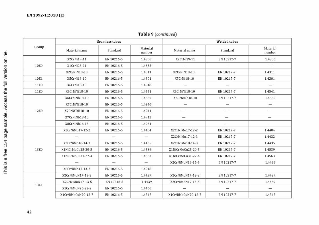
EN 1092-1:2018 (E)
42
Table 9 (continued)
Group
Seamless tubes Welded tubes
Material name Standard Material number Material name Standard Material
number
10E0
X2CrNi19-11 EN 10216-5 1.4306 X2CrNi19-11 EN 10217-7 1.4306
X1CrNi25-21 EN 10216-5 1.4335 — — —
X2CrNiN18-10 EN 10216-5 1.4311 X2CrNiN18-10 EN 10217-7 1.4311
10E1 X5CrNi18-10 EN 10216-5 1.4301 X5CrNi18-10 EN 10217-7 1.4301
11E0 X6CrNi18-10 EN 10216-5 1.4948 — — —
11E0 X6CrNiTi18-10 EN 10216-5 1.4541 X6CrNiTi18-10 EN 10217-7 1.4541
12E0
X6CrNiNb18-10 EN 10216-5 1.4550 X6CrNiNb18-10 EN 10217-7 1.4550
X7CrNiTi18-10 EN 10216-5 1.4940 — — —
X7CrNiTiB18-10 EN 10216-5 1.4941 — — —
X7CrNiNb18-10 EN 10216-5 1.4912 — — —
X8CrNiNb16-13 EN 10216-5 1.4961 — — —
13E0
X2CrNiMo17-12-2 EN 10216-5 1.4404 X2CrNiMo17-12-2 EN 10217-7 1.4404
— — — X2CrNiMo17-12-3 EN 10217-7 1.4432
X2CrNiMo18-14-3 EN 10216-5 1.4435 X2CrNiMo18-14-3 EN 10217-7 1.4435
X1NiCrMoCu25-20-5 EN 10216-5 1.4539 X1NiCrMoCu25-20-5 EN 10217-7 1.4539
X1NiCrMoCu31-27-4 EN 10216-5 1.4563 X1NiCrMoCu31-27-4 EN 10217-7 1.4563
— — — X2CrNiMoN18-15-4 EN 10217-7 1.4438
X6CrNiMo17-13-2 EN 10216-5 1.4918 — — —
13E1
X2CrNiMoN17-13-3 EN 10216-5 1.4429 X2CrNiMoN17-13-3 EN 10217-7 1.4429
X2CrNiMoN17-13-5 EN 10216-5 1.4439 X2CrNiMoN17-13-5 EN 10217-7 1.4439
X1CrNiMoN25-22-2 EN 10216-5 1.4466 — — —
X1CrNiMoCuN20-18-7 EN 10216-5 1.4547 X1CrNiMoCuN20-18-7 EN 10217-7 1.4547
I.S. EN 1092-1:2018
Thi
s is
a fr
ee 1
54 p
age
sam
ple.
Acc
ess
the
full
vers
ion
onlin
e.

EN 1092-1:2018 (E)
43
Table 9 (continued)
Group
Seamless tubes Welded tubes
Material name Standard Material number Material name Standard Material
number
X1NiCrMoCuN25-20-7 EN 10216-5 1.4529 X1NiCrMoCuN25-20-7 EN 10217-7 1.4529
14E0 X5CrNiMo17-12-2 EN 10216-5 1.4401 X5CrNiMo17-12-2 EN 10217-7 1.4401
X3CrNiMo17-13-3 EN 10216-5 1.4436 X3CrNiMo17-13-3 EN 10217-7 1.4436
15E0 X6CrNiMoTi17-12-2 EN 10216-5 1.4571 X6CrNiMoTi17-12-2 EN 10217-7 1.4571
X6CrNiMoNb17-12-2 EN 10216-5 1.4580 — — —
16E0
X2CrNiMoS18-5-3 EN 10216-5 1.4424 — — —
X2CrNiMoN22-5-3 EN 10216-5 1.4462 X2CrNiMoN22-5-3 EN 10217-7 1.4462
X2CrNiN23-4 EN 10216-5 1.4362 X2CrNiN23-4 EN 10217-7 1.4362
X2CrNiMoN25-7-4 EN 10216-5 1.4410 X2CrNiMoN25-7-4 EN 10217-7 1.4410
X2CrNiMoCuN25-6-3 EN 10216-5 1.4507 — — —
X2CrNiMoCuWN25-7-4 EN 10216-5 1.4501 X2CrNiMoCuWN25-7-4 EN 10217-7 1.4501
I.S. EN 1092-1:2018
Thi
s is
a fr
ee 1
54 p
age
sam
ple.
Acc
ess
the
full
vers
ion
onlin
e.

EN 1092-1:2018 (E)
44
a)
This diagram illustrates the arrangement but not necessarily the correct number of bolt holes. Refer to the column “Bolting Number” in Table 10 for actual number.
b)
Type 01 c) Type
05 d) Type 11 e) Type 02 and 35 f) Type 02 and 36 g) Type 02 and
37
h) Type 21 NOTE 1 Dimension N1 is measured at the intersection of the hub draft angle and the back face of the flange. NOTE 2 For dimension Gmax, refer to NOTE 1 of 5.6.1.
Figure 5 — Dimensions of PN 2,5 flanges
I.S. EN 1092-1:2018
Thi
s is
a fr
ee 1
54 p
age
sam
ple.
Acc
ess
the
full
vers
ion
onlin
e.

EN 1092-1:2018 (E)
45
Table 10 — Dimensions of PN 2,5 flanges Dimensions in millimetres
DN
Mating dimensions
Outside diameter
Diameter of bolt circle
Diameter of bolt
hole Bolting
Outside diameter of neck
Bore diameters Flange thickness Collar thickness
Cent
re p
ortio
n
Length Neck diameters
Corn
er
radi
i Wall thickness (see 5.6.1)
D K L Number Size A B1 B2 C1 C2 C3 C4 F Gmax H2 H3 H4 H5 N1 N3 R1 S
Flange type
01, 02, 05, 11, 21 11
21b 35 — 37
01 32
02 01 02
11 21
05 32 35 36 37 05 11 11 35 36 37 11 21 11 11, 35 to 37
10 75 50 11 4 M10 17,2 18,0 21 12 12 12 10 5 2 2,5 — 28 6 28 35 7 26 20 4
See
Anne
x A
15 80 55 11 4 M10 21,3 22,0 25 12 12 12 10 5 2 2,5 — 30 6 30 38 7 30 26 4
20 90 65 11 4 M10 26,9 27,5 31 14 14 14 10 6 2,5 3 — 32 6 32 40 8 38 34 4
25 100 75 11 4 M10 33,7 34,5 38 14 14 14 10 7 2,5 3 — 35 6 35 40 10 42 44 4
32 120 90 14 4 M12 42,4 43,5 46 16 14 14 10 8 3 3 — 35 6 35 42 12 55 54 6
40 130 100 14 4 M12 48,3 49,5 53 16 14 14 10 8 3 3 — 38 7 38 45 15 62 64 6
50 140 110 14 4 M12 60,3 61,5 65 16 14 14 12 8 3 3 — 38 8 38 45 20 74 74 6
65 160 130 14 4 M12 76,1 77,5 81 16 14 14 12 8 3 3 55 38 9 38 45 20 88 94 6
80 190 150 18 4 M16 88,9 90,5 94 18 16 16 12 10 3 3 70 42 10 42 50 25 102 110 8
100 210 170 18 4 M16 114,3 116,0 120 18 16 16 14 10 4 4 90 45 10 45 52 25 130 130 8
125 240 200 18 8 M16 139,7 141,5 145 20 18 18 14 10 4 4 115 48 10 48 55 25 155 160 8
150 265 225 18 8 M16 168,3 170,5 174 20 18 18 14 10 5 4 140 48 12 48 55 25 184 182 10
200 320 280 18 8 M16 219,1 221,5 226 22 20 20 16 11 5 5 190 55 15 55 62 30 236 238 10
I.S. EN 1092-1:2018
Thi
s is
a fr
ee 1
54 p
age
sam
ple.
Acc
ess
the
full
vers
ion
onlin
e.

EN 1092-1:2018 (E)
46
DN
Mating dimensions
Outside diameter
Diameter of bolt circle
Diameter of bolt
hole Bolting
Outside diameter of neck
Bore diameters Flange thickness Collar thickness
Cent
re p
ortio
n
Length Neck diameters
Corn
er
radi
i Wall thickness (see 5.6.1)
D K L Number Size A B1 B2 C1 C2 C3 C4 F Gmax H2 H3 H4 H5 N1 N3 R1 S
Flange type
01, 02, 05, 11, 21 11
21b 35 — 37
01 32
02 01 02
11 21
05 32 35 36 37 05 11 11 35 36 37 11 21 11 11, 35 to 37
250 375 335 18 12 M16 273,0 276,5 281 24 22 22 18 12 8 — 235 60 15 60 68 — 290 284 12
300 440 395 22 12 M20 323,9 327,5 333 24 22 22 18 12 8 — 285 62 15 62 68 — 342 342 12
350 490 445 22 12 M20 355,6 359,5 365 26 22 22 18 13 8 — 330 62 15 62 68 — 385 392 12
400 540 495 22 16 M20 406,4 411,0 416 28 22 22 20 14 8 — 380 65 15 65 72 — 438 442 12
450 595 550 22 16 M20 457,0 462,0 467 30 22 24 20 15 8 — 425 65 15 65 72 — 492 494 12
500 645 600 22 20 M20 508,0 513,5 519 30 24 24 22 16 8 — 475 68 15 68 75 — 538 544 12
600 755 705 26 20 M24 610,0 616,5 622 32 30 30 22 16 — — 575 70 16 70 — — 640 642 12
700 860 810 26 24 M24 711,0
a
721 40 30 40 — 16 — — 670 76 16 70 — — 740 746 12
800 975 920 30 24 M27 813,0 824 44 30 44 — 16 — — 770 76 16 70 — — 842 850 12
900 1 075 1 020 30 24 M27 914,0 926 48 30 48 — 16 — — 860 74 16 70 — — 942 950 12
1 000 1 175 1 120 30 28 M27 1 016,0 1 028 52 30 52 — 18 — — 960 74 16 70 — — 1 045 1 050 16
1 200 1 375 1 320 30 32 M27 1 219 1 234 60 32 50 — 20 — — 1 160 94 16 90 — — 1 245 — 16
1 400 1 575 1 520 30 36 M27 1 422 — — 38 — — — — — — 96 16 — — — 1 445 — 16
1 600 1 790 1 730 30 40 M27 1 626 — — 46 — — — — — — 102 20 — — — 1 645 — 16
a
1 800 1 990 1 930 30 44 M27 1 829 — — 46 — — — — — — 110 20 — — — 1 845 — 16
I.S. EN 1092-1:2018
Thi
s is
a fr
ee 1
54 p
age
sam
ple.
Acc
ess
the
full
vers
ion
onlin
e.

EN 1092-1:2018 (E)
47
DN
Mating dimensions
Outside diameter
Diameter of bolt circle
Diameter of bolt
hole Bolting
Outside diameter of neck
Bore diameters Flange thickness Collar thickness
Cent
re p
ortio
n
Length Neck diameters
Corn
er
radi
i Wall thickness (see 5.6.1)
D K L Number Size A B1 B2 C1 C2 C3 C4 F Gmax H2 H3 H4 H5 N1 N3 R1 S
Flange type
01, 02, 05, 11, 21 11
21b 35 — 37
01 32
02 01 02
11 21
05 32 35 36 37 05 11 11 35 36 37 11 21 11 11, 35 to 37
2 000 2 190 2 130 30 48 M27 2 032 — — 50 — — — — — — 122 22 — — — 2 045 — 16
2 200 2 405 2 340 33 52 M30 2 235 — — — 56 — — — — — — 129 25 — — — 2 248 — 18
2 400 2 605 2 540 33 56 M30 2 438 — — — 62 — — — — — — 143 25 — — — 2 448 — 18
2 600 2 805 2 740 33 60 M30 2 620 — — — 64 — — — — — — 148 25 — — — 2 648 — 18
2 800 3 030 2 960 36 64 M33 2 820 — — — 74 — — — — — — 161 25 — — — 2 848 — 18
3 000 3 230 3 160 36 68 M33 3 020 — — — 80 — — — — — — 170 25 — — — 3 050 — 18
3 200 3 430 3 360 36 72 M33 3 220 — — — 84 — — — — — — 180 25 — — — 3 250 — 20
3 400 3 630 3 560 36 76 M33 3 420 — — — 90 — — — — — — 194 28 — — — 3 450 — 20
3 600 3 840 3 770 36 80 M33 3 620 — — — 96 — — — — — — 201 28 — — — 3 652 — 20
3 800 4 045 3 970 39 80 M36 3 820 — — — 102 — — — — — — 212 28 — — — 3 852 — 20
4 000 4 245 4 170 39 84 M36 4 020 — — — 106 — — — — — — 226 28 — — — 4 052 — 20
a To be specified by the purchaser. b For flanges type 21 the outside hub diameter approximately corresponds to the outside pipe diameter and the nominal value dimensions A, N3 and R1 and their tolerances are included for guidance only.
I.S. EN 1092-1:2018
Thi
s is
a fr
ee 1
54 p
age
sam
ple.
Acc
ess
the
full
vers
ion
onlin
e.

EN 1092-1:2018 (E)
48
a)
This diagram illustrates the arrangement but not necessarily the correct number of bolt holes. Refer to the column “Bolting Number” in Table 11 for the actual number.
b) Type 01 c) Type 02 and 32 d) Type 02 and 33 e) Type 02 and 35 f) Type 02 and 36 g) Type 02 and
37
h) Type 05 i) Type 11 j) Type 12 k) Type 13 l) Type 21
NOTE 1 Dimensions N1, N2 and N3 are measured at the intersection of the hub draft angle and the back face of the flange. NOTE 2 For dimension d1, see Table 8. NOTE 3 For dimensions Gmax refer to NOTE 1 of 5.6.1. NOTE 4 Type 33; lapped pipe end without determination of thickness and height.
Figure 6 — Dimensions of PN 6 flanges
I.S. EN 1092-1:2018
Thi
s is
a fr
ee 1
54 p
age
sam
ple.
Acc
ess
the
full
vers
ion
onlin
e.

EN 1092-1:2018 (E)
49
Table 11 — Dimensions of PN 6 flanges Dimensions in millimetres
DN
Mating dimensions
Bore diameters
Flange thickness
Length Neck diameters
Outside diameter
Diameter of bolt circle
Diameter of
bolt hole Bolting
Outside diameter of neck
Chamfer Collar thickness
Centre portion
Corner radii
Wall thickness (see 5.6.1)
D K L Number Size A B1 B2 C1 C2
C4 E F Gmax H1 H2 H3 H4 H5 N1 N2 N3 R1 S C3
Flange type
01, 02, 05, 11, 12, 13, 21 11
21 a 35 - 37
01 12 32
02 01 02
11 12 13 21
05 02 32 35 36 37 05 12 13 11 11 35 36 37 11 12
13 21
11 12 13 21
11, 35 to 37
10 75 50 11 4 M10 17,2 18,0 21 12 12 12 3 10 5 2 2,5 — 20 28 6 28 35 7 26 25 20 4
See
Anne
x A
15 80 55 11 4 M10 21,3 22,0 25 12 12 12 3 10 5 2 2,5 — 20 30 6 30 38 7 30 30 26 4
20 90 65 11 4 M10 26,9 27,5 31 14 14 14 4 10 6 2,5 3 — 24 32 6 32 40 8 38 40 34 4
25 100 75 11 4 M10 33,7 34,5 38 14 14 14 4 10 7 2,5 3 — 24 35 6 35 40 10 42 50 44 4
32 120 90 14 4 M12 42,4 43,5 46 16 14 14 5 10 8 3 3 — 26 35 6 35 42 12 55 60 54 6
40 130 100 14 4 M12 48,3 49,5 53 16 14 14 5 10 8 3 3 — 26 38 7 38 45 15 62 70 64 6
50 140 110 14 4 M12 60,3 61,5 65 16 14 14 5 12 8 3 3 — 28 38 8 38 45 20 74 80 74 6
65 160 130 14 4 M12 76,1 77,5 81 16 14 14 6 12 8 3 3 55 32 38 9 38 45 20 88 100 94 6
80 190 150 18 4 M16 88,9 90,5 94 18 16 16 6 12 10 3 3 70 34 42 10 42 50 25 102 110 110 8
100 210 170 18 4 M16 114,3 116,0 120 18 16 16 6 14 10 4 4 90 40 45 10 45 52 25 130 130 130 8
125 240 200 18 8 M16 139,7 141,5 145 20 18 18 6 14 10 4 4 115 44 48 10 48 55 25 155 160 160 8
150 265 225 18 8 M16 168,3 170,5 174 20 18 18 6 14 10 5 4 140 44 48 12 48 55 25 184 185 182 10
200 320 280 18 8 M16 219,1 221,5 226 22 20 20 6 16 11 5 5 190 44 55 15 55 62 30 236 240 238 10
250 375 335 18 12 M16 273,0 276,5 281 24 22 22 8 18 12 8 235 44 60 15 60 68 — 290 295 284 12
300 440 395 22 12 M20 323,9 327,5 333 24 22 22 8 18 12 8 285 44 62 15 62 68 — 342 355 342 12
I.S. EN 1092-1:2018
Thi
s is
a fr
ee 1
54 p
age
sam
ple.
Acc
ess
the
full
vers
ion
onlin
e.

EN 1092-1:2018 (E)
50
DN
Mating dimensions
Bore diameters
Flange thickness
Length Neck diameters
Outside diameter
Diameter of bolt circle
Diameter of
bolt hole Bolting
Outside diameter of neck
Chamfer Collar thickness
Centre portion
Corner radii
Wall thickness (see 5.6.1)
D K L Number Size A B1 B2 C1 C2
C4 E F Gmax H1 H2 H3 H4 H5 N1 N2 N3 R1 S C3
Flange type
01, 02, 05, 11, 12, 13, 21 11
21 a 35 - 37
01 12 32
02 01 02
11 12 13 21
05 02 32 35 36 37 05 12 13 11 11 35 36 37 11 12
13 21
11 12 13 21
11, 35 to 37
350 490 445 22 12 M20 355,6 359,5 365 26 22 22 8 18 13 8 330 — 62 15 62 68 — 385 — 392 12
400 540 495 22 16 M20 406,4 411,0 416 28 22 22 8 20 14 8 380 — 65 15 65 72 — 438 — 442 12
450 595 550 22 16 M20 457,0 462,0 467 30 22 24 8 20 15 8 — 425 — 65 15 72 72 — 492 — 494 12
500 645 600 22 20 M20 508,0 513,5 519 30 24 24 8 22 16 8 — 475 — 68 15 75 75 — 538 — 544 12
See
Anne
x A
600 755 705 26 20 M24 610,0 616,5 622 32 30 30 8 22 16 — — 575 — 70 16 70 — — 640 — 642 12
700 860 810 26 24 M24 711,0
b
721 40 30 40 4 — 16 — — 670 — 76 16 70 — — 740 — 746 12
800 975 920 30 24 M27 813,0 824 44 30 44 4 — 16 — — 770 — 76 16 70 — — 842 — 850 12
900 1 075 1 020 30 24 M27 914,0 926 48 34 48 4 — 16 — — 860 — 78 16 70 — — 942 — 950 12
1 000 1 175 1 120 30 28 M27 1 016,0 1 028 52 38 52 4 — 18 — — 960 — 82 16 70 — — 1 045 — 1
050 16
1 200 1 405 1 340 33 32 M30 1 219,0 1 234 60 42 60 5 — 20 — — 1 160 — 10
4 20 90 — — 1 248 — 1
264 16
1 400 1 630 1 560 36 36 M33 1 422,0 — 72 56 68 — — — — — 1 346 — 114
20 — — — 1 452 — 1 480 16
1 600 1 830 1 760 36 40 M33 1 626,0 — 80 63 76 — — — — — 1 546 — 119
20 — — — 1 655 — 1 680 16
1 800 2 045 1 970 39 44 M36 1 829,0 — 88 69 84 — — — — — 1 746 — 133
20 — — — 1 855 — 1 878 16
2 000 2 265 2 180 42 48 M39 2 032,0 — 96 74 92 — — — — — 1 950 — 146
25 — — — 2 058 — 2 082 16
I.S. EN 1092-1:2018
Thi
s is
a fr
ee 1
54 p
age
sam
ple.
Acc
ess
the
full
vers
ion
onlin
e.

EN 1092-1:2018 (E)
51
DN
Mating dimensions
Bore diameters
Flange thickness
Length Neck diameters
Outside diameter
Diameter of bolt circle
Diameter of
bolt hole Bolting
Outside diameter of neck
Chamfer Collar thickness
Centre portion
Corner radii
Wall thickness (see 5.6.1)
D K L Number Size A B1 B2 C1 C2
C4 E F Gmax H1 H2 H3 H4 H5 N1 N2 N3 R1 S C3
Flange type
01, 02, 05, 11, 12, 13, 21 11
21 a 35 - 37
01 12 32
02 01 02
11 12 13 21
05 02 32 35 36 37 05 12 13 11 11 35 36 37 11 12
13 21
11 12 13 21
11, 35 to 37
2 200 2 475 2 390 42 52 M39 2 235,0 — — — 81 — — — — — — — — 154
25 — — — 2 260 — — 18
2 400 2 685 2 600 42 56 M39 2 438,0 — — — 87 — — — — — — — — 168
25 — — — 2 462 — — 18
2 600 2 905 2 810 48 60 M45 2 620,0 — — — 91 — — — — — — — — 175
25 — — — 2 665 — — 18
2 800 3 115 3 020 48 64 M45 2 820,0 — — — 101 — — — — — — — — 188
30 — — — 2 865 — — 18
3 000 3 315 3 220 48 68 M45 3 020,0 — — — 102 — — — — — — — — 192
30 — — — 3 068 — — 18
3 200 3 525 3 430 48 72 M45 3 220,0 — — — 106 — — — — — — — — 202
30 — — — 3 272 — — 20
3 400 3 735 3 640 48 76 M45 3 420,0 — — — 110 — — — — — — — — 214
35 — — — 3 475 — — 20
3 600 3 970 3 860 56 80 M52 3 620,0 — — — 124 — — — — — — — — 229
35 — — — 3 678 — — 20
a For flanges type 21 the outside hub diameter approximately corresponds to the outside pipe diameter and the nominal value dimensions A, N3 and R1 and their tolerances are included for guidance only. b To be specified by the purchaser.
I.S. EN 1092-1:2018
Thi
s is
a fr
ee 1
54 p
age
sam
ple.
Acc
ess
the
full
vers
ion
onlin
e.

EN 1092-1:2018 (E)
52
a)
This diagram illustrates the arrangement but not necessarily the correct number of bolt holes. Refer to the column “Bolting Number” in Table 12 for the actual number.
b) Type 01 c) Type 02 and 32
d) Type 02 and 33 e) Type 02 and 35 f) Type 02 and 36
g) Type 02 and 37
h) Type 04 and 34 i) Type 05 j) Type 11 k) Type 12 l) Type 13 m) Type 21
NOTE 1 Dimensions N1, N2 and N3 are measured at the intersection of the hub draft angle and the back face of the flange. NOTE 2 For dimension d1, see Table 8. NOTE 3 For dimensions Gmax refer to NOTE 1 of 5.6.1. NOTE 4 Type 33; lapped pipe end without determination of thickness and height.
Figure 7 — Dimensions of PN 10 flanges
I.S. EN 1092-1:2018
Thi
s is
a fr
ee 1
54 p
age
sam
ple.
Acc
ess
the
full
vers
ion
onlin
e.

EN 1092-1:2018 (E)
53
Table 12 — Dimensions of PN 10 flanges Dimensions in millimetres
DN
Mating dimensions Outside
diameter of neck
A
Bore diameters Flange thickness Chamfer Collar thickness
Centre portion Length Neck diameters Corner
radii Wall thickness
(see 5.6.1) Outside diameter
Diameter of bolt circle
Diameter of
bolt hole Bolting
D K L Number Size B1 B2 B3 C1 C2 C3 C4 E F Gmax H1 H2 H3 H4 H5 N1 N2 N3 R1 S
Flange type
01, 02, 04, 05, 11, 12, 13, 21
11 21 a 34 c
35 - 37
01 12 32
02 04 01 02 04
11 12 13
21 05 02 04
32 34 35 36 37 05 12
13 11 34c
11 34c 35 36 37 11
34c 12 13 21
11 12 13
21, 34
34 11, 35
to 37
10 90 60 14 4 M12 17,2 18,0 21 31 14 16 16 16 3 12 5 2 2,5 — 22 35 6 35 35 7 28 30 28 4 1,8
See
Anne
x A
15 95 65 14 4 M12 21,3 22,0 25 35 14 16 16 16 3 12 5 2 2,5 — 22 38 6 38 38 7 32 35 32 4 2,0
20 105 75 14 4 M12 26,9 27,5 31 42 16 18 18 18 4 14 6 2,5 3 — 26 40 6 40 40 8 40 45 40 4 2,3
25 115 85 14 4 M12 33,7 34,5 38 49 16 18 18 18 4 14 7 2,5 3 — 28 40 6 40 40 10 46 52 50 4 2,6
32 140 100 18 4 M16 42,4 43,5 47 59 18 18 18 18 5 14 8 3 3 — 30 42 6 42 42 12 56 60 60 6 2,6
40 150 110 18 4 M16 48,3 49,5 53 67 18 18 18 18 5 14 8 3 3 — 32 45 7 45 45 15 64 70 70 6 2,6
50 165 125 18 4 M16 60,3 61,5 65 77 20 18 18 18 5 16 8 3 3 — 28 45 8 45 45 20 74 84 84 6 2,9
65 185 145 18 8d M16 76,1 77,5 81 96 20 18 18 18 6 16 8 3 3 55 32 45 10 45 45 20 92 104 104 6 2,9
80 200 160 18 8 M16 88,9 90,5 94 108 20 20 20 20 6 16 10 3 3 70 34 50 10 50 50 25 105 118 120 6 3,2
100 220 180 18 8 M16 114,3 116,0 120 134 22 20 20 20 6 18 10 4 4 90 40 52 12 52 52 25 131 140 140 8 3,6
125 250 210 18 8 M16 139,7 141,5 145 162 22 22 22 22 6 18 10 4 4 115 44 55 12 55 55 25 156 168 170 8 4,0
150 285 240 22 8 M20 168,3 170,5 174 188 24 22 22 22 6 20 10 5 4 140 44 55 12 55 55 25 184 195 190 10 4,5
200 340 295 22 8 M20 219,1 221,5 226 240 24 24 24 24 6 20 11 5 5 190 44 62 16 62 62 30 234 246 246 10 6,3
250 395 350 22 12 M20 273,0 276,5 281 294 26 26 26 26 8 22 12 8 — 235 46 68 16 68 68 — 292 298 298 12 6,3
300 445 400 22 12 M20 323,9 327,5 333 348 26 26 26 26 8 22 12 8 — 285 46 68 16 68 68 — 342 350 348 12 7,1
350 505 460 22 16 M20 355,6 359,5 365 400 30 26 26 26 8 22 13 8 — 330 53 68 16 68 68 — 385 400 408 12 7,1
400 565 515 26 16 M24 406,4 411,0 416 450 32 26 26 26 8 24 14 8 — 380 57 72 16 72 72 — 440 456 456 12 7,1
450 615 565 26 20 M24 457,0 462,0 467 498 36 28 28 28 8 24 15 — — 425 63 72 16 72 — — 488 502 502 12 7,1
500 670 620 26 20 M24 508,0 513,5 519 550 38 28 28 28 8 26 16 — — 475 67 75 16 75 — — 542 559 559 12 7,1
I.S. EN 1092-1:2018
Thi
s is
a fr
ee 1
54 p
age
sam
ple.
Acc
ess
the
full
vers
ion
onlin
e.

EN 1092-1:2018 (E)
54
DN
Mating dimensions Outside
diameter of neck
A
Bore diameters Flange thickness Chamfer Collar thickness
Centre portion Length Neck diameters Corner
radii Wall thickness
(see 5.6.1) Outside diameter
Diameter of bolt circle
Diameter of
bolt hole Bolting
D K L Number Size B1 B2 B3 C1 C2 C3 C4 E F Gmax H1 H2 H3 H4 H5 N1 N2 N3 R1 S
Flange type
01, 02, 04, 05, 11, 12, 13, 21
11 21 a 34 c
35 - 37
01 12 32
02 04 01 02 04
11 12 13
21 05 02 04
32 34 35 36 37 05 12
13 11 34c
11 34c 35 36 37 11
34c 12 13 21
11 12 13
21, 34
34 11, 35
to 37
600 780 725 30 20 M27 610,0 616,5 622 650 42 30 34 34 8 26 18 — — 575 75 82 18 80 — — 642 658 658 12 8,0
700 895 840 30 24 M27 711,0
b
721 — 50 35
b
38 8 — 20 — — 670 — 85 18 80 — — 746 — 772 12 —
800 1 015 950 33 24 M30 813,0 824 — 56 38 48 8 — 20 — — 770 — 96 18 90 — — 850 — 876 12 —
900 1 115 1 050 33 28 M30 914,0 926 — 62 38 50 8 — 22 — — 860 — 99 20 95 — — 950 — 976 12 —
1 000 1 230 1 160 36 28 M33 1 016,0 1 028 — 70 44 54 8 — 24 — — 960 — 105 20 95 — — 1 052 — 1 080 16 —
1 200 1 455 1 380 39 32 M36 1 219,0 1 234 — 83 55 66 8 — 26 — — 1 160 — 132 25 115 — — 1 256 — 1 292 16 —
1 400 1 675 1 590 42 36 M39 1 422,0 — — —
b
65 — — — — — — — — 143 25 — — — 1 460 — 1 496 16 —
1 600 1 915 1 820 48 40 M45 1 626,0 — — — 75 — — — — — — — — 159 25 — — — 1 666 — 1 712 16 —
1 800 2 115 2 020 48 44 M45 1 829,0 — — — 85 — — — — — — — — 175 30 — — — 1 868 — 1 910 16 —
2 000 2 325 2 230 48 48 M45 2 032,0 — — —
b
90 — — — — — — — — — 186 30 — — — 2 072 — 2 120 16 —
See
Anne
x A 2 200 2 550 2 440 56 52 M52 2 235,0 — — — 100 — — — — — — — — — 202 35 — — — 2 275 — — 18 —
2 400 2 760 2 650 56 56 M52 2 438,0 — — — 110 — — — — — — — — — 218 35 — — — 2 478 — — 18 —
2 600 2 960 2 850 56 60 M52 2 620,0 — — — 110 — — — — — — — — — 224 40 — — — 2 680 — — 18 —
2 800 3 180 3 070 56 64 M52 2 820,0 — — — 124 — — — — — — — — — 244 40 — — — 2 882 — — 18 —
3 000 3 405 3 290 62 68 M56 3 020,0 — — — 132 — — — — — — — — — 257 45 — — — 3 085 — — 18 —
a For flanges type 21 the outside hub diameter approximately corresponds to the outside pipe diameter and the nominal value dimensions A, N3 and R1 and their tolerances are included for guidance only. b To be specified by the purchaser. c Use is limited up to DN 600. d According to EN 1092-2 (Cast iron flanges) and EN 1092-3 (Copper alloy flanges), the flanges in this DN and PN may be supplied with 4 holes. Where steel flanges are required with 4 holes, these may be supplied by agreement between flange manufacturer and purchaser.
I.S. EN 1092-1:2018
Thi
s is
a fr
ee 1
54 p
age
sam
ple.
Acc
ess
the
full
vers
ion
onlin
e.
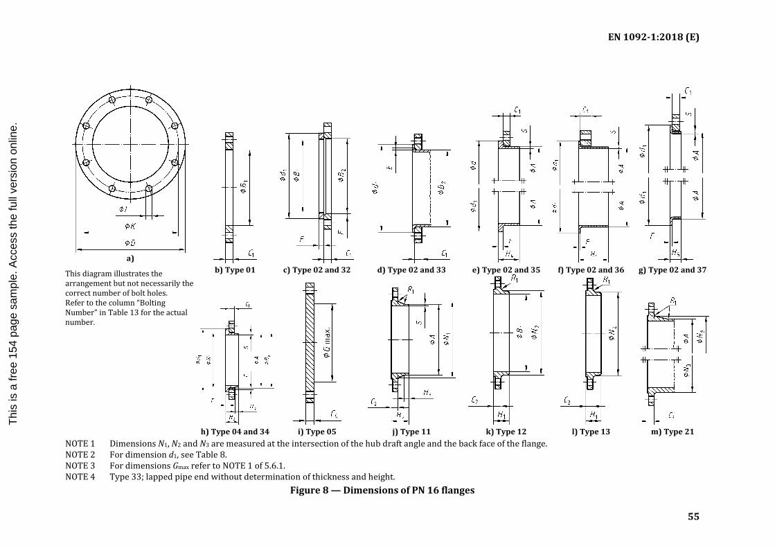
EN 1092-1:2018 (E)
55
a)
This diagram illustrates the arrangement but not necessarily the correct number of bolt holes. Refer to the column “Bolting Number” in Table 13 for the actual number.
b) Type 01 c) Type 02 and 32 d) Type 02 and 33 e) Type 02 and 35 f) Type 02 and 36 g) Type 02 and 37
h) Type 04 and 34 i) Type 05 j) Type 11 k) Type 12 l) Type 13 m) Type 21
NOTE 1 Dimensions N1, N2 and N3 are measured at the intersection of the hub draft angle and the back face of the flange. NOTE 2 For dimension d1, see Table 8. NOTE 3 For dimensions Gmax refer to NOTE 1 of 5.6.1. NOTE 4 Type 33; lapped pipe end without determination of thickness and height.
Figure 8 — Dimensions of PN 16 flanges
I.S. EN 1092-1:2018
Thi
s is
a fr
ee 1
54 p
age
sam
ple.
Acc
ess
the
full
vers
ion
onlin
e.

EN 1092-1:2018 (E)
56
Table 13 — Dimensions of PN 16 flanges Dimensions in millimetres
DN
Mating dimensions Outside
diameter of neck
Bore diameters Flange thickness Chamfer Collar
thickness Centre portion Length Neck diameters Corner
radii
Wall thickness (see 5.6.1)
Outside diameter
Diameter of bolt circle
Diameter of
bolt hole Bolting
D K L Number Size A B1 B2 B3 C1 C2 C3 C4 E F Gmax H1 H2 H3 H4 H5 N1 N2 N3 R1 S
Flange type
01, 02, 04, 05, 11, 12, 13, 21
11 21 a 34 d
35 - 37
01 12 32
02 04 01 02 04
11 12 13
21 05 02 04
32 34 d
35 36 37 05 12 13
11 34 c,d
11 34 c,d
35 36 37 11 34 c, d
12 13 21
11 12 13
21, 34d
34 d
11, 35 to 37
10 90 60 14 4 M12 17,2 18,0 21 31 14 16 16 16 3 12 5 2 2,5 — 22 35 6 35 35 7 28 30 28 4 1,8
See
Anne
x A
15 95 65 14 4 M12 21,3 22,0 25 35 14 16 16 16 3 12 5 2 2,5 — 22 38 6 38 38 7 32 35 32 4 2,0
20 105 75 14 4 M12 26,9 27,5 31 42 16 18 18 18 4 14 6 2,5 3 — 26 40 6 40 40 8 40 45 40 4 2,3
25 115 85 14 4 M12 33,7 34,5 38 49 16 18 18 18 4 14 7 2,5 3 — 28 40 6 40 40 10 46 52 50 4 2,6
32 140 100 18 4 M16 42,4 43,5 47 59 18 18 18 18 5 14 8 3 3 — 30 42 6 42 42 12 56 60 60 6 2,6
40 150 110 18 4 M16 48,3 49,5 53 67 18 18 18 18 5 14 8 3 3 — 32 45 7 45 45 15 64 70 70 6 2,6
50 165 125 18 4 M16 60,3 61,5 65 77 20 18 18 18 5 16 8 3 3 — 28 45 8 45 45 20 74 84 84 6 2,9
65 185 145 18 8b M16 76,1 77,5 81 96 20 18 18 18 6 16 8 3 3 55 32 45 10 45 45 20 92 104 104 6 2,9
80 200 160 18 8 M16 88,9 90,5 94 108 20 20 20 20 6 16 10 3 3 70 34 50 10 50 50 25 105 118 120 6 3,2
100 220 180 18 8 M16 114,3 116,0 120 134 22 20 20 20 6 18 10 4 4 90 40 52 12 52 52 25 131 140 140 8 3,6
125 250 210 18 8 M16 139,7 141,5 145 162 22 22 22 22 6 18 10 4 4 115 44 55 12 55 55 25 156 168 170 8 4,0
150 285 240 22 8 M20 168,3 170,5 174 188 24 22 22 22 6 20 10 5 5 140 44 55 12 55 55 25 184 195 190 10 4,5
200 340 295 22 12 M20 219,1 221,5 226 240 26 24 24 24 6 20 11 6 6 190 44 62 16 62 62 30 235 246 246 10 6,3
250 405 355 26 12 M24 273,0 276,5 281 294 29 26 26 26 8 22 12 10 — 235 46 70 16 70 68 — 292 298 296 12 6,3
300 460 410 26 12 M24 323,9 327,5 333 348 32 28 28 28 8 24 14 10 — 285 46 78 16 78 68 — 344 350 350 12 7,1
350 520 470 26 16 M24 355,6 359,5 365 400 35 30 30 30 8 26 18 10 — 330 57 82 16 82 68 — 390 400 410 12 8,0
I.S. EN 1092-1:2018
Thi
s is
a fr
ee 1
54 p
age
sam
ple.
Acc
ess
the
full
vers
ion
onlin
e.

EN 1092-1:2018 (E)
57
DN
Mating dimensions Outside
diameter of neck
Bore diameters Flange thickness Chamfer Collar
thickness Centre portion Length Neck diameters Corner
radii
Wall thickness (see 5.6.1)
Outside diameter
Diameter of bolt circle
Diameter of
bolt hole Bolting
D K L Number Size A B1 B2 B3 C1 C2 C3 C4 E F Gmax H1 H2 H3 H4 H5 N1 N2 N3 R1 S
Flange type
01, 02, 04, 05, 11, 12, 13, 21
11 21 a 34 d
35 - 37
01 12 32
02 04 01 02 04
11 12 13
21 05 02 04
32 34 d
35 36 37 05 12 13
11 34 c,d
11 34 c,d
35 36 37 11 34 c, d
12 13 21
11 12 13
21, 34d
34 d
11, 35 to 37
400 580 525 30 16 M27 406,4 411,0 416 454 38 32 32 32 8 28 20 10 — 380 63 85 16 85 72 — 445 456 458 12 8,0
450 640 585 30 20 M27 457,0 462,0 467 500 42 34 40 40 8 30 22 — — 425 68 83 16 87 — — 490 502 516 12 8,0
500 715 650 33 20 M30 508,0 513,5 519 556 46 36 44 44 8 32 22 — — 475 73 84 16 90 — — 548 559 576 12 8,0
600 840 770 36 20 M33 610,0 616,5 622 660 55 40 54 54 8 32 24 — — 575 83 88 18 95 — — 670 658 690 12 8,8
700 910 840 36 24 M33 711,0
c
721 — 63 40
c
58 8 — 26 — — 670 83 104 18 100 — — 755 760 760 12 —
800 1 025 950 39 24 M36 813,0 824 — 74 41 62 8 — 28 — — 770 90 108 20 105 — — 855 864 862 12 —
900 1 125 1 050 39 28 M36 914,0 926 — 82 48 64 8 — 30 — — 860 94 118 20 110 — — 955 968 962 12 —
1 000 1 255 1 170 42 28 M39 1 016,0 c 1 030 — 90 59
c
68 8 — 35 — — 960 100 137 22 120 — — 1 058 1 072 1 076 16 —
See
Anne
x A
1 200 1 485 1 390 48 32 M45 1 219,0 — — —
c
78 — — — — — — 1 160 — 160 30 — — — 1 262 — 1 282 16 —
1 400 1 685 1 590 48 36 M45 1 422,0 — — — 84 — — — — — — 1 346 — 177 30 — — — 1 465 — 1 482 16 —
1 600 1 930 1 820 56 40 M52 1 626,0 — — — 102 — — — — — — 1 546 — 204 35 — — — 1 668 — 1 696 16 —
1 800 2 130 2 020 56 44 M52 1 829,0 — — — 110 — — — — — — 1 746 — 218 35 — — — 1 870 — 1 896 16 —
2 000 2 345 2 230 62 48 M56 2 032,0 — — — 124 — — — — — — 1 950 — 238 40 — — — 2 072 — 2 100 16 —
a For flanges type 21 the outside hub diameter approximately corresponds to the outside pipe diameter and the nominal value dimensions A, N3 and R1 and their tolerances are included for guidance only. b According to EN 1092-2 (Cast iron flanges) and EN 1092-3 (Copper alloy flanges), the flanges in this DN and PN may be supplied with 4 holes. Where steel flanges are required with 4 holes, these may be supplied by agreement between flange manufacturer and purchaser. c To be specified by the purchaser. d Use is limited up to DN 600.
I.S. EN 1092-1:2018
Thi
s is
a fr
ee 1
54 p
age
sam
ple.
Acc
ess
the
full
vers
ion
onlin
e.

EN 1092-1:2018 (E)
58
a)
This diagram illustrates the arrangement but not necessarily the correct number of bolt holes. Refer to the column “Bolting Number” in Table 14 for the actual number.
b) Type 01 c) Type 02 and 32 d) Type 02 and 35 e) Type 04 and 34 f) Type 05
g) Type 11 h) Type 12 i) Type 13 j) Type 21
NOTE 1 Dimensions N1, N2 and N3 are measured at the intersection of the hub draft angle and the back face of the flange. NOTE 2 For dimension d1, see Table 8. NOTE 3 For dimensions Gmax refer to NOTE 1 of 5.6.1.
Figure 9 — Dimensions of PN 25 flanges
I.S. EN 1092-1:2018
Thi
s is
a fr
ee 1
54 p
age
sam
ple.
Acc
ess
the
full
vers
ion
onlin
e.

EN 1092-1:2018 (E)
59
Table 14 — Dimensions of PN 25 flanges Dimensions in millimetres
DN
Mating dimensions Outside
diameter of neck
Bore diameters Flange thickness Chamfer Collar thickness
Centre portion Length Neck diameters Corner
radii
Wall thickness (see 5.6.1)
Outside diameter
Diameter of bolt circle
Diameter of bolt
hole Bolting
D K L Number Size A B1 B2 B3 C1 C2 C3 C4 E F Gmax H1 H2 H3 H4 N1 N2 N3 R1 S
Flange type
01, 02, 04, 05, 11, 12, 13, 21 11, 21 a 34 c, 35
01 12 32
02 04 01 02 04
11 12 13
21 05 02 04
32 34 35 05 12
13 11
34 c
11 34 c
35 11 34
12 13 21
11, 12 13
21, 34 34 11,
35
10 90 60 14 4 M12 17,2 18,0 21 31 14 16 16 16 3 12 5 — 22 35 6 35 28 30 28 4 1,8
See
Anne
x A
15 95 65 14 4 M12 21,3 22,0 25 35 14 16 16 16 3 12 5 — 22 38 6 38 32 35 32 4 2,0
20 105 75 14 4 M12 26,9 27,5 31 42 16 18 18 18 4 14 6 — 26 40 6 40 40 45 40 4 2,3
25 115 85 14 4 M12 33,7 34,5 38 49 16 18 18 18 4 14 7 — 28 40 6 40 46 52 50 4 2,6
32 140 100 18 4 M16 42,4 43,5 47 59 18 18 18 18 5 14 8 — 30 42 6 42 56 60 60 6 2,6
40 150 110 18 4 M16 48,3 49,5 53 67 18 18 18 18 5 14 8 — 32 45 7 45 64 70 70 6 2,6
50 165 125 18 4 M16 60,3 61,5 65 77 20 20 20 20 5 16 10 — 34 48 8 48 75 84 84 6 2,9
65 185 145 18 8 M16 76,1 77,5 81 96 22 22 22 22 6 16 11 55 38 52 10 52 90 104 104 6 2,9
80 200 160 18 8 M16 88,9 90,5 94 114 24 24 24 24 6 18 12 70 40 58 12 58 105 118 120 8 3,2
100 235 190 22 8 M20 114,3 116,0 120 138 26 24 24 24 6 20 14 90 44 65 12 65 134 145 142 8 3,6
125 270 220 26 8 M24 139,7 141,5 145 166 28 26 26 26 6 22 16 115 48 68 12 68 162 170 162 8 4,0
150 300 250 26 8 M24 168,3 170,5 174 194 30 28 28 28 6 24 18 140 52 75 12 75 192 200 192 10 4,5
200 360 310 26 12 M24 219,1 221,5 226 250 32 30 30 30 6 26 18 190 52 80 16 80 244 256 252 10 6,3
250 425 370 30 12 M27 273,0 276,5 281 302 35 32 32 32 8 26 18 235 60 88 18 88 298 310 304 12 7,1
300 485 430 30 16 M27 323,9 327,5 333 356 38 34 34 34 8 28 20 285 67 92 18 92 352 364 364 12 8,0
350 555 490 33 16 M30 355,6 359,5 365 408 42 38 38 38 8 32 22 332 72 100 20 100 398 418 418 12 8,0
400 620 550 36 16 M33 406,4 411,0 416 462 48 40 40 40 8 34 24 380 78 110 20 110 452 472 472 12 8,8
I.S. EN 1092-1:2018
Thi
s is
a fr
ee 1
54 p
age
sam
ple.
Acc
ess
the
full
vers
ion
onlin
e.

EN 1092-1:2018 (E)
60
DN
Mating dimensions Outside
diameter of neck
Bore diameters Flange thickness Chamfer Collar thickness
Centre portion Length Neck diameters Corner
radii
Wall thickness (see 5.6.1)
Outside diameter
Diameter of bolt circle
Diameter of bolt
hole Bolting
D K L Number Size A B1 B2 B3 C1 C2 C3 C4 E F Gmax H1 H2 H3 H4 N1 N2 N3 R1 S
Flange type
01, 02, 04, 05, 11, 12, 13, 21 11, 21 a 34 c, 35
01 12 32
02 04 01 02 04
11 12 13
21 05 02 04
32 34 35 05 12
13 11
34 c
11 34 c
35 11 34
12 13 21
11, 12 13
21, 34 34 11,
35
450 670 600 36 20 M33 457,0 462,0 467 510 54 46 46 50 8 36 26 425 84 110 20 110 500 520 520 12 8,8
500 730 660 36 20 M33 508,0 513,5 519 568 58 48 48 51 8 38 28 475 90 125 20 125 558 580 580 12 10,0
600 845 770 39 20 M36 610,0 616,5 622 670 68 48 58 66 8 40 30 575 100 125 20 125 660 684 684 12 11,0
700 960 875 42 24 M39 711,0
b
721 — 85 50
b b
8 — 30 — — 129 20 125 760 — 780 12 —
800 1 085 990 48 24 M45 813,0 824 — 95 53 8 — 35 — — 138 22 135 864 — 882 12 —
900 1 185 1 090 48 28 M45 914,0 — — b
57 — — — — — 148 24 — 968 — 982 12 —
1 000 1 320 1 210 56 28 M52 1 016,0 b — — 63 — — — — — 160 24 — 1 070 — 1 086 16 —
1 200
d
1 400
1 600
1 800
2 000
a For flanges type 21 the outside hub diameter approximately corresponds to the outside pipe diameter and the nominal value dimensions A, N3 and R1 and their tolerances are included for guidance only. b To be specified by the purchaser. c Use is limited up to DN 500. d Only mating dimensions fixed, see Annex J.
I.S. EN 1092-1:2018
Thi
s is
a fr
ee 1
54 p
age
sam
ple.
Acc
ess
the
full
vers
ion
onlin
e.

EN 1092-1:2018 (E)
61
a)
This diagram illustrates the arrangement but not necessarily the correct number of bolt holes. Refer to the column “Bolting Number” in Table 15 for the actual number.
b) Type 01 c) Type 02 and 32 d) Type 02 and 35 e) Type 04 and 34 f) Type 05
g) Type 11 h) Type 12 i) Type 13 j) Type 21
NOTE 1 Dimensions N1, N2 and N3 are measured at the intersection of the hub draft angle and the back face of the flange. NOTE 2 For dimension d1, see Table 8. NOTE 3 For dimensions Gmax refer to NOTE 1 of 5.6.1.
Figure 10 — Dimensions of PN 40 flanges
I.S. EN 1092-1:2018
Thi
s is
a fr
ee 1
54 p
age
sam
ple.
Acc
ess
the
full
vers
ion
onlin
e.
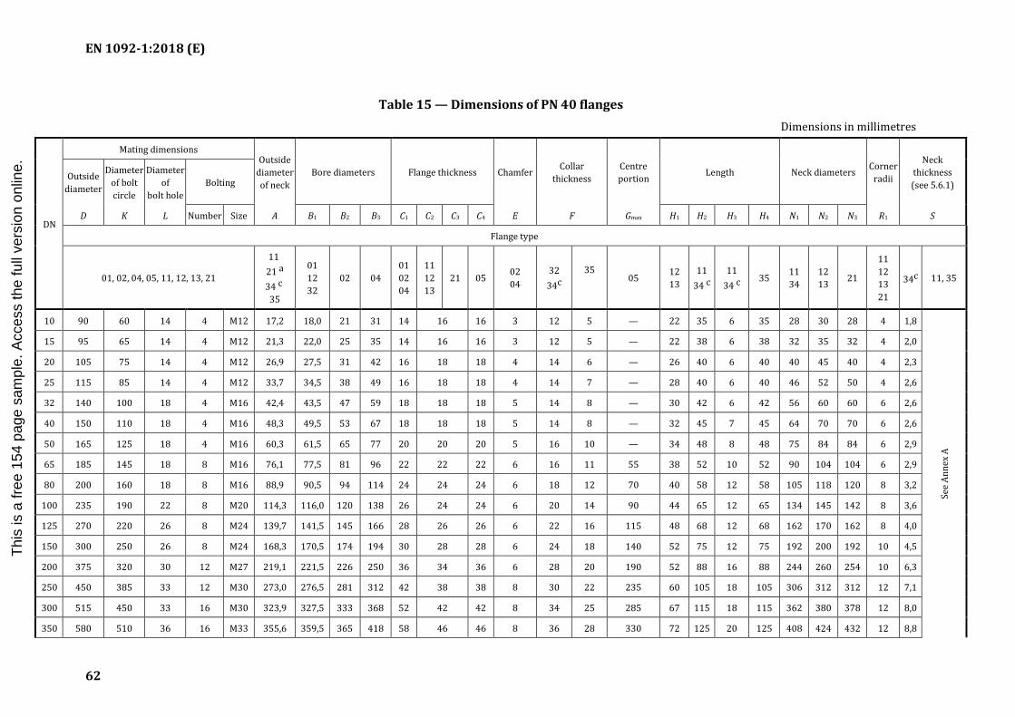
EN 1092-1:2018 (E)
62
Table 15 — Dimensions of PN 40 flanges Dimensions in millimetres
DN
Mating dimensions Outside
diameter of neck
Bore diameters Flange thickness Chamfer Collar thickness
Centre portion Length Neck diameters Corner
radii
Neck thickness (see 5.6.1)
Outside diameter
Diameter of bolt circle
Diameter of
bolt hole Bolting
D K L Number Size A B1 B2 B3 C1 C2 C3 C4 E F Gmax H1 H2 H3 H4 N1 N2 N3 R1 S
Flange type
01, 02, 04, 05, 11, 12, 13, 21
11 21 a 34 c 35
01 12 32
02 04 01 02 04
11 12 13
21 05 02 04
32 34c
35
05 12
13 11
34 c 11
34 c 35 11
34 12 13 21
11 12 13 21
34c 11, 35
10 90 60 14 4 M12 17,2 18,0 21 31 14 16 16 3 12 5 — 22 35 6 35 28 30 28 4 1,8
See
Anne
x A
15 95 65 14 4 M12 21,3 22,0 25 35 14 16 16 3 12 5 — 22 38 6 38 32 35 32 4 2,0
20 105 75 14 4 M12 26,9 27,5 31 42 16 18 18 4 14 6 — 26 40 6 40 40 45 40 4 2,3
25 115 85 14 4 M12 33,7 34,5 38 49 16 18 18 4 14 7 — 28 40 6 40 46 52 50 4 2,6
32 140 100 18 4 M16 42,4 43,5 47 59 18 18 18 5 14 8 — 30 42 6 42 56 60 60 6 2,6
40 150 110 18 4 M16 48,3 49,5 53 67 18 18 18 5 14 8 — 32 45 7 45 64 70 70 6 2,6
50 165 125 18 4 M16 60,3 61,5 65 77 20 20 20 5 16 10 — 34 48 8 48 75 84 84 6 2,9
65 185 145 18 8 M16 76,1 77,5 81 96 22 22 22 6 16 11 55 38 52 10 52 90 104 104 6 2,9
80 200 160 18 8 M16 88,9 90,5 94 114 24 24 24 6 18 12 70 40 58 12 58 105 118 120 8 3,2
100 235 190 22 8 M20 114,3 116,0 120 138 26 24 24 6 20 14 90 44 65 12 65 134 145 142 8 3,6
125 270 220 26 8 M24 139,7 141,5 145 166 28 26 26 6 22 16 115 48 68 12 68 162 170 162 8 4,0
150 300 250 26 8 M24 168,3 170,5 174 194 30 28 28 6 24 18 140 52 75 12 75 192 200 192 10 4,5
200 375 320 30 12 M27 219,1 221,5 226 250 36 34 36 6 28 20 190 52 88 16 88 244 260 254 10 6,3
250 450 385 33 12 M30 273,0 276,5 281 312 42 38 38 8 30 22 235 60 105 18 105 306 312 312 12 7,1
300 515 450 33 16 M30 323,9 327,5 333 368 52 42 42 8 34 25 285 67 115 18 115 362 380 378 12 8,0
350 580 510 36 16 M33 355,6 359,5 365 418 58 46 46 8 36 28 330 72 125 20 125 408 424 432 12 8,8
I.S. EN 1092-1:2018
Thi
s is
a fr
ee 1
54 p
age
sam
ple.
Acc
ess
the
full
vers
ion
onlin
e.

EN 1092-1:2018 (E)
63
DN
Mating dimensions Outside
diameter of neck
Bore diameters Flange thickness Chamfer Collar thickness
Centre portion Length Neck diameters Corner
radii
Neck thickness (see 5.6.1)
Outside diameter
Diameter of bolt circle
Diameter of
bolt hole Bolting
D K L Number Size A B1 B2 B3 C1 C2 C3 C4 E F Gmax H1 H2 H3 H4 N1 N2 N3 R1 S
Flange type
01, 02, 04, 05, 11, 12, 13, 21
11 21 a 34 c 35
01 12 32
02 04 01 02 04
11 12 13
21 05 02 04
32 34c
35
05 12
13 11
34 c 11
34 c 35 11
34 12 13 21
11 12 13 21
34c 11, 35
400 660 585 39 16 M36 406,4 411,0 416 472 65 50 50 8 42 32 380 78 135 20 135 462 478 498 12 11,0
450 685 610 39 20 M36 457,0 462,0 467 510
d
57 57 8 46 — 425 84 135 20 — 500 522 522 12 12,5
500 755 670 42 20 M39 508,0 513,5 519 572 57 57 8 50 — 475 90 140 20 — 562 576 576 12 14,2
600 890 795 48 20 M45 610,0 616,5 622 676 72 72 8 54 — 575 100 150 20 — 666 686 686 12 16,0
700
b
800
900
1 000
1 200
1 400
1 600
a For flanges type 21 the outside hub diameter approximately corresponds to the outside pipe diameter and the nominal value dimensions A, N3 and R1 and their tolerances are included for guidance only. b Only mating dimensions fixed, see Annex J. c Use is limited up to DN 600. d To be specified by the purchaser.
I.S. EN 1092-1:2018
Thi
s is
a fr
ee 1
54 p
age
sam
ple.
Acc
ess
the
full
vers
ion
onlin
e.
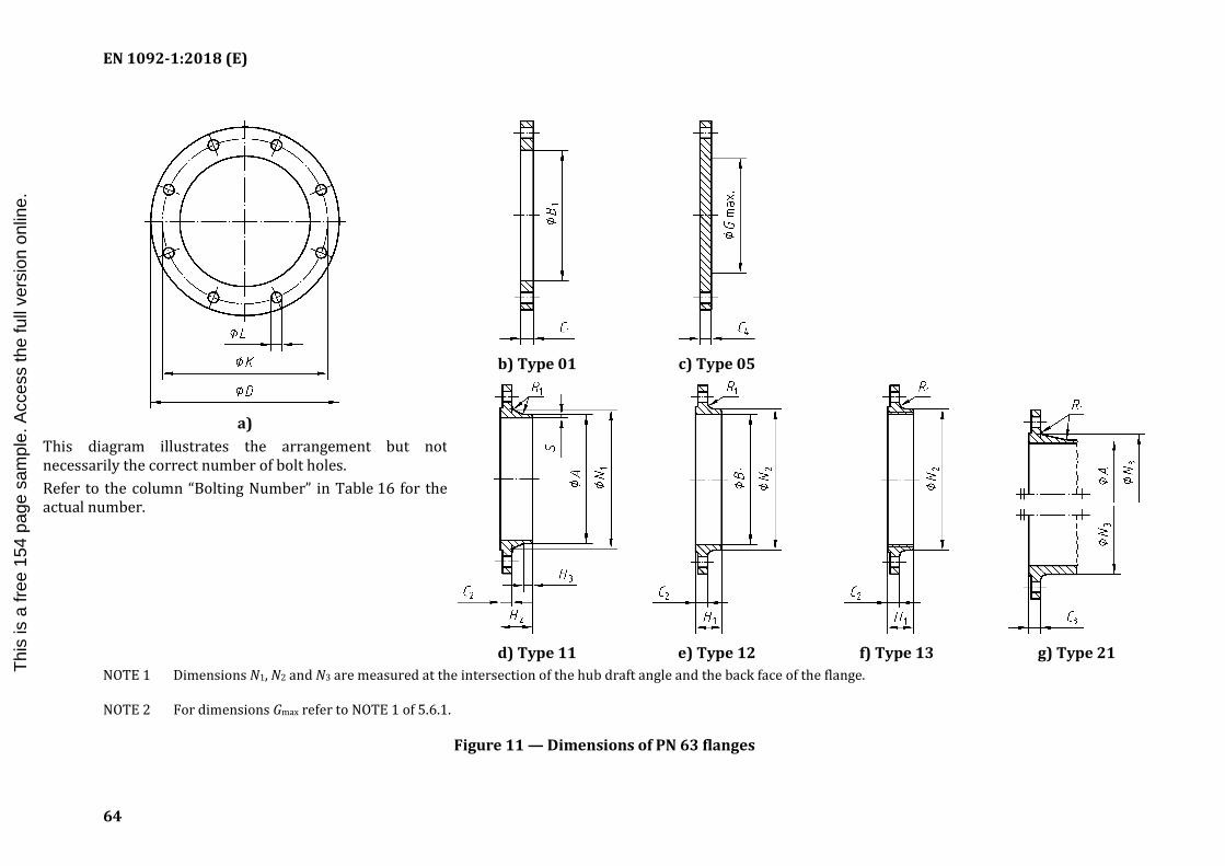
EN 1092-1:2018 (E)
64
a)
This diagram illustrates the arrangement but not necessarily the correct number of bolt holes. Refer to the column “Bolting Number” in Table 16 for the actual number.
b) Type 01 c) Type 05
d) Type 11 e) Type 12 f) Type 13 g) Type 21
NOTE 1 Dimensions N1, N2 and N3 are measured at the intersection of the hub draft angle and the back face of the flange.
NOTE 2 For dimensions Gmax refer to NOTE 1 of 5.6.1.
Figure 11 — Dimensions of PN 63 flanges
I.S. EN 1092-1:2018
Thi
s is
a fr
ee 1
54 p
age
sam
ple.
Acc
ess
the
full
vers
ion
onlin
e.

EN 1092-1:2018 (E)
65
Table 16 — Dimensions of PN 63 flanges Dimensions in millimetres
DN
Mating dimensions Wall
thickness (see 5.6.1)
Outside diameter
Diameter of bolt circle
Diameter of bolt
hole Bolting
Outside diameter of neck
Bore diameter Flange thickness Centre
portion Length Neck diameters Corner radii
D K L Number Size A B1 C1 C2 C3 C4 Gmax H1 H2 H3 N1 N2 N3 R1 S
Flange type
01, 05, 11, 12, 13, 21 11
21 a 01 12 01
11 12 13
21 05 05 12 13 11 11 11 12
13 21
11 12 13 21
11
10 100 70 14 4 M12 17,2 18,0 20 20 20 20 — 28 45 6 32 40 40 4
See
Anne
x A
15 105 75 14 4 M12 21,3 22,0 20 20 20 20 — 28 45 6 34 43 45 4
20 130 90 18 4 M16 26,9 27,5 22 22 22 22 — 30 48 8 42 52 50 4
25 140 100 18 4 M16 33,7 34,5 24 24 24 24 — 32 58 8 52 60 61 4
32 155 110 22 4 M20 42,4 43,5 24 24 26 24 — 32 60 8 62 68 68 6
40 170 125 22 4 M20 48,3 49,5 26 26 28 26 — 34 62 10 70 80 82 6
50 180 135 22 4 M20 60,3 61,5 26 26 26 26 — 36 62 10 82 90 90 6
65 205 160 22 8 M20 76,1 77,5 26 26 26 26 45 40 68 12 98 112 105 6
80 215 170 22 8 M20 88,9 90,5 30 28 28 28 60 44 72 12 112 125 122 8
100 250 200 26 8 M24 114,3 116,0 32 30 30 30 80 52 78 12 138 152 146 8
125 295 240 30 8 M27 139,7 141,5 34 34 34 34 105 56 88 12 168 185 177 8
150 345 280 33 8 M30 168,3 170,5 36 36 36 36 130 60 95 12 202 215 204 10
200 415 345 36 12 M33 219,1 221,5 48 42 42 42 180 — 110 16 256 — 264 10
250 470 400 36 12 M33 273,0 276,5 55 46 46 46 220 — 125 18 316 — 320 12
300 530 460 36 16 M33 323,9 327,5 65 52 52 52 270 — 140 18 372 — 378 12
350 600 525 39 16 M36 355,6 359,5 72 56 56 56 310 — 150 20 420 — 434 12
I.S. EN 1092-1:2018
Thi
s is
a fr
ee 1
54 p
age
sam
ple.
Acc
ess
the
full
vers
ion
onlin
e.

EN 1092-1:2018 (E)
66
DN
Mating dimensions Wall
thickness (see 5.6.1)
Outside diameter
Diameter of bolt circle
Diameter of bolt
hole Bolting
Outside diameter of neck
Bore diameter Flange thickness Centre
portion Length Neck diameters Corner radii
D K L Number Size A B1 C1 C2 C3 C4 Gmax H1 H2 H3 N1 N2 N3 R1 S
Flange type
01, 05, 11, 12, 13, 21 11
21 a 01 12 01
11 12 13
21 05 05 12 13 11 11 11 12
13 21
11 12 13 21
11
400 670 585 42 16 M39 406,4 411,0 80 60 60 60 360 — 160 20 475 — 490 12
500
b
600
700
800
900
1 000
1 200
a For flanges type 21 the outside hub diameter approximately corresponds to the outside pipe diameter and the nominal value dimensions A, N3 and R1 and their tolerances are included for guidance only. b Only mating dimensions fixed, see Annex J.
I.S. EN 1092-1:2018
Thi
s is
a fr
ee 1
54 p
age
sam
ple.
Acc
ess
the
full
vers
ion
onlin
e.

EN 1092-1:2018 (E)
67
a)
This diagram illustrates the arrangement but not necessarily the correct number of bolt holes. Refer to the column “Bolting Number” in Table 17 for the actual number.
b) Type 01 c) Type 05
d) Type 11 e) Type 12 f) Type 13 g) Type 21 NOTE 1 Dimensions N1, N2 and N3 are measured at the intersection of the hub draft angle and the back face of the flange.
NOTE 2 For dimensions Gmax refer to NOTE 1 of 5.6.1.
Figure 12 — Dimensions of PN 100 flanges
I.S. EN 1092-1:2018
Thi
s is
a fr
ee 1
54 p
age
sam
ple.
Acc
ess
the
full
vers
ion
onlin
e.

EN 1092-1:2018 (E)
68
Table 17 — Dimensions of PN 100 flanges Dimensions in millimetres
DN
Mating dimensions Wall
thickness (see 5.6.1) Outside
diameter Diameter
of bolt circle
Diameter of bolt
hole Bolting
Outside diameter of
neck Bore
diameter Flange thickness Centre portion Length Neck diameters Corner
radii
D K L Number Size A B1 C1 C2 C3 C4 G max H1 H2 H3 N1 N2 N3 R1 S
Flange type
01, 05, 11, 12, 13, 21 11 21 a
01 12 01
11 12 13
21 05 05 12 13 11 11 11 12
13 21 11 12 13 21
11
10 100 70 14 4 M12 17,2 18,0 20 20 20 20 — 28 45 6 32 40 40 4
See
Anne
x A
15 105 75 14 4 M12 21,3 22,0 20 20 20 20 — 28 45 6 34 43 45 4
20 130 90 18 4 M16 26,9 27,5 22 22 22 22 — 30 48 8 42 52 50 4
25 140 100 18 4 M16 33,7 34,5 24 24 24 24 — 32 58 8 52 60 61 4
32 155 110 22 4 M20 42,4 43,5 24 24 26 24 — 32 60 8 62 68 68 6
40 170 125 22 4 M20 48,3 49,5 26 26 28 26 — 34 62 10 70 80 82 6
50 195 145 26 4 M24 60,3 61,5 28 28 30 28 — 36 68 10 90 95 96 6
65 220 170 26 8 M24 76,1 77,5 30 30 34 30 45 40 76 12 108 118 118 6
80 230 180 26 8 M24 88,9 90,5 34 32 36 32 60 44 78 12 120 130 128 8
100 265 210 30 8 M27 114,3 116,0 36 36 40 36 80 52 90 12 150 158 150 8
125 315 250 33 8 M30 139,7 141,5 42 40 40 40 105 56 105 12 180 188 185 8
150 355 290 33 12 M30 168,3 170,5 48 44 44 44 130 60 115 12 210 225 216 10
200 430 360 36 12 M33 219,1 221,5 60 52 52 52 180 — 130 16 278 — 278 10
250 505 430 39 12 M36 273,0 276,5 72 60 60 60 210 — 157 18 340 — 340 12
300 585 500 42 16 M39 323,9 327,5 84 68 68 68 260 — 170 18 400 — 407 12
350 655 560 48 16 M45 355,6 359,5 95 74 74 74 300 — 189 20 460 — 460 12
400 b 500
a For flanges type 21 the outside hub diameter approximately corresponds to the outside pipe diameter and the nominal value dimensions A, N3 and R1 and their tolerances are included for guidance only. b Only mating dimensions fixed, see Annex J.
I.S. EN 1092-1:2018
Thi
s is
a fr
ee 1
54 p
age
sam
ple.
Acc
ess
the
full
vers
ion
onlin
e.

EN 1092-1:2018 (E)
69
a) b) Type 05 c) Type 11 d Type 21
This diagram illustrates the arrangement but not necessarily the correct number of bolt holes. Refer to the column “Bolting Number” in Table 18 for the actual number.
NOTE Dimensions N1 and N3 are measured at the intersection of the hub draft angle and the back face of the flange.
Figure 13 — Dimensions of PN 160 flanges
I.S. EN 1092-1:2018
Thi
s is
a fr
ee 1
54 p
age
sam
ple.
Acc
ess
the
full
vers
ion
onlin
e.

EN 1092-1:2018 (E)
70
Table 18 — Dimensions of PN 160 flanges Dimensions in millimetres
DN
Mating dimensions Wall
Thickness (see 5.6.1)
Outside diameter
Diameter of bolt circle
Diameter of bolt hole
Bolting
Outside Diameter
of neck
Flange thickness Centre portion
Length Neck
diameters
Corner radii
D K L Number Size A C4 C2 C3 Gmax H2 H3 N1 N3 R1 S
Flange type
05,11, 21 11
21 a 05 11
21
05 11 11 11 21 11 21 11
10 100 70 14 4 M12 17,2 20 20 20 — 45 6 32 40 4 4 2,0
15 105 75 14 4 M12 21,3 20 20 20 — 45 6 34 45 4 4 2,0
25 140 100 18 4 M16 33,7 24 24 24 — 58 8 52 61 4 4 2,9
40 170 125 22 4 M20 48,3 28 28 28 — 64 10 70 82 6 4 3,6
50 195 145 26 4 M24 60,3 30 30 30 — 75 10 90 96 6 4 4,0
65 220 170 26 8 M24 76,1 34 34 34 42 82 12 108 118 6 5 5,0
80 230 180 26 8 M24 88,9 36 36 36 55 86 12 120 128 8 5 6,3
100 265 210 30 8 M27 114,3 40 40 40 74 100 12 150 150 8 5 8,0
125 315 250 33 8 M30 139,7 44 44 44 98 115 14 180 184 8 6 10,0
150 355 290 33 12 M30 168,3 50 50 50 119 128 14 210 224 10 6 12,5
200 430 360 36 12 M33 219,1 62 60 60 168 140 16 278 288 10 8 16,0
250 515 430 42 12 M39 273,0 72 68 68 195 155 18 340 346 12 8 20,0
300 585 500 42 16 M39 323,9 84 78 78 235 175 18 400 414 12 10 22,2
a For flanges type 21 the outside hub diameter approximately corresponds to the outside pipe diameter and the nominal value dimensions A, N3 and R1 and their tolerances are included for guidance only.
I.S. EN 1092-1:2018
Thi
s is
a fr
ee 1
54 p
age
sam
ple.
Acc
ess
the
full
vers
ion
onlin
e.

EN 1092-1:2018 (E)
71
a) b) Type 05 c) Type 11 d Type 21
This diagram illustrates the arrangement but not necessarily the correct number of bolt holes. Refer to the column “Bolting Number” in Table 19 for the actual number.
NOTE Dimensions N1 and N3 are measured at the intersection of the hub draft angle and the back face of the flange.
Figure 14 — Dimensions of PN 250 flanges
I.S. EN 1092-1:2018
Thi
s is
a fr
ee 1
54 p
age
sam
ple.
Acc
ess
the
full
vers
ion
onlin
e.

EN 1092-1:2018 (E)
72
Table 19 — Dimensions of PN 250 flanges Dimensions in millimetres
DN
Mating dimensions Wall
thickness (see 5.6.1)
Outside diameter
Diameter of bolt circle
Diameter of bolt
hole Bolting
Outside diameter of neck
Flange thickness Centre portion
Length Neck diameters Corner radii
D K L Number Size A C4 C2 C3 Gmax H2 H3 N1 N3 R1 S
Flange type
05, 11, 21 11
21 a 05 11 21 05 11 11 11 21 11 21 11
10 b, c 125 85 18 4 M16 — — — 24 — — — — 46 — 4 —
15 130 90 18 4 M16 21,3 26 26 26 — 60 6 48 52 4 4 2,6
25 150 105 22 4 M20 33,7 28 28 28 — 65 8 60 63 4 4 3,6
40 185 135 26 4 M24 48,3 34 34 34 — 80 10 84 90 6 4 5,0
50 200 150 26 8 M24 60,3 38 38 38 — 85 10 95 102 6 5 6,3
65 230 180 26 8 M24 76,1 42 42 42 36 95 12 124 125 6 5 8,0
80 255 200 30 8 M27 101,6 46 46 46 46 102 12 136 142 8 6 11,0
100 300 235 33 8 M30 127,0 54 54 54 62 120 14 164 168 8 6 14,2
125 340 275 33 12 M30 152,4 60 60 60 86 140 16 200 207 8 6 16,0
150 390 320 36 12 M33 177,8 68 68 68 109 160 18 240 246 10 8 17,5
200 485 400 42 12 M39 244,5 85 82 82 150 190 25 305 314 10 8 25,0
250 585 490 48 16 M45 298,5 104 100 100 171 215 30 385 394 12 10 32,0
300 b 690 590 52 16 M48 — — — 120 — — — — 480 — 10 —
a For flanges type 21 the outside hub diameter approximately corresponds to the outside pipe diameter and the nominal value dimensions A, N3 and R1 and their tolerances are included for guidance only. b For flanges type 21. c For flanges type 11 use flanges PN 320.
I.S. EN 1092-1:2018
Thi
s is
a fr
ee 1
54 p
age
sam
ple.
Acc
ess
the
full
vers
ion
onlin
e.

EN 1092-1:2018 (E)
73
a) b) Type 05 c) Type 11 d Type 21
This diagram illustrates the arrangement but not necessarily the correct number of bolt holes. Refer to the column “Bolting Number” in Table 19 for the actual number.
NOTE Dimensions N1 and N3 are measured at the intersection of the hub draft angle and the back face of the flange.
Figure 15 — Dimensions of PN 320 flanges
I.S. EN 1092-1:2018
Thi
s is
a fr
ee 1
54 p
age
sam
ple.
Acc
ess
the
full
vers
ion
onlin
e.
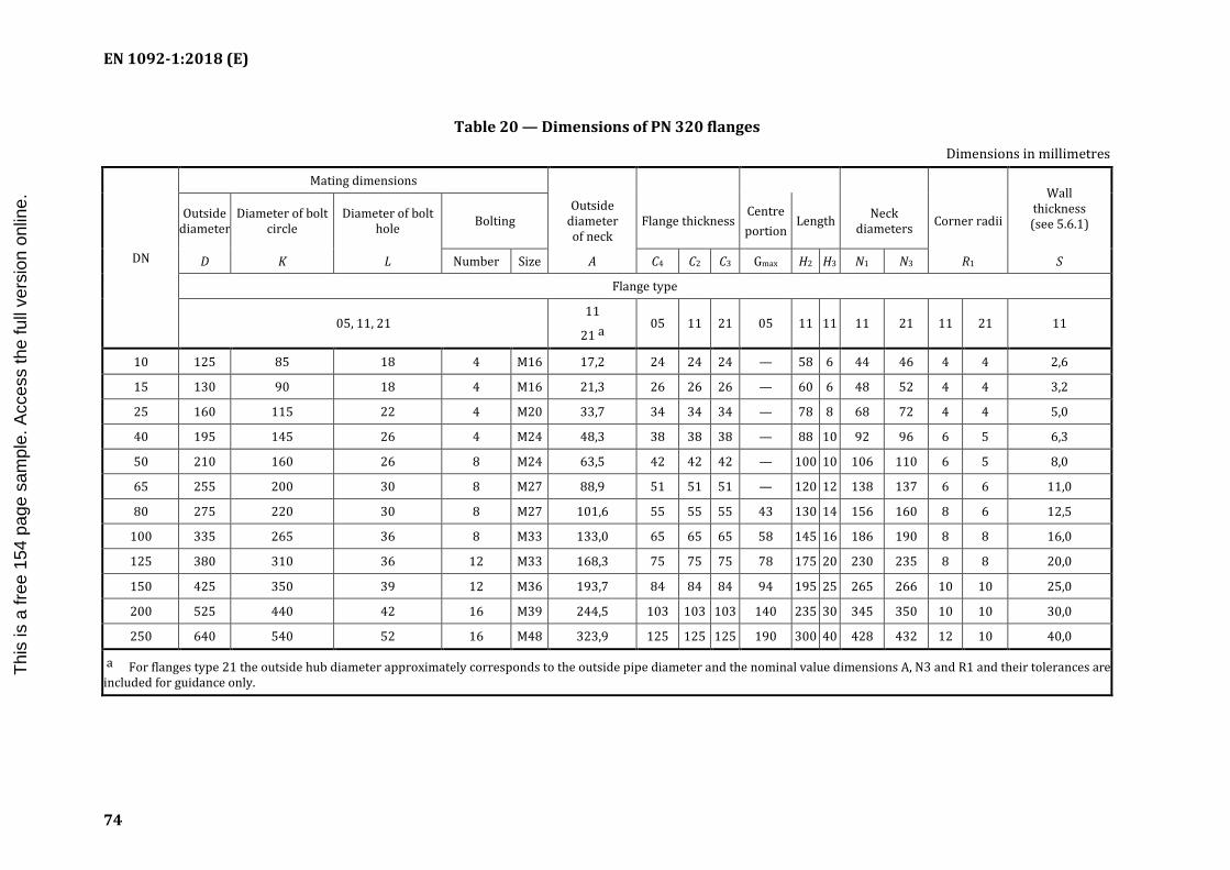
EN 1092-1:2018 (E)
74
Table 20 — Dimensions of PN 320 flanges Dimensions in millimetres
DN
Mating dimensions Wall
thickness (see 5.6.1)
Outside diameter
Diameter of bolt circle
Diameter of bolt hole Bolting
Outside diameter of neck
Flange thickness Centre portion
Length Neck diameters Corner radii
D K L Number Size A C4 C2 C3 Gmax H2 H3 N1 N3 R1 S
Flange type
05, 11, 21 11
21 a 05 11 21 05 11 11 11 21 11 21 11
10 125 85 18 4 M16 17,2 24 24 24 — 58 6 44 46 4 4 2,6
15 130 90 18 4 M16 21,3 26 26 26 — 60 6 48 52 4 4 3,2
25 160 115 22 4 M20 33,7 34 34 34 — 78 8 68 72 4 4 5,0
40 195 145 26 4 M24 48,3 38 38 38 — 88 10 92 96 6 5 6,3
50 210 160 26 8 M24 63,5 42 42 42 — 100 10 106 110 6 5 8,0
65 255 200 30 8 M27 88,9 51 51 51 — 120 12 138 137 6 6 11,0
80 275 220 30 8 M27 101,6 55 55 55 43 130 14 156 160 8 6 12,5
100 335 265 36 8 M33 133,0 65 65 65 58 145 16 186 190 8 8 16,0
125 380 310 36 12 M33 168,3 75 75 75 78 175 20 230 235 8 8 20,0
150 425 350 39 12 M36 193,7 84 84 84 94 195 25 265 266 10 10 25,0
200 525 440 42 16 M39 244,5 103 103 103 140 235 30 345 350 10 10 30,0
250 640 540 52 16 M48 323,9 125 125 125 190 300 40 428 432 12 10 40,0
a For flanges type 21 the outside hub diameter approximately corresponds to the outside pipe diameter and the nominal value dimensions A, N3 and R1 and their tolerances are included for guidance only.
I.S. EN 1092-1:2018
Thi
s is
a fr
ee 1
54 p
age
sam
ple.
Acc
ess
the
full
vers
ion
onlin
e.
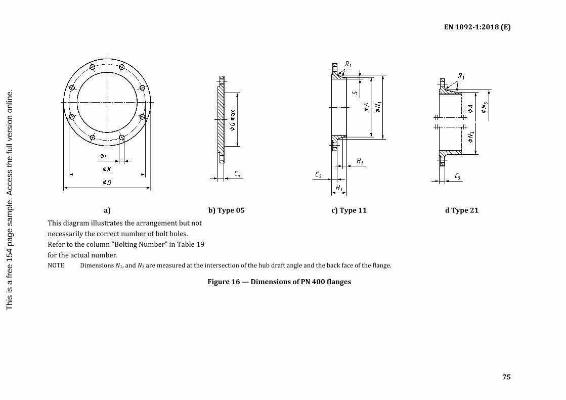
EN 1092-1:2018 (E)
75
a) b) Type 05 c) Type 11 d Type 21
This diagram illustrates the arrangement but not necessarily the correct number of bolt holes. Refer to the column “Bolting Number” in Table 19 for the actual number.
NOTE Dimensions N1, and N3 are measured at the intersection of the hub draft angle and the back face of the flange.
Figure 16 — Dimensions of PN 400 flanges
I.S. EN 1092-1:2018
Thi
s is
a fr
ee 1
54 p
age
sam
ple.
Acc
ess
the
full
vers
ion
onlin
e.

EN 1092-1:2018 (E)
76
Table 21 — Dimensions of PN 400 flanges Dimensions in millimetres
DN
Mating dimensions Wall thickness
(see 5.6.1) Outside diameter
Diameter of bolt circle
Diameter of bolt hole
Bolting Outside
diameter of neck
Flange thickness Centre portion
Length Neck diameters Corner radii
D K L Number Size A C4 C2 C3 Gmax H2 H3 N1 N3 R1 S
Flange type
05, 11, 21 11
21 a 05 11 21 05 11 11 11 21 11 21 11
10 125 85 18 4 M16 17,2 28 28 28 — 65 8 48 48 4 4 3,6
15 145 100 22 4 M20 26,9 30 30 30 — 68 8 56 57 4 4 5,0
25 180 130 26 4 M24 42,4 38 38 38 — 90 10 82 81 4 5 7,1
40 220 165 30 4 M27 60,3 48 48 48 — 110 12 106 105 6 5 10,0
50 235 180 30 8 M27 76,1 52 52 52 — 120 15 120 120 6 6 12,5
65 290 225 33 8 M30 101,6 64 64 64 — 135 18 158 158 6 6 16,0
80 305 240 33 8 M30 114,3 68 68 68 — 150 20 174 174 8 8 17,5
100 370 295 39 8 M36 139,7 80 80 80 46 175 25 216 216 8 8 22,2
125 415 340 39 12 M36 193,7 92 92 92 58 200 30 258 259 8 10 30,0
150 475 390 42 12 M39 219,1 105 105 105 74 225 35 302 302 10 10 35,0
200 585 490 48 16 M45 273,0 130 130 130 120 280 40 388 388 10 10 40,0
a For flanges type 21 the outside hub diameter approximately corresponds to the outside pipe diameter and the nominal value dimensions A, N3 and R1 and their tolerances are included for guidance only.
I.S. EN 1092-1:2018
Thi
s is
a fr
ee 1
54 p
age
sam
ple.
Acc
ess
the
full
vers
ion
onlin
e.

EN 1092-1:2018 (E)
77
Table 22 — Tolerances
Dimension Flange Type Size Tolerance mm
Outside diameter of neck A
11, 21, 34
≤ DN 125 +3,0 0
> DN 125 ≤ DN 1200 + 4,5 0
> DN 1200 + 6,0 0
35, 36, 37
≤ DN 150 ± 0,75 % a, min. ± 0,3 mm
> DN 150 ± 1 % a, max. ± 3,0 mm
Bore diameter B1, B2, B3 01, 02, 04, 12, 32
≤ DN 100 + 0,5 0
> DN 100 ≤ DN 400 +1,0 0
> DN 400 ≤ DN 600 +1,5 0
> DN 600 +3,0 0
Wall thickness Sc
11, 34b
machined
neck (both faces)
neck one face
machined or un-
machined
≤ DN 100 +1,0 0 + 2,0
0
> DN 100 ≤ DN 400 +1,5 0 + 2,5
0
> DN 400 + 2,0 0 +3,5
0
35 S ≤ 8 +−
15 %10 %
S > 8 +−15 %5 %
36, 37 ≤ DN 600 −
+12,5 %15 %
a
> DN 600 mm−+
0,515 %
a
Bevelled wall thickness Sp 35, 36, 37 S ≤ 6 +1,0
0
S > 6 + 2,00
I.S. EN 1092-1:2018T
his
is a
free
154
pag
e sa
mpl
e. A
cces
s th
e fu
ll ve
rsio
n on
line.

EN 1092-1:2018 (E)
78
Dimension Flange Type Size Tolerance mm
Outside diameter D
21
≤ DN 250 ± 4,0
> DN 250 ≤ DN 500 ± 5,0
> DN 500 ≤ DN 800 ± 6,0
> DN 800 ≤ DN 1200 ± 7,0
> DN 1200 ≤ DN 1600 ± 8,0
> DN 1600 ≤ DN 2000 ± 10,0
All other types
≤ DN 150 ± 2,0
> DN 150 ≤ DN 500 ± 3,0
> DN 500 ≤ DN 1200 ± 5,0
> DN 1200 ≤ DN 1800 ± 7,0
> DN 1800 ± 10,0
Length through hub H1, H2, H3, H4, H5
11, 12, 13, 34, 35, 36, 37
≤ DN 80 ± 1,5
> DN 80 ≤ DN 250 ± 2,0
> DN 250 ± 3,0
Neck diameter N1
11 (machined bearing surface)
N1 ≤ 120 −01,0
N1 > 120 ≤ 400 −01,2
N1 > 400 ≤ 1000 +1,60
N1 > 1000 ≤ 2000 +2,50
N1 > 2000 + 4,00
11 (un-machined bearing surface)
N1 ≤ 120 −01,0
N1 > 120 ≤ 400 −02,0
N1 > 400 ≤ 1000 + 4,00
N1 > 1000 ≤ 2000 + 6,00
N1 > 2000 + 8,00
I.S. EN 1092-1:2018T
his
is a
free
154
pag
e sa
mpl
e. A
cces
s th
e fu
ll ve
rsio
n on
line.

EN 1092-1:2018 (E)
79
Dimension Flange Type Size Tolerance mm
Neck diameter N1, N2, N3
21, 34 (un-machined bearing surface)
≤ DN 50 −02,0
> DN 50 ≤ DN 150 −04,0
> DN 150 ≤ DN 300 −06,0
> DN 300 ≤ DN 600 −08,0
> DN 600 ≤ DN 4000 −0
10,0
21, 34 (machined bearing surface)
≤ DN 50 +1,00
> DN 50 ≤ DN 150 +1,50
> DN 150 ≤ DN 300 + 2,00
> DN 300 ≤ DN 600 + 2,50
> DN 600 ≤ DN 4000 +3,00
Neck diameter N2, N3
12, 13 ≤ DN 50 +1,0
0
> DN 50 ≤ DN 150 + 2,00
> DN 150 ≤ DN 300 + 4,00
> DN 300 ≤ DN 600 + 8,00
> DN 600 ≤ DN 1200 +12,00
> DN 1200 ≤ DN 1800 +16,00
> DN 1800 + 20,00
I.S. EN 1092-1:2018T
his
is a
free
154
pag
e sa
mpl
e. A
cces
s th
e fu
ll ve
rsio
n on
line.

EN 1092-1:2018 (E)
80
Dimension Flange Type Size Tolerance mm
Collar thickness F 35 (machined on both facings)
≤ 18 mm thickness ± 1,0
> 18 mm ≤ 50 mm thickness ± 1,5
35 (machined on front face, only or un-machined)
≤ 18 mm thickness +−
2,01,3
> 18 mm ≤ 50 mm thickness +−
4,01,5
36 (machined on front face, only or un-machined)
≤ 18 mm thickness ± 10 %
37 (un-machined) ≤ 5 mm thickness ± 0,20
37 (un-machined) > 5 mm thickness ± 0,30
32, 34 (machined on both faces)
≤ 18 mm thickness +−
1,01,3
> 18 mm thickness ± 1,5
32, 34 (machined on front side only)
≤ 18 mm thickness +−
2,01,3
> 18 mm ≤30 mm thickness +−
3,01,5
> 30 mm thickness +−
4,01,5
Flange thickness C1, C2, C3, C4
All types (machined on both faces)
≤ 18 mm thickness +−
1,01,3
> 18 mm ≤ 50 mm thickness ± 1,5
> 50 mm thickness ± 2,0
All types (machined on front side only) Type 02 and 04 (un-machined)
≤ 18 mm thickness +−
2,01,3
> 18 mm ≤ 50 mm thickness +−
4,01,5
> 50 mm thickness +−
7,02,0
Facing diameter d1 All Types ≤ DN 250 +−
2,01,0
> DN 250 +−
3,01,0
I.S. EN 1092-1:2018T
his
is a
free
154
pag
e sa
mpl
e. A
cces
s th
e fu
ll ve
rsio
n on
line.

EN 1092-1:2018 (E)
81
Dimension Flange Type Size Tolerance mm
Facing height f1 All Types (Facing type B, D, F and G) ≤ DN 32 2 mm −
01,0
> DN 32 to DN 250 3 mm −02,0
> DN 250 to DN 500 4 mm −03,0
> DN 500 5 mm −04,0
Facing height f2 All types (Facing type C, E and G) All DN + 0,5
0
Facing height f3 All types (Facing type D and F) All DN + 0,5
0
All types (Facing type H) All DN + 0,2
0
Facing height f4 All types (Facing type H) All DN + 0,5
0
Facing W
All types All DN
+ 0,50
X −00,5
Y + 0,50
Z −00,5
Diameter of bolt circle K All types Bolt size M10 to M24 ± 1,0
Bolt size M27 to M45 ± 1,5
Bolt size > M45 ± 2,0
Diameter of bolt holes L All types Bolt size M10 to M24
+1,00
Bolt size M27 to M45
+ 2,50
Bolt size > M45 + 4,00
Centre-to-centre of adjacent bolt holes
All types Bolt size M10 to M24 ± 1,0
Bolt size M27 to M45 ± 1,5
Bolt size > M45 ± 2,0
I.S. EN 1092-1:2018T
his
is a
free
154
pag
e sa
mpl
e. A
cces
s th
e fu
ll ve
rsio
n on
line.

EN 1092-1:2018 (E)
82
Dimension Flange Type Size Tolerance mm
Eccentricity of machined facing diameters d
All types ≤ DN 65 1,0
> DN 65 2,0
Parallelism between bolting bearing surface and flange jointing faces
All types (machined bearing surface)
All DN
1°
All types (un-machined bearing surface)
2°
a Tolerance in % from the outside diameter or respectively from the wall thickness. b Bore tolerance not applicable. c Preparation of ends, see Annex A. d Between bolt circle and facing also as between bore diameter and facing.
Table 23 — Corner radii R1 and hub radius R2 after back facing
Flange size R1 min. a R1 max. a R2 min.
mm mm mm
Up to and including DN 50 3 5 1,6
Over DN 50 and up to including DN 350 3 6 2,4
Over DN 350 5 8 3,2
a Dimensions R1 are valid for types 33 and 35 to 37.
Dimensions R1 for other types 11, 12, 13, 21 and 34 see Table 10 to Table 21.
Figure 17 — Minimum hub radius after back facing
I.S. EN 1092-1:2018T
his
is a
free
154
pag
e sa
mpl
e. A
cces
s th
e fu
ll ve
rsio
n on
line.

EN 1092-1:2018 (E)
83
Annex A (normative)
Wall thickness and end preparation for flanges type 11, 34, 35, 36, 37 and
pipe nominal thicknesses for the use with type 01 flanges
A.1 Weld-end preparation for flanges types 11 and 34
Unless otherwise specified, for flanges in accordance with this European Standard the welding end connections given in Figures A.1 to A.3 shall be used. Additional types of welding ends are specified in EN ISO 9692-2 and examples of designs in EN 1708-1 and may be used by agreement between the component or pressure equipment manufacturer and the flange manufacturer.
— Wall thickness S ≤ 3 mm: Flanges/collars may be delivered with square cut ends.
— Wall thickness 3 < S < 22: Bevelled ends with an angle of 30° + °− °
50 and root face of (1,6 ± 0,8) mm.
— If flange wall thickness (S) > pipe wall thickness (T), the inner diameter shall be chamfered with an angle of 15° + °
− °50 to match (see Figure A.3).
Dimensions in millimetres
Key Key
S flange wall thickness S flange wall thickness
Figure A.1 — Welding end connection for wall thickness S < 22,2 mm
Figure A.2 — Welding end connection for wall thickness S ≥ 22,2 mm
I.S. EN 1092-1:2018T
his
is a
free
154
pag
e sa
mpl
e. A
cces
s th
e fu
ll ve
rsio
n on
line.

EN 1092-1:2018 (E)
84
Key S flange wall thickness Sp reduced flange wall thickness
Figure A.3 — Permissible bevel design for unequal wall thickness
For flanges required to connect to non-austenitic steel pipe of nominal wall thickness less than 4,8 mm, the welding ends should be finished to a slight chamfer or be square, at the option of the flange manufacturer, if nothing else has been agreed between flange manufacturer and purchaser or pressure equipment manufacturer.
For flanges required to connect to austenitic stainless steel pipe of nominal wall thickness 3,2 mm or less, the welding ends should be square cut ends.
The mating wall thickness of the flange (Sp) shall match to the pipe wall thickness (T).
Table A.1 — Wall thickness for type 11
∅ A PN 2,5 PN 6 PN 10 PN 16 PN 25 PN 40 PN 63 PN 100
S Sp S Sp S Sp S Sp S Sp S Sp S Sp S Sp
17,2 2,0 2,0 2,0 2,0 2,0 2,0 2,0 2,0 2,0 2,0 2,0 2,0 2,0 2,0 2,0 2,0
21,3 2,0 2,0 2,0 2,0 2,0 2,0 2,0 2,0 2,0 2,0 2,0 2,0 2,0 2,0 2,0 2,0
26,9 2,3 2,3 2,3 2,3 2,3 2,3 2,3 2,3 2,3 2,3 2,3 2,3 2,6 2,6 2,6 2,6
33,7 2,6 2,6 2,6 2,6 2,6 2,6 2,6 2,6 2,6 2,6 2,6 2,6 2,6 2,6 2,6 2,6
42,4 2,6 2,6 2,6 2,6 2,6 2,6 2,6 2,6 2,6 2,6 2,6 2,6 2,9 2,9 2,9 2,9
48,3 2,6 2,6 2,6 2,6 2,6 2,6 2,6 2,6 2,6 2,6 2,6 2,6 2,9 2,9 2,9 2,9
60,3 2,9 2,9 2,9 2,9 2,9 2,9 2,9 2,9 2,9 2,9 2,9 2,9 2,9 2,9 3,2 3,2
76,1 2,9 2,9 2,9 2,9 2,9 2,9 2,9 2,9 2,9 2,9 2,9 2,9 3,2 3,2 3,6 3,6
88,9 3,2 3,2 3,2 3,2 3,2 3,2 3,2 3,2 3,2 3,2 3,2 3,2 3,6 3,6 4,0 4,0
114,3 3,6 3,6 3,6 3,6 3,6 3,6 3,6 3,6 3,6 3,6 3,6 3,6 4,0 4,0 5,0 5,0
139,7 4,0 4,0 4,0 4,0 4,0 4,0 4,0 4,0 4,0 4,0 4,0 4,0 4,5 4,5 6,3 6,3
168,3 4,5 4,5 4,5 4,5 4,5 4,5 4,5 4,5 4,5 4,5 4,5 4,5 5,6 5,6 7,1 7,1
219,1 6,3 6,3 6,3 6,3 6,3 6,3 6,3 6,3 6,3 6,3 6,3 6,3 7,1 7,1 10,0 10,0
273 6,3 6,3 6,3 6,3 6,3 6,3 6,3 6,3 7,1 7,1 7,1 7,1 8,8 8,8 12,5 12,5
323,9 7,1 7,1 7,1 7,1 7,1 7,1 7,1 7,1 8,0 8,0 8,0 8,0 11,0 11,0 14,2 14,2
I.S. EN 1092-1:2018T
his
is a
free
154
pag
e sa
mpl
e. A
cces
s th
e fu
ll ve
rsio
n on
line.

EN 1092-1:2018 (E)
85
∅ A PN 2,5 PN 6 PN 10 PN 16 PN 25 PN 40 PN 63 PN 100
S Sp S Sp S Sp S Sp S Sp S Sp S Sp S Sp
355,6 7,1 7,1 7,1 7,1 7,1 7,1 8,0 8,0 8,0 8,0 8,8 8,8 12,5 12,5 16,0 16,0
406,4 7,1 7,1 7,1 7,1 7,1 7,1 8,0 8,0 8,8 8,8 11,0 11,0 14,2 14,2
457 7,1 7,1 7,1 7,1 7,1 7,1 8,8 8,0 8,8 8,8 12,5 12,5
508 7,1 7,1 7,1 7,1 7,1 7,1 8,8 8,0 10,0 10,0 14,2 14,2
610 7,1 7,1 7,1 7,1 8 7,1 11,0 8,8 12,5 11,0 16,0 16,0
711 7,1 7,1 8 7,1 8,8 8,0 11,0 8,8 14,2 12,5
813 7,1 7,1 8 7,1 8,8 8,0 12,5 10,0 16 14,2
914 7,1 7,1 8 7,1 12,5 10,0 12,5 10,0 17,5 16,0
1 016 7,1 7,1 8 7,1 12,5 10 12,5 10 20 17,5
1 219 8 7,1 8,8 8 12,5 11 14,2 12,5
1 422 8 7,1 8,8 8 14,2 12,5 16 14,2
1 626 8,8 8 10 9 16 14,2 17,5 16
1 829 10 10 11 10 17,5 16 20 17,5
2 032 11 10 12,5 11 17,5 16 22 20
2 235 11 10 14 12,5 20 18
2 438 11 10 15 14,2 22,2 20
2 620 11 10 16 14,2 25 22,2
2 820 11 10 17 16 25 22,2
3 020 11 10 20 16 32 24
3 220 11 10 20 16
3 420 11 10 22 17,5
3 620 11 10 22 17,5
3 820 11 10
4 020 11 10
Sp valves should match the values given in EN 10220 and accordingly EN ISO 1127.
A.2 Weld-end preparation for type 35
Dimensions: see Table A.2.
I.S. EN 1092-1:2018T
his
is a
free
154
pag
e sa
mpl
e. A
cces
s th
e fu
ll ve
rsio
n on
line.

EN 1092-1:2018 (E)
86
Figure A.4 — Chamfer A for type 35 Figure A.5 — Chamfer B for type 35
Table A.2 — Wall thickness for type 35
∅ A PN 2,5 PN 6 PN 10 PN 16 PN 25 PN 40
Chamfer S Sp S Sp S Sp S Sp S Sp S Sp
17,2 3 2 3 2 3 2 3 2 3 2 3 2
A
21,3 3 2 3 2 3 2 3 2 3 2 3 2
26,9 3 2 3 2 3 2 3 2 3 2 3 2
33,7 3 2 3 2 3 2 3 2 3 2 3 2
42,4 3 2 3 2 3 2 3 2 3 2 3 2
48,3 3 2 3 2 3 2 3 2 3 2 3 2
60,3 3 2 3 2 3 2 3 2 4 2,6 4 2,6
76,1 4 2 4 2 4 2 4 2 5 2,6 5 2,6
88,9 4 2 4 2 4 2 4 2 6 2,6 6 2,6
114,3 4 2 4 2 4 2 4 2 6 3,2 6 3,2
139,7 5 2 5 2 5 2 5 2 6 3,2 6 3,2
168,3 6 2 6 2 6 2 6 2 8 3,2 8 4
B
219,1 6 2,6 6 2,6 6 2,6 6 2,6 8 3,2 10 5
273 8 3,2 8 3,2 8 3,2 8 3,2 10 5 12 6,3
323,9 8 3,2 8 3,2 8 3,2 10 4 10 6,3 12 8
355,6 8 3,2 8 3,2 8 3,2 10 4 12 6,3 14 8
406,4 8 3,2 8 3,2 8 3,2 12 5 14 8 16 10
457 8 3,6 8 3,6 8 3,6 12 5 15 8
508 8 4 8 4 8 4 12 6,3 16 10
610 8 5 8 5 10 5 12 8 18 10
711 8 5 8 5 10 6,3 14 8 20 14,2
813 10 6,3 10 6,3 12 6,3 16 10 20 14,2
914 10 6,3 10 6,3 12 8 18 10
1 016 12 8 12 8 12 8 18 10
1 219 14 10 14 10 16 10
I.S. EN 1092-1:2018T
his
is a
free
154
pag
e sa
mpl
e. A
cces
s th
e fu
ll ve
rsio
n on
line.

EN 1092-1:2018 (E)
87
A.3 Weld end preparation for types 36 and 37
Dimensions: see Table A.3.
Tolerance of angle: + °− °
50
Figure A.6 — Chamfer A for types 36 and 37 Figure A.7 — Chamfer B for types 36 and 37
Table A.3 — Wall thickness for types 36 and 37
∅ A PN 2,5 to PN 10 PN 16
Chamfer Type 36 Type 37 Type 36 Type 37 S Sp S Sp S Sp S Sp
17,2 2 2 2 2 2 2 2 2
A
21,3 2 2 2 2 2 2 2 2 26,9 2,6 2,6 2 2 2,6 2,6 2 2 33,7 2,6 2,6 2 2 2,6 2,6 2 2 42,4 3,2 3,2 2 2 3,2 3,2 2 2 48,3 3,2 3,2 2 2 3,2 3,2 2 2 60,3 3,2 3,2 2 2 3,2 3,2 2 2 76,1 3,2 3,2 2 2 3,2 3,2 2 2 88,9 3,2 3,2 2 2 3,2 3,2 2 2
114,3 3,2 3,2 3,2 3,2 3,2 3,2 3,2 3,2
139,7 4 3,2 3,2 3,2 4 3,2 3,5 3,2
B
168,3 5 3,2 3,5 3,2 5 3,2 4,5 3,2 219,1 5 3,2 4,5 3,2 6 3,2 5,6 3,2 273 8 3,2 10 3,2 323,9 8 3,2 10 4b
355,6 8 3,2 10 4b
406,4 8 3,2 10 4b
457 8a 3,2a
508a 8a 3,2a a These values are valid only for PN 2,5 and PN 6. b Like chamfer B for Type 35.
I.S. EN 1092-1:2018T
his
is a
free
154
pag
e sa
mpl
e. A
cces
s th
e fu
ll ve
rsio
n on
line.

EN 1092-1:2018 (E)
88
Table A.4 — Pipe nominal thicknesses (T) to be used with Type 01 Plate Flanges (not for stainless steels)
(1 mm corrosion allowance included)
Ø A PN2,5 T PN6 T PN 10 T PN 16 T PN 25 T PN 40 T PN 63 T PN 100 T
17,2 2 2 2 2 2 2 3,2 3,2 21,3 2 2 2 2 2 2 3,2 3,2
26,9 2,3 2,3 2,3 2,3 2,3 2,3 3,6 3,6
33,7 2,6 2,6 2,6 2,6 2,6 2,6 3,6 3,6
42,4 2,6 2,6 2,6 2,6 2,6 2,6 3,6 3,6
48,3 2,6 2,6 2,6 2,6 2,6 2,6 4 4
60,3 2,9 2,9 2,9 2,9 2,9 2,9 4 4
76,1 2,9 2,9 2,9 2,9 2,9 2,9 4 4,5
88,9 3,2 3,2 3,2 3,2 3,2 3,2 4,5 5
114,3 3,2 3,2 3,2 3,2 3,6 3,6 4,5 5,6
139,7 3,2 3,2 3,2 3,2 4 4 5 6,3
168,3 3,2 3,2 3,2 3,2 4 4 5,6 7,1
219,1 3,6 3,6 3,6 3,6 4,5 6,3 7,1 10
273 4 4 4,5 4,5 6,3 7,1 8,8 12,5
323,9 4 4 4,5 5 7,1 8 11 14,2
355,6 4 4 4,5 5 7,1 8,8 12,5 16
406,4 4 4 4,5 6,3 8,8 11 14,2 —
457 4,5 4,5 4,5 6,3 8,8 — — —
508 5,6 5,6 5,6 7,1 10 — — —
610 6,3 6,3 6,3 8,8 11 — — —
711 6,3 6,3 7,1 8,8 12,5 — — —
813 7,1 7,1 7,1 10 14,2 — — —
914 7,1 7,1 8,8 10 — — — —
1016 7,1 7,1 8,8 10 — — — —
1219 7,1 8 11 — — — — —
1422 — 8 — — — — — —
1626 — 9 — — — — — —
1829 — 10 — — — — — —
2032 — 11 — — — — — —
For stainless steels, the nominal thickness should be specified by the purchaser.
I.S. EN 1092-1:2018T
his
is a
free
154
pag
e sa
mpl
e. A
cces
s th
e fu
ll ve
rsio
n on
line.

EN 1092-1:2018 (E)
89
Annex B (informative)
Material groups
The material groups contain materials of similar chemical/mechanical properties and corrosion resistance in order to facilitate an equivalent application of materials in a group depending on pressure, temperature and fluid.
The material groups 1E0 to 6E1 were part of several national standards of CEN Member nations and can be described as follows:
— 1E0 unalloyed structural steels without guaranteed elevated temperature properties, application range −10 °C to +100 °C;
— 1E1 unalloyed structural steels with elevated temperature properties;
— 3E0 unalloyed steels with guaranteed elevated temperature properties;
— 3E1 unalloyed steels with specified properties up to 400 °C, upper yield strength > 265 N/mm2;
— 4E0 low alloyed steels with 0,3 % molybdenum;
— 5E0 low alloyed steels with 1 % chromium and 0,5 % molybdenum;
— 6E0 low alloyed steels with 2 % chromium and 1 % molybdenum;
— 6E1 alloy steel with 5 % chromium and 0,5 % molybdenum.
The following groups of materials contain steels with low temperature toughness:
— 7E0 low-temperature-tough fine-grain steel with minimum yield strength of 275 N/mm2 at room temperature;
— 7E1 low-temperature-tough fine-grain steel with minimum yield strength of 355 N/mm2 at room temperature;
— 7E2 low-temperature nickel alloyed steel (Nickel ≤ 3 %);
— 7E3 low temperature nickel alloyed steel (Nickel > 3 %).
The following groups of materials contain fine-grain steels:
— 8E0 yield strength 225 N/mm2 min at room temperature;
— 8E2 yield strength 285 N/mm2 min at room temperature;
— 8E3 yield strength 355 N/mm2 min at room temperature.
The following groups of materials contain high-temperature-tough ferritic steel:
— 9E0 high-temperature-tough ferritic steel with 12 % chromium, 1 % molybdenum and 0,5 % vanadium;
— 9E1 high-temperature-tough ferritic steel with 9 % chromium, 1 % molybdenum and 0,25 % vanadium and 0,1 % niobium.
I.S. EN 1092-1:2018T
his
is a
free
154
pag
e sa
mpl
e. A
cces
s th
e fu
ll ve
rsio
n on
line.

EN 1092-1:2018 (E)
90
The following groups contain stainless austenitic and austenitic ferritic steels, with differences in corrosion resistance, weld ability and strength, Groups 10E0 up to 12E0 are not alloyed with molybdenum, groups 13E0 to 15E0 are alloyed with molybdenum:
— 10E0 LC-steel;
— 10E1 LC-steel, nitrogen-alloyed;
— 11E0 standard carbon-content;
— 12E0 standard carbon-content, stabilized with Ti resp. Nb;
— 13E0 LC-steel with molybdenum;
— 13E1 LC-steel with molybdenum and nitrogen alloyed;
— 14E0 standard carbon-content alloyed with molybdenum;
— 15E0 standard carbon-content, alloyed with molybdenum, stabilized with Ti resp. Nb;
— 16E0 comprise austenitic-ferritic steel.
I.S. EN 1092-1:2018T
his
is a
free
154
pag
e sa
mpl
e. A
cces
s th
e fu
ll ve
rsio
n on
line.

EN 1092-1:2018 (E)
91
Annex C (informative)
Approximate masses of flanges and collars
Table C.1 to Table C.12 give calculated masses of flanges and collars, which may be used for guidance only.
These calculated masses are based on nominal dimensions given in Table 10 to Table 21, and on densities of 7,85 g/cm3 for steel materials.
The actual masses may vary from the calculated masses due to dimensional variations within the permitted tolerances given in Table 22.
Table C.1 — Masses of flanges PN 2,5 Masses in kilogrammes
DN Type 01 Type 05 Type 11 Type 35 Type 36 Type 37
10 to 1 000 Use masses of flanges PN 6/Table C.2
1 200 — 574 104 56,3 — —
1 400 — — 133 — — —
1 600 — — 188 — — —
1 800 — — 215 — — —
2 000 — — 260 — — —
2 200 — — 332 — — —
2 400 — — 392 — — —
2 600 — — 497 — — —
2 800 — — 668 — — —
3 000 — — 772 — — —
3 200 — — 869 — — —
3 400 — — 988 — — —
3 600 — — 1 156 — — —
3 800 — — 1 309 — — —
4 000 — — 1 441 — — —
I.S. EN 1092-1:2018T
his
is a
free
154
pag
e sa
mpl
e. A
cces
s th
e fu
ll ve
rsio
n on
line.

EN 1092-1:2018 (E)
92
Table C.2 — Masses of flanges PN 6 Masses in kilogrammes
DN Type 01 Type 02 Type 05 Type 11 Type 12/13 Type 32 Type 35 Type 36 Type 37
10 0,356 0,345 0,380 0,353 0,326 0,056 0,08 — —
15 0,402 0,388 0,438 0,408 0,373 0,069 0,09 — —
20 0,592 0,568 0,657 0,621 0,584 0,108 0,17 — —
25 0,719 0,688 0,821 0,762 0,729 0,149 0,26 — —
32 1,16 1,12 1,18 1,11 1,04 0,185 0,36 — —
40 1,35 1,29 1,39 1,26 1,20 0,244 0,45 — —
50 1,48 1,42 1,62 1,43 1,34 0,319 0,53 — —
65 1,86 1,76 2,14 1,77 1,83 0,451 0,70 — —
80 2,95 2,84 3,43 2,88 2,75 0,606 1,0 — —
100 3,26 3,10 4,22 3,41 3,01 0,729 1,3 — —
125 4,31 4,12 6,10 4,65 4,30 1,00 1,9 — —
150 4,76 4,53 7,51 5,50 4,63 1,01 2,4 — —
200 6,88 6,51 12,3 8,60 6,97 1,73 3,9 — —
250 8,92 8,32 18,5 11,7 9,13 2,32 5,8 — —
300 11,9 11,1 25,5 15,3 12,4 2,88 6,8 — —
350 16,8 15,9 31,8 20,3 — 4,77 9,5 — —
400 19,8 18,8 38,5 23,1 — 5,83 11,6 — —
450 24,6 23,3 51,2 27,0 — 7,02 15,0 9,42 —
500 26,4 24,9 60,1 30,8 — 8,30 15,9 10,7 —
600 34,8 33,0 103 44,0 — 9,34 23,0 — —
700 — 50,1 178 53,7 — — 30,9 — —
800 — 67,7 252 64,4 — — 41,5 — —
900 — 81,7 336 79,2 — — 50,0 — —
1 000 — 95,5 435 98,6 — — 58,9 — —
1 200 — 154 717 152 — — 93,2 — —
1 400 — — 1 094 246 — — — — —
1 600 — — 1 545 309 — — — — —
1 800 — — 2 131 400 — — — — —
2 000 — — 2 862 516 — — — — —
2 200 — — — 645 — — — — —
2 400 — — — 786 — — — — —
I.S. EN 1092-1:2018T
his
is a
free
154
pag
e sa
mpl
e. A
cces
s th
e fu
ll ve
rsio
n on
line.

EN 1092-1:2018 (E)
93
DN Type 01 Type 02 Type 05 Type 11 Type 12/13 Type 32 Type 35 Type 36 Type 37
2 600 — — — 1 021 — — — — —
2 800 — — — 1 256 — — — — —
3 000 — — — 1 404 — — — — —
3 200 — — — 1 617 —
3 400 — — — 1 877 —
3 600 — — — 2 366 —
Table C.3 — Masses of flanges PN 10 Masses in kilogrammes
DN Type 01 Type 02 Type 04 Type 05 Type 11 Type 12/13 Type 32 Type 34 Type 35 Type 36 Type 37
10 0,604 0,591 0,549 0,722 0,678 0,646 0,094 0,148 0,08 0,04 0,03
15 0,670 0,654 0,606 0,813 0,768 0,722 0,114 0,189 0,09 0,06 0,03
20 0,936 0,909 0,836 1,14 1,09 1,04 0,225 0,340 0,17 0,10 0,06
25 1,11 1,08 0,990 1,38 1,30 1,25 0,296 0,444 0,26 0,13 0,08
32 1,82 1,77 1,65 2,03 1,91 1,81 0,362 0,572 0,36 0,21 0,10
40 2,08 2,02 1,85 2,35 2,15 2,06 0,457 0,734 0,45 0,26 0,13
50 2,73 2,52 2,34 2,88 2,53 2,39 0,653 0,974 0,53 0,33 0,22
65 3,16a 3,05 a 2,76 a 3,51a 3,03 a 2,97 a 0,876 1,29 0,70 0,43 0,30
80 3,60 3,48 3,17 4,61 3,92 3,78 1,07 1,67 1,0 0,54 0,38
100 4,39 4,20 3,78 5,65 4,62 4,38 1,28 2,12 1,3 0,75 0,51
125 5,41 5,21 4,57 8,13 6,30 6,07 1,70 2,88 1,9 1,13 0,66
150 7,14 6,89 6,22 10,5 7,81 7,24 1,96 3,46 2,4 1,62 0,77
200 9,27 8,87 7,90 16,5 11,6 10,1 2,81 5,49 3,9 2,37 1,45
250 11,8 11,2 9,99 24,1 15,8 12,8 3,52 7,53 5,8 4,93 —
300 13,6 12,8 11,1 30,8 18,3 14,5 4,02 9,11 6,8 5,83 —
350 21,8 20,9 14,7 39,6 25,3 22,7 7,55 14,1 9,5 7,55 —
400 27,5 26,4 20,5 49,4 30,6 28,0 9,38 17,8 11,6 8,99 —
450 33,6 32,2 25,5 63,0 35,1 32,3 10,3 19,6 15,0 — —
500 40,2 38,5 30,7 75,2 40,5 38,7 12,6 23,7 15,9 — —
600 54,5 52,2 43,0 124 52,9 48,9 14,3 28,9 23,0 — —
700 — 79,4 — 183 75,8 — — — 30,9 — —
800 — 112 — 297 102 — — — 41,5 — —
900 — 135 — 374 121 — — — 50,0 — —
I.S. EN 1092-1:2018T
his
is a
free
154
pag
e sa
mpl
e. A
cces
s th
e fu
ll ve
rsio
n on
line.
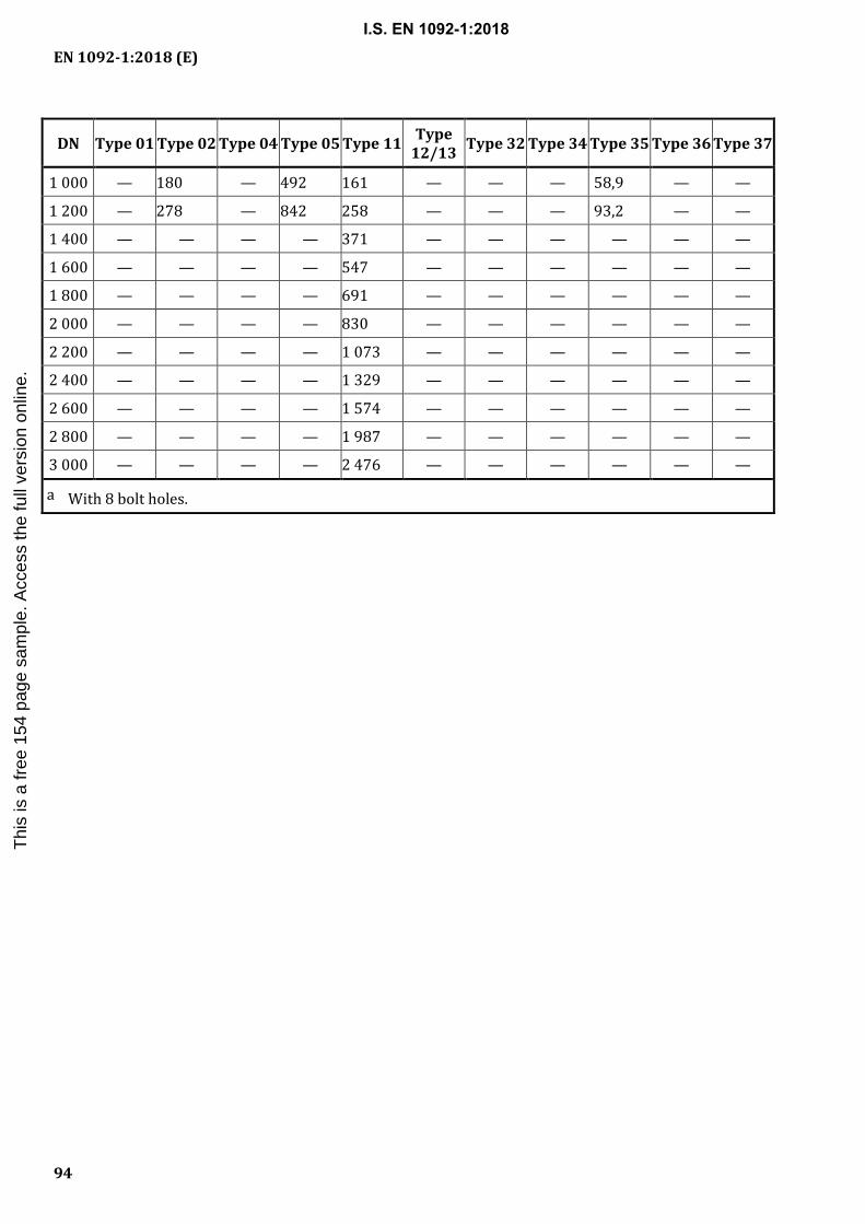
EN 1092-1:2018 (E)
94
DN Type 01 Type 02 Type 04 Type 05 Type 11 Type 12/13 Type 32 Type 34 Type 35 Type 36 Type 37
1 000 — 180 — 492 161 — — — 58,9 — —
1 200 — 278 — 842 258 — — — 93,2 — —
1 400 — — — — 371 — — — — — —
1 600 — — — — 547 — — — — — —
1 800 — — — — 691 — — — — — —
2 000 — — — — 830 — — — — — —
2 200 — — — — 1 073 — — — — — —
2 400 — — — — 1 329 — — — — — —
2 600 — — — — 1 574 — — — — — —
2 800 — — — — 1 987 — — — — — —
3 000 — — — — 2 476 — — — — — —
a With 8 bolt holes.
I.S. EN 1092-1:2018T
his
is a
free
154
pag
e sa
mpl
e. A
cces
s th
e fu
ll ve
rsio
n on
line.

EN 1092-1:2018 (E)
95
Table C.4 — Masses of flanges PN 16 Masses in kilogrammes
DN Type 01 Type 02 Type 04 Type 05 Type 11 Type 12/13 Type 32 Type 34 Type 35 Type 36 Type 37
10 0,604 0,591 0,549 0,722 0,678 0,646 0,094 0,148 0,08 0,04 0,03
15 0,670 0,654 0,606 0,813 0,768 0,722 0,114 0,189 0,09 0,06 0,03
20 0,936 0,909 0,836 1,14 1,09 1,04 0,225 0,340 0,17 0,10 0,06
25 1,11 1,08 0,990 1,38 1,30 1,25 0,296 0,444 0,26 0,13 0,08
32 1,82 1,77 1,65 2,03 1,91 1,81 0,362 0,572 0,36 0,21 0,10
40 2,08 2,02 1,85 2,35 2,15 2,06 0,457 0,734 0,45 0,26 0,13
50 2,73 2,52 2,34 2,88 2,53 2,39 0,653 0,974 0,53 0,33 0,22
65 3,16a 3,05 a 2,76 a 3,51 a 3,03 a 2,97a 0,876 1,29 0,70 0,43 0,30
80 3,60 3,48 3,17 4,61 3,92 3,78 1,07 1,67 1,0 0,54 0,44
100 4,39 4,20 3,78 5,65 4,62 4,38 1,28 2,12 1,3 0,75 0,51
125 5,41 5,21 4,57 8,13 6,30 6,07 1,70 2,88 1,9 1,13 0,68
150 7,14 6,89 6,22 10,5 7,81 7,24 1,96 3,46 2,4 1,62 0,97
200 9,73 9,31 8,37 16,2 11,5 9,80 2,81 5,55 3,9 2,84 1,77
250 14,2 13,5 12,4 25,0 16,7 13,6 3,52 7,71 5,8 6,13 —
300 19,0 18,0 16,3 35,1 22,1 17,2 5,27 11,4 9,5 7,61 —
350 28,2 27,0 21,5 48,0 32,8 27,9 10,1 19,2 15,2 9,83 —
400 35,9 34,6 27,1 63,5 41,1 35,7 12,3 23,7 18,7 11,66 —
450 46,1 44,6 36,7 96,6 48,5 45,0 16,5 28,2 24,4 — —
500 64,0 62,0 51,1 133 63,4 60,4 21,4 35,5 29,1 — —
600 102 98,8 78,3 226 94 94,0 28,7 47,9 40,3 — —
700 — 107 — 285 96,5 — — — 45,2 — —
800 — 152 — 388 122 — — — 59,9 — —
900 — 184 — 483 155 — — — 75,6 — —
1 000 — 257 — 640 233 — — — 106,46 — —
1 200 — — — — 390 — — — — — —
1 400 — — — — 495 — — — — — —
1 600 — — — — 760 — — — — — —
1 800 — — — — 929 — — — — — —
2 000 — — — — 1 185 — — — — — —
a With 8 bolt holes.
I.S. EN 1092-1:2018T
his
is a
free
154
pag
e sa
mpl
e. A
cces
s th
e fu
ll ve
rsio
n on
line.

EN 1092-1:2018 (E)
96
Table C.5 — Masses of flanges PN 25 Masses in kilogrammes
DN Type 01 Type 02 Type 04 Type 05 Type 11 Type 12/13 Type 32 Type 34 Type 35
200 14,3 13,8 11,6 22,5 17,1 14,9 4,52 9,07 6,6
250 20,1 19,4 17,0 33,5 24,3 20,9 5,73 12,7 10,0
300 26,6 25,5 22,0 46,3 31,8 27,3 8,42 18,0 15,3
350 41,8 40,5 32,1 68,1 48,8 45,1 14,5 27,8 20,8
400 57,6 56,1 44,5 89,7 63,3 57,7 18,0 36,3 28,6
450 69,8 67,8 54,2 130 76,0 69,6 21,0 40,9 34,4
500 87,0 84,6 65,9 159 97,0 87,0 26,8 55,7 45,8
600 127 124 98,4 278 121 111 34,1 70,5 61,0
700 — 188 — — 155 — — — 73,0
800 — 259 — — 205 — — — 97,0
900 — — — — 249 — — — —
1 000 — — — — 338 — — — —
I.S. EN 1092-1:2018T
his
is a
free
154
pag
e sa
mpl
e. A
cces
s th
e fu
ll ve
rsio
n on
line.

EN 1092-1:2018 (E)
97
Table C.6 — Masses of flanges PN 40 Masses in kilogrammes
DN Type 01 Type 02 Type 04 Type 05 Type 11 Type 12/13 Type 32 Type 34 Type 35
10 0,604 0,591 0,549 0,722 0,678 0,646 0,094 0,148 0,08
15 0,670 0,654 0,606 0,813 0,768 0,722 0,114 0,189 0,09
20 0,936 0,909 0,836 1,14 1,09 1,04 0,225 0,340 0,17
25 1,11 1,08 0,990 1,38 1,30 1,25 0,296 0,444 0,26
32 1,82 1,77 1,65 2,03 1,91 1,81 0,362 0,572 0,36
40 2,08 2,02 1,85 2,35 2,15 2,06 0,457 0,734 0,45
50 2,73 2,65 2,47 3,20 2,85 2,74 0,653 1,02 0,69
65 3,48 3,36 3,04 4,29 3,68 3,65 0,876 1,36 1,1
80 4,32 4,18 3,61 5,54 4,78 4,59 1,20 1,90 1,6
100 6,07 5,87 5,18 7,60 6,46 6,10 1,58 2,77 2,4
125 8,19 7,95 6,89 10,8 8,86 8,22 2,08 3,78 3,2
150 10,3 9,97 8,69 14,6 11,7 10,6 2,73 5,25 4,6
200 17,9 17,4 14,9 28,8 21,0 18,3 5,55 10,2 8,8
250 29,3 28,4 23,8 44,4 34,2 28,3 7,87 16,4 14,4
300 45,1 43,6 36,0 64,2 47,6 40,4 12,8 25,4 20,7
350 66,7 64,9 50,4 89,5 69,3 58,8 19,3 37,8 30,7
400 97,1 95,1 75,5 127 98 82,1 30,4 56,4 45,4
450 — — — 154 105 86,2 28,4 56,4 —
500 — — — 188 130 105 35,3 72,9 —
600 — — — 331 209 172 53,3 106 —
I.S. EN 1092-1:2018T
his
is a
free
154
pag
e sa
mpl
e. A
cces
s th
e fu
ll ve
rsio
n on
line.

EN 1092-1:2018 (E)
98
Table C.7 — Masses of flanges PN 63 Masses in kilogrammes
DN Type 01 Type 05 Type 11 Type 12/13
50 4,99 4,52 4,51 4,20
65 4,73 5,69 5,58 5,30
80 5,90 6,89 6,68 6,25
100 8,05 10,0 9,27 8,81
125 11,7 15,9 14,5 13,6
150 16,9 23,3 21,4 19,5
200 30,5 39,2 34,1 —
250 42,1 56,7 48,3 —
300 59,1 81,2 67,5 —
350 88,7 113 97,8 —
400 121 152 129 —
Table C.8 — Masses of flanges PN 100 Masses in kilogrammes
DN Type 01 Type 05 Type 11 Type 12/13
10 1,00 1,04 1,09 1,07
15 1,10 1,16 1,20 1,17
20 1,86 1,97 2,02 1,96
25 2,37 2,54 2,63 2,49
32 2,79 3,07 3,20 2,95
40 3,58 3,97 4,07 3,80
50 4,99 5,64 5,82 5,28
65 6,33 7,44 7,57 6,84
80 7,72 8,85 8,82 7,94
100 10,3 13,3 13,1 11,5
125 17,2 21,3 21,0 17,9
150 23,6 29,4 28,3 23,8
200 42,9 52,7 50,2 —
250 69,0 85,4 81,4 —
300 104 128 118 —
350 150 175 169 —
400 — — — —
500 — — — —
I.S. EN 1092-1:2018T
his
is a
free
154
pag
e sa
mpl
e. A
cces
s th
e fu
ll ve
rsio
n on
line.

EN 1092-1:2018 (E)
99
Table C.9 — Masses of flanges PN 160 Masses in kilogrammes
DN Type 5 Type 11
10 1,04 1,10
15 1,16 1,20
25 2,54 2,64
40 4,30 4,42
50 6,07 6,38
65 8,49 8,75
80 10,0 10,3
100 14,9 15,3
125 23,5 24,4
150 33,6 34,4
200 61,0 60,7
250 106 97,6
300 158 140
Table C.10 — Masses of flanges PN 250 Masses in kilogrammes
DN Type 5 Type 11
10 2,13 —
15 2,33 2,51
25 3,35 3,58
40 6,17 6,72
50 7,66 8,22
65 11,7 12,8
80 15,7 16,5
100 26,0 27,2
125 36,7 39,0
150 55,6 59,6
200 109 110
250 192 190
I.S. EN 1092-1:2018T
his
is a
free
154
pag
e sa
mpl
e. A
cces
s th
e fu
ll ve
rsio
n on
line.

EN 1092-1:2018 (E)
100
Table C.11 — Masses of flanges PN 320 Masses in kilogrammes
DN Type 5 Type 11
10 2,13 2,14
15 2,52 2,53
25 5,10 5,18
40 8,33 8,65
50 10,7 10,7
65 19,4 19,5
80 24,4 25,2
100 43,2 42,5
125 64,0 63,6
150 90,2 91,5
200 169 172
250 307 312
Table C.12 — Masses of flanges PN 400 Masses in kilogrammes
DN Type 5 Type 11
10 2,32 2,55
15 3,32 3,62
25 6,65 7,45
40 12,6 14,1
50 14,7 16,7
65 28,6 31,6
80 34,1 38,4
100 59,7 67,3
125 85,1 94,5
150 129 145
200 241 270
I.S. EN 1092-1:2018T
his
is a
free
154
pag
e sa
mpl
e. A
cces
s th
e fu
ll ve
rsio
n on
line.

EN 1092-1:2018 (E)
101
Annex D (informative)
Additional materials
Table D.1 lists, in addition to Table 9, materials which are widely in use, but which are not listed in EN standards. These materials do not have any presumption of conformity if used in pressure equipment under jurisdiction of Directive 2014/68/EU (Pressure Equipment Directive). These materials may be used in pressure equipment according to article 4.3 of the PED (sound engineering practice) or in applications that are not covered by the PED. If they are used in pressure equipment according to categories I to IV according to the PED, they shall have either a
— European Approval of Material (EAM), or
— be covered by a Particular Material Appraisal (PMA).
PMA shall be made by the pressure equipment manufacturer and in categories III and IV it shall have appraisal of the notified body that is responsible for the conformity assessment of the equipment. In the PMA it shall be proved, that the material fulfils the essential safety requirements of the PED.
Table D.1 — Additional materials
Material group b
Specification, grade, symbol and material number a
Castings c/ seamless tubes c/ welded pipes c, d
Forgings c, e Flat steel products c, e
Standard Grade/symbol/ material number
Standard Grade/symbol/material number
Standard Grade/symbol/ material number
1E0 DIN 1681 GS-38 VdTÜV 399/3f
C 21/1.0432 VdTÜV 399/1f
C 21/1.0432
1E1 — — EN 10025–2h S235JR/1.0038 EN 10025–2 S235JR/1.0038
3E0 — —
VdTÜV 350/3f
C 22.8/1.0460 VdTÜV 350/1f
C 22.8/1.0460
- -
7E0 — — DIN 17103g TSTE 285/ 1.0488
DIN 17102 TSTE 285/ 1.0488
7E1 DIN 17245 GS-10 Ni 19 DIN 17103g TSTE 355/ 1.0566
DIN 17102 TSTE 355/ 1.0566
— — — DIN 17103g TSTE 420/ 1.8912
DIN 17102 TSTE 420/ 1.8912
1E0 ASME SA 106 B — — — —
3E0 — — ASME SA 105 — — —
3E1 ASME SA 216 WCB — — ASME SA 515 70
ASME SA 216 WCC ASME SA 516 70
ASME SA 333 6 ASME SA 537 CL 1
4E0 ASME SA 217 WC 1 ASME SA 182 F1 ASME SA 204 A
I.S. EN 1092-1:2018T
his
is a
free
154
pag
e sa
mpl
e. A
cces
s th
e fu
ll ve
rsio
n on
line.

EN 1092-1:2018 (E)
102
Material group b
Specification, grade, symbol and material number a
Castings c/ seamless tubes c/ welded pipes c, d
Forgings c, e Flat steel products c, e
Standard Grade/symbol/ material number
Standard Grade/symbol/material number
Standard Grade/symbol/ material number
ASME SA 204 B
5E0 ASME SA 217 WC 6 ASME SA 182 F11 Cl 1, 2 and Cl 3
ASME SA 387 11
ASME SA 217 C 5
ASME SA 335 P 12 F12 Cl 1 and 2 12
6E0 ASME 217 C 12 ASME SA 182 F5 ASME SA 387 5
ASME SA 335 P 5 and P 9 F9 9
ASME SA 335 P 22 F 22 CI 1 and 3 22
7E3 ASME SA 352 LC 2, LC 3 and LC 8
ASME SA 350 LF 3 ASME SA 203 A
E
8E2 — — ASME SA 350 LF 2 Cl 1 / Cl 2 — —
10E0 ASME SA 351 CF 8 ASME SA 182 F 304 and 304 L ASME SA 240 304 and 304 L
ASME SA 312 TP 304 L and 304 L
11E0 SA 312 TP304 H SA 182 F 304 H SA 240 304H
12E0 SA 312 TP321and TP321 H SA 182 F321 and 321H — —
13E0 EN 10222-5 i X1NiCrMoCu25–20–5
1.4539
SA 312 TP316 L SA 182 F 316 L 316 L
14E0 SA 351 CF8 M SA 182 F316 and F316 H SA 240 316 and 316 H
SA 312 TP316, TP316 H
15E0 — — — — ASME SA 240 316 Ti
16E0 — — ASME SA 182 F 51 — —
a Material for bars in all Groups are identical with the material for forgings, ASME Materials see additionally footnote b. b The specification of ASME Materials may not be equivalent in all details to the material groups and therefore may not be equally for all applications. c Starting material for the manufacture of flanges. The properties of the resulting flanges may differ from starting material and require to be taken into consideration, so that the resulting flange has adequate properties. d Base material see flat steel products. e Impact properties for RT or low temperature service and guaranteed elevated temperature properties for high temperature service shall be considered. f Material Data Sheet by VdTÜV. g These DIN-materials are listed upon EN 10222–4 has been revised and provide the corresponding NL-Grades. h Use as forging with the requirements for chemical and mechanical properties of EN 10025–2, hot-rolled structural steel. i Material listed in German National Annex NB of DIN EN 10222–5.
I.S. EN 1092-1:2018T
his
is a
free
154
pag
e sa
mpl
e. A
cces
s th
e fu
ll ve
rsio
n on
line.

EN 1092-1:2018 (E)
103
Annex E (normative)
Basis of flange calculation
E.1 General
The calculation of flange union (pair of flanges, bolts and a gasket) according to this standard and the determination of p/T ratings have been carried out as follows. NOTE External loads have been considered and can be adopted according to the following methods of approximation. These are not mathematical formulae for the calculation of accurate values but an interpretation of the possible external loads derived from practical experience. The real external loads in piping can be different to those calculated below.
E.2 Calculation method
According to EN 1591-1; the correction for EN 13445-3:2014, Annex G has been applied to Formula (A.1).
E.3 Basic rules for calculation of flange connection
E.3.1 General
Calculation temperature for all load cases i.e. assembly, testing and operation to determine the standard flange geometrics for the different type of flanges is 20 °C.
To ensure that the requirements regarding permissible general membrane stress of the PED are met, flanges have been calculated using the values specified in Annex F, Table F.2.
For nominal design stresses higher than the time-independent design conditions the regulations of the applied design code such as EN 13445 (all parts) or EN 13480 (all parts) need to be considered. In any case attention needs to be paid to the effects of temperature.
External loads have been considered. These external loads are calculated by using the following formulae:
— Flange type 01, type 11, type 04 with type 34:
R R
R R
R R R
2
1
dimensions in mm in kN
Min DN DN in kNMax (
π= ⋅ ⋅ ⋅ −
= ⋅=
21 1
2
2
15 1 000
10
F A S S A S F
FF
FF F
( ) / , ,
( ; )
; )
— Flange types 32, 35, 36 and 37:
R R
R R
R R R
2
1
PN DN dimensions in mm in kN
DN in kNMin (
π= ⋅ ⋅
= ⋅=
21 1
2
2
40 000
5
F F
FF
FF F
( ) / ,
; )
I.S. EN 1092-1:2018T
his
is a
free
154
pag
e sa
mpl
e. A
cces
s th
e fu
ll ve
rsio
n on
line.

EN 1092-1:2018 (E)
104
E.3.2 Flanges
E.3.2.1 Flanges type 11, type 04 with type 34, type 05
a) Flange facing: Raised face.
b) Height of raised face according to Table 8, depending on DN.
c) Corrosions allowance (inner surface): 1,0 mm, for carbon steel, 0,0 mm for stainless steel.
d) Tolerances for flange thickness according to Table 22, for machined on front face only.
e) Flange material.
f) Nominal design stress:
1) at operation 140 MPa;
2) at assembly and testing 200 MPa (Ptest = 1,43 × PN).
NOTE That is close to the values of P245GH (forged steel, normally annealed (NG)) and 1.4404 (forged steel, solution treated (AT)).
g) E-Modulus: 212 000 MPa;
h) Mean coefficient of thermal expansion α (10– 6/K) = 11,9.
E.3.2.2 Flanges types 35, 36 and 37 with type 02
Material values have been similar according to E.3.2.1, but for austenitic steel:
a) e-modulus 200 000 MPa;
b) mean coefficient of thermal expansion α (10– 6/K) = 15,3;
c) no corrosion allowance;
d) flange facing and tolerances according to E.3.2.1.
E.3.2.3 Flanges type 01
a) Material values have been similar according to E.3.2.1.
b) Pipe nominal thickness has been chosen either according to Table A.1 or to Table A.2.
c) Corrosion allowance is 1 mm to pipe inner surface.
E.3.3 Pipes
a) Dimensional series for the pipe: EN 10216-2, EN 10216-5 and EN 10217-7.
b) Pipe wall thickness T = Mating wall thickness of flange Sp.
c) Consideration of elasticity of the hub especially for large DN.
d) Nominal design stress:
I.S. EN 1092-1:2018T
his
is a
free
154
pag
e sa
mpl
e. A
cces
s th
e fu
ll ve
rsio
n on
line.

EN 1092-1:2018 (E)
105
1) at operation 140 MPa;
2) at assembly and testing 200 MPa (Ptest = 1,43 × PN).
e) E-modulus: 212 000 MPa for Carbon steel and 200 000 MPa for Austenitic steel.
f) Mean coefficient of thermal expansion α (10– 6/K) = 11,9 (CS) and 15,3 (AS).
NOTE The values indicated above are close to those given for P235GH respectively X2CrNiMo17–12–2.
E.3.4 Bolting/Tightening
a) Bolts: Fully threaded screw (Hexagon head bolt) according to EN ISO 4014 with one nut, smooth and lubricated friction coefficient 0,2.
b) Bolt material:
1) ≤ M39: nominal design stress at operation 200 MPa, at assembly and testing 285,7 MPa;
NOTE 1 That is close to the values of 5.6-bolt.
2) > M39: nominal design stress at operation 250 MPa, at assembly and testing 419 MPa.
NOTE 2 That is close to the values of 25CrMo4.
c) E-modulus: 212 000 MPa.
d) Wrenching up to and including M20, torque wrench above M20.
e) Scatter value according to EN 1591-1:2013, Annex C, for one single bolt max M20: +/– 0,4 and for bolts larger than M20: ± 0,2.
f) Allowed slope of flange plate: 1,0°.
g) Bolting strength category according to EN 1515-2: medium strength.
h) Minimum bolt pre-tension rate: Minimum load ratio 0,3.
i) Number of assemblies/re-assemblies during lifetime: 20.
j) Integral coefficient of thermal expansion α (10– 6/K) = 11,9.
E.3.5 Gasket
a) Up to and incl. PN 63: Non-metallic flat gasket, larger DN of PN 63 and higher PN: Spiral wound gasket.
I.S. EN 1092-1:2018T
his
is a
free
154
pag
e sa
mpl
e. A
cces
s th
e fu
ll ve
rsio
n on
line.

EN 1092-1:2018 (E)
106
b) Gasket dimensions and factors:
Non-metallic flat gasket Spiral wound gasket
Dimensions EN 1514-1 EN 1514-21)
Thickness ≤ DN 300: = 2 mm = 4,5 mm
> DN 300: = 3 mm
Qmin = 25 MPa = 50 MPa
Qmax = 100 MPa = 300 MPa
E0 = 8 000 MPa = 10 000 MPa
K1 = 20 = 20
c1 = 0 = 0
gc = 0,9 = 0,9
QI/P (m) = 1,6 = 1,6
The Qmin / Qmax values have only been fixed for the geometrical calculation of the flanges; other values may be used.
NOTE Leakage classes are not considered.
1) Dimensions of spiral wound gaskets for flanges type 11 larger than PN 160: similar to EN 1514-2.
I.S. EN 1092-1:2018T
his
is a
free
154
pag
e sa
mpl
e. A
cces
s th
e fu
ll ve
rsio
n on
line.
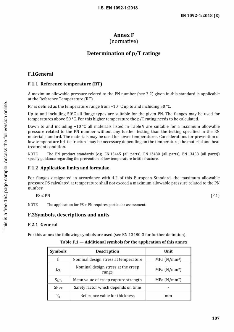
EN 1092-1:2018 (E)
107
Annex F (normative)
Determination of p/T ratings
F.1 General
F.1.1 Reference temperature (RT)
A maximum allowable pressure related to the PN number (see 3.2) given in this standard is applicable at the Reference Temperature (RT).
RT is defined as the temperature range from −10 °C up to and including 50 °C.
Up to and including 50°C all flange types are suitable for the given PN. The flanges may be used for temperatures above 50 °C. For this higher temperature the p/T rating needs to be calculated.
Down to and including −10 °C all materials listed in Table 9 are suitable for a maximum allowable pressure related to the PN number without any further testing than the testing specified in the EN material standard. The materials may be used for lower temperatures. Considerations for prevention of low temperature brittle fracture may be necessary depending on the temperature, the material and heat treatment condition. NOTE The EN product standards (e.g. EN 13445 (all parts), EN 13480 (all parts), EN 13458 (all parts)) specify guidance regarding the prevention of low temperature brittle fracture.
F.1.2 Application limits and formulae
For flanges designated in accordance with 4.2 of this European Standard, the maximum allowable pressure PS calculated at temperature shall not exceed a maximum allowable pressure related to the PN number.
PS ≤ PN (F.1)
NOTE The application for PS > PN requires particular assessment.
F.2 Symbols, descriptions and units
F.2.1 General
For this annex the following symbols are used (see EN 13480-3 for further definition).
Table F.1 — Additional symbols for the application of this annex
Symbols Description Unit
ft Nominal design stress at temperature MPa (N/mm2)
fCR Nominal design stress at the creep range MPa (N/mm2)
SR Tt Mean value of creep rupture strength MPa (N/mm2)
SF CR Safety factor which depends on time -
vR Reference value for thickness mm
I.S. EN 1092-1:2018T
his
is a
free
154
pag
e sa
mpl
e. A
cces
s th
e fu
ll ve
rsio
n on
line.

EN 1092-1:2018 (E)
108
F.2.2 p/T ratings for materials with time independent nominal design stress
The maximum allowable pressure at temperature is depending on the nominal design stress at temperature in relation to140 MPa and shall be:
PS = PN × ft /140 MPa (F.2)
The nominal design stress ft shall be determined in accordance with Table F.2 taking into account the actual value for vR.
F.2.3 p/T ratings for materials with time dependent nominal design stress
The maximum allowable pressure at temperature is depending on the lower value of the nominal design stress at temperature and the nominal design stress at creep range in relation to 140 MPa and shall be:
PS = PN × min (ft; fCR)/140 MPa (F.3)
The nominal design stresses ft and fCR shall be determined in accordance with Table F.2 and Table F.3 taking into account the actual value for vR.
F.2.4 Reference value for thickness (vR)
EN material standards are specifying strength values depending on different ranges of product thicknesses. The thickness related material values shall be used in calculation.
vR shall be the upper thickness of each nominal thickness range for which a material strength value (ReH, Rp, Rm as appropriate) is given in the material standard. The calculation results of Formulae (F.2) and (F.3) shall be valid for all flanges of this European Standard provided the flanges are made of material with the same or higher material values as the values used for the calculation.
For material with different vR, the p/T rating can be given for each vR.
NOTE The p/T ratings are built by a comparison of a material related term (ft; fCR) and the value of 140 MPa to PN. ft; fCR are a function of the material thickness for a given material. To compare the results of Formulae (F.2) and (F.3) with the thickness of a flange according to this European Standard, vR is introduced in this European Standard.
It is the intention of this annex to provide rules for determination of p/T ratings on a simplified procedure. But it should also be possible to use comparable higher mechanical properties for different thicknesses of base material if this covers the majority of flanges in use.
F.2.5 Nominal design stresses and safety factors for mean creep rupture strength
The nominal design stresses shall be based on strength values specified in the material standard. The nominal design stresses shall be calculated as shown in Table F.2. Guidance on safety factors as a function of mean creep rupture strength related to time is given in Table F.3.
Linear interpolation of strength values between two adjacent temperature values shall be applied for temperatures above 50 °C (e.g. for 80 °C between 20 °C and 100 °C; for 120 °C between 100 °C and 150 °C).
I.S. EN 1092-1:2018T
his
is a
free
154
pag
e sa
mpl
e. A
cces
s th
e fu
ll ve
rsio
n on
line.

EN 1092-1:2018 (E)
109
Table F.2 — Nominal design stresses
Material group Nominal design stress at Temperature / Nominal design stress at the creep range
3E0 to 9E1 and 16E0 f = min ((ReH t / 1,5 or Rp0,2 t / 1,5; Rm / 2,4); SR Tt / SFCR)
10E0 to 15E0 (for 30 ≤ A ≤ 35 %) a f = min((Rp1,0 t / 1,5; Rm / 2,4); SR Tt / SFCR)
10E0 to 15E0 (for A above 35 %) a f = min ((Rp1,0 t / 1,5) or min(Rp1,0 t / 1,2; Rmt / 3)b; SR Tt / SFCR))
3E0 to 4E0, 7E0, 7E1 (castings) f = min (Rp0,2 t / 1,9)
5E0, 6EO, 9E0 (castings) f = min (Rm / 3,0)
10E0 to 15E0 (castings) f = min (Rp1,0 t / 1,9)
a A = Elongation after rupture b If Rmt is available
Table F.3 — Safety factors for mean creep rupture strength
Time T in h Safety factor SFCR
200 000 1,25
150 000 1,35
100 000 1,5
NOTE Data of both tables are derived from EN 13480-3. See EN 13480-3 for further definition.
F.2.6 Flanges made from steel castings
For flanges made from steel casting (types no. 21, 34) the current dimension needs to be calculated.
The calculation shall be done if a steel flange is combined with a casted flange/valve. p/T ratings are not available for these combinations.
F.2.7 Rounding of maximum allowable pressure at temperature
The results of calculated maximum allowable pressure PS at temperature (according to Formula (F.2) respectively (F.3)) shall be rounded downwards to the first decimal place (e.g. value of 15,09 bar rounded downwards to 15,0 bar; or 15,19 bar rounded downwards to 15,1 bar).
I.S. EN 1092-1:2018T
his
is a
free
154
pag
e sa
mpl
e. A
cces
s th
e fu
ll ve
rsio
n on
line.

EN 1092-1:2018 (E)
110
Annex G (normative)
p/T ratings for a selection of EN materials
G.1 General
G.1.1 p/T ratings
A range of p/T ratings for a selection of commonly used EN materials is indicated in this annex. These p/T ratings are prepared to support the user of this European Standard and shall not be understood either as a limitation in p/T ratings nor materials. If the user of this European Standard has the need to determine his own p/T rating for a certain application this can be done under consideration of the basic rules to determine a p/T rating (see Annex F).
G.1.2 Basics of determination of p/T ratings (see Annex F)
p/T ratings are calculated by using Formulae (F.2) and (F.3).
In compliance with Formula (F.3), the calculated pressure values do not exceed PN.
Strength values for steel forgings, flat steel products and steel castings are taken from EN material standards considering the different range of product thickness. For provisions regarding the reference value for thickness vR see F.2.4.
p/T ratings are calculated by using the strength values of steel forgings depending on different range of product thickness and are verified for flat steel products of the same group.
Nominal design stresses are calculated by using the formulae as defined in Table F.2.
Interpolation rules as defined in Annex F have been applied.
At higher temperatures the additional external loads shall be reduced to the same degree as the maximum allowable pressure. NOTE 1 The graduation of vR depends from the product of material from which a flange is manufactured. For the different methods of fabrication see Table 1 of this European Standard.
NOTE 2 For flanges made from steel casting (type 21) see Table 6, footnote a and definitions stated in F.2.6.
NOTE 3 If the flange joint consists of materials with different strength properties (excluding bolts), p/T ratings need to be chosen in accordance with the lowest strength values.
NOTE 4 The p/T ratings are built by a comparison of a material related term (ft;fCR) and the value of 140 MPa to PN. ft;fCR are a function of the material thickness for a given material. To compare the results of Formulae (F.2) and (F.3) with the thickness of a flange of this European Standard vR is introduced in this European Standard.
G.1.3 Application limits for creep range
Materials marked with an “X” have been calculated using 100 000 h creep rupture strength values as given in EN material standards under consideration of the safety factor SFCR as indicated in Table F.3.
The application of creep range within the p/T ratings listed is limited up to and including 600 °C. This limit should be understood as a practical application limit and not as a restriction in use. If there is a need to extend this application limit to higher temperatures than 600 °C this can be done by individual calculations provided mean creep rupture strength values are given in EN material standards.
I.S. EN 1092-1:2018T
his
is a
free
154
pag
e sa
mpl
e. A
cces
s th
e fu
ll ve
rsio
n on
line.

EN 1092-1:2018 (E)
111
G.2 Non-austenitic steels
G.2.1 General
p/T ratings are given in Tables G.2 to G.13 for non-austenitic steels. They are calculated by using the strength values of steel forgings (see Table G.1) and are verified for flat steel products of the same group (see Table 9) up to and including 600 °C. Thickness related strength values for all thicknesses up to and including 150 mm have been considered, except for material 1.4903 where vR ≤ 130 mm.
p/T ratings are calculated by using the strength values of steel forgings and are verified for flat steel products of the same group (see Notes in Table G.1).
100 000 h creep rupture strength values are considered for materials marked with 'X' in Table G.1.
Maximum allowable pressures at temperatures for which 100 000 h creep have been considered are indicated in italic letters in Tables G.2 to G.13.
For the p/T rating for flanges made from steel castings type 21 (material selection see Table 9) see EN 12516-1. The wall thicknesses need to be verified (see provisions made in F.2.5).
I.S. EN 1092-1:2018T
his
is a
free
154
pag
e sa
mpl
e. A
cces
s th
e fu
ll ve
rsio
n on
line.

EN 1092-1:2018 (E)
112
G.2.2 List of materials
Table G.1 — Non-austenitic materials
Group Material Material No. EN Rp/Re Creep Notes
3E0 P245GH 1.0352 EN 10222–2 Rp0,2 t X
3E1 P280GH 1.0426 EN 10222–2 Rp0,2 t X
4E0 16Mo3 1.5415 EN 10222–2 Rp0,2 t X
5E0 13CrMo4–5 1.7335 EN 10222–2 Rp0,2 t X
6E0 11CrMo9–10 1.7383 EN 10222–2 Rp0,2 t X
6E1 X16CrMo5–1+NT 1.7366 EN 10222–2 Rp0,2 t X
7E3 13MnNi6–3 1.6217 EN 10222–3 Rp0,2 t — f
7E1 P355 NL1, P355 NL2
1.0566 1.1106 EN 10028–3 Rp0,2 t — a, g
7E2 15NiMn6 1.6228 EN 10222–3 Rp0,2 t — f
7E3 12Ni14 1.5637 EN 10222–3 Rp0,2 t — f
7E3 X8Ni9 1.5662 EN 10222–3 Rp0,2 t — f
8E2 P285NH 1.0487 EN 10222–4 Rp0,2 t — c, d
8E3 P355NH 1.0565 EN 10222–4 Rp0,2 t — b, d, e
9E0 X20CrMoV11–1 1.4922 EN 10222–2 Rp0,2 t X
9E1 X10CrMoVNb9–1 1.4903 EN 10222–2 Rp0,2 t X
NOTE The table contains a selection of commonly used non-austenitic materials.
a Refer to Annex D for steel forgings corresponding to this low-temperature-tough fine-grain steel. b p/T ratings can also be used for material group 7E1 under conditions (see EN 10028–3). c For all thicknesses of up to and including 70 mm the strength values for temperatures above 50 °C for a thickness range 35 < vR ≤ 70 have been used for calculation of p/T ratings.
d For all thicknesses up to and including 150 mm for strength values for temperatures above 50 °C lower strength values either of EN 10028-3 or EN 10222-4 has been used. e For all thicknesses of up to and including 100 mm the strength values for temperatures above 50 °C for a thickness range 50 < vR ≤ 100 have been used for calculation of p/T ratings.
f Material groups 7EO, 7E2; no separate p/T ratings are listed, because of the reason that no strength values for temperatures above 50 °C are given by the related EN standards EN 10222-3 and EN 10028-4. g No separate p/T ratings are listed, since the strength values are the same as for the NH-grade.
I.S. EN 1092-1:2018T
his
is a
free
154
pag
e sa
mpl
e. A
cces
s th
e fu
ll ve
rsio
n on
line.

EN 1092-1:2018 (E)
113
G.2.3 p/T ratings
Table G.2 — PN 2,5
PN Group vR (mm)
max. allowable temperature TS °C
RT 100 150 200 250 300 350 400 450 460 470 480 490 500 510 520 530 540 550 560 570 580 590 600
max. allowable pressure PS bar
2,5
3E0 ≤ 50 2,5 2,3 2,2 2,0 1,9 1,7 1,6 1,4 0,8
3E0 50 < vR ≤ 150 2,5 2,1 2,0 1,9 1,7 1,6 1,5 1,4 0,8
3E1 ≤ 50 2,5 2,5 2,5 2,5 2,4 2,2 2,0 1,8 1,0
3E1 50< vR ≤ 150 2,5 2,5 2,3 2,2 2,0 1,9 1,7 1,6 1,0
4E0 ≤ 60 2,5 2,5 2,5 2,5 2,4 2,1 2,0 1,8 1,7 1,6 1,4 1,3 1,2 1,1 0,8 0,7 0,5
4E0 60 < vR ≤ 90 2,5 2,5 2,5 2,5 2,3 2,0 1,9 1,7 1,6 1,5 1,4 1,3 1,2 1,1 0,8 0,7 0,5
4E0 90 < vR ≤ 150 2,5 2,5 2,5 2,3 2,1 1,9 1,7 1,5 1,4 1,4 1,3 1,2 1,1 1,1 0,8 0,7 0,5
5E0 ≤ 60 2,5 2,5 2,5 2,5 2,5 2,5 2,3 2,2 2,1 2 1,9 1,8 1,7 1,6 1,3 1,1 0,9 0,7 0,5 0,4 0,3
5E0 60 < vR ≤ 90 2,5 2,5 2,5 2,5 2,5 2,4 2,2 2,0 1,9 1,8 1,8 1,7 1,6 1,6 1,3 1,1 0,9 0,7 0,5 0,4 0,3
5E0 90 < vR ≤ 150 2,5 2,5 2,5 2,5 2,5 2,2 2,1 1,9 1,8 1,7 1,7 1,6 1,6 1,6 1,3 1,1 0,9 0,7 0,5 0,4 0,3
6E0 ≤ 150 2,5 2,5 2,5 2,5 2,5 2,5 2,4 2,3 2,2 2,0 1,9 1,8 1,7 1,6 1,4 1,2 1,0 0,9 0,8 0,6 0,6 0,5 0,4 0,4
6E1 ≤ 150 2,5 2,5 2,5 2,5 2,5 2,5 2,5 2,5 2,5 2,5 2,5 2,1 1,7 1,3 1,1 0,9 0,8 0,7 0,5 0,5 0,4
8E2 35 < vR ≤ 70 2,5 2,5 2,5 2,3 2,1 1,8 1,6 1,4
8E2 70 < vR ≤ 100 2,5 2,5 2,3 2,1 1,9 1,6 1,4 1,1
8E2 100 < vR ≤ 150 2,5 2,4 2,2 1,9 1,7 1,4 1,1 0,9
8E3 50 < vR ≤ 100 2,5 2,5 2,5 2,5 2,5 2,4 2,2 1,9
8E3 100 < vR ≤ 150 2,5 2,5 2,5 2,5 2,5 2,3 2,1 1,7
9E0 ≤ 150 2,5 2,5 2,5 2,5 2,5 2,5 2,5 2,5 2,5 2,5 2,5 2,5 2,5 2,5 2,5 2,2 1,9 1,7 1,5 1,3 1,1 0,9 0,8 0,7
9E1 ≤ 130 2,5 2,5 2,5 2,5 2,5 2,5 2,5 2,5 2,5 2,5 2,5 2,5 2,5 2,5 2,5 2,5 2,3 2,1 1,9 1,7 1,5 1,4 1,2 1,1
I.S. EN 1092-1:2018
Thi
s is
a fr
ee 1
54 p
age
sam
ple.
Acc
ess
the
full
vers
ion
onlin
e.

EN 1092-1:2018 (E)
114
Table G.3 — PN 6
PN Group vR (mm)
max. allowable temperature TS °C
RT 100 150 200 250 300 350 400 450 460 470 480 490 500 510 520 530 540 550 560 570 580 590 600
max. allowable pressure PS bar
6
3E0 ≤ 50 6,0 5,5 5,2 5 4,5 4,1 3,8 3,5 1,9
3E0 50 < vR ≤ 150
6,0 5,1 5 4,6 4,2 3,8 3,6 3,4 1,9
3E1 ≤ 50 6,0 6,0 6,0 6,0 5,8 5,2 4,8 4,4 2,4
3E1 50< vR ≤ 150 6,0 6,0 5,7 5,4 5,0 4,6 4,2 3,8 2,4 4E0 ≤ 60 6,0 6,0 6,0 6,0 5,8 5,1 4,8 4,4 4,1 3,8 3,5 3,2 2,9 2,6 2,1 1,6 1,3
4E0 60 < vR ≤ 90 6,0 6,0 6,0 6,0 5,5 4,8 4,5 4,1 3,8 3,6 3,3 3,1 2,8 2,6 2,1 1,6 1,3
4E0 90 < vR
≤ 150 6,0 6,0 6,0 5,5 5,1 4,5 4,2 3,8 3,5 3,3 3,1 3,0 2,8 2,6 2,1 1,6 1,3
5E0 ≤ 60 6,0 6,0 6,0 6,0 6,0 6,0 5,7 5,4 5,0 4,8 4,5 4,3 4,0 3,9 3,3 2,6 2,2 1,7 1,4 1,1 0,9 5E0 60 < vR ≤ 90 6,0 6,0 6,0 6,0 6,0 5,8 5,4 5,0 4,7 4,5 4,3 4,1 3,9 3,9 3,3 2,6 2,2 1,7 1,4 1,1 0,9
5E0 90 < vR
≤ 150 6,0 6,0 6,0 6,0 6,0 5,5 5,0 4,7 4,4 4,2 4,1 4,0 3,9 3,9 3,3 2,6 2,2 1,7 1,4 1,1 0,9
6E0 ≤ 150 6,0 6,0 6,0 6,0 6,0 6,0 5,8 5,5 5,2 5,0 4,7 4,4 4,1 3,8 3,3 2,9 2,5 2,2 1,9 1,6 1,4 1,2 1,0 0,9
6E1 ≤ 150 6,0 6,0 6,0 6,0 6,0 6,0 6,0 6,0 6,0 6,0 6,0 5,0 4,1 3,2 2,7 2,3 2,0 1,6 1,4 1,2 1,0
8E2 35 < vR ≤ 70 6,0 6,0 6,0 5,6 5,1 4,4 3,9 3,3
8E2 70 < vR ≤ 100 6,0 6,0 5,6 5,2 4,7 3,9 3,3 2,8
8E2 100 < vR ≤ 150 6,0 5,8 5,3 4,7 4,2 3,3 2,8 2,2
8E3 50 < vR ≤ 100 6,0 6,0 6,0 6,0 6,0 5,8 5,4 4,7
8E3 100 < vR ≤ 150 6,0 6,0 6,0 6,0 6,0 5,6 5,0 4,2
9E0 ≤ 150 6,0 6,0 6,0 6,0 6,0 6,0 6,0 6,0 6,0 6,0 6,0 6,0 6,0 6,0 6,0 5,3 4,7 4,2 3,6 3,1 2,7 2,3 1,9 1,6
9E1 ≤ 130 6,0 6,0 6,0 6,0 6,0 6,0 6,0 6,0 6,0 6,0 6,0 6,0 6,0 6,0 6,0 6,0 5,7 5,2 4,7 4,2 3,8 3,4 3,0 2,6
I.S. EN 1092-1:2018
Thi
s is
a fr
ee 1
54 p
age
sam
ple.
Acc
ess
the
full
vers
ion
onlin
e.

EN 1092-1:2018 (E)
115
Table G.4 — PN 10
PN Group vR (mm)
max. allowable temperature TS °C
RT 100 150 200 250 300 350 400 450 460 470 480 490 500 510 520 530 540 550 560 570 580 590 600
max. allowable pressure PS bar
10
3E0 ≤ 50 10,0 9,2 8,8 8,3 7,6 6,9 6,4 5,9 3,2
3E0 50 < vR ≤ 150 10,0 8,5 8,3 7,7 7,0 6,4 6,0 5,7 3,2
3E1 ≤ 50 10,0 10,0 10,0 10,0 9,7 8,8 8,0 7,3 4,0
3E1 50< vR ≤ 150 10,0 10,0 9,5 9,0 8,3 7,6 7,0 6,4 4,0
4E0 ≤ 60 10,0 10,0 10,0 10,0 9,7 8,5 8,0 7,4 6,9 6,4 5,9 5,4 4,9 4,4 3,5 2,8 2,2
4E0 60 < vR ≤ 90 10,0 10,0 10,0 10,0 9,2 8,0 7,6 6,9 6,4 6,0 5,6 5,2 4,8 4,4 3,5 2,8 2,2
4E0 90 < vR ≤ 150 10,0 10,0 10,0 9,2 8,5 7,6 7,0 6,3 5,9 5,6 5,3 5,0 4,7 4,4 3,5 2,8 2,2
5E0 ≤ 60 10,0 10,0 10,0 10,0 10,0 10,0 9,5 9,0 8,4 8,0 7,6 7,2 6,8 6,5 5,5 4,4 3,7 2,9 2,3 1,9 1,5
5E0 60 < vR ≤ 90 10,0 10,0 10,0 10,0 10,0 9,7 9,0 8,3 7,8 7,5 7,2 6,9 6,6 6,5 5,5 4,4 3,7 2,9 2,3 1,9 1,5
5E0 90 < vR ≤ 150 10,0 10,0 10,0 10,0 10,0 9,1 8,4 7,9 7,3 7,1 6,9 6,7 6,5 6,5 5,5 4,4 3,7 2,9 2,3 1,9 1,5
6E0 ≤ 150 10,0 10,0 10,0 10,0 10,0 10,0 9,7 9,2 8,8 8,3 7,8 7,3 6,9 6,4 5,6 4,9 4,2 3,7 3,2 2,7 2,4 2,0 1,8 1,6
6E1 ≤ 150 10,0 10,0 10,0 10,0 10,0 10,0 10,0 10,0 10,0 10,0 10,0 8,4 6,9 5,3 4,5 3,8 3,3 2,8 2,3 2,0 1,7
8E2 35 < vR ≤ 70 10,0 10,0 10,0 9,3 8,6 7,4 6,5 5,6
8E2 70 < vR ≤ 100 10,0 10,0 9,4 8,6 7,9 6,5 5,6 4,6
8E2 100 < vR ≤ 150 10,0 9,7 8,8 7,9 7,0 5,6 4,6 3,7
8E3 50 < vR ≤ 100 10,0 10,0 10,0 10,0 10,0 9,8 9,0 7,9
8E3 100 < vR ≤ 150 10,0 10,0 10,0 10,0 10,0 9,3 8,4 7,0
9E0 ≤ 150 10,0 10,0 10,0 10,0 10,0 10,0 10,0 10,0 10,0 10,0 10,0 10,0 10,0 10,0 10,0 8,9 7,9 7,0 6,0 5,2 4,5 3,8 3,2 2,8
9E1 ≤ 130 10,0 10,0 10,0 10,0 10,0 10,0 10,0 10,0 10,0 10,0 10,0 10,0 10,0 10,0 10,0 10,0 9,5 8,7 7,9 7,1 6,3 5,7 5,0 4,4
I.S. EN 1092-1:2018
Thi
s is
a fr
ee 1
54 p
age
sam
ple.
Acc
ess
the
full
vers
ion
onlin
e.

EN 1092-1:2018 (E)
116
Table G.5 — PN 16
PN Group vR (mm)
max. allowable temperature TS °C
RT 100 150 200 250 300 350 400 450 460 470 480 490 500 510 520 530 540 550 560 570 580 590 600
max. allowable pressure PS bar
16
3E0 ≤ 50 16,0 14,8 14 13,3 12,1 11 10,2 9,5 5,2
3E0 50 < vR ≤ 150 16,0 13,7 13,3 12,4 11,3 10,2 9,6 9,1 5,2
3E1 ≤ 50 16,0 16,0 16 16 15,6 14 12,9 11,8 6,4
3E1 50< vR ≤ 150 16,0 16,0 15,2 14,5 13,3 12,2 11,3 10,2 6,4
4E0 ≤ 60 16,0 16,0 16,0 16,0 15,6 13,7 12,9 11,9 11,0 10,2 9,4 8,6 7,8 7,0 5,6 4,4 3,5
4E0 60 < vR ≤ 90 16,0 16,0 16,0 16,0 14,8 12,9 12,1 11,1 10,2 9,6 9,0 8,3 7,7 7,0 5,6 4,4 3,5
4E0 90 < vR ≤ 150 16,0 16,0 16,0 14,8 13,7 12,1 11,2 10,1 9,4 8,9 8,5 8,0 7,5 7,0 5,6 4,4 3,5
5E0 ≤ 60 16,0 16,0 16,0 16,0 16,0 16,0 15,2 14,4 13,4 12,8 12,1 11,5 10,8 10,4 8,8 7,1 5,9 4,6 3,7 3,0 2,5
5E0 60 < vR ≤ 90 16,0 16,0 16,0 16,0 16,0 15,6 14,4 13,4 12,5 12 11,5 11 10,5 10,4 8,8 7,1 5,9 4,6 3,7 3,0 2,5
5E0 90 < vR ≤ 150 16,0 16,0 16,0 16,0 16,0 14,7 13,5 12,7 11,8 11,4 11,1 10,7 10,4 10,4 8,8 7,1 5,9 4,6 3,7 3,0 2,5
6E0 ≤ 150 16,0 16,0 16,0 16,0 16,0 16,0 15,6 14,8 14,0 13,3 12,5 11,8 11,0 10,2 8,9 7,8 6,8 5,9 5,1 4,4 3,8 3,3 2,8 2,5
6E1 ≤ 150 16,0 16,0 16,0 16,0 16,0 16,0 16,0 16,0 16,0 16,0 16,0 13,5 11,0 8,6 7,3 6,1 5,3 4,4 3,8 3,2 2,8
8E2 35 < vR ≤ 70 16,0 16,0 16,0 15,0 13,7 11,9 10,4 8,9
8E2 70 < vR ≤ 100 16,0 16,0 15,0 13,8 12,7 10,4 8,9 7,4
8E2 100 < vR ≤ 150 16,0 15,6 14,1 12,7 11,2 8,9 7,4 5,9
8E3 50 < vR ≤ 100 16,0 16,0 16,0 16,0 16,0 15,6 14,4 12,7
8E3 100 < vR ≤ 150 16,0 16,0 16,0 16,0 16,0 14,9 13,4 11,2
9E0 ≤ 150 16,0 16,0 16,0 16,0 16,0 16,0 16,0 16,0 16,0 16,0 16,0 16,0 16,0 16,0 16,0 14,3 12,7 11,2 9,7 8,4 7,2 6,1 5,2 4,4
9E1 ≤ 130 16,0 16,0 16,0 16,0 16,0 16,0 16,0 16,0 16,0 16,0 16,0 16,0 16,0 16,0 16,0 16,0 15,3 13,9 12,6 11,4 10,2 9,1 8,0 7,1
I.S. EN 1092-1:2018
Thi
s is
a fr
ee 1
54 p
age
sam
ple.
Acc
ess
the
full
vers
ion
onlin
e.

EN 1092-1:2018 (E)
117
Table G.6 — PN 25
PN Group vR (mm)
max. allowable temperature TS °C
RT 100 150 200 250 300 350 400 450 460 470 480 490 500 510 520 530 540 550 560 570 580 590 600
max. allowable pressure PS bar
25
3E0 ≤ 50 25,0 23,2 22,0 20,8 19,0 17,2 16,0 14,8 8,2
3E0 50 < vR ≤ 150 25,0 21,4 20,8 19,4 17,7 16,0 15,1 14,2 8,2
3E1 ≤ 50 25,0 25,0 25,0 25,0 24,4 22,0 20,2 18,4 10,1
3E1 50< vR ≤ 150 25,0 25,0 23,8 22,7 20,8 19,1 17,7 16,0 10,1
4E0 ≤ 60 25,0 25,0 25,0 25,0 24,4 21,4 20,2 18,6 17,2 16,0 14,7 13,5 12,3 11,0 8,8 7,0 5,5
4E0 60 < vR ≤ 90 25,0 25,0 25,0 25,0 23,2 20,2 19,0 17,3 16,0 15,0 14,0 13,0 12,0 11,0 8,8 7,0 5,5
4E0 90 < vR ≤ 150 25,0 25,0 25,0 23,2 21,4 19,0 17,5 15,8 14,7 14,0 13,2 12,5 11,8 11,0 8,8 7,0 5,5
5E0 ≤ 60 25,0 25,0 25,0 25,0 25,0 25,0 23,8 22,5 21,0 20,0 19,0 18,0 17,0 16,3 13,8 11,1 9,2 7,2 5,8 4,7 3,9
5E0 60 < vR ≤ 90 25,0 25,0 25,0 25,0 25,0 24,4 22,5 20,9 19,6 18,8 18,0 17,2 16,5 16,3 13,8 11,1 9,2 7,2 5,8 4,7 3,9
5E0 90 < vR ≤ 150 25,0 25,0 25,0 25,0 25,0 22,9 21,1 19,8 18,4 17,9 17,3 16,8 16,2 16,3 13,8 11,1 9,2 7,2 5,8 4,7 3,9
6E0 ≤ 150 25,0 25,0 25,0 25,0 25,0 25,0 24,4 23,2 22,0 20,8 19,6 18,4 17,2 16,0 14,0 12,2 10,7 9,2 8,0 6,9 6,0 5,2 4,5 4,0
6E1 ≤ 150 25,0 25,0 25,0 25,0 25,0 25,0 25,0 25,0 25,0 25,0 25,0 21,2 17,3 13,4 11,4 9,6 8,3 7,0 5,9 5,1 4,4
8E2 35 < vR ≤ 70 25,0 25,0 25,0 23,4 21,5 18,6 16,3 14,0
8E2 70 < vR ≤ 100 25,0 25,0 23,5 21,6 19,8 16,3 14,0 11,6
8E2 100 < vR ≤ 150 25,0 24,4 22,1 19,8 17,5 14,0 11,6 9,2
8E3 50 < vR ≤ 100 25,0 25,0 25,0 25,0 25,0 24,5 22,6 19,8
8E3 100 < vR ≤ 150 25,0 25,0 25,0 25,0 25,0 23,3 21,0 17,5
9E0 ≤ 150 25,0 25,0 25,0 25,0 25,0 25,0 25,0 25,0 25,0 25,0 25,0 25,0 25,0 25,0 25,0 22,3 19,8 17,5 15,2 13,2 11,3 9,6 8,2 7,0
9E1 ≤ 130 25,0 25,0 25,0 25,0 25,0 25,0 25,0 25,0 25,0 25,0 25,0 25,0 25,0 25,0 25,0 25,0 23,9 21,7 19,7 17,8 15,9 14,2 12,6 11,1
I.S. EN 1092-1:2018
Thi
s is
a fr
ee 1
54 p
age
sam
ple.
Acc
ess
the
full
vers
ion
onlin
e.

EN 1092-1:2018 (E)
118
Table G.7 — PN 40
PN Group vR (mm)
max. allowable temperature TS °C
RT 100 150 200 250 300 350 400 450 460 470 480 490 500 510 520 530 540 550 560 570 580 590 600
max. allowable pressure PS bar
40
3E0 ≤ 50 40,0 37,1 35,2 33,3 30,4 27,6 25,7 23,8 13,1
3E0 50 < vR ≤ 150 40,0 34,2 33,3 31,0 28,3 25,7 24,1 22,8 13,1
3E1 ≤ 50 40,0 40,0 40,0 40,0 39,0 35,2 32,3 29,5 16,1
3E1 50< vR ≤ 150 40,0 40,0 38,0 36,3 33,3 30,6 28,3 25,7 16,1
4E0 ≤ 60 40,0 40,0 40,0 40,0 39,0 34,2 32,3 29,9 27,6 25,6 23,6 21,6 19,7 17,7 14,0 11,2 8,9
4E0 60 < vR ≤ 90 40,0 40,0 40,0 40,0 37,1 32,3 30,4 27,8 25,7 24,1 22,5 20,9 19,3 17,7 14,0 11,2 8,9
4E0 90 < vR ≤ 150 40,0 40,0 40,0 37,1 34,2 30,4 28,0 25,3 23,6 22,4 21,2 20,0 18,9 17,7 14,0 11,2 8,9
5E0 ≤ 60 40,0 40,0 40,0 40,0 40,0 40,0 38,0 36,0 33,7 32,0 30,4 28,8 27,2 26,0 22,0 17,9 14,8 11,6 9,3 7,6 6,2
5E0 60 < vR ≤ 90 40,0 40,0 40,0 40,0 40,0 39,0 36,0 33,5 31,4 30,1 28,9 27,6 26,4 26,0 22,0 17,9 14,8 11,6 9,3 7,6 6,2
5E0 90 < vR ≤ 150 40,0 40,0 40,0 40,0 40,0 36,7 33,9 31,8 29,5 28,6 27,7 26,8 26,0 26,0 22,0 17,9 14,8 11,6 9,3 7,6 6,2
6E0 ≤ 150 40,0 40,0 40,0 40,0 40,0 40,0 39,0 37,1 35,2 33,3 31,4 29,5 27,6 25,7 22,4 19,6 17,1 14,8 12,9 11,0 9,7 8,3 7,2 6,4
6E1 ≤ 150 40,0 40,0 40,0 40,0 40,0 40,0 40,0 40,0 40,0 40,0 40,0 33,9 27,7 21,5 18,2 15,4 13,3 11,2 9,5 8,1 7,0
8E2 35 < vR ≤ 70 40,0 40,0 40,0 37,5 34,4 29,9 26,0 22,4
8E2 70 < vR ≤ 100 40,0 40,0 37,7 34,6 31,8 26,0 22,4 18,6
8E2 100 < vR ≤ 150 40,0 39,0 35,4 31,8 28,0 22,4 18,6 14,8
8E3 50 < vR ≤ 100 40,0 40,0 40,0 40,0 40,0 39,2 36,1 31,8
8E3 100 < vR ≤ 150 40,0 40,0 40,0 40,0 40,0 37,3 33,7 28,0
9E0 ≤ 150 40,0 40,0 40,0 40,0 40,0 40,0 40,0 40,0 40,0 40,0 40,0 40,0 40,0 40,0 40,0 35.8 31,8 28,0 24.3 21,1 18,0 15,4 13,1 11,2
9E1 ≤ 130 40,0 40,0 40,0 40,0 40,0 40,0 40,0 40,0 40,0 40,0 40,0 40,0 40,0 40,0 40,0 40.0 38,2 34,8 31.6 28,5 25,5 22,8 20,1 17,9
I.S. EN 1092-1:2018
Thi
s is
a fr
ee 1
54 p
age
sam
ple.
Acc
ess
the
full
vers
ion
onlin
e.

EN 1092-1:2018 (E)
119
Table G.8 — PN 63
PN Group vR (mm)
max. allowable temperature TS °C
RT 100 150 200 250 300 350 400 450 460 470 480 490 500 510 520 530 540 550 560 570 580 590 600
max. allowable pressure PS bar
63
3E0 ≤ 50 63,0 58,5 55,5 52,5 48,0 43,5 40,5 37,5 20,7
3E0 50 < vR ≤ 150 63,0 54,0 52,5 48,9 44,7 40,5 38,1 36,0 20,7
3E1 ≤ 50 63,0 63,0 63,0 63,0 61,5 55,5 51,0 46,5 25,5
3E1 50< vR ≤ 150 63,0 63,0 60,0 57,3 52,5 48,3 44,7 40,5 25,5 4E0 ≤ 60 63,0 63,0 63,0 63,0 61,5 54,0 51,0 47,1 43,5 40,3 37,2 34,1 31,0 27,9 22,2 17,7 14,1
4E0 60 < vR ≤ 90 63,0 63,0 63,0 63,0 58,5 51,0 48,0 43,8 40,5 37,9 35,4 32,9 30,4 27,9 22,2 17,7 14,1
4E0 90 < vR
≤ 150 63,0 63,0 63,0 58,5 54,0 48,0 44,1 39,9 37,2 35,3 33,4 31,6 29,7 27,9 22,2 17,7 14,1
5E0 ≤ 60 63,0 63,0 63,0 63,0 63,0 63,0 60,0 56,7 53,1 50,5 47,9 45,4 42,8 41,1 34,8 28,2 23,4 18,3 14,7 12,0 9,9 5E0 60 < vR ≤ 90 63,0 63,0 63,0 63,0 63,0 61,5 56,7 52,8 49,5 47,5 45,5 43,5 41,5 41,1 34,8 28,2 23,4 18,3 14,7 12,0 9,9
5E0 90 < vR
≤ 150 63,0 63,0 63,0 63,0 63,0 57,9 53,4 50,1 46,5 45,1 43,7 42,3 40,9 41,1 34,8 28,2 23,4 18,3 14,7 12,0 9,9
6E0 ≤ 150 63,0 63,0 63,0 63,0 63,0 63,0 61,5 58,5 55,5 52,5 49,5 46,5 43,5 40,5 35,4 30,9 27,0 23,4 20,4 17,4 15,3 13,2 11,4 10,2
6E1 ≤ 150 63,0 63,0 63,0 63,0 63,0 63,0 63,0 63,0 63,0 63,0 63,0 53,4 43,6 33,9 28,8 24,3 21,0 17,7 15,0 12,9 11,1
8E2 35 < vR ≤ 70 63,0 63,0 63,0 59,1 54,3 47,1 41,1 35,4
8E2 70 < vR ≤ 100 63,0 63,0 59,4 54,6 50,1 41,1 35,4 29,4
8E2 100 < vR ≤ 150 63,0 61,5 55,8 50,1 44,1 35,4 29,4 23,4
8E3 50 < vR ≤ 100 63,0 63,0 63,0 63,0 63,0 61,8 57,0 50,1
8E3 100 < vR ≤ 150 63,0 63,0 63,0 63,0 63,0 58,8 53,1 44,1
9E0 ≤ 150 63,0 63,0 63,0 63,0 63,0 63,0 63,0 63,0 63,0 63,0 63,0 63,0 63,0 63,0 63,0 56,4 50,1 44,1 38,4 33,3 28,5 24,3 20,7 17,7
9E1 ≤ 130 63,0 63,0 63,0 63,0 63,0 63,0 63,0 63,0 63,0 63,0 63,0 63,0 63,0 63,0 63,0 63,0 60,3 54,9 49,8 45,0 40,2 36,0 31,8 28,2
I.S. EN 1092-1:2018
Thi
s is
a fr
ee 1
54 p
age
sam
ple.
Acc
ess
the
full
vers
ion
onlin
e.

EN 1092-1:2018 (E)
120
Table G.9 — PN 100
PN Group vR (mm)
max. allowable temperature TS °C
RT 100 150 200 250 300 350 400 450 460 470 480 490 500 510 520 530 540 550 560 570 580 590 600
max. allowable pressure PS bar
100
3E0 ≤ 50 100,0 92,8 88,0 83,3 76,1 69,0 64,2 59,5 32,8
3E0 50 < vR ≤ 150 100,0 85,7 83,3 77,6 70,9 64,2 60,4 57,1 32,8
3E1 ≤ 50 100,0 100,0 100,0 100,0 97,6 88,0 80,9 73,8 40,4
3E1 50< vR ≤ 150 100,0 100,0 95,2 90,9 83,3 76,6 70,9 64,2 40,4
4E0 ≤ 60 100,0 100,0 100,0 100,0 97,6 85,7 80,9 74,7 69,0 64,0 59,1 54,2 49,2 44,2 35,2 28,0 22,3
4E0 60 < vR ≤ 90 100,0 100,0 100,0 100,0 92,8 80,9 76,1 69,5 64,2 60,2 56,2 52,2 48,2 44,2 35,2 28,0 22,3
4E0 90 < vR ≤ 150 100,0 100,0 100,0 92,8 85,7 76,1 70,0 63,3 59,0 56,0 53,1 50,2 47,2 44,2 35,2 28,0 22,3
5E0 ≤ 60 100,0 100,0 100,0 100,0 100,0 100,0 95,2 90,0 84,2 80,2 76,1 72,0 68,0 65,2 55,2 44,7 37,1 29,0 23,3 19,0 15,7
5E0 60 < vR ≤ 90 100,0 100,0 100,0 100,0 100,0 97,6 90,0 83,8 78,5 75,4 72,2 69,1 66,0 65,2 55,2 44,7 37,1 29,0 23,3 19,0 15,7
5E0 90 < vR ≤ 150 100,0 100,0 100,0 100,0 100,0 91,9 84,7 79,5 73,8 71,6 69,4 67,2 65,0 65,2 55,2 44,7 37,1 29,0 23,3 19,0 15,7
6E0 ≤ 150 100,0 100,0 100,0 100,0 100,0 100,0 97,6 92,8 88,0 83,3 78,5 73,8 69,0 64,2 56,1 49,0 42,8 37,1 32,3 27,6 24,2 20,9 18,0 16,1
6E1 ≤ 150 100,0 100,0 100,0 100,0 100,0 100,0 100,0 100,0 100,0 100,0 100,0 84,8 69,3 53,8 45,7 38,5 33,3 28,0 23,8 20,4 17,6
8E2 35 < vR ≤ 70 100,0 100,0 100,0 93,8 86,1 74,7 65,2 56,1
8E2 70 < vR ≤ 100 100,0 100,0 94,2 86,6 79,5 65,2 56,1 46,6
8E2 100 < vR ≤ 150 100,0 97,6 88,5 79,5 70,0 56,1 46,6 37,1
8E3 50 < vR ≤ 100 100,0 100,0 100,0 100,0 100,0 98,0 90,4 79,5
8E3 100 < vR ≤ 150 100,0 100,0 100,0 100,0 100,0 93,3 84,2 70,0
9E0 ≤ 150 100,0 100,0 100,0 100,0 100,0 100,0 100,0 100,0 100,0 100,0 100,0 100,0 100,0 100,0 100,0 89,5 79,5 70,0 60,9 52,8 45,2 38,5 32,8 28,0
9E1 ≤ 130 100,0 100,0 100,0 100,0 100,0 100,0 100,0 100,0 100,0 100,0 100,0 100,0 100,0 100,0 100,0 100,0 95,7 87,1 79,0 71,4 63,8 57,1 50,4 44,7
I.S. EN 1092-1:2018
Thi
s is
a fr
ee 1
54 p
age
sam
ple.
Acc
ess
the
full
vers
ion
onlin
e.

EN 1092-1:2018 (E)
121
Table G.10 — PN 160
PN Group vR (mm)
max. allowable temperature TS °C
RT 100 150 200 250 300 350 400 450 460 470 480 490 500 510 520 530 540 550 560 570 580 590 600
max. allowable pressure PS bar
160
3E0 ≤ 50 160,0 148,5 140,9 133,3 121,9 110,4 102,8 95,2 52,5
3E0 50 < vR ≤ 150 160,0 137,1 133,3 124,1 113,5 102,8 96,7 91,4 52,5
3E1 ≤ 50 160,0 160,0 160,0 160,0 156,1 140,9 129,5 118,0 64,7
3E1 50< vR ≤ 150 160,0 160,0 152,3 145,5 133,3 122,6 113,5 102,8 64,7
4E0 ≤ 60 160,0 160,0 160,0 160,0 156,1 137,1 129,5 119,6 110,4 102,5 94,6 86,7 78,8 70,8 56,3 44,9 35,8
4E0 60 < vR ≤ 90 160,0 160,0 160,0 160,0 148,5 129,5 121,9 111,2 102,8 96,4 90,0 83,6 77,2 70,8 56,3 44,9 35,8
4E0 90 < vR ≤ 150 160,0 160,0 160,0 148,5 137,1 121,9 112,0 101,3 94,4 89,7 85,0 80,3 75,6 70,8 56,3 44,9 35,8
5E0 ≤ 60 160,0 160,0 160,0 160,0 160,0 160,0 152,3 144,0 134,8 128,3 121,8 115,3 108,8 104,3 88,3 71,6 59,4 46,4 37,3 30,4 25,1
5E0 60 < vR ≤ 90 160,0 160,0 160,0 160,0 160,0 156,1 144,0 134,0 125,7 120,6 115,6 110,6 105,6 104,3 88,3 71,6 59,4 46,4 37,3 30,4 25,1
5E0 90 < vR ≤ 150 160,0 160,0 160,0 160,0 160,0 147,0 135,6 127,2 118,0 114,6 111,0 107,5 104,0 104,3 88,3 71,6 59,4 46,4 37,3 30,4 25,1
6E0 ≤ 150 160,0 160,0 160,0 160,0 160,0 160,0 156,1 148,5 140,9 133,3 125,7 118,0 110,4 102,8 89,9 78,4 68,5 59,4 51,8 44,1 38,8 33,5 28,9 25,9
6E1 ≤ 150 160,0 160,0 160,0 160,0 160,0 160,0 160,0 160,0 160,0 160,0 160,0 135,7 110,9 86,0 73,1 61,7 53,3 44,9 38,0 32,7 28,1
8E2 35 < vR ≤ 70 160,0 160,0 160,0 150,0 137,9 119,6 104,3 89,9
8E2 70 < vR ≤ 100 160,0 160,0 150,8 138,6 127,2 104,3 89,9 74,6
8E2 100 < vR ≤ 150 160,0 156,1 141,7 127,2 112,0 89,9 74,6 59,4
8E3 50 < vR ≤ 100 160,0 160,0 160,0 160,0 160,0 156,9 144,7 127,2
8E3 100 < vR ≤ 150 160,0 160,0 160,0 160,0 160,0 149,3 134,8 112,0
9E0 ≤ 150 160,0 160,0 160,0 160,0 160,0 160,0 160,0 160,0 160,0 160,0 160,0 160,0 160,0 160,0 160,0 143,2 127,2 112,0 97,5 84,5 72,3 61,7 52,5 44,9
9E1 ≤ 130 160,0 160,0 160,0 160,0 160,0 160,0 160,0 160,0 160,0 160,0 160,0 160,0 160,0 160,0 160,0 160,0 153,1 139,4 126,4 114,2 102,0 91,4 80,7 71,6
I.S. EN 1092-1:2018
Thi
s is
a fr
ee 1
54 p
age
sam
ple.
Acc
ess
the
full
vers
ion
onlin
e.

EN 1092-1:2018 (E)
122
Table G.11 — PN 250
PN Group vR (mm)
max. allowable temperature TS °C
RT 100 150 200 250 300 350 400 450 460 470 480 490 500 510 520 530 540 550 560 570 580 590 600
max. allowable pressure PS bar
250
3E0 ≤ 50 250,0 232,1 220,2 208,3 190,4 172,6 160,7 148,8 82,1
3E0 50 < vR ≤ 150 250,0 214,2 208,3 194,0 177,3 160,7 151,1 142,8 82,1
3E1 ≤ 50 250,0 250,0 250,0 250,0 244,0 220,2 202,3 184,5 101,1
3E1 50< vR ≤ 150 250,0 250,0 238,0 227,3 208,3 191,6 177,3 160,7 101,1
4E0 ≤ 60 250,0 250,0 250,0 250,0 244,0 214,2 202,3 186,9 172,6 160,1 147,8 135,5 123,2 110,7 88,0 70,2 55,9
4E0 60 < vR ≤ 90 250,0 250,0 250,0 250,0 232,1 202,3 190,4 173,8 160,7 150,7 140,7 130,7 120,7 110,7 88,0 70,2 55,9
4E0 90 < vR ≤ 150 250,0 250,0 250,0 232,1 214,2 190,4 175,0 158,3 147,6 140,1 132,8 125,5 118,2 110,7 88,0 70,2 55,9
5E0 ≤ 60 250,0 250,0 250,0 250,0 250,0 250,0 238,0 225,0 210,7 200,5 190,3 180,1 170,0 163,0 138,0 111,9 92,8 72,6 58,3 47,6 39,2
5E0 60 < vR ≤ 90 250,0 250,0 250,0 250,0 250,0 244,0 225,0 209,5 196,4 188,5 180,7 172,8 165,0 163,0 138,0 111,9 92,8 72,6 58,3 47,6 39,2
5E0 90 < vR ≤ 150 250,0 250,0 250,0 250,0 250,0 229,7 211,9 198,8 184,5 179,1 173,5 168,0 162,5 163,0 138,0 111,9 92,8 72,6 58,3 47,6 39,2
6E0 ≤ 150 250,0 250,0 250,0 250,0 250,0 250,0 244,0 232,1 220,2 208,3 196,4 184,5 172,6 160,7 140,4 122,6 107,1 92,8 80,9 69,0 60,7 52,3 45,2 40,4
6E1 ≤ 150 250,0 250,0 250,0 250,0 250,0 250,0 250,0 250,0 250,0 250,0 250,0 212,1 173,3 134,5 114,2 96,4 83,3 70,2 59,5 51,1 44,0
8E2 35 < vR ≤ 70 250,0 250,0 250,0 234,5 215,4 186,9 163,0 140,4
8E2 70 < vR ≤ 100 250,0 250,0 235,7 216,6 198,8 163,0 140,4 116,6
8E2 100 < vR ≤ 150 250,0 244,0 221,4 198,8 175,0 140,4 116,6 92,8
8E3 50 < vR ≤ 100 250,0 250,0 250,0 250,0 250,0 245,2 226,1 198,8
8E3 100 < vR ≤ 150 250,0 250,0 250,0 250,0 250,0 233,3 210,7 175,0
9E0 ≤ 150 250,0 250,0 250,0 250,0 250,0 250,0 250,0 250,0 250,0 250,0 250,0 250,0 250,0 250,0 250,0 223,8 198,8 175,0 152,3 132,1 113,0 96,4 82,1 70,2
9E1 ≤ 130 250,0 250,0 250,0 250,0 250,0 250,0 250,0 250,0 250,0 250,0 250,0 250,0 250,0 250,0 250,0 250,0 239,2 217,8 197,6 178,5 159,5 142,8 126,1 111,9
I.S. EN 1092-1:2018
Thi
s is
a fr
ee 1
54 p
age
sam
ple.
Acc
ess
the
full
vers
ion
onlin
e.

EN 1092-1:2018 (E)
123
Table G.12 — PN 320
PN Group vR (mm)
max. allowable temperature TS °C
RT 100 150 200 250 300 350 400 450 460 470 480 490 500 510 520 530 540 550 560 570 580 590 600
max. allowable pressure PS bar
320
3E0 ≤ 50 320,0 297,1 281,9 266,6 243,8 220,9 205,7 190,4 105,1
3E0 50 < vR ≤ 150 320,0 274,2 266,6 248,3 227,0 205,7 193,5 182,8 105,1
3E1 ≤ 50 320,0 320,0 320,0 320,0 312,3 281,9 259,0 236,1 129,5
3E1 50< vR ≤ 150 320,0 320,0 304,7 291,0 266,6 245,3 227,0 205,7 129,5
4E0 ≤ 60 320,0 320,0 320,0 320,0 312,3 274,2 259,0 239,2 220,9 205,0 189,2 173,4 157,7 141,7 112,7 89,9 71,6
4E0 60 < vR ≤ 90 320,0 320,0 320,0 320,0 297,1 259,0 243,8 222,4 205,7 192,9 180,1 167,3 154,5 141,7 112,7 89,9 71,6
4E0 90 < vR ≤ 150 320,0 320,0 320,0 297,1 274,2 243,8 224,0 202,6 188,9 179,4 170,0 160,6 151,3 141,7 112,7 89,9 71,6
5E0 ≤ 60 320,0 320,0 320,0 320,0 320,0 320,0 304,7 288,0 269,7 256,6 243,6 230,6 217,6 208,7 176,7 143,2 118,8 92,9 74,6 60,9 50,2
5E0 60 < vR ≤ 90 320,0 320,0 320,0 320,0 320,0 312,3 288,0 268,1 251,4 241,3 231,3 221,2 211,2 208,7 176,7 143,2 118,8 92,9 74,6 60,9 50,2
5E0 90 < vR ≤ 150 320,0 320,0 320,0 320,0 320,0 294,0 271,2 254,4 236,1 229,2 222,1 215,0 208,0 208,7 176,7 143,2 118,8 92,9 74,6 60,9 50,2
6E0 ≤ 150 320,0 320,0 320,0 320,0 320,0 320,0 312,3 297,1 281,9 266,6 251,4 236,1 220,9 205,7 179,8 156,9 137,1 118,8 103,6 88,3 77,7 67,0 57,9 51,8
6E1 ≤ 150 320,0 320,0 320,0 320,0 320,0 320,0 320,0 320,0 320,0 320,0 320,0 271,5 221,8 172,1 146,2 123,4 106,6 89,9 76,1 65,5 56,3
8E2 35 < vR ≤ 70 320,0 320,0 320,0 300,1 275,8 239,2 208,7 179,8
8E2 70 < vR ≤ 100 320,0 320,0 301,7 277,3 254,4 208,7 179,8 149,3
8E2 100 < vR ≤ 150 320,0 312,3 283,4 254,4 224,0 179,8 149,3 118,8
8E3 50 < vR ≤ 100 320,0 320,0 320,0 320,0 320,0 313,9 289,5 254,4
8E3 100 < vR ≤ 150 320,0 320,0 320,0 320,0 320,0 298,6 269,7 224,0
9E0 ≤ 150 320,0 320,0 320,0 320,0 320,0 320,0 320,0 320,0 320,0 320,0 320,0 320,0 320,0 320,0 320,0 286,4 254,4 224,0 195,0 169,1 144,7 123,4 105,1 89,9
9E1 ≤ 130 320,0 320,0 320,0 320,0 320,0 320,0 320,0 320,0 320,0 320,0 320,0 320,0 320,0 320,0 320,0 320,0 306,2 278,8 252,9 228,5 204,1 182,8 161,5 143,2
I.S. EN 1092-1:2018
Thi
s is
a fr
ee 1
54 p
age
sam
ple.
Acc
ess
the
full
vers
ion
onlin
e.

EN 1092-1:2018 (E)
124
Table G.13 — PN 400
PN Group vR (mm)
max. allowable temperature TS °C
RT 100 150 200 250 300 350 400 450 460 470 480 490 500 510 520 530 540 550 560 570 580 590 600
max. allowable pressure PS bar
400
3E0 ≤ 50 400,0 371,4 352,3 333,3 304,7 276,1 257,1 238,0 131,4
3E0 50 < vR ≤ 150 400,0 342,8 333,3 310,4 283,8 257,1 241,9 228,5 131,4
3E1 ≤ 50 400,0 400,0 400,0 400,0 390,4 352,3 323,8 295,2 161,9
3E1 50< vR ≤ 150 400,0 400,0 380,9 363,8 333,3 306,6 283,8 257,1 161,9
4E0 ≤ 60 400,0 400,0 400,0 400,0 390,4 342,8 323,8 299,0 276,1 256,2 236,5 216,8 197,1 177,1 140,9 112,3 89,5
4E0 60 < vR ≤ 90 400,0 400,0 400,0 400,0 371,4 323,8 304,7 278,0 257,1 241,1 225,1 209,1 193,1 177,1 140,9 112,3 89,5
4E0 90 < vR ≤ 150 400,0 400,0 400,0 371,4 342,8 304,7 280,0 253,3 236,1 224,2 212,5 200,8 189,1 177,1 140,9 112,3 89,5
5E0 ≤ 60 400,0 400,0 400,0 400,0 400,0 400,0 380,9 360,0 337,1 320,8 304,5 288,2 272,0 260,9 220,9 179,0 148,5 116,1 93,3 76,1 62,8
5E0 60 < vR ≤ 90 400,0 400,0 400,0 400,0 400,0 390,4 360,0 335,2 314,2 301,7 289,1 276,5 264,0 260,9 220,9 179,0 148,5 116,1 93,3 76,1 62,8
5E0 90 < vR ≤ 150 400,0 400,0 400,0 400,0 400,0 367,6 339,0 318,0 295,2 286,5 277,7 268,8 260,0 260,9 220,9 179,0 148,5 116,1 93,3 76,1 62,8
6E0 ≤ 150 400,0 400,0 400,0 400,0 400,0 400,0 390,4 371,4 352,3 333,3 314,2 295,2 276,1 257,1 224,7 196,1 171,4 148,5 129,5 110,4 97,1 83,8 72,3 64,7
6E1 ≤ 150 400,0 400,0 400,0 400,0 400,0 400,0 400,0 400,0 400,0 400,0 400,0 339,4 277,3 215,2 182,8 154,2 133,3 112,3 95,2 81,9 70,4
8E2 35 < vR ≤ 70 400,0 400,0 400,0 375,2 344,7 299,0 260,9 224,7
8E2 70 < vR ≤ 100 400,0 400,0 377,1 346,6 318,0 260,9 224,7 186,6
8E2 100 < vR ≤ 150 400,0 390,4 354,2 318,0 280,0 224,7 186,6 148,5
8E3 50 < vR ≤ 100 400,0 400,0 400,0 400,0 400,0 392,3 361,9 318,0
8E3 100 < vR ≤ 150 400,0 400,0 400,0 400,0 400,0 373,3 337,1 280,0
9E0 ≤ 150 400,0 400,0 400,0 400,0 400,0 400,0 400,0 400,0 400,0 400,0 400,0 400,0 400,0 400,0 400,0 358,0 318,0 280,0 243,8 211,4 180,9 154,2 131,4 112,3
9E1 ≤ 130 400,0 400,0 400,0 400,0 400,0 400,0 400,0 400,0 400,0 400,0 400,0 400,0 400,0 400,0 400,0 400,0 382,8 348,5 316,1 285,7 255,2 228,5 201,9 179,0
I.S. EN 1092-1:2018
Thi
s is
a fr
ee 1
54 p
age
sam
ple.
Acc
ess
the
full
vers
ion
onlin
e.

EN 1092-1:2018 (E)
125
G.3 Austenitic and austenitic-ferritic steels
G.3.1 General
p/T ratings are given in Tables G.15 to G.26 for austenitic and austenitic-ferritic steels. They are calculated by using the strength values of steel forgings (see Table G.14) and are verified for flat steel products of the same group (see Table 9) up to and incl. 600 °C. Thickness related strength values for all thicknesses up to and including 150 mm have been considered.
p/T ratings are calculated by using the strength values of steel forgings and are verified for flat steel products of the same group.
100 000 h creep rupture strength values are considered for materials marked with 'X' in Table G.14.
Maximum allowable pressures at temperatures for which 100 000 h creep rupture strength values have been considered are indicated in italic letters and shaded in grey in Tables G.15 to G.26.
For flanges made from steel castings (type 21; material selection see Table 9) the p/T ratings shall be the same as for the corresponding steel forgings respectively flat steel products (see Table 9). The wall thicknesses need to be verified (see provisions made in F.2.5). NOTE For nominal design stress values of steel castings it can be necessary to consider the provisions given in applicable component or equipment standards (e.g. EN 12516 (all parts)). For castings made of material 1.4470 according to EN 10213 the allowable temperature is 200 °C.
G.3.2 List of materials
Table G.14 — Austenitic and austenitic-ferritic materials
Group Material Material No. EN Rp/ Re Creep vR
(mm) A%
10E0 X2CrNi18–9 1.4307 10222–5 Rp1,0 t X — 35
10E1 X2CrNiN18–10 1.4311 10222–5 Rp1,0 t — — 35
11E0 X5CrNi18–10 1.4301 10222–5 Rp1,0 t X — 35
12E0 X6CrNiTi18–10 1.4541 10222–5 Rp1,0 t X — 30
12E0 X6CrNiNb18–10 1.4550 10222–5 Rp1,0 t — — 30
13E0 X2CrNiMo17–12–2 1.4404 10222–5 Rp1,0 t — — 35
14E0 X5CrNiMo17–12–2 1.4401 10222–5 Rp1,0 t X — 35
15E0 X6CrNiMoTi17–12–2 1.4571 10222–5 Rp1,0 t X — 35
16E0 X2CrNiMoN22–5-3 1.4462 10222–5 Rp0,2 t — — 25
11E0 X6CrNi18–10 1.4948 10222–5 Rp1,0 t X — 35
12E0 X6CrNiTiB18–10 1.4941 10222–5 Rp1,0 t X — 30
NOTE The table contains a selection of commonly used austenitic and austenitic-ferritic materials.
I.S. EN 1092-1:2018T
his
is a
free
154
pag
e sa
mpl
e. A
cces
s th
e fu
ll ve
rsio
n on
line.

EN 1092-1:2018 (E)
126
G.3.3 p/T ratings
Table G.15 — PN 2,5
PN Group Material-No.
max. allowable temperature TS °C
RT 100 150 200 250 300 350 400 450 500 550 560 570 580 590 600
max. allowable pressure PS bar
2,5
10E0 1.4307 2,5 2,1 1,9 1,7 1,6 1,5 1,4 1,3 1,3 1,2 1,0 1,0 0,9 0,8 0,7 0,7
10E1 1.4311 2,5 2,5 2,5 2,2 2,0 1,9 1,9 1,8 1,8 1,7
11E0 1.4301 2,5 2,2 2,0 1,8 1,7 1,6 1,5 1,4 1,4 1,4 1,0 1,0 0,9 0,8 0,7 0,7
12E0 1.4541 2,5 2,4 2,3 2,2 2,1 1,9 1,9 1,8 1,8 1,7 1,6 1,5 1,4 1,2 1,1 1,0
12E0 1.4550 2,5 2,5 2,3 2,2 2,1 1,9 1,9 1,8 1,8 1,7
13E0 1.4404 2,5 2,3 2,1 1,9 1,8 1,7 1,6 1,6 1,5 1,5
14E0 1.4401 2,5 2,5 2,2 2,1 1,9 1,8 1,7 1,7 1,6 1,6 1,6 1,6 1,5 1,5 1,5 1,4
15E0 1.4571 2,5 2,5 2,4 2,3 2,2 2,0 2,0 1,9 1,9 1,8 1,8 1,8 1,8 1,6 1,5 1,3
16E0 1.4462 2,5 2,5 2,5 2,5 2,5
11E0 1.4948 2,5 2,2 2 1,8 1,7 1,6 1,5 1,5 1,4 1,4 1,3 1,3 1,2 1,2 1,1 1
12E0 1.4941 2,5 2,3 2,2 2,1 2,0 2,0 1,9 1,9 1,8 1,8 1,7 1,7 1,6 1,5 1,3 1,2
I.S. EN 1092-1:2018
Thi
s is
a fr
ee 1
54 p
age
sam
ple.
Acc
ess
the
full
vers
ion
onlin
e.

EN 1092-1:2018 (E)
127
Table G.16 — PN 6
PN Group Material-No.
max. allowable temperature TS °C
RT 100 150 200 250 300 350 400 450 500 550 560 570 580 590 600
max. allowable pressure PS bar
6
10E0 1.4307 6,0 5,1 4,6 4,2 3,9 3,6 3,4 3,3 3,2 3,1 2,6 2,4 2,2 2,0 1,8 1,6
10E1 1.4311 6,0 6,0 6,0 5,3 5,0 4,7 4,6 4,4 4,3 4,2
11E0 1.4301 6,0 5,4 4,9 4,4 4,1 3,8 3,6 3,5 3,5 3,4 2,6 2,4 2,2 2,0 1,8 1,6
12E0 1.4541 6,0 5,9 5,6 5,3 5,0 4,7 4,6 4,4 4,3 4,2 4,0 3,6 3,3 3,0 2,7 2,4
12E0 1.4550 6,0 6,0 5,6 5,3 5,0 4,7 4,6 4,4 4,3 4,2
13E0 1.4404 6,0 5,6 5,1 4,7 4,4 4,1 3,9 3,8 3,7 3,6
14E0 1.4401 6,0 6,0 5,4 5,0 4,7 4,4 4,2 4,1 4,0 3,9 3,9 3,8 3,8 3,7 3,7 3,3
15E0 1.4571 6,0 6,0 5,8 5,6 5,3 5,0 4,8 4,6 4,6 4,5 4,4 4,4 4,4 4,0 3,6 3,3
16E0 1.4462 6,0 6,0 6,0 6,0 6,0
11E0 1.4948 6,0 5,4 4,9 4,4 4,2 3,9 3,7 3,6 3,5 3,3 3,2 3,1 3,1 3,0 2,8 2,5
12E0 1.4941 6,0 5,7 5,4 5,1 5,0 4,9 4,7 4,6 4,4 4,3 4,2 4,0 4,0 3,6 3,2 2,9
I.S. EN 1092-1:2018
Thi
s is
a fr
ee 1
54 p
age
sam
ple.
Acc
ess
the
full
vers
ion
onlin
e.

EN 1092-1:2018 (E)
128
Table G.17 — PN 10
PN Group Material-No.
max. allowable temperature TS °C
RT 100 150 200 250 300 350 400 450 500 550 560 570 580 590 600
max. allowable pressure PS bar
10
10E0 1.4307 10,0 8,6 7,7 7,0 6,5 6,0 5,7 5,5 5,3 5,1 4,3 4,0 3,7 3,4 3,0 2,8
10E1 1.4311 10,0 10,0 10 8,9 8,3 7,9 7,6 7,4 7,2 7
11E0 1.4301 10,0 9,0 8,1 7,4 6,9 6,4 6,1 5,9 5,8 5,7 4,3 4,0 3,7 3,4 3,0 2,8
12E0 1.4541 10,0 9,9 9,3 8,8 8,4 7,9 7,6 7,4 7,2 7 6,7 6,1 5,6 5,0 4,5 4,0
12E0 1.4550 10,0 10,0 9,3 8,8 8,4 7,9 7,6 7,4 7,2 7
13E0 1.4404 10,0 9,4 8,6 7,9 7,4 6,9 6,6 6,4 6,2 6
14E0 1.4401 10,0 10,0 9,0 8,4 7,9 7,4 7,1 6,8 6,7 6,6 6,5 6,4 6,3 6,2 6,1 5,6
15E0 1.4571 10,0 10,0 9,8 9,3 8,8 8,3 8,0 7,8 7,6 7,5 7,4 7,4 7,3 6,7 6,0 5,5
16E0 1.4462 10,0 10,0 10,0 10,0 10,0
11E0 1.4948 10,0 9,0 8,1 7,4 7,0 6,5 6,2 6,0 5,8 5,6 5,3 5,2 5,1 5,0 4,6 4,2
12E0 1.4941 10,0 9,5 9,0 8,6 8,3 8,1 7,9 7,7 7,4 7,2 7,0 6,8 6,6 6,0 5,4 4,8
I.S. EN 1092-1:2018
Thi
s is
a fr
ee 1
54 p
age
sam
ple.
Acc
ess
the
full
vers
ion
onlin
e.

EN 1092-1:2018 (E)
129
Table G.18 — PN 16
PN Group Material-No.
max. allowable temperature TS °C
RT 100 150 200 250 300 350 400 450 500 550 560 570 580 590 600
max. allowable pressure PS bar
16
10E0 1.4307 16,0 13,7 12,3 11,2 10,4 9,6 9,2 8,8 8,5 8,3 7,0 6,4 5,9 5,4 4,9 4,4
10E1 1.4311 16,0 16 16 14,2 13,3 12,7 12,2 11,8 11,6 11,3
11E0 1.4301 16,0 14,5 13,1 11,9 11 10,2 9,8 9,5 9,3 9,1 7,0 6,4 5,9 5,4 4,9 4,4
12E0 1.4541 16,0 15,8 14,9 14,1 13,4 12,7 12,2 11,8 11,6 11,3 10,8 9,8 8,9 8,1 7,3 6,5
12E0 1.4550 16,0 16,0 14,9 14,1 13,4 12,7 12,2 11,8 11,6 11,3
13E0 1.4404 16,0 15,1 13,7 12,7 11,9 11 10,5 10,2 10 9,7
14E0 1.4401 16,0 16,0 14,5 13,4 12,7 11,8 11,4 10,9 10,7 10,5 10,4 10,3 10,1 10,0 9,9 8,9
15E0 1.4571 16,0 16,0 15,6 14,9 14,1 13,3 12,8 12,4 12,2 12 11,9 11,8 11,7 10,7 9,7 8,8
16E0 1.4462 16,0 16,0 16,0 16,0 16,0
11E0 1.4948 16,0 14,5 13,1 11,9 11,2 10,4 10,0 9,6 9,3 8,9 8,6 8,4 8,2 8,1 7,4 6,7
12E0 1.4941 16,0 15,3 14,5 13,7 13,4 13,1 12,7 12,3 11,9 11,5 11,2 10,8 10,6 9,6 8,6 7,7
I.S. EN 1092-1:2018
Thi
s is
a fr
ee 1
54 p
age
sam
ple.
Acc
ess
the
full
vers
ion
onlin
e.

EN 1092-1:2018 (E)
130
Table G.19 — PN 25
PN Group Material-No.
max. allowable temperature TS °C
RT 100 150 200 250 300 350 400 450 500 550 560 570 580 590 600
max. allowable pressure PS bar
25
10E0 1.4307 25,0 21,5 19,2 17,5 16,3 15,1 14,4 13,8 13,3 12,9 10,9 10,1 9,2 8,5 7,7 7,0
10E1 1.4311 25,0 25,0 25,0 22,2 20,8 19,8 19,1 18,5 18,1 17,7
11E0 1.4301 25,0 22,7 20,4 18,6 17,2 16,0 15,3 14,8 14,5 14,2 10,9 10,1 9,2 8,5 7,7 7,0
12E0 1.4541 25,0 24,7 23,3 22,1 21,0 19,8 19,1 18,5 18,1 17,7 16,9 15,3 14,0 12,7 11,4 10,2
12E0 1.4550 25,0 25,0 23,3 22,1 21,0 19,8 19,1 18,5 18,1 17,7
13E0 1.4404 25,0 23,6 21,5 19,8 18,6 17,2 16,5 16,0 15,6 15,2
14E0 1.4401 25,0 25,0 22,7 21,0 19,8 18,5 17,8 17,1 16,8 16,5 16,3 16,0 15,8 15,6 15,4 14,0
15E0 1.4571 25,0 25,0 24,5 23,3 22,1 20,8 20,1 19,5 19,1 18,8 18,6 18,5 18,3 16,7 15,2 13,8
16E0 1.4462 25,0 25,0 25,0 25,0 25,0
11E0 1.4948 25,0 22,7 20,4 18,6 17,5 16,3 15,7 15,1 14,5 14,0 13,4 13,1 12,9 12,7 11,6 10,5
12E0 1.4941 25,0 23,9 22,7 21,5 20,9 20,4 19,8 19,2 18,6 18,0 17,5 17,0 16,6 15,1 13,5 12,1
I.S. EN 1092-1:2018
Thi
s is
a fr
ee 1
54 p
age
sam
ple.
Acc
ess
the
full
vers
ion
onlin
e.

EN 1092-1:2018 (E)
131
Table G.20 — PN 40
PN Group Material-No.
max. allowable temperature TS °C
RT 100 150 200 250 300 350 400 450 500 550 560 570 580 590 600
max. allowable pressure PS bar
40
10E0 1.4307 40,0 34,4 30,8 28,0 26,0 24,1 23,0 22,0 21,4 20,7 17,5 16,1 14,8 13,7 12,3 11,2
10E1 1.4311 40,0 40,0 40,0 35,6 33,3 31,8 30,6 29,7 29,0 28,3
11E0 1.4301 40,0 36,3 32,7 29,9 27,6 25,7 24,5 23,8 23,3 22,8 17,5 16,1 14,8 13,7 12,3 11,2
12E0 1.4541 40,0 39,6 37,3 35,4 33,7 31,8 30,6 29,7 29,0 28,3 27,0 24,5 22,4 20,3 18,2 16,3
12E0 1.4550 40,0 40,0 37,3 35,4 33,7 31,8 30,6 29,7 29,0 28,3
13E0 1.4404 40,0 37,9 34,4 31,8 29,9 27,6 26,4 25,7 25,0 24,3
14E0 1.4401 40,0 40,0 36,3 33,7 31,8 29,7 28,5 27,4 26,9 26,4 26,0 25,7 25,4 25,0 24,7 22,4
15E0 1.4571 40,0 40,0 39,2 37,3 35,4 33,3 32,1 31,2 30,6 30,0 29,9 29,6 29,3 26,8 24,3 22,0
16E0 1.4462 40,0 40,0 40,0 40,0 40,0
11E0 1.4948 40,0 36,3 32,7 29,9 28,0 26,0 25,1 24,1 23,3 22,4 21,5 21,0 20,7 20,3 18,6 16,9
12E0 1.4941 40,0 38,2 36,3 34,4 33,5 32,7 31,8 30,8 29,9 28,9 28,0 27,2 26,6 24,1 21,7 19,4
I.S. EN 1092-1:2018
Thi
s is
a fr
ee 1
54 p
age
sam
ple.
Acc
ess
the
full
vers
ion
onlin
e.

EN 1092-1:2018 (E)
132
Table G.21 — PN 63
PN Group Material-No.
max. allowable temperature TS °C
RT 100 150 200 250 300 350 400 450 500 550 560 570 580 590 600
max. allowable pressure PS bar
63
10E0 1.4307 63,0 54,3 48,6 44,1 41,1 38,1 36,3 34,8 33,7 32,7 27,6 25,5 23,4 21,6 19,5 17,7
10E1 1.4311 63,0 63,0 63,0 56,1 52,5 50,1 48,3 46,8 45,7 44,7
11E0 1.4301 63,0 57,3 51,6 47,1 43,5 40,5 38,7 37,5 36,7 36,0 27,6 25,5 23,4 21,6 19,5 17,7
12E0 1.4541 63,0 62,4 58,8 55,8 53,1 50,1 48,3 46,8 45,7 44,7 42,6 38,7 35,4 32,1 28,8 25,8
12E0 1.4550 63,0 63,0 58,8 55,8 53,1 50,1 48,3 46,8 45,7 44,7
13E0 1.4404 63,0 59,7 54,3 50,1 47,1 43,5 41,7 40,5 39,4 38,4
14E0 1.4401 63,0 63,0 57,3 53,1 50,1 46,8 45,0 43,2 42,4 41,7 41,1 40,5 40,0 39,5 39,0 35,4
15E0 1.4571 63,0 63,0 61,8 58,8 55,8 52,5 50,7 49,2 48,3 47,4 47,1 46,6 46,2 42,3 38,4 34,8
16E0 1.4462 63,0 63,0 63,0 63,0 63,0
11E0 1.4948 63,0 57,3 51,6 47,1 44,1 41,1 39,6 38,1 36,7 35,4 33,9 33,0 32,6 32,1 29,4 26,7
12E0 1.4941 63,0 60,3 57,3 54,3 52,8 51,6 50,1 48,6 47,1 45,6 44,1 42,8 42,0 38,1 34,2 30,6
I.S. EN 1092-1:2018
Thi
s is
a fr
ee 1
54 p
age
sam
ple.
Acc
ess
the
full
vers
ion
onlin
e.

EN 1092-1:2018 (E)
133
Table G.22 — PN 100
PN Group Material-No.
max. allowable temperature TS °C
RT 100 150 200 250 300 350 400 450 500 550 560 570 580 590 600
max. allowable pressure PS bar
100
10E0 1.4307 100,0 86,1 77,1 70,0 65,2 60,4 57,6 55,2 53,5 51,9 43,8 40,4 37,1 34,2 30,9 28,0
10E1 1.4311 100,0 100,0 100,0 89,0 83,3 79,5 76,6 74,2 72,6 70,9
11E0 1.4301 100,0 90,9 81,9 74,7 69,0 64,2 61,4 59,5 58,3 57,1 43,8 40,4 37,1 34,2 30,9 28,0
12E0 1.4541 100,0 99,0 93,3 88,5 84,2 79,5 76,6 74,2 72,6 70,9 67,6 61,4 56,1 50,9 45,7 40,9
12E0 1.4550 100,0 100,0 93,3 88,5 84,2 79,5 76,6 74,2 72,6 70,9
13E0 1.4404 100,0 94,7 86,1 79,5 74,7 69,0 66,1 64,2 62,6 60,9
14E0 1.4401 100,0 100,0 90,9 84,2 79,5 74,2 71,4 68,5 67,3 66,1 65,2 64,3 63,5 62,7 61,9 56,1
15E0 1.4571 100,0 100,0 98,0 93,3 88,5 83,3 80,4 78,0 76,6 75,2 74,7 74,0 73,3 67,1 60,9 55,2
16E0 1.4462 100,0 100,0 100,0 100,0 100,0
11E0 1.4948 100,0 90,9 81,9 74,7 70,0 65,2 62,8 60,4 58,3 56,1 53,8 52,5 51,7 50,9 46,6 42,3
12E0 1.4941 100,0 95,7 90,9 86,1 83,8 81,9 79,5 77,1 74,7 72,3 70,0 68,0 66,6 60,4 54,2 48,5
I.S. EN 1092-1:2018
Thi
s is
a fr
ee 1
54 p
age
sam
ple.
Acc
ess
the
full
vers
ion
onlin
e.

EN 1092-1:2018 (E)
134
Table G.23 — PN 160
PN Group Material-No.
max. allowable temperature TS °C
RT 100 150 200 250 300 350 400 450 500 550 560 570 580 590 600
max. allowable pressure PS bar
160
10E0 1.4307 160,0 137,9 123,4 112,0 104,3 96,7 92,1 88,3 85,7 83,0 70,0 64,7 59,4 54,8 49,5 44,9
10E1 1.4311 160,0 160,0 160,0 142,4 133,3 127,2 122,6 118,8 116,1 113,5
11E0 1.4301 160,0 145,5 131,0 119,6 110,4 102,8 98,2 95,2 93,3 91,4 70,0 64,7 59,4 54,8 49,5 44,9
12E0 1.4541 160,0 158,4 149,3 141,7 134,8 127,2 122,6 118,8 116,1 113,5 108,1 98,2 89,9 81,5 73,1 65,5
12E0 1.4550 160,0 160,0 149,3 141,7 134,8 127,2 122,6 118,8 116,1 113,5
13E0 1.4404 160,0 151,6 137,9 127,2 119,6 110,4 105,9 102,8 100,1 97,5
14E0 1.4401 160,0 160,0 145,5 134,8 127,2 118,8 114,2 109,7 107,8 105,9 104,3 103,0 101,6 100,3 99,0 89,9
15E0 1.4571 160,0 160,0 156,9 149,3 141,7 133,3 128,7 124,9 122,6 120,3 119,6 118,5 117,3 107,4 97,5 88,3
16E0 1.4462 160,0 160,0 160,0 160,0 160,0
11E0 1.4948 160,0 145,5 131,0 119,6 112,0 104,3 100,5 96,7 93,3 89,9 86,0 84,0 82,8 81,5 74,6 67,8
12E0 1.4941 160,0 153,1 145,5 137,9 134,0 131,0 127,2 123,4 119,6 115,8 112,0 108,9 106,6 96,7 86,8 77,7
I.S. EN 1092-1:2018
Thi
s is
a fr
ee 1
54 p
age
sam
ple.
Acc
ess
the
full
vers
ion
onlin
e.

EN 1092-1:2018 (E)
135
Table G.24 — PN 250
PN Group Material-No.
max. allowable temperature TS °C
RT 100 150 200 250 300 350 400 450 500 550 560 570 580 590 600
max. allowable pressure PS bar
250
10E0 1.4307 250,0 215,4 192,8 175,0 163,0 151,1 144,0 138,0 133,9 129,7 109,5 101,1 92,8 85,7 77,3 70,2
10E1 1.4311 250,0 250,0 250,0 222,6 208,3 198,8 191,6 185,7 181,5 177,3
11E0 1.4301 250,0 227,3 204,7 186,9 172,6 160,7 153,5 148,8 145,8 142,8 109,5 101,1 92,8 85,7 77,3 70,2
12E0 1.4541 250,0 247,6 233,3 221,4 210,7 198,8 191,6 185,7 181,5 177,3 169,0 153,5 140,4 127,3 114,2 102,3
12E0 1.4550 250,0 250,0 233,3 221,4 210,7 198,8 191,6 185,7 181,5 177,3
13E0 1.4404 250,0 236,9 215,4 198,8 186,9 172,6 165,4 160,7 156,5 152,3
14E0 1.4401 250,0 250,0 227,3 210,7 198,8 185,7 178,5 171,4 168,4 165,4 163,0 160,9 158,8 156,7 154,7 140,4
15E0 1.4571 250,0 250,0 245,2 233,3 221,4 208,3 201,1 195,2 191,6 188,0 186,9 185,1 183,3 167,8 152,3 138,0
16E0 1.4462 250,0 250,0 250,0 250,0 250,0
11E0 1.4948 250,0 227,3 204,7 186,9 175,0 163,0 157,1 151,1 145,8 140,4 134,5 131,2 129,4 127,3 116,6 105,9
12E0 1.4941 250,0 239,2 227,3 215,4 209,5 204,7 198,8 192,8 186,9 180,9 175,0 170,1 166,6 151,1 135,7 121,4
I.S. EN 1092-1:2018
Thi
s is
a fr
ee 1
54 p
age
sam
ple.
Acc
ess
the
full
vers
ion
onlin
e.

EN 1092-1:2018 (E)
136
Table G.25 — PN 320
PN Group Material-No.
max. allowable temperature TS °C
RT 100 150 200 250 300 350 400 450 500 550 560 570 580 590 600
max. allowable pressure PS bar
320
10E0 1.4307 320,0 275,8 246,8 224,0 208,7 193,5 184,3 176,7 171,4 166,0 140,1 129,5 118,8 109,7 99,0 89,9
10E1 1.4311 320,0 320,0 320,0 284,9 266,6 254,4 245,3 237,7 232,3 227,0
11E0 1.4301 320,0 291,0 262,0 239,2 220,9 205,7 196,5 190,4 186,6 182,8 140,1 129,5 118,8 109,7 99,0 89,9
12E0 1.4541 320,0 316,9 298,6 283,4 269,7 254,4 245,3 237,7 232,3 227,0 216,3 196,5 179,8 163,0 146,2 131,0
12E0 1.4550 320,0 320,0 298,6 283,4 269,7 254,4 245,3 237,7 232,3 227,0
13E0 1.4404 320,0 303,2 275,8 254,4 239,2 220,9 211,8 205,7 200,3 195,0
14E0 1.4401 320,0 320,0 291,0 269,7 254,4 237,7 228,5 219,4 215,6 211,8 208,7 206,0 203,3 200,6 198,0 179,8
15E0 1.4571 320,0 320,0 313,9 298,6 283,4 266,6 257,5 249,9 245,3 240,7 239,2 237,0 234,6 214,8 195,0 176,7
16E0 1.4462 320,0 320,0 320,0 320,0 320,0
11E0 1.4948 320,0 291,0 262,0 239,2 224,0 208,7 201,1 193,5 186,6 179,8 172,1 168,0 165,7 163,0 149,3 135,6
12E0 1.4941 320,0 306,2 291,0 275,8 268,1 262,0 254,4 246,8 239,2 231,6 224,0 217,8 213,3 193,5 173,7 155,4
I.S. EN 1092-1:2018
Thi
s is
a fr
ee 1
54 p
age
sam
ple.
Acc
ess
the
full
vers
ion
onlin
e.

EN 1092-1:2018 (E)
137
Table G.26 — PN 400
PN Group Material-No.
max. allowable temperature TS °C
RT 100 150 200 250 300 350 400 450 500 550 560 570 580 590 600
max. allowable pressure PS bar
400
10E0 1.4307 400,0 344,7 308,5 280,0 260,9 241,9 230,4 220,9 214,2 207,6 175,2 161,9 148,5 137,1 123,8 112,3
10E1 1.4311 400,0 400,0 400,0 356,1 333,3 318,0 306,6 297,1 290,4 283,8
11E0 1.4301 400,0 363,8 327,6 299,0 276,1 257,1 245,7 238,0 233,3 228,5 175,2 161,9 148,5 137,1 123,8 112,3
12E0 1.4541 400,0 396,1 373,3 354,2 337,1 318,0 306,6 297,1 290,4 283,8 270,4 245,7 224,7 203,8 182,8 163,8
12E0 1.4550 400,0 400,0 373,3 354,2 337,1 318,0 306,6 297,1 290,4 283,8
13E0 1.4404 400,0 379,0 344,7 318,0 299,0 276,1 264,7 257,1 250,4 243,8
14E0 1.4401 400,0 400,0 363,8 337,1 318,0 297,1 285,7 274,2 269,5 264,7 260,9 257,5 254,1 250,8 247,6 224,7
15E0 1.4571 400,0 400,0 392,3 373,3 354,2 333,3 321,9 312,3 306,6 300,9 299,0 296,2 293,3 268,5 243,8 220,9
16E0 1.4462 400,0 400,0 400,0 400,0 400,0
11E0 1.4948 400,0 363,8 327,6 299,0 280,0 260,9 251,4 241,9 233,3 224,7 215,2 210,0 207,1 203,8 186,6 169,5
12E0 1.4941 400,0 382,8 363,8 344,7 335,2 327,6 318,0 308,5 299,0 289,5 280,0 272,2 266,6 241,9 217,1 194,2
I.S. EN 1092-1:2018
Thi
s is
a fr
ee 1
54 p
age
sam
ple.
Acc
ess
the
full
vers
ion
onlin
e.

EN 1092-1:2018 (E)
138
Annex H (informative)
Rings for flanges with groove
The rings should be manufactured from the same material as the flanges they are used with unless otherwise agreed between flange manufacturer and pressure equipment manufacturer.
Rz = 160 µm
Ra = 40 µm turned
Table H.1 — Rings for PN 10 to PN 100 Dimensions in millimetres
DN Inner diameter
+ 0,50
Outer diameter
−00,5
Thickness +1
0
10 24 34
10
15 29 39
20 36 50
25 43 57
32 51 65
40 61 75
50 73 87
65 95 109
80 106 120
100 129 149
12
125 155 175
150 183 203
200 239 259
250 292 312
300 343 363
350 395 421
14
400 447 473
500 549 575
600 649 675
700 751 777
800 856 882
900 961 987
1 000 1 062 1 092 16
I.S. EN 1092-1:2018T
his
is a
free
154
pag
e sa
mpl
e. A
cces
s th
e fu
ll ve
rsio
n on
line.

EN 1092-1:2018 (E)
139
Annex I (informative)
Flanges with fixed inner diameter
I.1 General
The Metric pipe standard has a fixed inside diameter (ID), which differs from the EN, DIN and ISO pipe standard that has a fixed outside diameter (OD). Mating dimensions of flanges and collars of the Metric system comply with the other mating dimensions of this standard.
I.2 Scope
Annex I describes flanges and collars which are commonly used in the metric system and Table I.1 and Table I.2 specify dimensions which differ from, or are missing, in Table 12 to Table 15.
I.S. EN 1092-1:2018T
his
is a
free
154
pag
e sa
mpl
e. A
cces
s th
e fu
ll ve
rsio
n on
line.

EN 1092-1:2018 (E)
140
Table I.1 — Dimensions for types 01M, 02M, 11M Dimensions in millimetres
Nominal
Flange type
01M 02M
11M
PN 10 PN 16 PN 25 PN 40 ID Q B2 B2 B2 B2
10
All dimensions for type 01M are corresponding to the tables in this standard, except for B1, which is equal to OD + Q. OD Shall be specified by the pressure equipment manufacturer.
0,8
All dimensions for type 02M PN 10 are corresponding to the measures in Table 12, except for B2.
16
All dimensions for type 02M PN 10 are corresponding to the measures in Table 13, except for B2.
16
All dimensions for type 02M PN 10 are corresponding to the measures in Table 14, except for B2.
16
All dimensions for type 02M PN 10 are corresponding to the measures in Table 15, except for B2.
16
All dimensions are corresponding to the Tables in this standard, except A, which is determined of the ID and the OD of the pipe. This information shall be specified by the pressure equipment manufacturer. If no A-measure is specified it is determined by the nominal ID + S x 2. Allowable external pipe force is 70 % of the force in Annex E for Type 11 flange.
15 0,7 22 22 22 22 20 0,6 30 30 30 30 25 0,8 36 36 36 36 32 1,1 46 46 46 46 40 1,2 52 52 52 52 50 1,2 64 64 64 64 65 1,4 81 81 81 81 80 1,6 94 94 94 94
100 1,7 113 113 118 118 125 1,8 140 140 140 140
150 2,2 165 165 168 168 200 2,4 219 219 222 225 250 3,5 273 273 279 279 300 3,6 324 324 329 336 350 3,9 374 376 380 386 400 4,6 426 428 432 445 450 5,0 475 480 485 496 500 5,5 525 530 540 546 600 6,5 628 634 645 650 700 - 732 736 745 - 800 - 834 840 852 - 900 - 938 946 958 -
1000 - 1046 1046 - - 1200 - 1246 1254 - -
I.S. EN 1092-1:2018
Thi
s is
a fr
ee 1
54 p
age
sam
ple.
Acc
ess
the
full
vers
ion
onlin
e.

EN 1092-1:2018 (E)
141
R1 to be decided by the flange manufacturer
Designation: Type 35M
Figure I.1 — Type 35M (weld on collar with conical hub)
I.S. EN 1092-1:2018T
his
is a
free
154
pag
e sa
mpl
e. A
cces
s th
e fu
ll ve
rsio
n on
line.

EN 1092-1:2018 (E)
142
Table I.2 — Dimensions for type 35M (weld on collar with conical hub)
ID PN 10 PN 16 PN 25 PN 40
d1 H4 F S T1 d1 H4 F S T1 d1 H4 F S T1 d1 H4 F S T1
10 — — — — — — — — — — — — — — — — —
20 — — — — — 58 40 6 2,0 2,0 — — — — — 58 40 6 2,5 3,0
25 — — — — — 68 40 6 2,0 2,0 — — — — — 68 40 6 2,5 3,0
32 — — — — — 78 40 6 2,0 2,0 — — — — — 78 40 6 2,5 3,5
40 — — — — — 88 45 6 2,0 2,0 — — — — — 88 45 8 2,5 3,5
50 — — — — — 102 45 8 2,0 2,0 — — — — — 102 45 8 2,5 4,0
65 — — — — — 122 45 8 2,5 2,5 — — — — — 122 45 10 2,5 4,5
80 — — — — — 138 50 10 3,0 3,0 — — — — — 138 55 10 2,5 4,5
100 — — — — — 158 50 10 3,0 4,0 — — — — — 162 55 10 3,0 5,0
125 — — — — — 188 50 10 3,0 5,0 — — — — — 188 55 12 3,5 6,0
150 — — — — — 212 50 10 3,0 5,0 — — — — — 218 65 12 4,0 7,0
200 — — — — — 268 65 10 3,0 7,0 278 65 12,0 5,0 9,0 285 85 20 6,0 10,0
250 — — — —- — 320 70 12 3,5 10,0 335 75 15,0 6,5 10,0 345 100 22 8,0 12,0
300 370 60 12 3,0 8,0 370 70 12 4,0 10,0 390 80 16,0 7,5 11,5 410 110 24 9,0 15,0
350 430 60 12 3,5 8,0 430 70 15 4,5 10,0 450 85 18,0 5,0 12,0 465 120 30 10,0 15,0
400 482 65 12 3,5 8,0 482 80 15 5,0 12,0 505 95 18,0 6,0 13,5 535 130 30 12,0 20,0
450 532 70 15 3,5 8,0 532 85 15 5,0 12,0 555 105 20,0 8,0 15,0 560 135 30 12,0 20,0
500 585 75 15 4,0 9,0 585 95 18 5,0 12,0 615 115 22,0 8,0 15,0 615 140 35 15,0 20,0
600 685 80 15 4,0 10,0 685 100 18 6,0 14,0 720 115 24,0 12,0 18,0 735 150 40 15,0 24,0
700 800 90 15 4,5 12,0 795 110 20 10,0 14,0 820 115 30,0 15,0 20,0 — — — — —
800 905 100 15 5,0 13,0 900 110 22 12,0 16,0 930 115 34,0 15,0 22,0 — — — — —
900 1 005 110 18 6,0 15,0 1000 115 24 12,0 18,0 1 030 130 40,0 18,0 24,0 — — — — —
1 000 1 110 120 18 8,0 18,0 1115 130 32 15,0 18,0 — — — — — — — — — —
1 200 1 330 130 22 10,0 18,0 1330 130 32 15,0 22,0 — — — — — — — — — —
I.S. EN 1092-1:2018T
his
is a
free
154
pag
e sa
mpl
e. A
cces
s th
e fu
ll ve
rsio
n on
line.

EN 1092-1:2018 (E)
143
Table I.3 — Dimensions for types 36M and 37M
DN PN 10 PN 16 Chamfer
Type 36M Type 37M Type 36M Type 37M
Sp S F H4 Sp S F H5 Sp S F H4 Sp S F H5
10 2,00 2,00 2,00 35 2,00 2,00 2,00 8 2,00 2,00 2,00 35 2,00 2,00 2,50 8
A a
15 2,00 2,00 2,00 38 2,00 2,00 2,00 9 2,00 2,00 2,00 38 2,00 2,00 2,50 9
20 2,60 2,60 2,50 40 2,00 2,00 2,00 10 2,60 2,60 2,50 40 2,00 2,00 3,00 10
25 2,60 2,60 2,50 40 2,00 2,00 2,00 12 2,60 2,60 2,50 40 2,00 2,00 3,00 12
32 3,20 3,20 3,00 42 2,00 2,00 2,00 14 3,20 3,20 3,00 42 2,00 2,00 3,00 14
40 3,20 3,20 3,00 45 2,00 2,00 2,00 17 3,20 3,20 3,00 45 2,00 2,00 3,00 17
50 3,20 3,20 3,00 45 2,00 2,00 2,00 18 3,20 3,20 3,00 45 2,00 2,00 3,00 18
65 3,20 3,20 3,00 45 2,00 2,00 3,00 20 3,20 3,20 3,00 45 2,00 2,00 3,00 20
80 3,20 3,20 3,00 50 2,00 2,00 3,00 24 3,20 3,20 3,00 50 2,00 2,00 3,00 24
100 3,20 3,20 4,00 52 3,20 3,20 4,00 27
B a
125 3,20 4,00 4,00 55 3,20 4,00 5,00 27
150 3,20 5,00 5,00 55 3,20 4,50 5,00 27
200 3,20 6,00 6,00 62 3,20 5,00 6,00 26
250 3,20 8,00 8,00 68
300 3,20 8,00 8,00 68
350 3,20 8,00 8,00 68
400 3,20 8,00 8,00 72
NOTE Metric types, inside diameter same as DN, missing dimensions as for ISO Types 36 and 37. Loose flanges from Table I.1.
a Chamfer A and B as for Types 36 and 37, bevel outside of collar neck.
I.S. EN 1092-1:2018T
his
is a
free
154
pag
e sa
mpl
e. A
cces
s th
e fu
ll ve
rsio
n on
line.

EN 1092-1:2018 (E)
144
Annex J (informative)
Mating dimensions for flanges with higher DN
Table J.1 — Dimensions of PN 25 flanges, symbols (see Figure 9) Dimensions in millimetres
DN
Mating dimensions a
Outside diameter
Diameter of bolt circle
Diameter of bolt hole Bolting
Outside diameter of
neck
D K L Number Size A
Flange type
01, 02, 04, 05, 11, 12, 13, 21 11
21 b 35 - 37
1 200 1 530 1 420 56 32 M52 1 219,0
1 400 1 755 1 640 62 36 M56 1 422,0
1 600 1 975 1 860 62 40 M56 1 626,0
1 800 2 195 2 070 70 44 M64 1 829,0
2 000 2 425 2 300 70 48 M64 2 032,0
a Further dimensions to be specified by the purchaser. b For flanges type 21 the outside hub diameter approximately corresponds to the outside pipe diameter.
Table J.2 — Dimensions of PN 40 flanges, symbols see Figure 10 Dimensions in millimetres
DN
Mating dimensions a
Outside diameter
Diameter of bolt circle
Diameter of bolt
hole Bolting
D K L Number Size
Flange type
01, 02, 04, 05, 11, 12, 13, 21
700 995 900 48 24 M45
800 1 140 1 030 56 24 M52
900 1 250 1 140 56 28 M52
1 000 1 360 1 250 56 28 M52
1 200 1 575 1 460 62 32 M56
1 400 1 795 1 680 62 36 M56
1 600 2 025 1 900 70 40 M64
a Further dimensions to be specified by the purchaser.
I.S. EN 1092-1:2018T
his
is a
free
154
pag
e sa
mpl
e. A
cces
s th
e fu
ll ve
rsio
n on
line.

EN 1092-1:2018 (E)
145
Table J.3 — Dimensions of PN 63 flanges, symbols see Figure 11 Dimensions in millimetres
DN
Mating dimensions a
Outside diameter
Diameter of bolt circle
Diameter of bolt
hole Bolting
D K L Number Size
Flange type
01, 05, 11, 12, 13, 21
500 800 705 48 20 M45
600 930 820 56 20 M52
700 1 045 935 56 24 M52
800 1 165 1 050 62 24 M56
900 1 285 1 170 62 28 M56
1 000 1 415 1 290 70 28 M64
1 200 1 665 1 530 78 32 M72x6
a Further dimensions to be specified by the purchaser.
Table J.4 — Dimensions of PN 100 flanges, symbols see Figure 12 Dimensions in millimetres
DN
Mating dimensions a
Outside diameter
Diameter of bolt circle
Diameter of bolt
hole Bolting
Outside diameter of neck
Bore diameter
D K L Number Size A B1
Flange type
01, 05, 11, 12, 13, 21 11
21 b 01 12
400 715 620 48 16 M45 406,4 411,0
500 870 760 56 20 M52 508,0 513,5
a Further dimensions to be specified by the purchaser. b For flanges type 21 the outside hub diameter approximately corresponds to the outside pipe diameter.
I.S. EN 1092-1:2018T
his
is a
free
154
pag
e sa
mpl
e. A
cces
s th
e fu
ll ve
rsio
n on
line.

EN 1092-1:2018 (E)
146
Annex ZA (informative)
Relationship between this European Standard and the Essential
Requirements of EU Directive 2014/68/EU Pressure Equipment Directive aimed to be covered
This European Standard has been prepared under a Commission’s standardization request M/071 "Mandate to CEN for standardization in the field of Pressure equipment" to provide one voluntary means of conforming to Essential Requirements of the New Approach Pressure Equipment Directive 2014/68/EU.
Once this standard is cited in the Official Journal of the European Union under that Directive, compliance with the normative clauses of this standard given in Table ZA.1 confers, within the limits of the scope of this standard, a presumption of conformity with the corresponding Essential Requirements of that Directive and associated EFTA regulations.
Table ZA.1 — Correspondence between this European Standard and Annex I of the Directive 2014/68/EU on Pressure Equipment
Essential Safety Requirements (ERs) of
Directive 2014/68/EU on Pressure Equipment,
Annex I
Clause(s)/sub-clause(s) of this EN Remarks/Notes
4.1 a) 5.1.1 and F.1.1 Appropriate materials properties for pressurized parts
3.1.2 5.11 Permanent joining
3.1.3 5.12.1 NDT personnel qualification
3.1.5 5.13 Traceability of component parts materials
2.1, 2.2.1, 2.2.2, 2.2.3 a) and b) Annex E Design and calculation for adequate strength
7.1.2 Annex E and F, Table F.2 Permissible general membrane stress
WARNING 1 — Presumption of conformity stays valid only as long as a reference to this European Standard is maintained in the list published in the Official Journal of the European Union. Users of this standard should consult frequently the latest list published in the Official Journal of the European Union.
WARNING 2 — Other Union legislation may be applicable to the product(s) falling within the scope of this standard.
I.S. EN 1092-1:2018T
his
is a
free
154
pag
e sa
mpl
e. A
cces
s th
e fu
ll ve
rsio
n on
line.

EN 1092-1:2018 (E)
147
Bibliography
[1] EN 764-3:2002, Pressure equipment - Part 3: Definition of parties involved
[2] EN 764-5, Pressure equipment - Part 5: Compliance and Inspection Documentation of Materials
[3] EN 1092-2, Flanges and their joints - Circular flanges for pipes, valves, fittings and accessories, PN designated - Part 2: Cast iron flanges
[4] EN 1092-3, Flanges and their joints - Circular flanges for pipes, valves, fittings and accessories, PN designated - Part 3: Copper alloy flanges
[5] EN 1333:2006, Flanges and their joints - Pipework components - Definition and selection of PN
[6] EN 1591-2, Flanges and their joints - Design rules for gasketed circular flange connections - Part 2: Gasket parameters
[7] CEN/TS 1591-3, Flanges and their joints - Design rules for gasketed circular flange connections - Part 3: Calculation method for metal to metal contact type flanged joint
[8] EN 1759-1, Flanges and their joint - Circular flanges for pipes, valves, fittings and accessories, Class designated - Part 1: Steel flanges, NPS 1/2 to 24
[9] EN 1759-3, Flanges and their joints - Circular flanges for pipes, valves, fittings and accessories, Class designated - Part 3: Copper alloy flanges
[10] EN 1759-4, Flanges and their joint - Circular flanges for pipes, valves, fittings and accessories, class designated - Part 4: Aluminium alloy flanges
[11] EN 10025 (all parts), Hot rolled products of structural steels
[12] EN 10028-1, Flat products made of steels for pressure purposes - Part 1: General requirements
[13] EN 10216-1, Seamless steel tubes for pressure purposes - Technical delivery conditions - Part 1: Non-alloy steel tubes with specified room temperature properties
[14] EN 10253 (all parts), Butt-welding pipe fittings
[15] EN 12516 (all parts), Industrial valves - Shell design strength
[16] EN 13445 (all parts), Unfired pressure vessels
[17] EN 13458 (all parts), Cryogenic vessels - Static vacuum insulated vessels
[18] EN 13480 (all parts), Metallic industrial piping
[19] EN ISO 1127, Stainless steel tubes - Dimensions, tolerances and conventional masses per unit length (ISO 1127)
[20] EN ISO 3834-2, Quality requirements for fusion welding of metallic materials - Part 2: Comprehensive quality requirements (ISO 3834-2)
I.S. EN 1092-1:2018T
his
is a
free
154
pag
e sa
mpl
e. A
cces
s th
e fu
ll ve
rsio
n on
line.

EN 1092-1:2018 (E)
148
[21] EN ISO 6708:1995, Pipework components - Definition and selection of DN (nominal size) (ISO 6708:1995)
[22] EN ISO 9692-1, Welding and allied processes - Types of joint preparation - Part 1: Manual metal arc welding, gas-shielded metal arc welding, gas welding, TIG welding and beam welding of steels (ISO 9692-1)
[23] EN ISO 15607, Specification and qualification of welding procedures for metallic materials - General rules (ISO 15607)
[24] CEN ISO/TR 15608, Welding - Guidelines for a metallic materials grouping system (ISO/TR 15608)
[25] ISO 7005-1, Pipe flanges - Part 1: Steel flanges for industrial and general service piping systems
[26] DIN 1681, Cast steels for general engineering purposes; technical delivery conditions2)
[27] DIN 17102, Weldable normalized fine grain structural steels; technical delivery conditions for plate, strip, wide flats, sections and bars2)
[28] DIN 17103, Weldable fine grain structural steel forgings; technical delivery conditions2)
[29] DIN 17245, Ferritic steel castings with elevated temperature properties; technical delivery conditions2)
[30] VDTÜV — Data Sheets 350 and 399
[31] AD 2000-Merkblatt W 10, Materials for low temperatures - Ferrous materials
[32] AD 2000-Merkblatt W 1, Hot rolled products in unalloyed and alloyed steels
2) Withdrawn.
I.S. EN 1092-1:2018T
his
is a
free
154
pag
e sa
mpl
e. A
cces
s th
e fu
ll ve
rsio
n on
line.

This page is intentionally left blank
Thi
s is
a fr
ee 1
54 p
age
sam
ple.
Acc
ess
the
full
vers
ion
onlin
e.

National Standards Authority of Ireland NSAI is the state standardization body set up under the National Standards Authority of Ireland Act 1996 to publish Irish Standards. Revisions Irish Standards are updated by amendment or revisions from time to time. Users of Irish Standards should make sure that they possess the latest versions. NSAI’s Tailored updating service is designed to meet your precise needs and is therefore the most efficient and cost-effective way of keeping ahead. For more details on the tailored updating service see: Standards.ie Tel.: +353 1 857 6730/1 Buying standards NSAI and International publications can be accessed:
⎯ at standards.ie ⎯ by tel: +353 1 857 6730/1 or ⎯ email: [email protected].
Feedback on Standards NSAI welcomes any comments on standards whether proposing an amendment, correcting an error or identifying an ambiguity. Please use the “About NSAI” and then “Contact us” buttons on the NSAI.ie home page to explain your comment. Participation in developing Standards NSAI Standards, whether of National, European or International origin, are drawn up by panels of experts. Persons with expert knowledge in any field where standardization work is taking place and who are interested in contributing to the work of the panels are welcome to make themselves known to NSAI. Please note that conditions apply. Click on the “Get involved in Standards Development” button in NSAI.ie
Thi
s is
a fr
ee 1
54 p
age
sam
ple.
Acc
ess
the
full
vers
ion
onlin
e.

This is a free preview. Purchase the entire publication at the link below:
Looking for additional Standards? Visit SAI Global Infostore
Learn about LexConnect, All Jurisdictions, Standards referenced in Australian legislation
Need to speak with a Customer Service Representative - Contact Us
Thi
s is
a fr
ee 1
54 p
age
sam
ple.
Acc
ess
the
full
vers
ion
onlin
e.
I.S. EN 1092-1:2018 - PDF