Microwave building blocks: Gunn flanges - World Radio History
128
-
Upload
khangminh22 -
Category
Documents
-
view
0 -
download
0
Transcript of Microwave building blocks: Gunn flanges - World Radio History

March 1, 1971
Josephson junctions emerge from the lab 38 New isolation method shrinks bipolar ICs 52 Ruggedizing a minicomputer for industrial jobs 61
$1.00 A McGraw-Hill Publication
Electronics Microwave building blocks: Gunn flanges
313 elSSIU
9i6SSY OZ41

A new cost-saver... .0
Jut As io
Ad
Jo A+
.to A. At
hi.
to wrap your wires around. Here's a new family of miniature pc connectors from Amphenol for wire wrapping applications. They cost you less because we've engineered new industrial grade materials into these connectors, yet retained all the same features found in military connectors.
Contact spacing is on a .100 X .200, or .125 X .250 grid and the connectors are available in 22-, 30-, 43- and 50-position models with either grid spacing.
These new 225 Series connectors have bifurcated bellows contacts for smooth, positive, 2-point mating action no matter how irregulai the board
surface. he bellows exert firm pressure on the pads even under extreme vibration and shock con-ditions. You get thousands of insertions and with-drawals without a failure. We can also give you this new low-cost connec-
tor with solder terminations on .156 centers. And there's a QPL version to MIL-C-21097B, too.
Call your Amphenol salesman or distributor; he'll show how inexpensive it is to wrap your wires around a great connector. Or write us. Amphenol Industrial Division, The Bunker-Ramo Corporation, 1830 Soutn 54th Avenue, Chicago, Illinois 60650.
AMPHENOL THE BUNKER-RAMO CORPORATION
Circle 900 on reader service card

Here's One Place Where Your Dollar Is Worth A Dollar Two new HP oscillators are teaching the old standard
new tricks in performance and value. Both the new HP 204C / D and HP 209A Oscillators have exceptional
spectral purity (< 0.1% — 60dB). Both have FET's in the
bridge for improved stability — balanced output —sync
in /out. All this adds up to greatly improved performance.
And, you get this extra value at only a modest increase in
price over the old standard.
Both oscillators offer improvements that assure you
of a consistent signal —test after test —time after time... whether you are testing on a production line, researching
in a design lab. or instructing future engineers.
Portable, line or battery powered. The 204C is a
clean, inexpensive oscillator with a frequency range of 5 Hz to 1.2 MHz. Output is 2.5 Vrms into 600 12. 5 Vrms
into open circuit. Choose interchangeable power packs — line, rechargeable or mercury battery. Price HP 204C, $260 to $295.
2040 OSCILLATOR
t oi
HEWLETT -PACKARD
The 204D has the added convenience of a built-in 80 db
attenuator. Eliminates using an outside attenuator when
you need clean low-level signals. Price: HP 204D, $335. High power output, sine or square wave. The 209A
generates simultaneous sine and square wave outputs
over a frequency range of 4 Hz to 2 MHz. Amplitudes are
independently adjustable. Voltage output for a sine wave is double that of the 204 — 5 Vrms into 600 12, 10 Vrms
into open circuit. Square wave output is 20 V peak-to-
peak. Price HP 209A, $355. Get full value for your signal-source dollar. Consult
your HP Instrumentation Catalog for full specifications
and order your oscillator by calling your nearest HP
telephone order desk. For additional data, write Hewlett-
Packard, Palo Alto, California 94304. Europe: 1217
Meyrin-Geneva, Switzerland.
HEWLETT ie PACKARD
SIGNAL SOURCES
209A OSCILLATOR HEWLETT. PACKARD
Electronics March 1, 1971 Circle 1 on reader service card 1

Production people. Lab specialists. Q.C. technicians. Circuit designers. And researchers.
There's a Krohn-Hite Function Generator to meet all their needs.
Dependably. Accurately. Economically.
Prices start at $295 and end at $550. Featuring solid versatility and down-to-earth performance.
Models cover the frequency range of 0.002 HZ to 5 MHz. Wavemak-ing capability for sine, square, triangle, and plus or minus ramps; positive, negative pulses, and sawtooth outputs. And a host of other im-portant features, too. Something for everyone.
Learn more about the unique aspects of this Function Generator line, write: The Wavemakers, Krohn-Hite Corporation,
Functions for everyone.
Pat. Applied For
Circle 2 on reader service card Shown approx. same size
580 Massachusetts Avenue, Cambridge, Mass. 02139. Phone (617) 491-3211. TWX: 710-320-6583.
Wavemakers par excel ence.
KROHN—HITE
OSCILLATORS iLIERS AC SOURCES FUNCTION GENERATOR', AMPLIFIERS
OVERSEAS SALES OFFICES: BELGIUM, C. N. Rood s a..; DENMARK, SC Metric A/S; FRANCE, Antares; GERMANY, Nucletron Vertriebs-GMBH, HOL-LAND, C. N. Rood n. v.; ITALY, Dott. Ing. Mario Vianello; SWEDEN, Teleirstrument; ISRAEL, R. D. T. Elect. Eng. Ltd ; JAPAN, Shoshin Shoji Kaisha, Ltd.; AUSTRALIA, Sample Electronics (Vic.; Pty., Ltd.; G. B., B & K Inst. Ltd.

I
Electronics Volume No. 44, Number 5
19 Electronics Review
March 1, 1971
MEMORIES: Bipolar fights back in density war, 19; Imbalance aids performance, 19 MANUFACTURING: Automated system turns out hybrid IC every 1.8 sec., 20; Microscope tells circuit tale, 20 COMPUTERS: Paper tape in cartridge simplifies handling, 21 AVIONICS: NASA seeks industry STOL money, 22; Six-axis navigator triples reliability, 22 COMPONENTS: GaAs used in 4-watt cw lmpatt diodes, 32; HP-21 in oscillator/amplifier, 24 SPACE ELECTRONICS: Shuttle avionics standards formulated, 24 MEDICAL ELECTRONICS: Heartmobile loaded with electronic gear, 25 FOR THE RECORD: 25
37 Technical Articles
SPECIAL REPORT: Josephson junctions leave the lab—but only a few at a time, 38 SPECIAL REPORT: The making of Josephson junctions, 42 SPECIAL REPORT: A Josephson frequency converter, 45 MICROWAVE: The Gunn flange—a building block for low-cost microwave oscillators, 47 SOLID STATE: Isolation method shrinks bipolar cells for fast, dense memories, 52 CIRCUIT DESIGN: Designer's casebook, 57 PACKAGING: In military dress, minicomputer can handle toughest environment, 61 OPINION: Readers reply on MOS/LSI testing, 65
69 Probing the News
SOLID STATE: Schottky TTL blunts ECL growth, 69
CONSUMER ELECTRONICS: Quad sound: siren song for hi-fi sales, 73 COMPUTERS: Minicomputer market is shifting, 76 COMMERCIAL ELECTRONICS: Automated subway speeds along, 78
83 New Products
IN THE SPOTLIGHT: Manufacturing technique trims price of DIPs, 83 COMPONENTS: Light diodes aimed at consumer jobs, 85; Solid aluminum capacitors challenge tantalums, 86 INSTRUMENTS: Minicomputer data distributor, 87; Multiplier on a chip, 89; Counter with diode readout, 90 PACKAGING AND PRODUCTION: Lead-to-substrate bonder handles up to 400 devices an hour, 93 DATA HANDLING: Core pattern helps give memory 250-nanosecond access time, 95
103 Electronics International
GREAT BRITAIN: Concorde test flown by minicomputer, 103
WEST GERMANY: Tiny bipolar memory cell, 103; Simplified fm tuner check-out, 104 FRANCE: Static switch may speed data transmission, 105 JAPAN: Plated-wire in Fujitsu's new line, 105; Getting around PAL patents, 106; Electronic stopwatch, 106
Departments
Publisher's letter, 4 Readers comment, 6 People, 14 Meetings, 15 Electronics Newsletter, 17 Washington Newsletter, 31 International Newsletter, 101
Title R registered U.S. Patent Office; 0 copyright 1971 by McGraw-Hill Inc. All rights reserved, including the right to reproduce the contents of this publication in whole or in part.
Electronics March 1, 1971 3

Electronics
EDITOR-IN-CHIEF: Kemp Anderson
EXECUTIVE EDITOR: Samuel Weber
MANAGING EDITORS: Robert Henkel, News; Arthur Erikson, International
SENIOR EDITORS: John Johnsrud, H. Thomas Maguire, Stephen E. Scrupski
ASSOCIATE EDITORS: William Bucci, Richard Gundlach, Howard Wolff
DEPARTMENT EDITORS Communications & Microwave: Leon M. Magill; Computers: Wallace B. Riley; Consumer: Gerald M. Walker; Industrial Electronics: Alfred Rosenblatt; instrumentation Owen Doyle; Military/Aerospace: Herman Lowenhar; New Products: H. Thomas Maguire (Mgr.), William P. O'Brien; Packaging & Production: Stephen E. Scrupski; Solid State: Laurence Altman
COPY EDITORS: William S. Weiss, Margaret Eastman
ART: Fred Sklenar, Director Charles D. Ciatto, Associate Director
PRODUCTION EDITORS: Susan Hurlbut, Arthur C. Miller
EDITORIAL SECRETARIES: Claire Goodlin, Vickie Green, Terri O'Neil, Bernice Pawlak
FIELD EDITORS Boston: James Brinton (Mgr.), Gail Farrell; Dallas: Paul Franson (Mgr.); Los Angeles: Lawrence Curran (Mgr.); San Francisco: Stephen Wm. Fields (Mgr.), Marilyn Howey; Washington: Ray Connolly (Mgr.), Jim Hardcastle, Larry Armstrong; Frankfurt: John Gosch; London: Michael Payne; Paris: Arthur Erikson; Tokyo: Charles Cohen
McGRAW-HILL WORLD NEWS Director: Walter A. Stanbury; Atlanta: Stan Fisher; Chicago: Mike Sheldrick; Cleveland: Arthur Zimmerman; Dallas: Marvin Reid; Detroit; James Wargo; Los Angeles: Michael Murphy; San Francisco: Margaret Drossel, Tyler Marshall; Seattle: Ray Bloomberg; Washington: Charles Gardner, James Canan, Herbert W. Cheshire, Seth Payne, Warren Burkett, William D. Hickman; Bonn: Robert F. Ingersoll; Brussels: James Smith; London: Marvin Petal; Milan: Jack Star; Moscow: Axel Krause; Paris: Robert E. Farrell, Stewart Toy; Tokyo: Mike Mealey
PUBLISHER: Dan McMillan
ASSISTANT TO THE PUBLISHER: Wallace C. Carmichael
PLANNING & DEVELOPMENT MANAGER: Donald Christiansen
ADVERTISING SALES MANAGER: Pierre Braude
CIRCULATION MANAGER: George F. Werner
RESEARCH MANAGER: David Stressler
PROMOTION MANAGER: Tomlinson Howland ADVERTISING SALES SERVICE MANAGER:
Wallis Clarke
Publisher's letter
W e've said it before and we'll say it again because we're
proud of it: Electronics' coverage of technical news is worldwide. We've gone to quite a lot of ex-pense over the years to put tech-nically trained editors in Europe and Japan. Nor have we stinted in placing our own men in the field in the U.S. And it has more than paid off—in getting the hot tech-nical news stories to our readers first and in digging deep for you-won't-find-it-elsewhere coverage. Take the International Solid State
Circuits Conference as a timely example. Weeks before the event, not content to just mail out form letters asking for copies of the most significant papers, we sent our field men out to interview the engineers themselves, the movers of the lead-ing edge of solid state technology. What's more, in several cases,
our field editors were already onto the story and had filed to New York way before the assignment went out. In fact, the first story was dispatched from Japan and pub-lished last October. Last issue, dated two days before the isscc opened, we published previews of papers from Zurich, Tokyo, Moun-tain View, and Palo Alto; indeed three came from Palo Alto. And there's more in this issue
(see pages 19, 20, 23, and 103), because we sent five of our New York-based technical staff to attend the conference, not only to file on-the-spot stories, but to home in on trends and expected develop-ments, sorting out the major stories to be told in more detail over the
coming months—in in-depth news analysis stories and in comprehen-sive technical articles. Reading con-ference proceedings is fine for some publications, but there's just no substitute for talking directly with the newsmakers. That's where our worldwide coverage pays off.
Our field is riddled with differing opinions, thank heavens, and
every engineer can expect to get a hearing at Electronics. We have never been known to shy away from controversial subjects. Indeed we invite all our readers to con-sider the pages of Electronics as a forum for the discussion of any problem touching the professional life of the electronics engineer. Two issues ago we ran a critique
of mos/Lsi testing equipment that was one engineer's response to a trend report in a previous issue. That critique shook loose a lot of differing opinions, which we have put together in a special rebuttal article (see page 65). Letters to the editor, phone calls to various staff members, and additional re-porting by field editors all supplied the material for that rebuttal. mos/Lsi testing is a complex
field, but it is by no means the only area with complexities and controversy. And it is by no means the last controversial subject that will appear in our pages. So let's hear more from all of you.
elee, March 1, 1971 Volume 44, Number 5 91,087 copies of this issue printed
Published every other Monday by McGraw-Hill, Inc. Founder: James H. McGraw 1860-1948. Publication office 330 West 42nd, N.Y., N.Y. 10036; second class postage paid at New York, N.Y. and additional mailing offices.
Executive, editorial, circulation and advertising ad-dresses: Electronics, McGraw-Hill Building, 330 W. 42nd Street, New York, N.Y. 10036. Telephone (212) 971-3333. Teletype TWX N.Y. 710-581-4235. Cable address: MCGRAWHILLN.Y.
Subscriptions limited to persons with active, profes-sional, functional responsibility in electronics technol-ogy. Publisher reserves the right to reject non-qualified requests. No subscriptions accepted without complete identification of subscriber name, title, or lob function, company or organization, including product manufac-tured or services performed. Subscription rates: quali-fied subscribers in the United States and possessions and Canada, $13.00 one year, 112.00 two years, $16.00 thre-, years; all other countries $25.00 one year. Lim-ited quota of subscriptions available at higher-than-basic rate for persons outside of field served, as fol-lows: U.S. and possessions and Canada, $25.00 one year; all other countries $50.00. Air freight service to Japan $60.00 one year, including prepaid postage. Single copies: United States and possessions and Canada, $1.00; all other countries, $1.75
Officers of the McGraw-Hill Publications Company: John R. Emery, President; J. Elton Tuohig, Senior Vice President—Services; Donald B Gridley, Group Vice President; Vice Presidents: Ralph Blackburn, Circula-tion; John R. Callaham, Editorial; William P. GitillCi‘ Administration; David G. Jensen, Manufacturing; Jerome D. Luntz, Planning & Development; Joseph C. Page, Marketing; Robert M. Wilhelm, Finance.
Officers of the Corporation: Shelton Fisher, President; Joseph H. Allen, Group Vice President—Publications and Business Services; John J. Cooke, Senior Vice Presi-dent and Secretary; Ralph J. Webb, Treasurer.
Title e registered in U.S. Patent Office; (i!) Copyright 1971 by McGraw-Hill, Inc. All rights reserved. The con-tents of this publication may not be reproduced either in whole or in part without the consent of copyright owner.
Subscribers: The publisher, upon written request to our New York office from any subscriber, agrees to re-fund that part of the subscription price applying to copies not yet mailed. Please send change of address notices or complaints to Fulfillment Manager; subscription orders to Circulation Manager, Electronics at address below. Change of address notices should provide old as well as new address, including postal zip code number. If pos-sible, attach address label from recent issue. Allow one month for change to become effective. Postmaster: Please send form 3579 to Fulfillment Man-
ager, Electronics, P.O. Box 430, Hightstown, N.J. 08520.
4 Electronics March 1, 1971

DIGITAL IC CHIPS Series 74 and 74H: full line of standard circuits, high speed cir-cuits, and complex arrays. TTL logic for all of your digital system designs. Delivered in plastic "egg-crate" trays.
CERAMIC CAPACITOR CHIPS Both Monolythie and Single-Wafer chips in unusually large selection of capacitance values and body codes. Make it easy for you to meet budget/per-formance requirements for thick-film hybrid circuits.
TANTALUM CAPACITORS TANOX' Beam-Leaded Tanta-lum Thin-Film Capacitors and DOMINO') Molded Solid-Elec-trolyte TANTALEX'' Capacitors offer board choice of sought-for mechanical features, elec-trical characteristics, and capacitance values. Compatible with assembly techniques used for active device chips.
• ; ".` • a. ete 4
• toteipe _ - ••••
s• • • • lie•24:7,04"Ir •'•a • • • teitintr :nib • •••
••• S . *et . • •
METANET . RESISTOR CHIPS Precision noble metal resistor chips made to your require-ments. Available as networks or discrete resistors.
LINEAR IC CHIPS High gain op amp chips for in-tegrators, summing amplifiers, and amplifiers with operating charac-teristics as a function of external feedback components. Set new standards for price/performance.
TRANSISTOR CHIPS Small signal chips (10 to 600mA) and power chips (0.5 to 30 amps). High performance with economy. Silicon planar epitaxial transistors. 100% D-C probe tested. Guaran-teed to an LTPD of 10%.
Almost Everything You Need
To Make Hybrids Because Sprague Electric makes more
types of chips and packages than any other source can offer, our extensive ex-perience in this field assures that they're made well.
For technical data on the specific prod-ucts in which you are interested, fill out and mail the coupon below.
SPRAGUE ELECTRIC CO., Tech. Lit. Sec., 35 Marshall St., North Adams, Mass. 01247
MAIL technical literature describing the following:
D Digital IC Chips Linear IC Chips
D Transistor Chips D Ceramic Capacitor Chips
D Tantalum Capacitors D Metanet Resistor Chips li Packages E Assembly Equipment
Name
Title
Company
Street
City
State Zip
45•111 , G
SPRAGUE® THE MARK OF RELIABILITY
MUM 01
PACKAGES
Hermetic flatpacks of every description carried in stock. From 3/16" x 3/16" to 1" square. Radial and plug-in types. With base material choice of glass, ceramic, metal, or metallized ceramic. From 6 to 60 leads. Also custom made to meet special-ized needs.
ASSEMBLY EQUIPMENT
The most sophisticated equip-ment available in the industry. Made by Micro Tech, a Sprague subsidiary. Thermocompression wire bonders and chip attach-ers especially designed for rapid, accurate hybrid circuit assembly. Handle all types of substrates and packages up to 2" square.
Electronics March 1, 1971 5

-a
O o
.7) o o_ E o
o _o
o
o_ u)
o
a> u) z
G) -5
E o
LD
Readers comment
Unwrapped
To the Editor: In referring to the silicon gate process patent of Hughes Aircraft Co. [Jan. 4, p. 17], you state: "The Hughes division kept the development under wraps while Intel Corp. and then Fair-child Semiconductor, and now a host of other companies announced silicon gate mOs products." The foregoing does not accurately
state the facts. The silicon gate structure and technology were fully described by H.G. Dill, patentee of the Hughes patent, and R.W. Bower at the International Electron Devices Meeting in Washington in October 1966. This presentation later was acknowledged by J.C. Sarace, R.E. Kerwin, D.L. Klein, and R. Edwards in their paper entitled "Metal-Nitride-Oxide Sili-con Field Effect Transistors with Self-Aligned Gates," published in Solid State Electronics in 1968. This paper was first presented at a meeting of the Metallurgical So-ciety in New York in August 1967. You will recognize the authors as Bell Laboratories personnel; Sarace, Kerwin, and Klein are the patentees of the Bell Labs patents mentioned in your newsletter.
W.H. MacAllister Jr. Chief patent counsel Hughes Aircraft Co. Los Angeles, Calif.
More on Mrazek
To the Editor: In describing some mOS analog switches made with (100) silicon [June 8, 1970 p. 82], Dale Mrazek of National Semicon-ductor implied some superior prop-erties to the (100) process. He noted further in response to a letter [Nov. 23, 1970 p. 60] that (111) analog switches "are not available and cannot be compared." We at Intersil Memory Corp.
have just introduced and are pro-ducing a fully decoded, bipolar-compatible, eight-channel analog multiplex switch, designated 1M 7108/7118. Its on resistance and leakage properties are very similar to National's mm 451, an unde-coded four-channel switch. Thanks
to (111) silicon and silicon gate processing, we are able to achieve yield, speed, performance, and flat-ness of RON vs signal bias not possible with a (100) process simi-lar to National's. The (111) silicon process has
25% higher mobility than (100) silicon and does not require field doping to achieve adequate field threshold. As a result, with smaller transistors we achieve higher speed at the same power, both in dual 100-bit shift registers (3 megahertz guaranteed on 1m 7706/7) and static read-only memories (access time of 400 nanoseconds ± 200 ns at 75°C on 1m 7604/5).
Mr. Mrazek claims that (100) silicon "has a low fault concentra-tion and gives low-resistivity sili-con." Fault concentration and re-sistivity are independent of crystal orientation, as is leakage. Silicon leakage is dominated by depletion layer thermal generation, which is primarily dependent on carrier life-time and is a function of proc-essing. Similar lifetimes can be achieved with both processes.
Kenneth Moyle and Henry Blume
Intersil Memory Corp. Cupertino, Calif.
To the Editor: Dale Mrazek's re-cent reply claims that silicon gate analog switches are not yet avail-able. For some months we have been supplying 300-ohm silicon gate analog switches from stock. Our custom design group also has designed several circuits for both U.S. and U.K. companies that incor-porate silicon gate analog switches. Mr. Mrazek will be interested to note that in addition to having the low threshold which he rightly feels is so important, the silicon gate devices have gate-source and gate-drain capacitances of less than 0.5 picofarad, three to five times lower than in any conventional aluminum gate devices. These properties re-sult in considerable noise reduction. As for the discussion of leakage
properties between Messrs. Mrazek and Graham, we would suggest that junction leakage is most highly
6 Circle 6 on reader service card Electronics ! March 1, 1971

Electronic Arrays will build any circuit
that your little calculator desires We have in production a set of
standard MOS/ LSI calculator circuits that perform the functions of add, subtract, multiply and divide. But many of our customers want more. So we modify, expand, and design new circuits that provide the
functions and organization our customers want. The EA S-100 calculator circuit set was designed with a high degree of modularity. By adding new circuits, and special microprogramming of the Read Only Memory, many additional features are
possible. You can add in square and
square root, additional memory, grand total,
fixed and floating decimal point,
trigono-
metric functions,
character generators for
graphic displays, and also a printout capa-
bility. Electronic Arrays will design the circuit
functions you want. Buy an EA S-100 set for only
$158.46 at your favorite EA distributor. Evaluate it. Then let's talk
about your production needs or custom requirements.
Write for a free copy of Guidelines For Custom Calculators and a data sheet on the EA S-100.
electronic arrays, Inc. ELECTRONIC ARRAYS, INC., 501 Ellis Street, Mountain View, California 94040 Telephone (415) 964-4321 TWX: 910-379-6985
Stocking Distributors: Computer Components Corp., Cramer, Intermark, K-tronics/Wesco, Schweber Electronics
Electronics I March 1, 1971 Circle 7 on reader service card 7

AS PROMISED!
We Stuck Our
Chin Out and Got
Bruised a Bit ...
...BUT WE DELIVERED
During the month of February we allowed a 20% discount on invoices for orders that weren't shipped
out of our warehouse by the date we specified.
Percentagewise, we shipped 94.8% of the orders we
received on or before the dates we committed ourselves to ... not bad, but not a 100% either.
So Were Leaving Ourselves Open Again: For every order of $100 or more, we will ship on time per our promise,
or we will allow you a 20% discount from the face of your invoice. Offer good only during month of March, 1971.
...Wanna Go Another Round With Us?
to°
Check your open order files...if you're waiting for parts, chances are we have just what you need in our stockrooms right now.
Request Your FREE Catalog
on Your Next Order
It's like having
a 450,000 sq. ft.
electronics supply house
right in your hands!
Ay— A Subsidiary of ALLIED ELELTRONICny Tandy Corporation
2400 W. Washington Blvd, Chicago III. 60612 — Phone (312) 421-2400
Readers comment
dependent on junction profile and size. Dynamic shift registers using the silicon gate devices therefore provide good low-speed perform-ance. The difference in junction size for analog switches is not so dra-matic, but worthwhile reductions can be made.
John A. Roberts MOS standard products group
GEC Semiconductors Ltd. Witham, Essex, England
Foiled again
To the Editor: We were pleased that your eyes reached our secluded industry of truck security systems [Dec. 7, 1970, p. 40]. However, the headline is misleading. "Hijacking" refers to robbery or holdup of vehicles. The system you described offers protection against theft, rather than armed robbery. In case of a hijacking attempt on a truck, the driver would be forced to turn over the ignition key. Even with the sophisticated system described, the human element is still the weak link. We recently developed a true
antihijacking system that offers protection against both theft and holdups. A feature is a radio link to a central station that alerts a guard to the crime. The truck may then be disabled locally or from the remote central station.
Rudor Teich Alertronics Inc.
North Arlington, N.J.
Customer's choice
To the Editor: in your keyboard article [Dec. 7, 1970, p. 68] the Licon keyboard technology was misrepresented. One of its most important features is encoding at the switch, which allows the cus-tomer to choose standard or cus-tom encoding formats without special tooling and eliminates the need for a diode matrix or Mos chip. However, your article mis-takenly stated that our encoding is developed in TTL logic.
John Pfeiffer Licon division
Illinois Tool Works Inc. Chicago, Illinois
8 Circle 8 on reader service card Electronics March 1, 1971

some black and white facts coout our new, blue sky copTm ceramic capacitors Meet or exceed MIL-C-11015
ix Low cost! or MIL-C-20 specifications
tie Available in 3 temperature characteristics: NPO, X7R and Z5U Available in 50, 100 and 200 VDC
IT Capacity range between 2.2 pf and 4.7 mf
• Solder coated copper leads • Epoxy dipped, monolithic
construction
Want more information? Send for our latest technical data sheet.
hàvh:( Aerovox® AEROVOX CORPORATION, NEW BEDFORD, MASSACHUSETTS 02741 • TEL. 617-994-9661
PLANTS IN: NEW BEDFORD, MA., OLEAN & FRANKLINVILLE, N.Y., MYRTLE BEACH, S.C. AND HAMILTON, ONT., CANADA
Electronics March 1, 1971 Circle 9 on reader service card 9

Custom(er) Cable Constructions by Chester
Behind every foot of multi-conductor cable produced by our Chester Cable Oper-
ations, are the vast resources, technical skills and virtually unlimited facilities of Cities
Service. From the basic copper ore to the finished product, every care is exercised in
strict quality control to assure you of dependable and practical cable construction to
fulfill your most exacting requirements.
The samples of Plasticote multi-conductor cables shown on these pages are but a
few of the thousands of "specials" produced for our many customers. No matter what
your needs in conductors, insulations or jackets. check first with Chester ... we know
you•Il be more than pleased with the results.
E. F.
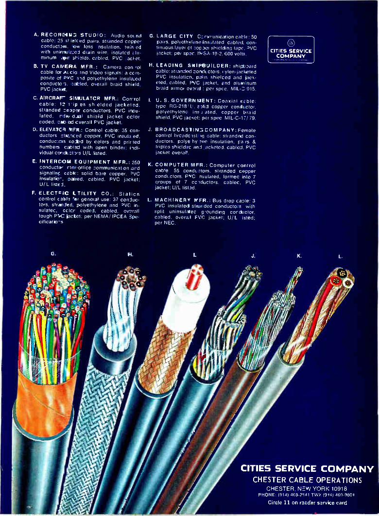
A. RECORDIN.".;. STUD 0: Audio soLnd cable: 25 irielced pairs, stranded copper conductas, Ow loss nsulation, twis ed with uninsuazei drain wire, isolated alu-minum •arpe shields. cabled, PVC acket.
B. TV CAMERA MFR.: Camera con rol cable for ALcio and Video signals: a com-posite of PVC lid polyethylene insulazed conducto-3, catled, overall braid shield, PVC jacket.
C. AIRCRAF" SIMULATCR MFR.: Con-rol cable: 1-2 tip es sh ,elded jacketed, stranded :caper conductors, PVC insu-lated. rdiv d..aal shield jacket color coded, cab ed cverall PVC jacket.
D. ELEVA1CR MFR.: Control cable: 35 con-ductors stm_iced copper, PVC insula ed, conducxes coded by colors and prirted numbers cal,lad with open binder: iicli-vIdual concLztors U/L listed.
E. INTEROOM EQUIPMENT MFR.: 250 conductor rter-office zommunicaten ard signal* cable: solid bare copper, PVC insulatio-, paiied, cabled, PVC jacket; U/L listed.
F. ELECTFIC LTILITY CO.: Station control cable for general use: 37 coniuc-tors, Crania& polyethylene and PVC in-sulatec. ccicr coded, cabled, overall tough roe ¡octet; per NEMA/ IPCEA Spe-cificatio-s
G. H.
CITIES SERVICE COMPANY
K. L.
G. LARGE CITY Czrinunication cable: 50 pairs, polyethyleneinsulated cabled, con-tinuous layer of •-.•.opaer shielding tape. DVC jacket: per spec. 'NSA-19-2, 600 vols.
H. LEADING SMINBUILDER: shipboard cable. stranded zondLctors. rylon-jacketed PVC insulation. pairs shielced and jack-eted, cabled. PVC jacket. and aluminum braid armor ovaral ; per spec. MIL-2,915.
I. U. S. GOVERNMENT: Coaxial cable: type RG-218 LI, slid copper conductor, polyethylene ins J ated. copper braid shield. PVC jac-tet: per spec MIL-C-1Z/ 79.
J. BROADCAS11M3COMPANY:Femote control broadcst.19 cable: stranded con-ductors. polye hy ace insulation, pa rs & triples shieldec and .acketed. cabled. PVC jacket overall.
K. COMPUTER MFR.: Computer control cable 55 cow:IL:tors, stranded copper condLctors, PvC nsulated, formec into 7 groups of 7 cciductors, cablec. PVC jacket; U/L listad.
L. MACHINERY KFR.: Bus drop caole: 3 PVC insulated saanded conductors with split uninsulatec grounding corductor, cabled, overa.I FVC jacket; U/L isted; per NEC.
J.
CITIES SERVICE COMPANY CHESTER CABLE OPERATIONS
CHESTER, NEW YORK 10918 PHONE: (914) 469-2141 TWX (9/4) 469-9801
Circle 11 on reader service card

We can't solve your problem. But we can help you get
a better look at it.
Take the situations you see above. In each, there's a need to simultaneously
measure and monitor several dynamic vari-ables. And that's a job that's tailor-made for Gould's line of Brush Recorders.
Brush Recorders can record up to 8 vari-ables against a common time base, side
Studying blood pressure, respiration rate,
heart sounds, temperature, EKG traces.
by side, on the same piece of chart paper. Instantaneously. Continuously. With a sys-tem accuracy of 99-1/2%.
Most Brush Recorders feature patented pressurized ink-writing. This means traces of uniform width and exceptional clarity. It also means no puddling or smearing.
12 Electronics March 1, 1971

Monitoring engine emissions for air pollution.
Measuring current, voltage and roll forces to control product uniformity.
........ . .....
-> wino
Measuring stress, stra'n and torque on aircraft assemblies.
MINN NUM WM= 11411111111111
ARM» MUIR MUM
MUM MUM MUM
MUM
UM» MUM MUM
As a result, charts generated by Brush Recorders can be studied or reproduced or referred to for years to come. With little
chance of the data being misread or mis-understcod.
So if you have questions, take a look at Gould's line of Brush Recorders. They have
a way of coming up with the answer. In
the lab, in the shop, and in the field. Brush Recorders. They're one more exam-
ple of how Gould's Instrumentation Group puts hard-to-get information into easy-to-use form. Gould Inc., 8550 West Bryn Mawr Avenue, Chicago, Illinois 60631.
Electronics March 1, 1971 Circle 13 on reader service card 13

People
Hunn
Should a man who has spent eight years of his life poking around
in mine shafts be entrusted with implementing the nation's air traf-fic control system? Brig. Gen. Spencer S. Hunn thinks so, but then, he's biased.
Prior to taking the post of di-rector of the Federal Aviation Ad-ministration's National Airspace Systems project office, Hunn spent much of his career underground working on the North American Air Defense Command's (Norad) underground nerve center and on the ill-fated Deep Underground Support Center, a command post that was to have been built under 5,000 feet of granite in Cripple Creek, Colo. "It was quite a project," Hunn says. "It was de-signed to take 39 200-megaton weapons to kill it. I was even given $12 million to go out to Cripple Creek and buy old gold mines." In the end, however, the com-mander of the Strategic Air Com-mand had bad words to say about the program before the House Ap-propriations Committee and four years of work died on the spot, Hunn says. Now that Hunn is out of the un-
derground command post busi-ness and heading the efforts to put the FAA's enroute and terminal air traffic control system into opera-tion, he will have plenty of oppor-tunities to apply much of the pro-gram-management experience he gained in his 18 years as an Air
Force systems manager. During his tenure, he worked on such pro-grams as the SAGE air defense sys-tem and the 407L tactical air traf-fic control system, before retiring six months ago as assistant deputy chief of staff for programs with the North American Air Defense Com-mand. Before that, Hunn was dep-uty and vice commander of the Air Force's Electronic Systems di-vision, Bedford, Mass.
Trained as a mechanical engi-neer at the University of Utah and holding a master's in jet propul-sion engineering from Purdue, Hunn says, "I was an engineer but I'm not anymore. I couldn't design a circuit if I had to." • He notes, however, that in so-
phisticated programs like the FAA's automation efforts, "If you leave it up to an engineer, he'll always try to improve it. You'll never get to the point where you can actually implement a system." "At some point," he continues,
"you have to be awfully hardnosed about freezing the design. If you put that change in and then an-other dhange in, costs go up and schedules get slipped." Hunn de-clines to apply this criticism to the FAA's delays. But many in the air-line industry are more than willing to say that the FAA's unwillingness to freeze designs and get on with implementing its systems is why so much has been spent on research and so little equipment has been installed.
Research administrators have found funding difficulties over-
shadowing other problems that are just as pressing. Among them are maintaining a steady flow of new knowledge through a center as technology grows and changes, of-fering, individual researchers in-centives and fulfillment instead of dead ends, and channeling work into productive areas without kill-ing initiative.
Last September, Richard H. Ful-ler, 42, inherited these problems with his responsibilities as general manager of the Sperry Rand Re-search Center, Sudbury, Mass.
Since then he appears to have solved some, and is moving toward resolving the others. One step would make the center
more of a corporate resource, in terms of both knowledge and peo-ple. "It's now routine," says Fuller, "to have frequent briefings here with the managers of other Sperry divisions. They present their prob-lems and market forecasts, and we can brainstorm solutions, or call a researcher's attention to a side of his work that interests other parts of the company." The technical re-source theme also extends to con-sultation: direct short-term appli-cation of the center's experts to problems that may occur at the divisional level.
Although Fuller wants to channel research toward projects with pre-dictable payoffs, one of his major goals is exploratory development of techniques that could lead to new business areas within Sperry. Right now, he has been able to allocate 10% to 15% of the center's budget to pregnant areas like environ-mental science and display tech-nology; one quick result has been formation of an information display division in Phoenix, Ariz. It's now developing a line of plasma dis-plays, some of which are descended from avionics development pro-grams at Sudbury, and it's a prom-ising new venture for Sperry, Fuller feels. But people problems—morale
and expertise—are often the most critical in any research organiza-tion. A prime need is individual fulfillment and Fuller is seeking it in two ways. "First, we are now using our experts as consultants in the divisions, and this allows them hands-on participation. Sec-ond, we hope to allow Sudbury researchers with potentially profit-able ideas to follow them out of the center and into the divisions and the marketplace. Scientists like to see their work bear fruit. Now they can follow their pet ideas to fruition—almost as if they were entrepreneurs solving problems on the outside. And, hopefully, they'll make money."
14 Electronics March 1, 1971

4 Quadrant Magnetic
Analog Multiplier DC x AC = AC Output
Product Accuracy is -±-112% of all readings Over Full Temperature Range of -55°C to +125°C
• Product accuracy is specified in % of reading for all output analog voltage product points over the full military temperature range instead of % of full scale error giving superior results for small values.
• Linearity, product accuracy, and zero point virtually unaffected by temperature changes.
II All units are hermetically sealed and completely shielded from external electric or magnetic fields.
Specifications Include: Transfer equation: E XY/3 X & Y input signal ranges: 0 to -±3V Peak
Maximum static and dynamic product error: 1/2% of point or 2 MVRMS,
whichever is greater, over entire temperature range
Input impedance: X = 10K: Y = 10K Full scale output: 3 VRMS Minimum load resistance for full scale output: 2000 ohms Output impedance: Less than 50 ohms X input bandwidth:
-+-0.5db. 0 to 200 hertz Y input bandwidth:
+0.5db. 20 hertz to 1000 hertz DC power: ±-15V unless otherwise
required @ 20 ma 2
There is No Substitute for Reliability
GENERAL MAGNETICS, INC. 135 Bloomfield Avenue
Bloomfield, New Jersey 07003 (201) 743-2700
Meetings
Calendar
International Convention & Exhibition, IEEE; Coliseum and New York Hilton Hotel, New York, March 22-25.
European Semiconductor Device Research Conference, IEEE, DPG (German physical society), NTG (German communications society); Munich, March 30-April 2.
Reliability Physics Symposium, IEEE; Stardust Hotel, Las Vegas, March 31-April 2.
USNC/URSI IEEE Spring Meeting, Statler Hilton Hotel, Washington, April 8-10.
National Telemetering Conference, IEEE; Washington Hilton Hotel, April 12-15.
International Magnetics Conference (Intermag), IEEE; Denver Hilton, Denver, Colo., April 13-16.
Conference & Exposition on Electronics in Medicine, Electronics, Medical World News, Modern Hos-pital, Postgraduate Medicine; Sher-aton-Boston Hotel and the John B. Hynes Civic Auditorium, April 13-15.
Offshore Technology Conference, IEEE, Houston, April 18-21.
International Geoscience Electronics Symposium, IEEE; Marriott Twin Bridges Motor Hotel, Washington, April 18-23.
Frequency Control Symposium, U.S. Army Electronics Command; Shelburne Hotel, Atlantic City, N.J., April 26-28.
Relay Conference, College of Engineering, Oklahoma State University Extension, National Association of Relay Manufacturers; Stillwater, Okla., April 27-28.
Southwestern IEEE Conference and Exhibition, Houston, Texas, April 25-May 2.
Symposium on Theory of Computing, Association for Computing Machinery; Shaker Heights, Ohio, May 3-5.
Call for papers
International Switching Symposium, Massachusetts Institute of Technology; Cambridge, June 6-9, 1972. April 1 is deadline for submission of synopses to J.G. Pearce, technical program chairman, Stromberg-Carlson Corp., 100 Carlson Road, Rochester, N.Y. 14603.
Sine-Cosine Function Generator
Provides A Two Quadrant lo Sine Function e
S
i with better than 1% Accuracy
mi Scaled for ±10V input and output
• Operates from conventional ±15V power supplies
• No external offset adjustments required
• Terminal provided to allow four quadrant operation
Specifications Include:
DC accuracy: -± (0.1% + 0.6% x EN/10V)
DC accuracy over the complete temperature range: ± (0.25% ± 0.75% x EN/10V
Input impedance (pin 1): 9.3K 12
Input voltage range (pin 1): ±10V DC
Rated output-voltage: -±-10V DC
Rated output-current: -+-5ma
Output impedance: 1 n Frequency response for 1% accuracy: DC 59 3kHz
There is No Substitute for Reliability
GENERAL MAGNETICS, INC. 135 Bloomfield Averue
Bloomfield, New Jersey 07003 (201) 743-2700
Circle 140 on reader service card Circle 15 on reader service card 15

A ai
ANNOUNCING... -...* - • - air A•t,i_e
,---.." n-... -.V"- • ' --›.-e t Tr ' •
4 1: " -0-e=„ ---«-,-----__-.: , :de• .0. P......itrl..••• ' .a.
=tr al
• ae."."-s-..-di s,--.2: ...
- -eRCA's EXPANDED LINE OF RECTIFIERS: init;etw:riie-74 e-cee'----6"--,,,,-.*----1.1::->' ---eze-el"-e"-- Ili r---41, -iilleebill-....2iiiit-,-
FAST RECOVERY, PLASTIC, AND AVALANCHE TYPES. T -13,
Here they are: production quantities of RCA's new fact-recovery silicon rectifiers, rugged plastic rectifiers, and hermetically-sealed controlled avalanche rectifiers. Construct-ed to the highest standards of quality and reliability, these arid the many others in RCA's established rectifier line are immediately available to fill your application needs.
Make use of RCA's 1- and 3-ampere diffused junction silicon rectifiers (DO-26 and modified DO-4 packages) in high-speed inverters, choppers, and other high-frequency ap-plications. Use RCA's 1- and 1.5-ampere plastic rectifiers (DO-15 package) in home entertainment equipment, indus-trial controls, appliance controls, and light industrial equip-ment. In instruments where reliable transistor protection is required, use RCA's nermetically-sealed (D0-26) controlled avalanche rectifiers.
For more details, call your local RCA Representative or your RCA Distributor, or write: RCA, Commercial Engi-neering, Section 70C-1/UR10, Harrison, N.J. 07029. Interna-tional: RCA, 2-4 rue du Lièvre, 1227 Geneva, Switzerland, or P.O. Box 112, Hong Kong.
Rectifier
Max. Repetitive Peak Reverse Voltage
(VRRM) (V)
Peak Maximum Surge* Forward Nan- Reverse Current Repet live Recovery
Avg. (10) (EMS) !Fail Time (trr) (A) (A) (A; (lis)
Package Capability
TA7892- 200-800 1.0 ..5 35 0.5 DO-26 fast recovery TA7895*
TA7398-TA7901
TA7996, TA7802-TA7806'
200-800 3.0 4.5 75 0.5 modified fast recovery DO-4
plastic general-purpose 100-1,000 1.0 35 DO-15
1N5391- 50-1,000 1.5 SO plastic general-purpose 1N5399 DC-15
40808 600 .5 35 DC-26 controlled avalanche (700-1100 V)
35 DO-26 controled avalar.,.;he (900-1300 V)
40809 800 .5
*RCA Developmental types
**For one-half cycle of applied voltage (f =60 fiz)
Rell Thyristors 16 Circle 16 on reader service card Electrorics March 1, 197

. I •
Electronics Newsletter
March 1, 1971
Laser communicator
aims at Gbit/sec
Monolithic op amp
has power, versatility
Creditors seek
to force
Viatron bankruptcy
GaAs wafers
off the shelf
Lockheed may be losing the C-5A and airbus battles, but it has a good chance of winning a battle in space. The Electronic Sciences Laboratory of the Lockheed Missiles & Space Co., a division of Lockheed Aircraft Corp., has developed a digital laser communications system that could be flyable in five years. At least two other companies are known to be working on space-qualified laser communications systems under contract to Wright-Patterson Air Force Base—these are for mode-locked neo-dymium YAC lasers. The Lockheed system, developed completely with in-house funds, employs a continuous-wave neodymium YAG laser. At present both systems have power problems—they require more pri-
mary power than a satellite can provide—and neither has yet achieved a 1 gigabit-per-second data-transmission rate. But the Lockheed sys-tem is much closer to the goals for a flyable system—it has reached 600 megabits per second as against 200 for the mode-locked system. And from a power standpoint, the Lockheed system looks even better. Recent calculations indicate that to achieve 1 gigabit per second with an error rate of 1 in 109 bits with present hardware, the Lockheed system would require 5% of the primary power of the mode-locked system.
What could be the first monolithic power operational amplifier to be offered commercially, a 15-watt unit, will be introduced soon by Fair-child Semiconductor. Electrically similar to the iLA 748, the device isn't aimed only at the high-power audio consumer market. The device could be used, says Fairchild, to drive de servo motors
directly. It also could find its way into stylus drivers, consumer audio, custom power-supply regulators, and into positive and negative tracking voltage regulators. In a bridge configuration, the op amp could drive ac servos. Moreover, it contains a chip-temperature sensor that auto-matically limits current in the event of a thermal overload.
A group of creditors has filed a court action seeking to force Viatron Computer Systems Corp. into bankruptcy under chapter 10, in which the corporation's assets are sold and the proceeds divided among creditors. The petition was filed by Manpower Inc. of Minneapolis; National Data Communications Systems, Somerville, Mass.; and Certified Business Forms, Newton, Mass. When Viatron replies to the petition in U.S. District Court, manage-
ment—perhaps with stockholder and bondholder seek at least a change to voluntary bankruptcy under chapter 11. This would give the company time to reorganize and refinance. The alternative, it ap-pears, would be the demise of the firm, whose low-cost System 21 was once the talk of the industry.
Bell & Howell is offering what it believes is a first—standard epitaxial substrates of gallium arsenide for use in a variety of devices from light-emitting diodes to injection lasers. While the wafer business has grown as a custom operation, the company hopes to reverse the trend in GaAs. In fact, John Nickerson, marketing director of Bell & Howell's Elec-tronic Materials division in Pasadena, Calif., says he knows of no firm
Electronics I March 1, 1971 17

Electronics Newsletter
that's ever offered standard off-the-shelf epitaxial wafers. The substrates are made of single-crystal gallium arsenide and have
been variously doped for six different product applications: visible light emitters, infrared emitters, opaque photocathodes (as in photomultiplier tubes), thin-film devices, microwave diodes, and injection lasers.
American Calculator
hits financial snag
XDS foresees 1971
as profitless year
Addenda
A buyer is being sought for American Calculator Corp. of Dallas. The company made a big splash last fall when it introduced a made-in-USA calculator with a light-emitting diode display using the Electronic Arrays kit of six LSI packages [Electronics, Nov. 23, 1970, P. 83].
Observers feel that American Calculator didn't have enough financing to carve out the market it had selected: selling machines to a large dis-tributor, such as a major chain store, in hopes of overcoming the market-ing problem faced by a small outfit that wants to compete with well-entrenched suppliers.
Xerox Data Systems, anticipating its second year of losses in a row, is tightening its organizational setup. The firm, whose sales had been growing 25% to 30% a year since its inception in 1961, saw them dip below $100 million in 1970—the first year of red ink. While William F Glavin, new XDS president, looks for a sales upturn
late this year or early in 1972, he has made these moves: first, the former marketing division has been folded into a newly formed business plan-ning group, which includes marketing, technical, market analysis, and administrative people charged with identifying market and product opportunities. Second, vice presidencies for administration and corporate planning have been eliminated. Third, the corporate planning responsi-bility now rests with a director, and the departments that formerly reported to the vice president for administration now report directly to other officers. Says Glavin, "We had too many levels of management— too many checkers. Too many people had to sign off before a decision was made." The business planning group will now have greater control over the direction in which XDS moves.
A loudspeaker maker, Bose Corp. of Natick, Mass., has filed a suit against Consumer Union charging bias, technical incompetence, and con-flict of interest. The suit alleges, among other things, that a CU employee and speaker tester, Arnold L. Seligson, holds a patent on an ionic speaker system and downgraded Bose's 901 system as a potential competitor. Bose seeks retraction of the 901 review, $500,000, and costs. Says Rob-ert L. Smith of CU: "Since our feeling is that the [Seligson] device as patented is not yet feasible for production or sales, we see no conflict of interest at this time. Professor Bose's reaction appears to be one of pique." . . . With MOS makers lining up to supply the innards of elec-tronic wristwatches—Mostek Corp. of Carrollton, Texas, is the latest— the Swiss have another idea. Heinz Hruegg and his associates at Faselac AG in Zurich have developed a bipolar circuit that they say equals com-plementary MOS in performance but requires only conventional proc-essing. The Swiss circuit uses ac coupled flip-flops for low-voltage opera-tion and pnp transistors instead of high-value resistors as active loads for small size.
18 Electronics I March 1, 1971

Electronics review
Bipolar memory cells strike back in war with MOS Bell Labs' transistor cell
fits into 1 mil2 with no loss
in speed or power dissipation,
promising more bits on chip
After losing battles in packing density to mos, bipolar technology may win the war yet—at least where large memories are con-cerned. Fairchild Semiconductor has dropped cell size to 12.5 mils2 (see p. 52) and IBM researchers in West Germany have achieved about the same reduction (see p. 109). But the tightest bipolar pack-ing yet has been achieved by Bell Laboratories. Bell has come up with a novel two-terminal transis-tor memory cell that fits into 1 mil2 of chip area, compared with typical MOS cell areas of 30 to 40 square mils. And, says Jerry Mar, Bell scientist responsible for the devel-opment, it's done with no reduc-tion in normal bipolar performance: speed is typically 5 to 10 micro-seconds per bit while power dissi-pation is approximately 10 to 20 microwatts per bit. The cell was described at the International Solid State Circuits Conference. What's more, it's estimated that
by using this cell-fabrication proc-ess in large integrated arrays—say a 2,000-bit read/write memory—a chip no larger than 5,000 mils2 can be used; this includes on-chip de-coding and refresh circuitry, to boot. It works out to about 2 mils2 per bit, less than half the size of comparable MOS memories. The Bell cell utilizes charge-
transfer instead of the conventional current-mode logic schemes. It con-sists of a transistor with the base unconnected except through the parasitic and junction capacitors. Operation is achieved through junc-tion breakdown stabilized through a process that enables breakdown to occur at a point removed from the junction edge. With this con-struction, charge is stored on two pn junctions formed back to back. To write a 0, a positive pulse of about 6 volts, large enough to strongly bias the cell, is applied across the cell. A 1 is written by applying a large positive pulse of 9 V followed by a small pulse of 3 V. This causes the collector base junction to break down, creating an excess of majority carriers, cancel-ing the charge depletion at the junction, and leaving the junctions weakly biased. Thus, 0 and 1 are simply functions of the bias condi-tion of the cell. To read the cell, a 6-V pulse is
applied and the resulting charge flow is measured, say a voltage across . the capacitance in the cir-cuit. Since for the 1 state measure-able amounts of charge flow (up to 7 microcoulombs), and in the 0 state almost no charge flows, the two states are readily distin-guishable.
Designed imbalance
adds performance
Volatility in a semiconductor memory always has been the plague of designers. But they've overlooked the fact that an array
March 1, 1971
of flip-flops, like a pair of loaded dice, tends to assume the same state with every power restoration. Designing a perfectly balanced flip-flop is a good deal harder than de-signing an honest pair of dice; in fact, it's impossible. Three researchers at IBM have
decided not to bother with perfect balancing. Instead, they propose to unbalance the flip-flops—to load the dice—to produce a desired pat-tern with every power restoration, and thus to impose a nonvolatile read-only characteristic on an otherwise conventional random-access read-write memory. They described their work at the Inter-national Solid State Circuits Con-ference in Philadelphia. The three —I.T. Ho, G.A. Maley, and R. Wax-man—note that when power in a memory is shut off, then restored, its contents are lost. But they also say that most of the time a par-ticular cell will adopt a particular one of its two states-0 for some cells, 1 for others—when power is restored.
In fact, the trio's tests on several hundred conventional cells showed that 95% of them exhibited a per-sistent preference for one state or the other. This preference arises because a solid state memory cell, although theoretically balanced, is never perfectly balanced. Their so-lution: design in just the right amount of imbalance so that it al-ways flops one way. Such imbalance is easy to
achieve, says the trio. For example, in a fast diode-coupled memory cell containing Schottky diodes, an additional Schottky device cou-
Electronics l March 1, 1971
•
19

• Electronics review
pling the collector of one of the two transistors in the cell to the p+ isolation wall won't affect the cell's operation, but will always pull it to the same state when power is on.
In a simpler cell without the di-odes, the ratio of the load resist-ance to the capacitance between the collector and ground affects the time constant of each side of the cell, and therefore determines the cell's preference. This capacit-ance is adjusted by offsetting the p+ isolation wall in the center of the cell to the left or to the right, from its nominally symmetrical po-sition. Either change is made in the masks.
Purposely unbalancing the cir-cuits can increase the cell's power dissipation, says the IBM trio. But if it is done carefully, the increase is negligible, they assert.
This technique opens up many potential applications: for example, reloadable control stores that don't need read-only memories or disk units for backup; a control mem-ory with its initial program-load routine already in it when it is turned on; readily available main-tenance and diagnostic routines; and even whole new systems, espe-cially small ones, whose architec-ture is based on this capability.
Manufacturing
Hybrid ICs turned out
every 1.8 seconds
Systems that crank out a hybrid circuit every couple of seconds used to be the exclusive province of IBM's module production line for the System 360 computers. Now another high-speed, high-volume automated production system has gone on line; this one for a large midwestern supplier of automotive electronics. The system, for bond-ing chips and testing circuits, turns out a complete hybrid circuit every 1.8 seconds. Developed by Hugle Industries of Sunnyvale, Calif., the line produces hybrid circuits for automobile radios, each of which requires three circuits with two, three, or four transistor chips.
Series. Each substrate in Hugle Industries' automated bonding and testing system for hybrid crcuits is checked for alignment, before chip bonding, with split-screen TV. Operator aligns marks on each end of substrate.
The system speed compares fa-vorably with IBM's automated pro-duction line, according to William R. Hugle, Hugle Industries chair-man. Hugle adds, however, that his version is adaptable to a wider range of substrates and screening techniques. He puts the cost at about $500,000 for the first system and about $250,000 for subsequent ones. The transistor chips are first
roughly oriented in their positions as they are separated and then picked out and put into a fixture that aligns triangularly oriented solder bumps, preventing any am-biguity in orientation. The fixtures, on a chain drive, then move around to an ultrasonic bonder station, where they meet the substrates. The substrates are aligned in their own fixtures by an operator who uses a split-screen, closed-circuit television system to match align-ment marks at each end of the substrate. The bonding tool then picks up
a chip and goes through its bond-ing cycle to tack the chip down. Four bonding tools are in use si-multaneously, so that all four chips are bonded at the same time to the four-transistor circuit. The sub-strates are heated with infrared lamps for reflow soldering of the bumps to complete the bonds. The
circuits move to the testing station, where the bonds and circuit opera-tion are checked. Four markers, one for each chip, gage the good units. A counter attached to each marker keeps a running total to monitor whether a particular bonder is producing continually bad bonds.
Voltage contrast
tells circuit tale
Engineers at Motorola's Semi-conductor Products division have married a scanning electron micro-scope to a video tape recorder for dynamic analysis of circuit func-tions. They use a technique called voltage contrast, in which portions of a circuit under power that are turned on appear much brighter on the tape, and in photos, than por-tions that are off. While the technique isn't unique
to Motorola, Anthony Gonzales, who is manager of the analytical services laboratory in Motorola's central research laboratory in Phoenix, believes his group works much closer with production lines in this kind of dynamic circuit analysis than is usual among semiconductor manufacturers. He expects the SEM/videotape corn-
20 Electronics March 1, 1971

bination to be a powerful tool in finding out why—and especially where—LSI parts aren't function-ing. "We can detect changes in volt-
age down to 0.5 volt, and even down to 100 or 200 millivolts, pretty easily through the glass pas-sivation on conductor surfaces," he reports, noting that conventional light microscopes can't detect volt-age contrast. "It's difficult to probe through the glass on such a circuit without damaging the underlying metal when you're looking for fail-ures," Gonzales continues. "But we don't use the technique on every circuit; it's mostly used for high-reliability circuits and those in which it might be difficult to de-tect problems with conventional microscopes."
Gonzales cites as a representa-tive circuit an MoS divide-by-16 counter that includes four flip-flops. To follow the logic sequence in this circuit, —15 volts was ap-plied to the input lead, causing that lead and the associated tran-sistors in the first stage of the counter to show up brightly on the video tape image taken from the SEM. A rapid-scan system that's sold with the SEM does a point-by-point raster scan of the circuit, producing a brightness image directly on the video tape by means of secondary electron emission. As the input lead to the first
stage is pulsed, Motorola engi-neers can watch each step in the divide process on the video tape; for each portion of the four flip-flops brightens and darkens in se-quence, as the circuit divides by a half, then a quarter, and so on until, at the completion of the di-vision, the transistors and output pad of the final stage go bright, indicating that the entire circuit has worked properly. If a failure occurs, however, it can easily be pinpointed by pulsing the circuit slowly enough to trace the logic sequence by the relative bright-ness or darkness of its cells. "We've also looked at some MSI
circuits, such as read-only memo-ries, with the voltage contrast
technique," Gonzales notes. "A mechanical probe may not work here because the metal lines can be very small—down to 0.5 to 1 mil—and a probe could damage them. Or again, they may be glass-passivated, and removing the glass could damage the metal." The ROM could be of the fusible-link variety that Motorola makes, in which a metal link is blown or retained depending on the data pattern to be encoded.
"In this kind of device, we can set up a known logic sequence," Gonzales says, "and then photo-graph the voltage distribution to see which devices are on or off, determining if the proper fusible links have been blown. If we apply a few volts, and there's an open where the link has been blown the metal lines would be bright up to the break and darker behind the break." Inadvertent scratches in the metal that cause opens also can be tracked down in that way.
"In LSI," says Gonzales, "with multilayer metal devices, you can reach a point very quickly where the device doesn't work and you want to know where the failure is." He's looking to SEM/video tape sleuthing to do the job.
Shades. MOS circuit through scanning electron microscope reveals different stages by lightness or darkness. Test is done while circuit is operating.
Motorola uses a Japan Electron Optical Laboratories scanning electron microscope and a Shiba-den video tape recorder in its work.
Computers
Paper tape in cartridge
features simplicity
Sometimes the simplest solution to a problem is overlooked. This seems to be the case with paper tape readers capable of accommo-dating more than one program. Most readers have spools or trays that hold the tape while it is being fed to the read head—essentially a one-at-a-time technique since the spool or the loose tape has to be changed each time the program is changed. Systems capable of doing more than that have been very expensive. So when engineers at Data Test
Corp. in Concord, Calif., needed a paper tape reader capable of han-dling many programs for their auto-matic printed circuit card test system, they decided to build it themselves. The result according to Neal Vinson, Data Test's president, "is so simple, I'm surprised no one had done it before." The reader is basically a $25 plastic tape car-tridge that holds up to 100 feet of paper or Mylar tape, and a simple transport. An unusual cod-ing scheme allows up to 100 pro-grams to be stored in an interlaced pattern so that access to any one program is almost instantaneous. Program selection is from the front panel or remotely from a computer or other control unit. Vinson says that in most mini-
computer applications, for example, programs are relatively short, so any inexpensive storage and re-trieval system for the program would find a waiting market. And he thinks that his system, with a projected price of $1,000 in high volume to OEMs fills the bill. "All you have to do is punch a two-digit code [on the Teletype unit] and any one of 100 programs is called up." Two reading rates will be available:
Electronics March 1, 1971 21

Electronics review
320 and 640 characters per second. The 100 feet of tape will store 12,000 characters.
But the coding scheme is the heart of the system. If, for example, 10 programs are to be stored in one cartridge, the first character on the tape is the first one of the first program. The second character is the first of the second program, and so on up to the tenth character. Similarly, the eleventh character is the second character of the first program, the twelfth is the second character of the second program, and so on. A capstan and a pinch roller drive the tape, freeing the sprocket holes in the tape for use as timing marks picked up by the phototransistor sensors. A built-in circuit takes care of the bookkeep-ing so that only one program is read out at a time. The reader interfaces with almost
any mini system because both the control signals and the data output signals •are transis tor-transistor-logic levels. And, adds Vinson, it can be used in many areas where loose paper tape can't be used. In numerical control systems, for ex-ample, where the equipment is out on the shop floor, paper tape coiled on the floor can be a hazard. But with Data Test's setup, the tape is in a plastic cartridge, and one cartridge would probably hold all the needed programs. Vinson also believes his system also could be employed in offices for form letters and storage of other routine infor-mation.
Avionics
STOL: NASA's bone
for industry's bucks
In Washington's latest variation on the man-bites-dog theme, NASA is appealing for industry money. In an unpublicized letter to 21 aero-space and aircraft companies, the hard-pressed agency is soliciting industry's participation in a joint government-industry development program for jet-powered, short takeoff and landing (STOL) airliners. Soon, the letter adds, NASA will
ask electronics manufacturers to cooperate in a similar program for developing the high-performance guidance and control systems needed to guide STOLs during their fast climbs and descents and on their jagged courses. Much less industry help will be needed for avionics than for airframes.
Industry sources are predicting that NASA will offer to spend $18.5 million in the coming year on re-search programs that will cut the risks in developing what has been called the missing generation of aircraft and STOL avionics. And the appeal of the predicted $1 billion for STOL aircraft alone makes it just possible that NASA will find the industry partners it is seeking. As the man responsible for
NASA's STOL avionics effort, George Cherry, says, the beauty of the STOL is that it can land and take off much closer to urban centers than conventional aircraft. But in order to use urban STOL-ports, navigation and guidance systems will have to be developed that will permit the aircraft to "fly steep, curved approaches that keep them away from populated areas. They will also have to maneuver around and above obstacles," he says.
Cherry's Aeronautical Operating Systems division has therefore budgeted $3.5 million in fiscal 1972 funds for work on developing a data base on STOL avionics, with most of the money to go on devel-oping a STOL guidance and control system to be flight-tested in March 1973 on a modified de Havilland Buffalo. Cherry says industry has been asked to submit proposals by March 8 for a guidance system, a digital flight control system, a flight director, and displays for the STOL tests. The winner in the competi-tion will also be asked to integrate into the avionics system a naviga-tion and guidance system devel-oped by the Department of Trans-portation's Transportation Systems center. During the flight tests, DOT's
navigation and guidance system and NASA's Stoland (STOL approach and landing avionics system) will be interfaced, to permit parallel
tests of the two competing guid-ance systems. The emphasis will be on designing systems versatile enough to permit them to be used in first-generation STOL aircraft as different from the Buffalo as the Breguet 94IS, he adds. Meanwhile, the Federal Aviation
Administration is asking Raytheon to modify its Modils scanning-beam microwave modular instrument landing system for the flight tests to be conducted near Ames Re-search Center, Moffett Field, Calif. The modifications will beef up per-formance at low altitudes so that all-weather landings can be simu-lated.
Six-axis navigator
triples reliability
Six axes instead of three may mean many times the reliability in a new strapdown inertial guidance system developed by the C. Stark Draper Laboratory at MIT, Cambridge, Mass. It is also seen as a cost saver. The new system has six gyros and six accelerometers rigidly mounted, instead of the usual three pairs for X, Y, and Z-axis sensing of com-mon inertial references. Though it could benefit commer-
cial navigation, NASA funded the three-year development at a cost of $2.6 million. The program was aimed at advanced space naviga-tion aids for the shuttle and "man-to-Mars" efforts.
Jerold P. Gilmore, the lab's dep-uty associate director and the sys-tem's principal developer, foresees improved accuracy, longer mean times before failure, fault isolation using the system's built-in compu-ter, and graceful degradation. In fact, degradation is so graceful, and MTBF is so long, that the six-pack, as it's called, could eliminate the need for the multiple backup plat-forms used aboard commercial air-craft and considered for the space shuttle. "The six-pack would probably
cost about twice as much to build as an ordinary three-axis system since it has twice the hardware; but net cost of a navigational sys-
22 Electronics ' March 1, 1971

tern could drop—as many as four three-axis systems are now needed where one six-pack could suffice," says Gilmore. For failure analysis, Gilmore has
worked out the probabilities of successful operation after 1,000 hours, using worst-case figures, and assuming the same kind of gyros and accelerometers are used in both systems, as 97.98% for the six-pack, and only about 60.2% for the three-axis system. These figures are about equivalent to MTBFs of about 34,500 hours for the six-pack sys-tem and about 1,683 hours for the three-axis system—a ratio of 20.5:1, and one that widens with length of mission. Gilmore notes his estimates are
based on individual MTBFs of 8,000 hours for gyro modules where com-mercial firms often claim 50,000 to 100,000 hours; his working accel-erometer MTBF was 20,000 hours versus an often-claimed 200,000 hours. The six-pack uses two gyro-ac-
celerometer pairs for each axis, off-setting each pair about 31.7° either side of axis. Because of its sym-metry, this distribution of sensor packages cuts down geometric er-ror-amplification characteristic of three-axis systems. It also makes fault location simpler, adds Gil-more; as many as two gyro-accel-erometer modules can fail before a human must intervene, and soft-ware is coming up which would au-tomate the location of third fail-ures. Even if several modules fail, the
system will still operate, though at a lower level of accuracy. And the six-pack is more accurate to begin with. With all sensors running, it is estimated that the deviation around a given axis would run only about 0.07° per hour at worst for the six-pack versus about 0.1° to 0.15° per hour for typical three-axis systems with equivalent gyros and accelerometers. With one fail-ure, deviation would rise only to about 0.082° per hour, and with two failures the three- and six-axis systems would be about equally accurate. Three failures would make the six-pack drift more than a
On the warpath
Army test pilots are making a preliminary evaluation of Lockheed-California Co.'s AH-56 Cheyenne helicopter at Yuma, Ariz., as the com-pany continues to push for an Army purchase of the high-speed gunship. The Pentagon's fiscal 1972 budget request calls for $13 million in Chey-enne R&D money to keep the program alive [Electronics, Feb. 15, p. 114]. With Southeast Asia procurement declining, Army-Lockheed proponents call for Cheyenne development as an all-weather "tank buster" for con-ventional land warfare using TOW and possibly Dragon missiles coupled with passive infrared-night-vision hardware and an on-board fire-control and navigation computer.
functioning three-axis system—but it would still put out usable data, while by this time a three-axis system with three failures would be turned into just so much useless hardware. The cause of both the higher ac-
curacy and the graceful degrada-tion of the, system is its computer sampling technique. Taking output from each sensor module, it uses voting logic to determine the amount and direction of movement about each axis. Today, however, voting must be done using mul-tiple three-axis systems, and often the computer is the navigator's eye-ball. That's why as many as four backup platforms are specified for some aircraft; often the votes vary widely and many are needed to do the job.
Gilmore sees many peripheral advantages to the six-pack. Less frequent maintenance would be needed because the system could withstand more failures before be-coming unreliable; that should in-
terest the airlines. Also, a failed sensor wouldn't be ignored by the computer's voting logic—just put on probation and used again if its failure were only temporary. But in these tight money times,
Gilmore expects to encounter op-position to selling the system, simply because its parts bill is double that of a three-axis system. -But net nay system cost should be lower," he maintains. "With three-axis systems priced on the order of $100,000 each, replacing four with one six-pack would save about $200,000."
Components
4-watt cw GaAs lmpatts
offered commercially
It has been theorized for some time that gallium-arsenide Impatt di-odes could go to higher power, but the catch was the material itself. The Raytheon Co. appears to have
Electronics ' March 1, 1971 23

Electronics review
turned the trick—it's offering in small lots what it calls the most powerful GaAs Impatts in or out of the lab. They have continuous wave outputs of 4 watts in C and X bands.
About the best result achieved in the lab—much less in commercial units—has been about 2.5 W in ex-perimental silicon diodes at Bell Labs. The germanium state of the art also seems to have peaked at Bell Labs with an output of about 1 W. To a great degree, it is Ray-
theon's once risky commitment to gallium arsenide that made the dif-ference. Three years ago, "theory pointed to higher powers, lower noise, greater efficiency, and opera-tion at higher temperatures than with other materials," says Wesley G. Matthei, R&D manager for the Microstate group at Raytheon's Special Microwave Devices opera-tion, Waltham, Mass. "So we de-cided to take the gamble and go with GaAs." But it has taken three years of
grappling with the problems of a notoriously cranky material; grow-ing good epitaxial layers atop bulk GaAs still can be tough, says Matthei. But as much to the point was the design thought invested in these Impatts.
Like most other firms, Microstate built its first Impatts with a mesa structure. But their junctions had to cool themselves by transmitting heat from the junction through the bulk of the material and into a heat sink. The thermal inertia of the bulk material automatically limited these early devices to low powers.
Next, Matthei's group flipped the mesa device over, placing its dif-fused junction in direct contact with its heat sink. Output rose from 0.075 W to 0.5 W immediately just because of better heat sinking. The next major move was to
replace the diffused junction with a vanishingly thin Schottky barrier junction—this further cut the ther-mal inertia between active area and heat sink, and power rose to 0.7 W cw. Improved bonding to copper heat
sinks then upped achievable power
to a full watt. And diamond heat sinking, in the Bell Labs tradition, got power up to about 1.3 W then to 2.1 w.
Early in 1970, Matthei and his fellow engineers tried etching a hole out of the middle of the gen-erally circular Schottky junction, al-lowing them to dissipate heat more evenly over its area. Although there were problems bonding the ring-like Schottky barrier junction to the heat sink, these were eventually solved by plating gold atop the mesa, lapping down to a thickness of about 1 mil, then etching to get the ring structure. With this con-figuration, the Raytheon group was able to outdo other teams using ring-shaped junctions and get more than 3 w cw. Ironically, most labs dropped the ring shape after suf-fering initial bonding problems. There are further experimental
steps that enabled Matthei to achieve the 4 W advertised, but that's still proprietary data. Matthei just grins and notes that "power output is proportional to ring area," implying he can cool large areas.
HP-21 finds place
in oscillator/amplifier
The recently introduced microwave transistor, the HP-21, is already finding its way into a Hewlett-Packard product—a 3-to-6.5-giga-hertz yig-tuned oscillator/amplifier that should be introduced shortly. It's intended to help fill a gap in the company's sweep frequency gen-erator line and provide a better low-noise local oscillator for spec-trum analyzers. Gunn diodes have been used in
higher bands, but "It's been diffi-cult to get Gunn diodes to cover this band," says Pierre 011ivier en-gineering manager for microwave transistor oscillators and amplifiers at H-P's Microwave division. "Peo-ple have been working on it for several years, and not one such device is on the market today." He claims that the Gunn diode oscil-lator, though it would give more power, would have very low effi-ciency at these lower frequencies.
Moreover, the Gunn is much nois-ier, a big drawback when consid-ered for use as the local oscillator in a spectrum analyzer.
This new oscillator/amplifier is slated to replace the 2-to-4-GHz os-cillator now being used in H-P's spectrum analyzers. Not only will it provide more harmonic power at X band, but it has very good noise characteristics—much better than klystrons. The fm noise in a 1-hertz bandwidth, 10 kilohertz away from the single sideband carrier, is 98 decibels down from the carrier level. The new unit uses three HP-21
transistors: a grounded base oscil-lator and two grounded emitter am-plifier stages. A single buffer am-plifier would have sufficed, but the second reduces frequency pulling to less than 1.2 MHz at 6.5 GHz with a variable short at the load. These versatile transistors are
also finding other applications. H-P is working on an amplifier to cover the 3-to-6.5 GHz range and provide the additional power output and the extra gain needed to level that output power. In addition, two transistors are being paralleled to provide even higher power output— upwards of 20 milliwatts. To manufacture these units, H-P
is using a technique called "mesh bonding." A method of connecting the transistor's emitter and base lead to the circuitry by using a grid pattern of wires consisting of 500 lines to the inch, it provides low in-ductance, good flexibility, and ease of fabrication. The inductance is as low as could be obtained using a flat gold ribbon of similar dimen-sions, and since only a single wire extended from the mesh is con-nected to the transistor lead, it pre-sents no production problem.
Space electronics
Standards set for
space shuttle avionics
After months of negotiation with the space shuttle's biggest potential users, NASA has told the two firms preparing preliminary designs of
24 Electronics ' March 1, 1971

71eee HARD COPY UNIT
the Tektronix T4002 Permanent copies from
Graphic Computer Terminal and.
This New Hard Copy Unit produces copies directly from Tektronix Storage CRT's. Operation is easy. At
the push of a button or upon programmed command, your computer outputs are permanently recorded on reproducible copies. In just 18 seconds a high resolu-tion copy of even complex displays is ready for use.
Now, information from your computer is quickly copied for distribution to management and office personnel. These copies are ideal for portfolios and permanent records—and serve as a quick, inexpen-sive method to keep business clients and associates informed with current information.
COPY COST is less than 8 cents per 8.5 x 11-inch copy, depending upon usage.
When people who have a need to know can't come to see the computer display, send them a copy. With the 4601 Hard Copy Unit you'll have a quick, easy, low-cost way to record and send information when and where it's needed.
For additional information, contact your Tektronix Field Engineer or Application Engineer: or write to Tektronix, Inc., P. 0. Box 500, Beaverton, Oregon 97005.
4601 Hard Copy Unit $3750
T4002 Graphic Computer Terminal, less interface $8800
Available in U.S. through the Tektronix lease plan U.S. Sales Price FOB Beaverton, Oregon
4691 HARD COPY cwri with 74002 OCT
, the T4005 Graphic Display
. . the 611 Storage Display Unit
TEKTRONIX® _ committed to
technical excellence
Electronics I March 1, 1971 Circle 25 on reader service card 25

Electronics review
the reusable craft that it expects airline-type avionic reliability and safety.
In a list of base-line requirements now being forwarded to McDonnell Douglas Aerospace Corp. and North American Rockwell, NASA says that shuttle avionics must be capable of operating at full perfor-mance after two major failures and with partial capabilities after a third failure. "This means quadru-ple redundancy," says Clarence Gay, the chief of the shuttle's sys-tems engineering team. NASA also says that it wants a
craft with an 1,100-mile crossrange and that the shuttle should be de-signed to carry jet engines. Both of these baselines are far closer to the 1,500 miles the Air Force said it would need than the 200-to-300-mile crossrange NASA avionics needs are now under study. The current schedule for shuttle
development calls for the two pre-liminary design contractors to sub-mit their studies in June. After extensive review, NASA will write requirements for the shuttle and begin detailed design efforts in the spring of 1972. Flight tests of the shuttle using its air-breathing en-gines would begin in 1975 or 1976 with first operational use starting before the end of the decade.
Medical electronics
Gear-loaded Heartmobile
undergoing trial runs
Spend $52,000 on a truck loaded with the latest medical electronic gear and communications equip-ment, and you save many heart attack victims who would otherwise be dead on arrival at a hospital. Or so claims the Montgomery County, Md., Heart Association, now test-ing such a prototype vehicle that it hopes will be the forerunner for a fleet of similarly equipped but less expensive ambulances. Dubbed the Heartmobile by its
sponsors, the suburban Washing-ton, D.C., mobile unit was designed and equipped with modified hos-pital monitoring equipment by the
American Optical Co., Bedford, Mass. Funds for the operation of the heartmobile and its three-man paramedical team come from the Department of Health, Education and Welfare.
Instrumentation for the van is valued at $33,000, including Ameri-can Optical's engineering expenses. A second Heartmobile could be equipped for half that cost. The truck itself, including modifications such as cabinetry, a 5,000-watt gasoline generator, and 3-hour bat-tery backup, comes to about $17,-000.
Yet the Heartmobile, however humane, would cost about $130,000 a year to operate full time—a price few communities can afford. Mont-gomery County would like to create a network of mini-Heartmobiles by equipping some large ambulances with the defibrillator-cardioscope package and trained personnel. Since the smaller vehicles are already equipped with two-way radios, American Optical estimates that the cost of converting each ambulance woud not exceed $5,000. Eventually, the county would like to equip and train police and fire rescue teams. The Maryland mobile coronary
care unit is manned by a registered nurse and a cardiovascular tech-nician cardiologist. When the team leaves the Heartmobile to go to the patient, it carries a battery-operated defibrillation unit with a cardioscope and built-in radio transmitter, a portable receiver, and a drug kit. The Heartmobile acts as a repeater station for the two-way portable telemetry. Output from the electro-cardiograph (EKG) and voice preamplifiers is transmitted to a hospital, where it is relayed to a specialist over two conventional telephone lines to his home or office. The 10 physicians who take turns
at backing up the unit are each equipped with a portable remote data reception set—a small portable oscilloscope and demodulating cir-cuits—for either hearing the para-medical team or seeing the EKG. If the physician decides that an emer-gency exists, he can order treat-
ment over the second phone line so that the team can administer drugs or defibrillate the patient, shocking his heart electrically to stabilize its rhythm. The van also carries a mechanical heart-lung resuscitator for automatic cardiac massage and artificial ventilation. Once the victim's heartbeat is
stabilized, he is moved to the Heartmobile. The truck itself is equipped with stationary defibrilla-tion and monitoring equipment, a chart recorder, additional drugs, and two pacemaking devices. One of the pacemakers is applicable ex-ternally by the Heartmobile team. The other, a catheter type, requires a physician's supervision; it is used after the Heartmobile arrives at the hospital and the physician steps aboard.
For the record
Little big man. A new $9,000 graphic display terminal can per-form many of the tricks of models costing several hundred thousand dollars, according to its developers at Conographic Corp., Cambridge, Mass. Using a keyboard or a sonic pen, the Conograph / 10 can trans-late, rotate, deform, or dynami-cally manipulate straight or curved shapes until the desired image is achieved on its 10-inch CRT. Heart of the technique is a simplified curve description—only its end points and slope are noted in mem-ory, in contrast to the common curve description built up out of descriptions of hundreds of straight-line sections which takes vast amounts of memory. The Conograph/ 10, instead of
logically rotating a vast matrix of data, can rotate the abbreviated description using only a little mem-ory. Conographic is patenting the technique, which, as a beneficial side effect of shortened graphic descriptions, makes possible 10 to 100 times faster image transmis-sion than competing graphic term-inals. This suits the machine to time-sharing applications, espe-cially those centered around mini-computers: not only is processing
26 Electronics I March 1, 1971

Bell & Howell &Ugly "What?"
The boys in the back had just come in with another gem.
"I said it's ugly. What is it?"
"The 1-175."
"Great name."
"It's a vibration monitor."
"Whee. That's what the world needs. Another one of those."
"This is a little different. It's derated. Sort of. You see, we took all our know-how from the hi rel, mil spec stuff we were making for the jet engine testers and put it together in this here not-so-fancy version. We figure it'll be a great industrial model."
So we looked. The thing is darn sound. Comes portable or rack mounted. Has analog output for simultaneous recording. Has an adjustable time delay (1-10 sec) so your system doesn't set off its alarm mechanisms or shut down during start up. Has a ±5% frequency response over the full range. -±2% linearity. Etc. And, as we happen to make a full line of vibration transducers, it seemed they might have something at that.
"Where do you use it?"
"Well, at last count, there were about 250K variables you could come up with based on the available options."
"And it could sell at $250. Bare bones, that is. Nice price, eh?"
"Fine, but where...
"We don't know. We got a good idea on some uses. But not all."
"Well, what the heck am I supposed to do, run an ad and ask guys to send in for the specs and at the same time tell us how they plan on using the fool thing?"
"Not a bad idea. Need some help with the words?"
"Beat it. It's still ugly."
"Great headline."
WISTRUMEMS Division
I l BELL E HOWELL
I agree with you, it ain't beautiful, but it sounds rather good. Send me the full information packet on that 1-175 Vibration Monitor. My application is:
Name
Title
Company
Address
City _ State
Bell & Howell, Instruments Division, 360 Sierra Madre Villa, Pasadena, California 91109
1
© Copyright 1971 Bell & Howell
Circle 27 on reader service card

So you won't have to pay later.. The design looks perfect ... but then, somewhere something goes wrong. A defective part, an improper assembly, or maybe it was the installation in the field. It's impossible to avoid all imperfections. As experts in the field of
reconstituted mica capacitors, our experience shows that the greatest single cause for capacitor failure is a short in the dielectric material. Consequently, we precisely inspect and grade all of our dielectric material before production. Because of our meticulous quality control, Custom Mica Capacitors are absolutely the finest quality capacitors of their kind avail-able on the market today. We pay now so you won't have to pay later. Another major reason why
you should join our client list of Who's Who in high voltage electronics. Write for our Facility Folder and Product Sheets, or call today for our rapid reaction quote to your specific requirements.
CUSTOM ELECTRONICS, Inc. Browne St., Oneonta, N. Y. 13820
PH: 607-432-3880 TWX 510-241-8292
and
epoxy housed
fill
CEM, epoxy molded
C—>STOM The QC Fanatics
Electronics review
simple, but little added mainframe memory is required.
Something new. Honeywell In-formation Systems has introduced its 6000 computer series, a contin-uation of the General Electric 600 line. There are six models, in three pairs: 6030/6040, 6050/6060, and 6070/6080. The even-numbered models are for business applica-tions, the odd-numbered for mixed business and scientific jobs.
Introduction. Memory Technol-ogy Inc., an early maker of read-only memories, is adding a line of IC ROMs and a random access memory. Up to now, the company has used only braided-wire tech-nology. The firm will announce mOS ROMs, followed by a bipolar Rom and a RAM, Come and get it. Tymshare Inc.
of Palo Alto, Calif., is making avail-able for private systems its remote, computer-controlled data-handling system. Known as Tymsat, it's basically a Varian 6201 minicom-puter with special logic and inter-face boards. The package can be described as a communications processor capable of handling 30 terminals of varying data rates and tying them to Tymshare's 14 Xerox Data Systems 940 machines. Each Tymsat requires one phone line and provides built-in error correc-tion. Error rate is 1 bit in 4 x 10°.
Smorgasbord. The buzz words these days for moS are complemen-tary, silicon gate, and silicon on sapphire. The complementary gives high speed and low standby power dissipation. The silicon gate gives even higher speed by providing better isolation. And combining all three results in a tremendous in-crease in operating speed. That's what RCA did in building the first silicon gate C/m0S-SOS inverter working at 0.55 nanosecond with a 15-volt supply, and 1.8 ns at 5 V. Most important, says the com-
pany, since these nanosecond switching delays can be obtained from the C/mos-sos circuits even when operated at bipolar levels,
buffering normally required be-tween high-voltage mOS and low-voltage bipolar circuits can be elim-inated. In fact, the circuits can be directly interfaced with high-speed bipolar circuits and operated from a single power supply,
Restoration. Salaries and work-ing hours of all domestic employ-ees of Fairchild Camera & Instru-ment, reduced by about 10% last Nov. 1, have been restored. Cor-porate officers were excluded from the restoration.
Oscillator eyed. Bell System engi-neers shortly will decide whether to install a newly designed silicon Impatt diode oscillator as a micro-wave carrier generator for the com-pany's TH3 long-haul radio repeater system. The 6-gigahertz, 1,800-voice channel system now uses a more complex varactor multiplier chain for carrier generation. According to Philip Nield of
Bell's North Andover, Mass., fa-cility, the new generator not only exceeds the system specifications for reliability, power, noise, and stability, but could save the com-pany as much as $400 per repeater as a replacement for the multiplier chain. The diode is coupled to an H011 invarmode circular cavity. Re-peatability and low cost are attri-butable to use of microwave IC techniques incorporating stripline, and a novel temperature control that utilizes excess heat from the diode.
GaP display. General Electric says it has overcome the obstacles to easy fabrication of gallium ar-senide light-emitting diode displays with a process that yields a 7,000-LED panel. The unit can display up to 200 characters simultane-ously while requiring only 1,200 interconnections within the display and 170 external leads. GE says it
can make up to 2,000 LEDs at a time on a wafer, the first time any complex GaP device with electri-cally isolated regions of both con-ductivity types on the same sub-strate has been made with planar geometry.
28 Circle 28 on reader service card Electronics I March 1, 1971

More JAN approved devices Six more SCRs, two transistors, and fo ur more rectifiers have joined the ranks of JAN approved products from UNITRODE. For fast action on these or any
Other products listed below, call Sales Engineering collect at (617) 926-0404, Unitrode Corporation, 580 Pleasant St.,
Watertown, Mass. 02172.
DESCRIPTION
SCRs — 5 TO 500mA DC CURRENT — TO-18 PKG
SWITCHING TRANSISTOR 10 AMP 80 VOLT
TO-5 PKG.
from imam UNITRODE
MIL-S-19500/419
MIL-S-19500/394
MIL-S-19500/277
MIL-S-19500/424
More than 60 existing JAN aevt‘e_
JAN & JANTX 1N4245-47
JAN & JANTX 1N4942.„4,,
JAN 8, JAN." 1 N3611-14
JAN & JANTX 1N4954-90
J11 2N870,04A
JAN & JANTX 2N2323oot —
DESCRIPTION
(-,,EN. PURPOSE »AR
- REOTtntn ___ •
FASTnrimmoilRECOVERY RECTIF IERS — 1 AMR
ZENER DIODES 5 WATTS 5% TOLERANCE
5597 & 5600
N
CRs ___ 200 VOLT
S125 AMP ScRs_400 VOLT 1.6' AMP
HIGH VOLTAGE STACKS
wn-s-195'286 wn_s_195c0/359e'
miL-S-195°13/ 228
,n-s-195'356
,mus-195'198
leeenoi.,e0tee.
from moo UNITRODE Circle 29 on reacer service card

Monolithic Memories double word score
Introducing the industry's first 2048 bit BIPOLAR Read Only Memory —the MM6205.
At 200 microwatts/bit and typi-cal access time of 30 nsec, the MM6205 breaks all density, speed, low power and cost barriers by combining the benefits of bipolar and MOS into one 16 pin DIP package.
One MM6205 replaces eight 256 bit ROMs; four 512 bit ROMs; or two 1024 bit ROMs. That means more than 75% savings on PC card area and masking cost$. One mask charge vs. eight.
This lower package count will score more than 200% improvement in automatic insertion production system thru-put. The MM6205 allows fewer interconnects for higher reliability.
Full TTL/DTL com-patibility eliminates additional analog interfacing and
special power supplies.
Price is the best part of the MM6205; 3e/bit in SMALL quantities. Write or call for the Double Word Score Card.
Monolithic Memories Monolithic Memories, Inc., 1165 E. Argues Ave., Sunnyvale, Calif. 94086 Telephone: (408) 739-3535 TWX: 910-339-9229 Telex: 346301
30 Circle 30 on reader service card Electronics March 1, 1971

Washington Newsletter
March 1, 1971
Europe hesitates
over letting U.S.
into accord...
October looms as the beginning of international certification and quality assessment for 17 classes of electronic components under a Multipartite Accord of 13 West European nations. But the United States won't know until mid-March at the earliest whether it will be permitted to partici-pate. If not, the accord will become a nontariff barrier to trade by limiting the use of American components in member countries. The Commerce Department's Richard Simpson, a deputy assistant
secretary and director of product standards, is "hopeful" that the U.S. will be asked to join the pact at a three-day meeting of the member countries tentatively scheduled for March 16 in London. "But that could slip to the end of April," Simpson says. At this point he has "no idea" if an invitation will be extended, even though the potential barrier raised by the agreement has been protested by the U.S. as a violation of the General Agreement on Tariffs and Trade.
... but EIA rushes Meanwhile, the Electronic Industries Association is rushing to get U.S. companies ready to participate by asking companies to estimate their
to survey costs of participation in the international program. The Multipartite likely members Accord is being handled by thé European commission on standardization
(CEN) and its electrical/electronics arm known as Cenel, quasi-gov-ernmental organizations. EIA calls the European rules and plan "rigor-ous and capable of implementation only by manufacturers of con-siderable sophistication in quality assurance." The concept is "roughly equivalent to, but in some ways more severe than, the U.S. Military specifications for defense and space hardware, EIA says.
Industry says Because of politically inspired haste, electronics technology will get short shrift in the Department of Transportation's $20-million Tracked
haste makes waste Air Cushion Vehicle system using linear induction motors, say sources in TACV system close to the program. DOT Secretary John Volpe is giving Rohr Corp.,
Grumman Aerospace Corp. and LTV Aerospace Corp. one month to prepare proposals for the 133-mile system between Dulles Airport and McLean in Washington's Virginia suburbs. The winner will then be required to complete the one-car system by May 1972—just in time for the International Transportation Exhibition at Dulles and five months before the 1972 Presidential elections. The rush means DOT will probably have to rely on a driver to moni-
tor the vehicle's operation, instead of automation equipment. How-ever, the electronics industries will be asked to provide the vehicle's intricate control system.
Tighter security
to accompany
defense funds
Expect plant and personnel security measures at industry and university facilities with Pentagon contracts to become stricter as a result of De-fense Secretary Laird's reorganization of intelligence activities. Besides creating a civilian review board to control domestic military intelligence gathering, Laird's mid-February directive defines part of the new Defense Investigative Program's role as the protection of operations "officially designated as key defense facilities." The directive's language is almost identical to that of a bill proposed
Electronics I March 1, 1971
••••
31

Washington Newsletter
by the House Committee on Internal Security, formerly the House Un-American Activities Committee. The bill passed the House in Janu-ary 1970, just after the University of Wisconsin's Mathematics Center bombing, but died in a Senate committee.
DOD's Packard sinks
Navy C-5 study
FCC responds to
PBX makers on
interconnection
Deputy Defense Secretary David Packard was quick to veto a Naval Air System Command plan to give Lockheed-Georgia Co. $95,900 for à classified study of how to modify the controversial C-5 supertransport into a nuclear-powered seaplane [Electronics, Feb. 1, p. 32]. Asked how the proposal got as far as it did before being killed, a Navy source ex-plained that "a contract by a command has to be $100,000 or more to rate a higher review."
The Federal Communications Commission is bringing the seven major manufacturers of private branch exchange (PBX) equipment together with American Telephone & Telegraph Co. this month to discuss the development of mutually acceptable standards. For, though more than two years have passed since the FCC's landmark Carterfone ruling per-mitting the connection of compatible equipment to Bell system lines, PBX switchboard makers complain AT&T is dragging its feet. Its latest ploy, say its critics, is to claim that complete compatibility with and pro-tection of its network demands industry standards for design, manufac-ture, installation inspection, and repair of all independent PBX equip-ment—a requirement that FCC officials say would be "unreasonably expensive." However, the FCC admits that the only sure outcome of the meeting
will be a determination of attitudes of the carrier and the hardware makers. This will dictate whether the FCC pursues the problem through voluntary industry meetings or the more formal hearing and rule-making process.
Let competition The White House Office of Telecommunications Policy seems willing regulate cmv to apply the same laissez-faire approach to cable TV that it has asked , the Federal Communications Commission to apply to domestic satellites. OTP director says "Co slow and don't lock yourselves in," OTP director Clay Whitehead
advised a group of municipal officials recently. "The great heyday of cable is not 1971—or '72 or '73. It will take
time to develop; its potential and its nature will evolve. It is easy to add restrictions as the need arises: it is almost impossible to remove privi-leges once they are granted," Whitehead said. He also believes exclusive operating rights are unwise; franchise fees should be minimal, and treat-ing cable as a public utility may be foolish.
Addenda Army's Safeguard ABM system will get a new commander on April 1 in Major General Walter P. Leber, a civil engineer now Governor of the Panama Canal Zone. Leber will succeed Lieutenant, General Alfred Starbird. . . . The Federal $100-million-plus annual phone bill for some 60,000 Telpak circuits serving 3,000 locations is expected to drop $4 million a year following computer analysis and rearrangement of the circuits for higher efficiency.
32 Electronics March 1, 1971

Stop settling for less than you need in 4 to 40 GHz VTOs Varian's new varactor tuned Gunn-effect oscillators deliver 40 mW from 4 to 18 GHz and 10 mW to 40 GHz. But more important, they offer far more design freedom than you've had in the past.
They're solid state. Need only two low voltage dc supplies. And they're stable from —54 to +50° C, take shock to 20 G.
Up to 10% voltage tuning ranges are readily available. Combination-tuning models typically tune ±200 MHz mechanically and ±20 MHz electrically.
Very fast sweeping. Tuning voltages can be continuously swept at rates of 20 MHz or more.
Low noise output. AM and FM noise figures are as low as those of a reflex klystron.
Flat power output. Even at 40 mW output, power variations are typically only ±5 mW across the tuning range.
They're from Varian, which means competitive prices and 30-90 day delivery, even on "specials." Varian makes all types of fundamental oscillators, so get what you really need from our more than 30 Electron Tube and Device Group Sales Offices throughout the world. Or contact Varian Solid State Division, 611 Hansen Way, Palo Alto, California 94303.
@ solid state division vanan
Electronics I March 1, 1971 Circle 33 on reader service card 33

What every 360* user should know about the Cogar70.
34 Electronics March 1, 1971

The money you'd spend in moving to a more powerful sys-tem. The Cogar 70 all-monolithic add-on memory is designed to plug into your present 360 system. Increasing system capacity. Improving performance. With no changestoyoursoftware.That means your 360 may be all you'll need for another two, three or even five years. Quite a saving.
And Cogar 70 keeps on saving you money as your memory requirements grow. You can add on to a Cogar 70. Plug in additional 262K-byte increments. All the way up to a full megabyte in the
It saves you mone •
same cabinet. With further cost savings at each increment.
You'll also save money on mainte-nance. Because Cogar 70 is all monolithic it's much more reliable. It eliminates tens of thousands of solder connections. Potential sources of fail-ure. It uses only one-third the power of a 2365. And finally, it has its own built-in fault-isolation system permitting "off line" troubleshooting to rapidly isolate memory failures.
How much does it all add up to? That depends on your present equipment and your future needs. Why not check with your Cogar representative.
He'll put it all in dollars and cents.
Cogar Corp., Technology Div., All Angels Road Wappingers Falls, N.Y 12590 (914) 297-4323 Please send me additional information on the Cogar 70 add-on memory. Name Title Company Address Zip Phone D I have an immediate application D I have a possible future application 1:1 Have salesman call My CPU is Model Core size
*360 is an IBM designation for its computer systems.
Electronics I March 1, 1971 Circle 35 on reader service card 35

We're putting our reputation on the line every time a Sorensen power supply goes into service.
Maybe that's why we have such a great reputation. Sorensen was the first commercial firm to manufacture and market precision electronic voltage regulators and power supplies. Today we have the most extensive power supply line available
from stock. Sixteen complete series, hundreds of individual models. Standard designs for almost any application. Custom designs for the rest. We have regulated and unregulated dc bench, rack, and modular supplies, dc high voltage and high power types, dc systems. DC isolated power supplies, dc/ac inverters, dc/dc and ac/ac converters. AC voltage regulators and line conditioners. Our new plant is equipped to manufacture to any specification
or standard. Everything is done in one plant, incoming material inspection to final equipment test, with rigidly controlled quality checking at each step. Sorensen means built-in reliability assurance. Write for our
complete catalog, with prices, today. Raytheon Company, Sorensen Power Supplies, 676 Island Pond Road, Manchester, N.H. 03103. Tel: (603) 668-1600.
Circle 36 on reader service card
------
.
Ur te :liege M.
.1 .... . ..... .1r, .. .. dir:
... 410r Jr.. ... ..... ,..., ,
MI ed.
- - .. ... - ....-. ... .... ..

'OH
Technical articles
Josephson junctions are leaving the lab—slowly: page 38
Long recognized as potentially valuable, these cryogenic-temperature devices are finding some applications in voltage measurements, frequency conversion, and logic and memory functions. But although real-world jobs are trickling in—the National Bureau of Standards, for example, will be using them as the primary voltage standard—they still face many problems.
Repeatability is the principal stumbling block in the progress of the Josephson junction, so experimenters are working with a variety of fabrication approaches. See page 42.
Among the applications for Josephson junctions are receivers or detectors with picowatt sensitivity, terahertz frequency range, and nanosecond speed. See page 45.
The Gunn flange means less work for microwave designers: page 47 (cover)
Starting with a flange that comes complete with circuitry and a Gunn diode, all that has to be added is a resonant cavity and the designer has a low-cost, compact X-band oscillator suitable for a variety of microwave applications. The modular approach eases servicing and repair.
Isolation method shrinks bipolar cells, expands memory density: page 52
The rule of thumb about choosing bipolar memories for speed and MOS units for density soon may be made meaningless by a passive isolation method that reduces the size of bipolar cells by 40%. And simplified masking and a self-alignment feature promise to reduce costs and increase yields. The first development is a random access memory.
Minicomputer is maxirugged: page 61
After being toughened up in military airborne applications, a minicomputer is ready to take on the most damaging industrial environments. This ruggedization includes conductive cooling via copper heat buses and an extra-strong, extra-tight housing.
Rebutting o critique of MOS/1.51 testers: page 65
Our Feb. 1 article on MOS/LSI test gear raised a storm of controversy. That critical review, which was one man's opinion, spawned quite a lot of dissent, from tester makers and users alike. Now it's their turn at bat.
And in the next issue ...
MOSFET amplifiers for CATV applications ... biggest bipolar ROM... testing large pc board assemblies ... on the eve of the big show, IEEE seeks relevance ... digital omnirange indicator uses ICs.
Electronics I March 1, 1971 37

Josephson junctions leave the lab ...but only a few at a time The unusual properties of these cryogenic devices are being put to use in a new primary voltage standard, in cardiology and elsewhere; but it's still impossible to mass-produce identical units
by Owen Doyle, Instrumentation editor
After 10 years, Josephson junctions are beginning to leave the laboratory and enter the real world. This summer the National Bureau of Standards will begin using them as the primary voltage standard for the U.S. In medical research, they are measuring magnetic fields from the heart and brain. University scientists are putting them to work as detectors in spectrometers and infrared radio telescopes. IBM and Bell Telephone Laboratories are studying their usefulness for com-puters. And three new companies are offering as catalog items instruments built with Josephson junc-tions. The junction itself is a simple device. It comprises
two superconducting layers either linked by a super-conducting whisker or separated by a thin layer of nonsuperconducting material. When immersed in liquid helium, the superconductors become weakly coupled and give rise to some unusual properties. For one thing, without any voltage being applied,
the junction produces direct current, the maximum level of which is extremely sensitive to the magnetic flux in the junction. For another, when a bias is applied, the junction generates not just a direct cur-rent but an alternating one also, the frequency of which is directly proportional to the bias level. Further, when irradiated by an rf signal, the junction evidences a profound change in its I-V curve: instead of increasing continuously with junction current, junc-tion voltage goes up in discrete steps. (For a detailed description of these three effects, see panel.) As a result of these properties, the Josephson junc-
tion has many possible uses, from measuring voltages in the femtovolt region, to converting infrared signals to an intermediate frequency, to performing logic and memory functions in high-speed computers.
But there are still problems, theoretical as well as practical. To some extent the junctions remain experi-mental. "Many things about the physics of the device aren't understood," says University of Pennsylvania physicist Donald Langenberg. Being cryogenic de-vices, the junctions have to be placed in fragile Dewar flasks or bulky refrigerators. In addition, it takes some skill to interface any cryogenic component with ambi-ent temperature circuitry. But the biggest obstacle is the difficulty of making reproducible junctions. Josephson junctions come in three main types, and
all present fabrication problems. Tunnel junctions
and bridges are both made of deposited thin films. A tunnel junction is two superconducting films sepa-rated by an oxide layer, while a bridge is a single film, constricted in the middle so that its shape resembles an hourglass. The third type is formed by a superconducting wire making a point contact with a superconducting plate. (For a more detailed descrip-tion of the three types, see article on p. 42.)
Point contact junctions are the most widely used, being inexpensive and relatively easy to make one at a time. But for any kind of widespread application, large quantities of identical Josephson junctions will have to be made, and it's doubtful if it will ever be possible to turn out point contact devices in this manner. Any thin-film device has the potential for mass
production. Unfortunately, the critical dimension in a thin-film Josephson junction—the oxide thickness in a tunnel junction or the constriction length in a bridge —is too small to be reproducible with today's thin-film technology. Most Josephson-junction research is concentrated
at the National Bureau of Standards—at both the Gaithersburg, Md., and Boulder, Colo., facilities—and at several universities, including the California Insti-tute of Technology, the University of Pennsylvania, and MIT. Funding for much of this work comes from NASA, the Atomic Energy Commission, and the Office of Naval Research.
It's at NBS in Gaithersburg that scientists are devel-oping Josephson junctions for use as high-accuracy voltage sources. For 75 years, the U.S. primary stand-ard for the volt, against which all U.S. voltmeters are calibrated, has been the average output of a bank of standard cells at NBS. But sometime this year the junctions will displace the cell bank as the primary standard, by becoming the reference source in a potentiometric setup with which NBS will periodically calibrate each standard cell. (The junction output volt-ages aren't yet high enough to make the devices practical for routine calibration work—typical output is 10 millivolts, which is sent through a complex step-up network to produce the 1 volt needed for calibrating the cells.) Josephson junctions will provide a much more
accurate standard than presently exists—potentially up to three orders of magnitude better than the 1 part
38 Electronics March 1, 1971

I -LW
in 106 that cells are able to offer. With the step-up network attached, today's junctions reach an accuracy of a few parts in 108. But even more important than their high accuracy
is the fact that the Josephson junction is a natural and therefore absolute standard of voltage, in the same way that an atomic clock is a natural standard of time. Therefore it's possible that engineers could some day build their own primary standards for laboratory work, or even for use as references in high-accuracy portable instruments. The Josephson junction can be a voltage source
because of the effect radiation has on its I-V curve (see panel). Without radiation, junction current I increases continuously as a function of junction volt-age V., except of course at zero voltage. When radia-tion of frequency f„ strikes a biased junction, it frequency-modulates the ac current. The resulting de sidebands show up as constant-voltage current steps on the I-V curve. At a given step V„ is defined by the equation
V. = (nhf„)/ 2e where n is an integer, h is Planck's constant, and e is electron charge. Therefore V„ is determined by two physical constants—h and e—and a parameter—fre-quency—which can itself be calibrated against a natural standard, an atomic clock. When a Josephson junction is used as a voltage
source, I is adjusted until V„ is at one of the constant-voltage steps, as seen with an oscilloscope. Then V. is calculated from the equation. The theoretical accu-racy depends only on the accuracy with which fs can be measured—presently on the order of 1 part in 10".
1. Cardiograms with Josephson junctions. At MIT, magnetometer built with Josephson junctions measures body's magnetic field. Resulting magnetocardiograms, like the one shown, may contain more information than electrocardiograms. Since changes in body's field are small, room in which measurements are taken has to be shielded against changes in the earth's magnetic field.
The junctions that NBS uses for its voltage standard are sets of four tunnel junctions on a single glass substrate. To fabricate them, NBS scientists first deposit four strips of lead to a thickness of approxi-mately 2,000 angstroms, then permit a 10-A oxidation layer to form over the entire area of the strips, and finally deposit a second set of lead strips so as to form four junctions, each 0.8 by 0.3 millimeters. Ohmic resistance of each junction is between 20 and 200 milliohms. Once the substrate is prepared, two leads—one for
current and one for voltage—are indium-soldered to the end of each strip, and the four-junction device is placed inside an X-band (5.2- to 10.9-megahertz) wave-guide. The whole is immersed in a liquid-helium bath, and the junctions biased and radiated with a 20-milliwatt rf signal. The junctions can be used one at a time or in series,
in which case their outputs add. The advantage of the series approach is that a lower current is needed to obtain a given output. At lower currents also, the constant-voltage steps are higher, and it's easier to set the voltage at a given step. The difficulty with series operation is that the junctions must be perfectly matched. With today's fabrication technology, this is rather difficult. The Bureau can generate a stable 10 mV with
either a single junction or up to as many as four con-nected in series. Steps at voltages as high as 18 mV have been observed, and up to 8 junctions have been operated in series. Because the critical transition current at the junction
is extremely sensitive to the magnetic field there,
Electronics March 1, 1971 39

The Josephson effects
In 1962 Brian Josephson, a graduate student at Cam-bridge University, made some startling predictions. He said that if two superconductors were weakly coupled, a de current would flow between them without any potential being applied. He also said that a bias applied across the superconductors would generate an ac cur-rent with frequency proportional to the bias level. At first greeted with skepticism, the theories were proven experimentally within a year by scientists at Bell Tele-phone Laboratories, Ford Laboratories, and A.D. Little Co.
Josephson based his predictions on theoretical studies of electron-pair tunneling. He originally thought the weak coupling would be accomplished by separating the superconductors with an extremely thin (10- to 20-angstrom) oxide layer. A device with this layout is called a Josephson tunnel junction. However, the so-called Josephson effects have been demonstrated in a variety of superconductor configurations, and today any configuration that exhibits the Josephson effects is referred to as a Josephson junction.
Although the literature commonly talks about two effects—de and ac—it's more convenient to think in terms of three. 1) The dc Josephson effect refers to the ability of a junction to generate a current in the absence of an applied voltage. For a given junction, this zero-voltage current has some maximum value L, which depends on such parameters as junction material and magnetic flux density. When junction current I tries to exceed L, the junction switches. In the case of some types of junctions, I drops to some low level, increasing as V,, is increased. For other types I doesn't drop, but stays constant until V. reaches a certain level. After that, I increases, le is in the Milliamp region, and V. is on the order of a few millivolts.
DC JOSEPHSON EFFECT
IC
BRIDGE OR POINT CONTACT
/
1."- -TUNNEL JUNCTION
vo
Although the zero-voltage current is the most striking aspect of the de effect, the dependence of L on flux density is of more practical importance. By suddenly changing L, it's possible to switch the junction from a zero- to a finite-resistance state. This transition takes place in less than a nanosecond, making the junction attractive for computer applications.
L's sensitivity to magnetic flux also can be used in magnetometers where changes in L. are converted into readings of changes in flux density. 2) The externally induced ac Josephson effect refers to the fact that, when a junction is irradiated by a signal of frequency f., its I-V curve takes on the appear-ance of a staircase. Junction voltage increases in discrete steps, with voltage at the n'th step being given by
V. = (nhf.) / (2e)
where h is Planck's constant and e is electron charge. This relationship means the junction can be a high-
accuracy voltage source. In this application, a signal of known frequency is shone onto the junction, and I is adjusted till V. is on a constant-voltage, current step. V. can now be calculated from the above equation. Since it's possible to measure frequency with an accu-racy of 1 part in 1011, it's theoretically possible to get voltage of the same accuracy from the junction. 3) The internally induced ac Josephson effect refers to the generation of an ac current by V.. In the presence of a small magnetic field, on the order of a few gauss, the bias generates a current whose frequency f0 is related to V. by the equation
f. = (2eV.) / h
The junction, therefore, is a voltage-tuned oscillator, which can be used as mixer for high-frequency con-version.
EXTERNALLY INDUCED AC JOSEPHSON EFFECT
RF --e RADIATION IC— n=
n = 3
n=2
Reactions. A Josephson junction has a characteristic maximum zero-voltage current, I. When junction current I from an applied voltage Vo tries to exceed le, I may remain constant or vary with Vo in different junction types (left). Rf radiation makes junction voltage increase stepwise (right).
vo
40 Electronics I March 1, 1971

magnetometry is another attractive application for Josephson devices. Many schemes have been devised for building Josephson-junction magnetometers (re-ferred to as Squids, for Superconducting Quantum Interference Devices), but the basic circuit is usually a superconducting loop containing one or two Joseph-son junctions. A current is fed through the loop, which is coupled to the magnetic field being measured. Change in critical current is related to change in magnetic flux density. Sensitivities down to 10-11 gauss have been achieved. One area where such sensitivity is needed is in
magnetocardiography—measuring the magnetic fields associated with the electrical activity of the heart. In the late 1960s James Zimmerman, a physicist now at NBS in Boulder, and David Cohen, of MIT's National Magnet Laboratory, began using junctions to take such measurements. Magnetocardiography is a young field. Before the
coming of Josephson-effect magnetometers, measure-ments were extremely difficult. As a result little has been done in the way of correlating magnetocardio-grams with various pathological conditions. Zimmerman and Cohen, who are now working
independently, expect this to change. Zimmerman points out that magnetocardiography has a number of potential advantages over electrocardiography. For one, it's safer. The magnetometer probe—usually a flux transformer attached to the Josephson junction—never touches the body. This means also that magnetocardio-grams can be taken faster, and by inexperienced per-sonnel who don't have to be concerned about exact placement of electrodes. Cohen feels also that the heart's magnetic field is less liable to distortion than the electrical signals picked up by an electrocardio-graph. If that's true, magnetocardiographs contain more information. A disadvantage is the need for shielding. Since the
changes of the body's field are on the order of 10-7 G, the effects of the earth's field—whose changes are on the order of 10-7 G to 10-6 G—must be eliminated. Cohen, whose interest is strictly in magnetocardiog-raphy and not device development, solves this prob-lem with a large shielded room. Zimmerman, however, taking advantage of his experience in fabricating Josephson junctions, is trying to eliminate this shield-ing requirement. He's developing a two-probe magne-tometer—or a gradiometer—which cancels the effects of changes in the earth's field.
Besides measuring flux density, magnetometers can be modified to measure voltage or current, because the unknown current or voltage generates a magnetic field that can be coupled to the probe. In this way John Clarke, a physicist at the University of California, Berkeley, has measured voltages as low as 1 fv. Thanks to this versatility, Josephson-junction mag-
netometry has spawned three small companies, all in California. All three use point contact junctions. San Diego's S.H.E. (Superconducting Helium Elec-
tronics) Manufacturing Corp. has already sold 30 to 40 magnetometers for about $3,000 each, reports com-pany president John Wheatley. S.H.E.'s magnetometer contains a sensor made with a single point contact
junction, a resonant circuit for exciting the junction, and a linearizing network with an output voltage directly proportional to the flux density. S.H.E.'s instru-ment can be modified to measure current, voltage, or very low resistances-104 or 10-5 ohms—with a pre-cision of 10 parts per million. Plans are also afoot to produce instruments that can be used for these pur-poses without modification. A Josephson-junction voltmeter is already on the
market. MacroQuan Data Systems Inc. of Los Angeles is offering an instrument called the MQ100A that measures voltage over a full-scale range of 1041 V, and current over a full-scale range of 10-8 amperes. Price is $2,750. MacroQuan also offers a magnetometer for $2,825.
In the works, says president Arthur Morse, are a femtoammeter, an infrared photon counting system, and a current source stable to 1 part in 108. The third company in the Josephson junction mar-
ket is Develco Inc. of Mountain View, Calif. A spin-off of Stanford Research Institute, Develco makes magnetometers and gradiometers. Major customers are research laboratories and Government agencies, says William Coree, manager of cryogenics. Some of Develco's instruments have been used, he adds, to measure the magnetic properties of biological and geological samples. New products are in the works. "Some other ap-
plications that we are investigating for Josephson-effect devices," says Coree, "are infrared detectors and voltage standards." Josephson junctions might also be used in com-
puters, where they would •take advantage of the dc Josephson effects to act as switches. In the "on" state, the junction has no voltage across it and con-ducts a current less than the critical current. The switch is turned off by applying enough magnetic flux to reduce the critical current level below the cur-rent level in the junction. The junction could there-fore act as a general logic and memory device, very much like a transistor. Leading a team of researchers studying this at IBM's
Thomas J. Watson Research Center is juri Matisoo, manager of a group charged with evaluating new types of memory elements. His group has developed experi-mental circuits using thin-film tunnel junctions with a third superconducting strip separated from the junc-tion by a 1,000-A insulating layer. This third conduc-tor controls the switch by carrying the current needed to induce the necessary switching flux. Although he labels IBM's activities "very much in
the experimental stage," Matisoo points out some po-tential advantages to the approach. "One is they [switches] operate at very high speeds [less than 200 picoseconds], and a second is they don't dissipate very much power [25 microwatts maximum]." Besides leading to increased efficiency, low power dissipation also means devices could be packed close • together reducing transit time.
Like other researchers Matisoo faces the fabrication obstacle. For computer work, it would be necessary to turn out thousands of junction arrays. This won't be feasible until very thin oxide layers—on the order
Electronics March 1, 1971 41

of 20 A—can be fabricated on a reproducible basis. Other applications for Josephson junctions have
been suggested and tried. Radiation detection is one (for more detail, see article on p. 44). Since the fre-quency of the junction current induced by junction voltage is proportional to the voltage, •the junction is a voltage-tuned oscillator. Furthermore, it can mix incident radiation with this "local oscillator" signal to produce an intermediate frequency. Junctions are al-ready being used as sensors in spectrometers at Berkeley and Harvard Universities. Another converter application is in infrared astronomy, a use that Sidney Shapiro, associate professor of electrical engineering at the University of Rochester, plans at his school for the junctions, as does physicist J. E. Mercereau of the California Institute of Technology. Astronomers at the University of Texas already have used Joseph-son-junction detectors in their telescopes—point con-tact devices developed by B. T. Olrich of the school's physics department. Akin to the N BS efforts to develop a voltage stand-
ard is the use of the Josephson junction to establish the physical constant-2 e/h—with greater accuracy. Much of the work in this area has been done at the University of Pennsylvania by Langenberg. He and his colleagues have measured the value as 483.5967 0.0012 MHz/MV. This 2.4-ppm uncertainty is 20 times better than that measured before the junctions became available. At NBS in Boulder, Robert Kamper, head of the
cryogenics division, has built a low-temperature ther-mometer from a Josephson point contact junction shunted by a 10-microohm resistor. Bias current ap-plied to this parallel network results in an alternating current in the junction, which is frequency-modulated by the Johnson noise in the resistor. A counter con-tinuously measures the frequency and sends the re-
sults to a computer, which analyzes the relation be-tween frequency and time to determine the temperature of the noise source. With this thermometer, Kamper has measured temperature as low as 0.023° Kelvin.
It's not inevitable that any or all of these applica-tions—from voltage standard to thermometer—will re-sult in widespread use of Josephson junctions. Never-theless, the sheer number of potential uses makes it likely that the junctions will find their way into some mass market, provided they can be made reproducibly. Even where point contacts are being used success-fully, the hope is for a thin-film replacement. The problems with making thin-film tunnel junc-
tions have centered around the deposition of the in-sulating layer that separates the two superconductors. "One must develop the technology for making very thin oxide layers reproducibly," says IBM's Matisoo. "In making a field effect transistor you're dealing with 800 A or 1,000 A of SiO2. We're dealing with oxides, too, but in our case their thickness is much smaller, between 10 A and 20 A. The difficulty does not lie in the breakdown of the oxide under electrical stresses, which are small, but in just making a reproducible thickness. The technology is yet to be developed."
Since tunnel junctions were the first type of Joseph-son junction to be made, much development work has centered around them. Matisoo speaks for many applications-oriented researchers when he says that he plans to concentrate on them.
Nevertheless, work is being done with bridges also. The more usual bridge consists of a single, homo-geneous film with a constriction in the middle that partially decouples the two areas of film on either side of it. But at Cal Tech, Mercereau has developed a variation of interest. He accomplishes the decoupling by locally doping the filin. This, he says, makes the junction "more reliable and reproducible." E
The making of Josephson junctions
With reproducibility the goal, the thin-film approach seems
the most promising of the various methods of fabrication
by D. N. Langenberg, T. F. Finnegan, and A. Denenstein,u.ot Pennsylvania, Phila., Pa.
E For the applications of Josephson-effect devices to become widespread, a junction must be found that can be reproduced economically. In the course of studying the basic physics of the Josephson effects, experimenters have come up with the junction types shown in Fig. 1. The first to be built was the Josephson tunnel junc-
tion. It consists of two superconductor films, which are often tin or lead, on a substrate that's usually glass. The films are typically several thousand ang-stroms thick and are deposited by evaporation in a vacuum of about 10—e torr. After the first film has been deposited, it's exposed to the air for a few min-
utes to allow an insulating oxide barrier, 10 A to 20 A thick, to form on it. Then the second film is evaporated over the barrier. (The films can be made more repro-ducibly if a pure oxygen atmosphere is used or if they're oxidized in a glow discharge.) The coupling between the superconductors occurs as a consequence of quantum-mechanical tunneling of superconducting electron pairs through the insulating barrier. The Dayem bridge, or weak link, was first studied
by P.W. Anderson and A.H. Dayem of Bell Telephone Laboratories. It consists of a single superconducting film again usually of tin or lead, with a constriction at the center that's on the order of 1 micron long and
42 Electronics , March 1, 1971

JOSEPHSON TUNNEL JUNCTION
SUPERCONDUCTING FILM WITH —10 /4 OXIDE LAYER
SUBSTRATE
JUNCTION
1m X 2eun BRIDGE
DAY EM BRIDGE PROXIMITY EFFECT BRIDGE
SUBSTRATE SUBSTRATE
SUPERCONDUCTING SUPERCONDUCTING
FILM (-1000 it)
POINT CONTACT
—1rnm
— SUPERCONDUCTING WIRE WITH FINE POINT
-- SUPERCONDUCTING POST
FILM (-1000 I
SNS JUNCTION
SUBSTRATE
10i.cm x 10,am BRIDGE
NORMAL METAL FILM (—S000 Z)
SUPERCONDUCTING FILMS (-10004)
SUPERCONDUCTING FILM
NORMAL METAL FILM
SLUG
OXIDIZED SUPERCONDUCTING WIRE (NIOBIUM)
SUPERCONDUCTING SOLDER BLOB
1. Types of Josephson ¡unctions. Several approaches have been taken to fabricating Josephson-effect devices. Tunnel ¡unctions arid bridges are thin-film devices, and could lend themselves to mass production. Point contact devices, though easy to make and widely used, are susceptible to vibration and shock. SNS ¡unctions are primarily an experimental tool. Slugs have found some use, but it's difficult to make two with identical characteristics.
2. Plus for tunnel junctions. Ability to make arrays of identical ¡unctions is important if they're to be operated in series for additive outputs— As many as 400 tunnel ¡unctions have been made on one substrate. Shown are eight ¡unctions on inch-square glass slide. Left of array is trace of characteristic Josephson-effect curve; small vertical deflection at origin is zero-voltage current.
1 micron wide. Here the coupling is between the two halves of the film and depends on a characteristic of the superconductor called the coherence length. This parameter is related to the distribution of cor-related electron pairs that form in the superconduct-ing state, and is a measure of the extent of one of these pairs. It's on the order of several thousand angstroms for materials with low transition temper-atures, like tin or lead, and diverges to infinity as transition temperature increases. If both the length and width of the constriction are less than film co-herence length, superconductivity is suppressed in the constriction as in the Dayem bridge. The two
halves are effectively decoupled, and the film is then a Josephson junction. A variant of the weak link, the proximity effect
bridge, has recently been developed by H.A. Notarys and J.E. Mercereau at Ford Research Laboratories. It's similar to the Dayem bridge except that the con-striction is crossed by a narrow strip of a normal (non-superconducting) metal, such as gold. The proximity of the normal metal tends further to weaken or sup-press the superconductivity in the constriction. As a result the constriction can be larger and therefore easier to fabricate than in the simple Dayem bridge. However, adding the strip adds a new problem— migration of metal atoms from the strip.to the con-striction metal. The point contact junction, first used by J.E. Zim-
merman and A.H. Silver at Ford Research Labora-tories, is formed by a superconducting wire, often niobium, that has about a 1-micron point radius and makes contact with a superconducting plate or post. The result is a weakly coupled pair that behaves like a Dayem bridge. Adjusting the force on the point changes the resistance at the contact, allowing the zero-voltage Josephson current to be varied from al-most zero to around 5 milliamperes. The SNS (super-normal-super) proximity effect junc-
tion, developed by J. Clarke at Cambridge University, England, physically resembles the tunnel junction ex-cept that the oxide barrier is replaced by a normal metal film, often copper, which can be as thick as 10,000 A. Its functioning, however, depends on the proximity of the two superconductors to the normal film: they induce in it a weak superconductivity, and thereby become weakly coupled. This particular de-vice has been used primarily as an experimental tool, and holds little promise for practical application be-
Electronics March 1, 1971 43

cause of the difficulty of coupling into it. Clarke also developed a device called the "slug".
It consists of a blob of ordinary solder solidified about an oxidized niobium wire (the natural oxide layer on the wire is usually adequate). The solder blob appar-ently makes several very small area contacts with the niobium through pin holes in the oxide. The result is a structure that contains several Josephson junctions in the oxide annulus and which has been successfully used in several applications, despite its often rather complex and unpredictable behavior. The many types of Josephson junctions differ widely
in their detailed properties and hence in their useful-ness for various applications. Tunnel junctions, because they are thin film devices,
are relatively easy to teproduce. It is even possible to fabricate more than one junction on a single substrate, and arrays with as many as 400 have been made. Since tunnel junctions can be connected in series to boost their total output voltage, they are particularly appropriate for use as a precise voltage source. Ex-periments with tunnel junctions at the University of Pennsylvania have demonstrated the feasibility of Josephson-junction voltage sources with outputs that can be precisely measured to within at least 3 parts in 108. On the minus side, tunnel junctions have a low
radio-frequency impedance. Therefore it's difficult to couple rf power into them. Typical efficiency is 0.01%. Coupling is even more difficult with the SNS junc-
tion because of its metallic barrier. The several types of weak links, on the other hand, are open structures that can couple fairly effectively to external fields. As for ease of fabrication, the slug and point con-
tact devices are best because they don't require the sophistication of thin-film technology. On the other hand, the Dayem and proximity effect bridges must be fabricated with extremely small geometries having
dimensions approaching the limits of existing mechan-ical scribing and photoresist techniques. Nonetheless, it's probable that some of the more sophisticated tech-niques being investigated or used in semiconductor technology will be adapted to the fabrication of such Josephson devices. Tunnel junctions have a reputa-tion of being tricky to make because of the necessity for a very thin but uniform insulating barrier. Still, many laboratories in the past year have demonstrated an ability to fabricate quite reproducible and essen-tially ideal tunnel junctions. For example, Walter Schroen of Texas Instruments has developed a tech-nique for storing them at room temperature.
Migration of different materials in the critical junc-tion region can be a problem, though not an insur-mountable.one, in tunnel junctions, as well as in prox-imity effect junctions. In the former, migration appears to be arrested when the oxidized layer is formed by glow discharge. At the University of Pennsylvania, tunnel junctions stored at liquid nitrogen tempera-tures have shown no change in their characteristics for almost a year. With proximity effect devices, the answer lies in better selection of materials. The characteristics of point contacts are extremely
sensitive to contact pressure and. therefore to shock, vibration, and thermal expansion effects. Even though ways round some of these difficulties have been found by point contact proponents, it's likely that this kind of device will eventually be dislodged by some kind of thin-film junction for practical applications. At present, all these types of Josephson junction are
being successfully fabricated and studied in various laboratories. Usually the technology has been carried only to the point where devices with the desired char-acteristics are readily available for laboratory study; but there appears to be no serious obstacle to the development of practical devices for application out-side the laboratory.
A Josephson frequency converter
Junction is both a mixer and local oscillator; it holds promise
for a detector with terahertz range and picowatt sensitivity
by Andrew Longacre, University of Rochester, Rochester, N.Y.
El Frequency conversion is one of the most attractive and potentially useful applications for Josephson junc-tions. They may make it possible to build receivers or detectors with picowatt or better sensitivity, at fre-quencies ranging from radio to far-infrared, and with nanosecond speed—properties that would enable the receivers to play an important role in such diverse areas as submillimeter-wave communications, astron-omy, and radiation detection. Although various design and fabrication problems
This article is based on work sponsored by the Office of Naval Research.
have still to be solved, Josephson-effect conversion devices are now moving beyond the merely theoretical stage. In fact, working units have already been demon-strated.
Their frequency conversion property arises in a straightforward way. It derives from the fact that the junction is both a tunable rf source and a mixing ele-ment and can combine these functions to act as a local oscillator/mixer in heterodyne fashion.
Physically, the junction is simply a weak link con-necting two superconducting bodies and usually talc-ing the form either of a very thin, insulating "tunnel-
44 Electronics March 1, 1971

ing" barrier or of a tiny, superconducting whisker or "bridge". The ac Josephson effect is manifest in the flow of oscillatory current in the junction when a de voltage is impressed across it. The frequency of oscil-lation is directly proportional to the impressed voltage, or about 483 megahertz per microvolt of bias. In effect, the junction is a voltage-tuned rf oscillator, which behaves according to the equations:
= J. sin and
where J J. = =
(80/8 t) = (4re/h)V
junction current density peak dc Josephson current the phase difference between quantum states on the two sides of the junction
V = total voltage across the junction e = electron charge h = Planck's constant. In frequency conversion, the junction is coupled to
an rf signal, usually by direct radiation, and is biased to the level where the ac Josephson current is at the desired local-oscillation frequency. Mixing occurs to produce current at an intermediate frequency. This intermediate-frequency signal is then coupled out of the junction. For the alternating Josephson currents to act as a
local oscillator, the voltage, V, across the junction must consist of a bias component, V., and the rf signal, Vscos.,„ t, or:
V = V„ ± Vscosw. t
When this value of V is substituted in the two basic equations, the current flowing in the junction is found to be:
4 co
= J. r .1„ (as) sin [((e. ncos) t O.]
where jn = as =
the nth Bessell function of the first kind (47re V8/h 8) and is a measure of r-f signal intensity
= (4re Vo/h) and is the ac Josephson frequency corresponding to the bias voltage V. a constant.
As in any mixer, components appear at many fre-quencies. Here, the i-f term with its frequency of (w. — (..) is of particular interest. Its amplitude is pro-portional to the amplitude V. of the signal voltage in the small-signal limit (as < 2), since J_1 is a linear function. (At higher signal levels saturation occurs.) Although the small amplitude of the Josephson cur-
rents limits the usefulness of this conversion property, the sensitvity, speed, and range of the effect make it attractive for low-level applications. Operating in a video mode, Josephson junctions have detected far-infrared radiation with a sensitivity equal to that of other helium temperature detectors (noise-equivalent power of less than 5 x 10-13 W/VHz in a one-cycle band), and with a response faster than 10 ns.1 In a narrow-band regenerative mode, the sensitivity was improved by more than an order of magnitude (nep<10-14w/VHz).2 On the high side, as much as 10-1° w of 10-GHz
radiation has been coupled out of the junctions.3 More-over, experiments are under way to boost this level by improving coupling efficiency and optimizing junc-tion impedance. The useful range depends on the junction material,
extending out to 360 GHz for aluminum and 2.8 tera-
1. Josephson i-f. In experimental setup for frequency conversion, Josephson junction, biased by V., generates ac at frequency proportional to bias level. Junction is placed in 20-Ghz resonant cavity. When rf signal (75 GHz in this case) is coupled in, it mixes with ac Josephson current. As expected, steps in junction's l-V curve occur when V. corresponds to cavity resonant frequency, co„ or to signal frequency, (0.. But since junction is generating i-f currents, steps also occur for V. corresponding to (w.±(0.).
Electronics March 1, 1971 45

hertz for niobium and approaching 10 THz in certain alloys with higher transition temperatures. Josephson frequency conversion has already been
demonstrated at millimeter and submillimeter wave-lengths with a Josephson junction coupled to a reso-nant cavity and irradiated with rf energy of a different and nonresonant frequency. The concept is illustrated by the experimental setup
of Fig. 1, where the junction is of the point contact variety, formed by a superconducting tin point in contact with a superconducting niobium surface; care-ful control of the contact pressure yields excellent ac Josephson behavior. Located at the base of the co-axial post, the junction is strongly coupled to the cavity's dominant TEM mode, which is resonant at about 20 GHz. A 75-GHz signal is shone onto the junc-tion through an RG99 waveguide which opens into the cavity through its side wall. The entire cavity is im-mersed in liquid helium at 3.7° Kelvin to establish the superconducting state in the niobium and tin. When a Josephson junction, in or out of a resonator,
is irradiated with rf energy, current steps in its I-V characteristic appear at those voltages corresponding to harmonics of the radiation frequency. These are the de terms that arise when we equals ncoe in the equation for j.
Similarly, when a junction is tightly coupled to a high-Q resonator and biased to produce currents at the resonant frequencies, other characteristic steps in the I-V curve appear. In this experiment, steps occur whenever there's an ac current of 20 GHz flowing in the junction. This happens, first, when the junction is biased at the voltage corresponding to 20 GHz, and the resultant step can be seen in the I-V curve that's shown in Fig. 1.
It also happens when the junction is driven with 75-GHz radiation while biased at levels correspond-ing to either 95 GHz or 55 GHz; the result, as the figure shows, is two small steps on either side of the large step induced by the 75-GHz radiation. This pattern, of two small i-f steps bracketing a larger step, also can be observed at harmonics of 75 GHz. In other words, steps appear for bias levels corresponding to (mu. ± we) as well as no.. The location, shape, and rf power dependence of
the sum and difference steps confirm that they arise by way of Josephson frequency conversion. For in-stance, the step at 95 GHz appears because, at the par-ticular bias voltage corresponding to 95 GHz, the junction converts the energy in the 75-CHz signal into 20-CHz energy, which excites the resonant cavity. The higher-order sum and difference steps at nws indicate a similar interaction involving the Ilth har-monic of the signal generated in the junction. Experi-mentally, steps have been observed up to the eighth harmonic, demonstrating the feasibility of Josephson frequency conversion from 600 GHz to 20 GHz in this particular setup. The coaxial 20-CHz cavity used in the experiment
has a hole in the side wall through which the TEM mode can be coupled to a K-band (10.9-MHz to 36-MHz) waveguide. Initially, the aim was to obtain Q measurements of the 20-GHz mode (because of the
small cross-sectional area of the junction, the meas-ured Q was 103). But the hole could also serve to couple out the 20-GHz i-f signals, thus demonstrating Josephson frequency conversion 'directly. In practical terms, however, this hole-cavity configuration would be a poor receiver front end. While the i-f signal can be coupled out efficiently, the brute force technique of coupling rf into the junction reduces signal sensi-tivity, and hence conversion efficiency, by two to four orders of magnitude. Coupling a junction to a radiation field requires
a rather severe impedance transformation, which is best achieved by placing the junction at a low im-pedance point of a resonator coupled to that field. It would seem that efficient frequency conversion could be achieved if the junction were coupled to two resonators, one at rf and one at i-f, while biased to the sum or difference frequency level. This is, of course, a common approach in masers and para-metric amplifiers.
Besides an efficient coupling technique, practical application of the Josephson frequency conversion property also requires the junction to be accurately biased. The usual technique for obtaining voltage bias is to pass a large measured current through a small, accurately known resistance in parallel with the junction. Still, at some point the demands of accu-racy will make it necessary to have an absolute voltage standard.
Fortuitously, that standard could turn out to be another Josephson-effect device. Instead of a known bias voltage being used to measure an un-known frequency, a signal of known frequency would be coupled into the device, precisely setting the volt-age across the junction. That voltage could then be used to bias the detector. The National Bureau of Standards, among others, is designing voltage stand-ards with Josephson-effect devices.
Alternatively, an automatic-frequency-control feed-back circuit like those in frequency-modulated re-ceivers could be used. However, this approach alone won't work in detector applications like astronomy, where the signal is intermittent. Afc circuits used in these low-level applications need a continuous signal, otherwise they'll drift. However, a fundamental prerequisite for exploit-
ing the frequency conversion effect is the ability to fabricate practical, reliable and reproducible Joseph-son junctions. Though the point contact junction has been the mainstay of research into the ac effects, it's unreliable, being very sensitive to mechanical shock. Evaporated thin-film junctions of the tunnel-ing or bridge type are justifiably the subjects of considerable research and development. Also desir-able, for the convenience of being able to use closed-cycle refrigeration systems, are junctions of high tran-sition-temperature alloys such as NbaSn alloy.
References 1. C.C. Grimes, P.L. Richards, and S. Shapiro, J. Appl Phys., Vol. 39, P. 3905, 1968.
2. P.L. Richards and S.A. Sterling, Appl Phys. Letters, Vol. 14, P. 394, 1969.
3. A.H. Dayem and C.C. Grimes, Appl. Phys. Letters, Vol. 9, p. 47, 1966.
46 Electronics I March 1, 1971

The Gunn flange-a building block for low-cost microwave oscillators Since the Gunn diode within the flange comes complete with matching circuitry, a resonant cavity is the only other element needed to make an X-band oscillator; ease of repair is an extra advantage
by James Bybokas and Bryan Farrell, Fairchild Microwave and Optoelectronics, Mountain View, Calif.
El Building a microwave oscillator becomes a simple job of adding a resonant cavity to a flange when that flange contains a Gunn diode, matching circuits and a bias port, and also serves as a heat sink. This modular approach also makes it easy to service the oscillator. Instead of tricky diode replacements and tuning ad-justments and perhaps the return of the entire oscil-lator to the factory for realignment, all that's necessary is to replace the inoperative Gunn flange with a new one. Such an X-band (8.2- to 12.4-gigahertz) oscillator
delivers 25 milliwatts of power over a 1.5-GHz band-width—sufficient power for many microwave applica-tions, including wideband signal sources, narrow-band low-noise sources, cw and fm doppler transmitters, and low-power pulse transmitters. Moreover, because of its small size, and because of the spectral purity it shares with all Gunn oscillators, the Gunn flange device is suitable as a replacement for low-power klystrons, backward-wave oscillators, and transistor oscillator-varactor chain multipliers.
Besides field replaceability, the flange has the ad-vantage of low cost. Although commercially available for several years, the Gunn diode is only now finding wide acceptance as a low-power microwave source. Those used in the flanges are gallium arsenide n+ n n+ sandwich structures, grown to a prescribed thick-ness for X-band operation and then inserted into a slot in the 0.2-inch-thick flange. The diode's thickness and its location in the slot determine where in X band it will operate. Since no special matching or extensive testing is required, the finished flange costs as little as $27 in quantities of 1,000. As a heat sink, too, the flange is superior. Instead
of removing heat froth just one side of the diode, as do heat sinks in conventional ceramic Gunn diode packages, the aluminum flange removes heat from both sides of the inserted diode. The heat spreads over the entire flange area and is removed through the attached output waveguide. Within the flange a distributed lowpass filter passes
the dc bias voltage, but prevents the loss of any rf power through the bias port. This pi network consists of a capacitive section between the bias post and a square hole in the flange, an inductive post in the square hole, and another capacitive section between the hole and the Gunn diode. The filter is necessary
to isolate the diode's negative resistance from the bias circuit, so as to prevent both rf leakage and bias circuit oscillations. A good rf impedance match between the diode and
the output waveguide is necessary for maximum power transfer. For this reason, the slot in which the Gunn diode is mounted is actually a waveguide section of reduced height. The impedance match de-pends on several variables—the slot size, the position of the slot relative to the waveguide, and the position of the diode in the slot—all of which are determined at the factory.
Finally, to make output power and frequency less vulnerable to load changes, the diode is decoupled by about 2 dB. Although the decoupling lowers the output power, it improves noise performance and tempera-ture stability. The flange is designed to operate with waveguide
hardware in the standard Tliio mode, so that the sim-plest possible resonator is a shorted section of WR 90 waveguide (Fig. 1). For this application the shorted section should be slightly less than a half-wavelength at the frequency of oscillation—it's not exactly A.12 because the discontinuity between the cavity wave-guide and the reduced-height waveguide in the flange introduces a shunt capacitance that makes the cavity look electrically longer.
Since the Gunn flange is a wideband device, a tunable short yields a mechanically tunable oscillator. For mechanical tuning, a screw inserted into the cavity will provide an output power within 3 dB over about 1.5 GHz.
Electronic tuning is also possible. An yttrium iron garnet resonator has the advantage of high Q, but its octave bandwidth tuning capability is hardly com-patible with the flange's 1.5-GHz bandwidth over an 8.2- to 12.4-GHz range. Moreover, it's difficult to locate the YiG sphere near the flange's Gunn diode. Varactor tuning is more feasible, certainly for narrow-band tuning, which is desirable for automatic-fre-quency-control oscillators. Over the full 1.5-GHz bandwidth however, mechanical tuning is preferable since varactor tuning would require a complex tuning diode structure.
Varactor diodes with Qs of 1,500 to 2,000 measured at 50 megahertz are required for an equivalent X-band diode Q of 10 and are well suited for tuning the
Electronics March 1, 1971 47

Gunn flange. A varactor diode inserted in a mechani-cally tuned cavity, a quarter wavelength from the Gunn diode, can be electrically tuned across a 200-MHz bandwidth within the mechanically tuned 1.5-GHz bandwidth. A tuning voltage of 0 to +60 V is adequate to cover the 200-MHz range.
Moreover, phase locking is quite simple when using varactor tuning. A portion of the output signal of the oscillator is coupled to one port of a phase de-tector. The output of a crystal-controlled oscillator, which has a phase displaced by a convenient amount from that of the flange oscillator, drives the other port of the phase detector. The detector output—a voltage that's proportional to the phase difference between the two oscillators—corrects the bias for the varactor. When the phase difference deviates from the preset phase, a correction voltage is applied to the varactor, and returns the flange oscillator to its initial frequency. The power supply selected to drive a Gunn oscil-
lator can take advantage of its low voltage operation. Unlike Impatt diode and transistor-type oscillators, the Gunn device needs only a single, low-bias voltage —typically +10 volts for X-band operation. However, another characteristic of the device is that it requires its maximum current at a relatively low voltage to start oscillating. So the bias supply must be able to deliver this peak current at the threshold voltage— usually about 520 mA at 3 v for X-band devices (Fig. 2). The Gunn flange operates most efficiently at some three to four times threshold voltage, where the cur-rent demand is 25% to 30% less than the threshold requirements—typically 350 mA, but varying from about 200 mA to 600 mA, depending on the character-istics of the diode used in the flange.
Operating frequency and maximum power capabil-ity of the Gunn flange are determined at the factory. First, the diodes are classified according to the operat-ing center frequencies at +10 v bias. The classifica-tion covers four frequency bands, each having a 3-dB bandwidth of 1.5 GHz: 8.95 GHz, 9.85 CHz, 10.75 GHz, and 11.65 GHz. The diodes are then inserted into the flanges, which
are further sorted into two groups according to mini-mum output power at the band edge, either 10 milli-watts or 25 mW. By maximizing yield, this approach keeps the cost of the flange to a minimum. Although each flange has a prescribed center frequency at +10 V bias, the center frequency can be changed with bias voltage (Fig. 3). Increasing the bias lowers the operating frequency, while decreasing the bias voltage increases it. An important characteristic of any Gunn oscillator
is spectral purity or noise performance. Being a fun-damental oscillator, it's free of harmonics normally associated with frequency multipliers. In the Gunn flange oscillator, moreover, any spurious oscillations outside the desired band are also suppressed since they cannot readily couple to a diode located in the reduced-height waveguide. Compared to Impatt diode oscillators operating in X band, the Gunn flange device has about a 10-dB better noise performance. For example, its amplitude-modulated noise measured in
1. Building blocks. Gunn flange combines with resonant waveguide cavity to form microwave oscillator. The reduced waveguide section matches the gallium arsenide Gunn diode to the output waveguide; the tuning screw provides a 1.5-gigahertz tuning range.
2. Low-voltage operation. Attached to resonant cavity, X-band Gunn flange requires 3-volt threshold voltage before it oscillates. Although most efficient operation occurs between 8 and 12 volts and at less than 400 milliamperes, the bias power supply must be capable of producing threshold current.
.00
THRESHOL
.
'00
;00 im
' 90 11
100 rin
2 4 6 8 10 12 1 INPUT VOLTAGE (volts)
48 Electronics I March 1, 1971

•
'..s. ,
7
12V
10V \8v
0 10.0
FREQUENCY (Gliz)
11.0
3. Output power. Operating frequency of a typical 10-mW Gunn flange oscillator varies with dc bias, but the operational 3-dB bandwidth remains about 1.5 GHz for each bias voltage setting.
a 1-kilohertz bandwidth, 100 kHz from the carrier frequency, is 120 to 130 dB below the carrier level, while frequency-modulated noise measured in the same bandwidth is normally in the range of 5- to 30-hertz root-mean-square deviation.
Like other Gunn-effect devices, again, the Gunn flange operates over most practical temperature ranges. When several units were measured for power variation over a —30°C to +70°C range, about 75% exhibited variations of less than 0.02 dB/ °C, and none a variation of more than 0.06 dB/ °C. Over the same temperature range, the frequency variations of units operating into a matched load were typically 400 to 500 IcHz/ °C. The oscillator's output frequency varies as the bias
voltage changes, and this variation is called the push-ing factor. The optimum pushing factor depends on the application. If tuning the oscillator by varying the bias voltage is desirable for any reason, then a high value is preferred. But when a very low noise or stable source is required, low pushing is preferred. The pushing factor .of the Gunn flange oscillator
generally ranges from 5 to 15 mHz/v (Fig. 4). It is a function of three variables: bias voltage; frequency of operation—whether the flange is operating at center frequency or at the band edges; and external rf cir-cuitry—as the loaded Q of external cavities increases, pushing decreases. Pushing can therefore be mini-mized in any of three ways: by selecting a high Q cavity as the resonator, by attaching a high Q cavity between the Gunn flange oscillator and the output waveguide system; or by operating at the bias-voltage
point where pushing has the smallest rate of change. The Gunn flange performance discussed so far has
been that which is readily achieved with a simple fixed or tunable waveguide resonator. But much im-proved performance is possible for a slight additional investment. For example, the easiest way to improve noise performance and temperature stability is to decouple the Gunn flange oscillator from the load. In the laboratory, decoupling can be achieved by inserting a slide-screw tuner between the oscillator and the output waveguide, while for field applications, a simple screw inserted into the output waveguide close to the oscillator will do the job: the distance the screw penetrates into the waveguide determines the power coupled from the oscillator.
Decoupling the oscillator from the load reduces the amount of power delivered to the load and increases the loaded Q of the oscillator. And, since fm noise is inversely proportional to loaded Q, the noise is reduced. The decoupling also reduces the variations of power output with frequency change, which can be caused by temperature. In addition, it minimizes frequency pulling—frequency changes due to any mis-match between the oscillator and the load. (Frequency pulling for the Gunn flange ranges from 8 MHz for a voltage standing wave ratio of 1.3 to 16 MHz for a VSWR of 2.0 (Fig. 6).) For example, 2 dB of decoupling generally provides 5 to 10 dB of fm noise improve-ment, 3- to 4-dB am noise improvement, reduces fre-quency drift with temperature by 25% to 50%, and reduces frequency pulling by about 50%, yielding a more stable oscillator.
Electronics I March 1, 1971 49

4. Pushing. The change in output frequency for a change in bias voltage (pushing factor) depends on bias voltage, frequency, and loaded Q of the external resonator. For a typical Gunn flange, the pushing factor can range from 5 to 15 MHz/V. A high pushing factor is preferred for tuning by varying the bias, while a low pushing factor is best for low-noise operation.
Other techniques to improve oscillator performance, such as temperature-compensating shorts and injec-tion locking, can be used for more demanding applica-tions. An Invar short can improve temperature stabil-ity by as much as 50% over broad temperature ranges. Injection locking reduces noise, improves temperature stability, and increases output power—but requires two oscillators.
In injection locking, the oscillators are placed at adjacent ports of a three-port circulator. The first oscillator is tuned to operate at frequency f., while a second, less stable oscillator operates at f. :h. M. With interaction between oscillators prevented by the circulator, the less stable oscillator locks onto the frequency of the more stable oscillator. This produces a signal with a frequency f0 and power equal to the sum of the power from both oscillators—the broadest locking range occurs when both oscillators produce equal power. The noise near the carrier is identical to that of the oscillator tuned to f., while away from the carrier the noise will increase as a result of the second oscillator. Another approach to increased output power is to
cascade a Gunn flange oscillator with just a Gunn flange, a half-wavelength apart. A screw centered in the half-wavelength-long waveguide between oscil-lator and flange acts as a capacitor to adjust the phase of the sources to produce maximum output power. This method will produce a 3-dB improvement in output power, but only over narrow bandwidths. The Gunn flange technique can be extended to
higher frequencies. In fact, a K.-band version (12.3
5. Making an oscillator. Gunn flange (right) is attached to screw-tuned waveguide cavity to form a microwave oscillator. Flange is available in four models, each with 1.5-GHz bandwidth, to cover X band (8.2 to 12.4 GHz). To achieve oscillation, all that's necessary is +10 volts applied to the bias post at the top of the flange. Field replaceability is feature of the device; in the event of diode failure, a new flange will restore oscillator operation without requiring skilled tuning procedures.
Will
led
LMA
INIM
IM .0 1 2 1 4 1
LOAD 6 1 VSWR
8 2.0
6. Pulling. Mismatches between oscillator and load cause the output frequency to change (pulling). This is minimized in the Gunn flange by decoupling the Gunn diode from the load. For 2 dB of decoupling, a voltage standing wave ratio of 2:1 pulls the X-band oscillator's frequency about 16 MHz.
to 18.1 cliz) will be available shortly. Designed to cover four bands with center frequencies of 13.1 GHz, 14.5 GHz, 15.9 GHz, and 17.3 GHz, each will have a tunable bandwidth of 1.6 GHz. As with the X-band flanges, the K„-band devices will deliver minimum powers of 10 and 25 mw. Bias voltage for the high-frequency flange will range from +6 to +10 volts, while operating and threshold currents are the saine as for the X-band flange.
50 Electronics March 1, 1971

Electronics I March 1. 1971
Geo-gia Departmert of InduEtry & Trade, Industry Division, Dept. EL-3, O. Box 38097, AtlaIa, Georgia 3( 3 34 Please send me free information 3in Georg a's unique prof t opportunities Name Tit e
Conr.pany
Address
City St 7'
eo Hire a Georgian End you hire an
Dedkated. Determined. He wants a good lâe for himself and his family Anc he's prepared to work hard for it
And Georgia las prepered -urn to do it. With 25 tecl-n cal training schools turning out thousands of skilled people for ndustry. Free
There's so much tc tell about Gecrgia, that we'e retained the Fantus Company to pul all the profitable facts together for you. Plus, summary of our technical trainir program, and up-to-date labor suppy information c.n 400 Gecrgia towns, ate ava lable free Just senc us the coupon. We'll gire you the facts.
Georgia, the unspoiled.
Circle 5l on reader service card 51

iheir own devices. Using new oxidized isolation process, Fairchild Semiconductor has fabricated ICs intended for memory applications. The +op photomicrograph shows a double-diffused transistor with a 1-mil by 0.2-mil ember and a single base strip; it operates at bipolar logic levels and speeds but with greatly reduced size. Such devices comprise a 12.5-mill2 diode-coupled cell (center) using the oxide isolation process wih self-aligned emitters; conventionally processed cells would occupy 30 mil2. Further area reduction is possible by reducing metal line widths and spaces. Decoder/word-driver (bottom), used to drive cells in memory, is only 22 roi12.
D A 40% savings in chip real estate is the promise of a process being developed for fabricating bipolar IC devices. This improvement on conventional bipolar techniques can be put to good use in producing LSI circuits, such as random access memories, that match the density of NIOS devices while retaining the speed advantages of bipolar units. Moreover, in attaining its properties with simplified masking, the new process strongly indicates greater yields and lower costs. These factors could have a far-reaching effect in deciding whether mos or bipolar devices will dominate the development of semiconductor memory technology. The process is based on a new approach to circuit
isolation called oxidized isolation, in which the active p-type diffusions that isolate conventional bipolar devices are replaced by passive insulator-oxide regions. With the isolation also serving as an insulator, there's no need to separate the isolation region from the transistor base. Hence the oxidized isolated de-vice achieves a considerable size reduction over its diode-isolated counterpart.
Implementation of the oxidized isolation technique required development of a method to mask the active region of the transistor—where the buried collector and the base and emitter are located—during the oxidized isolation step. The approach selected uses silicon nitride (Si3N4)
layers to mask against thermal oxidation of the sili-con in this region during the isolation step. Silicon nitride is ideal for this purpose because it remains practically inert during the oxide step. In fact, the nitride converts to silicon dioxide very slowly-1,000 angstroms of nitride will mask against oxidation for 10 hours at 1,150°C in steam.
Ironically, the basic silicon nitride mask technique was developed for fabricating moS devices. This method, shown in Fig. 1, was devised by an Italian physicist, F. Morandi,' to circumvent the problems inherent in the standard practice of fabricating active and inactive circuit areas by using different oxide thicknesses. The result of using these different oxide thicknesses is weak spots in the metalization pattern as it runs over the steps.
In the Morandi process, a silicon nitride layer covers the device's active areas. When the wafer is oxidized,
52 Electronics I March 1, 1971

Isolation method shrinks bipolar cells for fast, dense memories
Passive isolation promises ICs that combine bipolar speed and MOS density, while simplified masking and a self-alignment
feature presage higher yields and reduced costs
by Doug Peltzer and Bill Herndon, Fairchild Semiconductor division, Mountain View, Calif.
a thick thermal oxide grows in the field area; no oxide grows on the silicon surface beneath the nitride layer. For planar surfaces, the field oxide is removed by etching (the silicon nitride still is present) and a second oxide is grown, bringing the oxide level up to the silicon edge beneath the nitride layer.
Source and drain areas then are opened for diffusion by removing the nitride and conventional processing of the devices. Then the source and drain diffusions are performed, the nitride is removed from the gate, and the gate is oxidized. However, Morandi's method of oxide isolation re-
quires two oxidation steps. So another semiconductor specialist, J.A. Appels2 of N.V. Philips Gloeilampen-fabrieken in the Netherlands, directed his goal toward achieving a simplified process. Instead of double oxidation, he used a shallow silicon etch followed by a single oxidation to achieve a plane structure (Fig. 2). The principal advantage here is reduction of the total time required for oxidation: oxides 1 to 2 microns thick could be grown within 2 to 16 hours. (A planar MoS structure made this way is shown in Fig. 3.) But more significantly, Appels extended his single
oxidation method to fabricate discrete bipolar tran-sistors; the structure is shown in Fig. 4. When the thick field oxide is formed, the nitride layer cover-ing the top of the silicon mesa is removed with phosphoric etch. Since this etch attacks oxide slowly, the field oxide is relatively untouched during nitride removal. A p-type base then is diffused into the mesa and is covered with a thin layer of thermally grown oxide. Finally, an emitter region is cut into this oxide. The transistor is completed with an emitter deposi-tion and diffusion, a contact masking step, metaliza-tion, and a metal masking step. But important as Appels' work is, it's applicable
only to discrete transistors: since the n-type collector also is the substrate, the device clearly cannot be integrated; a contact to one collector would be com-mon to all. A process producing integrated transistors requires a method of isolating the collector while at the same time providing a means of contacting to the collector. The answer is the new technique, called the Iso-
planar process. To appreciate how it satisfies these
requirements, consider the conventional diffused iso-lation npn transistor shown in cross-section in Fig. 5. In this structure, the collector is buried beneath an epitaxial layer, through which contact is made, and a diffused p-type region isolates the collector region of one transistor from the collector region of an ad-jacent device. With the oxidized isolation, the p regions are replaced by selectively grown thermal oxide regions formed to the depth of the buried col-lector, resulting in the cross-section shown in Fig. 6. The electrical contact to the buried collector is sur-rounded by an additional oxide region that is located between the collector sink area and the base region.
Analyses of the new structure makes it apparent that good isolation is obtained with the oxide regions without hav'ng to separate the isolation region from the transistor base. The region between the p+ isolation and the base in Fig. 5 can be eliminated entirely, bringing with it a 40% saving in valuable chip area.
But more efficient utilization of space is only part of the promise. The other part is the anticipated lower fabricating costs resulting from simplier mask-ing processes. To picture how the masking is simplified, remember
that after the oxidation step, the nitride layer is still present on the wafer. It can be removed as required
Typical oxidized isolation transistor characteristics
Epitaxial base Double diffused
Static forward current transfer ratio (tiFE) @ 1 mA Emitter-to-collector breakdown voltage with base open (LVc.o) @ 1 mA Breakdown voltage, collector to base, emitter open (V,Rce") @ 10 A Saturation voltage (V,.,) @ 5 mA Maximum frequency of oscillation (small signal)
Carrier transit time (r.)
50-100 50-100
7 V 10 V
22 V 30 V
0.13 V 0.27 V
1-1.5 GHz 1.5-3 GHz
6-9 ns 13-20 ns
Electronics I March 1, 1971
•
53

SILICON SUBSTRATE
ORIGINAL SILICON SURFACE
THERMAL OXIDE SILICON NITRIDE
SILICON SUBSTRATE
1. New masks. First developed for MOS technology, nitride layer deposited on silicon wafer lets thick oxide grow in field area, not beneath nitride.
SILICON NITRIDE
THERMAL /9/9DE
2. Flat. Early nitride masking required two oxide steps. To avoid this, a shallow etch first can be made in the silicon, followed by a single oxidation.
3. Finished. MOS device is completed by removing the nitride and performing the source and drain diffusions in the conventional manner.
4. Bipolar bound. Applied to bipolar devices, once the thick field oxide is formed, the nitride layer covering the top of the silicon mesa is removed with phosphoric etch. A p-type base then is diffused into the mesa and covered with a thin layer of thermally grown oxide. Finally an emitter region is cut into this oxide and the transistor is completed with an emitter predeposition and diffusion, a contact masking step, metalization, and a metal masking step. Suitable for only discrete devices, a method was needed to isolate the n-type collector for IC applications.
Performance comparison
Cell size
Total chip area Access per bit time
Total power per bit
Standard isolation
256-bit RAM
30 mil' 114x14680 2 mW ns 256 =65 mil'
Silicon gate MOS
256-bit static RAM
25 mil' 112x128
exercised: 2 mW
standby: 50 ¡LW 256 1 gs =56 mil'
Projected
oxidized-isolation
256-bit RAM
12.5 mil'
78x84 2 mW 256 80 ns
=25 mil'
with a selective phosphoric etch that attacks nitride and not oxide. Thus, subsequent masking steps de-fining the base, emitter, and collector sink diffusions, can be made with masks in sequential steps, with only minimal concern for errant diffusion in the un-wanted areas, since these areas are protected by the previously applied nitride film or field oxides already grown in the isolation regions.
Yield also is improved because the new structures are less sensitive to the effects of pinholes formed during the isolation masking process. In standard structures, an oxide pinhole could cause low collector-isolation, or low collector-to-base breakdown voltage, or could cause shorts from bases and resistors to isolation regions. However, the same faults are minimized or eliminated in the Isoplanar process, because the isolator region does double duty by acting as an insulator. The oxidized isolation process can provide still
another advantage—a self-alignment feature. Since the nitride layers can •be etched away selectively with-out harming oxide layers, the base and collector sinks can be fabricated right out to -the oxide, so that the oxide, as an insulator, itself limits the extent of these diffusions. Thus, mask alignment is far less critical. Resistors can be aligned in the same manner, indicating the possibility of preregistration of both passive and active components with respect to the isolation regions.
In addition, a single base opening in a mask could form base regions for several individual transistors separated by properly located oxide isolations. In some cases it may even be possible to eliminate the base mask entirely simply by striping nitride across the entire surface. To date, two types of oxidized isolation transistors
have been fabricated—the double-diffused device shown in Fig. 6 and an epitaxial base transistor shown in Fig. 7. The epitaxial devices are similar to the collector diffused isolation transistors developed by Bell Laboratories, but thanks to the Isoplanar proc-ess they occupy only about half the area and have higher emitter-to-collector breakdown. They require 1-to 2-micron, p-type epitaxial layers and a collector
54 Electronics March 1, 1971

ISOLATION E L,
N+ N
N EPITAXIAL N+
P SUBSTRATE
5. Old way. Conventionally fabricated npn transistors use p region for isolation, requiring space between isolation and base.
N+ COLLECTOR
P SUBSTRATE
6. New way. By using thermal oxide in place of the p region, base can abut isolation region, saving 40% of chip real estate.
P SUBSTRATE
z THERMAL OXIDE
N+ COLLECTOR
7. Versatile. Both double diffused and epitaxial structures can be made with oxidized isolation. This epitaxial version requires separate collector sink.
sink diffusion. With epitaxial structure it's possible to build oxidized-isolation npn transistors and epi-taxial- and base-isolation isolated resistors. Also, the buried collector can provide a crossunder that in some circuits can provide still another layer of inter-connection.
Double-diffused devices include npn and pnp tran-sistors, Schottky barrier diodes for Schottky clamped circuits, base and epitaxial resistors, collector resistors —in fact, just about every circuit device that can be made with p-region isolation is possible with the Isoplanar process. Standard masking and diffusion steps can be used; for example, the double-diffused transistors require 1-to 2-micron, n-type epitaxial layers, and a shallow base diffusion, but do not need the separate collector sink diffusion required in the epitaxial-base structure.
Typical characteristics for both epitaxial-base and double-diffused transistors with 1-mil-x-0.2-mil emit-ter and single-base strips are summarized in table
Fairchild's Isoplanar plans
Many at the Fairchild Se' miconductor division feel the Isoplanar process is the first major development in isolation technology in a decade. And they expect the company to be putting its money into the process. Al-though it's still in the research and development stage, Fairchild expects to have an Isoplanar 258-bit random access memory by the summer; it will be followed by a 1,024-bit RAM, which Fairchild expects to pack in the same chip size used by Intel's 1,024-bit tos RAM. Memory is where the company thinks the Isoplanar
device market is—RAMS, read-only memories, shift regis-ters, anywhere chip size is a function of cell size. Be-cause the Isoplanar process reduces cell size, more bits per square mil can be packed on a chip, and more chips on a wafer. Thus, yield is greatly improved, and after all, "yield is the name of the game," says co-author Doug Peltzer. The reason the company feels that other bipolar
integrated circuits, such as logic devices, may not bene-fit as much from the size reduction afforded by the Isoplanar process is that they already are metal limited; even if transistor size were greatly reduced, the metal needed to interconnect the devices covers almost all the surface area. One limitation does apply to the Isoplanar process:
the breakdown properties of the oxide insulator limit Isoplanar devices to operating voltages below 10 volts. However, Fairchild is quick to point out that most memory circuits operate below 10 V anyway.
on page 53. Indications are that oxidized-isolation transistors are quite suitable in bipolar digital circuits, yielding devices that operate at standard bipolar logic levels and speed while occupying considerably re-duced wafer area. A large-scale memory best illustrates the chip
density available with the oxidized-isolation tech-nique. The table on page 54 compares a projected oxidized-isolation 256-bit random access memory with an available bipolar RAM using standard isolation, and with an available silicon gate MOS static RAM. The oxidized-isolation circuit's access time compares favorably with the other devices but it shows greatly reduced cell and die size.
References 1. Morandi, F., "The MOS Planox Process." IEEE International Electron Devices Meeting, session 18 (October 29-31, 1969). 2. Appels, JA., Kooi, Faffen, Schatorje, and Verkuylon, "Local Oxi-dation of Silicon and its App'ication in Semiconductor Device Technol-ogy," Philips Res. Reports, Vol. 25, (1970) pp. 113-132. 3. Murphy, B.T., Glinski, Gary, and Pedersen, "Collector Diffusion Iso-lated Integrated Circuits," IEEE Proc. Vol. 57, No. 9, (September 1969) pp. 1,523-1,527.
Bibliography V.V. Doo, "Silicon Nitride, A New Diffusion Mask", IEEE Transactions on Electron Devices, Vol. 13, No. 7, (July 1966) pp. 561-563. F.S. Green Jr. and N.V. Phan, "Megabit Bipolar Memory Systems," ISSCC Digest of Technical Papers, 1970, p. 41. Rex Rice, Wendall B. Sander, and Frank S. Green Jr., "Design Consid-erations Leading to the Illiac 4 LSI Process Element Memories," IEEE Journal of Solid State Circuits Vol. SC-5. No. 5 (October 1970), p. 174.181. Marcian E. Hoff, "Application Considerations for Semiconductor Mem-ories," EEE, (June 1970), p. 62-69. D.J. Lynes and D.A. Hodges, "A Diode-Coupled Bipolar Transistor Memory Cell," ISSCC Digest of Technical Papers, 1970, p. 44.
Electronics March 1, 1971 55

One way or another, you will pay
for the world's finest p.c. drilling equipment.
The question is: Will you get the finest?
EXCELLON ACCUMATICTm Multiple-Spindle Numerically
P ile!I ¿.Controlled; granite base & indexing beam with air bearings; 12 stacks or up to 4 hole
mum sizes/set-up; to 120 4Clir hits/minute; 3,000-
120,000 RPM; 0.0135- 0.250-inch drills.
MONOMATICTm 1-6-Spindle; N/C; granite base & fixed spindle beam; to 120 hits/ minute; 6 stacks or up to 3 hole sizes/set-up;
3,000-120,000 RPM; 0.0135-0.250-inch drills.
QUADRAMATIC 4-Spindle; N/C; granite surface plate with air-bearing work
table; up to 4 stacks; simultaneous loading & drilling; to 100 hits/minute;
to 100,000 RPM.
OPIC UT"' Optical Programming
& Inspection Center; for direct programming of any N/C
drilling machine at 1,300 positions & functions/hour; works direct from P.C. art, negs or boards;
punched tape and/or print-out.
QUAD.DRILLTM 4-Spindle manual template-following machine; up to 55 hits/minute; 4 stacks plus template;
to 21,000 RPM; 0.0135- 0.141-inch drills; optional projection scope permits working direct from p.c. art.
UNI-DRILLTM 1-Spindle manual template-follower; 50-60
hits/minute; single stack; to 45,000 RPM; 0.0135-0.141-inch drills; stylus
or projection scope for template or circuit art positioning.
Where variety is the problem, versatility is the answer.
Excellon
EXCELLON INDUSTRIES
23915 CARNIER / TORRANCE, CALIFORNIA 90505
Phone: (213) 325-8000
Telex : 674562 — Cable: EXCELLON Torrance
1011
ENGLAND • Excellon International • Arkwright 18, Astmoor Industrial Estate, Runcorn • Cheshire, England • Phone: Runcorn 66545 • Telex: 627496 FRANCE/BELGIUM • Electro-Outil • 31, Rue du Gouverneur-General-Eboue • Issy-Les-Moulineaux (Seine) • Paris, France • Phone: 736-16-50 • Telex: 25045 SCANDINAVIA • Edvard Schneidler AB • Malmskillnadsgatan 54 • Stockholm 3. Sweden • Phone: 23 24 20 • Telex: 17434 THE NETHERLANDS • Excellon Europa N.V. • Vijfhuizerdijk 158, Vijfhuizen • Netherlands • Phone: 02508-456 • Telex: 41478 GERMANY/AUSTRIA • Excellon Europa GmbH • 6368 Bad Vilbel b. Frankfurt • Aile Strasse 37 • Deutschland • Phone: 06193-85794 • Telex: 416101 FAR EAST • Nippon S.T. Johnson Sales Co. • No. 3-5. Uchikanda-3 chome Chiyodaku • Tokyo, Japan • Phone: Tokyo (252)1251-65 • Telex: 02223367 • Cable: NPOHEATING Tokyo
56 Circle 56 on reader service card Electronics I March 1, 1971

r- Designer's casebook
Op amp splits supply for other op amps Robert D. Pierce Gaithersburg, Md.
When operational amplifiers require a split power supply, and only one voltage is available, an extra op amp can serve as a supply divider. The unit can pro-vide positive and negative voltages, and balance them with feedback control.
Resistors R1 and Ro divide the voltage on the float-ing input. The control circuit essentially is a low output impedance follower with complementary cur-rent boosters in the feedback loop. Current flows into or out of ground when the outputs are unbalanced; the differences in positive and negative feedback drive the outputs back toward balance.
Good balance is maintained because small output variations result from a relatively large current flow. For example, if the input is 30 volts the outputs would be only 2 or 3 millivolts apart in absolute magnitude for a current change of 10 mA. If no current is re-quired from ground to power this circuit, total flow is only 2.5 mA.
Transistors Qi and Qo must dissipate an amount equal to lh Iv, where v is the input voltage and I sourcing and sinking current. These transistors can safely dissipate 150 milliwatts. Capacitor C1 reduces noise and prevents possible oscillations, while C2 helps absorb current transients.
Voltage regulation is about as good as the parent supply's since the outputs are 1/2v. Voltage range that can be handled depends on the op amp type. Because the unit supplies itself in this circuit, L1-_-1/2 V cannot exceed the device's specification. The maxi-mum for the p.A741c is ±18 V allowing v to be as high as 36 V. This unit was selected because it is internally compensated, and has overload protection.
Two supplies from one. While R1 and Ro divide the input supply voltage, feedback currents force the operational amplifier to keep the output voltages equal and opposite. Transistors handle most of the power dissipated and also improve balance control by acting as current boosters in the feedback loop.
FLOATING SUPPLY VOLTAGE
(V = 4V to 36V)
< Ri > 200k
Cl 22/2F
R2
200k
//A 741C
Q2
2N3904
2N3906 + C2
"--rs 22 p.F
Electronics March 1, 1971 57

Voltage changes frequency of multivibrator by 10,000:1 by Matthew J. Fisher and John Byrne, Drexel University, Philadelphia, Pa.
A simple addition to conventional astable multivi-brators can provide significant improvements in fre-quency range and duty cycle. Moreover the astable circuit is easily converted to monostable operation while retaining the operational features of the former. The basic circuit is quite simple. The control
voltage, Ve, determines the time it takes to charge the capacitors, so a broad range of frequencies can be selected. The more complex circuit is self-starting; it can be used as a free-running multivibrator and has extra components to improve output pulse shape.
Operating frequency varies between 1 hertz and 12 kilohertz with the components shown, at control voltages between V„ and 2 volts. Upper frequency limit of the basic design depends on the maximum value of the current source and the size of the timing capacitors. Leakage currents determine the lowest practical frequency (theoretically, the minimum is 0 Hz because V,. = V,.,. would make the charging time infinite).
Transistors QI and Q2 in the basic astable circuit are the primary switching elements. Q3 and R1 form, with the control voltage, a constant-current source
that charges timing capacitor CI. Q. and Ro later perform th'e same service for Co. The frequency control circuit consists of these
sources, plus Q5 and DI or Q6 and Do. The diodes permit the voltage at the base of Q3 or Q4 to be less than V, without affecting side-to-side switching. A half-cycle begins when Q1 saturates. Voltage
at Q's base is forced negative to approximately Now Q5 and Q2 are driven into cutoff by
the negative voltage and the constant-current source can charge CI. Transistor Q5 starts to conduct when the voltage on C, rises slightly above ground. As Q5 conducts, it forms a forward-biased pnpn switch with Q. Then resistor R1 can bias Q2 into satura-tion, reversing the state of the circuit and starting the second half-cycle. To make the edges of the output pulses more
vertical, Q7, Q8, D3 and D4 may be added. Self-starting operation is assured by Q0, D5, .D6, and DT. Maximum output voltage is clamped by the zener reference voltage. Open-circuit voltage at the bases of Q1 and Q. must be kept below the zener voltage by the bias resistors.
Collector-base voltages may reach 2V„ in the control transistors in the basic circuit. Types that can withstand K. V„ should be selected for the complex circuit. Parasitic capacitance problems will be di-minished if fast switching transistors with small collector-to-base capacitance are used. Also, output will be unbalanced by variations in component val-ues. Unless compensation is added, imbalance be-comes accentuated at the lower frequencies.
Dial a frequency. Timing capacitors CI and Co don't control frequency directly. Control voltage determines charging time and can vary the multivibrator period. Q1 starts CI's charging by cutting off Q5 and 00 and turning on constant-current source R1 and Q3. The charge causes Q2 to go into saturation and start Co charging.
58 Electronics March 1, 1971

Supply tester outdoes scope as ac noise meter by Louis F. Caso and Joseph Fazio Bethpage, N. Y.
A voltmeter can be used to measure the absolute peak-to-peak amplitude of low-level ac noise—regardless of waveshape—with the help of operational amplifiers. What's more, the combination will do the job better and faster than an oscilloscope, reducing measuring errors to ±1%, compared with the visual test norm of about ±3%. The circuit is used in automatic production testing
of de power supplies with tight specifications. It detects output ripple and inductive-switching spikes regardless of the positive-negative asymmetry of the noise waveform. The output is a true pk-pk total because the amplifiers bring portions of the waveform that fall below the threshold of the detector diodes back above threshold. Output ripple often can fall below conventional detector thresholds.
Amplifier Ai and its diode—capacitor network de-tect and filter the positive peak levels (V1) of the ac noise input Ein. A., inverts the waveform so A3 can detect the negative peaks and deliver a positive voltage (V2). Vi and V2 then are summed by A4. The total VT is negative but is the same magnitude as the
pk-pk noise. Input-output relationship is linear from near zero to about 3 V. Input capacitor Ci restricts Eir, to just the ac noise component riding on the de output of the supply under test. When Vi drops below the diode's threshold voltage, Di won't conduct; the high feedback resistance
then boosts Ai's gain above unity. When Vi goes above threshold, Di conducts. This allows C2 to charge to the input signal and decreases the feedback resistance so that Ai's gain again is unity. A2 is a unity-gain inverting amplifier, so A2 and A3
in combination work the same on the negative por-tion of Eh, as did Ai on the positive. D2 performs identically to Di. According to the superposition theorem, the voltage
at the junction of Ri and R2 is: (Ri R2V2)/(Ri -I- R2)
It is desirable to make Ri = R2 and use R3 for calibration. This makes Vi = 1/2 (V1 + V2). However, when this voltage is summed by A4, the
de output voltage is: VT = —R3 (VI/RI V2/R2)
Therefore, if Ri = R2 all that is needed to make VT equal —(V1 + V2) is to set the feedback resistor R3 equal to Ri + R2 or 48 kilohms. VT is negative because A4 inverts. An output in-
verter similar to A., will make it positive, but the inversion is not needed by most test instruments.
Designers casebook is a regular feature in Electronics. Readers are invited to submit novel circuit ideas and solutions to design problems. Descriptions should be brief. Well pay $50 for each item published.
Ripplemeter. Magnitude of asymmetrical noise waveform is detected by converting the positive and negative peak values to two voltages which are then summed. Amplifier A1 and its diode-capacitor network find the peak positive value of the signal level; A3 finds the negative peak. A4 SUMS V1 and V2.
O
EIN
Cl
O
0.5F
12k
5.6k
INVERTED
12 k
A2
20
13k 1./V\.•
SET AT
7.5k
OFFSET SET 0.01/..LF AT
7.5 k
13k
OFFSET SET AT 7.5k
13 k 0 •
1N914 D1
20
0.01/.41
13 k
1N914 D2
20
0.01/2F
—+ C2 33/.LF
24k
R3
100k
R2 A4
24 k
20
C3 0.01 33p.F i.LF
.„ SET —
'?AT 7.5k
V2
° / • I I
33/.LF
= —(V1 +V2)
ALL AMPLIFIERS ARE FAIRCHILD /IA 702
Electronics March 1, 1971 59

The LSI features a hybrid system of an optimum ten chips, seven registers, five data selectors, three arithmetic logic units and one clock driver. Plus it is bonded face down onto a ceramic substrate with multi layers of aluminum wiring . . . via ultrasonic methods.
The SSI features LTP, twenty-five and fifty ohm line driving capability, sixteen pin OIL ceramic package with improved GND terminal and, like the LS!, an ultra high switching speed of one nanosecond.
Now. You can order ECL circuits in volume.
SSI or LSI. Both types feature a propagation delay of one nanosecond per gate. And a minus-four volt power supply for
less dissipation. And flexible logic design capabilities. Moreover, each has undergone an eight million component hour high temperature operating life test as well as environmental testing to assure you high reliability. They're backed by Japan as part of its
••••••••
"National Techno Industrial Project", too. And our "old block" of long experience in state-of-art semiconductor technology. Now at one nanosecond.
HITACHI 6-2, 2-chome Otemachi, Chiyoda-ku, Tokyo 100 Tel: Tokyo (270) 2111 Telex: TK2395, 2432,4491 Cable Address: "HITACHY" TOKYO Hitachi America, Ltd. Chicago Office (Electronics Department': 111 East Wacker Drive, Chicago, Illinois 60601, U.S.A. Tel: (312)644-6565 Hitachi, Ltd. 1 Berlin 31, Kurfürstendamm 102, Deutschland Tel: 8864011; 8864012; West Berlin
A Chip Off The Old Block At One Nanosecond? Quick delivery of Quality ECL circuits in
Quantity for high speed computers, instruments and communications systems.
7 SSI (Small Scale Integration) & 16 LSI.
60 Circle 60 on reader service card Electronics March 1‘ 1971

In military dress, minicomputer can handle toughest environment To meet demanding airborne specifications, ruggedized machine uses smaller but stiffer pc boards, extra-strong, extra-tight housing, and copper heat buses; now it's ready for any industrial application
by Gene Richeson, Rolm Corp., Cupertino, Calif.
D The computer of the 1970s will have to do more than just provide a multiplicity of functions—it will have to leave the cozy environment of the office or laboratory and face the hostile world outside. To take the physical stresses in an oil field, withstand the corrosive atmosphere on the floor of a chemical plant, or cope with the cooling problems in an airplane, computers will have to be both rugged and reliable. One computer got a leg up on the future when Data
General Corp. gave Rolm Corp. the licensing rights to build the Nova computer for the tough environ-ments of military airborne and shipboard applications. Part of the solution to reliability questions already was designed into the Nova line—the machine uses NISI
logic and has read-only memory circuits that can be re-placed by available LSI units, so that the number of components can be reduced. But that was only part of the story: the Nova's package had to be redesigned to make the unit more rugged, to provide better cool-ing, and to make it fit in common airborne equipment cases. Though these changes put the Ruggednova's $20,000 pricetag well above the Nova's $8,000 cost, the wide range of military specifications met by the rug-gedized version should enable it to conquer nearly every severe industrial environment. To facilitate portability, and to ease the problem of
ruggedizing the computer, the Nova was broken up into three units, each in its own housing. These units are the mainframe, containing power supply and the central processing unit's printed circuit boards, a read-write core memory, and a control and display panel. Since the latter is separate from the mainframe, it can be used in remote locations.
In preparing the mainframe housing, the idea was to have the new package serve multiple functions. For example, the housing has sidewalls machined out of half-inch-thick aluminum, a 0.125-inch-thick front panel and 0.090-in.-thick top and bottom covers that are fastened with more screws than are necessary. These screws provide extra structural strength and help seal the package against dust contamination and radio frequency interference. The package also serves as a heat transfer mech-
anism. Forced air cooling was discarded in favor of cooling of the mainframe by copper heat buses on the pc cards to the aluminum housing walls. Heat then is transferred to the outside air or to the user's
cold plate, if desired. After sandblasting, the housing is black anodized; these steps further improve heat transfer by creating some turbulence in the air adja-cent to the roughened surface. The result is a package that offers adequate struc-
tural strength, good heat conduction, and effective shielding against rfi. In fact, tests show that the mainframe meets military specifications without rfi gasketing, which is often the weakest link in the environmental-resistance chain. Once a package is opened and the gasket is exposed to contaminants, it almost invarably corrodes. Though it isn't hermetically sealed, the package
does a good job of keeping out dust, contaminants, and moisture. However, all sensitive components, such as potentiometers, are in sealed packages, while all pc boards and other subassemblies are dipped in epoxy sealing compound. To make the package conform to an aircraft trans-
port racking box, the Nova's 15-in. pc boards (Fig. 1) were replaced with 7- by 10-in. cards. The larger units cost less to produce and assemble than the smaller cards holding equivalent circuitry, but they tend to bend and break under vibration and shock. The smaller, vertically mounted cards stand up better under stresses. The multipurpose approach again is evident in the
construction of the pc cards. Ceramic dual in-line ICs rest on copper heat buses (Figs. 1 and 2), which are shaped separately and are laminated to and insulated from the completed board. These strips-15 mils of glass-epoxy G-10 and 30 mils of copper—don't just conduct heat, they also stiffen the boards. The stiffening action helps prevent the "oil can"
effect, in which low-frequency mechanical responses build up during vibration and cause a pc board to ilex like the bottom of an oil can. If this happens, adjacent boards can snap up against each other, fatiguing solder and point-to-point wiring joints, and resulting in shorts, opens, and parts literally squirting off the boards. The boards, which use a type FR-4 high-strength,
high-temperature epoxy-fiberglass laminate, also have power supply and ground buses that run between the rows of ICs (Fig. 1). These buses are laminated from copper foil and insulation; their prongs can be soldered to the copper conductor pattern at regular
Electronics March 1, 1971 61

ammaleir
I iiimaanimiiiiiinuoimittittiiifint — MOW' itiffli
1. Down to size. For ruggedization, 15-inch circuit board in Nova is replaced by 7-by-10-inch board, which is less likely to bend or break. For better cooling, copper frame runs under IC packages, while copper buses between packages handle power distribution. Fork-type pc connectors replace plated-edge connections on Nova board. Four holes near center of board are for screws that hold board cover.
IC PACKAGE
PC CARD
THERMAL COMPOUND
COPPER FRAME
HEAT CONDUCTS TO COPPER FRAME
2. Tough cookie. Boards are protected with a "cookie sheet" cover fastened with four screws. Copper heat frame is applied separately to the pc board.
HEAT RADIATES TO STIFFENER
ALUMINUM STIFFENER
22°
WEDGE SCREW
NATURAL co,,:vE,T1^.1
OUTSIDE SURFACE OF CASE
3. Hold tight. Board and cover, when inserted in case slot, are locked in place via a wedge that's pulled tight by a screw through the sidewall. Heat flows from the IC to the copper frame and then to sidewall. Wedge presses cover edge against copper heat frame. Cover also collects radiated heat from IC and conducts it to sidewall.
intervals to accommodate IC connections. The sand-wich also acts as a capacitor that helps suppress transients on the supply voltage line.
Since they can run over the wiring pattern, these buses also effectively add another wiring layer to the pc boards. Even with the 10-mil line widths and spaces used on the boards, it would have been almost impossible to fit 42 IC packages on a double-sided board without all the voltage and ground lines sup-plied by the sandwich. And the buses provide still more stiffening.
Further insurance against vibration is offered by a "cookie sheet" that covers each board (Fig. 2). Stamped from 62-mil aluminum, the covers are fas-tened to the pc boards at four points near the board centers and are pressed against the cooling frame edges in the sidewall slots. This box-within-a-box structure is so rigid that there's practically no move-ment in any direction. And once again the multi-purpose approach is evident—the cookie sheets also collect radiated heat from the IC packages and carry it to the sidewalls for dissipation.
62 Electronics ! March 1, 1971

Still another feature of the Ruggednova package that provides both rigidity and heat conduction is the sidewall wedge. When the board, with its cookie sheet cover, is inserted in its channel, it is pulled up a ramp that tightens the aluminum sidewall wedges (Figs. 3, 4, 5). The wedges are pulled up the 22° ramp by screws (Fig. 5) in the housing sidewalls; they are self-aligning. As the aluminum wedges come up the inclined side of the slots, they are tightly pressed to the edge strips of the conduction cooling frame and the aluminum board cover, conforming to the edge of the board and thereby providing intimate contact for heat transfer. In fact, heat transmission efficiency is so good that temperature of a typical IC in the center of the central processing unit (cpu) card was found to be only 6°C above the case's outside wall tem-perature. Without the conduction cooling, the circuit could easily be 30°C higher.
4. Stack up. The logic boards with their covers fit in slots in the cpu module. Visible are the wedges that grip the board edges.
6. Line up. Alignment block inserted between pc board and cover, and between two pc connectors has a hole that matches pins in case. This helps strengthen bottom of board and also assures alignment. Pin also keys board in proper slot.
A multilayer pc board interconnects the edge con-nectors at the bottom of the cpu cavity. Stress is taken off the card-to-multilayer connectors with a guide block (Fig. 6) that fits snugly between the board and its cover, and the two connectors on each board. The pin keys the board in the proper slot, protects the connectors from insertion damage, and locks the board's lower edge in place.
All of the hot components, including transistors and high-dissipation resistors, are located on or adjacent to heat sinks. These are fastened to the module walls and are thermally connected with silicone grease. The main heat sink in the power supply is a heavy alu-minum chassis. In other modules, the sinks are heavy aluminum frames that fasten the small pc boards to the housing walls.
In addition to the changes in the cpu, the power supply and memory also had to be redesigned. Power
5. Painless extraction. The boards can be removed with a special handle. The holes in the sidewall hold screws that tighten the wedges.
7. In control. The control panel uses light-emitting diodes for address and data display. The module is in a separate housing from the central processor and memory unit, allowing remote operation in aircraft or industrial jobs.
Electronics March 1, 1971 63

Mil specs make sense
Lack of generally accepted specifications has made designing for the industrial computer market more difficult than it has to be. However, military specifica-tions could offer feasible guidelines, since they have evolved from field-maintenance studies and reliability analyses of equipment in severe environments. If a computer met these specifications, the designer could be sure that his computer would meet most, if not all, industrial requirements.
This consideration was given its due when the Rug-gednova was designed. Though initially aimed at air-borne applications, the computer also could serve in ground and shipboard environments; only the dimen-sions of the overall package would have to be altered, while heat-dissipation requirements could be relaxed slightly.
In its present form, the Ruggednova meets Mil-E-5400, the toughest cooling and vibration standard of any Mil spec. This code defines five classes of equip-ment, depending on altitude (30,000 to 100,000 feet) and temperature range ( —54°c to 71°c). In tempera-ture-altitude tests, actual flights are simulated in an environmental chamber while cycling pressure and temperature. The Ruggednova's design maximum of 80,000 feet and —55° to 95°c, allows a conservative Class 2 rating (70,000 feet and —54° to 71°c). Typi-cal vibration test procedures under Mil-E-5400 require from 2- to 10-g vibration along each axis of the housing for two to three hours. The computer has to operate
while being cycled back and forth over displacement and frequency ranges. If any mechanical resonances are noted, shake tests are administered at those fre-qencies along each axis for 30 minutes. To meet the general specification for naval ship
and shore electronic equipment (Mil-E-16400), ham-merdrop tests are required that involve peak shock ac-celerations of 200 to 600 g. These can be reduced up to 20 times by shock mounts. The system has to be shocked 18 times, three times on each of the housing's six faces. This is more rigorous than the ground and airborne specs, which call for half-sinewave accelera-tions over a 'given time (typically 40 g for 18 milli-seconds in Mil-E-4158, covering ground equipment, and 15 g for 11 ms as in Mil-E-5400, the airborne gear standard). Ruggednova specifications call for 15 g with-out shock mounts; shock mounts could raise this to about 300 g.
Other Mil specs met by the Ruggednova design cover electromagnetic interference suppression to 10 gigahertz, power line spikes of 100 volts, humidity to 95%, fungus resistance, salt-spray corrosion, wire abra-sion, and explosion prevention. In the explosive tests, the computer is operated in an atmosphere of 13:1 air and gasoline vapor. To further increase the diffi-culty factor, the military specifies tests at pressures equivalent to 5,000 and 10,000 feet, altitudes where corona and arc-over are more likely to occur than at sea level.
monitoring and auto restart circuits are built into the cpu to protect data being processed. If power fails, processor shutdown is delayed 1 to 2 milliseconds; the processor then can complete a memory cycle, so that the read-write memory contents will be unaf-fected. Meanwhile, the power monitor generates an interrupt signal so that the program can save the machine state and perform other housekeeping chores before power disappears altogether. The auto restart capability allows the machine to begin executing in-structions at location zero when power is restored.
Instead of the 30-mil cores used in the Nova, the Ruggednova uses 20-mil, wide-temperature, lithium ferrite cores because they require less drive power. Although direct reliability comparisons are difficult
because of different environmental specifications, the Ruggednova is generally considered from two times to more than 10 times as reliable as earlier militarized computers. The Ruggednova cpu contains only 200 ICs—three to five times fewer than other computers with similar capabilities. This accounts in large meas-ure for the Ruggednova's 11,000-hour mean-time-before-failure rating. The computer's MTBF in various applications is
shown in the table. The numbers in the table actually may be conservative—they are based on the serial failure model of Mil Hdbk 217A, in which the model assumes that if any component fails in the power supply, cpu or memory, the entire system fails. Actu-
What rugged design achieved
Application Failure Rate
(per million hours)
25°C Airborne Ground Shipboard Missile
95°C Airborne Ground Shipboard Missile
482 89 110
1,532
2,312 491 871
7,424
MTBF (hours)
2,080 11,250 9,100 654
433 2,040 1,050 135
ally failures will sometimes degrade performance, but the system remains operational.
In addition, such equipment is only in a high-stress environment for a small percentage of its lifetime. The high-temperature specifications of 95°C, for example, would only apply when the skin temperature of an aircraft in which the computer was mounted reached that figure. However, the plane typically might be flying only 200 hours of every thousand hours of com-puter operation, and only about 20 of the flight hours might be at high velocity. On this basis, the MTBF could be calculated as 7,730 hours in 95°C airborne applications, rather than 433 hours.
64 Electronics March 1, 1971

Readers reply on MOS/LSI testing Michael A. Robinton's Feb. 1 critique of MOS/LSI testing stirred up test gear makers and users, who were asked to offer their own comments; some found the article enlightening, but others called it unrealistic
by Lawrence Curran, Los Angeles bureau manager
E Testing large-scale integrated arrays is one of the most complex—and controversial—tasks that both de-vice makers and test equipment manufacturers must deal with. A wide variety of opinions—and emotions —surface quickly when the subject is discussed. Since LSI technology, especially MOS/LSI, is evolving very rapidly, test-equipment suppliers are reluctant to freeze the design of a system that works with de-vices operating at 5 megahertz when they know cir-cuits twice as fast may be on the market before their tester is. A staff-written article [Electronics, Dec. 7, 1970, p.
107], which spotlighted trends in new test systems, prompted a detailed and controversial reply from a reader, Michael A. Robinton. His article [Electronics, Feb. 1, p. 62] was clearly identified as an opinion. The editors of Electronics invited differing opinions from test equipment makers and users alike. Instead of submitting their views in writing, however, many readers telephoned Electronics' staffers in regional offices to express their views. Additionally, the editors sought further response to Robinton's critique. At the time of his writing, Robinton was a systems
engineer in charge of developing National Semicon-ductor Corp.'s in-house tester. He had previously been responsible for evaluating certain test systems made by outside manufacturers, but not specifically each of those included in his critique. He did evaluate the Fairchild Systems Technology division's Sentry 400 and the Xintel Corp.'s Spectrum 1, but from a personal-interest standpoint, not because he was re-sponsible for the make-or-buy decision on these sys-tems.
In his "brief, representative analysis of those who hold or have potential to capture a significant por-tion of the MOS/LSI" tester market, Robinton sep-arated equipment manufacturers into two classes— established makers of semiconductor test systems that are trying to adapt equipment for MOS/LSI, and the newer firms attempting to provide essentially spe-cialized testers. He offered strong opinions on the failings of both classes. Now the equipment manu-facturers Robinton criticized are taking their turn— and they're equally vocal. Teradyne Inc. is one of the established tester man-
ufacturers Robinton analyzed, as are Fairchild Sys-tems Technology, Adar Associates, and Datatron Inc.
Those firms characterized by Robinton as either start-up companies or new groups within established com-panies marketing specialized MOS/LSI testers include LSI Testing Inc., Macrodata Co., and Xintel Corp.
Officials at many of these companies are quick to point out that Robinton seems to be asking for a tester that will do all things for all kinds of MOS/LSI devices: parametric, de functional, and dynamic func-tional testing of shift registers, read-only memories, random combinatorial logic, sequential logic, and read-write memories. They reply that no such machine ex-ists, and if it did, it would be prohibitively expensive. "The author's general thesis that the MOS testing
problem is not solved by existing equipment is cor-rect: the problem is unsolvable," says Byron Brooks, Teradyne's product manager for digital IC test sys-tems. "The complete, do-everything test system that Mr. Robinton seems to ask for will never be built be-cause no one would be willing to pay what it would cost," Brooks continues. "His statement 'that a solu-tion to the price-capability dilemma does not seem to have been found' will be valid 10 years from now."
Needed: compromises The real art in designing production test equipment,
says Brooks, is selecting the proper compromises be-tween what is desirable and what can be done. "All Mos test systems," he points out, "end up offering limited mOS testing capability, a fact that shouldn't surprise anyone even remotely familiar with the prob-lem, and a fact that hardly warrants Mr. Robinton's broad-brush attack on the whole industry." Continuing in this vein, Ramon Alonso, president
of Adar Associates, says, "Robinton does have a point in that there is a nearly overwhelming variety of equipment with little internal consistency. But that reflects the disarray of things to be tested and opinions on how to do it," he asserts. "Until recently, users' specifications of a dream tester included that it be able to solve problems not yet thought of and that a single model be equally efficient and economical for engineering tests, wafer probe, and final production tests." Alonso also notes that this ideal tester was supposed to be able to handle a variety of devices, from random access memories to pc boards. About a year ago, Alonso relates, industry began
to face "real production problems of real MOs
Electronics March 1, 1971 65

MEMO
The same same pricin advantage holds true for RCA's 2N5038 — at (Prices of 2N5039 and its com-panion type are based on 1000-unit purchases.) For the full story, call your local RCA Representative or your RCA Distributor. For technical data, write: RCA, Commercial Engineering, Section zos-15/UT18, Harrison, New Jersey 07029. International: RCA 2-4 rue du Lièvre, 1227 Geneva, Switzerland, or P.O. Box 112, Hong Kong.
PIP-Atfactokij coL. atLe. e)c,eâxt
D've,viitodfiea acdo AkOW 'nu/
PriiCEA.
2N51339... switches off 15 A in less than 250 ns at ele« xtun
-s>
500
400
200
100
10
COLLECTOR CURRENT (lc) AMPERES
Gew-
15
RCA
68 Circle 68 on reader service card Electronics March 1, 1971

Probing the news
Schottky TTL blunts ECL growth
March 1, 1971
With speeds approaching, and prices 25% below, standard emitter-coupled logic,
Schottky TTL holds minicomputer market; recession-hit fast computers stay with ECL
by Paul Franson, Dallas bureau manager
While emitter-coupled logic has gained a fair amount of ground in computers, its progress has been too slow for many of its proponents. One reason, of course, was the recession-caused slowdown in sales of high-speed computers, where the big swing to ECL last year sparked some overly rosy projections on market penetration. Even more im-portant, though, is the tough com-petition from a new member of the transistor-transistor logic family— Schottky-clamped TTL. Minicom-puter manufacturers, in their quest for speed, turned their backs on ECL, opting instead to stick with the familiar TTL because of the compatibility offered by the speedy Schottky devices.
Introduced only a year ago by Texas Instruments Inc., Houston, Schottky TTL offers speeds close to the 2.5 nanosecond range of the most popular ECL circuits. Some claim it's easier to use and prom-ises higher-density msi than ECL. Already about 25% cheaper than comparable ECL, Schottky TTL
prices are expected to come down faster and further once mass use begins and other sources become available. But while Schottky TTL may
well halt much projected growth of ECL into broader markets, it still doesn't offer the speeds nec-essary for the fastest computers and doesn't pose a threat to that segment of the ECL market. Last year ECL sales reached $36
million, against $120 million for all TTL, and in 1971 they're expected to grow to $47-$55 million while TTL sales stay flat. By 1974, ECL may command a market worth from $80 to $120 million while TTL
Electronics March 1, 1971
could reach $200 to $300 million. Last year Schottky TTL accounted for well below 1% of the total TTL market but is expected to grow to one third of the TTL sales by 1975. Who commands the lion's share
of the ECL market depends on whom you talk to. Jim W. Huff-hines, marketing manager for ad-vanced circuits at TI's Sherman plant, claims the company sells more than 50% of all the ECL cir-cuits "if it's all reported to the EIA.- But Richard P. Abraham, di-rector of integrated circuits at Mo-torola's Semiconductor Products di-vision in Phoenix, Ariz., maintains his company has the lead notwith-standing TI's substantial sales to IBM. Some observers put TI in
first place unless IBM sales are excluded, but one notes that "Mo-torola is the only firm selling ECL seriously in the open market." Speed, of course, is ECL's main
advantage. The big sellers were Motorola's MECL 1 and similar 6-8 ns circuits, which accounted for two-thirds of the ECL market in 1970. But sales of these have dropped off, and the 2-3 ns ECL types have taken over. TI is the sales leader in this sector, with custom circuits similar to its 2500 standard line. "We're building in excess of 90% of 2.5-ns logic," re-ports TI's Huffhines. This speed range is matched by Fairchild's 9500 series and Motorola's MECL 2.5. Now being designed into some computers are the 1 to 1.5 ns MECL 3 and MECL 4 types and a new custom line from TI. Sources in the industry say the TI line will be 1.2 to 1.5 ns logic requiring a single 5-volt supply and will have half
the dissipation of MECL 3. Packag-ing will be more conventional than the stud package Motorola intro-duced MECL 3 in. By 1974 80% of the ECL market will be below 2 ns, predicts Motorola's Abraham. A TI source, however, pegs it at 40%.
TI has introduced 13 Schottky TTL devices so far, with 16 more expected this year. Thirteen will be MS! circuits, the first a quad two-input multiplexer. One of the most interesting devices is the SN74S 181 four-bit arithmetic logic unit, which has the equivalent of 75 gates. It can perform 16-bit addi-tion in 20 ns, faster than anything
Speedster. ECL is still choice for fast computers. TI waffle package is at top, TI hybric circuit, below.

Probing the news
available in ECL or any other logic form. Even if they're designing ma-
chines in the Schottky TTL speed range, the big computer designers are pretty much wedded to ECL. A source at Control Data Corp., St. Paul, Minn., says, "When you get tied into a technology and it's working for you—you're selling computers and making money—you stick with it. ECL is an established five-year-old technology, and you just don't switch to a one-year-old technology like Schottky TTL for mainframes."
Similarly, in England existing makers of fast computers also have a big investment in ECL, and Fer-ranti Ltd.'s sales manager doesn't see a very big market there for Schottky TTL. However, he sees some smaller makers of special-ized computers without ECL ex-perience going the Schottky route and cites Ferranti's own military computer department, which is evaluating a new design in both ECL and Schottky circuits. Minicomputer makers, however,
are much less enthusiastic about ECL. Roger Cady, PDP-11 engi-neering manager at Digital Equip-ment Corp., Maynard, Mass., says he can't see the need for raw speed in minicomputers.
Strong suit. Siemens sees 2-ns ECL, like this circuit, having biggest use.
gn • i rti ir
Compatibility with conventional TTL is a major feature for users such as Cady. After extensively in-vestigating 74S, MECL 2, MEÇL 2.5, and MECL 3 for a high-speed processor module to be added to the PDP-11 line, Cady's engineers settled on 74S. "From a systems point of view, 74S compatibility with the slower logic forms, the large number of circuit types, and the high levels of integration avail-able all favor it over ECL," says Cady. The PDP-11 uses TTL, so Cady's experience probably paral-lels many other users. What's more, notes jack C. Carsten, digital products manager for TI's Houston plant, 74s is a plug-in replacement for 74 and 74H in many applica-tions. Lawrence Seligman of Data
General Inc.'s computer design group and a key man in the de-sign of the high-speed Nova ma-chine, doesn't feel ECL will im-pact the minicomputer industry sig-nificantly. Semiconductor makers, though, are optimistic, and some feel that ECL will start to get into minicomputers. Other potential markets for ECL
that Motorola's Abraham says shouldn't be overlooked are high-speed counters and frequency synthesizers; digital-to-analog and analog-to-digital converters; signal processors; data communications; and control circuits. In fact, David A. Laws, product marketing man-ager for digital integrated circuits at Fairchild's Semiconductor divi-sion, Mountain View, Calif., points to data communications as one of the largest projected markets for ECL; he cites Comsat's message switching center as an example. But Schottky msi circuits could badly crimp ECL's progress in these sec-tors. "We anticipate using TTL, in-cluding high speed and Schottky types where needed, in almost all high-speed logic applications," says Robert G. Fulks, vice president of General Radio Co., Concord, Mass. "There's little hesitancy to do so since more complex functions are known to be coming in TTL. We don't use ECL unless there's no way out, and then we try to design that part of the system within a cage that includes interfacing to the rest of the digital world."
Still another potential ECL mar-ket is computer memories. But few companies are presently involved. One of them is Advanced Memory Systems Inc., Sunnyvale, Calif., whose vice president of marketing, Jerome Larkin says the ECL mem-ory market "is taking off quite well." He expects IBM's 3300 disk system to help ECL memory sales. "This system sees quite a bit of high-speed memory," notes Larkin. "If all the people now making IBM-compatible memories make the new system, there will be a tremendous need for high-speed memory," he notes. Larkin boosts ECL for gen-eral use. However, Fairchild's Laws, doesn't agree, even though Fairchild makes ECL and has an-nounced Schottky TTL. Laws still feels that "ECL is not a good gen-eral-purpose logic family unless you want fast-2-3 ns circuits." And even with expected improvements, such as lower power operation, few see ECL competing for general use with TTL circuits in similar speed ranges. Though ECL's advocates main-
tain that the family maintains a speed advantage over Schottky TTL, TI's Carsten points out that in complex circuits, Schottky TTL delay times can drop well below the 3-ns nominal for simple gates because much of the delay is in the rise and fall times of the input and output circuitry required for inter-facing with external circuits. When the gates are cascaded internally, as in Nis!, this circuitry is necessary only at external terminals. Carsten feels that this factor, when added to the inherent advantages of mg, makes a compelling reason for using 74s. Though the complexity of some of TI's own custom ECL has reached 30 gates, the practical limit per chip seems to be below 50, whereas Schottky TTL already is at 75. There's a widespread ex-pectation of more MSI Schottky cir-cuits, but few seem to look for it in ECL. However, Fairchild will an-nounce about 15 new ECL circuits in the first half of 1971, and about half of these will be Ms! units. On the other hand, ECL has a
structural advantage over TTL: its differential amplifier input makes one collector the complement of the other so that either or both can
70 Electronics March 1, 1971

Who's using ECL
ECL'S biggest fans are the big computer makers, and a listing of users in this sector reads like a who's who in America and abroad. Richard P. Abraham, director of integrated circuits at Motorola's Semiconductor Products division in Phoenix, Ariz., reports, "RCA will have a big new machine with ECL. The same goes for IBM. International Computers Ltd. in England, AEC Telefunken in Germany—all these are using ECL in their next generation machines, and Control Data Corp. is using our custom ECL circuits in its Star computer." The latter maker, which employs discrete ECL in its 6600 and 7600, is also buying custom Texas Instru-ments circuits for its Star computer. Abraham looks for Burroughs to switch to ECL in its new computers
after getting acquainted with the logic circuits in the Illiac 4 computer, but Burroughs says, for the time being, it will stick with
Other European users of ECL include Siemens AC, Computer Technology Ltd., and Saab. In Japan, Nippon Electric uses ECL in its newest large computer and in its version of the (Dendenkosha Information Processing Service) computer for Nippon Telephone and Telegraph Corp.'s data processing utility. Nippon Electric also plans to try to develop subnano-second ECL, which it may use in specialized applications such as pulse code modulated telephone equipment. Hitachi is using MECL 1-type cir-cuits in its current computers, and will use MECL 2.5 types in its version of the rows computer, in its 8700 computer, and in the national large-scale computer project. However, it may use Schottky rn. in its smaller and medium computers. Fujitsu is also making a nips computer using ECL.
drive an emitter-follower output. Thus, outputs become complements of each other. As a result, inverters don't have to be added to get one or the other function and logic design is simplified. One TI source points out that the dual polarity outputs can result in a savings of up to 20% of the gates in a system. But some users aren't impressed. "The complementary outputs don't begin to make up for the liabilities of ECL," says E. Douglas Jensen, senior digital systems engineer at Recognition Equipment Inc., Dal-las, Texas. Others feel that using ECL automatically increases the need for and cost of power supply regulation and means trouble in heat sinking. Thus, packaging be-comes a major problem.
Another plus for ECL is that it doesn't generate noise spikes on switching as does TTL's output; ex-ternal noise, though, is more of a problem with ECL because of its smaller logic swing, but a Control Data Corp. source points out, "The transmission lines in ECL are termi-nated with low impedances-50 to 100 ohms per board—and it takes a great deal of noise to cause prob-lems." On the negative side, ECL's
speed-power product is compared unfavorably to Schottky TTL's.
Certainly Schottky TTL is superior to the older forms of ECL in this respect and, according to Carsten, has a typical value near 30 pico-joules in actual use, whereas ECL is close to 100. Motorola's Weldon Douglas, operations manager for digital circuits, disputes this; he says MECL 2 and 74S are near the same value (150) at 50 megahertz, but notes that the newer MECL 2.5 is down to 100 at 50 MHz. Though differences in definitions cloud absolute judgments, it is clear that newer ECL products are far more efficient than other circuits. Also they don't usually require exotic cooling methods except in the fast-est speed ranges.
In Germany AEC-Telefunken labs found that Schottky Tn., circuits do not consume less but rather more power than comparable ECL or EEL, provided they are to be com-patible with conventional TTL fam-ilies with a supply voltage of five volts. If the supply voltage, and thus the output voltage swing, is reduced, then the power dissipa-tion and the delay time of Schottky circuits can be considerably re-duced. Other plusses for Schottky
TTL are that its propagation and rise times are not severely depen-dent on loading, as are ECL's and
HONOR EM
FACT® (Flexible Automatic Circuit Tester), Hug hes' random access test system determines the integrity of any kind of wiring circuit.
Continuity tests. Leakage tests. Quality verification and fault isolation. Shorts, opens, defective insulation, poor solder connections.
And to insure the results are always accurate, FACT tests itself.
FACT. Quick delivery. Order now. Lease/rental plans available. Contact: L. W. Risner FACT Systems Hughes Aircraft Company P. 0. Box 92904 Los Angeles, California 90009 (213) 670-9040
rare
HUGHES HUGHES AIRCRAFT COMPANY
FACT
Electronics March 1, 1971 Circle 71 on reader service card 71

Florida-Where the workers are as productive as the orange
groves
Read about a labor picture
that can only spellprofits... performance...
productivity for you.
Here's what we can deliver when you come to Florida. • We can out-recruit anyone for skilled
labor. We'll show you proof of 10-to-1 superiority in competitive recruitment.
• Our skilled work force is growing faster than in any state in the Southeast.
• We now have in Florida a larger working age population (18-65) than any other Southeastern state.
Florida is a great place to live and work. Won't you let us reveal the hidden profit potential in Florida's remarkable labor picture? Just phone (904) 224-1215 or write in confidence.
Dept. D-6 Please send information about:
D Manufacturing plant D Headquarters office D Research D Warehouse D Other
Florida DEPARTMENT OF COMMERCE BUREAU OF INDUSTRAL DEVELOPMENT 107 WEST GAINES STREET TALLAHASSEE FIG/40A 32304
NAME
TITLE
COMPANY
ADDRESS
CITY STATE ZIP
its noise margins are constant over wide temperature and supply volt-age changes. Most ECL circuits have characteristics that vary widely, though Fairchild's line is temperature compensated. One question that applies to
Schottky TTL, as it does to all Schottky devices, is long-term relia-bility. However, TI has performed extensive testing with no problems, and Carsten says, "I see no diffi-culty in meeting Mil Std 883."
Users accustomed to the wide-spread availability of TI'L are bothered by the lack of price-lower-ing second sources for ECL. Stewart-Warner Corp., Chicago, and Signetics Corp., Sunnyvale, Calif., have announced versions of Motorola's MECL, but that's it. On the other hand, while only TI is supplying Schottky TTL now, many other manufacturers are preparing to: Signetics, Fairchild, National Semiconductor, Motorola, and Sprague in the U.S., Ferranti in the U.K., and Fujitsu and Hitaohi in Japan. Walter Seelbach, manager for ad-
vanced development at Raytheon Co.'s Semiconductor division and one of the inventors of ECL, be-moans the lack of "standard" ECL parts. He says that "if ECL remains a sole-source product line, TTL will win out." He adds that "computer-aided-design and automatic mask generation have not solved the problem of standard parts." Ray-theon will get into ECL by second-sourcing "either Fairchild's 9500 series or Motorola's new 10,000 series.
Users of both Schottky TTL and all types of ECL but the fastest seem happy with dual in-line pack-ages. Larkin of Advanced Memory Systems says, "We will stay with the DIP because it is low cost and it is a standard—there is hardware available for automatic handling." However, the DIP's power handling capability is limited to about 500 milliwatts, so for higher dissipation requirements such as very fast ECL and MSI ECL, other packages are used. One is Motorola's small-stud flatpack, while TI has made a special "waffle" package with bumps on the ceramic that help increase thermal conductivity about 20% to 25%.
72 Circle 72 on reader service card Electronics I March 1, 1971

Probing the news
Consumer electronics
Quad sound: siren song for hi-fi sales Boom would spur dull market and help components and IC firms, but conflict
between four discrete channels and matrix approach threatens acceptance
by Gerald M. Walker, Consumer editor
Hi-fi manufacturers are winding up for a big pitch at four-channel stereo, the latest development in the consumer electronics market. But the delivery of four-channel stereo, which claims to surround the listener with sound or provide concert-hall reverberations at home, is by no means assured: signals are crossed up in a maze of conflicting approaches and the uncertainties of a virgin market. The consumer companies are
counting heavily on running up a big score. Last year was a down year in the consumer electronics sector, and 1971 isn't expected to show much improvement. How-ever, top-of-the-line stereo compon-ents provided one of the few bright spots in 1970 [Electronics, Jan. 4, p. 46], and the hi-fi firms are rush-ing to market expensive four-channel equipment that they hope will entice audiophiles.
Also standing to benefit from a strong showing will be components makers and IC houses. The corn-
plexities of providing four separate channels or additional decoding networks are sure to require more discrete componentry. And if the trend really catches on, cost-con-scious hi-fi manufacturers are al-most certain to make a heavy com-mitment to ICs and plug-in mod-ules. However, hope is just about all
the hi-fi manufacturers have to go on right now. For one thing, the paucity of four-channel playback material, broadcasts, and equip-ment has limited public exposure to the new sound to a few experi-mental fm broadcasts and some widely scattered demonstrations in showrooms and exhibition halls. Then there's the question of which of several competing quadraphonic techniques will capture the audio-philes first, and whether the mass of two-channel stereo listeners will be willing to spring for the extra speakers and amplifiers needed to listen to quad sound.
Several American audio compon-
Four to go. Companies like Scott will sell four-channel equipment even though standards haven't been set and playback material is scarce.
ents companies—such as H. H. Scott Inc., Maynard, Mass., Fisher Radio Corp., Long Island City, N. Y.; Harmon-Kardon, Plainview, N. Y.; and Acoustic Research Inc. and Advent Corp., Cambridge, Mass., to name a few—are ready to take the plunge into four channels with matrix decoders, amps, and receivers. Another participant, RCA Corp., New York, has announced an eight-track, discrete four-chan-nel tape cartridge unit capable of playing 2-channel cartridges as well.
In Japan, Sansui Electric Co. Ltd., claims to be first in that na-tion with a matrix unit for encod-ing and decoding four-channel ma-terial. Sanyo Electric Co., playing both sides of the fence, has an amplifier with built-in matrix and a discrete four-channel tape deck. Pioneer Electronic Corp. will start selling both a series of four-chan-nel amplifiers and a tape deck in March. Sony Corp. is readying quad tape players and Toyo Radio Co. has eight-track, four-channel cartridge units for home or car in the offing. Victor Co. of Japan is planning equipment to go along with its discrete four-channel disks, while TEAC is set to market its high-priced quad reel-to-reel tape players. In all, according to a hi-fi source in Japan, 15 or more manu-facturers with four-channel equip-ment will be sailing toward the U. S. by midyear. The optimists feel that by June,
nearly all the companies should be ready to show quad sound gear at the Electronic Industries Asso-ciation's Consumer Electronics show. Then, they say, the record companies will jump in, and fm
Electronics March 1, 1971 73

Probing the news
broadcasters will have sufficient audience and program material to hop aboard.
Concurring in this outlook is Peter Dyke, sales manager for Scott, who predicts, "About 10% of all amplifier and receiver sales will be four-channel in the fall, and in a year it will rise to 25%," he says.
If four-channel stereo sales be-have as expected, a very rough estimate of the quad market based on a rough estimate of high fidelity sales in 1970 would put four-chan-nel equipment's value in the neigh-borhood of $20-$35 million by the end of 1972. Using the same round estimate, imports could account for as much as $10-$15 million. By far the biggest stone in the
path to a four-channel boom is the lack of industrywide standards. This controversy centers around the merits of four discrete channels vs four-to-two-to-four-channel ma-trixing, as well as which recording or broadcasting system will pre-vail. Advocates of the discrete ap-proach claim theirs is the only tech-nique that will satisfy true audio-philes. "It's the real thing," asserts Avery Fisher, president of the Fisher Radio Co. The company has been marketing a $699 four-chan-nel receiver since November, and it's "selling very well," says Fisher. Fisher's model 701 has four dis-crete channels each with identical power output. When four-channel material proliferates, the receiver's discrete format will leave the op-tion of how the channels are used to the recording companies. Right now, the expectation is that rock and pop music will utilize four channels with equal loudness to create new variations on the old stereo "ping-pong ball" effect, while classical recordings will em-ploy the rear channels for the re-verberations usually encountered in concert halls. The Fisher receiver doesn't ob-
solete present two-channel stereo tapes, broadcasts, and disks: the owner can use all four speakers simultaneously with two-channel programs, get a reverberation effect from the rear two speakers, listen
just to the front speakers either in stereo or mono. The 701's multi-plex decoder section is wired to accommodate any four-channel broadcast format: when the deci-sion is made, an appropriate pc board can be snapped in, but the owner's old two-channel gear will be obsolete. On the other hand the matrix ap-
proach may have the inside track now because it utilizes present two-channel equipment. Initially the matrix system requires the con-sumer to buy two more speakers for rear channels (whether they must match the front pair is de-batable), an amplifier for the two rear channels, and a decoder con-nected between his two-channel preamp and the power amps. The music fan then can play four-chan-nel encoded records or two-chan-
On the track. Sony discrete four-chan-nel unit is already being sold.
nel stereo disks. But how well the various matrixing systems accom-plish this task is controversial.
Electro-Voice Inc., Buchanan, Mich., is vigorously marketing a black box for matrixing developed by engineering consultant Leonard Feldman. According to E-V Presi-dent Lawrence LeKashman, a num-ber of fm radio stations are pre-paring to broadcast four-channel material using the encoder without exceeding their FCC assigned fre-quencies. In addition, two record companies, Ovation Records and Command, will cut disks with four-channel encoders. E-V has begun
to sell home decoders for the Feld-man system for $59.50. LeKash-man says that the decoder uses thick film hybrid circuits, but adds he will shift to monolithic ICs when sales volume increases. E-V is also selling a $3 integrated circuit chip to OEMs that takes care of the de-coding function in stereo ampli-fiers. A competing system has been de-
veloped by Peter Scheiber, head of Audiodata Co. Using a method called "elliptical modulation," the Scheiber system features encoding and decoding of four-channel sig-nals cut into a standard record groove in such a way that the sounds going in retain "directional-ity" around 360° when played back. Scheiber contends that none of the other matrixing systems sustains mono compatibility because of a 3-dB "buildup" of center informa-tion, which alters program balance. A third system has been devel-
oped by CBS Laboratories, Stam-ford, Conn., under a Columbia Rec-ord Co. contract. Dubbed Stereo-Quad, the system is in the evalua-tion stage. Another contender for fm broadcast matrixing may be the Dorren system, named for 22-year-old Louis Dorren, a student at San Francisco State College. Forming Quadracast Systems Inc., San Mateo, Calif., Dorren and consult-ing engineer Thomas M. Lott ar-ranged for a test of four-channel broadcast at station KIOI, San Fran-cisco, with FCC blessing.
Like the other matrix developers, Dorren claims his system to be su-perior. On some recent tests, sep-aration of over 30 dB between any of the four channels was achieved and separation at the transmitter was better than 60 dB, according to Dorren. Station owner James Gabbert says that the FCC was pri-marily concerned about one station interfering with another during a four-channel broadcast, but "there wasn't any more than with present fm stereo." Although KIOI has submitted a
report with the Federal Communi-cations Commission, the FCC in-tends to sit tight until some station files a formal petition for a deci-sion on four-channel broadcasts. And that is not likely to happen un-til a manufacturer has a definite
74 Electronics I March 1, 1971

edge in quad broadcast technology, says an FCC official. To date, he adds, no researcher
has suggested a viable method of broadcasting four discrete 15-kilo-hertz channels with the present 75-kHz fm permissible bandwidth deviation. So, because the FCC is not expected to reallocate the fm band, the phase matrix encoder-decoder pairing systems have a bet-ter chance of acceptance than the discrete approach. Assuming that broadcasters can transmit a com-patible two-channel or monaural program within the 75-kHz devia-tion, the standard-setting jurisdic-tion could shift to the National As-sociation of Broadcasters, but NAB has not brought the industry to-gether to discuss the question yet.
In another trial, Sansui's encoder is going to be used by a New York broadcaster. The company's QS-1 unit for the receiving end is claimed to be unique among ma-trixing systems in that one unit is capable of decoding four-channel signals and "synthesizing" stand-ard two-channel material to pro-vide a quasi-quad sound.
Victor Co. of Japan has devel-oped a disk recording system that it says has a good chance of being adopted as standard by Japan's recording industry association. James V. Lansing will start selling both records and playback equip-ment this spring in addition to the reel-to-reel and stereo-eight gear already on the market.
In the recording process, car-rier modulation is centered around a middle frequency (800 hertz). Frequency modulation is used in the low-frequency range and phase modulation in the high-frequency range. Each channel has a fre-quency range of 30 Hz to 15 kHz; crosstalk is —20 to 25 dB, and signal-to-noise ratio is about —50 dB. The modulation permits plac-ing of two channels of left and two channels of right in the standard 45/45 groove used to cut stereo records. However, the record lathe in the cutting procedure is slowed down in order to prevent frequency deterioration; this lowers the pro-duction of disks. The disk also can be played back on two-channel stereo equipment without loss of rear channel information.
Circle 75 on reader service card—›-
You're looking at a iilieœ 20-7ÉMegfftfl1 in microelectronics cost reduction and quality assurance Now—speedily, surely—you can examine reflective m cro-objEcts for the first time as they really are. Full-color definition. Without flare, glare, shadowy anbiguity. With image quality comparable to the best monobjective microscope ... and in 3-D.
One-step visual quality control is now possible, for example, i -1 assembling microelectronics. And quality assurance checking of multi-layer elements is swift and conclusive. Results: significant time and cost reductions.
Naw, uniq...le, vertical illumination is the reason. The Bausch & _omb StereoZoom 7 Coaxial Illuminator supplies uniform-intensity, full-aperture, on-axis illuminaticn to both sides of the optical system. Better than ring I ghting. Better than ordinary vertical and incident light systems. But words can only hint. See it for yourself. Ask for Catalog 31-2368 and a demonstration of the Bausci & Lomb StereoZoom 7 Microscope with Coax al Illumination ... now.
BAUSCH & LOMB SCIENTIFIC INSTRUMENT DIVISION
9739 Bausch St, Rochester, N Y. 14602

Probing the news
Computers
Minicomputer market is shifting Industrial end users with computer savvy engineers are buying computers
direct from manufacturers and doing own systems and software work
by James Brinton, Boston bureau manager
The minicomputer industry rode a boom into the current recession, slowed down a bit, and now is starting to take off again. In the process, it's picked up a new group of sophisticated industrial buyers— end users who buy in lots like original - equipment-manufacturers and then do their own systems and software work. This new group could change the patterns of mini-computer marketing. While the long-term results of
this changing market profile are hard to judge, most marketing men agree that the new industrial end-user market çventually will cut into OEM sales. And with the mini-computer makers now building up strong lines of peripheral equip-ment to compete with their own OEM's for the end user's manage-ment-information and business-sys-tems dollar, the next few years could witness some hot competi-tion.
Meanwhile, almost every com-pany making small computers has noticed an upswing in sales or is predicting one (see panel). For ex-ample, David Armstrong, market-ing services director at Computer Automation Inc., Newport Beach, Calif., reports that "December was our best month ever, and January was good, but we expect Febru-ary's sales to be dramatically higher." He cites two reasons: capi-tal expenditures are on the rise, and "our fortunes are swinging with our OEM customers, all of which have turned on hard." The second reason is the emer-
gence of industrial end-users. "These people have good engineer-ing and software capabilities," says Armstrong. "They don't need much
hand-holding, and though we're largely an OEM house, we don't rule them out. These buyers com-mit for a firm number of machines on a firm schedule, and because that means little risk for us, it means a better discount for them." OEM sales once were the back-
bone of most minicomputer houses. Three years ago the typical OEM plugged a mini into systems rang-ing from keypunch replacement units to process controllers and then sold them to the eventual end user. "Although this side of the market still can account for about 40% to 60% of a firm's sales," says Allen Kluchman, mar-keting director of Data General Corp., Southboro, Mass., "the ulti-mate end user is doing more of his own software and systems engi-neering—he's cutting out the middle man, buying minicomputers and peripherals on a strict price per-formance basis with his particular need in mind and his own systems engineers and software specialists in house."
"Apparently over the past three years," says Frank S. Madran, com-puter applications engineer at Data General's Atlanta division, "cadres of EDP-educated men qui-etly have grown up at firms in textiles, petrochemicals, fibres, and other industries." Madran is well qualified to com-
ment: last year, he headed Bur-lington Industries Inc.'s Manage-ment Information Systems Services group in Greensboro, N.C. The group comprised one man three years ago; now there are six, ac-cording to Madran, busily automat-ing individual parts of Burlington's operations at a cost saving he esti-
mates at about 50% over turnkey purchases. "The money is saved because,
as insiders, the group knows ex-actly what's needed, and also knows the EDP market well enough to buy hardware on strict price-performance lines," he says. Thanks to these savings, he
maintains, it's becoming possible to automate ever-smaller sections of a manufacturing operation. "Be-fore we really awoke to minicom-puters, about the cheapest auto-mated system we could get away with cost about $250,000," he says. "With mini's the 'buy-in' price is about $25,000—it's a lot easier to get approval for that kind of fund-ing, so I expect this trend to grow." Madran notes that the $25,000
cost of minicomputer-based sys-tems also includes labor—about one man-year—and that the labor com-ponent will drop even further as more minicomputers arrive with Fortran programing, real-time ex-ecutive routines, etc., making the buy-in cost even lower and opening even more processes to individual computer control.
Typical of most industrial end-users is General Dynamics' Ocean Data Systems department, San Diego. "We know the instruments, computers, the communications as-pects, and in many cases our needs are unique," says engineer Louis Scott. Thus, it would be hard to find a systems supplier with the capability General Dynamics needs for the data buoy work it is doing for the Navy and hopes to do for the Coast Guard. This application eventually could mean the sale of about 25 computers. "All we do is specify the [mainframe] in terms
76 Èlectronics I March 1, 1971

IN A/D AND D/A CONVERTERS
Happy days ahead
Like most other minicomputer makers, the Digital Equipment Corp., Maynard, Mass., reports its sales have turned up, and though its earnings were down in its last fiscal quarter, the company feels healthy. "Although 1970 was our first year with a 16-bit minicomputer [Electronics, Jan. 5, 1970, p. 161]," notes Julius L. Marcus, pop-11 marketing manager, "over the past six months we've been pumping them out at a steady 20 to 25 units a week." Now Marcus forsees a general sales increase although "it's not a wide-open market yet." Howard O. Painter, marketing manager for the PDP-8 series, figures
that buyers now have resumed capital expenditures. "January was a particularly good month for PDP-8 sales," he says, adding that "it's a reasonable assumption that things have bottomed out." But both he and Marcus say they will be more confident after they see 1971's first-quarter earnings.
At the Data General Corp., Southboro, Mass., Allen Z. Kluchman, marketing director, notes that "while January usually is a low sales month, we witnessed a phenomenal increase in new orders—two times what we had projected, and we thought we were being optimistic." The West Coast firms are only slightly less optimistic. "Our business
has increased steadily for the last several quarters," says Charles Wolf, marketing vice president of General Automation Inc., Anaheim, Calif. Up the coast at Hewlett-Packard's Cupertino division, marketing
manager Robert L. Yeager notes that while January's sales held about even with each of the prior three months, the quarter as a whole was up, and the quarter to come should improve again. He figures that minicom-puter sales lag the stock market by about six months and so he's looking for a spurt around midyear.
At Varian Data Machines, Irvine, Calif., George Vosatka, president, notes that sales were fairly level in the fiscal quarter which began last September. But starting in April, "we'll see a substantial upturn," he says. For one thing, he expects the capital expenditures logjam to have broken by then. Secondly, and closer to home, Varian not only is introduc-ing a new data concentrator as a companion to its 620F, which could help it into the data communications market [Electronics, Feb. 1, p. 71], but also a new low-cost computer.
At Raytheon Data Systems Co.'s Santa Ana, Calif., computer operation, marketing director Thomas Quinn figures that "we all ought to be charg-ing along by the second quarter." While Raytheon's January computer sales were neither up nor down, Quinn claims to see signs that February will outstrip estimates and that his operation's growth should hit the pre-recession rate of 40% this year.
of core size and the amount of read-only memory we need," Scott reports. Some companies, however, are
just learning about the advantages of designing in minicomputers themselves. At the General Electric Co.'s Large Lamp division, Nela Park, Ohio, Raymond Brown re-ports, "I'm systems manager, sys-tems designer, the works. There's no team. But throughout our or-ganization, the concept of a few people building a system in house is growing." A big advantage of working di-
rectly with the mainframe maker, he notes, is that a lot of red tape is slashed. "To get approval for an entire system is an involved
process," he says. But by buying individual pieces of a system, each less costly than the whole, approval comes faster, and "you buy only what you really need," he adds.
Already some people, like Data General's Kluchman, see 10% of sales going to such purchasers and expect the figure to rise to 25% in 1971. On the industry's customer roster are Mobil Oil, General Mo-tors, Westinghouse, RCA, and IBM. And some marketing men even
look ahead to the time, perhaps only three to five years off, when the industrial end-user will be able to buy LSI logic blocks and, by building his own processors, cut out not only middlemen, but main-frame makers as well.
WHATSETS ANALOGIC APART ?
Accuracy. Analogic assures accuracy and stability through uncompromising standards in all phases of design, manufacture and test. Possible error sources are analyzed on a worst case basis and minimized to assure specified accuracy over the entire operating temperature range. Finally, sig-nificant and accurate specifications are published, and expert customer support engineering is readily available.
Excellent value at $290, unit quantity, two week delivery.
(Substantial OEM discounts available.)
Analogic's ADPACTM MP2212s, two mini-ature modules, occupy a total volume of less than 3.2 cubic inches and provide ultra-precise analog-to-digital conversion. Among the unique features is adjustable word length between 2 and 12 bits, ac-complished either by external jumpering or by digital command.
• Accuracy to 0.01% • Speed to 1 µsec/bit • DTL/T21. compatible • Precision internal reference • --t10 V, +10 V, -±5 V, +5 V F.S. Input
ranges • Temperature coefficient: 9ppm/°C
(gain); 0.0015% F.S./'C (offset) • All standard output codes, including
serial NRZ • Complete in two 2.0 x 2.0 x 0.39 inch
modules
The MP2212 consists of a temperature compensated, servo controlled zener ref-erence, a high-gain low-noise compara-tor, a proprietary DIA converter, highly flexible clock and trigger circuitry which permits conversion speed adjustments be-tween 1.0 and 4.0 gsec/bit. Specifications apply over full 0°C to +70°C range, optional extended temperature ranges available. Although thoroughly protected environmentally the modules are factory repairable.
For immediate information call Paul La-Brie, (617) 246-0300 or write for definitive data sheets and our comprehensive short form catalog. Analogic Corporation, 10 Audubon Road, Wakefield, Mass. 01880.
ANA1-0G1C ...The Digitizers
Electronics March 1, 1971
A member of the Gordon Group.
Circle 77 on reader service card 77

Probing the news
Commercial electronics
Automated subway speeds along Computer-controlled Bay Area Rapid Transit is set to go in the fall;
success could spur other high-electronics-content mass transit systems
by Marilyn Howey, San Francisco bureau
The most sophisticated automated mass transit system in the U.S. is scheduled to start passenger serv-ice in the San Francisco area this fall. And if the rail network, known as the Bay Area Rapid Transit (BART), achieves the success its developers expect, it could en-courage other cities to build their own highly automated systems, opening a lucrative market for elec-tronics companies. In BART alone, some $39 million of the $1.3 billion total has been spent for computers, display systems, telemetry, and other electronics, according to John R. Asmus, engineering director for San Francisco's Parsons, Brincker-hoff-Tudor-Bechtel, the general contractor.
Latest milestone for the auto-mated system was a successful trial run last month over a three-mile stretch of track at speeds up to 80 miles an hour. If developers solve
Monitor. Operator can watch train operations on display and make minor changes if necessary.
19,1, Suen Oaklend
12th $trset Oludwd
one remaining technical problem— short circuits of motors in the pro-totype cars—the first of BART%
seven lines will be operating com-mercially in the fall, with the other lines following in 1972.
Eight years in the making, BART is only 15 months behind schedule. According to the Westinghouse Electric Corp., Pittsburgh, which developed the electronic control system, the delay was caused not by technical problems but rather by a temporary drying up of funds before a sales tax was instituted in the counties BART will serve.
In the Westinghouse system, a central computer assigns each run a serial number, destination, and train length; only the destination changes throughout the day. The central computer, a Prodac 250, is located along with a standby unit in a control room, where it can make scheduling or routing changes for optimum service. Also in the control room are four operator con-soles and three cathode ray tube displays showing the status of train control, electrification, and support facilities.
Information on routing is sent from the computer to a dispatch yard. Each of 45 terminals, located in passenger stations, continuously monitors a group of "wayside sta-tions" near the tracks. These sta-tions actually control switching in sections of the track, as well as train spacing and speed. The sta-tions transmit signals to the lead car through a steel rail. These signals then are decoded by digital circuits and are routed to equip-ment in each car that operates the brakes and opens doors. As the train approaches a station,
it passes over flat cable in which two conductors cross each other every foot. An antenna on the train senses this crossover, thus produc-ing a distance measurement inde-pendent of wheel rotation. At that point an onboard minicomputer cal-culates the distance to go and stops the train. A minute before arrival, destination signs light up. At the station, doors open automatically, normally for a 20-second period. The central computer can accom-modate varying traffic loads by overriding local controls and changing the time the train re-mains in the station or altering its speed. While the system's electronics
haven't presented any problems, say the developers, the seven pro-totype cars supplied by the Rohr Corp. in Chula Vista, Calif. all have experienced shortcircuiting of their propulsion motors, possibly be-cause of metallic particles lifted up from the third rail and contact shield. Developers are now trying to pinpoint the cause. One of the prototypes has been fitted with current, voltage, and thermal sen-sors, as well as optical scanners, for this purpose. But developers aren't worried at this point about meeting the fall deadline.
Subcontractors include Philco-Ford Corp.'s Western Development Laboratories division, Palo Alto, Calif., which has built a computer-ized control and communications system for the main storage and maintenance yard. Stewart Warner Corp's Electronics division, Chi-cago, will deliver 276 train destina-tion signs, and IBM Corp., San Jose, Calif., will supply an automatic fare collection system.
Circle 79 on reader service card—›-

This Brush Multipoint recorder is 16 times faster
than conventional multipoints. And you can change it's mode
by turning a dial.
High speed. And exceptional versa-tility. These are two big reasons why the
Brush 816 Multipoint Recorder goes right to the head of its class.
It scans and displays up to 8 chan-nels of data 16 times faster than con-ventional multipoints. And that means maximum information at low-est cost per channel. The dial at upper left gives you
fingertip selection of operating mode; multipoint sampling, intensi-fied sampling (for channels of high dynamic content), or continuous single channel recording. Presenta-tion is rectilinear on a 41/2 grid while traces are clear and easy-to-read. Paper is stack-to-stack Z-folded and tucks neatly into a catch drawer be-low the writing table. And there's a pushbutton choice of 12 chart speeds. The 816 adapts to a wide range of
data sources and handles both high and low level inputs. A series of op-tional signal conditioners provides almost unlimited input flexibility.
Typical applications include: tem-perature dispersion vs. flow; pres-sure distribution within a vessel; structural stress analysis; dye dilu-tion studies; chemical analysis; pa-tient monitoring; machine or auto-motive dynamics. And many more. At first chance, take a good look at
the Brush 816 Multipoint Recorder. You'll get so much more ... but you won't pay more to get it. Write: Brush Division, Gould Inc., 3631 Perkins Avenue, Cleveland, Ohio 44114, or Rue Van Boeckel 38, Brus-sels 1140 Belgium.

FAIRCHILD TTL FAMILY TREE GIVES YOU FREEDOM OF CHOICE.
OUR NEW 9341/14101 AND COSTS 50% LESS.
91105i 74465• 9404 7004' -9401 , 741101 .
NCB, ›,21111:43'
9016
1014
9117
9011
X07
1111/ 7411
908/ 7410 11101/ 7411 910/ 705 3104/ 7401
91163/ 740 MO/ 7102 31101i 7631 91100/ 7493
X06
X05
934
/ 9333
5 9001 e UM.
131101811111
9H40 141140,
9410 14H30. 9420 741120' 9410' 14910'
91111/ 7116
ONO/ 71/16 11154/ 7454 363/ 7453 91151/ 7451 3150/ 7450
91140/ 7448 9100/ 7431 1121/ 7421
SS'
9114
I04
901
91118 74109. 9476 741176'
9413 /41177.
91117/ 74111
9315, 14141
0321
7474 31174/ 7474
7473 3177/ 7472 9171/ 7171
831
1130/ 7441
WI
01
9301
9359/ 740 13514 7441 73571/ 7447
135711/ 7448 9351/ 7444 053/ 7443
3351/ 7142
835 53 06
9372
9312
9337 S311 9309
9395/ 7435 S33/ 701 9311/ 7111
9331
03174 7477
5375/ 7475
9334.
9383/ 7413 SIC/ 140 9310/ /410
9311
9342/ 745$3•
9346
93113/ 74117. 931170/ 74196'
3356
931
931
9321
1393
MSI
tale
9314
9301
9374 9386
9304• 6305
0M1101
93113/ 74113 03/ 7492 9397/ 7493 9366/ 74193 03103
iN•r1113
30
•Il
FAIRCHILD TTL FAMILY
;MI PCONINIKPA «IMP, OP CUPON I
S1 PAR
9822
9621
90/2 9620
1601 9815 91625 96653 7529 9664i 7514 9610• 9644 I 904 9121
.1111‘.5 Uteri.
IKTERFACE
al The new high-speed, low-cost 9341/74181 ALU is another ex-
ample of how the Fairchild TTL family offers the freedom-loving designerthe broadest range of speed/power trade-offs including both proprietary and second-source devices.
80 Electronics March 1, 1971

AIM IS 25% FASTER
The price of liberty just went down. We're the first of the Big Guys to second source the 74181. But we second source our way: our 9341 is 25% faster than the original, costs but $7.7r
And, for the first time, the low price of the 9341 permits you to design in a monolithic ALU for less cost than doing it with SSI packages.
First source, second source, we travel only one way: first class.
9341/14181 FEATURES: • Generates all Boolean functions of two
variables, including addition and subtraction. • Full carry look-ahead for high-speed
arithmetic operation. • Pin-for-pin equivalent of 74181. • Available now from any friendly Fairchild
distributor.
"100-up, ceramic dip
5
4
so Si
S2
S3 Fo F1 F2 F3
2 1 23 22 21 20 19 18
0 BO 1 BI A2B2
9341/54181, 74181
4 BIT ARITHMETIC
LOGIC UNIT
3B3 C„ 4
A=B
16
4
G 0-17
P 0-15
CI) 9 10 11 13
'1'CC P." 24
GND 41r, 12
nurrite,
PAIRCHIL-C3
SEMICONDUCTOR
Fairchild Semiconductor. A division of Fairchild Camera and Instrument Corporation, Mountain View, California 94040. (415) 962-5011. TWX: 910-379-6435
Electronics March 1, 1971 Circle 81 on reader service card 81

Amin14 ceramics that dissipate heat
e
o
Helix Supports for Traveling Wave Tubes
Vacuum Tube Spacers and Heater Insulators
Substrates • Heat Sinks • Headers
Resistor Cores • Thermocouple Insulators
When heat is a major ,problem, the answer may be AlSiMag' beryllia ceramic parts. They conduct heat like aluminum metal. They also have favorable electrical characteristics comparable to alumina ceramics.
Now AlSiMag' beryllia ceramics can be custom made to close
tolerances in a full range of designs. Prototypes can be supplied promptly. Many widely used headers and substrates are stocked.
Test them in your circuitry. The AlSiMag trademark has always 'II been in the forefront of progress in the electronic field and these
beryllias now offer many new design possibilities for you.
Bulletin No. 703 "Stock Items of Thin Flat AlSiMag® Beryllia
Substrates" and Bulletin No. 693 "AlSiMag' Beryllia Ceramics" sent on request.
CODE DENT
PHONE 615 265 3411 • CHATTANOCSP TENNESSEE 37405. U.S A. A SuD L',RY OF
3 E-3S- COMPANY
NO 11r -. American Lava Corporation ryi For service, contact American La wa representatives in Offices of Minnesota Mining and Manufacturing Company in these cities
(see your local telephone directory'. Flost:e. Needham Heights. Mass • Chagrin Falls, O. • Chicago: Elmhurst, f • Dallas,
Tnk • India , md • Lai re , s S ts • Los Angeles. Caht • Metropolitan New York • West Caldwell, N. J. • Up-State New
York and Can,d . h-ommt r N • • Conn • Ph 1pl Penn • St. Louis, Lee's Summit, Mo. • Salem, Va. • S. San • • •. ,5. A.. L3 ,, ck,a ,tanooga, Tenn. 37405, U S.A., TELEX 558432

New products
Manufacturing technique trims price of DIPs by Stephen E. Scrupski, Packaging and Production editor
Three-step method for dual
in-lines promises to halve
cost of package; ceramic
units aimed at MOS markets
"Simple as A-B-C" aptly describes the three fabrication steps required for a hermetic ceramic dual in-line package for MOS/LSI circuits. The package, called the MOS-DIP, is being introduced by Mitronics divi-sion of Varadyne Industries Inc. and could halve the prices of cer-amic DIPs.
Pointing out that a typical 40-lead package now sells for $1 to $1.25, Mitronics general manager Gary Hillman says the new pack-age in a 40-lead configuration will sell for under $1.00—perhaps in the 80-cent range—and could reach the 50- to 55-cent range in 18 months. The key to the low cost is manu-
facturing simplicity. First, a metal lead frame, 5 or 10 mils thick, is stamped or etched out of Kovar. Other metals could be used, but the ceramic would have to be changed to match their thermal expansion coefficients. Next, it's pressed and molded into a ceramic substrate under a time-temperature profile. The lead frame extends all the way across the substrate center for direct wire-bonding to the chip, and has a pad attached that fits into a depression in the substrate for die-attach. When complete, sub-strate and pressed-in lead frame are flat to within 1 mil. Finally, a ceramic cap, also flat to 1 mil and colored to prevent light from reach-
ing the semiconductor chip, is then sealed to the substrate with glass solder or epoxy, protecting the chip and giving mechanical strength to the package. The same closure technique is
also being used in a 51-pin plug-in package that has passed tests at 85° C and 85% relative humidity for 2,000 hours. The simplicity of the new pack-
age contrasts with the currently most prevalent methods for making ceramic packages: screened sub-
March 1, 1971
strate, laminate, and sandwich. In the first, a substrate is screened with the conductor pattern and then with a glass coating, after appropriate heat treatment; the lead frame is attached to the edges of the package, and then a cap is applied. In the laminated pack-age, two green-state ceramic tapes are punched, screened with con-ductor patterns, and pressed to-gether to form a multilayer pack-age; a metal cap is brazed to the package, and then the lead frame
And in plastics... A low-cost semiconductor device package almost always has meant plastic. But because of questionable hermeticity, there has been little acceptance of plastic packages for mos/Lsx. This situation may be changing. Several semiconductor companies have in-house programs to develop better plastic units, and two package makers—U.S. Electronics Services Inc. of Clifton Heights, MI., and Interbond Systems Inc. of Sunnyvale, Calif.—are offering Ls! packages that cut prices for 40-lead types to well below 50 cents. The USES package employs thin-film metalization on a plastic sub-
strate to connect the lead frame—which is molded into the plastic along the edges—to the chip in the center cavity. At the edge, the lead frame makes a right-angle bend upward to contact the metalization pattern. This construction offers a moisture barrier, says Ray Martino, USES marketing vice president. He adds that the package has been tested to 1 x 10⁻⁸ cc/ s (air). Although earlier versions used a lid that was the same size as the substrate, and thus provided a long periphery for seal-ing, the new model has a small plastic or metal cap covering the central cavity area only, and this is sealed with a high-temperature adhesive around the shorter periphery. The Interbond package uses transfer molding around the lead frame,
and an aluminum insert in the center provides package rigidity and also improves heat dissipation. The chip is either ultrasonically bonded or cemented to the insert, and conventional wire bonding connects the lead frame to the chip. A metal cap is used for the cavity and is sealed with adhesive, a technique that Interbond president Jack Beal says is much less costly than is a molded plastic cap. Beal adds that the alumi-num insert could also be provided with a threaded stud for use with circuits that have high heat dissipation.
+-Circle 82 on reader service card 83

aer•o•ne•tics (ârea-ne'etiks)n. 1. Having to do with electronic metering and meas-uring. 2. The design and manufacture of metering and measuring devices to equal or exceed all known industrial, scientific or military requirements. 3, The ability to adapt principles proven by the aviation/ aerospace industry to satisfy similar electronic instru-mentation requirements.
AERONETICS Division has the engineering crea-tivity and manufacturing flexibility to satisfy your electronic metering and measuring needs. Send us your requirements and specifications.
AeroneTics a division of AAR CORP. 2100 Touhy Avenue Elk Grove Village, Illinois 60007 PHONE: (312) 593-6700 TELEX: 253594 / CABLE: AIRNAVCOM
Circle 84 on reader service card
DIGITAL ELECTRONICS ENGINEER This position requires you to design, construct and test high speed (1000 megabits/second) digital circuits such as: Pseudo-noise generators, time division multi-plexers, biphase modulators and phase locked loops, bit synchronizers and d multiplexers.
COMMUNICATION THEORY ENGINEER To qualify for this position, you must perform theo-retical analyses and link calculations regarding optical and microwave communication systems. Study error reduction codes, modulation formats and receiver opti-mization. Conceptually design Satellite Communica-tions Systems for multiple user applications.
Degree plus directly related experience is require for these positions. If you are interested, please write our Professional Placement Manager, Dept. 2711E, Lockheed Missile & Space Company, P. 0. Box 504, Sunnyvale, California 94088. An equal opportunity and F/M employer.
LOCKHEED MISSILES & SPACE COMPANY
A Group Division of Lockheed Aircraft Corporation
•
Three-piece assembly. Mitronics package consists of a cap (top) and a lead frame molded into ceramic.
is attached. The sandwich package has Kovar top and bottom plates and two glass-ceramic layers en-closing a Kovar lead frame. Inter-mediate between the major steps given here for each package are many other steps and heat treat-ments. But in the MOS-DIP, essen-tially only three steps are needed: formation of the lead frame, com-pression and molding, and attach-ment of the cap. Moreover, it uses half the number of bonds required in screened and laminated pack-ages, since it does not need them at the package edges where the lead frame is attached to the screened-on conductor patterns. The package could also be used
for hybrid circuits, since room could easily be made on the sub-strate for the hybrid circuit and the lead frame stubs on the sub-strate could be shortened.
It will be available in any num-ber of pins, but Hillman expects most interest in the greater-than-16-lead area, where complex mOS chips are being used. The package can house bipolar circuits, but Mi-tronics is aiming at mOS applica-tions such as in memories and desk-top calculators.
Mitronics division, Varadyne Industries, Floral Ave., Murray Hill, N.J. 07974 [338]
84 Electronics March 1, 1971
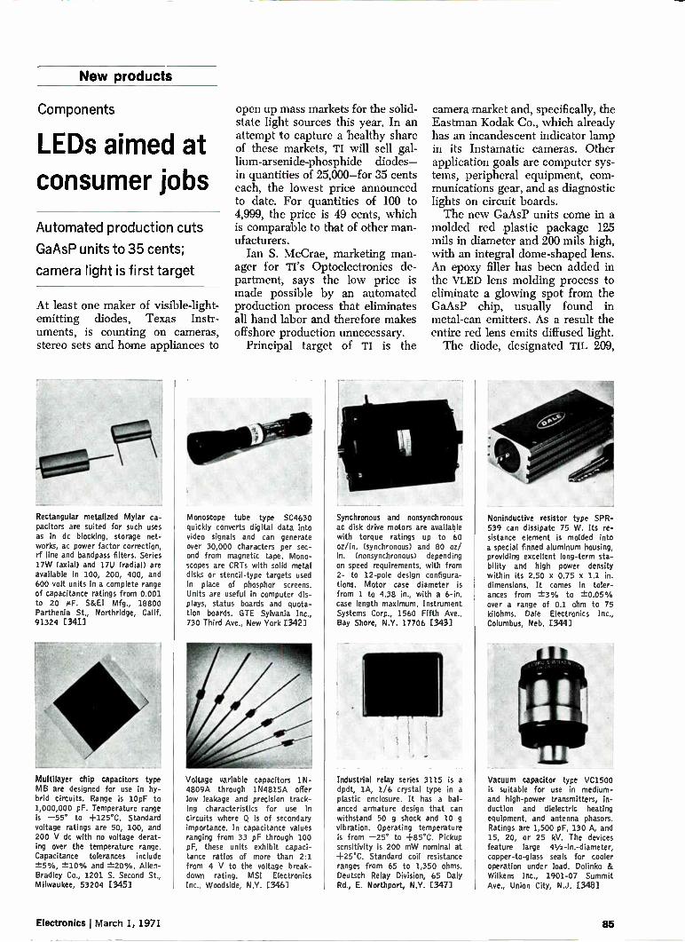
New products
Components
LEDs aimed at consumer jobs
Automated production cuts
GaAsP units to 35 cents;
camera light is first target
At least one maker of visible-light-emitting diodes, Texas Instr-uments, is counting on cameras, stereo sets and home appliances to
Rectangular metalized Mylar ca-pacitors are suited for such uses as in dc blocking, storage net-works, ac power factor correction, rf line and bandpass filters. Series 17W (axial) and 17U (radial) are available in 100, 200, 400, and 600 volt units in a complete range of capacitance ratings from 0.001 to 20 i/F. S&EI Mfg., 18800 Parthenia St., Northridge, Calif. 91324 [341]
Multilayer chip capacitors type MB are designed for use in hy-brid circuits. Range is 10pF to 1,000,000 pF. Temperature range is —55° to +125°C. Standard voltage ratings are 50, 100, and 200 V dc with no voltage derat-ing over the temperature range. Capacitance tolerances include ±5%, ±-10% and --I-20%. Allen-Bradley Co., 1201 S. Second St., Milwaukee, 53204 [345]
open up mass markets for the solid-state light sources this year. In an attempt to capture a healthy share of these markets, TI will sell gal-lium-arsenide-phosphide diodes— in quantities of 25,000—for 35 cents each, the lowest price announced to date. For quantities of 100 to 4,999, the price is 49 cents, which is comparable to that of other man-ufacturers.
Ian S. McCrae, marketing man-ager for TI's Optoelectronics de-partment, says the low price is made possible by an automated production process that eliminates all hand labor and therefore makes offshore production unnecessary.
Principal target of TI is the
Monoscope tube type SC4630 quickly converts digital data into video signals and can generate over 30,000 characters per sec-ond from magnetic tape. Mono-scopes are CRTs with solid metal disks or stencil-type targets used in place of phosphor screens. Units are useful in computer dis-plays, status boards and quota-tion boards. GTE Sylvania Inc., 730 Third Ave., New York [342]
Voltage variable capacitors 1N-4809A through 1N4815A offer low leakage and precision track-ing characteristics for use in circuits where Q is of secondary importance. In capacitance values ranging from 33 pF through 100 pF, these units exhibit capaci-tance ratios of more than 2:1 from 4 V to the voltage break-down rating. MSI Electronics Inc., Woodside, N.Y. [346]
camera market and, specifically, the Eastman Kodak Co., which already has an incandescent indicator lamp in its Instamatic cameras. Other application goals are computer sys-tems, peripheral equipment, com-munications gear, and as diagnostic lights on circuit boards. The new GaAsP units come in a
molded red plastic package 125 mils in diameter and 200 mils high, with an integral dome-shaped lens. An epoxy filler has been added in the VLED lens molding process to eliminate a glowing spot from the GaAsP chip, usually found in metal-can emitters. As a result the entire red lens emits diffused light. The diode, designated TIL 209,
Synchronous and nonsynchronous ac disk drive motors are available with torque ratings up to 60 oz/in. (synchronous) and 80 oz/ in. (nonsynchronous) depending on speed requirements, with from 2- to 12-pole design configura-tions. Motor case diameter is from 1 to 4.38 in., with a 6-in. case length maximum. Instrument Systems Corp., 1560 Fifth Ave., Bay Shore, N.Y. 17706 [343]
Industrial relay series 3115 is a dpdt, 1A, 1/6 crystal type in a plastic enclosure. It has a bal-anced armature design that can withstand 50 g shock and 10 g vibration. Operating temperature is from —25° to +85°C. Pickup sensitivity is 200 mW nominal at +25°C. Standard coil resistance ranges from 65 to 1,350 ohms. Deutsch Relay Division, 65 Daly Rd., E. Northport, N.Y. [347]
Noninductive resistor type SPR-539 can dissipate 75 W. Its re-sistance element is molded into a special finned aluminum housing, providing excellent long-term sta-bility and high power density within its 2.50 x 0.75 x 1.1 in. dimensions. It comes in toler-ances from ±-3% to ±-0.05% over a range of 0.1 ohm to 75 kilohms. Dale Electronics Inc., Columbus, Neb. [344]
Vacuum capacitor type VC1500 is suitable for use in medium-and high-power transmitters, in-duction and dielectric heating equipment, and antenna phasors. Ratings are 1,500 pF, 130 A, and 15, 20, or 25 kV. The devices feature large 41/2-in.-diameter, copper-to-glass seals for cooler operation under load. Dolinko & Wilkens Inc., 1901-07 Summit Ave., Union City, N.J. [348]
Electronics March 1, 1971 85

Monolithic crystal filters are becoming a popular topic of discussion these days. Since we've been making them longer (since 1967) and making more of them (over a quarter-million last year), we'd like to clear up a few misconceptions about the state-of-the-art.
1. Monolithics are expensive— Wrong. They cost less than conventional crystal filters. And, their low cost/high per-formance has brought reality to many "someday" applications.
2. There are no standard models—Wrong again. PTI has over 20 standards at the 10.7 MHz frequency alone. Plus a big selection of standards at other popular frequencies.
3. There isn't enough variety of packaging—Ph I offers several models in flatpack, upright mount and P.C. assembly. We've got more on the draw-ing board.
If you're now using standard crystal filters, or if you've been holding off because of cost, size or performance, we'd like to show you how monolithics can do the job better for less. Drop us a line and we'll send our new fact sheet.
For off-the-shelf or custom models, if you have questions about monolithics, we've got the answers.
Ut Piero Technology Inc.
2400 Diversified Way Orlando, Florida 32800 305-425-1574
The standard in monolithic crystal filters
New products
has a radiated power output of 15 microwatts minimum when the in-dicator device is forward-biased at 20 milliamperes. Even lower prices for even
brighter units are on the way, Mc-Crae says. TI is working with gal-lium-phosphide diodes and expects to market a GaP product line by mid-summer. With a high band-gap, McCrae says, GaP emits more brightly in the red than does GaAsP, so lower currents can pro-duce an equivalent brightness or the same current can result in brighter emission.
Further down the road is the gallium-aluminum-arsenide diode, which promises even more efficient operation. TI is now using them as laser pumps, operating in the infrared region. With the proper doping, McCrae points out, these units can emit in the visible spec-trum and will be a strong com-petitor to GaAsP and GaP. TI hopes to market visible-light GaAlAs di-odes by the end of 1971.
Texas Instruments Incorporated, Inquiry Answering Service, P.O. Box 5012, M/S 308, Dallas, Tex. 75222 [350]
Solid aluminum capacitors
to challenge tantalums
The solid tantalum capacitor, which has steadily been replacing other types in high-performance in-dustrial applications, may be in for a challenge from a solid-elec-trolyte aluminum-foil capacitor de-veloped by Philips Gloeilampen-fabrieken of Eindhoven in The Netherlands.
Philips is marketing its solid alu-minum 121 series in England, Sweden, and West Germany, and Amperex will market them in the U.S. The units will sell from 15 to 45% less than tantalums, depend-ing on size. The 121 series is produced in 30
capacitance-voltage combinations and in six case sizes, with rated voltages ranging from 6.3 to 40 volts. The technology closely fol-lows that of the dry-electrolyte alu-minum types, which consist of an aluminum-foil cathode and an
etched aluminum-foil anode that's covered with an aluminum-oxide dielectric layer. The cathode is in contact with paper impregnated with electrolyte. In the case of the solid aluminum capacitor, however, a glass fiber tape impregnated with manganese dioxide replaces the electrolyte-soaked paper.
Philips says the solid manganese dioxide does not attack the alu-minum oxide insulation and also prevents electrolytic losses by evaporation and decomposition at high temperatures. This results in high stability.
Philips engineers claim, too, that the solid aluminum units can take up to 15% reverse voltages with-out destruction, a feature that is important in applications, where current polarity may change. The new units can take a ripple current as high as 670 milliamperes for 330 microfarads at 6.3 v dc, or 325 mA for 47 le at 40 V dc. In addition, there is no limit on the discharge current so that series resistance in the circuit is not needed. One of the principal disadvant-
ages of solid aluminum types is size —they take up about four times the volume of tantalum for the same current-voltage product. But R. S. J. Geels, a Philips engineer, says the company expects to be able to persuade equipment makers to de-sign around the larger size, particu-larly in customized industrial ap-plications such as automobile safety devices where high reliability is re-quired over an extended period of time.
Philips sees other important mar-kets for the new capacitors in tele-communications, radar, unmanned relay stations, commercial radio, navigation systems and mobile tele-phone equipment.
Philips calculates the failure rate of solid aluminum at 0.01% per 1,-000 hours at 85°C with a confidence level of 60%. The corresponding tantalum unit for industrial appli-cation has a failure rate of 2% per 1,000 hours, according to the com-pany.
Amperex Electronic Corp., Component division, 35 Hoffman Ave., Hauppauge, N.Y. 11787 [351]
86 Circle 86 on reader service card Electronics March 1, 1971

New products
Instruments
Minicomputer power extended
Digital data distributor
lets single output channel
control up to 240 devices
Custom interfaces are usually needed if a minicomputer's few output channels have to control a great many devices. But now a
Test bridge 75-4320 is for in-coming inspection, quality con-trol, and production sorting of resistors. It has a wide resistance range of 0.1 ohm to 11 meg-ohms, tolerance limits up to -1--10% in steps of 0.01%, and fast response allowing over 100 tests/s. Power dissipation in the unknown resistance is less than 12 mW. James G. Biddle Co., Plymouth Meeting, Pa. [361]
Portable frequency counter model 4058, with a range from 10 Hz to 500 MHz, was designed for fast and accurate frequency checks of transmitters and field service. Unit offers a 100 mV input sensitivity over the entire frequency range, and an input im-pedance of 1 megohm from 10 Hz to 5 MHz and 50 ohms from 5 MHz to 500 MHz. Atec Inc., Box 19426, Houston [365]
digital data distributor developed by Hewlett-Packard Co. can extend the control capabilities of a single output to as many as 240 channels. The basic distributor, designated
the model 6936A Multiprogramer, can be coupled to as many as 15 model 6937A Extenders. Each of the 16 units expands one 16-bit minicomputer channel into 15 12-bit output channels for control of instruments or other devices—yet no change in computer hardware or software is needed.
In each of the 240 channels, plug-in cards provide outputs in the form of resistances, de voltages, contact closures or logic levels. Moreover, each Multiprogramer or
Wet WI HIM ...or
Mel an,
• 'f;
o
Bit error rate tester 2302/2301 generates pseudo-random test patterns of 63, 127, 511, 1,023, 2,047, and 32,767 bits as selected by a front panel control. Also selectable from the front panel Is the block size to be transmitted, including a free run mode which is ideal for running long-term reliability tests. Digitech Data Industries Inc., 22 Grove St., Ridgefield, Conn. (3621
Amplitude comparator model 52B-10 provides derived variables in the form of gate pulses as a func-tion of either threshold or meas-urement level. Using external counting pulses as high as 10 MHz, the unit can perform anal-yses of relatively low frequency signals. Input voltage is —5 to +5 V; frequency range, dc to 200 kHz. Disa-S&B Inc., Franklin Lakes, N.J. [366]
Extender will accept a combination of cards.
All the output channels are in-dividually and randomly address-able, a two-stage process. First, to select a Multiprogramer or Ex-tender, the computer transmits a control word containing the ad-dress of the desired unit. Second, to select the output card in that mainframe, it transmits a data word containing the numerical data and the card position. The two words are routed by the system's address and control logic to the addressed channel in the coned unit, where the numerical data is stored on the output plug-in card. Complete output isolation among
Reflectometer PRH-1 locates and identifies transmission line and antenna faults. With this equip-ment, line faults, faulty switches, line transitions and turns, stubs, and other line features can be seen along a calibrated range scale. The unit drives the trans-mission line with high voltage, gaussian shaped pulses. Delta Electronics, 4206 Wheeler Ave., Alexandria, Va. [363]
Solid state, platinum resistance thermometers models 551-3 and 551-4 are plug-in modules that combine with the model 251 main frame for temperature measure-ment using platinum resistance probes. The plug-in concept al-lows for convenient conversion from voltage measurement to wide-range temperature measure-ment. United Systems Corp., 918 Woodley Rd., Dayton, Ohio [3671
Tasco-Hirst digital Hall-effect gaussmeter model GM7OD has five non-overlapping measurement ranges from 20 gauss to 40 kilo-gauss, with the lowest resolution of 0.01 gauss. Basic detection circuit is a computer-designed signal detector incorporating nine ICs affording a very high measure-ment stability. Thomas & Skinner Inc., 1120 E. 23rd St., IndIgn-apolis 46205 [364]
Impedance bridge 330A measures resistance, capacitance and induc-tance of electronic components. Readout is direct and free from calculation errors; the decimal point and range units are auto-matically displayed. The standard unit has accuracies of --L-0.05% for resistance and --L-0.2% for capacitance or inductance. Price is $510. General Metrology Corp., Box 471, Edmonds, Wash. [36E]
Electronics I March 1, 1971 87

Trigger On A Free Triac Or Two. ... it'll handle up to 1,000 watts, full-wave! ... reliably and at low-cost! ... 25 to 600 volts!
The new, 4 A plastic Thermopad* Triac is destined to find its economy-minded way into more medium-current, power control designs than you can shake a price list at — and, you can get a 200-volt MAC77 Triac together with the MBS4991 trigger and 2 application notes from your Motorola distribu-tor . . . right now . . . for your workbench prototype . . . FREE!
And, if you're into lamp and relay drivers, small motor controls, gate drivers for larger thyris-tors and sensing and detection circuits, tell your dis-tributor you want a free 800 mA, 200 V Unibloc* SCR — optimized . . . and priced . . . for 3 different temperature requirements.
Big enough to handle 1,000 watts, yet inex-pensive enough to be 100-up priced at only 86e at 200 V, the new MAC77/2N6068 series features reli-able, fully glass-passivated (glassivated) construc-tion. And high operating temperature capability is afforded by low forward voltage drop and low thermal resistance. ejc is, in fact, only 3.5° C/W making them naturals for demanding industrial/consumer motor controls, light dimmers and relay replacements, particularly where heat sinking problems occur.
Symmetrical gate and hold characteristics ensure consistent bidirectional switching. Both are low, 30 mA maximums.
Its nearest competitor costs over 10% more at 200 volts!
The MAC77/2N6068's hand-in-glove partner in phase-control, the MBS4991 bilateral switch, pro-vides 0.2% / ° C temperature coefficient, uniform con-duction characteristics in both directions and built-in protection against premature firing. It turns on in 1 microsecond!
Contact your Motorola distributor today . . . ADDRESS
put it all together with Motorola thyristor power CITY
control — FREE!
AN-466
CIRCUIT APPLICATIONS FOR THE TRIAC
MO
FREE 4 A MAC77-4 200 V Triac + AN466
ucta Inc
...and the broadest line of
plastic thyristors available!
Circle the reader number and receive data sheets on them all. Or write Box 20912, Phoenix 85036 to trigger an immediate response to your immediate power control application needs.
Trigger Me On A Free Thyristor Or Two TO: (Distributor) Send me: D MAC77-4 (2N6071)/MBS4991 200 V Triac Design Kit
2N5064 200 V SCR Design Kit
NAME
TITLE
COMPANY
STATE ZIP
TRADEMARK MOTOROLA INC.
88 Circle 88 on reader service card
MOTOROLA THYRISTORS —300 ways to get control
Electronics March 1, 1971

AN-526
THEORY, CHARACTERISTICS NO APPIJCADONS OF SOWN UNILATERAL, AND BLATERAL SWITCHES
M1*. MO .1 Nalwann
....••••••••••0•0•••••
• •••••
t..*•••• I.. Me •0 ••••• ..••••••••
Pe I0
rn bROLA SefrolwInetee• Product* Ina.
FREE Full-Wave MBS4991 Bilateral Switch + AN526
MAC10/11 Triacs — 10 A glassivated ruggedness in 2 or 4 quadrants 2N4441-44 — Glassivated 8 A plastic SCR MCR406/407-Sensitive-gate 4 A SCR
III FREE 2N5060-68/MCR101-104, MCR115-120 SCRs — 800 mA, sensitive-gate, 85°, 110° or 125° application
MCR106 SCR — True power rated, sensitive-gate
MUS4987/MBS4991 — Bilateral/Unilateral triggers for phase-control
2N4870's — Versatile, economical unijunction transistors MU4891's — Wide-spec-choice-at-low-cost unijunctions MPU-131's — Programmable, nanoampere leakage unijunctions
1--, MU851's — Compact, 1 MHz, color-coded, computer unijunctions
New products
channels is achieved with either relays or pulse transformers. Iso-lated bias supplies in each unit in-dependently power the output cir-cuitry of each card. Each data transmission takes 10
microseconds, fast enough for ef-ficient operation with most com-puters but not so fast that it's extremely sensitive to noise, H-P says. Rather than being detected in sample and hold circuits, data is stored on each channel indef-initely. As a result, there's no need for the computer to refresh it pe-riodically. One of the first orders for the
system came from Eli Lilly Co. The pharmaceutical company is us-ing it to control the oven tempera-ture and conveyor and blower speeds in production of drug cap-sules. Bell Telephone Laborator-ies has another system that's being used to test racks of telephone switching equipment. Among other applications con-
templated for the Multiprogramer system are power supply program-ing, and directing automatic con-trol and test systems. The tech-nique can also be used to turn on such devices as valves, stepping motors, chart and X-Y recorders, cathode-ray tube displays, pulse generators, and solenoids. Cost of the model 6936A Multi-
programer mainframe is $1,200. Each model 6937A Extender main-frame sells for $750. Output cards must be purchased separately at $350 each. Delivery takes five weeks.
Hewlett-Packard Co., 1601 California Ave., Palo Alto, Calif. 94304 [369]
Analog multiplier on a chip
offers 1% overall accuracy
One way to develop a circuit that multiplies, divides, squares, and takes square roots is to design an operational amplifier into the ex-ternal feedback loop of an inte-grated circuit multiplier. The ac-curacy of the completed circuit depends on the skill of the design engineer. Now the same results can be achieved without external
circuitry or special design expertise through an IC analog multiplier on a monolithic chip. Analog multipliers formerly were
restricted to analog data processing applications and in communication systems, such as modems, detec-tors, discriminators, and mixers. But Analog Devices Inc. hopes to end all that with complete multi-pliers that sell for as little as $20 each. They can be used in ampli-tude stabilizing circuits, function generators, and response linear-izers. And since they can generate a power series—F(x)=A + Bx + Cx2 + Dx3 + .. .—the devices can be used to represent any continuous mathematical function, opening up possibilities for generating or simu-lating responses of industrial proc-esses, instruments, and transducers.
Called the AD530 series, the monolithic chips are hermetically sealed into 10-pin TO-100 packages; a dual in-line configuration is planned for the future. Overall cir-cuit accuracies of 1% and 2% are available in the AD530K and AD530J, respectively. Small-signal response of both units is 1 mega-hertz, while full power response is 750 kilohertz; slew rate is 45 volts per microsecond. Output of the AD530 is -±-10 volts and 5 milli-amperes; input voltage is -±-15 V dc. The analog multipliers' input im-
pedance is 7 megohms minimum on both X and Y channels. Tempera-ture drift is 0.04%/°C for overall accuracy and 0.03%/°C for gain. Maximum nonlinearity is 0.5%, while Y-channel linearity is 0.15%, making the units suitable for pre-cision attenuator applications. Op-erating temperature range of the devices is 0 to 70°C.
Prices for the AD530J and AD530K are $20 and $30, respectively, in quantities of 100. Prices are ex-pected to drop as low as $10 each as manufacturing techniques im-prove. Delivery time is two weeks. An AD530s that operates from —55° to +125°C, and an AD530L unit with 0.5% overall accuracy will be the next in the series.
Analog Devices Inc., 221 Fifth St., Cam-bridge, Mass. 02142 [370]
Electronics I March 1, 1971 89

SEARCHLIGHT SECTION • CLASSIFIED ADVERTISING • BUSINESS OPPORTUNITIES • USED OR SURPLUS EQUIPMENT
AUTOTRACK MOUNT 360 degree azimuth, 210 degree elevation sweep with better than 1 mll. accuracy. Missile velocity acceleration and !dewing rates. Amplidyne and servo control. Will handle up to 20 ft. dish. Sup-plied complete with con-trol chassis. In stock— immediate delivery. Used world over by NASA, USAF, MP-61-B. Type SCR-584. Ideal satellite tracking.
- Large spare parts inven-tory for back-up.
ANTI-AIRCRAFT- GUN M OUNT Will handle 6,000 lbs. rapid slew through 360" azi-muth, 180° elevation. Mobile.
COUNTERMEASURES SYSTEM Covers L-band, S-band. X-band, all radars. Tacan. UHF drone control, VHF drone control, Communi-cations band. All housed in shelter.
FIBERGLASS RADOME Will handle 20 foot antenna. Easily erected & shipped.
B-58 BOMBER ELECTRONICS Ku band search radar. Ku doppler radar, Ku alti-meter, all jamming countermeasures.
PULSE MODULATORS
MIT MODEL 9 PULSER 1 MW — HARD TUBE Output 251tv 40 amp., 30kv 40 amp. max. Duty ri. .002. .25 to 2 microsee Also 5 to 5 mieroaeo. and .1 to .5 microsee Uses 6C21. Input 115v 60 cycle AC. Mfg. GE. Complete with driver and high voltage power supply. Ref: MIT Rad. Lab. Series, Vol. 5, p. 152.
2 MEGAWATT PULSER Output 30 kv at 70 amp. Duty cycle .001. Rep. rates. 1 micreoec. 600 cps. 1 or 2 msee 300 pps. Use, 5048 hydrogen thyratron. Input 120/208 VAC 60 cycle. Mfr. GE. Complete with high voltage power supply.
SCR 584 AUTOTRACK RADARS Our 584s in like new condition ready to go, and in stock for immediate delivers. Ideal for telemetry research and develop-ment, missile tracking, satellite tracking. Fully Dew. MIT Rad. Lab. Series, Vol. 1. PPS. 207-210, 228, 284-288. Comp. Inst. Bk available $25.00 each.
AUTOMATIC TRACKING SYSTEM Sc!. AU. Mod. 3101-770 Antenna Pedestal. AZ-EL 15 deg, per second rated speed. 23 inch dia. bearing. Complete w/oontrol console 8r mag. amplifiers. Also in stock complete 010-track receiving system for 200-400 MHZ telemetry band including 12' square Quad. Helix. All part of Atlas missile instrumenta-tion system
MICROWAVE SYSTEMS
SPARE PARTS IN STOCK Nike Max, Nike Hercules, M-33, MPS-19, TPS-ID, TPS-10D, FPS-6 SM. SCR 584, BLPQ-18.
From Largest Inventory In World
KU BAND RF HEAD 6.5 GHz, 50 KW, .001 duty cycle, 45 Watts avg. come. w/5C22 modulator come. recv. Mfr. Emer-son Electrio. L BAND RF PKG 0 KW peak 990 to 1040 MC. Pulse width .7 to 1.2 micro gee Rep. rate 180 to 420 pps. Input 115 vac
MICROWAVE LINKS C BAND Piffle., CLR6, CLR7, CLIO. Radar video link. Motorola M.LIR-4.
X BAND FIRE CONTROL SYSTEM MD-4, A5, APG, 32 system. 50 KW Autotrack. rom plate system, all cables etc., incL gun turret if de ired.
AN/MPQ-29 3CM AUTOTRACK SYSTEM Complete with plotting boards in van. Capable of rain or beacon track. Ideal for moon drone, etc. Airborne beacons also in stock.
500 KW L BAND RADAR 500 kw 1220-1359 mac. 160 nautical mile search range PILL and A :scopes. DITI. thyratron mod 5326 magnetron. Complete system. C BAND AUTOTRACK 1 Megawatt 10 ft. Parabola. Sperry.
«MOT MORE IN STOIER LARGEST RADAR
INVENTORY IN MEL WIRE TOR (*TAIGA ON YOUR
IITTERNIA0
AN/GPG-1 SKYSWEEP TRACKER 3 cm. auto, tracking radar system. COMP. Pkg, w/indicator aye. Full target acquisi-tion & auto. tracking. Input 115v 60 ri. new. In stock few burned. del. Entire sra. 6' X 3' x 10'. Ideal for infrared tracker, drone tracker, missile tracker, R & D
INDICATOR CONSOLES AN/SPA-4A, PPI 10", range to 300 rai. V7-1 PPI 12 Range to 200 mi. VL-1 RHI 12" to 200, mi 60K ft. FPS-6 FUS-8 PRI. CPS-6B PPI. plus many more.
Radio-Research Instrument Co. 45 W. 45th St., New York, N.Y. 10036 212-586-4691•
POSITION WANTED
Senior Engineer—Industrial, Medical Elec-
tronic, electro-mesh. planning, design, super-
vision. 20 years exp. PW-3469, Electronics.
CIRCLE 966 ON READER SERVICE CARD
Sold! "Please discontinue our ad in 'The Trac-ers Section' as we have sold the equip-ment through this advertising."
Can This Section Serve You?
"SEARCHLIGHT"
is
OPPORTUNITY ADVERTISING
—to help you get what you want.
—to help you sell what you no longer need.
Take Advantage of it—For Every Business Want
"Think SEARCHLIGHT First"
New products
Counter with diode readout
is small in size and price
Thanks to extensive use of standard medium-scale integrated circuits, engineers at Monsel Electronic In-struments Ltd., Monsanto's sub-sidiary in Israel, were able to trim the size and price of a five-digit frequency counter, the 150A. Measuring 41/2 by 2 by 71/2
inches, the instrument is small enough to be picked up with one hand. And with a selling price of $475, it is one of the lowest-priced counters on the market. Light-emit-ting diodes provide the readout. Range of the 150A is 10 hertz to
32 megahertz. A built-in memory permits it to hold a reading until another has been taken. Intended primarily for field work,
the unit weighs a little over a half-pound, and can run off a battery. Dc input range is 10 to 32 volts. For ac operation, the 150A takes either a 50- or 60-Hz supply. Power dissipation is 6 watts. With only two front-panel con-
trols, the 150A is easy to operate. A dial adjusts sensitivity from a maximum of 50 millivolts rms. It also switches in a display-check circuit. The time-base switch selects
either automatic operation or a 1-second time base. If the switch is set to automatic (autoranging), the counter selects the smallest gate time that will provide five-digit resolution for signals above 10 kilohertz. For lower-frequency inputs, a 1-second base is auto-matically selected. The 1-second setting maintains
this time base for the entire fre-quency range, thereby allowing better than five-digit resolution for signals above 10 kHz. For example, if the input frequency is 8,365,732 Hz, the 150A displays 83657 MHz when set to automatic. 'When the 1-second time base is chosen, how-ever, the instrument reads 65732 Hz and an overrange light comes on. Therefore, the 150A has up to eight digits of resolution.
Monsanto Electronic Instruments, 630 Passaic Ave., West Caldwell, N.J. [372]
90 Electronics I March 1, 1971

Xerox Oscillographic Papers: 31 B.C. , ,... (Before Copiers)
àtic- le
or> 4M,
Forty-one years ago-31 years before copiers—Xerox made great oscillographic papers.
And we've been improving them ever since. You can order them direct from your local Xerox Product Specialist listed in your telephone directory for fast shipment from our Regional Supply Centers—our way of helping you save time and money, while solving storage and delivery problems. Check performance, price and service benefit that's yours with Xerox Astroprint DP90. Xerox Corporation, Business Products Group, Department HL, Rochester, New York 14603.
XEROX. Electronics March 1, 1971
Xerox and Astroprint are registered trademarks of Xerox Corporation
Circle 91 on reader service card 91

How Culligan Reverse Osmosis/Deionization System gives Teledyne quality water at less cost
In the competitive electronics business, transistor yield rate can mean the difference between profit and loss. And the biggest cause of low yields is impurities in manufacturing. That's why Teledyne Semiconductor, Los Angeles,
uses a Culligan Reverse Osmosis/Deionization System plus ozonation to insure that all water used in the manu-facture of its transistors is of extremely high purity. The system provides Teledyne with water of 18 megohms resistivity and virtually zero bacteria count. This water is used to rinse transistor wafers after each photo resist and etching process.
"Yield is strongly dependent on the quality of the rinse water," says Group Executive Dr. D. M. Van Winkle. "The plant would have to shut down without quality water. That's how important it is to us." Compare this to the situation before our system was
installed. The plant bought distilled water at 2.70 per gallon; Culligan water costs 0.80 per gallon. Best quality
of the distilled water was 2 megohms, compared to the present 18 megohms. The Culligan system meets all the plant's volume de-
mands, too. It is supplying Teledyne 20,000 gallons per day, which means savings of $380 per day! Supplying very high quality water at any volume
is a Culligan specialty, and our RO/DI systems are available in a wide range of capacities: from 500 gal-lons per day with packaged systems, to 60,000 gallons per day with customized installations built with modular components.
In addition to conditioning process and production water, Culligan capability includes equipment for soft-ening, filtration, boiler water, cooling towers, and waste water treatment.
Call your local Culligan Man today for a consultation. He will evaluate your own specific water needs as to flow, quality, application, and complete treatment equipment requirements.
THE WORLD-WIDE WATER CONDITIONING PEOPLE
10
WHO SERVE YOU BETTER LOCALLY
Franchised Dealers in the U.S. and 85 countries. Culligan International Headquarters, Northbrook, Illinois 60062. Franchises available.
92 Circle 92 on reader service card Electronics I March 1, 1971

New products
Packaging and production
Bonding done in one stroke
Machine connects all leads
to substrate, can handle
up to 400 devices an hour
Developments in bonding leads to chips have overshadowed the equally important job of connect-ing the lead frame and the sub-
Plated wire array tester model 5501 is announced. Word address selection uses a solid state selec-tion switch to deliver up to 1.2 amperes of pulse current at pro-gram speeds of less than 1 eis word line to word line. Digit ad-dress selection uses double pole reed relays with a switching speed of 2 ms. Price is $85,000. Tech-nitrol Inc., E. Allegheny Ave., Philadelphia, Pa. [421]
Thermal wire stripper model A5C safely and quickly removes in-sulations from all types of ther-moplastic insulations. A multi-level temperature control provides choice of temperature for fast insulation removal, while a finger-tip lever precisely controls strip-ping element contact pressure to handle the finest standard wires. The Eraser Co., P.O. Box 1342, Syracuse, N.Y. (425]
strate pad. In packages that use substrates, such contacts are usu-ally soldered, brazed, or welded. Now a thermocompression unit is available that bonds all leads to the substrate simultaneously. The new unit also makes a more
reliable connection, according to the manufacturer, Donovan Indus-tries. The machine can make all bonds in about eight seconds. It gives an intimate gold-to-gold con-tact, and the process could be mechanized with an automatic feed system. The machine can handle 300 to 400 devices an hour in the manual mode. An operator sets the desired time,
pressure, and bonding tempera-
High production speeds, greater accuracy, and ease of operation characterize the Accu-Speed com-ponent lead former. The unit is designed to multi-cut and form axial leads of components such as resistors, diodes, and capacitors. It will cut 18,000 to 25,000 com-ponents per hour depending on type of feed. Lectro Precision Tools Inc., P.O. Box 1360, Min-netonka, Minn. 55343 [422]
Compact vapor degreaser, called Porta/Flex, is suited for devel-oping photoresist, removing silk screen etch resist inks, and re-moving flux after soldering. It can also be used for degreasing parts prior to plating, printing, and soldering. Overall height of the unit is 31 in. Cleaning capac-ity is 200 pounds per hour. Porta/ Flex Corp., 50 Wall St., Bing-hamton, N.Y. 13901 [426]
ture, inserts the substrate and lead frame in the alignment fixture, and then presses palm buttons with both hands—a safety feature. The ram then comes down and com-pletes the bonds in one stroke. Temperature can be set up to
600°C, time up to 30 seconds, and pressure up to 1,000 pounds. The bonding ram requires 80 pounds-per-square-inch of air.
In developing any bonding sys-tem, the designer factors in pres-sure, temperature, and time to set up the proper bonding cycle. For each lead material and dimension, these have to be adjusted depend-ing on the number of leads over which the ram pressure is going
Torsion-bar squeegee pressure control is designed for thick-film IC production. The torsion head imparts a floating action to the squeegee blade as it travels through its printing stroke, allow-ing the squeegee to adjust for substrate thickness and camber changes while maintaining a con-stant pressure. Affiliated Manu-facturers Inc., P.O. Box 248, Whitehouse, N.J. 08888 [423]
Automated electrochemical etch-ing system, called Etch/Path System 100, is for semiconductor wafer production. The simultane-ous etching of aluminum on 20 semiconductor wafers is accom-plished with unattended operation by unskilled personnel. The price of $3,380 includes a control unit, an etching tank and a wafer boat. NuTek Industries Inc., Box 651, Mountain View, Calif. [427]
Low-profile headers, specifically designed for wave or dip soldering to pc boards up to 0.125 in. thick, accept IC packages having 14 or 16 rectangular leads up to 0.015 x 0.030 in. Only 0.150 in. high, the one-piece glass-filled nylon housing provides wide, angu-lar lead-in for easy insertion and is visually polarized to facilitate mounting. AMP Inc., Harrisburg, Pa. 17105 [424]
A series of 14-pin dual in-line headers, with caps, is available. The headers have gold plated pins laid out in the 0.100 x 0.300 in. DIP grid. U-shaped openings in the tops of the pins accept component leads to wire size 24. Four different snap-on caps pro-vide mechanical protection for many component types and sizes. Design & Production Associates, San Bernardino, Calif. [4281
Electronics March 1, 1971 93

Save Cost Enjoy Quality with TOKO INC. Announcing a new cost saving
plan on PCB assembly with transfermolded Dual-In-Line
PULSE TRANSFORMERS
and DELAY LINES
by thick film approach.
Offering a wide range of custom-designed features
which meet your
requirements.
for further information, just call or write
TOKO, INC. Head Office: I-17,2-chome, Higashi-Yukigaya, Ohta-ku, Tokyo, Japan
New York: Toko New York Inc. 350 Fifth Avenue, New York, N.Y. 10001 U.S.A. Tel: 565-3767
Los Angeles: Toko, Inc. Los Angeles Liaison Office 1830 West Olympic Blvd., Los Angeles, 90036 Cal. U.S.A. Tel: 380-0417
Düsseldorf: Toko, Inc. Europe Liaison Office 4 Düsseldorf, Kolner StraBe 246, Düsseldorf, W. Germany Tel: 78-7064
Circle 115 on reader service card See us at the IEEE Show—Booths 1708-10
0
Samples Show How
die cast NEW MOLDING PROCESS
ZINC ALLOY JOINS 2 DIFFERENT PLASTICS IN A
ce
molded PLASTICS
e.®
Coil Bobbins Gears & Pinions
SINGLE SMALL PART • Combine different col-
ors, physical, chemical properties of different plastics in a single tiny component.
• Movable-element parts, separable parts, two-color parts, numbered and lettered parts, com-bination-of-materials parts.
• Saves assembly costs, enhances appearance, performance of your product.
Write today for "inter-mold" samples and detailed bulletin.
Giles Reproducer Co. Division of Coats 8. Clark Inc.
151 Beechwood Ave., New Rochelle, N.Y. 10802 (914) 633-8600
THSTOiBSTIBI1/4 TO M B01 W.
If something's going wrong, it'll tell you. 1. Change in bowel or bladder habits. 2. A sore that does not heal. 3. Unusual bleeding or discharge. 4. Thickening or lump
in breast or elsewhere. 5. Indigestion or difficulty
in swallowing. 6. Obvious change in wart or mole. 7. Nagging cough or hoarseness.
If you have a warning signal, see your doctor. If it's a false alarm, he'll tell you. If it isn't, you can give him time to help. Don't be afraid. It's what you don't know that can hurt you.
American Cancer Society
One-shot bonding. Thermocompression bonds for lead frame are made with adjustable time, heat, and pressure.
to be distributed. One potential problem is that a
ceramic substrate will crack dur-ing the heavy bonding pressure. To prevent this, the Donovan machine uses pin supports under each bond in the alignment fixture to support the substrate and keep it from bending, and thus cracking. How-ever, ceramic is strong in compres-sion and easily withstands bonding pressure when supported. A dual-pressure feature is avail-
able as an option. With this feature, the ram descends at low pressure, contacts the substrate, and then waits a fixed length of time for the package to heat up. A second timer then takes over, and full bonding pressure is applied for a one-second interval. This is useful with heavy packages where it's de-sirable to give the substrate a chance to soak up heat first, and in multiple-lead packages where the bonding head must adjust to the different heights of the leads be-fore applying the final pressure. A machine with 2,000-lb bonding
force also is available. Price of the 1,000-lb unit, the
1560-1F, is $3,175. The dual-pres-sure arrangement is about $300 extra. Donovan Industries, Scotia, N.Y. 12302 [430]
94 Circle 94 on reader service card Electronics I March 1, 1971

New products
Data handling
Core pattern speeds memory
Edge-mounting technique
helps give 64,000-word unit
an access time of 250 ns
Closely following its introduction of a core memory stack using a new mounting technique [Electronics, Nov. 9, 1970, P. 119], the Computer
Four-transport magnetic tape system, model 4196 CartriFile, is for small digital computers. The transports are independently controlled by electronic circuitry that allows the computer to write data on one tape while reading from another. Each tape loop can hold over 3 million data bits. Complete system costs $6,050. Tri-Data Corp., 800 Maude Ave., Mountain View, Calif. [4011
Portable instrumentation tape re-corder/reproducer CPR-4000 of-fers precise automatic tape threading. It has seven electri-cally switchable speeds, from il to 60 in./s. It is capable of re-cording and reproducing up to seven channels on half-inch tape and accepts eight-inch-diameter reels. Unit weighs 70 lb. Bell & Howell Co., 360 Sierra Madre Villa, Pasadena, Calif. [4051
Products division of Ampex Corp., logically enough, has unveiled the first systems using the design. They are the 1800 and 3600 series mem-ories, offering maximum capacities of 8,000 words by 18 bits and 16,-000 words by 36 bits, respectively.
Robert Pryciak, product manager for core and semiconductor prod-ucts in the division, says the new series differs from memory systems with comparable capacities in a number of ways. The first is the interleaved, herringbone-patterned core arrangement. This allows the cores to be edge-mounted on centers equivalent to one-half their outside diameters; conventional techniques usually dictate edge-
General-purpose data acquisition system model S-4 will scan up to 100 3-wire channels of resist-ance, voltage or currents, convert these analog signals to three- or four-digit measurements and re-cord the values, along with fixed data and clock information on a wide choice of output recording devices. A basic system costs $3,535. Non-Linear Systems Inc., Box N, Del Mar, Calif. (4021
Rack-mountable analog signal multiplexing and converting unit MD40 offers accuracy up to 0.025% of full scale with reso-lution of 8 to 13 bits and through-put to 100,000 samples/s. Six data output formats are available: is or 2s complement (serial or parallel), sign-magnitude (paral-lel), or BCD (parallel). Xerox Data Systems, S. Aviation Blvd., El Segundo, Calif. [4061
mounting cores at right angles to each other, and on centers equal to one core diameter apart.
This is the primary factor respon-sible for the memories' high den-sity, Ampex engineers say. They're putting 7,000 18-mil-diameter cores in one square inch of board space, compared with 2,500 such cores with conventional-mounting meth-ods. Ampex has put all associated
electronics—drivers, sense ampli-fiers, timing controls, and interface hardware—on two circuit boards. Thus, the model 1865, with a maxi-mum of 64,000 words, consists of two cards of electronics and one card holding the core stack. The
Auto-Pro 3109 intercoupler is de-signed to convert digital BCD in-put of up to 16 bits into an ASCII format directly suitable for an ASR33 teletypewriter. It pro-vides output in a direct entry format for most data processors, including timesharing. Unit has front panel pushbutton, as well as remote controls. Beckman Instru-ments Inc., 2500 Harbor Blvd., Fullerton, Calif. 92634 [4031
Programable data generator 0G-1200A operates from 1 Hz to 120 MHz with its own internal oscillator, provides a serial data stream 16 bits long, and can op-erate in either RZ or NRZ fer-mat. Output signals feature 72:2.5 V offset and 2.5 V signal amplitude with 1.5 ns rise and fall. Price is $3,385. Tau-Tron Inc., 685 Lawrence St., Lowell, Mass. 01852 [41071
Any number of up to 100 paral-lel inputs can be coupled to up to 3 output devices driven by the versatile model 4200 data cou-pler. Two differently coded serial devices and one parallel device can be driven simultaneously. Unit couples multiple devices with digital outputs to a wide variety of recording machines. Monitor Laboratories Inc , 10451 Roselle, San Diego, Calif. [494]
Rugged memory system CR-75 features 750-nanosecond cyctE time. It is available in capacities of 4,096 or 8,192 words with a wide range of word structures— up to 20 bits for 8K and 40 bits for 4K versions. Calculated mean time between failure is 10,000 h, but field experience indicates re liability far exceeding this. Loch-heed Electronics Co., 62a1 E. Randolph St., Los Angeles [40ir
Electronics March 1, 1971 95

New products
stack plugs into both cards, forming the center of a sandwich-like arrangement. This model's full cycle time is 650 nanoseconds; access time is 250 ns. And by combining the new mounting technique with shorter drive and sense lines, Ampex claims, the core signal delay time is cut to half that of previous models. The model 1890 has a maximum capacity of 64,000
words, but is slightly slower due to its 22-mil-diameter cores: cycle time is 900 ns and access time is 350 ns. The two models in the 3600 series are the 3665 and
3690. Their capacities range between 64,000 and 131,-000 words. The 3665 is the faster at 650-ns cycle and 250-ns access times; the 3690 has 900-ns cycle and
Memory sandwich. Two circuit cards hold the
electronics, and the core stack plugs into both.
350-ns access times. Pryciak says most competitive systems either use
larger boards for their associated electronics, or more of them. The Ampex board sizes are 8 by 10 inches; this compares with-13 by 13, or 13 by 15 inches for competitive units, he maintains. No cabling or harnesses are used to interconnect the
boards: printed wiring and pin interconnects are used throughout. Further, Pryciak says the memories require only two power supply voltages, compared with three or four for competitive systems. The 1800 series uses ± 5 volts for all integrated circuits (TTL) and interface electronics, and a — 15-v drive level; the 3600 series uses ± 5 y and — 28 v.
Pryciak looks for the memories to be used primarily in mini- and medium-sized computer applications. Price in quantities of 100 or more will be "less than 2 cents a bit," he says. Delivery time is 60 to 90 days.
Computer Products division, Ampex Corp., 9937 W. Jefferson Blvd., Culver City, Calif. 90230 [409]
Di] 250- HI
OFF-THE-SHELF DELIVERY
ADDRESS "0"< 0.8V ,"7"› 2.0V
Bipolar Schottky design, programmable by the user to give maximum flexibility in computer and process control systems. Compatible with standard DTL and TTL logic.
• Propagation Delay — 5Ons • Organization — 256 word x 1 bit • Output "Three State", allowing both "OR-tie" and active pull-up • Operating Power — 500mW • Sink Current — 20mA
The HROM-1256 is available in a hermetically sealed 16-pin dual in-line package at: $23.50*ea. (0°C to +75°C) and $30.75*ea. (-55°C to +125°C)
*100 to 999 unit price.
HARRIS SEMICONDUCTOR
A DIVISION OF HARRIS- INTERTYPE CORPORATION
P. 0. Box 883. Melbourne. Florida 32901 (305) 727.5430 DISTRIBUTORS: HARVET/R & D ELECTRONICS—Lexington. Mass. (617) 861.9200/R. V. WEMHERFORD CO. Albta queroue (505) 2654112. Anaheim (714) 547.0891. Dallas (214) 231-6051, Denver (303) Enterprise 165, Glendale (213) 849.3451. Palo Alto (415) 321.5373. Phoenix (602) 272.7144. Pomona (7(4) 623-1261. San Diego (714) 278-7400, Seattle (206) 762-4200/SEMICONDUCTOR SPECIALISTS INC.—Chicago (312) 279.1000. Detroit (313) 255-0300, Minneapolis (6)2) 884.8132, Kansas City (816) 452-3900. St. Louis (314) 428.6100, Dallas (214) 358.5211, Indian-apolis (3(7) 243-8271, Pittsburgh (412) 781.8120, Dayton (513) 278-9455.
96 Circle 96 on reader service card

IN STOCK RELIABLE LOW COST
The Harris family is designed to solve your problems When you need to — convert to binary or decimal codes, convert voltage to current pulses, interface with modems, transmit and receive over a party line, encode a key-board or restore current pulses to voltage pulses — Call Harris.
DIGITAL I.C.'s Keyboard Encoder
Adapt to any Binary code HD-0165
Line Driver/Receiver Meets EIA RS-232-C Interface specification HD-1488, HD-1489
Party Line Transmitter/Receiver Compatible with DTL and TTL Logic HA-245, HA-246
Diode Matrix Easily customized to specific pattern 7 configurations
When you need to—amplify, buffer, compare, multiplex, convert D to A or anything else in analog signal processing — Call Harris.
LINEAR IC's Op Amp
General Purpose/ Low Power HA-2700 Wide Band HA-2620, HA-2625 High Slew Rate HA-2500, HA-2510, HA-2520 Low Noise HA-2909 High Impedance HA-2600
8-Bit D/A Converter Monolithic/Guaranteed Accuracy HI-1080
10-Bit Ladder Network Low Cost, High Accuracy HI-0910, HI-1010
16-Channel Multiplexer J-FET/Bipolar HS-1000
When you need to— convert a code, microprogram a computer, store information and recover it quickly — Call Harris.
MEMORY IC's 64 x 8 PROM T.
Field Programmable HROM-0512
256 x 1 PROM*. Field Programmable Very high speed HROM-1256
16-Bit RAM High speed HRAM-0016
64-Bit RAM High speed, fully decoded HRAM-0064
LII
• HARRIS P. 0. Box 883, Melbourne, Florida 32901 110 Please send me more information on the Harris Off-the-shelf IC's checked below.
NAME
ADDRESS
111 CITY
Li
E
Memories
Linear Circuits
Digital Circuits
TITLE
STATE
SEMICONDUCTOR A DIVISION OF HARRIS- INTERTYPE CORPORATION
DISTRIBUTORS, HARVEY 'R & D ELECTRONICS—Lexington, Mass. (617) 861 9200 R. V. WEATHERFORD CO.—Albuquerque (505) 265 6112. Ana• heim (714) 547.0891, Dallas (214) 231 6051. Denver (303) Enterprise 165. Glendale (213) 849-3451. Palo Alto (415) 321.5373. Phoenix (602) 272.7144. Pomona (714) 623.1261. San Dmgo (714) 278.7400. Seattle (206) 762.4200 SEMICONDUCTOR SPECIALISTS INC. — Chicago (312) 279.1000. Detroit (313) 255 0300. Minneapolis (612) 884.8132. Kansas City (816) 452.3900. St. Louis (314) 428 6100. Dallas (214) 358.5211. Indianapolis (317) 243-8271, Pittsburgh (412) 781-8120, DaytorL(513) 278-9455.
SALES OFFICES: P. 0. Box 883. Melbourne, Florida 32901 (305) 727.5430 ,Lexington. Massachusetts (617) 237.5430 'Frederick, Maryland (301) 662-5400 'Palos Heights. Illinois (312) 448.9110/A1-buquerque. New Mexico (505) 268.3549 , Palo Alto. California (415)
PHONE 321-2280/Dallas, Tex s (214) 231-9031 Long Beach. California (213) 426-7687 Norwalk C nnecticut (203) 853.3646/EXPORT SALES. DACE
•
RADIATION 1\111CROELECTRONIC757NGED ITS NAME TO HARRIS SEMICONDUCTOR CORPORATION. STAMFORD. CONNECTICUT.
Electronics I March 1, 1971 Circle 97 on reader service card 97

The fiber optics non-contact measuring unit that
fits in your hand ...and your budget Use the KD-38 Fotonic Sensor. It's not only portable, but sells for under $400.* It has demonstrated versatility for both laboratory and production uses. It offers non-contact measurement of displacement, vibration, position and velocity at frequencies from CC to 40KC, and to 10 millionths of an inch, yet is extremely simple to operate. An output jack permits results to be recorded or monitored. The KD-38 may be precisely the answer to your non-contact measurement needs. For even greater capability, look into the KD-45A series priced at under $1,000. Immediate availability. Call or write today for a free demonstration and complete literature.
•U.S.sales price, FOB Latham, N.Y.
MECHANICAL TECHNOLOGY INCORPORATED 968 Albany-Shaker Road Latham, New York 12110 Phone 518/785-2323
INSTRUMENTS
Circle 119 on reader service card
The dime-sized switch 500,000 switching operations
for less than $3.75.* Yes. It's the economy con-tinuous rotation version of the Series 50. Just one example of a wide variety of readily available Gray-hill rotary switches. We have thousands of
off-the-shelf miniature switches... single or multi-deck (recently we made some with 21 decks) with 15° to 90° angles of throw and a lot between, up to 12 poles per deck, 24 posi-tions per pole, shorting or non-shorting, P.C. or sol-der lug terminals. But if the life and load
ratings of our off-the-shelf switches are not accept-able for your application, we'll design and build one that is. Like to know more?
Write or phone for our latest general engineer-ing catalog. Grayhill, Inc., 523 Hillgrove Ave., La Grange, III. 60525, (312) 354-1040.
*Quantities of 100 or more.
Grayhill pioneers in miniaturization
Have you seen the light!
Hudson's inform-ative, fully-illus-trated 16 page catalog offers you much valuable data cn miniature, sub-miniature and micro-miniature lamps, with separate sections cov-ering automotive, indi-cator and panel appli-
cations. Cross references and o-dering information included. Ask for your catabg today! Write:
LAMP COMPANY
Hudson 528 Elm Street, Kearny, New _brsey 07032.
98 Circle 98 on reader service card Circle 120 on reader service card

New books Lectures on the Electrical Properties of Materials, L. Solymar and D. Walsh, Ox-ford University Press, 341 pp., $13.00.
Numerical Control, Nils O. Olesten, Wiley-lnterscience, 646 pp., $19.95.
DC Amplifiers in Instrumentation, Ralph Morrison, John Wiley & Sons, Inc., 241 pp., $13.95.
Bio-Medical Telemetry, R. Stuart Mac-kay, John Wiley & Sons, Inc., 447 pp., $14.95.
An Introduction to Error-Correcting Codes, Shun Lin, Prentice-Hall, Inc., 326 pp. $12.95.
Tellegen's Theorem and Electrical Net-works, Paul Penfield, Jr., MIT Press, 115 pp., $7.50.
Plastic Coatings for Electronics, James J. Licari, McGraw-Hill Book Co., 373 pp., $21.50.
State Variable and Communication Theory, Arthur B. Baggeroer, MIT Press, 186 pp., $11.50.
System Identification for Self-Adaptive Control, W.D.T. Davis, John Wiley & Sons, Inc., 366 pp., $16.50.
Radar and Electronic Navigation, G.J. Sonnenberg, Van Nostrand Reinhold, 308 pp., $15.00.
Stability Theory of Dynamical Systems, J.L. Willems, John Wiley & Sons, Inc., 198 pp., $11.00.
The Applications of Holography, Henry John Caufield and Sun Lu, Wiley-Inter-science, 134 pp., $9.95.
Theory of Nonlinear Control Systems, Nicolai Minorsky, McGraw-Hill Book Co., 324 pp. $16.50.
Discrete-Time and Computer Control Systems, James A. Cadzow and Hinrich R. Martens, Prentice-Hall, 462 pp., $15.95.
Noise: Sources, Characterization, Meas-urement, Aided Van Der Ziel, Prentice-Hall, 182 pp., $12.00.
Computer Architecture, Caxton C. Foster, Van Nostrand Reinhold Co., 220 pp., $12.50.
Optical Control Theory, Donald E. Kirk, Prentice-Hall, 442 pp., $13.50.
Managing Computer System Projects, John C. Shaw and William Atkins, Mc-Graw-Hill Book Co., 271 pp., $16.50.
Handbook of Materials and Processes for Electronics, Charles A. Harper, edi-tor, McGraw-Hill, 1344 pp., $33.50.
Technical abstracts
Fewer troubles with "bubbles"
Fabrication of "bubble" propagating circuits by electroless deposition of nickel-cobalt-phosphorus J.P. Reekstein Bell Telephone Laboratories, Inc. Murray Hill, N.J.
It's possible to make the cylindri-cal, magnetic domains or "bubbles" in a garnet platelet move from one stable position to another by bring-ing the platelet into contact with a periodic thin-film magnetic cir-cuit and alternately magnetizing different segments of the circuit with a rotating in-plane field. High-density bubble-propagating circuits of this kind can be made by etch-ing a pattern from a permalloy film vacuum-deposited on a glass substrate. However, with garnets as the
bubble material, each circuit re-quires a periodicity of 2 mils, pe-riodicity being defined as the dis-tance from a point on an element to a corresponding point on an adjacent element of the same shape. In circuits of such small dimensions, etching tends seriously to undercut the permalloy, and the problem has been circumvented by ion-milling the film. But a third alternative has been developed that results in rapid turn-around time, uses only inexpensive materials, and doesn't require sophisticated plating equipment. The process involves the elec-
troless deposition of a nickel-co-balt-phosphorus alloy. Circuits of the alloy have been deposited both on a glass substrate and directly on a garnet platelet cemented to a glass substrate. Linewidths of 2 microns are currently obtainable and appear limited only by the resolution of available photolitho-graphic techniques. A 0.6-mil-pe-riod 1,000-bit Y-bar shift register made in this way achieved a den-sity of 2.8 megabits per square inch. Moreover, a 1.2-mil-period 1,000-bit T-bar shift register per-formed at 500-kHz speed in a 28-Oe threshold field, or faster than its permalloy equivalent.
Presented at the 16th Annual Conference on Magnetism and Magnetic Materials, Miami Beach, Fla., Nov. 16-20.
One Time One Place
Entire Industry
March 22-25, 1971 New York Coliseum
New York Hilton
Great Contacts ... Great
Feedback ... Great Convention
Pursue your interests in depth.
Talk to authorities. Get the an-
swers at this all-in-one, problem-
solving event, focused on every
segment of the industry! Over
400 demonstrating exhibitors and
80 technical sessions combine
for an educational happening to
benefit you immediately.
12 Exhibit Categories (New York Coliseum)
Manufacturing Processing Packaging
Components Microelectronics
Enclosures Instrumentation
Computers Peripheral Equipment
New Technologies Communications
Science
50 Technical Program Sessions (New York Hilton)
30 Technical Application Sessions (New York Coliseum)
IEEE 71 INTERNATIONAL CONVENTION
AND EXPOSITION
Write IEEE Convention Department for Advance Program and
registration discount details.
The Institute of Electrical and Electronics Engineers, Inc.
345 E. 47th St., New York, N.Y. 10017
Electronics March 1, 1971 Circle 99 on reader service card 99

lumplea F Nialaita Flitairm
]r4JthiIÎdI ¡ri N SID maim chub How Hermes did away with vast rhombic or log-periodic antenna farms shoed away by a shrewd array ... Take 1 meter diameter loops 4 meters apart and get an omni directional broad-band receiving array. covers 2 - 32 MHz
optimum beam characteristics for both long and short range communications. Rosette configuaration of linear arrays gives a number of overlapping high gain beams all available simultaneously. *Using less than one hundredth of the real estate. Aperiodic Loop Systems are shrewd enough for restricted space, quick set up, roof mountable, or just below ground level. Governments and military agencies use them. Give up the antenna farm. ASK US
Hermes Electronics Limited Suite 315 2020 F Street N. W. WASHINGTON D.C., 20006 Telephone 202 296-2978 TWX 710-882-1106
New literature
Microwave products. RHG Electronics Laboratory Inc., 94 Milbar Blvd., Farm-ingdale, N.Y. 11735. Twelve-page cata-log 71A describes a line of microwave relay links, transmitters, receivers and components. Circle 446 on reader service card
Dc constant-current source. Hewlett-Packard, 1601 California St., Palo Alto, Calif. 94304, has available application note AN128, a 32-page booklet entitled "Applications of a dc Constant Current Source." [447]
Power Supplies. Trio Laboratories Inc., 80 Dupont St., Plainview, N.Y. 11803, has published bulletin S206 describing the 620 series of ultraminiature, com-puter grade, switching regulator power supplies. [448]
Flat braid cable. Calmont Engineering and Electronics Corp., 420 E. Alton St., Santa Ana, Calif. 92702, offers a data sheet covering both noninsulated and insulated flat braid cable that is avail-able in a variety of widths and current carying capabilities. [449]
Numerical control equipment. Superior Electric Co., 383 Middle St., Bristol, Conn. 06010. Thirty-two-page catalog NC970 describes the series 70 line of numerical controls plus auxiliary equip-ment. [450]
Power amplifier. Beckman Instruments Inc., 2500 Harbor Blvd., Fullerton, Calif. 92634, offers a catalog sheet describing a hybrid, cermet thick-film, unity volt-age gain power booster designed to supplement the performance of avail-able IC amplifiers. [451]
Rf instruments. Bird Electronic Corp., 30303 Aurora Rd., Cleveland, Ohio 44139, has available a 48-page catalog of coax load resistors and attenuators, absorption wattmeters, Thruline direc-tional peak and average wattmeters, rf filters and power sensors. [452]
Keyboards. Maxi-Switch Inc., 3121 Washington Ave. North, Minneapolis 55411, has published a brochure de-scribing the 1600 and 1800 series key-board units. [453]
Image pickup tube. Texas Instruments Inc., P.O. Box 5012, M/S 308, Dallas 75222. Brochure CB-127 discusses the technology and uses of the Tivicon image pickup tube, which uses a solid state target array as a light sensor in-stead of the conventional evaporated photoconductive coating. [454]
Data communication products. Interna-tional Communications Corp., 7620 N.W. 36th Ave., Miami, Fla. 33147, has available a fully illustrated catalog of data communications products. [455]
100 Circle 100 on reader service card Electronics I March 1, 1971

MARCH 1971
Consumerism 1971 cars: Picking the price you want
Health The rough road back from alcoholism
Insurance Wife insurance
Travel & Sports April in Palm Beach Purse-conscious skiing abroad New York's Steak Houses
Speech Arts Making the most of public speaking
Tax Advice Hiring a tax man to work your 1040
Healthy, Wealthy and Wise
Your Legal Rights: The Act of Self-Defense Self-defense—on the street, or even in your home—is no Sunday sup-plement cliché any more. It's a real and present danger to you and your family. With crime now a commonplace event in downtown areas—and even in suburban bed-room towns—you might consider the legal side of self-defense. What can and cannot be done within the law. Today, especially, crimes that
are drug-motivated confuse and complicate the whole question of personal protection. In the street. When any kind of violence looms when you are on the street, the basic rule is that if you, a family member, or a friend are attacked, you can use "reason-able" force to repel the aggressor. You can use greater force than you face—if it appears reasonable to you. And you aren't held to a fine line in deciding the difference. You can also use force to pre-
vent an attack. If threatened, you needn't wait for a blow to be struck. It's enough that you have a
Copyright 1971 McGraw-Hill, Inc
genuine belief that you or your wife or child are in danger—even if it turns out that you were mis-taken.
But there are limits on how far you can go. On the street, you're
Personal Business is an ex-clusive McGraw-Hill feature that you will see periodically in this magazine.
Personal Business takes a few moments -to discuss the personal interests you share with other successful people. Investments, health, housing, taxes, travel, books and fash-ion are a few of the subjects.
Like the rest of this maga-zine, Personal Business' pur-pose is to be helpful and we hope you enjoy it and look to it for valuable information.
under at least some obligation to try to avoid violence—to retreat part way, if possible, before strik-ing a blow in self-defense. But this becomes a fine legal line. You be-come the aggressor only when you
use force that is clearly excessive. For example, you can't respond to the threat of a clenched fist with a gun and quick shooting, or se-verely beat a man with a cane merely because he shoved you on the sidewalk. Note that if you are menaced by
juveniles, the rules of self-defense still apply. But you will almost cer-tainly be held to a stricter standard of conduct if you wind up in a courtroom. What is "reasonable" may differ if you're reacting to teenagers or children. A verbal attack also calls for re-
straint. Dirty words alone may not legally be met with physical force. Use force, and you are an attacker. In your home. A basic rule is that in your own house you need not retreat even part way in the face of an intruder, even if to do so would be "reasonable" and avoid vio-lence. You can shoot first, then in-vestigate—within limits. In most states, before using deadly force, you must have reason to believe that the intruder intends a crime.
Personal Business 1

The hard way to find out you're underinsured.
Inflation has increased the value oj the average home by 43% over the, past ten years. Unless you've recently increased the value of your Homeowners insurance, your home is probably one of the two out of three homes that are underinsured.
Don't take the chance of having to corne up with thousands of
dollars to make up the difference between what your insurance would pay and what it would cost to replace your home today.
Your State Farm Agent has a policy that not only covers your home and your possessions now, but automatically increases in value as inflation continues to boost the cost of things.
We're the world's largest home insurer. We protect you from loss by fire, tornado, burglary, vandalism and more. At surprisingly low rates.
State Farm Fire and Casualty Company. Home office: Bloomington, Illinois.
State Farm is all you need to know about insurance.
State Farm inflation-coverage
Homeowners Insurance
STATE FARM
eiff,C..D)
INSURANCE
2 Personal Business

— —1...i.a•••••••• eta • u. — e
But this line, too, is hard to draw. As for trespassers outside your
house, the general rule is that your right to use physical force usually be-gins only when an intruder tries to break in. Note especially: In most cases you have no legal right to shoot or otherwise harm a person tres-passing on your land. You can only try to chase him off—and call the po-lice.
Protection in public places: If you are in a store or bank, or such, and an armed robber traps you, all the legal rights of self-defense are on your side. But the owner of the premises is not an insurer of your safety— so you have almost no chance to recover damages. Keeping a gun. The pros and cons on owning a gun for home protection can be argued ad infinitum. In any case, most lawyers and law enforce-ment officials are opposed to the idea. They are, of course, particularly against owning a gun to be carried on the person away from home.
Getting shot with your own weapon, in a scuffle or by sheer acci-dent, is one reason a gun is a hazard. Notes one pro: "An unarmed assail-ant may grapple your gun away and shoot you—it happens. You may be killed by a sneak thief who had in-tended no violence." So, on balance, the pros suggest a walking cane or (better yet) a loud police whistle—or, in your home, watch dogs and effec-tive electronics. Drug addicts: The big danger is
being unable to judge the irrational momentary action of the drug-crimi-nal. This means that you must act with particular care and alertness at a time of threat or emergency.
CONSUMERISM
1971 Cars: Picking the Price You Want
If springtime car-shopping is on your list, you'll need all that extra cushion-ing to take up the shock. Prices are up 5% to 6% over last year—and this cov-ers optional equipment, too. You'll probably find it hard to walk out without spending $500 to $1,000 ex-
tra on the familiar options. And note: A dealer gets a 25% mark-up on these added attractions.
If you want to save cash and buy a Detroit product, your best bet is, of course, one of the new small-size cars: Ford Pinto ($1,900 basic), Chevy Vega ($2,100), or American's Grem-lin ($1,900-up). You get foreign-car size (about 165 in.) and 22 mi. to 25 mi. per gallon—if you're thinking of economy. Repair bills are generally smaller, too. Next best bet for economy are the
180-in. to 190-in, compacts that get
rr- 11,1011-1,,
American's Gremlin, a car with pep, vim—and devilish look
Lincoln-Mercury's Cougar for '71—in hardtop and convertible
20 mi. to the gallon. The big names: Chevy Nova, Plymouth Valiant, Dodge Dart, Ford Maverick, and the AM Hornet, and the new Lincoln-Mercury Comet (a revamped Maver-ick). List runs $2,300 and up—but fig-ure on going to $3,000-plus with op-tions, if you are like most auto-buyers. The countless intermediates and
standard models are a step-up in size—and this year, in price, too. Fig-ure the range at $3,000 to $5,000 and
lean to the high side. Note: Dealers get 21% to 26% on these cars, as against 17% on the minis and the compacts, a point to keep in mind when you make a deal. Sporty side. If you haven't shopped the showrooms in the past year, you may have missed the newest Chevy Camaro and Pontiac Firebird, the sporty cars that arrived on the scene in 1970. Price are in the $3,000-plus range—maybe slightly less if you drive a hard bargain. They're joined by a new AM Javelin and a restyled Mustang—so you have ample shop-
(American Motors)
(Lincoln-Mercury Div. of Ford)
ping in this price and style bracket. Lincoln-Mercury's sporty Cougar is
also restyled for 1971 ($3,500). Dealer relations: Warranty battles
may loom in the future. The coverage on 1971 Detroit models has been cut down. Engine and drive-train no longer are covered by a five-year, 50,000-mi. guarantee. These parts are now included in a 12-month, 12,000-mi. warranty that applies to the whole car. More reason for picking your dealer with care.
e—,
Personal Business 3

HEALTH
The Rough Road Back from Alcoholism
The juveniles have crowded the head-lines with their drugs. But the adults, it seems, maintain their own hangups. No. 1: alcoholism.
One survey shows about 40% entering AA stop drinking right away
By the current estimate, about 7-million Americans are alcoholics. That is up from 5-million just four years back, despite the best efforts of
"AA" itself remains a form of group psychotherapy (Alcoholics Anonymous)
the medical profession and Alcoholics Anonymous. Still, leading physicians in the field say with more assurance than ever that AA is by far the best hope for retrieving a victim. Where many medical men were
skeptical of AA's value a few years ago, most now applaud its work. "It's what gets practical results," says Har-
yard psychiatrist Dr. Graham Blaine, Jr. If you have doubts, the medics point to a survey showing that about 40% of those entering AA stop drink-ing right away; 25% more stop within a year; another 15% eventually man-age to quit. Not bad odds, say the physicians.
So, if you have a close friend or fam-ily member with a liquor problem, nudge him into AA if you can. And note: There is now a stronger tie be-tween AA and psychiatry. Psy-chotherapy is vital, say many special-ists. But getting sober—the AA part— must come first. The program. Suppose your friend is in bad shape and you call AA. What happens? Within a few hours, maybe a day, two AA members will show up. One might be a shopkeeper and the other the vice president of a suburban bank. They'll want to talk to your friend privately (no relatives in the
room), and they may call an M.D. Or, if your friend will go, they may
pack him off to a clinic for alcoholics for drying-out treatment that usually takes five days (and costs $100 to $150). In the clinic, he'll get sedation plus contact with visiting AAs who will serve cold ginger ale and push the AA concept.
If your friend is away from home— out of town in a hotel—AA will see that he gets home, unless, of course, he needs hospitalization. The big point: If he wants help, AA
will get him over the crisis. Thus AA's long range program starts as soon as a man is able to navigate. The philos-ophy boils down to this: An admission that with drinking,
life has become unmanageable. A firm decision to ask for help. A self-analysis and practical plan
to shape up honestly. An attempt to apply AA teachings
daily and assist other alcoholics. Your big mistake could be in push-
ing your friend. He must make the basic AA decision himself. Suggest it, maybe pointedly, but no more.
If your friend wants AA's help, members will soon have him at local group meetings—maybe the same night, if he can make it. AAs will even drive him to evening meetings in their cars. And if he shows a sus-tained interest, they'll keep it up— even if he has a "slip" and takes a drink. One thing the AAs won't do (and
Nagging won't solve the problem—It may have the reverse effect
you shouldn't do) is nag him to get sober. It won't work, and may have a reverse effect. Meetings. At a typical meeting, 25 to 75 AAs will gather in a church hall, hear some talks, then have coffee and cake. The speakers will be candid. The idea, of course, is that your friend will soon "relate." The activity builds, month by month. Your man can even join AA luncheon clubs in town, attend meetings in other cities, and even abroad.
During this process, his depend-ence on alcohol ebbs away. But one day, the steady coffee and cake rou-tine ends. After several years of sobri-ety, it's now recognized, your friend should be able to lessen his AA parti-cipation. He can never drink "so-cially". But he can participate in the entire normal span of social and ca-reer activities. Note especially that in recent years
a mutual respect has developed be-
4 Personal Business

Econo-Car put the Ford in affordable.
That's right. Econo-Car will rent you the very same Fords as Hertz ... but we cost a lot less. We can afford to cost less because we don't rent expensive counters in airports. Instead, we give you a toll free number
to call for nationwide reservations.
Econo-Car not only gives you a better deal; but better service. Our employees have given milk shakes
to businessmen with ulcers, aspirin to businessmen with headaches, directions to businessmen without any, and friendly smiles to businessmen from 'Canada to Puerto Rico.. . and from Hawaii to the Caribbean. Call us and see for yourself: 1-800-874-5000*
What does a 5th place car rental company do?
Anything you want us to!
ECONO - CAR INTERNATIONAL
*from Florida 1-800-342-5628
For more information and list of locations write to: Econo-Car International, Box 5765, Daytona Beach, Fla. 32020. Some franchises still available.
Personal Business 5

Advertisement
MOVING
New Laws of the Jungle Protect You and Your Household Goods This is how many people think of a moving man. He's a gorilla in canvas clothing. He breaks your furniture. He talks a legal gibberish of terms like "tare weights" and "bills of lad-ing." And people fear him. His world is a jungle they don't understand.
So how can you protect yourself? It's easy now. There are new federal
and state regula-tions designed to make.moving seem less of a jungle. And Lyon is offering to send you free copies of these regulations.
- You should take up the offer. It could save a lot of time and money the next time you move. When you move out of state, for
example, there's a regulation that tells you what to do when the moving company's final bill is more than 10% over its original estimate. Until now, you had to pay the whole bill. Or the moving company could refuse to unload your goods. Now, the moving company has to unload if you pay just the 10% of the additional cost plus the original estimate. And you have 15 days to pay the balance. For moves out of state, there are
several more rules regarding the mov-ing company's liability for damage or loss. How much value you should declare to fully cover your goods. What to do about fixing an exact date of delivery. Who is responsible for delays in delivery. And how generally to protect yourself and your goods.
There are different rules governing moves within a state. And these are often hard to learn. Because many states don't print them for general distribution to the public. Your local Lyon Moving and Storage agent will be happy to provide you with the rules that apply within your state. There are Lyon agents in all 50
states. Simply look in the phone book and call a Lyon agent. Ask for a copy of the various regulations governing your move whether within or out of state. There's no obligation. Why should Lyon, a moving com-
pany, want you to know about these new regulations? For a very simple reason. Lyon feels the more you know about the new rules that protect you, the more you'll want to let Lyon guard your goods. earOlhl MOVING • STORAGE
LYON VAN LINES, INC.
tween AA and the medical profes-sion. Psychiatrists are mostly pro-AA. Says psychiatrist Ruth Fox, M.D., a noted Manhattan specialist on alco-holism: "About 50% of all AAs can make a healthy adjustment with AA alone—it's enough. About 25% need limited psychotherapy. The rest need more."
But keep in mind: AA itself is a form of group therapy.
INSURANCE
Wife insurance: A Point for Review
You might be smart to check your life insurance protection. You may find a sizable gap in the coverage.
Consider the case of the business-man or professional who plans his fi-nancial strategy down to the last dime—but forgets to buy even a penny's worth of insurance on his wife. Then he outlives her. This case makes the point that the right size policy on your wife's life might one day save you or your family a sizable amount. Look first at income taxes, and con-
sider a simplified example. Say that Smith pays about $7,000 in income taxes each year, filing a joint return. If his wife dies, he gets the same rate for two years. But later he'll pay the single man's rate-20% more than his $7,000 starting in 1971. One estate-planning theory says that Smith should have at least enough life insur-ance on his wife to cover five years of extra income tax. In the example, it means a minimum policy of $7,000.
Note: If a man is especially well heeled, there can be an estate tax problem. In a case where the hus-band has, say, $300,000, the tax bite upon his death might logically be about $25,000 (assuming he has chil-dren). But if his wife dies first, the tax could jump to $50,000. The solution is simple: By insuring
his wife for enough to cover the extra $25,000, the husband shields his chil-dren from the tax collector. More than taxes. In any case, there
are some non-tax reasons in favor of buying wife insurance. One might be to protect the equity in a family busi-ness in which the wife owns stock. Another is to meet a widower's need
There's more than taxes to the "wife" insurance idea
for additional cash for a nursemaid or housekeeper—and you can figure a good $4,000 or more a year for this. None of this even hits at funeral ex-penses which can go up to several thousand.
Straight life insurance coverage for a wife will vary in cost. For instance, at age 45 it runs $23 to $25 per $1,000 per year. As for cash build-up, this reaches about $170 per $1,000 at age 55, and $400 at age 65. Making insurance work. In any gen-eral checking over of your family life insurance, don't go on the easy as-sumption that the best solution will always be to buy more. You may ac-tually be overinsured.
For example, say that your chil-dren are grown, your investments are up in value, and you want to sell your house in favor of leasing an apart-ment—which will mean a healthy profit for you and your wife. You might well decide to cut down on your personal life coverage. To do this, you can, of course, sim-
ply cash in a policy and reinvest the cash. Or you might want to get a paid-up policy with a smaller face value. Another idea is to borrow as much as possible on a life policy (at 5%), assign the policy to your chil-dren, and let them pay off both the premiums and the loan interest.
Some insurance moves need a very close going over
In these cases, the point is not to feel locked in with insurance.
But at the same time, go slow on some of the more glib suggestions for juggling your coverage. One popular notion, for example, is to sell your straight life insurance, profitably in-vest the cash—then buy term-life cov-erage for death-benefit protection. This may not work out. A middle-aged man may be virtually priced out
6 Personal Business

of term insurance. Age-40 cost doubles at age 50, and triples at 55.
What's needed is clear advice that's both candid and impartial.
TRAVEL & SPORTS
April's Fine Down in Palm Beach
There's a fresh round of activity this season at Florida's plush Palm Beach—and you can count on the weather in April. It's lovely. The Breakers, landmark hotel in
town has been renovated. There's a new wing of VIP suites plus 160 new guest rooms, and a new beach club with all the trimmings. For golfers: a second 18-hole championship course, now past the shakedown stage and rated A-1.
Close by (replacing the demolished Coral Beach Club) is the new Beach Club, a plush oasis that will vie with the Everglades Club for top-bracket attention. Nightly dining-dancing-en-tertainment adds to the fun; member-ship is closed, but you can arrange guest privileges without too much trouble. Another pleasant Palm Beach hotel
to be redone is the first-rate Palm Beach Towers. Here the traditional black-tie Monday night theatre party is a fixture during the run of the Palm Beach Playhouse season.
Favorite restaurants—Ta-Boo, Pe-tite Marmite, Maurice's, Chester's— are on hand, and added to the list are three new dining places run by the owners of Voisin in New York. Voisin Palm Beach is a French restaurant that duplicates the blue-and-white Wedgewood decor of the Manhattan address. And there are Polynesian and beef restaurants opened by the Voisin people.
Southward: The deluxe Boca Ra-ton Hotel has tacked on a 26-story tower, with the 25th and 26th floors fitted out in VIP fashion. Golfing is better, too. New 18-hole courses are in action at Boca Raton West.
NEWEST IN STEREO COMPONENTS
from KENWOOD
KENWOOD KT-5000 ... FM/AM, FET, IC, Stereo Tuner featuring mechanical filter and 2 tuning meters
KENWOOD KA-5002 ...150-Watt (111F @ 4 ohms) Stereo Amplifier featuring direct coupling per amplifier
Write for complete specifications:
15711 So. Broadway, Gardena, California 90247
For the KENWOOD DEALER nearest you call FREE 800-553-9550 (In Iowa call collect. 319-242-1861)
Planning to Build or Remodel? The windows and doors of your home are a basic factor in deter-mining its beauty and character.
That's why you should check first with Andersen before you make any final decisions. We offer the finest materials
and the widest selection of sizes and styles available.
Beauty and Practicality
Andersen Windows and Glid-ing Doors are made of warm, natural wood. They go beauti-fully with any style of home; and because they're made of wood, they act as natural insulators
against both summer heat and winter cold. They'll keep your family in comfort the year around.
If you choose Andersen's Perma-Shield® Windows, you won't have to bother with paint-ing and scraping. Perma-Shield is available with welded insulat-ing glass, too, so there's no need for storing, cleaning and chang-ing storm windows.
For more information on how Andersen Windows and Gliding Doors can bring more beauty, comfort and lasting economy to your home, send for our free booklet.
Please send me your free booklet, "I low to get good windows."
I plan to build. D plan to remodel a
Name
Address
City
PH-31 Andersen Window beauty is Andersen.
Hovoto get good
-vjnjins,. - —
difftE1015
effle4
State
indowS Andersen Corp. Bayport. Minnesota 55003
Zip
Personal Business 7
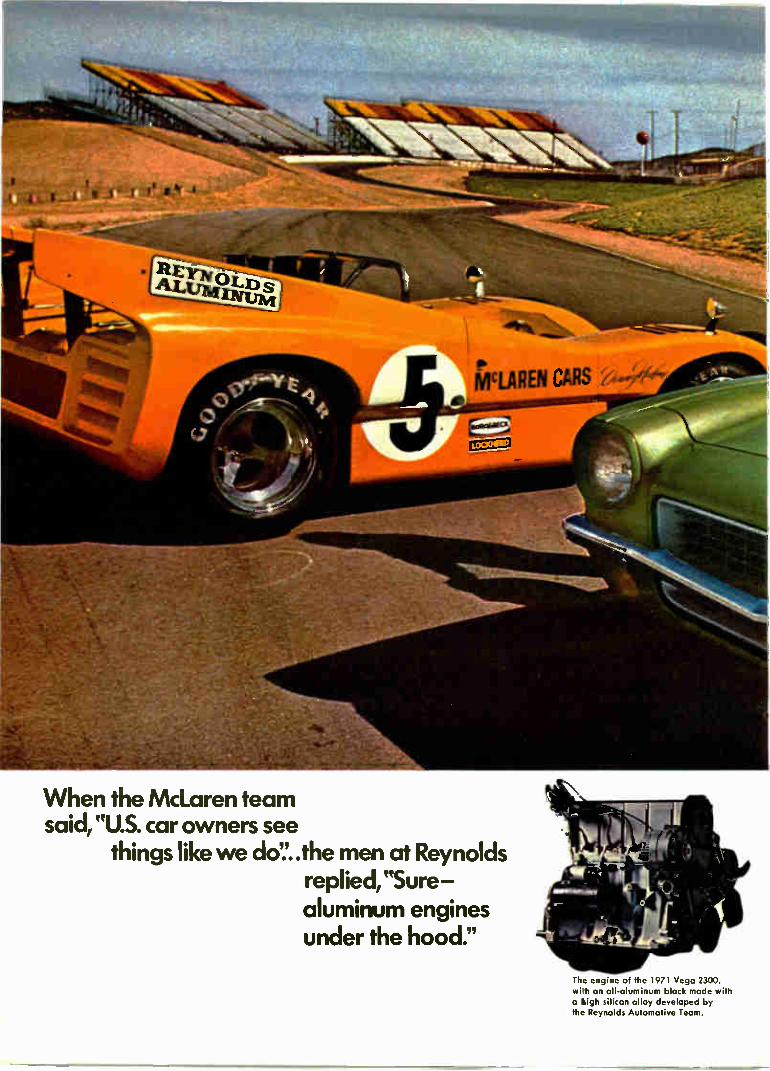
When the McLaren team said, "U.S. car owners see
things like we do'.'..the men at Reynolds replied, "Sure aluminum engines under the hood."
The engine of the 1971 Vega 2300, with an all-aluminum block made with a high silicon alloy developed by the Reynolds Automotive Team.

Der is HuMe of the 1970 Can-Am champion Mr...pren tearr, at Riverside, CaVornia, whE -e tea 11 won its 9th victcri in 10 Can-Am -a,:es
••• be.t• .11.. •
When a championship auto racing team builds an engine for its cars, money is no object. They look for performance—period.
To get that performance, the Canadian-American Challenge Cup champion, the McLaren team, used an aluminum engine made with a new alloy. Developed by the men at Reynolds, it's the same alloy that's in the aluminum engine of a new family-type economy car, the Chevrolet Vega 2300.
Years in research, this new alloy makes an engine that gives today's drivers the performance they
like: peppy, easy-handling, quick starting and stopping, and excellent gas mileage. Because it's tough and scuff-and-wear-resisting, the alloy eliminates the need for cylinder liners, so the engine is lighter and more economical.
Proven in the most grueling test of all—the rugged Can-Am road racing circuit—the new Reynolds alloy has helped put real automotive performance into the economy price class.
The new alloy is the latest in a long list of developments produced by the Reynolds Automotive Team,
the RAT Patrol, working with auto-motive industry designers, engineers, and leading racing drivers. They've put strong, weight-saving aluminum into dozens of trim and functional parts to help in the continuous effort to give U.S. car buyers better buys every year.
Reynolds Metals Company, leading supplier of aluminum to the automotive industry, P.O. Box 27003-LAP, Richmond, Virginia 23261.
REYNOLDS whrre, ri.,i, niecto take shape in
ALUMINUM

Ski in Europe and Hit a Slide in Price
A week's ski trip to the Alps can cost about the same—and may be more fun—than a junket to the Rockies, de-pending on where you live. From the U. S. East Coast to Italy, Switzerland, Austria, or France will set you back little more over-all than, say, Aspen or Sun Valley. You can be as far west as Pitts-
burgh and still come out pretty close on expenses. What's more, this year you'll find few booking problems
Where $20 a day double can be quite nice —and with meals
anywhere you go. As for timing, the Alps season runs to Apr. 30—and in some spots, to May 15. Economy. For example, the round-
than the price of a drink of Scotch, or a mug of coffee. Even skiing costs are less. A six-day
lift pass for two at Aspen is $85; at a swank Swiss resort, you'll pay only $50. Equipment rentals run $35 or more a person for a week in the U. S.—and $20 in the Alps.
Swiss resorts. You can sidestep some of the expense and crowds of the "name" ski spots in Switzerland— such as Zermatt, St. Moritz, and Davos—by following the natives to Verbier, 21/2 hours east of Geneva, where some fine runs start at the top of Mont Gele cableway (9,918 ft.). Stay at the Rhodania hotel ($25 double with meals) or the Farinet, which costs even less. Nearby in Saas-Fee, a little-known resort, the skiing is tops. Stay at the Grand or Wall-iserhof.
In the Bernese Oberland, try the Grindelwald-Kleine Scheidegg-Wengen area. Here Grindelwald is rated tops by the natives. The hotels:
- . •
enr/Alf - - e • limer -.`
• -ieelle't „ • -
(Italian Government Travel Office) At Sestriere, the kind of space a skier dreams about
trip economy air fare from New York to Aspen for two is $536. To St. Mor-itz, a central Alps location, the air tab (with a train ride) comes to $1,035—a difference of $500.
But you can make up most of this on ground expenses in Europe. At a top resort such as Snowmass-at-As-pen, your room, meals, entertain-ment, and gratuities per couple can easily go to $80 a day. Staying at the top-rank Carleton in St. Moritz adds up to only about $50. And you can do better. At good, economy-minded, chalet-type hotels in the Alps, $20 to $25 a day double is often the rule. And after-dark activities—swirling around small pubs—cost no more
10 Personal Business
the Regina, or an inexpensive chalet, the Adler. A close-by option is the vil-lage of Mürren, where the atmos-phere is delightful and the Schilthorn cafe is a must. Austria, Italy, France. Two hours by rail from Zurich in the Arlberg range of western Austria, there is St. Anton, a marvelous place to ski. Even the best hotels, the Alte Post and Schwar-zer Adler, are inexpensive ($20 for two with meals). Close by are the ski areas of Zürs and Lech, worth explor-ing for uncrowded ski runs and com-fortable overnight addresses such as the Zürserhof and Alpenrose.
Skiing in Italy centers on Cortina in the Dolomites. Here the jet setters
hit both the varied slopes and the late-night bars. Miramonti Majestic and Cristal Palace are the VIP hotels, but the Ancora, Excelsior Cademai, and Splendid Hotel Venezia are good, too. Ski runs vary from so-so to superior. But note: Local restaurants are exceptional and charge about 50% as much as you pay at home. Try Capannina, Fogher, Toula, and Cam-inetto.
Sestriere, near the French border, has 60 mi. of runs and action day and night. But for less neon and more serious skiing and relaxing, you might prefer Cervinia, in the Aosta Valley north of Sestriere. Local pros will check you onto excellent runs if you're up to it, or easier ones if need be. The Grand is the plush hotel, and the President, Gran Baita, and As-toria will give you good service. Tip: Go by car to nearby St. Vincent and try the casino. Two hours by rail from Geneva is
Flaine, a new French ski resort with some interesting prospects for a serious skier. Try the hotel Le Flaine, with a lively discotheque, or the brand new Les Lindars ($27). If someone in the family is a novice, don't miss Courchevel, south of Flaine. Here the runs suit the begin-ner, and the local hotels—especially the Carlina and the Célibataires—suit a cautious man's purse.
See Graham Pringle's Ski Country Guide to the Alps; it's pocket-size and practical (Pringle Alexander Assoc., 333 E. 34th St., New York, $1.95).
Flaine is for suntans—as well as sitzmarks (French Government Tourist Office)

oi.
Can you answerebee to ang of these questions?
Then clipping the coupon below may be one of the best business decisions you ever made.
Is your business a partnership?
With a "buy-sell" agreement and the right business life insurance plan, your business can be kept living and prosperous when a partner dies. What's more, the deceased partner's heirs will get a full fair price in cash with no financial strain on the surviving partner. Your Equitable of Iowa agent can give you all the details.
Are you a stockholder in a closely-held corporation?
If you qualify, specific estate settlement costs can be paid with corporate dollars. Complete Equitable of Iowa's
Section 303 Checklist as a guide for qualification. It could mean thousands of extra dollars for your family.
Having trouble keeping Key Men in your Keyholes?
Split dollar insurance— Equitable of Iowa's selective employee fringe benefit program offers extra inducements for a Key Man to stay with you. Your Equitable of Iowa agent can give you complete information.
Would the death of a top man cripple your company?
Death of a top man can mean a heavy loss in sales and net profits. Business life insurance can cushion the shock. For example $100,000 net insurance proceeds equal net profits on $5 million in sales at 2%. And the proceeds of a business life insurance policy come into the business tax free. Put your particular problem in the hands of an Equitable of Iowa agent.
Check your problem and send it to us on this coupon today
Equitable Life Insurance Company of Iowa 6th and Locust Streets Des Moines, Iowa 50306
This is my problem D Partnership D Selective Fringe Benefit Program D Settling estate with corporate D Tax-free dollars to replace
dollars sales lost
NAME
STREET AND NO.
CITY _STATE_ ZIP
Have your representative call for appointment phone no.
Personal Business 11

New York's Top Steakhouses: How They Rate
Food and beverage experts bend themselves into all manner of shapes trying to single out the "best" of any crop. These experts rarely agree, so that the average visitor to Manhat-tan, say, has the habit of wending his way back, time and again, to the same old places. To the same restau-rants, for instance, where he's been served for years. Here is a capsule rating of New
York's steakhouses compiled by food and beverage expert Howard Hill-man. It represents the consensus of opinion among the leading pros in the business. The top 10: 1—SAM'S*** "Modern" turn-of-
the-century atmosphere. 65th & Sec-ond (935-1282. 2—PALM*** Sawdust floors; car-
toons on walls. A man's spot. 837 Sec-ond (MU 2-9515). 3—CHRIST CELLA*** Plain de-
cor, dignified. 160 E 46th (OX 7-2479). 4—PETER LUGER*** Old New
York appeal. 178 Broadway in Brooklyn (EV 7-7400). 5—LOUIE'S*** Ultra modern
place, with soft red seats. 14 E 47th (490-2520). 6—WALLY'S** Unpretentious
tavern. Show business spot. 262 W 46th (582-0460). 7—KENNY'S** Dimly lit, mascu-
line setting. 565 Lexington (EL 5-0666). 8—PEN & PENCIL** Formerly
best known in town. Still good. 205 E 45th (MU 2-1580). 9—FRANKIE & JOHNNIE**
Plain decor. One flight up. Jammed. 269 W 45th (CI 5-9717). 10—DANNY'S HIDEAWAY**
Masculine atmosphere. 151 E 45th (YU 6-5399).
Other two-stars: Assembly, Billy's, Broadway Joe, Christo's, Jim Downey's, Paul's Steak Pub, Peter's Backyard, Ponte's. Top international steakhouses:
Argentine: La Cabana**, La Mi-longa**, Un Ricon Argentino*, El Tropezon*, La Hacienda* and El
Gaucho*. English: Dawson's**, Keen's**, Downing Square* and Sentry Box*. French: Le Steak**, L'Entrecote** and La Mascotte**. Italian: Italian Steakhouse**. Japa-nese: Arigato**, Japan's Kobe**, Benihana Palace**, Benihana East**, Benihana of Tokyo**, Kyoto**, Hime of Japan**, Japanese Steak-house** and Irori*. Key: *** excellent, ** very good,
* good. See At-A-Glance guidebook series, by Howard Hillman, published by Da-vid McKay Co.
SPEECH ARTS
Making the Most of Public Speaking
How do you rate at the speakers' table? If "saying a few words"—or putting over a serious 20-minute speech—is a chore for you, you're far from alone. Today, more than ever, businessmen and professionals are taking to the speaker's platform—and earning mixed reviews.
Those who seek out professional help to polish their speaking usually come out way ahead. But one word of caution at the outset: Some teachers still push the old "speaking coach" approach. Here the idea is that you practice and master certain fixed "platform techniques." But this is old hat, and you can disregard it.
A sharp opening gives your speech a chance to stay alive
Be yourself. Top pros (such as net-work radio and TV people) will tell you that what counts most is to re-member that each man—introvert or extrovert—has his own particular form of effectiveness. Your best chance for success as a public speaker is to "be yourself'—not to try to be-come the shadow of a George Jesse] or Walter Cronkite.
This is not to say that you don't perform or try to project. You do. But you develop and use your own best talents, and forget the gimmicks.
Being yourself is the underlying theme of public speaking courses now offered to sophisticated adults by such experts as Irving Rein of North-western's top-rank School of Speech, Howard Navins of Boston, Arthur Sager who teaches mainly in New York, and the Dale Carnegie people who offer advanced training to busi-nessmen and professionals in major cities. One key to being yourself is infor-
mality. "Learning to think on your feet in a natural way, without strain-ing, is half the battle," says a leading
Dale Carnegie Course class in session (Dale Carnegie & Assoc. inc.)
teacher. "You work when you speak— but you don't force." Mechanics. For all the informality, there are some mechanics to learn. Careful preparation is, of course, a must. Even for a brief talk, make a precise outline. Use a sharp, provoca tive opening (keep it short), then build up your points with factual ex-amples—and avoid generalities. Fi-nally, use a strong, fast conclusion.
Caution: Speak from notes, if you can. A full reading of a speech is usu-ally dull. If you must read, underline key words and phrases and use them as a guide. At all costs, avoid memo-rizing a speech word for word. It's dull—and if you get lost midway, you may be sunk. Making contact. Try to spark an emotional response in your audience. One way is to talk to your listeners as
12 Personal Business

If we can take delicate electronics equipment on tour from Portland to New York to Chicago to Atlantic City back to Los Angeles and on to Houston, without crossing its wires, then we can handle your important moves, without crossing yours! One of the things this
electronics company wanted from-us was a special Mayflower as driver, trained to haul and handle their delicate
‘if equipment.
They also wanted this driver to have a top-notch van. Some equipment just can't tolerate a lot of excess jiggling! And then they asked for realistic scheduling. Mayflower gave them all of it. We'll give rou our -all", too. The last thing you need is for the moving company you hire to get your wires crossed at the last minute!
Personal Business 13

Charlotte: th
441:,
manmade city.
A 17-oz. gold nugget unearthed east of town in 1799 attracted a lot of adventuresome men. They started building the Carolinas' largest city. And Charlotte's gold rush is still on. In the last five years alone, Charlotte business has created 40,000 new jobs. And filled them. Manpower and business keep attracting each other. Year-round boating and golfing weather is a reason. Being in the center of the eighth largest major trading area is another. Having the lowest building costs of 250 major U. S. cities helps. As does a re-markable air, rail and truck transport sys-tem, over $4.5 billion in bank resources,
plentiful water and low cost power. But it's manpower that's made Charlotte the special city it is. Happy people who like the exciting housing values, who support big city entertainment, arts, shopping. Who enjoy being a short drive from snow skiing and seashore surfing. Who find the right job with the right company at the right pay. You can have a free Prospector's Kit. Indicate your business and whether your interest is possible company relocation or personal career growth. Write Bill Ficklen, Charlotte Chamber of Commerce, 110 Addison Building, Charlotte, North Carolina 28202.
Charlotte The second gold rush is here. Get caught in it.
individuals, not just as members of a big group. Little things count for a lot. Like catching the eye of the man in the third row, and speaking di-rectly to him. This gives off a feeling of intimacy—and you'll feel more re-laxed, too.
It's apparent that you will want to inject as much human interest as pos-sible, and keep a light touch if you can. (Try not to reel off statistics.) But for most people, there's a parting word of caution: Avoid joke-telling unless you're good at it. There's noth-ing flatter than a fiat joke.
Timing: Shave a bit from your al-lotted time. If asked to speak for 20 minutes, take about 17. And never go over 30 if you can help it.
TAX ADVICE
Hiring a Tax Man to Work Your 1040
Should you hire a tax man to help you file your income tax return?
Says a top Washington tax lawyer: -It you feel that your 1040 has out-grown you, contact a CPA or tax law-yer promptly—and don't let the late March date scare you off. The real pros are prepared for this sort of thing." And he adds: "Don't let the size of your account put you off, ei-ther. Get yourself a bright young tax
Don't let the size of your account scare you off
man—he'll do your job quite effi-ciently, for a fee that you can afford." And note: Apr. 15 isn't a do-or-die
date. If the man you hire is terribly rushed with tax work, he probably will get you a 30-day to 60-day filing extension—and the 6% interest and small added penalty will be well worth it. To find a good man, you can, of
course, ask your company's attorney or accountant to recommend some-one. Or, if you're a professional, a business friend might be able to help. Usually your best bet is to find a small, top quality firm of accountants or lawyers. Get them to put you in touch with a specialist who will take
1 4 Personal Business

over a modest size account. Generally this means a younger man who's on his own way up. He'll be interested— and available in the future.
Don't count on a typical family lawyer for tax advice. The average at-torney in general practice is no tax specialist—and he isn't shunting you aside if he says he's unable to handle your tax problems. CPAs vs. lawyers. If you are coming up the line in your business or profes-sion, what you really need is some long-range tax strategy, not just a man to fill out your form 1040. This means everything from the tax side of investments to tax-planning in your will. Who do you hire for this type of broad-range service? A CPA? Or a tax attorney?
You can get into some pretty hot arguments over who can best do the job. The experts put it this way: The CPA has the top accounting cre-dentials. There are reliable, licensed accountants who aren't CPAs, but however competent, they lack first-rank rating. A CPA will usually have a closer knowledge than a lawyer of the details of the tax law and will give you highly skilled technical planning and paperwork. He also will know all the ins and outs at the local Internal Revenue office.
The tax lawyer provides similar services. He is less of a tax technician, but offers another advantage. He can help you with long-range tax-related affairs: estate planning, trusts for your family, and so on. It comes down to what you need. Fees. What you pay for tax services can range widely, depending on the city, the size and type of law or CPA firm, and the status of the specialist.
Generally, a young pro will charge about $100 to $150 or more (tax-de-ductible) for a thorough job on your Apr. 15 return. But this will usually include some consultation and ad-vice—and this, in the long run, is what can pay big dividends.
It's a case of viewing your present situation—and your potential.
Caution: No matter who you em-ploy, remember that a tax man cer-tifies only that his handling of the pa-perwork you've provided is complete and accurate. He does not certify your information. You do.
__State Zip
'I f Iltbilt
Of gI VI HO 3t, me 193 WIR IM UM la
Now solve scientific/financial problems with one calculator simultaneously —
The NEW WANG Series 100
Two complete adding and calculating machines plus four or twelve additional storage registers are but a few of the extras that are "built-in" to make the Wang Series 100 more than just a calculator, in either printing or display versions.
For engineers and scientists, the lowest cost calculator with ex, Log.X, trig. and
statistical keys. For budgets, cost analy-sis and all financial work, the essential roundoff keys and standard 10-key key-board with implied two decimal entry.
Our demonstrations are something to see. Phone Mr. Courtney today (collect 617-851-7211) for one in your office, or clip the coupon and let us know where and when.
WANG Laboratories, Inc. Dept. MPB-3 836 North Street, Tewksbury, Mass. 01876
I'd like a 100 demonstration in my office. Call me at Name for a date. (phone number) Company
Street
City —J
This unique book helps you manage your personal affairs with the same skill you bring to your business:
Business Week's
Guide to Personal Business
$9.95
"Many a man who should know better—whose business or professional income is, say, $25,000 to $50,000 or more—treats his own personal business like a third cousin who turns up in town in search of a loan. He brushes them off," says Editor Joseph L. Wiltsee.
If that describes your situation In any way, here's help. This unique book, dis-tilled from the popular "Personal Business" section of Business Week, offers you a wealth of new ideas on planning and managing your personal finances. Real estate, investments, insurance, school costs, taxes, estate planning—even advice on how to choose and evaluate an advisor! The money you can save— or make—from just one of the ideas in this 320-page guide should more than pay for its modest cost.
Get it now from your favorite book store for $9.95. Or send your order (enclose payment please) to the address below. Note: a special deluxe edition, bound in buckram, gold stamped, slipcased is available at $2.50 more per copy, by mail only.
Business Week Guide Book Service Office 330 Broadway Marion, Ohio 43302
Personal Business 15

Healthy, Wealthy and Wise
Cash parade: inflation, funds, money for minors
In taxes: "Proof" is the pudding
Manners and modes: brain teasers, kids on the move
If your wife is complaining about supermarket costs—and you're wondering about the sky-high tabs you're footing for everything from practice golf balls to hotel rooms—then David L. Markstein's How You Can Beat Inflation may help you. The author tells about such ideas as inflation-minded investments, the legal avoidance of high taxation, and ways to set up a budget and make it work. At least Markstein puts a little glue on your fingers to keep from letting dollars slip away like confetti (McGraw-Hill, $7.95). . . . Norman Dacey, the man who caused a sensation a couple of seasons ago with "How to Avoid Probate", is back. This time it's Dacey on Mutual Funds—a clean-cut book of pro and con that reveals a great deal about the funds and their management. It will make you a careful buyer. But after 1969-70— why not? (Crown, $4.95). . . . A particularly timely item is Harry D. Schultz's What the Prudent Investor Should Know About Switzerland and Other Foreign Money Havens; it's a territory to be pondered with deliberate speed (Arlington House, $7.95). . . . And Gifts of Securities or Money to Minors, a guide to the laws of.the 50 states, tells in practical terms about "custodian accounts" (Assn. of Stock Exchange Firms, 120 Broadway, New York 10005; $1).
"Proof" is the key idea when it comes to picking up tax deductions for what the trade calls T & E—travel and entertainment expenses. In a recent Tax Court case, a taxpayer's habit of mixing clients with personal friends at parties landed him in the soup. He wasn't able to prove a solid business or professional purpose in a social at-mosphere where fun appeared to be the prevailing motive. Non-business guests don't necessarily rule out T& E deductions, whether you're at a hardware con-vention or meeting of atomic physicists—but they do make the deductions harder to sell if you're called on the carpet by Internal Revenue. . . . In a related note, the Tax Court has said, in effect, that a T & E diary showing daily expenses is valu-able—if it's clear and shows dates, times, places, people, purposes. And, of course, amounts. But even this kind of diary isn't enough when expense items run to $25 or more. Here you need back-up evidence: receipted bills, cancelled checks, etc.
1970 note: If you have poor T & E records for last year, you may not know that you can legally reconstruct what you will need at the IRS. You can't create a diary. But you can dig up lost records. Phone your liquor store, restaurants, and such—and come up with the evidence of business-related entertainment expenses. It works.
It's hard to pick out brain-teasing board games that will perk the interest of bright teenagers and adults. Here are a few ideas that may help fill in some chilly March evenings: RSVP is a tough, three-dimensional word game developed by the Scrabble people ($6). Ad Lib, another word twister, forces you to draw on little-used vocabulary ($4). Facts in Five is a good concentration game that puts you under in-tellectual time-pressure ($9). Wff'N Proof varies in complexity and demands the use of logic and abstract thinking ($8). Stock Market tests your sound judgment ($10). . . . Changing neighborhoods or cities can shake up a child. But a group of psychologists at a Midwest symposium offered tips to reduce the pain. Put on a happy face and view the move positively—your mood will rub off on the kids. Also clearly explain the reasons for the move. A boy, they note, may react better than a girl—he's better at handling a new adventure. And note especially: Don't worry about breaking into the school year. In fact, a child is better off plunging into new school activities than facing summer doldrums in a strange place.
To ward off March chills: A lovely coffee drink is served up at Wally's, a new spot on West 46th Street in Manhattan: Put in a cup 2 oz. of strong Italian coffee, stir in a dash of Tia Maria, and top with whipped cream. It's called a Palm Sundae.
16 Personal Business

International Newsletter March 1, 1971
Plessey is first The Plessey Co. Ltd. claims to have beaten its competitor companies • to market with high-speed emitter-coupled logic divider chips for high-t o • market with
frequency instruments, particularly counters [see p. 69]. The company fast ECL divider is about to offer samples and small quantities of two divide-by-two chips
with guaranteed inputs of 550 megahertz and 400 MHz, respectively. The high speed results from collector-base diffusions claimed to be only 0.4-micron deep, yielding transistors with a 3-gigahertz cutoff frequency and permitting improved packing density and the low capacitances that result from it. The chip is 15 mils square and contains about 40 components, mostly
transistors. Propagation delay of internal gates is said to be only 0.7 nanosecond on the fastest chip. Power consumption is about 80 milli-watts per divider. Plessey researchers say that expected improvements in optical processing techniques will permit emitter widths down to 2 microns, which should make a 1-GHz divider possible without going to shallower diffusions. The devices will be exhibited at the IEEE Show.
IC production
in Japan falls
Rolls-Royce shakeout
bodes ill for
U.K. avionics firms
After several years of gains, integrated circuit production in Japan is showing a decline of about 10% to 20% compared with last fall at lead-ing companies such as Nippon Electric, Mitsubishi Electric Corp., Hitachi Ltd., and Toshiba. The recent economic decline is cited as one general reason; it has shown up in decreasing demand for computers, and hence ICs. Even more important to the IC manufacturers are decreased orders
from manufacturers of calculators—their biggest market. The overheated competition for calculator sales has caused prices to fall rapidly, and some potential buyers are holding out for even lower prices. Another factor in the decreased sales to calculator manufacturers is excess pur-chases by these firms last fall; now they are working off inventory. What's more, the swing to LSI chips, predominately from the U.S., also is hurting the Japanese IC companies.
Moreover, all of the Japanese IC firms are losing some transistor-transistor logic sales to low-priced imports from the U.S.
British stiff upper lips are trembling at the prospect of an American reaction against British aerospace products in the aftermath of the Rolls-Royce debacle. If Lockheed and the British government can't agree on a new deal for the Rolls RB-211 engine, and Lockheed is left without an engine for its Tristar, it's feared that "don't-buy-British" sentiments will add to existing anti-noise feeling and airline financing problems to kill U.S. sales of the Concorde supersonic airliner. This could influence other airlines and effectively kill the aircraft. Similarly, it's felt that the U.S. Marine Corps might have second thoughts on purchases of the Hawker Siddeley Harrier jump jet [Electronics, Jan. 18, p. 141]. Both aircraft contain sizable quantities of British avionics. Nobody expects existing orders to be cancelled suddenly, but new
orders might be very hard to come by. Worst-hit avionics company would be Elliott Flight Automation Ltd., which has several U.S. mili-tary and civil contracts accounting for about a quarter of its turnover, but nearly all British avionics makers sell to the U.S.
Electronics I March 1, 1971

International Newsletter
Victor of Japan
develops 4-channel
cassettes, players
Victor Co. of Japan Ltd. has developed four-channel cassettes and players, and is negotiating with Philips Gloeilampenfabrieken in an attempt to have its format selected as standard. The new tapes are com-pletely discrete—no matrixing of any kind is used [see p. 73]. Total compatibility is claimed; the new four-channel tapes can be played on existing stereo or mono machines, and existing stereo or mono tapes can be played on the new units.
Victor's new format calls for splitting each 0.6-mm-wide stereo track on Philips-type cassettes into two tracks, each 0.2-mm wide, with 0.2-mm spacing in between. Victor has developed ferrite playback heads to match this tape format in the same over-all dimensions as previous heads. Victor says it also has a noise-suppressing circuit that enables it to obtain performance levels comparable to present stereo units.
Cogar sets sights The Cogar Corp., the three-year-old U.S. firm specializing in mono-lithic semiconductor memories, is making a strong bid for the poten-on European tally lucrative European market. The firm has just set up a subsidiary
IC memory market in Munich, its first outside the U.S., and it's intended as a headquarters for sales throughout the Continent. Cogar also may establish similar sales organizations elsewhere in Europe and is already considering start-ing up an assembly plant, possibly in Germany or Belgium. Hans Kober, general manager of Cogar GmbH, is hopeful that the
monolithic memory market will rise quickly in Europe. Now that IBM has incorporated such memories in some of its new computer models, he expects IBM's competitors abroad to do likewise. Contacts with all major computer makers in Europe already have been made. Cogar predicts its European sales will soar to about $10 million,
representing about one-quarter of the company's $40 million turnover forecast for next year. The company intends to introduce its Cogar System 4 computer terminal, in addition to monolithic memories, at this spring's Hanover Fair.
Army order revives
Norwegian IC maker
Addenda
A/S Akers Electronics, Norway's sole maker of integrated circuits, has been given a new lease on life as a result of the Norwegian army's decision to go ahead with a manpack radio order. Akers was supplying frequency synthesizers to the main contractor, A/S Elektrisk Bureau, a subsidiary of L M Ericsson of Sweden. However, the order was delayed last year and Akers had been running in the red. "We had too many eggs in one basket," says Gustav Ring, whose firm, Gustav A. Ring A/S, acquired Akers in 1969. Ring says that as a result of renegotiations and the go-ahead on the army order, Akers' activities soon will be greatly expanded.
Philip Weber KG, a West German watch maker, seems to have a leg up in the battle to put an inexpensive quartz wristwatch on the market with a series of five prototype models that will sell for between $138 and $192. Weber claims the prices, the lowest yet, were achieved by allow-ing specialized firms to do the electronics R&D . . . Electrofact of Amers-foort, The Netherlands, a subsidiary of Control Data Corp., is laying off 65 workers, or 17% of its staff, as a result of sharply decreased demand for magnetic tape apparatus.
Ilactronlcs I March 1, 1971

Electronics international March 1, 1971
Concorde to pass fatigue tests— by minicomputer Pressure loads, as well as
heating and cooling stresses,
will be computer controlled
in test-bed simulation
To ensure that Concorde super-sonic airliners don't develop un-suspected fatigue failures, mini-computers will put the plane through its paces—on the ground. A complete airframe, structurally identical to operational Concordes, has been assembled in a special laboratory at the Royal Aircraft Establishment, Farnborough. Un-der minicomputer control, a test bed will subject the airframe to all the loadings that the real air-craft will have to stand up to in service.
Pressure loads will be applied by jacks. Heating and cooling loads, which will be much more severe on Concorde than on any previous civil aircraft, will be ap-plied by blowing hot and cold air over the airframe. Also an artifi-cial fuel load will be heated and chilled because on the Concorde the fuel is used as the main heat sink. The loadings will be pro-gramed to simulate complete flights, including taxiing, take-off, climb, cruise, descent, landing, and ground time, and will allow for sudden gusts and the like. The test airframe must complete
at least three times as many "flights" as any operational air-craft. The rig won't be completed until next year, so the 3-to-1 ratio is only possible by compressing
the flight cycle into one hour, attenuating the cruise and ground time phases, and keeping the rig going day and night. The loads will be applied, and
the performance of the rig moni-tored, through three intercon-nected Digital Equipment Corp. computers. One PDP-8 will control the pressure loadings, applied through over 100 hydraulic jacks. Another, incorporated in an indus-trial process control loop supplied by George Kent Ltd., looks after the temperature cycle. The per-formance of these computers, and of the jacks and temperature con-trollers, is monitored by a PDP-10 installation, which also feeds a data logger and some visual dis-plays. The three computers are further linked through a hardware watchdog that checks for proper time synchronization and correct programs. The mode of operation and the
software to implement it is the job of Computer Analysts and Pro-grammers Ltd. of Reading. Some of the software used in the tem-perature control loop is standard George Kent programing, but all the rest is specially written be-cause of the number of checks and precautions necessary. If the sys-tem went wrong—say a jack ap-plied too much pressure—part of the airframe might be damaged, which could set the program back and delay issue of the certificate of airworthiness. The PDP-10 checks the load ap-
plied by every jack every 50 milli-seconds, comparing the actual load with the programed load stored on
a 256-kiloword disk. If the load is outside tight preset tolerance lim-its, but not outside wider toler-ances, a teletypewriter prints out a continuous warning and if noth-ing is done the rig shuts down. If the load goes suddenly from within proper tolerances to outside the wide tolerances, the rig shuts down within 100 ms.
This checking operation takes up half the operating time of the PDP-10. To make it effective the PDP-8 controlling the jacks has to respond quickly, and in fact it passes on an order to a jack within 1 ms. The temperature cy-cling is less critical and is checked every few seconds. In all cases, if the checked parameter is not within tolerances, the rig shuts down. It also shuts down if the watchdog unit, specially built by DEC, detects out-of-sync or incor-rect programs. This is a positive reassurance system: each com-puter must send an OK signal to the watchdog every second or the watchdog shuts the rig down.
West Germany
Bipolar memory cell
points way to tiny RAM
Bipolar memory cells as small as 14 mil2 have been made by re-searchers at the International Busi-ness Machines Corp. laboratories in West Germany. The cells, said to be smaller by a factor of two compared with others developed until now, promise 512-bit, random access, read/write memory chips
Electronics I March 1, 1971

Electronics international
measuring only 130 by 130 mils. [For other approaches to bipolar memories, see pps. 19 and 52.]
Equally impressive is the cell's low de power dissipation: it con-sumes only 0.1 microwatt in stand-by. Developed at the company's Boeblingen facilities by Siegfried K. Wiedmann and Horst H. Berger, the new IBM device was discussed at the International Solid State Cir-cuits Conference held in Philadel-phia last month.
Practical applications for the new storage cell are still some time away. But the IBM researchers are experimenting with a two-by-three-bit array and also with simulated 16-by-32-bit arrays, for which an access time of 30 nanoseconds has been achieved when individual cells are powered by about 0.5 milliwatt. The planned 512-bit memory will be powered by 150 mw and will have access and cycle times of less than 100 and 200 ns, respectively. The key to the cell's small size
is a new approach to integrating its individual transistor structures. Instead of providing separate iso-lation pockets for each transistor, the IBM men use one-directional isolation beds that run as strips across the cell surface from one edge to the other. These beds also are used as connections between cells in the word rows. Further-more, the beds constitute part of the structure of the various semi-conductor devices on the cell. From an equivalent-circuits
point of view, the cell breaks down into two multicollector pnp tran-sistors serving as current source load devices, two npn transistors that form a flip-flop circuit, and another pair of npn transistors for decoupling. One n-type isolation bed is used as a common collector for the inversely operated flip-flop transistors. That bed also serves as the common word line. Another n-type isolation bed provides a common base for the pnp load transistors and serves as a com-mon collector for the npn de-coupling transistors. The bases of these transistors are merged with the collectors of the pnp load tran-
sistors. Thus, there's only one addi-tional n-plus region required to complete the decoupling transistors and only one p-type emitter for the p-collectors of adjacent cells in a bit column.
The small standby power dissipa-tion comes from the use of switch-able constant-current sources—the two pnp transistors—acting as load devices instead of collector load resistors. Because of the inherently high internal resistance of the cur-rent sources, stability is obtained down to currents at which the cur-rent gain of the flip-flop becomes unity. Typically, that occurs at cur-rents of a few nanoamperes.
In fabricating their memory cell, Wiedmann and Berger used stand-ard 6-micron epitaxial layer proc-esses. The metal interconnections that make up the bit columns have a line width of 0.4 mil. The spac-ing between lines is a minimum of 0.2 mil. Single-layer metalization is used without special crossun-ders.
Test unit simplifies
fm tuner check-out
For radio engineers, one of the most time-consuming jobs is a com-plete checkout of fm tuner opera-tion. Two qualified technicians can easily work several hours finding out how well a tuner performs un-der the large-signal interference conditions—such as intermodula-tion, spurious transmitter pulses, or cross modulation—that are increas-ing as short-wave bands become more crowded and radio stations more powerful. What's more, proper testing requires quite an array of equipment. Evaluating cross modulation alone takes three test transmitters and a lot of meas-uring gear. To cut test time and minimize
equipment needs, AEG-Telefunken engineers Heinz Rinderle and Wal-ter Beckenbach developed a proce-dure that can evaluate an fm tuner in 15 minutes. The method pro-vides a comprehensive and exact evaluation of all possible inter-ference effects by means of a sim-
ple test unit, an X-Y recorder, and a few interconnecting leads.
In their technique, large-signal interference pulses are applied to the tuner input together with a spectrum of smaller, equal-ampli-tude test signals, which are dis-tributed across the tuner's fre-quency range—typically from 87.5 to 104 megahertz. The signals can be spaced 100 to 300 kilohertz apart to correspond with band-width or channel distance. For identification, the test signal spec-trum is modulated by a 13-kHz pilot tone. The test unit's evaluation cir-
cuitry, which is connected to the tuner's fm demodulator, determines how much these signals are dis-torted or suppressed by the inter-ference pulses. The evaluation circuit has two channels. One is made up of a high-pass filter, a phase-shifter, and a synchronous demodulator and is designed to determine the absence or the pres-ence of the pilot tone. This checks whether the test signal is sup-pressed or not. The other channel, consisting of a low-pass filter, an amplifier, and a rectifier, deter-mines whether the tuner's receiver channel is affected by cross-modu-lation or other types of large-scale interference, such as spurious transmitter pulses, signal-to-noise increase, or intermodulation. The output of the tester is then
fed to the X-Y recorder. It displays the frequency distribution and the amplitude of the interference pulses, the amplitude of the test pulses, and the tuner's signal-to-noise ratio. The interference effects are always referenced to the tuner input, which means that the test results are independent of varia-tions in amplification or of the lim-iting effects within the tuner's circuitry. The method has applications far
beyond those connected with in-terference checks. Because of the high frequency stability of the unit's quartz-stabilized spectrum generator, the AEG-Telefunken multisignal test method can be used for scale calibrations and for determining frequency setting ac-
Electronics March 1, 1971

curacies. Furthermore, the tester is good for determining the tuner's amplification by means of the con-stant-amplitude test signals. Still another application is checking the tuner's absolute sensitivity over its whole frequency range.
France
Static switch may speed
data transmission
In the race to transmit computer data at higher and higher speeds, transmission line technology has sprinted ahead while the equally important switching relay develop-ment has jogged along at a more leisurely pace. But the tortoise is catching up.
A new French static electronic re-lay is so fast and sensitive that it outdistances not only all other re-lays but also the fastest transmis-sion systems now known. With a rise time of 1 microsecond, it is 1,000 times faster than the best reed relays and around 500 times faster than other top quality static relays. And unlike other static units, it can switch ac and dc. The French relay can switch up
to 100 watts, versus 10 w for reed relays and 2 w for other static re-lays. It is sensitive to a current of less than 20 milliwatts, compared with a 100-mw minimum for most other relays. It can be used with data transmission systems of 100,-000 bands. "We're going to kill the reed re-
lays," boasts Maurice Pilato, the independent French inventor who developed the new unit. Pilato has sold manufacturing rights to Tech-nimatic, a French affiliate of Gard-ner-Denver, which has built proto-types of several models and hopes to begin production in a few months. A basic model will sell for around $100. Pilato predicts a French market of from 100,000 to 200,000 relays a year, "and the American potential is enormous," he says. The innards of the new relay are
still largely secret pending patent approvals. But Pilato says his prob-
lem was to find a series trigger not needing an auxiliary power supply, as do standard designs like the Schmidt trigger. Pilato's approach is composed of bipolar transistors, but he says tunnel diodes would also do the job. The rise time of his trigger can be held to well under 1 microsecond. The fre-quency produced can be from sev-eral megahertz to several hundred megahertz. When oscillation starts, the de
power that reaches the base and emitter inputs of a power transis-tor saturates the transistor, lower-ing resistance to less than 2 ohms. The transistor thus acts virtually like a mechanical contact. The contact breaking power of
this basic relay is around 6 W. Adding an auxiliary unit composed of a power transistor and a heat radiator ups the switching power to 100 w. Switching efficiency of 98% at 100 W is claimed, and it is still better at lower wattage. Another attachment lets the re-
lay switch ac power. The design of this unit is top secret: Pilaw refuses to say more than that it contains "a mixture of semiconduc-tors." The ac and the 100-w at-tachments are expected to sell for around $5 each. The new relay should be useful
in space applications because of its low power needs. CNET, France's space agency, is interested in the relays and may be an early cus-tomer.
Japan
Fujitsu's big computer grows
again, thanks to plated wire
Japan's only independent computer maker, Fujitsu Ltd., has upgraded its series 230 model 75 computer, which already was the largest com-mercial computer offered by a Jap-anese firm. Now expected to have about six times the capacity of the current top-of-the-line model 60, double the previously announced power, the model 75 owes its in-creased capability to faster ECL cir-cuits and a faster memory—which
To the wire. Two models in Fujitsu's new computer line-up feature plated-wire memories, one of which boasts a 1-million-word capacity.
includes a large-scale plated-wire memory and a fast bipolar buffer memory. Fujitsu expects to have the first machine, for use within the company, completed by the fall of 1972, with deliveries to start early in 1973. The first large-scale Japanese
computer to use a plated-wire memory, it will boast a 1-million-word main memory with an access time of 1 microsecond for two words of 36 bits each. An extremely fast memory is a must to get high throughput from an array proces-sor, which is offered as an option for technical problems, because the array processor does not use a buffer memory. The array processor will increase the model 75's speed, compared with model 60, by 25 to 30 times when used on problems for which it is applicable—and per-haps 40 to 50 times if there are groups of zeroes in the matrixes being processed. The bipolar buffer memory has a cycle time of 90 nanoseconds and an access time of 45 ns per two words. It has a capacity of 4,000 36-bit words.
Fujitsu also announced that it is offering two new versions of its model 45, the largest model of its small and medium series. Capa-bility of largest model 45 will over-lap that of model 60, but the new versions will provide upward com-patibility for Fujitsu's current small-computer users; the machine
Electronics March 1, 1971

Electronics international
languages of the model 45 and 60 are different.
Fujitsu's new model 45S intro-duces a simplified version that only operates in single-processor config-uration and costs about 30% less than its dual-processor forerunner. It has a 512-kilobyte memory with a cycle time of 0.7 microsecond for two bytes. The model 45D is for users who need a growth version. It is a multiprocessor machine, with a capacity about three times that of the simplified version. It features a 1-million-byte wire memory with a cycle time of 0.55 microsecond for two bytes. The wire memories to be used
are an unwoven type developed and manufactured by Fujitsu itself. The cost comes out to perhaps 0.7 cent per bit. Fujitsu's calculations show that memory cores are less expensive than wire at low speeds. For high-speed memory, the price is less expensive for cores when memory capacity is small. But as memory capacity increases, the prices of the two cross. The actual wire portions of the
memories for the models 75 and 45D are similar, although the model 45's memory is faster for two reasons: it is a smaller memory, only 1 million bytes rather than 1 million words of 36 characters, and it pays to spend more money on its peripheral circuits because there is no buffer memory.
Color TV for PAL nations
gets around German patents
Patents, even those related to de-funct projects, are money in the bank. Figuring that it's time to cash in on some patents it received for work on a single-gun color TV tube, the General Corp. of Japan plans to make a PAL color set that does not infringe on AEG-Tele-funken's patents.
General plans to start mass pro-ducing a 12-inch color set in June and expects to be able to start sales in England in August at a price competitive with Sony's recently announced color TV [Electronics, Feb. 15, p. 149 or 3E]. It will also
Electronic stopwatch. Quartz crystal controlled and fitted with light-emitting diodes for read-out, Seiko stopwatch can time intervals down to 0.01 second. Rechargeable, built-in batteries allow one hour of operation with display on and three hours with it off. Auxiliary battery pack allows 10-hour operation. Cast aluminum case is sealed to keep out elements. Unit keeps accuracy from —20 to +85°C.
build larger PAL sets, and sell them in other PAL-broadcast countries. England was selected as the ini-
tial target because it is, after West Germany, the main Market for PAL color. Then, too, spurious radiation and other standards are not as severe in England as in Ger-many. Also, General probably shied at challenging AEC-Telefunken di-rectly in its home market initially. The PAL color signal differs from
the NTSC signal used in the U.S. in two basic characteristics. The first is the use of red-minus-lumi-nance and blue-minus-luminance color difference signals to modulate the quadrature-phase chroma sub-carriers rather than the complex I and Q signals used in the U.S. The second basic difference is
that the phase of the red-minus-luminance signal is shifted 180° for alternate horizontal lines. This phase inversion permits cancella-tion of phase errors in transmission,
because after demodulation such phase shifts have opposite signs for alternate lines. This error cor-rection mechanism is not available for the blue-minus-luminance sig-nal, but phase errors in that signal have lower visibility, and small errors do not visibly degrade the received picture. To demodulate the quadrature-
phase color subcarriers, reference signals for synchronous detection are needed. These signals are rather simple to produce in the NTSC receiver, but their generation is more complex in the PAL re-ceiver; the reference signal for the red-minus-luminance subcarrier must change phase by 180° for alternate lines. AEC-Telefunken de-veloped switching circuits for this purpose and protected them with an elaborate array of patents.
In the line-sequential color re-ceiver that General, then called Yaou Electric Co., developed in 1965, a very similar requirement existed. In that set [Electronics, May 21, 1965, p. 81] it was neces-sary to demodulate the chroma sub-carrier on three separate color axes, corresponding to the three primary colors, in sequence. Com-pany engineers developed a method of obtaining the proper sequential phase shift using only a single off-set subcarrier oscillator and a phase modulator, with no switching cir-cuits. The frequency of the refer-ence oscillator is offset above the subcarrier frequency by one-third the horizontal frequency, so that it advances in phase by the re-quired amount between successive lines; phase modulation is used to keep the phase of the oscillator constant during each line period. A similar method can be used
to obtain the proper reference phase for demodulating the PAL signal without using the switching circuits that would infringe on AEC-Telefunken patents. The sub-carrier oscillator is offset above the subcarrier frequency by one-half the horizontal frequency for an ad-vance of 180°, and the modulator keeps phase constant, resulting in the required inversion of phase on alternate lines.
Electronics ! March 1, 1971

Learn new applications for electronics in medicine
Ill Attend technical sessions
• See exhibits and demonstrations
• Participate in workshops
The 3rd National Conference and Exposition on Electronics in Medicine, presented by McGraw-Hill publications—ELECTRONICS, MEDICAL WORLD NEWS, MODERN HOSPI-TAL, and POSTGRADUATE MEDICINE— will be held April 13-14-15, 1971, at the Sheraton-Boston Hotel, Boston. The technical program will feature experts in the field of hospital equipment and automation, com-puters in medicine, patient monitoring, prosthetic devices, thermography, plethysmography, cardiac screening, multi-phasic screening, and other pertinent applications. Six workshop sessions will be lead by specialists who will invite active participation by conference attendees. New medical electronics instrumentation and support equipment will be featured in the exposition that accompanies the technical program. Pre-registrants may use the following form to avail themselves of the special advance registration rate.
REGISTER NOW—SAVE $35! Advance registration fee: $165 Registration at conference: $200 (includes all sessions, exhibits, two luncheons, reception and a digest of technical papers when published). Mail this form along with your check to: Donald Christiansen Conference Chairman Electronics in Medicine 330 West 42nd St.. New York, New York 10036 A block of rooms is being held at the Sheraton-Boston Hotel for registrants. Make your reservations directly with the hotel, identifying yourself as a Conference attendee.
Advance Registration Form 3rd National Conference & Exposition on Electronics in Medicine April 13-14-15, 1971
EL
El Please pre-register me for meetings, work sessions, and exhibits. My check for $165 is enclosed.
E I cannot attend the full conference hut plan to visit the exhibits. Fee: none for qualified registrants. Please pre-register me for
first day E third day D second day D all three days E
Name Title
Company or Hospital
Address
City State Zip
NOW.. Test and analyze ANY individual component on your LSI chip.
With the MARK TEN MICROTEST ANALYZER
you are no longer restricted to indirect methods
in determining why your chips don't wo -k or why
a failure occurred. Circuit trace IC chips with the
same ease as trouble shooting discrete compo-
nents on a PC board.
For complete information phone . (516) 488-2525
COMA1TEST INC. 124 South 8th Street, New Hyde Park, N. Y 11040
Circle 117 on reader service card
To pinpoint a cosmopolitan Texas
location convenient to R & D capabilities, brainpower and productive labor:
ASK INSTA-SITE The answers to specific Texas plant location
questions and impartial site selections are instantly available from the nation's most com-prehensive industrial computer program. Write or call for detailed Insta-Site information and your free copy of the Texas Fact Book.
TEXAS INDUSTRIAL COMMISSION capitol station -- Box 1272b-E Austin, Texas 78711 — 512/475-4331
Electronics I March 1, 1971 Circle 107 on reader service card D 1
•

Electronics advertisers March 1, 1971
Send us your precious metal scrap...
J.Doe Coetin
Corp.
we'll send you a big check.
I:0 2 7.0..00 2 31:
Handy & Harman has been refining its own scrap for a century. We know how to extract the last pennyweight of value. We have the equipment and the techniques to produce maximum value. Interested? We have some literature that tells the whole story, from finding the scrap to getting the check. Use the coupon.
Please send your booklet about precious metal scrap.
Name
Title
Company
Address
City
State Zip
HANDY & HARMAN WI 850 Third Avenue. Dept EL16, New York, N.Y. 10022
Aero Mayflower Caldwell Van Riper
Aeronetics Div. of AAR Corp. Robert L. Cohn Inc. Adv.
Aerovox Corporation Lescarboura Adv. Inc.
Airco Speer Electronic Components Hazard Adv. Co. Inc.
Allied Electronics 8 Ontario Advertising
American Lava Corporation, Sub of Minnesota Mining & Mfg. Co. 82 Designers Inc.
Analogic Corporation 77 Allied Adv. Agency Inc.
Andersen Corporation PB7 Campbell Mithun Inc.
PB13
84
9
6
Bausch & Lomb Inc. 75 Wolff Associates Inc.
Bell & Howell Electronics & Instruments Group 27 Coordinated Communications Inc.
" Bryans Ltd. 17E C. P. Wakefield Ltd.
Bunker Ramo Corp., Amphenol Components Group 2nd Cover Marsteller Inc.
Business Week Guide PB15 Benson, Stagg and Associates
Charlotte Chamber of Commerce PB14 Shotwell, Craven, Varner Inc
• Chester Cable Operations, Cities Service Company 10-11 Lewis Adv. Aoency
Cogar Corporation Information Systems Division 34, 35 Davi-Callihan Inc.
Comaltest Inc. D1 Litek Corporation
- • Cosmicar Optical Co. Ltd. 13E • Culligan U SA 92
Alex T. Franz Inc. Custom Electronics Inc.
Laux Advertising Inc.
- Dow Corning International Ltd. Marsteller International S. A.
Econo Car International Wm. Cook Advertising Inc
Electronic Arrays Inc. Reais McKenna Inc.
Electronics in Medicine Conference Electronic Processors Inc.
Broyles, Allebaugh & Davis Inc. Equitable of Iowa
Draoer Daniels Inc. Excellon Industries Inc.
Elgin Davis Inc.
Fairchild Semiconductor Inc. Carson/Roberts Inc. Adv.
Florida Dept. of Commerce, Division of Commercial Development William Cook Adv. Inc.
General Electric Company Robert S. Craain Inc.
General Magnetics McCarthy/Scelba/DeBiasi
Adv. Aaency Inc. Georgia Department of Industry & Trade Cargill, Wilson & Acree Inc. Adv.
▪ Gould, Inc. Brush Instruments Carr Liaoett Adv. Inc.
Gould Inc. Corporate Division Carr Liagett Adv. Inc.
• Grayhill Incoroorated Carr Liaaett Adv. Inc.
Gries Reproducer Company Harrold Marshall Advertising
Hutson Industries 28 Warren Associates
IEEE (Institute of Electrical & Electronic Engineers) Alpaugh Advertising
Kenwood Albert. Frank Guenther Law Inc.
Krohn Hite Corporation Ingalls Associates Inc.
99
PB7
2
Lockheed Missiles and Space Company 84 McCann Erickson Inc.
LTT 20E, 21E Publibel
Lyon Van Lines PB6 N. W. Ayer/Jorgensen/MacDonald Inc.
Mechanical Technology Incorporated Devey. Thompson & Vignola
Advertigina Inc. Monolithic Memories
Reais McKenna Inc. Motorola Semiconductor
Products Inc. Lane & Wampler Advertising Inc.
98
30
88, 89
7- Olympus Optical Co. Ltd. 8E
Piezo Technology Inc. Shattuck /Poether Advertising Inc.
n Philips N. V. Pit /TMI Division Marsteller International S. A.
' Plessey Electronic Components Rumrill Hoyt Inc.
86
2E
5E
RCA Electronic D4 Components 16, 68, 4th Cover
Al Paul Lefton Company ' Reliance Controls 22E
Bond PuhlicitV Services Ltd. 14E•15E Reynolds Metals Co. PBS-9
Clinton E. Frank Inc.
PB5
7
DI 24E
PB11
56
80, 81
Schauer Manufacturing Corp. D4 Nolan. Keelor & Stites
Solartron Electronics Group. Ltd. 6E, 7E T. B. Browne Ltd.
Sorensen Operation Raytheon Company 36 Provandie Eastwood & Lombardi Inc.
- Sprague Electric Company 5, 18E Harry P. Bridge Company
State Farm Insurance PB2 Needham Harper & Steers
• Tektronix Inc. Daw,on Inc.
Texas Industrial Commission The Pitluk Group Advertising
Toko Inc. 72 Hakuhodo Inc.
23E
15
51
79
12-13
98
94
Handy & Harman D2, D3 J. J. Lane Inc.
Harris Semiconductor 96, 97 W. M. 7emo and Associates
Hermes Electronics Ltd. 100 Public & Industrial Relations Limited
▪ Hewlett Packard Loveland Division 1 Tallant Yates Advertising
Hitachi Ltd. 60 Dentsu Advertising
Honeywell Discipline Division 3rd Cover Batten, Barton, Durstine & Osborn Inc.
Hudson Lamp Company 98 Mohr & Company Inc.
Hughes Aircraft Company 71 Foote, Cone & Belding
Unitrode Corporation Impact Advertising Inc.
Varian Associates, Electron Tube and Device Group Jack Herrick Adv. Inc.
25
DI
94
29
33
Wang Laboratories Inc. PB15 Chirurg & Cairns Inc.
Xerox Corporation 91 Hutchins Advertising Company Inc.
Classified & Employment Advertising F.J. Eberle, Manager 212-971-2557
EQUIPMENT (Used or Surplus New) For Sale Radio Research Instrument Co. 90
• For more information on complete product line see advertisement in the latest Elec-tronics Buyer's Guide Advertisers in Electronics International
D 2 Circle 108 on reader service card Electronics I March 1, 1971

How to make 42 intricate connections,
no hands.
Could a clad metal reduce your brazing/soldering costs?
Look closely at the illustrated procedure
on the right, in which an integrated cir-
cuit (MOS/LSI) gets packaged with 42
leads. Observe that at no time does a
hand appear to gingerly place a delicate
(.003" thick) brazing alloy preform.
42 connections are made, all of a piece, with a clad metal. Silver solder is clad as
continuous stripes in the base metal.
Devices get smaller; labor costs get
larger. The hand-to-hand combat of in-
tricate fastening is costly in time and re-
liability.
Clad metals strive for simplicity. Handy
& Harman will sell you the clad metal you
want and buy back the scrap. What you
do in the interim is your business.
(Marketing the clad metals—we call them
Bimets, a registered trademark—of course
encourages us to offer as much engi-
neering assistance as you require.)
You can seek simplicity through Bimets in several ways. Handling solder or braz-
ing alloy in clad metal form allows almost carefree positioning of lead matchups;
heat accomplishes the bond. It is also
simpler to lay silver into strips of base
metal, and stamp out intricate electrical
contacts, with silver consumed only at
those points where it must do work. You
eliminate a lot of assembly and fastening
costs.
This is the technology of clad metals.
Handy & Flarman, in precious metals for
more than a century, in brazing since
there was brazing, is now in clad metals.
It seemed logical. We are prepared to
work with many metals and alloys, in many strip (and wire) configurations. If
the costs of fabrication in your operation
need reducing perhaps a Bimet is the way. Just ask us.
Naturally, you'll ask Handy & Harman
Application:
Name
Company
Address
City
State
how clad metals could be used for
Title
Zip
2 rS
r —11 e (2/ LEAPS ON EACH siDE)
o i u a o
STAMP OUT THEE LEA0 FRAME (We Buy 771E SCRAP)
•14
AND TRIM ( WE 13lJ)" THAT SCRAP, TOO)
r Send to: Handy & Harman, 850 Third Avenue, Dept. EL 68, New York, N.Y. 10022 Ilei
Electronics March 1. 1971 Circle 109 on reader service card D 3

ftD, 3A Sensitive Gate
TRIAC's for IC Drivers
50-600V, 3mA all quadrant gating
6, 10, 15, 25, 30 & 40A
TRIAC's 4A to 35A
SCR's 200 , A to 25mA gates
For motor, heating, cooling and lighting controls and special applications
A complete line of oxide-glass passivated devices. Triacs, 6 to 40A., 50 to 800V. 3A sensitive gate Triacs, 3mA and 10mA(lar). SCR's, 4A, 200pA (lar) to 35A, 25mA(laT)• Compatible 32V Diacs available in DO-7 package.
Triac's and SCR's interchang-able with other industry types. Write for cross-reference and data sheets.
IMMEDIATE DELIVERY IN GLASS-PASSIVATED CHIP OR IN STANDARD PACKAGES
HUTSON INDUSTRIES 2019 W. VALLEY VIEW LANE DALLAS, TEXAS 75234 (214) 241-3511 TWX 910-860-5537
Also Available From: BODELLE COMPANY, Chicago, Ill. 312/468.1016 • INTERMARK ELECTRONICS, Newport Beach, Cal., 714/540.1322 la THOR ELECTRONICS, Elizabeth, N.J., 201/354.2420
Advertising Sales Staff
Pierre J. Braudé [212] 971-3485 Advertising Sales Manager
Atlanta, Ga. 30309: Charlton H. Calhoun, Ill 1375 Peachtree St., N.E. [404] 892-2868 Boston, Mass. 02116: William S. Hodgkinson, James R. Pierce, 607 Boylston St. [617] 262-1160
Chicago, III. 60611: Ralph Henning, Kenneth E. Nickles, 645 North Michigan Avenue, [312] MO 4-5800
Cleveland, Ohio 44113: William J. Boyle, [716] 586-5040
Dallas, Texas 75201: Richard P. Poole, 1800 Republic National Bank Tower, [214] RI 7-9721
Denver, Colo. 80202: Richard W. Carpenter Tower Bldg., 1700 Broadway [303] 266-3863
Detroit, Michigan 48226: Ralph Harming, 2600 Penobscot Building [313] 962-1793
Houston, Texas 77002: Richard P. Poole, 2270 Humble Bldg. [713] CA 4-8381
Los Angeles, Calif. 90017: Robert J. Rielly, Bradley K. Jones, 1125 W. 6th St., [213] HU 2-5450
Minneapolis, Minn. 55402: Kenneth E. Nickles, 1104 Northstar Center [612] 332-7425
New York, N.Y. 10036 500 Fifth Avenue Warren H. Gardner [212] 971-3617 Michael J. Stoller [212] 971-3616
Philadelphia, Pa. 19103: Jeffrey M. Preston 6 Penn Center Plaza, [215] LO 8-6161
Pittsburgh, Pa. 15222: Jeffrey M. Preston, 4 Gateway Center, [412] 391-1314
Rochester, N.Y. 14534: William J. Boyle, 9 Greylock Ridge, Pittsford, N.Y. [716] 586-5040
St. Louis, Mo. 63105: Kenneth E. Nickles, The Clayton Tower, 7751 Carondelet Ave. [314] PA 5-7285
San Francisco, Calif. 94111: Don Farris, Richard R. Butera, 425 Battery Street, [415] 362-4600
Paris: Alain Offergeld 17 Rue-Georges Bizet, 75 Paris 16, France Tel 727 33 42, 727 33 60
Geneva: Alain Offergeld 1 rue du Temple
United Kingdom and Scandinavia London: Keith Mantle, Tel: Hyde Park 1451 34 Dover Street, London W1
Milan: Robert Saidel 1 via Baracchinl Phone 86-90-656
Brussels: Alain Offergeld 22 Chaussee de Wavre Brussels 1040, Belgium
Frankfurt/Main: Fritz Krusebecker Elsa-Brandstroem Str. 2 Phone 72 01 81
Tokyo: Masaru Wakeshima, McGraw-Hill Publications Overseas Corporation, Kasumigaseki Building 2-5, 3-chome, Kasumigaseki, Chiyoda•Ku, Tokyo, Japan [581] 9811
Osaka: Akihiko Kamesaka, McGraw-Hill Publications Overseas Corporation, Kondo Bldg., 163, Umegae-cho Kita-ku [362] 8771
Australasia: Warren E. Ball, IPO Box 5106, Tokyo, Japan
Business Department
Stephen R. Weiss, Manager [212] 971-2044
Thomas M. Egan, Production Manager [212] 971-3140
Dorothy Carter, Contracts and Billings [212] 971-2908 Frances Vallone, Reader Service Manager [212] 971-6057
Electronics Buyers' Guide George F. Werner, Associate Publisher [212] 971-3139 Regina Hera, Directory Manager [212] 971-2544
AMERICAN MADE
Tolerance
SCHAUER 1-Watt
ZENERS Immediate Shipment
Low Prices ANY voltage from 2.0 to 18.0
Quantity 1-99 100-499 500-999 1000-4999 5000 up
.."••
Gold plated
leads
Write for complete rating data and other tolerance prices.
Price each $1.07
.97
.91
.86
.82
All welded and brazed assembly
No fragile nail heads
Buy the Skavite
fO_utten I Wall /11111 Net _ 3 nee tas às
All
csAuge lee. oleo.
:1
Kit contains a 51-piece assortment of SCHAUER 1% tolerance 1-watt zeners covering the voltage range of 2.7 to 16.0. Three diodes of each voltage packaged in reusable poly bags. Stored in a handy file box. Contact your distributor or order direct.
A $54.57 value for
ONLY Semiconductor Division
SCHAUER Manufacturing Corp.
4514 Alpine Ave. Cincinnati, Ohio 45242
Telephone: 513/791-3030
D 4 Circle 110 on reader service card Circle 116 on reader service card

Our ruggedized 316 minicomputer has a certified thick skin. An independent testing lab cer-
tified that our 316 meets MIL Specs for shock, vibration, EMI, inclination, altitude, temperature, and humidity.
And because it meets MIL Specs, it works wherever you work. It works in airborne applications. (It weighs less than 90 pounds.) It works near seismic explosions. It can ride out storms at sea and the 24-hour punishment of an oil rig. And it can easily handle the vibra-tions of a production line.
Our ruggedized 316 minicom-puter is compat-ible with all our ruggedized Series 16 computers. And, it's the lowest priced ruggedized minicomputer that's certified to meet MIL Specs.
Which proves that the beauty of our 316 computer isn't just skin deep.
Write: Honeywell Information Systems (MS 061), 200 Smith Street, Waltham, Massachusetts 02154.
The Other Computer Company: Honeywell
Circle 901 on reader service card

RCA Linear IC Arrays: performance, dependability, and versatility in application. Here are ten important answers to some of your most pressing circuit design problems. These monolithic, active-device arrays combine the at-tributes of integrated circuits with the design flexibility and accessibility of discrete devices.
In this series of transistor and diode arrays, you get the economy and avail-ability of mature devices. But you are in no way locked into a circuit config-
uration which may not meet the re-quirements of your application. RCA IC Arrays offer four, five or six
transistors in three package styles; six diodes in bridge configuration or as an array of independent diodes.
For new design freedom, for excel-lent device matching and temperature tracking, for significant savings—look into these RCA IC Arrays.
For further information, see your
local RCA Representative or your RCA Distributor. For a copy of RCA's In-tegrated Circuit Product Guide (or a specific technical bulletin by File No.) write RCA, Commercial Engineering, Section 70C-1/CA37, Harrison, New Jersey 07029. International: RCA, 2-4 rue du Lièvre, 1227 Geneva, Switzer-land, or P.O. Box 112, Hong Kong.
CA3045 CA3046
Technical Price Device Bulletin 11000-unit Type Package Description File No. laved
CA3018 12-lead TO-5 Two isolated 338 S 98 transistors and Darlington-connected transistor pair
CA3018A 12-lead TO-5 Premium version of 338 1 35 CA3018
CA3019 10-lead TO-5 One diode-quad. 236 .98 two isolated diodes
CA3026 12-lead TO-5 Dual differential 388 1.25 amplifier
CA3036 10-lead TO-5 Dual Darlington array 275 .89
CA3039 12-lead TO-5 Six matched diodes 343 .98
CA3045 14-lead OIL Differential amplilier 341 1.50 ceramic and three isolated
transistors
CA3046 14-lead OIL Differential amplifier 341 .98 plastic and three isolated
transistors
CA3049 12-lead TO-5 Dual independent 378 1.95 differential RF/IF amplifiers
CA3054 14 -lead OIL Dual independent 388 1.25 plastic differential amplifiers
CA305 4
CA3026
CA3036
C3049
RCA Circle 902 on reader service card Integrated Circuits