An efficient modified flanges only method for plate girder ...
23
This document is downloaded from DR‑NTU (https://dr.ntu.edu.sg) Nanyang Technological University, Singapore. An efficient modified flanges only method for plate girder bending resistance calculation Lee, Chi King; Chiew, Sing Ping 2013 Lee, C. K., & Chiew, S. P.(2013). An efficient modified flanges only method for plate girder bending resistance calculation. Journal of Constructional Steel Research, 89, 98‑106. https://hdl.handle.net/10356/102073 https://doi.org/10.1016/j.jcsr.2013.06.012 © 2013 Elsevier Ltd. This is the author created version of a work that has been peer reviewed and accepted for publication by Journal of Constructional Steel Research, Elsevier Ltd. It incorporates referee’s comments but changes resulting from the publishing process, such as copyediting, structural formatting, may not be reflected in this document. The published version is available at: [DOI:http://dx.doi.org/10.1016/j.jcsr.2013.06.012]. Downloaded on 28 Jan 2022 18:39:47 SGT
-
Upload
khangminh22 -
Category
Documents
-
view
2 -
download
0
Transcript of An efficient modified flanges only method for plate girder ...
This document is downloaded from DR‑NTU (https://dr.ntu.edu.sg)Nanyang Technological University, Singapore.
An efficient modified flanges only method forplate girder bending resistance calculation
Lee, Chi King; Chiew, Sing Ping
2013
Lee, C. K., & Chiew, S. P.(2013). An efficient modified flanges only method for plate girderbending resistance calculation. Journal of Constructional Steel Research, 89, 98‑106.
https://hdl.handle.net/10356/102073
https://doi.org/10.1016/j.jcsr.2013.06.012
© 2013 Elsevier Ltd. This is the author created version of a work that has been peerreviewed and accepted for publication by Journal of Constructional Steel Research,Elsevier Ltd. It incorporates referee’s comments but changes resulting from thepublishing process, such as copyediting, structural formatting, may not be reflected in thisdocument. The published version is available at:[DOI:http://dx.doi.org/10.1016/j.jcsr.2013.06.012].
Downloaded on 28 Jan 2022 18:39:47 SGT

1
An efficient modified flanges only method for plate girder bending resistance
calculation
C. K. Lee* and S. P. Chiew
School of Civil and Environmental Engineering
Nanyang Technological University
50 Nanyang Avenue, Singapore 639798
*Email: [email protected]
Abstract
The very popular “Flange Only” method suggested in the BS 5950 for calculation of bending
resistance of plate girder with Class 4 slender web is studied and compared with the more
complicated effective width method adopted by the EC3. It is shown that within all practical
range of web depth to thickness ratio, that the flanges only method is conservative but
sometime may be inefficient. Based on the study of these two methods, a very simple
modification factor, which can be obtained conveniently by hand calculation, is proposed to
improve the efficiency of the flanges only method. It is shown that the proposed modified
flanges only method, while still always remains conservative, could be able to estimate the
bending resistance of the girder more accurately than the original flanges only method. In
most cases, the bending resistances predicted by the proposed method are within the range
of 94% to 97% of those predicted by the more complicated effective width method.
Key Words: Plate girder, Class 4 slender web, bending resistance, flanges only method,
effective width method
LCK
Text Box
Pre-printed version of the paper published in the journal: Journal of Constructional Steel Research, Vol. 89, pp98-106, 2013

2
1. Introduction
The introduction of the Eurocodes is undoubtedly the biggest change in design concept and
practices in the European Union and many other countries [1]. With the Europe wide
implementation of the Eurocodes since 2010, conflicting national standards are gradually
withdrawn in the European Union and other countries which committed to adopt the
Eurocodes such as Singapore [2]. Regarding design of steel structures, while both the
Eurocode 3 (EC3) Part 1‐1 [3] and the BS 5950 Part 1 [4] share the same origin and are both
based on the limit states design concept [3‐6], there are significantly changes in different
aspects of the design practices, including notations, theoretical background, structural
analysis requirements and calculation procedures [7]. Hence, many design aids were written
to help practical engineers and engineering students to uptake the new design standard [8‐
12]. In general, when comparing with other national standards like the British Standard (BS)
[4], the Eurocodes gives better harmonisation of treatment while more preferences and
emphases are given to the use of appropriate (and sometime more complicated) mechanical
models and comprehensive analysis procedure. Regarding the design of plate girder which is
one of the most commonly encountered plated structures, unlike the BS [4], no explicit
section is devoted in the corresponding EC3 Part 1‐5 [13] to describe the detailed design
requirements and procedures. Instead, in EC3 Part 1‐5 [13] for plated structures design, only
the main design principles and a set of rules for some common plated structures are
presented and some design formulae are given in the accompanied informative annexes.
Hence, practicing engineers often need referring to some design manuals such as reference
[14] for design calculations and design examples. Toward this end, one example for such
situation is the calculation of bending resistance of a plate girder without longitudinal
stiffener when only the web of the girder is a Class 4 slender section. While both the BS [4]

3
and the EC3 [13] are, in fact essentially based on the same design principle, in the BS it is
stated explicitly (Clause 3.6.2.4 of reference [4]) how the effective width could be calculated
and a sub‐section (Section 4.4 of reference [4]) is devoted to describe the design
requirement of plate girder structures. Furthermore, a very popular simplified “Flanges only”
method [4, 15] is also described to allow practicing engineers to quickly estimate a
conservative bending resistance of the plate girder. However, in EC3 [13] (Section 4.3 of
reference [13]), only the essential design principle are described and they are supplemented
by a footnote which indicates that in order to use the “Effective width” (or sometimes called
the “Effective modulus” method) method suggested by EC3, an iterative procedure is
required to obtain the effective cross section and then the bending resistance. In order to
fully understand the theory behind the effective width method and the actual design and
calculation steps needed, a practicing engineer who is new to the EC3 may need to refer to
some detailed manuals such as reference [14] for the design rule (Section 2.4.2.2 of
reference [14]) and for calculation details (Example 2.4.2 of reference [14]). For a structural
engineer who is switching from the BS design to the EC3 design, it is interesting and
important to note that while the BS allows the use of the more exact effective width method
stated in EC3, EC3 does not state (nor in guidelines such as reference [14]) that whether the
well accepted the flanges only method mentioned in the BS is acceptable or not. Since when
portioning the dimensions of a plate girder, estimating its bending resistance is often an
essential initial step towards an efficient design, it would be much useful if a comparison
between the bending resistances predicted by the flanges only method and that by the
effective width method could be made. The main objective of this paper is to carry out such
a study to compare the bending resistances predicted by these two methods for a plate
girder with a Class 4 web without longitudinal stiffener. It will be shown that while in strict
4
mathematical sense the flanges only method does not always give a conservative bending
resistance when comparing with the effective width method, it is indeed conservative within
virtually all practical aspect ratios covered in usual plate girder design. However, in some
cases the flanges only method appears to be too conservative and is not efficient. As a result,
another contribution of this paper is to suggest a simple but practical alternative procedure
to increase the efficiency of the flanges only method.
In the next section, the calculation steps for predicting the bending resistance of a plate
girder with a Class 4 web without longitudinal stiffener based on the BS’s flanges only
method and the more exact EC3’s effective width method are described. They are then
followed by a comprehensive analytical study on these two methods. Based on the study
results, a simple modification factor will be suggested to improve the efficiency of the
flanges only method while the resulting bending resistance is still be conservative when
comparing with the more exact but tedious effective width method. A calculation example
will be given to demonstrate the results obtained. Finally, conclusions of the works
presented will be given.
2. The BS’s “Flanges only” method and the EC3’s “Effective width” method
2.1 Notations and assumptions
Since in this paper, both the design methods based on the BS [4] and the EC3 [3, 13] are
referred, in order to avoid ambiguity, all the symbols used (except those newly defined in
this paper) will be based on the EC3 notations. In addition, in order to simplify the discussion,
it is assumed that the plate girder under concern is symmetrical about its major axis and
subjected to pure bending only. The flanges of the girder are not in Class 4 according to EC3

5
classification. Furthermore, the yield strength of the flanges and web are the same (i.e. no
hybrid cross section is allowed) and no longitudinal stiffener is applied.
2.2 The BS’s “Flanges only” method [Clause 4.4.4.2(b) of Reference [4]]
In the BS’s flanges only method, it is assumed that the web is designed for shear only and all
the bending resistance of the plate girder (Fig. 1) is provided by the flanges only. Note that
since it is assumed that the whole web contribution is ignored, the centroid of the section G
remains at the middle of the web. By ignoring the contribution from the weld between the
web and the flanges (since the leg length of the welding lw<<bf and hw), the bending
resistance based on the flanges only method, Mf,Rd, can be expressed as
Mf,Rd = 2bftf(hw/2+tf/2)fy= bftf(hw+tf)fy= Af(hw+tf)fy (1a)
where in Eqn. 1a, fy is the yield strength of the section and Af=bftf is the area of the single
flange. Eqn. (1a) can be rewritten in the form of
Mf,Rd = Afhw(1+tf/hw)fy = Afhw(1+ξ)fy = Wpl,fl⋅fy (1b)
Wpl,fl = Afhw(1+ξ) (1c)
where Wpl,fl is the section plastic modulus contributed by the flanges only. Since usually tf<hw,
the dimensionless parameter ξ= tf/hw should be within the range 0<ξ≤0.2. The BS [4] allows
to take Mf,Rd as a conservative estimate of the section bending resistance Mc,Rd. Obviously,
Eqns. 1a to 1c are very simple and Mf,Rd could be conveniently obtained by hand calculation.
It can be seen that one important assumption of the flanges only method is that despite the
web is Class 4 slender, both the compression and tension flanges are assumed to be yielded
to provide the bending resistance at the ultimate limit state (ULS).

6
2.3 The EC3’s “Effective width” method [Section 4.3 of Reference [13]]
In the EC3’s effective width method, it is assumed that since the web is Class 4 slender, part
of the compressive web is subjected to local buckling and could no longer able to contribute
to the effective section of the plate girder (Fig. 2). In this case, only the remaining effective
section will act like an equivalent Class 3 section to provide the bending resistance at the ULS.
As part of the compressive web is ineffective, under the action of a sagging moment, the
centroid of the effective area will shift down from G to its new position G’ (Fig. 2). Hence, at
the ULS the top extreme fibre will be yielded while the bottom extreme fibre will remain
elastic. From reference [14], in the effective width method, the following assumptions are
made in order to compute the bending resistance of the equivalent Class 3 section:
(1) A linear strain distribution is assumed for the web.
(2) The ULS is reached when fy is reached at the centroid of the compressive flange while
stress at the centroid of the tension flange will be less than fy.
In order to compute the corresponding effective section properties, EC3 requires the
following iterative calculations steps [3, 13, 14].
(i) Assuming a linear stress distribution, compute the stress ratio ψ such that
ψ = σ1/σ2=‐(bt+tf)/(bc+tf) (2)
In Eqn. 2, σ1 and σ2 are the direct stress at the centroids of top and bottom flanges,
respectively. Note that in Eqn. 2, it is assumed that the section is subjected to sagging
moment and compressive stress is taken as positive. To start the calculation, one could
assume that initially the section is fully effective so that bt/bc=1 and hence ψ=‐1.
(ii) Use Table 4.1 of reference [13] and the value of ψ to determine the buckling factor kσ.
(iii) From kσ, compute the reduction factor ρ from Eqn. 4.2 of reference [13] such that

7
( )230550
p
p
σ
w
w
pλ
)(.λ ,
k28.4ε
)th(
λψ
ρ+−
== (3a)
where yf
235ε = .
(iv) The effective breath beff is then taken as
beff=ρbc=be1 + x + be2 (3b)
be1=0.4beff=0.4ρbc, be2=0.6beff=0.6ρbc, x=(1‐ρ)bc (3c)
(v) Based on the values of ρ, bc, be1 and be2, compute the location of the new centroid of
the effective section G’ and the corresponding shift in centroid location, ΔG (Fig. 3).
(vi) Based on ΔG, recomputed the values of bt and bc and go back to step (i). Iterate the
above calculation steps until the change of ΔG is negligible and the values of bt and bc
are converged.
(vii) Compute the effective section’s second moment of area Ieff based on the converged
values of bt, bc, ΔG and other section dimensions.
(viii) The effective section modulus of the section Weff, and the bending resistance Mc,Rd are
finally calculated as
Weff=Ieff/dc=Ieff/(hw/2+tf/2+ΔG) (4a)
Mc,Rd=Weff⋅fy (4b)
Obviously, the above calculation steps are not convenient for hand calculation and most
often a spreadsheet programme is preferred. Hence, in reference [14], it is mentioned that
EC3 does allow a simplified approaches for I‐section (and box section in bending only) that
end at two steps only. In the first step, it is only required to compute the values of ρ and ΔG
once based on the initial assumption of bt=bc. In the second step, based on the values of ρ
and ΔG obtained, the values of Ieff , dc and Weff are computed.

8
If one investigate more closely the above effective width method (or carry out a complete
calculation once), it could be easily found that the most clumsy step is the calculation of Ieff,
which involve calculations of the second moment of areas of a few separated rectangles. In
order to avoid calculation errors, it is preferable to carry out this step using a pre‐defined
spreadsheet.
3. Comparing the flanges only method with the effective width method
In order to compare the bending resistances predicted by these two methods, from Eqns. (1)
and (4), one only needs to consider the ratio
R=Weff/Wpl, fl (5)
In case that R >1, then the flanges only method is conservative and could be used as a safe
substitute for the more complex effective width method. While Wpl,fl could be easily
obtained from Eqn. 1(a), Section 2.3 indicates that Weff can only be obtained after some
calculations involving the computation of Ieff of the effective cross section.
3.1 Calculation of the factor ρ
In order to evaluate R (Eqn. 5) and to determine whether the flanges only method is
conservative or not, it is first necessary to express Weff in a form similar to Eqn. 1c. Toward
this end, the two‐step approach suggested by EC3 [3, 13, 14] is adopted here. As it is
assumed that initially bt=bc=hw/2 so that ψ=‐1 and from Table 4.1 of reference [13], kσ=23.9,
Eqn. (3) can be written as
( ) ( )2p
p2
p
pw
w
pλ
0.11λ
λ
0.055x2λ ,
138.84
)εth(
λ−
=−
== ρ (6)

9
A plot of ρ against hw/(tw⋅ε) is shown in Fig. 4. It can be seen that ρ decreases as hw/(tw⋅ε) is
larger than the Class 4 slender limit of 124 and ρ=0.2 when hw/(tw⋅ε)=680. It should be
stressed that Fig. 4 is generated based on the assumption that bt=bc and hence the stress
ratio ψ=‐1 and kσ=23.9 remain constant. In practice, if the full iteration steps (Section 2.3)
are carried out, when hw/(tw⋅ε) increases ψ will also be increased (e.g. changes from ‐1 to ‐
0.9). The values of kσ will then be decreased. The net outcome is that pλ will be increased at
a faster rate and eventually ρ will be decreased more rapidly as shown in Fig. 4. Hence, the
two‐step simplified method suggested in [14] should be used with caution whenever hw/(tw⋅ε)
is very large. In this paper, it is assume that the ratio hw/(tw⋅ε) for the plate girder is less than
400. Note that in BS5950 [4], a limiting value of hw/(tw⋅ε) approximately equal to 250 is
imposed for the design of plate girder without longitudinally stiffener.
3.2 Parametric form of Weff
Now for the effective section modulus calculation, from Eqns. 3b and 3c, when the two‐step
simplified method is used
beff=ρbc=ρhw/2 (7a)
be1=0.4beff=0.2ρhw, be2=0.6beff=0.3ρhw (7b)
x=(1‐ρ)hw/2 = F1(ρ)hw (7c)
where F1(ρ)=(1‐ρ)/2 (7d)
and the length r in Fig. 3 can be expressed as
r= be2+x/2=0.3ρhw+(1‐ρ)hw/4= hw(1+ρ/5)/4=F2(ρ)hw (8a)
where F2(ρ)=(1+ρ/5)/4 (8b)
The total area of the gross section AG can be conveniently expressed as
10
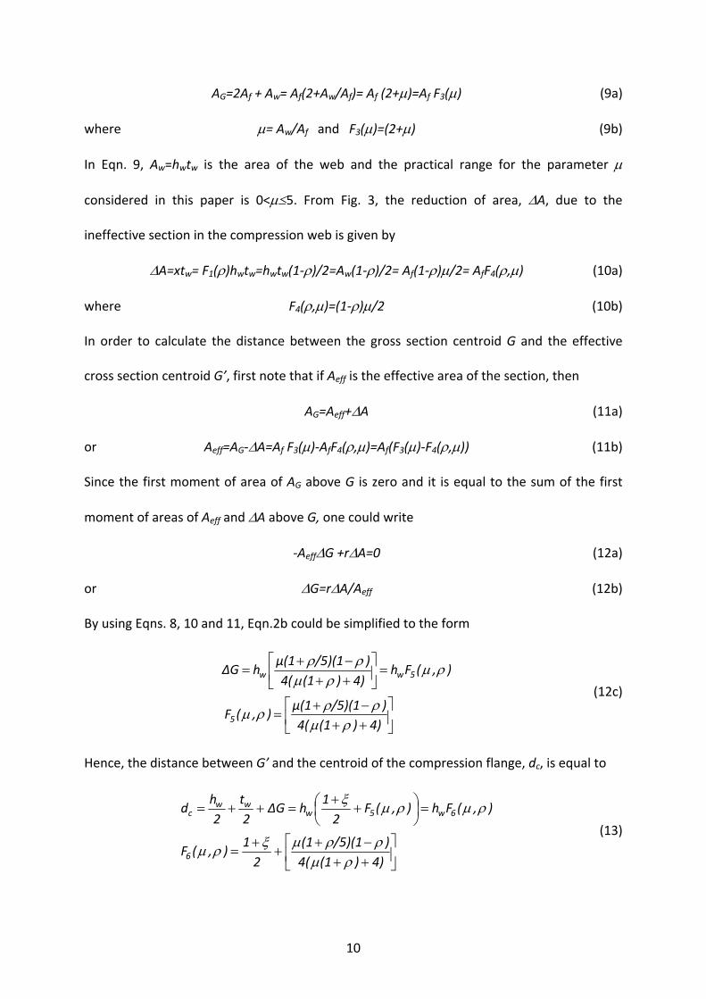
AG=2Af + Aw= Af(2+Aw/Af)= Af (2+μ)=Af F3(μ) (9a)
where μ= Aw/Af and F3(μ)=(2+μ) (9b)
In Eqn. 9, Aw=hwtw is the area of the web and the practical range for the parameter μ
considered in this paper is 0<μ≤5. From Fig. 3, the reduction of area, ΔA, due to the
ineffective section in the compression web is given by
ΔA=xtw= F1(ρ)hwtw=hwtw(1‐ρ)/2=Aw(1‐ρ)/2= Af(1‐ρ)μ/2= AfF4(ρ,μ) (10a)
where F4(ρ,μ)=(1‐ρ)μ/2 (10b)
In order to calculate the distance between the gross section centroid G and the effective
cross section centroid G’, first note that if Aeff is the effective area of the section, then
AG=Aeff+ΔA (11a)
or Aeff=AG‐ΔA=Af F3(μ)‐AfF4(ρ,μ)=Af(F3(μ)‐F4(ρ,μ)) (11b)
Since the first moment of area of AG above G is zero and it is equal to the sum of the first
moment of areas of Aeff and ΔA above G, one could write
‐AeffΔG +rΔA=0 (12a)
or ΔG=rΔA/Aeff (12b)
By using Eqns. 8, 10 and 11, Eqn.2b could be simplified to the form
⎥⎦
⎤⎢⎣
⎡++−+
=
=⎥⎦
⎤⎢⎣
⎡++−+
=
4))(14()/5)(1μ(1
),(F
),(Fh4))(14()/5)(1μ(1
hΔG
5
5ww
ρμρρρμ
ρμρμ
ρρ
(12c)
Hence, the distance between G’ and the centroid of the compression flange, dc, is equal to
⎥⎦
⎤⎢⎣
⎡++−+
++
=
=⎟⎠⎞
⎜⎝⎛ +
+=++=
4))(14()/5)(1(1
21
),(F
),(Fh),(F2
1hΔG
2t
2h
d
6
6w5www
c
ρμρρμξρμ
ρμρμξ
(13)

11
The second moment of area of the effective cross section with respect to G’ can be obtained
by subtracting the second moment of area of the ineffective area from the second moment
of area of the gross section so that
( ) ( )23
2
12GrA
txGAII w
GGeff Δ+Δ−−Δ+= (14)
In Eqn. 14, IG is the second moment of area of the gross section with respect to G and it can
be expressed as
⎥⎥⎦
⎤
⎢⎢⎣
⎡⎟⎟⎠
⎞⎜⎜⎝
⎛ +++=
2fw
f
3ffw
3w
G 2
thA
12
tb2
12th
I (15a)
Eqn. 15a can be simplified to the form of
( )⎥⎦
⎤⎢⎣
⎡ +++=
=22
7
72wfG
21
612),(F
),(FhAI
ξξμμξ
μξ
(15b)
Combining Eqn. 15 (for IG), Eqn. 9 (for AG), Eqn. 12 (for ΔG), Eqn. 7 (for x), Eqn. 10 (for ΔA)
and Eqn. 8 (for r) and simplify the results, Ieff can be expressed in the form
⎟⎟⎠
⎞⎜⎜⎝
⎛+−−+= 2
524
312
5372wfeff )F(FF
12μF
FFFhAI (16a)
Thus, the effective section modulus Weff is given by
6
2524
312
537wf
6w
2524
312
5372wf
c
effeff F
)F(FF12F
FFFhA
Fh
)F(FF12F
FFFhA
d
IW
⎟⎟⎠
⎞⎜⎜⎝
⎛+−−+
=⎟⎟⎠
⎞⎜⎜⎝
⎛+−−+
==
μμ
(16b)
By using Eqns. 1c and 16b, the ratio R defined in Eqn. 5 can now be expressed as
( )ξ
μ
ξμρ+
⎟⎟⎠
⎞⎜⎜⎝
⎛+−−+
==16
2524
312
537
fl pl,
eff
F
)F(FF12F
FFF
W
W),,R( (17)
12
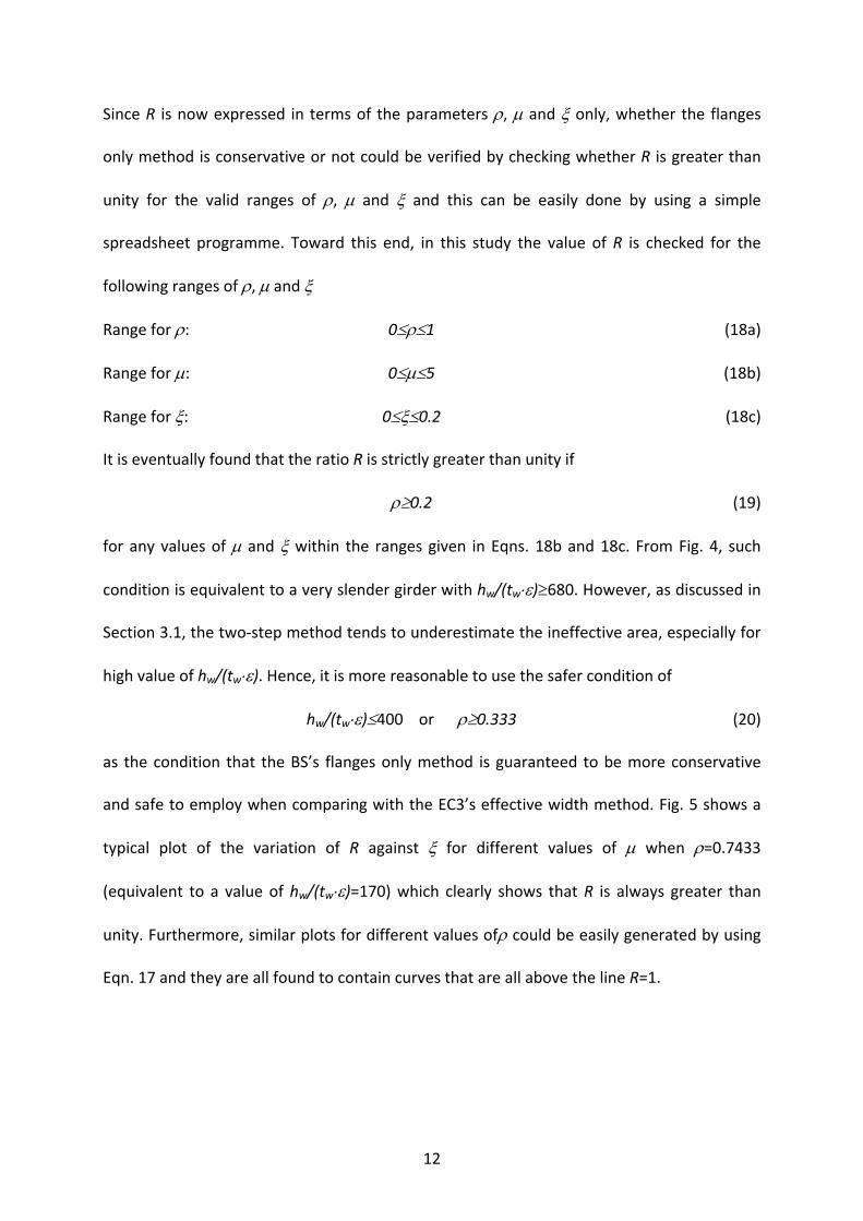
Since R is now expressed in terms of the parameters ρ, μ and ξ only, whether the flanges
only method is conservative or not could be verified by checking whether R is greater than
unity for the valid ranges of ρ, μ and ξ and this can be easily done by using a simple
spreadsheet programme. Toward this end, in this study the value of R is checked for the
following ranges of ρ, μ and ξ
Range for ρ: 0≤ρ≤1 (18a)
Range for μ: 0≤μ≤5 (18b)
Range for ξ: 0≤ξ≤0.2 (18c)
It is eventually found that the ratio R is strictly greater than unity if
ρ≥0.2 (19)
for any values of μ and ξ within the ranges given in Eqns. 18b and 18c. From Fig. 4, such
condition is equivalent to a very slender girder with hw/(tw⋅ε)≥680. However, as discussed in
Section 3.1, the two‐step method tends to underestimate the ineffective area, especially for
high value of hw/(tw⋅ε). Hence, it is more reasonable to use the safer condition of
hw/(tw⋅ε)≤400 or ρ≥0.333 (20)
as the condition that the BS’s flanges only method is guaranteed to be more conservative
and safe to employ when comparing with the EC3’s effective width method. Fig. 5 shows a
typical plot of the variation of R against ξ for different values of μ when ρ=0.7433
(equivalent to a value of hw/(tw⋅ε)=170) which clearly shows that R is always greater than
unity. Furthermore, similar plots for different values ofρ could be easily generated by using
Eqn. 17 and they are all found to contain curves that are all above the line R=1.
13
4. The modified flanges only method
While it is shown that R is strictly greater than unity for the range of 1≥ρ≥0.333, Fig. 5 shows
that the flanges only method sometime could be too conservative in the sense that for a
high value of μ, R could be greater than 1.3. That is, the flanges only method could
underestimate the bending resistance by more than 30% and such situation is more obvious
as ρ increases. Hence, a more efficient design could be achieved by increasing the bending
resistance predicted by the flanges only method. Note that direct calculation of R using Eqn.
17 has little practical value as it is even more tedious than the direct calculation of the
effective modulus. However, if one examines Fig. 5 more closely it could be found that for a
given value of ρ (or hw/(tw⋅ε)) and μ, the variation of R with respect to the variation of ξ is
small. This observation suggests that, for a given value of ρ (or hw/(tw⋅ε)), a reasonable and
not too conservative lower bound of R could be obtained by plotting the minimum value of R
from all ξ against μ. Such a plot for the range of 124≤hw/(tw⋅ε)≤400 is shown in Fig. 6. From
Fig. 6, it can be seen that for a given value of ρ (or hw/(tw⋅ε)), the minimum value of R is
almost a linear function of μ and increases as μ increases. On the other hand, in order to find
out the influence of hw/(twε), a plot of the minimum value of R from all ξ against hw/(twε) for
different values of μ is shown in Fig. 7. From Fig. 7, it can be seen that the minimum value of
R decreases in a quadratic manner as hw/(twε) increases. Based on the above observations, a
simple way to improve the efficiency of the flanges only method is to introduce a
modification factor )th
,(Rw
w
εμ which depends on μ and hw/(twε) only such that the estimated
bending resistance Rdf,M (c.f. Eqn. 1b) is given by
Rdf,M = )th
,(Rw
w
εμ Afhw(1+ξ)fy = )
th
,(Rw
w
εμ Wpl, fl⋅fy (21)

14
where in Eqn. 21, the modification factor should take a simple form of
⎟⎟⎟⎟⎟
⎠
⎞
⎜⎜⎜⎜⎜
⎝
⎛
⎟⎟⎟⎟
⎠
⎞
⎜⎜⎜⎜
⎝
⎛ −++=
2
w
w
1w
w
gth
g1)εt
h,(R
2
400εμμ (22)
After some trials and tests, it is found that if one takes g1 =0.028, g2=950, Eqn. 22 shall
always remain conservative (i.e. )th
,(Rw
w
εμ ≤R) whenever ρ≥0.333 while the modified
bending resistance calculated shall be very close (almost always greater than 92%) to the
bending resistance predicted by the effective width method (Eqns. 4b and 16b). As a result,
the following final form for the modification factor )th
,(Rw
w
εμ is suggested for the modified
flanges only method.
f
w
2
w
w
w
w
A
A ,
th
0.0281)εt
h,(R =
⎟⎟⎟⎟⎟
⎠
⎞
⎜⎜⎜⎜⎜
⎝
⎛
⎟⎟⎟⎟
⎠
⎞
⎜⎜⎜⎜
⎝
⎛ −++= μεμμ
950
400 (23a)
Mc,Rd=Weff⋅fy ≈ Rdf,M = )th
,(Rw
w
εμ Afhw(1+ξ)fy (23b)
5. Calculation example
In this section, a calculation example is given to demonstrate the efficiency of the modified
flanges only method. A symmetric plate girder shown in Fig. 8 is constructed using grade 355
steel. For this case, since ε=0.814, with tw=10mm, the minimum value of hw which makes the
web a Class 4 slender section is 10x0.814x124=1009.36mm. Hence, in this example, the
depth of the web hw is set to vary from 1010mm to 3000mm, which is corresponding to a
range of hw/(tw⋅ε) from 124 to 369. By using Eqns. 1, 4 and 23, the bending resistance

15
predicted by the BS’s flanges only method (Mf,Rd), the EC3’s effective width method (Mc,Rd)
and the modified flanges only method Rdf,M are respectively computed for different values
of hw and are plotted in Fig. 9. From Fig. 9, it can be seen that Mc,Rd is always the largest but
it is clumsy to calculate while Rdf,M is larger than Mf,Rd and is close to the value of Mc,Rd. Fig.
10 compares the performance of the flanges only method and the modified flanges only
method, it can be seen that while the original flanges only method could only able to predict
a bending resistances of approximately equal to 86% of that by the effective width method,
the modified method could yield bending resistances in the range of 94% to 97% of that by
the effective width method with very simple calculations.
6. Conclusions
In this paper, both the simple BS’s flanges only method and the more complicated EC3’s
effective width method for calculating the bending resistance of a plate girder with Class 4
slender web without longitudinal stiffener are reviewed. A detailed analytical study and
comparison are conducted for these two methods. It is found that within virtually all
practical range of the web depth to thickness ratio, the flanges only method is deemed to be
conservative when comparing with the effective width method. Hence, it could be safely
used in the prediction of bending resistance during the design plate girder according to the
Eurocodes 3. However, sometime the original form of the flanges only method could be too
conservative, especially when the ratio between the web area and the flange area is high. In
order to increase the efficiency of the flanges only method, a simple modification factor that
is suitable for hand calculation is suggested while the essential condition of conservative
prediction is strictly preserved. Finally, a calculation example is given to show that the

16
suggested modified method could result in better bending resistance prediction which is
very close to that predicted by the more complicated effective width method.
Reference
[1] D. A. Nethercot, Adopting the Structural Eurocodes, Proceedings of the Structures
Congreess 2005: Metropolis and Beyond, American Society of Civil Engineers, New York,
United States, April 20‐24 2005.
[2] F. S. K. Bijlaard. Eurocode 3: Design for Steel Structures “Ready for Practice”,
Proceeding of the International Symposium of Fatigue and Fracture of Steel Structures,
Edited by: S. P. Chiew, 4 December 2007, Nanyang Technological University, Singapore.
[3] British Standard Institution (2005), Eurocode 3: Design of Steel Structures: Part 1‐1
General rules and rules for buildings, BS EN 1993‐1‐1, BSI London.
[4] British Standard Institution (2000), Structural use of steelwork in building ‐Part 1: Code
of practice for design – Rolled and welded sections, BS 5950‐1:2000, BSI London.
[5] P. J. Dowling (1990), New Directions in European Structural Steel Design, Journal of
Constructional Steel Research, Vol. 17, pp 113‐40.
[6] B. Johansson, R. Maquoi and G. Sedlacek (2001), New design rules for plated structures
in Eurocode 3, Journal of Constructional Steel Research, Vol. 57, pp 279‐311
[7] N. S. Trahair, M. A. Bradford, D. A. Nethercot and L. Gardner (2008), The behaviour and
design of steel structures to EC3, Fourth Edition, Taylor & Francis, New York.
[8] L. Gardner and D. A. Nethercot (2011), Designer’s guide to Eurocode 3: Design of steel
buildings EN 1993‐1‐1, ‐1‐3 and ‐1‐8, Second edition, ICE publishing.
[9] M. E. Brettle (2009), Steel Building Design: Introduction to the Eurocodes, The Steel
Construction Institute, UK.

17
[10] M. E. Brettle (2009), Steel Building Design: Concise Eurocodes, in accordance with
Eurocodes and the UK National Annexes, The Steel Construction Institute, UK.
[11] M. E. Brettle and D. G. Brown (2009), Steel Building Design: Worked examples – Open
sections, in accordance with Eurocodes and the UK National Annexes, The Steel
Construction Institute, UK.
[12] Steel Building Design: Worked examples for students, in accordance with Eurocodes,
The Edited by M. E. Brettle (2008), Steel Construction Institute, UK.
[13] British Standard Institution (2006), Eurocode 3: Design of Steel Structures: Part 1‐5
Plated Structural elements, BS EN 1993‐1‐5, BSI London.
[14] D. Beg, U. Kuhlmann, L. Davaine and B. Braun. Design of plated Structures Eurocode 3:
Design of steel structures: Part 1‐5‐ Design of plated structures, ECCS and Ernst & Sohn,
2010
[15] D. Lam, P. Ang and S. P. Chiew (2004), Structural steelwork: Design to limit state theory,
Third edition, Elsevier Butterworth‐Heinemann, Boston.

18
Figure 1: A symmetrical plate girder with Class 4 web and with no longitudinal stiffener
Figure 2: Equivalent effective Class 3 section for the EC3’s effective width method
bf tf
tw
hw y y G
(a) Gross section
yy G
(b) Effective section(Class 3 equivalent)
y’y’ G’
Ineffective compressive web
G’=Centroid of effective sectionG=Centroid of gross section
fy
σ2=ψfy< fy
(c) Stress distributions of equivalent Class 3 section (under sagging moment)
y’ y’ G’
Compressive stress
tensile stress
Flanges
Web
bf tf
tw
hw
lw
yy G

19
Figure 3: Calculation of effective cross section for a symmetric plate girder with Class 4 slender web.
Figure 4: A plot of ρ against hw/(tw⋅ε)
0
0.2
0.4
0.6
0.8
1
1.2
0 100 200 300 400 500 600 700 800
ρ
hw/(twε)
ρ vs hw/(twε)
Class 3 Class 4
hw/(twε)=124 hw/(twε)=680
hw/(twε)=400
ρ≈0.333
ρ=0.2
ρ=1
yy G
(a) Effective section (Class 3 equivalent)
y’y’ G’
G’=Centroid of effective section G=Centroid of gross section
fy
σ=ψfy< fy
(b) Stress distributions ofequivalent Class 3 section(under sagging moment)
y’ y’ G’
Compressive stress
tensile stress dt
dc bc (=hw/2 in the two‐step method)
be1
be2
x
ΔG
r
bt

20
Figure 5: A plot of R against ξ for different values of μ when ρ=0.7433 (equivalent to hw/(tw⋅ε)=170)
Figure 6: A plot of the minimum value of R from all ξ against μ for different values of hw/(twε)
0.951
1.051.1
1.151.2
1.251.3
1.351.4
1.451.5
1.551.6
0 0.025 0.05 0.075 0.1 0.125 0.15 0.175 0.2
R
ξ
μ=0 μ=1 μ=2 μ=3 μ=4
1
1.05
1.1
1.15
1.2
1.25
1.3
1.35
1.4
1.45
1.5
0 0.5 1 1.5 2 2.5 3 3.5 4
Minimumvalue of Rfrom all ξ
μ
hw/tw=124e hw/tw=170e hw/tw=200e hw/tw=240e
hw/tw=280e hw/tw=320e hw/tw=360e hw/tw=400e

21
Figure 7: A plot of the minimum value of R from all ξ against hw/(twε) for different values of μ
Figure 8: A calculation example
1
1.1
1.2
1.3
1.4
1.5
120 170 220 270 320 370
Minimum value of R from
all ξ
hw/(twε)
μ=0.6 μ=1.0 μ=2 μ=3 μ=4
400 mm 25 mm
10 mmhw from 1010 mm to3000 mm
yy G
fy=355MPaε=0.814

22
Figure 9: Bending resistance predicted by different methods
Fig. 10. Comparison of bending resistance predicted by different methods
3000400050006000700080009000
10000110001200013000
1000 1500 2000 2500 3000
Bending Resistance(kNm)
hw (mm)
Bending resistance according to EC3's effective modulus method
Bending resistance according to the BS's flanges only method
Bending resistance according to modifed flanges only method suggested in this paper
0.84
0.86
0.88
0.9
0.92
0.94
0.96
0.98
1
1000 1500 2000 2500 3000
BendingResistance
Ratio
hw (mm)
Flanges only resistance/ Effective modulus resistance
Modified flanges only resistance/Effective modulus resistance