License Plate Recognition - DIVA
34
1 Code:________________ Faculty of Engineering and Sustainable Development License Plate Recognition Songke Li & Yixian Chen June 2011 Bachelor Thesis, 15 credits, C Computer Science Computer Science program Examiner: Douglas Howie Supervisor: Julia Åhlén
-
Upload
khangminh22 -
Category
Documents
-
view
0 -
download
0
Transcript of License Plate Recognition - DIVA

1
Code:________________
Faculty of Engineering and Sustainable Development
License Plate Recognition
Songke Li & Yixian Chen
June 2011
Bachelor Thesis, 15 credits, C
Computer Science
Computer Science program
Examiner: Douglas Howie
Supervisor: Julia Åhlén

2
License Plate Recognition
by
Songke Li & Yixian Chen
Faculty of Engineering and Sustainable Development
University of Gävle
S-801 76 Gävle, Sweden
Email:
Abstract
This paper presents a method for license plate recognition through analysis of vehicle
images. Accurate location of license plate and extracting characters of plate are
implemented. In the plate location module, the paper puts forward arithmetic of plate
edge recognition by morphology algorithms. Meanwhile, Radon transform is used to
adjust different angles between viewer and license plate. At last, characters extraction
is done by histogram. And the extraction characters are matched with the templates.
Experimental results show that this approach can recognize license plates more
effectively and establish a good technical base for the future advanced license plate
recognition.
Key words: plate license recognition, morphology algorithms, Radon transform,
template matching, MATLAB

3
Contents
1 Introduction ............................................................................................................. 1
1.1 Aim ....................................................................................................................................... 2
1.2 Background ........................................................................................................................... 3
1.3 Previous research .................................................................................................................. 7
1.4 Delimitation .......................................................................................................................... 8
1.5 Research Questions ............................................................................................................... 9
2 License plate recognition ........................................................................................ 9
2.1 Image preprocessing ........................................................................................................... 10
2.2 Adjust different distances between the viewer and the vehicle ........................................... 13
2.3 Locate the license plate by morphology algorithm ............................................................. 13
2.4 Adjust license plates which are in the different angle to the observer ................................ 15
2.5 Extract the license plate in more advanced detailing .......................................................... 17
2.6 Segment the characters out from license plate .................................................................... 20
2.7 Character‟s models matching .............................................................................................. 22
3 Results .............................................................................................................................. 23
3.1 The interface of the license plate recognition ..................................................................... 23
3.2 The accuracy of recognition ................................................................................................ 25
3.3 The analysis of the wrong recognition results ..................................................................... 26
4 Discussion ............................................................................................................... 28
5 Conclusions and Future Work ............................................................................. 29
6 Acknowledgements ................................................................................................ 29
References ................................................................................................................. 30

1
1. Introduction
Originally, vehicle license plate was invented and put in real use for carriages, but not
for automobiles. In Victoria Canada, the license plate was firstly introduced in 1884
for a horse-drawn hackney carriage. The world‟s first license plate rule is applied in
France on August 14, 1983.Under this rule: all the license plates must be registered
with their own name, address and registered number. In Germany, the police provided
Mr.Chubais Barthes the license plate on April 14, 1899, which is the first best saved
license plate in the world. This license plate is a rectangular piece, in which only „1‟
was written [3].
Figure 1: The first best saved license plate
Figure 2: Swedish euro license plate(Source: http://www.worldlicenseplates.com/ [17] )
Currently, as a main traffic tool in the developed society, vehicles have been used
widely in every area of production and life of people. With the total number of
vehicles increasing quickly, traffic violations will appear more frequently in the
public traffic, such as running the red light, over speed. If only the numbered traffic
police are relied on to avoid to huge number of traffic violations, the public traffic
will sink into paralyzed position. The license plate is unique information for every car.
And its image is an important resource for accessing its owner and exchanging

2
information. Therefore, images can be used as major media for human/vehicle
identification. And the technology of image analysis was involved in all kinds of
aspects of human life already. Therefore, automatic collection and management of
license plate information from digital image become an effective way to supervise
public transportation.
Vehicle License Plate Recognition is an extra critical part of modern intelligent
transportation system since the license plate number is a simple and effective way for
identifying vehicle. Specifically, there would be no vehicle parking access control and
auto payment check in highway without the technique of vehicle license plate
recognition. The license plates recognition system has a wide range of applications
[13]: 1) Highway automated tolling, monitoring management, 2) community
automated parking management, 3) the urban road monitoring and illegal-events
management, 4) checking vehicles, 5) traffic statistics, and safety management.
For instance, the tolling efficiency in traditional manual way on toll highway was
low. With the growing traffics in recent years, toll stations have already been a
bottleneck to impede the highway to fully display its advantages. Automatic toll
collection from the bank‟s account of vehicle owner without stopping is an effective
way to solve this problem. One main function of this system is that it will greatly
enhance the channel capacity and reduce time through toll stations. Statistics have
shown that the average vehicle passing rate is 1500 per hour on highway toll station
equipped with automatic toll collection, and the rate is 650 per hour on toll station
equipped with automatic coin-operated machine, while the maximum rate is 350 per
hour in traditional manual way [4].
LPR usually is used for detection of some special vehicles. This feature is mostly
focus on the vehicles listed in the blacklist, such as the vehicle fled after the accident,
or reported as stolen. As long as the relevant information of license plate is input into
dataset, LPR will automatically lead to find out the vehicle information. Once the
vehicle information found, the systems will feedback it to police station.
The techniques of the license plate recognition have been developed for many
years. With the hardware and software improved, the accuracy of license plate
recognition has been improved to some extent. But the current accuracy still cannot
satisfy all the requirements of the traffic department concerned. The license plate
extraction is not a simple process, as under some situations, it is easy for people to
judge but it will be very hard for computer to do it.
1.1 Aim
Our goal is to create a robust application to recognize the license plate on the road and
get the relevant characters, and numbers of the license plate. This application depends
on the combination of the knowledge of image analysis and our own understanding of
license plate recognition. Meanwhile, it is also based on the other previous research
on this field.

3
1.2 Background
The techniques of image processing have already developed maturely. In this section
we will describe the theoretical background needed to perform this study.
1.2.1 Robert operator
Robert algorithm is a basic method of edge detection techniques. It was one of the
first edge detectors and was initially proposed by Lawrence Roberts in 1963 [10]. It
uses two 2 X 2 mask to searcher for the derivatives. But Robert‟s edge detector is
sensitive to noise compared with the other edge detectors [14].
Figure 3: derivative masks
1.2.2 Prewitt operator
The prewitt operator is an edge detection algorithm which is always used in image
processing. The prewitt operator is based on convolving the image with a small,
separable, and integer valued filter in horizontal and vertical direction. Therefore, the
occupied space will be small in terms of computations. The gradient is estimated from
eight directions in a 3 X 3 convolution mask. In the process, the convolution result of
greatest magnitude indicates the gradient direction [14].
(a) (b) (c)
Figure 4: Prewitt edge detection template
Figure 4(a) shows the template used to detect the horizontal edges, which means
detecting the edges in X axis. Similarly, Figure 4(c) shows the template used to detect
the vertical edges (in Y axis). Those operators are able to find out the edges from two
different directions.

4
1.2.3 Median filter
In the image pre-processing, how to reduce noise always plays an extreme important
role. The median filter is a nonlinear digital filtering technique, which is always used
to remove noise effectively. It often does a better job than the other filter of
preserving useful detail in the image [5]. The median filter considers each pixel in the
image in turn and compares with its nearby neighbors to decide whether or not it is
representative of its surroundings.
Figure 5: Calculating the median value of a pixel neighborhood and the result of median filter
1.2.4 Histogram equalization
Histogram equalization is used to adjust contrast based on the image‟s histogram in
the image processing. It transfers the gray levels so that the histogram of the resulting
image is equalized to be a constant. The two purposes are always listed: to equally use
all available gray levels and for further histogram specification [14].
Figure 6: Example of histogram equalization

5
1.2.5 Radon transform
Applying the Radon transform on an image f (x,y) for a given set of angles can be
thought of as computing the projection of the image along the given angles. The
Radon transform of an image is the sum of the Radon transforms of each individual
pixel [12]. The result is a new image R(r,q). This is depicted in Figure 7. This can be
written mathematically by equation 1:
(1)
after which the Radon transform can be written as equation 2:
(2)
The algorithm divides pixels in the image into four subpixels and projects each
subpixel separately, as shown in the following Figure 7.
Figure 7: The rando algorithm
Each subpixel's contribution is proportionally split into the two nearest bins,
according to the distance between the projected location and the bin centers. If the
subpixel projection hits the center point of a bin, the bin on the axes gets the full value
of the subpixel, or one-fourth the value of the pixel. If the subpixel projection hits the
border between two bins, the subpixel value is split evenly between the bins [1].
1.2.6 Gray scale image
A grayscale (or gray level) image is a simply digital image in which the only colors

6
are shades of gray. Actually, the gray color is one in which the red, green and blue
components all have equal intensity in RGB space. Therefore, it carries only intensity
information for each pixel [14]. Typically, the intensity values are stored in an 8 bit
system, which have 256 gray-level per color. The gray image is displayed in Figure
8(b).
(a)Original image (b) Gray scale image (c) Binary image
Figure 8: the image in different color model
1.2.7 Binary image
Binary image is a digital image whose pixels have only two possible intensity values.
They are normally displayed as black and white. Numerically, the two values are
often 0 for black, and either 1 or 255 for white [14]. The binary image is displayed in
Figure 8(b).
1.2.8 Morphological Image Processing
The identification of objects within an image can be a very difficult task. Because
sometimes there are no efficient ways to find objects based on the intensity values of
the pixels. However, if recognize the object„s different features, we could use the
information about the shape of the object. Since the shape recognition is not based on
the intensities, but performed on binary images. Therefore, one way to simplify the
problem is to change the grayscale image into a binary image, in which each pixel is
restricted to a value of either 0 or 1 [14]. For a binary image, there are four
fundamental operations, dilation, erosion, opening, and closing.
Figure 9: the four basic morphological operations are used in the processing of binary image, (b) to (e) display the
result of applying these operations to the image in (a).
In (b), it shows the most general operation: Erosion. For the erosion, all pixels
7
outside the border should have value 1 for the binary process .It could make the object
smaller and segment one object into many objects.
Figure (c) displays another common operation, which is called Dilation. It is
totally opposite operation to the Erosion. For the dilation, all pixels outside the border
should have value 0 for the binary process. Typically, it can make the object bigger
and merge many objects into one.
The Figure (d) and (e) show the two derivational operations from the Erosion and
Dilation. Opening is defined as an erosion followed by dilation and Closing is defined
as dilation followed by erosion.
1.3 Previous Research
Currently, there is a lot of research on license plate recognition in recognition area.
Usually, license plate recognition is divided into five parts: input image, image
pretreatment, license plate location, character separation, character recognition.
In the first two parts, some common methods are usually used, such as Grayscale
image, Intensity Transformation Image [9]. The function of the first two steps is to
help search for the license plate in a more accurate way.
It is a truly that the first most important step of vehicles license plate recognition
system is to searcher and localizes the license plate. This detection step could greatly
affect the speed and accuracy of the whole automatic license plate recognition system.
In previous research, the most prevalent technique is the methods based on edge
statistics, which are based on the principle that the change of brightness in the license
plate region is more remarkable and more frequent than elsewhere. But they hardly
can be applied to complex images due to their sensitivity to the unwanted edges. S.
Wang and H. Lee [16] combined edge statistics with morphological steps to eliminate
unwanted edges in the processed images. On the other hand, some approaches take
advantage of color features. Lin Luo [8] creates a new and effective approach of
license plate location. The following three key sections are involved in this proposed
algorithm. Firstly, Sobel operator is used to extract the vertical edges of the vehicle
image. Then, HSV color space and integral image are employed to locate candidates
in yellow license plates and non-yellow license plates. Finally connected component
analysis is used to locate the license plate accurately. Similarly, Yao-quan [19] also
uses a color-based method, but in which the color information from the colored image
is reasonably utilized to greatly decrease the edge points. With this method, it also
eliminates the disturbances of the fake plate‟s region whose structure and texture are
similar to the vehicle plate but do not match the plate‟s fixed color collocation*.
Hsiao-Chen [6] introduced a totally different license plate detection method compared
with above, in which two subsystems were listed: Car detection subsystem and plate
extraction subsystem. Car detection subsystem uses Minimum Moving Amount
Decision Rule and Nearest Distance Decision Rule of dynamic images to find the
location of cars on the screen. Plate extraction subsystem uses the characteristics of
the plates and plate searching algorithm to extract plate. But we consider this method
is not suitable to detect license plate. Because the process of detection includes many
different levels so that it is easy to disorder each levels.
8
Another important step of vehicles license plate recognition system is to
recognize the Character. This step is a larger part which involves a great amount of
calculation. It could verify the accuracy of the whole system. When the vehicles
license plate is viewed in the dark or in rain or in other complicated environments, the
LP was really difficult to be recognized clearly. Therefore, we should use the
technique to recognize the Character. In the H. Ching-Tang [2] article, firstly they
calibrate the LP, using the gray level value to adjust the light and for the character
separation and modification of the integrality, they used the Black top-hat technology
to eliminate the shadow and get an optimal display. Finally, they used
back-propagation neural network to recognize each character. In the Q.Xiwen [18]‟s
license plate character recognition part, it introduce the method which is improved BP
Neural Network to recognize the Character. There are three layers, which are input
layer, hidden layer and output layer, in this design. If the BP neural network would
identify English characters, the output layer neuron number should be 5. This method
could improve the accuracy and training speed. Moreover, another important
advantage is to avoid falling into local minimum points. Y.Chenpu [3] describes a
template matching method. One database should be existed. For instance, for
recognition of English and digital letters, there are 26 letters and 10 digital letters in
the database. Then they used the calculation to match the template and judged
whether it matches or not. It also introduced the similar method for identification of
the Chinese character.
1.4 Delimitation
Detection of vehicle license is huge challenge in image processing. The reason can be
concluded as the following aspects. Firstly, the shape of car plate license plate may be
various in different countries. In China, license plate is combined with Chinese
characters, English characters and numbers. But in Europe, license plate includes
characters and numbers. Secondly, in real life, the license plate may be distorted as
well. Thirdly, the luminance condition may vary a lot in car images taken by auto
camera either too bright or too dark luminance may inevitably affect the accuracy and
increase the difficulty for plate detection. Each of factors increases the level of
difficulty of license plate detection.
On the other hand, as the application environments of license plate recognition are
different, the technical requirements on the license plate recognition are also different.
For instance, the system of license plate recognition must take into consideration of
the higher requirements on vehicle speed factor in highway, compared with that in the
standard way. In the system of license plate recognition, it is very hard to improve
both the accuracy and speed of recognition concurrently. The reasons lie not only in
the imperfection of the recognition‟s techniques, but also the limitation of hardware.
We delimit ourselves to plates with clear letters and numbers. This means, we leave
out the plates corrupted with much dirty or fuzzy because of the high speed. And, this
system is suitable with the Europe plate and Swedish plate. It cannot recognize the
Chinese or other countries‟ plate, due to the license plates are totally different in those
countries.

9
1.5 Research Questions
Is it possible to locate the license plates accurately from the vehicle on the road?
Is it possible to recognize license plates from images where plates are in the different
distances to the observer?
Is it possible to recognize license plate characters from images where plates are in the
different angle to the observer?
Is the program able to extract characters from the license plate on various screens?
Is it possible to distinguish the European license plate and Swedish license plate? For
instance in Figure 10:
Figure 10: the European license plate and Swedish license plate
2 License plate recognition
For recognizing the license plate, the process can be divided into two blocks. In the
first blocks, the relevant position of license plate is located in the testing image. Then,
extract the characters from the license plate and input them into the secondary blocks.
There are more detailed steps involved in each block. In the following part, we will
present the application step by step.
Image preprocessing
Adjust different
distances between the
viewer and vehicle.
Locate the license
plate by morphology
algorithm.
Adjust license plates
which are in the
different angle to the
observer.

10
License plate location is the first processing step in the system of license plate
recognition. It plays an important role since this process can affect directly the results
of recognition. If the position of license plate is located wrongly, it would imply that
the steps below would be invalid. The extraction of license plate comprises three parts:
image preprocessing, license plate search, and license plate location.
2.1 Image preprocessing
Generally, it is too complex to detect target from a color image. In order to identify
the outline of a target easier, an approach named grayscale is often used in image
processing. In most cases, the luminance of license plate is brighter than other
ordinary objects around vehicle in the image. Sometimes, the contrast between license
plate and other objects may not be sharp, which will decrease the accuracy of
recognition if we try to extract the license plate directly. Therefore, the intensity value
in grayscale image can be stretched in order to increases the contrast of the output
image. In this way it is possible to solve the problem effectively. The figure below
illustrates this idea, especially the marked part.
a) b)
Figure 11: a)Grayscale Image. b) Intensity Transformation Image
Extract the license
plate in more
advanced detailing.
Segment the
characters out from
license plate.
Character’s models
matching.

11
There is always some isolated noise in the image, such as pebbles on the road. If
this noise cannot be moved out effectively, it will affect the accuracy of extraction of
license plate. For instance, as we need to apply edge detection, removing noises is
necessary. After testing different ways of removing noise in this kind of images, we
found that pretty good images could be obtained by median filter. The purpose of this
operation succeeded in preparing the basic clear binary image for next operation.
Figure 12: (a) Grayscale Image after stretching histogram (b) Gray image after removing noise by median filter
The next step is to apply Robert operator of edge detection on the result form
previous step. The result is shown in Figure 13:
Figure13: The edge detection by Robert way
In the previous step, we found the position of the license plate, which is marked
by a lot of small edge. It implies that the density of white points on the vehicle area is
much larger than other area in same size. Therefore, we could use the closing
operation to process this image so that to offer a better help to next operations of
detecting license plate by morphology.
Most of noises are
deleted

12
Figure 14: The image after closing operations
The result from previous shows a lot of unwanted features such as in the Figure
14, we found the area of license plate is covered by abundant white points. This is
shown in Figure 15.
.
Figure 15 Example of abundant white areas
In this step, the operation removes all connected components (objects) that have
less than a certain number of pixels from a binary image. The result is shown as
Figure 16:
Figure 16: The result of the operation removing

13
2.2 Adjust different distances between the viewer and the vehicle
Generally, the cameras are set up in different locations at the toll station or on the road,
resulting in different distances between the observer and the vehicle. In some cases,
the distance between the observer and vehicle is very far. So we should decrease this
distance between the observer and the vehicle. During images testing, we found most
of the white points located on the car on road. This phenomenon inspires us to solve
this problem by localizing the coordinates of white points. In the programming, a
function is created to adjust the distances. Firstly, the coordinate summation of the all
white points in the image is calculated alone X axis and Y axis separately. After that,
the center of the white points is calculated according to the Equation 3:
(3)
Where Xk is every position of white point alone x axis, n is the total number of white
points in the image and x is the average number.
Lastly, we need to adjust appropriately the length and width around this center.
The distance between the viewer and the vehicle will be closer, which facilitates the
following step.
Figure 17: (a) original image (vehicle is close to camera) (b) the effect of adjusting the distance
Figure 18: (c) original image (vehicle is far to camera) (d) the effect of adjusting the distance
2.3 Locate the license plate by morphology algorithm
Basically, the algorithm of the license plate location plays a key role in this system. In
order to extract the license plate more accurately, we decide to implement the

14
algorithm for the binary image. After the image preprocessing, we obtained an
appropriate binary image. According to the analysis for the feature of the license plate,
typically, the white pixels should be correlated with a license plate. However, there
are some interference factors to interfere reorganization, such as logo of the car and so
on. Therefore, applying the length-width ratio for license plate which we have been
set, we could extract the license plate correctly.
In this algorithm, we should treat the binary image as a matrix. As we know,
when extracting the rectangle, we should know the 4 points‟ coordinates to limit the
field. Therefore, we divide this algorithm into two steps. First step is to find the two
y-coordinates and the second is to find the x-coordinates.
Figure 19: (a) It displays the first step of this algorithm. (b) It shows the second step of the algorithm.
(a) In this step, we find the white pixels and accumulate the pixel values in each row.
For every y- coordinate, there is a corresponding sum value. We should find the
maximum sum value and record the corresponding y-coordinate to PY1 and PY2.
Next, we search up and down along the vertical direction for finding the
terminated coordinate which can be treated as the edge of the license plate.
Therefore, using a loop to look up alone y-axis until the sum of some row‟s pixel
values reduced to less than 5, PY1 was recorded and look down until the sum of
some row‟s pixel values reduced to less than 5,PY2 represent the another
termination value(Figure 1(a)). So far, we have obtained two y-coordinate
(PY1and PY2) to limit some filed.
Figure 20: The effect of this step along Y-coordinate
(b) In this step, our purpose is to find the two X-coordinates which we call P_X1 and
P_X2. After the previous step, we obtained a region which is limited by PY1 and
Py2. On this basis, we could do some operation to extract the license plate. We
create a loop to find the PX1 and PX2 firstly. The idea of finding them is similar
with the previous step which is to calculate the sum of pixel values in each

15
column. We could obtain the PX1 and Px2 along the horizontal direction. So far,
the four coordinates which are PY2, PY1, PX1, and PX2 could define a rectangle;
see Figure 1(b). Actually, this rectangle represents the license plate.
Figure 21: The effect of this step along X-coordinate
2.4 Adjust license plates which are in the different angle to the
observer
In last example, we found appropriate cutting angles and lengths. But there may be
some parts of license plate that are disappearing if this plate is at certain different
angle to the observer, such as in Figure 22:
Figure 22: The original image
Firstly, the cutting range should be increase in cutting process, because both of
the length and width from the oblique plate are longer than that of horizontal plate
according to mathematic. In the Figure 23 (a), we assume that L is the length and W
is the width of license plate. If the license plate is the different angle to the observer,
such as Figure 23 (b), the width is W1 (W1>W) at least in the area we need to cut
from the original image.

16
a) b)
Figure 23: The principle of mathematic
Figure 24: Extend the range of cutting plate
After that, the radon transform is used to find out the angle between the license
plate and horizon. Before we use the radon transform to adjust license plate, we test
the basic function of radon transform. A simple image which is similar to license plate
is created, and we work it in radon transform at 0, 45, 90 degrees separately. [R, xt] =
radon(I, [0 45 90]);
Figure 25: (a) Original image (b) Applying radon transform along horizon.

17
(c) Applying radon transform along 45 degree. (d) Applying radon transform along 90 degree.
In this processing, the edge detection should be done firstly. During the test, the
result of the canny detection is better than others ways.
Figure 26: The principle of Rando transform
Then, according this principle, we search for the angle between license plate and
horizon. In other word, we need to find out which angle the license plate is projected
in mostly. At last, the maximal angle we should find out and save it. Next, the
function re-rotate is used to adjust the license plate to the horizontal direction
depending on the angle.
Figure 27: The binary image after Rando transform
2.5 Extract the license plate in more advanced detailing
Before segmenting the license plate, some basic preprocess is still necessary .Because
Angle

18
we expect to obtain a relatively perfect binary image for the operation. So far, we
have already extracted a license plate with its angle adjusted. Next, we would remove
some interference which is the stuff except the characters.
Firstly, we convert the grayscale image to a binary image. The output image
replaces all pixels in the input image with luminance greater than a threshold value
with the value 1 (white) and replaces all other pixels with the value 0 (black). We used
the function to compute the threshold value argument (Figure 1).
Figure 28: (a) is a grayscale image, (b) is a converting from (a) by im2bw function.
Secondly, in order to optimize the image, we should apply some morphological
operations to the binary image. One of the morphological operations is represented by
a function which removes the H-connected pixels. For example:
Figure 29: the diagram of examples using the first function.
Another morphological operation is applied by a function. It removes the spur
pixels. Example:
Figure 29: the diagram of an example using the second function.
Figure 30: (a)After first operation (b)After second operation
In the Figure 30, both(a) and (b) are the effect of morphological operations (the

19
first and second operation) to an binary image.The obviously different region is
shown in the red circle.
The third operation 'open' can perform morphological opening (erosion followed
by dilation).Figure 30 displays the compared effect with two morphological
operations.
Figure 31:(a)After second operation (b) After 'open' operation
In the Figure 31, both(a) and (b) are the effect of morphological operations (the
second and 'open' operation) to an binary image.The obviously different region is
shown in the red circle.
At last, in order to remove small objects, we would morphologically open binary
image. This function removes from a binary image all connected components (objects)
that have fewer than some pixels, producing another binary image. Figure 32 shows
the effect after declaring this function.
Figure 32: (a) After 'open' operation (b) After calling the function
In the Figure 32, (a) shows the effect of doing the 'open' morphological operation.
(b) displays the effect of using the function. The different region is shown in red
circle.
So far, we could obtain the licese plate. However, the black border is also still
exist. Therefore, in next step we would estiblish a function to remove the black border.
The idea of creating this function has a little similarity with the idea of license plate
location. If we can find the four coordinates, the rectangle which just cotains the
characters and EU symbols would be extracted. To this goal, we serch up and down
the y-coordinate from the have of the size in the vertical derection(Figure 33(a) shows
the first step in this function).There is a value to determin whether the loop should
cotinue or timinate. After huge numbers of the expirements, we find that using a
function to find the average value to be the threshold is appropriate.

20
Figure 33: As (a) shown, we search the y-coordinate (Y_Up and Y_Down) up and down by a „for‟ loop, in (b)
situation, we have already found the Y_UP and Y_Down, the loop is terminated.
Typically, as for the two X-coordinates, we make them 1 and x respectively.
Therefore, we could extract the image by four coordinates.
Figure 34: (a) illustrates the original binary image which is before using the touying function. As (b)
shown, after declaring this function, we extract the ideal image.
Actually, some interference factors outside the license plate have so far been
removed. However, some noise in the license plate has not yet been removed.
Therefore, the morphological operation is necessary again (Figure 35 shows the
treatment by the function).
Figure 35: (a) illustrates the original image, (b) shows the image after the morphological operation.
2.6 Segment the characters out from license plate.
The character segmentation is a significant part in this system. We establish a function
to segment the character.

21
Figure 36: it illustrate how to implement the algorithm of character segmentation (Swedish license plate)
Figure 37: it illustrate how to implement the algorithm of character segmentation (European license plate)
As shown in the Figure 37, we treat this binary image as a matrix. At the
beginning, we make this matrix oppositely. Then, we use the sum function which is to
return the row vector of the sums of each column. Next, we should research matrix
along the horizontal direction by a loop. According to the sum, we could create the
limited condition to judge whether the loop continue or terminate. The limited
condition is when the sum of some column is less than 1 and the sum of next column
is greater than 1, then it will be segmented from this column to before. Certainly, if
the condition isn‟t satisfied, it would continue to search. If the car is belonging to
Europe Union, the characters added one logo is 7 blocks. Therefore, it need segment
14 times in total. Otherwise, it just needs 12 times segmentation. In the processing of
segmentation, we set a counter to calculate how much segmentation the programming
need to segment. Thereby, we can get if this license plate belong to European or
Swedish, which will provide a lot help to next step (matching characters). The effect
of implementation of this function is shown as Figure 9.

22
Figure 38: The characters are segmented from swedish license plate.
Figure 39: The characters are segmented from European license plate.
2.7 Character’s models matching.
Since the counter has been set in the last step, this value will be used to judge if the
license plate belongs to the Swedish or European plate. For instance, if this value is
12, which means the license plate is cut off 12 times, this plate must be Swedish plate
judging from the above conclusions. Likewise, if the value is 14, the plate must
belong to European system. Then, the relevant characters‟ template should be used in
the first operation of the characters matching. The way we used is to cut out the
related characters from the license plate we have prepared early. For instance in
Figure
Figure 40: the template
In the beginning of model matching, the sizes of the original plate‟s image and
template image should be adjusted to obtain same size. After that, it should be judged
if the black point is in same position between original plate‟s image and the templates.
Meanwhile, a related counter is created in order to calculate how many points witch
satisfy the matching requirements. At last, we need to calculate the similarity rate of
those two images according to the equation of similarity function:

23
(4)
f(i,j) is the value in the position (x,y) in the original plate‟s image. t(i,j) is the value in
the position (x,y) in the template.
The concrete steps are: 1) after taking out the template, the template is moved in
context of surrounding five pixels in down, left, right, and up directions. The
similarity value S is calculated each time to figure out the maximum value of S as
similarity function. 2) find out the templates which are corresponding to the
maximum values of S one by one. Then, the value of S in this template is judged
whether larger than the threshold T. If S is larger than T, the matching is successful
and this template‟s character is the characters in license plate. On the countery, if S is
smaller than T, the matching is not successful and we need to repeat the matching
with others templates.
The effect as shown in Figure 41:
Figure 41: The final recognition result
3 Result
In the previous parts, we have already analyzed how to implement license plates
recognition. For now, we will is in this section present the results of recognition.
Meanwhile, we will analyze why some license plates failed in recognition.
3.1 The interface of the license plate recognition
In this part, we establish the interface of the license plate recognition testing system,
as shown in Figure 42:
24
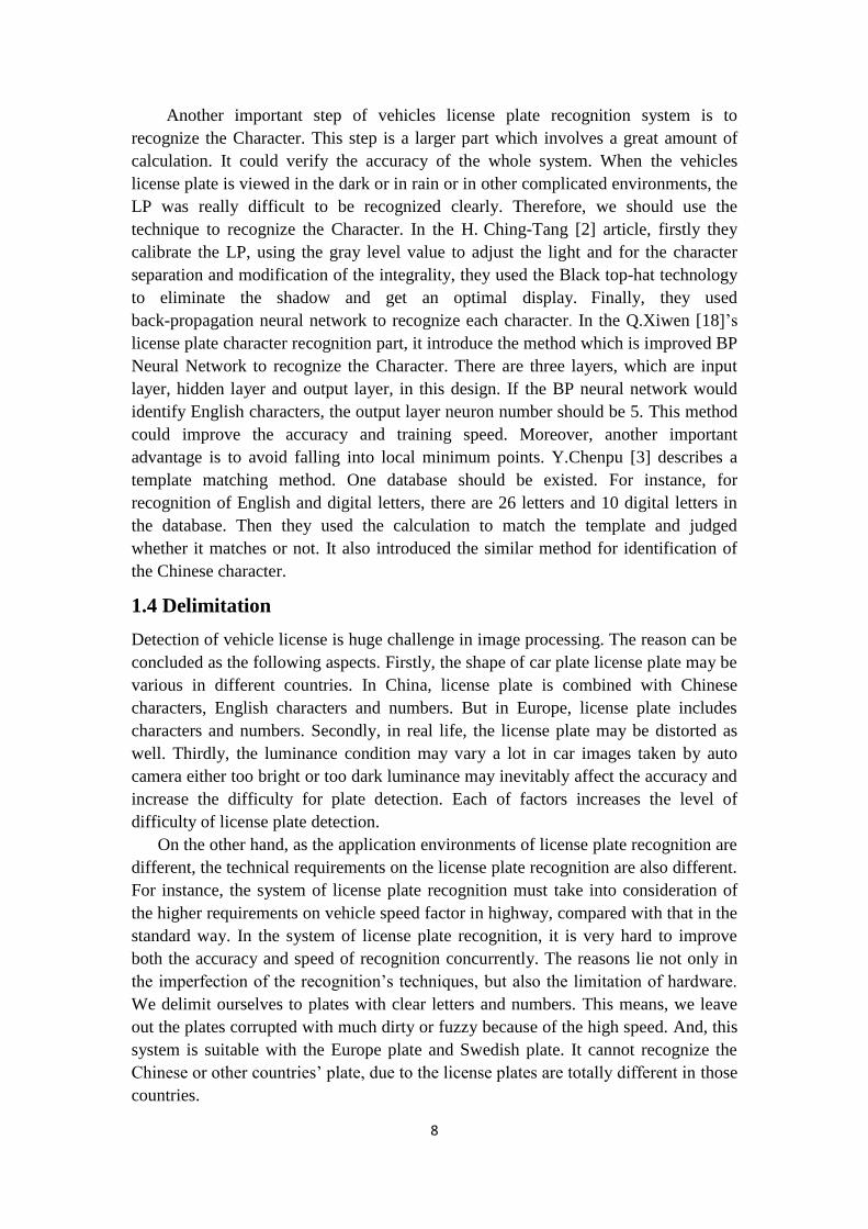
Figure 42: The interface of the plate license recognition testing system
The button „Start‟ can launch to test images. The function button „End‟ is to exit
the program. The images to be recognized are displayed in Area1. In Area2, the first
form shows the European sign if the license plate belongs to European common plates,
as shown in Figure 43:
Figure 43: The European sign
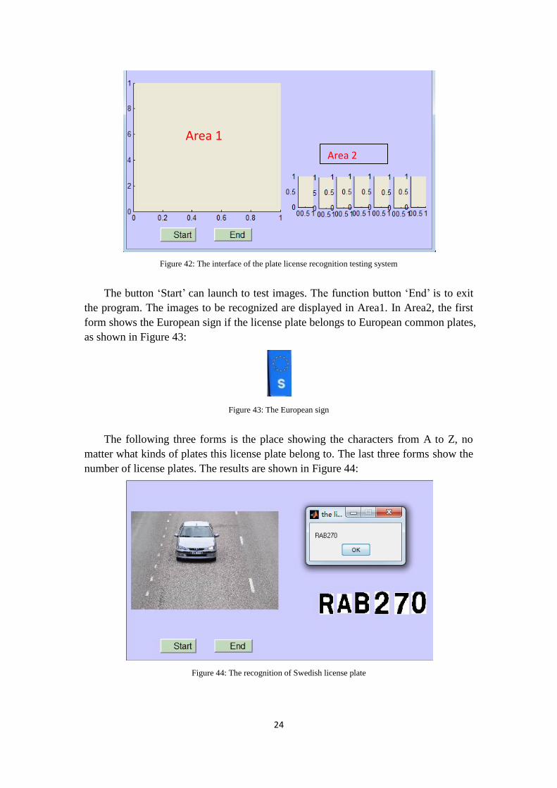
The following three forms is the place showing the characters from A to Z, no
matter what kinds of plates this license plate belong to. The last three forms show the
number of license plates. The results are shown in Figure 44:
Figure 44: The recognition of Swedish license plate
Area 1
Area 2
25
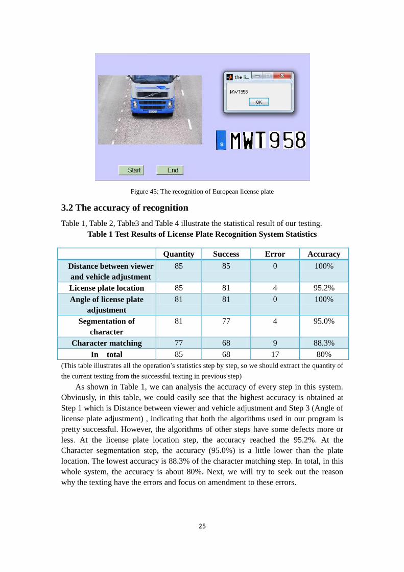
Figure 45: The recognition of European license plate
3.2 The accuracy of recognition
Table 1, Table 2, Table3 and Table 4 illustrate the statistical result of our testing.
Table 1 Test Results of License Plate Recognition System Statistics
(This table illustrates all the operation‟s statistics step by step, so we should extract the quantity of
the current texting from the successful texting in previous step)
As shown in Table 1, we can analysis the accuracy of every step in this system.
Obviously, in this table, we could easily see that the highest accuracy is obtained at
Step 1 which is Distance between viewer and vehicle adjustment and Step 3 (Angle of
license plate adjustment) , indicating that both the algorithms used in our program is
pretty successful. However, the algorithms of other steps have some defects more or
less. At the license plate location step, the accuracy reached the 95.2%. At the
Character segmentation step, the accuracy (95.0%) is a little lower than the plate
location. The lowest accuracy is 88.3% of the character matching step. In total, in this
whole system, the accuracy is about 80%. Next, we will try to seek out the reason
why the texting have the errors and focus on amendment to these errors.
Quantity Success Error Accuracy
Distance between viewer
and vehicle adjustment
85 85 0 100%
License plate location 85 81 4 95.2%
Angle of license plate
adjustment
81 81 0 100%
Segmentation of
character
81 77 4 95.0%
Character matching 77 68 9 88.3%
In total 85 68 17 80%

26
Table 2 the classification of the License plate location’s errors
Illumination
problem
Interference
around license
plate
Error 1 3
Table 2 displays the texting which have the error at the License plate location and
the classification of the different problems. Obviously, the main factor to lead the
wrong texting is the interferences existing around the license plate, such as the using
the net to cover the plate and so on.
Table 3 the classification of the character segmentation’s errors
Fuzzy character Mud and Noisy
interference
Error 2 2
As Table 3 shown, there are two problems to lead the imperfect texting. One
problem is that the characters in the license plate became fuzzy due to its the
high-speed. Another is the mud and noisy on the license plate. Clearly, in our texting,
both situations occurred twice for each.
Table 4 the classification of the Character matching’s errors
Mud and Noisy
interference
Template matching
problem
Error 2 7
Table 4 illustrates the situation of character matching‟s errors. The majority of the
problems come from the matching between template and the current character. Such
as: character C is misunderstood as G by template and so on. Another problem
leading the wrong texting is that there is the mud and noisy interference on the license
plate.
3.3 The analysis of the wrong recognition results
Here are some wrong recognition results of images and related analysis.

27
Figure 46: The wrong recognition
1) In this image (Figure 46), the license plate cannot be found out. There are
probably two reasons for this wrong recognition. Firstly, since this truck is in
white color, its image is over exposed under the sunshine. This factor seriously
impedes the seeking-out of the plate. Moreover, there is a mesh thing in front of
the vehicle, which also obstructs the seeking for the plate in the morphological
algorithm.
Figure 47: the wrong recognition
2) In Figure 47, there is a lot of dirty, such as on the character „S‟ and number „1‟ in
the license plate. These dirty can‟t be removed totally from the image in the
pro-processing operation. Meanwhile the speed of this vehicle is high so that the
definition of license plate is poor and the image is blurring. In addition, we can
see clearly from Figure 47 that there is a matching error in mistaking character O
as G, because the high speed of this vehicle leads to a poor definition of the
license plate and a serious blurring on the right part of the character „O‟. All these
reasons lead the failure of characters matching.

28
Figure 48: The wrong recognition
3) In Figure 48, the character „B‟ on the license plate is wrongly identified as „D‟.
It may be one of the reasons that the character „B‟ is similar to „D‟. Compared
with „B‟, „D‟ is just short of the small line in the middle part. In addition, the
templates in this system are not sufficient to distinguish between those two
characters. After testing all the images we prepared, the character pairs which are
frequently recognized mistakenly include „B‟ and „D‟, „C‟ and „G‟, „B‟ and „O‟, „C‟
and „O‟, and „R‟ and „P‟.
4 Discussion
In our application process, the database we use is made by ourselves, which is
including 85 images. Most of the license plates in those images can be recognized and
matched in this programming. On the other hand, although we come up with some
advanced ideas to solve some imminent issues, there are still a few of license plates
which can‟t be recognized. The reason is, of course, the license plate recognition is a
complicated academic field which needs to consider a great number of solutions
aiming at various cases. Because there are too many interferences affecting the
accuracy of vehicle recognition. However the aiming of our paper is limited, this
program can recognize the license plate recognition in most of images taken by the
cameras at the toll stations or alone the roads. In some cases, there are much dirty or
the characters are too fuzzy which resulting in the license plate recognition error.
Besides, the marching templates always appear error because some characters are too
similar,„C‟ and „G‟.
In this paper, the license plate location is the first step in this system of license
plate recognition. Therefore, this step play an extremely role and it can affect the
accuracy of following steps directly. In this step, the quality of the edge detection of
plate affects the process of plate location in the morphological algorithm. Then, the
binaryzation is of great importance in cutting the character out from the license plate.
If the above operations are well done, the features of license plate will be clear in
order to improve accuracy of the character matching. On the other hand, if the plates
are in the different angle to the observer, it is necessary to adjust the angle in order to

29
facilitate the characters matching. The Rando algorithm is used in this step. The
advantage of Rando is too fast and accurate on the field seeking for angle compared
with the horizontal edge. Matching template is the last step in this programming. We
prepared a lot of relevant templates including the test characters and test numbers. In
this step, characters are matched with templates by the black points‟ calculation
algorithm. The advantage is that is can improve the accuracy of matching. Oppositely,
the disadvantage of this method is that it may lengthen the time of matching.
5 Conclusion and Further work
To sum up, this paper describes a technique which recognizes the license plates by use
of image processing. The application of license plate system not only can distinguish
Europe Union license plates from Swedish license plates, but also can recognize the
characters on license plates. Therefore, the aim of this system is fully accomplished
and its application may inspire a series of research questions (see Chapter 1.4).
Typically, this system can also be applied to collect the information of vehicles on
road, since it can recognize the character and output the license plate number
automatically.
Obviously, the accuracy of the recognition is the most important in this system.
Therefore, this application should be optimized and modified for overcoming the
accuracy limitations. In order to make the recognition more precise, we should add
some preprocesses to remove the interferences. Moreover, we would continue the
further study for license plate recognition in some complicated environments, such as
vehicles at dark night or in heavy rains and so on. If we could accomplish all of the
objectives, this application would have a very promising future.
6 Acknowledgements
This work would not have been carried out without the support from our supervisor
Julia. Thanks to Julia Åhlén very much.

30
Reference
1 B. Well and N. Ronald, Two-Dimensional Imaging, Englewood Cliffs, NJ, Prentice
Hall, 1995, pp. 505-537.
2 C. Hsieh, L. Chang ,K. Hung, H. Huang, “A real-time mobile vehicle license plate
detection and recognition for vehicle monitoring and management” Pervasive
Computing (JCPC), 2009 Joint Conferences on,Page:197, Issue Date : 3-5 Dec.
2009.
3 C. Yu,M. Xi and J. Qi,“A Novel System Design of License Plate Recognition”
Computational Intelligence and Design, 2008. ISCID '08. International Symposium
on, Page: 114, Issue Date: 17-18 Oct. 2008.
4 Feature extractions from digital image,
URL: http://www.doc88.com/p-48937457189.html
Last access: 2011-04-10
5 HIPR, Median filtering, Rank filtering
URL: http://homepages.inf.ed.ac.uk/rbf/HIPR2/median.htm
Last access: 2011-05-06
6 H. Kuo, J. Lee, S. Kao, “An Autonomous License Plate Detection Method”
Intelligent Information Hiding and Multimedia Signal Processing, 2009. IIH-MSP '09.
Fifth International Conference on, Page: 110, Issue Date: 12-14 Sept. 2009.
7 Image Pre-processing: Local pre-processing
URL: http://www.icaen.uiowa.edu/~dip/LECTURE/PreProcessing3.html
Last access: 2011-05-08
8 L. Luo, H. Sun, W. Zhou and L. Luo, “An Efficient Method of License Plate
Location” Information Science and Engineering (ICISE), 2009 1st International
Conference on. Page: 770. 26-28 Dec. 2009.
9 L. Wang (2009). Research on the license plate recognition (in Chinese), Master
thesis, Shanghai Jiaotong University: China.
10 Machine Perceptions of Three-Dimensional Solids
URL: http://www.packet.cc/files/mach-per-3D-solids.html
Last access: 2011-05-08
11 N. Parker and J. Weeks (2004), Registration Plates of the World (4th edition),
Edited by Europlate.

31
12 P. Toft (1996), The Radon Transform - Theory and Implementation , PhD Thesis,
IMM, DTU.
13 P. Wang (2006). Research of the license plate automatic recognition (in Chinese),
Master thesis, Shanghai Southeast University: China.
14 R. Gonzalez, R. Woods (2002), Digital Image Processing (Second Edition),
Publisher: Prentice Hall.
15 S. Smith, The Scientist and Engineer's Guide to Digital Signal Processing,
Chapter 25: Special Imaging Techniques, Last accessed: 2011-05-11
16 S. Wang and H. Lee, “Detection and recognition of license plate characters with
different appearances,” IEEE Intelligent Transportation Systems, vol. 2, 2003.
17 The license plate of the world.
URL: http://www.worldlicenseplates.com/
Last access: 2011-05-05
18 X. Qin , Z. Tao , X. Wang, X. Dong, “License Plate Recognition Based on
Improved BP Neural Network”, Computer, Mechatronics, Control and Electronic
Engineering (CMCE), 2010 International Conference on,Page:171, Issue Date: 24-26
Aug. 2010.
19 Y. Yang, J. Bai, R. Tian, N. Liu, “ A vehicle license plate recognition system
based on fixed color collocation,” Machine Learning and Cybernetics, 2005.
Proceedings of 2005 International Conference on, Page: 5394, Issue Date: 18-21 Aug.
2005.