Ball on Plate BALANCING
45
TSHWANE UNIVERSITY OF TECHNOLOGY DEPARTMENT OF ELECTRICAL ENGINEERING Course: Project Report Practical 2 PROJECT REPORT: BALANCING BALL Student Name: Olushola Anne Moremie ABATAN Student No.: 208327488 Supervisor: De Vries Johannes
Transcript of Ball on Plate BALANCING

TSHWANE UNIVERSITY OFTECHNOLOGY
DEPARTMENT OF ELECTRICAL ENGINEERING
Course: Project Report Practical 2
PROJECT REPORT:
BALANCING BALL
Student Name: Olushola Anne Moremie ABATAN
Student No.: 208327488
Supervisor: De Vries Johannes

Template for Project Report by A.J. Visser, 2008, Updated by J. De Vries 2011
Table of ContentsPage no.
1.1 Introduction.............................................61.2 Problem statement........................................71.3 User requirement specification...........................71.4 Budget...................................................71.5 Literature review........................................81.5.1 Feedback systems.....................................81.5.2 Mechanical design of a ball-on-plate balancing system 81. Mechanical actuators.....................................92. Hydraulic actuators.....................................103. Pneumatic actuators.....................................101.5.3 Control electronics.................................101.5.4 RC Servo Motors.....................................121.5.5 Software algorithms.................................14
1.6 Proposed practical design or strategy...................151.7 Design of product.......................................171.7.1 Software Flow Diagram and description...............171.7.2 Circuit Diagram and description.....................181.7.3 PCB Layout..........................................201.7.4 Software Code and Comments..........................21
1.8 Implementation of product...............................261.9 Testing procedure.......................................261.10 Necessary changes encountered...........................271.11 Results of the tested product / procedure...............271.12 Comparison of results vs. requirements................271.10 conclusions and recommendations.........................27
Appendix......................................................281.11 A.1 Final Gantt chart...................................281.12 A.3 Detail designs......................................301.13 A.4 Software............................................311.14 Bill of Materials.......................................36
2

Template for Project Report by A.J. Visser, 2008, Updated by J. De Vries 2011
Table of Figures Pa
ge no.
Figure 2 1: Ball-on-plate system assembly 1.13.................9Figure 2 2: A mechanical linear actuator with digitalreadout.1.13...................................................9Figure 2 3: Example of Electric motors........................10Figure 2 4: Working of DC brushed motors......................11Figure 2 5: Stepper motor example.............................11Figure 2 6: Relationship between pulse with and the rotorposition......................................................12Figure 2 7: Anatomy of an RC servo motor 1.13.................13Figure 2 8: Details of a different part of an RC servo motor1.13..........................................................13Figure 2 9: Connection cable of RC Servo Motor................14Figure 2 10: Block Diagram of the proposed balancing ball.....15Figure 2 11: INFRARED LED.....................................15Figure 2 12: Pin Diagram of the pic16f684....................16Figure 2 13: Software Flow Diagram of the proposed balancingball..........................................................17Figure 2 14: Inputs and Outputs pins..........................17Figure 2 15: Circuit diagram of RC Servo motor, Power Supply andICSP..........................................................18Figure 2 16: Circuit diagram of IR led emitter................19Figure 2 17: Circuit diagram of the IR Receiver...............19Figure 2 18: PCB Layout of the complete circuit...............20Figure 2 19: PCB Layout of the RECEIVER.......................20Figure 2 20: PCB Layout of IR EMITTER.........................20Figure 2 21: PWM of One SERVO MOTOR...........................26Figure 2 22: PWM of BOTH SERVO MOTORS.........................26Figure 2 23: Testing points...................................27Figure 2 24: GANT CHART 1.....................................28Figure 2 25: GANT CHART 2.....................................28Figure 2 26: GANT CHART 3.....................................28
3

Template for Project Report by A.J. Visser, 2008, Updated by J. De Vries 2011
List of TablesPage no.
Table 1-1 Most important component cost........................7etc. …
4

Template for Project Report by A.J. Visser, 2008, Updated by J. De Vries 2011
Abstract
This report is to describe the design and development strategy to accomplish a control system to balance a ball on aplate. We will have two modes of operation in the system; one mode of operation is the Joystick control used to control manually the X-Y axis and the other mode is the Autonomous mode where we will use the IR beam to control the X-Y axis.
5

Template for Project Report by A.J. Visser, 2008, Updated by J. De Vries 2011
1.1 Introduction
The goal of this project is to develop a ball-on-platebalancing system, capable of controlling the position of a ballon a plate for both X and Y positions without the risk of theball falling off. Each tilting axis will be operated on by an RCservo electric motor. Each motor will be controlled usingsoftware, with a minimum of position feedback for control. Thecontrol of the X and Y positions should be with a joystick orautomatic using IR beam control.
Various modes of operations have been used: 1. System 1 : At RPI (Renssselaer Polytechnic Institute), they
have developed a ball on plate balancing where they have used initially a horizontal plate which is tilted along each of two axes in other to control the position of the ball. Each tilting axis operated by an electric motor. The motor is controlled using software with a minimum of position feedback for control. The position of the ball on plate is sensed through a resistive touch screen.
2. System 2: The balancing ball project has also been done atSchool of Engineering, Monash University Malaysia. A PC based system has been developed. A vision system named CCD camera has been incorporated as the feedback sensor to acquire the real-time position of the steel ball. Two actuators, namely the stepper motors are utilized to control the motion of the base plate system. These actuators are controlled from NI-ELVIS workstation.
3. System 3: Another ball on plate balancing has been designedat RPI; they have used a spatial linkage mechanism for actuating the plate. They have use a resistive touch-sensitive glass screen for sensing the ball position. Simple brushed DC motors have been used to control the encoder feedback to achieve a servo position control. A PIDcontroller has been used.
4. System 4: The ball on plate balancing has been developed using LEGO by Kenn. Using a webcam to control the position of the ball on the plate and PID control.
5. System 5: At Miskabir University of Technology a fuzzy logic controller has been developed; they have used a resistance sensor for controlling the position of the ball.
6

Template for Project Report by A.J. Visser, 2008, Updated by J. De Vries 2011
6. System 6 : By Daniele, the balancing ball on plate has been developed using LEGO MINDSTORMS, using a model predictive control of PID for the controller, for the feedback system,he used NXTcam.
The aim of this project will be to create a ball-platesystem using a joystick control and autonomous control platformto allow the X and Y-axis of movement of a ball by means of RCservo motors.
1.2 Problem statement
The Goal of the balancing ball system will be first to create a system that can hold a ball in a certain defined position. From there, the goal will then be able to move the ball on the platform in varying specific position.
1.3 User requirement specification
The user requirement specification is as followed:
The platform control surface should be 40 cm X 40 cm.
The use of two axis analog Joystick to be able tocontrol X and Y movement of the platform.
The use of RC servo motors for the actuators of theplatform.
7

Template for Project Report by A.J. Visser, 2008, Updated by J. De Vries 2011
The platform should be able to tilt maximum 5 cm whenmeasured on the sides.
The sensitivity level of the joystick potentiometershould be variable
1.4 Budget
The budget cost will be determine according to the 40X40 IRled, the RC servo motor and the joystick input control.
“Refer to appendix A.5 for a detail layout of the budget.”
Table 1-1 Most important component costComponents Cost [R]
80X IR beam Control
2 X RC servo motor1 X The Joystick(2 axis)
Total component cost:
1.5 Literature review
Different types of ball on plate system have been donebefore:
1. System 1: At RPI, resistive touch screen ball on platesystem using DC gear motors for the tilting of the plate.
2. System 2 : At Monash University Malaysia, CCD camera ball onplate system and Stepper motors for moving the plate.
3. System 3 : At RPI, PID controller and brushed DC motors havebeen used to design the balancing ball on plate.
400 Each = R800
3, 45 per 10 =R27, 6
R100
R927, 6
8
Template for Project Report by A.J. Visser, 2008, Updated by J. De Vries 2011
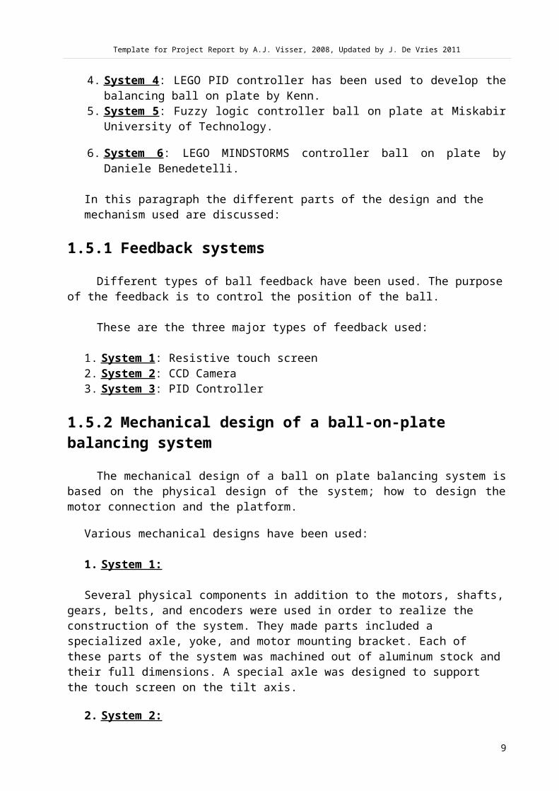
4. System 4 : LEGO PID controller has been used to develop thebalancing ball on plate by Kenn.
5. System 5 : Fuzzy logic controller ball on plate at MiskabirUniversity of Technology.
6. System 6 : LEGO MINDSTORMS controller ball on plate byDaniele Benedetelli.
In this paragraph the different parts of the design and the mechanism used are discussed:
1.5.1 Feedback systems
Different types of ball feedback have been used. The purposeof the feedback is to control the position of the ball.
These are the three major types of feedback used:
1. System 1 : Resistive touch screen2. System 2 : CCD Camera3. System 3 : PID Controller
1.5.2 Mechanical design of a ball-on-plate balancing system
The mechanical design of a ball on plate balancing system isbased on the physical design of the system; how to design themotor connection and the platform.
Various mechanical designs have been used:
1. System 1:
Several physical components in addition to the motors, shafts,gears, belts, and encoders were used in order to realize the construction of the system. They made parts included a specialized axle, yoke, and motor mounting bracket. Each of these parts of the system was machined out of aluminum stock andtheir full dimensions. A special axle was designed to support the touch screen on the tilt axis.
2. System 2:
9

Template for Project Report by A.J. Visser, 2008, Updated by J. De Vries 2011
Two actuators, namely the stepper motors are utilized to control the motion of the base plate system. These actuators arecontrolled from NI-ELVIS workstation.
3. System 3:
The physical system consists of an acrylic plate, an actuationmechanism for tilting the plate about two axes. Each motordrives one axis of the plate rotation angle and is connected tothe plate by a spatial linkage mechanism. Each side of thespatial linkage mechanism is a four-bar parallelogram linkage.See Figure 2 1.
Figure 2 1: Ball-on-plate system assembly
4. System 4:
He settled on using a Hough transformation of contourextractions. This actually worked quite well, with a successrate of over 80%, after a lot of tweaking of course. That stillleft him with around 900 data points to do by hand, but itwasn't so bad in the end. He has since then tweaked thealgorithm and now regularly reaches a success rate of 90%.
Actuators drive motions in mechanical system by converting electrical energy into some form of mechanical motion.
Some types of actuators:
LINEAR ACTUATORS:
A linear actuator is an actuator that, when driven by a non-linear motion, creates linear motion (as opposed to rotary
10

Template for Project Report by A.J. Visser, 2008, Updated by J. De Vries 2011
motion, e.g. of an electric motor). Mechanical and hydraulic actuations are the most common methods of achieving the linear motion.
1. Mechanical actuatorsMechanical linear actuators operate by conversion of rotary
motion into linear motion. Mechanical actuators typicallyconvert rotary motion of a control knob or handle into lineardisplacement via screws and/or gears to which the knob or handleis attached.
Figure 2 2: A mechanical linear actuator with digital readout.2. Hydraulic actuators
Hydraulic actuators or hydraulic cylinders typically involve ahollow cylinder having a piston inserted in it. The two sides ofthe piston are alternately pressurized/de-pressurized to achievecontrolled precise linear displacement of the piston and in turnthe entity connected to the piston. The physical linear displacement is only along the axis of the piston/cylinder. Thisdesign is based on the principles of hydraulics. A familiar example of a manually operated hydraulic actuator is a hydrauliccar jack. Typically though, the term "hydraulic actuator" refersto a device controlled by a hydraulic pump.
3. Pneumatic actuatorsPneumatic actuators, or pneumatic cylinders, are similar to
hydraulic actuators except they use compressed gas to provide pressure instead of a liquid.
4. Electro-mechanical actuatorsElectro-mechanical actuators are similar to mechanical
actuators except that the control knob or handle is replacedwith an electric motor. Rotary motion of the motor is convertedto linear displacement of the actuator.
A rotary driver (e.g. electric motor) is mechanicallyconnected to a lead screw so that the rotation of the electricmotor will make the lead screw rotate. A lead screw has acontinuous helical thread machined on its circumference running
11

Template for Project Report by A.J. Visser, 2008, Updated by J. De Vries 2011
along the length (similar to the thread on a bolt). Threadedonto the lead screw is a lead nut or ball nut with correspondinghelical threads.
1.5.3 Control electronics
The control electronic is based on how to drive the motorsand how to control the motors from the microcontroller. Thecontrol electronics used electric motor to convert electricalenergy into mechanical energy.
There are many types of motors that can be used in a linear actuator system.
Figure 2 3: Example of Electric motors
A. DC MOTORSA DC motor is designed to run on DC electric power. The most
common DC motor types are the brushed and brushless types, whichuse internal and external commutation respectively to periodically reverse the current in the rotor windings. There are two types:
Brushed DC motors: A brushed DC motor is an internally commutated electric motor designed to be run from a DC power source.
12

Template for Project Report by A.J. Visser, 2008, Updated by J. De Vries 2011
Figure 2 4: Working of DC brushed motors
When the coil is powered, a magnetic field is generatedaround the armature. The left side of the armature is pushedaway from the left magnet and drawn toward the right, causingrotation.
Brushless DC motors: BLDC motors also known as electronically commutated motors (ECMS, EC motors) are synchronous electric motors powered by direct current(DC) electricity and having electronic commutation systems, rather than mechanical commutations and brushes.
B. AC MOTORSAn AC motor is an electric motor driven by an alternating
current. There two types named:
Induction motor: runs slightly slower or faster than the supply frequency. The magnetic field on the rotor of this motor is created by an induced current.
Synchronous motor: does not rely on induction and as a result, can rotate exactly at the supply frequency or a sub-multiple of the supply frequency. The magnetic field onthe rotor is either generated by current delivered through slip rings or by a permanent magnet.
C. STEPPER MOTORSA stepper motor (or step motor) is a brushless, synchronous
electric motor that can divide a full rotation into a large number of steps. The motor's position can be controlled precisely without any feedback mechanism, as long as the motor is carefully sized to the application.
13

Template for Project Report by A.J. Visser, 2008, Updated by J. De Vries 2011
Figure 2 5: Stepper motor exampleStepper motors operate differently from DC brush motors,
which rotate when voltage is applied to their terminals. Stepper motors have multiple "toothed" electromagnets arranged
around a central gear-shaped piece of iron. The electromagnetsare energized by an external control circuit, such as amicrocontroller. To make the motor shaft turn, first oneelectromagnet is given power, which makes the gear's teethmagnetically attracted to the electromagnet's teeth. When thegear's teeth are thus aligned to the first electromagnet, theyare slightly offset from the next electromagnet. When the nextelectromagnet is turned on and the first is turned off, the gearrotates slightly to align with the next one, and from there theprocess is repeated. Each of those slight rotations is called a"step", with an integer number of steps making a full rotation.In that way, the motor can be turned by a precise angle.
D. SERVO MOTORSA servomotor is used within a position-control or speed-
control feedback control system. Servomotors are used in applications such as machine tools, pen plotters, and other control systems. The dynamic response characteristics such as winding inductance and rotor inertia are also important; these factors limit the overall performance of the servomechanism loop. Large, powerful, but slow-responding servo loops may use conventional AC or DC motors and drive systems with position or speed feedback on the motor.
A servo system differs from some stepper motor applications inthat the position feedback is continuous while the motor is running; a stepper system relies on the motor not to "miss steps" for short term accuracy, although a stepper system may include a "home" switch or other element to provide long-term stability of control.
As electronics control, we will be using the motors and specifically RC SERVO MOTORS because when it is set to a
14

Template for Project Report by A.J. Visser, 2008, Updated by J. De Vries 2011
position, it keeps that position until when you set to another position again.
1.5.4 RC Servo MotorsRC servos used PWM to control the position of an object. A
1.0 ms pulse rotates the shaft all the way counter-clockwise. A1.5 ms pulse puts the rotor at neutral (0 degrees), and a 2.0 mspulse will position the shaft all the way clockwise. The pulseis sent to the servo at a frequency of approximately 50 Hz. Therelationship between the pulse width and the rotor position isshown in picture
Figure 2 6: Relationship between pulse with and the rotor position
The picture in figure 2.2 represents the different blocks ofan RC servo.
Figure 2 7: Anatomy of an RC servo motor
15

Template for Project Report by A.J. Visser, 2008, Updated by J. De Vries 2011
Explanation of each block
The controller circuit: This is the "brain" of the Servo. This circuit is responsible to read the user's input signal(pulses) and translate it into a motor revolution in such away, that the drive shaft will be rotated to the desired position.
The feedback potentiometer: The shaft of the potentiometer is attached to the drive shaft of the servo. When the driveshaft rotates, so does the potentiometer. In that way, eachand every rotation angle of the drive shaft corresponds to a different resistance of the potentiometer. By reading thepotentiometer's resistance, the controller is able to know the exact angle of the drive shaft of the servo.
The motor: This is usually a small high speed DC motor controlled by a H-bridge circuit attached to the servos' controller.
The gearbox: The gearbox will drive the motor's revolution to the drive shaft. Also, the rpm will be significantly reduced and the torque will be increased. The torque is oneof the main characteristics of RC servos.
The drive shaft: When all of the above operate in perfect harmony, the drive shaft will be rotated with accuracy to the user's requested angle.
Figure 2 8: Details of a different part of an RC servo motor
They do not simply run on a DC voltage like a standard DCmotor. They have 3 wires. Red is power (generally 3V – 12Vmax), black is ground and then there is another wire, usuallywhite or yellow that is the “input signal wire”.
16

Template for Project Report by A.J. Visser, 2008, Updated by J. De Vries 2011
Figure 2 9: Connection cable of RC Servo Motor
The RC servo motor is the best one because of his propertyto position its output into a position that exactly correspondswith the movement of the corresponding stick.
1.5.5 Software algorithms
Three major control algorithms have been used:
1. PID control in Microcontroller2. Optimal Matlab control3. Fuzzy Logic control
We will be using the PID CONTROL in Microcontroller, because itis adequate to obtain a very high response speed.
17

Template for Project Report by A.J. Visser, 2008, Updated by J. De Vries 2011
1.6 Proposed practical design or strategy
Figure 2 10: Block Diagram of the proposed balancing ball
Description of the Inputs: Four of the Analog to Digital pins of the PIC areused.
a) Joystick Control
A joystick is an input device consisting of a stick that pivots on a base. It’s read the analog value and converts to an angle in which the plate must turn into.
Two Analog to Digital pins of the PIC should be used, for the user to be able to control X and Y movement of the platform (see picture in A.3).
b) IR Beam Control
Infrared beam are invisible electromagnetic radiation thathas a longer wavelength than visible light and is detectedmost often by its heating effect. This method shall be used tofollow and know the position of the ball on the plate. Another two Analog to Digital pins of the PIC should be usedto X and Y movement of the platform.
Two Joysticksfor X-Y axis
control
IR beamcontrol
CONTROLLER Servoscontrol
18

Template for Project Report by A.J. Visser, 2008, Updated by J. De Vries 2011
How does IR LED WORKS?
In my project, I am using IR beams that can determine theposition of the ball at any time on the plate. This Led shouldbe placed 40 in the X-axis and 40 in the Y-axis (1 IR percentimetre resolution) to create a grid of IR light beams. Whenthe beam is broken(get obstructed), the photo transistors from Xand Y axes detect the IR light beams which have been interruptedand transmit exact signals that identify the X and Y axescoordinates to the plate then the plate shall be tilt to thatspecific angle.
Figure 2 11: INFRARED LEDc) The Controller
This is the brain of the whole system. It reads the twoinputs. Its convert the two inputs to the two outputs. The twooutputs are the servos. These servos checked the pulse that hasbeen send and also the beam that have been broken. If the beamthat has been broken is greater than 20, the pulse should tellthe system to turn fully clockwise and if the beam is less than20, it should go clockwise opposite direction. In case the beamis near the middle, close to the middle nothing should happenthe ball should remain in the middle of the plate.
I will be using the PIC16F684 see Figure 2 12:
Figure 2 12: Pin Diagram of the pic16f684
Description of Pin out Labels Label Description
19

Template for Project Report by A.J. Visser, 2008, Updated by J. De Vries 2011
+ 5 V Ground External Voltage Reference PORTA/PORTC Programmable I/O A/D Channel External Interrupt Input PWM Output
Description of the Output:d) Servos
At the output, we shall be controlling the two axes (X-Y),using RC servo motors. These servos are involved in the designand the tilting of the plate. The feedback is sent to the RCservo to achieve a servo position control.
Pulse width modulation is used to send information to the RCServo Motor controller (in this case a Hobby Motors). A pulse ofabout 20 milliseconds are required to control the Hobby Motor,where the duty cycle (high time) of the pulse must be between 1and 2 milliseconds. A duty cycle of 1.5miliseconds will cause aneutral state. By decreasing the duty cycle, the motor will movein reverse, where it will reach maximum speed at 1 millisecond.By increasing the duty cycle, the motor will move in a forwardmotion, where 2 milliseconds will be the full speed. To generatethese signals, the PWM module of the PIC is used. The ability tocreate an 20 millisecond pulse depends on the selected frequencyof the oscillator, and the settings of the timer modules of themicrocontroller. For this reason a slow frequency of 500 KHz areused to drive the PIC.1.7 Design of product
1.7.1 Software Flow Diagram and description
Start
Set I/O
50% Duty Cycle(Set Panel Flat)
20

Template for Project Report by A.J. Visser, 2008, Updated by J. De Vries 2011
Figure 2 13: Software Flow Diagram of the proposed balancing ball
Description of the proposed software flow diagram1. Set I/O :In here, we specified which of the microcontroller pins we are
using. See Figure 2 13:
Figure 2 14: Inputs and Outputs pins
2. 50% Duty Cycle (Set Panel Flat) :
TestSwitch
Joystick Autonomous mode
SetPanel
End
ReadAnalogueVoltage
ChangeDuty
Change Duty
ReadAnalogue
Change Duty
Change Duty
2,2, >2, >2,
21

Template for Project Report by A.J. Visser, 2008, Updated by J. De Vries 2011
In here, we set the panel flat by setting the PWM Duty Cycle to 50%.
3. Test Switch : Now, we need to know in which mode are we? To do so we need to test the switch in other to select one mode, this shouldbe done in software.
Let say, we are running the Joystick mode in first position and the Autonomous mode in second.
If no switch is selected, we must set the panel flat and end the process.
4. Joystick Mode :We shall read the analogue voltage from the ADC (0 – 5Vdc). If
the voltage is smaller (>) than 2.3, according to the position in which the plate was set to, change the duty cycle to the selected position, and if the voltage is greater (<) than 2.7, according to which position the plate was, change the duty cycleto the selected position.
5. Autonomous Mode :We shall read the analogue voltage from the ADC (0 – 5Vdc). If
the voltage is smaller (>) than 2.3, according to the position in which the plate was set to, change the duty cycle to the selected position, and if the voltage is greater (<) than 2.7, according to which position the plate was, change the duty cycleto the selected position.
1.7.2 Circuit Diagram and description
22

Template for Project Report by A.J. Visser, 2008, Updated by J. De Vries 2011
Figure 2 15: Circuit diagram of RC Servo motor, Power Supply and ICSP
From the above circuit: U1, Pic16F684 MOTOR 1 and MOTOR 2 are RC Servo Motors R1,R2, Resistor Connector 1, Power Supply Connector 2, ICSP Connector 3, Inputs SW5, Switch
Figure 2 16: Circuit diagram of IR led emitter
From the above circuit:
40 x Led R1, R2, R3, R4, R5, R6, R7, R8, Resistor 180Ohms Connector, Power Supply
23

Template for Project Report by A.J. Visser, 2008, Updated by J. De Vries 2011
Figure 2 17: Circuit diagram of the IR Receiver
From the above circuit: 40 X Phototransistors (Receivers) 40 X Resistors 1KOhms 40 X Resistors 100Ohms 1 X Connector 2 pins, Power Supply
24
Template for Project Report by A.J. Visser, 2008, Updated by J. De Vries 2011
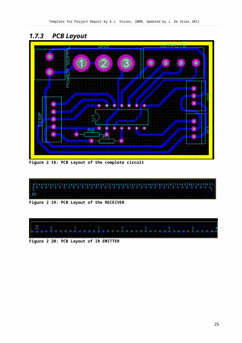
1.7.3 PCB Layout
Figure 2 18: PCB Layout of the complete circuit
Figure 2 19: PCB Layout of the RECEIVER
Figure 2 20: PCB Layout of IR EMITTER
25

Template for Project Report by A.J. Visser, 2008, Updated by J. De Vries 2011
1.7.4 Software Code and Comments
include<htc.h>__CONFIG(INTIO & UNPROTECT & MCLRDIS & PWRTEN & WDTDIS &BORDIS);
#define _XTAL_FREQ 500000 //oscillatorfrequency for __delay_msunsigned char adc_result_x, adc_result_y;unsigned char adc_x, adc_y;unsigned char count=0;/***************************INITIALIZATION******************************/void initialize()
{//1=Input 0=Output
CMCON0=7; //Disable comparatorsPORTA=0b00000000; //Clear port ATRISA=0b00110100; //RA4 RA2 RA5 INPUTsPORTC=0b00000000; //Clear port BTRISC=0b00001111; //RC5 OUTPUTANSEL=0b00001100; //AN3 analog inputPR2=155;PIR1=0; //Peripheral Interrupt request register 1T2CON=0b00000111; //prescaler 1:16, postscaler 1:1, Timer2 OnTMR2=0; //Start with zero counter}/******************************ADCX****************************************/unsigned char ADC_x_READ(){ADCON1=0b01110000; //FRC: Clock derived from a dedicatedinternal oscillator=500KHz maxADCON0=0b00001001; //Left justified, voltagereference=VDD, AN2=Analog Input, Initiate ADC and wait for startconversion__delay_us(10); //wait 10us for acquisition time
26

Template for Project Report by A.J. Visser, 2008, Updated by J. De Vries 2011
GODONE=1;while(GODONE);adc_result_x=(ADRESH);return adc_result_x;}/******************************ADCY****************************************/unsigned char ADC_y_READ(){ADCON1=0b01110000; //FRC: Clock derived from a dedicatedinternal oscillator=500KHz maxADCON0=0b00001101; //Left justified, voltagereference=VDD, AN3=Analog Input, Initiate ADC and wait for startconversion__delay_us(10); //wait 10us for acquisition timeGODONE=1;while(GODONE);adc_result_y=(ADRESH);return adc_result_y;}/********************************DELAY*************************************/void delay()
{unsigned int j;for(j=0; j<100;j++)
{__delay_us(20);}
}/***********************************SWITCH**********************************/unsigned char IS_SW5_PRESSED(){if(RA5==1) //Is SW pressed?{ //YES__delay_ms(10); //Wait 10ms for debouncereturn 0; //if not pressed}else{
27

Template for Project Report by A.J. Visser, 2008, Updated by J. De Vries 2011
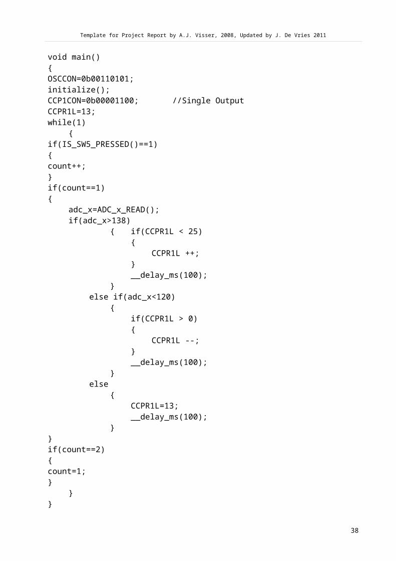
return 1;}}/**************************MAINFUNCTION*********************************/void main(){OSCCON=0b00110101;initialize();CCP1CON=0b00001100; //Single OutputCCPR1L=13;while(1)
{if(IS_SW5_PRESSED()==1){count++;}if(count==1){
adc_x=ADC_x_READ();if(adc_x>138)
{ if(CCPR1L < 25){
CCPR1L ++;}__delay_ms(100);
}else if(adc_x<120)
{if(CCPR1L > 0){
CCPR1L --;}__delay_ms(100);
}else
{CCPR1L=13;__delay_ms(100);
}}if(count==2){
28

Template for Project Report by A.J. Visser, 2008, Updated by J. De Vries 2011
count=1;}
}}
1.8 Implementation of product???????????????????This project teach how to derive a feedback
29
Template for Project Report by A.J. Visser, 2008, Updated by J. De Vries 2011
system.
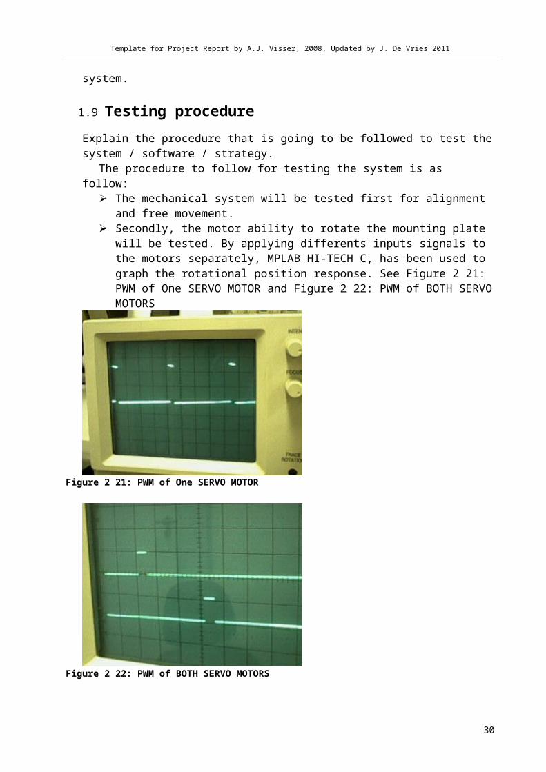
1.9 Testing procedureExplain the procedure that is going to be followed to test thesystem / software / strategy.
The procedure to follow for testing the system is as follow:
The mechanical system will be tested first for alignment and free movement.
Secondly, the motor ability to rotate the mounting plate will be tested. By applying differents inputs signals to the motors separately, MPLAB HI-TECH C, has been used to graph the rotational position response. See Figure 2 21: PWM of One SERVO MOTOR and Figure 2 22: PWM of BOTH SERVOMOTORS
Figure 2 21: PWM of One SERVO MOTOR
Figure 2 22: PWM of BOTH SERVO MOTORS
30

Template for Project Report by A.J. Visser, 2008, Updated by J. De Vries 2011
Several tests have been performed on the Joystick. TheJoystick is constituted of two (2) potentiometers. Thesepotentiometers used two different analogue pins of thePIC16F684.
Testing the IR led for controlling the two servos. After all the mechanical questions have been addressed the
control algorithms will be tested. Simple tasks like theball rolling and stopping at a certain point. With MPLABIDE, now able to direct the ball in two directions.
Figure 2 23: Testing points
1.10 Necessary changes encounteredThe major problem that I have had is how to control one servo at the time using one ADC pin of the PIC16F684 per servo. Finally, I have used Full Bridge PWM of the enhanced mode which gave me the possibility of using different PWM for different ADC.
1.11 Results of the tested product / procedureUse graphs and / or tables to show the results of the product / procedure. Also explain what the results in each graph or table means.
SERVO 1 SERVO 2
ADC1 PWM 1CENTER POSITIONLEFT POSITIONRIGHT POSITION
ADC2 PWM 2CENTER POSITIONLEFT POSITIONRIGHT POSITION
31

Template for Project Report by A.J. Visser, 2008, Updated by J. De Vries 2011
IR 1 PWM 1CENTER POSITIONLEFT POSITIONRIGHT POSITION
IR 2 PWM 2CENTER POSITIONLEFT POSITIONRIGHT POSITION
1.12 Comparison of results vs. requirementsCompare the results in paragraph 4.2 with the requirements in paragraph 2.4. Use a table to do this comparison. Also discusswhich results are similar to the requirements and which are different.1.10 Conclusions and recommendationsWrite an overall conclusion on the whole project, i.e. why certain parts of the project were successful and why certain parts of the project were not successful.NB! NB! The conclusions should be on the project itself and not so much on what you have learned.Also recommend what should be the changes or focus for similarprojects in the future.
32

Template for Project Report by A.J. Visser, 2008, Updated by J. De Vries 2011
Appendix1.11 A.1Final Gantt chart
Figure 2 24: GANT CHART 1
Figure 2 25: GANT CHART 2
Figure 2 26: GANT CHART 3
33

Template for Project Report by A.J. Visser, 2008, Updated by J. De Vries 2011
A.2 Literature Review1..http://www.cats.rpi.edu/~wenj/ECSE4962S04/final/team2finalreport.pdf, (11Ja)2..http://digital.ni.com/worldwide/singapore.nsf/web/all/A0420E70B017638F86257249002EC41E, (11Ja)3..http://www.das.ufsc.br/~camponog/Disciplinas/DAS-5341/Interesting_articles/ball-plate.pdf, (11Fe)4.. http://eissq.com/BallandPlate/index.html#Introduction, (11Fe)5..http://oru.academia.edu/NimaMohajerin/Papers/375716/Position_Control_of_Ball_and_Plate_System_Using_Fuzzy_Logic_Controller, (11Fe)6.. http://robotics.benedettelli.com/ballandplate.htm(Benedettelli, 2008)http://pcbheaven.com/wikipages/How_RC_Servos_Works/ (Lazaridis,2009)
:http://awtarlab3.engin.umich.edu/pdf/awtar_craig_2.pdf, (11Fe)1. http://en.wikipedia.org/wiki/Linear_actuator, (11Fe)
34

Template for Project Report by A.J. Visser, 2008, Updated by J. De Vries 2011
1.12 A.3Detail designs
Joystick
35

Template for Project Report by A.J. Visser, 2008, Updated by J. De Vries 2011
1.13 A.4Softwareinclude<htc.h>__CONFIG(INTIO & UNPROTECT & MCLRDIS & PWRTEN & WDTDIS &BORDIS);
#define _XTAL_FREQ 500000 //oscillatorfrequency for __delay_msunsigned char adc_result_x, adc_result_y;unsigned char adc_x, adc_y;unsigned char count=0;/***************************INITIALIZATION******************************/void initialize()
{//1=Input 0=Output
CMCON0=7; //Disable comparatorsPORTA=0b00000000; //Clear port ATRISA=0b00110100; //RA4 RA2 RA5 INPUTsPORTC=0b00000000; //Clear port BTRISC=0b00001111; //RC5 OUTPUTANSEL=0b00001100; //AN3 analog inputPR2=155;PIR1=0; //Peripheral Interrupt request register 1T2CON=0b00000111; //prescaler 1:16, postscaler 1:1, Timer2 OnTMR2=0; //Start with zero counter}/******************************ADCX****************************************/unsigned char ADC_x_READ(){ADCON1=0b01110000; //FRC: Clock derived from a dedicatedinternal oscillator=500KHz maxADCON0=0b00001001; //Left justified, voltagereference=VDD, AN2=Analog Input, Initiate ADC and wait for startconversion__delay_us(10); //wait 10us for acquisition timeGODONE=1;while(GODONE);adc_result_x=(ADRESH);return adc_result_x;}
36

Template for Project Report by A.J. Visser, 2008, Updated by J. De Vries 2011
/******************************ADCY****************************************/unsigned char ADC_y_READ(){ADCON1=0b01110000; //FRC: Clock derived from a dedicatedinternal oscillator=500KHz maxADCON0=0b00001101; //Left justified, voltagereference=VDD, AN3=Analog Input, Initiate ADC and wait for startconversion__delay_us(10); //wait 10us for acquisition timeGODONE=1;while(GODONE);adc_result_y=(ADRESH);return adc_result_y;}/********************************DELAY*************************************/void delay()
{unsigned int j;for(j=0; j<100;j++)
{__delay_us(20);}
}/***********************************SWITCH**********************************/unsigned char IS_SW5_PRESSED(){if(RA5==1) //Is SW pressed?{ //YES__delay_ms(10); //Wait 10ms for debouncereturn 0; //if not pressed}else{return 1;}}/**************************MAINFUNCTION*********************************/
37
Template for Project Report by A.J. Visser, 2008, Updated by J. De Vries 2011
void main(){OSCCON=0b00110101;initialize();CCP1CON=0b00001100; //Single OutputCCPR1L=13;while(1)
{if(IS_SW5_PRESSED()==1){count++;}if(count==1){
adc_x=ADC_x_READ();if(adc_x>138)
{ if(CCPR1L < 25){
CCPR1L ++;}__delay_ms(100);
}else if(adc_x<120)
{if(CCPR1L > 0){
CCPR1L --;}__delay_ms(100);
}else
{CCPR1L=13;__delay_ms(100);
}}if(count==2){count=1;}
}}
38

Template for Project Report by A.J. Visser, 2008, Updated by J. De Vries 2011
A.5 Datasheets
PHOTOS
SERVOS
Larger-Standard size digital servo with large torque and featuring strong metal gears.
Ideal for wheel steering on a Crawler, 1/8th Scale Buggy and 50 size airplaneFeatures
Precision made metal gears 39

Template for Project Report by A.J. Visser, 2008, Updated by J. De Vries 2011
Production and quality control of plastic component in our servos follow the standard of branded digital camera
Totally Green – from material to production, our servos are environmentally friendly.
Spec Check
Dimensions: 40.7 x 20 x 42.4mm Weight: 61g Speed (sec/60°): 0.18 Torque (kg-cm/oz-in): 16.0/222.1 Gear: Metal Case: Plastic
IR LED
PHOTOTRANSISTOR (Receivers)
40

Template for Project Report by A.J. Visser, 2008, Updated by J. De Vries 2011
1.14 Bill of Materials
Bill Of Materials For Circuit Complet.DSN Design Title :Circuit
Complet.DSNAuthor :<NONE>Revision :<NONE>Design Created :15 March 2011Design Last Modified
:20 June 2011
Total Parts In Design
:9
2 Modules
Quantity: References Value Order
Code2 M1, M2 TBLOCK-I3
2 Resistors
Quantity: References Value Order
Code2 R1, R2 10k
1 Integrated Circuits
Quantity: References Value Order
Code1 U1 PIC16F684
41

Template for Project Report by A.J. Visser, 2008, Updated by J. De Vries 2011
4 Miscellaneous
Quantity: References Value Order
Code1 ICSP Connector
21 OUTPUTS TBLOCK-I41 POWER SUPPLY Connector
11 SW5 SPDT - SW
24 June 2011 12:34:27 AM
Bill Of Materials For EMITTER FINAL1.DSN Design Title :EMITTER FINAL
1.DSNAuthor :<NONE>Revision :<NONE>Design Created :30 March 2011Design Last Modified
:23 June 2011
Total Parts In Design
:49
8 Resistors
Quantity: References Value Order
Code
42

Template for Project Report by A.J. Visser, 2008, Updated by J. De Vries 2011
8 R1-R8 180
40 Diodes
Quantity: References Value Order
Code4 D1-D4 MV210836 D5-D40 LED
1 Miscellaneous
Quantity: References Value Order
Code1 POWER SUPPLY Connect
or
24 June 2011 12:37:05 AM
Bill Of Materials For RECEIVER FINAL 1.DSN Design Title :RECEIVER FINAL
1.DSN43

Template for Project Report by A.J. Visser, 2008, Updated by J. De Vries 2011
Author :<NONE>Revision :<NONE>Design Created :30 March 2011Design Last Modified
:23 June 2011
Total Parts In Design
:123
82 Resistors
Quantity: References Value Order
Code42 R1, R3, R5, R7, R9,
R11, R13, R15, R17, R19, R21, R23, R25, R27, R29, R31, R33, R35, R37, R39, R41, R43, R45, R47, R49, R51, R53, R55, R57, R59, R61, R63, R65, R67, R69, R71, R73, R75, R77, R79, R81, R82
1k
40 R2, R4, R6, R8, R10, R12, R14, R16, R18, R20, R22, R24, R26, R28, R30, R32, R34, R36, R38, R40, R42, R44, R46, R48, R50, R52, R54, R56, R58, R60, R62, R64, R66, R68, R70, R72, R74, R76, R78, R80
100
40 Transistors
Quantity: References Value Order
Code40 Q1-Q40 2N3390
1 Miscellaneous
Quanti References Value Order
44

Template for Project Report by A.J. Visser, 2008, Updated by J. De Vries 2011
ty: Code1 POWER SUPPLY Connector
1
24 June 2011 12:38:32 AM
45