
Balancing of rotating masses
40
Balancing of rotating masses • Balancing – Rotating masses • Single plane • Different planes – Reciprocating masses – Reciprocating masses • Primary force and couple • Secondary force and couple 1
-
Upload
khangminh22 -
Category
Documents
-
view
7 -
download
0
Transcript of Balancing of rotating masses
Balancing of rotating masses
• Balancing
– Rotating masses
• Single plane
• Different planes
– Reciprocating masses– Reciprocating masses
• Primary force and couple
• Secondary force and couple
1

Balancing of single rotating weight by a weight rotating
in the same plane
m
ω
r
θO
A weight W carried on a
weight less arm of length
r rotates with angular
velocity ω as shown. For
completely balancing the
b
θ
θ
O
Bbmr
bBrm
=∴
=22 ωω
completely balancing the
mass m, a weight B at
distance b is attached to
the same axle in a
diametrically opposite
direction.
2

Balancing a number of masses rotating in one plane by another weight
rotating in the same plane
• Consider the masses m1, m2,m3 revolving
the at radii r1,r2,r3 respectively in the
same plane. Then each mass produces a
centrifugal force acting radially outwards
from the axis of rotation.
• If F is the vector sum,
F= m1r1ω2+ m2r2ω2+ m3r3ω2
All the masses will be in balance if F=0.
r1r2
r
m1
m2
θ1
θ2
θ3
θAll the masses will be in balance if F=0.
If F is not zero, a counter weight of mass mc
at radius rc is introduced to balance the
masses
F= m1r1ω2+ m2r2ω2+ m3r3ω2 + mcrcω2=0
m1r1+ m2r2+ m3r3 + mcrc=0
Analytically, it can be solved by resolving the
forces into components along and
perpendicular to x axis.
r3
m3
mc
rc
θc
m1r1
m2r2
m3r3
mcrc
3
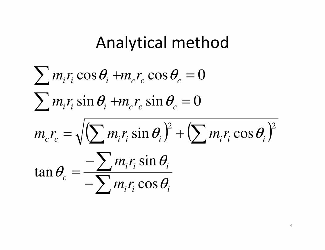
Analytical method
( ) ( )
+=
=+
=+
ccciii
ccciii
rmrmrm
rmrm
rmrm
θθ
θθ
θθ
cossin
0sinsin
0coscos
22( ) ( )
−
−=
+=
iii
iii
c
iiiiiicc
rm
rm
rmrmrm
θ
θθ
θθ
cos
sintan
cossin22
4
Balancing a number of masses rotating
in different planes
• It is proposed to reduce the case to the case
of several masses rotating in the same plane.
• In order to do so, the different masses rotating
in different planes will have to be transferred in different planes will have to be transferred
to one plane called as a reference plane.
5
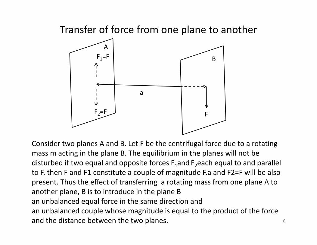
Transfer of force from one plane to another
FF2=F
F1=F
A
B
a
Consider two planes A and B. Let F be the centrifugal force due to a rotating
mass m acting in the plane B. The equilibrium in the planes will not be
disturbed if two equal and opposite forces F1and F2each equal to and parallel
to F. then F and F1 constitute a couple of magnitude F.a and F2=F will be also
present. Thus the effect of transferring a rotating mass from one plane A to
another plane, B is to introduce in the plane B
an unbalanced equal force in the same direction and
an unbalanced couple whose magnitude is equal to the product of the force
and the distance between the two planes. 6
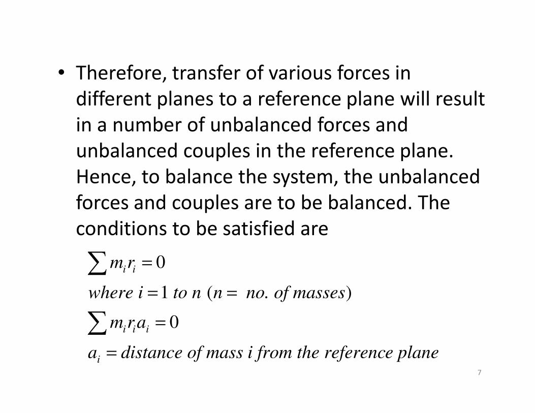
• Therefore, transfer of various forces in
different planes to a reference plane will result
in a number of unbalanced forces and
unbalanced couples in the reference plane.
Hence, to balance the system, the unbalanced
forces and couples are to be balanced. The forces and couples are to be balanced. The
conditions to be satisfied are
e planee referenc i from thce of masstandisa
arm
sses no. of man to n where i
rm
i
iii
ii
=
=
==
=
0
)(1
0
7

• couple acts in plane perpendicular to the plane in which the forces act. Its dire ction can be obtained by application of right hand screw rule. Thus the balancing couple will be at right angle to the forces producing it. However, in actual practice, the phase of couple diagram is changed through 90 degrees, thus enabling us to draw couples parallel to the forces.couples parallel to the forces.
• As a couple is produced by two forces, two balancing masses acting in two different planes will be required.
8
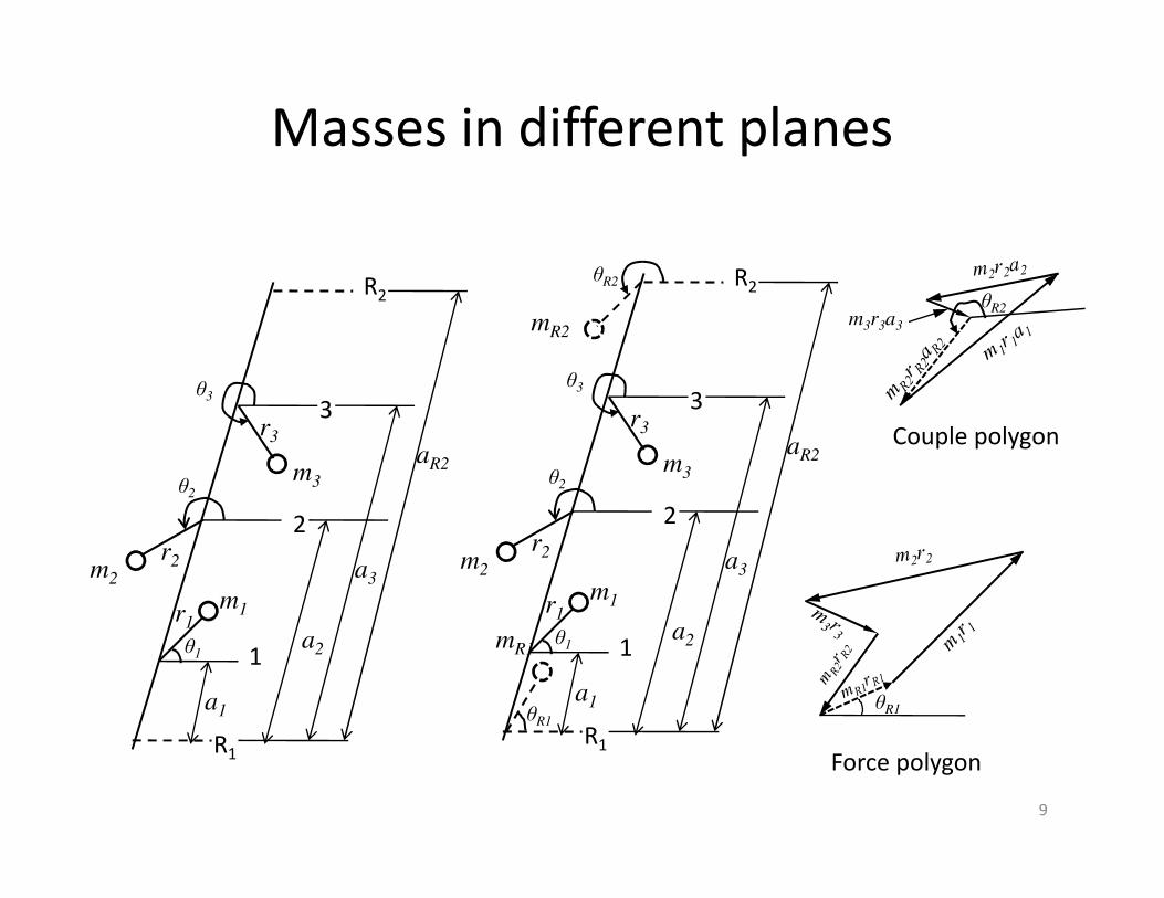
Masses in different planes
θ3
r3
3
R2
a
θ3
m
r3
3
R2
aR2
mR2
θR2
Couple polygon
m3r3a3
θR2
θ1
m1
θ2
m2
m3
r1
r2
R1
1
2
a1
a2
a3
aR2
mR1
θR1
θ1
m1
θ2
m2
m3
r1
r2
R1
1
2
a1
a2
a3
aR2
θR1
Force polygon
Couple polygon
9
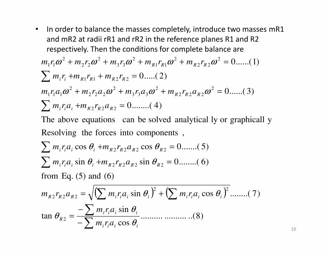
• In order to balance the masses completely, introduce two masses mR1
and mR2 at radii rR1 and rR2 in the reference planes R1 and R2
respectively. Then the conditions for complete balance are
ygraphicallor ly analytical solved becan equations above The
)4........(0
)3......(0
)2.....(0
)1......(0
222
2
222
2
333
2
222
2
111
2211
2
22
2
11
2
33
2
22
2
11
=+
=+++
=++
=++++
RRRiii
RRR
RRRRii
RRRR
armarm
armarmarmarm
rmrmrm
rmrmrmrmrm
ωωωω
ωωωωω
( ) ( )
)8..(....................cos
sintan
)7........(cossin
(6) and (5) Eq. from
)6........(0sinsin
)5.......(0coscos
,components into forces theResolving
2
22
222
2222
2222
−
−=
+=
=+
=+
iiii
iiii
R
iiiiiiiiRRR
RRRRiiii
RRRRiiii
arm
arm
armarmarm
armarm
armarm
θ
θθ
θθ
θθ
θθ
10

( ) ( )
( )( )
)10..(....................coscos
sinsintan
)9...(coscossinsin
components its by taking solved becan Eq.(2)
Eq.(2),in (8) and (7) Eq. from values thegSubsitutin
222
222
1
2
222
2
22211
+−
+−=
+++=
RRRiii
RRRiii
R
RRRiiiRRRiiiRR
rmrm
rmrm
rmrmrmrmrm
θθ
θθθ
θθθθ
The Eq. (2) and (4) can be solved graphically by solving first The Eq. (2) and (4) can be solved graphically by solving first
Eq.(4) by drawing couple polygon to determine mR2rR2aR2 and
θR2 and then Eq.(2) through force polygon to determine
mR1rR1 and θR1 .
11
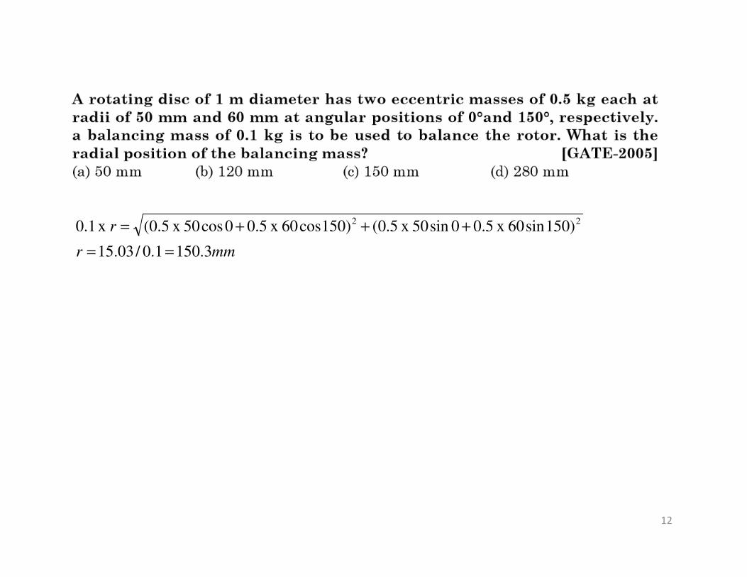
mmr
r
3.1501.0/03.15
)150sin60 x 5.00sin50 x 5.0()150cos60 x 5.00cos50 x 5.0( x 1.0 22
==
+++=
12

Balancing of reciprocating parts
• Acceleration of reciprocating parts in an
engine is given by
2coscos2
rts, ocating pathe recipre mass of If m is th
nrf
θθω
+=
13
force. ngacceleratisecondary thecalled is 2cos
and force ngacceleratiprimary thecalled is cos
2coscos
2
2
2
nmr
mr
nrmF
ss m isate the mato acceler required then force
θω
θω
θθω
+=
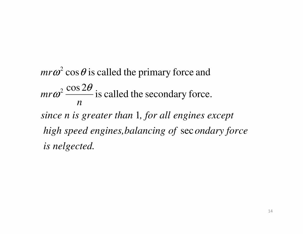
ceptengines ex, for all eater thance n is grsin
nmr
mr
1
force.secondary thecalled is 2cos
and forceprimary thecalled is cos
2
2
θω
θω
14
gected.nel is
ceondary forof balancing d engines, high spee
ceptengines ex, for all eater thance n is grsin
sec
1

Partial balancing of Primary force
• The primary force acts along the line of stroke as shown in the figure. The
primary force can be considered as a component of a centrifugal force due
to a mass m at the crank radius r. Thus, balancing of primary force is
A
O
m
θ
r
Bθ
to a mass m at the crank radius r. Thus, balancing of primary force is
equivalent to balancing of mass m.
• This can be done by attaching a mass B at a radius b in diametrically
opposite direction as shown such that Bb= mr
• By the above method, the primary force is completely balanced, but the
vertical component of the centrifugal force due to B = Bbω2 sinθ remains
and its maximum value, Bbω2 is again equal to the maximum magnitude
of the primary force, mrω2 .
• In other words, the effect of the above method of balancing is toun
change the direction of maximum unbalanced force from that along the
line of stroke to that perpendicular to it.15

• As a compromise, a fraction, c of the reciprocating parts is
balanced such that
Bb= cmr
As a result unbalanced force along the line of stroke = (1-
c)mrω2cosθ
Similarly, unbalanced force perpendicular to the line of stroke =
cmrω2sinθ
instantany at forceprimary unbalancedResultant ∴
16
( )[ ] [ ]
( )[ ] [ ]222
2222
sincos1
sincos1
instantany at forceprimary unbalancedResultant
θθω
θωθω
ccmr
cmrmrc
+−=
+−=
∴
The resultant unbalanced force will be minimum when c=1/2.
However, the unbalanced force along the line stroke is more
harmful than in a direction perpendicular to it. So, the common
practice is to balance two-third of the reciprocating parts.

Partial balancing of reciprocating parts of two cylinder locomotives
• The two cylinders of locomotive have their cranks at 90 degrees.
• On account of partial balancing of reciprocating parts, there is an
• 1. unbalanced force along the line of stroke and 2. unbalanced force perpendicular to the line of stroke.unbalanced force perpendicular to the line of stroke.
• The effect of unbalanced force along the line of stroke is to produce
– a)the variation of tractive force along the line of stroke
– b) the unbalanced couple
17
• The effect of unbalanced force perpendicular
to the line of stroke is to produce
– c) the variation of pressure on rails which results
in hammering action on the rails. The maximum
magnitude of the unbalanced force perpendicular
to the line of stroke is termed as hammer blow.to the line of stroke is termed as hammer blow.
18
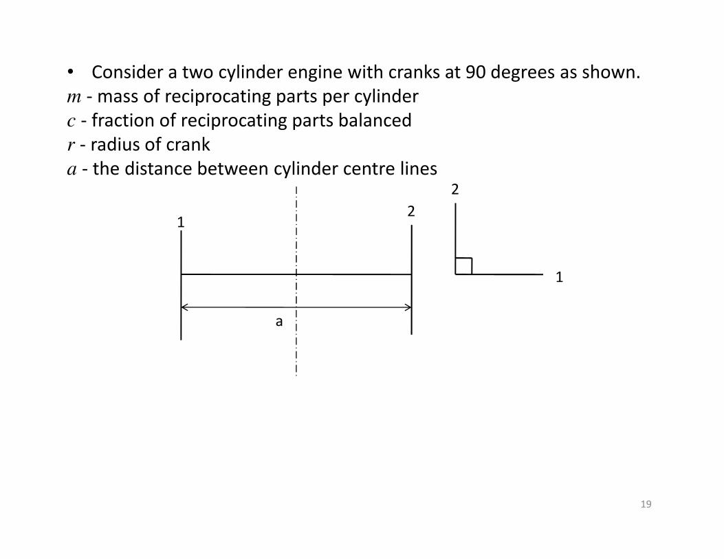
• Consider a two cylinder engine with cranks at 90 degrees as shown.
m - mass of reciprocating parts per cylinder
c - fraction of reciprocating parts balanced
r - radius of crank
a - the distance between cylinder centre lines
1
2
12
19
1
a

( )
( ) ( )
( ) ( ) 22
2
2
)90cos(1cos1F stroke of line
along force tractiveunbalancedResultant
90cos1
2cylinder
cos1
1cylinder
of stroke of line thealong force unbalanced
:force tractiveofVariation a)
+−+−=
+−=
−=
θωθω
θω
θω
mrcmrc
mrc
mrc
20
( ) ( )
( )
oo
t
2
t
22
t
315or 135
1tan
0cossin
0
minimumor maximum be toFfor
)sin(cos1F
)90cos(1cos1F stroke of line
=
−=
=−−
=
−−=
+−+−=
θ
θ
θθ
θ
θθω
θωθω
d
dF
mrc
mrcmrc
t
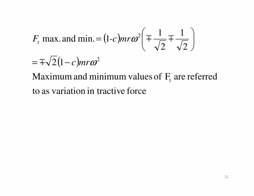
( )
( )
force ein tractiv variationas to
referred are F of valuesminimum and Maximum
12
2
1
2
11 min. and max.
t
2
2
ω
ω
mrc
mr-cFt
−=
=
m
mm
21
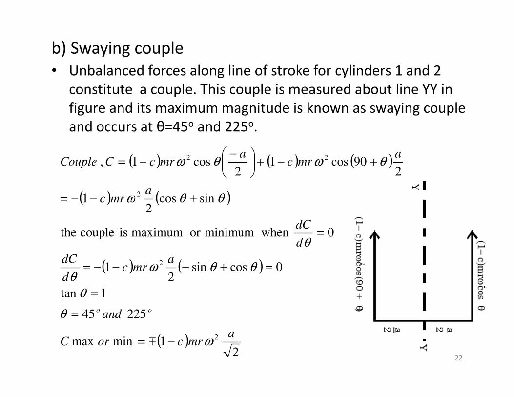
b) Swaying couple
• Unbalanced forces along line of stroke for cylinders 1 and 2
constitute a couple. This couple is measured about line YY in
figure and its maximum magnitude is known as swaying couple
and occurs at θ=45o and 225o.
( ) ( ) ( )
( ) ( )sincos1
290cos1
2cos1,
2
22
amrc
amrc
amrcCCouple
θθω
θωθω
+−−=
+−+
−−=
22
( ) ( )
( ) ( )
( )2
1minmax
225 45
1tan
0cossin2
1
0 when minimumor maximum is couple the
sincos2
1
2
2
amrcorC
and
amrc
d
dC
d
dC
mrc
oo
ω
θ
θ
θθωθ
θ
θθω
−=
=
=
=+−−−=
=
+−−=
m

c) Hammer blow• The unbalanced force perpendicular to the line of
stroke due to balance mass B1 at radius b to balance reciprocating parts only= B1bω
2 sinθ
• The maximum magnitude of this force is known is hammer blow and occurs at θ=90o and 270o
• Hammer blow =B1bω2
• If P is the downwards pressure on rail due to dead load • If P is the downwards pressure on rail due to dead load and other loads, then net pressure =P± B1bω
2.
• If P- B1bω2 is negative, then the wheels will be lifted
from the rails. Therefore the limiting condition in order that the wheel does not lift from rails is P- B1bω
2 =0.
• The permissible value of angular speed obtained from the condition is ω=(P/B1b)1/2
23
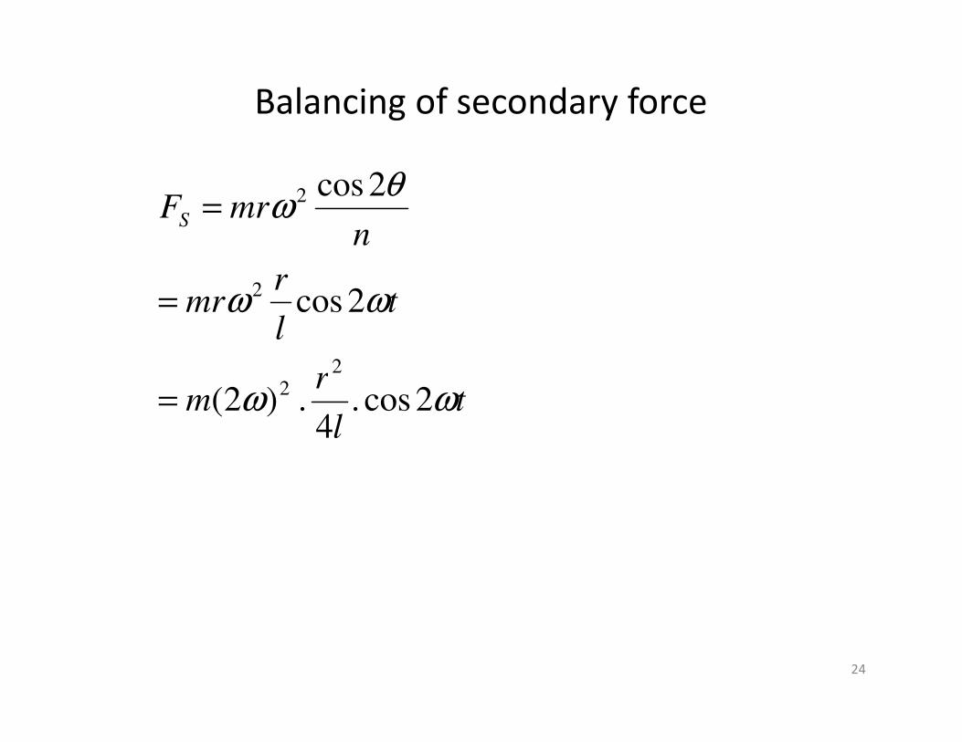
Balancing of secondary force
r
tl
rmr
nmrFS
ωω
θω
2cos
2cos
2
2
2
=
=
24
tl
rm ωω 2cos .
4 . )2(
22
=

Balancing of In-line engines
Two cylinder in-line engines:
Refe
rence p
lane
θmra cosθ
Primary couple polygonθ
r
25
c a
Refe
rence p
lane
Consider a two cylinder vertical engine having equal reciprocating masses and
cranks 180o apart as shown. The crank angles are θ and 180+θ. Length of each
crank is r and the distance of cylinder center lines from the reference plane are
c and a. the reference plane is at the centre of left hand main bearing.
θ
Primary force polygon
Two cylinder in-line engines….
• Primary forces: From the primary force polygon diagram, it is completely balanced.
• Primary couples: From the primary couple polygon diagram, resultant primary couple is proportional to the vertical component of the resultant mra.resultant mra.
• Resultant primary couple= mrω2acosθ
• It is maximum at θ=0 and 180o and the maximum value=±mrω2a
26
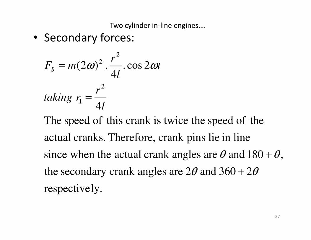
• Secondary forces:
theof speed the twiceiscrank thisof speed The
4
2cos .4
. )2(
2
1
22 ωω
=
=
l
rrtaking
tl
rmFS
Two cylinder in-line engines….
27
ly.respective
2360 and 2 are anglescrank secondary the
,180 and are anglescrank actual when thesince
linein lie pinscrank Therefore, cranks. actual
theof speed the twiceiscrank thisof speed The
θθ
θθ
+
+

Two cylinder in-line engines….
• Resultant centrifugal force is proportional to 2mr1.
( )
l
rm
l
rm
22
oooo
22
2 valuemaximum
theandcrank actual theof revolutionper four times i.e.
270 and 180 ,90 ,0 occur when valuesmaximum The
2cos4
22 forcesecondary Resultant
ω
θ
θω
=
=
=
28
lm2 valuemaximum =
2θr1
a
2θ
mr1
mr1
Secondary
force polygon
2θ
mr1(a/2)
Secondary
couple polygon
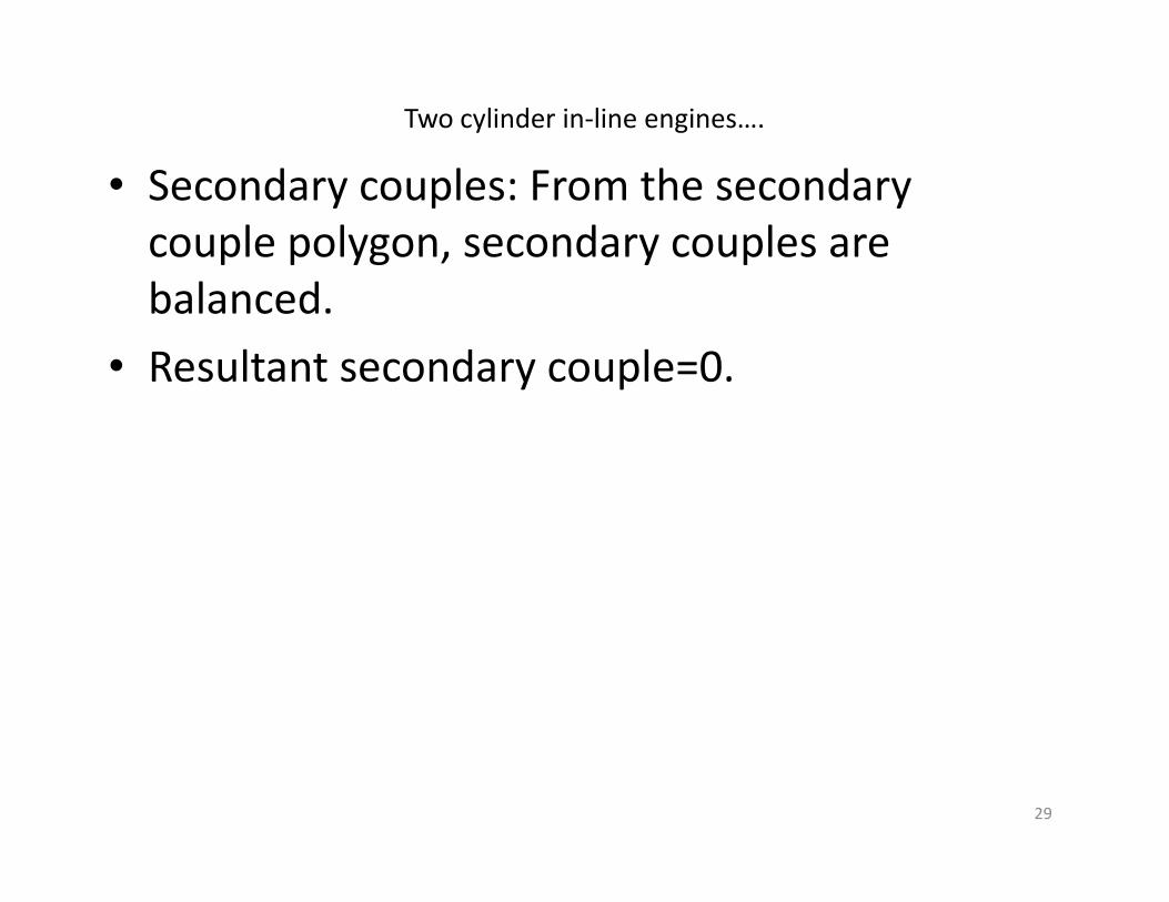
• Secondary couples: From the secondary
couple polygon, secondary couples are
balanced.
• Resultant secondary couple=0.
Two cylinder in-line engines….
29
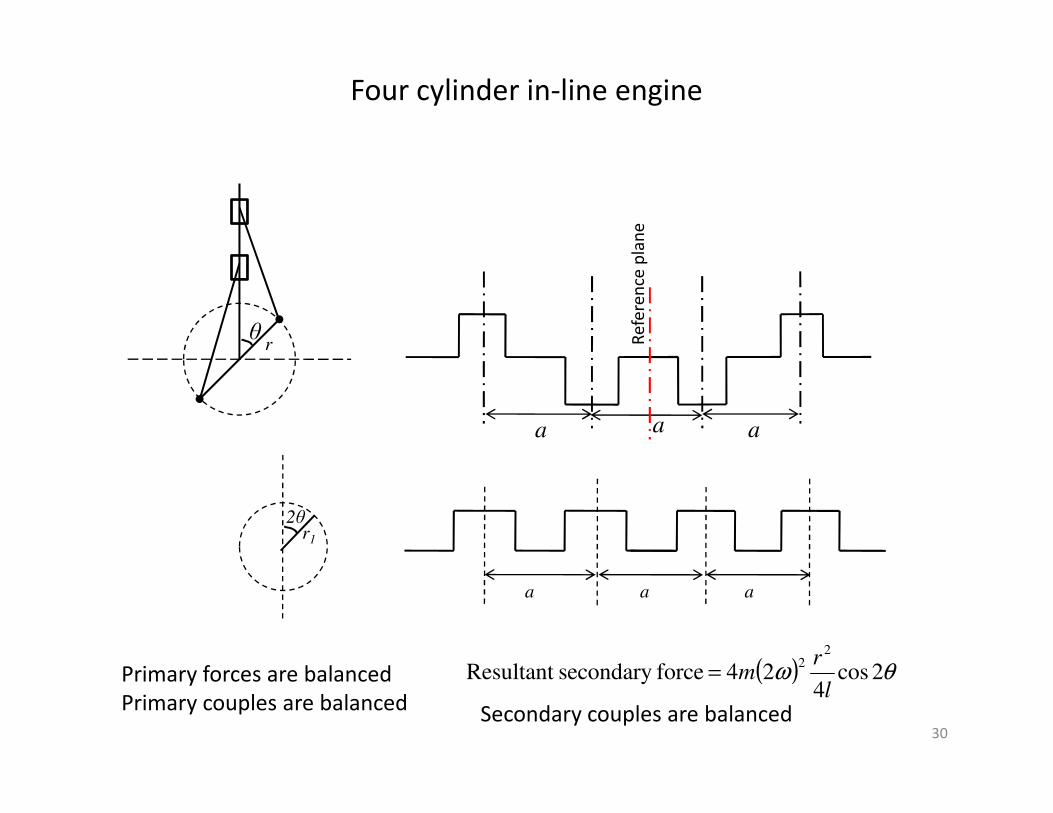
Four cylinder in-line engine
θ Re
fere
nce
pla
ne
r
30
aa a
2θr1
a aa
Primary forces are balanced
Primary couples are balanced
( ) θω 2cos4
24 forcesecondary Resultant 2
2
l
rm=
Secondary couples are balanced

Questions
31

Which one of the following can completely balance
several masses revolving in different planes on a
shaft?
(a)A single mass in one of the planes of the revolving
masses
32
masses
(b) A single mass in any one plane
(c)Two masses in any two planes
(d)Two equal masses in any two planes.
Ans. (c)

A rotor supported at A and B, carries two masses as
shown in the given figure. The rotor is
(a) dynamically balanced
(b) statically balanced
(c) statically and dynamically balanced
(d) not balanced.(d) not balanced.
33
Ans. (b)
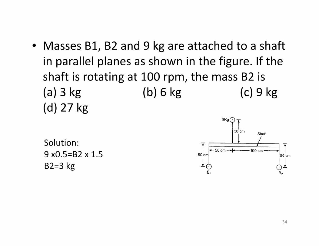
• Masses B1, B2 and 9 kg are attached to a shaft
in parallel planes as shown in the figure. If the
shaft is rotating at 100 rpm, the mass B2 is
(a) 3 kg (b) 6 kg (c) 9 kg
(d) 27 kg
34
Solution:
9 x0.5=B2 x 1.5
B2=3 kg

Static balancing is satisfactory for low speed rotors but with increasing speeds, dynamic balancing becomes necessary. This is because, the
(a) Unbalanced couples are caused only at higher speeds
(b) Unbalanced forces are not dangerous at higher speeds
(c) Effects of unbalances are proportional to the square of the speed
(d) Effects of unbalances are directly proportional to the speed speed
Ans. (C)
35
• The balancing weights are introduced in
planes parallel to the plane of rotation of the
disturbing mass. To obtain complete dynamic
balance, the minimum number of balancing balance, the minimum number of balancing
weights to be introduced in different planes is
(a) 1 (b) 2 (c) 3 (d) 4
• Ans. b
36
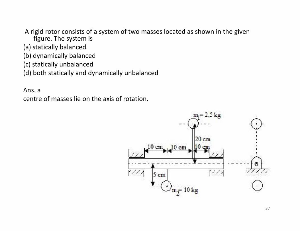
A rigid rotor consists of a system of two masses located as shown in the given figure. The system is
(a) statically balanced
(b) dynamically balanced
(c) statically unbalanced
(d) both statically and dynamically unbalanced
Ans. a
centre of masses lie on the axis of rotation.
37
If the ratio of the length of connecting rod to the crank radius increases, then
(a) Primary unbalanced forces will increase
(b) Primary unbalanced forces will decrease
(c) Secondary unbalanced forces will increase (c) Secondary unbalanced forces will increase
(d) Secondary unbalanced forces will decrease
Ans. (d) Secondary force only involves ratio of length of connecting rod and crank radius.
If n increases, value of secondary force will decrease.
38
• A single cylinder, four-stroke I.C. engine rotating
at 900 rpm has a crank length of 50 mm and a
connecting rod length of 200 mm. If the effective
reciprocating mass of the engine is 1.2 kg, what is
the approximate magnitude of the maximum
'secondary force' created by the engine?
(a) 533 N (b) 666 N (c) 133 N (a) 533 N (b) 666 N (c) 133 N
(d) None of the above
Sol: Maximum secondary force= mrω2/n
39
• Consider the following statements:
An in-line four-cylinder four-stroke engine is
completely balanced for
1. primary forces 2. secondary forces 1. primary forces 2. secondary forces
3. primary couples 4. secondary couples
Of these statements:
(a) 1, 3 and 4 are correct (b) 1, 2 and 4 are correct
(b) (c) 1 and 3 are correct (d) 2 and 4 are correct
40


![masos for the masses part three - []](https://static.fdokumen.com/doc/165x107/6328d98472264f12480374b5/masos-for-the-masses-part-three-.jpg)