CUMFLOW RP400XD ROTATING PAN MIXER PARTS ...
132
CUMFLOW RP400XD ROTATING PAN MIXER PARTS & OPERATION MANUAL WINGET LIMITED PO BOX 41 EDGEFOLD INDUSTRIAL ESTATE PLODDER LANE BOLTON LANCS BL4 OLS Tel: ++ 44 (0) 1204 854650 Fax:++ 44 (0) 1204 854663 [email protected] [email protected] www.winget.co.uk
-
Upload
khangminh22 -
Category
Documents
-
view
1 -
download
0
Transcript of CUMFLOW RP400XD ROTATING PAN MIXER PARTS ...

CUMFLOW RP400XDROTATING PAN MIXER
PARTS&
OPERATION MANUAL
WINGET LIMITEDPO BOX 41
EDGEFOLD INDUSTRIAL ESTATEPLODDER LANE
BOLTONLANCS
BL4 OLSTel: ++ 44 (0) 1204 854650Fax:++ 44 (0) 1204 [email protected]

INDEX
SECTION 1 GENERAL INFORMATION
1.1. Company Details1.2. Important Notice1.3. Mixer Operational and Safety Requirements1.4 Installation Drawing (Where applicable)1.5 Test Certificates (Where applicable)
SECTION 2 INSTALLATION AND OPERATING INSTRUCTIONS
2.1. Pre Installation Notes2.2. Installation Instructions2.3. Operating Instructions
SECTION 3 TECHNICAL SPECIFICATION AND MAINTENANCE
3.1. Technical Specification3.2. Shutdown Procedure and Maintenance3.3. Maintenance of Mixer3.4. Maintenance and Lubrication3.5. Lubrication Layout
SECTION 4 MIXER SPARE PARTS
4.1. General Arrangement of Parts and Top & Bottom Structures4.2. Pan Roller Assembly4.3. Discharge Blade & Door Control Assembly4.4. Discharge Door Pneumatic Cylinder4.4. Pan Drive Assembly4.5. Pan Assembly4.6. Pan Door Assembly4.7. Mixing Star Assembly4.8. Fixed Blade Assembly4.9. Layout of Guards4.10. Pan Sealing Arrangement4.11. Decals & Logo’s
SECTION 5 OPTIONAL ANCILLIARY EQUIPMENT SPARE PARTS
5.1 Arrangement of Loader Chassis Assembly5.2 Arrangement of Loader Runway (Combined Motor, Brake & Gear Unit)5.3 Arrangement of Winch Unit (Separate Motor, Brake & Gear Unit)5.4 Arrangement of Loader Runway (Separate Motor, Brake & Gear Unit)5.5 Worm Reduction Gearbox (Renold WU5)

5.6 Dewhurst Electromagnetic Brake5.7 N.R. Range Electromagnetic Brake5.8 Magnetic Brake Drum5.9 Arrangement of Batchweigher5.10 Arrangement of Whirler Motor Up5.11 Arrangement of Whirler Motor Up 460Volt 3Ph 60Hz5.12 Arrangement of Whirler5.13 Arrangement of Whirler Split Shaft5.14 Wire Rope Renewal Procedure5.15 Wire Rope Safety Notes5.16 Pneumatic Oiler (Not available on all models)5.17 0-100 Litre Flow Meter
SECTION 6 ELECTRICAL SYSTEM
6.1 Electrical Instructions6.2 Wiring Diagrams (Where Applicable)6.3 Component Listing (Where Applicable)6.4 Interlock Switch Mounting (Where Applicable)
SECTION 7 PNEUMATIC SYSTEM
7.1 Pneumatic Instructions – Shutdown Procedure7.2 Pneumatic Circuit Layout
SECTION 8 MISCELLANEOUS
8.1 Noise8.2 Special Pan Covers and Inlets8.3 Miscellaneous Items
SECTION 9 ELECTRONIC LOADCELL & READOUT BOX
The contents of this handbook although correct at the time of publication, may be subject toalteration by the manufacturers without notice and Winget Limited can accept no responsibility forany errors or omissions contained within the following pages. Nor can we accept any liabilitywhatsoever arising from the use of this manual howsoever caused.
Winget Limited operate a policy of continuous product development. Therefore, some illustrationsor text within this publication may differ from your machine
Winget Limited can accept no responsibility for incorrectly supplied spare parts unless the partnumber and a full description of the items required is given when the order is placed.
NOTE
Imperial fixings (bolts, setscrews, nuts, washers etc) have been progressively changed to Metric. Ifin doubt as to whether you have a Metric or Imperial fixing please order the metric items listed, i.e.bolt or set screw and associated or flat and spring washers to replace the existing items.

OPERATING
AND
MAINTENANCE MANUAL
SECTION 1
GENERAL INFORMATION

COMPANY DETAILS AND GENERAL INFORMATION
For any spares or service work, please contact:-
Winget LimitedP.O. Box 41
Edgefold Industrial EstatePlodder LaneBoltonLancs U.K.BL4 OLS
Telephone No: ++ 44 (0)1204 854650 Facsimile No: ++ 44 (0)1204 854663
‘E Mail’ [email protected] [email protected]
ORDERING SPARES
To help us to complete your order promptly and correctly we need:-
• Machine type and serial number• Description and quantity of parts required• The full address to which the parts are to be sent
Winget Limited can accept no responsibility for incorrectly supplied spare parts unless thepart number and a full description of the items required is given when the order is placed.

IMPORTANT NOTICE
The CUMFLOW RP400XD is a high performance mixer
The following precautions are necessary to obtain the best results and to avoiddamage to the MIXING STAR and PAN DRIVE
ENSURE TRANSIT BAR AND RING ARE REMOVED FROM DOORBEFORE STARTING MACHINE.
AGGREGATES
Strict control of graded aggregates must be maintainedMaximum size 19mm
Oversize lumps of aggregate or rogue materials must be prevented fromentering the Pan
MIXING STAR BLADES
They are to a special shape and material to prolong wear life. They should notbe modified in any way and only replaced with GENUINE ‘CROKER’ sparesObtained from WINGET LIMITED.
A daily check is advisable to ensure that the Blades/Wearing parts are secureand undamaged.
PAN RIM & BASE WEARING PLATES
They must be replaced before excessive wear causes distortion.
MAXIMUM BATCH LOADS
UNDER NO CIRCUMSTANCES should the Maximum Batch Loads quotedbe exceeded nor should the mixer be or re-started when there is a mix in thePan
MIXING PAN
Ensure that the Mixing Pan is rotating concentrically and that the pan base isRotating in horizontal place, otherwise damage may occur to the doormechanics.

WARNING
THE MANUFACTURER ACCEPTS NO RESPOSIBILITY FOR ANYDAMAGE OR FAILURE RESULTING FROM OPERATIONALMISUSE OR MALPRACTICE. ANY MODIFICATIONS TO THEMACHINE WILL AFFECT ITS WORKING PARAMETERS ANDSAFETY FACTORS. REFER TO THE MANUFACTURERS BEFOREFITTING ANY NON STANDARD EQUIPMENT OR PARTS.
THE MANUFACTURERS ACCEPT NO RESPONSIBILITY FOR ANYMODIFICATIONS MADE AFTER THE MACHINE HAS LEFT THEFACTORY, UNLESS PREVIOUSLY AGREED IN WRITING. THEMANUFACTURERS WILL ACCEPT NO LIABILITY FOR DAMAGETO PROPERTY, PERSONNEL OR THE MACHINE IF FAILURE ISBROUGHT ABOUT DUE TO SUCH MODIFICATIONS, OR THEFITMENT OF SPURIOUS PARTS.
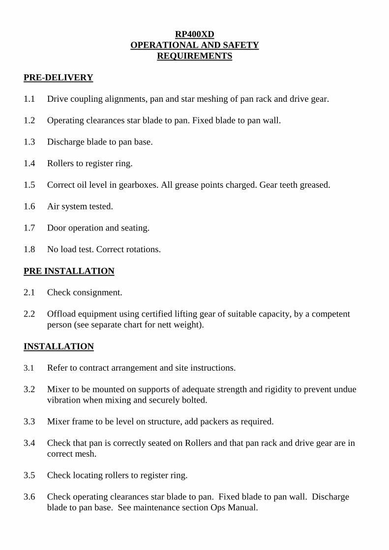
RP400XDOPERATIONAL AND SAFETY
REQUIREMENTS
PRE-DELIVERY
1.1 Drive coupling alignments, pan and star meshing of pan rack and drive gear.
1.2 Operating clearances star blade to pan. Fixed blade to pan wall.
1.3 Discharge blade to pan base.
1.4 Rollers to register ring.
1.5 Correct oil level in gearboxes. All grease points charged. Gear teeth greased.
1.6 Air system tested.
1.7 Door operation and seating.
1.8 No load test. Correct rotations.
PRE INSTALLATION
2.1 Check consignment.
2.2 Offload equipment using certified lifting gear of suitable capacity, by a competent person (see separate chart for nett weight).
INSTALLATION
3.1 Refer to contract arrangement and site instructions.
3.2 Mixer to be mounted on supports of adequate strength and rigidity to prevent undue vibration when mixing and securely bolted.
3.3 Mixer frame to be level on structure, add packers as required.
3.4 Check that pan is correctly seated on Rollers and that pan rack and drive gear are incorrect mesh.
3.5 Check locating rollers to register ring.
3.6 Check operating clearances star blade to pan. Fixed blade to pan wall. Dischargeblade to pan base. See maintenance section Ops Manual.

ELECTRICAL SERVICES
4.1 Refer to wiring diagrams in Section 6. All wiring to be undertaken by competent electrician.
4.2 Refer to pneumatic circuit diagram in Section 7. Connect compressor. Supplycompressed air 5.5 bars as required (80psi).
4.3 Refer to wiring diagram in Section 6 when connecting air control valves.
4.4 Remove transit bar and ring from door BEFORE starting mixer.
4.5 Ensure starters are mounted away from mixer on supports free of vibration.
4.6 Ensure starters are fitted with correct overloads – see technical specification powerunits.
OPERATION
5.1 Correct oil level, gearboxes. Air line lubricator.
5.2 Mixing pan clear of loose nuts and bolts to prevent damage to fingers and blades.
5.3 Check correct rotation – mixing star – anti clockwise; mixing pan – anti clockwise. All when viewed from the top.
5.4 Discharge door and blade correct operation.
5.5 Blade operating clearances adjust in line with maintenance instructions.
5.6 Never exceed manufacturer’s maximum capacity as detailed in specification.
SHUTDOWN
6.1 Prior to any work being carried out mixer to be isolated and physically locked off. Recommended equipment double key exchange system.
6.2 Follow procedure detailed in company and users’ Health and Safety Policy atall times.
6.2 Ensure all storage bins containing materials to be mixed are isolated.
6.3 Shut off water supply and drain off water tank or flowmeter

MAINTENANCE
7.1 Ensure that all maintenance is carried out in accordance with the Parts andOperating manuals and proprietary manufacturer’s specific instruction.
7.2 Isolate electrical and other services to the mixer as section 6 above.
7.3 Service at recommended intervals.
7.4 Use Croker manufactured replacement parts supplied by WINGET LIMITED.
GENERAL
8.1 Under no circumstances should the Maximum Batch Loads be exceeded byeither weight and volume as stated in Technical Specification.
8.2 Mixer star blades to be checked daily for damage.
8.3 Pan rim and base wearing plates must be replaced before excessive wear causesdistortion.
8.4 Ensure mixing pan is rotating concentrically and pan base is rotating inhorizontal plane.
8.5 Mixer must not be stopped and started when there is mix in the pan.
8.6 Refer to Contract Drawing for scope of supply. Site instruction notes outliningweights etc.
8.7 Refer to Method Statement when installation and commissioning isresponsibility of Winget Limited.
Nett Weights Max (kgs)
9.1 RP50XD 788 RP1250XD 4840RP100XD 814 RP1500XD 4980RP200XD 1400 RP3000XD 7112RP400XD 2000 FP1000 4040RP550XD 2150 FP1500 4065RP850XD 2600 FP2000 4100
9.2 Refer to technical specification for nett weights of ancillary equipment.
9.3 Refer to contract drawing for nett weights of ancillary equipment.

Miscellaneous
10.1 Noise measured in accordance with Directive 79/113 EEC 85LPA.
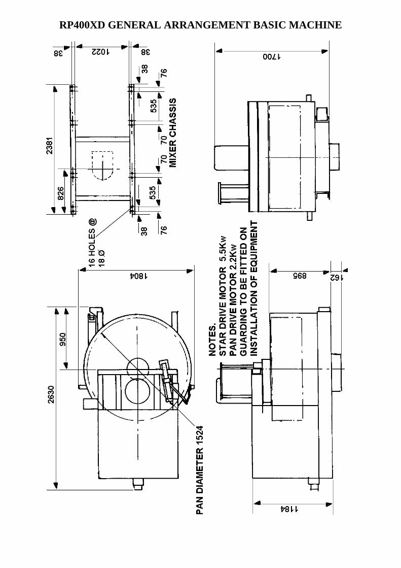
RP400XD GENERAL ARRANGEMENT BASIC MACHINE
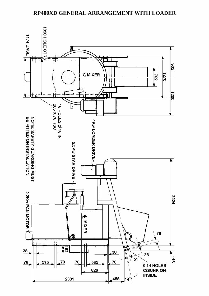
RP400XD GENERAL ARRANGEMENT WITH LOADER
RP400XD ARRANGEMENT OF BOTTOM DISCHARGELOADING HOPPER

RP400XD GENERAL ARRANGEMENT-PLANT

OPERATING
AND
MAINTENANCE MANUAL
SECTION 2
INSTALLATION AND OPERATINGINSTRUCTIONS

PRE-INSTALLATION
On arrival of the equipment it is advisable to check that all packages listed onthe consignment note have been received.
The equipment must be offloaded using certified lifting gear of suitablecapacity, by a competent person.
When unloading the mixer, care must be taken to ensure the discharge chuteremains clear of obstructions as the chute and door hang below the chassis.
An outline drawing and bolt hold plan is normally sent prior to the despatch ofthe machine and will enable preparations to be made for the installation. Withthe `picture` of what the machine will look like when it is assembled, theancillary equipment dismantled for transport can easily be identified.

INSTALLATION
Please refer to contract arrangement and site instructions as applicable.
It is recommended that a concrete foundation (to take foundation bolts – notsupplied) should be provided for each leg of the support structure and runwaywhen fitted. When the machine is supplied without a support structure itshould be mounted on supports of sufficient strength and rigidity to preventundue vibration when the machine is working. When making provision for aloading hopper pit it is strongly recommended that the pit is concreted out sothat it can easily be kept clean and free from any build up which could preventthe bottom limit switch from operating correctly.
Before completing the installation, check that the main mixer frame is levelwith a spirit level. Packings should be inserted as required under the structurelegs or main frame. The packings under the mixing pan roller brackets are setduring manufacturing and must not be disturbed under any circumstances.
Check that the pan is seated and that the pan rack and drive gear are in mesh.. Also check that all the blade clearances are in line with the maintenanceinstructions. It is essential that the machine is level and all rollers are in contactwith the pan roller track, if any of the rollers fail to revolve the trouble isusually found to be uneven foundations.
On connecting to the power supply, the wiring diagram must be referred to.A check that the wiring is correct is rotation of the following:-
• The mixing pan and mixing star rotate anti-clockwise when looking fromthe top.
• The loader winch rotates anti-clockwise looking from the rope drum end when the raise button is pressed.
• The whirler unit rotates clockwise when looking from the top.
It is advisable to mount the starters away from the machine on supports freefrom vibration. Ensure that the starters are fitted with suitable overloads – seetechnical specification – power units.
A simple Water Flow Meter is available as an option to the water tank, this hasa range of 0-100 litres and features an adjustable flow indicator with a resetfacility allowing very accurate measurement of water flow irrespective of thepressure. The Flow Meter is normally fitted with a manual ‘on/off’ valve and isprotected by a washable in line strainer.
A supply of compressed air at 5.5 bars is required. The inlet for the connectionfrom the air line is tapped ½” B.S.P. A drop in pressure will cause incorrectoperation of the pneumatic system.
OPERATING THE MACHINE
Before starting production the following points should checked:-
(1) That there is oil in (a) the Star Drive Gearbox(b) the Pan Drive Gearbox(c) the Loader Winch Gearbox (when fitted)(d) the Air Line lubricator
(2) The Mixing pan should be clear of loose nuts, bolts, spanners etc., asthese will damage the fingers and blades.
(3) Check that the Discharge Door and Discharge Blade are operatingcorrectly.
(4) Check that the blade clearances are correct and if necessary adjust, in linewith the maintenance instructions.
(5) Check that the limit switches on the loader stop the Loading Hopper inthe required positions at the top and bottom of the runway and that themagnetic brake is applied.
(6) Check that the Water tank is set to the required amount and is filling upto this level. (See later page for further information on Water Tankoperation, where fitted).
(7) If a Flow Meter is fitted check that the pointer is reset to zero and thestrainer is clean and free from debris.
(8) When Weigh Gear is fitted check that the setting arrangements and anylubrication requirements have been carried out. .
IMPORTANT:
The CUMFLOW is a high performance Mixer.
The following precautions are necessary to obtain the best results and to avoiddamage to the Mixing Star and Drive.

AGGREGATES:
Strict control of graded aggregates must be maintained. Maximum Size 19mm.
Oversize lumps of aggregate or rogue material must be prevented from enteringthe Pan.
MIXING STAR BLADES:
They are of a special shape and material to prolong wear life. They should notbe modified in any way and only replaced by genuine ‘WINGET CROKER’spares.
A daily check is advisable to ensure that the Blades/Wearing Pieces aresecurely bolted and undamaged.
PAN RIM & BASE WEARING PLATES:
They must be replaced before excessive wear causes distortion.
MAXIMUM BATCH LOADS:
Under no circumstances should the Maximum Batch Loads quoted beexceeded nor should the Mixer be stopped and re-started when there is a mix inthe Pan.
After each mix the contents of the pan must be completely discharged beforeattempting to close the discharge door. At the end of each period of operationthe mixing pan, mixing blades, discharge blade and fingers, discharge chute,discharge door and seating must be washed down to prevent concrete setting onthem and so impairing the efficiency of the machine.
WARNING:
THE MAUFACTURER ACCEPTS NO RESPONSIBILITY FOR ANYDAMAGE OR FAILURE RESULTING FROM OPERATIONAL MIS-USE OR MALPRACTICE.

OPERATING INSTRUCTIONS FOR WEIGH GEAR MECHANISM
HYDROSTATIC LOADCELL & GAUGE
The Hydrostatic Load Cell is connected by a flexible capillary tube (approx 9.7metres long) to a 300mm (12”) diameter weigh gauge.
The whole system is assembled and filled with fluid under vacuum and underno circumstances should any of the components be disconnected, in the eventof component damage the complete assembly should be returned to WingetLimited for repair.
The system is factory calibrated and any variation between the calculated tareand the actual tare recorded can be corrected by means of the tare adjustmentknob on the side of the gauge.
With no load acting on the loadcell the pointer will be below zero, this is toaccommodate the weight of the hopper. When the hopper is placed on to theloadcell the pointer will register zero. Final zero adjustment can be made viathe zero adjustment knob on the side of the gauge housing.
ELECTRONIC LOADCELL & GAUGE
The electronic Loadcell & Gauge consists of an electrically operated loadcellmounted on the weigher frame and connected to a remote mounted digitalreadout control box. The connecting lead should be protected from damageand the readout box mounted such that it is not affected by vibrations etc. Themounting instructions detailed within Section 9 of this manual should befollowed to avoid excess vibrations damaging the control box. Section 9 alsocontains detailed advice on setting up, obtaining zero and operation of theloadcell and readout box and should be referred to before the equipment isoperated.NOTE THE FOLLOWING WIRING CONNECTIONS
+ Excite RED- Excite BLUE
+ Signal GREEN- Signal YELLOW
OPERATING INSTRUCTIONS FOR 0-100 LITRE WATER FLOWMETER
The simple manually operated 0-100 litre Water Flow Meter is available as anoption to the water tank and is normally mounted on the side of the mixerfeeding directly into the pan. The meter is normally fitted with 1” hose tailconnectors but different sizes of water inlet connections to suit various hosediameters are also available. The meter is normally provided with a simple‘on/off’ valve and inline filter/strainer mounted next to but down stream of theflowmeter.
OPERATION
On a daily basis before use the strainer should be removed and checked fordebris and obstructions, cleaned and refitted. Ensure the on/off valve is in the‘off ‘ position and turn on the main water supply. Set the adjustable pointer onthe dial face via the central knob to the required amount of water. Check theindicator reads zero, if not operate the reset lever on the side of the meter whichwill reset the indicator. Turn the on/off valve slowly to the ‘on’ positionwatching the movement of the indicator around the dial, when the indicatorreaches the pointer sharply turn valve to the ‘off ‘ position. The indicator willregister the amount of water delivered. Operate the reset lever to bring theindicator back to zero and repeat the operation for each batch of materialmixed.
When shutting down the mixer either at night or at the end of each shift it isrecommended that the main water supply to the flow meter and ‘on/off’ valveis shut off.
If it is expected that the overnight temperatures will drop to or close to freezingit is recommended that the Flow Meter, Valve, Filter and Pipework are drainedto prevent damage.

OPERATING THE MIXER
SAFETY NOTES
Never operate the mixer unless you have read and fully understand the contentsof the Operators Manual If you are in doubt as to any aspect of the equipmentsoperation contact the manufacturer for guidance
Never operate the mixer whilst wearing loose fitting clothing
Never reach inside the Pan whilst it is rotating
Never operate any equipment unless you have received adequate training
Cement, certain other minerals and organic compounds can cause skin irritationleading to Dermatitis. Always use Personal Protective Equipment i.e. gloves etcto protect the skin from direct contact. If in any doubt about the materials beingused consult your employers COSHH manual
Wear Eye protection to protect your eyes from dust and liquid splashes
Do not attempt to remove the pan single handedly, (RP50/100) obtainassistance, use the Pan Trolley (if provided) or use suitable lifting equipment
Do not operate the mixer with any of the guards removed, safety devices orinterlocks disconnected. They are there to offer you some protection, ensurethey are correctly maintained
Carry out the daily maintenance before operating the mixer and report defectsto your supervisors
Oils, Greases and Lubricants are skin irritants and prolonged direct skin contactcan cause skin cancer. PPE or barrier creams should be used when carrying outmaintenance work, wash your hands on completion
Always dispose of waste oils and lubricants in a proper manner, it is illegal topour it down drains or bury it. Contact your local authority for a list ofauthorised disposal sites
Always disconnect the power supply at the mains before carrying out anymaintenance work or cleaning the equipment down. Do not turn on the poweruntil everything has dried out
Do not allow waste from the wash down process to enter the public drainagesystem unless it has been properly filtered.

Decals and Instruction Plates are attached to the equipment to warn againsthazards and assist in the safe operation of the equipment, if damaged or defacedthey should always be replaced.
It is likely that clutch and/or brake linings may contain asbestos and suitableprecautions should be taken to avoid breathing in the dust, protective clothingshould be worn. Hands should be washed immediately after handlingcomponents and old discarded parts or linings should be disposed of in aresponsible manner in line with local or national regulations covering thedisposal of asbestos waste.

OPERATING
AND
MAINTENANCE MANUAL
SECTION 3
TECHNICAL SPECIFICATIONAND MAINTENANCE
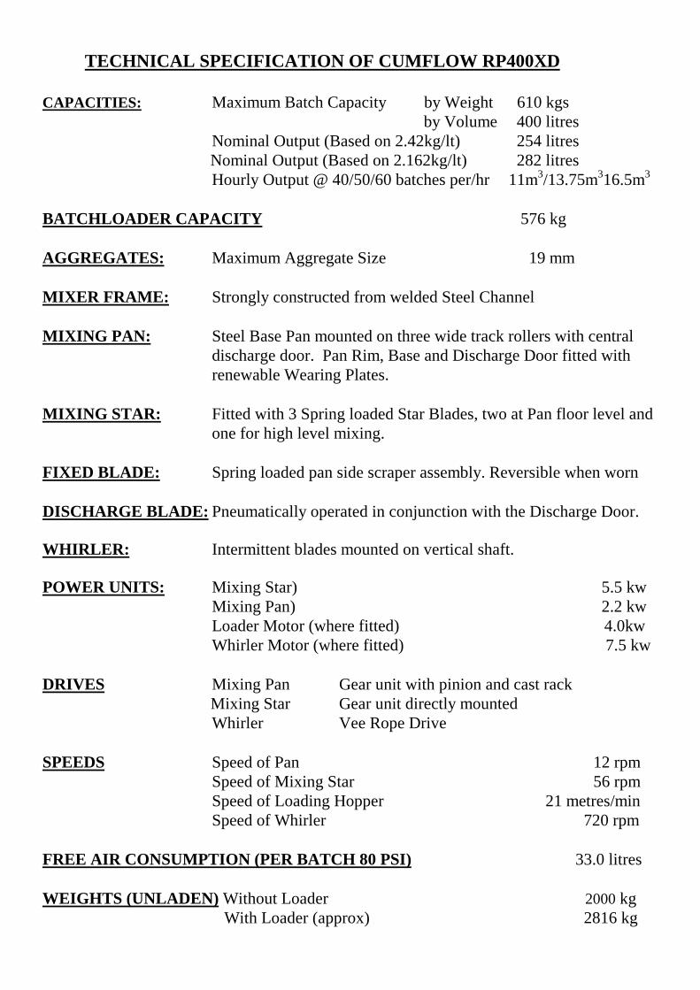
TECHNICAL SPECIFICATION OF CUMFLOW RP400XD
CAPACITIES: Maximum Batch Capacity by Weight 610 kgsby Volume 400 litres
Nominal Output (Based on 2.42kg/lt) 254 litres Nominal Output (Based on 2.162kg/lt) 282 litres
Hourly Output @ 40/50/60 batches per/hr 11m3/13.75m316.5m3
BATCHLOADER CAPACITY 576 kg
AGGREGATES: Maximum Aggregate Size 19 mm
MIXER FRAME: Strongly constructed from welded Steel Channel
MIXING PAN: Steel Base Pan mounted on three wide track rollers with centraldischarge door. Pan Rim, Base and Discharge Door fitted withrenewable Wearing Plates.
MIXING STAR: Fitted with 3 Spring loaded Star Blades, two at Pan floor level andone for high level mixing.
FIXED BLADE: Spring loaded pan side scraper assembly. Reversible when worn
DISCHARGE BLADE: Pneumatically operated in conjunction with the Discharge Door.
WHIRLER: Intermittent blades mounted on vertical shaft.
POWER UNITS: Mixing Star) 5.5 kwMixing Pan) 2.2 kwLoader Motor (where fitted) 4.0kwWhirler Motor (where fitted) 7.5 kw
DRIVES Mixing Pan Gear unit with pinion and cast rack Mixing Star Gear unit directly mounted
Whirler Vee Rope Drive
SPEEDS Speed of Pan 12 rpmSpeed of Mixing Star 56 rpmSpeed of Loading Hopper 21 metres/minSpeed of Whirler 720 rpm
FREE AIR CONSUMPTION (PER BATCH 80 PSI) 33.0 litres
WEIGHTS (UNLADEN) Without Loader 2000 kg With Loader (approx) 2816 kg

ELECTRICS Motor Voltage 415V 3ph 50hz Option 60 hz
Control Voltage 110V
MACHINE SAFETY DIRECTIVE
All Gears are suitably guarded.

MAINTENANCE
IMPORTANT
ALWAYS ENSURE APPARATUS IS ISOLATED FROM MAINS SUPPLYBEFORE COMMENCING MAINTENANCE.
SHUTDOWN PROCEDURE
Prior to any work being carried out the apparatus is to be isolated and physically locked off.
We recommend a double key exchange system.
Safe access to equipment with one access door and one control point.
Follow the procedures detailed in your Health and Safety Policy at all times.
Ensure all storage bins containing materials to be mixed are isolated.
Shut down the water supply and drain off any water tanks or flowmeter fitted
Supply on Key Trapped
Door LockedKey Trapped
Supply LockedOff Key Free
Door OpenKey Trapped
Equipment Stopped Supply Locked Off Access DoorOpen
Equipment Working SupplyOn Access Door Locked
Supply Locked Off KeyFree

MAINTENANCE OF MIXER
IMPORTANT NOTE:
Ensure that all maintenance is carried out in accordance with the Parts and OperatingManual and Proprietary Manufacturer’s specific instruction.
PROCEDURE
1 ISOLATE ELECTRICAL, PNEUMATIC AND OTHER SERVICES TO THEMIXER (see separate section).
2 Service at recommended intervals.
3 Use Croker manufactured replacement parts available from WINGET LIMITED.
4 Ensure all safety guards and interlocks are reinstated prior to operating the mixer.
5 Main items of wear (see Section 4).
A) Star BladesB) Fixed BladeC) Discharge BladeD) Whirler Blades
Access to mixing pan internals is via the safety interlocks. Each of the above arebolted components and are replaced by simple method and usually achieved in situwithout dismantling other components.
E) Pan base and rim wearing plates are also bolted construction and can bereplaced in situ. However, pan covers will need to be dismantled to provide thenecessary access.
F) Other items prone to less wear are star blade fingers, lower whirler shaftassembly and mixing star. Each can be replaced again in situ but pan coverswould require dismantling to provide necessary access.
G) Pan rollers can be adjusted to accommodate wear during operation. These canbe replaced when required in situ using jacking method to support pan andprovide the necessary access.
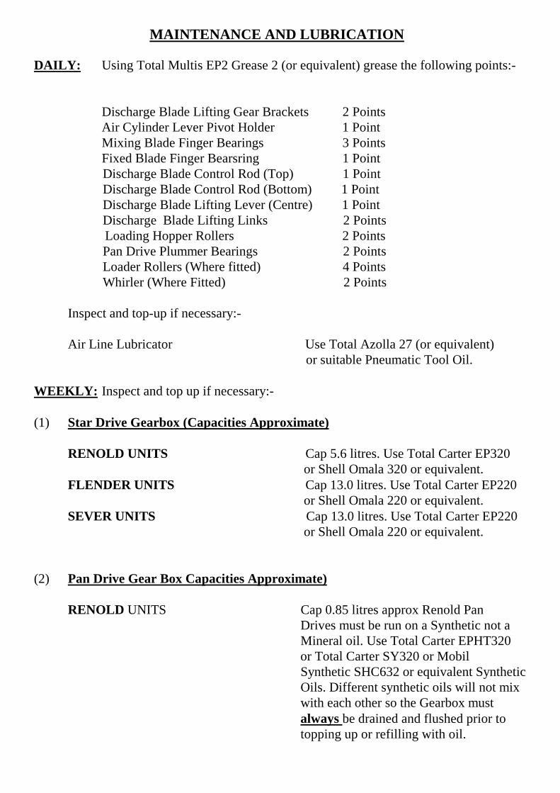
MAINTENANCE AND LUBRICATION
DAILY: Using Total Multis EP2 Grease 2 (or equivalent) grease the following points:-
Discharge Blade Lifting Gear Brackets 2 PointsAir Cylinder Lever Pivot Holder 1 PointMixing Blade Finger Bearings 3 PointsFixed Blade Finger Bearsring 1 Point
Discharge Blade Control Rod (Top) 1 Point Discharge Blade Control Rod (Bottom) 1 Point Discharge Blade Lifting Lever (Centre) 1 Point Discharge Blade Lifting Links 2 Points
Loading Hopper Rollers 2 Points Pan Drive Plummer Bearings 2 Points Loader Rollers (Where fitted) 4 Points Whirler (Where Fitted) 2 Points
Inspect and top-up if necessary:-
Air Line Lubricator Use Total Azolla 27 (or equivalent) or suitable Pneumatic Tool Oil.
WEEKLY: Inspect and top up if necessary:-
(1) Star Drive Gearbox (Capacities Approximate)
RENOLD UNITS Cap 5.6 litres. Use Total Carter EP320 or Shell Omala 320 or equivalent.FLENDER UNITS Cap 13.0 litres. Use Total Carter EP220 or Shell Omala 220 or equivalent.SEVER UNITS Cap 13.0 litres. Use Total Carter EP220 or Shell Omala 220 or equivalent.
(2) Pan Drive Gear Box Capacities Approximate)
RENOLD UNITS Cap 0.85 litres approx Renold Pan Drives must be run on a Synthetic not a Mineral oil. Use Total Carter EPHT320 or Total Carter SY320 or Mobil Synthetic SHC632 or equivalent Synthetic Oils. Different synthetic oils will not mix with each other so the Gearbox must always be drained and flushed prior to topping up or refilling with oil.

FLENDER UNITS Cap 1.1 litres approx. Flender Pan Drives must be run on a Synthetic not a Mineral Oil. Use Total Carter EPHT460 or Total Carter SY460 or Tribol 800 iso460 or B.P. Eersin SG-XP460 or equivalent Synthetic oils. The different Synthetic Oils will not mix with each other so the Gearbox must always be drained and flushed prior to topping up or refilling with oil.
SEVER UNITS Cap 2.0 litres approx. Sever Pan Drives must be run on a Synthetic not a Mineral Oil. Use Total Carter EPHT460 or Total Carter SY460 or Tribol 800 ISO460 or B.P. Eersyn SG-XP460 or Castrol Alphasyn PG680 or equivalent synthetic oils. The different synthetic oils will not mix with each other so the Gearbox must always be drained and flushed prior to topping up or refilling with oil.
(3) Loader Winch Reduction Gearbox (Renold WU5) Cap 4 litres. Use Total Carter EP320, Total Carter EPHT320 or Total Carter SY320 (or equivalent). Carter EPHT and SY320 are Synthetic Oils which will not mix with either Mineral Oils or other makes of Synthetic Oils. If in doubt drain and flush the gearbox before topping up.
Loader Winch Gearbox (Flender) Cap 5.5 litres. Use Total Carter EPHT460 or Total Carter SY460 or BP Enersyn SG-XP460 or equivalent. These are Synthetic Oils and will not mix with either Mineral Oils or other makes of Synthetic Oils. If in doubt drain and flush the gearbox before topping up.
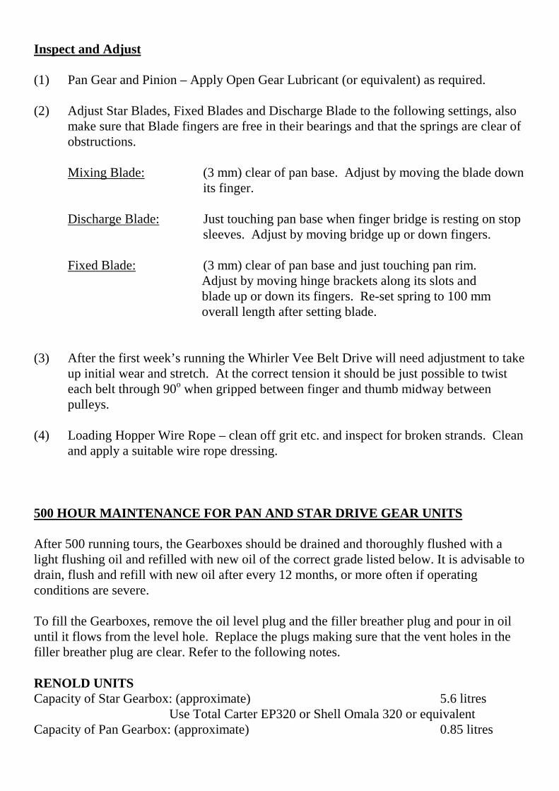
Inspect and Adjust
(1) Pan Gear and Pinion – Apply Open Gear Lubricant (or equivalent) as required.
(2) Adjust Star Blades, Fixed Blades and Discharge Blade to the following settings, alsomake sure that Blade fingers are free in their bearings and that the springs are clear ofobstructions.
Mixing Blade: (3 mm) clear of pan base. Adjust by moving the blade downits finger.
Discharge Blade: Just touching pan base when finger bridge is resting on stop sleeves. Adjust by moving bridge up or down fingers.
Fixed Blade: (3 mm) clear of pan base and just touching pan rim. Adjust by moving hinge brackets along its slots and blade up or down its fingers. Re-set spring to 100 mm overall length after setting blade.
(3) After the first week’s running the Whirler Vee Belt Drive will need adjustment to takeup initial wear and stretch. At the correct tension it should be just possible to twisteach belt through 90o when gripped between finger and thumb midway betweenpulleys.
(4) Loading Hopper Wire Rope – clean off grit etc. and inspect for broken strands. Cleanand apply a suitable wire rope dressing.
500 HOUR MAINTENANCE FOR PAN AND STAR DRIVE GEAR UNITS
After 500 running tours, the Gearboxes should be drained and thoroughly flushed with alight flushing oil and refilled with new oil of the correct grade listed below. It is advisable todrain, flush and refill with new oil after every 12 months, or more often if operatingconditions are severe.
To fill the Gearboxes, remove the oil level plug and the filler breather plug and pour in oiluntil it flows from the level hole. Replace the plugs making sure that the vent holes in thefiller breather plug are clear. Refer to the following notes.
RENOLD UNITSCapacity of Star Gearbox: (approximate) 5.6 litres
Use Total Carter EP320 or Shell Omala 320 or equivalentCapacity of Pan Gearbox: (approximate) 0.85 litres

The Renold Pan Drives must be run on a synthetic oil not a mineral. Use Total CarterEPHT320 or Total Carter SY320 or Mobil SHC632 (Synthetic Oils). The different syntheticoils will not mix with each other so the gearbox must be drained and flushed prior totopping up or refilling with oil.
FLENDER UNITS
Capacity of Star Gearbox (approximate) 13.0 Litres Use Total Carter EP220 or Shell Omala 220 or equivalent.
Capacity of Pan Gearbox (approximate) 1.1 LitresThe Flender Pan Drives must be run on a synthetic oil not a mineral. Use Total CarterEPHT460 or Total Carter SY460 or Tribol 800-ISO460 or B.P. Enersyn SG-XP460(Synthetic Oils). The different synthetic oils will not mix with each other so the gearboxmust be drained and flushed prior to topping up or refilling with oil.
SEVER UNITS
Capacity of Star Gearbox (approximate) 13.0 Litres Use Total Carter EP220 or Shell Omala 220 or equivalent.
Capacity of Pan Gearbox (approximate) 2.0 LitresThe Sever Pan Drives must be run on a synthetic oil not a mineral. Use Total CarterEPHT460 or Total Carter SY460 or Tribol 800 iso460 or B.P. Enersin SG-XP460 orCastrol Alphasyn PG680 or equivalent synthetic oil. The different synthetic oils will not mixwith each other so the gearbox must be drained and flushed prior to topping up or refillingwith oil.
MONTHLY: Inspect:
(1) All blades for wear – replace when worn.
(2) Pan rim, base and door wear plates – replace when worn
(3) Pan Roller Bearings – replace if necessary
(4) Pan Door Bearing – replace if necessary
(5) Pneumatic system for leaks – repair or replace damaged parts.
(6) Pneumatic Cylinders. Make sure that the door cylinder piston rod is atthe end of its travel when the discharge door is just home in its seating.
(7) Check the S.H. bushing securing the Mixing Star and Pan Drive to theirrespective gearbox shafts are tight. Torque setting 34 nm.

CAUTION: BEFORE WORKING UNDER LOADING HOPPER, REST HOPPER ON SAFETY BOLTS. DO NOT FORGET TO REMOVE THESE BOLTS BEFORE RE-STARTING THE MACHINE
Loader Magnetic Brake (see below for N.R. Range brake units.) – adjust if necessary, to the following instuctions (these instructions apply only if a separate brake unit is fitted, refer to the manufacturer if a combined motor and brake unit is fitted):-
Mounting:
Set the brake so that the horizontal centre-line of the shoe corresponds with the centre-line of the brake wheel shaft and the shoe pivots are equally spaced from the vertical centre-line.
Installing:
Slacken back equalising screw (Item 14) Slack nut (Item 5) and adjustscrew (Item 3) to give required braking torque.
WARNING:
The end of the adjusting screw (Item 3) must always be visible in the hole at the endof the adjusting nut (Item 6).
Set nuts (Item 5) so that contact is made with the load spring block in the shoe leverwhen solenoid plunger has moved through half its stoke. Once properly set, thissetting should not be altered. With solenoid plunger right down, set equalising screw(Item 14) to give equal friction lining clearances.
Tighten locknuts (Item 5 & Item 14) and be sure that the load spring bracket is inplace.
Check adjustments frequently and lubricate brake shoe pivots. To adjust for wear,screw in adjusting screw (Item 3) until the adjusting nuts are clear and only touchlever (Item 1) when plunger is depressed through half its stroke.
When new Brake Linings are fitted, repeat all adjustments. Refer to notes on safehandling and disposal of Asbestos waste and Brake Dust.
Orders and enquiries should always state full description of parts required togetherwith the make and model of brake and motor. The serial number on the brake shouldalways be quoted and when ordering replacement brake shoes give the dimensionsand number of rivet holes.

Check that the limit switch on the loader stops the hopper in the required position atthe top of the runway.
When operated the limit switch should stop the motor and apply the magnetic brakeunit.
If a Batch Weigher is not to be used in conjunction with the Loader, then the skiptrack must be extended and a lower limit switch and hopper stops incorporated.
The loading hopper must operate the lower limit switch before the hopper stops arereached and allowance made for the rope to slacken once the hopper is in the loadingposition.
NR Range Loader Magnetic Brakes – adjust if necessary, to the following instructions :-
MOUNTING
(1) Release the spring pressure completely by unscrewing the torque screw H, in mostcases the brake can now be slipped over and off the brake drum. If the brake cannotbe slipped off the drum due to the proximity of equipment i.e. motors etc, the plainarm can be removed by taking out the pivot pin K and withdrawing the arm from thebase. It may be necessary to remove the top rod.
(2) Set the brake unit in position on the bed plate, insert the fixing bolts and screw downfinger tight.

(3) If previously removed replace the plain arm, rod and pivot pin. With the brake baseresting evenly on the bed plate tighten up the torque screw H until the brake drum isgripped tightly by the shoes.
(4) Tighten down the fixing setscrews or bolts and set the brake arm shoe stop screwsAgainst the shoes to prevent them dropping in the released condition.
WIRING
A 3/4” screwed conduit entry is situated in each side of the base of the armaturehousing to accommodate the wiring to the terminals, it is essential that the conduit orlead in be flexible.
SETTING UP
(1) Adjust and lock the torque screw H so that only 3mm (1/8”) of further adjustment isavailable to compensate for any reduction in torque due to any wear of the brakelinings.
(2) Remove cover A and with no current flowing set gap E, indicated on the brake label,by adjusting the handwheel or alternatively the screw B. Replace the cover.
(3) Adjust the setscrew D so that both shoes lift equally when the brake is energised.
(4) When required the brake can be released manually by applying pressure to the releasedevice F, using a suitable lever
MAINTENANCE AND SERVICE
NOTE, until it is obvious that the friction surfaces have bedded down completely,gap E should be should be carefully checked at frequent intervals. The length of thisperiod will depend on the frequency of the operation of the brake. After this periodnormal maintenance only will be required. The only lubrication required is anoccasional light application to the armature spindle bearing through the holesprovided.

COIL REPLACEMENT
Isolate the electrical supply. Remove the armature cover A and disconnect the coilleads. Slacken the top rod adjustments by rotating the handwheel or alternatively thescrew B anti-clockwise. Remove the e-clips on the armature spindle J and withdrawthe spindle, lift out the armature G. Remove the eight nuts at C and withdraw the coil.Replace the coil and the nuts ensuring the positioning of the inner nuts preventsdistortion of the coil flange when the outer nuts are tightened. Refit the armature,spindle and e-clips, reset the gap E as previously described and reconnect the leads.Replace the cover.
BRAKE LINING REPLACEMENT
Isolate the electrical supply. Release the torque spring pressure by unscrewing thetorque screw N. Remove the shoe spindle and rotate the shoe around the drum byapproximately 90’ in an upward movement and withdraw. Fit new linings andreassemble. Reset as previously described under setting.
WARNING
It is likely that the Brake Lining may contain asbestos and suitable precautionsshould be taken to avoid breathing in the dust, protective clothing should beworn. Hands should be washed immediately after handling components and olddiscarded parts or linings should be disposed of in a responsible manner in linewith local or national regulations covering the disposal of asbestos waste.
ANNUALLY:
LOADER WORM REDUCTION GEAR UNIT RENOLD WU5
Drain and clean out the gear case and refill with Total Carter EP320, Total CarterEPHT320 or Total Carter SY320 or equivalent. (EPHT and SY320 are SyntheticOils). Mineral and Synthetic oils and are incompatible and will not mix, neither willdifferent makes of Synthetic Oils. If in doubt thoroughly flush out the unit prior torefilling. When running conditions are severe the oil should be changed morefrequently. (Capacities – 8.5 Imperial Pints: 4.0 Litres: 1.5 American Gallons).
LOADER WINCH GEAR BOX (FLENDER)
Drain and clean out the gear case and refill with Total Carter EPHT460 or TotalCarter SY460 or ICI Tribol 800-ISO460 or BP Enersyn SG-XP460 or equivalent. These are Synthetic Oils, Mineral and Synthetic Oils are incompatible and will notmix, neither will different makes of Synthetic Oils. If indoubt thoroughly flush out theunit prior to refilling. When running conditions are severe this procedure should beadopted more frequently. (Approximate Capacity – 11.6 Imperial Pints: 5.5 litres:1.45 American Gallons)

NOTE
Electrical cables particularly those with copper conductors suffer from a condition known as ‘relaxation’ which may cause wiring to work loose over a period of time, it is recommended that the tightness of wiring connections and terminals are checked following the first month in service.
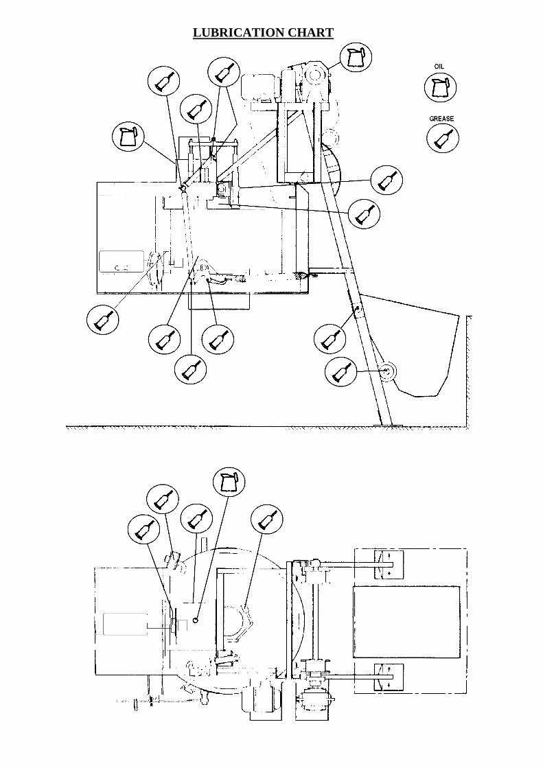
LUBRICATION CHART

OPERATING
AND
MAINTENANCE MANUAL
SECTION 4
MIXER SPARE PARTS
RP4
00XD
GEN
ERAL
AR
RAN
GEM
ENT

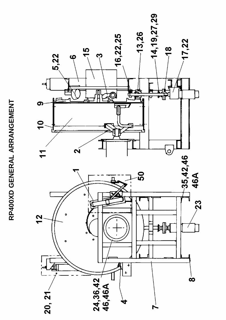
1 CR09100202 Discharge Blade Assembly 12 CR08100174 Arrangement of Mixing Star 13 CR09100178 Discharge Door Assembly 14 CR09100200 Fixed Blade Assembly 15 CR09100222 Pan Roller Assembly 36 CR26100157 Chassis 17 CR26100163 Top Structure 18 CR26100164 Top Structure Support 49 CR21100151 Pan Rack 110 CR54100152 Pan Rim 111 CR54100153 Pan Rim Wear Plate, Mild Steel 311 CR54100153SS Pan Rim Wear Plate, Stainless Steel 312 CR54100154 Pan Base Wear Plate, Mild Steel 412 CR54100154SS Pan Base Wear Plate, Stainless Steel 413 CR46100155 Bevel Pinion 114 CR52100156 Pan Drive Shaft 115 CR51100203 Discharge Chute 116 CR53100219 Packing A/R17 CR53100218 Packing A/R18 CR23100220 Pan Drive Shaft Coupling 119 CR46100224 Scraper Shovel Pinion 120 CR269280 Guard (Door Cylinder) 121 CR269281 Guard (Door Cylinder) 122 CR532016 Weldable Stops Roller Spindles, Bearings Etc. 823 CR299084 Pan Drive Gear Unit (FLENDER) 50Hz 123A CR29100626 Pan Drive Gear Unit USA/CAN Spec 60Hz 124 CR299085 Mixing Star Gear Unit (FLENDER) 50Hz 124A CR29100625 Mixing Star Gear Unit USA/CAN Spec 60Hz 125 CR159012 Bearing Pillow Block 226 CR189004 SH Centre Bushing 127 CR329074 Parallel Key 129 57S05D2 Screw Grub M8 x 10 135 11S06H Screw Set M16 x 50 3236 8S06H Bolt M16 x 60 1242 7S06 Nut M16 4446 267S09 Washer Flat M16 4446A 17S08 Washer Spring M16 44
50 CR54100432 Discharge Blade Guard 151 CR53100639 Forklift Support Channel (Not Illustrated) 252 CR53100437 Extension Feet (Not Illustrated) 4
RP400XD GENERAL ARRANGEMENT
RP4
00XD
PAN
RO
LLER
ASS
EMB
LY

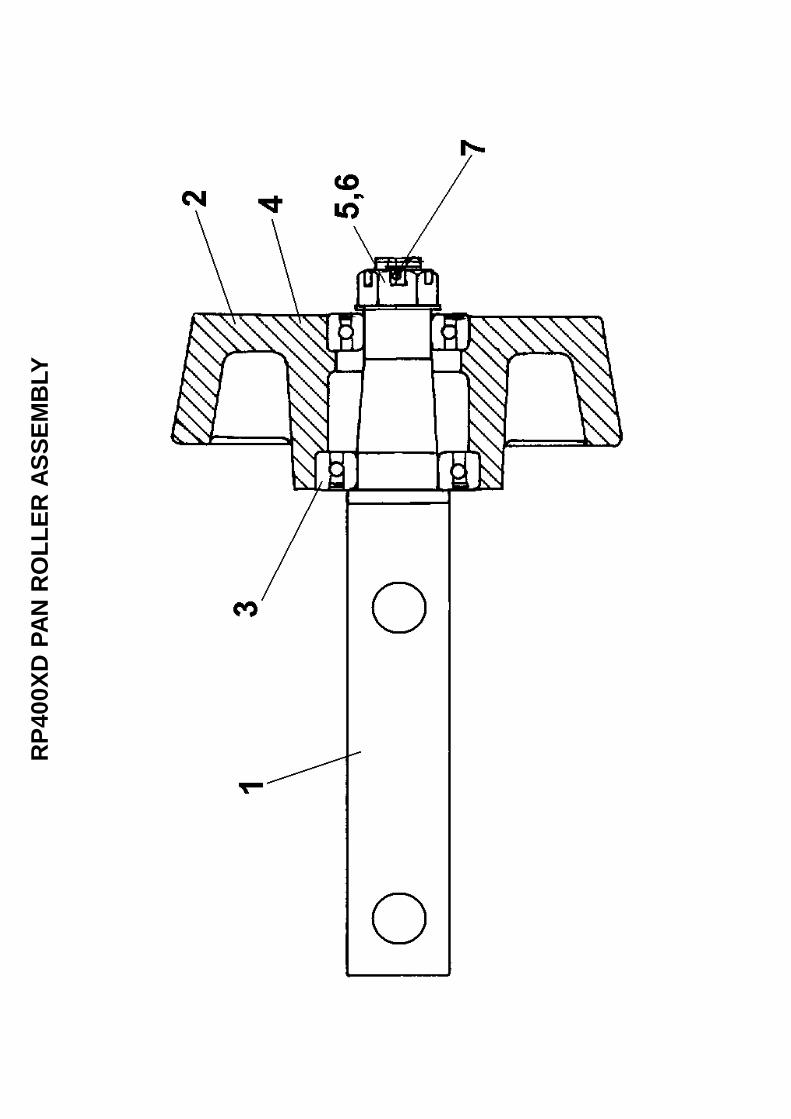
1 CR52100216 Pan Roller Spindle 42 CR21100217 Pan Roller 43 88S17C Bearing 44 88S13C Bearing 45 228S11 Hex Castle Nut 46 267S12 Flat Washer M24 47 44S16J Split Pin 48 CR532016 Stop Roller Spindle, Not Illustrated 89 105S07 Washer Tapered, Not Illustrated 810 8S06R Bolt M16 X 120, Not Illustrated 811 267S09 Washer Flat M16, Not Illustrated 812 61S06 Nut Binx M16, Not Illustrated 8
RP400XD PAN ROLLER ARRANGEMENT

RP4
00XD
DIS
CH
ARG
E B
LAD
E AS
SEM
BLY

1 CR26100170 Finger Bracket 12 CR52100171 Discharge Blade Finger,Mild Steel 22 23 CR540650 Discharge Blade, obsolete use item 3 below 3 CR54100172 Discharge Blade, Mild Steel 13 CR54100172H Discharge Blade, Wear Resistant Steel 13 14 CR52100173 Bridge Hinge 15 CR26100175 Finger Bridge 16 CR53100176 Blade Lifting Link 27 CR26100177 Lifting Lever 18 CR26100189 Lever Bracket 19 CR52100201 Discharge Door Shaft 110 CR53100194 Wiper Seal Housing, Mild Steel 410 411 CR53100192 Discharge Door Shaft Lever 112 CR26100191 Lever Pivot Holder 113 CR53100190 Cylinder Pivot Holder 114 CR541854 Air Cylinder Bracket 115 CR53100197 Air Cylinder Lever 116 CR53100198 Stop Pipe 217 CR52100044 Pin 118 CR52100195 Hinge Pin 319 CR52100196 Locking Pin 320 CR110298 Air Cylinder 130A CR110325 Seal Kit Air Cylinder 121 CR630075 Spacer 222 CR520441 Clevis Pin 123 CR159013 Bearing 224 CR030072 Control Rod 124A CR140004 L.H. Ball Joint 124B CR140005 R.H. Ball Joint 124C CR241648 Checknut - R.H. Thread 3/8" B.S.P. 124D CR241657 Checknut - L.H. Thread 3/8" B.S.P. 125 CR539103 Packer Plate Adaptor 226 CR159011 Bearing 427 44S16J Split Pin 228 267S12 Washer Flat M24 129 11S02C Screw Set M6 x 25 1630 17S03 Washer Spring M6 1631 CR579003 Wiper Seal 432 52S05N Screw C/Sunk M12 x 65 433 7S05 Nut M12 834 17S06 Washer Spring M12 835 8S05K Bolt M12 x 70 436 105S05 Washer Tapered M12 437 11S06H Screw Set M16 x 50 1138 7S06 Nut M16 1139 267S09 Washer Flat M16 1139A 17S08 Washer Spring M16 1140 105S07 Washer Tapered M16 7
RP400XD DISCHARGE BLADE ASSEMBLY
CR54100172SS Discharge Blade, Stainless Steel
CR53100194SS Wiper Seal Housing, Stainless Steel
CR52100171SS Discharge Blade Finger, Stainless Steel

41 7S08 Nut M24 242 267S12 Washer Flat M24 243 7S08 Nut M24 143A 56S08 Nut Lock Thin M24 144 44S18P Split Pin 545 CR329002 Key Parallel 246 57S05D2 Screw Grub M8 x 10 347 10S41 Washer Flat 1" 248 131S01 Grease Nipple 1/8" Straight 348A 176S01 Cover Nipple Grease 349 CR280008 Grease Nipple 1/4" 45' Angle 149A 176S01 Cover Nipple Grease 150 7S07 Nut M20 451 267S10 Washer Flat M20 452 56S07 Nut Thin M20 2
RP400XD DISCHARGE BLADE ASSEMBLY

RP4
00XD
DIS
CH
ARG
E D
OO
R A
IR C
YLIN
DER

CR110298 Air Cylinder Assembly Complete 1CR110325 Seal Kit for above 1
1 CR110336 Bearing Assembly 12 CR110337 Piston Rod Packing 13 CR110338 Front End Cover Assembly 14 CR110339 Cushion Seal 25 CR110340 Cushion SealRetaining Ring 26 CR110342 Rear End Cover Assembly 17 CR110349 Rear Clevis Mounting 18 CR110344 Tie Rod 49 CR110343 Tie Rod Nut 810 CR110346 Piston Seal 211 CR110341 Piston & Piston Rod Assembly 112 CR110347 Barrel 113 CR110348 O' Ring 214 CR110345 Wiper Seal 1
RP400XD DISCHARGE DOOR AIR CYLINDER
RP4
00XD
PAN
DR
IVE
ASSE
MBL
Y

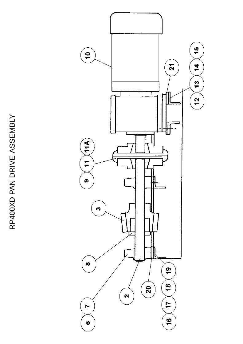
2 CR52100156 Pan Drve Shaft 13 CR46100155 Bevel Pinion 16 CR159012 Bearing Plummer Block 27 CR532016 Bearing Stop 48 CR189004 SH Centre Bushing, Taper Lock 19 CR23100220 Flexible Coupling Assembly 110 *CR299084 *Pan Drive Gearbox Flender 2.2kw 110A * *Pan Drive Gearbox Renold 2.2kw 110B * *Pan Drive Gearbox Sever UK Spec 110C CR29100626 *Pan Drive Gearbox USA/CAN Spec 60Hz 111 CR329074 Key Parallel 211A 57S05D2 Screw Grub M8 x 10 212 8S05H Bolt M12 x 50 413 267S07 Washer Flat M12 814 105S05 Washer Tapered M12 415 61S05 Nut Binx M12 1216 8S06H Bolt M16 x 50 417 267S09 Washer Flat M16 818 105S07 Washer Tapered M16 419 61S6 Nut Binx M16 420 CR53100218 Packing Large Hole (not illustrated) A/R21 CR53100219 Packing Small Hole (not illustrated) A/R
RP400XD PAN DRIVE ASSEMBLY
*Quote Make & Model of motor/gearbox when ordering spares for this item

RP4
00XD
MIX
ING
PAN
ASS
EMB
LY

1 CR21100151 Pan Rack 12 CR54100152 Pan Rim 13 CR54100153 Pan Rim Wear Plates, Mild Steel 33 CR54100153H Pan Rim Wear Plates, Wear Resistant Steel 33 CR54100153SS Pan Rim Wear Plates, Stainless Steel 34 CR54100154 Pan Base Wear Plates, Mild Steel 44 CR54100154H Pan Base Wear Plates, Wear Resistant Steel 44 CR54100154SS Pan Base Wear Plates, Stainless Steel 45 CR54100154 Door Seat, Mild Steel 15 CR54100154SS Door Seat, Stainless Steel 16 52S03E Pan Rim Wear C/Sunk Screws M8 x 25 247 52S06N Pan Base Wear Plate C/Sunk Screws M16 x 65 87A 52S06R Pan Base Wear Plate C/Sunk Screws M16 x 80 88 11S05F Pan Rim Hex Set Screws M12 x 40 129 52S06AG Pan Door Seating C/Sunk Screws M16 x 85 810 7S03 Nut M8 2411 61S05 Nut Binx M12 1212 7S06 Nut M16 2413 17S04 Washer Spring M8 2414 267S07 Washer Flat M12 1215 17S08 Washer Spring M16 24
RP400XD PAN ASSEMBLY

RP4
00XD
DIS
CH
ARG
E D
OO
R A
SSEM
BLY

1
1 CR21100179 Door, Mild Steel 12 CR21100180 Door Seating, Mild Steel 123 CR21100181 Door Lever 14 CR52100182 Spindle 15 CR630387A Thrust Washer 16 CR630387B Distance Piece 17 CR570017 Rubber Seal 18 CR210093 Bottom Cover 19 CR49100187 Bottom Cover Washer 110 CR540451 Nut Cover 111 CR150423 Bearing 112 CR150347 Bearing Thrust 113 11S05E Screw Set M12 x 35 414 52S06AG C/sunk Screw M16 x 85 815 7S06 Nut M16 816 7S08 Nut M24 117 56S08 Nut Lock Thin M24 118 17S06 Spring Washer M12 419 17S08 Spring Washer M16 820 97S15 Clip Hose 1
RP400XD DISCHARGE DOOR ARRANGEMENT
CR21100180SS Door Seating, Stainless Steel

RP4
00XD
MIX
ING
STA
R A
SSEM
BLY
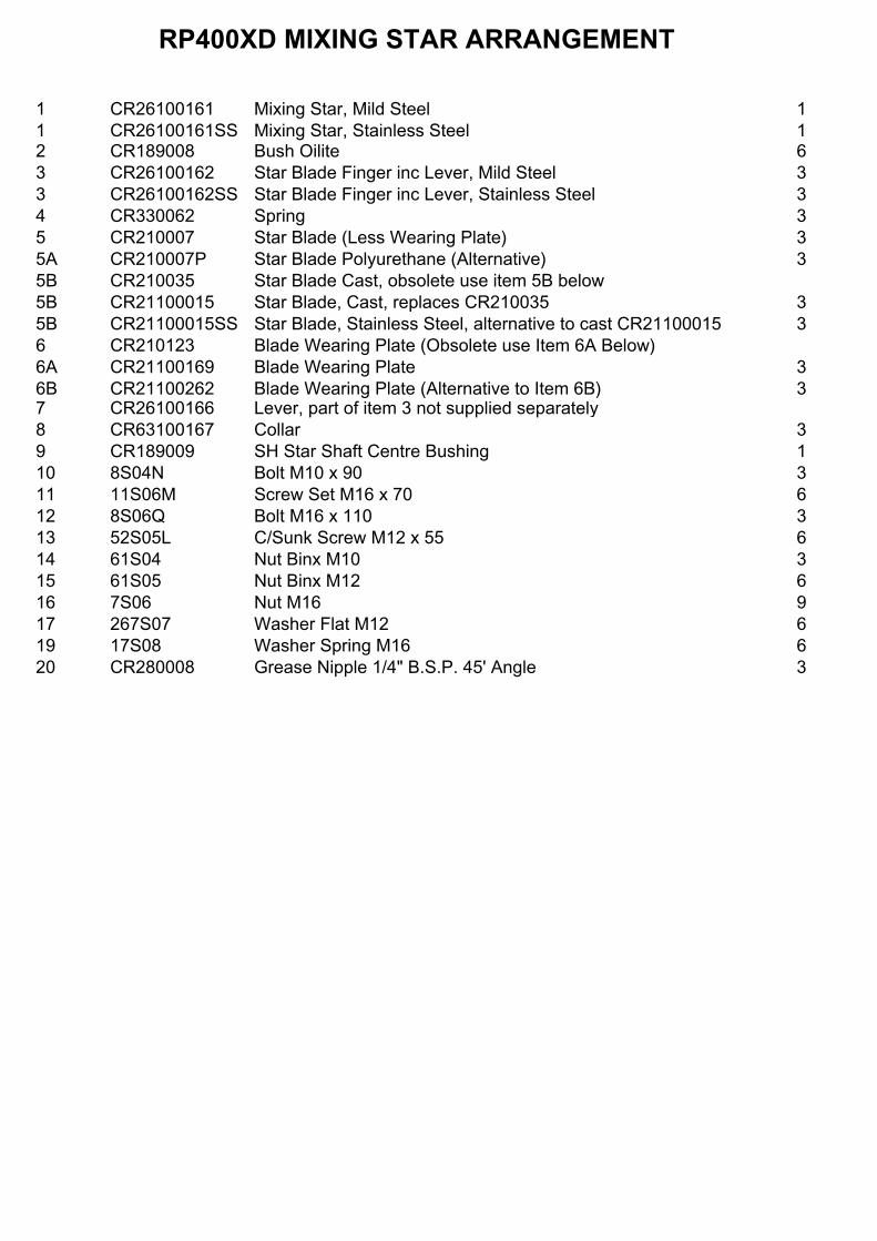
1 CR26100161 Mixing Star, Mild Steel 11 CR26100161SS Mixing Star, Stainless Steel 12 CR189008 Bush Oilite 63 CR26100162 Star Blade Finger inc Lever, Mild Steel 33 CR26100162SS Star Blade Finger inc Lever, Stainless Steel 34 CR330062 Spring 35 CR210007 Star Blade (Less Wearing Plate) 35A CR210007P Star Blade Polyurethane (Alternative) 35B CR210035 Star Blade Cast, obsolete use item 5B below5B CR21100015 Star Blade, Cast, replaces CR210035 35B CR21100015SS Star Blade, Stainless Steel, alternative to cast CR21100015 36 CR210123 Blade Wearing Plate (Obsolete use Item 6A Below)6A CR21100169 Blade Wearing Plate 36B CR21100262 Blade Wearing Plate (Alternative to Item 6B) 37 CR26100166 Lever, part of item 3 not supplied separately8 CR63100167 Collar 39 CR189009 SH Star Shaft Centre Bushing 110 8S04N Bolt M10 x 90 311 11S06M Screw Set M16 x 70 612 8S06Q Bolt M16 x 110 313 52S05L C/Sunk Screw M12 x 55 614 61S04 Nut Binx M10 315 61S05 Nut Binx M12 616 7S06 Nut M16 917 267S07 Washer Flat M12 619 17S08 Washer Spring M16 620 CR280008 Grease Nipple 1/4" B.S.P. 45' Angle 3
RP400XD MIXING STAR ARRANGEMENT

RP4
00XD
FIX
ED B
LAD
E AS
SEM
BLY

1 CR210102 Fixed Blade Spring Box 12 CR660008 Star Finger Bush 13 CR330063 Spring 14 CR53100199 Fixed Blade Finger and Lever, Mild Steel 14 CR53100199SS Fixed Blade Finger and Lever, Stainless Steel 15 CR63100159 Collar 16 CR530491 Fixed Blade Angle, Mild Steel 16 CR530491SS Fixed Blade Angle, Stainless Steel 17 CR530490 Fixed Blade, Mild Steel 1
CR530490H Fixed Blade, Wear Resistant Steel 17 CR530490SS Fixed Blade, Stainless Steel 18 8S04K Bolt M10 x 70 19 11S06M Screw Set M16 x 70 110 8S05M Bolt M12 x 80 211 52S05H C/Sink Screw M12 x 40 212 61S04 Nut Binx M10 113 7S05 Nut M12 414 7S06 Nut M16 115 17S06 Washer Spring M12 416 CR289002 Grease Nipple 1/4" B.S.P. 90' Angle 116A 176S01 Cover Nipple Grease 117 8S06J Bolt M16 x 65 218 267S09 Washer Flat M16 419 17S08 Washer Spring M16 220 7S06 Nut M16 2
RP400XD FIXED BLADE ASSEMBLY

RP4
00XD
PAN
ELS
& G
UAR
DS

1 CR54100204 Pan Guard 12 CR54100205 Pan Guard 13 CR54100206 Pan Guard 14 CR54100207 Side Guard 25 CR54100208 Rear Guard 16 CR54100209 Top Guard 17 CR54100210 Splash Guard 18 CR54100211 Bottom Guard 19 CR26100212 Pan Guard Top Support 110 CR242141 Screw Set M8 x 16 4011 CR499017 Washer Spring M8 4011A 267S05 Washer Flat M8 4012 CR53100214 Support Angle 213 CR54100203 Discharge Chute (Not Illustrated) 114 11S04D Srew Set M10 x 30 (Not Illustrated) 415 267S06 Washer Flat M10 (Not Illustrated) 816 17S05 Washer Spring M10 (Not Illustrated) 417 7S04 Nut M10 (Not Illustrated) 4
RP400XD PANELS AND GUARDS

RP400XD PAN SEALING EARLY VERSION

1 CR479005 Pan Sealing Rubber 42 CR539124 Holding Plate 43 CR529035 Spacer 164 8S03C Bolt M8 x 35 165 61S03 Nut Binx M8 166 267S05 Washer Flat M8 16
RP400XD PAN SEALING STRIP (EARLY TYPE)

RP400XD DECALS AND LOGOS
CROKER CUMFLOW RP400XD1
2
4
5
6
7
8
9
10
11
12
13
14

1 CR85100765 Decal RP400XD 32 V2003037 Plate Serial Number 13 101S05D Rivet Pop 44 V2003039 Decal WINGET Medium 35 V2003665 Decal Sling Point 46 V2003598 Decal British Made 37 V2004307 Decal Electrical Hazard 58 V2004223 Decal CE Mark 19 V2004229 Decal Operators Handbook 310 V2004744 Decal Eye Protection 311 504694600 Decal Safety 312 513331600 Decal Danger 813 CR85100771 Decal Batch Loader Guarding 214 CR85100772 Decal Pan Guarding 2
RP400XD DECALS AND LOGOS

INTENTIONALLY BLANK PAGE

INTENTIONALLY BLANK PAGE

INTENTIONALLY BLANK PAGE

OPERATING
AND
MAINTENANCE MANUAL
SECTION 5
OPTIONAL ANCILLARY EQUIPMENTSPARE PARTS

RP4
00XD
LO
ADER
CH
ASSI
S AS
SEM
BLY

1 CR549002 Bedplate Winch Unit 12 CR269108 Runway, Loader R.H. 13 CR269109 Runway, Loader L.H. 14 CR539088 Support Angle, Winch Unit Bedplate 25 CR539089 Channel Bedplate Support 16 CR539090 Brace Diagonal 17 CR539091 Brace Horizontal 38 CR26100312 Tie Beam, Long 19 CR26100313 Tie Beam, Short 110 CR53100314 Channel, Runway Support 211 CR53100288 Lower Tie Bracket 212 CR532191 Plummer Block Bearing Support Angle 113 CR532244 Cleat Bracing Support Bracket 214 CR532245 Bracing Angle Support Bracket 2
16 8S05B Bolt M12 x 30 817 8S05C Bolt M12 x 35 2818 52S05G Bolt C/Sunk M12 x 35 2818A 52S05K Bolt C/Sunk M12 x 50 219 7S05 Nut M12 6620 17S06 Washer Spring M12 6621 267S07 Washer Flat M12 6622 8S06F Bolt M16 x 50 1022A 17S08 Washer Spring M16 1022B 267S09 Washer Flat M16 1022C 7S06 Nut M16 1023A CR531003691 Guide Rail L.H. 223B CR531003692 Guide Rail R.H. 224 CR53100368 Packing, Guide Rail 4
RP400XD LOADER CHASSIS ASSEMBLY

RP4
00XD
LO
ADER
C/W
CO
MB
INED
MO
TOR
, BR
AKE
& G
EAR
UN
IT

1 Chassis Assembly, See Separate Page 12 CR239020 Rigid Couping c/w Taper Lock Bushes 1 x 60mm, 1 x 2" 13 CR210191 Rope Drum 24 CR520416 Rope Drum Shaft 15 CR299102 Combined Motor Brake & Gear Unit Assembly 15A 8S07K Bolt M20 x 70 45B 267S10 Washer Flat M20 45C 61S07 Nut Binx M20 46 CR520143A Axle Top 16A 8S05L Bolt Axle M12 x 75 26B 61S05 Nut Binx M12 27 CR520143C Axle Lower 17A 8S05L Bolt Axle M12 x 75 27B 61S05 Nut Binx M12 28 CR630209 Axle Collar 28A 57S05D2 Screw Grub 29 CR210192 Rope Pulley 210 CR530896 Taper Roller 211 CR21100121 Flanged Roller (Obsolete Use Item Below)11 CR210157 Flanged Roller 212 CR243033 Anchor Bolt 613 CR530692 Rope Retaining Block 114 CR260769 Hopper Rope Guide 214A 8S05L Bolt M12 x 75 214B 61S05 Nut Binx M12 215 CR091036 Hopper Rope Guide 215A 7S05 Nut M12 215B 8S05L Bolt M12 x 75 215C 61S05 Nut Binx M12 416 CR540756 Loading Hopper 117 CR089028 Hopper Stop Wedge 218 CR530968 Hopper Stop Pin (See Note) 219 CR530450 Limit Switch Plate 120 CR261502 Limit Switch Striker Plate 121 CR220005 Limit Switch (Obsolete Use Item 22A Below)22 CR220100 Limit Switch Arm (Obsolete Use Item 22A Below)22A CR229083 Limit Switch 122B 8S01D Limit Switch Securing Bolts (For CR229083) M5 x 40 422C 17S02 Washer Spring M5 422D 7S01 Nut M5 423 CR150884 Bearing Plummer Block 124 CR620006 Caution Plate 224A 11S02B Screw Set M6 x 20 824B 17S03 Washer Spring 824C 7S02 Nut M6 825 CR320020 Gib Head Key 226 333104020 Grease Nipple 1/4" B.S.P. 427 CR600005 Chain (See Note) 2
* Items 18 & 27 can be purchased as assembly CR530062
RP400XD LOADER C/W COMBINED MOTOR, BRAKE & GEAR UNIT

28 CR329053 Parallel Key 129 CR329002 Parallel Key 130 8S05D Bolt M12 x 40 231 8S06G Bolt M16 x 55 231A 267S09 Washer Flat M16 232 52S04G Screw Set C/Sunk M10 x 35 333 52S05H Screw Set C/Sunk M12 x 40 234 7S04 Nut M10 335 7S05 Nut M12 236 17S08 Washer Spring M16 237 17S05 Spring Washer M10 338 17S06 Spring Washer M12 439 7S06 Nut M16 240 105S05 Tapered Washer M12 240A 267S07 Washer Flat M12 241 10S43 Washer Flat Axle Shaft 242 44S17K Pin Split 243 CR531003691 Guide Rail LH (Not illustrated) 143 CR531003692 Guide Rail RH (Not illustrated) 1
RP400XD LOADER C/W COMBINED MOTOR, BRAKE & GEAR UNIT

RP4
00XD
WIN
CH
UN
IT, S
EPAR
ATE
MO
TOR
, BR
AKE
& G
EAR
UN
IT
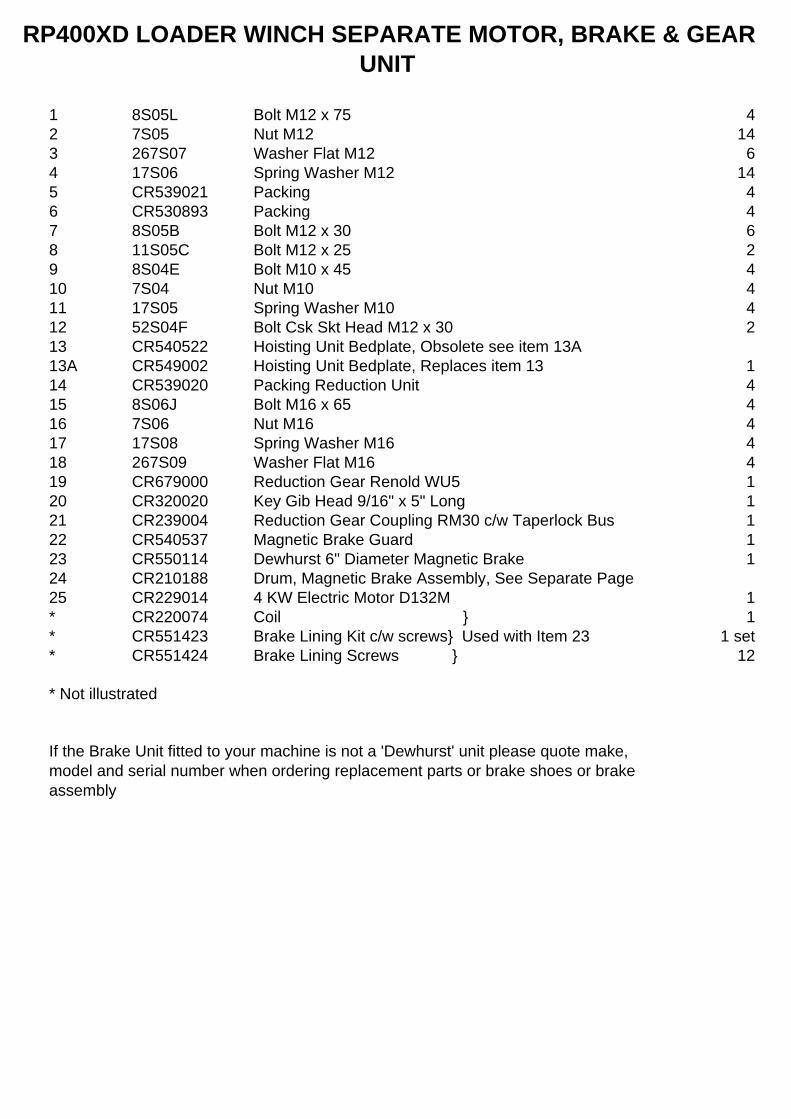
1 8S05L Bolt M12 x 75 42 7S05 Nut M12 143 267S07 Washer Flat M12 64 17S06 Spring Washer M12 145 CR539021 Packing 46 CR530893 Packing 47 8S05B Bolt M12 x 30 68 11S05C Bolt M12 x 25 29 8S04E Bolt M10 x 45 410 7S04 Nut M10 411 17S05 Spring Washer M10 412 52S04F Bolt Csk Skt Head M12 x 30 213 CR540522 Hoisting Unit Bedplate, Obsolete see item 13A13A CR549002 Hoisting Unit Bedplate, Replaces item 13 114 CR539020 Packing Reduction Unit 415 8S06J Bolt M16 x 65 416 7S06 Nut M16 417 17S08 Spring Washer M16 418 267S09 Washer Flat M16 419 CR679000 Reduction Gear Renold WU5 120 CR320020 Key Gib Head 9/16" x 5" Long 121 CR239004 Reduction Gear Coupling RM30 c/w Taperlock Bus 122 CR540537 Magnetic Brake Guard 123 CR550114 Dewhurst 6" Diameter Magnetic Brake 124 CR210188 Drum, Magnetic Brake Assembly, See Separate Page25 CR229014 4 KW Electric Motor D132M 1* CR220074 Coil } 1* CR551423 Brake Lining Kit c/w screws} Used with Item 23 1 set* CR551424 Brake Lining Screws } 12
* Not illustrated
If the Brake Unit fitted to your machine is not a 'Dewhurst' unit please quote make, model and serial number when ordering replacement parts or brake shoes or brake assembly
RP400XD LOADER WINCH SEPARATE MOTOR, BRAKE & GEAR UNIT

RP4
00XD
LO
ADER
C/W
SEP
ARAT
E M
OTO
R, B
RAK
E &
GEA
R U
NIT
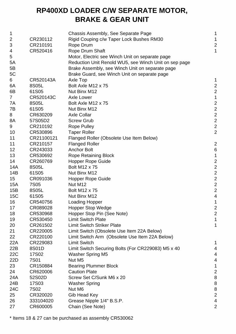
1 Chassis Assembly, See Separate Page 12 CR230112 Rigid Couping c/w Taper Lock Bushes RM30 13 CR210191 Rope Drum 24 CR520416 Rope Drum Shaft 15 Motor, Electric see Winch Unit on separate page5A Reduction Unit Renold WU5, see Winch Unit on sep page5B Brake Assembly, see Winch Unit on separate page5C Brake Guard, see Winch Unit on separate page6 CR520143A Axle Top 16A 8S05L Bolt Axle M12 x 75 26B 61S05 Nut Binx M12 27 CR520143C Axle Lower 17A 8S05L Bolt Axle M12 x 75 27B 61S05 Nut Binx M12 28 CR630209 Axle Collar 28A 57S05D2 Screw Grub 29 CR210192 Rope Pulley 210 CR530896 Taper Roller 211 CR21100121 Flanged Roller (Obsolete Use Item Below)11 CR210157 Flanged Roller 212 CR243033 Anchor Bolt 613 CR530692 Rope Retaining Block 114 CR260769 Hopper Rope Guide 214A 8S05L Bolt M12 x 75 214B 61S05 Nut Binx M12 215 CR091036 Hopper Rope Guide 215A 7S05 Nut M12 215B 8S05L Bolt M12 x 75 215C 61S05 Nut Binx M12 416 CR540756 Loading Hopper 117 CR089028 Hopper Stop Wedge 218 CR530968 Hopper Stop Pin (See Note) 219 CR530450 Limit Switch Plate 120 CR261502 Limit Switch Striker Plate 121 CR220005 Limit Switch (Obsolete Use Item 22A Below)22 CR220100 Limit Switch Arm (Obsolete Use Item 22A Below)22A CR229083 Limit Switch 122B 8S01D Limit Switch Securing Bolts (For CR229083) M5 x 40 422C 17S02 Washer Spring M5 422D 7S01 Nut M5 423 CR150884 Bearing Plummer Block 124 CR620006 Caution Plate 224A 52S02D Screw Set C/Sunk M6 x 20 824B 17S03 Washer Spring 824C 7S02 Nut M6 825 CR320020 Gib Head Key 226 333104020 Grease Nipple 1/4" B.S.P. 427 CR600005 Chain (See Note) 2
* Items 18 & 27 can be purchased as assembly CR530062
RP400XD LOADER C/W SEPARATE MOTOR, BRAKE & GEAR UNIT

28 CR329053 Key Parallel 129 CR329002 Key Parallel 130 8S05D Bolt M12 x 40 231 8S06G Bolt M16 x 55 231A 267S09 Washer Flat M16 232 52S04G Screw Set C/Sunk M10 x 35 333 52S05H Screw Set C/Sunk M12 x 40 234 7S04 Nut M10 335 7S05 Nut M12 236 17S08 Washer Spring M16 237 17S05 Spring Washer M10 338 17S06 Spring Washer M12 439 7S06 Nut M16 240 105S05 Tapered Washer M12 240A 267S07 Washer Flat M12 241 10S43 Washer Flat Axle Shaft 242 44S17K Pin Split 243 CR531003691 Guide Rail LH (Not illustrated) 144 CR531003692 Guide Rail RH (Not illustrated) 1
RP400XD LOADER C/W SEPARATE MOTOR, BRAKE & GEAR UNIT
RP4
00XD
WO
RM
RED
UC
TIO
N G
EAR
BO
X R
ENO
LD W
U5
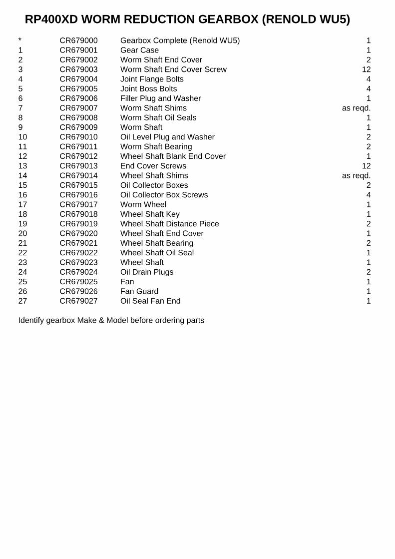
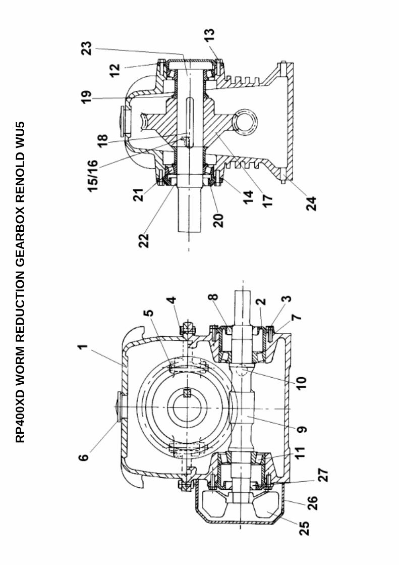
* CR679000 Gearbox Complete (Renold WU5) 11 CR679001 Gear Case 12 CR679002 Worm Shaft End Cover 23 CR679003 Worm Shaft End Cover Screw 124 CR679004 Joint Flange Bolts 45 CR679005 Joint Boss Bolts 46 CR679006 Filler Plug and Washer 17 CR679007 Worm Shaft Shims as reqd.8 CR679008 Worm Shaft Oil Seals 19 CR679009 Worm Shaft 110 CR679010 Oil Level Plug and Washer 211 CR679011 Worm Shaft Bearing 212 CR679012 Wheel Shaft Blank End Cover 113 CR679013 End Cover Screws 1214 CR679014 Wheel Shaft Shims as reqd.15 CR679015 Oil Collector Boxes 216 CR679016 Oil Collector Box Screws 417 CR679017 Worm Wheel 118 CR679018 Wheel Shaft Key 119 CR679019 Wheel Shaft Distance Piece 220 CR679020 Wheel Shaft End Cover 121 CR679021 Wheel Shaft Bearing 222 CR679022 Wheel Shaft Oil Seal 123 CR679023 Wheel Shaft 124 CR679024 Oil Drain Plugs 225 CR679025 Fan 126 CR679026 Fan Guard 127 CR679027 Oil Seal Fan End 1
RP400XD WORM REDUCTION GEARBOX (RENOLD WU5)
Identify gearbox Make & Model before ordering parts

RP4
00XD
DEW
HU
RST
ELE
CTR
OM
AGN
ETIC
BR
AKE
ASSE
MB
LY
SEPA
RAT
E B
RAK
E UN
ITS
ON
LYW
HEN
OR
DER
ING
SPA
RES
FO
R B
RAK
E U
NIT
ALW
AYS
QU
OTE
MAK
E &
MO
DEL
. W
HEN
OR
DER
ING
REP
LAC
EMEN
T B
RAK
E SH
OES
QU
OTE
SIZ
E AN
D N
UM
BER
OF
RIV
ET H
OLE
S

CR550114 Brake Unit Complete Dewhurst 6" Diameter 11 CR220074 Electric Coil 12 CR551423 Brake Linings & Rivets 1 SET3 CR551424 Brake Shoes Retaining Screws 12
It is not possible to supply other major parts as separate items. If any other items are required it will be necessary to replace the complete brake assembly.This is due to the number of brake units fitted over the years from different manufacturers and the diffilculties encountered identifying the different types. When ordering spares please quote the voltage, make, model and if possible the serial number together with a full description of the part required. When ordering replacement brake linings please give the physical dimensions together with the number of rivet holes required.
RP400XD DEWHURST ELECTROMAGNETIC BRAKE UNITSEPARATE BRAKE UNITS ONLY
RP4
00XD
N.R
. RAN
GE
ELEC
TRO
MAG
NET
IC B
RAK
E
SEPA
RAT
E B
RAK
E UN
ITS
ON
LY
WH
EN O
RD
ERIN
G S
PAR
ES F
OR
BR
AKE
UN
IT A
LWAY
SQ
UO
TE M
AKE
& M
OD
EL.
WH
EN O
RD
ERIN
GR
EPLA
CEM
ENT
BR
AKE
SHO
ES Q
UO
TE S
IZE
AND
NU
MB
ERO
F R
IVET
HO
LES

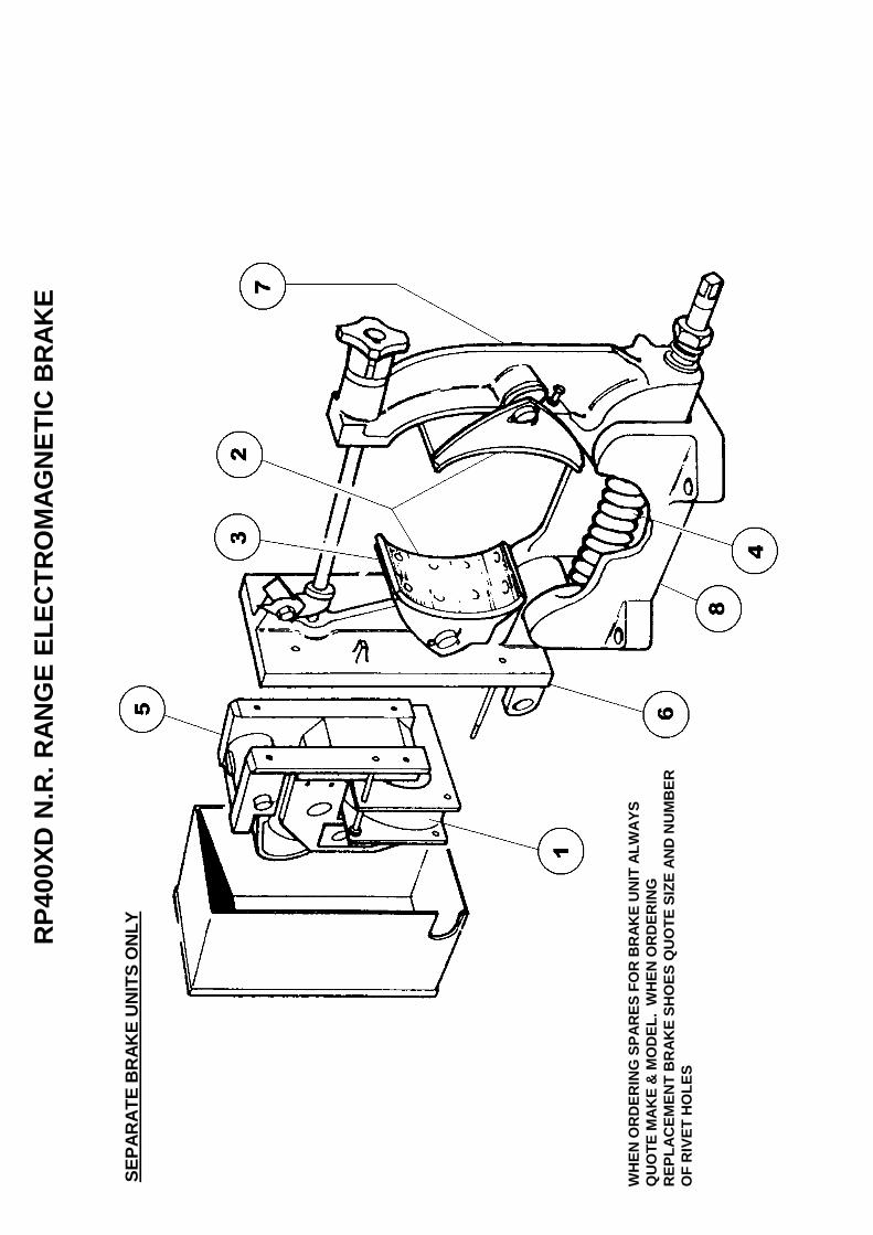
CR550115 Brake unit complete 11 CR550116 Electric Coil 12 CR550117 Brake Linings & Rivets 1 SET3 CR550118 Brake Shoes 24 CR550119 Torque Spring 15 CR550120 Magnet Unit (Less Coil) 16 CR550121 Magnet Carrier Arm (Less Shoe) 17 CR551022 Plain Arm (Less Shoe) 18 CR550123 Base 1
It is not possible to supply other major parts as separate items. If any other items are required it will be necessary to replace the complete brake assembly.This is due to the number of brake units fitted over the years from different manufacturers and the diffilculties encountered identifying the different types. When ordering spares please quote the voltage, make, model and if possible the serial number together with a full description of the part required. When ordering replacement brake linings please give the physical dimensions together with the number of rivet holes required.
RP400XD NR RANGE ELECTROMAGNETIC BRAKE UNITSEPARATE BRAKE UNITS ONLY

RP4
00XD
MAG
NET
IC B
RAK
E D
RU
M

1 CR520154 Magnetic Brake Drum Pins 32 41S05 Spring Washer 3/8" 33 2S04 Nut 3/8" B.S.F. 34 CR210188 Magnetic Brake Drum 15 CR230010 Magnetic Brake Flexible Disc 16 CR320058 Key Gib Head 10 X 8 X 60mm 17 CR230011 Magnetic Brake Coupling Pin 38 41S04 Spring Washer 5/16" 39 2S03 Nut 5/16" B.S.F 310 CR230112 Magnetic Brake Coupling 111 CR320011 Key Gib Head 3/8" 1
RP400XD MAGNETIC BRAKE DRUM

RP4
00XD
BAT
CH
WEI
GH
ER

1 CR091039 Weighbatcher Support Frame Assembly 12 CR150921 Bearing Plummer Block, 1.25" Bore 83 8S05G Bolt M12 x 55 84 7S05 Nut M12 505 17S06 Washer Spring M12 506 105S05 Washer Tapered M12 87 CR091039F Bearing Plate & Stop, Welded to item 1 48 CR261504 Runway Supports LH & RH 1PR9 52S05F Bolt Csk Hd M12 x 30 410 8S05B Bolt M12 x 30 2211 CR091040J Hopper Stops LH & RH, Welded to item 15 1PR12 CR220005 Limit Switch, Obsolete use item 12 Below12 CR229083 Limit Switch, CA12-G 113 CR532203 Support Plate Limit Switch 114 CR261508 Weighbridge, RP400 Standard 4' 2.25" Long 115 CR091040 Runway Assembly c/w item 11 116 8S05F Bolt M12 x 50 417 8S05M Bolt M12 x 80 418 8S05J Bolt M12 x 65 419 CR261505 Parallel Shaft Units 220 CR179002 Hydraulic Loadcell & Gauge Assembly 0-1000Kg Range 121 CR179003 Mountings, Anti Side Load
RP400XD WEIGHBATCHER ASSEMBLY

INTENTIONALLY BLANK PAGE

1 CR520520 Whirler Shaft 12 CR261471 Bearing Housing 13 CR532110 Bearing Cap 14 CR532111 Bearing Cap 15 CR532109 Spacer Top 16 CR569014 Lipseal 17 CR569016 Lipseal 18 CR150701 Bearing 19 CR150538 Bearing 110 52S05F S/Sunk Screw M12 x 30 611 CR219006 Whirler Blade Square, Mild Steel 311 CR219006SS Whirler Blade Square, Stainless Steel 311 CR219006SSA Whirler Blade Square, Stainless Steel, Angled 311 CR219006H Whirler Blade Square, Tungsten Carbide Coated 311 CR219006AH Whirler Blade Square, Tungsten Carbide Coated, Angled 311 CR219017 Whirler Blade, Two Blades, Tungsten Carbide Coated A/R11A CR219007 Blade Round, Mild Steel 111A CR219007SS Blade Round, Stainless Steel 112 CR539005 Retaining Washer 113 11S05F Screw Set M12 x 40 114 17S06 Washer Spring M12 316 CR539044 Sleeve 117 CR220156 Motor Electric 118 CR269165 Bracket 119 CR349006 Pulley 'V' Belt 120 CR349011 Bush Fenner Taperlock 121 CR349006 Pulley 'V' Belt 122 CR349002 Bush Fenner Taperlock 123 CR169005 Belt ''V' 224 CR091013 Belt Guard 125 CR329001 Key Parallel 126 CR329000 Key Parallel 127 11S05M Screw Set M12 x 70 228 7S05 Nut M12 229 131S01 Nipple Grease Straight 230 176S01 Cover Nipple Grease 231 CR269147 Support Whirler Motor 1
RP400XD WHIRLER ASSEMBLY

INTENTIONALLY BLANK PAGE

CROKER LOADER
WIRE ROPE RENEWAL PROCEDURE
1. Place the Hopper on the hopper stops. Loosen nut from rope anchor bolt,item 1, on one rope drum only, item 2.
2. Remove end of old wire rope from anchor bolt.
3. Fit end of new wire rope to anchor bolt and tighten nut.
4. Lay other end of new wire rope end to end with old wire rope removed inpart 2. Bind both ends together with sticky tape (electrical or maskingtape).
5. Carefully pull on the old wire rope to pull the new wire down to thebottom of the hopper and around the rear axle rope pulley, item 3, and upthrough the front axle rope guide, item 4.
6. Remove front axle rope retainer blocks, items 5 and 6, and slide onto thenew rope.
7. Continue to pull the wire and thread through the second rope guide, item7, and down around the second rope pulley, item 8, and up to the secondrope drum, item 9.
8. Remove old wire from second anchor bolt, item 10, on second ropedrum, item 9, and remove tape from ends of old and new wire.
9. Fit second end of new wire to second anchor bolt, item 10, on secondrope drum, item 9.
10. Tighten anchor bolt nuts on both rope drums.
11. The new wire should now run over the front edges of both rope drumsand down to front edges of both the lower axle rope pulleys, items 3 and8, and up the back of the rope pulleys to the rope guides, items 4 and 7,with both rope retainer blocks, items 5 and 6, located on the section ofwire rope between the two rope guides at the back of the hopper.
12. Start and stop the loader by hand, using the start and stop buttons, andtake out all the slack of the wire rope in the raise direction (see importantnote on page 30), ensuring that the wire slots into both axle rope pulleys,item 2 and 9, and that the wire has wound evenly onto both rope drums.Make sure the hopper is level and sitting on weigher track stops beforepositioning rope retainer blocks, items 5 and 6, approximately 2 inches

(50 mm) in board of rope guides, item 4 and 7, each side and make fastretainer blocks onto wire.
13. Check that both limit switches are working correctly and the magneticbrake applies correctly.
14. Make sure hopper clears both sides of rope drums at the top of itsoperation.
NOTE: Hopper reaches end of travel between rope drums.
IMPORTANT NOTE
Ensure that the slack wire is taken up in the raise direction and not the loweringdirection. If the rope is wound incorrectly in the reverse direction on to the ropedrums the hopper will not stop at the upper limit switch. It will continue until itmakes contact with the top of the structure and will continue to heave until thewire rope breaks, with the result , if both sides of the wire fail at the same time,that the hopper will drop to the bottom end of the skip track.

RP400XD WIRE ROPE RENEWAL PROCEDURE
WIRE ROPES
SAFETY NOTES
ALWAYS
Store and handle the wire rope correctly, wear protective gloves and eyeprotection.
Check the rope test certificate is still in date especially if the rope has beenin storage also check that the certificate is applicable to the rope.
Remove the rope from any reel or coil correctly and without kinking.
Only use correct end terminations and rope anchors.
Ensure that the rope is correctly located and seated on the rope drum.
Ensure that the rope is correct for the application and only use good qualityropes from reputable suppliers.
Inspect the wire rope for damage, wear, corrosion or abuse at the start ofeach shift.
Keep the wire rope clean and maintained in accordance with themanufacturers instructions.
NEVER
Try to shorten any wire rope by knotting.
Bend a wire rope over small radii.
Subject wire ropes to shock loadings.
Allow wire ropes to run over sharp edges or abrasive surfaces etc.
Subject wire ropes to extremes of temperature.
Use wire ropes with obvious signs of mechanical, corrosive or heat damage.
Use wire ropes that are worn, frayed, split or corroded.
STORAGE
Store wire ropes in a clean well ventilated, dry location preferablyundercover and protected from extremes of temperatures.
If site conditions are such that undercover storage is not possible cover therope with a waterproof cover and support clear of the ground.
Rotate stored wire ropes, reels or coils regularly to prevent migration of therope lubricant, particular in warm environments.
Be aware that subjecting wire ropes to extremes of temperature as can affectthe in service performance, high storage temperatures can reduce theeffective strength of the rope.
SAFETY
Running wire ropes are hazardous and should be guarded or personnelshould be prevented access to them whilst in motion.
Wire ropes develop broken strands during their working life which present ahazard to maintenance personnel, always wear suitable hand and eyeprotection when handling ropes.
Take care when unfastening a coiled rope as the inherent springiness whenreleased may cause it to strike attendant personnel or other equipmentcausing damage or injury.
Take care when removing worn, damaged or failed ropes from equipment asthey may be tightly coiled, grossly distorted and still retain their springiness.
IN SERVICE INSPECTION AND MAINTENANCE
Wire ropes used for lifting operations should be regularly inspected by acompetent person and inspection records kept upto date.

Inspections should not only concentrate on the rope but also extend to thecondition of sheaves, drums, guides etc.
Decisions on whether a wire rope is suitable for continued service shouldonly be made by a competent person.
IF IN DOUBT REPLACE THE ROPE.

INTENTIONALLY BLANK PAGE

INTENTIONALLY BLANK PAGE

OPERATING
AND
MAINTENANCE MANUAL
SECTION 6
ELECTRICAL SYSTEM
ELECTRICAL INFORMATION
1. The mixing pan and mixing star motors should be interconnected in the controlto operate at the same time, as it is important that both are working before a mixis added. Ensure that suitable overloads are fitted. The mixing pan and mixingstar rotate anti-clockwise when looking from the top.
NOTE: With motors 5.5 kw and above, use Star Delta Starters. Below this, use Direct on Line Starters.
2. When a loader is attached a direct on line reversing starter is required completewith suitable overloads. The loader winch rotates anti-clockwise looking fromthe rope drum end and when the raise button is pressed.
The upper and lower limit switches are positioned to break the electrical supplyto the loader motor when the loading hopper is in the required position at thetop and bottom of the runway.
3. The door control solenoid has to be energised when the mixer door is requiredin the open position.
It is advisable to mount the starters away from the machine on supports freefrom vibration.
4. IMPORTANT NOTICE: All work on plant electrics including control panelcircuits to be under taken by a suitably qualified and competent electricalperson. All wiring in exposed positions should be suitably protected orarmoured cable and protected by a suitable earth leakage circuit breaker.
5. The Mixing Star Dive and Pan Drive should be interconnected in order to startin the following sequence:- Mixing Star Motor Pan Drive Motor
6. When a Whirler is fitted the sequence should be:- Whirler Motor Mixing Star Motor Pan Drive Motor
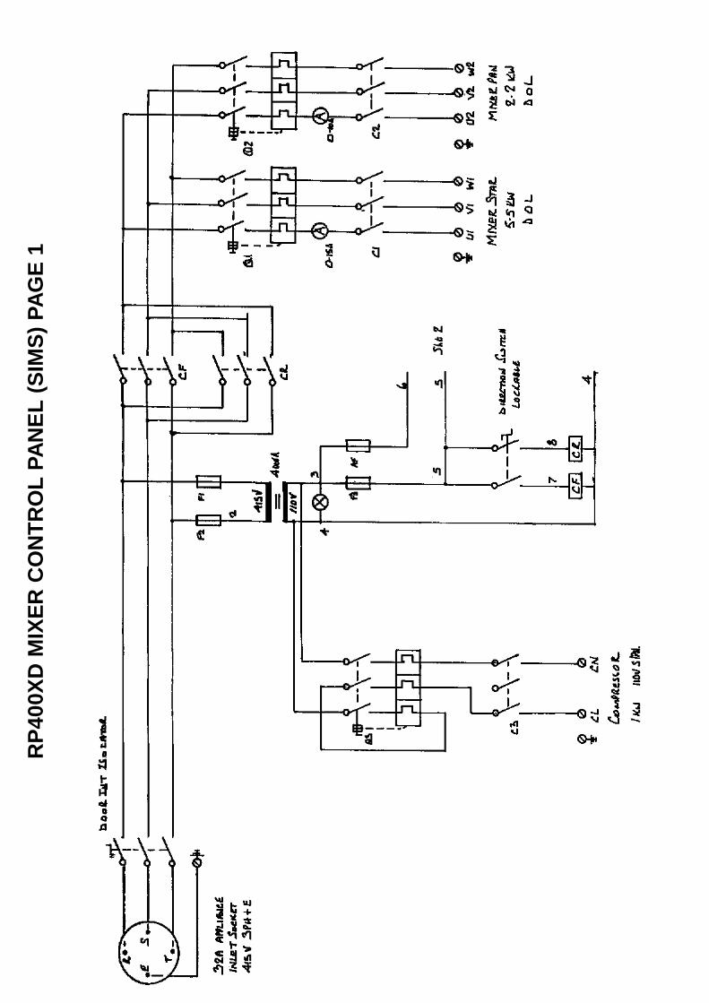
RP4
00XD
MIX
ER C
ON
TRO
L PA
NEL
(SIM
S) P
AGE
1
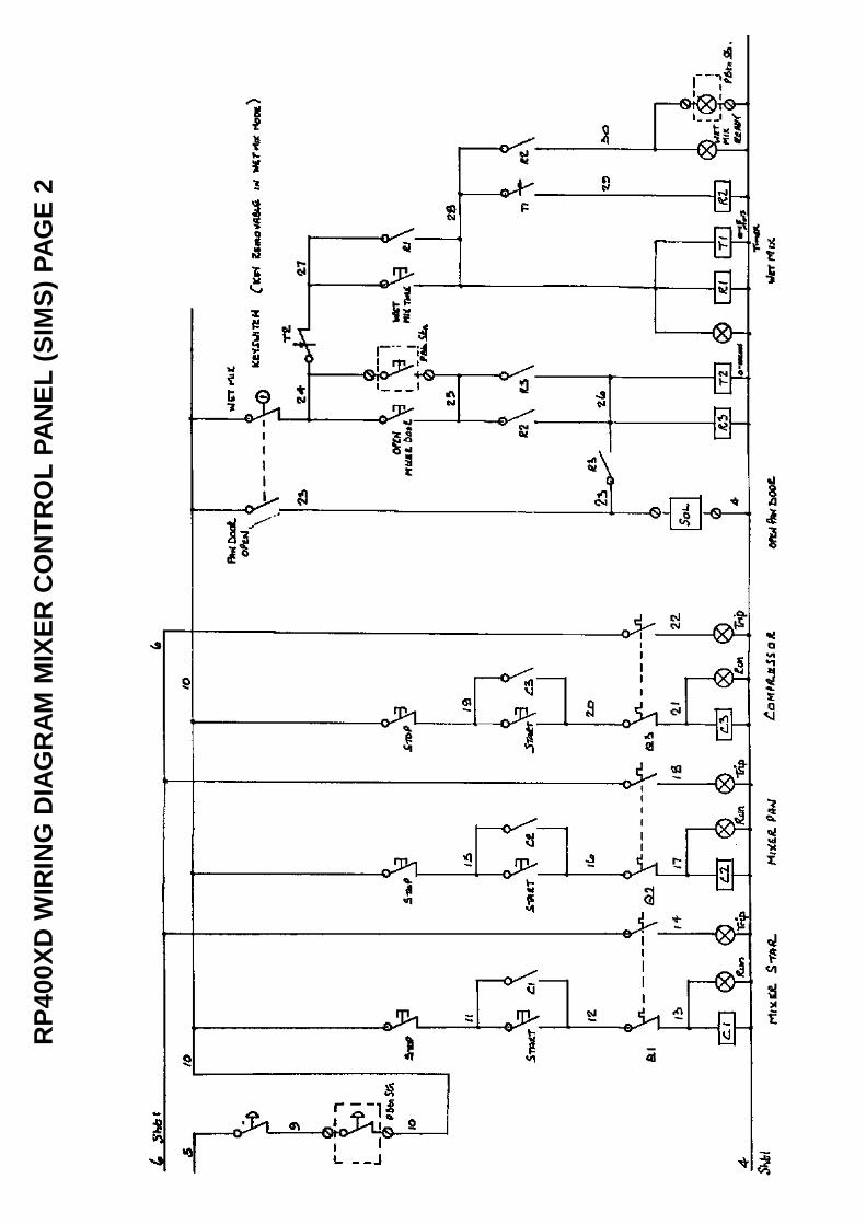
RP4
00XD
WIR
ING
DIA
GR
AM M
IXER
CO
NTR
OL
PAN
EL (S
IMS)
PAG
E 2

RP400XD WINCH MOTOR BRAKE WIRING
FLENDER MOTORS ABOVE 4KW
THREE PHASE A.C. BRAKE CONNECTEDACROSS MOTOR TERMINALS. DIRECT-ON- LINE STARTING METHOD ONLY
BRAKE WIRED ACROSS MOTOR 6 PINTERMINAL BLOCK
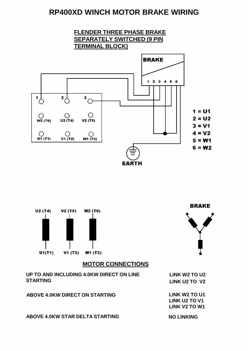
RP400XD WINCH MOTOR BRAKE WIRING
FLENDER THREE PHASE BRAKESEPARATELY SWITCHED (9 PINTERMINAL BLOCK)
MOTOR CONNECTIONSUP TO AND INCLUDING 4.0KW DIRECT ON LINESTARTING
LINK W2 TO U2LINK U2 TO V2
ABOVE 4.0KW DIRECT ON STARTING LINK W2 TO U1LINK U2 TO V1LINK V2 TO W1
ABOVE 4.0KW STAR DELTA STARTING NO LINKING

RP400XD FLENDER MOTOR WIRING DIAGRAM
MOTORS UPTO & INCLUDING 4.0Kw
SEE SEPARATE PAGE FOR MOTORS
5.5Kw AND ABOVE
UPTO & INC 4.0Kw

RP400XD FLENDER MOTOR WIRING DIAGRAM
MOTORS 5.5Kw AND ABOVE ONLY
SEE SEPARATE PAGE FOR MOTORS
4.0Kw & BELOW
5.5Kw & ABOVE

INTENTIONALLY BLANK PAGE
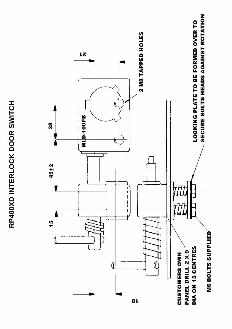
RP4
00XD
INTE
RLO
CK
DO
OR
SW
ITC
H

1 CR719072 Interlock Door MLD100FB A/R2 CR229093 Key MLK100A Code A A/R2A CR229094 Key MLK100B Code B A/R2B CR229124 Key MLK100C Code C A/R3 CR229125 Cap Dust MLM100 A/R
When ordering replacement keys quote code of interlock mechanism
MISTURA DOOR INTERLOCK MECHANISM

OPERATING
AND
MAINTENANCE MANUAL
SECTION 7
PNEUMATIC SYSTEM

SHUTDOWN PROCEDURE – PNEUMATICS
(This procedure to be read in conjunction with electrical procedure – see section six).
We Recommend
A lockable dump valve be fitted in the feed line to our mixing equipment (seedrawing below).
Prior to any maintenance, the mixing equipment must be isolated using the abovepadlockable shut off valve. When put to the dump position, air will be allowed tovent to atmosphere removing the potential stored energy hazard. With the system inthis condition, the mixer door will open and discharge blade will lower.
Important
Prior to entry into mixing pan, the air supply must be exhausted and isolated as above. Check door is fully open and the discharge blade rests upon pan base beforecommencing maintenance/cleaning. Also check that the pressure gauge reads zero.
Should blade or door remain up or partially closed, it is imperative that the cause isinvestigated and dealt with prior to entering mixing pan. See maintenance section.
SHUT OFF VALVE
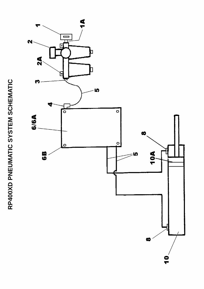
RP4
00XD
PN
EUM
ATIC
SYS
TEM
SC
HEM
ATIC

1 CR119347 Shut Off Valve 11A 191S03 1/2"-1/2" BSP Male/Male Nipple Adaptor Tapered 12 CR110005 Air Service Unit/Regulator/Lubricator 12A 11S03C Screw Set Air Unit/Regulator Retaining 42B 267S05 Washer Flat 82C 17S04 Washer Spring 42D 7S03 Nut 4
* CR119373 Bowl Regulator 1* CR119374 Bowl Lubricator 1* CR119375 Filter Repair Kit 1* CR119376 Filter Element 1* CR119377 Lubricator Repair Kit 1* CR119378 Pressure Gauge 1* CR119379 Bracket Mounting 2* CR119380 Knob Regulator 1
3 CR119261 1/2" BSP Male x 12mm Fem Push In Straight Adaptor 14 CR119129 3/8" BSP Male x 12mm Female Push In Elbow 15 CR119119 12mm Diameter Plastic Air Hose A/R6 CR119210 Electric/Pneumatic Solenoid Control Box 16A CR119346 Electric/Pneumatic Solenoid Control Box 60 Hz 16B 11S03C Screw Set Control Box Retaining 46C 267S05 Washer Flat 86D 17S04 Washer Spring 46E 7S03 Nut 4
8 CR119129 3/8" BSP Male x 12mm Female Push In Elbow, Discharge DoorCylinder, both ends 2
10 CR110298 Pneumatic Cylinder Discharge Door 110A CR110325 Seal Kit For Item 10 1
12 V2003253 Cable Tie Nylon Long (not illustrated) A/R13 V2003111 Cable Tie Nylon short (not illustrated) A/R
14 CR119215 M12 Female- M12 Male Push In Elbow, if required A/R
15 CR119239 Compressor 24 Litre Reciever No Illustrated 116 CR119144 Adaptor 1/4" B.S.P.- 12mm Push In Fitting Not Illus 1
17 CR119153 Hose Clip Double (not illustrated) 818 CR119288 Hose Clip (not illustrated) 219 CR119289 Screw Self Tapping (not illustrated) 10
CR119208 M12 Male - M8 Female Straight Push In Reducer A/RCR119133 8mm Diameter Plastic Air Hose A/R
The following alternative items are used to reduce from 12mm diameter Air Hose to 8mm diameter Air Hose if required
RP400XD PNEUMATIC CIRCUIT (PLASTIC PUSH IN FITTINGS)
Available spares for Air Service Unit itemised below:

INTENTIONALLY BLANK PAGE

OPERATING
AND
MAINTENANCE MANUAL
SECTION 8
MISCELLANEOUS

MISCELLANEOUS
8..1 NOISE DETAILS
Measured in accordance with Directive 79/113EEC at four points around the machineat 1 metre radius and at a height of 1 metre the noise did not exceed 85LPA

INTENTIONALLY BLANK PAGE

INTENTIONALLY BLANK PAGE

INTENTIONALLY BLANK PAGE

INTENTIONALLY BLANK PAGE

OPERATING
AND
MAINTENANCE MANUAL
SECTION 9
ELECTRONIC LOADCELL & INDICATOR/READOUT BOX