Batch Mixer Inspection for Optimal Performance - Rubber News
50
Batch Mixer Inspection for Optimal Performance September 2015 Bob McNabb HF Mixing Group Sales Manager, North America
-
Upload
khangminh22 -
Category
Documents
-
view
6 -
download
0
Transcript of Batch Mixer Inspection for Optimal Performance - Rubber News
Batch Mixer Inspection for Optimal Performance
September 2015
Bob McNabbHF Mixing Group
Sales Manager, North America

HF MIXING GROUP
2

HF MIXING GROUP
MIXING GROUPFreudenberg, Germany
GROUP Harburg-Freudenberger Maschinenbau GmbH
TireTech GROUPHamburg, Germany
Press+LipidTechHamburg, Germany
• Batch Mixing Equipment
• Continuous Mixing Equipment
Harburg-Freudenberger Maschinenbau
GmbH
Freudenberg, Germany
Rubber Machinery, IncTopeka, KS, US
Farrel
Rochdale, UK
Pomini
Rescaldina, Italy
Farrel Pomini
Ansonia, US
HF NaJUS, a.s.
Dubnica n. Vahom , Slovakia
• Extrusion Manchinery
• Tire Building Machines
• CuringPresses
Harburg-Freudenberger Maschinenbau
GmbHHamburg, Germany
Belišće d.o.o.Belišće, Croatia
Rubber Machinery, Inc.Akron, OH, US
3

Mixer Inspection and Maintenance Service
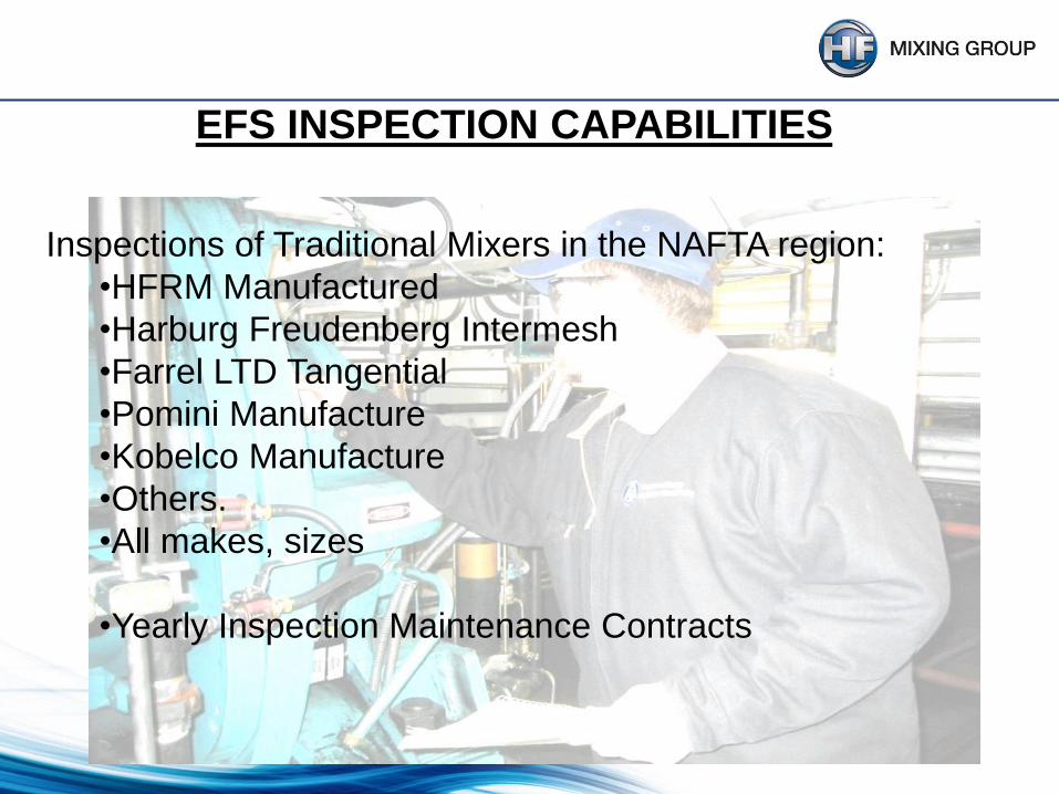
EFS INSPECTION CAPABILITIES
Inspections of Traditional Mixers in the NAFTA region:
•HFRM Manufactured
•Harburg Freudenberg Intermesh
•Farrel LTD Tangential
•Pomini Manufacture
•Kobelco Manufacture
•Others.
•All makes, sizes
•Yearly Inspection Maintenance Contracts

Inspection and condition assessment included in a preventive
maintenance program together with knowledge of component life and
machine history can be used to establish a wear trend to form the
foundation for a mechanical maintenance program to ensure peak mixer
performance.
So how do we get there?

Know your mixer condition.
Knowledge of the Individual mixer by regular INSPECTIONS
History of the mixer needs to be established and updated
at regular yearly intervals
•Document the mixer specifications
•Document the compounds mixed
•Confirm fill factors
•Note the shifts per day
•Note pounds of rubber produced
•Update component parts life
expectancy
•Reference past machine history
•Detail the current condition
of the mixer
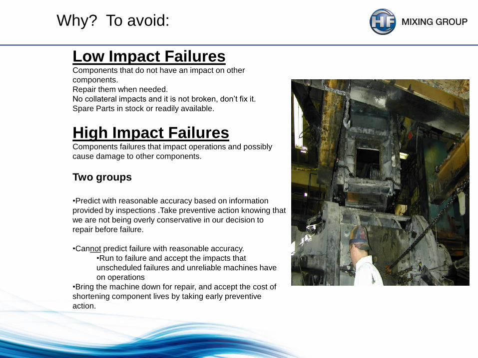
Low Impact FailuresComponents that do not have an impact on other
components.
Repair them when needed.
No collateral impacts and it is not broken, don’t fix it.
Spare Parts in stock or readily available.
High Impact FailuresComponents failures that impact operations and possibly
cause damage to other components.
Two groups
•Predict with reasonable accuracy based on information
provided by inspections .Take preventive action knowing that
we are not being overly conservative in our decision to
repair before failure.
•Cannot predict failure with reasonable accuracy.
•Run to failure and accept the impacts that
unscheduled failures and unreliable machines have
on operations
•Bring the machine down for repair, and accept the cost of
shortening component lives by taking early preventive
action.
Why? To avoid:

• Mixer Inspection To Determine:
– Process control remains accurate
– Lubrication program is adequate
– Machine adjustments are indicated
– Wear component replacement is warranted
– Planning for future Capital Expenditures.


E.L.C.I.
Equipment Life Cycle Indicator
E.L.C.I. is a data warehouse system which is able to give a forecast of the
remaining main components life-time of the internal mixer on the basis of
client-specific and tech-nological basis information and the process experience
of our engineers as well as based on information taken from inspections of
the internal mixer.
With the help of the results coming from this system future repairs or
replacements of main components can be planned accurately timed and
unplanned breakdowns/shut-downs of the internal mixer including all negative
consequences can be avoided.

Rotor Tip to Chamber Bore
Measure always from rotor top/wing!
This means, you have to turn the rotor.

13
Mixing Chamber
E.L.C.I. Description
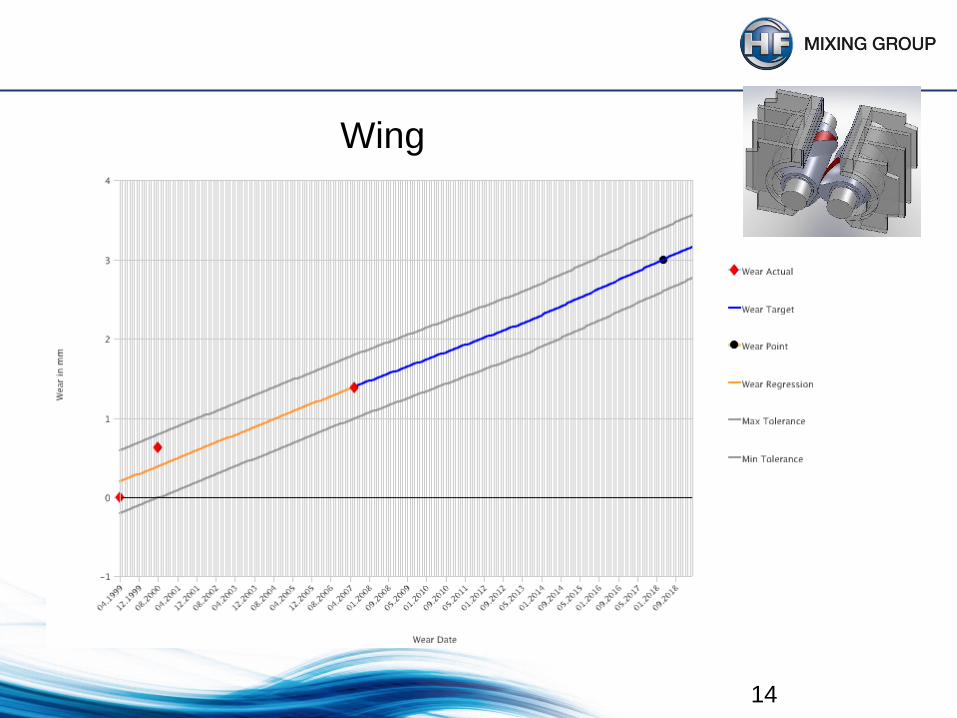
14
Wing

15
Rotor End to End Plate
e
f
g
h
drive side
16
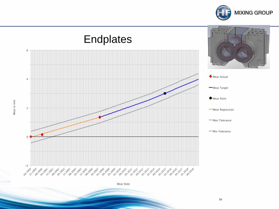
Endplates

Point m (from endplate to endplate)
m

Point l
l

Mixing Chamber Throat (A) and also Feeding
Device (B)
w - y
u - v

s - x t - v
st - uv
Mixing Chamber Throat (A) and also Feeding Device (B)

Shaft (measurement in the area of the corner
ledges)
w
s

Shaft (measurement in the area of the corner ledges)
x
u

Rotors: medium wear
23
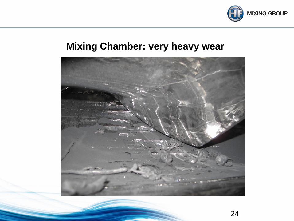
Mixing Chamber: very heavy wear
24

GK 320 E Comparison of Endplates Between Mixers
wear
in m
m
running time in years
25

GK 320 E Comparison of Rotor Front Side Left
wear
in m
m
running time in years
26

GK 320 E Comparison of Rotor Wings Between Mixers
wear
in m
m
running time in years
27
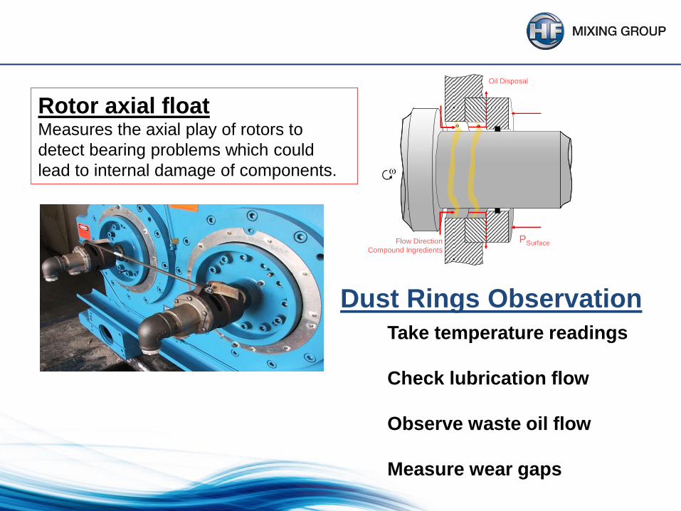
Rotor axial floatMeasures the axial play of rotors to
detect bearing problems which could
lead to internal damage of components.
PSurfaceFlow Direction
Compound Ingredients
Oil Disposal
Take temperature readings
Check lubrication flow
Observe waste oil flow
Measure wear gaps
Dust Rings Observation


Electronic device to determine the gap measurements. There are up to three ports available.
INTRODUCING ELECTRONIC GAP CONTROL TECHNOLOGY
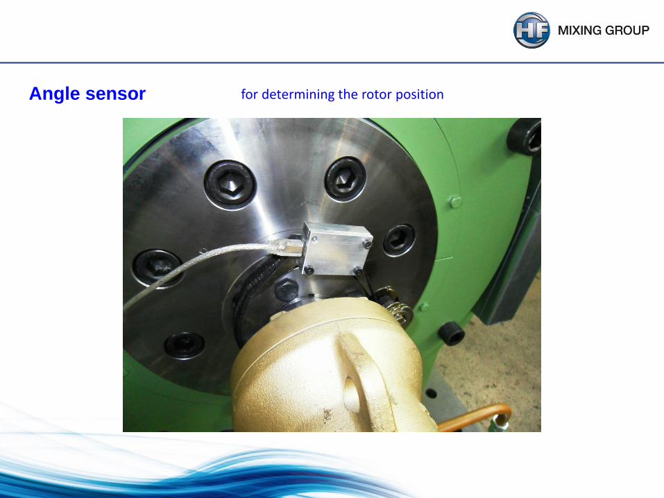
Angle sensor for determining the rotor position

Measuring method with new sensor
The sensor is fixed on the rotor with a magnet and adhesive tape
min. gap: 5 mmmax. gap: 14 mm


Measuring grid
measuring points radial: 19
measuring points axial: 9
measuring points total: 171
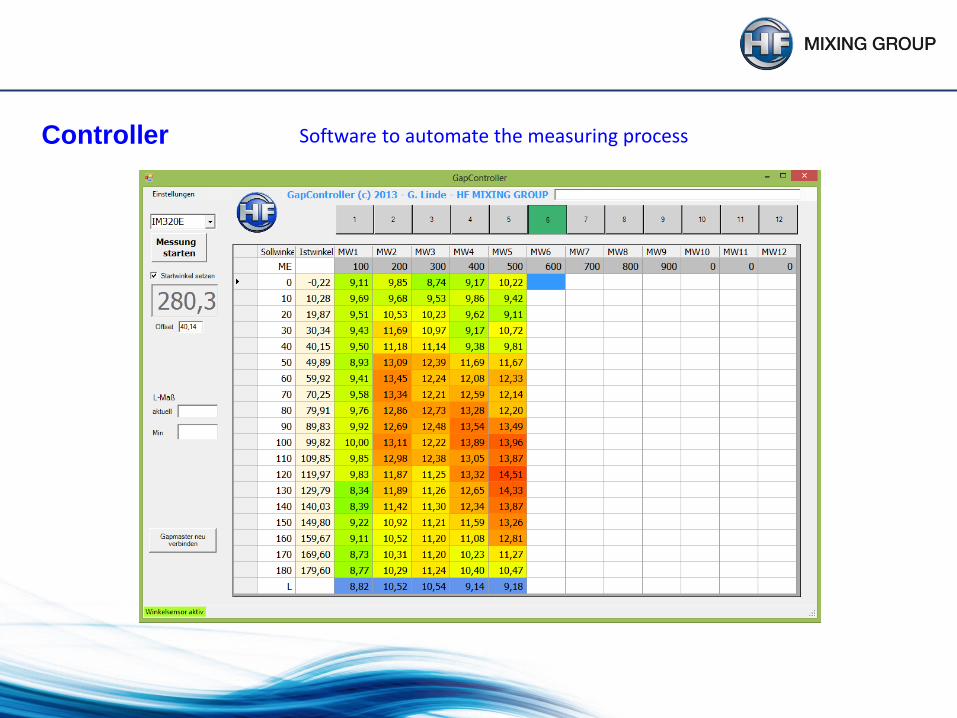
Controller Software to automate the measuring process

Evaluationof the measurement result
gaps depicted in colours

Result
the new measuring method provides exhaustive precise and replicable values.
nearly automated measuring method with fast and error-free sequences
Knowledge:
a visual inspection is still needed
the mixing chamber must be cleaned very carefully
the manual rotation of the rotors need to be facilitated
38
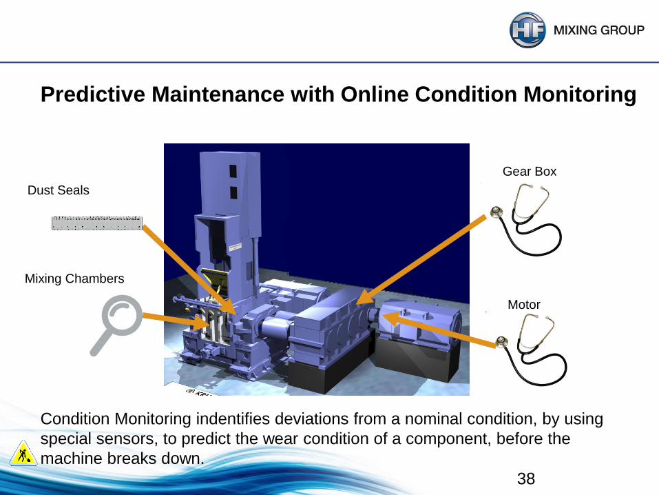
Predictive Maintenance with Online Condition Monitoring
Dust Seals
Mixing Chambers
Gear Box
Motor
Condition Monitoring indentifies deviations from a nominal condition, by using
special sensors, to predict the wear condition of a component, before the
machine breaks down.

Online-Chamber Side thickness measurement system
Ultrasonic
Sensor
area of “gun-drilled”
cooling channels
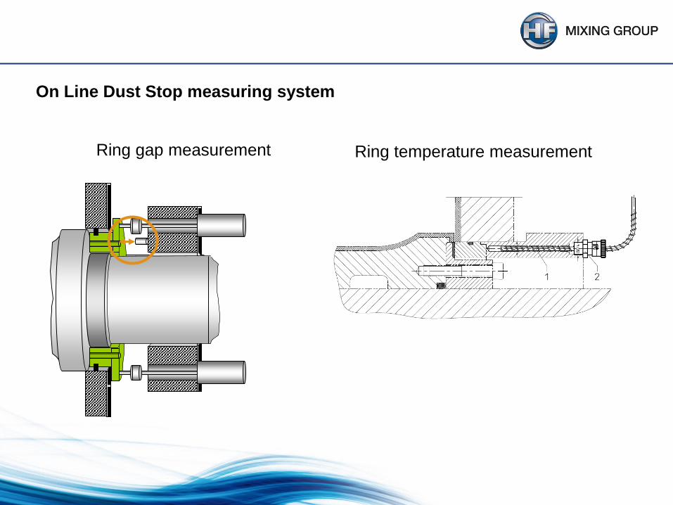
On Line Dust Stop measuring system
Ring gap measurement Ring temperature measurement

Dust Stop without sufficient pressure or out of adjustment
41
42
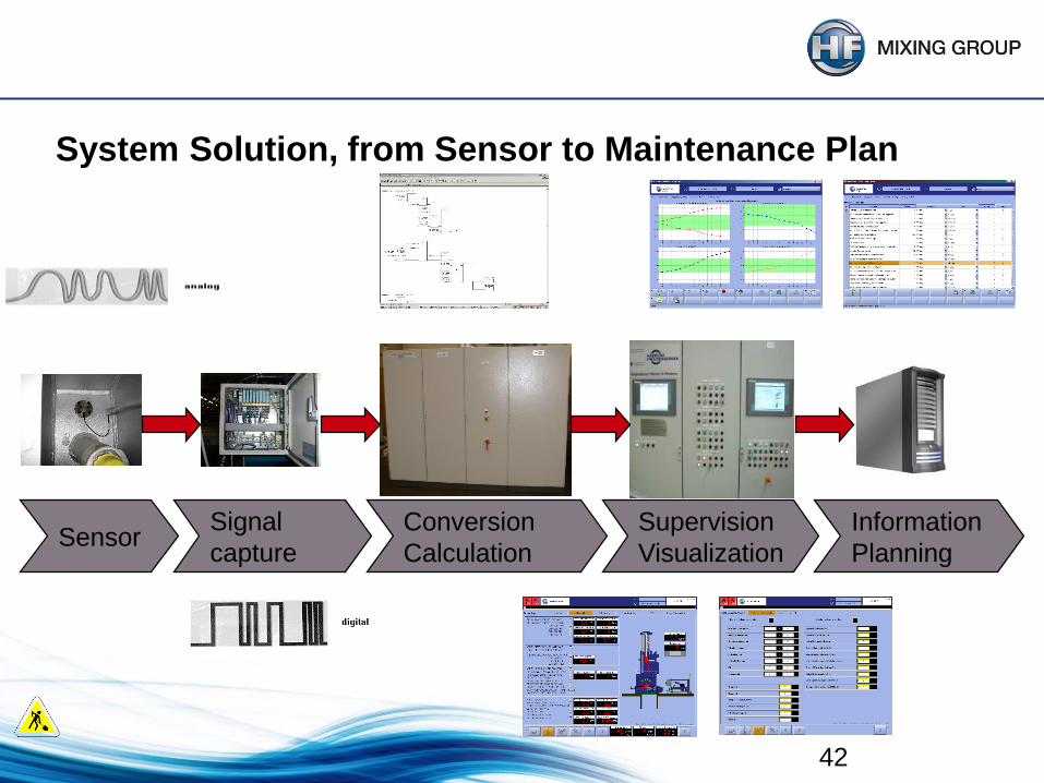
System Solution, from Sensor to Maintenance Plan
Information
Planning
Supervision
Visualization
Conversion
Calculation
Signal
captureSensor
43
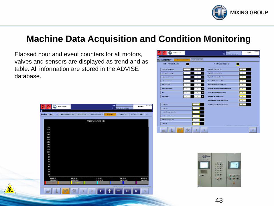
Machine Data Acquisition and Condition Monitoring
Elapsed hour and event counters for all motors,
valves and sensors are displayed as trend and as
table. All information are stored in the ADVISE
database.

SUPPORT AND AUXILIARY EQUIPMENT
Dust ring lubrication
Operation of pump
Leakage of lines
Flow rates
Motor/Gear/Coupling
Grease lubrication
Operation of pump
Canister Level
Leakage of lines
Flow rates
Hydraulic System
Pressure, system
Leakage
Pump
Temperatures
Functions
Timing of
Ram
Latch
Door
Piping Tightness
Zone Flows
Temperatures
Inflow
Outflow

Mixer Drive Checks
Motor
Noise or vibration
Gearbox
Lubricator Function
Oil level
Oil contamination
Bearing
temperatures
Alignments
HS Motor to
Gearbox
LS Gearbox to mixer
Couplings
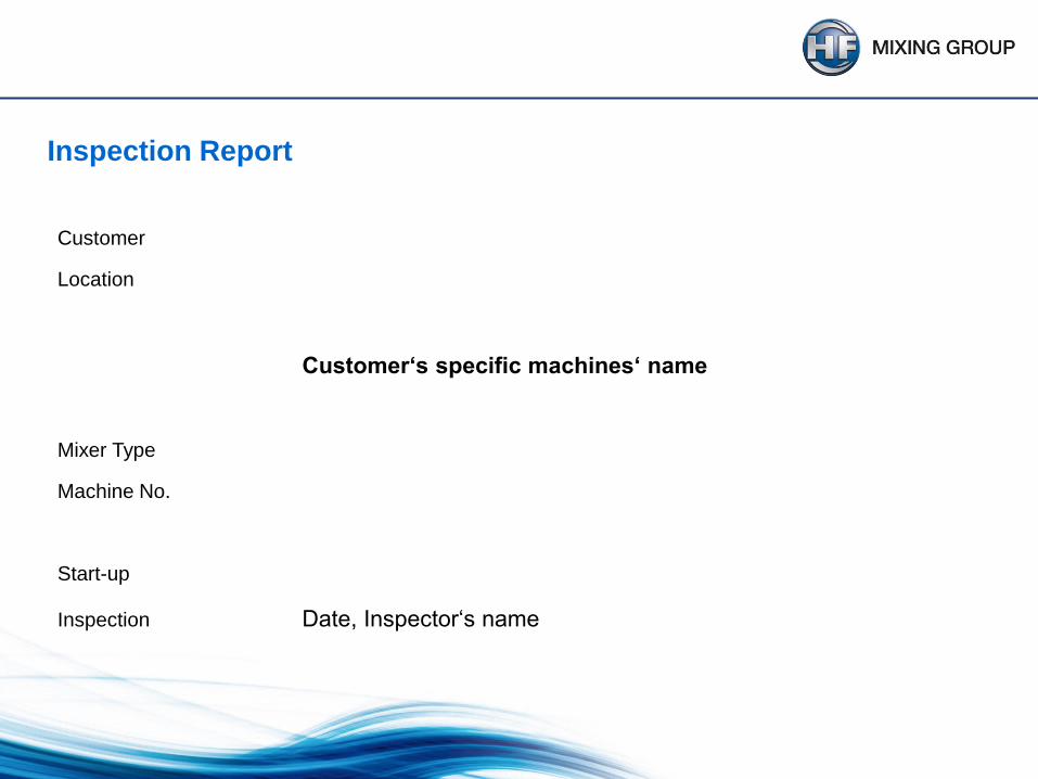
Customer
Location
Customer‘s specific machines‘ name
Mixer Type
Machine No.
Start-up
Inspection Date, Inspector‘s name
Inspection Report

Summary of the Inspection
• Rotors ZZ-2
- medium wear
• Endplates
- medium wear, deformed
• Dust Sealing
- medium to heavy wear
- lubrication not running
• Mixing Chamber
- very heavy wear
• Drop Door
- medium wear
• Interlocking Latch + Interlocking Plate
- heavy wear
• Feeding Hopper
- very heavy wear
- chromium-plating broken out
• Feeding Door
- material leakage

Maintenance
• Maintenance should be improved.
HF recommendations:
• Replace the feeding hopper and ram, including all guiding and sealing
elements.
• Replace the mixing chamber
• Replace the dust sealing.
• Replace the interlocking latch and the interlocking plate.
• Clean and check all elements of the lubrication pumps.
• Replace safety valves at distributor mixing block.
• Check the cooling system (rotors are very hot).
• Gearbox should be checked by manufacter.
• INSTALL ORIGINAL FEEDING DOOR SAFETY PIN !!! MORTAL DANGER !!!
Next inspection due...........

MAITENANCE INSPECTION SUMMARY
It is vital to implement the best tools and techniques available for
inspection and condition assessment of all internal mixers. Inspection
technicians are the CUSTOMERS eyes and ears. They must posses
the training and tools needed to inspect and report, so good business
decisions may be made.
This is what has driven the
HF Mixing Group to develop
and release these new
inspection technologies.