Inspection of Lined Pipelines With In-line Inspection Tools
6
1 GOEC11-GOXC11-007 Inspection of Lined Pipelines With In-line Inspection Tools A. SHATAT Russell NDE Systems Inc M. KORZ Russell NDE Systems Inc D. RUSSELL Russell NDE Systems Inc This paper has been selected for presentation and/or publication in the proceedings for the 2011 Gas and Oil Expo and Conference [GOEC11]. The authors of this material have been cleared by all interested companies/employers/clients to authorize dmg events (Canada) inc., the conference producer, to make this material available to the attendees of GOEC11 and other relevant industry personnel. Abstract The inspection of pipelines that contain epoxy, HDPE or cement mortar liners is difficult with conventional MFL and UT pigs. The liners can either be damaged by such pigs or are too thick for the sensors to read the steel thickness through the liner. A new technology for the assessment of the steel host pipe, employing low frequency AC fields is presented which overcomes these restrictions. Results from field trials are presented showing the success of the technology in the Alberta Oil Patch. Introduction Steel is economical to produce and exhibits excellent strength properties for pressure pipeline applications. Over the past 20 years, continued (significant) improvements to the tensile strength properties of pipe steel have made steel the material of choice in oil and gas pipelines. Certain pipeline products require special consideration for transport in steel pipe. Examples are corrosive products from sour fields and erosive slurries in oil sand operations. Changing the pipe material to stainless steel or hardened high-strength alloys would be cost prohibitive. Instead pipe development has focused on combining the desirable properties of carbon steel with internal liners. The liners are specifically formulated to handle the aggressive products transported by the pipe. Over the past three decades a variety of new lining technologies has been developed. The advancements have been driven not only by the need to protect pipes, but also by the desire to cost-effectively rehabilitate existing steel pipelines. As internal liners have become accepted as an effective means of protecting new pipe and rehabilitating old pipe, the installed base has grown steadily. To ensure the safe operation of lined pipelines, it is important that inspection technologies are developed that can inspect the host steel pipe without damaging the protective internal liners. Internal liners cover a large spectrum of materials and applications. This paper focuses on the inspection of pipe with internal HDPE liners. It should be understood that the same inspection technology has been successfully deployed in phenolic, nylon and cement lined pipe.
-
Upload
khangminh22 -
Category
Documents
-
view
11 -
download
0
Transcript of Inspection of Lined Pipelines With In-line Inspection Tools
1
GOEC11-GOXC11-007
Inspection of Lined Pipelines With In-line Inspection Tools
A. SHATAT Russell NDE Systems Inc
M. KORZ Russell NDE Systems Inc
D. RUSSELL Russell NDE Systems Inc
This paper has been selected for presentation and/or publication in the proceedings for the 2011 Gas and Oil Expo and Conference [GOEC11]. The authors of this material have been cleared by all interested companies/employers/clients to authorize dmg events (Canada) inc., the conference producer, to make this material available to the attendees of GOEC11 and other relevant industry personnel.
Abstract The inspection of pipelines that contain epoxy, HDPE or
cement mortar liners is difficult with conventional MFL and UT pigs. The liners can either be damaged by such pigs or are too thick for the sensors to read the steel thickness through the liner. A new technology for the assessment of the steel host pipe, employing low frequency AC fields is presented which overcomes these restrictions. Results from field trials are presented showing the success of the technology in the Alberta Oil Patch.
Introduction Steel is economical to produce and exhibits excellent
strength properties for pressure pipeline applications. Over the past 20 years, continued (significant) improvements to the tensile strength properties of pipe steel have made steel the material of choice in oil and gas pipelines. Certain pipeline products require special consideration for transport in steel pipe. Examples are corrosive products from sour fields and erosive slurries in oil sand operations. Changing the pipe material to stainless steel or hardened high-strength alloys would be cost prohibitive. Instead pipe development has focused on combining the desirable properties of carbon steel
with internal liners. The liners are specifically formulated to handle the aggressive products transported by the pipe.
Over the past three decades a variety of new lining
technologies has been developed. The advancements have been driven not only by the need to protect pipes, but also by the desire to cost-effectively rehabilitate existing steel pipelines. As internal liners have become accepted as an effective means of protecting new pipe and rehabilitating old pipe, the installed base has grown steadily. To ensure the safe operation of lined pipelines, it is important that inspection technologies are developed that can inspect the host steel pipe without damaging the protective internal liners.
Internal liners cover a large spectrum of materials and
applications. This paper focuses on the inspection of pipe with internal HDPE liners. It should be understood that the same inspection technology has been successfully deployed in phenolic, nylon and cement lined pipe.

2
HDPE Liners Internal thermoplastic liners have been a well-established
and cost-effective means of internally protecting carbon steel pipelines1. High Density Polyethylene (HDPE) is typically the material of choice due to low cost and availability. In addition, HDPE is chemically resistant and has excellent erosion resistance in slurry lines. Over the past two decades, HDPE liners have been installed in crude oil, oil emulsion, produced water, sour and wet gas, slurry and injection lines1. Because of the low hoop strength of HDPE, an HDPE liner is usually applied as a tight-fit liner relying on the host pipe for containing pressure.
An important consideration in gas lines is the fact that
HDPE is permeable, which means that product may permeate through the liner to the annulus between pipe and liner. The trapped gasses can cause liner collapses during pressure cycling. This effect is accumulative, meaning that initially the liner is just forced away from the pipe wall; however during subsequent pressure cycles the liner collapse will accelerate as the size of the annulus (and the amount of trapped molecules) grows1. To address this problem, HDPE liners have been designed with increased wall thickness to allow for the addition of axial channel-grooves on the outside of the liner. The grooves are collection points for permeated gasses, which travel in the channels to monitoring vent stations.
Why inspect HDPE Lined Pipe Liners are designed to protect the inside of pipelines. In
some applications there is a potential for internal corrosion on the steel pipe. Externally, pipes are protected with coatings backed-up by cathodic protection systems. Coating damage introduced during installation or by damage by third parties can result in external corrosion (besides the external mechanical damage). The level of integrity reduction will depend on the extent of the damage and local soil conditions.
On the inside of the pipe, some fluids trapped in the
annulus can potentially create corrosive environments. The accumulation of methanol (used for hydrate control and de-icing) and water in the annulus of HDPE lined pipelines transporting wet and sour gas, is suspect to have resulted in the reported failure of an HDPE lined pipeline2.
Although HDPE liners have some intrinsic ability to span
gaps in the pipe wall and thus prevent leaks, the hoop strength is not high enough to prevent rupture type failures. Given the nature of the products typically transported in lined pipes, it is critical that premature rupture type failures are prevented in HDPE lined pipelines. RFT inspections therefore represent an important means for detecting both internal and external corrosion that can lead to pipeline failures.
Most traditional pipeline inspection technologies require
contact with the pipe wall to assess the wall thickness. These technologies rely on the pipe wall contact to couple in either magnetic flux or ultrasound. Thick HDPE liners interfere with the coupling and therefore prevent the effective use of these technologies. In addition, standard inspection tools are not designed to accommodate “soft” thermoplastic liner
materials and the inspection will result in scrapes, gouges and other mechanical damage to the HDPE liners.
Remote Field Testing (RFT) is a pipeline inspection
technology that does not require intimate contact with the metallic pipe wall. The technique has been deployed in water lines since the mid 1990s. In most unlined metallic water mains heavy internal scaling prevents direct contact with the pipe wall, again limiting the effectiveness of the traditional magnetic and ultrasonic inspection technologies. RFT inspection tools for water lines have typically been deployed by tether from a single access due to the lack of launch and receive stations. The tether is also used for providing power to the RFT inspection tool3.
Given the relatively heavy thickness of HDPE liners and
the need to prevent damage to the liner, RFT technology is particularly well suited to inspect HDPE lined pipe. This paper describes the basic technology, a custom-developed RFT inspection tool, and presents the key results obtained from RFT field inspections of lined carbon steel pipe.
Remote Field Testing (RFT) In-line Inspection Tools
The RFT effect was first noted in the 1940’s and was patented by W.R.Maclean in 19514. In the late 1950s Tom Schmidt at Shell Development independently rediscovered the technique while developing a tool for the inspection of oil well casings5. Schmidt spearheaded the development of the technique and branded it “Remote Field Eddy Current”, in order to distinguish it from conventional Eddy Current Testing (ECT). The technique as used in industry is now commonly referred to as RFT, or “remote field testing”. The name “Remote Field Technique” minimizes confusion with ECT, and underlines the magnetic field interactions exhibited by RFT.
Remote Field Technology tools work by detecting changes
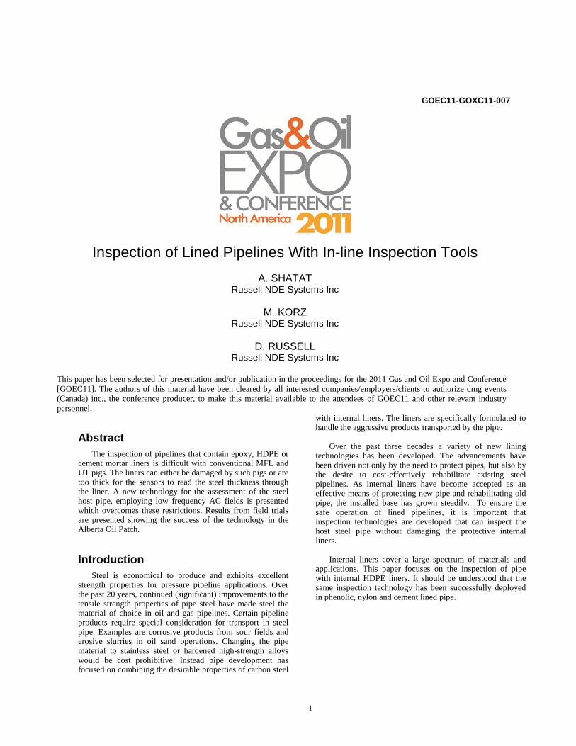
in an AC electromagnetic field that is generated by the tool and interacts with the metal in the encompassing pipe. The field is generated by the exciter section of the tool and detected by an array of receivers. On board electronics measure the time delay (phase shift) and the signal strength (Amplitude) of the AC electromagnetic signal. The receivers are positioned circumferentially so that they essentially are sensitive to the many clock locations of the pipe circumference. A basic RFT setup is shown in figure 1.
The exciter and detectors are separated by a distance
greater than 1.5 times the pipe diameter. The actual separation depends on the application, but will always be a minimum of 1.5 pipe diameters. It is this separation that gives RFT its name - the detector measures the EM field remote from the exciter. Although the fields have become very small at this distance from the exciter, they contain information on the full thickness of the pipe wall.
Remote Field is also known as a through-transmission
technique, highlighting that the signals measured by the tool actually come from outside the pipe. Due to eddy-currents in the pipe wall, any direct electromagnetic coupling from the
3
exciter section to the detector section (along the inside of the pipe) is heavily attenuated. Poynting vector calculations performed as part of Finite Element studies have shown that the dominant signals measured by RFT detectors actually follow an indirect coupling path along the outside of the pipe6. This is schematically indicated in figure 1 by the “Energy Flow Path”. Because this external coupling path includes the pipe wall, the signals measured by the detectors contain information on the thickness of the pipe.
Consequently, an RFT tool that is tuned to the
electromagnetic coupling along the outside of the pipe can determine the thickness of the pipe wall – even if the tool is dimensionally smaller than the pipe ID. This through-transmission characteristic makes RFT an attractive technology for high lift-off inspections since the tools can be (significantly) undersized w.r.t. the inside diameter (ID) of the pipe. Typical high-lift-off applications include scaled or lined pipelines, lines with more than one pipe size, and pipes with tight (small radius) elbows. Because RFT does not magnetically saturate the pipe wall, RFT tools will detect magnetic permeability changes as well as changes in the wall thickness.
For the successful inspection of HDPE lined pipe, the
traditional waterline RFT tools had to be customized/re-engineered. Some of the main additional design criteria that needed to be fulfilled:
1. Higher Operating Pressures (min 600 PSI). 2. On board battery power to support Free Swimming
Operation. 3. Matching the internal diameter (ID) of HDPE lined
pipe (which will be very different from the (standard) unlined steel pipe ID.
4. Ability to accommodate limited amounts of liner collapse.
5. Incorporate “soft –touch” materials on the outside of the tool to prevent damage to the internal liner.
6. Ability to accommodate oversize pipes. The lined pipe sections are occasionally interrupted by above ground risers that are unlined and can include valving and other ID changes. The tool must be able to bridge these internal upsets and transitions.
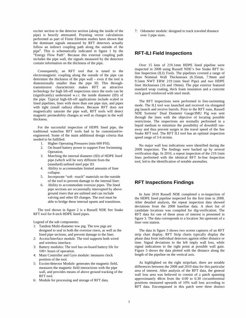
The tool shown in figure 2 is a Russell NDE See Snake
RFT tool for 8-inch HDPE lined pipes. Legend of the sub components: 1: Tandem Multi-diameter tow pig. The tow pigs are
designed to seal in both the oversize risers, as well as the lined pipe sections, and prevent damage to the liner.
2: Access/Interface module. The tool supports both wired and wireless interface.
3: Battery modules: The tool has on-board battery life for 100+ hours of operation.
4: Main Controller and Gyro module: measures clock position of the tool.
5: Exciter/detector Module: generates the magnetic field, measures the magnetic field interactions with the pipe wall, and provides means of above ground tracking of the RFT tool.
6: Module for processing and storage of RFT data.
7: Odometer module: designed to track traveled distance over 3 pipe sizes.
RFT-ILI Field Inspections
Over 15 kms of 219.1mm HDPE lined pipeline were
inspected in 2008 using Russell NDE’s See Snake RFT In-line Inspection (ILI) Tools. The pipelines covered a range of three Nominal Wall Thicknesses (6.35mm, 7.9mm and 9.5mm NWT ERW 219.1mm Steel Pipe) and two HDPE liner thicknesses (16 and 19mm). The pipe exterior featured standard wrap coating, thick foam insulation and a concrete rock guard reinforced with steel mesh.
The RFT inspections were performed in free-swimming
mode. The ILI tool was launched and received via elongated pig launch and receive barrels. Prior to the RFT runs, Russell NDE Systems’ Dual Diameter Gauge/IMU Pig was sent through the lines with the objective of locating possible restrictions. The inspections are normally performed in a liquid medium to minimize the possibility of downhill run-away and thus prevent surges in the travel speed of the See Snake RFT tool. The RFT ILI tool has an optimal inspection speed range of 3-6 m/min.
No major wall loss indications were identified during the
2008 inspection. The findings were backed up by several verification digs. In 2010, a repeat inspection of the 219.1mm lines performed with the identical RFT In-line Inspection tool, led to the identification of notable anomalies.
RFT Inspections Findings
In June 2010 Russell NDE completed a re-inspection of
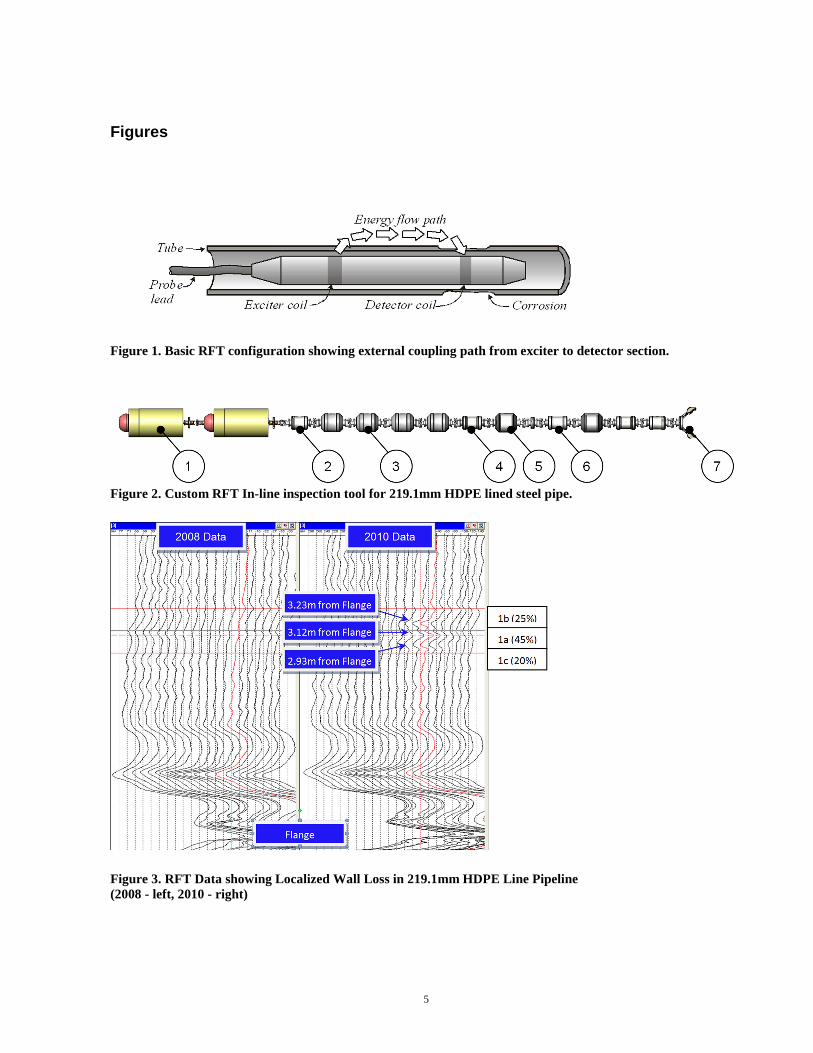
the HDPE lined pipeline inspected for the first time in 2008. After detailed analysis, the repeat inspection data showed deviations from the 2008 baseline data. A short list of candidate locations was compiled for dig-verification. The RFT data for one of these areas of interest is presented in figure 3. The data corresponds to a location 3m upstream of a liner vent station.
The data in figure 3 shows two screen captures of an RFT
strip chart display. RFT Strip charts typically display the phase data from individual detectors against either distance or time. Signal deviations to the left imply wall loss, while signal indications to the right point at possible wall gain. Figure 3 shows the data plotted with the distance along the length of the pipeline on the vertical axis.
As highlighted on the right stripchart, there are notable
differences between the 2008 and 2010 data for this particular area of interest. After analysis of the RFT data, the general wall loss area was believed to consist of a patch spanning approximately 48cm from the 4:00 to 6:30 circumferential positions measured upwards of 10% wall loss according to RFT data. Encompassed in this patch were three distinct

4
pitting signatures at the 5:30 circumferential positions measuring 25%, 45% and 20% based on the RFT data. The relative locations and sizes are detailed in Figure 3.
Verification digs were performed on the area of interest indicated by the data of figure 3. Hydrovacing was used to expose the pipe surface and both ultrasonic (UT) and radiography (RT) methods were employed to measure the severity of corrosion. Both methods confirmed the presence of shallow pitting discovered in the RFT data. UT information was used to more precisely size the depth of the localized pitting indications: 18%, 18% and 15% wall loss. The general band of corrosion was confirmed to be within 10%.
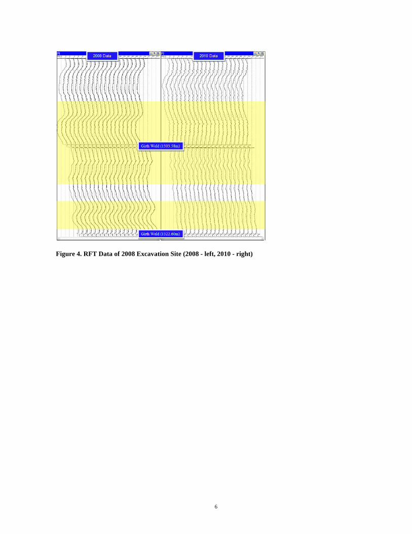
Another 2008-2010 data comparison example is shown in
the screen capture of figure 4. The screen capture shows data from one of the 2008 dig site locations. The 2008 data exhibits gradual changes in the baseline of the RFT signals not reproduced in the 2010 dataset. As can be observed, the indication just upstream of the 1303.58m girth weld has all but disappeared in the 2010 data. The secondary indication upstream of the 1322.6m girth weld seems to have lessened as well. The deviations are illustrated by the yellow highlight. The signal variations shown in figure 4 are due to changes in the local stress state of the pipe resulting from the soil disturbance of the 2008 verification digs. Although no major defects were found during the 2008 excavation, the excavations did result in changes to the stresses inside the pipe wall, which affected the magnetic permeability of the pipe material. Interesting is the fact that subtle secondary stress indications can be observed in the 2010 RFT data in pipe-lengths further upstream and downstream of the excavation site. This appears to imply that although some of the soil loading stresses were relieved by the excavation, a portion of the stresses traveled up and downstream.
Conclusion Internal HDPE liners have been an effective means of
internally protecting carbon steel pipelines. The potential threat of external corrosion (for example as a result of 3rd party damage) or internal corrosion still warrant the periodic inspection of lined pipe – especially given the nature of the products typically transported in lined pipes.
The relatively heavy thickness of HDPE liners and the
requirement to prevent damage to the liner, limits the effective deployment of traditional inspection technologies. Remote Field Testing (RFT) technology is a through-transmission technique and therefore relatively lift-off insensitive. It is well suited to inspect steel pipelines through thick HDPE liners.
The original development of RFT pipe inspection tools
has been mostly driven by the municipal water environment, where metallic water mains can exhibit heavy internal scaling. For the inspection of lined oil and gas pipelines, a custom RFT tool was developed to accommodate the requirements imposed by lined oil and gas pipes.
The developed RFT in-line inspection tool has been
successfully deployed in HDPE lined pipe since 2008. Repeat
inspections of a lined pipeline in 2008 and 2010 showed that RFT data has excellent reproducibility, with only a few minor deviations observed in the 2010 data compared to the 2008 baseline. Subsequent verification digs successfully correlated RFT signal deviations in the 2010 data to localized corrosion ranging up to 18% in depth.
The field inspections showed RFT to be a very promising
inspection technique and highlighted the technique’s ability to detect stresses inside the pipe wall due to soil loading.
References 1. Jim Schmitz; High Density Polyethylene Liners for
High Temperature and Gaseous Applications; Paper No. 10073 13th Middle East Corrosion Conference & Exhibition.
2. R. MacDonald, L. Simon, K. Goerz, M. Girgis; Corrosion Failure in a Lined Sour Gas Pipeline - Part 2: Role of Methanol in Corrosion Behind Liner; NACE NAWC February, 2010.
3. R.Tenove; Hydroscope Provides Water Line Asset Management; Trenchless Technology, March 997.
4. W.R. MacLean; Apparatus for Magnetically Measuring Thickness of Ferrous Pipe; U.S. Patent #2,573,799 (1951).
5. T. R. Schmidt; History of the Remote-Field Eddy Current Inspection Technique; Materials Evaluation. Vol. 47, No. 1. Columbus, OH: American Society for Nondestructive Testing (January 1989): p 14, 17-18, 20-22.
6. W. Lord, Y.-S. Sun, S.S. Udpa & S. Nath; A Finite Element Study of the Remote-Field Eddy Current Phenomenon; IEEE Transactions on Magnetics, Jan 1988, Vol. 24, pp 435-438.
5
Figures
Figure 1. Basic RFT configuration showing external coupling path from exciter to detector section.
Figure 2. Custom RFT In-line inspection tool for 219.1mm HDPE lined steel pipe.
Figure 3. RFT Data showing Localized Wall Loss in 219.1mm HDPE Line Pipeline (2008 - left, 2010 - right)
6
Figure 4. RFT Data of 2008 Excavation Site (2008 - left, 2010 - right)