
OPERATORS-MANUAL-PARTS-LIST-200TM-MIXER ... - Winget
238
200TM OPERATORS HANDBOOK & PARTS Manual V601651 August 2018 (This publication also includes Manual MANS545) WINGET LIMITED, P.O. Box 41, Edgefold Industrial Estate, Plodder Lane, Bolton, BL4 0LR, England Tel: +44 (0) 1204 854650 www.winget.co.uk MECHANICALLY-FED MIXER
-
Upload
khangminh22 -
Category
Documents
-
view
0 -
download
0
Transcript of OPERATORS-MANUAL-PARTS-LIST-200TM-MIXER ... - Winget

200TM
OPERATORS HANDBOOK&
PARTSManual V601651 August 2018(This publication also includes Manual MANS545)
WINGET LIMITED, P.O. Box 41, Edgefold Industrial Estate, Plodder Lane, Bolton, BL4 0LR, England Tel: +44 (0) 1204 854650
www.winget.co.uk
MECHANICALLY-FED MIXER


CONTENTS
INTRODUCTION
Introduction to the Handbook IIWarranty IIISafe working 1.1Lashing down and lifting points 1.6
INSTALLATION AND REMOVAL
Main components of mixer 2.1Installing the mixer on site:
Lifting the mixer 2.2Stabiliser 2.2/2.8Hopper 2.3/2.6Dragline 2.3/2.7Feed apron and ramp 2.5/2.6Water tank 2.5Electrically driven mixers 2.5/2.6Dismantling for transportation 2.6
OPERATION
Mixer drum positions 3.1Hopper controls 3.1Electric motor: Starting and stopping 3.2TS/TR1 engine: Starting and stopping 3.3Installation trials 3.6Mixing 3.6Batch weigher 3.8End of work procedure 3.9
SERVICING
Service schedule 4.1Servicing procedures:
TS/TR1 engine 4.2Batteries 4.6Hydraulic system 4.7Bolt torques 4.8General lubrication 4.9Drum drive 4.10Batch weigher 4.10Dragline 4.10
Mixer drum assembly 4.11Mixer drum drive overhaul 4.13TS/TR1 electrical fault finding 4.14Hour meter wiring 4.15Dragline electrical system 4.16Hydraulic circuits 4.18/4.21
SPECIFICATIONS
Lubricants 5.1Noise level of mixers 5.1Drum speed 5.1Mixer drum sealant 5.1Engine and motor outputs 5.1Dimensions 5.2
PARTS
Illustrated parts listings
CALIFORNIAN HEALTH WARNING
INTRODUCTION I

II INTRODUCTION
THE HANDBOOK MUST NOT BE REMOVED FROM THE MACHINE.The Handbook must be kept clean and in good condition. Additional copies of theHandbook can be obtained from your Distributor.
The contents of this Operator's Handbook are designed as a guide to the machine'scontrols, operation, working capacities and maintenance. It is not a training manual.Only trained operators should use this machine. Contact the C.I.T.B. or equivalent body foradvice on training.
The Handbook
The operator must read all the Handbook and fully understand its contentsbefore attempting to operate the machine.
In this Handbook are WARNING notes. They are preceded by this symbol:
These notes are used to indicate the procedure being described in theHandbook must be followed to avoid serious injury or death to yourself or toothers, or damage to the machine.The warnings are also used to protect the machine from unsafe servicingpractices.
Pay particular attention to the warnings given in the Handbook.If you have any doubts about any aspect of the machine's capability or servicingprocedures, you must consult the manufacturer.
The contents of this Handbook, although correct at the time of publicationmay be subject to alteration by the Manufacturers without notice.Winget Limited operate a policy of continuous product development.Therefore, some illustrations or text within this publication may differ fromyour machine.
IMPORTANT Engine change
From June 2005 (mixer serial number 1110) the Lister-Petter TS1 engine was replacedby the Lister-Petter TR1 engine. The TR range of engines is completely interchangeablewith the TS range and consumable items such as filter elements are identical. There aresome internal component differences and when ordering spares it is important to statewhether it is a TS1 or TR1 engine.Starting and maintenance instructions found throughout this Handbook which refer toTS engines are also applicable to the TR engine.

INTRODUCTION III
Warranty terms & conditions
The Manufacturer assures you that if any part of the machine becomes defective due tofaulty manufacture or materials within 12 months from the date of purchase, the part willbe repaired or replaced under warranty free of charge by any authorised WingetDistributor. Warranty repairs must be carried out by Winget Distributors.This Warranty is given to the first owner and may be transferred to subsequent owners forthe balance of the Warranty period.
The Manufacturer’s liability only extends to the costs of repair or replacement of the faultyparts and necessary labour charges involved in the repairs. The Company accepts noliability for any consequential loss, damage or injury, resulting directly or indirectly fromany defect in the goods.
Items not covered by Warranty and considered to be the customer’s responsibility includenormal maintenance services; replacement of service items and consumables;replacement required due to abuse, accident, misuse or improper operation; replacementof wearable items e.g. pins, bushes, brake linings, clutch linings etc.The Warranty will not apply where the equipment is modified, converted, or used forpurposes other than those for which it was designed, unless clearance for themodifications etc. have been granted by the Manufacturer, in writing.The Pre-Delivery Inspection and Warranty Registration Document must be completedcorrectly and returned to the Manufacturer within 7 days of sale date. Failure to do so mayresult in the claim being subsequently rejected.
Tyres and tubes are not covered by Warranty, but are covered by the tyre manufacturer’sown warranty system which provides against defects in material or workmanship. Enginesare covered separately by the engine manufacturers, and engine warranty repairs must behandled by the relevant engine manufacturers’ distributors.No claim will be considered if other than genuine Winget Limited parts, which must beobtained from Winget Limited via an authorised Distributor, are used to effect a repair, or iflubricants other than those recommended by Winget Limited are used.The equipment must be serviced in accordance with the service schedules laid down byWinget Limited. Evidence that these have been complied with may be required beforeWarranty Claims are reimbursed.
The Manufacturer’s policy is one of continuous improvement. Winget Limited reserve theright to change specifications without notice. No responsibility will be accepted fordiscrepancies which may occur between specification of machines and the descriptionscontained in publications.

IV INTRODUCTION

OPERATION
SAFE WORKING 1.1
Safety is the responsibility of the persons working with thismachine. Think “safety” at all times. Read and rememberthe contents of this Handbook.
MACHINE MODIFICATION
Any modifications to the machine will affect its working parameters and safetyfactors. Refer to the Manufacturers before fitting any non-standard equipmentor parts.The manufacturers accept no responsibility for any modifications made afterthe machine has left the factory, unless previously agreed by theManufacturers in writing. The Manufacturers will accept no liability for damageto property, personnel or the machine if failure is brought about due to suchmodifications, or fitment of spurious parts.
Only trained operators should use this machine. Always be aware of local and national regulations governing the use of themachine.Always ensure that all guards are in position and correctly fitted.Electrically driven mixers: Always ensure that the power supply has been
correctly connected by a qualified electrician.Electrical cables must be of a suitably armoured type. Ensure thatthey are protected from damage and not liable to be tripped over.Do not connect to a household socket!Use only with an RCD protected supply. Only connect via specialfeeding point (e.g. power distribution panel on building site with fault-current-breaker).
Only authorised persons should be allowed to operate the mixer, or be in theimmediate area.Never add fuel or lubricant to the machine while it is running.Keep the area around the machine clear of obstructions which could causepersons to fall onto moving parts.Keep the body and clothing clear of all moving and hot parts.Always ensure that during operation the mixer is standing on stable and levelground and that the wheels are chocked.Keep the engine/motor housing lid closed when the engine or electric motorare running.In the case of mixers fitted with a loading hopper, do not allow any person towalk, stand or lean under the hopper when raised. It is recommended that thearea around the hopper is guarded to prevent persons standing or walkingunder the hopper when the machine is in operation.

ENGINE
ELECTRICAL SYSTEMS
1.2 SAFE WORKING
Starting any diesel engine can be dangerous in the hands of inexperiencedpeople. Operators must be instructed in the correct procedures beforeattempting to start any engine.Always obtain advice before mixing oils; some oils are not compatible. If indoubt, drain and refill.The materials used in the manufacture and treatment of some filters andelements may cause irritation or discomfort if they come into contact with theeyes or mouth and they may give off toxic gases if they are burnt.Engine lifting eyes must not be used to lift the complete machine.Ether based cold start aids in aerosol cans must not be used under anycircumstances.EXHAUST GASES CONTAIN CARBON MONOXIDE WHICH IS ACOLOURLESS, ODOURLESS AND POISONOUS GAS THAT CAN CAUSEUNCONSCIOUSNESS AND DEATH.
Starting engines that are fitted with charge windings/alternators which havebeen disconnected from the battery may cause irreparable damage.
The following points must be strictly observed when charge windings arefitted otherwise serious damage can be done.
Never remove any electrical cable while the battery is connected inthe circuit.
Only disconnect the battery with the engine stopped and all switchesin the OFF position.
Always ensure that cables are fitted to their correct terminals. A shortcircuit or reversal of polarity will ruin diodes and transistors.
Never connect a battery into the system without checking that thevoltage and polarity are correct.
Never flash any connection to check the current flow.
Never experiment with any adjustments or repairs to the system.
The battery and charge windings/alternators must be disconnectedbefore commencing any electric welding when a pole strap is directlyor indirectly connected to the engine.
BATTERIES CONTAIN SULPHURIC ACID WHICH CAN CAUSE SEVEREBURNS AND PRODUCE EXPLOSIVE GASES. If the acid has beensplashed on the skin, eyes or clothes flush with copious amounts of freshwater and seek immediate medical aid.

SERVICING & MAINTENANCE
Fuel tank filling point.
Attach lifting hooks to this eye.
Read Operators Handbook, or OperatorsHandbook storage place.
The battery negative terminal isconnected to eath.
SAFE WORKING 1.3
Never allow unqualified personnel to attempt to remove or replace any partof the machine, or anyone to remove large or heavy components withoutadequate lifting equipment.
Before maintenance work is begun, ensure that the engine is stopped, orthat the electric motor is switched off, and isolated from the mains.
Always conform to service schedules except when an emergency calls forimmediate action, or adverse conditions necessitate more frequentservicing.
Always report any defect at once, before an accident or consequentialdamage can occur.
On completion of maintenance, check that the machine functions correctly,and that all guards are correctly fitted.
Disposal of waste oil. Dispose of waste oil into waste oil storage tanks. Ifstorage tanks are not available, consult your Distributor or local authority foraddresses of local designated disposal points. It is illegal to dispose ofwaste oil into drains or water courses, or to bury it.
DECALS
Ensure that all warning decals fitted to the mixer are legible. If any should becomedetached, they must be replaced immediately.
Descriptions of the pictorial decals are as follows:

Remove starting handle.
Beware of electrical hazards.
Engine stop.
Keep clear of chain drives.
These surfaces may be hot.
Keep hands clear of drum.
Battery isolator.
Wear ear protection.
Wear eye protection.
Conforms to EC standards.
1.4 SAFE WORKING

SAFE WORKING 1.5

GeneralCare should be taken when lifting ortransporting the mixer to ensure that liftingor retaining straps are in good conditionand the following procedures must befollowed when lifting or lashing down toavoid causing unnecessary damage.It is recommended that chains or webbingslings are used to lift the mixer via thelifting eyes on the mainframe (D) andhopper (E), and that ratchet type webbingstraps are used to lash the mixer down.
Lifting the Mixer (Crane)Using the tilting handwheel and lockingplunger, lock the drum so that the drumsopen end is away from the hopper.
Raise the hopper (A) and insert the ramsafety prop (B).
To prevent the drawbar swinging freely asthe mixer clears the ground, lash it up tothe handwheel (C).
If the mixer is on site and the wheels areimmersed in dried concrete or mortar thewheels must be freed before attempts aremade to lift the mixer.Attach suitable lifting equipment to thelifting eye (D) on the mainframe and thelifting eye (E) on the hopper, and slowlytake the weight.Do not 'snatch' the mixer otherwisedamage may be caused to the lifting eyesor lifting equipment.
As the mixer clears the groundthe hopper safety prop (B) willcome free from its upper seatand will swing down.
Be also aware that the mixerwill tend to swing as it leavesthe ground.
1.6 SAFE WORKING
LASHING DOWN & LIFTING POINTS

Lifting the Mixer(Forklift/Telehandler)Using the tilting handwheel and lockingplunger, lock the drum so that the drumsopen end (G) is away from the hopperLower the hopper. (If not already down)
Remove stabiliser legs (J) (If fitted)
To prevent the drawbar swinging freely asthe mixer clears the ground, lash it up tothe handwheel (H).
If the wheels are immersed in driedconcrete or mortar, free them beforeattempting to lift the mixer.
Spread the fork tines (K) as wide aspossible for them to pass under themainframe.
Ensure the forks do not foulthe bottom hoses of thehopper lifting ram
Position the carriage as close as possibleto the mixerSlowly tilt the carriage back slightly toprevent the mixer rocking forward, thenraise the mixer just clear of the ground.Do not raise the mixer unnecessarily high.Keep the height to the minimum requiredto clear any obstructions without undulyobstructing your forward vision.When travelling keep your speed to theminimum and when loading vehicles donot raise the mixer to the height of the beduntil the mixer is close to the vehicle.Similarly when unloading vehicles lowerthe mixer just clear of the ground as soonas it clears the side of the vehicle.
SAFE WORKING 1.7

Lashing downUnless the mixer is pulled up against aheadboard or some form of substantialwheel chocks, it is recommended that tworatchet type webbing straps are used toretain the mixer, one pulling to the rearand one pulling to the front.Position the mixer on the vehicle bed andchock the rear wheels to prevent it rollinguntil lashed down.Lower the hopper. (If not already down)
Turn the front axle so that the drawbar (N)is below the mixer, or alternatively removeit, so as not to form an obstruction on thevehicle bed.
Fit the stabiliser legs (O).
Pass one of the webbing straps aroundthe front of the mainframe at point (P) andsecure the strap down to retaining hookson the vehicle bed in front of the mixer.Pass the second strap around the rear ofthe mainframe at point (M) and secure thestrap down to retaining hooks on thevehicle bed to the rear of the mixer.Tighten the straps by means of theratchets until the mixer is securely held.
1.8 SAFE WORKING

MAIN COMPONENTS OF MIXER
INSTALLATION AND REMOVAL 2.1
1 Stabiliser2 Hopper3 Hopper safety prop4 Hopper control lever5 Hopper loading ramp6 Dragline cable7 Cable support
8 Dragline pulleys 9 Jib tie bars10 Jib legs11 Pulleys for electric cable12 Rubber flap13 Staking lugs14 Feed apron
15 Electric cable16 Micro switch17 Dragline shovel18 Water tank19 Weigher gauge

INSTALLING THE MIXER ON SITE
Lifting the mixerTwo lifting eyes are provided for usinghooks when unloading or loading themixer for transportation.When viewing the mixer from the hopperside, one lifting eye is situated on the lefthand side of the hopper cradle, and thesecond eye is at the top of the trunnionpedestal next to the engine housing. Theeyes are clearly marked with decals.
Installing stabiliserThe mixer must be sited on firm levelground.
Fit the stabiliser (1) to the mainframe (20)using the two locking pins (21). Securethese with lynch pins.Locate the top (angled) ends of the struts(22) onto the pins (23) of mainframe, andfit the bottom ends onto the pins (24) ofthe stabliser. Fit the four locking pins andsecure with lynch pins.As the mixer is standing on level ground, itwill be seen that there is a distance ofapproximately 25mm between thestabiliser feet and the ground (X). Thisspace must be packed with timber equalto the area of the feet.
Chock all four roadwheels (25) to preventthe mixer from moving.
Remove the the tow bar (26) and stow itsafely.
Ensure that the tyrepressures are corrrect. (Seespecifications section forcorrect pressure.)
2.2 INSTALLATION AND REMOVAL

Installing the hopperIf the hopper (2) has been removed toassist with transportation, it will benecessary to refit it as follows;
Ensure that the cradle (27) is in thelowered position. if it is not, it can belowered by raising it slightly, then swingingdown the safety prop (3).
The hopper weighsapproximately 100 kgs.
Using suitable lifting equipment, raise thehopper up to the cradle, aligning the eightfixing holes.Insert coach bolts through the holes fromthe inside of the hopper. Fit nuts to thebottom four bolts (Y) and tighten securely.Fit nuts to the four top bolts (Z) leavingthem finger tight.Raise the hopper/cradle assembly andinstall the safety prop (3). Tighten the topfour bolts securely.Detach and remove the lifting equipment.
Installing the dragline jib(optional equipment)Assemble the jib legs (30) to the topbeam (31) using the bolts provided.Loosely attach the jib tie bars (9/9A) withthe longer bar (M) at the mixer tilt wheelend.
Place the jib (10) in position against themainframe. Align the mounting holes atthe base of the jib with the correspondingholes in the mainframe (34).
Using the nuts and bolts provided, fastenthe jib to the mainframe leaving the nutsfinger tight.Support the top end of the jib on a trestle(W) approximately 1200mm high.
INSTALLATION AND REMOVAL 2.3

Pull out the dragline cable (6) from thewinch (35).Remove the cable cleat and thimble (6A)and thread the cable around pulley (8)and between pulleys (8A) on the jib.Replace the cleat and thimble, andconnect the cable to the shovel ring (36).Slot the cable mast (7) into its sleeve (37)on the jib leg.Unwind the electric cable (15) from theshovel (17). Connect the plug (17A) to thesocket situated beneath the enginehousing.Loop the cable (15) around the crossbar(38) at the bottom end of the cable mast,and over the cleat (39) at the top, leavingsufficient slack to allow the jib to pivotupwards.Two pulleys are assembled onto thecable, the first one (40) is hung from thecleat (39), while the second pulley (41)hangs free between the first pulley andthe cleat.Tension is added to the cable by a weight(42) added to the free hanging pulley.
The jib assembly weighsapproximately 125 kgs.
Securely fasten suitable lifting equipmentto each end of the top beam (N).Raise the jib assembly until the jib tie bars(9) can be bolted in position in the holesprovided adjacent to the tilt wheel and inthe back of the engine housing.Tighten bolts (34), to secure the jib legs tothe mainframe.Connect the winch hydraulic motor (35) tothe two hoses running from the solenoidvalve.Note: Ensure that the hoses are fitted to
the correct motor ports. Connecttogether the hose and port markedwith the same colour.
Strap the hoses to the jib leg.
2.4 INSTALLATION AND REMOVAL

Installing the feed apron(optional equipment)
It is recommended that when a dragline isfitted, a feed apron and ramp (14) are alsoinstalled in front of the loading hopper (2)so that materials may easily be tipped intoit. This is particularly important when abatch weigher is fitted, as it prevents thebuild up of aggregate under the hopper,which will cause faulty batch weights to begiven.Assemble the feed apron and ramp. Placeit squarely in front of the mixer so that thehopper does not foul it when being raisedand lowered.
The horizontal rubber flap (43) preventsmaterial from failing between the hopper(14) and ramp.Stake the apron securely into position,using the four lugs (44), two on each side.Extend the centre partition of the ramp byadding boards (45). This will help toseparate the aggregates.
Installing water supply to tankConnect the water tank stopcock (18) to amains supply of clean water.
Installing electrically drivenmixers(optional equipment)Electrically driven mixers must beconnected to the mains supply by aqualified electrician.
INSTALLATION AND REMOVAL 2.5

DISMANTLING THE MIXER FORTRANSPORTATION
TransportationWhen transporting the mixer on a vehicle,the dragline jib must be dismantled. It mayalso be necessary to remove the hopperfrom its cradle.
If the hopper is fitted duringtransportation, the stabiliser(1) and struts (22) must befitted.
If the mixer is to be towed, the dragline jibmust be dismantled, and the hopper andstabiliser removed.
Disconnecting electrically drivenmixersElectrically driven mixers must only bedisconnected from the mains supply by aqualified electrician.
Dismantling the feed apronRemove and stow the feed apron. Clearthe area in front of the mixer to aid thedismantling of the hopper and dragline.
Dismantling the hopper
Use suitable liftingequipment, securely fastenedto the hopper to take itsweight during dismantling.
The hopper weighsapproximately 100 kgs.
2.6 INSTALLATION AND REMOVAL

With the lifting equipment, slowly raise thehopper and swing the safety prop (3) upinto position. Lower the hopper onto theprop.
Slacken the four bolts (Z) securing the topof the hopper (2) to the cradle (27) untilthey are only finger tight.Raise the hopper and swing down thesafety prop. Fully lower the hopper.With the weight of the hopper taken onthe lifting equipment, remove the four top(Z) and four bottom (Y) bolts. Lower thehopper to the ground.Detach the lifting equipment. Replace thebolts in their holes in the cradle to preventloss.
Dismantling the dragline
Release all hydraulic pressurefrom the system as follows:Stop the engine.Raise and lower the hydrauliccontrol lever several times.DO NOT RE-START THEENGINE.
Use suitable lifting equipmentsecurely fastened at each end(N) of the jib top beam to takethe weight of the jib duringdismantling.
Unfasten the hoses from the jib leg.Remove the hoses from the winchhydraulic motor (35). Cap the ends of thehoses and the ports of the motor toprevent the ingress of dirt.
Take the weight of the jib (10) on thelifting equipment. Remove the boltsretaining the jib tie bars (9) to themainframe. Slacken the bolts retaining thejib legs to the mainframe (34).
Lower the jib on to a trestle approximately
INSTALLATION AND REMOVAL 2.7

1200mm high capable of taking its weight.Unfasten the dragline cable from theshovel ring (36) and remove the cleatsand thimble from the cable.
Wind the cable back onto the winch drum.Leave sufficient rope clear of the winchhousing to enable it to be pulled out whenreassembling the dragline. Replace cleatsand thimble onto the dragline cable.
Unplug the electrical control cable from itssocket under the engine housing. Removethe electrical cable (15) and pulleys(40/41) from the jib assembly. Wind thecable onto the shovel stowage arms.Strap the pulleys to the shovel handles toprevent loss. Remove the cable mast (7).
Remove the bolts (34) holding the jib legsto the mainframe.
To further assist in transporting, the jiblegs (30) can be unbolted from the top bar(31).
Replace all bolts back in their holes toprevent loss.
Dismantling stabiliser
Remove the two struts (22).
Remove the stabiliser (1) by extracting thepins securing it to the mainframe (20).
Replace all pins back in their holes toprevent loss.
2.8 INSTALLATION AND REMOVAL

OPERATION
Mixer drum positions
The locking plunger (57) holds the mixingdrum in one of the following positionsCHARGE (1) / MIX (2) / DISCHARGE (3).
To release the handwheel: Rotate theplunger (A) until the cross-pin (B) alignswith the slot (C), then pull the plungeroutwards (D).
To lock the handwheel: Align theplunger with the appropriate hole in theframe, then push (E) and rotate theplunger until the cross-pin is vertical (F),or locates in the vertical slot.
Hopper control
To raise hopper: Lift the control lever (4)and hold until the hopper (2) is fullyraised. Releasing the lever to the neutralposition will stop the ascent of the hopper.
Do not hold in the fully raisedposition for more than a fewseconds as this will cause thehydraulic components tooverheat.
To lower hopper: Push down the controllever to lower the hopper. Releasing thelever to the neutral position will stop thedescent of the hopper.
OPERATION 3.1

Before starting
The operator must calculate the correctpercentages of water and aggregates tobe mixed.
Check that the fuel tank is full and that thelevel of lubricating oil in the engine sumpis correct.
With the hopper in the down position,check the oil level in the hydraulic tank.
To start and stop the engine
As soon as the engine hasstarted the mixing drum willbegin to rotate, and thehydraulic system will bepressurised.
To start and stop electric motors:
To gain access to start button; raise themotor cover (50).
Start the motor by pressing button (51).
Lower the motor cover (50).
To stop the motor, press button (52).(Pressing button (53) will also stop it.)
In an EMERGENCY, pressbutton (52) to stop the motor.
To start and stop diesel engines:
The following instructions on how to startand stop the engine are for the Lister-Petter TS1 only.For other engines please read the EngineOperators Handbook that has beensupplied with the mixer.
3.2 OPERATION

TS/TR1 engines
Description
A DipstickB Lubricating oil fillerC Engine controlD Decompressor leversE Fuel tankF Cold start oil cup (where fitted)
Automatic Excess Fuel Device
The engine is fitted with an automaticexcess fuel device which becomesoperative, ready for the next start,when the engine is stopped.If the engine stops other than by theoperation of the engine control, thecontrol (G) must be turned anti-clockwise to the 'STOP' position andreleased before the device canoperate.As the engine runs up to speed theexcess fuel device will automaticallyreset to the normal running position.
Cold start aid (where fitted)
The cold start aid is fitted to thecombustion air intake port and is usedwhen the ambient temperature is below–10 deg. C (14 deg.F).
With the fuel turned on, turn theengine for up to 20 revolutions toprime the fuel and lubricationsystems.Withdraw the plunger (H) and fillone third of the cup (J) with thesame type of lubricating oil as usedin the engine.Replace the plunger and inject theoil just before starting the engine.
The device must not be usedmore than three times insuccession during the sameattempt to start the engine.
OPERATION 3.3

Starting handle(s)
A non-limited kick-back handle (C) orlimited kick-back handle (D) system maybe fitted to the engine.The two handles are not interchangeableand care must be taken to ensure thecorrect type is retained with the engine.Always use the correct starting handle thathas been designed for the engine.Ensure there are no burrs on the handle.Before attempting to use the handle,clean and lightly oil that part of it which fitsonto the engine.
Do not attempt to use ahandle if it is damaged in anyway.
Hand starting the engineTurn the engine control lever anti-clockwise to the "STOP" position (L)and release it.Move the decompressor levers towardsthe flywheel (M).
Insert the correct handle into thestarting housing.Turn the engine slowly for up to 20turns to prime the combustion chamberand lubricating oil system.Maintaining a firm grip on the startinghandle, crank the engine really fastand when sufficient speed is obtainedmove the decompressor levers away fromthe fly wheel (N) and continue to crankuntil the engine fires.Retain a firm grip on the handle andremove it from the engine.
3.4 OPERATION

Key Starting engines
Check that the decompressor lever isaway (N) from the flywheel.Turn the engine control lever anti-clockwise to the "STOP" position (L)and release it.
On the panel (X), turn the start keyclockwise to position (1). The batterycharging light (P) will illuminate.Turn the key and hold at the "START"position (2) until the engine fires andthen release it immediately.If the engine fails to start within 20seconds, release the key and attemptto restart after allowing sufficient timefor all moving parts to stop.
Stopping the engine
Never stop the engine byoperating the decompressorlever or valve damage mayoccur.
Hand start engines
Turn the engine control anti-clockwiseto the "STOP" position (L) and hold itthere until the engine comes to rest.
Key start engines
Turn the engine control anti-clockwiseto the "STOP" position (L) and hold itthere until the engine comes to rest.After the engine has stopped, turn thestarter key to the "OFF" (0) position.
OPERATION 3.5

Installation trialsBefore working with the mixer carry outthe following trials;
1 Ensure that the winch motor (35) isrevolving in the correct rotation. Viewedfrom the mixer engine end (R), thewinch drum should rotateanti-clockwise. If it is not, thentranspose the hydraulic motor hoses.
2 Slowly raise the hopper and check thatit does not foul the legs of the jib. Ifnecessary, slacken the four bolts (31)in the top beam and adjust the jibsideways to clear. Finally tighten allbolts.
3 A trial run may show that as the shovel(17) moves into the mixer the slack ofthe electric cable (15) is not taken upby the weighted pulley (41). Toovercome this, increase the weight (42)on the pulley. If the pulley then comestoo close to the ground, wind two turnsof the cable onto the stowage arms(17A) on the shovel.
4 If weigher equipment is fitted it shouldbe carefully checked and set up asshown in the Service section of thismanual. Its accuracy should be verifiedby using a known weight.
To start mixingOpen the stopcock (54) on the water tank.Observe the gauge glass (55) as the tankfills to the correct level for one mix. Closethe stopcock.Note: The tank has the capacity to
dispense quantities of water from4 to 38 litres.
Turn the mixing drum to the CHARGEposition, in preparation to receive a loadfrom the hopper.Note: If a weigher gauge is fitted, set the
coloured pointers to the aggregateproportion required for one load ofthe hopper. (see "Batch weigher')
Lower the hopper (2) by pushing thecontrol lever (4) down.
3.6 OPERATION

If the hopper will not lower. The followingmay have happened:
Hose failure valve lock-out(CE marked machines only)Operating the hopper controlvalve lever in a violent mannermay cause the Hose FailureValve to “lock-out” and preventthe hopper from moving.To release a “locked” HoseFailure Valve; operate thelever to raise the hopper, thiswill blow-off the Relief Valve.Then gently operate the leverto lower the hopper.
Load the hopper with aggregate by pullingthe shovel (17) away from the mixer andback over the aggregate. Press and holdthe micro-switch (16) on the shovel handleto start the winch motor (35), this will dragthe shovel back towards the mixer. Tostop the loaded shovel when it reachesthe hopper, release the micro-switch, andslip the contents of the shovel into thehopper.
Pull the chain (56) to discharge the water,while simultaneously pulling the controllever (4) up to raise the hopper and tip theaggregate into the mixing drum (58).
OPERATION 3.7

Turn the mixing drum to the MIX position.Allow the mixing to continue for about 1.5to 2 minutes.
Ensure that on the dischargeside of the mixer there ispositioned a suitablecontainer to catch thedischarging load.
Turn the mixer to the DISCHARGEposition, and allow the load to run into thecontainer.
Batch weigher (if fitted)The weigher gauge (X) is connected by ahydraulic pipe to a load cell (Y) mountedon the mainframe adjacent to the hoppercradle. The hydraulic circuit is primed andsealed by the manufacturers.
The hydraulic gauge/load cellcircuit must not bedisconnected.
The gauge, which is calibrated from 0 to500 kg. (0 to 1100 lbs.) gives accurateindication of batch weights.The adjustable coloured pointers mountedon the rim of the gauge can be set by theoperator to the aggregate proportionsrequired.A protective lid is provided for the gaugeto prevent damage when not in use.
It is important that the mixer isstanding firm and level andthat there is at least 50mm(2") clearance between theground and the base of thehopper at all times.
If aggregate is allowed tobuild up under the hopper,inaccurate gauge readingswill be obtained.
3.8 OPERATION

To use the batch weigher, proceed as follows:
Set the pointers on the gauge to theaggregate proportions required. With theengine running, slowly lower the hopperon to the load cell. Hold the hopper controllever fully down for a few seconds until thegauge needle begins to move up to "0"(zero) then release. The hopper is thenready to load.If a "0" (zero) reading cannot be obtained,adjust the gauge.
To set the weighing gauge to zero,proceed as follows:
Ensure that the mixer engine is running.
A Lower the hopper onto the load cell.
B Check that the hopper is clear of theground.
C Taking care not to stand on any part ofthe hopper, adjust the knurled knobon the side of the gauge to set thepointer to "0" (zero).
D Repeat lowering the hopper three orfour times to check that a constant “0"(zero) reading is obtained.
At the end of the working dayA Stop engine, and remove the starting
handle to prevent unauthorised use ofthe machine.
B Thoroughly clean out the mixing drumwith water and gravel.
C Clean out the hopper and wash theoutside of the mixer.
D Drain the water tank. This isparticularly important during periods offrost. To drain the tank, position themixing drum in the CHARGE position.Close the stopcock, and then pull thechain to drain the water into the drum.Turn the drum to the DISCHARGEposition to empty the water.
E Fully lower the hopper.
F Grease the machine and fill the fueltank.
G If the mixer has a weigher gauge, fit itsprotective cover.
OPERATION 3.9

3.10 OPERATION

SERVICING 4.1
SERVICE SCHEDULE(See also the relevant Engine Workshop Manual)
Every dayBatch weigher: Check accuracy.Links, hinges, shafts, bearings & pulleys: Lubricate.Engine: Check fuel & lubricating oil levels, also check for leaks.(see Engine Manual) Clean/replace air cleaner element under very dusty conditions.
Every week (or 50 hours running) The above and following itemsNuts, bolts and keys: Tighten (Each week for first month).Battery: Check electrolyte level & battery condition.Hydraulic oil: Check level.Dragline: Check condition of electrical control cable.
Check condition of winch cable.Drum Bevel Gears: Open Gear LubricantDrive chains: Lubricate & check tension.
Every 125 hours. The above and following itemsEngine: Clean/replace air cleaner under moderately dusty conditions.
Every 250 hours. The above and following itemsNuts, bolts & keys: Tighten.Engine: Change lubricating oil & oil filter.
Check valve clearance. (see Engine Manual)Clean/replace injectors if exhaust is dirty. (see Engine Manual)Renew fuel filter element if the fuel is not perfectly clean.
Every 500 hours. The above and following itemsHydraulic tank: Clean breather/filler cap & strainer.Dynamo: Check drive belt tension.Engine: Replace air cleaner element.
Check exhaust and induction for leaks, damage or restrictions.Renew fuel filter element.Check battery charge winding system. (see Engine Manual)
Every 1000 hours. The above and following itemsHydraulic tank Clean suction filter & change hydraulic oil.Engine: Decarbonise if the engine performance has deteriorated.(see Engine Manual) Clean cylinder barrel and head fins.
Clean restrictor banjo union at the cylinder head end of oil feed pipe.Flush and refill fuel tank.
Every 5000 hours. The above and following itemsEngine: Major overhaul, if necessary. (see Engine Manual)

ENGINE
IMPORTANT
Engines fitted in 200TM mixersUp to Feb. 1990, Lister-Petter PH1To service this engine, please refer to the“Engine Operator’s Handbook” or”Workshop Manual”.
From Feb. 1990, Lister-Petter TS/TR1
This engine will require additionalservicing and adjustment in addition tothose quoted in this handbook. Pleaserefer also to the “Engine Operator'sHandbook” or “Workshop Manual”.
ENGINE LUBRICATION OIL
For engine oil grades and oil changeperiods when operating in temperaturesabove 30 deg.C, see "Engine Handbook".
Lubrication oil cleanlinessis vital for the successfuloperation of your engine.The oil should be storedunder the cleanest possibleconditions. When changingor topping-up oil, use onlyclean receptacles.
Always wear protectivegloves when handling oilsfor topping up, draining, orrefill ing.
Oils and fuels can causeskin irritation. Wear suitableprotective clothing to preventskin contact.
After handling oils theusers hands should bethoroughly washed,particularly before eating.
Every 10 operating hours, or daily
Check lubrication oil level as follows:
Stop the engine and allow the oil tosettle.
Remove and clean dipstick (A), thencheck that the oil is at the full mark. Iflevel is low, top up through the filler(B) to the full mark with clean oilof the correct grade. DO NOTOVERFILL.For correct grade of engine oil, see"Specifications"
4.2 SERVICING

Every 250 hours
CHANGE SUMP OIL &OIL FILTER ELEMENT
Drain sump as follows:If possible run the engineimmediately before draining the oil.Place a suitable container under thedrain plug. Remove the drain plug(G) and drain oil.
Disposal of waste oil.Dispose of waste oil intowaste oil storage tanks. Ifstorage tanks are notavailable, consult yourDistributor or local authority foraddresses of local designateddisposal points. It is illegal todispose of waste oil into drainsor water courses, or to bury it.
Clean and coat the threads of thedrain plug with an appropriatesealant, e.g. Hylomar PL32/M orThree Bond 1110B.
Replace the drain plug (G) takingcare not to overtighten it.
Change oil filter element as follows:Using a suitable strap wrench,unscrew and remove the old filterelement (H).Do not attempt to clean the old filterelement ! Dispose of it safely.Thoroughly clean the crankcase filterhousing face.Apply a small amount of cleanengine oil to the element sealingjoint.Do not use a strap wrench to fitthe new element.Screw on the new element by
hand, until the sealing joint is justtouching the crankcase and thentighten a further half turn.
Refill sump as follows:
Fill the sump through the oil filler (B)to the top mark on the dipstick (A).Start the engine, run it for a fewminutes and check that the drainplug and the oil filter element, do notleak.Stop the engine, allow the oil tosettle for two minutes, then checkthe level on the dipstick (A).Add more oil if necessary.
For correct grade of engine oil, see"Specifications".
SERVICING 4.3

FUEL SYSTEMEvery 10 operating hours, or daily
Fuel tankFill the fuel tank at the end of each day toreduce overnight condensation within thetank.
Never mix gasoline or anyother fuel mixes with dieselfuel because of increased fireor explosion risks.Never remove the filler cap, orrefuel, with the enginerunning.Never smoke when refillingthe tank.
To fill the tank:
Stop the engine.Clean the area around the filler cap.Remove the cap.Fill the tank. Do not fill the tank tocapacity. Allow room for expansion, andwipe up spilt fuel immediately,otherwise paintwork will be damaged.Replace cap.
Every 250 hours
Fuel filterThe fuel filter is situated in the base of thefuel tank.Change the fuel filter element if the fuelbeing used is not perfectly clean (seebelow).
Every 500 hours
Fuel filterChange fuel filter element as follows:
Remove the retaining plug (R).Remove the old element (S) and joint(T).Fit new element and new joint.Replace and tighten the retaining plug(R).Prime the system.
Priming the fuel systemPrime the system as follows:
Fill the fuel tank.Move the engine control lever to theRUN position.Vent fuel at the pump through thebleed screw (U) until a full air freeflow of fuel is obtained.
3.64.4 SERVICING

AIR CLEANER: clean/replaceClean or replace the air cleaner (X)element under very dusty conditions.Release the metal clips to access theelement.
Every 125 operating hours
Air cleaner: checkCheck air cleaner element. Replace ifnecessary
Every 500 operating hours
Air cleaner: replaceFit new air cleaner element.
SERVICING 4.5

SAFE HANDLING OF BATTERIES
The battery contains asulphuric acid electrolytewhich can cause severeburns and produceexplosive gases.Wear protective clothing,gloves and goggles whenservicing the battery.Avoid contact with the skin,eyes or clothing. If spilledonto the skin, flushimmediately with cold water.If splashed into the eyes,flush immediately with coldwater for 15 minutes andget prompt medicalattention.Do not take internally. Ifaccidentally swallowed, calla doctor immediately.Do not use a naked flame orsmoke near the battery. Donot produce sparks withcable clamps when chargingthe battery or starting theengine with a slave battery.Always disconnect batteryleads, or activate batteryisolator where fitted, beforecarrying out anymaintenance to the electricalsystem.ALWAYS dispose ofunserviceable batteriessafely. Comply with localbyelaws and nationalregulations on the disposalof hazardous waste. Consultyour local authority foraddresses of localdesignated disposal points.
Every 50 hours
Check battery electrolyte level asfollows:
Ensure that the electrical connectionsare clean and tight, and coat theterminals with petroleum jelly toprotect them from corrosion.Remove battery filler plugs and checkthat the electrolyte level is between 6- 9 mm (0.25 - 0.37 in) above the tops ofthe separators.If necessary, top-up with distilledwater.Replace battery filler plugs and tightensecurely.
Battery removal
If the battery is to beremoved from the machine,ensure the followingprocedure is used.
Switch the engine off.Remove the starter key from the machine.Remove the battery cover and clamp.Disconnect the earth (-) lead from thebattery before removing the positive(+)lead.Lift the battery from the machine.
When installing the battery,the positive(+) lead MUST beconnected first.
4.6 SERVICING

HYDRAULIC SYSTEM
ALWAYS use the correctgrade of hydraulic oil.
ALWAYS obtain advice beforemixing different brands of oil.Some are not compatible .
In the event of a break down,NEVER dismantle anyhydraulic valve or ram unlessinstructed to do so, as thismay lead to furthercomplications.
The capacity of the hydraulic system isapproximately 9 litres.
Every week (or 50 hours running)Check the level of the oil in the hydraulictank (60) as follows:
Access to the filler cap is via the lid(67).Clean the area around the filler cap(61) before removing it.The oil level should be approximately25mm (1 inch) below the filler neck. Ifnecessary, top up with clean oil of thecorrect grade. (see SpecificationsSection for oil grades)
Filling strainer / breather capThe neck of the tank filler is fitted with acylindrical strainer (62) for filtering thehydraulic oil as the tank is either filled ortopped up.The filler cap incorporates a breather.
Every 500 hoursClean the breather cap (61) as follows:
Clean the top of the tank.Remove the breather cap, and coverthe opening with a clean cloth.The breather contained within the capshould be washed in petrol, and airdried.
Clean the strainer (62) as follows:Unbolt and remove panel (65) coveringthe tank. Clean the top of the tank.Remove the breather cap (61).The strainer is mounted in the lid (64)of the tank. Unscrew the 8 setscrews(66) and washers retaining the lid.Remove the lid and cover the openingwith a clean cloth.Thoroughly clean the strainer (62) withpetrol, and air dry.Remove the cloth and refit the lid (64)using the eight setscrews (66) andwashers. Securely tighten thesetscrews.Refit the breather cap (61).Refit the panel (65).
SERVICING 4.7

Every 1000 hoursClean the suction filter (68) and changethe oil as follows:
Clean and remove the tank lid completewith strainer and breather cap (aspreviously described).
Position a suitable container beneaththe drain plug (69) to catch the oil thatwill be drained from the tank.
Remove the drain plug (69) from thebottom of the tank. Be sure not to losethe sealing washer. Stand clear as theoil drains from the tank.
Unscrew the filter (68) from inside thetank, Thoroughly clean the filter inpetrol, and air dry.
Replace the drain plug and its seal.Screw the filter back inside the tank.Refit the tank lid with the strainer andbreather cap. (Before fitting, theseitems should have been cleaned aspreviously described).
Refill the tank with clean hydraulic oil ofthe correct grade.
Disposal of waste oil.Dispose of waste oil intowaste oil storage tanks. Ifstorage tanks are notavailable, consult yourDistributor or local authority foraddresses of local designateddisposal points. It is illegal todispose of waste oil into drainsor water courses, or to bury it.
BOLT TORQUES
Every week for the first month, thenevery three monthsCheck the tightness of all bolts, nuts, andkeys etc. Pay particular attention to enginemounting bolts.
4.8 SERVICING

GENERAL LUBRICATION
It is essential that oils andgrease used for servicing donot become contaminated withsand or cement dust.
Every dayApply a little engine oil to pin joints, watertank controls and hinges etc. to ensurethat they move easily and are free fromcorrosion.Shafts and bearings fitted with greasenipples must be greased using a goodquality medium grease.Bearings must not be allowed to run dry.When greasing it is better to give a littlefrequently rather than a lot at longintervals.
LUBRICATION POINTS
Number of pointsA Main drive chain Oil 1B Trunnion pivots Grease 2C Dragline pulleys Grease 3D Drive chain Oil 1E Road wheels (pneumatic tyres) Grease 4F Hopper pivots Grease 4G Ram Grease 2
SERVICING 4.9

DRUM DRIVEEvery week (or 50 hours running)
Lubricate the main bevel pinion drivechain with a little engine oil.Check the tension of the chains andadjust if necessary as follows:
On the slack side of the chain thereshould be free movement equal to thelength of one pitch of the chain.i.e. If the pitch of the chain is 20mm,then the movement on the slack sideshould be 20mm.Never over-tighten chains as this willput excessive strain on enginebearings causing vibration and wear.
BATCH WEIGHER (if fitted)Every day
To allow accurate functioning, keep themechanism as clean as possible, specialattention being paid to the lower link pivotwhich should run freely. Clean the groundunder the hopper frequently to avoid anybuild up of aggregate.Grease the four nipples on the upperhopper pivot links.
The bushes in the lower linksmust NOT be lubricated, asthis will cause them todeteriorate.
NEVER disconnect the load cell from the weighing dial.
Do not allow a loaded or empty hopper to drop uncontrolled onto the loadcell. Doing so can irreparably damage the loadcell or gauge by causing a large pressure spike.
DRAGLINE (if fitted)
Winch cable pulleysEvery dayGrease the nipples fitted to the threepulleys of the winch cable.
DynamoEvery 500 hoursCheck the tension of the dynamo drivebelt. If necessary, adjust the belt asfollows:
Slacken the dynamo fixing bolts.Pivot the dynamo in its mounting totension the drive.Retighten the fixing bolts.
Check the dynamo brushes periodically.The dynamo voltage is maintained at 12.5to 13 volts by a pre-set regulator.
Electrical control cableEvery week (or 50 working hours)Check the control cable for cuts andchafing, or other signs of damage.If the control cable needs to be repaired, itshould not be shortened by more than1500mm (5 feet).
Hydraulic winch motorThe hydraulic winch motor does notrequire servicing.
Hydraulic winch cableEvery week (or 50 working hours)Check the winch cable for fraying, chafingor other signs of damage.
4.10 SERVICING

MIXER DRUM ASSEMBLYThe drum is manufactured in two halvesjoined together by a drum clip. This allowseither half to be replaced separately.Some export machines are delivered withthe drum cone and blades detached. Thisis to aid shipping.There are two methods of reassemblingthe two halves of the drum, they are:
A Assembling drum using specialclamping tool.
(The special clamping tool, part number513204000, can be obtained from anyWinget distributor.)
Bolt the two blades into the drum base(1). Tighten the bolts with fingers only.Lift the cone (2) over the blades andposition it on the drum base (3).Turn the cone until one hole at the topof each blade (4) aligns with one ofthe two holes in the cone. It isnecessary to drill a new hole throughthe cone to align with the obstructedhole of each blade. Fit bolts andtighten with fingers only. Fill theunused holes in the cone with siliconesealer. (see Specifications Section for sealer)Smear silicone sealer around theinside face of the drum clip (5).Locate the drum clip around theperiphery of the drum base and coneflange.Locate the clamping tool (7) into thetwo holes (8) of the drum clip. Tightenthe tool securely, using a 0.5 inchU.N.C. spanner.Centralise the bridge piece (9) on thedrum clip between the jaws of theclamping tool.Weld the bridge piece (9) to the drumclip (5).Remove the clamping tool (7).
Tighten securely all of the blade fixingbolts.
SERVICING 4.11

B Assembling drum using atourniquetIf the special clamping tool is notavailable a touniquet can be used asillustrated by looping a length of ropethrough four blocks of wood (10),each block having a vee cut, and twoholes to take the rope.Twist the rope around a bar (11) totighten the drum clip.All other aspects of the assembly arethe same as "Assembling the drumusing special clamping tool".
4.12 SERVICING

MIXER DRUM DRIVE OVERHAUL
On reassembling the drum drive, after an overhaul, the following points must be observed:Note: It is important to pack all sealed
bearings with grease prior to assembly.
A Coat with anti-seize compound thedrum shaft (j) at points (a), and thescrews (j1).(see Specifications Section for theAnti-seize Compound)
B The bearings (b) on either end of thebevel pinion shaft (d) are sealed for life and therefore require no maintenance after the initial charge of grease
The bevel gears (c) are to be coatedliberally with Open Gear Fluid. (seespecifications Section)
C The bevel pinion assembly (d) must beset horizontally in the trunnion. Do thisas follows:Ensure that the drive chain (f) iscorrectly adjusted, then set the bevelpinion assembly (d) horizontal byadjusting shims (e).
D To adjust the mesh of the bevel piniongears proceed as follows:Allow the bevel gear to sit fully in mesh with the bevel pinion. Check the number of washers required to fill the gap (g) between the drum shaft flange and the trunnion face. Remove one washer from each side, fit screws (h) and tighten. Using a combination of the varying thickness of shims and washers it is possible to fine tune the backlash. Acceptable backlash is approx. 3mm
SERVICING 4.13

TS/TR ENGINES (ELECTRIC START)
Electrical fault finding
When an electric start engine is fitted thecharging system built into the engineprovides the electrical power to operatethe dragline solenoid valve.
Power is taken from terminal 2 on theignition switch, through two core cable viaa plug and socket, through the shovelmounted operating button/switch, backthrough the plug and socket down to thedragline solenoid valve (see wiringdiagram below).
The most common causes of electricalfailure are:1 Break in the two core cable between
the shovel mounted button/switch andthe socket and plug mounted below thewinch motor. (If the cable is shorteneddo not reduce the length to less than19.8 metres, 65 feet.)
2 Ignition Switch in the "Off" position.3 Dirty or loose electrical connections at
the plug and socket, the solenoid valve,ignition switch or battery.
4 Flat battery.5 Charging system failure. (See Engine
Workshop Manual).6 Bad Earth Connections.
Voltage Setting InstructionsIt is not possible to adjust the voltagesetting but the voltage can be measuredat the terminal block on the solenoidvalve.Remove the terminal block, connect aD.C. voltmeter to the terminal block andstart the engine. Depress the shovelmounted button/switch and note thevoltage reading. It should not exceed 14.5volts. If the voltmeter indicates a negativereading or reads in the reverse directioninterchange the voltmeter leads.
4.14 SERVICING

HOUR METER WIRING
SERVICING 4.15

DRAGLINE ELECTRICAL SYSTEM
Hand start engines and electric motordriven mixers:
Voltage setting instructions
Set the voltage as follows:(to be read in conjunction with theillustration on the following page)
Start the machine.
Plug in loading shovel to machine.Remove solenoid valve cover andregulator adjusting screw rubber plug.
Connect a D.C. voltmeter to the twoway terminal block inside the valvebody. With the aid of a second personto operate the loading shovel, bydepressing the shovel control unit pushbutton, note the reading on thevoltmeter.
The correct figure should be 12 volts. Ifthe voltmeter reads in the reversedirection, interchange the voltmeterleads.
If voltage is incorrect, then with themeter still connected and the loadingshovel working, turn voltage regulatoradjusting screw (8) (situated aboveconnection point 'A') with a small shortscrewdriver, either clockwise oranticlockwise until meter reads 12 voltsconstantly.
After adjustment, replace valve coverand regulator plug.
Note: Do not interfere with adjustingscrew above connection point 'E'.
4.16 SERVICING

ELECTRICAL WIRING LAYOUT
1 Terminal with insulator 2 Generator 3 Terminal with insulator 4 Cable, twin core brown & blue 5 Tape 6 Cable, blue 7 Regulator 8 Screw, voltage adjusting 9 Cable, green10 Cable, red11 Connector12 Nipples13 Cable, twin core, brown & blue14 Socket, shovel unit
15 Plug, shovel unit16 Control, shovel unit17 Clips, brass18 Solenoid valve19 Connect cable to solenoid valve plug
as shown, so that the cable falls awayfrom the valve, not over it.
20 Cable, twin core, brown & blue21 Board, insulating22 Resistor23 Connector24 Cable, twin core, brown & blue25 Dragline solenoid valve26 Socket, dragline27 Plug, dragline28 Button, dragline operating
SERVICING 4.17

4.18 SERVICINGHYDRAULIC CIRCUIT, basic mixerUp to mixer serial number 0800

SERVICING 4.19
HYDRAULIC CIRCUIT, mixer with batch weigher and draglineUp to mixer serial number 0800

4.20 SERVICING
HYDRAULIC CIRCUIT, basic mixerFrom mixer serial number 0801

SERVICING 4.21
HYDRAULIC CIRCUIT, mixer with batch weigher and draglineFrom mixer serial number 0801

4.22 SERVICING

LubricantsMixers are factory filled with the following TOTAL oils.
Lister-Petter TS/TR Lubricating oil Rubia B 10W/30 2.7 litresFuel 8.25 litres
Hydraulic oil Equivis ZS 46SAE 10 oil for temperatures up to 60 deg. F (15 deg. C)SAE 20 oil for temperatures between 60 & 90 deg. F (15 & 32 deg. C)SAE 30 oil for temperatures above 90 deg. F (32 deg. C)
Electric motor bearing Multis EP 2Drive chains Rubia B 20W/30Bevel gears Open gear fluidDrum shaft Anti-seize compoundGrease nipples Multis EP 2Linkages and hinges Rubia B 20W/30
Noise levels of mixersTested in accordance with EC Directive2000/14/EC
Tested in accordance with 79/113 EEC
LPA 85 LWA 105 Lister-Petter TS1 LPA 85 LWA 104 Lister-Petter TS1LPA 67 LWA 88 Electric motor LPA 67 LWA 88 Electric motor
Drum speed22 rpm (approximately)
Mixer drum sealantSilicone sealant (part number V2000772)
Engine and motor outputsLister-Petter TS/TR1 (Standard)4.5 kW (6 bhp) @ 1500 rpm
Electric motors 415v 3ph (Option)4 kW (5.5 bhp) @ 1440 rpm
SPECIFICATIONS 5.1

DIMENSIONS
A 2320 mm
B 2920 mm
C 1210 mm
D 1630 mm
E 2200 mm
F 2980 mm
G 756 mm
H 451 mm
J 105 mm
K 470 mm
L 1710 mm
5.2 SPECIFICATIONS

<< To beginning of book
Mixers manfactured up to
serial number TM200DA0523(January 1993)
Mixers manfactured from
serial number TM200DA0524(January 1993)


<< To beginning of Parts
Mixers manfactured up to
serial number TM200DA0523(January 1993)


ContentsMAINFRAME A - 1
DRUM & TRUNNION B - 1
DRIVE ASSEMBLY, PETTER PH1 C - 1
AIR CLEANER (optional) C - 2
DRIVE ASSEMBLY, ELECTRIC C - 3
DRIVE ASSEMBLY, LISTER-PETTER TS/TR1 C - 4
HOPPER D - 1
HOPPER CRADLE, non weigher D - 2
HOPPER CRADLE, weigher D - 3
HYDRAULIC CIRCUIT, basic E - 1
CONTROL VALVE, monobloc (up to Jan '88) E - 1AA
CONTROL VALVE, sectional (Feb '88 to serial number 0659) E - 1A
SECTION, control valve (Feb '88 to serial number 0659) E - 1B
HYDRAULIC CIRCUIT, weigher E - 2
LOADCELL & GAUGE E - 3
WEIGH GAUGE E - 3A
HYDRAULC CIRCUIT, dragline E - 4
RAM, hopper (up to Nov. '99) E - 5
WATER TANK F - 1
DRAGLINE G - 1
LOADING SHOVEL G - 2
LOADING RAMP G - 3
WIRING LOOM, dragline H - 1
DYNAMO & MOUNT, for dragline mixer with Petter PH1 engine H - 2
DYNAMO & MOUNT, for dragline mixer with electric drive H - 3
DYNAMO & MOUNT, dragline mixer with Lister-Petter TS/TR1 engine H - 4
DECALS & PLATES J - 1
SPECIAL TOOLS J - 2
NUMERICAL INDEX INDEX


A - 1 200TM Mixer (up to serial number 0523)

MAINFRAME A - 1
Item Part no Serial no Description Qty
1 513313100 MAINFRAME, Electric Drive 11 513313100 / Feb-90 MAINFRAME, Petter PH1 engine 11 513347000 Feb-90 / MAINFRAME, Lister-PetterTS1 engine 12 513318900 SUBFRAME, Electric Drive 12 513318900 / Feb-90 SUBFRAME, Petter PH1 12 513345900 Feb-90 / SUBFRAME, Lister-PetterTS1 13 513317700 STABILISER, leg 14 513318300 STABILISER, strut, L.H. (illustrated) 1- 513318301 STABILISER, strut, R.H. (not illustrated) 15 513318800 NUT, clamp 26 513320300 PROP, hopper 17 513328600 HOOK, stowage 18 61S05 NUT, self-locking 289 8S05D BOLT 1
10 12S54 WASHER, flat 511 353325040 PIN, split 112 8S07K BOLT 413 61S07 NUT, self-locking 415 17S03 / Feb-90 WASHER, spring 1415 17S03 Feb-90 / WASHER, spring 1216 17S04 WASHER, spring 1617 332719000 NUT, spire, captive 818 513307000 TANK, oil housing 119 513307100 FLAP 120 513327500 PLATE, control valve 121 11S03A / Feb-90 SCREW, set 1621 11S03A Feb-90 / SCREW, set 1422 11S03A SCREW, set 1023 61S02 NUT, self-locking 124 7S03 NUT 825 11 S02AA SCREW, set 127 7S02 / Feb-90 NUT 627 7S02 Feb-90 / NUT 428 513342400 COVER, control valve 1
28A C163B Jan-88 / BRACKET 228B 11 SO2A Jan-88 / SCREW, set 228C 267S04 Jan-88 / WASHER, flat 228D 17S03 Jan-88 / WASHER, spring 228E 7S02 Jan-88 / NUT 2
29 12S23 WASHER, flat 830 11S05D SCREW, set 1831 353308200 PIN, split 232 10S31 WASHER, flat 233 513315100 PIN, swivel 134 513314700 BRACKET, swivel 135 8S02H BOLT 4
V601137 / July '03 continued >

A - 1 200TM Mixer (up to serial number 0523)

MAINFRAME A - 1
Item Part no Serial no Description Qty
36 513198500 ROAD WHEEL, pressed steel 4or
37 475122000 WHEEL, pneumatic, assembly 437A 475122001 TYRE 137B 475122002 TUBE 1
38 475121001 BEARING, roller 138A 475122003 RETAINER, roller bearing 2
39 131S04 NIPPLE, grease 140 513340000 AXLE, front 141 513340100 AXLE, rear 142 513315200 TOWBAR 143 513327300 SUPPORT, outer 144 513327400 SUPPORT, inner 145 513329500 PLATE, strip 146 11S05C SCREW, set 247 17S06 WASHER, spring 248 513326000 / Feb-90 PLATE, top 148 513347100 Feb-90 / PLATE, top 149 513324700 COLLAR, axle 450 513325900 PLATE, cover 1
V601137 / July '03

B - 1 200TM Mixer (up to serial number 0523)

DRUM & TRUNNION B - 1Item Part no Serial no Description Qty
1 513315400 HANDWHEEL 12 352806100 PIN, mills 13 513194400 PLUNGER 14 304708040 KEY, feather 15 57SO6F1 SCREW, grub 1
6 513315600 BEARING, handwheel 17 513315900 PLATE, backing 18 112803400 BUSH 29 513316000 SHAFT, tilting pinion 1
10 134105107 CHAIN 1
10A 134105002 LINK, connecting 1--- 134105001 LINK, half AR11 513323902 DRUM TOP 112 513324100 DRUM CLIP 113 11S04E SCREW, set 414 17S05 WASHER, spring 1415 513324200 BRIDGE PIECE 1
16 513324000 BASE, drum 117 513305200 GEAR, drum drive 118 17S06 WASHER, spring 1019 134105070 CHAIN 1
19A 134105002 LINK, connecting 1--- 134105001 LINK, half AR20 332719000 NUT, captive 10
21 405100616 SCREW, set 1022 335010200 NIPPLE, grease, 90 degree 1--- 176S01 CAP, grease nipple 123 7S05 NUT 424 17S03 WASHER, spring 425 513323800 PLATE, retaining 1
26 513323700 INSERT 127 11SO5D SCREW, set 628 88S42D BEARING 129 132760000 CIRCLIP 130 7S04 NUT 10
32 16SO9D SCREW 833 315803100 PLUG, grease 134 333102020 NIPPLE, grease, straight 2
--- 176S01 CAP, grease nipple 135 11 S02AA SCREW, set 4
V601137 / July '03 continued >

B - 1 200TM Mixer (up to serial number 0523)

DRUM & TRUNNION B - 1
Item Part no Serial no Description Qty
36 513324300 BLADE, Electric Drive 2
36 513324300 / Feb-90 BLADE, Petter PH1 engine 236 513348200 Feb-90 / BLADE, Lister-PetterTS1 engine 2
37 513316600 GUARD, chain, trunnion 138 513324400 WASHER, tab 139 513310100 SHAFT, drum 140 132313000 CIRCLIP 1
41 513324500 / Dec-92 TRUNNION (OBSOLETE: use trunnion513354000 and dowel 513310000) 1
41A 513309300 Dec-92 / BOSS, drum shaft support (Fits trunnion513324500 only.) 1
41 513354000 Jan-93 / # TRUNNION41B 513310000 Jan-93 / # DOWEL
# When ordering trunnion 513354000 it isnecessary to order dowel 513310000. (Thedowel will need to be welded to the trunnion)
42 11S03B SCREW, set 843 17S04 WASHER, spring 844 7S03 NUT 445 11SO4B SCREW, set 2
46 17S05 WASHER, spring 248 300110845 KEY, taper, gib head 349 132775000 CIRCLIP 150 88S45D BEARING 1
51 513313900 BACK PLATE, chain guard 152 513316400 GUARD, chain 154 513316500 GUARD, drum gear 155 12S26 WASHER, flat AR
56 513310600 FLANGE, drum shaft 157 17S08 WASHER, spring 258 11 SO6H SCREW, set 259 513316300 GUARD, chain, tilt, upper 160 513310700 BEVEL PINION 1
61 132362000 CIRCLIP 162 88S05D BEARING 263 513310300 SHAFT, bevel pinion 164 11S05H SCREW, set 265 513152400 PACKING PIECE (set of 2) set 1
V601137 / July '03 continued >
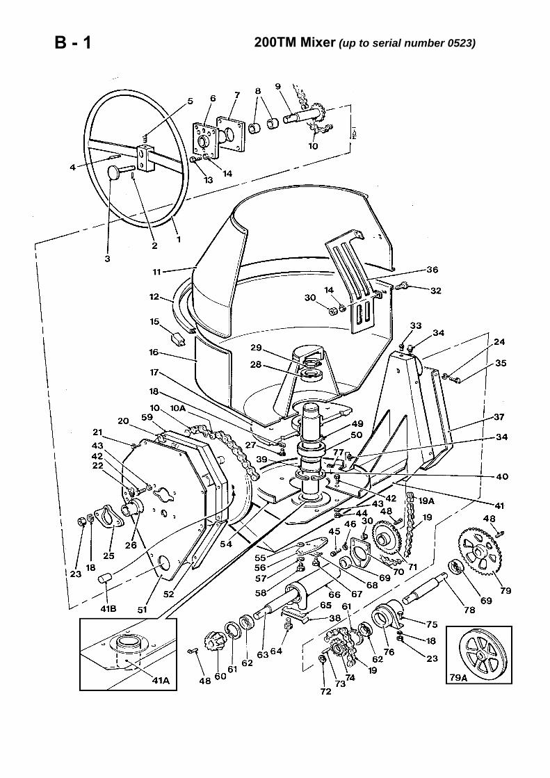
B - 1 200TM Mixer (up to serial number 0523)

DRUM & TRUNNION B - 1
Item Part no Serial no Description Qty
66 513305400 HOUSING, shaft, bevel pinion 167 11SO6E SCREW, set 268 513326300 WASHER, tab 169 88S15D BEARING 270 513151900 PLATE, adjusting 1
71 513305300 CHAIN WHEEL, bevel pinion shaft 172 132725000 CIRCLIP 173 304708035 KEY, feather 174 513310500 SPROCKET, countershaft 175 11SO5F SCREW, set 2
76 513305500 BEARING, trunnion 177 72S02 NUT, (welded to Guard, item 54) 178 513310400 COUNTERSHAFT 1
79 513310800 CHAIN WHEEL, countershaft, Petter PH1& Lister-Petter TS1 1
79A 513331800 PULLEY, vee, countershaft, electric drive 1
- V2000772 SEALING COMPOUND, AR(Between items 11 & 16 on assembly)
V601137 / July '03

C - 1 200TM Mixer (up to serial number 0523)

DRIVE ASSEMBLY, Petter PH1 C - 1
Item Part no Serial no Description Qty
1 354071250 / Feb-90 ENGINE, Petter PH1 12 8SO5K BOLT 43 59S04 NUT, nylon insert 44 513142800 SHIMS (set) set 15 513329000 SPROCKET, engine 1
6 300106160 KEY, gib head 17 513335300 PIPE, exhaust 18 513335200 BRACKET, exhaust pipe 19 241908000 SOCKET 1
10 240708000 ELBOW, 90 degree, m/f 1
11 513333400 PLATE, closing 112 513335600 GUARD, sprocket 113 --- PUMP, hydraulic (See page E - 1) 114 3SO3E SCREW, set 215 11S04B SCREW, set 10
16 7S04 NUT 1017 17S05 WASHER, spring 1018 134105102 CHAIN 1--- 134105002 LINK, connecting 1--- 134105001 LINK, half 119 513328200 LID, engine housing 120 513325800 STAY 1
21 11S04D SCREW, set 222 7S03 NUT 123 11S03C SCREW, set 124 12S03 WASHER, flat 125 513205300 STOP, lid 2
26 11 SO2A SCREW, set 427 7S02 NUT 428 513248700 GUARD, chain 129 11S03A SCREW, set 830 17S04 WASHER, spring 8
31 7S02 NUT 8
V601137 / July '03

C - 2 200TM Mixer (up to serial number 0523)

AIR CLEANER (optional) C - 2
Item Part no Serial no Description Qty
1 220229000 AIR CLEANER, assembly 1
- 220229001 ELEMENT 1
2 220229002 CLAMP, band 2
3 220229004 CAP, stack 1
4 10840A03 HOSE, air intake, c/w adaptor flange 1
5 97S12 CLIP, worm drive 2
6 11SO3B SCREW, set 4
7 7S03 NUT 48 17S04 WASHER, spring 4
V601137 / July '03

C - 3 200TM Mixer (up to serial number 0523)

DRIVE ASSEMBLY, electric C - 3Item Part no Description Qty
1 202439000 / Apr-87 MOTOR, electric 11 202440000 Apr-87 / MOTOR, electric 12 208393500 / 0507 # SWITCH, `Start/ stop" 1
2A 208304103 0508 / # SWITCH, "Start/ stop" 12B 208304104 0508 / # RELAY, overload 12C 13203000 0508 / # MOUNTING, shock absorbing 3
# Machine Serial numbers
3 208870000 / Oct-04 # SWITCH, stop, assembly 1# OBSOLETE: use 208880000
…… V602651 / Oct-04 KEY, stop switch 13 208880000 Oct-04 / SWITCH, stop, assembly 1
…… V603623 Oct-04 / KEY, stop switch 14 513332600 PLATE, motor mounting 15 513332700 SUPPORT, motor mounting 16 513334700 PULLEY,'V', motor 17 513336100 GUARD 18 513332800 PLATE, mounting, hydraulic pump 19 513332900 COUPLING, pump, half 1
10 513336300 GUARD, internal drive 111 11SO5D SCREW, set 212 59S04 NUT, nylon insert 413 8SO5E BOLT 214 267S07 WASHER, flat 215 8S04D BOLT 416 59S03 NUT, nylon insert 417 7S05 NUT 418 17S06 WASHER, spring 419 11 S03C SCREW, set 420 59S12 NUT, nylon insert 421 304710840 KEY, parallel 222 57SO4D SCREW, grub 123 147320400 / Apr-87 COUPLING, drive half, 24mm bore 123 147320500 Apr-87 / COUPLING, drive half, 28mm bore 124 11 SO2A SCREW, set 225 147320303 SLEEVE, coupling 126 --- PUMP, hydraulic (See page E - 1) 127 8SO2C BOLT 428 7S02 NUT 529 17S03 WASHER, spring 430 397400100 BELT,'V` 131 16SO6H SCREW, pan head slotted 232 7S01 NUT 833 17S02 WASHER, spring 834 11S03A SCREW, set 8
V601137 / Nov '04 continued >
Date

C - 3 200TM Mixer (up to serial number 0523)

DRIVE ASSEMBLY, electric C - 3
Item Part no Serial no Description Qty
V601137 / July '03
55 17S05 WASHER, spring 654 7S04 NUT 653 11S04B SCREW, set 652 513205300 STOP, lid 151 513248700 GUARD, chain 1
50 513336200 LID, housing 149 17S05 WASHER, spring 248 1 1SO4D SCREW, set 247 267S05 WASHER, flat 146 813325800 STAY 1
- 144799000 CABLE, greenlyellow (order by metre) AR- 144798000 CABLE, black (order by metre) AR- 144797000 CABLE, red (order by metre) AR
45 131271000 COUPLING 244 131770000 CONDUIT, pliable (0.75 metres long) 143 131570016 SOCKET, reducing 142 131766010 CONDUIT, pliable (0.5 metres long) 141 133266050 NUT, locking 140 131270000 COUPLING 1
39 11SO1B SCREW, set 338 513333300 PLATE, closing 137 513333100 STUD, motor adjusting 136 7S03 NUT 635 17S04 WASHER, spring 8

C - 4 200TM Mixer (up to serial number 0523)
To order engine spares, please click below and refer to the relevant engine parts manual :
LISTER PETTER TR1

DRIVE ASSEMBLY, Lister-Petter TS/TR1 C - 4
Item Part no Serial no Description Qty
1 17S05 Feb-90 / WASHER, spring 22 1 1S04D Feb-90 / SCREW, set 23 7S03 Feb-90 / NUT 14 12S03 Feb-90 / WASHER, flat 15 11 S03C Feb-90 / SCREW, set 1
6 153S08 Feb-90 / CLAMP, exhaust pipe 17 13204000 Feb-90 / Apr-91 STOP, bump (OBSOLETE: use 7A to 7D)
7A 513205300 Apr-91 / STOP, bump 27B 11 S02A Apr-91 / SCREW, set 47C 61S02 Apr-91 / NUT, self-locking 47D 267S04 Apr-91 / WASHER, flat 4
8 513325800 Feb-90 / STAY 19 513346700 Feb-90 / LID, engine housing 1
10 --- Feb-90 / PUMP, hydraulic (See page E - 1) 111 513346800 Feb-90 / PLATE, closing 112 513348300 Feb-90 / SPROCKET 113 304312050 Feb-90 / KEY, gib head 114 V2001661 Feb-90 / ENGINE, TS/TR1 115 - Feb-90 / DYNAMO (see Electrics Section)
16 513248700 Feb-90 / GUARD, chain 117 513347900 Feb-90 / PIPE, exhaust 118 7S04 Feb-90 / NUT 619 17S05 Feb-90 / WASHER, spring 620 11S04B Feb-90 / SCREW, set 6
21 59S04 Feb-90 / NUT, nylon insert 422 513348400 Feb-90 / SHIMS (set) 1 set23 8S05K Feb-90 / BOLT, engine mounting 424 103SO2C Feb-90 / SCREW 425 41S03 Feb-90 / WASHER, spring 4
26 397355000 Feb-90 / BELT, vee 127 513335600 Feb-90 / 0479 # GUARD (OBSOLETE: use 513350500) 127 513350500 0480 / # GUARD, sprocket 1
# Machine Serial numbers
28 11 S04C Feb-90 / SCREW, set 129 7S04 Feb-90 / NUT 130 17S05 Feb-90 / WASHER, spring 131 134105102 Feb-90 / CHAIN 1--- 134105002 Feb-90 / LINK, connecting 1--- 134105001 Feb-90 / LINK, half 1
V601137 / July '03

D - 1 200TM Mixer (up to serial number 0523)

HOPPER D - 1
Item Part no Serial no Description Qty
1 513310900 HOPPER, assembly 1
2 513311400 / 0533 COVER (welded to hopper) 1
3 11SO3A / 0533 SCREW, set 10
4 17S04 / 0533 WASHER, spring 10
5 7S03 / 0533 NUT 10
V601137 / July '03

D - 2 200TM Mixer (up to serial number 0523)

HOPPER CRADLE, non weigher D - 2
Item Part no Serial no Description Qty
1 513311800 CRADLE, non weigher 12 513312600 BEARING 23 513312700 PIN, pivot, hopper 14 --- RAM, hopper (see page E - 5) 15 513312900 PIN, ram, lower 1
6 513313000 PIN, ram, upper 17 8S03E BOLT 28 17S04 WASHER, spring 59 7S03 NUT 2
10 172SO5D BOLT, coach 8
11 267S07 WASHER, flat 812 56S05 NUT, locking 813 7S05 NUT 814 131S01 NIPPLE, grease, straight 3--- 131S02 NIPPLE, grease 90 deg. 1--- 176S01 CAP, grease nipple 4
15 11S03A SCREW, set 116 68SO4D SCREW, socket head cap 2
V601137 / July '03

D - 3 200TM Mixer (up to serial number 0523)

HOPPER CRADLE, weigher D - 3
Item Part no Serial no Description Qty
1 513317500 CRADLE, weigher 12 513316700 SHAFT, cradle 13 513316800 SHAFT, hopper 14 513328800 WASHER 45 417705600 SEALS 8
6 113179100 BEARING, needle 47 513317100 CARRIER 48 513316900 LINK, weigher 29 267S12 WASHER, flat 4
10 7S08 NUT 4
11 131S01 NIPPLE, grease straight 5--- 131S02 NI PPLE, grease, 90 deg. 1--- 176S01 CAP, grease nipple 412 68SO4C SCREW, socket head cap 413 17S04 WASHER, spring 214 11S05C SCREW, set 815 513322200 BRACKET, cradle 1
16 513317200 ROLLER, cradle 117 112753000 BUSH 418 513317400 PIN 119 61S05 NUT, self-locking 820 267S07 WASHER, flat 9
21 513321000 PIVOT 122 513321700 BRACKET 123 513317300 PIN, loadcell bracket 124 1 1SO3E SCREW, set 125 7S03 NUT 2
26 --- LOADCELL & GAUGE (see page E - 3) 127 513329200 STRIKER 128 56S06 NUT, locking 129 513312900 PIN, ram, lower 130 513313000 PIN, ram, upper
31 8S03E BOLT 232 17S04 WASHER, spring 433 7S03 NUT 234 --- RAM, hopper (see page E - 5) 135 172SO5D BOLT, coach 8
36 7S05 NUT 837 56S05 NUT, locking 838 57SO5E2 SCREW, grub 239 17S04 WASHER, spring 440 68SO4D SCREW, socket head cap 2
V601137 / July '03

E - 1 200TM Mixer (up to serial number 0523)

HYDRAULIC CIRCUIT, basic E - 1
Item Part no Serial no Description Qty
1 513305800 TANK, oil 12 513306400 LID, tank 13 513328000 CLAMP, hose 34 513329600 CLAMP, hose 1
5 451441500 / Jan-88 VALVE, control 15A --- Jan-88 / VALVE, control (see page E - 1 A) 1
6 11S03AA / Jan-88 SCREW, set 26A 8S04J Jan-88 / BOLT 36B 7S04 Jan-88 / NUT 3
7 17S04 / Jan-88 WASHER, spring 167 17S04 Jan-88 / WASHER, spring 14
7A 17S05 Jan-88 / WASHER, spring 3
8 100S04 / Jan-88 SEAL, bonded 48 100S04 Jan-88 / SEAL, bonded 2
8A 100S06 Jan-88 / SEAL, bonded 2
8B 100S04 / Sep-87 SEAL, bonded 1BC 100S06 Sep-87/ Feb-90 SEAL, bonded 1
9 360400400 / Jan-88 PLUG 19A 127S04 Jan-88 / PLUG 1
10 119S08 / Jan-88 ADAPTOR, m/m 410 119S08 Jan-88 / ADAPTOR, m/m 2
10A 119S10 Jan-88 / ADAPTOR, m/m 210B 119S08 Jan-88 / ADAPTOR, m/m 1
11 513329700 HOSE 112 31SO2EE HOSE 113 122S03 ADAPTOR, m/m 2
13A 122S03 / Sep-87 ADAPTOR, m/m 114 100S03 SEAL, bonded 2
14A 100S03 / Sep-87 SEAL, bonded 115 360400200 PLUG 216 41S05 WASHER, spring 117 66SO3CC SCREW, set 118 503139400 MANIFOLD 119 7S03 NUT 1420 8S03E BOLT 421 513329800 HOSE 122 31SO2D HOSE 1
23 122S04 / Sep-87 ADAPTOR, m/m 123A 119S13 Sep-87 / Feb-90 ADAPTOR, m/m 1
V601137 / July '03 continued >

E - 1 200TM Mixer (up to serial number 0523)

HYDRAULIC CIRCUIT, basic E - 1
Item Part no Description Qty
24 365866100 / Sep-87 FITTING, elbow 124A 103S03J / Sep-87 SCREW, socket 224B V2002309 Sep-87 / Feb-90 KIT, elbow, assembly 124C - Sep-87 / Feb-90 ELBOW (order assembly) 124D 41S03 Sep-87 / Feb-90 WASHER, spring 224E 391832000 Sep-87 / Feb-90 SEAL, 'O' ring 124F 103SO2F Sep-87 / Feb-90 SCREW, socket 2
24G 119S13 Feb-90 / 0524 # ADAPTOR, m/m 124G 122S04 0525 / # ADAPTOR, m/m
24H 100S06 Feb-90 / 0524 # SEAL, bonded24H 100S04 0525 / # SEAL, bonded
# Machine Serial numbers
Petter PH1 engined mixers25 365867000 Sep-87 PUMP, hydraulic ("Dowty/Ultra") 125 365869000 Sep-87 / Feb-90 PUMP, hydraulic ("Sunstrand") 1
Lister- Petter TS1 engined mixers25 11040A03 Feb-90 / 0524 # PUMP, hydraulic ('Sunstrand") 125 10977A03 0525 / # PUMP, hydraulic ("Ultra") 1
# Machine Serial numbers
Electrically driven mixers25 365866000 / Sep-87 PUMP, hydraulic ("Dowty/Ultra") 125 365868000 Sep-87 / 0524 # PUMP, hydraulic ("Sunstrand") 125 10977A03 0525 / # PUMP, hydraulic ("Ultra") 1
# Machine Serial numbers
26 391832000 / Sep-87 'O' RING 126 391109000 Sep-87 / Feb-90 'O' RING 1
27 555136400 / Sep-87 CONNECTOR, pump 127A V2002321 Sep-87 / Feb-90 KIT, adaptor plate, assembly 127B - Sep-87 / Feb-90 PLATE, adaptor (order assembly) 127C 103S02B Sep-87 / Feb-90 SCREW, socket 227D 41S03 Sep-87 / Feb-90 WASHER, spring 2
27 391832000 Sep-87 / Feb-90 SEAL, 'O' ring 127F 119S08 Feb-90 / FITTING, adaptor, m/m 127G 100S04 Feb-90 / SEAL, bonded 1
28 103S03C / Sep-87 SCREW, socket head cap 2
29 96S09 ELBOW 1
30 513335500 / Sep-87 HOSE, Petter PH1 drive 130 31S03Q / Sep-87 HOSE, Electric drive 130 36SO3EE Sep-87 / Feb-90 HOSE 130 V2003289 Feb-90 / HOSE, Lister-Petter TS1 1
V601137 / July '03 continued >
Date

E - 1 200TM Mixer (up to serial number 0523)

HYDRAULIC CIRCUIT, basic E - 1
Item Part no Serial no Description Qty
31 220246000 FILLER/BREATHER 132 417735000 GASKET 133 220592000 STRAINER 134 241702000 PLUG 1
35 11S03A SCREW, set 1036 100S02 SEAL, bonded 237 120S02 PLUG, blanking, cap 138 186S02 WASHER, selon 639 332719000 NUT, spire, captive 8
40 11 SO2A SCREW, set 841 --- RAM, hopper (see page E - 5) 1
V601137 / July '03

E - 1AA 200TM Mixer (up to serial number 0523)

CONTROL VALVE, monobloc E - 1AA
Item Part no Serial no Description Qty
1 451441600 / Jan-88 CONTROL VALVE 1
2 30322A0502 SCREW, socket cap head 2
3 30322A0204 CAP, end 1
4 30322A0102 VALVE, relief 1
5 30322A0503 HANDLE, assembly 1
6 68S02B SCREW, socket cap head 4
7 10S05 SPACER, washer 1
8 451441501 ADAPTOR 1
10 451441502 KIT, seals 1
11 30322A0203 KIT, repair 1
12 13S01 WASHER 8
13 30322A0505 KNOB 1
V601137 / Nov '04

E - 1A 200TM Mixer (up to serial number 0523)

CONTROL VALVE, sectional E - 1A
Item Part no Serial no Description Qty
1 V2000399 Feb-88 / CONTROL VALVE, assembly 12 V600017 COVER, inlet 14 127S04 PLUG 15 100S06 SEAL, bonded 16 V2003112 COVER, end 17 V600178 KIT, seals 18 V600184 VALVE, relief, 2000psi 19 V600023 KIT, seals 1
10 V600024 STUD 311 9S03 NUT 312 41S05 WASHER, spring 313 --- SECTION, control valve (see page E-1B)
14 451431029 FITTING, carryover, assembly 114A 451431005 SEAL,'O' ring 1
V601137 / July '03

E - 1B 200TM Mixer (up to serial number 0523)

SECTION, control valve E - 1B
Item Part no Serial no Description Qty
1 V600026 Feb-88 / SCREW, c/w washer 22 V2003116 CAP, end 13 V2003115 SCREW, shoulder 14 V2003117 SEAT, spring 25 V2003114 SPRING 16 V600179 SPACER 1
6A V600180 CHECK VALVE, assembly 17 V600181 KIT, repair 18 V2003118 GUIDE, check valve 19 V600182 RING, back up 1
10 V600183 O' RING 111 V2003119 SPRING 112 V2003120 POPPET 1
13 V600185 BODY, c/w spool 114 V2003113 O' RING 2
14A V601259 LEVER, assembly 115 V2003122 SEAL, wiper 116 V600059 BRACKET, handle 117 V600060 PIN, roll 118 V600061 LINK 119 V600062 SCREW, c/w washer 220 V600063 CLEVIS 121 V600064 PIN 122 V600065 PIN, clip 1
22A V600159 HANDLE, assembly 123 V600066 NUT 124 --- HANDLE, (order assembly) 125 V600068 KNOB 126 V600069 GAITER 1
V601137 / July '03

E - 2 200TM Mixer (up to serial number 0523)

HYDRAULIC CIRCUIT, weigher E - 2
Item Part no Serial no Description Qty
Additional fittings for weigher.
For basic hydraulic circuit, see page E - 1
1 503139300 VALVE, bleed, assembly 12 503139400 BODY, bleed valve 13 423208280 SPRING 14 503139500 PLUNGER, bleed valve 1
5 110959000 TUBE, nylon 16 139210063 COUPLING 27 70SO4E SCREW, pan head 28 143200900 CLIP, nylon 29 7S01 NUT 2
10 100S02 SEAL, bonded 211 66SO3CC SCREW, set 112 41S05 WASHER, spring 1
V601137 / July '03

E - 3 200TM Mixer (up to serial number 0523)
MHY-1

LOADCELL & GAUGE E - 3
Item Part no Serial no Description Qty
1A 513338440 LOADCELL & GAUGE, assembly 11 - WEIGH GAUGE (see page E - 3A) 12 253817055 POINTERS, load indicating set 13 417858000 SEAL, bonded 14 555182800 ADAPTOR 15 513331700 HOSE 1
5A 513331700 $ HOSE 15B V601532 $ ADAPTOR & BLOCK 15C 116S06 $ WASHER, copper 2
$ Alternative hose arrangement
6 100S02 # SEAL, bonded 27 353304070 # PIN, split 18 555182700 # ADAPTOR 1
# Not fitted from circa 1990
9 513265700 PIN, locking 110 513265500 RING, sealing 211 403760610 SCREW, grub 112 101104001 BALL, steel 113 513265300 BODY, loadcell 114 391350340 SEAL, ‘O’ ring 215 513265400 PLATEN 116 513265600 SLEEVE, floating 1
17 13203000 SHOCK ABSORBER, rubber, c\w nuts 418 11S03B SCREW, set 219 17S04 WASHER, spring 220 7S03 NUT 2
21 555125000 COVER, dial 122 261S02M SCREW, thumb 4
23 513327700 BRACKET 124 513327800 BRACKET 1
25 16S05B SCREW, pan head 226 143200900 CLIP, nylon 2
……. 267S02 WASHER, flat (not illustrated) 2……. 17S10 WASHER, spring (not illustrated) 227 7S09 NUT 2
28 11S05C SCREW, set 129 17S06 WASHER, spring 130 267S07 WASHER, flat 1
V601137 / July '03

E - 3A 200TM Mixer (up to serial number 0523)

WEIGH GAUGE E - 3A
Item Part no Serial no Description Qty
1 253824000 GAUGE, assy. (see also page E - 3) 1
2 253818012 DIAL, 12", 1100 lbs 1
3 253818005 GLASS 1
4 253818006 SEAL, glass 1
5 253818003 SEAL, backplate 1
6 253818002 BACKPLATE 1
6A 253818004 SCREW, round head 6
7 253818000 INDICATOR 1
8 253817001 MOVEMENT 1
9 253824001 TUBE-COIL 1
10 253817005 # BLEED SCREW & BALL (1/8" ball) 110 253817006 # BLEED SCREW & BALL (2.5mm ball)
# Before ordering check size of the ballas they are not interchangeable
11 —---------- BODY c/w front plate (order assy.) 111A 253818001 SCREW, round head 6
—- —---------- NUT, gauge zeroing (order assy.) 1
15 67S01 WASHER, shakeproof 416 253817045 SCREW, set 4
V601137 / July '03

E - 4 200TM Mixer (up to serial number 0523)

HYDRAULIC CIRCUIT, dragline E - 4
Item Part no Serial no Description Qty
Additional fittings for dragline.
For basic hydraulic circuit, see page E - 1
ADAPTOR, motor supply ports1 555276700 ADAPTOR, winch motor2 391111000 SEAL,'O' ring 13 404921000 SCREW, grub 24 417804000 SEAL bonded 25 101120000 BALL, steel 16 555267100 SPRING, bleed valve 17 142515000 ADAPTOR, m/m 1
ADAPTOR, motor supply port8 555276600 ADAPTOR, winch motor 19 391111000 SEAL,'O' ring 1
10 417804000 SEAL, bonded 111 142515000 ADAPTOR, m/m 1
12 267115000 MOTOR, hydraulic 113 31S02M HOSE 214 V2003111 STRAP, nylon 215 446110000 ADAPTOR, m/m 416 100S03 SEAL, bonded 417 555137900 MANIFOLD, dragline control 118 555138300 VALVE, relief 119 555556100 SPRING 120 10S02 WASHER, flat 121 100S04 SEAL, bonded 222 555138200 VALVE, guide 123 66SO1AA SCREW, set 224 41S03 WASHER, spring 425 103SO2H SCREW, socket head 426 31SO2FF HOSE 127 513330800 HOSE 128 119S08 ADAPTOR, m/m 1
29 451441501 / Jan-88 ADAPTOR, carry over, used with controlvalve 451441500 1
29 V2000401 Jan-88 / ADAPTOR, carry over, used with controlvalve V2000399 1
Note: For control valve, see page E - 1
30 211158000 VALVE, solenoid 131 10S01 WASHER, flat 2
V601137 / July '03

E - 5 200TM Mixer (up to serial number 0523)

RAM, hopper E - 5
Item Part no Serial no Description Qty
1A 513305700 RAM, hopper, assembly 11 272137501 CYLINDER, ram 12 272137502 ROD, ram 13 272137503 PISTON, ram 14 272137504 PLATE, back up 15 272137505 CAP, screwed 1
5A 513305701 KIT, seals, assembly 16 --- SEAL, piston (order assembly) 17 --- SEAL, wiper (order assembly) 18 --- SEAL,'O' ring (order assembly) 19 272137509 PIN, split 1
10 272137510 SCREW 111 272137511 NUT 112 513350400 Nov-90 / RESTRICTOR 1
15 131S01 0478 / NIPPLE grease, straight16 131S02 0478 / NIPPLE: grease, 90 deg.17 176S01 0478 / CAP, grease nipple 2
V601137 / July '03

F - 1 200TM Mixer (up to serial number 0523)

WATER TANK F - 1
Item Part no Serial no Description Qty
1 513327100 BODY, water tank 12 513327000 STAY 13 8S03E BOLT 14 61S03 NUT, binx 15 44S17J PIN, split 2
6 425435000 SPRING 17 513326600 ROD 18 513326700 PLATE 19 513326800 CONNECTOR 1
10 7S04 NUT 1
11 267S06 WASHER, flat 112 513286200 VALVE, rubber 113 513286400 CHAIN & RING 114 383106000 PIN, split 115 513324600 SCALE 1
16 70SO4D SCREW, pan head 217 59S13 NUT, self-locking 218 12S48 WASHER, flat 219 430904001 TUBE 120 132111200 CLIP, hose 2
21 101256000 BALL 122 450150000 VALVE 123 130354000 CONNECTOR, hose 124 11SO5C SCREW, set 425 7S05 NUT 4
26 17S06 WASHER, spring 427 513337800 LID, tank 128 11 S02C SCREW, set 229 17S03 WASHER, spring 230 504531500 NOZZLE, rubber 1
31 97S13 CLIP, hose 132 236S04 NUT, blind 233 267S05 WASHER, flat 1
V601137 / July '03

G - 1 200TM Mixer (up to serial number 0523)

DRAGLINE G - 1
Item Part no Serial no Description Qty
1 513322400 JIB, leg, R.H. 12 513322500 JIB, leg, L.H. 13 513322700 TIE BAR, tilt end 14 513323400 TIE BAR, engine end 15 513338100 PLATE 4
6 513338000 JIB, leg 27 513322600 BEAM, top 18 513323500 PIN, pulley 29 513330000 PIN, pivot 1
10 555228100 BRACKET, pulley 1
11 555265000 PIN, pulley 212 555265200 / Jan-93 PULLEY, (cast iron) 312 555285500 Jan 93 / PULLEY, (nylon) 313 513330300 MAST, cable 114 513330200 GUARD, winch 115 513330400 GUARD, rope 1
16 513330500 PLATE, rope guard 117 513330100 DRUM, winding 118 555266300 WASHER 119 555208500 PULLEY, block, assembly 220 555208300 PIN, pulley 1
21 555208100 PULLEY 122 555208400 BLOCK, pulley 123 44S14F PIN, split 124 555204800 WEIGHT, sheave 125 353325050 PIN, split 4
26 8S05L BOLT 627 61S05 NUT, binx 1428 11SO5C SCREW, set 229 7S05 NUT 630 17S06 WASHER, spring 6
31 8SO5M BOLT 832 8S05H BOLT 433 11S02A SCREW, set 934 11S02AA SCREW, set 835 332719000 NUT, spire, captive 9
36 7S02 NUT 237 17S03 WASHER, spring 238 8S07G BOLT 239 7S07 NUT 240 17S09 WASHER, spring 2
V601137 / July '03 Continued >

G - 1 200TM Mixer (up to serial number 0523)

DRAGLINE G - 1
Item Part no Serial no Description Qty
41 - MOTOR, hydraulic (see page E - 4) 142 6SO6H BOLT 143 41S09 WASHER, spring 144 477502000 ROPE, wire 145 132204000 CLIP, rope 3
46 443105010 THIMBLE 147 412606000 SHACKLE 148 330102020 NIPPLE, grease 349 112805300 / Jan-93 BUSH 650 12S23 WASHER, flat 14
V601137 / July '03

G - 2 200TM Mixer (up to serial number 0523)

LOADING SHOVEL G - 2
Item Part no Serial no Description Qty
1 513331300 SHOVEL 12 555209100 HANDLE, shovel 13 44S17K PIN, split 24 369200000 TUBE, rubber 15 555214800 CLAMP, switch 16 8SO1F BOLT 27 11S05D SCREW, set 28 143200300 CLIP, cable 19 144734000 CABLE 1
10 16S05B SCREW, pan head 111 17S02 WASHER, spring 112 205304600 PLUG 113 208143000 SLEEVING 114 208561000 SWITCH 115 250166010 GLAND, cable 116 264705000 HANDLE, grip 217 7S01 NUT 418 463504000 WASHER, rubber 119 59S04 NUT, self-locking 220 267S07 WASHER, flat 221 135905000 CHAIN & RING 122 59S02 NUT, nylon insert 1
V601137 / July '03

G - 3 200TM Mixer (up to serial number 0523)

LOADING RAMP G - 3
Item Part no Serial no Description Qty
1 513336900 PANEL, side, L.H. 12 513332000 PLATE, floor 13 513336901 PANEL, side, R.H. 14 513337000 PARTITION 15 513332300 STRIP, countersunk 16 52S04G SCREW, countersunk 97 7S04 NUT 98 17S05 WASHER, spring 99 513332500 FLAP, rubber 1
10 513336700 SUPPORT, angle 111 11S05C SCREW, set 2612 7S05 NUT 2613 17S06 WASHER, spring 26
V601137 / July '03

H - 1 200TM Mixer (up to serial number 0523)

WIRING LOOM, dragline H - 1
Item Part no Serial no Description Qty
- 513340300 LOOM assembly, dragline 11 20203000 REGULATOR 12 205304600 PLUG, socket 13 V2003252 GROMMET 24 207652000 RESISTOR, wire wound 15 555213700 BOARD, insulating 16 555253800 CLAMP, socket cable 17 82SO7F SCREW, round head 18 83S07 NUT 19 11SO1A SCREW, set 2
10 17S02 WASHER, spring 211 7S01 NUT 212 11SO2B SCREW, set 213 267S04 WASHER, flat 414 61S02 NUT, self -locking 215 11SO1A SCREW, set 216 267S03 WASHER, flat 417 17S03 WASHER, spring 218 7S01 NUT
V601137 / July '03

H - 2 200TM Mixer (up to serial number 0523)

DYNAMO & MOUNTING H - 2Dragline mixer with Petter PH1 engine
Item Part no Serial no Description Qty
1 513334200 BRACKET, dynamo adjuster 12 513334600 BRACKET 13 397463000 BELT, vee 14 418200808 SCREW, set 25 41S07 WASHER, spring 26 66SO2A SCREW, set 27 104S02 NUT 28 41S04 WASHER, spring 29 66S02CC SCREW, set 1
10 10S02 WASHER, flat 111 513335100 PULLEY 112 513334300 PULLEY, dynamo 113 205501000 DYNAMO 1
V601137 / July '03

H - 3 200TM Mixer (up to serial number 0523)

DYNAMO & MOUNTING H - 3Dragline mixer with Electric drive
Item Part no Description Qty
1 513333000 BRACKET, dynamo 12 513333200 BRACKET, dynamo adjuster 13 513334300 PULLEY, dynamo 1
4 513334900 / Apr-87 PULLEY, dynamo drive, 24mm bore 14 513350600 Apr-87 / 0507 # PULLEY, dynamo drive, 28mm bore 1
4A 513349900 0508 / # PULLEY/HALF COUPLING, (welded) 1Note: 513349900 consists of pulley513350600 and half coupling 147320500welded together.
# machine serial numbers
5 397436000 BELT, vee 16 66SO2A SCREW, set 57 104S02 NUT 58 41S04 WASHER, spring 59 66SO2CC SCREW, set 1
10 10S02 WASHER, flat 111 205501000 DYNAMO 1
V601137 / July '03
Date

H - 4 200TM Mixer (up to serial number 0523)

DYNAMO & MOUNTING H - 4Dragline mixer with Lister-Petter TS/TR1 engine
Item Part no Serial no Description Qty
1 205501100 Feb 90 / DYNAMO 11A 513334300 PULLEY,dynamo 1
2 --- CABLE, electric (see page H - 1)3 513347300 BRACKET, dynamo 14 11 S03C SCREW, set 25 17S04 WASHER, spring 26 7S03 NUT 17 17S04 WASHER, spring 18 513347400 STAY, dynamo 19 267S05 WASHER, flat 1
10 11S03D SCREW, set 111 17S04 WASHER, spring 112 11S03B SCREW, set 113 66SO3CC SCREW, set 214 41S05 WASHER, spring 215 513347700 BRACKET, stay, dynamo 1
20 513348500 PULLEY, assembly, engine 121 57SO5E1 SCREW, grub 1
22 189S02A BELT, 850mm long 1
25 11 S03B SCREW, set 226 267S05 WASHER, flat 227 17S04 WASHER, spring 228 7S03 NUT 2
V601137 / July '03

J - 1 200TM Mixer (up to serial number 0523)

DECALS & PLATES J - 1
Item Part no Serial no Description Qty
1 V2003108 “200TM” 1
2 V2003037 PLATE, serial number 1- 15S01A SCREW 4
3 504600900 WARNING, engine housing 1
4 504694600 WARNING, safety 1
5 513331500 WATER TANK OPERATION 1
6 513331600 DANGER, hopper 2
7 555153600 HOPPER CONTROL 1
8 V2003039 LOGO, "WINGET" 4
9 V2003038 STRIPE, bodywork 4
10 V2003101 DIESEL FUEL 1
11 V2003100 HYDRAULIC OIL 1
12 515175000 WARNING, loadcell 1- 101S05D RIVET, pop 4
13 V2003665 SLING POINTS 2
14 V2003598 BRITISH MADE 1
15 10166A02 TYRE PRESSURE 4
16 4602331 NEGATIVE 1
V601137 / July '03

J - 1A 200TM Mixer (up to serial number 0523)

DECALS & PLATES J - 1A
Item Part no Serial no Description Qty
20 V2004259 HOPPER CONTROLS 1
21 V2004137 EAR PROTECTION 2
22 V2004227 BATTERY ISOLATOR 1
23 V2004229 OPERATORS HANDBOOK 2
24 V2004282 HOT SURFACES 1
25 V2004289 HANDS CLEAR 2
26 V2004302 ENGINE STOP 1
27 V2004307 ELECTRICAL HAZARD 2
28 V2004288 REMOVE STARTING HANDLE 1
29 V2004235 NEGATIVE EARTH 1
30 V2004281 ENTRAPMENT 1
31 V2004131 85 LpA 1
32 V2003575 105 LWA 1
V601137 / July '03

J - 1B 200TM Mixer (up to serial number 0523)

DECALS & PLATES J - 1B
Item Part no Serial no Description Qty
35 V2004223 “CE” MARK 1(Only applied to EC specification machines)
36 V2004744 EYE PROTECTION 2
37 V2005208 ENGINE STARTING PROCEDURE 1
V601137 / July '03

J - 2 200TM Mixer (up to serial number 0523)
MMI - 15

SPECIAL TOOLS J - 2
Item Part no Serial no Description Qty
1 513204000 CLAMP, drum clip 1
2 V2003698 PUNCH, bleed valve seat 1
V601137 / July '03

Up to mixer serial number 0523
Numerical Index


Part No. Page Part No. Page Part No. Page 4602331 J - 1 134105102 C - 4 220246000 E - 1
13203000 C - 3 134105107 B - 1 220592000 E - 113203000 E - 3 135902000 G - 2 240708000 C - 113204000 C - 4 139210063 E - 2 241702000 E - 120203000 H - 1 142515000 E - 4 241908000 C - 1
101104001 E - 3 143200300 G - 2 250166010 G - 2101120000 E - 4 143200900 E - 2 253817001 E - 3A101256000 F - 1 143200900 E - 3 253817005 E - 3A110959000 E - 2 144734000 G - 2 253817006 E - 3A112753000 D - 3 144797000 C - 3 253817045 E - 3A112803400 B - 1 144798000 C - 3 253817055 E - 3112805300 G - 1 144799000 C - 3 253818000 E - 3A113179100 D - 3 147320303 C - 3 253818001 E - 3A130354000 F - 1 147320400 C - 3 253818002 E - 3A131270000 C - 3 147320500 C - 3 253818003 E - 3A131271000 C - 3 202439000 C - 3 253818004 E - 3A131570016 C - 3 202440000 C - 3 253818005 E - 3A131766010 C - 3 205304600 G - 2 253818006 E - 3A131770000 C - 3 205304600 H - 1 253818012 E - 3A132111200 F - 1 205501000 H - 2 253824000 E - 3A132204000 G - 1 205501000 H - 3 253824001 E - 3A132313000 B - 1 205501100 H - 4 264705000 G - 2132362000 B - 1 207652000 H - 1 267115000 E - 4132725000 B - 1 208143000 G - 2 272137501 E - 5132760000 B - 1 208304103 C - 3 272137502 E - 5132775000 B - 1 208304104 C - 3 272137503 E - 5134105001 B - 1 208393500 C - 3 272137504 E - 5134105001 C - 1 208561000 G - 2 272137505 E - 5134105001 C - 4 208870000 C - 3 272137509 E - 5134105002 B - 1 211158000 E - 4 272137510 E - 5134105002 C - 1 220229000 C - 2 272137511 E - 5134105002 C - 4 220229001 C - 2 300106160 C - 1134105070 B - 1 220229002 C - 2 300110845 B - 1134105102 C - 1 220229004 C - 2 304312050 C - 4

Part No. Page Part No. Page Part No. Page 304708035 B - 1 397463000 H - 2 504531500 F - 1304708040 B - 1 403760610 E - 3 504600900 J - 1304710840 C - 3 404921000 E - 4 504694600 J - 1315803100 B - 1 405100616 B - 1 513142800 C - 1330102020 G - 1 412606000 G - 1 513151900 B - 1332719000 A - 1 417705600 D - 3 513152400 B - 1332719000 B - 1 417735000 E - 1 513194400 B - 1332719000 E - 1 417804000 E - 4 513198500 A - 1332719000 G - 1 417858000 E - 3 513204000 J - 2333102020 B - 1 418200808 H - 2 513205300 C - 1335010200 B - 1 423208280 E - 2 513205300 C - 3352806100 B - 1 425435000 F - 1 513205300 C - 4353304070 E - 3 430904001 F - 1 513248700 C - 1353308200 A - 1 443105010 G - 1 513248700 C - 3353325040 A - 1 446110000 E - 4 513248700 C - 4353325050 G - 1 450150000 F - 1 513265300 E - 3354071250 C - 1 451431005 E - 1A 513265400 E - 3360400200 E - 1 451431029 E - 1A 513265500 E - 3360400400 E - 1 451441500 E - 1 513265600 E - 3365866000 E - 1 451441501 E - 1AA 513265700 E - 3365866100 E - 1 451441501 E - 4 513286200 F - 1365867000 E - 1 451441502 E - 1AA 513286400 F - 1365868000 E - 1 451441600 E - 1AA 513305200 B - 1365869000 E - 1 463504000 G - 2 513305300 B - 1369200000 G - 2 475121001 A - 1 513305400 B - 1383106000 F - 1 475122000 A - 1 513305500 B - 1391109000 E - 1 475122001 A - 1 513305700 E - 5391111000 E - 4 475122002 A - 1 513305701 E - 5391350340 E - 3 475122003 A - 1 513305800 E - 1391832000 E - 1 477502000 G - 1 513306400 E - 1391832000 E - 1 503139300 E - 2 513307000 A - 1397355000 C - 4 503139400 E - 1 513307100 A - 1397400100 C - 3 503139400 E - 2 513309300 B - 1397436000 H - 3 503139500 E - 2 513310000 B - 1

Part No. Page Part No. Page Part No. Page 513310100 B - 1 513317500 D - 3 513326800 F - 1513310300 B - 1 513317700 A - 1 513327000 F - 1513310400 B - 1 513318300 A - 1 513327100 F - 1513310500 B - 1 513318301 A - 1 513327300 A - 1513310600 B - 1 513318800 A - 1 513327400 A - 1513310700 B - 1 513318900 A - 1 513327500 A - 1513310800 B - 1 513320300 A - 1 513327700 E - 3513311800 D - 2 513321000 D - 3 513327800 E - 3513312600 D - 2 513321700 D - 3 513328000 E - 1513312700 D - 2 513322200 D - 3 513328200 C - 1513312900 D - 2 513322400 G - 1 513328600 A - 1513312900 D - 3 513322500 G - 1 513328800 D - 3513313000 D - 2 513322600 G - 1 513329000 C - 1513313000 D - 3 513322700 G - 1 513329200 D - 3513313100 A - 1 513323400 G - 1 513329500 A - 1513313900 B - 1 513323500 G - 1 513329600 E - 1513314700 A - 1 513323700 B - 1 513329700 E - 1513315100 A - 1 513323800 B - 1 513329800 E - 1513315200 A - 1 513323902 B - 1 513330000 G - 1513315400 B - 1 513324000 B - 1 513330100 G - 1513315600 B - 1 513324100 B - 1 513330200 G - 1513315900 B - 1 513324200 B - 1 513330300 G - 1513316000 B - 1 513324300 B - 1 513330400 G - 1513316300 B - 1 513324400 B - 1 513330500 G - 1513316400 B - 1 513324500 B - 1 513330800 E - 4513316500 B - 1 513324600 F - 1 513331300 G - 2513316600 B - 1 513324700 A - 1 513331500 J - 1513316700 D - 3 513325800 C - 1 513331600 J - 1513316800 D - 3 513325800 C - 4 513331700 E - 3513316900 D - 3 513325900 A - 1 513331800 B - 1513317100 D - 3 513326000 A - 1 513332000 G - 3513317200 D - 3 513326300 B - 1 513332300 G - 3513317300 D - 3 513326600 F - 1 513332500 G - 3513317400 D - 3 513326700 F - 1 513332600 C - 3

Part No. Page Part No. Page Part No. Page 513332700 C - 3 513340300 H - 1 555209100 G - 2513332800 C - 3 513342400 A - 1 555213700 H - 1513332900 C - 3 513345900 A - 1 555214800 G - 2513333000 H - 3 513346700 C - 4 555228100 G - 1513333100 C - 3 513346800 C - 4 555253800 H - 1513333200 H - 3 513347000 A - 1 555265000 G - 1513333300 C - 3 513347100 A - 1 555265200 G - 1513333400 C - 1 513347300 H - 4 555266300 G - 1513334200 H - 2 513347400 H - 4 555267100 E - 4513334300 H - 2 513347700 H - 4 555276600 E - 4513334300 H - 3 513347900 C - 4 555276700 E - 4513334300 H - 4 513348200 B - 1 555285500 G - 1513334600 H - 2 513348300 C - 4 555556100 E - 4513334700 C - 3 513348400 C - 4 813325800 C - 3513334900 H - 3 513348500 H - 4 100S02 E - 1513335100 H - 2 513349900 H - 3 100S02 E - 2513335200 C - 1 513350400 E - 5 100S02 E - 3513335300 C - 1 513350500 C - 4 100S03 E - 1513335500 E - 1 513350600 H - 3 100S03 E - 4513335600 C - 1 513354000 B - 1 100S04 E - 1513335600 C - 4 515175000 J - 1 100S04 E - 4513336100 C - 3 555125000 E - 3 100S06 E - 1513336200 C - 3 555136400 E - 1 100S06 E - 1A513336300 C - 3 555137900 E - 4 10166A02 J - 1513336700 G - 3 555138200 E - 4 101S05D J - 1513336900 G - 3 555138300 E - 4 103S02B E - 1513336901 G - 3 555153600 J - 1 103S02C C - 4513337000 G - 3 555182700 E - 3 103S02F E - 1513337800 F - 1 555182800 E - 3 103S02H E - 4513338000 G - 1 555204800 G - 1 103S03C E - 1513338100 G - 1 555208100 G - 1 103S03J E - 1513338440 E - 3 555208300 G - 1 104S02 H - 2513340000 A - 1 555208400 G - 1 104S02 H - 3513340100 A - 1 555208500 G - 1 10840A03 C - 2

Part No. Page Part No. Page Part No. Page 10977A03 E - 1 11S03B B - 1 122S03 E - 1
10S01 E - 4 11S03B E - 3 122S04 E - 110S02 E - 4 11S03B H - 4 127S04 E - 110S02 H - 2 11S03B C - 2 127S04 E - 1A10S02 H - 3 11S03C C - 3 12S03 C - 110S05 E - 1AA 11S03C C - 4 12S03 C - 410S31 A - 1 11S03C H - 4 12S23 A - 1
11040A03 E - 1 11S03C C - 1 12S23 G - 1116S06 E - 3 11S03D H - 4 12S26 B - 1119S08 E - 1 11S03E D - 3 12S48 F - 1119S08 E - 4 11S04B C - 3 12S54 A - 1119S10 E - 1 11S04B C - 1 131S01 D - 2119S13 E - 1 11S04B C - 4 131S01 D - 311S01A H - 1 11S04B B - 1 131S01 E - 511S01B C - 3 11S04C C - 4 131S02 D - 211S02A C - 4 11S04D C - 4 131S02 D - 311S02A A - 1 11S04D C - 3 131S02 E - 511S02A C - 1 11S04D C - 1 131S04 A - 111S02A C - 3 11S04E B - 1 153S08 C - 411S02A E - 1 11S05C A - 1 15S01A J - 111S02A G - 1 11S05C D - 3 16S05B E - 3
11S02AA A - 1 11S05C E - 3 16S05B G - 211S02AA B - 1 11S05C G - 3 16S06H C - 311S02AA G - 1 11S05C F - 1 16S09D B - 1
11S02B H - 1 11S05C G - 1 172S05D D - 211S02C F - 1 11S05D A - 1 172S05D D - 311S03A A - 1 11S05D G - 2 176S01 B - 111S03A C - 1 11S05D B - 1 176S01 D - 211S03A C - 3 11S05D C - 3 176S01 D - 311S03A D - 2 11S05F B - 1 176S01 E - 511S03A E - 1 11S05H B - 1 17S02 C - 311S03A D - 1 11S06E B - 1 17S02 G - 2
11S03AA E - 1 11S06H B - 1 17S02 H - 111S03B H - 4 120S02 E - 1 17S03 A - 1

Part No. Page Part No. Page Part No. Page 17S03 B - 1 236S04 F - 1 41S05 E - 117S03 C - 3 261S02M E - 3 41S05 E - 1A17S03 F - 1 267S02 E - 3 41S05 E - 217S03 G - 1 267S03 H - 1 41S05 H - 417S03 H - 1 267S04 A - 1 41S07 H - 217S04 A - 1 267S04 C - 4 41S09 G - 117S04 B - 1 267S04 H - 1 44S14F G - 117S04 C - 1 267S05 C - 3 44S17J F - 117S04 C - 2 267S05 F - 1 44S17K G - 217S04 C - 3 267S05 H - 4 513310900 D - 117S04 D - 1 267S06 F - 1 513311400 D - 117S04 D - 2 267S07 C - 3 52S04G G - 317S04 D - 3 267S07 D - 2 56S05 D - 217S04 E - 1 267S07 D - 3 56S05 D - 317S04 E - 3 267S07 E - 3 56S06 C - 317S04 H - 4 267S07 G - 2 56S06 D - 317S05 B - 1 267S12 D - 3 57S04D C - 317S05 C - 1 30322A0102 E - 1AA 57S05E1 H - 417S05 C - 3 30322A0203 E - 1AA 57S05E2 D - 317S05 C - 4 30322A0204 E - 1AA 57S06F1 B - 117S05 E - 1 30322A0502 E - 1AA 59S02 G - 217S05 G - 3 30322A0503 E - 1AA 59S03 C - 317S06 A - 1 31S02D E - 1 59S04 C - 117S06 B - 1 31S02EE E - 1 59S04 C - 317S06 C - 3 31S02FF E - 4 59S04 C - 417S06 E - 3 31S02M E - 4 59S04 G - 217S06 F - 1 31S03Q E - 1 59S12 C - 317S06 G - 1 36S03EE E - 1 59S13 F - 117S06 G - 3 3S03E C - 1 61S02 A - 117S08 B - 1 41S03 C - 4 61S02 C - 417S09 G - 1 41S03 E - 1 61S02 H - 117S10 E - 3 41S03 E - 4 61S03 F - 1
186S02 E - 1 41S04 H - 2 61S05 A - 1189S02A H - 4 41S04 H - 3 61S05 D - 3

Part No. Page Part No. Page Part No. Page 61S05 G - 1 7S03 D - 2 8S03E F - 161S07 A - 1 7S03 D - 3 8S04D C - 3
66S01AA E - 4 7S03 E - 1 8S04J E - 166S02A H - 2 7S03 E - 3 8S05D A - 166S02A H - 3 7S03 H - 4 8S05E C - 3
66S02CC H - 2 7S04 B - 1 8S05H G - 166S02CC H - 3 7S04 C - 1 8S05K C - 466S03CC E - 1 7S04 C - 3 8S05K C - 166S03CC E - 2 7S04 C - 4 8S05L G - 166S03CC H - 4 7S04 E - 1 8S05M G - 1
67S01 E - 3A 7S04 F - 1 8S07G G - 168S02B E - 1AA 7S04 G - 3 8S07K A - 168S04C D - 3 7S05 B - 1 96S09 E - 168S04D D - 2 7S05 C - 3 97S12 C - 268S04D D - 3 7S05 D - 2 97S13 F - 16S06H G - 1 7S05 D - 3 9S03 E - 1A
70S04D F - 1 7S05 F - 1 C163B A - 170S04E E - 2 7S05 G - 1 V2000399 E - 1A
72S02 B - 1 7S05 G - 3 V2000401 E - 47S01 C - 3 7S07 G - 1 V2000772 B - 17S01 E - 2 7S08 D - 3 V2001661 C - 47S01 G - 2 7S09 E - 3 V2002309 E - 17S01 H - 1 82S07F H - 1 V2002321 E - 17S02 A - 1 83S07 H - 1 V2003037 J - 17S02 C - 1 88S05D B - 1 V2003038 J - 17S02 C - 3 88S15D B - 1 V2003039 J - 17S02 G - 1 88S42D B - 1 V2003100 J - 17S03 A - 1 88S45D B - 1 V2003101 J - 17S03 B - 1 8S01F G - 2 V2003108 J - 17S03 C - 1 8S02C C - 3 V2003111 E - 47S03 C - 2 8S02H A - 1 V2003112 E - 1A7S03 C - 3 8S03E D - 2 V2003113 E - 1B7S03 C - 4 8S03E D - 3 V2003114 E - 1B7S03 D - 1 8S03E E - 1 V2003115 E - 1B

Part No. Page Part No. Page V2003116 E - 1B V600062 E - 1BV2003117 E - 1B V600063 E - 1BV2003118 E - 1B V600064 E - 1BV2003119 E - 1B V600065 E - 1BV2003120 E - 1B V600066 E - 1BV2003122 E - 1B V600068 E - 1BV2003252 H - 1 V600069 E - 1BV2003289 E - 1 V600159 E - 1BV2003575 J - 1A V600178 E - 1AV2003598 J - 1 V600179 E - 1BV2003665 J - 1 V600180 E - 1BV2003698 J - 2 V600181 E - 1BV2004131 J - 1A V600182 E - 1BV2004137 J - 1A V600183 E - 1BV2004223 J - 1B V600184 E - 1AV2004227 J - 1A V600185 E - 1BV2004229 J - 1A V601259 E - 1BV2004235 J - 1A V601532 E - 3V2004259 J - 1AV2004281 J - 1AV2004282 J - 1AV2004288 J - 1AV2004289 J - 1AV2004302 J - 1AV2004307 J - 1AV2004744 J - 1BV2005208 J - 1BV600017 E - 1AV600023 E - 1AV600024 E - 1AV600026 E - 1BV600059 E - 1BV600060 E - 1BV600061 E - 1B


<< To beginning of Parts
Mixers manfactured from
serial number TM200DA0524(January 1993)


ContentsMAINFRAME, AXLES & STABILISER A - 1PANELS A - 2DRUM B - 1DRUM B - 1TRUNNION & TILT WHEEL B - 2DRUM DRIVE B - 3LISTER-PETTER TS1 & TR1 ENGINE C - 1ELECTRIC MOTOR C - 2HOPPER D - 1HOPPER CRADLE, non weigher D - 2HOPPER CRADLE, weigher D - 3HYDRAULIC CIRCUIT, basic E - 1HYDRAULIC PUMP, DIRECT DRIVE (TR1 Engine) E - 1A, ( g )
CONTROL VALVE, sectional E - 2SECTION, control valve E - 3CONTROL VALVE, monobloc E - 3AHYDRAULIC CIRCUIT, bleed valve for weigher E - 4LOADCELL & GAUGE E 5LOADCELL & GAUGE E - 5WEIGH GAUGE E - 6HYDRAULIC CIRCUIT, dragline winch motor E - 7RAM, hopper (up to November 1999) E - 8RAM, hopper (from November 1999 to April 2010) E - 9RAM, hopper (from April 2010) E - 9AWATER TANK F - 1DRAGLINE G - 1LOADING SHOVEL G - 2LOADING RAMP G 3LOADING RAMP G - 3WIRING LOOM, dragline H - 1START/STOP SWITCHES, electric motors H - 2DYNAMO & MOUNT, for dragline mixer with electric drive H - 3DYNAMO & MOUNT, dragline mixer with hand start Lister-Petter TS/TR1 engine H - 4BATTERY TRAYS H - 5ELECTRIC START CIRCUIT H - 6DECALS & PLATES J - 1SPECIAL TOOLS J - 2


A - 1 200TM Mixer (from serial number 0524)
MCH-26

MAINFRAME, AXLES & STABLISER A - 1
Item Part no Serial no Description Qty
1 513350700 MAINFRAME 1
2 513327300 SUPPORT tank 13 11S05E SCREW, set 24 17S06 WASHER, spring 25 7S05 NUT 2
6 513355700 COVER, hydraulic control valve 17 7S03 NUT 38 17S04 WASHER, spring 39 267S05 WASHER, flat 3
10 11S03C SCREW, set 111 11S03C SCREW, set 2
15 513340000 AXLE, front 116 353308200 PIN, split 217 10S31 WASHER, flat 218 513315100 PIN, swivel 119 11S05C SCREW, set 220 61S05 NUT, self-locking 2
25 513315200 BAR, towing 126 61S05 NUT, self-locking 227 11S05D SCREW, set 2
30 513340100 AXLE, rear 131 11S05D SCREW, set 432 267S07 WASHER, flat 433 61S05 NUT, self-locking 4
35 475122000 WHEEL, pneumatic, assembly 436 475122001 TYRE 137 475122002 TUBE 138 475121001 BEARING 139 475122003 RETAINER 2
40 513198500 WHEEL, steel 4
41 513324700 COLLAR 442 8S02H BOLT 443 61S02 NUT, self-locking 4
45 513353100 STABILISER 146 513353000 STRUT 247 513354800 PIN, stabiliser 248 902S02 PIN, lynch 6
V601191 / issue 02 0301 Continued>>

A - 1 200TM Mixer (from serial number 0524)
MCH-26

MAINFRAME, AXLES & STABLISER A - 1
Item Part no Serial no Description Qty
50 513354100 STRUT, hopper support 151 267S10 WASHER, flat 152 44S17J PIN, split 1
55 V2004201 BRACKET, housing support 156 11S03C SCREW, set 157 11S03B SCREW, set 358 267S05 WASHER, flat 459 17S04 WASHER, spring 460 7S03 NUT 4
V601191 / issue 02 0301

A - 2 200TM Mixer (from serial number 0524)
MCH-25

PANELS A - 2Item Part no Serial no Description Qty
1 V2003568 (year) / 1993 BOX, document 1(document box now welded to item 45)
2 101S07E (year) / 1993 RIVET 2
5 513347100 PLATE (diesel engines) 16 513347100 / 0596 PLATE (electric motors) 16 513360000 0597 / PLATE (electric motors)7 513357600 / 0596 PLUG, (electric motors) 6
8 11S03A SCREW, set 69 17S04 WASHER, spring
10 7S03 NUT 615 513325800 STRUT, cover support 116 11S03D SCREW, set 117 61S03 NUT, self-locking 120 513346700 COVER, engine/electric motor 121 59S03 NUT, nyloc 222 267S06 WASHER, flat 223 11S04G SCREW, set 2
23A V2004220 WASHER, flat, not illustrated A/Ror
23B 555170000 SPACER, not illustrated 225 513205300 STOP, lid 226 11S02A SCREW, lid 427 61S02 NUT, self-locking 428 267S04 WASHER, flat 430 513346800 PLATE 1
31 7S03 NUT 432 17S04 WASHER, spring 433 11S03A SCREW, set 435 513356000 COVER (electric motors) 136 11S03B SCREW, set 437 267S05 WASHER, flat 438 17S04 WASHER, spring 439 7S03 NUT 440 513350500 GUARD, sprocket (diesel engines) 141 513336100 GUARD, sprocket (electric motors) 142 11S04B SCREW, set 1/243 17S05 WASHER, spring 1/244 7S04 NUT 1/245 513248700 GUARD chain/belt 146 11S04B SCREW, set 447 17S05 WASHER, spring 448 7S04 NUT 149 241859000 PLUG
V601191 / September '17 Continued>>

A - 2 200TM Mixer (from serial number 0524)

PANELS A - 2Item Part no Serial no Description Qty
50 513354600 PLATE 151 11S02A SCREW, set 252 17S03 WASHER, spring 253 7S02 NUT 2
55 513307000 COVER, hydraulic tank 156 11S03A SCREW, set 657 17S04 WASHER, spring 658 7S03 NUT 6
59 513307100 COVER, hydraulic filler 160 11S02A SCREW, set 161 61S02 NUT, self-locking 1
62 10537A02 CATCH, engine cover, not illustrated 263 10538A02 CATCH, plate, not illustrated 264 11S01AA SCREW, set, not illustrated 865 267S03 WASHER, flat, not illustrated 866 59S13 Nut, nyloc, not illustrated 8
V601191 / issue 03 0917

B - 1 200TM Mixer (from serial number 0524)
MD-16

DRUM B - 1Item Part no Serial no Description Qty
1 513323902 DRUM, top 12 513324000 DRUM, base 13 513324100 CLIP, drum 14 513324200 BRIDGE PIECE 15 V2000772 ADHESIVE, flexible tube 1
10 513348200 BLADE (diesel motors) illustrated 210 513324300 BLADE, (electric motors) not illustrated 2
11 16S09D SCREW, slottted panhead 812 17S05 WASHER, spring 813 7S04 NUT 8
15 513305200 GEAR, drum drive 115A 513371201 PACKER, shim, 0.5mm A/R15B 513371202 PACKER, shim, 1.0mm A/R15C 513371203 PACKER, shim, 2.0mm A/R
16 17S06 WASHER, spring 616A 267S07 WASHER, flat 6
17 11S05D SCREW, set 6
20 132760000 CIRCLIP 121 88S42D BEARING 1
22 132775000 CIRCLIP 123 88S45D BEARING 1
24 513310100 SHAFT, drum 125 132313000 CIRCLIP 1
26 267S09 WASHER, flat, thick, 3mm A/R26A 267S20 WASHER, flat, thick, 2mm A/R26B WASHER, shim, 0.5mm A/R26C WASHER, shim, 1.0mm A/R
27 513310600 PLATE, retaining 128 17S08 WASHER, spring 229 11S06H SCREW, set 2
30 513326300 WASHER, locking strip 131 11S06E SCREW, set 2
V601191 / August '18

B - 2 200TM Mixer (from serial number 0524)
MD-17

TRUNNION & TILT WHEEL B - 2Item Part no Serial no Description Qty
1 513354000 # TRUNNION 12 513310000 # DOWEL 1
# When ordering Trunnion 513354000 it is necessary to order dowel 513310000.(The dowel will need to be welded to the trunnion.)
3 513316600 COVER, rear 14 11S02AA SCREW, set 45 17S03 WASHER, spring 4
6 131S01 NIPPLE, grease 17 176S01 CAP, nipple 18 315803100 NIPPLE, grease 1
10 513316500 GUARD, drum gear 111 11S03B SCREW, set 412 17S04 WASHER, spring 413 7S03 NUT 4
15 513316300 GUARD, upper 116 513316400 GUARD, lower 117 332719000 NUT, captive 1018 11S02C SCREW, set 1019 17S03 WASHER, spring 10
20 131S02 NIPPLE, grease, 900 121 176S01 CAP, nipple 122 513323700 INSERT 123 513323800 PLATE 124 17S06 WASHER, spring 225 7S05 NUT 2
26 513315400 WHEEL, tilt 127 513194400 PLUNGER, locking 1
27A 513345300 July-03 / SPRING 128 54S01A PIN, roll 129 304710840 KEY, rectangular feather 130 57S06F1 SCREW, grub 1
31 11S04E SCREW, set 432 17S05 WASHER, spring 433 513315600 BEARING, tilt wheel 134 513315900 PLATE 135 112803400 BUSH 236 513316000 SHAFT, tilt wheel 1
37 134105107 CHAIN, tilt wheel 138 134105002 LINK, connecting 239 134105001 LINK, half 1
V601191 / July '03

B - 3 200TM Mixer (from serial number 0524)
MD-15

DRUM DRIVE B - 3
Item Part no Serial no Description Qty
1 300110845 KEY, taper gib 12 513310700 PINION 13 132362000 CIRCLIP 14 88S05D BEARING 15 513310300 SHAFT 16 513305400 HOUSING 17 88S15D BEARING 1
10 513152400 SHIM, pack set 111 513324400 WASHER, locking strip 112 11S05H SCREW, set 2
15 513298900 PLATE 116 11S04C SCREW, set 217 267S06 WASHER, flat 218 17S05 WASHER, spring 219 7S04 NUT 2
20 513305300 SPROCKET 121 300110845 KEY, taber gib 1
22 134105070 CHAIN 123 134105002 LINK, connecting 124 134105001 LINK, half 1
30 132725000 CIRCLIP 131 304708035 KEY, rectangular feather 132 513310500 SPROCKET 133 132362000 CIRCLIP 134 88S05D BEARING 135 513305500 HOUSING 136 11S05F SCREW, set 237 17S06 WASHER, spring 238 7S05 NUT 239 513310400 SHAFT, counter 140 88S15D BEARING 1
41 513310800 SPROCKET (diesel engines) 1or
42 513331800 PULLEY, (electric motors) 1
43 300110845 KEY, gib head 1
45 513211800 GUARD, bevel pinion 146 66S03AA SCREW, set 147 41S05 WASHER, spring 1
V601191 / issue 01 0993

C - 1 200TM Mixer (from serial number 0524)
ELP-29
To order engine spares, please click below and refer to the relevant engine parts manual :
LISTER PETTER TR1

DRIVE ASSEMBLY, Lister-Petter TS1 & TR1 engines C - 1
Item Part no Description Qty
1 V2001661 / 1995 ENGINE, hand start 11 V2003660 / 1995 ENGINE, electric start 12 20354A01 / 1995 HANDLE,starting 1
1 V2001661 1995 / ENGINE, hand start, NOT UK/EEC1 V2003660 1995 / ENGINE, electric start, NOT UK/EEC2 20354A01 1995 / HANDLE,starting 1
1 V2004279 1995 / ENGINE, hand start, UK/EEC 11 V2004394 1995 / ENGINE, electric start, UK/EEC 1
2A 20147701 1995 / X HANDLE, starting. 'Round pin X' 12A 20147700 1995 / X HANDLE, starting. 'Diamond pin X' 1
X The 'round pin' handle is inter-changeablewith the 'diamond pin' handle, but thediamond pin' handle is NOT inter-changeable with the 'round pin' handle.
5 513348400 SHIMS (set) set 16 8S05L BOLT 47 267S07 WASHER, flat 48 59S04 NUT, nylon insert 4
10 513347900 PIPE, exhaust 111 153S08 CLAMP, exhaust pipe 112 267S05 WASHER, flat 213 17S04 WASHER, spring 2
15 513348300 SPROCKET 115A 57S05D2 June 2001 / SCREW, grub 1
16 304312050 KEY, gib head 1
17 134105102 CHAIN 118 134105002 LINK, connecting 1—- 134105001 LINK, half AR
V601191 / May '05 Continued >>
Date
IMPORTANT Engine change
From mixer serial number 1110 (June 2005) the Lister-Petter TS1 engine was replaced by the Lister-Petter TR1 engine.
The TR1 engine is completely interchangeable with the TS1 engine and consumable items such as filter elements are identical. there are some internal component differences and when ordering spares it is important to state whether it is a TS1 or TR1 engine.
As the engines are interchangeable, part numbers will not change.

C - 1 200TM Mixer (from serial number 0524)

DRIVE ASSEMBLY, Lister-Petter TS1 & TR1 engines C - 1
Item Part no Description Qty
20 —- PUMP, hydraulic (see Hydraulic Sec.) 121 —- STUD, (see Engine Parts Catalogue) 422 17S04 WASHER, spring 423 7S03 NUT 4
25 513359800 PIPE, oil drain 126 241904000 SOCKET 127 —- PLUG, (see Engine Parts Catalogue) 1
—- —- DYNAMO (see Electrics Section)
V601191 / May '05
Date

C - 2 200TM Mixer (from serial number 0524)
MEL-19

DRIVE ASSEMBLY, electric C - 2
Item Part no Serial no Description Qty
1 202440000 / 0892 MOTOR, electric, "Star Delta" 11 202450000 0893 / MOTOR, electric, "Direct On Line" 1
2 8S04D BOLT 43 59S03 NUT, nylon insert 4
5 304710840 KEY, parallel 16 57S04D2 SCREW, grub 17 513334700 PULLEY, vee 18 397400100 BELT, vee 1
10 304710840 KEY, parallel 111 147320500 COUPLING, drive half, 112 147320303 SLEEVE, coupling 113 513332900 COUPLING, pump, half 114 57S05C1 SCREW, grub 1
15 —- PUMP, hydraulic, (see page E-1) 1—- 555107700 SHIM, kit, for insertion between pump
and its mounting bracket, item 20. 1 set
16 8S02C BOLT 417 267S04 WASHER, flat 418 17S03 WASHER, spring 419 7S02 NUT 4
20 513332800 PLATE, pump mounting 121 11S03C SCREW, set 422 267S05 WASHER, flat 423 61S03 NUT, self-locking 4
25 513332600 PLATE, motor mounting 126 513333100 STUD 127 7S05 NUT 428 17S06 WASHER, spring 229 8S05E BOLT 230 267S07 WASHER, flat 231 59S04 NUT, nylon insert 2
35 513332700 SUPPORT, motor mounting 136 11S05D SCREW, set 237 267S07 WASHER, flat 238 59S04 NUT, nylon insert 2
V601191 / June '03

D - 1 200TM Mixer (from serial number 0524)
MH-4

HOPPER D - 1
Item Part no Serial no Description Qty
1 513310900 HOPPER, assembly 1
2 172S05D BOLT, coach 83 267S07 WASHER, flat 84 61S05 NUT, self-locking 8
V601191 / issue 01 0993

D - 2 200TM Mixer (from serial number 0524)
MH-5

HOPPER CRADLE, non weigher D - 2
Item Part no Serial no Description Qty
1 513311800 CRADLE, non weigher 12 513312600 BEARING 23 513312700 PIN, pivot, hopper 1
4 17S04 WASHER, spring 35 11S03A SCREW, set 16 68S04D SCREW, socket head cap 2
7 131S01 NIPPLE, grease, straight 28 176S01 CAP, grease nipple 2
10 —- RAM, hopper (see page E - 8) 1
11 513312900 PIN, ram, lower 112 513313000 PIN, ram, upper 1
13 8S03E BOLT 214 61S03 NUT, self-locking 2
15 131S01 NIPPLE, grease, straight 116 131S02 NIPPLE, grease, 90O 117 176S01 CAP, grease nipple 2
V601191 / issue 01 0993

D - 3 200TM Mixer (from serial number 0524)

HOPPER CRADLE, weigher D - 3
Item Part no Serial no Description Qty
1 513317500 CRADLE, weigher 12 513316700 SHAFT, cradle 13 513316800 SHAFT, hopper 14 513328800 WASHER 45 417705600 SEAL 86 113179100 BEARING, needle 47 513317100 CARRIER 48 513316900 LINK, weigher 29 267S12 WASHER, flat 4
10 7S08 NUT 411 131S01 NIPPLE, grease, straight 412 176S01 CAP, grease nipple 4
13 17S04 WASHER, spring 414 68S04C SCREW, socket head cap 215 68S04D SCREW, socket head cap 2
20 513322200 BRACKET, cradle 121 513317400 PIN 122 513317200 ROLLER 123 112753000 BUSH 224 57S05E2 SCREW, grub 1
25 11S05C SCREW, set 426 267S07 WASHER, flat 427 61S05 NUT, self-locking 4
30 513321000 PIVOT 1
31 112753000 BUSH 2
32 57S05E2 SCREW, grub 133 513317300 PIN, 134 56S06 NUT, locking 135 68S08M SCREW, socket head cap 1
40 —- RAM, hopper (see page E - 8) 141 513312900 PIN, ram, lower 142 513313000 PIN, ram, upper 143 8S03E BOLT 244 61S03 NUT 245 131S01 NIPPLE, grease, straight 146 131S02 NIPPLE, grease, 90O 147 176S01 CAP, grease nipple 2
50 11S03E SCREW, set 151 7S03 NUT 2
V601191 / issue 01 0993

E - 1 200TM Mixer (from serial number 0524)

HYDRAULIC CIRCUIT, basic E - 1Item Part no Serial no Description Qty
1 513305800 TANK, oil 12 332719000 NUT, spire, captive 63 417735000 GASKET, strip 1metre4 513306400 LID, tank 15 186S02 WASHER, selon 66 267S04 WASHER, flat 67 11S02A SCREW, set 6
9 10565A01 FILLER / BREATHER 110 101S07E RIVET 6
11 220592000 STRAINER 1
12 127S02 PLUG 112A 100S02 SEAL, bonded 1
13 127S02 PLUG (Non weigher) 114 100S02 SEAL, bonded 1
15 11S03A SCREW, set 416 17S04 WASHER, spring 417 7S03 NUT 417 7S03 NUT 4
18 120S02 CAP, blanking, 1
20 11040A03 / 0524 PUMP, hydraulic "Sunstrand" 1…….. 11046A01 KIT, seals "Sunstrand" AR
Sunstrand pump is obsolete and isreplaced by kit 10977A04 that containsan Ultra pump plus fittings.
20 10977A03 0525 / PUMP, hydraulic "Ultra/Dowty" C/R 1…….. 10190A01 KIT, seals "Ultra/Dowty" AR20 10977A05 PUMP, hydraulic "Bosch" C/R 1
…….. ………...….. KIT, seals "Bosch"20 10977A06 1391 / PUMP, hydraulic "Dowty" AC/R 1
(refer to page E-1A)
25 V2003289 HOSE, tank to pump (diesel engines) 125 31S03Q HOSE, tank to pump (electric motors) 1
26 122S04 ADAPTOR 127 100S04 SEAL, bonded 1
30 513329800 HOSE, pump to control valve 1
V601191 / issue 03 0115 Continued >>

E - 1 200TM Mixer (from serial number 0524)

HYDRAULIC CIRCUIT, basic E - 1
Item Part no Serial no Description Qty
31 100S04 / 0658 # SEAL, bonded 132 119S08 / 0658 # ADAPTOR, m/m 1
35 31S02G HOSE, control valve to tank 136 119S10 / 0658 # ADAPTOR, m/m 237 100S06 / 0658 # SEAL, bonded 2
40 36S02Z HOSE, control valve to ram 141 122S03 ADAPTOR, m/m 142 100S03 SEAL, bonded 1
45 —- / 0658 # VALVE, control (see pages E-2 & E-3A)46 7S04 / 0658 # NUT 347 17S05 / 0658 # WASHER, spring 348 8S04J / 0658 # BOLT 3
Note # Valve and fittings were changed at serialnumber 0658. See page E-3A for latervalve and fittings.
50 —- RAM, hopper (see pages E-8, E-9 & E9A) 1
51 V2003253 STRAP 1
52 V2004171 $ VALVE, hose failure 153 100S03 $ SEAL, bonded 254 122S03 $ ADAPTOR 1
Note $ EC spec. models only
55 53S01D HOSE, return to tank 1
56 100S03 SEAL, bonded 157 119S03 ADAPTOR 1
58 100S02 SEAL, bonded 159 122S02 ADAPTOR 1
V601191 / issue 02 0301

E - 1A 200TM Mixer (from serial number 1391)

HYDRAULIC PUMP, DIRECT DRIVE, (TR1 Engine) E - 1AItem Part no Serial no Description Qty
1 V2006390 1391 / 12 V2006381 1391 / 13 417732500 1391 /
STUD SHAFT, extensionSEAL, oil, gear cover 1
4 10977A06 1391 / PUMP. Hydraulic "Dowty" Anti-Clock 1…….. 10190A01 1391 / KIT, seals "Dowty" 1
5 8S02C 1391 / BOLT 46 267S04 1391 / WASHER, flat 47 17S03 1391 / WASHER, spring 48 7S02 1391 / NUT 4
10 V2006385 1391 / BRACKET, pump mounting 111 8S03N 1391 / BOLT 312 17S04 1391 / WASHER, spring 313 267S05 1391 / WASHER, flat 314 513340800 1391 / SPACER 6
15 V2006389 1391 / COUPLING, assembly, pump 1consists of items 15, 16 & 21
17 11S03B 1391 / SCREW, set 118 17S04 1391 / WASHER, spring 119 267S05 1391 / WASHER, flat 120 V2004220 1391 / WASHER, flat, special 1
22 305110550 1391 / KEY, parallel, (cut to length) 1
23 V2006388 1391 / GUARD, coupling 124 11S03B 1391 / SCREW, set 125 17S04 1391 / WASHER, spring 126 267S05 1391 / WASHER, flat 1
V601191 / issue 01 0115
The following parts are not illustrated

E - 2 200TM Mixer (from serial number 0524)
DHY-14

CONTROL VALVE, HYDRAULIC E - 2
Item Part no Serial no Description Qty
1 V2000399 Feb-88 / 0658 CONTROL VALVE, assembly 12 V600017 COVER, inlet 14 127S04 PLUG 15 100S06 SEAL, bonded 16 V2003112 COVER, end 17 V600178 KIT, seals 18 V600184 VALVE, relief, 2000psi 19 V600023 KIT, seals 1
10 V600024 STUD 311 9S03 NUT 312 41S05 WASHER, spring 3
13 ------------ SECTION, control valve (see page E - 3)
14 451431029 FITTING, carryover, assembly 114A 451431005 SEAL, ‘O’ ring 1
V601191 / issue 01 0993

E - 3 200TM Mixer (from serial number 0524)
DHY-15

CONTROL VALVE SECTION E - 3
Item Part no Serial no Description Qty
1 V600026 Feb-88 / 0658 SCREW, c/w washer 22 V2003116 CAP, end 13 V2003115 SCREW, shoulder 14 V2003117 SEAT, spring 25 V2003114 SPRING 16 V600179 SPACER 1
6A V600180 CHECK VALVE, assembly 17 V600181 KIT, repair 18 V2003118 GUIDE, check valve 19 V600182 RING, back up 1
10 V600183 ‘O’ RING 111 V2003119 SPRING 112 V2003120 POPPET 1
13 V600185 BODY, c/w spool 114 V2003113 ‘O’ RING 2
14A V601259 LEVER, assembly 115 V2003122 SEAL, wiper 116 V600059 BRACKET, handle 117 V600060 PIN, roll 118 V600061 LINK 119 V600062 SCREW, c/w washer 220 V600063 CLEVIS 121 V600064 PIN 122 V600065 PIN, clip 1
22A V600159 HANDLE, assembly 123 V600066 NUT 124 —- HANDLE, (order assembly) 125 V600068 KNOB 126 V600069 GAITER 1
V601191 / issue 01 0993

E - 3A 200TM Mixer (from serial number 0524)

CONTROL VALVE, monobloc E - 3A
Item Part no Serial no Description Qty
1 V2004605 0659 / VALVE, control, assembly 1
2 V602630 LEVER 1
3 7S04 NUT 1
4 V602629 SEALS, repair kit AR
5 V603565 END CAP, lever 1
5A V603605 VALVE, relief 1
5B V603606 END CAP, spring base 1
7 V2004607 # SCREW, socket head, H.P.C. (fitted inside valve) 1
8 93S01 # ADAPTOR, m/m 1 # High pressure carryover to dragline
9 127S03 $ PLUG, male 1 $ When no dragline is fitted
10 100S03 SEAL, bonded 6
11 127S03 PLUG, male 1
12 122S03 ADAPTOR, m/m, inlet from pump 1
13 122S03 ADAPTOR, m/m, return to tank 1
14 122S03 ADAPTOR, m/m, to hopper ram 1
20 8S03H BOLT 2
21 267S05 WASHER, flat 2
22 17S04 WASHER, spring 2
23 7S03 NUT 2
V601191 / Aug '11

E - 4 200TM Mixer (from serial number 0524)
MHY-28

HYDRAULIC CIRCUIT, bleed valve for weigher E - 4
Item Part no Serial no Description Qty
For basic hydraulic circuit and hose failure valve,see page E - 1
1 503139300 VALVE, bleed, assembly 12 503139400 BODY, bleed valve 13 423208280 SPRING 14 503139500 PLUNGER, bleed valve 1
5 66S03CC SCREW, set 16 41S05 WASHER, spring 1
10 36S02Z HOSE 111 119S08 ADAPTOR 112 100S04 SEAL, bonded 113 —- ADAPTOR (see page E-1)14 —- SEAL, bonded (see page E-1)
15 36S02UU HOSE 116 122S03 ADAPTOR 117 100S03 SEAL, bonded 118 —- ADAPTOR (see page E-1)19 —- SEAL, bonded (see page E-1)
HOSE 1ADAPTOR 2
20 36S02TT 21 119S03 22 100S02 SEAL, bonded 2
V601191 / issue 02 0301

E - 5 200TM Mixer (from serial number 0524)
MHY-1

LOADCELL & GAUGE E - 5
Item Part no Serial no Description Qty
1A 513338440 LOADCELL & GAUGE, assembly 11 - WEIGH GAUGE (see page E - 6) 12 253817055 POINTERS, load indicating set 13 417858000 SEAL, bonded 14 555182800 ADAPTOR 15 513331700 HOSE 1
5A 513331700 $ HOSE 15B V601532 $ ADAPTOR & BLOCK 15C 116S06 $ WASHER, copper 2
$ Alternative hose arrangement
6 100S02 # SEAL, bonded 27 353304070 # PIN, split 18 555182700 # ADAPTOR 1
# Not fitted from circa 1990
9 513265700 PIN, locking 110 513265500 RING, sealing 211 403760610 SCREW, grub 112 101104001 BALL, steel 113 513265300 BODY, loadcell 114 391350340 SEAL, ‘O’ ring 215 513265400 PLATEN 116 513265600 SLEEVE, floating 1
17 13203000 SHOCK ABSORBER, rubber, c\w nuts 418 11S03B SCREW, set 219 17S04 WASHER, spring 220 7S03 NUT 2
21 555125000 COVER, dial 122 261S02M SCREW, thumb 4
23 513327700 BRACKET 124 513327800 BRACKET 1
25 16S05B SCREW, pan head 226 143200900 CLIP, nylon 2
……. 267S02 WASHER, flat (not illustrated) 2……. 17S10 WASHER, spring (not illustrated) 227 7S09 NUT 2
28 11S05C SCREW, set 129 17S06 WASHER, spring 130 267S07 WASHER, flat 1
V601191 / June '03

E - 6 200TM Mixer (from serial number 0524)
MHY-21

WEIGH GAUGE E - 6
Item Part no Serial no Description Qty
1 253824000 GAUGE, assy. (see also page E - 5) 1
2 253818012 DIAL, 12", 1100 lbs 1
3 253818005 GLASS 1
4 253818006 SEAL, glass 1
5 253818003 SEAL, backplate 1
6 253818002 BACKPLATE 1
6A 253818004 SCREW, round head 6
7 253818000 INDICATOR 1
8 253817001 MOVEMENT 1
9 253824001 TUBE-COIL 1
10 253817005 # BLEED SCREW & BALL (1/8" ball) 1
10 253817006 # BLEED SCREW & BALL (2.5mm ball)
# Before ordering check size of the ballas they are not interchangeable
11 —---------- BODY c/w front plate (order assy.) 1
11A 253818001 SCREW, round head 6
—- —---------- NUT, gauge zeroing (order assy.) 1
15 67S01 WASHER, shakeproof 4
16 253817045 SCREW, set 4
V601191 / June '03

E - 7 200TM Mixer (from serial number 0524)
MHY-27

HYDRAULIC CIRCUIT, dragline winch motor E - 7
Item Part no Serial no Description Qty
For basic hydraulic circuit, see page E - 1
1 267115000 / 0730 MOTOR, hydraulic "Lucas" 1…… …………… / 0730 KIT, seals AR
1 267118000 0731 / MOTOR, hydraulic "White" 1…… 267117001 0731 / KIT, seals AR
2 391111000 SEAL, ‘O’ ring 2
3 126S09 # ADAPTOR 14 31S02M # HOSE, pressure, (to motor port “B”) 1
# The Pressure Hose (4) and its Adaptor (3) are marked with RED.
5 126S09 ADAPTOR 16 31S02M HOSE, return, (to motor port “A”) 1
7 V2003253 STRAP, nylon 28 122S03 ADAPTOR, m/m 59 100S03 SEAL, bonded 5
10 211158000 $ VALVE, solenoid 1$ Valve marked either "Atos" or
"Johnston Fluid Power"11 41S03 WASHER, spring 412 103S02G $ SCREW, socket head "Atos" 412 103S02H $ SCREW, skt hd. "Johnston Fluid Power" 4
13 555137900 / 0590 MANIFOLD, dragline control 1555284600 0591 / MANIFOLD, dragline control
14 555138300 VALVE, relief 115 555556100 SPRING 116 10S02 WASHER, flat AR17 100S04 SEAL, bonded 118 555138200 VALVE, guide 1
20 66S01AA SCREW, set 221 41S03 WASHER, spring 222 10S01 WASHER, flat 2
Sectional Control Valve, (refer to page E2 & E3)
25 31S02G HOSE, manifold to control valve 126 119S08 / 0658 ADAPTOR, m/m 127 100S04 / 0658 SEAL, bonded 128 451431029 / 0658 ADAPTOR, f/m 1
V601191 / issue 03 Aug '11 continued >

E - 7 200TM Mixer (from serial number 0524)
MHY-27

HYDRAULIC CIRCUIT, dragline winch motor E - 7Item Part no Serial no Description Qty
For basic hydraulic circuit, see page E - 1
Monoblock Control Valve, (refer to page E3A)
25 31S02G HOSE, manifold to control valve 126 93S01 0659/ ADAPTOR, bulkhead m/m 127 100S03 0659/ SEAL, bonded 128 V2004607 0659/ ADAPTOR, plug, HPCO 1
30 31S02LL HOSE, manifold to tee 131 154S09 0591 / FITTING, tee, m/m/f 132 31S02GG 0591 / HOSE, manifold to tee 1
V601191 / issue 03 Aug '11

E - 8 200TM Mixer (from serial number 0524)

RAM, hopper up to November 1999 E - 8
Item Part no Serial no Description Qty
1A 513305700 / 0800 RAM, hopper, assembly 11 272137501 CYLINDER, ram 12 272137502 ROD, ram 13 272137503 PISTON, ram 14 272137504 PLATE, back up 15 272137505 CAP, screwed 1
5A 513305701 KIT, seals, assembly 16 - SEAL, piston (order assembly) 17 - SEAL, wiper (order assembly) 18 - SEAL, ‘O’ ring (order assembly) 19 272137509 PIN, split 1
10 272137510 SCREW 111 272137511 NUT 112 513350400 RESTRICTOR 1
15 131S01 NIPPLE, grease, straight 116 131S02 NIPPLE, grease, 90O 117 176S01 COVER, grease nipple 2
V601191 / issue 02 0301

E - 9 200TM Mixer (from serial number 0524)
MHY-38

RAM, hopper from November 1999 E - 9
Item Part no Serial no Description Qty
1A 513361300 0801 /1317 RAM, hopper, assembly 11 272137517 CYLINDER, ram 12 272137502 ROD, ram 13 272137503 PISTON, ram 14 272137504 PLATE, back up 15 272137518 RETAINER 1
5A 513305701 KIT, seals, assembly 16 ---------- SEAL, piston (order 5A ) 17 ---------- SEAL, wiper (order 5A) 1
7A ---------- SEAL, pressure (order 5A) 18 ---------- SEAL, ‘O’ ring (order 5A) 19 272137509 PIN, split 1
11 272137511 NUT 112 513350400 RESTRICTOR 1
15 131S01 NIPPLE, grease, straight 116 131S02 NIPPLE, grease, 90O 117 176S01 COVER, grease nipple 2
V601191 / issue 03 0410

E - 9A 200TM Mixer (from serial number 1318)

RAM, hopper from April 2010 E - 9A
Item Part no Serial no Description Qty
1A 513369100 1318 / RAM, hopper, assembly 11 272137520 CYLINDER, ram 12 272137521 ROD, ram 13 272137522 RETAINER 14 272137523 PISTON, ram 15 59S20 NUT, nyloc 16 513369200 KIT, seals, assembly 1
---------- SEAL, piston 1 ---------- SEAL, wiper 1 ---------- SEAL, pressure 1 ---------- SEAL, ‘O’ ring 1 ---------- SEAL, ‘O’ ring 1
7 131S01 NIPPLE, grease, straight 18 131S02 NIPPLE, grease, 90O 19 176S01 COVER, grease nipple 2
V601191 / issue 01 0410

F - 1 200TM Mixer (from serial number 0524)

WATER TANK F - 1
Item Part no Serial no Description Qty
1 513327100 BODY, water tank 12 513327000 STRUT 13 8S03E BOLT 14 61S03 NUT, self-locking 15 44S17J PIN, split 26 425435000 SPRING 17 513326600 ROD 18 513326700 PLATE 19 513326800 CONNECTOR 1
10 61S04 NUT, self-locking 111 267S06 WASHER, flat 112 513286200 VALVE, rubber 113 513286400 CHAIN & RING 114 383106000 RING, split 115 513324600 SCALE 116 70S04D SCREW, pan head 217 59S13 NUT, self-locking 2
19 430904001 TUBE 120 132111200 CLIP, hose 221 101256000 BALL 122 450150000 VALVE 123 130354000 CONNECTOR, hose 124 11S05C SCREW, set 425 7S05 NUT 426 17S06 WASHER, spring 427 513337800 LID, tank 128 11S02C SCREW, set 229 17S03 WASHER, spring 230 504531500 NOZZLE, rubber 131 97S13 CLIP, hose 132 236S04 NUT, blind 233 267S05 WASHER, flat 1
V601191 / issue 01 0993

G - 1 200TM Mixer (from serial number 0524)
MDR-11

DRAGLINE G - 1Item Part no Serial no Description Qty
1 513355100 JIB, leg, R.H. 12 513355000 JIB, leg, L.H. 13 8S07G BOLT 24 17S09 WASHER, spring 25 7S07 NUT 2
6 513322600 BEAM, top 17 8S05L BOLT 48 267S07 WASHER, flat 49 61S05 NUT, self-locking 4
10 513322700 TIE BAR, 1570mm long (tilt wheel end) 111 513323400 TIE BAR, 1390mm long (engine end) 112 8S05L BOLT 213 267S07 WASHER, flat 214 61S05 NUT, self-locking 215 11S05C SCREW, set 216 17S06 WASHER, spring 217 7S05 NUT 2
20 555285500 PULLEY (R.H. jib leg) 121 513323500 PIN, pulley 122 44S17K PIN, split 123 131S01 NIPPLE, grease 124 176S01 CAP, grease nipple 1
25 555285500 PULLEY (top beam) 226 555265000 PIN, pulley 227 44S17K PIN, split 328 131S01 NIPPLE, grease 2
28A 176S01 CAP, grease nipple 2
29 513330000 PIN, pivot 130 555228100 BRACKET, pulley 1
31 513330300 MAST, electric cable 132 555208500 PULLEY, block, assembly 233 555208400 BLOCK, pulley 134 555208300 PIN, pulley 135 555208100 PULLEY 1
36 44S03C PIN, split 137 555204800 WEIGHT 1
40 —— MOTOR, hydraulic (see page E - 7) 141 7S05 NUT 442 17S06 WASHER, spring 443 8S05H BOLT 4
V601191 / issue 01 0993 continued >

G - 1 200TM Mixer (from serial number 0524)
MDR-11

DRAGLINE G - 1
Item Part no Serial no Description Qty
45 513330100 DRUM, winding 1
46 267S07 / 0730 WASHER, flat46 10S05 0731 / WASHER, flat 1
47 17S06 / 0730 WASHER, spring47 41S09 0731 / WASHER, spring 1
48 11S05M / 0730 SCREW, set, M12 148 6S06H 0731 / BOLT, 5/8" UNF 1
50 477502000 ROPE, wire 151 132204000 CLIP, rope 352 443105010 THIMBLE 153 412606000 SHACKLE 1
55 513330200 GUARD, winch 156 513330400 GUARD, rope 157 513330500 PLATE, rope guard 158 11S02A SCREW, set 1259 267S04 WASHER, flat 2160 332719000 NUT, spire, captive 361 61S02 NUT, self-locking 962 17S03 WASHER, spring 3
V601191 / issue 02 0301

G - 2 200TM Mixer (from serial number 0524)
MDR-2(A)

LOADING SHOVEL G - 2
Item Part no Serial no Description Qty
1 513331300 SHOVEL 12 555209100 HANDLE, shovel 13 44S17K PIN, split 24 369200000 TUBE, rubber (300mm long) 15 555214800 CLAMP, switch 16 8S01F BOLT 27 11S05D SCREW, set 28 143200300 CLIP, cable 19 144734000 CABLE 1
10 16S05B SCREW, pan head 111 17S02 WASHER, spring 212 205304600 PLUG 113 208143000 SLEEVING 114 208561000 SWITCH 115 250166010 GLAND, cable 116 264705000 HANDLE, grip 217 7S01 NUT 2
19 59S04 NUT, self-locking 220 267S07 WASHER, flat 221 135905000 CHAIN & RING 122 59S02 NUT, nylon insert 1
V601191 / issue 01 0993

G - 3 200TM Mixer (from serial number 0524)
MDR-3

LOADING RAMP G - 3
Item Part no Serial no Description Qty
1 513336900 PANEL, side, L.H. 1
2 513332000 PLATE, floor 1
3 513336901 PANEL, side, R.H. 1
4 513337000 PANEL, partition 1
5 513332300 RETAINER, countersunk 1
6 52S04G SCREW, countersunk 9
7 7S04 NUT 9
8 17S05 WASHER, spring 9
9 513332500 TRIM, rubber 1
10 513336700 ANGLE, tie 1
11 11S05C SCREW, set 26
12 7S05 NUT 26
13 17S06 WASHER, spring 26
V601191 / issue 01 0993

H - 1 200TM Mixer (from serial number 0524)
MEL-4

WIRING LOOM, dragline H - 1
Item Part no Serial no Description Qty
- 513340300 LOOM assembly, dragline 11 20203000 REGULATOR 1
2 205304600 PLUG, socket 13 V2003252 GROMMET 2
4 207652000 RESISTOR, wire wound 15 555213700 BOARD, insulating 1
6 555253800 CLAMP, socket cable 17 82S07F SCREW, round head 18 83S07 NUT 19 11S01A SCREW, set 2
10 17S02 WASHER, spring 211 7S01 NUT 2
12 11S02B SCREW,set 213 267S04 WASHER, flat 414 61S02 NUT, self-locking 2
15 11S01A SCREW, set 216 267S03 WASHER, flat 417 17S03 WASHER,spring 218 7S01 NUT 2
V601191 / issue 01 0993

H - 2 200TM Mixer (from serial number 0524)

START / STOP SWITCHES, electric drive mixers H - 2
Item Part no Serial no Description Qty
When ordering please state whether the Start/Stop switch is ………
# "Star Delta"or
x "Direct On Line"
1 208304103 / 0892 # SWITCH, “ Start / Stop ” 11 208304109 0893 / x SWITCH, “ Start / Stop ” 1
2 208304104 / 0892 # RELAY, overload 12 208304108 0893 / x RELAY, overload 1
3 13203000 MOUNTING, shock absorbing 3
5 131736000 / 0892 # TUBE, conduit, 25mm .75 meter5 131770010 0893 / x TUBE, conduit, 20mm .75 meter
….... 131575020 SOCKET, reducer, 25x20 mm AR(if required)
V601191 / Nov '04
18 7S01 NUT 2
….... 267S03 WASHER, flat 217 17S02 WASHER, spring 2
16 11S01D Oct-04 / SCREW, set16 16S06H / Oct-04 SCREW, set 2
….... 133470000 PLUG, stop switch casing 1
15A V603623 Oct-04 / KEY, stop switch 2
…… 208880000C Oct-04 / ENCLOSURE 1
…… 208880000B Oct-04 / CONTACTOR 1
…… 208880000A Oct-04 / MUSHROOM key reset, c/w keys 115 208880000 Oct-04 / SWITCH, stop, assembly 1
15A V602651 / Oct-04 KEY, stop switch 1
# OBSOLETE: use 20888000015 208870000 / Oct-04 # SWITCH, stop, assembly 1
10 144799000 CABLE, green/yellow (order by meter)9 144798000 CABLE, black (order by meter)8 144797000 CABLE, red (order by meter)
7 133272000 0893 / x NUT, locking 37 133275050 / 0892 # NUT, locking 3
6 131271000 0893 / x COUPLING, 20mm 46 131272000 / 0892 # COUPLING, 25mm 4

H - 3 200TM Mixer (from serial number 0524)
MEL-3

DYNAMO & MOUNT - Dragline mixer with Electric drive H - 3
Item Part no Serial no Description Qty
1 513333000 BRACKET, dynamo 12 513333200 BRACKET, dynamo adjuster 13 513334300 PULLEY, dynamo 1
4 513350600 # PULLEY, dynamo drive, 28mm bore 1
4A 513349900 # PULLEY/HALF COUPLING (welded) # 513349900 consists of pulley 513350600
and half coupling 147320500 weldedtogether.
5 397436000 BELT, vee 1
6 11S03C SCREW, set 57 7S03 NUT 58 17S04 WASHER, spring 5
9 66S02CC SCREW, set 110 41S04 WASHER, flat 1
11 205501000 DYNAMO, clockwise rotation 1
V601191 / issue 01 0993

H - 4 200TM Mixer (from serial number 0524)
MEL-21

DYNAMO & MOUNTING - Dragline mixer H - 4Lister-Petter TS1 (hand start) engine
Item Part no Serial no Description Qty
1 205501100 DYNAMO 12 513334300 PULLEY, dynamo 1
3 513347300 BRACKET, dynamo 14 267S05 WASHER, flat 25 11S03B SCREW, set 26 11S03C SCREW, set 27 17S04 WASHER, spring 48 7S03 NUT 2
10 513347400 STAY, dynamo 111 66S03A SCREW, set 112 41S05 WASHER, spring 113 66S02CC SCREW, set 114 41S04 WASHER, spring 115 10S02 WASHER, flat 1
20 513348500 PULLEY, assembly, engine 121 57S05E1 SCREW, grub 1
22 189S02A BELT, 850mm long 1
25 —- CABLE, electric (see page H - 1)
V601191 / issue 02 0301

H - 5 200TM Mixer (from serial number 0524)

BATTERY TRAYS H - 5
Item Part no Serial no Description Qty
5 30080A03 CARRIER, battery 16 11S04C SCREW, set 27 59S03 NUT, nylon insert 2
8 40SA17 ROD, tie 29 9S01 NUT 6
10 267S04 WASHER, flat 611 10559A01 CLAMP, battery 1
15 10742A05 COVER, battery 116 267S04 WASHER, flat 217 177S03 NUT, wing 2
18 —- DECAL, Neg. Earth (see Decal Sec.) 1
20 513358600 COVER, battery 121 V2004055 CLAMP, battery 1
22 11S04B SCREW, set 223 7S04 NUT 224 17S05 WASHER, spring 225 267S06 WASHER, flat 2
26 61S02 NUT, "Binx", self locking 227 267S04 WASHER, flat 228 V2004120 ROD, clamp 2
29 513358500 TRAY, battery 1
V601191 / issue 03 0114

H - 6 200TM Mixer (from serial number 0524)

ELECTRIC START CIRCUIT H - 6
Item Part no Serial no Description Qty
1 109S08 BATTERY 12 10989A10 CABLE, battery, "Positive" 1
2A V2004204 INSULATOR, positive cable
3 V2003510 CABLE, battery “Negative” 13A V2004214 ISOLATOR, negative cable
20 20313A05 PANEL, instruments 121 11S04B SCREW, set 222 17S05 WASHER, spring 223 7S04 NUT 2
24 V602634 LIGHT, “Warning” 124A V602635 LENS 124B V602636 BULB 1
25 V2004189 SWITCH, engine starting 125A V601179 KEY 225B V2003540 RING, key 1
26 30231A11 LOOM 127 V2003111 TIE, cable, nylon, 200mm long AR27 V2003253 TIE, cable, nylon, 380mm long AR
V601191 / issue 04 1013

J - 1 200TM Mixer (from serial number 0524)

DECALS & PLATES J - 1
Item Part no Serial no Description Qty
1 V2003108 “200TM” 1
2 V2003037 PLATE, serial number 1- 15S01A SCREW 4
3 504600900 WARNING, engine housing 1
4 504694600 WARNING, safety 1
5 513331500 WATER TANK OPERATION 1
6 513331600 DANGER, hopper 2
7 555153600 HOPPER CONTROL 1
8 V2003039 LOGO, "WINGET" 4
9 V2003038 STRIPE, bodywork 4
10 V2003101 DIESEL FUEL 1
11 V2003100 HYDRAULIC OIL 1
12 515175000 WARNING, loadcell 1- 101S05D RIVET, pop 4
13 V2003665 SLING POINTS 2
14 V2003598 BRITISH MADE 1
15 10166A02 TYRE PRESSURE 4
16 4602331 NEGATIVE 1
V601191 / issue 02 0301

J - 1A 200TM Mixer (from serial number 0524)

DECALS & PLATES J - 1A
Item Part no Serial no Description Qty
20 V2004259 HOPPER CONTROLS 1
21 V2004137 EAR PROTECTION 2
22 V2004227 BATTERY ISOLATOR 1
23 V2004229 OPERATORS HANDBOOK 2
24 V2004282 HOT SURFACES 1
25 V2004289 HANDS CLEAR 2
26 V2004302 ENGINE STOP 1
27 V2004307 ELECTRICAL HAZARD 2
28 V2004288 REMOVE STARTING HANDLE 1
29 V2004235 NEGATIVE EARTH 1
30 V2004281 ENTRAPMENT 1
31 V2004131 85 LpA 1
32 V2003575 105 LWA 1
V601191 / June '03

J - 1B 200TM Mixer (from serial number 0524)

DECALS & PLATES J - 1B
Item Part no Serial no Description Qty
35 V2004223 “CE” MARK 1(Only applied to EC specification machines)
36 V2004744 EYE PROTECTION 2
37 V2005208 ENGINE STARTING PROCEDURE 1
V601191 / issue 02 0301

J - 2 200TM Mixer (from serial number 0524)
MMI - 15

SPECIAL TOOLS J - 2
Item Part no Serial no Description Qty
1 513204000 CLAMP, drum clip 1
2 V2003698 PUNCH, bleed valve seat 1
V601191 / issue 01 0993


CALIFORNIAProposition 65 Warning
Diesel engine exhaust and some of itsconstituents are known to the stateof California to cause cancer, birthdefects, and other reproductiveharm.