
ILLUSTRATED PARTS MANUAL - Cub Cadet Parts, Cub ...
40
CUB CADET LLC, P.O. BOX 361131 CLEVELAND, OHIO 44136-0019 Printed In USA ILLUSTRATED P ARTS MANUAL 42” RZT Series Tractor Form No. 769-05934 (February 15, 2010)
-
Upload
khangminh22 -
Category
Documents
-
view
0 -
download
0
Transcript of ILLUSTRATED PARTS MANUAL - Cub Cadet Parts, Cub ...

CUB CADET LLC, P.O. BOX 361131 CLEVELAND, OHIO 44136-0019
Printed In USA
Illustrated Parts Manual
42” RZT Series Tractor
Form No. 769-05934 (February 15, 2010)
Thank you for purchasing a Cub Cadet Zero-Turn Tractor. It was carefully engineered to provide excellent performance when properly operated and maintained.
All information in this manual is relative to the most recent product information available at the time of printing. Please be aware that this Illustrated Part’s Manual may cover a range of product specifications for various models.
Components listed and/or illustrated in this manual may not be applicable to all models. We reserve the right to change product specifications, designs and equipment without notice and without incurring obligation.
Throughout this manual, all references to right (RH) and left (LH) are observed from the operating position.
Thank You
0637 Black
4021 Yellow (Cub Cadet)
0499 Beige (Cub Cadet)
0685 Blue (Cub Cadet)
0691 Black Jack (Cub Cadet Commercial)
To The Owner
2
Axle, Front ................................................................ 8Battery ...................................................................... 5Mower Deck ............................................................12Lapbar Levers .........................................................10Consoles ................................................................... 4Drive System ............................................................ 7Electrical Schematic .............................................. 36Engine, Kohler SV600-0221 ............................. 14-22Engine, Kohler SV530-0217 .............................. 24-35Engine Accessories .................................................. 9Frame ....................................................................... 3Fuel Tank .................................................................. 4Deck Lift Handle/Linkage ......................................10
Hour Meter ............................................................... 5Labels ..................................................................... 38Muffler ...................................................................... 9PTO Lever ................................................................. 5Seat ........................................................................... 4Solenoid ................................................................... 5Switches, Interlock .................................................. 5Throttle Control ....................................................... 9Choke Control .......................................................... 9Transmission ............................................................ 7Wheels, Rear ............................................................ 7Wheels, Front ........................................................... 8
Table of Contents
Record Product InformationTo ease in ordering replacement parts, please locate the model plate on the equipment and record the information in the provided area to the right. You can locate the model plate by looking beneath the seat.
Model nuMber
serIal nuMber
Painted PartsWhen ordering painted service parts, a four digit color suffix must be added to the part number (e.g. 783-XXXXX-0637). Please refer to the table below for current color codes:
3
1
5
3
8
5
10
7
3
5
2
6
94
Ref. Part Number Description
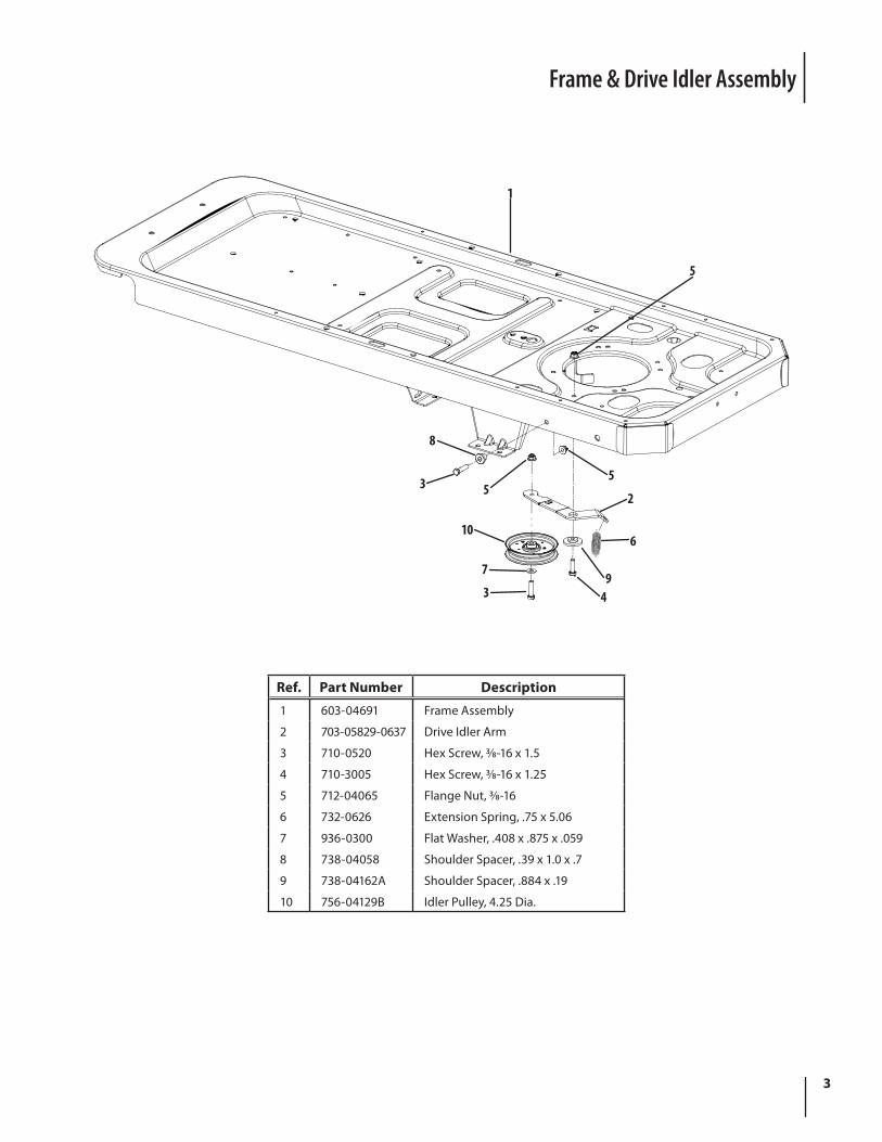
1 603-04691 Frame Assembly
2 703-05829-0637 Drive Idler Arm
3 710-0520 Hex Screw, 3⁄8-16 x 1.5
4 710-3005 Hex Screw, 3⁄8-16 x 1.25
5 712-04065 Flange Nut, 3⁄8-16
6 732-0626 Extension Spring, .75 x 5.06
7 936-0300 Flat Washer, .408 x .875 x .059
8 738-04058 Shoulder Spacer, .39 x 1.0 x .7
9 738-04162A Shoulder Spacer, .884 x .19
10 756-04129B Idler Pulley, 4.25 Dia.
Frame & Drive Idler Assembly
4
Operator’s Platform
3
17
8 10 4
8
8
8
11 14 168
18
1213
8
15 86
13
12
15
158
1213
7
8
8
11 14 16
19
9
58
820
20
Ref Part Number Description
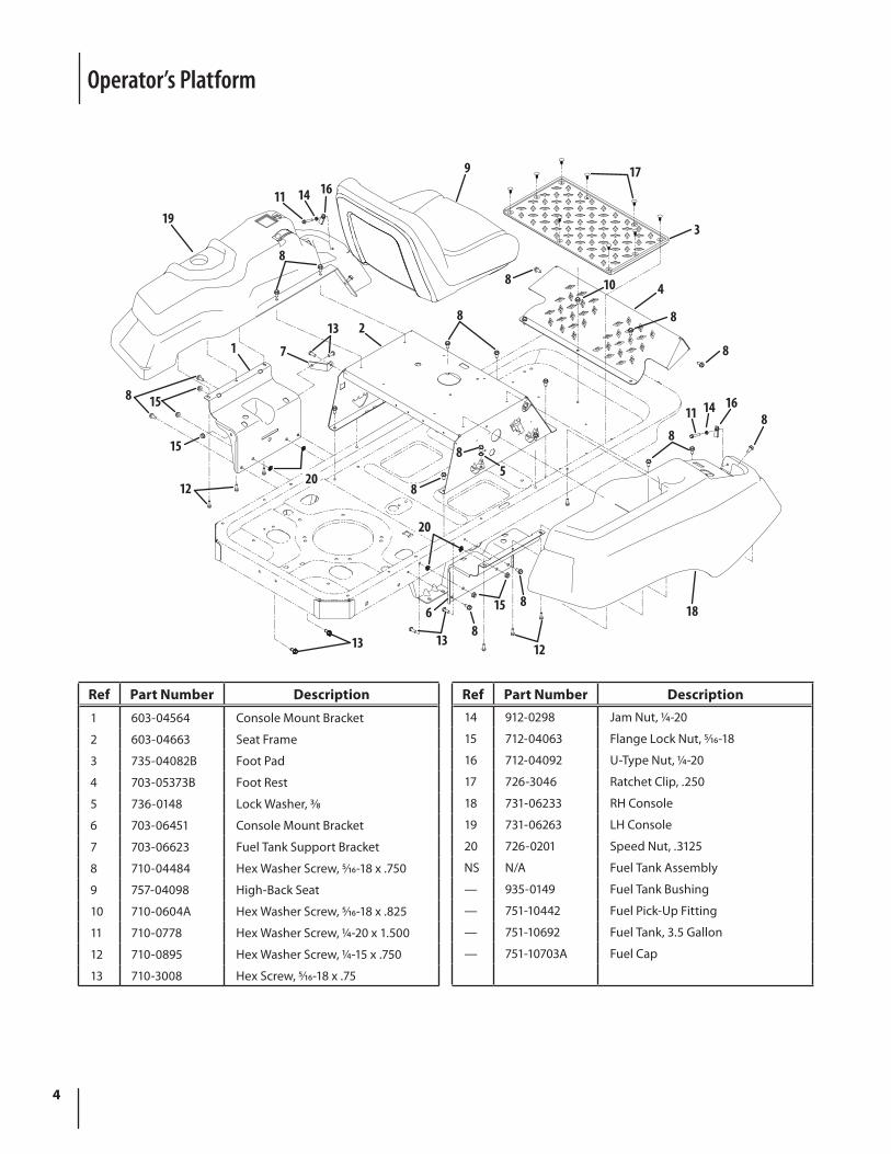
1 603-04564 Console Mount Bracket
2 603-04663 Seat Frame
3 735-04082B Foot Pad
4 703-05373B Foot Rest
5 736-0148 Lock Washer, 3⁄8
6 703-06451 Console Mount Bracket
7 703-06623 Fuel Tank Support Bracket
8 710-04484 Hex Washer Screw, 5⁄16-18 x .750
9 757-04098 High-Back Seat
10 710-0604A Hex Washer Screw, 5⁄16-18 x .825
11 710-0778 Hex Washer Screw, 1⁄4-20 x 1.500
12 710-0895 Hex Washer Screw, 1⁄4-15 x .750
13 710-3008 Hex Screw, 5⁄16-18 x .75
Ref Part Number Description14 912-0298 Jam Nut, 1⁄4-20
15 712-04063 Flange Lock Nut, 5⁄16-18
16 712-04092 U-Type Nut, 1⁄4-20
17 726-3046 Ratchet Clip, .250
18 731-06233 RH Console
19 731-06263 LH Console
20 726-0201 Speed Nut, .3125
NS N/A Fuel Tank Assembly
— 935-0149 Fuel Tank Bushing
— 751-10442 Fuel Pick-Up Fitting
— 751-10692 Fuel Tank, 3.5 Gallon
— 751-10703A Fuel Cap
5
Electrical
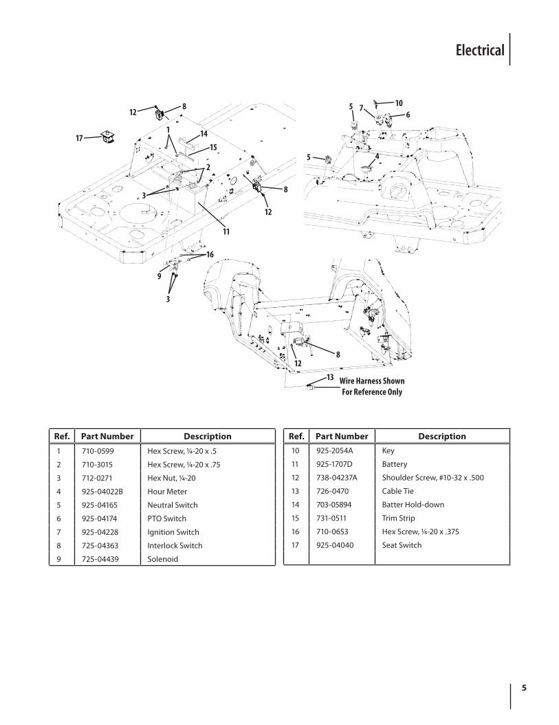
Wire Harness ShownFor Reference Only
128
117
3
11
12
8
2
1514
9
3
16
5
1312
8
4
61075
Ref. Part Number Description
1 710-0599 Hex Screw, 1⁄4-20 x .5
2 710-3015 Hex Screw, 1⁄4-20 x .75
3 712-0271 Hex Nut, 1⁄4-20
4 925-04022B Hour Meter
5 925-04165 Neutral Switch
6 925-04174 PTO Switch
7 925-04228 Ignition Switch
8 725-04363 Interlock Switch
9 725-04439 Solenoid
Ref. Part Number Description10 925-2054A Key
11 925-1707D Battery
12 738-04237A Shoulder Screw, #10-32 x .500
13 726-0470 Cable Tie
14 703-05894 Batter Hold-down
15 731-0511 Trim Strip
16 710-0653 Hex Screw, 1⁄4-20 x .375
17 925-04040 Seat Switch
6
3
9
5
3
28
4
3
1
7
8
10
6
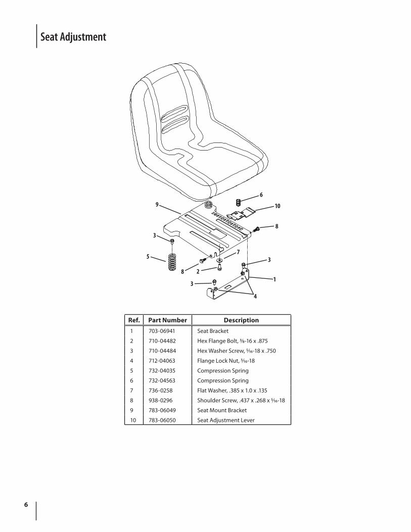
Seat Adjustment
Ref. Part Number Description
1 703-06941 Seat Bracket
2 710-04482 Hex Flange Bolt, 3⁄8-16 x .875
3 710-04484 Hex Washer Screw, 5⁄16-18 x .750
4 712-04063 Flange Lock Nut, 5⁄16-18
5 732-04035 Compression Spring
6 732-04563 Compression Spring
7 736-0258 Flat Washer, .385 x 1.0 x .135
8 938-0296 Shoulder Screw, .437 x .268 x 5⁄16-18
9 783-06049 Seat Mount Bracket
10 783-06050 Seat Adjustment Lever
7
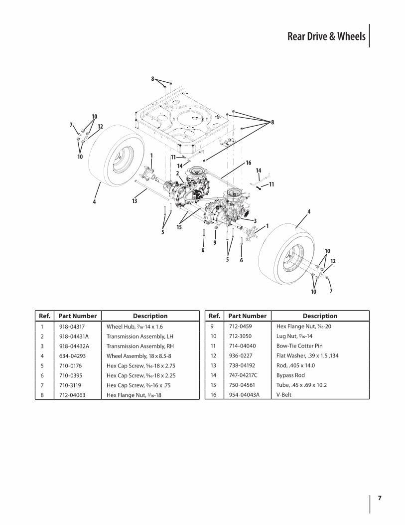
Rear Drive & Wheels
7 1210
10
4
1
13
515
11142
69
5 6
13
4
1012
710
11
1416
8
8
Ref. Part Number Description
1 918-04317 Wheel Hub, 7⁄16-14 x 1.6
2 918-04431A Transmission Assembly, LH
3 918-04432A Transmission Assembly, RH
4 634-04293 Wheel Assembly, 18 x 8.5-8
5 710-0176 Hex Cap Screw, 5⁄16-18 x 2.75
6 710-0395 Hex Cap Screw, 5⁄16-18 x 2.25
7 710-3119 Hex Cap Screw, 3⁄8-16 x .75
8 712-04063 Hex Flange Nut, 5⁄16-18
Ref. Part Number Description9 712-0459 Hex Flange Nut, 7⁄16-20
10 712-3050 Lug Nut, 7⁄16-14
11 714-04040 Bow-Tie Cotter Pin
12 936-0227 Flat Washer, .39 x 1.5 .134
13 738-04192 Rod, .405 x 14.0
14 747-04217C Bypass Rod
15 750-04561 Tube, .45 x .69 x 10.2
16 954-04043A V-Belt
8
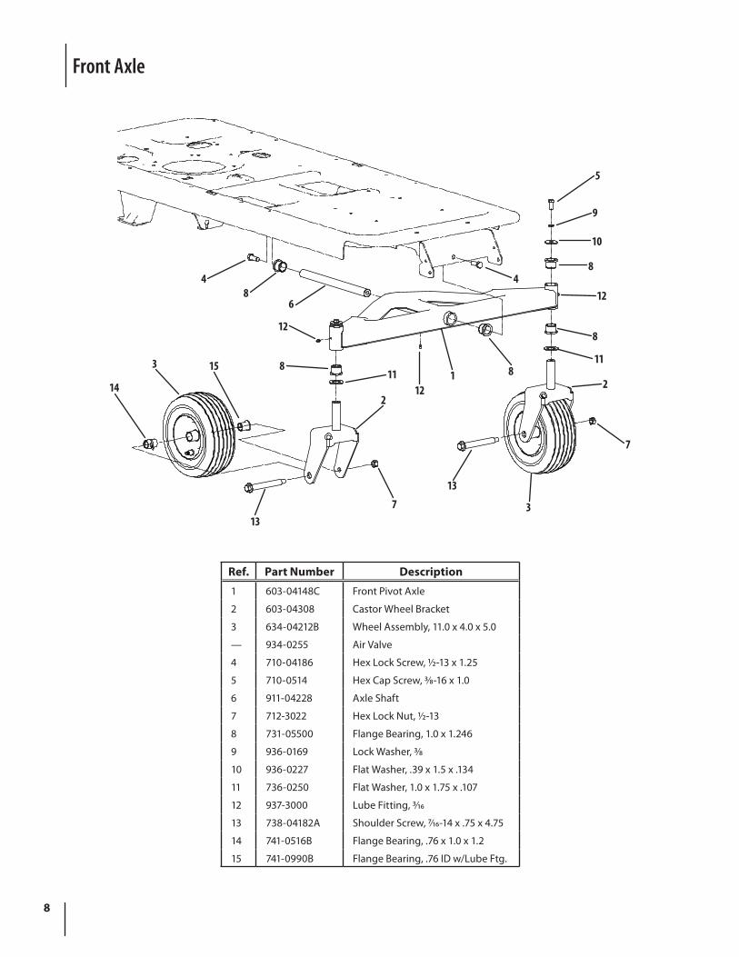
Front Axle
5
9
10
8
12
8
11
2
7
3
13
713
14
3 15
2
118
12
68
4
121 8
4
Ref. Part Number Description
1 603-04148C Front Pivot Axle
2 603-04308 Castor Wheel Bracket
3 634-04212B Wheel Assembly, 11.0 x 4.0 x 5.0
— 934-0255 Air Valve
4 710-04186 Hex Lock Screw, 1⁄2-13 x 1.25
5 710-0514 Hex Cap Screw, 3⁄8-16 x 1.0
6 911-04228 Axle Shaft
7 712-3022 Hex Lock Nut, 1⁄2-13
8 731-05500 Flange Bearing, 1.0 x 1.246
9 936-0169 Lock Washer, 3⁄8
10 936-0227 Flat Washer, .39 x 1.5 x .134
11 736-0250 Flat Washer, 1.0 x 1.75 x .107
12 937-3000 Lube Fitting, 3⁄16
13 738-04182A Shoulder Screw, 7⁄16-14 x .75 x 4.75
14 741-0516B Flange Bearing, .76 x 1.0 x 1.2
15 741-0990B Flange Bearing, .76 ID w/Lube Ftg.
9
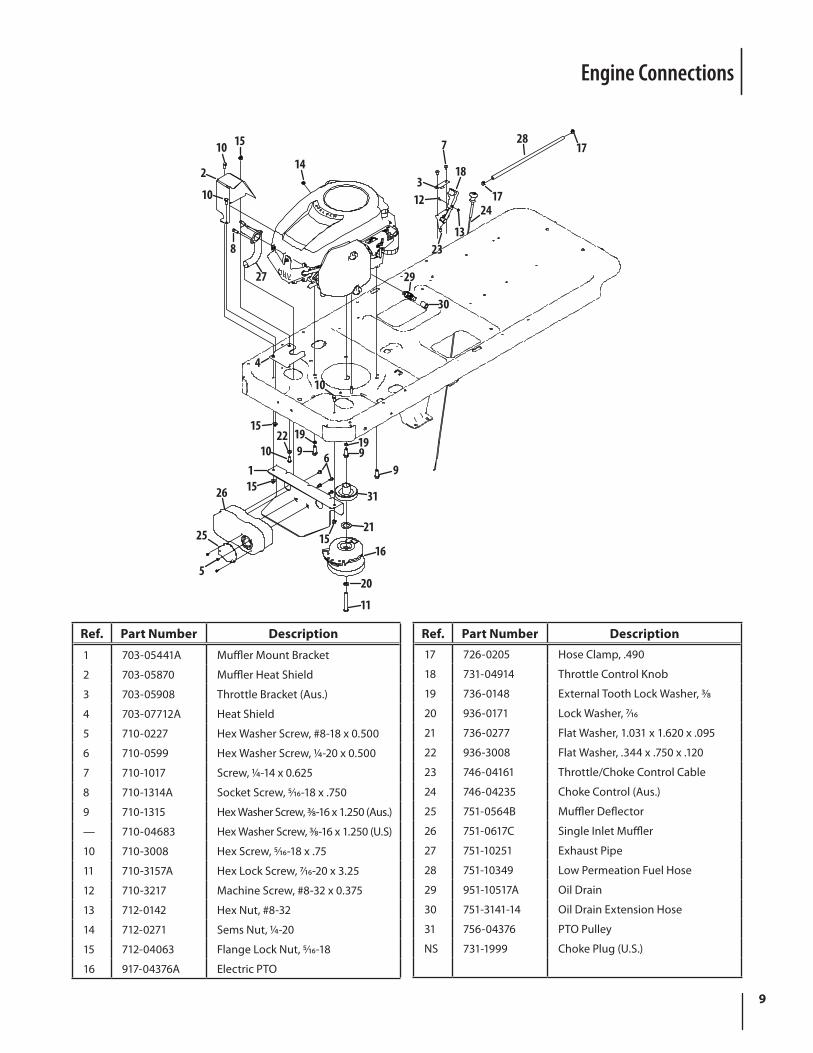
Ref. Part Number Description
1 703-05441A Muffler Mount Bracket
2 703-05870 Muffler Heat Shield
3 703-05908 Throttle Bracket (Aus.)
4 703-07712A Heat Shield
5 710-0227 Hex Washer Screw, #8-18 x 0.500
6 710-0599 Hex Washer Screw, 1⁄4-20 x 0.500
7 710-1017 Screw, 1⁄4-14 x 0.625
8 710-1314A Socket Screw, 5⁄16-18 x .750
9 710-1315 Hex Washer Screw, 3⁄8-16 x 1.250 (Aus.)
— 710-04683 Hex Washer Screw, 3⁄8-16 x 1.250 (U.S)
10 710-3008 Hex Screw, 5⁄16-18 x .75
11 710-3157A Hex Lock Screw, 7⁄16-20 x 3.25
12 710-3217 Machine Screw, #8-32 x 0.375
13 712-0142 Hex Nut, #8-32
14 712-0271 Sems Nut, 1⁄4-20
15 712-04063 Flange Lock Nut, 5⁄16-18
16 917-04376A Electric PTO
Ref. Part Number Description17 726-0205 Hose Clamp, .490
18 731-04914 Throttle Control Knob
19 736-0148 External Tooth Lock Washer, 3⁄8
20 936-0171 Lock Washer, 7⁄16
21 736-0277 Flat Washer, 1.031 x 1.620 x .095
22 936-3008 Flat Washer, .344 x .750 x .120
23 746-04161 Throttle/Choke Control Cable
24 746-04235 Choke Control (Aus.)
25 751-0564B Muffler Deflector
26 751-0617C Single Inlet Muffler
27 751-10251 Exhaust Pipe
28 751-10349 Low Permeation Fuel Hose
29 951-10517A Oil Drain
30 751-3141-14 Oil Drain Extension Hose
31 756-04376 PTO Pulley
NS 731-1999 Choke Plug (U.S.)
Engine Connections
27
8
10
2
10 15
14
10
4
19
1521
31
9151
6 919
91022
15
5
25
11
20
16
26
17
1728
23
24123
18
7
13
30
29
10
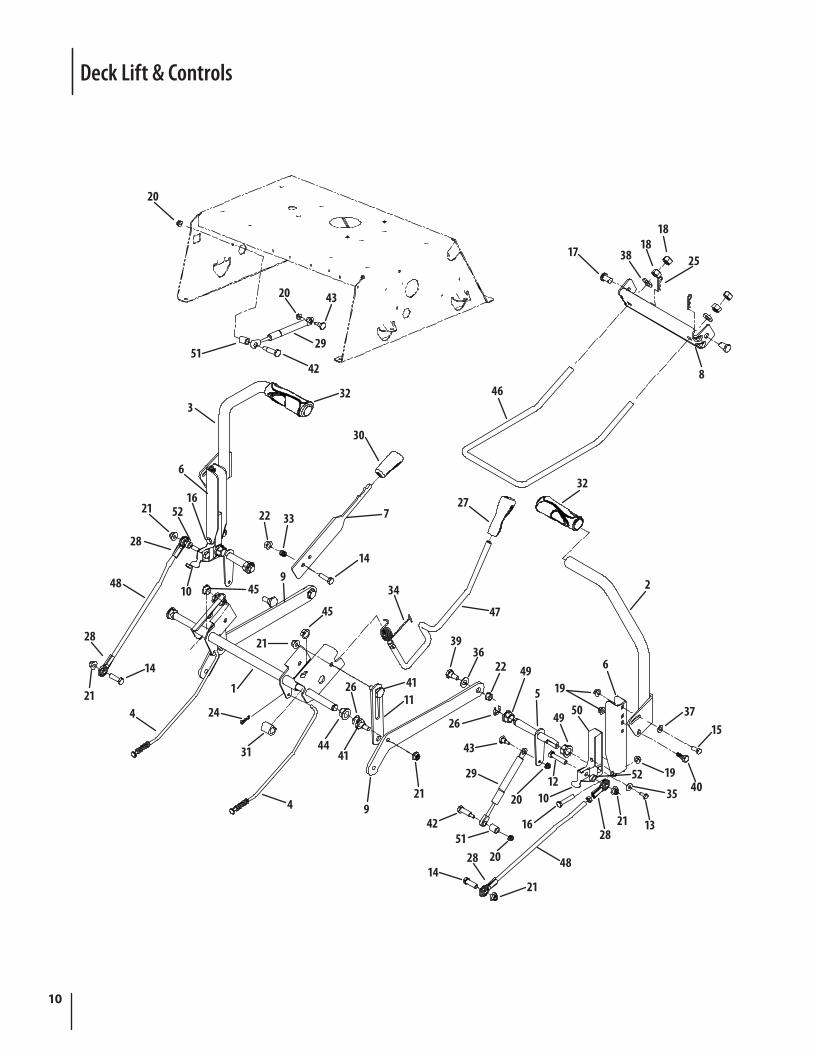
Deck Lift & Controls
51
20
42
29
4320
332
22 33
14
7
30
1048
28
21 5216
6
14
21
28
4
459
41
4441
26
4
31
24
1
21
45
11
34
47
5
102012
29
49 50
43
26
19
6492236
39
9
1421
4828 2051
42
21
1628
35
3715
401952
1321
2
3227
468
1818
38 2517
11
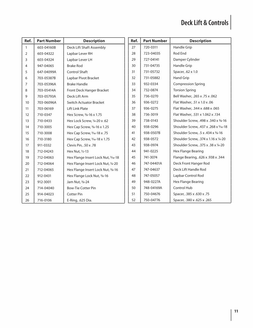
Deck Lift & Controls
Ref. Part Number Description
1 603-04160B Deck Lift Shaft Assembly
2 603-04322 Lapbar Lever RH
3 603-04324 Lapbar Lever LH
4 947-04065 Brake Rod
5 647-04099A Control Shaft
6 703-05387B Lapbar Pivot Bracket
7 703-05396A Brake Handle
8 703-05414A Front Deck Hanger Bracket
9 703-05793A Deck Lift Arm
10 703-06096A Switch Actuator Bracket
11 703-06169 Lift Link Plate
12 710-0347 Hex Screw, 3⁄8-16 x 1.75
13 710-0433 Hex Lock Screw, 1⁄4-20 x .62
14 710-3005 Hex Cap Screw, 3⁄8-16 x 1.25
15 710-3008 Hex Cap Screw, 5⁄16-18 x .75
16 710-3180 Hex Cap Screw, 5⁄16-18 x 1.75
17 911-0332 Clevis Pin, .50 x .78
18 712-04243 Hex Nut, 1⁄2-13
19 712-04063 Hex Flange Insert Lock Nut, 5⁄16-18
20 712-04064 Hex Flange Insert Lock Nut, 1⁄4-20
21 712-04065 Hex Flange Insert Lock Nut, 3⁄8-16
22 912-0431 Hex Flange Lock Nut, 3⁄8-16
23 912-3001 Jam Nut, 3⁄8-24
24 714-04040 Bow-Tie Cotter Pin
25 914-04023 Cotter Pin
26 716-0106 E-Ring, .625 Dia.
Ref. Part Number Description27 720-0311 Handle Grip
28 723-04035 Rod End
29 727-04141 Damper Cylinder
30 731-04735 Handle Grip
31 731-05732 Spacer, .62 x 1.0
32 731-05882 Hand Grip
33 932-0334 Compression Spring
34 732-0874 Torsion Spring
35 736-0270 Bell Washer, .265 x .75 x .062
36 936-0272 Flat Washer, .51 x 1.0 x .06
37 936-0275 Flat Washer, .344 x .688 x .065
38 736-3019 Flat Washer, .531 x 1.062 x .134
39 738-0143 Shoulder Screw, .498 x .340 x 3⁄8-16
40 938-0296 Shoulder Screw, .437 x .268 x 5⁄16-18
41 938-0507B Shoulder Screw, .5 x .434 x 3⁄8-16
42 938-0572 Shoulder Screw, .374 x 1.16 x 1⁄4-20
43 938-0974 Shoulder Screw, .375 x .38 x 1⁄4-20
44 941-0225 Hex Flange Bearing
45 741-3074 Flange Bearing, .626 x .938 x .344
46 747-04401A Deck Front Hanger Rod
47 747-04637 Deck Lift Handle Rod
48 747-05057 Lapbar Control Rod
49 948-0227A Hex Flange Bearing
50 748-04169A Control Hub
51 750-04676 Spacer, .385 x .630 x .75
52 750-04776 Spacer, .380 x .625 x .265
12
17
46
44
4345
3
45
43
42
39
27
8
533
403
24
34
2
7
32
20
8
741
17
37
18714
13
15
10
21
12
29
26
36
3019 6 31
2338
22
28
16
40
33
535
11
4
16
26
1
25
9
47
489
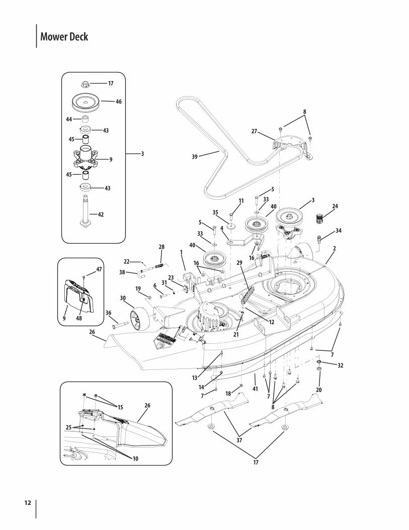
Mower Deck
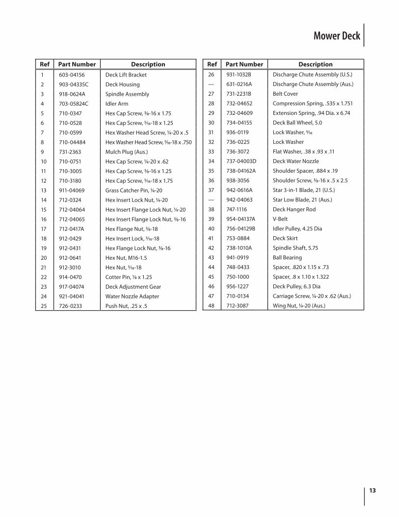
13
Ref Part Number Description
1 603-04156 Deck Lift Bracket
2 903-04335C Deck Housing
3 918-0624A Spindle Assembly
4 703-05824C Idler Arm
5 710-0347 Hex Cap Screw, 3⁄8-16 x 1.75
6 710-0528 Hex Cap Screw, 5⁄16-18 x 1.25
7 710-0599 Hex Washer Head Screw, 1⁄4-20 x .5
8 710-04484 Hex Washer Head Screw, 5⁄16-18 x .750
9 731-2363 Mulch Plug (Aus.)
10 710-0751 Hex Cap Screw, 1⁄4-20 x .62
11 710-3005 Hex Cap Screw, 3⁄8-16 x 1.25
12 710-3180 Hex Cap Screw, 5⁄16-18 x 1.75
13 911-04069 Grass Catcher Pin, 1⁄4-20
14 712-0324 Hex Insert Lock Nut, 1⁄4-20
15 712-04064 Hex Insert Flange Lock Nut, 1⁄4-20
16 712-04065 Hex Insert Flange Lock Nut, 3⁄8-16
17 712-0417A Hex Flange Nut, 5⁄8-18
18 912-0429 Hex Insert Lock, 5⁄16-18
19 912-0431 Hex Flange Lock Nut, 3⁄8-16
20 912-0641 Hex Nut, M16-1.5
21 912-3010 Hex Nut, 5⁄16-18
22 914-0470 Cotter Pin, 1⁄8 x 1.25
23 917-04074 Deck Adjustment Gear
24 921-04041 Water Nozzle Adapter
25 726-0233 Push Nut, .25 x .5
Mower Deck
Ref Part Number Description26 931-1032B Discharge Chute Assembly (U.S.)
— 631-0216A Discharge Chute Assembly (Aus.)
27 731-2231B Belt Cover
28 732-04652 Compression Spring, .535 x 1.751
29 732-04609 Extension Spring, .94 Dia. x 6.74
30 734-04155 Deck Ball Wheel, 5.0
31 936-0119 Lock Washer, 5⁄16
32 736-0225 Lock Washer
33 736-3072 Flat Washer, .38 x .93 x .11
34 737-04003D Deck Water Nozzle
35 738-04162A Shoulder Spacer, .884 x .19
36 938-3056 Shoulder Screw, 3⁄8-16 x .5 x 2.5
37 942-0616A Star 3-in-1 Blade, 21 (U.S.)
— 942-04063 Star Low Blade, 21 (Aus.)
38 747-1116 Deck Hanger Rod
39 954-04137A V-Belt
40 756-04129B Idler Pulley, 4.25 Dia
41 753-0884 Deck Skirt
42 738-1010A Spindle Shaft, 5.75
43 941-0919 Ball Bearing
44 748-0433 Spacer, .820 x 1.15 x .73
45 750-1000 Spacer, .8 x 1.10 x 1.322
46 956-1227 Deck Pulley, 6.3 Dia
47 710-0134 Carriage Screw, 1⁄4-20 x .62 (Aus.)
48 712-3087 Wing Nut, 1⁄4-20 (Aus.)
14
2
1
3
4
6
5
7
Ref. Part Number Description
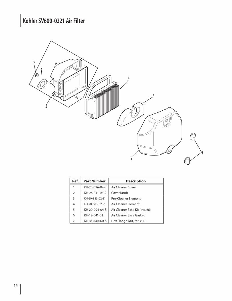
1 KH-20-096-04-S Air Cleaner Cover
2 KH-25-341-05-S Cover Knob
3 KH-20-883-02-S1 Pre-Cleaner Element
4 KH-20-883-02-S1 Air Cleaner Element
5 KH-20-094-04-S Air Cleaner Base Kit (Inc. #6)
6 KH-12-041-02 Air Cleaner Base Gasket
7 KH-M-641060-S Hex Flange Nut, M6 x 1.0
Kohler SV600-0221 Air Filter
15
16 1
15
13
2
3
4
5
6
7
9
1011
12
8
14
Ref. Part Number Description
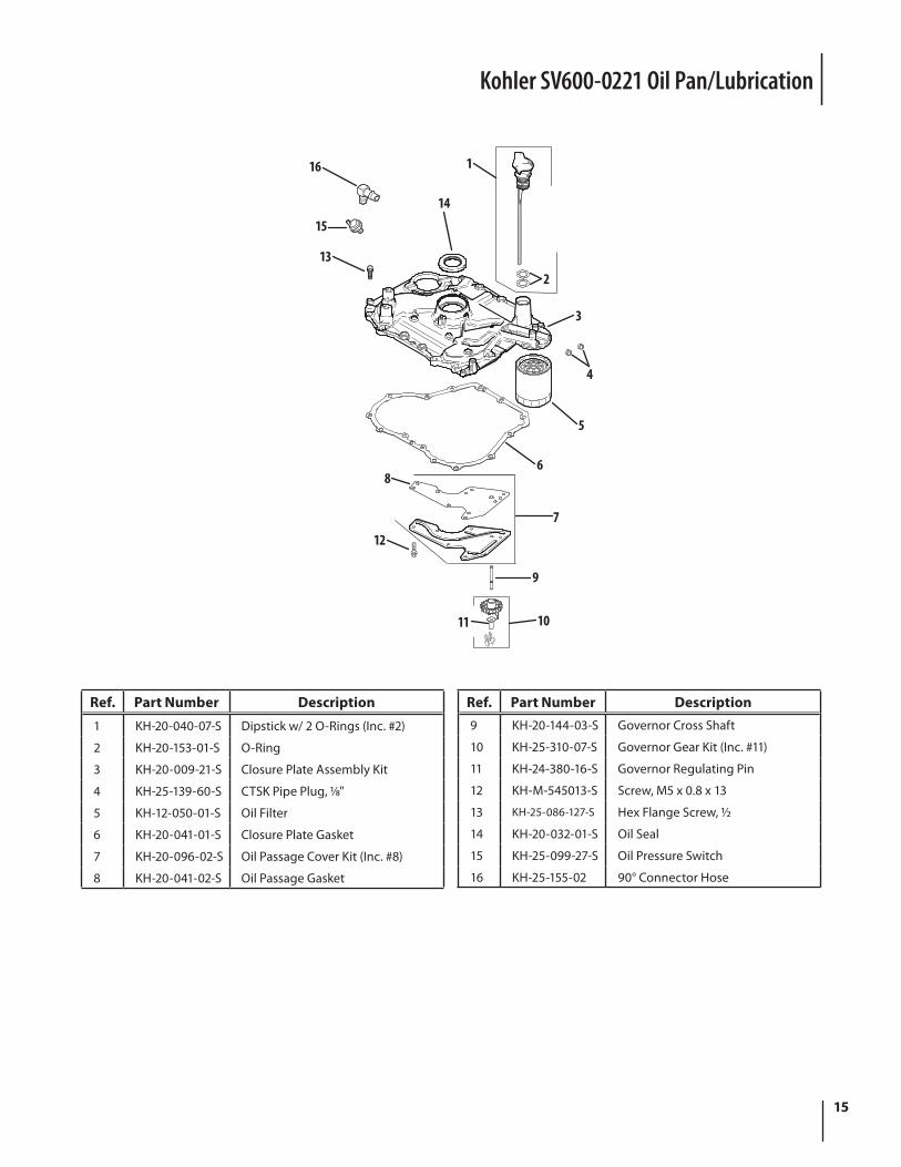
1 KH-20-040-07-S Dipstick w/ 2 O-Rings (Inc. #2)
2 KH-20-153-01-S O-Ring
3 KH-20-009-21-S Closure Plate Assembly Kit
4 KH-25-139-60-S CTSK Pipe Plug, 1⁄8"
5 KH-12-050-01-S Oil Filter
6 KH-20-041-01-S Closure Plate Gasket
7 KH-20-096-02-S Oil Passage Cover Kit (Inc. #8)
8 KH-20-041-02-S Oil Passage Gasket
Kohler SV600-0221 Oil Pan/Lubrication
Ref. Part Number Description9 KH-20-144-03-S Governor Cross Shaft
10 KH-25-310-07-S Governor Gear Kit (Inc. #11)
11 KH-24-380-16-S Governor Regulating Pin
12 KH-M-545013-S Screw, M5 x 0.8 x 13
13 KH-25-086-127-S Hex Flange Screw, 1⁄2
14 KH-20-032-01-S Oil Seal
15 KH-25-099-27-S Oil Pressure Switch
16 KH-25-155-02 90° Connector Hose
16
25242322 27
26
21 2120 20
18
19
1514
13
1112
17
16
1
8
7
6
5
4
3
2
10
9
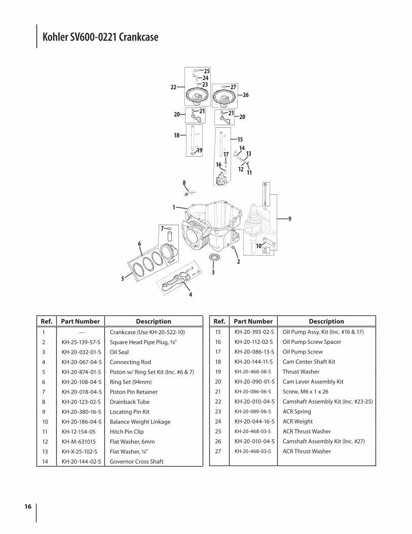
Ref. Part Number Description
1 — Crankcase (Use KH-20-522-10)
2 KH-25-139-57-S Square Head Pipe Plug, 3⁄8"
3 KH-20-032-01-S Oil Seal
4 KH-20-067-04-S Connecting Rod
5 KH-20-874-01-S Piston w/ Ring Set Kit (Inc. #6 & 7)
6 KH-20-108-04-S Ring Set (94mm)
7 KH-20-018-04-S Piston Pin Retainer
8 KH-20-123-02-S Drainback Tube
9 KH-20-380-16-S Locating Pin Kit
10 KH-20-186-04-S Balance Weight Linkage
11 KH-12-154-05 Hitch Pin Clip
12 KH-M-631015 Flat Washer, 6mm
13 KH-X-25-102-S Flat Washer, 1⁄4"
14 KH-20-144-02-S Governor Cross Shaft
Ref. Part Number Description15 KH-20-393-02-S Oil Pump Assy. Kit (Inc. #16 & 17)
16 KH-20-112-02-S Oil Pump Screw Spacer
17 KH-20-086-13-S Oil Pump Screw
18 KH-20-144-11-S Cam Center Shaft Kit
19 KH-20-468-08-S Thrust Washer
20 KH-20-090-01-S Cam Lever Assembly Kit
21 KH-20-086-06-S Screw, M6 x 1 x 26
22 KH-20-010-04-S Camshaft Assembly Kit (Inc. #23-25)
23 KH-20-089-06-S ACR Spring
24 KH-20-044-16-S ACR Weight
25 KH-20-468-03-S ACR Thrust Washer
26 KH-20-010-04-S Camshaft Assembly Kit (Inc. #27)
27 KH-20-468-03-S ACR Thrust Washer
Kohler SV600-0221 Crankcase
17
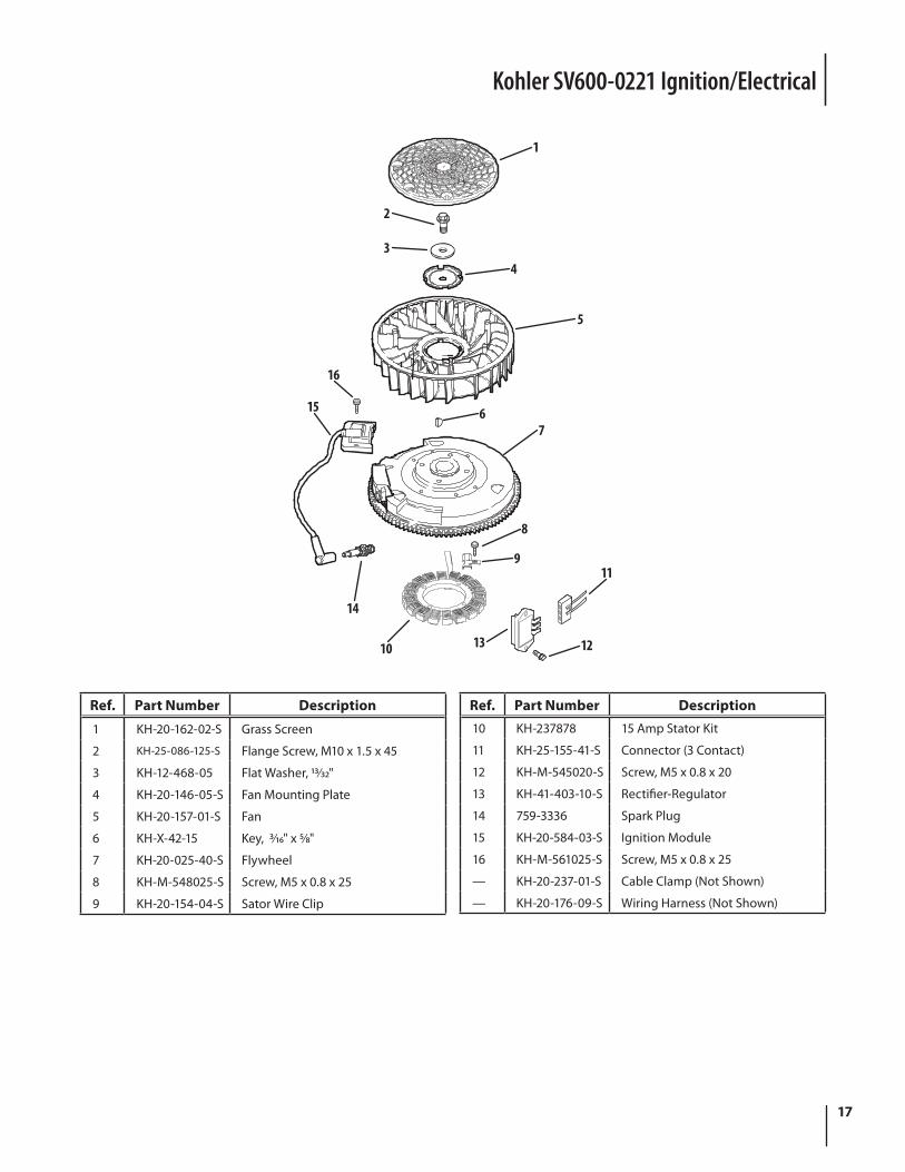
Kohler SV600-0221 Ignition/Electrical
2
1
34
5
16
15 67
8
9
14
10 13
11
12
Ref. Part Number Description
1 KH-20-162-02-S Grass Screen
2 KH-25-086-125-S Flange Screw, M10 x 1.5 x 45
3 KH-12-468-05 Flat Washer, 13⁄32"
4 KH-20-146-05-S Fan Mounting Plate
5 KH-20-157-01-S Fan
6 KH-X-42-15 Key, 3⁄16" x 5⁄8"
7 KH-20-025-40-S Flywheel
8 KH-M-548025-S Screw, M5 x 0.8 x 25
9 KH-20-154-04-S Sator Wire Clip
Ref. Part Number Description10 KH-237878 15 Amp Stator Kit
11 KH-25-155-41-S Connector (3 Contact)
12 KH-M-545020-S Screw, M5 x 0.8 x 20
13 KH-41-403-10-S Rectifier-Regulator
14 759-3336 Spark Plug
15 KH-20-584-03-S Ignition Module
16 KH-M-561025-S Screw, M5 x 0.8 x 25
— KH-20-237-01-S Cable Clamp (Not Shown)
— KH-20-176-09-S Wiring Harness (Not Shown)
18
3
1
2
4
5
6
5
7
8
9
10
10
11
1112
12
13
13
14
15 17
16
1819
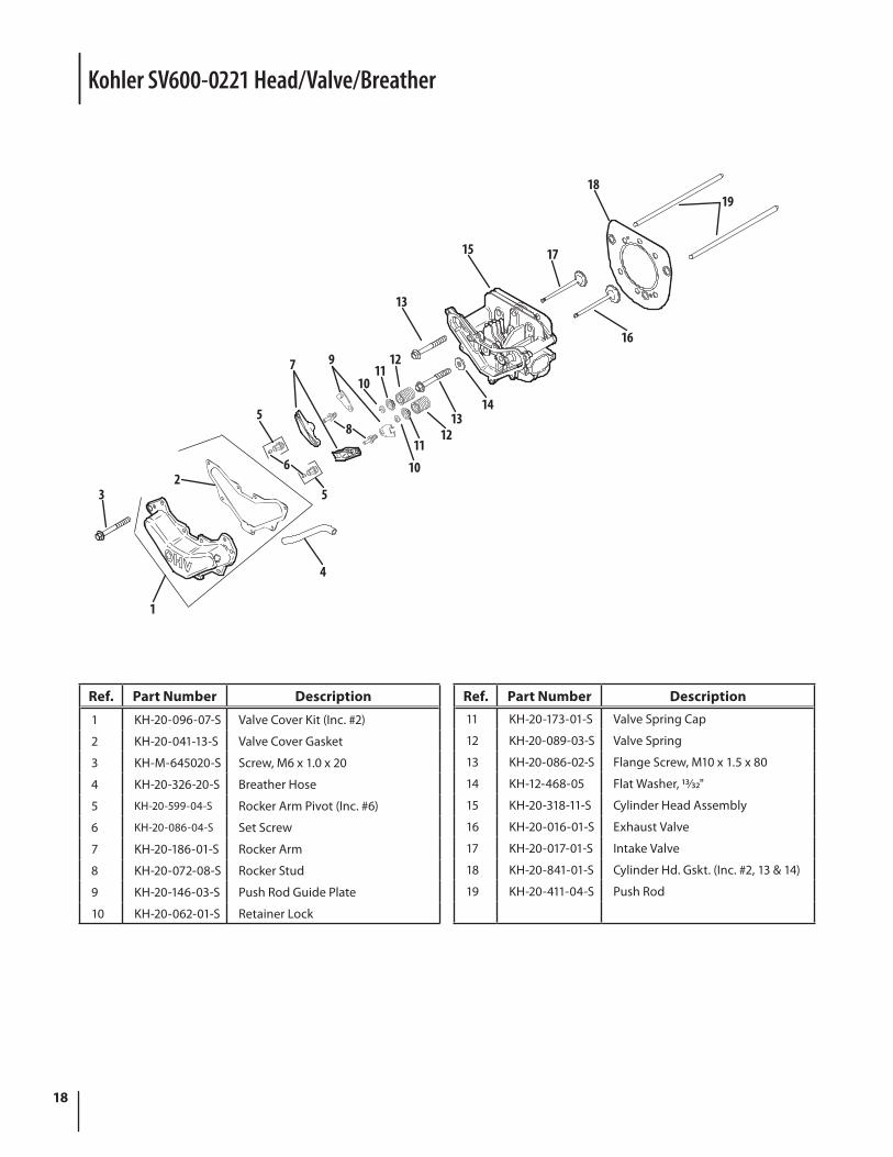
Ref. Part Number Description
1 KH-20-096-07-S Valve Cover Kit (Inc. #2)
2 KH-20-041-13-S Valve Cover Gasket
3 KH-M-645020-S Screw, M6 x 1.0 x 20
4 KH-20-326-20-S Breather Hose
5 KH-20-599-04-S Rocker Arm Pivot (Inc. #6)
6 KH-20-086-04-S Set Screw
7 KH-20-186-01-S Rocker Arm
8 KH-20-072-08-S Rocker Stud
9 KH-20-146-03-S Push Rod Guide Plate
10 KH-20-062-01-S Retainer Lock
Ref. Part Number Description11 KH-20-173-01-S Valve Spring Cap
12 KH-20-089-03-S Valve Spring
13 KH-20-086-02-S Flange Screw, M10 x 1.5 x 80
14 KH-12-468-05 Flat Washer, 13⁄32"
15 KH-20-318-11-S Cylinder Head Assembly
16 KH-20-016-01-S Exhaust Valve
17 KH-20-017-01-S Intake Valve
18 KH-20-841-01-S Cylinder Hd. Gskt. (Inc. #2, 13 & 14)
19 KH-20-411-04-S Push Rod
Kohler SV600-0221 Head/Valve/Breather
19
Kohler SV600-0221 Starting System
14
15
10
1312
11
9
8 71
2
4
3
5618
1716
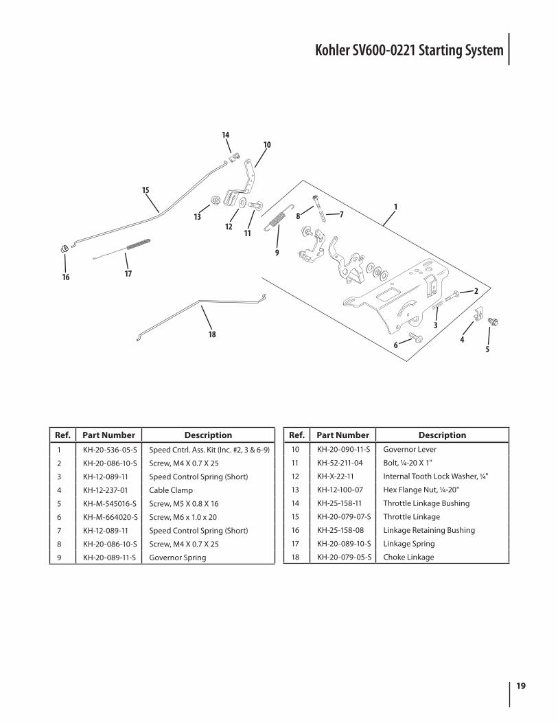
Ref. Part Number Description
1 KH-20-536-05-S Speed Cntrl. Ass. Kit (Inc. #2, 3 & 6-9)
2 KH-20-086-10-S Screw, M4 X 0.7 X 25
3 KH-12-089-11 Speed Control Spring (Short)
4 KH-12-237-01 Cable Clamp
5 KH-M-545016-S Screw, M5 X 0.8 X 16
6 KH-M-664020-S Screw, M6 x 1.0 x 20
7 KH-12-089-11 Speed Control Spring (Short)
8 KH-20-086-10-S Screw, M4 X 0.7 X 25
9 KH-20-089-11-S Governor Spring
Ref. Part Number Description10 KH-20-090-11-S Governor Lever
11 KH-52-211-04 Bolt, 1⁄4-20 X 1"
12 KH-X-22-11 Internal Tooth Lock Washer, 1⁄4"
13 KH-12-100-07 Hex Flange Nut, 1⁄4-20"
14 KH-25-158-11 Throttle Linkage Bushing
15 KH-20-079-07-S Throttle Linkage
16 KH-25-158-08 Linkage Retaining Bushing
17 KH-20-089-10-S Linkage Spring
18 KH-20-079-05-S Choke Linkage
20
23
4
1
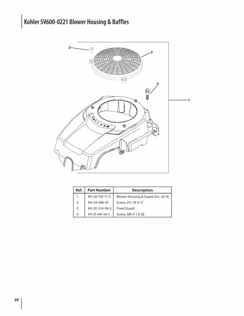
Ref. Part Number Description
1 KH-20-755-11-S Blower Housing & Guard (Inc. #2-4)
2 KH-24-086-41 Screw, #11-16 X 1⁄2"
3 KH-20-314-06-S Fixed Guard
4 KH-20-086-06-S Screw, M6 X 1 X 26
Kohler SV600-0221 Blower Housing & Baffles
21
Kohler SV600-0221 Starting System
3
2
1
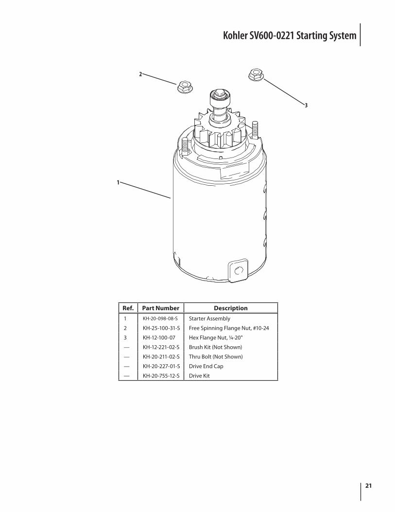
Ref. Part Number Description
1 KH-20-098-08-S Starter Assembly
2 KH-25-100-31-S Free Spinning Flange Nut, #10-24
3 KH-12-100-07 Hex Flange Nut, 1⁄4-20"
— KH-12-221-02-S Brush Kit (Not Shown)
— KH-20-211-02-S Thru Bolt (Not Shown)
— KH-20-227-01-S Drive End Cap
— KH-20-755-12-S Drive Kit
22
1415
16
12
12
11
12
17
13
12
1
23
4 5
7
86
9
10
Ref. Part Number Description
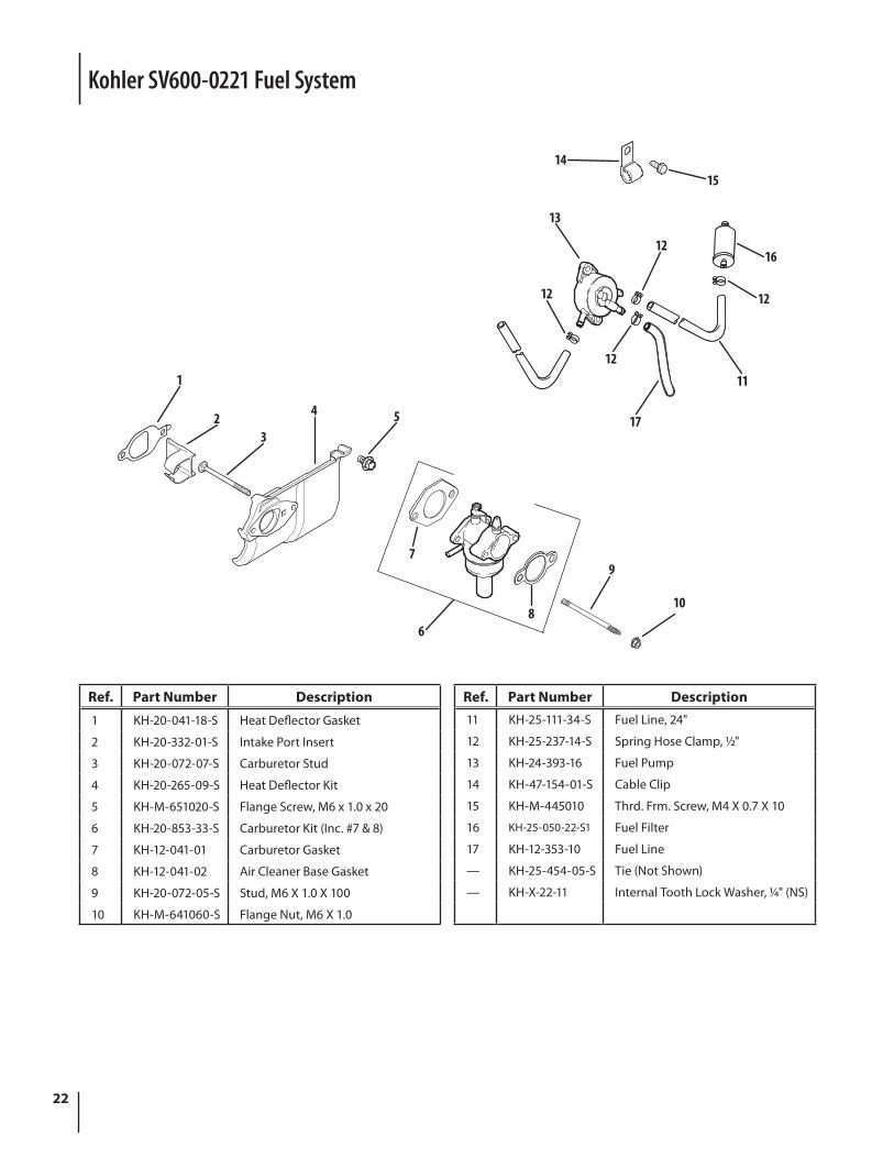
1 KH-20-041-18-S Heat Deflector Gasket
2 KH-20-332-01-S Intake Port Insert
3 KH-20-072-07-S Carburetor Stud
4 KH-20-265-09-S Heat Deflector Kit
5 KH-M-651020-S Flange Screw, M6 x 1.0 x 20
6 KH-20-853-33-S Carburetor Kit (Inc. #7 & 8)
7 KH-12-041-01 Carburetor Gasket
8 KH-12-041-02 Air Cleaner Base Gasket
9 KH-20-072-05-S Stud, M6 X 1.0 X 100
10 KH-M-641060-S Flange Nut, M6 X 1.0
Ref. Part Number Description11 KH-25-111-34-S Fuel Line, 24"
12 KH-25-237-14-S Spring Hose Clamp, 1⁄2"
13 KH-24-393-16 Fuel Pump
14 KH-47-154-01-S Cable Clip
15 KH-M-445010 Thrd. Frm. Screw, M4 X 0.7 X 10
16 KH-25-050-22-S1 Fuel Filter
17 KH-12-353-10 Fuel Line
— KH-25-454-05-S Tie (Not Shown)
— KH-X-22-11 Internal Tooth Lock Washer, 1⁄4" (NS)
Kohler SV600-0221 Fuel System

23notes
Notes
24
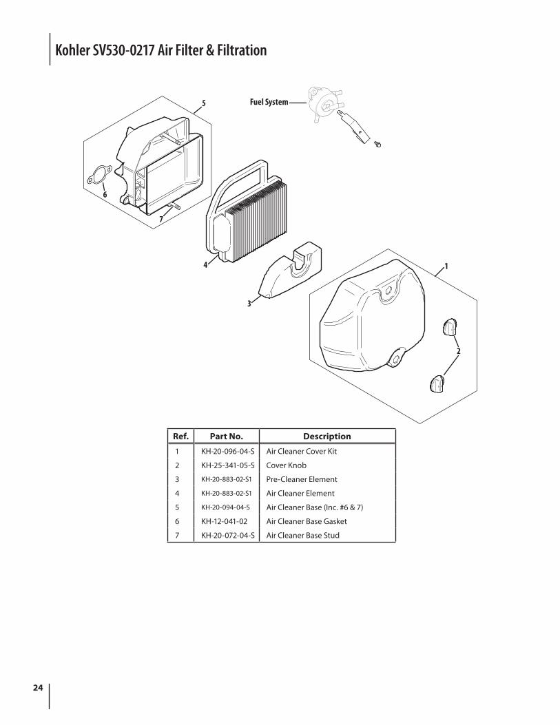
Ref. Part No. Description
1 KH-20-096-04-S Air Cleaner Cover Kit
2 KH-25-341-05-S Cover Knob
3 KH-20-883-02-S1 Pre-Cleaner Element
4 KH-20-883-02-S1 Air Cleaner Element
5 KH-20-094-04-S Air Cleaner Base (Inc. #6 & 7)
6 KH-12-041-02 Air Cleaner Base Gasket
7 KH-20-072-04-S Air Cleaner Base Stud
Kohler SV530-0217 Air Filter & Filtration
5
3
4 1
6
7
2
Fuel System
25
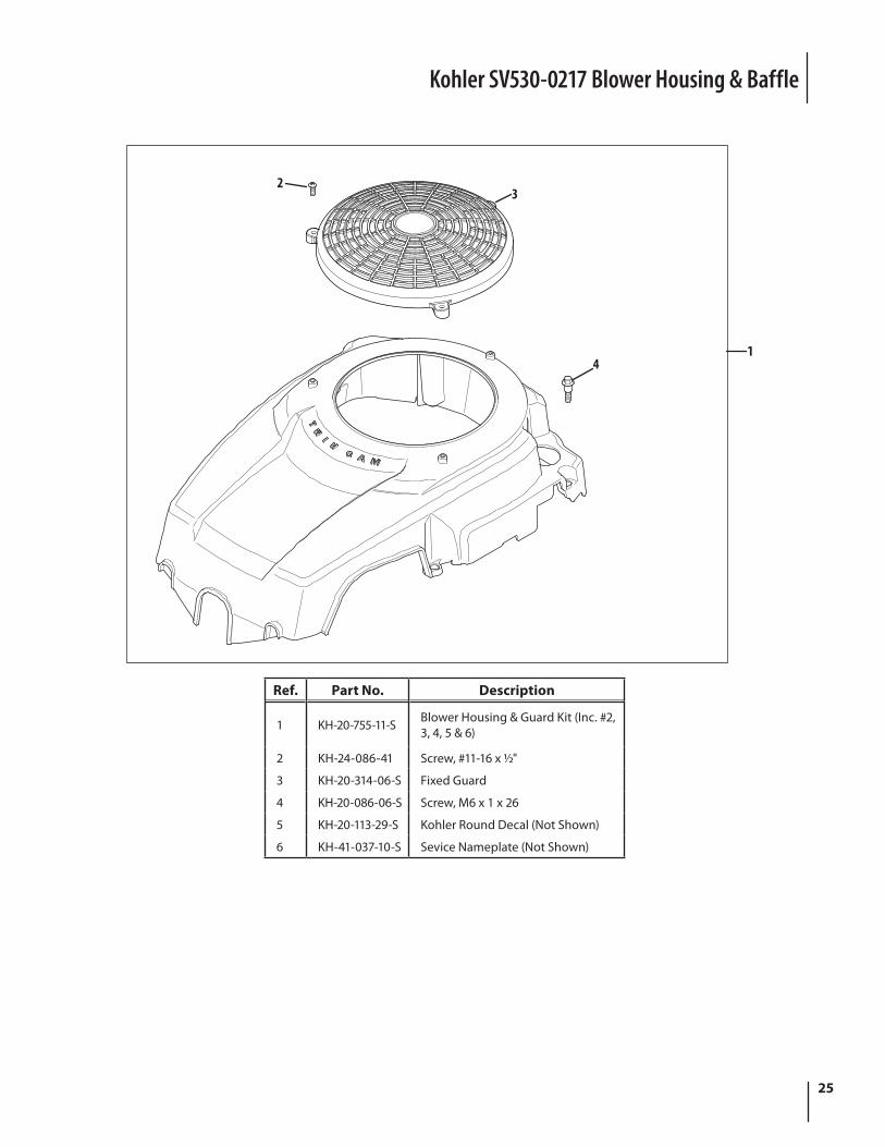
Kohler SV530-0217 Blower Housing & Baffle
23
41
Ref. Part No. Description
1 KH-20-755-11-S Blower Housing & Guard Kit (Inc. #2, 3, 4, 5 & 6)
2 KH-24-086-41 Screw, #11-16 x 1⁄2"
3 KH-20-314-06-S Fixed Guard
4 KH-20-086-06-S Screw, M6 x 1 x 26
5 KH-20-113-29-S Kohler Round Decal (Not Shown)
6 KH-41-037-10-S Sevice Nameplate (Not Shown)
26
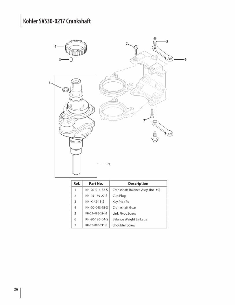
Kohler SV530-0217 Crankshaft
1
2
6
5
3
4
7
7
Ref. Part No. Description
1 KH-20-014-32-S Crankshaft Balance Assy. (Inc. #2)
2 KH-25-139-27-S Cup Plug
3 KH-X-42-15-S Key, 3⁄16 x 5⁄8
4 KH-20-043-15-S Crankshaft Gear
5 KH-25-086-214-S Link Pivot Screw
6 KH-20-186-04-S Balance Weight Linkage
7 KH-25-086-213-S Shoulder Screw
27
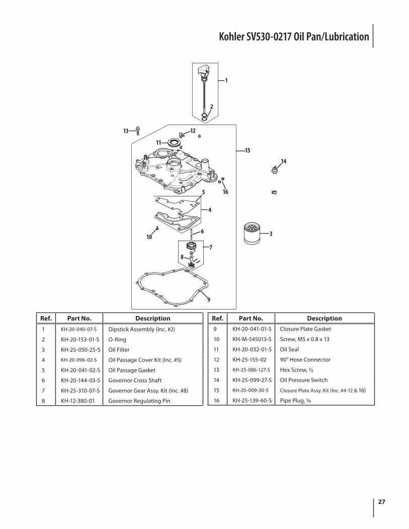
Kohler SV530-0217 Oil Pan/Lubrication
Ref. Part No. Description
1 KH-20-040-07-S Dipstick Assembly (Inc. #2)
2 KH-20-153-01-S O-Ring
3 KH-25-050-25-S Oil Filter
4 KH-20-096-02-S Oil Passage Cover Kit (Inc. #5)
5 KH-20-041-02-S Oil Passage Gasket
6 KH-20-144-03-S Governor Cross Shaft
7 KH-25-310-07-S Governor Gear Assy. Kit (Inc. #8)
8 KH-12-380-01 Governor Regulating Pin
1115
12
2
1
4
5 16
14
87
6 3
9
10
13
Ref. Part No. Description
9 KH-20-041-01-S Closure Plate Gasket
10 KH-M-545013-S Screw, M5 x 0.8 x 13
11 KH-20-032-01-S Oil Seal
12 KH-25-155-02 90° Hose Connector
13 KH-25-086-127-S Hex Screw, 1⁄2
14 KH-25-099-27-S Oil Pressure Switch
15 KH-20-009-30-S Closure Plate Assy. Kit (Inc. #4-12 & 16)
16 KH-25-139-60-S Pipe Plug, 1⁄8
28
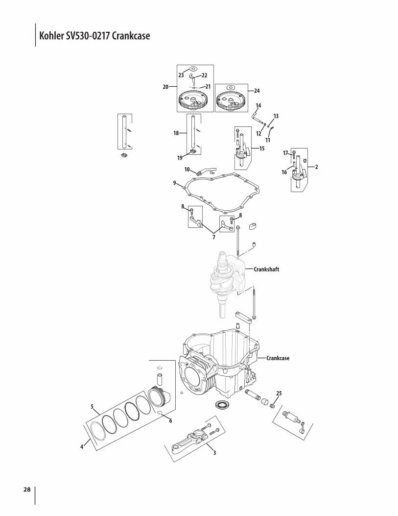
Kohler SV530-0217 Crankcase
20 21
2223
24
15
13
1112
14
16
17
2
18
19
10
7
8
9
8
Crankshaft
Crankcase
25
3
6
5
4
29
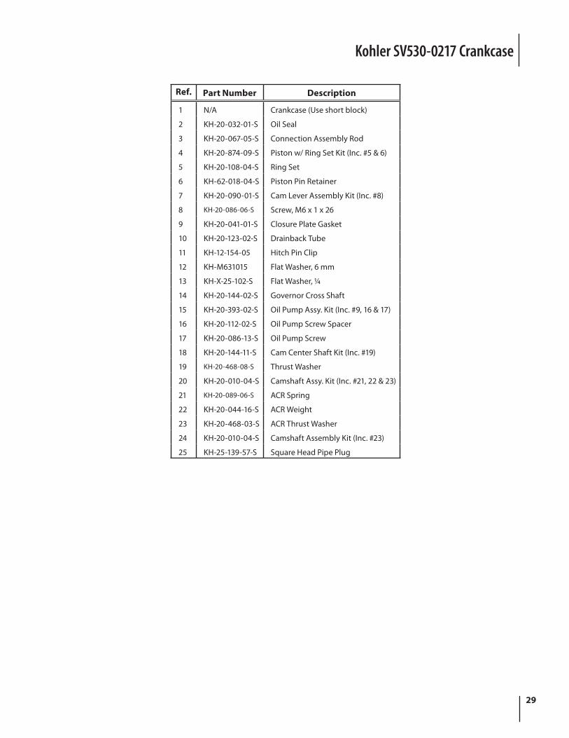
Kohler SV530-0217 Crankcase
Ref. Part Number Description
1 N/A Crankcase (Use short block)
2 KH-20-032-01-S Oil Seal
3 KH-20-067-05-S Connection Assembly Rod
4 KH-20-874-09-S Piston w/ Ring Set Kit (Inc. #5 & 6)
5 KH-20-108-04-S Ring Set
6 KH-62-018-04-S Piston Pin Retainer
7 KH-20-090-01-S Cam Lever Assembly Kit (Inc. #8)
8 KH-20-086-06-S Screw, M6 x 1 x 26
9 KH-20-041-01-S Closure Plate Gasket
10 KH-20-123-02-S Drainback Tube
11 KH-12-154-05 Hitch Pin Clip
12 KH-M631015 Flat Washer, 6 mm
13 KH-X-25-102-S Flat Washer, 1⁄4
14 KH-20-144-02-S Governor Cross Shaft
15 KH-20-393-02-S Oil Pump Assy. Kit (Inc. #9, 16 & 17)
16 KH-20-112-02-S Oil Pump Screw Spacer
17 KH-20-086-13-S Oil Pump Screw
18 KH-20-144-11-S Cam Center Shaft Kit (Inc. #19)
19 KH-20-468-08-S Thrust Washer
20 KH-20-010-04-S Camshaft Assy. Kit (Inc. #21, 22 & 23)
21 KH-20-089-06-S ACR Spring
22 KH-20-044-16-S ACR Weight
23 KH-20-468-03-S ACR Thrust Washer
24 KH-20-010-04-S Camshaft Assembly Kit (Inc. #23)
25 KH-25-139-57-S Square Head Pipe Plug
30
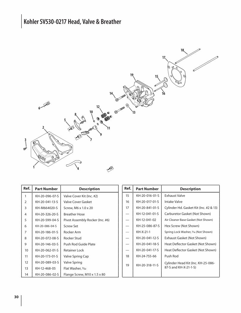
Kohler SV530-0217 Head, Valve & Breather
Ref. Part Number Description
1 KH-20-096-07-S Valve Cover Kit (Inc. #2)
2 KH-20-041-13-S Valve Cover Gasket
3 KH-M664020-S Screw, M6 x 1.0 x 20
4 KH-20-326-20-S Breather Hose
5 KH-20-599-04-S Pivot Assembly Rocker (Inc. #6)
6 KH-20-086-04-S Screw Set
7 KH-20-186-01-S Rocker Arm
8 KH-20-072-08-S Rocker Stud
9 KH-20-146-03-S Push Rod Guide Plate
10 KH-20-062-01-S Retainer Lock
11 KH-20-173-01-S Valve Spring Cap
12 KH-20-089-03-S Valve Spring
13 KH-12-468-05 Flat Washer, 3⁄32
14 KH-20-086-02-S Flange Screw, M10 x 1.5 x 80
Ref. Part Number Description
15 KH-20-016-01-S Exhaust Valve
16 KH-20-017-01-S Intake Valve
17 KH-20-841-01-S Cylinder Hd. Gasket Kit (Inc. #2 & 13)
— KH-12-041-01-S Carburetor Gasket (Not Shown)
— KH-12-041-02 Air Cleaner Base Gasket (Not Shown)
— KH-25-086-87-S Hex Screw (Not Shown)
— KH-X-21-1 Spring Lock Washer, 5⁄16 (Not Shown)
— KH-20-041-12-S Exhaust Gasket (Not Shown)
— KH-20-041-18-S Heat Deflector Gasket (Not Shown)
— KH-20-041-17-S Heat Deflector Gasket (Not Shown)
18 KH-24-755-66 Push Rod
19 KH-20-318-11-S Cylinder Head Kit (Inc. KH-25-086-87-S and KH-X-21-1-S)
14
1519
16
17
18
9
10
11
1213
5
7
8
6
3
1
2
4
31
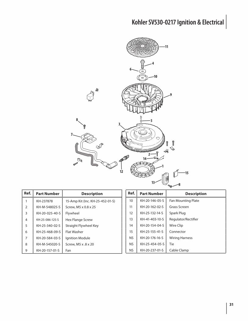
Kohler SV530-0217 Ignition & Electrical
Ref. Part Number Description
1 KH-237878 15-Amp Kit (Inc. KH-25-452-01-S)
2 KH-M-548025-S Screw, M5 x 0.8 x 25
3 KH-20-025-40-S Flywheel
4 KH-25-086-125-S Hex Flange Screw
5 KH-25-340-02-S Straight Flywheel Key
6 KH-25-468-09-S Flat Washer
7 KH-20-584-03-S Ignition Module
8 KH-M-545020-S Screw, M5 x .8 x 20
9 KH-20-157-01-S Fan
Ref. Part Number Description
10 KH-20-146-05-S Fan Mounting Plate
11 KH-20-162-02-S Grass Screen
12 KH-25-132-14-S Spark Plug
13 KH-41-403-10-S Regulator/Rectifier
14 KH-20-154-04-S Wire Clip
15 KH-25-155-41-S Connector
NS KH-20-176-16-S Wiring Harness
NS KH-25-454-05-S Tie
NS KH-20-237-01-S Cable Clamp
10
35
9
64
11
7
8
13 8
15
1
142
12
32
4
3
5
1
2
6
7
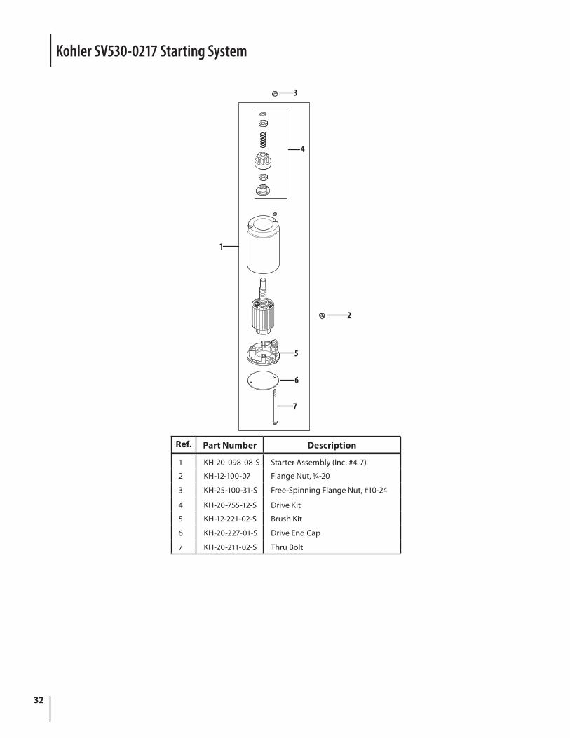
Ref. Part Number Description
1 KH-20-098-08-S Starter Assembly (Inc. #4-7)
2 KH-12-100-07 Flange Nut, 1⁄4-20
3 KH-25-100-31-S Free-Spinning Flange Nut, #10-24
4 KH-20-755-12-S Drive Kit
5 KH-12-221-02-S Brush Kit
6 KH-20-227-01-S Drive End Cap
7 KH-20-211-02-S Thru Bolt
Kohler SV530-0217 Starting System
33
19
10
765
13
13
12
11
15
14
2
3
48
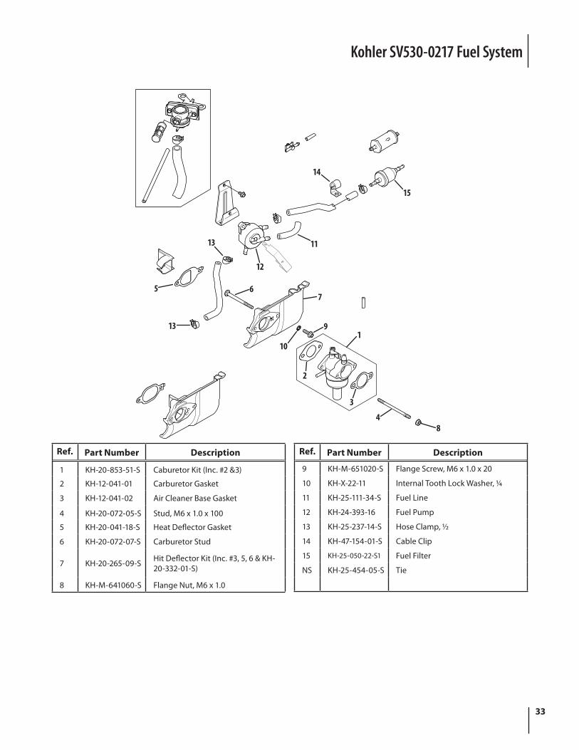
Ref. Part Number Description
1 KH-20-853-51-S Caburetor Kit (Inc. #2 &3)
2 KH-12-041-01 Carburetor Gasket
3 KH-12-041-02 Air Cleaner Base Gasket
4 KH-20-072-05-S Stud, M6 x 1.0 x 100
5 KH-20-041-18-S Heat Deflector Gasket
6 KH-20-072-07-S Carburetor Stud
7 KH-20-265-09-S Hit Deflector Kit (Inc. #3, 5, 6 & KH-20-332-01-S)
8 KH-M-641060-S Flange Nut, M6 x 1.0
Ref. Part Number Description
9 KH-M-651020-S Flange Screw, M6 x 1.0 x 20
10 KH-X-22-11 Internal Tooth Lock Washer, 1⁄4
11 KH-25-111-34-S Fuel Line
12 KH-24-393-16 Fuel Pump
13 KH-25-237-14-S Hose Clamp, 1⁄2
14 KH-47-154-01-S Cable Clip
15 KH-25-050-22-S1 Fuel Filter
NS KH-25-454-05-S Tie
Kohler SV530-0217 Fuel System
34
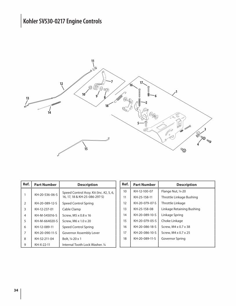
Kohler SV530-0217 Engine Controls
12
14
13 9 810
7
11
18
1617
6
2
5
3
415
1
Ref. Part Number Description
1 KH-20-536-06-S Speed Control Assy. Kit (Inc. #2, 5, 6, 16, 17, 18 & KH-25-086-297-S)
2 KH-20-089-12-S Speed Control Spring
3 KH-12-237-01 Cable Clamp
4 KH-M-545016-S Screw, M5 x 0.8 x 16
5 KH-M-664020-S Screw, M6 x 1.0 x 20
6 KH-12-089-11 Speed Control Spring
7 KH-20-090-11-S Governor Assembly Lever
8 KH-52-211-04 Bolt, 1⁄4-20 x 1
9 KH-X-22-11 Internal Tooth Lock Washer. 1⁄4
Ref. Part Number Description
10 KH-12-100-07 Flange Nut, 1⁄4-20
11 KH-25-158-11 Throttle Linkage Bushing
12 KH-20-079-07-S Throttle Linkage
13 KH-25-158-08 Linkage Retaining Bushing
14 KH-20-089-10-S Linkage Spring
15 KH-20-079-05-S Choke Linkage
16 KH-20-086-18-S Screw, M4 x 0.7 x 38
17 KH-20-086-10-S Screw, M4 x 0.7 x 25
18 KH-20-089-11-S Governor Spring
35
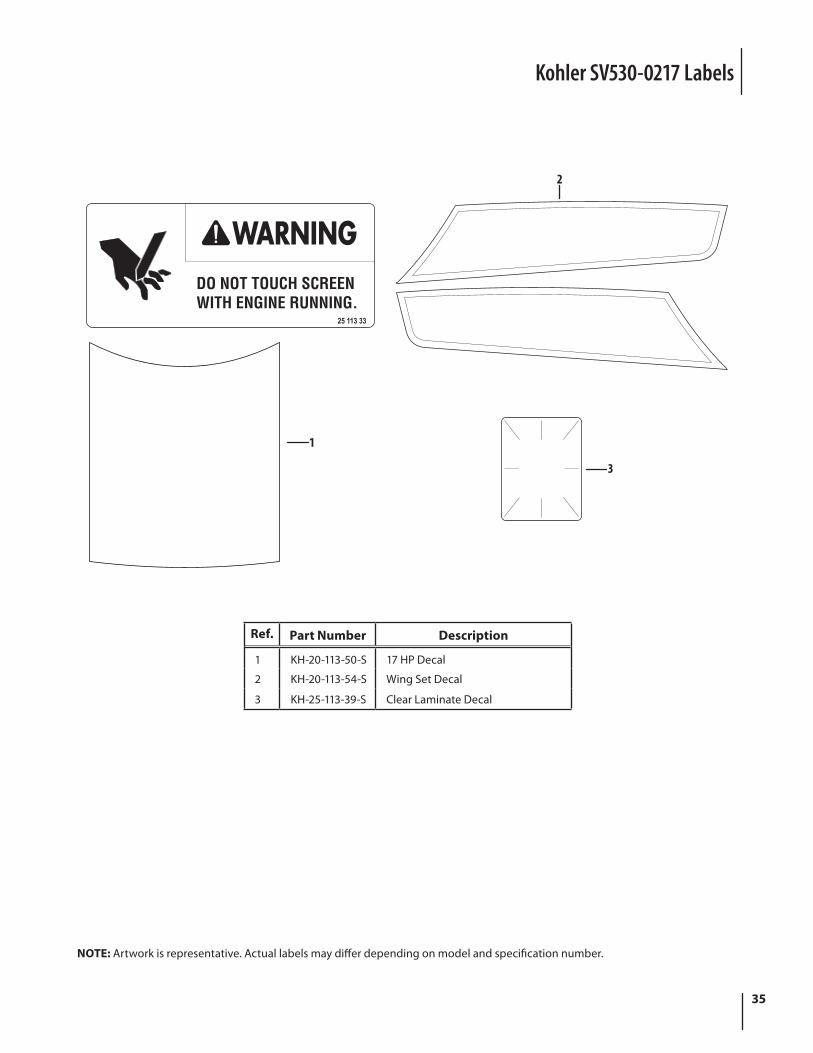
Kohler SV530-0217 Labels
Ref. Part Number Description
1 KH-20-113-50-S 17 HP Decal
2 KH-20-113-54-S Wing Set Decal
3 KH-25-113-39-S Clear Laminate Decal
1
3
2
NOTE: Artwork is representative. Actual labels may differ depending on model and specification number.
36
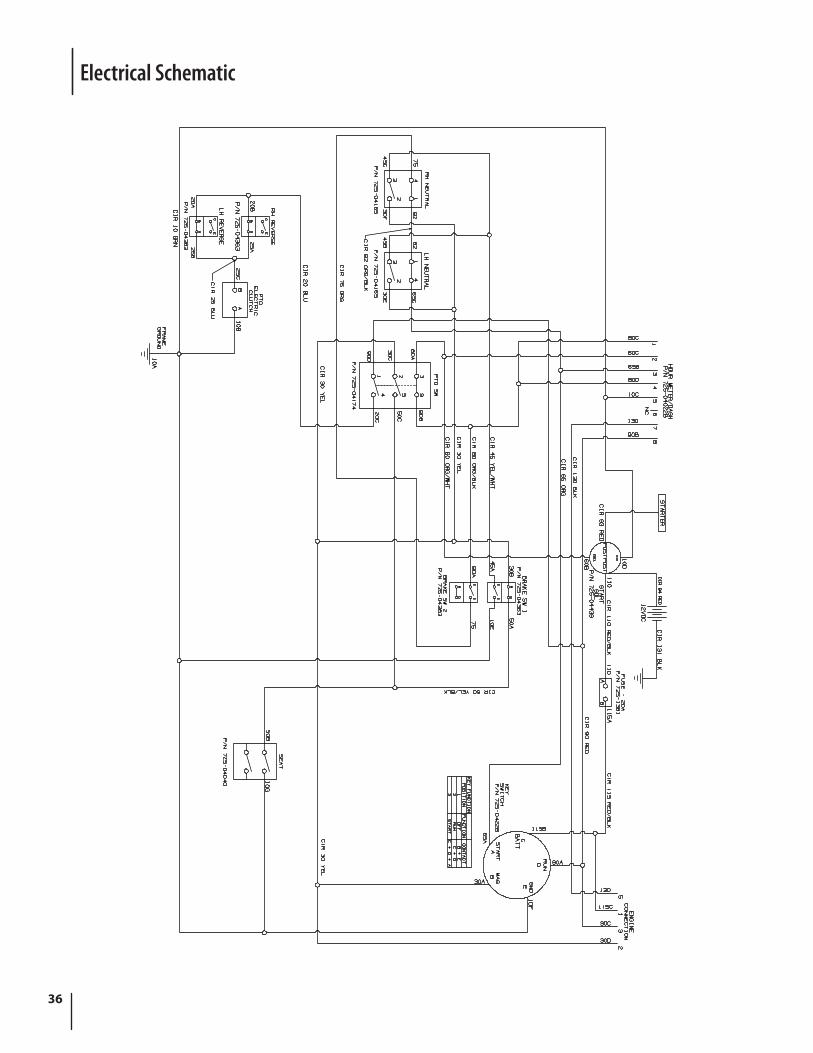
Electrical Schematic
37
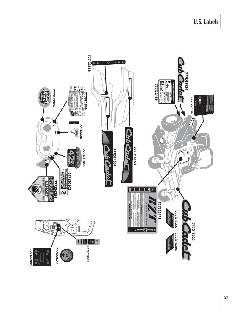
U.S. Labels
Key
STARTING INSTRUCTIONS• To START, PARK BRAKE m
ust be set• P.T.O. sw
itch in OFF (down) position
• Lap bars in NEUTRAL and outward positions
• Throttle set properly, CHOKE position if "cold"• Turn key to ON, then START, release when engine runs
NOTICE• PTO Autom
atically Disengages When Both Lap
Bars AreMoved Into Reverse.
• PTO Automatically Reengages W
hen Levers Are Returned To The Neutral Or Forw
ard Positions. FOR FIRST-TIME OPERATORS
• Start Off In A Flat, Open Area.• Keep Bystanders Aw
ay.• Set Throttle At A Low
Speed.• Practice M
aneuvering, (Forward,
Reverse, Left, Right) W
ithout Deck Engaged.
METER M
INDEREvery 50 Hours of Use a “Change Oil” M
essage Will Flash On The Display For 2
Minutes Every Tim
e The Tractor Is Started. Follow
The Oil Change Intervals Provided In The Engine M
anual.
PTO
HANDLEOPERATION
ON
PARK
BRA
KE
CUTT
ING
HEIG
HTHILOW
OFF P
AV
OID
SE
RIO
US
IN
JU
RY
OR
DE
AT
H
Oper
atio
n Of
Thi
s Eq
uipm
ent
May
Cre
ate
Spar
ks T
hat
Can
Star
t Fi
res
Arou
nd D
ry V
eget
atio
n. A
Spa
rk A
rres
tor
May
Be
Requ
ired.
The
Ope
rato
r Sho
uld
Cont
act L
ocal
Fire
Age
ncie
s Fo
r Law
s Or
Reg
ulat
ions
To F
ire P
reve
ntio
n Re
quire
men
ts.
• R
ead
Th
e O
per
ato
r's
Man
ual
.•
Go
Acr
oss
Slo
pes
, No
t U
p A
nd
Dow
n.
• If
Mac
hin
e S
top
s G
oin
g U
ph
ill, S
top
Bla
de
An
d B
ack
D
own
Slo
wly
.•
Avo
id S
udd
en Tu
rns.
• D
o N
ot
Mow
Wh
en C
hild
ren
Or
Oth
ers
Are
Aro
un
d.
• N
ever
Car
ry C
hild
ren
Eve
n W
ith
Bla
des
Off
.•
Lo
ok
Dow
n A
nd
Beh
ind
Bef
ore
An
d W
hile
Bac
kin
g.
• K
eep
Saf
ety
Dev
ices
(G
uar
ds,
Sh
ield
s, S
wit
ches
, Etc
.)
In P
lace
An
d W
ork
ing
.•
Rem
ove
Ob
ject
s T
hat
Co
uld
Be
Th
row
n B
y T
he
Bla
de.
• D
o N
ot
Op
erat
e U
nit
Wh
ere
It C
ou
ld S
lip O
r Tip
.•
Kn
ow L
oca
tio
n A
nd
Fu
nct
ion
Of
All
Co
ntr
ols
.
• B
e S
ure
Bla
des
And
Eng
ine
Are
Sto
pped
Bef
ore
Pla
cing
Han
ds
Or
Feet
Nea
r B
lade
s.•
Bef
ore
Lea
vin
g O
per
ato
r Po
siti
on
, Dis
eng
age
Bla
des
, Pla
ce
In N
eutr
al, E
ng
age
Par
kin
g B
rake
, Sh
ut
Off
An
d R
emov
e K
ey.
• W
hen
Usi
ng
Th
e O
pti
on
al G
rass
Bag
gin
g A
ttac
hm
ent,
Th
e
Fro
nt
Co
un
ter W
eig
ht
Incl
ud
ed W
ith
Bag
ger
Mu
st B
e In
stal
led
.•
Do
no
t ad
d f
uel
wh
ile t
he
eng
ine
is h
ot
or
run
nin
g.
• S
top
engi
ne, d
isco
nnec
t spa
rk p
lug
befo
re a
djus
ting
or s
ervi
cing
.•
Bef
ore
leav
ing
op
erat
or'
s p
osi
tio
n:
• D
isen
gag
e im
ple
men
t d
rive
.
•
Pla
ce s
pee
d c
on
tro
ls in
neu
tral
an
d s
et p
arki
ng
bra
ke.
• Wai
t fo
r al
l mov
emen
t to
sto
p.
• D
o n
ot
allo
w o
per
atio
n b
y u
ntr
ain
ed p
erso
nn
el.
Release Both Transmission Release
Levers Before Moving Vehicle
To Drive (Transmission
Engage), Lift Rod IntoLarge Opening AndRelease.
To Push (Transmission
Disengage), Lift Rod Through Large Opening,Push Dow
n.I22489 AC
SLOPES GREATER THAN 15 .̊ MOW
ACROSS NOT UP AND DOW
N. AVOID SUDDE N TURNS. USE LOW SPEED.
KEEP HANDS AND FEET AWAY FROM ROTATING PARTS
42
INCHC
UT
DECKD
AN
GE
RK
EE
P H
AN
DS
AN
D FE
ET
AW
AY.
DO
NO
T O
PE
RA
TE
MO
WE
R
UN
LE
SS
CH
UT
E D
EF
LE
CT
OR
O
R E
NT
IRE
GR
AS
S C
ATC
HE
R IS
IN
ITS
PR
OP
ER
PLA
CE
.ASSEM
BLE CHUTE DEFLECTOR TO THIS UNIT BEFORE OPERATING.S
30503
TO R
EDU
CE THE R
ISK OF IN
JUR
Y, DO
NO
TO
PERATE U
NLESS DISCHARGE COVER OR
GRASS CATCHER
IS IN ITS PR
OPER
PLACE.IF D
AM
AG
ED, R
EPLA
CE IM
MED
IATELY.
100%50%0%
HO
UR
S 1/10
PTO
/B
LAD
EPA
RK
BR
AK
E
OIL
BAT
T.
FAS
T
SL
OW
OIL
CHECK OIL BEFORE EACH USE
777I22884777D
13930
777I22489
777D14068
777D14067
777I22888777S32599
777I22281777D
11854
777S30503
777S30284777D
13924777I22679
777I22887
777I22885
777S33471
777D13208
777D13207
777D13929
38
100% 50
% 0%
S32
356
4FR N
35
1P
2
kg
=+I
O
P
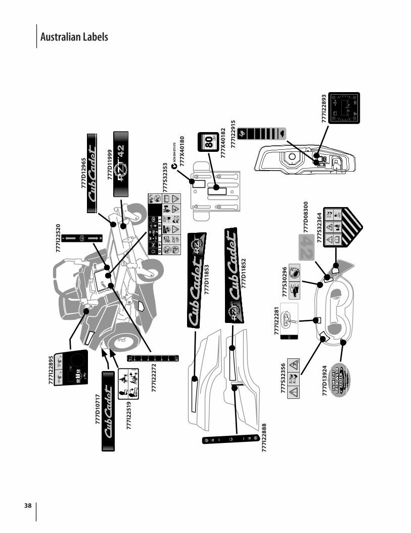
I22519 AC
RF
N
777I
2289
5
777D
1071
7
777I
2251
9
777I
2227
2
777I
2288
8
777D
1185
3
777D
1185
2
777S
3235
3 777X
4018
0
777X
4018
2
777I
2291
5 777I
2289
377
7S32
364
777D
0830
0
777S
3029
677
7I22
281
777S
3235
6
777D
1392
4
777D
1199
9
777D
1296
5
777I
2252
0
Australian Labels

39notes
Notes
CUB CADET LLC, P.O. BOX 361131 CLEVELAND, OHIO 44136-0019
G E N U I N E
FACTORY PARTS
To order replacement parts, call a Customer Support Representative at (800) 965-4CUB.Locate your nearest Cub Cadet dealer at (877) 282-8684
or visit www.cubcadet.com to find the nearest Cub Cadet dealer in your area.