OPERATORS MANUAL
27
Model U218 OPERATORS MANUAL Manual No. 513631 Rev.1
-
Upload
khangminh22 -
Category
Documents
-
view
2 -
download
0
Transcript of OPERATORS MANUAL

Model U218OPERATORS MANUAL
Manual No. 513631 Rev.1


This manual provides basic information about the machine. Instructions and suggestions are given covering its operation and care.
The illustrations and specifi cations are not binding in detail. We reserve the right to make changes to the machine without notice, and without incurring any obligation to modify or pro-vide new parts for machines built prior to date of change.
DO NOT ATTEMPT to operate the machine until instructions and safety precautions in this manual are read completely and are thoroughly understood. If problems develop or questions arise in connection with installation, operation, or servicing of the machine, contact Stoelting.
Stoelting Foodservice Equipment502 Highway 67Kiel, WI 53042-1600U.S.A.
Main Tel: 800.558.5807Fax: 920.894.7029
Customer Service: 888.429.5920 Fax: 800.545.0662 Email: [email protected]
© 2014 PW Stoelting, LLCstoeltingfoodservice.com

Safety Alert Symbol:
This symbol Indicates danger, warning or caution. Attention is required in order to avoid serious per-sonal injury. The message that follows the symbol contains important information about safety.
Signal Word:
Signal words are distinctive words used throughout this manual that alert the reader to the existence and relative degree of a hazard.
CAUTION
The signal word “CAUTION” indicates a potentially hazardous situation, which, if not avoided, may result in minor or moderate injury and equipment/property damage.
A Few Words About Safety
Safety Information Read and understand the entire manual before operating or maintaining Stoelting equipment.
This manual provides the operator with information for the safe operation and maintenance of Stoelting equipment. As with any machine, there are hazards associated with their operation. For this reason safety is emphasized throughout the manual. To highlight specifi c safety information, the following safety defi ni-tions are provided to assist the reader.
The purpose of safety symbols is to attract your at-tention to possible dangers. The safety symbols, and their explanations, deserve your careful attention and understanding. The safety warnings do not by themselves eliminate any danger. The instructions or warnings they give are not substitutes for proper accident prevention measures.
If you need to replace a part, use genuine Stoelting parts with the correct part number or an equivalent part. We strongly recommend that you do not use replacement parts of inferior quality.
WARNINGThe signal word “WARNING” indicates a potentially hazardous situation, which, if not avoided, may result in death or serious injury and equipment/property damage.
CAUTIONThe signal word “CAUTION” not preceded by the safety alert symbol indicates a potentially hazardous situation, which, if not avoided, may result in equip-ment/property damage.
NOTE (or NOTICE)The signal word “NOTICE” indicates information or procedures that relate directly or indirectly to the safety of personnel or equipment/property.

Section Description Page1 Description and Specifications1.1 Description .................................................................................................11.2 Specifications.............................................................................................1
2 Installation Instructions2.1 Safety Precautions .....................................................................................32.2 Shipment and Transit .................................................................................32.3 Freezer Installation ....................................................................................3
3 Initial Set-Up and Operation3.1 Operator”s Safety Precautions ...................................................................53.2 Operating Controls and Indicators .............................................................53.3 Sanitizing ...................................................................................................63.4 Freeze Down and Operation ......................................................................73.5 Removing Mix From Freezer .....................................................................73.6 Cleaning the Freezer .................................................................................73.7 Disassembly of Freezer Parts ....................................................................73.8 Cleaning the Freezer Parts ........................................................................83.9 Sanitize Freezer and Freezer Parts ...........................................................83.10 Assembly of Freezer ..................................................................................93.11 Routine Cleaning .......................................................................................103.12 Preventative Maintenance..........................................................................103.13 Extended Storage ......................................................................................11
4 Troubleshooting4.1 Light Indicators ..........................................................................................134.2 Troubleshooting .........................................................................................13
5 Replacement Parts5.1 Decals and Lubrication ..............................................................................155.2 Auger Shaft and Faceplate Parts ...............................................................165.3 Hopper Parts ..............................................................................................185.4 Autofill Options ...........................................................................................19
TABLE OFCONTENTS


1
SECTION 1DESCRIPTION AND SPECIFICATIONS
1.1 DESCRIPTIONThe Stoelting U218 freezer is available as gravity fed orwith an optional autofill kit. It is equipped with fully auto-matic controls to provide a uniform product. The U218freezer will operate with almost any type of frozen bever-age mix. This manual is designed to help qualified servicepersonnel and operators with the installation, operationand maintenance of the Stoelting U218 freezer.
1.2 SPECIFICATIONS
Figure 1-1 Model U218
Figure 1-2 Model U218 Dimensions

2
1.2 SPECIFICATIONS - CONTINUED
Dimensionswidthheightdepth
WeightElectrical
running ampsconnection typeCompressorDrive Motor
Air FlowHopper Volume
Freezing Cylinder Volume
Production Capacity
2 gallon (8 quart), 7,57 liters
11,000 Btu/hr1/2 hp
Air cooled units require 3" (7,6 cm) air space at front and back.7 gallon (26,50 liters)
Model U218
33'' (83,7 cm)64-1/2'' (163,8 cm)18-1/4'' (46,3 cm)
Freezer
30 GPH (113,59 liters) per Freezing Cylinder
with crate25'' (63,5 cm)66'' (167,5 cm)51'' (129,5 cm)1 lbs (0,5 kg)1 lbs (0,5 kg)
1 Phase, 208-230 VAC, 60Hzapproximately 12A
NEMA6-20P power cord provided

3
SECTION 2INSTALLATION INSTRUCTIONS
2.1 SAFETY PRECAUTIONSDo not attempt to operate the freezer until the safetyprecautions and operating instructions in this manual areread completely and are thoroughly understood.Take notice of all warning labels on the freezer. The labelshave been put there to help maintain a safe workingenvironment. The labels have been designed to withstandwashing and cleaning. All labels must remain legible forthe life of the freezer. Labels should be checked periodi-cally to be sure they can be recognized as warning labels.If danger, warning or caution labels are needed, indicatethe part number, type of label, location of label, andquantity required along with your address and mail to:
STOELTING, LLCATTENTION: Customer Service
502 Hwy. 67Kiel, Wisconsin 53042
2.2 SHIPMENT AND TRANSITThe freezer has been assembled, operated and inspectedat the factory. Upon arrival at the final destination, theentire freezer must be checked for any damage which mayhave occurred during transit.With the method of packaging used, the freezer shouldarrive in excellent condition. THE CARRIER IS RESPON-SIBLE FOR ALL DAMAGE IN TRANSIT, WHETHERVISIBLE OR CONCEALED. Do not pay the freight bill untilthe freezer has been checked for damage. Have thecarrier note any visible damage on the freight bill. Ifconcealed damage and/or shortage is found later, advisethe carrier within 10 days and request inspection. Thecustomer must place claim for damages and/or shortagesin shipment with the carrier. Stoelting, LLC cannot makeany claims against the carrier.2.3 FREEZER INSTALLATIONInstallation of the freezer involves moving the freezerclose to its permanent location, removing all crating,setting in place, assembling parts, and cleaning.A. Uncrate the freezer.B. Accurate leveling is necessary for correct drainage
of freezer barrel and to insure correct overrun.Place a bubble level on top of the freezer at eachcorner to check for level condition. If adjustmentis necessary, level the freezer by turning the nut ofeach caster in or out.
C. Correct ventilation is required. Install the rear airbaffle to provide the 3” clearance at the front andback (Refer to Figure 2-1). Remove the rear panelscrews and use them to attach the baffle. Thefreezer can be placed side-by-side next to otherequipment.
D. Place the CLEAN-ON-OFF switch in the OFFposition.
E. Connect the power cord to the proper powersupply. The plug on the U218 is designed for 230volt / 20 amp duty. Check the nameplate on yourfreezer for proper supply. The unit must beconnected to a properly grounded receptacle.The electrical cord furnished as part of the freezerhas a three prong grounding type plug. The use ofan extension cord is not recommended, ifnecessary use one with a size 12 gauge or heavierwith ground wire. Do not use an adapter tocircumvent the grounding requirement.
WARNING
Do not alter or deform electrical plug in any way.Altering the plug to fit into an outlet of different con-figuration may cause fire, risk of electrical shock,product damage and will void warranty.
Figure 2-1 Rear Air Baffle

4

5
SECTION 3INITIAL SET-UP AND OPERATION
3.1 OPERATOR’S SAFETY PRECAUTIONSSAFE OPERATION IS NO ACCIDENT; observe theserules:A. Know the freezer. Read and understand the
Operating Instructions.B. Notice all warning labels on the freezer.C. Wear proper clothing. Avoid loose fitting garments,
and remove watches, rings or jewelry that couldcause a serious accident.
D. Maintain a clean work area. Avoid accidents bycleaning up the area and keeping it clean.
E. Stay alert at all times. Know which switch, pushbutton or control you are about to use and whateffect it is going to have.
F. Disconnect electrical cord for maintenance. Neverattempt to repair or perform maintenance on thefreezer until the main electrical power has beendisconnected.
G. Do not operate under unsafe operating conditions.Never operate the freezer if unusual or excessivenoise or vibration occurs.
3.2 OPERATING CONTROLS AND INDICATORSBefore operating the freezer, it is required that the operatorknow the function of each operating control. Refer toFigure 3-1 for the location of the operating controls on thefreezer.
A. Spigot SwitchThe spigot switch will automatically start the augerdrive and refrigeration systems when the spigot isopened to dispense product. When the spigot isclosed, the drive motor and compressor will remainon until the product in the freezing cylinder reachesthe proper consistency..
B. CLEAN-OFF-ON SwitchThe CLEAN-OFF-ON switch is used to supplypower to the control circuit. When the switch is inthe OFF (middle) position, power will not besupplied to the control board or refrigeration
WARNING
High voltage will shock, burn or cause death. TheOFF-ON switch must be placed in the OFF positionprior to disassembling for cleaning or servicing. Donot operate machine with cabinet panels removed.
Figure 3-1 Freezer Controls
ConsistencyAdjustment
Knob
DiagnosticLight
Add MixIndicator
Clean/Off/OnSwitch

6
system. When the switch is in the ON position, thefreezer will operate in the freezing mode. Whenthe switch is in the CLEAN position, all refrigerationwill stop and the auger will start rotating.
C. ADD MIX LightThe ADD MIX light will flash to alert the operatorto a low mix condition. It does so by monitoring themix level in the hopper. When the ADD MIX lightis flashing, refill hopper immediately.
NOTEFailure to refill hopper immediately may result inoperational problems.
D. Diagnostic LightThe Diagnostic Light will light and stay lit during adefrost cycle (Shake mode only). The defrostcycle starts after 3 hours without a spigot pull. Theauger rotates for 90 seconds every 7 minutes.After 5 hours the normal freezing mode will start.The Diagnostic Light will flash if an error occurs.The light will flash once if there is a compressorerror. There will be two quick flashes if there is anauger error. And there will be three quick flashesif the freezer is left in clean mode for more than 20minutes. Refer to the troubleshooting section fordetails.
E. Consistency Adjustment Knob (A&W Freezershave an adjustment screw)The Consistency Adjustment Knob increases ordecreases product consistency. A tension springis connected to the knob and changes the amountof torque needed to complete a refrigeration cycle.Turn the knob clockwise to increase consistencyor counterclockwise to decrease consistency.
F. Front Door Safety SwitchThe front door safety switch prevents the augerfrom turning when the front door is removed. Theswitch is open when the door is not in place andclosed when the door is properly installed.
G. Autofill Kit - Optional (Part 2187317)The autofill kit is used with a pump to keep thehopper filled. The autofill kit is for use with non-potentially hazardous food substances; non-dairy.Refer to Section 5-4 for Autofill options.
3.3 SANITIZINGSanitizing must be done after the freezer is cleaned andjust before the hopper is filled with mix. Sanitizing the nightbefore is not effective. However, you should always cleanthe freezer and parts after each use.
The United States Department of Agriculture andthe Food and Drug Administration require that allcleaning and sanitizing solutions used with food pro-cessing equipment be certified for this use.
When sanitizing the freezer, refer to local sanitary regula-tions for applicable codes and recommended sanitizingproducts and procedures. The frequency of sanitizingmust comply with local health regulations.Mix sanitizer according to manufacturer’s instructions toprovide a 100 parts per million strength solution. Mixsanitizer in quantities of no less than 2 gallons (7.5 liters)of 90° to 110°F (32° to 43°C) water. Allow sanitizer tocontact the surfaces to be sanitized for 5 minutes. Anysanitizer must be used only in accordance with themanufacturer’s instructions.In general, sanitizing may be conducted as follows:
A. Prepare Stera-Sheen Green Label Sanitizer orequivalent according to manufacturer’sinstructions to provide a 100 ppm strength solution.Mix the sanitizer in quantities of no less than 2gallons of 90° to 110°F (32° to 43°C) water. Checkthe strength of the sanitizing solution. Use achlorine test strip and color chart to make sure thesolution has 100 ppm. Any sanitizer must be usedonly in accordance with the manufacturer’sinstructions.
B. Pour the sanitizing solution into the hopper andplace the switch in the CLEAN position. Check forleaks. Place the switch in the CLEAN position.Check for leaks.
C. Clean the sides of the hopper and the undersideof the hopper cover using a soft bristle brushdipped in the sanitizing solution (Refer to Figure 3-2).
CAUTION
Do not allow sanitizer to remain in contact with stain-less steel freezer parts for prolonged periods. Pro-longed contact of sanitizer with freezer may causecorrosion of stainless steel parts.
Figure 3-2 Brush Hopper

7
D. After five minutes, place a bucket under the spigotand open spigot to drain most sanitizing solution.Leave a small amount of the sanitizing solution inthe freezing cylinder. Place the switch in the OFF(middle) position.
E. Collect the remaining sanitizing solution in a cupand test the chlorine contents with a new test strip.If the reading is less than 100 ppm, sanitize thefreezer again.If the reading is less than 100 ppm after sanitizingthe second time, disassemble and wash the freezeragain.
3.4 FREEZE DOWN AND OPERATIONA. Sanitize just prior to use.B. Place the switch in the OFF (middle) position.C. Fill the hopper with mix.D. Open spigot and drain a small amount of mix to
remove any remaining sanitizer.E. Place the switch in the ON position.
NOTEAfter the drive motor starts, there is a 3 second de-lay before the compressor starts.
F. After 8 to 12 minutes the product will be atconsistency and will be ready to serve. Freezedown time may vary depending on mix type andambient temperatures.
G. To dispense, pull the spigot handle down to openthe spigot.
The freezer is designed to dispense the product at areasonable draw rate. If the freezer is overdrawn, theresult is a soft product or a product that will not dispenseat all. If this should occur, allow the freezer to run forapproximately 30 seconds before dispensing additionalproduct.Do not operate the freezer when the ADD MIX light is on.Refill the hopper immediately.
3.5 REMOVING MIX FROM FREEZERTo remove the mix from the freezer, refer to the followingsteps:A. Place the switch in the CLEAN position to rotate
the auger. Allow the mix to agitate in freezingcylinder until the mix has become liquid, about 5minutes.
B. Drain the mix by opening the spigot. A containershould be placed under the spigot to collect theliquid mix.
C. Place the switch in the OFF (middle) position.
3.6 CLEANING THE FREEZERNOTE
The frequency of cleaning the freezer and freezerparts must comply with local health regulations.
After the mix has been removed from the freezer, thefreezer must be cleaned. To clean the freezer, refer to thefollowing steps:A. Make sure the spigot is closed and fill the hopper
with 2 gallons (8 liters) of tap water.B. Place the switch in the CLEAN position. The
auger will start to rotate.C. Allow the water to agitate for approximately 30
seconds.D. Open the spigot to drain the water. Remember to
place a container under the spigot to catch thewater. When the water has drained, place theswitch in the OFF (middle) position. Allow thefreezing cylinder to drain completely.
E. Prepare sanitizing solution according tomanufacturer’s instructions to provide a 100 ppmstrength solution. Mix the sanitizer in quantities ofno less than 2 gallons of 90° to 110°F (32° to 43°C)water. Check the strength of the sanitizing solution.Use a chlorine test strip and color chart to makesure the solution has 100 ppm. Repeat steps Athrough D using the sanitizing solution.
3.7 DISASSEMBLY OF FREEZER PARTSInspection for worn or broken parts should be made eachtime the freezer is disassembled. All worn or broken partsshould be replaced to ensure safety to both the operatorand the customer and to maintain good freezer perfor-mance and a quality product. Frequency of cleaning mustcomply with the local health regulations.To disassemble the freezer, refer to the following steps:
A. Make sure the freezer has been drained of mix.Remove hopper cover.
B. Pull out the spigot pin by its ring (Refer to Figure3-3).
CAUTION
Hazardous Moving Parts.Revolving auger shaft can grab and cause injury.Place the switch in the OFF (middle) position be-fore disassembling for cleaning or servicing.

8
C. Remove the spigot handle.D. Remove front door by turning the circular knobs
and then pulling door off the studs.NOTE
When removing front door, entire door and statorassembly will come out as well.
E. Remove torque rod from stator assembly.F. Remove quad ring from groove in front door.G. Remove stator bar. Remove o-ring and white
bushing from stator bar.H. Remove auger support bushing.I. Turn the spigot body until the ice breaker bar can
be removed. Remove breaker bar (Refer to Figure3-4).
J. Remove spigot body from the front door.
K. Remove o-rings (2) from the spigot by first wipingoff the lubricant using a clean paper towel. Thensqueeze the o-ring upward with a dry cloth. Whena loop is formed, roll the o-ring out of the groove(Refer to Figure 3-5).
L. Remove auger assembly from the freezing cylinderand remove auger blades.
M. Remove rear seal and o-ring from auger.N. Remove the flavor pumps from the bottles.O. Remove drain tray, drip tray and drip tray grid.
3.8 CLEANING THE FREEZER PARTSPlace all loose parts in a pan or container and take to thewash sink for cleaning. Local and state health codesdictate the procedure required. Some health codes re-quire a four-sink process (pre-wash, wash, rinse, sanitize,and air-dry), while other codes require a three-sink pro-cess (without the pre-wash step). The following proce-dures are a general guideline only. Consult your local andstate health codes for procedures required in your loca-tion.A. Prepare detergent water by mixing 2 oz. of
Palmolive detergent or equivalent in 2 gallons of90° to 110°F (32° to 43°C) water. Place all partsin detergent solution and clean with providedbrushes. Prepare detergent water by mixing 2 oz.of Palmolive detergent or equivalent in 2 gallonsof 90° to 110°F (32° to 43°C) water.
B. Prepare sanitizing solution according tomanufacturer’s instructions to provide a 100 ppmstrength solution. Mix the sanitizer in quantities ofno less than 2 gallons of 90° to 110°F (32° to 43°C)water. Check the strength of the sanitizing solution.Use a chlorine test strip and color chart to makesure the solution has 100 ppm.
C. Place all parts in detergent solution and clean withprovided brushes. Rinse all parts with clean 90° to110°F (32° to 43°C) water. Place the parts in thesanitizing solution.
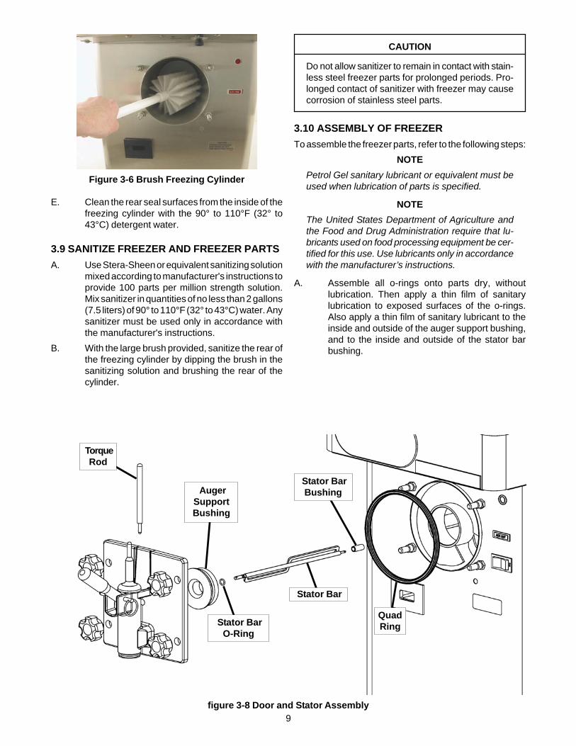
D. Wash the hopper and freezing cylinder with the90° to 110°F (32° to 43°C) detergent water andbrushes provided (Refer to Figure 3-6).
Figure 3-4 Spigot and Ice Breaker Bar Removal
Figure 3-5 Remove O-Ring
Figure 3-3 Remove Spigot Pin
9
E. Clean the rear seal surfaces from the inside of thefreezing cylinder with the 90° to 110°F (32° to43°C) detergent water.
3.9 SANITIZE FREEZER AND FREEZER PARTSA. Use Stera-Sheen or equivalent sanitizing solution
mixed according to manufacturer's instructions toprovide 100 parts per million strength solution.Mix sanitizer in quantities of no less than 2 gallons(7.5 liters) of 90° to 110°F (32° to 43°C) water. Anysanitizer must be used only in accordance withthe manufacturer's instructions.
B. With the large brush provided, sanitize the rear ofthe freezing cylinder by dipping the brush in thesanitizing solution and brushing the rear of thecylinder.
3.10 ASSEMBLY OF FREEZERTo assemble the freezer parts, refer to the following steps:
NOTEPetrol Gel sanitary lubricant or equivalent must beused when lubrication of parts is specified.
NOTEThe United States Department of Agriculture andthe Food and Drug Administration require that lu-bricants used on food processing equipment be cer-tified for this use. Use lubricants only in accordancewith the manufacturer’s instructions.
A. Assemble all o-rings onto parts dry, withoutlubrication. Then apply a thin film of sanitarylubrication to exposed surfaces of the o-rings.Also apply a thin film of sanitary lubricant to theinside and outside of the auger support bushing,and to the inside and outside of the stator barbushing.
figure 3-8 Door and Stator Assembly
TorqueRod
AugerSupportBushing
Stator BarO-Ring
Stator BarBushing
QuadRing
Stator Bar
Figure 3-6 Brush Freezing Cylinder
CAUTION
Do not allow sanitizer to remain in contact with stain-less steel freezer parts for prolonged periods. Pro-longed contact of sanitizer with freezer may causecorrosion of stainless steel parts.

10
B. Assemble the rear seal onto the auger with thelarge end to the rear. Be sure the o-ring is in placebefore installing the rear seal (Refer to Figure 3-7).
C. Put a small amount of white Hex Drive Anti Seize(spline lube) on the hex end of the auger shaft. Asmall container of Anti Seize is shipped with thefreezer.
D. Install the plastic auger blade onto the auger.E. Push the auger into freezing cylinder and rotate it
slowly until it engages the drive shaft.F. Insert the spigot body into front door.
NOTEPress the o-rings against the spigot body when in-serting it into the front door to prevent damage.
G. Turn spigot body until the ice breaker bar can beinserted. Insert breaker bar and rotate spigotbody 90°.
H. Install auger support bushing onto front door sobeveled edge of bushing is against door.
I. Install the white stator bar bushing onto the rear ofthe stator bar and insert stator into spigot.
J. Insert the torque rod. The rod should be placedthrough the hole in stator bar.
K. Install the front door onto the freezer.NOTE
When installing the door onto the freezer, the torquerod must be placed in the center of the metal torqueactuator arm.
L. Install the knobs on the freezer studs.M. Look for a proper seal between the freezing
cylinder, quad ring, and front doorN. Insert the spigot handle so the hole lines up and
insert the spigot pin.O. Install the flavor pumps onto the bottles and place
them into the flavor rack.P. Install the hopper cover, drain tray, drip tray, and
drip tray grid.
3.11 ROUTINE CLEANINGTo remove spilled or dried mix from the freezer exterior,wash in the direction of the finish with warm soapy waterand wipe dry. Do not use highly abrasive materials as theywill mar the finish.
3.12 PREVENTIVE MAINTENANCEA. DAILY1. The exterior should be kept clean at all times to
preserve the luster of the stainless steel. A mildalkaline cleaner is recommended. Use a soft clothor sponge to apply the cleaner.
B. WEEKLY1. Check the o-rings and the rear seal for excessive
wear and replace them if necessary.2. Remove the drip tray by gently lifting it up and
pulling it out. Clean behind the drip tray and frontof the freezer with a soap solution.
C. QUARTERLYAir Cooled FreezerThe air-cooled condenser is a copper tube and aluminumfin type. Condensing is totally dependent upon airflow. Aplugged condenser filter, condenser, or restrictions in thelouvered panel will restrict airflow. This will lower thecapacity of the system and damage the compressor.The condenser must be kept clean of dirt and grease. TheU218 must have a minimum of 3” (7.6 cm) of ventilation atthe front and back of the unit for free flow of air. Make surethe air entering the freezer is under 100° F (37° C).The condenser and condenser filter require periodic clean-ing. To clean, refer to the following procedures.Condenser Filter Cleaning1. The condenser filter is located at the front of the
freezer. It is mounted to the freezer by brackets atthe top and bottom of the front panel. Remove thefilter by sliding it to the side.
2. Visually inspect the filter for dirt. If it is dirty, shakeor brush the excess dirt off the filter and wash it inwarm, soapy water.
3. Once the filter is clean, rinse it thoroughly in warm,clear water and shake dry, taking care not todamage the filter in any way.
Condenser Cleaning1. Disconnect (unplug) from the electrical supply
source.2. Remove the Phillips head screw from the bottom
of the right side panel, and then slide the paneldown and out.
3. Visually inspect the condenser for dirt by shininga light through the coil from the back (inside) of thecondenser.
Figure 3-7 Install Rear Seal

11
4. If the condenser is dirty, place a wet towel over thefront (outside) of the condenser.
5. Using a vacuum, carefully clean the condensercoil from the inside and outside of the freezer. Astiff bristled brush may help in releasing debrisfrom between the condenser coils.
Water Cooled FreezerThe water-cooled condenser is a tube and shell type. Thecondenser needs a cool, clean supply of water to properlycool the freezer, inlet and discharge lines must be 3/8” I.D.minimum. Make sure the freezer is receiving an unre-stricted supply of cold, clean water.E. SEMI-ANNUALLY1. Disconnect the freezer from the power source.2. Check drive belt for proper tension. Push belt in
with one finger, belt should deflect about 3/8".3. Lubricate condenser fan motor with S.A.E. 20
weight oil. Three to six drops are required.
3.13 EXTENDED STORAGERefer to the following steps for storage of the freezer overany long period of shutdown time:A. Place the CLEAN-OFF-ON switch in the OFF
(middle) position.B. Disconnect (unplug) from the electrical supply
source.C. With warm detergent water, thoroughly clean all
parts that come in contact with mix. Rinse theparts in clean water and dry them. Do not sanitize.
NOTEDo not let the cleaning solution stand in the hopperor in the freezing cylinder during the shutdown pe-riod.
D. In a water cooled freezer, disconnect water linesand drain water. With a flathead screwdriver, holdthe water valve open and use compressed air toclear the lines of any remaining water.

12

13
SECTION 4TROUBLESHOOTING
4.1 LIGHT INDICATORSThe freezer has two lights that will alert the user if a problem occurs: an ADD MIX light and a Diagnostic Light.The ADD MIX light will flash to alert the operator to a low mix condition. It does so by monitoring the mix level in thehopper. When the ADD MIX light is flashing, refill hopper immediately.The Diagnostic Light will flash if an error occurs. Refer to the chart below for details.
4.2 TROUBLESHOOTING
PROBLEM POSSIBLE CAUSE REMEDY
Freezer does not run.
1. Power to freezer is off.2. Blown fuse or tripped circuit.3. Freeze-up (auger will not turn).
4. High pressure cut-out tripped.5. Front door not in place.
1. Supply power to freezer.2. Replace or reset.3. Turn CLEAN-OFF-ON switch to OFF (middle) position for 15 minutes, then restart.4. Wait until automatic reset for freezer to start.5. Assemble front door in place.
Freezer will not shut off.
1. Drive belt failure.2. Consistency temperature setting is too firm.3. Refrigeration problem.
1. Replace drive belt.2. Turn Consistency Adjustment knob counter-clockwise.3. Check system. (Call distributor for service)
Product is too firm.1. Consistency temperature setting is too firm.
1. Turn Consistency Adjustment knob counter-clockwise.
Indication On One Blink Two Blinks Three Blinks
Conditions Defrost Mode
Torque is not met after 20
minutes (22 minutes for
shake)
Drive current is not sensedFreezer left in clean
mode for over 20 minutes
Self Correction
N/A N/A
The freezer attempts to sense drive current with a 3 second pre-stir. If current is sensed, the freezer will return to normal
operation. If current is not sensed, the freezer will wait 7 minutes and try to
sense current with another 3 second pre-stir. After the third attempt, the compressor will run on timers.
N/A
Operation
Every 7 minutes the auger will
run for 90 seconds.
Timers Timers Off
Corrective Action N/A
Contact Service Technician Contact Service Technician
Turn CLEAN-OFF-ON switch to OFF
(middle) position then turn the switch to ON.
14
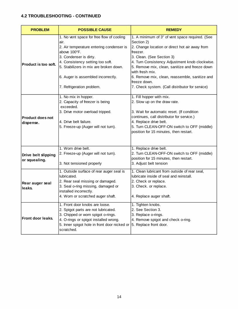
4.2 TROUBLESHOOTING - CONTINUED
PROBLEM POSSIBLE CAUSE REMEDY
Product is too soft.
1. No vent space for free flow of cooling air.2. Air temperature entering condenser is above 100°F.3. Condenser is dirty.4. Consistency setting too soft.5. Stabilizers in mix are broken down.
6. Auger is assembled incorrectly.
7. Refrigeration problem.
1. A minimum of 3" of vent space required. (See Section 2)2. Change location or direct hot air away from freezer.3. Clean. (See Section 3)4. Turn Consistency Adjustment knob clockwise.5. Remove mix, clean, sanitize and freeze down with fresh mix.6. Remove mix, clean, reassemble, sanitize and freeze down.7. Check system. (Call distributor for service)
Product does not dispense.
1. No mix in hopper. 2. Capacity of freezer is being exceeded.3. Drive motor overload tripped.
4. Drive belt failure.5. Freeze-up (Auger will not turn).
1. Fill hopper with mix.2. Slow up on the draw rate.
3. Wait for automatic reset. (If condition continues, call distributor for service.)4. Replace drive belt.5. Turn CLEAN-OFF-ON switch to OFF (middle) position for 15 minutes, then restart.
Drive belt slipping or squealing.
1. Worn drive belt.2. Freeze-up (Auger will not turn).
3. Not tensioned properly
1. Replace drive belt.2. Turn CLEAN-OFF-ON switch to OFF (middle) position for 15 minutes, then restart.3. Adjust belt tension
Rear auger seal leaks.
1. Outside surface of rear auger seal is lubricated.2. Rear seal missing or damaged.3. Seal o-ring missing, damaged or installed incorrectly.4. Worn or scratched auger shaft.
1. Clean lubricant from outside of rear seal, lubricate inside of seal and reinstall.2. Check or replace.3. Check. or replace.
4. Replace auger shaft.
Front door leaks.
1. Front door knobs are loose.2. Spigot parts are not lubricated.3. Chipped or worn spigot o-rings.4. O-rings or spigot installed wrong.5. Inner spigot hole in front door nicked or scratched.
1. Tighten knobs.2. See Section 3.3. Replace o-rings.4. Remove spigot and check o-ring.5. Replace front door.

15
SECTION 5REPLACEMENT PARTS
Part Description Quantity208135 Brush - 4" X 8" X 16" (Barrel) 1208380 Brush - 1/4" X 3" X 14" 1208401 Brush - 1" X 3" X 10" 1324105 Decal - Caution Electrical Shock 1324106 Decal - Caution Electrical Wiring Materials 1324107 Decal - Caution Hazardous Moving Parts 1324141 Decal - Caution Rotating Blades 1324208 Decal - Attention Refrigerant Leak Check 1324393 Decal - Stoelting Swirl Logo 1324509 Decal - Cleaning Instructions 1324548 Decal - Adequate Ventilation 6" 1324566 Decal - Wired According To 1324686 Decal - Danger Automatic Start 1324804 Decal - Domed Stoelting Swirl (Header Panel) 1324852 Decal - Clean Condenser Filter 1324853 Decal - Warmer / Colder 1508048 Lubricant - Spline (2 oz Squeeze Tube) 1508135 Petrol Gel - 4 oz Tube 1
5.1 DECALS AND LUBRICATION

16
6245
45
6246
78
6253
10
6667
86
2183
444
2187
188
2187
189
2187
187
2183
751
5.2 AUGER SHAFT AND FACEPLATE PARTS
5701
96
6246
45
2183
099
6300
53
2183
739
6246
44
4820
19
3365
51
2183
447

17
Part
Des
crip
tion
Qua
ntity
3365
51D
oor -
Fro
nt1
4820
19K
nob
- Fro
nt D
oor (
Bla
ck)
457
0196
Pin
- C
otte
rless
Cle
vis
(Fro
nt D
oor)
162
4545
-5O
-Rin
g - S
tato
r Bar
(5 P
ack)
162
4644
-5O
-Rin
g - S
pigo
t Bod
y (B
otto
m) (
5 P
ack)
162
4645
-5O
-Rin
g - S
pigo
t Bod
y (T
op) (
5 P
ack)
162
4678
-5O
-Rin
g - R
ear S
eal -
Bla
ck (5
Pac
k)1
6253
10Q
uad-
Rin
g - F
ront
Doo
r - B
lack
163
0053
Rod
- To
rque
Act
uato
r1
6667
86S
eal -
Rea
r Aug
er -
Bla
ck1
2183
099
Bre
aker
Bar
- S
pigo
t Bod
y1
2183
444
Bus
hing
- S
tato
r Sup
port
(Rea
r)1
2183
447
Spi
got H
andl
e1
2183
739
Spi
got B
ody
121
8375
1B
lade
- S
crap
er1
2187
187
Aug
er S
haft
121
8718
8B
ushi
ng -
Fron
t Aug
er S
uppo
rt1
2187
189
Sta
tor B
ar1
5.2 AUGER SHAFT AND FACEPLATE PARTS - CONTINUED

18
744281
314465
Part Description Quantity194024 Bottle - Flavor 7314465 Cover - Hopper 1417010 Grid - Drip Tray 1600082 Pump - Flavor 7
624607-5 O-Ring - Mix Inlet (5 Pack) 2695706 Spring - Consistency Adjustment (Green) 1744287 Tray - Drip 1744281 Tray - Drain 1
5.3 HOPPER PARTS
744287
417010
695706194024
600082

19
5.4 AUTOFILL OPTIONSThe E112 and F112 freezers can easily be configured touse an Autofill System. The Autofill System provides aconstant supply of non-dairy mix to the freezer.AUTOFILL KITAn autofill kit is needed to use an Autofill System. The kitincludes a solenoid, tubing, and a new hopper cover (theF112 also includes a transformer). See below for theAutofill Kit part numbers.AUTOFILL SYSTEMSThere are two Autofill Systems available: the Fill-O-MaticII and the Fill-O-Matic III. See below for details on theAutofill Systems.Fill-O-Matic IIThe Fill-O-Matic II is powered through an electrical outletand pumps up to 60 gallons per hour.Fill-O-Matic IIIThe Fill-O-Matic III is powered by gas and pumps up to 45gallons per hour.
Fill-O-Matic IIPart Numbers Autofill System: 4177349
E112 Autofill Kit: 2183807F112 Autofill Kit: 2187101
Usage For use with non-potentially hazardous food substances; non-dairyDimensions L 11-1/2" x W 11-1/2" x H 32-1/2"
Electrical 115VAC 60Hz55A power cord provided
Mix Storage 15 gallon plastic tankClean Process Removable strainer allows for easy cleaning
Output Pumps up to 60 gallons per hour
Fill-O-Matic IIIPart Numbers Autofill System: 4177370
E112 Autofill Kit: 2183807F112 Autofill Kit: 2187101
Usage For use with non-potentially hazardous food substances; non-dairyDimensions L 11-1/2" x W 11-1/2" x H 27-1/2"
Electrical No electrical connections requiredPowered by CO2, Nitrogen or compressed air
Mix Storage 15 gallon plastic tankClean Process Clean-in-place by pumping solution through hoses
Output Pumps up to 45 gallons per hour
Fill-O-Matic II & Fill-O-Matic III

20

Form 721-012, Rev, 3
WARRANTY MIX TRANSFER PUMPS / COCKTAIL / SLUSH
1. Scope: Stoelting LLC warrants to the first user (the “Buyer”) that the evaporator assembly and compressor (if
applicable) of Stoelting mix transfer pump, cocktail and slush equipment will be free from defects in materials and workmanship under normal use and proper maintenance appearing within five (5) years (two (2) years for “Mirage” equipment), and that all other components of such equipment manufactured by Stoelting will be free from defects in material and workmanship under normal use and proper maintenance appearing within twelve (12) months after the date that such equipment is originally installed.
2. Disclaimer of Other Warranties:
THIS WARRANTY IS EXCLUSIVE; AND STOELTING HEREBY DISCLAIMS ANY IMPLIED WARRANTY OF MERCHANTABILITY OR FITNESS FOR PARTICULAR PURPOSE.
3. Remedies: Stoelting’s sole obligations, and Buyer’s sole remedies, for any breach of this warranty shall be the
repair or (at Stoelting’s option) replacement of the affected component at Stoelting’s plant in Kiel, Wisconsin, or (again, at Stoelting’s option) refund of the purchase price of the affected equipment, and, during the first twelve (12) months (ninety (90) days for “Mirage” equipment) of the warranty period, deinstallation/reinstallation of the affected component from/into the equipment. Those obligations/remedies are subject to the conditions that Buyer (a) signs and returns to Stoelting, upon installation, the Warranty Registration Card for the affected equipment, (b) gives Stoelting prompt written notice of any claimed breach of warranty within the applicable warranty period, and (c) delivers the affected equipment to Stoelting or its designated service location, in its original packaging/crating, also within that period. Buyer shall bear the cost and risk of shipping to and from Stoelting’s plant or designated service location.
4. Extensions: The warranty period for the drive motor and speed reducer to be free of defects in materials and
workmanship extended to five (5) years on the following models: E112, F112, SO218, SO318, SO328, U218
5. Exclusions and Limitations: This warranty does not extend to parts, sometimes called “wear parts”, which are generally expected
to deteriorate and to require replacement as equipment is used, including as examples but not intended to be limited to o-rings, hoses, seals and drive belts. All such parts are sold
AS IS.
Further, Stoelting shall not be responsible to provide any remedy under this warranty with respect to
any component that fails by reason of negligence, abnormal use, misuse or abuse, use with parts or equipment not manufactured or supplied by Stoelting, or damage in transit.
THE REMEDIES SET FORTH IN THIS WARRANTY SHALL BE THE SOLE LIABILITY
STOELTING AND THE EXCLUSIVE REMEDY OF BUYER WITH RESPECT TO EQUIPMENT SUPPLIED BY STOELTING; AND IN NO EVENT SHALL STOELTING BE LIABLE FOR ANY INCIDENTAL OR CONSEQUENTIAL DAMAGES, WHETHER FOR BREACH OF WARRANTY OR OTHER CONTRACT BREACH, NEGLIGENCE OR OTHER TORT, OR ON ANY STRICT LIABILITY THEORY.
File: Policy Manual/Warrantyslush1