EARTH DRILL OPERATORS MANUAL - Auger Torque
68
www.augertorque.com EARTH DRILL OPERATORS MANUAL 99-95200001 - ISSUE 9-3 ENGLISH
-
Upload
khangminh22 -
Category
Documents
-
view
1 -
download
0
Transcript of EARTH DRILL OPERATORS MANUAL - Auger Torque

www.augertorque.com
EARTH DRILLOPERATORS MANUAL
99-95200001 - ISSUE 9-3 ENGLISH

www.augertorque.com 22 www.augertorque.com 22
INDEXFOREWORD . . . . . . . . . . . . . . . . . . . . . . . . . . . . . . . . . . . . . . . . . . . . . . . . . 4
Enquiries . . . . . . . . . . . . . . . . . . . . . . . . . . . . . . . . . . . . . . . . . . . . . . . 4
Operating Limits . . . . . . . . . . . . . . . . . . . . . . . . . . . . . . . . . . . . . . . . . 4
The Machinery Directive (European Community only) . . . . . . . . . . . 4
Declaration Of Conformity . . . . . . . . . . . . . . . . . . . . . . . . . . . . . . . . . 4
REGISTRATION . . . . . . . . . . . . . . . . . . . . . . . . . . . . . . . . . . . . . . . . . . . . . . 6
INTRODUCTION . . . . . . . . . . . . . . . . . . . . . . . . . . . . . . . . . . . . . . . . . . . . . . 9
SAFETY NOTES . . . . . . . . . . . . . . . . . . . . . . . . . . . . . . . . . . . . . . . . . . . . . 10
Protect Yourself . . . . . . . . . . . . . . . . . . . . . . . . . . . . . . . . . . . . . . . . . 10
You May Need . . . . . . . . . . . . . . . . . . . . . . . . . . . . . . . . . . . . . . . . . . . 10
Know Your Equipment . . . . . . . . . . . . . . . . . . . . . . . . . . . . . . . . . . . . 10
Danger, Warning And Caution . . . . . . . . . . . . . . . . . . . . . . . . . . . . . . 10
Protective And Safety Devices . . . . . . . . . . . . . . . . . . . . . . . . . . . . . 11
Check The Equipment . . . . . . . . . . . . . . . . . . . . . . . . . . . . . . . . . . . . 11
Hazard Classification (Only applicable to ANSI Safety Labels) . . . . . . . . . 11
Safety Precautions . . . . . . . . . . . . . . . . . . . . . . . . . . . . . . . . . . . . . . . 12
IDENTIFICATION . . . . . . . . . . . . . . . . . . . . . . . . . . . . . . . . . . . . . . . . . . . . 13
Typical Setup . . . . . . . . . . . . . . . . . . . . . . . . . . . . . . . . . . . . . . . . . . . 13
Rope Wind Hitch Parts . . . . . . . . . . . . . . . . . . . . . . . . . . . . . . . . . . . 14
MOUNTING - HITCH FITTING . . . . . . . . . . . . . . . . . . . . . . . . . . . . . . . . . . 15
Single Pin Hitch . . . . . . . . . . . . . . . . . . . . . . . . . . . . . . . . . . . . . . . . . 15
Double Pin Hitch . . . . . . . . . . . . . . . . . . . . . . . . . . . . . . . . . . . . . . . . 16
Cradle Hitch . . . . . . . . . . . . . . . . . . . . . . . . . . . . . . . . . . . . . . . . . . . . 17
Skid Steer Loader & Telehandler . . . . . . . . . . . . . . . . . . . . . . . . . . . 18
MOUNTING - TRUCK CRANE . . . . . . . . . . . . . . . . . . . . . . . . . . . . . . . . . . 19
Linkage Block . . . . . . . . . . . . . . . . . . . . . . . . . . . . . . . . . . . . . . . . . . 19
Rope Wind Hitch . . . . . . . . . . . . . . . . . . . . . . . . . . . . . . . . . . . . . . . . 20
Attach Rope Wind Hitch . . . . . . . . . . . . . . . . . . . . . . . . . . . . . . . . . . . 21
MOUNTING - 150XHT / 250XHT . . . . . . . . . . . . . . . . . . . . . . . . . . . . . . . 22
Mounting Unit from Cradle . . . . . . . . . . . . . . . . . . . . . . . . . . . . . . . . 23
HYDRAULIC CONNECTIONS . . . . . . . . . . . . . . . . . . . . . . . . . . . . . . . . . . . 24
Rope Wind Hitch . . . . . . . . . . . . . . . . . . . . . . . . . . . . . . . . . . . . . . . . 25
Attach Hydraulic Hoses - Earth Drill . . . . . . . . . . . . . . . . . . . . . . . 25
Attach Hoses - Earth Drill Stop Valve . . . . . . . . . . . . . . . . . . . . . . . 25
Maximum Permissible Back Pressures . . . . . . . . . . . . . . . . . . . . . . 26

www.augertorque.com 33 www.augertorque.com 33
Case drain line fitting . . . . . . . . . . . . . . . . . . . . . . . . . . . . . . . . . . . . 26
Hoses Specifications . . . . . . . . . . . . . . . . . . . . . . . . . . . . . . . . . . . . . 27
AIR SYSTEM CONNECTION . . . . . . . . . . . . . . . . . . . . . . . . . . . . . . . . . . . . 28
Rope Wind - Auger Hook Control . . . . . . . . . . . . . . . . . . . . . . . . . . 28
Auger Hook Air Control - Fitting . . . . . . . . . . . . . . . . . . . . . . . . . . . 29
RUNNING-IN . . . . . . . . . . . . . . . . . . . . . . . . . . . . . . . . . . . . . . . . . . . . . . . 30
FITTING THE AUGER . . . . . . . . . . . . . . . . . . . . . . . . . . . . . . . . . . . . . . . . . 31
PREPARATION . . . . . . . . . . . . . . . . . . . . . . . . . . . . . . . . . . . . . . . . . . . . . . 32
WORKING PROCEDURE . . . . . . . . . . . . . . . . . . . . . . . . . . . . . . . . . . . . . . 33
DRILLING WITH FIXED EXTENSIONS . . . . . . . . . . . . . . . . . . . . . . . . . . . 36
REMOVING A FIXED EXTENSION . . . . . . . . . . . . . . . . . . . . . . . . . . . . . . . 37
Removing PA Fixed Extensions . . . . . . . . . . . . . . . . . . . . . . . . . . . . 38
Multiple Fixed Extensions . . . . . . . . . . . . . . . . . . . . . . . . . . . . . . . . . 38
DRILLING WITH TELESCOPIC EXTENSIONS . . . . . . . . . . . . . . . . . . . . . 39
Fitting A Telescopic Extension . . . . . . . . . . . . . . . . . . . . . . . . . . . . . 39
ADJUSTING A TELESCOPIC EXTENSION . . . . . . . . . . . . . . . . . . . . . . . . 40
ADJUSTING A PA TELESCOPIC EXTENSION . . . . . . . . . . . . . . . . . . . . . . 41
TRANSPORTATION . . . . . . . . . . . . . . . . . . . . . . . . . . . . . . . . . . . . . . . . . . 42
Transportation On Public Highways . . . . . . . . . . . . . . . . . . . . . . . . . 42
Transportation Within The Job Site . . . . . . . . . . . . . . . . . . . . . . . . . 42
150XHT / 250XHT . . . . . . . . . . . . . . . . . . . . . . . . . . . . . . . . . . . . . . . . 42
Rope Wind Earth Drill . . . . . . . . . . . . . . . . . . . . . . . . . . . . . . . . . . . . 43
ROPE WIND EARTH DRILL STOWING . . . . . . . . . . . . . . . . . . . . . . . . . . . 44
ROPE WIND AUGER DEPLOYMENT . . . . . . . . . . . . . . . . . . . . . . . . . . . . . 46
MAINTENANCE & LUBRICATION . . . . . . . . . . . . . . . . . . . . . . . . . . . . . . . 48
Daily Check For Larger Units . . . . . . . . . . . . . . . . . . . . . . . . . . . . . . 49
Service Intervals . . . . . . . . . . . . . . . . . . . . . . . . . . . . . . . . . . . . . . . . 50
Recommended Oil Change Intervals . . . . . . . . . . . . . . . . . . . . . . . . 51
Oil Change Procedure . . . . . . . . . . . . . . . . . . . . . . . . . . . . . . . . . . . . 52
Recommended Lubricants . . . . . . . . . . . . . . . . . . . . . . . . . . . . . . . . 53
Component Wear . . . . . . . . . . . . . . . . . . . . . . . . . . . . . . . . . . . . . . . . 54
Auger Tooth Replacement . . . . . . . . . . . . . . . . . . . . . . . . . . . . . . . . 55
Shock Lock Teeth . . . . . . . . . . . . . . . . . . . . . . . . . . . . . . . . . . . . . . . . 55
TROUBLESHOOTING . . . . . . . . . . . . . . . . . . . . . . . . . . . . . . . . . . . . . . . . . 56
SERVICE RECORD . . . . . . . . . . . . . . . . . . . . . . . . . . . . . . . . . . . . . . . . . . . 59
WARRANTY STATEMENT . . . . . . . . . . . . . . . . . . . . . . . . . . . . . . . . . . . . . 65
www.augertorque.com 44
Lpm
Bar
Bar
Kg
Date ofManufacture
Model: Serial No:
FlowRange: From To
From ToPressureRange:Max. BackPressure:
Weight:
99-5057
Distributed by:
www.augertorque.com 44
FOREWORD
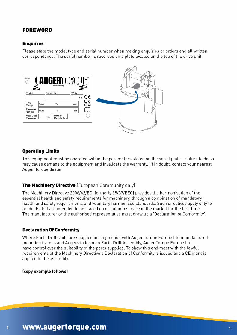
Enquiries Please state the model type and serial number when making enquiries or orders and all written correspondence . The serial number is recorded on a plate located on the top of the drive unit .
Operating LimitsThis equipment must be operated within the parameters stated on the serial plate . Failure to do so may cause damage to the equipment and invalidate the warranty . If in doubt, contact your nearest Auger Torque dealer .
The Machinery Directive (European Community only)The Machinery Directive 2006/42/EC (formerly 98/37/EEC) provides the harmonisation of the essential health and safety requirements for machinery, through a combination of mandatory health and safety requirements and voluntary harmonised standards . Such directives apply only to products that are intended to be placed on or put into service in the market for the first time .The manufacturer or the authorised representative must draw up a ‘Declaration of Conformity’ .
Declaration Of Conformity Where Earth Drill Units are supplied in conjunction with Auger Torque Europe Ltd manufactured mounting frames and Augers to form an Earth Drill Assembly, Auger Torque Europe Ltd have control over the suitability of the parts supplied . To show this and meet with the lawful requirements of the Machinery Directive a Declaration of Conformity is issued and a CE mark is applied to the assembly .
(copy example follows)

www.augertorque.com 55 www.augertorque.com 55
EU Declaration of Conformity
The responsible person: Name
Position
Company Name Auger Torque Europe Ltd.
Address Telephone Fax
Hazelton, Cheltenham, GL54 4DX, England ++44 (0) 1451 861652 ++44 (0) 1451 861660
Declares that the product described:
Manufacturer Auger Torque Europe Ltd.
Model
Serial Number
Conforms to the Machinery Directive 2006/42/EC.
It also complies with the essential health and safety requirements, national standards and the transposed harmonised standards appropriate for this product. Signed by: Dated (The responsible person)
Manufactured by Auger Torque Europe Limited

www.augertorque.com 66
Auger Torque Australia Pty Ltd122 Boundary RdRockleaQueensland 4106Australia Tel:+61(0)7 3274 2077Fax:+61(0)7 3274 5077Email: sales@augertorque .com .au
Auger Torque Europe LtdHazletonCheltenhamGL54 4DXEnglandTel:+44(0)1451 861652Fax:+44(0)1451 861660Email: sales@augertorque .com
Auger Torque USA LLC2640 Jason Industrial ParkwayWinston, GA 30187USATel: (+1) 844 287 6300Fax: (+1) 770 947 9916Email: sales@augertorqueusa .com
www.augertorque.com 66
REGISTRATIONComplete this form and keep it with the manual
MODEL NUMBER:
SERIAL NUMBER:
DATE OF MANUFACTURE:
SUPPLIER / DEALER:
DATE SOLD TO SUPPLIER / DEALER:
DATE SOLD TO ORIGINAL END USER:
OWNER OR OPERATOR:
PARENT MACHINE MAKE & MODEL:
Note; Always quote the serial number in any communication with your supplier / dealer

www.augertorque.com 77
Auger Torque USA LLC2640 Jason Industrial ParkwayWinston, GA 30187USATel: (+1) 844 287 6300Fax: (+1) 770 947 9916Email: sales@augertorqueusa .com
Auger Torque Australia Pty Ltd122 Boundary RdRockleaQueensland 4106Australia Tel:+61(0)7 3274 2077Fax:+61(0)7 3274 5077Email: sales@augertorque .com .au
Auger Torque Europe LtdHazletonCheltenhamGL54 4DXEnglandTel:+44(0)1451 861652Fax:+44(0)1451 861660Email: sales@augertorque .com
www.augertorque.com 77
REGISTRATIONFor warranty purposes this form MUST be completed and returned to Auger Torque within 14 days of purchase by the end user .
MODEL NUMBER:
SERIAL NUMBER:
DATE OF MANUFACTURE:
SUPPLIER / DEALER:
DATE SOLD TO SUPPLIER / DEALER:
DATE SOLD TO ORIGINAL END USER:
OWNER OR OPERATOR:
PARENT MACHINE MAKE & MODEL:
Note; Always quote the serial number in any communication with your supplier / dealer

www.augertorque.com 88
Auger Torque USA LLC2640 Jason Industrial ParkwayWinston, GA 30187USATel: (+1) 844 287 6300Fax: (+1) 770 947 9916Email: sales@augertorqueusa .com
Auger Torque Australia Pty Ltd122 Boundary RdRockleaQueensland 4106Australia Tel:+61(0)7 3274 2077Fax:+61(0)7 3274 5077Email: sales@augertorque .com .au
Auger Torque Europe LtdHazletonCheltenhamGL54 4DXEnglandTel:+44(0)1451 861652Fax:+44(0)1451 861660Email: sales@augertorque .com
MODEL NO.
SERIAL NO.
DATE OF MANUFACTURE
SUPPLIER/DEALER
DATE SOLD TO SUPPLIER/DEALERDATE SOLD TO ORIGINAL END USERNAME OF END USER
PARENT MACHINE MAKE & MODEL
99-5175
PLEA
SE N
OTE
:
THIS
REG
ISTR
ATIO
N F
ORM
MU
ST B
E CO
MPL
ETED
AN
D R
ETUR
NED
TO V
ALID
ATE
THE
WAR
RAN
TY O
F TH
IS A
TTAC
HMEN
T
PLEASE NOTE:THE REGISTRATION FORM ON THE REVERSE MUST BE COMPLETED AND
RETURNED TO VALIDATE THE WARRANTY OF THIS ATTACHMENT
THIS FORM MUST BE COMPLETED TO VALIDATE THE WARRANTY OF THIS ATTACHMENT
Aug
er T
orqu
e Eu
rope
Ltd
H
azle
ton
Chel
tenh
am
GL5
4 4D
XEN
GLA
ND
Send
to:
56Nm
1/2”BSP
73Nm
3/4”BSP
20 min
20 min
100hours
REGISTRATION FORM
www.augertorque.com 88
For warranty purposes the form on the reverse of this page should be completed and returned to the appropriate address.
Alternatively, if your machine has a pre-installation checks label, like this;-
Just fill in the details on the back and post it to us,the address is printed on the front.

www.augertorque.com 99 www.augertorque.com 99
INTRODUCTION
Auger Torque thank you for purchasing your new product . This operating manual has been prepared to enable you to operate the equipment in a safe manner .
Auger Torque Earth Drill Units have been designed for use with specific Auger Torque mounting frames, Augers, Auger extensions and Auger wear parts . Provided these are used and maintained correctly, they will provide a safe and reliable method of boring holes in the earth .
For information on lubrication and maintenance intervals, see pages 48 to 55Before operating the Earth Drill, please note:
Your Earth Drill comes complete, filled with the correct amount of oil . There is no need to check the oil level .
Hydraulic hoses must be fitted and tightened to the correct torque (see page 24) .
If a case drain hose is fitted to your unit, it must be connected correctly (See page 26) .
The unit must be run in following the recommended procedure (see page 30) .
NOTE:This operating manual should be used in conjunction with the parent machine’s operating instructions .
Instruction books should be regarded as part of the machine . They should always be kept safe with the machine for easy and quick reference .
New or extra copies can be obtained from your Auger Torque dealer or direct from Auger Torque .
Auger Torque Earth Drill Units have been designed for use with specific parent machines along with the Auger Torque range of mounting frames, Augers, Auger extensions and Auger wear parts . Provided these are used and maintained correctly, they will provide a safe and reliable method of boring holes in the earth .
Auger Torque continually strives to improve and increase its range of products and therefore reserves the right to alter its specifications at any time without notice or obligation . The company accepts no responsibility for discrepancies which may occur between specifications of its machines and descriptions thereof contained in its publications .

www.augertorque.com 1010 www.augertorque.com 1010
SAFETY NOTES
Protect YourselfMake sure you wear protective clothing and personal safety items .
You May Need• A Hard Hat• Safety Goggles• Hearing Protection• Foul Weather Clothing• Reflective Clothing• Protective Gloves• Safety Boots
DO NOT wear items of loose clothing, jewellery or other items and tie up any long hair which could entangle in the controls or other parts of the machine .
Know Your EquipmentGet to know all you how to operate all controls on the machine and the attachments
IF THERE IS SOMETHING IN THE MANUAL WHICH YOU DO NOT UNDERSTAND, CONTACT THE MACHINE AGENT OR MANUFACTURER AND ASK THEM TO EXPLAIN IT TO YOU .
Danger, Warning And CautionThis symbol below has 3 important meanings when used with the following captions .
DANGER: An IMMINENTLY HAZARDOUS situation that WILL result in DEATH or
VERY SERIOUS INJURY
WARNING: A POTENTIALLY HAZARDOUS situation that COULD result in DEATH
or VERY SERIOUS INJURY
CAUTION: A POTENTIALLY HAZARDOUS situation that MAY result in MINOR
INJURY

www.augertorque.com 1111 www.augertorque.com 1111
Protective And Safety DevicesKeep all protective devices in place and securely fastened . Make sure all guards, sheilds and safety signs are properly installed and are in good condition .
Check The EquipmentBefore you operate the equipment, take time to check your machine and ensure that all systems are in good operational order .
• Never operate the equipment with worn, damaged or missing parts . Use only genuine replacement parts .
• Always ensure that the parent machine is secure and stable with its engine switched off and hydraulic pipes disconnected before carrying out any maintenance work .
• Check for loose, broken, missing or damaged parts . Have everything put into good repair and make sure all safety devices are in place .
• Perform all maintenance procedures outlined for the equipment .• Always protect hands . Select appropriate gloves when handling the equipment during fitting,
removing or adjusting• Always protect feet with safety boots .
WARNING: Hydraulic fluid under pressure can penetrate the skin or eyes and cause serious PERSONAL INJURY, BLINDNESS OR DEATH .Fluid leaks under pressure may not be visible . Use a piece of wood or thick cardboard to find leaks . DO NOT USE YOUR BARE HANDS . Wear safety goggles for eye protection . If any fluid is injected into the skin, it MUST be surgically removed . SEE A DOCTOR IMMEDIATELY
Make sure all hydraulic lines are correctly installed
Before applying pressure to the hydraulic system be sure all connections are tight and that lines, pipes and hoses are not damaged . Before disconnecting hydraulic lines, be sure to relieve all pressure .
Hazard Classification (Only applicable to ANSI Safety Labels)
DANGER: IMMEDIATE HAZARD! - Failure to understand or obey this information is likely to result in personal injury or death .WARNING: Failure to follow these instructions may result in personal injury or death .CAUTION: Failure to follow these instructions may result in minor personal injury or damage to the machine or the vehicle .NOTICE: This is important information for the proper use of this equipment . Failure to comply may lead to premature equipmentfailure .
CLEAN OR REPLACE THE SAFETY LABELS IF THEY CANNOT BE CLEARLY READ OR UNDERSTOOD

www.augertorque.com 1212 www.augertorque.com 1212
Safety Precautions
NEVER operate or assemble the equipment without fully understanding the operating instructions of both the equipment unit and the parent machine .
Auger Torque recommend you receive dealer instruction before operating the unit .
NEVER operate the equipment unless you are in good physical condition and mental health .
NEVER operate the equipment under the influence of any substance (including drugs & alcohol) which might impair vision .
NEVER operate the equipment with worn, damaged or missing parts . Use only genuine replacement parts .
NEVER proceed with works before completing a site risks assessment immediately before commencing work . Nominating the safe work exclusion zone radius for persons and animals as part of identifying risks and implementing controls .
NEVER allow minors to operate the equipment .
ALWAYS survey the work area before commencing operations . Check for potential hazards, eg . Electricity or communication cables etc .
ALWAYS ensure that the parent machine is secure and stable with it’s engine switched off before carrying out any maintenance work .
ALWAYS ensure the hydraulic oil supply to the attachment is disconnected by uncoupling the hydraulic hose connectors before fitting, removing or adjusting the equipment
ALWAYS wear head protection and eye protection when working on the unit .
ALWAYS protect hands . Select appropriate when handling the equipment
during fitting, removing or adjusting the unit .
ALWAYS protect feet . Wear approved safety boots .
ALWAYS follow the parent machine instructions regarding noise protection .
STAY ALERT. Should something break, come loose or fail to operate on your equipment, STOP WORK, lower equipment to the ground, shut off the engine and lock out hydraulic supply, inspect the machine and have repairs or adjustments made before resuming operation .
www.augertorque.com 1313 www.augertorque.com 1313
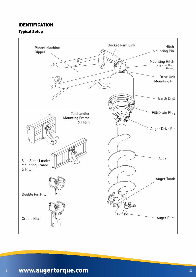
IDENTIFICATIONTypical Setup
Parent MachineDipper
Bucket Ram Link HitchMounting Pin
Mounting Hitch(Single Pin Hitch
Shown)
Drive UnitMounting Pin
Earth Drill
Fill/Drain Plug
Auger Drive Pin
Auger
Auger Tooth
Auger Pilot
Skid Steer Loader Mounting Frame& Hitch
TelehandlerMounting Frame
& Hitch
Double Pin Hitch
Cradle Hitch

www.augertorque.com 1414 www.augertorque.com 1414
Rope Wind Hitch Parts
AirControl Valve
Rope WindHitch
LinkageBlock
Earth Drill
Earth DrillStop Valve
StowageRope
RopeHook
AugerRetention Hook
AugerStowage
Slot
Auger
HookOperatingCylinder
RopeLoop
Truck CraneExtension
ExtensionClamp
HydraulicPower Hoses

www.augertorque.com 1515
B
1
1
2
5
67
8
8
9
10
118
8
9
10
11
3
4
C
26Nm/19ft-lb
26Nm/19ft-lb
100Nm/74ft-lb
A
www.augertorque.com 1515
MOUNTING - HITCH FITTINGSingle Pin Hitch
SAFETY FIRST
ALWAYS work in pairs (2 skilled operatives) whenever Earth Drill unit componentsare being assembled or disassembled from the parent machine . Always check the weight of the attachment and ensure you have the correct equipment for handling it .
ALWAYS check parent machine:• Is in correct working order• Is parked correctly on flat ground• Has its hand brake ON, its hydraulic circuit locked out and its engine switched OFF .
Check that the mounting frame is of the correct model and type to fit the parent machine .Ensure mounting frame and attachment points are clean before fitting .Use suitably rated lifting equipment if required (see data plate for weight) .
DIN 1284
NOTE: The single Pin Hitch CANNOT be fitted to a quick Hitch .FITTING Ensure all components are greased on assembly:
Set the Earth Drill unit horizontally, with the output shaft towards the parent machine as in fig A .There are two types of Pin for fitting the hood to the Mounting Hitch (1): The Threaded Mounting Pin (item 2, fig B) Has a locating plate with a hole that fits over a peg in the hood ear . Align the Pin holes, fit the Pin (2), washer (3) and nylon insert nut (4) and torque to 100Nm/74ft-lb . To fit the Through-Bolted Mounting Pin (item 5, fig C) Align the Pin holes and push the Pin (5) fully home taking care to line up the Through Bolt holes . At both ends of the Pin fit the Through Bolts (6) and Nylon Insert Nuts (7) and tighten to 26Nm/19ft-lb .Fitting to the parent machine is with through-bolted Pins in all cases:Align the Pin holes of the mounting Hitch (1) and parent machine . Align bolt location holes fit spacers (8) if required to centralise the Hitch . Push the Pin (9) fully home, taking care to line up the Through Bolt holes . Fit the Through Bolts (10) and Nylon Insert Nuts (11) and tighten to 26Nm/19ft-lb .Once fitted, check the Earth Drill swings freely in all directions .

www.augertorque.com 1616
11
2 5
67
10
1112
8
9
3
4
26Nm/19ft-lb
26Nm/19ft-lb100Nm/74ft-lb
B C
A
www.augertorque.com 1616
Double Pin HitchSAFETY FIRST
ALWAYS work in pairs (2 skilled operatives) whenever Earth Drill unit components are being assembled or disassembled from the parent machine . Always check the weight of the attachment and ensure you have the correct equipment for handling it
ALWAYS check parent machine:• Is in correct working order• Is parked correctly on flat ground• Has its hand brake ON, its hydraulic circuit locked out and its engine switched OFF .
Check that the mounting frame is of the correct model and type to fit the parent machine .Ensure mounting frame and attachment points are clean before fitting .Use suitably rated lifting equipment if required (see data plate for weight) .
DIN 1284
NOTE: If a quick Hitch is fitted to the parent machine, refer to the quick Hitch manufacturer’s installation instructions for correct fitting procedure .FITTING ensure all components are greased on assembly:
Set the Earth Drill unit horizontally, with the output shaft towards the parent machine as in fig A .There are two types of Pin for fitting the hood to the Mounting Hitch (1): The Threaded Mounting Pin (item 2, fig B) has a locating plate with a hole that fits on a peg in the hood ear . Align the Pin holes, fit the Pin (2), washer (3) and nylon insert nut (4) and torque to 100Nm/74ft-lb . To fit the Through-Bolted Mounting Pin (item 5, fig C), align the Pin holes and push the Pin (5) fully home taking care to line up the Through Bolt holes . At both ends of the Pin fit the Through Bolts (6), Nylon Insert Nuts (7) and tighten to 26Nm/19ft-lb .There are two types of Pin for fitting the Mounting Hitch (1) to the Parent Machine: To attach a Linch Pin fitting (item 8, fig B), align the Pin holes, push the Pin (8) fully home and fit the linch Pin (9) To fit the Through-Bolted Mounting Pin (10, fig C), align the Pin holes and push the Pin (10 fully home taking care to line up the Through Bolt holes, fit the Through Bolts (11) and Nylon Insert Nuts (12) and tighten to 26Nm/19ft-lb .

www.augertorque.com 1717
1 1
2 5
67
1011
12
8
9
3
4
26Nm/19ft-lb
26Nm/19ft-lb
100Nm/74ft-lb
B C
A
www.augertorque.com 1717
Cradle HitchSAFETY FIRST
ALWAYS work in pairs (2 skilled operatives) whenever Earth Drill unit components are being assembled or disassembled from the parent machine . Always check the weight of the attachment and ensure you have the correct equipment for handling it .
ALWAYS check parent machine:• Is in correct working order• Is parked correctly on flat ground• Has its hand brake ON, its hydraulic circuit locked out and its engine switched OFF .
Check that the mounting frame is of the correct model and type to fit the parent machine .Ensure mounting frame and attachment points are clean before fitting .Use suitably rated lifting equipment if required (see data plate for weight) .
DIN 1284
NOTE: If a quick Hitch is fitted to the parent machine, refer to the quick Hitch manufacturer’s installation instructions for correct fitting procedure . FITTING Ensure all components are greased on assembly:
Set the Earth Drill Unit horizontally in the cradle Hitch, with the output shaft towards the parent machine as in Fig A .There are two types of Pin for fitting the Hood to the Mounting Hitch (1): The Threaded Mounting Pin (item 2, Fig B) has a locating plate with a hole that fits on a peg in the hood ear . Align the Pin holes, fit the Pin (2), Washer (3) and Nylon Insert Nut (4) and torque to 100Nm/74ft-lb . To fit the Through-Bolted Mounting Pin (item 5, Fig C), align the Pin holes and push the Pin (5) fully home taking care to line up the Through Bolt holes . At both ends of the Pin fit the Through Bolts (6) and Nylon Insert Nuts (7) and tighten to 26Nm/19ft-lb .There are two types of Pin for fitting the Mounting Hitch (1) to the Parent Machine: To attach a Linch Pin fitting (item 8, Fig B), align the Pin holes, push the Pin (8) fully home and fit the Linch Pin (9) To fit the Through-Bolted Mounting Pin (item 10, Fig C), align the Pin holes and push the Pin (10) fully home taking care to line up the Through Bolt holes, fit the Through Bolts (11) and Nylon Insert Nuts (12) and tighten to 26Nm/19ft-lb .

www.augertorque.com 1818
100Nm/74ft-lb
A
B
C
D
1
2
3
www.augertorque.com 1818
Skid Steer Loader & TelehandlerSAFETY FIRST
ALWAYS work in pairs (2 skilled operatives) whenever Earth Drill unit components are being assembled or disassembled from the parent machine . Always check the weight of the attachment and ensure you have the correct equipment for handling it .
ALWAYS check parent machine:• Is in correct working order• Is parked correctly on flat ground• Has its hand brake ON, its hydraulic circuit locked out and its engine switched OFF .
Check that the mounting frame is of the correct model and type to fit the parent machine .Ensure mounting frame and attachment points are clean before fitting .Use suitably rated lifting equipment if required (see data plate for weight) .
DIN 1284FITTING: Ensure all components are greased on assembly:
A Slot the top of the parent machine frame under the top edge of the Mounting
Frame or Locating Hooks (refer to parent machine operator’s manual) .
B Swing the parent machine frame to the vertical position .
C Following the parent machine operator’s manual, ensure that the Mounting
Frame is securely locked in place .
D Working as a pair, lift the Earth Drill in to place with the port opening facing
upwards Align hood ears with the hole in the linkage block . Secure the
Earth Drill with the Pin (1), Washer (2) and Nylon Insert Nut (3) and torque to
100Nm/74ft-lb .

www.augertorque.com 1919
2
3
4 15
6
100Nm/74ft-lb
B
A
www.augertorque.com 1919
MOUNTING - TRUCK CRANELinkage BlockSAFETY FIRST
ALWAYS work in pairs (2 skilled operatives) whenever Earth Drill unit components are being assembled or disassembled from the parent machine . Always check the weight of the attachment and ensure you have the correct equipment for handling it
ALWAYS check parent machine:• Is in correct working order• Is parked correctly on flat ground• Has its hand brake ON, its hydraulic circuit locked out and its engine switched OFF .
Check that the mounting frame is of the correct model and type to fit the parent machine .Ensure mounting frame and attachment points are clean before fitting .Use suitably rated lifting equipment if required (see data plate for weight) .On Truck Cranes, the Earth Drill is attached via a Linkage Block .The Linkage Block fits between the hook attachment ears .
DIN 1284 FITTING Ensure all components are greased on assembly:
Set the Earth Drill Unit horizontally, with the output shaft towards the parent machine as in Fig A .
The Threaded Mounting Pin has a locating plate with a hole that fits on a peg in the hood ear Fig B . Align the Pin holes in the hood ears and Linkage Block (1), fit the Pin (2), Washer (3) and Nylon Insert Nut (4) and torque to 100Nm/74ft-lb .
Align the holes in the Linkage Block (1) with the attachment ears on the parent machine Fig B .
Insert the mounting Pin (5) and spring clip (6)
Once fitted, check that the Linkage Block swings freely .
Mounting pionts may differ . (refer to parent
machine operator’s manual for further
information) .
www.augertorque.com 2020
M20 - 385Nm/284ft-lb
x3
x3
www.augertorque.com 2020
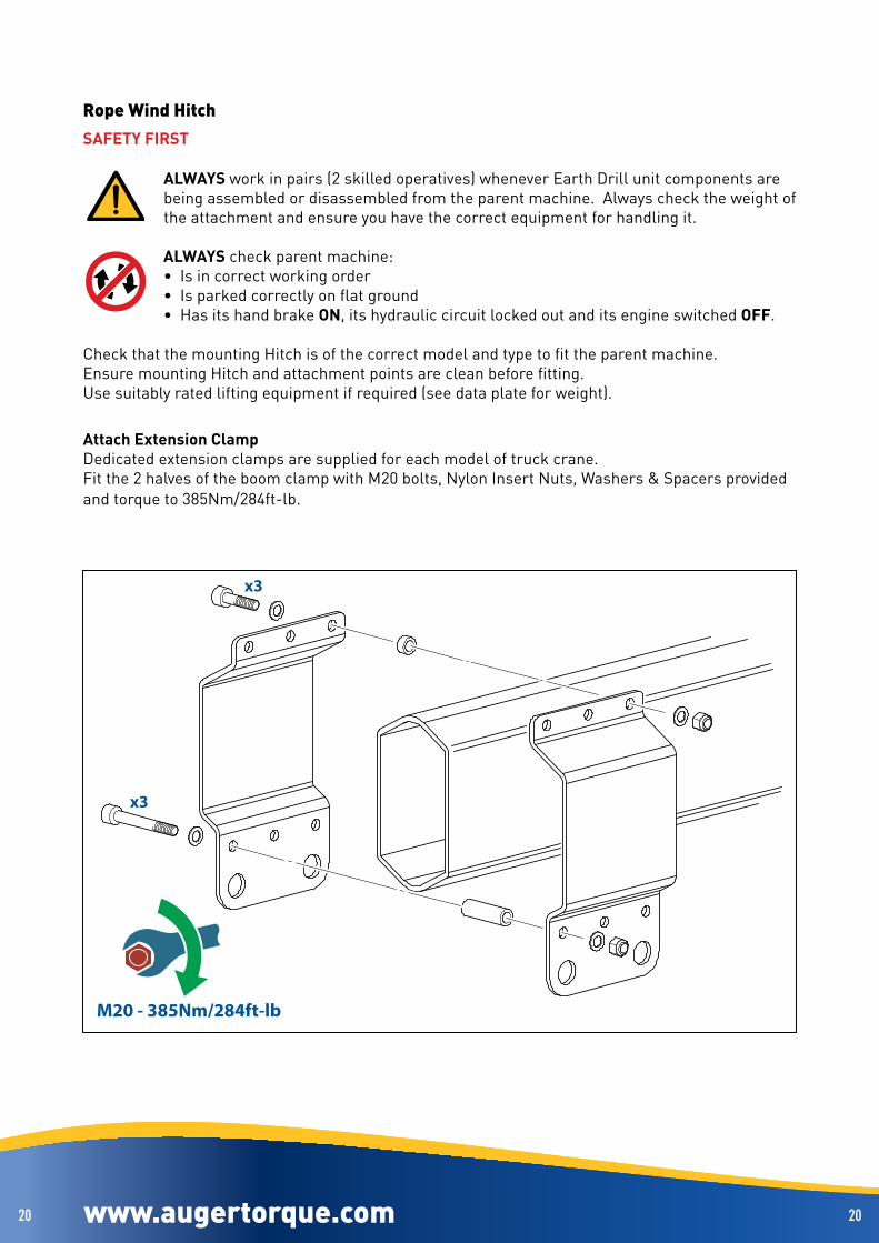
Rope Wind HitchSAFETY FIRST
ALWAYS work in pairs (2 skilled operatives) whenever Earth Drill unit components are being assembled or disassembled from the parent machine . Always check the weight of the attachment and ensure you have the correct equipment for handling it .
ALWAYS check parent machine:• Is in correct working order• Is parked correctly on flat ground• Has its hand brake ON, its hydraulic circuit locked out and its engine switched OFF .
Check that the mounting Hitch is of the correct model and type to fit the parent machine .Ensure mounting Hitch and attachment points are clean before fitting .Use suitably rated lifting equipment if required (see data plate for weight) .
Attach Extension ClampDedicated extension clamps are supplied for each model of truck crane .Fit the 2 halves of the boom clamp with M20 bolts, Nylon Insert Nuts, Washers & Spacers provided and torque to 385Nm/284ft-lb .

www.augertorque.com 2121
M10 - 46Nm/34ft-lb
www.augertorque.com 2121
Rope Wind Hitch (continued)
Attach Rope Wind HitchFit the hitch with the 2 pins and secure with M10 bolts & nuts . Tighten to 46Nm/34ft-lb .
The Rope wind Hitch is supplied with a Linkage Block fitted . Refer to Linkage Block section to fit Earth Drill (see page 19) .
www.augertorque.com 2222
A
A B
B
www.augertorque.com 2222
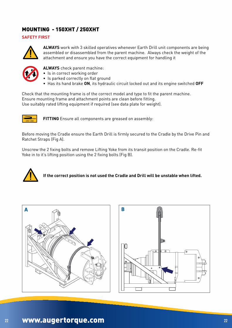
MOUNTING - 150XHT / 250XHTSAFETY FIRST
ALWAYS work with 3 skilled operatives whenever Earth Drill unit components are being assembled or disassembled from the parent machine . Always check the weight of the attachment and ensure you have the correct equipment for handling it
ALWAYS check parent machine:• Is in correct working order• Is parked correctly on flat ground• Has its hand brake ON, its hydraulic circuit locked out and its engine switched OFF
Check that the mounting frame is of the correct model and type to fit the parent machine .Ensure mounting frame and attachment points are clean before fitting .Use suitably rated lifting equipment if required (see data plate for weight) .
DIN 1284FITTING Ensure all components are greased on assembly:
Before moving the Cradle ensure the Earth Drill is firmly secured to the Cradle by the Drive Pin and Ratchet Straps (Fig A) .
Unscrew the 2 fixing bolts and remove Lifting Yoke from its transit position on the Cradle . Re-fit Yoke in to it’s lifting position using the 2 fixing bolts (Fig B) .
If the correct position is not used the Cradle and Drill will be unstable when lifted.

www.augertorque.com 2323
C
200Nm/147ft-lb
D
1
2
4
3
5
5
6
www.augertorque.com 2323
Mounting Unit from Cradle
Slowly lift the Cradle in to upright position, one person should be stood on either side of the Cradle holding the grab handles to steady the Cradle during the lift (Fig C) .
• Fit Mounting Hitch to the parent machine (item 1, Fig D) .• Remove nuts and bolts from Hood Pin and remove Pin (items 2, 3, & 4 Fig D) .• Align the Pin holes on the Mounting Hitch and Hood . Push the Hood Pin fully home taking care
to line up the bolt holes .• Refit nuts and bolts at both ends of the Pin tighten to 200Nm/147ft-lb .• Remove Drive Pin and Ratchet Straps, lift Earth Drill off Cradle with parent machine (items 5 & 6, Fig D) .
www.augertorque.com 2424
C
A56Nm/41ft-lb
73Nm/54ft-lb
1/2” BSP
112Nm/83ft-lb
1” BSP
3/4” BSP
137Nm/101ft-lb
1 1/4” BSP
B
www.augertorque.com 2424
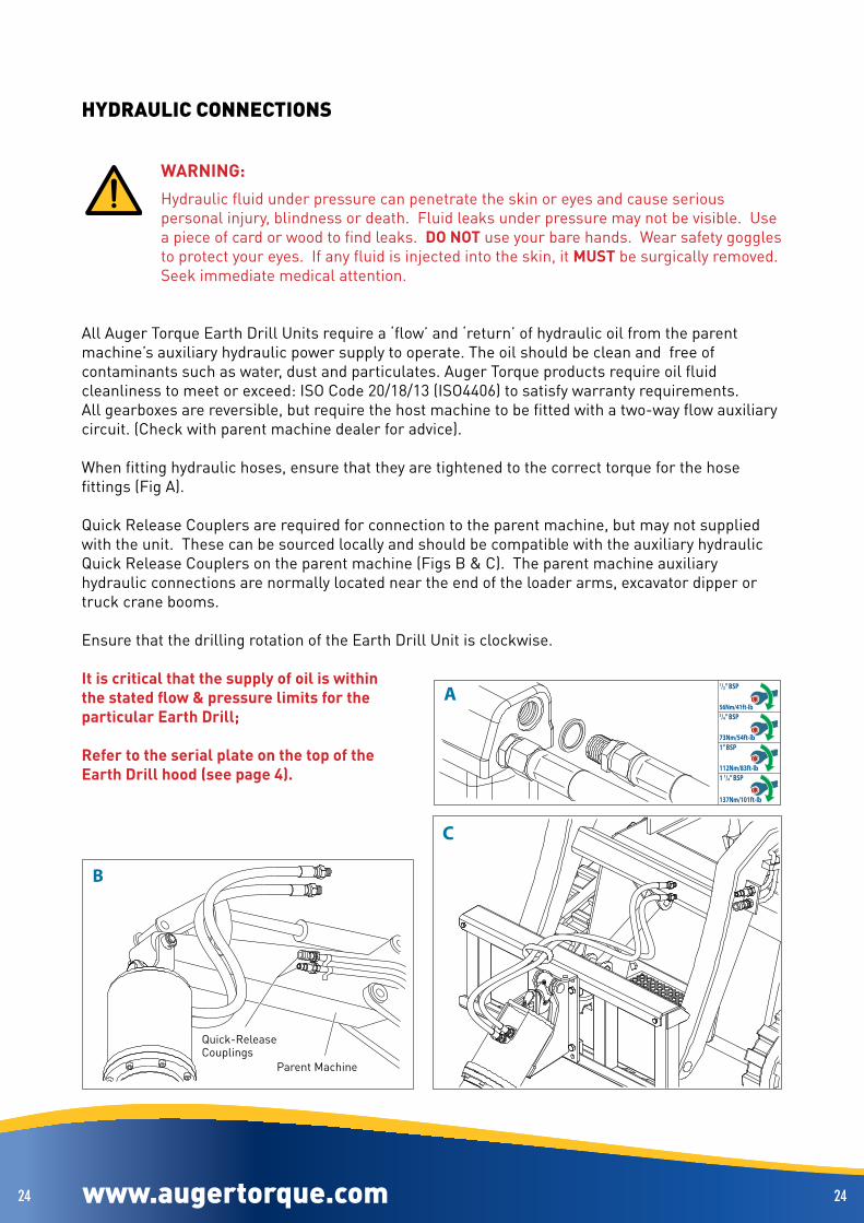
HYDRAULIC CONNECTIONS
WARNING:Hydraulic fluid under pressure can penetrate the skin or eyes and cause serious personal injury, blindness or death . Fluid leaks under pressure may not be visible . Use a piece of card or wood to find leaks . DO NOT use your bare hands . Wear safety goggles to protect your eyes . If any fluid is injected into the skin, it MUST be surgically removed . Seek immediate medical attention .
All Auger Torque Earth Drill Units require a ‘flow’ and ‘return’ of hydraulic oil from the parent machine’s auxiliary hydraulic power supply to operate . The oil should be clean and free of contaminants such as water, dust and particulates . Auger Torque products require oil fluid cleanliness to meet or exceed: ISO Code 20/18/13 (ISO4406) to satisfy warranty requirements .All gearboxes are reversible, but require the host machine to be fitted with a two-way flow auxiliary circuit . (Check with parent machine dealer for advice) . When fitting hydraulic hoses, ensure that they are tightened to the correct torque for the hose fittings (Fig A) .
Quick Release Couplers are required for connection to the parent machine, but may not supplied with the unit . These can be sourced locally and should be compatible with the auxiliary hydraulic Quick Release Couplers on the parent machine (Figs B & C) . The parent machine auxiliary hydraulic connections are normally located near the end of the loader arms, excavator dipper or truck crane booms .
Ensure that the drilling rotation of the Earth Drill Unit is clockwise .
It is critical that the supply of oil is within the stated flow & pressure limits for the particular Earth Drill;
Refer to the serial plate on the top of the Earth Drill hood (see page 4).
Quick-ReleaseCouplings
Parent Machine

www.augertorque.com 2525
56Nm/41ft-lb
1/2” BSP
56Nm/41ft-lb
1/2” BSP
www.augertorque.com 2525
Rope Wind Hitch
Attach Hydraulic Hoses - Earth DrillFit the hoses to the motor ports . Tighten to 56Nm/41ft-lb .
Attach Hoses - Earth Drill Stop ValveA hydraulic valve is fitted at the top of the rope wind hitch .
The purpose of the valve is to stop the rotation of the Auger when it reaches its stowed position .
This function is described in more detail on page 45 .
Fit the hoses to the Earth Drill Stop Valve . Tighten to 56Nm/41ft-lb .

www.augertorque.com 2626 www.augertorque.com 2626
Earth Drill Maximum Permissible Back Pressures
Case drain line fitting
Some of the larger Auger Torque Earth Drills are fitted with a case drain line .
This is a flexible hose protruding from the Earth Drill hood and must be connected to a line that returns to the machine’s hydraulic fluid reservoir . The parts required to complete this circuit will vary, depending on the machine and the hydraulic equipment fitted . Consequently, case drain hose fittings are not supplied with the Earth Drill and must be sourced separately .
When fitting a case drain line, there must be no restrictions to the flow between the Earth Drill and the reservoir . You MUST not use quick release couplings .
You may receive an installation form with your unit, this form must be completed and returned to Auger Torque to validate the warranty .
Case Drain Linemaximum permitted back pressureis 4.5 bar unless otherwise advised.
Model bar / psi
10 000 / 8000-40 12 / 174
12 000 / 9500-40 18 / 261
12 000MAX / 9000-45 6 / 87
15 000 / 11000-40 20 / 290
15 000MAX / 11000-45 7 / 101
17 000MAX / 12500-45 6 / 87
20 000MAX / 15000-45 15 / 217
25 000MAX / 18500-45 15 / 217
30 000 / 20000-45 16 / 232
Model bar / psi
30 000MAX / 24000-80 3 / 43
35 000MAX / 26000-60 20 / 290
40 000 / 32000-45 26 / 377
42 000MAX / 31000-60 20 / 290
50 000MAX / 35000-80 4 .5 / 65
65 000MAX / 48000-80 4 .5 / 65
100 000MAX / 74000-75 4 .5 / 65
150XHT / 110XHT 4 .5 / 65
250XHT / 185XHT 20 / 290
Model bar / psi
1200 / 900-9 15 / 217
X1500 / X1100-13 28 / 406
X2000 / X1600-15 28 / 406
X2500 / X2100-17 28 / 406
ML1500 / ML1100-13 28 / 406
ML2000 / ML1600-15 28 / 406
ML2500 / ML2100-17 28 / 406
3000TC / 2300-10 33 / 478
3000MAX / 2200-20 33 / 478
Model bar / psi
3500MAX / 2700-25 33 / 478
4500MAX / 3300-30 59 / 855
5000 / 3700-30 45 / 652
5500TC / 4000-14 33 / 478
5500MAX / 4000-30 45 / 652
7000 / 5000-30 59 / 855
7000TC / 5000-14 59 / 855
7000MAX / 5200-35 39 / 565
8000MAX / 6000-40 38 / 551

www.augertorque.com 2727 www.augertorque.com 2727
Hoses Specifications Minimum internal diameter
Minimum hydraulic hose requirements
Model Minimum internal hose diameter (in/mm)
Minimum working pressure Bar/PSI
1200 / 900-9 1/2” / 12 .7mm 185Bar / 2680PSIX1500 / X1100-13 1/2” / 12 .7mm 205Bar / 2973PSIX2000 / X1600-15 1/2” / 12 .7mm 240Bar / 3480PSIX2500 / X2100-17 1/2” / 12 .7mm 240Bar / 3480PSIML1500 / ML1100-13 1/2” / 12 .7mm 205Bar / 2973PSIML2000 / ML1600-15 1/2” / 12 .7mm 240Bar / 3480PSIML2500 / ML2100-17 1/2” / 12 .7mm 240Bar / 3480PSI3000MAX / 2200-20 1/2” / 12 .7mm 240Bar / 3480PSI3500MAX / 2700-25 1/2” / 12 .7mm 240Bar / 3480PSI4500MAX / 3300-30 1/2” / 12 .7mm 240Bar / 3480PSI5000 / 3700-30 1/2” / 12 .7mm 240Bar / 3480PSI5500MAX / 4000-30 1/2” / 12 .7mm 240Bar / 3480PSI7000 / 5000-30 1/2” / 12 .7mm 260Bar / 3771PSI7000MAX / 5200-35 3/4” / 19 .0mm 260Bar / 3771PSI8000MAX / 6000-40 3/4” / 19 .0mm 240Bar / 3480PSI10 000 / 8000-40 3/4” / 19 .0mm 240Bar / 3480PSI12 000 / 9500-40 3/4” / 19 .0mm 240Bar / 3480PSI12 000MAX / 9000-45 1” / 25 .4mm 240Bar / 3480PSI15 000 / 11000-40 3/4” / 19 .0mm 240Bar / 3480PSI15 000MAX / 11000-45 1” / 25 .4mm 240Bar / 3480PSI17 000MAX / 12500-45 1” / 25 .4mm 260Bar / 3770PSI20 000MAX / 15000-45 1” / 25 .4mm 240Bar / 3480PSI25 000MAX / 18500-45 1” / 25 .4mm 240Bar / 3480PSI30 000 / 20000-45 1” / 25 .4mm 240Bar / 3480PSI30 000MAX / 24000-80 11/4” / 31 .8mm 450Bar / 6526PSI35 000MAX / 26000-60 1” / 25 .4mm 310Bar / 4496PSI40 000 / 32000-45 1” / 25 .4mm 240Bar / 3480PSI42 000MAX / 31000-60 1” / 25 .4mm 310Bar / 4496PSI50 000MAX / 35000-80 11/2” / 31 .8mm 320Bar / 4640PSI65 000MAX / 48000-80 11/2” / 31 .8mm 320Bar / 4640PSI100 000MAX / 74000-75 11/2” / 31 .8mm 350Bar / 5076PSI3000TC / 2300-10 1/2” / 12 .7mm 260Bar / 3771PSI5500TC / 4000-14 1/2” / 12 .7mm 260Bar / 3771PSI7000TC / 5000-14 1/2” / 12 .7mm 260Bar / 3771PSI150XHT / 110XHT 11/2” / 38 .1mm 360Bar / 5221PSI250XHT / 185XHT 11/6” / 29 .6mm 310Bar / 4496PSI
Replacement hydraulic hoses MUST be rated equal or greater than the minimum working pressure.

www.augertorque.com 2828
1 2
www.augertorque.com 2828
AIR SYSTEM CONNECTIONRope Wind - Auger Hook Control
The Auger retention hook is operated by a momentary valve, which operates as follows;-
Normal state = OFF (Fig .1):
With the button in it’s Normal state, the system is vented and the Auger hook is retained in its
closed position under spring tension .
Pressed = ON (Fig . 2):
While the operating button is depressed, the valve pressurises the system and opens the retaining
hook .
Releasing the button returns the valve to the Normal (vented) state (Fig .1), allowing the hook to
return to its closed position under spring tension .
www.augertorque.com 2929 www.augertorque.com 2929
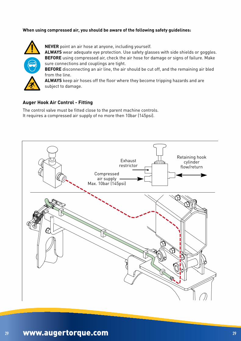
When using compressed air, you should be aware of the following safety guidelines:
NEVER point an air hose at anyone, including yourself .ALWAYS wear adequate eye protection . Use safety glasses with side shields or goggles .BEFORE using compressed air, check the air hose for damage or signs of failure . Make sure connections and couplings are tight .BEFORE disconnecting an air line, the air should be cut off, and the remaining air bled from the line .ALWAYS keep air hoses off the floor where they become tripping hazards and are subject to damage .
Auger Hook Air Control - FittingThe control valve must be fitted close to the parent machine controls .It requires a compressed air supply of no more then 10bar (145psi) .
Compressedair supply
Max . 10bar (145psi)
Exhaustrestrictor
Retaining hookcylinder
flow/return

www.augertorque.com 3030
1
2
20
20
www.augertorque.com 3030
RUNNING-INTo maximise the life of the unit, it must be run in for a period .
To carry out the running in procedure, suspend the Earth Drill in it’s vertical, working position .
For the duration of the running in procedure, ensure there are no bystanders within the nominated radius as defined in the risk assessment completed prior to commencing any works .
Operate the motor at 30% of rated pressure for 20 minutes in each direction before application of full operating load .
To further ensure best motor life and maintain warranty, refer to page 49 for lubrication instructions .
www.augertorque.com 3131 www.augertorque.com 3131
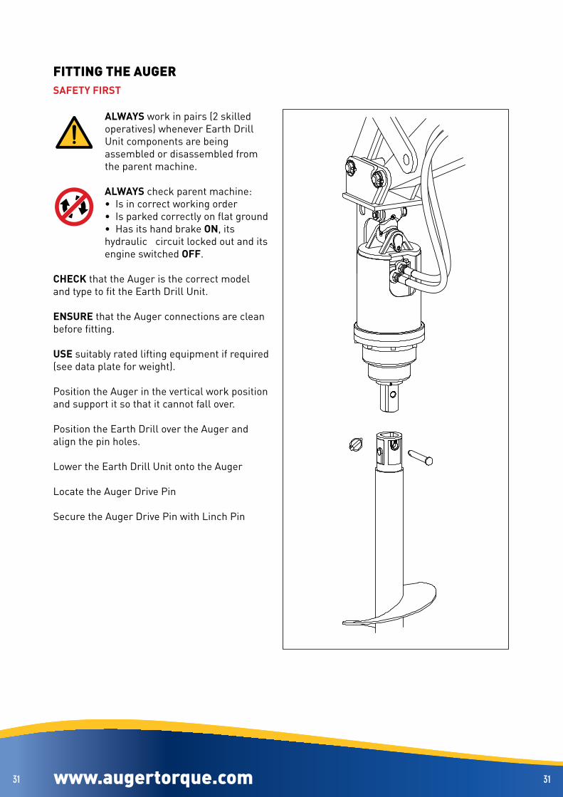
FITTING THE AUGERSAFETY FIRST
ALWAYS work in pairs (2 skilled operatives) whenever Earth Drill Unit components are being assembled or disassembled from the parent machine .
ALWAYS check parent machine:• Is in correct working order• Is parked correctly on flat ground• Has its hand brake ON, its hydraulic circuit locked out and its engine switched OFF .
CHECK that the Auger is the correct model and type to fit the Earth Drill Unit .
ENSURE that the Auger connections are clean before fitting .
USE suitably rated lifting equipment if required (see data plate for weight) .
Position the Auger in the vertical work position and support it so that it cannot fall over .
Position the Earth Drill over the Auger and align the pin holes .
Lower the Earth Drill Unit onto the Auger
Locate the Auger Drive Pin
Secure the Auger Drive Pin with Linch Pin

www.augertorque.com 3232 www.augertorque.com 3232
PREPARATION
CONSIDER the topography (e .g . risk of subsidence, slope angle, position to embankments and any previous excavation) .
NOTE the type of soil and its condition to enable selection of suitable teeth and pilot
ALWAYS carry out a site survey and risk assessment BEFORE starting work
AVOID underground hazards, such as water / gas / electricity / communication lines etc .
If in doubt detection equipment and professional advice should always be considered before carrying out any work .

www.augertorque.com 3333
A
B
C
www.augertorque.com 3333
WORKING PROCEDUREBefore commencing work, ensure that:
The correct hoses are fitted and tightened correctly (See page 24) .The unit has been properly run in (See page 30) .
There are no bystanders within the nominated radius as defined in the risk assessment completed prior to commencing any works .
SET Auger in a vertical drilling position (Fig A) .ENSURE the direction of rotation is CLOCKWISE .ONLY start drilling after a site survey on apre-marked safe location (see page 32) .GRADUALLY lower the parent machine arm(s) to apply down force to the Auger . The harder the ground the more down force required .Maintain drilling speed . DO NOT CONTINUALLY STALL the Earth Drill unit with excessive down force, as this will overheat the hydraulic oil and could damage the machine .KEEP THE AUGER VERTICAL;For skid steer machines (Fig B);Adjust the angle of the arms, mounting frame and the position of the parent machine as necessary .For excavators (Fig C);Adjust the angle of the dipper and boom .MAXIMISE efficiency and avoid damaging the Auger assembly by keeping the Auger vertical .REGULARLY raise the Auger out of the ground to clear material from the Auger . This will help maintain drilling effectiveness and ensure your machine does not become unstable .NEVER Drill beyond the length of the Auger .NEVER leave the Auger assembly suspended .ALWAYS park with the Auger on the ground .
DRILLING PARKING

www.augertorque.com 3434
B
A
www.augertorque.com 3434
Horizontal Drilling
Before commencing work, ensure that:
The correct hoses are fitted and tightened correctly (See page 24) .The unit has been properly run in (See page 30) .
There are no bystanders within the nominated radius as defined in the risk assessment completed prior to commencing any works .
Horizontal drilling is possible with the use of an excavator . A Cradle Hitch is required to hold the Earth Drill and Auger in a horizontal position . Refer to the Cradle Hitch section for fitting instructions .
FIT Cradle Hitch in reverse orientation (Fig A) .SET Auger in a horizontal drilling position (Fig B) .ENSURE the direction of rotation is CLOCKWISE .ONLY start drilling after a site survey on apre-marked safe location (see page 32) .GRADUALLY adjust the parent machine arm(s) to apply a force to the Auger in the direction of drilling . The harder the ground the more force required .Maintain drilling speed . DO NOT CONTINUALLY STALL the Earth Drill unit with excessive force, as this will overheat the hydraulic oil and could damage the machine .KEEP THE AUGER HORIZONTAL:Adjust the angle of the dipper and boom (Fig B) .MAXIMISE efficiency and avoid damaging the Auger assembly by keeping the Auger horizontal .REGULARLY remove the Auger out of the hole to clear material from the Auger . This will help maintain drilling effectiveness and ensure your machine does not become unstable .NEVER Drill beyond the length of the Auger .NEVER leave the Auger assembly suspended .ALWAYS park with the Auger on the ground .

www.augertorque.com 3535
BA
www.augertorque.com 3535
Auger Alignment
When drilling, you must keep the auger vertical at all times to avoid uneven holes and potential damage to the auger . The natural arc of the parent machine arms will push the auger out of alignment (Fig A) . Continuous adjustment is required of the parent machine arms to maintain vertical alignment (Fig B) .
Natural Arc

www.augertorque.com 3636 www.augertorque.com 3636
DRILLING WITH FIXED EXTENSIONSWhen the required hole depth is greater than the length of the Auger, an Extension should be used .DO NOT allow the Earth Drill to enter the hole as seals can be damaged by spoil being extracted .
SAFETY FIRST
Whenever Earth Drill Unit components are being assembled or disassembled from the parent machine ALWAYS work in pairs (2 skilled operatives) . While fitting components,
ALWAYS check parent machine:• Is in correct working order• Is parked correctly on flat ground• Has its hand brake ON, its hydraulic circuit locked out and its engine switched OFF .
CHECK that the Extension is the correct model and type to fit the Earth Drill Unit and Auger .ENSURE that all Earth Drill, Auger and Extension connections are clean before fitting .USE suitably rated lifting equipment if required .
When using extensions in drilling operations, a length of timber is required for supporting the Auger while removing the Extension . The timber must be of minimum dimensions 150mm (6”) deep x 50mm (2”) wide and long enough to span the hole being drilled, plus an additional 300mm (12”) length at each end .
Fitting A Fixed ExtensionWhen the hole has been drilled to the point where the top of the auger comes within 200mm (8”) above ground level;• Stop drilling .• Remove the auger from the hole and clear the spoil from
the auger .• Lower the auger back into the hole so that its’ weight
is supported and remove the Linch Pin and Auger Drive Pin .
• Lift the Earth Drill clear of the Auger and slew it to one side, clear of the hole and set it to a height that will allow the extension to be fitted easily .
• Position the Extension in the vertical work position and support it so that it cannot fall over .
• Position the Earth Drill over the Extension and align the pin holes .
• Lower the Earth Drill Unit onto the Extension .• Insert the Extension Drive Pin .• Secure the Extension Drive Pin with Linch Pin .• Position the Earth Drill and Extension over the Auger
and align the pin holes .• Lower the Earth Drill and Extension onto the Auger .• Insert the Auger Drive Pin .• Secure the Auger Drive Pin with Linch Pin .• Continue drilling .

www.augertorque.com 3737 www.augertorque.com 3737
REMOVING A FIXED EXTENSIONIf the parent machine has a high reach, it may be possible to lift the auger clear of the hole to clear the spoil without removing the Extension . For smaller machines, and in cases where multiple Extensions are being used, it may be necessary to remove the Extension first .
• Lift the Earth Drill until the Auger Flight is clear of the ground and insert the timber support through the Auger Flight .
• Lower the Earth Drill until the weight of the Auger and Extension are supported by the timber . Make sure that the load is spread equally on either side of the hole .
• Remove the Linch Pin and Auger Drive Pin .• Lift the Earth Drill until the Extension is clear of the Auger
and slew it to one side, clear of the hole and set it to a height that will allow safe removal of the extension .
• Support the weight of the Extension .• Remove the Linch Pin and Extension Drive Pin .• Remove the Extension and lay it on the ground .• Position the Earth Drill over the Auger and align the pin
holes .• Lower the Earth Drill Unit onto the Auger .• Insert the Auger Drive Pin .• Secure the Auger Drive Pin with the Linch Pin .• Lift the Earth Drill to remove the load from the timber
support .• Remove the timber support .

www.augertorque.com 3838 www.augertorque.com 3838
Removing PA Fixed ExtensionsIf the parent machine has a high reach, it may be possible to lift the auger clear of the hole to clear the spoil without removing the Extension . For smaller machines, and in cases where multiple Extensions are being used, it may be necessary to remove the Extension first .
• Lift the Earth Drill until the Auger Handle is clear of the ground and insert the timber support through the handle .
• Lower the Earth Drill until the weight of the Auger and Extension are supported by the timber . Make sure that the load is spread equally on either side of the hole .
• Remove the Linch Pin and Auger Drive Pin .• Lift the Earth Drill until the Extension is clear of the
Auger and slew it to one side, clear of the hole and set it to a height that will allow safe removal of the extension .
• Support the weight of the Extension .• Remove the Linch Pin and Extension Drive Pin .• Remove the Extension and lay it on the ground .• Position the Earth Drill over the Auger and align the
pin holes .• Lower the Earth Drill Unit onto the Auger .• Insert the Auger Drive Pin .• Secure the Auger Drive Pin with the Linch Pin .• Lift the Earth Drill to remove the load from the timber
support .• Remove the timber support .
Multiple Fixed ExtensionsFollowing the procedures above, multiple fixed Extensions may be added to further increase the hole depth . As with the Auger, each Extension is fitted with a handle through which the timber support can be inserted to support the Extension while adding or removing additional Extensions .

www.augertorque.com 3939 www.augertorque.com 3939
DRILLING WITH TELESCOPIC EXTENSIONSTelescopic Extensions enable the drilling holes deeper than the Auger length, without the need to remove the Extension to extract the Auger .DO NOT allow the Earth Drill to enter the hole as seals can be damaged by spoil being extracted .
SAFETY FIRSTWhenever Earth Drill Unit components are being assembled or disassembled from the parent machine ALWAYS work in pairs (2 skilled operatives) . While fitting components, ALWAYS check parent machine:• Is in correct working order• Is parked correctly on flat ground• Has its hand brake ON, hydraulic circuit locked out and its engine switched OFF .
CHECK that the Extension is the correct model and type to fit the Earth Drill Unit and Auger .ENSURE that all Earth Drill, Auger and Extension connections are clean before fitting .USE suitably rated lifting equipment if required .When using Telescopic Extensions in drilling operations, a length of timber is required for supporting the Auger while adjusting the Extension . The timber must be of minimum dimensions 150mm (6”) deep x 50mm (2”) wide and long enough to span the hole being drilled, plus an additional 300mm (12”) length at each end .NOTE: Minimum auger diameter to be used with a telescopic extension is 300mm .
Fitting A Telescopic Extension
NOTE: The Telescopic Extension Hub is bolted to the Extension Shaft, DO NOT remove this bolt . The extension is fixed to the Auger with a pin and linch pin .The Telescopic Extension can be fitted before drilling commences:• Insert the Extension into the Auger, ensuring that the pin holes
line up .• Fix the extension to the Auger at the top pin hole (the shortest
setting) .• Position the Auger and Extension in the vertical work position and
support it so that it cannot fall over .• Position the Earth Drill over the Auger and Extension align the pin
holes .• Lower the Earth Drill Unit onto the Extension .• Insert the Extension Drive Pin .• Secure the Extension Drive Pin with Linch Pin .• Commence drilling .
www.augertorque.com 4040 www.augertorque.com 4040
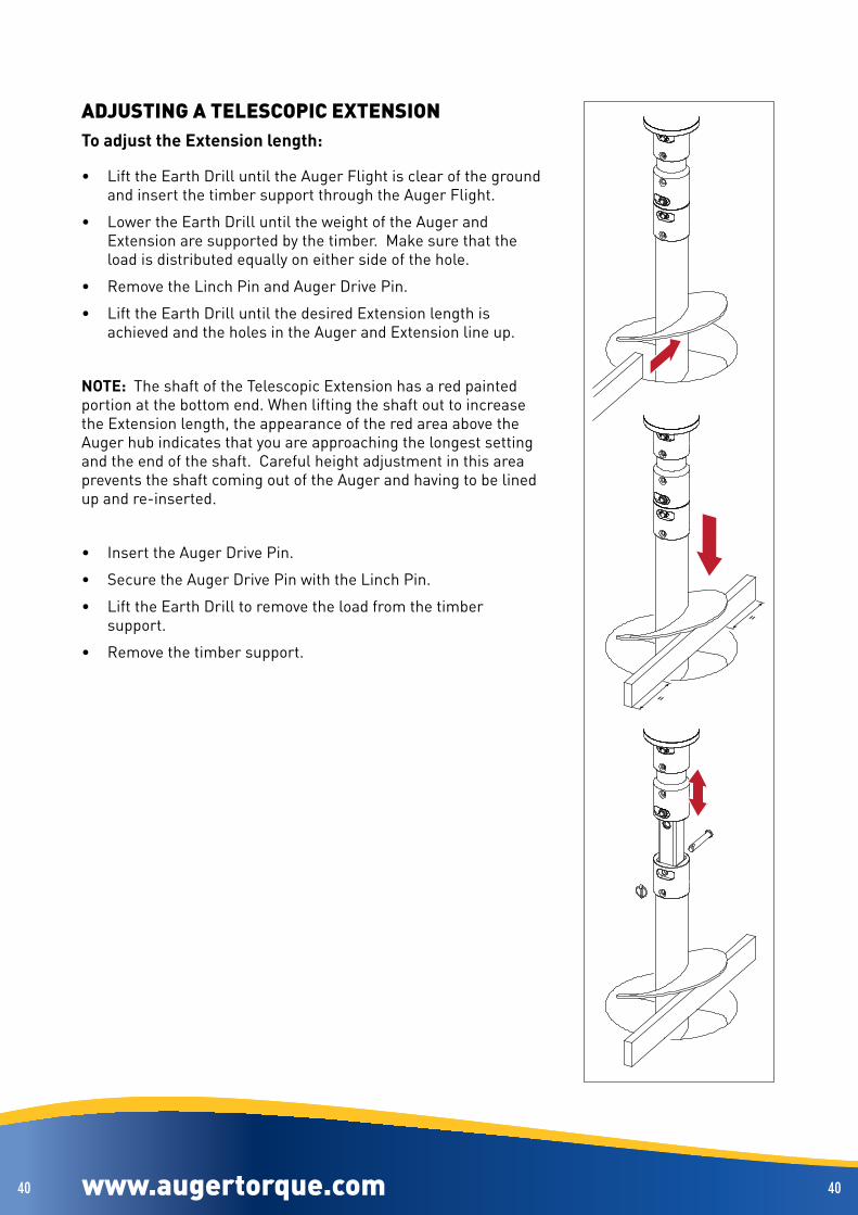
ADJUSTING A TELESCOPIC EXTENSIONTo adjust the Extension length:
• Lift the Earth Drill until the Auger Flight is clear of the ground and insert the timber support through the Auger Flight .
• Lower the Earth Drill until the weight of the Auger and Extension are supported by the timber . Make sure that the load is distributed equally on either side of the hole .
• Remove the Linch Pin and Auger Drive Pin .
• Lift the Earth Drill until the desired Extension length is achieved and the holes in the Auger and Extension line up .
NOTE: The shaft of the Telescopic Extension has a red painted portion at the bottom end . When lifting the shaft out to increase the Extension length, the appearance of the red area above the Auger hub indicates that you are approaching the longest setting and the end of the shaft . Careful height adjustment in this area prevents the shaft coming out of the Auger and having to be lined up and re-inserted .
• Insert the Auger Drive Pin .
• Secure the Auger Drive Pin with the Linch Pin .
• Lift the Earth Drill to remove the load from the timber support .
• Remove the timber support .

www.augertorque.com 4141 www.augertorque.com 4141
ADJUSTING A PA TELESCOPIC EXTENSIONTo adjust the Extension length:
• Lift the Earth Drill until the Auger Handle is clear of the ground and insert the timber support through the handle .
• Lower the Earth Drill until the weight of the Auger and Extension are supported by the timber . Make sure that the load is distributed equally on either side of the hole .
• Remove the Linch Pin and Auger Drive Pin .
• Lift the Earth Drill until the desired Extension length is achieved and the holes in the Auger and Extension line up .
NOTE: The shaft of the Telescopic Extension has a red painted portion at the bottom end . When lifting the shaft out to increase the Extension length, the appearance of the red area above the Auger hub indicates that you are approaching the longest setting and the end of the shaft . Careful height adjustment in this area prevents the shaft coming out of the Auger and having to be lined up and re-inserted .
• Insert the Auger Drive Pin .
• Secure the Auger Drive Pin with the Linch Pin .
• Lift the Earth Drill to remove the load from the timber support .
• Remove the timber support .
www.augertorque.com 4242 www.augertorque.com 4242
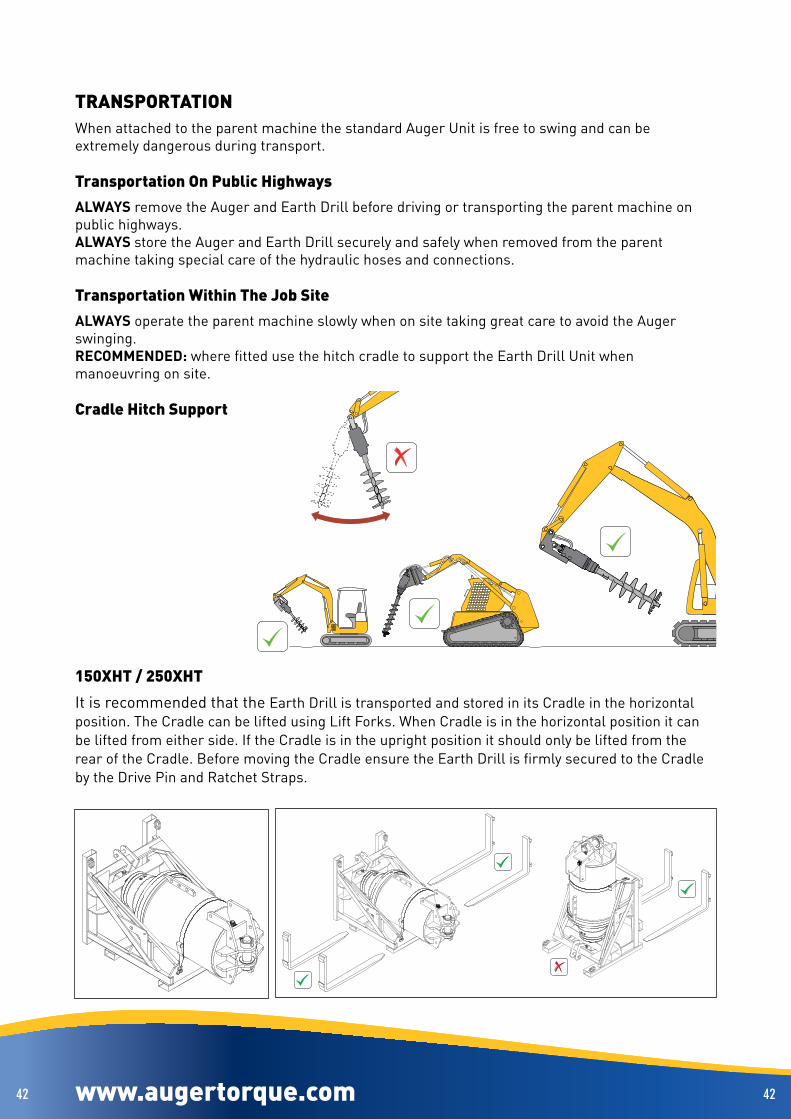
TRANSPORTATIONWhen attached to the parent machine the standard Auger Unit is free to swing and can be extremely dangerous during transport .
Transportation On Public HighwaysALWAYS remove the Auger and Earth Drill before driving or transporting the parent machine on public highways .ALWAYS store the Auger and Earth Drill securely and safely when removed from the parent machine taking special care of the hydraulic hoses and connections .
Transportation Within The Job SiteALWAYS operate the parent machine slowly when on site taking great care to avoid the Auger swinging .RECOMMENDED: where fitted use the hitch cradle to support the Earth Drill Unit when manoeuvring on site .
Cradle Hitch Support
150XHT / 250XHT
It is recommended that the Earth Drill is transported and stored in its Cradle in the horizontal position . The Cradle can be lifted using Lift Forks . When Cradle is in the horizontal position it can be lifted from either side . If the Cradle is in the upright position it should only be lifted from the rear of the Cradle . Before moving the Cradle ensure the Earth Drill is firmly secured to the Cradle by the Drive Pin and Ratchet Straps .

www.augertorque.com 4343 www.augertorque.com 4343
Rope Wind Earth DrillWhether the vehicle is being moved on public road or on site, the Earth Drill and Auger MUST be secured in the STOWED position . The unit MUST be supported by the Auger Retention Hook NOT the Rope .
SAFETY INSTRUCTIONS
Before using the rope to stow the Earth Drill and Auger, ALWAYS carry out these safety checks:
ALWAYS: Follow safe practices as supplied with your rope Store and handle the rope correctly to avoid damage Inspect the rope before use, and before storing Replace the rope after one years use Lift the load steadily to avoid shock loading Check all equipment is free from damage Regularly inspect the rope for wear and damageNEVER; Exceed safe working load Use at temperature exceeding 100 degrees or below -40 degrees Expose the rope to chemicals without consulting supplier Use if there are any cuts or loose stitching Leave the Earth Drill/Auger suspended by the rope

www.augertorque.com 4444
A
B
www.augertorque.com 4444
ROPE WIND EARTH DRILL STOWINGBefore using the Stowage Rope, ALWAYS refer to the STOWAGE ROPE SAFETY INSTRUCTIONS
STEP 1 - Attach rope .
NOTE: Only use the supplied rope for stowing the Auger, check that it is in good condition and replace it after one year’s use .
A Pass one end of the rope through the attachment loop on the hitch frame .
B Pass the other end of the rope through the loop in the first end and pull tight to secure . Thread the loop on the second end on to the hook on the Auger .
STEP 2 - Retract Earth Drill & Auger
Rotate the Earth Drill in the cutting direction .
The rope will wind around the Auger shaft . When the rope becomes tight, the Earth Drill and Auger will be pulled towards the Stowage Slot .
STEP 3 - Stowage position
As the Auger reaches the Stowage Slot, the Auger will automatically operate the Auger retention hook and lock into place .

www.augertorque.com 4545 www.augertorque.com 4545
STEP 4 - Secure the Auger
When the Auger reaches its stowed position, the stop valve is operated .
The valve plunger is operated by contact with the Earth Drill output housing when the Auger has reached its maximum height . The valve diverts hydraulic fluid from the earth Drill motor, stopping Auger rotation .
Check that the Auger Retention Hook has engaged .
STEP 5 - Release load from rope
With the Auger Retention Hook engaged, reverse the Earth Drill until the rope is slack and the Auger is supported on the Hook .
www.augertorque.com 4646 www.augertorque.com 4646
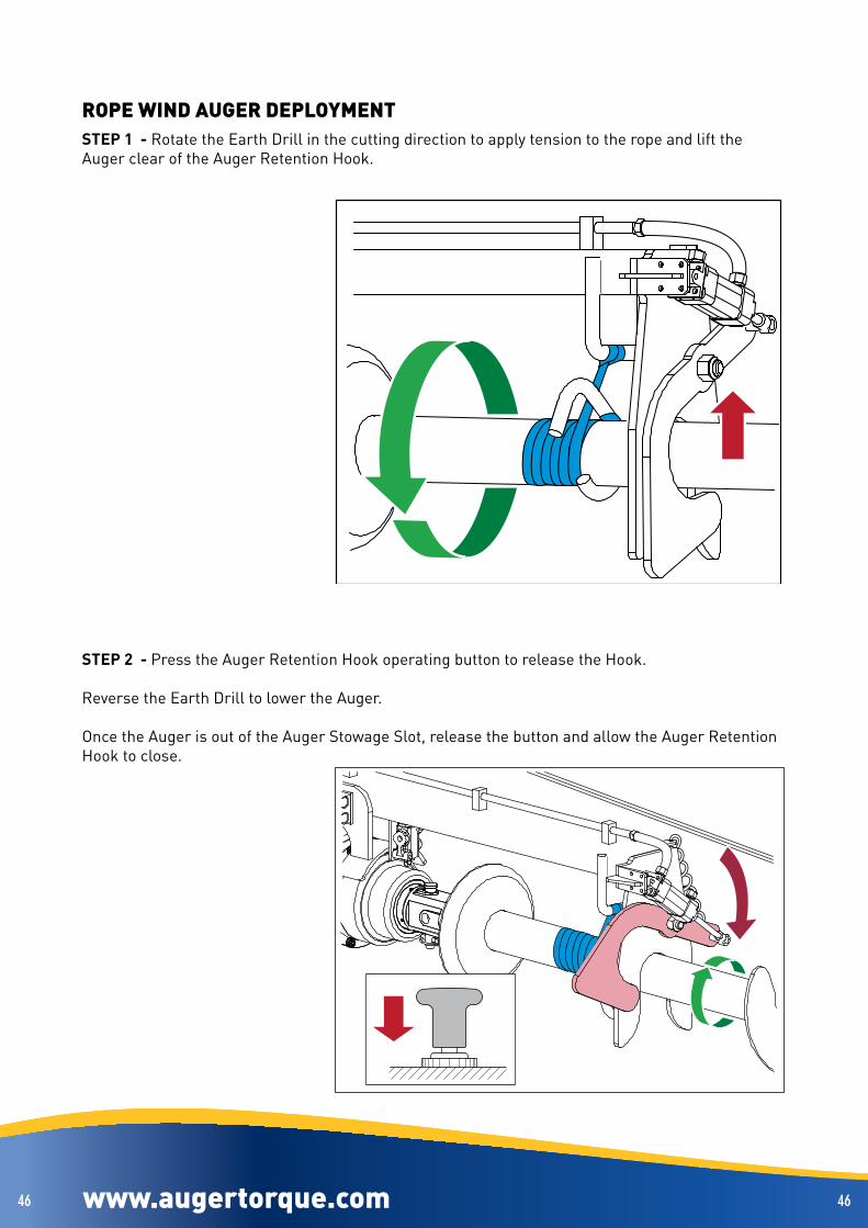
ROPE WIND AUGER DEPLOYMENTSTEP 1 - Rotate the Earth Drill in the cutting direction to apply tension to the rope and lift the Auger clear of the Auger Retention Hook .
STEP 2 - Press the Auger Retention Hook operating button to release the Hook .
Reverse the Earth Drill to lower the Auger .
Once the Auger is out of the Auger Stowage Slot, release the button and allow the Auger Retention Hook to close .

www.augertorque.com 4747 www.augertorque.com 4747
STEP 3 - Keep the Earth Drill rotating in the reverse direction until the Auger hangs vertically .Stop the Earth Drill .
STEP 4 - Remove the rope and stow it safely, away from direct sunlight, moisture and contaminants .

www.augertorque.com 4848 www.augertorque.com 4848
MAINTENANCE & LUBRICATIONSAFETY
Safety at all times
Ensure environmentally safe disposal of waste oil:
Do not pour down drain!
Avoid Fire or Explosion:
Do not smoke near, or expose lubricants to, any possible sources of ignition
(e .g . fire, electrical sparks or heat sources .)
All lubricants are toxic and potentially carcinogenic (cancer causing).
Avoid contact with skin and eyes:
Wear suitable protective clothing and gloves .
Always use a suitable barrier cream in case of skin contact .
Always wear eye protection:
In the event of skin contact wash with soap and water .
In the event of eye contact wash with water and seek medical advice .
Do not digest:
If swallowed seek medical advice immediately .

www.augertorque.com 4949
x4CHECK BEFOREOPERATION
99-5064
USE FULLYSYNTHETICGEAR OIL: SY..................................
www.augertorque.com 4949
Daily Check For Larger Units
SPECIAL NOTE
This page applies only to models:
17,000MAX - 20,000MAX - 25,000MAX - 30,000 - 30,000MAX - 35,000MAX
40,000 - 42,000MAX - 50,000MAX - 65,000MAX - 100,000MAX
12500-45 - 15000-45 - 18500-45 - 20000-45 - 24000-80 - 26000-60
31000-60 - 32000-45 - 35000-80 - 48000-80 - 74000-75
The following daily check MUST be carried out prior to any operation of the Earth Drill unit .
1 . With the Earth Drill unit secured in a vertical position . Remove the sight glass guard plate to gain access to the sight glass and check the oil level
2 . If the sight glass is fully filled with oil, the unit is filled to an acceptable level .
3 . If the sight glass is only partially filled with oil, top up using the oil fill/level point, until the acceptable level is achieved . Ensure that the correct grade of oil is used . This information can be found on the label (shown above) fitted to the Earth Drill unit .

www.augertorque.com 5050
DIN 1284
www.augertorque.com 5050
Service Intervals
Your Auger Torque Europe Ltd Earth Drill Unit features a sealed gear housing filled with gear oil to lubricate the planetary gearset components and bearings within the housing .
Auger Torque Europe Ltd Earth Drill Units are low maintenance, however regular checks for oil leaks and following the service schedules are recommended to ensure a trouble free product .
Weekly:
Grease hitch and Earth Drill pivot pins .
Oil Lubrication
Your Earth Drill has been prefilled with Gear Oil . This oil requires regular changing . Changing the oil at regular intervals will prolong the life of the unit .
100,000MAX Recommendation
these bolts be replaced every 250hrs or 6 months operation . Inspect the removed bolts for signs of irregular wear .
Important
To maintain product warranty, your Auger Torque Dealer MUST record proof of each oil change .
Please have your Earth Drill serviced as specified in the chart on page 51 by an Authorised Auger Torque service representative.
Make sure that each service is documented in the Service Record section of this manual to ensure product warranty is retained and the product life is extended .

www.augertorque.com 5151 www.augertorque.com 5151
Recommended Oil Change Intervals
Oil change frequency
Model First oil change after initial use Subsequent oil change frequency
1200 / 900-9 3 Months or 200 hours* 12 Months or 800 hours*X1500 / X1100-13 3 Months or 200 hours* 12 Months or 800 hours*X2000 / X1600-15 3 Months or 200 hours* 12 Months or 800 hours*X2500 / X2100-17 3 Months or 200 hours* 12 Months or 800 hours*ML1500 / ML1100-13 3 Months or 200 hours* 12 Months or 800 hours*ML2000 / ML1600-15 3 Months or 200 hours* 12 Months or 800 hours*ML2500 / ML2100-17 3 Months or 200 hours* 12 Months or 800 hours*3000TC / 2300-10 3 Months or 200 hours* 12 Months or 800 hours*3000MAX / 2200-20 3 Months or 200 hours* 12 Months or 800 hours*3500MAX / 2700-25 3 Months or 200 hours* 12 Months or 800 hours*4500MAX / 3300-30 3 Months or 200 hours* 12 Months or 800 hours*5000 / 3700-30 3 Months or 200 hours* 12 Months or 800 hours*5500TC / 4000-14 3 Months or 200 hours* 12 Months or 800 hours*5500MAX / 4000-30 3 Months or 200 hours* 12 Months or 800 hours*7000 / 5000-30 3 Months or 200 hours* 12 Months or 800 hours*7000TC / 5000-14 3 Months or 200 hours* 12 Months or 800 hours*7000MAX / 5200-35 2 Months or 120 hours* 12 Months or 800 hours*8000MAX / 6000-40 2 Months or 120 hours* 12 Months or 800 hours*10000 / 8000-40 2 Months or 120 hours* 12 Months or 800 hours*12000 / 9500-40 2 Months or 120 hours* 12 Months or 800 hours*12000MAX / 9000-45 2 Months or 120 hours* 12 Months or 800 hours*15000 / 11000-40 2 Months or 120 hours* 12 Months or 800 hours*15000MAX / 11000-45 2 Months or 120 hours* 12 Months or 800 hours*17000MAX / 12500-45 1 Month or 50 hours* 4 Months or 200 hours*20000MAX / 15000-45 1 Month or 50 hours* 4 Months or 200 hours*25000MAX / 18500-45 1 Month or 50 hours* 4 Months or 200 hours*30000 / 20000-45 1 Month or 50 hours* 4 Months or 200 hours*30000MAX / 24000-80 1 Month or 50 hours* 4 Months or 200 hours*35000MAX / 26000-60 1 Month or 50 hours* 4 Months or 200 hours*40000 / 32000-45 1 Month or 50 hours* 4 Months or 200 hours*42000MAX / 31000-60 1 Month or 50 hours* 4 Months or 200 hours*50000MAX / 35000-80 1 Month or 50 hours* 4 Months or 200 hours*65000MAX / 48000-80 1 Month or 50 hours* 4 Months or 200 hours*100000MAX / 74000-75 1 Month or 50 hours* 4 Months or 200 hours*150XHT / 110XHT 1 Month or 50 hours* 4 Months or 200 hours*250XHT / 185XHT 1 Month or 50 hours* 4 Months or 200 hours*
* Whichever time period occurs first .

www.augertorque.com 5252
1
2
1
2
A
B
C
10
15
www.augertorque.com 5252
Oil Change Procedure
Before starting any maintenance work on this unit, read the instructions carefully and ensure you have the correct tools, materials and safety equipment to hand .
NOTE: The procedure described below should be carried out by a competent and proficient engineer .
1 . Pre-heat the oil by running the unit for 15 minutes (Fig A) . Ensure that the unit is safely supported in a horizontal position, with the fill & drain plugs (Fig B, 1 & 2) at top and bottom of the housing
2 . Remove drain & fill plugs using correct tooling and allow oil to drain in to a suitable container for a minimum of 10 minutes . For best results leave to drain overnight .
Refer to page 53 for correct oil grades and quantities
3 . Refit drain plug (Fig C, 2) and fill with oil .
4 . Refit fill plug (Fig C, 1) .
5 . Check for signs of leakage, refill as necessary .
Contaminated fluids / oils MUST be disposed of in accordance with local environmental regulations .

www.augertorque.com 5353 www.augertorque.com 5353
Recommended Lubricants
All units are supplied with ISO320 viscosity oil unless otherwise requested .When using or storing the units below -15°C, an ISO150 viscosity oil must be used .When using or storing units above 35°C, an ISO460 viscosity oil must be used .
ModelOil Quantity
mlGrade Type
1200 150 Mobil Gear 600XP Mineral
X1500 400 Mobil Gear 600XP Mineral
X2000 400 Mobil Gear 600XP Mineral
X2500 400 Mobil Gear 600XP Mineral
ML1500 400 Mobil Gear 600XP Mineral
ML2000 400 Mobil Gear 600XP Mineral
ML2500 400 Mobil Gear 600XP Mineral
3000TC 850 Mobil Gear 600XP Mineral
3000MAX 850 Mobil Gear 600XP Mineral
3500MAX 850 Mobil Gear 600XP Mineral
4500MAX 850 Mobil Gear 600XP Mineral
5000 1250 Mobil Gear 600XP Mineral
5500TC 1250 Mobil Gear 600XP Mineral
5500MAX 1250 Mobil Gear 600XP Mineral
7000 1250 Mobil Gear 600XP Mineral
7000TC 1250 Mobil Gear 600XP Mineral
7000MAX 1250 Mobil Gear 600XP Mineral
8000MAX 1250 Mobil Gear 600XP Mineral
10 000 2150 Mobil Gear 600XP Mineral
12 000 2150 Mobil Gear 600XP Mineral
12 000MAX 2150 Mobil Gear 600XP Mineral
15 000 2150 Mobil Gear 600XP Mineral
15 000MAX 2150 Mobil Gear 600XP Mineral
17 000MAX 6750 Mobil Gear 600XP Mineral
20 000MAX 6750 Mobil Gear 600XP Mineral
25 000MAX 6750 Mobil Gear 600XP Mineral
30 000 8000 PAO Mobil SHC Polyglycol
30 000MAX 8000 PAO Mobil SHC Polyglycol
35 000MAX 8000 PAO Mobil SHC Polyglycol
40 000 8000 PAO Mobil SHC Polyglycol
42 000MAX 8000 PAO Mobil SHC Polyglycol
50 000MAX 8800 PAO Mobil SHC Polyglycol
65 000MAX 8800 PAO Mobil SHC Polyglycol
100 000MAX 21000 PAO Mobil SHC Polyglycol
150XHT 58000 PAO Mobil SHC Polyglycol
250XHT 58000 PAO Mobil SHC Polyglycol
ModelOil Quantity
pintGrade Type
900-9 0 .32 Mobil Gear 600XP Mineral
X1100-13 0 .85 Mobil Gear 600XP Mineral
X1600-15 0 .85 Mobil Gear 600XP Mineral
X2100-17 0 .85 Mobil Gear 600XP Mineral
ML1100-13 0 .85 Mobil Gear 600XP Mineral
ML1600-15 0 .85 Mobil Gear 600XP Mineral
ML2100-17 0 .85 Mobil Gear 600XP Mineral
2300-10 1 .79 Mobil Gear 600XP Mineral
2200-20 1 .79 Mobil Gear 600XP Mineral
2700-25 1 .79 Mobil Gear 600XP Mineral
3300-30 1 .79 Mobil Gear 600XP Mineral
3700-30 2 .64 Mobil Gear 600XP Mineral
4000-14 2 .64 Mobil Gear 600XP Mineral
4000-30 2 .64 Mobil Gear 600XP Mineral
5000-30 2 .64 Mobil Gear 600XP Mineral
5000-14 2 .64 Mobil Gear 600XP Mineral
5200-35 2 .64 Mobil Gear 600XP Mineral
6000-40 2 .64 Mobil Gear 600XP Mineral
8000-40 4 .54 Mobil Gear 600XP Mineral
9500-40 4 .54 Mobil Gear 600XP Mineral
9000-45 4 .54 Mobil Gear 600XP Mineral
11000-40 4 .54 Mobil Gear 600XP Mineral
11000-45 4 .54 Mobil Gear 600XP Mineral
12500-45 14 .26 Mobil Gear 600XP Mineral
15000-45 14 .26 Mobil Gear 600XP Mineral
18500-45 14 .26 Mobil Gear 600XP Mineral
20000-45 16 .90 PAO Mobil SHC Polyglycol
24000-80 16 .90 PAO Mobil SHC Polyglycol
26000-60 16 .90 PAO Mobil SHC Polyglycol
32000-45 16 .90 PAO Mobil SHC Polyglycol
31000-60 16 .90 PAO Mobil SHC Polyglycol
35000-80 18 .59 PAO Mobil SHC Polyglycol
48000-80 18 .59 PAO Mobil SHC Polyglycol
74000-75 44 .38 PAO Mobil SHC Polyglycol
110XHT 122 .57 PAO Mobil SHC Polyglycol
185XHT 122 .57 PAO Mobil SHC Polyglycol

www.augertorque.com 5454 www.augertorque.com 5454
Component WearThe cutting teeth and pilot should be checked regularly for wear .The diagrams below show acceptable levels of wear .
NOTE: Excessively worn teeth & pilots may cause damage to the Auger
NOTE: Pilots can be replaced by unbolting the old pilot and bolting the new one in its place . For tooth replacement, refer to page 55 .
Earth Tooth
NEW
OK
REPLACE
Pilot Bit
NEW
OK
REPLACE
S4 . . . . . . . . . .70mm/2 3/4”S5/S6 . . . . .110mm/4 21/64”PA . . . . . . . . . .115mm/4 17/32”
Tungsten Tipped Teeth & Pilots
REPLACEOKNEW

www.augertorque.com 5555
5mm
www.augertorque.com 5555
Auger Tooth ReplacementNOTE; Before removing Auger teeth, ensure that the Auger is horizontal and securely supported with the teeth easily accessible . Always wear appropriate protective clothing .
Shock Lock TeethUse a 5mm pin punch to drive the retaining pin out through the top of the tooth holder .The tooth and Shock Lock rubber can then be withdrawn .To install a replacement Shock Lock tooth, fit the rubber into the slot in the tooth .Press the tooth and rubber into the tooth holder, ensuring that the cut-out for the pin is on the correct side . You may need to use a soft-faced hammer to drive it in fully .Insert a new retaining pin into the top of the tooth holder, plain end first .Drive the pin in, ensuring that it locates in the cut-out in the tooth .Use a pin punch to make sure that the knurled end of the pin is fully engaged in the hole .
Rock TeethDrive out the rock tooth from the back, using a 12mm/15/32” pin punch .When installing a new rock tooth, ensure that the flats on the tooth and socket line up, before driving the tooth in with a soft-faced hammer .
12mm/ 15/32”

www.augertorque.com 5656 www.augertorque.com 5656
TROUBLESHOOTINGIF IN DOUBT ASK! - Seek Auger Torque / parent machine dealer for advice & repair .BE SAFE - only use genuine Auger Torque / parent machine spare parts .
FAULT
Mounting framedoes not fit parentmachine
MOUNTING FRAME - ASSEMBLY
POSSIBLE CAUSE
Incorrect or non-genuine mounting frame being used
Damaged / worn parts
ACTION
Refer to both this manual and parent machine’s operating assembly instructions
Repair or replace with genuine mounting frame
FAULT
Excessive movement in locating pins
MOUNTING FRAME - OPERATION
POSSIBLE CAUSE
Incorrect or worn locating pins
Parent machine pin location / linkage frame pin location worn
Damaged parts
ACTION
Replace with correct new parts
Seek advice from parent machine dealer
Seek advice from Auger Torque / parent machine dealer . Only use genuine spare parts
FAULT
Earth Drill Unit will not fit mounting frame
Excessive movement in locating pins
AUGER DRIVE UNIT - ASSEMBLY
POSSIBLE CAUSE
Incorrect / incompatible or non genuine mounting frame / Earth Drill Unit
Damaged parts
Incorrect or worn pins
ACTION
Obtain & fit correct and compatible genuine parts
Seek advice from Auger Torque dealer . Only use genuine spare parts
Replace with correct new genuine parts
FAULT
Earth Drill output shaft does not rotate
EARTH DRILL UNIT - OPERATION
POSSIBLE CAUSE
No oil flow
ACTION
Check that quick release coupler(s) are correctly engaged to parent machine
Check that parent machine hydraulic system is operating correctly and has sufficient oil of the correct grade (refer to parent machine operaing instrucions)

www.augertorque.com 5757 www.augertorque.com 5757
FAULT
Earth Drill output shaft does not rotate
Slow digging speed / slow rotation of Earth Drill output shaft
Auger stalls during work
EARTH DRILL UNIT - OPERATION
POSSIBLE CAUSE
Parent machine pressure relief valve faulty or set too low
Earth Drill unit seized
Auger jammed in ground
Insufficient oil flow from parent machine
Incompatible Earth Drill to parent machine combination
Incorrect auger, boring teeth or pilot fitted or worn boring teeth/pilot
Worn Earth Drill hydraulic motor possibly due to incorrect or dirty oil supply
Parent machine pressure relief valve faulty or set too low
Restricted oil flow
Blocked hydraulic filter
Excessive parent machine down force on auger
Incompatible Earth Drill / auger size / parent machine combination
ACTION
Test, reset or replace to parent machine’s specification
Seek advice from Auger Torque dealer
Remove auger from ground before starting machine
Check tha parent machine hydraulic system is operating correctly and has sufficient oil of the correct grade
Check specification . Seek advice from Auger Torque dealer
Ensure auger size is compatible with Earth Drill Unit (not to large) and that boring teeth/pilot are suitable for he ground conditions and not worn
Seek advice from Auger Torque dealer . Only use genuine spare parts . Change parent machine hydraulic oil and filter before fitting replacement drive unit
Reset/replace pressure release valve to parent machine’s specification
Check for damaged or incorrect hydraulic hoses and connections
Change parent machine filter and oil
Reduce down force
Check specification . Seek advice from Auger Torque dealer

www.augertorque.com 5858 www.augertorque.com 5858
FAULT
Rotation doesn’t stop when Earth Drill and auger reach top of stowage slot
Retention hook doesn’t open
Retention hook doesn’t close
ROPE WIND HITCH
POSSIBLE CAUSE
Poor adjustment of valve
Faulty valve
Auger is supported by hook
Faulty air supply
Faulty air valve
Faulty hook operating cylinder
Earth Drill and auger have not reached top of stowage slot
Faulty hook operating cylinder
Broken return spring
Pivot bolt too tight
ACTION
Adjust position of valve
Check valve and if necessary, replace
Check hose connections to valve
Lift auger clear of hook by rotating the Earth Drill
Check air hose to valve, repair or replace as necessary
Check air valve operation, replace as necessary
Check cylinder operation, replace as necessary
Lift auger to top of stowage slot by rotating the Earth Drill
Check cylinder operation, replace as necessary
Replace
Check and re-set as necessary

www.augertorque.com 5959 www.augertorque.com 5959
SERVICE RECORD
Ensure that each Earth Drill service is documented in the Service Records below to ensure product warranty is retained and the product life is extended .
Earth Drill Model
Serial Number
Make & Model of Parent Machine
Date of Purchase
Work carried out - please tick boxes Date Hours
Visual Inspection Comments\remarks
Oil Change
Lubricant Used
Motor Test
Motor Bolts Torqued
Hood Bolts Torqued
Next Service Date\Hours
Work carried out - please tick boxes Date Hours
Visual Inspection Comments\remarks
Oil Change
Lubricant Used
Motor Test
Motor Bolts Torqued
Hood Bolts Torqued
Next Service Date\Hours

www.augertorque.com 6060 www.augertorque.com 6060
Work carried out - please tick boxes Date Hours
Visual Inspection Comments\remarks
Oil Change
Lubricant Used
Motor Test
Motor Bolts Torqued
Hood Bolts Torqued
Next Service Date\Hours
Work carried out - please tick boxes Date Hours
Visual Inspection Comments\remarks
Oil Change
Lubricant Used
Motor Test
Motor Bolts Torqued
Hood Bolts Torqued
Next Service Date\Hours
Work carried out - please tick boxes Date Hours
Visual Inspection Comments\remarks
Oil Change
Lubricant Used
Motor Test
Motor Bolts Torqued
Hood Bolts Torqued
Next Service Date\Hours

www.augertorque.com 6161 www.augertorque.com 6161
Work carried out - please tick boxes Date Hours
Visual Inspection Comments\remarks
Oil Change
Lubricant Used
Motor Test
Motor Bolts Torqued
Hood Bolts Torqued
Next Service Date\Hours
Work carried out - please tick boxes Date Hours
Visual Inspection Comments\remarks
Oil Change
Lubricant Used
Motor Test
Motor Bolts Torqued
Hood Bolts Torqued
Next Service Date\Hours
Work carried out - please tick boxes Date Hours
Visual Inspection Comments\remarks
Oil Change
Lubricant Used
Motor Test
Motor Bolts Torqued
Hood Bolts Torqued
Next Service Date\Hours

www.augertorque.com 6262 www.augertorque.com 6262
Work carried out - please tick boxes Date Hours
Visual Inspection Comments\remarks
Oil Change
Lubricant Used
Motor Test
Motor Bolts Torqued
Hood Bolts Torqued
Next Service Date\Hours
Work carried out - please tick boxes Date Hours
Visual Inspection Comments\remarks
Oil Change
Lubricant Used
Motor Test
Motor Bolts Torqued
Hood Bolts Torqued
Next Service Date\Hours
Work carried out - please tick boxes Date Hours
Visual Inspection Comments\remarks
Oil Change
Lubricant Used
Motor Test
Motor Bolts Torqued
Hood Bolts Torqued
Next Service Date\Hours

www.augertorque.com 6363 www.augertorque.com 6363
Work carried out - please tick boxes Date Hours
Visual Inspection Comments\remarks
Oil Change
Lubricant Used
Motor Test
Motor Bolts Torqued
Hood Bolts Torqued
Next Service Date\Hours
Work carried out - please tick boxes Date Hours
Visual Inspection Comments\remarks
Oil Change
Lubricant Used
Motor Test
Motor Bolts Torqued
Hood Bolts Torqued
Next Service Date\Hours
Work carried out - please tick boxes Date Hours
Visual Inspection Comments\remarks
Oil Change
Lubricant Used
Motor Test
Motor Bolts Torqued
Hood Bolts Torqued
Next Service Date\Hours

www.augertorque.com 6464 www.augertorque.com 6464
Work carried out - please tick boxes Date Hours
Visual Inspection Comments\remarks
Oil Change
Lubricant Used
Motor Test
Motor Bolts Torqued
Hood Bolts Torqued
Next Service Date\Hours
Work carried out - please tick boxes Date Hours
Visual Inspection Comments\remarks
Oil Change
Lubricant Used
Motor Test
Motor Bolts Torqued
Hood Bolts Torqued
Next Service Date\Hours
Work carried out - please tick boxes Date Hours
Visual Inspection Comments\remarks
Oil Change
Lubricant Used
Motor Test
Motor Bolts Torqued
Hood Bolts Torqued
Next Service Date\Hours

www.augertorque.com 6565 www.augertorque.com 6565
WARRANTY STATEMENTAuger Torque provide a LIFETIME parts replacement warranty on the dislodgement of the Earth Drill shaft and any failure of the Shock Lock system to prevent loss of teeth under normal operating conditions.
All Auger Torque products are warranted to be free from defects in materials or workmanship for the periods summarised below:
•Planetary Gearbox Components - 72 Months•Hydraulic Motors - 36 Months•All Other Parts / Products - 12 Months
The warranty periods will commence from Date of Sale by an authorised Auger Torque Dealer . Evidence of the date of sale may be required and for Planetary and Hydraulic Motor warranties to be valid the product must be registered with Auger Torque within 4 weeks of the date of sale . Extended Warranty (> 12 months) Products can be registered by returning the Registration Card or completing the form on page 7 . This warranty is not transferable beyond the initial purchaser of the product .
A warranty claim should be reported to the Auger Torque Dealer who supplied the unit . The Dealer, with the technical backup of Auger Torque, will make an initial assessment .
The customer is responsible for returning the product for warranty inspection to the original supplying dealer’s facility . Parts should not be delivered without the prior agreement of the dealer or Auger Torque .
During the warranty period Auger Torque, at its option, will repair or replace any parts free of charge determined as defective by Auger Torque . Such repairs will be undertaken by Auger Torque or its nominated representative at an Auger Torque facility or a location deemed suitable by Auger Torque . Auger Torque are not liable for any associated costs relating to a warranty failure .
Parts repaired or replaced by Auger Torque are then covered by this warranty for the remainder of the original warranty as if such parts were original parts .
Products or parts which, as determined by Auger Torques examination, show wear from normal use, have been improperly operated, damaged by accident or negligence, altered or modified are not considered defective and are not covered by this warranty .
This warranty is void if any attempt is made to make field repairs unless these have been pre-approved in writing by Auger Torque .
This warranty is void if the products are not serviced in-line with the instructions in the Operators Manual . Particular care should be taken to perform regular oil changes in gearboxes .
This warranty is exclusive and in-lieu of any other expressed warranties . There are no warranties of merchantability or fitness for a particular purpose . Auger Torque shall not be liable for any consequential, incidental or punitive damages, losses or expenses, including those resulting from or caused by any defects .
As you would expect from Auger Torque, with our extensive experience and product reliability we’ll always go the extra mile to keep you working.

www.augertorque.com 6666 www.augertorque.com 6666
Notes
. . . . . . . . . . . . . . . . . . . . . . . . . . . . . . . . . . . . . . . . . . . . . . . . . . . . . . . . . . . . . . . . . . . . . . . . . . . . .
. . . . . . . . . . . . . . . . . . . . . . . . . . . . . . . . . . . . . . . . . . . . . . . . . . . . . . . . . . . . . . . . . . . . . . . . . . . . .
. . . . . . . . . . . . . . . . . . . . . . . . . . . . . . . . . . . . . . . . . . . . . . . . . . . . . . . . . . . . . . . . . . . . . . . . . . . . .
. . . . . . . . . . . . . . . . . . . . . . . . . . . . . . . . . . . . . . . . . . . . . . . . . . . . . . . . . . . . . . . . . . . . . . . . . . . . .
. . . . . . . . . . . . . . . . . . . . . . . . . . . . . . . . . . . . . . . . . . . . . . . . . . . . . . . . . . . . . . . . . . . . . . . . . . . . .
. . . . . . . . . . . . . . . . . . . . . . . . . . . . . . . . . . . . . . . . . . . . . . . . . . . . . . . . . . . . . . . . . . . . . . . . . . . . .
. . . . . . . . . . . . . . . . . . . . . . . . . . . . . . . . . . . . . . . . . . . . . . . . . . . . . . . . . . . . . . . . . . . . . . . . . . . . .
. . . . . . . . . . . . . . . . . . . . . . . . . . . . . . . . . . . . . . . . . . . . . . . . . . . . . . . . . . . . . . . . . . . . . . . . . . . . .
. . . . . . . . . . . . . . . . . . . . . . . . . . . . . . . . . . . . . . . . . . . . . . . . . . . . . . . . . . . . . . . . . . . . . . . . . . . . .
. . . . . . . . . . . . . . . . . . . . . . . . . . . . . . . . . . . . . . . . . . . . . . . . . . . . . . . . . . . . . . . . . . . . . . . . . . . . .
. . . . . . . . . . . . . . . . . . . . . . . . . . . . . . . . . . . . . . . . . . . . . . . . . . . . . . . . . . . . . . . . . . . . . . . . . . . . .
. . . . . . . . . . . . . . . . . . . . . . . . . . . . . . . . . . . . . . . . . . . . . . . . . . . . . . . . . . . . . . . . . . . . . . . . . . . . .
. . . . . . . . . . . . . . . . . . . . . . . . . . . . . . . . . . . . . . . . . . . . . . . . . . . . . . . . . . . . . . . . . . . . . . . . . . . . .
. . . . . . . . . . . . . . . . . . . . . . . . . . . . . . . . . . . . . . . . . . . . . . . . . . . . . . . . . . . . . . . . . . . . . . . . . . . . .
. . . . . . . . . . . . . . . . . . . . . . . . . . . . . . . . . . . . . . . . . . . . . . . . . . . . . . . . . . . . . . . . . . . . . . . . . . . . .
. . . . . . . . . . . . . . . . . . . . . . . . . . . . . . . . . . . . . . . . . . . . . . . . . . . . . . . . . . . . . . . . . . . . . . . . . . . . .
. . . . . . . . . . . . . . . . . . . . . . . . . . . . . . . . . . . . . . . . . . . . . . . . . . . . . . . . . . . . . . . . . . . . . . . . . . . . .
. . . . . . . . . . . . . . . . . . . . . . . . . . . . . . . . . . . . . . . . . . . . . . . . . . . . . . . . . . . . . . . . . . . . . . . . . . . . .
. . . . . . . . . . . . . . . . . . . . . . . . . . . . . . . . . . . . . . . . . . . . . . . . . . . . . . . . . . . . . . . . . . . . . . . . . . . . .

www.augertorque.com 6767 www.augertorque.com 6767
Notes
. . . . . . . . . . . . . . . . . . . . . . . . . . . . . . . . . . . . . . . . . . . . . . . . . . . . . . . . . . . . . . . . . . . . . . . . . . . . .
. . . . . . . . . . . . . . . . . . . . . . . . . . . . . . . . . . . . . . . . . . . . . . . . . . . . . . . . . . . . . . . . . . . . . . . . . . . . .
. . . . . . . . . . . . . . . . . . . . . . . . . . . . . . . . . . . . . . . . . . . . . . . . . . . . . . . . . . . . . . . . . . . . . . . . . . . . .
. . . . . . . . . . . . . . . . . . . . . . . . . . . . . . . . . . . . . . . . . . . . . . . . . . . . . . . . . . . . . . . . . . . . . . . . . . . . .
. . . . . . . . . . . . . . . . . . . . . . . . . . . . . . . . . . . . . . . . . . . . . . . . . . . . . . . . . . . . . . . . . . . . . . . . . . . . .
. . . . . . . . . . . . . . . . . . . . . . . . . . . . . . . . . . . . . . . . . . . . . . . . . . . . . . . . . . . . . . . . . . . . . . . . . . . . .
. . . . . . . . . . . . . . . . . . . . . . . . . . . . . . . . . . . . . . . . . . . . . . . . . . . . . . . . . . . . . . . . . . . . . . . . . . . . .
. . . . . . . . . . . . . . . . . . . . . . . . . . . . . . . . . . . . . . . . . . . . . . . . . . . . . . . . . . . . . . . . . . . . . . . . . . . . .
. . . . . . . . . . . . . . . . . . . . . . . . . . . . . . . . . . . . . . . . . . . . . . . . . . . . . . . . . . . . . . . . . . . . . . . . . . . . .
. . . . . . . . . . . . . . . . . . . . . . . . . . . . . . . . . . . . . . . . . . . . . . . . . . . . . . . . . . . . . . . . . . . . . . . . . . . . .
. . . . . . . . . . . . . . . . . . . . . . . . . . . . . . . . . . . . . . . . . . . . . . . . . . . . . . . . . . . . . . . . . . . . . . . . . . . . .
. . . . . . . . . . . . . . . . . . . . . . . . . . . . . . . . . . . . . . . . . . . . . . . . . . . . . . . . . . . . . . . . . . . . . . . . . . . . .
. . . . . . . . . . . . . . . . . . . . . . . . . . . . . . . . . . . . . . . . . . . . . . . . . . . . . . . . . . . . . . . . . . . . . . . . . . . . .
. . . . . . . . . . . . . . . . . . . . . . . . . . . . . . . . . . . . . . . . . . . . . . . . . . . . . . . . . . . . . . . . . . . . . . . . . . . . .
. . . . . . . . . . . . . . . . . . . . . . . . . . . . . . . . . . . . . . . . . . . . . . . . . . . . . . . . . . . . . . . . . . . . . . . . . . . . .
. . . . . . . . . . . . . . . . . . . . . . . . . . . . . . . . . . . . . . . . . . . . . . . . . . . . . . . . . . . . . . . . . . . . . . . . . . . . .
. . . . . . . . . . . . . . . . . . . . . . . . . . . . . . . . . . . . . . . . . . . . . . . . . . . . . . . . . . . . . . . . . . . . . . . . . . . . .
. . . . . . . . . . . . . . . . . . . . . . . . . . . . . . . . . . . . . . . . . . . . . . . . . . . . . . . . . . . . . . . . . . . . . . . . . . . . .
. . . . . . . . . . . . . . . . . . . . . . . . . . . . . . . . . . . . . . . . . . . . . . . . . . . . . . . . . . . . . . . . . . . . . . . . . . . . .

TAHITI
BUFFALO
ATLANTA
CHELTENHAM
NINGBO
BRISBANE
MELBOURNE
www.augertorque.com
YOUR DEALER IS
Products and specifications subject to change without prior notice.Some products may not be available in your country or region.
AUGER TORQUE, SHOCK LOCK™, NDS™ and the AUGER TORQUE LOGO are trademarks of Auger Torque Europe Ltd © 2021 Auger Torque Europe Ltd. All Rights Reserved.
Auger Torque USA LLC2640 Jason Industrial Parkway
Winston, GA 30187USA
Tel: (+1) 844 287 6300Fax: (+1) 770 947 9916
Email: [email protected]
Auger Torque Europe LtdHazleton
CheltenhamGL54 4DXEngland
Tel: +44 (0) 1451 861652Fax: +44 (0) 1451 861660
Email: [email protected]
Auger Torque Australia Pty Ltd122 Boundary Rd
RockleaQueensland 4106
Australia Tel: +61 (0) 7 3274 2077Fax: +61 (0) 7 3274 5077
Email: [email protected]