Analysis of Cuttings Transport and Flow Pattern in Nearly ...
Upload
khangminh22Category
view
1download
0

ENERGY EFFICIENT DRILL CUTTINGS TREATMENT PLANT
DESIGNED BY NORWEGIAN-GROUP AS
A FEASABILITY STUDY
Sindre Åse Lunde
FACULTY OF SCIENCE AND TECHNOLOGY
DEPARTMENT OF MATHEMATICS AND NATURAL SCIENCE
WATER SCIENCE AND TECHNOLOGY
2015
SINDRE ÅSE LUNDE
ENERGY EFFICIENT DRILL CUTTINGS TREATMENT PLANT DESIGNED BY NORWEGIAN-GROUP AS A FEASABILITY STUDY
iii
Abstract
The cuttings produced by the oil and gas industry must be handled according to legislations. According
to OSPAR, drill cuttings should contain less than 1 percent oil by weigh before discharged. There
is several cuttings waste handling options. Treating the drill cuttings offshore is considered
economically favorable. Some offshore treatment technologies are able to meet the legislation
requirements.
Norwegian-Group AS provides a treatment plant concept intended for treating cuttings offshore.
The treatment plant is based on three separation technologies. The first separation stage is a
steam assisted cuttings dryer. The cuttings are then transported to the thermal separation. The
thermal separation chamber is fitted with steam assistance combined with a heat source. Oil and
water vapor from the cuttings dryer and thermal separation chamber is separated by a
membrane. Clean steam is recirculated and reused.
This thesis evaluates the following topics. Potential steam supply systems for the cuttings dryer.
Potential heat sources that can be combined with steam assistance in the thermal separation
chamber. The feasibility of separating oil and water by membranes to reduce the energy
consumption and cuttings handling cost. Potential advantages and limitations that the treatment
plant may feature.
Increased the separation degree by utilizing steam in combination with the cuttings dryer is
considered feasible.
The recommended heat source to be combined with steam in the thermal separation chamber is
microwave radiation due to its energy efficiency and unique ability to desorb capillary bond water
and oil.
On the other hand, the idea of using a membrane to reduce the energy consumption and cuttings
handling costs is considered not attractive. As it cannot satisfy the aim of cost reduction.
The treatment plant may serve great advantages over the current cuttings handling options suited
for offshore treatment. The potential advantages are related to treatment capacity, energy
consumption and handling costs. Potential limitations are related to reaching the legislation of
various cuttings characteristics.

SINDRE ÅSE LUNDE
ENERGY EFFICIENT DRILL CUTTINGS TREATMENT PLANT DESIGNED BY NORWEGIAN-GROUP AS A FEASABILITY STUDY
iv
Acknowledgement
I would like to express my deepest gratitude for the support and guidance provided by Stig Ovar
Keller, Solmaz Hajizadeh, Trond Aarestrup, Torleiv Bilstad and Evgenia Protasova.

SINDRE ÅSE LUNDE
ENERGY EFFICIENT DRILL CUTTINGS TREATMENT PLANT DESIGNED BY NORWEGIAN-GROUP AS A FEASABILITY STUDY
v
Table of Content Chapter 1: introduction ................................................................................................................................ 1
1.1 Background ......................................................................................................................................... 1
1.2 Problem description ........................................................................................................................... 2
1.3 Objective ............................................................................................................................................. 2
Chapter 2: Drilling waste .............................................................................................................................. 3
2.1 Types of drilling waste ........................................................................................................................ 3
2.2 Cuttings handling and cost ................................................................................................................. 5
2.3 Discharge regulations ......................................................................................................................... 7
Chapter 3: Waste Management ................................................................................................................. 10
3.1 Treatment and disposal options for drill cuttings ........................................................................... 11
3.2 Cuttings handling offshore ............................................................................................................... 12
3.2.1 Ship to shore .............................................................................................................................. 13
3.2.2 Cuttings Re-injection ................................................................................................................. 14
3.2.3 Desorption offshore................................................................................................................... 15
3.2.3.1 Cuttings dryer.....................................................................................................................15
3.2.3.2 Thermo-mechanical cuttings cleaner…………………………………………………………………………….18
3.3 Upcoming technologies for treating cuttings offshore ............................................................. 21
3.3.1 Microwave assisted nitrogen stripping ..................................................................................... 21
3.3.2 Liquefied gas extraction ............................................................................................................ 26
3.3.3 Cutcube ...................................................................................................................................... 26
Chapter 4: The treatment plant concept of Norwegian-Group AS ........................................................... 27
4.1 An outline of Norwegian Group AS treatment plant concept ........................................................ 27
4.2 Separation principles ........................................................................................................................ 29
4.2.1 Steam distillation ....................................................................................................................... 30
4.2.2 Superheated steam drying ........................................................................................................ 30
4.2.3 Steam assisted cuttings dryer ................................................................................................... 35
4.2.4 Membrane separation of oil and water vapor ......................................................................... 41
4.3 Potential heat sources for the steam assisted thermal separation chamber ................................ 49
4.3.1 Resistance heating ..................................................................................................................... 51

SINDRE ÅSE LUNDE
ENERGY EFFICIENT DRILL CUTTINGS TREATMENT PLANT DESIGNED BY NORWEGIAN-GROUP AS A FEASABILITY STUDY
vi
4.3.2 Electromagnetic heating ............................................................................................................ 55
4.3.2.1 Induction heating ………………………………………………………………………………………………………… 57
4.3.2.2 Infrared heating…………………………………………………………………………………………………………… 62
4.3.2.3 Dielectric heating…………………………………………………………………………………………………………. 63
Chapter 5: Conclusion and Recommendations .......................................................................................... 79
Chapter 6: Future research ......................................................................................................................... 83
6.1 Super heated steam drying .............................................................................................................. 83
6.2 Steam assisted cuttings dryer .......................................................................................................... 83
6.3 Thermal separation chamber ........................................................................................................... 83
6.4 Membrane separation of oil and water vapor ................................................................................ 84
Referances…………………………………………………………………………………………………………….……………………........... 85

SINDRE ÅSE LUNDE
ENERGY EFFICIENT DRILL CUTTINGS TREATMENT PLANT DESIGNED BY NORWEGIAN-GROUP AS A FEASABILITY STUDY
vii
LIST OF FIGURES
Figure 1: Distribution of water and oil when drilled through a water saturated formation 4
Figure 2: Generation and distribution of oil contaminated drill cuttings from year 2006 to 2011.
The Y-axis represents tons of drill cuttings generated 6
Figure 3: Prognosis for oil-contaminated cuttings sent to shore along with cuttings handling
capacity 6
Figure 4: Martin Linge-field. Located close to British sector at a depth of 100-120 meters 9
Figure 5: The waste handling triangle 10
Figure 6: Drill cuttings slurry fabrication and injection system 14
Figure 7: Working principle of a Vertical basket centrifuge 16
Figure 8: Horizontal cuttings dryer installation 16
Figure 9: Thermal separation chamber 18
Figure 10: TCC process plant 19
Figure 11: The microwave assisted nitrogen stripping drill cuttings treatment plant 22
Figure 12: Applied power versus residual of oil for different cuttings characteristics and water
content. The feed rate (treatment rate) is 150 kg/h 23
Figure 13: Energy requirement plotted against ROC for cuttings with different oil and water
content 24
Figure 14: Cuttings treatment plant concept of Norwegian-Groups AS 28
Figure 15: Classifications of super-heated steam dryers 31
Figure 16: Removal of oil on cuttings in a fixed-bed configuration. Nitrogen and steam was
supplied under a fixed bed container. The x-axis represents time and bed volumes passed 33
Figure 17: Cuttings prior to the treatment contains 10 percent ROC as illustrated in the picture to
the left. The picture on the right side is after treatment. The ROC is reduced to 2 percent 36
Figure 18: Horizontal dryer schematic 37
Figure 19: Coupling between the spinning steam pipe that is placed inside the drive shaft, and the
pipe extension 38
Figure 20: Illustrates steam supply system on the outside of the driveshaft 38
Figure 21: Steam supplied through the casing 39
Figure 22: Separation through porous membranes with different pore size and dense MF
membranes 46
Figure 23: Temperature stabilities of polymer and ceramic membranes 47
Figure 24: Direct resistance heater setup 51
Figure 25: Indirect resistance heater 51

SINDRE ÅSE LUNDE
ENERGY EFFICIENT DRILL CUTTINGS TREATMENT PLANT DESIGNED BY NORWEGIAN-GROUP AS A FEASABILITY STUDY
viii
Figure 26: Electrode configuration in wells to enhance oil recovery 53
Figure 27: Electromagnetic wave 55
Figure 28: The electromagnetic frequencies along with their classifications 56
Figure 29: Current distribution in induction heating 57
Figure 30: Induction heated screw conveyor for use in gasification plants 61
Figure 31: Outline of infrared heating 62
Figure 32: Heat pattern when heating with conventional heating (left), compared to microwave
heating (right) 63
Figure 33: Electric field (E0) and power density (P0) plotted against penetration depth (δ) 66
Figure 34: Typical microwave heating setup 67
Figure 35: Microwave interactions 68
Figure 36: Microwave assisted nitrogen stripping versus only nitrogen stripping 71
Figure 37: Microwave assisted steam stripping versus only steam stripping 71
Figure 38: Energy requirements for only steam, only nitrogen and microwave enhanced nitrogen
stripping 72
Figure 39: Steam supplied in cavities under the screw conveyor. The screw conveyor is fitted
inside the thermal separation chamber 76
Figure 40: Typical RF heating setup 77
Figure 41: Main types of applicators for RF heating. (a) stray field, (b) staggered through, (c) flat
plate and (d) welding electrode 77

SINDRE ÅSE LUNDE
ENERGY EFFICIENT DRILL CUTTINGS TREATMENT PLANT DESIGNED BY NORWEGIAN-GROUP AS A FEASABILITY STUDY
ix
LIST OF TABLES
Table 1: Cost associated with drill waste handling 7
Table 2: Cuttings volume balance for a generic well (Svensen & Taugbol, 2011) 12
Table 3: Energy balance for treatment of 1 ton cuttings per hour of typical drilling waste 20
Table 4: Energy requirement to achieve less than 1 % ROC for different samples 23
Table 5: Input power versus energy consumption for a specific cuttings sample from a sandstone
reservoir 25
Table 6: Assumed result by the steam assisted cuttings dryer 41
Table 7: Overall vapor supplied and generated when treating 10 ton cuttings per hour 44
Table 8: Summary of heat sources evaluated 48
Table 9: Relative dielectric loss factor for radio and microwave frequencies 64
Table 10: Relating dielectric loss factor to penetration depth for microwave heating 69

SINDRE ÅSE LUNDE
ENERGY EFFICIENT DRILL CUTTINGS TREATMENT PLANT DESIGNED BY NORWEGIAN-GROUP AS A FEASABILITY STUDY
x
LIST OF EQUATIONS
Equation 1 Daltons law: Ptotal = PA + PB 30
Equation 2 Maxwell`s equation: δ = 503 √p
µf [m]
Equation 3 R = 𝑝𝑙
𝑎 58
Equation 4 P0 = 2πfԑἔ (E)2 65
Equation 5 𝑑𝑇
𝑑𝑡 =
P0 = 2πfԑἔ (E)2
𝑝𝐶𝑝 65

SINDRE ÅSE LUNDE
ENERGY EFFICIENT DRILL CUTTINGS TREATMENT PLANT DESIGNED BY NORWEGIAN-GROUP AS A FEASABILITY STUDY
xi
NOMENCLATURE
°C Temperature, degrees Celsius
CO2 Carbon Dioxide
l Liter
h Hour
m3 Cubic meter
% Percent
“ Inch
Bbl Oil barrel
kW Kilo Watt
%wt Percent by weight
Kg Kilogram
δ Penetration depth
p Resistivity
µ Magnetic permeability
f Frequency
R Resistance
L length of current carrying conductor
A Area of conductors cross-section
m2 Square meter
ԑ Permittivity of free space
ἔ Relative permittivity
P0 Power density
E Magnitude of electric field
t Time
ρ Material density

SINDRE ÅSE LUNDE
ENERGY EFFICIENT DRILL CUTTINGS TREATMENT PLANT DESIGNED BY NORWEGIAN-GROUP AS A FEASABILITY STUDY
xii
Cp Specific density of material
e 2.718
Dp Penetration depth
GHz Giga hertz
MHz Mega hertz
Cm Centimeter

SINDRE ÅSE LUNDE
ENERGY EFFICIENT DRILL CUTTINGS TREATMENT PLANT DESIGNED BY NORWEGIAN-GROUP AS A FEASABILITY STUDY
xiii
ABBREVIATIONS
ABM Aqueous based mud
Avg Average
BAT Best available technique
BEP Best environmental practice
CRI Cuttings Re-injection
DNV Den Norske Veritas
EM Electromagnetic
HPWBM High performance water based mud
HSE Health Safety and Environment
IH Induction heating
Klif Klima og Forurensningsdirektoratet
NCS Norwegian Continental Shelf
NABM Non aqueous based mud
Max Maximum
OBM Oil based mud
OSPAR commission Oslo and Paris commission
OLF Oljeindustriens Landsforening
PAH Poly aromatic hydrocarbons
ROP Rate of penetration
SBM Synthetic based mud
SSD Superheated steam drying
TCC Thermo-mechanical Cuttings Cleaner
WBM Water based Mud
SINDRE ÅSE LUNDE
ENERGY EFFICIENT DRILL CUTTINGS TREATMENT PLANT DESIGNED BY NORWEGIAN-GROUP AS A FEASABILITY STUDY
1
Chapter 1: introduction
The treatment plant of Norwegian-Group AS is based on applying thermal and mechanical
desorption to separate oil from oil contaminated drill cuttings. The treated waste from a steam
assisted centrifuge (cuttings dryer) is transported to a thermal desorption chamber. This chamber
is fitted with a heat source combined in combination with steam assistance. Steam and oil vapor
from the steam assisted cuttings dryer and thermal separation chamber is separated by a
membrane. Recovered steam is recirculated and reused to reduce the energy consumption and
cuttings handling costs.
1.1 Background During drilling operations rotating drill bits crush the formation while allowing the drill bit to
penetrate. The crushed formation is called drill cuttings. Drilling fluid or mud is jetted out of bit
nozzles in the drill bit. This serves multiple purposes, including cooling and lubrication of the drill
bit and most importantly, it suspends and transports the cuttings to the surface (El-sayed & El-
Naga, 2001). The type of drilling mud is chosen based on the type of well drilled. Oil based or
synthetic based drilling mud contains hydrocarbons (oil). Due to the environmental aspect,
hydrocarbons must be removed before discharging the drilling waste. The mud and drilled
cuttings are separated in a primary treatment stage. This involved shale shakers, hydro-cyclones
(de-sanders and de-silters) and centrifuges. The primary treatment occurs on the drilling rig and
allows for recirculation of the expensive drilling mud (Charles, Sayle, Phillips, & Morehouse,
2010). Around 70 percent mud is recovered in this separation stage (DNV, 2013).
The cuttings are still contaminated with mud after the primary treatment. Until 1992, cuttings
were discharged to sea despite the drilling mud they contained (OSPAR2, 2014). This resulted in
environmental harm and large cutting piles around the platforms. The new regulations for
Norwegian continental shelf (NCS) has stated that cuttings should not be discharged unless the
content of reservoir oil or base oil from the drilling fluid is lower than 10 gr per kg of dry mass
(Aktivitetsforeskriften, 2010). However, in a limiting trail for cuttings treatment offshore at the
Martin Linge-field, the maximum allowed retained oil on cuttings (ROC) was 5 gr oil per kg dry
mass before discharge (Miljødirektoratet1, 2014). To meet these requirements, the drilling waste
served several different faiths. Cuttings are shipped to shore for treatment and final disposal at
approved sites, or slurryfied and re-injected into a suitable formation for storage. In recent years,
cuttings reinjection decreased or stopped completely at several drill fields on NCS. This related to
slurry leakages from the storage formation to the surface. The overall slurryfication expenses are
also considered high (DNV, 2013).
The shipment of cuttings for further treatment offers several challenges. These were associated
with demanding logistics, heavy crane lifting, separation, and disposal onshore. The crane lifting
of cuttings on to the supply vessel required good weather conditions. Poor weather conditions
SINDRE ÅSE LUNDE
ENERGY EFFICIENT DRILL CUTTINGS TREATMENT PLANT DESIGNED BY NORWEGIAN-GROUP AS A FEASABILITY STUDY
2
could stop or limit the drilling process because cuttings accumulate on the drill rig. Crane lifting
also implies the risk related to falling objects (Svensen & Taugbol, 2011). Operators have been
seeking alternative ways of handling drilled cuttings. Treatment system that offers desorption on
the drilling rig is considered attractive as cuttings may be discharged from the drilling rig. Several
desorption technologies can offer a potential solution.
1.2 Problem description Norwegian-Group AS is a company that delivers environmental sustainable solutions to the oil
and gas industry. The company was founded in 2012. The treatment plant concept reviewed in
this thesis is intended for appliance offshore on a drilling rig. The feasibility and the challenges
associated with the treatment concept are to be discussed and reviewed. These challenges are
associated with modifying the centrifuge to allow steam assistance, finding a proper heat source
for the thermal separation chamber, and membrane separation of oil and steam vapor. In
addition, the treatment plant has to compete with current and upcoming treatment technologies.
1.3 Objective The aim of this thesis is to evaluate the feasibility of Norwegian-groups cuttings treatment
concept. The treatment concept is based on two new desorption methods applied on drill
cuttings. These concepts are:
1. Steam assisted horizontal centrifuge
2. Steam assisted thermal desorption chamber
Under the processes (1) and (2), water and oil are desorbed from the cuttings surface. This is done
in liquid and gas form in the steam assisted centrifuge and gas form in the steam assisted thermal
desorption chamber. The thermal separation chamber is also fitted with a heat in addition to
steam.
Steam and oil vapor are separated by a membrane. This may allow the steam to be reused,
which reduces the energy consumption and costs associated with cuttings treatment. The
objective of this thesis includes presenting and evaluating the topics listed below:
1. Relevant information about drilling waste.
2. Overview of regulations for discharge of drill cuttings.
3. A presentation of successful and potential current and upcoming treatment technologies
to be used for offshore treatment of drill cuttings.
4. The overall working principle of the treatment plant.
SINDRE ÅSE LUNDE
ENERGY EFFICIENT DRILL CUTTINGS TREATMENT PLANT DESIGNED BY NORWEGIAN-GROUP AS A FEASABILITY STUDY
3
5. Potential steam supply systems for the cuttings dryer.
6. The principle of applying membrane separation to reduce the energy consumption and
the drill cuttings treatment costs.
7. Different heat sources to be combined with steam assistance in the thermal separation
chamber.
8. Potential advantages and limitations that the treatment plant may feature.
Chapter 2: Drilling waste
In this chapter, types of drilling waste are presented along with handling and costs associated
with drill cuttings. The drill cuttings need to be handled according to discharge regulations. The
regulations vary between oil producing regions. Regulations relating to the North East Atlantic
and Norwegian Continental Shelf are also presented.
2.1 Types of drilling waste “Drilling waste” is defined as the byproduct of drilling activities (Svensen & Taugbol, 2011). It
comprises of drilled cuttings, used drilling fluid (mud), slop and oil contaminated mass (DNV,
2013). After primary treatment, drilling fluid adhere to the cuttings surface. The treatment
depends on the type of drilling fluid used. There are two categories of drilling mud, Aqueous
(ABM) and Non-aqueous base mud (NABM). These muds may also be denoted as water-based
mud (WBM) or oil-based mud (OBM) respectfully. Aqueous based mud is used in drilling processes
that does not require high performance mud. This mud consists of water mixed with weighting
agent like bentonite clay, and barite in addition to some additives. The drill cuttings and water
based mud is discharged without treatment (Svensen & Taugbol, 2011). Deep drilling and
horizontal drilling requires better drilling fluid properties to support the drilling process. High
performance water based mud (HPWBM) claims similar performance as (NABM). This was found
not to be the case (Svensen & Taugbol, 2011).
Non aqueous based mud allows high performance. This drilling mud is essentially emulsions of
oil, mineral oil, diesel, or synthetic hydrocarbons. The amount of aromatic hydrocarbons present
in the mud affects the toxicity. Synthetic based mud (SBM) contains low amounts of aromatic
hydrocarbons and other toxic chemicals. However, does not feature the same performance as
OBM (Melton et al., 2004).
The drill cuttings contain different amount of oil, water, salt. The formation may also differ with
respect to size and could be either porous or non-porous. The distribution of oil, water and salt
may therefore differ. It depends on several factor. One factor that affects the distribution of mud,
SINDRE ÅSE LUNDE
ENERGY EFFICIENT DRILL CUTTINGS TREATMENT PLANT DESIGNED BY NORWEGIAN-GROUP AS A FEASABILITY STUDY
4
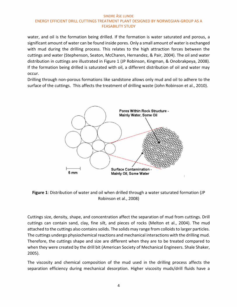
water, and oil is the formation being drilled. If the formation is water saturated and porous, a
significant amount of water can be found inside pores. Only a small amount of water is exchanged
with mud during the drilling process. This relates to the high attraction forces between the
cuttings and water (Stephenson, Seaton, McCharen, Hernandez, & Pair, 2004). The oil and water
distribution in cuttings are illustrated in Figure 1 (JP Robinson, Kingman, & Onobrakpeya, 2008).
If the formation being drilled is saturated with oil, a different distribution of oil and water may
occur.
Drilling through non-porous formations like sandstone allows only mud and oil to adhere to the
surface of the cuttings. This affects the treatment of drilling waste (John Robinson et al., 2010).
Figure 1: Distribution of water and oil when drilled through a water saturated formation (JP
Robinson et al., 2008)
Cuttings size, density, shape, and concentration affect the separation of mud from cuttings. Drill
cuttings can contain sand, clay, fine silt, and pieces of rocks (Melton et al., 2004). The mud
attached to the cuttings also contains solids. The solids may range from colloids to larger particles.
The cuttings undergo physiochemical reactions and mechanical interactions with the drilling mud.
Therefore, the cuttings shape and size are different when they are to be treated compared to
when they were created by the drill bit (American Society of Mechanical Engineers. Shale Shaker,
2005).
The viscosity and chemical composition of the mud used in the drilling process affects the
separation efficiency during mechanical desorption. Higher viscosity muds/drill fluids have a

SINDRE ÅSE LUNDE
ENERGY EFFICIENT DRILL CUTTINGS TREATMENT PLANT DESIGNED BY NORWEGIAN-GROUP AS A FEASABILITY STUDY
5
tendency to allow more mud to coat or stick to the surface. High concentration of emulsifiers and
wettings agents can also decrease the separation degree (Cannon & Martin, 2001).
Large dense particles are considered the easiest to separate from mud during mechanical
desorption (American Society of Mechanical Engineers. Shale Shaker, 2005).
The typical oil content on cuttings sent to secondary treatment is in the range of 10-15 percent
ROC by weight. The water content is typically around 10 percent (John Robinson et al., 2010).
Recovering and reusing the mud or oil is considered good economical practice.
The amount of hydrocarbons, metals, and radioactivity imposes a risk of effecting biology when
disposing cuttings. The amount of hydrocarbons and radioactive waste affects the environment
significantly. The metals present may be associated with environmental negative effects (Breuer,
Stevenson, Howe, Carroll, & Shimmield, 2004).
2.2 Cuttings handling and cost Operators have made an effort in order to reduce the amount of oily drilling waste generated.
This relates to the type of drilling mud utilized, recirculation system and by pledging the mud
suppliers to by the used drilling fluid (mud). Maximum profit was then achieved by re-using the
drilling fluid.
The general trend is that more demanding wells are drilled. This requires high performance
drilling fluid that offers both optimum wellbore stability and drilling efficiency. Oil based mud are
used for this purpose. The drilling waste generation will therefore likely increase (Svensen &
Taugbol, 2011).
An evaluation of oil contaminated waste offshore was performed by Den Norske Veritas (DNV,
2013) for Oljeindustriens Landsforening (OLF) based on a request from Klima og
Forurensningsdirektoratet (Klif). The report was handed to Klif 8.juni 2012. The evaluation (DNV,
2013) included historical handling, prognosis, costs, and environmental consequences of different
waste handling options for drilling waste on Norwegian continental shelf (NCS).
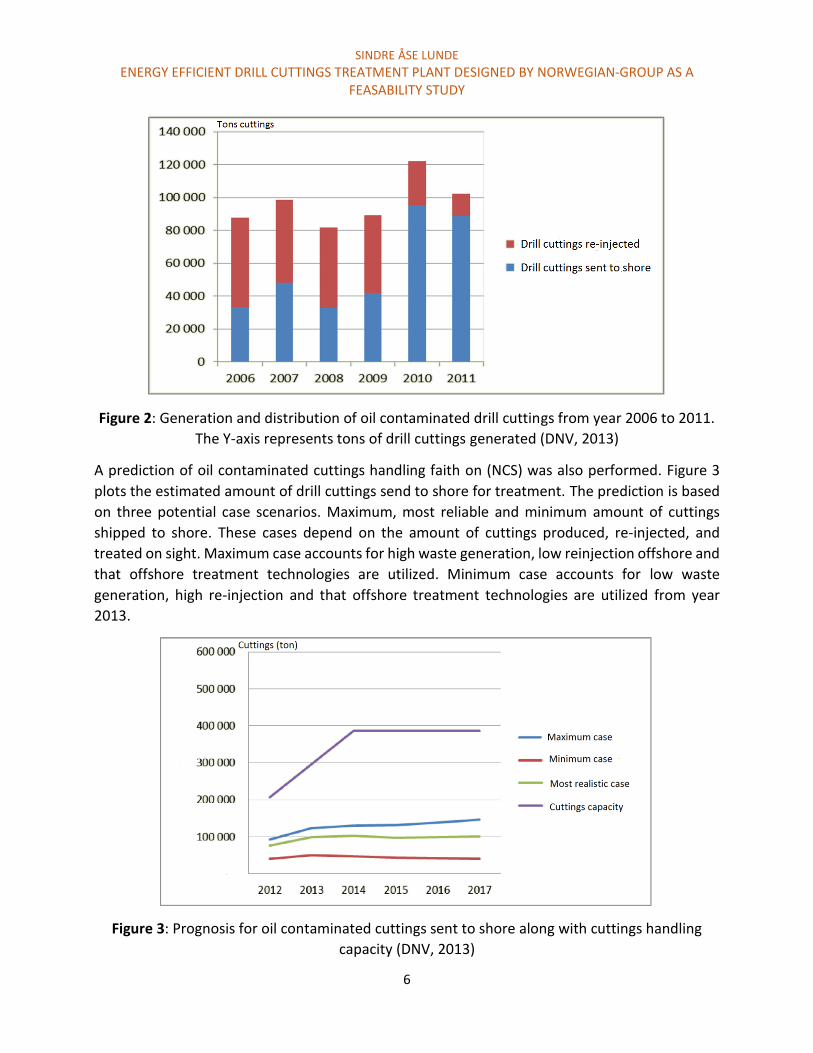
The oil contaminated cuttings waste generation was relative stable in the time-period from 2006
to 2011. The handling of the cuttings did however shift. This is illustrated in Figure 2, which reviles
that in 2010 and 2011 an increased amount of cuttings were shipped to shore. This relates to
problems associated with injection wells leakage.
SINDRE ÅSE LUNDE
ENERGY EFFICIENT DRILL CUTTINGS TREATMENT PLANT DESIGNED BY NORWEGIAN-GROUP AS A FEASABILITY STUDY
6
Figure 2: Generation and distribution of oil contaminated drill cuttings from year 2006 to 2011.
The Y-axis represents tons of drill cuttings generated (DNV, 2013)
A prediction of oil contaminated cuttings handling faith on (NCS) was also performed. Figure 3
plots the estimated amount of drill cuttings send to shore for treatment. The prediction is based
on three potential case scenarios. Maximum, most reliable and minimum amount of cuttings
shipped to shore. These cases depend on the amount of cuttings produced, re-injected, and
treated on sight. Maximum case accounts for high waste generation, low reinjection offshore and
that offshore treatment technologies are utilized. Minimum case accounts for low waste
generation, high re-injection and that offshore treatment technologies are utilized from year
2013.
Figure 3: Prognosis for oil contaminated cuttings sent to shore along with cuttings handling
capacity (DNV, 2013)

SINDRE ÅSE LUNDE
ENERGY EFFICIENT DRILL CUTTINGS TREATMENT PLANT DESIGNED BY NORWEGIAN-GROUP AS A FEASABILITY STUDY
7
The cost associated with the three different handling options are summarized in table 1. The re-
injection cost was considered dependent on field-specific conditions. This includes amount of
cuttings re-injected and the expected lifetime of the deposit well. The cost of 9600 NOK/ton was
calculated based on an expected well lifetime of 5 years and with an injection rate of 8000 tons
mud and cuttings at a 1:1 ratio by weight per year (DNV, 2013).
Table 1: Cost associated with drill waste handling (DNV, 2013)
Waste handling option Cost (per ton cuttings)
Transport and handling of cuttings on
shore 9000 NOK
Cuttings re-injection 9600 NOK Cuttings treatment offshore 6500 NOK
The potential cost savings achieved when treating cuttings offshore is considered a huge
motivation to develop sustainable and efficient treating solutions offshore. In the prognosis
presented in Figure 3, all scenarios accounts for that offshore treatment of cuttings are applied.
Environmental effects and CO2 emissions was also discussed in the report. The CO2 emissions for
the three different faiths were expected to be about the same (DNV, 2013).
2.3 Discharge regulations The environmental legislation varies between oil producing regions. It varies from “zero
discharge” like in Kazakhstan’s Caspian Sea and Nigeria to less strict requirements. The North
Western coast follows legislation requirements from OSPAR. This includes that cuttings cannot
be discharged unless the ROC is less than one percent by weight. For other regions, the maximum
ROC is 6.9% and 10%. This is relevant for Gulf of Mexico and in many parts of South East Asia
respectfully. It is important to notice that the permission of allowable oil content is not directly
comparable. This relates to restriction of the type of oil being used in the mud, and that the
percentage may be calculated on a different baseline (Kirkness, 2008).

SINDRE ÅSE LUNDE
ENERGY EFFICIENT DRILL CUTTINGS TREATMENT PLANT DESIGNED BY NORWEGIAN-GROUP AS A FEASABILITY STUDY
8
OSPAR COMMISSION
OSPAR is the mechanism by which fifteen governments of the western coasts and catchments
collaborate with the European Union to protect marine environment of the North-East Atlantic
Ocean (OSPAR1, 2014). The OSPAR convention was generated during a unification of the Oslo
Convention and the Paris Convention in 1992. Certain principles rely on the counteracting parties
(OSPAR3, 2014). An important principle that relates to this feasibility study is the Best Available
Techniques (BAT) and Best Environmental Practice (BEP). The OSPAR convention require
appliance of (BAT) and (BEP) in their effort to prevent and eliminate marine pollution. This is
based on adopted recommendations and decisions on BAT and BEP from various industrial
technologies and sources of land-based pollution. The BAT and BEP is constantly under
development and it is based on technological advances, economic and social factors, as well as
changes in knowledge and understanding.
The cuttings treatment plant must therefore be considered as BAT and BET in order to be used
for treating cuttings in the North-East Atlantic.
The OSPAR convention and commission have worked out the decisions and recommendations for
discharge of chemicals and oil. Among these recommendations relies Decision 2000/3
(OSPAR2000/3, 2000). The operators are to obtain permission to use organic-phase drilling fluid.
Use of diesel in drilling fluid and discharge of organic-phase drilling fluid to sea are banned. If the
concentration of oil on dry cuttings are reduced to less than 1 percent by weight, the cuttings can
be discharged. Disposal of cuttings contaminated by synthetic based mud shall not be granted if
it is not absolutely required with regards to BAT and BET.
Norway is influenced by OSPAR since they are a counteracting party. The Norwegian
environmental agency (Miljødirektoratet, 2014) governs the offshore oil and gas industry. The
discharge permits are given according to the pollution law (Forurensningsloven, 2014). The
evaluations of discharge applications rest upon Aktivitetsforeskriften (Aktivitetsforeskriften,
2010). This describes how activities in the oil and gas industry shall be performed.
§60 - Oil content in water discharged to sea should not exceed 30 mg oil per liter water as
an average in a calendar month.
§68 - Discharge of solids containing more than 1% oil by weight is forbidden
The Environmental protection agency requires strict discharge limits in the upcoming drilling
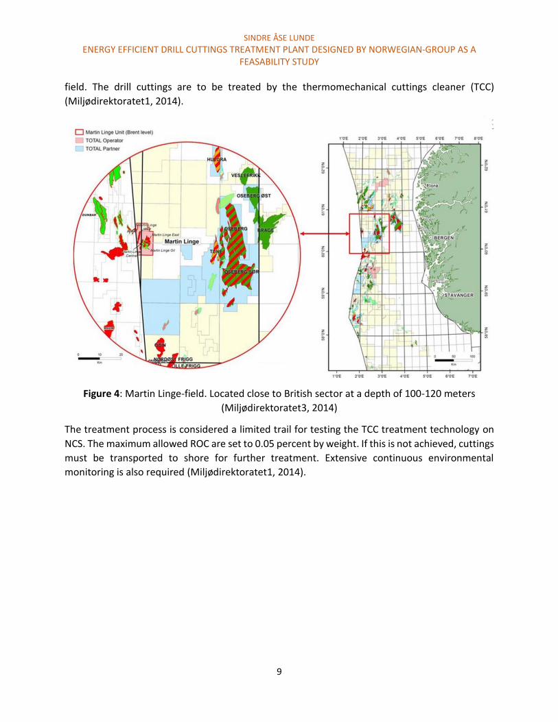
process at the Martin Linge-field. The field is located in the North Sea as illustrated in Figure 4.
Offshore treatment of drill cuttings on NCS will be performed for the first time the Martin Linge-
SINDRE ÅSE LUNDE
ENERGY EFFICIENT DRILL CUTTINGS TREATMENT PLANT DESIGNED BY NORWEGIAN-GROUP AS A FEASABILITY STUDY
9
field. The drill cuttings are to be treated by the thermomechanical cuttings cleaner (TCC)
(Miljødirektoratet1, 2014).
Figure 4: Martin Linge-field. Located close to British sector at a depth of 100-120 meters
(Miljødirektoratet3, 2014)
The treatment process is considered a limited trail for testing the TCC treatment technology on
NCS. The maximum allowed ROC are set to 0.05 percent by weight. If this is not achieved, cuttings
must be transported to shore for further treatment. Extensive continuous environmental
monitoring is also required (Miljødirektoratet1, 2014).

SINDRE ÅSE LUNDE
ENERGY EFFICIENT DRILL CUTTINGS TREATMENT PLANT DESIGNED BY NORWEGIAN-GROUP AS A FEASABILITY STUDY
10
Chapter 3: Waste Management
Waste management involves waste prevention, handling options and disposal. Good waste
management includes low cost and high environmental benefits. Figure 5 illustrates strategies in
order to achieve the optimum waste management. The strategy is based on report 093
recommended guideline for waste management in the offshore industry. This report is provided
by Norwegian oil and gas association (The Norwegian Oil and Gas Association, 2013)
Figure 5: The waste handling triangle (The Norwegian Oil and Gas Association, 2013)
Preventing waste is considered the best solution. This reduced the costs and is environmental
beneficial. Waste prevention can be achieved through several different strategies at the drilling
sight. Using WBM allows for direct dumping of cuttings. This reduces the overall waste generated
and the associated handling costs (Svensen & Taugbol, 2011).
Slim-hole design is based on drilling wells with smaller diameter compared to conventional wells.
This action is typically more relevant for explorations wells.
Multilateral well design where several lateral wells are starting from one main wellbore may also
reduce the drilling waste (Miljødirektoratet4, 2008).
Another possibility is to re-use the drilling mud retained on the cuttings. This is relevant in both
the primary and secondary treatments. Desorption technologies that allow for clean cuttings and
reusable oil is associated with mechanical or thermal desorption. Bioremediation and incineration
does not allow for mud recovery.
SINDRE ÅSE LUNDE
ENERGY EFFICIENT DRILL CUTTINGS TREATMENT PLANT DESIGNED BY NORWEGIAN-GROUP AS A FEASABILITY STUDY
11
3.1 Treatment and disposal options for drill cuttings Drilling waste containing oily cuttings must be handled according to the legislations that are
discussed in Chapter 2.3. There are several different cuttings handling options.
The first separation stage of cuttings and mud n is the primary treatment. As mentioned earlier,
primary treatment has an aim to maximize the recovery of mud, while removing drill cuttings.
The configuration may vary in this treatment and it is depending upon the specific solid control
and treatment requirements for the well (Charles et al., 2010)
Secondary treatment involves handling oily cuttings from the primary treatment. This can be done
by cuttings re-injection (CRI), desorption offshore, or ship to shore for handling. These handling
concepts are presented in Chapter 3.2.
Ship to shore includes treating cuttings on shore using while several different methods. Shipping
to shore for treatment is considered expensive and has several limitations with respect to the
transport (DNV, 2013; Svensen & Taugbol, 2011). Neither onshore waste handling options nor
technologies that does not allow desorption offshore, or reuse of oil retained on cuttings are
discussed in this chapter. These handling options include:
Bioremediation/Land farming
Incineration
Indirect thermal desorption
Dispersion by chemical reaction
The overall challenge with separation oil from cuttings relies on the distribution of oil in the mud
and cuttings. Cuttings waste includes:
1. Free oil intermixed with water and cuttings
2. Oil emulsified with water
3. Oil found within the interstices of the cuttings
During thermal desorption, free and emulsified oil are separated with ease as enough energy is
provided to evaporate oil and water. Removing interstitial oil such as crude oil is considered more
challenging.
Drilling fluid may exchange with water under intense heat and pressure as a result of drilling. The
reason for the low interstitial exchange between water and oil has to do with molecular forces.
The molecular forces between water and cuttings exhibit stronger attraction than cuttings and
oil. The attraction force includes capillary force. This force is linked to surface tension, and

SINDRE ÅSE LUNDE
ENERGY EFFICIENT DRILL CUTTINGS TREATMENT PLANT DESIGNED BY NORWEGIAN-GROUP AS A FEASABILITY STUDY
12
molecular interaction. The oil and water trapped inside the pores are considered tightly bound.
The interstices or pores are typically in the range of 10 to 100 microns in diameter. The overall
consequence relating to thermal desorption is that higher levels of heat is required in order to
remove this oil and water. The need to separate interstitial oil could be relevant in order to
achieve lower than 1% ROC (Stephenson et al., 2004). The TCC offers a great method to remove
interstitial oil, which will be discussed in Chapter 3.2.3.2. The cuttings are crushed in the heating
process. This results in less diffusion distance for the oil trapped inside pores. High treatment
capacity and oil removal efficiency could then be achieved (Murray et al., 2008).
3.2 Cuttings handling offshore After the primary treatment, there is a need for further treatment of oil contaminated drill
cuttings before discharge. The amount of waste to be handled depends on the section (hole-
diameter) and length of the well. In table 2, waste generation from a generic well from NCS is
used as an example. In this example, oil based mud from lower sections was evaluated. The
estimated washout factor is 0.1 and an oil on cuttings adherence of 0.5 when the cuttings have
passed the shakers.
Table 2: Cuttings volume balance for a generic well (Svensen & Taugbol, 2011)
Section
(hole diameter inch)
OBM 17 . 𝟓 " OBM 12 . 𝟐𝟓 " OBM 8.5 " Total all OBM
sections
Section length
(m)
1727 1386 569 3682
ROP (m/h)
Max-avg
60-40 45-30 30-15 60-15
Estimated weight
(ton/h)
Max-avg
32-21 12-8 4-2 32-2
Estimated volume
(m3/h)
Max-avg
14-9 5-4 1.5-1 14-1
Cuttings generated
(ton)
958 377 74 1409
Cuttings generated
(m3)
415 163 33 611
In order to avoid accumulation and storage of waste on the drilling rig, the handling options must
offer high capacity. The cuttings waste generation rate depends on rate of penetration (ROP) and
section diameter. Table 2 represents the max and average of ROP, weight, and volume of drill
SINDRE ÅSE LUNDE
ENERGY EFFICIENT DRILL CUTTINGS TREATMENT PLANT DESIGNED BY NORWEGIAN-GROUP AS A FEASABILITY STUDY
13
cuttings generated. High ROP generates larger cuttings that is more easily treated (American
Society of Mechanical Engineers. Shale Shaker, 2005). Cuttings re-injection, offshore treatment,
or ship to shore is possible waste handling options. A combination of these handling options or
reducing the ROP may be necessary in order to continuously handle the waste generated
(Svensen & Taugbol, 2011).
3.2.1 Ship to shore Ship to shore involves loading drilling waste on to a supply vessel to transport the waste to shore.
Cuttings are transported to skips from the chute via blowers or conveyors. Skips may also be
referred to as boxes or containers. Typical volume of the skips is 3.6 m3 or 4 m3 with open or
closed lid. The filled skips are then lifted and replaced by crane lifts from the drilling rig, to a
supply vessel. This handling option has limitations with respect to lifting capacity and HSE issues.
Drilling waste may be generated faster than the ability to lift the skips on to the supply vessel.
High deck space, weight, and weather dependency is also negative consequences (Svensen &
Taugbol, 2011).
Slurryfication of the cuttings and pumping the waste on to the supply vessel are also a possible
option. By doing so, the drilling waste volume increases. The volume may increase by a factor of
5 to 6. As a consequence, high cost and emissions would appear. Slurryfication will also affect the
treatment onshore in a negative manner (Svensen & Taugbol, 2011).
Bulk transfer is considered a robust and environmental friendly solution for transporting cuttings
the supply vessel. The transport system uses a holding tank along with a pneumatic pumping
system. The cuttings are transported to the supply vessel with a hose. The cuttings are at their
original shape, and no extra volume of waste is generated. Crane lifts are only necessary during
mobilization and demobilization, and when hooking the hose to the ship. The technology has
been used by Statoil for several years. However, a significant deck space is required. Continuous
handling of waste from 17.5 inch section with average ROP for 12 hour requires back-up solutions.
Using two independent transfer lines could allow average ROP of 30-40 m/h. Pipe clogging and
harsh weather conditions are considered limitations (Svensen & Taugbol, 2011).
In general, shipping to shore is associated with relative high costs (DNV, 2013), and this handling
option may limit the drilling process with respect to weather conditions and low continuous
handling capacity (Svensen & Taugbol, 2011).

SINDRE ÅSE LUNDE
ENERGY EFFICIENT DRILL CUTTINGS TREATMENT PLANT DESIGNED BY NORWEGIAN-GROUP AS A FEASABILITY STUDY
14
3.2.2 Cuttings Re-injection Cuttings re-injection (CRI) is a process in were solids (cuttings) and liquids (waste fluids) are
converted into a slurry. The slurry is then hydraulically injected into a subsurface formation that
is considered receptive and permanently isolated (Alba Rodriguez, Fragachan, Ovalle, &
Shokanov, 2007). The main advantages of CRI are:
Providing zero discharge politic
Reducing logistical burden
Limited risk of environmental discharge during transportation
In-situ handling
The cuttings reinjection system comprises of three principal components. This include cuttings
transport system, slurryfication system and re-injection system (Alba Rodriguez et al., 2007). The
basic equipment is illustrated in Figure 6.
Figure 6: Drill cuttings slurry fabrication and injection system (Guo & Abou-Sayed, 2003)
The direct cuttings injection regulation and permitting requirements are often dealt with through
regional agreements in certain marine areas, and through national legislation. Not all regulations
allows for CRI (Guo & Abou-Sayed, 2003). Re-injection of drilling waste has been extensively used
on NCS since 1990 (DNV, 2013). This waste handling options are generally considered
environmentally friendly and cost effective (Alba Rodriguez et al., 2007; Guo & Abou-Sayed,
2003). However, several incidents related to cracking and leakage of the slurry has been
experienced on NCS. Extensive supervision and research on suitable injection formation is
therefore required. Den Norske Veritas (DNV, 2013) estimated this handling option to be the most
expensive.
SINDRE ÅSE LUNDE
ENERGY EFFICIENT DRILL CUTTINGS TREATMENT PLANT DESIGNED BY NORWEGIAN-GROUP AS A FEASABILITY STUDY
15
3.2.3 Desorption offshore Desorption and treating cuttings offshore offer great potential advantages with respect to
handling costs and the convenience of potential continuous waste handling in various weather
conditions. Reusing oil or mud reduces the overall waste generation and cost. The two most
common methods for desorption of oil are cuttings dryers and thermal desorption. Cuttings
dryers are typically used to recover synthetic based mud on the drilling rig. The technology does
not achieve sufficient separation degree according to OSPAR legislations with respect to ROC for
NABM. Thermal desorption can achieve well below these requirements (less than 1 percent ROC
by weight) (Charles et al., 2010). Oil and water can often be used in new drilling mud.
3.2.3.1 Cuttings dryer The cuttings dryer is based on mechanical desorption of cuttings by using horizontal or vertical
high-speed centrifuges (Seaton & Hall, 2005). Vertical basket centrifuges have been used in the
mining industry for more than 40 year to dry water-wet coal and other process minerals. These
centrifuges were designed to process large volumes at high process rates. The technology was
adapted to cuttings treatment. The intended application was to reuse synthetic base mud and
allow the cuttings to be discharged offshore (Cannon & Martin, 2001).
The cuttings dryer designed for reusing synthetic based mud involves a two-part process. A basket
centrifuge for desorbing oil from the contaminated cuttings. The separated mud is then subjected
to a high-speed centrifuge to remove colloids and particles. Required mud properties are than
fulfilled, and the mud may be reused (Cannon & Martin, 2001; Seaton & Hall, 2005). The design
of the basket centrifuge allows for different configurations. This is with respect to feed, discharge,
and recondition of recovered drilling fluid.
The feeding of cuttings from the shale shaker can be done by gravity, augers or by vacuum
transport. Figure 7 illustrates the working principle of a vertical basket centrifuge and Figure 8
illustrates a typical horizontal cuttings dryer installation

SINDRE ÅSE LUNDE
ENERGY EFFICIENT DRILL CUTTINGS TREATMENT PLANT DESIGNED BY NORWEGIAN-GROUP AS A FEASABILITY STUDY
16
Figure 7: Working principle of a Vertical basket centrifuge
(Cannon & Martin, 2001)
Figure 8: Horizontal cuttings dryer installation (American Society of Mechanical Engineers. Shale
Shaker, 2005)

SINDRE ÅSE LUNDE
ENERGY EFFICIENT DRILL CUTTINGS TREATMENT PLANT DESIGNED BY NORWEGIAN-GROUP AS A FEASABILITY STUDY
17
The vertical basket centrifuge utilizes a wire screen that rotates at 667 rpm resulting in a G-force
of 230 G (Cannon & Martin, 2001). The separation relates to Stokes law. The performance and
separation efficiency depend on properties of the drilling fluid and the drill cuttings (Cannon &
Martin, 2001). Some factors effecting the separation efficiency include:
Viscosity
Temperature of the drilling waste
Particle size (cuttings characteristics)
Mineral composition of the drilled formation
Density and chemical composition of the drilling fluid
To determine the separation degree of the vertical basket centrifuge, data from 23 wells was
collected. The average ROC after primary treatment was 11.47 percent by weight. The cuttings
dryer reduced the ROC to 3.99 percent. This resulted in 65 percent reduction. The total amount
recovered drilling fluid in this process was 14.140 bbls (615bbls per well). This gave a total drilling
fluid savings valued to 2.83 million US$ (Cannon & Martin, 2001). In a statement by S. Seaton
(Seaton & Hall, 2005), a ROC reduction down to Three to five percent is to be expected. For
demanding conditions, one could expect a ROC at around five percent or even higher.
The cuttings dryer is considered the only desorption technology that can continuously handle
cuttings as they are generated, while achieving less than 4 percent ROC by weight (American
Society of Mechanical Engineers. Shale Shaker, 2005).
Challenges associated with the technology are centered on transportation of cuttings to and from
the vertical basket centrifuge. More complex transport equipment increases the likelihood of
stoppage problems (Cannon & Martin, 2001).
One important consideration related to the treatment plant of Norwegian-Groups AS is the total
weight and deck space. Since a modified cuttings dryer is considered one of the separation
methods, the overall required deck space is of great relevance. Figure 8 illustrates the typical size
of a horizontal cuttings dryer installation on a jack up rig. The plant is fitted with two high-speed
centrifuges processing in series for removing low-gravity solids. The pumps and process thanks
are placed beneath the process equipment.
.
SINDRE ÅSE LUNDE
ENERGY EFFICIENT DRILL CUTTINGS TREATMENT PLANT DESIGNED BY NORWEGIAN-GROUP AS A FEASABILITY STUDY
18
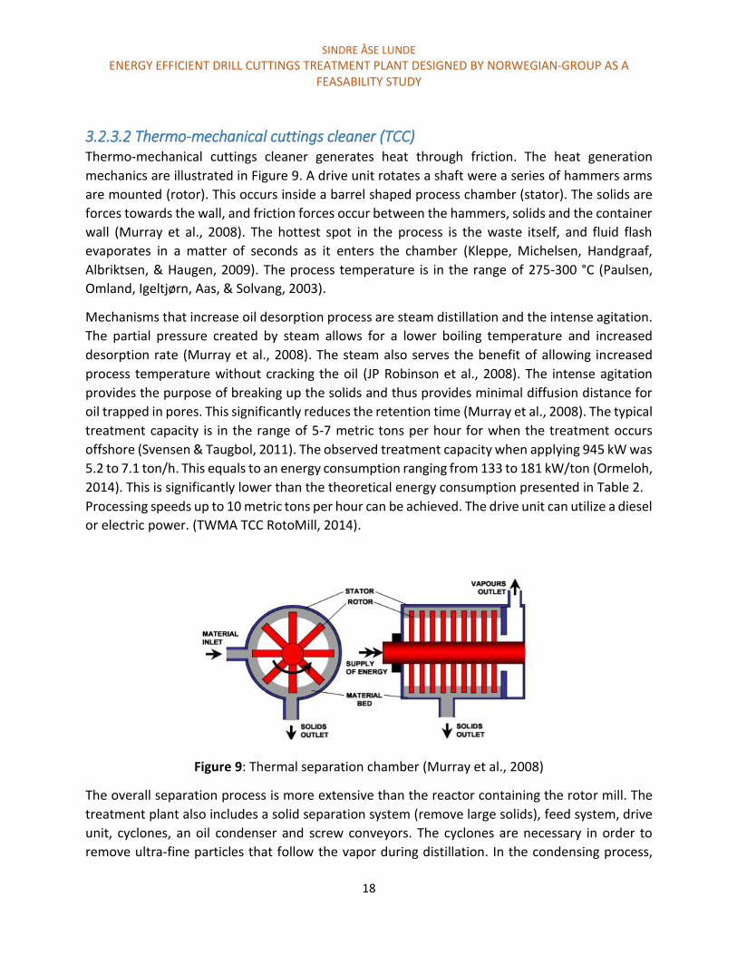
3.2.3.2 Thermo-mechanical cuttings cleaner (TCC) Thermo-mechanical cuttings cleaner generates heat through friction. The heat generation
mechanics are illustrated in Figure 9. A drive unit rotates a shaft were a series of hammers arms
are mounted (rotor). This occurs inside a barrel shaped process chamber (stator). The solids are
forces towards the wall, and friction forces occur between the hammers, solids and the container
wall (Murray et al., 2008). The hottest spot in the process is the waste itself, and fluid flash
evaporates in a matter of seconds as it enters the chamber (Kleppe, Michelsen, Handgraaf,
Albriktsen, & Haugen, 2009). The process temperature is in the range of 275-300 °C (Paulsen,
Omland, Igeltjørn, Aas, & Solvang, 2003).
Mechanisms that increase oil desorption process are steam distillation and the intense agitation.
The partial pressure created by steam allows for a lower boiling temperature and increased
desorption rate (Murray et al., 2008). The steam also serves the benefit of allowing increased
process temperature without cracking the oil (JP Robinson et al., 2008). The intense agitation
provides the purpose of breaking up the solids and thus provides minimal diffusion distance for
oil trapped in pores. This significantly reduces the retention time (Murray et al., 2008). The typical
treatment capacity is in the range of 5-7 metric tons per hour for when the treatment occurs
offshore (Svensen & Taugbol, 2011). The observed treatment capacity when applying 945 kW was
5.2 to 7.1 ton/h. This equals to an energy consumption ranging from 133 to 181 kW/ton (Ormeloh,
2014). This is significantly lower than the theoretical energy consumption presented in Table 2.
Processing speeds up to 10 metric tons per hour can be achieved. The drive unit can utilize a diesel
or electric power. (TWMA TCC RotoMill, 2014).
Figure 9: Thermal separation chamber (Murray et al., 2008)
The overall separation process is more extensive than the reactor containing the rotor mill. The
treatment plant also includes a solid separation system (remove large solids), feed system, drive
unit, cyclones, an oil condenser and screw conveyors. The cyclones are necessary in order to
remove ultra-fine particles that follow the vapor during distillation. In the condensing process,

SINDRE ÅSE LUNDE
ENERGY EFFICIENT DRILL CUTTINGS TREATMENT PLANT DESIGNED BY NORWEGIAN-GROUP AS A FEASABILITY STUDY
19
seawater, cooling towers or radiators are utilized. In Figure 10, the total TCC process plant is
illustrated.
Figure 10: TCC process plant (Murray et al., 2008)
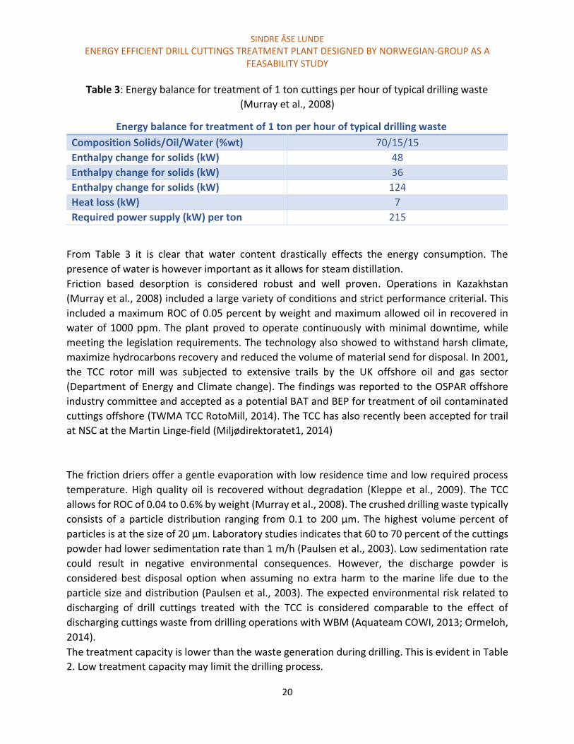
As previous mentioned the energy consumption is typically from 131 to 181 kW/ton cuttings.
However, the theoretical energy consumption when treating drilling waste with a solid/oil/water
ratio of 70/15/15 percent is calculated to be 215 kW/ton. This calculation is based on energy
required to increase the temperature of the drilling waste from a feed temperature (20 °C) to a
process temperature of 300 °C. The energy balance is presented in Table 3 (Murray et al., 2008).
SINDRE ÅSE LUNDE
ENERGY EFFICIENT DRILL CUTTINGS TREATMENT PLANT DESIGNED BY NORWEGIAN-GROUP AS A FEASABILITY STUDY
20
Table 3: Energy balance for treatment of 1 ton cuttings per hour of typical drilling waste
(Murray et al., 2008)
Energy balance for treatment of 1 ton per hour of typical drilling waste
Composition Solids/Oil/Water (%wt) 70/15/15
Enthalpy change for solids (kW) 48
Enthalpy change for solids (kW) 36
Enthalpy change for solids (kW) 124
Heat loss (kW) 7
Required power supply (kW) per ton 215
From Table 3 it is clear that water content drastically effects the energy consumption. The
presence of water is however important as it allows for steam distillation.
Friction based desorption is considered robust and well proven. Operations in Kazakhstan
(Murray et al., 2008) included a large variety of conditions and strict performance criterial. This
included a maximum ROC of 0.05 percent by weight and maximum allowed oil in recovered in
water of 1000 ppm. The plant proved to operate continuously with minimal downtime, while
meeting the legislation requirements. The technology also showed to withstand harsh climate,
maximize hydrocarbons recovery and reduced the volume of material send for disposal. In 2001,
the TCC rotor mill was subjected to extensive trails by the UK offshore oil and gas sector
(Department of Energy and Climate change). The findings was reported to the OSPAR offshore
industry committee and accepted as a potential BAT and BEP for treatment of oil contaminated
cuttings offshore (TWMA TCC RotoMill, 2014). The TCC has also recently been accepted for trail
at NSC at the Martin Linge-field (Miljødirektoratet1, 2014)
The friction driers offer a gentle evaporation with low residence time and low required process
temperature. High quality oil is recovered without degradation (Kleppe et al., 2009). The TCC
allows for ROC of 0.04 to 0.6% by weight (Murray et al., 2008). The crushed drilling waste typically
consists of a particle distribution ranging from 0.1 to 200 µm. The highest volume percent of
particles is at the size of 20 µm. Laboratory studies indicates that 60 to 70 percent of the cuttings
powder had lower sedimentation rate than 1 m/h (Paulsen et al., 2003). Low sedimentation rate
could result in negative environmental consequences. However, the discharge powder is
considered best disposal option when assuming no extra harm to the marine life due to the
particle size and distribution (Paulsen et al., 2003). The expected environmental risk related to
discharging of drill cuttings treated with the TCC is considered comparable to the effect of
discharging cuttings waste from drilling operations with WBM (Aquateam COWI, 2013; Ormeloh,
2014).
The treatment capacity is lower than the waste generation during drilling. This is evident in Table
2. Low treatment capacity may limit the drilling process.

SINDRE ÅSE LUNDE
ENERGY EFFICIENT DRILL CUTTINGS TREATMENT PLANT DESIGNED BY NORWEGIAN-GROUP AS A FEASABILITY STUDY
21
3.1 Upcoming technologies for treating cuttings offshore The TCC offers a highly effective desorption solution, and will be tested offshore on NCS.
However, there is a demand for a better solution. Upcoming technologies may have the potential
to achieve this by implementing better separation processes that leads to higher capacity, less
energy consumption, robust and easy waste handling.
3.3.1 Microwave assisted nitrogen stripping The research done by J.P Robison evolved from a laboratory bench test (JP Robinson et al., 2008)
in to a pilot scale that allowed for continuous treating of drill cuttings (John Robinson et al., 2010;
John Robinson et al., 2008). During the laboratory test, research regarding the principles of both
microwave assisted steam stripping and nitrogen stripping was performed. The article concluded
that nitrogen gas was more suited to be combine with microwave heating. The laboratory
research involved into a cuttings treatment solution at pilot scale. The early research relates a
great deal to the thermal separation chamber in the treatment plant concept of Norwegian-Group
AS. The effect of steam stripping and microwave heating is presented in Chapter 4.2.2 and 4.3
respectfully.
The pilot scale cuttings treatment plant (John Robinson et al., 2010; John Robinson et al., 2008)
offers a treatment capacity of 500 kg cuttings per hour. A small footprint is achieved, with an
energy consumption of 100 kW per ton cuttings. The recovered oil is suitable for reuse. The
energy consumption is lower than for the TCC. This may be a result of lower process temperature.
The bulk temperature of microwave assisted nitrogen stripping do not exceed 55 ᵒC during
desorption.
Parameters such as bed depth, packing density, moisture content should be closely monitored.
This relates to microwave absorbance, microwave penetration depth, bulk temperature, oil
removal performance, and treatment capacity (John Robinson et al., 2010).
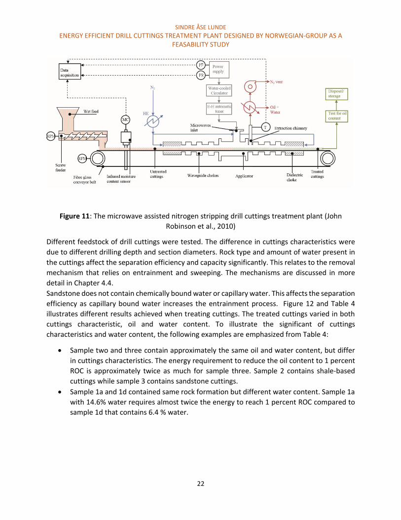
The plant setup utilizes a 30 kW microwave generator (magnetron) at 2.45 GHz. Nitrogen is
introduced into the cavity at three points. Nitrogen acts as a sweep gas and provide an inert
environment. A schematic of the plant setup is presented in the Figure 11 (John Robinson et al.,
2010).
SINDRE ÅSE LUNDE
ENERGY EFFICIENT DRILL CUTTINGS TREATMENT PLANT DESIGNED BY NORWEGIAN-GROUP AS A FEASABILITY STUDY
22
Figure 11: The microwave assisted nitrogen stripping drill cuttings treatment plant (John
Robinson et al., 2010)
Different feedstock of drill cuttings were tested. The difference in cuttings characteristics were
due to different drilling depth and section diameters. Rock type and amount of water present in
the cuttings affect the separation efficiency and capacity significantly. This relates to the removal
mechanism that relies on entrainment and sweeping. The mechanisms are discussed in more
detail in Chapter 4.4.
Sandstone does not contain chemically bound water or capillary water. This affects the separation
efficiency as capillary bound water increases the entrainment process. Figure 12 and Table 4
illustrates different results achieved when treating cuttings. The treated cuttings varied in both
cuttings characteristic, oil and water content. To illustrate the significant of cuttings
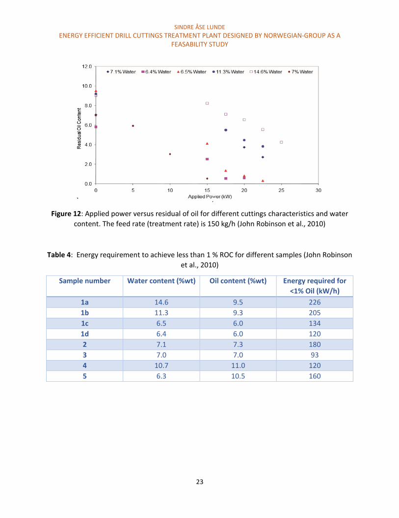
characteristics and water content, the following examples are emphasized from Table 4:
Sample two and three contain approximately the same oil and water content, but differ
in cuttings characteristics. The energy requirement to reduce the oil content to 1 percent
ROC is approximately twice as much for sample three. Sample 2 contains shale-based
cuttings while sample 3 contains sandstone cuttings.
Sample 1a and 1d contained same rock formation but different water content. Sample 1a
with 14.6% water requires almost twice the energy to reach 1 percent ROC compared to
sample 1d that contains 6.4 % water.
SINDRE ÅSE LUNDE
ENERGY EFFICIENT DRILL CUTTINGS TREATMENT PLANT DESIGNED BY NORWEGIAN-GROUP AS A FEASABILITY STUDY
23
Figure 12: Applied power versus residual of oil for different cuttings characteristics and water
content. The feed rate (treatment rate) is 150 kg/h (John Robinson et al., 2010)
Table 4: Energy requirement to achieve less than 1 % ROC for different samples (John Robinson
et al., 2010)
Sample number Water content (%wt) Oil content (%wt) Energy required for
<1% Oil (kW/h)
1a 14.6 9.5 226
1b 11.3 9.3 205
1c 6.5 6.0 134
1d 6.4 6.0 120
2 7.1 7.3 180
3 7.0 7.0 93
4 10.7 11.0 120
5 6.3 10.5 160

SINDRE ÅSE LUNDE
ENERGY EFFICIENT DRILL CUTTINGS TREATMENT PLANT DESIGNED BY NORWEGIAN-GROUP AS A FEASABILITY STUDY
24
Figure 13 illustrates a trend of increased energy requirements when removing oil to lower than 1
percent ROC. A 15 kW power source is utilized. Removing oil down to 1 percent offers a linear
relationship between energy requirement and ROC. When removing ROC to lower than 1 percent,
an exponential relationship is evident (John Robinson et al., 2008).
Figure 13: Energy requirement plotted against ROC for cuttings with different oil and water
content (John Robinson et al., 2008)
The definition of dry, medium and wet cuttings are listed up below:
Dry: oil/water = 5% and 6 %
Medium : oil/water = 7% and 6%
Wet: oil/water 11% and 6%
SINDRE ÅSE LUNDE
ENERGY EFFICIENT DRILL CUTTINGS TREATMENT PLANT DESIGNED BY NORWEGIAN-GROUP AS A FEASABILITY STUDY
25
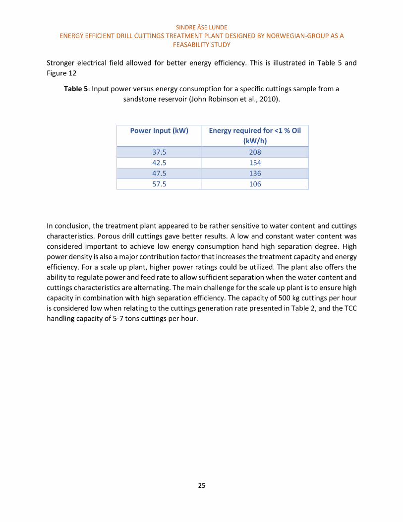
Stronger electrical field allowed for better energy efficiency. This is illustrated in Table 5 and
Figure 12
Table 5: Input power versus energy consumption for a specific cuttings sample from a
sandstone reservoir (John Robinson et al., 2010).
Power Input (kW) Energy required for <1 % Oil
(kW/h)
37.5 208
42.5 154
47.5 136
57.5 106
In conclusion, the treatment plant appeared to be rather sensitive to water content and cuttings
characteristics. Porous drill cuttings gave better results. A low and constant water content was
considered important to achieve low energy consumption hand high separation degree. High
power density is also a major contribution factor that increases the treatment capacity and energy
efficiency. For a scale up plant, higher power ratings could be utilized. The plant also offers the
ability to regulate power and feed rate to allow sufficient separation when the water content and
cuttings characteristics are alternating. The main challenge for the scale up plant is to ensure high
capacity in combination with high separation efficiency. The capacity of 500 kg cuttings per hour
is considered low when relating to the cuttings generation rate presented in Table 2, and the TCC
handling capacity of 5-7 tons cuttings per hour.

SINDRE ÅSE LUNDE
ENERGY EFFICIENT DRILL CUTTINGS TREATMENT PLANT DESIGNED BY NORWEGIAN-GROUP AS A FEASABILITY STUDY
26
3.3.2 Liquefied gas extraction Solvent extraction builds on the principle of dissolve and separate oil retained on cuttings. This is
typically achieved by increasing the temperature and pressure of the solvent gas so that it reaches
its critical point and beyond. At this state, the increased thermodynamically energy causes the
forces at the molecule level to equalize. The gas exhibits liquid and gas properties by having high
density, diffusivity, and low viscosity. Supercritical fluids are proven good solvents of hydrophobic
molecules (Street, Tesche, & Guigard, 2009).
Carbon dioxide extraction was considered a potential solvent system. The cost associated with
such a system is extremely high. This was due to the high pressure and temperatures required
to:
1. Turn carbon dioxide into supercritical fluid
2. Treating the cuttings
3. Recover the extracted oil
Using other hydrocarbon gasses as solvents allow for lower pressures (40-100 psi) and
temperatures. Potentially lower treatment costs could then be achieved. However, the use of
hydrocarbon gasses could raise safety concerns (Seaton & Hall, 2005).
Laboratory test using CO2, butane and propane has been performed (Seaton & Hall, 2005; Street
et al., 2009). All gasses allowed high removal efficiency when using relatively small cuttings
samples (ranging from grams up to some kilograms). A full scale cuttings treatment plant was not
found in the literature.
3.3.3 Cutcube A relative new development for secondary treatment of cuttings are the Cutcube. Cutcube is
created by Cubility AS. Cubility AS offers a compact treatment solution intended for offshore
usage. It allows continuous feeding of oil contaminated cutting straight from the Mudcube or
shale shaker. The separation principle is based on thermal desorption. Distillate is condensed and
hydrocarbons are separated from water. The drilling fluid may be reused. The ROC are claimed to
be below 1 percent, and may be disposed at the drilling sight. Vacuum combined with a direct
electromagnetic heat source are utilized in the thermal desorption process. The type of
electromagnetic heat source was not reviled. In a patent application for treating drill cuttings,
microwave radiation was the heat source (Vasshus & Malmin, 2013). Their process video (Fabel
Media AS, 2014) published in May 2014 also reviles double screw conveyors in the process
chamber. Treating capacity and field-testing are not to be found in the literature.
SINDRE ÅSE LUNDE
ENERGY EFFICIENT DRILL CUTTINGS TREATMENT PLANT DESIGNED BY NORWEGIAN-GROUP AS A FEASABILITY STUDY
27
Chapter 4: The treatment plant concept of Norwegian-Group AS
Norwegian-Group AS offers a concept with a possibility to improve the current desorption
technologies and fulfill the markets need for a robust treatment plant that is able to treat drill
cuttings offshore with high separation degree, capacity with low energy consumption.
In this study, the treatment concept and possible solutions will be presented. The separation
principles that contribute or increase the oil separation process will also be presented.
The thermal desorption chamber is considered most important separation stage. Evaluating
potential heat sources is therefore considered the main objective of this thesis. Several heat
sources are to be discussed and reviewed based on its ability to work in combination with steam.
Potential heat sources are discussed in Chapter 4.3. Potential steam supply systems for the steam
assisted cuttings dryer, and an evaluation of the benefits or limitations of separating oil and steam
vapor by membranes to increase the energy efficiency will also be presented.
4.1 An outline of Norwegian Group AS treatment plant concept The treatment plant concept is illustrated in Figure 14.
Oil contaminated cuttings are transported into a steam assisted cuttings dryer. Steam will
potentially increase the oil removal efficiency. Condensed steam and mud is collected in tank
(A), while steam and oil vapor is transported for membrane separation.
The cuttings are transported from the cuttings dryer to the steam assisted thermal separation
chamber. A heat sources is combined with steam to desorb interstitial and surface oil. The
chamber must be able to handle drill cuttings continuously. Oil and steam vapor are transported
to the membrane for separation.
The membrane separates the oil and water vapor at gas phase. Clean steam permeates the
membrane and is reheated and reused. The retentate (pure oil) or a mixture of oil and water is
condensed. The cuttings are discharged.

SINDRE ÅSE LUNDE
ENERGY EFFICIENT DRILL CUTTINGS TREATMENT PLANT DESIGNED BY NORWEGIAN-GROUP AS A FEASABILITY STUDY
28
Figure 14: Cuttings treatment plant concept of Norwegian-Groups AS
SINDRE ÅSE LUNDE
ENERGY EFFICIENT DRILL CUTTINGS TREATMENT PLANT DESIGNED BY NORWEGIAN-GROUP AS A FEASABILITY STUDY
29
4.2 Separation principles The separation technologies utilized in this treatment plant includes:
1. Steam assisted cuttings dryer
2. Steam assisted thermal desorption
3. Membrane separation of oil and water vapor
The cuttings dryer is modified with steam assistance in order to increase the separation degree.
The steam supply system to the cuttings dryer is considered important in order to achieve
sufficient separation. Potential steam supply system is presented in Chapter 4.2.3.
The purpose separating oil and water vapor by a membrane is to reduce then energy
consumption and cuttings handling cost. An evaluation of the feasibility of energy and cost
savings is presented in Chapter 4.2.4.
Steam is supplied in the cuttings dryer and thermal separation chamber. Information about the
Super heated steam drying process presented in Chapter 4.2.2.
Steam distillation is an important mechanism that supports oil separation. The principle of
steam distillation is presented in Chapter 4.2.1.
The discussion is presented at the end of each individual sub chapter.
The steam assisted thermal desorption chamber is considered the most important separation
stage. Suitable heat sources for this application is presented and discussed in Chapter 4.3.
SINDRE ÅSE LUNDE
ENERGY EFFICIENT DRILL CUTTINGS TREATMENT PLANT DESIGNED BY NORWEGIAN-GROUP AS A FEASABILITY STUDY
30
4.2.1 Steam distillation The typical amount of oil and water after primary treatment is in the range of 10 to 15 percent of
oil and 10 percent water. The distillation process is highly effected by the presence of water. This
relates to the process of steam distillation. Steam distillation occurs as the vapor pressure for two
immiscible mixtures adds up to a total vapor pressure according to Dalton`s law.
Equation 1 Daltons law: Ptotal = PA + PB
Higher vapor pressure causes the mixture to reach the surrounding pressure at lower
temperature. This allows sufficient distillation and boiling at lower temperatures. Dalton’s law is
independent of the quantity of the components (water and oil). In order for the process to obey
Dalton’s law, the compounds must be “mixed” so that all components have contact with the
surrounding environment. If there are layers between oil and water, Daltons law would not be
obeyed (Department of Chemistry, 2004). Oil trapped inside cuttings pores may be isolated and
thus would not be in contact with steam. Boiling and distilling capillary bound oil may therefore
require temperatures close to the boiling point of oil (typically from 250 to 300 ˚C).
The presence of steam also allow for higher distilling temperatures without cracking the oil.
Temperature in excess of 600 °C could be applied without decomposing the oil (JP Robinson et
al., 2008).
If situations occur were little or no water is present in the cuttings waste, supplying super-heated
steam would allow steam distillation to occur.
4.2.2 Superheated steam drying The process of superheated steam drying (SSD) involves using superheated steam to evaporate
liquid. Hot air, combustion, or flue gasses are also used for the same purpose. Direct or indirect
heating through convection or conduction can be combined with SSD. Energy reduction by
recover the latent heat supplied from the SSD exhaust is possible. This can be achieved by
condensing the exhaust steam by mechanical- or thermo-compression to elevate its specific
enthalpy for reuse. The substances that are dried release water (steam). This leads to excess
steam. If the steam is reused, it may not be charged as energy consumption for SSD. By assuming
this, the energy consumption is in the range of 1000 to 1500 kJ/kg water removed. Hot air-dryers
require energy in the range of 4000-6000 kJ/kg water removed (Mujumdar, 2006). This energy
comparison is relevant since it indicates potential energy saving when utilizing steam instead of
nitrogen gas as utilized in MW assisted nitrogen stripping plant presented in Chapter 3.3.1. Many
other factors play an important role when considering energy consumption, especially since
SINDRE ÅSE LUNDE
ENERGY EFFICIENT DRILL CUTTINGS TREATMENT PLANT DESIGNED BY NORWEGIAN-GROUP AS A FEASABILITY STUDY
31
microwave radiation is applied in combination with the stripping gas. These factors are more
discussed in Chapter 4.3.2.3.
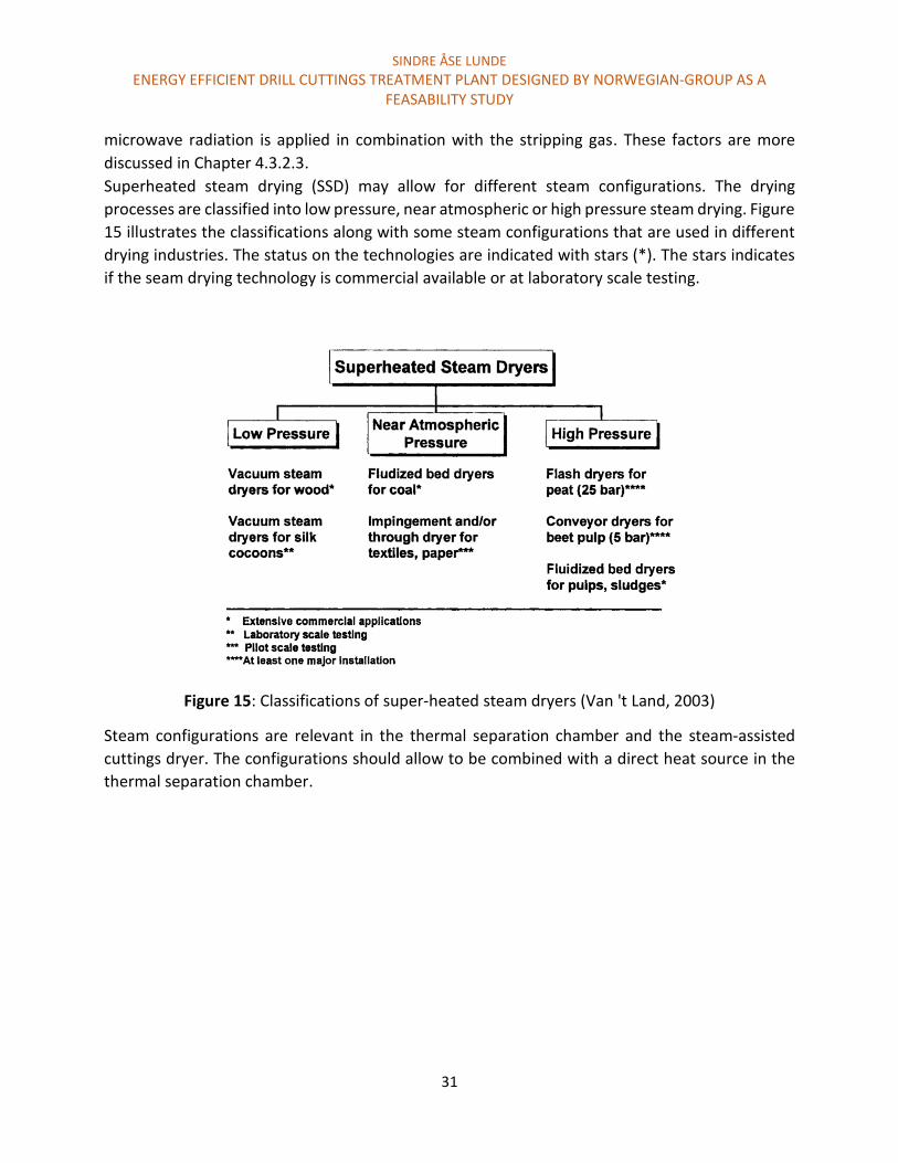
Superheated steam drying (SSD) may allow for different steam configurations. The drying
processes are classified into low pressure, near atmospheric or high pressure steam drying. Figure
15 illustrates the classifications along with some steam configurations that are used in different
drying industries. The status on the technologies are indicated with stars (*). The stars indicates
if the seam drying technology is commercial available or at laboratory scale testing.
Figure 15: Classifications of super-heated steam dryers (Van 't Land, 2003)
Steam configurations are relevant in the thermal separation chamber and the steam-assisted
cuttings dryer. The configurations should allow to be combined with a direct heat source in the
thermal separation chamber.

SINDRE ÅSE LUNDE
ENERGY EFFICIENT DRILL CUTTINGS TREATMENT PLANT DESIGNED BY NORWEGIAN-GROUP AS A FEASABILITY STUDY
32
Key advantages that SSD offers (Mujumdar, 2006):
1. No oxidation or combustion reactions (fire and explosion). This also gives a better quality
product.
2. High drying rates. Higher temperatures lead to higher drying rates for surface moisture
above the inversion temperature. Below the inversion temperature, drying with air is
faster.
3. Steam allows recovery without degradation of organic products. The separation of steam
and organics typically occurs in liquid phase.
Limitations on SSD:
1. Slow startup and shutdown
2. No leaks are allowed
3. Steam is typically only justified for large tonnage of continuous operated systems. This
relates to the economy attached to feeding systems, product collection systems, exhaust
steam recovery system etc. The cost for the steam dryer itself is not expensive compared
to added support systems for steam and waste handling.
Steam versus nitrogen stripping of oil-contaminated cuttings
A laboratory study of steam stripping versus nitrogen stripping on oil contaminated cuttings were
performed by J.P Robinson (JP Robinson et al., 2008). In the laboratory setup, gas at 120 °C, 10
L/min with a Reynolds number of 15 was added from the bottom of a fixed bed container. The
amount of oil contaminated cuttings in the container was 30 g. A Reynolds number of 15 were
considered a transition between laminar and turbulent flow. It was found to be the highest
turbulence allowed without fluidizing the bed. Fluidizing the bed has the potential of increasing
the separation (Van 't Land, 2003). This study was however limited to fix bed gas stripping, as the
intention was to revile interactions and separation incensements when microwave radiation was
added in addition to the stripping gas. The effect of microwave assisted nitrogen and steam
stripping is discussed in Chapter 4.3.2.3 Dielectric heating. The laboratory setup for steam and
nitrogen stripping was limited by design as a result of the microwave setup. This allowed for a
maximum width of 40 mm for the sample container. The oil and water content in the drill cuttings
samples were 10 and 12 percent respectfully. The cuttings size ranged from three to then
millimeters. Among the separation mechanisms were steam distillation, entrainment, and
dissolution.

SINDRE ÅSE LUNDE
ENERGY EFFICIENT DRILL CUTTINGS TREATMENT PLANT DESIGNED BY NORWEGIAN-GROUP AS A FEASABILITY STUDY
33
The result from nitrogen and steam stripping is presented in Figure 16. Steam gave a better
separation degree than nitrogen gas. The content of oil and water initially and after treatment is
only based on surface oil/water. Capillary bound water and oil is not included in the content
determination.
Figure 16: Removal of oil on cuttings in a fixed-bed configuration. Nitrogen and steam was
supplied under a fixed bed container. The x-axis represents time and bed volumes passed (JP
Robinson et al., 2008)
In order to achieve sufficient separation degree (less than 1 percent ROC), 90 to 95 percent oil
removal is required. This was not achieved during this experiment. However, the experiment was
not run to optimize the stripping process, but rather to compare the results with microwave
assistance. Higher Reynolds number, better gas supply configuration that allows for better gas
contact could increase the separation degree. Supplying steam at high temperatures may also
give different results. The oil can sustain steam temperature in excess of 600 °C without
decomposing (JP Robinson et al., 2008).
The reason for the low separation degree when using nitrogen as stripping gas was believed to
be a result of evaporating water in addition to oil. As water is removed, steam distillation will not
occur. The stripping will then proceed via conventional solubility process or desorption in excess

SINDRE ÅSE LUNDE
ENERGY EFFICIENT DRILL CUTTINGS TREATMENT PLANT DESIGNED BY NORWEGIAN-GROUP AS A FEASABILITY STUDY
34
of the endpoint i.e. 250 °C. This appears to be evident in Figure 16 at near 60 percent oil removal.
When steam is utilized, steam distillation occurs. Steam condensates on the cuttings, and the
water present in the cuttings were replenished so that the cuttings did not become complete
water dry.
The separation degree limitations were believed to be a result of poor heat and mass transfer.
Fixed bed stripping is considered adequate for removal of surface contaminants, but inefficient
for removal of oil and water trapped inside pores (JP Robinson et al., 2008).
Discussion
Superheated steam stripping serves great potential on the ability to remove oil from cuttings.
Applying steam in the steam assisted cuttings dryer and thermal desorption chamber changes
several parameters that could increase the separation degree.
One important consideration during thermal desorption is mechanism of entrainment. The
degree of entrainment depends on evaporation rate, gas velocity and several other factors.
Entrainment is a beneficial process that supports oil desorption from cuttings. However, small
particles may also be entrained (evaporated) (Mujumdar, 2006). The particles can interfere with
the membrane separation or precipitate in the piping. This can eventually lead to particle
accumulation and clogging of pipes and membrane. TCC uses cyclones to remove ultrafine
particles that evaporate along with the oil and water vapor. The problem may be more severe for
TCC as cuttings are crushed to ultrafine particles. Small particles could be more easily evaporated.
Entrained particles can also be removed by bag filter, scrubbers, or electrostatic precipitation
(Mujumdar, 2006). The entrainment is however most likely to appear in the thermal separation
chamber. When cuttings are pretreated with a steam assisted cuttings dryer, small particles are
typically removed. Less small particles will therefore enter the steam assisted thermal separation
chamber. This could reduce the amount of particles entrained. Solid particles removal before the
membrane separation may therefore not be required.
In order to achieve optimum steam stripping performance, the following factors are important:
Reynolds number
Steam contact
Steam temperature
The steam temperature could have a major effect on the oil separation. Having low steam
temperature may result in steam condensation and release of latent heat. High steam could
contribute to high heat transfer in addition to other separation processes. The optimal steam
temperature may vary both in steam assisted cuttings dryer and the thermal separation chamber.
This is further discussed in Chapter 4.3.2.3.

SINDRE ÅSE LUNDE
ENERGY EFFICIENT DRILL CUTTINGS TREATMENT PLANT DESIGNED BY NORWEGIAN-GROUP AS A FEASABILITY STUDY
35
Reynolds number and steam contact is affected by the steam feed rate and steam supply system
in the steam assisted cuttings dryer and thermal separation chamber.
One great advantage that steam offers is the ability to potentially be recirculated and reused. This
could reduce the energy consumption of the treatment plant.
4.2.3 Steam assisted cuttings dryer The steam assisted cuttings dryer is a new concept (technology) that builds on the current
technology (cuttings dryer). Working principle and experiences are described in Chapter 3.2.3.1.
The performance and separation degree was influenced by properties of drilling fluid and
cuttings. Applying the technology for OBM may therefore affect the separation degree compared
to synthetic based mud (Cannon & Martin, 2001).
Supplying steam to the cuttings dryer has the potential of increasing the oil separation. Several
mechanisms may contribute to increased oil separation as steam is supplied. Some of these
processes relate to steam ability to remove oil. Another factor that may increase the separation
degree is the heat transfer. Heat will reduce the oil viscosity. Less viscous oil may be more easily
removed. Both viscosity and temperature is mentioned as factors that effects the separation
efficiency in Chapter 3.2.3.1.
As described in the Chapter 3.2.3.1 the ROC after treatment typically ranges between 3-5 percent
by weight when cuttings are contaminated with synthetic based mud. The drilling mud removed
from the cuttings are treated in a high speed centrifuge to remove colloids. The recovered mud
may then be reused.
Figure 17 illustrates cuttings before and after treatment.

SINDRE ÅSE LUNDE
ENERGY EFFICIENT DRILL CUTTINGS TREATMENT PLANT DESIGNED BY NORWEGIAN-GROUP AS A FEASABILITY STUDY
36
Figure 17: Cuttings prior to the treatment contains 10 percent ROC as illustrated in the picture
to the left. The picture on the right side is after treatment. The ROC is reduced to 2 percent
(American Society of Mechanical Engineers. Shale Shaker, 2005)
Steam supply systems
The challenge that is associated with modifying the cuttings dryer to allow steam assistance is
considered a design issue. How to add the steam and how to fit steam nozzles inside the
centrifuge is considered important with respect to separation efficiency, steam consumption and
the overall feasibility of supplying steam. For these reasons, potential steam supply is suggested
and discussed. Sealing the centrifuge, preventing steam to exit both the inlet and outlet, and
other potential challenges that supplying steam to the cuttings dryer may impose, will not be
discussed.
A large variety of centrifuges exists. The basket centrifuge (horizontal or vertical) makes up to
about 80 percent of the centrifuges in use (American Society of Mechanical Engineers. Shale
Shaker, 2005). Some centrifuges may be considered more suitable to be modified with steam
assistance then others. The horizontal basket centrifuge illustrated in Figure 18 is used as a
fundament for modification.
Some potential steam supply systems are listed up below:
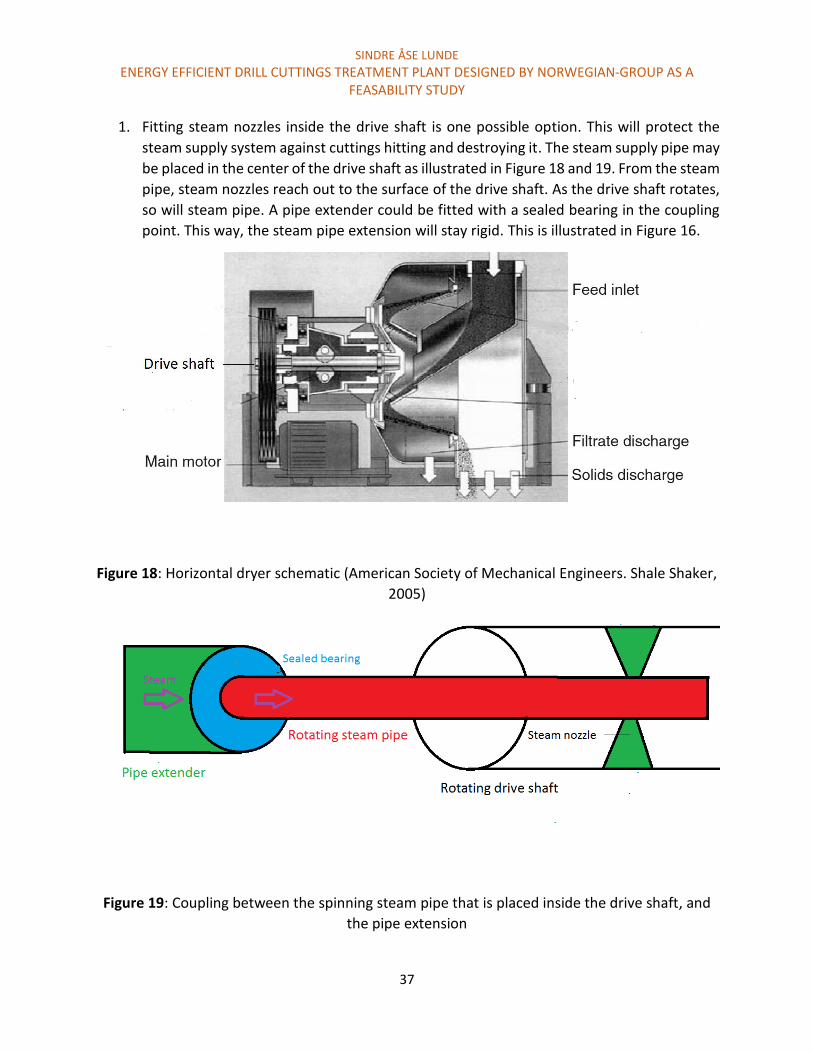
SINDRE ÅSE LUNDE
ENERGY EFFICIENT DRILL CUTTINGS TREATMENT PLANT DESIGNED BY NORWEGIAN-GROUP AS A FEASABILITY STUDY
37
1. Fitting steam nozzles inside the drive shaft is one possible option. This will protect the
steam supply system against cuttings hitting and destroying it. The steam supply pipe may
be placed in the center of the drive shaft as illustrated in Figure 18 and 19. From the steam
pipe, steam nozzles reach out to the surface of the drive shaft. As the drive shaft rotates,
so will steam pipe. A pipe extender could be fitted with a sealed bearing in the coupling
point. This way, the steam pipe extension will stay rigid. This is illustrated in Figure 16.
Figure 18: Horizontal dryer schematic (American Society of Mechanical Engineers. Shale Shaker,
2005)
Figure 19: Coupling between the spinning steam pipe that is placed inside the drive shaft, and
the pipe extension
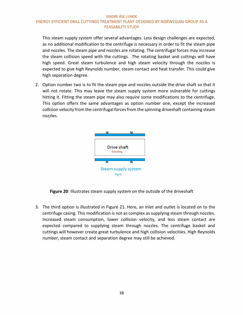
SINDRE ÅSE LUNDE
ENERGY EFFICIENT DRILL CUTTINGS TREATMENT PLANT DESIGNED BY NORWEGIAN-GROUP AS A FEASABILITY STUDY
38
This steam supply system offer several advantages. Less design challenges are expected,
as no additional modification to the centrifuge is necessary in order to fit the steam pipe
and nozzles. The steam pipe and nozzles are rotating. The centrifugal forces may increase
the steam collision speed with the cuttings. The rotating basket and cuttings will have
high speed. Great steam turbulence and high steam velocity through the nozzles is
expected to give high Reynolds number, steam contact and heat transfer. This could give
high separation degree.
2. Option number two is to fit the steam pipe and nozzles outside the drive shaft so that it
will not rotate. This may leave the steam supply system more vulnerable for cuttings
hitting it. Fitting the steam pipe may also require some modifications to the centrifuge.
This option offers the same advantages as option number one, except the increased
collision velocity from the centrifugal forces from the spinning driveshaft containing steam
nozzles.
Figure 20: Illustrates steam supply system on the outside of the driveshaft
3. The third option is illustrated in Figure 21. Here, an inlet and outlet is located on to the
centrifuge casing. This modification is not as complex as supplying steam through nozzles.
Increased steam consumption, lower collision velocity, and less steam contact are
expected compared to supplying steam through nozzles. The centrifuge basket and
cuttings will however create great turbulence and high collision velocities. High Reynolds
number, steam contact and separation degree may still be achieved.
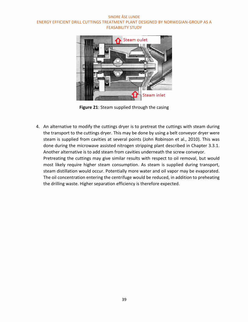
SINDRE ÅSE LUNDE
ENERGY EFFICIENT DRILL CUTTINGS TREATMENT PLANT DESIGNED BY NORWEGIAN-GROUP AS A FEASABILITY STUDY
39
Figure 21: Steam supplied through the casing
4. An alternative to modify the cuttings dryer is to pretreat the cuttings with steam during
the transport to the cuttings dryer. This may be done by using a belt conveyor dryer were
steam is supplied from cavities at several points (John Robinson et al., 2010). This was
done during the microwave assisted nitrogen stripping plant described in Chapter 3.3.1.
Another alternative is to add steam from cavities underneath the screw conveyor.
Pretreating the cuttings may give similar results with respect to oil removal, but would
most likely require higher steam consumption. As steam is supplied during transport,
steam distillation would occur. Potentially more water and oil vapor may be evaporated.
The oil concentration entering the centrifuge would be reduced, in addition to preheating
the drilling waste. Higher separation efficiency is therefore expected.

SINDRE ÅSE LUNDE
ENERGY EFFICIENT DRILL CUTTINGS TREATMENT PLANT DESIGNED BY NORWEGIAN-GROUP AS A FEASABILITY STUDY
40
Discussion
Increasing the performance by supplying steam is considered feasible. This may be done by either
modifying the centrifuge to allow for steam assistance, or preheating the cuttings with steam.
There may be several beneficial mechanisms that contribute to increased oil separation in the
steam assisted cuttings dryer. The effect of increased temperature and reduced viscosity may be
of great relevance. The heat transfer depends on both the steam temperature, and steam supply
system. Supplying steam through nozzles could potentially increase the steam contact, and
Reynolds number. As a result, better heat transfer and potentially increase separation degree
could be achieved while using less steam.
It is believed that modifying the cuttings dryer is the most attractive option with respect to steam
consumption and separation degree. This is based on potentially better steam contact and greater
Reynolds number. However, a comparison test between different steam supply systems and
preheating the cuttings with steam should be performed.
Placing steam nozzles inside the drive shaft may be the most attractive steam supply system. This
could be the case as the steam supply system is protected, and potentially fewer modifications to
the cuttings dryer are required in order to fit the steam supply system. Increased steam collision
could increase the separation degree. The suggested steam supply systems are however only
based ideas. The ideas could work, but more research is required in order to determine if each
individual idea is feasible.
Steam temperature is also of great relevance. As mentioned in Chapter 4.2.2, supplying steam at
low temperature may allow the steam to condense on the cuttings surface, and release the latent
heat. Higher temperature may also be attractive. The optimal steam temperature may be
determined through experiments or more research.
One concern that relates to the effect of supplying steam is the ability to reuse drilling mud. Steam
could affect the mud characteristics and make the mud not suitable for reuse. This could
drastically effect the cost associated with drill cuttings treatment. More research on factors that
affect the mud quality should be performed in order to evaluate if this is a potential problem.
If the drilling mud is considered not suitable for reuse, the oil may still be recovered and reused.

SINDRE ÅSE LUNDE
ENERGY EFFICIENT DRILL CUTTINGS TREATMENT PLANT DESIGNED BY NORWEGIAN-GROUP AS A FEASABILITY STUDY
41
4.2.4 Membrane separation of oil and water vapor Separation of oil and water vapor by membranes gives the possibility to reduce the energy
consumption as the permeate (steam) could be recirculated. The retentate (pure oil or
concentrated oil and steam vapor) will be condensed. The energy gained from recirculating the
steam is highly dependent the amount of steam and oil vapor separated. In order to estimate this
amount, several assumptions are required. Some assumption could in general be vague, as more
research or possibly some laboratory experiments may be required in order to increase the
precision. However, a trend may detected valuable information when evaluating the energy
reduction and potential cost savings associated with membrane separation.
Typical cuttings characteristics used as a fundament for the calculations are listed up below:
Cuttings feed = 10 ton/h
ROC in feed: 12 percent by weight
Water content: 10 percent by weight
Steam and oil removed in the cuttings dryer
The first separation stage (steam assisted cuttings dryer) could offer both separation of oil and
water in liquid and gas phase. The majority of oil and water would most likely be removed in liquid
phase. This is assumed as the heat transfer may not be high enough to allow for steam distillation
before the oil and water is removed by gravitational separation. However, a fraction of oil and
water may be removed in gas phase. In table 6, assumed results are listed up.
Table 6: Assumed result by the steam assisted cuttings dryer
Compounds Inlett Outlet Separated liquid Separated gas
% wt Kg/h % wt Kg/h % wt Kg/h % wt Kg/h
Drilling
waste
100 10000 81 8100 18 1800 2 200
Oil 12 1200 2 200 9 900 1 100
Water 10 1000 1 100 9 900 1 100
Solids 78 7800 78 7800 0 0 0 0

SINDRE ÅSE LUNDE
ENERGY EFFICIENT DRILL CUTTINGS TREATMENT PLANT DESIGNED BY NORWEGIAN-GROUP AS A FEASABILITY STUDY
42
Based on table 6, 200 kg/h drilling waste are removed in gas phase in the steam assisted cuttings
dryer. It is important to include the super heated steam added in the cuttings dryer. The amount
of steam that is required in this process depends on several factors. Factors of great relevance
are:
Steam temperature
Steam supply system
Centrifuge rpm
Retention time
Steam temperature will affect the amount of steam evaporated. In order to transfer heat to the
cuttings, steam could be supplied at relatively low temperatures (100 °C), or high temperature
(600 °C). If low steam temperatures are utilized, steam may condense on the cuttings surface,
and the latent heat is transferred. A significant amount of the added steam may then be removed
in liquid phase.
In order to estimate the amount of supplied steam necessary, the following assumptions are
made:
Steam is supplied at 100 kPa (1 atm) with a temperature of 100 °C. This gives a density of
1.694 m3/kg (Borgnakke, Sonntag, & Van Wylen, 2009)
Assuming the volume of the cuttings dryer casing is 1.5 m3
The steam is supplied at a rate that shifts out the whole volume of the cuttings dryer casing
(1.5 m3) each 10 second.
The steam is supplied through nozzles.
50 percent of the supplied steam condenses, and is removed in liquid phase.
Based on these assumptions, steam is added at a rate of 9 m3/min (540 m3/h). If the steam
temperature were 100 °C, the water consumption would be 319 kg water/h. This will leave
approximately 160 kg of the supplied steam to evaporate and transported to the membranes for
separation.
Steam and oil removed in the thermal separation chamber
The pretreated drilling waste contains 7800 kg cuttings, 200 kg oil, and 100 kg water. This drilling
waste is fed in to the thermal separation chamber according to the assumption in Table 6. Oil and
water in the thermal separation chamber are removed in gas phase. In addition, steam is supplied
to enhance the removal process.
In order to predict the steam consumption, the microwave assisted nitrogen plant at pilot scale
is used as a comparison. Even though steam and nitrogen feature different characteristics, a
tendency of the required steam consumption could be representative. In the nitrogen stripping
SINDRE ÅSE LUNDE
ENERGY EFFICIENT DRILL CUTTINGS TREATMENT PLANT DESIGNED BY NORWEGIAN-GROUP AS A FEASABILITY STUDY
43
plant, 22 L/min nitrogen gas was added as sweep gas to treat a maximum of 500 kg cuttings per
hour (John Robinson et al., 2008). Replacing the nitrogen with steam, and scaling the treatment
plant to handle 10 ton drilling waste per hour would require 220 L steam/min (13.2 m3/h). If the
supplied steam has a temperature of 300 °C and at atmospheric pressure, the steam density
would be 2.64 m3/kg (Borgnakke et al., 2009). This would result in a steam consumption of 5 kg/h.
Several factors can contribute to both increased and reduced steam consumption. Some
important factors to consider are listed up below:
The inlet feed to the nitrogen stripping plant are not pretreated. Cuttings would therefore
contain 12% oil and 10% water. The water are heated with MW radiation and converted
into steam. The steam generated supports the oil removal process. The drill cuttings
pretreated by the steam assisted cuttings dryer will contain less oil and water. This could
potentially decrease the amount of required steam supplied in the thermal separation
chamber.
Steam supplied from the cuttings bed could give better steam contact than heating
surface water with MW radiation.
Superheated steam at 300 °C could give different results compared to supplying nitrogen
gas at room temperature.
Mixing inside the thermal separation chamber. This is suggested in Chapter 4.3.2.3 in
combination with microwave radiation as a heat source. Mixing the cuttings could give
better steam and microwave contact. This could increase the oil removal process and
reduce the steam consumption.
Based on the estimations in Table 6, the oil and water content are two and one percent
respectfully. Considering the oil to water ratio is important, as steam generated by a heat
source supports the separation. The required ratio may depend on the heat source used. It is
assumed that microwave radiation is utilized. The oil to water ratio of 2:1 is typically higher
than tested for in Figure 12 and Table 4. The figure reviles that the highest oil to water removal
ratio was 3:2. The water content was 6.5 percent and the oil content was approximately 9.5
percent in that case. The ROC was reduced to approximately 0.1 percent. However, the
required oil to water ratio may vary, and depends on the cuttings characteristics.
High water content has typically a negative effect according to Figure 12 and Table 4. An oil
to water ratio of 2:1 could be enough to achieve sufficient separation. However, a laboratory
test would revile of it is possible.
The required amount of steam supplied would then be 5 kg/h if the cuttings were not
pretreated. By assuming worst case scenarios, increasing the supplied steam to 50 kg/h would
most likely give sufficient separation in various conditions. Less steam may be required, but
supplying 50 kg steam/h in the thermal separation chamber will be used in the steam

SINDRE ÅSE LUNDE
ENERGY EFFICIENT DRILL CUTTINGS TREATMENT PLANT DESIGNED BY NORWEGIAN-GROUP AS A FEASABILITY STUDY
44
estimation calculations. The overall steam and water removed in gas phase is listed up in
Table 7.
Overall vapor generation, and potential energy recovery
Based on table 7, the total amount of steam possible to recover by membrane separation is 410
kg/h. This is when assumed that oil and water vapor is completely separated. Pure oil would then
be in the retentate and pure water would permeate the membrane. Under these conditions,
liquid oil/water separation would not be necessary.
Table 7: Overall vapor supplied and generated when treating 10 ton cuttings per hour
Separation method Kg in gas phase
Steam supplied
(kg/h)
Steam generated
(kg/h)
Oil vapor (kg/h)
Steam assisted
cuttings dryer
160 100 100
Thermal separation
chamber
50 100 200
Total amount 210 200 300
It is important to consider the energy reduction and the economy associated with this process of
recirculating the steam. Recirculate 410 kg steam per hour may reduce the operation cost. As
presented in Table 3, heating 150 kg water from 20 to 300 °C requires 124 kW. Heating 1 kg water
from 20 to 300 °C would therefore require 0.83 kW/kg water. Assuming this is the potential
energy recovery when recirculating the steam, the total amount of energy recovered would be
340 kW/h. A realistic energy recovery would probably be much lower when considering:
The energy consumption associated with membrane separation.
The steam temperature may be lower than 300 °C.
Oil and water may not be completely separated by the membrane.
Energy loss would occur in the recirculation process.
The estimated costs when treating cuttings offshore was 6500 NOK per ton cuttings according to
DNV (DNV, 2013). In this energy recovery calculation, a treatment capacity of 10 ton cuttings per
hour was used as a fundament. This will give an operation cost of 65000 NOK per hour.
SINDRE ÅSE LUNDE
ENERGY EFFICIENT DRILL CUTTINGS TREATMENT PLANT DESIGNED BY NORWEGIAN-GROUP AS A FEASABILITY STUDY
45
Assuming that the energy price is 1 NOK/kW, the cost reduction from recirculating the steam is
340 NOK. This is when not considering for the energy loss in the separation process, and costs
associated with membrane separation.
Membrane separation
The water and oil vapor produced in both the steam assisted cuttings dryer and thermal
separation chamber are estimated to be 710 kg. The vapor concentration was estimated to be
around 43 percent oil. The oil and water vapor may be separated by membranes. If the steam
permeate the membranes, the oil would be up concentrated in the retentate. If hundred percent
separation were achieved, pure oil would be in the retentate. This would require membrane
qualities that can support high oil concentrations.
The separation of the oil and water vapor requires certain specifications in order to fit into the
treatment plant. Some requirements are listed up below:
The membrane separation equipment must in general be small, so that the overall size
of the whole process plant does not exceed the maximum size allowed for offshore
applications.
The investment and running cost should be low, since the energy recovery and the
cost reductions are expected to be low.
The membrane plant must be robust, and allow for continuous treatment. Stoppages
would lead to gas accumulations.
The membrane must support high treatment capacity. The required flux through the
membrane must be of a minimum of 410 kg steam/h. If assuming that the steam is 100
°C, this equals to 695 m3 steam/h. This is relevant based on the assumptions made
when handling 10 ton cuttings per hour.
The membrane must be able to handle high and various temperatures. The exit
temperature of steam and oil in the cuttings dryer may not be the same as in the
thermal separation chamber.
The membrane must be able to handle high oil concentrations in addition to a large
variety of oil characteristics. In drilling mud, medium and heavy oil fractions are
present. Hydrocarbons present in drilling fluids include, PAH, aromatics, and aliphatic
hydrocarbons. The average carbon content may range from then to eighteen carbons
(Matthew, 2014). In addition, crude oil with various carbon content could also be
present.
High separation degree, and high steam recovery is required in order to achieve
reasonable energy recovery.
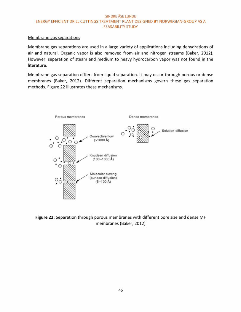
SINDRE ÅSE LUNDE
ENERGY EFFICIENT DRILL CUTTINGS TREATMENT PLANT DESIGNED BY NORWEGIAN-GROUP AS A FEASABILITY STUDY
46
Membrane gas separations
Membrane gas separations are used in a large variety of applications including dehydrations of
air and natural. Organic vapor is also removed from air and nitrogen streams (Baker, 2012).
However, separation of steam and medium to heavy hydrocarbon vapor was not found in the
literature.
Membrane gas separation differs from liquid separation. It may occur through porous or dense
membranes (Baker, 2012). Different separation mechanisms govern these gas separation
methods. Figure 22 illustrates these mechanisms.
Figure 22: Separation through porous membranes with different pore size and dense MF
membranes (Baker, 2012)

SINDRE ÅSE LUNDE
ENERGY EFFICIENT DRILL CUTTINGS TREATMENT PLANT DESIGNED BY NORWEGIAN-GROUP AS A FEASABILITY STUDY
47
Very small porous membranes have not been used in large scale activities for gas separation.
These membranes features very high molecular selectivity, and have been prepared in the
laboratory scale. Some potential membranes along with their initially applications are presented
below (Baker, 2012).
Metals membranes: are typically used to permeate hydrogen. The membrane requires higher
temperatures than 300 °C in this application, and achieves permeations rates of then to hundred
times the rate of polymeric membranes.
Ceramic and Zeolite membranes: are typically used in dehydration of alcohols by vapor/vapor
permeation. Ceramic membranes are known to support high temperatures and durability
(Cheryan, 1998)
Thermally Rearranged/Microporous Carbon membranes: Have exceptional oxygen/nitrogen,
carbon dioxide/methane, and propylene/propane selectivity. The membrane is known to be
brittle and is typically plugged by heavy hydrocarbons.
The current commercial gas separation is typically based on dense polymer membranes. The
separation occurs by solution-diffusion. Polymer membranes may offer several limitations if used
in oil and water vapor separation. Limitations with respect to temperatures are of great concerns.
In Figure 23, a temperature range for some polymer membranes and ceramic membranes are
illustrated.
Figure 23: Temperature stabilities of polymer and ceramic membranes (Cheryan, 1998)
SINDRE ÅSE LUNDE
ENERGY EFFICIENT DRILL CUTTINGS TREATMENT PLANT DESIGNED BY NORWEGIAN-GROUP AS A FEASABILITY STUDY
48
Modified polymeric membranes with better temperature durability may be available, but the
figure illustrates a temperature trend between ceramic and polymeric membranes. The exit
temperature from the cuttings dryer and thermal separation chamber may vary, but could exceed
300 °C.
Particles and oil mist are considered potential fouling materials for dense polymeric membranes
in some gas separation processes. These fouling agents are typically removed with coalescing
filters. In natural gas separation, water and higher hydrocarbons are often condensed and
subjected to fractional distillation to recover each individual component.
More research is required in order to evaluate if there is a membrane system available, and can
support the criterial necessary in order to consider membrane separation is attractive. Research
on suitable membranes systems for this application is not considered as an objective of this thesis.
Discussion
Based on the estimations, recirculating the steam to reduce the energy consumption may not be
economical favorable. It is possible that the cost associated with membrane separation of steam
and oil vapor could be higher than the cost reduction achieved when recirculating and reusing
the steam. This is based on the low potential cost reduction gained from recirculating the steam.
Separating oil and water in liquid form is considered expensive due to potential high membrane
cost, fouling and low membrane lifetime (Baker, 2012). The cost related to gas separating is not
estimated as it is not certain if the separation process is feasible. If the same challenges of liquid
separation are relevant for gas separation, the separation processes are likely to be too
expensive.
Applying membrane separation in the treatment plant features several challenges associated
with the membrane separation system and the requirement in order to consider membrane to
be an attractive option. Some of these challenges or possible limitations was listed up, but not
discussed further as the author considered membrane separation not to be feasible based on the
low potential cost reduction.

SINDRE ÅSE LUNDE
ENERGY EFFICIENT DRILL CUTTINGS TREATMENT PLANT DESIGNED BY NORWEGIAN-GROUP AS A FEASABILITY STUDY
49
4.3 Potential heat sources for the steam assisted thermal separation
chamber The treatment capacity of the steam-assisted cuttings dryer can treat cuttings continuously as
they are generated. The separation efficiency and capacity of the thermal desorption chamber
would therefore be the limiting process in order to create an attractive treatment plant.
Evaluation of heat sources suitable in the steam assisted thermal separation chamber is for this
reason considered the main objective in this thesis.
The applied heat source is considered a major factor in order to achieve high treatment capacity
along with high separation degree. Superheated steam will support the separation process and
potentially make the treatment plant more robust. A more robust treatment plant may be
achieved when steam is supplied because steam distillation may occur independently of the
water content in the drill cuttings waste. Increased heat transfer will also be achieved. The steam
assisted thermal desorption chamber should be able to remove both surface oil and oil trapped
inside pores. The latter case usually offers challenges when utilizing surface heating. This relates
to the poor heat transfer characteristics of drill cuttings. Heating in depth of granular material
with relatively low surface temperatures are considered inefficient and require high retention
time (JP Robinson et al., 2008; John Robinson et al., 2008). Increasing the surface temperature to
enhance heat transfer may decompose the oil. Oil isolated in pores may also not be subjected to
steam. As a result, steam distillation would not occur. High distillation temperatures may
therefore be required in order to desorb the oil. This could also result in decomposition of oil.
Different heat sources serve different advantages and disadvantages depending on the
application and in general. Some potential heat sources for use the thermal separation chamber
are to be discussed and reviewed. In order to fit into the thermal separation chamber, the heat
source must allow two main criterial.
1. The heat source must allow for continuous cuttings feeding
2. The heat source must allow for steam assistance
Electric heating sources are considered most attractive in this application and will therefore only
be evaluated.

SINDRE ÅSE LUNDE
ENERGY EFFICIENT DRILL CUTTINGS TREATMENT PLANT DESIGNED BY NORWEGIAN-GROUP AS A FEASABILITY STUDY
50
In Table 8, a summary of the evaluated heat sources are presented. The heat sources can be both
direct and indirect. By definition, indirect heating occurs when heat is generated through an
external heat source. The heat transfer through the surface of the heated part. Through heating
is achieved by heat transfer, conduction, convection, or radiation. During direct heating, the heat
is generated within the product itself. Direct selective heating is defined as heating the material
directly, while only heating one specific compound. An example of this is microwave radiation
that only heats the water present in cuttings.
Table 8: Summary of heat sources evaluated
Heat sources Direct Indirect Heating cuttings Recommended
Conventional Resistance
heating Yes Yes Direct/Indirect No
Electromagnetic Induction heating Yes Yes Direct/indirect No Infrared heating No Yes Indirect No Electromagnetic-Dielectric Microwave
radiation Yes Yes Direct/indirect Yes
Radio frequency
heating
Yes Yes Direct/indirect No
The heat sources will be discussed and reviewed based on its ability to fit into Norwegian-Groups
treatment plant. The heating mechanism will be presented, as it is of great relevance in order to
evaluate the heat source. Recommended heat sources are defined as heat sources considered
very attractive to be combined with steam to remove cuttings with low oil and water
concentrations.
A combination of direct and indirect heat sources could also be considered as attractive. For this
reason, some indirect heat sources are also presented.
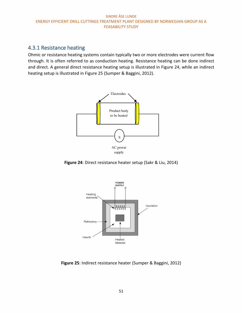
SINDRE ÅSE LUNDE
ENERGY EFFICIENT DRILL CUTTINGS TREATMENT PLANT DESIGNED BY NORWEGIAN-GROUP AS A FEASABILITY STUDY
51
4.3.1 Resistance heating Ohmic or resistance heating systems contain typically two or more electrodes were current flow
through. It is often referred to as conduction heating. Resistance heating can be done indirect
and direct. A general direct resistance heating setup is illustrated in Figure 24, while an indirect
heating setup is illustrated in Figure 25 (Sumper & Baggini, 2012).
Figure 24: Direct resistance heater setup (Sakr & Liu, 2014)
Figure 25: Indirect resistance heater (Sumper & Baggini, 2012)

SINDRE ÅSE LUNDE
ENERGY EFFICIENT DRILL CUTTINGS TREATMENT PLANT DESIGNED BY NORWEGIAN-GROUP AS A FEASABILITY STUDY
52
Direct resistance heating
Direct resistance heating involves passing electric current through the object to be heated. Heat
is generated by the Joule effect and then transferred to the heated object by conduction,
convection or/and radiation. It is the resistance in the heated object that allow for heating. The
material must be electrically conductive. However, metals with higher resistivity generate more
heat. This makes the process more efficient. The temperature is controlled by adjusting the
current. The current can be either alternating (AC) or direct current (DC). Using low frequency
current (DC or 50 Hz) will allow for through heating, while higher frequencies are typically used
for surface heating (Sumper & Baggini, 2012).
Typical application for direct resistance heating is for metal heating, heating or melting glass,
silicone salt batch, steam generation, and food heating etc. (Sumper & Baggini, 2012). Heating of
reservoirs to enhance oil recovery is also a possible application (Sahni, Kumar, Knapp, &
Livermore, 2000)
Direct resistance heating offer great advantages. High energy efficiency is achieved as only the
workpiece is heated. Radiation and convention losses are considered very small. Rapid heating,
and high power densities (105 kW/m2) is also achievable. Direct resistance heating requires
certain material characteristics to be considered as effective (Sumper & Baggini, 2012). Heating
cuttings directly could work. An application that relates to direct resistance heating of cuttings
are reservoir heating to enhance oil recovery. Heating drill cuttings relates to reservoir heating in
the sense that the same compounds are present in these two applications (oil, water, ground
formation, and ions). The amount of each compounds present may differ. Heating setup and
challenges of reservoir heating is therefore relevant as these challenges and limitations could
indicate if this heat source is considered attractive for the application.
Reservoirs heating occur when low frequency alternating current (60 Hz) flow through the
reservoir between an anode and cathode. A simple electrode configuration is placing an electrode
between two neighbor production oil wells. This is illustrated in Figure 26. The electric path
between the electrodes is provided by ion rich water. A distance of 30 m between the electrodes
gave sufficient results. Uniform and widespread heating of the reservoir was achieved. The heat
distribution was monitored based on simulations. The heating process did however need to be
closely regulated as too much heating resulted in water evaporation and boiling. This increased
the resistance and thus reduced the current flow. Keeping the temperature below 100 °C
improved the electric heat distribution. Highest heating was present near the electrodes (Sahni
et al., 2000).

SINDRE ÅSE LUNDE
ENERGY EFFICIENT DRILL CUTTINGS TREATMENT PLANT DESIGNED BY NORWEGIAN-GROUP AS A FEASABILITY STUDY
53
Figure 26: Electrode configuration in wells to enhance oil recovery (Sahni et al., 2000)
Discussion
The electric path is supported by ionic rich water. However, as the water evaporates the electric
path may disappear. For this reason, direct resistance heating is not suitable for thermal
desorption of cuttings.
One important factor to consider is that the cuttings are pretreated in the steam assisted cuttings
dryer. The cuttings dryer remove both oil and water. Water is less viscous than oil, and may then
be more easily removed. Figure 17 illustrates drill cuttings treated by the cuttings dryer. Based on
the Figure, the water content is very low. It is likely that the drilling waste would not be electrically
conductive due to the low water content. Direct resistance heating is not considered a potential
heat source for the steam assisted thermal desorption chamber.

SINDRE ÅSE LUNDE
ENERGY EFFICIENT DRILL CUTTINGS TREATMENT PLANT DESIGNED BY NORWEGIAN-GROUP AS A FEASABILITY STUDY
54
Indirect resistance heating
Indirect resistance heating is based on heating a material (susceptor) that transfers heat by
conduction, convection or radiation to object to the cuttings. For temperatures below 650 °C,
convection is mainly used in the heat transfer process. Heating of the susceptor relies on the same
principle of direct resistance heating (Joule effect). Examples of materials with high resistance are
graphite, silicon-carbide or nickel-chrome. Heating is usually done in a furnace or vacuum
furnaces at high temperatures. The energy efficiency is in the range of 80 percent (Sumper &
Baggini, 2012).
Indirect resistance heating offers both batch and continuous furnaces process. This heating
method offers a large variety of application including steam generation and drying. The
applications can typically replace the fuel-based process heating systems or steam-based
systems. The efficiency is however strongly influenced by heat transfer rate and insulation
(Sumper & Baggini, 2012).
Discussion
Indirect resistance contributes just too surface heating. Different heat element configuration that
allows for high surface contact and mixing could be utilized in the steam assisted thermal
desorption chamber. However, surface heating has great limitations. Indirect resistance heating
is not considered an attractive solution.

SINDRE ÅSE LUNDE
ENERGY EFFICIENT DRILL CUTTINGS TREATMENT PLANT DESIGNED BY NORWEGIAN-GROUP AS A FEASABILITY STUDY
55
4.3.2 Electromagnetic heating Electromagnetic (EM) heating serves great potential when it comes to the process of thermal
desorption. This relates to the fact that it EM heating allows for direct, direct selective and indirect
heating. EM heating transfer energy through EM waves. The waves consist of both electric and
magnetic fields that oscillate at right angel to each (Gupta & Leong, 2008). This is illustrated in
the figure below.
Figure 27: Electromagnetic wave (Gupta & Leong, 2008)
In general, the EM radiation is classified by wavelength as illustrated in Figure 28. The heat
mechanism depends on the frequency. The frequency utilized determines the type of materials
that may be heated.

SINDRE ÅSE LUNDE
ENERGY EFFICIENT DRILL CUTTINGS TREATMENT PLANT DESIGNED BY NORWEGIAN-GROUP AS A FEASABILITY STUDY
56
Figure 28: The electromagnetic frequencies along with their classifications (Mehdizadeh, 2009)
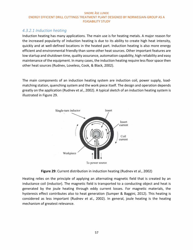
SINDRE ÅSE LUNDE
ENERGY EFFICIENT DRILL CUTTINGS TREATMENT PLANT DESIGNED BY NORWEGIAN-GROUP AS A FEASABILITY STUDY
57
4.3.2.1 Induction heating Induction heating has many applications. The main use is for heating metals. A major reason for
the increased popularity of induction heating is due to its ability to create high heat intensity,
quickly and at well-defined locations in the heated part. Induction heating is also more energy
efficient and environmental friendly than some other heat sources. Other important features are
low startup and shutdown time, quality assurance, automation capability, high reliability and easy
maintenance of the equipment. In many cases, the induction heating require less floor space then
other heat sources (Rudnev, Loveless, Cook, & Black, 2002).
The main components of an induction heating system are induction coil, power supply, load-
matching station, quenching system and the work piece itself. The design and operation depends
greatly on the application (Rudnev et al., 2002). A typical sketch of an induction heating system is
illustrated in Figure 29.
Figure 29: Current distribution in induction heating (Rudnev et al., 2002)
Heating relies on the principle of applying an alternating magnetic field that is created by an
inductance coil (inductor). The magnetic field is transported to a conducting object and heat is
generated by the joule heating through eddy current losses. For magnetic materials, the
hysteresis effect contributes also to heat generation (Sumper & Baggini, 2012). This heating is
considered as less important (Rudnev et al., 2002). In general, joule heating is the heating
mechanism of greatest relevance.

SINDRE ÅSE LUNDE
ENERGY EFFICIENT DRILL CUTTINGS TREATMENT PLANT DESIGNED BY NORWEGIAN-GROUP AS A FEASABILITY STUDY
58
The alternating currents are concentrated on the outside of the workpiece (conductor). This is
called the skin effect. The current and heat generated are highest at the surface and diminish
towards the center.
Penetration depth is defined as the thickness of the layer where 87 % of the power is developed
(Sumper & Baggini, 2012). This follows Maxwell`s equation
Equation 2 Maxwell`s equation: δ = 503 √p
µf [m]
δ = Penetration depth
p = Resistivity
µ = Magnetic permeability of the material
f = frequency
When heating drill cuttings, penetration depth is considered to be of great importance. The
frequency offers a convenient possibility to control the penetration depth. This is evident in
Equation 2.
Resistivity is considered a major factor in order to heat materials. It affects all the important
parameters of induction heating. This includes penetration depth, heat uninformative, coil
electrical efficiency, coil impedance and others. Metals and alloys are considered good
conductors. They have much less resistance compared to other materials like ceramics and plastic
(Rudnev et al., 2002). The relationship between resistance R (Ω) and resistivity (p) is showed in
equation Y1.
Equation 3 R = 𝑝𝑙
𝑎
R: resistance
(p): resistivity
L: represent the length of the current-carrying conductor
A: is the area of the cross-section of the conductor
The electrical resistivity varies also with temperature, chemical composition, metal
microstructure, and grain size. Finer grains will increase the resistivity. They will be heated up
more quickly. This is because more surface is present (Sumper & Baggini, 2012).
Since Joule heating is the main mechanism of heating, the material must be electrical conductive
in order to generate heat. According to Equation 2 and 3, higher resistance will give higher
penetration depth.
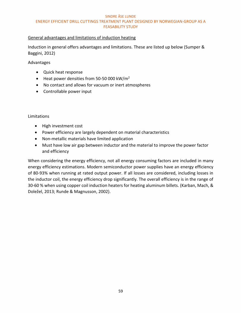
SINDRE ÅSE LUNDE
ENERGY EFFICIENT DRILL CUTTINGS TREATMENT PLANT DESIGNED BY NORWEGIAN-GROUP AS A FEASABILITY STUDY
59
General advantages and limitations of induction heating
Induction in general offers advantages and limitations. These are listed up below (Sumper &
Baggini, 2012)
Advantages
Quick heat response
Heat power densities from 50-50 000 kW/m2
No contact and allows for vacuum or inert atmospheres
Controllable power input
Limitations
High investment cost
Power efficiency are largely dependent on material characteristics
Non-metallic materials have limited application
Must have low air gap between inductor and the material to improve the power factor
and efficiency
When considering the energy efficiency, not all energy consuming factors are included in many
energy efficiency estimations. Modern semiconductor power supplies have an energy efficiency
of 80-93% when running at rated output power. If all losses are considered, including losses in
the inductor coil, the energy efficiency drop significantly. The overall efficiency is in the range of
30-60 % when using copper coil induction heaters for heating aluminum billets. (Karban, Mach, &
Doležel, 2013; Runde & Magnusson, 2002).

SINDRE ÅSE LUNDE
ENERGY EFFICIENT DRILL CUTTINGS TREATMENT PLANT DESIGNED BY NORWEGIAN-GROUP AS A FEASABILITY STUDY
60
Direct and indirect induction heating
Direct induction occurs when heat is generated in the workpiece itself as a result of alternating
magnetic field. This is utilized in the metal industry for melting, heating, and heat treatment
(Sumper & Baggini, 2012). Non-metal materials may also be heated by induction. Coal in coal
gasification plants and carbon fiber reinforces thermoplastic allows for direct heating. This is due
to the high eddy-current loss in the materials. Energy is absorbed efficient from an intense
magnetic field. (Fisher, 1979; Rudolf, Mitschang, & Neitzel, 2000). High eddy current loss is
achieved for conductive materials with relative high resistance.
Indirect induction is based on heating an electrically conductive material called a susceptor. The
susceptor transfer heat to the workpiece. Indirect heating is used for heating nonconductive
materials (Sumper & Baggini, 2012). Susceptor heating is used in several industries. In the fiber
optic industry, materials with very high resistivity (insulators) like silicone, germanium, and other
materials are heated to high temperatures with the use of susceptors. When these materials are
hot, they can be heated further through direct induction heating (Zinn & Semiatin, 1988).
Induction heating and resistance heating both generate heat by the Joule effect. The discussion
from the resistance heating is therefore also relevant for induction heating. However, one
important consideration is that material with high resistivity can be heated directly if they are
heated to very high temperatures. Drill cuttings and oil could therefore be heated directly. A
concern is however that the oil would crack before it becomes electrically conductive.
Since a combination of direct and indirect heating could be achieved, different susceptor
configuration is further discussed.
Innovative susceptor configurations include heating a screw conveyor. The cuttings would then
be transported while being mixed and heated by the susceptor. This principle is utilized in
gasification plants (Bratina, Bowering, Kriech, Eyster, & Roberts, 2012; Jeney, 2009, 2010; Zinn &
Semiatin, 1988).
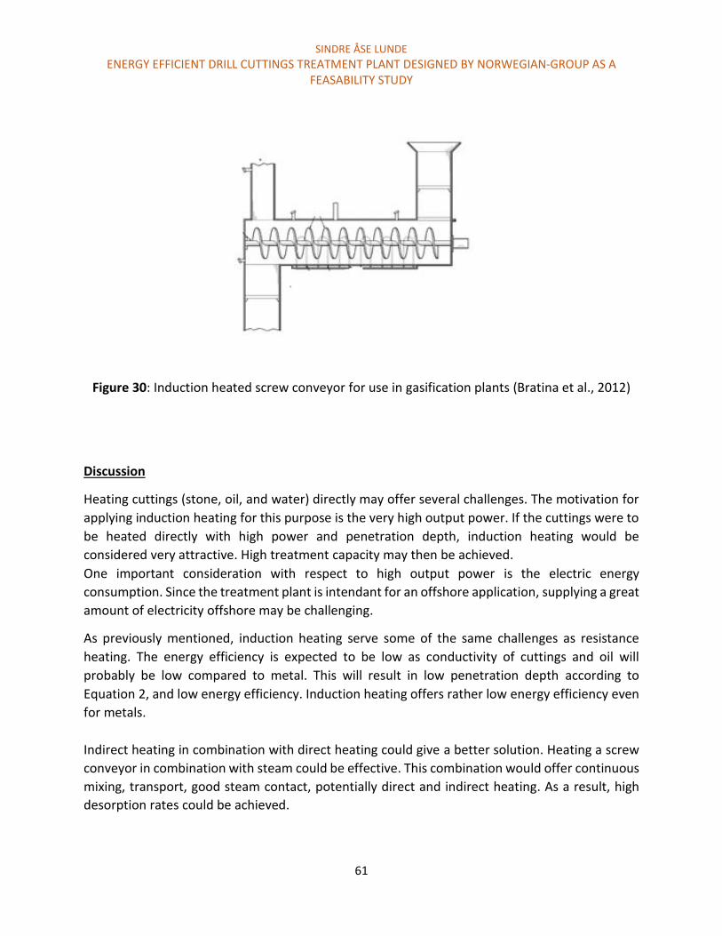
SINDRE ÅSE LUNDE
ENERGY EFFICIENT DRILL CUTTINGS TREATMENT PLANT DESIGNED BY NORWEGIAN-GROUP AS A FEASABILITY STUDY
61
Figure 30: Induction heated screw conveyor for use in gasification plants (Bratina et al., 2012)
Discussion
Heating cuttings (stone, oil, and water) directly may offer several challenges. The motivation for
applying induction heating for this purpose is the very high output power. If the cuttings were to
be heated directly with high power and penetration depth, induction heating would be
considered very attractive. High treatment capacity may then be achieved.
One important consideration with respect to high output power is the electric energy
consumption. Since the treatment plant is intendant for an offshore application, supplying a great
amount of electricity offshore may be challenging.
As previously mentioned, induction heating serve some of the same challenges as resistance
heating. The energy efficiency is expected to be low as conductivity of cuttings and oil will
probably be low compared to metal. This will result in low penetration depth according to
Equation 2, and low energy efficiency. Induction heating offers rather low energy efficiency even
for metals.
Indirect heating in combination with direct heating could give a better solution. Heating a screw
conveyor in combination with steam could be effective. This combination would offer continuous
mixing, transport, good steam contact, potentially direct and indirect heating. As a result, high
desorption rates could be achieved.

SINDRE ÅSE LUNDE
ENERGY EFFICIENT DRILL CUTTINGS TREATMENT PLANT DESIGNED BY NORWEGIAN-GROUP AS A FEASABILITY STUDY
62
4.3.2.2 Infrared Heating Infrared radiation heating is a variant of indirect resistance heating. Heat radiation is emitted by
electrical resistors. Typical resistor material is nickel-chromium or tungsten. These materials are
heated to relative high temperatures. Most of Infrared (IR) applications involve surface heating.
However, it is possible to use IR in bulk heating applications (Sumper & Baggini, 2012). An outline
of IR heating is illustrated in Figure 31.
Figure 31: Outline of infrared heating (Sumper & Baggini, 2012)
The numbers 1, 2 and 3 represents emitters including reflector systems, furnace wall, and the
heated part respectfully. Material handling systems and ventilations are also often present.
Some applications include drying of coatings, particles, and dehydration. The heating technology
offers several great advantages including high energy efficiency, however IR is most suited for
heating layer or sheet products. Bulk heating considered slow due to the slow heat transfer from
surfaces (Sumper & Baggini, 2012).
Discussion
IR is not considered an attractive heat source in a steam assisted thermal desorption chamber.
This is based on the poor bulk heating capabilities, and that a combination with steam could
interfere with the heat transfer process.
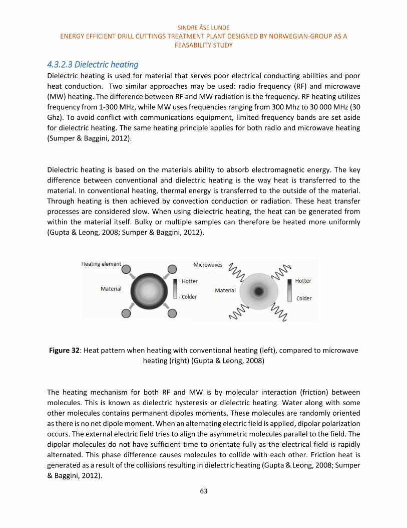
SINDRE ÅSE LUNDE
ENERGY EFFICIENT DRILL CUTTINGS TREATMENT PLANT DESIGNED BY NORWEGIAN-GROUP AS A FEASABILITY STUDY
63
4.3.2.3 Dielectric heating Dielectric heating is used for material that serves poor electrical conducting abilities and poor
heat conduction. Two similar approaches may be used: radio frequency (RF) and microwave
(MW) heating. The difference between RF and MW radiation is the frequency. RF heating utilizes
frequency from 1-300 MHz, while MW uses frequencies ranging from 300 Mhz to 30 000 MHz (30
Ghz). To avoid conflict with communications equipment, limited frequency bands are set aside
for dielectric heating. The same heating principle applies for both radio and microwave heating
(Sumper & Baggini, 2012).
Dielectric heating is based on the materials ability to absorb electromagnetic energy. The key
difference between conventional and dielectric heating is the way heat is transferred to the
material. In conventional heating, thermal energy is transferred to the outside of the material.
Through heating is then achieved by convection conduction or radiation. These heat transfer
processes are considered slow. When using dielectric heating, the heat can be generated from
within the material itself. Bulky or multiple samples can therefore be heated more uniformly
(Gupta & Leong, 2008; Sumper & Baggini, 2012).
Figure 32: Heat pattern when heating with conventional heating (left), compared to microwave
heating (right) (Gupta & Leong, 2008)
The heating mechanism for both RF and MW is by molecular interaction (friction) between
molecules. This is known as dielectric hysteresis or dielectric heating. Water along with some
other molecules contains permanent dipoles moments. These molecules are randomly oriented
as there is no net dipole moment. When an alternating electric field is applied, dipolar polarization
occurs. The external electric field tries to align the asymmetric molecules parallel to the field. The
dipolar molecules do not have sufficient time to orientate fully as the electrical field is rapidly
alternated. This phase difference causes molecules to collide with each other. Friction heat is
generated as a result of the collisions resulting in dielectric heating (Gupta & Leong, 2008; Sumper
& Baggini, 2012).

SINDRE ÅSE LUNDE
ENERGY EFFICIENT DRILL CUTTINGS TREATMENT PLANT DESIGNED BY NORWEGIAN-GROUP AS A FEASABILITY STUDY
64
The energy absorbance depends on the material characteristics. Parameters that effect energy
absorbance are the loss factor also called relative permittivity (ἔ) and the dielectric constant (ԑ).
Higher loss factor and dielectric constant allows more energy to be absorbed. This is evident in
Equation 4. The loss factor depends on parameters like frequency, temperature, salt
concentration, and orientation of electrical field. In Table 9, different materials loss factors are
presented for RF heating (30 MHz) and MW heating (2500 MHz) (Sumper & Baggini, 2012)
Table 9: Relative dielectric loss factor for radio and microwave frequencies
(Sumper & Baggini, 2012)
Frequency RF
(30 MHz)
MW
(2500 MHZ)
Material Temperature ԑ ἔ ԑ ἔ
Water 25 78 0.4 77 13
85 58 0.3 56 3
Salt solution
0.1M
25 76 480 76 20
Salt solution
0.5M
25 75 2400 68 54
Water subjected to 30 MHz gives a decreasing in ἔ and ԑ as the temperature increases. Less energy
will therefore get absorbed. The same trend is evident for MW heating at 2500 Mhz. This is
important to consider as the drilling waste is preheated in the steam assisted cuttings dryer as it
enters the thermal separation chamber. Higher penetration depth will be achieved as a result
decreased ἔ and ԑ. This relates to Equation 4 combined with Figure 32. The penetration depth is
considered an important parameter with respect to the treatment capacity. This is evident in the
section “Microwave assisted steam stripping of drill cuttings” presented later in this chapter.
The presence of salt in water has a large impact on the relative permitivity. This will increase the
penetration depth significantly. This is evident in Table 9. As salt is present in the cuttings, low
penetration depth is expected. However, the steam assisted cuttings dryer will remove ion rich
surface water. As a result, high penetration depth may still be achieved when utilizing dielectric
heating.
SINDRE ÅSE LUNDE
ENERGY EFFICIENT DRILL CUTTINGS TREATMENT PLANT DESIGNED BY NORWEGIAN-GROUP AS A FEASABILITY STUDY
65
During microwave heating, the parameters that affect the power densities (P0) are presented in
Equation 4. The power density represents the power absorbed per unit volume of material. The
heating rate is presented Equation 5 (Gupta & Leong, 2008; Shang, Snape, Kingman, & Robinson,
2006).
Equation 4 P0 = 2πfԑἔ (E)2
Equation 5 𝑑𝑇
𝑑𝑡 =
P0 = 2πfԑἔ (E)2
𝑝𝐶𝑝
P0 = Power density
f = frequency
ԑ = permitivity of free space (8.85 x 10⁻¹²F/m)
ἔ = relative permittivity
E = magnitude of electric field
T = temperature
t = time
ρ = material density
Cp = specific density of the material
From these equations, it is evident that several factors play an important role with respect to P0.
High frequency, relative permittivity, and the magnitude of the electric field play an important
part. Power density is also related to penetration depth. The relation is evident in Figure 33.
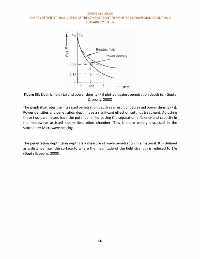
SINDRE ÅSE LUNDE
ENERGY EFFICIENT DRILL CUTTINGS TREATMENT PLANT DESIGNED BY NORWEGIAN-GROUP AS A FEASABILITY STUDY
66
Figure 33: Electric field (E0) and power density (P0) plotted against penetration depth (δ) (Gupta
& Leong, 2008)
The graph illustrates the increased penetration depth as a result of decreased power density (P0).
Power densities and penetration depth have a significant effect on cuttings treatment. Adjusting
these two parameters have the potential of increasing the separation efficiency and capacity in
the microwave assisted steam desorption chamber. This is more widely discussed in the
subchapter Microwave heating.
The penetration depth (skin depth) is a measure of wave penetration in a material. It is defined
as a distance from the surface to where the magnitude of the field strength is reduced to 1/e
(Gupta & Leong, 2008).

SINDRE ÅSE LUNDE
ENERGY EFFICIENT DRILL CUTTINGS TREATMENT PLANT DESIGNED BY NORWEGIAN-GROUP AS A FEASABILITY STUDY
67
Microwave heating
Microwave processing systems usually consist of a microwave source, applicator, and a control
system. The microwave source generates the microwave radiation. The applicator delivers the
power to the material, and the control system monitor and regulates the power. There are several
different types of microwave generators and they should be evaluated based on the application.
MW generator differs in power deliverance, frequency, efficiency, gain, bandwidth, phase, size,
weight, and cost. The most common type of microwave generator is the magnetron. It offers high
efficiency and low size and cost. The magnetron is used widely in microwave ovens and radar
system. The operation frequency is typically at 2.45 GHz.
There are two types available. Pulse and continuous magnetron. Pulse magnetron gives the
opportunity to deliver high peak output power for a very short duration time. The output power
could be up to several megawatts. The continuous magnetron produces an output power up to
some kilowatts. A high-powered magnetron delivers power in the range up of 25-100 kW per tube
at a frequency of 915MHz (Gupta & Leong, 2008).
A typical microwave setup when using a magnetron is illustrated in Figure 34
Figure 34: Typical microwave heating setup (Sumper & Baggini, 2012)
Other microwave generators may also be used. Klystron is a high powered microwave generator
that is used in industrial heating processes in addition to other applications. Typical frequencies
are in the range from 300 MHz to 40 GHz with an output power in the range of 100 W to 1 MW.
Power grid tubes and Gyrotrons are microwave generators typically used in fusion research for
plasma heating (Gupta & Leong, 2008)
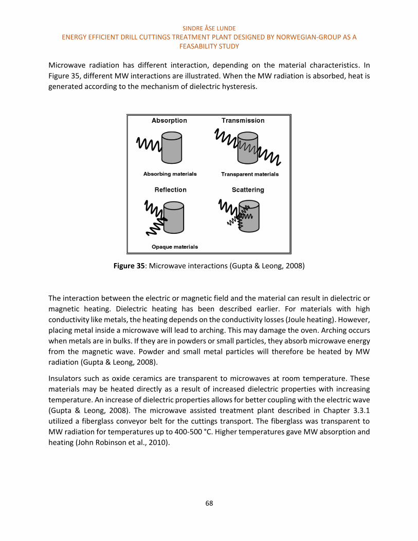
SINDRE ÅSE LUNDE
ENERGY EFFICIENT DRILL CUTTINGS TREATMENT PLANT DESIGNED BY NORWEGIAN-GROUP AS A FEASABILITY STUDY
68
Microwave radiation has different interaction, depending on the material characteristics. In
Figure 35, different MW interactions are illustrated. When the MW radiation is absorbed, heat is
generated according to the mechanism of dielectric hysteresis.
Figure 35: Microwave interactions (Gupta & Leong, 2008)
The interaction between the electric or magnetic field and the material can result in dielectric or
magnetic heating. Dielectric heating has been described earlier. For materials with high
conductivity like metals, the heating depends on the conductivity losses (Joule heating). However,
placing metal inside a microwave will lead to arching. This may damage the oven. Arching occurs
when metals are in bulks. If they are in powders or small particles, they absorb microwave energy
from the magnetic wave. Powder and small metal particles will therefore be heated by MW
radiation (Gupta & Leong, 2008).
Insulators such as oxide ceramics are transparent to microwaves at room temperature. These
materials may be heated directly as a result of increased dielectric properties with increasing
temperature. An increase of dielectric properties allows for better coupling with the electric wave
(Gupta & Leong, 2008). The microwave assisted treatment plant described in Chapter 3.3.1
utilized a fiberglass conveyor belt for the cuttings transport. The fiberglass was transparent to
MW radiation for temperatures up to 400-500 °C. Higher temperatures gave MW absorption and
heating (John Robinson et al., 2010).
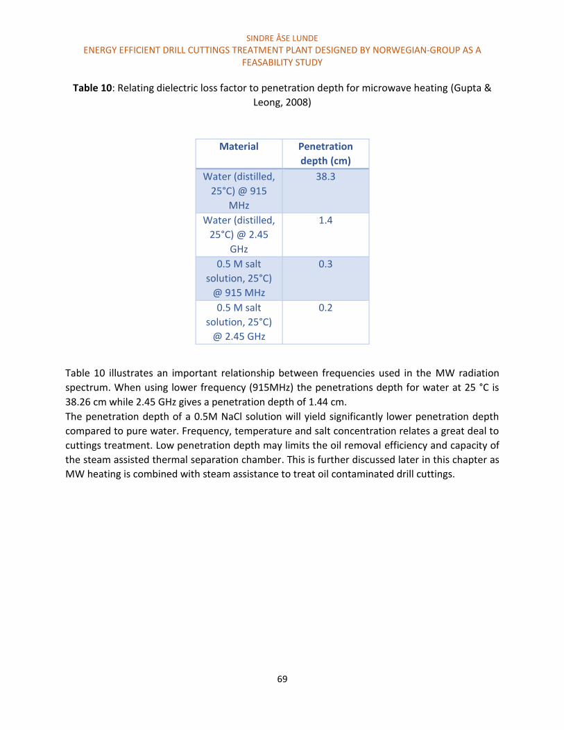
SINDRE ÅSE LUNDE
ENERGY EFFICIENT DRILL CUTTINGS TREATMENT PLANT DESIGNED BY NORWEGIAN-GROUP AS A FEASABILITY STUDY
69
Table 10: Relating dielectric loss factor to penetration depth for microwave heating (Gupta &
Leong, 2008)
Material Penetration
depth (cm)
Water (distilled,
25°C) @ 915
MHz
38.3
Water (distilled,
25°C) @ 2.45
GHz
1.4
0.5 M salt
solution, 25°C)
@ 915 MHz
0.3
0.5 M salt
solution, 25°C)
@ 2.45 GHz
0.2
Table 10 illustrates an important relationship between frequencies used in the MW radiation
spectrum. When using lower frequency (915MHz) the penetrations depth for water at 25 °C is
38.26 cm while 2.45 GHz gives a penetration depth of 1.44 cm.
The penetration depth of a 0.5M NaCl solution will yield significantly lower penetration depth
compared to pure water. Frequency, temperature and salt concentration relates a great deal to
cuttings treatment. Low penetration depth may limits the oil removal efficiency and capacity of
the steam assisted thermal separation chamber. This is further discussed later in this chapter as
MW heating is combined with steam assistance to treat oil contaminated drill cuttings.
SINDRE ÅSE LUNDE
ENERGY EFFICIENT DRILL CUTTINGS TREATMENT PLANT DESIGNED BY NORWEGIAN-GROUP AS A FEASABILITY STUDY
70
General advantages and limitations with microwave radiation
Advantages using microwave radiation includes (Sumper & Baggini, 2012):
High energy efficiency. It is typically in the range of 50 to 70 percent
Power densities up to 500 kW/m2
Microwave tube lifetime in the range of 5000 to 8000 hours of operation
Low energy consumption may be achieved through selective heating
Challenges associated with microwave radiation
Possibility of runaway temperature rise, burning or arching
Materials that serve poor absorbing capabilities may not be heated at room temperatures
Burning may be a result of uneven heat distribution (hot spots).This is usually prevented by
rotation turntables or mode stirrers. Mode stirrers alternate the standing wave patterns. It is
normally done by a rotating fan near the waveguide input.
For material that serves poor absorbing capabilities, hybrid heating by susceptors are often
utilized (Gupta & Leong, 2008).
Microwave heating are often used in evaporation (drying) (Sumper & Baggini, 2012).
Microwave assisted steam stripping of drill cuttings
Microwave heating has been applied in several other applications that can related to cuttings
treatment. Heating of wet soil has been successfully applied to remove soil contaminants. The
water in the soil absorbs microwave energy and steam is created. The steam desorbs or entrains
the organic contaminants. This process contributes to mass transfer rather than thermal energy
transfer (JP Robinson et al., 2008).
Microwave heating also show potential to heat oil reservoir for enhanced oil recovery (EOR). EOR
is achieved by steam generating and heat transfer. The MW source is an antenna that is added
into a well near the reservoir (Bogdanov, Torres, Kamp, & Corre, 2011; Sahni et al., 2000)
In Chapter 4.2.2, nitrogen versus steam stripping was discussed. These processes were later
combined with MW assistance. This resulted in both higher desorption rate and less energy
consumption. Oil and cuttings are transparent to MW radiation. Surface and capillary bound
water was converted in to steam. As a result, oil was entrained when the steam passed from the
pores into the bulk.
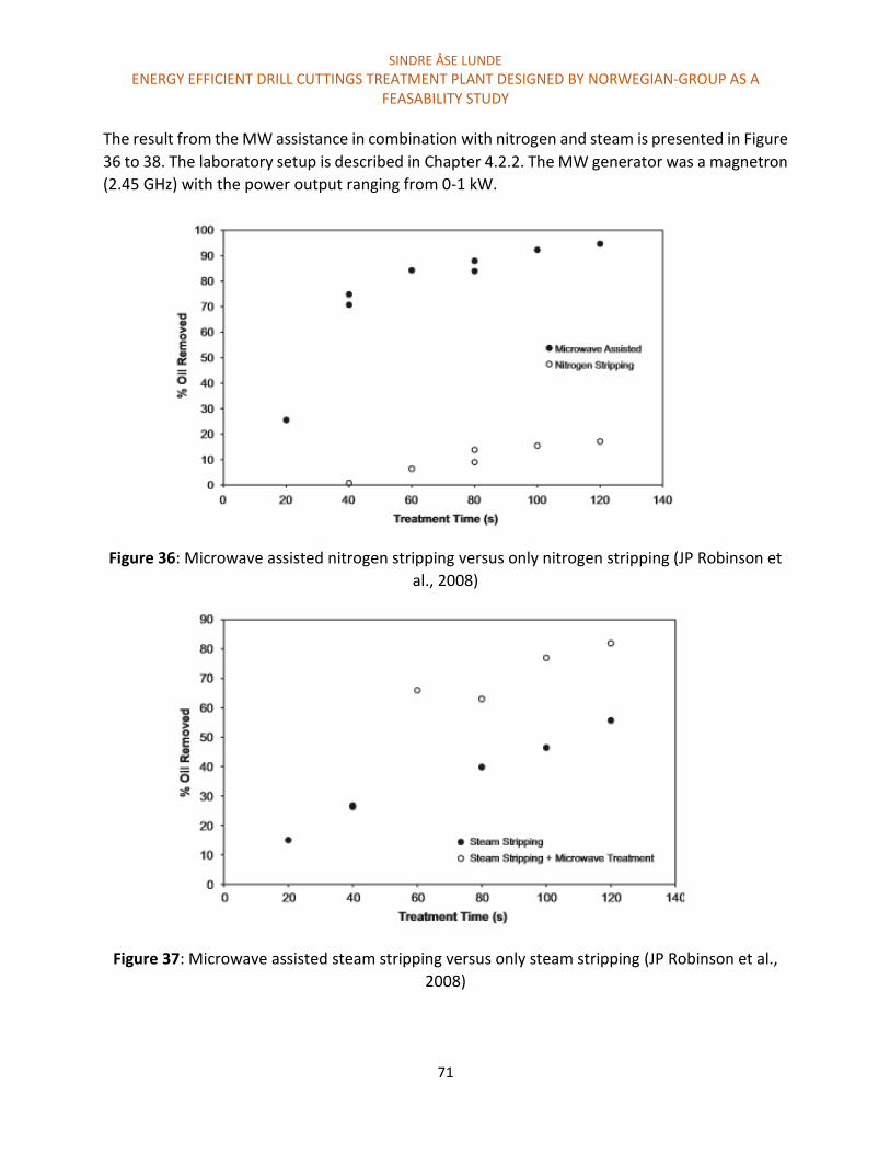
SINDRE ÅSE LUNDE
ENERGY EFFICIENT DRILL CUTTINGS TREATMENT PLANT DESIGNED BY NORWEGIAN-GROUP AS A FEASABILITY STUDY
71
The result from the MW assistance in combination with nitrogen and steam is presented in Figure
36 to 38. The laboratory setup is described in Chapter 4.2.2. The MW generator was a magnetron
(2.45 GHz) with the power output ranging from 0-1 kW.
Figure 36: Microwave assisted nitrogen stripping versus only nitrogen stripping (JP Robinson et
al., 2008)
Figure 37: Microwave assisted steam stripping versus only steam stripping (JP Robinson et al.,
2008)

SINDRE ÅSE LUNDE
ENERGY EFFICIENT DRILL CUTTINGS TREATMENT PLANT DESIGNED BY NORWEGIAN-GROUP AS A FEASABILITY STUDY
72
Figure 38: Energy requirements for only steam, only nitrogen and microwave enhanced nitrogen
stripping (JP Robinson et al., 2008)
In the conclusion of J.P Robinson, 120 second was used as a fundament for comparison.
Microwave assisted nitrogen stripping yielded 95 % removal compared to 80 % using microwave
assisted steam stripping. Without microwave assistance, the results where 18% and 55%
respectfully. Stripping with only nitrogen and steam required five minutes in order to achieve 60
% and 80 % separation efficiency respectfully. This is evident in Figure 16.
The reason for the difference in removal efficiency when nitrogen gas was supplied compared to
steam was believed to be a result of MW penetration depth. Both nitrogen and steam is
considered microwave transparent (JP Robinson et al., 2008). The steam that was supplied at 120
°C, condensed on the surface of the cuttings. This increased the microwave radiation absorbance.
The water condensation (deposit) occurred on the surface and in macrospores of the drill cuttings.
Oil present in this region was likely to be removed. The removal efficiency stagnated at 80 %
because the condensed water was deposit at the same places.
When dry nitrogen gas was utilized, MW penetrated the whole sample. As a result, increased
efficiency and desorption kinetics was achieved (JP Robinson et al., 2008).

SINDRE ÅSE LUNDE
ENERGY EFFICIENT DRILL CUTTINGS TREATMENT PLANT DESIGNED BY NORWEGIAN-GROUP AS A FEASABILITY STUDY
73
Discussion
The discussion is divided up in 3 categories. The microwave assisted steam and nitrogen
experiment will be discussed first, followed by future research and potential limitation of the
microwave assisted nitrogen desorption plant that was discussed in Chapter 3.3.1. In the last
discussion sub chapter, MW radiations ability to fit in to the treatment plant of Norwegian-Group
AS is presented.
The steam and nitrogen assisted microwave experiment
It is evident that MW penetration depth plays an important role in order to benefit from MW
radiation in combination with gas stripping. Without applying MW radiation, steam offers the
highest oil removal efficiency at 120 °C and 10 L/m.
Figure 36, 37 and 38 may not support enough information in order to conclude if steam or
nitrogen is the favorable support gas. Several modifications could be done in order improve the
results, including:
Increasing the gas (steam) temperature
Mixing or fluidizing the cuttings
Modify the MW frequency
Mixing may have a significant effect on the stripping processes. Based on the removal mechanism,
steam may benefit more from mixing than nitrogen gas. The condensed surface water permitted
MW radiation to penetrate the whole cuttings and thus reduced the removal efficiency. If mixing
was applied, better steam and microwave distribution could be achieved.
One of the most important modification is the steam temperature. Increasing the steam
temperature could affect the stripping processes in addition to the MW penetration depth. If
steam did not condensate on the cuttings surface, the MW penetration depth would be higher.
This may change the results significantly.
Another modification that could give different results when comparing nitrogen to steam is the
MW frequency. Lower frequency allow for deeper MW penetration depth. Reducing the
frequency to 915 MHz would yield higher penetration depth. This is evident in Table 10. Using
water at 25 °C as reference, 915 MHz would allow a penetration depth of 38.0 cm while 2.45 GHz
gives 1.4 cm. However, since the cuttings most likely contain a significant amount of salt, the
penetration depth may still be low.

SINDRE ÅSE LUNDE
ENERGY EFFICIENT DRILL CUTTINGS TREATMENT PLANT DESIGNED BY NORWEGIAN-GROUP AS A FEASABILITY STUDY
74
Evaluation of the microwave assisted nitrogen stripping plant
The MW assisted nitrogen stripping plant has the potential of increasing the treatment capacity
of 500 kg cuttings per hour by lowering the frequency and increasing the MW power output. The
treatment plant was sensitive to water content and cuttings characteristics. High water content
gave a tendency of decreased desorption rate, and increased the energy consumption. This is
evident in Figure 12 and Table 4. Lower desorption rate and higher energy consumption could be
a result of absorbed MW radiation by the surface water. This permits the MW to penetrate the
whole cuttings pile. As more MW radiation is absorbed, more energy is required.
Sandstone may cuttings require up to twice the energy consumption compared to shale base
cuttings. This was believed to be a result of the entrainment process. This process was not so
significant for non-porous cuttings.
If the water content is very low, the cuttings may become completely water dry before all the oil
is removed. This was considered the limiting factor with respect to separation degree during only
nitrogen stripping. If no water were present in the cuttings, the MW heating, and steam
distillation would not occur if nitrogen were added. For these reasons, the oil desorption would
most likely stagnate, and legislation requirements for discharge would not be fulfilled. This was
not evident in any experiment published. However, this scenario could be relevant.
In order to increase the treatment capacity, higher power output was suggested by J.P Robinson
(John Robinson et al., 2010). Lowering the frequency to 896 MHz or 433 MHz was also suggested
in the early research (JP Robinson et al., 2008). The implementation of lower frequencies did
require more research, and creating a pilot scale plant was considered more important.
Evaluation of applying microwave radiation in the steam assisted thermal desorption chamber
Norwegian-Group AS may generate an energy efficient treatment plant with high capacity if
utilizing MW radiation in combination with steam assistance in the thermal separation chamber.
The drill cuttings are pretreated in the steam assisted cuttings dryer before entering the thermal
separation chamber. This separation stage would also reduce the oil and water content
significantly. The reduced oil and water content could potentially increase the treatment capacity
significantly. Based on the assumptions presented in Table 7, 100 kg water would be evaporated
by the microwave radiation combined with steam assistance when treating 10 ton cuttings per
hour. This is relevant when assuming that all water in the cuttings waste needs to be evaporated
in order to reach the legislation requirements with respect to ROC. The required energy
deliverance could be roughly estimated. In order to simplify the calculation, the following
assumptions are made:

SINDRE ÅSE LUNDE
ENERGY EFFICIENT DRILL CUTTINGS TREATMENT PLANT DESIGNED BY NORWEGIAN-GROUP AS A FEASABILITY STUDY
75
The water inlet temperature is 20 °C
The steam exit temperature is 300 °C
The estimation in Table 7 is relevant
Based on table 2, 124 kW is required in order to distill and superheat 150 kg water from 20 °C to
300 °C. The pretreated drill cuttings would contain 100 kg water according to Table 7. If all water
is evaporated and heated from 20 to 300 °C, the required energy would be 83 kW/h.
The energy deliverance required by the microwave radiation depends on the energy transfer from
the steam.
A typical MW radiation setup offers the possibility to regulate the power deliverance. High power
magnetrons at 915 MHz can deliver 100 kW/tube, while a maximum of 30 kW/tube can be
achieved using 2.45 GHz (Sumper & Baggini, 2012). Using 915 MHz also offers increased
penetration depth. It is important to consider that the energy efficiency is typically between 50
to 70 percent. Utilizing several tubes could increase the energy output. Utilizing one magnetron
at 100 kW could potentially support a treatment capacity of 10 ton cuttings per hour based on
the estimated energy requirements.
In comparison to the microwave assisted nitrogen stripping plant, 10 ton cuttings would require
1000 kg water to be evaporated. Significantly higher power output would then be required.
One advantage when utilizing steam instead of nitrogen gas is that steam distillation would occur
independently of the water content present in the cuttings. However, if no water were present
in the cuttings, MW radiation would give no heat transfer. No water is less likely as the drilling
mud contains oil/water emulsions. However, there may be not enough water to separate all the
oil present in the drilling waste in some scenarios. In that case, steam alone must remove the oil.
Based on the results presented in Chapter 4.2.2, oil on cuttings would be desorbed. If mixing is
applied in combination with steam stripping, legislation requirements could be achieved. A
laboratory experiment could revile if this statement is valid.
Ion rich water decrease the penetration depth. This could affect the separation efficiency and
capacity. However, most of the ion rich water is likely to be removed in the steam-assisted
cuttings dryer. High penetration depth may therefore be achieved.
The cuttings are also preheated in the steam assisted cuttings dryer. This would also increase the
penetration depth.
It was mentioned in the discussion for the microwave assisted steam and nitrogen stripping
experiment that mixing may be beneficial with respect to oil removal. Better steam contact and
MW distribution could achieved with sufficient mixing. In the MW assisted nitrogen stripping
plant, a fiberglass conveyor belt was used for transporting cuttings through the thermal
separation chamber. Fiberglass was considered microwave transparent to temperatures up to
400 to 500 °C. Using a Fiberglass screw conveyor and supplying steam through cavities could offer
both mixing and better steam contact. Figure 39 illustrates this setup.

SINDRE ÅSE LUNDE
ENERGY EFFICIENT DRILL CUTTINGS TREATMENT PLANT DESIGNED BY NORWEGIAN-GROUP AS A FEASABILITY STUDY
76
Figure 39: Steam supplied in cavities under the screw conveyor. The screw conveyor is fitted
inside the thermal separation chamber
MW radiation offers an excellent ability to remove capillary bound water and oil. This relates to
microwaves ability to penetrate the stone, and heat up the water present in the pore. The water
evaporates and entrains oil present in the pore and on the surface. A concern is however if the
pore is saturated with oil. This may only be relevant when drilling through an oil saturation
formation. Little oil is exchanged with water during the drilling process because of waters high
attraction forces.
Capillary bound oil may be challenging to remove if no water is present in the pores. This is
considered challenging as the oil may be isolated and could therefore not be subjected to steam
distillation. Oil is also considered MW transparent. More research should also be performed in
order to determine the significance of this potential problem.

SINDRE ÅSE LUNDE
ENERGY EFFICIENT DRILL CUTTINGS TREATMENT PLANT DESIGNED BY NORWEGIAN-GROUP AS A FEASABILITY STUDY
77
4.3.2.4 Radio frequency heating Radio frequency (RF) heating is also referred to as capacitive heating. Heating is achieved by
generating an electric field at its specific frequency range. The typical system setup is two
conductive plates (electrodes) were alternating voltage is applied. The material to be heated is
placed between the electrodes like illustrated in Figure 40 (Sumper & Baggini, 2012).
Figure 40: Typical RF heating setup (Sumper & Baggini, 2012)
Typical RF heating system include a power supply, the applicator (or operation space), material
handling system, the material to be heated and sometimes a ventilation system. Different
configurations are possible and depend on the application. In Figure 41, different configurations
are illustrated (Sumper & Baggini, 2012).
Figure 41: Main types of applicators for RF heating. (a) stray field, (b) staggered through, (c) flat
plate and (d) welding electrode (Sumper & Baggini, 2012)
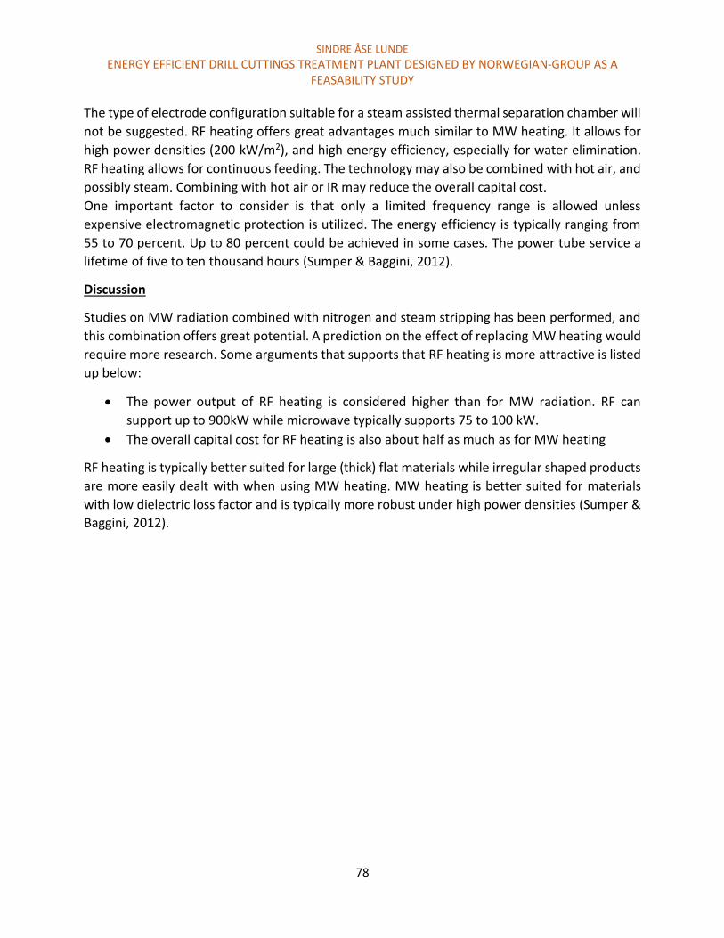
SINDRE ÅSE LUNDE
ENERGY EFFICIENT DRILL CUTTINGS TREATMENT PLANT DESIGNED BY NORWEGIAN-GROUP AS A FEASABILITY STUDY
78
The type of electrode configuration suitable for a steam assisted thermal separation chamber will
not be suggested. RF heating offers great advantages much similar to MW heating. It allows for
high power densities (200 kW/m2), and high energy efficiency, especially for water elimination.
RF heating allows for continuous feeding. The technology may also be combined with hot air, and
possibly steam. Combining with hot air or IR may reduce the overall capital cost.
One important factor to consider is that only a limited frequency range is allowed unless
expensive electromagnetic protection is utilized. The energy efficiency is typically ranging from
55 to 70 percent. Up to 80 percent could be achieved in some cases. The power tube service a
lifetime of five to ten thousand hours (Sumper & Baggini, 2012).
Discussion
Studies on MW radiation combined with nitrogen and steam stripping has been performed, and
this combination offers great potential. A prediction on the effect of replacing MW heating would
require more research. Some arguments that supports that RF heating is more attractive is listed
up below:
The power output of RF heating is considered higher than for MW radiation. RF can
support up to 900kW while microwave typically supports 75 to 100 kW.
The overall capital cost for RF heating is also about half as much as for MW heating
RF heating is typically better suited for large (thick) flat materials while irregular shaped products
are more easily dealt with when using MW heating. MW heating is better suited for materials
with low dielectric loss factor and is typically more robust under high power densities (Sumper &
Baggini, 2012).
SINDRE ÅSE LUNDE
ENERGY EFFICIENT DRILL CUTTINGS TREATMENT PLANT DESIGNED BY NORWEGIAN-GROUP AS A FEASABILITY STUDY
79
Chapter 5: Conclusion and Recommendations
The aim of this thesis is to determine if the treatment plant concept of Norwegian-Group AS is
feasible. This included an evaluating of the separation concepts. A part of the feasibility study is
also to recommend solutions that would make the treatment plant attractive compared to
conventional cuttings handling technologies. Conclusions and recommendations are presented
below:
1. Is it possible to modify the cuttings dryer to allow for steam assistance?
Evaluate potential steam supply system was considered the objective. Modifying the whole
cuttings dryer to support steam assistance would require more research. However, fitting a steam
supply system to the cuttings dryer is believed to be an important part of the modification.
Different steam supply systems should be closely evaluated in order to achieve optimal
separation degree, low steam consumption, and high robustness. Benefitting from supplying
steam is considered feasible based on the suggested steam supply alternatives.
2. What may be the consequences of supplying steam in the cuttings dryer?
Overall, it is expected that supplying steam would lead to increase oil separation. There may be
many mechanisms involved that contributes to increased separation degree. Heat transfer may
play a significant role. The steam supply systems may be of great relevance in order to achieve
increased oil separation. Supplying steam through nozzles where steam is added directly on the
cuttings could both result in decreased steam consumption and increased separation degree. This
is believed to be a result of increased Reynolds number and better steam contact.
A potential negative consequence of supplying steam is that the mud quality could be affected.
Mud from the cuttings dryer is recirculated and reused after separation. Supplying steam could
affect the mud properties in general, and the mud may not be suitable for reuse. This may result
in increased cuttings handling costs.
3. Is membrane separation of oil and water vapor considered an attractive solution in order
to reduce the energy and cuttings handling costs?
Based on estimations, the majority of oil and water is removed in liquid phase. As a result,
potentially low amounts of steam may be generated. The required steam consumption in the
steam assisted cuttings dryer and thermal separation chamber is also estimated to be relatively
low. The maximum energy reduction was estimated to 34 kW/ton cuttings. This is relevant when
assuming no energy consumption or energy loss during the membrane separation process.

SINDRE ÅSE LUNDE
ENERGY EFFICIENT DRILL CUTTINGS TREATMENT PLANT DESIGNED BY NORWEGIAN-GROUP AS A FEASABILITY STUDY
80
Assuming an energy price of 1 NOK/kW, the cost reduction would be 34 NOK per ton cuttings. It
is possible that the cost of separating the oil and water vapor by membranes exceeds 34 NOK per
ton cuttings. The potential cost reduction was considered insignificant related to the cuttings
handling cost of 6500 NOK/ton cuttings.
No literature was found on separation of oil and water vapor by membranes. Some concerns with
respect to the separation processes included:
The costs associated with membrane separation
The size of the membrane separation equipment
The feasibility of the separation process
Steam recovery by membrane separation in order to reduce the cuttings handling cost was
considered challenging as the estimated potential cost reduction was relatively small.
4. What heat source is considered most attractive in the steam assisted thermal separation
chamber?
The most attractive heating principle in the steam assisted thermal separation chamber is
believed to be dielectric heating. Microwave heating in particular, is recommended as a
potential heat source. Based on previous research on MW in combination with nitrogen gas
stripping, and several estimation, a prediction of the potential treatment capacity was
calculated. A treatment capacity of 10 ton cuttings per hour was considered feasible when
considering that the cuttings are pretreated by the steam assisted cuttings dryer. However,
the treatment capacity is affected by several suggested modifications. The modifications
relate to the articles published by J.P Robinson in the process of creating the microwave
assisted nitrogen stripping plant. The modifications are listed up below:
Decreasing the frequency from 2.45 GHz to 915 MHz and increasing the power
output from 30kW to 100 kW. This could be achieved by utilizing high powered
magnetrons.
Utilize high steam temperature so that less steam would condense on the cuttings
and interfere with the MW penetration depth. Research on the effect of
temperature in combination with mixing and lower frequency would revile the
optimal conditions.
Achieve mixing inside the thermal separation chamber. A suggestion was to utilize
a fiberglass screw conveyor, and add steam in cavities below the cuttings.

SINDRE ÅSE LUNDE
ENERGY EFFICIENT DRILL CUTTINGS TREATMENT PLANT DESIGNED BY NORWEGIAN-GROUP AS A FEASABILITY STUDY
81
It is believed that MW in combination with steam would fulfill the legislation requirements
for various cuttings characteristics. However, a potential limitation is if the cuttings pores
are saturated with oil, and no water is present.
Radiofrequency heating is also considered dielectric heating. More research is required in
order to evaluate the feasibility of applying RF heating. The advantages of RF heating
include lower capital costs and higher power output.
5. On what premises will the treatment plant concept compete or outcompete current
cuttings handling options?
Handling cuttings offshore or at the drilling sight is considered economical and logistical
attractive. The TCC is considered BAT, and may be the main competitor with respect to
treating cuttings offshore. The Cutcube could also be a potential competitor, but little
information was found regarding this product. Research on the treatment plant concept of
Norwegian-Group AS is in an early stage. However, if the estimations are correct, the
treatment plant could potentially offer the following advantages compared to TCC:
Higher treatment capacity
Low energy consumption
Handling cuttings at their original shape
The possibility to reused the drilling mud from the cuttings dryer
Potentially lower handling cost
Higher treatment capacity may be the most important factor as cuttings are typically
generated at a higher rate than the treatment capacity of the TCC.
An attractive advantage from utilizing the steam assisted cuttings dryer is that drilling mud
can potentially be recirculated. This may reduce the handling costs significantly.
Lower energy consumption could be relevant because much water and oil is removed in liquid
phase. Another factor that could reduce the energy consumption is selective heating by MW
radiation. Only the water is heated directly by the heat source. All the drilling waste is heated
directly in the TCC treatment plant.
In general, the treatment plant is considered robust as the cuttings dryer achieves good
separation efficiency for larger non-porous cuttings, while MW radiation achieves better
results for porous cuttings. The advantage of supplying steam in the thermal separation
chamber is that steam distillation would occur independent of the water content in the
cuttings.

SINDRE ÅSE LUNDE
ENERGY EFFICIENT DRILL CUTTINGS TREATMENT PLANT DESIGNED BY NORWEGIAN-GROUP AS A FEASABILITY STUDY
82
6. Is there any challenges or limitations that the treatment plant a faced with?
The treatment plant research is in an early stage, and may be faced with several challenges. Some
fundamental potential limitations are listed below:
The legislation requirements with respect to ROC for various cuttings characteristics may
not be fulfilled. Low water content, and oil saturated pores are considered challenging
conditions.
MW radiation may impose HSE issues when located on a drilling rig.
Increased handling cost could be relevant if the separated mud characteristics are not
suitable for reuse separation in the steam assisted cuttings dryer.

SINDRE ÅSE LUNDE
ENERGY EFFICIENT DRILL CUTTINGS TREATMENT PLANT DESIGNED BY NORWEGIAN-GROUP AS A FEASABILITY STUDY
83
Chapter 6: Future research
In this thesis, a rough overall evaluation of the treatment plant concept was performed. More
research is required in every aspect of the treatment plant. The suggestions are categorized based
on the separation principles:
6.1 Super heated steam drying Super heated steam is considered a major contributor to the oil separation efficiency. Steam is
added in the cuttings dryer and in the thermal separation chamber. Suggested future research
with respect to super heated stripping is listed up below:
1. Determine the optimal stripping temperature in the cuttings dryer and thermal separation
chamber.
2. Determine the effect of mixing the cuttings in combination with steam stripping and steam
stripping combined with microwave radiation.
3. Determine the significance of interstitial bound oil with respect to total ROC, and
determine if superheated steam could desorb this oil.
The suggested research could potentially be performed in small scale laboratory tests. The
information gained from the experiments could be of great value when estimating the challenges
and expected results from a large-scale treatment plant.
6.2 Steam assisted cuttings dryer Modify the cuttings dryer to allow for steam assistance would require more research. Addressing
all the challenging aspects related to supplying steam is considered important. Implementing the
steam supply systems would require more research and testing.
6.3 Thermal separation chamber MW radiation is considered the most attractive heat source to be combined with steam in the
thermal separation chamber. Future research includes:
1. Determine the effect of lowering the MW frequency on treatment capacity.
2. Determine the optimal steam temperature to be combined with microwave radiation.
3. Determine if legislation requirements could be reached in the thermal separation
chamber when treating cuttings with low oil and water content. Cuttings with low water
and oil content simulate cuttings treated with a steam assisted cuttings dryer.
SINDRE ÅSE LUNDE
ENERGY EFFICIENT DRILL CUTTINGS TREATMENT PLANT DESIGNED BY NORWEGIAN-GROUP AS A FEASABILITY STUDY
84
It was mentioned that RF heating could potentially replace MW heating. More research is
required in order to evaluate if this is feasible.
6.4 Membrane separation of oil and water vapor Separating and recirculating steam is considered unnecessary due to the potentially low cost
reduction. The cost reduction was based on estimation. Future research could revile that the
estimations was not representative, and that energy recovery is necessary. More research on the
feasibility of oil and steam vapor separation by membranes would then be required.
Other separation methods could serve the same purpose. An evaluation of different separation
methods should be performed.
SINDRE ÅSE LUNDE
ENERGY EFFICIENT DRILL CUTTINGS TREATMENT PLANT DESIGNED BY NORWEGIAN-GROUP AS A FEASABILITY STUDY
85
References
Aktivitetsforeskriften. (2010). Forskrift om inføring av aktiviteter i petroleumsvirksomheten Retrieved 2014.11.16, from https://lovdata.no/dokument/SF/forskrift/2010-04-29-613#KAPITTEL_11
Alba Rodriguez, A., Fragachan, F. E., Ovalle, A., & Shokanov, T. A. (2007). Environmentally Safe Waste Disposal: The integration of Cutting Collection Transportation and Re-Injection. Paper presented at the International Oil Conference and Exhibition in Mexico.
American Society of Mechanical Engineers. Shale Shaker, C. (2005). Drilling fluids processing handbook. Amsterdam ; Boston : Burlington, Mass.: Amsterdam ; Boston : Elsevier ; Burlington, Mass. : Gulf Professional Pub.
Aquateam COWI. (2013). Årsrapport. Retrieved 2015.01.08, from http://www.aquateam.no/attachments/article/281/%C3%85rsrapport2013.pdf
Baker, R. W. (2012). Membrane technology and applications Bogdanov, I., Torres, J., Kamp, A. M., & Corre, B. (2011). Comparative Analysis of Electromagnetic
Methods for Heavy Oil Recovery. Paper presented at the SPE Heavy Oil Conference and Exhibition.
Borgnakke, C., Sonntag, R. E., & Van Wylen, G. J. (2009). Fundamentals of thermodynamics (7th ed., SI version. ed.). Hoboken, N.J: Wiley.
Bratina, J. E., Bowering, D., Kriech, A., Eyster, P., & Roberts, T. (2012). Induction heated gasifier: Google Patents.
Breuer, E., Stevenson, A., Howe, J., Carroll, J., & Shimmield, G. (2004). Drill cutting accumulations in the Northern and Central North Sea: a review of environmental interactions and chemical fate. Marine Pollution Bulletin, 48(1), 12-25.
Cannon, R., & Martin, D. (2001). Reduction of Synthetic Based Fluid Discharges Offshore by the Use of Vertical Basket Centrifuges. Paper presented at the SPE/EPA/DOE Exploration and Production Environmental Conference.
Charles, M., Sayle, S., Phillips, N. W., & Morehouse, D. (2010). Offshore drill cuttings treatment technology evaluation. Paper presented at the SPE International Conference on Health Safety and Environment in Oil and Gas Exploration and Production.
Cheryan, M. (1998). Ultrafiltration and microfiltration handbook (2nd ed. ed.). Lancaster, Pa: Technomic Publ.
Department of Chemistry. (2004). Boiling Points and Distillation. Retrieved 2014.11.28, from http://www.chem.wisc.edu/courses/342/Fall2004/Distillation.pdf
DNV. (2013). Vurdering av oljeholdig avfall fra petroleumsvirksomhet til havs. DNV referanse:nr. 149JIOC-3, Rapport:nr. 2012-4087/DNV.
El-sayed, A., & El-Naga, K. H. A. (2001). Treatment Of Drill Cuttings. Paper presented at the SPE/EPA/DOE Exploration and Production Environmental Conference.
Fabel Media AS. (2014). Product movie - Cubility Cutcube. Retrieved 2014.11.26, from http://vimeo.com/96201148
Fisher, S. (1979). Electrical induction heating: A new approach to underground coal gasification. Energy Conversion, 19(2), 77-84.
Forurensningsloven. (2014). Law and protection against pollution and waste. Retrieved 2014.11.16, from https://lovdata.no/dokument/NL/lov/1981-03-13-6
SINDRE ÅSE LUNDE
ENERGY EFFICIENT DRILL CUTTINGS TREATMENT PLANT DESIGNED BY NORWEGIAN-GROUP AS A FEASABILITY STUDY
86
Guo, Q., & Abou-Sayed, A. S. (2003). Worldwide Drill Cuttings Injection Permitting Requirements and Guidelines. Paper presented at the SPE/EPA/DOE Exploration and Production Environmental Conference.
Gupta, M., & Leong, E. W. W. (2008). Microwaves and metals: John Wiley & Sons. Jeney, P. (2009). Coated susceptor for a high-temperature furnace and furnace comprising such a
susceptor: Google Patents. Jeney, P. (2010). High temperature furnace with an oxygen-free infeed section and use of such a furnace:
Google Patents. Karban, P., Mach, F., & Doležel, I. (2013). Modeling of rotational induction heating of nonmagnetic
cylindrical billets. Applied Mathematics and Computation, 219(13), 7170-7180. Kirkness, A. J. (2008). Treatment of Nonaqueous-Fluid-Contaminated Drill Cuttings—Raising
Environmental and Safety Standards. Paper presented at the IADC/SPE Drilling Conference. Kleppe, S., Michelsen, E., Handgraaf, P., Albriktsen, P., & Haugen, A. (2009). Reusing Recovered Base Oil
From OBM Cuttings. Paper presented at the Asia Pacific Health Safety Security and Environment Conference.
Matthew, W. (2014). Superheated steam distillation for treatment of drill cuttings contaminated with oil based drilling fluids. (Master).
Mehdizadeh, M. (2009). Microwave/RF Applicators and Probes for Material Heating, Sensing, and Plasma Generation : A Design Guide. Burlington, MA, USA: Elsevier Science & Technology.
Melton, H., Smith, J., Mairs, H., Bernier, R., Garland, E., Glickman, A., . . . Campbell, J. (2004). Environmental aspects of the use and disposal of non aqueous drilling fluids associated with offshore oil & gas operations. Paper presented at the SPE International Conference on Health Safety and Environment in Oil and Gas Exploration and Production.
Miljødirektoratet1. (2014). Drilling at Martin Linge PL043. Retrieved 2014, from http://www.miljodirektoratet.no/Documents/Nyhetsdokumenter/martinlinge_3609-2013-tillatelse040814.pdf
Miljødirektoratet3. (2014). Map of Martin Linge-field. Retrieved 2014.11.16, from http://www.miljodirektoratet.no/no/Nyheter/Nyheter/2014/August-2014/Renser-borekaks-offshore/
Miljødirektoratet4. (2008). Beskrivelse av miljøteknologi. Retrieved 2013.12.03, from http://www.xn--miljdirektoratet-oxb.no/old/dirnat/attachment/968/OD_Milj%C3%B8teknologirapport_110408.pdf
Miljødirektoratet. (2014). Miljødirektoratet - Petroleumseksjonen (IPE). Retrieved 2014.11.16, from http://www.miljodirektoratet.no/no/Om-Miljodirektoratet/Organisasjonskart/Industriavdelingen-IAL/Seksjon-for-petroleumsvirksomhet-IPV/
Mujumdar, A. S. (2006). Handbook of industrial drying: CRC Press. Murray, A. J., Kapila, M., Ferrari, G., Degouy, D., Espagne, B. J.-L., & Handgraaf, P. (2008). Friction-Based
Thermal Desorption Technology: Kashagan Development Project Meets Environmental Compliance in Drill-Cuttings Treatment and Disposal. Paper presented at the SPE Annual Technical Conference and Exhibition.
Ormeloh, J. (2014). Thermomechanical cuttings cleaner – qualification for offshore treatment of oil contaminated cuttings on the norwegian continental shelf and martin linge case study: University of Stavanger, Norway.
OSPAR1. (2014). Definition OSPAR,. Retrieved 2014.11.16, from http://www.ospar.org/content/content.asp?menu=00010100000000_000000_000000

SINDRE ÅSE LUNDE
ENERGY EFFICIENT DRILL CUTTINGS TREATMENT PLANT DESIGNED BY NORWEGIAN-GROUP AS A FEASABILITY STUDY
87
OSPAR2. (2014). OSPAR discharge regulations. Retrieved 2014.11.16, from http://www.ospar.org/content/content.asp?menu=00120000000059_000000_000000
OSPAR3. (2014). OSPAR Principples. Retrieved 2014.11.16, from http://www.ospar.org/content/content.asp?menu=00430109150000_000000_000000
OSPAR2000/3. (2000). Decision 2000/3. Retrieved 2014.11.16 from http://www.ospar.org/v_measures/browse.asp
Paulsen, J. E., Omland, T. H., Igeltjørn, H., Aas, N., & Solvang, S. A. (2003). Drill Cuttings Disposal Balancing Zero Discharge and Use of Best Available Technique. Paper presented at the SPE/IADC Middle East Drilling Technology Conference and Exhibition.
Robinson, J., Kingman, S., & Onobrakpeya, O. (2008). Microwave-assisted stripping of oil contaminated drill cuttings. Journal of environmental management, 88(2), 211-218.
Robinson, J., Kingman, S., Snape, C. E., Antonio, C., Pereira, I., Page, P. W., & Thomas, D. (2010). Microwave treatment of oil contaminated drill cuttings-Toward a commercial scale system. Paper presented at the SPE International Conference on Health, Safety and Environment in Oil and Gas Exploration and Production.
Robinson, J., Kingman, S., Snape, C. E., Bradley, M., Bradshaw, S., Thomas, D. J., & Page, P. W. (2008). Microwave treatment of oil-contaminated drill cuttings at pilot scale. Paper presented at the SPE International Conference on Health Safety and Environment in Oil and Gas Exploration and Production.
Rudnev, V., Loveless, D., Cook, R. L., & Black, M. (2002). Handbook of induction heating: CRC Press. Rudolf, R., Mitschang, P., & Neitzel, M. (2000). Induction heating of continuous carbon-fibre-reinforced
thermoplastics. Composites Part A: Applied Science and Manufacturing, 31(11), 1191-1202. Runde, M., & Magnusson, N. (2002). Induction heating of aluminium billets using superconducting coils.
Physica C: Superconductivity, 372, 1339-1341. Sahni, A., Kumar, M., Knapp, R. B., & Livermore, L. (2000). Electromagnetic heating methods for heavy oil
reservoirs. paper SPE, 62550. Sakr, M., & Liu, S. (2014). A comprehensive review on applications of ohmic heating (OH). Renewable and
Sustainable Energy Reviews, 39, 262-269. Seaton, S., & Hall, J. (2005). Recovery of oil From drilled cuttings by liquefied gas extraction. Paper
presented at the SPE International Symposium on Oilfield Chemistry. Shang, H., Snape, C., Kingman, S., & Robinson, J. (2006). Microwave treatment of oil-contaminated North
Sea drill cuttings in a high power multimode cavity. Separation and purification technology, 49(1), 84-90.
Stephenson, R. L., Seaton, S., McCharen, R., Hernandez, E., & Pair, R. B. (2004). Thermal desorption of oil from oil-based drilling fluids cuttings: processes and technologies. Paper presented at the SPE Asia Pacific Oil and Gas Conference and Exhibition.
Street, C. G., Tesche, C., & Guigard, S. (2009). Treatment of Hydrocarbon-Based Drilling Waste Using Supercritical Carbon Dioxide. SPE Drilling & Completion, 24(03), 413-417.
Sumper, A., & Baggini, A. (2012). Electrical energy efficiency: technologies and applications: John Wiley & Sons.
Svensen, T., & Taugbol, K. (2011). Drilling Waste Handling in Challenging Offshore Operations (Russian). Paper presented at the SPE Arctic and Extreme Environments Conference and Exhibition.
The Norwegian Oil and Gas Association. (2013). 093 Recommended guidelines for waste managment in the offshore industry. Retrieved 2013.01.25 http://www.norskoljeoggass.no/Global/Retningslinjer/Milj%C3%B8/093_Recommended%20Guidelines%20for%20Waste%20Management%20in%20the%20Offshore%20Industry.pdf
SINDRE ÅSE LUNDE
ENERGY EFFICIENT DRILL CUTTINGS TREATMENT PLANT DESIGNED BY NORWEGIAN-GROUP AS A FEASABILITY STUDY
88
TWMA TCC RotoMill. (2014). TCC Offshore Processing. Retrieved 2014.11.24, from http://www.twma.co.uk/Offshore-processing
Van 't Land, K. (2003). Advanced Drying Technologies By T. Kudra and A. S. Mujumdar. Marcel Dekker: New York. 2002. 459 pp. $175.00. ISBN 0-8247-9618-7. Organic Process Research & Development, 7(1), 121-122. doi: 10.1021/op010102p
Vasshus, J. K., & Malmin, A. (2013). Cleaning device: Google Patents. Zinn, S., & Semiatin, S. L. (1988). Elements of Induction Heating : Design, Control, and Applications.
Materials Park, OH, USA: A S M International.
Copyright © 2022 FDOKUMEN