SAFETY IN NORWEGIAN DRILL AND BLAST TUNNELLING
72
NORWEGIAN T UNNELLING S OCIETY PUBLICATION NO. 27 1 PUBLICATION NO. 27 NORWEGIAN TUNNELLING SOCIETY SAFETY IN NORWEGIAN DRILL AND BLAST TUNNELLING
-
Upload
khangminh22 -
Category
Documents
-
view
5 -
download
0
Transcript of SAFETY IN NORWEGIAN DRILL AND BLAST TUNNELLING

NORWEGIAN TUNNELLING SOCIETY PUBLICATION NO. 27
1 PUBLICATION NO. 27
NORWEGIAN TUNNELLING SOCIETY
SAFETY IN NORWEGIAN DRILL AND BLAST
TUNNELLING
NORSK FORENING FOR FJELLSPRENGNINGSTEKNIKK
Norwegian Tunnelling Sosiety
[email protected] - www.tunnel.no
www.nff.no
REPRESENTS EXPERTISE IN• Hard Rock Tunnelling techniques• Rock blasting technology• Rock mechanics and engineering ge-
ology
USED IN THE DESIGN AND CONSTRUCTION OF• Hydroelectric power development,
including:- water conveying tunnels- unlined pressure shafts- subsurface power stations- lake taps- earth and rock fill dams
• Transportation tunnels• Underground storage facilities
• Underground openings for public use
NORWEGIAN TUNNELLING SOCIETY
Photo: Hæhre Entreprenør AS

SAFETY IN NORWEGIAN DRILL AND BLAST TUNNELLING
Publication No. 27
NORWEGIAN TUNNELLING SOCIETY2018
DESIGN/PRINT BY KONSIS, OSLO, NORWAY

NorwegiaN TuNNelliNg SocieTy PublicaTioN No. 27
4
PUBLICATION NO. 27
© Norsk Forening for Fjellsprengningsteknikk NFF
ISBN 978-82-92641-41-5
Front page image: AF Gruppen
Layout/Print:Konsis Grafisk [email protected]
DISCLAIMER
“Readers are advised that the publications fromThe Norwegian Tunnelling Society (NFF) are issuedsolely for informational purpose. The opinions and statements included are based on reliable sources in good faith. In no event, however, shall NFF or the authors be liable for direct or indirect incidental orconsequential damages resulting from the use of this information.”

NorwegiaN TuNNelliNg SocieTy PublicaTioN No. 27
5
The Norwegian Tunnelling Society (NFF) is a society open to individuals, companies, institutions and gov-ernment services that are engaged in or associated with the construction industry where use of the under-ground and the related work tasks and disciplines are central.
The Society’s members, both personal and corporate, come from every single segment in the industry chain. The publication Safety in Norwegian Drill and Blast Tunnelling is part of a series of publications published by NFF and has been produced under the direction of NFF’s Development Committee.
In the text, reference is made to several Norwegian laws and regulations. We have explained the main intention of these legislative texts, but for a fuller understanding of the scope of their provisions, we recom-mend they be consulted in their entirety. Some already exist in English translation, others may need to be translated. This publication is intended to be used by qualified persons who understand the limitations of a concise publication.
Its content reflects the state of knowledge at the time of editing completion. Whilst every effort has been made to assure the quality of the publication, it may nevertheless contain errors and omissions. NFF and/or the authors are not liable for any errors and/or omissions in the publication or for the consequences thereof.Examples of forms that can be used for tasks specified in regulations are included in the appendices. For practical use, these forms can be downloaded from NFF’s website www.nff.no.
The publication deals with matters related to safety in the performance of various types of work under-ground and provides recommendations as to how safety may be ensured, but the solutions must be adapted to each individual project.
The working group responsible for this publication was composed of the following members:
Preface
John Ivar Fagermo Veidekke EntreprenørHerman Messelt Veidekke EntreprenørØystein Birkeland Hæhre Entreprenør Glenn Seland Norwegian Union of General WorkersOdd T. Johannesen Norwegian Labour Inspection AuthorityMarie Halvorsen Norwegian National Rail AdministrationJan Erik Lien Norwegian Public Roads AdministrationPeder Andersen Andersens Mek. VerkstedRoar Sve Skanska NorwayArild Berglund Skanska NorwayThor Skjeggedal Skjeggedal Construction ServicesStein Rune Sakshaug Nye veierJarle Gausen Secretary
NFF would like to thank everyone who has contributed to this publication. It is hoped it will be a useful resource in relation to safe operations during the construction of tunnels and rock caverns.
In particular, the working group would like to express their gratitude to all participants of the group interviews that were conducted in several tunnelling projects in Norway. Thank you for being willing to take part and share with us your experience, insight and knowledge of what it is like to be a tunnel construction worker.
Oslo, March 2018
Norwegian Tunnelling Society (NFF)Development Committee

NORWEGIAN TUNNELLING SOCIETY PUBLICATION NO. 27
6

NorwegiaN TuNNelliNg SocieTy PublicaTioN No. 27
7
Contents
Preface ................................................................................................................................................................ 3
1. Introduction ................................................................................................................................................91.1. Scope of the publication ...................................................................................................................................................... 91.2. Content ..................................................................................................................................................................................... 9
2. Group interview and methodology .......................................................................................................... 10
3. Definitions .................................................................................................................................................. 113.1. Danger zone ............................................................................................................................................................................. 113.2. Risk.............................................................................................................................................................................................. 113.3. Hazard source ......................................................................................................................................................................... 113.4. Risk assessment ...................................................................................................................................................................... 113.5. Work permit ............................................................................................................................................................................. 113.6. Safe Job Analysis ................................................................................................................................................................... 113.7. Work instructions .................................................................................................................................................................. 11
DEL 1
4. The participants’ tasks, responsibilities and obligations ........................................................................134.1. The client’s responsibilities ............................................................................................................................................... 134.2. The designer’s responsibilities and obligations ...........................................................................................................144.3. The principal contractor’s responsibilities ....................................................................................................................144.4. The employer’s responsibilities ......................................................................................................................................... 154.5. The foreman’s responsibilities and obligations ............................................................................................................ 154.6. The employee’s duty of participation ............................................................................................................................. 154.7. The role of the safety representative .............................................................................................................................. 15
5. Systematic approach to health, safety and environment management .................................................175.1. General risks in underground works ................................................................................................................................ 175.2. Risk management .................................................................................................................................................................. 185.3. HSE plan for rock works ...................................................................................................................................................... 195.4. Organisation (appropriate planning) of rock works ................................................................................................... 195.5. Contingency measures .......................................................................................................................................................205.6. Working environment measures ...................................................................................................................................... 225.7. Reporting of non-conformances, incidents and accidents involving explosives .............................................. 235.8. Conduct in the event of fire in a tunnel/rock cavern during construction work .............................................. 23

8
DEL 2
6. Preparatory works – rigging and operation ............................................................................................ 256.1. High-voltage and other electrical works ...................................................................................................................... 25
7. Work activities .......................................................................................................................................... 277.1. Tunnel entrance – initial approach .................................................................................................................................. 277.2. Work ahead of the tunnel work face ..............................................................................................................................29 7.2.1. General considerations ..........................................................................................................................................29 7.2.2. Drilling of probe and control holes .................................................................................................................... 31 7.2.3. Grout hole drilling .................................................................................................................................................... 31 7.2.4. Core drilling .............................................................................................................................................................. 31 7.2.5. Grouting ...................................................................................................................................................................... 317.3. Work at the face ................................................................................................................................................................... 33 7.3.1. Blasthole drilling ...................................................................................................................................................... 33 7.3.2. Charging .................................................................................................................................................................... 35 7.3.3. Warning prior to blasting ..................................................................................................................................... 37 7.3.4. Blasting ...................................................................................................................................................................... 37 7.3.5. Handling of partially detonated rounds (misfires) ....................................................................................... 37 7.3.6. Storage, temporary placement, transport and handling of explosives .................................................. 37 7.3.7. Loading ...................................................................................................................................................................... 37 7.3.8. Transport of excavated material ....................................................................................................................... 38 7.3.9. Tip site ........................................................................................................................................................................397.4. Rock support work ...............................................................................................................................................................39 7.4.1. Mechanised scaling.................................................................................................................................................40 7.4.2. Manual scaling..........................................................................................................................................................40 7.4.3. Bolting ........................................................................................................................................................................42 7.4.4. Sprayed concrete ....................................................................................................................................................43 7.4.5. Heavy rock support ................................................................................................................................................437.5. Work behind the face ..........................................................................................................................................................44
8. Work requiring coordination (during tunnel driving) .............................................................................47
9. Rehabilitation of existing tunnels and rock caverns ................................................................................51
10. Relevant Norwegian laws and regulations .............................................................................................. 53
11. Literature list .............................................................................................................................................54
12. Appendices ............................................................................................................................................... 55
Information letter and consent form for group interview participants ......................................................... 57Interview guide ................................................................................................................................................58Template/Example Work Permit .....................................................................................................................59Safe Job Analysis (SJA) - tips and advice .......................................................................................................62SJA - Safe Job Analysis ....................................................................................................................................63Norwegian Tunnelling Society NFF International Support Group .................................................................64Orderform .........................................................................................................................................................67

9
Extensive tunneling
competence
Follow us on ncc.group and social media.
NCC is one of the leading construction companies in northern Europe.
ncc.group
Phot
o: R
obin
Ste
ners
en

INNOVATION RUNS DEEP
Where others hit the wall,we break through.
www.amv-as.no
High quality heavy duty tunneling and mining equipment
has been an AMV hallmark since 1860.
As a total supplier of tunnelling solutions AMV offers a wide sortiment of
both standardized and custom builds.
Behind every piece of machinery, every technological breakthrough
and every successful project you’ll find a professional
and innovative staff at your service, from drilling of the first blast hole
until the last boulder falls.
Our well-proven machines and solutionshelp companies go deeper all over the globe.
We’re proud of that.But it’s no coincidence.

NorwegiaN TuNNelliNg SocieTy PublicaTioN No. 27
11
The publication Safety in Norwegian Drill and Blast Tunnelling is intended to be a resource and a guide to promote safe operations from planning stage to completed project. The aim is that the book should help the owner or client, designer and contractor to:
• think safety throughout the planning, design and execution phases of a project
• prepare specifications and tender documents that are detailed and clear in regards to pricing of safety measures
• clarify specific requirements in Norwegian public laws and regulations in connection with project design and execution
• draw up SJA plans and HSE plans• describe the risk factors for different types of
work in tunnels and rock caverns• provide information about the effect such fac-
tors may have on safety• describe measures and good practice for ensur-
ing safety underground• carry out work in tunnels, rock caverns and
shafts in a safe manner
The publication consists of two parts:Part 1 (chapters 4 - 6), which primarily addresses clients, designers, coordinators etc; and
Part 2 (chapters 7 - 9), which describes “best prac-tice” and is aimed at employers, foremen and tunnel construction workers.
The project participants mentioned above, all have in common an obligation to carry out risk assess-ment in all phases of a project. This assessment shall be made in keeping with Norwegian Standard NS 5815:2006 Risk Assessment of Construction Work.
This standard relates to risk assessment of the actual performance of construction work. Since the works may vary in scope and complexity from project to project, it is important to point out that the require-ments for risk assessment laid out in the standard are minimum requirements.
The risk of personal injury, damage to the environ-ment (including the external environment), mate-
rial damage and any own-defined success factors and goals are all covered by the standard. This also extends to damage and inconvenience for third par-ties, for example, neighbours to the construction site. The standard is intended to be used for both large and small projects.
A number of laws and regulations relating to under-ground works are referred to throughout the text. The relevant documents are listed at the end of the publication.
1.1. Scope of the publicationThis publication relates to underground rock works, which are described as:
All forms of rock breaking, including work on inspec-tion, scaling and installing rock support. It also includes loading and transport of blasted rock within the workplace in connection with:
• building tunnels and rock caverns for railway projects, road projects, power stations, parking facilities, storage halls and other rock caverns
• shaftexcavation
The publication does not cover work in mines and work or driving tunnels with tunnel boring machines (TBMs).
1.2. Content The publication describes:
• work in front of the tunnel face, at and behind the face
• transport of rock to an on-site deposit, or to the border thereof
• finishing works in the form of trenches, pipes, water and frost protection, elements and concrete works, where they are carried out simultaneously with the rock works at the tunnel face and where these works have an impact on each other
NFF's Publication No. 9 Arbeidsmiljø under jord (“The working environment underground”) deals with matters relating to the working environment with a focus on health and the environment and therefore these issues are not discussed here.
1. Introduction

NORWEGIAN TUNNELLING SOCIETY PUBLICATION NO. 27
12
During the production of this publication, the work-ing group chose to conduct group interviews with construction workers involved in various tunnel and/or rock cavern projects in Norway. The purpose of the interviews was to gain a better understanding of the working day and the challenges faced by the workers during the different work operations. To gain necessary insight into the workers’ work situ-ation, four group interviews were conducted involv-ing personnel from projects in Bodø, Mo i Rana and Sørkjosen, respectively.
Before the interviews, all participants were given an information letter and consent form (appendix 1). This document explains, among other things, the object of the group interview, the topic to be discussed, and how the workers’ contribution was to be used in the production of this publication. Participation was voluntary and the participants could withdraw from the interview at any time. The topic and the questions, 11 in total, were directed at the workers’ perceived risk during rock works in tun-
nels (for the complete interview guide, see appendix 2). The group interviews were conducted by two representatives from the publication working group.
The views expressed in the different group inter-views were not very different, but rather a consensus of what was perceived as the greatest risks when working in a tunnel. In all the interviews, particu-lar mention was made of the risk of rockfall, crush hazard and challenges presented by high pressure in connection with grouting. Furthermore, all the participants mentioned challenges related to com-munication (good communication systems were essential for communication within the shift team, and also between shift teams and truckdrivers as well as communication with those working at site outside the tunnel.
The interviews have provided an important con-tribution to the publication, and the findings from the interviews have been incorporated in the chapters below.
2. Group interview and methodology
www.geofrost.no
Tunneling & Construction in Wet Ground Waterproof stabilization

NorwegiaN TuNNelliNg SocieTy PublicaTioN No. 27
13
3.1. Danger zoneAny area in which an employee’s safety may be at risk due the nature of the work, including any area in or around work equipment.
3.2. RiskA function of the probability of an undesirable event taking place and the consequences thereof for the employee’s life or health.
3.3. Hazard source An action or situation that could lead to an undesir-able event.
3.4. Risk assessmentA methodical way of uncovering possible hazards/risks, in order to take appropriate measures to reduce probability and or consequence.
3.5. Work permitA work permit provides written authorisation to carry out a defined job, at a specific location in a project, under given conditions and in a safe manner. It allows the work to start once approval has been given, and as soon as a specific set of operating and safety requirements has been met and the measures taken to meet the requirements have been accepted, documented and approved.
A work permit is an operational safety barrier against undesirable events. It serves to ensure that normal barriers are not taken out of service without compensatory measures being taken. It also sets standards for different operational and safety prepa-rations that are a prerequisite for clearing a job for execution.
Use of work permits will also ensure that simultane-ous activities in a project are assessed to prevent unintended effects and avoid the escalation of unde-sirable events.
It is the duty of everyone involved in the plan-ning, approval and execution of the work to assess whether there is a need for a work permit for the job in question.
A work permit must be issued by a person given this authority on behalf of the project. This could be somebody working for the main contractor or the client.
See the template for a work permit in appendix 3.
3.6. Safe Job AnalysisA Safe Job Analysis (SJA) is a systematic review and assessment of hazards ahead of an activity dur-ing which hazardous situations may arise.
Everyone who is to take part in the activity in ques-tion must participate in the completion of a SJA.
The object is to evaluate whether adequate regard has been paid to safety through existing work pro-cedures, instructions and plans, or whether there is a need to implement additional measures capable of eliminating or controlling the hazards. A SJA is also a tool for ensuring that the measures previously agreed are in fact implemented.
It is especially important to complete a SJA when:• the work involves non-conformance with descrip-
tions in procedures, instructions and plans• the work operation is new and unfamiliar to
those who are to perform it• people who do not know one another are to
work together• equipment of which the workers have no experi-
ence is to be used• the conditions have changed, for example,
weather conditions, time available, altered sequence of tasks, difficult coordination with other activities
• accidents/undesirable events have occurred pre-viously in connection with similar activities
• A SJA template and tips and advice can be seen in appendices 4 and 5.
3.7. Work instructions Work instructions indicate how one or more per-sons are to act in a given situation or during the performance of an activity. The instructions may be in the form of a text, a checklist, a flow chart, pictures or video.
3. Definitions

NORWEGIAN TUNNELLING SOCIETY PUBLICATION NO. 27
14
NORWEGIAN TUNNELLING SOCIETY PUBLICATION NO. 27
15
To achieve a safe working environment underground, it is important to develop general competence and knowledge by providing all clients, designers, employers and employees with safety information relating to the site, equipment and work tasks.
The general risks that have to be controlled and the measures that are important in this connection are described in chapters 5 and 6.
Chapters 7, 8 and 9 give a description of the par-ticular risks and relevant measures in the different work activities.
4.1. The client’s responsibilities The client has an overall responsibility to ensure that the project is planned and carried out in such a way as to give due regard to health, safety, and environ-ment (HSE/OHS) on the building or construction
4. The participants’ tasks, responsibilities and obligations
DEL 1
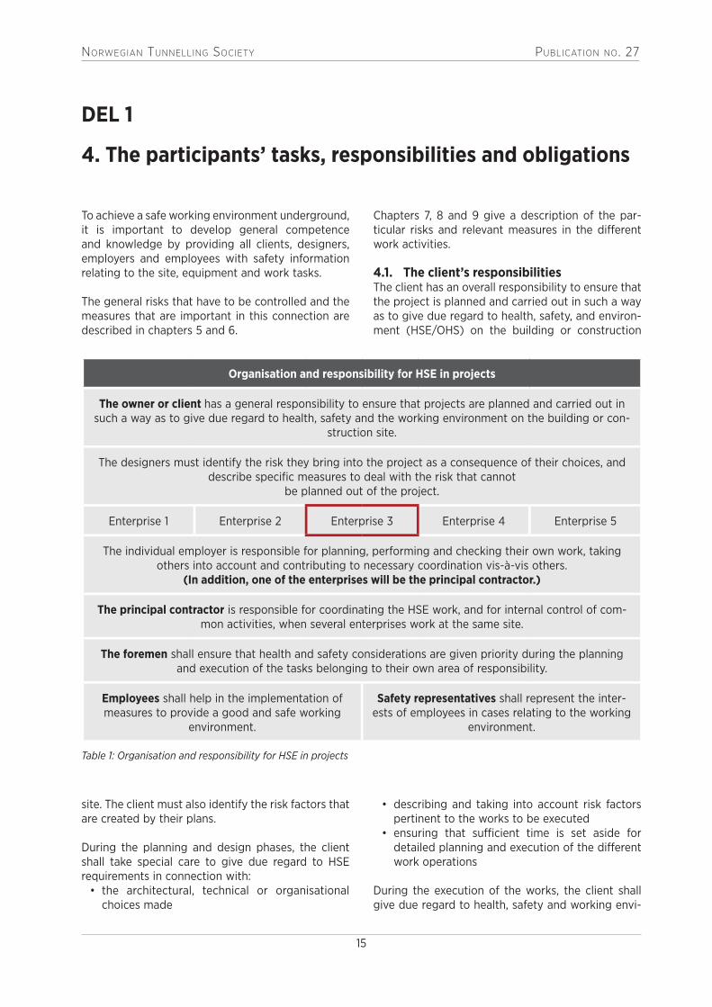
Organisation and responsibility for HSE in projects
The owner or client has a general responsibility to ensure that projects are planned and carried out in such a way as to give due regard to health, safety and the working environment on the building or con-
struction site.
The designers must identify the risk they bring into the project as a consequence of their choices, and describe specific measures to deal with the risk that cannot
be planned out of the project.
Enterprise 1 Enterprise 2 Enterprise 3 Enterprise 4 Enterprise 5
The individual employer is responsible for planning, performing and checking their own work, taking others into account and contributing to necessary coordination vis-à-vis others.
(In addition, one of the enterprises will be the principal contractor.)
The principal contractor is responsible for coordinating the HSE work, and for internal control of com-mon activities, when several enterprises work at the same site.
The foremen shall ensure that health and safety considerations are given priority during the planning and execution of the tasks belonging to their own area of responsibility.
Employees shall help in the implementation of measures to provide a good and safe working
environment.
Safety representatives shall represent the inter-ests of employees in cases relating to the working
environment.
site. The client must also identify the risk factors that are created by their plans.
During the planning and design phases, the client shall take special care to give due regard to HSE requirements in connection with:
• the architectural, technical or organisational choices made
• describing and taking into account risk factors pertinent to the works to be executed
• ensuring that sufficient time is set aside for detailed planning and execution of the different work operations
During the execution of the works, the client shall give due regard to health, safety and working envi-
Table 1: Organisation and responsibility for HSE in projects

NorwegiaN TuNNelliNg SocieTy PublicaTioN No. 27
16
ronment considerations when coordinating the work conducted by the enterprises on the building or construction site.
The Construction Client Regulations (BHF) basically relate to risk management and organisation. The cli-ent’s HSE plan is a key tool, the purpose of which is to describe how the risk factors in the project are to be dealt with.
The HSE plan shall contain specific measures related to work that may involve a danger to life and health, and a description of specific measures required to deal with the risk factors identified during planning and design phases shall be incorporated in the ten-der documents.
In underground rock works, factors such as geologi-cal and rock engineering conditions have an impact on risk factors and safety. The client shall describe and take into account such factors during the plan-ning and design phases and ensure they are later included in the tender material.
4.2. The designer’s responsibilities and obligations
The designers are professional players whom the cli-ent either appoints directly or through an agreement with a contractor.
Their obligations, like those of the client, involve identifying the risk they bring into the project as a consequence of their choices, and describing spe-cific measures to deal with the risk that cannot be designed out of the project.
Factors that the designers must take into special consideration are:
• work schedule• location or design of the building or structure• choice of building products• choice of structures for foundation and bearing
elements• choice and location of installations and rigging
areas• choice of installations• work in the vicinity of or close to other infra-
structure, including traffic• appropriate planning for operation, maintenance
and cleaning
4.3. The principal contractor’s responsibilities
If several enterprises work on the same worksite, and at the same time more than ten employees are employed on this site, one of the enterprises shall have the role of principal contractor with the
responsibility of coordinating the health, safety and environment activities of the individual enterprises.The coordination work of the principal contractor shall include ensuring that the individual employers have the necessary information about each other’s work to be able to prevent injury to the other work-ers. Such coordination is especially relevant in the case of work in common areas and use of shared resources such as cranes, lifts, scaffolding and portacabins.
Besides coordinating meetings, the principal con-tractor shall also exercise a certain form of control and supervision over common areas and shared resources. This shall in practice be done by means of inspections on the building or construction site (safety inspection rounds) and shall cover at least the basic conditions that have previously been found to have an impact on health, safety and the working environment.
The competence of the principal contractor places certain limits on the possibility of coordination. It is not a requirement that the principal contractor should become familiar with new disciplines in order to be able to check the work of others. Furthermore, the principal contractor’s duty of coordination does not diminish the obligations of employers when it comes to safeguarding the health and safety of their own employees.
If a principal contractor leaves the workplace whilst the work is in progress, one of the remaining enter-prises will have to take on the duty of principal con-tractor. The original principal contractor must give notice in good time to the remaining enterprises, such that it can be established who shall take over as principal contractor.
The difference between coordination under the Working Environment Act (AML) and coordination according to the Construction Client Regulations (BHF)
The client’s coordination does not replace but comes in addition to the principal contrac-tor’s coordination. Coordination under BHF is a paid, contractual task the main purpose of which is to prevent unnecessary conflict between different enterprises and different work operations. Focus on, and decisions as to simultaneity, sequence and time.
Coordination under AML is an unpaid duty the main purpose of which is to ensure that the

NorwegiaN TuNNelliNg SocieTy PublicaTioN No. 27
17
4.4. The employer’s responsibilitiesIn order to safeguard the health, safety and environ-ment of their employees, all employers shall ensure that systematic management of health, safety and environment is implemented at all levels of the enterprise.
In addition, employers shall:• ensure that their own activities and those of
their employees are organised and performed in such a manner that persons other than their own employees, who are involved in work on the project, are guaranteed a thoroughly safe and sound working environment
• cooperate with other employers to ensure a thoroughly safe working environment
• ensure that the working hours of contracted workers are in accordance with the provisions in the Working Environment Act
See chapter 5 in this publication for a more detailed description of what systematic health, safety and environment activities entail.
4.5. The foreman’s responsibilities and obligations
An employee whose job it is to supervise other employees must ensure that the due regard is paid to health and safety during the planning and execu-tion of the work tasks that come under their own area of responsibility.
4.6. The employee’s duty of participationEmployees shall participate in the development, implementation and follow-up of the enterprise’s systematic management of health, safety and environment.
Employees shall take part in the organised safety and environmental work of the enterprise and shall actively contribute to the implementation of the measures intended to create a good and safe work-ing environment.
Employees shall use protective equipment, exercise caution and notify the employer and safety repre-
individual employers have the necessary infor-mation about each other’s work (when con-flict cannot be avoided) so that they can take into account and prevent injury to the other employees. Focus on information and rules on use of common areas and shared resources.
sentative of any faults or defects found. Employees shall stop work if it is understood that the work cannot continue without involving danger to life or health.
4.7. The role of the safety representativeA safety representative shall be elected in all enter-prises covered by the Working Environment Act. This will in practice apply to all organisations that work on construction projects in Norway.
In any enterprise with fewer that ten employees, the parties may agree in writing a different arrange-ment, including having no safety representative in the enterprise.
One of the tasks of the safety representative is to represent the employees’ interests in matters con-cerning the working environment. This does not mean, however, that the safety representative should always act on behalf of his work colleagues if they have problems related to the working environment.
All problems should first be attempted to be solved by the person who best knows the problem, for example, by the individual discussing the case with their immediate superior. If the matter is not resolved, the next step is to contact the safety representative.
The safety representative shall ensure that the enterprise is organised and maintained, and that the work is carried out, in such a way that due regard is given to the employees’ health safety and welfare in accordance with the provisions of the Working Environment Act.
The safety representative shall ensure in particular that:
• employees are not exposed to hazards from machines, technical apparatus, chemical sub-stances and work processes
• protective devices and personal protective equipment are present in adequate numbers, that they are easily accessible and are in a sound condition
• the employees receive the necessary instruc-tion, practice and training
• the work is otherwise organised such that the employees can perform the work in an appro-priate manner as regards health and safety
• notification of any workplace accidents is to be sent to the appropriate authorities in accordance with the Working Environment Act, section 5-2

NorwegiaN TuNNelliNg SocieTy PublicaTioN No. 27
18W. Giertsen Tunnel AS Nygårdsviken 1, N-5165 Laksevåg-Bergen, Norwaywww.giertsentunnel.no I [email protected] I +47 5594 3030
WG TUNNEL SEALINGCOMPLETE WATERPROOFING SYSTEM
FOR ANY CAVERNS, SHAFTS AND
OTHER UNDERGROUND FACILITIES
WG TUNNEL SEALING IS A COST-EFFECTIVE METHOD TO PROVIDE A PERMANENT SEALING OF ROCK WALLS AND CAVERNS.
Key features with WG Tunnel Sealing:• Patented solution with extensive experience• Tailored for each individual project and facility• Can be uses in all types of underground facilities• Life span minimum 50 years• The fabric is self-extingishing and will never spread or maintain a fi re• Avoid risk caused by dripping water and humidity
Examples of where WG Tunnelsealing is installed:• Water treatment facilities• Parking facilities• Sewage treatment plant• Storage facilities• Sporting facilities• Power plants• Cable tunnels• Valve chambers• Technical rooms• Access tunnels• Military installations and hospital• Mines• Drop protection in road tunnels

NorwegiaN TuNNelliNg SocieTy PublicaTioN No. 27
19
5. Systematic approach to health, safety and environment management
A systematic approach to HSE management entails being one step ahead, identifying risks and imple-menting measures. It is a continuous process and should be an integral part of the culture of any enterprise.
The Norwegian Regulations on systematic health, safety and environment in enterprises (Internal Control Regulations) state that the person respon-sible for the enterprise has a duty to ensure there is systematic follow-up of health, safety and environ-ment. This shall be done in cooperation with the employees and their representatives. The routines shall be set out in writing and shall ensure that problems are identified and dealt with promptly. Internal control is quality assurance, and entails that the enterprise shall:
• ensure that the laws and regulations in the health, safety and environment legislation that apply to the enterprise are available, and have an overview over the requirements that are especially important for the enterprise
• ensure that the employees have sufficient knowl-edge and skills in the systematic approach to the area of health, safety and the environment, including information about changes
• ensure that the employees participate so that collective knowledge and experience are utilised
• establish targets for health, safety and environment
• have an overview over the enterprise’s organi-sation, including how responsibility, tasks and authority for the work on health, safety and environment are distributed
• identify dangers and problems and, on this basis, assess the risk, and also produce plans and measures for reducing the risk factors
• implement routines to identify, remedy and pre-vent contraventions of requirements laid down in or pursuant to legislation relating to health, safety and environment
• systematically monitor and review internal con-trol to ensure it works as intended
Underground works are governed specifically by Regulations on the performance of work, chapter 27, Rock works, and in the Regulations on the handling
of explosive substances, chapter 2, General provi-sions on the use of explosives, and chapter 10, Rock blasting.
In addition, the general provisions in the Working Environment Act, the Regulations on organisa-tion, management and employee participation, the Workplace Regulations and other chapters in the Regulations on the performance of work all apply.The comprehensive rules and regulations that apply to this work represent important safety barriers for preventing accidents and injuries.
5.1. General risks in underground worksThere are several sources that help to identify the risk factors, both general and specific, that are rel-evant during underground works. Statutory require-ments as set out in the relevant laws and regulations are one source. Another is experience and learning from incidents. Last, but not least, the risk as expe-rienced by the tunnel workers is a vital source of knowledge about these factors. Through the group interviews mentioned in chapter 2, more than 30 workers in three different contractor companies have made known what they believe to be major and relevant risk factors.
It became clear during the group interviews that a view shared by all the workers was that it is extremely unfortunate that different contractual requirements as regards safety in tunnelling work are set by the different clients. There is less respect for the importance of understanding and comply-ing with the contractual requirements when the risk situation for the work operations is described differ-ently from one client to another. The workers also clearly expressed frustration and resignation over some contractual requirements, which they see as inexpedient with respect to safety. This concerned in particular the ban on simultaneous drilling and bolt-ing. It emerged that there are other work operations that the workers find to be far more hazardous, such as simultaneous bolting and charging, but which are not given the same degree of attention. The workers were very clear that it would have a huge impact on their working day and safety if there were more consistent and uniform contractual requirements in regard to safety in tunnels from client to client.

NorwegiaN TuNNelliNg SocieTy PublicaTioN No. 27
20
They also pointed out that there is far too much simultaneous work, for example during rigging, exca-vation and the transport of excavated material, or muck, which they regard as hazardous in relation to their own safety. The workers feel that there is little understanding of their safety when so many other types of simultaneous work take place in a tunnel.
Another topic the workers had fairly similar views on, was the construction time. They feel that they work increasingly against the clock and that they feel time pressure during their working day. Many sub-deadlines are perceived as being too short, and the workers feel that some of the work becomes stressful as the responsibility and time pressure are too great. It was mentioned in particular that bolt installation is a very heavy and physically demand-ing work operation, which is often carried out after blasthole drilling and/or parallel with the charging operation, which is also an extremely physical and laborious operation. The workers said they found that it made more sense to carry out bolt instal-lation during blasthole drilling, as this causes less stress and strain, and in addition allows more time to inspect the rock to see whether anything has become loose during the drilling.
General risk factors during rock works in a tunnel can be summarised as follows:
Geological factors, design and location of the tunnel
• Loose rock• Quartz, radon etc• Cross-section• Steep tunnels with a gradient > 14%• Shafts• Explosives remaining from earlier work
Conditions at the workplace
• Poor lighting• Poor air quality, dust, gases and lack of oxygen• Noise• Live cables• High-pressure water pipes and hoses• Poor access routes• Unsupported rock, danger of rockfall• Fire hazard• Explosion hazard, explosives
Conditions during work operations
• Work at a height• Splatter hazard• Crush hazard• Heavy lifts
• Stress and time pressure• Communication and culture• Work methods• Equipment used
Conditions resulting from sequential and simultaneous jobs
• Falling objects during simultaneous jobs at dif-ferent heights
• Traffic – speed of travel through work areas
Risk factors of varying degrees of seriousness can arise singly or as a combination of several factors that occur simultaneously. Rockfall at the face is probably the biggest risk factor with today’s tunnel excavation methods.
How the above risks are to be controlled will be dealt with in the following chapters and sections of this publication.
5.2. Risk managementRisk management (conducting risk assessment and making decisions based on risk assessment) is cen-tral in creating safe work operations and safe end products in the building and construction industry. Risk management is a proactive approach in the sense that hazards and undesirable events are iden-tified and handled before they potentially happen.
The goal of risk management is to make sound deci-sions concerning risk-reducing measures. Such deci-sions must be based on results of risk assessment.
Risk assessment is a combined process consisting of risk analysis and risk evaluation. These terms are explained in more detail below.
Risk analysis is systematic use of available informa-tion to identify hazard sources and estimate the risks associated therewith. The analysis is performed in three stages: 1) identify hazard sources and potential undesirable events; 2) frequency analysis (how often we think an event will occur); and 3) consequence analysis. The result of a risk analysis is often referred to as a risk picture.
Risk evaluation is a comparison of the results of the risk analysis with criteria for acceptable risk in order to assess whether the risk is tolerable or not.
As described in section 4.1, the owner shall ensure that due regard is paid to health, safety and envi-ronment on the building or construction site. The first risk assessment made for a project is carried out in the project development phase. In this

NORWEGIAN TUNNELLING SOCIETY PUBLICATION NO. 27
21
Figure 1: Risk management process (figure based on ISO 31000).
phase, risk assessments are made as a part of the feasibility study. The purpose of the feasibility study is first and foremost to find out whether the project can be carried out. The risk assessment made as a part of the feasibility study looks at all types of risks in a project, including the risk of acci-dents in an executing phase. An important stage in the identification of hazards in the project develop-ment phase is a preliminary examination of the site area, for example, in relation to geological dangers, risk of natural disaster, accessible infrastructure (road transport, ambulance services).
5.3. HSE plan for rock excavation worksA written plan for health, safety and environment (HSE plan) is required when rock excavation is to be carried out. The HSE plan must be prepared on the basis of a risk analysis and made available to the employees. Moreover, it should be updated regularly as required. An HSE plan for rock excava-tion should contain:
• measures for relevant risk factors (escape routes, rescue/refuge containers, personal ID tags)
• a description of how coordination will be addressed
• rules for safe use of methods and equipment• a description of contingency plans• a general outlay of the working area• information about the ventilation system• a description of measures for preventing explosions
• requirements pertaining to personal protective equipment and preventive measures against harmful gases
• contingency plans and measures for preventing and fighting fire
• identification and assessment of hazards• information about safety assessments of work-
places and equipment
In the following chapters, the publication provides guidelines as to how central parts of the HSE plan for rock excavation works can be drawn up.
The HSE plan shall make it clear that the risks to which the workers are exposed at the workplace have been identified and assessed, and shall detail the measures that are to be implemented to prevent accident and injury. In particular, it shall be evident from the plan that the design, use and maintenance of workplace and equipment have been assessed for safety.
5.4. Organisation (appropriate planning) of rock excavation works
In addition to an HSE plan for rock excavation works, these works shall be organised so that the employ-ees can perform their tasks without putting their own health and safety, or that of others, at risk. In the table below is a list of recommendations of how organisational requirements relating to rock excava-tion workscan be met.

NorwegiaN TuNNelliNg SocieTy PublicaTioN No. 27
22
Requirement that: Can be met by:
• The workplaces shall be designed, construct-ed, equipped, put into operation, used and maintained.
• A good rigging plan, access to appropriate equipment and good routines for maintenance of equipment and facilities.
• The workplaces shall be kept in good order, and hazardous substances or deposits shall be removed or monitored.
• Good routines for order and maintenance, and measures for handling hazardous substances.
• The workplaces shall be designed and construct-ed in accordance with ergonomic principles.
• Access to appropriate equipment and resources.
• The employer shall provide necessary supervi-sion of work activities by persons with the req-uisite competence.
• Clear role descriptions for team leaders, fore-men and production managers that ensure they meet their responsibilities. Assess the need for additional supervisors.
• The employer shall ensure that there are a suf-ficient number of employees with the skills, experience and training required to do the jobs they are assigned.
• Overview of competence requirements, training and experience for the relevant work opera-tions/employees. Special focus on training in use of different types of equipment and han-dling of explosives.
• Workplaces for underground rock works shall be constructed, run, equipped and maintained so that the employees can work and move around with minimum risk.
• Planned and maintained site roads and walk-ways that physically separate vehicular and pedestrian traffic to maximum extent possible and have good lighting.
• Continuous safety work.• Good coordination of simultaneous activities.
• Particularly hazardous work, and work which in combination with another activity can give rise to a serious risk, shall only be carried out by employees who have been given a special per-mit by the employer and who have specialised skills in the area. The permit shall specify the conditions to be met and the precautions to be taken, before, during and after the work.
• Use of routine for work permit.
Table 2: Organisation of rock works
5.5. Contingency measuresThis section gives an example of how contingency measures for rock works can be described.
System for overview over personnel underground
• A system shall be established that keeps track of which workers are below ground at any given time, and their probable location.
• There must not be more personnel inside the tunnel/rock cavern than there is capacity to evacuate to the surface or rescue chamber in an emergency situation.

NorwegiaN TuNNelliNg SocieTy PublicaTioN No. 27
23
Communication • Communication shall be established between the personnel working underground and personnel on the surface so as to be able to raise the alarm in an emergency situation.
• In the event of insufficient communication equipment to safeguard the workers’ health and safety, manned workplaces shall be checked every second hour. The responsibility for carrying out these checks must be defined.
• There shall be communication equipment/systems in all vehicles/machines.
Rescue/refuge container • The need for, and the number and location of rescue containers shall also be risk assessed when the tunnel length is greater than 500m, on the basis of the following conditions:
- Capacity of the rescue container (number of persons/size of gas cyl-inder bank).
- What walking distance is acceptable with the escape masks in question?
- Installations - where are electrical installations, machines and equip-ment located?
- Escape routes/rescue routes - connection to parallel tubes? - Accessibility of the tunnel - area of the cross-section? - Activities - what activities at what time?• Rescue containers shall be maintained and ready for use at all times. A
check shall be carried out at a minimum of every two weeks and shall be documented in the HSE logbook for rescue container checks.
• Location of the rescue containers shall be indicated on the rigging plan/map with profile number. If a rescue container is moved, the rig-ging plan shall be updated.
Marking of tunnel tubes and niches
• Tunnel tubes and niches shall be marked so that personnel can find their way in a rescue operation.
• The marking shall be indicated on plans/maps in the contingency plan with profile number.
Fire contingency measures
• Storage of inflammable material in tunnels shall be avoided.• All mechanical equipment (cars, loaders, drilling jumbos, charging vehi-
cles) shall be equipped with at least one 6 kg ABC fire extinguisher.• Locations or structures that represent a particular fire hazard, such as
cable reels and transformers shall also have fire extinguishers located by them.
Personal torch • All personnel who are below ground shall carry a personal torch.
Self-rescuers, escape masks
• Self-rescuers/escape masks shall be available, inside the tunnel, for all workers who are in the tunnel during operations (eg, located in machines) - escape masks with long service life shall primarily be used.
• All personnel shall be given training in use of escape masks.
Information about con-tingency measures and escape routes
• Everyone on the work team shall be given the necessary information about contingency measures and escape routes, including information about changes in the rigging plan.
• Regular safety and escape practices proportionate with the risk on site shall be carried out.
Table 3: Description of contingency measures

NorwegiaN TuNNelliNg SocieTy PublicaTioN No. 27
24
Illustration 1: Rescue container (Photo: Skanska Norway)
Table 4: Working environment measures
5.6. Working environment measuresThis section gives examples of how working environ-ment measures for rock works can be described.
Ventilation • There shall be continuous and adequate ventilation to provide fresh air for the workers, adapted to the work methods used and the physical strain to which the workers are subjected.
• The ventilation system shall be checked and maintained continuously. Responsibility must be allocated.
Measurement of gases, dust and noise, plus requirements for personal protective equipment
• The need to measure gases, dust and noise shall be risk assessed (what measurements shall be made, where and how often, choice of measur-ing method). Depending on the conditions, it is recommended that the following be measured: total dust, quartz, radon, asbestos, CO, NO2/NOX, noise.
• Based on the risk assessment, a HSE plan and documentation of gas measurements in the tunnel shall be prepared. A person responsible for the measurements shall be designated at the start of operations.
• The measuring instruments shall be placed where exposure is expected to be greatest and taken so as to obtain representative measurements of the exposure to which the workers are subjected throughout a work-ing day.
• In the event of a change in tunnel driving routines and/or work meth-ods, measurements shall be made more frequently until the exposure level is under control.
• Protective equipment (respiratory and hearing protection) must be adapted to the result of the measurements.

NorwegiaN TuNNelliNg SocieTy PublicaTioN No. 27
25
Table 6: Recommended conduct
Table 5: Reporting
Who shall report? • The enterprise that has executed the blasting work is under obligation to report all incidents involving explosives.
How shall reporting be done?
• Incidents and accidents involving the use of explosives shall be reported immediately to the Police and the Directorate for Civil Protection (DSB). Near misses shall only be reported immediately to the Police and DSB if they have a real potential to cause injury or harm. The threshold for reporting near misses is lower in, eg, built-up areas, although a real potential of injury or damage is still required if such incidents are to be reported immediately.
• Serious hazard situations in connection with rock works shall also be reported to the Norwegian Labour Inspection Authority.
• Notification or an accident report form shall be sent as soon as possible and, at the latest within eight days of an accident, incident or near accident, to DSB at [email protected]. Alternatively, notification may be filed electroni-cally using the form http://www.dsb.no/skjema. - Accidents with explosives. In addition to a copy of the blasting plan, charging plan etc that must be included, the notification also contain the enterprise’s own evaluation of the cause of the incident and what has been done to prevent repetition.
• DSB shall be notified immediately if it is suspected that an explosive is defec-tive. By defective is meant that there is a product defect, material defect or other defect of the product that is assumed to be due to production, storage or distribution conditions that have occurred prior to delivery to the end user.
Ventilation fan • The fans shall not be stopped as this causes the absolutely most adverse situation for trapped personnel (supplying air/oxygen acceler-ates the fire thereby avoiding smoulder fire).
• This also applies if the ventilation ducting has collapsed and the air passes directly to the location of fire.
Conduct at the face and behind the face
• When the fire prevents the crews from moving past the location of fire, the following measures shall be implemented:
- alert crews at the surface via telephone/radio. - prepare escape masks. - if possible, seek refuge in a rescue container.
Conduct at the surface • Alert rescue personnel, authorities and personnel within the enterprise.• Establish contact with the crews underground.• Obtain a list of the crews that are below ground.
5.7. Reporting of non-conformances, incidents and accidents involving explosives
This section outlines recommendations as to how non-conformances, incidents and accidents involv-ing explosives shall be reported.
5.8. Conduct in the event of fire in a tunnel/rock cavern during construction work
Recommendations for conduct in the event of a fire in a tunnel or rock cavern during excavation are
In Norway there is a specific directorate responsi-ble for public security and emergency planning, the Directorate for Civil Protection (DSB). This body is responsible for regulating matters related to the civilian use of explosives. Therefore, DSB has been included in the reporting routines given in the table below.
provided in this section. The recommendations are based on a report from the Norwegian Fire Research Laboratory on 1/10 scale experimental tests on fire in tunnels during tunnel construction.

NORWEGIAN TUNNELLING SOCIETY PUBLICATION NO. 27
26
EMPOWERMENT
Multiconsult has been at the forefront of rock engineering and underground construction technology development for the last 4 decades, with extensive experience from numerous projects, large and small, both in Norway and overseas.
In cooperation with other disciplines our core staff of geologists and civil engineers are fully engaged with concept development, site investigations, feasibility studies, engineering and site follow-up of a broad range of underground projects.
www.multiconsult.no

NorwegiaN TuNNelliNg SocieTy PublicaTioN No. 27
27
DEL 2
6. Preparatory works – rigging and operation
The preparatory works and continual mobilisation and operation are important for safe and efficient production when the actual tunnelling work is to be carried out. This involves:
• preparing a remobilisation plan and site layout plan
• preparing a work schedule• securing the areas for third parties• establishing a workshop• establishing an access control system• establishing communications systems• preparing contingency plans• establishing a tunnel water treatment plant • preparing plans for and establishing ventilation,
pump lines, lighting• establishing power and water supply to the tun-
nelling jumbo
These tasks will be discussed in more detail under the respective work activities in chapter 7.
6.1. High-voltage and other electrical works
Requirements
High-voltage installations:Installations with a nominal voltage higher than 1000V alternating voltage or higher than 1500V direct-current voltage.
Low-voltage installations:Installations with voltage of up to 1000V alternating voltage or up to 1500V direct-current voltage.
Qualification requirements:Workers involved in the design and maintenance of electrical installations must have a relevant electrical trade certificate (license).
Project design and execution:Electrical installations shall be designed, executed and maintained so as to ensure that they perform their intended function without posing a hazard to life, health or material assets.
The contractor responsible for the electrical instal-lations shall meet the requirements given in the
Regulations on electrical enterprises and the quali-fication requirements for work related to electrical installations and equipment.
Special risk factors
These may include:• short circuits because of technical faults• collisions into installations and cables• damage to cables when unreeling/reeling• earth faults• damage to cables during behind-face work,
finishing works and in particular bolt drilling for water and frost protection
• rockfalls on installations and cables• dust, water and exhaust gases
Measures• Installations that carry high voltage must be
labelled “High voltage – danger to life”, whilst low-voltage installations shall be marked with nominal voltage.
• Installations shall be protected by earth fault protection with trip settings.
• Transformers must be suitably located so that they do not cause a major danger in the event of fire.
• Transformers must not be located too close to rescue containers or objects that represent a fire hazard.
• All cables and electrical installations must be suspended so as to prevent damage during ordi-nary tunnelling operations.
• Cables and installations must be protected from mechanical stress with protective pipes or other durable protection.
• Work on or close to electrical installations shall be carried out as per the safety regulations for electrical installations and be risk-assessed in accordance with these regulations.
• Frequent and planned cleaning of electrical installations.
General measures for parallel electrical installations
These measures may include:• instructing persons who are familiar with the
risk factors

NorwegiaN TuNNelliNg SocieTy PublicaTioN No. 27
28
• allowing only qualified persons to work with electricity
• designing electrical installations • protecting installations from collision by correct
placement, physical barriers and reflectors• providing lighting on transformer stations and
cable reels
Tel: +47 76 11 57 00 / www.lns.no
Rock solid - from pole to poleLNS delivers total contracting to the entire world in its business areas. We focus on developing our expertise and we are at the forefront of new technology to ensure effi cient and profi table operations. LNS is at the cutting edge of Norwegian tunnel and mining technology internationally. Our most important resource is our competent, committed employees, who satisfy our clients every day by solving the tasks in hand. In the LNS group, there is also a strong focus on health, safety and the environment (HSE).
The LNS group provides the following products and services:• Tunnels and rock chambers• Road building• Mining contracts• Rubin mining
• Rock support and injection• Earthworks• Concrete production• Production of modules and wood elements
vizuelli.no
• establishing good grounding• keeping cabinet doors closed and locked• shielding installations from water leaks• mounting strain reliever on the cable to the
jumbo and establishing good routines for han-dling it (laying it to the side, checking the residual current device RCD)

NorwegiaN TuNNelliNg SocieTy PublicaTioN No. 27
29
7. Work activities
This chapter describes the different activities involved in underground works.
7.1. Tunnel entrance – initial approachThe tunnel entrance must be planned and con-structed on the basis of the local conditions and the contract. In the planning phase, when positioning the entrance, it is essential to map and assess con-ditions in the surrounding environment (buildings, wells) and the geological conditions, and determine whether there is sufficient rock cover. In addition, every effort shall be made to ensure that the tunnel entrance face is as perpendicular as possible to the tunnelling direction.
Furthermore, it is imperative to assess the need for inspection, preliminary investigations and support of the area above the entrance to protect against fall-ing rocks, rockslides and collapse.
The first round is normally split into pilot heading, bottom heading and top heading, with a length of
up to three metres. Usually two three-metre long pilot rounds are blasted putting the pilot head-ing ahead (if shorter rounds are blasted, the time interval between them should not be too long). This is repeated at least twice with a new single row of holes with spiling bolts. Based on geological conditions, it is determined whether stitch drilling is appropriate. If it is decided that this method is suitable for contour drilling, holes are drilled 35 cm apart from centre to centre and every other hole is loaded with contour explosive (pipe charge).
If another contractor has carried out the preparatory works in connection with establishing a cutting/tun-nel entrance, they must hand over blasting plans, blasting round reports and drilling logs in order to pass on information about how the work has been done, and what explosives and detonators have been used.
Typical features Challenges Important to remember
Tunnel entrance must be planned and constructed on the basis of local conditions. Geological conditions and adequate rock cover are key factors.
• Falling rock, rock-slides and collapse
• Secure area above entrance. Scaling, bolting, wire mesh and straps
• Rockfall netting, landslide control wall and sprayed concrete may be relevant safety measures
• Drilling on explosives (especially in invert from bench drilling)
• Check entrance face and floor for remaining explosives
• Check blasting round report/drilling log for rounds in cutting
• Flyrock from blasting • Each round must be covered with blasting mats with good overlap
• Consider stitching the mats together; build-ing rock banks in front of the mats is a good measure
• Crush hazard • Avoid presence in danger zones and blind zones around machines with moving compo-nents or machines in motion
Table 7: Tunnel entrance

NorwegiaN TuNNelliNg SocieTy PublicaTioN No. 27
30
Measures• Review of blasting round plans for blasting of
the cutting, especially if this has been done by another contractor or before workers with tun-nel competence were present on the site.
• Prepare a blasting round plan for entrance rounds (containing drilling, charging and deto-nation plans).
• Prepare a blasting plan for the entrance rounds that comprises covering, warning and posting plans.
• Secure the entrance face (and any cutting in towards the entrance). Determine the scope of necessary support with bolts, bars, wire mesh, strips and sprayed concrete on the basis of geology/rock conditions. It is usual to install double spiling bolts around the tunnel contour in the opening round(s). Spiling is usually done using 6-8-metre long, 32-mm diameter rebars that are grouted. The bolts are spaced at about 80 cm from centre to centre in the innermost row and at about 90 cm from centre to centre in the outermost row when the distance between
the rows is about 50-80 cm. The bolts in the two rows are staggered so that a bolt in second row comes between the bolts in the first row. Rock straps are placed between the rows, and the holes are grouted. To compensate for lack of abutment on the air side of the spiling, it is important to ensure that the cooperating arch does not fall out. This is normally done using four-metre long cross-bolts (ca. 45° radially upwards or outwards) with centre-to-centre spacing of 1.5-2 metres.
• Each round must be covered with blasting mats that are suspended from bolts across the tunnel profile. The mats must cover the whole round and have a good overlap. Consider the need to stitch the mats together depending on the surroundings. Building rock banks in front of the mats (not on top of) is a good measure. It may also be sensible to have additional mats on mobile units.
See also measures under section 7.3.1 Blasthole drilling.
Illustration 2: Entrance (Photo: Hæhre Entreprenør)

NorwegiaN TuNNelliNg SocieTy PublicaTioN No. 27
31
Table 8: Long-hole drilling
Table 9: Core drilling
7.2. Work ahead of the tunnel work faceWorks ahead of the work face as discussed here include drilling probe holes, control holes and grout holes, core drilling and grouting. These are activities whose purpose is to gather information about the rock conditions ahead of the face or render the rock
impervious to water ahead of the face. The person-nel involved in this work are located at the face, and the safety risks they may encounter are in general the same as those involved in work at the face (see section. 7.3), although there are also some special risk elements ahead of the face.
Typical features Challenges Important to remember
• With extension rods using a drilling jumbo to investigate conditions ahead of the face
• Rockfall from tunnel crown • Rock support work shall be carried out before the start of drilling
• All bolts shall be grouted before injection work starts
• On the basis of identified risks, risk assessment and instructions from the jumbo manufacturer, a horizontal and vertical plane shall be defined which indicate the limits of the danger zone
• The rods must be extended • Proximity to rotating components
• Noise• Presence between booms• Handling of heavy drill rods• Travel along tunnel floor• Spray from flushing water• Splinters from collaring and
possible failure of drill string
• Use of automatic rod han-dling is recommended
Typical features Challenges Important to remember
• Drilling done with separate core drilling rig to extract drill cores for analysis and documentation of the rock conditions ahead of the work face
• Performed from the face or a niche
• Often performed by a subcontractor
• Secured and orderly rigging area
• Lighting of rigging area• Ventilation that ensures air
quality at the face• Communication with other
activities in the tunnel
7.2.1. General considerations

NorwegiaN TuNNelliNg SocieTy PublicaTioN No. 27
32
Typical features Challenges Important to remember
• Rockfalls of varying sizes • If grouting material flows into the fracture plane that lies parallel to the established rock cavern, the pressure could open new fractures, resulting in decreased rock stability - at worst, such frac-tures could cause rockfall
• It is recommended that sprayed concrete be applied prior to start of grouting work
• Observe rock cavern to check whether grouting material exits behind the face; check whether cracks arise in the rock or sprayed concrete
• Packer and injection rods are pushed out of holes
• The packer may be placed in poor rock
• The hole can be “lubricated” by grout before the packer is placed
• The packer may have a wrong diameter
• The packer may be of too low a pressure rating
• The packer may be inad-equately tightened because of poor threads
• The packer may be inade-quately tightened because of inadequate make-up torque
• Packer and outer injection pipe do not match
• Rods shall be secured to pre-vent them from coming out of the hole - they can be secured to the face by bolts or by chains between the rods
• Air pockets under high pres-sure can occur in grouting holes and can result in the injection rod being ejected from the hole if the grip between packer and bore-hole fails
• Grout spill • Spill from worn couplings, hoses or taps
• Spill from couplings under pressure during connection
• Spill from taps• Spill from mixer vessels• Spill as a result of
misunderstandings
• Rout spill is a frequently occurring incident during grouting
• Sealed safety goggles shall be prescribed, and there shall be easy access to eyewash at the workplace
• Product data sheets must be readily accessible
• Communications system integrated in helmets would facilitate communication at the face
• Placement of packers • Poor rock conditions/high static water pressure
• Grout steel pipes in the injec-tion hole prior to drilling long holes (better anchoring of packers)
Table 10: Grouting work

NorwegiaN TuNNelliNg SocieTy PublicaTioN No. 27
33
Special risk factorsRod change during long-hole boring can be carried out both mechanically and manually. Mechanical rod change is recommended. Manual rod change requires thorough risk assessment, and measures in the form of, for example, work procedures so as to ensure the personnel handling the drill rods are not exposed to unacceptable risk. The following is a non-exhaustive list of special risk factors:
• rockfall from the tunnel crown, walls or work face• crush hazard between booms• risk of tripping on coarse rubble when moving
between booms• proximity to rotating drill rods• handling heavy drill rods• spray from water flushing• rockfall and rock splinters from collar area• communication with drill operator and person-
nel at the drill string
MeasuresRock support of tunnel crown and walls must be put in place before long-hole drilling or grouting can start. In particularly poor rock conditions, the face shall also be provided with support. Support with sprayed con-crete will help to reduce the risk of rockfall.
To increase safety, separate work instructions shall be drawn up for long-hole and grout hole drilling.
Ensure that the tunnel floor is properly levelled ahead of the face, such that personnel can move without the risk of tripping on rubble and uneven ground.
Ensure that the equipment is maintained and is in working order, such that rod change can be carried out safely, preferably without manual handling.
7.2.2. Drilling of probe and control holesDrilling of probe and control holes involves the drill-ing of long individual holes to examine the rock con-ditions ahead of the face and to check the effect of grouting. Drilling is done using the tunnelling jumbo.
Usually, two to six 24-metre long holes are drilled for every third round. The holes are often placed far down in the walls and in the shoulders.
Drilling of probe and control holes is carried out sporadically and can exceptionally be done using manual rod handling procedures.
7.2.3. Grout hole drillingGrout hole drilling is done using the jumbo to form a grout umbrella around the whole or parts of the rock cavern. In comparison to probe drilling, grout hole
drilling involves significantly more drilling. A grout umbrella along the whole tunnel profile can contain over 1000 drill metres.
7.2.4. Core drilling Core drilling is done to extract samples (core samples) from the rock ahead of the face. The drilling is done using a core drilling rig and is normally carried out by personnel who do not participate in extraction of the rock. The drill holes may be several hundred metres long, and for each core sample that is taken out, the whole drill string must be mounted and dismantled. For this reason, a well-organised rigging area must be established with good access paths around the drilling rig such that handling of the drill rods and drill cores can be done without any risk of tripping. Core drilling is often done by one to two persons, and at faces or in niches where there is no other activity. Before the start of this operation, it would be natural, in a risk analysis, to consider the following:
• need for rock support of crown, walls and face• design of rigging area to ensure good access
paths between drilling rig, drill bit magazine and core boxes
• appropriate ventilation and lighting• communication/warning routines to responsible
foreman and those running other activities
7.2.5. Grouting
RequirementsEquipment designed for correct grouting pressure must be used. This includes pumps, hoses, couplings and packers.
Special risk factorsPre-excavation grouting using high-pressure equip-ment is a normal sealing method during tunnel construction. It is not uncommon to use pressures as high as 80 bar, and in some cases 100 bar. This high pressure involves a significant risk, both directly and indirectly. There have been many serious incidents associated with grout spill, including a large number of eye injuries. The high pressure can represent dan-ger to life if it causes compression of air. Air pockets can be trapped in a hole and if the packer blocking the hole fails, the packer will shoot out of the hole.
The major risk factors in grouting are related to grouting at high pressure:
• Rockfalls of varying sizes: - If grout flows into a fracture plane that is paral-
lel to the established rock cavern, the pressure could open new fractures and result decreased rock stability. At worst, such fractures could result in rockfall.

NorwegiaN TuNNelliNg SocieTy PublicaTioN No. 27
34
• Packers and rods are pressed out of holes: - The packer may be placed in poor rock. - The hole may be “lubricated” by grouting
material before the packer is placed. - The packer may be of the wrong diameter. - The packer may have too low a pressure rating. - The packer can be inadequately tightened due
to poor threads. - The packer can be inadequately tightened
due to inadequate make-up torque. - The packer and outer pipe do not fit each other.• Grout spill: - Spill from worn couplings, hoses or taps. - Spill from couplings under pressure during
connection. - Spill from taps. - Spill from mixer vessels.
Measures• Use products of the correct pressure rating.• Secure the rods such that they cannot be forced
out of the hole.• Use packers of the right dimension.• Establish routines to avoid misunderstandings,
ensure that the grouting line is not under pres-sure before it is connected (bend the hose to check that it is not under pressure).
• Replace worn components.• Use sealed safety goggles and suitable gloves.• Have eyewash readily available and prioritise
washing the eye well and continuously in the event of grout splatter.
• Always have easy access to HSE product data sheets for grouting materials.
• Communication between the person driving the grouting rig and the person connecting the hoses can be ensured by using communication equipment.
• To increase safety, separate work instructions should be drawn up for grouting and a SJA should be carried out before the start of grout-ing work.
See also:NFF Handbook No. 01: Berginjeksjon (“Rock Grouting”), revised 2002
NFF Handbook No. 06: Praktisk berginjeksjon for underjordsanlegg (“Practical rock grouting for underground works”), 2010
NFF Technical Report No. 08: Sikkerhet ved bergin-jeksjon (“Safety during rock grouting”), 2008
Illustration 3: Grouting (Photo: Veidekke Entreprenør)

NorwegiaN TuNNelliNg SocieTy PublicaTioN No. 27
35
Table 11: Blasthole drilling
7.3. Work at the faceWork at the face includes drilling and blasting rounds, loading blasted rock material, scaling and installation of rock support. The area is often defined as extend-ing from the tunnel face back towards the ventilation ducting, or about 50 metres from the face.
In Norway it is a requirement that the employees working at the face with charging and blasting, need to be certified as rock blasters. This is quite an extensive education, and it is DSB that issues this certificate. In addition, the rock blaster needs to work in a company where at least one fulltime employee is certified as a rock blasting manager. This certification is also issued by DSB. This exten-sive requirement for competence is one of the most important measures in order to keep a safe working place regarding this part of tunnelling.
For all tunnel excavation, it is essential to have con-trol over the personnel who are in the tunnel (access control). This is important both in the case of fire or accident but also for preventing undesirable events. Furthermore, there must be satisfactory radio com-munication between workplaces in the tunnel and the crew at the surface.
Self-rescue masks shall also be available in all vehi-cles and machines used in the tunnel. The tunnelling jumbo shall have a minimum of three such masks. There shall also be fire extinguishers in all vehicles and machines, and close to all objects that present a fire hazard in the tunnel (cable reel, transformer, pump container etc). The establishment of a fire water outlet on water lines in niches and breakdown bays should also be considered.
7.3.1. Blasthole drillingPrior to the start of drilling, the face shall be checked visually and any undetonated explosives removed. The removal of old explosives shall be done by flush-ing out with water. If there is any doubt, the rock blasting foreman shall be called in for assessment. Drilling in old holes must never take place. The blast-ing round plan shall be followed precisely.
Work at the face represents a major safety risk and requires:
• assessment of risk factors• assessment of safety measures• good routines• continuous monitoring and good
communication
Typical features Challenges Important to remember
• Drilling shall be carried out as indicated in the blasting plan
• The work shall be led by personnel with relevant experience and competence
• Rockfalls of varying sizes • Inspection, mechanised scal-ing, manual scaling, bolting, sprayed concrete
• Fallout of fresh sprayed concrete
• Check that the concrete has sufficient strength
• Crush hazard • Avoid presence in danger area and blind zones
• Fire • Self-rescue masks for everyone
• Fire extinguishers in all vehi-cles, machines and by all objects that present a fire hazard in the tunnel
• Good cleaning and maintenance
• Drilling on explosives • Never drill in old holes; flush the face and check for remaining explosives
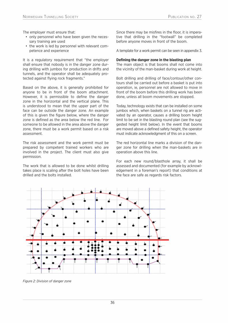
NORWEGIAN TUNNELLING SOCIETY PUBLICATION NO. 27
36
The employer must ensure that:• only personnel who have been given the neces-
sary training are used• the work is led by personnel with relevant com-
petence and experience
It is a regulatory requirement that “the employer shall ensure that nobody is in the danger zone dur-ing drilling with jumbos for production in drifts and tunnels, and the operator shall be adequately pro-tected against flying rock fragments.”
Based on the above, it is generally prohibited for anyone to be in front of the boom attachment. However, it is permissible to define the danger zone in the horizontal and the vertical plane. This is understood to mean that the upper part of the face can be outside the danger zone. An example of this is given the figure below, where the danger zone is defined as the area below the red line. For someone to be allowed in the area above the danger zone, there must be a work permit based on a risk assessment.
The risk assessment and the work permit must be prepared by competent trained workers who are involved in the project. The client must also give permission.
The work that is allowed to be done whilst drilling takes place is scaling after the bolt holes have been drilled and the bolts installed.
Since there may be misfires in the floor, it is impera-tive that drilling in the “footwall” be completed before anyone moves in front of the boom.
A template for a work permit can be seen in appendix 3.
Defining the danger zone in the blasting plan The main object is that booms shall not come into the vicinity of the man-basket during work at height.
Bolt drilling and drilling of face/contour/other con-tours shall be carried out before a basket is put into operation, ie, personnel are not allowed to move in front of the boom before this drilling work has been done, unless all boom movements are stopped.
Today, technology exists that can be installed on some jumbos which, when baskets on a tunnel rig are acti-vated by an operator, causes a drilling boom height limit to be set in the blasting round plan (see the sug-gested height limit below). In the event that booms are moved above a defined safety height, the operator must indicate acknowledgment of this on a screen.
The red horizontal line marks a division of the dan-ger zone for drilling when the man-baskets are in operation above this line.
For each new round/blasthole array, it shall be assessed and documented (for example by acknowl-edgement in a foreman’s report) that conditions at the face are safe as regards risk factors.
Figure 2: Division of danger zone

NorwegiaN TuNNelliNg SocieTy PublicaTioN No. 27
37
Illustration 4: Blasthole and rock bolt drilling (Photo: Skanska Norway)
Continuous assessment of geological conditions, good scaling of the crown, walls and face as well as a manual inspection before the start of drilling are very important in order to reduce the risk of rockfalls.
For inter-shift and intra-shift communication, it is recommended that a communication system mounted in all helmets be used – with specially fit-ted earphones/microphones.
7.3.2. ChargingCharging of rounds in the tunnel shall follow a pre-pared charging plan.
It is preferable to use an emulsion-based explosive (slurry) delivered in bulk, non-electric or electronic detonators (NONEL) and primers with about 15-25 gram cartridged explosive (pentrite/dynamite).
Contour and other blastholes with reduced charg-ing potential are charged with emulsion by spring charging with an automatic hose extraction sys-tem. String charging is obtained by using a retrac-tion system that pulls the charging hose out at a certain rate such that a string of emulsion remains with a charge concentration that is adapted to the type of charging hole so as to give the desired blasting results.
Exceptionally, other types of explosive (pipe charges, dynamite) and electronic detonators are used. Electronic detonators may have some advantages as regards precision, fragmentation of rock in a blasting round, and pollution in water. The shock tubes of non-electric detonators are a source of environmental pollution (plastic that floats and remains on beaches when dumped in the sea).

NorwegiaN TuNNelliNg SocieTy PublicaTioN No. 27
38
Typical features Challenges Important to remember
• Today, it is preferred to use emulsion-based explosive, non-electric detonators (NONEL) and primers with 15-25 gram cartridged explosive
• Do not start charging from the floor before bolting and scaling have been completed
• Detonators shall not be put in the priming cartridge/ primer before it is to be run into the borehole
• Rockfalls from tunnel crown and face
• Work at several levels in the ver-tical plane
• Thorough scaling and rock support
• Avoid working below the person charging the top round
• Charging may not be carried out whilst blasthole drilling is in progress
• Charging may not be started before blast-hole drilling has been completed
• Spill from charging hose/borehole
• Incorrect handling of explosive and equipment
• Use eye protection• Everyone who charges shall
either have the Rock Blasting Certificate, be registered with DSB as undergoing training or registered as apprentice
• Unattended round • There must always be a guard on a round that is not blasted immediately after completed charging
Table 12: Charging
Illustration 5: Charging (Photo: Veidekke Entreprenør)

NorwegiaN TuNNelliNg SocieTy PublicaTioN No. 27
39
7.3.3. Warning prior to blastingIf there are several outlets, faces or connecting tun-nels to the area that is to be blasted, these areas shall be checked and personnel warned. If there are works in progress in the vicinity of the face (distance to face < 200 metres), a warning shall be given prior to blasting.
7.3.4. BlastingBlack powder fuse and percussion cap are used where safe. The fuse shall be laid double, and it shall be at least one metre long (two metres laid double). Otherwise, a round is fired using an ignition device. The advantage of an ignition device is that it allows control of the blasting time.
When blasting is carried out, there shall always be two persons present. Vehicles used to evacuate the tunnel shall be parked facing the exit before the work operations commence. It shall be checked that the vehicle is in order and that it is not stuck. When a black powder fuse is used to initiate the blast, the engine shall be running and one of the persons present shall be at the wheel ready to drive out of the tunnel.
Check that all explosives have detonated and that there are no misfires, especially in connection with finishing works such as mechanised scaling and muck loading and drilling a new/next round.
7.3.5. Handling of partially detonated rounds (misfires)
The rock blaster shall check all detonated rounds. If a round is partially detonated, or if it is suspected that there is still explosive in the rock, the following actions shall be taken:
• the area must immediately be closed off and secured
• the rock blasting foreman must be advised of the situation
• the work instructions that have been drawn up must be followed and a SJA prepared by the fol-lowing participants: blaster, shift manager and site manager
7.3.6. Storage, temporary placement, transport and handling of explosives
RequirementsThe Norwegian Directorate for Civil Protection (DSB) sets special requirements for storage and handling of explosives. This is governed by the Regulations on the handling of explosive substances, section 7, which relates to storage, and section 11, which relates to handling and temporary storage. The working environment requirements with respect to
fire and explosion hazard in connection with rock works can be seen in particular from the require-ments in the Regulations on the performance of work, sections 27-18, 27-20 and 27-22.
Special risk factors• unintentional detonation• fire• theft
Measures• For transport of explosives and detonators on
public roads, vehicles must be ADR-approved when more than 50 kg of explosive is to be transported. The driver of the vehicle must have an ADR certificate. ADR does not apply to closed site areas. The vehicle shall nevertheless be suitable for transport of explosives, and there must always be a fire extinguisher, minimum 2 kg, in the vehicle during transport. Mixed loads are not allowed on either public roads or closed construction sites.
• A list must be kept of the explosives that at any time are in approved storage sites (type and amount of explosive and detonator). This means that the explosives must be monitored, both at the location where they are permanently stored and at the location to which they are transported for use. Temporary placement at the user location has a time-limited duration of 12 hours maximum. This does not need any special approval, but the explosives must either be under constant super-vision or properly locked up.
• Limit temporary placement of explosives and detonators on the blast site. As a general rule, explosives shall not be transported to the blast site before it is ready to be charged.
• Always store/place explosives and detonators separately.
• Separate safety plans and risk assessments must be established for handling of misfires. There are special requirements as to how this shall be done in the Regulations for the civilian handling of explosives.
• Establish good and safe routines for proper han-dling of explosives.
• Implement measures to prevent fire.• Training of personnel who transport explosive
goods on public roads (ADR-certificate).• Everyone who handles explosive goods shall
have special in-house training provided by the company with which they are employed.
7.3.7. LoadingLoading at the face, in a niche behind the face or from an intermediate store is carried out using dif-ferent types of machines (wheeled loader, tracked

NorwegiaN TuNNelliNg SocieTy PublicaTioN No. 27
40
loader, scooper loader, front acting shovel or load-and-carry machine). The rock can be loaded onto the vehicle or carried to an intermediate store behind the face or out to a tip. There may also be work arrangements where two loaders are used that load and carry to an intermediate store in the tun-nel. To achieve an optimum/lowest possible loading time, the size of the loaders is adapted to the tunnel cross-section.
If the rock quality is considered too poor for loading to continue, the site management shall be notified immediately, and measures implemented.
Requirements• The loader must be equipped with a fire extin-
guisher, self-rescue mask and communications equipment.
• Safety approved roof on the operator’s cab (ROPS/FOPS).
• The operator must have a licence to operate loaders.
• The loader must be equipped with either an audio-visual system, a sound or a light signal. Thorough cleaning is important. The use of light signals is recommended in tunnels.
Special risk factors• Rockfall from crown and face.• Unwanted movement in the danger and blind
zones of machines.• Collision with other vehicles.• Fire on the machine.• Handling of blocks.• Unauthorised persons at the face.
MeasuresA good rule is to minimise movement in tun-nels when loading takes place. If there is to be an inspection of the tunnel work face when loading is in progress, it must be ensured that visual contact is established with the operator of the loader and drivers in transport vehicles. All activity must be
stopped before anyone moves into the danger zone of the machines.
It may be a challenge for the loader operator if there are many large blocks in the muck pile. This requires extra handling, which entails a risk when moving/“splitting” blocks or loading on dumpers or trucks. It may be advisable to change the blasting plan if this is a reoccurring problem.
7.3.8. Transport of excavated material Transport of rock from the face is done using dumpers, tippers, trucks, load-and-carry machines, wheeled loaders or conveyor belts on which the rock is moved either to a site for intermediate storage, a depot or directly to a tip.
RequirementsAll operators of machines in a tunnel must have the relevant licence and training.
Special risk factorsThere will always be a risk during loading and trans-port in tunnels. During loading at the face, there may be a danger of rockfall from the walls, crown or face. All machine operators must be aware of this.
Conflict between man and machine is one of the biggest risks during work in tunnels. It is therefore important that care is always taken when driving. All personnel in a tunnel, including machine operators, must be aware that rock may fall from the transport unit and cause damage to machines and equipment and, at worst, injury to personnel. The operator of a loader and the driver of a transport unit must ensure that the risk of rockfall from the box is minimal.
Sometimes visibility will be poor in the tunnel due to dust and exhaust gases during loading. If, in addition, lighting is poor, the personnel involved in loading will need to show extra vigilance. Should fire break out in a vehicle in the tunnel during the loading process, it is imperative to try to extinguish the fire immediately. If the fire is not extinguished, an alarm shall be given over the radio communication system and the tunnel must be evacuated, either to the surface or to a rescue container.
There are special challenges in connection with long, steep tunnels that have a gradient of up to 20 % (1:5) in regard to engine and brake capacity of the machines and equipment.
Other risk factors are:• running into/over personnel• rockfall from truck/dumper• collisions• no or poor visibilityIllustration 6: Loading (Photo: Pon Equipment)

NorwegiaN TuNNelliNg SocieTy PublicaTioN No. 27
41
• high speed - must be adapted to visibility and driving conditions
• driving off the road on the way to the tip because of slippery road surface
• poor road surface• driving too far out on the edge of the ditch• fire in the machine• rocks that become stuck between tyres of dual
wheels• overturning of dumper / truck at the tip• steep tunnels – gradient of up to 20 % (1:5)
MeasuresThere shall be no pedestrians in the tunnel whilst loading and transport take place. If, in exceptional circumstances, this is necessary, special arrange-ments must be made. Operators must not move outside their vehicle at the face during loading. There shall be a special focus on keeping windows and lights clean at all times to improve visibility in the tunnel when driving.
To increase safety during transport, a risk assess-ment must be made before it commences, and this assessment shall be updated before each change in the transport plan. Such changes may be, for exam-ple, a new tip, relocation of an intermediate store or the arrival of winter. Routines for maintenance of the road surface in the tunnel and the roads outside (gritting) are very important and shall be a part of the risk analysis. Maintenance of the road shall be carried out by the enterprise responsible for the transport of rock. It is this company that is most dependent on a good road surface.
The transport equipment must have approved lights, reversing alarm and fire extinguisher, and planned, correct maintenance must be carried out. Cleaning of lights and brakes is an essential part of daily maintenance.
For long tunnels, ventilation/airing may be a chal-lenge. Vehicles can in such cases be equipped with fresh air masks.
Planning of long and steep tunnels should be avoided, as it entails greater HSE risks. Steep tunnels have led to many accidents on various power plants. Maximum gradient should be around 14 % (1:7). If steep tunnels are built, special requirements must be made with regard to brake systems on machines and equipment – and specific training on the equipment must be provided.
7.3.9. Tip siteTip sites shall be illuminated when it is dark, but in such a way that operators are not blinded. The tip
area shall be kept level, and when it is slippery it shall be cleared and gritted. A permanent tip site and other areas where use of vehicles may entail a particular hazard shall have barriers to prevent vehicles running off the road. When using tippers, loads shall be tipped into the tip, and then spread outwards. If a tip is higher than 3-4 metres, a tipper should always be used.
Special risk factorsSpecial risk factors in connection with tipping arise when both delivery and removal of material take place simultaneously at the tip. One special case is when crushing takes place on the tip area. Good rou-tines and responsibility must be established as well as good communication. In addition, everyone must have a common understanding of the risk picture.
Risk elements are:• ground failure at the tip or landfill, especially a
landfill in water• overturning of a dumper/truck at the tip• danger of material “getting stuck in the box”• reversing over the tip • poor lighting• several activities at the tip (crushing)
Measures• Everyone must be familiar with the safety rules
at the tip, and any changed circumstances dur-ing operation.
• Ground surveys are particularly important when tipping in water. Be aware of any fracturing or settling in the ground.
• Good routines for tipping and correct position-ing of vehicles (avoid jack-knifing truck and trailer, do not park askew).
• If a tipper is used, the operator of the tipper is responsible for giving a stop signal.
• Material should be tipped at a safe distance from the tip edge, physical barriers should be established.
• If there is any doubt about the conditions, go out of the vehicle to check.
• Ensure there is adequate lighting.
7.4. Rock support workWork instructions are required for all rock support work.
• Continuous checks must be made of the rock and the support work already done.
• Loose rock that presents a rockfall hazard must be removed as quickly as possible or stabilised in a safe manner. The method used to remove loose rock and secure it in place must be assessed continuously.

NorwegiaN TuNNelliNg SocieTy PublicaTioN No. 27
42
Appropriate methods may be:• mechanised scaling, based on profile and geology• manual scaling (scaling using crowbars and scal-
ing rods)• use of sprayed concrete• bolting
In general, the following applies to support work:• mechanised scaling shall always be followed
by manual scaling (scaling using crowbar or scaling rod)
• no unauthorised persons may be in the vicinity of the scaling work.
Special conditions that impact on the rock sup-port work must be passed on to the next shift and recorded in writing. Documentation shall be kept at the workplace as long as the work is in progress.
7.4.1. Mechanised scalingThis is performed using a purpose-designed scaler. The machine usually has an impact hammer (about
Table 13: Mechanised scaling
Table 14: Manual scaling
500 kg) mounted on a pivoting telescopic arm and a lifting/tilting cabin on a wheeled or tracked chassis.
In tunnels in competent rock, it is often preferable to use a small to moderate high-frequency hydraulic hammer adapted to the strength of the rock mass instead of a larger low-frequency hammer, so that only loose rock is cleared, and new fractures and cracks are not caused by excessive hammering on clinker rock masses.
7.4.2. Manual scalingManual scaling is done with a scaling rod or crowbar from a certified work platform mounted on a certi-fied mobile base machine or from a certified man lift.
Manual scaling shall be done by a crew with the nec-essary experience and insight into the work (at least one member of the crew must be very experienced in this technique). The number of persons on the work platform shall always be assessed on the basis of space and need.
Challenges Important to remember
• The size of the machine in relation to the tun-nel cross-section is not adequate
• Comes too close to the scaling area thereby presenting a rockfall hazard via the scaling boom and in the worst case impact damage to the operators cabin
• Must have a sufficiently large machine
• Must avoid boom impact, as this damages the scaling hammer
• The equipment must be used carefully/ properly, huge forces are involved
Challenges Important to remember
• Poor lighting • There must be adequate lighting to be able to carry out the work in a safe manner
• Crush hazard • Agreed and good communication between personnel on the work platform and operator of base machine
• Uncontrolled rockfall • If the geological conditions are such that it is not sufficient/safe to carry out manual scaling after mechanised scaling, the rock must be supported with sprayed concrete
• Manual scaling must always be done from a secured area, and with the work platform positioned so that rock that is prised off falls outside the platform
• Unwanted traffic in danger zone • No unauthorised personnel must be in the vicinity when the scaling work is in progress
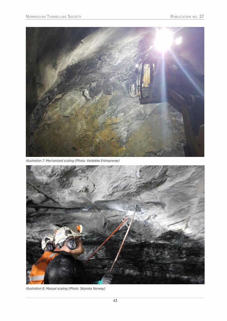
NorwegiaN TuNNelliNg SocieTy PublicaTioN No. 27
43
Illustration 7: Mechanised scaling (Photo: Veidekke Entreprenør)
Illustration 8: Manual scaling (Photo: Skanska Norway)

NorwegiaN TuNNelliNg SocieTy PublicaTioN No. 27
44
7.4.3. BoltingBolting is done to provide both temporary support and permanent support in order to prevent rockfall.
• Preliminary bolting at the face (grouted rein-forced steel bolts, bars etc).
Table 15: Bolting
Challenges Important to remember
• Rockfall• Grout spill• Crush hazard• Rotating machine parts• Installation of bolts in the face during blasthole
drilling
• The work operations involved in bolting must be included in the risk analysis, and work instruc-tions must be drawn up for the bolting work
• There must be a work permit - see template for work permit for simultaneous bolting and drill-ing, appendix 3
• Rock bolts on the face (expansion, polyester, combination bolts etc).
• Rock bolt behind the face (grouted bolts, com-bination bolts).
Illustration 9: Bolting (Photo: Skanska Norway)

NorwegiaN TuNNelliNg SocieTy PublicaTioN No. 27
45
Table 16: Sprayed concrete work
Challenges Important to remember
• Rockfall from unsupported rock• Blockages• Unwanted traffic in danger zone• Spill from concrete discharge• Spill from concrete jet and aggregate rebound• Collapse of non-hardened concrete• Crush hazard between concrete truck and
spraying rig
• The work operation involving sprayed concrete must be included in the risk analysis, and work instructions must be drawn up for sprayed concrete
• The need for a SJA must be assessed prior to the start work at each shotcreting location
• Health hazard associated with both handling of cement and addition of accelerator (corrosive)
• Choose accelerator that represents minimum risk (non-alkaline)
• Choice of spraying rig (type) that causes mini-mum personal exposure/risk (remote control)
• Use breathing apparatus (preferably fresh air supply), face mask and skin protection when working with or in proximity to shotcreting
• Avoid presence of persons in polluted atmos-phere (during and immediately after spraying) in areas where there is a risk of falling material
7.4.4. Sprayed concreteSprayed concrete is used for both temporary and permanent support, and both before and after bolting.
An accelerator is added to the concrete in the noz-zle such that it hardens and adheres quickly to the
surface, and fibres are also added to take up tension and sag.
The rock is flushed with water before concrete is sprayed on to give the concrete good adhesion to the surface, and the thickness is dimensioned according to need.
7.4.5. Heavy rock supportHeavy rock support is used to stabilise rock with poor stability, little rock cover or which for other reasons requires heavier support than bolts and sprayed concrete.
Support measures may be:• spiling• pipe umbrellas• sprayed concrete arches or lattice girders• concrete linings (if the tunnel profile is “lost”)
In recent years, the tendency has been towards more use of the combination of spiling and sprayed concrete arches and less use of full linings. There has been good experience with the use of pipe umbrel-las (inlaid casings as spiling) in projects where the whole or parts of the cross-section are characterised by weak rock or soil-like masses.
When there is a need for heavy support, the rock con-ditions are often extremely poor, with a great danger
of rockfall prior to rock support work. Normal rock support in the form of sprayed concrete and bolts should be installed if the conditions do allow before heavy support work is started. If support with sprayed concrete arches can be carried out some way behind the face, this will give much safer working conditions. Spiling bolts combined with rock straps can then be installed as temporary support at the face, prior to installation of sprayed concrete arches.
If the conditions require heavy support work at the face, special care must be taken. It may be necessary to sprayed concrete the face prior to the start of installation work starts in order to prevent rock face fall-out towards personnel on the floor. In extreme cases, full lining must be carried out at the face. If collapses develop it may be necessary to close the face with concrete.
It is essential to carry out risk analyses in which the prevailing geological conditions are considered prior to the implementation of these measures. The support

NorwegiaN TuNNelliNg SocieTy PublicaTioN No. 27
46
work must perhaps be carried out in several stages (often with a SJA), but it is an absolute requirement that personnel at all times remain in a safe area.
See also:NFF Handbook No. 05: Tung bergsikring i under-jordsanlegg (“Heavy rock support in underground works”), 2008.
7.5. Work behind the faceDifferent types of work involving a risk of undesir-able events are carried out behind the face. These jobs include the installation of ventilation ducting, water pipes and electricity, and the maintenance of pump systems, water supply and lighting. The work is usually done when there is no transport in the tunnel, but may also take place as a parallel activity.
RequirementsThe workplace must be provided with adequate lighting and air quality. During work at a height, a certified and approved work platform and tools must be used.
Special risk factorsThe major risk elements associated with work behind the face are:
• crush hazard• “loose” compressor hoses• falling objects• falls from a higher level• unintentional start of fans• work close to ongoing transport• dust and gas
Table 17: Installation and maintenance of ventilation
Typical features Challenges Important to remember
• Drilling and installation of suspension bolts
• Advance of suspension wire• Suspension of ventilation
ducting• Patching of ventilation
ducting
• Dust and rock particles from drilling
• Setting up, fastening and cut-ting wire. Danger of impact from tensioned wire
• Crush hazard if tunnel fan is started during installation work
• Dust and rock particles can loosen from the ducting
• Dry drilling must not be done in tunnels
• Drilling should be done using the jumbo
• Wire must be secured before cutting
• Fan control should be locked during installation work
• Use protective goggles and dust mask
Table 18: Routing of process water
Typical features Challenges Important to remember
• Drilling and installation of suspension bolts
• Connection and disconnec-tion of drill head
• Running of water pipe
• Dust and rock particles from drilling
• Work must be carried out when loading or scaling is in progress
• Dry drilling shall not be done in tunnels
• Drilling should be done using the jumbo
• The area around the work-place should be closed off and illuminated.
Table 19: Running pump piping
Typical features Challenges Important to remember
• Connection and disconnec-tion of pump hose
• Running of pump piping
• The work has to be carried out when loading or scaling is in progress
• Pump pipes can be heavy to handle
• The area around the work-site should be closed off and illuminated

NorwegiaN TuNNelliNg SocieTy PublicaTioN No. 27
47
Table 20: Running power supply to the face
Typical features Challenges Important to remember
• Connect cable reel to trans-port unit
• Disconnect reel and move it forwards towards the face
• Avoid damage to the cable• Ensure that the reel is loose
and that the cable is not pulled with the reel
• Use adapted equipment• Disconnect from voltage• Ensure that the reel spins
freely• The cable is suspended in
accordance with approved electrotechnical standards
• Should not be done when there is transport in the tun-nel; must be done when there is no need for power at the face
Table 21: Running high-voltage cable
Table 22: Relocation of transformer
Typical features Challenges Important to remember
• Drilling for suspension bolts• Suspension of ferraline• Suspension and marking of
cable
• Dust and rock splinters from drilling
• Suspension and cutting of wire
• Attachment of cable to sus-pension wire
• Drilling is done using tunnel-ling jumbo
• Is placed at a level with the centre of the ventilation screen
• Wire is fixed prior to cutting• Crush hazard during routing
of cable• Traffic past suspension site
should be avoided
Typical features Challenges Important to remember
• Disconnection of cables• Transport of transformer• Connection to cables that
have been run into place
• High voltage• Careful transport• High-voltage connection
• Disconnection of power prior to connection -use high-voltage electrician
• Transformer should be equipped with robust trans-port hook
• Use high-voltage electrician• Should be done when there
is no need for power at the face

NorwegiaN TuNNelliNg SocieTy PublicaTioN No. 27
48
SWECO PLANS AND DESIGNS THE CITIES AND COMMUNITIES OF THE FUTURE. WHATEVER CHALLENGES OUR CUSTOMERS HAVE, THEY CAN COUNT ON US TO SOLVE THEM.SWECO NORWAY – NEARLY 100 YEARS OF EXPERIENCE WITHIN:· Underground Works and Engineering Geology· Soil Mechanics and Foundation Engineering· Energy· Environment and Water Resources· Industry/Structures· Transportation
SWECO NORWAY ASDrammensveien 260, Box 80 SkøyenNO-0212 Oslo, Norway Telephone +47 67 12 80 00SWECO.NO
OREA, extension of the existing underground sewer treatment plant in
Strømmen, Norway
SWCO0100_Annonse_100 years of experience A4.indd 1 15.05.2017 14.54

NorwegiaN TuNNelliNg SocieTy PublicaTioN No. 27
49
SWECO PLANS AND DESIGNS THE CITIES AND COMMUNITIES OF THE FUTURE. WHATEVER CHALLENGES OUR CUSTOMERS HAVE, THEY CAN COUNT ON US TO SOLVE THEM.SWECO NORWAY – NEARLY 100 YEARS OF EXPERIENCE WITHIN:· Underground Works and Engineering Geology· Soil Mechanics and Foundation Engineering· Energy· Environment and Water Resources· Industry/Structures· Transportation
SWECO NORWAY ASDrammensveien 260, Box 80 SkøyenNO-0212 Oslo, Norway Telephone +47 67 12 80 00SWECO.NO
OREA, extension of the existing underground sewer treatment plant in
Strømmen, Norway
SWCO0100_Annonse_100 years of experience A4.indd 1 15.05.2017 14.54
8. Work requiring coordination (during tunnel excavation)
Finishing work in this context includes all activities that take place in an underground construction site in the period between completion of rock support and handover of the site to the owner or client. Rather than making a detailed assessment of each individual activity, we will examine the risk factors the different additional works may entail as a result of simultaneity and the consequences for other activities.
In many projects, the requirement of progress means that many activities further back in the tunnel must be carried out before breakthrough of the tun-nel. This makes it imperative that everyone is fully informed of what is happening in the project, and that the work sequence and routines are made clear. It is important that new information is provided when there is a change in arrangements or work operations. For all such works, it may be a challenge to have adequate ventilation of the workplace. All works that take place in parallel with tunnel driving result in lower productivity and must as a rule be carried out because of time pressure.
Activities that may take place at the same time dur-ing tunnel excavation include:
• trenching and road building• installation work• various concrete works
Trenching is the first activity to be done in order to develop the tunnel after it has been excavated. This involves placing drainage and cable draw pits, laying drainage pipes and ducts for electricity. The road structure has sometimes also been completed in this phase of the project. Choice of equipment is crucial in regard to the risks, and to how this work affects other activities in the tunnel.
Installation works in road and railway tunnels consist primarily of installation of bolts, concrete elements, PE foam, membranes, vaults, mesh reinforcement and technical equipment. There are several types of concrete elements that are installed in underground works, for example, wall and ceiling elements in road and railway tunnels and prefabricated elements in caverns, such as columns and flooring in parking facilities. In recent years, technical rooms have been built in transport tunnels on the basis of prefabri-
cated solutions. Installation is often carried out in parallel with other activities and with passing traffic. These works require special machines and equip-ment, which must be certified and whose drivers must have machine-specific training.
Illustration 10: Element machine (Photo: Skanska Norway)
During tunnelling, concrete works are often carried out in parallel with the tunnel excavation. These may be works related to tunnel portals, concreting of OPI ducts (routing for electric cables etc), work on tech-nical buildings and pumping stations. When time is short, concrete barriers (New Jersey) and shoulders may be slip formed. This activity will as a rule take place after breakthrough of the tunnel.
In the case of twin tube tunnels, it is possible to carry out works in one tube whilst transport takes place in the other. This requires some of the cross connections between the tubes to be blasted to a size which would allow construction machines to be driven through. The biggest challenge with this method is to establish a good ventilation system. This can be solved with a well-designed ventila-tion system, which includes tight walls and doors between the tunnel tubes.
The owner or client and designer have a special responsibility to identify the risk that is added to the project when a great deal of simultaneity is planned. Specific risk-reducing measures must be considered and described. The client must in addi-tion have strong focus on coordination between participants.

NORWEGIAN TUNNELLING SOCIETY PUBLICATION NO. 27
50
Table 23: General works between tunnel work face and tunnel entrance
Typical features Challenges Important to remember
• Works involving completion of/internal work in the tunnel
• Unwanted traffic in the dan-ger zone
• Passing vehicles, danger of collisions
• Polluted air• Noise and light conditions
• Planning of additional work to allow sufficient time with-out conflict with other works
• Risk assessment of all activi-ties with all participants
• Barriers of concrete blocks between activities
• Correct dimensioning of ventilation
• Extra lighting where activities take place
• High-visibility clothing (cl.3)• Good hearing protection
(personal)
Typical features Challenges Important to remember
• Establishing pits or basins/laying of pipes
• Site access road• Rock falling off vehicles• Crush hazard• Reversing/running into
people• Collision between vehicles• Undetonated explosives
• Systematic checking of loads on vehicles
• Acoustic reversing signal and camera on all vehicles
• Marker signs• Check of blasted surfaces
before drilling/picking
Typical features Challenges Important to remember
• Installation of concrete elements
• Installation of PE foam or membrane
• Fireproofing of PE foam • Membrane with sprayed
concrete
• Crush hazard• Falling objects• Collision between vehicles• Fire in plastic materials• Intermediate storage of plas-
tic materials in tunnels and rock caverns
• Special problems with dust during sprayed concrete work
• Special signposting/closing off of work area
• Special risk assessment – heavy lifts/vacuum.
• Visibility marking lights.• Reduce speed when passing.• Use of fire close to plastic
materials must be prohibited.• Minimise exposure of plastic
materials, under- ground (unsprayed/stored)
• Use dust masks, tunnelling jumbo with enclosed cab
Table 24: Trenching/road building in tunnels
Table 25: Installation work
NORWEGIAN TUNNELLING SOCIETY PUBLICATION NO. 27
51
Typical features Challenges Important to remember
• Portals• Technical buildings• SOS telephone
booths• Slip forming (NJ)
• Lack of approved scaffolding, rail-ings, barriers, warnings etc
• Falling objects• Many activities in the tunnel
• Protect scaffolding and slip forms from collision
• Reduced speed• Minimise work in the tunnel –
consider prefabricated solutions
Table 26: Concrete work
At NGI we research and develop solutions for both industry and society, ensuring that we live, build and travel on safe ground – be that above or below the surface of the earth. We are experts in geotechnics, rock mechanics & engineering, rock mass classification, underground support design and hydrogeology.
We participate in construction of tunnels and rock caverns for traffic, hydropower development and other infrastructure, and our expertise is in demand in several parts of the world – from Bhutan to Bodø.
Expert solutions for underground structures
NGI.NO
Building and construction Offshore energy Natural hazards Environmental engineering
#onsafeground

NORWEGIAN TUNNELLING SOCIETY PUBLICATION NO. 27
52
United. Inspired.
Discover what Epiroc can do for you.Epiroc was formed to be a stronger partner for you in mining,
infrastructureand natural resources. By building on proven
Atlas Copco expertise, you can count on us to deliver the
performance you need today and the technology to lead
tomorrow.
epiroc.com

NORWEGIAN TUNNELLING SOCIETY PUBLICATION NO. 27
53
9. Rehabilitation of existing tunnels and rock caverns
Rehabilitation of existing transport tunnels normally consists of some of the following activities:
• removal of existing tunnel installations• removal of waterproofing• removal of existing rock support• removal of any remaining old explosive material
After this, new caverns are established, and new and/or supplementary rock support is installed, as is new water and frost protection. This is followed by the assembly and installation of new ventilation, electrical equipment and communication equip-ment. The existing fill and drainage system are then removed from the tunnel floor, a larger drainage ditch is blasted, and a new road surface and drain-age system are established, together with conduits for electric and communication cables. Work on electrical installations often starts before rock works and the installation of water and frost protection have been completed.
During rehabilitation work in existing underground facilities, the risk picture may be far more compli-cated than when corresponding work is performed in new constructions. The reason for this is that in addition to the rock and production engineering conditions, there are also operational considerations to be taken. Examples here include road tunnels with short windows of available work time, old waterways in power plants or sewage tunnels. Rehabilitation work where there is a short distance to installations in operation or to high water pressure etc is another example.
During rehabilitation work in road tunnels conflicts arise between traffic flow and a safe working envi-ronment for the tunnel workers. In general, it is the workers’ safety that must be given priority. Good planning and early warning of closure will allow rehabilitation work to be carried out as efficiently and safely as possible.
Traffic flow should be defined in the specification and there should be clear requirements as regards performance of the work. It is important to be aware that rehabilitation work can be carried out with much more efficiency and safety by stopping all traffic throughout the work period. Experience has shown that in tunnels where traffic flow is main-tained, the production capacity will be 30 to 50 %
of the capacity that can be achieved in tunnels that are closed.
RequirementsThe developer or client shall risk assess the work that is to be done with a view to safety and working environment.
The employer shall risk assess safety and working environment prior to start-up and monitor the HSE situation during the performance of the work.
Special risk factors• Ahead of rehabilitation works, steps shall be
taken to map occurrences of, for example, radon, asbestos and quartz in the bedrock.
• During the rehabilitation of existing road tun-nels, it has been discovered that rock drilling, installation of water and frost protection, asphalt milling, and asphalting are jobs that generate a particularly high exposure to dust and gas. A connection has been established between quartz dust and lung damage and between exposure to radon/asbestos and lung cancer.
• During work in road tunnels, highly stressful sit-uations arise when traffic is to pass at frequent intervals in convoys.
• The rigging and dismantling of equipment with transport in and out of the tunnel each day.
• Damage to important installations can occur as a result of, e.g., ablasting work, and thereby worsen the work situation. Importance should be given to protecting installations, and plans should be drawn up for maintaining traffic flow without safety installations.
• Emergency vehicles do not respect roadworks warnings or escort vehicles and can cause dan-gerous situations. Notification of the need for emergency responses through roadworks warn-ing areas should be given to the workplace via road traffic information centres.
Measures• Operations shall be planned so as to avoid
simultaneous performance of works that have a particularly heavy impact on the working environment.
• Dust-producing works should be avoided, or dust-damping measures implemented. Dry drilling must be avoided. However, in the winter a cold draught can result in ice formation when wet drilling.
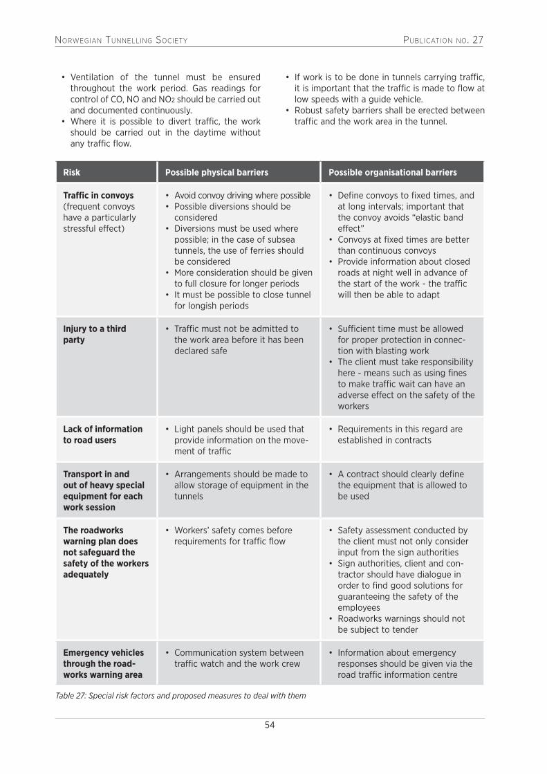
NorwegiaN TuNNelliNg SocieTy PublicaTioN No. 27
54
• Ventilation of the tunnel must be ensured throughout the work period. Gas readings for control of CO, NO and NO2 should be carried out and documented continuously.
• Where it is possible to divert traffic, the work should be carried out in the daytime without any traffic flow.
• If work is to be done in tunnels carrying traffic, it is important that the traffic is made to flow at low speeds with a guide vehicle.
• Robust safety barriers shall be erected between traffic and the work area in the tunnel.
Risk Possible physical barriers Possible organisational barriers
Traffic in convoys (frequent convoys have a particularly stressful effect)
• Avoid convoy driving where possible• Possible diversions should be
considered• Diversions must be used where
possible; in the case of subsea tunnels, the use of ferries should be considered
• More consideration should be given to full closure for longer periods
• It must be possible to close tunnel for longish periods
• Define convoys to fixed times, and at long intervals; important that the convoy avoids “elastic band effect”
• Convoys at fixed times are better than continuous convoys
• Provide information about closed roads at night well in advance of the start of the work - the traffic will then be able to adapt
Injury to a third party
• Traffic must not be admitted to the work area before it has been declared safe
• Sufficient time must be allowed for proper protection in connec-tion with blasting work
• The client must take responsibility here - means such as using fines to make traffic wait can have an adverse effect on the safety of the workers
Lack of information to road users
• Light panels should be used that provide information on the move-ment of traffic
• Requirements in this regard are established in contracts
Transport in and out of heavy special equipment for each work session
• Arrangements should be made to allow storage of equipment in the tunnels
• A contract should clearly define the equipment that is allowed to be used
The roadworks warning plan does not safeguard the safety of the workers adequately
• Workers’ safety comes before requirements for traffic flow
• Safety assessment conducted by the client must not only consider input from the sign authorities
• Sign authorities, client and con-tractor should have dialogue in order to find good solutions for guaranteeing the safety of the employees
• Roadworks warnings should not be subject to tender
Emergency vehicles through the road-works warning area
• Communication system between traffic watch and the work crew
• Information about emergency responses should be given via the road traffic information centre
Table 27: Special risk factors and proposed measures to deal with them

NorwegiaN TuNNelliNg SocieTy PublicaTioN No. 27
55
10. Relevant Norwegian laws and regulations
LOV-2005-06-17-62 Lov om arbeidsmiljø, arbeidstid og stillingsvern mv. (arbeidsmiljøloven – AML) - Act relating to working environment, working hours and employment protection etc (Working Environment Act)
FOR-2011-12-06-1356 Forskrift om utforming og innretning av arbeidsplasser og arbeidslokaler (Arbeidsplassforskriften) - Regulations on the design and layout of workplaces and premises for work (Workplace Regulations)
FOR-2009-08-03-1028 Forskrift om sikkerhet, helse og arbeidsmiljø på bygge- og anleggsplasser (Byggherreforskriften) - Regulations on health, safety and working environment on building or construction sites (Construction Client Regulations)
FOR-2011-12-06-1355 Forskrift om organisering, ledelse og medvirkning - Regulations on organisation, management and employee participation
FOR-2011-12-06-1357 Forskrift om utførelse av arbeid, bruk av arbeidsutstyr og tilhørende tekniske krav (Forskrift om utførelse av arbeid) - Regulations on the performance of work, use of work equipment and technical associated requirements (Regulations on the perfor-mance of work)
FOR-2017-06-15-844 Forskrift om sivil handling av eksplosjonsfarlig stoff (Eksplosivforskriften) - Regulations on the civilian handling of explosive substances (Explosives Regulations)
FOR-2006-04-28-458 Forskrift om sikkerhet ved arbeid i og drift av elektriske anlegg - Regulations on safety in work on and operation of electrical installations
FOR-2013-06-19-739 Forskrift om elektroforetak og kvalifikasjonskrav for arbeid knyttet til elektriske anlegg og elektrisk utstyr - Regulations for electrical enterprises and qualification requirements for work related to electrical installations and equipment
FOR-1996-12-06-1127 Forskrift om systematisk helse-, miljø- og sikkerhetsarbeid i virksomheter (Internkontrollforskriften) - Regulations on systematic health, safety and environ-mental work in enterprises (Internal Control Regulations)

NorwegiaN TuNNelliNg SocieTy PublicaTioN No. 27
56
11. Literature list
NFF Handbook No. 01 Berginjeksjon (2002)
NFF Handbook No. 02 Engineering Geology and Rock Engineering (2000)
NFF Handbook No. 03 Arbeidsmiljø under jord (2000)
NFF Handbook No. 05 Tung bergsikring i undergrunnsanlegg (2008)
NFF Handbook No. 06 Praktisk berginjeksjon for underjordsanlegg (2010)
NFF Handbook No. 07 Håndbok for bestiller av bergsprengningsarbeid (2012)
NFF Handbook No. 08 Håndbok for utfører av bergsprengningsarbeid (2014)
NFF Handbook No. 09 Håndbok for arbeidsmiljø under jord (2015)
WE CREATE SUSTAINABLE SOLUTIONS WITHIN BUILDINGS, TRANSPORT, PLANNING & URBAN DESIGN, WATER, ENVIRONMENT & HEALTH, ENERGY AND MANAGEMENT CONSULTING
ADVANCED GEOPHYSICAL TECHNIQUES GIVE INNOVATIVE SOLUTIONS IN TUNNEL AND ROCK ENGINEERING DESIGN(AND STRONG CONNECTIONS)www.ramboll.no
Contact person: [email protected]

NorwegiaN TuNNelliNg SocieTy PublicaTioN No. 27
57
12. Appendices
Handbooks published by NFFNo. 1: Fjellinjeksjon. Praktisk veiledning i valg av tettestrategi og injeksjonsopplegg. (NOK 200)No. 2: Engineering Geology and Rock Engineering. NBG (NOK 500) No. 3: Arbeidsmiljø under jord. (NOK 200)No. 4: Håndbok for skytebas. (NOK 200)No. 5: Tung bergsikring i underjordsanlegg (NOK 200)No. 6: Praktisk berginjeksjon for underjordsanlegg (NOK 200)No. 7: Håndbok for bestiller av bergsprengningsarbeid (NOK 200)No. 8: Håndbok for utfører av bergsprengningsarbeid (NOK 200)No. 9: Håndbok for arbeidsmiljø under jord (NOK 200)No. 10: Håndbok for sikkerhet ved arbeid i tunneler og bergrom (NOK 200)
Technical reports published by NFF (NOK 100 each)No. 01: Redningskammer for underjordsdriftNo. 02: Diesel under jord. Sluttrapport fra forprosjektet.No. 02E: Diesel Underground – a project report.No. 03: Sikker sprengning i dagen.No. 04: Plastmaterialer i tunneler og bergrom – sikker håndtering i anleggsfasen.No. 05: Informasjon, takk! Råd og tips om kommunikasjon i en anleggshverdag.No. 06: Sikker boring gjennom ylte.No. 07: Diesel under jordNo. 08: Sikkerhet ved berginjeksjonNo. 09: Behandling og utslipp av driftsvann fra tunnelanleggNo. 10: Rescue chamber for underground work. Translation of Technical Report 1 No. 11: Nøyaktig boringNo. 12: Konturkvalitet i sprengte tunnelerNo. 13: Ventilasjon ved tunneldriftNo. 14: Gruvedrift under jordNo. 15: Støy fra bygge- og anleggsvirksomhetNo. 16: Anbefalte retningslinjer for utarbeidelse av miljøbudsjett og miljøregnskap for tunnellerNo. 17: Kort innføring i bruk av TBM
Publications from the Norwegian Tunnelling TechnologyNo. 1 Hard Rock TunnellingNo. 2: Tunnelling TechnologyNo. 3: Hydropower TunnellingNo. 4: Road TunnellingNo. 5: Tunnelling TodayNo. 6: Geology of Norway (a map)No. 7: Tunnelling Reviewed in the International PressNo. 8: Subsea TunnellingNo. 9: Underground StorageNo. 10: Urban TunnellingNo. 11: Hard Rock TBM TunnellingNo. 12: Water Control TunnellingNo. 13: Health and Safety in Norwegian TunnellingNo. 14: Norwegian TunnellingNo. 15: Sustainable Underground Concepts
No. 16: Underground Constr. for the Norwegian Oil and Gas Industry
No. 17: Underground Openings - Operations, Maintenance and Repair
No. 18: Subsea TunnelsNo. 19: Rock Support in Norwegian TunnellingNo. 20: Rock Mass GroutingNo. 21: Contracts in Norwegian TunnellingNo. 22: Norwegian Hydropower Tunnelling IINo. 23: Norwegian Tunnelling TechnologyNo. 24: Health, Safety and Environment in
Norwegian TunnellingNo. 25: Norwegian Rock CavernsNo. 26: Principles of Norwegian Tunnelling

NorwegiaN TuNNelliNg SocieTy PublicaTioN No. 27
58
Norconsult is a multidisciplinary engineering and design consultancy,
providing services to clients in public and private sectors worldwide.
The company has designed constructions and facilities in rock for
more than 80 years.
Our special advisors can off er a complete range of engineering services
from concept/feasibility studies through detailed design and construction,
including planning and follow up of ground investigations and site super-
vision during construction.
Among our special fi elds of expertise within rock construction are:
• Hydropower development
• Subsea tunnelling and lake taps
• Oil and gas underground storages
• Groundwater control and grouting technology
• Rock cuts and slope engineering
• Blasting techniques, vibration monitoring
• TBM excavation
• Rock stability assessments and reinforcement techniques
• Analytical and numerical analyses
Going Underground?We know HOW and WHY
WWW.NORCONSULT.COM

NorwegiaN TuNNelliNg SocieTy PublicaTioN No. 27
59
We hope that you will take part in the focus group interview organised by the Norwegian Tunnelling Society’s (NFF) Development Committee, in con-nection with their work on a new handbook entitled Safety in tunnel and cavern construction work.
Who are we?We are the NFF working group behind the produc-tion of the handbook and represent the Norwegian Labour Inspection Authority, Hæhre Entreprenør, the Norwegian National Rail Administration, the Norwegian Union of General Workers, Skanska Norway, the Norwegian Public Roads Administration/Directorate of Public Road and Veidekke Entreprenør. Two representatives from the working group will conduct the interview
What do we want?We believe that to prepare a handbook on safety in tunnel and cavern construction work it is essential to find out what those of you who work in tun-nels every day think about safety and the risks you encounter. Therefore, to gain a better understanding of what this handbook should contain as regards recommended practice in tunnel and cavern con-struction work, we wish to learn more about your daily working life and how you see all the challenges that arise during tunnelling work.
We want to listen to what you have to say so as to be able to form as accurate a picture as possible of the real working day in tunnels and ensure the handbook contains appropriate guidelines and rec-ommended practice with the correct focus.
What is a focus group interview?To gain necessary insight we need to speak to you, the people who actually perform this work. We therefore wish to interview some of you in what is called a focus group interview. This is an interview form in which we gather six to ten tunnel workers (in this case a shift team) in one group and discuss different topics that we and you believe to be of importance in tunnelling work: how you perceive the risk associated with the different work operations and the surroundings, and the challenges that you yourselves experience.
Where will the interview take place?The focus group interview will be held at the end of a shift and after a meal (eg, the afternoon shift will be interviewed after dinner). The interview will last at most 60 minutes and will be held close to your workplace.
Can I be anonymous?As this is an interview in a group together with others in your shift team, it will not be possible to conceal your identity during the interview. However, the infor-mation you give in the course of the interview will be anonymised during our work on the handbook and will not be traceable back to you. It is up to you whether you wish to use your name during the interview or not.The interview will be audiotaped, and then played back and transcribed so that we can carefully review what you said. The recordings will be deleted as soon as transcription has been completed.
Participation is voluntaryParticipation in the focus group interview is of course voluntary. If you do not wish to participate, it will not have any consequences for you or you relationship with your employer.
Should you find anything unclear or would like fur-ther information, please do not hesitate to contact us.
Marie HalvorsenFacilitator, focus group interviewTel. 932 10 005
Declaration of consentI wish to take part in the focus group interview for the NFF Development Committee’s handbook on safety in tunnel and cavern construction work.I am aware of what the interview involves, and what it is to be used for.I am familiar with my rights as a volunteer.
PARTICIPANT’S NAME: ……………………………………………….
PARTICIPANT’ SIGNATURE: ………………………………………………………………...
NFF, Publication no 27Appendix 1.
Information letter and consent form for group interview participants

NorwegiaN TuNNelliNg SocieTy PublicaTioN No. 27
60
NFF, Publication no 27Appendix 2.
Interview guide Focus group interview: Perceived risk in underground construction work
Topics (highlighted/underlined) for discussion during the interview:
1. Perceived risk when working in a tunnel (general) a) What do you perceive as the greatest risk or risks when working in a tunnel? b) What undesirable events are most commonly reported? c) What is the effect of cross-section and incline versus decline?
(the geometry)
2. Work ahead of the face (long-hole drilling and grouting) a) What do you perceive as the greatest risk in connection with long hole drilling and
grouting?
3. Work at the face (scaling, shotcrete, drilling, charging and blasting, simultaneous drilling and bolting, loading)
a) What do you perceive as the greatest risk in connection with work at the face? b) How do you feel about different operations being carried out simultaneously?
4. Work behind the face (behind-face work/service work, installation work simultaneous with tunnel driving)
a) What do you perceive as the greatest risk in connection with work behind the face, such as, eg, suspension of ventilation ducting, water and pump pipes? • Simultaneity?
5. Transport (muck transport, tip work (overturns), road maintenance) a) How do you feel that the transport of excavated rock, or muck, affects your safety? b) How do you think the drivers see the situation?
6. Concluding question a) What in your view should be the major focus of this handbook on safety in tunnel
and cavern construction work?

NORWEGIAN TUNNELLING SOCIETY PUBLICATION NO. 27
61
NFF, Publication no 27Appendix 3.
Template/Example Work PermitRisk assessment, work permit and instructions for simultaneous work in front of the boom attachment on a drilling jumbo
Risk assessment, work permit and instructions for simultaneous work in front of the boom attachment on a drilling jumbo
The Norwegian Regulations concerning the performance of work (703), section 27-16, stipu-lates the following with regard to drilling with drilling jumbos: “The employer shall ensure that nobody occupies the danger zone during drilling with rock drilling rigs for mine and tunnel excava-tion, and that operators are adequately protected against flying rock fragments.”
The comment to section 27-16 explains that: “What constitutes the danger zone should be deter-mined specifically by identifying risks, conducting a risk assessment and having regard to instruc-tions from the rig manufacturer.” Based on the above, no one as a general rule is allowed to be in front of the boom attachment on the drilling jumbo. Moreover, simultaneous drilling and charging is not permitted.
The division of the danger zone can be defined in the horizontal plane and the vertical plane on the basis of a risk assessment. This means that the upper part of the face could be defined as outside the danger zone as indicated in the figure
Figure – Division of the danger zone in the horizontal plane
The red horizontal line marks the division of the danger zone for drilling in a horizontal plane. Simultaneous drilling and rock support work in the form of bolting and scaling, from man-baskets above the defined danger zone in the horizontal plane, may be allowed through a work permit and instructions.

NorwegiaN TuNNelliNg SocieTy PublicaTioN No. 27
62
Risk identification/assessment: What can go wrong, and what can we do about it?
Possible hazards/ risk – control questions
No Yes If yes, how should the hazards/risks be controlled?
Responsible
Is the tunnel cross-section (height) a risk for the performance of the work?
Is there a need for measures/protection against rockfall from the crown and face?
Is there a need for measures in connection with shotcrete applied (NB! Must have adequate strength)?
Is there a risk of encountering high water pressure?
Is there a risk that rockfall/rockslide can be triggered as a result of drilling in adjacent rock?
Is there a risk of drilling into old explosive material, fragment spray produced by possible detonation of explosives that lie hidden in the face after a previous blasting round?
Is there a risk associated with rotating drill bits and moving booms (proximity to them)?
Is there a risk of splinters from the drill string and rock loosening and hitting personnel?
Are there noise problems, vibrations, risk of hearing damage and accidents as a result of high noise level from boring machines in opera-tion? (Consider hearing protection, time spent in work area)
Are there special chemical exposure hazards (dust, oil fog)
Is there experience from previous reports of undesirable events at the face? (Findings and measures)
3 I confirm that this risk assessment has been carried out with the support of personnel who have a funda-mental knowledge of rock engineering, skills in rock support work, and an adequate knowledge of HSE.
3 I confirm that bolt drilling and face/contour/other contour drilling has been completed. 3 I confirm that the floor has been checked for misfires and that the “footwall” has been drilled. 3 In my view, the measures described are satisfactory to provide safety when support work is to be carried
out in front of the boom attachment on the drilling jumbo at the same time as drilling. 3 I also confirm that I have gone through this work permit/set of instructions with everyone who will be
involved in the work operation. 3 I confirm that I have gone through “Requirements that must always be met in order to control possible
risk and prevent/reduce the crush hazard between moving booms and rock” with everyone involved in the work operation.

NorwegiaN TuNNelliNg SocieTy PublicaTioN No. 27
63
This work permit is given for the following period of time:
Date: Name: Representative for employer (signature)
Signature:
Signed document will be filed for the project in accordance with the project’s filing key.
Rock drill operator:
Worker(s) in basket:
Other workers:
Possible representative for client
Requirements that must always be met in order to control possible risk and prevent/reduce the crush hazard between moving booms or between boom and rock:
3 Double hearing protection, frequent replacement of protection (at least every third month). Noise measurements must be carried out, and a reduction in time spent at drill rig/face considered.
3 An employee who carries out work in front of the boom attachments on the drilling jumbo should do this work from an approved man-basket with railings.
3 The man-basket on the jumbo must have an emergency stop that is in working order. 3 The operator should be protected against flying rock fragments. 3 There must at all times be a minimum distance between the man-basket in which the operator is posi-tioned and the booms on the jumbo.
3 No one must be under the basket or the drilling activity 3 Drilling must be carried out manually (not automatically) whilst simultaneous work is carried out in front of the boom attachments.
3 Drilling should be monitored with regular mapping of the conditions, assessment of risk, implementa-tion of measures and routines to maintain or increase safety.
3 All non-conformances that are identified at the face must be registered in the enterprise’s non-conformance system so that they can be used as indicators of “hazards”, and at the same time ensure that necessary measures are implemented.
3 Everyone involved in this work operation must have full focus and through their signature undertake to perform the measures that are described in this work permit.

NorwegiaN TuNNelliNg SocieTy PublicaTioN No. 27
64
NFF, Publication no 27Appendix 4.
Safe Job Analysis (SJA) - tips and advice What is a SJA?
A SJA is a systematic review and assessment of hazards ahead of an activity during which hazardous situations may arise.
Risk should as, a general principle, be mitigated through analyses and choices made in early project phases, but changes to plans and unforeseen circumstances can necessitate reassess-ment of safety and implementation of measures “there and then”.
When should a SJA be conducted?It is particularly important to conduct a SJA in the following situations:
• The work results in non-conformance with specifications in procedures and plans.• The work operation is new and unfamiliar to those who are to perform it.• People who do not know each other are to work together.• Equipment of which the workers have no experience is to be used.• The conditions have changed, eg, weather conditions, time available, changed sequence
of tasks, difficult coordination with other activities.• Accidents/undesirable events have occurred previously in connection with similar activities.
Often it will be the workers themselves - those who are in the thick of it - who will discover the need for a SJA.
Some advice
• Involve the workers Those who are to carry out the work have a unique insight into how to find practical solutions. Therefore, the workers are a key resource for the performance of a JSA. At the same time, involvement will increase awareness of the hazards and create ownership of the measures implemented.
• Be open to all input All involved parties should be given the opportunity to comment and make suggestions if they think that major factors have not been given sufficient attention. No question or suggestion is too stupid.

NORWEGIAN TUNNELLING SOCIETY PUBLICATION NO. 27
65
NFF, Publication no 27Appendix 5.
SJA - Safe Job Analysis
Appe
ndix
5
SJA
– Sa
fe Jo
b An
alys
is
Proj
ect (
no. a
nd n
ame)
Pe
rson
resp
onsib
le fo
r SJA
(nam
e, si
gn)
Date
:
Brie
f des
crip
tion
of a
ctiv
ity
Resp
onsib
le fo
r act
ivity
(com
pany
)
A
SJA
is be
ing
cond
ucte
d be
caus
e (c
ross
off
one
or m
ore
of th
e fo
llow
ing)
: ☐
The
wor
k re
sults
in n
on-c
onfo
rman
ce w
ith s
peci
ficat
ion
in p
roce
dure
s an
d pl
ans
☐
Equ
ipm
ent o
f whi
ch th
e w
orke
rs h
ave
no e
xper
ienc
e is
to b
e us
ed.
☐ T
he a
ctiv
ity is
new
and
unf
amili
ar.
☐
The
con
ditio
ns h
ave
chan
ged
(eg,
wea
ther
con
ditio
ns, a
vaila
ble
time,
☐
Peo
ple
who
do
not k
now
eac
h ot
her a
re to
wor
k to
geth
er
seq
uenc
e of
task
s, o
ther
act
iviti
es b
eing
car
ried
out n
earb
y)
☐
Acc
iden
ts/u
ndes
irabl
e ev
ents
hav
e oc
curr
ed p
revi
ousl
y in
con
nect
ion
with
sim
ilar a
ctiv
ities
.
Wha
t tas
ks g
ive
caus
e fo
r co
ncer
n?
Haza
rds –
wha
t can
go
wro
ng?
(See
exa
mpl
es in
list
bel
ow)
Do w
e ha
ve c
ontr
ol o
ver
the
haza
rds?
(cro
ss o
ff)
Y
es
Par
tly
Litt
le
Mea
sure
s H
ow sh
ould
the
haza
rds
be c
ontr
olle
d?
Resp
onsib
le
Wha
t can
be
lear
ned:
(To
be fi
lled
in b
y pe
rson
resp
onsi
ble
for S
JA a
fter
the
job
has
been
don
e: W
hat c
an b
e do
ne d
iffer
ently
/bet
ter n
ext t
ime?
wha
t pos
itive
find
ings
are
impo
rtan
t to
rem
embe
r?)
Poss
ible
haz
ards
1
Cras
hes/
colli
sion
6
Falli
ng o
bjec
ts
11
Hig
h pr
essu
re, s
plat
ter h
azar
d 16
W
eath
er c
ondi
tions
(win
d, c
old,
fog)
2
Stru
ctur
al fa
ilure
7
Falls
12
N
oise
, vib
ratio
n 17
N
atur
al e
vent
s (flo
od, l
ands
lide)
3
Fire
, exp
losi
on
8 H
eavy
lift
s/he
avy
mat
eria
ls
13
Radi
atio
n 18
W
ork
in ta
nks/
lack
of o
xyge
n 4
Mov
ing
obje
cts/
crus
h ha
zard
9
Surf
aces
with
hig
h/lo
w te
mpe
ratu
re
14
Dust
, sm
oke,
gas
es, t
oxic
sub
stan
ces
19
Drow
ning
haz
ard
5 Sh
arp
obje
cts
(cut
s/pe
rfor
atio
ns)
10
Risk
of e
lect
ric sh
ocks
15
In
adeq
uate
ligh
ting
20
Oth
er, s
peci
fy:

NorwegiaN TuNNelliNg SocieTy PublicaTioN No. 27
66
NFF, Publication no 25Appendix 6.
Norwegian Tunnelling Society NFF International Support Group
The Norwegian Tunnelling Society NFF has some 1200 members, among those approximately 70 corporate members covering private sector, governmental agencies, research and education. Their representatives are active in the various permanent committees. One of these - The International Committee responsible for this publication - is specially supported by the core group presented below:
ANDERSENS MEK. VERKSTED A.SP.O. Box 194, N - 4401 FLEKKEFJORDTEL. +47.38 32 04 20FAX. +47.38 32 33 30
Supplier of tunnelling equipment and machineryto the international market. Shotcrete robots andcomputerised drill [email protected]
BASF AS – Admixture SystemsGRANERUD INDUSTRIOMRÅDE, P.O.Box 13, N - 2120 SAGS TUATEL. +47.62 97 00 20FAX. +47.62 97 18 85
Supplier of chemical products and equipment for rock support and water control in [email protected]
COWI ASGrensevn. 88, N-0605 OsloTEL.:+47.02694
Multidiscipline Consulting [email protected]
GHELLA S.P.A NUFSluttstykket 2, N-1291 OSLO
INJEKSJON & TUNNEL-SUPPORT ASSlemmestadvn.30, N-1408 KråkstadTEL.:+47.91 30 08 50
Supplier of equipment for grout [email protected]
LNS ASN – 8484 RisøyhamnTEL +47 76 11 57 00FAX +47 76 11 57 01
General Contractors, Heavy construction.Underground [email protected]
MAPEI ASVallsetvn.6, N - 2120 SAGSTUATEL. +47.62 97 20 00FAX. +47.62 97 20 99
Supplier of concrete additives for rock support andwater control in [email protected]
MULTICONSULTP.O.Box 265 Skøyen, N – 0213 OSLOTEL +47.21 58 00 00Fax +47.21 58 00 01
Complete deliveries of consulting services.Energy, oil & gas, underground [email protected]

NorwegiaN TuNNelliNg SocieTy PublicaTioN No. 27
67
NCC CONSTRUCTION P.O. Box 93 Sentrum, N - 0663 OSLOTEL + 47.22 98 68 00Fax + 47.22 89 68 01
General Contractors, Heavy construction.Underground [email protected]
NMC TERMONOVA OYTorpmalmasvëgen 44, FI-10210 INGÅ
NORCONSULT ASVestfjordgt. 4, N - 1338 SANDVIKA TEL. + 47.67 57 10 00FAX. +47.67 54 45 76
Multi-Discipline Consulting and Engineering services. Underground facilities, geotechnical and rock [email protected]
NORMET NORWAY ASSilovn. 20, NO-2100 Skarnes Tel. + 47 476 66 476
Supplier of tunnelling equipment and concrete additives
NORWEGIAN GEOTECHNICAL INSTITUTE NGIP.O. Box 3930 Ullevål Hageby, N - 0806 OSLOTEL. +47.22 02 30 00FAX. +47.22 23 04 48
Consulting and engineering services.Geotechnical, geology, rock [email protected]
ORICA NORWAY ASP.O. Box 614, N - 3412 LIERMARKATEL. +47.22 31 70 00FAX. +47.22 31 78 56
Supplier of explosives and advanced charging [email protected] www.orica.com
PROTAN AS P.O. Box 420, N - 3002 DRAMMENTEL. +47.32 22 16 00FAX. +47.32 22 17 00
Intelligent tunnel ventilation, ducts, electronic tunnel tagging [email protected]
SIGICOM ABGötalandsvëgen 230, SE-125 44 ÄLVSÖ
SINTEFRock and Soil MechanicsN - 7465 TRONDHEIMTEL. +47.73 59 30 00Fax. +47.73 59 33 50
Research and consulting [email protected] www.sintef.no
SKANSKA NORWAY ASP.O. Box 1175 Sentrum, N - 0107 OSLOTEL. +47.40 00 64 00FAX. +47.23 27 17 30
General contractor. Tunnelling [email protected] www.skanska.no
STATENS VEGVESEN, VEG DIR.P.O. Box 8142 Dep, N-0033 OSLO

NorwegiaN TuNNelliNg SocieTy PublicaTioN No. 27
68
SWECO NORWAY ASP.O. Box 400, N - 1327 LYSAKERTEL. +47.67 12 80 00FAX. +47.67 12 58 40
Multidiscipline Consulting and engineering services. Hydropower, underground facilities, geotechnicaland rock [email protected] www.sweco.no
VEIDEKKE ENTREPRENØR ASP.O. Box 504 Skøyen, N - 0214 OSLOTEL. +47.21 05 50 00FAX. +47.21 05 50 01
General contractor. Tunnelling [email protected] www.veidekke.no
VIK ØRSTA ASP.O. Box 194, N - 6151 ØRSTATEL. +47.70 04 70 00FAX. +47.70 04 70 04
Supplier of rock support quality steel items e.g. the [email protected]
W. GIERTSEN TUNNEL ASP.O. Box 78 Laksevåg, N - 5847 BERGENTEL. +47.55 94 30 30FAX +47.55 94 31 15
Waterproof lining in rock caverns and tunnels.Membranes for tunnels, shafts and rock [email protected], [email protected]
NORWEGIAN TUNNELLING NETWORKLavendelgången 3, SE-459 32 LJUNGSKILETEL. + 46 768 528 750
Network of Norwegian Companies for promotingcommercial cooperation involving Norwegianunderground knowledge and [email protected]
NORWEGIAN TUNNELLING SOCIETYP.O. Box 626 NO – 1303 SANDVIKATEL. +47.67 57 11 73
A leading national society with focus on rock engi-neering with governmental, private sector and indi-vidual [email protected] www.nff.no

NorwegiaN TuNNelliNg SocieTy PublicaTioN No. 27
69
Orderform
Please mail or fax this order form to:NORWEGIAN TUNNELLING SOCIETY - NFFP.O.Box 2752 Solli, 0204 OsloTel + 47 98 21 05 30e-mail: [email protected]
Publications in the English language available from Norwegian Tunnelling Society NFFPrices in NOK (Postage incl.):
¨ Publication No. I Norwegian Hard Rock Tunnelling (104 pp) 100¨ Publication No. 2 Norwegian Tunnelling Technology (84 pp) 100¨ Publication No. 3 Norwegian Hydropower Tunnelling (I19 pp) 100¨ Publication No. 4 Norwegian Road Tunnelling (172 pp) – sold out 50¨ Publication No. 5 Norwegian Tunnelling Today (I 35 pp) 100¨ Publication No. 6 Geology of Norway (4 pp. and geol. map) 100¨ Publication No. 7 Norwegian Tunnels & Tunnelling (130 pp) – sold out 50¨ Publication No. 8 Norwegian Subsea Tunnelling (100 pp) 100¨ Publication No. 9 Norwegian Underground Storage (103 pp) 100¨ Publication No. 10 Norwegian Urban Tunnelling (86 pp) 100¨ Publication No. 11 Norwegian TBM Tunnelling (118 pp) 100¨ Publication No. 12 Water Control in Norwegian Tunnelling (105 pp) 150¨ Publication No. 13 Health and Safety in Norwegian Tunnelling (90 pp) 200¨ Publication No 14 Norwegian Tunnelling (105 pp) 200¨ Publication No 15 Sustainable Underground Concepts( 130 pp) 200¨ Publication No 16 Undergr.Constr.for the Norwegian Oil and Gas industry 200¨ Publication No 17 Underground openings-operations, maintenance and repair 200¨ Publication No 18 Norwegian Subsea Tunnelling 200¨ Publication No 19 Rock Support in Norwegian Tunnelling 200¨ Publication No 20 Rock Mass Grouting 200¨ Publication No 21 Contract Practise in Norwegian Tunnelling 200¨ Publication No 22 Norwegian Hydropower Tunnelling II 200¨ Publication No 23 Norwegian Tunnelling II 200¨ Publication No 24 Health, Safety and Environment in Norwegian Tunnelling 200¨ Publication No 25 Norwegian Rock Caverns 200¨ Publication No 26 The principles of Norwegian Tunnelling 200
Most of the above publications can be downloaded at no cost from internet: www.tunnel.no
To order, please send e-mail to [email protected].
NFF, Publication no 27Appendix 7.

NorwegiaN TuNNelliNg SocieTy PublicaTioN No. 27
70


NorwegiaN TuNNelliNg SocieTy PublicaTioN No. 27
72
You will find:
– Consultants and experts – Contractors – Equipment and Suppliers
– Applied technology – Project descriptions – Publications
A NFF (Norwegian Tunnelling Society)
initiative to promote modern, cost and time efficient tunnelling
Are you looking for
tunnelling technology and experience?
Check out:
www.tunnel.no The Tunnelling Technology Website