Analysis of Cuttings Transport and Flow Pattern in Nearly ...
18
Journal of Advanced Research in Fluid Mechanics and Thermal Sciences 71, Issue 2 (2020) 69-86 69 Journal of Advanced Research in Fluid Mechanics and Thermal Sciences Journal homepage: www.akademiabaru.com/arfmts.html ISSN: 2289-7879 Analysis of Cuttings Transport and Flow Pattern in Nearly Horizontal Extended Reach Well Golam Rasul 1 , M. Fahed Qureshi 1 , Hicham Ferroudji 1 , Stephen Butt 2 , Rashid Hasan 3 , Ibrahim Hassan 1 , Mohammad Azizur Rahman 1,* 1 Texas A&M University at Qatar, Education City, Doha, Qatar 2 Memorial University of Newfoundland, St. John’s Newfoundland and Labrador, Canada 3 Texas A&M University, College Station, Texas, United States ARTICLE INFO ABSTRACT Article history: Received 31 December 2019 Received in revised form 13 February 2020 Accepted 13 February 2020 Available online 27 May 2020 During the drilling activity, in an extended reach well, the deposition of cuttings (solids) in the annulus can lead to issues such as differential sticking and inefficient hole cleaning. This makes it essential to identify different multi-phase flow patterns and study the effect of drill pipe eccentricity and rotational speed on cutting transport in the annulus. Therefore, in this study, the experiments were conducted in a near- horizontal flow loop system, where the length of an annulus section was 6.16 m (20.2 ft) long and the outer and inner diameters were 4.5 in. (11.4 cm/0.37 ft) and 2.5 in. (6.4 cm/0.21 ft), respectively. A high-speed CCD camera was used to perform the in- situ visualization of the multiphase-flow through the annulus. Then the recorded videos were used to investigate the cuttings transport for both 2 and 5 wt% solid concentrations. Glass beads having a diameter of 0.5-2 mm were used as cuttings for the experiments. The video recordings were used to scrutinize the flow behavior pattern which depicts the possible flow patterns for the gas-liquid-solid multiphase- flow through horizontal annuli. The effects of varying pipe eccentricity (0 to 75 %), drill pipe rotational speed (0- 120 RPM), air pressure (0.4-0.8 bar) and solid concentration on the cuttings transport through the annulus were investigated. It was observed that high rotational speed and eccentricity of the drill pipe lead to better hole cleaning. At 30% eccentricity, the solid bed height was found to vary from 8 to 20 times at different rotational speeds for changing the solid concentration form 2 wt% to 5 wt%. Moreover, while different drilling conditions were tested for cutting transport, six distinguishable flow patterns were observed. The findings also show that 75% of eccentricity may not be optimum drilling conditions because of the contact between cutting and the drill pipe. The novelty aspect of this work was the use of three phases (solid, liquid and gas) to investigate the flow pattern behavior and cutting transport phenomena in the annular flow loop system by varying drill pipe rotational speed and drill pipe eccentricity. The flow map of this work can be used to develop 3-phase models to figure out optimum conditions for cutting transport in horizontal wells for enhanced oil recovery. * Corresponding author. E-mail address: [email protected] (Mohammad Azizur Rahman) https://doi.org/10.37934/arfmts.71.2.6986 Open Access
-
Upload
khangminh22 -
Category
Documents
-
view
0 -
download
0
Transcript of Analysis of Cuttings Transport and Flow Pattern in Nearly ...

Journal of Advanced Research in Fluid Mechanics and Thermal Sciences 71, Issue 2 (2020) 69-86
69
Journal of Advanced Research in Fluid
Mechanics and Thermal Sciences
Journal homepage: www.akademiabaru.com/arfmts.html ISSN: 2289-7879
Analysis of Cuttings Transport and Flow Pattern in Nearly Horizontal Extended Reach Well
Golam Rasul1, M. Fahed Qureshi1, Hicham Ferroudji1, Stephen Butt2, Rashid Hasan3, Ibrahim Hassan1, Mohammad Azizur Rahman1,* 1 Texas A&M University at Qatar, Education City, Doha, Qatar 2 Memorial University of Newfoundland, St. John’s Newfoundland and Labrador, Canada 3 Texas A&M University, College Station, Texas, United States
ARTICLE INFO ABSTRACT
Article history: Received 31 December 2019 Received in revised form 13 February 2020 Accepted 13 February 2020 Available online 27 May 2020
During the drilling activity, in an extended reach well, the deposition of cuttings (solids) in the annulus can lead to issues such as differential sticking and inefficient hole cleaning. This makes it essential to identify different multi-phase flow patterns and study the effect of drill pipe eccentricity and rotational speed on cutting transport in the annulus. Therefore, in this study, the experiments were conducted in a near-horizontal flow loop system, where the length of an annulus section was 6.16 m (20.2 ft) long and the outer and inner diameters were 4.5 in. (11.4 cm/0.37 ft) and 2.5 in. (6.4 cm/0.21 ft), respectively. A high-speed CCD camera was used to perform the in-situ visualization of the multiphase-flow through the annulus. Then the recorded videos were used to investigate the cuttings transport for both 2 and 5 wt% solid concentrations. Glass beads having a diameter of 0.5-2 mm were used as cuttings for the experiments. The video recordings were used to scrutinize the flow behavior pattern which depicts the possible flow patterns for the gas-liquid-solid multiphase-flow through horizontal annuli. The effects of varying pipe eccentricity (0 to 75 %), drill pipe rotational speed (0- 120 RPM), air pressure (0.4-0.8 bar) and solid concentration on the cuttings transport through the annulus were investigated. It was observed that high rotational speed and eccentricity of the drill pipe lead to better hole cleaning. At 30% eccentricity, the solid bed height was found to vary from 8 to 20 times at different rotational speeds for changing the solid concentration form 2 wt% to 5 wt%. Moreover, while different drilling conditions were tested for cutting transport, six distinguishable flow patterns were observed. The findings also show that 75% of eccentricity may not be optimum drilling conditions because of the contact between cutting and the drill pipe. The novelty aspect of this work was the use of three phases (solid, liquid and gas) to investigate the flow pattern behavior and cutting transport phenomena in the annular flow loop system by varying drill pipe rotational speed and drill pipe eccentricity. The flow map of this work can be used to develop 3-phase models to figure out optimum conditions for cutting transport in horizontal wells for enhanced oil recovery.
* Corresponding author. E-mail address: [email protected] (Mohammad Azizur Rahman) https://doi.org/10.37934/arfmts.71.2.6986
Open
Access

Journal of Advanced Research in Fluid Mechanics and Thermal Sciences
Volume 71, Issue 2 (2020) 69-86
70
Keywords: Cuttings transport; Flow pattern; Multiphase flow; Horizontal annulus; Eccentricity Copyright © 2020 PENERBIT AKADEMIA BARU - All rights reserved
1. Introduction
Multiphase flow can take place through the whole production system intricate in fluids flowing across offshore oil and gas wells to the onshore facilities [1]. The multiphase flow can occur in the oil and gas reservoirs, the tubulars that link the reservoir to the surface and any flow lines that transport fluids from one facility to other processing facilities [2]. The multiphase flow encountered in the industry can be an amalgamation of a solid, liquid and gas phase [3]. The occurrence of multiphase flow in the petroleum industry forms complications, as the fluids involved are multicomponent mixtures whose phase behavior is extremely complex to determine [4]. This makes it difficult for engineers to predict the correlations between flow rates, pressure drop, and piping geometry (length, diameter, angle, etc.) for the multi-phase fluids produced across offshore fields and onshore processing facilities [5]. The study of multi-phase flow across annulus is also essential to determine the cuttings transport phenomena and ensure proper cleaning of the annulus [6]. As deposition of cuttings (solids) in the annulus can lead to issues such as differential sticking, loss of fluid circulation, blockages and inefficient hole cleaning. 1.1 Effect of Geometry
Earlier in the 1980s, Salcudean et al., [7] conducted experimental work to study the effect of flow impediment geometry on pressure drop in horizontal two-phase (water-air) system. In this work, a pipe of diameter 1 inch consisting of impediments positioned centrally and tangentially was used to evaluate pressure drop. The effect of the level of flow impediment and flow shape impediments on pressure drop was evaluated. However, no two-phase flow-regimes were reported in their work. Osamusali and Chang [8], investigated multiphase flow (water-air) regime alterations in horizontal annuli designed by concentrically positioning central rod, with variable radiuses in an acrylic tube of diameter 2 inches. The inner and outer diameters ratios varied from 0.375 to 0.675. The flow regimes observed by Osamusali and Chang [8], included stratified wavy, stratified-smooth, slug, plug and annular.
Ekberg et al., [9], investigated two-phase flow regimes in thin horizontal annulus sections. They carried out experiments in two different annuli. The first annulus had the inner and outer diameters of 0.26 inch and 0.34 respectively, having an ID/OD ratio of 0.76. The second annulus had the inner and outer diameters of 1.30 inch and 1.38 correspondingly, providing an ID/OD ratio of 0.94. The two-phase flow regimes noted included some hybrid regimes and common flow regimes like a plug, slug, dispersed, bubble and churn flow. Lage, Rommetveit [10], carried out small scale experimental work to investigate the two-phase flow regimes in horizontal and marginally diverged fully eccentric annuli. The annulus had an inner and outer diameter of 2 inches and 4 inch and correspondingly, providing an ID/OD ratio of 0.5. The fluids tested in the annulus were the mixtures of water-air and nitrogen-diesel respectively. The flow regimes observed by Lage et al., [10], comprised of the stratified, dispersed bubble, annular and intermittent flows. But, the complete flow regime maps cannot be developed out of their experimental work due to a limited number of data points.
Zhou et al., [11], conducted intensive two-phase (air-water) experiments in a larger size annulus with outer and inner diameters 8.34 inch and 3.50 inch correspondingly, providing ID/OD ratio of 0.42. The flow regimes identified included stratified wavy, stratified-smooth, stratified to slug, slug,

Journal of Advanced Research in Fluid Mechanics and Thermal Sciences
Volume 71, Issue 2 (2020) 69-86
71
slug to annular and slug to dispersed bubble. Zhou et al., [11], also provided a theoretical explanation for the flow regime transitions in the two-phase system.
Omurlu and Ozbayoglu [12] and Metin and Ozbayoglu [13] investigated two-phase flow through a fully peculiar horizontal annulus. Their experimental loops involved variable outer diameters (3.67 inch, 4.5 inch) and variable inner diameters (1.92 inch, 2.25 inch) providing ID/OD ratios of 0.52 and 0.5 respectively. They observed flow regimes visually and mainly observed intermittent flow regime due to setup confinements. Based on their observation, they develop a mechanistic model that helps to predict a flow regime in annulus based on the reference diameter. 1.2 Effect of Eccentricity
Sorgun et al., [14], examined gas-liquid flow inside horizontal eccentric annulus using an Eulerian CFD model for two-phase flow, using different flow patterns, such as dispersed bubble, dispersed annular, plug, slug and wavy annular. The results of Sorgun et al., [14] simulations were compared with the experimental data and they were found to be in an agreement of ±20-30% error in estimates of gas-liquid pressure losses.
Ettehadi Osgouei et al., [15] examined the pressure loss differences among horizontal, inclined and nearly vertical positions for three-phase flow in eccentric annuli. It was observed that because of the increased gas velocity in the wellbore, the total pressure loss changes moderately in the horizontal section. However, in the case of inclined and nearly vertical sections, total pressure loss decreases considerably with increased gas velocity. They also indicated that the conformal mapping could also be useful to describe the impact of eccentricity in the three-phase flow system.
Gschnaidtner [16], carried out multiphase flow (air-water) experimental work in a concentric annulus with an outer diameter of 2 inch and an inner diameter of 1.3 inch, providing the ratio of 0.65. The flow regimes inside the annulus were observed using an HD video camera. The flow regimes reported were characterized as intermittent and bubble flow as only a minor range of gas and liquid superficial velocities were investigated.
Recently, our group Zahid et al., [17], at Texas A & M University at Qatar (TAMUQ), observed flow regimes of two different multi-phase flow systems consisting of air-water and glass bead-water using a high-speed CCD camera in a horizontal annulus with a length of 240 inch and outer-inner diameters of 4.5 inch and 2.5 inch respectively, providing ID/OD ratio of 0.5. The flow regimes observed for the air-water system at different system pressure (0.2-0.4 bars) were characterized as bubbly and wavy. On the other hand, the flow regime observed for glass bead- water system at 0.3 bar was observed as a stationary bed. Moreover, the Computational fluid dynamics model work was also conducted by our group to develop correlations for pressure losses in annular geometries [18,19].
Based on the literature review, it is evident that the study of cutting transport is essential for smooth drilling operation and flow assurance [20-22]. The majority of work in cuttings transport has been conducted using two-phase flow [23-27] and work using three-phase flow is limited [28-30]. Therefore, in this work, our group has used three phases (solid, liquid and gas) to investigate the flow pattern behavior and cutting transport phenomena in the same annular flow loop system by varying drill pipe rotational speed and drill pipe eccentricity. The group has used two different solid concentrations (2- 5wt %) and system operating pressure (0.4-0.8 bars) to visually observe the flow regimes within the system. In order to visualize the flow patterns, digital video recordings were collected and the image processing technique is applied for the corresponding videos. Different flow conditions and drilling parameters have been tested and subsequent analyses have also been performed to construct the desired flow map and flow regime.

Journal of Advanced Research in Fluid Mechanics and Thermal Sciences
Volume 71, Issue 2 (2020) 69-86
72
2. Background
In the drilling activity, the fluid is pumped across the drilled pipe down to the hole. At that point, the fluid with cuttings flows back up to the surface via the annular space between the drilled pipe and the hole [31]. The hole cleaning is vital as it has a major influence on the drilling operations cost, time of operations and process safety. Insufficient hole cleaning can lead to issues such as differential sticking, premature wear out of drill bit, fracture formation and inducement of high torque or drag [32]. The type of fluid pumped and the other factors such as rotation of the drilled pipe affect the transport of cuttings. If cleaning of the annular hole is not carried out appropriately by the injection fluid, it may cause problems like pipe sticking, premature wear out of drill bit and lead to formation damages or issues in cementing or logging process [33]. It may also cause temporary hole blockages resulting in loss of circulation, excessive wear and tear in the pipe and more additives will be required in the drilling fluid which directly increases the cost of the drilling operation [34,35]. Sometimes, the sticking of the solid particles at the lower annular section may also lead to a reduced penetration rate and also cause thickening of the pipeline [36].
The different elements which affect the efficiency of the hole cleaning process include the injection rate of the fluid stream, inclination of hole angle, rotation of drill, the rate of penetration (ROP), fluid properties and type of cuttings present in the hole [37]. These elements also rely on the mechanics of fluid transportation [33]. For instance, lower turbulence levels in the injection flow through the annulus may lead to inappropriate carrying up of the cuttings across the narrow zones of the annulus causing hole cleaning issues [38]. 2.1 Effect of Multiphase Flow Regimes on Cuttings Transport
The transport of cuttings as a multiphase flow is essential for drilling operation, as it may help to reduce operation cost, reduce operation time, and improve the quality of well drilling and completion [39,40]. The addition of the gas phase, into the flow system, helps to improve the cutting transport dynamics. The liquid phase of the blend provides cuttings moving capacity and assures that the cuttings move at the rate of fluid velocity, provided they are not present in the cuttings bed [41].
The most widely recognized flow regimes for effective cuttings transport are slug flow and dispersed-bubbly stream. The formation of cuttings beds occurs when the fluid flow rate in the annulus can't avoid cuttings deposition [42]. As the thickness of bed increases, the annular speed and the frictional pressure losses also increase due to restricted flow region, until equilibrium conditions or steady-state condition is achieved (rate of pumping and fluid properties, etc) [42]. The majority of cuttings transport models and correlations are also set up under equilibrium conditions or steady-state conditions. In order to ensure effective drilling operations and efficient transport of cuttings, it is essential to know about different types of multi-phase flow regimes patterns that occur in the horizontal or vertical systems. 2.1.1 Gas-liquid flow regimes
In a horizontal annulus, the gas-liquid flow regimes can be classified as the bubble flow, the plug flow, the slug flow, the wavy flow, stratified flow, disperse flow and the annular flow (Figure 1). The bubbly flow contains small-sized distributed bubbles in the liquid [43]. The plug flow involves a combination of liquids and large size bubbles with some small-sized bubbles. The slug flow consists of a mixture of liquids and large gas slugs which have random frequency [43]. In the wavy flow, the gas phase tends to flow distinctly on top of the liquid phase and depicts a wavy surface and in the

Journal of Advanced Research in Fluid Mechanics and Thermal Sciences
Volume 71, Issue 2 (2020) 69-86
73
annular flow, the liquid tends to flow as a narrow film adjacent to the pipe wall [44]. In the stratified flow both liquid and gas maintain moderate velocities and fluid surface remain flat, whereas in the case of dispersing flow, both velocities are very high and dispersed gas bubbles are scattered along the whole cross-section.
Fig. 1. Flow regimes for gas-liquid two-phase flow in a horizontal pipe
In vertical or discretely deviated pipes, the most widely recognized flow regime for gas-liquid
mixtures are bubble flow, slug flow, mist flow, churn flow and annular flow [45]. In the bubble flow, the gas phase is circulated in the liquid phase and the fragile bubble moves upward in a zig-zag motion. The wall of the pipe is in touch with the liquid phase [45]. In the slug flow, the gas exists as large bullet-shaped air pockets with the area close to the area of the pipe. These air pockets, also known as Taylor bubbles, move consistently upward and are isolated by slugs of continuous liquid that connects with the pipe and contain small-sized gas bubbles. The speed of gas bubbles is higher compared to the liquid [46]. This oscillatory flow of the liquid is distinctive of churn flow and it may not take place in smaller size pipes.
In the Annular - Mist Flow, amid annular, the liquid phase flows consistently as an annular film on the wall with gas flowing as a central core. A portion of this liquid is entrained as small molecules in this gas core (mist flow) [47]. 2.1.2 Solid-liquid flow regimes
In liquid-solid flow, the solid particles traveling through the annuli can form various patterns [48]. The term stationary bed relates to the flow regime where the liquid streams over a stationary solid bed molded at the bottom of an annulus. This type of phase scattering takes place when the liquid velocity varies from moderate to low [48]. As the flow rate of the liquid rises, the stationary bed separates into a pattern depicting moving dunes and as the flow rate of the liquid rises further the occurrence of a scouring regime may take place [48]. In that case, few particles tend to travel over the solid dune, while most of the particles gather in the lower portion of the dunes. This mechanism forces the solids towards the direction of flow. The dispersed flow regime takes place as a result of a high liquid flow rate in the annular horizontal portion [49].
Journal of Advanced Research in Fluid Mechanics and Thermal Sciences
Volume 71, Issue 2 (2020) 69-86
74
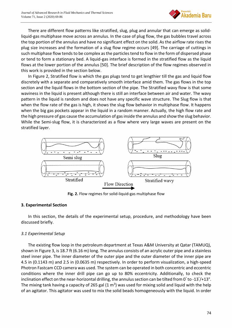
There are different flow patterns like stratified, slug, plug and annular that can emerge as solid-liquid-gas multiphase move across an annulus. In the case of plug flow, the gas bubbles travel across the top portion of the annulus and have no significant effect on the solid. As the airflow rate rises the plug size increases and the formation of a slug flow regime occurs [49]. The carriage of cuttings in such multiphase flow tends to be complex as the particles tend to flow in the form of dispersed phase or tend to form a stationary bed. A liquid-gas interface is formed in the stratified flow as the liquid flows at the lower portion of the annulus [50]. The brief description of the flow regimes observed in this work is provided in the section below.
In Figure 2, Stratified flow is which the gas plugs tend to get lengthier till the gas and liquid flow discretely with a separate and comparatively smooth interface amid them. The gas flows in the top section and the liquid flows in the bottom section of the pipe. The Stratified wavy flow is that some waviness in the liquid is present although there is still an interface between air and water. The wavy pattern in the liquid is random and does not have any specific wave structure. The Slug flow is that when the flow rate of the gas is high, it shows the slug flow behavior in multiphase flow. It happens when the big gas pockets appear in the liquid in a random manner. Actually, the high flow rate and the high pressure of gas cause the accumulation of gas inside the annulus and show the slug behavior. While the Semi-slug flow, it is characterized as a flow where very large waves are present on the stratified layer.
Fig. 2. Flow regimes for solid-liquid-gas multiphase flow
3. Experimental Section
In this section, the details of the experimental setup, procedure, and methodology have been discussed briefly. 3.1 Experimental Setup
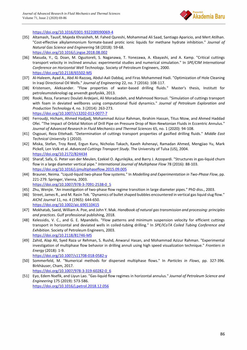
The existing flow loop in the petroleum department at Texas A&M University at Qatar (TAMUQ), shown in Figure 3, is 18.7 ft (6.16 m) long. The annulus consists of an acrylic outer pipe and a stainless steel inner pipe. The inner diameter of the outer pipe and the outer diameter of the inner pipe are 4.5 in (0.1143 m) and 2.5 in (0.0635 m) respectively. In order to perform visualization, a high-speed Photron Fastcam CCD camera was used. The system can be operated in both concentric and eccentric conditions where the inner drill pipe can go up to 80% eccentricity. Additionally, to check the inclination effect on the near-horizontal drilling, the annulus section can be tilted from 0° to -13°/+13°. The mixing tank having a capacity of 265 gal (1 m3) was used for mixing solid and liquid with the help of an agitator. This agitator was used to mix the solid beads homogeneously with the liquid. In order

Journal of Advanced Research in Fluid Mechanics and Thermal Sciences
Volume 71, Issue 2 (2020) 69-86
75
to keep the solid beads suspended, the agitator can be operated at different rotary speeds up to 200 RPM.
Fig. 3. Schematic of flow loop at Texas A&M University at Qatar
The data acquisition system helps to acquire precise readings per second for each sensor
integrated with the equipment of a flow loop system as shown in Figure 3. The data is displayed in the monitor containing the flow loop software. For aerated flow, air with variable pressure (0.4 bar and 0.8 bar) was injected inside the annulus along with water and solid mixture. Two different Coriolis flowmeters were used for measuring air and liquid flow rates. Both of them are Micro MotionTM branded having measurement accuracy of +/- 1.0%.
The robust flow loop system also contains pressure transducer, two flow meters (one for slurry another for air), hydro-cyclone, pressure relief valves, data acquisition system (DAS), ERT, and a high-speed CCD camera with the computer display. A Toshiba branded slurry pump has a rating of 18.7 hp, 0.33 ft inlet and 0.166 ft outlet, which was used to maintain the desired flow of slurry. The multivariate pressure transmitter (MVT), two digital pressure sensors, and two Coriolis flowmeters are used in the system to make sure the measurement and control of the fluid flow through the loop. 3.2 Experimental Procedure
Before the initiation of the experiments, the water volume of about 300 liters is added into the tank (Figure 3). After achieving the stable flow through the annulus the solid particles (glass beads) are added into the system. The flow loop can handle the maximum flow rate of 0.0213 m3/s (21.3 l/s) which corresponds to the maximum angular velocity of 3 m/s (Re ~ 2×10⁵). A slurry pump with a maximum capacity of 650 kg/min was employed to pump the slurry from tank to annulus. The solids weight of about 6 kg (2wt%) and 15 kg (5wt%) are added into the tank and then well agitated. These solids are spherical glass beads having a diameter of 0.5-2 mm and a density of 2650 kg/m3.

Journal of Advanced Research in Fluid Mechanics and Thermal Sciences
Volume 71, Issue 2 (2020) 69-86
76
The eccentricity of the inner pipe is controlled by a mechanical process built by the vendor (MARZOR LTD & CO) of the flow loop system. At first, the lock is released, and then the ratchet situated on top of the 3rd metallic flange is used to adjust the position of the inner pipe. The scale with an indicator on the same flange indicates the percentage of eccentricity. As the ratchet is turned, the indicator moves downward, and the eccentricity increases. While the indicator touches the halfway mark on the scale, it means 50% eccentricity is achieved. Similarly, the other values of eccentricity are measured based on the position of the indicator on the scale. Once the desired eccentricity is obtained, the locking system is engaged to ensure the inner pipe will not slip anymore. Moreover, there are several O-rings at the joints of the annulus section. Their internal mechanism also helps to minimize the chances of pipe sagging.
The solid dunes height, translational velocity, and type of flow pattern are visually observed by the help of the high-speed CCD camera (FASTCAM SA-X2) situated in front of the RIM (Refraction Index Matching) box, that records the images and videos of the solid dune across the RIM box. These recorded videos are used to investigate the cuttings transport for both 2 and 5 wt% solid concentrations. The video recordings help to scrutinize the flow behavior pattern which depicts the possible flow patterns for the gas-liquid-solid multiphase-flow through horizontal annuli. This helps to investigate the effects of varying pipe eccentricity (0 to 75 %), drill pipe rotational speed (0- 120 RPM), air pressure (0.4-0.8 bar) and solid concentration on the cuttings transport across the annulus. 4. Results & Discussions
The effects of drill pipe RPM (0-120) and eccentricity (0-75%) on the multiphase flow patterns in annulus were observed under different pressure conditions during the experiments. The purpose of these experiments was to visualize the type of flow and level of solid accumulation that occurs by varying the RPM and eccentricity parameters during the experiments. A high-speed CCD camera (Photron FastCam SA-X2) was used to visualize and conduct image analysis through the transparent section across the flow loop.
The CCD camera recordings captured for each experimental condition were carefully examined and still, images were collected from these recordings as shown in the Tables below. These images were further enhanced to provide better visual illustrations of the type of flows, flow regimes and level of mixing occurring within the system. 4.1 Analysis for 2 wt% Solid Concentration
In order to investigate the effect of drilling parameters such as drill pipe eccentricity and rotational speed on cutting transport, experiments were performed at different gas pressure (Table 1). The change in parameters also showed different flow patterns inside the annulus.
Table 1 Summary of the observation with 2 wt% solid at different drill pipe rotation, eccentricity and gas pressure
Phase Component Drill Pipe Rotational Speed (RPM)
Gas Pressure (bar)
Eccentricity (%)
Flow Type
Water, air and glass beads 0 0.4 30 Stratified wavy Water, air and glass beads 40 0.4 30 Stratified wavy Water, air and glass beads 120 0.4 30 Stratified wavy Water, air and glass beads 0 0.8 75 Stratified wavy Water, air and glass beads 40 0.8 75 Bubbly stratified Water, air and glass beads 120 0.8 75 Bubbly slug

Journal of Advanced Research in Fluid Mechanics and Thermal Sciences
Volume 71, Issue 2 (2020) 69-86
77
Overall analysis shows that at 0.4 bar gas pressure and 30% eccentricity of the drill pipe, the flow pattern remains as stratified wavy. For these cases, the contribution of air is not that high and liquid is the dominating phase inside the annulus. So, liquid may tend to compress the air at the top of the annulus while the weak airflow causes the waviness in the flow.
However, at elevated gas pressure (0.8 bar), rotational speed (40 and 120 RPM) and eccentricity (75%) bubbly stratified and slug flow were observed. The combined impact of those parameters may cause such transformation of flow patterns.
The dimensionless analysis was performed to calculate and compare the solid bed height at different drilling conditions. The dimensionless bed height was evaluated from the ratio between actual bed height and the considered standard height. In our case, the considered standard height was the casing diameter (4.5 in or 114.3 mm). During our observation, some drilling conditions displayed very efficient cutting transport and hence, the subsequent bed height was also very thin. However, to report the experimented values correctly, the captured images were scrutinized by the graphics editor tool. In our study, we utilized the pixel-based analysis method of the Microsoft Paint application. This method considered a vertical straight line on the captured image. The intersection points between that straight line and the horizontal lines generated by the casing and solid bed were notified. The corresponding pixels of those points were recorded. From that information, the distance between the lowest and highest points was calibrated as the casing diameter (114.3 mm). Based on this calibration, the distance between the lowest point and the point on the solid bed line provided the actual bed height. Furthermore, the dimensionless bed height was calculated by taking the ratio.
Figure 4 shows a clear decreasing trend of solid bed height with increasing rotational speed for different eccentricity. Higher the rotation better the agitation and that may increase shear stress too. This phenomenon does not allow the accumulation of the solid as a stationary bed. Moreover, when the eccentricity is enhanced the flow area reduces at the bottom of the annulus. Because of the rule of fluid dynamics (continuity equation for incompressible fluid), the corresponding flow velocity increases at the bottom at the same time and ensures less accumulation of solids. On top of that, our overall finding from visualization confirms that 2 wt% solid concentration is not high enough to get settled at the bottom of the annulus by superseding the liquid flow velocity.
Fig. 4. Change in solid bed height with different rotational speed and eccentricity for 2 wt% solid concentration
0.002
0.008
0.014
0.02
0 20 40 60 80 100 120 140
No
n D
imen
sio
nal
Bed
Hei
ght
Drill Pipe Rotational Speed (RPM)
75 % Eccentricty 30% Eccnetricity

Journal of Advanced Research in Fluid Mechanics and Thermal Sciences
Volume 71, Issue 2 (2020) 69-86
78
However, 30% eccentricity with 0.4 bar gas pressure shows better hole cleaning than 75% eccentricity with 0.8 bar gas pressure. It clearly indicates that moderate eccentricity (30%) could be more desirable in the hole cleaning process than high eccentricity (75%). From the visualization, we also detected the contact between the drill pipe and cutting during high eccentricity. The friction between cutting and drill pipe due to the contact obstructs the cutting transport process through the annulus. 4.2 Analysis for 5 wt% Solid Concentration
The gas pressure was kept constant at 0.8 bar with the fixed liquid flow rate, whereas the eccentricity and the drill pipe rotational speed were varied to observe the solid accumulation and corresponding flow regime.
Without any eccentricity and rotational speed, we observed stratified wavy flow with a thick solid bed at the bottom of the annulus recorded in Table 2. However, if the rotational speed is increased to 120 RPM without any eccentricity, the solids are dispersed in the annulus while the wavy flow contains some bubbles at the top of the flow. In that case, high RPM provides more shear stress and agitation in the fluid which accelerates the particles and pushes them away from their stationary position.
In order to check the eccentricity effect, similar experiments were carried out for 30% eccentricity of the drill pipe. The identical rotational speed effect is also noticed the same as previous experiments. Moreover, the combined impact of eccentricity and rotational speed is found to provide better hole cleaning conditions. At 30% eccentricity in Table 3, stratified flow is investigated for both 0 and 40 RPM of the drill pipe as shown in Figure 5. However, at 120 RPM slug flow is recorded with the least amount of solid in the annulus in Table 3. As eccentricity is increased the flow area at the bottom part of the annulus is decreased that causes higher flow velocity in the same region which eventually pushes more solid out of the annulus.
Figure 5 shows the impact of the rotational speed of the drill pipe on cutting accumulation for both concentric and eccentric situations. The analysis clearly represents that at higher eccentricity solid bed height is comparatively lower than the solid bed height found for the concentric situation. It also depicts that the increasing rotational speed helps the hole cleaning process irrespective of eccentricity.
From the aforementioned visualization Table 2 and Figure 5, it is clearly understandable that the drilling parameters like eccentricity and rotational speed of the drill pipe facilitate the cutting transport process for 5 wt% solid concentration.

Journal of Advanced Research in Fluid Mechanics and Thermal Sciences
Volume 71, Issue 2 (2020) 69-86
79
Table 2 Summary of visualization observed with 5 wt% solid at different drill pipe rotation and eccentricity at 0.8 bar gas pressure Phase Component
Drill Pipe Rotational Speed (RPM)
Eccentricity (%)
Flow Type Visualized Image
Water, air and glass beads
0 0 Stratified wavy
Water, air and glass beads
120 0 Bubbly wavy
The solid concentration plays a vital role in cutting accumulation and transportation processes. Higher concentration causes a thicker bed of solid inside the annulus. Figure 6 displays this practical fact where the solid bed height for 5 wt% is clearly higher than the 2 wt% solid bed. With the variation of the rotational speed, the corresponding solid bed height varies from 8 to 20 times. Although the low concentration is showing less accumulation of cutting, in reality, the general drilling process deals with higher concentration having more than 2 wt% of solid.
Cuttings
Cuttings
Liquid
Gas
Drill Pipe Gas-liquid interface

Journal of Advanced Research in Fluid Mechanics and Thermal Sciences
Volume 71, Issue 2 (2020) 69-86
80
Table 3 Summary of visualization observed with 5 wt% solid at different drill pipe rotation and eccentricity at 0.8 bar gas pressure & eccentricity 30 Phase Component
Drill Pipe Rotational Speed (RPM)
Eccentricity (%)
Flow Type
Visualized Image
Water, air and glass beads
0 30 Stratified
Water, air and glass beads
40 30 Stratified
Water, air and glass beads
120 30 Slug

Journal of Advanced Research in Fluid Mechanics and Thermal Sciences
Volume 71, Issue 2 (2020) 69-86
81
Fig. 5. Effect of rotational speed and eccentricity on solid accumulation for 5 wt% solid concentration
Fig. 6. Variation in cutting accumulation for different concentrations of solid
4.3 Flow Regime Maps
Since the dimensionless numbers are used either to scale up or to scale down the phenomenon to determine the influence of parameters affecting the phenomenon in different scales, effect of the liquid and gas Froude numbers times Weber number on the flow regime map of multi-phase flow in terms of liquid and gas flow pattern and distribution of the solid phase in the annulus as presented in the Figure 7. As can be seen in Figure 7, a moving bed + slug wavy is stated at low values of liquid and gas Froude numbers times Weber number, however, the flow pattern is became moving/stationary bed + stratified wavy with an increase of the gas Froude numbers times Weber number.
0
0.1
0.2
0 120
No
n D
imen
sio
nal
Bed
Hei
ght
Drill Pipe Rotational Speed (RPM)
Concentric
30% Eccentircity
0
0.08
0.16
0 40 120
No
n D
imen
sio
nal
Bed
Hei
ght
Drill Pipe Rotational Speed (RPM)
5% solid Conc.
2% Solid Conc.

Journal of Advanced Research in Fluid Mechanics and Thermal Sciences
Volume 71, Issue 2 (2020) 69-86
82
Fig. 7. Three Phase Flow Regimes in the Horizontal Annulus
Moreover, high values of liquid Froude numbers times Weber number results in moving bed and
suspended asymmetric of the solid phase which allows achieving efficient cuttings transport and preventing the formation of the cuttings bed in the lower side of the annulus. Moreover, the orange color indicates an efficient cuttings transport process induced by the suitable parameters considered in this study, On the other hand, the dimensionless numbers adopted in this investigation may help to scale up findings of this study for comparison reasons.
A flow regime maps as shown in Figure 7 are developed using the modified gas and liquid Froude numbers reported by Eyo and Lao [51]. The Froude number is an essential dimensionless parameter for identifying the flow regime and it provides an indication of the ratio of the inertial forces to the external field. The gas and liquid Froude numbers can be expressed as:
𝐹𝑟𝐺= √
𝜌𝐺𝑉𝑆𝐺
(𝜌𝐿−𝜌𝐺)𝐷𝐻𝑔𝑐𝑜𝑠𝜃 (1)
𝐹𝑟𝐿= √
𝜌𝐺𝑉𝑆𝐿
(𝜌𝐿−𝜌𝐺)𝐷𝐻𝑔𝑐𝑜𝑠𝜃 (2)
In the above expressions, 𝑉𝑆𝐿, 𝑉𝑆𝐺, g, 𝐷𝐻, are the liquid superficial velocity, gas superficial velocity,
gravitational acceleration, and hydraulic diameter respectively; while 𝜌𝐿, 𝜌𝐺 are the liquid and gas densities respectively. However, the Weber number is introduced to show the impact of a curved surface at the interface of multiphase flow and represented by the following equation:
𝑊𝑒 =𝜌𝑣2𝑙
𝜎 (3)
Here, 𝜌 is the mixture of solid and liquid density, 𝑣 is the velocity of the fluid, 𝑙 is the
characteristics length and 𝜎 is the surface tension. Figure 8 outlines the development of the flow regime map with respect to the inner pipe rotation and liquid mass flow.

Journal of Advanced Research in Fluid Mechanics and Thermal Sciences
Volume 71, Issue 2 (2020) 69-86
83
Fig. 8. Liquid mass flow vs. Inner pipe rotation in the horizontal annulus
As shown in Figure 8, high values of the inner pipe rotation has a positive effect on the
accumulation of the solid particles where there is no formation of the stationary bed at 120 rpm even though for low liquid mass flow, however, for high liquid mass flow, suspended asymmetric + bubbly occurs in the annulus due to the agitation effect induced by the inner pipe rotation and high quantity of the liquid volume fraction (Holdup) in the annular space. Moreover, it can be concluded from this figure that liquid mass flow is the dominant parameter to handle cuttings transport issue till a certain limit like drilling pump capacity, additional pressure drop induced by the increase of flow rate, drilling operating window, etc. On the other hand, from the present study, rotation of the drill pipe is considered as the second dominant parameter on cuttings transport, especially, for low liquid mass flow. 5. Conclusions
In this study, we tried to find out the impact of drilling parameters such as eccentricity and rotation of drill pipe on the cutting transport processes. The corresponding flow patterns of the multiphase flow for different drilling conditions have also been investigated. Two different concentrations of solids have been checked and their comparative analysis has been performed to find out the solid bed behavior inside the annulus.
Based on the analysis showed in the results and discussions section, we can conclude that drilling parameters like eccentricity and rotational speed of the drill pipe facilitate the cutting transport process for different solid concentration. The 75% eccentricity may not be the optimum drilling condition because of the contact between cutting and the drill pipe. Due to the friction generated from the contact the cutting transport hampers and may result in higher solid bed formation than 30% eccentricity.
Six different flow patterns were observed during the experimental analysis. Most of the visualization results confirm the stratified wavy pattern, whereas slug flow was observed at elevated gas pressure and rotational speed condition. At 30% eccentricity, the solid bed height was found to vary from 8 to 20 times at different rotational speeds for changing the solid concentration form 2 wt% to 5 wt%.

Journal of Advanced Research in Fluid Mechanics and Thermal Sciences
Volume 71, Issue 2 (2020) 69-86
84
Acknowledgment This publication was also made possible by the grant NPRP10-0101-170091 from Qatar National Research Fund (a member of the Qatar Foundation). Statements made herein are solely the responsibility of the authors. References [1] Oliemans, R. V. A. "Multiphase science and technology for oil/gas production and transport." In University of Tulsa
Centennial Petroleum Engineering Symposium. Society of Petroleum Engineers, 1994. https://doi.org/10.2118/27958-MS
[2] Falcone, Gioia, Geoffrey Hewitt, and Claudio Alimonti. Multiphase flow metering: principles and applications. Elsevier, 2009. https://doi.org/10.1016/S0376-7361(09)05403-X
[3] Gerritsen, Margot G., and Louis J. Durlofsky. "Modeling fluid flow in oil reservoirs." Annu. Rev. Fluid Mech. 37 (2005): 211-238. https://doi.org/10.1146/annurev.fluid.37.061903.175748
[4] Munkejord, Svend Tollak, Jana P. Jakobsen, Anders Austegard, and Mona J. Mølnvik. "Thermo-and fluid-dynamical modelling of two-phase multi-component carbon dioxide mixtures." International Journal of Greenhouse Gas Control 4, no. 4 (2010): 589-596. https://doi.org/10.1016/j.ijggc.2010.02.003
[5] Spedding, P. L., J. K. Watterson, S. R. Raghunathan, and M. E. G. Ferguson. "Two-phase co-current flow in inclined pipe." International Journal of Heat and Mass Transfer 41, no. 24 (1998): 4205-4228. https://doi.org/10.1016/S0017-9310(98)00122-7
[6] Rooki, Reza, Faramarz Doulati Ardejani, Ali Moradzadeh, and Mahmood Norouzi. "CFD simulation of rheological model effect on cuttings transport." Journal of Dispersion Science and Technology 36, no. 3 (2015): 402-410. https://doi.org/10.1080/01932691.2014.896219
[7] Salcudean, Martha, Dionysius C. Groeneveld, and Laurence Leung. "Effect of flow-obstruction geometry on pressure drops in horizontal air-water flow." International Journal of Multiphase Flow 9, no. 1 (1983): 73-85. https://doi.org/10.1016/0301-9322(83)90007-1
[8] Osamusali, S. I., and J. S. Chang. "Two-phase flow regime transition in a horizontal pipe and annulus flow under gas-liquid two-phase flow." ASME FED 72 (1988): 63-69.
[9] Ekberg, N. P., S. M. Ghiaasiaan, S. I. Abdel-Khalik, M. Yoda, and S. M. Jeter. "Gas-liquid two-phase flow in narrow horizontal annuli." Nuclear Engineering and Design 192, no. 1 (1999): 59-80. https://doi.org/10.1016/S0029-5493(99)00078-3
[10] Lage, Antonio CVM, Rolv Rommetveit, and Rune W. Time. "An experimental and theoretical study of two-phase flow in horizontal or slightly deviated fully eccentric annuli." In IADC/SPE Asia Pacific Drilling Technology. Society of Petroleum Engineers, 2000. https://doi.org/10.2118/62793-MS
[11] Zhou, L., R. M. Ahmed, S. Z. Miska, N. E. Takach, M. Yu, and M. B. Pickell. "Experimental study of aerated mud flows under horizontal borehole conditions." In SPE/ICoTA Coiled Tubing Conference and Exhibition. Society of Petroleum Engineers, 2004. https://doi.org/10.2118/89531-MS
[12] Omurlu, Cigdem, and Mehmet Evren Ozbayoglu. "A new mechanistic model for two-phase flow through eccentric horizontal annulus." In SPE Europec/EAGE Annual Conference and Exhibition. Society of Petroleum Engineers, 2006. https://doi.org/10.2118/100300-MS
[13] Metin, Cigdem Omurlu, and Mehmet Evren Ozbayoglu. "Two-Phase Fluid Flow Through Fully Eccentric Horizontal Annuli: A Mechanistic Approach." In SPE/ICoTA Coiled Tubing and Well Intervention Conference and Exhibition. Society of Petroleum Engineers, 2007. https://doi.org/10.2118/107076-MS
[14] Sorgun, M., R. E. Osgouei, M. E. Ozbayoglu, and A. M. Ozbayoglu. "An experimental and numerical study of two-phase flow in horizontal eccentric annuli." Energy Sources, Part A: Recovery, Utilization, and Environmental Effects 35, no. 10 (2013): 891-899. https://doi.org/10.1080/15567036.2011.559524
[15] Ettehadi Osgouei, Reza, Mehmet Evren Ozbayoglu, Ahmet M. Ozbayoglu, and Tuna Eren. "Three phase flow characteristics in inclined eccentric annuli." In SPE/IADC Middle East Drilling Technology Conference & Exhibition. Society of Petroleum Engineers, 2013.

Journal of Advanced Research in Fluid Mechanics and Thermal Sciences
Volume 71, Issue 2 (2020) 69-86
85
https://doi.org/10.2118/166687-MS [16] Gschnaidtner, Tobias. "Two-phase Flow (Air-water) Characteristics in Annulus." Master's thesis, Cranfield
University, 2014. [17] Zahid, Alap Ali, Syed Raza ur Rehman, S. Rushd, Anwarul Hasan, and Mohammad Azizur Rahman. "Experimental
investigation of multiphase flow behavior in drilling annuli using high speed visualization technique." Frontiers in Energy (2018): 1-9. https://doi.org/10.1007/s11708-018-0582-y
[18] Sultan, Rasel A., M. Aziz Rahman, Sayeed Rushd, Sohrab Zendehboudi, and Vassilios C. Kelessidis. "Validation of CFD model of multiphase flow through pipeline and annular geometries." Particulate Science and Technology 37, no. 6 (2019): 685-697. https://doi.org/10.1080/02726351.2018.1435594
[19] Dall'Acqua, D., A. Terenzi, M. Leporini, V. D'Alessandro, G. Giacchetta, and B. Marchetti. "A new tool for modelling the decompression behaviour of CO2 with impurities using the Peng-Robinson equation of state." Applied Energy 206 (2017): 1432-1445. https://doi.org/10.1016/j.apenergy.2017.09.118
[20] Qureshi, M. Fahed, Mert Atilhan, Tausif Altamash, Mohamad Tariq, Majeda Khraisheh, Santiago Aparicio, and Bahman Tohidi. "Gas hydrate prevention and flow assurance by using mixtures of ionic liquids and synergent compounds: combined kinetics and thermodynamic approach." Energy & Fuels 30, no. 4 (2016): 3541-3548. https://doi.org/10.1021/acs.energyfuels.5b03001
[21] Altamash, Tausif, M. Fahed Qureshi, Santiago Aparicio, Morteza Aminnaji, Bahman Tohidi, and Mert Atilhan. "Gas hydrates inhibition via combined biomolecules and synergistic materials at wide process conditions." Journal of Natural Gas Science and Engineering 46 (2017): 873-883. https://doi.org/10.1016/j.jngse.2017.07.034
[22] Tang, Cuiping, Xiangyong Zhao, Dongliang Li, Yong He, Xiaodong Shen, and Deqing Liang. "Investigation of the flow characteristics of methane hydrate slurries with low flow rates." Energies 10, no. 1 (2017): 145. https://doi.org/10.3390/en10010145
[23] Moghari, R. Mokhtari, A. Akbarinia, M. Shariat, F. Talebi, and R. Laur. "Two phase mixed convection Al2O3-water nanofluid flow in an annulus." International Journal of Multiphase Flow 37, no. 6 (2011): 585-595. https://doi.org/10.1016/j.ijmultiphaseflow.2011.03.008
[24] Mao, Keyou, and Takashi Hibiki. "Drift-flux model for upward two-phase cross-flow in horizontal tube bundles." International Journal of Multiphase Flow 91 (2017): 170-183. https://doi.org/10.1016/j.ijmultiphaseflow.2017.01.013
[25] Baghernejad, Yosef, Ebrahim Hajidavalloo, Seyed Mohsen Hashem Zadeh, and Morteza Behbahani-Nejad. "Effect of pipe rotation on flow pattern and pressure drop of horizontal two-phase flow." International Journal of Multiphase Flow 111 (2019): 101-111. https://doi.org/10.1016/j.ijmultiphaseflow.2018.11.012
[26] Ahammad, M. J., M. A. Rahman, L. Zheng, J. M. Alam, and S. D. Butt. "Numerical investigation of two-phase fluid flow in a perforation tunnel." Journal of Natural Gas Science and Engineering 55 (2018): 606-611. https://doi.org/10.1016/j.jngse.2017.10.016
[27] Frank, Michael, Robin Kamenicky, Dimitris Drikakis, Lee Thomas, Hans Ledin, and Terry Wood. "Multiphase flow effects in a horizontal oil and gas separator." Energies 12, no. 11 (2019): 2116. https://doi.org/10.3390/en12112116
[28] Jose, Edgar. "Experimental Study of Hole Cleaning Win an Aerated Fluid at Intermediate Hole Angles." PhD diss., University of Tulsa, 2003.
[29] Sunthankar, Ashwin. "Study of the flow of aerated drilling fluids in annulus under ambient temperature and pressure coditions." PhD diss., University of Tulsa, 2000.
[30] Kelessidis, V. C., G. E. Bandelis, and J. Li. "Flow of dilute solid-liquid mixtures in horizontal concentric and eccentric annuli." Journal of Canadian Petroleum Technology 46, no. 05 (2007). https://doi.org/10.2118/07-05-06
[31] Zhou, Lei. "Finding ways to improve UBD hole cleaning." Drilling Contractor 62, no. 3 (2006): 58-59. [32] Ndeda, Rehema, E. Sebusang, R. Marumo, and E. Ogur. "Review of thermal surface drilling technologies." In
Proceedings of Sustainable Research and Innovation Conference, pp. 61-69. 2015. [33] Dewangan, Satish K., and Shobha L. Sinha. "Exploring the hole cleaning parameters of horizontal wellbore using
two-phase Eulerian CFD approach." The Journal of Computational Multiphase Flows 8, no. 1 (2016): 15-39. https://doi.org/10.1177/1757482X16634218
[34] Kelessidis, V. C., and A. E. Dukler. "Modeling flow pattern transitions for upward gas-liquid flow in vertical concentric and eccentric annuli." International Journal of Multiphase Flow 15, no. 2 (1989): 173-191.
Journal of Advanced Research in Fluid Mechanics and Thermal Sciences
Volume 71, Issue 2 (2020) 69-86
86
https://doi.org/10.1016/0301-9322(89)90069-4 [35] Altamash, Tausif, Majeda Khraisheh, M. Fahed Qureshi, Mohammad Ali Saad, Santiago Aparicio, and Mert Atilhan.
"Cost-effective alkylammonium formate-based protic ionic liquids for methane hydrate inhibition." Journal of Natural Gas Science and Engineering 58 (2018): 59-68. https://doi.org/10.1016/j.jngse.2018.08.002
[36] Masuda, Y., Q. Doan, M. Oguztoreli, S. Naganawa, T. Yonezawa, A. Kbayashi, and A. Kamp. "Critical cuttings transport velocity in inclined annulus: experimental studies and numerical simulation." In SPE/CIM International Conference on Horizontal Well Technology. Society of Petroleum Engineers, 2000. https://doi.org/10.2118/65502-MS
[37] Al-Haleem, Ayad A., Abd Al-Razzaq, Abdul-Aali Dabbaj, and Firas Mohammed Hadi. "Optimization of Hole Cleaning In Iraqi Directional Oil Wells." Journal of Engineering 22, no. 7 (2016): 108-117.
[38] Kristensen, Aleksander. "Flow properties of water-based drilling fluids." Master's thesis, Institutt for petroleumsteknologi og anvendt geofysikk, 2013.
[39] Rooki, Reza, Faramarz Doulati Ardejani, Ali Moradzadeh, and Mahmood Norouzi. "Simulation of cuttings transport with foam in deviated wellbores using computational fluid dynamics." Journal of Petroleum Exploration and Production Technology 4, no. 3 (2014): 263-273. https://doi.org/10.1007/s13202-013-0077-7
[40] Ferroudji, Hicham, Ahmed Hadjadj, Mohammad Azizur Rahman, Ibrahim Hassan, Titus Ntow, and Ahmed Haddad Ofei. "The Impact of Orbital Motion of Drill Pipe on Pressure Drop of Non-Newtonian Fluids in Eccentric Annulus." Journal of Advanced Research in Fluid Mechanics and Thermal Sciences 65, no. 1 (2020): 94-108.
[41] Osgouei, Reza Ettehadi. "Determination of cuttings transport properties of gasified drilling fluids." Middle East Technical University 1 (2010).
[42] Miska, Stefan, Troy Reed, Ergun Kuru, Nicholas Takach, Kaveh Ashenayi, Ramadan Ahmed, Mengjiao Yu, Mark Pickell, Len Volk et al. Advanced Cuttings Transport Study. The University of Tulsa (US), 2004. https://doi.org/10.2172/824434
[43] Sharaf, Safa, G. Peter van der Meulen, Ezekiel O. Agunlejika, and Barry J. Azzopardi. "Structures in gas-liquid churn flow in a large diameter vertical pipe." International Journal of Multiphase Flow 78 (2016): 88-103. https://doi.org/10.1016/j.ijmultiphaseflow.2015.09.005
[44] Brauner, Neima. "Liquid-liquid two-phase flow systems." In Modelling and Experimentation in Two-Phase Flow, pp. 221-279. Springer, Vienna, 2003. https://doi.org/10.1007/978-3-7091-2538-0_5
[45] Zhu, Wenjie. "An investigation of two-phase flow regime transition in large diameter pipes." PhD diss., 2003. [46] Street, James R., and M. Rasin Tek. "Dynamics of bullet shaped bubbles encountered in vertical gas liquid slug flow."
AIChE Journal 11, no. 4 (1965): 644-650. https://doi.org/10.1002/aic.690110415
[47] Mokhatab, Saeid, William A. Poe, and John Y. Mak. Handbook of natural gas transmission and processing: principles and practices. Gulf professional publishing, 2018.
[48] Kelessidis, V. C., and G. E. Mpandelis. "Flow patterns and minimum suspension velocity for efficient cuttings transport in horizontal and deviated wells in coiled-tubing drilling." In SPE/ICoTA Coiled Tubing Conference and Exhibition. Society of Petroleum Engineers, 2003. https://doi.org/10.2118/81746-MS
[49] Zahid, Alap Ali, Syed Raza ur Rehman, S. Rushd, Anwarul Hasan, and Mohammad Azizur Rahman. "Experimental investigation of multiphase flow behavior in drilling annuli using high speed visualization technique." Frontiers in Energy (2018): 1-9. https://doi.org/10.1007/s11708-018-0582-y
[50] Sommerfeld, M. "Numerical methods for dispersed multiphase flows." In Particles in Flows, pp. 327-396. Birkhäuser, Cham, 2017. https://doi.org/10.1007/978-3-319-60282-0_6
[51] Eyo, Edem Nsefik, and Liyun Lao. "Gas-liquid flow regimes in horizontal annulus." Journal of Petroleum Science and Engineering 175 (2019): 573-586. https://doi.org/10.1016/j.petrol.2018.12.056