Route Pattern Setup - Cisco
18
Route Pattern Setup This chapter provides information to find, add, update, copy, or delete a route pattern. For additional information, see topics related to wildcards and special characters in route patterns and hunt pilots in the Cisco Unified Communications Manager System Guide, as well as topics related to route plans and route filter configuration. For additional information about local route groups, see the Cisco Unified Communications Manager Features and Services Guide. • About Route Pattern Setup , on page 1 • Route Pattern Settings , on page 2 About Route Pattern Setup In Cisco Unified Communications Manager Administration, use the Call Routing > Route/Hunt > Route Pattern menu path to configure route patterns. A route pattern comprises a string of digits (an address) and a set of associated digit manipulations that route calls to a route list or a gateway. Route patterns provide flexibility in network design. They work in conjunction with route filters and route lists to direct calls to specific devices and to include, exclude, or modify specific digit patterns. Route Pattern Configuration Tips Before you begin, ensure that the following items are configured in Cisco Unified Communications Manager: • Gateway • Route list • Partition (unless you are using <None>) • Route filter (unless you are using <None>) Assigning 8XXX to a gateway routes all directory numbers 8000 to 8999 out the gateway. Similarly, 82XX routes directory numbers 8200 to 8299. Timesaver Route Pattern Setup 1
-
Upload
khangminh22 -
Category
Documents
-
view
0 -
download
0
Transcript of Route Pattern Setup - Cisco

Route Pattern Setup
This chapter provides information to find, add, update, copy, or delete a route pattern.
For additional information, see topics related to wildcards and special characters in route patterns and huntpilots in the Cisco Unified Communications Manager System Guide, as well as topics related to route plansand route filter configuration.
For additional information about local route groups, see theCisco Unified CommunicationsManager Featuresand Services Guide.
• About Route Pattern Setup , on page 1• Route Pattern Settings , on page 2
About Route Pattern SetupIn Cisco Unified Communications Manager Administration, use the Call Routing > Route/Hunt > RoutePattern menu path to configure route patterns.
A route pattern comprises a string of digits (an address) and a set of associated digit manipulations that routecalls to a route list or a gateway. Route patterns provide flexibility in network design. They work in conjunctionwith route filters and route lists to direct calls to specific devices and to include, exclude, or modify specificdigit patterns.
Route Pattern Configuration Tips
Before you begin, ensure that the following items are configured in Cisco Unified CommunicationsManager:
• Gateway
• Route list
• Partition (unless you are using <None>)
• Route filter (unless you are using <None>)
Assigning 8XXX to a gateway routes all directory numbers 8000 to 8999 out thegateway. Similarly, 82XX routes directory numbers 8200 to 8299.
Timesaver
Route Pattern Setup1

If you change the gateway or route list, you must click Save prior to choosing the Edit link. Otherwise, youget linked to the previous gateway or route list.
Note
The (Edit) link next to the Gateway or Route List field takes you to the Gateway Configuration or Route ListConfiguration window for reference, depending on whether the Gateway or Route List field contains a gatewayor a route list. The Gateway Configuration window displays devices that are associated with the specifiedgateway. The Route List Configuration window displays the route groups that are associated with the specifiedroute list.
Note
Route Pattern SettingsDescriptionField
Pattern Definition
Enter the route pattern, including numbers andwildcards (do not use spaces); for example, for NANP,enter 9.@ for typical local access or 8XXX for atypical private network numbering plan. Validcharacters include the uppercase characters A, B, C,and D and \+, which represents the internationalescape character +.
Ensure that the directory route pattern,which uses the chosen partition, routefilter, and numbering plan combination, isunique. Check the route pattern, translationpattern, directory number, call parknumber, call pickup number, messagewaiting on/off, or meet me number if youreceive an error that indicates duplicateentries. You can also check the route planreport.
Note
Route Pattern
Route Pattern Setup2
Route Pattern SetupRoute Pattern Settings

DescriptionField
If you want to use a partition to restrict access to theroute pattern, choose the desired partition from thedrop-down list box. If you do not want to restrictaccess to the route pattern, choose <None> for thepartition.
You can configure the number of partitions thatdisplay in this drop-down list box by using the MaxList Box Items enterprise parameter. If more partitionsexist than theMax List Box Items enterprise parameterspecifies, the Find button displays next to thedrop-down list box. Click the Find button to displaythe Find and List Partitions window, then find andchoose a partition name.
To set the maximum list box items, chooseSystem > Enterprise Parameters andchoose CCMAdmin Parameters.
Note
Make sure that the combination of routepattern, route filter, and partition is uniquewithin the Cisco Unified CommunicationsManager cluster.
Note
Route Partition
Enter a description of the route pattern. Thedescription can include up to 50 characters in anylanguage, but it cannot include double-quotes ("),percentage sign (%), ampersand (&), or angle brackets(<>).
Description
Choose a numbering plan.Numbering Plan
If your route pattern includes the @ wildcard, youmay choose a route filter. The optional act of choosinga route filter restricts certain number patterns.
The route filters that display depend on the numberingplan that you choose from the Numbering Plandrop-down list box.
You can configure the number of items that displayin this drop-down list box by using the Max List BoxItems enterprise parameter. If more route filters existthan the Max List Box Items enterprise parameterspecifies, the Find button displays next to thedrop-down list box. Click the Find button to displaythe Find and List Route Filters window, then find andchoose a route filter name.
To set the maximum list box items, chooseSystem > Enterprise Parameters andchoose CCMAdmin Parameters.
Note
Route Filter
Route Pattern Setup3
Route Pattern SetupRoute Pattern Settings
DescriptionField
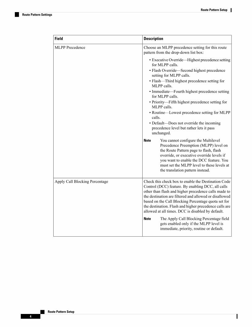
Choose an MLPP precedence setting for this routepattern from the drop-down list box:
• Executive Override—Highest precedence settingfor MLPP calls.
• Flash Override—Second highest precedencesetting for MLPP calls.
• Flash—Third highest precedence setting forMLPP calls.
• Immediate—Fourth highest precedence settingfor MLPP calls.
• Priority—Fifth highest precedence setting forMLPP calls.
• Routine—Lowest precedence setting for MLPPcalls.
• Default—Does not override the incomingprecedence level but rather lets it passunchanged.
You cannot configure the MultilevelPrecedence Preemption (MLPP) level onthe Route Pattern page to flash, flashoverride, or executive override levels ifyou want to enable the DCC feature. Youmust set the MLPP level to these levels atthe translation pattern instead.
Note
MLPP Precedence
Check this check box to enable the Destination CodeControl (DCC) feature. By enabling DCC, all callsother than flash and higher precedence calls made tothe destination are filtered and allowed or disallowedbased on the Call Blocking Percentage quota set forthe destination. Flash and higher precedence calls areallowed at all times. DCC is disabled by default.
The Apply Call Blocking Percentage fieldgets enabled only if the MLPP level isimmediate, priority, routine or default.
Note
Apply Call Blocking Percentage
Route Pattern Setup4
Route Pattern SetupRoute Pattern Settings
DescriptionField
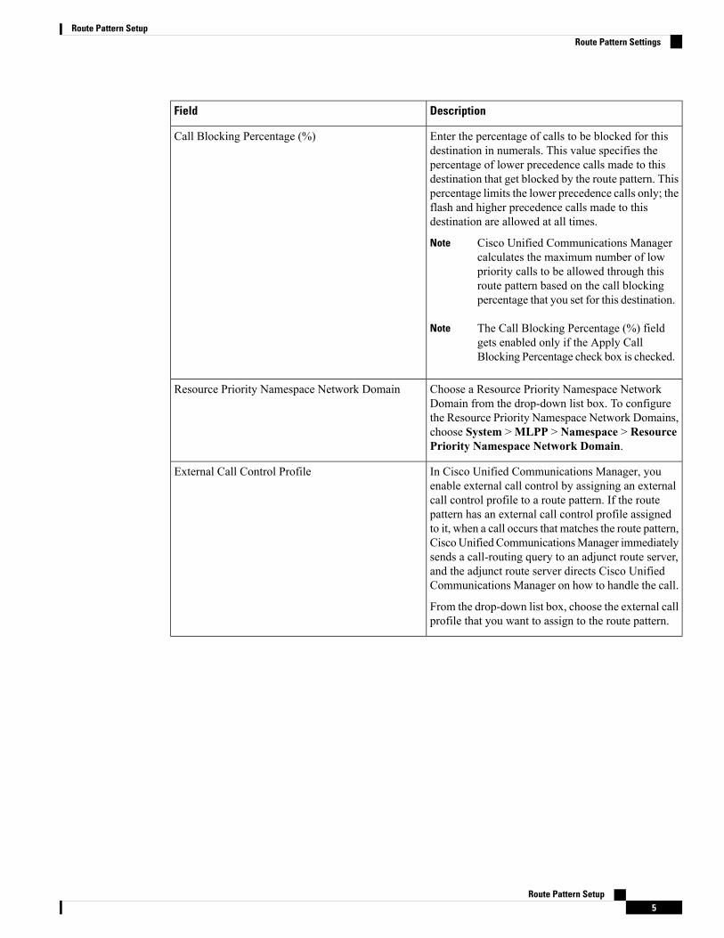
Enter the percentage of calls to be blocked for thisdestination in numerals. This value specifies thepercentage of lower precedence calls made to thisdestination that get blocked by the route pattern. Thispercentage limits the lower precedence calls only; theflash and higher precedence calls made to thisdestination are allowed at all times.
Cisco Unified Communications Managercalculates the maximum number of lowpriority calls to be allowed through thisroute pattern based on the call blockingpercentage that you set for this destination.
Note
The Call Blocking Percentage (%) fieldgets enabled only if the Apply CallBlocking Percentage check box is checked.
Note
Call Blocking Percentage (%)
Choose a Resource Priority Namespace NetworkDomain from the drop-down list box. To configurethe Resource Priority Namespace Network Domains,choose System >MLPP > Namespace > ResourcePriority Namespace Network Domain.
Resource Priority Namespace Network Domain
In Cisco Unified Communications Manager, youenable external call control by assigning an externalcall control profile to a route pattern. If the routepattern has an external call control profile assignedto it, when a call occurs that matches the route pattern,CiscoUnified CommunicationsManager immediatelysends a call-routing query to an adjunct route server,and the adjunct route server directs Cisco UnifiedCommunications Manager on how to handle the call.
From the drop-down list box, choose the external callprofile that you want to assign to the route pattern.
External Call Control Profile
Route Pattern Setup5
Route Pattern SetupRoute Pattern Settings

DescriptionField
Choose a route class setting for this translation patternfrom the drop-down list box:
• Default• Voice• Data• Satellite Avoidance• Hotline voice• Hotline data
The route class is a DSN code that identifies the classof traffic for a call. The route class informsdownstream devices about special routing ortermination requirements. The Default setting usesthe existing route class of the incoming call.
You can use non-default route class settings totranslate an inbound T1 CAS route class digit into aCisco Unified Communications Manager route classvalue (and strip off the digit). You should not need toassign a non-default route class setting to any otherinbound calls that use pattern configuration.
If the route pattern points to a SIP trunk supportingG.Clear, then specify Data or Hotline as the RouteClass.
Route Class
Choose the gateway or route list for which you areadding a route pattern.
If the gateway is included in a RouteGroup, this drop-down list box does notdisplay the gateway. When a gateway ischosen in the drop-down list box, CiscoUnified CommunicationsManager uses allthe ports in the gateway to route/block thisroute pattern. This action does not applyfor MGCP gateways.
Note
Gateway/Route List
Route Pattern Setup6
Route Pattern SetupRoute Pattern Settings

DescriptionField
The Route Option designation indicates whether youwant this route pattern to be used for routing calls(such as 9.@ or 8[2-9]XX) or for blocking calls.Choose the Route this pattern or Block this patternradio button.
If you choose the Block this pattern radio button, youmust choose the reason for which you want this routepattern to block calls. Choose a value from thedrop-down list box:
• No Error• Unallocated Number• Call Rejected• Number Changed• Invalid Number Format• Precedence Level Exceeded
Route Option
Call Classification indicates whether the call that isrouted through this route pattern is considered eitheroff (OffNet) or on (OnNet) the local network. Thedefault value specifies OffNet. When adding a routepattern, if you uncheck the Provide Outside Dial Tonecheck box, you set Call Classification as OnNet.
Call Classification
This check box remains unchecked by default. Whenthe check box is checked, the system uses the CallClassification setting that is configured on theassociated gateway or trunk to consider the outgoingcall as OffNet or OnNet.
Allow Device Override
Check this check box to provide outside dial tone. Toroute the call in the network, leave the check boxunchecked.
Provide Outside Dial Tone
With overlap sending enabled, when Cisco UnifiedCommunications Manager passes a call to the PSTN,it relies on overlap sending in the PSTN to determinehowmany digits to collect and where to route the call.Check this check box for each route pattern that youconsider to be assigned to a gateway or route list thatroutes the calls to a PSTN that supports overlapsending.
The CMC and FAC features do not support overlapsending because the Cisco Unified CommunicationsManager cannot determine when to prompt the userfor the code. If you check the Require ForcedAuthorization Code or the Require ClientMatter Codecheck box, the system disables the Allow OverlapSending check box.
Allow Overlap Sending
Route Pattern Setup7
Route Pattern SetupRoute Pattern Settings

DescriptionField
If the dial plan contains overlapping route patterns,Cisco Unified Communications Manager does notroute the call until the interdigit timer expires (evenif dialing a sequence of digits to choose a currentmatch is possible). Check this check box to interruptinterdigit timingwhen CiscoUnified CommunicationsManager must route a call immediately.
Urgent Priority
If you want to use forced authorization codes withthis route pattern, check this check box.
The FAC feature does not support overlap sendingbecause the Cisco Unified CommunicationsManagercannot determine when to prompt the user for thecode. If you check the Allow Overlap Sending checkbox, the system disables the Require ForcedAuthorization Code check box.
Require Forced Authorization Code
Enter the authorization level for the route pattern. Thenumber that you specify in this field determines theminimum authorization level that is needed tosuccessfully route a call through this route pattern.
To activate the authorization code, youmust check the Require ForcedAuthorization Code. If you do not checkthe check box, a message displays whenyou insert the route pattern that indicatesthat the authorization code cannot beactivated. To activate the code, clickCancel, check the Require ForcedAuthorization Code check box, and clickInsert. To activate the code at a later time,click OK.
Tip
Authorization Level
If you want to use client matter codes with this routepattern, check this check box.
The CMC feature does not support overlap sendingbecause the Cisco Unified CommunicationsManagercannot determine when to prompt the user for thecode. If you check the Allow Overlap Sending checkbox, the Require Client Matter Code check boxbecome disabled.
Require Client Matter Code
Route Pattern Setup8
Route Pattern SetupRoute Pattern Settings

DescriptionField
Enable this route pattern to be used for EmergencyCall handling.
Emergency Call Handler helps you to manageemergency calls in your telephony network whilefollowing local ordinances and regulations.
This setting applies only to the EmergencyCall Handler feature, and not to otherexternal emergency calling solutions suchas Cisco Emergency Responder.
Note
Is an Emergency Services Number (used byEmergency Call Handler)
Calling Party Transformations
Check the check box if you want the full, externalphone number to be used for calling line identification(CLID) on outgoing calls. You may also configure anExternal Phone Number Mask on all phone devices.
The calling party transformation settingsthat are assigned to the route groups in aroute list override any calling partytransformation settings that are assignedto a route pattern that is associated withthat route list.
Note
Use Calling Party's External Phone Number Mask
Enter a transformation mask value. Valid entries forthe National Numbering Plan include the digits 0through 9; the wildcard characters X, asterisk (*), andoctothorpe (#); the international escape character +;and blank. If this field is blank and the preceding fieldis not checked, no calling party transformation takesplace.
Calling Party Transform Mask
Enter prefix digits in the Prefix Digits (OutgoingCalls) field. Valid entries for the National NumberingPlan include the digits 0 through 9, the wildcardcharacters asterisk (*) and octothorpe (#), theinternational escape character +, and blank.
The appended prefix digit does not affectwhich directory numbers route to theassigned device.
Note
Prefix Digits (Outgoing Calls)
Route Pattern Setup9
Route Pattern SetupRoute Pattern Settings

DescriptionField
Cisco Unified CommunicationsManager uses callingline ID presentation (CLIP/CLIR) as a supplementaryservice to allow or restrict the originating caller phonenumber on a call-by-call basis.
Choose whether you want the Cisco UnifiedCommunications Manager to allow or restrict thedisplay of the calling party phone number on thecalled party phone display for this route pattern.
Choose Default if you do not want to change callingline ID presentation. Choose Allowed if you wantCiscoUnified CommunicationsManager to allow thedisplay of the calling number. Choose Restricted ifyou want Cisco Unified Communications Managerto block the display of the calling number.
Calling Line ID Presentation
Cisco Unified CommunicationsManager uses callingname presentation (CNIP/CNIR) as a supplementaryservice to allow or restrict the originating caller nameon a call-by-call basis.
Choose whether you want the Cisco UnifiedCommunications Manager to allow or restrict thedisplay of the calling party name on the called partyphone display for this route pattern.
Choose Default if you do not want to change callingname presentation. Choose Allowed if you want CiscoUnified Communications Manager to display thecalling name information. Choose Restricted if youwant Cisco Unified Communications Manager toblock the display of the calling name information.
Calling Name Presentation
Route Pattern Setup10
Route Pattern SetupRoute Pattern Settings

DescriptionField
Choose the format for the number type in calling partydirectory numbers.
Cisco Unified Communications Manager sets thecalling directory number (DN) type. Ciscorecommends that you do not change the default valueunless you have advanced experience with dialingplans such as NANP or the European dialing plan.Youmay need to change the default in Europe becauseCisco Unified Communications Manager does notrecognize European national dialing patterns. Youcan also change this setting when you are connectingto a PBX that expects the calling directory number tobe encoded to a non-national numbering plan type.
Choose one of the following options:
• Cisco Unified Communications Manager—TheCisco Unified Communications Manager setsthe directory number type.
• Unknown—Use when the dialing plan isunknown.
• National—Use when you are dialing within thedialing plan for your country.
• International—Usewhen you are dialing outsidethe dialing plan for your country.
• Subscriber—Use when you are dialing asubscriber by using a shortened subscribernumber.
Calling Party Number Type
Route Pattern Setup11
Route Pattern SetupRoute Pattern Settings

DescriptionField
Choose the format for the numbering plan in callingparty directory numbers.
Cisco Unified Communications Manager sets thecalling DN numbering plan. Cisco recommends thatyou do not change the default value unless you haveadvanced experiencewith dialing plans such as NANPor the European dialing plan. Youmay need to changethe default in Europe because Cisco UnifiedCommunications Manager does not recognizeEuropean national dialing patterns. You can alsochange this setting when you are connecting to PBXsby using routing as a non national type number.
Choose one of the following options:
• Cisco Unified Communications Manager—Usewhen the Cisco Unified CommunicationsManager sets the Numbering Plan in the directorynumber.
• ISDN—Use when you are dialing outside thedialing plan for your country.
• National Standard—Use when you are dialingwithin the dialing plan for your country.
• Private—Use when you are dialing within aprivate network.
• Unknown—Use when the dialing plan isunknown.
Calling Party Numbering Plan
Connected Party Transformations
Route Pattern Setup12
Route Pattern SetupRoute Pattern Settings

DescriptionField
Cisco Unified Communications Manager usesconnected line ID presentation (COLP/COLR) as asupplementary service to allow or restrict the calledparty phone number on a call-by-call basis.
Choose whether you want Cisco UnifiedCommunications Manager to allow or restrict thedisplay of the connected party phone number on thecalling party phone display for this route pattern.
Choose Default if you do not want to change theconnected line ID presentation. Choose Allowed ifyou want to display the connected party phonenumber. Choose Restricted if you want Cisco UnifiedCommunications Manager to block the display of theconnected party phone number.
If a call that originates from an IP phone on CiscoUnified Communications Manager encounters adevice, such as a trunk, gateway, or route pattern, thathas the Connected Line ID Presentation set to Default,the presentation value is automatically set to Allowed.
Connected Line ID Presentation
Cisco Unified Communications Manager usesconnected name presentation (CONP/CONR) as asupplementary service to allow or restrict the calledparty name on a call-by-call basis.
Choose whether you want Cisco UnifiedCommunications Manager to allow or restrict thedisplay of the connected party name on the callingparty phone display for this route pattern.
Choose Default if you do not want to change theconnected name presentation. Choose Allowed if youwant to display the connected party name. ChooseRestricted if you want Cisco Unified CommunicationsManager to block the display of the connected partyname.
Connected Name Presentation
Called Party Transformations
Route Pattern Setup13
Route Pattern SetupRoute Pattern Settings

DescriptionField
From the Discard Digits drop-down list box, choosethe discard digits instructions that you want toassociate with this route pattern. The discard digitsthat display depend on the numbering plan that youchoose from the Numbering Plan drop-down list box.
The called party transformation settingsthat are assigned to the route groups in aroute list override any called partytransformation settings that are assignedto a route pattern that is associated withthat route list.
Note
Discard Digits
Enter a transformation mask value. Valid entries forthe National Numbering Plan include the digits 0through 9; the wildcard characters X, asterisk (*), andoctothorpe (#); the international escape character +;and blank. If the field is blank, no transformation takesplace. Cisco Unified CommunicationsManager sendsthe dialed digits exactly as dialed.
Called Party Transform Mask
Enter prefix digits in the Prefix Digits (OutgoingCalls) field. Valid entries for the National NumberingPlan include the digits 0 through 9; the wildcardcharacters asterisk (*) and octothorpe (#); theinternational escape character +; and blank.
The appended prefix digit does not affectwhich directory numbers route to theassigned device.
Note
Prefix Digits (Outgoing Calls)
Route Pattern Setup14
Route Pattern SetupRoute Pattern Settings

DescriptionField
Choose the format for the number type in called partydirectory numbers.
Cisco Unified Communications Manager sets thecalled directory number (DN) type. Cisco recommendsthat you do not change the default value unless youhave advanced experience with dialing plans such asNANP or the European dialing plan. You may needto change the default in Europe because Cisco UnifiedCommunications Manager does not recognizeEuropean national dialing patterns. You can alsochange this setting when you are connecting to a PBXthat expects the called directory number to be encodedto a non-national type numbering plan.
Choose one of the following options:
• Cisco Unified Communications Manager—Usewhen the Cisco Unified CommunicationsManager sets the directory number type.
• Unknown—Use when the dialing plan isunknown.
• National—Use when you are dialing within thedialing plan for your country.
• International—Usewhen you are dialing outsidethe dialing plan for your country.
• Subscriber—Use when you are dialing asubscriber by using a shortened subscribernumber.
Called Party Number Type
Route Pattern Setup15
Route Pattern SetupRoute Pattern Settings

DescriptionField
Choose the format for the numbering plan in calledparty directory numbers.
Cisco Unified Communications Manager sets thecalled DN numbering plan. Cisco recommends thatyou do not change the default value unless you haveadvanced experiencewith dialing plans such as NANPor the European dialing plan. Youmay need to changethe default in Europe because Cisco UnifiedCommunications Manager does not recognizeEuropean national dialing patterns. You can alsochange this setting when you are connecting to PBXsby using routing as a non national type number.
Choose one of the following options:
• Cisco Unified Communications Manager—Usewhen the Cisco Unified CommunicationsManager sets the Numbering Plan in the directorynumber.
• ISDN—Use when you are dialing outside thedialing plan for your country.
• National Standard—Use when you are dialingwithin the dialing plan for your country.
• Private—Use when you are dialing within aprivate network.
• Unknown—Use when the dialing plan isunknown.
Called Party Numbering Plan
ISDN Network-Specific Facilities Information Element
From the Network Service Protocol drop-down listbox, choose the PRI protocol that matches the protocolof the terminating gateway.
Network Service Protocol
Enter the appropriate carrier identification code (0, 3,or 4 digits) in the Carrier Identification Code field.Carrier identification codes allow customers to reachthe services of interexchange carriers.
The following list shows examples of commonly usedcarrier identification codes:
• ATT—0288• Sprint—0333• WorldCom/MCI—0222
For a complete list of NANP carrier identificationcodes, visit the NANPA website.
Carrier Identification Code
Route Pattern Setup16
Route Pattern SetupRoute Pattern Settings

DescriptionField
Choose the appropriate network service. The valuesvary depending on the network service protocol thatyou choose from the Network Service Protocol field.
Network Service
This field displays the service parameter name that isassociated with the chosen network service. If noservice parameter exists for the network service, thefield displays <Not Exist>.
Service Parameter Name
Enter the appropriate service parameter value. Validentries include the digits 0 through 9. If a serviceparameter does not exist for the network service, CiscoUnified Communications Manager Administrationdisables this field.
Service Parameter Value
Route Pattern Setup17
Route Pattern SetupRoute Pattern Settings

Route Pattern Setup18
Route Pattern SetupRoute Pattern Settings