Hornet 565 Quick Setup Guide
18
I595-E-01 Hornet 565 Robot Quick Setup Guide
-
Upload
khangminh22 -
Category
Documents
-
view
0 -
download
0
Transcript of Hornet 565 Quick Setup Guide

I595-E-01
Hornet 565 Robot
Quick Setup Guide

Copyright Notice
The information contained herein is the property of Omron Adept Technologies, Inc., and shall not bereproduced in whole or in part without prior written approval of Omron Adept Technologies, Inc. Theinformation herein is subject to change without notice and should not be construed as a commitment byOmron Adept Technologies, Inc. The documentation is periodically reviewed and revised.
Omron Adept Technologies, Inc., assumes no responsibility for any errors or omissions in the doc-umentation. Critical evaluation of the documentation by the user is welcomed. Your comments assist usin preparation of future documentation. Please submit your comments to: [email protected].
Copyright 2015, 2016 by Omron Adept Technologies, Inc. All rights reserved.
Any trademarks from other companies used in this publicationare the property of those respective companies.
Created in the United States of America
Hornet 565 Robot Quick Setup Guide, 14692-000 Rev CPage 3 of 18
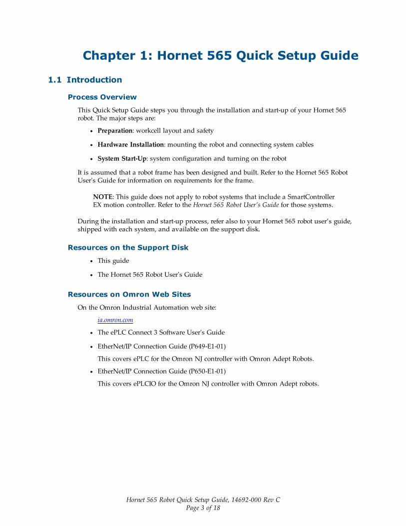
Chapter 1: Hornet 565 Quick Setup Guide
1.1 Introduction
Process Overview
This Quick Setup Guide steps you through the installation and start-up of your Hornet 565robot. The major steps are:
l Preparation: workcell layout and safety
l Hardware Installation: mounting the robot and connecting system cables
l System Start-Up: system configuration and turning on the robot
It is assumed that a robot frame has been designed and built. Refer to the Hornet 565 RobotUser's Guide for information on requirements for the frame.
NOTE: This guide does not apply to robot systems that include a SmartControllerEX motion controller. Refer to the Hornet 565 Robot User’s Guide for those systems.
During the installation and start-up process, refer also to your Hornet 565 robot user’s guide,shipped with each system, and available on the support disk.
Resources on the Support Disk
l This guide
l The Hornet 565 Robot User's Guide
Resources on Omron Web Sites
On the Omron Industrial Automation web site:
ia.omron.com
l The ePLC Connect 3 Software User's Guide
l EtherNet/IP Connection Guide (P649-E1-01)
This covers ePLC for the Omron NJ controller with Omron Adept Robots.
l EtherNet/IP Connection Guide (P650-E1-01)
This covers ePLCIO for the Omron NJ controller with Omron Adept robots.

Chapter 1: Hornet 565 Quick Setup Guide
On the Omron Adept web site:
adept.com
l Legacy systems communication structure pdfs
l Legacy systems code examples
1.2 SafetyWARNING: It is strictly prohibited to install or operate ourrobots without adequate safeguards according to applicablelocal and national standards. See the following figure for asimple workcell layout.
You must read the Robot Safety Guide and the Robot Installation and Operation chapters in therobot user’s guide for information on safe operation of your robot system.
Refer to Installing User-Supplied Safety Equipment in the System Installation chapter of therobot user’s guide, which provides details on connecting a user-designed E-Stop systemthrough the XUSR connector to the robot.
1.3 Workcell LayoutThe following figure shows a simple workcell layout with a user-supplied safety barrier and E-Stops provided by the optional Front Panel and optional T20 pendant.
Front Panel -Optional
T20 Pendant -Optional
PC running ACE Software
Safety Barrier
Restricted Area Inside Safety Barrier
200-240 VAC
Typical Workcell Layout
Hornet 565 Robot
24 VDCXUSR
Robot’s eAIB
Programmable LogicController (PLC)
User-SuppliedComponents
STOP
R
Figure 1-1. Simple Workcell Layout
Hornet 565 Robot Quick Setup Guide, 14692-000 Rev CPage 4 of 18

Chapter 1: Hornet 565 Quick Setup Guide
1.4 Installing the Robot
Frame
The Hornet 565 robot is mounted in a user-supplied frame, so that it hangs over the work-space. A sample frame design is given, with dimensions, in the user’s guide. See the followingfigure.
Ensure that the robot is oriented such that the Status Display panel faces away from the con-veyor, if your system has a conveyor. This will give you the best view of the Status Displaypanel, and provide the best cross-belt movement of the robot’s platform.
Mounting the Robot
1. Position the robot under the mounting frame.
The pallet will not fit in most frames, so the robot will need to be unstrapped from thepallet and moved manually.
2. Put nylon slings through the six lifting slots. See the following figure.
Joint 1
Slots
Joint 2 Slots
Joint
3
Figure 1-2. Four of Six Lifting Slots, Sample Frame (not to scale)
3. Take up the slack in the slings.
4. Lift the robot up to the mounting pads on the frame.
5. Mount the robot with three M12 x 1.75 screws. Mounting screws are user-supplied; thelength is determined by your frame design.
The screws should be stainless or zinc-plated steel.
Lock washers are not needed, as the robot base has spring-lock Heli-Coil® inserts.
Hornet 565 Robot Quick Setup Guide, 14692-000 Rev CPage 5 of 18

Chapter 1: Hornet 565 Quick Setup Guide
6. Use an external-tooth star washer, under one of the mounting screw heads, to groundthe robot base to the frame.
If the frame is painted where the star washer makes contact with it, use a ring terminalunder the star washer, and connect the other end of the wire from the terminal to a suit-able grounding surface on the frame.
If the frame is not painted where the M12 screw makes contact with it, you do not needto use a ring terminal - just put an external-tooth star washer under the mounting screwhead.
7. Tighten all mounting screws to 61 N-m (45 ft-lbf).
Brake-ReleaseButton
Status DisplayPanel
Joint 1
Joint 2
Ball Joints,Joint 3
Status LED/High-power
Lamp
Inner ArmMotor Plug
Joint 4 Cover
Robot Base
Robot BaseCover
Mounting Pad x3
Tool Flange
J4 Platformand Ball Joints
ThetaDriveShaft
Outer Arms
Figure 1-3. Labeled Drawing of Hornet Components, J4 Platform, Springs not Shown
Hornet 565 Robot Quick Setup Guide, 14692-000 Rev CPage 6 of 18

Chapter 1: Hornet 565 Quick Setup Guide
3 x 120°
3x Ø 42.84
Units are mm
M12 x 1.75
24
5
Section A-A
3x Ø 24
36°Joint 1
Joint 2Joint 3
Ø 885.69
B.C. Ø 740.00 A
A
X+
Y+
Joint 4
Conveyor
Direction
Figure 1-4. Hornet 565 Robot Base Mounting Pattern
Attaching the Outer Arms and Platform
The Hornet 565 robot is available with either a rotating platform (J4) or a fixed platform. Thefixed platform model does not use a J4 motor or a theta drive shaft.
The Hornet 565 robot platform gets attached to the inner arms by the outer arms.
NOTE: Except for attaching the outer arms and, for the J4 platform, the theta driveshaft, the platform is shipped fully assembled.
One pair of outer arms attaches between each inner arm and the platform. No tools areneeded.
For the J4 platform only: Both the theta drive shaft attachment on the J4 motor and the plat-form are offset by about 2 in. from the centers of the robot base and tool flange. The platformshould be attached so that its shaft aligns between the Joint 1 and Joint 3 ball studs on therobot base. Joint 1 should connect to motor 1, which is immediately to the right of the StatusDisplay panel on the robot base. See the preceding figure.
l Each outer arm has a ball joint socket at each end.
l The inner arms and the platform have corresponding pairs of ball studs.
l The procedure for attaching the outer arms is the same for both platforms.
Hornet 565 Robot Quick Setup Guide, 14692-000 Rev CPage 7 of 18

Chapter 1: Hornet 565 Quick Setup Guide
1. Attach one pair of outer arms to each inner arm.
Inner
Arm
Ball Joint
Socket
Ball Joint
Socket Insert
Outer Arm Springs Spring
Horseshoe
Pressed Pin
Ball Joint Stud
Outer Arms
Figure 1-5. Ball Joint Assembly, Inner Arm
a. Pivot the two arms away from each other lengthwise. This requires the leaststretching of the spring to attach the ball joints.
b. Slip one ball joint socket over the corresponding ball stud.
c. Swing the bottom end of the outer arm pair sideways as you slip the other balljoint socket over the corresponding ball stud.
CAUTION: Do not overstretch the outer arm springs. Separ-ate the sockets only enough to fit them over the ball studs.
2. Attach one pair of outer arms to each of the three pairs of ball studs on the platform.
Hornet 565 Robot Quick Setup Guide, 14692-000 Rev CPage 8 of 18

Chapter 1: Hornet 565 Quick Setup Guide
Theta
Drive
Shaft
Attachment Joint 1
Joint 3 Joint 2
Tool
Flange
X+
Y+
Figure 1-6. Top View of J4 Platform
a. Swing the bottom end of the outer arm pair to the right, as far as possible.
b. Slip the right ball joint socket over the right ball stud. (Move the platform asneeded to do this.)
c. Move the platform and outer arm pair to the left as you slip the left ball jointsocket over the corresponding ball stud.
3. Ensure that all spring hooks are fully-seated in the grooves of the horseshoes. See the fol-lowing figure.
Figure 1-7. Ball Joint Assembly, Showing Springs and Horseshoes
Attaching the Theta Drive Shaft (J4 Platform Only)
NOTE: The fixed platform does not use a theta drive shaft, so this section does notapply to robots with a fixed platform.
Each U-joint has two identical ends. When the theta drive shaft is shipped, it will have oneend of a U-joint attached to each end. Attach the top end of the drive shaft to the J4 motorshaft, labeled Top, first. This requires using a 3 mm hex key, with its short end shortened to 10- 15 mm. A normal hex key will not fit in the space available.
Hornet 565 Robot Quick Setup Guide, 14692-000 Rev CPage 9 of 18
Chapter 1: Hornet 565 Quick Setup Guide
10 - 15 mm3 mm
Figure 1-8. Shortened Hex Key
ThetaDriveShaft
SetScrew
U-Joint
J4 Shaft(Motor orPlatform)
Upper U-Jointat J4 Motor
Center Sectionof Drive Shaft
CylinderSectionof Drive Shaft
Lower U-Jointat J4 Platform
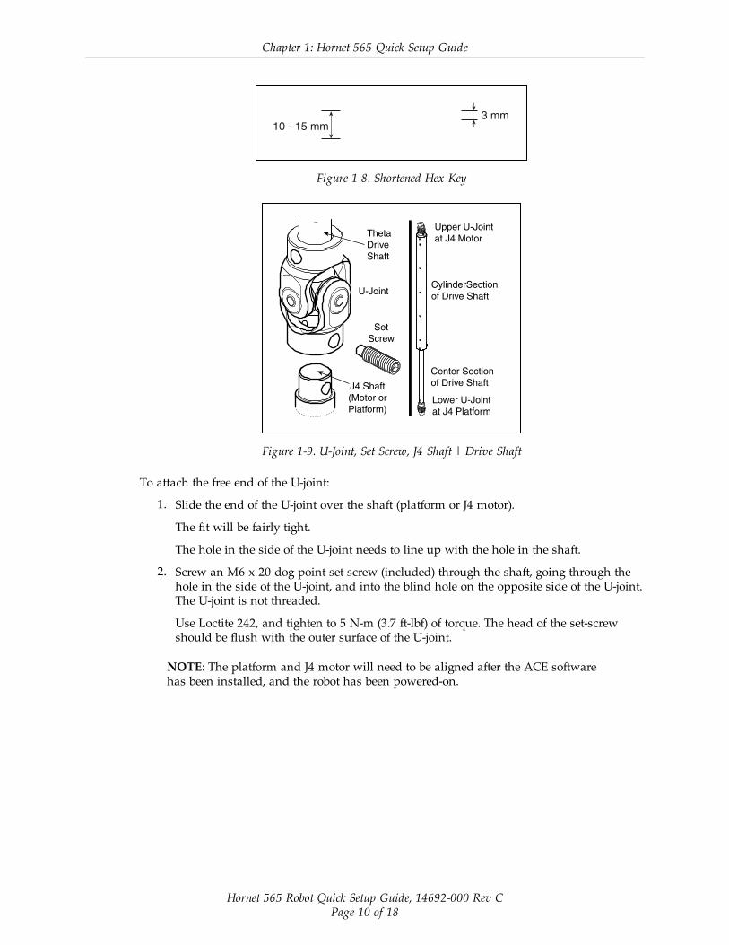
Figure 1-9. U-Joint, Set Screw, J4 Shaft | Drive Shaft
To attach the free end of the U-joint:
1. Slide the end of the U-joint over the shaft (platform or J4 motor).
The fit will be fairly tight.
The hole in the side of the U-joint needs to line up with the hole in the shaft.
2. Screw an M6 x 20 dog point set screw (included) through the shaft, going through thehole in the side of the U-joint, and into the blind hole on the opposite side of the U-joint.The U-joint is not threaded.
Use Loctite 242, and tighten to 5 N-m (3.7 ft-lbf) of torque. The head of the set-screwshould be flush with the outer surface of the U-joint.
NOTE: The platform and J4 motor will need to be aligned after the ACE softwarehas been installed, and the robot has been powered-on.
Hornet 565 Robot Quick Setup Guide, 14692-000 Rev CPage 10 of 18

Chapter 1: Hornet 565 Quick Setup Guide
1.5 System Cable ConnectionsOpen the Accessory box and locate the eAIB XSYSTEM cable. Connect the cables and peri-pherals as shown in the following figure. Parts and steps are covered in the following twotables. Refer to the System Installation chapter in your Hornet 565 Robot User’s Guide for moredetail.
DC
IN
24 VGND
AC
200 -
240 V
Ø1
XB
ELT
IO
XIO Servo
ENETENETXSYSTEM
Hornet 565Robot
24 VDC, 6 A Power Supply
200-240 VAC
10 A
single-phase
AC Power
Cable
Front Panel
Cable
Front Panel (option)
User-Supplied PCrunning ACE Software
T20 Adapter
Cable
XMCP Jumper Plug
XMCP
XFP
XUSR
XUSR Jumper Plug
eAIB
XSYSTEM
Cable
Robot Interface Panel
XUSR for:
- User E-Stop/Safety Gate
- Muted Safety Gate
The Jumper Plug is required if
neither of these is used
Ethernet
from PC
T20 Bypass Plug
T20 Pendant (option)Either T20 Pendant,T20 Bypass Plug, or
XMCP Jumper Plug must be used
2
3
4aA
B
GH
J
4a
4 4
1
6
7
98
L
M
QP
E
K
D
N
3
85 - 264 VAC Universal Input
DC
IN
24VGND
AC
200 -
240V
Ø1
XB
ELT
IO
XIO Servo
ENETENETXSYSTEM
Ethernet to eAIB
FP Jumper Plug
FEither Front Panel or
FP plug must be used
3a
2aC
Ethernet from eAIB
to SmartVision MX
R
9b
9a
User-supplied
Switch
User-supplied
PLC Option
to eAIB XBELTIOConveyors 1 & 2
XB
EL
T IO
134
63-0
00
HDB26
FEMALE
BE
LT
EN
CO
DE
R
FO
RC
E/
EX
PIO
RS
23
2
BE
LT E
NC
.
09
44
3-0
00
DB15
FEMALE
12
Belt
Force/EXPIO
RS-232
SmartVision MX (option)
R
S
7a
M
DC Power
Cable
Camera
(option)
T
10
10
12
11
UV
Figure 1-10. System Cable Diagram, with SmartVision MX, Front Panel, and T20 Pendant Options
WARNING: If you do not purchase a Front Panel, you mustprovide your own E-Stop circuit and button.
Hornet 565 Robot Quick Setup Guide, 14692-000 Rev CPage 11 of 18

Chapter 1: Hornet 565 Quick Setup Guide
Parts Table
Part Cable and Parts List Part # Part of: Notes
A eAIB XSYSTEM Cable Assembly 13323-000 standard, eAIB
B User E-Stop, Safety Gate n/a n/a user-supplied
C XUSR Jumper Plug 04736-000 13323-000 standard, eAIB
D Front Panel 90356-10358 or user-supplied
E Front Panel Cable 10356-10500 90356-10358 or user-supplied
F Front Panel Jumper Plug 10053-000 13323-000 standard, eAIB
G XMCP Jumper Plug 04737-000 13323-000 standard, eAIB
H T20 Bypass Plug 10048-000 10055-000 standard, T20
J T20 Adapter Cable 10051-003 10055-000 standard, T20
K T20 Pendant (option) 10055-000 option
L AC Power Cable (option) 04118-000 90565-010 or user-supplied
M 24 VDC Power Cable (option) 04120-000 90565-010 or user-supplied
N 24 VDC, 6 A Power Supply(option)
04536-000 90565-010 or user-supplied
P Ethernet Cable - PC -> PLC(Only while programming PLC)
n/a n/a user-supplied
Q Ethernet Cable - switch -> eAIB n/a n/a user-supplied
R Ethernet Cable - switch ->SmartVision MX
n/a n/a user-supplied
S Ethernet switch, cable forSmartVision MX.
n/a n/a option,user-supplied
T Camera and cable n/a n/a option
U eAIB XBELTIO cable 13463-000 option
V Y-adapter cable 09443-000 option
The XUSR, XMCP, and XFP jumpers intentionally bypass safety connections so you can testthe system functionality during setup.
WARNING: Under no circumstances should you run thesystem, in production mode, with all three jumpersinstalled. This would leave the system with no E-Stops.
Hornet 565 Robot Quick Setup Guide, 14692-000 Rev CPage 12 of 18

Chapter 1: Hornet 565 Quick Setup Guide
Connection Steps Table
Step Connection Part
1 Connect eAIB XSYSTEM cable to XSYSTEM on eAIB. A
2 Connect a user E-Stop or Muted Safety Gate to the eAIB XSYSTEM cableXUSR connector or
B
2a verify XUSR jumper plug is installed in eAIB XSYSTEM cable XUSR con-nector.
C
3 If you purchased a Front Panel, connect Front Panel cable to Front Panel andeAIB XSYSTEM cable XFP connector or
D, E
3a if using user-supplied Front Panel, connect Front Panel to eAIB XSYSTEMcable XFP. See warning after table.
A, E
4 Connect T20 adapter cable to eAIB XSYSTEM cable XMCP connector or J, K
4a if no T20, install XMCP jumperorT20 Adapter Cable with T20 bypass plug.
GorH
5 Connect user-supplied ground to robot. n/a
6 Connect 200-240 VAC to AC Input on eAIB Interface Panel; secure withclamp.
L
7 Connect 24 VDC to DC Input on Interface Panel. N,M
7a Connect 24 VDC and shield ground to SmartVision MX, if used. SeeSmartVision MX user's guide for location.
N,M
8 Connect Ethernet cable from PC to PLC, if a PLC is used. P
9 Connect Ethernet cable from PLC to switch, if a PLC is used. S
9a Connect Ethernet cable from switch to eAIB. Q, S
9b Connect Ethernet cable from SmartVision MX, if used, to switch. R, S
10 Connect optional camera and cable to SmartVision MX, if used. T
11 Connect optional eAIB XBELTIO cable to the XBELTIO port on eAIB. U
12 Connect the Y-adapter cable to the eAIB XBELTIO cable, Belt branch V
WARNING: If you do not purchase a Front Panel, you mustprovide your own front panel with equivalent circuits to beable to enable power and have an E-Stop button.
XBELTIO pinouts are covered in the full Hornet User’s Guide.
Hornet 565 Robot Quick Setup Guide, 14692-000 Rev CPage 13 of 18

Chapter 1: Hornet 565 Quick Setup Guide
Power Requirements
The power requirements for the SmartVision EX and the Hornet 565 robot are covered in theirrespective user guides. For 24 VDC, both can be powered by the same power supply.
Grounding the System
NOTE: The resistance of all ground conductors must be ≤ 10 Ω.
The following ground connections need to be made:
l End effector-to-robot base, if hazardous voltage is present on the end-effector
l Robot base-to-frame
l Frame-to-Earth
l 24 VDC cable shield to power supply and eAIB
1.6 ConfigurationThe user-supplied PLC and Hornet 565 robot are connected either through a shared network orvia a user-supplied Ethernet cable.
When the Hornet 565 robot is powered on and waiting for a PLC connection, the robot statuspanel will display its IP address, two digits at a time.
The format will be:
IP xxx-xxx-xxx-xxx OK
NOTE: If you can use the robot’s default IP address, then you can skip the ACE soft-ware installation completely.
Installing ACE Software
ACE is used to change the IP address of the robot and for troubleshooting. You install ACEfrom the software disk.
NOTE: You will have to restart the PC after installing ACE software.
Setting the Robot IP Address
Configure the IP address of the Hornet 565 robot using ACE software.
1. Connect the PC and the robot, either through a shared network or with an Ethernetcable between them.
2. Start the ACE software.
3. Click the Detect and Configure button, circled in the following figure.
Hornet 565 Robot Quick Setup Guide, 14692-000 Rev CPage 14 of 18

Chapter 1: Hornet 565 Quick Setup Guide
Figure 1-11. Detect and Configure Button
The IP address detection and configuration window will open. The ACE software will showthe IP address of any controllers it detects. See the following figure.
Figure 1-12. IP Addresses Detected
4. You can change the IP address and subnet mask in the Desired Address and DesiredSubnet fields, if needed.
5. Click OK. The ACE software will ask you to wait for the controller to reboot.
Hornet 565 Robot Quick Setup Guide, 14692-000 Rev CPage 15 of 18

Chapter 1: Hornet 565 Quick Setup Guide
Configuring the Omron PLC
Refer to the EtherNet/IP Connection Guide (P649-E1-01) for configuring the Omron PLC towork with Omron Adept robots. Refer to Resources on Omron Web Sites on page 3.
Using your PLC software, set the IP address for the PLC to connect to on the robot.
Enabling High Power
The details of enabling high power to the robot are covered in the EtherNet/IP ConnectionGuide (P649-E1-01).
Once high power is enabled, the Robot Status Panel displays ON, and the amber Robot StatusLED is on.
1.7 Start-up Procedure
Aligning the Platform and J4 Motor
It is possible for either the motor shaft or the platform shaft to be turned, manually, before thetheta drive shaft is connected to both. If not detected, the software may assume the robot’s toolflange is at a different angle than it really is. To ensure that the software knows the actual rota-tion of the tool flange with respect to the J4 motor, you need to use the ACE software to estab-lish this alignment.
1. Within the ACE software, open the Hornet robot object.
2. In the Configure tab, click Adjust J4 Zero.
This will launch a utility for aligning the theta drive shaft.
3. Follow the instructions in the utility.
Contact Omron Adept Technologies, Inc. for more information on this procedure.
NOTE: Once the theta drive shaft is installed, the J4 motor and the tool flange willalways rotate together, so the software will know the orientation of the tool flange.
Hornet 565 Robot Quick Setup Guide, 14692-000 Rev CPage 16 of 18

Chapter 1: Hornet 565 Quick Setup Guide
1.8 Finding Additional Information
Installing Optional Equipment
For details on installing optional equipment, see the following topics in the Optional Equip-ment Installation chapter of the Hornet 565 user’s guide:
l Installing end-effectors
l Connecting user air and electrical lines to user connection panel
l Mounting external equipment on the robot
l Mounting the robot solenoid option kit
NOTE: For dimensions and specifications, see Technical Specifications in the Hor-net 565 User’s Guide.
System Operation
For details on system operation, see the following topics in the System Operation chapter of theHornet 565 user’s guide:
l Robot Status LED Indicator
l Status panel fault codes
l Brake Release button (located above or in diagnostic panel). To move Joint 3 manually,press the Brake Release button.
l Connecting digital I/O on the XIO connector at the robot interface panel
l Connecting a user-designed E-Stop System
For information on the ePLC Connect software interface, refer to the ePLC Connect 3 SoftwareUser's Guide.
Hornet 565 Robot Quick Setup Guide, 14692-000 Rev CPage 17 of 18

Authorized Distributor:
In the interest of product improvement, specifications are subject to change without notice.
Cat. No. I595-E-01
Printed in USA0416
© OMRON Corporation 2016 All Rights Reserved.
OMRON Corporation Industrial Automation Company
OMRON ELECTRONICS LLC2895 Greenspoint Parkway, Suite 200 Hoffman Estates, IL 60169 U.S.A.Tel: (1) 847-843-7900/Fax: (1) 847-843-7787
OMRON ADEPT TECHNOLOGIES, INC. 4550 Norris Canyon Road, Suite 150, San Ramon, CA 94583 U.S.A.Tel: (1) 925-245-3400/Fax: (1) 925-960-0590
Regional HeadquartersOMRON EUROPE B.V.Wegalaan 67-69, 2132 JD HoofddorpThe NetherlandsTel: (31)2356-81-300/Fax: (31)2356-81-388
Contact: industrial.omron.euKyoto, JAPAN
OMRON ASIA PACIFIC PTE. LTD.No. 438A Alexandra Road # 05-05/08 (Lobby 2), Alexandra Technopark, Singapore 119967Tel: (65) 6835-3011/Fax: (65) 6835-2711 OMRON (CHINA) CO., LTD.
Room 2211, Bank of China Tower, 200 Yin Cheng Zhong Road, PuDong New Area, Shanghai, 200120, ChinaTel: (86) 21-5037-2222/Fax: (86) 21-5037-2200