Quick Selection
204
MAKING MODERN LIVING POSSIBLE REFRIGERATION & AIR CONDITIONING DIVISION Quick Selection Automatic Controls, Compressors and Condensing units Catalogue
-
Upload
khangminh22 -
Category
Documents
-
view
0 -
download
0
Transcript of Quick Selection

MAKING MODERN LIVING POSSIBLE
REFRIGERATION & AIR CONDITIONING DIVISION
Quick SelectionAutomatic Controls, Compressors and Condensing units
Catalogue
2
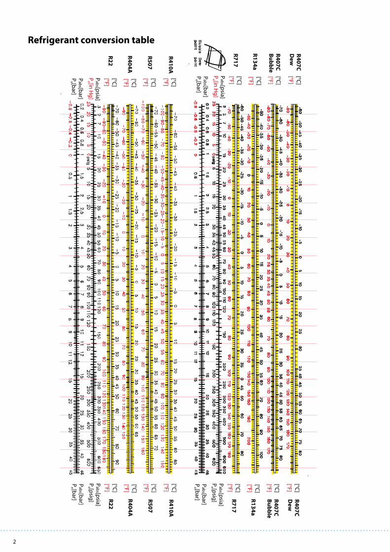
Refrigerant conversion table

3
Contents
1. Expansion valves
Thermostatic expansion valves
Thermostatic expansion valves .............. T2, TE2 ................................ 6
Thermostatic expansion valves ............. TE5-55 ................................ 10
Thermostatic expansion valves ............. TUA, TUAE and TCAE ..... 14
Thermostatic expansion valves ............. PHT ..................................... 20
Electronically operated
Expansion valves ........................................ AKV ..................................... 24
Electrical expansion valves ..................... ETS ...................................... 28
2. Solenoid valves and coils
Solenoid valves and coils ......................... EVR ...................................... 30
Solenoid valves ........................................... EVRA and EVRAT ............ 32
4-Way Reversing valves ............................ VHV and STF .................... 34
3. Pressure controls and thermostats
Pressure controls and thermostats ...... KP ........................................ 36
Cartridge pressure controls ..................... ACB ..................................... 38
Thermostat ................................................... UT ........................................ 40
Pressure controls and thermostats ....... RT ........................................ 42
4. Pressure regulators
Pressure regulators .................................... KVP ...................................... 46
Pressure regulators .................................... KVR and NRD 48
Pressure regulators .................................... KVL ...................................... 50
Pressure regulators .................................... KVD ..................................... 52
Pressure regulators .................................... KVC ..................................... 54
Capacity regulator ...................................... CPCE ................................... 56
Motor valves ................................................. ICM 20-65 ......................... 58
Pilot controlled servo valves .................. ICS 25-65 ........................... 62
5. Water valves
Pressure controlled water valve ............ WVFX .................................. 68
Thermostatic controlled water valves AVTA ................................... 70
6. Line components – Commercial
Ball valves ...................................................... GBC ..................................... 72
Check valves ................................................. NRV and NRVH ............... 74
Oil separator ................................................. OUB .................................... 76
Heat exchanger ........................................... HE ........................................ 78
Sight glasses ................................................. SGN/H, SGR, SGRN/H .... 80
Liquid line filter driers ............................... DML .................................... 82
Filter driers .................................................... DCR ..................................... 84
Bi-flow filter driers ...................................... DMB .................................... 88
Combi filter driers ....................................... DMC .................................... 90
Burn-out filter drier .................................... DAS ..................................... 92
Stop valves .................................................... SVA ...................................... 94
Regulating valves ....................................... REG and REG-SS ............. 98
7. Line components – Industrial
Filters ............................................................... FIA, FIA-SS ........................ 100
Liquid level glasses .................................... LLG ...................................... 102
8. Gas Detector
Gas detectors ............................................... GD ....................................... 104
9. Electronic controls
Refrigeration controllers .......................... EKC 315A .......................... 106
........................................................................... EKC 202 ............................. 108
Controller for appliance control ............ AK-CC 550 ......................... 110
Temperature controller ............................ EKC 102 ............................. 112
Universal refrigeration controller ......... AK-CC 210 ......................... 114
System manager ......................................... AK-SM 350 ........................ 116
Media temperature control .................... EKC 361 .............................. 118
Controller interface .................................... EKC 366 ............................. 120
Condenser fan speed controls ............... XGE/RGE ............................ 122
Capacity controllers .................................... EKC 331T ........................... 124
........................................................................... AK-PC 530 ......................... 126
10. Sensors and transmitters
Sensors and transmitters .......................................................................... 128
11. Compressors range
Compressors ................................................................................................. 131
Direct current reciprocating compressors ......................................... 133
Reciprocating Compressors ..................................................................... 145
Scroll compressors ..................................................................................... 153
12. Condensing units range
OPTYMATM condensing units .................................................................. 167
OPTYMA PLUSTM condensing units ...................................................... 185
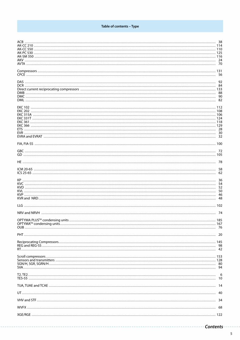
Table of contents

4
5
Contents
ACB .............................................................................................................................................................................................................................................................. 38AK-CC 210 .................................................................................................................................................................................................................................................. 114AK-CC 550 .................................................................................................................................................................................................................................................. 110AK-PC 530 .................................................................................................................................................................................................................................................. 125AK-SM 350 ................................................................................................................................................................................................................................................. 116AKV .............................................................................................................................................................................................................................................................. 24AVTA ............................................................................................................................................................................................................................................................ 70
Compressors ............................................................................................................................................................................................................................................. 131CPCE ............................................................................................................................................................................................................................................................ 56
DAS .............................................................................................................................................................................................................................................................. 92DCR .............................................................................................................................................................................................................................................................. 84Direct current reciprocating compressors .................................................................................................................................................................................... 133DMB ............................................................................................................................................................................................................................................................. 88DMC ............................................................................................................................................................................................................................................................. 90DML ............................................................................................................................................................................................................................................................. 82
EKC 102 ...................................................................................................................................................................................................................................................... 112EKC 202 ...................................................................................................................................................................................................................................................... 108EKC 315A ................................................................................................................................................................................................................................................... 106EKC 331T .................................................................................................................................................................................................................................................... 124EKC 361 ....................................................................................................................................................................................................................................................... 118EKC 366 ...................................................................................................................................................................................................................................................... 129ETS ............................................................................................................................................................................................................................................................... 28EVR ............................................................................................................................................................................................................................................................... 30EVRA and EVRAT ..................................................................................................................................................................................................................................... 32
FIA, FIA-SS ................................................................................................................................................................................................................................................. 100
GBC .............................................................................................................................................................................................................................................................. 72GD ................................................................................................................................................................................................................................................................ 105
HE ................................................................................................................................................................................................................................................................. 78
ICM 20-65 .................................................................................................................................................................................................................................................. 58ICS 25-65 .................................................................................................................................................................................................................................................... 62
KP ................................................................................................................................................................................................................................................................. 36KVC .............................................................................................................................................................................................................................................................. 54KVD .............................................................................................................................................................................................................................................................. 52KVL ............................................................................................................................................................................................................................................................... 50KVP ............................................................................................................................................................................................................................................................... 46KVR and NRD ............................................................................................................................................................................................................................................ 48
LLG ............................................................................................................................................................................................................................................................... 102
NRV and NRVH ........................................................................................................................................................................................................................................ 74
OPTYMA PLUSTM condensing units ................................................................................................................................................................................................... 185OPTYMATM condensing units ............................................................................................................................................................................................................... 167OUB .............................................................................................................................................................................................................................................................. 76
PHT ............................................................................................................................................................................................................................................................... 20
Reciprocating Compressors ................................................................................................................................................................................................................. 145REG and REG-SS ....................................................................................................................................................................................................................................... 98RT................................................................................................................................................................................................................................................................... 42
Scroll compressors .................................................................................................................................................................................................................................. 153Sensors and transmitters ..................................................................................................................................................................................................................... 128SGN/H, SGR, SGRN/H .............................................................................................................................................................................................................................. 80SVA ................................................................................................................................................................................................................................................................ 94
T2, TE2 .......................................................................................................................................................................................................................................................... 6TE5-55 ......................................................................................................................................................................................................................................................... 10
TUA, TUAE and TCAE .............................................................................................................................................................................................................................. 14
UT .................................................................................................................................................................................................................................................................. 40
VHV and STF .............................................................................................................................................................................................................................................. 34
WVFX ........................................................................................................................................................................................................................................................... 68
XGE/RGE ..................................................................................................................................................................................................................................................... 122
Table of contents – Type

6
Applications Advantages FactsApplications Advantages Facts
T2 / TE2: reliable and easy to use
Thermostatic expansion valves regulate the injection of liguid refrigerant into evaporators. Injection is
controlled by the refrigerant superheat. Therefore the valves are especially suitable for liquid injection in
”dry“ evaporators where the superheat at the evaporator outlet is proportional to the evaporator load.
Features
Stainless steel capillary tube
and bulb:
- high corrosion resistance
- high strength and vibration
resistance
Laser-engraved label
Inlet in flare.
Solder adaptor is an option
Easy adjustment of
superheat setting
Interchangeable
orifice assembly with
dirt protection filter
Laser-welded power element
in stainless steel
- longer diaphragm life
- high pressure tolerance
and working pressure
- high corrosion resistance
Flare or solder outlet
· Traditional refrigeration
· Heat pump systems
· Air conditioning units
· Liquid coolers
· Ice cube machines
· Transport refrigeration
· Large temperature range.
Equally applicable to freezing,
refrigeration and air conditioning
applications.
· Interchangeable orifice assembly
· easy stocking
· easy capacity matching
· better service
· Can be supplied with MOP
(Max. Operating Pressure)
Protects the compressor motor
against excessive evaporating pres-
sure during normal operation.
· Rated capacities from 0.5 to 15.5 kW
for R22.
· Valves for special temperature ranges
can be supplied.
· Flare / solder adaptor can be supplied.

7
The adaptor is for use with thermostatic
expansion valves T2 and TE2. When the
adaptor is fitted correctly it meets the
sealing requirements of DIN 8964.
The flare orifice in T2 and TE2 can be used
with a solder adaptor when the orifice
filter is replaced with a specific filter
intended for solder adaptors. Only in this
way the sealing requirements of DIN 8964
can be fulfilled.
Solder adaptors for filter driers (FSA) must
not be used in the T2 inlet.1) Code numbers in bold are normally on stock and a shorter delivery time can therefore be expected.
2) Including filter.
Orifice assembly
Orifice no.
Range N: –40 to +10°C Range B: –60 to –25°C Code no. 1)
Rated capacity in tons (TR)
Rated capacity in kW
Rated capacity in tons (TR)
Rated capacity in kW Flare × Flare
version 2)
Solder adaptorversion 2)
R22 R407C R134aR404AR507
R22 R407C R134aR404AR507
R22R404AR507
R22R404AR507
0X 0.15 0.16 0.11 0.11 0.50 0.50 0.40 0.38 0.15 0.11 0.50 0.38 068-2002 068-2089
00 0.30 0.30 0.25 0.21 1.0 1.1 0.90 0.70 0.20 0.21 0.70 0.70 068-2003 068-2090
01 0.70 0.80 0.50 0.45 2.5 2.7 1.8 1.6 0.30 0.45 1.0 1.6 068-2010 068-2091
02 1.0 1.1 0.80 0.60 3.5 3.8 2.6 2.1 0.60 0.60 2.1 2.1 068-2015 068-2092
03 1.5 1.6 1.3 1.2 5.2 5.6 4.6 4.2 0.80 1.0 2.8 3.5 068-2006 068-2093
04 2.3 2.5 1.9 1.7 8.0 8.6 6.7 6.0 1.2 1.4 4.2 4.9 068-2007 068-2094
05 3.0 3.2 2.5 2.2 10.5 11.3 8.6 7.7 1.5 1.7 5.2 6.0 068-2008 068-2095
06 4.5 4.9 3.0 2.6 15.5 16.7 10.5 9.1 2.0 1.9 7.0 6.6 068-2009 068-2096
Thermostatic element with: bulb strap, without: orifice, filter cone and nuts Flare × flare connection
RefrigerantValve type
Pressureequaliza-
tionFlare
Capillarytube
Connection Code no. 1)
Inlet × outlet Range N
–40 to +10°CRange NM–40 to –5°C
Range NL–40 to –15°C
Range B–60 to –25°C
m in. × in. mm × mm Without MOP MOP +15°C MOP 0°C MOP –10°C Without MOP MOP –20°C
R22TX 2 - 1.5 3/8 × 1/2 10 × 12 068Z3206 068Z3208 068Z3224 068Z3226 068Z3207 068Z3228
TEX 2 ¼ in. 1.5 3/8 × 1/2 10 × 12 068Z3209 068Z3211 068Z3225 068Z3227 068Z3210 068Z3229
R407CTZ 2 - 1.5 3/8 × 1/2 10 × 12 068Z3496 068Z3516
TEZ 2 ¼ in. 1.5 3/8 × 1/2 10 × 12 068Z3501 068Z3517
R134aTN 2 - 1.5 3/8 × 1/2 10 × 12 068Z3346 068Z3347 068Z3393 068Z3369
TEN 2 ¼ in. 1.5 3/8 × 1/2 10 × 12 068Z3348 068Z3349 068Z3392 068Z3370
R404A/R507TS 2 - 1.5 3/8 × 1/2 10 × 12 068Z3400 068Z3402 068Z3406 068Z3408 068Z3401 068Z3410
TES 2 ¼ in. 1.5 3/8 × 1/2 10 × 12 068Z3403 068Z3405 068Z3407 068Z3409 068Z3404 068Z3411
Thermostatic element with: bulb strap, without: orifice, filter cone and nuts Flare × solder connection
RefrigerantValve type
Pressure equalization
Solder
Capillarytube
Connection Code no. 1)
InletFlare
OutletODF solder
Range N–40 to +10°C
Range NL–40 to –15°C
Range B–60 to –25°C
m Without MOP MOP +15°C MOP –10°C Without MOP MOP –20°C
R22
TX 2 - 1.5 3/8 in. 1/2 in. 068Z3281 068Z3287 068Z3357 068Z3319TX 2 - 1.5 10 mm 12 mm 068Z3302 068Z3308 068Z3366 068Z3361 068Z3276
TEX 2 ¼ in. 1.5 3/8 in. 1/2 in. 068Z3284 068Z3290 068Z3359 068Z3220TEX 2 6 mm. 1.5 10 mm 12 mm 068Z3305 068Z3311 068Z3367 068Z3363 068Z3277
R407C
TZ 2 - 1.5 3/8 in. 1/2 in. 068Z3329TZ 2 - 1.5 10 mm 12 mm 068Z3502 068Z3514
TEZ 2 ¼ in. 1.5 3/8 in. 1/2 in. 068Z3446 068Z3447TEZ 2 6 mm. 1.5 10 mm 12 mm 068Z3503 068Z3515
R134a
TN 2 - 1.5 3/8 in. 1/2 in. 068Z3383 068Z3387TN 2 - 1.5 10 mm 12 mm 068Z3384 068Z3388
TEN 2 ¼ in. 1.5 3/8 in. 1/2 in. 068Z3385 068Z3389TEN 2 6 mm. 1.5 10 mm 12 mm 068Z3386 068Z3390
R404A/R507
TS 2 - 1.5 3/8 in. 1/2 in. 068Z3414 068Z3416 068Z3429 068Z3418 068Z3420TS 2 - 1.5 10 mm 12 mm 068Z3435 068Z3423 068Z3436 068Z3425 068Z3427
TES 2 ¼ in. 1.5 3/8 in. 1/2 in. 068Z3415 068Z3417 068Z3430 068Z3419 068Z3421TES 2 6 mm. 1.5 10 mm 12 mm 068Z3422 068Z3424 068Z3437 068Z3426 068Z3428
Solder adaptor without orifice assembly
Connection - ODF solder Code no. 1)
1/4 in. 068-2062
6 mm 068-2063
6 mm 068-41012)
3/8 in. 068-2060
10 mm 068-2061
10 mm 068-41002)
Filter
Filter type Code no. 1)
For flare connection 068-0003
For solder adaptor 068-0015
The rated capacity is based on: Evaporating temperature te = +5°C for range N and te = –30°C for range B, condensing temperature tc = +32°C, and refrigerant temperature ahead of valve tl = +28°C.
Thermostatic expansion valves – T2, TE2
Technical data and ordering

8
+
Capacities
R22 R134a R404A/R507 R407C
Valve
type/
Orifice
Cond.
temp.3)
[°C]
Capacity in [kW] Capacity in [kW] Capacity in [kW] Capacity in [kW]
Evaporating temp. [°C] Evaporating temp. [°C] Evaporating temp. [°C] Evaporating temp. [°C]
-35 -30 -10 0 5 -30 -10 -5 0 5 -40 -35 -30 -10 0 -10 -5 0 5 10
T2 / 0X
25
0.49 0.51 0.55 0.54 0.51 0.35 0.40 0.41 0.41 0.40 0.33 0.35 0.37 0.42 0.41 0.59 0.59 0.59 0.58 0.55
T2 / 00 0.95 1.00 1.1 1.1 1.1 0.61 0.73 0.75 0.77 0.77 0.61 0.66 0.70 0.85 0.88 1.2 1.2 1.3 1.3 1.2
T2 / 01 1.6 1.7 2.4 2.7 2.7 0.88 1.3 1.5 1.6 1.6 0.96 1.1 1.2 1.8 2.1 2.5 2.7 2.9 3.1 3.2
T2 / 02 2.2 2.5 3.5 3.9 3.9 1.2 1.9 2.0 2.1 2.2 1.3 1.5 1.7 2.6 3.0 3.7 4.0 4.3 4.5 4.6
T2 / 03 3.9 4.3 6.2 6.9 7.0 2.2 3.3 3.6 3.8 4.0 2.4 2.7 3.1 4.7 5.4 6.6 7.1 7.6 8.1 8.3
T2 / 04 5.7 6.4 9.1 10.2 10.5 3.2 4.8 5.2 5.6 5.9 3.5 4.0 4.6 7.0 8.0 9.8 10.6 11.4 12.0 12.5
T2 / 05 7.3 8.0 11.6 13.0 13.3 4.0 6.1 6.6 7.1 7.5 4.5 5.1 5.8 8.9 10.2 12.4 13.4 14.4 15.2 15.7
T2 / 06 8.9 9.8 14.1 15.9 16.3 4.9 7.5 8.2 8.7 9.1 5.5 6.2 7.1 10.8 12.4 15.1 16.4 17.6 18.6 19.2
T2 / 0X
35
0.53 0.55 0.60 0.61 0.60 0.37 0.44 0.45 0.45 0.46 0.32 0.34 0.36 0.42 0.43 0.61 0.62 0.63 0.63 0.62
T2 / 00 1.0 1.1 1.2 1.3 1.3 0.64 0.79 0.83 0.86 0.88 0.59 0.64 0.69 0.86 0.92 1.3 1.3 1.3 1.4 1.4
T2 / 01 1.7 1.8 2.6 3.0 3.2 0.93 1.4 1.6 1.7 1.9 0.92 1.1 1.2 1.8 2.2 2.7 2.9 3.1 3.3 3.5
T2 / 02 2.3 2.6 3.8 4.4 4.7 1.3 2.0 2.2 2.4 2.6 1.2 1.4 1.7 2.7 3.2 3.9 4.3 4.6 5.0 5.3
T2 / 03 4.1 4.6 6.8 7.9 8.4 2.3 3.6 4.0 4.4 4.7 2.2 2.6 3.0 4.8 5.7 7.0 7.6 8.3 8.9 9.4
T2 / 04 6.1 6.8 10.1 11.8 12.5 3.4 5.3 5.8 6.4 6.9 3.3 3.9 4.5 7.1 8.5 10.3 11.3 12.3 13.3 14.2
T2 / 05 7.7 8.6 12.8 14.9 15.8 4.2 6.7 7.4 8.1 8.8 4.3 4.9 5.6 9.0 10.7 13.0 14.3 15.6 16.7 17.8
T2 / 06 9.5 10.5 15.6 18.2 19.3 5.2 8.2 9.1 9.9 10.7 5.2 6.0 6.9 11.0 13.1 15.9 17.4 19.0 20 22
T2 / 0X
45
0.55 0.57 0.64 0.65 0.64 0.38 0.45 0.47 0.48 0.49 0.29 0.31 0.33 0.40 0.42 0.62 0.63 0.64 0.64 0.64
T2 / 00 1.0 1.1 1.3 1.4 1.4 0.65 0.82 0.86 0.90 0.94 0.55 0.60 0.64 0.83 0.90 1.3 1.3 1.3 1.4 1.4
T2 / 01 1.7 1.9 2.8 3.2 3.4 0.96 1.5 1.7 1.8 2.0 0.85 0.98 1.1 1.8 2.1 2.7 2.9 3.2 3.4 3.7
T2 / 02 2.4 2.7 4.0 4.8 5.1 1.3 2.1 2.4 2.6 2.8 1.1 1.3 1.5 2.6 3.2 3.9 4.3 4.7 5.2 5.6
T2 / 03 4.3 4.8 7.2 8.5 9.2 2.3 3.8 4.2 4.7 5.1 1.9 2.3 2.7 4.6 5.7 7.0 7.7 8.5 9.2 9.9
T2 / 04 6.3 7.1 10.7 12.7 13.7 3.4 5.6 6.2 6.9 7.6 3.0 3.5 4.1 6.9 8.4 10.4 11.5 12.6 13.8 14.9
T2 / 05 8.0 9.0 13.6 16.1 17.3 4.3 7.0 7.8 8.7 9.6 3.8 4.4 5.2 8.7 10.6 13.2 14.5 15.9 17.3 18.7
T2 / 06 9.8 11.0 16.6 19.6 21 5.3 8.6 9.6 10.7 11.7 4.7 5.5 6.4 10.6 12.9 16.0 17.7 19.4 21 23
T2 / 0X
55
0.56 0.58 0.65 0.67 0.67 0.38 0.45 0.47 0.49 0.50 0.26 0.28 0.30 0.37 0.39 0.60 0.61 0.62 0.63 0.63
T2 / 00 1.1 1.1 1.3 1.4 1.4 0.63 0.81 0.86 0.90 0.95 0.48 0.53 0.57 0.75 0.82 1.2 1.2 1.3 1.3 1.3
T2 / 01 1.7 1.9 2.8 3.3 3.6 0.95 1.5 1.7 1.9 2.0 0.74 0.86 1.0 1.7 2.0 2.6 2.9 3.1 3.4 3.6
T2 / 02 2.3 2.6 4.1 5.0 5.4 1.2 2.1 2.4 2.7 2.9 0.82 1.0 1.3 2.4 2.9 3.8 4.2 4.7 5.1 5.6
T2 / 03 4.3 4.8 7.4 8.9 9.6 2.2 3.8 4.3 4.8 5.3 1.5 1.8 2.2 4.2 5.3 6.8 7.5 8.3 9.1 9.9
T2 / 04 6.4 7.2 11.0 13.3 14.4 3.4 5.7 6.4 7.2 7.9 2.4 2.9 3.5 6.3 7.8 10.1 11.3 12.4 13.7 14.9
T2 / 05 8.1 9.1 14.0 16.7 18.1 4.2 7.0 8.0 9.0 10.0 3.0 3.7 4.4 7.9 9.9 12.8 14.2 15.7 17.2 18.7
T2 / 06 9.9 11.1 17.0 20 22 5.2 8.7 9.8 11.0 12.1 3.8 4.6 5.4 9.7 12.1 15.6 17.3 19.1 21 233) Condensing temperature at bubble point.
When the subcooling ≠ 4 K then:
1. Table value x Factor = Plant capacity
2. Plant capacity / Factor = Table value
Example:
Refrigerant = R407C
Qnom = 10 kW
te = 0°C
tc = 55°C
Δtsub = 25 K
Selection:
1. T2, Orifice 04 = 12.4 kW x 1.27 = 15.75 kW → Valve too large
Right selection:
2. 10 kW / 1.27 = 7.9 kW → T2, Orifice 03
Thermostatic valve Orifice
Correction factor
RefrigerantSubcooling [K]
2 4 10 15 20 25 30 35 40 45 50
R22 0.98 1 1.06 1.11 1.15 1.20 1.25 1.30 1.35 1.39 1.44
R134a 0.98 1 1.08 1.13 1.19 1.25 1.31 1.37 1.42 1.48 1.54
R404A/R507 0.96 1 1.10 1.20 1.29 1.37 1.46 1.54 1.63 1.70 1.78
R407C 0.97 1 1.08 1.14 1.21 1.27 1.33 1.39 1.45 1.51 1.57

9
+
+
+
+ +
+
+
The complete Danfoss program of thermostatic expansion valves:
Thermostatic expansion valves parts program:
T 2 and TE 2
TUA/TUAE and TCAE
TE 5 - TE 55
PHT
Thermostatic element Orifice Valve body Flanges
Thermostatic element Orifice Valve body
Thermostatic valve Orifice
Thermostatic valve Orifice
TypeRated capacities in kW for range N
ConnectionsR22 R134a R404A / R507 R407C R410A
T 2 and TE 2 1) 0.5 - 15.5 0.4 - 10.5 0.38 - 9.1 0.5 - 16.7 -Flare x flare and flare x solder
Solder x solder (solder adaptor)
TUA and TUAE 1) 0.6 - 16 0.45 - 12 0.45 - 12 0.63 - 17 1.3 - 26Solder
Bi-metal (stainless steel / copper)
TUB and TUBE 2) 0.9 - 16 0.7 - 12 0.7 - 12 0.92 - 17 1.3 - 26Solder
Bi-metal (stainless steel / copper)
TCAE 1) and TCBE 2) 17.5 - 26.5 12 - 18 13.5 - 20 19.0 - 28.5 23 - 34Solder
Bi-metal (stainless steel / copper)
TRE 10 - TRE 80 2) 28 - 245 18 - 196 21 - 187 28 - 245 28 - 350Solder
Bi-metal (stainless steel / copper)
TE 5 - TE 55 1) 19.7 - 356 12.9 - 220 13 - 197 21.3 - 385 - Flare / solder /solder flanges
PHT 1) 105 - 1890 55 - 1083 99 - 1623 117 - 2020 - Solder or weld flanges
TDE and TDEB 2) 10.5 - 140 5.7 - 79 8.4 - 109 10.5 - 140 - Solder (copper)
1) Interchangeable orifice.2) Fixed orifice.
Thermostatic expansion valves – T2, TE2

10
Applications Advantages Facts
TE5-55: flexible solution for medium sized refrigeration plants
Thermostatic expansion valves TE5-55 regulate the injection of refrigerant liquid into evaporators for
medium sized plants (rated capacities from 19 to 356 kW for R22). Injection is controlled by the refriger-
ant superheat. Therefore the valves are especially suitable for liquid injection in ”dry“ evaporators where
the superheat at the evaporator outlet is proportional to the evaporator load.
Features
· Traditional refrigeration
· Air conditioning units
· Ice cube machines
· Water chillers
· Interchangeable orifice assembly
designed for:
· Easy assembly and mounting
· Optimised capacity matching
· Balanced port (TE55 only)
· Large temperature range –60 to +10°C
· Available with MOP
(Max. Operating Pressure). Protects
the compressor motor against exces-
sive evaporating pressure.
· Rated capacities:
TE5-20: From 19.7 to 108 kW for R22
TE55: From 239 to 356 kW for R22
· Refrigerants:
R22, R134a, R404A/R507 and R407C
· Maximum Working Pressure: 28 bar
To ensure long operating life, the valve
cone and seat are made of a special alloy
with particularly good wear qualities.
Stainless steel capillary tube and bulb:
- high corrosion resistance
- high strength and vibration resistance
Easy adjustment of
superheat setting
Laser-welded power element in stainless steel:
- longer diaphragm life
- high pressure tolerance and working pressure
- high corrosion resistance
Large parts program ensures
minimal stocks
More connection possibilities
- solder × solder
- flare × flare
- flanges
- straightway or angleway

11
+ +
Technical data and ordering: Orifice assembly
1) The rated capacity is based on: Evaporating temperature te = +5°C for range N and te = –30°C for range B, Condensing temperature tc = +32°C Refrigerant temperature ahead of valve tl = +28°C
2) Code numbers in bold are normally on stock and a shorter delivery time can therefore be expected.
Orifice assembly R22
Valve type
Rated capacity
Range N:
–40 to 10°C
kW 1)
Rated capacity
Range B:
–60 to –25°C
kW 1)
Orifice no. Code no. 2)
TEX 5-3 19.7 11.9 01 067B2089
TEX 5-4.5 26.9 16.7 02 067B2090
TEX 5-7.5 38.8 24.8 03 067B2091
TEX 5-12 55.3 35.4 04 067B2092
TEX 12-4.5 26.8 17.2 01 067B2005
TEX 12-7.5 43.4 28.2 02 067B2006
TEX 12-12 64.0 41.4 03 067B2007
TEX 12-18 84.4 55.9 04 067B2008
TEX 20-30 108.0 70.0 01 067B2172
TEX 55-50 239.0 148.0 01 067G2005
TEX 55-85 356.0 228.0 02 067G2006
Orifice assembly R407C
Valve type
Rated capacity
Range N:
–40 to 10°C
kW 1)
Orifice no. Code no. 2)
TEZ 5-3.2 21.3 01 067B2089
TEZ 5-5.0 29.1 02 067B2090
TEZ 5-8.0 41.9 03 067B2091
TEZ 5-13 59.7 04 067B2092
TEZ 12-5.0 28.9 01 067B2005
TEZ 12-8.0 46.9 02 067B2006
TEZ 12-13 69.1 03 067B2007
TEZ 12-19.5 91.2 04 067B2008
TEZ 20-32.5 116.0 01 067B2172
TEZ 55-54 259.0 01 067G2005
TEZ 55-92 385.0 02 067G2006
Orifice assembly R134a
Valve type
Rated capacity
Range N:
–40 to 10°C
kW 1)
Orifice no. Code no. 2)
TEN 5-3.7 12.9 01 067B2089
TEN 5-5.4 19.1 02 067B2090
TEN 5-8.3 29.1 03 067B2091
TEN 5-11.2 39.6 04 067B2092
TEN 12-4.7 16.7 01 067B2005
TEN 12-7.7 27.2 02 067B2006
TEN 12-11.4 40.0 03 067B2007
TEN 12-15 53.0 04 067B2008
TEN 20-18 65.0 01 067B2170
TEN 55-41 145.0 01 067G2001
TEN 55-62 220.0 02 067G2002
Orifice assembly R404A/R507
Valve type
Rated capacity
range N:
–40 to 10°C
kW 1)
Rated capacity
range B:
–60 to –25°C
kW 1)
Orifice no. Code no. 2)
TES 5-3.7 13.0 8.0 01 067B2089
TES 5-5.0 17.6 11.2 02 067B2090
TES 5-7.2 25.3 16.6 03 067B2091
TES 5-10.3 36.2 23.7 04 067B2092
TES12-4.2 14.8 11.6 01 067B2005
TES 12-6.8 23.9 18.9 02 067B2006
TES 12-10.0 35.2 27.7 03 067B2007
TES 12-13.4 47.1 37.5 04 067B2008
TES 20-16.5 59.0 41.0 01 067B2175
TES 55-37.0 130.0 95.0 01 067G2011
TES 55-56.0 197.0 144.0 02 067G2012
Thermostatic element Orifice Valve body
When the subcooling ≠ 4 K then:
1. Table value x Factor = Plant capacity
2. Plant capacity / Factor = Table value
Example:
Refrigerant = R404A
Qnom = 10 kW
te = –10°C
tc = 45°C
Δtsub = 25 K
Selection:
1. TE5, Orifice 03 = 15.3 kW x 1.46 = 22.34 kW → Valve too large
Right selection:
2. 10 kW / 1.46 = 6.85 kW → TE5, Orifice 01
Thermostatic expansion valves – TE5-55

12
R22 R134a R404A/R507 R407C
Valve
type /
Orifice
Cond.
temp.3)
[°C]
Capacity in [kW] Capacity in [kW] Capacity in [kW] Capacity in [kW]
Evaporating temp. [°C] Evaporating temp. [°C] Evaporating temp. [°C] Evaporating temp. [°C]
–35 –30 –10 0 5 –30 –10 –5 0 5 –40 –35 –30 –10 0 -10 -5 0 5 10
TE5 / 01
25
9.9 11.1 17.3 18.4 17.7 5.7 9.3 10.1 10.9 11.4 5.8 6.5 7.4 12.2 13.7 18.4 19.6 20 20 18.9
TE5 / 02 13.9 15.6 24 25 24 8.6 13.9 15.2 16.2 16.9 8.1 9.1 10.5 16.7 18.6 25 27 28 27 26
TE5 / 03 21 23 34 36 35 12.6 20 22 24 25 12.6 14.0 15.9 25 27 37 39 40 40 38
TE5 / 04 29 33 49 52 50 18.0 29 32 34 35 17.9 19.9 23 35 39 52 55 57 57 53
TE12 / 01 14.8 16.3 23 24 23 8.5 12.7 13.6 14.3 14.7 7.7 8.6 9.6 14.0 15.6 24 25 26 27 26
TE12 / 02 24 27 37 39 38 13.9 21 22 23 24 12.3 14.1 15.8 23 25 39 41 43 43 42
TE12 / 03 35 39 54 57 55 20 30 32 34 35 18.4 21 23 33 37 57 61 63 63 61
TE12 / 04 47 52 72 75 73 27 40 43 45 47 26 29 32 45 49 77 81 83 84 81
TE20 / 01 60 67 90 96 95 33 50 54 57 58 31 35 39 55 61 96 102 106 108 108
TE55 / 01 128 142 198 212 211 73 110 119 125 128 62 72 82 121 136 210 224 234 241 240
TE55 / 02 196 218 298 318 317 113 169 182 192 197 97 112 127 184 206 317 336 351 360 358
TE5 / 01
35
10.5 12.0 19.0 21 21 6.0 10.1 11.2 12.3 13.3 5.6 6.3 7.4 12.5 14.6 19.3 21 22 22 21
TE5 / 02 14.8 16.7 26 28 28 9.2 15.2 16.8 18.3 19.7 7.9 9.0 10.4 17.2 19.8 26 28 30 30 29
TE5 / 03 22 25 38 41 41 13.6 22 25 27 28 12.5 14.0 16.0 26 29 39 41 43 43 42
TE5 / 04 32 36 54 59 58 19.4 32 35 38 41 17.8 20.0 23 37 41 55 59 61 62 60
TE12 / 01 15.7 17.5 25 27 28 9.0 13.9 15.2 16.3 17.3 7.3 8.3 9.4 14.5 17.0 25 27 29 29 30
TE12 / 02 26 29 40 44 45 14.8 23 25 27 28 12.0 13.8 15.7 23 27 41 44 46 47 48
TE12 / 03 38 42 59 65 65 22 33 36 39 41 18.4 21 24 35 40 61 65 68 69 70
TE12 / 04 52 57 79 86 87 29 44 48 52 55 26 30 33 47 53 81 86 90 92 91
TE20 / 01 65 72 99 109 112 36 55 60 64 68 31 35 40 57 66 101 108 114 119 122
TE55 / 01 135 151 217 242 249 77 121 132 142 151 59 69 80 124 145 220 237 252 264 272
TE55 / 02 208 232 327 362 372 119 184 201 216 229 93 108 124 189 219 332 356 377 393 404
TE5 / 01
45
10.9 12.5 20 22 23 6.1 10.5 11.8 13.1 14.3 5.1 5.9 6.9 12.4 14.7 19.5 21 22 23 22
TE5 / 02 15.4 17.5 27 30 31 9.4 15.9 17.7 19.5 21 7.2 8.3 9.8 16.9 19.9 27 29 30 31 30
TE5 / 03 24 27 40 44 44 14.1 24 26 29 31 11.8 13.3 15.3 25 29 39 42 44 44 43
TE5 / 04 34 38 57 63 63 20 34 37 41 44 16.8 19.0 22 36 42 56 60 62 63 62
TE12 / 01 16.2 18.2 26 29 30 9.2 14.6 16.0 17.5 18.8 6.2 7.2 8.4 14.0 17.0 26 28 29 30 31
TE12 / 02 27 30 43 48 49 15.1 24 26 28 31 11.0 12.8 14.7 23 27 41 45 47 49 50
TE12 / 03 40 44 63 70 72 22 35 38 42 45 17.4 20.0 23 34 40 61 66 69 72 73
TE12 / 04 55 60 85 93 95 30 47 51 56 60 26 29 32 47 55 83 88 92 95 95
TE20 / 01 69 76 105 118 122 37 58 63 69 74 29 34 38 57 67 102 110 116 122 127
TE55 / 01 139 156 229 260 272 77 126 139 152 164 53 63 74 121 146 221 239 256 272 284
TE55 / 02 215 240 345 388 404 120 192 211 229 247 83 99 115 184 220 333 359 382 403 419
TE5 / 01
55
11.0 12.7 21 23 24 5.9 10.6 12.0 13.4 14.8 4.2 5.0 6.1 11.7 14.2 19.1 21 22 22 22
TE5 / 02 15.6 17.8 28 32 32 9.1 15.9 17.9 19.9 22 6.1 7.2 8.7 16.1 19.3 26 28 30 30 30
TE5 / 03 24 27 41 46 46 14.2 24 27 29 32 10.4 11.9 14.0 24 28 38 41 43 43 42
TE5 / 04 34 39 59 65 66 20 34 38 42 45 14.8 17.0 20 35 41 55 58 61 62 61
TE12 / 01 16.3 18.4 27 31 32 9.1 14.8 16.4 18.0 19.5 4.4 5.4 6.6 12.6 15.9 25 27 29 30 31
TE12 / 02 27 30 44 49 51 14.7 24 27 29 32 9.3 11.1 13.1 22 26 40 43 46 48 50
TE12 / 03 41 45 65 72 75 22 35 39 43 46 15.5 18.0 21 33 39 60 64 68 71 72
TE12 / 04 57 63 88 96 99 31 48 53 57 62 24 27 30 45 53 81 86 90 93 94
TE20 / 01 70 78 109 122 128 37 59 65 71 76 26 30 35 54 64 100 107 114 120 126
TE55 / 01 138 156 233 268 283 74 126 140 155 169 43 53 64 113 140 213 232 250 267 281
TE55 / 02 215 242 352 399 419 117 192 213 234 254 69 85 101 172 210 320 347 371 393 4123) Condensing temperature at bubble point.
Correction factor
RefrigerantSubcooling [K]
2 4 10 15 20 25 30 35 40 45 50
R22 0.98 1 1.06 1.11 1.15 1.20 1.25 1.30 1.35 1.39 1.44
R134a 0.98 1 1.08 1.13 1.19 1.25 1.31 1.37 1.42 1.48 1.54
R404A/R507 0.96 1 1.10 1.20 1.29 1.37 1.46 1.54 1.63 1.70 1.78
R407C 0.97 1 1.08 1.14 1.21 1.27 1.33 1.39 1.45 1.51 1.57
Capacities
13
Thermostatic expansion valves – TE5-55
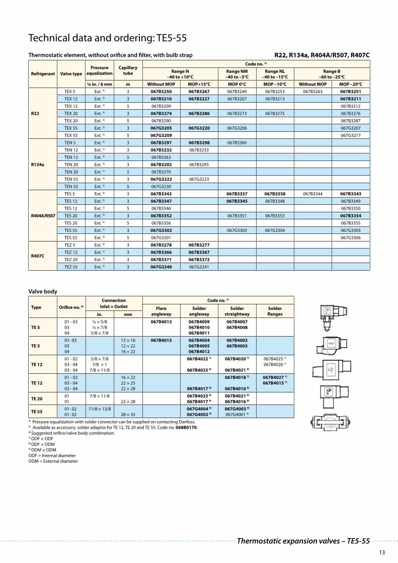
Technical data and ordering: TE5-55
Thermostatic element, without orifice and filter, with bulb strap R22, R134a, R404A/R507, R407C
Refrigerant Valve type
Pressure
equalization
Capillary
tube
Code no. 2)
Range N
–40 to +10°C
Range NM
–40 to –5°C
Range NL
–40 to –15°C
Range B
–60 to –25°C
¼ in. / 6 mm m Without MOP MOP+15°C MOP 0°C MOP –10°C Without MOP MOP –20°C
R22
TEX 5 Ext. 4) 3 067B3250 067B3267 067B3249 067B3253 067B3263 067B3251
TEX 12 Ext. 5) 3 067B3210 067B3227 067B3207 067B3213 067B3211
TEX 12 Ext. 5) 5 067B3209 067B3212
TEX 20 Ext. 5) 3 067B3274 067B3286 067B3273 067B3275 067B3276
TEX 20 Ext. 5) 5 067B3290 067B3287
TEX 55 Ext. 5) 3 067G3205 067G3220 067G3206 067G3207
TEX 55 Ext. 5) 5 067G3209 067G3217
R134a
TEN 5 Ext. 4) 3 067B3297 067B3298 067B3360
TEN 12 Ext. 5) 3 067B3232 067B3233
TEN 12 Ext. 5) 5 067B3363
TEN 20 Ext. 5) 3 067B3292 067B3293
TEN 20 Ext. 5) 5 067B3370
TEN 55 Ext. 5) 3 067G3222 067G3223
TEN 55 Ext. 5) 5 067G3230
R404A/R507
TES 5 Ext. 4) 3 067B3342 067B3357 067B3358 067B3344 067B3343
TES 12 Ext. 5) 3 067B3347 067B3345 067B3348 067B3349
TES 12 Ext. 5) 5 067B3346 067B3350
TES 20 Ext. 5) 3 067B3352 067B3351 067B3353 067B3354
TES 20 Ext. 5) 5 067B3356 067B3355
TES 55 Ext. 5) 3 067G3302 067G3303 067G3304 067G3305
TES 55 Ext. 5) 5 067G3301 067G3306
R407C
TEZ 5 Ext. 4) 3 067B3278 067B3277
TEZ 12 Ext. 5) 3 067B3366 067B3367
TEZ 20 Ext. 5) 3 067B3371 067B3372
TEZ 55 Ext. 5) 3 067G3240 067G3241
Valve body
Type Orifice no. 6)
Connection Code no. 2)
Inlet × Outlet Flare
angleway
Solder
angleway
Solder
straightway
Solder
flangesin. mm
TE 5
01 - 03
03
04
½ × 5/8
½ × 7/8
5/8 × 7/8
067B4013 067B4009
067B4010
067B4011
067B4007
067B4008
TE 5
01- 03
03
04
12 × 16
12 × 22
16 × 22
067B4013 067B4004
067B4005
067B4012
067B4002
067B4003
TE 12
01 - 02
03 - 04
03 - 04
5/8 × 7/8
7/8 × 1
7/8 × 11/8
067B4022 7)
067B4023 8)
067B4020 7)
067B4021 8)
067B4025 7)
067B4026 7)
TE 12
01 - 02
03 - 04
03 - 04
16 × 22
22 × 25
22 × 28 067B4017 8)
067B4018 7)
067B4016 8)
067B4027 7)
067B4015 7)
TE 2001
01
7/8 × 11/8
22 × 28
067B4023 8)
067B4017 8)
067B4021 8)
067B4016 8)
TE 5501- 02
01- 02
11/8 × 13/8
28 × 35
067G4004 9)
067G4002 9)
067G4003 9)
067G4001 9)
4) Pressure equalization with solder connector can be supplied on contacting Danfoss.5) Available as accessory: solder adaptor for TE 12, TE 20 and TE 55. Code no. 068B0170.6) Suggested orifice/valve body combination.7) ODF × ODF8) ODF × ODM9) ODM × ODM
ODF = Internal diameter
ODM = External diameter

14
Applications Advantages Facts
TU / TC: superior by design and function
The function of a thermostatic expansion valve is determined by three fundamental pressures: the bulb
pressure, the evaporating pressure and the spring pressure. When the expansion valve regulates, balance
is created between bulb pressure on one side of the diaphragm and evaporating pressure plus spring
force on the other side. The spring is used to set superheat.
Features
· Traditional refrigeration
· Heat pump systems
· Air conditioning units
· Liquid coolers
· Ice cube machines
· Transport refrigeration
· The use of stainless steel makes the
valves light and strong.
· Bi-metal connections for safe, fast and
convenient soldering.
· Stainless steel capillary tube for supe-
rior strength and ductility.
· Allen key superheat setting screw
is convenient and space-saving
compared to the standard screwdriver
adjustment used in most conventional
valves.
· Can be supplied with MOP
(Max. Operating Pressure)
Protects the compressor motor
against excessive evaporating pres-
sure during normal operation.
· Valves for special temperature ranges
can be supplied.
· Only 4 K opening superheat.
· Bi-flow function.
Laser-engraved inscription
Laser welded stainless steel
thermostatic element for
unsurpassed joint strength
and operational lifetime
Capillary tube in stainless steelBulb in stainless steel
Bi-metal connections
Stainless steel with rolled on
copper cladding for safe, fast and
convenient copper-to-copper
solderingSeparate strainer, mounted on
the orifice assembly for easy
maintenance and cleaningOrifice assembly with an
unmatched hermetic seal

15
Technical data and ordering: TUA / TUAE
Thermostatic element, without orifice and filter, with bulb strap 1) R22, R134a, R404A/R507, R407C, R410A
Refrigerant TypePressure
equalization
ConnectionsInlet × outlet
Code no. 2)
Range N–40 to +10°C
Range NM–40 to –5°C
Range B–60 to –25°C
in. mm Without MOP MOP +15°C MOP 0°C Without MOP MOP –20°C
R22
TUA
TUA
TUA
TUA
Int.
Int.
Int.
Int.
1/4 × 1/2
3/8 × 1/2
6 × 12
10 × 12
068U2234
068U2230
068U2235
068U2231
068U2242
068U2238
068U2243
068U2239
TUAE
TUAE
TUAE
TUAE
Ext. 1/4 in.
Ext. 6 mm
Ext. 1/4 in.
Ext. 6 mm
1/4 × 1/2
3/8 × 1/2
6 × 12
10 × 12
068U2236
068U2232
068U2237
068U2233
068U2244
068U2240
068U2245
068U2241
R134a
TUA
TUA
TUA
TUA
Int.
Int.
Int.
Int.
1/4 × 1/2
3/8 × 1/2
6 × 12
10 × 12
068U2204
068U2200
068U2205
068U2201
068U2212
068U2208
068U2213
068U2209
TUAE
TUAE
TUAE
TUAE
Ext. 1/4 in.
Ext. 6 mm
Ext. 1/4 in.
Ext. 6 mm
1/4 × 1/2
3/8 × 1/2
6 × 12
10 × 12
068U2206
068U2202
068U2207
068U2203
068U2214
068U2210
068U2215
068U2211
R404A/R507
TUA
TUA
TUA
TUA
Int.
Int.
Int.
Int.
1/4 × 1/2
3/8 × 1/2
6 × 12
10 × 12
068U2284
068U2280
068U2285
068U2281
068U2292
068U2288
068U2293
068U2289
068U2300
068U2296
068U2301
068U2297
068U2308
068U2304
068U2309
068U2305
068U2316
068U2312
068U2317
068U2313
TUAE
TUAE
TUAE
TUAE
Ext. 1/4 in.
Ext. 6 mm
Ext. 1/4 in.
Ext. 6 mm
1/4 × 1/2
3/8 × 1/2
6 × 12
10 × 12
068U2286
068U2282
068U2287
068U2283
068U2294
068U2290
068U2295
068U2291
068U2302
068U2298
068U2303
068U2299
068U2310
068U2306
068U2311
068U2307
068U2318
068U2314
068U2319
068U2315
R407C
TUA
TUA
TUA
TUA
Int.
Int.
Int.
Int.
1/4 × 1/2
3/8 × 1/2
6 × 12
10 × 12
068U2324
068U2320
068U2325
068U2321
068U2332
068U2328
068U2333
068U2329
TUAE
TUAE
TUAE
TUAE
Ext. 1/4 in.
Ext. 6 mm
Ext. 1/4 in.
Ext. 6 mm
1/4 × 1/2
3/8 × 1/2
6 × 12
10 × 12
068U2326
068U2322
068U2327
068U2323
068U2334
068U2330
068U2335
068U2331
R410A
TUA 3/8 × 1/2 068U2414
TUAE
TUAE
3/8 × 1/2
10 × 12
068U1714
068U2780 068U2450
Orifice assembly with filter and gasket
Orifice
no.
Range N: –40 to +10°C Range B: –60 to –25°C
Code no. 2)Rated capacity in kW 3) Rated capacity in tons (TR) Rated capacity in kW 3) Rated capacity in tons (TR)
R22 R134aR404AR507
R407C R410A R22 R134aR404AR507
R407C R410A R22R404AR507
R407C R22R404AR507
R407C
0 0.60 0.47 0.45 0.63 - 0.17 0.13 0.13 0.18 - 0.52 0.36 0.46 0.15 0.10 0.13 068U1030
1 0.9 0.7 0.66 0.92 1.3 0.25 0.19 0.19 0.26 0.4 0.68 0.50 0.58 0.19 0.14 0.16 068U1031
2 1.3 1.0 1.0 1.4 2.1 0.36 0.28 0.27 0.38 0.6 0.85 0.64 0.70 0.24 0.18 0.20 068U1032
3 1.8 1.4 1.3 1.9 2.9 0.50 0.39 0.38 0.53 0.8 1.2 0.89 1.0 0.34 0.25 0.28 068U1033
4 2.6 2.1 2.0 2.8 4.5 0.75 0.59 0.57 0.80 1.3 1.8 1.3 1.4 0.50 0.37 0.41 068U1034
5 3.5 2.7 2.7 3.8 5.9 1.00 0.78 0.76 1.1 1.7 2.3 1.8 1.9 0.66 0.50 0.55 068U1035
6 5.3 4.1 4.0 5.7 9.0 1.5 1.2 1.1 1.6 2.5 3.5 2.7 2.9 1.0 0.75 0.82 068U1036
7 7.0 5.5 5.3 7.5 12.0 2.0 1.6 1.5 2.1 3.4 4.7 3.5 3.9 1.3 1.0 1.1 068U1037
8 11.0 8.2 8.0 11.0 18.0 3.0 2.3 2.3 3.2 5.0 7.1 5.3 5.8 2.0 1.5 1.6 068U1038
9 16.0 12.0 12.0 17.0 26.0 4.5 3.5 3.5 4.8 7.5 10.4 7.8 8.5 2.9 2.2 2.4 068U1039
1) Capillary tube length 1.5 m.2) Code numbers in bold are normally on stock and a shorter delivery time can therefore be expected.3) The rated capacity is based on: Evaporating temperature te = +5°C for range N and te = –30°C for range B, condensing temperature tc = +32°C, refrigerant temperature ahead of valve tl = +28°C, and opening superheat OS = 4 K.
Thermostatic expansion valves – TUA, TUAE and TCAE
16
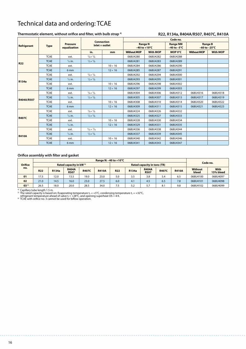
Technical data and ordering: TCAE
Thermostatic element, without orifice and filter, with bulb strap 4) R22, R134a, R404A/R507, R407C, R410A
Refrigerant TypePressure
equalization
Connection
Inlet × outlet
Code no.
Range N
–40 to +10°C
Range NM
–40 to –5°C
Range B
–60 to –25°C
in. mm Without MOP With MOP MOP 0°C Without MOP With MOP
R22
TCAE ext. 3/8 × 5/8 068U4280 068U4282 068U4288
TCAE 1/4 in. 1/2 × 5/8 068U4281 068U4283 068U4289
TCAE ext. 10 × 16 068U4284 068U4286 068U4290
TCAE 6 mm 12 × 16 068U4285 068U4287 068U4291
R134a
TCAE ext. 3/8 × 5/8 068U4292 068U4294 068U4300
TCAE 1/4 in. 1/2 × 5/8 068U4293 068U4295 068U4301
TCAE ext. 10 × 16 068U4296 068U4298 068U4302
TCAE 6 mm 12 × 16 068U4297 068U4299 068U4303
R404A/R507
TCAE ext. 3/8 × 5/8 068U4304 068U4306 068U4312 068U4316 068U4318
TCAE 1/4 in. 1/2 × 5/8 068U4305 068U4307 068U4313 068U4317 068U4319
TCAE ext. 10 × 16 068U4308 068U4310 068U4314 068U4320 068U4322
TCAE 6 mm 12 × 16 068U4309 068U4311 068U4315 068U4321 068U4323
R407C
TCAE ext. 3/8 × 5/8 068U4324 068U4326 068U4332
TCAE 1/4 in. 1/2 × 5/8 068U4325 068U4327 068U4333
TCAE ext. 10 × 16 068U4328 068U4330 068U4334
TCAE 1/4 in. 12 × 16 068U4329 068U4331 068U4335
R410A
TCAE ext. 3/8 × 5/8 068U4336 068U4338 068U4344
TCAE 1/4 in. 1/2 × 5/8 068U4337 068U4339 068U4345
TCAE ext. 10 × 16 068U4340 068U4342 068U4346
TCAE 6 mm 12 × 16 068U4341 068U4343 068U4347
Orifice assembly with filter and gasket
Orifice no.
Range N: –40 to +10°CCode no.
Rated capacity in kW 5) Rated capacity in tons (TR)
R22 R134aR404AR507
R407C R410A R22 R134aR404AR507
R407C R410AWithout
bleedWith
15% bleed
01 17.5 12.0 13.5 19.0 23.0 5.0 3.5 3.8 5.4 6.5 068U4100 068U4097
02 21.0 14.5 16.0 23.0 27.5 6.0 4.1 4.5 6.5 7.8 068U4101 068U4098
03 6) 26.5 18.0 20.0 28.5 34.0 7.5 5.2 5.7 8.1 9.8 068U4102 068U4099
4) Capillary tube length 1.5 m.5) The rated capacity is based on: Evaporating temperature te = +5°C, condensing temperature tc = +32°C,
refrigerant temperature ahead of valve tl = +28°C, and opening superheat OS = 4 K.6) TCAE with orifice no. 3 cannot be used for biflow operation.

17
Capacities
R22 R134a R404A/R507 R407C
Valve
type/
Orifice
Cond.
temp. 7)
[°C]
Capacity in [kW] Capacity in [kW] Capacity in [kW] Capacity in [kW]
Evaporating temp. [°C] Evaporating temp. [°C] Evaporating temp. [°C] Evaporating temp. [°C]
–35 –30 –10 0 5 –30 –10 –5 0 5 –40 –35 –30 –10 0 –10 –5 0 5 10
TU / 00
25
0.38 0.41 0.53 0.55 0.54 0.27 0.38 0.40 0.41 0.42 0.25 0.28 0.31 0.40 0.43 0.54 0.58 0.61 0.61 0.58
TU / 01 0.44 0.50 0.72 0.79 0.79 0.31 0.52 0.57 0.60 0.62 0.28 0.33 0.38 0.56 0.62 0.75 0.80 0.85 0.88 0.89
TU / 02 0.51 0.59 0.94 1.1 1.1 0.35 0.67 0.75 0.83 0.89 0.33 0.4 0.5 0.7 0.9 0.96 1.1 1.2 1.3 1.3
TU / 03 0.73 0.84 1.3 1.5 1.5 0.49 0.94 1.0 1.1 1.2 0.5 0.5 0.6 1.1 1.2 1.3 1.5 1.6 1.7 1.8
TU / 04 1.1 1.2 1.9 2.2 2.3 0.72 1.4 1.6 1.7 1.8 0.7 0.8 0.9 1.6 1.8 2.0 2.2 2.4 2.6 2.8
TU / 05 1.4 1.6 2.6 3.0 3.1 0.99 1.9 2.1 2.3 2.4 0.9 1.1 1.3 2.1 2.5 2.7 3.0 3.2 3.5 3.7
TU / 06 2.1 2.4 3.9 4.5 4.7 1.4 2.8 3.1 3.5 3.7 1.4 1.6 1.9 3.1 3.7 4.0 4.4 4.9 5.3 5.6
TU / 07 2.8 3.2 5.2 6.0 6.3 1.9 3.7 4.2 4.6 4.9 1.8 2.1 2.5 4.2 4.9 5.3 5.9 6.5 7.0 7.4
TU / 08 4.2 4.9 7.8 9.0 9.3 2.9 5.6 6.3 6.9 7.3 2.8 3.3 3.8 6.3 7.3 8.0 8.9 9.7 10.5 11.0
TU / 09 6.2 7.1 11.6 13.4 14.0 4.3 8.2 9.3 10.2 10.9 4.0 4.8 5.6 9.3 11.0 11.8 13.2 14.5 15.6 16.5
TC / 01 9.7 10.9 14.9 15.7 15.6 5.9 8.9 9.5 9.9 10.1 5.8 6.6 7.4 10.4 11.3 14.7 15.6 16.2 16.7 16.7
TC / 02 11.5 12.9 17.7 18.9 18.8 7.2 11.1 11.9 12.5 12.7 7.2 8.2 9.3 13.2 14.3 18.5 19.6 20.5 21.0 21.0
TC / 03 14.9 16.6 22.4 23.6 23.4 9.6 14.5 15.5 16.1 16.3 9.6 10.9 12.2 16.9 18.2 23.8 25.1 26.1 26.6 26.4
TU / 00
35
0.40 0.44 0.57 0.61 0.62 0.28 0.41 0.44 0.46 0.47 0.24 0.27 0.30 0.40 0.44 0.56 0.61 0.64 0.66 0.65
TU / 01 0.46 0.53 0.78 0.88 0.91 0.32 0.56 0.62 0.66 0.70 0.26 0.32 0.37 0.57 0.64 0.77 0.84 0.90 0.94 0.98
TU / 02 0.53 0.62 1.0 1.2 1.3 0.37 0.72 0.83 0.94 1.0 0.3 0.4 0.4 0.8 0.9 1.0 1.1 1.3 1.4 1.5
TU / 03 0.75 0.88 1.4 1.7 1.8 0.52 1.0 1.2 1.3 1.4 0.4 0.5 0.6 1.1 1.3 1.4 1.6 1.8 1.9 2.1
TU / 04 1.1 1.3 2.1 2.6 2.8 0.76 1.5 1.7 1.9 2.1 0.6 0.8 0.9 1.6 1.9 2.1 2.4 2.6 2.9 3.1
TU / 05 1.5 1.7 2.8 3.4 3.7 1.0 2.0 2.3 2.6 2.9 0.9 1.0 1.2 2.1 2.6 2.8 3.1 3.5 3.8 4.2
TU / 06 2.2 2.6 4.2 5.1 5.5 1.5 3.0 3.5 3.9 4.3 1.3 1.5 1.8 3.2 3.9 4.2 4.7 5.2 5.8 6.3
TU / 07 2.9 3.4 5.7 6.9 7.4 2.1 4.0 4.6 5.2 5.8 1.7 2.1 2.4 4.3 5.2 5.6 6.3 7.0 7.7 8.4
TU / 08 4.4 5.1 8.5 10.2 11.0 3.1 6.1 6.9 7.8 8.5 2.6 3.1 3.7 6.3 7.7 8.4 9.4 10.5 11.5 12.4
TU / 09 6.5 7.5 12.6 15.3 16.4 4.5 8.9 10.2 11.5 12.8 3.7 4.5 5.3 9.4 11.6 12.4 13.9 15.5 17.1 18.6
TC / 01 10.3 11.5 16.3 17.9 18.3 6.2 9.7 10.5 11.2 11.7 5.4 6.3 7.2 10.6 11.9 15.4 16.5 17.4 18.2 18.8
TC / 02 12.2 13.7 19.5 21.5 22.1 7.7 12.2 13.2 14.1 14.8 6.9 7.9 9.1 13.4 15.1 19.4 20.9 22.1 23.1 23.8
TC / 03 15.9 17.8 24.7 26.9 27.5 10.2 15.9 17.1 18.2 19.0 9.3 10.6 12.0 17.3 19.2 25.1 26.8 28.2 29.3 29.9
TU / 00
45
0.40 0.45 0.60 0.65 0.67 0.28 0.43 0.46 0.48 0.51 0.21 0.24 0.27 0.38 0.43 0.56 0.61 0.65 0.67 0.68
TU / 01 0.47 0.54 0.82 0.94 0.98 0.32 0.58 0.64 0.70 0.75 0.23 0.28 0.34 0.54 0.6 0.77 0.84 0.91 0.96 1.0
TU / 02 0.54 0.63 1.1 1.3 1.5 0.37 0.75 0.87 0.99 1.1 0.3 0.3 0.4 0.7 0.9 1.0 1.2 1.3 1.4 1.6
TU / 03 0.75 0.89 1.5 1.8 2.0 0.52 1.1 1.2 1.4 1.5 0.4 0.4 0.5 1.0 1.3 1.4 1.6 1.8 2.0 2.2
TU / 04 1.1 1.3 2.2 2.8 3.0 0.77 1.6 1.8 2.1 2.3 0.5 0.7 0.8 1.5 1.9 2.1 2.4 2.7 3.0 3.3
TU / 05 1.5 1.7 3.0 3.7 4.0 1.0 2.1 2.4 2.8 3.1 0.7 0.9 1.1 2.0 2.6 2.8 3.2 3.6 4.0 4.4
TU / 06 2.2 2.6 4.5 5.5 6.1 1.5 3.1 3.6 4.1 4.7 1.1 1.4 1.7 3.0 3.8 4.2 4.8 5.4 6.0 6.6
TU / 07 3.0 3.5 6.0 7.4 8.1 2.1 4.2 4.9 5.5 6.2 1.5 1.8 2.2 4.1 5.1 5.6 6.4 7.2 8.0 8.9
TU / 08 4.5 5.3 9.0 11.1 12.1 3.1 6.3 7.3 8.3 9.3 2.3 2.8 3.3 6.1 7.6 8.4 9.6 10.7 11.9 13.1
TU / 09 6.6 7.7 13.3 16.5 18.0 4.5 9.3 10.8 12.3 13.8 3.1 3.9 4.8 9.0 11.4 12.4 14.1 15.9 17.8 19.6
TC / 01 10.5 11.9 17.2 19.3 20.1 6.3 10.1 11.1 11.9 12.7 4.8 5.7 6.6 10.2 11.7 15.6 16.8 17.9 18.9 19.8
TC / 02 12.6 14.2 20.7 23.3 24.3 7.9 12.8 14.0 15.2 16.2 6.2 7.2 8.4 12.9 14.9 19.8 21.4 22.8 24.1 25.2
TC / 03 16.6 18.7 26.4 29.3 30.3 10.6 16.8 18.2 19.6 20.7 8.5 9.9 11.3 16.8 19.0 25.8 27.6 29.3 30.7 31.7
TU / 00
55
0.41 0.45 0.62 0.68 0.70 0.27 0.43 0.46 0.49 0.52 0.17 0.20 0.24 0.35 0.39 0.54 0.59 0.63 0.66 0.67
TU / 01 0.47 0.54 0.84 0.98 1.0 0.31 0.58 0.65 0.71 0.77 0.18 0.23 0.28 0.48 0.6 0.75 0.82 0.89 0.95 1.0
TU / 02 0.53 0.63 1.1 1.4 1.6 0.37 0.75 0.87 1.0 1.2 0.20 0.3 0.3 0.7 0.9 1.00 1.1 1.3 1.5 1.6
TU / 03 0.73 0.88 1.6 1.9 2.1 0.50 1.1 1.3 1.4 1.6 0.2 0.3 0.4 0.9 1.2 1.4 1.6 1.8 2.0 2.2
TU / 04 1.1 1.3 2.3 2.9 3.2 0.75 1.6 1.8 2.1 2.4 0.4 0.5 0.6 1.4 1.8 2.1 2.4 2.7 3.0 3.3
TU / 05 1.5 1.7 3.1 3.8 4.3 0.96 2.1 2.4 2.8 3.2 0.5 0.7 0.9 1.8 2.4 2.7 3.1 3.6 4.0 4.5
TU / 06 2.2 2.6 4.7 5.8 6.4 1.4 3.2 3.7 4.3 4.9 0.9 1.1 1.4 2.8 3.6 4.2 4.8 5.4 6.1 6.8
TU / 07 2.9 3.5 6.2 7.7 8.5 2.0 4.2 4.9 5.7 6.4 1.1 1.5 1.8 3.7 4.8 5.4 6.2 7.1 8.0 9.0
TU / 08 4.4 5.2 9.2 11.5 12.7 3.0 6.3 7.4 8.5 9.6 1.8 2.2 2.8 5.5 7.1 8.2 9.4 10.7 12.0 13.3
TU / 09 6.5 7.7 13.7 17.2 19.0 4.3 9.3 10.9 12.5 14.3 2.2 3.0 3.8 8.1 10.5 12.1 13.9 15.8 17.8 19.9
TC / 01 10.6 12.1 17.8 20.2 21.2 6.2 10.3 11.3 12.3 13.2 3.8 4.7 5.6 9.3 10.9 15.3 16.6 17.9 19.0 20.1
TC / 02 12.8 14.5 21.6 24.5 25.8 7.9 13.1 14.4 15.7 16.8 5.1 6.1 7.3 11.9 14.0 19.6 21.3 22.9 24.3 25.6
TC / 03 17.1 19.3 27.6 30.9 32.2 10.7 17.2 18.8 20.3 21.7 7.2 8.6 10.0 15.6 17.9 25.8 27.8 29.6 31.1 32.47) Condensing temperature at bubble point.
Thermostatic expansion valves – TUA, TUAE and TCAE

18
Capacities
Correction factor
RefrigerantSubcooling [K]
2 4 10 15 20 25 30 35 40 45 50
R22 0.98 1 1.06 1.11 1.15 1.20 1.25 1.30 1.35 1.39 1.44
R134a 0.98 1 1.08 1.13 1.19 1.25 1.31 1.37 1.42 1.48 1.54
R404A / R507 0.96 1 1.10 1.20 1.29 1.37 1.46 1.54 1.63 1.70 1.78
R407C 0.97 1 1.08 1.14 1.21 1.27 1.33 1.39 1.45 1.51 1.57
R410A 0.97 1 1.08 1.15 1.21 1.27 1.33 1.39 1.45 1.50 1.56
When the subcooling ≠ 4 K then:
1. Table value x Factor = Plant capacity
2. Plant capacity / Factor = Table value
Example:
Qnom = 10 kW
te = –10°C
tc = 55°C
Δtsub = 25 K
Selection:
1. TC, Orifice 01 = 10.3 kW x 1.25 = 12.9 kW → Valve too large
Right selection:
2. 10 kW / 1.25 = 8 kW → TU, Orifice 09
R410A
Valve
type/
Orifice
Cond.
temp. 7)
[°C]
Capacity in [kW]
Evaporating temp. [°C]
–10 –5 0 5 10
TU / 00
25
0.77 0.78 0.78 0.76 0.71
TU / 01 1.11 1.15 1.17 1.16 1.11
TU / 02 1.60 1.7 1.8 1.9 1.9
TU / 03 2.2 2.4 2.6 2.6 2.6
TU / 04 3.3 3.6 3.9 4.0 4.0
TU / 05 4.4 4.8 5.1 5.3 5.3
TU / 06 6.7 7.3 7.8 8.1 8.0
TU / 07 8.9 9.7 10.3 10.7 10.7
TU / 08 13.3 14.5 15.3 15.8 15.7
TU / 09 19.9 21.6 23.0 23.9 23.7
TC / 01 17.3 18.2 18.7 18.7 17.9
TC / 02 21.9 23.0 23.7 23.7 22.8
TC / 03 28.4 29.6 30.3 30.2 28.8
TU / 00
35
0.80 0.83 0.84 0.85 0.83
TU / 01 1.16 1.22 1.27 1.30 1.30
TU / 02 1.7 1.9 2.0 2.2 2.3
TU / 03 2.4 2.6 2.8 3.0 3.1
TU / 04 3.6 3.9 4.3 4.6 4.8
TU / 05 4.7 5.2 5.7 6.1 6.3
TU / 06 7.1 7.9 8.6 9.2 9.7
TU / 07 9.5 10.5 11.4 12.2 12.9
TU / 08 14.2 15.6 16.9 18.0 18.8
TU / 09 21.1 23.3 25.4 27.1 28.5
TC / 01 18.5 19.7 20.7 21.3 21.6
TC / 02 23.5 25.0 26.2 27.1 27.5
TC / 03 30.4 32.2 33.6 34.5 34.8
TU / 00
45
0.80 0.83 0.86 0.87 0.87
TU / 01 1.17 1.23 1.29 1.34 1.4
TU / 02 1.7 1.9 2.1 2.3 2.4
TU / 03 2.4 2.7 2.9 3.1 3.3
TU / 04 3.6 4.0 4.4 4.8 5.1
TU / 05 4.8 5.3 5.8 6.3 6.8
TU / 06 7.2 8.0 8.9 9.6 10.3
TU / 07 9.6 10.7 11.7 12.8 13.7
TU / 08 14.3 15.9 17.4 18.8 20.1
TU / 09 21.3 23.7 26.1 28.3 30.3
TC / 01 18.8 20.1 21.4 22.4 23.1
TC / 02 23.9 25.6 27.2 28.5 29.5
TC / 03 31.1 33.1 34.9 36.3 37.2
TU / 00
55
0.77 0.80 0.83 0.85 0.86
TU / 01 1.12 1.19 1.26 1.31 1.3
TU / 02 1.67 1.9 2.1 2.2 2.4
TU / 03 2.3 2.6 2.9 3.1 3.3
TU / 04 3.4 3.9 4.3 4.7 5.1
TU / 05 4.7 5.2 5.7 6.3 6.8
TU / 06 6.9 7.8 8.7 9.5 10.4
TU / 07 9.2 10.4 11.5 12.6 13.7
TU / 08 13.8 15.5 17.1 18.6 20.1
TU / 09 20.5 23.0 25.5 28.0 30.3
TC / 01 18.3 19.7 21.0 22.2 23.2
TC / 02 23.3 25.2 26.9 28.4 29.7
TC / 03 30.5 32.6 34.5 36.1 37.4
N = –40°C → +10°C
NM = –40°C → –5°C with MOP
NL = –40°C → –15°C with MOP
B = –60°C → –25°C with MOP
Orifice / Superheat
Exchangeable Adjustable
A Yes YES
B NO YES
C NO NO
T U A E
Thermostatic
Capacity range
Orifice / Superheat
Ext. equalization
TUA(E)
TCAE
TUB(E)
TUC(E)
TCBE
TCCE
+
Thermostatic
valve
Orifice
or
Thermostatic valve incl. orifice
Valve types TUB(E)/TUC(E) and TCBE/TCCE can be
replaced by TUA(E) and TCAE types

19
Thermostatic expansion valves – TUA, TUAE and TCAE
+
+
+
+ +
+
+
TypeRated capacities in kW for range N
ConnectionsR22 R134a R404A / R507 R407C R410A
T 2 and TE 2 1) 0.5 - 15.5 0.4 - 10.5 0.38 - 9.1 0.5 - 16.7 -Flare x flare and flare x solder
Solder x solder (solder adaptor)
TUA and TUAE 1) 0.6 - 16 0.45 - 12 0.45 - 12 0.63 - 17 1.3 - 26Solder
Bi-metal (stainless steel / copper)
TUB and TUBE 2) 0.9 - 16 0.7 - 12 0.7 - 12 0.92 - 17 1.3 - 26Solder
Bi-metal (stainless steel / copper)
TCAE 1) and TCBE 2) 17.5 - 26.5 12 - 18 13.5 - 20 19.0 - 28.5 23 - 34Solder
Bi-metal (stainless steel / copper)
TRE 10 - TRE 80 2) 28 - 245 18 - 196 21 - 187 28 - 245 28 - 350Solder
Bi-metal (stainless steel / copper)
TE 5 - TE 55 1) 19.7 - 356 12.9 - 220 13 - 197 21.3 - 385 - Flare / solder /solder flanges
PHT 1) 105 - 1890 55 - 1083 99 - 1623 117 - 2020 - Solder or weld flanges
TDE and TDEB 2) 10.5 - 140 5.7 - 79 8.4 - 109 10.5 - 140 - Solder (copper)
1) Interchangeable orifice.2) Fixed orifice.
The complete Danfoss program of thermostatic expansion valves:
Thermostatic expansion valves parts program:
T 2 and TE 2
TUA/TUAE and TCAE
TE 5 - TE 55
PHT
Thermostatic element Orifice Valve body Flanges
Thermostatic element Orifice Valve body
Thermostatic valve Orifice
Thermostatic valve Orifice

20
Applications Advantages Facts
PHT: The parts programme make flexibility
PHT thermostatic expansion valves regulate the injection of refrigerant liquid into evaporators.
Injection is controlled by the refrigerant superheat.
Therefore the valves are especially suitable for liquid injection in ”dry“ evaporators where the superheat
at the evaporator outlet is proportional to the evaporator load.
Features
· Traditional refrigeration and freezing
applications
· Water coolers and air conditioning
· Interchangeable orifice assembly
- easier stocking
- easy capacity matching
- better service.
· Very tight main orifice
Also used as solenoid valve
(not PHT 300)
· Superheat
Static superheat SS can be adjusted
with setting spindle ( ).
· Permissible working pressure
- PHT 85 and 125: PS / MWP = 28 bar
- PHT 300: PS / MWP = 20 bar
· Rated capacities from 105 to 1890 kW
(30 to 540 TR) for R22
· Can be supplied with MOP
(Max. Operating Pressure)
Protects the compressor motor
against excessive evaporating pres-
sure
· Range: –40 to +50°C
Capillary tube and sensor in
stainless steel.
Vibration proof due to the
strong capillary tube.
Weld or solder flanges
Weld: 1 to 2 in.
Solder: 1 1/8 in (28 mm)
to 1 3/8 in. (35 mm)
Connection for
external pilot
Easy adjustment of
superheat
Laser welded thermostatic element
in stainless steel. Secure, stronger
diaphram and longer lifetime.

21
Technical data and ordering
4. Flange set
Valve flange Flange type Weld flanges Solder flanges
in. Code no. in. Code no. mm Code no.
PHT 85 2 1 027N1025
PHT 85 2 11/8 027L1029 28 027L1028
PHT 85 2 13/8 027L1035 35 027L1035
PHT 125 3 A 11/4 027N1032
PHT 300 4 A 11/2 027N1040
PHT 300 4 A 2 027N1050
1. Pilot orifice assembly
Type Code no.
PHT 067B2090
2. Valve body, flange gaskets, flange bolts and screws
Type Orifice no. Rated capacity 2)
R22
Rated capacity 1)
R134a
Code no.
Range N:
–40 to +10°C
Range N:
–40 to +10°C
Range A:
+10 to +50°C
TR kW TR kW TR kW
PHT 85 1 30 105 16 55 20 69 026H1160
PHT 85 2 50 175 26 92 33 114 026H1161
PHT 85 3 80 280 39 138 52 182 026H1162
PHT 85 4 130 455 59 208 72 273 026H1163
PHT 125 1 225 790 125 438 156 545 026H1164
PHT 300 1 325 1140 178 622 221 773 026H0165
PHT 300 2 540 1890 309 1083 351 1227 026H0166
1) A PHT 85 with orifice no. 5 and a capacity of +5 +10% compared to orifice no. 4 can be ordered. The code no. is 026H1187.2) The rated capacity for range N is based on evaporating temperature t
e = +5°C, condensing temperature t
c = +32°C,
and refrigerant liquid temperature ahead of valve tl = +28°C.
The rated capacity for range A is based on evaporating temperature te = +5°C, condensing temperature t
c = +42°C,
and refrigerant liquid temperature ahead of valve tl = +38°C.
See following pages for extended capacity tables.
3. Thermostatic element (incl. accessory bag)
Range Refrigerant Code no.
3 m capillary tube 5 m capillary tube
–40 to +10°C
R22 067B3303 067B3304
R22, MOP 100 psig 067B3300 067B3306
R407C 067B3314 067B3341
R407C, MOP 95 psig 067B3311
R134a 067B3310 067B3315
R134a, MOP 55 psig 067B3316 067B3317
R404A / R507 067B3319
+10 to +50°C R134a 067B3318
PHT 85
Solder or weld flanges
1. Orifice assembly for pilot valve
2. Valve body, flange gaskets, flange bolts and screws
3. Thermostatic element (incl. accessory bag with screws)
4. Flange set
Thermostatic expansion valves – PHT

22
Technical data and ordering
R22 R134a R404A / R507 R407C
Valve type
/
Orifice
Cond.
temp.
[°C]
Capacity in [kW]
Evaporating temp. [°C]
Capacity in [kW]
Evaporating temp. [°C]
Capacity in [kW]
Evaporating temp. [°C]
Capacity in [kW]
Evaporating temp. [°C]
-35 -30 -10 0 5 -30 -10 -5 0 5 -40 -35 -30 -10 0 -10 -5 0 5 10
PHT85-1
25
42 49 79 90 93 17.8 38 43 48 51 34 40 47 76 87 85 94 101 108 111
PHT85-2 73 85 133 149 151 32 67 76 83 87 59 70 81 124 139 143 156 167 174 177
PHT85-3 110 128 205 234 240 47 101 114 125 132 90 105 122 193 220 221 242 262 277 285
PHT85-4 109 128 292 377 403 52 108 128 150 172 96 112 139 300 371 317 372 422 464 492
PHT125-1 357 407 609 653 642 160 322 360 391 411 283 324 371 562 614 655 700 730 739 719
PHT300-1 483 553 869 994 1025 224 445 500 547 580 391 454 522 809 921 930 1019 1099 1164 1203
PHT300-2 864 980 1472 1642 1671 411 788 877 952 1002 693 797 906 1334 1477 1573 1701 1811 1891 1926
PHT85-1
35
45 53 89 106 113 19.6 43 50 56 62 33 39 46 79 95 91 101 111 121 129
PHT85-2 79 92 149 173 181 35 75 86 96 104 57 68 80 129 150 153 168 182 194 203
PHT85-3 119 139 229 271 288 51 113 130 146 160 86 103 120 200 238 235 260 285 308 327
PHT85-4 121 144 331 438 484 58 125 150 181 215 93 110 139 314 402 341 402 461 515 560
PHT125-1 379 436 680 760 773 174 357 404 448 486 271 315 365 579 654 697 756 804 834 843
PHT300-1 521 599 962 1135 1205 245 495 563 628 686 380 445 516 833 985 982 1085 1185 1277 1356
PHT300-2 935 1064 1628 1867 1953 449 874 983 1085 1173 675 783 898 1373 1575 1660 1809 1946 2065 2158
PHT85-1
45
47 56 95 116 125 21 46 53 61 68 29 35 43 77 95 93 104 116 127 137
PHT85-2 83 97 159 188 201 36 80 92 104 115 51 62 74 127 151 155 172 188 202 214
PHT85-3 125 146 245 295 318 53 120 139 158 177 76 93 111 195 239 238 266 294 320 345
PHT85-4 129 155 357 478 532 61 135 164 199 241 80 99 128 310 404 350 413 476 535 589
PHT125-1 384 448 729 838 870 179 376 429 481 529 240 285 338 563 651 712 783 843 890 919
PHT300-1 548 631 1024 1224 1316 255 524 600 675 748 341 406 478 807 978 995 1105 1214 1318 1416
PHT300-2 985 1122 1730 2008 2124 469 922 1044 1161 1270 613 723 839 1334 1564 1681 1839 1988 2124 2241
PHT85-1
55
48 57 99 122 133 21 47 55 63 72 22 28 36 71 90 91 103 115 127 139
PHT85-2 84 99 166 198 212 36 82 95 108 121 40 51 63 117 143 153 170 186 201 215
PHT85-3 127 149 253 308 335 51 122 142 163 183 59 75 93 179 225 233 262 290 319 346
PHT85-4 134 162 373 500 560 61 138 169 208 254 59 77 106 287 383 345 409 473 534 589
PHT125-1 373 443 758 891 940 176 381 438 494 547 189 236 289 520 613 702 781 852 912 956
PHT300-1 561 647 1057 1273 1376 253 532 612 694 774 275 338 408 736 912 973 1085 1196 1306 1411
PHT300-2 1011 1154 1785 2083 2213 468 936 1063 1189 1308 508 616 731 1226 1465 1642 1801 1952 2093 2218
Correction factor
RefrigerantSubcooling [K]
2 4 10 15 20 25 30 35 40 45 50
R22 0.98 1 1.06 1.11 1.15 1.2 1.25 1.3 1.35 1.39 1.44
R134a 0.98 1 1.08 1.13 1.19 1.25 1.31 1.37 1.42 1.48 1.54
R404A/507 0.96 1 1.1 1.2 1.29 1.37 1.46 1.54 1.63 1.7 1.78
R407C 0.97 1 1.08 1.14 1.21 1.27 1.33 1.39 1.45 1.51 1.57
When the subcooling ≠ 4 K then:1. Table value x Factor = Plant capacity2. Plant capacity : Factor = Table value
Example: Qo = 10 kWto = -10°Ctc = 45°CΔtu = 25 K
Selection:1. PHT 85, Orifice 04 = 135 KW x 1,25 = 168,75 kW ! Valve too large
Right selection:2. 130 kW : 1,25 = 104 kW è PHT, Orifice 03

23
Thermostatic expansion valves – PHT
+
+
+
+ +
+
+
Thermostatic expansion valves parts program:
T 2 and TE 2
TUA/TUAE and TCAE
TE 5 - TE 55
PHT
Thermostatic element Orifice Valve body Flanges
Thermostatic element Orifice Valve body
Thermostatic valve Orifice
Thermostatic valve Orifice

24
Applications Advantages Facts
AKV : Precise injection in the evaporator
AKV are electrically operated expansion valves designed for refrigerating plant.
The AKV valves are normally operated by a controller from the Danfoss ADAP-KOOL range.
The valves are operated with pulsating regulation which means that the opening degree is controlled by
demand (adaptive regulation).
Features
· Traditional refrigeration
· Cold rooms
· Water chillers
· The AKV valves are supplied as a com-
ponent programme, as follows:
· Separate valve incl. exchangeable orifice
· Separate coil
· Flexibility in MOP setting (the regula-
tor closes when the pressure in the
evaporator falls below the set value).
· The valve requires no adjustment
· The AKV 10 valves cover a capacity
range from 1 kW to 16 kW (R22) and
are divided into 7 capacity ranges.
· The AKV 15 valves cover a capacity
range from 25 kW to 100 kW (R22) and
are divided into 4 capacity ranges.
· The AKV 20 valves cover a capacity
range from 100 kW to 630 kW (R22)
and are divided into 5 capacity ranges.
· The AKV valves can be used for HCFC
and HFC, R744 refrigerants.
The orifice assembly
is replaceable
Available with ODF solder
connections or weld
(AKV 15 and 20 – straight way)
Both expansion valve and
solenoid valve
Available with terminal box,
cable or AMP
Wide range of coils
for d.c. and a.c.

25
Technical data and ordering
AKV 10
Valve type
Rated capacity kW 1) kv
value
Connections
Solder ODF
R22 R134a R404A/R507 R407C m3/hInlet × outlet
in.Code no.
Inlet × outlet
mmCode no.
AKV 10-1 1.0 0.9 0.8 1.1 0.010 ³⁄₈ × ½ 068F1161 10 × 12 068F1162
AKV 10-2 1.6 1.4 1.3 1.7 0.017 ³⁄₈ × ½ 068F1164 10 × 12 068F1165
AKV 10-3 2.6 2.1 2.0 2.5 0.025 ³⁄₈ × ½ 068F1167 10 × 12 068F1168
AKV 10-4 4.1 3.4 3.1 4.0 0.046 ³⁄₈ × ½ 068F1170 10 × 12 068F1171
AKV 10-5 6.4 5.3 4.9 6.4 0.064 ³⁄₈ × ½ 068F1173 10 × 12 068F1174
AKV 10-6 10.2 8.5 7.8 10.1 0.114 ³⁄₈ × ½ 068F1176 10 × 12 068F1177
AKV 10-7 16.3 13.5 12.5 17.0 0.209 ½ × ⁵⁄₈ 068F1179 12 × 16 068F1180
AKV 15
AKV 15-1 25.5 21.2 19.6 25.2 0.25 ¾ × ¾ 068F5000 18 × 18 068F5001
AKV 15-2 40.8 33.8 31.4 40.4 0.40 ¾ × ¾ 068F5005 18 × 18 068F5006
AKV 15-3 64.3 53.3 49.4 63.7 0.63 ⁷⁄₈ × ⁷⁄₈ 068F5010 22 × 22 068F5010
AKV 15-4 102 84.6 78.3 101 1.0 1¹⁄₈ × 1¹⁄₈ 068F5015 28 × 28 068F5016
AKV 20
Valve type
Rated capacity kW 1) kv
value
Connections
Solder ODF Weld
R22 R134a R404A/R507 R407C m3/hInlet × outlet
in.Code no.
Inlet × outlet
mmCode no.
Inlet × outlet
in.Code no.
AKV 20-1 102 84.6 78.3 101 1.0 1³⁄₈ × 1³⁄₈ 042H2020 35 × 35 042H2020 1¹⁄₄ × 1¹⁄₄ 042H2021
AKV 20-2 163 135 125 170 1.6 1³⁄₈ × 1³⁄₈ 042H2022 35 × 35 042H2022 1¹⁄₄ × 1¹⁄₄ 042H2023
AKV 20-3 255 212 196 252 2.5 1⁵⁄₈ × 1⁵⁄₈ 042H2024 42 × 42 042H2025 1¹⁄₄ × 1¹⁄₄ 042H2026
AKV 20-4 408 338 314 404 4.0 2¹⁄₈ × 2¹⁄₈ 042H2027 54 × 54 042H2027 1½ × 1½ 042H2028
AKV 20-5 643 533 494 637 6.3 2¹⁄₈ × 2¹⁄₈ 042H2029 54 × 54 042H2029 2 × 2 042H2030
1) Rated capacities are based on:
Condensing temperature tc = 32°C
Liquid temperature tl = 28°C
Evaporating temperature te = 5°C
Technical data
Valve type AKV 10 AKV 15 AKV 20
Tolerance of coil voltage +10 / –15% +10 / –15% +10 / –15%
Enclosure to IEC 529 Max. IP 67 Max. IP 67 Max. IP 67
Working principle (Pulse-width modulation) PWM PWM PWM
Recommended period of time 6 Seconds 6 Seconds 6 Seconds
Capacity (R22) 1 to 16 kW 25 to 100 kW 100 to 630 kW
Regulation range (Capacity range) 10 to 100% 10 to 100% 10 to 100%
Connection Solder Solder Solder or weld
Evaporating temperature – 60 to 60°C – 50 to 60°C – 40 to 60°C
Ambient temperature – 50 to 50°C – 40 to 50°C – 40 to 50°C
Leak of valve seat <0.02% of kv-value <0.02% of k
v-value <0.02% of k
v-value
MOPD 18 bar 22 bar 18 bar
Filter, replaceable Internal 100 μm External 100 μm External 100 μm
Max. working pressure PS=42 bargAKV 15-1,2,3 PS 42 barg
AKV 15-4 PS 28 barg28 barg
Expansion valves – AKV

26
Technical data and ordering
OrderingCoils for AKV valves
AKV AKV AKV AKV AKV AKV
10-1
10-2
10-3
10-4
10-5
10-6 10-7 15-1
15-2
15-3
15-4
20-1
20-2
20-3
20-4
20-5
D.C. coils Code no.
220 V d.c. 20 W, standard
with terminal box 018F6851+ + + + + +
100 V d.c. 18 W, special
with terminal box
with DIN plugs
018F6780 + + + + + +
230 V d.c. 18 W, special
with terminal box
with DIN plugs
018F67811)
018F69911)
+ + + + + +
230 V d.c. 18 W, special
with 2.5 m cable
with 4.0 m cable
with 8.0 m cable
018F62881)
018F62781)
018F62791)
+ + + + + +
1) Recommended for commercial refrigeration plant
A.C. coils Code no.
240 V a.c. 10 W, 50 Hz
with terminal box
with DIN plugs
018F6702
018F6177
+ + – + – –
240 V a.c. 10 W, 60 Hz
with terminal box
with DIN plugs
018F6713
018F6188
+ + – + – –
240 V a.c. 12 W, 50 Hz
with terminal box 018F6802+ + + + + –
230 V a.c. 10 W, 50 Hz
with terminal box
with DIN-plugs
018F6701
018F6176
+ + – + – –
230 V a.c. 10 W, 60 Hz
with terminal box
with DIN-plugs
018F6714
018F6189
+ + – + – –
230 V a.c. 10 W, 50/60 Hz
with terminal box
with DIN-plugs
018F6732
018F6193
+ + – + – –
230 V a.c. 12 W, 50 Hz
with terminal box 018F6801+ + – + + –
230 V a.c. 12 W, 60 Hz
with terminal box 018F6814+ + – + + –
115 V a.c. 10 W, 50 Hz
with terminal box
with DIN-plugs
018F6711
018F6186
+ + – + – –
115 V a.c. 10 W, 60 Hz
with terminal box
with DIN-plugs
018F6710
018F6185
+ + – + – –
110 V a.c. 12 W, 50 Hz
with terminal box 018F6811+ + – + + –
110 V a.c. 12 W, 60 Hz
with terminal box 018F6813+ + – + + –
110 V a.c. 20 W, 50 Hz
with terminal box 018Z6904+ + + + + +
24 V a.c. 10 W, 50 Hz
with terminal box
with DIN-plugs
018F6707
018F6182
+ – – + – –
24 V a.c. 10 W, 60 Hz
with terminal box
with DIN-plugs
018F6715
018F6190
– – – + – –
24 V a.c. 12 W, 50 Hz
with terminal box 018F6807+ – – + + +
24 V a.c. 12 W, 60 Hz
with terminal box 018F6815+ – – + + +
24 V a.c. 20 W, 50 Hz
with terminal box 018F6901+ + + + + +
24 V a.c. 20 W, 60 Hz
with terminal box 018F6902+ + + + + +

27
Expansion valves – AKV
Application example
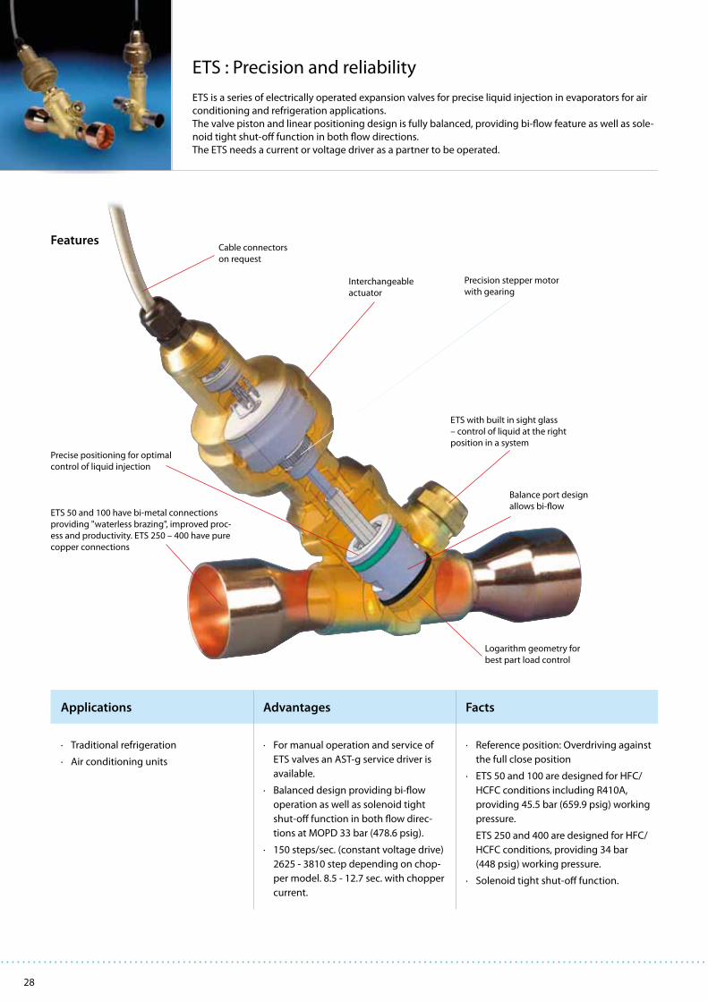
28
Applications Advantages Facts
ETS : Precision and reliability
ETS is a series of electrically operated expansion valves for precise liquid injection in evaporators for air
conditioning and refrigeration applications.
The valve piston and linear positioning design is fully balanced, providing bi-flow feature as well as sole-
noid tight shut-off function in both flow directions.
The ETS needs a current or voltage driver as a partner to be operated.
Features
· Traditional refrigeration
· Air conditioning units
· For manual operation and service of
ETS valves an AST-g service driver is
available.
· Balanced design providing bi-flow
operation as well as solenoid tight
shut-off function in both flow direc-
tions at MOPD 33 bar (478.6 psig).
· 150 steps/sec. (constant voltage drive)
2625 - 3810 step depending on chop-
per model. 8.5 - 12.7 sec. with chopper
current.
· Reference position: Overdriving against
the full close position
· ETS 50 and 100 are designed for HFC/
HCFC conditions including R410A,
providing 45.5 bar (659.9 psig) working
pressure.
ETS 250 and 400 are designed for HFC/
HCFC conditions, providing 34 bar
(448 psig) working pressure.
· Solenoid tight shut-off function.
ETS 50 and 100 have bi-metal connections
providing "waterless brazing", improved proc-
ess and productivity. ETS 250 – 400 have pure
copper connections
Precision stepper motor
with gearing
ETS with built in sight glass
– control of liquid at the right
position in a system
Cable connectors
on request
Precise positioning for optimal
control of liquid injection
Interchangeable
actuator
Balance port design
allows bi-flow
Logarithm geometry for
best part load control

29
250
2000
1600
1200
800
400
00 10 20 30 40 50 60 70 80 90 100
ETS 400
Q
[kW
]0
Opening [%]
1400
1200
1000
800
0 10 20 30 40 50 60 70 80 90 100
600
400
200
0
ETS 250
Q
[kW
]0
Opening [%]
450
400
350
300
00 10 20 30 40 50 60 70 80 90 100
250
200
150
100
50
ETS 100
Q
[kW
]0
Opening [%]
200
150
100
50
00 10 20 30 40 50 60 70 80 90 100
ETS 50
Q
[kW
]0
Opening [%]
Code no.
Industrial pack
Code no.
Single pack
Electrical expansion valves – ETS
Technical data and ordering
1) The rated capacity is based on: Evaporating temperature t
e : 5°C (40°F)
Liquid temperature tl : 28°C (82°F)
Condensing temperature tc : 32°C (90°F)
Full stroke opening.
2) ETS 25B is available upon request. Please contact Danfoss. Note: ETS 25B is half the capacity of ETS 50B.
Valve incl. actuator – Industrial pack (9 pcs.)
Type
Connection Connection
ODF × ODF
in
Code no.
Industrial pack
ODF × ODF
mm
Code no.
Industrial pack
ETS 50B
7/8 × 7/
8034G1000 22 × 22 034G1050
7/8 × 11/
8034G1001 22 × 28 034G1051
7/8 × 13/
8034G1002 22 × 35 034G1052
11/8 × 11/
8034G1003 28 × 28 034G1053
11/8 × 13/
8034G1004 28 × 35 034G1054
ETS 100B
11/8 × 11/
8034G0000 28 × 28 034G0050
11/8 × 13/
8034G0001 28 × 35 034G0051
11/8 × 15/
8034G0002 28 × 42 034G0052
13/8 × 13/
8034G0003 35 × 35 034G0053
13/8 × 15/
8034G0004 35 × 42 034G0054
15/8 × 15/
8034G0005 42 × 42 034G0055
Valve incl. actuator and sight glass – Single pack
Type
Connection
ODF × ODF
[in.]
ODF × ODF
[mm]
Code no.
Single pack
ETS 50B 2)
7/8 × 7/
822 × 22 034G1008
7/8 × 11/
822 × 28 034G1005
11/8 × 11/
828 × 28 034G1006
ETS 100B11/
8 × 11/
828 × 28 034G0007
13/8 × 13/
835 × 35 034G0008
ETS 250
11/8 × 11/
828 × 28 034G2000
13/8 × 13/
835 × 35 034G2001
15/8 × 15/
8034G2002
ETS 40015/
8 × 15/
8034G3000
21/8 × 21/
854 × 54 034G3001
Capacities
Type
Rated capacity1)
R410A R407C R22 R134a R404A
kW TR kW TR kW TR kW TR kW TR
ETS 50B 2) 262.3 75.7 240.5 69.1 215 62 170 48.9 161.4 46.3
ETS 100B 488.4 140.9 447.8 128.7 400.4 115.4 316.5 91.2 300.5 86.6
ETS 250 - - 1212 349 1106 319 874 252 828 239
ETS 400 - - 1933 556 1764 509 1394 402 1320 381
Valve operation
Capacity based on: R407C
te = 5°C (40°F)
tl = 28°C (82°F)
tc
= 32°C (90°F)

30
Applications Advantages Facts
EVR: high reliability and flexibility
EVR valves are direct or servo-operated solenoid valves for liquid, suction and hot gas lines. They are
suitable for condensing units and power packs in all refrigeration, freezing and air conditioning appli-
cations and are compatible with fluorinated refrigerants, including high-pressure refrigerants such as
R410A (EVRH). The valves can be delivered as normally open and normally closed valves as well as with
or without manual operation.
Features
· Traditional refrigeration
· Heat pump systems
· Air conditioning units
· Liquid coolers
· Transport refrigeration
· Complete programme of valves and
coils for every application.
· Wide range of coils for a.c. and d.c.
· Wide range of connection types and
sizes.
· Normally open or normally closed.
· With or without manual operation.
· High reliability and durability due to
maximum internal and external tight-
ness.
· Can be used for all fluorinated
refrigerants (CFC, HCFC and HFC).
· Temperature range: –40 to 105°C
· Max. working pressure (MWP) 32 bar
(EVR 2-3, 45.2 bar / EVR 6-10, 35 bar /
EVR 15 - 50, 32 bar).
· MOPD up to 25 bar with 12 W a.c. coil.
· 100% test of functionality, internal/
external leakage and electrical charac-
teristics.
Forged brass body for maximum
external tightness
Extended ends for soldering
make installation easy
Teflon seat plate with cardan effect to
secure maximum internal tightness
Stainless steel armature
Drawn stainless steel tube with internal
armature top for maximum external tightness
Spring damping to increase
the lifetime of the seat plate
Coil with terminal box,
1 m cable or DIN plug
"Clip on" coil system for
quick and easy mounting

31
Solenoid valves and coils – EVR
Technical data and ordering
Separate valve bodies, normally closed (NC)
TypeRequired
coil type
Connection
Code no. 1)
Valve body without coil
kv value 2)Flare Solder ODF
in. mm in./mm in. mmWith manual
operation
Without manual
operation
EVR 2 a.c. ¼ 6 032F8056 032F1201 032F1202 0.16
EVR 3
a.c./d.c.
¼ 6 032F8107 032F1206 032F12070.27
3/8 10 032F8116 032F1204 032F1208
EVR 63/8 10 032F8072 032F1212 032F1213
0.8½ 12 032F8079 032F1209 032F1236
EVR 10½ 12 032F8095 032F1217 032F1218
1.95/8 16 032F8098 032F1214 032F1214
EVR 15
5/8 16 032F8101 032F1228 032F1228
2.65/8 16 032F8100 032F1227
7/8 22 032F1225 032F1225
EVR 20
a.c.
7/8 22 032F1240 032F1240
5.0
7/8 22 032F1254
11/8 28 032F1244 032F1245
d.c.7/8 22 032F1264 032F1264
7/8 22 032F1274
EVR 22 a.c. 13/8 35 032F3267 032F3267 6.0
EVR 25
a.c./d.c.
11/8 032F2200 032F2201
10.028 032F2205 032F2206
13/8 35 032F2207 032F2208
EVR 32
13/8 35 042H1105 042H1106
16.015/8 042H1103 042H1104
42 042H1107 042H1108
EVR 40
15/8 042H1109 042H1110
25.042 042H1113 042H1114
21/8 54 042H1111 042H1112
Coils - alternating current a.c
TypeVoltage
V
Frequency
Hz
Code no. 1)
Appendix
no.
Power con-
sumptionWith 1 m
3-core cable
IP 67
With
terminal box
IP 67
With DIN plugs
and protective
cap IP 20
With
DIN plugs
EVR
2 → 40 (NC)
12 50 018F6256 018F6706 018F6181 15
Holding:10 W21 VA
Inrush:44 VA
24 50 018F6257 018F6707 018F6182 018F7358 16
42 50 018F6258 018F6708 018F6183 17
48 50 018F6259 018F6709 018F6184 18
115 50 018F6261 018F6711 018F6186 018F7361 22
220-230 50 018F6251 018F6701 018F6176 018F7351 31
240 50 018F6252 018F6702 018F6177 018F7352 33
380-400 50 018F6253 018F6703 018F6178 37
420 50 018F6254 018F6704 018F6179 38
24 60 018F6265 018F6715 018F6190 14
115 60 018F6260 018F6710 018F6185 20
220 60 018F6264 018F6714 018F6189 29
240 60 018F6263 018F6713 018F6188 30
110 50/60 018F6280 018F6730 018F6192 018F7360 21
220-230 50/60 018F6282 018F6732 018F6193 018F7363 32
Terminal box with LED light indicator
Terminal box With built-in light emmiting indicator diode for solenoid valves 018Z0089
DIN socket 042N0156
1) Code numbers in bold are normally on stock and a shorter delivery time can therefore be expected.2) The kv value is the water flow in m3/h at a pressure drop across valve of 1 bar, ρ = 1000 kg/m3.
Mounting bracket
Mounting bracket For mounting EVR 2, 3, 6 and 10 032F0197

32
EVRA and EVRAT - Solenoid valves
EVRA is a direct or servo operated solenoid valve for liquid, suction and hot gas lines with ammonia or
fluorinated refrigerants. EVRA valves can be supplied as complete valves or as components, i.e. valve
body, flanges and coils. EVRAT has capacities similar to the EVRA but has the advantage of no opening
pressure differential - it will open - and stay open, also when there is no flow through the valve.
· EVRA and EVRAT valves can be used for all non-flam-
mable refrigerants, including R 717, and non-corrosive
gases/liquids - assuming seals of correct material are
used
· EVRA and EVRAT valves uses a teflon gasket which en-
sures a very high tightness across valve seat
· EVRA valves has a low pressure drop
· EVRAT valves has a opening differential pressure of 0
(zero)
· The EVRA and EVRAT valves offers a wide range of flange
connection dimensions in accordance with standards:
DIN ANSI, SOC, SA and FPT
· The EVRA and EVRAT valve range can be used with the
wide range of standard Danfoss coils
· Strainer type FA can be mounted directly on the valve
body except for EVRA 32 and 40
· Certification: Please contact Danfoss for an updated list
with type approvals for the products
Connections
There is a wide range of connection possibilities with EVRA 3 to 25
and EVRAT 10-20:
· Butt welding DIN (2448)
· Butt welding ANSI
(3⁄8 - 1½ in. B36.10 schedule 80, 2 in. B36.10 schedule 40)
· Socket welding ANSI (B 16.11)
· Solder connection DIN (2856)
· Solder connection ANSI (B 16.22
· FPT internal thread, NPT (ANSI/ASME B 1.20.1)
EVRA 32 and 40 are supplied with integrated flanges for either:
· Welding DIN (2448) or
· Welding ANSI (B 36.10)
Advantages and features

33
Technical data and code numbers
Separate valve bodiesType Connection Required coil type Code no.
Valves with manual operation
EVRA 10
See table Flange set
a.c. / d.c. 032F6210
EVRAT 10 a.c. / d.c. 032F6214
EVRA 15 a.c. / d.c. 032F6215
EVRAT 15 a.c. / d.c. 032F6216
EVRA 20 a.c. 032F6220
EVRA 20 d.c. 032F6221
EVRAT 20 a.c. / d.c. 032F6219
EVRA 25 a.c. / d.c. 032F6225
Valves without manual operation
EVRA 3
See table Flange set
a.c. / d.c. 032F3050
EVRA 10 a.c. / d.c. 032F6211
EVRA 25 a.c. / d.c. 032F6226
Separate valve bodies with butt weld connections
Type
Butt weld connection
SizeDIN ANSI
Code no. Code no.
Valves with manual operation
EVRA 32 1 ¼ in. 042H1126 042H1140
EVRA 32 1 ½ in. 042H1131 042H1141
EVRA 40 1 ½ in. 042H1128 042H1142
EVRA 40 2 in. 042H1132 042H1143
Technical data
Type
Opening differential pressure with standard coil ∆p bar Temperature of medium
°C
Max. working pressure PB bar
kv-value
m3/hMin.
Max. (= MOPD) liquid 2)
10 W a.c. 12 W a.c. 20 W d.c.
EVRA 3 0.00 21 25 14
-40 → 105 42
0.23
EVRA 10 0.05 21 25 18 1.5
EVRAT 10 0.00 14 21 16 1.5
EVRA 15 0.05 21 25 18 2.7
EVRAT 15 0.00 14 21 16 2.7
EVRA 20 0.05 21 25 13 4.5
EVRAT 20 0.00 14 21 13 4.5
EVRA 25 0.20 21 25 14 10.0
EVRA 32 0.20 21 25 14 16.0
EVRA 40 0.20 21 25 14 25.01) The k
v value is the water flow in m3/h at a pressure drop across valve of 1 bar, ρ = 1000 kg/m3 .
2) MOPD for media in gas form is approx. 1 bar greater.
Code numbersComplete valves without flanges
Type ConnectionCode no.1)
10 W coil with 1 m cable 10 W coil with terminal box
Valves with manual operationEVRA 3
See table "Flange set"032F3102 032F3103
EVRA 10 032F6207 032F6208
Valves without manual operation
EVRA 10
See table "Flange set"
032F6212 032F6213
EVRA 15 032F6217 032F6218
EVRA 20 032F6222 032F6223
1) Valve body with gaskets, bolts and 10 W a.c. coil. Please specify code no., voltage and frequency. Voltage and frequency can also be given in the form of an appendix number, see table “Appendix numbers”, under EVR.
Flange setsConnection
Code no.mm in.
EVRA 3, 10 and 15EVRAT 10 and 15
Butt welding DIN (2448), Tongue flange sets
10 3/8 027N1112
15 ½ 027N1115
20 ¾ 027N1120
Butt welding ANSI B 36.10, Tongue flange sets
10 3/8 027N2020
15 ½ 027N2021
20 ¾ 027N2022
Socket welding ANSI (B 16.11), Tongue flange sets10 3/8 027N2010
15 ½ 027N2011
Solder DIN (2856), Tongue flange sets16 027L1116
22 027L1122
Solder ANSI B 16.22, Tongue flange sets5/8 027L11177/8 027L1123
FPT internal thread, NPT (ANSI / ASME B 1.20.1),
Tongue flange sets
10 3/8 027G1005
15 ½ 027G1006
EVRA 20 and 25EVRAT 20
Butt welding DIN (2448), Tongue flange sets
20 ¾ 027N1220
25 1 027N1225
32 1¼ 027N1230
Butt welding ANSI B 36.10, Tongue flange sets
20 ¾ 027N3031
25 1 027N3032
32 1¼ 027N3033
Socket welding ANSI (B 16.11), Tongue flange sets20 ¾ 027N2001
25 1 027N2002
Soldering DIN (2856), Tongue flange sets22 027N1222
28 027N1228
Soldering ANSI B 16.22, Tongue flange sets7/8 027N1223
1 1/8 027N1229
FPT internal thread, NPT (ANSI / ASME B 1.20.1),
Tongue flange sets
20 ¾ 027G1001
25 1 027G1002
Solenoid valves – EVRA and EVRAT

34
Applications Advantages Facts
VHV and STF: 4-way reversing valves
Pilot operated 4-way reversing valves allow an inversion of the refrigeration cycle, changing from cooling
mode in summer to heating mode in winter. 4 way valves are also used in defrost cycles in order to allow
hot gas to be sent into iced up evaporators. The cycle inversion is initiated by a small solenoid pilot valve,
which controls the movement of a slider, and in turn governs the refrigerant flow path. The valve is con-
nected to the discharge and suction of the compressor.
· Heat pump applications
· Reversing chillers
· Packaged air conditioning systems
· Room air conditioning systems
· Each model can be used with R410A
refrigerant as well as R407C, R134a,
R404A, R22
· Different tube diameters and configu-
rations available
· Designed for instantaneous changeo-
ver with minimum pressure differen-
tial
· Minimized leakage in the valve
· Reduced pressure drop due to unique
design (shape of internal elements)
· Wide application range for all com-
monly used refrigerants: (R134A,
R404A, R407C, R22 and R410A)
· Max. working pressure: 45 bar
· Ambient temperature: -20 to 55ºC
· Full capacity range up to 400 kW
· Largest valve available on the market
(VHV-6001)
· 30 years of experience and know-how
Features
slider
discharge connection
connection to evaporator/
condenser
suction connection
connection to condenser/evaporator
valve body

35
4-way reversing valves – VHV and STF
Technical data and ordering
Model Discharge Suction Nominal capacity 1)
Style Code no. Box qty
mm inch mm in. kW
STF-0101G 8.10 5/16 9.70 3/8 1.6 - 5.1 A 061L1206 4
STF-0101G 8.10 5/16 9.70 3/8 1.6 - 5.1 A 061L1188 45
STF-0104G 8.10 5/16 9.70 3/8 2.4 - 6.4 A 061L1143 45
STF-0201G 9.70 3/8 12.95 1/2 2.8 - 11.4 A 061L1207 3
STF-0201G 9.70 3/8 12.95 1/2 2.8 - 11.4 A 061L1144 32
STF-0202G 9.70 3/8 12.95 1/2 3.8 - 10.3 A 061L1139 32
STF-0204G 9.70 3/8 16.03 5/8 2.8 - 11.4 D 061L1145 32
STF-0205G 8.10 5/16 12.95 1/2 2.8 - 11.4 B 061L1146 32
STF-0208G 9.70 3/8 16.03 5/8 2.8 - 11.4 C 061L1147 32
STF-0209G 9.70 3/8 12.95 1/2 2.8 - 11.4 B 061L1148 32
STF-0214G 12.95 1/2 16.03 5/8 2.8 - 11.4 D 061L1149 32
STF-0301G 12.95 1/2 16.15 5/8 5.3 - 14.6 E 061L1208 4
STF-0301G 12.95 1/2 16.15 5/8 5.3 - 14.6 E 061L1150 32
STF-0306G 12.95 1/2 19.2 3/4 5.3 - 14.6 E 061L1151 32
STF-0401G 12.80 1/2 19.15 3/4 8.3 - 29.2 B 061L1209 2
STF-0401G 12.80 1/2 19.15 3/4 8.3 - 29.2 B 061L1152 24
STF-0404G 12.80 1/2 19.15 3/4 8.4 - 33 B 061L1193 24
STF-0409G 12.80 1/2 22.40 7/8 8.3 - 29.2 B 061L1154 24
STF-0413G 16.00 5/8 22.40 7/8 8.3 - 29.2 B 061L1155 24
STF-0420G 12.80 1/2 22.40 7/8 8.4 - 33 B 061L1156 24
STF-0712G 19.15 3/4 22.30 7/8 21 - 53 B 061L1223 1
STF-0712G 19.15 3/4 22.30 7/8 21 - 53 B 061L1195 6
STF-0715G 22.50 7/8 28.70 1 1/8 21 - 53 B 061L1158 6
STF-0728G 22.50 7/8 22.30 7/8 21 - 53 B 061L1160 6
STF-1511G 22.50 7/8 28.90 1 1/8 41 - 61 F 061L1224 1
STF-1513G 22.50 7/8 35.22 1 3/8 41 - 61 F 061L1217 1
STF-1514G 28.90 1 1/8 35.22 1 3/8 41 - 61 F 061L1218 1
STF-2011G 22.50 7/8 28.90 1 1/8 41 - 77 B 061L1219 1
STF-2017G 28.70 1 1/8 45.15 1 3/8 41 - 77 B 061L1225 1
VHV-2501 2) 25.70 1 32.05 1 1/4 55 - 98 G 061L1175 1
VHV-2505 28.70 1 1/8 45.15 1 3/8 55 - 98 G 061L1191 1
VHV-2506 28.70 1 1/8 41.70 1 5/8 55 - 98 G 061L1192 1
VHV-3001 32.05 1 1/4 38.40 1 1/2 68 - 129 G 061L1176 1
VHV-3003 28.50 3) 1 1/8 41.70 1 5/8 68 - 129 G 061L1183 1
VHV-4001 38.35 1 1/2 45.15 1 3/4 122 - 195 G 061L1179 1
VHV-4002 41.20 3) 1 5/8 41.70 1 5/8 122 - 195 G 061L1184 1
VHV-5001 38.35 1 1/2 54.40 2 1/8 183 - 256 G 061L1180 1
VHV-5002 41.20 3) 1 5/8 54.40 2 1/8 183 - 256 G 061L1185 1
VHV-6001 41.20 3) 1 5/8 67.00 2 5/8 267 - 374 G 061L1186 1
Model 4) Cable length mm
Rated voltage Code no. Box qty
STF-01AB500A1 600 24 V AC 061F2092 10
STF-01AB503B1 1200 24 V AC 061L2038 100
STF-01AJ506B1 600 220-240 V AC 061L2093 10
STF-01AJ504F1 1200 208-240 V AC 061L2016 100
STF-01AJ504F1 1200 208-240 V AC 061L2094 10
STF-01AJ512D1 2000 220-240 V AC 061L2095 10
STF-01AJ512D1 2000 220-240 V AC 061L2074 60
1) The nominal capacities for R407C
2) VHV-2501 does not have a bracket
3) Refers to O.D.
4) STF coils can be used with all STF and VHV valves
A
B
C
D
E
F
G

36
Applications Advantages Facts
KP: excellent operation and easy installation
KP pressure controls are designed to protect refrigeration systems from excessively high discharge pres-
sures, excessively low suction pressures, to start/stop compressors or to operate fans of aircooled con-
densers. KP thermostats with adsorption charge are the optimum choice for frost protection of chillers.
The enhanced contact system for 16 Amp makes it possible to operate electrical motors up to 2 kW
directly, without the use of contactors.
Features
· Traditional refrigeration
· Heat pump systems
· Air conditioning units
· Liquid coolers
· Transport refrigeration
· Easy to handle compact design with
large and visible scale plates.
· Particularly vibration and shock resistant.
· Accurate and reliable compressor
operation due to excellent electro-
mechanical function.
· Easy functional check with manual test
function of contact system (no tools).
· Easy to install electrical connection
which also facilitates rack mounting.
· Can be used for all fluorinated refrige-
rants.
· Approval: CE and UL.
· Pressure controls available with flare,
solder or capillary tube connections.
· Thermostats available with capillary
sensor, air sensor or cylindrical pocket
sensor.
· IP30 and IP44 enclosures available.
· KP 6, 7 and 17 with fail-safe bellows
element.
Manual test
Large pressure ranges
R410A and CO2 compatible
Fully welded
bellows element / fail-safe bellow Flare or hermetic tight
solder connections
Reliable and fully visible
switch function
High contact rating;
16 Amp, 400V
Vibration proof
Compact design

37
A
B
C
E
F
Pressure controls and thermostats – KP
Technical data and ordering
Pressure controls for fluorinated refrigerants
Type Pressure
Low pressure (LP) High pressure (HP) Reset
Contactsystem
Code no. 1)
Regulatingrange
bar
DifferentialΔpbar
Regulatingrange
bar
DifferentialΔpbar
LP HP ¼ in.
6 mmflare
¼ in.ODF
solder
6 mmODF
solder
KP 5 High 8 → 321.8 → 6.0 Aut.
SPDT060-117166 060-117966 060-117766
Fixed 3 Man. 060-117366 060-118066 060-117866
KP 15 Dual −0.2 → 7.5 0.7 → 4.0 8 → 32 Fixed 4Aut.
Aut.SPDT + LP
signal
060-124166 060-125466
Man.060-124366
060-126166
Aut.SPDT + LP/HP
signal
060-126566 060-129966
Man. 060-126466 060-128466
Conv. Conv. 060-115466 060-001066
Pressure controls with DIN 32733 approval, for fluorinated refrigerants
Type 2) Pressure
Low pressure (LP) High pressure (HP) Reset
Contact
system
Code no. 1)
Regulating
range
bar
Differential
∆p
bar
Regulating
range
bar
Differential
∆p
bar
LP HP
¼ in.
6 mm
flare
¼ in.
ODFsolder
6 mm
ODF
solder
KP 1 Low0.2 → 7.5 0.7 → 4.0 Aut.
SPDT060-110166 060-111266 060-111066
−0.9 → 7.0 Fixed 0.7 Man. 060-110366 060-111166 060-110966
KP 2 Low −0.2 → 5.0 0.4 → 1.5 Aut. SPDT 060-112066 060-112366
KP 6W High 8 → 42 4 → 10 Aut. SPDT 060-519066
KP 6B High 8 → 42 Fixed 4 Man. SPDT 060-519166
KP 7W High 8 → 32 4 → 10 Aut. SPDT 060-119066 060-120366
KP 7B High 8 → 32 Fixed 4 Man. SPDT 060-119166
KP 7BS Dual 8 → 32 Fixed 4Man./
Man.SPST 060-120066
KP 17W Dual 0.2 → 7.5 0.7 → 4 8 → 32 Fixed 4 Aut. Aut.SPDT + LP/HP
signal060-127566 060-127666
KP 17B Dual −0.2 → 7.5 0.7 → 4 8 → 32 Fixed 4 Aut. Man SPDT 060-126866 060-127466
KP17WB Dual −0.2 → 7.5 Fixed 1 8 → 32 Fixed 4 Conv. Conv.SPDT + LP/HP
signal060-539766
Thermostats
Type
Setting
range
°C
Differential ∆t
Charge Bulb type Reset
Max. bulb
temp.
°C
Capillary-
tube in
m
Code no. 1)Lowest
temperature
°C
Highest
temperature
°C
KP 61
–30 → 15 5.5 → 23 1.5 → 7 Vapour A aut. 1202 060L110066
5 060L110166
–30 → 13 4.5 → 23 1.2 → 7 Vapour B aut. 120 2 060L110266
–30 → 15 5.5 → 23 1.5 → 7 Vapour B aut. 120 2060L110366
060L112866
KP 62 –30 → 15 6.0 → 23 1.5 → 7 Vapour C aut. 120 060L110666
KP 63 –50 → –10 10.0 → 70 2.7 → 8 Vapour B aut. 120 2 060L110866
KP 68 –5 → 35 4.5 → 25 1.8 → 7 Vapour C aut. 120 060L111166
KP 69 –5 → 35 4.5 → 25 1.8 → 7 Vapour B aut. 120 2 060L111266
KP 62 –30 → 15 5.0 → 20 2.0 → 8 Adsorbtion C aut. 80 060L111066
KP 71 –5 → 20 3.0 → 10 2.2 → 9 Adsorbtion E aut. 80 2 060L111366
KP 73
–25 → 15 12.0 → 70 8.0 → 25
Adsorbtion E aut.
80 2 060L111766
–20 → 15 4.0 → 15 2.0 → 13 55 3 060L114066
–25 → 15 3.5 → 20 3.25 → 18 80 2 060L114366
KP 75 0 → 35 3.5 → 16 2.5 → 12 AdsorbtionF
aut. 110 2060L112066
E 060L113766
KP 77 20 → 60 3.5 → 10 3.5 → 10 Adsorbtion E aut. 130 2 060L112166
KP 98OIL: 60 → 120 OIL: Fixed 14 OIL: Fixed 14
Adsorbtion E max.150 1
060L113166HT: 100 → 180 HT: Fixed 25 HT: Fixed 25 250 2
Mounting brackets
Type Code no. 1)
Wall bracket 060-105566
Angle bracket 060-105666
1) Code numbers in bold are normally on stock and a shorter delivery time can therefore be expected.
2) KP 6, 7 and 17 with fail-safe bellows element.

38
Applications Advantages Facts
ACB: Cartridge Pressure Controls
The ACB series cartridge switches, are small disc type pressure controls manufactured by Danfoss
Saginomiya in Poland. The core steps of the manufacturing process of these controls are carried out
using precision manufacturing techniques, and within a clean-room environment. This ensures that
product specifications can be guaranteed over a longer period, providing reliable performance during
the whole product lifetime.
· Traditional refrigeration
· Heat pump systems
· Air conditioning units
· Liquid coolers
· Transport refrigeration
· Compact and easy to install
· Excellent reliability and repeatability
· Wide choice of specifications: set-
point, pressure connection, electrical
connection
· Flexible order quantity due to Euro-
pean production with short lead times
· Global coverage and widespread use
at all major OEMs
· Over 100million pcs installed in the
field
· CE, TÜV, VDE, UL and C-UL approvals
(SPDT man. only CE appovals)
· Contact load up to 6 A (250 V AC)
· Normally Closed (NC), Normally Open
(NO) or SPDT contact system
· Spades or cables (1,5 m cable for
standard program)
· Pressure range from - 0,50 bar to
45 bar
· Automatic or manual reset
· IP 65 (water proof version with cables)
and IP40 (version with spade connec-
tors) available
Features
wires
reset button
water-proof casing
diaphragm
pressure connection
(1/4” female flare)
electrical terminals
micro-switch
shaft depressor pinFig.: type SPST manual reset

39
Cartridge pressure controls – ACB
Technical data and ordering
Application Reset
Cut out Cut in Contact system/
enclosure type:
W-water-proof 1)
S-with spades 2)
Connection
bar barSolder
1/4” female flare6mm 1/4”
High
pressure cut outautomatic 18 ± 0,7 13 ± 1,2
SPST-NC / W 061F7504 061F7505 061F7506
SPST-NC / S - 061F8711 061F8709
SPDT / W - - 061F9057
automatic 20 ± 1,0 16 ± 1,5 SPST-NC / S - 061F8710 061F8708
automatic 23 ± 1,0 19 ± 1,5 SPST-NC / S - 061F8707 061F8703
automatic23 ± 0,7 19 ± 1,2
SPST-NC / W - - 061F8494
SPDT / W- - 061F9056
manual - - 061F9243
automatic
26 ± 1,0 20 ± 1,5
SPST-NC / W 061F7507 061F7508 061F7509
SPST-NC / S - 061F8705 061F8701
automaticSPDT / S - 061F9104 061F9100
SPDT / W - - 061F9055
manual 26 ± 1,0 20 ± 2,0 SPST-NC / W 061F9703 061F9714 061F9713
automatic
28 ± 1,0 21 ± 1,5
SPST-NC / W 061F7510 061F7513 061F7514
automatic SPST-NC / S - 061F8704 061F8700
automaticSPDT / W - - 061F9054
SPDT / S - 061F9107 061F9103
manual SPDT / W - - 061F9242
manual 28 ± 1,0 21 ± 2,0 SPST-NC / W - - 061F9522
automatic 31 ± 1,0 24 ± 1,5
SPST-NC / W 061F8493 - 061F8492
SPST-NC / S - 061F8706 061F8702
SPDT / W - - 061F9053
automatic
42 ± 1,2 33 ± 2,0SPST-NC / W
061F7515 061F7516 061F7517
manual - - 061F9575
automatic SPDT / W - - 061F9052
Low pressure
cut-outautomatic
0,5 ± 0,4 1,5 ± 0,3 SPST-NO / W 061F7518 061F7519 061F7520
0,5 ± 0,5 1,5 ± 0,5SPST-NO / S - 061F7402 061F7400
SPDT / S - 061F9106 061F9102
automatic
0,7 ± 0,5 1,7 ± 0,4SPST-NO / W 061F7521 061F7522 061F7523
SPDT / W - - 061F9058
0,7 ± 0,5 1,7 ± 0,5SPST-NO / S - 061F7403 061F7401
SPDT / S - 061F9105 061F9101
automatic 1,7 ± 0,5 2,7 ± 0,4 SPST-NO / W 061F7524 061F7525 061F7526
Fan Control
automatic
8,5 ± 1,2 11 ± 0,8
SPST-NO / W
061F8491 - 061F8490
13 ± 1,5 16 ± 1,0 061F8334 - 061F8333
1) Waterproof models (IP 65) with 1,5 m wires AWG18, packed per 20 pcs 2) Models with spade connectors (IP 40), packed per 50 pcs

40
Applications Advantages Facts
UT: Simple and easy temperature control
The UT thermostat is a temperature-controlled thermostat with stainless steel (18/8) or copper capillary
and sensor. The temperature must be set to correspond to the required mean temperature.
The thermostat has a fixed differential.
Features
· Cold rooms
· Beverage coolers
· Ice cream makers
· Milk coolers
· Refrigerated counters
· Air-conditioning plant
· Heat recovery systems
· UT is available for wall or panel
mounting
· UT for wall mounting:
IP 20 to EN 60529/IEC 52
· UT for panel mounting:
IP 00 to EN 60529/IEC 529
· UT 72 for universal use -30 to 30°C
· UT 73 for frost protection 0 to 40°C
· Differential is fixed 2.3°K
· Automatic reset
· Contact load:
- AC 1: 10 A, 250/380 V (ohmic)
- AC 11: 2.5 A, 250/380 V (induct.)
The temperature can be set easily
and accurately using the large knob
on the front of the thermostat.
Electric connections are
made by means of cable
clamps and terminal screws.
Switch system:
Changeover (SPDT) switch
Capillary tube copper or 18/8 steel
Sensor copper or 18/8 steel
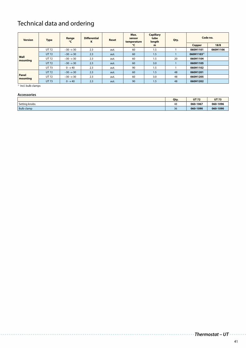
41
Thermostat – UT
Technical data and ordering
Version TypeRange
°C
Differential
KReset
Max.
sensor
temperature
°C
Capillary
tube
length
m
Qty.Code no.
Copper 18/8
Wall
mounting
UT 72 –30 → 30 2.3 aut. 60 1.5 1 060H1101 060H1106
UT 72 –30 → 30 2.3 aut. 60 1.5 1 060H11031)
UT 72 –30 → 30 2.3 aut. 60 1.5 20 060H1104
UT 72 –30 → 30 2.3 aut. 60 3.0 1 060H1105
UT 73 0 → 40 2.3 aut. 90 1.5 1 060H1102
Panel
mounting
UT 72 –30 → 30 2.3 aut. 60 1.5 48 060H1201
UT 72 –30 → 30 2.3 aut. 60 3.0 48 060H1205
UT 73 0 → 40 2.3 aut. 90 1.5 48 060H1202
1) Incl. bulb clamps
Accessories
Qty. UT 72 UT 73
Setting knobs 48 060-1067 060-1096
Bulb clamp 36 060-1090 060-1090

42
Applications Advantages Facts
RT: pressure and temperature controls
The RT series includes thermostats and pressure controls for general applications within industrial and
marine refrigeration. An RT thermostat is fitted with a single-pole changeover switch. The position of
the contacts depends on the bulb temperature and the set scale value. An RT pressure control contains
a pressure operated single-pole changeover contact, the position of which depends on the pressure in
the in let connection and the set scale value.
· General applications within industrial
and marine refrigeration
· Wide regulating range
· Suitable for alternating and direct cur-
rent
· Interchangeable contact system
· Special versions with gold plated
contact surfaces for PLC applications
· Versions for neutral zone regulation
· Waterproof versions, enclosure IP 66
· High stability and accuracy
· Long operating life time
· Enclosure: IP 66 to EN 60529 / IEC
60529, except for versions with ext.
reset which are to IP 54
· Short circuit protection, fuse 10 Amp
· Insulation 400 V
· Ambient temperature: −50 to +70°C
for housing
· Cable connection: Pg 13.5.
· Cable diameter: 6 → 14 mm.
· Pressure controls for fluorinated refrig-
erants and R717 (NH3)
Features
Setting knob
Heavy duty body
High precision control system
Stanless steel bellow
Cable entry Pg 13.5
0.2 to 2.5 mm² wiring
Interchangeable SPDT
contact system
IP 66

43
Pressure controls and thermostats – RT
Type of bulb / sensor
A B C D
Cylindrical
remote sensor
Room sensor Duct sensor Capillary
tube sensor
Technical data and ordering: RT temperature controls
Charge Type Bulb
type
Regulation
range
Differential Δ t Reset Max.
bulb temp.
Capillary
tube length
Code no.
°C
Lowest
temp.
setting
K
Highest
temp.
setting
K °C m
Vapour 1)
RT 10 A -60 → -25 1.7 → 7.0 1.0 → 3.0 aut. 150 2 017-507766
RT 9 A -45 → -15 2.2 → 10.0 1.0 → 4.5 aut. 150 2 017-506666
RT 3 A -25 → +15 2.8 → 10.0 1.0 → 4.0 aut. 150 2 017-501466
RT 17 B -50 → -15 2.2 → 7.0 1.5 → 5.0 aut. 100 017-511766
RT 11 B -30 → 0 1.5 → 6.0 1.0 → 3.0 aut. 66 017-508366
RT 4 B -5 → +30 1.5 → 7.0 1.2 → 4.0 aut. 75 017-503666
017-5037664)
Adsorption 2)
RT 13 A -30 → 0 1.5 → 6.0 1.0 → 3.0 aut. 150 2 017-509766
RT 2 A -25 → +15 5.0 → 18.0 6.0 → 20.0 aut. 150 2 017-500866
RT 8 A -20 → +12 1.5 → 7.0 1.5 → 7.0 aut. 145 2 017-506366
RT 12 A -5 → +10 1.0 → 3.5 1.0 → 3.0 aut. 65 2 017-508966
RT 23 A +5 → +22 1.1 → 3.5 1.0 → 3.0 aut. 85 2 017-527866
RT 15 A +8 → +32 1.6 → 8.0 1.6 → 8.0 aut. 150 2 017-511566
RT 24 A +15 → +34 1.4 → 4.0 1.4 → 3.5 aut. 105 2 017-528566
RT 140 C +15 → +45 1.8 → 8.0 2.5 → 11.0 aut. 240 2 017-523666
RT 102 D +25 → +90 2.4 → 10.0 3.5 → 20.0 aut. 300 2 017-514766
RT 34 B -25 → +15 2.0 → 10.0 2.0 → 12.0 aut. 100 017-511866
RT 7 A -25 → +15 2.0 → 10.0 2.5 → 14.0 aut. 150 2 017-505366
RT 14 A -5 → +30 2.0 → 8.0 2.0 → 10.0 aut. 150 2 017-509966
RT 101 A +25 → +90 2.4 → 10.0 3.5 → 20.0 aut. 300 2 017-500366
Partial 3) RT 107 A +70 →+150 6.0 → 25.0 1.8 → 8.0 aut. 215 2 017-513566
1) The sensor must be located colder than thermostat housing and capillary tube. 2) The sensor can be located warmer or colder than thermostat housing. 3) The sensor must be
located warmer than thermostat housing and capillary tube. 4) With built-in heating coil - reduces the thermal differential.

44
Range °C Type
-60 → -25 RT 10
Vapour-charged with remote bulb
(bulb coldest)
-45 → -15 RT 9
-30 → 0 RT 13
-25 → +15 RT 3
-25 → +15 RT 2,7
-20 → +12 RT 8
-5 → +10 RT 12
-5 → +30 RT 14
Adsorption-charged with remote bulb
(bulb warmest or coldest)
+5 → +22 RT 23
+8 → +32 RT 15
+15 → +34 RT 24
+15 → +45 RT 140
+25 → +90 RT 101, 102
Partial charge with remote bulb (bulb warmest) +70 → +150 RT 107
-50 → -15 RT 17
Vapour-charged with coiled capillary tube sensor
(room thermostats)
-30 → 0 RT 11
-5 → +30 RT 4
Adsorption-charged with coiled capillary tube sensor (room thermostats) -25 → +15 RT 34
-20 → +12 RT 8L
Adsorption-charged dead zone thermostats with remote bulb
(bulb warmest or coldest)
-5 → +30 RT 14L
+15 → +45 RT 140L
Vapour-charged dead zone thermostat (room thermostat) 0 → +38 RT 16L
Vapour-charged differential thermostats with remote bulb (bulb warmest or coldest) -30 → +40 RT 270
-50 0 +50 +100 +150 +200 +250 +300°C
-50 0 +50 +100 +150 +200 +250 +300°C
Safety pressure controls w EN 12263 / DIN 32733 appr. and CE marked acc. PED, Pressure Equipment Directive
Pressure Type Regulation
range
bar
Differential
(fixed)
Δp
bar
Reset Max.
working
pressure
PB
bar
Max.
test
pressure p’
bar
Code no.
Connection
1/4 in./
6mm
flare
cutting ring
∅ 6 mm
G 3/8 A 1) +
weld nipple
∅ 6.5/10
mm
G1/2 A 1)
HighRT 36B2) 0 → 2.5 max. 0.2 man. 22 25 017-525866
RT 36S2) 0 → 2.5 max. 0.2 man. 22 25 017-525966
High
RT 6W2) 5 → 25 2.0 - 3.0 aut. 34 38 017-503166
RT 6B2) 10 → 28 max. 1.0 man. 34 38 017-503466
RT 6S2) 10 → 28 max. 1.0 man. 34 38 017-507566
High
RT30AW3) 1 → 10 0.2 - 0.8 aut. 22 25 017-518766
RT30AB3) 1 → 10 max. 0.4 man. 22 25 017-518866
RT30AS3) 1 → 10 max. 0.4 man. 22 25 017-519966
High
RT6AW3) 5 → 25 2.0 - 3.0 aut. 34 38 017-513166 017-503266
RT6AB3) 10 → 28 max. 1.5 man. 34 38 017-513366 017-503566
RT6AS3) 10 → 28 max. 1.5 man. 34 38 017-514666 017-507666
1) BSP ext. thread, ISO 228/1.2) Pressure controls for fluorinated refrigerants.3) Pressure controls for R 717 (NH3) and fluorinated refrigerants.
Technical data and ordering: RT pressure controls
Overview RT thermostats

45
Differential pressure controls for R 717(NH3) and fluorinated refrigerants
Type Regulation range
bar
Differential
Δp
bar
Operating range
for LP bellows
bar
Max.
working pressure
PB
bar
Max.
test
pressure p’
bar
Code no.
Connection
cutting ring
∅ 6 mm
G 3/8 A 1) + weld
nipple
∅ 6.5/10 mm
RT 260A
0.5 → 4 fixed 0.3 -1 → 18 22 25 017D001466 017D002166
0.5 → 4 fixed 0.3 -1 → 18 22 25 017D0022662)
0.5 → 6 fixed 0.5 -1 → 36 42 47 017D001566 017D002366
1.5 → 11 fixed 0.5 -1 → 31 42 47 017D001666 017D002466
RT 252A 0.1 → 1.5 fixed 0.1 -1 → 9 22 13 017D001366 017D002566
RT 2653) 1 → 6 fixed 0.5 -1 → 36 42 47 017D007266
1) BSP ext. thread, ISO 228/1.2) Man. reset.3) Filter monitor: Alarm ∆p = 0.8 bar, cut-out ∆p = 1 bar (factory setting).
Differential pressure controls with adjustable dead zone for R 717(NH3) and fluorinated refrigerants
Type Regulation range
bar
Differential
Δ p
bar
Dead
zone
NZ
bar
Operating range
for LP bellows
bar
Max.
working pressure
PB
bar
Max.
test
pressure p’
bar
Code no.
Connection
G 1/2 A 1) + weld
nipple
∅ 6.5/10 mm
RT 262 AL 0.1 → 1.5 fixed 0.1 -1 → 0.33 -1 → 9 11 13 017D0043662)
1) BSP ext. thread, ISO 228/1.2) Differential pressure control for R 717 (NH
3) and fluorinated refrigerants.
Pressure controls with adjustable dead zone for R717 (NH3) and fluorinated refrigerants
Pressure Type Regulation
range
bar
Differential
Δp
bar
Dead
zone
NZ
Δp
bar
Max.
working pres-
sure
PB
bar
Max.
test
pressure p’
bar
Code no.
Connection
cutting ring
∅ 6 mm
G 3/8 A 1) +
weld nipple
∅ 6.5/10 mm
LowRT 1AL2) -0.8 → 5 fixed 0.2 0.2 → 0.9 22 25 017L001666 017L003366
RT 200L3) 0.2 → 6 fixed 0.25 0.25 → 0.7 22 25 017L003266
HighRT 5AL2) 4 → 17 fixed 0.35 0.35 → 1.4 22 25 017L0017664) 017L0040664)
RT 117L3) 10 → 30 fixed 1.0 1 → 3.0 42 47 017L0042664)
1) BSP ext. thread, ISO 228/1.2) Pressure controls for R 717 (NH
3) and fluorinated refrigerants.
3) Pressure controls for fluorinated refrigerants.4) Without nipple.
Pressure controls and thermostats – RT
Technical data and ordering: RT pressure controls

46
Applications Advantages Facts
Features
pplications Advantages Facts
ures
KVP Evaporator pressure regulator
The KVP is mounted in the suction line after the evaporator and is maintaining a constant evaporating
pressure and thereby a constant surface temperature on the evaporator. The regulation is modulating.
By throttling in the suction line, the amount of refrigerant gas is matched to the evaporator load.
· Traditional refrigeration
· Air conditioning units
· Transport refrigeration
· The KVP can also be used to differenti-
ate the evaporating pressures in two
or more evaporators in systems with
one compressor.
· Protection against too low an evapo-
rating pressure (e.g. as protection
against freezing in a water chiller). The
regulator closes when the pressure
in the evaporator falls below the set
value.
· Wide capacity and operating range
· Regulation range: 0 to 5.5 bar
· For use with CFC, HCFC and HFC
refrigerants
"Hermetic" brazed construction
Pulsation damping design
Compact angle design for easy
installation in any position
Stainless steel bellows
1/4 in. Schrader valve
for pressure testing
Available with flare and
ODF solder connections
Accurate, adjustable pressure regulation
with allen key

47
Pressure regulators – KVP
Technical data and ordering
Evaporating pressure regulator
TypeRated capacity in kW 1) Flare connection 2) 3)
Code no. 4)Solder connection 3)
Code no. 4)
R22 R134a R404A/R507 R407C in. mm in. mm
KVP 12 4.0 2.8 3.6 3.7½ 12 034L0021 ½ 034L0023
12 034L0028
KVP 15 4.0 2.8 3.6 3.7 5/8 16 034L0022 5/8 16 034L0029
KVP 22 4.0 2.8 3.6 3.7 7/8 22 034L0025
KVP 28 8.6 6.1 7.7 7.911/8 034L0026
28 034L0031
KVP 35 8.6 6.1 7.7 7.9 13/8 35 034L00321) Rated capacity is the capacity of the regulator at
– Evaporating temperature te = −10°C, – Condensing temperature tc = +25°C – Pressure drop in regulator Δp = 0.2 bar, offset = 0.6 bar
2) Supplied without flare nuts. Separate flare nuts can be supplied: ½ in./12 mm, code no. 011L1103, 5/8 in./16 mm, code no. 011L1167.
3) The connection dimensions chosen must not be too small, since gas velocities in excess of 40 m/s at the inlet of the regulator can give flow noise.
4) Code numbers in bold are normally on stock and a shorter delivery time can therefore be expected.

48
Applications Advantages Facts
Features
Advantages Facts
KVR and NRD condensing pressure regulators
Regulator system KVR and NRD is used to maintain a constant and sufficiently high condenser and receiver pressure in refrigeration and air conditioning plant with air-cooled condensers.
KVR can also be used together with receiver pressure regulator type KVD.
· Traditional refrigeration
· Air conditioning units
· Transport refrigeration
· The valves are the most compact one
on the market.
· Excellent performance because of bal-
ance port design (equalization of force
on port)
· The refrigeration system can operate
with very large load variations
· Very easy to adjust the KVR
· The NRD is non-adjustable – it always
follows the actual pressure in the
system
· Reliable design
· Wide capacity and operating range
· Regulation range: 5 to 17.5 bar
· For use with CFC, HCFC and HFC refrigerants
"Hermetic" brazed construction
Pulsation damping design
Compact angle design for easy
installation in any position
Stainless steel bellows
1/4 in. Schrader valve
for pressure testing
Available with flare and
ODF solder connections
Accurate, adjustable pressure regulation
with allen key

49
Pressure regulators – KVR and NRD
Technical data and ordering
Condensing pressure regulator
Type
Evaporator capacity Flare
connection 2) 3)
Code no. 4)
Solder
connection 3)
Code no. 4)Rated liquid capacity in kW 1) Rated hot gas in kW 1)
R22 R134aR404A/
R507R407C R22 R134a
R404A/R507
R407C in. mm in. mm
KVR 12
50.4 47.3 36.6 54.4 13.2 11.6 12.0 14.3
½ 12 034L0091 ½ 034L0093
12 034L0096
KVR 15 5/8 16 034L0092 5/8 16 034L0097
KVR 22 7/8 22 034L0094
KVR 28129 121 93.7 139.3 34.9 30.6 34.9 37.7
11/8 034L0095
28 034L0099
KVR 35 13/8 35 034L0100
NRD½ 020-1132
12 020-1136
1) Rated capacity is the capacity of the regulator at – Evaporating temperature te = –10°C, – Condensing temperature tc = +30°C – Pressure drop in regulator ∆p = · liquid line dp = 0,2 bar
· hotgas line dp = 0,4 bar · offset = 3 bar2) Supplied without flare nuts. Separate flare nuts can be supplied:
½ in./12 mm, code no. 011L1103, 5/8 in./16 mm, code no. 011L1167.
3) The connection dimensions chosen must not be too small, since gas velocities in excess of 40 m/s at the inlet of the regulator can give flow noise.
4) Code numbers in bold are normally on stock and a shorter delivery time can therefore be expected.

50
Applications Advantages Factspplications Advantages Facts
Features
KVL compressor overload protection
Crankcase pressure regulator type KVL is fittet into the suction line ahead of the compressor. The KVL
protects the compressor motor against overload during start-up after long standstill period or after
defrost periods (high pressure in evaporator).
· Traditional refrigeration
· Air conditioning units
· Transport refrigeration
· Unaffected by ambient pressure
variations
· Bellows welded to the body for
long lifetime
· Accurate, adjustable pressure
regulation
· Easy adjustment before start up
· Wide capacity and operating range
· Regulation range: 0.2 to 6 bar
· For use with CFC, HCFC and HFC refrigerants
Accurate, adjustable pressure regulation
with allen key
Compact angle design for easy
installation in any position
Pulsation damping design
Stainless steel bellows
"Hermetic" brazed construction
Available with flare and
ODF solder connections

51
Pressure regulators – KVL
Technical data and ordering
Crankcase pressure regulator
TypeRated capacity in kW 1) Flare connection 2) 3)
Code no. 4)Solder connection 3)
Code no. 4)
R22 R134a R404A/R507 R407C in. mm in. mm
KVL 12 7.1 5.3 6.3 6.4½ 12 034L0041 ½ 034L0043
12 034L0048
KVL 15 7.1 5.3 6.3 6.5 5/8 16 034L0042 5/8 16 034L0049
KVL 22 7.1 5.3 6.3 6.5 7/8 22 034L0045
KVL 28 17.8 13.2 15.9 16.4 11/8 034L0046
28 034L0051
KVL 35 17.8 13.2 15.9 16.4 13/8 35 034L0052
1) Rated capacity is the capacity of the regulator at – Evaporating temperature te = –10°C, – Condensing temperature tc = +25°C – Pressure drop in regulator ∆p = 0.2 bar
2) Supplied without flare nuts. Separate flare nuts can be supplied: ½ in./12 mm, code no. 011L1103, 5/8 in./16 mm, code no. 011L1167.
3) The connection dimensions chosen must not be too small, since gas velocities in excess of 40 m/s at the inlet of the regulator can give flow noise.
4) Code numbers in bold are normally on stock and a shorter delivery time can therefore be expected.

52
Applications Advantages Facts
Features
KVD Receiver pressure regulator
KVD is a modulating pressure regulator. It opens on falling receiver pressure and bypasses hot gas to
maintain the receiver pressure at the regulator setting (adjustable).
KVD and KVR form a regulating system, used to maintain constant and adequately high condensing and
receiver pressure in plant with heat-recovery, and in refrigeration and air conditioning plant with air-
cooled condensers.
· Traditional refrigeration
· Air conditioning units
· The regulator is equipped with an
effective damping device (9) against
pulsations which can normally arise in
a refrigeration plant.
· KVD regulations is only dependent
upon the outlet pressure. Pressure
variations on the inlet side of the
regulator do not affect the degree of
opening since KVD is equipped with
an equalization bellows.
· Wide capacity and operating range
· Regulation range: 3 to 20 bar
· Max. working pressure PS = 28 bar
· Can be used as a relief valve from high
pressure to suction side
· For use with CFC, HCFC and HFC
refrigerants
"Hermetic" brazed construction
Pulsation damping design
Compact angle design for easy
installation in any position
Stainless steel bellows
1/4 in. Schrader valve
for pressure testing
Available with flare and
ODF solder connections
Accurate, adjustable pressure regulation
with allen key

53
Receiver pressure regulators
Typekv value
m3/h 1)
Flare connection 2) 3)
Code no.Solder connection 3)
Code no.in. mm in. mm
KVD 121.75 ½ 12 034L0171 ½ 034L0173
1.75 12 034L0176
KVD 15 1.75 5/8 16 034L0172 5/8 16 034L0177
1) The kv value is the flow of water in m3/h at a pressure drop across valve of 1 bar, ρ = 1000 kg/m3.
2) Supplied without flare nuts. Separate flare nuts can be supplied: ½ in./12 mm, code no. 011L1103, 5/8 in./16 mm, code no. 011L1167.
3) The connection dimensions chosen must not be too small, since gas velocities in excess of 40 m/s at the inlet of the regulator can give flow noise.
Pressure regulators – KVD
Technical data and ordering

54
Applications Advantages Facts
Features
KVC Capacity regulator
KVC is a capacity regulator used for the adaption of the compressor capacity to the actual evaporator load. Placed in a bypass between high- and low pressure sides of the refrigeration system, KVC imposes a lower limit on the compressor suction pressure by supplying the low pressure side with replacement capacity in the form of hot gas/cool gas from the high pressure side.
· Traditional refrigeration
· Air conditioning units
· Transport refrigeration
· KVC regulations is only dependent
upon the outlet pressure. Pressure
variations on the inlet side of the
regulator do not affect the degree of
opening since KVC is equipped with
an equalization bellows.
· The regulator is also equipped with
an effective damping device against
pulsations which can normally arise in
a refrigeration plant.
· Wide capacity and operating range
· Regulation range: 0,2 to 6 bar
· Maximum working pressure PS = 28 bar
· The damping device to ensure long
life for the regulator
· For use with CFC, HCFC and HFC
refrigerants
"Hermetic" brazed construction
Pulsation damping design
Compact angle design for easy
installation in any position
Stainless steel bellows
Available with flare and
ODF solder connections
Accurate, adjustable pressure regulation
with allen key

55
1) Supplied without flare nuts. Separate flare nuts can be supplied: ½ in./12 mm, code no. 011L1103, 5/8 in./16 mm, code no. 011L1167.
2) The connection dimensions chosen must not be too small, since gas velocities in excess of 40 m/s at the inlet of the regulator can give flow noise.
3) If the discharge tube temperature becomes too high in relation to the compressor specification, the installation of an injection valve in a bypass between liquid line and compressor suction line is recommended.
4) Rated capacity is the capacity of the regulator at: – Evaporating temperature te = –10°C, – Condensing temperature tc = +25°C
Capacity regulators
TypeRated capacity in kW 4) Flare connection 1) 2)
Code no.Solder connection 2)
Code no.R22 R134a R404A/R507 R407C in. mm in. mm
KVC 12 3) 7.6 4.8 6.9 8.4½ 12 034L0141 ½ 034L0143
12 034L0146
KVC 15 3) 14.9 9.4 13.6 16.4 5/8 16 034L0142 5/8 16 034L0147
KVC 22 3) 19.1 12.0 17.4 21.0 7/8 22 034L0144
Pressure regulators – KVC
Technical data and ordering

56
Applications Advantages Facts
Flare or solder connections
Easy and exact adjustment
Pilot pressure connection
Pilot orifice
Main orifice for pricise
opening and closing
CPCE capacity regulator
CPCE capacity regulators adapt compressor capacity to actual evaporator load. They are designed for
installation in a bypass line between the low and high pressure sides of the refrigeration system, for hot
gas injection between evaporator and thermostatic expansion valve. Injection should be arranged to
occur through an LG liquid-gas mixer.
Features
· Traditional refrigeration
· Air conditioning units
· Avoids high suction superheats by
combining hot gas injection with
expansion valve characteristics
· Protection against too low an evapo-
rating temperature, i.e. avoids evapo-
rator icing
· LG can be used for hot gas defrosting
or reverse cycle systems
· The regulator increases evaporator gas
velocity thus ensuring better oil return
to compressor
· Direct connection to system suction
line regulates hot gas injection inde-
pendent of evaporator pressure drop
· LG provides homogenous mixing
of the liquid and hot gas refrigerant
injected into the evaporator
· Can be used for CFC, HCFC and HFC
refrigerants
· Max. working pressure PS = 28 bar

57
Capacity regulators
TypeRated capacity in kW 1) Flare connection Solder connection
Code no.R22 R134a R404A/R507 R407C in. mm in. mm
CPCE 12 17.4 7.9 16.4 19.0 ½ 12 034N0081
CPCE 12 17.4 7.9 16.4 19.0 ½ 12 034N0082
CPCE 15 25.6 11.6 24.2 27.9 5/8 16 034N0083
CPCE 22 34.0 15.2 32.0 37.1 7/8 22 034N00841) Rated capacity is the capacity of the regulator at:
– Evaporating temperature te = –10°C, – Condensing temperature tc = +30°C – Reduction of suction temperature/pressure ∆ts = CPCE: 4 K.
Liquid-gas mixer
Type
Connection
Code no.Expansion valve
ODM
Hot gas
ODF
Liquid distributor
ODF
in. mm in. mm in. mm
LG 12-16 5/8 16 ½ 12 5/8 16 069G4001
LG 12-22 7/8 22 ½ 12 7/8 22 069G4002
LG 16-28 11/8 28 5/8 16 11/8 28 069G4003
LG 22-35 13/8 35 7/8 22 13/8 35 069G4004
Capacity regulator – CPCE
Technical data and ordering

58
Stainless steel
shieldMagnetic
coupling
Spindle
Regulating cone
Valve seat
Modularity, flexibility and unique features
Danfoss’ extensive experience has been used to create a new valve concept which sets new and im-
proved standards with respect to the demands required from control and injection valves.
ICM valves are manufactured with a series of unique features.
Features
· Designed for industrial refrigeration applications for a
maximum working pressure of 52 bar/754 psig.
· Modular Concept
· Each valve body is available with several different
connection types and sizes
· Valve overhaul is performed by replacing the function
module
· Possible to convert ICM motor valve to ICS servo valve.
· Low weight and compact design.
· Low temperature steel body
· Direct coupled connections
Connection types include butt weld, socket weld, solder
and threaded connections.
· V-port regulating cone ensures optimum regulating
accuracy particularly at part load.
· Manual opening possible via ICAD or Multifunction
tool.
· Cavitation resistant valve seat.
· Magnet coupling - real hermetic sealing.
Advantages and features Facts
· Refrigerants:
Applicable to all common refrigerants including R717 and
R744 (CO2) and non- corrosive gases/liquids.
Use with flammable hydrocarbons cannot be recommend-
ed; please contact Danfoss.
· Temperature range
–60/+120°C (–76/+248°F).
· Surface protection
The external surface is zinc-chromated to provide good
corrosion protection.
· Pressure range
The valve is designed for:
Max. working pressure: 52 bar g (754 psig)
· Max. openening pressure differential (MOPD)
– ICM 20-32: 52 bar (750 psi)
– ICM 40: 40 bar (580 psi)
– ICM 50: 30 bar (435 psi)
– ICM 65: 20 bar (290 psi)

59
Motor valves – ICM 20-65
ICAD 600 ICAD 900
The ICM concept is developed around a modular principle. This gives the possibility of combining func-
tion modules and top covers with valve bodies, which are available in many different sizes and with a
variety of connection possibilities.
Each valve body is available with a range of
undersized through oversized connection sizes
and types.
Each body may be fitted with multiple function
module / top cover to give different capacities.
There are six valve bodies available.
D A J SOC SD SA FPT
Butt-weld DIN Butt-weld ANSI Butt-weld JIS Socket weld ANSI Solder DIN Solder ANSI Female Pipe Thread
The ICM concept
The valve body
The function module / top cover
A magnetic coupled actuator is easily installed.
Two actuators cover the entire ICM program
Type Valve body
size
Kv
(m3/h)
Cv
(USgal/min)
ICM20-A
20
0.6 0.7
ICM20-B 2.4 2.8
ICM20-C 4.6 5.3
ICM25-A25
6 7.0
ICM25-B 12 13.9
ICM32-A32
9 10.4
ICM32-B 17 20
ICM40-A40
15 17
ICM40-B 26 30
ICM50-A50
23 27
ICM50-B 40 46
ICM65-B 65 70 81
ICV 20 ICV 25 ICV 32 ICV 40 ICV 50 ICV 65
The actuator

60
Quick selection of ICM valves
Suction line (capacity in kW)
Type
Refrigerant
Kv value
(m3/h)
R 717 R 744 R 407C R 404A
–40°C –10°C –50°C –30°C –5°C 5°C –40°C –10°C
∆p bar
0.1 0.2 0.2 0.2 0.2 0.2 0.1 0.2
ICM 20-A
DN20
1.4 4 2.1 3.1 1.65 2.4 0.45 1.3 0.6
ICM 20-B 5.6 16.2 8.3 12 6.5 7.6 1.8 5 2.4
ICM 20-C 10.8 31 16 23 12.5 14.2 3.4 10 4.6
ICM 25-A DN25
14.1 40 21 31 16.5 18.5 4.5 13 6
ICM 25-B 28.2 81 42 61 31 37 9 26 12
ICM 32-A DN32
21.2 61 31 46 23 28 6.5 19 9
ICM 32-B 40 115 59 86 43 52 12.5 36 17
ICM 40-A DN40
35.3 101 52 76 37 46 11 32 15
ICM 40-B 61.2 175 90 132 65 79 19 56 26
ICM 50-A DN50
54 155 80 117 57 70 16.5 49 23
ICM 50-B 94 270 138 203 99 122 30 86 40
ICM 65-B DN65 164 472 241 355 174 213 51 150 70
Liquid line (capacity in kW)
Type
Refrigerant
Kv value
(m3/h)
R 717 R 744 R 407C R 404A
–40°C –10°C –50°C –30°C –5°C 5°C –40°C –10°C
∆p bar
0.2 0.2 0.2 0.2 0.2 0.2 0.2 0.2
ICM 20-A
DN20
62 64 15 15.4 13.5 13.9 7.2 9 0.6
ICM 20-B 249 255 60 62 54 56 29 34 2.4
ICM 20-C 478 489 115 118 103 107 55 65 4.6
ICM 25-A DN25
624 638 150 154 135 139 72 85 6
ICM 25-B 1248 1277 300 308 270 278 143 170 12
ICM 32-A DN32
936 958 225 231 202 208 107 128 9
ICM 32-B 1769 1809 425 436 381 393 203 241 17
ICM 40-A DN40
1561 1596 375 385 337 347 179 213 15
ICM 40-B 2705 2767 650 667 584 602 310 369 26
ICM 50-A DN50
2393 2447 575 590 516 532 274 327 23
ICM 50-B 4162 4256 1000 1026 898 926 477 568 40
ICM 65-B DN65 7284 7449 1750 1796 1571 1654 835 994 70
Hot gas line (capacity in kW)
Type
Refrigerant
Kv value
(m3/h)
R 717 R 744 R 407C R 404A
–40°C –10°C –50°C –30°C –5°C 5°C –40°C –10°C
∆p bar
0.2 0.2 0.2 0.2 0.2 0.2 0.2 0.2
ICM 20-A
DN20
6.4 6.9 3.8 4.2 2.97 3.3 1 2 0.6
ICM 20-B 25 28 15.5 17 12.2 11 6 7 2.4
ICM 20-C 48 53 29 32 19.9 21 11 13 4.6
ICM 25-A DN25
64 69 38 41 26 27 15 18 6
ICM 25-B 126 139 76 83 52 54 29 35 12
ICM 32-A DN32
95 104 57 62 39 41 22 26 9
ICM 32-B 180 196 108 117 73 77 42 50 17
ICM 40-A DN40
157 173 95 104 65 68 37 44 15
ICM 40-B 272 300 165 180 112 119 64 76 26
ICM 50-A DN50
240 266 146 159 99 105 56 67 23
ICM 50-B 420 462 254 276 172 182 98 117 40
ICM 65-B DN65 735 809 443 484 302 309 172 205 70
Conditions: R717, R404A, R407C: tliq
= 30°C, R744: tliq
= 10°C
Please note:
For proper selection of the ICM motor valve Danfoss recommend that you use the technical leaflet (DKRCI.PD.HT0.A) or the
Danfoss calculation Software DIRCalcTM. The sofware is free of charge. Please contact your local Danfoss sales office.

61
Can be ordered as parts programme (separate ordering of valve body, function / top cover and actuator).
Please contact your local Danfoss sales company for more information.
Type ICM 20-A ICM 20-B ICM 20-C ICM 25-A ICM 25-B ICM 32-A ICM 32-B
Operates with ICAD 600 actuator (not included)
Connection Code no. Code no. Code no. Code no. Code no. Code no. Code no.
Butt-weld
DIN
DN 20 027H1030 027H1031 027H1032
DN 25 027H1020 027H1021 027H1022 027H2000 027H2001
DN 32 027H3000 027H3001
DN 40 027H2016 027H3012
Solder
DIN & ANSI
22 mm 027H1045 027H1046 027H1047 027H2006 027H2007
28 mm 027H2008 027H2009
35 mm 027H2014 027H3006 027H3007
7/8” SA 027H1050 027H1051 027H1052 027H2010 027H2011
1 1/8” SA 027H2012 027H2013
1 3/8” SA 027H3006 027H3007
1 5/8” SA 027H3008 027H3009
Type ICM 40-A ICM 40-B ICM 50-A ICM 50-B ICM 65-B
Operates with ICAD 900 actuator (not included)
Connection Code no. Code no. Code no. Code no. Code no.
Butt-weld
DIN
DN 40 027H4000 027H4001
DN 50 027H4010 027H5000 027H5001
DN 65 027H5008 027H6001
Solder
DIN & ANSI
42 mm 027H4008 027H4009
54 mm 027H5006 027H5007
76 mm 027H6009
1 5/8” SA 027H4006 027H4007
2 1/8” SA 027H5006 027H5007
2 5/8” SA 027H6007
Actuator type Supply voltage Load Input Output Code no.
ICAD 60024 V d.c.
1.2 A 0/4-20 mA0/4-20 mA
027H1200
ICAD 900 2.0 A 0/2-10 V 027H1201
Service Tool Functions Code no.
for ICM 20-32 Featuring a magnetic coupling for manual operation of the ICM and a threaded
end for dismounting of the ICS function module and other useful functions.
027H0180
for ICM 40-65 027H0181
Ordering the ICM valve
Motor valves – ICM 20-65
ICM 20 ICM 25-65
ICAD 600 ICAD 900

62
Modularity, flexibility and unique features
Danfoss’ extensive experience has been used to create a new valve concept which sets new and im-
proved standards with respect to the demands required from control and injection valves.
ICS valves are manufactured with a series of unique features.
Features
· Designed for industrial refrigeration applications for a
maximum working pressure of 52 bar/754 psig.
· Modular Concept
· Each valve body is available with several different
connection types and sizes
· Valve overhaul is performed by replacing the function
module
· Possible to convert ICS servo to ICM motor valve
· Low weight and compact design.
· Low temperature steel body
· Direct coupled connections
Connection types include butt weld, socket weld, solder
and threaded connections.
· V-port regulating cone ensures optimum regulating
accuracy particularly at part load.
· Manual operating spindle.
· The ICS valve is a multifunction valve where 1 or up to 3
pilot valves can be mounted into the pilot ports.
Advantages and features Facts
· Refrigerants:
Applicable to all common refrigerants including R717 and
R744 (CO2) and non- corrosive gases/liquids.
Use with flammable hydrocarbons cannot be recommend-
ed; please contact Danfoss.
· Temperature range
–60/+120°C (–76/+248°F).
· Surface protection
The external surface is zinc-chromated to provide good
corrosion protection.
· Pressure range
The valve is designed for:
Max. working pressure: 52 bar g (754 psig)
Servo Piston
Regulating cone
Valve seat
Closed positionClosed position

63
Pilot controlled servo valves – ICS 25-65
The ICS concept is developed around a modular principle. This gives the possibility of combining function
modules and top covers with valve bodies, which are available in many different sizes and with a variety of
connection possibilities.
Each valve body is available with a range of
undersized through oversized connection sizes
and types.
Each valve body may be fitted with a 1 pilot or 3
pilot top cover.
Type Valve body
size
Kv
(m3/h)
ICS25-5
25
1.7
ICS25-10 3.5
ICS25-15 6.0
ICS25-20 8
ICS25-25 11.5
ICS32 32 17
ICS40 40 27
ICS50 50 44
ICS65 65 70
In ICS, multiple inserts (function modules) are
available to give different capacities.
There are five valve bodies available.
D A J SOC SD SA FPT
Butt-weld DIN Butt-weld ANSI Butt-weld JIS Socket weld ANSI Solder DIN Solder ANSI Female Pipe Thread
ICS 25 ICS 32 ICS 40 ICS 50 ICS 65
The ICS concept
The valve body
The top cover
The function module

64
0.20.1 0.12 0.14 0.16 0.18
0
R4
04
A
Δp [bar]R4
07
C
ICS 25-25
ICS 25-20
ICS 25-15
ICS 25-10
ICS 25-5
10
0
30
40
10
20
30
40
50
60
70
80
90
R7
17
0
1
2
3
4
5
6
7
8
9
10
11
12
13
14
15
0.3
Capacity [kW]
20
Capacity [kW x 10]
R4
04
A
R4
07
C
R7
17 0.20.1 0.12 0.14 0.16 0.18
Δp [bar]
0.3
ICS 65
ICS 50
ICS 40
ICS 32
Capacity [kW x 10]
R4
04
A
R4
07
C
R7
17 0.20.1 0.12 0.14 0.16 0.18
Δp [bar]
0.3
Capacity [kW x 100]
R4
04
A
R4
07
C
R7
17 0.20.1 0.12 0.14 0.16 0.18
Δp [bar]
0.3
Capacity [kW]
R4
04
A
R4
07
C
R7
17 0.20.1 0.12 0.14 0.16 0.18
Δp [bar]
0.3
Capacity [kW x 10]
R4
04
A
R4
07
C
R7
17 0.20.1 0.12 0.14 0.16 0.18
Δp [bar]
0.3
5
10
15
20
25
30
35
40
45
50
55
60
65
70
75
80
85
90
0
5
10
20
15
25
30
35
0
5
10
15
20
25
ICS 65
ICS 50
ICS 40
ICS 32
Quick selection of ICS valves
Suction line
Example:R407C - suction lineQ
o = 23 kW
to = 0°C
Result:Both ICS 25-20 and ICS 25-25 can be used.
Liquid line
Hot gas line
Conditions:Evaporating temperature:R717 t
o = –10°C
R407C to
= 0°CR404A t
o = –40°C
Condensing temperature: t
c = +32°C
tliq
= +30°C
The capacities in the range 0.1 bar to 0.2 bars are approx. values. For proper selection of the ICS valve Danfoss recommend that you use the technical leaflet (DKRCI.PD.HS0.A) or the Danfoss calculation Software DIRCalcTM. The sofware is free of charge. Please contact your local Danfoss sales office.

65
Pilot controlled servo valves – ICS 25-65
Ordering the ICS valve
1 pilot 3 pilots
Available connections
20 D (3/4 in.) 25 D (1 in.) 32 D (11/
4 in.) 40 D (11/
2 in.) 35 SD (13/
8 in. SA) 28 SA (11/
8 in.) 22 SA (7/
8 in.) 28 SD (11/
8 in.)
ICS 25-51 Pilot 027H2028 027H2020 027H2026 027H2025 027H2024
3 Pilots 027H2078 027H2070 027H2076 027H2075 027H2074
ICS 25-101 Pilot 027H2038 027H2030 027H2036 027H2035 027H2034
3 Pilots 027H2088 027H2080 027H2086 027H2085 027H2084
ICS 25-151 Pilot 027H2048 027H2040 027H2046 027H2045 027H2044
3 Pilots 027H2098 027H2090 027H2096 027H2095 027H2094
ICS 25-201 Pilot 027H2058 027H2050 027H2056 027H2055 027H2054
3 Pilots 027H2108 027H2100 027H2106 027H2105 027H2104
ICS 25-251 Pilot 027H2068 027H2060 027H2066 027H2065 027H2064
3 Pilots 027H2118 027H2110 027H2116 027H2115 027H2114
22 SD (7/8 in.) 20 A (3/
4 in.) 25 A (1 in.) 32 A (11/
4 in. ) 20 SOC (3/
4 in.) 25 SOC (1 in.) 20 FPT (3/
4 in. ) 25 FPT (1 in. )
ICS 25-51 Pilot 027H2023 027H2029 027H2021 027H2140
3 Pilots 027H2073 027H2079 027H2071 027H2145
ICS 25-101 Pilot 027H2033 027H2039 027H2031 027H2141
3 Pilots 027H2083 027H2089 027H2081 027H2146
ICS 25-151 Pilot 027H2043 027H2049 027H2041 027H2142
3 Pilots 027H2093 027H2099 027H2091 027H2147
ICS 25-201 Pilot 027H2053 027H2059 027H2051 027H2143
3 Pilots 027H2103 027H2109 027H2101 027H2148
ICS 25-251 Pilot 027H2063 027H2061 027H2062
3 Pilots 027H2113 027H2111 027H2112
Available connections
32 D (11/4 in.) 40 D (11/
2 in.) 42 SA (15/
8 in.) 42 SD (15/
8 in.) 35 SD (13/
8 in. SA) 32 A (11/
4 in.) 32 SOC (11/
4 in.) 40 A (11/
2 in.)
ICS 321 Pilot 027H3020 027H3023 027H3021 027H3022
3 Pilots 027H3030 027H3033 027H3031 027H3032
Available connections
40 D (11/2 in.) 50 D (2 in.) 42 SA (15/
8 in.) 42 SD (15/
8 in.) 40 A (11/
2 in.) 40 SOC (11/
2 in.) 50 A (2 in.)
ICS 401 Pilot 027H4020 027H4024 027H4023 027H4021 027H4022
3 Pilots 027H4030 027H4034 027H4033 027H4031 027H4032
Available connections
50 D (2 in.) 65 D (21/2 in.) 54 SD (21/
8 in. SA) 65 A (21/
2 in.) 50 A (2 in.) 50 SOC (2 in.)
ICS 501 Pilot 027H5020 027H5023 027H5021 027H5022
3 Pilots 027H5030 027H5033 027H5031 027H5032
Available connections
65 D (21/2 in.) 65 A (21/
2 in.) 65 SOC (21/
2 in.) 80 D (3 in.) 80 A (3 in.) 67 SA (25/
8 in.) 76 SD (3 in.) 65 J (21/
2 in.)
ICS 651 Pilot 027H6020 027H6021 027H6023 027H6025 027H6024
3 Pilots 027H6030 027H6031 027H6033 027H6035 027H6034
Can be ordered as parts programme (separate ordering of valve body, top cover and function module).
Please contact your local Danfoss sales company for more information.

66
The ICS valve will be fully open if the pilot valve in P is fully open, irrespective of the degree of opening of pilot valves SI and SII.The ICS valve will be fully closed if the pilot valve in P is fully closed and at least one of the valves in SI or SII is fully closed at the same time. The relation between the pilot valves in ports SI, SII and P is shown in the table below.
ICS application examples
There are several combination possibillieties; here you will see an overview of the most important ICS application possibillities.
Pilot valve port ICS valve
SI SII P
Open Open Closed Open
Open Open Open Open
Open Closed Closed Closed
Open Closed Open Open
Closed Open Closed Closed
Closed Open Open Open
Closed Closed Closed Closed
Closed Closed Open Open
Blanking plug A Blanking plug A + B
Example no. 1-1 Products
Constant pressure regulation.
–0.66 to 7 bar g
(19.5 in. Hg to 102 psig).
1 × ICS 1 Pilot
1 × CVP (LP)
Example no. 1-2 Products
Differential pressure regulation.
0 to 7 bar g (0 to 102 psig).
1 × ICS 1 Pilot
1 × CVPP (LP)
Example no. 1-5 Products
On/off regulation (solenoid
valve).
1 × ICS 1 Pilot
1 × EVM
1 × coil
Example no. 1-11 Products
Electronically controlled media
temperature regulation.
–1 to 8 bar g
(0 in. Hg to 116 psig).
1 × ICS 1 Pilot
1 × CVQ
Example no. 3-1 Products
Constant pressure regulation
combined with electrical shut
off.
–0.66 to 7 bar g
(19.5 in. Hg to 102 psig).
1 × ICS 3 Pilots
1 × blanking plug
1 × CVP (LP)
1 × EVM
1 × coil

67
Pilot controlled servo valves – ICS 25-65
Example no. 3-2 Products
Constant pressure regulation
combined with electrical wide
open.
–0.66 to 7 bar g
(19.5 in. Hg to 102 psig).
1 × ICS 3 Pilots
1 × blanking plug
1 × CVP (LP)
1 × EVM
Example no. 3-4 Products
Constant pressure regulation
with change-over between two
preset evaporating pressures.
–0.66 to 7 bar g
(19.5 in. Hg to 102 psig).
1 × ICS 3 Pilots
2 × CVP (LP)
1 × EVM
1 × coil
Example no. 3-5 Products
External control pressure with
electrical shut off combined
with constant pressure
regulation.
–0.66 to 7 bar g
(19.5 in. Hg to 102 psig).
1 × ICS 3 Pilots
1 × nipple for external control
pressure
1 × CVP (LP)
1 × EVM
1 × coil
Example no. 3-18 Products
Constant pressure regulation
with change-over between two
preset evaporating pressures.
–0.66 to 28 bar g
(19.5 in. Hg to 406 psig).
1 × ICS 3 Pilots
2 × CVP (HP)
1 × EVM
1 × coil
Example no. 3-21 Products
Differential pressure regulation
combined with electrical wide
open and shut off.
0 to 22 bar g
(0 to 319 psig).
1 × ICS 3 Pilots
1 × CVPP (HP)
2 × EVM
2 × coils
Example no. 3-25 Products
Crankcase pressure regulation
(max. suction pressure
regulation) at low pressure
drops across the valve.
–0.45 to 7 bar g
(13.3 in. Hg to 102 psig).
1 × ICS 3 Pilots
1 × blanking plug
1 × nipple for external control
pressure
1 × CVC
Example no. 3-31 Products
Electronically controlled
media temperature regulation
combined with electrical shut
off and change over to constant
pressure regulation.
–1 to 8 bar g
(0 in. Hg to 116 psig).
1 × ICS 3 Pilots
1 × CVQ
1 × CVP (LP)
1 × EVM
1 × coil

68
Applications Advantages Facts
WVFX: Correct condensing and receiver pressure
The pressure controlled water valve WVFX are used for regulating the flow of water in refrigeration plant
with water-cooled condensers.
The water valve modulates the condensing pressure to maintain it at a constant level during operation.
When the refrigeration plant is stopped, the cooling water flow is shut off automatically.
Features
· Traditional refrigeration
· Air conditioning units
· Other applications with watercooled
condenser
· WVFX 15, 20 and 25 can be supplied
in stainless steel housing which can
be used in connection with sea water
cooling of condensers and compres-
sors.
· The valves are pressure-relieved in
such a way that a variation in the
water pressure will not affect their set-
ting.
· Below 20% of max. capacity the WVS
will act as an on-off regulator.
· WVFX 10 → 40 are direct actuated
valves.
· WVS 32 → 100 are servo-operated
valves.
Connection 1/4 in. / 6 mm flare
Brass valve plate vulcanized
with special rubber
Externally sealed by diaphragms
Connections – water side
· WVFM - G 3/8 - G 1/2
· WVFX - G 3/8 - G 1 1/2
· WVS - G 1 1/4 - G 1 1/2 and
2 - 4 in. for weld flanges
WVFX 15 - 25, stainless steel
housing (option)

69
WVFX, complete valves
Type
Connection Range
bar
Code no.Water side
ISO 228/1Condenser side
WVFX 10 G 3/8 1/4 in. / 6 mm flare 3.5 → 16 003N1100
WVFX 10 G 3/8 1/4 in. / 6 mm flare 4.0 → 23 003N1105
WVFX 15 G 1/2 1/4 in. / 6 mm flare 3.5 → 16 003N2100
WVFX 15 G 1/2 1/4 in. / 6 mm flare 4.0 → 23 003N2105
WVFX 20 G 3/4 1/4 in. / 6 mm flare 3.5 →16 003N3100
WVFX 20 G 3/4 1/4 in. / 6 mm flare 4.0 → 23 003N3105
WVFX 25 G 1 1/4 in. / 6 mm flare 3.5 →16 003N4100
WVFX 25 G 1 1/4 in. / 6 mm flare 4.0 → 23 003N4105
WVFX 32 G 1 1/4 1/4 in. / 6 mm flare 4.0 →17 003F1232
WVFX 40 G 1 1/2 1/4 in. / 6 mm flare 4.0 →17 003F1240
WVFX with stainless steel housing (W. no. 1.4581)WVFX 15 G 1/2 1/4 in. / 6 mm flare 3.5 → 16 003N2101
WVFX 15 G 1/2 1/4 in. / 6 mm flare 4.0 → 23 003N2104
WVFX 20 G 3/4 1/4 in. / 6 mm flare 3.5 → 16 003N3101
WVFX 20 G 3/4 1/4 in. / 6 mm flare 4.0 → 23 003N3104
WVFX 25 G 1 1/4 in. / 6 mm flare 3.5 → 16 003N4101
WVFX 25 G 1 1/4 in. / 6 mm flare 4.0 → 23 003N4104
WVS, parts programme
Type Connection
Code no.
Valve body Pilot unit 3) Flange set 4)
Servo spring for differential
pressure range of
1 → 10 bar
WVS 32 1 1/4 1) 016D5032 016D1017 016D1327
WVS 40 1 1/2 1) 016D5040 016D1017 016D0575
WVS 50 2 weld flange 016D5050 2) 016D1017 027N3050 016D0576
WVS 65 2 1/2 weld flange 016D5065 2) 016D1017 027N3065 016D0577
WVS 80 3 weld flange 016D5080 2) 016D1017 027N3080 016D0578
WVS 100 4 weld flange 016D5100 2) 016D1017 027N3100 016D0579
1) ISO 228/1 - G 2) Code numbers cover valve body, flange gaskets, flange bolts and screws for pilot valve. 3) Code numbers cover control element and spring housing.4) Code numbers cover an inlet and an outlet flange.
AccessoriesDescription Code no.
1 m capillary tube 1/4 in. (6 mm)
flare coupling nuts at each end060-0071
Bracket for WVFX 10 → 25 003N0388
Technical data
Type
Condenser side Liquid sidek
v value1)
m3/h
Refrigerant
Control
press.
adjust-
able closing
press.
bar
Max. work-
ing pressure
PB
bar
Max.
test pres-
sure
p’
bar
Media
Max. work-
ing pressure
PB
bar
Max.
test pres-
sure
p’
bar
WVFX 10 2)
CFC, HCFC,
HFC
4.0 → 23.0 26.4 29.0
Fresh water,
neutral
brine,
sea water 3)
16 24 1.4
WVFX 15 3.5 → 16.0 26.4 29.0 16 24 1.9
WVFX 15 2) 4.0 → 23.0 26.4 29.0 16 24 1.9
WVFX 20 3.5 → 16.0 26.4 29.0 16 24 3.4
WVFX 20 2) 4.0 → 23.0 26.4 29.0 16 24 3.4
WVFX 25 3.5 → 16.0 26.4 29.0 16 24 5.5
WVFX 25 2) 4.0 → 23.0 26.4 29.0 16 24 5.5
WVFX 32 4.0 → 17.0 24.1 26.5 10 10 11.0
WVFX 40 4.0 → 17.0 24.1 26.5 10 10 11.0
WVS 32
CFC, HCFC,
HFC
R717 (NH3)
2.2 → 19.0 26.4 29.0
Fresh water,
neutral
brine
10 16 12.5
WVS 40 2.2 → 19.0 26.4 29.0 10 16 21.0
WVS 50 2.2 → 19.0 26.4 29.0 10 16 32.0
WVS 65 2.2 → 19.0 26.4 29.0 10 16 45.0
WVS 80 2.2 → 19.0 26.4 29.0 10 16 80.0
WVS 100 2.2 → 19.0 26.4 29.0 10 16 125.0
1) The kv value is the flow of water in m3/h at a pressure drop across valve of 1 bar, ρ = 1000 kg/m3.
2) Fully open valve requires 33% higher pressure than a WVFX, range 3.5 → 16 bar.3) WVFX 15, 20 and 25 with stainless
steel housing only.
Pressure controlled water valve – WVFX
Technical data and ordering
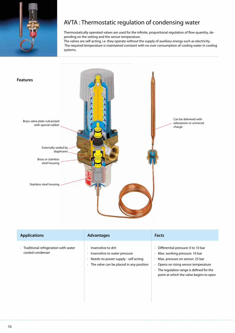
70
Applications Advantages Facts
AVTA : Thermostatic regulation of condensing water
Thermostatically operated valves are used for the infinite, proportional regulation of flow quantity, de-
pending on the setting and the sensor temperature.
The valves are self-acting, i.e. they operate without the supply of auxiliary energy such as electricity.
The required temperature is maintained constant with no over consumption of cooling water in cooling
systems.
Features
· Traditional refrigeration with water
cooled condenser
· Insensitive to dirt
· Insensitive to water pressure
· Needs no power supply - self acting
· The valve can be placed in any position
· Differential pressure: 0 to 10 bar
· Max. working pressure: 16 bar
· Max. pressure on sensor: 25 bar
· Opens on rising sensor temperature
· The regulation range is defined for the
point at which the valve begins to open
Can be delivered with
adsorpsion or universal
charge
Externally sealed by
diaphrams
Stainless steel housing
Brass valve plate vulcanized
with special rubber
Brass or stainless
steel housing

71
Technical data and ordering
AVTA with adsorption charge
ConnectionISO 228
Regulating range[oC]
Max.temp.sensor
[oC]
kv value
(m3/h at ∆p = 1 bar)
Capillary tube length
[m]Type Code no. 1)
G 3/8
+10 to +80 130
1.4
2.3
AVTA 10 003N1144
G 1/2 1.9 AVTA 15 003N0107
G 3/4 3.4 AVTA 20 003N0108
G 1 5.5 AVTA 25 003N0109
1) Code no. covers complete valve incl. capillary tube gland.Immersion pockets, see “Spare parts and accessories”, page 8.
The charge consists of active carbon and CO2 which is adsorbed on falling sensor temperature and thereby produces pressure changes in the element.
AVTA with universal charge
Connection
ISO 228
Regulating
range
[oC]
Max.temp.sensor
[oC]
kv value
(m3/h at ∆p = 1 bar)
Capillary tube
length
[m]
Type Code no. 1)
G 3/8
+0 to +30 57
1.4
2.0
AVTA 10 003N1132
G 1/2 1.9 AVTA 15 003N2132
G 3/4 3.4 AVTA 20 003N3132
G 1 5.5 AVTA 25 003N4132
G 3/8
+25 to +65 90
1.4 2.0 AVTA 10 003N1162
G 1/2 1.9 2.0 AVTA 15 003N2162
G 1/2 1.9 2.0 (armoured) AVTA 15 003N0041
G 3/4 3.4 2.0 AVTA 20 003N3162
G 3/4 3.4 5.0 AVTA 20 003N3165
G 3/4 3.4 2.0 (armoured) AVTA 20 003N0031
G 1 5.5 2.0 AVTA 25 003N4162
G 1 5.5 2.0 (armoured) AVTA 25 003N0032
G 1 5.5 5.0 AVTA 25 003N4165
G 3/8
+50 to +90 125
1.4 2.0 AVTA 10 003N1182
G1/2 1.9 2.0 AVTA 15 003N2182
G 3/4 3.4 2.0 AVTA 20 003N3182
G 1 5.5 2.0 AVTA 25 003N4182
G 1 5.5 3.0 AVTA 25 003N4183 2)
1) Code no. covers complete valve incl. capillary tube gland.2) A Ø 2 mm bypass is drilled in the valve body.
The charge is a mix of liquid and gas where the liquid surface (regulating point) is always inside the sensor. Which charge medium is used depends on the regulation range.
Thermostatic controlled water valves – AVTA
Small sensor dimensions
– Ø 9,5 × 160 mm
Sensor dimensions
– Ø 18 × 210 mm
Small sensor dimensions
– Ø 9,5 × 160 mm
AVTA with mass charge
Connection
ISO 228
Regulating
range
[oC]
Max.temp.sensor
[oC]
kv value
(m3/h at ∆p = 1 bar)
Capillary tube
length
[m]
Type Code no. 1)
G 1/2+0 to +30 57
1.92.0
AVTA 15 003N0042
G 3/4 3.4 AVTA 20 003N0043
G 1/2
+25 to +65 90
1.9 2.0 AVTA 10 003N0045
G 1/2 1.9 2.0 (armoured) AVTA 15 003N0299
G 1/2 1.9 5.0 AVTA 15 003N0034
G 3/4 3.4 2.0 AVTA 20 003N0046
G 1 5.5 2.0 AVTA 25 003N0047
1) Code no. covers complete valve incl. capillary tube gland. The charge is a mix of liquid and gas. Due to the volumetric conditions the sensor must be installed warmer than the valve, since the liquid surface (regulation point) must be in the sensor.
Small sensor dimensions
– Ø 9,5 × 160 mm
AVTA in stainless steel with adsorption charge
Connection
ISO 228
Regulating
range
[oC]
Max.temp.sensor
[oC]
kv value
(m3/h at ∆p = 1 bar)
Capillary tube
length
[m]
Type Code no. 1)
G 1/2
+10 to +80 130
1.9
2.3
AVTA 15 003N2150
G 3/4 3.4 AVTA 20 003N3150
G 1 5.5 AVTA 25 003N4140
1) Code no. covers complete valve incl. capillary tube gland. The charge consists of active carbon and CO2 which is adsorbed on falling sensor temperature and thereby produces pressure changes in the element.

72
Applications Advantages Facts
GBC: excellent mounting and service
GBC ball valves are manually operated shut-off valves suitable for bi-directional flow. Ball valves are used
in liquid, suction and hot gas lines in refrigeration, freezing and air conditioning systems. The GBC bi-
directional ball valves can be delivered with or without external access port. The valves have one-piece
wire seal cap to prevent unintentional cap removal or tampering between services.
Features
· GBC valves are used in liquid, suction
and hot gas lines in all refrigeration
and air-conditioning systems with
fluorinated refrigerants.
· Full flow with minimum pressure drop.
· Bi-directional flow, i.e. valve orienta-
tion is unimportant.
· Slimline design ensures easy opera-
tional handling.
· Burst proof spindle design prevents
liquid from being trapped internally.
· Valve seat of special teflon to secure
maximum tightness and a long life-
time.
· The available access port saves money
if service of the system is necessary.
· GBC can be used for all fluorinated
refrigerants (CFC, HCFC and HFC).
· Temperature range:
–40 to +150°C
· Max. working pressure (PS/MWP)
45 bar (650 psig).
· Test pressure: 65 bar (940 psig).
· Approvals: UL, CSA and CE.
One-piece seal cap conforms to EN 378
Gasket of special PTFE teflon
Operation by wrench,
¼ turn from fully open to
fully closed valve
Rotation stop for fully open and
fully closed valve
Burst proof spindle design
Valve seat of
special teflon
Fixing holes for
panel mounting
Bi-directional flow
Valves with access
port available
High precision
laser welding

73
Ball valves – GBC
Technical data and ordering
Standard valve
TypeSolder ODF connection Solder ODF connection kv value 1)
in. Code no. 2) mm Code no. 2) m3/h
GBC 6s 1/4 009G7020 6 009G7030 2.0
GBC 10s 3/8 009G7021 10 009G7031 5.7
GBC 12s 1/2 009G7022 12 009G7032 10.6
GBC 16s 5/8 009G7023 16 009G7023 14.1
GBC 18s 3/4 009G7024 18 009G7035 20.4
GBC 22s 7/8 009G7025 22 009G7025 28.2
GBC 28s 11/8 009G7026 28 009G7033 52.0
GBC 35s 13/8 009G7027 35 009G7027 80.9
GBC 42s 15/8 009G7028 42 009G7034 121
GBC 54s 21/8 009G7029 54 009G7029 225
GBC 67s 25/8 009G7036 246
GBC 79s 31/8 009G7037 223
Valve with access port
TypeSolder ODF connection Solder ODF connection kv value 1)
in. Code no. 2) mm Code no. 2) m3/h
GBC 6s 1/4 009G7050 6 009G7060 2.0
GBC 10s 3/8 009G7051 10 009G7061 5.7
GBC 12s 1/2 009G7052 12 009G7062 10.6
GBC 16s 5/8 009G7053 16 009G7053 14.1
GBC 18s 3/4 009G7054 18 009G7065 20.4
GBC 22s 7/8 009G7055 22 009G7055 28.2
GBC 28s 11/8 009G7056 28 009G7063 52.0
GBC 35s 13/8 009G7057 35 009G7057 80.9
GBC 42s 15/8 009G7058 42 009G7064 121
GBC 54s 21/8 009G7059 54 009G7059 225
GBC 67s 25/8 009G7066 246
GBC 79s 31/8 009G7067 223
1) CFD calculated values (Computational Fluid Dynamics)2) Code numbers in bold are normally on stock and a shorter delivery time can, therefore, be expected.
Standard GBC valve
GBC valve with access port

74
Applications Advantages Facts
NRV and NRVH: correct flow direction - flexible to use
NRV and NRVH check valves can be used in liquid, suction and hot gas lines in refrigeration and air con-
ditioning plants with fluorinated refrigerants. The valves ensure the correct flow direction and prevent
back-condensation from a warm part of the system to the cold evaporator. A built-in damping piston
makes the valves suitable for installation in lines where pulsation can occur, e.g. in the discharge line
from the compressor.
Features
· Traditional refrigeration
· Heat pump systems
· Air conditioning units
· Liquid coolers
· Transport refrigeration
· For all flourinated refrigerants
· Resonance problems can be avoided
at partial load in the refrigeration
plant.
· Oversize connections provide flexi-
bility in use.
· Prevents back-condensation from
warm to cold system part.
· Ensures correct flow direction.
· In refrigeration plants with compres-
sors connected in parallel, it is advan-
tageous to use NRVH, since the spring
is stronger than in NRV.
· Both straightway and angleway
versions.
· Max. working pressure
PS/MWP = 46 bar
· Max. test pressure
p' = 60 bar
· Temperature of the medium
–50 → 140°C
Flare and solder version
NRV(H) 6 to 19 - straightway
NRV(H) 22 to 35 - angleway
Built-in damping piston
Max. working pressure
46 bar
Pressure drop
NRV 0.04 - 0.07 bar
NRVH 0.3 bar
Standard or oversize
solder connections

75
Check valves – NRV and NRVH
Technical data and ordering
1) Code numbers in bold are normally on stock and a shorter delivery time can, therefore, be expected.2) Δp = the minimum pressure at which the valve is completely open. The NRVH with a stronger spring is used in the discharge line from compressors connected in parallel.3) The kv value is the flow of water in m3/h at a pressure drop across valve of 1 bar, ρ = 1000 kg/m3.4) Oversize connections.
Type Version
Connection Pressure drop
across valve
Δp bar 2)
kv-value 3)
m3/h
Max.
working
pressure
in. mm
Size Code no. 1) Size Code no. 1)
NRV6
Straight-
way
Flare
¼ 020-1040 6 020-10400.07
0.56
46 bar
NRV 10 3/8 020-1041 10 020-1041 1.43
NRV 12 ½ 020-1042 12 020-1042
0.05
2.05
NRV 16 5/8 020-1043 16 020-1043 3.60
NRV 19 ¾ 020-1044 19 020-1044 5.50
NRV 6s
Solder
ODF
¼ 020-1010 6 020-10140.07
0.56NRV 6s 4) 3/8 020-1057 10 020-1050
NRVH 6s 4) 3/8 020-1069 10 020-1062 0.30
NRV 10s 3/8 020-1011 10 020-1015 0.07
1.43NRVH 10s 3/8 020-1046 10 020-1036 0.30
NRV 10s 4) ½ 020-1058 12 020-1051 0.07
NRVH 10s 4) ½ 020-1070 12 020-1063 0.30
NRV 12s ½ 020-1012 12 020-1016 0.05
2.05NRVH 12s ½ 020-1039 12 020-1037 0.30
NRV 12s 4) 5/8 020-1052 16 020-1052 0.05
NRVH 12s 4) 5/8 020-1064 16 020-1064 0.30
NRV 16s 5/8 020-1018 16 020-1018 0.05
3.60
NRVH 16s 5/8 020-1038 16 020-1038 0.30
NRV 16s 4) - - 18 020-1053 0.05
NRVH 16s 4) - - 18 020-1065 0.30
NRV 16s 4) ¾ 020-1059 19 020-1059 0.05
NRVH 16s 4) ¾ 020-1071 19 020-1071 0.30
NRV 19s - - 18 020-1017 0.05
5.50
NRVH 19s - - 18 020-1008 0.30
NRV 19s ¾ 020-1019 19 020-1019 0.05
NRVH 19s ¾ 020-1023 19 020-1023 0.30
NRV 19s 4) 7/8 020-1054 22 020-1054 0.05
NRVH 19s 4) 7/8 020-1066 22 020-1066 0.30
NRV 22s
Angle-
way
7/8 020-1020 22 020-1020 0.04
8.50NRVH 22s 7/8 020-1032 22 020-1032 0.30
NRV 22s 4) 11/8 020-1060 28 020-1055 0.04
NRVH 22s 4) 11/8 020-1072 28 020-1067 0.30
NRV 28s 11/8 020-1021 28 020-1025 0.04
19.00NRVH 28s 11/8 020-1029 28 020-1033 0.30
NRV 28s 4) 13/8 020-1056 35 020-1056 0.04
NRVH 28s 4) 13/8 020-1068 35 020-1068 0.30
NRV 35s 13/8 020-1026 35 020-1026 0.04
29.00NRVH 35s 13/8 020-1034 35 020-1034 0.30
NRV 35s 4) 15/8 020-1061 42 020-1027 0.04
NRVH 35s 4) 15/8 020-1073 42 020-1035 0.30

76
Applications Advantages Facts
Features
OUB: The easy way for oil return
The oil separator type OUB is for use in all refrigeration plant where the compressor lubricating oil must
be returned direct to the compressor oil sump under all operating conditions.
In this way lubricating oil from the compressor is prevented from circulating with the refrigerant in the
refrigeration system itself.
Features
· Traditional refrigeration
· Air conditioning units
· High efficiency
Due to the interaction of reduced flow
and a change of flow direction for oil
concentration. The collection of the
separated oil at high temperature and
the automatic return of the oil to the
crankcase.
· High efficiency
Protects against liquid hammer in
compressor
· Better utilisation of condenser and
evaporator capacity (no oil-gas
collection).
· Ensures oil return to compressor oil
sump. Prevents compressor breakdown
caused by lack of lubrication. Increases
compressor operating life.
· Pulsation and noise damping on high-
pressure side of system
· Max. working pressure PS = 28 bar
· Refrigerants CFC, HCFC, HFC
Flare or solder connection
Available with 1/4 in. flare or
6 mm solder connection oil
return
Net volume
OUB 1: 0.52 l
OUB 4: 2.46 l
Easy mounting with bracket
Efficient oil separation and
filtration
The OUB opens for automatic oil
return through a needle valve

77
OUB 1 / OUB 4
OUB 1s
Technical data and ordering
Oil separator – OUB
TypeConnection
Rated plant capacity
kW Code no.
for OUB + unions (straightway)in. mm Version R22 R134a R404A R507 R407C
OUB 1
3/8 10 Flare
3.1 2.5 3.5 3.5 4.4
040B0010 + 2 × 040B0132
3/8 Solder 040B0010 + 2 × 040B0140
10 Solder 040B0010 + 2 × 040B0138
1/2 12 Flare 040B0010 + 2 × 040B0134
1/2 Solder 040B0010 + 2 × 040B0142
12 Solder 040B0010 + 2 × 040B0139
5/8 16 Flare 040B0010 + 2 × 040B0136
5/8 16 Solder 040B0010 + 2 × 040B0144
Without connection unions 040B0010
OUB 1s 1) 10 Solder3.1 2.5 3.5 3.5 4.4
040B0023
OUB 1s 2) 10 Solder 040B0029
OUB 4
5/8 16 Flare
11.6 9.6 12.8 12.8 16.0
040B0040 + 2 × 040B0256
5/8 16 Solder 040B0040 + 2 × 040B0266
3/4 18 Flare 040B0040 + 2 × 040B0258
3/4 Solder 040B0040 + 2 × 040B0268
7/8 Solder 040B0040 + 2 × 040B0270
22 Solder 040B0040 + 2 × 040B0264
1 25 Flare 040B0040 + 2 × 040B0260
1 Solder 040B0040 + 2 × 040B0272
11/8 Solder 040B0040 + 2 × 040B0274
28 Solder 040B0040 + 2 × 040B0265
Without connection unions 040B0040
1) 1/4 in. flare connection to oil return line.2) 6 mm ODF solder connection to oil return line.

78
Applications Advantages Facts
Product type HE
File name 15D58
Date I.S. 2007.08.09
HE : utilization of cooling effect
Heat exchanger type HE is used primarily for heat transfer between the liquid and suction lines of the
refrigeration plant.
The purpose is to utilize the cooling effect which without a heat exchanger is otherwise lost to the
ambient air via uninsulated suction lines.
In the heat exchanger, this effect is used to subcool the refrigerant liquid.
Features
· Traditional refrigeration
· Air conditioning units
· The design is such that normal suction
gas velocities are achieved, with a sub-
sequent small pressure drop. Thus the
heat exchanger capacity will match
plant capacity.
· At the same time, oil return to the
compressor is ensured.
· An HE used as an auxiliary condenser
must always be selected according to
the connection dimensions.
· For use with CFC, HCFC and HFC
refrigerants
· Max. working pressure
HE 0.5, 1.0, 1.5, 4.0: PS = 28 bar
HE 8.0: PS = 21.5 bar
Connection size liquid line
6 to 16 mm (1/4 to 5/8 in.)
Connection size suction line
12 to 42 mm (1/2 to 1 5/8 in.)
Pure copper for optimal heat transfer
Avaiable in 5 different sizes

79
Heat exchanger – HE
Technical data and ordering
Type
Solder connection ODF
Code no.Liquid line Suction line
in. mm in. mm
HE 0.5 6 12 015D0001
1/4
1/2
015D0002
HE 1.010 16 015D0003
3/8
5/8
015D0004
HE 1.512 18 015D0005
1/2
3/4
015D0006
HE 4.012 28 015D0007
1/2
11/8
015D0008
HE 8.016 42 015D0009
5/8
15/8
015D0010
The curve for R22 shows that an HE 4.0 is
suitable. The curve for HE 4.0 lies imme-
diately above the intersection of the lines
through
Qe = 4.5 kW and t
e = –25°C.
The heat flow Q during heat exchange is
calculated from the formula:
Q = k × A × Δtm
Q heat flow in W
k heat transfer coefficient in W/m2 °C
A transfer area of the heat exchanger
in m2
Δtm
the average temperature difference
in °C, calculated from the formula:
Δtmax.
– t
min.
Δt
m = Δt
max.
ln
Δtmin.
k × A values
Determined by experiment (see table).
Precise heat exchanger sizing can be obtained
from the curves which show plant capacity Qe for
R22, R134a and R404A depending on evaporat-
ing temperature te.
Example
Plant capacity Qe = 4.5 kW
Refrigerant = R22
Evaporating temperature te = –25°C
Type
K × A
1) Dry suction gas / refrigerant liquid
(normal use in refrigeration plant
with fluorinated refrigerants)
W / °C
HE 0.5 2.3
HE 1.0 3.1
HE 1.5 4.9
HE 4.0 11.0
HE 8.0 23.0
1) These figures apply to dry gas only. Even if a thermostatic expansion valve is used, the suction gas will carry very small liquid drops into the suction line. The fins of the HE catch these drops which then evaporate. This may result in a smaller superheat than the theoretically calculated value.
Selection

80
Applications Advantages Facts
SGN/H, SGR, SGRN/H: secure optimal protection
Sight glasses are mostly installed in the liquid line between the filter drier and the expansion valve to
monitor the condition of the refrigerant. The SGR is mainly used to indicate the condition of the refrige-
rant as well as the liquid level in the receiver or the oil level in the compressor and has no moisture indi-
cator. The SGN/H and SGRN/H are equipped with sensitive indicators that reflects a colour, depending on
the moisture content in the refrigerant.
Features
· Traditional refrigeration
· Heat pump systems
· Air conditioning units
· Liquid coolers
· Transport refrigeration
· Best visual indication of moisture
(minimal dependence on tempera-
ture).
· The flare ext. × int. version can be
screwed together with filter drier
(reduction of assembly costs).
· Flare connections are 4-sided for quick
installation.
· Extended solder connections.
· Glass diameter permits high working
pressures.
· Designed for HFC refrigerants.
· Flare-/solder connection or socket
type.
· Wide range with sizes from 6 to 22
mm.
· Max. working pressure: up to 46 bar.
· Working temperature: –50 to 80°C.
· Approvals: PED, UL, GOST.
Tightening gasket
Indicator
- green for dry
- yellow for wet
Connections:
solder × solder (illustrated),
flare ext. × ext. or
flare int. × ext.
Max. working pressure:
up to 46 bar
Working temperature range:
–50 to 80°C
Designed for CFC and HCFC
Very reliable due to minimal
dependancy on temperature

81
Sight glasses – SGN/H, SGR and SGRN/H
Technical data and ordering
Type VersionConnection
Code no. 1) MWPin. mm
SGN 6
SGN 10
SGN 12
SGN 16
SGN 19
Flare, ext. × ext.
¼ × ¼
3/8 × 3/8
½ × ½
5/8 × 5/8
¾ × ¾
6 × 6
10 × 10
12 × 12
16 × 16
19 × 19
014-0161
014-0162
014-0163
014-0165
014-0166
35
SGN 6
SGN 10
SGN 12
SGN 16
SGN 19
Flare, int. × ext. 2)
¼ × ¼
3/8 × 3/8
½ × ½
5/8 × 5/8
¾ × ¾
6 × 6
10 × 10
12 × 12
16 × 16
19 × 19
014-0171
014-0172
014-0173
014-0174
014-0175
35
SGN 6s
SGN 6s
SGN 10s
SGN 10s
SGN 12s
SGN 12s
SGN 16s
SGN 18s
SGN 19s
SGN 22s
SGN 22s
Solder, ODF × ODF
¼ × ¼
3/8 × 3/8
½ × ½
5/8 × 5/8
¾ × ¾
7/8 × 7/8
11/8 × 11/8
6 × 6
10 × 10
12 × 12
16 × 16
18 × 18
19 × 19
22 × 22
014-0181
014-0191
014-0182
014-0192
014-0183
014-0193
014-0184
014-0195
014-0185
014-0186
014-0187
35
SGN 6s
SGN 10s
SGN 12s
SGN 16s
SGN 22s
Solder, ODF × ODM 2)
¼ × ¼
3/8 × 3/8
½ × ½
5/8 × 5/8
7/8 × 7/8
16 × 16
22 × 22
014-0201
014-0202
014-0203
014-0204
014-0206
35
SGH 6 Flare, ext. × ext. ¼ × ¼ 014-1660 46
SGH 6s
SGH 10s
SGH 12s
SGH 16s
SGH 22s
SGH 22s
Solder, ODF × ODF
¼ × ¼
3/8 × 3/8
½ × ½
5/8 × 5/8
7/8 × 7/8
11/8 × 11/8
014-1090
014-1092
014-1091
014-1094
014-1096
014-1098
46
SGR
Pipe thread
NPT
NPT
G ¾ A 3)
¾ NPT
½ NPT
014-0004
014-0005
014-0002
35
SGRN ½
SGRN for saddle
NPT
M
½ NPT
M24 ×1
014-0006
014-115535
Sight glass
saddle for
SGRN
Tube fitting
(M24 × 1)
7/8
11/8
13/8
15/8
21/8
31/8
41/8
014-1059
014-1056
014-1057
014-1058
014-1067
014-1068
014-1069
-
SGRH for
saddleM M20 ×1 014-1601 46
Sight glass
saddle for
SGRH
Tube fitting
(M20 × ½)31/8 014-1072 -
1) Code numbers in bold are normally on stock and a shorter delivery time can, therefore, be expected.2) Can be mounted directly into the filter drier.3) ISO 228/1.
Moisture content ppm = parts per million
Green - dry Intermed. color Yellow - wet Green - dry Intermed. color Yellow - wet
SGN and SGRN Liquid temperature 25°C Liquid temperature 43°C
R22 < 30 30 - 120 >120 < 50 50 - 200 >200
R134a < 30 30 - 100 >100 < 45 45 - 170 >170
R404A < 20 20 - 70 > 70 < 25 25 - 100 >100
R407C < 30 30 - 140 >140 < 60 60 - 225 >225
R507 < 15 15 - 60 > 60 < 30 30 - 110 >110
SGH and SGRH Liquid temperature 25°C Liquid temperature 43°C
R410A < 20 20 - 165 >165 < 40 40 - 350 >350

82
Applications Advantages Facts
DML: Excellent protection of your refrigeration system
The DML liquid line filter driers protect refrigeration and air conditioning systemsfrom moisture, acids
and solid particles. The 100% solid molecular sieve core, assuresa high drying capacity and avoids acid
formation in the system.
Features
· Traditional refrigeration
· Air conditioning units
· Transport refrigeration
· 100% 3Å molecular sieve core.
· Optimized for HFC refrigerants (R134a, R404A, R410A, etc.) with POE and PAG oils. Compatible with R22.
· MWP (PS): up to 42 bar (610 psi).
· HCFC & HFC refrigerants.
· Available with flare- or solder connectors (copper-plated steel).
· Wide range with sizes from 3 to 75 cubicinches.
· UL and PED approvals – label indicating internal free volume.
· Can be installed in any position provided "the arrow" is in the direction of flow.
Powder painted surface
to prevent corrosion
Copper plated steel
connectors
Felt pad protecting core from
breaking up due to vibration
Spring to keep core
in fixed position
Eliminator® core for
optimal drying capacity
Perforated plate – to keep
internal parts in position
High dirt retention, down to 25 μm particles,
with minimal pressure drop
1 piece plasma welded shell
– less risk of refrigerant loss
Inlet
Outlet
Easy to remove
protective cap
· High drying capacity avoiding the risk of acid formation in the refrigeration system.
· Driers with flare connections have hard plastic screw type end caps for greater protection and easy removal. Aluminium caps on driers with solder connections.
· Wide range with sizes from 3 to 75 cubic inches.

83
Liquid line filter driers – DML
Technical data and ordering
TypeConnection
Solid core Drying capacity [kg refrigerant]1) Liquid capacity in kW2) Solder Flare
Surface[cm3]
Volume[cm3]
R134aR404AR507
R22R407CR410A R134a
R404AR507
R22R407CR410A
Code no.3) Code no.3)
Code no.3)
in. mm 24°C 52°C 24°C 52°C 24°C 52°C in. mm
DML 032 1/4 665 41 5.5 5 7.5 4.5 4.5 4
7 5 7 023Z45524) 023Z45514) 023Z50354)
DML 033 3/8 10 17 13 19 023Z4555 023Z4554 023Z50364)
DML 052 1/4 675 65 8.5 8 13 7.5 8 7
7 5 8 023Z4559 023Z4558 023Z5037
DML 053 3/8 10 18 14 19 023Z4562 023Z4561 023Z5038
DML 082 1/4 6
110 100 12.5 12 20 11.5 12.5 11
7 5 8 023Z4567 023Z4566 023Z5039
DML 083 3/8 10 19 14 21 023Z4570 023Z4569 023Z5040
DML 084 1/2 12 26 20 29 023Z4572 023Z4571 023Z5041
DML 085 5/8 16 42 31 46 023Z4573 023Z4573 023Z5073
DML 162 1/4 6
175 225 27 25.5 43.5 24 27 23
7 5 8 023Z4575 023Z4574 023Z5042
DML 163 3/8 10 22 16 24 023Z4578 023Z4577 023Z5043
DML 164 1/2 12 30 22 33 023Z4580 023Z4579 023Z5044
DML 165 5/8 16 43 30 47 023Z4581 023Z4581 023Z5045
DML 166 3/4 19 44 31 48 023Z4582 023Z4582 023Z5046
DML 303 3/8 10
330 480 57 54 92.5 51 57 48.5
21 15 23 023Z4585 023Z4584 023Z0049
DML 304 1/2 12 31 22 34 023Z4587 023Z4586 023Z0050
DML 305 5/8 16 45 33 49 023Z4588 023Z4588 023Z0051
DML 306 3/4 19 62 45 68 023Z4589 023Z4589 023Z0193
DML 307 7/8 22 62 45 68 023Z4590 023Z4590
DML 414 1/2 12
400 650 80 75 130 70 80 74
32 23 35 023Z4594 023Z4593 023Z0109
DML 415 5/8 16 53 37 58 023Z4595 023Z4595 023Z0110
DML 417 7/8 22 91 65 100 023Z4696 023Z4596
DML 606 3/4 19
660 960 113 107 185 101 114 97
44 32 48 023Z4601 023Z4601
DML 607 7/8 22 75 54 82 023Z4602 023Z4602
DML 609 11/8 28 87 64 95 023Z4604 023Z4603
DML 757 7/8 22800 1300 160 150 260 140 160 148
82 60 90 023Z4605 023Z4605
DML 759 11/8 28 94 68 102 023Z4607 023Z4606
1) Drying capacity is based on following moisture content test standards before and after drying: R134a: From 1050 ppm W to 75 ppm W. If drying to 50 ppm W is required, reduce stated capacities by 15%. R404A, R507: From 1020 ppm W to 30 ppm W. R407C: From 1020 ppm W to 30 ppm W. R410A: From 1050 ppm W to 60 ppm W. R22: From 1050 ppm W to 60 ppm W in accordance with ARI 710-86.
2) Given in accordance with ARI 710-86 for te = –15°C (5°F), t
c = 30°C (85°F) and ∆p = 0.07 bar (1 psig).
3) Code numbers in bold are normally on stock and a shorter delivery time can therefore be expected.4) Wire mesh in filter drier outlet.
Solder version Flare version
Filter drier
Flare / solder adapter
TypeConnection
flare × solderin.
Code no.3)
for1 pc
Code no.3)
for2 pcs.
FSA 22 1/4 × 1/4 023U8012 023U8002
FSA 32 3/8 × 1/4 023U8022 -
FSA 33 3/8 × 3/8 023U8014 023U8004
FSA 44 1/2 × 1/2 023U8016 023U8006
FSA 516m 5/8 × 5/8 023U8017 023U8007
FSA 66 3/4 × 3/4 023U8020 023U8010
TypeConnection
flare × soldermm
Code no.3)
for1 pc
Code no.3)
for2 pcs.
FSA 26m 1/4 × 6 023U8011 023U8001
FSA 36m 3/8 × 6 023U8021 -
FSA 310m 3/8 × 10 023U8013 023U8003
FSA 412m 1/2 × 12 023U8015 023U8005
FSA 516m 5/8 × 16 023U8017 023U8007
FSA 618m 3/4 × 18 023U8019 023U8009
Accessories
Copper seal Size Qty. Code no.3)
B2 - 4 spec. 1/4 in./6 mm 300 011L4025
B2 - 6 3/8 in./10 mm 300 011L4017
B2 - 8 1/2 in./12 mm 200 011L4018
Copper seal Size Qty. Code no.3)
B2 -10 5/8 in./16 mm 100 011L4019
B2 -12 3/4 in./18 mm 50 011L4020

84
Applications Advantages Facts
DCR: compact design for easy installation and service
DCR filter driers protect refrigeration and air conditioning systems from moisture, acids and solid
particles. They utilise (a) replaceable solid core(s) and are suitable for liquid and suction line installation
in both single and multi-compressor configurations. The solid core assures a high drying capacity and
avoids acid formation in the system.
Features
· Commercial plants with fluorinated
refrigerants or CO2.
· Industrial plants with fluorinated
refrigerants or CO2.
· Highly efficient dirt retaining capabili-
ties on both the suction and the liquid
line.
· Can be used in all environments,
including marine applications.
· The new core holder requires mini-
mum free space to remove the core
for replacement.
· One of the 8 holes for fixing the screws
in the cover has a split screw hole to
keep the cover in place (very easy to
place the cover back in position and
fix the screws).
· Can be installed in any position.
· 48 - DM core for liquid line application
(100% molecular sieve for HFC). Pro-
vides high moisture adsorption at low
and high condensing temperatures.
Effective protection against impurities.
· 48 - DC core for liquid line application
(80% molecular sieve and 20% acti-
vated alumina for CFC and HCFC).
Effectively adsorbs moisture and acid
in the system.
· 48 - DA core for suction line after a
compressor burn-out (30% molecular
sieve and 70% activated alumina for
CFC/HCFC/HFC).
· 48 - F strainer for suction line.
Top cover with or with-
out external access port.
Standard or high pressure top cover.
Standard program for working
pressures below 35 bar.
High pressure versions
available for applications
up to 46 bar.
Connections for solder (copper/steel)
or welding (steel).
Core holder for fixing
the core in position.
Helium leak tested housings
for 1-4 cores.
Filter to catch possible
loose particles.
Three different core types available.
Strainer is an option.
The welding version allows sol-
dering into copper tubes with
Silver-flo 55 and Easy-flow flux.Corrosion-resistant powder-paint finish
including zinc-phosphate pre-treatment

85
1) Drying capacity is based on the following moisture contents before and after drying: R22: From 1050 ppm W to 60 ppm W in accordance with ARI 710-86. R134a: From 1050 ppm W to 75 ppm W. If refrigerant is to be dried to 50 ppm W, reduce the stated capacities by 15%. R404A, R407C & R507: From 1020 ppm W to 30 ppm W. R410A: From 1050 ppm W to 60 ppm W.2) Liquid capacity given in accordance with ARI 710-2002 evaporating temperature te
= –15°C, condensing temperature tc = +30°C and pressure drop across filter drier Δp = 0.07 bar.
48-DM
TypeNumber
of cores
Drying capacity [kg refrigerant] 1) Liquid capacity [kW] 2)
R134a R404A/R507 R407C/R410AR134a R404A/R507 R407C/R410A
24°C 52°C 24°C 52°C 24°C 52°C
DCR 0485
DCR 0487
DCR 0489
DCR 04811
DCR 04813
DCR 04817
DCR 04821
1 82.5 78.5 135.0 74.0 83.0 71.0
79
139
186
227
227
227
227
57
99
133
162
162
162
162
88
153
206
259
259
259
259
DCR 0967
DCR 0969
DCR 09611
DCR 09613
DCR 09617
2 165.0 157.0 270.0 148.0 166.0 142.0
140
217
295
358
358
100
155
211
256
256
155
240
326
396
396
DCR 1449
DCR 14411
DCR 14413
DCR 14417
3 247.5 235.5 405.0 222.0 249.0 213.0
226
356
356
356
162
255
255
255
250
394
394
394
DCR 19211
DCR 19213
DCR 19217
4 330.0 314.0 540.0 296.0 332.0 284.0
372
460
460
266
329
329
411
509
509
48-DC
TypeNumber
of cores
Drying capacity [kg refrigerant] 1) Liquid capacity [kW] 2)
R22 R134a R404A/R507 R407C/R410AR22 R134a
R404A/
R507
R407C/
R410A24°C 52°C 24°C 52°C 24°C 52°C 24°C 52°C
DCR 0485
DCR 0487
DCR 0489
DCR 04811
DCR 04813
DCR 04817
DCR 04821
1 67.0 62.0 71.0 67.5 115.0 62.0 70.5 60.0
88
153
206
259
259
259
259
79
139
186
227
227
227
227
57
99
133
162
162
162
162
88
153
206
259
259
259
259
DCR 0967
DCR 0969
DCR 09611
DCR 09613
DCR 09617
2 134.0 124.0 142.0 135.0 230.0 124.0 141.0 120.0
155
240
326
396
396
140
217
295
358
358
100
155
211
256
256
155
240
326
396
396
DCR 1449
DCR 14411
DCR 14413
DCR 14417
3 201.0 186.0 213.0 202.5 345.0 186.0 211.5 180.0
250
394
394
394
226
356
356
356
162
255
255
255
250
394
394
394
DCR 19211
DCR 19213
DCR 19217
DCR 19221
4 268.0 248.0 284.0 270.0 460.0 248.0 282.0 240.0
411
509
509
509
372
460
460
460
266
329
329
329
411
509
509
509
Capacities
Filter driers – DCR

86
Strainer mounted in suction line 48-F
Refrigerant R22 R134a R404A/R507 R407C/R410A
Evaporating temperature [°C] –40 –20 4.4 –30 –20 4.4 –40 –20 4.4 –40 –20 4.4
Pressure drop [Δp bar] 0.04 0.10 0.21 0.04 0.07 0.14 0.04 0.10 0.21 0.04 0.10 0.21
Recommended plant capacity [kW] 15 47 113 15 28 69 12 38 93 15 47 113
5) Recommended plant capacity is given in accordance with ARI-Standard 710-2002 at: Evaporating temperature te = 4.4°C Condensing temperature tc = 32.2°C
Recommended plant capacity [kW] 5) in suction line - burn-out 48-DA
Type
Evaporating temperature te [°C]
–40 –20 4.4 –30 –20 4.4 –40 –20 4.4 –40 –20 4.4
Pressure drop [Δp bar]
0.04 0.10 0.21 0.04 0.07 0.14 0.04 0.10 0.21 0.04 0.10 0.21
R22 R134a R404A/R507 R407C/R410A
DCR 0485
DCR 0487
DCR 0489
DCR 04811
DCR 04813
DCR 04817
DCR 04821
3.1
5.8
7.8
10.0
10.0
10.0
10.0
8.9
16.1
21.6
27.3
27.3
27.3
27.3
21.0
37.8
50.7
63.3
63.3
63.3
63.3
3.0
5.6
7.5
9.6
9.6
9.6
9.6
5.4
9.9
13.3
16.8
16.8
16.8
16.8
13.0
23.4
31.5
39.5
39.5
39.5
39.5
2.4
4.5
6.0
7.7
7.7
7.7
7.7
7.1
12.9
17.2
21.8
21.8
21.8
21.8
17.5
31.2
41.8
51.9
51.9
51.9
51.9
3.1
5.8
7.8
10.0
10.0
10.0
10.0
8.9
16.1
21.6
27.3
27.3
27.3
27.3
21.0
37.8
50.7
63.3
63.3
63.3
63.3
DCR 0965
DCR 0967
DCR 0969
DCR 09611
DCR 09613
DCR 09617
DCR 09621
3.3
5.8
8.7
11.9
14.1
14.1
14.1
9.1
16.2
24.6
33.4
39.9
39.9
39.9
21.4
38.1
58.3
79.3
95.2
95.2
95.2
3.2
5.6
8.4
11.4
13.6
13.6
13.6
5.7
9.9
15.0
20.4
24.3
24.3
24.3
13.4
23.6
35.9
48.9
58.5
58.5
58.5
2.5
4.5
6.8
9.3
11.0
11.0
11.0
7.4
12.9
19.7
26.8
32.0
32.0
32.0
18.0
31.4
48.1
65.4
78.7
78.7
78.7
3.3
5.8
8.7
11.9
14.1
14.1
14.1
9.2
16.2
24.6
33.4
39.9
39.9
39.9
21.6
38.1
58.3
79.3
95.2
95.2
95.2
DCR 1445
DCR 1447
DCR 1449
DCR 14411
DCR 14413
DCR 14417
DCR 14421
3.5
6.6
8.8
13.2
13.2
13.2
13.2
10.0
18.9
25.1
38.1
38.1
38.1
38.1
22.8
42.9
57.2
92.2
92.2
92.2
92.2
3.4
6.3
8.4
12.7
12.7
12.7
12.7
6.0
11.2
15.0
23.0
23.0
23.0
23.0
14.0
26.4
35.2
56.2
56.2
56.2
56.2
2.7
5.1
6.8
10.3
10.3
10.3
10.3
7.7
14.5
19.4
30.7
30.7
30.7
30.7
18.9
35.6
47.5
76.6
76.6
76.6
76.6
3.5
6.6
8.8
13.2
13.2
13.2
13.2
10.0
18.9
25.1
38.1
38.1
38.1
38.1
22.8
42.9
57.2
92.2
92.2
92.2
92.2
DCR 1925
DCR 1927
DCR 1929
DCR 19211
DCR 19213
DCR 19217
DCR 19221
4.2
7.9
10.6
14.8
18.0
18.0
18.0
11.5
21.6
28.9
41.8
51.1
51.1
51.1
27.3
51.4
68.9
99.4
122.1
122.1
122.1
4.0
7.6
10.2
14.3
17.4
17.4
17.4
7.1
13.4
18.0
25.5
31.1
31.1
31.1
16.8
31.6
42.1
61.2
75.0
75.0
75.0
3.2
6.1
8.2
11.6
14.1
14.1
14.1
9.2
17.4
23.3
33.6
41.1
41.1
41.1
22.7
42.7
57.2
82.2
101.0
101.0
101.0
4.2
7.9
10.6
14.8
18.0
18.0
18.0
11.5
21.6
28.9
41.8
51.1
51.1
51.1
27.3
51.4
68.9
99.4
122.1
122.1
122.1
3) Drying capacity is expressed during drying in: R22: EPD = 10 ppm W, corresponding to a dew point temperature = –50°C R134a: EPD = 50 ppm W, corresponding to a dew point temperature = –37°C R404A: EPD = 10 ppm W, corresponding to a dew point temperature = –40°C R407C: EPD = 10 ppm W, corresponding to a dew point temperature = –40°C4) Adsorption capacity of oleic acid at 0.05 TAN (Total Acid Number).
Drying capacity [g of water] 3) 48-DA
TypeNumber
of cores
Evaporating temperature te [°C]Acid capacity 4)
[g]–40 –20 4.4 –30 –20 4.4 –40 –20 4.4 –40 –20 4.4
R22 R134a R404A/R507 R407C/R410A
DCR 048 1 28 19 12 45 38 27 47 30 19 42 35 25 26.6
DCR 096 2 56 37 24 90 77 54 94 60 37 84 70 50 53.3
DCR 144 3 84 56 36 135 115 81 142 90 56 126 105 75 79.9
DCR 192 4 112 74 48 180 153 108 189 120 75 168 140 100 106.5
6) Recommended plant capacity is given in accordance with ARI-Standard 710-2002 at: Evaporating temperature te
= –15°C Condensing temperature tc = +30°C Pressure drop across filter drier Δp = 0.07 bar
The data given apply to DCR 04811 with 48-F core.
Strainer mounted in liquid line 6)
Refrigerant R22 R134a R404A/R507 R407C/R410A
Recommended plant capacity [kW] 390 350 260 390
Capacities

87
Copper connectors
DCR 0485s
1
5/8 16 - 023U7250
35 bar
DCR 0487s 7/8 22 - 023U7251
DCR 0489s - 28 - 023U7252
DCR 0489s 11/8 - - 023U7253
DCR 04811s 13/8 35 - 023U7254
DCR 04813s 15/8 - - 023U7255
DCR 04813s - 42 - 023U7256
DCR 04817s 21/8 54 - 023U7257
DCR 04821s 25/8 - - 023U7276
DCR 0969s
2
- 28 - 023U7259
DCR 09611s 13/8 35 - 023U7261
DCR 09613s - 42 - 023U7263
DCR 09617s 21/8 54 - 023U7264
DCR 1449s
3
- 28 - 023U7265
DCR 14413s - 42 - 023U7269
DCR 14417s 15/8 54 - 023U7270
DCR 19213s 4 - 42 - 023U7273 28 bar
Steel connectors
TypeNumber of
cores
Solder Butt weld
Code no. 7)
Max. working
pressure
(PS/MWP)ODF
in.
ODF
mm in.
DCR 0485
1
5/8 16 1/2 023U7050
35 bar
DCR 0487 7/8 22 3/4 023U7051
DCR 0489 1 1/8 - 1 023U7053
DCR 04811 1 3/8 35 1 1/4 023U7054
DCR 04813 1 5/8 - 1 1/2 023U7055
DCR 04817 2 1/8 54 2 023U7057
DCR 04821 2 5/8 - 2 1/2 023U7076
DCR 0969
2
- 28 1 023U7059
DCR 0969 1 1/8 - 1 023U7060
DCR 09611 1 3/8 35 1 1/4 023U7061
DCR 09613 1 5/8 - 1 1/2 023U7062
DCR 09613 - 42 1 1/2 023U7063
DCR 09617 2 1/8 54 2 023U7064
DCR 1449
3
- 28 1 023U7065
DCR 1449 1 1/8 - 1 023U7066
DCR 14413 1 5/8 35 1 1/4 023U7068
DCR 14413 - 42 1 1/2 023U7069
DCR 14417 2 1/8 54 2 023U7070
DCR 19211
4
1 3/8 35 1 1/4 023U7071
28 barDCR 19213 1 5/8 - 1 1/2 023U7072
DCR 19213 - 42 1 1/2 023U7073
DCR inserts with gasket
Type MaterialCode no. 7)
8 pcs.
48-DM solid core 100% molecular sieve 023U1392
48-DM solid core 100% molecular sieve (with special gasket kit) 023U1496
48-DC solid core 80% molecular sieve & 20% Al3O2 023U4381
48-DA solid core 30% molecular sieve & 70% Al3O2 023U5381
48-F strainer 023U1921
High-pressure steel connectors
DCR 0487
1
7/8 22 3/4 023U7451
46 bar
DCR 0489 - 28 1 023U7452
DCR0489 11/8 - 1 023U7453
DCR 04811 13/8 35 11/4 023U7454
DCR 04813 15/8 - 11/2 023U7455
DCR 04817 21/8 54 2 023U7457
DCR 0967
2
7/8 22 3/4 023U7458
46 bar
DCR 0969 11/8 - 1 023U7459
DCR 09611 13/8 35 11/4 023U7461
DCR 09613 15/8 - 11/2 023U7462
DCR 09617 21/8 54 2 023U7464
Technical data and ordering
DCR housing
incl. top cover
Replaceable
solid core
Strainer
Filter driers – DCR
7) Code numbers in bold are normally on stock and a shorter delivery time can, therefore, be expected.

88
Applications Advantages Facts
DMB: Drying out in bi-flow systems
Bi-flow filter driers have built-in check valves which ensure that refrigerant liquid always flows through
the filter driers from the outer side of the filter core towards the center. Thus all dirt particles are retained
irrespective of flow direction.
DMB filter driers ensure fast and effective adsorption of moisture as well as organic and inorganic acids.
Features
· Traditional refrigeration
· Heat pumps
· Air conditioning units
· No dirt released by reversing the flow
direction
· The check valves are not sensitive to
dirt and give minimum restriction,
irrespective of flow direction
· When building heat pump systems,
the use of Bi-flow filters can, depend-
ing on the type of system, save up to
ten solder connections. This reduces
production costs and the number of
potential leakage points.
· DMB filter driers contain a solid core
consisting of 100% 3Å Molecular
Sieve.
· DMB filter driers are especially suitable
for heat pumps with HFC refrigerant
and polyolester oil with additives
· Optimum flow characteristics and dirt
retention
· Specially designed for HCFC refrigerants
and mineral oil, and also with HFC
refrigerants and polyolester oil.
Powder painted surface to
prevent corrosion
Flare or copper plated
steel solder connections
Check valves to secure the
flow through the filter in both
directions
Effective dirt removal
to 25 μm
Eliminator® core for
optimal drying capacity
Felt pad protecting
core from breaking up
due to vibrations
Perforated plate - to keep
internal parts in position

89
Bi-flow filter driers – DMB
Technical data and ordering
Drying and liquid capacity R134a, R507, R404A, R407C, R410A, R22
Type
Drying capacity [kg refrigerant] 1) Liquid capacity [kW] 2) MaxWorkingPressure
PS[bar]
R134aR404A R507
R407CR410A
R22R134a
R404A
R507
R22R407CR410A24°C 52°C 24°C 52°C 24°C 52°C 24°C 52°C
DMB 082 / 082s
DMB 083 / 083s
DMB 084 / 084s
9.2 8.5 8.7 8.1 8.0 7.3 8.7 8.0
3.9
7.4
8.3
2.8
5.3
6.0
4.3
8.2
9.2
42
42
42
DMB 162
DMB 163 / 163s
DMB 164 / 164s
DMB 165 / 165s
17.8 16.5 16.8 15.7 15.4 14.1 16.8 15.6
7.6
18
28
37
5.3
13
20
29
8.8
20
32
40
42
42
42
42
DMB 303
DMB 304 / 304s
DMB 305 / 305s
DMB 307s
43.5 40.4 41.4 38.4 37.8 34.6 41.2 38.1
19
28
38
43
15
20
28
32
21
31
42
47
42
42
42
35
1) Drying capacity is based on following moisture content test standards before and after drying:
R134a: From 1050 ppm W to 75 ppm W. If drying to 50 ppm W is required, reduce stated capacities by 15%.
R404A, R507: From 1020 ppm W to 30 ppm W. R407C: From 1020 ppm W to 30 ppm W. R410A: From 1050 ppm W to 60 ppm W. R22: From 1050 ppm W to 60 ppm W in accordance with ARI 710-86.
2) Capacity given in accordance with ARI 710-86 t
e = −15°C (5°F)
tc = 30°C (86°F)
∆p = 0.07 bar (1 psig).
Flare
TypeConn.
in.Code no.
DMB 082 1/4
6 023Z1412
DMB 083 3/8 10 023Z1411
DMB 084 1/2 12 023Z1410
DMB 162 1/4 6 023Z1416
DMB 163 3/8
10 023Z1415
DMB 164 1/2
12 023Z1414
DMB 165 5/8
16 023Z1413
DMB 303 3/8
10 023Z1419
DMB 304 1/2
12 023Z1418
DMB 305 5/8
16 023Z1417
Solder (Cu-plated - ODF)
TypeConn.
in.Code no.
Conn.
mmCode no.
DMB 082s 1/4
023Z1473 6 023Z1461
DMB 083s 3/8 023Z1472 10 023Z1459
DMB 084s 1/2 023Z1471 12 023Z1457
DMB 163s 3/8
023Z1476 10 023Z1455
DMB 164s 1/2 023Z1475 12 023Z1453
DMB 165s 5/8
023Z1474 16 023Z1474
DMB 304s 1/2 023Z1479 12 023Z1451
DMB 305s 5/8
023Z1478 16 023Z1478
DMB 307s 7/8
023Z1477 22 023Z1477

90
Applications Advantages Facts
DMC: Combined filter drier and receiver
These filters contain a solid core consisting of 100% Molecular Sieve. DMC filter driers are especially
suitable for A/C systems with HFC refrigerant and polyolester oil with additives.
Under operating conditions where the condenser cannot contain the total quantity of refrigerant, a
receiver might be necessary.
This extra receiver capacity can be provided by using a DMC combined receiver and filter drier.
Features
· Air conditioning systems
· Heat pumps
· Combination of filter drier and
receiver
· Space-saving
· Fast installation
· High drying capacity at high and low
liquid temperatures
· DMC filter driers contain a solid core
consisting of 100% 3Å Molecular Sieve.
· Available with solder connections
(Cu-plated steel connectors)
· Optimum flow characteristics and dirt
retention
· Specially designed for HCFC refriger-
ants and mineral oil, and also with HFC
refrigerants and polyolester oil.
· Approved as HP container according to
PED 97/23/EC - a3p3
Powder painted surface to
prevent corrosion
Copper plated steel solder
connections
Effective dirt removal
to 25 μm
Eliminator® core for
optimal drying capacity
Felt pad protecting
core from breaking up
due to vibrations
Perforated plate - to keep
internal parts in position
Receiver

91
Combi filter driers – DMC
Technical data and ordering
Capacity
Drying and liquid capacity R134a, R507, R404A, R407C, R410A, R22
Type
Drying Capacity (kg of refrigerant)1) Liquid Capacity (kW)2) Max.
Working Pressure PS
[bar]
R410AR407C
R22 R134aR404AR507
R22R410AR407C
R134aR404AR507
24°C 52°C 24°C 52°C 24°C 52°C 24°C 52°C
DMC 0432s 5.9 5.4 6.4 5.9 6.4 5.9 6.3 6.0 7.5 7.0 5.0 42
DMC 0732s 5.9 5.4 6.4 5.9 6.4 5.9 6.3 6.0 7.5 7.0 5.0 42
DMC 2032s 5.9 5.4 6.4 5.9 6.4 5.9 6.3 6.0
7.5 7.0 5.042DMC 2033s 21.0 19.0 14.0
DMC 2034s 26.5 24.0 18.5
DMC 40163s25.8 23.7 28.1 26.0 28.3 26.0 27.8 26.2
23.0 21.0 15.042
DMC 40164s 28.5 26.0 19.5
1) Drying capacity is based on following moisture content in the refrigerant before and after drying:
R22: From 1050 ppm W to 60 ppm W in accordance with ARI 710-86.
R134a: From 1050 ppm W to 75 ppm W. If drying of refrigerant to 50 ppm W is required, this can be achieved with a 15% reduction of the stated capacities.
R404A, R407C og R507: From 1020 ppm W to 30 ppm W.
R410A: From 1050 ppm W to 60 ppm W.
2) Given in accordance with ARI 710-86 for t
e = –15°C (5°F),
tc = 30°C (86°C) and
∆p = 0.07 bar (1 psig).
TypeConnections
Cu-plated (ODF)
Industrial pack Multi-pack
Code no. Qty. Code no. Qty.
DMC 0432s 6 mm 023Z7012 16 023Z7019 28
DMC 0732s 6 mm 023Z7013 16 023Z7020 28
DMC 2032s 6 mm 023Z7007 10 023Z7021 18DMC 2032s 1/4 in 023Z7008 10 023Z7022 18DMC 2033s 10 mm 023Z7014 10 023Z7023 18DMC 2033s 3/8 in 023Z7009 10 023Z7024 18DMC 2034s 12 mm 023Z7015 10 023Z7025 18DMC 2034s 1/2 in 023Z7010 10 023Z7026 18
DMC 40163s 10 mm 023Z7016 6 023Z7027 10DMC 40163s 3/8 in 023Z7017 6 023Z7028 10DMC 40164s 12 mm 023Z7018 6 023Z7029 10DMC 40164s 1/2 in 023Z7011 6 023Z7030 10

92
Applications Advantages Facts
DAS: Clean up your refrigerant
Eliminator ® burn-out filter driers type DAS are used in the suction line to clean up refrigeration and
AC-systems with flourinated refrigerants after a compressor motor burn-out.
The solid core, which is composed of 70% activated alumina and 30% Molecular Sieve, adsorbs harmful
acids as well as moisture. By adsorbing these acids, the DAS burn-out filter drier protects the new com-
pressor against premature failure.
Features
· Traditional refrigeration
· Air conditioning units
· Transport refrigeration
· The large diameter of the burn-out
filter drier means that flow velocity
is suitably low and the pressure drop
minimal.
· Powder formation is eliminated
because the solid core grains are
bonded and cannot move against
each other.
· Allows installation with any orientation
provided the flow is in the arrow
direction
· Available in sizes from 8 to 60 cubic
inches
· For use with CFC, HCFC and HFC
refrigerants
2 Schraeder access valves to measure
pressure drop across the drier
Flare or solder connections
(pure copper)
120 mesh wire mesh provides
solid particle retention with
minimal pressure drop
Solid core with 70% activated alumina
and 30% Molecular Sieve for adsorption
of acid and moisture
Corrosion resistant powder-
painted finish
Felt pad protecting core from
breaking up due to vibrations

93
Burn-out filter drier – DAS
Technical data and ordering
Capacities
Capacities for other temperatures than 4°C are
calculated by use of correction factors. Divide
your actual evaporator capacity with the cor-
rection factor given for your actual evaporating
temperature.
Look up the capacity table for the necessary
rated capacity.
Qe / F
e = Q
n
Qe = Actual evaporator capacity
Qn = Nominal capacity
Fe = Correction factor
Rated capacity, Qn 1) Acid capacity2)
R22/R407C/R410A R134a R404A/R507
[TR] [kW] [TR] [kW] [TR] [kW] [g]
DAS 083
DAS 084
DAS 085
DAS 086
1.7
2.9
4.1
5.4
6.0
10.0
14.5
19.0
1.0
1.6
2.6
3.3
3.5
5.5
9.0
11.5
1.3
2.3
3.6
4.7
4.5
8.0
12.5
16.5
3.8
DAS 164
DAS 165
DAS 166
DAS 167
3.0
4.3
5.7
6.3
10.5
15.0
20.0
22.0
1.7
2.7
3.4
3.9
6.0
9.5
12.0
13.5
2.4
3.7
4.9
5.4
8.5
13.0
17.0
19.0
8.6
DAS 305
DAS 306
DAS 307
DAS 309
5.1
6.3
7.4
8.9
18.0
22.0
26.0
31.0
3.1
4.0
4.6
5.7
11.0
14.0
16.0
20.0
4.3
5.4
6.3
7.7
15.0
19.0
22.0
27.0
18.2
DAS 417
DAS 419
8.6
10.0
30.0
35.0
5.1
6.3
18.0
22.0
7.1
8.6
25.0
30.024.3
DAS 607 5.7 20.0 3.4 12.0 4.9 17.0 36.5
1) Rated capacity is stated at: evaporating temperature t
e = 4°C
pressure drop Δp = 0.21 bar
2) Adsorption capacity of oleic acid at 0.05 TAN (Total Acid Number).
Correction factors. Fe evaporating temperatures [°C]
[°C] 4 0 –5 –10 –15 –20 –25 –30 –35 –40
Fe
1 0.9 0.75 0.6 0.5 0.4 0.35 0.25 0.2 0.15
Ordering Flare
TypeConnection
in.Code no.
DAS 083
DAS 084
3/8
1/2
023Z1001
023Z1002
DAS 164
DAS 165
1/2
5/8
023Z1007
023Z1008
Solder
TypeConnection
in.Code no.
DAS 083
DAS 084
DAS 085
DAS 086
3/8
1/2
5/8
3/4
023Z1003
023Z1004
023Z1005
023Z1006
DAS 164
DAS 165
DAS 166
DAS 167
1/2
5/8
3/4
7/8
023Z1009
023Z1010
023Z1011
023Z1012
DAS 305
DAS 306
DAS 307
DAS 309
5/8
3/4
7/8
11/8
023Z1013
023Z1014
023Z1015
023Z1016
DAS 417
DAS 419
7/8
11/8
023Z1017
023Z1018
DAS 607
DAS 609
7/8
11/8
023Z1019
023Z1020
Example
To select a burn-out filter drier for a R22 plant
with an evaporator capacity at 8.5 kW at –20°C
you may use a burn-out filter drier with a rated
capacity of 8.5/0.4 = 21.25 kW or bigger.
For example DAS 306.

94
SVA - Stop valves
SVA are angleway and straightway stop valves which are designed to meet all industrial refrigeration
application requirements. The valves are designed to give favourable flow characteristics and are easy to
dismantle and repair when necessary. The valve cone is designed to ensure perfect closing.
· Applicable to all common refrigerants including R717 and non corrosive gases/liquids
· Optional accessories:
- Heavy duty industrial hand wheel for frequent operation
- Cap for infrequent operation - Lock washers for the stop valves subjected
to high vibrations/pulsations
· The valves and caps are prepared for sealing, to prevent operation by unauthorized persons, using a seal wire
· Standard bonnet is suitable for installation in normal insulated systems
· SVA-HS valves has an extended bonnet, suitable for insulated low temperature applications.
· Internal metal backseating - DN 6 - 65 (1/4 - 2½ in.) Internal PTFE backseating - DN 80 - 300 (3 - 12 in.)
· Accepts flow in both directions
· Housing and bonnet material for SVA-ST, -DL, -DH and HS is low temperature steel according to requirements of the Pressure Equipment Directive and other international classification authorities. SVA-SS housing material is special cold resistant stainless steel approved for low temperature operations
· Exact capacity and setting of the valve can be calculated for all refrigerants by means of DIRcalc™ (Danfoss Industrial Refrigeration calculation programme). Please contact your local Danfoss Sales Company to have your own copy of DIRcalc™.
· Classification: To get an updated list of certification on the products please
contact your local Danfoss Sales Company.
Advantages and features

95
Stop valves – SVA
Technical data and code numbers
Code numbersSVA-ST stop valves:
DIN Angleway DIN StraightwaySize
Type Code numberSize
Type Code numbermm in. mm in.15 ½ SVA-ST 15 D ANG H-Wheel 148B3361 15 ½ SVA-ST 15 D STR H-Wheel 148B3401
15 ½ SVA-ST 15 D ANG Cap 148B3362 15 ½ SVA-ST 15 D STR Cap 148B3402
20 ¾ SVA-ST 20 D ANG H-Wheel 148B3441 20 ¾ SVA-ST 20 D STR H-Wheel 148B3481
20 ¾ SVA-ST 20 D ANG Cap 148B3442 20 ¾ SVA-ST 20 D STR Cap 148B3482
25 1 SVA-ST 25 D ANG H-Wheel 148B3521 25 1 SVA-ST 25 D STR H-Wheel 148B3561
25 1 SVA-ST 25 D ANG Cap 148B3522 25 1 SVA-ST 25 D STR Cap 148B3562
32 1¼ SVA-ST 32 D ANG H-Wheel 148B3601 32 1¼ SVA-ST 32 D STR H-Wheel 148B3641
32 1¼ SVA-ST 32 D ANG Cap 148B3602 32 1¼ SVA-ST 32 D STR Cap 148B3642
40 1½ SVA-ST 40 D ANG H-Wheel 148B3681 40 1½ SVA-ST 40 D STR H-Wheel 148B3711
40 1½ SVA-ST 40 D ANG Cap 148B3682 40 1½ SVA-ST 40 D STR Cap 148B3712
50 2 SVA-ST 50 D ANG H-Wheel 148B3032 50 2 SVA-ST 50 D STR H-Wheel 148B3038
50 2 SVA-ST 50 D ANG Cap 148B3033 50 2 SVA-ST 50 D STR Cap 148B3039
65 2½ SVA-ST 65 D ANG H-Wheel 148B3044 65 2½ SVA-ST 65 D STR H-Wheel 148B3050
65 2½ SVA-ST 65 D ANG Cap 148B3045 65 2½ SVA-ST 65 D STR Cap 148B3051
80 3 SVA-ST 80 D ANG H-Wheel 148B3061 80 3 SVA-ST 80 D STR H-Wheel 148B3081
80 3 SVA-ST 80 D ANG Cap 148B3062 80 3 SVA-ST 80 D STR Cap 148B3082
100 4 SVA-ST 100 D ANG H-Wheel 148B3101 100 4 SVA-ST 100 D STR H-Wheel 148B3121
100 4 SVA-ST 100 D ANG Cap 148B3102 100 4 SVA-ST 100 D STR Cap 148B3122
125 5 SVA-ST 125 D ANG H-Wheel 148B3141 125 5 SVA-ST 125 D STR H-Wheel 148B3161
125 5 SVA-ST 125 D ANG Cap 148B3142 125 5 SVA-ST 125 D STR Cap 148B3162
150 6 SVA-ST 150 D ANG H-Wheel 148B3181 150 6 SVA-ST 150 D STR H-Wheel 148B3201
150 6 SVA-ST 150 D ANG Cap 148B3182 150 6 SVA-ST 150 D STR Cap 148B3202
200 8 SVA-ST 200 D ANG H-Wheel 148B3221 200 8 SVA-ST 200 D STR H-Wheel 148B3241
200 8 SVA-ST 200 D ANG Cap 148B3222 200 8 SVA-ST 200 D STR Cap 148B3242
SVA-DL stop valves:DIN
Type Code numberSizemm in.250 10 SVA-DL 250 D CAP 148B3760
250 10 SVA-DL 250 D H-HEEL 148B3761
300 12 SVA-DL 300 D CAP 148B3770
300 12 SVA-DL 300 D H-WHEEL 148B3771
SVA-DH stop valves:DIN
Type Code numberSizemm in.250 10 SVA-DH 250 D CAP 148B3764
250 10 SVA-DH 250 D H-WHEEL 148B3765
300 12 SVA-DH 300 D CAP 148B3774
300 12 SVA-DH 300 D H-WHEEL 148B3775
The SVA stop valve range cover valves from DN 6 (¼ in.) up to DN 300 (12 in.)
· SVA-ST is the Danfoss standard industrial valve series up to DN 200.
· SVA-DL and SVA-DH are the large industrial valves with a balanced design that allows opening of the valves with a limited torque.
Sizes from DN 250 (10 in.) up to DN 300 (12 in)
· SVA-HS is the Danfoss valve series with higher specification for i.e. the petrochemical industry.
· SVA-SS is the Danfoss stainless steel industrial valve series.
Technical dataSVA 6 - 10 and SVA-ST SVA-HS SVA -Dl and SVA-DH SVA - SS
Refrigerants
Applicable to all common non flammable refrigerants including R717 and non corrosive gases/liquids
Applicable to all common refrigerants including flammable hydrocarbons and all non-corrosive gases/liquids.
Applicable to all common non flammable refrigerants including R717 and non corrosive gases/liquids
Applicable to all common non flammable refrigerants including R717 and non corrosive gases/liquids
Temperature range –50/+150°C –60/+150°C –60/+150°C –60/+150°C
Pressure range
The valves are designed for max. working pressure 40 bar g. Valves for higher working pressure are available on request.
The valves are designed for max. working pressure 40 bar g. Valves for higher working pressure are available on request.
The valves are designed for max. working pressure 40 bar g. Valves for higher working pressure are available on request.
Are designed for max. working pressure 52 bar.
For further information please see installation instructions for SVA-ST, HS and SS or for SVA - DL and SVA - DH

96
SVA-SS (stainless steel) stop valves15 ½ SVA-SS 15 D ANG Cap 52 bar 148B3843 15 ½ SVA-SS 15 D STR Cap 52 bar 148B4249
15 ½ SVA-SS 15 D ANG H-Wheel 52 bar 148B3844 15 ½ SVA-SS 15 D STR H-Wheel 52 bar 148B4250
20 ¾ SVA-SS 20 D ANG Cap 52 bar 148B3845 20 ¾ SVA-SS 20 D STR Cap 52 bar 148B4251
20 ¾ SVA-SS 20 D ANG H-Wheel 52 bar 148B3846 20 ¾ SVA-SS 20 D STR H-Wheel 52 bar 148B4252
25 1 SVA-SS 25 D ANG Cap 52 bar 148B3847 25 1 SVA-SS 25 D STR Cap 52 bar 148B4253
25 1 SVA-SS 25 D ANG H-Wheel 52 bar 148B3848 25 1 SVA-SS 25 D STR H-Wheel 52 bar 148B4254
32 1¼ SVA-SS 32 D ANG Cap 52 bar 148B3849 32 1¼ SVA-SS 32 D STR Cap 52 bar 148B4255
32 1¼ SVA-SS 32 D ANG H-Wheel 52 bar 148B3850 32 1¼ SVA-SS 32 D STR H-Wheel 52 bar 148B4256
40 1½ SVA-SS 40 D ANG Cap 52 bar 148B3851 40 1½ SVA-SS 40 D STR Cap 52 bar 148B4257
40 1½ SVA-SS 40 D ANG H-Wheel 52 bar 148B3852 40 1½ SVA-SS 40 D STR H-Wheel 52 bar 148B4258
50 2 SVA-SS 50 D ANG Cap 52 bar 148B3853 50 2 SVA-SS 50 D STR Cap 52 bar 148B4259
50 2 SVA-SS 50 D ANG H-Wheel 52 bar 148B3854 50 2 SVA-SS 50 D STR H-Wheel 52 bar 148B4260
65 2½ SVA-SS 65 D ANG Cap 52 bar 148B3855 65 2½ SVA-SS 65 D STR Cap 52 bar 148B4261
65 2½ SVA-SS 65 D ANG H-Wheel 52 bar 148B3856 65 2½ SVA-SS 65 D STR H-Wheel 52 bar 148B4262
- Example: SVA-HS 32 DIN angleway with hand wheel = 148B3607- Important! Where products need to be certified according to specific certification societies or
where higher pressures are required, the relevant information should be included at the time of order
- For a complete range of valves with ANSI, Socket and threaded connection please see the technical leaflet for further information and code numbers- D = Butt-weld DIN, ANG= Angle-way, STR = Straight-way, Cap = Cap, H-Wheel = Hand wheel
Code numbersSVA-HS stop valves:
DIN Angleway DIN StraightwaySize
Type Code numberSize
Type Code numbermm in. mm in.15 ½ SVA-HS 15 D ANG H-Wheel 148B3367 15 ½ SVA-HS 15 D STR H-Wheel 148B3407
15 ½ SVA-HS 15 D ANG Cap 148B3368 15 ½ SVA-HS 15 D STR Cap 148B3408
20 ¾ SVA-HS 20 D ANG H-Wheel 148B3447 20 ¾ SVA-HS 20 D STR H-Wheel 148B3487
20 ¾ SVA-HS 20 D ANG Cap 148B3448 20 ¾ SVA-HS 20 D STR Cap 148B3488
25 1 SVA-HS 25 D ANG H-Wheel 148B3527 25 1 SVA-HS 25 D STR H-Wheel 148B3567
25 1 SVA-HS 25 D ANG Cap 148B3528 25 1 SVA-HS 25 D STR Cap 148B3568
32 1¼ SVA-HS 32 D ANG H-Wheel 148B3607 32 1¼ SVA-HS 32 D STR H-Wheel 148B3647
32 1¼ SVA-HS 32 D ANG Cap 148B3608 32 1¼ SVA-HS 32 D STR Cap 148B3648
40 1½ SVA-HS 40 D ANG H-Wheel 148B3687 40 1½ SVA-HS 40 D STR H-Wheel 148B3717
40 1½ SVA-HS 40 D ANG Cap 148B3688 40 1½ SVA-HS 40 D STR Cap 148B3718
50 2 SVA-HS 50 D ANG H-Wheel 148B3267 50 2 SVA-HS 50 D STR H-Wheel 148B3297
50 2 SVA-HS 50 D ANG Cap 148B3268 50 2 SVA-HS 50 D STR Cap 148B3298
65 2½ SVA-HS 65 D ANG H-Wheel 148B3327 65 2½ SVA-HS 65 D STR H-Wheel 148B3347
65 2½ SVA-HS 65 D ANG Cap 148B3328 65 2½ SVA-HS 65 D STR Cap 148B3348
80 3 SVA-HS 80 D ANG H-Wheel 148B3067 80 3 SVA-HS 80 D STR H-Wheel 148B3087
80 3 SVA-HS 80 D ANG Cap 148B3068 80 3 SVA-HS 80 D STR Cap 148B3088
100 4 SVA-HS 100 D ANG H-Wheel 148B3107 100 4 SVA-HS 100 D STR H-Wheel 148B3127
100 4 SVA-HS 100 D ANG Cap 148B3108 100 4 SVA-HS 100 D STR Cap 148B3128
125 5 SVA-HS 125 D ANG H-Wheel 148B3147 125 5 SVA-HS 125 D STR H-Wheel 148B3167
125 5 SVA-HS 125 D ANG Cap 148B3148 125 5 SVA-HS 125 D STR Cap 148B3168
150 6 SVA-HS 150 D ANG H-Wheel 148B3187 150 6 SVA-HS 150 D STR H-Wheel 148B3207
150 6 SVA-HS 150 D ANG Cap 148B3188 150 6 SVA-HS 150 D STR Cap 148B3208
200 8 SVA-HS 200 D ANG H-Wheel 148B3227 200 8 SVA-HS 200 D STR H-Wheel 148B3247
200 8 SVA-HS 200 D ANG Cap 148B3228 200 8 SVA-HS 200 D STR Cap 148B3248

97
Stop valves – SVA

98
REG and REG-SS - Regulating valves
REG and REG-SS are regulating valves which are available as angle-way and straight-way valves. When
they are in closed position they act as a normal stop valve. The valves are designed to meet the strict
quality requirements on refrigerating installations specified by the international classification societies
and are carefully designed to present favourable flow conditions and accurate linear characteristics. REG
are equipped with vented cap and have internal backseating enabling the spindle seal to be replaced
with the valve still under pressure.
· Applicable to all common non flammable refrigerants
including R 717 and non corrosive gases/liquids.
· Designed to ensure perfect regulation.
· Internal backseating enables replacement of the spindle
seal whilst the valve is active, i.e. under pressure.
· Easy to disassemble for inspection and possible repair.
· Act as a normal stop valve in closed position.
· Housing and bonnet material is low temperature steel
according to requirements of the Pressure Equipment
Directive and other international classification authorities.
REG-SS housing material in special cold resistant stainless
steel approved for low temperature operations.
· Exact capacity and setting of the valve can be calculated
for all refrigerants by means of "DIRcalc™" (Danfoss Industrial
Refrigeration calculation programme).
Please contact your local Danfoss Sales Company to have
your own copy of DIRcalc.
· Classification: To get an updated list of certification on the
products please contact your local Danfoss Sales Company.
Advantages and features

99
Regulating valves – REG and REG-SS
Technical data and code numbers
Technical dataREG REG-SS
Flow coefficientsFlow coefficients for fully opened valves from k
v = 0.17 to 81.4 m3/h
Flow coefficients for fully opened valves from k
v = 0.17 to 81.4 m3/h
Temperatur range –50/+150°C –60/+150°C
Pressure rangeMax. operating pressure
40 bar g 52 bar g
Please see the technical leaflet for further detailsValves for higher working pressure are available on request.
Code numbersDIN Angleway
SizeType designation Code number
mm in.6 ¼ REG 6 D ANG CONE#1 2415+426
6 ¼ REG 6 D ANG CONE#2 2415+427
6 ¼ REG 6 D ANG CONE#3 2415+428
10 ⁄ REG 10 D ANG CONE#1 2415+432
10 ⁄ REG 10 D ANG CONE#2 2415+433
10 ⁄ REG 10 D ANG CONE#3 2415+434
15 ½ REG 15 D ANG CONE#3 2415+883
15 ½ REG 15 D ANG CONE#4 148G3239
15 ½ REG 15 D ANG CONE#5 148G3240
15 ½ REG 15 D ANG CONE#6 148G3241
15 ½ REG 15 D ANG CONE#7 148G3242
20 ¾ REG 20 D ANG CONE#4 148G3247
20 ¾ REG 20 D ANG CONE#5 148G3248
20 ¾ REG 20 D ANG CONE#6 148G3249
20 ¾ REG 20 D ANG CONE#7 148G3250
25 1 REG 25 D ANG CONE#4 148G3255
25 1 REG 25 D ANG CONE#5 148G3256
25 1 REG 25 D ANG CONE#6 148G3257
25 1 REG 25 D ANG CONE#7 148G3258
32 1¼ REG 32 D ANG CONE#8 148G3263
32 1¼ REG 32 D ANG CONE#9 148G3264
32 1¼ REG 32 D ANG CONE#10 148G3265
40 1½ REG 40 D ANG CONE#8 148G3269
40 1½ REG 40 D ANG CONE#9 148G3270
40 1½ REG 40 D ANG CONE#10 148G3271
50 2 REG 50 D ANG CONE#11 148G3485
65 2½ REG 65 D ANG CONE#12 148G3486
DIN Straightway
SizeType Code number
mm in.6 ¼ REG 6 D STR CONE#1 2415+429
6 ¼ REG 6 D STR CONE#2 2415+430
6 ¼ REG 6 D STR CONE#3 2415+431
10 ⁄ REG 10 D STR CONE#1 2415+435
10 ⁄ REG 10 D STR CONE#2 2415+436
10 ⁄ REG 10 D STR CONE#3 2415+437
15 ½ REG 15 D STR CONE#4 148G3243
15 ½ REG 15 D STR CONE#5 148G3244
15 ½ REG 15 D STR CONE#6 148G3245
15 ½ REG 15 D STR CONE#7 148G3246
20 ¾ REG 20 D STR CONE#4 148G3251
20 ¾ REG 20 D STR CONE#5 148G3252
20 ¾ REG 20 D STR CONE#6 148G3253
20 ¾ REG 20 D STR CONE#7 148G3254
25 1 REG 25 D STR CONE#4 148G3259
25 1 REG 25 D STR CONE#5 148G3260
25 1 REG 25 D STR CONE#6 148G3261
25 1 REG 25 D STR CONE#7 148G3262
32 1¼ REG 32 D STR CONE#8 148G3266
32 1¼ REG 32 D STR CONE#9 148G3267
32 1¼ REG 32 D STR CONE#10 148G3268
40 1½ REG 40 D STR CONE#8 148G3273
40 1½ REG 40 D STR CONE#9 148G3274
40 1½ REG 40 D STR CONE#10 148G3275
- Example: REG 15 DIN angleway with cone no. 7 = 148G3242
- Important! Where products need to be certified according to specific certification societies or where higher pressures are required, the relevant information should
be included at the time of ordering.
- To find the complete range of valves with ANSI, socket and threaded connections please study the technical leaflet for further information and code numbers.
- D = Butt-weld DIN A = ANSI ANG= Angle-way STR = Straight-way
REG valves in stainless steelDIN Angleway
SizeType designation Code number
mm in.15 ½ REG-SS 15 D ANG CONG#4 Reg valve 52 bar 148G3542
15 ½ REG-SS 15 D ANG CONG#5 Reg valve 52 bar 148G3543
15 ½ REG-SS 15 D ANG CONG#6 Reg valve 52 bar 148G3544
15 ½ REG-SS 15 D ANG CONG#7 Reg valve 52 bar 148G3545
20 ¾ REG-SS 20 D ANG CONG#4 Reg valve 52 bar 148G3546
20 ¾ REG-SS 20 D ANG CONG#5 Reg valve 52 bar 148G3547
20 ¾ REG-SS 20 D ANG CONG#6 Reg valve 52 bar 148G3548
20 ¾ REG-SS 20 D ANG CONG#7 Reg valve 52 bar 148G3549
25 1 REG-SS 25 D ANG CONG#4 Reg valve 52 bar 148G3550
25 1 REG-SS 25 D ANG CONG#5 Reg valve 52 bar 148G3551
25 1 REG-SS 25 D ANG CONG#6 Reg valve 52 bar 148G3552
25 1 REG-SS 25 D ANG CONG#7 Reg valve 52 bar 148G3553
32 1¼ REG-SS 32 D ANG CONG#8 Reg valve 52 bar 148G3555
32 1¼ REG-SS 32 D ANG CONG#9 Reg valve 52 bar 148G3556
32 1¼ REG-SS 32 D ANG CONG#10 Reg valve 52 bar 148G3554
40 1½ REG-SS 40 D ANG CONG#8 Reg valve 52 bar 148G3558
40 1½ REG-SS 40 D ANG CONG#9 Reg valve 52 bar 148G3559
40 1½ REG-SS 40 D ANG CONG#10 Reg valve 52 bar 148G3557
DIN Straightway
SizeType designation Code number
mm in.15 ½ REG-SS 15 D STR CONG#4 Reg valve 52 bar 148G3640
15 ½ REG-SS 15 D STR CONG#5 Reg valve 52 bar 148G3641
15 ½ REG-SS 15 D STR CONG#6 Reg valve 52 bar 148G3642
15 ½ REG-SS 15 D STR CONG#7 Reg valve 52 bar 148G3643
20 ¾ REG-SS 20 D STR CONG#4 Reg valve 52 bar 148G3644
20 ¾ REG-SS 20 D STR CONG#5 Reg valve 52 bar 148G3645
20 ¾ REG-SS 20 D STR CONG#6 Reg valve 52 bar 148G3646
20 ¾ REG-SS 20 D STR CONG#7 Reg valve 52 bar 148G3647
25 1 REG-SS 25 D STR CONG#4 Reg valve 52 bar 148G3648
25 1 REG-SS 25 D STR CONG#5 Reg valve 52 bar 148G3649
25 1 REG-SS 25 D STR CONG#6 Reg valve 52 bar 148G3650
25 1 REG-SS 25 D STR CONG#7 Reg valve 52 bar 148G3651
32 1¼ REG-SS 32 D STR CONG#8 Reg valve 52 bar 148G3653
32 1¼ REG-SS 32 D STR CONG#9 Reg valve 52 bar 148G3654
32 1¼ REG-SS 32 D STR CONG#10 Reg valve 52 bar 148G3652
40 1½ REG-SS 40 D STR CONG#8 Reg valve 52 bar 148G3656
40 1½ REG-SS 40 D STR CONG#9 Reg valve 52 bar 148G3657
40 1½ REG-SS 40 D STR CONG#10 Reg valve 52 bar 148G3655
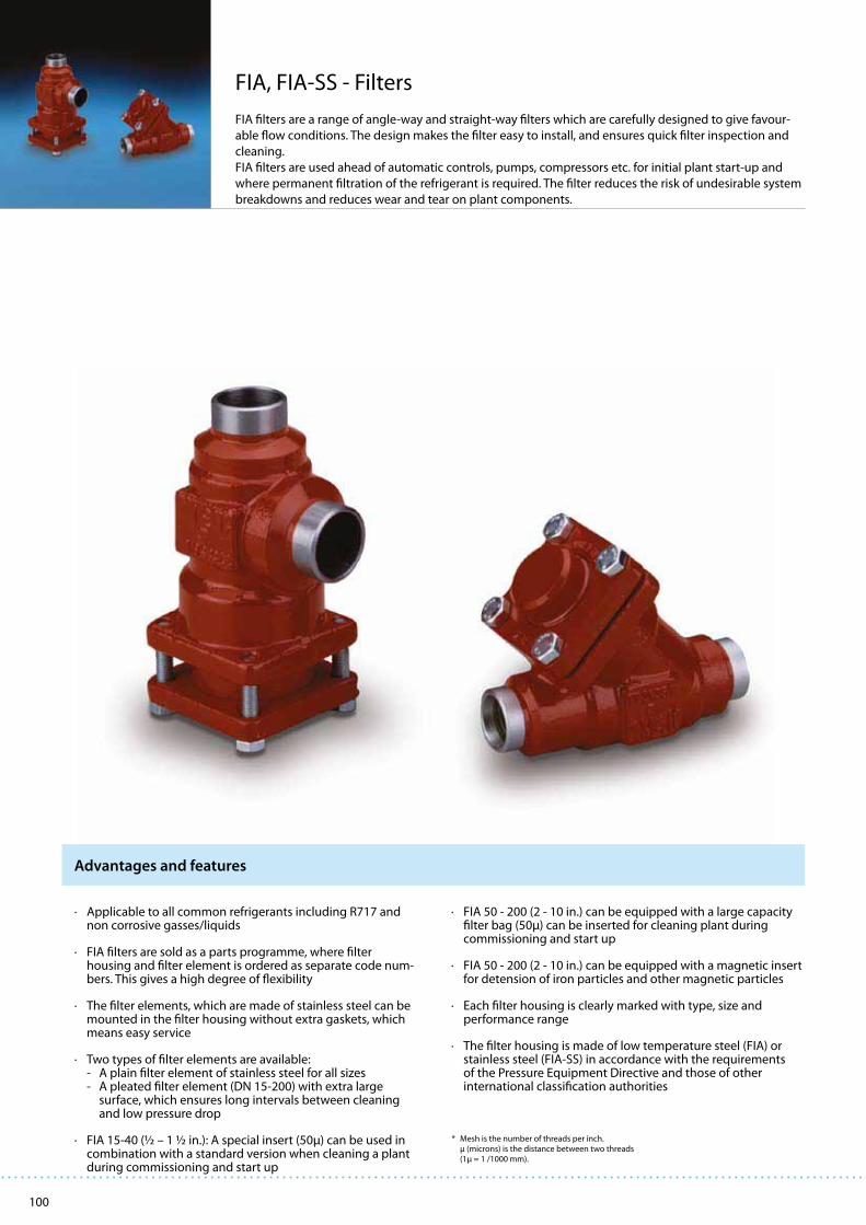
100
FIA, FIA-SS - Filters
FIA filters are a range of angle-way and straight-way filters which are carefully designed to give favour-
able flow conditions. The design makes the filter easy to install, and ensures quick filter inspection and
cleaning.
FIA filters are used ahead of automatic controls, pumps, compressors etc. for initial plant start-up and
where permanent filtration of the refrigerant is required. The filter reduces the risk of undesirable system
breakdowns and reduces wear and tear on plant components.
· Applicable to all common refrigerants including R717 and non corrosive gasses/liquids
· FIA filters are sold as a parts programme, where filter housing and filter element is ordered as separate code num-bers. This gives a high degree of flexibility
· The filter elements, which are made of stainless steel can be mounted in the filter housing without extra gaskets, which means easy service
· Two types of filter elements are available: - A plain filter element of stainless steel for all sizes
- A pleated filter element (DN 15-200) with extra large surface, which ensures long intervals between cleaning and low pressure drop
· FIA 15-40 (½ – 1 ½ in.): A special insert (50μ) can be used in combination with a standard version when cleaning a plant during commissioning and start up
· FIA 50 - 200 (2 - 10 in.) can be equipped with a large capacity filter bag (50μ) can be inserted for cleaning plant during commissioning and start up
· FIA 50 - 200 (2 - 10 in.) can be equipped with a magnetic insert for detension of iron particles and other magnetic particles
· Each filter housing is clearly marked with type, size and performance range
· The filter housing is made of low temperature steel (FIA) or stainless steel (FIA-SS) in accordance with the requirements of the Pressure Equipment Directive and those of other international classification authorities
Advantages and features
* Mesh is the number of threads per inch. μ (microns) is the distance between two threads (1μ = 1 /1000 mm).
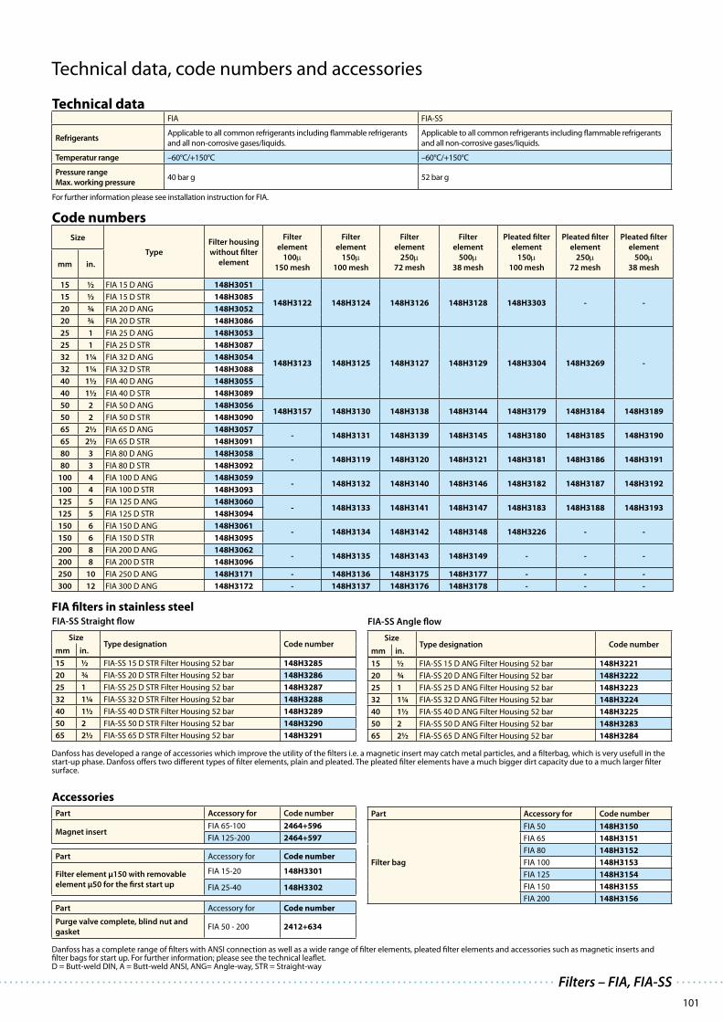
101
Filters – FIA, FIA-SS
Technical data, code numbers and accessories
Technical dataFIA FIA-SS
RefrigerantsApplicable to all common refrigerants including flammable refrigerants
and all non-corrosive gases/liquids.
Applicable to all common refrigerants including flammable refrigerants
and all non-corrosive gases/liquids.
Temperatur range –60°C/+150°C –60°C/+150°C
Pressure range
Max. working pressure40 bar g 52 bar g
For further information please see installation instruction for FIA.
Code numbers
Size
Type
Filter housing
without filter
element
Filter
element
100μ150 mesh
Filter
element
150μ100 mesh
Filter
element
250μ72 mesh
Filter
element
500μ38 mesh
Pleated filter
element
150μ100 mesh
Pleated filter
element
250μ72 mesh
Pleated filter
element
500μ38 meshmm in.
15 ½ FIA 15 D ANG 148H3051
148H3122 148H3124 148H3126 148H3128 148H3303 - -15 ½ FIA 15 D STR 148H3085
20 ¾ FIA 20 D ANG 148H3052
20 ¾ FIA 20 D STR 148H3086
25 1 FIA 25 D ANG 148H3053
148H3123 148H3125 148H3127 148H3129 148H3304 148H3269 -
25 1 FIA 25 D STR 148H3087
32 1¼ FIA 32 D ANG 148H3054
32 1¼ FIA 32 D STR 148H3088
40 1½ FIA 40 D ANG 148H3055
40 1½ FIA 40 D STR 148H3089
50 2 FIA 50 D ANG 148H3056148H3157 148H3130 148H3138 148H3144 148H3179 148H3184 148H3189
50 2 FIA 50 D STR 148H3090
65 2½ FIA 65 D ANG 148H3057- 148H3131 148H3139 148H3145 148H3180 148H3185 148H3190
65 2½ FIA 65 D STR 148H3091
80 3 FIA 80 D ANG 148H3058- 148H3119 148H3120 148H3121 148H3181 148H3186 148H3191
80 3 FIA 80 D STR 148H3092
100 4 FIA 100 D ANG 148H3059- 148H3132 148H3140 148H3146 148H3182 148H3187 148H3192
100 4 FIA 100 D STR 148H3093
125 5 FIA 125 D ANG 148H3060- 148H3133 148H3141 148H3147 148H3183 148H3188 148H3193
125 5 FIA 125 D STR 148H3094
150 6 FIA 150 D ANG 148H3061- 148H3134 148H3142 148H3148 148H3226 - -
150 6 FIA 150 D STR 148H3095
200 8 FIA 200 D ANG 148H3062- 148H3135 148H3143 148H3149 - - -
200 8 FIA 200 D STR 148H3096
250 10 FIA 250 D ANG 148H3171 - 148H3136 148H3175 148H3177 - - -
300 12 FIA 300 D ANG 148H3172 - 148H3137 148H3176 148H3178 - - -
Accessories
Part Accessory for Code number
Magnet insertFIA 65-100 2464+596
FIA 125-200 2464+597
Part Accessory for Code number
Filter element μ150 with removable
element μ50 for the first start up
FIA 15-20 148H3301
FIA 25-40 148H3302
Part Accessory for Code number
Purge valve complete, blind nut and
gasketFIA 50 - 200 2412+634
Part Accessory for Code number
Filter bag
FIA 50 148H3150
FIA 65 148H3151
FIA 80 148H3152
FIA 100 148H3153
FIA 125 148H3154
FIA 150 148H3155
FIA 200 148H3156
FIA-SS Angle flow
SizeType designation Code number
mm in.
15 ½ FIA-SS 15 D ANG Filter Housing 52 bar 148H3221
20 ¾ FIA-SS 20 D ANG Filter Housing 52 bar 148H3222
25 1 FIA-SS 25 D ANG Filter Housing 52 bar 148H3223
32 1¼ FIA-SS 32 D ANG Filter Housing 52 bar 148H3224
40 1½ FIA-SS 40 D ANG Filter Housing 52 bar 148H3225
50 2 FIA-SS 50 D ANG Filter Housing 52 bar 148H3283
65 2½ FIA-SS 65 D ANG Filter Housing 52 bar 148H3284
FIA-SS Straight flow
SizeType designation Code number
mm in.
15 ½ FIA-SS 15 D STR Filter Housing 52 bar 148H3285
20 ¾ FIA-SS 20 D STR Filter Housing 52 bar 148H3286
25 1 FIA-SS 25 D STR Filter Housing 52 bar 148H3287
32 1¼ FIA-SS 32 D STR Filter Housing 52 bar 148H3288
40 1½ FIA-SS 40 D STR Filter Housing 52 bar 148H3289
50 2 FIA-SS 50 D STR Filter Housing 52 bar 148H3290
65 2½ FIA-SS 65 D STR Filter Housing 52 bar 148H3291
Danfoss has a complete range of filters with ANSI connection as well as a wide range of filter elements, pleated filter elements and accessories such as magnetic inserts and filter bags for start up. For further information; please see the technical leaflet.D = Butt-weld DIN, A = Butt-weld ANSI, ANG= Angle-way, STR = Straight-way
FIA filters in stainless steel
Danfoss has developed a range of accessories which improve the utility of the filters i.e. a magnetic insert may catch metal particles, and a filterbag, which is very usefull in the start-up phase. Danfoss offers two different types of filter elements, plain and pleated. The pleated filter elements have a much bigger dirt capacity due to a much larger filter surface.

102
LLG - liquid level glasses
LLG are liquid level glasses made of ductile steel which meets the strictest requirements on industrial
and marine refrigeration installations
LLG has sufficient flow areas to secure the highest possible degree of synchronous operation, and have
a specially hardened reflection glass for quick reading. The LLG are delivered with stop valves, which
ensures easy insulation on site as well as easy inspection and service, if any.
· All LLG liquid level glasses are equipped as standard with a
built-in safety system (non return device). If a glass is
damaged, the pressure of the refrigerant will activate the
safety system and refrigerant loss will be limited to an
absolute minimum.
· Refrigerants Applicable to all common non flammable refrigerants including R717 and non corrosive gases/liquids dependent on sealing material compatibility.
· Temperature range –10/+100°C or –50/+30°C
· Maximum operating pressure: 25 bar g Equipped with boron-silicate glass, hardened by an accurately controlled heat treatment process.
· Classification: To get an updated list of certification on the products please contact your local Danfoss Sales Company.
· The range of liquid level glasses is based on 3 basic liquid level glasses: LLG 185, LLG 335 and LLG 740. The other standard lengths are combined by using variations of basic glass lengths.
· The liquid level glasses are offered in 4 different versions: - with welding nipples (LLG). - with stop valves equipped with caps (LLG S). - with sight adapter in acrylic glass ready for insulation on site (LLG F). - with stop valves and sight adapter in acrylic glass ready for insulation on site (LLG SF).
NOTE: The LLG liquid level glass can only be placed in CE approved applications with the stop valves in front i.e. LLG S or LLG SF.
Advantages and features

103
Liquid level glasses – LLG
Technical data and code numbers
Technical dataLLG
RefrigerantsThe liquid level glasses are applicable to all common non flammable refrigerants including R717 and non corrosive gases/liquids. Flammable hydrocarbons are not recommended.
Temperatur range LLG S: –10/+100°C LLG SF: –50/+30°C
Pressure range Max. operating pressure
25 bar g
Pressure range Strength test 50 bar g
Pressure range Leakage test at 25 bar g
Please see the technical leaflet for further details.
Code numbersLiquid level glasses - LLG S With safety system and stop valves (SNV-ST)
LengthType Code no.
mm in.
185 7¼ LLG 185 S 2512+056
335 13¼ LLG 335 S 2512+057
590 23¼ LLG 590 S 2512+058
740 29¼ LLG 740 S 2512+059
995 39¼ LLG 995 S 2512+060
1145 45 LLG 1145 S 2512+061
1550 61 LLG 1550 S 2512+062
Liquid level glasses for insulating - LLG SF With safety system, stop valves (SNV-ST) and sight adapter
LengthType Code no.
mm in.
185 7¼ LLG 185 SF 2512+066
335 13¼ LLG 335 SF 2512+067
590 23¼ LLG 590 SF 2512+068
740 29¼ LLG 740 SF 2512+069
995 39¼ LLG 995 SF 2512+070
1145 45 LLG 1145 SF 2512+071
1550 61 LLG 1550 SF 2512+072
Important!
Where products need to be certified according to specific certification societies or where higher pressures are required, the relevant information should be included
at the time of order.

104
GD - Gas Detectors
Danfoss Gas Detectorss, type GD are a range of products designed to meet all industrial refrigeration
and air conditioning application requirements.
GD detects a wide range of commonly used refrigerants including Ammonia, Carbon Dioxide,
Halo-Carbons and Hydro-Carbons.
· GD is specifically developed for refrigeration applications
· Interchangeable precalibrated sensors
· Optional models: LCD display, IP 65 enclosure, EExd (Explosion Protected)
· Can operate as stand alone product
· Linear analog outputs, current (mA) / volt (V) proportional to the gas concentration
· Two digital outputs. Low Level and High Level Alarm
· Adjustable setting for alarm levels and output contacts with optional NO or NC switches
· Manual or automatic alarm reset optional
· Alarm levels can be set locally.
· GD can be connected directly to a Danfoss monitoring unit system
· Available with a range of different sensor technologies to monitor industrial refrigeration gases: – Electro-Chemical – Semi-Conductor – Catalytic – Infra-Red
Advantages and features

105
Type of gas
All models Standard With LCD
display
EExd IP 56
Low Temp.
EExd
Low. Temp.
IP 66 with
remote
IP 65
sensor
IP 66 with
remote
IP 65
EExd sensor
IP 56
Danfoss Type * Range
[PPM]
Code No.
Ammonia - NH3
R 717
GDA EC 100 0-100 148H5000 148H5001 148H5003 148H5005 148H5006 148H5009
GDA EC 300 0-300 148H5063
GDA EC 1000 0-1,000 148H5010 148H5011 148H5013 148H5015 148H5016 148H5019
GDA EC 1000 0-1,000 148H5050 148H5051 148H5053 148H5055 148H5059
GDA SC 1000 0-1,000 148H5040 148H5049
GDA SC 10000 0-10,000 148H5020 148H5021 148H5023 148H5025 148H5026 148H5027 148H5028 148H5029
GDA CT 30000 0-30,000 148H5030 148H5031 148H5033 148H5035 148H6039
Carbon Dioxide - CO2
R 744
GDC IR 10000 0-10,000 148H5070 148H5071 148H5073 148H5075 148H5072
GDC IR 20000 0-20,000 148H5085 148H5092
GDC IR 40000 0-40,000 148H5092
Halo-Carbon
HCFC
(R 22, R 123)GDHC SC 1000 0-1,000 148H5100 148H5101 148H5105 148H5107 148H5109
HFC
(R 404A, R 410A, R 134A,
R 407C, R 507)
GDHF SC 1000 0-1,000 148H5110 148H5111 148H5115 148H5117 148H5119
HFC
(R 134a)GDHF-R3 SC 1000 0-1,000 148H5120 148H5121 148H5125 148H5127 148H5129
Hydro-carbon
(R 290(Propane), R 600,
R 600A, R 1270)GDH CT 5000 0-5,000 148H5160 148H5161 148H5193
Various gases
Various gases GDCM SC 500 0-5,00 148H5180
EC = Electro-chemical
SC = Semi-cheminal
CT = Catalytic
IR = Infrared
Please consult the technical leaflet for more versions and for more information.
Code numbers
Technical data and code numbers
Technical data
Refrigerants Ammonia (R 717)
Type GDA: 0-100 ppm, 0-300 ppm, 0-1,000 ppm, 0-10,000 ppm, 0-30,000 ppm
Carbon Dioxide (R 744)
Type GDC: 0-10,000 ppm, 0-20,000 ppm, 0-30,000 ppm
Halo-Carbon - HCFC (R 22, R 123)
Type GDHC: 0-1,000 ppm
HFC (R 404A, R410A, R134A, R 407C, R 507)
Type GDHF: 0-1,000 ppm
Hydro-carbon - Propane (R 290, R 600, R 600A, R 1270)
Type GDH: 0-5,000 ppm
Versions / temperature range Standard, LCD display, IP 65 and EExd: –20°C/+50°C
Low temperature model: –40°C/+50°C
Cable connection 1 gland for 6-13 mm cable (0.2”-0.5”) 1 Ø 20 mm (0.8”) hole with blanking plug.
1 extra gland can be fitted (only Standard, LCD display and EExd).
Approvals CE:
EN55011: 1998,
EN61326: 1996
Following the provisions of 89/336/EEC, EMC directives and, Cenelec EN61010-2 : 2001
Following the provisions of 73/23/EEC, Low Voltage directive (LVD)
ATEX for EExd model:
Directive 94/9/EC Group 2, Category2, G and D, Zones 1 and 2.
Gas detectors – GD

106
EKC 315A - Refrigeration control
The controller and valve can be used where there are requirements to accurate control of superheat and temperature in connection with refrigeration. E.g.: · Cold store (air coolers)· Processing plant (water chillers)· A/C plant
· The evaporator is charged optimally – even when there
are great variations of load and suction pressure
· Energy savings – the adaptive regulation of the refriger-
ant injection ensures optimum utilisation of the evapo-
rator and hence a high suction pressure
· Exact temperature control – the combination of adap-
tive evaporator and temperature control ensures great
temperature accuracy for the media
· The superheating is regulated to the lowest possible
value at the same time as the media temperature is
controlled by the thermostat function
· Regulation of superheat
· Temperature control
· MOP function
· ON/OFF input for start/stop of regulation
· Input signal that can displace the superheat reference
or the temperature reference
· Alarm if the set alarm limits are exceeded
· Relay output for solenoid valve
· PID regulation
· Output signal following the temperature showing in
the display
Functions Advantages

107
Technical data
Supply voltage24 V a.c. +/-15% 50/60 Hz, (80 VA)
(the supply voltage is galvanically separated from the input and output signals)
Power consumption Controller
AKV coil
5 VA
55 VA
Input signal
Current signal 4-20 mA or 0-20 mA
Pressure transmitter 4-20 mA from AKS 33
Digital input from external contact function
Sensor input 2 pcs. Pt 1000 ohm
Output signalCurrent signal 4-20 mA or 0-20 mA
Load Max. 200 ohm
Relay output 1 pcs. SPST AC-1: 4 A (ohmic)
AC-15: 3 A (inductive)Alarm relay 1 pcs. SPST
ICAD ICAD mounted on ICMCurrent signal
4-20 mA or 0-20 mA
Data communication Possible to connect a data communication module
Environments
-10 to 55°C, during operations
-40 to +70°C, during transport
20 - 80% Rh, not condensed
No shock influence/vibrations
Enclosure IP 20
Weight 300 g
Mounting DIN rail
Display LED, 3 digits
Terminals max. 2.5 mm2 multicore
Approvals
EU Low Voltage Directive and EMC demands re CE-marking
complied with.
LVD-tested acc. to EN 60730-1 and EN 60730-2-9
EMC-tested acc. to EN50081-1 and EN 50082-2
Ordering
Type Description Code no.
EKC 315A Superheat controller 084B7086
EKC 315A Superheat controller, AKS 32R 084B7085
EKC 315A I-pack of 084B7085 084B7128
Accessories
EKA 173 FTT 10 LON 084B7092
EKA 174
Data communication module
(accessories), (RS 485 module)
with galvanic separation
084B7124
EKA 175 RS485 LON 084B7093
AKA 211 Cable filter * 084B2238
AKS 11 Pt 1000 Sensor 084N0003
AKS 33 Pressure transmitter -1/12 bar, 0.3% 060G2049
AKS 3000 Pressure transmitter -1/12 bar, 1% 060G1323
The installation of data communications must comply with the requirements described in literature sheet no. RC8AC
Additional information!
Manual: RS8CS
* When cable lengths exceed 5 m, max. cable length with filter: 50 m
Refrigeration controllers – EKC 315A
Technical data and ordering

108
Thermostat· ON/OFF heating or cooling thermostat· Sensors: Danfoss Pt1000, PTC1000 or NTC5000· Day / night control· Thermostat band· Alarm thermostat with delay
Defrost· Electrical, natural or hot gas defrost· Start via DI input, time interval or schedule (RTC)· Defrost on demand· Stop on time or temperature· Coordinated defrost
Compressor· Anti cycle timers for optimum protection· High-effect 16A relays for connection of compressors without use of intermediate relays
DI input· Multi purpose DI input for defrost start, door function, night setback, main switch, appliance cleaning, general alarm, defrost coordination and thermostat band.
Fan· Fan delay during defrost· Fan stop when compressor cuts out· Fan stop at high S5 temperature
Light control· Light control of day/night, door, or via network
· Integrated refrigeration-technical functions
· Defrost on demand in 1:1 systems
· Buttons and seal imbedded in the front
· IP 65 density from the front panel
· Digital input for either: - Door contact function with alarm - Defrost start - Start/stop of regulation - Night operation - Change-over between two temperature reference - Case cleaning function
· Instant programming via programming key
· HACCP Factory calibration that will guarantee a better measuring accuracy than stated in the standard EN 441-13 without subsequent calibration (Pt 1000 ohm sensor)
Functions Advantages
EKC 202 - Refrigeration controller
The series of EKC 202 controllers can be used for a wide range of different
refrigeration applications – from control of air temperatures and defrost to more
advanced applications, including control of light and fans.

109
Technical dataSupply voltage 230 V a.c. +10/-15 %. 1.5 VA
Sensors
Pt 1000 or
PTC (1000 ohm/25°C) or
NTC-M2020 (5000 ohm/25°C)
Accuracy
Measuring range -60 to +99°C
Controller
±1 K below -35°C
±0,5 K between -35 to +25°C
±1 K above +25°C
Pt 1000 sensor±0.3 K at 0°C
±0.005 K per grad
Display LED, 3 digits
Digital inputs
Signal from contact functions
Requirements to contacts: Gold plating
Cable length must be max. 15 m
Use auxiliary relays when the cable is longer
Electrical connection cable
Max.1,5 mm2 multi-core cable on supply and relays.
Power current terminals are mounted on the circuit board.
Max. 1 mm2 on sensors - and DI inputs.
Low current terminals are with plugs
Relays*
CE
(250 V a.c.)
UL ***
(240 V a.c.)
DO1.
Refrigeration10 (6) A
10 A Resistive
5FLA, 30LRA
DO2. Defrost 10 (6) A10 A Resistive
5FLA, 30LRA
DO3. Fan 6 (3) A
6 A Resistive
3FLA, 18LRA
131 VA Pilot duty
DO4. Alarm or light4 (1) A
Min. 100 mA**
4 A Resistive
131 VA Pilot duty
Environments
0 to +55°C, During operations
-40 to +70°C, During transport
20 - 80% Rh, not condensed
No shock influence/vibrations
EnclosureIP 65 from front.
Buttons and packing are imbedded in the front.
Escapement reserve for the clock 4 hours
Approvals
EU Low Voltage Directive and EMC demands re CE-marking complied with
LVD tested acc. EN 60730-1 og EN 60730-2-9, A1, A2
EMC tested acc. EN50082-1 og EN 60730-2-9, A2
* DO1 and DO2 are 16 A relays. DO3 and DO4 are 8 A relays. Max. load must be keept.
** Gold plating ensures make function with small contact loads
*** UL-approval based on 30000 couplings
Additional information!
Manual: RS8DZ
Ordering
Type Description Code No.
EKC 202A Refrigeration controller 084B8521
EKC 202B Refrigeration controller with fan function 084B8522
EKC 202C Refrigeration controller for electric defrost 084B8523
Accessories
EKA 178AData communication module
MOD bus 084B8564
EKA 179A RS485 LON 084B8565
EKA 181A Battery & Buzzer 084B8566
EKA 181CBattery module that will protect the clock in case of
lengthy power failure084B8577
EKA 182A Copy key EKC - EKC 084B8567
AKS 12 Pt 1000 Sensor 084N0036
EKS 111 PTC 1000 Sensor 084N1178
EKS 211 NTC 5000 Sensor 084N1220
Technical data and ordering
Refrigeration controllers – EKC 202

110
AK-CC 550 - Controller for appliance control
AK-CC 550 is a complete refrigeration appliance control with great flexibility toadapt to all types of refrigeration appliances and cold storage rooms.
· Day/night thermostat with ON/OFF or modulating
principle
· Product sensor S6 with separate alarm limits
· Switch between thermostat settings via digital input
· Adaptive control of superheat
· Adaptive defrosting based on evaporator performance
· Start of defrost via schedule, digital input or network
· Natural, electric or hot gas defrost
· Stop of defrost on time and/or temperature
· Coordination of defrosting among several controls
· Pulsing of fans when thermostat is satisfied
· Case cleaning function for documentation of HACCP
procedure
· Rail heat control via day/night load or dew point
· Door function
· Control of two compressors
· Control of night blinds
· Light control
· Heat thermostat
· Factory calibration that will ensure a better measuring
accuracy than stated in the standard EN 441-13 without
subsequent calibration (Pt 1000 ohm sensor)
· Integrated MODBUS communication with the option of
mounting a LonWorks or Ethernet communication card
· Energy optimisation of the whole refrigeration appliance
· One controller for several different refrigeration appliances
· Integrated display at the front of the controller
· Quick set-up with predefined settings
· Built-in data communication
· Built-in clock function with power reserve
Functions Advantages

111
OrderingType Description Code no.
AK-CC 550
Case controller with MODBU data communicationSensor connections are with screw terminals
084B8020
Case controller with MODBU data communicationSensor connections are with plug connections
084B8021
EKA 175Data communication module LON RS 485
084B8579
EKA 177Data communication module Ethernet
084B8581
EKA 178B Data communication module MODBUS 084B8571
EKA 163B External display with plug fo direct connection 084B8574
EKA 164BExternal display operation buttons and plug for direct connection
084B8575
EKA 163A External display with screw terminals 084B8562
EKA 164AExternal display with operation buttons and screw terminals
084B8563
EKA 17111 RTC-module 084B7069
Additional information!
Manual: RS8EN
Technical data
Supply voltage 230 V a.c. +10/-15%, 5 VA
Sensor S111, (S1) Pt 1000
Sensor S3, S4, S5, S6Pt 1000PTC 1000 ohm/1115°C(All 4 must be of the same type)
Accuracy
Measuring range -60 to +120°C
Controller ±1 K below -35°C±0.5 K between -35 to +1115°C±1 K above +1115°C
Pt 1000 sensor±0.3 K at 0°C±0.005 K per grad
Measuring of Pe Pressure transmitter AKS 3111R
Display LED, 3-digits
External display EKA 163B or 164B. (any EKA 163A or 164A)
Digital inputsDI1, DI111
Signal from contact functionsRequirements to contacts: Gold plating Cable length must be max. 15 m Use auxiliary relays when the cable is longer
Digital input DI3 11130 V a.c.
Electrical connection cable Max. 1.5 mm111 multi-core cable
Solid state output DO1 (for AKV coil)
Max. 11140 V a.c. , Min. 1118 V a.c.Max. 0,5 ALeak < 1 mAMax. 1 pcs. AKV
Relays*
CE (250 V a.c.)
DO3, DO4 4 (3) A
DO2, DO5, DO6 4 (3) A
Environments
0 to +55°C, During operations-40 to +70°C, During transport
20 - 80% Rh, not condensed
No shock influence/vibrations
Density IP 20
Mounting DIN rail or on wall
Weight 0.4 kg
Data communication
Fixed MODBUS
Extension options
LON RS485
TCP/IP
MODBUS
The controller cannot be hooked up with a monitoring unit type m2.
Power reserve for the clock 4 hours
ApprovalsEU Low Voltage Directive and EMC demands re CE-marking complied with.LVD-tested acc. to EN 60730-1 and EN 60730-2-9EMC-tested acc. to EN 50081-1 and EN 50082-2
*) DO3 and DO4 are 16 A relays. DO111, DO5 and DO6 are 8 A relays. Max. load must be observed.
Controller for appliance control – AK-CC 550
Technical data and ordering

112
Thermostat· ON/OFF thermostat· Sensors: Danfoss Pt1000, PTC1000 or NTC5000· Calibration of sensors· Day/night control· Alarm thermostat with delays
Defrost· Electrical or natural defrost· Start via DI input, time interval or display· Defrost on demand· Stop on time or temperature
Compressor· Anti cycle timers for optimum compressor protection· High-effect 16A relays for connection of compressors without use of intermediate relay· Control of 2 compressors (version 102B)
Multipurpose DI input· Multipurpose DI input for defrost start, day/night control, dooralarm or main switch
Other functions· The S5 sensor can be used for monitoring of condenser temperature or as product sensor (version 102B+102D)· Door function with alarm monitoring· Manual control of outputs· Delay of outputs at power up
Display & Programming· High-efficient LED display with icons for indication of operational status. Parameter settings/readouts and alarm conditions can be read on the display.· ”Copy key” programming key with room for 25 different controller setups
Fan (102D only)· Fan delay during defrost· Fan stop when compressor cuts out· Fan stop at high S5 temperature
· Integrated refrigeration-technical functions
· Defrost on demand in 1:1 systems
· Buttons and seal imbedded in the front
· IP 65 density from the front panel
· Can control two compressors
· Digital input for either: - Door alarm - Defrost start - Start/stop of regulation - Night operation - Change-over between two temperature reference - Case cleaning function
· Instant programming via programming key
· HACCP Factory calibration that will guarantee a better measuring accu racy than stated in the standard EN 441-13 without subsequent calibration (Pt 1000 ohm sensor)
Functions Advantages
EKC 102 - Temperature controller
EKC 102 controllers for panel mounting are used for temperature and defrostcontrol via pump-down or start/stop of compressor.

113
Technical data
Supply voltage 230 V a.c.(115 V) +10/-15 %. 1.5 VA
Sensors
Pt 1000 or
PTC (1000 ohm/25°C) or
NTC-M2020 (5000 ohm/25°C)
Accuracy
Measuring range -60 to +99°C
Controller
±1 K below -35°C
±0.5 K between -35 to +25°C
±1 K above +25°C
Pt 1000 sensor±0.3 K at 0°C
±0.005 K per grad
Display LED, 3 digits
Digital inputs
Signal from contact functions
Requirements to contacts: Gold plating
Cable length must be max. 15 m
Use auxiliary relays when the cable is longer
Electrical connection cable
Max.1.5 mm2 multi-core cable on supply and relays.
Max. 1 mm2 on sensors - and DI inputs.
Terminals are mounted on the circuit board
Relays*
CE
(250 V a.c.)
UL **
(240 V a.c.)
DO1.
Refrigeration10 (6) A
10 A Resistive
5FLA, 30LRA
DO2. Alarm/
Defrost/
Refrigeration
10 (6) A10 A Resistive
5FLA, 30LRA
DO3. Fan 6 (3) A
6 A Resistive
3FLA, 18LRA
131 VA Pilot duty
Environments
0 to +55°C, During operations
-40 to +70°C, During transport
20 - 80% Rh, not condensed
No shock influence/vibrations
EnclosureIP 65 from front.
Buttons and packing are imbedded in the front.
Approvals
EU Low Voltage Directive and EMC demands re CE-marking complied with
LVD tested acc. EN 60730-1 og EN 60730-2-9, A1, A2
EMC tested acc. EN50082-1 og EN 60730-2-9, A2
* DO1 and DO2 are 16 A relays. DO3 is a 8 A relay. Max. load must be keept.
** UL-approval based on 30000 couplings
Ordering
Type Description Supply Code No.
EKC 102A Temperature controller 230 V a.c. 084B8500
115 V a.c. 084B8503
EKC 102B Temperature controller with alarm
function
230 V a.c. 084B8501
115 V a.c. 084B8504
EKC 102C Temperature controller for electric
defrost
230 V a.c. 084B8502
115 V a.c. 084B8505
EKC 102D Controller for refrigeration with fan
function
230 V a.c. 084B8506
115 V a.c. 084B8507
Accessories
EKA 179A RS485 LON 084B8565
EKA 181A Battery & Buzzer 084B8566
EKA 182A Copy key EKC - EKC 084B8567
AKS 12 Pt 1000 Sensor 084N0036
EKS 111 PTC 1000 Sensor 084N1178
EKS 211 NTC 5000 Sensor 084N1220
Additional information!
Manual: RS8DY
Temperature controller – EKC 102
Technical data and ordering

114
Thermostat· ON/OFF heating or cooling thermostat· Sensors: Danfoss Pt1000, PTC1000 or NTC5000· Day / night control· Thermostat band· Alarm thermostat with delay
Defrost· Electrical, natural or hot gas defrost· Start via DI input, time interval or schedule (RTC)· Defrost on demand· Stop on time or temperature· Coordinated defrost
Compressor· Anti cycle timers for optimum protection· High-effect 16A relays for connection of compressors without use of intermediate relays
DI input· Multi purpose DI input for defrost start, door function, night setback, main switch, appliance cleaning, general alarm, defrost coordination and thermostat band.
Fan· Fan delay during defrost· Fan stop when compressor cuts out· Fan stop at high S5 temperature
Light control· Light control of day/night, door, or via network Other functions· S5 sensor can be used for monitoring of condenser temperature or as product sensor· Door function with alarm monitoring· Manual control of outputs· Case cleaning function
Supplementary options· RS 485 network card for connection to network· Battery back-up card for real time clock· ”Copy key” programming key
· Many applications in the same unit
· The controller has integrated refrigeration-technical functions, so that it can replace a whole collection of thermostats and timers
· Buttons and seal imbedded in the front
· Can control two compressors
· Easy to remount data communication
· Quick setup
· Two temperature references
· Digital inputs for various functions
· Clock function with backup
· HACCP (Hazard Analysis and Critical Control Points) - Temperature monitoring and registration of period with too
high temperature
- Factory calibration that will guarantee a better measuring
accuracy than stated in the standard EN 441-13 without sub-
sequent calibration (Pt 1000 ohm sensor)
Functions Advantages
AK-CC 210 - Universal refrigeration controller
The controller is used for evaporator control refrigeration appliances in supermarkets.
With many predefined applications one unit will offer you many options. Flexibility has been planned
both for new installations and for service in the refrigeration trade.

115
Additional information!
Manual: RS8DZ
Ordering
Type Description Code No.
AK-CC 210Refrigeration controller without data communication
but prepared for LON RS 485 module084B8520
Accessories
EKA 163A External display for AK-CC 210 084B8562
EKA 178A Data communication module MOD bus 084B8564
EKA 179A RS485 LON 084B8565
EKA 181A Battery & Buzzer 084B8566
EKA 181CBattery module that will protect the clock in case of
lengthy power failure084B8577
EKA 182A Copy key EKC - EKC 084B8567
AKS 12 Pt 1000 Sensor 084N0036
EKS 111 PTC 1000 Sensor 084N1178
EKS 211 NTC 5000 Sensor 084N1220
Technical data
Supply voltage 230 V a.c. +10/-15 %. 2.5 VA
Sensors 3 pcs off either
Pt 1000 or
PTC (1000 ohm / 25°C) or
NTC-M2020 (5000 ohm / 25°C)
Accuracy
Measuring range -60 to +99°C
Controller
±1 K below -35°C
±0.5 K between -35 to +25°C
±1 K above +25°C
Pt 1000 sensor±0.3 K at 0°C
±0.005 K per grad
Display LED, 3-digits
External display EKA 163A
Digital inputs
Signal from contact functions
Requirements to contacts: Gold plating
Cable length must be max. 15 m
Use auxiliary relays when the cable is longer
Electrical connection cable Max.1,5 mm2 multi-core cable
Relays*
CE
(250 V a.c.)
UL ***
(240 V a.c.)
DO1.
Refrigeration10 (6) A
10 A Resistive
5FLA, 30LRA
DO2. Defrost 10 (6) A10 A Resistive
5FLA, 30LRA
DO3. Fan 6 (3) A
6 A Resistive
3FLA, 18LRA
131 VA Pilot duty
DO4. Alarm4 (1) A
Min. 100 mA**
4 A Resistive
131 VA Pilot duty
Environments
0 to +55°C, During operations
-40 to +70°C, During transport
20 - 80% Rh, not condensed
No shock influence / vibrations
DensityIP 65 from front.
Buttons and packing are embedded in the front.
Escapement reserve for the clock 4 hours
Approvals
EU Low Voltage Directive and EMC demands re CE-marking complied with
LVD tested acc. EN 60730-1 og EN 60730-2-9, A1, A2
EMC tested acc. EN50082-1 og EN 60730-2-9, A2
* DO1 and DO2 are 16 A relays. DO3 and DO4 are 8 A relays. Max. load must be keept.
** Gold plating ensures make function wiht small contact loads
*** UL-approval based on 30000 couplings
Universal refrigeration controller – AK-CC 210
Technical data and ordering

116
Functions Advantages
The monitoring unit can monitor up to 65 measurements.
They can originate from:
- up to 16 direct connections from sensors or switch functions
- signals from separate refrigeration controllers, EKC and
AK types, via data communication
- signals from connections on the expansion module m2+
and from gas detectors. These readings are also transferred
via data communication.
- Pulse counting function for energy display
- All defined points can be recorded and saved with the set
time intervals.
- The values can be viewed on the display and retrieved by
connecting a printer or connecting a PC or modem.
Compact unit for registering temperatures
· Collects temperature data to present to authorities
· Alarm function
- Local alarm or via modem/IP
- Alarm at deviations in temperature
- Alarms when doors to cold storage rooms and freezer
rooms are open
· Text describing the measuring area can be added to the
measuring points
AK-SM 350 - System Manager
The unit is a combined data collection unit and monitoring unit for smaller refrigeration installations.
· Corner shops
· Smaller supermarkets
· Restaurants
· Food manufacturers

117
Technical data
Supply 115 V/230 V
+10/-15%, 50/60 Hz, 10 VA
Connection PT 1000 ohm at 0°C or
PTC 1000 ohm at 25°C or
NTC 5000 ohm at 25°C or
Termistor (-80 to 0, -40 to 40 or 0 to 100°C)
Digital On/Off signal or
Standard 0 - 10 V /4 - 20 mA signal
Display Graphic LCD, 240 x 64
Direct measuring points 16
Total number of points 65
Measuring range, general -60 to +50°C
Measuring accuracy at Pt 1000 Resolution 0.1 K
Accuracy: +/- 0.5 K
Measuring interval 15, 30, 60, 120 or 240 minutes
Data capacity 55 log points, every 15 min. for 1 year
Battery backup Button cell for clock function
Power supply for e.g. pressure
transmitter
5 V max. 50 mA
12 V max. 50 mA
Pulse counter inputs for output
reading
Acc. to DIN 43864.
(Only for inputs 1 and 2)
Printer connection HP PCL-3, Parallel
Modem connection RJ 45
TCP/IP connection RJ 45
PC connection RJ 45
Data communication RS232, RS 485 (LON), RS 485 (MOD-bus), RS 485 (TP) (TP= Third Party)
Relays Quantity 2
Max. load 24 V a.c. or 230 V a.c.
Imax (AC-1) = 5 A
Imax (AC-15) = 3 A
Enclosure IP 20
Ambient environmen 0 to 50°C, during operation
-20 to +70°C, during transport
20-80% RH, Non-condensed
No shock loads/vibrations
Approvals EN 60730-1 and EN 60730-2-9
EN 50081-1 and EN 50082-1
Weight 1.6 Kg
Additional information!
Manual: RS8EF
System manager – AK-SM 350
Technical data and ordering
Ordering
Type Measuring points Description Language Code No.
AK-SM 350 16 With inputs for PT 1000
ohm & PTC 1000 ohm
English, German, French,
dutch, Italian080Z8500
English (UK), Spanish,
Portuguese,
English (US)
080Z8502
English,
Danish,
Swedish, Finnish
080Z8503
m2+ 16 080Z8005
Accessories
Printer cable 3 m (parallel) 080Z8401
Cable for PC
(see also AK-ST 500 literature)RJ 45 - Com port 080Z0262
Important: Installation of data communication cables and repeaters must comply with the requirements contained in the document:
Data communication between ADAP-KOOL® Refrigeration system controls.
Number = RC8AC.

118
· Modulating temperature control
· Digital ON/OFF input for start/stop of regulation ICS/PM
or forced closing of ICM
· Alarm if the set alarm limits are exceeded
· Relay output for fan
· Relay output for solenoid valves
· Analog input signal that can displace the temperature
reference
· Analog Output signal corresponding to selecting
temperature as running display value.
Please observe : Not possible if ICM is selected as valve
· The temperature is kept within an accuracy of ±0.25°C or
better in normal operation
· The evaporator's temperature is kept as high as possible,
so that the air humidity is kept high to avoid waste
· A transient phenomenon can be controlled with the adap-
tive function. Select either:
- Fast build-up where underswings are allowed
- Not quite so fast build-up where underswings are less
pronounced
- Build-up without underswings
· PID regulation
· p0 limitation
Functions Advantages
EKC 361 - Media temperature control
The controller and valve can be used where there are stringent requirements to accurate temperature control in connection with refrigeration. E.g.: · Cold room for fruits and food products· Refrigerating systems· Work premises in the food industry· Process cooling of liquids

119
Ordering
Type Description Code No.
EKC 361 Evaporating pressure controller 084B7060
Accessories
EKA 173 FTT 10 LON 084B7092
EKA 174Data communication module (accessories), (RS 485
module) with galvanic separation084B7124
EKA 175 RS485 LON 084B7093
AKS 21M Pt 1000 Sensor 084N2003
AKA 211 Cable filter * 084B2238
* When cable lengths between controller and valve exceed 5 m, max. cable length with filter: 50 m
The installation of data communications must comply with the requirements described in literature sheet no. RC8AC
Technical data
Supply voltage24 V a.c. +/-15% 50/60 Hz, 80 VA
(the supply voltage is galvanically separated from the input and output signals)
Power consumptionController
Actuator
5 VA
75 VA
Input signal Current signal 4-20 mA or 0-20 mA
Digital input from external contact function
Sensor input 2 pcs. Pt 1000 ohm
Output signal Current signal4-20 mA or 0-20 mA
Max. load: 200 ohm
Relay output 2 pcs. SPST a.c.-1: 4 A (ohmic)
a.c.-15: 3 A (inductive)Alarm relay 1 pcs. SPST
ActuatorInput Temperature signal from sensor in the actuator
Output Pulsating 24 V a.c. to actuator
Data communication Possible to connect a data communication module
Ambient
temperature
During operation
During transport
-10 - 55°C
-40 - 70°C
Enclosure IP 20
Weight 300 g
Mounting DIN rail
Display LED, 3 digits
Terminals max. 2.5 mm2 multicore
Approvals
EU Low Voltage Directive and EMC demands re CE-marking complied with.
LVD-tested acc. to EN 60730-1 and EN 60730-2-9
EMC-tested acc. to EN50081-1 and EN 50082-2
Media temperature control – EKC 361
Technical data and ordering

120
· The valve constantly receives feedback of the pressure in
the evaporator. Whatever the variations in the suction pres-
sure from the compressor, this feedback will produce the
result that the evaporating pressure is kept constant.
· In conjunction with the controller, an electronic constant
pressure valve is thus obtained.
· Inserted between the controller and the actuator is a so-
called inner regulating loop. This loop will – via an NTC
resistance – constantly control the temperature in the
actuator.
· In an application where a PLC or similar device is used for
regulating a media temperature, the regulating system
will in this way be supplied with an outer regulating loop
– which will result in great regulating accuracy.
The controller has been specially designed for the following
functions:
· Maintenance of a constant evaporating pressure
A temperature sensor in the valve’s actuator will regulate its
temperature. This temperature is an indication of the pres-
sure in the valve, and the interface module will keep this
temperature constant.
· The media temperature is regulated by a PLC or similar
device.
Here the interface module receives a variable signal from
the PLC and will subsequently regulate the valve, so that the
refrigeration will be as accurate as possible.
Functions Advantages
EKC 366 - Controller Interface
The controller is used for regulating a valve in a refrigerating system - for example in connection with:
· Long-term storage of fruits and vegetables
· Refrigerating plant
· Brewery systems
· Processing plant

121
Controller interface – EKC 366
Technical data and ordering
Ordering
Type Function Code No.
EKC 366 Interface module 084B7076
Accessories
EKA 173Data communication module (accessories),
(FTT 10 module)084B7092
EKA 174Data communication module (accessories),
(RS 485 module) with galvanic separation084B7124
Valves: Kindly refer to catalogue RK0YG
Technical data
Supply voltage24 V a.c. +/-15% 50/60 Hz, 80 VA
(the supply voltage is galvanically separated from the input and output signals)
Power consumptionController
Valve
5 VA
75 VA
Input signal 4-20 mA, 0-20 mA, 0-10V d.c. or
2-10 V d.c.
ActuatorInput Temperature signal from sensor in actuator
Output Pulsating 24 V a.c. to actuator
Data communication Possible to connect a data communication module
Ambient temperatureDuring operation
During transport
-10 - 55°C
-40 - 70°C
Enclosure IP 20
Weight 300 g
Mounting DIN rail
Display LED, 3 digits
Terminals max. 2.5 mm2 multicore
Approvals
EU Low Voltage Directive and EMC demands re CE-marking complied with.
LVD-tested acc. to EN 60730-1 and EN 60730-2-9
EMC-tested acc. to EN 50081-1 and EN 50082-2

122
Applications Advantages Facts
XGE/RGE: Condenser fan speed controls
Fan speed control is becoming increasingly widespread in different refrigeration and air conditioning
units, with the benefits of reduced noise and stable condensing pressures under different climatic condi-
tions. The XGE range is very compact and offers the ideal solution for reliable fan control for most units
where small fans are used. For medium to large sized fans (single and three phase) the RGE range offers a
simple and efficient fan speed control solution.
· Freezing and refrigeration condensing
units
· Packaged air conditioners and
chillers
· Simple to install and easy setting
· “All in one”: senses pressure and con-
trols fan speed
· Reliable sensing mechanism
· XGE:
- Compact & light weight (length:
112mm - diameter: 66mm - weight:
180g)
- Can be directly mounted onto the
refrigeration line or fixed onto a sim-
ple bracket (accessory) and screwed
to a panel
- Easily accessible adjusting screw on
the top surface
- Easy wiring and electrical connec-
tion
- Specially designed heat dissipation
radiator to prevent overheating
· Electrical rating from 3 to 8A (single
phase) and 5 to 7A (3 phase)
· For all the commonly used refriger-
ants, including R410A
· Enclosure: IP 65 (XGE) and IP54 (RGE)
· Full CE / EMC approved
· Dual frequency: 50/60 Hz
· Max. working pressure: 47 bar
· With low speed operation it is pos-
sible to select either minimum speed
operation or cut-off operation
Features
Applications Advantages Facts
Easily accessible
adjusting screw
Waterproof housing
with IP 65
1/4 in female or male
connection (or ¼ in
female with capillary
tube for RGE)Installation flexibility: direct or
panel mounting
Quick electrical connection
in 4 different directions

123
Condenser fan speed controls – XGE/RGE
Technical data and ordering
Model Mode 1) Pressure
connection
Adjusting
range
[bar]
P-band
[bar]
Pre-setting
[bar]
Rated
motor
rating [A]
No. of phase/
voltage [VAC]Code no.
XGE-4C C 1/4 in female flare 10-25 6 19 0.2-3 1 / 200-240 061H3140
XGE-4CB C 1/4 in male flare 10-25 6 19 0.2-3 1 / 200-240 061H3142
XGE-6C C 1/4 in female flare 22-39 7 28 0.2-3 1 / 200-240 061H3160
XGE-6CB C 1/4 in male flare 22-39 7 28 0.2-3 1 / 200-240 061H3162
XGE-4M M 1/4 in female flare 10-25 6 19 0.2-3 1 / 200-240 061H3240
XGE-4MB M 1/4 in male flare 10-25 6 19 0.2-3 1 / 200-240 061H3242
XGE-6M M 1/4 in female flare 22-39 7 28 0.2-3 1 / 200-240 061H3260
XGE-6MB M 1/4 in male flare 22-39 7 28 0.2-3 1 / 200-240 061H3262
RGE-Z1N4-7DS C or M 1/4 in female flare 8-28 4 19 0.2-4 1 / 200-240 061H3005
RGE-Z1N6-7DS C or M 1/4 in female flare 16-39 8 32 0.2-4 1 / 200-240 061H3021
RGE-Z1P4-7DS C or M 1/4 in female flare 8-28 4 19 0.2-6 1 / 200-240 061H3008
RGE-Z1P6-7DS C or M 1/4 in female flare 16-39 8 32 0.2-6 1 / 200-240 061H3022
RGE-Z1Q4-7DS C or M 1/4 in female flare 8-28 4 19 0.2-8 1 / 200-240 061H3009
RGE-Z1Q6-7DS C or M 1/4 in female flare 16-39 8 32 0.2-8 1 / 200-240 061H3023
RGE-Z3R4-7DS C or M 1/4 in female flare 8-28 4 16 0.2-5 3 / 200-240 061H3003
RGE-X3R4-7DS C or M 1/4 in female flare 8-28 4 16 0.2-5 3 / 380-415 061H3006
RGE-Z3R6-7DS C or M 1/4 in female flare 16-39 8 32 0.2-5 3 / 200-240 061H3027
RGE-X3R6-7DS C or M 1/4 in female flare 16-39 8 32 0.2-5 3 / 380-415 061H3028
RGE-Z3T4-7DS C or M 1/4 in female flare 8-28 4 16 0.2-7 3 / 200-240 061H3050
RGE-Z3T6-7DS C or M 1/4 in female flare 16-39 8 32 0.2-7 3 / 200-240 061H3051
1) C = Cut-off, M = Min. speed
Accessories
Model Description Dimensions Code no.
XGE-AE01 Fixing bracket accessory for panel mount H: 38mm, W: 42mm, D: 45mm 061H3102

124
· RegulationRegulation with up to four relay outputs can be carried out. Regulation takes place with a set reference which is compared to a signal from a pressure transmitter or a temperature sensor.
· Relay moduleIt is possible to use the controller as relay module, so that the relays are cut in or out by means of an external voltage signal.
· AlarmfunctionA relay becomes activated when the set alarm limits are exceeded.
· Digital inputThe digital input can be used for:- night operation where the suction pressure is raised- heat recovery where the condensing pressure is raised- external start/stop of the regulation.- Monitoring of safety circuit
· Possibility of data communication
· Patented neutral zone regulation
· Sequential or cyclic operation
Functions Advantages
EKC 331T - Capacity control
The controller is used for capacity regulation of compressors or condensers in small
refrigerating systems.
Regulation can be carried out with up to four identical capacity steps.

125
Ordering
Type Function Ordering
EKC 331T Capacity controller 084B7105
EKA 175 Data communication module
(accessories), (RS 485 module)084B7093
Additional information!
Manual: RS8CU
Technical data
Supply voltage 230 V a.c. +/-15% 50/60 Hz, 5 VA
Input signal
Pressure transmitter*) with 4-20 mA or
temperature sensor Pt 1000 ohm or
temperature sensor PTC 1000 ohm or
voltage signal (0 - 5 V, 0 - 10 V or 5 - 10 V)
Digital input to external contact function
Relay output 4 pcs. SPSTAC-1: 4 A (ohmic)
AC-15: 3 A (inductive)
Alarmrelay 1 pcs. SPSTAC-1: 4 A (ohmic)
AC-15: 1 A (inductive)
Data communication Possible to connect a data communication module
Environments
-10 - 55°C, during operation
-40 - 70°C, during transport
20 - 80% Rh, not condensed
No shock influence/vibrations
Enclosure IP 20
Weight 300 g
Mounting DIN rail
Display LED, 3 digits
Terminals max. 2.5 mm2 multicore
Approvals
EU Low voltage Directive and EMC demands re CE-marking complied with.
LVD-tested acc. to EN 60730-1 and EN 60730-2-9
EMC-tested acc. to EN50081-1 and EN 50082-2
*) As pressure transmitter can be used AKS 32R or AKS 33.
The installation of data communications must comply with the requirements described in literature sheet no. RC8AC
Capacity control – EKC 331T
Technical data and ordering

126
· Relays for compressor and condenser regulation
· Voltage output for capacity regulation of condenser
· Status inputs. An interrupted signal indicates that the safety circuit has been activated and the respective circuit stopped
· Contact inputs for indication of alarms
· Contact inputs for displacement of references or for indica- tion of alarms
· Alarm relay
· External start/stop of regulation
· Possibility of data communication
· Patented neutral zone regulation
· Many possible combinations for compressor constellations
· Sequential or cyclic operation
· Possibility of suction pressure optimization via the data communication
Functions Advantages
AK-PC 530 - Capacity controller
The controller is used for capacity regulation of compressors or condensers in small refrigerating
systems.
Numbers of compressors and condensers can be connected, as required.
There are eight outputs and more can be added via an external relay module.

127
Technical data
Supply voltage 24 V a.c. +/-15% 50/60 Hz, 5 VA
Input signal
2 pcs. Pressure transmitters type AKS 32R (temperature sensor in brine systems)
3 pcs. temperature sensor input for PT 1000 ohm/0°C or PTC 1000 ohm/25°C
Digitale input from contact func-
tion.
1 pcs. for Start/stop of regulation
8 pcs. for monitoring of safety circuits
3 pcs. for alarm function
2 pcs. for alarm function or for displacement of references
Relay output for capacity regula-
tion8 pcs. SPST AC-1: 3 A (ohmic)
AC-15: 2 A (inductive)"AKD start/stop" relay 1 pcs. SPST
Alarm relay 1 pcs. SPDTAC-1: 6 A (ohmic)
AC-15: 3 (inductive)
Voltage output 0-10 V d.c.
Display outputsEKA 163 Pc display
EKA 165(164) Operation, P0 display and LED
Data communication Possible to connect a data communication module
Environments
0 - 55°C, during operation
-40 - 70°C, during transport
20 - 80% Rh, not condensing
No shock influence / vibrations
Enclosure IP 20
Weight 0.4 kg
Mounting DIN rail or on wall
Terminals max. 2.5 mm2 multicore
Approvals
EU Low voltage Directive and EMC demands re CE-marking complied with.
LVD-tested acc. to EN 60730-1 and EN 60730-2-9
EMC-tested acc. to EN61000-6-2 and 3
Ordering
Type Function Code no.
AK-PC 530 Capacity controller 084B8007
Accessories
EKA 163B Display unit 084B8574
EKA 164B Display unit with operation buttons 084B8575
EKA 165Display unit with operation buttons and light-emitting
diodes for input and output084B8573
EKA 173 Data communication module, FTT 10 084B7092
EKA 175 Data communication module, RS 485 084B7093
CablesCable for display unit 2 m, 1 pcs. 084B7298
Cable for display unit 6 m, 1 pcs. 084B7299
Capacity controller – AK-PC 530
Technical data and ordering

128
Sensors and transmitters
Danfoss can supply a wide range of sensors and transmitters for electronic control of refrigeration applications.
· AKS pressure transmitters are designed for precise and
energy optimized control.
· The robust design makes AKS suitable for a wide range
of applications, such as:
- Air conditioning systems-Refrigeration plants
- Process control applications
- Laboratory applications
· Product range:
- 4 - 20 mA (AKS 33, AKS 3000)
- 1 - 5 V d.c.,
- 1 - 6 V d.c.,
- 0 - 10 V d.c. (AKS 32)10
- 90% ratiometric output (AKS 32R)
· Temperature sensors are temperature dependent resist-
ance sensors.
· Sensors in the AKS series are mainly for use in commer-
cial and industrial refrigeration plants where the require-
ments on grade of enclosure and temperature range are
high.
· The sensors are adjusted and meet the tolerance re-
quirements of DIN IEC 751 class B.
· Sensors in the EKS series are mainly for use in air condi-
tioning and comfort applications where there is a focus
on the design of the unit and where the requirements to
the temperature regulation are less demanding.
· The EKS sensors consist of a PTC element (1000 ohm at
25°C).
Temperature sensors Pressure transmitters

129
Sensors and transmitters
Technical data and code numbers
Temperature sensors
Type Code number Signal Measure range Sensor tube Electrical connection
Cable length
EKS 111 084N1178 PTC1000 –55 → 100°C Round Cable with pins 1.5 m
EKS 111 084N1179 PTC1000 –55 → 100°C Round Cable with pins 3.5 m
EKS 111 084N1182 PTC1000 –55 → 100°C Round AMP Plug 3.5 m
EKS 211 084B4404 NTC5000 –40 → 80°C Round Cable 3.5 m
EKS 211 084N1220 NTC5000 –40 → 80°C Round Cable 1.5 m
AKS12 084N0036 PT1000 –40 → 80°C Round Cable 1.5 m
AKS12 084N0045 PT1000 –40 → 80°C Round AMP Plug 5.5 m
AKS 11 084N0003 PT1000 –50 → 100°C Concave Cable 3.5 m
AKS 11 084N0005 PT1000 –50 → 100°C Concave Cable 5.5 m
AKS 11 084N0008 PT1000 –50 → 100°C Concave Cable 8.5 m
AKS 21 M 084N2003 PT1000 –70 → 180°C Round Cable 2.5 m
AKS 21 W 084N2017 PT1000 –70 → 180°C Sensor pipe Cable 2.5 m
AKS 21 D 084N2035 PT1000 –40 → 80°C Channel bulb Terminal socket/Type B
–
Cable with plug for AKS32R
060G1034 Plug 3 + E (female) 5 m
Pressure transmitters
Type Code number Signal Measure range Max. working pressure
Electrical connection
Connection
AKS 32R, 10-90% rated output signal, 4.75-8 V d.c. supply voltage, 0.3% FS
AKS 32R 060G0090 10-90% supply voltage
–1/12 bar33 bar DIN 43650-A
Connection without plug
7/16-20 UNF flareAKS 32R 060G1036 10-90%
supply voltage–1/34 bar
55 bar
AKS 32, 1-5 V output signal, 9-30 V d.c. supply voltage, 0.3% FS
AKS 32 060G2069 1 → 5 V –1/12 bar 33 barDIN 43650-A Plug Pg 9
7/16-20 UNF flareAKS 32 060G2071 1 → 5 V –1/34 bar 55 bar
AKS 33, 4-20 mA output signal, 10-30 V d.c. supply voltage, 0.3% FS
AKS 33 060G2048 4 → 20 mA –1/6 bar 33 bar
DIN 43650-A Plug Pg 9
7/16-20 UNF flareAKS 33 060G2049 4 → 20 mA –1/12 bar 33 bar
AKS 33 060G2045 4 → 20 mA –1/25 bar 33 bar
AKS 33 060G2051 4 → 20 mA –1/34 bar 33 bar
AKS 33 060G2104 4 → 20 mA –1/6 bar 33 bar
G3/8 EN 837AKS 33 060G2105 4 → 20 mA –1/12 bar 33 bar
AKS 33 060G2107 4 → 20 mA –1/34 bar 33 bar
AKS 3000, 4-20 mA output signal, 10-30 V d.c. supply voltage, 1.0% FS
AKS 3000 060G1323 4 → 20 mA –1/12 bar 33 bar DIN 43650-A Plug Pg 9
7/16-20 UNF flareAKS 3000 060G1327 4 → 20 mA 0/30 bar 55 bar
AKS 3000 060G1896 4 → 20 mA –1/12 bar 33 barDIN 43650-A Plug Pg 9
G3/8 EN 837
AKS 3000 060G1041 4 → 20 mA 0/25 bar 40 bar DIN 43650-A Plug Pg 9
G3/8 EN 837AKS 3000 060G1066 4 → 20 mA 0/40 bar 100 bar
Level controls
Type Code number Signal Length Max. working pressure
Electrical connection
Pipe connection
AKS 41-3 084H4053 4 → 20 mA 280 mm
60 bar60/100°C
DIN 43650-A Plug Pg 9
G 1A - ISO 228/1
AKS 41-5 084H4055 4 → 20 mA 500 mm
AKS 41-8 084H4058 4 → 20 mA 800 mm
AKS 41-10 084H4060 4 → 20 mA 1000 mm
AKS 41-12 084H4062 4 → 20 mA 1200 mm
AKS 41-15 084H40654 4 → 20 mA 1500 mm
AKS 41-17 084H40674 4 → 20 mA 1700 mm
AKS 41-22 084H40724 4 → 20 mA 2200 mm
EKS 111, 211
AKS 12, 21M
AKS 11
AKS 21W
AKS 21D
AKS 32 AKS 32R
AKS 33
AKS 3000
AKS 41

130
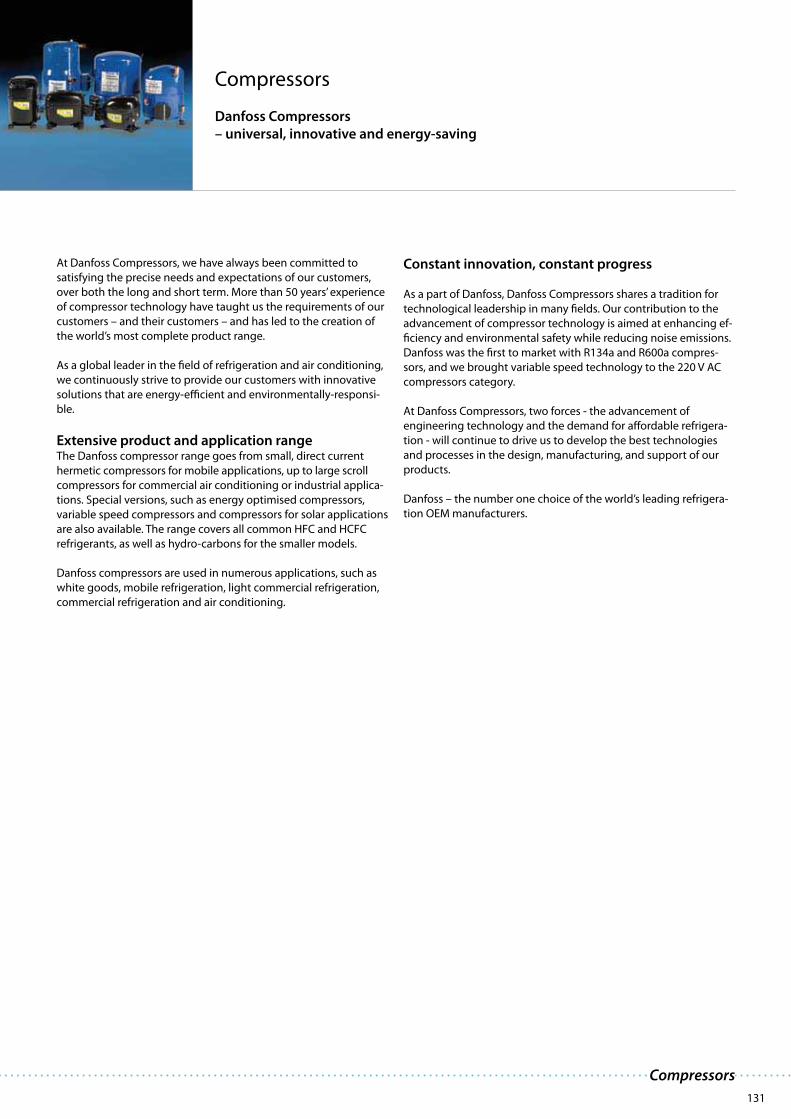
131
Compressors
Danfoss Compressors
– universal, innovative and energy-saving
At Danfoss Compressors, we have always been committed to
satisfying the precise needs and expectations of our customers,
over both the long and short term. More than 50 years’ experience
of compressor technology have taught us the requirements of our
customers – and their customers – and has led to the creation of
the world’s most complete product range.
As a global leader in the field of refrigeration and air conditioning,
we continuously strive to provide our customers with innovative
solutions that are energy-efficient and environmentally-responsi-
ble.
Extensive product and application rangeThe Danfoss compressor range goes from small, direct current
hermetic compressors for mobile applications, up to large scroll
compressors for commercial air conditioning or industrial applica-
tions. Special versions, such as energy optimised compressors,
variable speed compressors and compressors for solar applications
are also available. The range covers all common HFC and HCFC
refrigerants, as well as hydro-carbons for the smaller models.
Danfoss compressors are used in numerous applications, such as
white goods, mobile refrigeration, light commercial refrigeration,
commercial refrigeration and air conditioning.
Constant innovation, constant progress
As a part of Danfoss, Danfoss Compressors shares a tradition for
technological leadership in many fields. Our contribution to the
advancement of compressor technology is aimed at enhancing ef-
ficiency and environmental safety while reducing noise emissions.
Danfoss was the first to market with R134a and R600a compres-
sors, and we brought variable speed technology to the 220 V AC
compressors category.
At Danfoss Compressors, two forces - the advancement of
engineering technology and the demand for affordable refrigera-
tion - will continue to drive us to develop the best technologies
and processes in the design, manufacturing, and support of our
products.
Danfoss – the number one choice of the world’s leading refrigera-
tion OEM manufacturers.
Compressors

132

133
· Efficient and reliable
· Lasting performance
· Low weight
· Silent operation
· Ideal for solar energy supply
· Compact design
· Energy optimisation
· Speed/capacity control
· Operation under extreme conditions
· Minimal energy consumption
· Portable beyond traditional limits
· Low sound emission
· Application possible at extreme voltage rate
· Fits virtually anywhere
· Safeguard for your food
Product advantages Customer benefits
Direct current reciprocating compressorsDanfoss DC compressors perfectly suit applications like:
Tailored for cooling on the moveDesigned for 12 V and 24 V direct current dual voltage, Danfoss
DC compressors are designed for refrigeration in areas without a
mains power supply, like cars, vans, boats and trucks.
The DC compressors BD35F/50F/80F/120CN/150CL and BD150F
for 12 V and 24 V DC power supply are tailored to be used in both
refrigerators and freezers with refrigerant R134a/R404A/R507/
R290/R600a. They are equipped with an electronic unit that pro-
tects against overload and destructive battery discharge.
For ‘spot cooling’ systems, the BD350GH and BD350GH compres-
sors are the right choice. Installed in, for example, sleeping cabins
in trucks, the sleeping compartment of caravans, golf buggies,
flight bridges on day cruisers and lift trucks, they lower the tem-
perature and, at the same time, reduce humidity to a comfortable
level.
Danfoss DC compressors are unsurpassed in tolerating changeable
climatic conditions and vibrations under harsh road conditions, all
over the world.
· Trucks· Boats· Recreational vehicles· Medi boxes· Ice cream stands in holiday resorts
· Portable cooling boxes· Goods vehicles and trailers· Cars· Spot cooling systems
Direct current reciprocating compressors

134
Refrigerant Compressor Code noCode no
electronicdevice
rpmCapacity (EN 12900 Household/CECOMAF9 12 V d.c. static cooling)
-40 -35 -30 -25 -23.3 -20 -15 -10 -5 0 5 7.2 10 15
R134a
BD 35F 101Z0200 101N0210 3500 26.2 35.9 40.4 50.5 69.8 93.6 122
BD 50 F 101Z1220 101N0210 3500 36.7 52.2 58.3 71.4 94.9 123* 157*
BD 80 F 101Z0280 101N0280 4400 54.8 78.0 86.7 105 138 176 221
BD150F 102G4784 105N4220 4000 78 111 153 170 205 269 345
BD250GH 101Z0400 101N0280 4400 62.9 70.7 87.0 116 149 175 189 236 290 316 353 425
BD250/250GH 101Z0500 101N0280 4400 126 141 174 231 299 378 471 580 633 705 849
BD350GH 24 V DC 101Z0720 101N0710 4400 132 148 183 243 314 397 495 609 665 740 891
BD350GH 12 V DC 101Z0720 101N0700 4400 132 148 183 243 314 397 495 609 665 740 891
R290 BD100CN 101Z0401 101N0280 4400 44.6 62.4 83.4 108 117 137 170 209
R600a BD35K 101Z0211 101N0210 3500 24.9 36.0 40.2 49.3 65.1 83.8 106
Even cooling without power supply
Thanks to an extensive voltage rate
the BD compressors are ideal for solar
energy supply. The exceptionally low
starting current eliminates the need
for current batteries if an ice bank is
used for energy storage. When storing
the sun energy in ice packs the cabinet
can be kept at desired temperatures
both night and day.
This feature opens for numerous uses
in areas without power supply like
storage and transportation of drugs,
ice cream stands in holiday resorts,
food preservation under off road
conditions, refrigerators in boats to
name but a few.
* Fan cooling of electronic unit compulsory
Power consumption is limited to 100 W with electronic unit 101N0500
Modern comfort is brought into life
when leaving home.
As people goes mobile, so does food.
The excellent performance of the BD
series safeguards food preservation.
With our outstanding DC compressor
for cars, vans, boats, trucks, etc., Danfoss
has transcended the barriers for mobile
refrigeration.
The direct current voltage compressors
BD35F/50F/80F and BD150F for 12 V
and 24 V DC power supply can be used
in both refrigerators and freezers with
refrigerant R134a/R290/R600a and are
equipped with an electronic unit that
protects against overload protection
and destructive battery discharge.

135
· Smaller compressor dimensions or smaller displace-
ments possible
- Higher cooling capacity
· Low noise level, innovative compressor technology
· Low energy consumption
- High cooling capacity
- Improved COP
· Small start equipment
· High starting torque
· High thermal working conditions
- Oil and surface cooling
- Integrated winding protection
· High product quality
· Wide voltage range:
- 220-240 V 50 Hz programme
- 208-230 V 60 Hz programme (contact Danfoss)
- 115 V 60 Hz programme (contact Danfoss)
· Dual frequency models
· Extensive application range
· Low sound emission
· Low running costs
· Reduced installation costs
· Operation with thermostatic expansion valve possible
· Application at high ambient temperature possible
· High appliance and system robustness in rough operating
conditions
· Immune to unstable electric power supply
Product advantages Customer benefits
Reciprocating compressorsDanfoss compressors perfectly suit applications like:
Highly energy-efficient compressors for household
and light commercial applicationsDanfoss offers the world’s most comprehensive and high-quality
range of hermetic reciprocating compressors for refrigerators,
freezers and light commercial applications, such as bottle coolers
and display counters.
Available for use with refrigerant R134a, R404A, R407c, R600a and
R290, for 115V 60Hz and 230V 50HZ/60Hz, they cover the whole
spectrum of cooling needs for applications from 1.5 kW to 6 kW
and enable considerable energy savings.
Danfoss hermetic reciprocating compressors deliver a high cooling
capacity, particularly at low and very low evaporating tempera-
tures, and are tailored to meet the wide range of specific require-
ments our customers demand. These include space-saving design,
enhanced functionalities, low noise emission, high reliability and
efficiency.
· Laboratory and medical equipment· Clip-on units and condensing units· Compressed air dryers· Glass door merchandisers· Bakery refrigeration equipment· Ice cream cabinets
· Display cabinets – low temperature
· Vending machines· Soft ice cream machines· Ice making machines (ML/DL)· Blast freezers
· Slush/frozen beverage makers· Small coolers for trucks, working
while stationary· Heat pumps· Milk cooling tanks· Bottle coolers
Reciprocating Compressors

136
Ap
pli
cati
on
Compressor Code numbers EN 12900 (CECOMAF)
Capacity [W]
Evaporating temperature [°C]
EN 12900 (CECOMAF)
Com- Com- Power consumption [W]
pressor pressor
with
oil cooling Evporating temp. [°C]
-35 -30 -25 -23.3 -20 -15 -10 -6.7 -5 0 5 7.2 10 15 20 -35 -25 -10 5
HB
P /
MB
P /
(L
BP
)
PL35G 101G0250 28 31.6 39.3 53 69.4 82 89 112 140 153 172 209 48 66.6 90
TL2.5G 102G4251 11 22.4 35.5 40.5 50.9 69 90.4 107 116 145 179 196 219 264 47.6 59.6 83.9 113
TL3G 102G4350 25.3 40.9 46.7 59.1 80.5 106 125 136 170 211 231 258 312 65.8 96.2 133
TL4G 102G4452 40.8 58.3 65.3 80.3 107 140 165 180 226 280 306 342 413 82.7 118 154
TL5G 102G4550 55.6 79 87.9 107 139 178 208 224 278 341 372 414 497 100 149 205
FR6G 103G6660 47.7 83.3 96.5 124 171 226 267 290 365 452 494 552 109 172 241
FR7.5G 103G6680 103G6690 61.7 99 113 142 193 254 299 325 408 505 553 618 126 194 272
FR8.5G 103G6780 103G6790 84.9 123 138 171 228 298 351 381 478 592 647 722 151 231 321
FR10G 103G6880 103G6890 91.9 136 152 188 250 324 380 412 516 638 697 779 179 265 362
FR11G 103G6980 115 170 191 233 307 395 463 501 628 780 202 317 445
SC10G 104G8000 23 60 113 135 183 268 369 445 486 618 764 833 925 1100 93 181 290 383
SC12G 104G8240 104G8250 64.6 113 175 199 252 348 464 553 603 768 960 1054 1182 1437 148 227 355 493
SC15G 104G8520 104G8530 164 206 290 424 568 672 728 908 1110 1207 1340 1600 233 440 595
SC18G 104G8820 104G8830 283 318 394 526 684 804 870 1087 1337 1459 1624 1950 331 507 695
SC21G 104G8140 333 370 453 606 792 934 1012 1268 1560 1700 1889 2257 382 575 789
SC12/12G 104G8280 129 226 350 399 505 696 928 1106 1206 1535 1920 2108 2364 2875 296 454 710 986
SC15/15G 104G8580 328 413 581 847 1137 1344 1457 1815 2220 2415 2679 3201 465 879 1190
SC18/18G 104G8880 566 636 788 1052 1368 1607 1740 2174 2674 2918 3248 3900 662 1014 1390
SC21/21G 104G8180 667 741 907 1212 1584 1868 2025 2536 3120 3400 3778 4511 771 1156 1581
LB
P
PL50F 101G0220 14 26 40 45 56 74 95 43 60 85
TL4F 102G4400 31 44 61 67 81 107 137 60 81 122
TL5F 102G4501 43 60 82 91 110 144 183 70 101 154
TLS5F 102G4520 48 71 98 109 131 170 216 82 112 162
TLS6F 102G4620 58 77 104 115 139 183 235 84 119 181
TLS7F 102G4720 66 89 120 133 160 208 264 97 136 207
NL6F 105G6606 52 77 110 123 151 200 258 80 118 185
NL7F 105G6706 71 99 136 151 182 238 303 71 136 303
NL8F 105G6822 82 112 149 163 194 249 317 82 149 317
NL9F 105G6802 105G6812 74 111 155 172 207 268 340 109 167 260
NL11F 105G6900 105G6910 102 146 200 222 268 351 453 137 212 331
LB
P/B
MP NF7FX 105G6743 79 110 151 167 199 260 332 390 417 516 134 176 235 314
NF10FX 105G6846 104 144 197 217 258 336 428 503 538 667 214 272 354 462
NF11FX 105G6944 114 159 216 238 283 366 465 545 583 720 236 291 383 512
LB
P
SC15F 104G8500 104G8510 100 155 230 260 325 439 573 726 186 275 432
SC18F 104G8800 104G8810 129 194 280 314 388 518 669 842 206 313 492
SC21F 104G8100 104G8110 186 246 335 375 454 602 780 987 275 380 600
MB
P GS26MFX 107B0700 754 989 1266 1476 1591 1970 2411 2626 695 941
GS34MFX 107B0701 958 1246 1596 1866 2013 2505 3079 3360 924 1025
HB
P
TL4GH 102G4455 104 140 167 182 230 287 315 353 429 121 159
FR7GH 103G6683 103G6692 199 255 301 327 417 525 580 655 807 192 258
SC10GH 104G8041 233 352 425 478 613 762 832 927 1113 1323 281 395
SC12GH 104G8261 429 505 577 752 957 1058 1196 1471 1787 356 487
SC15GH 104G8561 559 669 723 915 1139 1249 1398 1698 2041 424 565
SC18GH 104G8860 539 676 789 855 1077 1340 1469 1645 1990 498 697
SC18GH 104G8861 485 639 758 825 1047 1310 1440 1618 1976 2389 452 605
SC15GHH 104G8571 435 570 670 726 911 1135 1247 1405 1731 377 505
Model designation
Compressordesign
Optimizationlevel
Compressorsize
Applicationrange
Startcharacteristics
PL
BlankStandard
energy level
SSemi-direct
intake
Nominal displacement
in cm3
Exception: For PL
com pres sors the
ca pa ci ty at ra ting point
is stated.
FR134a LBP/
(MBP)
GR134a LBP/MBP/HBP
GH R134a Heat
pumps
GHHR134a Heat
pumps (opt.)
MFR134a MBP
Blank =>universal
(principal rule)
X = HSTcharacteristics
(expansion valve)
TL
NL
FR
SC
GS
Examples
TL S 5 F
NL 9 F
SC 15 GHH
GS 26 MF X
Accessories for SC Twin
SC10/10, SC12/12 and SC15/15:Service valve for 12 mm tube 118-7350Solder connector for 12 mm tube 104B0584SC18/18 and SC21/21:Service valve for 16 mm tube 118-7351Solder connector for 16 mm tube 118-7405SC10/10, SC12/12, SC15/15, SC18/18 and SC21/21:Seal ring for service valve and solder connector 118-3638Time-delay relay 117N0001Check valve (to be used with time-delay relay) 020-1014
R134a hermetic compressors · 220-240 V · 50 Hz

137
Reciprocating Compressors
Displace- Recommended Voltage Electrical Equipment Compressor
ment compressor cooling and LST (RSIR) HST (CSIR) HST (CSR) LST/HST
at frequen- PTC Starting Starting Starting Starting Cord Cover
ambient temperature cies device relay capacitor device relief
32°C 38°C 43°C spades spades spades
[cm3] LBP MBP HBP LBP MBP HBP LBP MBP HBP 6.3 mm 4.8 mm 6.3 mm 6.3 mm 6.3 mm
2.00 F2 F2 F2 F2 1/5 103N0011 103N0018 117U6021 117U5014 103N1010 103N0491 PL35G
2.61 S S S S S S S S F2 1/2/3/6 103N0011 103N0018 117U6007 117U5014 103N1010 103N2011 TL2.5G
3.13 S S F2 S S F2 S S F2 1/2/3 103N0011 103N0018 117U6009 117U5014 103N1010 103N2010 TL3G
3.86 S S F2 S S F2 S S F2 1/2/3 103N0011 103N0018 117U6004 117U5014 103N1010 103N2010 TL4G
5.08 S S F2 S S F2 S S F2 1/2/3 103N0011 103N0018 117U6000 117U5014 103N1010 103N2010 TL5G
6.23 S S F2 S S F2 S S F2 1/2/3 103N0011 103N0018 117U6000 117U5015 103N1010 103N2010 FR6G
6.93 S F2 F2 S F2 F2 O/F1 F2 F2 1/2/3 103N0011 103N0018 117U6001 117U5015 103N1010 103N2010 FR7.5G
7.95 S F2 F2 O/F1 F2 F2 O/F1 F2 F2 1/2/3 103N0011 103N0018 117U6015 117U5015 103N1010 103N2010 FR8.5G
9.05 S F2 F2 O/F1 F2 F2 O/F1 F2 F2 1/2/3 103N0011 103N0018 117U6010 117U5015 103N1010 103N2010 FR10G
11.15 F2 F2 F2 F2 F2 F2 F2 F2 F2 1/2 103N0011 103N0018 117U6010 117U5015 103N1010 103N2010 FR11G
10.29 F1 F1 F2 F1 F1 F2 F1 F1 F2 1/2/3 103N0002 117U6002 117U5017 103N1004 103N2009 SC10G
12.87 O/F1 F2 F2 O/F1 F2 F2 O/F1 F2 F2 1/2/3 103N0002 117U6003 117U5017 103N1004 103N2009 SC12G
15.28 O/F1 F2 F2 O/F1 F2 F2 O/F1 F2 F2 1/2/3 117U6005 117U5017 103N1004 103N2009 SC15G
17.69 O/F1 F2 F2 O/F1 F2 F2 O/F1 F2 F2 1/2/3 117U6019 117U5017 103N1004 103N2009 SC18G
20.95 F2 F2 F2 F2 F2 F2 F2 F2 F2 1/2/3 117-7028 103N1004 103N2009 SC21G
2 x 12.87 F2 F2 F2 F2 F2 F2 F2 F2 F2 1 117U6003 117U5017 103N1004 103N2009 SC12/12G
2 x 15.28 F2 F2 F2 F2 F2 F2 F2 F2 F2 1 117U6005 117U5017 103N1004 103N2009 SC15/15G
2 x 17.69 F2 F2 F2 F2 F2 F2 F2 F2 F2 1 117U6019 117U5017 103N1004 103N2009 SC18/18G
2 x 20.95 F2 F2 F2 F2 F2 F2 F2 F2 F2 1 117-7028 103N1004 103N2009 SC21/21G
2.50 S S 1 103N0011 103N0018 103N1010 103N0491 PL50F
3.86 S S 1 103N0011 103N0018 117U6009 117U5014 103N1010 103N2010 TL4F
5.08 S S 1 103N0011 103N0018 117U6004 117U5014 103N1010 103N2010 TL5F
5.08 S S 1 103N0011 103N0018 117U6004 117U5014 103N1010 103N2010 TLS5F
5.70 S S 1 103N0011 103N0018 117U6004 117U5014 103N1010 103N2010 TLS6F
6.49 S S* 1 103N0011 103N0018 117U6000 117U5014 103N0016 103N1010 103N2010 TLS7F
6.13 S S 1 103N0011 103N0018 117U6004 117U5015 103N1010 103N2010 NL6F
7.27 S S 1 103N0011 103N0018 117U6000 117U5015 103N1010 103N2010 NL7F
7.95 S S 1 103N0011 103N0018 117U6001 117U5015 103N1010 103N2010 NL8F
8.35 S S 1 103N0011 103N0018 117U6001 117U5015 103N1010 103N2010 NL9F
11.15 O/F1 O/F1 1 103N0011 103N0018 117U6002 117U5015 103N1010 103N2010 NL11F
7.27 S S F1 F1 4/5 117U4140 117U5018 2x117U0349 117U1023 NF7FX
10.09 F1 F1 F2 F2 4 117U4139 117U5018 2x117U0349 117U1021 NF10FX
11.15 F2 F2 F2 F2 4 117U4139 117U5018 2x117U0349 117U1023 NF11FX
15.28 O/F1 O/F1 1 103N0002 117U6003 117U5017 103N1004 103N2009 SC15F
17.69 O/F1 O/F1 1 117U6005 117U5017 103N1004 103N2009 SC18F
20.95 O/F1 O/F1 1 117U6019 117U5017 103N1004 103N2009 SC21F
26.30 F2 F2 F2 1 Starting device (start. relay, start. & run capacitor): 117-7055 107B9100/9101/9104 GS26MFX
33.80 F2 F2 F2 1 Starting device (start. relay, start. & run capacitor): 117-7056 107B9100/9101/9104 GS34MFX
3.86 F2 F2 F2 1/4 117U6000 117U5014 103N1010 103N2011 TL4GH
6.93 O/F1 O/F1 O/F1 1/4 117U6016 117U5015 103N1010 103N2011 FR7GH
10.29 F2 F2 F2 1/4 117U6005 117U5019 103N1004 103N2008 SC10GH
12.87 F2 F2 F2 1/4 117U6011 117U5019 103N1004 103N2008 SC12GH
15.28 F2 F2 F2 1/4 117U6011 117U5019 103N1004 103N2008 SC15GH
17.69 F2 F2 F2 1 117U6019 117U5017 103N1004 103N2009 SC18GH
17.69 F2 F2 F2 1/4 117-7038 103N1004 103N2008 SC18GH
15.28 O O O 1 117-7012 103N1004 103N2009 SC15GHH
ApplicationsLBP: Low Back PressureHBP: High Back PressureMBP: Medium Back Pressure
Motor typesRSIR: Resistant Start Induction RunRSCR: Resistant Start Capacitor RunCSIR: Capacitor Start Induction RunCSR: Capacitor Start Run
Starting devicesLST: Low Starting TorqueLST is used with capillary tube control and pressure equalizing. (Pressure equalizing may exceed 10 min-utes). The PTC starting device requires 5 minutes cooling before each start.
Note: To fulfil the requirements of EN 60355-2-34 the protection screen 103N0476 must be applied to the PTC starting device.
HST: High Starting TorqueHST consisting of relay and starting capacitor, is used for expansion valve control or for capillary tube control without pressure equalizing.
Test conditions EN 12900 (CECOMAF)PL/TL/TLS/TLES/NL/NLE/FR/SCApplication R134aCondensing temperature 55°CAmbient temperature 32°CSuction gas temperature 32°CLiquid temperature 55°C220 V / 50 Hz
Test conditions EN 12900 (CECOMAF)GSApplication MPB HBPCondensing temperature 45°C 50°CAmbient temperature 32°C 32°CSuction gas temperature 20°C 20°CLiquid temperature no subcooling220 V / 50 Hz
1 Watt = 0.86 kcal/h1 Watt = 3.41 Btu/h
Compressor coolingS = Static cooling normally sufficientO = Oil cooling F
1 = Fan cooling 1.5 m/s
(compressor compartment temp. equal to ambient temperature)F
2 = Fan cooling 3.0 m/s necessary
* = O/F1 possible at 220 V nominal (187-242 V)
Voltages and frequencies1 = 198-254 V, 50 Hz2 = 187-254 V, 50 Hz, LBP3 = 198-254 V, 60 Hz, LBP4 = 198-254 V, 60 Hz5 = 198-254 V, 60 Hz, MBP6 = 207-254 V, 60 Hz, HBP

138
Co
mp
ress
or
Dimensions
Height Connectors
[mm] location/I.D. [mm]
Suc-
tion
Pro-
cess
Dis-
charge
Oil
cooler
A B C D E F
PL35G 137 135 6.2 6.2 5.0
TL2.5G 163 159 6.2 6.2 5.0
TL3G 163 159 6.2 6.2 5.0
TL4G 173 169 6.2 6.2 5.0
TL5G 173 169 6.2 6.2 5.0
FR6G 196 191 8.2 6.2 6.2
FR7.5G 196 191 8.2 6.2 6.2 6.2
FR8.5G 196 191 8.2 6.2 6.2 6.2
FR10G 196 191 8.2 6.2 6.2 6.2
FR11G 196 191 8.2 6.2 6.2
SC10G 199 193 8.2 6.2 6.2
SC12G 209 203 8.2 6.2 6.2 6.2
SC15G 209 203 10.2 6.2 6.2 6.2
SC18G 219 213 8.2 6.2 6.2 6.2
SC21G 219 213 10.2 6.2 6.2
SC12/12G 249 244 12 6.2 6.2
SC15/15G 249 244 12 6.2 6.2
SC18/18G 259 254 16 6.2 6.2
SC21/21G 259 254 16 6.2 6.2
PL50F 137 135 6.2 6.2 5.0
TL4F 163 159 6.2 6.2 5.0
TL5F 173 169 6.2 6.2 5.0
TLS5F 173 169 6.2 6.2 5.0
TLS6F 173 169 6.2 6.2 5.0
TLS7F 173 169 6.2 6.2 5.0
NL6F 188 181 6.2 6.2 5.0
NL7F 190 183 6.2 6.2 5.0
NL8F 197 191 6.2 6.2 5.0
NL9F 197 191 8.2 6.2 6.2 6.2
NL11F 203 197 8.2 6.2 6.2 6.2
NF7FX 203 197 8.2 6.5 6.5
NF10FX 203 197 8.2 6.5 6.5
NF11FX 203 197 8.2 6.5 6.5
SC15F 209 203 8.2 6.2 6.2 6.2
SC18F 209 203 10.2 6.2 6.2 6.2
SC21F 219 213 10.2 6.2 6.2 6.2
GS26MFX 259 247 12.9 6.5 8.2
GS34MFX 259 247 12.9 6.5 8.2
TL4GH 173 169 6.2 6.2 5.0
FR7GH 196 191 8.2 6.2 8.2 8.2
SC10GH 199 193 10.2 6.2 8.2
SC12GH 209 203 10.2 6.2 8.2
SC15GH 209 203 10.2 6.2 8.2
SC18GH 219 213 10.2 6.2 8.2
SC18GH 219 213 10.2 6.2 8.2
SC15GHH 209 203 10.2 6.2 8.2 8.2
= preliminary data
R134a hermetic compressors · 220-240 V · 50 Hz
3327-2
9
Compressor base Grommet sleevWasher Nut M6
Cabinet base Screw M6 x 25 Rubber grom
9
Washer
Compressor base
Clip
Steel pin
7382-2
Cabinet base Rubber grommet
Bolt joint for one compressor: 118-1917
in quantities: 118-1918
Bolt joint for one GS compressor: 107B9150
Snap-on in quantities: 118-1919
Mounting accessories SC Twin12
710
0
127
175
302
ø16
326
320
1"-14 UNF8305
A B
D
E
C
GS
173
122
203
B A
8542-2
E
D C
ø19
235
SC
B A
255
D C
E
F
151
8304
70
ø16
170127
ø19
127
FR
127
170
70 127
A B
F
E
CD
156
ø19ø16
243
8303
NL
70
ø16
254
170
A B
C
E
F
D
166
8302
TLS
157
170
70
ø16
BA
222
D
E
8301-7
C
PL
B A
206
170
70
ø16
CE
D
130
8300
TL
157
170
70
ø16
BA
222
D
E
8301
orC
Cor
D

139
Reciprocating Compressors
LST - RSIR
PL
8224
N
N LC
b
d
a1
a1
Winding protector
Start windingMain winding
g
TL-TLS-NL-FR
8217
N
N LC
b
d
a1
a1
Winding protector
Start windingMain winding
g
SC
8221
N
N LC
b
d
a1
a1
Winding protector
Start windingMain winding
HST - CSIR
PL
8225
10 11
131214
b
d
a2
c
Main winding Start windingWinding protector
c
TL-TLS-NL-FR
8219
10 11
131214
b
d
a2
c
Main winding Start windingWinding protector
c
SC
8222
b
d
a2
c
10 11
131214
c
Main windingStart winding
Winding protector
HST - CSR Legend
SC
M
1 1
2 2N NL L
5
4
2
1
b
d
Start winding
Main winding
Windingprotector
Thermostat Fan
e
a2
a2
Bleeder resistance
c
c
a3
e
a3
TOP
8227
GS
b
Start winding
Main winding
Windingprotector
Thermostat Fan
a2
Bleeder resistance
c
a3
e
8543
d
ea2
c
a3
TOP
b1
b2
Earthing(yellow/green)
R un (blue)
C ommon (brown)
S tart (black)
RCS
M
1 1
2 2N NL L
5
4
2
1
R
C
S
a1: PTC starting device
a2: Starting relay
a3: Starting device
b: Cover
b1/b2: Clamp/Gasket (parts of compressor)
c: Starting capacitor
d: Cord relief
e: Run capacitor
g: Protection screen for PTC
HST - CSR HST - CSIR
SC Twin
1932
Winding protector
Main windingStart winding
Starting relayStarting capacitor
Run capacitorBleeder resistance
ThermostatSafety pressure control
Time delayrelay
BlueBlack
Brown
Thermostat 2
Fan
Remove wire L-1 if time delay is used Remove wire 1-2 if thermostat 2 is used
M
1 12 2N NL L
5 2
14
2 1 3
1 12 2N NL L
5 2
14
SC Twin
1933
M
Starting relayStarting capacitor
Start windingWindingprotector
Main winding
Thermostat
Safety pressure control
Time delay relayThermostat 2
Fan
Remove wire L-1 if time delay is used Remove wire 1-2 if thermostat 2 is used
BlueBlack
Brown
12
10 11
13
14
12
14
10 11
13
2 1 3
12NL
12NL
1 12 2N NL L

140
Re
frig
era
nt
Ap
pli
cati
on
Compressorincl. the
GEEPTM range
Compressor code
number 2)
EN 12900 (CECOMAF)
Capacity [W]
Evaporating temperature [°C]
-45 -40 -35 -30 -25 -23.3 -20 -15 -10 -6.7 -5 0 5 7.2 10 15
1 P
ha
se
R4
04
A
LB
P
TL4CL 102U2071 52 65 84 110 142 155 182 230 286 328 352
TL4.5CLX 102U2111 80 106 139 181 197 232 294 366
FR6CL 103U2670 77 108 145 189 243 263 307 383 473 541 578
FR7.5CL 103U2790 86 114 154 202 262 285 333 418 515 587 630
FR8.5CL 103U2890 99 126 168 222 290 317 372 468 577
NL7CLX 105F3710 102 146 199 263 340 369 430 536 657 746 796
NL8.4CLX 105F3800 111 158 216 287 370 402 468 583 715 812 866
SC10CLX1) 104L2533 166 255 360 400 483 625 789 910 977 1190 1430
SC12CLX.21) 104L2697 130 205 294 399 522 569 666 834 1026
SC15CLX.21) 104L2896 159 250 358 486 637 694 813 1017 1251 1424 1519
SC18CLX.21) 104L2197 194 306 439 595 780 849 995 1245 1532
SCE18CLX.21) 104L2196 194 306 439 595 780 849 995 1245 1532
SC21CL 104L2322 226 325 455 617 813 887 1042 1306 1606
GS26CLX * GEEPTM 107B0500 325 497 703 949 1240 1348 1580 1974 2427
GS34CLX * GEEPTM 107B0501 721 986 1297 1663 1807 2092 2577 3120
NTZ0481) 120F0089 261 527 964 1405 1931 2131 2550 3270 4100
NTZ0681) 120F0090 779 1130 1756 2332 3030 3297 3863 4849 6001
MB
P
NF7MLX 105F3720 526 645 733 781 936 1110 1193 1305
SC10MLX 104L2506 465 546 687 855 981 1051 1278 1537
SC12MLX 104L2606 572 669 838 1038 1188 1272 1542 1852 2001
SC15MLX 104L2869 710 829 1038 1285 1471 1574 1909 2293 2478
SC18MLX 104L2139 831 968 1210 1497 1712 1832 2220 2665 2880
SC18MLX.3 104L2146 876 1018 1266 1557 1779 1898 2292 2743 2964
GS21MLX * GEEPTM 107B0502 1419 1777 2044 2186 2642 3140 3354
GS26MLX * GEEPTM 107B0503 1535 1917 2365 2680 2854 3401 3990 4260
GS34MLX * GEEPTM 107B0504 1925 2397 2952 3359 3585 4286 5060 5418
MPZ0381) GEEPTM 120F0153 851 1289 1426 1722 2257 2904 3399 3675 4580 5628 6138 6831
MPZ0481) GEEPTM 120F0154 1214 1823 2006 2398 3091 3914 4535 4881 6004 7298 7924 8774
MPZ0541) GEEPTM 120F0155 1250 1997 2224 2700 3518 4465 5168 5555 6803 8222 8968 9826
MPZ0611) GEEPTM 120F0156 1484 2368 2580 3106 4003 5030 5786 6201 7528 9023 9738 10700
MPZ0681) GEEPTM 120F0157 1889 2828 3098 3665 4636 5758 6591 7051 8530 10215 11026 12123
R4
04
A
HB
P
TL4DL 102U2038 196 229 281 329 349 432 527 527 631
FR6DL 103U2680 317 385 471 538 576 698 840 907 999 1177
SC10DL 104L2525 471 611 775 899 968 1192 1450 1576 1747 2085
SC12DL 104L2625 609 806 1028 1190 1279 1565 1890 2046 2258 2674
SC15DL 104L2856 759 964 1207 1391 1493 1825 2210 2397 2652 3156
SC10/10DL 104L4091 943 1222 1550 1798 1935 2383 2900 3152 3494 4169
SC12/12DL 104L4092 1217 1612 2055 2380 2559 3130 3780 4092 4516 5348
SC15/15DL 104L4093 1518 1928 2414 2781 2985 3651 4420 4795 5304 6311
3 P
ha
se
R4
04
A
LB
P NTZ0481) 120F0008 289 558 995 1424 1931 2122 2522 3204 3987
NTZ0681) 120F0009 673 1075 1750 2380 3122 3402 3988 4992 6146
MB
P
MPZ0381) GEEPTM 120F0057 879 1342 1484 1791 2339 2995 3492 3770 4673 5715 6220 6906
MPZ0481) GEEPTM 120F0058 1173 1846 2047 2467 3183 4005 4611 4943 6009 7212 7788 8563
MPZ0541) GEEPTM 120F0059 1250 1997 2700 2224 3518 4465 5168 5555 6803 8222 8904 9826
MPZ0611) GEEPTM 120F0060 1484 2328 3106 2580 4003 5030 5786 6201 7528 9023 9738 10700
MPZ0681) GEEPTM 120F0061 1777 2732 3011 3592 4579 5707 6537 6992 8449 10093 10880 11940
SC
B A
255
D C
E
151
8304-5
70
ø16
170127
ø19
127
GS
173
122
203
B A
8542-4
E
D C
ø19
235
MPZ
C
ED
B A
190
254
8639
234190
NTZ
C
B
A
E
8638
ø 224
162
33°
35°
227
D
Note:On GS34CLX compressors suction and process connectors areinterchanged.
R404A/R507 hermetic compressors · 220-240 V · 50 Hz & 60 Hz incl. GEEP range

141
Reciprocating Compressors
EN 12900 (CECOMAF)
Power consumption
[W]
Evporating temp.
[°C]
Dis-place-ment
Recommended compressor coolingat
ambient temperatures
Voltageandfre-
quen-cies
Electrical equipment (HST), spade dimensions Single packcode
number
HST (CSIR) HST (CSR) LST/HST
32 °C 38 °C 43 °C Startingrelay
Startingcapacitor
Startingdevice
Cordrelief
Cover
spades spades
-35 -25 -10 5 [cm3] LBP MBP HBP LBP MBP HBP LBP MBP HBP 6.3 mm 6.3 mm 6.3 mm
105 140 198 3.86 F₂ F₂ F₂ F₂ 1 117U6000 117U5014 103N1010 103N2010
138 181 252 4.63 F₂ F₂ F₂ 7 117U6001 117U5014 103N1004 117U1022
180 242 353 6.23 F₂ F₂ F₂ F₂ 1 117U6015 117U5015 103N1010 103N2010
197 267 395 6.93 F₂ F₂ F₂ F₂ 1 117U6016 117U5015 103N1010 103N2010
231 315 472 7.95 F₂ F₂ 1 117U6010 117U5015 103N1010 103N2010
214 274 381 7.27 F1 F1 F1 F1 F₂ F₂ 1 117U6002 117U5015 103N1010 103N2010
271 305 428 8.35 F₂ F₂ F₂ F₂ F₂ F₂ 7 117U6003 117U5015 103N1010 103N2010
258 352 508 631 10.29 F₂ F₂ F₂ F₂ 117U6005 117U5019 103N1004 103N2008 195B0151
365 475 659 12.87 F₂ F₂ 117U6019 117U5019 103N1004 103N2008 195B0379
433 565 783 15.28 F₂ F₂ F₂ 117U6019 117U5017 103N1004 103N2009 195B0399
517 680 949 17.68 F₂ F₂ F₂ 117U6013 117U5012 103N1004 103N2009 195B0332
459 621 888 17.68 F₂ F₂ F₂ 117-7012 103N1004 103N2009 on request
534 702 989 20.95 F₂ F₂ 117-7012 103N1004 103N2009 195B0070
669 888 1285 26.30 F₂ F₂ F₂ 117-7056 107B9100/9101/9104 195B0427
909 1165 1696 33.80 F₂ F₂ 117-7074 107B9100/9101/9104 195B0439
1342 1885 48.1 SG SG SG SG SG SG 7701028 8156134 120F0087
2067 2936 67.9 SG SG SG SG SG SG 7701028 8156134 120F0088
398 556 7.27 F₂ F₂ F₂ 7 117U4139 117U5018 2x117U0349 117U1021
518 633 10.29 F₂ F₂ F₂ 117U6011 117U5019 103N1004 103N2009 195B0345
620 762 12.87 F₂ F₂ F₂ 117U6011 117U5019 103N1004 103N2009 195B0323
780 979 15.28 F₂ F₂ 117U6013 117U5012 103N1004 103N2009 195B0391
860 1080 17.68 F₂ F₂ 117-7012 103N1004 103N2009 195B0392
878 1096 17.68 F₂ F₂ 117-7012 103N1004 103N2009 195B0412
981 1210 21.20 F₂ F₂ F₂ 117-7070 107B9100/9101/9104 195B0436
1207 1478 26.30 F₂ F₂ F₂ 117-7072 107B9100/9101/9104 195B0437
1722 2204 33.80 F₂ F₂ F₂ 117-7073 107B9100/9101/9104 195B0438
930 1374 1711 38.1 SG SG SG 120F0143
1326 1869 2352 48.1 SG SG SG 120F0144
1420 2154 2725 53.9 SG SG SG 120F0145
1676 2522 3159 60.5 SG SG SG 120F0146
2091 2965 3682 67.9 SG SG SG 120F0147
203 256 3.86 F₂ F₂ F₂ F₂ 1 117U6001 117U5014 103N1010 103N2010
354 456 6.23 F₂ F₂ F₂ F₂ 1 117U6010 117U5015 103N1010 103N2010
479 590 10.29 F₂ F₂ F₂ F₂ 1 117U6005 117U5017 103N1004 103N2009
624 750 12.87 F₂ F₂ F₂ F₂ 1 117U6019 117U5017 103N1004 103N2009
722 865 15.28 F₂ F₂ F₂ F₂ 1 117-7028 103N1004 103N2009
957 1180 2x10.29 F₂ F₂ F₂ F₂ 1 117U6005 117U5017 103N1004 103N2009
1248 1500 2x12.87 F₂ F₂ F₂ F₂ 1 117U6019 117U5017 103N1004 103N2009
1445 1730 2x15.28 F₂ F₂ F₂ F₂ 1 117-7028 103N1004 103N2009
1328 1884 48.1 SG SG SG SG SG SG 8156134 120F0001
2017 2843 67.9 SG SG SG SG SG SG 8156134 120F0002
966 1419 1739 38.1 SG SG SG 120F0047
1288 1896 2361 48.1 SG SG SG 120F0048
1420 2154 2725 53.9 SG SG SG 120F0049
1676 2522 3159 60.5 SG SG SG 120F0050
1942 2905 3706 67.9 SG SG SG 120F0051
FR
A B
E
CD
ø19ø16
243 8303-4
127
170
70 127
156
TL
157
170
70
ø16
BA
222
D
E
8301
orC
Cor
D
NL
70
ø16
254
170
A B
C
ED
166
8302-3
1) available for 60 Hz also

142
M
1 1
2 2N NL L
5
4
2
1
b
d
Start winding
Main winding
Windingprotector
Thermostat Fan
e
a2
a2
Bleeder resistance
c
c
a3
e
a3
TOP
8227
b
Start winding
Main winding
Windingprotector
Thermostat Fan
a2
Bleeder resistance
c
a3
e
8543
d
ea2
c
a3
TOP
b1
b2
Earthing(yellow/green)
R un (blue)
C ommon (brown)
S tart (black)
RCS
M
1 1
2 2N NL L
5
4
2
1
R
C
S
8222
b
d
a2
c
10 11
131214
c
Main windingStart winding
Winding protector
Re
frig
era
nt
Ap
pli
cati
on
Compressorincl. the
GEEPTM range
Dimensions
Height[mm]
Connectorslocation/I.D. [mm]
A B
Suc- Pro- Dis-
tion cess charge
C D E
1 P
ha
se
R4
04
A
LB
P
TL4CL 173 169 6.2 6.2 5.0
TL4.5CLX 173 169 6.2 6.2 5.0
FR6CL 196 191 8.2 6.2 6.2
FR7.5CL 196 191 8.2 6.2 6.2
FR8.5CL 196 191 8.2 6.2 6.2
NL7CLX 203 197 8.2 6.2 6.2
NL8.4CLX 203 197 8.2 6.2 6.2
SC10CLX1) 209 203 8.2 6.2 6.2
SC12CLX.21) 219 213 8.2 6.2 6.2
SC15CLX.21) 219 213 10.2 6.2 6.2
SC18CLX.21) 219 213 10.2 6.2 6.2
SCE18CLX.21) 219 213 10.2 6.2 6.2
SC21CL 219 213 10.2 6.2 6.2
GS26CLX * GEEPTM 259 247 12.9 6.5 8.2
GS34CLX * GEEPTM 259 247 12.9 6.5 8.2
NTZ0481) 333 263 5/8” Flare 1/2”
NTZ0681) 333 263 5/8” Flare 1/2”
MB
P
NF7MLX 203 197 9.7 6.5 6.5
SC10MLX 209 203 8.2 6.5 6.5
SC12MLX 219 213 8.2 6.5 6.5
SC15MLX 219 213 10.2 6.2 6.2
SC18MLX 219 213 10.2 6.2 6.2
SC18MLX.3 219 213 10.2 6.2 6.2
GS21MLX * GEEPTM 259 247 12.9 6.5 8.2
GS26MLX * GEEPTM 279 267 16.1 6.5 9.7
GS34MLX * GEEPTM 279 267 16.1 6.5 9.7
MPZ0381) GEEPTM 356 342 3/4” 3/8” 1/2”
MPZ0481) GEEPTM 356 342 3/4” 3/8” 1/2”
MPZ0541) GEEPTM 356 342 3/4” 3/8” 1/2”
MPZ0611) GEEPTM 356 342 3/4” 3/8” 1/2”
MPZ0681) GEEPTM 356 342 3/4” 3/8” 1/2”
R4
04
A
HB
P
TL4DL 173 169 6.2 6.2 5.0
FR6DL 196 191 8.2 6.2 6.2
SC10DL 209 203 8.2 6.2 6.2
SC12DL 219 213 10.2 6.2 6.2
SC15DL 219 213 10.2 6.2 6.2
SC10/10DL 249 244 12 6.2 6.2
SC12/12DL 249 244 12 6.2 6.2
SC15/15DL 259 254 16 6.2 6.2
3 P
ha
se
R4
04
A
LB
P NTZ0481) 333 263 5/8” Flare 1/2”
NTZ0681) 333 263 5/8” Flare 1/2”
MB
P
MPZ0381) GEEPTM 348 346 3/4” 3/8” 1/2”
MPZ0481) GEEPTM 348 346 3/4” 3/8” 1/2”
MPZ0541) GEEPTM 348 346 3/4 3/8” 1/2”
MPZ0611) GEEPTM 348 346 3/4” 3/8” 1/2”
MPZ0681) GEEPTM 348 346 3/4” 3/8” 1/2”
CSIR CSR
SC MPZ
CSR CSR
SC NTZ
CSR Legend
GSa1: PTC starting devicea2: Starting relaya3: Starting deviceb: Coverb1/b2: Clamp/Gasket (parts of compressor)c: Starting capacitord: Cord reliefe: Run capacitor
Spade connectors 1/4”
Earth M4-12
Knock-out Ø 21 mm (0.83 in)
Hole Ø 21 mm (0.83 in)
R404A/R507 hermetic compressors · 220-240 V · 50 Hz & 60 Hz incl. GEEP range

143
HST - CSIR
TL4.5CLX
8417
M
10
5
4
3
2
1
L
N
7
8
6
12
14
13
11
Main windingStart winding
Winding protector
a2
b
a2
c
c
TL-NL-FR
Applications
LBP: Low Back Pressure
MBP: Medium Back Pressure
HBP: High Back Pressure
Motor types
CSIR: Capacitor Start Induction Run
CSR: Capacitor Start Run
Starting devices
HST: High Starting Torque
Test conditions EN 12900 (CECOMAF)
TL/NL/FR/SC
Application R404A/R507
Condensing temperature 45°C
Ambient temperature 32°C
Suction gas temperature 32°C
No subcooling
220 V / 50 Hz
Test conditions EN 12900
GS/NTZ/MPZ:
Condensing temp. LBP 40°C
Condensing temp. MBP 45°C
Condensing temp. HBP 50°C
Ambient temperature 32°C
Suction gas temperature 20°C
NTZ at Te = -45°C, -40°C SH=20K
MPZ at Te = -30°C SH=20K
Liquid temperature no subcooling
220 V / 50 Hz (GS)
230 V / 1 ph / 50 Hz (NTZ/MPZ)
400 V / 3 ph / 50 Hz (NTZ/MPZ)
Compressor cooling
S = Static cooling normally sufficient
O = Oil cooling
F1 = Fan cooling 1.5 m/s
(compressor compartment temp.
equal to ambient temperature)
F2 = Fan cooling 3.0 m/s necessary
F2 = Fan cooling 3.0 m/s necessary
SG = Suction gas cooling normally
sufficient
Hermetic compressors type TL, NL, FR, SC, GS, MPZ, NTZ R404A/R507
8219
10 11
131214
b
d
a2
c
Main winding Start windingWinding protector
c
Reciprocating Compressors

144

145
· Efficient and reliable
· Designed for multiple applications
· Rugged
· Designed for high, medium and low evaporating
temperature applications
· Quick pull down capabilities
· 100% suction gas-cooled motor
· Internal motor protection
· High efficiency circular valve design
· High torque motors
· Operation under extreme conditions
· Versatile: Suitable for air conditioning as well as chilling
applications
· No need for air circulation around the compressor
· Simple to use
· Flexibility of location
· High limit on maximum operating condensing temperature
Product advantages Customer benefits
Reciprocating CompressorsDanfoss Maneurop compressors perfectly suit applications like:
Universal compressors for commercial refrigeration
and air conditioning applicationsDesigned for refrigeration as well as air conditioning applica-
tions with refrigerants R22, R407C, R134a, R404A and R507A, the
Maneurop range covers all requirements in the 1.5 to 26 HP range.
Thanks to a very large internal volume, large oil sump, the sturdy
design of the compression parts and its 100% suction gas-cooled
electric motor, the Maneurop reciprocating compressor has
consistently proven itself capable of withstanding the harshest
conditions.
The range consists of single compressors with rotolock connec-
tions, suitable for parallel mounting as well as factory-made
tandem units.
Maneurop compressors are used in a large array of applications in
a variety of businesses, ranging from water chillers to large pack-
aged air conditioners, as well as medium and low temperature
refrigeration systems for food storage and processing.
· Walk-in freezers & cold rooms· Frozen food processing and storage· Blast freezers· Low temperature racks· Ice flake machines
· Ice cream machines· Display cabinets· Water chillers· Large packaged air conditioners
Reciprocating Compressors
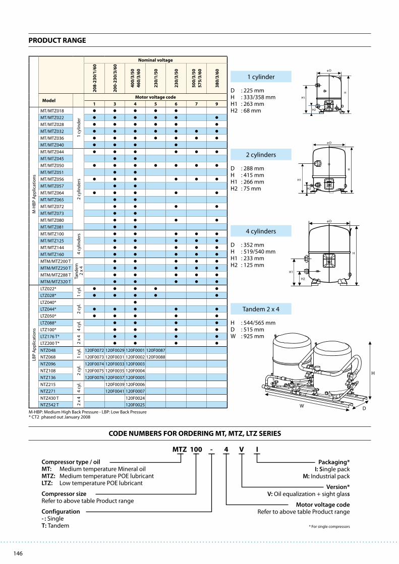
146
PRODUCT RANGE
CODE NUMBERS FOR ORDERING MT, MTZ, LTZ SERIES
H
DW
H
H1
ø D
H2
H1
ø D
H2
H
H1
H
H2
ø D
Nominal voltage
20
8-2
30
/1/6
0
20
0-2
30
/3/6
0
40
0/3
/50
46
0/3
/60
23
0/1
/50
23
0/3
/50
50
0/3
/50
57
5/3
/60
38
0/3
/60
ModelMotor voltage code
1 3 4 5 6 7 9
M-H
BP
Ap
plic
ati
on
s
MT/MTZ018
1 c
ylin
de
rMT/MTZ022
MT/MTZ028
MT/MTZ032
MT/MTZ036
MT/MTZ040
MT/MTZ044
2 c
ylin
de
rs
MT/MTZ045
MT/MTZ050
MT/MTZ051
MT/MTZ056
MT/MTZ057
MT/MTZ064
MT/MTZ065
MT/MTZ072
MT/MTZ073
MT/MTZ080
MT/MTZ081
MT/MTZ100
4 c
ylin
de
rs
MT/MTZ125
MT/MTZ144
MT/MTZ160
MTM/MTZ200 T
Tan
de
m
2 x
4MTM/MTZ250 T
MTM/MTZ288 T
MTM/MTZ320 T
LBP
Ap
plic
ati
on
s
LTZ022*
1 c
yl.
LTZ028*
LTZ040*
2 c
yl.
LTZ044*
LTZ050*
LTZ088*
4 c
yl.
LTZ100*
LTZ176 T*
2 x
4
LTZ200 T*
NTZ048
1 c
yl.
120F0072 120F0029 120F0001 120F0087
NTZ068 120F0073 120F0031 120F0002 120F0088
NTZ096
2 c
yl. 120F0074 120F0033 120F0003
NTZ108 120F0075 120F0035 120F0004
NTZ136 120F0076 120F0037 120F0005
NTZ215
4 c
yl.
120F0039 120F0006
NTZ271 120F0041 120F0007
NTZ430 T
2 x
4 120F0024
NTZ542 T 120F0025
Compressor type / oilMT: Medium temperature Mineral oilMTZ: Medium temperature POE lubricantLTZ: Low temperature POE lubricant
Compressor sizeRefer to above table Product range
Configuration- : SingleT : Tandem
Packaging* I: Single pack
M: Industrial pack
Version* V: Oil equalization + sight glass
Motor voltage code Refer to above table Product range
* For single compressors
I4 V-100MTZ
D : 225 mmH : 333/358 mmH1 : 263 mmH2 : 68 mm
1 cylinder
D : 288 mmH : 415 mmH1 : 266 mmH2 : 75 mm
2 cylinders
D : 352 mmH : 519/540 mmH1 : 233 mmH2 : 125 mm
4 cylinders
H : 544/565 mmD : 515 mmW : 925 mm
Tandem 2 x 4
M-HBP: Medium High Back Pressure - LBP: Low Back Pressure* CT2 phased out January 2008

147
MTZ PERFORMANCE DATA R134a
ModelTo -15 -10 -5 0 5 10 15 20
Tc Qo Pe Qo Pe Qo Pe Qo Pe Qo Pe Qo Pe Qo Pe Qo Pe
MTZ018
35 1 020 0.58 1 450 0.64 1 980 0.70 2 610 0.74 3 350 0.76 4 210 0.77 5 200 0.76 6 340 0.73
45 760 0.61 1 140 0.69 1 600 0.76 2 150 0.82 2 800 0.87 3 550 0.91 4 430 0.93 5 430 0.93
55 580 0.61 890 0.71 1 270 0.80 1 720 0.88 2 250 0.96 2 880 1.03 3 620 1.09 4 480 1.12
MTZ022
35 1 320 0.68 1 860 0.76 2 520 0.84 3 310 0.90 4 260 0.94 5 370 0.96 6 660 0.97 8 160 0.94
45 1 030 0.72 1 500 0.81 2 080 0.91 2 770 0.99 3 610 1.06 4 600 1.11 5 750 1.15 7 090 1.16
55 810 0.72 1 190 0.84 1 670 0.95 2 250 1.06 2 960 1.16 3 800 1.25 4 800 1.32 5 960 1.37
MTZ028
35 1 650 0.85 2 260 0.94 3 030 1.03 4 000 1.11 5 170 1.19 6 580 1.25 8 260 1.29 10 200 1.32
45 1 350 0.91 1 880 1.02 2 560 1.13 3 410 1.23 4 450 1.34 5 710 1.43 7 210 1.51 8 980 1.58
55 1 140 0.95 1 570 1.08 2 120 1.22 2 830 1.35 3 720 1.48 4 800 1.61 6 110 1.73 7 660 1.85
MTZ032
35 1 940 1.03 2 680 1.17 3 590 1.30 4 710 1.41 6 070 1.49 7 680 1.55 9 580 1.57 11 800 1.56
45 1 560 1.09 2 210 1.25 3 020 1.40 4 020 1.54 5 230 1.66 6 690 1.76 8 400 1.83 10 400 1.86
55 1 260 1.11 1 790 1.29 2 470 1.48 3 320 1.65 4 370 1.81 5 630 1.96 7 140 2.08 8 930 2.16
MTZ036
35 2 650 1.20 3 480 1.33 4 490 1.45 5 690 1.56 7 100 1.64 8 750 1.70 10 700 1.73 12 800 1.72
45 2 250 1.29 3 000 1.45 3 910 1.60 4 990 1.74 6 280 1.86 7 780 1.97 9 530 2.05 11 500 2.10
55 1 860 1.35 2 510 1.54 3 300 1.72 4 250 1.91 5 380 2.08 6 720 2.23 8 270 2.37 10 100 2.48
MTZ040
35 3 070 1.33 3 910 1.44 4 890 1.56 6 030 1.65 7 350 1.73 8 860 1.79 10 600 1.82 12 500 1.83
45 2 680 1.47 3 460 1.61 4 370 1.75 5 420 1.89 6 640 2.01 8 020 2.12 9 600 2.21 11 400 2.27
55 2 260 1.56 2 950 1.74 3 770 1.92 4 720 2.10 5 810 2.28 7 060 2.44 8 490 2.59 10 100 2.72
MTZ044
35 2 880 1.55 3 910 1.70 5 190 1.83 6 760 1.94 8 640 2.02 10 900 2.07 13 500 2.08 16 600 2.04
45 2 270 1.62 3 170 1.80 4 290 1.96 5 670 2.12 7 340 2.25 9 340 2.35 11 700 2.42 14 400 2.45
55 1 820 1.64 2 560 1.85 3 490 2.07 4 650 2.27 6 070 2.46 7 780 2.63 9 830 2.77 12 200 2.87
MTZ045
35 2 890 1.27 3 910 1.42 5 180 1.55 6 730 1.65 8 610 1.72 10 900 1.78 13 500 1.80 16 600 1.80
45 2 280 1.29 3 190 1.49 4 290 1.67 5 650 1.83 7 290 1.95 9 300 2.05 11 600 2.13 14 400 2.17
55 1 690 1.24 2 490 1.51 3 460 1.76 4 630 1.97 6 050 2.16 7 770 2.32 9 800 2.45 12 200 2.55
MTZ050
35 3 350 1.72 4 550 1.90 6 040 2.06 7 850 2.20 10 000 2.30 12 600 2.37 15 600 2.39 19 100 2.36
45 2 630 1.79 3 700 2.01 5 020 2.21 6 630 2.40 8 570 2.56 10 900 2.69 13 600 2.78 16 700 2.83
55 2 100 1.81 2 990 2.07 4 100 2.32 5 470 2.57 7 140 2.80 9 140 3.01 11 500 3.18 14 300 3.32
MTZ051
35 3 270 1.54 4 500 1.71 6 030 1.86 7 890 1.97 10 100 2.06 12 800 2.13 15 900 2.16 19 500 2.18
45 2 580 1.57 3 660 1.80 4 970 2.00 6 580 2.17 8 510 2.31 10 800 2.42 13 500 2.51 16 700 2.57
55 1 950 1.54 2 900 1.85 4 040 2.12 5 420 2.36 7 080 2.57 9 060 2.74 11 400 2.89 14 200 3.00
MTZ056
35 3 720 1.87 5 060 2.08 6 720 2.27 8 720 2.44 11 100 2.57 13 900 2.65 17 200 2.69 21 000 2.66
45 2 930 1.95 4 140 2.20 5 620 2.44 7 420 2.66 9 580 2.85 12 100 3.01 15 100 3.13 18 600 3.20
55 2 300 1.96 3 330 2.26 4 600 2.56 6 150 2.85 8 030 3.12 10 300 3.37 12 900 3.58 16 000 3.75
MTZ057
35 3 210 1.63 4 560 1.83 6 240 2.00 8 290 2.15 10 700 2.28 13 600 2.37 17 000 2.43 20 900 2.46
45 2 510 1.64 3 690 1.88 5 160 2.11 6 970 2.31 9 150 2.49 11 700 2.64 14 800 2.77 18 300 2.86
55 1 940 1.65 2 930 1.95 4 190 2.24 5 760 2.51 7 670 2.76 10 000 2.99 12 700 3.18 15 800 3.35
MTZ064
35 4 200 2.06 5 740 2.31 7 610 2.53 9 870 2.73 12 600 2.88 15 700 2.99 19 400 3.04 23 700 3.02
45 3 320 2.14 4 700 2.43 6 400 2.71 8 440 2.97 10 900 3.20 13 800 3.40 17 100 3.54 21 000 3.63
55 2 580 2.15 3 780 2.50 5 240 2.84 7 020 3.18 9 170 3.50 11 700 3.80 14 700 4.05 18 200 4.26
MTZ065
35 3 740 1.84 5 320 2.07 7 250 2.27 9 570 2.43 12 300 2.57 15 500 2.67 19 300 2.73 23 600 2.76
45 2 960 1.87 4 390 2.17 6 110 2.43 8 180 2.67 10 600 2.87 13 500 3.04 16 800 3.18 20 700 3.27
55 2 210 1.84 3 490 2.22 5 010 2.57 6 830 2.88 8 990 3.17 11 500 3.42 14 500 3.64 17 900 3.82
MTZ072
35 5 040 2.27 6 780 2.53 8 880 2.77 11 400 2.98 14 300 3.15 17 800 3.27 21 800 3.33 26 400 3.32
45 4 000 2.34 5 590 2.67 7 510 2.99 9 800 3.30 12 500 3.58 15 700 3.83 19 400 4.03 23 600 4.18
55 2 990 2.17 4 390 2.59 6 080 3.01 8 110 3.44 10 500 3.85 13 400 4.24 16 700 4.61 20 500 4.93
MTZ073
35 4 320 2.09 6 050 2.36 8 150 2.59 10 700 2.79 13 700 2.97 17 200 3.13 21 300 3.27 26 000 3.40
45 3 500 2.16 5 090 2.50 7 010 2.81 9 320 3.08 12 100 3.33 15 300 3.54 19 000 3.74 23 300 3.92
55 2 680 2.14 4 100 2.58 5 810 2.98 7 870 3.34 10 300 3.67 13 200 3.97 16 600 4.24 20 500 4.48
MTZ080
35 5 940 2.64 7 880 2.94 10 200 3.23 13 000 3.50 16 300 3.75 20 100 3.96 24 500 4.12 29 500 4.23
45 4 860 2.76 6 630 3.11 8 750 3.46 11 300 3.80 14 300 4.13 17 700 4.42 21 800 4.69 26 400 4.91
55 3 830 2.80 5 380 3.22 7 250 3.64 9 480 4.06 12 100 4.48 15 200 4.88 18 900 5.26 23 000 5.60
MTZ081
35 5 460 2.50 7 350 2.76 9 700 3.00 12 500 3.22 15 800 3.41 19 700 3.59 24 300 3.74 29 700 3.87
45 4 520 2.59 6 230 2.93 8 320 3.24 10 800 3.54 13 800 3.80 17 400 4.05 21 600 4.27 26 400 4.48
55 3 580 2.64 5 100 3.07 6 950 3.48 9 170 3.87 11 800 4.23 15 000 4.57 18 800 4.88 23 100 5.18
MTZ100
35 6 360 3.05 8 660 3.38 11 500 3.68 14 900 3.91 18 900 4.08 23 700 4.16 29 300 4.14 35 700 4.01
45 5 100 3.25 7 160 3.65 9 670 4.02 12 700 4.35 16 400 4.63 20 700 4.84 25 700 4.96 31 600 4.98
55 4 150 3.33 5 880 3.82 8 020 4.29 10 600 4.74 13 800 5.15 17 500 5.50 22 000 5.79 27 200 5.98
MTZ125
35 8 160 3.49 11 000 3.95 14 400 4.37 18 500 4.71 23 400 4.97 29 100 5.12 35 700 5.15 43 200 5.02
45 6 430 3.63 9 000 4.17 12 100 4.69 15 800 5.16 20 200 5.57 25 400 5.89 31 400 6.09 38 300 6.18
55 4 940 3.58 7 150 4.24 9 840 4.89 13 100 5.51 16 900 6.09 21 500 6.60 26 800 7.02 33 000 7.33
MTZ144
35 10 500 4.53 13 800 5.01 17 900 5.46 22 700 5.87 28 400 6.22 34 900 6.49 42 600 6.67 51 300 6.75
45 8 630 4.85 11 700 5.40 15 300 5.94 19 700 6.46 24 800 6.93 30 800 7.34 37 800 7.67 45 700 7.92
55 6 970 5.07 9 610 5.71 12 800 6.36 16 600 7.00 21 100 7.61 26 500 8.18 32 600 8.70 39 800 9.13
MTZ160
35 11 500 4.90 15 200 5.44 19 700 5.98 25 000 6.49 31 300 6.98 38 700 7.42 47 200 7.80 57 000 8.12
45 9 610 5.23 12 900 5.84 16 900 6.45 21 700 7.06 27 300 7.65 34 000 8.21 41 700 8.72 50 600 9.18
55 7 920 5.48 10 700 6.17 14 100 6.88 18 200 7.59 23 100 8.31 28 900 9.00 35 700 9.67 43 600 10.30
MTZ200
35 12 700 6.11 17 300 6.77 23 000 7.35 29 800 7.82 37 900 8.16 47 500 8.32 58 600 8.29 71 400 8.02
45 10 200 6.50 14 300 7.29 19 300 8.04 25 400 8.70 32 700 9.26 41 300 9.68 51 400 9.92 63 100 9.96
55 8 300 6.67 11 800 7.64 16 000 8.58 21 300 9.48 27 600 10.30 35 100 11.01 44 000 11.57 54 300 11.97
MTZ250
35 16 300 6.99 22 000 7.91 28 900 8.73 37 100 9.42 46 800 9.94 58 200 10.24 71 300 10.29 86 400 10.05
45 12 900 7.25 18 000 8.35 24 200 9.39 31 600 10.33 40 400 11.14 50 700 11.77 62 700 12.19 76 500 12.35
55 9 880 7.16 14 300 8.48 19 700 9.78 26 200 11.03 33 900 12.18 43 000 13.20 53 700 14.03 66 000 14.66
MTZ288
35 20 900 9.06 27 700 10.02 35 800 10.92 45 400 11.73 56 700 12.43 69 900 12.98 85 100 13.34 102 500 13.50
45 17 300 9.71 23 400 10.81 30 700 11.89 39 400 12.91 49 700 13.85 61 700 14.67 75 600 15.35 91 500 15.84
55 13 900 10.14 19 200 11.43 25 600 12.73 33 200 14.00 42 300 15.23 52 900 16.37 65 300 17.39 79 500 18.27
MTZ320
35 23 100 9.79 30 400 10.88 39 300 11.95 50 000 12.99 62 600 13.96 77 300 14.84 94 400 15.60 114 000 16.23
45 19 200 10.46 25 800 11.67 33 800 12.90 43 300 14.11 54 600 15.29 67 900 16.41 83 400 17.44 101 200 18.37
55 15 800 10.96 21 400 12.34 28 200 13.76 36 500 15.19 46 300 16.62 57 900 18.01 71 500 19.35 87 200 20.60
Legend: To: Evaporating temperature in °C Qo: Cooling capacity in W Superheat = 11.1 K Voltage: 400 V / 3 / 50 Hz Tc: Condensing temperature in °C Pe: Power input in kW Subcooling = 8.3 K
Reciprocating Compressors

148
MTZ PERFORMANCE DATA R404A / R507A
ModelTo -30 -25 -20 -15 -10 -5 0 5 10
Tc Qo Pe Qo Pe Qo Pe Qo Pe Qo Pe Qo Pe Qo Pe Qo Pe Qo Pe
MTZ018
35 620 0.70 980 0.82 1 440 0.94 2 010 1.05 2 700 1.14 3 530 1.21 4 510 1.27 5 650 1.31 6 970 1.33
45 450 0.69 750 0.83 1 130 0.96 1 600 1.09 2 170 1.21 2 860 1.31 3 680 1.40 4 650 1.47 5 770 1.53
55 - - 540 0.84 840 0.99 1 210 1.14 1 670 1.28 2 220 1.40 2 880 1.52 3 670 1.63 4 600 1.72
MTZ022
35 1 030 0.89 1 510 1.03 2 100 1.16 2 850 1.27 3 750 1.37 4 820 1.45 6 090 1.52 7 570 1.57 9 270 1.60
45 740 0.86 1 130 1.03 1 620 1.19 2 240 1.34 2 990 1.48 3 900 1.61 4 990 1.72 6 260 1.82 7 740 1.90
55 - - 790 1.00 1 170 1.20 1 650 1.39 2 260 1.58 3 000 1.75 3 900 1.92 4 970 2.07 6 220 2.20
MTZ028
35 1 330 1.09 1 980 1.30 2 780 1.49 3 730 1.66 4 870 1.82 6 200 1.95 7 740 2.06 9 520 2.14 11 600 2.20
45 880 1.05 1 440 1.30 2 120 1.53 2 940 1.75 3 910 1.96 5 050 2.14 6 390 2.31 7 950 2.45 9 730 2.56
55 - - 950 1.26 1 520 1.55 2 190 1.82 3 000 2.08 3 960 2.32 5 090 2.54 6 420 2.75 7 960 2.93
MTZ032
35 1 700 1.24 2 420 1.46 3 290 1.65 4 350 1.83 5 600 2.00 7 080 2.14 8 790 2.26 10 800 2.37 13 000 2.44
45 1 210 1.20 1 830 1.46 2 570 1.71 3 470 1.94 4 540 2.16 5 810 2.36 7 290 2.55 9 010 2.71 11 000 2.86
55 - - 1 270 1.41 1 880 1.71 2 610 2.01 3 490 2.29 4 540 2.56 5 790 2.81 7 250 3.04 8 940 3.26
MTZ036
35 2 040 1.50 2 860 1.73 3 860 1.95 5 060 2.16 6 470 2.34 8 130 2.51 10 000 2.64 12 300 2.74 14 800 2.81
45 1 510 1.50 2 230 1.78 3 090 2.06 4 120 2.33 5 320 2.58 6 740 2.81 8 380 3.01 10 300 3.19 12 400 3.34
55 - - 1 590 1.78 2 320 2.12 3 170 2.45 4 170 2.76 5 340 3.07 6 710 3.35 8 290 3.61 10 100 3.85
MTZ040
35 2 440 1.70 3 360 1.98 4 470 2.24 5 770 2.48 7 310 2.70 9 100 2.90 11 200 3.07 13 500 3.23 16 200 3.36
45 1 860 1.70 2 670 2.05 3 630 2.37 4 760 2.67 6 080 2.95 7 620 3.20 9 390 3.44 11 400 3.65 13 800 3.84
55 - - 1 960 2.08 2 770 2.48 3 710 2.86 4 810 3.22 6 080 3.55 7 560 3.86 9 280 4.14 11 200 4.40
MTZ044
35 2 330 1.93 3 200 2.20 4 310 2.46 5 710 2.70 7 440 2.92 9 550 3.11 12 100 3.25 15 100 3.35 18 600 3.38
45 1 530 2.00 2 270 2.29 3 220 2.59 4 400 2.88 5 870 3.16 7 670 3.42 9 840 3.64 12 400 3.83 15 500 3.96
55 - - 1 660 2.27 2 360 2.62 3 270 2.98 4 410 3.33 5 830 3.68 7 580 4.00 9 700 4.29 12 200 4.54
MTZ045
35 2 210 1.65 3 160 1.92 4 330 2.15 5 740 2.37 7 440 2.56 9 450 2.73 11 800 2.88 14 600 3.01 17 700 3.12
45 1 580 1.60 2 420 1.94 3 440 2.25 4 660 2.52 6 120 2.77 7 860 3.00 9 900 3.20 12 300 3.38 15 100 3.54
55 - - 1 660 1.89 2 520 2.28 3 540 2.64 4 760 2.97 6 220 3.26 7 940 3.53 9 980 3.77 12 300 3.99
MTZ050
35 2 900 2.20 3 920 2.50 5 220 2.80 6 850 3.08 8 850 3.33 11 300 3.54 14 200 3.70 17 600 3.79 21 600 3.81
45 1 940 2.27 2 820 2.61 3 930 2.95 5 310 3.29 7 010 3.61 9 090 3.90 11 600 4.15 14 500 4.36 18 000 4.50
55 - - 2 070 2.59 2 900 2.99 3 960 3.41 5 290 3.81 6 930 4.21 8 930 4.57 11 300 4.91 14 200 5.19
MTZ051
35 2 670 1.95 3 780 2.24 5 160 2.51 6 850 2.75 8 880 2.97 11 300 3.16 14 100 3.32 17 500 3.45 21 300 3.54
45 1 970 1.94 2 890 2.29 4 030 2.62 5 440 2.93 7 130 3.22 9 170 3.48 11 600 3.71 14 400 3.91 17 700 4.07
55 - - 2 100 2.28 3 010 2.69 4 140 3.07 5 510 3.44 7 170 3.78 9 150 4.09 11 500 4.37 14 200 4.62
MTZ056
35 2 890 2.30 4 170 2.67 5 730 3.03 7 620 3.37 9 870 3.68 12 500 3.94 15 600 4.14 19 200 4.27 23 300 4.32
45 1 910 2.40 3 050 2.81 4 410 3.22 6 040 3.62 7 980 4.00 10 300 4.35 12 900 4.66 16 000 4.90 19 600 5.08
55 - - 2 170 2.84 3 260 3.32 4 550 3.81 6 100 4.28 7 940 4.74 10 100 5.17 12 600 5.55 15 600 5.87
MTZ057
35 2 740 2.06 3 940 2.39 5 420 2.70 7 250 2.99 9 450 3.25 12 100 3.49 15 200 3.69 18 800 3.86 23 000 3.98
45 2 010 2.04 3 020 2.43 4 270 2.81 5 790 3.17 7 650 3.51 9 900 3.83 12 500 4.11 15 600 4.36 19 200 4.57
55 - - 2 190 2.42 3 220 2.88 4 460 3.33 5 990 3.76 7 830 4.17 10 000 4.55 12 700 4.90 15 700 5.21
MTZ064
35 3 530 2.63 4 980 3.03 6 740 3.44 8 860 3.82 11 400 4.17 14 400 4.48 17 800 4.73 21 800 4.92 26 300 5.02
45 2 410 2.77 3 700 3.21 5 240 3.66 7 090 4.11 9 270 4.54 11 800 4.94 14 800 5.30 18 300 5.61 22 200 5.84
55 - - 2 670 3.25 3 920 3.77 5 400 4.30 7 160 4.83 9 240 5.35 11 700 5.83 14 500 6.28 17 800 6.68
MTZ065
35 3 440 2.40 4 820 2.82 6 540 3.21 8 640 3.57 11 200 3.90 14 200 4.20 17 800 4.45 22 000 4.67 26 800 4.84
45 2 510 2.32 3 690 2.83 5 150 3.32 6 930 3.78 9 100 4.20 11 700 4.60 14 800 4.96 18 400 5.28 22 700 5.55
55 - - 2 610 2.74 3 800 3.34 5 260 3.90 7 050 4.44 9 210 4.95 11 800 5.42 14 900 5.85 18 600 6.25
MTZ072
35 4 250 2.96 5 830 3.39 7 770 3.83 10 100 4.26 12 900 4.66 16 100 5.02 20 000 5.34 24 400 5.59 29 400 5.78
45 2 890 3.05 4 300 3.52 6 000 4.01 8 020 4.50 10 400 4.99 13 300 5.45 16 600 5.88 20 400 6.26 24 800 6.59
55 - - 3 110 3.58 4 480 4.14 6 110 4.73 8 060 5.31 10 400 5.90 13 100 6.46 16 300 6.99 19 900 7.48
MTZ073
35 3 940 2.77 5 490 3.21 7 400 3.62 9 740 4.01 12 600 4.37 15 900 4.70 19 800 4.98 24 300 5.23 29 500 5.43
45 2 960 2.74 4 240 3.25 5 840 3.75 7 790 4.23 10 200 4.69 13 000 5.11 16 400 5.51 20 300 5.87 24 800 6.19
55 - - 3 160 3.27 4 430 3.86 6 010 4.43 7 960 4.98 10 300 5.51 13 100 6.01 16 500 6.49 20 300 6.94
MTZ080
35 4 790 3.48 6 670 3.98 8 920 4.48 11 600 4.97 14 700 5.44 18 400 5.87 22 600 6.25 27 400 6.57 32 800 6.81
45 3 210 3.63 4 910 4.17 6 900 4.72 9 250 5.29 12 000 5.84 15 200 6.38 18 800 6.88 23 000 7.34 27 800 7.73
55 - - 3 470 4.25 5 110 4.89 7 030 5.54 9 280 6.21 11 900 6.87 14 900 7.51 18 400 8.13 22 400 8.70
MTZ081
35 4 830 3.18 6 620 3.75 8 800 4.26 11 400 4.73 14 500 5.17 18 100 5.57 22 300 5.94 27 200 6.29 32 700 6.62
45 3 680 3.15 5 230 3.85 7 080 4.48 9 300 5.07 11 900 5.61 15 000 6.11 18 700 6.57 22 900 7.01 27 700 7.41
55 - - 3 910 3.85 5 460 4.63 7 300 5.35 9 480 6.02 12 100 6.64 15 100 7.21 18 700 7.75 22 800 8.25
MTZ100
35 5 130 4.06 7 290 4.68 9 950 5.22 13 200 5.70 17 000 6.12 21 500 6.46 26 800 6.74 32 900 6.94 40 000 7.08
45 3 760 4.01 5 690 4.80 8 000 5.53 10 700 6.18 14 000 6.76 17 800 7.26 22 300 7.70 27 500 8.06 33 500 8.34
55 - - 3 930 4.65 5 920 5.58 8 230 6.44 10 900 7.22 14 100 7.92 17 800 8.54 22 100 9.08 27 100 9.54
MTZ125
35 7 120 5.12 9 820 5.85 13 200 6.53 17 200 7.17 22 100 7.75 27 900 8.27 34 700 8.71 42 500 9.09 51 400 9.37
45 5 400 5.16 7 640 6.02 10 400 6.86 13 800 7.67 17 900 8.44 22 800 9.16 28 600 9.83 35 300 10.44 43 100 10.98
55 - - 5 740 6.12 7 950 7.11 10 700 8.09 14 000 9.04 18 100 9.96 22 900 10.85 28 600 11.69 35 200 12.48
MTZ144
35 8 680 6.03 11 800 6.84 15 600 7.61 20 200 8.32 25 700 8.98 32 100 9.57 39 500 10.09 48 100 10.52 57 800 10.87
45 6 610 6.08 9 300 7.05 12 500 8.00 16 400 8.91 21 100 9.78 26 600 10.60 33 000 11.36 40 400 12.06 48 900 12.69
55 - - 6 920 7.12 9 570 8.25 12 700 9.35 16 600 10.43 21 100 11.48 26 500 12.49 32 700 13.46 40 000 14.36
MTZ160
35 9 510 6.77 13 000 7.71 17 100 8.58 22 100 9.40 28 100 10.19 35 000 10.94 43 100 11.68 52 400 12.42 63 000 13.16
45 7 280 6.80 10 200 7.95 13 800 9.04 18 100 10.08 23 200 11.08 29 100 12.05 36 100 13.01 44 200 13.97 53 500 14.95
55 - - 7 670 8.06 10 600 9.37 14 100 10.63 18 300 11.86 23 300 13.06 29 200 14.25 36 100 15.45 44 000 16.66
MTZ200
35 10 300 8.12 14 600 9.35 19 900 10.45 26 300 11.41 34 000 12.23 43 100 12.92 53 600 13.47 65 900 13.88 79 900 14.15
45 7 520 8.02 11 400 9.60 16 000 11.05 21 500 12.36 28 000 13.52 35 700 14.53 44 600 15.39 55 000 16.11 67 000 16.68
55 - - 7 850 9.31 11 800 11.17 16 500 12.88 21 900 14.43 28 200 15.83 35 600 17.08 44 300 18.16 54 200 19.08
MTZ250
35 14 200 10.25 19 600 11.70 26 300 13.07 34 500 14.34 44 200 15.50 55 800 16.53 69 300 17.43 84 900 18.17 102 900 18.75
45 10 800 10.32 15 300 12.05 20 800 13.73 27 600 15.34 35 800 16.88 45 600 18.32 57 200 19.66 70 700 20.88 86 300 21.96
55 - - 11 500 12.25 15 900 14.23 21 300 16.18 28 000 18.08 36 100 19.92 45 800 21.69 57 100 23.37 70 500 24.95
MTZ288
35 17 400 12.06 23 600 13.68 31 300 15.21 40 500 16.64 51 300 17.96 64 100 19.14 79 000 20.17 96 100 21.04 115 600 21.73
45 13 200 12.17 18 600 14.11 25 100 16.00 32 900 17.82 42 200 19.56 53 100 21.20 65 900 22.72 80 800 24.12 97 800 25.37
55 - - 13 800 14.25 19 100 16.49 25 500 18.70 33 100 20.87 42 200 22.97 52 900 24.99 65 500 26.91 80 000 28.72
MTZ320
35 19 000 13.54 25 900 15.42 34 300 17.16 44 300 18.81 56 100 20.37 70 000 21.88 86 200 23.36 104 800 24.84 126 000 26.33
45 14 600 13.61 20 500 15.90 27 600 18.08 36 200 20.15 46 300 22.15 58 300 24.10 72 300 26.03 88 400 27.95 107 000 29.90
55 - - 15 300 16.12 21 200 18.73 28 200 21.26 36 600 23.71 46 600 26.12 58 400 28.50 72 100 30.89 88 100 33.31
Legend: To: Evaporating temperature in °C Qo: Cooling capacity in W Superheat = 11.1 K Voltage: 400 V / 3 / 50 Hz Tc: Condensing temperature in °C Pe: Power input in kW Subcooling = 8.3 K

149
MTZ PERFORMANCE DATA R407C
ModelTo -15 -10 -5 0 5 10 15
Tc Qo Pe Qo Pe Qo Pe Qo Pe Qo Pe Qo Pe Qo Pe
MTZ018
35 1 560 0.79 2 210 0.88 3 000 0.95 3 920 1.00 5 010 1.05 6 270 1.08 7 720 1.11
45 1 180 0.82 1 750 0.94 2 430 1.04 3 240 1.13 4 180 1.20 5 270 1.25 6 530 1.30
55 - - - - 1 930 1.11 2 620 1.24 3 420 1.34 4 350 1.44 5 430 1.52
MTZ022
35 2 250 1.04 3 060 1.16 4 010 1.25 5 130 1.32 6 430 1.37 7 940 1.41 9 660 1.43
45 1 770 1.07 2 490 1.24 3 330 1.39 4 320 1.50 5 460 1.60 6 790 1.67 8 310 1.73
55 - - - - 2 660 1.48 3 510 1.66 4 500 1.81 5 640 1.94 6 960 2.05
MTZ028
35 2 740 1.26 3 790 1.42 5 030 1.56 6 480 1.66 8 180 1.73 10 100 1.78 12 400 1.79
45 2 160 1.30 3 110 1.52 4 220 1.72 5 520 1.89 7 030 2.03 8 770 2.13 10 800 2.21
55 - - - - 3 390 1.83 4 520 2.08 5 840 2.29 7 360 2.48 9 110 2.63
MTZ032
35 3 380 1.45 4 530 1.61 5 870 1.75 7 450 1.86 9 280 1.94 11 400 2.01 13 800 2.07
45 2 710 1.50 3 740 1.75 4 940 1.95 6 330 2.12 7 940 2.27 9 800 2.38 11 900 2.48
55 - - - - 4 000 2.10 5 210 2.36 6 600 2.59 8 200 2.78 10 000 2.94
MTZ036
35 3 980 1.72 5 230 1.93 6 690 2.11 8 400 2.25 10 400 2.35 12 600 2.43 15 200 2.47
45 3 270 1.81 4 400 2.10 5 710 2.36 7 200 2.57 8 920 2.73 10 900 2.86 13 100 2.95
55 - - - - 4 700 2.56 6 020 2.87 7 510 3.13 9 190 3.35 11 100 3.51
MTZ040
35 4 620 2.04 6 010 2.25 7 640 2.44 9 540 2.61 11 700 2.75 14 300 2.85 17 200 2.93
45 3 890 2.18 5 150 2.48 6 610 2.74 8 290 2.98 10 200 3.18 12 400 3.35 15 000 3.48
55 - - - - 5 530 3.00 7 020 3.33 8 710 3.62 10 600 3.88 12 800 4.10
MTZ044
35 4 340 2.06 5 880 2.27 7 740 2.45 9 940 2.59 12 500 2.69 15 500 2.73 19 000 2.71
45 3 390 2.21 4 770 2.47 6 420 2.72 8 390 2.94 10 700 3.14 13 400 3.28 16 500 3.38
55 - - - - 5 080 2.91 6 760 3.23 8 750 3.53 11 100 3.81 13 800 4.04
MTZ045
35 4 500 1.92 6 090 2.13 8 040 2.31 10 400 2.44 13 100 2.56 16 300 2.65 20 100 2.73
45 3 570 1.97 4 920 2.28 6 590 2.54 8 610 2.76 11 000 2.94 13 800 3.10 17 100 3.24
55 - - - - 5 250 2.69 6 940 3.01 8 990 3.29 11 400 3.53 14 300 3.75
MTZ050
35 4 940 2.28 6 690 2.54 8 800 2.78 11 300 2.98 14 300 3.13 17 700 3.23 21 600 3.26
45 3 880 2.42 5 450 2.74 7 330 3.04 9 570 3.32 12 200 3.57 15 300 3.78 18 800 3.94
55 - - - - 5 840 3.24 7 750 3.63 10 000 3.99 12 700 4.33 15 700 4.62
MTZ051
35 5 230 2.24 6 990 2.48 9 120 2.68 11 600 2.85 14 600 2.99 18 100 3.10 22 100 3.19
45 4 200 2.34 5 780 2.70 7 650 3.00 9 860 3.24 12 500 3.45 15 500 3.61 19 000 3.75
55 - - - - 6 180 3.22 8 090 3.60 10 300 3.91 13 000 4.18 16 000 4.39
MTZ056
35 5 650 2.54 7 670 2.87 10 100 3.17 13 000 3.44 16 300 3.66 20 200 3.83 24 700 3.93
45 4 460 2.67 6 260 3.05 8 420 3.43 11 000 3.78 14 000 4.10 17 500 4.38 21 500 4.60
55 - - - - 6 760 3.65 8 940 4.10 11 500 4.54 14 500 4.94 18 000 5.31
MTZ057
35 5 640 2.40 7 620 2.68 10 000 2.91 12 900 3.11 16 200 3.28 20 100 3.43 24 600 3.56
45 4 540 2.50 6 310 2.90 8 440 3.24 11 000 3.53 13 900 3.77 17 400 3.98 21 400 4.16
55 - - - - 6 840 3.47 9 040 3.89 11 600 4.26 14 700 4.56 18 200 4.83
MTZ064
35 6 340 2.80 8 620 3.19 11 300 3.56 14 600 3.89 18 400 4.18 22 700 4.41 27 800 4.58
45 5 020 2.91 7 060 3.36 9 490 3.80 12 400 4.22 15 700 4.61 19 600 4.96 24 100 5.25
55 - - - - 7 660 4.04 10 100 4.57 13 000 5.07 16 400 5.55 20 300 5.99
MTZ065
35 6 800 2.78 9 000 3.08 11 700 3.34 14 800 3.56 18 500 3.76 22 900 3.94 27 900 4.12
45 5 550 2.91 7 480 3.35 9 820 3.73 12 600 4.05 15 900 4.32 19 800 4.57 24 300 4.79
55 - - - - 8 030 4.02 10 400 4.48 13 300 4.89 16 700 5.25 20 700 5.56
MTZ072
35 7 330 3.16 9 850 3.61 12 800 4.03 16 400 4.41 20 500 4.74 25 200 5.01 30 600 5.21
45 5 850 3.30 8 110 3.81 10 800 4.32 13 900 4.80 17 600 5.25 21 900 5.64 26 700 5.98
55 - - - - 8 770 4.58 11 500 5.18 14 600 5.76 18 300 6.31 22 500 6.81
MTZ073
35 7 680 3.31 10 200 3.66 13 200 3.96 16 800 4.22 21 000 4.43 25 900 4.58 31 500 4.69
45 6 300 3.49 8 540 3.96 11 200 4.39 14 400 4.77 18 200 5.11 22 600 5.39 27 700 5.63
55 - - - - 9 220 4.70 12 000 5.23 15 300 5.71 19 200 6.15 23 700 6.53
MTZ080
35 8 510 3.60 11 300 4.11 14 600 4.60 18 500 5.04 23 000 5.42 28 200 5.73 34 100 5.96
45 6 850 3.76 9 380 4.35 12 400 4.93 15 800 5.48 19 900 6.00 24 500 6.46 29 800 6.85
55 - - - - 10 100 5.23 13 100 5.92 16 600 6.59 20 600 7.22 25 300 7.80
MTZ081
35 8 770 3.84 11 600 4.23 15 000 4.57 18 900 4.84 23 500 5.06 28 900 5.24 35 000 5.38
45 7 290 4.08 9 860 4.64 12 900 5.12 16 400 5.54 20 600 5.89 25 300 6.19 30 800 6.45
55 - - - - 10 700 5.55 13 800 6.14 17 400 6.66 21 600 7.12 26 500 7.53
MTZ100
35 9 910 4.58 13 500 5.04 17 800 5.41 22 800 5.72 28 800 5.97 35 700 6.18 43 600 6.37
45 7 870 4.81 11 000 5.47 14 800 6.04 19 300 6.52 24 500 6.92 30 700 7.26 37 800 7.56
55 - - - - 11 900 6.49 15 700 7.19 20 300 7.81 25 600 8.34 31 800 8.81
MTZ125
35 14 100 5.76 18 400 6.33 23 600 6.81 29 700 7.21 36 800 7.55 45 000 7.83 54 400 8.08
45 11 500 6.13 15 500 6.97 20 100 7.69 25 600 8.31 31 900 8.84 39 300 9.30 47 700 9.69
55 - - - - 16 500 8.34 21 300 9.26 26 900 10.08 33 300 10.79 40 700 11.42
MTZ144
35 15 400 6.61 20 200 7.26 26 000 7.82 32 800 8.29 40 700 8.66 49 800 8.91 60 300 9.05
45 12 700 7.07 17 000 7.92 22 200 8.70 28 200 9.42 35 300 10.04 43 500 10.58 52 900 11.01
55 - - - - 18 300 9.46 23 600 10.41 29 800 11.30 37 000 12.11 45 300 12.84
MTZ160
35 18 300 7.64 23 700 8.36 30 100 9.01 37 600 9.63 46 400 10.23 56 600 10.82 68 300 11.45
45 15 400 8.21 20 200 9.20 25 800 10.09 32 500 10.91 40 300 11.68 49 400 12.42 59 900 13.16
55 - - - - 21 600 10.96 27 400 12.08 34 200 13.11 42 200 14.09 51 300 15.03
MTZ200
35 19 800 9.16 27 000 10.07 35 500 10.82 45 600 11.44 57 500 11.95 71 300 12.37 87 200 12.73
45 15 700 9.61 22 000 10.94 29 600 12.08 38 600 13.03 49 100 13.84 61 400 14.53 75 500 15.11
55 - - - - 23 700 12.97 31 400 14.39 40 500 15.62 51 200 16.69 63 600 17.62
MTZ250
35 28 100 11.52 36 900 12.66 47 200 13.61 59 400 14.42 73 600 15.10 90 100 15.67 108 900 16.16
45 23 000 12.26 30 900 13.93 40 200 15.37 51 100 16.61 63 800 17.68 78 500 18.59 95 400 19.38
55 - - - - 33 000 16.67 42 600 18.52 53 700 20.15 66 600 21.58 81 500 22.84
MTZ288
35 30 800 13.22 40 500 14.51 52 000 15.64 65 600 16.58 81 400 17.31 99 600 17.82 120 600 18.09
45 25 300 14.13 34 000 15.83 44 400 17.41 56 500 18.83 70 600 20.09 87 000 21.16 105 900 22.02
55 - - - - 36 600 18.91 47 200 20.82 59 600 22.60 74 000 24.22 90 700 25.68
MTZ320
35 36 700 15.28 47 400 16.71 60 100 18.03 75 100 19.26 92 700 20.45 113 100 21.65 136 600 22.90
45 30 700 16.43 40 300 18.39 51 700 20.17 65 100 21.81 80 700 23.36 98 800 24.85 119 700 26.32
55 - - - - 43 100 21.93 54 800 24.16 68 400 26.22 84 300 28.18 102 700 30.07
Legend: To: Evaporating temperature in °C Qo: Cooling capacity in W Superheat = 11.1 K Voltage: 400 V / 3 / 50 Hz Tc: Condensing temperature in °C Pe: Power input in kW Subcooling = 8.3 K
Reciprocating Compressors

150
MT PERFORMANCE DATA R22
ModelTo -25 -20 -15 -10 -5 0 5 10 15
Tc Qo Pe Qo Pe Qo Pe Qo Pe Qo Pe Qo Pe Qo Pe Qo Pe Qo Pe
MT018
35 750 0.61 1 120 0.72 1 590 0.82 2 180 0.92 2 900 1.00 3 780 1.07 4 820 1.11 6 050 1.13 7 490 1.12
45 570 0.64 890 0.76 1 300 0.88 1 810 1.00 2 450 1.10 3 220 1.19 4 150 1.26 5 260 1.31 6 550 1.33
55 - - - - 1 030 0.93 1 450 1.07 1 970 1.20 2 630 1.32 3 430 1.42 4 390 1.50 5 530 1.56
MT022
35 1 120 0.74 1 710 0.90 2 410 1.05 3 230 1.19 4 190 1.31 5 300 1.40 6 570 1.46 8 010 1.49 9 650 1.47
45 740 0.77 1 280 0.95 1 920 1.12 2 670 1.29 3 540 1.44 4 560 1.56 5 720 1.66 7 040 1.73 8 550 1.76
55 - - - - 1 430 1.15 2 090 1.35 2 860 1.53 3 760 1.70 4 800 1.85 5 990 1.96 7 340 2.04
MT028
35 1 930 1.21 2 710 1.38 3 610 1.55 4 640 1.69 5 810 1.80 7 140 1.87 8 640 1.90 10 300 1.88 12 200 1.79
45 1 460 1.22 2 190 1.43 3 030 1.63 4 000 1.81 5 090 1.98 6 330 2.11 7 720 2.20 9 280 2.25 11 000 2.24
55 - - - - 2 420 1.67 3 300 1.91 4 300 2.14 5 430 2.34 6 700 2.51 8 130 2.64 9 730 2.72
MT032
35 2 080 1.41 2 900 1.61 3 860 1.80 4 990 1.97 6 310 2.11 7 820 2.22 9 560 2.29 11 500 2.32 13 800 2.29
45 1 550 1.46 2 310 1.68 3 190 1.90 4 230 2.11 5 440 2.31 6 830 2.47 8 420 2.60 10 200 2.69 12 300 2.74
55 - - - - 2 610 1.99 3 530 2.25 4 610 2.50 5 860 2.73 7 300 2.93 8 940 3.09 10 800 3.22
MT036
35 2 600 1.58 3 580 1.78 4 710 1.97 5 990 2.16 7 430 2.32 9 060 2.46 10 900 2.58 12 900 2.65 15 100 2.69
45 1 960 1.68 2 890 1.90 3 950 2.13 5 150 2.35 6 500 2.56 8 020 2.76 9 710 2.93 11 600 3.07 13 700 3.17
55 - - - - 3 160 2.28 4 260 2.55 5 500 2.81 6 890 3.06 8 450 3.30 10 200 3.51 12 100 3.70
MT040
35 2 810 1.64 3 880 1.91 5 090 2.17 6 470 2.40 8 030 2.59 9 780 2.74 11 700 2.82 13 900 2.83 16 300 2.76
45 2 050 1.77 3 080 2.08 4 260 2.39 5 590 2.67 7 090 2.93 8 780 3.15 10 700 3.32 12 800 3.42 15 100 3.45
55 - - - - 3 410 2.53 4 690 2.89 6 130 3.22 7 740 3.53 9 550 3.79 11 600 4.00 13 800 4.14
MT044
35 2 850 1.66 3 850 1.94 5 080 2.20 6 580 2.43 8 390 2.62 10 500 2.75 13 100 2.82 16 000 2.82 19 500 2.72
45 2 350 1.82 3 240 2.13 4 340 2.44 5 680 2.72 7 310 2.98 9 250 3.19 11 600 3.34 14 200 3.43 17 400 3.44
55 - - - - 3 630 2.58 4 780 2.94 6 190 3.27 7 890 3.57 9 920 3.82 12 300 4.02 15 100 4.14
MT045
35 2 380 1.65 3 400 1.87 4 690 2.06 6 290 2.24 8 200 2.40 10 500 2.54 13 100 2.66 16 200 2.76 19 700 2.83
45 1 920 1.70 2 760 1.97 3 850 2.22 5 210 2.46 6 880 2.68 8 880 2.88 11 200 3.07 14 000 3.23 17 100 3.38
55 - - - - 3 120 2.31 4 240 2.62 5 640 2.91 7 350 3.19 9 390 3.45 11 800 3.69 14 600 3.91
MT050
35 3 280 1.79 4 340 2.08 5 670 2.37 7 310 2.65 9 290 2.91 11 700 3.14 14 500 3.34 17 800 3.48 21 600 3.57
45 2 560 1.99 3 530 2.31 4 740 2.63 6 230 2.95 8 050 3.25 10 200 3.54 12 800 3.79 15 900 4.00 19 400 4.16
55 - - - - 3 810 2.83 5 120 3.20 6 740 3.55 8 700 3.90 11 000 4.21 13 800 4.50 17 100 4.74
MT051
35 2 820 1.92 4 100 2.20 5 650 2.45 7 490 2.65 9 650 2.82 12 200 2.97 15 100 3.09 18 400 3.19 22 100 3.28
45 2 170 1.93 3 300 2.31 4 660 2.65 6 290 2.94 8 210 3.20 10 500 3.42 13 000 3.61 16 000 3.77 19 400 3.92
55 - - - - 3 720 2.75 5 120 3.15 6 780 3.51 8 730 3.82 11 000 4.10 13 600 4.35 16 600 4.58
MT056
35 3 430 2.08 4 860 2.45 6 540 2.79 8 500 3.10 10 800 3.34 13 300 3.52 16 300 3.61 19 600 3.59 23 300 3.46
45 2 660 2.21 3 990 2.64 5 530 3.05 7 320 3.44 9 380 3.78 11 700 4.07 14 400 4.28 17 500 4.40 20 900 4.42
55 - - - - 4 530 3.24 6 120 3.73 7 950 4.19 10 100 4.60 12 500 4.95 15 200 5.23 18 300 5.41
MT057
35 3 160 2.09 4 470 2.38 6 110 2.63 8 120 2.86 10 500 3.07 13 400 3.26 16 700 3.43 20 500 3.57 24 900 3.70
45 2 680 2.20 3 770 2.55 5 170 2.88 6 910 3.18 9 020 3.46 11 500 3.72 14 500 3.96 17 900 4.18 21 900 4.38
55 - - - - 4 380 3.08 5 820 3.46 7 600 3.82 9 800 4.16 12 300 4.48 15 400 4.78 18 900 5.07
MT064
35 3 910 2.34 5 470 2.74 7 330 3.13 9 530 3.48 12 100 3.79 15 100 4.04 18 600 4.21 22 600 4.30 27 100 4.28
45 3 090 2.57 4 500 3.02 6 190 3.46 8 190 3.89 10 500 4.28 13 300 4.62 16 500 4.91 20 100 5.11 24 300 5.22
55 - - - - 5 240 3.69 6 990 4.20 9 050 4.69 11 500 5.15 14 300 5.55 17 600 5.88 21 300 6.14
MT065
35 3 980 2.36 5 560 2.70 7 460 3.01 9 700 3.28 12 300 3.52 15 400 3.71 18 900 3.88 22 800 4.00 27 400 4.10
45 3 140 2.40 4 580 2.85 6 290 3.27 8 310 3.64 10 700 3.98 13 400 4.27 16 600 4.53 20 200 4.76 24 300 4.94
55 - - - - 5 130 3.41 6 900 3.91 8 980 4.37 11 400 4.78 14 200 5.16 17 400 5.50 21 100 5.80
MT072
35 4 310 2.77 6 080 3.14 8 150 3.51 10 600 3.87 13 400 4.22 16 600 4.54 20 200 4.82 24 400 5.06 29 100 5.25
45 3 470 3.07 5 070 3.47 6 950 3.88 9 130 4.29 11 700 4.69 14 600 5.08 17 900 5.44 21 600 5.76 25 900 6.03
55 - - - - 6 010 4.33 7 910 4.80 10 100 5.27 12 600 5.73 15 600 6.17 18 900 6.59 22 700 6.96
MT073
35 4 220 2.61 6 060 3.06 8 270 3.45 10 900 3.79 13 900 4.08 17 500 4.34 21 600 4.56 26 300 4.75 31 600 4.92
45 3 240 2.61 4 950 3.20 6 960 3.72 9 340 4.19 12 100 4.60 15 300 4.96 19 000 5.27 23 300 5.54 28 100 5.78
55 - - - - 5 620 3.87 7 760 4.49 10 200 5.05 13 100 5.54 16 400 5.98 20 200 6.37 24 500 6.71
MT080
35 4 920 3.10 6 930 3.52 9 290 3.94 12 000 4.35 15 200 4.75 18 900 5.12 23 100 5.45 27 800 5.73 33 100 5.95
45 3 950 3.46 5 780 3.91 7 930 4.38 10 400 4.84 13 300 5.30 16 600 5.74 20 400 6.14 24 700 6.51 29 500 6.83
55 - - - - 6 810 4.90 8 990 5.43 11 500 5.96 14 400 6.48 17 800 6.97 21 600 7.44 25 900 7.86
MT081
35 5 290 3.20 7 390 3.64 9 900 4.03 12 800 4.39 16 200 4.72 20 000 5.01 24 500 5.28 29 500 5.53 35 200 5.76
45 4 230 3.32 6 180 3.89 8 450 4.41 11 100 4.89 14 200 5.33 17 700 5.72 21 700 6.09 26 300 6.42 31 500 6.72
55 - - - - 6 990 4.69 9 350 5.32 12 100 5.90 15 200 6.44 18 800 6.93 22 900 7.38 27 500 7.80
MT100
35 6 280 3.97 8 580 4.49 11 400 4.98 14 700 5.41 18 600 5.75 23 200 5.99 28 600 6.10 34 700 6.05 41 800 5.83
45 4 570 4.06 6 650 4.66 9 150 5.25 12 100 5.79 15 700 6.27 19 900 6.66 24 700 6.94 30 400 7.09 36 800 7.08
55 - - - - 7 400 5.49 10 000 6.17 13 100 6.82 16 800 7.39 21 100 7.87 26 100 8.24 31 900 8.47
MT125
35 8 380 5.08 11 300 5.69 14 900 6.28 19 200 6.82 24 200 7.31 30 000 7.70 36 800 8.00 44 600 8.17 53 500 8.19
45 6 690 5.48 9 360 6.17 12 500 6.87 16 400 7.55 20 800 8.18 26 100 8.75 32 200 9.24 39 300 9.63 47 400 9.88
55 - - - - 10 400 7.32 13 700 8.15 17 500 8.97 22 100 9.74 27 500 10.45 33 700 11.08 40 900 11.60
MT144
35 9 660 5.73 13 000 6.41 17 000 7.06 21 800 7.66 27 500 8.20 34 200 8.65 42 000 8.97 51 000 9.16 61 300 9.19
45 7 700 6.16 10 700 6.94 14 200 7.71 18 500 8.47 23 600 9.17 29 600 9.81 36 600 10.36 44 700 10.80 54 000 11.09
55 - - - - 11 700 8.20 15 400 9.14 19 700 10.05 24 900 10.92 31 000 11.72 38 100 12.43 46 300 13.02
MT160
35 10 800 6.46 14 400 7.21 18 800 7.93 24 100 8.61 30 300 9.20 37 700 9.70 46 200 10.07 56 100 10.28 67 400 10.32
45 8 660 6.93 11 900 7.79 15 800 8.65 20 600 9.49 26 200 10.28 32 800 11.00 40 500 11.61 49 500 12.10 59 800 12.44
55 - - - - 13 100 9.19 17 200 10.23 22 000 11.26 27 800 12.23 34 500 13.13 42 500 13.93 51 600 14.60
MTM200
35 12 600 7.95 17 200 8.99 22 700 9.96 29 300 10.81 37 200 11.50 46 400 11.98 57 200 12.19 69 500 12.11 83 600 11.67
45 9 140 8.12 13 300 9.32 18 300 10.49 24 300 11.58 31 400 12.54 39 700 13.32 49 500 13.89 60 700 14.19 73 600 14.17
55 - - - - 14 800 10.98 20 000 12.35 26 200 13.63 33 500 14.78 42 100 15.74 52 100 16.48 63 700 16.93
MTM250
35 16 800 10.16 22 700 11.38 29 800 12.55 38 300 13.64 48 300 14.61 60 100 15.41 73 700 16.00 89 300 16.34 107 100 16.38
45 13 400 10.95 18 700 12.35 25 100 13.74 32 700 15.09 41 700 16.36 52 200 17.51 64 500 18.49 78 600 19.25 94 800 19.77
55 - - - - 20 800 14.63 27 300 16.31 35 100 17.94 44 200 19.49 55 000 20.91 67 400 22.16 81 800 23.21
MTM288
35 19 300 11.46 26 000 12.81 34 000 14.12 43 600 15.33 55 000 16.40 68 400 17.29 84 000 17.95 102 000 18.33 122 500 18.38
45 15 400 12.32 21 300 13.87 28 500 15.42 37 000 16.93 47 200 18.35 59 200 19.63 73 200 20.72 89 400 21.59 108 000 22.18
55 - - - - 23 500 16.40 30 700 18.27 39 400 20.10 49 800 21.83 62 000 23.43 76 200 24.85 92 600 26.04
MTM320
35 21 500 12.92 28 800 14.42 37 600 15.87 48 100 17.21 60 600 18.41 75 300 19.40 92 500 20.13 112 200 20.56 134 800 20.63
45 17 300 13.86 23 800 15.58 31 700 17.30 41 100 18.98 52 300 20.57 65 600 22.00 81 000 23.23 98 900 24.20 119 500 24.88
55 - - - - 26 300 18.38 34 400 20.47 44 000 22.51 55 500 24.46 69 100 26.26 84 900 27.85 103 200 29.20
Legend: To: Evaporating temperature in °C Qo: Cooling capacity in W Superheat = 11.1 K Voltage: 400 V / 3 / 50 Hz Tc: Condensing temperature in °C Pe: Power input in kW Subcooling = 8.3 K

151
NTZ PERFORMANCE DATA R404A / R507A
ModelTo -45 -40 -35 -30 -25 -20 -15 -10
Tc Qo Pe Qo Pe Qo Pe Qo Pe Qo Pe Qo Pe Qo Pe Qo Pe
NTZ048
35 370 0.46 660 0.67 1 140 0.89 1 610 1.10 2 160 1.30 2 800 1.49 3 550 1.64 4 400 1.76
45 190 0.35 420 0.59 710 0.84 1 240 1.09 1 700 1.34 2 240 1.57 2 860 1.79 3 570 1.99
55 - - - - 430 0.73 700 1.01 1 030 1.30 1 660 1.59 2 160 1.87 2 720 2.13
NTZ068
35 790 1.04 1220 1.26 1980 1.48 2670 1.71 3480 1.94 4430 2.18 5520 2.43 6780 2.70
45 520 1.02 870 1.28 1290 1.54 2110 1.81 2785 2.09 3570 2.38 4490 2.68 5540 2.99
55 - - - - 900 1.58 1300 1.90 1790 2.23 2800 2.57 3540 2.93 4390 3.30
NTZ096
35 1 400 1.43 2 310 1.77 3 190 2.12 4 290 2.47 5 620 2.81 7 220 3.15 9 100 3.48
45 - - 910 1.29 1 420 1.67 2 430 2.09 3 360 2.53 4 510 2.99 5 900 3.47 7 550 3.97
55 - - - - 820 1.50 1 320 1.95 1 980 2.46 3 320 3.02 4 480 3.61 5 870 4.25
NTZ108
35 1070 1.32 1700 1.71 2820 2.10 3880 2.47 5150 2.84 6650 3.20 8410 3.55 10440 3.88
45 - - 1120 1.57 1770 2.03 3010 2.49 4080 2.95 5340 3.40 680 3.85 8530 4.29
55 - - - - 1080 1.85 1710 2.39 2480 2.94 4010 3.49 5200 4.04 65808 4.60
NTZ136
35 1 500 1.84 2 260 2.38 3 640 2.91 4 920 3.43 6 450 3.92 8 270 4.39 10 410 4.82 12 880 5.21
45 - - 1 570 2.27 2 360 2.86 3 890 3.47 5 200 4.08 6 750 4.69 8 570 5.29 10 710 5.87
55 - - - - 1 540 2.80 2 300 3.47 3 250 4.17 5 200 4.90 6 710 5.64 8 490 6.40
NTZ215
35 2 220 2.65 3 450 3.40 5 640 4.15 7 620 4.90 9 970 5.60 12 700 6.24 15 860 6.79 19 490 7.23
45 1 190 2.31 2 240 3.17 3 540 4.08 5 970 5.01 8 030 5.94 10 440 6.86 13 220 7.72 16 420 8.52
55 - - - - 2 050 3.70 3 300 4.81 4 830 5.95 7 860 7.11 10 210 8.26 12 930 9.38
NTZ271
35 3 240 3.75 4 850 4.64 7 750 5.54 10 380 6.44 13 500 7.35 17 170 8.25 21 420 9.16 26 320 10.05
45 2 120 3.57 3 470 4.61 5 140 5.66 8 380 6.73 11 050 7.81 14 190 8.90 17 840 10.00 22 040 11.10
55 - - - - 3 390 5.58 4 980 6.82 6 940 8.09 10 950 9.38 13 940 10.69 17 410 12.02
NTZ430
35 4 430 5.30 6 910 6.80 11 270 8.31 15 250 9.79 19 930 11.19 25 400 12.47 31 730 13.58 38 970 14.47
45 2 370 4.61 4 480 6.33 7 080 8.15 11 930 10.02 16 060 11.89 20 880 13.71 26 450 15.44 32 840 17.04
55 - - - - 4 090 7.41 6 590 9.61 9 660 11.89 15 720 14.21 20 430 16.52 25 860 18.77
NTZ542
35 6 480 7.50 9 690 9.28 15 500 11.08 20 760 12.89 27 000 14.70 34 330 16.51 42 840 18.31 52 630 20.10
45 4 240 7.14 6 940 9.21 10 290 11.32 16 760 13.46 22 110 15.62 28 380 17.80 35 670 19.99 44 080 22.20
55 - - - - 6 780 11.15 9 960 13.64 13 890 16.18 21 900 18.76 27 880 21.38 34 810 24.03
Legend: To: Evaporating temperature in °C Qo: Cooling capacity in W Superheat = 10K Suction temp. = 20°C
Tc: Condensing temperature in °C Pe: Power input in kW Subcooling = 0 K Subcooling = 0 K
NTZ series are drop-in replacement for LTZ series
Reciprocating Compressors

152

153
· Simple, lightweight and compact construction for easy
assembly
· Lowest sound level in HVAC&R industry
· Optimised for easy integration and servicing in existing
systems
· Minimised friction and wear
· Optimised upper shell design
· 100% suction gas cooled and shielded motor
· Large oil reserve
· Large internal free volume
· Large refrigerant charge capacity
· Easy to install and service
· Silent operation
· Low energy consumption
· Long lifetime
· Low running costs
· High thermal working conditions
· Constant performance
Product advantages Customer benefits
Scroll compressorsScroll compressors perfectly suit applications like:
The complete solution for air-conditioning applicationsDesigned for excellence in performance, silence and endurance,
Danfoss Scroll Compressors are the quietest, most reliable and
longest-lasting compressors you can get. Available in a full range
of capacities from 2,5 to 30 hp, they provide the perfect fit for any
application, from light commercial to large commercial applica-
tions, and help you handle even the toughest challenges in the
HVAC&R industry.
There is no contact between the scroll flanks in a Performer scroll
compressor. The ultra-precise scroll profiles, with controlled orbit,
roll and slide on an oil film without friction or wear. Floating tip
seals ensure axial sealing with low friction losses. With these
techniques, built into an optimised upper shell design, the Scroll
compressor combines high energy efficiency with low sound and
vibration characteristics.
Danfoss Scroll Compressors are available in a large variety of single
and tandem models for R407C, R134a, R410A and R22 refrigerants.
· Water chillers· Self-contained air conditioning units· Split systems· Central air handling units· Heat pumps· Residential air conditioning
Scroll compressors

154
Type FeaturesMotorSize
HRH P6U1L036Application:
H: high temperature / air conditioning
Family:
C: light commercial scroll
R: residential scroll (new platform)
L: light commercial scroll (new platform)
Refrigerant & lubricant:
M: R22, mineral or alkylbenzene oil
P: R407C, POE lubricant
H: R410A, POE lubricant
J: R410A, PVE lubricant
Nominal capacity:
In thousand Btu/h at 60 Hz,
ARI conditions
Other features
Tubing and electrical connections
P: brazed connections, spade terminals
C: brazed connections, screw terminals
Motor protection
L: internal motor protection
Motor voltage code
1: 208-230V/1~/60 Hz
2: 208-230V/3~/60 Hz
4: 380-400V/3~/50 Hz & 460V/3~/60 Hz
5: 220-240V/1~/50 Hz & 265V/1~/60 Hz
7: 500V/3~/50 Hz & 575V/ 3~/60 Hz
9: 380V/3~/60 Hz
Model variation
T: design optimized for 7.2/54.4 (45/130)
U: design optimized for 7.2/37.8 (45/100)
Oil sight
glassOil
equalisationOil drain
LP gauge
port
2 None None None Schrader
6 None None None None
7 Threaded None None None
8 None Brazed None None
Dimensions
R22 R407C R410A D H H1 H2
HRM032 HRP038 HRH031
165 420 257 386HRM034 HRP040 HRH032
HRM040 HRP042 HRH034
HRM042 HRH036
HRM045 HRP045 HRH038165 446 282 412
HRM047 HRP047 HRH040
HRM048 HRP048 HRH041
184 462 287 429
HRM051 HRP051 HRH044
HRM054 HRP054 HRH049
HRM058 HRP058 HRH051
HRM060 HRP060 HRH054
HLM068 HLP068 HRH056
HLM072 HLP072 HLH068
HLM075 HLP075 HLJ072
HLM078 HLP081 HLJ083
HLM081
All dimensions in mm
R22 R407C D H H1 H2
HCM094 HCP094 184 539 372 512
HCM109 HCP109184 548 372 522
HCM120 HCP120
All dimensions in mm
D
H1
H2H
D
H1
H2 H
239
190.5
232190.5
D
H1H2
H
C6 P6
C6
Please check with Danfoss for availability of C6 / P6 and other features.

155
HRH/HLH/HLJ Performance data R407C
To: Evaporating temperature in °C Qo: Cooling capacity in W Superheat = 11.1 K Voltage: 400 V / 3 / 50 HzTc: Condensing temperature in °C Pe: Power input in kW Subcooling = 8.3 K *: Voltage: 220-240 V / 1 / 50 Hz
LIG
HT
CO
MM
ER
CIA
L S
CR
OL
L
HLP072T4
120U1756
35 5 160 3.16 6 590 3.19 8 350 3.23 10 470 3.28 12 970 3,33 15 890 3.38 19 270 3.45 23 130 3.52
45 - - 5 780 4.30 7 390 4.27 9 320 4.24 11 600 4,22 14 270 4.21 17 360 4.21 20 900 4.23
55 - - - - - - 8 060 5.40 10 110 5,33 12 520 5.28 15 310 5.24 18 520 5.22
HLP081T4
120U1781
35 5 690 3.93 7 300 3.91 9 260 3.89 11 610 3.87 14 380 3,85 17 620 3.81 21 350 3.75 25 630 3.65
45 - - 6 440 4.80 8 210 4.78 10 340 4.76 12 860 4.74 15 810 4.71 19 230 4.66 23 150 4.58
55 - - - - - - 8 900 5.83 11 170 5.81 13 830 5.79 16 940 5.76 20 510 5.70
HCP094T4
120U0601
35 6 600 4.61 8 480 4.59 10 760 4.57 13 480 4.55 16 700 4.52 20 450 4.47 24 790 4.40 29 760 4.29
45 - - 7 470 5.63 9 530 5.60 12 000 5.58 14 920 5.56 18 350 5.52 22 320 5.46 26 880 5.37
55 - - - - - - 10 330 6.82 12 960 6.81 16 050 6.78 19 650 6.74 23 810 6.68
HCP109T4
120U0376
35 7 710 5.83 9 900 5.81 12 570 5.80 15 750 5.77 19 510 5.73 23 890 5.67 28 960 5.58 34 770 5.45
45 - - 8 700 6.86 11 100 6.85 13 980 6.83 17 390 6.80 21 380 6.75 26 000 6.68 31 310 6.57
55 - - - - - - 11 990 7,97 15 050 7.96 18 640 7.93 22 820 7.88 27 650 7.79
HCP120T4
120U0401
35 8 420 6.36 10 810 6.35 13 720 6.33 17 190 6.30 21 300 6.26 26 090 6.19 31 620 6.09 37 960 5.95
45 - - 9 500 7.48 12 120 7.47 15 260 7.45 18 980 7.42 23 340 7.37 28 380 7.29 34 180 7.17
55 - - - - - - 13 090 8.69 16 430 8.68 20 350 8.65 24 920 8.59 30 180 8.50
These code mumbers are normally on stock at our Partner, Wholesaler or have a short lead-time.
RE
SID
EN
TIA
L S
CR
OL
L
To -25 -20 -15 -10 -5 0 5 10
Model Tc Qo Pe Qo Pe Qo Pe Qo Pe Qo Pe Qo Pe Qo Pe Qo Pe
HRP034T5120U2019*
35 2 341 1,85 3119 1.82 4 019 1,79 5066 1.78 6 289 1.77 7 717 1.75 9375 1.71 11 292 1.66
45 - - 2714 2.29 3 536 2.26 4494 2.24 5 614 2.22 6 925 2.20 8455 2.18 10230 2.13
55 - - - - - - 3850 2.88 4 848 2.85 6 025 2.82 7407 2.78 9 022 2.73
HRP040T5
120U1929*
35 2 524 2.138 3 369 2.097 4 346 2.072 5 484 2.06 6 815 2.04 8 370 2.02 10 181 1.98 12 278 1.92
45 - - 2 879 2.654 3 761 2.617 4 787 2.59 5 989 2.57 7 398 2.55 9 043 2.56 10 956 2.46
55 - - - - 4 014 3.34 5 066 3.30 6 306 3.26 7 765 3.22 9 473 3.16
HRP047T5
120U0986*
35 3 029 2.468 4 051 2.419 5 227 2.390 6 595 2.37 8 196 2.36 10 066 2.33 12 245 2.28 14 771 2.214
45 - - 3 424 3.082 4 485 3.038 5 714 3.01 7 149 2.99 8 829 2.96 10 792 2.92 13 077 2.86
55 4 746 3.90 5 994 3.86 7 462 3.82 9 187 3.77 11 208 3.70
HRP060T5
120U1606*
35 3 754 2.999 5 006 2.940 6 455 2.905 8 147 2.88 10 125 2.86 12 435 2.83 15 123 2.78 18 234 2.69
45 - - 4 310 3.740 5 620 3.686 7 150 3.65 8 944 3.62 11 047 3.59 13 504 3.54 16 361 3.47
55 6 034 4.73 7 611 4.67 9 473 4.62 11 666 4.56 14 232 4.47
HRP034T4
120U2024
35 2 480 1.73 3190 1.71 4 050 1.70 5080 1.69 6 290 1.68 7710 1.67 9340 1.64 11 220 1.59
45 - - 2770 2.19 3 550 2.17 4470 2.16 5 560 2.15 6830 2.14 8310 2.11 10 010 2.08
55 - - - - - - 3790 2.77 4 760 2.76 5900 2.75 7220 2.73 8 740 2.71
HRP040T4
120U1016
35 2 850 2.02 3 670 2.01 4 660 2.00 5 840 1.99 7 230 1.97 8 860 1.95 10 740 1.92 12 890 1.87
45 - - 3 180 2.57 4 070 2.55 5 130 2.54 6 380 2.52 7 850 2.51 9 540 2.48 11 500 2.44
55 - - - - - - 4 350 3.24 5 460 3.23 6 770 3.22 8 290 3.20 10 040 3.17
HRP047T4
120U1046
35 3 440 2.30 4 410 2.28 5 600 2.26 7 020 2.25 8 690 2.24 10 650 2.22 12 910 2.18 15 500 2.12
45 - - 3 870 2.97 4 940 2.94 6 220 2.93 7 740 2.91 9 510 2.89 11 570 2.86 13 930 2.81
55 - - - - - - 5 320 3.81 6 680 3.80 8 280 3.78 10 130 3.76 12 270 3.73
HRP054T4
120U1691
35 3 920 2.44 5 020 2.46 6 350 2.50 7 950 2.53 9 850 2.57 12 070 2.61 14 640 2.66 17 580 2.71
45 - - 4 380 3.32 5 590 3.29 7 030 3.26 8 750 3.25 10 760 3.24 13 090 3.24 15 770 3.25
55 - - - - - - 6 060 4.15 7 570 4.10 9 360 4.06 11 440 4.03 13 840 4.01
HRP060T4
120U1726
35 4 350 2.71 5 560 2.74 7 040 2.78 8 820 2.81 10 920 2.85 13 380 2.90 16 230 2.95 19 490 3.02
45 - - 4 850 3.65 6 180 3.61 7 780 3.58 9 670 3.55 11 890 3.54 14 470 3.54 17 440 3.56
55 - - - - - - 6 690 4.50 8 360 4.42 10 320 4.36 12 610 4.32 15 260 4.30
Scroll compressors

156
Full Danfoss A/C scroll compressor line-upLarge
Commercial
Light co
mmercial
Residential
TR2.5
3
3.5
4
4.5
5
6
8
10
12
2015
25
30
8
9
10
20
25
30
35
4560
7590
kW
12
15
HLP
HCP
SZ
HLJ
SH
SY
SM
HCM
HLM
HRPHRH
HRM
R22 R407C R410A

157
H2
H1
H
ØD
H2
H1
H
ØD
VersionApplies toMotor protection type
Internal overload
protector
Internal thermo-
stat, external
overload protec-
tor required
Electronic
protection
module
V
V
C
C
R
R
A
A
M
M
Brazed
Brazed
Brazed
Brazed
Rotolock
Rotolock
Brazed
Brazed
Rotolock
Rotolock
A
A
A
A
B
A
B
Evolution index
Evolution index
Evolution index
24 V
115/230 V
24 V
115/230 V
S 084 - 090 - 100 -
110 - 120 - 148 - 161
S 115 - 125 - 160 -
175 - 185
S 240 - 300
S 380 (no rotolock)
V
VA
C
CA
R
RA
AA
AB
MA
MB
Family, lubricant & refrigerantSM: Scroll, Mineral oil, for R22SY: Scroll, POE lubricant, for R22SZ: Scroll, POE lubricant, for R407C - R134a
Nominal capacity in thousand Btu/h at 60 Hz, R22, ARI conditions
Motor voltage codeRefer to above table
Family, lubricant
& refrigerant
Nominalcapacity
Voltage Version Packaging
PackagingI: IndividualM: Multiple
M9SY A AA300I4SZ - R185
0 D
HH2
H1
Product range single compressors
D H H1 H2
S084S090S100
254 508 142 465
S110S120
254 558 178 515
S148S161
266 591 180 556
All dimensions in mm
D H H1 H2
S115S125
254 586 180 538
S160 266 631 180 596
S175S185
316 678 180 641
All dimensions in mm
D H H1 H2
S240 344 729 196 656
S300 344 740 196 667
S380 344 770 203 695
All dimensions in mm
Nominal voltage
200-230/
3/60
400/3/50
460/3/60230/3/50
500/3/50
575/3/60380/3/60
ModelMotor voltage code
3 4 6 7 9
SM/SZ084
SM/SZ090
SM/SZ100
SM/SZ110
SM/SZ115
SM/SZ120
SM/SZ125
SM/SZ148
SM/SZ160
SM/SZ161
SM/SZ175
SM/SZ185
SY/SZ240
SY/SZ300
SY/SZ380 *
* SY380 only available for 400/3/50Hz Rotolock version Brazed version
Scroll compressors

158
SM / SY R22 Performance data
Legend: To: Evaporating temperature in °C Qo: Cooling capacity in W Superheat = 11.1 K Voltage: 400 V / 3 / 50 Hz Tc: Condensing temperature in °C Pe: Power input in kW Subcooling = 8.3 K
ModelTo -20 -15 -10 -5 0 5 10 15Tc Qo Pe Qo Pe Qo Pe Qo Pe Qo Pe Qo Pe Qo Pe Qo Pe
SM08435 7 700 4.0 9 900 4.0 12 500 4.0 15 500 4.0 18 900 4.0 22 800 4.0 27 200 3.9 32 100 3.955 - - - - - - 12 000 6.4 15 000 6.3 18 500 6.2 22 500 6.2 26 900 6.1
SM09035 8 600 4.3 10 900 4.4 13 600 4.4 16 700 4.4 20 200 4.4 24 300 4.4 28 900 4.4 34 100 4.455 - - - - - - 13 300 6.7 16 400 6.7 19 900 6.6 23 900 6.6 28 400 6.5
SM10035 9 000 4.6 11 500 4.6 14 400 4.7 17 700 4.7 21 500 4.7 25 800 4.7 30 700 4.7 36 200 4.755 - - - - - - 14 200 7.1 17 400 7.1 21 200 7.1 25 400 7.0 30 200 7.0
SM11035 10 200 5.2 13 000 5.2 16 200 5.2 20 000 5.2 24 200 5.2 29 000 5.2 34 400 5.2 40 400 5.255 - - - - - - 15 900 8.0 19 600 8.0 23 800 7.9 28 400 7.9 33 700 7.8
SM11535 11 200 5.4 13 900 5.4 17 100 5.4 20 800 5.5 25 100 5.5 30 000 5.4 35 600 5.4 41 800 5.455 - - - - - - 16 500 8.6 20 700 8.5 25 500 8.5 31 000 8.4 37 100 8.3
SM12035 11 800 6.0 15 200 6.0 19 000 6.0 23 300 5.9 28 200 5.9 33 700 5.9 39 900 5.9 46 700 5.955 - - - - - - 18 600 9.2 22 800 9.2 27 600 9.1 33 000 9.0 38 900 9.0
SM12535 12 000 5.8 15 000 5.8 18 400 5.9 22 400 5.9 27 000 5.9 32 300 5.9 38 200 5.8 45 000 5.855 - - - - - - 17 700 9.3 22 300 9.2 27 400 9.1 33 300 9.0 39 900 8.9
SM14835 14 800 7.0 18 500 7.0 22 900 7.1 27 800 7.1 33 600 7.2 40 100 7.2 47 500 7.3 55 900 7.355 - - - - - - 22 600 10.9 27 500 10.9 33 100 10.9 39 500 11.0 46 800 11.0
SM16035 15 500 7.6 19 600 7.7 24 300 7.8 29 700 7.9 35 900 8.0 43 000 8.1 50 900 8.1 59 800 8.255 - - - - - - 24 100 11.6 29 600 11.6 35 800 11.7 42 900 11.8 50 800 11.8
SM16135 16 000 7.5 20 100 7.6 24 700 7.6 30 100 7.6 36 300 7.7 43 400 7.7 51 400 7.8 60 500 7.855 - - - - - - 24 400 11.7 29 700 11.7 35 800 11.7 42 800 11.8 50 600 11.8
SM17535 17 000 8.1 21 300 8.1 26 400 8.2 32 300 8.3 39 000 8.4 46 600 8.4 55 200 8.5 64 800 8.555 - - - - - - 26 200 12.4 32 000 12.5 38 500 12.6 46 000 12.6 54 400 12.7
SM18535 18 400 8.8 23 100 8.9 28 600 9.0 35 000 9.1 42 200 9.1 50 500 9.2 59 800 9.3 70 200 9.355 - - - - - - 28 400 13.6 34 600 13.7 41 800 13.8 49 800 13.8 58 900 13.9
SY24035 25 100 11.7 31 400 11.8 38 800 12.0 47 300 12.1 57 100 12.4 68 300 12.6 81 000 13.0 95 300 13.355 - - - - - - 38 400 17.8 46 600 18.0 56 100 18.3 67 000 18.6 79 300 18.9
SY30035 31 900 14.2 39 900 14.5 49 300 14.8 60 300 15.1 73 100 15.6 87 900 16.1 104 800 16.7 124 100 17.455 - - - - - - 48 600 22.0 59 200 22.4 71 600 22.8 85 900 23.4 102 300 24.1
SY38035 40 100 17.3 49 500 17.6 60 500 18.0 73 300 18.4 88 100 18.8 104 900 19.2 124 100 19.8 145 800 20.455 - - - - - - 59 700 26.8 72 300 27.1 86 800 27.5 103 400 27.9 122 300 28.4
SM17035 15 200 8.0 19 500 8.0 24 600 8.0 30 500 8.0 37 200 8.0 44 900 7.9 53 500 7.9 63 200 7.855 - - - - - - 23 600 12.7 29 600 12.6 36 500 12.5 44 300 12.3 53 100 12.1
SM18035 16 900 8.6 21 400 8.7 26 700 8.8 32 800 8.8 39 900 8.8 47 900 8.8 56 900 8.8 67 100 8.755 - - - - - - 26 200 13.4 32 300 13.3 39 300 13.3 47 100 13.2 56 000 13.1
SM20035 17 700 9.2 22 600 9.3 28 300 9.3 34 800 9.3 42 300 9.4 50 900 9.4 60 500 9.4 71 300 9.455 - - - - - - 27 900 14.3 34 400 14.2 41 700 14.1 50 000 14.0 59 400 13.9
SM22035 20 000 10.4 25 500 10.4 32 000 10.4 39 300 10.4 47 700 10.5 57 100 10.5 67 700 10.4 79 500 10.455 - - - - - - 31 400 16.0 38 600 16.0 46 800 15.9 56 000 15.8 66 300 15.6
SM23035 22 000 10.8 27 400 10.9 33 700 10.9 41 000 10.9 49 500 10.9 59 100 10.9 70 100 10.9 82 400 10.855 - - - - - - 32 500 17.2 40 800 17.1 50 200 16.9 61 000 16.7 73 100 16.5
SM24235 23 300 12.0 29 900 11.9 37 400 11.9 45 900 11.9 55 600 11.9 66 400 11.9 78 500 11.8 92 000 11.855 - - - - - - 36 600 18.4 45 000 18.3 54 400 18.2 64 900 18.1 76 600 17.9
SM25035 23 700 11.6 29 500 11.7 36 200 11.7 44 100 11.7 53 200 11.7 63 500 11.7 75 300 11.7 88 600 11.655 - - - - - - 35 000 18.5 43 800 18.4 54 000 18.2 65 600 18.0 78 600 17.7
SM26835 26 300 13.0 33 200 13.0 41 200 13.0 50 400 13.1 60 800 13.1 72 700 13.2 86 000 13.2 101 000 13.255 - - - - - - 40 500 20.1 49 600 20.1 59 800 20.0 71 400 20.0 84 400 20.0
SM27135 25 800 12.7 32 500 12.8 40 300 12.8 49 300 12.9 59 600 12.9 71 300 13.0 84 500 13.0 99 300 13.055 - - - - - - 39 700 19.7 48 600 19.7 58 700 19.7 70 100 19.6 83 000 19.6
SM28135 27 500 13.5 34 700 13.5 43 000 13.6 52 600 13.6 63 600 13.6 75 900 13.7 89 900 13.7 105 500 13.755 - - - - - - 42 300 20.9 51 800 20.9 62 500 20.8 74 600 20.8 88 200 20.8
SM28535 27 100 13.4 34 000 13.5 42 100 13.6 51 400 13.7 62 000 13.8 74 100 13.9 87 800 14.0 103 200 14.155 - - - - - - 41 200 20.8 51 100 20.8 62 300 20.8 75 000 20.8 89 300 20.7
SM29035 27 700 13.5 34 700 13.6 42 900 13.7 52 300 13.8 63 100 13.8 75 400 13.9 89 400 13.9 105 100 13.955 - - - - - - 42 000 21.0 51 900 21.1 63 100 21.1 75 800 21.0 90 100 20.9
SM29635 29 200 14.0 36 500 14.1 45 000 14.2 54 800 14.2 66 100 14.3 79 000 14.4 93 600 14.5 110 100 14.655 - - - - - - 44 500 21.8 54 100 21.8 65 200 21.8 77 900 21.9 92 200 21.9
SM31035 30 000 14.6 37 500 14.7 46 300 14.8 56 500 14.9 68 200 15.0 81 500 15.1 96 500 15.1 113 500 15.155 - - - - - - 45 400 22.8 56 000 22.9 68 100 22.9 81 900 22.8 97 300 22.7
SM32035 30 600 15.2 38 600 15.4 47 900 15.6 58 600 15.7 70 800 15.9 84 700 16.1 100 300 16.3 117 900 16.555 - - - - - - 47 400 23.1 58 300 23.3 70 600 23.4 84 500 23.5 100 100 23.7
SM32235 31 600 15.0 39 500 15.1 48 700 15.2 59 300 15.3 71 500 15.4 85 500 15.5 101 300 15.6 119 100 15.655 - - - - - - 48 100 23.4 58 600 23.4 70 600 23.4 84 200 23.5 99 700 23.5
SM35035 33 500 16.1 42 000 16.3 52 000 16.4 63 600 16.6 76 800 16.7 91 800 16.8 108 700 16.9 127 700 17.055 - - - - - - 51 600 24.9 63 000 25.0 75 900 25.2 90 600 25.3 107 100 25.4
SM37035 36 200 17.6 45 500 17.8 56 400 18.0 68 900 18.1 83 200 18.3 99 400 18.4 117 700 18.5 138 300 18.655 - - - - - - 55 900 27.2 68 200 27.3 82 300 27.5 98 200 27.6 116 000 27.7
SY48235 49 500 23.3 61 900 23.6 76 400 23.9 93 200 24.3 112 500 24.7 134 500 25.2 159 500 25.9 187 700 26.655 - - - - - - 75 600 35.6 91 900 36.1 110 600 36.6 131 900 37.1 156 100 37.8
SY54035 56 200 25.9 70 200 26.3 86 700 26.7 106 000 27.3 128 300 27.9 153 800 28.7 183 000 29.6 216 000 30.755 - - - - - - 85 600 39.8 104 300 40.4 125 900 41.1 150 600 42.0 178 800 43.0
SY60035 62 900 28.5 78 600 28.9 97 100 29.5 118 800 30.2 144 100 31.1 173 200 32.2 206 500 33.4 244 400 34.855 - - - - - - 95 700 43.9 116 700 44.7 141 100 45.7 169 300 46.8 201 500 48.1
SY62035 64 200 29.0 79 700 29.5 97 800 29.9 118 800 30.5 143 000 31.1 170 600 31.9 202 000 32.7 237 400 33.755 - - - - - - 96 600 44.6 117 200 45.1 140 800 45.7 167 800 46.5 198 500 47.3
SY68035 70 900 31.6 88 100 32.1 108 200 32.7 131 600 33.5 158 800 34.3 189 900 35.3 225 500 36.5 265 800 37.855 - - - - - - 106 600 48.7 129 600 49.4 156 100 50.3 186 500 51.3 221 200 52.5
SY76035 79 000 34.7 97 600 35.3 119 300 35.9 144 500 36.7 173 500 37.5 206 700 38.5 244 400 39.5 287 100 40.755 - - - - - - 117 600 53.5 142 500 54.1 171 000 54.9 203 700 55.8 240 900 56.8

159
ModelTo -15 -10 -5 0 5 10 15
Tc Qo Pe Qo Pe Qo Pe Qo Pe Qo Pe Qo Pe Qo Pe
SZ08435 6 200 2.8 8 000 2.8 10 100 2.8 12 600 2.8 15 400 2.7 18 700 2.7 22 400 2.6
55 - - 6 100 4.3 7 900 4.3 9 900 4.3 12 400 4.3 15 100 4.3 18 300 4.2
SZ09035 6 700 2.9 8 600 2.9 10 900 3.0 13 400 2.9 16 400 2.9 19 800 2.9 23 600 2.8
55 - - 6 600 4.5 8 500 4.6 10 700 4.6 13 200 4.6 16 000 4.5 19 300 4.5
SZ10035 7 300 3.1 9 400 3.1 11 700 3.1 14 400 3.1 17 500 3.1 21 000 3.1 25 000 3.1
55 - - 7 300 4.8 9 300 4.8 11 500 4.9 14 100 4.9 17 100 4.9 20 400 4.8
SZ11035 8 200 3.5 10 500 3.5 13 200 3.5 16 200 3.5 19 800 3.5 23 800 3.5 28 400 3.5
55 - - 8 100 5.4 10 400 5.4 13 000 5.5 16 000 5.5 19 400 5.5 23 300 5.4
SZ11535 9 000 3.8 11 600 3.8 14 500 3.8 17 900 3.8 21 800 3.8 26 300 3.7 31 200 3.7
55 - - 8 900 5.9 11 400 5.9 14 300 5.9 17 600 5.9 21 400 5.9 25 700 5.9
SZ12035 9 400 4.0 12 000 4.0 15 100 4.1 18 700 4.1 22 800 4.1 27 500 4.1 32 900 4.0
55 - - 9 300 6.2 11 900 6.3 14 900 6.3 18 400 6.3 22 400 6.3 27 000 6.2
SZ12535 9 600 4.1 12 300 4.1 15 500 4.1 19 100 4.1 23 300 4.0 28 000 4.0 33 300 3.9
55 - - 9 500 6.3 12 100 6.3 15 200 6.3 18 800 6.3 22 800 6.3 27 400 6.2
SZ14835 11 200 5.0 14 400 5.0 18 100 5.0 22 600 5.0 27 900 5.0 34 000 5.0 41 100 5.0
55 - - 11 200 7.7 14 200 7.7 17 800 7.7 22 100 7.7 27 100 7.8 32 800 7.8
SZ16035 12 400 5.3 15 900 5.3 20 000 5.4 24 700 5.4 30 200 5.4 36 400 5.4 43 500 5.4
55 - - 12 300 7.9 15 800 8.0 19 800 8.0 24 500 8.1 29 800 8.1 35 900 8.1
SZ16135 12 000 5.2 15 300 5.2 19 200 5.3 23 800 5.3 29 200 5.4 35 500 5.4 42 700 5.4
55 - - 12 100 8.0 15 300 8.0 19 200 8.1 23 700 8.1 28 900 8.1 35 000 8.1
SZ17535 13 200 5.7 16 900 5.8 21 200 5.8 26 200 5.9 32 100 5.9 38 700 5.9 46 200 5.8
55 - - 13 100 8.6 16 700 8.6 21 000 8.7 26 000 8.7 31 700 8.8 38 100 8.8
SZ18535 14 000 6.1 18 000 6.1 22 600 6.2 27 900 6.2 34 100 6.3 41 200 6.3 49 200 6.2
55 - - 13 900 9.1 17 800 9.2 22 400 9.3 27 700 9.3 33 700 9.3 40 600 9.3
SZ24035 18 900 8.4 23 900 8.5 29 900 8.6 37 100 8.7 45 700 8.7 56 000 8.8 68 200 8.9
55 - - 18 800 12.3 23 800 12.5 29 700 12.6 36 700 12.7 45 000 12.9 54 700 13.0
SZ30035 23 700 10.2 30 000 10.4 37 500 10.5 46 300 10.6 56 700 10.7 68 900 10.8 82 800 11.0
55 - - 23 600 15.2 29 700 15.4 37 100 15.6 45 800 15.9 55 900 16.1 67 800 16.4
SZ17035 12 200 5.5 15 700 5.6 19 900 5.6 24 800 5.5 30 400 5.5 36 800 5.4 44 000 5.3
55 - - 11 900 8.6 15 500 8.6 19 600 8.6 24 300 8.6 29 800 8.5 36 000 8.4
SZ18035 13 300 5.9 17 000 5.9 21 400 5.9 26 500 5.9 32 300 5.8 39 000 5.8 46 500 5.7
55 - - 13 100 9.1 16 800 9.1 21 100 9.1 26 000 9.1 31 600 9.1 38 000 9.0
SZ20035 14 500 6.2 18 400 6.2 23 000 6.3 28 400 6.3 34 500 6.2 41 400 6.2 49 200 6.1
55 - - 14 400 9.6 18 200 9.7 22 700 9.7 27 800 9.7 33 600 9.7 40 200 9.7
SZ22035 16 300 7.0 20 700 7.0 25 900 7.1 32 000 7.1 39 000 7.1 46 900 7.0 56 000 6.9
55 - - 16 100 10.8 20 500 10.9 25 600 10.9 31 400 10.9 38 200 10.9 45 900 10.9
SZ23035 17 800 7.6 22 800 7.6 28 600 7.6 35 300 7.6 43 000 7.6 51 700 7.5 61 600 7.4
55 - - 17 500 11.7 22 500 11.8 28 200 11.8 34 800 11.8 42 200 11.8 50 700 11.7
SZ24235 18 600 8.0 23 700 8.1 29 700 8.1 36 800 8.1 44 900 8.1 54 200 8.1 64 900 8.0
55 - - 18 300 12.5 23 400 12.5 29 300 12.5 36 200 12.5 44 200 12.5 53 300 12.4
SZ25035 19 000 8.1 24 300 8.1 30 500 8.1 37 600 8.1 45 800 8.1 55 100 8.0 65 600 7.9
55 - - 18 600 12.5 23 900 12.5 30 000 12.6 37 000 12.6 45 000 12.5 54 000 12.5
SZ26835 20 300 9.0 26 000 9.1 32 700 9.1 40 700 9.1 49 900 9.1 60 600 9.1 72 900 9.0
55 - - 20 100 13.9 25 700 14.0 32 200 14.0 39 900 14.0 48 700 14.0 59 000 14.0
SZ27135 19 900 8.7 27 800 9.4 34 900 9.4 39 500 8.9 48 300 8.9 58 400 8.9 70 000 8.9
55 - - 21 400 14.2 27 500 14.2 31 700 13.5 39 000 13.6 47 600 13.6 57 400 13.6
SZ28135 21 100 9.2 29 200 10.2 36 800 10.3 41 900 9.4 51 200 9.4 62 100 9.4 74 500 9.4
55 - - 22 900 15.7 29 100 15.7 33 500 14.3 41 400 14.4 50 600 14.4 61 100 14.3
SZ28535 21 700 9.3 27 800 9.4 34 900 9.4 43 100 9.5 52 600 9.5 63 400 9.4 75 600 9.3
55 - - 21 400 14.2 27 500 14.2 34 500 14.3 42 600 14.4 51 900 14.4 62 400 14.3
SZ29035 21 900 9.5 28 000 9.6 35 200 9.6 43 500 9.7 53 100 9.7 64 000 9.6 76 300 9.5
55 - - 21 600 14.4 27 700 14.5 34 800 14.6 43 000 14.6 52 300 14.7 62 900 14.6
SZ29635 22 100 10.0 28 300 10.0 35 700 10.0 44 500 10.0 54 900 10.0 67 000 10.0 80 900 10.0
55 - - 22 000 15.4 28 000 15.4 35 200 15.4 43 500 15.5 53 300 15.5 64 700 15.6
SZ31035 23 300 10.1 29 800 10.2 37 500 10.3 46 300 10.3 56 500 10.3 68 100 10.2 81 200 10.1
55 - - 23 000 15.4 29 500 15.5 37 100 15.5 45 800 15.6 55 700 15.6 67 000 15.6
SZ32035 24 400 10.5 31 300 10.6 39 300 10.7 48 700 10.8 59 400 10.8 71 700 10.8 85 700 10.8
55 - - 24 200 15.8 31 000 15.9 39 000 16.0 48 200 16.1 58 700 16.2 70 700 16.2
SZ32235 23 600 10.4 30 100 10.5 37 800 10.5 46 900 10.6 57 600 10.7 69 900 10.8 84 100 10.8
55 - - 23 800 15.9 30 200 16.0 37 800 16.1 46 600 16.2 56 900 16.2 68 900 16.2
SZ35035 26 000 11.4 33 200 11.5 41 800 11.6 51 700 11.7 63 100 11.8 76 200 11.7 91 100 11.7
55 - - 25 700 17.1 33 000 17.3 41 400 17.4 51 200 17.5 62 400 17.5 75 100 17.5
SZ37035 27 600 12.1 35 400 12.3 44 500 12.4 55 000 12.5 67 200 12.5 81 100 12.5 96 900 12.4
55 - - 27 400 18.2 35 100 18.4 44 100 18.5 54 500 18.6 66 400 18.7 79 900 18.6
SZ42535 32 500 14.5 37 100 12.9 46 600 13.0 64 100 14.9 78 700 15.0 95 700 15.1 115 600 15.1
55 - - 28 700 19.9 36 700 20.0 51 300 21.9 63 400 22.1 77 500 22.2 93 900 22.3
SZ48235 37 300 16.8 47 100 17.0 58 900 17.2 73 100 17.3 90 100 17.5 110 400 17.6 134 300 17.7
55 - - 37 100 24.6 46 900 24.9 58 500 25.2 72 300 25.5 88 600 25.7 107 800 26.0
SZ48535 37 200 16.3 43 800 15.1 54 800 15.2 73 200 16.9 89 500 17.0 108 400 17.1 130 100 17.2
55 - - 33 800 23.3 43 200 23.4 58 600 24.9 72 300 25.2 88 300 25.5 106 800 25.8
SZ54035 42 000 18.6 53 100 18.9 66 400 19.1 82 200 19.3 100 900 19.5 123 000 19.6 148 700 19.8
55 - - 41 800 27.5 52 800 27.9 65 800 28.3 81 200 28.6 99 400 29.0 120 700 29.4
SZ60035 46 800 20.5 59 100 20.8 73 800 21.0 91 300 21.2 111 800 21.4 135 600 21.6 163 200 21.9
55 - - 46 500 30.3 58 600 30.8 73 000 31.3 90 100 31.8 110 200 32.3 133 600 32.8
SZ R134a Performance data
Legend: To: Evaporating temperature in °C Qo: Cooling capacity in W Superheat = 11.1 K Voltage: 400 V / 3 / 50 Hz Tc: Condensing temperature in °C Pe: Power input in kW Subcooling = 8.3 K
Scroll compressors

160
SZ R407C Performance data
Legend: To: Evaporating temperature in °C Qo: Cooling capacity in W Superheat = 11.1 K Voltage: 400 V / 3 / 50 Hz Tc: Condensing temperature in °C Pe: Power input in kW Subcooling = 8.3 K
ModelTo -20 -15 -10 -5 0 5 10 15Tc Qo Pe Qo Pe Qo Pe Qo Pe Qo Pe Qo Pe Qo Pe Qo Pe
SZ08435 7 200 3.9 9 300 3.9 11 800 4.0 14 800 4.0 18 300 4.0 22 300 4.0 27 000 4.0 32 300 3.955 - - - - - - 11 300 6.2 14 200 6.2 17 500 6.2 21 400 6.2 25 800 6.2
SZ09035 7 600 4.1 9 800 4.1 12 500 4.2 15 600 4.2 19 300 4.2 23 600 4.2 28 500 4.2 34 100 4.155 - - - - - - 12 000 6.5 15 000 6.5 18 500 6.5 22 500 6.5 27 200 6.5
SZ10035 8 100 4.3 10 500 4.4 13 300 4.4 16 600 4.4 20 500 4.5 25 000 4.4 30 100 4.4 36 000 4.455 - - - - - - 12 700 6.9 15 900 6.9 19 600 6.9 23 800 6.9 28 700 6.9
SZ11035 9 300 4.9 12 000 5.0 15 200 5.0 19 000 5.0 23 400 5.0 28 500 5.0 34 300 5.0 40 900 4.955 - - - - - - 14 500 7.9 18 100 7.9 22 300 7.9 27 200 7.8 32 700 7.8
SZ11535 10 100 5.4 13 100 5.4 16 600 5.4 20 800 5.5 25 600 5.4 31 100 5.4 37 400 5.4 44 500 5.355 - - - - - - 15 800 8.7 19 800 8.7 24 400 8.6 29 600 8.6 35 600 8.5
SZ12035 11 000 5.7 14 200 5.7 17 900 5.8 22 200 5.8 27 300 5.8 33 200 5.8 39 900 5.7 47 600 5.655 - - - - - - 17 000 9.2 21 200 9.2 26 100 9.2 31 600 9.1 38 000 9.0
SZ12535 10 800 5.7 14 000 5.7 17 700 5.7 22 100 5.7 27 200 5.7 33 100 5.7 39 800 5.7 47 400 5.655 - - - - - - 16 800 9.2 21 000 9.1 25 900 9.1 31 500 9.0 37 900 9.0
SZ14835 13 500 6.9 17 300 7.0 21 700 7.0 27 000 7.0 33 100 7.1 40 300 7.1 48 500 7.1 57 800 7.255 - - - - - - 21 200 11.1 26 200 11.1 32 100 11.1 38 900 11.1 46 700 11.1
SZ16035 14 800 7.3 19 000 7.4 23 900 7.5 29 700 7.6 36 400 7.6 44 300 7.6 53 300 7.6 63 600 7.655 - - - - - - 23 200 11.8 28 800 11.9 35 200 11.9 42 700 11.9 51 400 11.9
SZ16135 14 600 7.4 18 700 7.5 23 500 7.5 29 200 7.6 35 800 7.6 43 500 7.6 52 400 7.7 62 600 7.855 - - - - - - 22 900 12.0 28 400 12.0 34 700 12.0 42 100 12.0 50 600 12.0
SZ17535 15 500 8.0 19 800 8.0 25 000 8.1 31 100 8.2 38 100 8.2 46 300 8.2 55 600 8.2 66 200 8.255 - - - - - - 24 000 12.7 29 800 12.8 36 500 12.8 44 200 12.8 53 000 12.8
SZ18535 16 600 8.6 21 300 8.6 26 900 8.7 33 400 8.8 41 000 8.8 49 700 8.8 59 700 8.8 71 100 8.855 - - - - - - 25 700 13.7 32 000 13.7 39 200 13.8 47 500 13.8 56 900 13.8
SZ24035 22 400 11.7 28 800 11.8 36 400 11.9 45 300 12.1 55 800 12.2 67 900 12.4 81 800 12.5 97 800 12.655 - - 21 800 17.9 28 000 18.0 35 300 18.2 43 800 18.4 53 800 18.7 65 300 18.9 78 500 19.2
SZ30035 28 600 13.7 36 100 13.9 45 000 14.1 55 400 14.3 67 500 14.5 81 600 14.7 97 800 14.9 116 300 15.255 - - 28 400 21.2 35 700 21.6 44 400 22.1 54 500 22.5 66 400 22.9 80 100 23.2 95 900 23.6
SZ38035 36 000 16.9 45 300 17.3 56 400 17.6 69 400 18.0 84 600 18.3 102 200 18.6 122 400 18.9 145 400 19.455 - - 35 000 26.1 44 200 26.6 55 000 27.0 67 500 27.4 82 100 27.8 98 900 28.1 118 200 28.5
SZ17035 14 200 7.8 18 300 7.9 23 200 8.0 29 100 8.0 36 000 8.0 44 000 8.0 53 200 8.0 63 700 7.955 - - - - - - 22 300 12.3 27 900 12.4 34 500 12.4 42 100 12.4 50 900 12.4
SZ18035 15 000 8.2 19 400 8.3 24 600 8.3 30 800 8.4 38 000 8.4 46 400 8.4 56 100 8.3 67 100 8.255 - - - - - - 23 600 13.0 29 500 13.0 36 400 13.1 44 400 13.0 53 600 13.0
SZ20035 16 000 8.7 20 600 8.8 26 100 8.8 32 700 8.9 40 300 8.9 49 200 8.9 59 300 8.8 70 900 8.755 - - - - - - 25 000 13.8 31 300 13.9 38 600 13.9 47 000 13.8 56 600 13.8
SZ22035 18 400 9.9 23 700 9.9 30 000 10.0 37 400 10.1 46 100 10.1 56 100 10.0 67 500 10.0 80 600 9.855 - - - - - - 28 600 15.8 35 800 15.8 44 000 15.8 53 500 15.7 64 400 15.5
SZ23035 20 000 10.8 25 800 10.8 32 800 10.9 40 900 10.9 50 400 10.9 61 200 10.9 73 700 10.8 87 700 10.755 - - - - - - 31 100 17.4 38 900 17.3 48 000 17.3 58 400 17.2 70 200 17.0
SZ24235 21 600 11.4 27 900 11.5 35 200 11.6 43 800 11.6 53 800 11.6 65 400 11.5 78 600 11.4 93 700 11.255 - - - - - - 33 600 18.3 41 800 18.4 51 300 18.3 62 300 18.1 74 800 17.9
SZ25035 21 200 11.4 27 500 11.4 34 900 11.5 43 500 11.5 53 600 11.5 65 200 11.4 78 300 11.4 93 300 11.355 - - - - - - 33 100 18.3 41 400 18.3 51 100 18.2 62 100 18.1 74 700 17.9
SZ26835 24 100 12.6 31 000 12.7 39 000 12.8 48 500 12.9 59 500 12.9 72 300 12.9 87 000 12.9 103 800 12.855 - - - - - - 37 600 20.3 46 700 20.3 57 300 20.3 69 400 20.2 83 400 20.1
SZ27135 23 600 12.4 30 200 12.5 38 100 12.6 47 400 12.6 58 300 12.6 70 900 12.7 85 400 12.7 102 000 12.755 - - - - - - 36 900 19.9 45 800 19.9 56 200 19.9 68 200 19.9 82 000 19.8
SZ28135 25 200 13.1 32 300 13.2 40 800 13.3 50 700 13.4 62 200 13.4 75 600 13.4 90 900 13.4 108 500 13.455 - - - - - - 39 300 21.2 48 800 21.2 59 900 21.2 72 600 21.1 87 200 21.0
SZ28535 25 200 13.0 32 400 13.2 41 000 13.3 51 000 13.3 62 700 13.3 76 200 13.3 91 700 13.3 109 300 13.255 - - - - - - 39 400 21.0 49 000 21.0 60 200 21.0 73 200 21.0 88 000 20.9
SZ29035 25 200 13.4 32 500 13.5 41 000 13.5 51 100 13.6 62 800 13.7 76 200 13.7 91 600 13.6 109 000 13.555 - - - - - - 39 100 21.4 48 800 21.5 59 900 21.5 72 700 21.4 87 300 21.3
SZ29635 26 600 13.8 34 000 13.9 42 800 14.0 53 200 14.1 65 300 14.2 79 300 14.2 95 500 14.3 114 000 14.455 - - - - - - 41 700 22.2 51 700 22.3 63 200 22.3 76 600 22.3 92 000 22.3
SZ31035 27 000 14.2 34 700 14.4 43 900 14.5 54 700 14.5 67 200 14.6 81 600 14.6 98 000 14.5 116 700 14.455 - - - - - - 41 900 22.9 52 200 22.9 64 100 22.9 77 800 22.9 93 400 22.8
SZ32035 29 200 14.7 37 300 14.9 47 000 15.0 58 400 15.1 71 800 15.2 87 200 15.2 105 000 15.2 125 400 15.255 - - - - - - 45 700 23.6 56 700 23.7 69 400 23.8 84 200 23.8 101 300 23.9
SZ32235 28 700 14.9 36 800 15.0 46 300 15.1 57 500 15.1 70 600 15.2 85 800 15.3 103 300 15.4 123 300 15.555 - - - - - - 45 100 23.9 55 900 24.0 68 400 24.0 82 900 24.0 99 600 24.0
SZ35035 30 500 15.9 39 100 16.1 49 300 16.2 61 200 16.3 75 200 16.4 91 200 16.4 109 500 16.4 130 300 16.455 - - - - - - 47 200 25.4 58 600 25.6 71 900 25.6 87 100 25.7 104 400 25.7
SZ37035 32 700 17.1 42 000 17.3 52 900 17.4 65 800 17.5 80 700 17.6 98 000 17.7 117 700 17.7 140 000 17.655 - - - - - - 50 700 27.4 63 000 27.5 77 200 27.6 93 500 27.6 112 100 27.6
SZ42535 38 400 20.2 49 400 20.4 62 300 20.7 77 500 20.9 95 300 21.1 115 800 21.2 139 400 21.4 166 400 21.555 - - - - - - 60 100 31.9 74 700 32.2 91 600 32.5 111 100 32.8 133 400 33.0
SZ48235 44 100 23.4 56 700 23.6 71 700 23.9 89 300 24.2 109 800 24.5 133 700 24.8 161 200 25.0 192 700 25.355 - - - - - - 69 500 36.4 86 300 36.8 105 900 37.3 128 600 37.9 154 700 38.4
SZ48535 44 600 22.2 56 600 22.5 70 800 22.8 87 400 23.1 106 800 23.3 129 300 23.5 155 100 23.8 184 600 24.055 - - - - - - 69 100 35.7 85 200 36.2 104 000 36.6 125 700 37.0 150 600 37.4
SZ54035 50 300 25.4 64 000 25.7 80 100 26.0 99 200 26.4 121 400 26.7 147 200 27.1 176 900 27.5 210 900 27.855 - - 49 400 39.1 62 800 39.6 78 500 40.3 96 900 40.9 118 300 41.5 143 200 42.2 171 800 42.8
SZ60035 56 400 27.4 71 200 27.8 88 600 28.1 109 100 28.5 132 900 28.9 160 700 29.4 192 600 29.9 229 100 30.455 - - 55 900 42.3 70 400 43.2 87 400 44.1 107 400 44.9 130 700 45.7 157 800 46.4 189 000 47.2
SZ62035 57 500 28.6 73 000 29.1 91 400 29.6 113 000 30.0 138 300 30.5 167 500 31.0 201 200 31.5 239 600 32.055 - - 56 000 43.9 71 200 44.6 88 900 45.2 109 700 45.9 133 800 46.5 161 700 47.1 193 700 47.7
SZ68035 63 600 30.6 80 200 31.2 99 900 31.7 122 900 32.2 149 800 32.7 181 000 33.3 216 900 33.9 257 800 34.655 - - 62 500 47.2 78 800 48.2 97 900 49.1 120 200 49.9 146 200 50.6 176 300 51.4 210 900 52.1
SZ76035 70 800 33.8 89 300 34.6 111 200 35.3 136 800 35.9 166 700 36.5 201 300 37.1 241 100 37.9 286 500 38.755 - - 69 000 52.1 87 200 53.2 108 300 54.1 133 000 54.8 161 700 55.5 194 800 56.2 232 800 56.9

161
Performer ® technology
Rotolock Brazed
Scrolls with tip seal tech-
nology and «no contact»
between scroll flanksWith its controlled orbit and
ultra-precise scroll profile, the
Performer® orbiting scroll rolls
and slides on an oil film with no
friction or wear. In the axial plane the scroll tips are
kept dynamically in contact with the opposite
scroll base plate via opposing floating seals,
reducing friction losses and
increasing efficiency.
Motor protection
Oil sight glass
Suction connection
Discharge check valve
Reverse rotation
protection
Discharge port
Oldham coupling
Upper bearing, shaft
and counterweight
Shielded motor 100%
gas cooled
Lower bearing
and oil pump
Discharge connection rotolock or
brazed
Stationary scroll
Multiple knock out connecting box
Scroll compressors

162
L
H
D
L
H
D
L
H
D
Family, lubricant
& refrigerant
SM: Scroll, Mineral oil, for R22
SY: Scroll, POE lubricant, for R22
SZ: Scroll, POE lubricant, for R407C - R134a
Family, lubricant
& refrigerant
Nominalcapacity
Voltage Evolutionindex
A4SZ - -285
Motor voltage code:
Refer to above table
Nominal capacity
in thousand Btu/h
at 60 Hz, R22,
ARI conditions
Product range tandem compressors
L D H
S170 - 180 - 200 757 423 532
S 220 - 242 777 443 582
S 230 - 250 836 480 603
S 320 911 480 657
S 296 - 322 924 438 614
S 350 - 370 1004 495 717
All dimensions in mm
Nominal voltage
200-230/
3/60
400/3/50
460/3/60230/3/50
500/3/50
575/3/60380/3/60
Model CompositionMotor voltage code
3 4 6 7 9
SM/SZ170 S084 + S084
SM/SZ180 S090 + S090
SM/SZ200 S100 + S100
SM/SZ220 S110 + S110
SM/SZ230 S115 + S115
SM/SZ242 S120 + S120
SM/SZ250 S125 + S125
SM/SZ268 S148 + S120
SM/SZ271 S161 + S110
SM/SZ281 S161 + s120
SM/SZ285 S160 + S125
SM/SZ290 S175 + S115
SM/SZ296 S148 + S148
SM/SZ310 S185 + S125
SM/SZ320 S160 + S160
SM/SZ322 S161 + S161
SM/SZ350 S175 + S175
SM/SZ370 S185 + S185
SZ425 S240 + S185
SY/SZ482 S240 + S240
SZ485 S300 + S185
SY/SZ540 S300 + S240
SY/SZ600 S300 + S300
SY/SZ620 * S240 + S380
SY/SZ680 * S300 + S380
SY/SZ760 * S380 + S380
* SY models only available for 400/3/50Hz Factory built Field assembly
L D H
S 268 - 271 - 281 930 441 614
S 285 884 480 657
S 290 - 310 924 480 705
S 425 1029 552 729
S 485 1029 552 740
All dimensions in mm
L D H
S 482 984 510 730
S 540 984 510 740
S 600 984 510 740
S 620 1058 595 770
S 680 1058 595 770
S 760 1063 595 770
All dimensions in mm

163
PRODUCT RANGE
NAMEPLATE REFERENCE
SH: Scroll, for R410A
Nominal capacity in thousand Btu/h at 60 Hz, R410A, ARI conditions
Motor voltage code:3: 200-230/3/604: 380-400/3/50 - 460/3/606: 230/3/507: 500/3/50 - 575/3/609: 380/3/60
UL index
Motor protectionL: Internal overload protector A: Electronic, 24V
B: Electronic, SH180: 230VSH240-300: 115/230V
C: Customized electrical box
Suction and discharge connectionsA: Brazed connections M: Rotolock connections
Evolution index
A4SH A AB300
Model
Voltage code - Nominal voltage - Range
3 4 6 7 9
200-230/3/60400/3/50
460/3/60230/3/50
500/3/50
575/3/60380/3/60
SH090
SH120
SH161
SH180 -
SH240 -
SH300 -
SH380 -
Model
Dimensions
D
(mm)
H
(mm)
H1
(mm)
H2
(mm)
SH090 243 483 235 452
SH120 243 540 278 509
SH161 243 540 278 509
SH180 318 679 331 664
SH240 318 679 331 664
SH300 333 723 331 658
SH380 333 755 331 696
Brazed version Rotolock version
D
H
H1
H2
Tandem
modelComposition
Voltage code - Nominal voltage - Range
3 4 6 7 9
200-230/3/60400/3/50
460/3/60230/3/50
500/3/50
575/3/60380/3/60
SH182 SH090 + SH090
SH210 SH120 + SH090
SH242 SH120 + SH120
SH281 SH161 + SH120
SH322 SH161 + SH161
SH360 SH180 + SH180 -
SH420 SH240 + SH180 -
SH480 SH300 + SH180 -
SH482 SH240 + SH240 -
SH540 SH300 + SH240 -
SH600 SH300 + SH300 -
SH760 SH380 + SH380 -
Tandem
model
Dimensions
L
(mm)
W
(mm)
H
(mm)
SH182 732 425 506
SH210 732 425 563
SH242 724 425 563
SH281 724 425 563
SH322 724 425 563
SH360 985 526 700
SH420 987 533 700
SH480 987 535 737
SH482 985 533 700
SH540 987 535 737
SH600 985 535 737
SH760 990 535 770
L
W
H
L
W
H
D
H
H1
H2
D
H
H1
H2
D
H
H1
H2
D
H
H1
H2
D
H
H1
H2
SH090 SH120 - SH161 SH240 SH300 SH380
SH182 - SH210 - SH242 - SH281 - SH322 SH360 - SH420 - SH480 - SH482 - SH540 - SH600 - SH760
SH180
Scroll compressors

164
SH - R410A 50 Hz PERFORMANCE DATA
Legend: To: Evaporating temperature in °C Qo: Cooling capacity in W Superheat = 11.1 K Voltage: 400 V / 3 / 50 Hz Tc: Condensing temperature in °C Pe: Power input in kW Subcooling = 8.3 K
Performance data for SH090-120-161-380 and corresponding tandem models are provisional data
To -20 -15 -10 -5 0 5 10 15
Model Tc Qo Pe Qo Pe Qo Pe Qo Pe Qo Pe Qo Pe Qo Pe Qo Pe
35 9 730 4.5 12 140 4.6 14 960 4.7 18 230 4.8 21 990 4.8 26 310 4.9 31 230 4.9 36 790 4.9
SH090-4 45 8 460 5.6 10 670 5.7 13 220 5.7 16 180 5.8 19 590 5.9 23 510 5.9 27 970 6.0 33 040 6.0
55 - - - - 11 330 7.1 13 930 7.1 16 940 7.2 20 410 7.2 24 390 7.3 28 930 7.4
35 13 070 5.9 16 310 6.0 20 090 6.1 24 480 6.2 29 540 6.3 35 330 6.4 41 930 6.5 49 400 6.5
SH120-4 45 11 370 7.4 14 340 7.4 17 780 7.5 21 750 7.6 26 330 7.7 31 590 7.8 37 580 7.9 44 380 7.9
55 - - - - 15 220 9.3 18 720 9.4 22 760 9.5 27 420 9.5 32 750 9.6 38 820 9.7
35 17 320 7.8 21 470 7.9 26 300 7.9 31 900 8.0 38 350 8.0 45 730 8.1 54 120 8.2 63 620 8.4
SH161-4 45 15 080 9.8 18 890 9.8 23 310 9.8 28 420 9.8 34 310 9.9 41 050 9.9 48 730 10.0 57 450 10.1
55 - - - - 19 850 12.4 24 350 12.3 29 540 12.3 35 520 12.3 42 380 12.3 50 200 12.3
35 19 200 9.4 23 870 9.3 29 340 9.2 35 740 9.2 43 150 9.1 51 690 9.1 61 460 9.1 72 560 9.1
SH180-4 45 16 080 11.8 20 530 11.6 25 670 11.4 31 610 11.3 38 450 11.3 46 310 11.2 55 280 11.2 65 470 11.2
55 - - - - 21 790 14.3 27 120 14.1 33 230 14.0 40 240 13.9 48 260 13.9 57 400 13.9
35 26 450 12.2 32 880 12.2 40 380 12.2 49 070 12.2 59 080 12.2 70 540 12.2 83 570 12.3 98 300 12.6
SH240-4 45 22 840 15.2 28 750 15.3 35 610 15.3 43 550 15.3 52 680 15.2 63 140 15.2 75 070 15.2 88 570 15.3
55 - - - - 30 370 19.2 37 400 19.2 45 520 19.1 54 850 19.1 65 540 19.0 77 710 19.0
35 33 720 16.0 41 790 16.1 51 210 16.2 62 140 16.2 74 710 16.2 89 110 16.2 105 470 16.2 123 970 16.2
SH300-4 45 29 260 19.5 36 720 19.7 45 390 19.7 55 410 19.8 66 960 19.8 80 190 19.8 95 250 19.8 112 320 19.7
55 - - - - 38 620 24.3 47 480 24.3 57 730 24.4 69 540 24.3 83 060 24.3 98 470 24.2
35 40 130 18.7 49 630 18.7 60 680 18.7 73 500 18.8 88 250 18.9 105 140 19.0 124 360 19.1 146 090 19.1
SH380-4 45 35 000 23.0 43 710 22.9 53 800 22.9 65 460 23.0 78 890 23.1 94 280 23.2 111 820 23.3 131 710 23.4
55 - - - - 45 930 28.3 56 170 28.3 68 020 28.4 81 660 28.5 97 290 28.6 115 110 28.7
35 19 180 9.0 23 930 9.2 29 470 9.4 35 900 9.5 43 330 9.6 51 830 9.8 61 520 9.8 72 480 9.9
SH182-4 45 16 670 11.2 21 010 11.3 26 050 11.4 31 870 11.6 38 600 11.7 46 310 11.9 55 110 12.0 65 100 12.1
55 - - - - 22 320 14.2 27 450 14.3 33 380 14.4 40 210 14.5 48 050 14.6 56 990 14.7
35 22 460 10.5 28 030 10.6 34 520 10.8 42 060 11.0 50 760 11.2 60 720 11.3 72 060 11.4 84 900 11.5
SH210-4 45 19 540 13.0 24 630 13.1 30 530 13.3 37 360 13.4 45 240 13.6 54 270 13.7 64 570 13.9 76 260 14.0
55 - - - - 26 150 16.4 32 160 16.5 39 110 16.7 47 110 16.8 56 280 16.9 66 740 17.0
35 25 750 11.9 32 130 12.1 39 580 12.3 48 220 12.5 58 180 12.7 69 600 12.8 82 600 12.9 97 320 13.0
SH242-4 45 22 400 14.7 28 240 14.9 35 020 15.1 42 850 15.2 51 880 15.4 62 230 15.6 74 030 15.7 87 430 15.9
55 - - - - 29 980 18.7 36 880 18.8 44 840 18.9 54 010 19.1 64 510 19.2 76 480 19.3
35 29 930 13.8 37 210 13.9 45 690 14.1 55 530 14.2 66 860 14.3 79 840 14.5 94 610 14.7 111 320 14.9
SH281-4 45 26 050 17.2 32 730 17.3 40 470 17.4 49 420 17.5 59 730 17.6 71 550 17.7 85 020 17.8 100 300 18.0
55 - - - - 34 540 21.7 42 420 21.8 51 520 21.8 62 000 21.9 74 000 21.9 87 690 22.0
35 34 110 15.7 42 290 15.7 51 810 15.8 62 840 15.9 75 540 16.0 90 080 16.2 106 620 16.4 125 330 16.7
SH322-4 45 29 700 19.6 37 220 19.6 45 930 19.7 55 990 19.7 67 580 19.7 80 870 19.8 96 010 19.9 113 170 20.1
55 - - - - 39 110 24.7 47 960 24.7 58 200 24.6 69 980 24.6 83 500 24.6 98 900 24.7
35 37 820 18.8 47 020 18.6 57 810 18.4 70 400 18.3 85 010 18.3 101 830 18.2 121 080 18.2 142 950 18.1
SH360-4 45 31 670 23.6 40 450 23.2 50 580 22.9 62 280 22.7 75 760 22.5 91 230 22.4 108 900 22.4 128 980 22.4
55 - - - - 42 930 28.6 53 420 28.3 65 460 28.0 79 270 27.8 95 080 27.8 113 080 27.7
35 44 960 21.6 55 890 21.5 68 680 21.4 83 540 21.4 100 700 21.3 120 400 21.3 142 860 21.4 168 300 21.6
SH420-4 45 38 330 27.0 48 540 26.9 60 360 26.7 74 030 26.6 89 770 26.5 107 810 26.4 128 390 26.4 151 730 26.5
55 - - - - 51 380 33.5 63 550 33.3 77 560 33.1 93 670 33.0 112 100 32.9 133 080 32.8
35 52 120 25.5 64 680 25.4 79 350 25.4 96 410 25.4 116 100 25.4 138 690 25.3 164 430 25.3 193 580 25.3
SH480-4 45 44 660 31.4 56 390 31.3 69 990 31.2 85 720 31.1 103 830 31.1 124 600 31.0 148 270 31.0 175 120 30.9
55 - - - - 59 500 38.6 73 480 38.5 89 600 38.4 108 130 38.3 129 360 38.2 153 530 38.1
35 52 110 24.4 64 770 24.4 79 540 24.4 96 670 24.3 116 390 24.3 138 970 24.4 164 630 24.7 193 640 25.1
SH482-4 45 44 990 30.3 56 640 30.5 70 150 30.5 85 780 30.5 103 780 30.4 124 400 30.3 147 880 30.4 174 490 30.5
55 - - - - 59 830 38.3 73 680 38.3 89 670 38.2 108 060 38.1 129 120 38.0 153 090 37.9
35 59 270 28.2 73 550 28.3 90 220 28.4 109 540 28.4 131 790 28.4 157 250 28.4 186 210 28.5 218 930 28.8
SH540-4 45 51 310 34.7 64 490 34.9 79 780 35.0 97 470 35.0 117 850 35.0 141 180 35.0 167 770 35.0 197 880 35.0
55 - - - - 67 960 43.4 83 610 43.5 101 700 43.5 122 530 43.4 146 370 43.3 173 540 43.2
35 66 430 32.0 82 340 32.2 100 890 32.3 122 410 32.4 147 190 32.4 175 540 32.4 207 780 32.4 244 210 32.4
SH600-4 45 57 640 39.0 72 340 39.3 89 410 39.5 109 160 39.6 131 910 39.6 157 970 39.5 187 650 39.5 221 270 39.4
55 - - - - 76 080 48.5 93 530 48.6 113 730 48.7 136 990 48.6 163 630 48.6 193 990 48.4
35 80 260 37.4 99 250 37.4 121 370 37.5 147 000 37.7 176 510 37.8 210 290 38.0 248 720 38.1 292 170 38.1
SH760-4 45 70 000 46.0 87 420 45.9 107 600 45.9 130 930 46.0 157 790 46.2 188 570 46.5 223 650 46.7 263 420 46.8
55 - - - - 91 850 56.7 112 350 56.7 136 040 56.8 163 310 57.0 194 580 57.2 230 230 57.4

165
SH - R410A 60 Hz PERFORMANCE DATA
Legend: To: Evaporating temperature in °C Qo: Cooling capacity in W Superheat = 11.1 K Voltage: 460 V / 3 / 60 Hz Tc: Condensing temperature in °C Pe: Power input in kW Subcooling = 8.3 K
Performance data for SH090-120-161-380 and corresponding tandem models are provisional data
To -20 -15 -10 -5 0 5 10 15
Model Tc Qo Pe Qo Pe Qo Pe Qo Pe Qo Pe Qo Pe Qo Pe Qo Pe
35 11 800 5.4 14 690 5.5 18 050 5.6 21 940 5.7 26 440 5.8 31 590 5.9 37 450 6.0 44 100 6.1
SH090-4 45 10 340 6.7 12 990 6.7 16 060 6.8 19 620 6.9 23 720 7.0 28 430 7.1 33 800 7.2 39 890 7.3
55 - - - - 13 830 8.4 16 980 8.5 20 620 8.5 24 820 8.6 29 630 8.7 35 120 8.8
35 16 010 7.2 19 930 7.3 24 490 7.4 29 760 7.5 35 840 7.7 42 790 7.8 50 710 8.1 59 660 8.3
SH120-4 45 13 990 8.8 17 630 8.9 21 820 9.0 26 640 9.1 32 180 9.2 38 520 9.4 45 740 9.5 53 910 9.8
55 - - - - 18 730 11.1 23 050 11.1 28 010 11.2 33 680 11.3 40 150 11.5 47 490 11.6
35 21 390 9.2 26 330 9.3 32 080 9.5 38 740 9.6 46 420 9.7 55 210 9.9 65 220 10.1 76 560 10.3
SH161-4 45 18 740 11.4 23 260 11.5 28 510 11.6 34 590 11.7 41 590 11.8 49 630 11.9 58 800 12.1 69 220 12.2
55 - - - - 24 480 14.3 29 850 14.4 36 070 14.5 43 240 14.6 51 460 14.7 60 830 14.8
35 24 030 10.8 29 730 10.8 36 350 10.9 44 030 10.9 52 900 10.9 63 090 10.9 74 730 10.9 87 960 10.9
SH180-4 45 20 280 13.5 25 600 13.5 31 740 13.5 38 820 13.5 46 970 13.5 56 340 13.6 67 050 13.6 79 230 13.6
55 - - - - 26 960 16.8 33 350 16.7 40 710 16.7 49 160 16.7 58 850 16.7 69 900 16.7
35 32 870 14.5 40 560 14.6 49 510 14.6 59 880 14.7 71 820 14.7 85 500 14.8 101 070 15.0 118 700 15.3
SH240-4 45 28 840 17.9 35 880 18.0 44 040 18.1 53 470 18.2 64 330 18.3 76 790 18.3 91 000 18.4 107 130 18.5
55 - - - - 38 010 22.5 46 350 22.6 55 980 22.7 67 060 22.7 79 760 22.8 94 230 22.9
35 40 840 19.1 50 620 19.3 62 000 19.4 75 200 19.5 90 390 19.6 107 800 19.7 127 620 19.8 150 060 20.0
SH300-4 45 35 730 23.2 44 700 23.4 55 100 23.6 67 130 23.7 81 000 23.8 96 900 23.8 115 030 23.9 135 610 24.0
55 - - - - 47 350 28.8 57 970 28.9 70 260 29.0 84 410 29.1 100 620 29.1 119 100 29.1
35 48 760 22.6 60 230 22.7 73 640 22.9 89 230 23.0 107 250 23.2 127 950 23.4 151 580 23.8 178 390 24.3
SH380-4 45 42 710 27.5 53 170 27.7 65 360 27.8 79 540 27.9 95 960 28.0 114 860 28.2 136 480 28.4 161 090 28.8
55 - - - - 56 080 34.0 68 560 34.1 83 070 34.2 99 870 34.3 119 210 34.5 141 320 34.7
35 23 250 10.8 28 930 11.0 35 550 11.2 43 230 11.4 52 080 11.6 62 220 11.8 73 780 12.1 86 870 12.3
SH182-4 45 20 370 13.3 25 590 13.5 31 640 13.7 38 650 13.8 46 730 14.0 56 000 14.2 66 580 14.4 78 590 14.6
55 - - - - 27 240 16.8 33 450 16.9 40 630 17.1 48 890 17.3 58 370 17.4 69 180 17.6
35 27 390 12.6 34 090 12.8 41 900 13.0 50 930 13.2 61 340 13.5 73 260 13.8 86 840 14.1 102 200 14.5
SH210-4 45 23 970 15.5 30 160 15.6 37 310 15.8 45 560 16.0 55 060 16.2 65 940 16.5 78 340 16.8 92 400 17.1
55 - - - - 32 070 19.5 39 430 19.6 47 900 19.8 57 620 20.0 68 730 20.2 81 370 20.4
35 31 530 14.3 39 260 14.5 48 240 14.7 58 630 15.0 70 600 15.3 84 300 15.7 99 890 16.1 117 530 16.6
SH242-4 45 27 570 17.6 34 720 17.8 42 980 17.9 52 480 18.2 63 400 18.4 75 890 18.7 90 110 19.1 106 210 19.5
55 - - - - 36 890 22.1 45 410 22.3 55 170 22.4 66 350 22.6 79 090 22.9 93 560 23.2
35 36 840 16.4 45 570 16.6 55 720 16.8 67 480 17.1 81 020 17.4 96 530 17.8 114 190 18.1 134 180 18.6
SH281-4 45 32 240 20.2 40 280 20.3 49 570 20.5 60 310 20.8 72 670 21.0 86 830 21.3 102 970 21.6 121 290 22.0
55 - - - - 42 560 25.4 52 110 25.5 63 120 25.7 75 760 25.9 90 230 26.1 106 700 26.4
35 42 140 18.4 51 870 18.7 63 200 18.9 76 320 19.2 91 440 19.5 108 760 19.8 128 490 20.2 150 820 20.6
SH322-4 45 36 910 22.7 45 830 22.9 56 170 23.1 68 140 23.3 81 930 23.6 97 770 23.8 115 840 24.1 136 360 24.5
55 - - - - 48 230 28.7 58 810 28.8 71 060 28.9 85 180 29.1 101 370 29.3 119 830 29.6
35 47 330 21.5 58 570 21.7 71 620 21.8 86 750 21.8 104 210 21.9 124 280 21.9 147 210 21.8 173 270 21.8
SH360-4 45 39 950 27.1 50 440 27.1 62 530 27.1 76 470 27.1 92 540 27.1 110 990 27.1 132 080 27.2 156 080 27.3
55 - - - - 53 120 33.6 65 710 33.5 80 200 33.3 96 850 33.3 115 930 33.3 137 690 33.5
35 56 040 25.2 69 240 25.4 84 580 25.5 102 360 25.6 122 850 25.7 146 360 25.8 173 160 25.9 203 550 26.2
SH420-4 45 48 380 31.4 60 560 31.6 74 640 31.7 90 900 31.7 109 640 31.8 131 130 31.9 155 680 32.0 183 560 32.2
55 - - - - 64 000 39.3 78 510 39.4 95 240 39.4 114 480 39.4 136 530 39.5 161 660 39.6
35 63 890 29.9 79 140 30.1 96 880 30.3 117 440 30.4 141 140 30.5 168 330 30.6 199 320 30.8 234 440 31.0
SH480-4 45 55 170 36.7 69 250 36.9 85 540 37.1 104 360 37.2 126 050 37.3 150 940 37.4 179 350 37.5 211 620 37.6
55 - - - - 73 200 45.6 89 960 45.7 109 310 45.7 131 570 45.7 157 080 45.7 186 160 45.8
35 64 750 28.9 79 910 29.1 97 540 29.2 117 960 29.3 141 490 29.5 168 430 29.7 199 110 30.0 233 830 30.5
SH482-4 45 56 820 35.7 70 690 36.0 86 750 36.3 105 330 36.4 126 730 36.5 151 280 36.6 179 270 36.8 211 040 37.0
55 - - - - 74 880 45.0 91 310 45.2 110 280 45.4 132 110 45.5 157 130 45.6 185 630 45.7
35 72 600 33.6 89 810 33.8 109 850 34.0 133 050 34.2 159 780 34.3 190 400 34.5 225 260 34.8 264 720 35.3
SH540-4 45 63 610 41.0 79 380 41.4 97 650 41.7 118 790 41.9 143 150 42.0 171 080 42.1 202 950 42.3 239 100 42.5
55 - - - - 84 080 51.3 102 760 51.6 124 350 51.7 149 200 51.8 177 680 51.9 210 130 52.0
35 80 450 38.2 99 720 38.5 122 150 38.8 148 130 39.0 178 080 39.1 212 370 39.3 251 420 39.6 295 610 40.0
SH600-4 45 70 400 46.3 88 070 46.8 108 550 47.1 132 250 47.3 159 570 47.5 190 890 47.6 226 620 47.8 267 160 48.0
55 - - - - 93 270 57.6 114 210 57.9 138 420 58.0 166 290 58.1 198 230 58.1 234 630 58.1
35 97 520 45.2 120 460 45.5 147 270 45.7 178 450 46.0 214 500 46.3 255 900 46.9 303 160 47.6 356 780 48.6
SH760-4 45 85 420 54.9 106 340 55.3 130 730 55.6 159 090 55.8 191 920 56.1 229 710 56.4 272 970 56.8 322 180 57.5
55 - - - - 112 160 67.9 137 120 68.2 166 150 68.4 199 750 68.7 238 410 69.0 282 650 69.4
Scroll compressors

166
CODE NUMBERS
Compressor
modelConnections
Motor
protection
code numbers for industrial packs
3 4 6 7 9
200-230/3/60400/3/50
460/3/60230/3/50
500/3/50
575/3/60380/3/60
SH090 Brazed Internal 120H0002 120H0004 120H0006 120H0008 120H0010
SH120 Brazed Internal 120H0012 120H0014 120H0016 120H0018 120H0020
SH161 Brazed Internal 120H0022 120H0024 120H0026 120H0028 120H0030
SH180
Brazed M24 120H0032 120H0040 - 120H0048 120H0056
Brazed M230 120H0034 120H0042 - 120H0050 120H0058
Rotolock M24 120H0036 120H0044 - 120H0052 120H0060
Rotolock M230 120H0038 120H0046 - 120H0054 120H0062
SH240
Brazed M24 120H0064 120H0075 - 120H0086 120H0097
Brazed M115-230 120H0066 120H0077 - 120H0088 120H0099
Rotolock M24 120H0071 120H0082 - 120H0093 120H0104
Rotolock M115-230 120H0073 120H0084 - 120H0095 120H0106
SH300
Brazed M24 120H0108 120H0119 - 120H0130 120H0141
Brazed M115-230 120H0110 120H0121 - 120H0132 120H0143
Rotolock M24 120H0115 120H0126 - 120H0137 120H0148
Rotolock M115-230 120H0117 120H0128 - 120H0139 120H0150
SH380
Brazed M24 120H0152 120H0160 - 120H0168 120H0176
Brazed M115-230 120H0154 120H0162 - 120H0170 120H0178
Rotolock M24 120H0156 120H0164 - 120H0172 120H0180
Rotolock M115-230 120H0158 120H0166 - 120H0174 120H0182
code numbers for single packs
SH090 Brazed Internal 120H0001 120H0003 120H0005 120H0007 120H0009
SH120 Brazed Internal 120H0011 120H0013 120H0015 120H0017 120H0019
SH161 Brazed Internal 120H0021 120H0023 120H0025 120H0027 120H0029
SH180
Brazed M24 120H0031 120H0039 - 120H0047 120H0055
Brazed M230 120H0033 120H0041 - 120H0049 120H0057
Rotolock M24 120H0035 120H0043 - 120H0051 120H0059
Rotolock M230 120H0037 120H0045 - 120H0053 120H0061
SH240
Brazed M24 120H0063 120H0074 - 120H0085 120H0096
Brazed M115-230 120H0065 120H0076 - 120H0087 120H0098
Rotolock M24 120H0070 120H0081 - 120H0092 120H0103
Rotolock M115-230 120H0072 120H0083 - 120H0094 120H0105
SH300
Brazed M24 120H0107 120H0118 - 120H0129 120H0140
Brazed M115-230 120H0109 120H0120 - 120H0131 120H0142
Rotolock M24 120H0114 120H0125 - 120H0136 120H0147
Rotolock M115-230 120H0116 120H0127 - 120H0138 120H0149
SH380
Brazed M24 120H0151 120H0159 - 120H0167 120H0175
Brazed M115-230 120H0153 120H0161 - 120H0169 120H0177
Rotolock M24 120H0155 120H0163 - 120H0171 120H0179
Rotolock M115-230 120H0157 120H0165 - 120H0173 120H0181

167
· Energy-efficient
· Low energy consumption
· Electrical box: IP 54
· Low noise levels
· Small dimensions
· Built-in grab for easier handling on site
· Base plate design allow easy mounting on wall brackets
· Easy access to all components for improved serviceability
and simplified maintenance
· Integrated Danfoss design
· Outstanding performance, even in the toughest applica-
tions
· A minimal footprint, enabling installation in small spaces
without compromising unit performance or service acces-
sibility
· Common Danfoss components, all stocked locally by
wholesalers
· Low noise operation
· Reliable, high ambient operation and proven reliability in
the most demanding applications
· Energy saving benefits with fan speed control and selec-
tion of energy-efficient components
Product advantages Customer benefits
OPTYMATM condensing unitsDanfoss OPTYMATM condensing units perfectly suit applications like:
The optimum range of low-noise condensing units
for quick installationBased on many years of experience, we have developed a com-
plete range of hermetic condensing units that meet even the
highest standards.
OPTYMA condensing units are unique integral condensing units
built around Danfoss components.
With specially-designed single fan units and a compressor plat-
form for low temperatures, OPTYMA condensing units include
features like high COP, low noise levels and energy consumption
and a wide application range, as well as simple installation and
maintenance.
The OPTYMA range is available for refrigerants R134a, R404A, R507
and R407C. Capacity ranges from 0 to 20.000 Watt (R134a). All
units are fully wired and factory tested, reducing commissioning
time on site.
Installation is effortless: just mount the unit, switch on the current,
and the cooling process is up and running.
· Cold stores and freezer rooms· Beer and wine cellars· Small food retail and mini markets· Garage forecourt shops· Display cabinets
· Ice cream freezers· Bottle coolers· Air driers· Residential air conditioning
OPTYMATM condensing units

168
OPTYMA™ condensing unit R404A/R507 LBP
Electrical characteristics
= 10K superheat
UnitLRA compressor [A] MCC compressor [A] MCC Fan [A]
400 V/3 phase
230 V/1 phase
400 V/3 phase
Contactor Overload relay230 V/
1 phaseContactor Overload relay
400 V/3 phase
230 V/1 phase
OP-LCHC004 - 5.7 - - - - - - - 0.19
OP-LCHC006 - 9 - - - - - - - 0.19
OP-LCHC008 - 10 - - - - - - - 0.25
OP-LCHC007 - 10.4 - - - - - - - 0.25
OP-LCHC010 - 14.8 - - - - - - - 0.25
OP-LCHC012 - 18.6 - - - - - - - 0.39
OP-LCHC015 - 21.8 - - - - - - - 0.39
OP-LCHC018 - 23.5 - - - - - - - 0.39
OP-LCHC021 - 23.4 - - - - - - - 0.39
OP-LCHC026 - 25.7 - - - - - - - 0.75
OP-LCHC034 - 26.6 - - - - - - - 0.75
OP-LCHC048 16 37 4.8 CI 6 TI 16C 11 CI 12 TI 16C 0.35 0.85
OP-LCHC068 25 53 8.4 CI 9 TI 16C 17 CI 15 TI 16C 0.5 1.2
OP-LCHC096 32 - 10.1 CI 12 TI 16C - - - 0.5 1.2
OP-LCHC108 45 - 12.1 CI 12 TI 16C - - - 0.7 1.3
OP-LCHC136 51 - 14.3 CI 15 TI 16C - - - 0.7 1.3
OP-LCHC215 74 - 22.3 CI 25 TI 25C - - - 1.2 3.4
OP-LCHC271 96 - 27 CI 30 TI 30C - - - 1.2 3.4
OP-LGHC048 16 - 4.8 CI 6 TI 16C 11 CI 12 TI 16C - 2x0.32
OP-LGHC068 25 - 8.4 CI 9 TI 16C 17 CI 20 TI 25C 2x0.35 2x0.85
OP-LGHC096 32 - 10.1 CI 12 TI 16C - - - 2x0.35 2x0.85
OP-LGHC108 45 - 12.1 CI 12 TI 16C - - - 2x0.5 2x1.2
OP-LGHC136 51 - 14.3 CI 15 TI 16C - - - 2x0.5 2x1.2
OP-LGHC215 74 - 22.3 CI 25 TI 25C - - - 2x1.2 2x1.7
OP-LGHC271 96 - 27 CI 30 TI 30C - - - 2x1.2 2x1.7
Test
con
dit
ion
s
Unit
Pla
tfo
rm
Version
Ele
ctri
cal
cod
e
HP
Condenser coilCondenser
fan Cooling capacity in [W] at
evaporating temperature °CType
Airflow
[m3/h]
Int.
volume
[dm3]
Fan blade
∅ [mm]A00 A01 A02 A04 -45 -40 -35 -30 -25
CE
CO
MA
FOP-LCHC004 TL 114X1208 114X1209 114X1211 G ¼ BG2 231 0.25 1 × 200 64 85 110 141 177
OP-LCHC006 FR 114X1216 114X1217 114X1219 G 1⁄3 BG2 231 0.25 1 × 200 91 128 171 219 273
OP-LCHC008 FR 114X1324 114X1325 114X1327 G 1⁄3 BG3 518 0.31 1 × 230 130 161 208 268 340
OP-LCHC007 NL 114X1328 114X1329 114X1331 G 1⁄3 BG3 518 0.31 1 × 230 126 175 234 302 380
OP-LCHC010 SC 114X1332 114X1333 114X1335 G ½ BG3 518 0.31 1 × 230 216 300 393
OP-LCHC012 SC 114X1440 114X1441 114X1443 G ½ BG4 631 0.40 1 × 254 129 220 320 429 547
OP-LCHC015 SC 114X1548 114X1549 114X1551 G 5⁄8 BG5 583 0.53 1 × 254 198 292 400 521 654
OP-LCHC018 SC 114X1556 114X1557 114X1559 G ¾ BG5 583 0.53 1 × 254 232 349 475 610 751
OP-LCHC021 SC 114X1564 114X1565 114X1567 G 7⁄8 BG5 583 0.53 1 × 254 291 405 535 680 840
RG
T2
0
OP-LCHC026 GS 114X1672 114X1673 114X1675 G 1 BG6 1150 0.63 1 × 300 350 500 670 860 1.070
OP-LCHC034 GS 114X1780 114X1781 114X1783 G 1½ BG7 990 0.84 1 × 300 450 650 850 1.100 1.350
OP-LCHC048 NT
114X5044 G
2½ A4 1.200 1.2 1 × 300 513 831 1.186 1.388 1.775 114X5030 D
114X5037 E
OP-LCHC068 NT
114X5045 G
3½ C4 2.150 2.3 1 × 350 730 1.121 1.629 2.193 2.834114X5031 D
114X5038 E
OP-LCHC096 NT114X5032 D
5 D4 2.000 3.1 1 × 350 1.474 2.083 2.771 3.567114X5039 E
OP-LCHC108 NT114X5033 D
5½ E4 3.150 2.5 1 × 400 1.630 2.390 3.332 4.297114X5040 E
OP-LCHC136 NT114X5034 D
7 G4 3.150 4.1 1 × 400 2.375 3.222 4.307 5.437114X5041 E
OP-LCHC215 NT114X5035 D
10 J4 6.000 4.4 1 × 500 2.407 3.565 4.910 6.588 8.308114X5042 E
OP-LCHC271 NT114X5036 D
13 L4 5.850 6.3 1 × 500 3.488 4.988 6.726 8.901 11.092114X5043 E
OP-LGHC048 NT114X5096 G
2½ C3 1.450 1.6 2 × 254 509 828 1.185 1.389 1.780 114X5089 E
OP-LGHC068 NT
114X5097 G
3 ½ D3 2.800 1.5 2 × 300 711 1.096 1.595 2.147 2.773114X5083 D
114X5090 E
OP-LGHC096 NT114X5084 D
5 E3 2.100 2.2 2 × 300 1.485 2.103 2.806 3.622114X5091 E
OP-LGHC108 NT114X5085 D
5½ G3 4.600 2.3 2 × 355 1.605 2.345 3.253 4.172114X5092 E
OP-LGHC136 NT114X5086 D
7 H3 3.600 4.7 2 × 355 2.449 3.415 4.472 5.678114X5093 E
OP-LGHC215 NT114X5087 D
10 L3 9.000 5.1 2 × 450 2.396 3.551 4.891 6.563 8.274114X5094 E
OP-LGHC271 NT114X5088 D
13 L3 8600 5.1 2 × 450 3.553 5.098 6.897 9.169 11.492114X5095 E
Test condition RGT 20 CECOMAFEN 13215 Constant suction gas temperature Household & similarAmbient temperature 32°C 32°CSuction gas temperature 20°C 32°C
VersionA00 Without valves and receiver for capillary tubesA01 With receiver. 2 stop valves. bracket and copper pipes for KPA02 With receiver, stop valves, universal pressure switch (KP17WB), flexible hoses and electrical boxA04 A01 + KP 17WB + FSA-Kit + power cord (except LCHC034)

169
Application range
[°C]
Power
consumption
[W] at evap.
temp. Re
ceiv
er
vo
lum
e [
l]
Dimensions
[mm] Weight
[kg]
Co
mp
res s
or
Fig. Height
H
[mm]
Width
W
[mm]
Length
D
[mm]
Dist.
a
[mm]
Dist.
b
[mm]
Suction
line
Liquid
line
-20 -15 -10 -5 -25°C -35°C A00 A01 A02 A04
218 265 318 378 38°C: -45°C till -5°C 162 0.8 1 226 304 432 310 10 mm 6 mm 12.0 13.8 17.8 TL4CLX
332 397 468 542 38°C: -45°C till -10°C 267 0.8 2 226 304 432 310 10 mm 6 mm 15.1 16.7 17.8 FR6CLX
420 508 599 692 38°C: -45°C till -10°C 336 1.1 2 256 321 444 325 10 mm 6 mm 15.5 17.9 18.9 FR8.5CLX
497 563 667 779 38°C: -45°C till -10°C 336 1.1 3 256 321 444 325 10 mm 6 mm 15.5 17.9 18.9 NL7CLX
496 609 730 860 38°C: -45°C till -10°C 373 1.1 4 256 321 444 325 10 mm 6 mm 15.5 17.9 18.9 SC10CLX
672 804 943 1.088 38°C: -45°C till -15°C 479 1.1 4 296 331 451 325 10 mm 6 mm 19.8 22.0 22.9 SC12CLX
799 955 1.122 1.298 38°C: -45°C till -10°C 558 1.1 4 296 331 473 325 10 mm 6 mm 21.1 23.4 24.2 SC15CLX
899 1.052 1.212 1.379 38°C: -45°C till -15°C 649 1.1 4 296 331 513 365 10 mm 6 mm 21.1 23.4 24.2 SC18CLX
1.014 1.202 1.407 38°C: -45°C till -15°C 754 1.1 4 296 331 513 365 10 mm 6 mm 21.1 23.4 24.2 SC21CLX
1.290 1.525 1.770 38°C: -45°C till -23.3°C 1.023 2.4 7 340 430 480 310 385 12 mm 10 mm 36 39 40.5 GS26CLX
1.625 1.900 2.200 38°C: -45°C till -23.3°C 1.170 2.4 7 340 430 480 310 385 12 mm 10 mm 39 42 43.5 GS34CLX
2.186 2.614 3.054
46°C: -20°C till -35°C
43°C: -15°C till -40°C
935 3 5 402 500 600 400 465 5⁄8" 3⁄8" 54 NTZ048
3.544 4.317 5.139 1.478 6 5 555 630 650 400 595 5⁄8" ½" 64 NTZ068
4.461 5.442 6.499 1.851 6 5 555 630 650 400 595 7⁄8" ½" 78 NTZ096
5.328 6.399 7.500 2.274 6 5 605 630 650 400 595 7⁄8" ½" 92 NTZ108
6.685 8.030 9.466 3.029 8 5 656 755 700 400 720 7⁄8" ½" 95 NTZ136
10.169 12.158 14.229 4.814 14 5 708 900 900 600 865 11⁄8" 5⁄8" 151 NTZ215
13.431 15.900 18.435 6.312 14 5 759 900 900 600 865 11⁄8" 5⁄8" 166 NTZ271
2.196 2.629 3.079 998 3 6 392 700 500 300 660 5⁄8" 3⁄8" 55 NTZ048
3.463 4.210 5.009 1.487 6 6 442 800 600 400 760 5⁄8" ½" 62 NTZ068
4.548 5.570 6.677 1.869 6 6 442 800 600 400 760 7⁄8" ½" 78 NTZ096
5.139 6.135 7.132 2.267 8 6 555 1000 700 460 960 7⁄8" ½" 102 NTZ108
7.020 8.496 10.080 3.130 8 6 555 1000 700 460 960 7⁄8" ½" 107 NTZ136
10.124 12.092 14.156 4.413 14 6 671 1200 800 500 1160 11⁄8" 5⁄8" 152 NTZ215
14.018 16.696 19.517 6.512 14 6 671 1200 800 500 1160 11⁄8" 5⁄8" 158 NTZ271
Automatic controls
Platform GS: Preliminary data
UnitExpansion valve type
Orifice Filter driertype
Sight glasstype
Pressure control type
Thermostat type
Solenoid valve type -25°C
Coilcode no.
Fan speed controller type
Weatherproof housing code no.-10°C +5°C
OP-LCHC004 TS 2/TES 2 0X 0X DML 032 SGN 6 KP 1/KP 7/KP 17 KP 61/EKC 202 018F6701 118U4620
OP-LCHC006 TS 2/TES 2 0X 0X DML 032 SGN 6 KP 1/KP 7/KP 17 KP 61/EKC 202 018F6701 118U4620
OP-LCHC008 TS 2/TES 2 0X 00 DML 032 SGN 6 KP 1/KP 7/KP 17 KP 61/EKC 202 018F6701 118U4620
OP-LCHC007 TS 2/TES 2 0X 00 DML 032 SGN 6 KP 1/KP 7/KP 17 KP 61/EKC 202 018F6701 118U4620
OP-LCHC010 TS 2/TES 2 0X 00 DML 032 SGN 6 KP 1/KP 7/KP 17 KP 61/EKC 202 018F6701 118U4620
OP-LCHC012 TS 2/TES 2 0X 01 DML 032 SGN 6 KP 1/KP 7/KP 17 KP 61/EKC 202 018F6701 118U4620
OP-LCHC015 TS 2/TES 2 00 01 DML 032 SGN 6 KP 1/KP 7/KP 17 KP 61/EKC 202 018F6701 118U4620
OP-LCHC018 TS 2/TES 2 00 01 DML 032 SGN 6 KP 1/KP 7/KP 17 KP 61/EKC 202 018F6701 118U4620
OP-LCHC021 TS 2/TES 2 00 01 DML 032 SGN 6 KP 1/KP 7/KP 17 KP 61/EKC 202 018F6701 118U4621
OP-LCHC026 TS 2/TES 2 00 01 DML 032 SGN 10 KP 1/KP 7/KP 17 KP 61/EKC 202 018F6701 118U4621
OP-LCHC034 TS 2/TES 2 00 01 DML 032 SGN 10 KP 1/KP 7/KP 17 KP 61/EKC 202 018F6701 118U4621
OP-LCHC048
To be selected depending on your application
DML 053 SGN 10 KP 1/KP 7/KP 17 KP 61/EKC 202 EVR 3 018F6701 RGE-Z1L4-7DS 118U8030
OP-LCHC068 DML 084 SGN 12 KP 1/KP 7/KP 17 KP 61/EKC 202 EVR 3 018F6701 RGE-Z1L4-7DS 118U8031
OP-LCHC096 DML 084 SGN 12 KP 1/KP 7/KP 17 KP 61/EKC 202 EVR 3 018F6701 RGE-Z1L4-7DS 118U8031
OP-LCHC108 DML 084 SGN 12 KP 1/KP 7/KP 17 KP 61/EKC 202 EVR 3 018F6701 RGE-Z1L4-7DS 118U8031
OP-LCHC136 DML 084 SGN 12 KP 1/KP 7/KP 17 KP 61/EKC 202 EVR 6 018F6701 RGE-Z1L4-7DS 118U8032
OP-LCHC215 DML 165 SGN 16 KP 1/KP 7/KP 17 KP 61/EKC 202 EVR 6 018F6701 RGE-Z1N4-7DS 118U8033
OP-LCHC271 DML 165 SGN 16 KP 1/KP 7/KP 17 KP 61/EKC 202 EVR 6 018F6701 RGE-Z1N4-7DS 118U8033
OP-LGHC048 DML 053 SGN 10 KP 1/KP 7/KP 17 KP 61/EKC 202 EVR 3 018F6701 RGE-Z1L4-7DS 7710017
OP-LGHC068 DML 084 SGN 12 KP 1/KP 7/KP 17 KP 61/EKC 202 EVR 3 018F6701 RGE-Z1L4-7DS 7710018
OP-LGHC096 DML 084 SGN 12 KP 1/KP 7/KP 17 KP 61/EKC 202 EVR 3 018F6701 RGE-Z1L4-7DS 7710018
OP-LGHC108 DML 084 SGN 12 KP 1/KP 7/KP 17 KP 61/EKC 202 EVR 3 018F6701 RGE-Z1L4-7DS 7710019
OP-LGHC136 DML 084 SGN 12 KP 1/KP 7/KP 17 KP 61/EKC 202 EVR 6 018F6701 RGE-Z1L4-7DS 7710019
OP-LGHC215 DML 165 SGN 16 KP 1/KP 7/KP 17 KP 61/EKC 202 EVR 6 018F6701 RGE-Z1N4-7DS 7710020
OP-LGHC271 DML 165 SGN 16 KP 1/KP 7/KP 17 KP 61/EKC 202 EVR 6 018F6701 RGE-Z1N4-7DS 7710020
The mentioned RGE are only suitable for 1 phase fans
Electrical CodeA Compressor 220 V/1 phase/50+60 Hz, fan 220 V/1 phase/50+60 Hz D Compressor 400 V/3 phase/50 Hz, fan 400 V/3 phase/50 Hz
E Compressor 400 V/3 phase/50 Hz, fan 230 V/1 phase/50 Hz G Compressor 220 V/1 phase/50 Hz, fan 220 V/1 phase/50 Hz
OPTYMATM condensing units

170
UnitLRA compressor [A] MCC compressor [A] MCC Fan [A]
400 V/3 phase
230 V/1 phase
400 V/3 phase
Contactor Overload relay230 V/
1 phaseContactor Overload relay
400 V/3 phase
230 V/1 phase
OP-MCHC004 - 7.5 - - - - - - - 0.19
OP-MCHC006 - 10.9 - - - - - - - 0.25
OP-MCHC007 - 20.0 - - - - - - - 0.39
OP-MCHC010 - 18.4 - - - - - - - 0.39
OP-MCHC012 - 23.4 - - - - - - - 0.39
OP-MCHC015 - 23.4 - - - - - - - 0.48
OP-MCHC018 - 23.4 - - - - - - - 0.48
OP-MCHC021 - 24.4 - - - - - - - 0.75
OP-MCHC026 - 26.6 - - - - - - - 0.75
OP-MCHC034 - 27.2 - - - - - - - 0.62OP-MCHC038 29.2 56 6.3 CI 9 TI 16C 15 CI 16 TI 16C 0.5 1.2
OP-MCHC048 29.2 56 6.3 CI 9 TI 16C 16 CI 16 TI 16C 0.5 1.2
OP-MCHC054 29.2 56 6.4 CI 9 TI 16C 20 CI 20 TI 25C 0.5 1.2
OP-MCHC060 38.1 61 8.5 CI 12 TI 16C 20 CI 20 TI 25C 0.5 1.2
OP-MCHC068 38.1 - 9 CI 12 TI 16C - - - 0.7 1.3
OP-MCZC086 48.5 92 11.5 CI 15 TI 16C 29 - TI 25C 0.7 1.3
OP-MCZC096 64 - 12 CI 15 TI 16C - - - 0.7 1.3
OP-MCZC108 64 - 14 CI 15 TI 16C - - - 1.2 3.4
OP-MCZC121 80 - 17 CI 20 TI 25C - - - 1.2 3.4
OP-MCZC136 80 - 19 CI 20 TI 25C - - - 1.2 3.4
OP-MCZC171 90 - 22 CI 25 TI 25C - - - 1.2 3.4
OP-MGZC215 105 - 27 CI 37 TI25C - - - 2x1.2 2x3.4
OP-MGZC242 115 - 30 CI 37 TI 25C - - - 2x1.2 2x3.4
OP-MGZC271 140 - 36 CI 45 TI 25C - - - 2x1.2 2x3.4
OPTYMA™ condensing unit R404A/R507 MBP
Test condition Superheat 10K RGT20 CECOMAFEN 13215 Constant suction gas temp. Household & similarAmbient temperature 32°C 32°C 32°CSuction gas temperature 20°C 32°CSubcooling within the limits of the condensing unit
VersionA00 Without valves and receiver for capillary tubesA01 With receiver. 2 stop valves. bracket and copper pipes for KPA02 With receiver, stop valves, universal pressure switch (KP17WB), flexible hoses and electrical boxA04 A01 + KP 17WB + FSA-Kit + power cord (except MCHC034)
Electrical characteristics
Test
con
dit
ion
s
Unit
Pla
tfo
rm Version
Ele
ctri
cal
cod
e
HP
Condenser coilCondenser
fan Cooling capacity in [W] at evaporating
temperature °C
TypeAirflow
[m3/h]
Int. vol-
ume
[dm3]
Fan blade ∅ [mm]A00 A01 A02 A04 -30 -25 -20 -15 -10 -5
CE
CO
MA
F
OP-MCHC004 TL 114X2208 114X2209 114X2211 G ¼ BG2 231 0.25 1 × 200 265 314 377
OP-MCHC006 FR 114X2316 114X2317 114X2319 G 1⁄3 BG3 518 0.31 1 × 230 428 511 603
OP-MCHC007 NF 114X2424 114X2425 114X2427 G 1⁄3 BG4 631 0.40 1 × 254 577 688 810
OP-MCHC010 SC 114X2532 114X2533 114X2535 A 1⁄3 BG5 583 0.53 1 × 254 604 736 884 1.046
OP-MCHC012 SC 114X2540 114X2541 114X2543 G ½ BG5 583 0.53 1 × 254 715 863 1.027 1.205
OP-MCHC015 SC 114X2648 114X2649 114X2651 G ½ BG6 1.132 1.1 1 × 300 893 1.081 1.290 1.519
OP-MCHC018 SC 114X2756 114X2757 114X2759 G 5⁄8 BG7 827 1.8 1 × 300 1.062 1.287 1.538 1.816
RG
T2
0
OP-MCHC021 GS 114X2764 114X2765 114X2767 G 7⁄8 BG7 990 0.84 1 × 300 1.165 1.410 1.665 1.925
OP-MCHC026 GS 114X2772 114X2773 114X2775 G 1 BG7 990 0.84 1 × 300 1.275 1.575 1.870 2.175
OP-MCHC034 GS 114X2880 114X2881 114X2883 G 1½ BG8 2.300 1.36 1 × 350 1.900 2.350 2.800 3.250
OP-MCHC038 MP
114X5322 G
1¾ B4 1.750 1.3 1 × 350 1.216 1.582 2.012 2.501 3.045 3.636114X5307 D
114X5312 E
OP-MCHC048 MP
114X5323 G
2 C4 2.150 2.3 1 × 350 1.662 2.187 2.782 3.440 4.149 4.905114X5308 D
114X5313 E
OP-MCHC054 MP
114X5324 G
2½ C4 2.150 2.3 1 × 350 1.763 2.343 2.998 3.715 4.487 5.299114X5309 D
114X5314 E
OP-MCHC060 MP
114X5325 G
3 D4 2.000 3.1 1 × 350 2.036 2.675 3.391 4.173 5.010 5.884114X5310 D
114X5315 E
OP-MCHC068 MP 114X5311 D
3½ E4 3.150 2.5 1 × 400 2.388 3.114 3.925 4.809 5.751 6.739114X5316 E
SH
10
K
OP-MCZC086 MT
114X5029 G
4½ F4 3.300 3.1 1 × 400 2.231 3.054 4.020 5.119 6.349 7.692114X5006 D
114X5018 E
OP-MCZC096 MT 114X5007 D
4¼ G4 3.150 4.1 1 × 400 2.316 3.222 4.291 5.520 6.900 8.423114X5019 E
OP-MCZC108 MT 114X5008 D
5½ H4 4.300 4.1 1 × 500 2.914 3.969 5.215 6.653 8.277 10.080114X5020 E
OP-MCZC121 MT 114X5009 D
6 J4 6.000 4.4 1 × 500 3.362 4.545 5.939 7.552 9.372 11.937114X5021 E
OP-MCZC136 MT 114X5010 D
6½ K4 6.200 4.7 1 × 500 4.048 5.399 6.956 8.715 10.663 12.794114X5022 E
OP-MCZC171 MT 114X5011 D
8½ L4 5.850 6.3 1 × 500 4.277 5.928 7.843 9.998 12.379 14.950114X5023 E
OP-MGZC215 MT 114X5058 D
10 M4 11.000 7.4 2 × 500 6.040 8.107 10.539 13.348 16.512 20.030114X5073 E
OP-MGZC242 MT 114X5059 D
12 M4 11.000 7.4 2 × 500 7.180 9.526 12.229 15.268 18.642 22.309114X5074 E
OP-MGZC271 MT 114X5060 D
13½ N4 9.200 12.3 2 × 500 7.989 10.611 13.642 17.070 20.873 25.030114X5075 E

171
Application range
[°C]
Power
consumption
[W] at evap.
temp.
Re
ceiv
er
vo
lum
e
[l]
Dimensions
[mm]Weight
[kg]
Co
mp
res s
or
Fig. Height
H
[mm]
Width
W
[mm]
Length
D
[mm]
Dist.
a
[mm]
Dist.
b
[mm]
Suction
line
Liquid
line0 5 7.2 10 -10°C 5°C A00 A01 A02 A04
450 528 563 588 38°C: -15°C till +10°C 284 0.8 1 226 304 432 310 10 mm 6 mm 12.0 13.8 17.8 TL4DLX
705 812 860 923 38°C: -15°C till 0°C 502 1.1 2 256 321 444 325 10 mm 6 mm 15.5 17.9 18.9 FR6DLX
941 1.080 1.143 38°C: -15°C till 0°C 624 1.1 3 296 331 451 325 10 mm 6 mm 15.9 18.3 19.3 NF7MLX
1.220 1.403 1.486 38°C: -15°C till -5°C 728 1.1 4 296 321 473 325 10 mm 6 mm 19.8 22.0 22.9 SC10MLX
1.392 1.586 38°C: -15°C till -6.7°C 890 1.1 4 296 321 473 325 10 mm 6 mm 19.8 22.0 22.9 SC12MLX
1.765 2.026 2.145 38°C: -15°C till -5°C 1.145 1.1 4 350 442 610 370 10 mm 6 mm 33.7 40.6 42.5 SC15MLX
2.116 2.437 2.584 38°C: -15°C till -5°C 1.235 1.1 4 350 442 610 370 10 mm 6 mm 41.6 43.6 47.4 SC18MLX
2.195 2.460 2.600 38°C: -25°C till -10°C 1.250 1.6 7 340 430 480 310 385 16 mm 10 mm 33.0 36.0 37.5 GS21MLX
2.470 2.765 2.850 38°C: -20°C till -10°C 1.500 1.6 7 340 430 480 310 385 16 mm 10 mm 36.0 39.0 40.5 GS26MLX
3.725 4.200 4.375 38°C: -20°C till -10°C 2.220 2.4 8 450 500 600 310 470 16 mm 10 mm 41.0 44.0 49.5 GS34MLX
4.270 4.948 6.141 7.660
43°C:-30°C till 0°C
46°C: -25°C till -5°C
1.502 3 5 451 500 600 400 465 5⁄8" 3⁄8" 56 MPZ038
5.094 6.520 6.892 7.365 2.016 6 5 555 630 650 400 595 5⁄8" ½" 64 MPZ048
6.146 7.013 7.403 7.900 2.297 6 5 555 630 650 400 595 5⁄8" ½" 65 MPZ054
6.797 7.722 8.137 8.664 2.683 6 5 555 630 650 400 595 5⁄8" ½" 68 MPZ061
7.768 8.813 9.282 9.878 3.081 6 5 605 630 650 400 595 5⁄8" ½" 72 MPZ068
9.146 10.682 11.330 12.301 3.384 8 5 656 755 700 400 720 7⁄8" ½" 95 MTZ51
10.085 11.854 12.604 13.730 3.670 8 5 656 755 700 400 720 7⁄8" ½" 100 MTZ57
12.051 14.187 15.094 16.455 4.888 8 5 656 755 700 400 720 7⁄8" ½" 113 MTZ65
13.601 15.997 17.012 18.534 5.355 10 5 708 900 900 600 865 11⁄8" ½" 127 MTZ73
15.106 17.550 18.584 20.136 6.335 10 5 759 900 900 600 865 11⁄8" ½" 140 MTZ81
17.700 20.564 21.758 23.549 7.521 14 5 759 900 900 600 865 11⁄8" 5⁄8" 162 MTZ100
23.863 28.004 29.761 32.395 9.777 14 6 759 1350 820 550 1.315 11⁄8" 5⁄8" 191 MTZ125
26.266 30.429 32.179 34.805 11.240 14 6 759 1350 820 550 1.315 11⁄8" 5⁄8" 194 MTZ144
29.508 34.290 36.291 39.292 12.492 14 6 759 1350 820 550 1.315 11⁄8" 5⁄8" 199 MTZ160
UnitExpansion valve type
Orifice Filter driertype
Sight glasstype
Pressure control type
Thermostat type
Solenoid valve type Coil
code no.Fan speed
controller typeWeatherproof
housing code no.-10°C +5°C -10°C +5°C
OP-MCHC004 TS 2/TES 2 0X 0X DML 052 SGN 6 KP 1/KP 7/KP 17 KP 61/EKC 202 018F6701 118U4620
OP-MCHC006 TS 2/TES 2 00 00 DML 052 SGN 6 KP 1/KP 7/KP 17 KP 61/EKC 202 018F6701 118U4620
OP-MCHC007 TS 2/TES 2 00 00 DML 052 SGN 6 KP 1/KP 7/KP 17 KP 61/EKC 202 018F6701 118U4620
OP-MCHC010 TS 2/TES 2 01 01 DML 052 SGN 6 KP 1/KP 7/KP 17 KP 61/EKC 202 018F6701 118U4620
OP-MCHC012 TS 2/TES 2 01 01 DML 052 SGN 6 KP 1/KP 7/KP 17 KP 61/EKC 202 018F6701 118U4620
OP-MCHC015 TS 2/TES 2 01 01 DML 052 SGN 6 KP 1/KP 7/KP 17 KP 61/EKC 202 018F6701 118U4621
OP-MCHC018 TS 2/TES 2 01 02 DML 052 SGN 6 KP 1/KP 7/KP 17 KP 61/EKC 202 018F6701 118U4621
OP-MCHC021 TS 2/TES 2 01 02 DML 052 SGN 6 KP 1/KP 7/KP 17 KP 61/EKC 202 018F6701 118U4621
OP-MCHC026 TS 2/TES 2 01 02 DML 052 SGN 10 KP 1/KP 7/KP 17 KP 61/EKC 202 018F6701 118U4621
OP-MCHC034 TS 2/TES 2 01 02 DML 052 SGN 10 KP 1/KP 7/KP 17 KP 61/EKC 202 018F6701OP-MCHC038
To be selected depending on your application
DML053 SGN 10 KP 1/KP 7/KP 17 KP 61/EKC 202 EVR 3 018F6701 RGE-Z1L4-7DS 118U8030OP-MCHC048 DML084 SGN 12 KP 1/KP 7/KP 17 KP 61/EKC 202 EVR 3 018F6701 RGE-Z1L4-7DS 118U8031OP-MCHC054 DML084 SGN 12 KP 1/KP 7/KP 17 KP 61/EKC 202 EVR 3 018F6701 RGE-Z1L4-7DS 118U8031OP-MCHC060 DML084 SGN 12 KP 1/KP 7/KP 17 KP 61/EKC 202 EVR 3 018F6701 RGE-Z1L4-7DS 118U8031OP-MCHC068 DML084 SGN 12 KP 1/KP 7/KP 17 KP 61/EKC 202 EVR 6 018F6701 RGE-Z1L4-7DS 118U8031
OP-MCZC086 DML 084 SGN 12 KP 1/KP 7/KP 17 KP 61/EKC 202 EVR 6 018F6701 RGE-Z1L4-7DS 118U8032
OP-MCZC096 DML 084 SGN 12 KP 1/KP 7/KP 17 KP 61/EKC 202 EVR 6 018F6701 RGE-Z1L4-7DS 118U8032
OP-MCZC108 DML 084 SGN 12 KP 1/KP 7/KP 17 KP 61/EKC 202 EVR 6 018F6701 RGE-Z1N4-7DS 118U8032
OP-MCZC121 DML 084 SGN 12 KP 1/KP 7/KP 17 KP 61/EKC 202 EVR 6 018F6701 RGE-Z1N4-7DS 118U8033
OP-MCZC136 DML 084 SGN 12 KP 1/KP 7/KP 17 KP 61/EKC 202 EVR 6 018F6701 RGE-Z1N4-7DS 118U8033
OP-MCZC171 DML 165 SGN 16 KP 1/KP 7/KP 17 KP 61/EKC 202 EVR 10 018F6701 RGE-Z1N4-7DS 118U8033
OP-MGZC215 DML 165 SGN 16 KP 1/KP 7/KP 17 KP 61/EKC 202 EVR 10 018F6701 RGE-Z1Q4-7DS 118U8034
OP-MGZC242 DML 165 SGN 16 KP1/KP 7/KP 17 KP 61/EKC 202 EVR 10 018F6701 RGE-Z1Q4-7DS 118U8034
OP-MGZC271 DML 165 SGN 16 KP 1/KP 7/KP 17 KP 61/EKC 202 EVR 10 018F6701 RGE-Z1Q4-7DS 118U8034
Automatic controls
Electrical codeA Compressor 220 V/1 phase/50+60 Hz, fan 220 V/1 phase/50+60 Hz D Compressor 400 V/3 phase/50 Hz, fan 400 V/3 phase/50 Hz
E Compressor 400 V/3 phase/50 Hz, fan 230 V/1 phase/50 HzG Compressor 220 V/1 phase/50 Hz, fan 220 V/1 phase/50 Hz
Platform GS: Preliminary data
The mentioned RGE are only suitable for 1 phase fans
OPTYMATM condensing units

172
OPTYMA™ condensing unit R404A/R507 MBP – special designed for areas with high ambient
Test condition Superheat 10K RGT20EN 13215 Constant suction gas temp.Ambient temperature 32°C 32°CSuction gas temperature 20°CSubcooling within the limits of the condensing unit
VersionA00 Without valves and receiver for capillary tubesA01 With receiver. 2 stop valves. bracket and copper pipes for KPA02 With receiver, stop valves, universal pressure switch (KP17WB), flexible hoses amd electrical boxA04 A01 + KP 17WB + FSA-Kit + power cord
Electrical characteristics
UnitLRA compressor [A] MCC compressor [A] MCC fan [A]400 V/
3 phase230 V/
1 phase400 V/
3 phaseContactor Overload relay
230 V/1 phase
Contactor Overload relay400 V/
3 phase230 V/
1 phase
OP-MGZD030 20 40 5 CI 6 TI 16C 10 CI 12 TI 16C - 2x0.32
OP-MGHD038 29.2 56 6.3 CI 9 TI 16C 15 CI 16 TI 16C 2x0.35 2x0.85
OP-MGHD048 29.2 56 6.3 CI 9 TI 16C 16 CI 16 TI 16C 2x0.35 2x0.85
OP-MGHD054 29.2 56 6.4 CI 9 TI 16C 20 CI 20 TI 25C 2x0.35 2x0.85
OP-MGHD060 38.1 61 8.5 CI 12 TI 16C 20 CI 20 TI 25C 2x0.5 2x1.2
OP-MGHD068 38.1 - 9 CI 12 TI 16C - - - 2x0.5 2x1.2
OP-MGZD086 48.5 92 11.5 CI 15 TI 16C 29 CI 30 TI 25C 2x0.5 2x1.2
OP-MGZD096 64 - 12 CI 15 TI 16C - - - 2x0.5 2x1.2
OP-MGZD108 64 - 14 CI 15 TI 16C - - - 2x0.7 2x1.3
OP-MGZD121 80 - 17 CI 20 TI 25C - - - 2x0.7 2x1.3
OP-MGZD136 80 - 19 CI 20 TI 25C - - - 2x1.05 2x1.7
OP-MGZD171 90 - 22 CI 25 TI 25C - - - 2x1.05 2x1.7
OP-MGZD215 105 - 27 CI 37 TI 25C - - - 2x1.2 2x3.4
OP-MGZD242 115 - 30 CI 37 TI 25C - - - 2x1.2 2x3.4
OP-MGZD271 140 - 36 CI 45 TI 25C - - - 2x1.6 2x3.0
Test
con
dit
ion
sUnit
Pla
tfo
rm
Version
A02
Ele
ctri
cal
cod
e
HP
Condenser coilCondenser
fan Cooling capacity in [W] at evaporating
temperature °C
TypeAirflow
[m3/h]
Int.
volume
[dm3]
Fan blade ∅ [mm] -30 -25 -20 -15 -10 -5 0
RG
T2
0
OP-MGZD030 MT
114X5076 G
1½ C3 1.300 1.7 2 × 254 448 713 1.051 1.460 1.941 2.489 3.098114X5046 F
114X5061 E
OP-MGHD038 MP
114X5341 G
1¾ D3 2.800 1.5 2 × 300 1.253 1.645 2.113 2.651 3.258 3.909 4.612114X5326 D
114X5331 E
OP-MGHD048 MP
114X5342 G
2 E3 2.600 2.2 2 × 300 1.662 2.198 2.810 3.492 4.232 5.052 5.298114X5327 D
114X5332 E
OP-MGHD054 MP
114X5343 G
2 ½ E3 2.600 2.2 2 × 300 1.781 2.378 3.058 3.808 4.622 5.485 6.392114X5328 D
114X5333 E
OP-MGHD060 MP
114X5344 G
3 G3 4.600 2.3 2 × 355 2.117 2.795 3.561 4.423 5.361 6.384 7.477114X5329 D
114X5334 E
OP-MGHD068 MP114X5330 D
3½ H3 3.600 4.7 2 × 355 2.507 3.301 4.200 5.194 6.269 7.447 8.700114X5335 E
SH
10
K
OP-MGZD086 MT
114X5081 G
4 H3 3.600 4.7 2 × 355 2.319 3.198 4.240 5.453 6.830 8.364 10.046114X5052 D
114X5067 E
OP-MGZD096 MT114X5053 D
4¼ H3 3.600 4.7 2 × 355 2.370 3.310 4.422 5.717 7.184 8.824 10.620114X5068 E
OP-MGZD108 MT114X5054 D
5½ J3 5.400 4.7 2 × 400 3.005 4.113 5.429 6.972 8.740 10.728 12.932114X5069 E
OP-MGZD121 MT114X5055 D
6 J3 5.400 4.7 2 × 400 3.387 4.586 6.004 7.650 9.513 11.596 13.876114X5070 E
OP-MGZD136 MT114X5056 D
6½ L3 8.600 5.1 2 × 450 4.198 5.630 7.295 9.207 11.361 13.748 16.363114X5071 E
OP-MGZD171 MT114X5057 D
8½ M3 8.200 6.8 2 × 450 4.455 6.205 8.259 10.624 13.283 16.211 19.391114X5072 E
OP-MGZD215 MT114X5115 D
10 N4 9.200 12.3 2 × 500 6.234 8.384 10.937 13.894 17.266 21.026 25.174114X5118 E
OP-MGZD242 MT114X5116 D
12 N4 9.200 12.3 2 × 500 7.430 9.881 12.718 15.952 19.558 23.536 27.839114X5119 E
OP-MGZD271 MT114X5117 D
13½ U 14.000 14.3 2 × 600 8.239 10.995 14.199 17.878 22.021 26.604 31.624114X5120 E

173
temperature
Application range
[°C] at max.
ambient
temperature
Power consumption
[W] at evap. temp.
Re
ceiv
er
vo
lum
e
[l]
Dimensions
[mm]Weight
[kg]Compres sor
Fig.
Height
H
[mm]
Width
W
[mm]
Length
D
[mm]
Dist.
a
[mm]
Dist.
b
[mm]
Suction
line
[inch]
Liquid
line
[inch]5 10 -10°C 5°C
3.765 4.484
48°C: -30°C till -5°C46°C: -25°C till 0°C
1.344 3 6 392 700 500 300 660 5⁄8 5⁄8 56 MTZ18
5.369 6.226 1.550 6 6 442 800 600 400 760 5⁄8 5⁄8 60 MPZ038
6.813 7.733 2.000 6 6 442 800 600 400 760 5⁄8 5⁄8 64 MPZ048
7.329 8.374 2.290 6 6 442 800 600 400 760 5⁄8 ½ 65 MPZ054
8.610 9.790 2.700 8 6 555 1.000 700 460 960 5⁄8 ½ 88 MPZ061
9.959 11.360 3.050 8 6 555 1.000 700 460 960 5⁄8 ½ 96 MPZ068
11.869 13.829 3.411 8 6 555 1.000 700 460 960 7⁄8 ½ 107 MTZ51
12.570 14.645 3.763 8 6 555 1.000 700 460 960 7⁄8 ½ 109 MTZ57
15.346 17.955 4.427 10 6 555 1.000 700 460 960 7⁄8 ½ 113 MTZ65
16.355 18.997 4.937 10 6 555 1.000 700 460 960 7⁄8 ½ 115 MTZ73
19.198 22.250 6.426 10 6 671 1.200 800 500 1.160 11⁄8 ½ 133 MTZ81
22.796 26.436 7.565 14 6 671 1.200 800 500 1.160 11⁄8 5⁄8 158 MTZ100
29.669 34.509 9.657 14 6 759 1.350 820 550 1.315 11⁄8 5⁄8 196 MTZ125
32.468 37.337 10.757 14 6 759 1.350 820 550 1.315 11⁄8 5⁄8 199 MTZ144
37.016 42.813 12.319 14 6 975 1.500 870 500 1.460 11⁄8 5⁄8 230 MTZ160
UnitExpansion valve type
Orifice Filter driertype
Sight glasstype
Pressure control type
Thermostat type
Solenoid valvetype Coil
Code no.Fan speed
controller typeWeatherproof
housing code no.-10°C +5°C -10°C +5°C
OP-MGZD030
To be selected depending on your application
DML 053 SGN 10 KP 1/KP 7/KP 17 KP 61/EKC 202 EVR 3 EVR 3 018F6701 RGE-Z1L4-7DS 7710017
OP-MGHD038 DML084 SGN12 KP1/KP7/KP17 KP 61/EKC 202 EVR 3 EVR 3 018F6701 RGE-Z1L4-7DS 118U8036
OP-MGHD048 DML084 SGN12 KP1/KP7/KP17 KP 61/EKC 202 EVR 3 EVR 6 018F6701 RGE-Z1L4-7DS 118U8036
OP-MGHD054 DML084 SGN12 KP1/KP7/KP17 KP 61/EKC 202 EVR 3 EVR 6 018F6701 RGE-Z1L4-7DS 118U8036
OP-MGHD060 DML084 SGN12 KP1/KP7/KP17 KP 61/EKC 202 EVR 3 EVR 6 018F6701 RGE-Z1N4-7DS 118U8037
OP-MGHD068 DML084 SGN12 KP1/KP7/KP17 KP 61/EKC 202 EVR 6 EVR 6 018F6701 RGE-Z1N4-7DS 118U8037
OP-MGZD086 DML 084 SGN 12 KP 1/KP 7/KP 17 KP 61/EKC 202 EVR 6 EVR 6 018F6701 RGE-Z1N4-7DS 7710019
OP-MGZD096 DML 084 SGN 12 KP 1/KP 7/KP 17 KP 61/EKC 202 EVR 6 EVR 10 018F6701 RGE-Z1N4-7DS 7710019
OP-MGZD108 DML 084 SGN 12 KP 1/KP 7/KP 17 KP 61/EKC 202 EVR 6 EVR 10 018F6701 RGE-Z1N4-7DS 7710019
OP-MGZD121 DML 084 SGN 12 KP 1/KP 7/KP 17 KP 61/EKC 202 EVR 6 EVR 10 018F6701 RGE-Z1N4-7DS 7710019
OP-MGZD136 DML 084 SGN 12 KP 1/KP 7/KP 17 KP 61/EKC 202 EVR 6 EVR 10 018F6701 RGE-Z1N4-7DS 7710020
OP-MGZD171 DML 165 SGN 16 KP 1/KP 7/KP 17 KP 61/EKC 202 EVR 10 EVR 10 018F6701 RGE-Z1N4-7DS 7710020
OP-MGZD215 DML 165 SGN 16 KP 1/KP 7/KP 17 KP 61/EKC 202 EVR 10 EVR 15 018F6701 RGE-Z1Q4-7DS 118U8034
OP-MGZD242 DML 165 SGN 16 KP 1/KP 7/KP 17 KP 61/EKC 202 EVR 10 EVR 15 018F6701 RGE-Z1Q4-7DS 118U8034
OP-MGZD271 DML 165 SGN 16 KP 1/KP 7/KP 17 KP 61/EKC 202 EVR 10 EVR 15 018F6701 RGE-Z1Q4-7DS 7710021
Automatic controls
Electrical codeA Compressor 220 V/1 phase/50+60 Hz, fan 220 V/1 phase/50+60 Hz D Compressor 400 V/3 phase/50 Hz, fan 400 V/3 phase/50 Hz
E Compressor 400 V/3 phase/50 Hz, fan 230 V/1 phase/50 HzG Compressor 220 V/1 phase/50 Hz, fan 220 V/1 phase/50 Hz
The mentioned RGE are only suitable for 1 phase fans
OPTYMATM condensing units

174
Automatic controls
OPTYMA™ condensing unit R134a LBP/MBP/HBP
Test
con
dit
ion
s
Unit
Pla
tfo
rm Version
Ele
ctri
cal
cod
e
HP
Condenser
coilCondenser
fan Cooling capacity in [W] at evaporating
temperature °C
Type
Air-
flow
[m3/h]
Int.
volume
[dm3]
Fan blade ∅[mm]A00 A01 A04 -35 -30 -25 -20 -15 -10 -5
CE
CO
MA
F
OP-UCGC003 TL 114X0104 114X0105 114X0107 G 1⁄12 BG1 243 0.13 172 37 52 69 91 117 147 181
OP-UCGC004 TL 114X0108 114X0109 114X0111 G 1⁄10 BG1 243 0.13 172 49 67 89 115 146 182 222
OP-UCGC005 TL 114X0112 114X0113 114X0115 G 1⁄8 BG1 243 0.13 172 62 83 108 139 175 217 264
OP-UCGC006 FR 114X0200 114X0201 114X0203 G 1⁄6 BG2 231 0.25 200 74 106 142 185 235 294 361
OP-UCGC007 FR 114X0216 114X0217 114X0219 G 1⁄5 BG2 231 0.25 200 81 114 154 201 257 321 395
OP-UCGC008 FR 114X0224 114X0225 114X0227 G 1⁄5 BG2 231 0.25 200 103 141 186 240 303 376 458
OP-UCGC010 FR 114X0232 114X0233 114X0235 G 1⁄5 BG2 231 0.25 200 103 149 197 254 320 396 483
OP-UCGC011 FR 114X0336 114X0337 114X0339 G ¼ BG3 518 0.31 230 89 168 246 327 414 510 616
OP-UCGC012 SC 114X0340 114X0341 114X0343 G 1⁄3 BG3 518 0.31 230 136 202 285 381 490 610 741
OP-UCGC015 SC 114X0448 114X0449 114X0451 G 3⁄8 BG4 631 0.40 254 348 463 591 731 882
OP-UCGC018 SC 114X0556 114X0557 114X0559 G ½ BG5 583 0.53 254 404 531 673 833 1.011
OP-UCGC021 SC 114X0564 114X0565 114X0567 G 5⁄8 BG5 583 0.53 254 474 622 792 981 1.189
RG
T2
0 OP-UCGC026 GS 114X0772 114X0773 114X0775 G ¾ BG7 990 0.84 300 820 1.040 1.290 1.575
OP-UCGC034 GS 114X0780 114X0781 114X0783 G 1 BG7 990 0.84 300 990 1.250 1.500 1.800
Electrical characteristics
UnitLRA compressor MCC fan
230 V/1 phase 230 V/1 phase
OP-UCGC003 4.9 0.19
OP-UCGC004 5.1 0.19
OP-UCGC005 5.7 0.19
OP-UCGC006 7.5 0.19
OP-UCGC007 8.1 0.19
OP-UCGC008 8.2 0.19
OP-UCGC010 10 0.19
OP-UCGC011 10 0.25
OP-UCGC012 12.6 0.25
OP-UCGC015 14.8 0.39
OP-UCGC018 18.6 0.39
OP-UCGC021 21.8 0.39
OP-UCGC026 20.2 0.75
OP-UCGC034 25.7 0.75
VersionA00 Without valves and receiver for capillary tubesA01 With receiver. 2 stop valves. bracket and copper pipes for KPA02 With receiver, stop valves, universal pressure switch (KP17WB) and flexible hosesA04 A01 + KP 17WB + FSA-Kit + power cord (except UCGC034)
Test conditionEN 13125Ambient temperatureSuction gas temperatureSubcooling within the limits of the condensing unit
RGT 20Constant suction gas temperature32°C20°C
CECOMAFHousehold and similar32°C32°C
UnitExpansion valve
type
Orifice
-25°C -10°C +5°C
OP-UCGC003 TN 2/TEN 2 0X 0X 0X
OP-UCGC004 TN 2/TEN 2 0X 0X 0X
OP-UCGC005 TN 2/TEN 2 0X 0X 0X
OP-UCGC006 TN 2/TEN 2 0X 0X 0X
OP-UCGC007 TN 2/TEN 2 0X 0X 00
OP-UCGC008 TS 2/TES 2 0X 0X 00
OP-UCGC010 TS 2/TES 2 0X 0X 00
OP-UCGC011 TS 2/TES 2 0X 0X 00
OP-UCGC012 TS 2/TES 2 0X 00 01
OP-UCGC015 TN 2/TEN 2 0X 00 01
OP-UCGC018 TN 2/TEN 2 0X 01 01
OP-UCGC021 TN 2/TEN 2 00 01 02
OP-UCGC026 TN 2/TEN 2 00 01 02
OP-UCGC034 TN 2/TEN 2 00 01 02

175
Application
range
at 43°C
Power
consumption
[W] at evap.
temp.
Receiver
volume
[l]
Dimensions
[mm] Weight
[kg] CompressorFig. Height
H
[mm]
Width
W
[mm]
Length
D
[mm]
Dist.
a
[mm]
Suction
line
[mm]
Liquid
line
[mm]0 5 7.2 10 15 -25°C A00 A01 A04
220 263 282 309 359 -35°C till +15°C 93 0.8 1 197 289 410 310 6 6 11.4 13.2 14.2 TL3GX
269 320 344 377 439 -35°C till +15°C 110 0.8 1 197 289 410 310 6 6 11.4 13.2 14.2 TL4GX
317 374 401 436 502 -35°C till +5°C 123 0.8 1 197 289 410 310 6 6 11.4 13.2 14.2 TL5GX
437 522 532 617 -35°C till +10°C 145 0.8 2 226 304 432 310 10 6 15.1 13.2 17.8 FR6GX
478 571 615 674 -35°C till +10°C 159 0.8 2 226 304 432 310 10 6 15.1 16.7 17.8 FR7.5GX
550 652 699 762 -35°C till +10°C 181 0.8 2 226 304 432 310 10 6 15.1 16.7 17.8 FR8.5GX
580 688 737 805 -35°C till +5°C 207 0.8 2 226 304 432 310 10 6 15.1 16.7 17.8 FR10GX
737 875 -35°C till +5°C 236 1.1 2 256 321 444 325 10 6 15.2 17.6 18.6 FR11GX
880 1029 1.095 1.185 1.349 -35°C till +5°C 261 1.1 4 256 321 444 325 10 6 15.5 17.9 18.9 SC12GX
1.045 1.220 1.221 1.405 1.603 -35°C till +5°C 323 1.1 4 296 331 451 325 10 6 19.8 22.0 22.9 SC15GX
1.210 1.432 1.538 1.682 1.962 -35°C till +5°C 367 1.1 4 296 331 473 325 10 6 19.8 23.4 24.2 SC18GX
1.414 1.652 1.759 1.902 2.160 -35°C till 0°C 437 1.1 4 296 331 513 365 10 6 21.1 23.4 24.2 SC21GX
1.890 2.230 2.390 -20°C till +7.2°C (-20°) 660 2.4 7 340 430 480 310 12 10 31.5 34.5 36.0 GS26MFX
2.100 2.450 2.600 -20°C till +7.2°C (-20°) 700 2.4 7 340 430 480 310 12 10 33.0 36.0 37.5 GS34MFX
Filter driertype
Sight glasstype
Pressure control
type
Thermostattype
Solenoid valve type
(excl. coil)
Coilcode no.
Fan speedcontroller
type
Weatherproof housingcode no.
DML 032 SGN 6 KP1/KP7/KP17 KP61/KP62 EVR 2 018F6701 RGE-Z1L4-7DS 118U4620
DML 032 SGN 6 KP1/KP7/KP17 KP61/KP62 EVR 2 018F6701 RGE-Z1L4-7DS 118U4620
DML 032 SGN 6 KP1/KP7/KP17 KP61/KP62 EVR 2 018F6701 RGE-Z1L4-7DS 118U4620
DML 032 SGN 6 KP1/KP7/KP17 KP61/KP62 EVR 2 018F6701 RGE-Z1L4-7DS 118U4620
DML 032 SGN 6 KP1/KP7/KP17 KP61/KP62 EVR 2 018F6701 RGE-Z1L4-7DS 118U4620
DML 032 SGN 6 KP1/KP7/KP17 KP61/KP62 EVR 2 018F6701 RGE-Z1L4-7DS 118U4620
DML 032 SGN 6 KP1/KP7/KP17 KP61/KP62 EVR 2 018F6701 RGE-Z1L4-7DS 118U4620
DML 032 SGN 6 KP1/KP7/KP17 KP61/KP62 EVR 2 018F6701 RGE-Z1L4-7DS 118U4620
DML 052 SGN 6 KP1/KP7/KP17 KP61/KP62 EVR 3-6 mm 018F6701 RGE-Z1L4-7DS 118U4620
DML 052 SGN 6 KP1/KP7/KP17 KP61/KP62 EVR 3-6 mm 018F6701 RGE-Z1L4-7DS 118U4620
DML 052 SGN 6 KP1/KP7/KP17 KP61/KP62 EVR 3-6 mm 018F6701 RGE-Z1L4-7DS 118U4620
DML 052 SGN 6 KP1/KP7/KP17 KP61/KP62 EVR 3-6 mm 018F6701 RGE-Z1L4-7DS 118U4620
DML 053 SGN 10 KP1/KP7/KP17 KP61/KP62 EVR 3-10 mm 018F6701 RGE-Z1L4-7DS 118U4621
DML 053 SGN 10 KP1/KP7/KP17 KP61/KP62 EVR 3-10 mm 018F6701 RGE-Z1L4-7DS 118U4621
Electrical CodeA Compressor 220 V/1 phase/50+60 Hz, fan 220 V/1 phase/50+60 HzD Compressor 400 V/3 phase/50 Hz, fan 400 V/3 phase/50 HzE Compressor 400 V/3 phase/50 Hz, fan 230 V/1 phase/50 HzG Compressor 220 V/1 phase/50 Hz, fan 220 V/1 phase/50 Hz
Platform GS: Preliminary data
OPTYMATM condensing units

176
Unit
LRA Compressor [A] MCC Compressor [A] MCC Fan [A]
400 V/3 phase
230 V/1 phase
400 V/3 phase
ContactorOverload
relay230 V/
1 phaseContactor
Overload relay
400 V/3 phase
230 V/1 phase
OP-MGZD030 20 40 5 CI 6 TI 16C 10 CI 12 TI 16C - 2x0.32
OP-MGZD038 16 41 6 CI 9 TI 16C 15 CI 16 TI 16C 2x0.35 2x0.85
OP-MGZD048 23 55 7.5 CI 9 TI 16C 16 CI 16 TI 16C 2x0.35 2x0.85
OP-MGZD054 25 70 8 CI 9 TI 16C 20 CI 20 TI 25C 2x0.35 2x0.85
OP-MGZD060 30 70 9 CI 12 TI 16C 20 CI 20 TI 25C 2x0.5 2x1.2
OP-MGZD068 38 - 10 CI 12 TI 16C - - - 2x0.5 2x1.2
OP-MGZD086 48.5 92 11.5 CI 15 TI 16C 29 CI 30 TI 25C 2x0.5 2x1.2
OP-MGZD096 64 - 12 CI 15 TI 16C - - - 2x0.5 2x1.2
OP-MGZD108 64 - 14 CI 15 TI 16C - - - 2x0.7 2x1.3
OP-MGZD121 80 - 17 CI 20 TI 25C - - - 2x0.7 2x1.3
OP-MGZD136 80 - 19 CI 20 TI 25C - - - 2x1.05 2x1.7
OP-MGZD171 90 - 22 CI 25 TI 25C - - - 2x1.05 2x1.7
OP-MGZD215 105 - 27 CI 37 TI 25C - - - 2x1.2 2x3.4
OP-MGZD242 115 - 30 CI 37 TI 25C - - - 2x1.2 2x3.4
OP-MGZD271 140 - 36 CI 45 TI 25C - - - 2x1.6 2x3
Electrical characteristics
OPTYMA™ condensing unit R134a – special designed for areas with high ambient temperature
Test
co
nd
ito
ns
Unit
Pla
tfo
rm Version
A02
Ele
ctri
cal
cod
e
HP
Condenser coilCooling capacity in [W] at evaporating
temperature °C
TypeAirflow
[m3/h]
Int.
volume
[dm3]
Fan blade ∅[mm]
-15 -10 -5 0 5S
H1
0K
OP-MGZD030 MT
114X5076 G
1½ C3 1300 1.7 2 × 254 892 1.249 1.662 2.133 2.655114X5046 F
114X5061 E
OP-MGZD038 MT
114X5077 G
13⁄4 D3 2800 1.5 2 × 300 1.187 1.636 2.168 2.785 3.487114X5047 D
114X5062 E
OP-MGZD048 MT
114X5078 G
2 E3 2600 2.2 2 × 300 1.493 2.013 2.650 3.412 4.302114X5048 D
114X5063 E
OP-MGZD054 MT
114X5079 G
2½ E3 2600 2.2 2 × 300 1.725 2.330 3.057 3.914 4.898114X5049 D
114X5064 E
OP-MGZD060 MT
114X5080 G
3 G3 4600 2.3 2 × 355 2.389 3.094 3.920 4.871 5.951114X5050 D
114X5065 E
OP-MGZD068 MT114X5051 D
3½ H3 3600 4.7 2 × 355 2.826 3.658 4.422 5.393 6.483114X5066 E
OP-MGZD086 MT
114X5081 G
4 H3 3600 4.7 2 × 355 2.955 3.945 5.127 6.513 8.097114X5052 D
114X5067 E
OP-MGZD096 MT114X5053 D
4½ H3 3600 4.7 2 × 355 3.534 4.722 6.134 7.773 9.636114X5068 E
OP-MGZD108 MT114X5054 D
5½ J3 5400 4.7 2 × 400 3.746 5.025 6.542 8.312 10.336114X5069 E
OP-MGZD121 MT114X5055 D
6 J3 5400 4.7 2 × 400 4.424 5.845 7.511 9.424 11.581114X5070 E
OP-MGZD136 MT114X5056 D
6½ L3 8600 5.1 2 × 450 5.302 6.934 8.842 11.043 13.536114X5071 E
OP-MGZD171 MT114X5057 D
8½ M3 8200 6.8 2 × 450 5.670 7.593 9.876 12.539 15.583114X5072 E
OP-MGZD215 MT114X5115 D
10 N4 9200 12.25 2 × 500 7.337 9.725 12.538 15.806 19.529114X5118 E
OP-MGZD242 MT114X5116 D
12 N4 9200 12.25 2 × 500 9.072 11.787 14.937 18.538 22.567114X5119 E
OP-MGZD271 MT114X5117 D
13½ U 14000 14.2 2 × 600 10.356 13.447 17.074 21.262 26.005114X5120 E
VersionA00 Without valves and receiver for capillary tubesA01 With receiver. 2 stop valves. bracket and copper pipes for KPA02 With receiver, stop valves, universal pressure switch (KP17WB), flexible hoses and electrical boxA04 A01 + KP 17WB + FSA-Kit + power cord (except UCGC034)
Test condition Superheat 10K EN 13215 Ambient temperature 32°CSuction gas temperature Subcooling within the limits of the condensing unit

177
Application range at following
ambient temperature
Power consumption
[W] at evap. temp.Receiver
volume
[l]
Dimensions [mm]
Weight
[kg]Compressor
10 15 20 -10°C 5°CFig
Height
H
[mm]
Width
W
[mm]
Length
D
[mm]
Dist
a
[mm]
Dist
b
[mm]
Suction
line
[inch]
Liquid
line
[inch]
3.229 3.846 4.504
46°C: -15°C till +15°C 48°C: -15°C till +10°C
793 3 6 392 700 500 300 660 ½ 3⁄8 56 MTZ18
4.270 5.132 6.070 915 6 6 442 800 600 400 760 ½ ½ 60 MTZ22
5.315 6.449 7.696 1101 6 6 442 800 600 400 760 ½ ½ 64 MTZ28
6.007 7.238 8.571 1341 6 6 442 800 600 400 760 5⁄8 ½ 65 MTZ32
7.154 8.475 9.914 1619 8 6 555 1000 700 460 960 5⁄8 ½ 88 MTZ36
7.695 9.029 10.478 1735 8 6 555 1000 700 460 960 5⁄8 ½ 96 MTZ40
9.880 11.944 13.984 2636 8 6 555 1000 700 460 960 7⁄8 ½ 107 MTZ51
11.718 14.010 16.840 2378 8 6 555 1000 700 460 960 7⁄8 ½ 109 MTZ57
12.606 15.116 17.857 2636 10 6 555 1000 700 460 960 7⁄8 ½ 113 MTZ65
13.975 16.594 19.400 2896 10 6 555 1000 700 460 960 7⁄8 ½ 115 MTZ73
16.312 19.361 22.682 3907 10 6 671 1200 800 500 1160 11⁄8 ½ 133 MTZ81
18.995 22.761 26.876 4384 14 6 671 1200 800 500 1160 11⁄8 5⁄8 158 MTZ100
23.700 28.311 33.366 5392 14 6 759 1350 820 550 1315 11⁄8 5⁄8 196 MTZ125
27.005 31.831 36.938 6567 14 6 759 1350 820 550 1315 11⁄8 5⁄8 199 MTZ144
31.278 37.051 43.323 6982 14 6 975 1500 870 500 1460 11⁄8 5⁄8 230 MTZ160
UnitExpansion
valve type
OrificeFilter drier
typeSight glass
type
Pressure control
type
Thermostat type
Solenoid valve type Coil
code number
Fan Speed controller
type
Weatherproof housing
type
-10°C +5°C -10°C +5°C
OP-MCZC030
To be selected dependingon your application
DML053 SGN10 KP1/KP7/KP17 KP 61/EKC202 018F6701 RGE-Z1L4-7DS 118U8030
OP-MCZC038 DML053 SGN10 KP1/KP7/KP17 KP 61/EKC202 EVR3 EVR3 018F6701 RGE-Z1L4-7DS 118U8030
OP-MCZC048 DML084 SGN12 KP1/KP7/KP17 KP 61/EKC202 EVR3 EVR3 018F6701 RGE-Z1L4-7DS 118U8031
OP-MCZC054 DML084 SGN12 KP1/KP7/KP17 KP 61/EKC202 EVR3 EVR3 018F6701 RGE-Z1L4-7DS 118U8031
OP-MCZC060 DML084 SGN12 KP1/KP7/KP17 KP 61/EKC202 EVR3 EVR3 018F6701 RGE-Z1L4-7DS 118U8031
OP-MCZC068 DML084 SGN12 KP1/KP7/KP17 KP 61/EKC202 EVR3 EVR3 018F6701 RGE-Z1L4-7DS 118U8031
OP-MCZC086 DML084 SGN12 KP1/KP7/KP17 KP 61/EKC202 EVR3 EVR3 018F6701 RGE-Z1L4-7DS 118U8032
OP-MCZC096 DML084 SGN12 KP1/KP7/KP17 KP 61/EKC202 EVR3 EVR6 018F6701 RGE-Z1L4-7DS 118U8032
OP-MCZC108 DML084 SGN12 KP1/KP7/KP17 KP 61/EKC202 EVR3 EVR6 018F6701 RGE-Z1N4-7DS 118U8032
OP-MCZC121 DML084 SGN12 KP1/KP7/KP17 KP 61/EKC202 EVR3 EVR6 018F6701 REG-Z1N4-7DS 118U8033
OP-MCZC136 DML084 SGN12 KP1/KP7/KP17 KP 61/EKC202 EVR3 EVR6 018F6701 RGE-Z1N4-7DS 118U8033
OP-MCZC171 DML165 SGN16 KP1/KP7/KP17 KP 61/EKC202 EVR3 EVR6 018F6701 RGE-Z1N4-7DS 118U8033
OP-MGZC215 DML165 SGN16 KP1/KP7/KP17 KP 61/EKC202 EVR6 EVR6 018F6701 RGE-Z1Q4-7DS 118U8034
OP-MGZC242 DML165 SGN16 KP1/KP7/KP17 KP 61/EKC202 EVR6 EVR10 018F6701 RGE-Z1Q4-7DS 118U8034
OP-MGZC271 DML165 SGN16 KP1/KP7/KP17 KP 61/EKC202 EVR6 EVR10 018F6701 RGE-Z1Q4-7DS 118U8034
Automatic controls
The mentioned RGE are only suitable for 1 phase fans
Electrical CodeA Compressor 220 V/1 phase/50+60 Hz, fan 220 V/1 phase/50+60 HzD Compressor 400 V/3 phase/50 Hz, fan 400 V/3 phase/50 HzE Compressor 400 V/3 phase/50 Hz, fan 230 V/1 phase/50 HzG Compressor 220 V/1 phase/50 Hz, fan 220 V/1 phase/50 HzF Compressor 400 V/3 phase/50 Hz, fan 400 V/1 phase/50 Hz
OPTYMATM condensing units
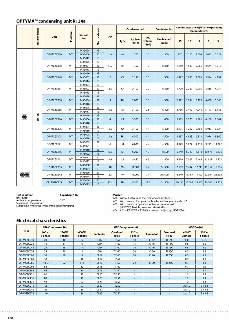
178
Unit
LRA Compressor [A] MCC Compressor [A] MCC Fan [A]
400 V/
3 phase
230 V/
1 phase
400 V/
3 phaseContactor
Overload
relay
230 V/
1 phaseContactor
Overload
relay
400 V/
3 phase
230 V/
1 phase
OP-MCZC030 20 40 5 CI 6 TI 16C 10 CI 12 TI 16C 0.35 0.85
OP-MCZC038 16 41 6 CI 9 TI 16C 15 CI 16 TI 16C 0.5 1.2
OP-MCZC048 23 55 7.5 CI 9 TI 16C 16 CI 16 TI 16C 0.5 1.2
OP-MCZC054 25 70 8 CI 9 TI 16C 20 CI 20 TI 25C 0.5 1.2
OP-MCZC060 30 70 9 CI 12 TI 16C 20 CI 20 TI 25C 0.5 1.2
OP-MCZC068 38 - 10 CI 12 TI 16C - 0.7 1.3
OP-MCZC086 48.5 92 11.5 CI 15 TI 16C 29 CI 30 TI 25C 0.7 1.3
OP-MCZC096 64 - 12 CI 15 TI 16C - - - 0.7 1.3
OP-MCZC108 64 - 14 CI 15 TI 16C - - - 1.2 3.4
OP-MCZC121 80 - 17 CI 20 TI 25C - - - 1.2 3.4
OP-MCZC136 80 - 19 CI 20 TI 25C - - - 1.2 3.4
OP-MCZC171 90 - 22 CI 25 TI 25C - - - 1.2 3.4
OP-MGZC215 105 - 27 CI 37 TI 25C - - - 2 x 1.2 2 x 3.4
OP-MGZC242 115 - 30 CI 37 TI 25C - - - 2 x 1.2 2 x 3.4
OP-MGZC271 140 - 36 CI 45 TI 25C - - - 2 x 1.2 2 x 3.4
Electrical characteristics
OPTYMA™ condensing unit R134a
Test
co
nd
ito
ns
Unit
Pla
tfo
rm Version
A02
Ele
ctri
cal
cod
e
HP
Condenser coil Condenser fanCooling capacity in [W] at evaporating
temperature °C
TypeAirflow
[m3/h]
Int.
volume
[dm3]
Fan blade ∅
[mm]-15 -10 -5 0 5
SH
10
K
OP-MCZC030 MT
114X5024 G
1½ A4 1.200 1.2 1 × 300 867 1.210 1.604 2.045 2.529114X5000 D
114X5012 E
OP-MCZC038 MT
114X5025 G
13⁄4 B4 1.750 1.3 1 × 350 1.150 1.580 2.085 2.664 3.312114X5001 D
114X5013 E
OP-MCZC048 MT
114X5026 G
2 C4 2.150 2.3 1 × 350 1.477 1.986 2.606 3.344 4.197114X5002 D
114X5014 E
OP-MCZC054 MT
114X5027 G
2½ C4 2.150 2.3 1 × 350 1.700 2.289 2.995 3.818 4.757114X5003 D
114X5015 E
OP-MCZC060 MT
114X5028 G
3 D4 2.000 3.1 1 × 350 2.322 2.994 3.773 4.658 5.646114X5004 D
114X5016 E
OP-MCZC068 MT114X5005 D
3½ E4 3.150 2.5 1 × 400 2.736 3.442 4.244 5.147 6.143114X5017 E
OP-MCZC086 MT
114X5029 G
4 F4 3.300 3.1 1 × 400 2.833 3.770 4.881 6.159 7.601114X5006 D
114X5018 E
OP-MCZC096 MT114X5007 D
4½ G4 3.150 4.1 1 × 400 3.174 4.232 5.480 6.913 8.527114X5019 E
OP-MCZC108 MT114X5008 D
5½ H4 4.300 4.1 1 × 500 3.637 4.863 6.311 7.976 9.860114X5020 E
OP-MCZC121 MT114X5009 D
6 J4 6.000 4.4 1 × 500 4.379 5.777 7.410 9.275 11.372114X5021 E
OP-MCZC136 MT114X5010 D
6½ K4 6.200 4.7 1 × 500 5.140 6.700 8.513 10.573 12.876114X5022 E
OP-MCZC171 MT114X5011 D
8½ L4 5.850 6.3 1 × 500 5.479 7.309 9.465 11.938 14.722114X5023 E
OP-MGZC215 MT114X5058 D
10 M4 11.000 7.4 2 × 500 7.169 9.492 12.213 15.352 18.896114X5073 E
OP-MGZC242 MT114X5059 D
12 M4 11.000 7.4 2 × 500 8.849 11.467 14.493 17.907 21.692114X5074 E
OP- MGZC271 MT114X5060 D
13½ N4 9.200 12.3 2 × 500 10.113 13.087 16.557 20.506 24.933114X5075 E
VersionA00 Without valves and receiver for capillary tubesA01 With receiver. 2 stop valves. bracket and copper pipes for KPA02 With receiver, stop valves, universal pressure switch (KP17WB), flexible hoses and electrical boxA04 A01 + KP 17WB + FSA-Kit + power cord (except UCGC034)
Test condition Superheat 10K EN 13215 Ambient temperature 32°CSuction gas temperature Subcooling within the limits of the condensing unit
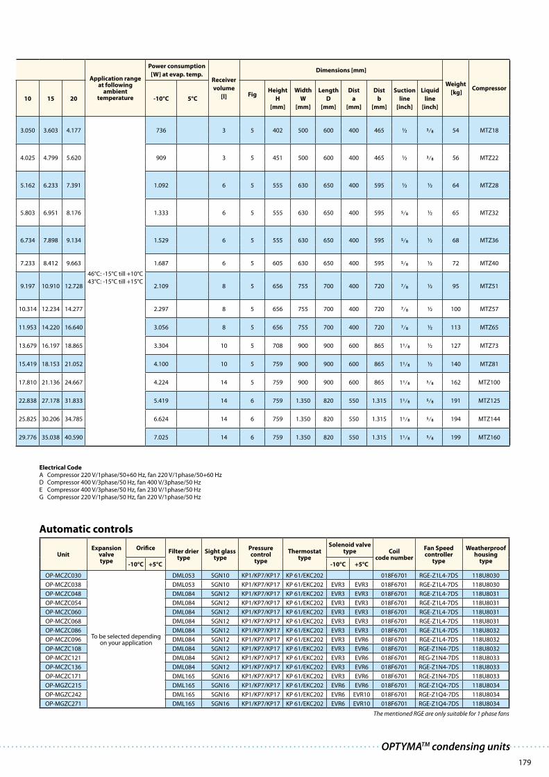
179
Application range at following
ambient temperature
Power consumption
[W] at evap. temp.Receiver
volume
[l]
Dimensions [mm]
Weight
[kg]Compressor
10 15 20 -10°C 5°CFig
Height
H
[mm]
Width
W
[mm]
Length
D
[mm]
Dist
a
[mm]
Dist
b
[mm]
Suction
line
[inch]
Liquid
line
[inch]
3.050 3.603 4.177
46°C: -15°C till +10°C
43°C: -15°C till +15°C
736 3 5 402 500 600 400 465 ½ 3⁄8 54 MTZ18
4.025 4.799 5.620 909 3 5 451 500 600 400 465 ½ 3⁄8 56 MTZ22
5.162 6.233 7.391 1.092 6 5 555 630 650 400 595 ½ ½ 64 MTZ28
5.803 6.951 8.176 1.333 6 5 555 630 650 400 595 5⁄8 ½ 65 MTZ32
6.734 7.898 9.134 1.529 6 5 555 630 650 400 595 5⁄8 ½ 68 MTZ36
7.233 8.412 9.663 1.687 6 5 605 630 650 400 595 5⁄8 ½ 72 MTZ40
9.197 10.910 12.728 2.109 8 5 656 755 700 400 720 7⁄8 ½ 95 MTZ51
10.314 12.234 14.277 2.297 8 5 656 755 700 400 720 7⁄8 ½ 100 MTZ57
11.953 14.220 16.640 3.056 8 5 656 755 700 400 720 7⁄8 ½ 113 MTZ65
13.679 16.197 18.865 3.304 10 5 708 900 900 600 865 11⁄8 ½ 127 MTZ73
15.419 18.153 21.052 4.100 10 5 759 900 900 600 865 11⁄8 ½ 140 MTZ81
17.810 21.136 24.667 4.224 14 5 759 900 900 600 865 11⁄8 5⁄8 162 MTZ100
22.838 27.178 31.833 5.419 14 6 759 1.350 820 550 1.315 11⁄8 5⁄8 191 MTZ125
25.825 30.206 34.785 6.624 14 6 759 1.350 820 550 1.315 11⁄8 5⁄8 194 MTZ144
29.776 35.038 40.590 7.025 14 6 759 1.350 820 550 1.315 11⁄8 5⁄8 199 MTZ160
Automatic controls
UnitExpansion
valve type
OrificeFilter drier
typeSight glass
type
Pressure control
type
Thermostat type
Solenoid valve type Coil
code number
Fan Speed controller
type
Weatherproof housing
type-10°C +5°C -10°C +5°C
OP-MCZC030
To be selected dependingon your application
DML053 SGN10 KP1/KP7/KP17 KP 61/EKC202 018F6701 RGE-Z1L4-7DS 118U8030
OP-MCZC038 DML053 SGN10 KP1/KP7/KP17 KP 61/EKC202 EVR3 EVR3 018F6701 RGE-Z1L4-7DS 118U8030
OP-MCZC048 DML084 SGN12 KP1/KP7/KP17 KP 61/EKC202 EVR3 EVR3 018F6701 RGE-Z1L4-7DS 118U8031
OP-MCZC054 DML084 SGN12 KP1/KP7/KP17 KP 61/EKC202 EVR3 EVR3 018F6701 RGE-Z1L4-7DS 118U8031
OP-MCZC060 DML084 SGN12 KP1/KP7/KP17 KP 61/EKC202 EVR3 EVR3 018F6701 RGE-Z1L4-7DS 118U8031
OP-MCZC068 DML084 SGN12 KP1/KP7/KP17 KP 61/EKC202 EVR3 EVR3 018F6701 RGE-Z1L4-7DS 118U8031
OP-MCZC086 DML084 SGN12 KP1/KP7/KP17 KP 61/EKC202 EVR3 EVR3 018F6701 RGE-Z1L4-7DS 118U8032
OP-MCZC096 DML084 SGN12 KP1/KP7/KP17 KP 61/EKC202 EVR3 EVR6 018F6701 RGE-Z1L4-7DS 118U8032
OP-MCZC108 DML084 SGN12 KP1/KP7/KP17 KP 61/EKC202 EVR3 EVR6 018F6701 RGE-Z1N4-7DS 118U8032
OP-MCZC121 DML084 SGN12 KP1/KP7/KP17 KP 61/EKC202 EVR3 EVR6 018F6701 REG-Z1N4-7DS 118U8033
OP-MCZC136 DML084 SGN12 KP1/KP7/KP17 KP 61/EKC202 EVR3 EVR6 018F6701 RGE-Z1N4-7DS 118U8033
OP-MCZC171 DML165 SGN16 KP1/KP7/KP17 KP 61/EKC202 EVR3 EVR6 018F6701 RGE-Z1N4-7DS 118U8033
OP-MGZC215 DML165 SGN16 KP1/KP7/KP17 KP 61/EKC202 EVR6 EVR6 018F6701 RGE-Z1Q4-7DS 118U8034
OP-MGZC242 DML165 SGN16 KP1/KP7/KP17 KP 61/EKC202 EVR6 EVR10 018F6701 RGE-Z1Q4-7DS 118U8034
OP-MGZC271 DML165 SGN16 KP1/KP7/KP17 KP 61/EKC202 EVR6 EVR10 018F6701 RGE-Z1Q4-7DS 118U8034
The mentioned RGE are only suitable for 1 phase fans
Electrical CodeA Compressor 220 V/1phase/50+60 Hz, fan 220 V/1phase/50+60 HzD Compressor 400 V/3phase/50 Hz, fan 400 V/3phase/50 HzE Compressor 400 V/3phase/50 Hz, fan 230 V/1phase/50 HzG Compressor 220 V/1phase/50 Hz, fan 220 V/1phase/50 Hz
OPTYMATM condensing units

180
OPTYMA™ condensing unit R407C
Electrical characteristics
Test
co
nd
ito
ns
Unit
Pla
tfo
rm
Version
A02
Ele
ctri
cal
cod
e
HP
Condenser coil Condenser fanCooling capacity in [W] at
evaporating temperature °C
TypeAirflow[m3/h]
Int. volume
[dm3]
Fan blade ∅
[mm]-15 -10 -5 0
SH
10
K
OP-MCZC030 MT
114X5024 G
1½ A4 1.200 1.2 1 × 300 1.161 1.620 2.134 2.700114X5000 D
114X5012 E
OP-MCZC038 MT
114X5025 G
1¾ B4 1.750 1.3 1 × 350 1.683 2.249 2.878 3.658114X5001 D
114X5013 E
OP-MCZC048 MT
114X5026 G
2 C4 2.150 2.3 1 × 350 2.149 2.925 3.794 4.746114X5002 D
114X5014 E
OP-MCZC054 MT
114X5027 G
2½ C4 2.150 2.3 1 × 350 2.596 3.405 4.296 5.266114X5003 D
114X5015 E
OP-MCZC060 MT
114X5028 G
3 D4 2.000 3.1 1 × 350 3.104 3.986 4.946 5.986114X5004 D
114X5016 E
OP-MCZC068 MT114X5005 D
3½ E4 3.150 2.5 1 × 400 3.631 4.637 5.742 6.943114X5017 E
OP-MCZC086 MT
114X5029 G
4 F4 3.300 3.1 1 × 400 3.965 5.186 6.549 8.048114X5006 D
114X5018 E
OP-MCZC096 MT114X5007 D
4½ G4 3.150 4.1 1 × 400 4.366 5.765 7.341 9.089114X5019 E
OP-MCZC108 MT114X5008 D
5½ H4 4.300 4.1 1 × 500 5.342 6.891 8.659 10.646114X5020 E
OP-MCZC121 MT114X5009 D
6 J4 6.000 4.4 1 × 500 6.068 7.882 9.942 12.250114X5021 E
OP-MCZC136 MT114X5010 D
6½ K4 6.200 4.7 1 × 500 6.821 8.863 11.143 13.650114X5022 E
OP-MCZC171 MT114X5011 D
8½ L4 5.850 6.3 1 × 500 7.433 9.892 12.645 15.692114X5023 E
OP-MGZC215 MT114X5058 D
10 M4 11.000 7.4 2 × 500 11.007 14.191 17.757 21.713114X5073 E
OP-MGZC242 MT114X5059 D
12 M4 11.000 7.4 2 × 500 12.089 15.606 19.542 23.895114X5074 E
OP- MGZC271 MT114X5060 D
13½ N4 9.200 12.3 2 × 500 14.508 18.346 22.647 27.411114X5075 E
Unit
LRA Compressor [A] MCC Compressor [A] MCC Fan [A]
400 V/3 phase
230 V/1 phase
400 V/3 phase
ContactorOverload
relay230 V/
1 phaseContactor
Overload relay
400 V/3 phase
230 V/1 phase
OP-MCZC030 20 40 5 CI 6 TI 16C 10 CI 12 TI 16C 0.35 0.85
OP-MCZC038 16 41 6 CI 9 TI 16C 15 CI 16 TI 16C 0.5 1.2
OP-MCZC048 23 55 7.5 CI 9 TI 16C 16 CI 16 TI 16C 0.5 1.2
OP-MCZC054 25 70 8 CI 9 TI 16C 20 CI 20 TI 25C 0.5 1.2
OP-MCZC060 30 70 9 CI 12 TI 16C 20 CI 20 TI 25C 0.5 1.2
OP-MCZC068 38 - 10 CI 12 TI 16C - 0.7 1.3
OP-MCZC086 48.5 92 11.5 CI 15 TI 16C 29 CI 30 TI 25C 0.7 1.3
OP-MCZC096 64 - 12 CI 15 TI 16C - - - 0.7 1.3
OP-MCZC108 64 - 14 CI 15 TI 16C - - - 1.2 3.4
OP-MCZC121 80 - 17 CI 20 TI 25C - - - 1.2 3.4
OP-MCZC136 80 - 19 CI 20 TI 25C - - - 1.2 3.4
OP-MCZC171 90 - 22 CI 25 TI 25C - - - 1.2 3.4
OP-MGZC215 105 - 27 CI 37 TI 25C - - - 2 x 1.2 2 x 3.4
OP-MGZC242 115 - 30 CI 37 TI 25C - - - 2 x 1.2 2 x 3.4
OP-MGZC271 140 - 36 CI 45 TI 25C - - - 2 x 1.2 2 x 3.4
VersionA02 With receiver, stop valves, universal pressure switch (KP17WB), flexible hoses and electrical box
Test condition Superheat 10K EN 13215 Ambient temperature 32°CSuction gas temperature Subcooling within the limits of the condensing unit

181
Application range at
following ambient
temperature
Power
consumption [W]
at evap. temp. Receiver
volume
[l]
Dimensions [mm]
Weight
[kg]Compressor
5 10 38°C -10°C 5°CFig
Height
H
[mm]
Width
W
[mm]
Length
D
[mm]
Dist
a
[mm]
Dist
b
[mm]
Suction
line
[inch]
Liquid
line
[inch]
3.305 3.945
-10°C till
+10°C
1.007 3 5 408 500 600 400 465 ½ 3⁄8 54 MTZ18
4.309 5.093 1.367 3 5 451 500 620 400 465 ½ 3⁄8 56 MTZ22
5.781 6.879 1.639 6 5 555 630 650 400 595 ½ ½ 64 MTZ28
6.294 7.376 1.878 6 5 555 630 650 400 595 5⁄8 ½ 65 MTZ32
7.070 8.198 2.248 6 5 555 630 650 400 595 5⁄8 ½ 68 MTZ36
8.214 9.550 2.662 6 5 605 630 650 400 595 5⁄8 ½ 72 MTZ40
9.662 11.380 2.869 8 5 656 755 700 400 720 7⁄8 ½ 95 MTZ51
10.981 12.996 3.061 8 5 656 755 700 400 720 7⁄8 ½ 100 MTZ57
12.827 15.180 4.047 8 5 656 755 700 400 720 7⁄8 ½ 113 MTZ65
14.764 17.469 4.659 10 5 708 900 900 600 865 11⁄8 ½ 127 MTZ73
16.349 19.224 5.387 10 5 759 900 900 600 865 11⁄8 ½ 140 MTZ81
18.969 22.458 6.209 14 5 759 900 900 600 865 11⁄8 5⁄8 162 MTZ100
25.991 30.572 8.375 14 6 759 1.350 820 550 1.315 11⁄8 5⁄8 191 MTZ125
28.625 33.732 9.399 14 6 759 1.350 820 550 1.315 11⁄8 5⁄8 194 MTZ144
32.558 38.075 10.678 14 6 759 1.350 820 550 1.315 11⁄8 5⁄8 199 MTZ160
Automatic controls
UnitExpansion
valve type
OrificeFilter drier
type
Sight glass
type
Pressure
control
type
Thermostat
type
Solenoid valve
type Coil
code number
Fan Speed
controller type
Weatherproof
housing type-10°C +5°C -10°C +5°C
OP-MCZC030
To be selected depending
your application
DML053 SGN10 KP1/KP7/KP17 KP 61/EKC 202 018F6701 RGE-Z1L4-7DS 118U8030
OP-MCZC038 DML053 SGN10 KP1/KP7/KP17 KP 61/EKC 202 EVR 3 EVR 3 018F6701 RGE-Z1L4-7DS 118U8030
OP-MCZC048 DML084 SGN12 KP1/KP7/KP17 KP 61/EKC 202 EVR 3 EVR 3 018F6701 RGE-Z1L4-7DS 118U8031
OP-MCZC054 DML084 SGN12 KP1/KP7/KP17 KP 61/EKC 202 EVR 3 EVR 3 018F6701 RGE-Z1L4-7DS 118U8031
OP-MCZC060 DML084 SGN12 KP1/KP7/KP17 KP 61/EKC 202 EVR 3 EVR 3 018F6701 RGE-Z1L4-7DS 118U8031
OP-MCZC068 DML084 SGN12 KP1/KP7/KP17 KP 61/EKC 202 EVR 3 EVR 6 018F6701 RGE-Z1L4-7DS 118U8031
OP-MCZC086 DML084 SGN12 KP1/KP7/KP17 KP 61/EKC 202 EVR 3 EVR 6 018F6701 RGE-Z1L4-7DS 118U8032
OP-MCZC096 DML084 SGN12 KP1/KP7/KP17 KP 61/EKC 202 EVR 3 EVR 6 018F6701 RGE-Z1L4-7DS 118U8032
OP-MCZC108 DML084 SGN12 KP1/KP7/KP17 KP 61/EKC 202 EVR 3 EVR 6 018F6701 RGE-Z1N4-7DS 118U8032
OP-MCZC121 DML084 SGN12 KP1/KP7/KP17 KP 61/EKC 202 EVR 3 EVR 6 018F6701 REG-Z1N4-7DS 118U8033
OP-MCZC136 DML084 SGN12 KP1/KP7/KP17 KP 61/EKC 202 EVR 3 EVR 6 018F6701 RGE-Z1N4-7DS 118U8033
OP-MCZC171 DML165 SGN16 KP1/KP7/KP17 KP 61/EKC 202 EVR 6 EVR 6 018F6701 RGE-Z1N4-7DS 118U8033
OP-MGZC215 DML165 SGN16 KP1/KP7/KP17 KP 61/EKC 202 EVR 6 EVR 10 018F6701 RGE-Z1Q4-7DS 118U8034
OP-MGZC242 DML165 SGN16 KP1/KP7/KP17 KP 61/EKC 202 EVR 6 EVR 10 018F6701 RGE-Z1Q4-7DS 118U8034
OP-MGZC271 DML165 SGN16 KP1/KP7/KP17 KP 61/EKC 202 EVR 6 EVR 10 018F6701 RGE-Z1Q4-7DS 118U8034
Electrical CodeD Compressor 400 V/3 phase/50 Hz, fan 400 V/3 phase/50 Hz E Compressor 400 V/3 phase/50 Hz, fan 230 V/1 phase/50 HzG Compressor 220 V/1 phase/50 Hz, fan 220 V/1 phase/50 Hz
The mentioned RGE are only suitable for 1 phase fans
OPTYMATM condensing units

182
H
aD
W
8 x ø7
192
228
8.5
8570
W
H
aD
8 x ø7
192
228
8.5
8571
8572
H
aD
W
8 x ø7
192
228
8.5
H
aD
W
8 x ø7
192
228
8.5
8573
Dimensions

183
D
17.5
20
H
W
a
b
8560
4 x12
ø
4 x12
øaD
20
17.5
b
H
W
8561
Da 20
WH
385
8623
4 x ø9
2020
Da326
HW
8 x ø9
1020
470
8624
152
342
20
Dimensions
OPTYMATM condensing units

184

185
OPTYMA PLUS™ – the low noise condensing units for quick installationOPTYMA PLUS™ is a unique integral Danfoss condensing unit built around Danfoss components. In
designing the range Danfoss combined the very best design knowledge to create a fully factory built
condensing unit ready for quick installation and quiet operation.
OPTYMA PLUS™ condensing units
· Fully weatherproof housing made from epoxy powder
coated steel
· Extremely low noise level – as standard supplied with
Danfoss compressor, fan speed control, filter drier, shut
off valve, pressure switch, magnetic contactor, sight
glass and electrical fuse.
· Small dimensions
· Electrical box : IP 54
· Energy efficient
· Low energy consumption
Installer benefits:
· An integrated Danfoss design
· Easy maintenance: just remove the panels and you have
easy access to the components
· Outstanding performance even in the toughest applications
· A minimum size footprint enabling installation in small
spaces without compromising the units’ performance or
service accessibility
· Common Danfoss components all stocked locally by
wholesalers
End-user benefits:
· Low noise operation
· Modern practical design with a neutral colour to fit in with
its surroundings
· Strong weather resistant housing with lasting durability
even in the harshest environments
· Reliable high ambient operation and proven reliability in
the most demanding applications
· Energy saving benefits with fan speed control and selection
of energy efficient components
Product advantages Customer benefits

186
OPTYMA PLUS™ R404A/R507 LBP
Test
conditonsUnit
Plat-
form
Code
number
Electrical
codeHP
Condenser coilCondenser
fan
Am
bie
nt
°C
Capacity in [W] at
evaporating temperature [°C]
TypeAirflow
[m3/h]
Int. volume
[L]
Fan blade ∅
[mm]-45 -40 -35 -30
SH 10K
OP-LPHC018 SC 114X3108 G 3⁄4 A6 1.500 1.6 1×356
27 276 384 516 671
32 239 338 459 603
38 189 280 389 521
43 331 452
OP-LPHC026 GS 114X3116 G 1 A6 1.500 1.6 1×356
27 390 550 741 968
32 328 473 650 859
38 255 386 545 733
43 461 632
OP-LPHC048 NT 114X3224 G 2 1⁄2 C6 3.000 1.1 1×406
27 485 769 1.109 1.503
32 396 659 971 1.331
38 290 528 808 1.128
43 422 675 962
OP-LPHC048 NT 114X3232 E 2 1⁄2 C6 3.000 1.1 1×406
27 485 769 1.109 1.503
32 396 659 971 1.331
38 290 528 808 1.128
43 422 675 962
OP-LPHC068 NT 114X3240 G 3 1⁄2 D6 2.600 2.2 1×406
27 969 1.400 1.911 2.503
32 815 1.212 1.681 2.226
38 650 1.007 1.428 1.913
43 852 1.232 1.669
OP-LPHC068 NT 114X3248 E 3 1⁄2 D6 2.600 2.2 1×406
27 969 1.400 1.911 2.503
32 815 1.212 1.681 2.226
38 650 1.007 1.428 1.913
43 852 1.232 1.669
OP-LPHC096 NT 114X3356 E 5 F6 6.100 3.4 1×609
27 1223 1.792 2.388 3.227
32 1.483 2.099 2.872
38 1.194 1.742 2.432
43 957 1.445 2.062
OP-LPHC136 NT 114X3364 E 7 F6 6.100 3.4 1×609
27 1.847 2.611 3.550 4.674
32 2.275 3.143 4.177
38 1.881 2.660 3.586
43 1.562 2.266 3.100
OP-LPHC271 NT 114X3480 E 13 1⁄2 J6 12.200 6.9 2×609
27 3.900 5.530 7.517 9.871
32 3.370 4.894 6.736 8.906
38 2.721 4.107 5.767 7.711
43 3.447 4.946 6.696
Electrical codeE Compressor 400 V/3 phase/50 Hz, fan 230 V/1 phase/50 HzG Compressor 230 V/1 phase/50 Hz, fan 230 V/1 phase/50 Hz
Test condition Superheat 10K EN 13215 Subcooling within the limits of the condensing unit

187
RGT 20
-35°C
EN 13215
(ref. point)
Receiver
volume
[L]
Dimensions
[mm]Connections Weight
Sound
power
level
dB(A)
Sound
pressure
level
10 m dB(A)
Com-
pressor-25 -20 -15 -10 Housing
Height
H
Width
W
Depth
D
Suction
line
Liquid
line
Gross/Net
[kg]
854 1.068 1.312 1.591
1.2 1 652 906 430 1⁄2 3⁄8 96/64 61 30 SC18CLX774 973 1.202 1.463 510
676 858 1.067 1.307
594 760
1.233 1.536 1.879 2.261
1.2 1 652 906 430 5⁄8 3⁄8 102/76 61 30 GS26CLX1.104 1.385 1.702 2.059 725
953 1.207 1.495 1.819
831 1.062
1.951 2.445 2.981 3.557
4.2 2 760 1.053 480 5⁄8 3⁄8 116/82 72 41 NTZ0481.738 2.188 2.675 3.198 1.087
1.487 1.883 2.313 2.774
1.282 1.634
1.951 2.445 2.981 3.557
4.2 2 760 1.053 480 5⁄8 3⁄8 116/82 72 41 NTZ0481.738 2.188 2.675 3.198 1.087
1.487 1.883 2.313 2.774
1.282 1.634
3.177 3.928 4.751 5.640
4.2 2 760 1.053 480 5⁄8 3⁄8 118/84 71 39 NTZ0682.843 3.534 4.291 5.112 1.884
2.464 3.082 3.761 4.499
2.165 2.720
3.177 3.928 4.751 5.640
4.2 2 760 1.053 480 5⁄8 3⁄8 118/84 71 39 NTZ0682.843 3.534 4.291 5.112 1.884
2.464 3.082 3.761 4.499
2.165 2.720
4.250 5.469 6.889 8.520
7.1 3 975 1.406 550 7⁄8 3⁄8 161/115 73 42 NTZ0963.816 4.943 6.261 7.779 2.338
3.279 4.293 5.486 6.868
2.824 3.744
5.988 7.496 9.191 11.068
7.1 3 975 1.406 550 1 1⁄8 1⁄2 161/115 73 42 NTZ1365.387 6.776 8.339 10.073 3.518
4.668 5.911 7.318 8.881
4.076 5.197
12.591 15.685 19.113 22.872
14.0 4 1.794 1.420 650 1 3⁄8 3⁄4 329/275 78 47 NTZ27111.411 14.254 17.410 20.869 7.544
9.949 12.483 15.312 18.416
8.710 10.986
EN 13215
Information point RGT 20
Constant Return Gas Temperature 20°C
Ambient temperature = +32°c
Subcooling within the limits of the condensing unit
Sound measurement done in accordance with ISO 3743-1 and ISO 3744.
MBP measured according to EN 13215 @ -10°C suction, +32°C ambient, SH 10 K
LBP measured according to EN 13215 @ -25°C suction, +32°C ambient, SH 10 K
OPTYMA PLUS™ condensing units

188
OPTYMA PLUS™ R404A/R507 MBP
Test
conditonsUnit
Plat-
form
Code
number
Electrical
codeHP
Condenser coilCondenser
fan
Am
bie
nt
°C
Capacity in [W] at
evaporating temperature [°C]
TypeAirflow
[m3/h]
Int. volume
[L]
Fan blade ∅
[mm]-30°C -25°C -20°C -15°C
SH 10K
OP-MPHC010 SC 114×4100 G 1⁄3 A6 1.500 1.6 1×356
27 621 776
32 565 708
38 496 626
43 557
OP-MPHC018 SC 114X4108 G 5⁄8 A6 1.500 1.6 1×356
27 1.050 1.294
32 953 1.181
38 838 1.045
43 932
OP-MPZC030 MT 114X4216 G 1 1⁄2 C6 3.000 1.1 1×406
27 645 971 1.367 1.832
32 561 860 1.223 1.649
38 465 734 1.056 1.433
43 389 632 921 1.258
OP-MPZC030 MT 114X4224 E 1 1⁄2 C6 3.000 1.1 1×406
27 645 971 1.367 1.832
32 561 860 1.223 1.649
38 465 734 1.056 1.433
43 389 632 921 1.258
OP-MPHC034 GS 114X4228 G 1 5⁄8 A6 1.500 1.6 1×356
27 2.510
32 2.304
38 2.492
43 1.827
OP-MPZC048 MT 114X4232 G 2 D6 2.600 2.2 1×406
27 1.389 1.948 2.604 3.358
32 1.175 1.698 2.309 3.008
38 934 1.412 1.966 2.600
43 746 1.185 1.692 2.269
OP-MPZC048 MT 114X4240 E 2 D6 2.600 2.2 1×406
27 1.389 1.948 2.604 3.358
32 1.175 1.698 2.309 3.008
38 934 1.412 1.966 2.600
43 746 1.185 1.692 2.269
OP-MPZC060 MT 114X4248 G 3 D6 2.600 2.2 1×406
27 1.963 2.641 3.426 4.307
32 1.727 2.360 3.086 3.898
38 1.446 2.025 2.679 3.407
43 1.211 1.745 2.341 2.998
OP-MPZC060 MT 114X4256 E 3 D6 2.600 2.2 1×406
27 1.963 2.641 3.426 4.307
32 1.727 2.360 3.086 3.898
38 1.446 2.025 2.679 3.407
43 1.211 1.745 2.341 2.998
OP-MPZC086 MT 114X4364 E 4 1⁄4 F6 6.100 3.4 1×609
27 2.753 3.745 4.937 6.331
32 2.401 3.316 4.411 5.691
38 2.010 2.830 3.809 4.954
43 1.705 2.448 3.330 4.360
OP-MPZC108 MT 114X4372 E 5 1⁄4 F6 6.100 3.4 1×609
27 3.441 4615 6.018 7.656
32 3.008 4.102 5.398 6.905
38 2.506 3.499 4.667 6.019
43 2.102 3.008 4.067 5.290
OP-MPZC136 MT 114X4380 E 7 G6 5.100 5.2 1×609
27 4.692 6.175 7.897 9.855
32 4.153 5.537 7.131 8.942
38 3.537 4.796 6.236 7.864
43 3.043 4.196 5.505 6.975
OP-MPZC171 MT 114X4488 E 8 1⁄2 J6 12.200 6.9 2×609
27 5.238 7.183 9.519 12.246
32 4.641 6.464 8.629 11.145
38 3.895 5.576 7.542 9.807
43 3.243 4.811 6.616 8.679
OP-MPZC215 MT 114X4496 E 10 J6 12.200 6.9 2×609
27 7.078 9.390 12.129 15.303
32 6.221 8.350 10.869 13.785
38 5.280 7.183 9.436 12.040
43 4.561 6.274 8.295 10.640
Electrical codeE Compressor 400 V/3 phase/50 Hz, fan 240 V/3 phase/50 HzG Compressor 230 V/1 phase/50 Hz, fan 230 V/1 phase/50 Hz
Test condition Superheat 10K EN 13215 Subcooling within the limits of the condensing unit
= Superheat 15K

189
Receiver
volume
[L]
Dimensions
[mm]Connections Weight
Sound
power
level
dB(A)
Sound
pressure
level
10 m dB(A)
Compressor
-10°C -5°C 0°C 5°C 10°C HousingHeight
H
Width
W
Depth
D
Suction
line
Liquid
line
Gross/Net
[kg]
961 1.177 1.425 1.703
1.2 1 652 906 430 3⁄8 3⁄8 96/64 61 30 SC10MLX879 1.079 1.308 1.566
780 960 1.167 1.401
697 861 1.049
1.580 1.907 2.277 2.691
1.2 1 652 906 430 3⁄8 3⁄8 96/64 61 30 SC18MLX1.447 1.753 2.100 2.489
1.287 1.565 1.882 2.240
1.152 1.406 1.697
2.365 2.958 3.605 4.299 5.033
4.2 2 760 1.053 480 5⁄8 3⁄8 116/83 72 41 MTZ182.135 2.677 3.270 3.908 4.585
1.863 2.346 2.874 3.445 4.053
1.642 2.073 2.548
2.365 2.958 3.605 4.299 5.033
4.2 2 760 1.053 480 5⁄8 3⁄8 116/83 72 41 MTZ182.135 2.677 3.270 3.908 4.585
1.863 2.346 2.874 3.445 4.053
1.642 2.073 2.548
3.035 3.627 4.286 5.012
4.2 2 760 1.053 480 5⁄8 3⁄8 114/82 67 36 GS34MLX2.794 3.345 3.957 4.630
2.991 3.544 4.152 4.438
2.234 2.687 3.190 3.742
4.209 5.149 6.176 7.282 8.459
4.2 2 760 1.053 480 5⁄8 3⁄8 120/86 71 39 MTZ283.798 4.672 5.625 6.654 7.751
3.315 4.106 4.972 7.751 6.910
2.920 3.644 4.436
4.209 5.149 6.176 7.282 8.459
4.2 2 760 1.053 480 5⁄8 3⁄8 120/86 71 39 MTZ283.798 4.672 5.625 6.654 7.751
3.315 4.106 4.972 7.751 6.910
2.920 3.644 4.436
5.275 6.318 7.422 8.572 9.755
4.2 2 760 1.053 480 5⁄8 3⁄8 125/88 72 40 MTZ364.785 5.740 6.749 7.800 8.884
4.198 5.046 5.942 6.877 7.846
3.708 4.470 5.272
5.275 6.318 7.422 8.572 9.755
4.2 2 760 1.053 480 5⁄8 3⁄8 125/88 72 40 MTZ364.785 5.740 6.749 7.800 8.884
4.198 5.046 5.942 6.877 7.846
3.708 4.470 5.272
7.929 9.718 11.691 13.836 16.138
7.1 3 975 1.406 550 7⁄8 5⁄8 163/117 74 42 MTZ517.158 8.814 10.639 12.626 14.767
6.267 7.753 9.398 11.201 13.146
5.544 6.884 8.834
9.517 11.596 13.877 16.339 18.961
7.1 3 975 1.406 550 7⁄8 5⁄8 163/117 74 42 MTZ658.626 10.545 12.654 14.937 17.376
7.565 9.291 11.192 13.262 15.484
6.686 8.251 9.984
12.031 14.413 16.977 19.701 22.559
7.1 3 975 1.406 550 1 1⁄8 5⁄8 168/122 76 45 MTZ8110.951 13.146 15.516 18.037 20.691
9.667 11.641 13.775 16.054 18.466
8.610 10.400 12.337
15.355 18.838 22.650 26.772 31.667
14.0 4 1.794 1.420 650 1 3⁄8 5⁄8 327/271 78 47 MTZ10014.003 17.024 20.709 24.499 28.553
12.371 15.235 18.374 21.782 25.426
11.000 13.584 16.434
18.887 22.862 27.204 31.875 36.834
14.0 4 1.794 1.420 650 1 3⁄8 3⁄4 329/275 78 47 MTZ12517.095 20.773 24.790 29.126 33.744
15.010 18.316 21.944 25.878 30.088
13.322 16.314 19.622
Sound measurement done in accordance with ISO 3743-1 and ISO 3744.
MBP measured according to EN 13215 @ -10°C suction, +32°C ambient, SH 10 K
LBP measured according to EN 13215 @ -25°C suction, +32°C ambient, SH 10 K
OPTYMA PLUS™ condensing units

190
OPTYMA PLUS™ R134a MBP
Test
conditonsUnit
Plat-
form
Code
number
Electrical
codeHP
Condenser coilCondenser
fan
Am
bie
nt
°C
Capacity in [W] at evaporating temperature [°C ]
TypeAirflow
[m3/h]
Int. volume
[L]
Fan blade ∅
[mm]-15 -10 -5 0
SH 10K
OP-MPZC030 MT 114X4216 G 1 1⁄2 C6 3.000 1.1 1×406
27 996 1.425 1.885 2.403
32 919 1.285 1.712 2.199
38 778 1.119 1.513 1.961
43 677 993 1.356 1.768
OP-MPZC030 MT 114X4224 E 1 1⁄2 C6 3.000 1.1 1×406
27 996 1.425 1.885 2.403
32 919 1.285 1.712 2.199
38 778 1.119 1.513 1.961
43 677 993 1.356 1.768
OP-MPGC034 GS 114X4112 G 1 5⁄8 A6 1.500 1.6 1×356
27 1.347 1.677 2.059 2.493
32 1.255 1.568 1.930 2.344
38 1.143 1.436 1.775 2.163
43 1.048 1.325 1.645 2.011
OP-MPZC048 MT 114X4232 G 2 D6 2.600 2.2 1×406
27 1.615 2.214 2.974 3.738
32 1.518 2.044 2.692 3.469
38 1.348 1.835 2.433 3.149
43 1.226 1.675 2.225 2.886
OP-MPZC048 MT 114X4240 E 2 D6 2.600 2.2 1×406
27 1.615 2.214 2.974 3.738
32 1.518 2.044 2.692 3.469
38 1.348 1.835 2.433 3.149
43 1.226 1.675 2.225 2.886
OP-MPZC060 MT 114X4248 G 3 D6 2.600 2.2 1×406
27 2.597 3.278 4.125 5.097
32 2.364 3.053 3.858 4.778
38 2.138 2.783 3.530 4.385
43 1.954 2.558 3.255 4.049
OP-MPZC060 MT 114X4256 E 3 D6 2.600 2.2 1×406
27 2.597 3.278 4.125 5.097
32 2.364 3.053 3.858 4.778
38 2.138 2.783 3.530 4.385
43 1.954 2.558 3.255 4.049
OP-MPZC086 MT 114X4364 E 4 1⁄4 F6 6.100 3.4 1×609
27 3.201 4.411 5.908 7.423
32 3.021 4.077 5.340 6.822
38 2.637 3.612 4.776 6.145
43 2.334 3.248 4.335 5.611
OP-MPZC108 MT 114X4372 E 5 1⁄2 F6 6.100 3.4 1×609
27 3.662 5.216 6.858 8.792
32 3.411 4.754 6.337 8.165
38 2.982 4.243 5.723 7.426
43 2.632 3.827 5.220 6.822
OP-MPZC136 MT 114X4380 E 7 G6 5.100 5.2 1×609
27 5.347 7.201 8.998 11.305
32 4.923 6.509 8.386 10.570
38 4.402 5.889 7.642 9.677
43 3.967 5.370 7.018 8.930
OP-MPZC171 MT 114X4488 E 8 1⁄2 J6 12.200 6.9 2×609
27 6.228 8.486 11.253 14.151
32 5.900 7.908 10.315 13.150
38 5.180 7.066 9.318 11.961
43 4.646 6.414 8.521 10.990
OP-MPZC215 MT 114X4496 E 10 J6 12.200 6.9 2×609
27 7.987 10.774 13.704 17.156
32 7.406 9.805 12.641 15.930
38 6.458 8.721 11.382 14.458
43 5.721 7.855 10.352 13.234
Electrical codeE Compressor 400 V/3 phase/50 Hz, fan 230 V/3 phase/50 HzG Compressor 230 V/1 phase/50 Hz, fan 230 V/1 phase/50 Hz
Test condition Superheat 10K EN 13215 Subcooling within the limits of the condensing unit

191
Receiver
volume
[L]
Housing
Dimensions
[mm]Connections Weight
Sound
power
level
dB(A)
Sound
pressure
level
10 m dB(A)
Compressor
5 10 15 20Height
H
Width
W
Depth
D
Suction
line
Liquid
line
Gross/Net
[kg]
2.987 3.632 4.334 5.087
4.2 2 760 1.053 480 5⁄8 3⁄8 116/83 72 41 MTZ182.747 3.350 4.006 4.708
2.462 3.013 3.610 4.249
2.226 2.732
2.987 3.632 4.334 5.087
4.2 2 760 1.053 480 5⁄8 3⁄8 116/83 72 41 MTZ182.747 3.350 4.006 4.708
2.462 3.013 3.610 4.249
2.226 2.732
2.984
1.2 1 652 906 430 1⁄2 3⁄8 102/76 63 32 GS34MFX2.811
2.603
2.427
4.704 5.808 7.048 8.413
4.2 2 760 1.053 480 5⁄8 3⁄8 120/86 71 39 MTZ284.379 5.419 6.587 7.872
3.988 4.947 6.023 7.210
3.660 4.549
4.704 5.808 7.048 8.413
4.2 2 760 1.053 480 5⁄8 3⁄8 120/86 71 39 MTZ284.379 5.419 6.587 7.872
3.988 4.947 6.023 7.210
3.660 4.549
6.195 7.410 8.735 10.158
4.2 2 760 1.053 480 3⁄4 3⁄8 125/88 72 40 MTZ365.814 6.958 8.203 9.540
5.342 6.398 7.546 8.777
4.937 5.917
6.195 7.410 8.735 10.158
4.2 2 760 1.053 480 3⁄4 3⁄8 125/88 72 40 MTZ365.814 6.958 8.203 9.540
5.342 6.398 7.546 8.777
4.937 5.917
9.242 11.293 13.571 16.072
7.1 3 975 1.406 550 7⁄8 5⁄8 163/117 74 42 MTZ518.528 10.466 12.621 14.993
7.723 9.520 11.528 13.747
7.086 8.770
10.975 13.406 16.068 18.942
7.1 3 975 1.406 550 7⁄8 5⁄8 163/117 74 42 MTZ6510.235 12.535 15.057 17.783
9.356 11.501 13.855 16.403
8.635 10.650
13.930 16.871 20.108 23.625
7.1 3 975 1.406 550 1 1⁄8 5⁄8 168/122 76 45 MTZ8113.055 15.840 18.909 22.247
11.993 14.592 17.462 20.588
11.105 13.546
17.602 21.539 25.945 30.821
14.0 4 1.794 1.420 650 1 3⁄8 5⁄8 327/271 78 47 MTZ10016.426 20.159 24.338 28.958
15.015 18.492 22.385 26.685
13.843 17.097
21.113 25.554 30.479 35.854
14.0 4 1.794 1.420 650 1 3⁄8 3⁄4 329/275 78 47 MTZ12519.688 23.902 28.568 33.662
17.965 21.893 26.233 30.972
16.518 20.194
Sound measurement done in accordance with ISO 3743-1 and ISO 3744.
MBP measured according to EN 13215 @ -10°C suction, +32°C ambient, SH 10 K
LBP measured according to EN 13215 @ -25°C suction, +32°C ambient, SH 10 K
OPTYMA PLUS™ condensing units

192
OPTYMA PLUS™ R407C MBP
Test
conditonsUnit
Plat-
form
Code
number
Electrical
codeHP
Condenser coilCondenser
fan
Am
bie
nt
°C
Capacity in [W] at evaporating temperature [°C ]
TypeAirflow
[m3/h]
Int. volume
[L]
Fan blade ∅
[mm]-15 -10 -5
SH 10K
OP-MPZC030 MT 114X4216 G 1 1⁄2 C6 3.000 1.1 1×406
27 1.479 1.999 2.585
32 1.308 1.798 2.351
38 1.570 2.083
43 1.869
OP-MPZC030 MT 114X4224 E 1 1⁄2 C6 3.000 1.1 1×406
27 1.479 1.999 2.585
32 1.308 1.798 2.351
38 1.570 2.083
43 1.869
OP-MPZC048 MT 114X4232 G 2 D6 2.600 2.2 1×406
27 2.534 3.402 4.370
32 2.289 3.112 4.023
38 2.756 3.603
43 3.250
OP-MPZC048 MT 114X4240 E 2 D6 2.600 2.2 1×406
27 2.534 3.402 4.370
32 2.289 3.112 4.023
38 2.756 3.603
43 3.250
OP-MPZC060 MT 114X4248 G 3 D6 2.600 2.2 1×406
27 3.398 4.375 5.452
32 3.058 3.986 5.001
38 3.508 4.450
43 3.983
OP-MPZC060 MT 114X4256 E 3 D6 2.600 2.2 1×406
27 3.398 4.375 5.452
32 3.058 3.986 5.001
38 3.508 4.450
43 3.983
OP-MPZC086 MT 114X4364 E 4 1⁄4 F6 6.100 3.4 1×609
27 5.117 6.471 8.158
32 4.544 5.927 7.508
38 5.275 6.730
43 6.084
OP-MPZC108 MT 114X4372 E 5 1⁄2 F6 6.100 3.4 1×609
27 6.256 7.978 9.935
32 5.701 7.315 9.149
38 6.541 8.223
43 7.470
OP-MPZC136 MT 114X4380 E 7 G6 5.100 5.2 1×609
27 7.933 10.125 12.575
32 7.271 9.344 11.647
38 8.402 10.525
43 9.590
OP-MPZC171 MT 114X4488 E 8 1⁄2 J6 12.200 6.9 2×609
27 9.705 12.536 15.963
32 8.627 11.436 14.657
38 10.128 13.095
43 11.806
OP-MPZC215 MT 114X4496 E 10 J6 12.200 6.9 2×609
27 12.921 16.388 20.274
32 11.790 15.068 18.726
38 13.472 16.854
43 15.294
Electrical codeE Compressor 400 V/3 phase/50 Hz, fan 230 V/3 phase/50 HzG Compressor 230 V/1 phase/50 Hz, fan 230 V/1 phase/50 Hz
Test condition Superheat 10K
EN 13215
Subcooling within the limits of the condensing unit

193
Receiver
volume
[L]
Housing
Dimensions
[mm]Connections Weight Sound
power level
dB(A)
Sound
pressure
level
10 m dB(A)
Compressor
0 5 10Height
H
Width
W
Depth
D
Suction
line
Liquid
line
Gross/Net
[kg]
3.232 3.933 4.678
4.2 2 760 1.053 480 5⁄8 3⁄8 116/83 72 41 MTZ182.960 3.618 4.318
2.645 3.252 3.896
2.393
3.232 3.933 4.678
4.2 2 760 1.053 480 5⁄8 3⁄8 116/83 72 41 MTZ182.960 3.618 4.318
2.645 3.252 3.896
2.393
5.425 6.547 7.719
4.2 2 760 1.053 480 5⁄8 3⁄8 120/86 71 39 MTZ285.009 6.055 7.144
4.510 5.467 6.459
4.093
5.425 6.547 7.719
4.2 2 760 1.053 480 5⁄8 3⁄8 120/86 71 39 MTZ285.009 6.055 7.144
4.510 5.467 6.459
4.093
6.609 7.828 9.089
4.2 2 760 1.053 480 3⁄4 3⁄8 125/88 72 40 MTZ366.087 7.227 8.404
5.453 6.500 7.576
4.916
6.609 7.828 9.089
4.2 2 760 1.053 480 3⁄4 3⁄8 125/88 72 40 MTZ366.087 7.227 8.404
5.453 6.500 7.576
4.916
10.045 12.125 14.376
7.1 3 975 1.406 550 7⁄8 5⁄8 163/117 74 42 MTZ519.274 11.218 13.325
8.353 10.135 12.069
7.590
12.118 14.506 17.073
7.1 3 975 1.406 550 7⁄8 5⁄8 163/117 74 42 MTZ6511.194 13.433 15.842
10.098 12.155 14.371
9.201
15.249 18.114 21.130
7.1 3 975 1.406 550 1 1⁄8 5⁄8 168/122 76 45 MTZ8114.152 16.827 19.636
12.824 15.270 17.833
11.715
19.809 24.053 28.657
14.0 4 1.794 1.420 650 1 3⁄8 5⁄8 327/271 78 47 MTZ10018.263 22.243 26.562
16.414 20.071 24.044
14.885
24.561 29.198 34.150
14.0 4 1.794 1.420 650 1 3⁄8 3⁄4 329/275 78 47 MTZ12522.747 27.095 31.725
20.558 24.554 28.806
18.732
Sound measurement done in accordance with ISO 3743-1 and ISO 3744.
MBP measured according to EN 13215 @ -10°C suction, +32°C ambient, SH 10 K
LBP measured according to EN 13215 @ -25°C suction, +32°C ambient, SH 10 K
OPTYMA PLUS™ condensing units

194
LBP – R404A/R507
Electrical characteristics – 230 V, 1 phase
UnitLRA Compressor
[A]
MCC Compressor
[A]
Max. continuous
power
consumption [W]
ContactorCode
number
Main
switch
Code
number
MCC fan
[A]
Fan power
[W]
OP-LPHC018 23.5 6 0.97 CI 9 037H0021
CTI25M(B)
047B3149 0.32 1×25OP-LPHC026 25.7 5.7 1.37 CI 9
OP-LPHC048 37 11 2.19 CI 12 037H0031047B3157 0.63 1×75
OP-LPHC068 53 17 3.30 CI 15 037H0049
Electrical characteristics – 400 V, 3 phase
UnitLRA Compressor
[A]
MCC Compressor
[A]
Max. continuous
power
consumption [W]
ContactorCode
number
Main
switch
Code
number
MCC fan
[A]
Fan power
[W]
OP-LPHC048 16 4.8 2.19 CI 6 037H0015
CTI25M(B)
047B31470.63 1×75
OP-LPHC068 25 8.4 3.30 CI 9 037H0021047B3149
OP-LPHC096 32 10.1 4.21CI 12 037H0031 1.1 1×130
OP-LPHC136 51 14.3 6.37 047B3157
OP-LPHC271 96 27 11.99 CI 30 037H0055 047B3159 2×1.1 2×130
Automatic controls
Unit Filter drier Sight glass Pressure switch Suction valve Liquid valve Fan Speed controller
OP-LPHC018
DML82.5s 023Z4568SGN10s 014-0182
KP17 WB 060-5397
GBC12s 009G7052
GBC10s 009G7051 RGE-Z1L4-7DS
or
XGE-4CB1
061H3045
or
061H3142
OP-LPHC026
GBC16s 009G7053OP-LPHC048
OP-LPHC068
OP-LPHC096 DML162.5s 023Z4576 GBC22s 009G7055
OP-LPHC136 DML164s 023Z4580 SGN12s 014-0183 GBC28s 009G7056 GBC12s 009G7052
OP-LPHC271 DML166s 023Z4582 SGN19s 014-0185 GBC35s 009G7057 GBC18s 009G7054
Spare parts
Unit PlatformReceiver volume
[L]
Fan Motor
(capacitor included)Fan Blade Fan Grill Fan capacitor
Handling
handle
OP-LPHC018 SC1.2 118U0003 Fan motor 25 W 118U0016 Blade 14" 118U0017 Grill H1 118U0018 1.8 μF 118U0019
118U0013
OP-LPHC026 GS
OP-LPHC048 NT4.2 118U0004 Fan motor 75 W 118U0007 Blade 16" 118U0009 Grill H2 118U0011 3.5 μF 118U0014
OP-LPHC068 NT
OP-LPHC096 NT7.1 118U0005
Fan motor 130 W 118U0008 Blade 24" 118U0010Grill H3
118U0012 6.0 μF 118U0015OP-LPHC136 NT
OP-LPHC271 NT 14.0 118U0006 Grill H4
Note:
LRA (Locked Rotor Amps)
MCC (Maximum Continuous Current)

195
OPTYMA PLUS™ condensing units
MBP – R404A/R507
Electrical characteristics – 230 V, 1 phase
UnitLRA Compressor
[A]
MCC Compressor
[A]
Max. continuous
power
consumption [W]
ContactorCode
number
Main
switch
Code
number
MCC fan
[A]
Fan power
[W]
OP-MPHC010 18.4 4.5 0.65 CI 6 037H0015
CTI25M(B)
047B31480.32 1×25
OP-MPHC018 23.4 6 1.13CI 9 037H0021 047B3149
OP-MPZC030 40 10 1.82
0.63 1×75OP-MPHC034 45.7 12.6 2.58 CI15 037H0049
047B3157OP-MPZC048 55 16 3.07 CI 16 037H0049
OP-MPZC060 70 20 4.20 CI 20 037H0045 047B3158
Electrical characteristics – 400 V, 3 phase
UnitLRA Compressor
[A]
MCC Compressor
[A]
Max. continuous
power
consumption [W]
ContactorCode
number
Main
switch
Code
number
MCC fan
[A]
Fan power
[W]
OP-MPZC030 20 5 1.82 CI 6 037H0015
CTI25M(B)
047B3147
0.63 1×75OP-MPZC048 23 7.5 3.07CI 9 037H0021
047B3148
OP-MPZC060 30 8.5 4.20
047B3157OP-MPZC086 48.5 11.5 4.72 CI 12 037H0031
1.1 1×130OP-MPZC108 64 14 6.60CI 16 037H0041
OP-MPZC136 80 19 8.78047B3158
OP-MPZC171 90 22 9.66 CI 25 037H00512×1.1 2×130
OP-MPZC215 105 27 13.10 CI 30 037H0055 047B3159
Automatic controls
Unit Filter drier Sight glass Pressure switch Suction valve Liquid valve Fan Speed controller
OP-MPHC010
DML082.5s 023Z4568SGN10s 014-0182
KP17 WB 060-5397
GBC10s 009G7051
GBC10s 009G7051
RGE-Z1L4-7DS
or
XGE-4CB1
061H3045
or
061H3142
OP-MPHC018
OP-MPZC030
GBC16s 009G7053OP-MPHC034
OP-MPZC048
OP-MPZC060 DML083s 023Z4570 GBC18s 009G7054
OP-MPZC086
DML165s 023Z4581 SGN16s 014-0184
GBC22s 009G7055
GBC16s 009G7053OP-MPZC108
OP-MPZC136 GBC28s 009G7056
OP-MPZC171GBC35s 009G7057
OP-MPZC215 DML166s 023Z4582 SGN19s 014-0185 GBC18s 009G7054
Spare parts
UnitReceiver volume
[L]
Fan Motor
(capacitor included)Fan Blade Fan Grill Fan capacitor
Handling
handle
OP-MPHC0101.2 118U0003 Fan motor 25 W 118U0016 Blade 14" 118U0017 Grill H1 118U0018 1.8 μF 118U0019
118U0013
OP-MPHC018
OP-MPZC030
4.2 118U0004 Fan motor 75 W 118U0007 Blade 16" 118U0009 Grill H2 118U0011 3.5 μF 118U0014OP-MPHC034
OP-MPZC048
OP-MPZC060
OP-MPZC086
7.1 118U0005
Fan motor 130 W 118U0008 Blade 24" 118U0010
Grill H3
118U0012 6.0 μF 118U0015
OP-MPZC108
OP-MPZC136
OP-MPZC17114.0 118U0006 Grill H4
OP-MPZC215

196
MBP – R134a
Electrical characteristics – 230 V, 1 phase
UnitLRA Compressor
[A]
MCC Compressor
[A]
Max. continuous
power
consumption [W]
ContactorCode
number
Main
switch
Code
number
MCC fan
[A]
Fan power
[W]
OP-MPZC030 40 10 1.82CI 9 037H0021
CTI25MB
047B31490.63 1×75
OP-MPGC034 25.7 6.8 1.48 0.32 1×25
OP-MPZC048 55 16 3.07 CI 16 037H0049 047B31570.63 1×75
OP-MPZC060 70 20 4.20 CI 20 037H0045 047B3158
Electrical characteristics – 400 V, 3 phase
UnitLRA Compressor
[A]
MCC Compressor
[A]
Max. continuous
power
consumption [W]
ContactorCode
number
Main
switch
Code
number
MCC fan
[A]
Fan power
[W]
OP-MPZC030 20 5 1.82 CI 6 037H0015
CTI25M
047B3147
0.63 1x75OP-MPZC048 23 7.5 3.07CI 9 037H0021
047B3148
OP-MPZC060 30 8.5 4.20
047B3157OP-MPZC086 48.5 11.5 4.72 CI 12 037H0031
1.1 1×130OP-MPZC108 64 14 6.60CI 16 037H0041
OP-MPZC136 80 19 8.78047B3158
OP-MPZC171 90 22 9.66 CI25 037H0051 CTI25MB2×1.1 2×130
OP-MPZC215 105 27 13.10 CI30 037H0055 CTI25MB 047B3159
Automatic controls
Unit Filter drier Sight glass Pressure switch Suction valve Liquid valve Fan Speed controller
OP-MPZC030
DML082,5s 023Z4568SGN10s 014-0182
KP17 WB 060-5397
GBC16s 009G7053
GBC10s 009G7051
RGE-Z1L4-7DS
or
XGE-4CB1
061H3045
or
061H3142
OP-MPGC034 GBC12s 009G7052
OP-MPZC048 GBC16s 009G7053
OP-MPZC060 DML083s 023Z4570 GBC18s 009G7054
OP-MPZC086
DML165s 023Z4581 SGN16s 014-0184
GBC22s 009G7055
GBC16s 009G7053OP-MPZC108
OP-MPZC136 GBC28s 009G7056
OP-MPZC171GBC35s 009G7057
OP-MPZC215 DML166s 023Z4582 SGN19s 014-0185 GBC18s 009G7054
Spare parts
UnitReceiver volume
[L]
Fan Motor
(capacitor included)Fan Blade Fan Grill Fan capacitor
Handling
handle
OP-MPZC030 4.2 118U0004 Fan motor 75 W 118U0007 Blade 16" 118U0009 Grill H2 118U0011 3.5 μF 118U0014
118U0013
OP-MPGC034 1.2 118U0003 Fan motor 25 W 118U0016 Blade 14” 118U0017 Grill H1 118U0018 1.8 μF 118U0018
OP-MPZC0484.2 118U0004 Fan motor 75 W 118U0007 Blade 16” 118U0009 Grill H2 118U0011 3.5 μF 118U0014
OP-MPZC060
OP-MPZC086
7.0 118U0005
Fan motor 130 W 118U0008 Blade 24" 118U0010
Grill H3
118U0012 6.0 μF 118U0015
OP-MPZC108
OP-MPZC136
OP-MPZC17114.0 118U0006 Grill H4
OP-MPZC215
Note:
LRA (Locked Rotor Amps)
MCC (Maximum Continuous Current)
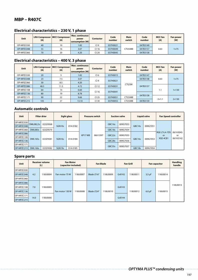
197
OPTYMA PLUS™ condensing units
MBP – R407C
Electrical characteristics – 230 V, 1 phase
UnitLRA Compressor
[A]
MCC Compressor
[A]
Max. continuous
power
consumption [W]
ContactorCode
number
Main
switch
Code
number
MCC fan
[A]
Fan power
[W]
OP-MPZC030 40 10 1.82 CI 9 037H0021
CTI25MB
047B3149
0.63 1×75OP-MPZC048 55 16 3.07 CI 16 037H0049 047B3157
OP-MPZC060 70 20 4.20 CI 20 037H0045 047B3158
Electrical characteristics – 400 V, 3 phase
UnitLRA Compressor
[A]
MCC Compressor
[A]
Max. continuous
power
consumption [W]
ContactorCode
number
Main
switch
Code
number
MCC fan
[A]
Fan power
[W]
OP-MPZC030 20 5 1.82 CI 6 037H0015
CTI25M
047B3147
0.63 1×75OP-MPZC048 23 7.5 3.07CI 9 037H0021
047B3148
OP-MPZC060 30 8.5 4.20
047B3157OP-MPZC086 48.5 11.5 4.72 CI 12 037H0031
1.1 1×130OP-MPZC108 64 14 6.60CI 16 037H0041
OP-MPZC136 80 19 8.78047B3158
OP-MPZC171 90 22 9.66 CI 25 037H0051 CTI25MB2×1.1 2×130
OP-MPZC215 105 27 13.10 CI 30 037H0055 CTI25MB 047B3159
Automatic controls
Unit Filter drier Sight glass Pressure switch Suction valve Liquid valve Fan Speed controller
OP-MPZC030DML082,5s 023Z4568
SGN10s 014-0182
KP17 WB 060-5397
GBC16s 009G7053GBC10s 009G7051
RGE-Z1L4-7DS
or
XGE-4CB1
061H3045
or
061H3142
OP-MPZC048
OP-MPZC060 DML083s 023Z4570 GBC18s 009G7054
OP-MPZC086
DML165s 023Z4581 SGN16s 014-0184
GBC22s 009G7055
GBC16s 009G7053OP-MPZC108
OP-MPZC136 GBC28s 009G7056
OP-MPZC171GBC35s 009G7057
OP-MPZC215 DML166s 023Z4582 SGN19s 014-0185 GBC18s 009G7054
Spare parts
UnitReceiver volume
[L]
Fan Motor
(capacitor included)Fan Blade Fan Grill Fan capacitor
Handling
handle
OP-MPZC030
4.2 118U0004 Fan motor 75 W 118U0007 Blade 16" 118U0009 Grill H2 118U0011 3,5 μF 118U0014
118U0013
OP-MPZC048
OP-MPZC060
OP-MPZC086
7.0 118U0005
Fan motor 130 W 118U0008 Blade 24" 118U0010
Grill H3
118U0012 6.0 μF 118U0015
OP-MPZC108
OP-MPZC136
OP-MPZC17114.0 118U0006 Grill H4
OP-MPZC215

198
Dimensions
A
A
A ( 1 : 2 )
38
91
22
10
0
W=906900850
57
356
24
D=
43
0
H=
65
2
12
D=
48
0
H=
76
0
A ( 1 : 2 )
401
55
24
12
43
6
1050
W=1053
50
12
0
90
1002
A
A
Housing 1
Housing 2

199
OPTYMA PLUS™ condensing units
DimensionsD
=5
50
51
31
30
H=
97
5
A ( 1 : 2 )
A
481
60
1400
W=1406
1340
57
24
12
10
0
A
A ( 1 : 2 )
1350
569
1410
W=1420
10
0
13
0
61
2
D=
65
0
H=
17
94
56
55
24
12
A
A
Housing 3
Housing 4

200
Wiring diagrams
M1~M1
P
B1
M1~M2 E1
K2
K2
F1
Q1
K2
P<
P>
B2
T>
S1
4X1
5X1
L1N
K2
K1C1
DWG.-NO.: 118A0156_b
C2
I > I > I >
2 4 6
Q1
B1: Fan speed control
C1: Start Capacitor (Compressor)
E1: Crankcase HeaterF1: Fuse (Control Circuit)
K2: ContactorM1: Compresssor
Q1: Main Switch
B2: High- and Low Presssure switch
K1: Start Relay
M2: Fan Motor
X1: Terminals for Room Thermostat S1: Room Thermostat (optional)
C2: Run Capacitor (Fan)
F1
Q1
K2
P<
P>
B2
T>
S1
4X1K2
L1N
5X1
C1
C2K1
M1~M1
P
B1
M1~M2
C3
E1
K2
K2
DWG.-NO.: 118A0158_a
I > I > I >
2 4 6
Q1
B1: Fan speed control
C1: Start Capacitor (Compressor)
C3: Run Capacitor (Fan)E1: Crankcase HeaterF1: Fuse (Control Circuit)
K2: ContactorM1: Compresssor
Q1: Main Switch
B2: High- and Low Presssure switch
K1: Start Relay
M2: Fan Motor
X1: Terminals for Room Thermostat S1: Room Thermostat (optional)
C2: Run Capacitor (Compressor)
1 phase (only for OP-LPHC018 and OP-MPHC010)
1 phase

201
OPTYMA PLUS™ condensing units
L = LBP M = MBP026 = 26 cm3
171 = 171 cm3
P = Packaged units
GS = GS
MT= MTZ
NT = NTZ
SC=SC
Z = R404A, R134a, R507, R407C
H = R404A/R507
G = R134a
P00
C = Standard
G = Compressor 230 V/1 phase/50 Hz,
fan 230 V/1 phase/50 Hz
E = Compressor 400 V/3 phase/50 Hz,
fan 230 V/1 phase/50 Hz
Designation system for the OPTYMATM PLUS programme (additional programme frequency etc.: please contact your local wholesaler)
1.
2.
3.
4.
5.
6.
7.
8.
OP-MPHC 018 SC P00 G
1 2 3 4 5 6 7 8
Application
Design
Refrigerant
Condenser option
Displacement
Compressor platform
Version
Electrical code
1 5
2 6
3 7
4 8
Wiring diagrams
P<
P>
B2
T>
S1
L1L2L3N
E1
M3~M1
I > I > I >
2 4 6
Q1
P
B1
F1
Q1
M1~M2
C1
M1~M3
C2
NX1
4X1
5X1
K1
K1
K1 K1
DWG.-NO.: 118A0157_b
B1: Fan speed controlB2: High- and Low Presssure switch
E1: Crankcase HeaterF1: Fuse (Control Circuit)K1: ContactorM1: CompressorM2: Fan Motor
C1: Run Capacitor (Fan)
Q1: Main Switch
X1: Terminals for Room Thermostat S1: Room Thermostat (optional)
M3: Fan Motor (only Housing 4)
C2: Run Capacitor (Fan, only Housing 4)
3 phase


Valve factory in Denmark

DKRA.PK.100.A1.02 / 520B3137 Produced by Danfoss A/S © – G1 Advertising/bpv Apr 2008
The Danfoss product range for the
refrigeration and air conditioning industry
Danfoss Refrigeration & Air Conditioning is
a worldwide manufacturer with a leading
position in industrial, commercial and
supermarket refrigeration as well as air
conditioning and climate solutions.
We focus on our core business of making
quality products, components and systems
that enhance performance and reduce
total life cycle costs – the key to major
savings.
Controls for
Commercial Refrigeration
Controls for
Industrial Refrigeration
Industrial Automation Household Compressors Commercial Compressors
ThermostatsSub-Assemblies
Electronic Controls &
Sensors
We offer a single source for one of the widest ranges of innovative refrigeration and air
conditioning components and systems in the world. And, we back technical
solutions with business solutions to help your company reduce costs,
streamline processes and achieve your business goals.
Danfoss A/S · www.danfoss.com
Brazed plate
heat exchangers