VEGAPULS 64 Radar Level Sensor Quick Setup Guide
24
Quick setup guide Radar sensor for continuous level measurement of liquids VEGAPULS 64 4 … 20 mA/HART - two-wire Document ID: 51462
-
Upload
khangminh22 -
Category
Documents
-
view
0 -
download
0
Transcript of VEGAPULS 64 Radar Level Sensor Quick Setup Guide

Quick setup guideRadar sensor for continuous level measurement of liquids
VEGAPULS 644 … 20 mA/HART - two-wire
Document ID: 51462
Dan Macey
HP

2
Contents
VEGAPULS 64 • 4 … 20 mA/HART - two-wire
51462-EN-160111
Contents1 For your safety
1.1 Authorised personnel ....................................................................................................... 31.2 Appropriate use ................................................................................................................ 31.3 Warning about incorrect use ............................................................................................. 31.4 General safety instructions ............................................................................................... 31.5 CE conformity ................................................................................................................... 41.6 NAMUR recommendations .............................................................................................. 41.7 Radio license for Europe .................................................................................................. 41.8 Environmental instructions ............................................................................................... 4
2 Product description2.1 Configuration .................................................................................................................... 6
3 Mounting3.1 Mounting preparations, mounting strap ............................................................................ 73.2 Mounting instructions ....................................................................................................... 7
4 Connecting to power supply4.1 Connecting ....................................................................................................................... 94.2 Wiring plan, single chamber housing.............................................................................. 10
5 Set up with the display and adjustment module5.1 Insert display and adjustment module ............................................................................ 125.2 Parameter adjustment - Quick setup .............................................................................. 135.3 Parameter adjustment - Extended adjustment................................................................ 15
6 Supplement6.1 Technical data ................................................................................................................ 21
Information:This quick setup guide enables quick setup and commissioning of your instrument.Youcanfindsupplementaryinformationinthecorresponding,moredetailed Operating Instructions Manual as well as the Safety Manual thatcomeswithinstrumentswithSILqualification.Thesemanualsareavailable on the supplied DVD or in the download area of "www.vega.com".
Operating instructions VEGAPULS 64 - 4 … 20 mA/HART - two-wire: Document-ID 51141Editing status of the quick setup guide: 2015-12-04

3
1 For your safety
VEGAPULS 64 • 4 … 20 mA/HART - two-wire
5146
2-EN
-160
111
1 For your safety
1.1 Authorised personnelAll operations described in this operating instructions manual must be carried out only by trained specialist personnel authorised by the plant operator.During work on and with the device the required personal protective equipment must always be worn.
1.2 Appropriate useVEGAPULS 64 is a sensor for continuous level measurement.Youcanfinddetailedinformationabouttheareaofapplicationinchapter "Product description".Operational reliability is ensured only if the instrument is properly usedaccordingtothespecificationsintheoperatinginstructionsmanual as well as possible supplementary instructions.
1.3 Warning about incorrect useInappropriate or incorrect use of the instrument can give rise to application-specifichazards,e.g.vesseloverfillordamagetosystemcomponents through incorrect mounting or adjustment. Also the pro-tectivecharacteristicsoftheinstrumentcanbeinfluenced.
1.4 General safety instructionsThis is a state-of-the-art instrument complying with all prevailing regulations and guidelines. The instrument must only be operated in a technicallyflawlessandreliablecondition.Theoperatorisresponsiblefor the trouble-free operation of the instrument.During the entire duration of use, the user is obliged to determine the compliance of the necessary occupational safety measures with the current valid rules and regulations and also take note of new regula-tions.The safety instructions in this operating instructions manual, the na-tional installation standards as well as the valid safety regulations and accident prevention rules must be observed by the user.For safety and warranty reasons, any invasive work on the device beyond that described in the operating instructions manual may be carried out only by personnel authorised by the manufacturer. Arbi-traryconversionsormodificationsareexplicitlyforbidden.The safety approval markings and safety tips on the device must also be observed.Depending on the instrument version, the emitting frequencies are in the C, K or W band range. The low emitting frequencies are far below the internationally approved limit values. When used correctly, the device poses no danger to health.

4
1 For your safety
VEGAPULS 64 • 4 … 20 mA/HART - two-wire
51462-EN-160111
1.5 CE conformityThedevicefulfillsthelegalrequirementsoftheapplicableECguide-lines.ByaffixingtheCEmarking,weconfirmsuccessfultestingoftheproduct.YoucanfindtheCECertificateofConformityinthedownloadsectionof our homepage.
1.6 NAMUR recommendationsNAMUR is the automation technology user association in the process industry in Germany. The published NAMUR recommendations are acceptedasthestandardinfieldinstrumentation.ThedevicefulfillstherequirementsofthefollowingNAMURrecom-mendations:
• NE 21 – Electromagnetic compatibility of equipment• NE 43 – Signal level for malfunction information from measuring
transducers• NE53–Compatibilityoffielddevicesanddisplay/adjustment
components• NE107–Self-monitoringanddiagnosisoffielddevicesFor further information see www.namur.de.
1.7 Radio license for EuropeThe instrument is approved according to EN 302372-1/2 V1.2.1 (2011-02) for use in closed vessels.For operation inside of closed vessels, the following conditions must befulfilled:
• The instrument must be permanently mounted on a closed vessel made of metal, reinforced concrete, or comparable attenuating materials.
• Flanges,processfittingsandmountingaccessoriesmustensurethe microwave impermeability of the vessel and not let the radar signal escape to the outside
• If necessary, existing viewing windows in the vessel must be coated with a microwave impermeable material (e.g. electrically conductive coating)
• Manholesandflangesonthevesselmustbeclosedandsealedtoavoid penetration of the radar signal
• The instrument should be preferably mounted on top of the vessel with antenna orientation downward
• The instrument must only be installed and maintained by appropri-atelyqualifiedstaff
1.8 Environmental instructionsProtection of the environment is one of our most important duties. That is why we have introduced an environment management system with the goal of continuously improving company environmental pro-tection.Theenvironmentmanagementsystemiscertifiedaccordingto DIN EN ISO 14001.

5
1 For your safety
VEGAPULS 64 • 4 … 20 mA/HART - two-wire
5146
2-EN
-160
111
Pleasehelpusfulfillthisobligationbyobservingtheenvironmentalinstructions in this manual:
• Chapter "Packaging, transport and storage"• Chapter "Disposal"

6
2 Product description
VEGAPULS 64 • 4 … 20 mA/HART - two-wire
51462-EN-160111
2 Product description
2.1 ConfigurationThetypelabelcontainsthemostimportantdataforidentificationanduse of the instrument:
21
12
11
10
9
56
4
3
78
Fig. 1: Layout of the type label (example)1 Instrument type2 Product code3 License label4 Power supply and signal output, electronics5 Protection rating6 Measuring range7 Process and ambient temperature, process pressure8 Material, wetted parts9 Serial number of the instrument10 Data-Matrix-Code for smartphone app11 Symbol of the device protection class12 Reminder to observe the instrument documentation
The type label contains the serial number of the instrument. With it youcanfindthefollowinginstrumentdataonourhomepage:
• Product code (HTML)• Delivery date (HTML)• Order-specificinstrumentfeatures(HTML)• Operating instructions and quick setup guide at the time of ship-
ment (PDF)• Order-specificsensordataforanelectronicsexchange(XML)• Testcertificate(PDF)-optionalGo to www.vega.com "VEGA Tools" and "Instrument search". Enter the serial number.Alternatively, you can access the data via your smartphone:
• Download the smartphone app "VEGA Tools" from the "Apple App Store" or the "Google Play Store"
• Scan the Data Matrix code on the type label of the instrument or• Enter the serial number manually in the app
Type label
Serial number - Instru-ment search

7
3 Mounting
VEGAPULS 64 • 4 … 20 mA/HART - two-wire
5146
2-EN
-160
111
3 Mounting
3.1 Mounting preparations, mounting strapThe mounting strap is supplied unassembled (optionally) and must be screwed to the sensor before setup with three hexagon socket screws M5 x 10 and spring washers. Max. torque, see chapter "Technical data".Requiredtools:Allenwrenchsize4.Therearetwodifferentvariantsofscrewingthestraptothesensor,see following illustration:
1 2
Fig. 2: Mounting strap for screwing to the sensor1 For angle of inclination in steps2 Forangleofinclination,infinitelyvariable
Depending on the selected variant, the sensor can be rotated in the strap:
• Single chamber housing – Angle of inclination in three steps 0°, 90° and 180° – Angleofinclination180°,infinitelyvariable
• Double chamber housing – Angleofinclination90°,infinitelyvariable – Angle of inclination in two steps 0° and 90°
3.2 Mounting instructionsRadar sensors for level measurement emit electromagnetic waves. Thepolarizationisthedirectionoftheelectricalcomponentofthesewaves.Thepolarizationdirectionismarkedbyanoseonthehousing,seefollowing drawing:
1
Fig. 3: Position of the polarisation1 Nose for marking the direction of polarisation
Polarisation

8
3 Mounting
VEGAPULS 64 • 4 … 20 mA/HART - two-wire
51462-EN-160111
Information:Whenthehousingisrotated,thedirectionofpolarizationchangesandhencetheinfluenceofthefalseechoonthemeasuredvalue.Please keep this in mind when mounting or making changes later.
When mounting the sensor, keep a distance of at least 200 mm (7.874 in) from the vessel wall. If the sensor is installed in the center of dished or round vessel tops, multiple echoes can arise. However, these can be suppressed by an appropriate adjustment (see chapter "Setup").If you cannot maintain this distance, you should carry out a false signal storage during setup. This applies particularly if buildup on the vessel wall is expected. In such cases, we recommend repeating the false signal storage at a later date with existing buildup.
> 200 mm(7.87")
Fig. 4: Mounting of the radar sensor on round vessel tops
In vessels with conical bottom it can be advantageous to mount the sensor in the center of the vessel, as measurement is then possible down to the lowest point of the vessel bottom.
Fig. 5: Mounting of the radar sensor on vessels with conical bottom
Installation position
9
4 Connecting to power supply
VEGAPULS 64 • 4 … 20 mA/HART - two-wire
5146
2-EN
-160
111
4 Connecting to power supply
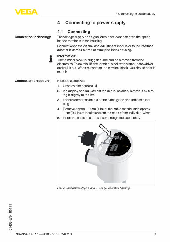
4.1 ConnectingThe voltage supply and signal output are connected via the spring-loaded terminals in the housing.Connection to the display and adjustment module or to the interface adapter is carried out via contact pins in the housing.
Information:The terminal block is pluggable and can be removed from the electronics. To do this, lift the terminal block with a small screwdriver and pull it out. When reinserting the terminal block, you should hear it snap in.
Proceed as follows:1. Unscrew the housing lid2. If a display and adjustment module is installed, remove it by turn-
ing it slightly to the left.3. Loosen compression nut of the cable gland and remove blind
plug4. Remove approx. 10 cm (4 in) of the cable mantle, strip approx.
1 cm (0.4 in) of insulation from the ends of the individual wires5. Insert the cable into the sensor through the cable entry
Fig. 6: Connection steps 5 and 6 - Single chamber housing
Connection technology
Connection procedure

10
4 Connecting to power supply
VEGAPULS 64 • 4 … 20 mA/HART - two-wire
51462-EN-160111
Fig. 7: Connection steps 5 and 6 - Double chamber housing
6. Insert the wire ends into the terminals according to the wiring plan
Information:Solidcoresaswellasflexiblecoreswithwireendsleevesareinsert-eddirectlyintotheterminalopenings.Incaseofflexiblecoreswithoutend sleeves, press the terminal from above with a small screwdriver, the terminal opening is then free. When the screwdriver is released, the terminal closes again.Youcanfindfurtherinformationonthemax.wirecross-sectionunder"Technical data - Electromechanical data"
7. Check the hold of the wires in the terminals by lightly pulling on them
8. Connect the screen to the internal ground terminal, connect the external ground terminal to potential equalisation
9. Tighten the compression nut of the cable entry gland. The seal ring must completely encircle the cable
10. Reinsert the display and adjustment module, if one was installed11. Screw the housing lid back onTheelectricalconnectionisfinished.
4.2 Wiring plan, single chamber housingThe following illustration applies to the non-Ex as well as to the Ex-ia version.
11
4 Connecting to power supply
VEGAPULS 64 • 4 … 20 mA/HART - two-wire
5146
2-EN
-160
111
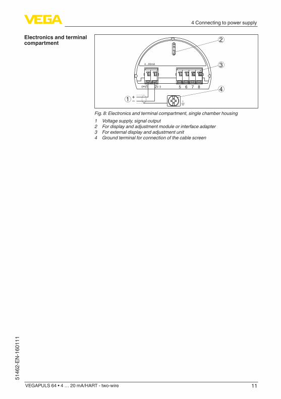
51 2+( ) (-) 6 7 8
4...20mA
2
3
41
Fig. 8: Electronics and terminal compartment, single chamber housing1 Voltage supply, signal output2 For display and adjustment module or interface adapter3 For external display and adjustment unit4 Ground terminal for connection of the cable screen
Electronics and terminal compartment

12
5 Set up with the display and adjustment module
VEGAPULS 64 • 4 … 20 mA/HART - two-wire
51462-EN-160111
5 Set up with the display and adjustment module
5.1 Insert display and adjustment moduleThe display and adjustment module can be inserted into the sensor andremovedagainatanytime.Youcanchooseanyoneoffourdiffer-ent positions - each displaced by 90°. It is not necessary to interrupt the power supply.Proceed as follows:1. Unscrew the housing lid2. Place the display and adjustment module on the electronics in the
desired position and turn it to the right until it snaps in.3. Screw housing lid with inspection window tightly back onDisassembly is carried out in reverse order.The display and adjustment module is powered by the sensor, an ad-ditional connection is not necessary.
Fig. 9: Installing the display and adjustment module in the electronics compart-ment of the single chamber housing

13
5 Set up with the display and adjustment module
VEGAPULS 64 • 4 … 20 mA/HART - two-wire
5146
2-EN
-160
111
1 2
Fig. 10: Installing the display and adjustment module in the double chamber housing1 In the electronics compartment2 In the terminal compartment
Note:Ifyouintendtoretrofittheinstrumentwithadisplayandadjustmentmodule for continuous measured value indication, a higher lid with an inspection glass is required.
5.2 Parameter adjustment - Quick setupTo quickly and easily adapt the sensor to the application, select the menu item "Quick setup" in the start graphic on the display and adjustment module.
Select the individual menu items with the [->] key. Carry out the steps in the below sequence.
1. Measurement loop nameInthefirstmenuitemyouassignasuitablemeasurementloopname.Permitted are names with max. 19 characters.
2. MediumIn this menu item you select the medium. The selection comprises liquidswithdifferentproperties.
Quick setup process

14
5 Set up with the display and adjustment module
VEGAPULS 64 • 4 … 20 mA/HART - two-wire
51462-EN-160111
3. ApplicationIn this menu item you determine the application.
4. Vessel formIn this menu item you specify the for of the vessel bottom and top.
5. Vessel height/Measuring rangeIn this menu item you enter the height of the vessel and hence the active measuring range.
6. Max. adjustmentIn this menu item you carry out the max. adjustment.Enterthemeasuringdistancefor100%filling.
7. Min. adjustmentIn this menu item you carry out the min. adjustment.Enterthemeasuringdistancefor0%filling.
8. Termination"Quick setup terminated successfully"isdisplayedbriefly.
Information:The echo curve of setup was stored automatically during the quick setup.
Thequicksetupisfinished.

15
5 Set up with the display and adjustment module
VEGAPULS 64 • 4 … 20 mA/HART - two-wire
5146
2-EN
-160
111
The return to the measured value indication is carried out through the [->] or [ESC] keys or automatically after 3 s
The menu "Extended adjustment" is available for further settings. Im-portantfunctionsaredescribedinthefollowingchapter.Youcanfindacomplete description of all functions of the "Extended adjustment" in the operating instructions manual of VEGAPULS 64.
5.3 Parameter adjustment - Extended adjustmentThemainmenuisdividedintofivesectionswiththefollowingfunc-tions:
Setup: Settings, e.g., for measurement loop name, units, application, adjustment, signal outputDisplay: Settings, e.g., for language, measured value display, lightingDiagnosis: Information, for example, on device status, peak value, simulation, echo curveAdditional adjustments: Date/Time, reset, copy function, scaling, currentoutput,falsesignalsuppression,linearization,HARTmode,special parametersInfo: Instrument name, hardware and software version, calibration date, instrument featuresIn the main menu item "Setup", the individual submenu items should be selected one after the other and provided with the correct parameters to ensure optimum adjustment of the measurement. The procedure is described in the following.
Since the radar sensor is a distance measuring instrument, the distance from the sensor to the product surface is measured. To indicate the actual level, an allocation of the measured distance to the percentage height must be carried out.To perform the adjustment, enter the distance with full and empty ves-sel, see the following example:
Extended adjustment
Main menu
Setup - Adjustment

16
5 Set up with the display and adjustment module
VEGAPULS 64 • 4 … 20 mA/HART - two-wire
51462-EN-160111
100%
0%
0,5
m(1
9.68
")5
m(1
96.9
")
2
1
3
Fig. 11: Parameter adjustment example min./max. adjustment1 Min. level = max. measuring distance2 Max. level = min. measuring distance3 Reference plane
If these values are not known, an adjustment with the distances of e.g. 10%and90%ispossible.Startingpointforthesedistancespecifica-tionsisalwaysthesealingsurfaceofthethreadorflange.Youcanfindspecificationsonthereferenceplaneinchapter"Technical data". The actual level is calculated on the basis of these settings.The actual product level during this adjustment is not important, because the min./max. adjustment is always carried out without changing the product level. These settings can be made ahead of time without the instrument having to be installed.
The function "Setup" allows the echo curve to be saved at the time of setup.
Information:This is generally recommended, however, for use of the Asset Management functions it is absolutely necessary. Saving should be carried out with a very low level.
The function "Echo curve memory" allows up to ten individual echo curves to be stored, for example to detect the measurement behav-iourofthesensorindifferentoperatingconditions.With the adjustment software PACTware and the PC, the stored echo curvescanbedisplayedwithhighresolutionandusedtorecognizesignal changes over time. In addition, the echo curve saved during setup can also be displayed in the echo curve window and compared with the current echo curve.
Diagnostics - Echo curve memory

17
5 Set up with the display and adjustment module
VEGAPULS 64 • 4 … 20 mA/HART - two-wire
5146
2-EN
-160
111
Menu - Setup
Menu item Parameter Default setting
Measurement loop name
Sensor
Units Distance in mTemperature in °C
Application Medium Water based
Application Storage tank
Vessel top/Vessel bottom
Dished form/Dished form
Vessel height/Measuring range
30 m
Adjustment Max. adjustment 0,000 m(d)100.00 %
Min. adjustment 30 m0.00 %
Damping Integration time 0.0 s
Current output Current output - Mode
Output characteristics4 … 20 mAReaction when malfunctions occur≤3.6mA
Current output - Min./Max.
3.8 mA20.5 mA
Lock adjustment Released
Menu - Display
Menu item Default setting
Menu language Order-specific
Displayed value 1 Filling height in %
Displayed value 2 Electronics temperature in °C
Backlight Switched on
Menu - Diagnosis
Menu item Parameter Default setting
Sensor status -
Peak value Distance -
Meas. certainty -
Menu and parameter overview

18
5 Set up with the display and adjustment module
VEGAPULS 64 • 4 … 20 mA/HART - two-wire
51462-EN-160111
Menu item Parameter Default setting
Peak values, ad-ditional
Temperature -
Curve indication Echo curve -
False signal sup-pression
-
Simulation Percent
Echo curve memory
Percent
Menu - Additional adjustments
Menu item Parameter Default setting
Date/Time Actual date/Actual time
Reset -
Copy in-strument settings
-
Scaling Scalingsize Volume in l
Scaling format 0 % corresponds to 0 l100 % corresponds to 0 l
Current out-put 1
Current output - Meas. vari-able
Lin. percent - Level
Current output - Adjustment 0 … 100 % correspond to 4 … 20 mA
Current out-put 2
Current output - Meas. vari-able
Lin. percent - Level
Current output - Adjustment 0 … 100 % correspond to 4 … 20 mA
False signal suppression
-
Linearization Linear
HART mode Address 0
Special pa-rameters
-
Menu - Info
Menu item Parameter
Device name VEGAPULS 6.
Instrument version Hardware and software version
Factory calibration date
Date
Sensor characteristics Order-specificcharacteristics

19
5 Set up with the display and adjustment module
VEGAPULS 64 • 4 … 20 mA/HART - two-wire
5146
2-EN
-160
111
Thefollowingcircumstancescauseinterferingreflectionsandcaninfluencethemeasurement:
• High sockets• Vessel installations such as struts• Agitators• Buildup or welded joints on vessel walls
Note:A false signal suppression detects, marks and saves these false signals so that they are no longer taken into account in the level measurement.
This should be done with a low level so that all potential interfering reflectionscanbedetected.Proceed as follows:1. Select with [->] the menu item "False signal suppression" and
confirmwith[OK].
2. Confirmagainwith[OK].
3. Confirmagainwith[OK].
4. Confirmagainwith[OK] and enter the actual distance from the sensor to the product surface.
5. All interfering signals in this section are detected by the sensor andstoredafterconfirmingwith[OK].
Note:Check the distance to the product surface, because if an incorrect (too large) value is entered, the existing level will be saved as a false signal. The level would then no longer be detectable in this area.
If a false signal suppression has already been saved in the sensor, the following menu window appears when selecting "False signal suppression":
Additional adjustments - False signal suppression

20
5 Set up with the display and adjustment module
VEGAPULS 64 • 4 … 20 mA/HART - two-wire
51462-EN-160111
Delete: An already created false signal suppression will be com-pletely deleted. This is useful if the saved false signal suppression no longer matches the metrological conditions in the vessel.Extend: is used to extend an already created false signal suppres-sion. This is useful if a false signal suppression was carried out with too high a level and not all false signals could be detected. When selecting "Extend", the distance to the product surface of the created false signal suppression is displayed. This value can now be changed and the false signal suppression can be extended to this range.

21
6 Supplement
VEGAPULS 64 • 4 … 20 mA/HART - two-wire
5146
2-EN
-160
111
6 Supplement
6.1 Technical dataElectromechanical data - version IP 66/IP 67 and IP 66/IP 68; 0.2 barOptions of the cable entry
Ʋ Cable entry M20 x 1.5, ½ NPT Ʋ Cable gland M20 x 1,5; ½ NPT (cable ø see below table) Ʋ Blind plug M20 x 1.5; ½ NPT Ʋ Closing cap ½ NPT
Material ca-ble gland
Material seal insert
Cable diameter
4.5 … 8.5 mm 5 … 9 mm 6 … 12 mm 7 … 12 mm 10 … 14 mm
PA NBR – ● ● – ●
Brass, nickel-plated
NBR ● ● ● – –
Stainless steel
NBR – ● ● – ●
Wire cross-section (spring-loaded terminals) Ʋ Massive wire, stranded wire 0.2 … 2.5 mm² (AWG 24 … 14) Ʋ Stranded wire with end sleeve 0.2 … 1.5 mm² (AWG 24 … 16)
Voltage supplyOperating voltage UB
Ʋ Non-Ex instrument 12 … 35 V DC Ʋ Ex-d instrument 12 … 35 V DC Ʋ Ex ia instrument 12 … 30 V DC Ʋ Ex-d-ia instrument 17 … 35 V DC
Operating voltage UB - illuminated display and adjustment module Ʋ Non-Ex instrument 18 … 35 V DC Ʋ Ex-d instrument 18 … 35 V DC Ʋ Ex ia instrument 18 … 30 V DC Ʋ Ex-d-ia instrument Due to the barrier, no lighting possible
Reverse voltage protection IntegratedPermissible residual ripple - Non-Ex, Ex-ia instrument
Ʋ for 12 V< UB < 18 V ≤0.7Veff(16…400Hz) Ʋ for 18 V< UB < 35 V ≤1.0Veff(16…400Hz)
Permissible residual ripple - Ex-d-ia instrument Ʋ for 18 V< UB < 35 V ≤1Veff(16…400Hz)
Load resistor Ʋ Calculation (UB - Umin)/0.022 A Ʋ Example - Non-Ex instrument with UB= 24 V DC
(24V-12V)/0.022A=545Ω

22
Notes
VEGAPULS 64 • 4 … 20 mA/HART - two-wire
51462-EN-160111

23
Notes
VEGAPULS 64 • 4 … 20 mA/HART - two-wire
5146
2-EN
-160
111

Printing date:
5146
2-E
N-1
6011
1
All statements concerning scope of delivery, application, practical use and operat-ing conditions of the sensors and processing systems correspond to the information available at the time of printing.Subject to change without prior notice
© VEGA Grieshaber KG, Schiltach/Germany 2016
Dan Macey
HP