700/70 Series Setup Manual
551
-
Upload
khangminh22 -
Category
Documents
-
view
1 -
download
0
Transcript of 700/70 Series Setup Manual


MELDAS is a registered trademark of Mitsubishi Electric Corporation. Other company and product names that appear in this manual are trademarks or registered trademarks of the respective companies.

Introduction
This manual is the alarm/parameter guide required to use the MITSUBISHI CNC700/70 Series. This manual is prepared on the assumption that your machine is provided with all of the MITSUBISHI CNC700/70 Series functions. Confirm the functions available for your NC before proceeding to operation by referring to the specification issued by the machine tool builder. Notes on Reading This Manual (1) This manual explains general parameters as viewed from the NC.
For information about each machine tool, refer to manuals issued from the machine tool builder. If the descriptions relating to "restrictions" and "allowable conditions" conflict between this manual and the machine tool builder's instruction manual, the later has priority over the former.
(2) This manual is intended to contain as much descriptions as possible even about special operations.
The operations to which no reference is made in this manual should be considered impossible. (3) The "special display unit" explained in this manual is the display unit incorporated by the machine
tool builder, and is not the MITSUBISHI standard display unit.
Caution
If the descriptions relating to the "restrictions" and "allowable conditions" conflict between this manual and the machine tool builder’s instruction manual‚ the latter has priority over the former.
The operations to which no reference is made in this manual should be considered "impossible".
This manual is complied on the assumption that your machine is provided with all optional functions. Confirm the functions available for your machine before proceeding to operation by referring to the specification issued by the machine tool builder.
In some NC system versions‚ there may be cases that different pictures appear on the screen‚ the machine operates in a different way or some function is not activated.


Precautions for Safety Always read the specifications issued by the machine tool builder, this manual, related manuals and attached documents before installation, operation, programming, maintenance or inspection to ensure correct use. Understand this numerical controller, safety items and cautions before using the unit. This manual ranks the safety precautions into "DANGER", "WARNING" and "CAUTION".
DANGER
When the user may be subject to imminent fatalities or major injuries if handling is mistaken.
WARNING
When the user may be subject to fatalities or major injuries if handling is mistaken.
CAUTION
When the user may be subject to injuries or when physical damage may occur if handling is mistaken.
Note that even items ranked as " CAUTION", may lead to major results depending on the situation. In any case, important information that must always be observed is described.
DANGER
Not applicable in this manual.
WARNING
Not applicable in this manual.
CAUTION
1. Items related to product and manual
If the descriptions relating to the "restrictions" and "allowable conditions" conflict between this manual and the machine tool builder's instruction manual‚ the latter has priority over the former.
The operations to which no reference is made in this manual should be considered impossible.
This manual is complied on the assumption that your machine is provided with all optional functions. Confirm the functions available for your machine before proceeding to operation by referring to the specification issued by the machine tool builder.
In some NC system versions‚ there may be cases that different pictures appear on the screen‚ the machine operates in a different way on some function is not activated.
2. Items related to faults and abnormalities
If the battery low alarm is output, save the machining programs, tool data and parameters to an input/output device, and then replace the battery. If the BATTERY alarm occurs, the machining programs, tool data and parameters may be damaged. After replacing the battery, reload each data item.
[Continued on next page]

CAUTION [Continued]
3. Items related to maintenance
Do not replace the battery while the power is ON.
Do not short-circuit, charge, heat, incinerate or disassemble the battery.
Dispose of the spent battery according to local laws. Do not connect or disconnect the connection cables between each unit while the power is ON. Do not pull the cables when connecting/disconnecting it.
Do not replace cooling fan while the power is ON.
Dispose of the replaced cooling fan according to the local laws.
Do not replace backlight while the power is ON.
Dispose of the spent backlights according to the local laws.
Do not touch backlight while the power is ON. Failure to observe this could result in electric shocks due to high voltage.
Do not touch backlight while LCD panel is in use. Failure to observe this could result in burns.
LCD panel and backlight are made of glass, so do not apply impacts or pressure on them. Failure to observe this could result in breakage.
Incorrect connections could cause the devices to damage. Connect the cable to the designated connector.
Do not replace control units while the power is ON.
Do not replace display units while the power is ON.
Do not replace keyboard units while the power is ON.
Do not replace DX units while the power is ON.
Do not replace hard disk units while the power is ON.
Dispose of the replaced hard disk unit according to the local laws.
Hard disk unit is a precision device, so do not drop or apply strong impacts on it.
4. Items related to servo parameters and spindle parameters
Do not adjust or change the parameter settings greatly as operation could become unstable.
In the explanation on bits, set all bits not used, including blank bits, to "0".

CONTENTS
I Procedures for Starting up
1. Procedures for Starting Up 700 Series ........................................................................................1 1.1 Outline of Hardware Configuration .........................................................................................1 1.2 Outline of Setup Procedures ..................................................................................................2
2. Procedures for Starting Up 70 Series ..........................................................................................3 2.1 Outline of Hardware Configuration .........................................................................................3 2.2 Outline of Setup Procedures ..................................................................................................4
3. Setup Details ...............................................................................................................................5 3.1 Connecting the Control Unit and Peripheral Devices .............................................................5
3.1.1 Setting the MDS-D/DH Series Rotary Switch and DIP Switch .........................................7 3.1.2 Setting the MDS-D-SVJ3/SPJ3 Series Rotary Switch......................................................9
3.2 Erasing the Backed up Data (SRAM) ...................................................................................10 3.3 Inputting the Parameters ......................................................................................................12
3.3.1 When There is No Parameter File..................................................................................12 3.3.2 When a Parameter File is Available ...............................................................................15
3.4 Formatting the File System...................................................................................................16 3.5 Inputting the Ladder Program...............................................................................................17 3.6 Credit System.......................................................................................................................19 3.7 Setting the Handy Terminal ..................................................................................................21
3.7.1 When Connecting with PC to Input ................................................................................21 3.7.2 When Connecting with NC to Input ................................................................................23
3.8 Adjustment of Dog-type Reference Position Return for Relative Position Detection............24 3.8.1 Dog-type Reference Position Return Operation.............................................................24 3.8.2 Dog-type Reference Position Return Adjustment Procedures .......................................25
3.9 Absolute Position Detection System.....................................................................................31 3.9.1 Dog-type Reference Position Return Operation.............................................................31 3.9.2 Starting up the Absolute Position Detection System......................................................32
3.10 Auxiliary Axis Operation .....................................................................................................34 3.10.1 Preparations.................................................................................................................35 3.10.2 Absolute Position Initial Setting....................................................................................36 3.10.3 Test Operation..............................................................................................................36 3.10.4 PLC device ...................................................................................................................37 3.10.5 Notes............................................................................................................................40
3.11 Data Sampling ....................................................................................................................41 3.12 Data backup .......................................................................................................................41 3.13 M70 SETUP INSTALLER ...................................................................................................42
3.13.1 Compatible Data and CF Card Folder Configuration ...................................................42 3.13.2 Operation Method.........................................................................................................44 3.13.3 List of Error Messages .................................................................................................49
4. 700 Series H/W Replacement Methods.....................................................................................50 4.1 Durable Parts........................................................................................................................50
4.1.1 Control unit battery .........................................................................................................50 4.1.2 Cooling fan for control unit .............................................................................................52 4.1.3 Cooling fan for display unit (XP terminal) .......................................................................53

4.1.4 Backlight .........................................................................................................................54 4.2 Unit .......................................................................................................................................57
4.2.1 Control Unit.....................................................................................................................57 4.2.2 Display Unit ....................................................................................................................59 4.2.3 Keyboard unit .................................................................................................................60 4.2.4 DX Unit ...........................................................................................................................62 4.2.5 Hard Disk Unit ................................................................................................................63
4.3 Compact Flash......................................................................................................................64 4.3.1 Control Unit Compact Flash ............................................................................................64
4.4 IC card ..................................................................................................................................65 4.4.1 Front IC Card ..................................................................................................................65
5. 70 Series H/W Replacement Methods.......................................................................................66 5.1 Durable Parts........................................................................................................................66
5.1.1 Control unit battery .........................................................................................................66 5.1.2 Backlight .........................................................................................................................68
5.2 Unit .......................................................................................................................................70 5.2.1 Control Unit.....................................................................................................................70 5.2.2 Display Unit ....................................................................................................................72 5.2.3 Keyboard unit .................................................................................................................73 5.2.4 DX Unit ...........................................................................................................................75
5.3 Compact Flash......................................................................................................................76 5.3.1 Front Compact Flash......................................................................................................76
6. Cable ......................................................................................................................................77
II Explanation of Alarms
1. List of Alarms ...............................................................................................................................1 1.1 Operation Alarms....................................................................................................................1 1.2 Stop Codes ...........................................................................................................................10 1.3 Servo/Spindle Alarms ...........................................................................................................15 1.4 MCP Alarm ...........................................................................................................................25 1.5 System Alarms......................................................................................................................35 1.6 Absolute Position Detection System Alarms.........................................................................41 1.7 Distance-coded Reference Scale Errors ..............................................................................44 1.8 Messages during Emergency Stop.......................................................................................45 1.9 Auxiliary Axis Alarms ............................................................................................................47 1.10 Computer Link Errors..........................................................................................................54 1.11 User PLC Alarms ................................................................................................................55 1.12 Network Service Errors.......................................................................................................57
2. Operation Messages..................................................................................................................58 2.1 Search-related Operation Messages ....................................................................................58 2.2 Graphic Display-related Operation Messages ......................................................................59 2.3 Variable (Common variables, local variables) - related Operation Messages ......................60 2.4 PLC Switch-related Operation Messages.............................................................................60 2.5 Compensation-related (Tool compensation, coordinate system offset) Operation Messages60 2.6 Data Input/Output-related Operation Messages ...................................................................61

2.7 Parameter-related Operation Messages ..............................................................................64 2.8 Measurement-related (Workpiece, rotation) Operation Messages.......................................65 2.9 Tool (Tool registration, tool life) -related Operation Messages.............................................67 2.10 Editing-related Operation Messages ..................................................................................68 2.11 Diagnosis-related Operation Messages .............................................................................70 2.12 Maintenance-related Operation Messages.........................................................................71 2.13 Data Sampling-related Operation Messages......................................................................73 2.14 Absolute Position Detection-related Operation Messages .................................................74 2.15 System Setup-related Operation Messages.......................................................................74 2.16 Automatic Backup-related Operation Messages ................................................................75 2.17 Alarm History-related Operation Messages........................................................................75 2.18 Anshin-net-related Operation Messages ............................................................................76 2.19 Messages Related to Machine Tool Builder Network System............................................81 2.20 Other Operation Messages ................................................................................................83
3. Program Error ............................................................................................................................84 4. Troubleshooting .......................................................................................................................104
4.1 Drive System Troubleshooting ...........................................................................................104 4.1.1 Troubleshooting at Power ON......................................................................................104 4.1.2 Troubleshooting for each alarm No. .............................................................................105 4.1.3 Troubleshooting for each warning No. .........................................................................130 4.1.4 Parameter numbers during initial parameter error .......................................................132 4.1.5 Troubleshooting the spindle system when there is no alarm or warning......................133
III Explanation of Parameters
1. Outline .........................................................................................................................................1 1.1 Screen Transition Chart..........................................................................................................1 1.2 Unit .........................................................................................................................................1
2. User Parameters..........................................................................................................................2 2.1 Process Parameters ...............................................................................................................2 2.2 Control Parameters ..............................................................................................................15 2.3 Axis Parameters ...................................................................................................................19 2.4 Operation Parameters ..........................................................................................................22 2.5 Barrier Data (For L system only) ..........................................................................................27 2.6 I/O Parameters .....................................................................................................................30 2.7 Ethernet Parameters ............................................................................................................49 2.8 Computer Link Parameters...................................................................................................56 2.9 Subprogram Storage Destination Parameters......................................................................59 2.10 Anshin-net Parameter 1......................................................................................................63 2.11 Machine Tool Builder Network System (MTB-net) Parameter 1.........................................64
3. Setting the Machine Parameters ...............................................................................................65 4. Base Specifications Parameters................................................................................................66 5. Axis Specifications Parameters ...............................................................................................123
5.1 Axis Specifications Parameters ..........................................................................................123 5.2 Zero Point Return Parameters............................................................................................129

5.3 Absolute Position Parameters ............................................................................................134 5.4 Axis Specifications Parameters 2 .......................................................................................136
6. Servo Parameters ....................................................................................................................148 6.1 Details for servo parameters...............................................................................................148 6.2 List of standard parameters for each servomotor ...............................................................166 6.3 Supplement.........................................................................................................................174
6.3.1 D/A Output No. .............................................................................................................174 6.3.1.1 MDS-D/DH Series................................................................................................................. 174 6.3.1.2 MDS-D-SVJ3 Series ............................................................................................................. 177
6.3.2 Electronic Gears...........................................................................................................180 6.3.3 Lost Motion Compensation...........................................................................................181
7. Spindle Parameters .................................................................................................................182 7.1 Spindle Base Specifications Parameters............................................................................182 7.2 Spindle Parameters ............................................................................................................198 7.3 Supplement.........................................................................................................................221
7.3.1 D/A Output Numbers ....................................................................................................221 7.3.1.1 MDS-D/DH Series................................................................................................................. 221 7.3.1.2 MDS-D-SPJ3 Series ............................................................................................................. 225
8. Rotary Axis Configuration Parameters.....................................................................................229 9. Machine Error Compensation ..................................................................................................235
9.1 Function Outline..................................................................................................................235 9.2 Setting Compensation Data................................................................................................239 9.3 Example in Using a Linear Axis as the Base Axis ..............................................................241 9.4 Example in Using a Rotary Axis as the Base Axis..............................................................245
10. PLC Constants.......................................................................................................................246 10.1 PLC Timer.........................................................................................................................246 10.2 PLC Integrated Timer .......................................................................................................247 10.3 PLC Counter .....................................................................................................................247 10.4 PLC Constants..................................................................................................................248 10.5 Selecting the PLC Bit........................................................................................................248
11. Macro List ..............................................................................................................................251 12. Position Switch.......................................................................................................................253
12.1 Canceling the Position Switch ..........................................................................................255 13. Auxiliary Axis Parameter ........................................................................................................256 14. Open Parameter ....................................................................................................................275 15. CC-Link Parameter ................................................................................................................276
15.1 CC-Link Parameter 1 ........................................................................................................276 15.2 CC-Link Parameter 2 ........................................................................................................287
16. Anshin-net Parameter 2 / MTB-net Parameter 2....................................................................290 17. PLC Axis Parameters.............................................................................................................303

I Procedures for Starting Up


1. Procedures for Starting Up 700 Series 1.1 Outline of Hardware Configuration
I - 1
1. Procedures for Starting Up 700 Series This section explains the normal work required to newly start up the MITSUBISHI CNC 700 Series. Start up the system following these setup procedures.
1.1 Outline of Hardware Configuration
The names of the hardware used in this section's explanations are explained below.
Display unit Keyboard
Tab right INPUTIC card interface on front of display unit
Back Next
Control unit
Lower rotary switch
Upper rotary switch
2 E
5
34C
79 86A
1F
B
D
0
2 E
5
34C
79 86A
1F
B
D
0
LED1
CS1
LED2
CS2
SW1

1. Procedures for Starting Up 700 Series 1.2 Outline of Setup Procedures
I - 2
1.2 Outline of Setup Procedures The procedures for setting up are explained with a flow chart.
Start
Connecting the control unit
and peripheral devices Refer to 3.1
Connect the control unit with the peripheral devices (servo/spindle drive, auxiliary axis, remote I/O).
Erasing the backed up data (SRAM) Refer to 3.2
Erase the backed up data (SRAM). Set CS1 to "0" and CS2 to "C" to erase the SRAM.
Turning the power ON again.
Inputting the parameters Refer to 3.3
If there is no parameter file, input the parameters with system setup or by manual input operation. If there is a parameter file, input the parameters with input/output screen.
Turning the power ON again.
Formatting the file system Refer to 3.4
Format the file system
Turning the power ON again.
Setting the data/time Refer to 700/70 Series Instruction Manual
Set the data and time in the integrated time display pop-up window.
Inputting the ladder program Refer to 3.5
Input the ladder program using "GX Developer" or "PLC Onboard".
Setting the credit system Refer to 3.6
This is necessary only if the credit system is valid.
Setting the handy terminal Refer to 3.7
Input the customized data of handy terminal. (Note) This is necessary only if the handy terminal is connected.
Inputting the machining program
End
Carry out the procedures below if necessary. 1 Adjustment of dog-type reference position return Refer to 3.8 2 Absolute position detection system Refer to 3.9 3 Auxiliary axis operation Refer to 3.10 4 Data sampling Refer to 3.11 5 Data backup Refer to 3.12

2. Procedures for Starting Up 70 Series 2.1 Outline of Hardware Configuration
I - 3
2. Procedures for Starting Up 70 Series This section explains the normal work required to newly start up the MITSUBISHI CNC 70 Series. Start up the system following these setup procedures.
2.1 Outline of Hardware Configuration
The names of the hardware used in this section's explanations are explained below.
Display unit Keyboard
Tab right INPUT CF card interface on frontof display unit
Back Next
Left rotary switch
Control unit
Right rotary switch

2. Procedures for Starting Up 70 Series 2.2 Outline of Setup Procedures
I - 4
2.2 Outline of Setup Procedures The procedures for setting up are explained with a flow chart.
Start
Connecting the control unit
and peripheral devices Refer to 3.1
Connect the control unit with the peripheral devices (servo/spindle drive, and remote I/O).
Erasing the backed up data (SRAM) Refer to 3.2
Erase the backed up data (SRAM). Set RSW1 to "0" and RSW2 to "C" to erase the SRAM.
Turning the power ON again.
Setting up with M70 SETUP INSTALLER Refer to 3.13
Install the language data, custom data and custom startup screen. Turning the power ON again.
Inputting the parameters Refer to 3.3
If there is no parameter file, input the parameters with system setup or by manual input operation. If there is a parameter file, input the parameters with input/output screen.
Turning the power ON again.
Formatting the file system Refer to 3.4
Format the file system
Turning the power ON again.
Setting the data/time Refer to 700/70 Series Instruction Manual
Set the data and time in the integrated time display pop-up window.
Inputting the ladder program Refer to 3.5
Input the ladder program using "GX Developer".
Setting the credit system Refer to 3.6
This is necessary only if the credit system is valid.
Inputting the machining program
End
Carry out the procedures below if necessary. 1 Adjustment of dog-type reference position return Refer to 3.8 2 Absolute position detection system Refer to 3.9 3 Data sampling Refer to 3.11 4 Data backup Refer to 3.12
3. Setup Details 3.1 Connecting the Control Unit and Peripheral Devices
I - 5
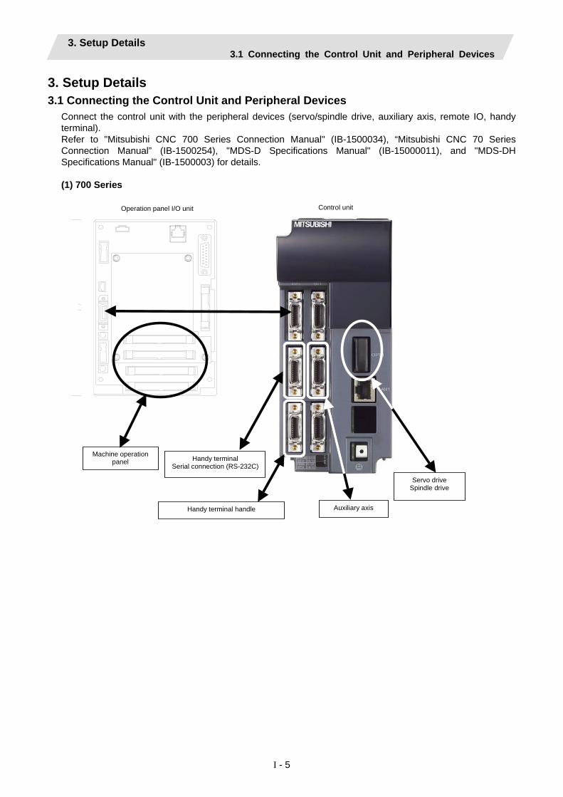
3. Setup Details 3.1 Connecting the Control Unit and Peripheral Devices
Connect the control unit with the peripheral devices (servo/spindle drive, auxiliary axis, remote IO, handy terminal). Refer to "Mitsubishi CNC 700 Series Connection Manual" (IB-1500034), “Mitsubishi CNC 70 Series Connection Manual” (IB-1500254), "MDS-D Specifications Manual" (IB-15000011), and "MDS-DH Specifications Manual" (IB-1500003) for details. (1) 700 Series
Control unit Operation panel I/O unit
Machine operation panel
Auxiliary axis
Servo drive Spindle drive
Handy terminal Serial connection (RS-232C)
Handy terminal handle

3. Setup Details 3.1 Connecting the Control Unit and Peripheral Devices
I - 6
(2) 70 Series Control unit
Operation panel I/O unit
Machine operation panel
Servo drive Spindle drive
Serial communicaton(RS-232C)
Handle

3. Setup Details 3.1 Connecting the Control Unit and Peripheral Devices
I - 7
3.1.1 Setting the MDS-D/DH Series Rotary Switch and DIP Switch (1) Rotary switch setting
Before turning on the power, the axis No. must be set with the rotary switch. The rotary switch settings will be validated when the drive units are turned ON.
1st axis
Servo drive unit (MDS-D/DH-V1)
2nd axis Servo drive unit(MDS-D/DH-V2)
Spindle Drive unit
(MDS-D/DH-SP□)
Power supply unit(MDS-D/DH-CV)
L axis M axis
0 1 F2 E
4 C3 D
5 B6 A7 98
0 1 F2 E
4 C3 D
5 B6 A7 98
01 F2 E
4 C 3 D
5 B 6 A 7 98
01 F2 E
4 C3 D
5 B6 A7 98
0 1 F 2 E
4 C 3 D
5 B 6 A 7 9 8
Details Rotary switch setting MDS-D/DH-V1/V2/SP
setting MDS-D/DH-CV
setting 0 1st axis Normal setting 1 2nd axis 2 3rd axis 3 4th axis
Setting prohibited
4 5th axis External emergency stop valid (CN23 used)
5 6th axis 6 7th axis 7 8th axis 8 9th axis 9 10th axis A 11th axis Setting prohibited B 12th axis C 13th axis D 14th axis E 15th axis F 16th axis

3. Setup Details 3.1 Connecting the Control Unit and Peripheral Devices
I - 8
(2) DIP switch setting
Setting the DIP switches is necessary prior to turning ON the power. Setting of the DIP switches at the time of turning ON the power is validated. The DIP switches shall be as the standard setting (all the switches OFF).
The switches are OFF when facing bottom as illustrated.
M axis Setting unused axis
L axis Setting unused axis
Unused axis can be set by turning the switches ON.When there is unused axis for the 2-axis drive unit, set unused axis.
Turn this switch ON for the drive unit to which the terminator is connected. Note that the switch must be turned OFF when the network configuration is valid.
(Note) If the NC system is compatible with A1 or the prior version, set "1" to the base specifications parameter "#1240 set12/bit4" and turn the last DIP switch ON.

3. Setup Details 3.1 Connecting the Control Unit and Peripheral Devices
I - 9
3.1.2 Setting the MDS-D-SVJ3/SPJ3 Series Rotary Switch Before turning on the power, the axis No. must be set with the rotary switch. The rotary switch settings will be validated when the drive units are turned ON.
Servo drive unit (MDS-D-SVJ3)
Spindle drive unit(MDS-D-SPJ3)
0 1 F 2 E
4 C 3 D
5 B 6 A 7 9 8
01 F
2 E
4 C3 D
5 B6 A7 98
Details Setting the rotary switch Setting the MDS-D-SVJ3/SPJ3
0 1st axis 1 2nd axis 2 3rd axis 3 4th axis 4 5th axis 5 6th axis 6 7th axis 7 8th axis 8 9th axis 9 10th axis A 11th axis B 12th axis C 13th axis D 14th axis E 15th axis F 16th axis

3. Setup Details 3.2 Erasing the Backed up Data (SRAM)
I - 10
3.2 Erasing the Backed up Data (SRAM) Use the following procedure if the backed up data (SRAM) needs to be cleared after the control unit is replaced, etc. (There is no influence on the option parameters even if the backup data is deleted.) (1) 700 Series
(a) With the NC power OFF, set the upper rotary switch (CS1) on the control unit to "0" and the lower rotary switch (CS2) to "C". Then, turn the power ON.
2 E
5
34C
79 8 6A
1F
B D
0
2 E
5
34C
79 8 6A
1F
B
D
0
LED1
CS1
LED2
CS2
SW1
LED1 LED2
(b) The LED display will change from "08." → "00" →
"01" ... "08". The process is completed when "0Y" is displayed. (Required time: 8 seconds)
(c) Turn the NC power OFF. (d) Set the lower rotary switch (CS2) to "0".
2 E
5
3 4 C
7 9 8 6 A
1 F
B D
0
2 E
5 3 4 C
7 9 8 6 A
1 F
B D
0
LED1
CS1
LED2
CS2
SW1
(e) After turning the power OFF and ON, do nothing, and then turn the power OFF and ON again.
(Note) After the SRAM is cleared and the NC power is turned ON, the IP addresses are initialized to the
following values. <Base common parameters> #1934 Local IP address : 192.168.100. 1 #1935 Local Subnet mask : 255.255.255. 0
To communicate with the screen, the parameter value and the "C:\WINDOWS\melcfg.ini" setting value must match. Confirm that "C:\WINDOWS\melcfg.ini" is set to the above value. Last line of C:\WINDOWS\melcfg.ini
• • • [HOSTS] TCP1=192.168.100.1,683
3. Setup Details 3.2 Erasing the Backed up Data (SRAM)
I - 11
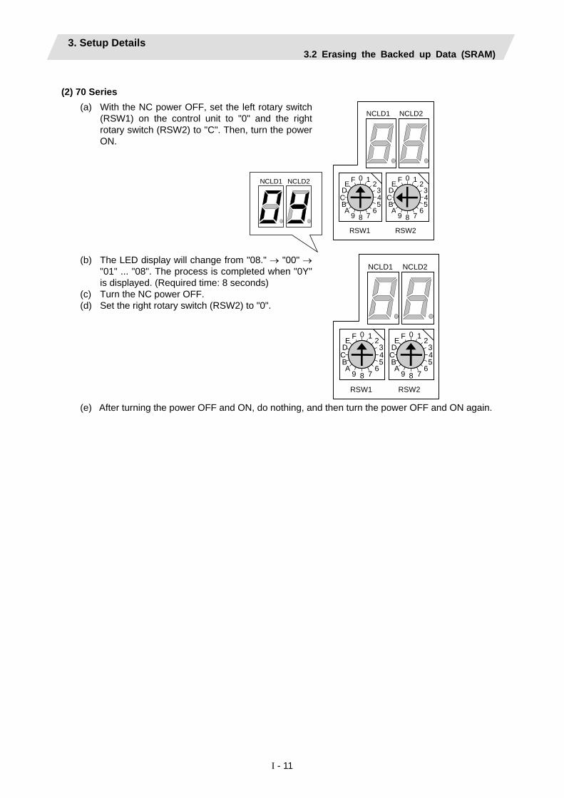
(2) 70 Series (a) With the NC power OFF, set the left rotary switch
(RSW1) on the control unit to "0" and the right rotary switch (RSW2) to "C". Then, turn the power ON.
NCLD1 NCLD2
RSW2 RSW1
NCLD1
2 E
5
3 4 C
7 9 8 6 A
1 F
B
D
0
NCLD2
2 E
5
34C
79 86A
1F
B
D
0
(b) The LED display will change from "08." → "00" →
"01" ... "08". The process is completed when "0Y" is displayed. (Required time: 8 seconds)
(c) Turn the NC power OFF. (d) Set the right rotary switch (RSW2) to "0".
RSW2 RSW1
NCLD1
2 E
5
3 4 C
7 9 8 6 A
1 F
B
D
0
NCLD2
2 E
5
34C
79 86A
1F
B
D
0
(e) After turning the power OFF and ON, do nothing, and then turn the power OFF and ON again.
3. Setup Details 3.3 Inputting the Parameters
I - 12
3.3 Inputting the Parameters 3.3.1 When There is No Parameter File
If there is no parameter file (ALL.PRM), input the parameters with system setup or by manual input operation.
(1) Parameter input with system setup
With the system setup function, various setups necessary for the NC to initially startup are available by simply entering the minimum required items. File formatting can be done at the same time.
Items required for setting with system setup are as follows.
● Display language, number of spindle connections, number of auxiliary axis connections (for 700 Series only)
● Number of axes and command type for each part system
● Servo I/F connection channel and rotary switch setting for each spindle. Also, type of converter connected with each spindle drive.
● Servo I/F connection channel and rotary switch setting for each servo axis. Also, type of converter connected with each servo drive.
For details, refer to the section "system setup screen" in the instruction manual.
(2) Parameter input by manual input operation
(a) Select "MAINTENANCE (Mainte)" → "Mainte" → "Psswd input", and input "MPARA". Then, press INPUT.
(b) Select the "Retn" menu → "Param", and set the various parameters such as the base specifications parameters and axis specification parameters according to the machine configuration.
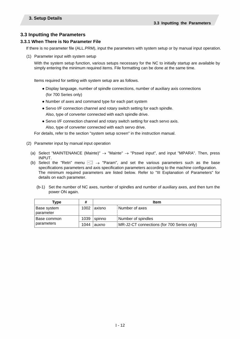
The minimum required parameters are listed below. Refer to "III Explanation of Parameters" for details on each parameter.
(b-1) Set the number of NC axes, number of spindles and number of auxiliary axes, and then turn the
power ON again.
Type # Item Base system parameter
1002 axisno Number of axes
1039 spinno Number of spindles Base common parameters 1044 auxno MR-J2-CT connections (for 700 Series only)

3. Setup Details 3.3 Inputting the Parameters
I - 13
(b-2) Set the minimum required parameters such as the axis name.
Type # Item
1013 axname Axis name 1021 mcp_no Drive unit I/F channel No. (Servo)
Base axis specification parameters
1022 axname2 2nd axis name 1155 DOOR_m Signal input device 1 for door interlock II common for part
systems Base common parameters
1156 DOOR_s Signal input device 2 for door interlock II common for part systems
2001 rapid Rapid traverse rate 2002 clamp Cutting federate for clamp function 2003 smgst Acceleration/deceleration modes 2004 G0tL G0 time constant (linear) 2005 G0t1 G0 time constant (primary delay) 2007 G1tL G1 time constant (linear) 2008 G1t1 G1 time constant (primary delay) 2102 skip_tL Skip time constant linear
Axis specification parameters
2103 skip_t1 Skip time constant primary delay acceleration/ deceleration by software 2nd stage
Zero point return parameter
2029 grspc Grid interval
Servo parameters 2201 :
2456
SV001 : SV256
Servo parameters
3001 slimt1 Limit rotation speed 3005 smax1 Maximum rotation speed 3024 sout Spindle connection 3025 enc_on Spindle encoder 3031 smcp_no Drive unit I/F channel No. (Spindle) 3105 sut Speed reach range 3107 ori_spd Orientation command speed
Spindle specification parameters
3109 zdetspd Z phase detection speed Spindle parameters 13001
: 13240
SP1001 : SP1240
Spindle parameters

3. Setup Details 3.3 Inputting the Parameters
I - 14
(Setting example) For 3 NC axes (X, Y, Z) and 1 spindle axis (S)
Drive unit rotary switch No. 0 1 2 3
#1021 mcp_no 1001 1002 1003 #3031 smcp_no 1004
Y Z S
NC
X P
Power supply unit
3rd axis for 1st channel

3. Setup Details 3.3 Inputting the Parameters
I - 15
3.3.2 When a Parameter File is Available If a parameter file is available, input the parameters using the input/output function. (Example) When files are available on a compact flash (CF) card (1) Insert the CF card into the IC card interface on the front of the display unit.
Display unit Adapter CF card
(Note) 70 Series, which has the CF card interface, does not need adapter.
(2) Select "MAINTENANCE (EDIT)" → "Input/Output". (3) Confirm that device A is selected, and then select "Device select" → "Memory card". (4) Select "File name" → "From list" → "ALL.PRM", and then press INPUT. (5) Press "Area change", and select device B. (6) Select "Device select" → "Memory". (7) Select "Dir" → "Param". * "ALL.PRM" is directly input as the file name. (8) Press "Transfr A → B", and execute parameter input.

3. Setup Details 3.4 Formatting the File System
I - 16
3.4 Formatting the File System The base specification parameter "#1037 cmdtyp" must be set before the file system is formatted. M System specifications : Set 1 or 2 according to the tool compensation type. L System specifications : Select and set from 3 to 8 according to the G code list. (1) Select "MAINTENANCE (Mainte)" → "NEXT" menu → "Format". (2) The message "Format NC memory (Y/N)?" will appear. Press "Y". (3) When the memory is correctly formatted, the message "Format complete" will appear.
(Note) When the parameter is set with system setup, the file system does not need to be formatted.

3. Setup Details 3.5 Inputting the Ladder Program
I - 17
3.5 Inputting the Ladder Program The ladder program can be created and input using the GX Developer installed in an external personal computer or with the PLC onboard editing screen. Refer to the "MITSUBISHI CNC 700 Series PLC Programming manual" (IB-1500036) for details. The ladder program creation and input procedures are explained below with a flow chart.
(1) 700 Series Start
Create with GX Developer
Creation methods
Create with PLC onboard
Write to NC temporary memory Writing method
Write with GX Developer Write with PLC onboard
Save ladder program on
IC card
Open ladder program in IC card with PLC onboard
Write to NC temporary memory
Write to NC temporary memory with Ethernet
communication
Write to NC temporary memory with RS-232-C
Write ladder program to NC ROM
End
Connection method

3. Setup Details 3.5 Inputting the Ladder Program
I - 18
(2) 70 Series Start
Create with GX Developer
Write with GX Developer
Write to NC temporary memory with Ethernet
communication
Write to NC temporary memory with RS-232-C
Write ladder program to NC ROM
End
Connection method

3. Setup Details 3.6 Credit System
I - 19
3.6 Credit System Encryption key and decryption code need to be set in order to validate credit system.
(1) Enter code key in the input/output screen.
(a) Set the device name, directory and file name in [A:Dev].
(b) Set "Memory" in device section and "/CRE" in directory section of [B:Dev].
Contens in directory section/file name section will be written over. Directroy section "Encryption Key" File name section "ENCKEY.DAT"
(c) Press the menu key [Trnsfr A→B].
(2) Enter cancel code in the input/output screen.
(a) Set the device name, directory and
file name in [A:Dev].
(b) Set "Memory" in device section and "/RLS" in directory section of [B:Dev].
Contens in directory section/file name section will be written over. Directory section "Decryption Code" File name section "PASSCODE.DAT"
(c) Press the menu key [Trnsfr A→B].

3. Setup Details 3.6 Credit System
I - 20
(3) Turn the power ON again.
Confirm that the expiration date (time limit) is indicated in [DIAGN]-[Self diag] screen.

3. Setup Details 3.7 Setting the Handy Terminal
I - 21
3.7 Setting the Handy Terminal It is necessary to customize the display part composition, the key input, and the communication condition with NC, etc. to connect the handy terminal (HG1T-SB12UH-MK1346-L*). Create the customized data by "NC Designer HT", and download to the handy terminal. There are two inputting methods of the handy terminal's costomaized data. (1) Connecting PC and the handy terminal, the data is input from "NC Designer HT". (2) Connecting NC and the handy terminal, the data is input from CF (Compact Flash).
3.7.1 When Connecting with PC to Input Project data (*.p1t) handled as customized data is created by customized data creation tool "NC Designer HT" and download to the handy terminal. (1) Start the customized data creating tool "NC Designer HT" and create the project data (*.p1t).
(2) Connect PC and the handy terminal with serial (RS-232C). (3) Select [Online] - [Communication setting] from the menu of "NC Designer HT", confirm the
communication condition is as follows. Port : Set the PC side port. Transmission :19200 [bps] Data : 8 [bit] Stop bit : 1 Parity : None

3. Setup Details 3.7 Setting the Handy Terminal
I - 22
(4) Select [Online] - [Download] from the menu of "NC Designer HT". (5) The following dialog box is displayed, so press the "Yes".
(6) If the passward is set to the downloaded costomazed data, the "Input password" dialog box is displayed.
So input the passward, press the "OK".
(7) The costomaized data is downloaded to the handy terminal.
(8) When the download has been completed, the following dialog box is displayed.

3. Setup Details 3.7 Setting the Handy Terminal
I - 23
3.7.2 When Connecting with NC to Input Download data (handy.cod) is created from project data (*.p1t) created by customized data creation tool "NC Designer HT", and the customized data is downloaded to the handy terminal. (1) Start the customized data creating tool "NC Designer HT" and create the project data (*.p1t).
(2) Select [File] - [Writing download data] from the menu of "NC Designer HT", and save the download data
named as "handy.cod" in the root directory of CF. (3) Insert the CF created in the step (2) to the control unit. (4) Set the passward which has been set to the handy terminal to "#11011 Handy TERM. PW." (Note) When downloading the data for the first time, nothing is set to the parameter. (5) NC power supply is turned OFF, and the handy terminal is connected with NC.

3. Setup Details 3.8 Adjustment of Dog-type Reference Position Return for Relative Position Detection
I - 24
3.8 Adjustment of Dog-type Reference Position Return for Relative Position Detection There are two types for the position detection system, the relative position detection and the absolute position detection. The methods of returning to the reference position include the dog-type reference position return and the dogless-type reference position return. This section describes the method to adjust the dog-type reference position return for the relative position detection. Refer to the section "3.9 Absolute Position Detection System" for the method of adjusting the absolute position detection.
3.8.1 Dog-type Reference Position Return Operation
Progress state Operation of axis (1) Executes dog-type reference position
return. -> Starts moving in G28 rapid traverse rate.
(2) Detects near-point dog while travelling. -> Decelerates to a stop, then resumes moving in G28 approach speed.
(3) Reaches the first grid point leaving near-point dog.
-> Stops.
This grid point where the axis stops with (3) is called the electrical zero point. Normally, this electrical zero point position is regarded as the reference position.
- +
Grid point
Limit switch for near-point detection
Direction of reference position return
G28 rapid traverse rate
G28 approach speed
Grid space Near-point dog
Grid amount
Electrical zero point
Reference position (1)
(2)
(3)
The first reference position return after turning the power ON is carried out with the dog-type reference position return. The second and following returns are carried out with either the dog-type reference position return or the high-speed reference position return, depending on the parameter. High-speed reference position return is a function that directly positions to the reference position saved in the memory without decelerating at the near-point dog.
(Note) If reference position return has not been executed even once after turning the power ON, the program error (P430) will occur when movement commands other than G28 are executed.

3. Setup Details 3.8 Adjustment of Dog-type Reference Position Return for Relative Position Detection
I - 25
3.8.2 Dog-type Reference Position Return Adjustment Procedures Adjust the dog-type reference position return with the following steps. Refer to the next page and followings for details of parameters and the calculation method for grid mask amount.
Procedures
(1) Set the following parameter to "0". ・Reference position shift amount (#2027 G28sft). ・Grid mask amount (#2028 grmask).
(2) Turn the power OFF and ON, and then execute reference position return. (3) Confirm the grid space and grid amount values on DRIVE MONITOR screen. (4) Calculate the grid mask amount with the calculation method for grid mask amount. (5) Set the grid mask amount. (6) Turn the power OFF and ON, and then execute reference position return. (7) Confirm the grid space and grid amount values on DRIVE MONITOR screen.
If the grid amount value is approx. half of the grid space, the grid mask amount has been set correctly. If the value is not approx. half, repeat the procedure from step (1).
(8) Set the reference position shift amount (#2027 G28sft). (9) Turn the power OFF and ON, and then execute reference position return. (10) Set the machine coordinate system offset amount (#2037 G53ofs).
3. Setup Details 3.8 Adjustment of Dog-type Reference Position Return for Relative Position Detection
I - 26
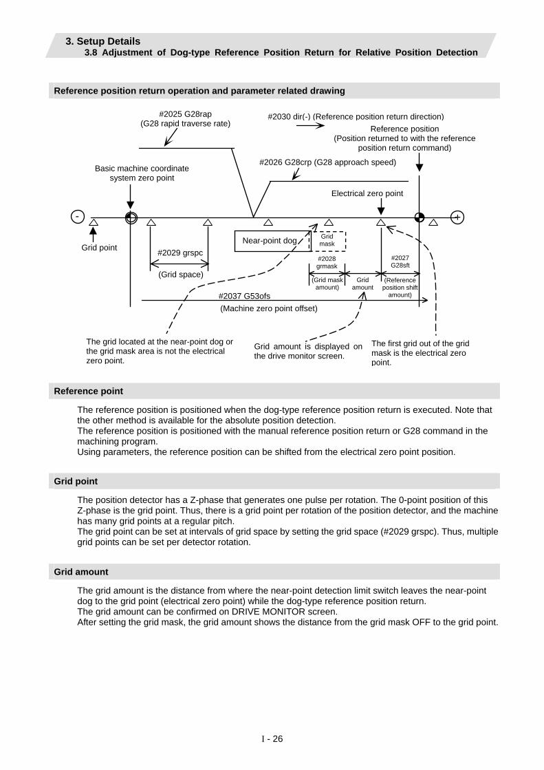
Reference position return operation and parameter related drawing
- +
#2025 G28rap (G28 rapid traverse rate)
#2030 dir(-) (Reference position return direction) Reference position
(Position returned to with the referenceposition return command)
#2026 G28crp (G28 approach speed) Basic machine coordinate
system zero point
Electrical zero point
Grid point #2029 grspc
(Grid space)
Near-point dog
#2037 G53ofs
#2028 grmask
Grid mask
(Grid mask amount)
Grid amount
(Reference position shift
amount)
The grid located at the near-point dog or the grid mask area is not the electrical zero point.
The first grid out of the gridmask is the electrical zero point.
Grid amount is displayed onthe drive monitor screen.
(Machine zero point offset)
#2027 G28sft
Reference point
The reference position is positioned when the dog-type reference position return is executed. Note that the other method is available for the absolute position detection. The reference position is positioned with the manual reference position return or G28 command in the machining program. Using parameters, the reference position can be shifted from the electrical zero point position.
Grid point
The position detector has a Z-phase that generates one pulse per rotation. The 0-point position of this Z-phase is the grid point. Thus, there is a grid point per rotation of the position detector, and the machine has many grid points at a regular pitch. The grid point can be set at intervals of grid space by setting the grid space (#2029 grspc). Thus, multiple grid points can be set per detector rotation.
Grid amount
The grid amount is the distance from where the near-point detection limit switch leaves the near-point dog to the grid point (electrical zero point) while the dog-type reference position return. The grid amount can be confirmed on DRIVE MONITOR screen. After setting the grid mask, the grid amount shows the distance from the grid mask OFF to the grid point.

3. Setup Details 3.8 Adjustment of Dog-type Reference Position Return for Relative Position Detection
I - 27
G28 rapid traverse rate (#2025 G28rap)
Set the feedrate for dog-type reference position return in manual operation and automatic operation. The rapid traverse rate (#2001 rapid) is applied for the feedrate during high-speed reference position return.
G28 approach speed (#2026 G28crp)
Set the approach speed (creep speed) to the reference position after decelerating to a stop by the near-dog detection. Since the creep speed is accelerated and decelerated in steps (no-acceleration/deceleration), the mechanical shock, etc., could occur if the speed is too large. The creep speed should be set between 100 and 300 mm/min., or within 500 mm/min. at the fastest.
Reference position shift amount (#2027 G28sft)
Set the shift amount to shift the reference position from the electrical zero point. The shift direction can be set only in the reference position return direction. If the reference position shift amount is "0", the grid point (electrical zero point) will be the reference position.
Grid mask amount (#2028 grmask)
The first grid point after the dog OFF is regarded as the electrical zero point. If the grid point is at the position where the near-point dog is kicked OFF, the position of electrical zero point may differ because of the delay of the limit switch operation, at the grid point where the dog is kicked OFF or the next grid point. This causes a deviation of reference position by the amount of the grid space. The position that the dog is kicked OFF should be at the approximate center of the grid space.
Dog
Reference position
Electrical zero point shitsdepending on the speed oflimit switch delay.
Adjustments can be made by changing the near-point dog or by setting the grid mask amount. Setting the grid mask has the same effect as lengthening the near-point dog. If the grid amount is approximate the grid space or 0, the grid point may be at the position of near-point dog OFF, so set a grid mask. Set the grid mask amount so that the grid amount is one-half of the grid space. The grid mask amount can be set only in the reference position return direction. The grid amount and grid space can be confirmed on the DRIVE MONITOR screen. Refer to "calculation method for the grid mask amount" on the next page for the grid mask amount values.

3. Setup Details 3.8 Adjustment of Dog-type Reference Position Return for Relative Position Detection
I - 28
Calculation method for grid mask amount
Grid space Grid space When
2 < Grid amount Grid mask amount = Grid amount −
2
- +
Grid mask
Grid mask amount
Grid amount
Reference position (Position returned to withthe reference position return command)
Electrical zero point
Grid space
2
Near-point dog
#2016
Grid space Grid space When 2
> Grid amount Grid mask amount = Grid amount + 2
+ -
Near-point dog Grid mask
Grid space 2
Grid amount Grid mask amount
#2016Grid amount after grid mask is set.
Reference position after grid mask is set.
This will not be the electrical zero point due to the grid mask.
Reference position before grid mask is set.

3. Setup Details 3.8 Adjustment of Dog-type Reference Position Return for Relative Position Detection
I - 29
Grid space (#2029 grspc)
Set the distance between grids. The normal grid space is the ball screw pitch value (#2218 PIT) or the movement amount per motor rotation set as a mm unit. To make the grid space smaller, set a divisor of the grid space. Calculation method for movement amount per motor rotation (1) When linear feed mechanism is ball screw:
Motor side gear ratio Movement amount per motor rotation = Machine side gear ratio
∗ Ball screw pitch
(2) When linear feed mechanism is rack & pinion:
Motor side gear ratio Movement amount per motor rotation = Machine side gear ratio
∗ Number of pinion gear teeth ∗ Rack pitch
(3) For rotary axis:
Motor side gear ratio Movement angle per motor rotation= Machine side gear ratio
∗ 360
PC1 N = PC2 ∗ PIT
N PC1 PC2 PIT
= Movement amount per motor rotation = Motor side gear ratio = Machine side gear ratio = Ball screw pitch

3. Setup Details 3.8 Adjustment of Dog-type Reference Position Return for Relative Position Detection
I - 30
Reference position return direction (#2030 dir (−))
Set the direction to move after the limit switch kicks the dog causing a deceleration stop during dog-type reference position return. The direction is either positive "0" or negative "1". Set "0" if the reference position is in the positive direction from the near-point dog. Set "1" if the reference position is in the negative direction from the near-point dog. (a) When reference position return direction is positive (+)
To move in + direction
To move in - direction
(-) (+)
DogReference position
(b) When reference position return direction is negative (−)
To move in + direction
To move in - direction
(-) (+)
DogReference position
Axis with no reference position (#2031 noref)
Set "0" for the axis to carry out dog-type reference position return and the axis for absolute position detection. Set "1" for the axis without carrying out reference position return during relative position detection.
Machine coordinate system offset (#2037 G53ofs)
Set the amount to shift the basic machine coordinate system zero point position from the reference position. When "0" is set, the reference position will be the position of the basic machine coordinate system zero point. In “G53ofs” parameter, set the position of the reference position looking from the basic machine coordinate system zero point with the coordinates of basic machine coordinate system. By the reference position return after the power is turned ON, the machine position will be set and the basic machine coordinate system will be established.
Selection of grid display type (#1229 set01/bit6)
Select the grid display type on DRIVE MONITOR screen during dog-type reference position return. 0: Distance from dog OFF to electric zero point (including grid mask amount) 1: Distance from dog OFF to electric zero point (excluding grid mask amount)

3. Setup Details 3.9 Absolute Position Detection System
I - 31
3.9 Absolute Position Detection System The absolute position detection function detects the machine movement amount while the power is OFF. This allows automatic operation to be started without carrying out reference position return after the power is turned ON. This function is extremely reliable as it carries out a mutual check of the feedback amount from the detector, and checks the absolute position unique to the machine, etc. To carry out the absolute position detection, the machine zero point must be determined, and the absolute position must be established. Following two methods are available depending on how the absolute position is established.
(1) Dogless-type absolute position detection
The absolute position is established by setting an arbitrary coordinate at an arbitrary position without using the dog. The absolute position basic point can be determined with the following three methods.
・Machine end stopper method ・Marked point alignment method ・Marked point alignment method II
For the machine end stopper method, the manual initialization and automatic initialization methods can be used.
(2) Dog-type absolute position detection The absolute position is established by executing dog-type reference position return.
The validity and method of the absolute position detection system can be selected with parameters for each axis. Note that the servo drive unit and detector must have the specifications compatible for the absolute position detection.
3.9.1 Dog-type Reference Position Return Operation Using the mechanical basic position (machine end or marked point) or the electrical basic position (grid point immediately before the machine end or marked point) as the absolute position basic point, the basic machine coordinate system zero point will be set at the position "ZERO" value far from the absolute position basic point in the direction of reversed “ZERO” sign. The reference position is set at the position "G53ofs" value far from the basic machine coordinate system's zero point.
Reference position
"G53ofs"
Basic machine coordinate system
"ZERO"
Absolute position basic point
Dogless absolute position coordinate system
ZERO : Coordinate position of absolute position basic point looking from basic machine
coordinate system zero point. (ABS. POSITION PARAMETER screen "#2 ZERO") G53ofs : Coordinate position of reference position looking from basic machine coordinate
system zero point. (axis specifications parameter "#2037 G53ofs")
(Note) Select with the parameter "#2059 zerbas" whether to use the mechanical basic position or electrical basic position as the absolute position basic point for the machine end stopper method.
3. Setup Details 3.9 Absolute Position Detection System
I - 32
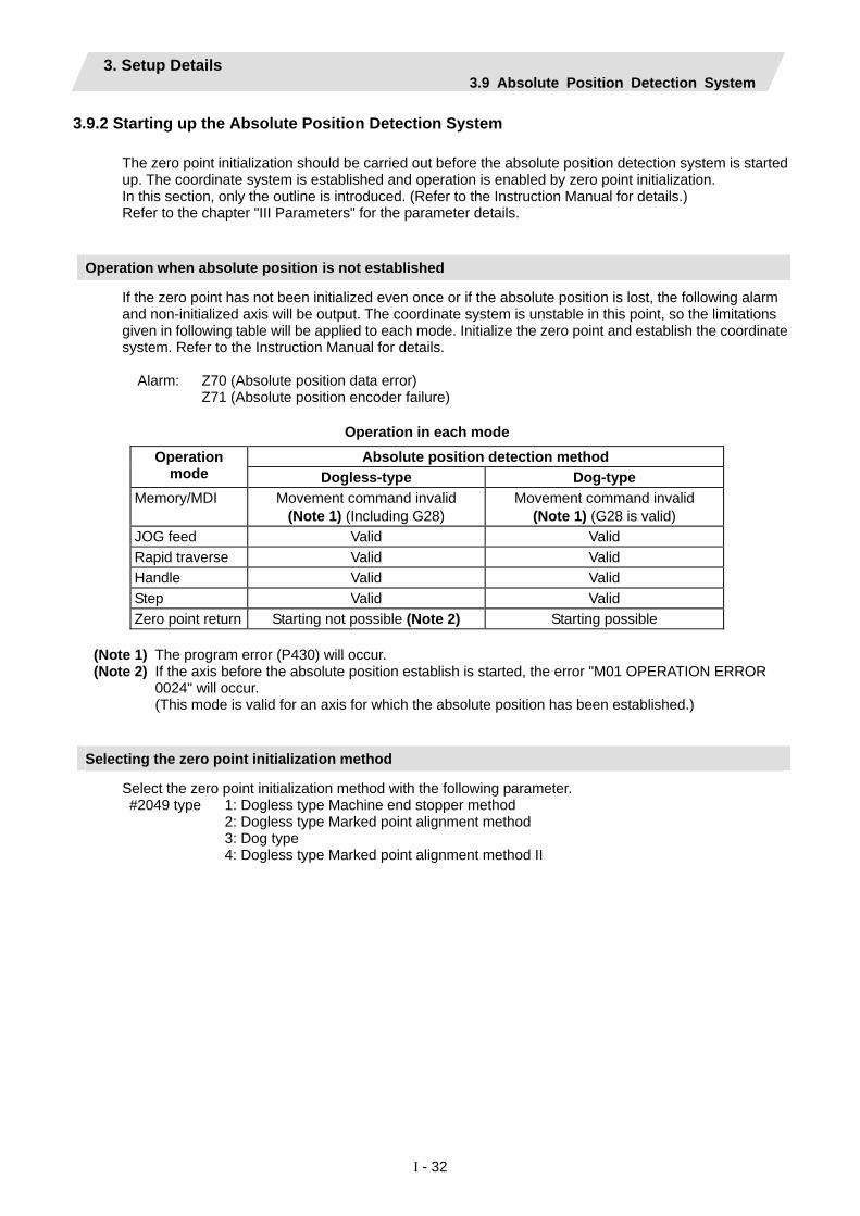
3.9.2 Starting up the Absolute Position Detection System The zero point initialization should be carried out before the absolute position detection system is started up. The coordinate system is established and operation is enabled by zero point initialization. In this section, only the outline is introduced. (Refer to the Instruction Manual for details.) Refer to the chapter "III Parameters" for the parameter details.
Operation when absolute position is not established
If the zero point has not been initialized even once or if the absolute position is lost, the following alarm and non-initialized axis will be output. The coordinate system is unstable in this point, so the limitations given in following table will be applied to each mode. Initialize the zero point and establish the coordinate system. Refer to the Instruction Manual for details.
Alarm: Z70 (Absolute position data error) Z71 (Absolute position encoder failure)
Operation in each mode
Absolute position detection method Operation mode Dogless-type Dog-type
Memory/MDI Movement command invalid (Note 1) (Including G28)
Movement command invalid (Note 1) (G28 is valid)
JOG feed Valid Valid Rapid traverse Valid Valid Handle Valid Valid Step Valid Valid Zero point return Starting not possible (Note 2) Starting possible
(Note 1) The program error (P430) will occur. (Note 2) If the axis before the absolute position establish is started, the error "M01 OPERATION ERROR
0024" will occur. (This mode is valid for an axis for which the absolute position has been established.)
Selecting the zero point initialization method
Select the zero point initialization method with the following parameter. #2049 type 1: Dogless type Machine end stopper method 2: Dogless type Marked point alignment method 3: Dog type 4: Dogless type Marked point alignment method II

3. Setup Details 3.9 Absolute Position Detection System
I - 33
Dogless-type zero point initialization
The zero point is initialized using the ABS POSITION SET screen and JOG or handle. The operation methods differ according to the zero point initialization method. Refer to the Instruction Manual for details. (1) Machine end stopper method
The machine end stopper method includes the manual initialization and automatic initialization methods.
(a) Manual initialization
With this method, the axis is pushed against the machine end stopper using handle or JOG.
(b) Automatic initialization With this method, the axis is pushed against the machine end stopper, and can be used when the "INIT-SET" mode is selected. This method has the following features compared to the manual initialization method. ・The axis is pushed with the same conditions (feedrate, distance) each time, so inconsistencies in the zero point position can be reduced. ・Part of the operations is automated to simplify the zero point initialization.
(2) Marked point alignment method
With this method, the axis is aligned to the machine's basic point (marked point) using handle or JOG. The first grid point where the axis reaches upon retraction in the opposite direction after alignment to the marked point is regarded as the basic point.
(3) Marked point alignment method II With this method, the axis is aligned to the machine's basic point (marked point) using handle or JOG. The machine’s basic position (marked point) is regarded as the basic point.
Dog-type zero point initialization
By executing dog-type reference position return with the manual reference position return mode or automatic reference position return command (G28), the zero point will be initialized.

3. Setup Details 3.10 Auxiliary Axis Operation
I - 34
3.10 Auxiliary Axis Operation Auxiliary axis absolute position initial setting and test run are carried out on the auxiliary axis test screen. In this section, only the outline is introduced. Refer to the Instruction Manual and "MR-J2-CT Specifications and Instruction Manual (BNP-B3944)" for details. Also, refer to "13. Auxiliary Axis Parameter" in "III Parameter" for details on the auxiliary axis parameters.
3. Setup Details 3.10 Auxiliary Axis Operation
I - 35
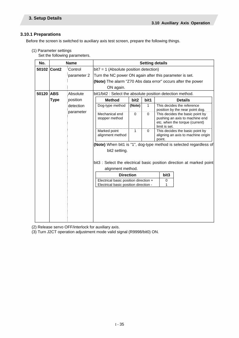
3.10.1 Preparations Before the screen is switched to auxiliary axis test screen, prepare the following things.
(1) Parameter settings Set the following parameters.
No. Name Setting details
50102 Cont2 Control parameter 2
bit7 = 1 (Absolute position detection) Turn the NC power ON again after this parameter is set. (Note) The alarm "Z70 Abs data error" occurs after the power
ON again. 50120 ABS
Type Absolute position detection parameter
bit1/bit2 : Select the absolute position detection method. Method bit2 bit1 Details
Dog-type method (Note) 1 This decides the reference position by the near point dog.
Mechanical end stopper method
0 0 This decides the basic point by pushing an axis to machine end etc. when the torque (current) limit is set.
Marked point alignment method
1 0 This decides the basic point by aligning an axis to machine origin point.
(Note) When bit1 is "1", dog-type method is selected regardless of bit2 setting.
bit3 : Select the electrical basic position direction at marked point
alignment method. Direction bit3
Electrical basic position direction + 0 Electrical basic position direction - 1
(2) Release servo OFF/interlock for auxiliary axis. (3) Turn J2CT operation adjustment mode valid signal (R9998/bit0) ON.

3. Setup Details 3.10 Auxiliary Axis Operation
I - 36
3.10.2 Absolute Position Initial Setting The coordinate system is established and operation is enabled when the absolute position is initially set. Carry this out when absolute position is not established. Refer to the Instruction Manual for detailed operations.
3.10.3 Test Operation Disconnect the auxiliary axis control from PLC and startup in a forward/reverse run by menu operation to carry out a test operation. Refer to the Instruction Manual for detailed operations.

3. Setup Details 3.10 Auxiliary Axis Operation
I - 37
3.10.4 PLC device Devices that are used for auxiliary axis operation adjustment and control are as follows. Refer to "MR-J2-CT Specifications and Instruction Manual (BNP-B3944)" for details.
(1) Operation adjustment mode
Device No. bit
Abbrev. Signal name
R9998 bit0 J2CT Operation adjustment mode valid (Common for all axes) R9948 bit0 J2CT 1st axis in operation adjustment mode bit1 J2CT 2nd axis in operation adjustment mode bit2 J2CT 3rd axis in operation adjustment mode bit3 J2CT 4th axis in operation adjustment mode
(2) Auxiliary axis control command
Signal name J2CT
Control command 4
J2CT Control
command 3
J2CT Control
command 2
J2CT Control
command 1
J2CT Control
command L
J2CT Control
command HAbbrev. CTCM4 CTCM3 CTCM2 CTCM1 CTCML CTCMH
J2CT 1st axis
R9950 R9951 R9952 R9953 R9954 R9955
J2CT 2nd axis
R9956 R9957 R9958 R9959 R9960 R9961
J2CT 3rd axis
R9962 R9963 R9964 R9965 R9966 R9967
J2CT 4th axis
R9968 R9969 R9970 R9971 R9972 R9973
(a) CTCM1 (J2CT Control command 1) (b) CTCM2 (J2CT Control command 2)
bit Details 0 *SVF Servo OFF 1 QEMG PLC emergency stop 2 *PRT1 Data protect 3 MRST MC reset 4 *IT+ Interlock + 5 *IT- Interlock - 6 RDF Ready OFF 7 H Handle mode 8 AUT Automatic operation mode 9 MAN Manual operation mode A J Jog mode B ZRN Reference position mode C D AZS Zero point initialization mode E ZST Basic position set F S Incremental mode
bit Details 0 ST Operation start 1 DIR Rotation direction 2 STS Arbitrary point feed command valid3 PUS Stopper positioning command valid4 MP1 Incremental feed magnification 1 5 MP2 Incremental feed magnification 2 6 PR1 Operation parameter selection1 7 PR2 Operation parameter selection 2 8 9 A B C D E F

3. Setup Details 3.10 Auxiliary Axis Operation
I - 38
(c) CTCM3 (J2CT Control command 3) (b) CTCM4 (J2CT Control command 4)
bit Details 0 ST1 Station selection 1 1 ST2 Station selection 2 2 ST4 Station selection 4 3 ST8 Station selection 8 4 ST16 Station selection 16 5 ST32 Station selection 32 6 ST64 Station selection 64 7 ST128 Station selection 128 8 ST256 Station selection 256 9 A B C D E F
bit Details 0 OVR1 Speed override 1 1 OVR2 Speed override 2 2 OVR4 Speed override 4 3 OVR8 Speed override 8 4 OVR16 Speed override 16 5 OVR32 Speed override 32 6 OVR64 Speed override 64 7 OVR Speed override valid 8 9 A B C D E F
(e) CTCML, CTCMH (J2CT Control command L, control command H) CTCML CTCMH
Command position during arbitrary point feed command valid (32bit)
3. Setup Details 3.10 Auxiliary Axis Operation
I - 39
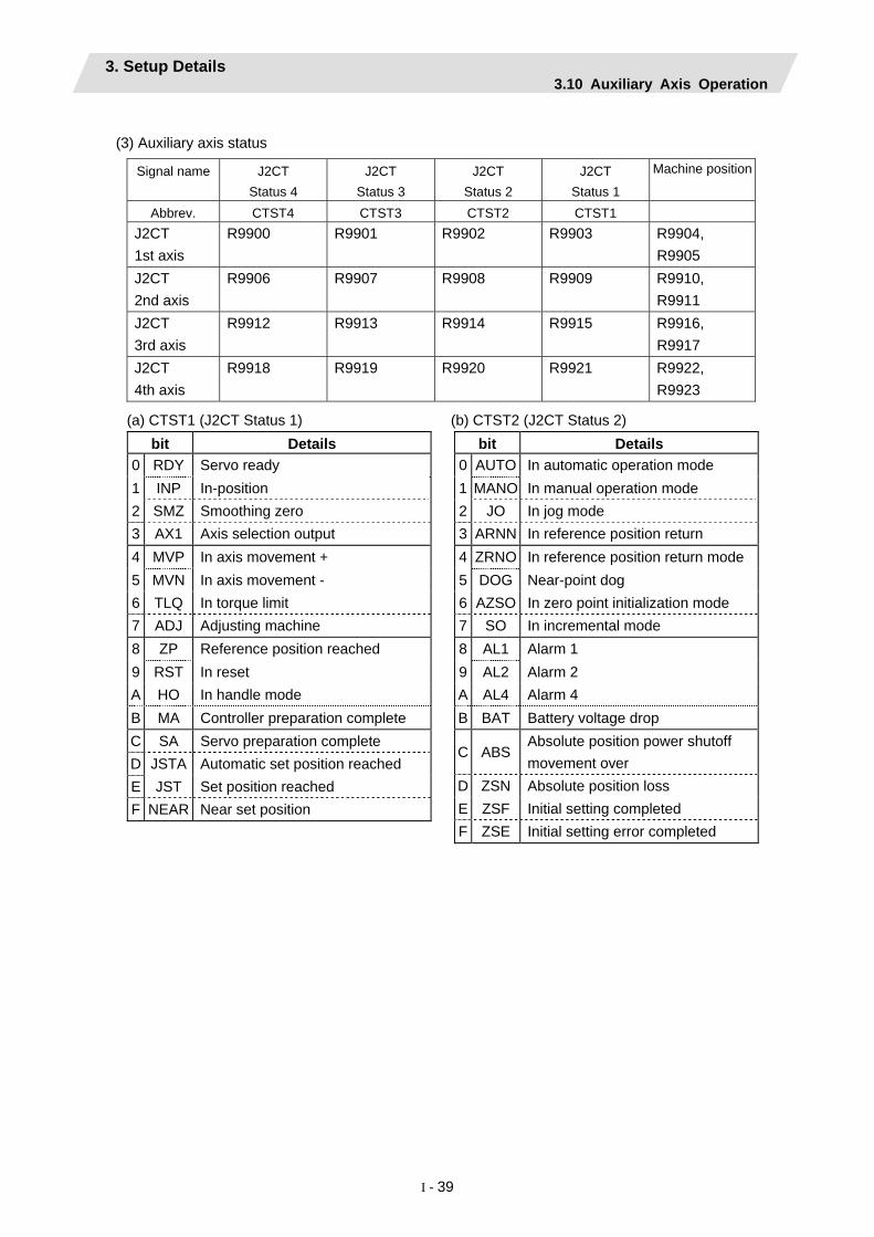
(3) Auxiliary axis status
Signal name J2CT
Status 4 J2CT
Status 3 J2CT
Status 2 J2CT
Status 1
Machine position
Abbrev. CTST4 CTST3 CTST2 CTST1
J2CT 1st axis
R9900 R9901 R9902 R9903 R9904, R9905
J2CT 2nd axis
R9906 R9907 R9908 R9909 R9910, R9911
J2CT 3rd axis
R9912 R9913 R9914 R9915 R9916, R9917
J2CT 4th axis
R9918 R9919 R9920 R9921 R9922, R9923
(a) CTST1 (J2CT Status 1) (b) CTST2 (J2CT Status 2)
bit Details 0 RDY Servo ready 1 INP In-position 2 SMZ Smoothing zero 3 AX1 Axis selection output 4 MVP In axis movement + 5 MVN In axis movement - 6 TLQ In torque limit 7 ADJ Adjusting machine 8 ZP Reference position reached 9 RST In reset A HO In handle mode B MA Controller preparation complete C SA Servo preparation complete D JSTA Automatic set position reached E JST Set position reached F NEAR Near set position
bit Details 0 AUTO In automatic operation mode 1 MANO In manual operation mode 2 JO In jog mode 3 ARNN In reference position return 4 ZRNO In reference position return mode 5 DOG Near-point dog 6 AZSO In zero point initialization mode 7 SO In incremental mode 8 AL1 Alarm 1 9 AL2 Alarm 2 A AL4 Alarm 4 B BAT Battery voltage drop
C ABSAbsolute position power shutoff movement over
D ZSN Absolute position loss E ZSF Initial setting completed F ZSE Initial setting error completed

3. Setup Details 3.10 Auxiliary Axis Operation
I - 40
(c) CTST3 (Status 3) (d) CTST4 (J2CT Status 4)
bit Details 0 STO1 Station position 1 1 STO2 Station position 2 2 STO4 Station position 4 3 STO8 Station position 8 4 STO16 Station position 16 5 STO32 Station position 32 6 STO64 Station position 64 7 STO128 Station position 128 8 STO256 Station position 256 9 A B C D E F
bit Details 0 PSW1 Position switch 1 1 PSW2 Position switch 2 2 PSW3 Position switch 3 3 PSW4 Position switch 4 4 PSW5 Position switch 5 5 PSW6 Position switch 6 6 PSW7 Position switch 7 7 PSW8 Position switch 8 8 PMV In positioning operation 9 PFN Positioning complete A PSI In stopper B C D E F
3.10.5 Notes (1) Do not turn "Auto operation "start" command signal (ST) " ON during Ope. test mode. (2) NC does not retain auxiliary axis parameters. Parameters are retained at the auxiliary axis side. (3) Auxiliary axis emergency stop has to be commanded by PLC interface. (4) NC axis handle movement is invalid during auxiliary axis handle mode. (5) If the screen shifts other screen, the auxiliary axis mode (Ope. test mode, Absolute posn set) is held. Thus, the axis does not stop even if the axis is rotating.

3. Setup Details 3.11 Data Sampling
I - 41
3.11 Data Sampling NC data sampling function allows a sampling of NC internal data (speed output from NC to drive unit, feedback data from drive unit, etc.) so that the data is output as text data.
Item Specifications Sampling cycle 700 Series
1.7ms x setting value 70 Series (type A) 1.7ms x setting value 70 Series (type B) 3.5ms x setting value
Number of sampled axes 700 Series Servo axis : 1 to 16 axes Spindle : 1 to 4 axes 70 Series Servo axis : 1 to 7 axes Spindle : 1 to 3 axes
Number of sampled channels
1 to 8 points
Sampling data size 700 Series Maximum 1,310,720 points 70 Series Maximum 655,360 points (Note 1) This is the entire data size. The data size per channel will decrease when the number of sampled channels increases. (Note 2) If the open DRAM memory is insufficient, the maximum data size will decrease.
● Parameter output is not executed for the data set with this function. ● The state returns to "Sampling stop" when the power is turned ON.
Refer to the "diagnosis data collection setting screen" section in the Instruction Manual for detailed operations.
3.12 Data backup With this function, system data (program, parameter, R register, etc.), ladder (user PLC program), APLC data can be backed up/restored. Refer to the "all backup screen" section in the Instruction Manual for detailed operations.

3. Setup Details 3.13 M70 SETUP INSTALLER
I - 42
3.13 M70 SETUP INSTALLER Install the following data with M70 SETUP INSTALLER.
(1) Language data (2) Custom data
• Custom screen • PLC alarm guidance
(3) Custom startup screen Use CF card to carry out the installation.
3.13.1 Compatible Data and CF Card Folder Configuration (1) Compatible data with M70 SETUP INSTALLER
Type Data Details Remarks lang0_xxx.bin Language data (for FROM) Language data
lang1_xxx.bin Language data (for expansion FROM)
Language identification string is shown instead of xxx. (ex. jpn: Japanese, fra: french)
Custom screen module
Interpreter data and object data
config.ini A setting file to register custom screen.
customdef.ini A setting file to register custom screen for the menus and function buttons on the default screen.
customload.txt A setting file to register name and load order of the object data.
Custom data
PLC alarm guidance data
HTML files and JPEG files to be displayed in the PLC alarm guidance.
Custom startup screen
startupscreen.bmp A bitmap file to be displayed on the initial screen when power is turned ON.
Color: 256 Colors (8 bit)
Size: 640 * 440

3. Setup Details 3.13 M70 SETUP INSTALLER
I - 43
(2) CF card folder configuration
Compatible data with M70 SETUP INSTALLER is stored in CF card with the folder configuration as follows.
CF Card
startupscreen.bmp (bitmap data for custom startup screen)
Lang (language data folder)
A0 (folder labeled by version)
lang0_jpn.bin (Japanese language data for FROM)
lang1_jpn.bin (Japanese language data for expansion FROM)
: :
A1 (folder labeled by version)
custom (custom data folder)
PLCAlarm (PLC alarm guidance folder)
PLCAlarm_0001_jpn.htm (PLC alarm guidance data) :
: Custom screen modules
Setting files
Installer (installer folder)
installer.o (installer)
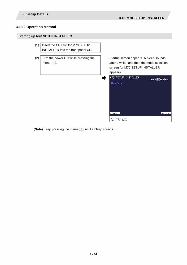
3. Setup Details 3.13 M70 SETUP INSTALLER
I - 44
3.13.2 Operation Method
Starting up M70 SETUP INSTALLER
(1) Insert the CF card for M70 SETUP INSTALLER into the front panel CF.
(2) Turn the power ON while pressing the menu .
Startup screen appears. A bleep sounds after a while, and then the mode selection screen for M70 SETUP INSTALLER appears.
(Note) Keep pressing the menu until a bleep sounds.

3. Setup Details 3.13 M70 SETUP INSTALLER
I - 45
Installing language data
(1) Press the menu key [Lang Pack] on the
mode selection screen. Language data installation screen appears. The language selection menu is displayed.
The language currently installed is shown in the “Installed Language” field.
• The next language selection menu is displayed by pressing menu (Next menu >>). (2) Select the language to install with the
menu key. The language selected is shown in the “Now Selected Language” field.
• To change the language already selected, press the menu key [Clear] and select again. • The 2nd language can be selected when the expansion FROM is provided. (Cursor moves to the “2nd” field after the 1st language has been selected.)
(3) Press the menu key [Install]. A confirmation message appears.
(4) Press the menu key [Yes]. A message appears after the installation has
completed.
• Pressing the menu key [No] returns to the language selection menu. • Do not turn the power OFF during the installation of language data.
(Note) Pressing the menu (<< Cancel) returns to the mode selection screen.
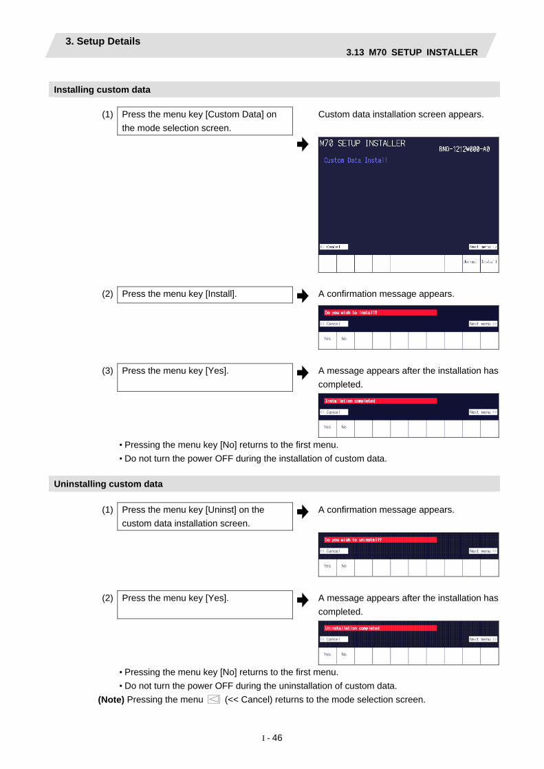
3. Setup Details 3.13 M70 SETUP INSTALLER
I - 46
Installing custom data
(1) Press the menu key [Custom Data] on
the mode selection screen. Custom data installation screen appears.
(2) Press the menu key [Install]. A confirmation message appears.
(3) Press the menu key [Yes]. A message appears after the installation has
completed.
• Pressing the menu key [No] returns to the first menu. • Do not turn the power OFF during the installation of custom data.
Uninstalling custom data
(1) Press the menu key [Uninst] on the
custom data installation screen. A confirmation message appears.
(2) Press the menu key [Yes]. A message appears after the installation has
completed.
• Pressing the menu key [No] returns to the first menu. • Do not turn the power OFF during the uninstallation of custom data.
(Note) Pressing the menu (<< Cancel) returns to the mode selection screen.

3. Setup Details 3.13 M70 SETUP INSTALLER
I - 47
Installing custom startup screen
(1) Press the menu key [Custom Startup] on
the initial screen of M70 SETUP INSTALLER.
Custom Startup Screen Install screen appears.
(2) Press the menu key [Install]. A confirmation message appears.
(3) Press the menu key [Yes]. A message appears after the installation has
completed.
• Pressing the menu key [No] returns to the first menu. • Do not turn the power OFF during the installation of custom startup screen.

3. Setup Details 3.13 M70 SETUP INSTALLER
I - 48
Uninstalling custom startup screen
(1) Press the menu key [Uninst] on the
Custom Startup Screen Install screen. A confirmation message appears.
(2) Press the menu key [Yes]. A message appears after the installation has
completed.
• Pressing the menu key [No] returns to the first menu. • Do not turn the power OFF during the uninstallation of custom startup screen.
(Note) Pressing the menu (<< Cancel) returns to the mode selection screen.

3. Setup Details 3.13 M70 SETUP INSTALLER
I - 49
3.13.3 List of Error Messages Message Details
The 1st language is not selected. The first language has not been selected at the installation of language pack. Specify the first language again.
The same language is selected. The same language has been selected as both first and second language at the installation of language pack. Specify the language again.
The selected language does not exist.(1st) The language data, selected as the 1st language at the installation of language pack, does not exist . Ensure that the language data has been stored in the CF card, and that the version of the data is appropriate.
The selected language does not exist.(2nd) The language data, selected as the 2nd language at the installation of language pack, does not exist. Ensure that the language data has been stored in the CF card, and that the version of the data is appropriate.
The custom data does not exist. The “custom” folder does not exist in the CF card. Check the stored data in the CF card.
The file startupscreen.bmp" does not exist." The "startupscreen.bmp" file does not exist in the CF card. Check the stored data in the CF card.

4. 700 Series H/W Replacement Methods 4.1 Durable Parts
I - 50
4. 700 Series H/W Replacement Methods 4.1 Durable Parts 4.1.1 Control unit battery
All data, such as the parameters and machining programs that need to be backed up when the power is turned OFF, are saved by a lithium battery installed in the control unit's battery holder.
Battery Q6BAT BKO-C10811H03 (SANYO CR17335SE-R with Mitsubishi specifications)
Battery cumulative data holding time 45,000 hours (At room temperature. The life will be shorter if the temperature is high.))
Battery life Approx. 5 years (from date of battery manufacture)
(Note) Replace the battery when the alarm "Z52 Battery drop 0001" appears on the NC screen. The internal data could be damaged if the alarm "Z52 Battery drop 0003" appears.
[Replacement procedures] Always replace the battery with the control unit (machine) power turned OFF. Complete the replacement within 30 minutes after turning the power OFF. (If the battery is not connected within 30 minutes, the data being backed up might be destroyed.)
(1) Check that the machine power is turned OFF. (If the power is not OFF, turn it OFF.) (2) Open the electric cabinet door, and confirm that the control unit LED, 7-segment display, etc., are all
OFF. (3) Open the front cover of the control unit. Pull the right side of the front cover toward front. (4) Pull the connector connected to the battery out from the BAT connector. (5) Remove the battery from the battery holder. (6) Fit the new battery into the battery holder. (7) Insert the connector connected to the new battery into the BAT connector. Pay attention to the
connector orientation, being careful not to insert backwards. (8) Close the front cover of the control unit. At this time, confirm that the cover is closed by listening for the
"click" sound when the latch catches. (9) Close the door of the electric cabinet.
Front cover
BAT connector
Battery holder
Connector connectedto the battery
Battery

4. 700 Series H/W Replacement Methods 4.1 Durable Parts
I - 51
[Precautions for handling battery]
(1) Always replace the battery with the same type. (2) Do not disassemble the battery. (3) Do not place the battery in flames or water. (4) Do not pressurize and deform the battery. (5) This is a primary battery so do not charge it. (6) Dispose of the spent battery as industrial waste.
! CAUTION
If the battery low warning is issued, save the machining programs, tool data and parameters in an input/output device, and then replace the battery. When the battery alarm is issued, the machining programs, tool data and parameters may be destroyed. Reload the data after replacing the battery.
Do not short circuit, charge, overheat, incinerate or disassemble the battery.
Dispose the spent battery according to the local laws.

4. 700 Series H/W Replacement Methods 4.1 Durable Parts
I - 52
4.1.2 Cooling fan for control unit Type : 109P0412H731 Life : 60,000 hours (When the rotary speed decreased 30% less than the initial values) Cooling fan (for control unit) life is estimated on the assumption that it is used under 60°C environment. Keep in mind that the value above is not a guaranteed value. [Replacement procedures] Always replace the cooling fan with the control unit (machine) power turned OFF.
(1) Check that the machine power is turned OFF. (If the power is not OFF, turn it OFF.) (2) Open the electric cabinet door. (3) Remove the fan cover on the top center of the control unit. (Remove the fan cover by pushing up the
front tab.) (4) Pull out the cooling fan from the control unit cooling fan housing. (5) Pull the connector connected to the cooling fan out from the control unit PCB. (6) Replace the cooling fan with the new one. Insert the connector connected to the new cooling fan into
the control unit PCB. (7) Put the cooling fan into the control section cooling fan housing. (Be sure the label side is on the top.) (8) Arrange the cooling fan wiring neatly in the control unit cooling fan housing. (9) Install the fan cover. (First install the back tabs in the control unit. Then install the front tabs in the
control unit.) (10) Confirm that all the cables are correctly connected and close the electric cabinet door.
Fan cover
Back tab
Front tab
Cooling fan
Control unit
! CAUTION
Do not replace the control unit while the power is ON.
Collect and dispose of the spent cooling fan according to the local laws.

4. 700 Series H/W Replacement Methods 4.1 Durable Parts
I - 53
4.1.3 Cooling fan for display unit (XP terminal) Type : MMF-06D24DS-RP3 Life : 50,000 hours (When the rotary speed decreased 20% less than the initial values) Cooling fan (for display unit) life is estimated on the assumption that it is used under 60°C environment. Keep in mind that the value above is not a guaranteed value. [Replacement procedures] Always replace the cooling fan for display unit with the control unit (machine) power turned OFF.
(1) Check that the machine power is turned OFF. (If the power is not OFF, turn it OFF.) (2) Open the electric cabinet door. (3) Remove the fan cover of cooling fan housing (2 parts) that is installed to PCB on back of display unit.
(Remove the fan cover by pushing up the front tab.) (4) Pull out the cooling fan from the control unit cooling fan housing. (5) Pull the connector connected to the cooling fan out from the control unit PCB. (6) Replace the cooling fan with the new one. Insert the connector connected to the new cooling fan into
the control unit PCB. (7) Put the cooling fan into the control section cooling fan housing. (Be sure the label side is on the top.) (8) Arrange the cooling fan wiring neatly in the control unit cooling fan housing. (9) Install the fan cover. (10) Confirm that all the cables are correctly connected and close the electric cabinet door.
Tab
Cooling fan
Cooling fan housing
Fan cover
! CAUTION
Do not replace the control unit while the power is ON.
Collect and dispose of the spent cooling fan according to the local laws.

4. 700 Series H/W Replacement Methods 4.1 Durable Parts
I - 54
4.1.4 Backlight
● 8.4-type LCD panel NL6448BC26-01 (NEC) Inverter 65PWB31 (NEC) Backlight for replacement 84LHS01 (NEC) Backlight life 30,000 hours (Duration of time until luminance drops to 50% of the initial value.) ● 10.4-type LCD panel NL6448BC33-53, NL6448BC33-54 (NEC) Inverter 104PW161 (NEC) Backlight for replacement 104LHS35 (NEC) Backlight life 50,000 hours (ambient temperature 25°C) (Duration of time until luminance drops to 50% of the initial value.) Backlight life is estimated on the assumption that it is used under 25°C environment. Keep in mind that the value above is not a guaranteed value. [Replacement procedures] Always replace the backlight for LCD panel with the control unit (machine) power turned OFF.
(1) Check that the machine power is turned OFF. (If the power is not OFF, turn it OFF.) (2) Open the electric cabinet door. (3) Pull the connector connected to the backlight out from the backlight power supply PCB. (For 8.4 inch,
one each for top and bottom; for 10.4 inch, one for top.) (4) Disconnect the menu key connector. (5) Remove the escutcheon fixing screws (at 4 places) and take the escutcheon off. (6) Pull out the backlight installed on the left side of the LCD panel. (The backlights have locking claws on
the front. Hold these claws down while pulling the backlight out.) (7) Insert the new backlight into the upper and lower sections at the left end of the LCD panel. (Press in
until the locking claws click.) (8) Mount the escutcheon with 2 fixing screws (1 each for the upper and lower sections of the left end). (9) Connect the backlight connection connector to the backlight power supply PCB. (10) Confirm that all the cables are correctly connected and close the electric cabinet door. (11) Connect the menu key connector.
[Precautions for using LCD panel]
(1) Depending on the ambient temperature, response time, brightness and color may differ. (2) Depending on the display contents, nonuniformity of brightness, flickers and streaks may be observed
on LCD display. (3) Because cold cathod-tube is used for LCD display, optical characteristics (nonuniformity of brightness
and display) change according to the operation time. (Especially in low temperature.) (4) Screen display color may be differed depending on the angle to view it.

4. 700 Series H/W Replacement Methods 4.1 Durable Parts
I - 55
! CAUTION
Do not replace the backlight while the power is ON.
Dispose the replaced backlight according to the local laws.
Do not touch the backlight while the power is ON. Failure to observe this could result in electric shocks due to high voltage.
Do not touch the backlight while the LCD panel is in use. Failure to observe this could result in burns.
Do not apply impact or pressure on the LCD panel or backlight. Failure to observe this could result in breakage as they are made of glass.
[8.4-type display unit]
Escutcheon
Backlight
LCD panel Menu key connector
Escutcheon
Menu key connector

4. 700 Series H/W Replacement Methods 4.1 Durable Parts
I - 56
[10.4-type display unit]
Control unit fittings
LCD panel
Backlight
Escutcheon
Menu key connector
Escutcheon
Menu key connector

4. 700 Series H/W Replacement Methods 4.2 Unit
I - 57
4.2 Unit 4.2.1 Control Unit
[Replacement procedures] Always replace the control unit with the control unit (machine) power turned OFF.
(1) Check that the machine power is turned OFF. (If the power is not OFF, turn it OFF.) (2) Open the electric cabinet door. (3) Disconnect all the cables connected to the control unit. (4) Remove the screws fixing the control unit, and remove the control unit from the control unit installation
fitting. (Loosen the two lower fixing screws first, and then remove one upper fixing screw while supporting the control unit with a hand. Then lift the control unit upward and take it off. The two lower fixing screws do not need to be removed.)
(5) Replace with a new control unit, and fix the control unit onto control unit installation fitting with the fixing screws.
(6) Connect all the cables back to the control unit. (Connect the cables to the designated connectors.) (7) Confirm that all the cables are correctly connected and close the electric cabinet door.
Fixing screws (3)
! CAUTION Incorrect connections may damage the devices, so connect the cables to the specified connectors.
Do not replace the control unit while the power is ON.
Do not connect or disconnect the connection cables between each unit while the power is ON.

4. 700 Series H/W Replacement Methods 4.2 Unit
I - 58
(Note) Wire the control unit optical cable as shown below.
Recommended clamp material CKN-13SP KITAGAWA INDUSTRIES
Optical communication cable (section with reinforced sheath): Bending radius: 50mm or more
Optical communication cable (section without reinforced sheath): Bending radius: 25mm or more
Control unit
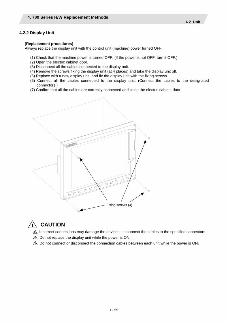
4. 700 Series H/W Replacement Methods 4.2 Unit
I - 59
4.2.2 Display Unit [Replacement procedures] Always replace the display unit with the control unit (machine) power turned OFF.
(1) Check that the machine power is turned OFF. (If the power is not OFF, turn it OFF.) (2) Open the electric cabinet door. (3) Disconnect all the cables connected to the display unit. (4) Remove the screws fixing the display unit (at 4 places) and take the display unit off. (5) Replace with a new display unit, and fix the display unit with the fixing screws. (6) Connect all the cables connected to the display unit. (Connect the cables to the designated
connectors.) (7) Confirm that all the cables are correctly connected and close the electric cabinet door.
Fixing screws (4)
! CAUTION Incorrect connections may damage the devices, so connect the cables to the specified connectors.
Do not replace the display unit while the power is ON.
Do not connect or disconnect the connection cables between each unit while the power is ON.
4. 700 Series H/W Replacement Methods 4.2 Unit
I - 60
4.2.3 Keyboard unit [Replacement procedures] Always replace the keyboard unit with the control unit (machine) power turned OFF.
(1) Check that the machine power is turned OFF. (If the power is not OFF, turn it OFF.) (2) Open the electric cabinet door. (3) Disconnect all the cables connected to the keyboard unit. (4) Remove the screws fixing the keyboard unit and take the keyboard unit off. (5) Replace with a new keyboard unit, and fix the keyboard unit with the fixing screws. (6) Connect all the cables connected to the keyboard unit. (Connect the cables to the designated
connectors.) (7) Confirm that all the cables are correctly connected and close the electric cabinet door.
! CAUTION Incorrect connections may damage the devices, so connect the cables to the specified connectors.
Do not replace the keyboard unit while the power is ON.
Do not connect or disconnect the connection cables between each unit while the power is ON.

4. 700 Series H/W Replacement Methods 4.2 Unit
I - 61
[8.4-type Keyboard unit]
Fixing screws (4)
[10.4-type Keyboard unit]
Fixing screws (4)

4. 700 Series H/W Replacement Methods 4.2 Unit
I - 62
4.2.4 DX Unit [Replacement procedures] Always replace the DX unit with the control unit (machine) power turned OFF.
(1) Check that the machine power is turned OFF. (If the power is not OFF, turn it OFF.) (2) Open the electric cabinet door. (3) Disconnect all the cables connected to the DX unit. (4) Remove the screws fixing the DX unit and take the DX unit off. (5) Replace with a new DX unit, and fix the DX unit onto the control unit with the fixing screws.
(Fix so that the DX unit connector slot is placed at the lower part.) (6) Connect all the cables connected to the DX unit. (Connect the cables to the designated connectors.) (7) Confirm that all the cables are correctly connected and close the electric cabinet door.
Connector slot
Fixing screws (4)
! CAUTION Incorrect connections may damage the devices, so connect the cables to the specified connectors.
Do not replace the DX unit while the power is ON.
Do not connect or disconnect the connection cables between each unit while the power is ON.

4. 700 Series H/W Replacement Methods 4.2 Unit
I - 63
4.2.5 Hard Disk Unit Hard disk unit life: 5 years or 20,000 hours of power ON, whichever comes first. [Replacement procedures] Always replace the hard disk unit with the control unit (machine) power turned OFF.
(1) Check that the machine power is turned OFF. (If the power is not OFF, turn it OFF.) (2) Open the electric cabinet door. (3) Disconnect all F140 cables connected to the hard disk in the hard disk unit.
(Always disconnect F140 cables holding the front and back of the hard disk securely with fingers.) (4) Remove the screws fixing the hard disk unit (2 at upper part, 1 at lower part) and take the hard disk unit
off. (5) Replace with a new hard disk unit, and fix the hard disk unit with the fixing screws. (6) Connect F140 cables to the hard disk in the hard disk unit.
(Always connect F140 cables in the correct connector direction fixing the bottom of the hard disk with fingers.)
(7) Confirm that all the cables are correctly connected and close the electric cabinet door.
Fixing screws (2)
(Note) When mounting the hard disk unit, face the cable lead-out side directly straight up, and mount within
±15°.
15° 15°
! CAUTION Incorrect connections may damage the devices, so connect the cables to the specified connectors.
Do not replace the hard disk unit while the power is ON.
Dispose of the replaced hard disk unit according to the local laws. Hard disk unit is a precision device, so do not drop or apply strong impacts on it.

4. 700 Series H/W Replacement Methods 4.3 Compact Flash
I - 64
4.3 Compact Flash 4.3.1 Control Unit Compact Flash
[Replacement procedures] Always replace the compact flash with the control unit (machine) power turned OFF.
(1) Check that the machine power is turned OFF. (If the power is not OFF, turn it OFF.) (2) Open the electric cabinet door, and confirm that the control unit LED, 7-segment display, etc., are all
OFF. (3) Open the front cover of the control unit. (4) Press the eject lever twice to eject the compact flash. (5) Insert the new compact flash. (The surface is faced on the observers' right.) (6) Close the front cover of the control unit. At this time, confirm that the cover is closed by listening for the
"click" sound when the latch catches. (7) Close the electric cabinet door.
Compact flash slot
Front cover
Compact flash
Eject lever
(Note 1) There may be a compatibility problem with commercially available compact flash memory, resulting in mulfunction.

4. 700 Series H/W Replacement Methods 4.4 IC Card
I - 65
4.4 IC card 4.4.1 Front IC Card
[Card insertion procedures]
(1) Open the card slot door located on the display unit right end. (2) Insert the IC card. (The surface is faced on the observers' right.)
[Card ejecting procedures]
(1) Open the card slot door located on the display unit right end. (2) Press the eject lever twice to eject the IC card.
IC card
Eject lever
(Note 1) Do not eject an IC card during the data reading/writing. (Note 2) There may be a compatibility problem between devices a commercially available IC card, so
illegal operations may occur.

5. 70 Series H/W Replacement Methods 5.1 Durable Parts
I - 66
5. 70 Series H/W Replacement Methods 5.1 Durable Parts 5.1.1 Control unit battery
All data, such as the parameters and machining programs that need to be backed up when the power is turned OFF, are saved by a lithium battery installed in the control unit's battery holder.
Battery Q6BAT BKO-C10811H03 (SANYO CR17335SE-R with Mitsubishi specifications)
Battery cumulative data holding time 45,000 hours (At room temperature. The life will be shorter if the temperature is high.))
Battery life Approx. 5 years (from date of battery manufacture)
(Note) Replace the battery when the alarm "Z52 Battery drop 0001" appears on the NC screen. The internal data could be damaged if the alarm "Z52 Battery drop 0003" appears.
[Replacement procedures] Always replace the battery with the control unit (machine) power turned OFF. Complete the replacement within 30 minutes after turning the power OFF. (If the battery is not connected within 30 minutes, the data being backed up might be destroyed.)
(1) Check that the machine power is turned OFF. (If the power is not OFF, turn it OFF.) (2) Confirm that the control unit LED, 7-segment display, etc., are all OFF. (3) Open the battery cover of the control unit. Pull the right side of the battery cover toward front. (4) Pull the connector connected to the battery out from the BAT connector. (5) Remove the battery from the battery holder. (6) Fit the new battery into the battery holder. (7) Insert the connector connected to the new battery into the BAT connector. Pay attention to the
connector orientation, being careful not to insert backwards. (8) Close the front cover of the control unit. At this time, confirm that the cover is closed by listening for the
"click" sound when the latch catches.
BatteryBattery cover
Battery holder
BAT connector
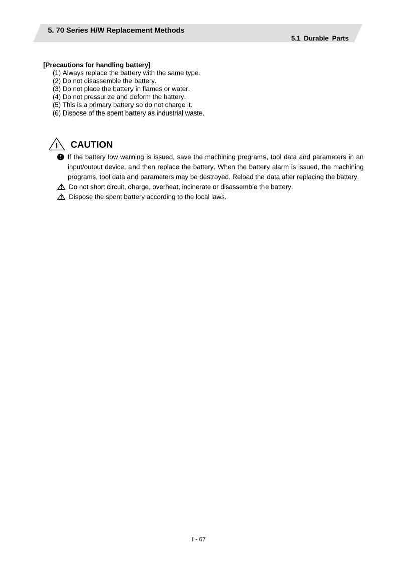
5. 70 Series H/W Replacement Methods 5.1 Durable Parts
I - 67
[Precautions for handling battery]
(1) Always replace the battery with the same type. (2) Do not disassemble the battery. (3) Do not place the battery in flames or water. (4) Do not pressurize and deform the battery. (5) This is a primary battery so do not charge it. (6) Dispose of the spent battery as industrial waste.
! CAUTION
If the battery low warning is issued, save the machining programs, tool data and parameters in an input/output device, and then replace the battery. When the battery alarm is issued, the machining programs, tool data and parameters may be destroyed. Reload the data after replacing the battery.
Do not short circuit, charge, overheat, incinerate or disassemble the battery.
Dispose the spent battery according to the local laws.

5. 70 Series H/W Replacement Methods 5.1 Durable Parts
I - 68
5.1.2 Backlight
● 8.4-type Inverter 65PWB31 Backlight for replacement 84LHS01 Backlight life 50,000 hours (Duration of time until luminance drops to 50% of the initial value.) ● 10.4-type Inverter 104PW161 Backlight for replacement 104LHS35 Backlight life 50,000 hours (ambient temperature 25°C) (Duration of time until luminance drops to 50% of the initial value.) Backlight life is estimated on the assumption that it is used under 25°C environment. Keep in mind that the value above is not a guaranteed value. [Replacement procedures] Always replace the backlight for LCD panel with the control unit (machine) power turned OFF.
(1) Check that the machine power is turned OFF. (If the power is not OFF, turn it OFF.) (2) Pull the connector connected to the backlight out from the backlight inverter (one for top). (3) Disconnect the MENU connector. (4) Remove the escutcheon fixing screws (at 4 places) and take the escutcheon off. (5) Pull out the backlight installed on the left side of the LCD panel. (The backlights have locking claws on
the front. Hold these claws down while pulling the backlight out.) (6) Insert the new backlight into the upper and lower sections at the left end of the LCD panel. (Press in
until the locking claws click.) (7) Mount the escutcheon with 4 fixing screws (1 each for 4 sections). (8) Connect the backlight connection connector to the backlight inverter. (9) Confirm that all the cables are correctly connected and close the electric cabinet door. (10) Connect the MENU connector.
[Precautions for using LCD panel]
(1) Depending on the ambient temperature, response time, brightness and color may differ. (2) Depending on the display contents, nonuniformity of brightness, flickers and streaks may be observed
on LCD display. (3) Because cold cathod-tube is used for LCD display, optical characteristics (nonuniformity of brightness
and display) change according to the operation time. (Especially in low temperature.) (4) Screen display color may be differed depending on the angle to view it.

5. 70 Series H/W Replacement Methods 5.1 Durable Parts
I - 69
! CAUTION
Do not replace the backlight while the power is ON.
Dispose the replaced backlight according to the local laws.
Do not touch the backlight while the power is ON. Failure to observe this could result in electric shocks due to high voltage.
Do not touch the backlight while the LCD panel is in use. Failure to observe this could result in burns.
Do not apply impact or pressure on the LCD panel or backlight. Failure to observe this could result in breakage as they are made of glass.
[8.4-type/10.4-type display unit]
Backlight connector
Backlight
Backlight inverter
MENU connector

5. 70 Series H/W Replacement Methods 5.2 Unit
I - 70
5.2 Unit 5.2.1 Control Unit
[Replacement procedures] Always replace the control unit with the control unit (machine) power turned OFF.
(1) Check that the machine power is turned OFF. (If the power is not OFF, turn it OFF.) (2) Disconnect all the external cables connected to the control unit. (3) Remove all the internal cables connected to the control unit. (MENU/INV/LCD connector)
(Note) Open the battery cover to remove LCD connector. (4) Remove the screws fixing the control unit, and remove the control unit from the control unit installation
fitting. (Loosen the two lower fixing screws first, and then remove one upper fixing screw while supporting the control unit with a hand. Then lift the control unit upward and take it off. The two lower fixing screws do not need to be removed.)
(5) Replace with a new control unit, and fix the control unit onto control unit installation fitting with the fixing screws.
(6) Connect all the cables back to the control unit. (Connect the cables to the designated connectors.) (7) Confirm that all the cables are correctly connected and close the electric cabinet door.
MENU connector
Battery cover
LCD connector INV connector
! CAUTION Incorrect connections may damage the devices, so connect the cables to the specified connectors.
Do not replace the control unit while the power is ON.
Do not connect or disconnect the connection cables between each unit while the power is ON.

5. 70 Series H/W Replacement Methods 5.2 Unit
I - 71
(Note) Wire the control unit optical cable as shown below.
Recommended clamp material CKN-13SP KITAGAWA INDUSTRIES
Optical communication cable (section without reinforced sheath): Bending radius: 30mm or more
Control unit

5. 70 Series H/W Replacement Methods 5.2 Unit
I - 72
5.2.2 Display Unit [Replacement procedures] Always replace the display unit with the control unit (machine) power turned OFF.
(1) Check that the machine power is turned OFF. (If the power is not OFF, turn it OFF.) (2) Open the electric cabinet door. (3) Disconnect all the cables connected to the display unit. (4) Remove the screws fixing the display unit (at 4 places) and take the display unit off. (5) Replace with a new display unit, and fix the display unit with the fixing screws. (6) Connect all the cables connected to the display unit. (Connect the cables to the designated
connectors.) (7) Confirm that all the cables are correctly connected and close the electric cabinet door.
Fixing screws (4)
! CAUTION Incorrect connections may damage the devices, so connect the cables to the specified connectors.
Do not replace the display unit while the power is ON.
Do not connect or disconnect the connection cables between each unit while the power is ON.

5. 70 Series H/W Replacement Methods 5.2 Unit
I - 73
5.2.3 Keyboard unit [Replacement procedures] Always replace the keyboard unit with the control unit (machine) power turned OFF.
(1) Check that the machine power is turned OFF. (If the power is not OFF, turn it OFF.) (2) Open the electric cabinet door. (3) Disconnect all the cables connected to the keyboard unit. (4) Remove the screws fixing the keyboard unit and take the keyboard unit off. (5) Replace with a new keyboard unit, and fix the keyboard unit with the fixing screws. (6) Connect all the cables connected to the keyboard unit. (Connect the cables to the designated
connectors.) (7) Confirm that all the cables are correctly connected and close the electric cabinet door.
! CAUTION Incorrect connections may damage the devices, so connect the cables to the specified connectors.
Do not replace the keyboard unit while the power is ON.
Do not connect or disconnect the connection cables between each unit while the power is ON.

5. 70 Series H/W Replacement Methods 5.2 Unit
I - 74
[8.4-type Keyboard unit]
Fixing screws (4)
[10.4-type Keyboard unit]
Fixing screws (4)

5. 70 Series H/W Replacement Methods 5.2 Unit
I - 75
5.2.4 DX Unit [Replacement procedures] Always replace the DX unit with the control unit (machine) power turned OFF.
(1) Check that the machine power is turned OFF. (If the power is not OFF, turn it OFF.) (2) Open the electric cabinet door. (3) Disconnect all the cables connected to the DX unit. (4) Remove the screws fixing the DX unit and take the DX unit off. (5) Replace with a new DX unit, and fix the DX unit onto the control unit with the fixing screws.
(Fix so that the NCKB connector slot is placed at the lower part.) (6) Connect all the cables connected to the DX unit. (Connect the cables to the designated connectors.)
NCKB cable can be easily inserted by fitting the Δ1st pin position with the connector. (7) Confirm that all the cables are correctly connected and close the electric cabinet door.
Fixing screws (4)
NCKB connector
! CAUTION Incorrect connections may damage the devices, so connect the cables to the specified connectors.
Do not replace the DX unit while the power is ON.
Do not connect or disconnect the connection cables between each unit while the power is ON.

5. 70 Series H/W Replacement Methods 5.3 Compact Flash
I - 76
5.3 Compact Flash 5.3.1 Front Compact Flash
[Card insertion procedures]
(1) Open the card slot door located on the display unit right end. (2) Insert the compact flash. (The surface is faced on the observers' right.)
[Card ejecting procedures]
(1) Open the card slot door located on the display unit right end. (2) Press the eject lever twice to eject the compact flash.
Compact flash Eject lever
(Note 1) Do not eject a compact flash during the data reading/writing. (Note 2) There may be a compatibility problem with non-recommended compact flashes, which may lead
illegal operations.

6. Cable
I - 77
6. Cable If the cable is replaced without turning the power OFF, the normal unit or peripheral devices could be damaged, and risks could be imposed. Disconnect each cable with the following procedures.
(a) For the following type of connector, press the tabs with a thumb and forefinger in the direction of the arrow, and pull the connector off.
(2) Pull
(1) Press
(2) Pull
Y
(1) Press
(2) Pull
(2) Pull
(1) Press
(1) Press
View from above
! CAUTION Do not connect or disconnect the connection cables between each unit while the power is ON. Do not pull the cables when connecting/disconnecting it.

6. Cable
I - 78
(b) For a flat cable type connector with latches, open the latches in the directions of the arrows, and pull
the connector off.
(2) Pull
(1) Open
(c) For a flat cable type connector without latches, hold the connector with a thumb and forefinger, and pull
the connector off.
(2) Pull
(1) Hold with thumb and forefinger.
(d) For the screw fixed type connector, loosen the two fixing screws, and pull the connector off.
(2) Pull (2) Pull
(1) Loosen
(1) Loosen
! CAUTION Do not connect or disconnect the connection cables between each unit while the power is ON. Do not pull the cables when connecting/disconnecting it.

6. Cable
I - 79
(e) For the optical cable connector, pull off while holding down the lock button.
(1) Press
(2) Pull (f) For the Ethernet connector, pull off while holding down the locked latch.
(2) Pull
(1) Press
! CAUTION Do not connect or disconnect the connection cables between each unit while the power is ON. Do not pull the cables when connecting/disconnecting it.


II Explanation of Alarms


1. List of Alarms 1.1 Operation Alarms
II - 1
1. List of Alarms 1.1 Operation Alarms
(The bold characters are the messages displayed on the screen.) M Message
Error No. Message Class
(1) Class: M01 Operation error
Alarms occurring due to incorrect operation by the operator during NC operation and those by machine trouble are displayed.
Error No. Details Remedy 0001 Dog overrun
When returning to the reference position‚ the near-point detection limit switch did not stop over the dog‚ but overran the dog.
• Increase the length of the near-point dog. • Reduce the reference position return speed.
0002 Some ax does not pass Z phase One of the axes did not pass the Z-phase during the initial reference position return after the power was turned ON.
• Move the detector one rotation or more in the opposite direction of the reference position‚ and repeat reference position return.
0003 R-pnt direction illegal When manually returning to the reference position‚ the return direction differs from the axis movement direction selected with the AXIS SELECTION key.
• The selection of the AXIS SELECTION key's +/- direction is incorrect. The error is canceled by feeding the axis in the correct direction.
0004 External interlock axis exists The external interlock function has activated (the input signal is "OFF") and one of the axes has entered the interlock state.
• As the interlock function has activated‚ release it before resuming operation.
• Check the sequence on the machine side. • Check for broken wires in the interlock signal
line. 0005 Internal interlock axis exists
The internal interlock state has been entered. The absolute position detector axis has been removed. A command for the manual/automatic simultaneous valid axis was issued from the automatic mode. The manual speed command was issued while the tool length measurement 1 signal is ON.
• The servo OFF function is valid‚ so release it first.
• An axis that can be removed has been issued‚ so perform the correct operations.
• The command is issued in the same direction as the direction where manual skip turned ON‚ so perform the correct operations.
• During the manual/automatic simultaneous mode‚ the axis commanded in the automatic mode became the manual operation axis. Turn OFF the manual/automatic valid signal for the commanded axis.
• Turn ON the power again‚ and perform absolute position initialization.
• Turn OFF the tool length measurement 1 signal to start the program by the manual speed command.
0006 H/W stroke end axis exists The stroke end function has activated (the input signal is "OFF") and one of the axes is in the stroke end status.
• Move the machine manually. • Check for broken wires in the stroke end signal
wire. • Check for trouble in the limit switch.

1. List of Alarms 1.1 Operation Alarms
II - 2
Error No. Details Remedy
0007 S/W stroke end axis exists The stored stroke limit I‚ II‚ IIB or IB function has activated.
• Move it manually. • If the stored stroke limit in the parameter is
incorrectly set‚ correct it. 0008 Chuck/tailstock stroke end ax
The chuck/tail-stock barrier function turned ON‚ and an axis entered the stroke end state.
• Reset the alarm with reset‚ and move the machine in the reverse direction.
0009 Ref point return No. invalid Return to the No. 2 reference position was performed before return to the No. 1 reference position was completed.
• Execute No. 1 reference position return.
0019 Sensor signal illegal ON The sensor signal was already ON when the tool measurement mode (TLM) signal was validated. The sensor signal turned ON when there was no axis movement after the tool measurement mode (TLM) signal was validated. The sensor signal turned ON at a position within 100μm from the final entry start position.
• Turn the tool measurement mode signal input OFF, and move the axis in a safe direction.
• The operation alarm will turn OFF even when the sensor signal is turned OFF.
(Note) When the tool measurement mode signal input is turned OFF, the axis can be moved in either direction. Pay attention to the movement direction.
0020 Ref point retract invalid Return to the reference position was performed before the coordinates had not been established.
• Execute reference position return
0021 Tool ofs invld after R-pnt Reference position return was performed during tool retract return, and therefore the tool compensation amount became invalid after reference position return was completed.
• The error is cleared if the operation mode is changed to other than reference position return before the axis performs reference position return.
• The error is cleared when reference position return is completed.
• The error is cleared if reset 1 is input or the emergency stop button is pushed.
0024 R-pnt ret invld at abs pos alm A zero point return signal was input during an absolute position detection alarm.
• Reset the absolute position detection alarm‚ and then perform zero point return.
0025 R-pnt ret invld at zero pt ini A zero point return signal was input during zero point initialization of the absolute position detection system.
• Complete zero point initialization‚ and then perform zero point return.
0030 Now skip on The skip signal remains input when the skip return operation changed to the measurement operation.
• Increase the skip return amount.
0031 No skip Even though 1st skip was to the correct position, the 2nd skip could not be found.
• Check whether the measurement target has moved.
0050 Chopping axis R-pnt incomplete The chopping axis has not completed zero point return before entering the chopping mode. All axes interlock will be applied.
• Reset or turn the chopping signal OFF, and then carry out zero point return.

1. List of Alarms 1.1 Operation Alarms
II - 3
Error No. Details Remedy
0051 Synchronous error excessive The synchronization error of the master and slave axes exceeded the allowable value under synchronous control. A deviation exceeding the synchronization error limit value was found with the synchronization deviation detection.
• Select the correction mode and move one of the axes in the direction in which the errors are reduced.
• Increase the allowable value or reset it to 0 (check disabled).
• When using simple C-axis synchronous control, set the contents of the R435 register to 0.
• Check the parameter (#2024 synerr). 0053 No spindle select signal
Synchronous tapping command was issued when the spindle select signals (SWS) for all spindles were OFF in the multiple-spindle control II.
• Turn ON the spindle select signal (SWS) responding to the tapping spindle before performing the synchronous tapping command.
0054 No spindle serial connection Synchronous tapping command was issued when the spindle that the spindle select signal (SWS) was ON was not serially connected in the multiple-spindle control II.
• Make sure the spindle select signal (SWS) for the responding spindle is ON.
• When issuing a command, consider the machine construction.
0055 Spindle fwd/rvs run para err Asynchronous tapping command was issued when M code of the spindle frd/rvs run command set by the parameter "#3028 sprcmm" was one of the followings in the multiple-spindle control II. • One of M0, M1, M2, M30, M98, M99, M198• M code No. that commands macro interrupt
signal valid/invalid
• Change the value of the parameter #3028 sprcmm.
0056 Tap pitch/thread number error The command of the pitch/thread number is not correct in the synchronous tapping command of the multiple-spindle control II. The pitch is too small for the spindle rotation speed. Thread number is too large for the spindle rotation speed.
• Check the pitch/thread number and rotation speed of the tapping spindle.
0060 Handle ratio too large Handle ratio is too large for the rapid traverse rate (or external deceleration speed when external deceleration is valid).
• Set a smaller ratio.
0065 R-pos offset value illegal At the start of reference position initial setting, setting of reference position offset value (#2034 rfpofs) is other than 0.
• Set the reference position offset value (#2034 rfpofs) to 0, then turn the power ON again to perform reference position initial setting.
0066 R-pos scan distance exceeded Reference position could not be established within the maximum scan distance.
• Check the scale to see if it has dirt or damage.• Check if the servo drive unit supports this
function.

1. List of Alarms 1.1 Operation Alarms
II - 4
Error No. Details Remedy
0101 No operation mode • Check for a broken wire in the input mode signal wire.
• Check for trouble in the mode selector switch. • Check the sequence program.
0102 Cutting override zero The "cutting feed override" switch on the machine operation panel is set to zero. The override was set to "0" during a single block stop.
• Set the "cutting feed override" switch to a value other than zero to clear the error.
• When the "cutting feed override" switch is set to a value other than zero‚ check for a short circuit in the signal wire.
• Check the sequence program. 0103 External feed rate zero
"The manual feed speed" switch on the machine operation panel is set to zero when the machine is in the jog mode or automatic dry run mode. The "Manual feedrate B speed" is set to zero during the jog mode when manual feedrate B is valid. The "each axis manual feedrate B speed" is set to zero during the jog mode when each axis manual feedrate B is valid.
• Set "the manual feed speed" switch to a value other than zero to release the error.
• If "the manual feed speed" switch is set to a value other than zero‚ check for a short circuit in the signal wire.
• Check the sequence program.
0104 F 1-digit feed rate zero The F1-digit feedrate is set to zero when the F1-digit feed command is being executed.
• Set the F1-digit feedrate on the setup parameter screen.
0105 Spindle stop The spindle stopped during the synchronous feed command.
• Rotate the spindle. • If the workpiece is not being cut‚ start dry run. • Check for a broken wire in the spindle encoder
cable. • Check the connections for the spindle encoder
connectors. • Check the spindle encoder pulse. • Reconsider the program. (Command, address)
0106 Handle feed ax No. illegal An axis not found in the specifications was designated for handle feed or the handle feed axis was not selected.
• Check for broken wires in the handle feed axis selection signal wire.
• Check the sequence program. • Check the No. of axes listed in the
specifications. 0107 Spindle rotation speed over
The spindle rotation speed exceeded the axis clamp speed during the thread cutting command.
• Lower the commanded spindle rotation speed.
0108 Fixed pnt mode feed ax illegal An axis not found in the specifications was designated for the fixed point mode feed or the fixed point mode feedrate is illegal.
• Check for broken wires in the fixed mode feed axis selection signal wire and fixed point mode feedrate wire.
• Check the fixed point mode feed specifications.0109 Block start interlock
An interlock signal that locks the start of the block has been input.
• Check the sequence program.
0110 Cutting block start interlock An interlock signal that locks the start of the cutting block has been input.
• Check the sequence program.
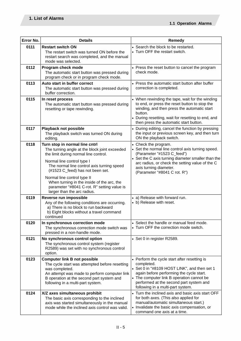
1. List of Alarms 1.1 Operation Alarms
II - 5
Error No. Details Remedy
0111 Restart switch ON The restart switch was turned ON before the restart search was completed, and the manual mode was selected.
• Search the block to be restarted. • Turn OFF the restart switch.
0112 Program check mode The automatic start button was pressed during program check or in program check mode.
• Press the reset button to cancel the program check mode.
0113 Auto start in buffer correct The automatic start button was pressed during buffer correction.
• Press the automatic start button after buffer correction is completed.
0115 In reset process The automatic start button was pressed during resetting or tape rewinding.
• When rewinding the tape‚ wait for the winding to end‚ or press the reset button to stop the winding‚ and then press the automatic start button.
• During resetting‚ wait for resetting to end‚ and then press the automatic start button.
0117 Playback not possible The playback switch was turned ON during editing.
• During editing‚ cancel the function by pressing the input or previous screen key‚ and then turn ON the playback switch.
0118 Turn stop in normal line cntrl The turning angle at the block joint exceeded the limit during normal line control.
Normal line control type I The normal line control axis turning speed (#1523 C_feed) has not been set.
Normal line control type II When turning in the inside of the arc, the parameter "#8041 C-rot. R" setting value is larger than the arc radius.
• Check the program. • Set the normal line control axis turning speed.
(Parameter "#1523 C_feed") • Set the C axis turning diameter smaller than the
arc radius, or check the setting value of the C axis turning diameter. (Parameter "#8041 C rot. R")
0119 Reverse run impossible Any of the following conditions are occurring. a) There is no block to run backward b) Eight blocks without a travel command continued
• a) Release with forward run. • b) Release with reset.
0120 In synchronous correction mode The synchronous correction mode switch was pressed in a non-handle mode.
• Select the handle or manual feed mode. • Turn OFF the correction mode switch.
0121 No synchronous control option The synchronous control system (register R2589) was set with no synchronous control option.
• Set 0 in register R2589.
0123 Computer link B not possible The cycle start was attempted before resetting was completed. An attempt was made to perform computer link B operation at the second part system and following in a multi-part system.
• Perform the cycle start after resetting is completed.
• Set 0 in "#8109 HOST LINK", and then set 1 again before performing the cycle start.
• The computer link B operation cannot be performed at the second part system and following in a multi-part system.
0124 X/Z axes simultaneous prohibit The basic axis corresponding to the inclined axis was started simultaneously in the manual mode while the inclined axis control was valid.
• Turn the inclined axis and basic axis start OFF for both axes. (This also applied for manual/automatic simultaneous start.)
• Invalidate the basic axis compensation, or command one axis at a time.

1. List of Alarms 1.1 Operation Alarms
II - 6
Error No. Details Remedy
0125 Rapid override zero The "rapid traverse override" switch on the machine operation panel is set to zero.
• Set the "rapid traverse override" switch to a value other than zero to clear the error.
• When the "rapid traverse override" switch is set to a value other than zero, check for a short circuit in the signal wire.
• Check the sequence program. 0126 Program restart machine lock
Machine lock was applied on the return axis while manually returning to the restart position.
• Release the machine lock before resuming operations.
0127 Rot axis parameter error The orthogonal coordinate axis name does not exist. The rotary axis name does not exist. The orthogonal coordinate axis name is duplicated. The number of axes that were selected to change tool length compensation along the tool axis amount exceeds the maximum number of axes. The orthogonal coordinate axis name is that of the rotary axis name.
• Review the rotational axis configuration parameters.
0128 Restart pos return incomplete Automatic return was performed with an axis whose return to the restart position was not complete.
• Perform restart position return manually. • Validate the parameter "automatic return by
program restart" (#1302 AutoRP), then execute automatic start.
0150 Chopping override zero The override became "0" while performing the chopping operation.
• Check the chopping override (R2530). • Check the rapid traverse override (R2502).
0151 Command axis chopping axis A chopping axis movement command was issued from the program during the chopping mode. (This alarm will not occur when the movement amount is commanded as 0.) (All axes interlock state will be applied.)
• Reset, or turn OFF the chopping signal. When the chopping signal is turned OFF, the axis will return to the reference position, and then the program movement command will be executed.
0153 Bottom dead center pos. zero The bottom dead center position is set to the same position as the upper dead center position.
• Correctly set the bottom dead center position.
0154 Chopping disable for handle ax Chopping was started when the chopping axis was selected as the handle axis.
• Select an axis other than the chopping axis as the handle axis, or start chopping after changing the mode to another mode.
0160 No speed set out of soft limit Returned from the outside of the soft limit range for the axis with no maximum speed set for the outside of the soft limit range.
• Set the maximum speed for the outside of the soft limit range. (Parameter "#2021 out_f")
• Change the soft limit range. (Parameter "#2013 OT-" "#2014 OT+")
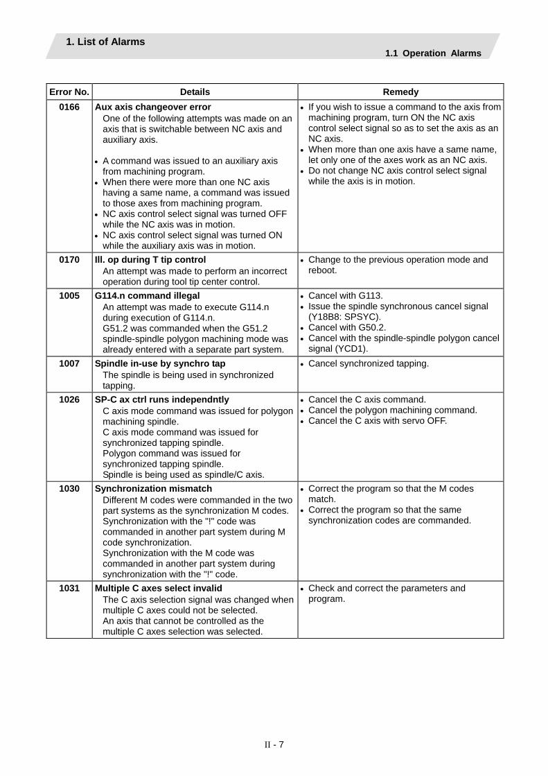
1. List of Alarms 1.1 Operation Alarms
II - 7
Error No. Details Remedy
0166 Aux axis changeover error One of the following attempts was made on an axis that is switchable between NC axis and auxiliary axis.
• A command was issued to an auxiliary axis from machining program.
• When there were more than one NC axis having a same name, a command was issued to those axes from machining program.
• NC axis control select signal was turned OFF while the NC axis was in motion.
• NC axis control select signal was turned ON while the auxiliary axis was in motion.
• If you wish to issue a command to the axis from machining program, turn ON the NC axis control select signal so as to set the axis as an NC axis.
• When more than one axis have a same name, let only one of the axes work as an NC axis.
• Do not change NC axis control select signal while the axis is in motion.
0170 Ill. op during T tip control An attempt was made to perform an incorrect operation during tool tip center control.
• Change to the previous operation mode and reboot.
1005 G114.n command illegal An attempt was made to execute G114.n during execution of G114.n. G51.2 was commanded when the G51.2 spindle-spindle polygon machining mode was already entered with a separate part system.
• Cancel with G113. • Issue the spindle synchronous cancel signal
(Y18B8: SPSYC). • Cancel with G50.2. • Cancel with the spindle-spindle polygon cancel
signal (YCD1). 1007 Spindle in-use by synchro tap
The spindle is being used in synchronized tapping.
• Cancel synchronized tapping.
1026 SP-C ax ctrl runs independntly C axis mode command was issued for polygon machining spindle. C axis mode command was issued for synchronized tapping spindle. Polygon command was issued for synchronized tapping spindle. Spindle is being used as spindle/C axis.
• Cancel the C axis command. • Cancel the polygon machining command. • Cancel the C axis with servo OFF.
1030 Synchronization mismatch Different M codes were commanded in the two part systems as the synchronization M codes. Synchronization with the "!" code was commanded in another part system during M code synchronization. Synchronization with the M code was commanded in another part system during synchronization with the "!" code.
• Correct the program so that the M codes match.
• Correct the program so that the same synchronization codes are commanded.
1031 Multiple C axes select invalid The C axis selection signal was changed when multiple C axes could not be selected. An axis that cannot be controlled as the multiple C axes selection was selected.
• Check and correct the parameters and program.

1. List of Alarms 1.1 Operation Alarms
II - 8
Error No. Details Remedy
1032 Tap retract Sp select illegal Tap return was executed when a different spindle was selected. Cutting feed will wait until synchronization is completed.
• Select the spindle for which tap cycle was halted before the tap return signal was turned ON.
1033 Sp-Sp polygon cut interlock Cutting feed will wait until synchronization is completed.
• Wait for synchronization to end.
1034 Mixed sync ctrl prmtr illegal Mixed synchronization control exceeding the number of control axes was attempted. Mixed synchronization control with duplicated axis addresses was attempted.
• Check the parameter settings for mixed synchronization control.
1035 Mixed sync ctrl disable modal Mixed synchronization was commanded for a part system in which mixed synchronization control is disabled as shown below.
• During nose R compensation mode • During pole coordinate interpolation mode • During cylindrical interpolation mode • During balance cut mode • During fixed cycle machining mode • During facing turret mirror image
• Check the program.
1036 Synchro ctrl setting disable The synchronous control operation method selection (R2589 register) was set when the mode was not the C axis mode. The synchronous control operation method selection (R2589 register) was set in the zero point not set state.
Mirror image disable state The external mirror image or parameter mirror image was commanded during facing turret mirror image.
• Set the R2589 register to 0. • Check the program and parameters.
1037 Synchro start/cancel disable Synchronous control was started or canceled when synchronous control could not be started or canceled.
• Check the program and parameters.
1038 Move cmnd invld to synchro ax A movement command was issued to a synchronous axis in synchronous control.
• Check the program.
1106 Sp synchro phase calc illegal The spindle synchronization phase alignment command was issued while the spindle synchronization phase calculation request signal was ON.
• Check the program. • Check the sequence program.

1. List of Alarms 1.1 Operation Alarms
II - 9
(2) Class: M90 Message: Parameter set mode
M90 Messages output when the setup parameter lock function is enabled are displayed.
Error No. Details Remedy - Setup parameter lock released
The setup parameter lock is released. Automatic start is disabled when setup parameters can be set.
Refer to the manual issued by the machine tool builder.

1. List of Alarms 1.2 Stop Codes
II - 10
1.2 Stop Codes These codes indicate a status that caused the controller to stop for some reason. (The bold characters are the messages displayed on the screen.)
T Message
Error No. Message Class
(1) Class: T01 Cycle start prohibit
This indicates the state where automatic operation cannot be started when attempting to start it from the stop state.
Error No. Details Remedy 0101 Axis in motion
Automatic start is not possible as one of the axes is moving.
• Try automatic start again after all axes have stopped.
0102 NC not ready Automatic start is not possible as the NC is not ready.
• Another alarm has occurred. Check the details and remedy.
0103 Reset signal ON Automatic start is not possible as the reset signal has been input.
• Turn OFF the reset input signal. • Check that the reset switch is not ON
constantly due to trouble. • Check the sequence program.
0104 Auto operation pause signal ON The FEED HOLD switch on the machine operation panel is ON (valid).
• Check the FEED HOLD switch. • The feed hold switch is the B contact. • Check for broken wires in the feed hold signal
wire. • Check the sequence program.
0105 H/W stroke end axis exists Automatic start is not possible as one of the axes is at the stroke end.
• If one of the axis' ends is at the stroke end‚ move the axis manually.
• Check for broken wire in the stroke end signal wire.
• Check for trouble in the stroke end limit switch.0106 S/W stroke end axis exists
Automatic start is not possible as one of the axes is at the stored stroke limit.
• Move the axis manually. • If an axis is not at the end‚ check the parameter
details. 0107 No operation mode
The operation mode has not been selected. • Select the automatic operation mode. • Check for broken wires in the automatic
operation mode (memory‚ tape‚ MDl) signal wire.
0108 Operation mode duplicated Two or more automatic operation modes are selected.
• Check for a short circuit in the mode selection signal wire (memory‚ tape‚ MDl).
• Check for trouble in the switch. • Check the sequence program.
0109 Operation mode changed The automatic operation mode changed to another automatic operation mode.
• Return to the original automatic operation mode‚ and start automatic start.
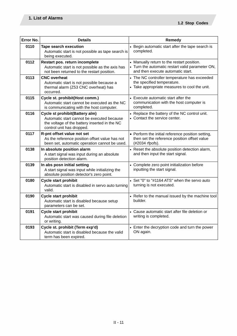
1. List of Alarms 1.2 Stop Codes
II - 11
Error No. Details Remedy
0110 Tape search execution Automatic start is not possible as tape search is being executed.
• Begin automatic start after the tape search is completed.
0112 Restart pos. return incomplete Automatic start is not possible as the axis has not been returned to the restart position.
• Manually return to the restart position. • Turn the automatic restart valid parameter ON,
and then execute automatic start. 0113 CNC overheat
Automatic start is not possible because a thermal alarm (Z53 CNC overheat) has occurred.
• The NC controller temperature has exceeded the specified temperature.
• Take appropriate measures to cool the unit.
0115 Cycle st. prohibit(Host comm.) Automatic start cannot be executed as the NC is communicating with the host computer.
• Execute automatic start after the communication with the host computer is completed.
0116 Cycle st prohibit(Battery alm) Automatic start cannot be executed because the voltage of the battery inserted in the NC control unit has dropped.
• Replace the battery of the NC control unit. • Contact the service center.
0117 R-pnt offset value not set As the reference position offset value has not been set, automatic operation cannot be used.
• Perform the initial reference position setting, then set the reference position offset value (#2034 rfpofs).
0138 In absolute position alarm A start signal was input during an absolute position detection alarm.
• Reset the absolute position detection alarm‚ and then input the start signal.
0139 In abs posn initial setting A start signal was input while initializing the absolute position detector's zero point.
• Complete zero point initialization before inputting the start signal.
0180 Cycle start prohibit Automatic start is disabled in servo auto turning valid.
• Set "0" to "#1164 ATS" when the servo auto turning is not executed.
0190 Cycle start prohibit Automatic start is disabled because setup parameters can be set.
• Refer to the manual issued by the machine tool builder.
0191 Cycle start prohibit Automatic start was caused during file deletion or writing.
• Cause automatic start after file deletion or writing is completed.
0193 Cycle st. prohibit (Term exp'd) Automatic start is disabled because the valid term has been expired.
• Enter the decryption code and turn the power ON again.

1. List of Alarms 1.2 Stop Codes
II - 12
(2) Class: T02 Feed hold
The feed hold state been entered due to a condition in the automatic operation.
Error No. Details Remedy 0201 H/W stroke end axis exists
An axis is at the stroke end. • Manually move the axis away from the stroke
end limit switch. • The machining program must be corrected.
0202 S/W stroke end axis exists An axis is at the stored stroke limit.
• Manually move the axis. • The machining program must be corrected.
0203 Reset signal ON The reset signal has been input.
• The program execution position has returned to the start of the program. Execute automatic operation from the start of the machining program.
0204 Auto operation pause signal ON The FEED HOLD switch is ON.
• Resume automatic operation by pressing the "CYCLE START" switch.
0205 Operation mode changed The operation mode changed to another mode during automatic operation.
• Return to the original automatic operation mode‚ and resume automatic operation by pressing the "CYCLE START" switch.
0206 Acc/dec time cnst too large The acceleration and deceleration time constants are too large. (This problem occurs at the same time as system alarm Z59.)
• Increase the set value of the parameter "#1206 G1bF".
• Decrease the set value of the parameter "#1207 G1btL".
• Lower the cutting speed. 0215 Abs posn detect alarm occurred
An absolute position detection alarm occurred.• Reset the absolute position detection alarm.
0220 Aux axis changeover error A movement command was issued to an auxiliary axis.
• When NC axis control selection signal is ON, automatic operation can be resumed by pressing the "CYCLE START" switch.

1. List of Alarms 1.2 Stop Codes
II - 13
(3) Class: T03 Block stop
This indicates that automatic operation stopped after executing one block of the program.
Error No. Details Remedy 0301 Single block stop signal ON
The SINGLE BLOCK switch on the machine operation panel is ON. The single block or machine lock switch changed.
• Automatic operation can be resumed by turning the CYCLE START switch ON.
0302 Block stop cmnd in user macro The block stop command was issued in the user macro program.
• Automatic operation can be resumed by turning the CYCLE START switch ON.
0303 Operation mode changed The automatic mode changed to another automatic mode.
• Return to the original automatic operation mode‚ and resume automatic operation by turning the CYCLE START switch ON.
0304 MDI completed The last block of MDI was completed.
• Set MDI again‚ and turn the CYCLE START switch ON to resume MDl operation.
0305 Block start interlock The interlock signal that locks the block start is entered.
• Check the sequence program.
0306 Cutting blck start interlock The interlock signal that locks the block cutting start is entered.
• Check the sequence program.
0310 Inclined Z offset change Whether to validate the offset of the inclined Z-axis switched during program operation.
• Automatic operation can be restarted by turning ON the CYCLE START switch.
0330 Aux axis changeover error NC axis control selection signal was OFF while traveling NC axis.
• When NC axis control selection signal is ON, automatic operation can be resumed by pressing the "CYCLE START" switch.
(4) Class: T04 Collation stop
This indicates that collation stop was applied during automatic operation.
Error No. Details Remedy 0401 Collation stop
Collation stop occurred. • Automatic operation can be restarted with
automatic start.
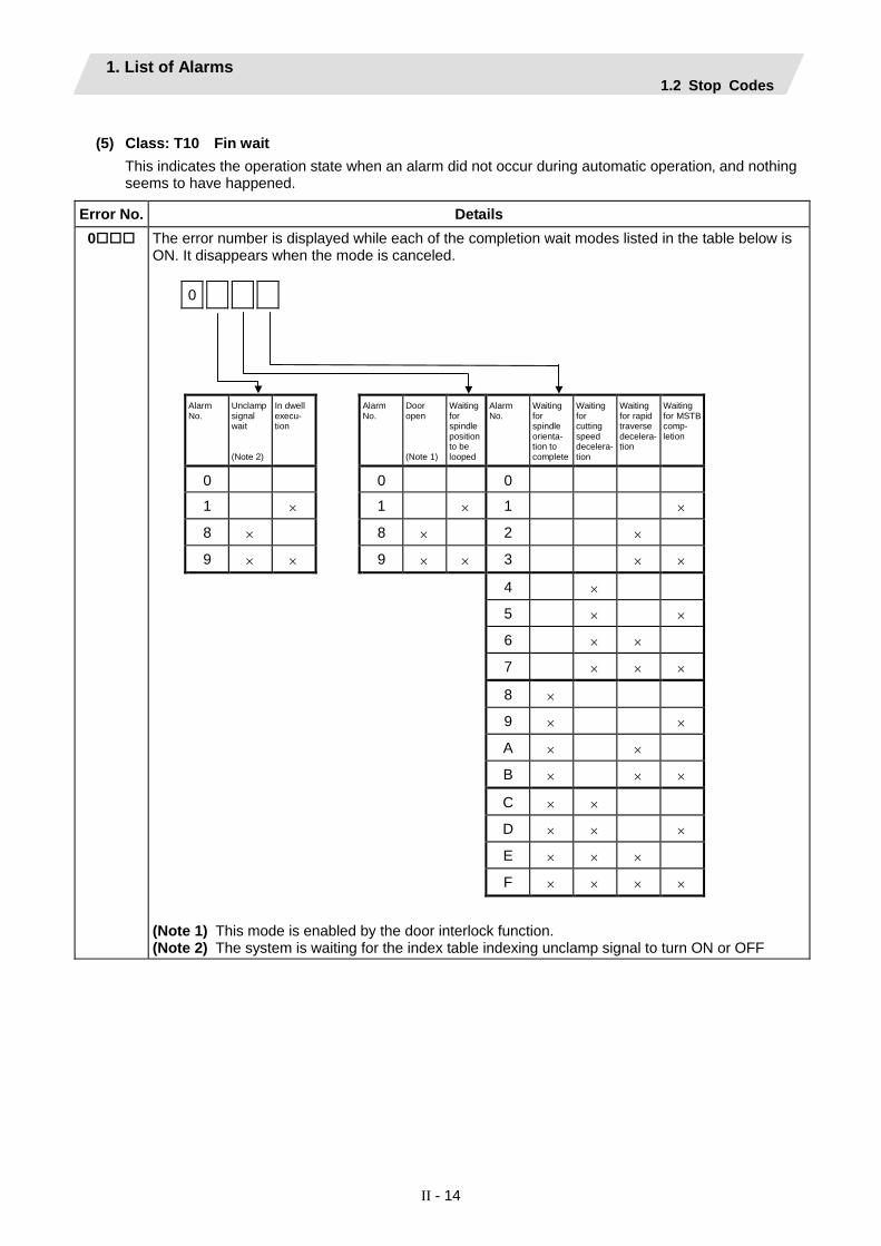
1. List of Alarms 1.2 Stop Codes
II - 14
(5) Class: T10 Fin wait
This indicates the operation state when an alarm did not occur during automatic operation‚ and nothing seems to have happened.
Error No. Details 0 The error number is displayed while each of the completion wait modes listed in the table below is
ON. It disappears when the mode is canceled.
0
Alarm No.
Unclamp signal wait (Note 2)
In dwell execu- tion
Alarm No.
Door open (Note 1)
Waiting for spindle position to be looped
Alarm No.
Waiting for spindle orienta- tion to complete
Waiting for cutting speed decelera-tion
Waiting for rapid traverse decelera- tion
Waiting for MSTB comp- letion
0 0 0
1 × 1 × 1 ×
8 × 8 × 2 ×
9 × × 9 × × 3 × ×
4 ×
5 × ×
6 × ×
7 × × ×
8 ×
9 × ×
A × ×
B × × ×
C × ×
D × × ×
E × × ×
F × × × ×
(Note 1) This mode is enabled by the door interlock function. (Note 2) The system is waiting for the index table indexing unclamp signal to turn ON or OFF
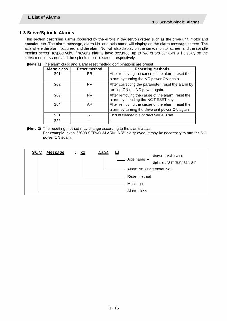
1. List of Alarms 1.3 Servo/Spindle Alarms
II - 15
1.3 Servo/Spindle Alarms This section describes alarms occurred by the errors in the servo system such as the drive unit‚ motor and encoder, etc. The alarm message‚ alarm No. and axis name will display on the alarm message screen. The axis where the alarm occurred and the alarm No. will also display on the servo monitor screen and the spindle monitor screen respectively. If several alarms have occurred‚ up to two errors per axis will display on the servo monitor screen and the spindle monitor screen respectively.
(Note 1) The alarm class and alarm reset method combinations are preset. Alarm class Reset method Resetting methods S01 PR After removing the cause of the alarm, reset the
alarm by turning the NC power ON again.
S02 PR After correcting the parameter, reset the alarm by turning ON the NC power again.
S03 NR After removing the cause of the alarm, reset the alarm by inputting the NC RESET key.
S04 AR After removing the cause of the alarm, reset the alarm by turning the drive unit power ON again.
S51 - This is cleared if a correct value is set. S52 - -
(Note 2) The resetting method may change according to the alarm class. For example, even if "S03 SERVO ALARM: NR" is displayed, it may be necessary to turn the NC
power ON again.
S Message : xx ΔΔΔΔ
Axis name
Alarm No. (Parameter No.)
Reset method
Message
Alarm class
Servo : Axis name
Spindle : "S1","S2","S3","S4"

1. List of Alarms 1.3 Servo/Spindle Alarms
II - 16
(1) Class: S01/S03/S04 Servo alarm (a) Servo drive unit alarm
No. Message Details Reset method Stop method
0010 Insufficient voltage A drop of bus voltage was detected in main circuit. PR Dynamic stop 0011 Axis selection error The axis selection rotary switch has been incorrectly set. AR Initial error 0012 Memory error 1 A hardware error was detected during the power ON
self-check. AR Initial error
0013 Software processing error 1 An error was detected for the software execution state. PR Dynamic stop 0016 Init mag pole pos detect err The initial magnetic pole position, detected in the initial
magnetic pole position detection control, is not reliable. In the DC excitation function, this error will be detected when the servo ON has been set before the magnetic pole shift amount is set while the absolute position detector is used.
PR Dynamic stop
0017 A/D converter error A current feedback error was detected. PR Dynamic stop 0018 Motor side dtc: Init commu err An error was detected in the initial communication with
the motor side detector. PR Initial error
001A Machine side dtc: Init comu er An error was detected in the initial communication with the machine side detector.
PR Initial error
001B Machine side dtc: Error 1 001C Machine side dtc: Error 2 001D Machine side dtc: Error 3 001E Machine side dtc: Error 4
An error was detected by the detector connected to the machine side. The error details are different according to the connected detector. Refer to "Detector alarm".
Dynamic stop
001F Machine side dtc: Commu error An error was detected in the communication with the machine side detector.
PR Dynamic stop
0021 Machine side dtc: No signal An error was detected in the ABZ-phase in the full closed loop control system.
PR Dynamic stop
0024 Grounding The motor power cable is in contact with FG (Frame Ground).
PR Dynamic stop
0025 Absolute position data lost The absolute position was lost in the detector. AR Initial error 0026 Unused axis error A power module error was detected on the axis set to
Free. PR Dynamic stop
0027 Machine side dtc: Error 5 0028 Machine side dtc: Error 6 0029 Machine side dtc: Error 7 002A Machine side dtc: Error 8
An error was detected by the detector connected to the machine side. The error details are different according to the connected detector. Refer to "Detector alarm".
Dynamic stop
002B Motor side dtc: Error 1 002C Motor side dtc: Error 2 002D Motor side dtc: Error 3 002E Motor side dtc: Error 4
An error was detected by the detector connected to the motor side. The error details are different according to the connected detector. Refer to "Detector alarm".
Dynamic stop
002F Motor side dtc: Commu error An error was detected in the communication with the motor side detector.
PR Dynamic stop
0030 Over regeneration Over-regeneration level exceeded 100%. The regenerative resistor is overloaded.
PR Dynamic stop
0031 Overspeed The motor speed exceeded the allowable speed. PR Deceleration stop enabled
0032 Power module overcurrent The power module detected the overcurrent. PR Dynamic stop 0033 Overvoltage The bus voltage in main circuit exceeded the allowable
value. PR Dynamic stop
0034 NC-DRV commu: CRC error An error was detected in the data received from the NC. PR Deceleration stop enabled
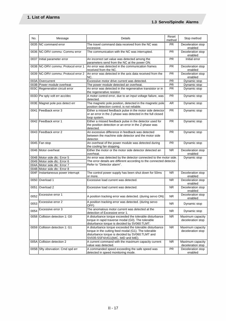
1. List of Alarms 1.3 Servo/Spindle Alarms
II - 17
No. Message Details Reset
method Stop method
0035 NC command error The travel command data received from the NC was excessive.
PR Deceleration stop enabled
0036 NC-DRV commu: Commu error The communication with the NC was interrupted. PR Deceleration stop enabled
0037 Initial parameter error An incorrect set value was detected among the parameters send from the NC at the power ON.
PR Initial error
0038 NC-DRV commu: Protocol error 1 An error was detected in the communication frames received from the NC.
PR Deceleration stop enabled
0039 NC-DRV commu: Protocol error 2 An error was detected in the axis data received from the NC.
PR Deceleration stop enabled
003A Overcurrent Excessive motor drive current was detected. PR Dynamic stop 003B Power module overheat The power module detected an overheat. PR Dynamic stop 003C Regeneration circuit error An error was detected in the regenerative transistor or in
the regenerative resistor. PR Dynamic stop
003D Pw sply volt err acc/dec A motor control error, due to an input voltage failure, was detected.
PR Dynamic stop
003E Magnet pole pos detect err The magnetic pole position, detected in the magnetic pole position detection control, is not reliable.
AR Dynamic stop
0041 Feedback error 3 Either a missed feedback pulse in the motor side detector or an error in the Z-phase was detected in the full closed loop system.
PR Dynamic stop
0042 Feedback error 1 Either a missed feedback pulse in the detector used for the position detection or an error in the Z-phase was detected.
PR Dynamic stop
0043 Feedback error 2 An excessive difference in feedback was detected between the machine side detector and the motor side detector.
PR Dynamic stop
0045 Fan stop An overheat of the power module was detected during the cooling fan stopping.
PR Dynamic stop
0046 Motor overheat Either the motor or the motor side detector detected an overheat.
NR Deceleration stop enabled
0048 Motor side dtc: Error 5 0049 Motor side dtc: Error 6 004A Motor side dtc: Error 7 004B Motor side dtc: Error 8
An error was detected by the detector connected to the motor side. The error details are different according to the connected detector. Refer to "Detector alarm".
Dynamic stop
004F Instantaneous power interrupt The control power supply has been shut down for 50ms or more.
NR Deceleration stop enabled
0050 Overload 1 Excessive load current was detected. NR Deceleration stop enabled
0051 Overload 2 Excessive load current was detected. NR Deceleration stop enabled
0052 Excessive error 1 A position tracking error was detected. (during servo ON) NR Deceleration stop enabled
0053 Excessive error 2 A position tracking error was detected. (during servo OFF) NR Dynamic stop
0054 Excessive error 3 The anomalous motor current was detected at the detection of Excessive error 1. NR Dynamic stop
0058 Collision detection 1: G0 A disturbance torque exceeded the tolerable disturbance torque in rapid traverse modal (G0). The tolerable disturbance torque is decided by SV060:TLMT.
NR Maximum capacity deceleration stop
0059 Collision detection 1: G1 A disturbance torque exceeded the tolerable disturbance torque in the cutting feed modal (G1). The tolerable disturbance torque is decided by SV060:TLMT and SV035:SSF4/clG1(bitC, bitD and bitE).
NR Maximum capacity deceleration stop
005A Collision detection 2 A current command with the maximum capacity current value was detected.
NR Maximum capacity deceleration stop
005B Sfty obsrvation: Cmd spd err A commanded speed exceeding the safe speed was detected in speed monitoring mode.
PR Deceleration stop enabled

1. List of Alarms 1.3 Servo/Spindle Alarms
II - 18
No. Message Details Reset
method Stop method
005D Sfty obsrvation: Door stat err
The door state signal input in the NC does not coincide with the door state signal input in the drive unit. Otherwise, door open state was detected in normal mode.
PR Deceleration stop enabled
005E Sfty obsrvation: FB speed err A motor speed exceeding the safe speed was detected in the speed monitoring mode.
PR Deceleration stop enabled
005F External contactor error A contact of the external contactor is welding. NR Deceleration stop enabled
0060 ~
0077
Power supply alarm The power supply unit detected an error. The error details are different according to the connected power supply unit. Refer to "Power supply alarm".
Dynamic stop
0080 Motor side dtc: cable err A difference of type was detected between the motor side detector and the cable connected to the detector. Otherwise, the cable type for the motor side detector was not successfully achieved.
AR Initial error
0081 Machine side dtc: cable err A difference of type was detected between the machine side detector and the cable connected to the detector. Otherwise, the cable type for the machine side detector was not successfully achieved.
AR Initial error
0087 Drive unit communication error The communication frame between drivers was aborted. PR Dynamic stop 0088 Watchdog The drive unit does not operate correctly. AR Dynamic stop 008A Drivers commu data error 1 The communication data 1 between drivers exceeded the
tolerable value in the communication between drivers. PR Dynamic stop
008B Drivers commu data error 2 The communication data 2 between drivers exceeded the tolerable value in the communication between drivers.
PR Dynamic stop
(Note1) Definitions of terms in the table are as follows. Motor side detector: Detector connected to CN2 Machine side detector: Detector connected to CN3
(Note2) Resetting methods NR: Reset with the NC RESET button. This alarm can also be reset with the PR and AR resetting conditions. PR: Reset by turning the NC power ON again. This alarm can also be reset with the AR resetting conditions.
When the control axis is removed, this alarm can be reset with the NC RESET button. (Excluding alarms 32 and 37.) AR: Reset by turning the servo drive unit power ON again.
Separate table : Detector alarm (Servo drive unit)
Alarm number when the detector is connected to the motor side 2B 2C 2D 2E 48 49 4A 4B
Alarm number when the detector is connected to the machine side 1B 1C 1D 1E 27 28 29 2A
OSA17 OSE104, OSE105 OSA104, OSA105 OSA405, OSA166
Memory alarm LED alarm Data alarm - - - - -
OSA18 CPU alarm - Data alarm - - - - -
MDS-B-HR
MITSUBISHI
Memory error - Data error - Scale not connected - - -
AT343, AT543 Mitutoyo Initialization error
EEPROMerror
Photoelectric type, static
capacity type data
mismatch
ROM/RAMerror CPU error
Photoelectric type
overspeed
Static capacity type
error
Photoelectric type error
LC191M, LC491M RCN723, RCN223
APE391M HEIDENHAIN Initialization
error EEPROM
error
Relative/ absolute
position data mismatch
ROM/RAMerror CPU error Overspeed
Absolute position data
error
Relative position data
error
Futaba absolute position scale Futaba - - - - - - Waveform
error
OverspeedAbsolute position is
lost
MP scale, MPI scale
Mitsubishi Heavy
Industries
Installation accuracy
fault -
Detection position deviance
Scale breaking
Absolute value
detection fault
- Gain fault Phase fault
MJ831 SONY - - - - - - - Detector alarm
(Note1) Definitions of terms in the table are as follows. Motor side detector: Detector connected to CN2 Machine side detector: Detector connected to CN3
(Note2) A driver processes all reset types of alarms as "PR". However, "AR" will be applied according to the detector.

1. List of Alarms 1.3 Servo/Spindle Alarms
II - 19
(b) Spindle drive unit alarm
No. Message Details Reset method Stop method
0010 Insufficient voltage A drop of bus voltage was detected in main circuit. PR Coast to a stop 0011 Axis selection error The axis selection rotary switch has been incorrectly set. AR Initial error 0012 Memory error 1 A hardware error was detected during the power ON
self-check. AR Initial error
0013 Software processing error 1 An error was detected for the software execution state. PR Coast to a stop 0016 Init mag pole pos detect err The magnetic pole position, detected in the initial
magnetic pole position detection control, is not reliable. PR Coast to a stop
0017 A/D converter error A current feedback error was detected. PR Coast to a stop 0018 Motor side dtc: Init commu err An error was detected in the initial communication with
the motor side detector. PR Initial error
0019 Detector commu err in syn cont An error was detected in the communication with the extended connection detector.
PR Coast to a stop
001A Machine side dtc: Init comu er An error was detected in the initial communication with the machine side detector.
PR Initial error
001B Machine side dtc: Error 1 001C Machine side dtc: Error 2 001D Machine side dtc: Error 3 001E Machine side dtc: Error 4
An error was detected by the detector connected to the machine side. The error details are different according to the connected detector. Refer to "Detector alarm".
Coast to a stop
001F Machine side dtc: Commu error An error was detected in the communication with the machine side detector.
PR Coast to a stop
0020 Motor side dtc: No signal The cable type of the motor side detector does not coincide with the detector type set with the parameter.
PR Initial error
The cable type of the machine side detector does not coincide with the detector type set with the parameter.
PR Initial error 0021 Machine side dtc: No signal Excessive speed error
An error was detected in the ABZ-phase in the full closed loop control system.
PR Coast to a stop
0023 Grounding An excessive speed tracking error was detected (during servo ON).
NR Coast to a stop
0024 Machine side dtc: No signal A grounding of the motor power cable or motor was detected.
AR Coast to a stop
0026 Unused axis error A power module error was detected on the axis set to Free.
PR Coast to a stop
0027 Machine side dtc: Error 5 0028 Machine side dtc: Error 6 0029 Machine side dtc: Error 7 002A Machine side dtc: Error 8
An error was detected by the detector connected to the machine side. The error details are different according to the connected detector. Refer to "Detector alarm".
Coast to a stop
002B Motor side dtc: Error 1 002C Motor side dtc: Error 2 002D Motor side dtc: Error 3 002E Motor side dtc: Error 4
An error was detected by the detector connected to the motor side. The error details are different according to the connected detector. Refer to "Detector alarm".
Coast to a stop
002F Motor side dtc: Commu error An error was detected in the communication with the motor side detector.
PR Coast to a stop
0030 Over regeneration Over-regeneration level exceeded 100%. The regenerative resistor is overloaded.
PR Coast to a stop
0031 Overspeed The motor speed exceeded the allowable speed. PR Deceleration stop enabled
0032 Power module overcurrent The power module detected the overcurrent. PR Coast to a stop 0033 Overvoltage The bus voltage in main circuit exceeded the allowable
value. PR Coast to a stop
0034 NC-DRV commu: CRC error An error was detected in the data received from the NC. PR Deceleration stop enabled
0035 NC command error An error was detected in the travel command data received from the NC.
PR Deceleration stop enabled
0036 NC-DRV commu: Commu error The communication with the NC was interrupted. PR Deceleration stop enabled
0037 Initial parameter error An incorrect set value was detected among the parameters send from the NC at the power ON.
PR Initial error
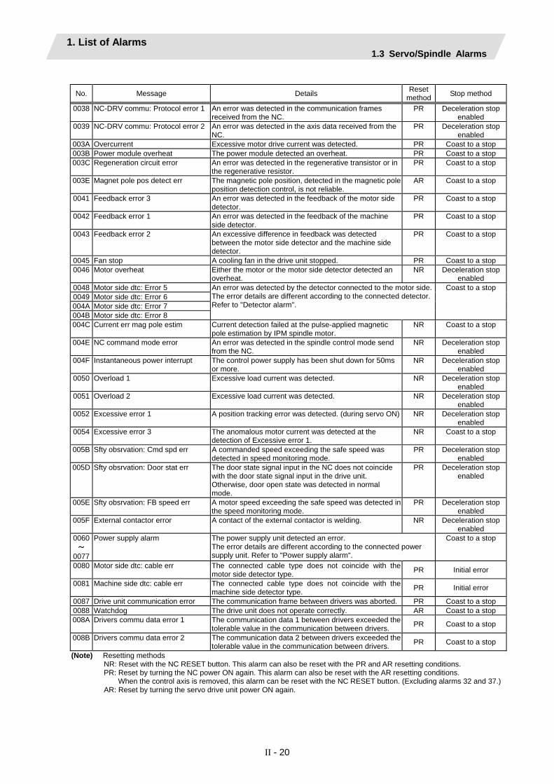
1. List of Alarms 1.3 Servo/Spindle Alarms
II - 20
No. Message Details Reset
method Stop method
0038 NC-DRV commu: Protocol error 1 An error was detected in the communication frames received from the NC.
PR Deceleration stop enabled
0039 NC-DRV commu: Protocol error 2 An error was detected in the axis data received from the NC.
PR Deceleration stop enabled
003A Overcurrent Excessive motor drive current was detected. PR Coast to a stop 003B Power module overheat The power module detected an overheat. PR Coast to a stop 003C Regeneration circuit error An error was detected in the regenerative transistor or in
the regenerative resistor. PR Coast to a stop
003E Magnet pole pos detect err The magnetic pole position, detected in the magnetic pole position detection control, is not reliable.
AR Coast to a stop
0041 Feedback error 3 An error was detected in the feedback of the motor side detector.
PR Coast to a stop
0042 Feedback error 1 An error was detected in the feedback of the machine side detector.
PR Coast to a stop
0043 Feedback error 2 An excessive difference in feedback was detected between the motor side detector and the machine side detector.
PR Coast to a stop
0045 Fan stop A cooling fan in the drive unit stopped. PR Coast to a stop 0046 Motor overheat Either the motor or the motor side detector detected an
overheat. NR Deceleration stop
enabled 0048 Motor side dtc: Error 5 0049 Motor side dtc: Error 6 004A Motor side dtc: Error 7 004B Motor side dtc: Error 8
An error was detected by the detector connected to the motor side. The error details are different according to the connected detector. Refer to "Detector alarm".
Coast to a stop
004C Current err mag pole estim Current detection failed at the pulse-applied magnetic pole estimation by IPM spindle motor.
NR Coast to a stop
004E NC command mode error An error was detected in the spindle control mode send from the NC.
NR Deceleration stop enabled
004F Instantaneous power interrupt The control power supply has been shut down for 50ms or more.
NR Deceleration stop enabled
0050 Overload 1 Excessive load current was detected. NR Deceleration stop enabled
0051 Overload 2 Excessive load current was detected. NR Deceleration stop enabled
0052 Excessive error 1 A position tracking error was detected. (during servo ON) NR Deceleration stop enabled
0054 Excessive error 3 The anomalous motor current was detected at the detection of Excessive error 1.
NR Coast to a stop
005B Sfty obsrvation: Cmd spd err A commanded speed exceeding the safe speed was detected in speed monitoring mode.
PR Deceleration stop enabled
005D Sfty obsrvation: Door stat err
The door state signal input in the NC does not coincide with the door state signal input in the drive unit. Otherwise, door open state was detected in normal mode.
PR Deceleration stop enabled
005E Sfty obsrvation: FB speed err A motor speed exceeding the safe speed was detected in the speed monitoring mode.
PR Deceleration stop enabled
005F External contactor error A contact of the external contactor is welding. NR Deceleration stop enabled
0060 ~
0077
Power supply alarm The power supply unit detected an error. The error details are different according to the connected power supply unit. Refer to "Power supply alarm".
Coast to a stop
0080 Motor side dtc: cable err The connected cable type does not coincide with the motor side detector type. PR Initial error
0081 Machine side dtc: cable err The connected cable type does not coincide with the machine side detector type. PR Initial error
0087 Drive unit communication error The communication frame between drivers was aborted. PR Coast to a stop 0088 Watchdog The drive unit does not operate correctly. AR Coast to a stop 008A Drivers commu data error 1 The communication data 1 between drivers exceeded the
tolerable value in the communication between drivers. PR Coast to a stop
008B Drivers commu data error 2 The communication data 2 between drivers exceeded the tolerable value in the communication between drivers. PR Coast to a stop
(Note) Resetting methods NR: Reset with the NC RESET button. This alarm can also be reset with the PR and AR resetting conditions. PR: Reset by turning the NC power ON again. This alarm can also be reset with the AR resetting conditions.
When the control axis is removed, this alarm can be reset with the NC RESET button. (Excluding alarms 32 and 37.) AR: Reset by turning the servo drive unit power ON again.

1. List of Alarms 1.3 Servo/Spindle Alarms
II - 21
Separate table : Detector alarm (Spindle drive unit)
Alarm number when the detector is connected to the motor side 2B 2C 2D 2E 48 49 4A 4B
Alarm number when the detector is connected to the machine side 1B 1C 1D 1E 27 28 29 2A
TS5690 TS5691 Memory error Waveform
error - - - Overspeed - Relative
position data error
MDS-B-HR Initialization error - Data error - Connection
error - - -
OSA18
MITSUBISHI
CPU error - Data error - - - - -
ERM280 +
APE391M HEIDENHAIN Initialization
error EEPROM
error - - CPU error Overspeed - Relative
position data error
MPCI scale Mitsubishi
Heavy Industries
Installation accuracy
fault -
Detection position deviance
Scale breaking - - Gain fault Phase fault
(Note) A driver processes all reset types of alarms as "PR". However, "AR" will be applied according to the detector.
(c) Power supply alarm
No. LED display Message Details Reset
method0061
Pw sply: Pwr module overcurnt Overcurrent protection function in the power module has started its
operation. PR
0062
Pw sply: Frequency error The input power supply frequency increased above the
specification range. PR
0067
Pw sply: Phase interruption An open-phase condition was detected in input power supply circuit. PR
0068
Pw sply: Watchdog The system does not operate correctly. AR
0069
Pw sply: Grounding The motor power cable is in contact with FG (Frame Ground). PR
006A
Pw sply: Ext contactor weld A contact of the external contactor is welding. PR
006B
Pw sply: Rush relay welding A resistor relay for rush short circuit fails to be OFF. PR
006C
Pw sply: Main circuit error An error was detected in charging operation of the main circuit
capacitor. PR
006E
Pw sply: Memory error/AD error An error was detected in the internal memory or A/D converter. AR
006F
Power supply error No power supply is connected to the drive unit, or a communication
error was detected. AR
0070
Pw sply: Ext emergency stp err A mismatch of the external emergency stop input and NC
emergency stop input continued for 30 seconds. PR
0071
Pw sply: Instant pwr interrupt The power was momentarily interrupted. NR
0072
Pw sply: Fan stop A cooling fan built in the power supply unit stopped, and overheat
occurred in the power module. PR
0073
Pw sply: Over regeneration Over-regeneration detection level became over 100%. The
regenerative resistor is overloaded. This alarm cannot be reset for 15 min from the occurrence to protect the regeneration resistor. Leave the drive system energized for more than 15 min, then turn the power ON to reset the alarm.
NR
0075
Pw sply: Overvoltage L+ and L- bus voltage in main circuit exceeded the allowable value.
As the voltage between L+ and L- is high immediately after this alarm, another alarm may occur if this alarm is reset in a short time. Wait more than 5 min before resetting so that the voltage drops.
NR
0076
Pw sply: Ext EMG stop set err The rotary switch setting of external emergency stop is not correct,
or a wrong external emergency stop signal is input. AR
0077
Pw sply: Power module overheat Thermal protection function in the power module has started its
operation. PR
(Note 1) If a power supply alarm (60 to 77) occurs, all servos will stop with the dynamic brakes, and all spindles will coast to a stop. (Note 2) "b", "C" and "d" displayed on the power supply unit's LED as a solid light (not flickering) do not indicate an alarm.

1. List of Alarms 1.3 Servo/Spindle Alarms
II - 22
(2) Class: S02 Message: Initial parameter error
An error was found in the parameters transmitted from the controller to the drive unit when the power was turned ON. Remove the cause of the alarm, and then reset the alarm by turning the controller power OFF once.
Alarm No. Details Remedy
2201 to
2264
The servo parameter setting data is illegal. The alarm No. is the No. of the servo parameter where the error occurred.
Check the descriptions for the appropriate servo parameters and correct them.
2301 The number of constants to be used in the following functions is too large: • Electronic gears • Position loop gain • Speed feedback conversion
Check that all the related parameters are specified correctly.
sv001:PC1, sv002:PC2, sv003:PGN1 sv018:PIT, sv019:RNG1, sv020:RNG2
2302 When high-speed serial incremental detector (OSE104, OSE105) is connected, parameters for absolute position are set to ON. Set the parameters for absolute position detection to OFF. To detect an absolute position, replace the incremental specification detector with an absolute position detector.
Check that all the related parameters are specified correctly.
sv017:SPEC, sv025:MTYP
2303 No servo option is found. The closed loop (including the ball screw- end detector) or dual feedback control is an optional function.
Check that all the related parameters are specified correctly.
sv025:MTYP/pen sv017:SPEC/dfbx
2304 No servo option is found. The SHG control is an optional function.
Check that all the related parameters are specified correctly.
sv057:SHGC sv058:SHGCsp
2305 No servo option is found. The adaptive filtering is an optional function.
Check that all the related parameters are specified correctly.
sv027:SSF1/aflt 13001
to 13256
Parameter error The spindle parameter setting data is illegal. The alarm No. is the No. of the spindle parameter where the error occurred.
Check the descriptions for the appropriate spindle parameters and correct them. Refer to Alarm No.37 in Spindle Drive Maintenance Manual.
(3) Class: S51 Message: Parameter error This warning is displayed if a parameter outside the tolerance range is set. Illegal settings will be ignored. This alarm will be reset when a correct value is set.
Alarm No. Details Remedy
2201 to
2264
Servo parameter setting data is illegal. The alarm No. is the No. of the servo parameter where the warning occurred.
Check the descriptions for the appropriate servo parameters and correct them.
13001 to
13256
Spindle parameter setting data is illegal. The alarm No. is the No. of the spindle parameter where the warning occurred.
Check the descriptions for the appropriate spindle parameters and correct them. Refer to Spindle Drive Maintenance Manual.

1. List of Alarms 1.3 Servo/Spindle Alarms
II - 23
(4) Class: S52 Servo warning
When a warning occurs, a warning No. will appear on the NC monitor screen and with the LEDs on the front of the drive unit. Check the warning No., and remove the cause of the warning by following this list.
(a) Servo drive unit warning
No. Message Details Reset method Stop method
0096 Scale feedback error An excessive difference in feedback amount was detected between the motor side detector and the MPI scale in MPI scale absolute position detection system.
* -
0097 Scale offset error An error was detected in the offset data that is read at the NC power-ON in MPI scale absolute position detection system.
PR -
009E Absolute position detector: Revolution counter error
An error was detected in the revolution counter data of the absolute position detector. The accuracy of absolute position is not guaranteed.
* -
009F Battery voltage drop The battery voltage to be supplied to the absolute position detector is dropping.
* -
00A6 Fan stop warning A cooling fan in the drive unit stopped. * - 00E0 Overregeneration warning Over-regeneration detection level exceeded 80%. * - 00E1 Overload warning A level of 80% of the Overload 1 alarm state was
detected. * -
00E4 Set parameter warning An incorrect set value was detected among the parameters send from the NC in the normal operation.
* -
00E6 Control axis detachment warning A control axis is being detached. (State display) * - 00E7 In NC emergency stop state In NC emergency stop. (State display) * Deceleration stop
enabled 00E8 ~
00EF
Power supply warning The power supply unit detected a warning. The error details are different according to the connected power supply unit. Refer to "Power supply warning".
* - *EA:
Deceleration stop enabled
(Note1) Definitions of terms in the table are as follows. Motor side detector: Detector connected to CN2 Machine side detector: Detector connected to CN3
(Note 2) Resetting methods *: Automatically reset once the cause of the warning is removed. NR: Reset with the NC RESET button. This warning can also be reset with the PR and AR resetting conditions. PR: Reset by turning the NC power ON again. This warning can also be reset with the AR resetting conditions.
When the control axis is removed, this warning can be reset with the NC RESET button. (Excluding warning 93.) AR: Reset by turning the servo drive unit power ON again.
(Note 3) Servo and spindle motor do not stop when the warning occurs. (Note 4) When an emergency stop is input, servo and spindle motor decelerate to a stop.
(When SV048, SV055 or SV056 is set for servo and when SP055 or SP056 is set for spindle.)
(b) Spindle drive unit warning
No. Message Details Reset method Stop method
00A6 Fan stop warning A cooling fan in the drive unit stopped. * - 00E0 Overregeneration warning Over-regeneration detection level exceeded 80%. * - 00E1 Overload warning A level of 80% of the Overload 1 alarm state was
detected. * -
00E4 Set parameter warning A parameter was set to the value over the setting range. * - 00E6 Control axis detachment warning A control axis is being detached. (State display) * - 00E7 In NC emergency stop state In NC emergency stop. (State display) * Deceleration stop
enabled 00E8 ~
00EF
Power supply warning The power supply unit detected a warning. The error details are different according to the connected power supply unit. Refer to "Power supply warning".
* -
(Note 1) Resetting methods *: Automatically reset once the cause of the warning is removed. NR: Reset with the NC RESET button. This warning can also be reset with the PR and AR resetting conditions. PR: Reset by turning the NC power ON again. This warning can also be reset with the AR resetting conditions.
When the control axis is removed, this warning can be reset with the NC RESET button. (Excluding warning 93.) AR: Reset by turning the servo drive unit power ON again.
(Note 2) Servo and spindle motor do not stop when the warning occurs. (Note 3) When an emergency stop is input, servo and spindle motor decelerate to a stop.
(When SV048, SV055 or SV056 is set for servo and when SP055 or SP056 is set for spindle.)

1. List of Alarms 1.3 Servo/Spindle Alarms
II - 24
(c) Power supply warning
No. LED display Message Details Reset
method00E9
Instantaneous power interruption warning
The power was momentarily interrupted. NR
00EA
In external emergency stop state External emergency stop signal was input. *
00EB
Power supply: Over regeneration warning
Over-regeneration detection level exceeded 80%. *
00EE
Pw sply: Fan stop warning A cooling fan built in the power supply unit stopped. *
(Note 1) Resetting methods *: Automatically reset once the cause of the warning is removed. NR: Reset with the NC RESET button. This warning can also be reset with the PR and AR resetting conditions. PR: Reset by turning the NC power ON again. This warning can also be reset with the AR resetting conditions.
When the control axis is removed, this warning can be reset with the NC RESET button. (Excluding warning 93.) AR: Reset by turning the servo drive unit power ON again.
(Note 2) Servo and spindle motor do not stop when the warning occurs.

1. List of Alarms 1.4 MCP Alarm
II - 25
1.4 MCP Alarm An error has occurred in the drive unit and other interfaces. (The bold characters are the messages displayed on the screen.)
Y Message
Alarm No. Error No. Message Class

1. List of Alarms 1.4 MCP Alarm
II - 26
(1) Class: Y02 System alarm
An error occurred in the data transmitted between the MCP and drive unit after the power was turned ON.
Error No. Details Remedy 0050 System alm: Process time over The software or hardware may be damaged.
Contact the service center. Alarm No.
0000 SV commu er: CRC error 1 (10 times/910.2 ms)
0001 SV commu er: CRC error 2 (2 continuous times)
0002 SV commu er: Recv timing err (2 continuous times)
0051
xy03 SV commu er: Data ID error (2 continuous times) x: Channel No. (0 to) y: Drive unit rotary switch No.
(0 to) xy04 SV commu er: Recv frame No.
(2 continuous times) x: Channel No. (0 to) y: Number of reception frame -1
(0 to) x005 SV commu er: Commu error
(No error classification) x: Channel No. (0 to)
x006 SV commu er: Connect error x: Channel No. (0 to)
xy20 SV commu er: Init commu error The drive unit could not shift to the initial communication run time and stopped. x: Channel No. (0 to) y: Drive unit rotary switch No.
(0 to) xy30 SV commu er: Node detect error
No response from drive unit to the request from NC when setting network configuration. x: Channel No. (0 to) y: Station No. (0 to)
xy31 SV commu er: Commu not support
Drive unit's software version doesn't support the communication mode that the controller requires. x: Channel No. (0 to) y: Station No. (0 to)
A communication error has occurred between the controller and drive unit. • Take measures against noise. • Check that the communication cable connector
between the controller and drive unit and one between the drive units are tight.
• Check whether the communication cable between the controller and drive unit and one between the drive units are disconnected.
• A drive unit may be faulty. Take a note of the 7-segment LED contents of each drive unit and report to the Service Center.
• Update the drive unit software version.
(Note) When two or more "Y02 System alarms" occur at the same time, only the alarm which occurs first is
displayed.

1. List of Alarms 1.4 MCP Alarm
II - 27
(2) Class: Y03 Message: Drive unit unequipped
The drive unit is not correctly connected.
Error No. Details Remedy Alphabet
(axis name)
Servo axis drive unit not mounted
1 to 4 PLC axis drive unit not mounted
S No.1 spindle axis drive unit not mounted
T No.2 spindle axis drive unit not mounted M No.3 spindle axis drive unit not mounted N No.4 spindle axis drive unit not mounted
Check the drive unit mounting state. • Check the end of the cable wiring. • Check the cable for broken wires. • Check the connector insertion. • The drive unit input power is not being input. • The drive unit axis No. switch is illegal.
(3) Class : Y05 Message: Initial parameter error
Details Remedy There is a problem in the value set for the number of axes or the number of part systems.
Check the value set for the corresponding parameters. #1001 SYS_ON #1002 axisno #1039 spinno, etc.
(4) Class: Y06 Message: mcp_no setting error
There are differences in the MCP and axis parameters when the NC power is turned ON.
Error No. Details Remedy 0001 There is a skipped number in the channels.
0002 The random layout setting is duplicated.
0003 The drive unit fixed setting "0000" and random layout setting "∗∗∗∗" are both set.
0004 The spindle/C axis "#1021 mcp_no" and "#3031 smcp_no" are not set to the same values.
0005 A random layout is set for the "#1154 pdoor" =1 two-part system.
0006 The channel No. parameter is not within the setting range.
Check the values set for the following parameters. #1021 mcp_no #3031 smcp_no

1. List of Alarms 1.4 MCP Alarm
II - 28
(5) Class: Y07 Message: Too many axes connected
The number of connected axes exceeds the number allowed in the system.
(Alarm No.)
0 0
Exceeded number of axes at drive unit interface channel 1
Exceeded number of axes at drive unit interface channel 2
Alarm No. Details Remedy
0000 to
00FF
The number of axes connected to each channel exceeds the maximum number of connectable axes. The exceeded number of axes per channel is displayed as alarm No. This alarm occurs when the drive unit is connected only with the 2nd channel without connecting with the 1st channel.
Remove connected axes from the channel whose alarm No. is other than 0 for the number displayed as the alarm No. Keep the number of connected axes to or less than the maximum that can be connected.
(Note 1) The number of axes is limited per each drive unit interface channel.
(Note 2) Maximum number of axes that can be connected differs depending on whether or not an expansion unit is available or the setting of "#11012 16 axes for 1ch". The maximum number of connectable axes is as shown below.
Extension unit #11012 16 axes for 1ch Maximum number of axes to be connected
(Per 1 channel) Yes 0/1
0 8 axes
No 1 16 axes
(Note 3) If this alarm occurs, the alarm "Y03 Message: Drive unit unequipped" will not occur.
(Note 4) This alarm is displayed taking precedence over the alarm "Y08 Too many drive units connected" and "Y09 Too many axisno connected".

1. List of Alarms 1.4 MCP Alarm
II - 29
(6) Class: Y08 Message: Too many drive units connected
The number of connected drive units exceeds the number allowed in the system.
(Alarm No.)
0 0
Exceeded number of drive units at drive unit interface channel 1
Exceeded number of drive units at drive unit interface channel 2
Alarm No. Details Remedy 0000
to 00FF
The number of drive units connected to each channel exceeds 8. The exceeded number of drive units per channel is displayed as alarm No.
Remove drive units from the channel whose alarm No. is other than 0 for the number displayed as the alarm No. Keep the number of connected drive units to 8 or less.
(Note 1) The drive unit is not counted when all the axes connected to it are invalid.
(Note 2) If this alarm occurs, the alarm "Y03 Message: Drive unit unequipped" will not occur.
(Note 3) The alarm "Y07 Too many axes connected" and "Y09 Too many axisno connected" are displayed taking precedence over this alarm.

1. List of Alarms 1.4 MCP Alarm
II - 30
(7) Class: Y09 Message: Too many axisno connected
The connected axes No. (drive unit's rotary switch No.) is bigger than the No. allowed in the system.
(Alarm No.)
0 0
"1" when the axis No. at drive unit interface channel 1 is too big
"1" when the axis No. at drive unit interface channel 2 is too big
Alarm No. Details Remedy 0000
to 0011
The No. of the axis (drive unit's rotary switch No.) connected to each channel is bigger than the No. allowed.
For the channel whose alarm No. is 1, keep the axis No. (drive unit's rotary switch No.) not bigger than the No. allowed.
(Note 1) The axis No. is limited per each drive unit interface channel.
(Note 2) The biggest allowed connected axis No. differs depending on whether or not an expansion unit is available or the setting of "#11012 16 axes for 1ch". The biggest connectable axis No. is as shown below.
Extension unit #11012 16 axes for 1ch Highest allowed connected axis No.
(Per 1 channel) Yes 0/1
0 0 to 7
No 1 0 to F
(Note 3) If this alarm occurs, the alarm "Y03 Message: Drive unit unequipped" will not occur.
(Note 4) This alarm is displayed taking precedence over the alarm "Y08 Too many drive units connected".
(Note 5) The alarm "Y07 Too many axes connected" is displayed taking precedence over this alarm.
(8) Class: Y12 Message: No commu. with axis drv unit
Details Remedy Even though the high-speed synchronous tapping option is valid, drive unit that doesn't support the option is connected.
Replace it with a drive unit that supports the option.
(9) Class: Y13 Message: No commu. with sp drv unit
Details Remedy Even though the high-speed synchronous tapping option is valid, drive unit that doesn't support the option is connected.
Replace it with a drive unit that supports the option.
(10) Class: Y14 Message: Comm btwn drives not ready
Details Remedy Communication of drive units failed to be ready within a specified time.
• Connection of drive units may be wrong. • Check if any of drive units is broken.

1. List of Alarms 1.4 MCP Alarm
II - 31
(11) Class: Y20 Safety observation alarm
When this alarm is output, emergency stop mode is applied. Refer to "remedy" of each alarm as to how to cancel the alarm.
Error No. Alarm No. Details Remedy 0001 Axis name Parameter compare error
The speed monitoring parameter in the NC and the parameter transmitted to the drive unit are not matched. The name of the axis with an error is displayed.
The NC or the servo drive unit may be damaged. Contact the service center.
0002 Axis name Sfty obsrvation: Cmd spd err The speed exceeding the speed set with the parameter was commanded during the speed monitoring mode. The name of the axis with an error is displayed.
Check the speed monitoring parameter and the user PLC. Restart the NC.
0003 Axis name Sfty obsrvation: FB pos err The commanded position transmitted to the servo drive unit from NC and the feedback position to be received from the servo drive unit are totally different during the speed monitoring mode. The name of the axis with an error is displayed.
The NC or the servo drive unit may be damaged. Contact the service center.
0004 Axis name Sfty obsrvation: FB speed err Actual rotation speed of the motor is exceeding the speed set with speed monitoring parameter during the speed monitoring mode.The name of the axis with an error is displayed.
Check the speed observation parameter and the user PLC. Restart the NC.
0005 Door No. Door signal: Input mismatch Door state signals on the NC side and the drive side do not match. It may be caused by the followings: • Cable disconnection • Damaged door switch • Damaged NC or servo drive unit
Check the cable. Check the door switch. Restart the NC.
0006 Door No. No spd obsv mode in door open The door open state was detected when the speed monitoring mode was invalid. The causes may be same as the ones for 0005 (Door signal: Input mismatch). Also the user PLC may not be correct.
Check the user PLC. Restart the NC.
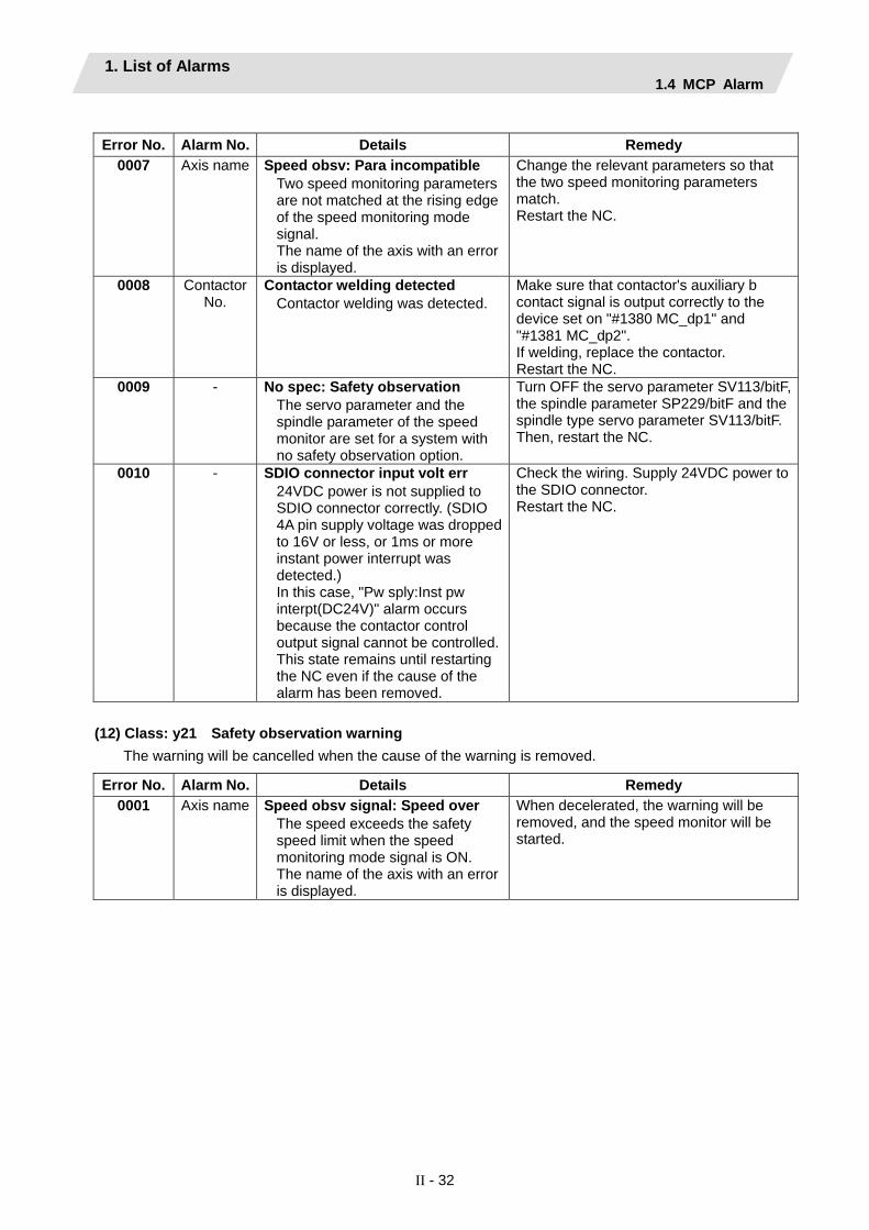
1. List of Alarms 1.4 MCP Alarm
II - 32
Error No. Alarm No. Details Remedy
0007 Axis name Speed obsv: Para incompatible Two speed monitoring parameters are not matched at the rising edge of the speed monitoring mode signal. The name of the axis with an error is displayed.
Change the relevant parameters so that the two speed monitoring parameters match. Restart the NC.
0008 Contactor No.
Contactor welding detected Contactor welding was detected.
Make sure that contactor's auxiliary b contact signal is output correctly to the device set on "#1380 MC_dp1" and "#1381 MC_dp2". If welding, replace the contactor. Restart the NC.
0009 - No spec: Safety observation The servo parameter and the spindle parameter of the speed monitor are set for a system with no safety observation option.
Turn OFF the servo parameter SV113/bitF, the spindle parameter SP229/bitF and the spindle type servo parameter SV113/bitF. Then, restart the NC.
0010 - SDIO connector input volt err 24VDC power is not supplied to SDIO connector correctly. (SDIO 4A pin supply voltage was dropped to 16V or less, or 1ms or more instant power interrupt was detected.) In this case, "Pw sply:Inst pw interpt(DC24V)" alarm occurs because the contactor control output signal cannot be controlled.This state remains until restarting the NC even if the cause of the alarm has been removed.
Check the wiring. Supply 24VDC power to the SDIO connector. Restart the NC.
(12) Class: y21 Safety observation warning The warning will be cancelled when the cause of the warning is removed.
Error No. Alarm No. Details Remedy 0001 Axis name Speed obsv signal: Speed over
The speed exceeds the safety speed limit when the speed monitoring mode signal is ON. The name of the axis with an error is displayed.
When decelerated, the warning will be removed, and the speed monitor will be started.

1. List of Alarms 1.4 MCP Alarm
II - 33
(13) Class: Y51 Parameter error
An error occurred in a parameter that causes an alarm while the control axis was operating.
Error No. Details Remedy 0001 Parameter G0tL illegal
The time constant has not been set or the setting exceeded the setting range.
• Check “#2004 G0tL”.
0002 Parameter G1tL illegal The time constant has not been set or the setting exceeded the setting range.
• Check “#2007 G1tL”.
0003 Parameter G0t1 illegal The time constant has not been set or the setting exceeded the setting range.
• Check “#2005 G0t1”.
0004 Parameter G1t1 illegal The time constant has not been set or the setting exceeded the setting range.
• Check “#2008 G1t1”.
0009 Parameter grid space illegal • Check “#2029 grspc”.
0012 Parameter stapt1-4 illegal The time constant has not been set or the setting exceeded the setting range.
• Check spindle parameters” #3017 stapt1” to “#3020 stapt4”.
0015 Parameter skip_tL illegal The time constant has not been set or the setting exceeded the setting range.
• Check “#2102 skip_tL”.
0016 Parameter skip_t1 illegal The time constant has not been set or the setting exceeded the setting range.
• Check “#2103 skip_t1”.
0017 Parameter G0bdcc illegal “#1205 G0bdcc” for the 2nd part system is set to acceleration/deceleration before G0 interpolation.
• Check “#1205 G0bdcc”.
0018 OMR-II parameter error The OMR-II related parameter settings are incorrect. In this case, the OMR-II is disabled.
• Check the related parameter settings.
0019 PLC indexing stroke length err When the linear axis equal indexing is validated for the PLC indexing axis, "#12804 aux_tleng" has not been set. Otherwise, it is out of the setting range.
• Check "#12804 aux_tleng".
0020 No hi-accu acc/dec t-const ext Option to extend the high-accuracy acceleration/deceleration time constant is unavailable.
• Set "#1207 G1btL" to the value with which high-accuracy time constant extension specification is unavailable.
0101 Values of PC1/PC2 too large The PC1 and PC2 settings used for the rotary axis are too large.
• Check "#2201 PC1" and "#2202 PC2".

1. List of Alarms 1.4 MCP Alarm
II - 34
(14) Class: Y90 Message: No spindle signal
Alarm No. Z open phase
B open phase
A open phase
1 × 2 × 3 × × 4 × 5 × × 6 × × 7 × × ×
0 0
(Alarm No.)
No.2 spindle
No.1 spindle
No.3 spindle No.4 spindle
Alarm No. Details Remedy
0001 to
0007
There is an error in the spindle encoder signal. The data transmission to the drive unit is stopped when this error occurs.
• Check the spindle encoder's feedback cable and the encoder.

1. List of Alarms 1.5 System Alarms
II - 35
1.5 System Alarms
(The bold characters are the messages displayed on the screen.)
Z31 DataServer error
Warning No. Message
Warning No. Explanation 0001 Socket open error(socket) 0002 Socket bind error(bind) 0003 Connection wait queue error(listen) 0004 Connection request error(accept) 0005 Data recv error(socket error) 0006 Data recv error(data error) 0007 Data send error(socket error) 0008 Data send error(data error) 000A Socket close error(close)
(Note) If warning No. 0001, 0002, 0003, or 000A is displayed, set the parameters, then turn power OFF and
turn it ON again.

1. List of Alarms 1.5 System Alarms
II - 36
(The bold characters are the messages displayed on the screen.)
Message Details Remedy Z40
Format mismatch
This appears when the parameter MemVal is formatted at 0, and MemVal is set to 1.
• Either return the MemVal setting, or format and restart.
Z51 E2PROM error 00xx
<Type> Z51 E2PROM error 0011: Read error Z51 E2PROM error 0012: Write error
• If the same alarm is output by the same operation, the cause is an H/W fault. Contact the Service Center.
Z52 Battery fault 000x
The voltage of the battery inserted in the NC control unit has dropped. (The battery used to save the internal data.)
0001: Battery warning 0002: Battery detecting circuit error 0003: Battery alarm
(Note 1)
• Replace the battery of the NC control unit.• Check for disconnection of the battery
cable. • After treating the battery‚ check the
machining program.
Z53 CNC overheat
The controller or operation board temperature has risen above the designated value. (Note 2)
• Cooling measures are required. • Turn OFF the controller power‚ or lower
the temperature with a cooler‚ etc. Z55
RIO communication stop
This occurs when an error occurs in the communication between the controller and remote l/O unit. • Cable breakage • Remote l/O unit fault • Power supply to remote l/O unit fault (Note 3)
• Check and replace the cables. • Replace the remote I/O unit. • Check the power supply. (existence of
supply‚ voltage)
Z57 System warning
The program memory capacity setting value cannot be formatted. The expansion cassette (HR437) is not mounted after formatting. An expansion cassette different from the expansion cassette (HR437) mounted during formatting is mounted.
Check the state of the following items. • Program memory capacity • Status of expansion cassette (HR437)
mounting • APLC open option
Z58 ROM write not completed
The machine tool builder macro program was not written to the FROM after being registered, edited, copied, condensed, merged, the number changed, or deleted.
• Write the machine tool builder macro program to the FROM.
• If the operations, such as editing, done while the NC power was OFF can be invalidated, the program does not need to be written to the FROM.
Z59 Acc/dec time cnst too large
Acceleration and deceleration time constants are too large. (This alarm is output at the same time as "T02 Acc/dec time cnst too large 0206.")
• Increase the value specified as the "#1206 G1bF" parameter.
• Decrease the value specified as the "#1207 G1btL" parameter.
• Lower the feedrate. Z60
Fieldbus communi- cation error
Communication error has occurred on the Fieldbus communication using HN571/HN573/HN575.
• Refer to (Note 4) for details.
Z64 Valid term soon to be expired xx
The valid term will be expired in less than a week. Remaining valid term is xx more days.
• Obtain a decryption code by making a payment. Enter the decryption code.
Z65 Valid term has been expired
No decryption code was input before the valid term was expired.
• Obtain a decryption code by making a payment. Enter the decryption code.

1. List of Alarms 1.5 System Alarms
II - 37
Message Details Remedy
Z67 CC-Link communication error
A communication error occurred during CC-Link communication using CC-Link unit.
• Refer to "List of Messages" in CC-Link (Master/Slave) Specification manual (BNP-C3039-214).
Z68 CC-Link unconnected
The cable connected between CC-Link unit and each device is disconnected or broken.
• Connect the cable. • Check whether or not the cable is broken.
! CAUTION
If the battery low warning is issued, save the machining programs, tool data and parameters in an input/output device, and then replace the battery. When the battery alarm is issued, the machining programs, tool data and parameters may be destroyed. Reload the data after replacing the battery.
Do not replace the battery while the power is ON.
Do not short circuit, charge, heat, incinerate or disassemble the battery.
Dispose of the spent battery following local laws.
(Note 1) The display of Z52 battery fault 0001 can be removed by resetting. However, the warning state will not be cancelled until the battery is replaced.
(Note 2) Temperature warning If the alarm is displayed when an overheat alarm is detected‚ the overheat signal will be output simultaneously. If the machine is in automatic operation‚ the operation will be continued‚ but restarting will not be possible after resetting or stopping with M02/M30. (Starting will be possible after block stop or feed hold.) The alarm will be reset and the overheat signal will turn OFF when the temperature drops below the specified temperature.
Z53 CNC overheat 000x ↑ 0001 : The temperature in the controller is high. 0002 : The temperature around the communication terminal (setting and display unit) is high. 0003 : The temperature in the controller and around the communication terminal (setting and display unit) is high.
The ambient temperature must be lowered immediately when a "Z53 CNC overheat" alarm occurs‚ but if machining must be continued‚ the alarm can be invalidated by turning the following parameter OFF.
7 6 5 4 3 2 1 0 PLC parameter bit selection #6449
Communication terminal (setting and display unit) 0: Detection invalid Controller 1: Detection valid

1. List of Alarms 1.5 System Alarms
II - 38
(Note 3) RIO communication interrupt
If communication between the control unit and remote I/O unit fails, the alarm and remote I/O unit number are displayed.
Z55 RIO communication stop
(a) and (b) above indicate the following matters.
Alarm number
RIO (seventh station)
RIO (sixth station)
RIO (fifth station)
RIO (fourth station)
Alarm number
RIO (third station)
RIO (second station)
RIO (first station)
RIO (0th station)
0 0
1 × 1 ×
2 × 2 ×
3 × × 3 × ×
4 × 4 ×
5 × × 5 × ×
6 × × 6 × ×
7 × × × 7 × × ×
8 × 8 ×
9 × × 9 × ×
A × × A × ×
B × × × B × × ×
C × × C × ×
D × × × D × × ×
E × × × E × × ×
F × × × × F × × × ×
(a)(b) ↓ ↓
Board connection remote I/O communication interrupted station Remote I/O 3rd part system communication interrupted station Remote I/O 1st part system communication interrupted station Remote I/O 2nd part system communication interrupted station
This also applies for the remote I/O 1st part system communication interrupted station, remote I/O 3rd part system communication interrupted station and board connection remote I/O communication interrupted station.

1. List of Alarms 1.5 System Alarms
II - 39
(Note 4)
Z60 Fieldbus communication error n1 n2 n3 n4 Classification No.
Message
Class. No.
Details
Shows state of the master channel (shown in hexadecimal number) 00: Offline In initializing 40: Stop Cutting I/O communication 80: Clear Resetting output data of each slave by sending 0 data.
n1
C0: In operation In I/O communication n2 Shows error state (shown in hexadecimal number)
7 6 5 4 3 2 1 0Bit
BIT Details 0 Control error: Parameter error 1 Auto clear error: Communication with all the slave channels was cut because
a communication with one slave channel had an error. 2 Non exchange error: Slave channel with communication error is found 3 Fatal error: The communication cannot be continued because sever network
failure exists. 4 Event error: Short-circuit was found on the network. 5 Not ready: CNC communication is not ready. 6 Time out error: Time out was detected in communication with each channel.7 Not used
n3 Shows error No. (shown in hexadecimal number)
Refer to "(a) Error in master channel" and "(b) Error in slave channel" for details. n4 Shows slave No. where communication error has occurred. (shown in hexadecimal
number) "FF" means an error in master channel.

1. List of Alarms 1.5 System Alarms
II - 40
(a) Error in master channel (when remote address with an error is FF (hexadecimal number))
Value in n3
Details Remedy
0 No error Operating normally 32 No USR_INTF-task Damage in HN571. Replace HN571. 33 No global data field 34 No FDL-task 35 No PLC-task 37 Master parameter incorrect 39 Slave parameter incorrect 3C Data offset exceeding allowable set
value received Check the configuration setting.
3D Slave data send range overlap 3E Slave data receive range overlap 3F Not set data hand shake Damage in HN571. Replace HN571. 40 RAM range exceeded 41 Slave parameter data set illegal CA No segment D4 Data base read illegal Download the configuration data again. D5 Operating system illegal Damage in HN571. Replace HN571. DC Watch dog error DD Hand shake mode
No data communication by 0
DE Master auto clear mode When setting auto clear mode, the auto clear mode was performed because one slave was not able to connect in run time.
(b) Error in slave channel (when remote address with an error is other than FF (hexadecimal number))
Value in n4
Details Remedy
2 Station overflow reported 3 Station stopped responding to
master command 9 No slave required responding data 11 No station respond 12 No master to logical token ring 15 Illegal parameter requested
Check the configuration of slave channel in which error has occurred. Check if there is any short-circuit in wire to bus.
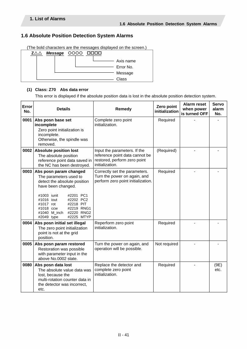
1. List of Alarms 1.6 Absolute Position Detection System Alarms
II - 41
1.6 Absolute Position Detection System Alarms
(The bold characters are the messages displayed on the screen.) Z Message
Axis name Error No. Message Class
(1) Class: Z70 Abs data error
This error is displayed if the absolute position data is lost in the absolute position detection system.
Error No. Details Remedy Zero point
initialization Alarm reset when power
is turned OFF
Servo alarm No.
0001 Abs posn base set incomplete
Zero point initialization is incomplete. Otherwise, the spindle was removed.
Complete zero point initialization.
Required - -
0002 Absolute position lost The absolute position reference point data saved in the NC has been destroyed.
Input the parameters. If the reference point data cannot be restored‚ perform zero point initialization.
(Required) - -
0003 Abs posn param changed The parameters used to detect the absolute position have been changed. #1003 iunit #2201 PC1 #1016 iout #2202 PC2 #1017 rot #2218 PIT #1018 ccw #2219 RNG1 #1040 M_inch #2220 RNG2 #2049 type #2225 MTYP
Correctly set the parameters. Turn the power on again‚ and perform zero point initialization.
Required - -
0004 Abs posn initial set illegal The zero point initialization point is not at the grid position.
Reperform zero point initialization.
Required - -
0005 Abs posn param restored Restoration was possible with parameter input in the above No.0002 state.
Turn the power on again‚ and operation will be possible.
Not required - -
0080 Abs posn data lost The absolute value data was lost, because the multi-rotation counter data in the detector was incorrect, etc.
Replace the detector and complete zero point initialization.
Required - (9E) etc.

1. List of Alarms 1.6 Absolute Position Detection System Alarms
II - 42
Error No. Details Remedy Zero point
initialization Alarm reset when power
is turned OFF
Servo alarm No.
0101 Abs posn error(servo alm 25) The power was turned ON again after the servo alarm No. 25 displayed.
Reperform zero point initialization.
Required - (25)
0106 Abs posn error(servo alm E3)
The power was turned ON again after the servo alarm No. E3 displayed.
Reperform zero point initialization.
Required - (E3)
(Note) To release alarm "Z70 Abs data error", enter the parameter data output when establishing the
absolute position and turn ON the power again. For the rotary axis, however, the alarm cannot be released by entering the parameter data.
(2) Class: Z71 Abs encoder failure
This alarm is displayed if an error is found in the detector for the absolute position detection system.
Error No. Details Remedy Zero point
initialization Alarm reset when power
is turned OFF
Servo alarm No.
0001 AbsEncoder:Backup voltage drop
The backup voltage in the absolute position detector dropped.
Replace the battery‚ check the cable connections‚ and check the detector. Turn the power ON again‚ and perform zero point initialization.
Required - (Z70-0101
displays after power is
turned ON again.)
25
0003 AbsEncoder: Commu error Communication with the absolute position detector was not possible.
Check and replace the cables‚ card or detector. Turn the power ON again‚ and perform zero point initialization.
(Required) Only when detector is replaced.
Reset 91
0004 AbsEncoder: Abs data changed
The absolute position data fluctuated when establishing the absolute position.
Check and replace the cables‚ card or detector. Turn the power ON again‚ and perform zero point initialization.
(Required) Only when detector is replaced.
Reset 93
0005 AbsEncoder: Serial data error
An error was found in the serial data from the absolute position detector.
Check and replace the cables‚ card or detector. Turn the power ON again‚ and perform zero point initialization.
(Required) Only when detector is replaced.
Reset 92
0006 AbsEncoder: Abs/inc posn diffr
Servo alarm E3 Absolute position counter warning
Operation is possible until the power is turned off.
(Required) When power is turned ON
again.
Reset (Z70-0106
displays after power is
turned ON again.)
E3
0007 AbsEncoder: Initial commu err
Initial communication with the absolute position detector was not possible.
Check and replace the cables‚ card or detector. Turn the power ON again‚ and perform zero point initialization.
(Required) Only when detector is replaced.
Reset 18

1. List of Alarms 1.6 Absolute Position Detection System Alarms
II - 43
(3) Class: Z72 Message: Position check error
This alarm is displayed if an error is detected when comparing the detector's absolute position and controller coordinate values in the absolute position system.
(4) Class: Z73 Message: Absolute position data warning
This warning is displayed for the absolute position detection system.
Alarm No. Details Remedy
0001 Battery for abs data fault Servo alarm 9F Low battery voltage
If the battery voltage is low or the cable is damaged, there is no need to initialize the absolute position.
(Note) When this alarm occurs, do not turn OFF the drive unit power to protect the absolute position data.
Replace the battery while the drive unit power is ON.
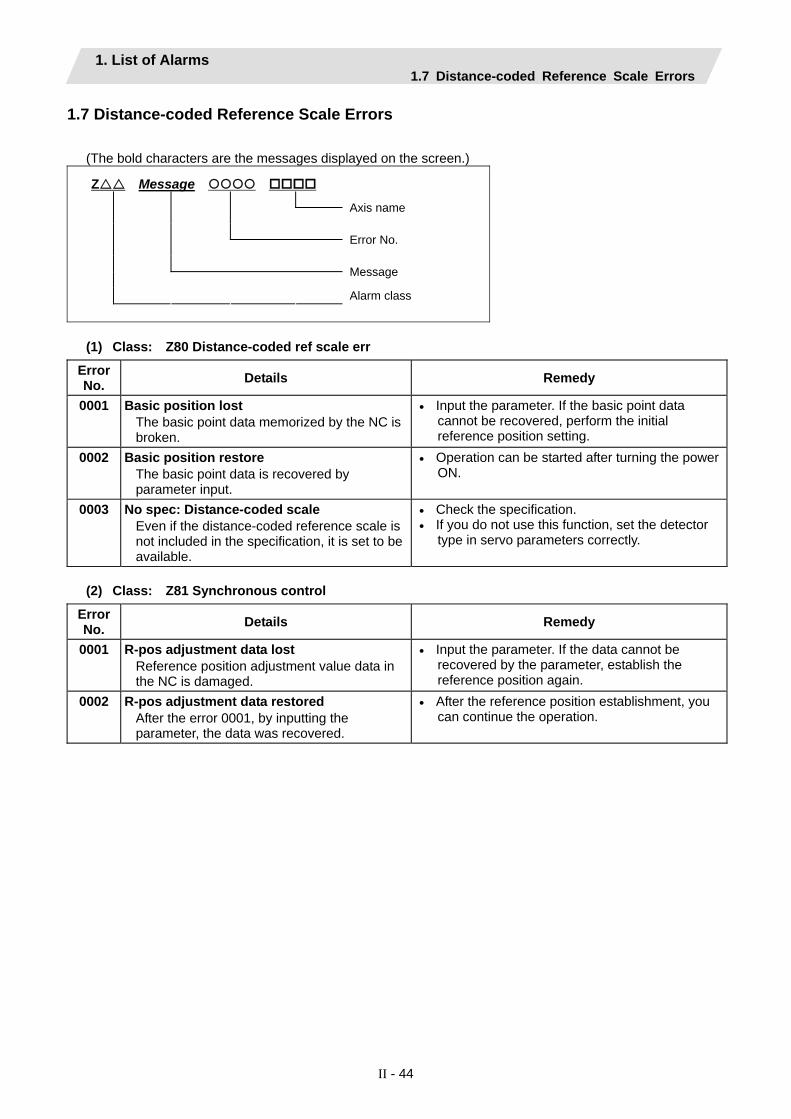
1. List of Alarms 1.7 Distance-coded Reference Scale Errors
II - 44
1.7 Distance-coded Reference Scale Errors
(The bold characters are the messages displayed on the screen.)
Z Message
Axis name
Error No.
Message
Alarm class
(1) Class: Z80 Distance-coded ref scale err
Error No. Details Remedy
0001 Basic position lost The basic point data memorized by the NC is broken.
• Input the parameter. If the basic point data cannot be recovered, perform the initial reference position setting.
0002 Basic position restore The basic point data is recovered by parameter input.
• Operation can be started after turning the power ON.
0003 No spec: Distance-coded scale Even if the distance-coded reference scale is not included in the specification, it is set to be available.
• Check the specification. • If you do not use this function, set the detector
type in servo parameters correctly.
(2) Class: Z81 Synchronous control
Error No. Details Remedy
0001 R-pos adjustment data lost Reference position adjustment value data in the NC is damaged.
• Input the parameter. If the data cannot be recovered by the parameter, establish the reference position again.
0002 R-pos adjustment data restored After the error 0001, by inputting the parameter, the data was recovered.
• After the reference position establishment, you can continue the operation.

1. List of Alarms 1.8 Messages during Emergency Stop
II - 45
1.8 Messages during Emergency Stop (The bold characters are the messages displayed on the screen.)
EMG Emergency stop Error items
Error Item Details Remedy
PLC The user PLC has entered the emergency stop state during the sequence process.
• Investigate and remove the cause of the user PLC emergency stop.
EXIN The emergency stop input signal for machine operation board or handy terminal is significant (open).
• Cancel the emergency stop input signal. • Check the wiring to see if any wiring is broken.
SRV An alarm occurred in the servo system causing an emergency stop.
• Investigate and remove the cause of the servo alarm.
STOP The user PLC (ladder sequence) is not running. • Check if the rotary switch CS2 on the top of the controller front panel is set to 1.
• Check if the PLC edit file save screen (onboard function) [4RUN/SP] (run/stop) switch is turned ON.
SPIN Spindle drive unit not mounted The spindle drive unit is not mounted.
• Cancel the causes of the other emergency stop.
• Check emergency stop signal input in the spindle drive unit.
PC_H High-speed PC processing abnormal • Check the sequence program. (To stop monitoring the high-speed PC processing temporarily, set 1 in "#1219 aux03/bit1". Disable the monitoring function only as a temporary measure.)
PARA Setting of the door open II fixed device is illegal.The dog signal random assignment parameter setting is illegal.
• Specify the "#1155 DOOR_m" and "#1156 DOOR_s" parameters correctly. (When the door open II fixed device is not used, set "#1155 DOOR_m" and "#1156 DOOR_s" to "100".)
• Correctly set the "#2073 zrn_dog", "#2074 H/W_OT+", "#2075 H/W_OT-" and "#1226 aux10/bit5" parameters.

1. List of Alarms 1.8 Messages during Emergency Stop
II - 46
Error No. Details Remedy
LINK If the FROM/TO instruction is not executed within 500 ms, an emergency stop occurs.
• Try to execute the FROM or TO instruction one or more times every 500 ms.
* Measure the time in which no interrupt request is issued from MELSEC and store the result in the R register. R10190: Current time-out counter R10191: Counter for maximum time-out after
power-on R10192: Counter for maximum time-out after
system start-up (backed up) MELSEC is held in error and reset states. • Check the MELSEC states.
The contents of MELSEC-specific code area in buffer memory have been destroyed.
• Check the MELSEC states.
PLC serial link communication has stopped.
(Note) When "WAIT" is entered for the PLC serial link, only the preparation sequence has been established before the communication stops. Therefore, it is supposed that the basic specification parameters related to serial link parameters #1902 and #1903 are incorrect or the #1909 set-time is too short.
• Check that HR571 card wiring and external sequencer transmission are normal.
• Check the diagnostic screen for link communication errors.
• Check whether the basic specification parameters related to serial link parameters are specified correctly.
WAIT The preparation sequence is not sent from the master station. Otherwise, the contents of the received preparation sequence are inconsistent with those of the parameters, so that the usual sequence cannot be started.
(Note) When "LINK" is also entered for the PLC serial link, refer to "Note" in the section, "LINK".
• Check that the HR571 card rotary switch and wiring and the external sequencer transmission are normal.
• Check the diagnostic screen for link communication errors.
XTEN The HR571 card operates abnormally or the rotary switch is set incorrectly.
• Check the HR571 card rotary switch and replace the HR571 card if required.
LAD The user PLC (ladder sequence) has an illegal code.
• Check the user PLC (ladder sequence) to see if it uses illegal device numbers or constants.
CVIN The external emergency stop function for power supply is valid. So, the emergency stop input signal for power supply is significant (open).
• Cancel the emergency stop input signal. • Check the wiring to see if any wiring is broken.
MCT An emergency stop occurs because the contactor shutoff test is executing.
• Automatically cancel the emergency stop after the contactor shutoff is confirmed.
• When the contactor shutoff cannot be confirmed within 5 seconds after contactor shutoff test signal (Y742) is input, "Y20 Contactor welding detected" alarm will occur, and the emergency stop status remains.
• Turn the power ON again after confirming "contactor's auxiliary b contact" signal is correctly output to the device that is set with "#1330 MC_dp1" and "#1331 MC_dp2".

1. List of Alarms 1.9 Auxiliary Axis Alarms
II - 47
1.9 Auxiliary Axis Alarms Refer to "1.3 Servo/spindle alarms" for details of the alarm class and alarm clear class combination. (The bold characters are the messages displayed on the screen.)
S Message Axis No. 1 to 4 Alarm information (Follows MR-J2-CT alarm information) Message Alarm class
(1) Class: S01 Aux ax servo alarm
Alarm information Details Remedy
0011 Aux ax PCB err (Drive circuit) An error occurred in the drive unit's internal PCB.
• Replace servo drive unit.
0013 Aux ax S/W processing error An error occurred in the drive unit's internal reference clock.
• Replace servo drive unit.
Aux ax motor/detector type err 0016 Motor type error. • Use a correct drive unit and motor
combination. Detector initial communication error. • Connect correctly.
• Replace the motor. • Replace or repair cable.
Detector CPU error. • Replace the motor (detector). 0017 Aux ax PCB error(A/D err)
An error occurred in the drive unit's internal A/D converter.• Replace servo drive unit.
0025 Aux ax absolute posn lost An error occurred in the detector's internal absolute position data.
• Turn the power ON for 2 to 3 minutes while the alarm is occurring, and then turn the power ON again.
• Replace the battery, and initialize the absolute position again.
0034 Aux ax CRC error An error occurred in the communication with the NC.
• Take countermeasures against noise.
0036 Aux ax communication timeout Communication with the NC was cut off.
• Connect correctly. • Turn the NC power ON. • Replace the drive unit or NC.
0037 Aux ax parameter error The parameter setting value is incorrect.
• Set the parameter correctly.
0038 Aux ax frame error An error occurred in the communication with the NC.
• Take countermeasures against noise.
0039 Aux ax commu INFO error Undefined data was transferred from the NC.
• Change the NC software version to a compatible version.

1. List of Alarms 1.9 Auxiliary Axis Alarms
II - 48
(2) Class: S02 Aux ax servo alarm
Alarm information Details Remedy
0011 Aux ax PCB err (Drive circuit) An error occurred in the drive unit's internal PCB.
• Replace servo drive unit.
0013 Aux ax S/W processing error An error occurred in the drive unit's internal reference clock.
• Replace servo drive unit.
0015 Aux ax EEROM error A write error occurred to the EEROM in the drive unit.
• Replace servo drive unit.
0017 Aux ax PCB error(A/D err) An error occurred in the drive unit's internal A/D converter.
• Replace servo drive unit.
0018 Aux ax PCB error(LSI err) An error occurred in the drive unit's internal LSI.
• Replace servo drive unit.
0020 Aux ax detector error An error occurred in the communication between the servo drive unit and detector.
• Connect correctly. • Replace or repair cable.
0024 Aux ax ground fault detection A ground fault of the output was detected when the power was turned ON.
• Repair the ground fault section. • Replace the cable or motor.
(3) Class: S03 Aux ax servo alarm
Alarm information Details Remedy
0010 Aux ax under voltage The power voltage is 160V or less.
• Review the power supply. • Replace the servo drive unit.
0030 Aux ax regeneration error
The tolerable regeneration power of the internal regenerative resistor or external regenerative option was exceeded.
• Set the parameter #50002 correctly. • Connect correctly. • Lower the positioning frequency. • Change the regenerative option to
a larger capacity. • Lower the load. • Review the power supply.
Regenerative transistor error • Replace the servo drive unit.
0031 Aux ax overspeed The motor's rotation speed exceeded the tolerable momentary speed.
• Increase the acceleration/ deceleration time constant.
• Review the gear ratio. • Replace the detector.
0032 Aux ax overcurrent A current exceeding the servo drive unit's tolerable current flowed.
• Repair the wiring. • Replace the servo drive unit. • Take countermeasures against
noise.

1. List of Alarms 1.9 Auxiliary Axis Alarms
II - 49
Alarm
information Details Remedy
0033 Aux ax overvoltage The voltage of the converter in the servo drive unit was 400V or more.
• Wire correctly. • Replace the servo drive unit. • For the internal regenerative
resistor, replace the drive unit. • For the external regenerative option,
replace the regenerative option. 0046 Aux ax motor overheating
An operation state causing the motor to overheat continued.
• Reduce the motor load. • Review the operation pattern.
0050 Aux ax overload 1 The servo drive unit or servomotor overload protection function activated.
• Reduce the motor load. • Review the operation pattern. • Change to a motor or drive unit
with large output. • Change the setting of the
automatic tuning response characteristics.
• Correct the connection. • Replace the servomotor.
0051 Aux ax overload 2 The max. output current flowed for several seconds due to a machine collision or overload.
• Review the operation pattern. • Change the setting of the
automatic tuning response characteristics.
• Correct the connection. • Replace the servomotor.
0052 Aux ax excessive error A position deflection exceeding the excessive error detection setting value occurred.
• Increase the acceleration/ deceleration time constant.
• Increase the torque limit value. • Review the power facility capacity.• Review the operation pattern. • Replace the servomotor. • Connect correctly. • Repair or replace the cable.

1. List of Alarms 1.9 Auxiliary Axis Alarms
II - 50
(4) Class: S52 Message: Aux ax servo warning
Alarm information Details Remedy
0092 Aux ax battery voltage drop The absolute position detection battery voltage dropped.
• Mount a battery. • Replace the battery and initialize
the absolute position.
00E0 Aux ax overregeneration warning The regeneration power may have exceeded the tolerable range of the built-in regenerative resistor or external regenerative option.
• Lower the positioning frequency. • Change the regenerative option to
a larger one. • Lower the load.
00E1 Aux ax overload warning The overload alarm 1 could occur.
• Refer to the items for S03 0050.
00E3 Aux ax abs position counter warning There is an error in the absolute position detector internal data.
• Take countermeasures against noise.
• Replace the servomotor.
00E9 Aux ax main circuit OFF warning The servo ON signal was input while the main circuit power was OFF. The contactor operation is faulty.
• Turn ON the main circuit power.
(5) Class: Z70 Message: Aux ax abs position error
Alarm information Details Remedy
0001 Aux ax abs posn base set incomplete The zero point (reference point) has not been initialized in the absolute position system.
• Initialize the zero point (reference point).
0002 Aux ax absolute position lost The absolute position coordinate data in the drive unit has been lost.
• Initialize the zero point (reference point).
0003 Aux ax abs posn param changed The absolute position system related parameters have been changed or lost.
• Correctly set the parameters and then initialize the zero point (reference point).
(6) Class: Z71 Message: Aux ax drop voltage
Alarm information Details Remedy
0001 Aux ax abs encoder: back up voltage drop The data in the detector has been lost. Battery voltage drop. Detector cable wire breakage or looseness.
• Check the battery and detector cable and then initialize the zero point (reference point).

1. List of Alarms 1.9 Auxiliary Axis Alarms
II - 51
(7) Class: Z73 Message: Aux ax system warning
Alarm information Details Remedy
0001 Aux ax battery for abs data fault Battery voltage drop. Detector cable wire breakage or looseness.
• Check the battery and detector cable. The zero point does not need to be initialized.
0003 Aux ax absolute position counter warning An error occurred in the detector's absolute position counter.
• Replace the detector.
(8) Class: M00 Aux ax operation error
Alarm information Details Remedy
0001 Aux ax dog overrun When executing dog-type reference position, the zero point return speed is too fast or the dog length is too short.
• Lower the zero point return speed or increase the dog length.
0003 Aux ax R-pnt direction illegal When executing reference position return, the axis was moved in the opposite of the designated direction.
• Move the axis in the correct direction.
0004 Aux ax external interlock The axis interlock function is valid.
• Cancel the interlock signal
0005 Aux ax internal interlock An interlock was established by the servo OFF function.
• Cancel the servo OFF.
0007 Aux ax soft limit The soft limit was reached.
• Check the soft limit setting and machine position
0024 Aux ax R ret invld at abs alm Reference position return was executed during an absolute position alarm.
• Initialize the absolute position reference point and then fix the absolute position coordinates.
0025 Aux ax R ret invld at ini Reference position return was executed while initializing the absolute position.
• Initialize the absolute position reference point and then fix the absolute position coordinates.
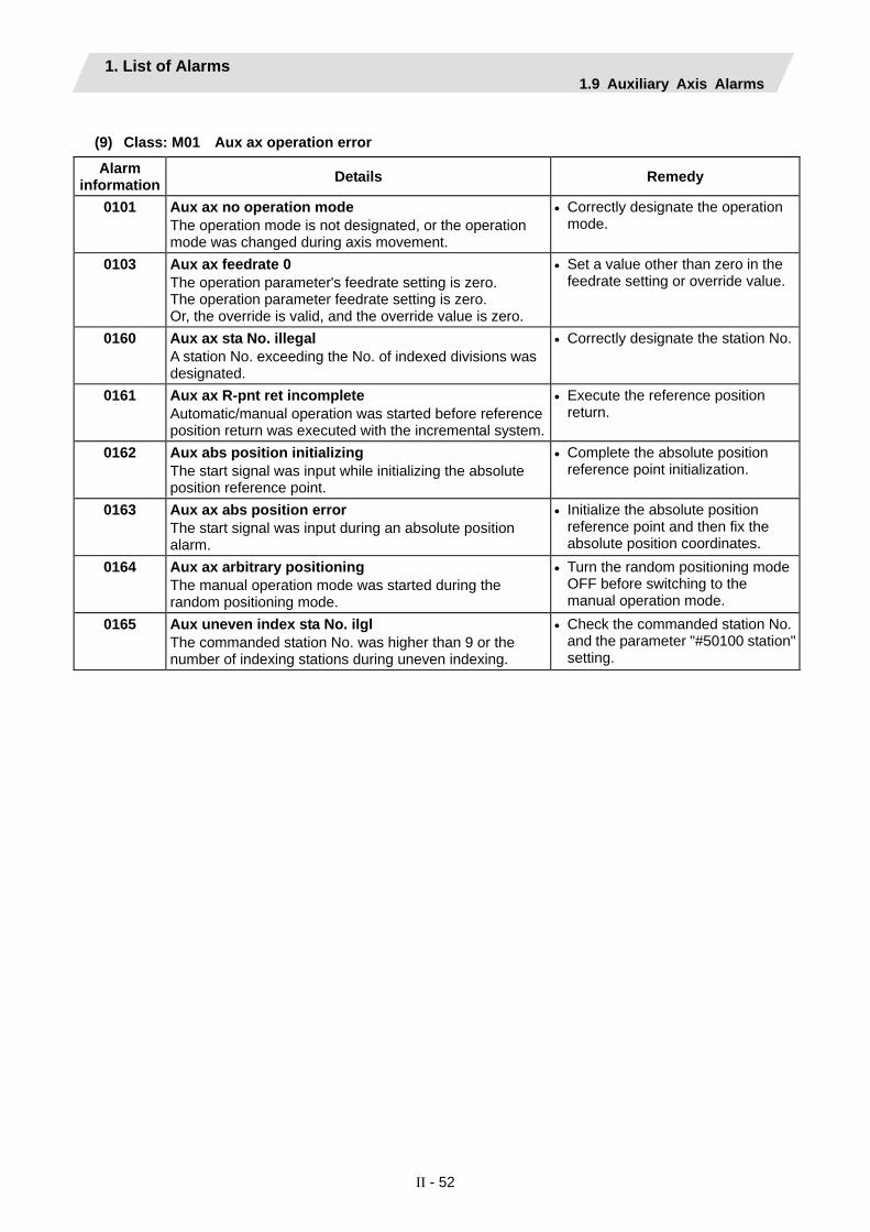
1. List of Alarms 1.9 Auxiliary Axis Alarms
II - 52
(9) Class: M01 Aux ax operation error
Alarm information Details Remedy
0101 Aux ax no operation mode The operation mode is not designated, or the operation mode was changed during axis movement.
• Correctly designate the operation mode.
0103 Aux ax feedrate 0 The operation parameter's feedrate setting is zero. The operation parameter feedrate setting is zero. Or, the override is valid, and the override value is zero.
• Set a value other than zero in the feedrate setting or override value.
0160 Aux ax sta No. illegal A station No. exceeding the No. of indexed divisions was designated.
• Correctly designate the station No.
0161 Aux ax R-pnt ret incomplete Automatic/manual operation was started before reference position return was executed with the incremental system.
• Execute the reference position return.
0162 Aux abs position initializing The start signal was input while initializing the absolute position reference point.
• Complete the absolute position reference point initialization.
0163 Aux ax abs position error The start signal was input during an absolute position alarm.
• Initialize the absolute position reference point and then fix the absolute position coordinates.
0164 Aux ax arbitrary positioning The manual operation mode was started during the random positioning mode.
• Turn the random positioning mode OFF before switching to the manual operation mode.
0165 Aux uneven index sta No. ilgl The commanded station No. was higher than 9 or the number of indexing stations during uneven indexing.
• Check the commanded station No. and the parameter "#50100 station"setting.

1. List of Alarms 1.9 Auxiliary Axis Alarms
II - 53
(10) Class: Y02 Auxiliary axis MCP alarms An error occurred during data transfer between the MCP and auxiliary axis drive unit after turning on the power.
Error No. Details Remedy 0050 Aux ax sys alm: Proc time over The software or hardware may be damaged.
Contact the service center. 0000 Aux ax commu er:CRC error 1
(10 times/910.2ms) 0001 Aux ax commu er:CRC error 2
(2 continuous times) 0002 Aux ax commu er:Recv timing
(2 continuous times) xx03 Aux ax commu er:Data ID
(2 continuous times) xx: Axis No.
0051
xx04 Aux ax commu er:Recv frame no. (2 continuous times) xx: Axis No.
A communication error has occurred between the controller and drive unit. • Take measures against noise. • Check that the communication cable connector
between the controller and drive unit and one between the drive unit are tight.
• Check whether the communication cable between the controller and drive unit and one between the drive units are disconnected.
• A driving drive unit may be faulty. Take a note of the 7-segment LED contents of each driving drive unit and report to the Service Center.
(11) Class: Y03 Message: Aux ax drive unit unequipped The drive unit is not properly connected.
Error No. Details Remedy Axis No.
1 to 4 bit correspondence (bit 0: 1st axis, bit 1: 2nd axis, bit 2: 3rd axis, bit 3: 4th axis)
Check the auxiliary axis drive unit mounting state. • Check the end of the cable wiring. • Check the cable for broken wires. • Check the connector insertion. The auxiliary axis drive unit input power is not being input. The auxiliary axis drive unit axis No. switch is illegal.

1. List of Alarms 1.10 Computer Link Errors
II - 54
1.10 Computer Link Errors
(The bold characters are the messages displayed on the screen.)
L Message
Error No.
Message
Alarm class
(1) Class: L01 Computer link error
Error No. Details Remedy
-2 Serial port being used Serial port has already being opened or cannot be used.
• Check whether the same port being used by Anshin-net, etc.
• Recheck the parameters for tape operation port.-4 Timeout error
Communication ends with timeout CNC has a 248-byte receive buffer. The time during which CNC receives 248 bytes exceeds the "TIME-OUT" value set in the I/O device parameter.
• Set a greater timeout value in the input/output device parameter.
• Recheck the HOST software as to whether or not the HOST transmits data in response to DC1 from CNC (data request).
• Check whether or not start code of computer link parameter is set to 0.
-10 Host ER signal OFF HOST ER (CNC DR) signal is not turned ON.
• Check whether or not the cable is disconnected from the connector.
• Check whether or not the cable is broken. • Check whether or not the HOST power is turned
ON. -15 Parity H error
Communication ends with parity H. • Recheck the HOST software as to whether or not
the data to be transmitted to CNC is ISO code. -16 Parity V error
Communication ends with parity V. • Recheck the data to be transmitted to CNC.
-17 Overrun error Although CNC transmits DC3 (request to stop data transfer) to the HOST, it receives data of 10 bytes or more from the HOST, thus terminates communication. When CNC is transmitting data to the HOST, it receives data of 10 bytes or more from the HOST.
• Recheck the software as to whether or not the HOST stops transmitting data within 10 bytes after receiving DC3.
• Recheck the HOST software as to whether or not the HOST transmits data such as a command or header to CNC during receiving a work program.

1. List of Alarms 1.11 User PLC Alarms
II - 55
1.11 User PLC Alarms
(The bold characters are the messages displayed on the screen.) U Message
Sub-status 2Sub-status 1Message Alarm class
Sub-status Message 1 2
Details Remedy
U01 No user PLC
- - PLC program is not input. (Note) Emergency stop (EMG) will
be applied.
Download the PLC program of the format selected with the PLC environment selection parameters (bit selection #51/bit 4).
0x0010 - PLC scan time error The scan time is 1 second or longer.
Edit the PLC program size to a smaller size.
0x0040 - PLC program operation mode illegal
PLC program different from the designated mode was downloaded.
(Note) Emergency stop (EMG) will be applied.
Download the PLC program having the same format as when the power was reset or turned ON.
0x0080 - GPPW ladder code error (Note) Emergency stop (EMG) will
be applied.
Download the correct GPPW format PLC program.
0x008x - PLC4B ladder code error An illegal circuit was found in the PLC4B ladder. bit1: PC medium-speed circuit
illegal bit2: PC high-speed circuit illegal
(Note) Emergency stop (EMG) will be applied.
Download the correct PLC4B format PLC program.
U10 Illegal PLC
0x0400 Number of ladder steps
Software illegal interrupt The PLC program process stopped abnormally due to an illegal software command code.
(Note) Emergency stop (EMG) will be applied.
Turn the power ON again. If the error is not reset, download the correct PLC program.

1. List of Alarms 1.11 User PLC Alarms
II - 56
Sub-status Message
1 2 Details Remedy
Software exception The PLC program process stopped abnormally due to a bus error, etc.
bit 0: BIN command operation errorbit 1: BCD command operation
error
Refer to the methods for using the BCD and BIN function commands.
U10 Illegal PLC
0x800x Number of PLC program steps
bit6: CALL/CALLS/RET command error
bit7: IRET command execution error
(Note) Emergency stop (EMG) is applied for bit 6/7.
Turn the power ON again. If the error is not reset, download the correct PLC program.
U50 PLC stopped
The PLC program is stopped. Start the PLC program.
U55 PLC stopped / is not saved
The PLC program is stopped and not written into ROM.
Write the PLC program into ROM.
U60 Ladder is not saved
The PLC program is not written into ROM.
Write the PLC program into ROM.
(Note) The number of PLC program steps displayed on the screen may not match the actual number of error
occurrence steps because of the PLC program timing. Use this as a guideline of the occurrence place.
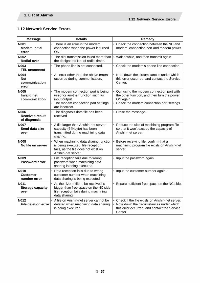
1. List of Alarms 1.12 Network Service Errors
II - 57
1.12 Network Service Errors
Message Details Remedy N001
Modem initial error
• There is an error in the modem connection when the power is turned ON.
• Check the connection between the NC and modem, connection port and modem power.
N002 Redial over
• The dial transmission failed more than the designated No. of redial times.
• Wait a while, and then transmit again.
N003 TEL unconnect
• The phone line is not connected. • Check the modem’s phone line connection.
N004 Net communication error
• An error other than the above errors occurred during communication.
• Note down the circumstances under which this error occurred, and contact the Service Center.
N005 Invalid net communication
• The modem connection port is being used for another function such as input/output.
• The modem connection port settings are incorrect.
• Quit using the modem connection port with the other function, and then turn the power ON again.
• Check the modem connection port settings.
N006 Received result of diagnosis
• The diagnosis data file has been received
• Erase the message.
N007 Send data size over
• A file larger than Anshin-net server capacity (64Kbyte) has been transmitted during machining data sharing.
• Reduce the size of machining program file so that it won't exceed the capacity of Anshin-net server.
N008 No file on server
• When machining data sharing function is being executed, file reception fails, as the file does not exist on Anshin-net server.
• Before receiving file, confirm that a machining program file exists on Anshin-net server.
N009 Password error
• File reception fails due to wrong password when machining data sharing is being executed.
• Input the password again.
N010 Customer number error
• Data reception fails due to wrong customer number when machining data sharing is being executed.
• Input the customer number again.
N011 Storage capacity over
• As the size of file to be received is bigger than free space on the NC side, file reception fails during machining data sharing.
• Ensure sufficient free space on the NC side.
N012 File deletion error
• A file on Anshin-net server cannot be deleted when machining data sharing is being executed.
• Check if the file exists on Anshin-net server.• Note down the circumstances under which
this error occurred, and contact the Service Center.

2. Operation Messages 2.1 Search-related Operation Messages
II - 58
2. Operation Messages The following messages display on each screen.
2.1 Search-related Operation Messages Message Details
Searching • The operation search is being executed. Search completed • The operation search was completed correctly. Verifying • The program is being verified. Verifying stopped • The program verification stopped. Search error • Could not find the designated ONB number.
Review the ONB number or machining program settings. • The operation search could not be completed correctly. • When the parameter (#9005) of the tape mode port was set out of the
range or when the port was not connected, an operation search of NC serial was performed.
• The T code list search failed. Review the program name. • Could not find the machining program in HD or IC card. • Check the parameters for HD operation or IC card operation. • Tape search was executed during the HOST LINK communication.
Setting error • The directory name exceeded the display range. A directory path for which the entire directory cannot be displayed cannot be designated in the directory name area.
• The search is not possible because ONB number is not designated.Restart search is completed • The restart search was completed. Executing restart search • The restart search is being executed. Execute operation search • The program is not searched.
Execute the operation search. Can't cancel verify stop • The compare stop cannot be canceled because the operation is not
in a compare stop. Executing top search • The top search is being executed correctly. Top search completed • The top search was completed correctly. Top search not completed • The restart search (type 2) was executed without the top search. Can't input data • Data input was attempted during M, S, T, B history display. Input some of ONB • Awaiting ONB number input Verifying stop posn already registered
• The verify stop position has already been registered.
No searched program • The program has not been searched. Program restarting • The program is being restarted. Program error • The restart search was executed in the program with an error. N/B block not found • The restart search was executed, designating N or B No. not exist. Restart search interrupted by reset
• Reset was executed during the restart search.
No. of repetitions exceeded • The restart search was executed, designating the number of repetitions exceeding the number set in the program.
Program not found • The restart search was executed, designating a program No. not exist.

2. Operation Messages 2.2 Graphic Display-related Operation Messages
II - 59
2.2 Graphic Display-related Operation Messages
Message Details Searching • The check search is being executed.
Search error • Could not find the designated ONB number. Review the ONB number or machining program settings.
• The check search could not be completed correctly. • When the parameter (#9005) of the tape mode port was set out of the
range or when the port was not connected, an operation search of NC serial was performed.
Executing automatic operation • An attempt was made to perform operations such as parameter, tool compensation amount data and coordinate system offset settings during auto operation. (Input/output also possible during auto operation)
• The machining program and MDI data that the operator is attempting to edit cannot be edited during auto operation.
• It is not possible to be executed a check search or check start-up during auto operation.
• An attempt was made to set the verify stop position during auto operation.
Setting error • The directory name exceeded the display range. A directory path for which the entire directory cannot be displayed cannot be designated in the directory name area.
• The check search is not possible because ONB number is not designated.
• A non-existent axis name or setting that does not exist in the format was made when making the display mode settings. Set using an existing axis name.
• Incorrect tool No. was specified at the execution of tool clear. Execute operation search • The program is not searched.
Execute the operation search. Checking • The program check is being executed. Check stopped • The program check is being stopped. Work form is illegal • A workpiece is not drawn correctly because the two or more
workpiece widths are set to "0". Push [Check reset] menu • An error occurred in the graphic check.
Press the [Check reset] menu key to reset the error. Executing trace • The trace mode is valid. Program check completed • The trace in the program check completed with an M02/M30 code. Reset complete • The program check was reset. Tool interfere with work • The tool contacted the workpiece when performing rapid traverse
(G0) movement with the interference check enabled. Program checking • The program check is being executed. Executing reset operation • The program check is being reset. Executing trace(tip posn) • The tip position trace mode is valid. Executing BG simulation • The back ground simulation is being executed. Draw library inside error (n) • Contact the service center.

2. Operation Messages 2.3 Variable (Common variables, local variables) - related Operation Messages
II - 60
Message Details
Program check not possible • Graphic check was attempted during the Computer link B operation.Execute check search • The program check is disabled. Execute the check search. Solid check disabled (memory shortage)
• The 3D program check is disabled due to the memory shortage. Separate the programs and execute the check drawing again. Press the menu [Work init] once before performing the check drawing again.
2.3 Variable (Common variables, local variables) - related Operation Messages Message Details
Erase? (Y/N) • Message to confirm the line erase. [Y] or [INPUT] : Variables are deleted. [N] : Variables are not deleted.
2.4 PLC Switch-related Operation Messages
Message Details Set up parameter ?(Y/N) • Message to confirm the parameter setup.
[Y] or [INPUT] : It will be possible to make settings. [N] : It will not be possible to make settings.
2.5 Compensation-related (Tool compensation, coordinate system offset) Operation
Messages Message Details
Erase? (Y/N) • Message to confirm the erasing. [Y] or [INPUT] : Erase the data. [N] : Do not erase the data.
Clear all axes? (Y/N) • Message to confirm the all axes clear. [Y] or [INPUT] : Clear the data for all axes. [N] : Do not clear the data.
Cannot return to origin • Operations other than line paste, paste and data input cannot be undone.
• It is the initial state. Cannot undo. • The last operation was performed in another part system. Cannot
undo the operation. Clear all? (Y/N) • Message to confirm the clearing the all data.
[Y] or [INPUT] : Clear all data. [N] : Do not clear the data.
Input P number • The coordinate system [Coord G54.1 P] menu was pressed. • The expansion workpiece coordinate system P No. was input.
Data clear complete • Clearing of the collection data is complete. Execute the collection data clear?
• Determines whether to clear the collection data. Press [Y] or [INPUT] to clear the data.

2. Operation Messages 2.6 Data Input/Output-related Operation Messages
II - 61
2.6 Data Input/Output-related Operation Messages Message Details
Overwrite this file?(Y/N) • Message to confirm the overwriting. [Y] or [INPUT] : Overwrite the file. [N] : Do not overwrite the file.
Over run error • The buffer overran or overflowed. Memory over • The program cannot be written, because the memory capacity will be
exceeded. Edit lock B • It is not possible to change machining program B (8000 to 8999: user
standard subprogram) or machining program C (9000 to 9999: machine tool builder custom program) as edit lock B is enabled.
Edit lock C • It is not possible to change machining program C (9000 to 9999: machine tool builder custom program) as edit lock C is enabled.
Can't make directory on this device
• Creation of a directory was attempted for a device that cannot have adirectory.
Designated file does not exist • The file specified in device A, and B does not exist. • The applicable file does not exist in the specified directory.
The file name is a directory • A directory was designated for the file transfer. A directory cannot betransferred.
Change complete • The data conversion completed correctly. Changing • The data is being converted. Erase complete • The file has been erased. Erase ended. Some file not erased
• The file erasing completed, but there are some files that could not beerased.
Verify error • An error occurred when performing a file verification.
Compare error. Compare next file?(Y/N)
• Message to confirm the comparison [Y] or [INPUT] : Compare the next file. [N] : Do not compare the next file.
Compare complete • The data comparison completed. Verifying • The data is being compared. The file already exists • The input file name already exists.
• The file name after renaming already exists. Can't erase designated file • Erasing was attempted of a file that cannot be erased. Can't rename designated file • An attempt was made to change the name of a file that cannot be
renamed.
Can't condense designated file • Condensing of a file that cannot be condensed was attempted.
Designated file is locked • Changing was attempted of a locked file. Can't open file for dev A • Could not find the file for device A.
Or, the file is in a state in which it cannot be accessed. Can't open file for dev B • Could not find the file for device B.
Or, the file is in a state in which it cannot be accessed. Can't read file for dev A • Could not read in the file for device A.
Recheck the connection status for device A or the input/outputparameter setting.
Can't read file for dev B • Could not read in the file for device B. Recheck the connection status for device B or the input/output parameter setting.
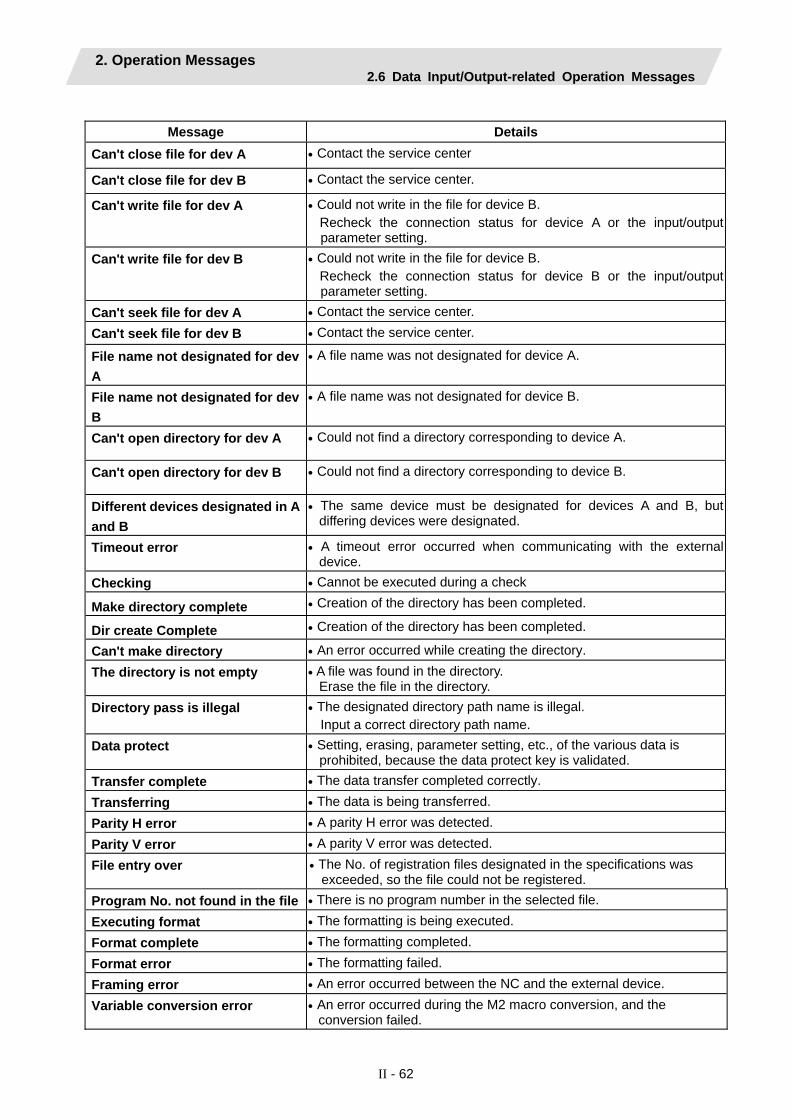
2. Operation Messages 2.6 Data Input/Output-related Operation Messages
II - 62
Message Details
Can't close file for dev A • Contact the service center
Can't close file for dev B • Contact the service center.
Can't write file for dev A • Could not write in the file for device B. Recheck the connection status for device A or the input/output parameter setting.
Can't write file for dev B • Could not write in the file for device B. Recheck the connection status for device B or the input/output parameter setting.
Can't seek file for dev A • Contact the service center. Can't seek file for dev B • Contact the service center.
File name not designated for dev A
• A file name was not designated for device A.
File name not designated for dev B
• A file name was not designated for device B.
Can't open directory for dev A • Could not find a directory corresponding to device A.
Can't open directory for dev B • Could not find a directory corresponding to device B.
Different devices designated in A and B
• The same device must be designated for devices A and B, but differing devices were designated.
Timeout error • A timeout error occurred when communicating with the external device.
Checking • Cannot be executed during a check
Make directory complete • Creation of the directory has been completed.
Dir create Complete • Creation of the directory has been completed.
Can't make directory • An error occurred while creating the directory. The directory is not empty • A file was found in the directory.
Erase the file in the directory. Directory pass is illegal • The designated directory path name is illegal.
Input a correct directory path name. Data protect • Setting, erasing, parameter setting, etc., of the various data is
prohibited, because the data protect key is validated. Transfer complete • The data transfer completed correctly. Transferring • The data is being transferred. Parity H error • A parity H error was detected. Parity V error • A parity V error was detected. File entry over • The No. of registration files designated in the specifications was
exceeded, so the file could not be registered. Program No. not found in the file • There is no program number in the selected file. Executing format • The formatting is being executed. Format complete • The formatting completed. Format error • The formatting failed. Framing error • An error occurred between the NC and the external device. Variable conversion error • An error occurred during the M2 macro conversion, and the
conversion failed.

2. Operation Messages 2.6 Data Input/Output-related Operation Messages
II - 63
Message Details
Merge complete • The data merge completed. Merge execution • The data merge is being executed. Memory alloc error • Securing of the communication data range failed. Rename complete • The rename has been completed.
OK? (Y/N) • Message to confirm the operation. [Y] or [INPUT] : Execute the operation
[N] : Cancel the operation.
I/O not ready • An error occurred between the NC and the external device. I/O parameter error • The external device settings and input/output parameters do not
match. I/O port busy • Input/output was not possible as the I/O port is busy. FD write protect • The FD is write-protected.
Release the write protection. PLC running • An attempt was made to input a user PLC during PLC RUN.
• Stop the PLC on the maintenance screen. FD not ready • An attempt was made to perform an FD operation search with no FD.
• An attempt was made to display the FD list with no FD. MemoryCard not ready • An attempt was made to perform operations with no memory card.
DS not ready • An attempt was made to perform operations with no data server.
Can't write in READ-ONLY file • Contact the service center.
Condense complete • Condensing has been completed.
A directory does not exist • The specified directory does not exist.
Setting complete normally • Decryption code setting file of the credit system was set normally.

2. Operation Messages 2.7 Parameter-related Operation Messages
II - 64
2.7 Parameter-related Operation Messages Message Details
Designate copy end posn • The copy start position was specified using the cursor. Continue and specify the copy end position using the cursor.
Copy start posn and end posn reversed
• When the copy range was designated, a position before the startposition was designated as the end position.
Columns of copy start and end different
• A different column (axis or part system) was specified for the copy start/end position at the screen with the arrangement configuration for each axis and part system.
Copy range is inadequate • Could not find the parameter No. for the copy start position. • A value larger than the last parameter No. was designated as the
copy end position parameter No. Check the designated copy range.
Setting error • The port is already being used. • The parameter HOST LINK was turned ON during the Anshin-net
communication. Setting error: column n • The nth column setting data is inappropriate when multiple axes were
set at the same time (/ division). (Settings have been made up to the (n-1)th column.)
Password is illegal • The password designated for displaying the Machine Parameter screen is illegal.
Input the password • The menu key for first displaying the Machine Parameter screen was pressed after the power was turned ON.
Paste error • An attempt was made to paste in a different parameter from the copy parameter.
Paste? (Y/N) • Message to confirm the operation when pasting. [Y] or [INPUT] : Paste the data at the current cursor position. [N] : Do not paste the data.
Data protect • Setting, erasing, parameter settings, etc., of the various data is prohibit, because the data protect key is validated.
Executing automatic operation • An attempt was made to make parameter settings during auto operation.
Can't select • The password designated for displaying the machine parameters hasnot been input.
• Display of the machine parameters was attempted on the [Param No.] menu, but the password has not been input. Press the [Machine param] menu, and input the password fordisplaying the machine parameters.
No odd number for R register start No.
• An odd number cannot be used for R register start No. Use an even number.
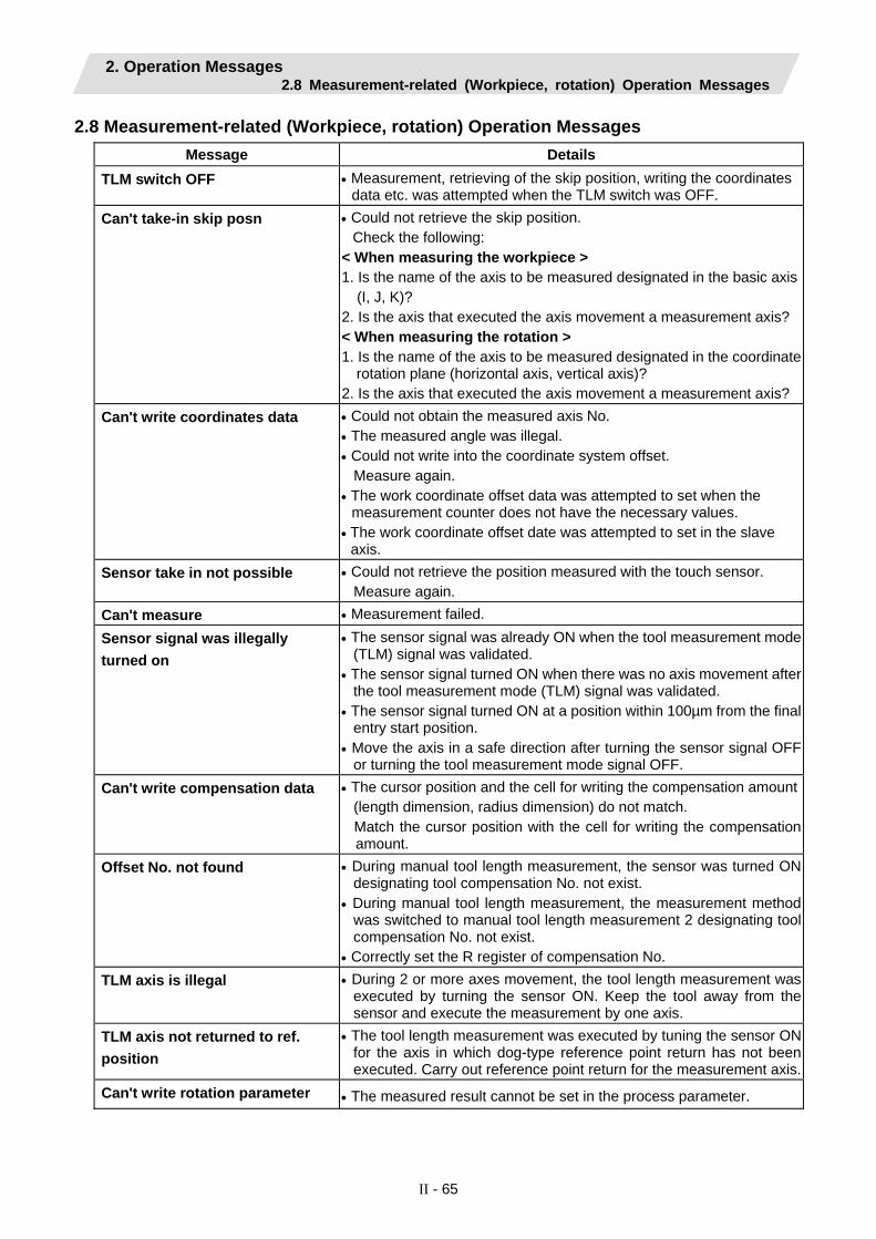
2. Operation Messages 2.8 Measurement-related (Workpiece, rotation) Operation Messages
II - 65
2.8 Measurement-related (Workpiece, rotation) Operation Messages Message Details
TLM switch OFF • Measurement, retrieving of the skip position, writing the coordinates data etc. was attempted when the TLM switch was OFF.
Can't take-in skip posn • Could not retrieve the skip position. Check the following:
< When measuring the workpiece > 1. Is the name of the axis to be measured designated in the basic axis
(I, J, K)? 2. Is the axis that executed the axis movement a measurement axis? < When measuring the rotation > 1. Is the name of the axis to be measured designated in the coordinate
rotation plane (horizontal axis, vertical axis)? 2. Is the axis that executed the axis movement a measurement axis?
Can't write coordinates data • Could not obtain the measured axis No. • The measured angle was illegal. • Could not write into the coordinate system offset.
Measure again. • The work coordinate offset data was attempted to set when the
measurement counter does not have the necessary values. • The work coordinate offset date was attempted to set in the slave
axis. Sensor take in not possible • Could not retrieve the position measured with the touch sensor.
Measure again. Can't measure • Measurement failed. Sensor signal was illegally turned on
• The sensor signal was already ON when the tool measurement mode(TLM) signal was validated.
• The sensor signal turned ON when there was no axis movement afterthe tool measurement mode (TLM) signal was validated.
• The sensor signal turned ON at a position within 100µm from the finalentry start position.
• Move the axis in a safe direction after turning the sensor signal OFFor turning the tool measurement mode signal OFF.
Can't write compensation data • The cursor position and the cell for writing the compensation amount(length dimension, radius dimension) do not match. Match the cursor position with the cell for writing the compensationamount.
Offset No. not found • During manual tool length measurement, the sensor was turned ONdesignating tool compensation No. not exist.
• During manual tool length measurement, the measurement methodwas switched to manual tool length measurement 2 designating toolcompensation No. not exist.
• Correctly set the R register of compensation No. TLM axis is illegal • During 2 or more axes movement, the tool length measurement was
executed by turning the sensor ON. Keep the tool away from thesensor and execute the measurement by one axis.
TLM axis not returned to ref. position
• The tool length measurement was executed by tuning the sensor ONfor the axis in which dog-type reference point return has not beenexecuted. Carry out reference point return for the measurement axis.
Can't write rotation parameter • The measured result cannot be set in the process parameter.

2. Operation Messages 2.8 Measurement-related (Workpiece, rotation) Operation Messages
II - 66
Message Details
Can't calculate center & angle for rot
• Three points necessary for calculation are not retrieved.
• Center shift amount or censor radius was failed to retrieve.
• Calculation of the center and the angle was failed.
Input 0 to coord center & angle for rot
• The center and the angle are not "0".
Set "0" in the parameter "#8623 Coord rot centr (H)", "#8624 Coord rot centr (V)" and "#8627 Coord rot angle".
Can't calculate • Hole center cannot be determined.
Meas axis not returned to ref. position
• The workpiece measurement was executed when dog-type reference point return has not been executed. Carry out reference point return for the measurement axis.

2. Operation Messages 2.9 Tool (Tool registration, tool life) -related Operation Messages
II - 67
2.9 Tool (Tool registration, tool life) -related Operation Messages Message Details
Designated group already exists • An already existing group No. was designated when changing thegroup No. (Tool life screen (grp))
• An already existing group No. was designated when newly creating the group. (Tool life screen (grp list)) Designate a group No. that does not already exist.
Designated group does not exist • Erasing was attempted on the Tool life screen (grp list) of a group thatdoes not exist.
Can't register group • The group registration process on the Tool life screen (grp list) failed.Can't delete group • The group deletion process on the Tool life screen (grp list) failed. Erase? (Y/N) • Message to confirm the erasing.
[Y] or [INPUT] : Erase the data [N] : Do not erase the data.
Delete all groups? (Y/N) • Message to confirm the erasing of all groups. [Y] or [INPUT] : Erase all groups [N] : Do not erase all groups.
Can't delete all groups • All groups' deletion cannot be executed because data protection key (KEY 1) is validated or automatic operation mode is validated, etc. during all groups' deletion. All groups' deletion cannot be executed because nothing has been registered to group, also.
Pot number not exist • The set pot number does not exist. Check the pot number.
Create new file? (Y/N) • Message to confirm the operation when newly creating data, files, etc. [Y] or [INPUT] : Newly create. [N] : Cancel the operation.
Input the tool number • Waiting tool number input. Clear not possible • The clear range is incorrect. Spindle/stndby tool display not possible
• The spindle standby cannot be displayed due to the user PLC setting.Contact the machine tool builder.
Format tool life data? (Y/N) • Determines whether to format the tool life management data. When [Y] is input, the formatting is executed.
Tool life format complete • The tool life management data formatting completed. Exists in spindle/standby. Set? (Y/N)
• An attempt was made to set the same No. as the tool No. for spindle/standby.
Exists in magazine 1. Set? (Y/N) • An attempt was made to set the same No. as the tool No. that has been registered to the valid magazine.
Exists in magazine 2. Set? (Y/N) • An attempt was made to set the same No. as the tool No. that has been registered to the valid magazine.
Exists in magazine 3. Set? (Y/N) • An attempt was made to set the same No. as the tool No. that has been registered to the valid magazine.
Exists in magazine 4. Set? (Y/N) • An attempt was made to set the same No. as the tool No. that has been registered to the valid magazine.
Exists in magazine 5. Set? (Y/N) • An attempt was made to set the same No. as the tool No. that has been registered to the valid magazine.

2. Operation Messages 2.10 Editing-related Operation Messages
II - 68
2.10 Editing-related Operation Messages Message Details
Buffer correct not possible • Buffer correction cannot be performed for this program. • Buffer correction was attempted during the BTR operation.
Can't write into file • Could not write the data to the memory with the buffer correction. Contact the service center.
Overwrite this file?(Y/N) • Message to confirm when registering MDI [Y] or [INPUT] : Overwrite the file. [N] : Do not overwrite the file.
Memory over • The program cannot be written, because the memory capacity will beexceeded.
Designated character string not found
• Could not find the search results and character string in the program.
Save current file ?(Y/N) • Message to confirm the saving. [Y] : Save the changes to the current file. [N] : Do not save the changes to the current file.
A file does not exist • An attempt was made to select and edit a non-existent file.
Executing • Following menu's process is executing now: "Line paste", "Line clear", "Undo", "String search", "String replace","Miss warning", or "Next miss".
Designated file does not exist • An attempt was made to select and erase a non-existent file. Erase complete • The data erasing completed. Can't erase designated file • The selected file cannot currently be erased. Designated file does not exist • A file that does not exist was designated when file editing. Designated file already exists • When creating a new file, a file name was designated that already
exists. Replace? (Y/N) • Message to confirm the character string replacement.
[Y] or [INPUT] : Replace the character string. [N] : Do not replace the character string.
File access error • Contact the Service Center. File open error • The designated file is already open. Editing • A program is being edited on the screen.
Save the program to write it into the memory. Program entry over • The program could not be registered in the memory when attempted,
because the No. of registrations designated in the specifications would be exceeded.
Block char nos over • The character number limitation in one block was exceeded.
Paste error • Pasting was attempted within the copy range of the same file.
Copy range is inadequate • The copy range designation is inadequate. Check whether the designated range exists.
• The range was designated exceeding 100 lines during mass editing.Area designation is inadequate
• The area designation is inadequate. Check whether the designated area exists.
Designated line is out of program range
• Designation was attempted of a line No. larger than the No. of lines inthe entire program.

2. Operation Messages 2.10 Editing-related Operation Messages
II - 69
Message Details
MDI no setting • Editing of the MDI was started, but the MDI setting was incomplete. Abs/Inc mode is illegal • During playback editing:
G90 was set when control parameter "Playback G90" was OFF. G91 was set when control parameter "Playback G90" was ON.
MDI search complete • The MDI search completed. Can't search in MDI mode • The restart search was attempted during MDI mode.
• Execute the restart search after switching other than MDI mode. MDI Set ended • MDI setting cannot be executed. MDI Setting error • MDI setting was completed. MDI search error • Could not execute the MDI search. MDI entry complete • MDI entry has been completed. Can't edit except in MDI mode • "#1144 mdlkof" (MDI setting lock) is "0" and therefore it is not possible
to edit the MDI program in a mode other than MDI mode. Input miss was detected • An input miss was detected. Input miss was not detected • A search was performed for an input miss, however, none was found.Can't edit a file except in NC memory
• Editing cannot be performed at the edit window for programs other than those in the NC memory.
Save it • The cursor was tried to move beyond the editable range during mass-editing. Save, then operate again.
Save not possible • A special file (history file etc.) that cannot be saved was edited and an attempt was made to save it. Perform an operation to quit editing.
• Failed saving due to file size over, etc. during mass-editing. • Setting of "#1166 fixpro" was illegal. Use the settings for a regular
program. • MDI cannot be entered due to MDI editing mode. Press INPUT key
and finish editing. Save left side file? (Y/N)
• Message to confirm whether saving the left side file of the multi-program display type [Y]: Save the change [N]: Do not save the change
Save right side file? (Y/N)
• Message to confirm whether saving the right side file of the multi-program display type [Y]: Save the change [N]: Do not save the change
Can't edit because of size over • The program cannot be written, because the memory capacity will beexceeded.
• If the memory capacity of the transfer designation device is exceeded during the automatic backup, increase the available memory of the device.
Can't edit the searched file • The serial file cannot be edited.
DS not ready
• Operation was attempted when a DS was not inserted. • Creating or opening a program was attempted when a DS was not
inserted. FD not ready
• The FD operation search was attempted when an FD was not inserted.
• The FD list display was attempted when an FD was not inserted. • Creating or opening a program was attempted when an FD was not
inserted.
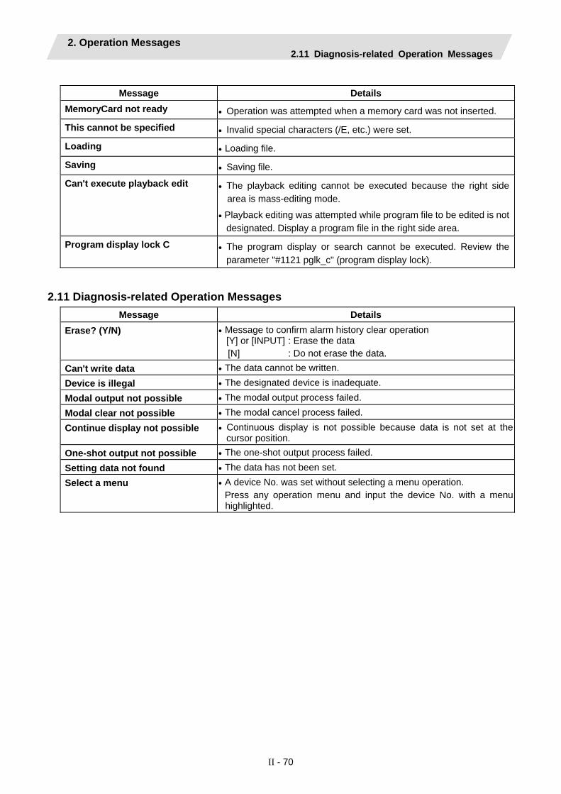
2. Operation Messages 2.11 Diagnosis-related Operation Messages
II - 70
Message Details
MemoryCard not ready • Operation was attempted when a memory card was not inserted.
This cannot be specified • Invalid special characters (/E, etc.) were set.
Loading • Loading file.
Saving • Saving file.
Can't execute playback edit • The playback editing cannot be executed because the right side area is mass-editing mode.
• Playback editing was attempted while program file to be edited is not designated. Display a program file in the right side area.
Program display lock C • The program display or search cannot be executed. Review the parameter "#1121 pglk_c" (program display lock).
2.11 Diagnosis-related Operation Messages Message Details
Erase? (Y/N) • Message to confirm alarm history clear operation [Y] or [INPUT] : Erase the data [N] : Do not erase the data.
Can't write data • The data cannot be written. Device is illegal • The designated device is inadequate. Modal output not possible • The modal output process failed. Modal clear not possible • The modal cancel process failed. Continue display not possible • Continuous display is not possible because data is not set at the
cursor position. One-shot output not possible • The one-shot output process failed. Setting data not found • The data has not been set. Select a menu • A device No. was set without selecting a menu operation.
Press any operation menu and input the device No. with a menuhighlighted.

2. Operation Messages 2.12 Maintenance-related Operation Messages
II - 71
2.12 Maintenance-related Operation Messages Message Details
Password is illegal • The input password is incorrect. Input password • The [Password] menu key was pressed, and the password input
mode was entered. Input a password.
Now making back-up • Currently backing up system data and the user PLC program to a specified device.
Backupping • The SRAM data is being backed up on the HD. Backup complete • Backup of the SRAM data on the HD has been completed.
• Back up of system data and user PLC program to a specified device has been completed.
Backup error • An error occurred while backing up the SRAM data on the HD. Select directory to backup
• Select area by moving cursor, using ↑ and ↓ keys.
Press the "INPUT" key to confirm.
Select directory to restore • Select file by moving cursor, using ↑ and ↓ keys. Press the "INPUT" key to confirm.
Executing format • The formatting is being executed correctly. Format complete • The formatting completed correctly. Format error • The NC memory formatting failed.
Contact the nearest service center. Quit HMI ?(Y/N) • Message to confirm the HMI quitting
[Y] or [INPUT] : Quit the HMI. [N] : Do not quit the HMI.
Format NC memory?(Y/N) • Message to confirm the NC memory formatting [Y] or [INPUT] : Start formatting the NC memory. [N] : Do not format the NC memory.
Execute SRAM backup ?(Y/N) • Message to confirm the SRAM back up [Y] or [INPUT] : The SRAM data is backed up to the HD. [N] : The SRAM data is not backed up to the HD.
PLC running. Does it stop? (Y/N) • Message to confirm the PLC STOP [Y] or [INPUT] : Backup the SRAM data on the HD. [N] : Do not backup the SRAM data on the HD.
Restoring • The system data and user PLC program are now being restored to the NC from a specified device.
Restore complete • Restoration of system data and user PLC program to the NC from a specified device has been completed.
Auto adjust error • The H/W status cannot be read properly, and therefore it is not possible to perform auto adjustments. Check the remote I/O unit. Perform manual adjustments.
• The unit is defective. Replace the unit. Change Ope. test mode • Operation of the Operation test screen was attempted when the
operation adjustment mode was not selected. Test mode sig valid signal is now OFF
• The operation adjustment mode cannot be selected because the operation adjustment mode valid signal (R9998/bit0) is 0.

2. Operation Messages 2.12 Maintenance-related Operation Messages
II - 72
Message Details
Auto adjust complete • Analog output adjustment completed normally. Auto adjust execution • Performing analog output adjustment normally. Execute? (Y/N) • Message to confirm the operation
[Y] or [INPUT] : The currently selected operation is performed. [N] : The currently selected operation is not performed.
Unit not equipped • The machine is not equipped with an analog output unit. A serial number is inaccurate • The system data to be restored and the serial number in the NC do
not match, and therefore it is not possible to restore. • Check to ensure that the serial number in the NC has been set and
that the system data to be restored matches. Operating aux axis • It is not possible to set parameter and input/output data during
auxiliary axis operation. • It is not possible to change the display axis during auxiliary axis
operation.
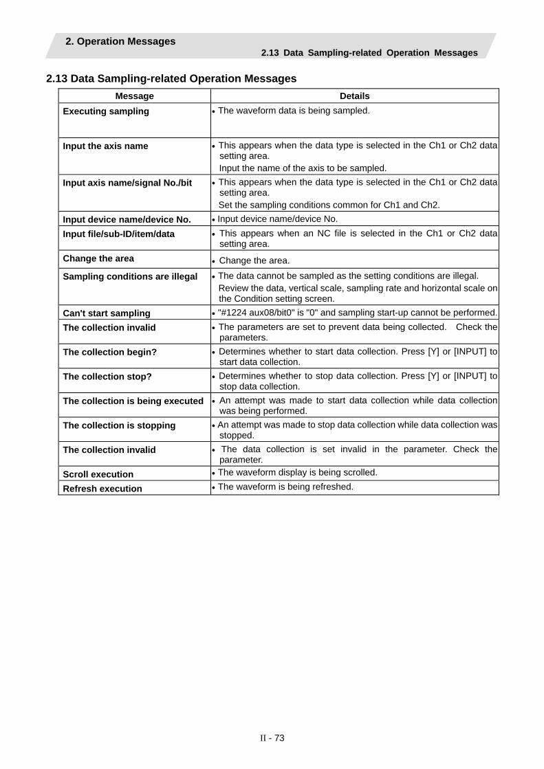
2. Operation Messages 2.13 Data Sampling-related Operation Messages
II - 73
2.13 Data Sampling-related Operation Messages Message Details
Executing sampling • The waveform data is being sampled.
Input the axis name • This appears when the data type is selected in the Ch1 or Ch2 datasetting area. Input the name of the axis to be sampled.
Input axis name/signal No./bit • This appears when the data type is selected in the Ch1 or Ch2 datasetting area. Set the sampling conditions common for Ch1 and Ch2.
Input device name/device No. • Input device name/device No. Input file/sub-ID/item/data • This appears when an NC file is selected in the Ch1 or Ch2 data
setting area. Change the area • Change the area.
Sampling conditions are illegal • The data cannot be sampled as the setting conditions are illegal. Review the data, vertical scale, sampling rate and horizontal scale on the Condition setting screen.
Can't start sampling • "#1224 aux08/bit0" is "0" and sampling start-up cannot be performed.The collection invalid • The parameters are set to prevent data being collected. Check the
parameters. The collection begin? • Determines whether to start data collection. Press [Y] or [INPUT] to
start data collection. The collection stop? • Determines whether to stop data collection. Press [Y] or [INPUT] to
stop data collection. The collection is being executed • An attempt was made to start data collection while data collection
was being performed. The collection is stopping • An attempt was made to stop data collection while data collection was
stopped. The collection invalid • The data collection is set invalid in the parameter. Check the
parameter. Scroll execution • The waveform display is being scrolled.
Refresh execution • The waveform is being refreshed.

2. Operation Messages 2.14 Absolute Position Detection-related Operation Messages
II - 74
2.14 Absolute Position Detection-related Operation Messages Message Details
Setting absolute position set • Setting from the screen was attempted of absolute position detection data when the "Absolute Position Set" was not ON. Press the menu key [Absolute Position Set] to turn it ON.
Not the abs position detection system
• An absolute position detection system has not been selected for thecurrently selected axis. The machine parameter (Axis specification parameter "#2049 type") must be set.
Axis name inappropriate • The set axis name is inappropriate. Check the axis name. Not passed on grid • The absolute position basic point was set without passing the grid
after the power ON in the dogless-type absolute position detection. Return one grid back and repeat the procedure.
Can't start • Settings of "#0 absolute posn set", "#2 Z-point" and "#2055 pushf" are not adequate.
• "AbsEncoder: Serial data error" alarm (Z71 0005) has occurred. Check the parameter and the alarm.
Illegal direction • JOG starting direction is illegal in the machine end stopper method of the dogless-type absolute position detection.
2.15 System Setup-related Operation Messages Message Details
Initial parameter creating • The initial parameter is being created.
Initial parameter transferring • The initial parameter is being transferred.
Spindle initial parameter transferring
• The spindle initial parameter is being transferred.
Can't write data • The data cannot be written. • Setting of the initial parameter failed. • Contact the service center.
Param set ended. Format NC memory? (Y/N)
• After completing the parameter setting, it determines whether executing the file format or not. Enter [Y] or [INPUT] to execute the file format.
Write sample ladder? (Y/N) • It determines whether executing writing the sample PLC program or not. Enter [Y] or [INPUT] to start writing the sample PLC program.
Sample ladder not found • The file to set the sample PLC program is lost. Contact the service center.

2. Operation Messages 2.16 Automatic Backup-related Operation Messages
II - 75
2.16 Automatic Backup-related Operation Messages Message Details
Auto backup disabled (Device illegal)
• Set a correct value in the device No. of the automatic backup device.
Auto backup disabled (No DS) • When turning ON the power next time, insert DS.
Auto backup disabled (No memory card)
• When turning ON the power next time, insert the memory card.
Auto backup proceeding • Wait for the automatic backup to complete.
Auto backup completed • The automatic back up is completed.
Memory over • The memory capacity of the transfer designation device was exceeded during the automatic backup. Increase the available memory of the transfer designation device.
File access error • A file access error occurred during the automatic backup. Contact the service center.
Can't make directory • The storage destination directory of the automatic backup data described in the custom definition file does not exist. Create the directory of the storage destination.
Write protect • The memory card is write-protected. Release the write protection.
2.17 Alarm History-related Operation Messages Message Details
The collection begin? (Y/N) • Determines whether to start alarm history. Press [Y] or [INPUT] tostart alarm history.
The collection stop? (Y/N) • Determines whether to stop alarm history. Press [Y] or [INPUT] tostop alarm history.
The collection is being executed • An attempt was made to start alarm history while alarm history was being performed.
The collection is stopping • An attempt was made to stop alarm history while alarm history was being stopped.
Execute the collection data clear?(Y/N)
• Determines whether to clear alarm history. Press [Y] or [INPUT] to clear alarm history.
Data clear complete • The alarm history cleared was completed. The collection begin • The alarm history was started. The collection stop • The alarm history was stopped.

2. Operation Messages 2.18 Anshin-net-related Operation Messages
II - 76
2.18 Anshin-net-related Operation Messages (1) Messages related to all Anshin-net screens
Message Details (None) Press one-touch call to
call the NC service. Do not turn the power OFF during the one-touch call.
• Communication has not been started. • A call is being placed with automatic alarm notification or one-touch call, and a call is being received from the NC service.
(2) Messages related to automatic alarm notification
Message Details dialing Do not turn the power OFF
until the automatic alarm notification ends.
• A call is being placed with automatic alarm notification.
• Communication starts when an alarm occurs, but the line is not connected yet in this state.
• This state is also entered when standing by for transmission.
• Communication has been started with emergency stop by the servo, spindle or PLC alarm, or by the establishment of the conditionsset in the parameters.
Waiting for dialing Do not turn the power OFF until the automatic alarm notification ends.
● Redialing since the NC service is using the line for other communication.
Verifying the user registration
Do not turn the power OFF until the automatic alarm notification ends.
• User authentication is being executed by the NC service side.
Connecting Do not turn the power OFF until the automatic alarm notification ends.
• The line is connected with automatic alarm notification.
Receiving Do not turn the power OFF until the automatic alarm notification ends.
• The diagnosis data is being received with automatic alarm notification.
Sending Do not turn the power OFF until the automatic alarm notification ends.
• The diagnosis data is being sent with automatic alarm notification.
Transmission completed
Press one-touch call to call the NC service. Do not turn the power OFF during the one-touch call.
• Automatic alarm notification has ended, and the line has been disconnected.
Reception completed Press one-touch call to call the NC service. Do not turn the power OFF during the one-touch call.
• Automatic alarm notification has ended, and the line has been disconnected.
• This is displayed when at least one file has been received.
(Status of communication with NC service)
Connecting with NC service. Wait for communication to end.
• In connection standby state since line is being used by Anshin-net.

2. Operation Messages 2.18 Anshin-net-related Operation Messages
II - 77
(3) Messages related to automatic alarm notification
Message Details Operator notice effective
If automatic operation stops while operator notification is valid, the designated telephone number will be contacted.
• Operator notification is valid. • If machining ends normally or abnormally in this
state, communication with operator notification will start.
Dialing Do not turn the power OFF until the operator notification ends.
• Data is being transmitted with operator notification.
• Communication will start when machining ends normally or abnormally, but the line is not connected yet in this state.
• This state is also entered when standing by for transmission.
Waiting for dialing Do not turn the power OFF until the operator notification ends.
• Redialing since the NC service is using the line for other communication.
Verifying the user registration
Do not turn the power OFF until the operator notification ends.
• User authentication is being executed by the NC service side.
Connecting Do not turn the power OFF until the operator notification ends.
• The line is connected with operator notification.
Receiving Do not turn the power OFF until the operator notification ends.
• The diagnosis data is being received with operator notification.
Sending Do not turn the power OFF until the operator notification ends.
• The diagnosis data is being sent with operator notification.
Transmission completed
Press one-touch call to call the NC service. Do not turn the power OFF during the one-touch call.
• Operator notification has ended, and the line has been disconnected.
Reception completed Press one-touch call to call the NC service. Do not turn the power OFF during the one-touch call.
• Operator notification has ended, and the line has been disconnected.
• This is displayed when at least one file has been received.
(Status of communication with NC service)
Connecting with NC service. Wait for communication to end.
• In connection standby state since line is being used by Anshin-net.

2. Operation Messages 2.18 Anshin-net-related Operation Messages
II - 78
(4) Messages related to automatic alarm notification
Message Details Carry out one-touch call? (Y/N)
Press "Y" to make a one-touch call and "N" to cancel. If the line is being in use, a connection with NC service will be established as soon as the line becomes idle.
• A connection with NC service has not been established.
• The system is confirming whether to actually make a one-touch call.
• This is displayed when the Call menu is pressed. Press Y or INPUT to execute one-touch call.
Message Details
Dialing Do not turn the power OFF until the one-touch call ends.
• Data is being transmitted with one-touch call. • Communication will start when one-touch call is
executed, but the line is not connected yet in this state.
• This state is also entered when standing by for transmission.
Waiting for dialing Do not turn the power OFF until the one-touch call ends.
• Redialing since the NC service is using the line for other communication.
Verifying the user registration
Do not turn the power OFF until the one-touch call ends.
• User authentication is being executed by the NC service side.
Connecting Do not turn the power OFF until the one-touch call ends.
• The line is connected with one-touch call.
Receiving Do not turn the power OFF until the one-touch call ends.
• The diagnosis data is being received with one-touch call.
Sending Do not turn the power OFF until the one-touch call ends.
• The diagnosis data is being sent with one-touch call.
Transmission completed
Press one-touch call to call the NC service. Do not turn the power OFF during the one-touch call.
• Communication with one-touch call has ended, and the line has been disconnected.
Reception completed Press one-touch call to call the NC service. Do not turn the power OFF during the one-touch call.
• Communication with one-touch call has ended, and the line has been disconnected.
• This is displayed when at least one file has been received.
(Status of communication with NC service)
Connecting with NC service. Wait for communication to end.
• In connection standby state since line is being used by Anshin-net.

2. Operation Messages 2.18 Anshin-net-related Operation Messages
II - 79
(5) Messages related to transmission request from NC service
Message Details Verifying the distination
Connecting with NC service. Wait for communication to end.
• User authentication is being executed by the NC system side.
Connecting Connecting with NC service. Wait for communication to end.
• The line is connected upon transmission request from NC service.
Receiving Connecting with NC service. Wait for communication to end.
• Data is being received upon transmission request from NC service.
Sending Connecting with NC service. Wait for communication to end.
• Data is being sent upon transmission request from NC service.
Transmission completed
Press one-touch call to call the NC service. Do not turn the power OFF during the one-touch call.
• Transmission request from NC service has been completed, and the line has been disconnected.
Reception completed Press one-touch call to call the NC service. Do not turn the power OFF during the one-touch call.
• Transmission request from NC service has been completed, and the line has been disconnected.
• This is displayed when at least one file or message has been received.
(6) Messages related to number 1 to 3 menu operations
Message Details (None) Press one-touch call to
call the NC service. Do not turn the power OFF during the one-touch call.
• The selected telephone No. will be set as the telephone No. to be notified to the NC service.
• Hereafter, the telephone No. set with one-touch call or operator notification will be notified to the NC service.
(7) Messages related to arbitrary number setting
Message Details (None) Input the telephone No. to
be notified. • The input telephone No. will be set as the
telephone No. to be notified to the NC service.• Hereafter, the telephone No. set with one-touch
call or operator notification will be notified to the NC service.

2. Operation Messages 2.18 Anshin-net-related Operation Messages
II - 80
(8) Messages related to sharing of machining data
Message Details Transmit by the set password?(Y/N)
• The line is not connected with NC service. • The system is confirming whether to transfer machining data. Press
"Y" or "INPUT" to transfer machining data, "N" to cancel. OK? (Y/N) • The line is not connected with NC service.
• The system is confirming whether to erase machining data. Press "Y" or "INPUT" to erase machining data, "N" to cancel.
dialing • A call is being placed. • "Transmit by the set password?(Y/N)" or "OK? (Y/N)" is shown.
Pressing "Y" or "INPUT" starts the communication. The line is not connected yet in this state.
Connecting • The line is connected for sharing of machining data. Transmitting • The machining data is being transmitted. Transmission completed • Machining data transmission has ended, and the line has been
disconnected. Receiving • The machining data is being received. Reception completed • Machining data reception has ended, and the line has been
disconnected. Erase complete • Machining data erasing has ended, and the line has been
disconnected. Waiting for dialing • In dialing standby state since the line is being used. Input the password • The password, which is required for the transmission/reception of
machining data, has not been set. Input the password set on the Anshin-net parameter 1 screen.
Input the user number • The user number, which is required for the transmission/reception of machining data, has not been set. Input the user number set on the Anshin-net parameter 1 screen.

2. Operation Messages 2.19 Messages Related to Machine Tool Builder Network System
II - 81
2.19 Messages Related to Machine Tool Builder Network System (1) Messages related to all Machine Tool Builder Network System (MTB net) Screens.
Message Details (None) Press the [Send] menu
when you transmit the diagnosis data to MTB. Don't turn OFF the power supply while transmitting.
• Communication has not been started.
Message Details Network service is connected • The settings of the MTB net parameter 1,2 cannot be changed
since the system is communicating with Call Center or machine tool builder. Set again after the communication has ended.
(2) Messages related to transmission of diagnosis data
Message Details Transmit diagnosis data? (Y/N)
Press Y (transmit the diagnosis data) or N (cancel).You'll connect with MTB when it gets available if line used.
• The system is confirming the transmission of diagnosis data.
dialing Don't turn OFF a power supply until diagnosis data transmission ends.
• The diagnosis data is being transmitted. • The line is not connected yet in this state.
Verifying the user registration
Don't turn OFF a power supply until diagnosis data transmission ends.
• The system is waiting for an authentication response from remote diagnosis tool kit.
Waiting for the reply Don't turn OFF a power supply until diagnosis data transmission ends.
• The line has been disconnected once, and the system is waiting for a connection with the machine tool builder.
Verifying the destination
Don't turn OFF a power supply until diagnosis data transmission ends.
• The line has been connected corresponding to the received call from the machine tool builder. The system is confirming the destination of connection.
Connecting Don't turn OFF a power supply until diagnosis data transmission ends.
• The system is connected or connecting with machine tool builder.
Transmitting Don't turn OFF a power supply until diagnosis data transmission ends.
• The diagnosis data is actually being transmitted.
Transmission completed
Press Y (transmit the diagnosis data) or N (cancel).You'll connect with MTB when it gets available if line used.
• The transmission of diagnosis data has ended, and the line has been disconnected.

2. Operation Messages 2.19 Messages Related to Machine Tool Builder Network System
II - 82
Message Details
Waiting for dialing Don't turn OFF a power supply until diagnosis data transmission ends.
• The machine tool builder is using the line for other communication.
(Status of communication with NC service)
Connecting with NC service. Please wait until the communication ends.
• In connection standby state since line is being used by Anshin-net.
(Status of communication with machine manufacturer)
Connecting with MTB. Please wait until the communication ends.
• In connection standby state since line is being used by the machine tool builder.
(3) Messages related to reception of the diagnosis results
Message Details Verifying the destination
Connecting with MTB. Please wait until the communication ends.
• The line has been connected corresponding to the received call from the machine tool builder. The system is confirming the destination of connection.
Connecting Connecting with MTB. Please wait until the communication ends.
• The system is connected or connecting with machine tool builder.
Receiving Connecting with MTB. Please wait until the communication ends.
• The diagnosis results are actually being received.
Reception completed Press the [Send] menu when you transmit the diagnosis data to MTB. Don't turn OFF the power supply while transmitting.
• Reception of the diagnosis results has ended, and the line has been disconnected.
(4) Messages related to reception of messages
Message Details Verifying the destination
Connecting with MTB. Please wait until the communication ends.
• The line has been connected corresponding to the received call from the machine tool builder. The system is confirming the destination of connection.
Connecting Connecting with MTB. Please wait until the communication ends.
• The system is connected or connecting with machine tool builder.
Reception completed Press the [Send] menu when you transmit the diagnosis data to MTB. Don't turn OFF the power supply while transmitting.
• Reception of the message has ended, and the line has been disconnected.

2. Operation Messages 2.20 Other Operation Messages
II - 83
2.20 Other Operation Messages Message Details
Executing automatic operation • Cannot be performed during automatic operation. Perform the operation again after automatic operation has been completed.
Setting error • The setting data is inadequate. (Alphabetic characters were set where only numeric characters can be set, etc.)
• The data has not been set. • There is no specification.
Data range error • The input data exceeded the range. Set the value again within the range.
Data protect • Setting, erasing, parameter setting, etc., of the various data isprohibited, because the data protect key is validated. Reconsider the data protect key setting.
Write protect • Attempted to create a new program file in the write-protected device
• Opened the program file of the write-protected device
• Attempted to save the program file of the write-protected device
• Attempted to correct the buffer for the write-protected file.
• Attempted to edit or correct the buffer for the read-only program file.
Edit lock B • It is not possible to change machining program B (8000 to 8999: user standard subprogram) or machining program C (9000 to 9999: machine tool builder custom program) as edit lock B is enabled.
Edit lock C • It is not possible to change machining program C (9000 to 9999: machine tool builder custom program) as edit lock C is enabled.
Origin set not possible • The operation is in a state in which origin set is not possible. Check the parameter "#1123 origin (Origin set prohibited)" setting.
• Check that the axis has stopped. • Check that idling (post-reset status) is currently being performed.
Can't command manual value • The manual numerical value protect is valid and therefore it is not possible to perform a manual numerical value command.
Getting T code list • T code list is being retrieved.
T code list complete • Retrieving T code list is completed.
Load meter display not possible • The load meter cannot be displayed. Contact the machine tool builder.
Pallet running • Each setting was executed during pallet running.
APC executing • Each setting was executed during automatic pallet changer executing.

3. Program Error
II - 84
3. Program Error (The bold characters are the message displayed in the screen.) These alarms occur during automatic operation‚ and the causes of these alarms are mainly program errors which occur‚ for instance‚ when mistakes have been made in the preparation of the machining programs or when programs which conform to the specification have not been prepared.
Error No. Details Remedy
P 10 No. of simultaneous axes over The number of axis addresses commanded in the same block exceeds the specifications.
• Divide the alarm block command into two. • Check the specifications.
P 11 Illegal axis address The axis address commanded by the program and the axis address set by the parameter do not match.
• Revise the axis names in the program.
P 20 Division error An axis command which cannot be divided by the command unit has been issued.
• Check the program.
P 29 Not accept command The normal line control command (G40.1, G41.1, G42.1) has been issued during the modal in which the normal line control is not acceptable.
• Check the program.
P 30 Parity H error The number of holes per character on the paper tape is even for EIA code and odd for ISO code.
• Check the paper tape. • Check the tape puncher and tape reader.
P 31 Parity V error The number of characters per block on the paper tape is odd.
• Make the number of characters per block on the paper tape even.
• Set the parameter parity V selection OFF. P 32 Illegal address
An address not listed in the specifications has been used.
• Check and revise the program address. • Check and correct the parameters values. • Check the specifications.
P 33 Format error The command format in the program is not correct.
• Check the program.
Illegal G code A G code not listed in the specifications has been used. An illegal G code was commanded during the coordinate rotation command (G68).
• Check and correct the G code address in the program.
P 34
G51.2 or G50.2 was commanded when the rotary tool axis No. (#1501 polyax) was set to "0". G51.2 or G50.2 was commanded when the tool axis was set to the linear axis (#1017 rot "0").
• Check the parameter setting values.
P 35 Setting value range over The setting range for the addresses has been exceeded.
• Check the program.
P 36 Program end error "EOR" has been read during tape and memory mode.
• Enter the M02 and M30 command at the end of the program.
• Enter the M99 command at the end of the subprogram.

3. Program Error
II - 85
Error No. Details Remedy
P 37 O, N number zero A zero has been specified for program and sequence Nos.
• The program Nos. are designated across a range from 1 to 99999999.
• The sequence Nos. are designated across a range from 1 to 99999.
P 38 No spec: Add. Op block skip "/n" has been issued even though there are no optional block skip addition specifications.
• Check the specifications.
P 39 No specifications • A non-specified G code was specified. • The selected operation mode is not used.
• Check the specifications.
P 40 Pre-read block error When tool radius compensation is executed‚ there is an error in the pre-read block and so the interference check is disabled.
• Reconsider the program.
P 48 Restart pos return incomplete Movement command was executed before executing the block that is restart-searched.
• Carry out program restart again. Movement command cannot be executed before executing the block that is restart-searched.
P 49 Invalid restart search • Restart search was attempted for the
3-dimensional circular interpolation. • Restart search was attempted during the
cylindrical interpolation, polar coordinate interpolation, and tool tip center control.
• Reconsider the program. • Reconsider the restart search position.
P 50 No spec: Inch/Metric change Inch/Metric changeover (G20/G21) command was issued even though there is no inch/metric conversion specification.
• Check the specifications.
P 60 Compensation length over The commanded movement distance is excessive. (Over 231)
• Reconsider the axis address command.
P 61 No spec: Unidirectional posit. Unidirectional positioning (G60) was commanded even though there is no unidirectional positioning specification.
• Check the specifications.
P 62 No F command • No feed rate command has been issued. • There is no F command in the cylindrical
interpolation or polar coordinate interpolation immediately after the G95 mode is commanded.
• The default movement modal command at power ON is G01. This causes the machine to move without a G01 command if a movement command is issued in the program, and an alarm results. Use an F command to specify the feed rate.
• Specify F with a thread lead command. P 63 No spec: High-speed machining
High-speed machining cancel (G5P0) was commanded even though there is no high-speed machining mode specification.
• Check the specifications.
P 65 No spec: High speed mode 3 • Check the high-speed mode III specifications.

3. Program Error
II - 86
Error No. Details Remedy
P 70 Arc end point deviation large • There is an error in the arc start and end
points as well as in the arc center. • The difference of the involute curve through
the start point and the end point is large. • When arc was commanded, one of the two
axes configuring the arc plane was a scaling valid axis.
• Check the numerical values of the addresses that specify the start and end points, arc center as well as the radius in the program.
• Check the "+" and "-" directions of the address numerical values.
• Check the scaling valid axis.
P 71 Arc center error • The arc center is not sought during
R-specified circular interpolation. • The curvature center of the involute curve
cannot be obtained.
• Check the numerical values of the addresses in the program.
• Check whether the start point or end point is on the inner side of the base circle for involute interpolation. When carrying out tool radius compensation, check that the start point and end point after compensation are not on the inner side of the base circle for involute interpolation.
• Check whether the start point and end point are at an even distance from the center of the base circle for involute interpolation.
P 72 No spec: Herical cutting A helical command has been issued though it is not included in the specifications.
• Check the helical specifications. • An Axis 3 command was issued by the
circular interpolation command. If there is no helical specification, the linear axis is moved to the next block.
P 73 No spec: Spiral cutting A spiral command was issued despite the fact that such a command does not exist in the specifications.
• The G02.1 and G03.1 commands are issued for circular interpolation.
• Check the spiral specifications.
P 74 Can't calculate 3DIM arc The end block was not specified during 3-dimension circular interpolation supplementary modal, and therefore it is not possible to calculate the 3-dimension circular interpolation. Furthermore, it not possible to calculate the 3-dimension circular interpolation due to an interruption during 3-dimension circular interpolation supplementary modal.
• Reconsider the program.
P 75 3DIM arc illegal An unusable G code was issued during 3-dimension circular interpolation modal. Or, a 3-dimension circular interpolation command was issued during a modal for which a 3-dimension circular interpolation command cannot be issued.
• Reconsider the program.
P 76 No spec: 3DIM arc interpolat G02.4/G03.4 was commanded even though there is no 3-dimension circular interpolation specification.
• Check the specifications.
P80 No spec: Hypoth ax interpolat Hypothetical axis interpolation (G07) was commanded even though there is no hypothetical axis interpolation specification.
• Check the specifications.

3. Program Error
II - 87
Error No. Details Remedy
P 90 No spec: Thread cutting A thread cutting command was issued even though there is no thread cutting command specification.
• Check the specifications.
P 91 No spec: Var lead threading Variable lead thread cutting (G34) was commanded even though there is no variable lead thread cutting specification.
• Check the specifications.
P 93 Illegal pitch vaule The thread lead (thread pitch) when performing the thread cutting command is incorrect.
• Set the correct thread lead command for the thread cutting command.
P100 No spec: Cylindric interpolat A cylindrical interpolation command was issued even though there is no cylindrical interpolation specification.
• Check the specifications.
P110 Plane select during figure rot Plane selection (G17/G18/G19) was commanded during figure rotation.
• Check the machining program.
P111 Plane selected while coord rot Plane selection commands (G17, G18, G19) were issued during a coordinate rotation command (G68).
• After command G68, always issue a plane selection command following a G69 (coordinate rotation cancel) command.
P112 Plane selected while R compen • Plane selection commands (G17, G18,
G19) were issued while tool radius compensation (G41, G42) and nose R compensation (G41, G42, G46) commands were being issued.
• Plane selection commands were issued after completing nose R compensation commands when there are no further axis movement commands after G40, and compensation has not been cancelled.
• Issue plane selection commands after completing (axis movement commands issued after G40 cancel command) tool radius compensation and nose R compensation commands.
P113 Illegal plane select The circular command axis differs from the selected plane.
• Issue a circular command after correct plane selection.
P120 No spec: Feed per rotation Feed per rotation (G95) was commanded even though there is no feed per rotation specification.
• Check the specifications.
P121 F0 command during arc modal F0 (F 1-digit feed) was commanded during the arc modal (G02/G03).
• Check the machining program.
P122 No spec: Auto corner override An auto corner override command (G62) was issued even though there is no auto corner override specification.
• Check the specifications. • Delete the G62 command from the program.
P123 No spec: High-accuracy control High-accuracy control command was issued even though there is no high-accuracy control specification
• Check the specifications.

3. Program Error
II - 88
Error No. Details Remedy
P124 No spec: Inverse time feed There is no inverse time option.
• Check the specifications.
P125 G93 mode error • A G code command that cannot be issued
was issued during G93 mode. • G93 command was issued during a modal
for which inverse time feed cannot be performed.
• Reconsider the program.
P126 Invalid cmnd in high-accuracy An illegal command was issued during the high-accuracy control mode. • A G code group 13 command was issued
during the high-accuracy control mode. • Milling, cylindrical interpolation or pole
coordinate interpolation was commanded during the high-accuracy control mode.
• Reconsider the program.
P127 No spec: SSS Control The SSS control valid parameter was set to ON although there is no SSS control specification.
• Check the specifications. If there is no SSS control specification, set the parameter #8090 SSS ON to 0.
P130 2nd M function code illegal The 2nd miscellaneous function address commanded in the program differs from the address set in the parameters. miscellaneous function.
• Check and correct the 2nd miscellaneous function address in the program.
P131 No spec: Cnst surface ctrl G96 A constant surface speed control command (G96) was issued even though there is no specification.
• Check the specifications. • Change the constant surface speed control
command (G96) to a rotation speed command (G97).
P132 Spindle rotation speed S=0 No spindle rotation speed command has been issued.
• Reconsider the program.
P133 Illegal P-No. G96 An invalid constant surface speed control axis has been specified.
• Reconsider the parameter specified for the constant surface speed control axis.
P140 No spec: Pos compen cmd The position compensation command (G45 to G48) specifications are not available.
• Check the specifications.
P141 Pos compen during rotation Position compensation was commanded during the figure rotation or coordinate rotation command.
• Reconsider the program.
P142 Pos compen invalid arc A position compensation invalid arc command was commanded.
• Reconsider the program.

3. Program Error
II - 89
Error No. Details Remedy
P150 No spec: Nose R compensation • Even though there were no tool radius
compensation specifications, tool radius compensation commands (G41 and G42) were issued.
• Even though there were no nose R compensation specifications, nose R compensation commands (G41, G42, and G46) were issued.
• Check the specifications.
P151 Radius compen during arc mode A compensation command (G40‚ G41‚ G42‚ G43‚ G44‚ G46) has been issued in the arc modal (G02‚ G03).
• Issue the linear command (G01) or rapid traverse command (G00) in the compensation command block or cancel block. (Set the modal to linear interpolation.)
P152 No intersection In interference block processing during execution of a tool radius compensation (G41 or G42) or nose R compensation (G41‚ G42‚ or G46) command‚ the intersection point after one block is skipped cannot be determined.
• Reconsider the program.
P153 Compensation interference An interference error has arisen while the tool radius compensation command (G41‚ G42) or nose R compensation command (G41‚ G42‚ G46) was being executed.
• Reconsider the program.
P154 No spec: 3D compensation A three-dimensional compensation command was issued even though there are no three-dimensional compensation specifications.
• Check the specifications.
P155 Fixed cyc exec during compen A fixed cycle command has been issued in the radius compensation mode.
• The radius compensation mode is established when a fixed cycle command is executed and so the radius compensation cancel command (G40) should be issued.
P156 R compen direction not defined At the start of G46 nose R compensation‚ the compensation direction is undefined if this shift vector is used.
• Change the vector to that with which the compensation direction is defined.
• Exchange with a tool having a different tip point No.
P157 R compen direction changed During G46 nose R compensation‚ the compensation direction is inverted.
• Change the G command to that which allows inversion of the compensation direction (G00‚ G28‚ G30‚ G33‚ or G53).
• Exchange with a tool having a different tip point No.
• Turn ON the "#8106 G46 NO REV-ERR" parameter.
P158 Illegal tip point During G46 nose R compensation‚ the tip point is illegal (other than 1 to 8).
• Change the tip point No. to a legal one.

3. Program Error
II - 90
Error No. Details Remedy
P170 No offset number The compensation No. (DOO‚ TOO‚ HOO) command was not given when the radius compensation (G41‚ G42‚ G43‚ G46) command was issued. Alternatively‚ the compensation No. is larger than the number of sets in the specifications.
• Add the compensation No. command to the compensation command block.
• Check the number of compensation No. sets a correct it to a compensation No. command within the permitted number of tool compensation sets.
P171 No spec:Comp input by prog G10 Compensation data input by program (G10) was commanded even though there is no specification of compensation data input by program.
• Check the specifications.
P172 G10 L number error (G10 L-No. error) The L address command is not correct when the G10 command is issued.
• Check the address L-No. of the G10 command and correct the No.
P173 G10 P number error (G10 compensation error) When the G10 command is issued‚ a compensation No. outside the permitted number of sets in the specifications has been commanded for the compensation No. command.
• First check the number of compensation sets and then set the address P designation to within the permitted number of sets.
P174 No spec:Comp input by prog G11 Compensation data input by program cancel (G11) was commanded even though there is no specification of compensation data input by program.
• Check the specifications.
P177 Tool life count active Registration of tool life management data with G10 was attempted when the used data count valid signal was ON.
• The tool life management data cannot be registered when counting the used data. Turn the used data count valid signal OFF.
P178 Tool life data entry over The number of registration groups‚ total number of registered tools or the number of registrations per group exceeded the specifications range.
• Review the number of registrations.
P179 Illegal group No. • When registering the tool life management
data with G10‚ the group No. was commanded in duplicate.
• A group No. that was not registered was designated during the T 99 command.
• An M code command must be issued as a single command but coexists in the same block as that of another M code command.
• The M code commands set in the same group exist in the same block.
• The group No. cannot be commanded in duplicate. When registering the group data‚ register it in group units.
• Correct to the correct group No.
P180 No spec: Drilling cycle A fixed cycle command was issued though there are not fixed cycle (G72 - G89) specifications.
• Check the specifications. • Correct the program.

3. Program Error
II - 91
Error No. Details Remedy
P181 No spindle command (Tap cycle) The spindle rotation speed command has not been issued when the fixed cycle for drilling command is given. "S*****" type S command does not exist in the same block with the synchronous tapping cycle.
• Issue the spindle rotation speed command (S) when the fixed cycle for drilling command G84‚ G74 (G84‚ G88) is given.
• Enter "S*****" type S command.
P182 Synchronous tap error • Connection to the main spindle unit was not
established. • The synchronous tapping was attempted
with the spindle not serially connected under the multiple-spindle control I.
• Check connection to the main spindle. • Check that the main spindle encoder exists. • Set 1 to the parameter #3024 (sout).
P183 No pitch/thread number The pitch or thread number command has not been issued in the tap cycle of a fixed cycle for drilling command.
• Specify the pitch data and the number of threads by F or E command.
P184 Pitch/thread number error • The pitch or the number of threads per inch
is illegal in the tap cycle of the fixed cycle for drilling command.
• The pitch is too small for the spindle rotation speed.
• The thread number is too large for the spindle rotation speed.
• Check the pitch or the number of threads per inch.
P185 No spec: Sync tapping cycle Synchronous tapping cycle (G84/G74) was commanded even though there is no synchronous tapping cycle specification.
• Check the specifications.
P186 Illegal S cmnd in synchro tap S command was issued during synchronous tapping modal.
• Cancel the synchronous tapping before issuing the S command.
P190 No spec: Turning cycle A lathe cutting cycle command was input although the lathe cutting cycle was undefined in the specification.
• Check the specification. • Delete the lathe cutting cycle command.
P191 Taper length error In the lathe cutting cycle‚ the specified length of taper section is illegal.
• The radius set value in the lathe cycle command must be smaller than the axis shift amount.
P192 Chamfering error Chamfering in the thread cutting cycle is illegal.
• Set a chamfering amount not exceeding the cycle.
P200 No spec: MRC cycle The compound type fixed cycle for turning machining I (G70 to G73) was commanded when the compound type fixed cycle for turning machining I specifications were not provided.
• Check the specification.

3. Program Error
II - 92
Error No. Details Remedy
P201 Program error (MRC) • When called with a compound type fixed
cycle for turning machining I command, the subprogram contained at least one of the following commands:
• Reference position return command (G27, G28, G29, G30)
• Thread cutting (G33, G34) • Fixed cycle skip-function (G31, G31.n)
• The first move block of the finish shape program in compound type fixed cycle for turning machining I contains an arc command.
• Delete the following G codes from this subprogram that is called with the compound type fixed cycle for turning machining I commands (G70 to G73): G27‚ G28‚ G29, G30‚ G31‚ G33‚ G34, and fixed cycle G codes.
• Remove G2 and G3 from the first move block of the finish shape program in compound type fixed cycle for turning machining I.
P202 Block over (MRC) The number of blocks in the shape program of the compound type fixed cycle for turning machining I is over 50 or 200 (this differs according to the model).
• Specify 50 or a less value. The number of blocks in the shape program called by the compound type fixed cycle for turning machining I commands (G70 to G73) must be decreased below 50 or 200 (this differs according to the model).
P203 D cmnd figure error (MRC) The compound type fixed cycle for turning machining I (G70 to G73) shape program could not cut the work normally because it defined an abnormal shape.
• Check the compound type fixed cycle for turning machining I (G70 to G73) shape program.
P204 E cmnd fixed cycle error A command value of the compound type fixed cycle for turning machining (G70 to G76) is illegal.
• Check the compound type fixed cycle for turning machining (G70 to G76) command value.
P210 No spec: Pattern cycle A compound type fixed cycle for turning machining II (G74 to G76) command was input although it was undefined in the specification.
• Check the specification.
P220 No spec: Special fixed cycle No special fixed cycle specifications are available.
• Check the specifications.
P221 No. of special fixed holes = 0 A 0 has been specified for the number of holes in special fixed cycle mode.
• Reconsider the program.
P222 G36 angle error A G36 command specifies 0 for angle intervals.
• Reconsider the program.
P223 G12/G13 radius error The radius value specified with a G12 or G13 command is below the compensation amount.
• Reconsider the program.
P224 No spec: Circular (G12/G13) There are no circular cutting specifications.
• Check the specifications.
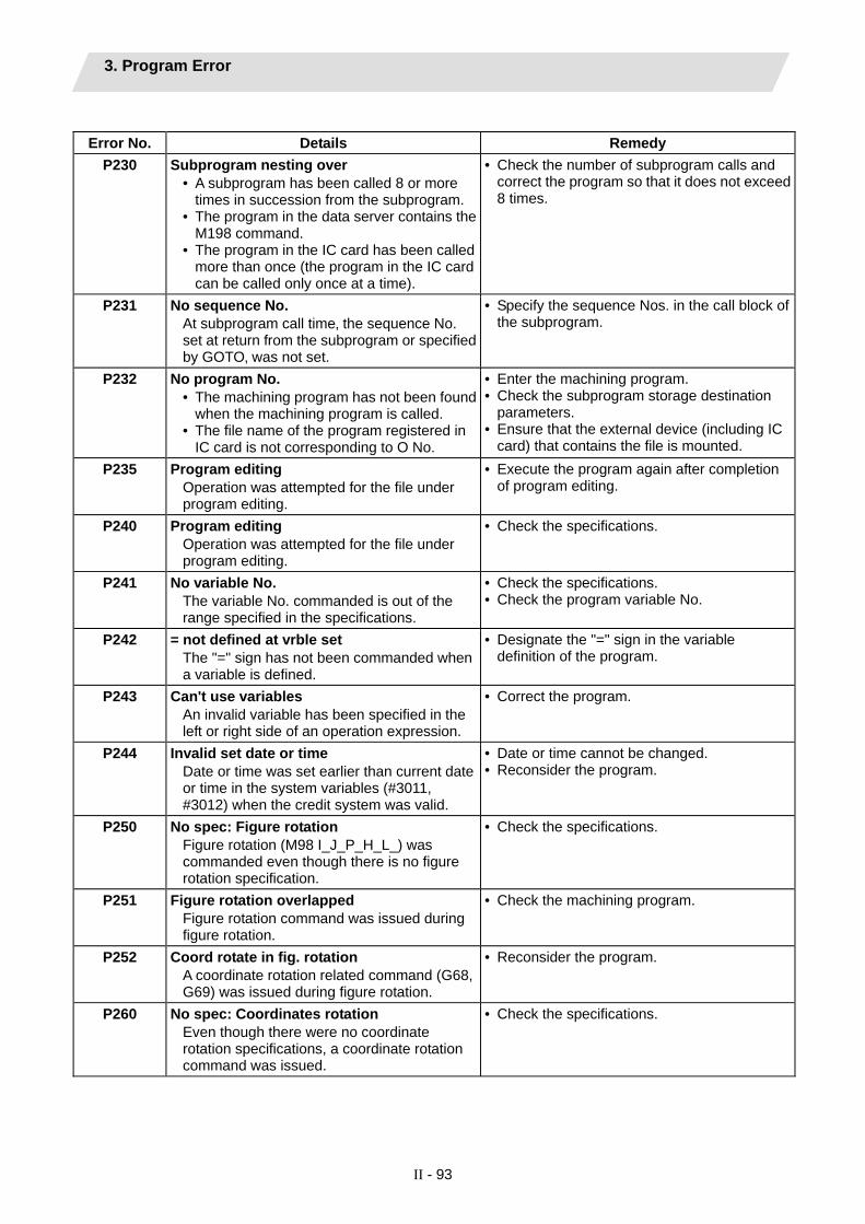
3. Program Error
II - 93
Error No. Details Remedy
P230 Subprogram nesting over • A subprogram has been called 8 or more
times in succession from the subprogram. • The program in the data server contains the
M198 command. • The program in the IC card has been called
more than once (the program in the IC card can be called only once at a time).
• Check the number of subprogram calls and correct the program so that it does not exceed 8 times.
P231 No sequence No. At subprogram call time‚ the sequence No. set at return from the subprogram or specified by GOTO‚ was not set.
• Specify the sequence Nos. in the call block of the subprogram.
P232 No program No. • The machining program has not been found
when the machining program is called. • The file name of the program registered in
IC card is not corresponding to O No.
• Enter the machining program. • Check the subprogram storage destination
parameters. • Ensure that the external device (including IC
card) that contains the file is mounted. P235 Program editing
Operation was attempted for the file under program editing.
• Execute the program again after completion of program editing.
P240 Program editing Operation was attempted for the file under program editing.
• Check the specifications.
P241 No variable No. The variable No. commanded is out of the range specified in the specifications.
• Check the specifications. • Check the program variable No.
P242 = not defined at vrble set The "=" sign has not been commanded when a variable is defined.
• Designate the "=" sign in the variable definition of the program.
P243 Can't use variables An invalid variable has been specified in the left or right side of an operation expression.
• Correct the program.
P244 Invalid set date or time Date or time was set earlier than current date or time in the system variables (#3011, #3012) when the credit system was valid.
• Date or time cannot be changed. • Reconsider the program.
P250 No spec: Figure rotation Figure rotation (M98 I_J_P_H_L_) was commanded even though there is no figure rotation specification.
• Check the specifications.
P251 Figure rotation overlapped Figure rotation command was issued during figure rotation.
• Check the machining program.
P252 Coord rotate in fig. rotation A coordinate rotation related command (G68, G69) was issued during figure rotation.
• Reconsider the program.
P260 No spec: Coordinates rotation Even though there were no coordinate rotation specifications, a coordinate rotation command was issued.
• Check the specifications.
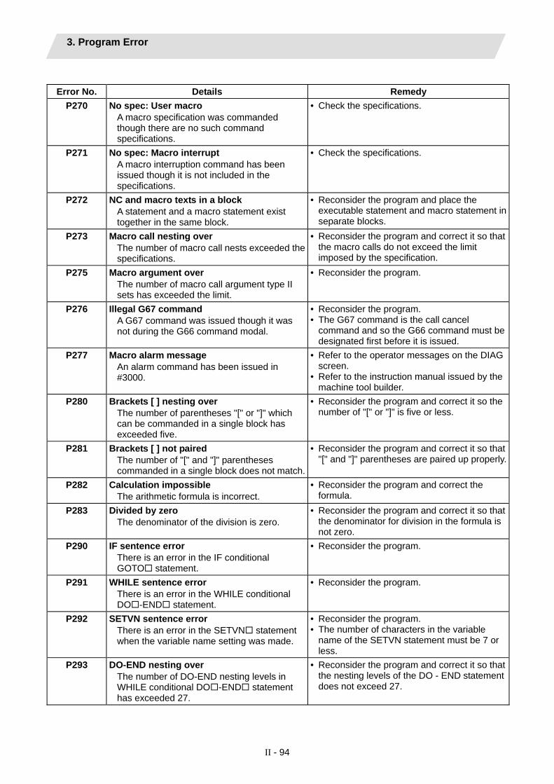
3. Program Error
II - 94
Error No. Details Remedy
P270 No spec: User macro A macro specification was commanded though there are no such command specifications.
• Check the specifications.
P271 No spec: Macro interrupt A macro interruption command has been issued though it is not included in the specifications.
• Check the specifications.
P272 NC and macro texts in a block A statement and a macro statement exist together in the same block.
• Reconsider the program and place the executable statement and macro statement in separate blocks.
P273 Macro call nesting over The number of macro call nests exceeded the specifications.
• Reconsider the program and correct it so that the macro calls do not exceed the limit imposed by the specification.
P275 Macro argument over The number of macro call argument type II sets has exceeded the limit.
• Reconsider the program.
P276 Illegal G67 command A G67 command was issued though it was not during the G66 command modal.
• Reconsider the program. • The G67 command is the call cancel
command and so the G66 command must be designated first before it is issued.
P277 Macro alarm message An alarm command has been issued in #3000.
• Refer to the operator messages on the DIAG screen.
• Refer to the instruction manual issued by the machine tool builder.
P280 Brackets [ ] nesting over The number of parentheses "[" or "]" which can be commanded in a single block has exceeded five.
• Reconsider the program and correct it so the number of "[" or "]" is five or less.
P281 Brackets [ ] not paired The number of "[" and "]" parentheses commanded in a single block does not match.
• Reconsider the program and correct it so that "[" and "]" parentheses are paired up properly.
P282 Calculation impossible The arithmetic formula is incorrect.
• Reconsider the program and correct the formula.
P283 Divided by zero The denominator of the division is zero.
• Reconsider the program and correct it so that the denominator for division in the formula is not zero.
P290 IF sentence error There is an error in the IF conditional GOTO statement.
• Reconsider the program.
P291 WHILE sentence error There is an error in the WHILE conditional DO -END statement.
• Reconsider the program.
P292 SETVN sentence error There is an error in the SETVN statement when the variable name setting was made.
• Reconsider the program. • The number of characters in the variable
name of the SETVN statement must be 7 or less.
P293 DO-END nesting over The number of DO-END nesting levels in WHILE conditional DO -END statement has exceeded 27.
• Reconsider the program and correct it so that the nesting levels of the DO - END statement does not exceed 27.

3. Program Error
II - 95
Error No. Details Remedy
P294 DO and END not paired The DO's and END's are not paired off properly.
• Reconsider the program and correct it so that the DO's and END's are paired off properly.
P295 WHILE/GOTO in tape There is a WHILE or GOTO statement on the tape during tape operation.
• During tape operation‚ a program which includes a WHILE or GOTO statement cannot be executed and so the memory operation mode is established instead.
P296 No address (macro) A required address has not been specified in the user macro.
• Review the program.
P297 Address-A error The user macro does not use address A as a variable.
• Review the program.
P298 G200-G202 cmnd in tape User macro G200‚ G201‚ or G202 was specified during tape or MDI mode.
• Review the program.
P300 Variable name illegal The variable names have not been commanded properly.
• Reconsider the variable names in the program and correct them.
P301 Variable name duplicated The name of the variable has been duplicated.
• Correct the program so that the name is not duplicated.
P310 Not use GMSTB macro code G, M, S, T, or B macro code was called during fixed cycle.
• Review the program. • Review the parameter.
P350 No spec: Scaling command The scaling command (G50, G51) was issued when the scaling specifications were not available.
• Check the specifications.
P360 No spec: Program mirror A mirror image (G50.1 or G51.1) command has been issued though the programmable mirror image specifications are not provided.
• Check the specifications.
P370 No spec: Facing t-post MR The facing turret mirror image specifications are not provided.
• Check the specifications.
P371 Facing t-post MR illegal Mirror image for facing tool posts was commanded to an axis for which external mirror image or parameter mirror image is valid. Mirror image for facing tool posts validating mirror image for a rotary axis was commanded.
• Check the program. • Check the parameters.
P380 No spec: Corner R/C The corner R/C was issued when the corner R/C specifications were not available.
• Check the specifications. • Remove the corner chamfering/corner
rounding command from the program.

3. Program Error
II - 96
Error No. Details Remedy
P381 No spec: Arc R/C Corner chamfering II /corner rounding II was specified in the arc interpolation block although corner chamfering/corner rounding II is unsupported.
• Check the specifications.
P382 No corner movement The block next to corner chamfering/ corner rounding is not a movement command.
• Replace the block succeeding the corner chamfering/corner rounding command by G01 command.
P383 Corner movement short In the corner chamfering/corner rounding command‚ the movement distance was shorter than the value in the corner chamfering/corner rounding command.
• Make the corner chamfering/corner rounding less than the movement distance since this distance is shorter than the corner chamfering/corner rounding.
P384 Corner next movement short When the corner chamfering/corner rounding command was input‚ the movement distance in the following block was shorter than the length of the corner chamfering/corner rounding.
• Make the corner chamfering/corner rounding less than the movement distance since this distance in the following block is shorter than the corner chamfering/corner rounding.
P385 Corner during G00/G33 A block with corner chamfering/corner rounding was given during G00 or G33 modal.
• Recheck the program.
P390 No spec: Geometric A geometric command was issued though there are no geometric specifications.
• Check the specifications.
P391 No spec: Geometric arc There are no geometric IB specifications.
• Check the specifications.
P392 Angle < 1 degree (GEOMT) The angular difference between the geometric line and line is 1° or less.
• Correct the geometric angle.
P393 Inc value in 2nd block (GEOMT) The second geometric block was specified by an incremental value.
• Specify this block by an absolute value.
P394 No linear move command (GEOMT) The second geometric block contains no linear command.
• Specify the G01 command.
P395 Illegal address (GEOMT) The geometric format is invalid.
• Recheck the program.
P396 Plane selected in GEOMT ctrl A plane switching command was executed during geometric command processing.
• Execute the plane switching command before geometric command processing.
P397 Arc error (GEOMT) In geometric IB‚ the circular arc end point does not contact or cross the next block start point.
• Recheck the geometric circular arc command and the preceding and following commands.
P398 No spec: Geometric1B Although the geometric IB specifications are not included‚ a geometric command is given.
• Check the specifications.

3. Program Error
II - 97
Error No. Details Remedy
P411 Illegal modal G111 • G111 was issued during milling mode. • G111 was issued during nose R
compensation mode. • G111 was issued during constant surface
speed. • G111 was issued during mixed
synchronization control. • G111 was issued during fixed cycle. • G111 was issued during polar coordinate
interpolation. • G111 was issued during cylindrical
interpolation mode.
• Before commanding G111, cancel the following commands. • Milling mode • Nose R compensation • Constant surface speed • Mixed synchronization control • Fixed cycle • Polar coordinate interpolation • Cylindrical interpolation
P412 P412 No spec: Axis name switch Axis name switch (G111) was issued even though there is no axis name switch (G111) specification.
• Check the specifications.
P420 No spec: Para input by program Parameter input by program (G10) was commanded even though there is no specification of parameter input by program.
• Check the specifications.
P421 Parameter input error • The specified parameter No. or set data is
illegal. • An illegal G command address was input in
parameter input mode. • A parameter input command was input
during fixed cycle modal or nose R compensation.
• G10L50, G10L70, G11 were not commanded in independent blocks.
• Check the program.
P430 R-pnt return incomplete • A command was issued to move an axis‚
which has not returned to the reference position‚ away from that reference position.
• A command was issued to an axis removal axis.
• Execute reference position return manually. • The command was issued to an axis for
which axis removal is validated so invalidate axis removal.
P431 No spec: 2,3,4th R-point ret A command for second‚ third or fourth reference position return was issued though there are no such command specifications.
• Check the specifications.
P432 No spec: Start position return Start position return (G29) was commanded even though there is no start position return specification.
• Check the specifications.
P433 No spec: R-position check Reference position check (G27) was commanded even though there is no reference position check specification.
• Check the specifications.

3. Program Error
II - 98
Error No. Details Remedy
P434 Compare error One of the axes did not return to the reference position when the reference position check command (G27) was executed.
• Check the program.
P435 G27 and M commands in a block An M command was issued simultaneously in the G27 command block.
• An M code command cannot be issued in a G27 command block and so the G27 command and M code command must be placed in separate blocks.
P436 G29 and M commands in a block An M command was issued simultaneously in the G29 command block.
• An M code command cannot be issued in a G29 command block and so the G29 command and M code command must be placed in separate blocks.
P438
G52 invalid during G54.1 A local coordinate system command was issued during execution of the G54.1 command.
• Review the program.
P450 No spec: Chuck barrier The chuck barrier on command (G22) was specified although the chuck barrier was undefined in the specification.
• Check the specification.
P451 No spec: Stroke chk bef travel Stroke check before travel (G22/G23) was commanded even though there is no stroke check before travel specification.
• Check the specification.
P452 Limit before travel exists An illegal command such as the start or end point of the traveling axis is inside the prohibited area or the axis passes through the prohibited area, was detected when Stroke check before travel (G22) was ON.
• Review the coordinate values of the axis address commanded in the program.
P460 Tape I/O error An error has arisen in the tape reader or‚ alternatively‚ in the printer during macro printing.
• Check the power and cable of the connected devices.
• Check the I/O device parameters.
P461 File I/O error A file of the machining program cannot be read. IC card has not been inserted.
• In memory mode, the programs stored in memory may have been destroyed. Output all of the programs and tool data once and format them.
• Ensure that the external device (including an IC card, etc) that contains the file is mounted.
• Check the parameters for HD operation or IC card operation.
P462 Computer link commu error A communication error occurred during the BTR operation.
• "L01 Computer link error" is displayed simultaneously, so remedy the problem according to the error No.
P480 No spec: Milling • Milling was commanded when the milling
specifications were not provided. • Polar coordinate interpolation was
commanded when the polar coordinate interpolation specifications were not provided.
• Check the specification.

3. Program Error
II - 99
Error No. Details Remedy
P481 Illegal G code (mill) • An illegal G code was used during the
milling mode. • An illegal G code was used during
cylindrical interpolation or polar coordinate interpolation.
• The G07.1 command was issued during the tool radius compensation.
• Check the program.
P482 Illegal axis (mill) • A rotary axis was commanded during the
milling mode. • Milling was executed even though an illegal
value was set for the milling axis No. • Cylindrical interpolation or polar coordinate
interpolation was commanded during mirror image.
• Cylindrical interpolation or polar coordinate interpolation was commanded before the tool compensation was completed after the T command.
• G07.1 was commanded when cylindrical interpolation was not possible (there is no rotary axis, or external mirror image is ON).
• An axis other than a cylindrical coordinate system axis was commanded during cylindrical interpolation.
• Check the machining program, parameters and PLC I/F signal.
P484 R-pnt ret incomplete (mill) • Movement was commanded to an axis that
had not completed reference position return during the milling mode.
• Movement was commanded to an axis that had not completed reference position return during cylindrical interpolation or polar coordinate interpolation.
• Carry out manual reference position return.
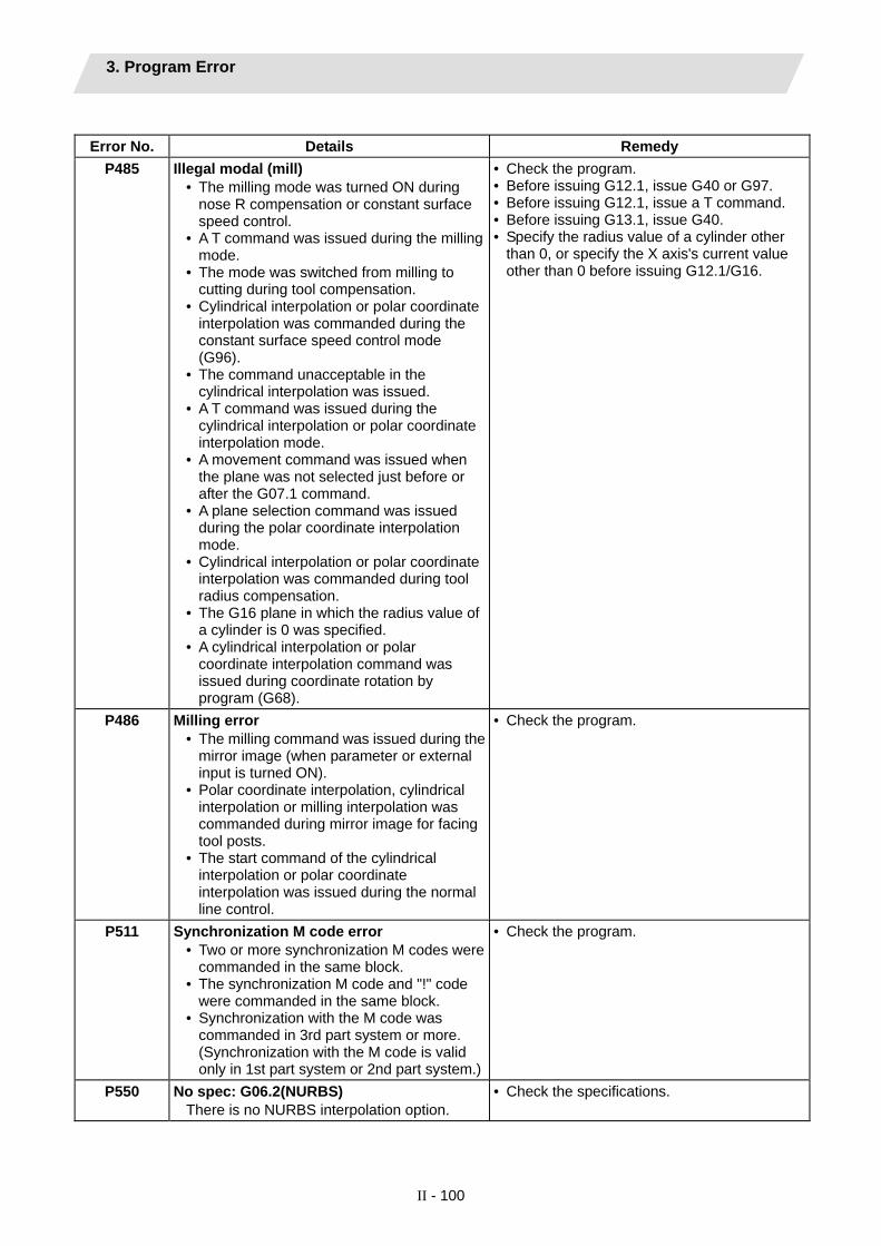
3. Program Error
II - 100
Error No. Details Remedy
P485 Illegal modal (mill) • The milling mode was turned ON during
nose R compensation or constant surface speed control.
• A T command was issued during the milling mode.
• The mode was switched from milling to cutting during tool compensation.
• Cylindrical interpolation or polar coordinate interpolation was commanded during the constant surface speed control mode (G96).
• The command unacceptable in the cylindrical interpolation was issued.
• A T command was issued during the cylindrical interpolation or polar coordinate interpolation mode.
• A movement command was issued when the plane was not selected just before or after the G07.1 command.
• A plane selection command was issued during the polar coordinate interpolation mode.
• Cylindrical interpolation or polar coordinate interpolation was commanded during tool radius compensation.
• The G16 plane in which the radius value of a cylinder is 0 was specified.
• A cylindrical interpolation or polar coordinate interpolation command was issued during coordinate rotation by program (G68).
• Check the program. • Before issuing G12.1, issue G40 or G97. • Before issuing G12.1, issue a T command. • Before issuing G13.1, issue G40. • Specify the radius value of a cylinder other
than 0, or specify the X axis's current value other than 0 before issuing G12.1/G16.
P486 Milling error • The milling command was issued during the
mirror image (when parameter or external input is turned ON).
• Polar coordinate interpolation, cylindrical interpolation or milling interpolation was commanded during mirror image for facing tool posts.
• The start command of the cylindrical interpolation or polar coordinate interpolation was issued during the normal line control.
• Check the program.
P511 Synchronization M code error • Two or more synchronization M codes were
commanded in the same block. • The synchronization M code and "!" code
were commanded in the same block. • Synchronization with the M code was
commanded in 3rd part system or more. (Synchronization with the M code is valid only in 1st part system or 2nd part system.)
• Check the program.
P550 No spec: G06.2(NURBS) There is no NURBS interpolation option.
• Check the specifications.

3. Program Error
II - 101
Error No. Details Remedy
P551 G06.2 knot error The knot (k) command value is smaller than the value for the previous block.
• Reconsider the program. • Specify the knot by monotone increment.
P552 Start point of 1st G06.2 err The block end point immediately before the G06.2 command and the G06.2 first block command value do not match.
• Match the G06.2 first block coordinate command value with the previous block end point.
P554 Invld manual interrupt in G6.2 Manual interruption using a block was performed while in G06.2 mode.
• Perform for blocks other than G06.2 mode when manually interrupting.
P555 Invalid restart during G06.2 Restart was attempted from the block in G06.2 mode.
• Restart from the block other than in G06.2 mode.
P600 No spec: Auto TLM An automatic tool length measurement command (G37) was execute though there are no such command specifications.
• Check the specifications.
P601 No spec: Skip A skip command (G31) was issued though there are no such command specifications.
• Check the specifications.
P602 No spec: Multi skip A multiple skip command (G31.1‚ G31.2 or G31.3) was issued though there are no such command specifications.
• Check the specifications.
P603 Skip speed 0 The skip speed is 0.
• Specify the skip speed.
P604 TLM illegal axis No axis or more than one axis was specified in the automatic tool length measurement block.
• Specify only one axis.
P605 T & TLM command in a block The T code is in the same block as the automatic tool length measurement block.
• Specify this T code before the block.
P606 T cmnd not found before TLM The T code was not yet specified in automatic tool length measurement.
• Specify this T code before the block.
P607 TLM illegal signal Before the area specified by the D command or decelerating area parameter d‚ the measurement position arrival signal went ON. The signal remains OFF to the end.
• Check the program.
P608 Skip during radius compen A skip command was specified during radius compensation processing.
• Specify a radius compensation cancel (G40) command or remove the skip command.
P610 Illegal parameter • The parameter setting is not correct. • G114.1 was commanded when the spindle
synchronization with PLC I/F command was selected.
• G113 was commanded when the spindle-spindle polygon machining option was OFF and the spindle synchronization with PLC I/F command was selected.
• Check whether "#1549 Iv0vR1" to "#1553 Iv0vR5" are set in descending order (in order of large values).
• Check whether "#1554 Iv0rd2" to "#1557 Iv0rd5" are set in descending order.
• Check and correct "#1514 expLinax" and "#1515 expRotax".
• Check the program. • Check the parameter.
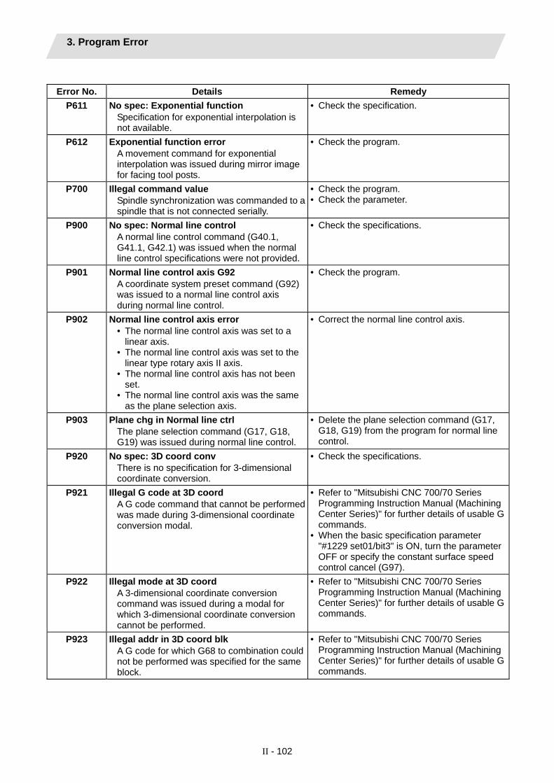
3. Program Error
II - 102
Error No. Details Remedy
P611 No spec: Exponential function Specification for exponential interpolation is not available.
• Check the specification.
P612 Exponential function error A movement command for exponential interpolation was issued during mirror image for facing tool posts.
• Check the program.
P700 Illegal command value Spindle synchronization was commanded to a spindle that is not connected serially.
• Check the program. • Check the parameter.
P900 No spec: Normal line control A normal line control command (G40.1, G41.1, G42.1) was issued when the normal line control specifications were not provided.
• Check the specifications.
P901 Normal line control axis G92 A coordinate system preset command (G92) was issued to a normal line control axis during normal line control.
• Check the program.
P902 Normal line control axis error • The normal line control axis was set to a
linear axis. • The normal line control axis was set to the
linear type rotary axis II axis. • The normal line control axis has not been
set. • The normal line control axis was the same
as the plane selection axis.
• Correct the normal line control axis.
P903 Plane chg in Normal line ctrl The plane selection command (G17, G18, G19) was issued during normal line control.
• Delete the plane selection command (G17, G18, G19) from the program for normal line control.
P920 No spec: 3D coord conv There is no specification for 3-dimensional coordinate conversion.
• Check the specifications.
P921 Illegal G code at 3D coord A G code command that cannot be performed was made during 3-dimensional coordinate conversion modal.
• Refer to "Mitsubishi CNC 700/70 Series Programming Instruction Manual (Machining Center Series)" for further details of usable G commands.
• When the basic specification parameter "#1229 set01/bit3" is ON, turn the parameter OFF or specify the constant surface speed control cancel (G97).
P922 Illegal mode at 3D coord A 3-dimensional coordinate conversion command was issued during a modal for which 3-dimensional coordinate conversion cannot be performed.
• Refer to "Mitsubishi CNC 700/70 Series Programming Instruction Manual (Machining Center Series)" for further details of usable G commands.
P923 Illegal addr in 3D coord blk A G code for which G68 to combination could not be performed was specified for the same block.
• Refer to "Mitsubishi CNC 700/70 Series Programming Instruction Manual (Machining Center Series)" for further details of usable G commands.

3. Program Error
II - 103
Error No. Details Remedy
P930 No spec: Tool axis compen A tool length compensation along the tool axis command was issued even though there is no tool length compensation along the tool axis specification.
• Check the specifications.
P931 Executing tool axis compen A G code that cannot be commanded exists during tool length compensation along the tool axis.
• Reconsider the program.
P932 Rot axis parameter error There is a mistake in the linear axis name and rotary axis name in the rotary axis configuration parameters.
• Set the correct value and reboot.
P940 No spec: Tool tip control There is no tool tip center control specification.
• Check the specifications.
P941 Invalid T tip control command A tool tip center control command was issued during a modal for which a tool tip center control command cannot be issued.
• Reconsider the program.
P942 Invalid cmnd during T tip ctrl A G code that cannot be commanded was issued during tool tip center control.
• Reconsider the program.
P943 Tool posture command illegal In the case of tool tip center control type 1, if the signs at the tool-side rotary axis or table base-side rotary axis start and finish points differ, a tool base-side rotary axis or table workpiece-side rotary axis rotation exists for the same block, and does not pass a singular point. In the case of tool tip center control type 2, the posture vector command is incorrect.
• Reconsider the program.
P990 PREPRO error Combining commands that required pre-reading (nose R offset‚ corner chamfering/corner rounding‚ geometric I‚ geometric IB‚ and compound type fixed cycle for turning machining) resulted in eight or more pre-read blocks.
• Reduce the number of commands that require pre-reading or delete such commands.

4. Troubleshooting 4.1 Drive System Troubleshooting
II - 104
4. Troubleshooting 4.1 Drive System Troubleshooting 4.1.1 Troubleshooting at Power ON
If the NC system does not start up correctly and a system error occurs when the NC power is turned ON, the drive unit may not have been started up properly. Check the LED display on the drive unit, and take measures according to this section.
LED
display Symptom Cause of occurrence Investigation method Remedy
The drive unit axis No. setting is incorrect.
Is there any other drive unit that has the same axis No. set?
Set correctly.
The CNC setting is incorrect. Is the No. of CNC controlled axes correct?
Set correctly.
Is the connector (CN1A, CN1B) connected?
Connect correctly.
AA Initial communication with the CNC was not completed correctly.
Communication with CNC is incorrect.
Is the cable broken? Replace the cable.The axis is not used, the setting is for use inhibiting.
Is the DIP switch set correctly? Set correctly.
Is the connector (CN1A, CN1B) connected?
Connect correctly.
Ab Initial communication with the CNC was not carried out. Communication with CNC is
incorrect. Is the cable broken? Replace the cable.Check the repeatability. Replace the unit. 12 An error was detected in
the unit's memory and IC during the self-diagnosis at power ON.
The CPU peripheral circuit is abnormal. Check whether there is any abnormality
with the unit's surrounding environment, etc.
Improve the surrounding environment.
The drive unit has started up normally if the following type of emergency stop (E7) is displayed on the display unit's LED display.
F1 F+axis No.
E7 Emergency stop
Not lit F2 F+axis No.
E7 Emergency stop
Normal drive unit LED display at NC power ON (for 1st axis)

4. Troubleshooting 4.1 Drive System Troubleshooting
II - 105
4.1.2 Troubleshooting for each alarm No.
Alarm No. 10
Insufficient voltage Insufficient bus voltage was detected in main circuit.
Investigation details Investigation results Remedies SV SPThe moment of READY ON Check the investigation item No. 2. 1 Check the timing when the alarm
occurs. During operation Review the power supply capacity. The external contactor did not turn ON.
Check the investigation item No. 3. 2 Did the external contactor turn ON at the READY ON?
The external contactor turned ON, but the alarm occurred immediately.
Check the investigation item No. 4.
The wiring is correct. Replace the contactor. 3 Check the wiring of contactor excitation circuit. The wiring is not correct. Rewire.
The input voltage is normal. Replace the drive unit. 4 Check the input voltage of the drive unit. (Voltage between L1 and L2, L2 and L3, L1 and L3)
The input voltage is abnormal. Review the power supply capacity.
Alarm No.
11 Axis selection error
Setting of the axis No. selection switch is incorrect.
Investigation details Investigation results Remedies SV SPThe same axis No. is set for the L and M axes.
Correctly set the axis No. 0 = No. 1 axis, 1 = No. 2 axis, ...
The value is duplicated with other axis.
Correctly set the axis No. 0 = No. 1 axis, 1 = No. 2 axis, ...
1 Check the setting of the axis selection switch (rotary switch) on the top of the unit.
No abnormality is found in particular. Replace the drive unit.
Alarm No. 12
Memory error 1 A CPU error or an internal memory error was detected during the power ON self-check.
Investigation details Investigation results Remedies SV SPThe version was changed. There is a possibility that the spindle
software was downloaded into servo, or the servo software was downloaded into spindle. Download servo/spindle software again.
1 Check whether the servo or spindle software version was changed recently.
The version was not changed. Check the investigation item No. 2. The error is always repeated. Replace the drive unit. 2 Check the repeatability. The state returns to normal once, but occurs sometimes thereafter.
Check the investigation item No. 3.
3 Check if there is any abnormality in the unit's ambient environment. (Ex. Ambient temperature, noise, grounding)
Take remedies according to the causes of the abnormality in the ambient environment.
Alarm No.
13 Software processing error 1
Software processing has not finished within the specified time.
Investigation details Investigation results Remedies SV SPThe version was changed. Change software version back to the
original. 1 Check whether the servo or spindle
software version was changed recently. The version was not changed. Check the investigation item No. 2.
The error is always repeated. Replace the drive unit. 2 Check the repeatability. The state returns to normal once, but occurs sometimes thereafter.
Check the investigation item No. 3.
3 Check if there is any abnormality in the unit's ambient environment. (Ex. Ambient temperature, noise, grounding)
Take remedies according to the causes of the abnormality in the ambient environment.

4. Troubleshooting 4.1 Drive System Troubleshooting
II - 106
Alarm No.
16 Magnetic pole position detection error
An error was detected in the magnetic pole detection for controlling the motor.
Investigation details Investigation results Remedies SV SPThe parameters specified with the adjustment are not set.
Replace the drive unit. 1 Check the parameters.
Correct parameters are set. Check the investigation item No. 2. The error is always repeated. Replace the drive unit. 2 Check the repeatability. The state returns to normal once, but occurs sometimes thereafter.
Check the investigation item No. 3.
3 Check if there is any abnormality in the unit's ambient environment. (Ex. Ambient temperature, noise, grounding)
Take remedies according to the causes of the abnormality in the ambient environment.
Alarm No.
17 A/D converter error
An error was detected in the A/D converter for detecting current FB.
Investigation details Investigation results Remedies SV SPThe error is always repeated. Replace the drive unit. 1 Check the repeatability. The state returns to normal once, but occurs sometimes thereafter.
Check the investigation item No. 2.
2 Check if there is any abnormality in the unit's ambient environment. (Ex. Ambient temperature, noise, grounding)
Take remedies according to the causes of the abnormality in the ambient environment.
Alarm No.
18 Motor side detector: Initial communication error
Initial communication with the motor side detector failed.
Investigation details Investigation results Remedies SV SPThe value is not set correctly. Correctly set SV025. 1 Check the servo parameter
(SV025.ent) setting value. OSE104: 0, OSA104: 1 Are all others set to 2? (Excluding slave axis for synchronous control)
The value is set correctly. Check the investigation item No. 2.
The connector is disconnected (or loose).
Correctly install. 2 Jiggle the detector connectors (drive unit side and detector side) and check if they are disconnected. The connector is not disconnected. Check the investigation item No. 3.
The connection is faulty. Replace the detector cable. 3 Turn the power OFF, and check the detector cable connection with a tester.
The connection is normal. Check the investigation item No. 4.
The alarm is on the drive unit side. Replace the drive unit. 4 Replace with another unit, and check whether the fault is on the unit side or detector side.
The alarm is on the detector side. Check the investigation item No. 5.
5 Check if there is any abnormality in the detector's ambient environment. (Ex. Ambient temperature, noise, grounding)
Take remedies according to the causes of the abnormality in the ambient environment.

4. Troubleshooting 4.1 Drive System Troubleshooting
II - 107
Alarm No.
1A Machine side detector: Initial communication error
Initial communication with the linear scale or the ball screw side detector failed.
Investigation details Investigation results Remedies SV SPThe value is not set correctly. Correctly set SV025. 1 Check the servo parameter
(SV025.pen) setting value. Are the serial communication type detector parameters set for the pulse type detector?
The value is set correctly. Check the investigation item No. 2.
The connector is disconnected (or loose).
Correctly install. 2 Jiggle the detector connectors (drive unit side and detector side) and check if they are disconnected. The connector is not disconnected. Check the investigation item No. 3.
The connection is faulty. Replace the detector cable. 3 Turn the power OFF, and check the detector cable connection with a tester.
The connection is normal. Check the investigation item No. 4.
The alarm is on the drive unit side. Replace the drive unit. 4 Replace with another unit, and check whether the fault is on the unit side or detector side.
The alarm is on the detector side. Check the investigation item No. 5.
5 Check if there is any abnormality in the detector's ambient environment. (Ex. Ambient temperature, noise, grounding)
Take remedies according to the causes of the abnormality in the ambient environment.
Alarm No.
1B
Machine side detector: Error 1 The machine side detector detected an error. As details defer from detector to detector, refer to the separate table (1).
Investigation details Investigation results Remedies SV SPThe axis has operated. Check the investigation item No. 3. 1 Check whether the servo axis has
moved and the spindle has rotated when an alarm occurred.
The axis has not operated. Check the investigation item No. 2.
The operation is normal. Check the investigation item No. 3. 2 Check whether the operation at low speed is normal. The operation is not normal. Check the cautions at power ON.
• Wiring check • Parameter check
The connector is disconnected (or loose).
Correctly install. 3 Jiggle the detector connectors (drive unit side and detector side) and check if they are disconnected. The connector is not disconnected. Check the investigation item No. 4.
The connection is faulty. Replace the detector cable. 4 Turn the power OFF, and check the detector cable connection with a tester.
The connection is normal. Check the investigation item No. 5.
The alarm is on the drive unit side. Replace the drive unit. 5 Replace with another unit, and check whether the fault is on the unit side or detector side.
The alarm is on the detector side. Check the investigation item No. 6.
6 Check if there is any abnormality in the detector's ambient environment. (Ex. Ambient temperature, noise, grounding)
Take remedies according to the causes of the abnormality in the ambient environment.
Alarm No.
1C
Machine side detector: Error 2 The machine side detector detected an error. As details defer from detector to detector, refer to the separate table (1).
Investigation details Investigation results Remedies SV SP1 Check the alarm No. "1B" items.
Alarm No.
1D
Machine side detector: Error 3 The machine side detector detected an error. As details defer from detector to detector, refer to the separate table (1).
Investigation details Investigation results Remedies SV SP1 Check the alarm No. "1B" items.
Alarm No.
1E
Machine side detector: Error 4 The machine side detector detected an error. As details defer from detector to detector, refer to the separate table (1).
Investigation details Investigation results Remedies SV SP1 Check the alarm No. "1B" items.

4. Troubleshooting 4.1 Drive System Troubleshooting
II - 108
Alarm No.
1F
Machine side detector: Communication error An error was detected in communication data with the linear scale or the ball screw side detector. Or the communication was interrupted.
Investigation details Investigation results Remedies SV SPThe connector is disconnected (or loose).
Correctly install. 1 Jiggle the detector connectors (drive unit side and detector side) and check if they are disconnected. The connector is not disconnected. Check the investigation item No. 2.
The cables are wired near each other. (Noise is entering from the power cable.)
Improve the cable wiring. 2 Is the detector cable wired in the same conduit as the motor's power cable, or are the two cables laid in parallel near each other? The wires are sufficiently separated. Check the investigation item No. 3.
The motor FG wire is grounded on the motor side.
Ground the motor to one point, connecting the wires together on the drive unit side.
3 Is the motor FG wire connected only to the drive unit which drives it? (Is the motor grounded to one point?)
The motor is grounded to one point. Check the investigation item No. 4. The connection is faulty. Replace the detector cable. 4 Turn the power OFF, and check the
detector cable connection with a tester. (Is the cable shielded?)
The connection is normal. Check the investigation item No. 5.
The alarm is on the drive unit side. Replace the drive unit. 5 Replace with another unit, and check whether the fault is on the unit side or detector side.
The alarm is on the detector side. Check the investigation item No. 6.
6 Check if there is any abnormality in the detector's ambient environment. (Ex. Ambient temperature, noise, grounding)
Take remedies according to the causes of the abnormality in the ambient environment.
Alarm No.
21 Machine side detector: No signal
When an excessive error alarm occurred, no signal from the machine side detector was detected.
Investigation details Investigation results Remedies SV SPThe value is not set correctly. Correctly set SV025. 1 Check the servo parameter (SV025.
pen) setting value. Are the pulse type detector parameters set for a serial communication type detector?
The value is set correctly. Check the investigation item No. 3.
The connector is disconnected (or loose).
Correctly install. 2 Jiggle the detector connectors (drive unit side and detector side) and check if they are disconnected. The connector is not disconnected. Check the investigation item No. 4.
The connection is faulty. Replace the detector cable. 3 Turn the power OFF, and check the detector cable connection with a tester.
The connection is normal. Check the investigation item No. 5.
The alarm is on the drive unit side. Replace the drive unit. 4 Replace with another unit, and check whether the fault is on the unit side or detector side.
The alarm is on the detector side. Check the investigation item No. 6.
5 Check if there is any abnormality in the detector's ambient environment. (Ex. Ambient temperature, noise, grounding)
Take remedies according to the causes of the abnormality in the ambient environment.
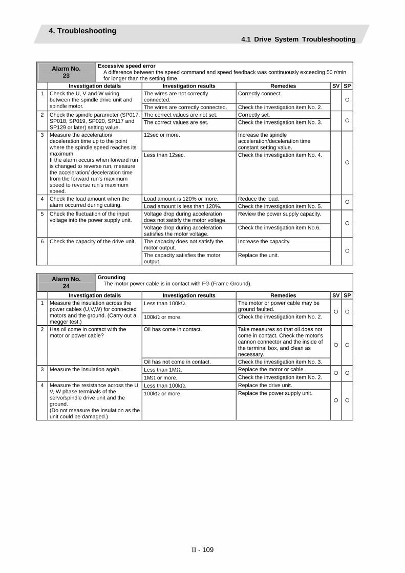
4. Troubleshooting 4.1 Drive System Troubleshooting
II - 109
Alarm No.
23
Excessive speed error A difference between the speed command and speed feedback was continuously exceeding 50 r/min for longer than the setting time.
Investigation details Investigation results Remedies SV SPThe wires are not correctly connected.
Correctly connect. 1 Check the U, V and W wiring between the spindle drive unit and spindle motor. The wires are correctly connected. Check the investigation item No. 2.
The correct values are not set. Correctly set. 2 Check the spindle parameter (SP017, SP018, SP019, SP020, SP117 and SP129 or later) setting value.
The correct values are set. Check the investigation item No. 3.
12sec or more. Increase the spindle acceleration/deceleration time constant setting value.
3 Measure the acceleration/ deceleration time up to the point where the spindle speed reaches its maximum. If the alarm occurs when forward run is changed to reverse run, measure the acceleration/ deceleration time from the forward run's maximum speed to reverse run's maximum speed.
Less than 12sec. Check the investigation item No. 4.
Load amount is 120% or more. Reduce the load. 4 Check the load amount when the alarm occurred during cutting. Load amount is less than 120%. Check the investigation item No. 5.
Voltage drop during acceleration does not satisfy the motor voltage.
Review the power supply capacity. 5 Check the fluctuation of the input voltage into the power supply unit.
Voltage drop during acceleration satisfies the motor voltage.
Check the investigation item No.6.
The capacity does not satisfy the motor output.
Increase the capacity. 6 Check the capacity of the drive unit.
The capacity satisfies the motor output.
Replace the unit.
Alarm No.
24 Grounding
The motor power cable is in contact with FG (Frame Ground).
Investigation details Investigation results Remedies SV SPLess than 100kΩ. The motor or power cable may be
ground faulted. 1 Measure the insulation across the
power cables (U,V,W) for connected motors and the ground. (Carry out a megger test.)
100kΩ or more. Check the investigation item No. 2.
Oil has come in contact. Take measures so that oil does not come in contact. Check the motor's cannon connector and the inside of the terminal box, and clean as necessary.
2 Has oil come in contact with the motor or power cable?
Oil has not come in contact. Check the investigation item No. 3. Less than 1MΩ. Replace the motor or cable. 3 Measure the insulation again. 1MΩ or more. Check the investigation item No. 2. Less than 100kΩ. Replace the drive unit. 4 Measure the resistance across the U,
V, W phase terminals of the servo/spindle drive unit and the ground. (Do not measure the insulation as the unit could be damaged.)
100kΩ or more. Replace the power supply unit.

4. Troubleshooting 4.1 Drive System Troubleshooting
II - 110
Alarm No.
25 Absolute position data lost
The absolute position was lost, as the backup battery voltage dropped in the absolute position detector.
Investigation details Investigation results Remedies SV SPThe warning is occurring. Check the investigation item No. 2. 1 Is warning 9F occurring at the same
time? The warning is not occurring. Check the investigation item No. 3. Less than 3V. Replace the battery, and establish the
zero point. 2 Measure the battery voltage with a
tester. 3V or more. Check the NC bus cable connection. Alarm No.18 occurred. Turn the drive unit control power ON
again, and establish the zero point. 3 Did alarm No.18 occur when the
power was turned ON the last time? Alarm No.18 did not occur. Check the investigation item No. 4. The unit was left disconnected for a long time. Guide at delivery : 20 hours or moreAfter 5 years : 10 hours or more
Turn the drive unit control power ON again, and establish the zero point.
4 Was the detector cable or battery cable left disconnected from the unit for a long time?
The cables were not left disconnected.
Check the investigation item No. 5.
The connection is faulty. Replace the cable. 5 Check the detector cable or battery cable connection with a tester. The connection is normal. Replace the drive unit.
Alarm No.
26 Unused axis error
A power module error occurred in the axis whose axis No. selection switch was set to "F"(free axis).
Investigation details Investigation results Remedies SV SPThe error is always repeated. Replace the drive unit. 1 Check the repeatability. The state returns to normal once, but occurs sometimes thereafter.
Check the investigation item No. 2.
2 Check if there is any abnormality in the unit's ambient environment. (Ex. Ambient temperature, noise, grounding)
Take remedies according to the causes of the abnormality in the ambient environment.
Alarm No.
27
Machine side detector: Error 5 The machine side detector detected an error. As details defer from detector to detector, refer to the separate table (1).
Investigation details Investigation results Remedies SV SP1 Check the alarm No. "1B" items.
Alarm No.
28
Machine side detector: Error 6 The machine side detector detected an error. As details defer from detector to detector, refer to the separate table (1).
Investigation details Investigation results Remedies SV SP1 Check the alarm No. "1B" items.
Alarm No.
29
Machine side detector: Error 7 The machine side detector detected an error. As details defer from detector to detector, refer to the separate table (1).
Investigation details Investigation results Remedies SV SP1 Check the alarm No. "1B" items.
Alarm No.
2A
Machine side detector: Error 8 The machine side detector detected an error. As details defer from detector to detector, refer to the separate table (1).
Investigation details Investigation results Remedies SV SP1 Check the alarm No. "1B" items.

4. Troubleshooting 4.1 Drive System Troubleshooting
II - 111
Alarm No.
2B
Motor side detector: Error 1 The motor side detector (linear scale in the case of linear motor) detected an error. As details defer from detector to detector, refer to the separate table (1).
Investigation details Investigation results Remedies SV SP1 Check the alarm No. "1B" items.
Alarm No.
2C
Motor side detector: Error 2 The motor side detector (linear scale in the case of linear motor) detected an error. As details defer from detector to detector, refer to the separate table (1).
Investigation details Investigation results Remedies SV SP1 Check the alarm No. "1B" items.
Alarm No.
2D
Motor side detector: Error 3 The motor side detector (linear scale in the case of linear motor) detected an error. As details defer from detector to detector, refer to the separate table (1).
Investigation details Investigation results Remedies SV SP1 Check the alarm No. "1B" items.
Alarm No.
2E
Motor side detector: Error 4 The motor side detector (linear scale in the case of linear motor) detected an error. As details defer from detector to detector, refer to the separate table (1).
Investigation details Investigation results Remedies SV SP1 Check the alarm No. "1B" items.
Alarm No.
2F
Motor side detector: Communication error An error was detected in communication data with the motor side detector or with the linear scale of a linear servo system. Or the communication was interrupted.
Investigation details Investigation results Remedies SV SPThe connector is disconnected (or loose).
Correctly install. 1 Jiggle the detector connectors (drive unit side and detector side) and check if they are disconnected. The connector is not disconnected. Check the investigation item No. 2.
The cables are wired near each other. (Noise is entering from the power cable.)
Improve the cable wiring. 2 Is the detector cable wired in the same conduit as the motor's power cable, or are the two cables laid in parallel near each other? The wires are sufficiently separated. Check the investigation item No. 3.
The motor FG wire is grounded on the motor side.
Ground the motor to one point, connecting the wires together on the drive unit side.
3 Is the motor FG wire connected only to the drive unit which drives it? (Is the motor grounded to one point?)
The motor is grounded to one point. Check the investigation item No. 4. The connection is faulty. Replace the detector cable. 4 Turn the power OFF, and check the
detector cable connection with a tester. (Is the cable shielded?)
The connection is normal. Check the investigation item No. 5.
The alarm is on the drive unit side. Replace the drive unit. 5 Replace with another unit, and check whether the fault is on the unit side or detector side.
The alarm is on the detector side. Check the investigation item No. 6.
6 Check if there is any abnormality in the detector's ambient environment. (Ex. Ambient temperature, noise, grounding)
Take remedies according to the causes of the abnormality in the ambient environment.
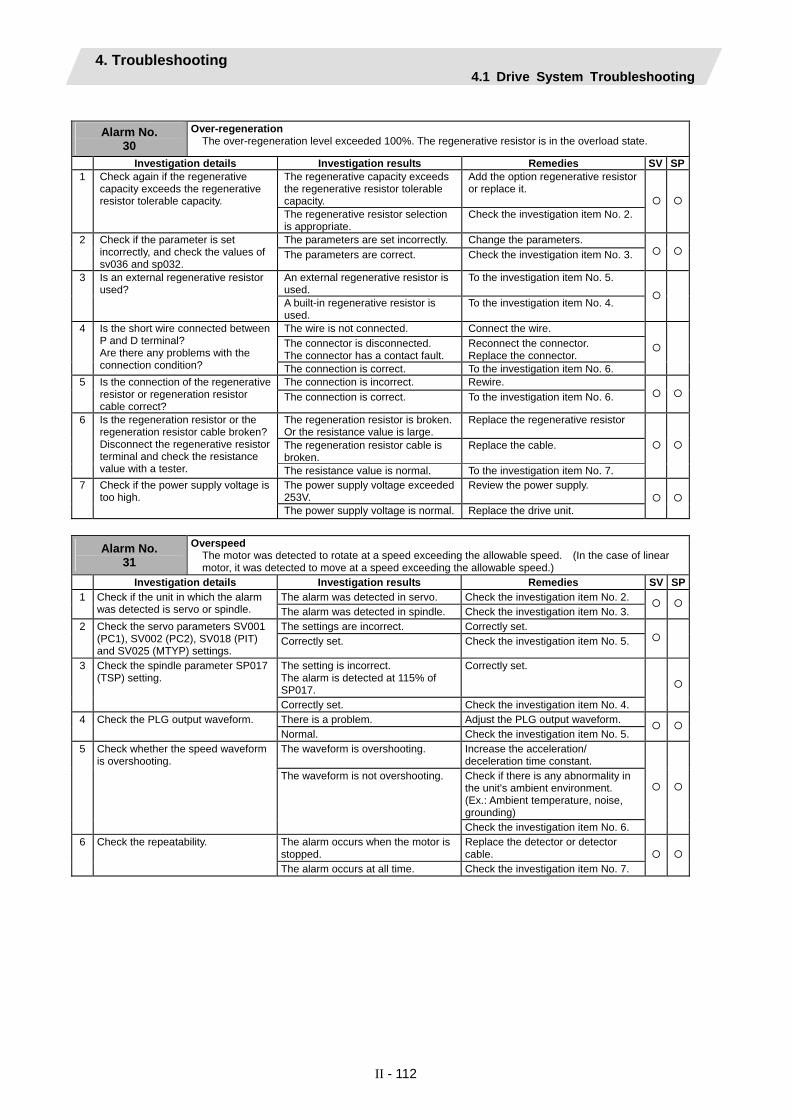
4. Troubleshooting 4.1 Drive System Troubleshooting
II - 112
Alarm No.
30 Over-regeneration
The over-regeneration level exceeded 100%. The regenerative resistor is in the overload state.
Investigation details Investigation results Remedies SV SPThe regenerative capacity exceeds the regenerative resistor tolerable capacity.
Add the option regenerative resistor or replace it.
1 Check again if the regenerative capacity exceeds the regenerative resistor tolerable capacity.
The regenerative resistor selection is appropriate.
Check the investigation item No. 2.
The parameters are set incorrectly. Change the parameters. 2 Check if the parameter is set incorrectly, and check the values of sv036 and sp032.
The parameters are correct. Check the investigation item No. 3.
An external regenerative resistor is used.
To the investigation item No. 5. 3 Is an external regenerative resistor used?
A built-in regenerative resistor is used.
To the investigation item No. 4.
The wire is not connected. Connect the wire. The connector is disconnected. The connector has a contact fault.
Reconnect the connector. Replace the connector.
4 Is the short wire connected between P and D terminal? Are there any problems with the connection condition? The connection is correct. To the investigation item No. 6.
The connection is incorrect. Rewire. 5 Is the connection of the regenerative resistor or regeneration resistor cable correct?
The connection is correct. To the investigation item No. 6.
The regeneration resistor is broken. Or the resistance value is large.
Replace the regenerative resistor
The regeneration resistor cable is broken.
Replace the cable.
6 Is the regeneration resistor or the regeneration resistor cable broken? Disconnect the regenerative resistor terminal and check the resistance value with a tester. The resistance value is normal. To the investigation item No. 7.
The power supply voltage exceeded 253V.
Review the power supply. 7 Check if the power supply voltage is too high.
The power supply voltage is normal. Replace the drive unit.
Alarm No.
31
Overspeed The motor was detected to rotate at a speed exceeding the allowable speed. (In the case of linear motor, it was detected to move at a speed exceeding the allowable speed.)
Investigation details Investigation results Remedies SV SPThe alarm was detected in servo. Check the investigation item No. 2. 1 Check if the unit in which the alarm
was detected is servo or spindle. The alarm was detected in spindle. Check the investigation item No. 3. The settings are incorrect. Correctly set. 2 Check the servo parameters SV001
(PC1), SV002 (PC2), SV018 (PIT) and SV025 (MTYP) settings.
Correctly set. Check the investigation item No. 5.
The setting is incorrect. The alarm is detected at 115% of SP017.
Correctly set. 3 Check the spindle parameter SP017 (TSP) setting.
Correctly set. Check the investigation item No. 4. There is a problem. Adjust the PLG output waveform. 4 Check the PLG output waveform. Normal. Check the investigation item No. 5. The waveform is overshooting. Increase the acceleration/
deceleration time constant. Check if there is any abnormality in the unit's ambient environment. (Ex.: Ambient temperature, noise, grounding)
5 Check whether the speed waveform is overshooting.
The waveform is not overshooting.
Check the investigation item No. 6. The alarm occurs when the motor is stopped.
Replace the detector or detector cable.
6 Check the repeatability.
The alarm occurs at all time. Check the investigation item No. 7.
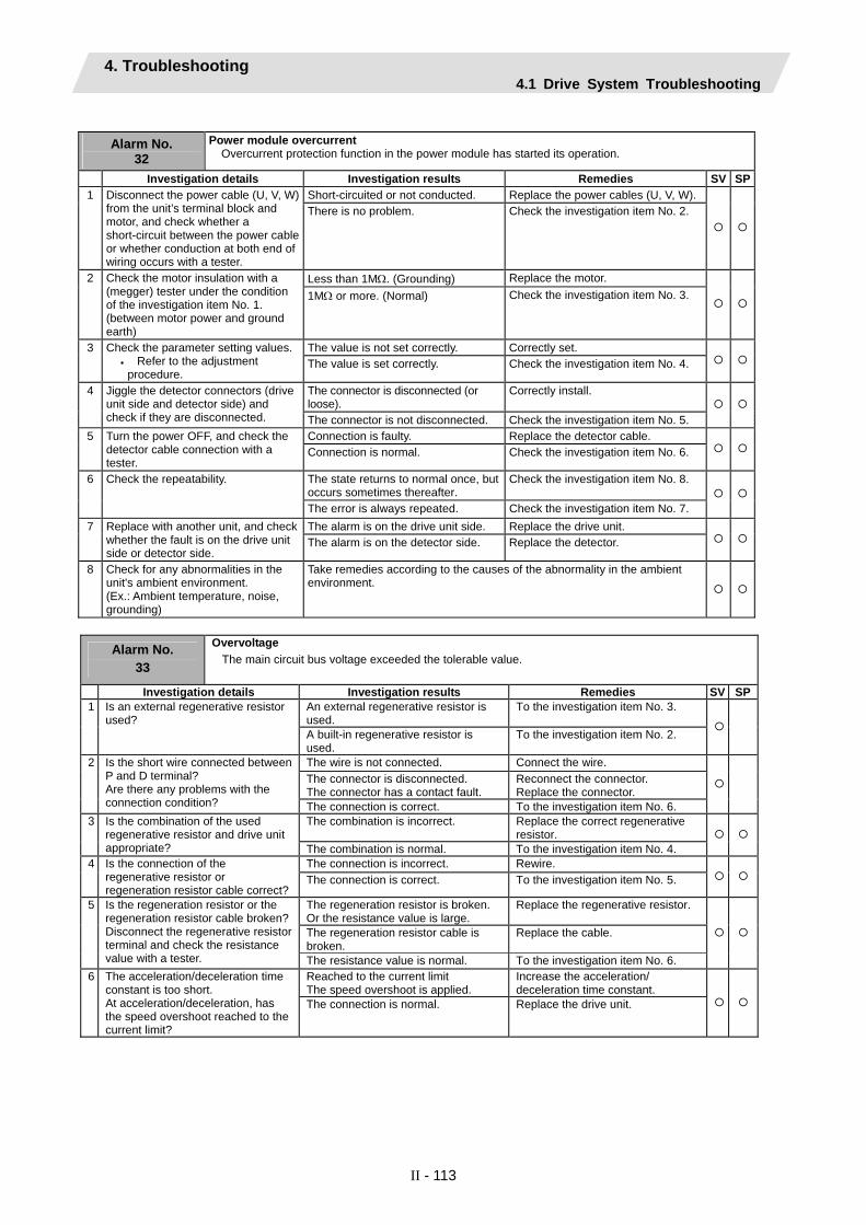
4. Troubleshooting 4.1 Drive System Troubleshooting
II - 113
Alarm No.
32 Power module overcurrent
Overcurrent protection function in the power module has started its operation.
Investigation details Investigation results Remedies SV SPShort-circuited or not conducted. Replace the power cables (U, V, W). 1 Disconnect the power cable (U, V, W)
from the unit’s terminal block and motor, and check whether a short-circuit between the power cable or whether conduction at both end of wiring occurs with a tester.
There is no problem. Check the investigation item No. 2.
Less than 1MΩ. (Grounding) Replace the motor. 2 Check the motor insulation with a (megger) tester under the condition of the investigation item No. 1. (between motor power and ground earth)
1MΩ or more. (Normal) Check the investigation item No. 3.
The value is not set correctly. Correctly set. 3 Check the parameter setting values. • Refer to the adjustment
procedure. The value is set correctly. Check the investigation item No. 4.
The connector is disconnected (or loose).
Correctly install. 4 Jiggle the detector connectors (drive unit side and detector side) and check if they are disconnected. The connector is not disconnected. Check the investigation item No. 5.
Connection is faulty. Replace the detector cable. 5 Turn the power OFF, and check the detector cable connection with a tester.
Connection is normal. Check the investigation item No. 6.
The state returns to normal once, but occurs sometimes thereafter.
Check the investigation item No. 8. 6 Check the repeatability.
The error is always repeated. Check the investigation item No. 7. The alarm is on the drive unit side. Replace the drive unit. 7 Replace with another unit, and check
whether the fault is on the drive unit side or detector side.
The alarm is on the detector side. Replace the detector.
8 Check for any abnormalities in the unit's ambient environment. (Ex.: Ambient temperature, noise, grounding)
Take remedies according to the causes of the abnormality in the ambient environment.
Alarm No.
33
Overvoltage The main circuit bus voltage exceeded the tolerable value.
Investigation details Investigation results Remedies SV SPAn external regenerative resistor is used.
To the investigation item No. 3. 1 Is an external regenerative resistor used?
A built-in regenerative resistor is used.
To the investigation item No. 2.
The wire is not connected. Connect the wire. The connector is disconnected. The connector has a contact fault.
Reconnect the connector. Replace the connector.
2 Is the short wire connected between P and D terminal? Are there any problems with the connection condition? The connection is correct. To the investigation item No. 6.
The combination is incorrect. Replace the correct regenerative resistor.
3 Is the combination of the used regenerative resistor and drive unit appropriate? The combination is normal. To the investigation item No. 4.
The connection is incorrect. Rewire. 4 Is the connection of the regenerative resistor or regeneration resistor cable correct?
The connection is correct. To the investigation item No. 5.
The regeneration resistor is broken. Or the resistance value is large.
Replace the regenerative resistor.
The regeneration resistor cable is broken.
Replace the cable.
5 Is the regeneration resistor or the regeneration resistor cable broken? Disconnect the regenerative resistor terminal and check the resistance value with a tester. The resistance value is normal. To the investigation item No. 6.
Reached to the current limit The speed overshoot is applied.
Increase the acceleration/ deceleration time constant.
6 The acceleration/deceleration time constant is too short. At acceleration/deceleration, has the speed overshoot reached to the current limit?
The connection is normal. Replace the drive unit.

4. Troubleshooting 4.1 Drive System Troubleshooting
II - 114
Alarm No.
34 NC-DRV communication: CRC error
An error was detected in the data received from the CNC.
Investigation details Investigation results Remedies SV SPThe connector is disconnected (or loose).
Correctly install. 1 Manually shake the connection connectors between NC and drive unit, battery unit and drive unit, or among multiple drive units to check if they are disconnected. Also, check if an excessive force is not applied on them.
The connector is not disconnected. Check the investigation item No. 2.
The connection is faulty. Replace the communication cable. 2 Turn the power OFF, and check the connection of the communication cables indicated in item 1 with a tester. Or, replace with a correct cable.
The connection is normal. Check the investigation item No. 3.
The version was changed. Change software version back to the original.
3 Check whether the NC or drive unit software version was changed recently. The version was not changed. Check the investigation item No. 4.
The alarm is on the drive unit side. Replace the drive unit. 4 Replace with another drive unit, and check whether the fault is on the NC side or drive unit side.
The alarm is on the unit connections. Check the investigation item No. 5.
5 Check if there is any abnormality in the unit's ambient environment. (Ex. Ambient temperature, noise, grounding)
Take remedies according to the causes of the abnormality in the ambient environment.
Alarm No.
35 NC command error
The travel command data that was received from the CNC was excessive.
Investigation details Investigation results Remedies SV SP1 Check the alarm No. "34" items.
Alarm No.
36 NC-DRV communication: Communication error
The communication with the CNC was interrupted.
Investigation details Investigation results Remedies SV SP1 Check the alarm No. "34" items.
Alarm No.
37 Initial parameter error
An incorrect parameter was detected among the parameters received from the CNC at the power ON.
Investigation details Investigation results Remedies SV SPThe alarm was detected in servo. Check the investigation item No. 2. 1 Check if the unit in which the alarm
was detected is servo or spindle. The alarm was detected in spindle. Check the investigation item No. 3. Wrong parameters were set. SV001 to SV005
Correct the parameter. Set the value within the designated setting range.
-1 The electronic gears are overflowing.
Check SV001, SV002 and SV018.
-2 The absolute position detection parameter is valid when OSE104 and OSE105 are connected. (Absolute position control cannot be used.)
In order to use the absolute position control function, an absolute position option is required.
2 An error parameter No. is displayed on the NC diagnosis screen. Check the servo parameter with the parameter adjustment procedure.
Correct parameters were set. Check the investigation item No. 4. 3 An error parameter No. is displayed
on the NC diagnosis screen. Check the servo parameter with the parameter adjustment procedure.
SP001 to SP384 Set the value within the designated setting range.
4 Check the alarm No. "34" items.

4. Troubleshooting 4.1 Drive System Troubleshooting
II - 115
Alarm No.
38 NC-DRV communication: Protocol error 1
An error was detected in the communication frames received from the CNC.
Investigation details Investigation results Remedies SV SP1 Check the alarm No. "34" items.
Alarm No.
39 NC-DRV communication: Protocol error 2
An error was detected in the axis information data received from the CNC.
Investigation details Investigation results Remedies SV SP1 Check the alarm No. "34" items.
Alarm No.
3A Overcurrent
Excessive current was detected in the motor drive current.
Investigation details Investigation results Remedies SV SPVibration is occurring. • Set a filter.
• Lower the speed loop gain (SV005/SP005).
1 Check whether vibration is occurring.
There is no vibration. Check the investigation item No. 2. The setting is too large. Set an appropriate value. 2 The speed loop gain setting is larger
than the standard value. Servo: SV005 / Spindle: SP005
The setting is approximately the same as the standard value.
Check the investigation item No. 3.
The setting is incorrect. Set the standard value. 3 Check the current loop gain. Servo: SV009,SV010,SV011,SV012 Spindle: SP081,SP082,SP083,SP084
The standard value is set. Check the investigation item No. 4.
The power cable is short-circuited. Replace the motor power cable. 4 Disconnect the power cable (U,V,W) from the terminal block and the cannon plug from the motor. Check the insulation with a tester.
There is no problem. Check the investigation item No. 5.
There is a ground fault at the power cable.
Replace the motor power cable. 5 Check the insulation between the motor power cable and FG.
There is no problem. Check the investigation item No. 6. There is a ground fault in the motor. Replace the motor.
(With the absolute position system, the zero point must be established.)
6 Connect the cannon plug, and check the insulation between the power cable and FG.
There is no problem. Check the investigation item No. 7. 7 Check if there is any abnormality in
the motor's ambient environment. (Ex. Ambient temperature, cutting water)
Take remedies according to the causes of the abnormality in the ambient environment.
Alarm No.
3B Power module overheat
Thermal protection function in the power module has started its operation.
Investigation details Investigation results Remedies SV SPLarge amounts of cutting oil or cutting chips, etc., are adhered, or the rotation is slow.
Clean or replace the fan. 1 Check that the fan is rotating correctly.
The fan is rotating properly. Check the investigation item No. 2. Cutting oil or cutting chips, etc., are adhered, and the fins are clogged.
Clean the fins. 2 Check whether the heat dissipating fins are dirty.
The fins are normal. Check the investigation item No. 3. 55°C or more. Improve the ventilation and cooling
for the power distribution panel. 3 Measure the drive unit's ambient
temperature. Less than 55°C. Check the investigation item No. 4.
4 Check if there is any abnormality in the unit's ambient environment. (Ex. Ambient temperature, noise, grounding)
Take remedies according to the causes of the abnormality in the ambient environment.
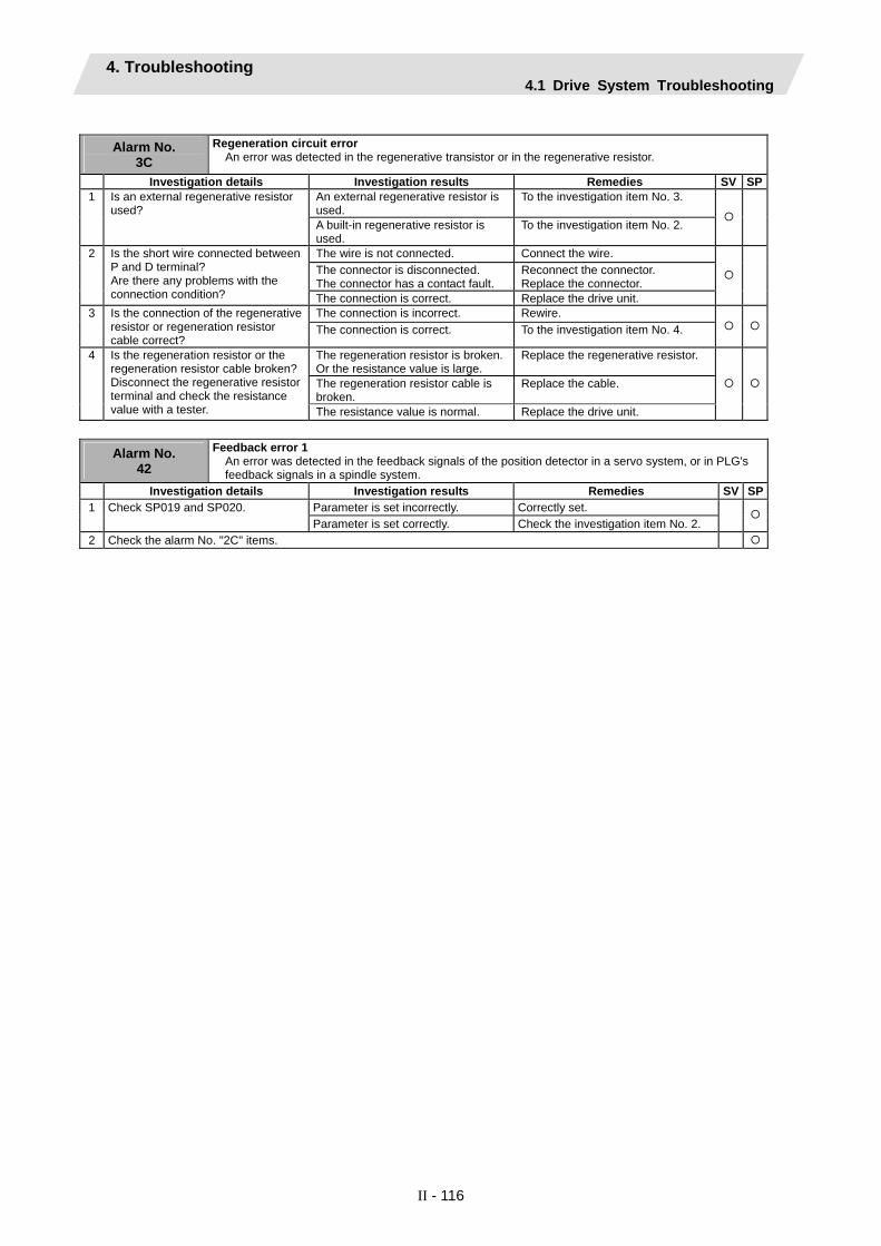
4. Troubleshooting 4.1 Drive System Troubleshooting
II - 116
Alarm No.
3C Regeneration circuit error
An error was detected in the regenerative transistor or in the regenerative resistor.
Investigation details Investigation results Remedies SV SPAn external regenerative resistor is used.
To the investigation item No. 3. 1 Is an external regenerative resistor used?
A built-in regenerative resistor is used.
To the investigation item No. 2.
The wire is not connected. Connect the wire. The connector is disconnected. The connector has a contact fault.
Reconnect the connector. Replace the connector.
2 Is the short wire connected between P and D terminal? Are there any problems with the connection condition? The connection is correct. Replace the drive unit.
The connection is incorrect. Rewire. 3 Is the connection of the regenerative resistor or regeneration resistor cable correct?
The connection is correct. To the investigation item No. 4.
The regeneration resistor is broken. Or the resistance value is large.
Replace the regenerative resistor.
The regeneration resistor cable is broken.
Replace the cable.
4 Is the regeneration resistor or the regeneration resistor cable broken? Disconnect the regenerative resistor terminal and check the resistance value with a tester. The resistance value is normal. Replace the drive unit.
Alarm No.
42
Feedback error 1 An error was detected in the feedback signals of the position detector in a servo system, or in PLG's feedback signals in a spindle system.
Investigation details Investigation results Remedies SV SPParameter is set incorrectly. Correctly set. 1 Check SP019 and SP020. Parameter is set correctly. Check the investigation item No. 2.
2 Check the alarm No. "2C" items.

4. Troubleshooting 4.1 Drive System Troubleshooting
II - 117
Alarm No. 43
Feedback error 2 Excessive difference was detected in position data between the motor side detector and the machine side detector in a servo system. In a spindle system, an error was detected in the encoder feedback signals.
Investigation details Investigation results Remedies SV SPThe connector is disconnected (or loose).
Correctly install. 1 Jiggle the detector connectors (drive unit side and detector side) and check if they are disconnected. The connector is not disconnected. Check the investigation item No. 2.
The cables are wired near each other. (Noise is entering from the power cable.)
Improve the cable wiring. 2 Is the detector cable wired in the same conduit as the motor's power cable, or are the two cables laid in parallel near each other? The wires are sufficiently separated. Check the investigation item No. 3.
The motor FG wire is grounded on the motor side.
Ground the motor to one point, connecting the wires together on the drive unit side.
3 Is the motor FG wire connected only to the drive unit which drives it? (Is the motor grounded to one point?)
The motor is grounded to one point. Check the investigation item No. 4. The connection is faulty. Replace the detector cable. 4 Turn the power OFF, and check the
detector cable connection with a tester. (Is the cable shielded?)
The connection is normal. Check the investigation item No. 5.
The alarm is on the drive unit side. Replace the drive unit. 5 Replace with another unit, and check whether the fault is on the unit side or detector side.
The alarm is on the detector side. Check the investigation item No. 6.
6 Check if there is any abnormality in the detector's ambient environment. (Ex. Ambient temperature, noise, grounding)
Take remedies according to the causes of the abnormality in the ambient environment.
Parameter is set incorrectly. Correctly set. 7 Check SP019 and SP020. Parameter is set correctly. Check the investigation item No. 8.
8 Check the alarm No. "1B" items.
Alarm No. 45
Fan stop A cooling fan built in the drive unit stopped, and overheat occurred in the power module.
Investigation details Investigation results Remedies SV SPThe fan is rotating, and an alarm did not occur again.
Continue to use. The power may be turned ON without assuring more than 10 seconds for the time from when the power is turned OFF till when it is turned ON. Leave for more than 10 seconds, and turn the power ON again.
1 Turn the unit power ON again, and confirm the rotation of the fan. Note) Assure more than 10 seconds
for the time from when the power is turned OFF till when it is turned ON. For the fan used for the drive unit, assuring more than 10 seconds for the time from when the power is turned OFF till when it is turned ON is required.
The fan did not rotate. Or, an alarm occurred again.
Check the investigation item No. 2.
The connector is disconnected. Correctly connect the connector. 2 Check if the connector connected to a fan is disconnected. The connector is not disconnected. Check the investigation item No. 3.
Oil or cutting chips are adhered. Improve the use environment and replace the drive unit.
3 Check if oil or cutting chips are adhered to the fan.
Oil or cutting chips are not adhered.The cable may be broken.
Replace the drive unit.
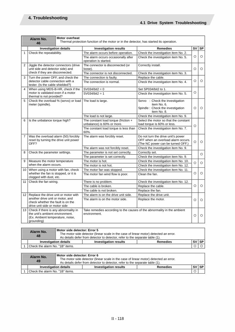
4. Troubleshooting 4.1 Drive System Troubleshooting
II - 118
Alarm No.
46 Motor overheat
Thermal protection function of the motor or in the detector, has started its operation.
Investigation details Investigation results Remedies SV SPThe alarm occurs before operation. Check the investigation item No. 2. 1 Check the repeatability. The alarm occurs occasionally after operation is started.
Check the investigation item No. 5.
The connector is disconnected (or loose).
Correctly install. 2 Jiggle the detector connectors (drive unit side and detector side) and check if they are disconnected. The connector is not disconnected. Check the investigation item No. 3.
The connection is faulty. Replace the cable. 3 Turn the power OFF, and check the detector cable connection with a tester. (Is the cable shielded?)
The connection is normal. Check the investigation item No. 4.
SV034/bit2 = 0 Set SP034/bit2 to 1. 4 When using MDS-B-HR, check if the motor is validated even if a motor thermal is not provided?
SV034/bit2 = 1 Check the investigation item No. 5.
The load is large. Servo : Check the investigation item No. 6.
Spindle : Check the investigation item No. 8.
5 Check the overload % (servo) or load meter (spindle).
The load is not large. Check the investigation item No. 9. The constant load torque (friction + unbalance) is 60% or more.
Select the motor so that the constant load torque is 60% or less.
6 Is the unbalance torque high?
The constant load torque is less than 60%.
Check the investigation item No. 7.
The alarm was forcibly reset. Do not turn the drive unit's power OFF when an overload alarm occurs. (The NC power can be turned OFF.)
7 Was the overload alarm (50) forcibly reset by turning the drive unit power OFF?
The alarm was not forcibly reset. Check the investigation item No. 9. The parameter is not set correctly. Correctly set. 8 Check the parameter settings. The parameter is set correctly. Check the investigation item No. 9. The motor is hot. Check the investigation item No. 10. 9 Measure the motor temperature
when the alarm occurs. The motor is not hot. Check the investigation item No. 12. The motor fan was stopped. Check the investigation item No. 11. 10 When using a motor with fan, check
whether the fan is stopped, or it is clogged with dust, etc.
The motor fan wind flow is poor. Clean the fan.
There is no problem. Check the investigation item No. 12. The cable is broken. Replace the cable.
11 Check the fan wiring.
The cable is not broken. Replace the fan. The alarm is on the drive unit side. Replace the drive unit. 12 Replace the drive unit or motor with
another drive unit or motor, and check whether the fault is on the drive unit side or motor side
The alarm is on the motor side. Replace the motor.
13 Check if there is any abnormality in the unit's ambient environment. (Ex. Ambient temperature, noise, grounding)
Take remedies according to the causes of the abnormality in the ambient environment.
Alarm No.
48
Motor side detector: Error 5 The motor side detector (linear scale in the case of linear motor) detected an error. As details defer from detector to detector, refer to the separate table (1).
Investigation details Investigation results Remedies SV SP1 Check the alarm No. "1B" items.
Alarm No.
49
Motor side detector: Error 6 The motor side detector (linear scale in the case of linear motor) detected an error. As details defer from detector to detector, refer to the separate table (1).
Investigation details Investigation results Remedies SV SP1 Check the alarm No. "1B" items.

4. Troubleshooting 4.1 Drive System Troubleshooting
II - 119
Alarm No.
4A
Motor side detector: Error 7 The motor side detector (linear scale in the case of linear motor) detected an error. As details defer from detector to detector, refer to the separate table (1).
Investigation details Investigation results Remedies SV SP1 Check the alarm No. "1B" items.
Alarm No.
4B
Motor side detector: Error 8 The motor side detector (linear scale in the case of linear motor) detected an error. As details defer from detector to detector, refer to the separate table (1).
Investigation details Investigation results Remedies SV SP1 Check the alarm No. "1B" items.
Alarm No.
4E NC command mode error
The mode outside the specification was input in spindle control mode selection.
Investigation details Investigation results Remedies SV SP1) The grounding is incomplete. Correctly ground. 2) The alarm occurs easily when a
specific device operates. Use noise measures on the device described on the left.
3) The cable is not correctly shielded. Correctly shield the cable.
1 Check the wiring and setting environment. 1) Correctly grounded? 2) Any noise generating devices
around the unit? 3) Are the speed/position detector
cables correctly shielded? No abnormality is found in particular. Replace the drive unit.
Alarm No.
50 Overload 1
Overload detection level became over 100%. The motor or the drive unit is overloaded.
Investigation details Investigation results Remedies SV SPThe standard values (below) are not set. Servo : SV021 = 60, SV022 = 150Spindle : SV063 = 60, SP064 = 110
Set the standard values. 1 Check the overload parameters. Servo : SV021, SV022 Spindle : SP063, SP064
The standard values are set. Investigate item 2. The load is large. Servo : Investigate item 3.
Spindle : Investigate item 7. 2 Check the overload % (servo) or load
meter (spindle). The load is not large. Investigate item 9. Resonance is occurring. Adjust the parameters.
• Set the notch filter. • Lower VGN1 (SV005).
3 Check whether machine resonance is occurring.
Resonance is not occurring. Investigate item 4. The motor is hunting. Adjust the parameters.
• Increase VGN1 (SV005). • Lower VIA (SV008).
4 Check whether the shaft sways when the motor is stopped. (Hunting)
The motor is not hunting. Investigate item 5. The motor brakes are not released. Correct the faulty section. 5 Check the brake operation.
• Check the brake relay. • Check the connector (CN20)
connection.
The motor brake operation is normal. Investigate item 6.
The cutting load is large. Lower the cutting load. There is interference with the positioning pin.
When using the positioning pin, turn the servo OFF when stopped.
An excessive force is applied from the machine.
Check whether the ball screw is bent, or whether there is a fault in the guide.
6 Check the load current with the NC Servo Monitor, and investigate the machine load.
The machine load is not large. Investigate item 8. There is a problem. Adjust the PLG output waveform. 7 Check the PLG output waveform. Normal Investigate item 8. The motor performance is insufficient.
Lower the acceleration/deceleration rate or cutting load.
8 Confirm the motor capacity selection again.
The motor performance is sufficient. Investigate item 9. Improved. Replace the drive unit. 9 Try replacing the drive unit. Not improved. Replace the motor.
(Note) NR and PR resetting are not possible when the overload level is 50% or more. Do not forcibly reset (AR) by turning the unit power OFF. If AR resetting is used at 50% or higher, the level is set to 80% when the power is turned ON next. (Servo)

4. Troubleshooting 4.1 Drive System Troubleshooting
II - 120
Alarm No. 51
Overload 2 Current command of more than 95% of the unit's max. current was being continuously given for longer than 1 second in a servo system. In a spindle system, current command of more than 95% of the motor's max. current was being continuously given for longer than 1 second.
Investigation details Investigation results Remedies SV SPThe alarm occurred after ready ON before operation starts.
Investigate item 2. 1 Did the alarm occur immediately after READY ON?
The alarm occurred after normal operation.
Investigate item 5.
The voltage is not supplied. Correctly supply the PN voltage. 2 Check that the PN voltage is supplied to the drive unit. • Is the CHARGE lamp ON?
Approx. 300V is correctly supplied. Investigate item 3.
The connections are incorrect. Connect correctly. 3 Check the motor power cable (U, V, W phases). • The power cable is not connected. • Is the cable connected to the motor
for another axis?
The connections are correct. Investigate item 4.
The connections are incorrect. Connect correctly. 4 Check the detector cable connection. • Is the cable connected to the motor
for another axis? The connections are correct. Investigate item 5.
The machine has collided. Check the machining program and soft limit settings.
5 Check whether the machine has collided.
The machine has not collided. Investigate item 6. The current is saturated during acceleration/deceleration.
Increase the acceleration/ deceleration time constant.
6 Check whether the current value on the NC Servo Monitor screen is saturated during acceleration/deceleration.
The current value during acceleration/deceleration is appropriate.
Investigate item 7.
The FB signal is abnormal. Replace the detector. (With the absolute position system, the zero point must be established.)
7 Check the detector FB.
The FB signal is normal. Replace the drive unit. The load is large. Lower the load. 8 Check the load meter value. The load is not large. Investigate item 9. There is a problem. Adjust the PLG output waveform. 9 Check the PLG output waveform. Normal Replace the drive unit.
Alarm No.
52
Excessive error 1 A difference between the actual and theoretical motor positions during servo ON exceeded the setting value.
Investigation details Investigation results Remedies SV SPThe excessive error detection width is too small. Servo standard value:
SV023 = RAPID60 × PGN1 ÷ 2
For the spindle, a value larger than the droop amount: Droop amount =
Spindle rotation speed × No. of pulses60 × position loop gain
Set appropriate values. 1 Check the excessive error detection width.
SV023 (Servo) SP102 (Orientation control) SP154, SP155 (C-axis control) SP177/bitD, SP186 (Spindle synchronous control) SP193/bitD, SP218 (Synchronous tap)
Appropriate values are set. Investigate item 2. The polarity is reversed. Correctly set the parameters. 2 Check the position detector polarity.
SV017/bit4 (Servo) SP097/bit5 (Orientation control) SP129/bit5 (C-axis control) SP177/bit5 (Spindle synchronous control) SP193/bit5 (Synchronous tap control)
Normal. Investigate item 3.
3 Check the alarm No. "51" items.

4. Troubleshooting 4.1 Drive System Troubleshooting
II - 121
Alarm No.
53
Excessive error 2 A difference between the actual and theoretical motor positions during servo OFF exceeded the setting value.
Investigation details Investigation results Remedies SV SPThe axis detachment function (NC parameter) is invalid. (Note) For the axis detachment
function, refer to the NC manual.
Check the investigation item No. 2. 1 Check the follow-up function while the NC is in the servo OFF state.
The axis detachment function (NC parameter) is valid. (Note) For the axis detachment
function, refer to the NC manual.
Check the investigation item No. 3.
The axis has moved. Adjust the brakes, etc. so that the axis does not move.
2 Check whether the axis has moved during servo OFF, and check the motor brake operation. The axis has not moved. Check the investigation item No. 3.
The excessive error detection width is too small.
SV026 = RAPID60 × PGN1 ÷ 2
Set an appropriate value. 3 Check the excessive error detection width.
SV026 (Servo)
An appropriate value is set. Check for problems on the NC side, such as the position FB follow-up control.
Alarm No.
54 Excessive error 3
When an excessive error 1 occurred, detection of the motor current failed.
Investigation details Investigation results Remedies SV SPThe voltage is not supplied. Correctly supply the PN voltage. 1 Check that the PN voltage is supplied
to the drive unit. • Is the CHARGE lamp ON?
Approx. 300V is correctly supplied. Investigate item 2.
The connections are incorrect. Connect correctly. 2 Check the motor power cable (U, V, W phases). • The power cable is not connected. • Is the cable connected to the motor
for another axis?
The connections are correct. Replace the drive unit.
Supplement (servo)
Depending on the ideal machine position in respect to the command position, the actual machine position could enter the actual shaded section shown below, which is separated more than the distance set in OD1.
Ideal machine position
Servo OFF
Command position
Servo ON Time
OD1
OD1
OD2
OD2
Position
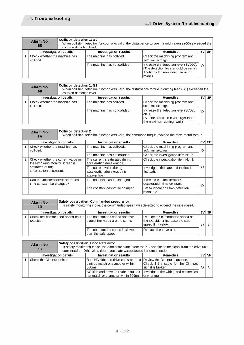
4. Troubleshooting 4.1 Drive System Troubleshooting
II - 122
Alarm No.
58
Collision detection 1: G0 When collision detection function was valid, the disturbance torque in rapid traverse (G0) exceeded the collision detection level.
Investigation details Investigation results Remedies SV SPThe machine has collided. Check the machining program and
soft limit settings. 1 Check whether the machine has
collided. The machine has not collided. Increase the detection level (SV060).
(The detection level should be set as 1.5-times the maximum torque or more.)
Alarm No.
59
Collision detection 1: G1 When collision detection function was valid, the disturbance torque in cutting feed (G1) exceeded the collision detection level.
Investigation details Investigation results Remedies SV SPThe machine has collided. Check the machining program and
soft limit settings. 1 Check whether the machine has
collided. The machine has not collided. Increase the detection level (SV035.
clG1). (Set the detection level larger than the maximum cutting load.)
Alarm No.
5A Collision detection 2
When collision detection function was valid, the command torque reached the max. motor torque.
Investigation details Investigation results Remedies SV SPThe machine has collided. Check the machining program and
soft limit settings. 1 Check whether the machine has
collided. The machine has not collided. Check the investigation item No. 2. The current is saturated during acceleration/deceleration.
Check the investigation item No. 3. 2 Check whether the current value on the NC Servo Monitor screen is saturated during acceleration/deceleration.
The current value during acceleration/deceleration is appropriate.
Investigate the cause of the load fluctuation.
The constant can be changed. Increase the acceleration/ deceleration time constant.
3 Can the acceleration/deceleration time constant be changed?
The constant cannot be changed. Set to ignore collision detection method 2.
Alarm No.
5B Safety observation: Commanded speed error
In safety monitoring mode, the commanded speed was detected to exceed the safe speed.
Investigation details Investigation results Remedies SV SPThe commanded speed and safe speed limit value are the same.
Reduce the commanded speed on the NC side or increase the safe speed limit value.
1 Check the commanded speed on the NC side.
The commanded speed is slower than the safe speed.
Replace the drive unit.
Alarm No.
5D
Safety observation: Door state error In safety monitoring mode, the door state signal from the NC and the same signal from the drive unit don't match. Otherwise, door open state was detected in normal mode.
Investigation details Investigation results Remedies SV SPBoth NC side and drive unit side input timings match one another within 500ms.
Review the DI input sequence. Check if the cable for the DI input signal is broken.
1 Check the DI input timing.
NC side and drive unit side inputs do not match one another within 500ms.
Investigate the wiring and connection environment.

4. Troubleshooting 4.1 Drive System Troubleshooting
II - 123
Alarm No.
5E Safety observation: Feedback speed error
In safety monitoring mode, the motor speed was detected to exceed the safe speed.
Investigation details Investigation results Remedies SV SPThe feedback speed and safe speed limit value are the same.
Reduce the commanded speed on the NC side or increase the safe speed limit value.
1 Check the DI input timing.
The feedback speed is slower than the safe speed.
Replace the drive unit.
1) The grounding is incomplete. Correctly ground. 2) The alarm occurs easily when a specific device operates.
Use noise measures on the device described on the left.
3) The cable is not correctly shielded. Correctly shield the cable.
2 Check the wiring and setting environment. 1) Correctly grounded? 2) Any noise generating devices
around the unit? 3) Are the speed/position detector
cables correctly shielded? No abnormality is found in particular. Replace the drive unit.
Alarm No.
5F External contactor error
A contact of the external contactor is welding.
Investigation details Investigation results Remedies SV SPThe contactor has melted. Replace the contactor. 1 Check whether the contactor's
contact has melted.
The contactor has not melted. Check the investigation item No. 2.
The alarm occurred at the axis where the contactor control is not executed.
Set the parameter correctly. 2 Check whether the axis where an alarm occurred was a contactor control axis. The alarm occurred at the axis where
the contactor control is executed. Replace the drive unit.
Alarm No.
61 Power supply: Power module overcurrent
Overcurrent protection function in the power module has started its operation.
Investigation details Investigation results Remedies CV The alarm occurs each time immediately after 200VAC is supplied or after READY is turned ON.
Replace the unit.
The alarm occurs frequently during READY ON.
Check the investigation item No. 3.
1 Check the state of the operation when the alarm occurs, and check the repeatability.
The alarm occurs after continuous operation for a long time. The unit is hot.
Check the investigation item No. 2.
The total load of all motors exceeds the rated capacity of the power supply unit.
Lower the motor load and operation frequency.
2 Check the load state of all motors, and the starting/stopping frequency.
The total does not exceed the capacity.
Check the investigation item No. 3.
The power capacity is insufficient. Increase the power capacity. 3 Check the power capacity. The specified power capacity is secured.
Check the investigation item No. 4.
The voltage drops to 170V or less occasionally.
Increase the power capacity.
The difference of the voltage across wires is 10V or more.
Improve the power phase balance.
4 Measure the voltage across wires. • Is the voltage 170V or more even
when the motor is accelerating?
The difference of the voltage across wires is less than 10V.
Check the investigation item No. 5.
The power voltage is distorted. Improve the source of the distortion. Install an AC reactor.
5 Measure the power voltage with a synchroscope, and check whether there is any distortion. • Are there any other devices
causing the power distortion?
The power voltage waveform is not abnormal.
Check the investigation item No. 6.
6 Check if there is any abnormality in the unit's ambient environment. (Ex. Noise, grounding, etc.)
Take remedies according to the causes of the abnormality in the ambient environment.
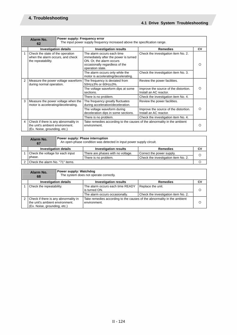
4. Troubleshooting 4.1 Drive System Troubleshooting
II - 124
Alarm No.
62 Power supply: Frequency error
The input power supply frequency increased above the specification range.
Investigation details Investigation results Remedies CV The alarm occurs each time immediately after the power is turned ON. Or, the alarm occurs occasionally regardless of the operation state.
Check the investigation item No. 2. 1 Check the state of the operation when the alarm occurs, and check the repeatability.
The alarm occurs only while the motor is accelerating/decelerating.
Check the investigation item No. 3.
The frequency is deviated from 50Hz±3% or 60Hz±3%.
Review the power facilities.
The voltage waveform dips at some sections.
Improve the source of the distortion. Install an AC reactor.
2 Measure the power voltage waveform during normal operation.
There is no problem. Check the investigation item No. 4.
The frequency greatly fluctuates during acceleration/deceleration.
Review the power facilities.
The voltage waveform during deceleration dips in some sections.
Improve the source of the distortion. Install an AC reactor.
3 Measure the power voltage when the motor is accelerating/decelerating.
There is no problem. Check the investigation item No. 4.
4 Check if there is any abnormality in the unit's ambient environment. (Ex. Noise, grounding, etc.)
Take remedies according to the causes of the abnormality in the ambient environment.
Alarm No.
67 Power supply: Phase interruption
An open-phase condition was detected in input power supply circuit.
Investigation details Investigation results Remedies CV There are phases with no voltage. Correct the power supply. 1 Check the voltage for each input
phase. There is no problem. Check the investigation item No. 2.
2 Check the alarm No. "71" items.
Alarm No. 68
Power supply: Watchdog The system does not operate correctly.
Investigation details Investigation results Remedies CV The alarm occurs each time READY is turned ON.
Replace the unit. 1 Check the repeatability.
The alarm occurs occasionally. Check the investigation item No. 2.
2 Check if there is any abnormality in the unit's ambient environment. (Ex. Noise, grounding, etc.)
Take remedies according to the causes of the abnormality in the ambient environment.

4. Troubleshooting 4.1 Drive System Troubleshooting
II - 125
Alarm No.
69 Power supply: Grounding
The motor power cable is in contact with FG (Frame Ground).
Investigation details Investigation results Remedies SV SPLess than 100kΩ. (Grounding) The motor or power cable may be
ground faulted. 1 Measure the insulation across the
power cables (U,V,W) for all motors and the ground. (Carry out a megger test.)
100kΩ or more. (Normal) Check the investigation item No. 2.
Oil has come in contact. Take measures so that oil does not come in contact. Check the motor's cannon connector and the inside of the terminal box, and clean as necessary.
2 Has oil come in contact with the motor or power cable?
Oil has not come in contact. Check the investigation item No. 3. Less than 1MΩ. (Grounding) Replace the motor or cable. 3 Measure the insulation again. 1MΩ or more. (Normal) Check the investigation item No. 2. Less than 100kΩ. Replace the drive unit. 4 Measure the resistance across the U,
V, W phase terminals of the servo/spindle drive unit and the ground. (Do not measure the insulation as the unit could be damaged.)
100kΩ or more. Replace the power supply unit.
There is an axis in which alarm has occurred.
Check the alarm No. "24" items. 5 Check whether there is any axis in which alarm has occurred.
There is no axis in which alarm has occurred.
Check the investigation item No. 2.
Alarm No.
6A Power supply: External contactor welding
A contact of the external contactor is welding.
Investigation details Investigation results Remedies CV An alarm has occurred. Remove the cause of the alarm on
the drive side, and check the investigation item No. 2.
1 Check whether any alarm has occurred on the drive unit side.
An alarm has not occurred. Check the investigation item No. 2.
The contactor has melted. Replace the contactor. 2 Check whether the contactor's contact has melted. The contactor has not melted. Check the investigation item No. 3.
The connection is correct. Correctly connect. 3 Check that the contactor excitation wiring is correctly connected from the power supply unit's MC1 terminal.
The connection is incorrect. Replace the power supply unit.
Alarm No.
6B Power supply: Rush relay welding
A resistor relay for rush short circuit fails to be OFF.
Investigation details Investigation results Remedies CV An alarm has occurred. Remove the cause of the alarm on
the drive side, and then carry out the investigation details 2.
1 Check whether any alarm has occurred on the drive unit side.
An alarm has not occurred. Check the investigation item No. 2.
The alarm occurs each time READY is turned ON.
Replace the unit. 2 Check the repeatability.
The alarm occurs occasionally. Check the investigation item No. 3.
3 Check if there is any abnormality in the unit's ambient environment. (Ex. Noise, grounding, etc.)
Take remedies according to the causes of the abnormality in the ambient environment.

4. Troubleshooting 4.1 Drive System Troubleshooting
II - 126
Alarm No.
6C Power supply: Main circuit error
An error was detected in charging operation of the main circuit capacitor.
Investigation details Investigation results Remedies CV The CHARGE lamp remains ON for some time.
Replace the power supply unit.
The lamp turns ON instantly, but when the alarm occurs and the contactor turns OFF, the lamp turns OFF immediately.
Check the investigation item No. 2.
1 Check the CHARGE lamp state when the alarm occurs.
The lamp never turns ON. Check the investigation item No. 2. Then replace the unit.
1) The power supply unit side is abnormal.
Replace the power supply unit.
2) The drive unit side is abnormal. Disconnect the PN wiring, and then check the drive unit side.
2 Disconnect the power supply unit's PN terminal block wiring, and measure the resistance value at 1) and 2) shown below.
1) and 2) are both normal.
Replace the power supply unit.
Alarm No.
6E Power supply: Memory error/AD error
An error was detected in the internal memory or A/D converter.
Investigation details Investigation results Remedies CV The alarm occurs each time READY is turned ON.
Replace the unit. 1 Check the repeatability.
The alarm occurs occasionally. Check the investigation item No. 2.
2 Check if there is any abnormality in the unit's ambient environment. (Ex. Noise, grounding, etc.)
Take remedies according to the causes of the abnormality in the ambient environment.
Alarm No.
6F Power supply error
No power supply is connected to the drive unit, or a communication error was detected.
Investigation details Investigation results Remedies CV "F" is flickering. An A/D converter error has occurred.
Check the alarm No. "6E" items. Another alarm code is flickering. Check items of each alarm No. "0" is displayed. Check the investigation item No. 2. "F" is displayed. Check the investigation item No. 2. "8" is displayed. Check the alarm No. "68" items. "b", "C", "d" is displayed. Check the investigation item No. 3.
1 Check the LED display on the power supply unit.
Something else is displayed. Check the alarm No. "68" items.
0 or 4 is set. Check the investigation item No. 3. 2 Check the rotary switch setting. A value other than the above is set. Correctly set the rotary switch.
There is a problem with the wiring or shield.
Replace the cable. 3 Check the communication cable (CN4) connected with the drive unit.
There is no problem. Replace the unit.
(Note) Alarm 6F is detected at the same time other power supply alarms occur.
Drive unit Power supply
unit
P N
2)
1)
PolarityTester measure-
ment point + -Normal Abnormal
P N Several 100Ω Short-circuit/∞Ω1) N P ∞Ω Several 100Ω P N Several 100Ω Short-circuit/∞Ω2) N P ∞Ω Several 100Ω

4. Troubleshooting 4.1 Drive System Troubleshooting
II - 127
Alarm No.
70
Power supply: External emergency stop error A mismatch of the external emergency stop input and CNC emergency stop input continued for 30 seconds.
Investigation details Investigation results Remedies CV 1 Check the connection between
external emergency stop and NC emergency stop.
Not wired. Correctly wire the external emergency stop and NC emergency stop.
No abnormality is found in particular. Replace the drive unit. 2 Check if there is any abnormality in the unit's ambient environment. The grounding is incomplete. Take remedies according to the
causes of the abnormality. Additionally ground and review.
Alarm No.
71 Power supply: Instantaneous power interruption
The power was momentarily interrupted.
Investigation details Investigation results Remedies CV The contactor has been turned OFF externally.
Review the machine sequence. When turning the contactor OFF with external means, such as an emergency stop button, this alarm can be avoided by inputting NC emergency stop at the same time.
1 Investigate the sequence to check whether the contactor has been turned OFF with an emergency stop button, etc.
The contactor has not been turned OFF.
Check the investigation item No. 2.
The alarm occurs each time READY is turned ON.
Check the investigation item No. 3.
The alarm occurs at a certain operation.
Check the investigation item No. 1. If there is no problem, check the investigation item No. 3.
2 Check the repeatability.
The alarm occurs occasionally during operation.
Check the investigation item No. 4.
The wiring is incorrect. Correctly connect. 3 Check whether the power input wire and contactor are correctly wired. There is no problem. Check the investigation item No. 4.
An instantaneous power failure or voltage drop occurs frequently.
Correct the power facility. 4 Check the power voltage waveform with a synchroscope.
There is no problem. Replace the unit.
Alarm No.
72 Power supply: Fan stop
A cooling fan built in the power supply unit stopped, and overheat occurred in the power module.
Investigation details Investigation results Remedies CV The fan is rotating, and an alarm did not occur again.
Continue to use. The power may be turned ON without assuring more than 10 seconds for the time from when the power is turned OFF till when it is turned ON. Leave for more than 10 seconds, and turn the power ON again.
1 Turn the unit power ON again, and confirm the rotation of the fan. Note) Assure more than 10 seconds
for the time from when the power is turned OFF till when it is turned ON. For the fan used for the drive unit, assuring more than 10 seconds for the time from when the power is turned OFF till when it is turned ON is required.
The fan did not rotate. Or, an alarm occurred again.
Check the investigation item No. 2.
The connector is disconnected. Correctly connect the connector. 1 Check if the connector connected to a fan is disconnected.
The connector is not disconnected. Check the investigation item No. 3.
Oil or cutting chips are adhered. Improve the use environment and replace the drive unit.
2 Check if oil or cutting chips are adhered to the fan.
Oil or cutting chips are not adhered.The cable may be broken.
Replace the drive unit.

4. Troubleshooting 4.1 Drive System Troubleshooting
II - 128
Alarm No. 73
Power supply: Over regeneration Over-regeneration detection level became over 100%. The regenerative resistor is overloaded. This alarm cannot be reset for 15 min from the occurrence. Leave the drive system energized for more than 15 min, then turn the power ON to reset the alarm.
Investigation details Investigation results Remedies CV The regenerative load value increases when the power is turned ON and the motor is not rotated.
Check whether the state is affected by power fluctuation, grounding or noise. If there is no problem, replace the unit.
The regenerative load value increases each time the motor decelerates, and the alarm occurs.
A-CR : Check the investigation item No. 2.
C1-CV : Check the investigation item No. 4.
1 Check the alarm occurrence state and regenerative load displayed on the NC Monitor screen while changing the operation mode.
The regenerative load value increases each time the motor decelerates, but the alarm does not occur when the operation mode is eased.
A-CR : Check the investigation item No. 2. C1-CV : Ease the operation mode.
The setting is incorrect. Correctly set. (Check the alarm No. "6D" items.)
2 Check whether the parameter (regenerative resistor type) of the drive unit controlling the power supply unit is correct.
The setting is correct. Check the investigation item No. 3.
The regenerative resistor is abnormal.
Replace the regenerative resistor. 3 Check the regenerative resistor's state. • Is oil adhered? • Measure the resistance value.
There is no problem. Check the investigation item No. 4.
4 Check the alarm No. "75" items.
Alarm No. 75
Power supply: Overvoltage L+ and L- bus voltage in main circuit exceeded the allowable value. As the voltage between L+ and L- is high immediately after this alarm, another alarm may occur if this alarm is reset in a short time. Wait more than 5 min before resetting so that the voltage drops.
Investigation details Investigation results Remedies CV The alarm occurs each time the motor decelerates.
Check the investigation item No. 3. 1 Check the repeatability.
The alarm occurs occasionally. Check the investigation item No. 2.
Auxiliary regeneration frequency over (E8) occurs just before the over-voltage occurs.
Limit the occurrence of the excessive instantaneous regeneration by not decelerating multiple axes at the same time.
2 Check the power supply's alarm history.
Others. Check the investigation item No. 3.
The power capacity is insufficient. Increase the power capacity. 3 Check the power capacity. The specified power capacity is secured.
Check the investigation item No. 4.
The voltage drops to 170V or less occasionally.
Increase the power capacity.
The difference of the voltage across wires is 10V or more.
Improve the power phase balance.
4 Measure the voltage across wires. • Is the voltage 170V or more even
when the motor is accelerating?
The difference of the voltage across wires is less than 10V.
Check the investigation item No. 5.
The power voltage is distorted. Improve the source of the distortion. Install an AC reactor.
5 Measure the power voltage with a synchroscope, and check whether there is any distortion. • Are there any other devices
causing the power distortion?
The power voltage waveform is not abnormal.
Check the investigation item No. 6.
6 Check if there is any abnormality in the unit's ambient environment. (Ex. Noise, grounding, etc.)
Take remedies according to the causes of the abnormality in the ambient environment.

4. Troubleshooting 4.1 Drive System Troubleshooting
II - 129
Alarm No.
76
Power supply: External emergency stop setting error The rotary switch setting of external emergency stop is not correct, or a wrong external emergency stop signal is input.
Investigation details Investigation results Remedies CV 1 Check the rotary switch setting. When using external emergency
stop, rotary switch is not set to "4". Set the rotary switch to "4".
No abnormality is found in particular. Replace the drive unit. 2 Check if there is any abnormality in the unit's ambient environment. The grounding is incomplete. Take remedies according to the
causes of the abnormality. Additionally ground and review.
Alarm No.
77 Power supply: Power module overheat
Thermal protection function in the power module has started its operation.
Investigation details Investigation results Remedies CV Large amounts of cutting oil or cutting chips, etc., are adhered, or the rotation is slow.
Clean or replace the fan. 1 Confirm that the fan is properly rotating.
The fan is properly rotating. Check the investigation item No. 2.
Cutting oil or cutting chips, etc., are adhered, and the fins are clogged.
Clean the fins. 2 Check whether the heat dissipating fins are dirty.
The fins are normal. Check the investigation item No. 3.
55°C or more Improve the ventilation and cooling for the power distribution panel.
3 Measure the power supply unit's ambient temperature.
Less than 55°C. Check the investigation item No. 4.
4 Check if there is any abnormality in the unit's ambient environment. (Ex. Ambient temperature, noise, grounding)
Take remedies according to the causes of the abnormality in the ambient environment.
Alarm No.
88 Watchdog
The system does not operate correctly.
Investigation details Investigation results Remedies SV SPThe version was changed. Change software version back to the
original. 1 Check whether the servo or spindle
software version was changed recently. The version was not changed. Check the investigation item No. 2.
The error is always repeated. Replace the drive unit. 2 Check the repeatability. The state returns to normal once, but occurs sometimes thereafter.
Check the investigation item No. 3.
3 Check if there is any abnormality in the unit's ambient environment. (Ex. Ambient temperature, noise, grounding)
Take remedies according to the causes of the abnormality in the ambient environment.

4. Troubleshooting 4.1 Drive System Troubleshooting
II - 130
4.1.3 Troubleshooting for each warning No.
Warning No. 9E
Absolute position detector: Revolution counter error An error was detected in the revolution counter of the absolute position detector. The absolute position data cannot be compensated.
Investigation details Investigation results Remedies SV SP1 Check if there is any abnormality in
the detector's ambient environment. (Ex. Ambient temperature, noise, grounding)
Take remedies according to the causes of the abnormality in the ambient environment.
Occurs frequently. Replace the detector. 2 Check the repeatability. Is not repeated. Check the investigation item No. 1.
Warning No.
9F
Battery voltage drop The battery voltage that is supplied to the absolute position detector dropped. The absolute position data is retained.
Investigation details Investigation results Remedies SV SPLess than 3V. Replace the battery unit. 1 Measure the battery (MDS-A-BT)
voltage. 3V or more. Check the investigation item No. 2. The cable is disconnected. Correctly connect. 2 Check whether the NC bus cable is
disconnected. The cable is not disconnected. Check the investigation item No. 3. The cable is broken. Replace the cable. 3 Check whether the battery wire in the
detector cable is broken. The cable is not broken. Check the investigation item No. 4. Improved. Replace the drive unit. 4 Replace the drive unit. Not improved. Replace the detector.
(With the absolute position system, the zero point must be established.)
(Note) When warning 9F occurs, do not turn the drive unit power OFF to ensure that the absolute position data is held. Replace the battery with the drive unit power ON.
Warning No.
A6 Fan stop warning
A cooling fan built in the drive unit stopped.
Investigation details Investigation results Remedies SV SP1 Check the alarm No. "45" items.
Warning No.
E1 Overload warning
Overload detection level exceeded 80%.
Investigation details Investigation results Remedies SV SPMotor is hot. Check the alarm No. "50" items. 1 Check if the motor is hot. Motor is not hot. Check the investigation item No. 2. Error is not found in operation. Thus, operation is possible.
Ease the operation patter, if possible. If no alarm occurs, operation can be continued as it is.
2 Check if an error occurs when executing acceleration/deceleration operation.
Error is found in operation. Check the investigation item 3 or later of Alarm No. 50.
3 Check the alarm No. "50" items.
Warning No. E4
Set parameter warning An incorrect parameter was detected among the parameters received from the CNC.
Investigation details Investigation results Remedies SV SP1 Check the error parameter No. SV001 to SV256
SP001 to SP256 Set the value within the designated setting range.
2 Check the spindle control input 4/bit 0 to 2.
Selected other than 000, 001, 010 and 100 when the alarm occurred.
Correctly select.
Warning No.
E6 Control axis detachment warning
Control axis detachment was commanded.
Investigation details Investigation results Remedies SV SP1 The status in which removal of the control axis was commanded from the NC is indicated.

4. Troubleshooting 4.1 Drive System Troubleshooting
II - 131
Warning No.
E7 In NC emergency stop state
Emergency stop was input from the CNC.
Investigation details Investigation results Remedies SV SPThe emergency stop is applied. Check the investigation item No. 2. 1 Check if the emergency stop is
applied on the NC side. The emergency stop is cancelled. Check the investigation item No. 3. Normally starts up. Normal. 2 Cancel the emergency stop. "E7" remains displayed. Check the investigation item No. 3. An alarm is occurring in another drive unit.
Reset the alarm in the other drive unit.
3 Check whether an alarm is occurring in another drive unit.
An alarm is not occurring. Check the investigation item No. 4. 4 Turn the power of NC and 200VAC (400V) ON again
Warning No.
E9 Instantaneous power interruption warning
The power was momentarily interrupted.
Investigation details Investigation results Remedies CV 1 Check the alarm No. "71" items.
Warning No.
EA In external emergency stop state
External emergency stop signal was input.
Investigation details Investigation results Remedies CV Use is not allowed. Invalidate the external emergency
stop. 1 Check whether the specifications
allow use of the external emergency stop. Use is allowed. Check the investigation item No. 2.
24V is input. Replace the power supply unit. 2 Measure the input voltage of the CN23 connector. (While emergency stop is cancelled.)
24V is not input. Check whether the external emergency stop cable is broken, or check the external contact operation.
Warning No.
EB Power supply: Over regeneration warning
Over-regeneration detection level exceeded 80%.
Investigation details Investigation results Remedies CV 1 Check the alarm No. "73" items.
Warning No.
EE Power supply: Fan stop warning
A cooling fan built in the power supply unit stopped.
Investigation details Investigation results Remedies CV 1 Check the alarm No. "72" items.
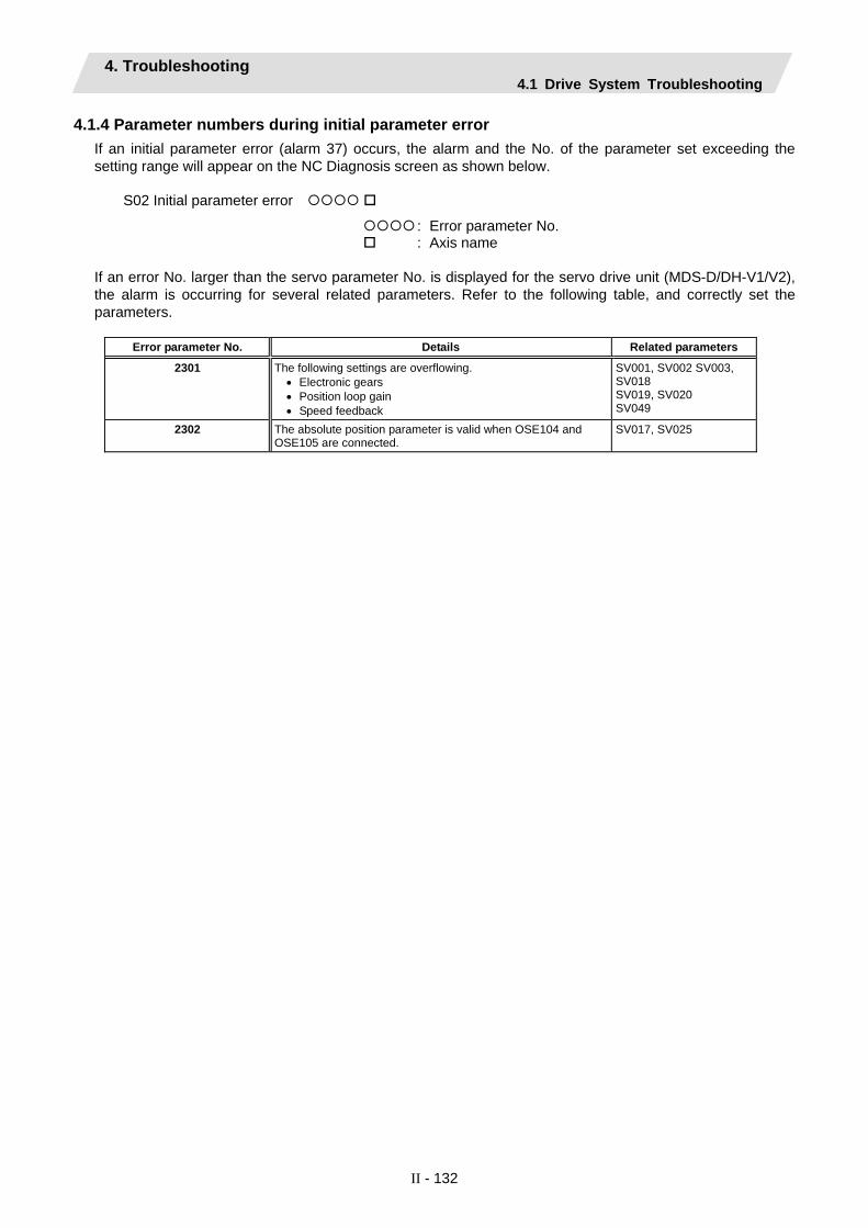
4. Troubleshooting 4.1 Drive System Troubleshooting
II - 132
4.1.4 Parameter numbers during initial parameter error If an initial parameter error (alarm 37) occurs, the alarm and the No. of the parameter set exceeding the setting range will appear on the NC Diagnosis screen as shown below.
S02 Initial parameter error
: Error parameter No. : Axis name
If an error No. larger than the servo parameter No. is displayed for the servo drive unit (MDS-D/DH-V1/V2), the alarm is occurring for several related parameters. Refer to the following table, and correctly set the parameters.
Error parameter No. Details Related parameters
2301 The following settings are overflowing. • Electronic gears • Position loop gain • Speed feedback
SV001, SV002 SV003, SV018 SV019, SV020 SV049
2302 The absolute position parameter is valid when OSE104 and OSE105 are connected.
SV017, SV025
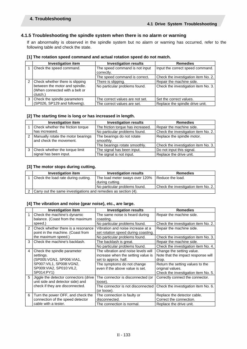
4. Troubleshooting 4.1 Drive System Troubleshooting
II - 133
4.1.5 Troubleshooting the spindle system when there is no alarm or warning If an abnormality is observed in the spindle system but no alarm or warning has occurred, refer to the following table and check the state.
[1] The rotation speed command and actual rotation speed do not match. Investigation item Investigation results Remedies
The speed command is not input correctly.
Input the correct speed command.1 Check the speed command.
The speed command is correct. Check the investigation item No. 2.There is slipping. Repair the machine side. 2 Check whether there is slipping
between the motor and spindle. (When connected with a belt or clutch.)
No particular problems found. Check the investigation item No. 3.
The correct values are not set. Set the correct values. 3 Check the spindle parameters (SP026, SP129 and following). The correct values are set. Replace the spindle drive unit.
[2] The starting time is long or has increased in length. Investigation item Investigation results Remedies
The friction torque has increased. Repair the machine side. 1 Check whether the friction torque has increased. No particular problems found. Check the investigation item No. 2.
The bearings do not rotate smoothly.
Replace the spindle motor. 2 Manually rotate the motor bearings and check the movement.
The bearings rotate smoothly. Check the investigation item No. 3.The signal has been input. Do not input this signal. 3 Check whether the torque limit
signal has been input. The signal is not input. Replace the drive unit.
[3] The motor stops during cutting. Investigation item Investigation results Remedies
The load meter sways over 120% during cutting.
Reduce the load. 1 Check the load rate during cutting.
No particular problems found. Check the investigation item No. 2.2 Carry out the same investigations and remedies as section (4).
[4] The vibration and noise (gear noise), etc., are large. Investigation item Investigation results Remedies
The same noise is heard during coasting.
Repair the machine side. 1 Check the machine's dynamic balance. (Coast from the maximum speed.) No particular problems found. Check the investigation item No. 2.
Vibration and noise increase at a set rotation speed during coasting.
Repair the machine side. 2 Check whether there is a resonance point in the machine. (Coast from the maximum speed.) No particular problems found. Check the investigation item No. 3.
The backlash is great. Repair the machine side. 3 Check the machine's backlash. No particular problems found. Check the investigation item No. 4.The vibration and noise levels will increase when the setting value is set to approx. half.
Change the setting value. Note that the impact response will drop.
4 Check the spindle parameter settings. (SP005:VGN1, SP006:VIA1, SP007:VIL1, SP008:VGN2, SP009:VIA2, SP010:VIL2, SP014:PY1)
The symptoms do not change even if the above value is set.
Return the setting values to the original values. Check the investigation item No. 5.
The connector is disconnected (or loose).
Correctly connect the connector. 5 Jiggle the detector connectors (drive unit side and detector side) and check if they are disconnected. The connector is not disconnected
(or loose). Check the investigation item No. 6.
The connection is faulty or disconnected.
Replace the detector cable. Correct the connection.
6 Turn the power OFF, and check the connection of the speed detector cable with a tester. The connection is normal. Replace the drive unit.

4. Troubleshooting 4.1 Drive System Troubleshooting
II - 134
[5] The spindle coasts during deceleration. Investigation item Investigation results Remedies
There is slipping. Repair the machine side. 1 Check whether there is slipping between the motor and spindle. (When connected with a belt or clutch.)
No particular problems found. Replace the drive unit.
[6] The rotation does not stabilize. Investigation item Investigation results Remedies
The rotation stabilizes when the settings values are both set to approx. double.
Change the setting value. Note that the gear noise may increase.
1 Check the spindle parameter SP005 (SP008) settings.
The symptoms do not change even when the above value is set.
Return the setting values to the original values. Check the investigation item No. 2.
The connector is disconnected (or loose).
Correctly connect the connector. 2 Manually shake the speed detector connectors (spindle drive unit side and speed detector side) to check if they are disconnected.
The connector is not disconnected (or loose).
Check the investigation item No. 3.
The connection is faulty or disconnected.
Replace the detector cable. Correct the connection.
3 Turn the power OFF, and check the connection of the speed detector cable with a tester. (Especially check the shield wiring.)
The connection is normal. Check the investigation item No. 4.
1) The grounding is incomplete. Correctly ground. 2) The alarm occurs easily when a
specific device operates. Use noise measures on the device described on the left.
4 Investigate the wiring and installation environment. 1) Is the ground correctly
connected? 2) Are there any noise-generating
devices near the drive unit?
No particular problems found. Replace the spindle drive unit.
[7] The speed does not rise above a set level. Investigation item Investigation results Remedies
The speed command is not input correctly.
Input the correct speed command.1 Check the speed command. Check whether the override input is input from the machine operation panel.
The speed command is input correctly.
Check the investigation item No. 2.
The load has become heavier. Repair the machine side. 2 Check whether the load has suddenly become heavier. No particular problems found. Check the investigation item No. 3.
The bearings do not rotate smoothly.
Replace the spindle motor. 3 Manually rotate the motor bearings and check the movement.
The bearings rotate smoothly. Check the investigation item No. 4.The connector is disconnected (or loose).
Correctly connect the connector. 4 Manually shake the speed detector connectors (spindle drive unit side and speed detector side) to check if they are disconnected.
The connector is not disconnected (or loose).
Check the investigation item No. 5.
The connection is faulty or disconnected.
Replace the detector cable. Correct the connection.
5 Turn the power OFF, and check the connection of the speed detector cable with a tester. (Especially check the shield wiring.)
The waveform is normal. Replace the spindle drive unit.

III Explanation of Parameters


1. Outline 1.1 Screen Transition Chart
III - 1
1. Outline 1.1 Screen Transition Chart
The menus for screens related to maintenance appear when the function key Mainte is pressed. The parameter menu appears when the menu key Param is pressed.
Ethernet parameters
I/O parameters
Axis parameters
Control parameters
Process parameters
Computer link
parameters
Zero point return
parameters
Axis specifica-
tions parameters
Base common
parameters
Base axis specifica-
tion parameters
Base system
parameters
Absolute position
parameters
Spindle specifica-
tion parameters
Servo parameters
Spindle parameters
Selecting the PLC bit
PLC constants
PLC counter
PLC integrated
timer
Rotary axis configura-
tion parameters
Error data
Error compensa-
tion parameters
PLC timer
Operation parameters
Subprogram storage
destination parameters
Position switches
Macro list
Barrier data
Auxiliary axis
parameters
User parameters
Machine parameters
Open param 2
Open param 1
(Note) There are user parameter dedicated menus in the screens related to setup. The menu configuration
differs slightly from the above configuration. Refer to the Instruction Manual for details.
1.2 Unit (1) Input setting unit and number of decimal digits
The number of digits in the decimal section of the parameters related to length is determined by the input setting unit. The input setting unit is set with parameter "#1003 iunit".
Input setting unit
No. of digits in decimal section Example of setting range
B 3 0 to 999.999 (mm) C 4 0 to 999.9999 (mm) D 5 0 to 999.99999 (mm) E 6 0 to 999.999999 (mm)
The setting ranges indicated in this manual use the input setting unit "B".
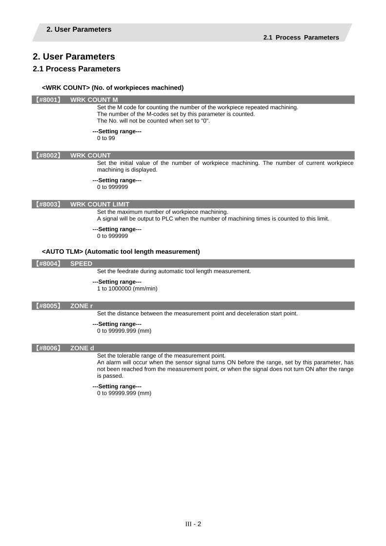
2. User Parameters 2.1 Process Parameters
III - 2
2. User Parameters 2.1 Process Parameters
<WRK COUNT> (No. of workpieces machined)
【#8001】 WRK COUNT M Set the M code for counting the number of the workpiece repeated machining. The number of the M-codes set by this parameter is counted. The No. will not be counted when set to "0".
---Setting range--- 0 to 99
【#8002】 WRK COUNT Set the initial value of the number of workpiece machining. The number of current workpiece machining is displayed.
---Setting range--- 0 to 999999
【#8003】 WRK COUNT LIMIT Set the maximum number of workpiece machining. A signal will be output to PLC when the number of machining times is counted to this limit.
---Setting range--- 0 to 999999
<AUTO TLM> (Automatic tool length measurement)
【#8004】 SPEED Set the feedrate during automatic tool length measurement.
---Setting range--- 1 to 1000000 (mm/min)
【#8005】 ZONE r Set the distance between the measurement point and deceleration start point.
---Setting range--- 0 to 99999.999 (mm)
【#8006】 ZONE d Set the tolerable range of the measurement point. An alarm will occur when the sensor signal turns ON before the range, set by this parameter, has not been reached from the measurement point, or when the signal does not turn ON after the range is passed.
---Setting range--- 0 to 99999.999 (mm)

2. User Parameters 2.1 Process Parameters
III - 3
<AUTO CORNER OVR.> (Automatic corner override)
【#8007】 OVERRIDE Set the override value for automatic corner override.
---Setting range--- 0 to 100 (%)
【#8008】 MAX ANGLE Set the maximum corner opening angle where deceleration should start automatically. When the angle is larger than this value‚ deceleration will not start.
---Setting range--- 0 to 180 (°)
【#8009】 DSC. ZONE Set the position where deceleration starts at the corner. Designate at which length point before the corner deceleration should start.
---Setting range--- 0 to 99999.999 (mm)
<T-TIP OFFSET> (Wear data input)
【#8010】 ABS. MAX. for L system only Set the maximum value when inputting the tool wear compensation amount. A value exceeding this setting value cannot be set. Absolute value of the input value is set. (If a negative value is input, it is treated and set as a positive value.) If "0" is input, this parameter will be disabled.
---Setting range--- 0 to 99.999 (mm) (Input setting increment applies)
【#8011】 INC. MAX. for L system only Set the maximum value for when inputting the tool wear compensation amount in the incremental mode. A value exceeding this setting value cannot be set. Absolute value of the input value is set. (If a negative value is input, it is treated and set as a positive value.) If "0" is input, this parameter will be disabled.
---Setting range--- 0 to 99.999 (mm) (Input setting increment applies)

2. User Parameters 2.1 Process Parameters
III - 4
<FIXED C.> (Fixed cycle)
【#8012】 G73 n for M system only Set the return amount for G73 (step cycle).
---Setting range--- 0 to 99999.999 (mm)
【#8013】 G83 n Set the return amount for G83 (deep hole drilling cycle).
---Setting range--- 0 to 99999.999 (mm)
【#8014】 CDZ-VALE for L system only Set the screw cut up amount for G76 and G78 (thread cutting cycle).
---Setting range--- 0 to 127 (0.1 lead)
【#8015】 CDZ-ANGLE for L system only Set the screw cut up angle for G76 and G78 (thread cutting cycle).
---Setting range--- 0 to 89 (°)
【#8016】 G71 MINIMUM for L system only Set the minimum value of the last cutting amount by the rough cutting cycle (G71, G72). The cutting amount of the last cutting will be the remainder. When the remainder is smaller than this parameter setting, the last cycle will not be executed.
---Setting range--- 0 to 999.999 (mm)
【#8017】 G71 DELTA-D for L system only Set the change amount of the rough cutting cycle. The rough cutting cycle (G71, G72) cutting amount repeats d+Δd, d, d-Δd using the value (d) commanded with D as a reference. Set the change amount Δd.
---Setting range--- 0 to 999.999 (mm)
【#8018】 G84/G74 n for M system only Not used. Set to "0".

2. User Parameters 2.1 Process Parameters
III - 5
<PRECISION> (High-accuracy control)
【#8019】 R COMP Set a compensation coefficient for reducing a control error in the reduction of a corner roundness and arch radius. The larger the setup value, the smaller the theoretical error will be. However, since the speed at the corner will go down, the cycle time will be extended. Coefficient = 100 - setting value (Note) This is valid when "#8021 COMP CHANGE" is set to "0".
---Setting range--- 0 to 99 (%)
Theor R decrease The value calculated with the following data is displayed for the theoretical radius reduction error amount ΔR (mm).
+
Command path
Path after servo control
ΔR
F
Theoretical radius reduction amount at arc center
【#8020】 DCC. angle Set up the minimum value of an angle (external angle) that should be assumed to be a corner. When an inter-block angle (external angle) in high-accuracy mode is larger than the set value, it will be determined as a corner and the speed will go down to sharpen the edge.
θ If the set value is smaller than θ, the speed goes down to optimize the corner.
(Note) If "0" is set, it will be handled as 5 degrees.
---Setting range--- 0 to 89 (degrees) 0: The angle will be 5°.
【#8021】 COMP_CHANGE Select whether to share or separate the compensation coefficient at the corner/curve during the high-accuracy control mode. 0: Share ("#8019 R COMP" is applied.) 1: Separate ・ Corner : #8022 CORNER COMP ・ Curve : #8023 CURVE COMP (Note) Set "1" when using SSS control.

2. User Parameters 2.1 Process Parameters
III - 6
【#8022】 CORNER COMP Set the compensation coefficient to further reduce or increase the roundness at the corner during the high-accuracy control mode. Coefficient = 100 - setting value (Note) This is valid when "#8021 COMP CHANGE" is set to "1".
---Setting range--- -1000 to 99 (%)
【#8023】 CURVE COMP Set the compensation coefficient to further reduce or increase the radius reduction amount at the curve (arc, involute, spline) during the high-accuracy control mode. Coefficient = 100 - setting value (Note) This is valid when "#8021 COMP CHANGE" is set to "1". For theoretical radius reduction error amount, refer to "Theor R decrease" in "#8019 R COMP"
---Setting range--- -1000 to 99 (%)
<SPILINE> (High-accuracy spline)
【#8025】 SPLINE ON for M system only Select whether to enable the spline function. 0: Disable 1: Enable Spline interpolation is valid during G61.2 modal, regardless of this setting.
【#8026】 CANCEL ANG. for M system only Set the angle where the spline interpolation is temporarily canceled. When the angle made by blocks exceeds this parameter setting value, spline interpolation will be canceled temporarily. In consideration of the pick feed, set a value a little smaller than the pick feed angle.
---Setting range--- 0 to 180 (°) 0: 180 (°)
【#8027】 Toler-1 for M system only Set the maximum chord error (tolerance) in a block that includes an inflection point. Set the tolerance applicable when the applicable block is developed to fine segments by CAM. (normally about 10 μm) When "0.000" is set, the applicable block will be linear.
---Setting range--- 0.000 to 100.000 (mm)
【#8028】 Toler-2 for M system only Set the maximum chord error (tolerance) in a block that includes no inflection point. Set the tolerance applicable when the applicable block is developed to fine segments by CAM. (normally about 10 μm) When "0.000" is set, the applicable block will be linear.
---Setting range--- 0.000 to 100.000 (mm)
【#8029】 FairingL for M system only Set the length of the block subject to fairing. (Enabled when "#8033 Fairing ON" is set to "1".)
---Setting range--- 0 to 100.000 (mm)

2. User Parameters 2.1 Process Parameters
III - 7
【#8030】 MINUTE LENGS for M system only Set the fine-segment length where the spline interpolation is temporarily canceled. When the length of one block exceeds this parameter setting value, spline interpolation is canceled temporarily and linear interpolation is performed. Set a value a little smaller than one block length of the program. If "-1" is set, spline interpolation will be performed regardless of block length.
---Setting range--- -1 to 127 (mm) 0: 1 (mm)
<Fairing>
【#8033】 Fairing ON for M system only Select whether to use the fairing function. 0: Not use 1: Use Fairing function is enabled during G61.2 modal, regardless of this setting.
【#8034】 AccClamp ON for M system only Select the method for clamping the cutting speed. 0: Clamp with parameter "#2002 clamp" or the corner deceleration function. 1: Clamp the cutting speed with acceleration judgment. (Enabled when "#8033 Fairing ON" is set to "1".)
【#8036】 CordecJudge for M system only Select the condition to decide a corner. 0: A corner is decided from the angle of the neighboring block. 1: A corner is decided from the angle of the neighboring block, excluding minute blocks. (Enabled when "#8033 Fairing ON" is set to "1".)
【#8037】 CorJudgeL for M system only Set the length of the block to be excluded when deciding a corner. (Enabled when "#8036 CordecJudge" is set to "1".)
---Setting range--- 0 to 99999.999 (mm)
<C-MODAL> (C axis normal line)
【#8041】 C-rot.R Set the length from the center of the normal line control axis to the tool tip. This is used to calculate the turning speed at the block joint. This is enabled during the normal line control type II.
---Setting range--- 0.000 to 99999.999 (mm)
【#8042】 C-ins.R Set the radius of the arc to be automatically inserted into the corner during normal line control. This is enabled during the normal line control type I.
---Setting range--- 0.000 to 99999.999 (mm)
【#8043】 Tool HDL FD OFS Set the length from the tool holder to the tool tip.
---Setting range--- 0.000 to 99999.999 (mm)

2. User Parameters 2.1 Process Parameters
III - 8
【#8044】 UNIT*10 Set the command increment scale. The scale will be "1" when "0" is set.
---Setting range--- 0 to 10000 (fold) 0: One fold
<FIXED C.> (Fixed cycle)
【#8051】 G71 THICK Set the amount of cut-in by the rough cutting cycle (G71, G72)
---Setting range--- 0 to 99999.999 (mm)
【#8052】 G71 PULL UP Set the amount of pull-up when returning to the cutting start point for the rough cutting cycle (G71. G72).
---Setting range--- 0 to 99999.999 (mm)
【#8053】 G73 U Set the X-axis cutting margin of the forming rough cutting cycle (G73).
---Setting range--- -99999.999 to 99999.999 (mm)
【#8054】 G73 W Set the Z-axis cutting margin of the forming rough cutting cycle (G73).
---Setting range--- -99999.999 to 99999.999 (mm)
【#8055】 G73 R Set how many times cutting will be performed in the forming rough cutting cycle (G73).
---Setting range--- 0 to 99999 (times)
【#8056】 G74 RETRACT Set the amount of retract (amount of cut-up) of the cutting-off cycle (G74, G75).
---Setting range--- 0 to 999.999 (mm)
【#8057】 G76 LAST-D Set the amount of final cut-in by the compound type thread cutting (G76).
---Setting range--- 0 to 999.999 (mm)
【#8058】 G76 TIMES Set how many times the amount of final cut-in cycle (G76 finish margin) will be divided in the compound type thread cutting (G76).
---Setting range--- 0 to 99 (times)

2. User Parameters 2.1 Process Parameters
III - 9
【#8059】 G76 ANGLE Set the angle (thread angle) of the tool nose in the compound type thread cutting (G76).
---Setting range--- 0 to 99 (°)
<3-dimensional tool radius compensation>
【#8071】 3-D CMP for M system only Set the value of the denominator constants for 3-dimensional tool radius compensation. Set the value of "p" in the following formula. Vx = i x r/p, Vy = j x r/p, Vz = k x r/p Vx, Vy, Vz : X, Y, and Z axes or vectors of horizontal axes i, j, k : Program command value r : Offset p =√(i2 + j2 + k2) when the set value is "0".
---Setting range--- 0 to 99999.999
<Scaling>
【#8072】 SCALING P for M system only Set the scale factor for reduction or magnification in the machining program specified by G50 or G51 command. This parameter will be valid when the program specifies no scale factor.
---Setting range--- -99.999999 to 99.999999
<Spiral interpolation>
【#8075】 SpiralEndErr for M system only Set the tolerable error range (absolute value) when the end point position, commanded by the spiral or conical interpolation command with the command format type 2, differs from the end point position obtained from the speed and increment/decrement amount.
---Setting range--- 0 to 99999.999 (mm)
【#8078】 Screen Saver Timer Set the period of time before turn-OFF of the display unit backlight. When "0" is set, the backlight is not turned OFF.
---Setting range--- 0 to 60 (min) 0: The backlight is not turned OFF
<Deep hole drilling cycle>
【#8083】 G83S modeM for M system only Set the M command code for changing to the small diameter deep hole drilling cycle mode.
---Setting range--- 1 to 99999999
【#8084】 G83S Clearance for M system only Set the clearance amount for the small diameter deep hole drilling cycle (G83).
---Setting range--- 0 to 999.999 (mm)

2. User Parameters 2.1 Process Parameters
III - 10
【#8085】 G83S Forward F for M system only Set the feedrate from the R point to the cutting start position in the small diameter deep hole drilling cycle (G83).
---Setting range--- 0 to 99999 (mm/min)
【#8086】 G83S Back F for M system only Set the speed for returning from the hole bottom during the small diameter deep hole drilling cycle (G83).
---Setting range--- 0 to 99999 (mm/min)
<SSS control>
【#8090】 SSS ON for M system only Set whether to enable the SSS control with G05 P10000. 0: Disable 1: Enable
【#8091】 StdLength for M system only Set the maximum value of the range for recognizing the shape. To eliminate the effect of steps or errors, etc., set a large value. To enable sufficient deceleration, set a small value. If "0.000" is set, the standard value (1.000mm) will be applied.
---Setting range--- 0 to 100.000 (mm)
【#8092】 ClampCoeff for M system only Set the clamp speed at the curved section configured of fine segments. Coefficient = √setting value
---Setting range--- 1 to 100
【#8093】 StepLeng for M system only Set the width of the step at which the speed is not to be decelerated. (Approximately the same as the CAM path difference [Tolerance].) If "0" is set, the standard value (5µm) will be applied. If a minus value is set, the speed will decelerate at all minute steps.
---Setting range--- -1.000 to 0.100 (mm)
【#8094】 DccWaitAdd for M system only Set the time to wait for deceleration when the speed FB does not drop to the clamp speed.
---Setting range--- 0 to 100 (ms)

2. User Parameters 2.1 Process Parameters
III - 11
<Coord rotation>
【#8621】 Coord rot plane (H) Set the plane (horizontal axis) for coordinate rotation control. Usually, set the name of the 1st axis. When not set, "X" axis will be set.
---Setting range--- Axis name
【#8622】 Coord rot plane (V) Set the plane (vertical axis) for coordinate rotation control. Usually, set the name of the 2nd axis. When not set, "Y" axis will be set.
---Setting range--- Axis name
【#8623】 Coord rot centr (H) Set the center coordinates (horizontal axis) for coordinate rotation control.
---Setting range--- -999999.999 to 999999.999 (mm)
【#8624】 Coord rot centr (V) Set the center coordinates (vertical axis) for coordinate rotation control.
---Setting range--- -999999.999 to 999999.999 (mm)
【#8625】 Coord rot vctr (H) Set the vector components (horizontal axis) for coordinate rotation control. When this parameter is set, the coordinate rotation control angle (#8627) will be automatically calculated.
---Setting range--- -999999.999 to 999999.999 (mm)
【#8626】 Coord rot vctr (V) Set the vector components (vertical axis) for coordinate rotation control. When this parameter is set, the coordinate rotation control angle (#8627) will be automatically calculated.
---Setting range--- -999999.999 to 999999.999 (mm)
【#8627】 Coord rot angle Set the rotation angle for coordinate rotation control. When this parameter is set, the coordinate rotation vector (#8625, #8626) will be "0".
---Setting range--- -360.000 to 360.000 (°)

2. User Parameters 2.1 Process Parameters
III - 12
<TLM>
【#8701】 Tool length Set the length to the touch tool tip.
---Setting range--- ±99999.999 (mm)
【#8702】 Tool Dia Set the diameter of the sphere at the touch tool tip.
---Setting range--- ±99999.999 (mm)
【#8703】 OFFSET X This sets the deviation amount (X direction) from the touch tool center to the spindle center.
---Setting range--- ±99999.999 (mm)
【#8704】 OFFSET Y Set the deviation amount (Y direction) from the touch tool center to the spindle center.
---Setting range--- ±99999.999 (mm)
【#8705】 RETURN Set the one-time return distance for contacting again.
---Setting range--- 0 to 99999.999 (mm)
【#8706】 FEED Set the feedrate when contacting again.
---Setting range--- 1 to 60000 (mm/min)
【#8707】 Skip past amout (H) Set the difference (horizontal axis direction) between the skip read value and actual skip position.
---Setting range--- ±99999.999 (mm)
【#8708】 Skip past amout (V) Set the difference (vertical axis direction) between the skip read value and actual skip position.
---Setting range--- ±99999.999 (mm)
【#8709】 EXT work sign rvs Select when using the external workpiece coordinate system with Z shift. Select whether to reverse the sign. 0: External workpiece offset (Z shift) without sign reversal 1: External workpiece offset (Z shift) with sign reversal
【#8710】 EXT work ofs invld Set whether to enable external workpiece offset subtraction when setting the workpiece coordinate offset. 0: Not subtract the external workpiece offset. (Conventional specification) 1: Subtract the external workpiece offset.
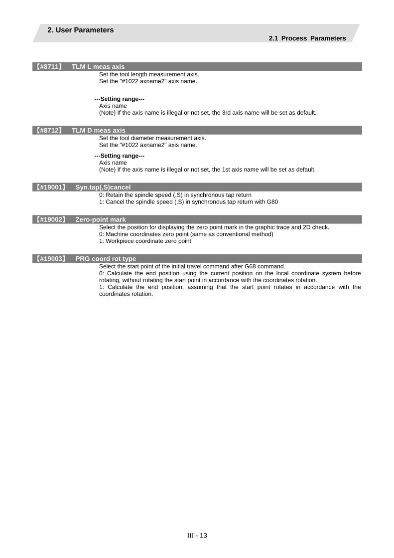
2. User Parameters 2.1 Process Parameters
III - 13
【#8711】 TLM L meas axis Set the tool length measurement axis. Set the "#1022 axname2" axis name.
---Setting range--- Axis name (Note) If the axis name is illegal or not set, the 3rd axis name will be set as default.
【#8712】 TLM D meas axis Set the tool diameter measurement axis. Set the "#1022 axname2" axis name.
---Setting range--- Axis name (Note) If the axis name is illegal or not set, the 1st axis name will be set as default.
【#19001】 Syn.tap(,S)cancel 0: Retain the spindle speed (,S) in synchronous tap return 1: Cancel the spindle speed (,S) in synchronous tap return with G80
【#19002】 Zero-point mark Select the position for displaying the zero point mark in the graphic trace and 2D check. 0: Machine coordinates zero point (same as conventional method) 1: Workpiece coordinate zero point
【#19003】 PRG coord rot type Select the start point of the initial travel command after G68 command. 0: Calculate the end position using the current position on the local coordinate system before rotating, without rotating the start point in accordance with the coordinates rotation. 1: Calculate the end position, assuming that the start point rotates in accordance with the coordinates rotation.

2. User Parameters 2.1 Process Parameters
III - 14
<Surface speed control>
【#19425】 ManualB Std R1 Set a radius used as standard for the rotary axis speed. When the setting value of #19425 is larger than that of "#19427 ManualB Std R2", #19425 setting will be used as surface speed control standard radius 2: #19427 setting will be used as surface speed control standard radius 1.
---Setting range--- 0 to 99999.999 (mm)
【#19426】 ManualB Std F1 This sets the rotary axis speed for surface speed control standard radius 1 (ManualB Std R1). When the setting value of #19426 is larger than that of "#19428 ManualB Std F2", #19426 setting will be used as surface speed control standard speed 2: #19427 setting will be used as surface speed control standard speed 1.
---Setting range--- 1 to 1000000 (°/min)
【#19427】 ManualB Std R2 Set a radius used as standard for the rotary axis speed. When the same value is set as "#19425 ManualB Std R1", the surface speed control standard speed 1 (ManualB Std F1) will be selected as the rotary axis speed if the radius is less than that value. The surface speed control standard speed 2 (ManualB Std F2) is selected if larger than the set value.
---Setting range--- 0 to 99999.999 (mm)
【#19428】 ManualB Std F2 Set the rotary axis speed for surface speed control standard radius 2 (ManualB Std R2).
---Setting range--- 1 to 1000000 (°/min)

2. User Parameters 2.2 Control Parameters
III - 15
2.2 Control Parameters
【#8101】 MACRO SINGLE Select how to control the blocks where the user macro command continues. 0: Do not stop while macro blocks continue. 1: Stop every block during signal block operation.
【#8102】 COLL. ALM OFF Select the interference (bite) control to the workpiece from the tool diameter during tool radius compensation and nose R compensation. 0: An alarm will be output and operation stops when an interference is judged. 1: Changes the path to avoid interference.
【#8103】 COLL. CHK OFF Select the interference (bite) control to the workpiece from the tool diameter during tool radius compensation and nose R compensation. 0: Performs interference check. 1: Does not perform interference check.
【#8105】 EDIT LOCK B Select the edit lock for program Nos. 8000 to 9999 in the memory. 0: Enable the editing. 1: Prohibit the editing of above programs. When "1" is set, the file cannot be opened.
【#8106】 G46 NO REV-ERR for L system only Select the control for the compensation direction reversal in G46 (nose R compensation). 0: An alarm will be output and operation will stop when the compensation direction is reversed (G41 -> G42’ G42 -> G41). 1: An alarm won't occur when the compensation direction is reversed, and the current compensation direction will be maintained.
【#8107】 R COMPENSATION Select whether to move to the inside because of a delay in servo response to a command during arc cutting mode. 0: Move to the inside, making the arc smaller than the command value. 1: Compensate the movement to the inside.
【#8108】 R COMP Select Select the arc radius error compensation target. 0: Perform compensation over all axes. 1: Perform compensation axis by axis. (Note) This parameter is effective only when "#8107 R COMPENSATION" is "1".
【#8109】 HOST LINK Select whether to enable computer link B instead of the RS-232C port. 0: Disable (Enable normal RS-232C communication.) 1: Enable (Disable normal RS-232C communication.)

2. User Parameters 2.2 Control Parameters
III - 16
【#8110】 G71/G72 POCKET Select whether to enable the pocket machining when there is a dimple (pocket) in the rough cutting cycle (G71, G72) finishing program. 0: OFF 1: ON
【#8111】 Milling Radius Select the diameter and radius of the linear axis for milling (cylindrical/pole coordinate) interpolation. 0: All axes radius command 1: Each axis setting (follows "#1019 dia") (Note) This parameter is valid only in the milling (cylindrical/polar coordinate) interpolation mode.
【#8112】 DECIMAL PNT-P Select whether to enable the decimal point command for G04 address P. 0: Disable 1: Enable
【#8113】 Milling Init G16 Set which plane to execute for milling machining after the power is turned ON or reset.
#8113 #8114 Plane0 0 G17 plane0 1 G19 plane1 01 1
G16 plane
0: Not G16 plane 1: G16 plane (Note) This parameter is valid for the G code system 2 or 3 ("#1037 cmdtyp"="3" or "4").
【#8114】 Milling Init G19 Set which plane to execute for milling machining after the power is turned ON or reset.
#8113 #8114 Plane0 0 G17 plane0 1 G19 plane1 01 1
G16 plane
0: Not G19 plane 1: G19 plane (Note) This parameter is valid for the G code system 2 or 3 ("#1037 cmdtyp"="3" or "4").
【#8116】 Coord rot para invd Select whether to enable the coordinate rotation by the parameters. 0: Enable 1: Disable
【#8117】 OFS Diam DESIGN Select tool radius or tool diameter compensation amount to be specified. 0: Tool radius compensation amount 1: Tool diameter compensation amount
【#8119】 Comp. unit switch Select the setting unit of compensation amount that has no decimal point. 0: 1mm (or 1inch) unit 1: The minimum command unit (follows "#1003 iunit")

2. User Parameters 2.2 Control Parameters
III - 17
【#8121】 Screen Capture Select whether to enable the screen capture function. 0: Disable 1: Enable (Note1) By setting this parameter to "1", and by keeping pushing the [SHIFT] key, screen capture will be executed. (Note2) This parameter is valid only with M70 Series.
【#8122】 Keep G43 MDL M-REF Select whether to keep the tool length offset by high speed manual reference position return during tool length offset. 0: Will not be kept (Cancel) 1: Kept
【#8124】 Mirr img at reset Select the operation type of the mirror image by parameter setting and the mirror image by external input.
0: The current mirror image is canceled, and new mirror image will start with the machine position at reset as the mirror center. 1: The mirror center is kept to continue the mirror image.
【#8145】 Validate F1 digit Select whether to execute the F command with a 1-digit code command or with a direct numerical command. 0: Direct numerical command (command feedrate during feed per minute or rotation) 1: 1-digit code command (with the feedrate specified by the parameters "#1185 spd_F1" to "#1189 F5")
【#8154(PR)】 Not used. Set to "0".
【#8155】 Sub-pro interrupt Select the method for the user macro interrupt. 0: The user macro interrupt of macro type 1: The user macro interrupt of sub-program type
【#8156】 Fine thread cut E Select the address E type when cutting an inch screw. 0: Specify the number of threads per inch for inch screw cutting. 1: Specify the precision lead for inch screw cutting.
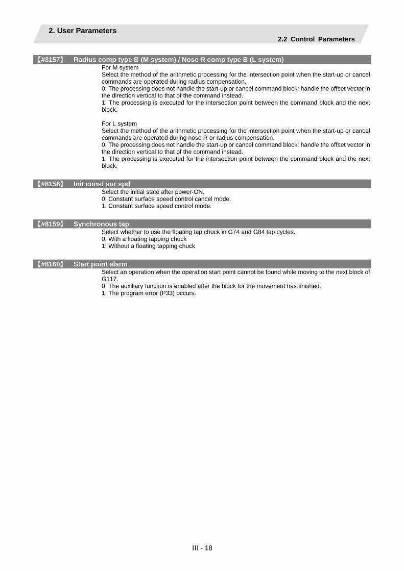
2. User Parameters 2.2 Control Parameters
III - 18
【#8157】 Radius comp type B (M system) / Nose R comp type B (L system) For M system Select the method of the arithmetic processing for the intersection point when the start-up or cancel commands are operated during radius compensation. 0: The processing does not handle the start-up or cancel command block: handle the offset vector in the direction vertical to that of the command instead. 1: The processing is executed for the intersection point between the command block and the next block. For L system Select the method of the arithmetic processing for the intersection point when the start-up or cancel commands are operated during nose R or radius compensation. 0: The processing does not handle the start-up or cancel command block: handle the offset vector in the direction vertical to that of the command instead. 1: The processing is executed for the intersection point between the command block and the next block.
【#8158】 Init const sur spd Select the initial state after power-ON. 0: Constant surface speed control cancel mode. 1: Constant surface speed control mode.
【#8159】 Synchronous tap Select whether to use the floating tap chuck in G74 and G84 tap cycles. 0: With a floating tapping chuck 1: Without a floating tapping chuck
【#8160】 Start point alarm Select an operation when the operation start point cannot be found while moving to the next block of G117. 0: The auxiliary function is enabled after the block for the movement has finished. 1: The program error (P33) occurs.
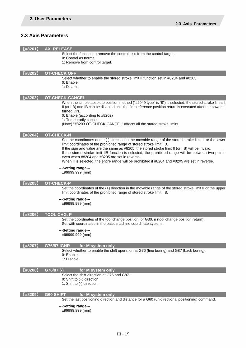
2. User Parameters 2.3 Axis Parameters
III - 19
2.3 Axis Parameters
【#8201】 AX. RELEASE Select the function to remove the control axis from the control target. 0: Control as normal. 1: Remove from control target.
【#8202】 OT-CHECK OFF Select whether to enable the stored stroke limit II function set in #8204 and #8205. 0: Enable 1: Disable
【#8203】 OT-CHECK-CANCEL When the simple absolute position method ("#2049 type" is "9") is selected, the stored stroke limits I, II (or IIB) and IB can be disabled until the first reference position return is executed after the power is turned ON. 0: Enable (according to #8202) 1: Temporarily cancel (Note) "#8203 OT-CHECK-CANCEL" affects all the stored stroke limits.
【#8204】 OT-CHECK-N Set the coordinates of the (-) direction in the movable range of the stored stroke limit II or the lower limit coordinates of the prohibited range of stored stroke limit IIB. If the sign and value are the same as #8205, the stored stroke limit II (or IIB) will be invalid. If the stored stroke limit IIB function is selected, the prohibited range will be between two points even when #8204 and #8205 are set in reverse. When II is selected, the entire range will be prohibited if #8204 and #8205 are set in reverse.
---Setting range--- ±99999.999 (mm)
【#8205】 OT-CHECK-P Set the coordinates of the (+) direction in the movable range of the stored stroke limit II or the upper limit coordinates of the prohibited range of stored stroke limit IIB.
---Setting range--- ±99999.999 (mm)
【#8206】 TOOL CHG. P Set the coordinates of the tool change position for G30. n (tool change position return). Set with coordinates in the basic machine coordinate system.
---Setting range--- ±99999.999 (mm)
【#8207】 G76/87 IGNR for M system only Select whether to enable the shift operation at G76 (fine boring) and G87 (back boring). 0: Enable 1: Disable
【#8208】 G76/87 (-) for M system only Select the shift direction at G76 and G87. 0: Shift to (+) direction 1: Shift to (-) direction
【#8209】 G60 SHIFT for M system only Set the last positioning direction and distance for a G60 (unidirectional positioning) command.
---Setting range--- ±99999.999 (mm)
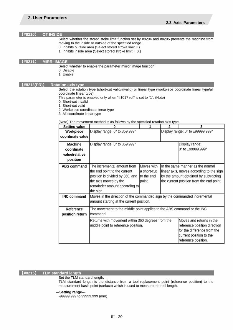
2. User Parameters 2.3 Axis Parameters
III - 20
【#8210】 OT INSIDE Select whether the stored stoke limit function set by #8204 and #8205 prevents the machine from moving to the inside or outside of the specified range. 0: Inhibits outside area (Select stored stroke limit II.) 1: Inhibits inside area (Select stored stroke limit II B.)
【#8211】 MIRR. IMAGE Select whether to enable the parameter mirror image function. 0: Disable 1: Enable
【#8213(PR)】 Rotation axis type Select the rotation type (short-cut valid/invalid) or linear type (workpiece coordinate linear type/all coordinate linear type). This parameter is enabled only when "#1017 rot" is set to "1". (Note) 0: Short-cut invalid 1: Short-cut valid 2: Workpiece coordinate linear type 3: All coordinate linear type (Note) The movement method is as follows by the specified rotation axis type.
Setting value 0 1 2 3Workpiece
coordinate value
Machinecoordinate
value/relativeposition
Display range:0° to ±99999.999°
ABS command The incremental amount fromthe end point to the currentposition is divided by 360, andthe axis moves by theremainder amount according tothe sign.
Moves witha short-cutto the endpoint.
INC command
Moves and returns in thereference position directionfor the difference from thecurrent position to thereference position.
Display range: 0° to 359.999° Display range: 0° to ±99999.999°
Display range: 0° to 359.999°
Referenceposition return
In the same manner as the normallinear axis, moves according to the signby the amount obtained by subtractingthe current position from the end point.
Moves in the direction of the commanded sign by the commanded incrementalamount starting at the current position.
The movement to the middle point applies to the ABS command or the INCcommand.Returns with movement within 360 degrees from themiddle point to reference position.
【#8215】 TLM standard length Set the TLM standard length. TLM standard length is the distance from a tool replacement point (reference position) to the measurement basic point (surface) which is used to measure the tool length.
---Setting range--- -99999.999 to 99999.999 (mm)

2. User Parameters 2.3 Axis Parameters
III - 21
【#8216】 Type in G28 return Select the performance after establishing the reference position in reference position return command. 0: Moves to the reference position. 1: Won't move to the reference position.
【#8217】 Check start point Set a drawing start position in graphic check of each axis.
---Setting range--- -99999.999 to 99999.999 (mm)

2. User Parameters 2.4 Operation Parameters
III - 22
2.4 Operation Parameters
【#8901】 Counter type 1 Set the type of counter displayed at the upper left of the AUTO/MDI display on the Monitor screen. 1: Current position 2: Work coordinate position 3: Machine position 4: Program position 8: Remain command 9: Manual interrupt amount 10: Next command 11: Restart position 12: Remain distance 16: Tip work coordinate position 18: Tool axis movement 19: Tip machine position 20: Relative position
---Setting range--- 0 to 255
【#8902】 Counter type 2 Set the type of counter displayed at the lower left of the AUTO/MDI display on the Monitor screen. 1: Current position 2: Work coordinate position 3: Machine position 4: Program position 8: Remain command 9: Manual interrupt amount 10: Next command 11: Restart position 12: Remain distance 16: Tip work coordinate position 18: Tool axis movement 19: Tip machine position 20: Relative position
---Setting range--- 0 to 255
【#8903】 Counter type 3 Set the type of counter displayed at the upper right of the AUTO/MDI display on the Monitor screen. 1: Current position 2: Work coordinate position 3: Machine position 4: Program position 8: Remain command 9: Manual interrupt amount 10: Next command 11: Restart position 12: Remain distance 16: Tip work coordinate position 18: Tool axis movement 19: Tip machine position 20: Relative position
---Setting range--- 0 to 255

2. User Parameters 2.4 Operation Parameters
III - 23
【#8904】 Counter type 4 Set the type of counter displayed at the lower right of the AUTO/MDI display on the Monitor screen. 1: Current position 2: Work coordinate position 3: Machine position 4: Program position 8: Remain command 9: Manual interrupt amount 10: Next command 11: Restart position 12: Remain distance 16: Tip work coordinate position 18: Tool axis movement 19: Tip machine position 20: Relative position
---Setting range--- 0 to 255
【#8905】 Counter type 5 Set the type of counter displayed at the left of the Manual display on the Monitor screen. 1: Current position 2: Work coordinate position 3: Machine position 4: Program position 8: Remain command 9: Manual interrupt amount 10: Next command 11: Restart position 12: Remain distance 16: Tip work coordinate position 18: Tool axis movement 19: Tip machine position 20: Relative position
---Setting range--- 0 to 255
【#8906】 Counter type 6 Set the type of counter displayed at the right of the Manual display on the Monitor screen. 1: Current position 2: Work coordinate position 3: Machine position 4: Program position 8: Remain command 9: Manual interrupt amount 10: Next command 11: Restart position 12: Remain distance 16: Tip work coordinate position 18: Tool axis movement 19: Tip machine position 20: Relative position
---Setting range--- 0 to 255
【#8910】 Edit undo Set whether to enable the Undo function during program edit on the Monitor screen or Edit screen. 0: Disable 1: Enable

2. User Parameters 2.4 Operation Parameters
III - 24
【#8914】 Auto Top search Select the operation method for restart search type 2. 0: It is necessary to set the top search position arbitrarily. 1: The restart search is executed from O No. that is designated as head.
【#8915】 Auto backup day 1 When the NC power is ON after the designated date was passed over, the automatic backup is executed. When "-1" is set to "Auto backup day 1", the automatic backup is executed every turning NC power ON. When "0" is set to all on "Auto backup day 1" to "4", the automatic backup is not executed. It is possible to specify the designated date up to 4 days for a month.
---Setting range--- -1 to 31 ("-1" can be set for "Auto backup day 1" only.)
【#8916】 Auto backup day 2 When the NC power is ON after the designated date was passed over, the automatic backup is executed. When "-1" is set to "Auto backup day 1", the automatic backup is executed every turning NC power ON. When "0" is set to all on "Auto backup day 1" to "4", the automatic backup is not executed. It is possible to specify the designated date up to 4 days for a month.
---Setting range--- -1 to 31 ("-1" can be set for "Auto backup day 1" only.)
【#8917】 Auto backup day 3 When the NC power is ON after the designated date was passed over, the automatic backup is executed. When "-1" is set to "Auto backup day 1", the automatic backup is executed every turning NC power ON. When "0" is set to all on "Auto backup day 1" to "4", the automatic backup is not executed. It is possible to specify the designated date up to 4 days for a month.
---Setting range--- -1 to 31 ("-1" can be set for "Auto backup day 1" only.)
【#8918】 Auto backup day 4 When the NC power is ON after the designated date was passed over, the automatic backup is executed. When "-1" is set to "Auto backup day 1", the automatic backup is executed every turning NC power ON. When "0" is set to all on "Auto backup day 1" to "4", the automatic backup is not executed. It is possible to specify the designated date up to 4 days for a month.
---Setting range--- -1 to 31 ("-1" can be set for "Auto backup day 1" only.)
【#8919】 Auto backup device Select the automatic backup target device. *The setting range differs according to the model.
---Setting range--- [M700 Series] 0: DS 1: HD 2: Memory card [M70 Series] 0: Memory card

2. User Parameters 2.4 Operation Parameters
III - 25
【#8920】 3D tool ofs select Select the method to calculate the drawing position when drawing a solid. With 3D drawing, the drawing position (tool tip position) is calculated with the method designated with this parameter, and the image is drawn. 0: Machine position ± tool shape setting window data 1: Machine position ± tool compensation amount 2: Machine position ± tool shape setting window data 3: Machine position ± tool shape setting window data
【#8921】 Mass Edit select Select the editing mode for the machining programs saved in HD, FD, and memory card. When the program size is 1.0MB (When "#8910 Edit Undo" is invalid, 2.0MB) or more, mass-editing will be applied. 0: Regular editing mode 1: Mass-editing mode
【#8922】 T-reg-dup check Set whether to enable the duplication check in registering tools to magazine pots, and in setting tool Nos. for spindle/standby. 0: Duplication check valid for all valid magazines 1: Duplication check invalid 2: Duplication check valid only for the selected magazine
【#8923(PR)】 Hide Edit-IO menu Set whether to enable the edit-in/out menu. When disabled, the edit-input/output menu won't appear. However, the maintenance-in/out menu is always enabled regardless of this parameter setting. 0: Enable 1: Disable
【#8924】 MEAS. CONFIRM MSG Select whether to display a confirming message when attempting to write compensation data for tool measurement, or coordinate system data for workpiece measurement. 0: Not display a confirming message 1: Display a confirming message
【#8925】 SP on 1st part sys Set a spindle No. to be displayed on the 1st part system window when 2-part system simultaneous display is valid. High-order: Select an upper side spindle No. Low-order: Select a lower side spindle No. (Note 1) When "00" is set, spindles will be displayed in a default order (the 1st spindle on the upper side, the 2nd spindle on the lower side) (Note 2) If you designate a bigger number than the setting of "#1039 spinno", or either the high-order or low-order setting is "0", the 1st spindle will be displayed.
---Setting range--- High-order: 0 to 6 Low-order: 0 to 6

2. User Parameters 2.4 Operation Parameters
III - 26
【#8926】 SP on 2nd part sys Set a spindle No. to be displayed on the 2nd part system window when 2-part system simultaneous display is valid. High-order: Select an upper side spindle No. Low-order: Select a lower side spindle No. (Note 1) When "00" is set, spindles will be displayed in a default order (the 1st spindle on the upper side, the 2nd spindle on the lower side) (Note 2) If you designate a bigger number than the setting of "#1039 spinno", or either the high-order or low-order setting is "0", the 1st spindle will be displayed.
---Setting range--- High-order: 0 to 6 Low-order: 0 to 6
【#8927】 SP on 3rd part sys Set a spindle No. to be displayed on the 3rd part system window when 2-part system simultaneous display is valid. High-order: Select an upper side spindle No. Low-order: Select a lower side spindle No. (Note 1) When "00" is set, spindles will be displayed in a default order (the 1st spindle on the upper side, the 2nd spindle on the lower side) (Note 2) If you designate a bigger number than the setting of "#1039 spinno", or either the high-order or low-order setting is "0", the 1st spindle will be displayed.
---Setting range--- High-order: 0 to 6 Low-order: 0 to 6
【#8928】 SP on 4th part sys Set a spindle No. to be displayed on the 4th part system window when 2-part system simultaneous display is valid. High-order: Select an upper side spindle No. Low-order: Select a lower side spindle No. (Note 1) When "00" is set, spindles will be displayed in a default order (the 1st spindle on the upper side, the 2nd spindle on the lower side) (Note 2) If you designate a bigger number than the setting of "#1039 spinno", or either the high-order or low-order setting is "0", the 1st spindle will be displayed.
---Setting range--- High-order: 0 to 6 Low-order: 0 to 6

2. User Parameters 2.5 Barrier Data
III - 27
2.5 Barrier Data (For L system only)
【#8300】 P0 Set the reference X-coordinates of the chuck and the tail stock barrier. Set the center coordinate (radius value) of workpiece by the basic machine coordinate system.
---Setting range--- ±99999.999 (mm)
【#8301】 P1 Set the area of the chuck and tail stock barrier. Set the coordinate from the center of workpiece (P0) for X-axis. (radius value) Set the coordinate value by basic machine coordinate system for Z-axis.
---Setting range--- ±99999.999 (mm)
【#8302】 P2 Set the area of the chuck and tail stock barrier. Set the coordinate from the center of workpiece (P0) for X-axis. (radius value) Set the coordinate value by basic machine coordinate system for Z-axis.
---Setting range--- ±99999.999 (mm)
【#8303】 P3 Set the area of the chuck and tail stock barrier. Set the coordinate from the center of workpiece (P0) for X-axis. (radius value) Set the coordinate value by basic machine coordinate system for Z-axis.
---Setting range--- ±99999.999 (mm)
【#8304】 P4 Set the area of the chuck and tail stock barrier. Set the coordinate from the center of workpiece (P0) for X-axis. (radius value) Set the coordinate value by basic machine coordinate system for Z-axis.
---Setting range--- ±99999.999 (mm)
【#8305】 P5 Set the area of the chuck and tail stock barrier. Set the coordinate from the center of workpiece (P0) for X-axis. (radius value) Set the coordinate value by basic machine coordinate system for Z-axis.
---Setting range--- ±99999.999 (mm)
【#8306】 P6 Set the area of the chuck and tail stock barrier. Set the coordinate from the center of workpiece (P0) for X-axis. (radius value) Set the coordinate value by basic machine coordinate system for Z-axis.
---Setting range--- ±99999.999 (mm)
【#8310】 Barrier ON Select whether to enable the chuck and tailstock barrier. 0: Disable (Setting from special display unit will be enabled) 1: Enable

2. User Parameters 2.5 Barrier Data
III - 28
【#8311】 P7 Set the area of the left spindle section. Set the coordinate from the center of workpiece (P0) for X-axis. (radius value) Set the coordinate value by basic machine coordinate system for Z-axis.
---Setting range--- ±99999.999 (mm)
【#8312】 P8 Set the area of the left spindle section. Set the coordinate from the center of workpiece (P0) for X-axis. (radius value) Set the coordinate value by basic machine coordinate system for Z-axis.
---Setting range--- ±99999.999 (mm)
【#8313】 P9 Set the area of the right spindle section. X axis: Set the coordinate from the workpiece center (P0). (radius value) Z axis: Set the coordinates in the basic machine coordinate system.
---Setting range--- ±99999.999 (mm)
【#8314】 P10 Set the area of the right spindle section. Set the coordinate from the center of workpiece (P0) for X-axis. (radius value) Set the coordinate value by basic machine coordinate system for Z-axis.
---Setting range--- ±99999.999 (mm)
【#8315】 Barrier Type (L) Select the shape of the left chuck and tailstock barrier. 0: No area 1: Chuck 2: Tailstock
【#8316】 Barrier Type (R) Select the shape of the right chuck and tailstock barrier. 0: No area 1: Chuck 2: Tailstock
【#8317】 ELIV. AX. Name Set the name of the delivery axis when the right chuck and tailstock barrier is movable. When using the multi-part system method and the delivery axis is an axis in the other part system, designate the axis including the part system as 1A, 1B or 2A, 2B. If the part system is not designated as A and B, the set part system will be used.
---Setting range--- A/B/.. (axis name) 1A/1B/.. 2A/2B/.. (with part system designated) 0: Cancel
【#8318】 Stock Angle (L) Set the angle for the left tailstock end section. The angle will be interpreted as 90° if there is no setting (when "0" is set).
---Setting range--- 0 to 180 (°) 0: 90° (default)

2. User Parameters 2.5 Barrier Data
III - 29
【#8319】 Stock Angle (R) Set the angle for the right tailstock end section. The angle will be interpreted as 90° if there is no setting (when "0" is set).
---Setting range--- 0 to 180 (°) 0: 90° (default)
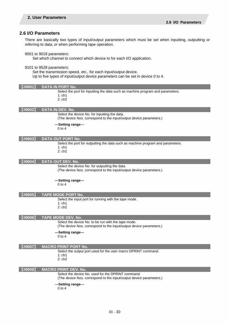
2. User Parameters 2.6 I/O Parameters
III - 30
2.6 I/O Parameters There are basically two types of input/output parameters which must be set when inputting‚ outputting or referring to data‚ or when performing tape operation.
9001 to 9018 parameters:
Set which channel to connect which device to for each I/O application.
9101 to 9528 parameters: Set the transmission speed, etc., for each input/output device. Up to five types of input/output device parameters can be set in device 0 to 4.
【#9001】 DATA IN PORT No. Select the port for inputting the data such as machine program and parameters. 1: ch1 2: ch2
【#9002】 DATA IN DEV. No. Select the device No. for inputting the data. (The device Nos. correspond to the input/output device parameters.)
---Setting range--- 0 to 4
【#9003】 DATA OUT PORT No. Select the port for outputting the data such as machine program and parameters. 1: ch1 2: ch2
【#9004】 DATA OUT DEV. No. Select the device No. for outputting the data. (The device Nos. correspond to the input/output device parameters.)
---Setting range--- 0 to 4
【#9005】 TAPE MODE PORT No. Select the input port for running with the tape mode. 1: ch1 2: ch2
【#9006】 TAPE MODE DEV. No. Select the device No. to be run with the tape mode. (The device Nos. correspond to the input/output device parameters.)
---Setting range--- 0 to 4
【#9007】 MACRO PRINT PORT No. Select the output port used for the user macro DPRINT command. 1: ch1 2: ch2
【#9008】 MACRO PRINT DEV. No. Select the device No. used for the DPRINT command. (The device Nos. correspond to the input/output device parameters.)
---Setting range--- 0 to 4
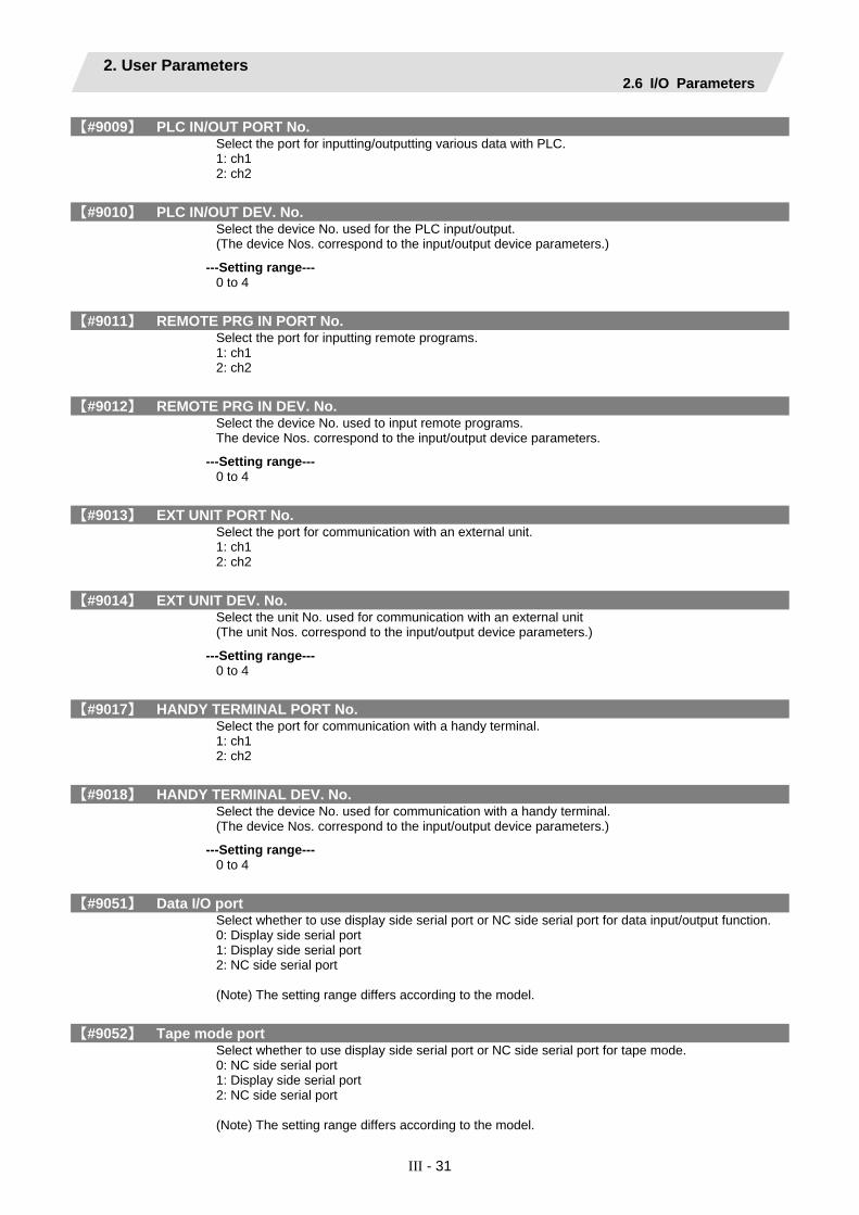
2. User Parameters 2.6 I/O Parameters
III - 31
【#9009】 PLC IN/OUT PORT No. Select the port for inputting/outputting various data with PLC. 1: ch1 2: ch2
【#9010】 PLC IN/OUT DEV. No. Select the device No. used for the PLC input/output. (The device Nos. correspond to the input/output device parameters.)
---Setting range--- 0 to 4
【#9011】 REMOTE PRG IN PORT No. Select the port for inputting remote programs. 1: ch1 2: ch2
【#9012】 REMOTE PRG IN DEV. No. Select the device No. used to input remote programs. The device Nos. correspond to the input/output device parameters.
---Setting range--- 0 to 4
【#9013】 EXT UNIT PORT No. Select the port for communication with an external unit. 1: ch1 2: ch2
【#9014】 EXT UNIT DEV. No. Select the unit No. used for communication with an external unit (The unit Nos. correspond to the input/output device parameters.)
---Setting range--- 0 to 4
【#9017】 HANDY TERMINAL PORT No. Select the port for communication with a handy terminal. 1: ch1 2: ch2
【#9018】 HANDY TERMINAL DEV. No. Select the device No. used for communication with a handy terminal. (The device Nos. correspond to the input/output device parameters.)
---Setting range--- 0 to 4
【#9051】 Data I/O port Select whether to use display side serial port or NC side serial port for data input/output function. 0: Display side serial port 1: Display side serial port 2: NC side serial port (Note) The setting range differs according to the model.
【#9052】 Tape mode port Select whether to use display side serial port or NC side serial port for tape mode. 0: NC side serial port 1: Display side serial port 2: NC side serial port (Note) The setting range differs according to the model.

2. User Parameters 2.6 I/O Parameters
III - 32
【#9101】 DEV0 DEVICE NAME Set the device name corresponding to the device No. Set a simple name for quick identification.
---Setting range--- Use alphabet characters‚ numerals and symbols to set a name within 3 characters.
【#9102】 DEV0 BAUD RATE Select the serial communication speed. 0: 19200 (bps) 1: 9600 2: 4800 3: 2400 4: 1200 5: 600 6: 300 7: 110
【#9103】 DEV0 STOP BIT Select the stop bit length used in the start-stop system. Refer to "#9104 DEV0 PARITY CHECK". At the output of data, the number of characters is always adjusted for the parity check. 1: 1 (bit) 2: 1.5 3: 2
【#9104】 DEV0 PARITY CHECK Select whether to add the parity check bit to the data. ON OFF
Start bit Data bit Parity bit Stop bit
1 character
b1 b2 b3 b4 b5 b6 bn
Set this parameter in accordance with the I/O device specifications. 0: Not add a parity bit in I/O mode 1: Add a parity bit in I/O mode
【#9105】 DEV0 EVEN PARITY Select odd or even when parity is added to the data. This parameter is ignored when no parity is added. 0: Odd parity 1: Even parity
【#9106】 DEV0 CHR. LENGTH Set the length of the data bit. Refer to "#9104 DEV0 PARITY CHECK". 0: 5 (bit) 1: 6 2: 7 (NC connection not supported) 3: 8
【#9107】 DEV0 TERMINATR TYP Select the code to terminate data reading. 0, 3: EOR 1, 2: EOB or EOR

2. User Parameters 2.6 I/O Parameters
III - 33
【#9108】 DEV0 HAND SHAKE Select the transmission control method. No handshaking will be used when a value except 1 to 3 is set. 1: RTS/CTS method 2: No handshaking 3: DC code method
【#9109】 DEV0 DC CODE PRTY Select the DC code type when the DC code method is selected. 0: Not add parity to DC code (DC3 = 13H) 1: Add parity to DC code (DC3 = 93H)
【#9111】 DEV0 DC2/4 OUTPUT Select the DC code handling when outputting data to the output device.
---Setting range--- DC2 / DC4 0: None / None 1: Yes / None 2: None / Yes 3: Yes / Yes
【#9112】 DEV0 CR OUTPUT Select whether to add the (CR) code just before the EOB (L/F) code during output. 0: Not add 1: Add
【#9113】 DEV0 EIA OUTPUT Select ISO or EIA code for data output. In data input mode, the ISO and EIA codes are identified automatically. 0: ISO code output 1: EIA code output
【#9114】 DEV0 FEED CHR. Set the length of the tape feed to be output at the start and end of the data during tape output.
---Setting range--- 0 to 999 (characters)
【#9115】 DEV0 PARITY V Select whether to perform the parity check for the number of characters in a block at the input of data. At the output of data, the number of characters is always adjusted to for the parity check. 0: Not perform parity V check 1: Perform parity V check
【#9116】 DEV0 TIME-OUT (sec) Set the time out time to detect an interruption in communication. Time out check will not be executed when set to "0".
---Setting range--- 0 to 30 (s)
【#9117】 DEV0 DR OFF Select whether to enable the DR data check in data I/O mode. 0: Enable 1: Disable

2. User Parameters 2.6 I/O Parameters
III - 34
【#9118】 DEV0 DATA ASCII Select the code of the output data. 0: ISO/EIA code (Depends on whether #9113, #9213, #9313, #9413 or #9513 EIA output parameter is set up.) 1: ASCII code
【#9119】 DEV0 INPUT TYPE Select the mode for input (verification). 0: Standard input (Data from the very first EOB is handled as significant information.) 1: EOBs following the first EOB of the input data are skipped until data other than EOB is input
【#9121】 DEV0 EIA CODE [ Set the code in hexadecimal, which does not duplicate the existing EIA codes, for the special code " [ ". When output with EIA code‚ data can be output using the alternate code in which the special ISO code, not included in EIA, is specified.
---Setting range--- 0 to FF (hexadecimal)
【#9122】 DEV0 EIA CODE ] Set the code in hexadecimal, which does not duplicate the existing EIA codes, for the special code " ] ". When output with EIA code, data can be output using the alternate code in which the special ISO code, not included in EIA, is specified.
---Setting range--- 0 to FF (hexadecimal)
【#9123】 DEV0 EIA CODE # Set the code in hexadecimal, which does not duplicate the existing EIA codes, for the special code "#". When output with EIA code, data can be output using the alternate code in which the special ISO code, not included in EIA, is specified.
---Setting range--- 0 to FF (hexadecimal)
【#9124】 DEV0 EIA CODE * Set the code in hexadecimal, which does not duplicate the existing EIA codes, for the special code "∗". When output with EIA code‚ data can be output using the alternate code in which the special ISO code, not included in EIA, is specified.
---Setting range--- 0 to FF (hexadecimal)
【#9125】 DEV0 EIA CODE = Set the code in hexadecimal, which does not duplicate the existing EIA codes, for the special code "=". When output with EIA code‚ data can be output using the alternate code in which the special ISO code, not included in EIA, is specified.
---Setting range--- 0 to FF (hexadecimal)
【#9126】 DEV0 EIA CODE : Set the code in hexadecimal, which does not duplicate the existing EIA codes, for the special code " : ". When output with EIA code‚ data can be output using the alternate code in which the special ISO code, not included in EIA, is specified.
---Setting range--- 0 to FF (hexadecimal)

2. User Parameters 2.6 I/O Parameters
III - 35
【#9127】 DEV0 EIA CODE $ Set the code in hexadecimal, which does not duplicate the existing EIA codes, for the special code "$". When output with EIA code‚ data can be output using the alternate code in which the special ISO code, not included in EIA, is specified.
---Setting range--- 0 to FF (hexadecimal)
【#9128】 DEV0 EIA CODE ! Set the code in hexadecimal, which does not duplicate the existing EIA codes, for the special code "!". When output with EIA code‚ data can be output using the alternate code in which the special ISO code, not included in EIA, is specified.
---Setting range--- 0 to FF (hexadecimal)
【#9201】 DEV1 DEVICE NAME Set the device name corresponding to the device No. Set a simple name for quick identification. <Setting range> Use alphabet characters‚ numerals and symbols to set a name within 3 characters.
【#9202】 DEV1 BAUD RATE Select the serial communication speed. 0: 19200 (bps) 1: 9600 2: 4800 3: 2400 4: 1200 5: 600 6: 300 7: 110
【#9203】 DEV1 STOP BIT Select the stop bit length used in the start-stop system. Refer to "#9204 DEV1 PARITY CHECK". At the output of data, the number of characters is always adjusted to for the parity check. <Setting range> 1: 1 (bit) 2: 1.5 3: 2
【#9204】 DEV1 PARITY CHECK Select whether to add a parity check bit to the data.
ON OFF
Start bit Data bit Parity bit Stop bit
1 character
b1 b2 b3 b4 b5 b6 bn
Set this parameter in accordance with the I/O device specifications. 0: Not add a parity bit in I/O mode 1: Add a parity bit in I/O mode
【#9205】 DEV1 EVEN PARITY Select whether even or odd parity will be used when parity is used. This parameter is ignored when no parity is added. 0: Odd parity 1: Even parity

2. User Parameters 2.6 I/O Parameters
III - 36
【#9206】 DEV1 CHR. LENGTH Select the length of the data bit. Refer to "#9204 DEV1 PARITY CHECK". <Setting range> 0: 5 (bit) 1: 6 2: 7 (NC connection not supported) 3: 8
【#9207】 DEV1 TERMINATR TYP Select the code to terminate data reading. 0,3: EOR 1,2: EOB or EOR
【#9208】 DEV1 HAND SHAKE Select the transmission control method. No handshaking will be used when a value except 1 to 3 is set. 1: RTS/CTS method 2: No handshaking 3: DC code method
【#9209】 DEV1 DC CODE PRTY Select the DC code type when the DC code method is selected. 0: Not add parity to DC code (DC3 = 13H) 1: Add parity to DC code (DC3 = 93H)
【#9211】 DEV1 DC2/4 OUTPUT Select the DC code handling when outputting data to the output device. <Setting range> DC2 / DC4 0: None / None 1: Yes / None 2: None / Yes 3: Yes / Yes
【#9212】 DEV1 CR OUTPUT Select whether to add the (CR) code just before the EOB (L/F) code during output. 0: Not add 1: Add
【#9213】 DEV1 EIA OUTPUT Select ISO or EIA code for data output. In data input mode, the ISO and EIA codes are identified automatically. 0: ISO code output 1: EIA code output
【#9214】 DEV1 FEED CHR. Set the length of the tape feed to be output at the start and end of the data during tape output. <Setting range> 0 to 999 (characters)
【#9215】 DEV1 PARITY V Select whether to perform the parity check for the number of characters in a block at the input of data. At the output of data, the number of characters is always adjusted to for the parity check. 0: Not perform parity V check 1: Perform parity V check

2. User Parameters 2.6 I/O Parameters
III - 37
【#9216】 DEV1 TIME-OUT (sec) Set the time out time to detect an interruption in communication. Time out check will not be executed when set to "0". <Setting range> 0 to 30 (s)
【#9217】 DEV1 DR OFF Select whether to enable the DR data check in data I/O mode. 0: Enable 1: Disable
【#9218】 DEV1 DATA ASCII Select the code of the output data. 0: ISO/EIA code (Depends on whether #9113, #9213, #9313, #9413 or #9513 EIA output parameter is set up.) 1: ASCII code
【#9219】 DEV1 INPUT TYPE Select the mode for input (verification). 0: Standard input (Data from the very first EOB is handled as significant information.) 1: EOBs following the first EOB of the input data are skipped until data other than EOB is input
【#9221】 DEV1 EIA CODE [ Set the code in hexadecimal, which does not duplicate the existing EIA codes, for the special code " [ ". When output with EIA code, data can be output using the alternate code in which the special ISO code, not included in EIA, is specified. <Setting range> 0 to FF (hexadecimal)
【#9222】 DEV1 EIA CODE ] Set the code in hexadecimal, which does not duplicate the existing EIA codes, for the special code " ] ". When output with EIA code, data can be output using the alternate code in which the special ISO code, not included in EIA, is specified. <Setting range> 0 to FF (hexadecimal)
【#9223】 DEV1 EIA CODE # Set the code in hexadecimal, which does not duplicate the existing EIA codes, for the special code "#". When output with EIA code, data can be output using the alternate code in which the special ISO code, not included in EIA, is specified. . <Setting range> 0 to FF (hexadecimal)
【#9224】 DEV1 EIA CODE ∗ Set the code in hexadecimal, which does not duplicate the existing EIA codes, for the special code "∗". When output with EIA code, data can be output using the alternate code in which the special ISO code, not included in EIA, is specified. <Setting range> 0 to FF (hexadecimal)

2. User Parameters 2.6 I/O Parameters
III - 38
【#9225】 DEV1 EIA CODE = Set the code in hexadecimal, which does not duplicate the existing EIA codes, for the special code "=". When output with EIA code‚ data can be output using the alternate code in which the special ISO code, not included in EIA, is specified. <Setting range> 0 to FF (hexadecimal)
【#9226】 DEV1 EIA CODE : Set the code in hexadecimal, which does not duplicate the existing EIA codes, for the special code " : ". When output with EIA code‚ data can be output using the alternate code in which the special ISO code, not included in EIA, is specified. <Setting range> 0 to FF (hexadecimal)
【#9227】 DEV1 EIA CODE $ Set the code in hexadecimal, which does not duplicate the existing EIA codes, for the special code "$". When output with EIA code‚ data can be output using the alternate code in which the special ISO code, not included in EIA, is specified. <Setting range> 0 to FF (hexadecimal)
【#9228】 DEV1 EIA CODE ! Set the code in hexadecimal, which does not duplicate the existing EIA codes, for the special code "!". When output with EIA code‚ data can be output using the alternate code in which the special ISO code, not included in EIA, is specified. <Setting range> 0 to FF (hexadecimal)
【#9301】 DEV2 DEVICE NAME Set the device name corresponding to the device No. Set a simple name for quick identification. <Setting range> Use alphabet characters‚ numerals and symbols to set a name within 3 characters.
【#9302】 DEV2 BAUD RATE Select the serial communication speed. 0: 19200 (bps) 1: 9600 2: 4800 3: 2400 4: 1200 5: 600 6: 300 7: 110
【#9303】 DEV2 STOP BIT Select the stop bit length used in the start-stop system. Refer to "#9304 DEV2 PARITY CHECK". At the output of data, the number of characters is always adjusted to for the parity check. 1: 1 (bit) 2: 1.5 3: 2

2. User Parameters 2.6 I/O Parameters
III - 39
【#9304】 DEV2 PARITY CHECK Select whether to add a parity check bit to the data.
ON OFF
Start bit Data bit Parity bit Stop bit
1 character
b1 b2 b3 b4 b5 b6 bn
Set this parameter in accordance with the I/O device specifications. 0: Not add a parity bit in I/O mode 1: Add a parity bit in I/O mode
【#9305】 DEV2 EVEN PARITY Select whether even or odd parity will be used when parity is used. This parameter is ignored when no parity is added. 0: Odd parity 1: Even parity
【#9306】 DEV2 CHR. LENGTH Select the length of the data bit. Refer to "#9304 DEV2 PARITY CHECK". 0: 5 (bit) 1: 6 2: 7 (NC connection not supported) 3: 8
【#9307】 DEV2 TERMINATR TYP Select the code to terminate data reading. 0, 3: EOR 1, 2: EOB or EOR
【#9308】 DEV2 HAND SHAKE Select the transmission control method. No handshaking will be used when a value except 1 to 3 is set. 1: RTS/CTS method 2: No handshaking 3: DC code method
【#9309】 DEV2 DC CODE PRTY Select the DC code type when the DC code method is selected. 0: Not add parity to DC code (DC3 = 13H) 1: Add parity to DC code (DC3 = 93H)
【#9311】 DEV2 DC2/4 OUTPUT Select the DC code handling when outputting data to the output device. <Setting range> DC2 / DC4 0: None / None 1: Yes / None 2: None / Yes 3: Yes / Yes
【#9312】 DEV2 CR OUTPUT Select whether to add the (CR) code just before the EOB (L/F) code during output. 0: Not add 1: Add
【#9313】 DEV2 EIA OUTPUT Select ISO or EIA code for data output. In data input mode, the ISO and EIA codes are identified automatically. 0: ISO code output 1: EIA code output
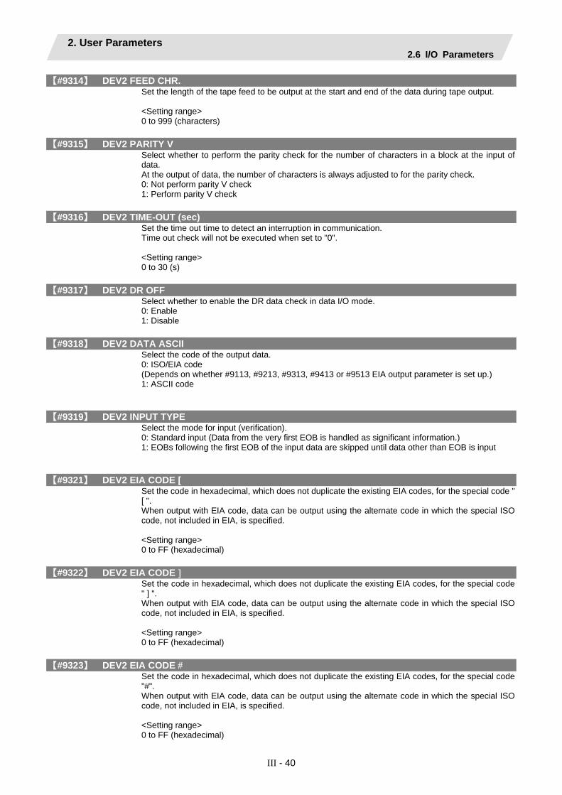
2. User Parameters 2.6 I/O Parameters
III - 40
【#9314】 DEV2 FEED CHR. Set the length of the tape feed to be output at the start and end of the data during tape output. <Setting range> 0 to 999 (characters)
【#9315】 DEV2 PARITY V Select whether to perform the parity check for the number of characters in a block at the input of data. At the output of data, the number of characters is always adjusted to for the parity check. 0: Not perform parity V check 1: Perform parity V check
【#9316】 DEV2 TIME-OUT (sec) Set the time out time to detect an interruption in communication. Time out check will not be executed when set to "0". <Setting range> 0 to 30 (s)
【#9317】 DEV2 DR OFF Select whether to enable the DR data check in data I/O mode. 0: Enable 1: Disable
【#9318】 DEV2 DATA ASCII Select the code of the output data. 0: ISO/EIA code (Depends on whether #9113, #9213, #9313, #9413 or #9513 EIA output parameter is set up.) 1: ASCII code
【#9319】 DEV2 INPUT TYPE Select the mode for input (verification). 0: Standard input (Data from the very first EOB is handled as significant information.) 1: EOBs following the first EOB of the input data are skipped until data other than EOB is input
【#9321】 DEV2 EIA CODE [ Set the code in hexadecimal, which does not duplicate the existing EIA codes, for the special code " [ ". When output with EIA code, data can be output using the alternate code in which the special ISO code, not included in EIA, is specified. <Setting range> 0 to FF (hexadecimal)
【#9322】 DEV2 EIA CODE ] Set the code in hexadecimal, which does not duplicate the existing EIA codes, for the special code " ] ". When output with EIA code, data can be output using the alternate code in which the special ISO code, not included in EIA, is specified. <Setting range> 0 to FF (hexadecimal)
【#9323】 DEV2 EIA CODE # Set the code in hexadecimal, which does not duplicate the existing EIA codes, for the special code "#". When output with EIA code, data can be output using the alternate code in which the special ISO code, not included in EIA, is specified. <Setting range> 0 to FF (hexadecimal)

2. User Parameters 2.6 I/O Parameters
III - 41
【#9324】 DEV2 EIA CODE ∗ Set the code in hexadecimal, which does not duplicate the existing EIA codes, for the special code "∗". When output with EIA code, data can be output using the alternate code in which the special ISO code, not included in EIA, is specified. <Setting range> 0 to FF (hexadecimal)
【#9325】 DEV2 EIA CODE = Set the code in hexadecimal, which does not duplicate the existing EIA codes, for the special code "=". When output with EIA code, data can be output using the alternate code in which the special ISO code, not included in EIA, is specified. <Setting range> 0 to FF (hexadecimal)
【#9326】 DEV2 EIA CODE : Set the code in hexadecimal, which does not duplicate the existing EIA codes, for the special code " : ". When output with EIA code, data can be output using the alternate code in which the special ISO code, not included in EIA, is specified. <Setting range> 0 to FF (hexadecimal)
【#9327】 DEV2 EIA CODE $ Set the code in hexadecimal, which does not duplicate the existing EIA codes, for the special code "$". When output with EIA code, data can be output using the alternate code in which the special ISO code, not included in EIA, is specified. <Setting range> 0 to FF (hexadecimal)
【#9328】 DEV2 EIA CODE ! Set the code in hexadecimal, which does not duplicate the existing EIA codes, for the special code "!". When output with EIA code, data can be output using the alternate code in which the special ISO code, not included in EIA, is specified. <Setting range> 0 to FF (hexadecimal)
【#9401】 DEV3 DEVICE NAME Set the device name corresponding to the device No. Set a simple name for quick identification. <Setting range> Use alphabet characters‚ numerals and symbols to set a name within 3 characters.
【#9402】 DEV3 BAUD RATE Select the serial communication speed. 0: 19200 (bps) 1: 9600 2: 4800 3: 2400 4: 1200 5: 600 6: 300 7: 110
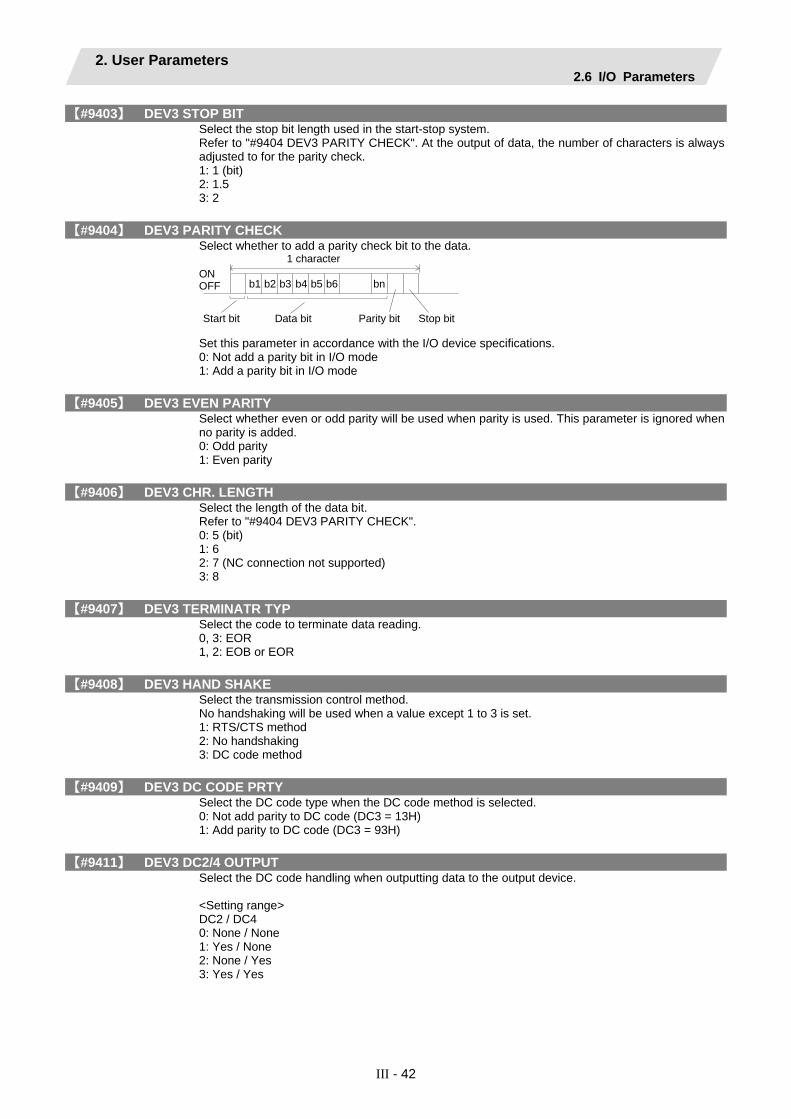
2. User Parameters 2.6 I/O Parameters
III - 42
【#9403】 DEV3 STOP BIT Select the stop bit length used in the start-stop system. Refer to "#9404 DEV3 PARITY CHECK". At the output of data, the number of characters is always adjusted to for the parity check. 1: 1 (bit) 2: 1.5 3: 2
【#9404】 DEV3 PARITY CHECK Select whether to add a parity check bit to the data. ON OFF
Start bit Data bit Parity bit Stop bit
1 character
b1 b2 b3 b4 b5 b6 bn
Set this parameter in accordance with the I/O device specifications. 0: Not add a parity bit in I/O mode 1: Add a parity bit in I/O mode
【#9405】 DEV3 EVEN PARITY Select whether even or odd parity will be used when parity is used. This parameter is ignored when no parity is added. 0: Odd parity 1: Even parity
【#9406】 DEV3 CHR. LENGTH Select the length of the data bit. Refer to "#9404 DEV3 PARITY CHECK". 0: 5 (bit) 1: 6 2: 7 (NC connection not supported) 3: 8
【#9407】 DEV3 TERMINATR TYP Select the code to terminate data reading. 0, 3: EOR 1, 2: EOB or EOR
【#9408】 DEV3 HAND SHAKE Select the transmission control method. No handshaking will be used when a value except 1 to 3 is set. 1: RTS/CTS method 2: No handshaking 3: DC code method
【#9409】 DEV3 DC CODE PRTY Select the DC code type when the DC code method is selected. 0: Not add parity to DC code (DC3 = 13H) 1: Add parity to DC code (DC3 = 93H)
【#9411】 DEV3 DC2/4 OUTPUT Select the DC code handling when outputting data to the output device. <Setting range> DC2 / DC4 0: None / None 1: Yes / None 2: None / Yes 3: Yes / Yes

2. User Parameters 2.6 I/O Parameters
III - 43
【#9412】 DEV3 CR OUTPUT Select whether to add the (CR) code just before the EOB (L/F) code during output. 0: Not add 1: Add
【#9413】 DEV3 EIA OUTPUT Select ISO or EIA code for data output. In data input mode, the ISO and EIA codes are identified automatically. 0: ISO code output 1: EIA code output
【#9414】 DEV3 FEED CHR. Set the length of the tape feed to be output at the start and end of the data during tape output. <Setting range> 0 to 999 (characters)
【#9415】 DEV3 PARITY V Select whether to perform the parity check for the number of characters in a block at the input of data. At the output of data, the number of characters is always adjusted to for the parity check. 0: Not perform parity V check 1: Perform parity V check
【#9416】 DEV3 TIME-OUT (sec) Set the time out time to detect an interruption in communication. Time out check will not be executed when set to "0". <Setting range> 0 to 30 (s)
【#9417】 DEV3 DR OFF Select whether to enable the DR data check in data I/O mode. 0: Enable 1: Disable
【#9418】 DEV3 DATA ASCII Select the code of the output data. 0: ISO/EIA code (Depends on whether #9113, #9213, #9313, #9413 or #9513 EIA output parameter is set up.) 1: ASCII code
【#9419】 DEV3 INPUT TYPE Select the mode for input (verification). 0: Standard input (Data from the very first EOB is handled as significant information.) 1: EOBs following the first EOB of the input data are skipped until data other than EOB is input.
【#9421】 DEV3 EIA CODE [ Set the code in hexadecimal, which does not duplicate the existing EIA codes, for the special code " [ ". When output with EIA code, data can be output using the alternate code in which the special ISO code, not included in EIA, is specified. <Setting range> 0 to FF (hexadecimal)

2. User Parameters 2.6 I/O Parameters
III - 44
【#9422】 DEV3 EIA CODE ] Set the code in hexadecimal, which does not duplicate the existing EIA codes, for the special code " ] ". When output with EIA code, data can be output using the alternate code in which the special ISO code, not included in EIA, is specified. <Setting range> 0 to FF (hexadecimal)
【#9423】 DEV3 EIA CODE # Set the code in hexadecimal, which does not duplicate the existing EIA codes, for the special code "#". When output with EIA code, data can be output using the alternate code in which the special ISO code, not included in EIA, is specified. <Setting range> 0 to FF (hexadecimal)
【#9424】 DEV3 EIA CODE ∗ Set the code in hexadecimal, which does not duplicate the existing EIA codes, for the special code "∗". When output with EIA code, data can be output using the alternate code in which the special ISO code, not included in EIA, is specified. <Setting range> 0 to FF (hexadecimal)
【#9425】 DEV3 EIA CODE = Set the code in hexadecimal, which does not duplicate the existing EIA codes, for the special code "=". When output with EIA code, data can be output using the alternate code in which the special ISO code, not included in EIA, is specified. <Setting range> 0 to FF (hexadecimal)
【#9426】 DEV3 EIA CODE : Set the code in hexadecimal, which does not duplicate the existing EIA codes, for the special code " : ". When output with EIA code, data can be output using the alternate code in which the special ISO code, not included in EIA, is specified. <Setting range> 0 to FF (hexadecimal)
【#9427】 DEV3 EIA CODE $ Set the code in hexadecimal, which does not duplicate the existing EIA codes, for the special code "$". When output with EIA code, data can be output using the alternate code in which the special ISO code, not included in EIA, is specified. <Setting range> 0 to FF (hexadecimal)
【#9428】 DEV3 EIA CODE ! Set the code in hexadecimal, which does not duplicate the existing EIA codes, for the special code "!". When output with EIA code, data can be output using the alternate code in which the special ISO code, not included in EIA, is specified. <Setting range> 0 to FF (hexadecimal)

2. User Parameters 2.6 I/O Parameters
III - 45
【#9501】 DEV4 DEVICE NAME Set the device name corresponding to the device No. Set a simple name for quick identification. <Setting range> Use alphabet characters‚ numerals and symbols to set a name within 3 characters.
【#9502】 DEV4 BAUD RATE Select the serial communication speed. 0: 19200 (bps) 1: 9600 2: 4800 3: 2400 4: 1200 5: 600 6: 300 7: 110
【#9503】 DEV4 STOP BIT Select the stop bit length used in the start-stop system. Refer to "#9504 DEV4 PARITY CHECK". At the output of data, the number of characters is always adjusted to for the parity check. 1: 1 (bit) 2: 1.5 3: 2
【#9504】 DEV4 PARITY CHECK Select whether to add a parity check bit to the data. ON OFF
Start bit Data bit Parity bit Stop bit
1 character
b1 b2 b3 b4 b5 b6 bn
Set this parameter in accordance with the I/O device specifications. 0: Not add a parity bit in I/O mode 1: Add a parity bit in I/O mode
【#9505】 DEV4 EVEN PARITY Select whether even or odd parity will be used when parity is used. This parameter is ignored when no parity is added. 0: Odd parity 1: Even parity
【#9506】 DEV4 CHR. LENGTH Select the length of the data bit. Refer to "#9504 DEV4 PARITY CHECK". 0: 5 (bit) 1: 6 2: 7 (NC connection not supported) 3: 8
【#9507】 DEV4 TERMINATR TYP Select the code to terminate data reading. 0. 3: EOR 1, 2: EOB or EOR
【#9508】 DEV4 HAND SHAKE Select the transmission control method. No handshaking will be used when a value except 1 to 3 is set. 1: RTS/CTS method 2: No handshaking 3: DC code method

2. User Parameters 2.6 I/O Parameters
III - 46
【#9509】 DEV4 DC CODE PRTY Select the DC code type when the DC code method is selected. 0: Not add parity to DC code (DC3 = 13H) 1: Add parity to DC code (DC3 = 93H)
【#9511】 DEV4 DC2/4 OUTPUT Select the DC code handling when outputting data to the output device. <Setting range> DC2 / DC4 0: None / None 1: Yes / None 2: None / Yes 3: Yes / Yes
【#9512】 DEV4 CR OUTPUT Select whether to add the (CR) code just before the EOB (L/F) code during output. 0: Not add 1: Add
【#9513】 DEV4 EIA OUTPUT Select ISO or EIA code for data output. In data input mode, the ISO and EIA codes are identified automatically. 0: ISO code output 1: EIA code output
【#9514】 DEV4 FEED CHR. Set the length of the tape feed to be output at the start and end of the data during tape output. <Setting range> 0 to 999 (characters)
【#9515】 DEV4 PARITY V Select whether to perform the parity check for the number of characters in a block at the input of data. At the output of data, the number of characters is always adjusted to for the parity check. 0: Not perform parity V check 1: Perform parity V check
【#9516】 DEV4 TIME-OUT (sec) Set the time out time to detect an interruption in communication. Time out check will not be executed when set to "0". <Setting range> 0 to 30 (s)
【#9517】 DEV4 DR OFF Select whether to enable the DR data check in data I/O mode. 0: Enable 1: Disable
【#9518】 DEV4 DATA ASCII Select the code of the output data. 0: ISO/EIA code (Depends on whether #9113, #9213, #9313, #9413 or #9513 EIA output parameter is set up.) 1: ASCII code
【#9519】 DEV4 INPUT TYPE Select the mode for input (verification). 0: Standard input (Data from the very first EOB is handled as significant information.) 1: EOBs following the first EOB of the input data are skipped until data other than EOB is input.
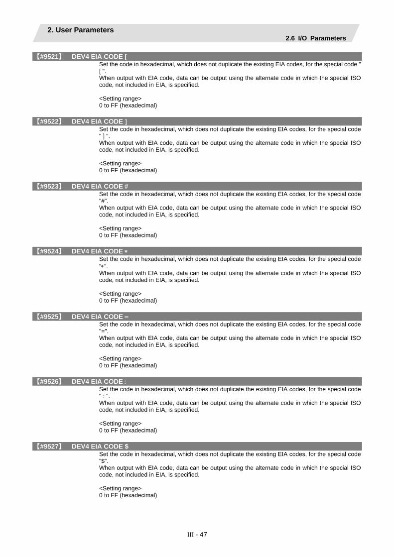
2. User Parameters 2.6 I/O Parameters
III - 47
【#9521】 DEV4 EIA CODE [ Set the code in hexadecimal, which does not duplicate the existing EIA codes, for the special code " [ ". When output with EIA code, data can be output using the alternate code in which the special ISO code, not included in EIA, is specified. <Setting range> 0 to FF (hexadecimal)
【#9522】 DEV4 EIA CODE ] Set the code in hexadecimal, which does not duplicate the existing EIA codes, for the special code " ] ". When output with EIA code, data can be output using the alternate code in which the special ISO code, not included in EIA, is specified. <Setting range> 0 to FF (hexadecimal)
【#9523】 DEV4 EIA CODE # Set the code in hexadecimal, which does not duplicate the existing EIA codes, for the special code "#". When output with EIA code, data can be output using the alternate code in which the special ISO code, not included in EIA, is specified. <Setting range> 0 to FF (hexadecimal)
【#9524】 DEV4 EIA CODE ∗ Set the code in hexadecimal, which does not duplicate the existing EIA codes, for the special code "∗". When output with EIA code, data can be output using the alternate code in which the special ISO code, not included in EIA, is specified. <Setting range> 0 to FF (hexadecimal)
【#9525】 DEV4 EIA CODE = Set the code in hexadecimal, which does not duplicate the existing EIA codes, for the special code "=". When output with EIA code, data can be output using the alternate code in which the special ISO code, not included in EIA, is specified. <Setting range> 0 to FF (hexadecimal)
【#9526】 DEV4 EIA CODE : Set the code in hexadecimal, which does not duplicate the existing EIA codes, for the special code " : ". When output with EIA code, data can be output using the alternate code in which the special ISO code, not included in EIA, is specified. <Setting range> 0 to FF (hexadecimal)
【#9527】 DEV4 EIA CODE $ Set the code in hexadecimal, which does not duplicate the existing EIA codes, for the special code "$". When output with EIA code, data can be output using the alternate code in which the special ISO code, not included in EIA, is specified. <Setting range> 0 to FF (hexadecimal)

2. User Parameters 2.6 I/O Parameters
III - 48
【#9528】 DEV4 EIA CODE ! Set the code in hexadecimal, which does not duplicate the existing EIA codes, for the special code "!". When output with EIA code, data can be output using the alternate code in which the special ISO code, not included in EIA, is specified. <Setting range> 0 to FF (hexadecimal)

2. User Parameters 2.7 Ethernet Parameters
III - 49
2.7 Ethernet Parameters
Set the parameters related to Ethernet input/output. After setting up the parameter (PR) listed in the table, turn OFF the NC power. To validate the parameter, turn ON the power again.
9701 to 9706 parameters:
When several TCP/IP drivers are installed and the IP address is set manually ("#9701 IP address automatic setting" is set to 0), the same setting will be made for all parameters.
9711 to 9781 parameters:
Set the server information required for using the Ethernet function. Server information for up to four units can be set.
【#9701(PR)】 IP addr auto set The IP address is automatically assigned from the server. 0: Manual setting 1: Automatic setting (Note) When the automatic setting is selected, "#11005 PC IP address, PC Subnet, PC Gateway" will be invalid.
【#9706】 Host No. Select the No. of the host to be used from host 1 to host 4.
---Setting range--- 1 to 4 : Host No.
【#9711】 Host1 host name Set the host computer name. This parameter allows the NC to easily recognize the host computer on the network. Set the host computer's name (name registered in C:¥windows¥hosts) or the IP address. ---Setting example--- For host name: mspc160 For IP address: 150.40.0.111 (Note) Set the host computer's TCP/IP address if communication is not carried out correctly.
---Setting range--- 15 characters (alphanumeric) or less
【#9712】 Host1 user name Set the user name when logging into the host computer.
---Setting range--- 15 characters (alphanumeric) or less
【#9713】 Host1 password Set the password when logging into the host computer.
---Setting range--- 15 characters (alphanumeric) or less
【#9714】 Host1 directory Set the directory name of the host computer. The directory released to the client (NC unit) with the host computer's server is handled as root directory by the NC unit.
---Setting range--- 31 characters (alphanumeric) or less

2. User Parameters 2.7 Ethernet Parameters
III - 50
【#9715】 Host1 host type Select the type of the host computer. 0: UNIX/PC automatic judgment 1: UNIX 2: PC (DOS) (Note) When "0" is set, the settings for the following parameters will be invalid. • #9716 Wrd pos: name • #9717 Wrd pos: size • #9718 Wrd pos: Dir • #9719 Wrd pos: cmnt • #9720 Wrd num: cmnt
【#9716】 Host 1 Wrd pos: name Set the file name display position (nth word from left) of the list displayed when the ftp command "dir" is executed. (Note) One word designates a character string divided by one or more spaces.
---Setting range--- 0 to 100 0: Default value
【#9717】 Host 1 Wrd pos: size Set the size display position (nth word from left) of the list displayed when the ftp command "dir" is executed. (Note) One word designates a character string divided by one or more spaces.
---Setting range--- 0 to 100 0: Default value
【#9718】 Host 1 Wrd pos: Dir Set the <DIR> display position (nth word from left) of the list displayed when the ftp command "dir" is executed. (Note) One word designates a character string divided by one or more spaces.
---Setting range--- 0 to 100 0: Default value
【#9719】 Host 1 Wrd pos: cmnt Set the comment (date, time, etc.) display position (nth word from left) of the list displayed when the ftp command "dir" is executed. (Note) One word designates a character string divided by one or more spaces.
---Setting range--- 0 to 100 0: Default value
【#9720】 Host 1 Wrd num: cmnt Set the number of words to be displayed as a comment. (Note) One word designates a character string divided by one or more spaces.
---Setting range--- 0 to 100 0: Default value
【#9721】 Host 1 no total siz Set whether to display the total number of characters registered in the machining programs of host1 when displaying the file list. If there are many files in the directory to be referred to, the list can be updated quickly by setting "1". 0: Display 1: Not display

2. User Parameters 2.7 Ethernet Parameters
III - 51
【#9731】 Host2 host name Set the host computer name. This parameter allows the NC to easily recognize the host computer on the network. Set the host computer's name (name registered in C:¥windows¥hosts) or the IP address. ---Setting example--- For host name: mspc160 For IP address: 150.40.0.111 (Note) Set the host computer's TCP/IP address if communication is not carried out correctly.
---Setting range--- 15 characters (alphanumeric) or less
【#9732】 Host2 user name Set the user name when logging into the host computer.
---Setting range--- 15 characters (alphanumeric) or less
【#9733】 Host2 password Set the password when logging into the host computer.
---Setting range--- 15 characters (alphanumeric) or less
【#9734】 Host2 directory Set the directory name of the host computer. The directory released to the client (NC unit) with the host computer's server is handled as the root directory by the NC unit.
---Setting range--- 31 characters (alphanumeric) or less
【#9735】 Host2 host type Select the type of the host computer. 0: UNIX/PC automatic judgment 1: UNIX 2: PC (DOS) (Note) When "0" is set, the settings for the following parameters will be invalid. • #9736 Wrd pos: name • #9737 Wrd pos: size • #9738 Wrd pos: Dir • #9739 Wrd pos: cmnt • #9740 Wrd num: cmnt
【#9736】 Host 2 Wrd pos: name Set the file name display position (nth word from left) of the list displayed when the ftp command "dir" is executed. (Note) One word designates a character string divided by one or more spaces.
---Setting range--- 0 to 100 0: Default value
【#9737】 Host 2 Wrd pos: size Set the size display position (nth word from left) of the list displayed when the ftp command "dir" is executed. (Note) One word designates a character string divided by one or more spaces.
---Setting range--- 0 to 100 0: Default value

2. User Parameters 2.7 Ethernet Parameters
III - 52
【#9738】 Host 2 Wrd pos: Dir Set the <DIR> display position (nth word from left) of the list displayed when the ftp command "dir" is executed. (Note) One word designates a character string divided by one or more spaces.
---Setting range--- 0 to 100 0: Default value
【#9739】 Host 2 Wrd pos: cmnt Set the comment (date, time, etc.) display position (nth word from left) of the list displayed when the ftp command "dir" is executed. (Note) One word designates a character string divided by one or more spaces.
---Setting range--- 0 to 100 0: Default value
【#9740】 Host 2 Wrd num: cmnt Set the number of words to be displayed as a comment. (Note) One word designates a character string divided by one or more spaces.
---Setting range--- 0 to 100 0: Default value
【#9741】 Host 2 no total siz Set whether to display the total number of characters registered in the machining programs of host1 when displaying the file list. If there are many files in the directory to be referred to, the list can be updated quickly by setting "1".
---Setting range--- 0: Display 1: Not display
【#9751】 Host3 host name Set the host computer name. This parameter allows the NC to easily recognize the host computer on the network. Set the host computer's name (name registered in C:¥windows¥hosts) or the IP address. ---Setting example--- For host name: mspc160 For IP address: 150.40.0.111 (Note) Set the host computer's TCP/IP address if communication is not carried out correctly.
---Setting range--- 15 characters (alphanumeric) or less
【#9752】 Host3 user name Set the user name when logging into the host computer.
---Setting range--- 15 characters (alphanumeric) or less
【#9753】 Host3 password Set the password when logging into the host computer.
---Setting range--- 15 characters (alphanumeric) or less
【#9754】 Host3 directory Set the directory name of the host computer. The directory released to the client (NC unit) with the host computer's server is handled as the root directory by the NC unit.
---Setting range--- 31 characters (alphanumeric) or less

2. User Parameters 2.7 Ethernet Parameters
III - 53
【#9755】 Host3 host type Select the type of the host computer. 0: UNIX/PC automatic judgment 1: UNIX 2: PC (DOS) (Note) When "0" is set, the settings for the following parameters will be invalid. • #9756 Wrd pos: name • #9757 Wrd pos: size • #9758 Wrd pos: Dir • #9759 Wrd pos: cmnt • #9760 Wrd num: cmnt
【#9756】 Host 3 Wrd pos: name Set the file name display position (nth word from left) of the list displayed when the ftp command "dir" is executed. (Note) One word designates a character string divided by one or more spaces.
---Setting range--- 0 to 100 0: Default value
【#9757】 Host 3 Wrd pos: size Set the size display position (nth word from left) of the list displayed when the ftp command "dir" is executed. (Note) One word designates a character string divided by one or more spaces.
---Setting range--- 0 to 100 0: Default value
【#9758】 Host 3 Wrd pos: Dir Set the <DIR> display position (nth word from left) of the list displayed when the ftp command "dir" is executed. (Note) One word designates a character string divided by one or more spaces.
---Setting range--- 0 to 100 0: Default value
【#9759】 Host 3 Wrd pos: cmnt Set the comment (date, time, etc.) display position (nth word from left) of the list displayed when the ftp command "dir" is executed. (Note) One word designates a character string divided by one or more spaces.
---Setting range--- 0 to 100 0: Default value
【#9760】 Host 3 Wrd num: cmnt Set the number of words to be displayed as a comment. (Note) One word designates a character string divided by one or more spaces.
---Setting range--- 0 to 100 0: Default value
【#9761】 Host 3 no total siz Set whether to display the total number of characters registered in the machining programs of host1 when displaying the file list. If there are many files in the directory to be referred to, the list can be updated quickly by setting "1".
---Setting range--- 0: Display 1: Not display

2. User Parameters 2.7 Ethernet Parameters
III - 54
【#9771】 Host4 host name Set the host computer name. This parameter allows the NC to easily recognize the host computer on the network. Set the host computer's name (name registered in C:¥windows¥hosts) or the IP address. ---Setting example--- For host name: mspc160 For IP address: 150.40.0.111 (Note) Set the host computer's TCP/IP address if communication is not carried out correctly.
---Setting range--- 15 characters (alphanumeric) or less
【#9772】 Host4 user name Set the user name when logging into the host computer.
---Setting range--- 15 characters (alphanumeric) or less
【#9773】 Host4 password Set the password when logging into the host computer.
---Setting range--- 15 characters (alphanumeric) or less
【#9774】 Host4 directory Set the directory name of the host computer. The directory released to the client (NC unit) with the host computer's server is handled as the root directory by the NC unit.
---Setting range--- 31 characters (alphanumeric) or less
【#9775】 Host4 host type Select the type of the host computer. 0: UNIX/PC automatic judgment 1: UNIX 2: PC (DOS) (Note) When "0" is set, the settings for the following parameters will be invalid. • #9776 Wrd pos: name • #9777 Wrd pos: size • #9778 Wrd pos: Dir • #9779 Wrd pos: cmnt • #9780 Wrd num: cmnt
【#9776】 Host 4 Wrd pos: name Set the file name display position (nth word from left) of the list displayed when the ftp command "dir" is executed. (Note) One word designates a character string divided by one or more spaces.
---Setting range--- 0 to 100 0: Default value
【#9777】 Host 4 Wrd pos: size Set the size display position (nth word from left) of the list displayed when the ftp command "dir" is executed. (Note) One word designates a character string divided by one or more spaces.
---Setting range--- 0 to 100 0: Default value

2. User Parameters 2.7 Ethernet Parameters
III - 55
【#9778】 Host 4 Wrd pos: Dir Set the <DIR> display position (nth word from left) of the list displayed when the ftp command "dir" is executed. (Note) One word designates a character string divided by one or more spaces.
---Setting range--- 0 to 100 0: Default value
【#9779】 Host 4 Wrd pos: cmnt Set the comment (date, time, etc.) display position (nth word from left) of the list displayed when the ftp command "dir" is executed. (Note) One word designates a character string divided by one or more spaces.
---Setting range--- 0 to 100 0: Default value
【#9780】 Host 4 Wrd num: cmnt Set the number of words to be displayed as a comment. (Note) One word designates a character string divided by one or more spaces.
---Setting range--- 0 to 100 0: Default value
【#9781】 Host 4 no total siz Set whether to display the total number of characters registered in the machining programs of host1 when displaying the file list. If there are many files in the directory to be referred to, the list can be updated quickly by setting "1".
---Setting range--- 0: Display 1: Not display

2. User Parameters 2.8 Computer Link Parameters
III - 56
2.8 Computer Link Parameters
【#9601】 BAUD RATE Select the rate at which data is transferred.
---Setting range--- 0: 19200 (bps) 1: 9600 2: 4800 3: 2400 4: 1200 5: 600 6: 300 7: 110 8: 38400
【#9602】 Stop Bit Select the stop bit length used in the start-stop system. Refer to "#9603 PARITY EFFECTIVE". At the output of data, the number of characters is always adjusted to for the parity check. 1: 1 (bit) 2: 1.5 3: 2
【#9603】 PARITY EFFECTIVE Select whether to add the parity bit to the data. The parameter is set when using a parity bit separately from the data bit.
ON OFF
Start bit Data bit Parity bit Stop bit
1 character
b1 b2 b3 b4 b5 b6 bn
Set this parameter according to the specifications of input/output device. 0: Not add a parity bit at the input/output 1: Add a parity bit at the input/output
【#9604】 EVEN PARITY Select odd or even when parity is added to the data. This parameter is ignored when no parity is added. 0: Odd parity 1: Even parity
【#9605】 CHR. LENGTH Select the length of the data bit. Refer to "#9603 PARITY EFFECTIVE". 0: 5 (bit) 1: 6 2: 7 (NC connection not supported) 3: 8
【#9606】 HAND SHAKE Select the transmission control method. "3" (DC code method) should be set for computer link B. 0: No control 1: RTS/CTS method 2: No handshaking 3: DC code method
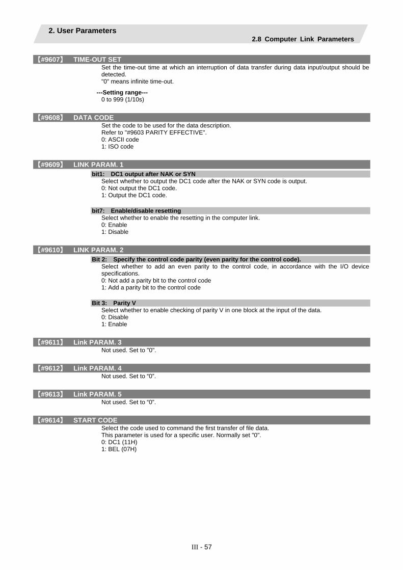
2. User Parameters 2.8 Computer Link Parameters
III - 57
【#9607】 TIME-OUT SET Set the time-out time at which an interruption of data transfer during data input/output should be detected. "0" means infinite time-out.
---Setting range--- 0 to 999 (1/10s)
【#9608】 DATA CODE Set the code to be used for the data description. Refer to "#9603 PARITY EFFECTIVE". 0: ASCII code 1: ISO code
【#9609】 LINK PARAM. 1
bit1: DC1 output after NAK or SYN Select whether to output the DC1 code after the NAK or SYN code is output. 0: Not output the DC1 code. 1: Output the DC1 code.
bit7: Enable/disable resetting Select whether to enable the resetting in the computer link. 0: Enable 1: Disable
【#9610】 LINK PARAM. 2
Bit 2: Specify the control code parity (even parity for the control code). Select whether to add an even parity to the control code, in accordance with the I/O device specifications. 0: Not add a parity bit to the control code 1: Add a parity bit to the control code
Bit 3: Parity V Select whether to enable checking of parity V in one block at the input of the data. 0: Disable 1: Enable
【#9611】 Link PARAM. 3 Not used. Set to "0".
【#9612】 Link PARAM. 4 Not used. Set to “0”.
【#9613】 Link PARAM. 5 Not used. Set to “0”.
【#9614】 START CODE Select the code used to command the first transfer of file data. This parameter is used for a specific user. Normally set "0". 0: DC1 (11H) 1: BEL (07H)
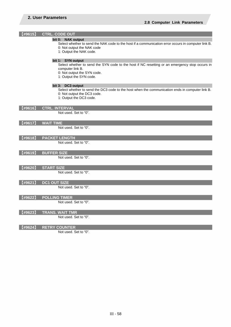
2. User Parameters 2.8 Computer Link Parameters
III - 58
【#9615】 CTRL. CODE OUT
bit 0: NAK output Select whether to send the NAK code to the host if a communication error occurs in computer link B. 0: Not output the NAK code 1: Output the NAK code.
bit 1: SYN output Select whether to send the SYN code to the host if NC resetting or an emergency stop occurs in computer link B. 0: Not output the SYN code. 1: Output the SYN code.
bit 3: DC3 output Select whether to send the DC3 code to the host when the communication ends in computer link B. 0: Not output the DC3 code. 1: Output the DC3 code.
【#9616】 CTRL. INTERVAL Not used. Set to “0”.
【#9617】 WAIT TIME Not used. Set to “0”.
【#9618】 PACKET LENGTH Not used. Set to “0”.
【#9619】 BUFFER SIZE Not used. Set to “0”.
【#9620】 START SIZE Not used. Set to “0”.
【#9621】 DC1 OUT SIZE Not used. Set to “0”.
【#9622】 POLLING TIMER Not used. Set to “0”.
【#9623】 TRANS. WAIT TMR Not used. Set to “0”.
【#9624】 RETRY COUNTER Not used. Set to “0”.
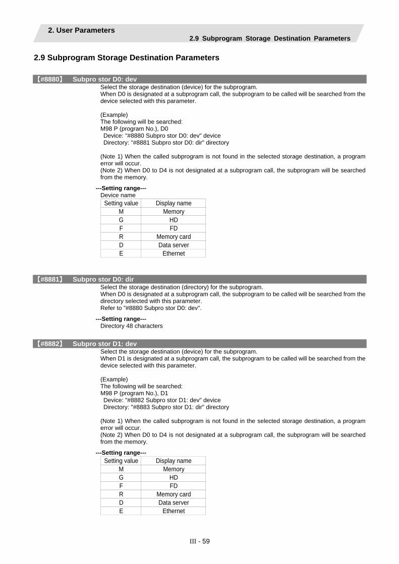
2. User Parameters 2.9 Subprogram Storage Destination Parameters
III - 59
2.9 Subprogram Storage Destination Parameters
【#8880】 Subpro stor D0: dev Select the storage destination (device) for the subprogram. When D0 is designated at a subprogram call, the subprogram to be called will be searched from the device selected with this parameter. (Example) The following will be searched: M98 P (program No.), D0 Device: "#8880 Subpro stor D0: dev" device Directory: "#8881 Subpro stor D0: dir" directory (Note 1) When the called subprogram is not found in the selected storage destination, a program error will occur. (Note 2) When D0 to D4 is not designated at a subprogram call, the subprogram will be searched from the memory.
---Setting range--- Device name
Setting value Display nameM MemoryG HDF FDR Memory cardD Data serverE Ethernet
【#8881】 Subpro stor D0: dir Select the storage destination (directory) for the subprogram. When D0 is designated at a subprogram call, the subprogram to be called will be searched from the directory selected with this parameter. Refer to "#8880 Subpro stor D0: dev".
---Setting range--- Directory 48 characters
【#8882】 Subpro stor D1: dev Select the storage destination (device) for the subprogram. When D1 is designated at a subprogram call, the subprogram to be called will be searched from the device selected with this parameter. (Example) The following will be searched: M98 P (program No.), D1 Device: "#8882 Subpro stor D1: dev" device Directory: "#8883 Subpro stor D1: dir" directory (Note 1) When the called subprogram is not found in the selected storage destination, a program error will occur. (Note 2) When D0 to D4 is not designated at a subprogram call, the subprogram will be searched from the memory.
---Setting range--- Setting value Display name
M MemoryG HDF FDR Memory cardD Data serverE Ethernet

2. User Parameters 2.9 Subprogram Storage Destination Parameters
III - 60
【#8883】 Subpro stor D1: dir Select the storage destination (directory) for the subprogram. When D1 is designated at a subprogram call, the subprogram to be called will be searched from the directory selected with this parameter. Refer to "#8882 Subpro stor D1: dev".
---Setting range--- Directory 48 characters
【#8884】 Subpro stor D2: dev Select the storage destination (device) for the subprogram. When D2 is designated at a subprogram call, the subprogram to be called will be searched from the device selected with this parameter. (Example) The following will be searched: M98 P (program No.), D2 Device: "#8884 Subpro stor D2: dev" device Directory: "#8885 Subpro stor D2: dir" directory (Note 1) When the called subprogram is not found in the selected storage destination, a program error will occur. (Note 2) When D0 to D4 is not designated at a subprogram call, the subprogram will be searched from the memory.
---Setting range--- Setting value Display name
M MemoryG HDF FDR Memory cardD Data serverE Ethernet
【#8885】 Subpro stor D2: dir Select the storage destination (directory) for the subprogram. When D2 is designated at a subprogram call, the subprogram to be called will be searched from the directory selected with this parameter. Refer to "#8884 Subpro stor D2: dev".
---Setting range--- Directory 48 characters

2. User Parameters 2.9 Subprogram Storage Destination Parameters
III - 61
【#8886】 Subpro stor D3: dev Select the storage destination (device) for the subprogram. When D3 is designated at a subprogram call, the subprogram to be called will be searched from the device selected with this parameter. (Example) The following will be searched: M98 P (program No.), D3 Device: "#8886 Subpro stor D3: dev" device Directory: "#8887 Subpro stor D3: dir" directory (Note 1) When the called subprogram is not found in the selected storage destination, a program error will occur. (Note 2) When D0 to D4 is not designated at a subprogram call, the subprogram will be searched from the memory.
---Setting range--- Setting value Display name
M MemoryG HDF FDR Memory cardD Data serverE Ethernet
【#8887】 Subpro stor D3: dir Select the storage destination (directory) for the subprogram. When D3 is designated at a subprogram call, the subprogram to be called will be searched from the directory selected with this parameter. Refer to "#8886 Subpro stor D3: dev".
---Setting range--- Directory 48 characters
【#8888】 Subpro stor D4: dev Select the storage destination (device) for the subprogram. When D4 is designated at a subprogram call, the subprogram to be called will be searched from the device selected with this parameter. (Example) The following will be searched: M98 P (program No.), D4 Device: "#8888 Subpro stor D4: dev" device Directory: "#8889 Subpro stor D4: dir" directory (Note 1) When the called subprogram is not found in the selected storage destination, a program error will occur. (Note 2) When D0 to D4 is not designated at a subprogram call, the subprogram will be searched from the memory.
---Setting range--- Device name
Setting value Display nameM MemoryG HDF FDR Memory cardD Data serverE Ethernet

2. User Parameters 2.9 Subprogram Storage Destination Parameters
III - 62
【#8889】 Subpro stor D4: dir Select the storage destination (directory) for the subprogram. When D4 is designated at a subprogram calling, the subprogram to be called will be searched from the directory selected with this parameter. Refer to "#8888 Subpro stor D4: dev".
---Setting range--- Directory 48 characters

2. User Parameters 2.10 Anshin-net Parameter 1
III - 63
2.10 Anshin-net Parameter 1
【#10801】 Notice tel num 1 Set the call-back telephone No. used for one-touch call and operator notification. Begin with the No. from an area code for domestic call. Begin with a communication company No. for international call. Hyphens "-" can be used as a delimiting character.
---Setting range--- Within 28 characters
【#10802】 Comment 1 Set a comment, such as a party's name, for the notification party telephone No.1.
---Setting range--- Within 20 alphanumerical characters (excluding spaces)
【#10803】 Notice tel num 2 Set the call-back telephone No. used for one-touch call and operator notification. Begin with the No. from an area code for domestic call. Begin with a communication company No. for international call. Hyphens "-" can be used as a delimiting character.
---Setting range--- Within 28 characters
【#10804】 Comment 2 Set a comment, such as a party's name, for the notification party telephone No.2.
---Setting range--- Within 20 alphanumerical characters (excluding spaces)
【#10805】 Notice tel num 3 Set the call-back telephone No. used for one-touch call and operator notification. Begin with the No. from an area code for domestic call. Begin with a communication company No. for international call. Hyphens "-" can be used as a delimiting character.
---Setting range--- Within 28 characters
【#10806】 Comment 3 Set a comment, such as a party's name, for the notification party telephone No.3.
---Setting range--- Within 20 alphanumerical characters (excluding spaces)
【#10807】 Password Set the password for sharing of machining data.
---Setting range--- 4 characters (one-byte alphanumeric characters, without space)
【#10808】 Customer number Set the user No. for sharing of machining data.
---Setting range--- Within 8 characters (one-byte alphanumeric characters, without space)
【#10812】 Anshin-net valid Select whether to enable the Anshin-net function. 0: Disable 1: Enable

2. User Parameters 2.11 Machine Tool Builder Network System (MTB-net) Parameter 1
III - 64
2.11 Machine Tool Builder Network System (MTB-net) Parameter 1
【#10813】 MTBnet enable Select whether to enable the machine tool builder network system. 0: Disable 1: Enable Standard setting: 0 (Note) Values other than "0" and "1" are invalid.
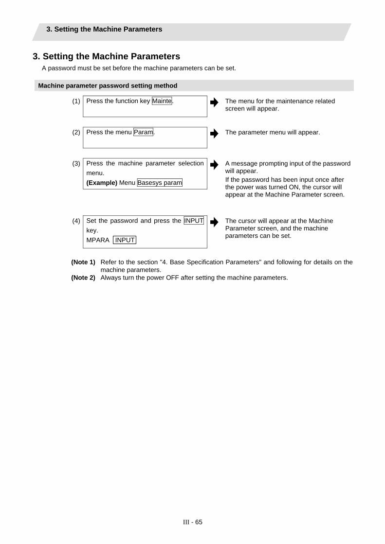
3. Setting the Machine Parameters
III - 65
3. Setting the Machine Parameters A password must be set before the machine parameters can be set.
Machine parameter password setting method
(1) Press the function key Mainte.
The menu for the maintenance related screen will appear.
(2) Press the menu Param. The parameter menu will appear.
(3) Press the machine parameter selection
menu. (Example) Menu Basesys param
A message prompting input of the password will appear. If the password has been input once after the power was turned ON, the cursor will appear at the Machine Parameter screen.
(4) Set the password and press the INPUT key. MPARA INPUT
The cursor will appear at the Machine Parameter screen, and the machine parameters can be set.
(Note 1) Refer to the section "4. Base Specification Parameters" and following for details on the
machine parameters. (Note 2) Always turn the power OFF after setting the machine parameters.

4. Base Specifications Parameters
III - 66
4. Base Specifications Parameters Base specification parameter is the generic term for the following three parameters. In this Manual, the parameters are explained in order of number.
Base system parameters Base axis specification parameters Base common parameters
#1001-#1006, #1025-#1037 #1073-#1076, #1085-#1086 #1109-#1111, #1151 #1169-#1216, #1501-#1574 #1590-#1593, #12001-#12012
#1010-#1024, #1061-#1072 #1493-#1494
#1038-#1059, #1077-#1084 #1087-#1108, #1112-#1149 #1153-#1168, #1217-#1343 #1361, #1901-#1911 #1925-#1935, #11001-#11021#11028-#11029
After setting up the parameter (PR) listed in the table, turn OFF the NC power. To validate the parameter, turn ON the power again.
【#1001(PR)】 SYS_ON System validation setup Select the existence of PLC axes and part systems.
---Setting range--- 0: Not exist 1: Exist
【#1002(PR)】 axisno Number of axes Set the number of control axes and PLC axes. A total of 16 axes can be set. Control axis: 0 to 8 PLC axis: 0 to 2 When set to “0”, the number of control axes in the part system will be “0”. Do not set the number of control axes of the first part system to “0”. (Note) The setting range differs according to the model.
【#1003(PR)】 iunit Input setup unit Select the input setting value for each part system and the PLC axis. Increments in parameters will follow this selection.
B : 1 µm C : 0.1 µm D : 0.01 µm (10nm) E : 0.001 µm (1nm)
【#1004(PR)】 ctrl_unit Control unit Select the control increment for each part system and PLC axis. Select the increment for the NC internal position data, communication data between the NC and drive unit, and the servo travel data. Increments for some parameters, such as the pitch error and backlash, will follow this selection.
B : 1 µm C : 0.1 µm D : 0.01 µm (10nm) E : 0.001 µm (1nm)
【#1005(PR)】 plcunit PLC unit Select the PLC interface setting and display increment. The PLC interface setting and display increment will follow this specification. Note that the PLC axis will follow “#1003 iunit”.
B : 1 µm C : 0.1 µm D : 0.01 µm (10nm) E : 0.001 µm (1nm)

4. Base Specifications Parameters
III - 67
【#1006(PR)】 mcmpunit Machine error compensa-tion unit Select the machine error compensation setting and display increment. The parameters related to machine error compensation (backlash, pitch error compensation, etc.) and PLC interface (external machine coordinate system compensation) will follow this selection.
B : 1 µm C : 0.1 µm D : 0.01 µm (10nm) E : 0.001 µm (1nm)
【#1007(PR)】 System type select System type select Select the NC system type.
0: Machining center system (M system) 1: Lathe system (L system)
(Note 1) If the setting value is out of range, M system will be selected. (Note 2) This parameter is exclusively for 70 series. 700 series doesn’t support this parameter.
【#1010(PR)】 srvunit Output unit (servo) Select the output increment to servo. The standard value is “E”.
B : 1 µm C : 0.1 µm D : 0.01 µm (10nm) E : 0.001 µm (1nm)
【#1013(PR)】 axname Axis name Set each axis’s name with an alphabetic character. Use the characters X‚ Y‚ Z‚ U‚ V‚ W‚ A‚ B or C. (Note 1) Do not set the same name twice in one part system. The same name which is used in another part system can be set. (Note 2) The PLC name does not need to be set. (The axis name is displayed as 1 and 2.)
---Setting range--- X, Y, Z, U, V, W, A, B, C
【#1014(PR)】 incax Increment command axis name Set the axis name when commanding an incremental value for the axis travel amount. Available alphabets are the same as in “#1013 axname”. (Note 1) Set an alphabet that is different from that of “#1013 axname”. (Note 2) Setting is not required if absolute/incremental specification with axis names is not performed (“#1076 Abslnc” = “0”).
---Setting range--- X, Y, Z, U, V, W, A, B, C
【#1015(PR)】 cunit Program command unit Set the minimum increment of program travel command. cunit Travel amount for travel command 1
0: Follow “#1003 iunit” 1: 0.0001 mm (0.1µm) 10: 0.001 mm (1µm) 100: 0.01 mm (10µm) 1000: 0.1 mm (100µm) 10000: 1.0 mm
If there is a decimal point in travel command‚ the decimal point position will be handled as 1mm regardless of this setting.

4. Base Specifications Parameters
III - 68
【#1017(PR)】 rot Rotational axis Select whether the axis is a rotary axis or linear axis. When rotary axis is set, the axis will be controlled with the rotary axis's coordinate system. Set the rotary axis type with "#8213 Rotation axis type".
0: Linear axis 1: Rotary axis
【#1018(PR)】 ccw Motor CCW Select the direction of the motor rotation to the command direction.
0: Clockwise (looking from motor shaft) with the forward rotation command 1: Counterclockwise (looking from motor shaft) with the forward rotation command
【#1019(PR)】 dia Diameter specification axis Select the command method of program travel amount. When the travel amount is commanded with the diameter dimensions‚ the travel distance will be 5mm when the command is 10mm of travel distance. The travel amount per pulse will also be halved during manual pulse feed. If diameter is selected, tool length, the wear compensation amount, and the workpiece coordinate offset will be displayed in diameter value. Other parameters concerning length will always be displayed in radius value.
0: Command with travel amount 1: Command with diameter dimension
【#1020(PR)】 sp_ax Spindle Interpolation Select "1" when using the spindle for the contour control of NC axis (C-axis).
0: Servo axis is used for contour control. 1: Spindle is used for contour control.
【#1021(PR)】 mcp_no Drive unit I/F channel No. (servo) Using a 4-digit number, set the drive unit interface channel No. and which axis in that channel is to be used when connecting a servo drive unit.
Axis No. Not used (Set to “0”) Drive unit interface channel No.
【#1022(PR)】 axname2 2nd axis name Set the name of the axis displayed on the screen with two characters. (X1, Z2, etc.) Always use an alphabetic character (A to Z) for the first character.
---Setting range--- A to Z and 1 to 9 (Two digits) (Setting will be cleared when “0” is set)
【#1023(PR)】 crsadr Command address during cross machining Set the axis name for issuing a command to this axis during cross machining control.
---Setting range--- A to Z (Setting will be cleared when “0” is set)
【#1024(PR)】 crsinc Incremental command address during cross machining Set the axis name for issuing an incremental command to this axis during cross machining control.
---Setting range--- A to Z (Setting will be cleared when “0” is set)
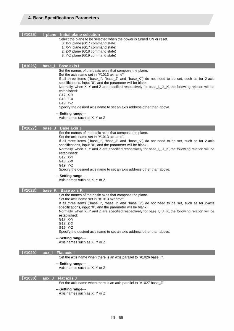
4. Base Specifications Parameters
III - 69
【#1025】 l_plane Initial plane selection Select the plane to be selected when the power is turned ON or reset.
0: X-Y plane (G17 command state) 1: X-Y plane (G17 command state) 2: Z-X plane (G18 command state) 3: Y-Z plane (G19 command state)
【#1026】 base_l Base axis I Set the names of the basic axes that compose the plane. Set the axis name set in "#1013 axname". If all three items ("base_I", "base_J" and "base_K") do not need to be set, such as for 2-axis specifications, input "0", and the parameter will be blank. Normally‚ when X‚ Y and Z are specified respectively for base_l‚_J‚_K‚ the following relation will be established: G17: X-Y G18: Z-X G19: Y-Z Specify the desired axis name to set an axis address other than above.
---Setting range--- Axis names such as X, Y or Z
【#1027】 base_J Base axis J Set the names of the basic axes that compose the plane. Set the axis name set in "#1013 axname". If all three items ("base_I", "base_J" and "base_K") do not need to be set, such as for 2-axis specifications, input "0", and the parameter will be blank. Normally‚ when X‚ Y and Z are specified respectively for base_l‚_J‚_K‚ the following relation will be established: G17: X-Y G18: Z-X G19: Y-Z Specify the desired axis name to set an axis address other than above.
---Setting range--- Axis names such as X, Y or Z
【#1028】 base_K Base axis K Set the names of the basic axes that compose the plane. Set the axis name set in "#1013 axname". If all three items ("base_I", "base_J" and "base_K") do not need to be set, such as for 2-axis specifications, input "0", and the parameter will be blank. Normally‚ when X‚ Y and Z are specified respectively for base_l‚_J‚_K‚ the following relation will be established: G17: X-Y G18: Z-X G19: Y-Z Specify the desired axis name to set an axis address other than above.
---Setting range--- Axis names such as X, Y or Z
【#1029】 aux_I Flat axis I Set the axis name when there is an axis parallel to "#1026 base_I".
---Setting range--- Axis names such as X, Y or Z
【#1030】 aux_J Flat axis J Set the axis name when there is an axis parallel to "#1027 base_J".
---Setting range--- Axis names such as X, Y or Z

4. Base Specifications Parameters
III - 70
【#1031】 aux_K Flat axis K Set the axis name when there is an axis parallel to "#1028 base_K".
---Setting range--- Axis names such as X, Y or Z
【#1037(PR)】 cmdtyp Command type Set the G code list and compensation type for programs.
cmdtyp G code list Compensation type1 List 1 (for M) Type A
(one compensation amount for one compensation No.)2 List 1 (for M) Type B
(shape and wear compensation amountsfor one compensation No.)
3 List 2 (for L) Type C(shape and wear compensation amountsfor one compensation No.)
4 List 3 (for L) Ditto
5 List 4 (for special L) Ditto
6 List 5 (for special L) Ditto
7 List 6 (for special L) Ditto
8 List 7 (for special L) Ditto
9 List 8 (for M)M2 format type A
Type A(one compensation amount for one compensation No.)
10 List 8 (for M)M2 format type B
Type B(shape and wear amounts for one compensation No.)
There are some items in the specifications that can be used or cannot be used according to the value set in this parameter. The file structure may also change depending on the compensation data type.
【#1038】 plcsel Ladder selection Not used. Set to "0".
【#1039(PR)】 spinno Number of spindles Select the number of spindles.
0: No spindle 1 to 6: One to Six spindles
(Note) The setting range differs according to the model.
【#1040(PR)】 M_inch Constant input (inch) Select the unit system for setting and display regarding machine parameter and PLC interface’s position, length and speed.
0: Metric system 1: Inch system
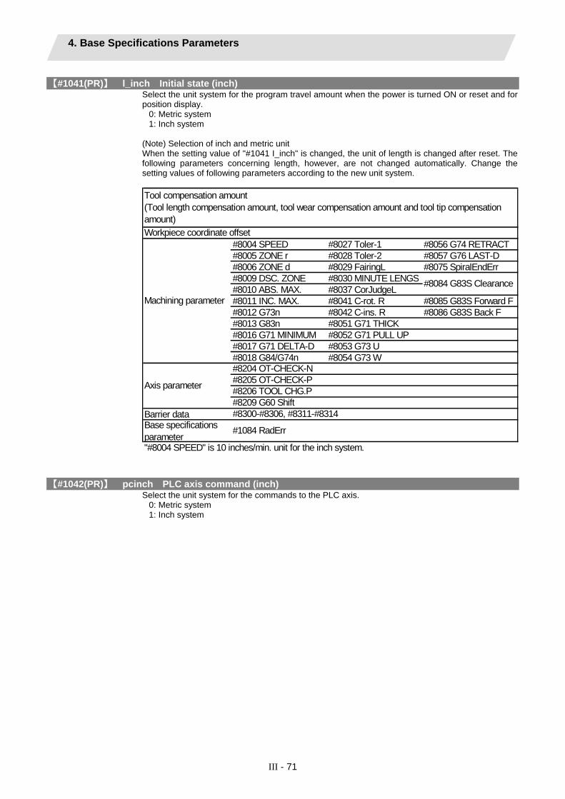
4. Base Specifications Parameters
III - 71
【#1041(PR)】 l_inch Initial state (inch) Select the unit system for the program travel amount when the power is turned ON or reset and for position display.
0: Metric system 1: Inch system
(Note) Selection of inch and metric unit When the setting value of "#1041 I_inch" is changed, the unit of length is changed after reset. The following parameters concerning length, however, are not changed automatically. Change the setting values of following parameters according to the new unit system.
#8004 SPEED #8027 Toler-1 #8056 G74 RETRACT#8005 ZONE r #8028 Toler-2 #8057 G76 LAST-D#8006 ZONE d #8029 FairingL #8075 SpiralEndErr
#8009 DSC. ZONE #8030 MINUTE LENGS#8010 ABS. MAX. #8037 CorJudgeL#8011 INC. MAX. #8041 C-rot. R #8085 G83S Forward F#8012 G73n #8042 C-ins. R #8086 G83S Back F#8013 G83n #8051 G71 THICK#8016 G71 MINIMUM #8052 G71 PULL UP
#8017 G71 DELTA-D #8053 G73 U #8018 G84/G74n #8054 G73 W
Barrier dataBase specificationsparameter"#8004 SPEED" is 10 inches/min. unit for the inch system.
Workpiece coordinate offset
Tool compensation amount(Tool length compensation amount, tool wear compensation amount and tool tip compensationamount)
#8084 G83S Clearance
Machining parameter
Axis parameter
#1084 RadErr
#8300-#8306, #8311-#8314
#8204 OT-CHECK-N#8205 OT-CHECK-P#8206 TOOL CHG.P#8209 G60 Shift
【#1042(PR)】 pcinch PLC axis command (inch) Select the unit system for the commands to the PLC axis.
0: Metric system 1: Inch system

4. Base Specifications Parameters
III - 72
【#1043】 lang Select language displayed Select the display language.
0: English (Standard) 1: Japanese (Standard) 11: German (Option) 12: French (Option) 13: Italian (Option) 14: Spanish (Option) 15: Traditional Chinese (Option) 16: Korean (Option) 17: Portuguese (Option) 18: Dutch (Option) 19: Swedish (Option) 20: Hungarian (Option) 21: Polish (Option) 22: Simplified Chinese (Option) 23: Russian (Option) 24: Turkish (Option) 25: Czech (Option)
(Note) A language which can be displayed is different according to each series.
【#1044(PR)】 auxno MR-J2-CT Connections Set the number of MR-J2-CTs connected. (Note) The number of MR-J2-CTs possible to connect and setting range are different according to the model. Check the specifications of each series.
【#1045(PR)】 nskno Megatorgue motor connections Set the number of NSK megatorque motors connected. When a value other than “0” is set, 2nd miscellaneous function data will be output as signed binary data.
---Setting range--- 0 to 16
【#1051(PR)】 MemTol Tool compensation memory common for part systems 0: Tool compensation memory separate for part systems 1: Tool compensation memory common for part systems
【#1052(PR)】 MemVal No. of common variables shared in part system designation 0: Common variables common for part systems (number fixed) #100 - : Per part system #500 - : Common for part systems 1: Common variables common for part systems (number designation) #100 - : Designate with V1comN #500 - : Designate with V0comN
(Note) When this parameter is changed, the file system will be changed after the power is turned ON. So always execute format. The new format will be enabled after turning the power ON again.
---Setting order--- (1) MemVal changeover -> (2) Turn power ON again -> (3) Format ->(4) Turn power ON again
【#1061(PR)】 intabs Manual ABS updating Select whether to update the absolute position data during automatic handle interrupt. This parameter is enabled only when "#1145 l_abs" is set to “1”. 0: Do not update (coordinate system shifted the amount of the interruption) 1: Update (same coordinates as when interrupt did not occur will be applied)

4. Base Specifications Parameters
III - 73
【#1062】 T_cmp Tool compensation function Select whether the tool length compensation and wear compensation are enabled during T command execution.
【#1063】 mandog Manual dog-type Select the manual reference position return method for the second return (after the coordinate system is established) and later. The initial reference position return after the power ON is performed with dog-type return, and the coordinate system will be established. (This setting is not required when the absolute position detection is used.)
0: High speed return 1: Dog-type
【#1064(PR)】 svof Error correction Select whether to correct the error when the servo is OFF.
0: Not correct the error 1: Correct the error
【#1068(PR)】 slavno Slave axis number Set the axis number of the slave axis in synchronous control. The axis number is an NC number excluding the spindle and PLC axis. Two or more slave axes cannot be set for one master axis. This parameter cannot be set for a slave axis. When using the multi-part system, the relation of the master axis and slave axis cannot extend over part systems.
0: No slave axis 1 to 16: First to sixteenth axis
【#1069】 no_dsp Axis with no counter display Select whether to display the axis counter or not. This setting is enabled on the counter display screen (relative position counter, etc.).
0: Display 1: Not display
【#1070】 axoff Axis removal Select whether to enable or disable axis removal control.
0: Disable 1: Enable
【#1072】 chop_ax Chopping axis Select the chopping axis.
0: Non-chopping axis 1: Chopping axis
【#1073】 I_Absm Initial absolute setting Select the mode (absolute or incremental) at turning ON the power or reset.
0: Incremental setting 1: Absolute setting
Setting value Tool length compensation Wear compensation0 Enable Enable 1 Enable Disable 2 Disable Enable 3 Disable Disable

4. Base Specifications Parameters
III - 74
【#1074】 l_Sync Initial synchronous feed Select the feedrate mode at turning ON the power or reset.
0: Asynchronous feed (feed per minute) 1: Synchronous feed (feed per revolution)
【#1075】 I_G00 Initial G00 Select the linear command mode at turning ON the power or reset.
0: Linear interpolation (G01 command state) 1: Positioning (G00 command state)
【#1076】 Abslnc ABS/INC address for L system only Select the command method for the absolute and incremental commands.
0: Use G command for the absolute and incremental commands. 1: Use axis name for the absolute and incremental commands.
(The axis name in "#1013 axname" will be the absolute command, "#1014 incax" will be the incremental command.) When "1" is selected, using two axis names, one each for the absolute and incremental commands, allows to issue the absolute and incremental commands appropriately to an axis.
【#1077】 radius Incremental command for diameter specification axis Select whether the incremental command of the diameter specification axis (“#1019 dia” is set to “1”) uses the diameter value or radius value.
0: Diameter value 1: Radius value
【#1078】 Decpt2 Decimal point type 2 Select the increment of position commands that do not have a decimal point.
0: Minimum input command unit (follows "#1015 cunit") 1: 1mm (or 1inch) unit (For the dwell time, 1s unit is used.)
【#1079】 F1digt Validate F1 digit Select the F command method.
0: Direct numerical command (command feedrate during feed per minute or rotation) 1: 1-digit code command (feedrate set with “#1185 spd_F1” – “#1189 F5”)
【#1080】 Dril_Z (For M system only) Specify boring axis Select a fixed cycle hole drilling axis.
0: Use an axis vertical to the selected plane as hole drilling axis. 1: Use the Z axis as the hole drilling axis regardless of the selected plane.
【#1081】 Gmac_P Give priority to G code parameter Select the G code priority relationship during the macro call with G command.
0: Priority is on G code used in the system 1: Priority is on registered G code for call
【#1082】 Geomet Geometric Select the type of geometric to use.
0: Not use 1: Use only geometric I 2: Use geometric I and IB
With geometric, specific address codes are used for exclusive meanings. Thus, if A or C is used for the axis name or 2nd miscellaneous command code, the A used for the axis name may function as the geometric's angle designation. Pay special attention to axis names, etc., when using this function.

4. Base Specifications Parameters
III - 75
【#1084】 RadErr Arc error Set the tolerable error range when the end point deviates from the center coordinate in the circular command.
---Setting range--- 0 to 1.000 (mm)
【#1085】 G00Drn G00 dry run Select whether to apply dry run (feed at manual setting speed instead of command feedrate) to the G00 command. 0: Not apply to G00. (move at rapid traverse rate) 1: Apply to G00. (move at manual setting speed)
【#1086】 G0lntp G00 non-interpolation Select the G00 travel path type. 0: Move linearly toward the end point. (interpolation type) 1: Move to the end point of each axis at the rapid traverse feedrate for each axis. (non-interpolation) (Note) If this parameter is set to "1", neither of the following functions will be available: rapid traverse constant inclination acceleration/deceleration and rapid traverse constant inclination multi-step acceleration/deceleration.
【#1087】 G96_G0 Constant surface speed control by rapid traverse feed command Select how to handle the surface speed for the G00 command when using the constant surface speed control function.
0: Calculate the surface speed constantly even during G00 movement 1: Calculate the surface speed at the block end point in the G00 command
【#1088】 G30SL Disable G30 soft limit Select how to handle the soft limit during G30 (2nd reference position return).
0: Enable 1: Disable
【#1091】 Mpoint Ignore middle point Select how to handle the middle point during G28 and G30 reference position return.
0: Pass the middle point designated in the program and move to the reference position. 1: Ignore the middle point designated in the program and move straight to the reference position.
【#1092】 Tchg _A Replace tools for additional axis Select the movement of the additional axis at the tool change position return command.
0: The additional axis will not move 1: After the standard axis returns, the additional axis will also return to the tool change position
【#1093】 Wmvfin Synchronization between part systems method Slect the timing of synchronization between part systems when using the multi-part system. When the travel command is found in the synchronization command (!, M) block:
0: Synchronize before executing travel command 1: Synchronize after executing travel command
【#1094】 Tl_SBK Select life count for single block for L system only Select whether to count the data units to be used for single block operation when using the tool life management II function (L system).
0: Not count 1: Count
【#1095】 T0tfof TF output Select how to handle TF for T00 command.
0: TF will be output 1: TF wont be output

4. Base Specifications Parameters
III - 76
【#1096(PR)】 T_Ltyp Tool life management type for L system only Select the tool life management type.
1: Life management l In this type, how long and how many times the program commanded tool is used are accumulated to monitor the usage state. 2: Life management ll This method is the same as tool life management I, but with the spare tool selection function. A spare tool is selected from a group of tool commands commanded in the program. Tool compensation (tool length compensation and tool radius compensation) is carried out for the selected tool.
【#1097】 T1digt Tool wear compensation number 1-digit command Select the number of digits of the tool wear compensation No. in the T command.
0: The 2 high-order digits are the tool No.‚ and the 2 Iow-order digits are the wear compensation No. 1: The 3 high-order digits are the tool No.‚ and the 1 Iow-order digit is the wear compensation No.
This parameter will be fixed to “0” when tool life management II is selected.
【#1098】 Tlno. Tool length offset number Select the number of digits of the tool length compensation No. in the T command.
0: The 2 or 3 high-order digits are the tool No. The 2 or 1 Iow-order digits are the tool length compensation and wear compensation Nos. 1: The 2 or 3 high-order digits are the tool No. and tool length compensation Nos. The 2 or 1 Iow-order digits are the wear compensation No.
【#1099】 Treset Cancel tool compensation amount Select how to handle the tool compensation vector when resetting the system.
0: Clear the tool length and wear compensation vectors when resetting 1: Hold the tool length and wear compensation vectors when resetting
When the values are cleared‚ the compensation will not be applied‚ so the axis will be shifted by the compensation amount in the next compensation operation. When the values are kept‚ the compensation will be applied‚ so the axis will shift the differential amount of the compensation amount in the next compensation operation.
【#1100】 Tmove Tool compensation Select when to perform tool length compensation and wear compensation.
0: Compensate when T command is executed. 1: Superimpose and compensate with the travel command in the block where the T command is located. If there is no travel command in the same block‚ compensation will be executed after the travel command is superimposed in the next travel command block. 2: Compensate the wear amount when the T command is executed. Superimpose and compensate the tool length compensation amount with the travel command in the same block. If there is no travel command in the same block, compensation will be executed after the travel command is superimposed in the next travel command block.
【#1101】 Tabsmv Tool compensation method Select the type of travel command when “#1100 Tmove” is set to “1” or “2”.
0: Compensate regardless of the travel command type 1: Compensate only at the travel command in the absolute command
【#1102】 tlm Manual tool length measuring system for L system only Select the measurement method for manual tool measurement l.
0: Align tool with basic point 1: Input measurement results
(Note) Interpreted as “0” when other than “0” or “1” is set.

4. Base Specifications Parameters
III - 77
【#1103】 T_life Validate life management Select whether to use the tool life management.
0: Not use 1: Use
【#1104】 T_Com2 Tool command method 2 Select how to handle the tool command in the program when "#1103 T_Life" is set to "1".
0: Handle the command as group No. 1: Handle the command as tool No.
【#1105】 T_Sel2 Tool selection method 2 Select the tool selection method when "#1103 T_Life" is set to "1".
0: Select in order of registered No. from the tools used in the same group. 1: Select the tool with the longest remaining life from the tools used or unused in the same group.
【#1106】 Tcount Life management for L system only Select the input method when address N is omitted in inputting the data (G10 L3 command) for tool life management function II.
0: Time specified input 1: Number of times specified input
【#1107】 Tllfsc Split life management display screen for L system only Set the number of groups to be displayed on the tool life management II (L system) screen.
0: Displayed group count 1, maximum number of registered tools: 16 1: Displayed group count 2, maximum number of registered tools: 8 2: Displayed group count 4, maximum number of registered tools: 4
【#1108】 TlrectM Life management re-count M code for L system only Set the M code for tool life management II (L system) re-count.
---Setting range--- 0 to 99
【#1109】 subs_M Validate alternate M code Select the user macro interrupt with the substitute M code.
0: Disable alternate M code 1: Enable alternate M code
【#1110】 M96_M M96 alternate M code Set an M code to replace M96 when “#1109 subs_M” is set to “1”.
---Setting range--- 3 to 97 (excluding 30)
【#1111】 M97_M M97 alternate M code Specify an M code to replace M97 when #1109 subs_M is set to 1.
---Setting range--- 3 to 97 (excluding 30)
【#1112(PR)】 S_TRG Validate status trigger method Select the enable conditions for the user macro interrupt signal (UIT).
0: Enable when interrupt signal (UIT) turns ON 1: Enable when interrupt signal (UIT) is ON
【#1113(PR)】 INT_2 Validate interrupt method type 2 Select the performance after user macro interrupt signal (UIT) input.
0: Execute interrupt program without waiting for block being executed to end 1: Execute interrupt program after completing block being executed

4. Base Specifications Parameters
III - 78
【#1114】 mcrint Macro argument initialization Select whether to clear statements other than specified arguments by macro call. Also select whether to clear local variables by power-ON and resetting.
0: Clear the non-specified arguments by macro call. 1: Hold non-specified arguments by macro call 2: Hold non-specified arguments by macro call, and clear local variables by power-ON and resetting
【#1115】 thwait Waiting for thread cutting Set the queue number during screw thread cutting when chamfering is disabled.
---Setting range--- 0 to 99 (Approx. 4 ms) Standard seting value: 4
【#1116】 G30SLM Invalidate soft limit (manual operation) Enable this function when disabling the soft limit check function at the second to fourth reference position return. 0: Enable soft limit function 1: Disable soft limit function
【#1117(PR)】 H_sens Handle response switch Select the handle response mode during handle feed. 0: Standard 1: High-speed
【#1118】 mirr_A Select how to set up the length of tools on cutter tables (opposed tables) for L system only
Select one of the following two methods: • Set the current length of tools on each facing turret. • Set a value, assuming that the tools on each facing turret are in the same direction as that of those on the base turret.
0: Current length of the tools on each facing turret 1: Value, assuming that the tools on each facing turret are in the same direction as that of those on the base turret
【#1119】 Tmiron Select the mirror image of each facing turret with T command for L system only Select whether to enable the mirror image of each facing turret with the T command.
0: Disable 1: Enable
【#1120(PR)】 TofVal Change macro variable Select whether to change the macro variable (tool offset) numbers for shape compensation and wear compensation.
0: Not change (Conventional specification) 1: Change the shape and wear compensation variable numbers each for X, Z, and R
【#1121】 edlk_c Edit lock C Select the edit lock for program Nos. 9000 to 9999 in memory. 0: Editing possible 1: Editing prohibited. The file cannot be opened. (Note) If “#1122” is set to “1” or “2”, “1” will be set in “#1121” when the power is turned ON.
【#1122(PR)】 pglk_c Program display lock C Select whether to prohibit the program display and search for program Nos. 9000 to 9999 in memory.
0: Program display and search is possible 1: Program display is impossible. Search is possible. 2: Program display and search is impossible
(Note) If “#1122” is set to “1” or “2”, “1” will be set in “#1121” when the power is turned ON.

4. Base Specifications Parameters
III - 79
【#1123】 origin Origin set prohibit Select whether to use the origin set function.
0: Use 1: Not use
【#1124】 ofsfix Fix tool compensation No. Select how to handle the compensation No. when the input key is pressed on the tool compensation screen.
0: Increment the compensation No. by 1 (Same as general parameters) 1: # compensation No. does not change
When setting in sequence‚ “0” is handier. When changing and setting repeatedly while adjusting one compensation value‚ “1” is handier
【#1125】 real_f Actual feedrate display Select the feedrate display on the monitor screen.
0: Command speed 1: Actual travel feedrate
【#1126】 PB_G90 Playback G90 Select the method to command the playback travel amount in the playback editing. 0: Incremental value 1: Absolute value
【#1127】 DPRINT DPRINT alignment Select the alignment for printing out with the DPRINT function.
0: No alignment‚ output s printed with left justification 1: Align the minimum digit and output
【#1128】 RstVCI Clear variables by resetting Select how to handle the common variables when resetting. 0: Common variables won't change after resetting. 1: The following common variables will be cleared by resetting: #100 to #149 when 100 sets of variables are provided. #100 to #199 when 200 sets or more of variables are provided.
【#1129】 PwrVCl Clear variables by power-ON Select how to handle the common variables when the power is turned ON. 0: The common variables are in the same state as before turning the power OFF. 1: The following common variables will be cleared when the power is turned ON: #100 to #149 when 100 sets of variables are provided. #100 to #199 when 200 sets or more of variables are provided.
【#1130】 set_t Display selected tool number Select the tool command value display on the POSITION screen. 0: Display T-modal value of program command 1: Display Tool No. sent from PLC
【#1132】 CRT Not used. Set to "0".
【#1133】 ofsmem Not used. Set to "0".
【#1134】 LCDneg Not used. Set to "0".

4. Base Specifications Parameters
III - 80
【#1135】 unt_nm Unit name Set the unit name. Set with 4 or less characters consisting of both alphabets and numbers. If “0” is set, the unit name won’t be displayed.
---Setting range--- 4 or less characters consisting of both alphabets and numbers
【#1136】 optype Not used. Set to "0".
【#1137】 Cntsel Not used. Set to "0".
【#1138】 Pnosel Not used. Set to "0".
【#1139】 edtype Not used. Set to "0".
【#1140】 Mn100 M code number Set the first number of M code that corresponds to the setup Nos. from 100 to 199.
---Setting range- 0 to 99999999
【#1141】 Mn200 M code number Set the first number of M code that corresponds to the setup Nos. from 200 to 299.
---Setting range--- 0 to 99999999
【#1142】 Mn300 M code number Set the first number of M code that corresponds to the setup Nos. from 300 to 399.
---Setting range--- 0 to 99999999
【#1143】 Mn400 M code number Set the first number of M code that corresponds to the setup Nos. from 400 to 499.
---Setting range--- 0 to 99999999
【#1144】 mdlkof MDI setup lock Select whether to enable MDI setting in non-MDI mode.
0: Disable MDI setting 1: Enable MDI setting
【#1145】 I_abs Manual ABS parameter Select how to handle the absolute position data during automatic handle interrupt.
0: Absolute position data will be renewed if manual ABS switch is ON. If it is OFF, data won’t be renewed. 1: Follow the "intabs" state when "#1061 intabs" is enabled
【#1146】 Sclamp Spindle rotation speed clamp function Select how to handle the spindle rotation speed clamp function with the G92S command.
0: G92S command is handled as a clamp command only in the G96 state (during constant surface speed control). G92S will be handled as normal S command in G97 state (constant surface speed OFF). 1: The S command in the same block as G92 is constantly handled as a clamp command

4. Base Specifications Parameters
III - 81
【#1147】 smin_V Minimum spindle rotation speed clamp type Specify the type of spindle min. rotation speed clamp value.
0: Rotation speed setting 1: Output voltage coefficient setting
Set “#3023 smini” according to this type setting.
【#1148】 I_G611 Initial high precision Set the high accuracy control mode for the modal state when the power is turned ON.
0: G64 (cutting mode) at power ON 1: G61.1 (high-accuracy control mode) at power ON
【#1149】 cireft Arc deceleration speed change Select whether to decelerate at the arc entrance or exit.
0: Not decelerate 1: Decelerate
【#1151】 rstint Reset initial Select whether to initialize (power ON state) the modals by resetting.
0: Not initialize modal state 1: Initialize modal state
【#1153】 FixbDc Hole bottom deceleration check Select whether to perform a deceleration check or in-position check at the hole bottom in a hole drilling cycle. This parameter is enabled only for a hole drilling cycle in which no dwell command can be issued at the hole bottom.
0: Perform no deceleration check and in-position check 1: Perform deceleration check 2: Perform in-position check
【#1154(PR)】 pdoor Not used. Set to "0".
【#1155】 DOOR_m Not used. Set to "100".
---Setting range--- 100
【#1156】 DOOR_s Not used. Set to "100".
---Setting range--- 100
【#1157】 F0atrn Not used. Set to "0".
【#1158】 F0atno Not used. Set to "0".
【#1163(PR)】 No rio RIO connection detection invalid Select whether to enable or disable RIO connection detection.
0: Enable 1: Disable
If your I/O consists of only cards such as CC-LINK, setting this parameter to “1” will avoid the RIO communication cutoff alarm.

4. Base Specifications Parameters
III - 82
【#1164(PR)】 ATS Automatic tuning function Select whether to enable or disable the automatic tuning function.
0: Disable 1: Enable
【#1166】 fixpro Fixed cycle editing Select a type of program dealt on the edit/program list/data in/out screen, general program fixed cycle, or machine tool builder macro program.
0: General programs can be edited, etc. 1: Fixed cycles can be edited, etc. Password No.: The machine tool builder macro programs can be edited, etc.
---Setting range--- 0 to 99999999
【#1167】 e2rom Not used. Set to "0".
【#1168】 test Simulation test Select the test mode for the control unit. In the test mode, test is performed with a hypothetical reference position return complete even though the real reference position return hasn’t been completed. This is limited to test operation of the control unit itself‚ and must not be used when the machine is connected.
0: Normal operation mode 1: Test mode
【#1169】 part system name Part system name Set the name of each part system. This must be set only when using multi-part system. This name will be displayed on the screen only when the part systems must be identified. Use a max. of four alphabetic characters or numerals.
---Setting range--- A max. of four alphabetic characters or numerals.
【#1170】 M2name Second miscellaneous code Set this address code when using the 2nd miscellaneous command. Set an address with A‚ B or C that is not used for "#1013 axname" or "#1014 incax".
---Setting range--- A, B, C
【#1171】 taprov Tap return override Set the tap return override value for the synchronous tapping. When "0" is set, it will be regarded as 100%.
---Setting range--- 1 to 100 (%)
【#1172】 tapovr Tap return override Set the override value when leaving the tap end point in the synchronous tapping cycle. The setting range is 1 to 999‚ and the unit is %. When a value less than 100 is set‚ it will be judged as 100%.
---Setting range--- 1 to 999 (%)

4. Base Specifications Parameters
III - 83
【#1173】 dwlskp G04 skip condition Set the skip signal for ending the G04 (dwell) command.
---Setting range--- PLC interface input signal Skip3 Skip2 Skip1 0 : - - - 1 : - - * 2 : - * - 3 : - * * 4 : * - - 5 : * - * 6 : * * - 7 : * * * (* : Enable - : Disable)
【#1174】 skip_F G31 skip speed Set the feedrate when there is no F command in the program at G31 (skip) command.
---Setting range--- 1 to 999999 (mm/min)
【#1175】 skip1 G31.1 skip condition Designate the skip signal in multi-step skip G31.1.
---Setting range--- The setting method is same as “#1173”.
【#1176】 skip1f G31.2 skip speed Set the skip feedrate in multi-step skip G31.1.
---Setting range--- 1 to 999999 (mm/min)
【#1177】 skip2 G31.2 skip condition Set the skip signal in multi-step skip G31.2.
---Setting range--- The setting method is same as “#1173”.
【#1178】 skip2f G31.2 skip speed Set the skip signal in multi-step skip G31.2.
0 - - - 1 - - 2 - - 3 - 4 - - 5 - 6 - 7
Skip 1 Skip 2 Skip 3 Set- ting
PLC interface input signal
: Enable -: Disable
【#1179】 skip3 G31.3 skip condition Set the skip signal in multi-step skip G31.3
---Setting range--- The setting method is same as “#1173”.

4. Base Specifications Parameters
III - 84
【#1180】 skip3f G31.3 skip speed Set the skip signal in multi-step skip G31.3.
---Setting range--- 1 to 999999 (mm/min)
【#1181】 G96_ax Constant surface speed axis Select the axis to be targeted for constant surface speed control. 0: Program setting will be disabled‚ and the axis will always be fixed to the 1st axis 1: 1st axis 2: 2nd axis 3: 3rd axis : : 8: 8th axis However, when set to other than “0”, the priority will be on the program setting.
【#1182】 thr_F Thread cutting speed Set the screw cut up speed when not using chamfering in the thread cutting cycle.
0: Cutting feed clamp feedrate 1 to 60000 mm/min: Setting feedrate
---Setting range--- 0 to 60000 (mm/min)
【#1183】 clmp_M M code for clamp Set the M code for C axis clamp in hole drilling cycle.
---Setting range--- 0 to 99999999
【#1184】 clmp_D Dwelling time after outputting M code for unclamp Set the dwell time after outputting the M code for C axis unclamp in hole drilling cycle.
---Setting range--- 0.000 to 99999.999 (s)
【#1185】 spd_F1 F1 digit feedrate F1 Set the feedrate for the F command in the F 1-digit command ("#1079 F1digit" is set to "1"). Feedrate when F1 is issued (mm/min)
---Setting range--- 1 to 60000 (mm/min)
【#1186】 spd_F2 F1 digit feedrate F2 Set the feedrate for the F command in the F 1-digit command ("#1079 F1digit" is set to "1"). Feedrate when F2 is issued (mm/min)
---Setting range--- 1 to 60000 (mm/min)
【#1187】 spd_F3 F1 digit feedrate F3 Set the feedrate for the F command in the F 1-digit command ("#1079 F1digit" is set to "1"). Feedrate when F3 is issued (mm/min)
---Setting range--- 1 to 60000 (mm/min)
【#1188】 spd_F4 F1 digit feedrate F4 Set the feedrate for the F command in the F 1-digit command ("#1079 F1digit" is set to "1"). Feedrate when F4 is issued (mm/min)
---Setting range--- 1 to 60000 (mm/min)

4. Base Specifications Parameters
III - 85
【#1189】 spd_F5 F1 digit feedrate F5 Set the feedrate for the F command in the F 1-digit command ("#1079 F1digit" is set to "1"). Feedrate when F5 is issued (mm/min)
---Setting range--- 1 to 60000 (mm/min)
【#1190(PR)】 s_xcnt Validate inclined axis control for L system only Select whether to enable or disable inclined axis control.
0: Disable inclined axis control 1: Enable inclined axis control
【#1191(PR)】 s_angl Inclination angle for L system only Set the inclination angle (θ). (Note) When set to "0", the angle determined by three-side setting will be applied.
---Setting range--- ± 80.000 (°)
【#1192(PR)】 s_zrmv Compensation at reference position return for L system only Select whether to perform compensation for the base axis corresponding to the inclined axis at reference position return.
0: Perform compensation 1: Not perform compensation
【#1193】 inpos Deceleration check method 1/ Validate in-position check The definitions are changed with the setting of "#1306 InpsTyp Deceleration check specification type". <When Deceleration check method 1 is selected> Select the deceleration check method for G0.
0: Command deceleration check 1: In-position check
<When Deceleration check method 2 is selected> Select the deceleration confirmation method for the positioning or cutting command.
0: G0, G1+G9 Command deceleration check 1: G0, G1+G9 In-position check
【#1194】 H_acdc Time constant 0 for handle feed Select the time constant for manual handle feed.
0: Use time constant for G01 1: Time constant 0 (step)
【#1195】 Mmac Macro call for M command Select whether to enable or disable M command macro call of user macro.
0: Disable 1: Enable
【#1196】 Smac Macro call for S command Select whether to enable or disable S command macro call of user macro.
0: Disable 1: Enable
【#1197】 Tmac Macro call for T command Select whether to enable or disable T command macro call of user macro.
0: Disable 1: Enable
【#1198】 M2mac Macro call with 2nd miscellaneous code Select whether to enable or disable 2nd miscellaneous command macro call of user macro.
0: Disable 1: Enable

4. Base Specifications Parameters
III - 86
【#1199】 Sselect Select initial spindle control Select the initial condition of spindle control after power is turned ON.
0: 1st spindle control mode (G43.1) 1: Selected spindle control mode (G44.1) 2: All spindle simultaneously control mode (G47.1)
(Note) Spindle No. when G44.1 is commanded is selected with “#1534 SnG44.1”.
【#1200(PR)】 G0_acc Validate acceleration and deceleration with inclination angle constant G0 Select the acceleration and deceleration type when a rapid traverse command is issued.
0: Acceleration and deceleration with constant time (conventional type) 1: Acceleration and deceleration with a constant angle of inclination
(Note) When rapid traverse constant inclination multi-step acceleration/deceleration is valid, this parameter will be invalid.
【#1201(PR)】 G1_acc Validate acceleration and deceleration with inclination constant G1 Select the acceleration and deceleration type when a linear interpolation command is issued.
0: Acceleration and deceleration with constant time (conventional type) 1: Acceleration and deceleration with a constant angle of inclination
【#1202】 mirofs Distance between facing turrets for L system only Set the distance between tools (edges) (between facing turrets).
---Setting range--- 0 to 99999.999 (mm)
【#1203】 TmirS1 Select turrets as facing turrets with T command for L system only Select the turrets, which correspond to the tool Nos. 1 to 32, as facing turrets for T code mirror image.
---Setting range--- 0 to FFFFFFFF
【#1204】 TmirS2 Select turrets as facing turrets with T command for L system only Select the turrets, which correspond to the tool Nos. 33 to 64, as facing turrets for T code mirror image.
---Setting range--- 0 to FFFFFFFF
【#1205】 G0bdcc Acceleration and deceleration before G0 interpolation 0: Post-interpolation acceleration/deceleration is applied to G00. 1: Pre-interpolation acceleration/deceleration is applied to G00 even in the high accuracy control mode. 2: Rapid traverse constant inclination multi-step acceleration/deceleration is enabled.
(Note) "1" cannot be set for the 2nd part system and the following.
【#1206】 G1bF Maximum speed Set a cutting feedrate when applying pre-interpolation acceleration/deceleration. When high-accuracy control time constant expansion is valid, set the maximum of cutting feed clamp speed of each axis.
---Setting range--- 1 to 999999 (mm/min)

4. Base Specifications Parameters
III - 87
【#1207】 G1btL Time constant Set a cutting feed time constant when applying pre-interpolation acceleration/deceleration. When "0" is set, the time constant will be clamped at 1ms.
G1bF
G1btL Time
Speed
---Setting range---
Without high-accuracy control time constant expansion : 0 to 5000 (ms) With high-accuracy control time constant expansion : 0 to 30000 (ms)
【#1208】 RCK Arc radius error compensation factor Set a coefficient for arc radius error compensation. An arc radius error compensation amount can be increased or decreased between -60.0 and +20.0%.
---Setting range--- -60.0 to +20.0 (%)
【#1209】 cirdcc Arc deceleration speed Set the deceleration speed at the arc entrance or exit.
---Setting range--- 1 to 999999 (mm/min)
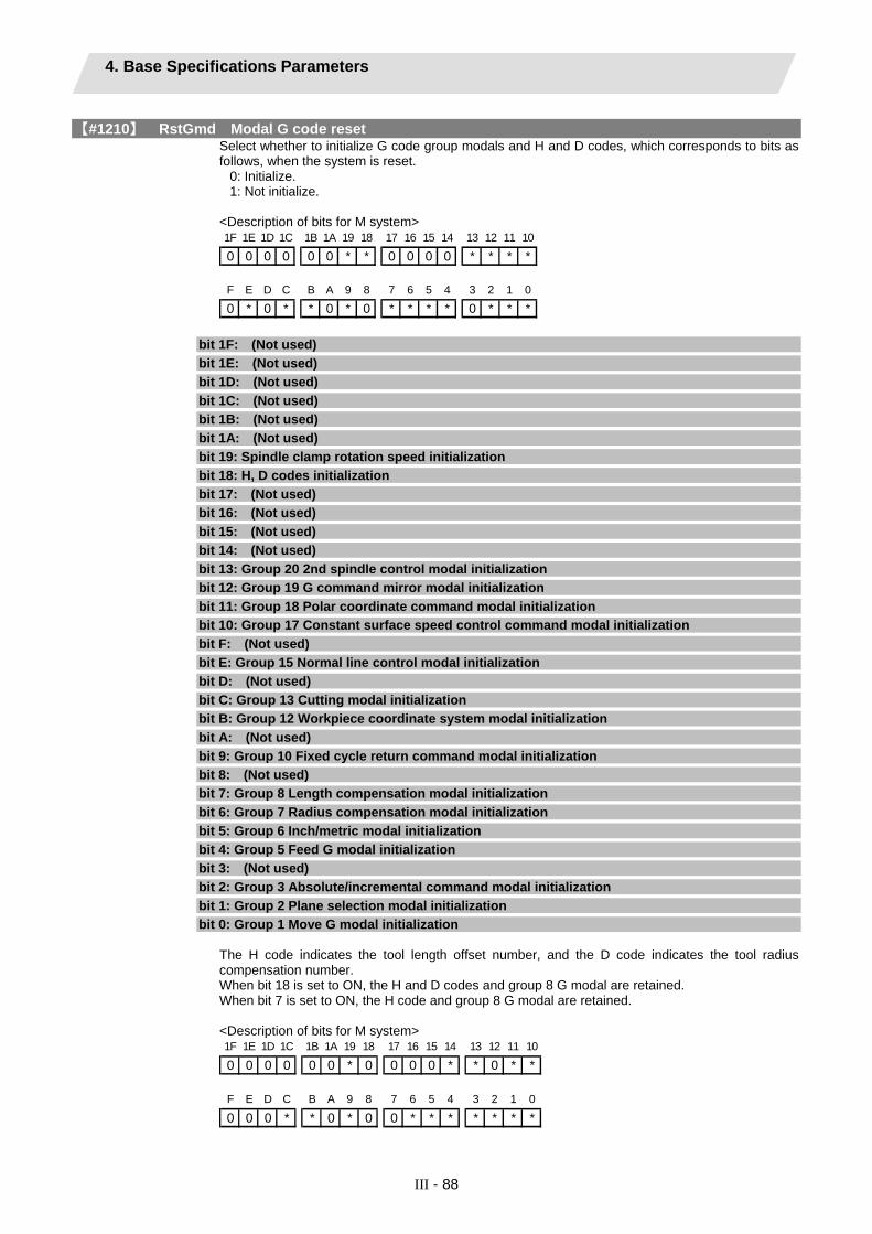
4. Base Specifications Parameters
III - 88
【#1210】 RstGmd Modal G code reset Select whether to initialize G code group modals and H and D codes, which corresponds to bits as follows, when the system is reset.
0: Initialize. 1: Not initialize.
<Description of bits for M system> 1F 1E 1D 1C 1B 1A 19 18 17 16 15 14 13 12 11 10
0 0 0 0 0 0 * * 0 0 0 0 * * * *
F E D C B A 9 8 7 6 5 4 3 2 1 0
0 * 0 * * 0 * 0 * * * * 0 * * *
bit 1F: (Not used)
bit 1E: (Not used)
bit 1D: (Not used)
bit 1C: (Not used)
bit 1B: (Not used)
bit 1A: (Not used)
bit 19: Spindle clamp rotation speed initialization
bit 18: H, D codes initialization
bit 17: (Not used)
bit 16: (Not used)
bit 15: (Not used)
bit 14: (Not used)
bit 13: Group 20 2nd spindle control modal initialization
bit 12: Group 19 G command mirror modal initialization
bit 11: Group 18 Polar coordinate command modal initialization
bit 10: Group 17 Constant surface speed control command modal initialization
bit F: (Not used)
bit E: Group 15 Normal line control modal initialization
bit D: (Not used)
bit C: Group 13 Cutting modal initialization
bit B: Group 12 Workpiece coordinate system modal initialization
bit A: (Not used)
bit 9: Group 10 Fixed cycle return command modal initialization
bit 8: (Not used)
bit 7: Group 8 Length compensation modal initialization
bit 6: Group 7 Radius compensation modal initialization
bit 5: Group 6 Inch/metric modal initialization
bit 4: Group 5 Feed G modal initialization
bit 3: (Not used)
bit 2: Group 3 Absolute/incremental command modal initialization
bit 1: Group 2 Plane selection modal initialization
bit 0: Group 1 Move G modal initialization The H code indicates the tool length offset number, and the D code indicates the tool radius compensation number. When bit 18 is set to ON, the H and D codes and group 8 G modal are retained. When bit 7 is set to ON, the H code and group 8 G modal are retained. <Description of bits for M system> 1F 1E 1D 1C 1B 1A 19 18 17 16 15 14 13 12 11 10
0 0 0 0 0 0 * 0 0 0 0 * * 0 * *
F E D C B A 9 8 7 6 5 4 3 2 1 0
0 0 0 * * 0 * 0 0 * * * * * * *

4. Base Specifications Parameters
III - 89
bit 1F: (Not used)
bit 1E: (Not used)
bit 1D: (Not used)
bit 1C: (Not used)
bit 1B: (Not used)
bit 1A: (Not used)
bit 19: Spindle clamp rotation speed initialization
bit 18: (Not used)
bit 17: (Not used)
bit 16: (Not used)
bit 15: (Not used)
bit 14: Group 15 Facing turret mirror image initialization
bit 13: Group 20 2nd spindle control modal initialization
bit 12: (Not used)
bit 11: Group 18 Balance cut initialization
bit 10: Group 17 Constant surface speed control command modal initialization
bit F: (Not used)
bit E: (Not used)
bit D: (Not used)
bit C: Group 13 Cutting modal initialization
bit B: Group 12 Workpiece coordinate system modal initialization
bit A: (Not used)
bit 9: Group 10 Fixed cycle return command modal initialization
bit 8: (Not used)
bit 7: (Not used)
bit 6: Group 7 Nose R compensation modal initialization
bit 5: Group 6 Inch/metric modal initialization
bit 4: Group 5 Feed G modal initialization
bit 3: Group 4 Barrier check modal initialization
bit 2: Group 3 Absolute/incremental command modal initialization
bit 1: Group 2 Plane selection modal initialization
bit 0: Group 1 Move G modal initialization
【#1213(PR)】 proaxy Side 1 of inclination angle for L system only Set the length within the orthogonal coordinate of the inclined axis, a side of the triangle formed with the inclination angle.
---Setting range--- ±9999.999
【#1214(PR)】 macaxy Side 2 of inclination angle for L system only Set the actual length of the base axis corresponding to the inclined axis, a side of the triangle formed with the inclination angle.
---Setting range--- ±9999.999
【#1215(PR)】 macaxx Side 3 of inclination angle for L system only Set the actual length of the inclined axis, a side of the triangle formed with the inclination angle.
---Setting range--- ±9999.999
【#1216】 extdcc External deceleration level Set the upper limit value of the feedrate when the external deceleration signals are enabled. This parameter is valid when "#1239 set11/bit6" is set to "0".
---Setting range--- 1 to 999999 (mm/min)

4. Base Specifications Parameters
III - 90
【#1217】 aux01 Not used. Set to "0".
【#1218】 aux02
bit3: Parameter input/output format Select the parameter input/output format.
0: Type I 1: Type II (related to "#1218 aux02/bit5")
bit4: External workpiece coordinate offset tool number selection Select the R register that contains the tool number used for automatic calculation when measuring the coordinate offset of an external workpiece.
0: Follow the setting of "#1130 set_t". 1: Use the tool number indicated by user PLC.
bit5: Parameter I/O II spindle specification address Select the spindle specification address of parameter I/O type II.
0: C 1: T
This parameter is also applied to the spindle specification address for input and verification. (Note) This parameter is valid only for parameter I/O type II (when "#1218 aux02/bit3" is set to "1").
bit6: Set No. valid when program input Select which program No. is applied when inputting programs in "#1 MAIN PROGRAM" on Data I/O screen.
0: The No. in the input data 1: The No. set in the data setting area
bit7: Input by program overwrite (1) Select the operation when the program to be input in "#1 MAIN PROGRAM" on Data I/O screen, has already been registered.
0: An operation error (E65) occurs. 1: Input by overwrite.
(2) Select the operation in the high-speed program server mode, when the name of the file to be transmitted with (IC -> host) transmission already exists in the host.
0: Prohibit overwrite 1: Enable overwrite
【#1219】 aux03
bit1: Stop high-speed PC monitoring function Set "1" to disable the function that triggers the emergency stop when the PC high-speed processing time is extended. Disable the monitoring function only as a temporary measure.
bit5: Dog-type intermediate point Select whether to move to the intermediate point during automatic dog-type reference position return. 0: Not move. 1: Move.
bit7: Time constant setting changeover for soft acceleration/deceleration Select the time constant for soft acceleration/deceleration. 0: Accelerating time is obtained with G0tL (G1tL). 1: Accelerating time is obtained with G0tL + G0t1 (G1tL + G1t1).
【#1220】 aux04 for L system only
bit 0: Tool life check timing selection Select the criterion to judge the tool life end when the use count is incremented in tool life management II.
0: Determine the tool life end when the incremented use count has exceeded the life count. (Default) (Use count > life count) 1: Determine the tool life end when the incremented use count has reached the life count. (Use count ≥ life count)
【#1221】 aux05 Not used. Set to "0".
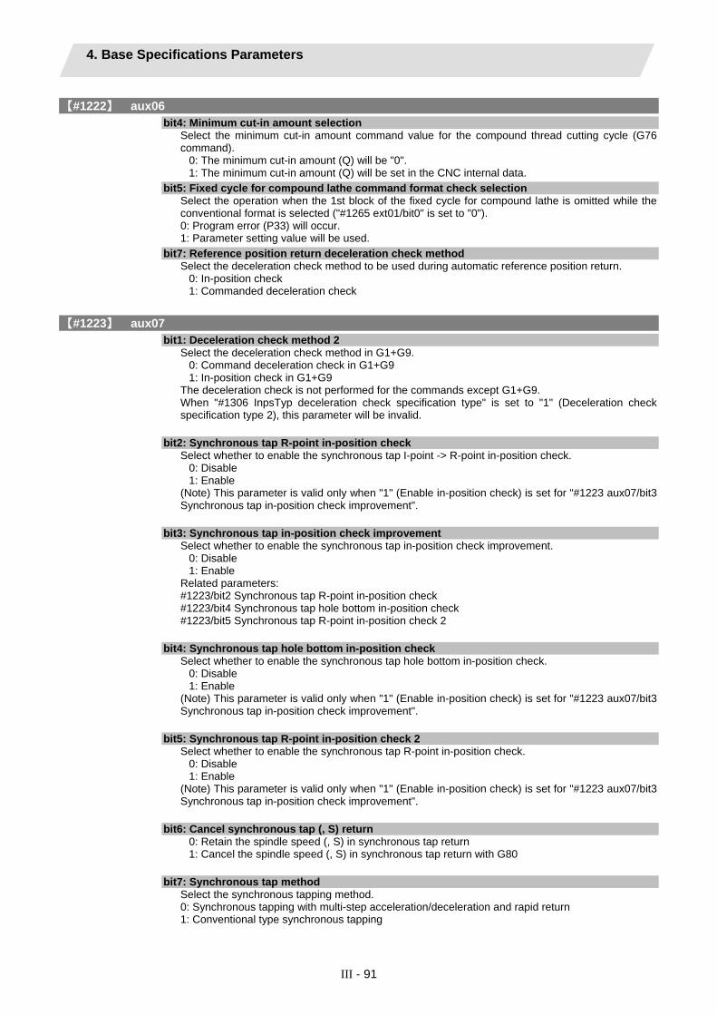
4. Base Specifications Parameters
III - 91
【#1222】 aux06
bit4: Minimum cut-in amount selection Select the minimum cut-in amount command value for the compound thread cutting cycle (G76 command).
0: The minimum cut-in amount (Q) will be "0". 1: The minimum cut-in amount (Q) will be set in the CNC internal data.
bit5: Fixed cycle for compound lathe command format check selection Select the operation when the 1st block of the fixed cycle for compound lathe is omitted while the conventional format is selected ("#1265 ext01/bit0" is set to "0"). 0: Program error (P33) will occur. 1: Parameter setting value will be used.
bit7: Reference position return deceleration check method Select the deceleration check method to be used during automatic reference position return.
0: In-position check 1: Commanded deceleration check
【#1223】 aux07
bit1: Deceleration check method 2 Select the deceleration check method in G1+G9.
0: Command deceleration check in G1+G9 1: In-position check in G1+G9
The deceleration check is not performed for the commands except G1+G9. When "#1306 InpsTyp deceleration check specification type" is set to "1" (Deceleration check specification type 2), this parameter will be invalid.
bit2: Synchronous tap R-point in-position check Select whether to enable the synchronous tap I-point -> R-point in-position check.
0: Disable 1: Enable
(Note) This parameter is valid only when "1" (Enable in-position check) is set for "#1223 aux07/bit3 Synchronous tap in-position check improvement".
bit3: Synchronous tap in-position check improvement Select whether to enable the synchronous tap in-position check improvement.
0: Disable 1: Enable
Related parameters: #1223/bit2 Synchronous tap R-point in-position check #1223/bit4 Synchronous tap hole bottom in-position check #1223/bit5 Synchronous tap R-point in-position check 2
bit4: Synchronous tap hole bottom in-position check Select whether to enable the synchronous tap hole bottom in-position check.
0: Disable 1: Enable
(Note) This parameter is valid only when "1" (Enable in-position check) is set for "#1223 aux07/bit3 Synchronous tap in-position check improvement".
bit5: Synchronous tap R-point in-position check 2 Select whether to enable the synchronous tap R-point in-position check.
0: Disable 1: Enable
(Note) This parameter is valid only when "1" (Enable in-position check) is set for "#1223 aux07/bit3 Synchronous tap in-position check improvement".
bit6: Cancel synchronous tap (, S) return 0: Retain the spindle speed (, S) in synchronous tap return 1: Cancel the spindle speed (, S) in synchronous tap return with G80
bit7: Synchronous tap method Select the synchronous tapping method. 0: Synchronous tapping with multi-step acceleration/deceleration and rapid return 1: Conventional type synchronous tapping

4. Base Specifications Parameters
III - 92
【#1224】 aux08
bit0: Sampling data output Select whether to enable the sampling data output. 0: Disable 1: Enable
【#1225】 aux09
bit6: Enable/disable spindle rotation speed clamp 2 Select whether to enable the spindle rotation speed clamp by the G92 Q command for the spindle command rotation speed (R7000) set with the user ladder.
0: Follow the setting of "aux09/bit7". 1: Only G92 S is valid for R7000. G92 Q is invalid.
When this parameter is set to "1", setting of "aux09/bit7" is invalid.
bit7: Enable/disable spindle rotation speed clamp Select whether to enable the spindle rotation speed clamp by the G92 S or Q command for the spindle command rotation speed (R7000) set with the user ladder. 0: Enable 1: Disable
【#1226】 aux10
bit0: Tool compensation data for external workpiece coordinate offset measurement Select the tool compensation data to be used for external workpiece coordinate offset measurement.
0: Tool length data and tool nose wear data 1: Tool length data
bit1: Optional block skip type Select whether to enable the optional block skip in the middle of a block.
0: Enable only at the beginning of a block. 1: Enable in the middle of a block, as well as at the beginning of the block.
bit2: Single block stop timing Select the timing at which the single block signal is activated.
0: When the signal goes ON while automatic operation is starting, the block will stop after finished. 1: When the signal is ON at the end of the block, the block will stop.
bit3: C-axis reference position return type Select the C-axis reference position return type.
0: Basic position return is performed by the G28 reference position return command or by activating the manual reference position return. The basic point dog is used. 1: When the first C-axis command is issued after the C-axis mode is entered in automatic mode, reference position return is performed before the execution of the block. The reference position return is also performed by the G28 reference position return command or by activating the manual reference position return. The Z phase of the encoder is used.
bit4: S command during constant surface speed Select whether to output a strobe signal when the S command is issued in constant surface speed mode.
0: Not output any strobe signal in constant surface speed mode. 1: Output strobe signals in constant surface speed mode.
bit5: Arbitrary allocation of dog signal Select whether to enable the arbitrary allocation parameter for the origin dog and H/W OT.
0: Disable (Fixed device is used.) 1: Enable (Device is specified by the parameter.)
bit7: Shorten JOG stop time Select whether to shorten the JOG stop time.
0: Not shorten (Conventional specification) 1: Shorten

4. Base Specifications Parameters
III - 93
【#1227】 aux11
bit0: Select PLC signal or spindle feedrate attained Set up this option when disabling the cutting start interlock by spindle feedrate attained.
0: Cutting start interlock by PLC signal 1: Cutting start interlock by spindle feedrate attained
bit1: Select H or D code Set up this option to validate the data that is set up on the tool life management screen when issuing the H99 or D99 command.
0: The H and D codes validate the data that is set up on the management setup screen. 1: Validates the data that is set up on the management setup screen when issuing the H99 or D99 command.
bit2: Measures against tool setter chattering Select a condition where a relieving operation completes after measurement with tools. 0: Sensor signals have stopped for 500 ms or longer. 1: 100μm or longer has passed after sensor signals stopped.
bit3: Absolute coordinate switching (nose R) Select whether to display a nose position or coordinate value with the absolute coordinate counter.
0: Displays the nose position. 1: Displays the position specified by program command. Select a condition where a relieving operation completes after measurement with tools.
bit5: Spindle rotation speed clamp Specify whether to clamp the rotation speed in constant surface speed mode when the spindle rotation clamp command is issued.
0: Clamps the rotation regardless of the constant surface speed mode. 1: Clamps the rotation only in constant surface speed mode.
bit7: Switch the range of tool life data to be input Set up the range of tool life data to be input or compared.
0: Inputs or compares all of the data output. 1: Inputs or compares part of the data output
1) Tool life management I data to be input or compared tool number (D), lifetime (E), life count (F), and auxiliary data (B). 2) Tool life management II data to be input or compared Group number (G), method (M), life (E/F), tool number (D), and compensation number (H)

4. Base Specifications Parameters
III - 94
【#1228】 aux12
bit1: Switch "offset and parameter" screen Select to switch the "offset and parameter" screen to the parameter screen.
0: Display the "offset and parameter" screen. 1: Display the "parameter" screen.
bit2: Switch data protection in data transmission mode Select the range of data protection in data transmission mode.
0: Enable the protection for both send and receive data. 1: Enable the protection for receive data only.
bit3: Nose R specification Select the method to specify the nose R compensation.
0: Specify the nose R compensation by shape number. 1: Specify the nose R compensation by wear number.
bit4: Select operation error or stop code Select operation error or stop code to provide for both block start and cutting start interlocks.
0: Operation error 1: Stop code
bit5: Select constant surface speed coordinates Select the constant surface speed coordinate.
0: Workpiece coordinate 1: Absolute value coordinate
bit6: Switch relative values displayed Select whether to preset the relative coordinates with workpiece coordinate preset (G92.1) or counter preset (G92).
0: Preset the relative coordinates. 1: Not preset the relative coordinates.
bit7: Protection with manual value command Select whether to protect a manual value command.
0: Not protect. (Conventional specification) 1: Protect.

4. Base Specifications Parameters
III - 95
【#1229】 set01
bit0: Subprogram interrupt Select the type of the user macro interrupt. 0: Macro type user macro interrupt 1: Sub-program type user macro interrupt
bit1: Accurate thread cutting E Select what the address E specifies in inch screw cutting. 0: Number of threads per inch 1: Precision lead
bit2: Radius compensation type B (for M system only) Select the method of the arithmetic processing for the intersection point when the start-up or cancel command is operated during radius compensation. 0: The processing does not handle the start-up or cancel command block: handle the offset vector in the direction vertical to that of the command instead. 1: The processing is executed for the intersection point between the command block and the next block.
bit2: Nose R compensation type B (for L system only) Select the method of the arithmetic processing for the intersection point when the start-up or cancel commands are operated during nose R or radius compensation. 0: The processing does not handle the start-up or cancel command block: handle the offset vector in the direction vertical to that of the command instead. 1: The processing is executed for the intersection point between the command block and the next block.
bit3: Initial constant surface speed Select the initial state after the power-ON. 0: Constant surface speed control cancel mode 1: Constant surface speed control mode
bit4: Synchronous tap Select whether to use the floating tap chuck in G74 and G84 tapping cycles. 0: With a floating tap chuck 1: Without a floating tap chuck
bit5: Start point alarm Select the operation when the operation start point cannot be found while executing the next block of G117. 0: Enables the auxiliary function after the block has been executed. 1: Outputs the program error (P33).
bit6: Grid display selection Select the grid display type on the servo monitor screen during the dog type reference position return. 0: Distance between dog OFF and basic point (including a grid mask amount) 1: A value given by reducing a grid mask amount from the distance between dog OFF and basic point
【#1230】 set02
bit7: Macro interface input/output for each part system Select the specification of the macro interface input/output.
0: Shared by all part systems. 1: Used independently by the part systems.
【#1231】 set03
bit0: Graphic check compatibility parameter Select whether to return the data to the pre-starting data after having checked a machining program that rewrites the common variables, workpiece offsets and tool offsets.
0: Return the data. 1: Not return the data.
bit4: Switch zero point mark display position Select the position for displaying the basic point mark in the graphic trace and 2D check.
0: Machine coordinate basic point (same as conventional method) 1: Workpiece coordinate basic point
bit5: Switch graphic check counter display Select the type of counter displayed on the Graphic Check screen.
0: Machine position counter 1: Workpiece coordinate position counter

4. Base Specifications Parameters
III - 96
【#1232】 set04 Not used. Set to "0".
【#1233】 set05 Not used. Set to "0".
【#1234】 set06 Not used. Set to "0".
【#1235】 set07
bit0: Helical interpolation speed 2 0: Select normal speed designation also for 3rd axis 1: Select arc plane element speed designation
bit2: Fixed type chopping compensation valid only at start When the fixed type compensation value is selected, the method can be changed to the compensation value sequential update type after the first four cycles.
0: Disable the method changeover 1: Enable the method changeover
bit4: Selection condition of synchronous tapping gear step Select the parameters that determine the gear step for synchronous tapping.
0: #3005 through #3008 (smax1 to 4) when "#1223 aux07/bit7" is "0". Or #3013 through #3016 (stap1 to 4) when "#1223 aux07/bit7" is "1". 1: Always #3013 through #3016 (stap1 to 4)
【#1236】 set08
bit0: Manual rotary axis feedrate unit Select the unit of manual rotary axis feedrate.
0: Fixed to [°/min] 1: Same speed as before (When inch command, the speed is the command speed divided by 25.4.)
bit1: Spindle speed detection Select the pulse input source of actual spindle rotation speed (R6506/R6507) when the spindle encoder serial connection is selected ("#3025 enc-on" is set to "2").
0: Serial input 1: Encoder input connector
bit2: Current limit droop cancel invalid Select whether to cancel the position droop when the current limit changeover signal is canceled.
0: Cancel the droop. 1: Not cancel the droop.
bit3: Rotary axis command speed scale Select to multiply the rotary axis command speed by 10 times.
0: Invalid 1: During initial inching, the rotary axis command speed is multiplied by 10. In other words, if "F100" is commanded, the speed will be the same as when 1000°/min is commanded. The rotary axis speed display unit will be 10°/min.
【#1237(PR)】 set09 Not used. Set to "0".
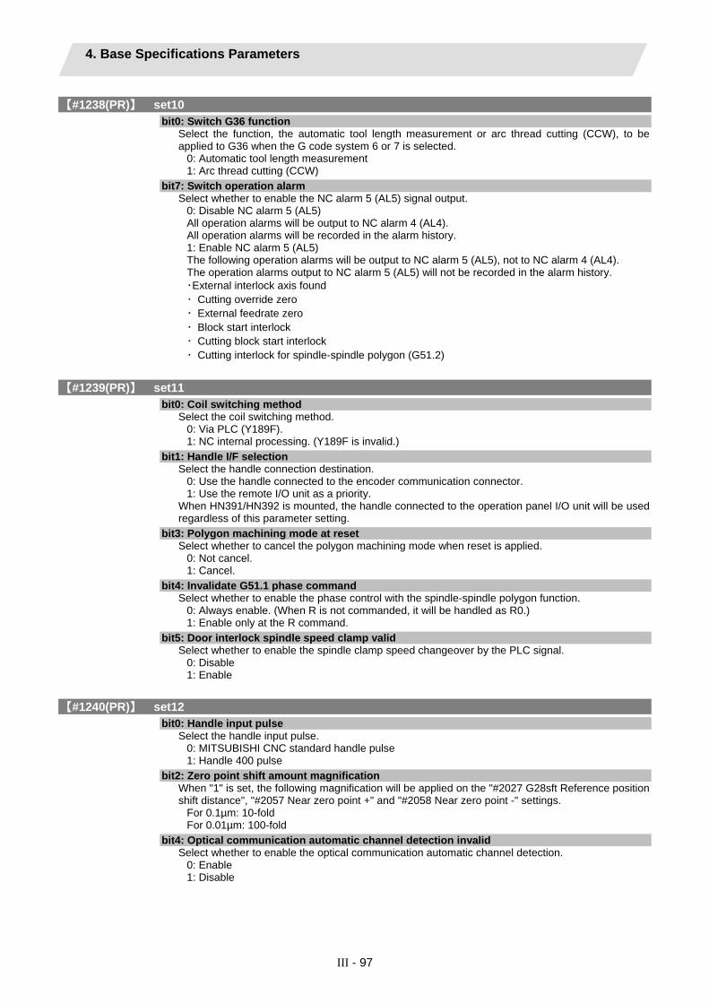
4. Base Specifications Parameters
III - 97
【#1238(PR)】 set10
bit0: Switch G36 function Select the function, the automatic tool length measurement or arc thread cutting (CCW), to be applied to G36 when the G code system 6 or 7 is selected.
0: Automatic tool length measurement 1: Arc thread cutting (CCW)
bit7: Switch operation alarm Select whether to enable the NC alarm 5 (AL5) signal output.
0: Disable NC alarm 5 (AL5) All operation alarms will be output to NC alarm 4 (AL4). All operation alarms will be recorded in the alarm history. 1: Enable NC alarm 5 (AL5) The following operation alarms will be output to NC alarm 5 (AL5), not to NC alarm 4 (AL4). The operation alarms output to NC alarm 5 (AL5) will not be recorded in the alarm history. ・External interlock axis found ・ Cutting override zero ・ External feedrate zero ・ Block start interlock ・ Cutting block start interlock ・ Cutting interlock for spindle-spindle polygon (G51.2)
【#1239(PR)】 set11
bit0: Coil switching method Select the coil switching method.
0: Via PLC (Y189F). 1: NC internal processing. (Y189F is invalid.)
bit1: Handle I/F selection Select the handle connection destination.
0: Use the handle connected to the encoder communication connector. 1: Use the remote I/O unit as a priority.
When HN391/HN392 is mounted, the handle connected to the operation panel I/O unit will be used regardless of this parameter setting.
bit3: Polygon machining mode at reset Select whether to cancel the polygon machining mode when reset is applied.
0: Not cancel. 1: Cancel.
bit4: Invalidate G51.1 phase command Select whether to enable the phase control with the spindle-spindle polygon function.
0: Always enable. (When R is not commanded, it will be handled as R0.) 1: Enable only at the R command.
bit5: Door interlock spindle speed clamp valid Select whether to enable the spindle clamp speed changeover by the PLC signal.
0: Disable 1: Enable
【#1240(PR)】 set12
bit0: Handle input pulse Select the handle input pulse.
0: MITSUBISHI CNC standard handle pulse 1: Handle 400 pulse
bit2: Zero point shift amount magnification When "1" is set, the following magnification will be applied on the "#2027 G28sft Reference position shift distance", "#2057 Near zero point +" and "#2058 Near zero point -" settings.
For 0.1µm: 10-fold For 0.01µm: 100-fold
bit4: Optical communication automatic channel detection invalid Select whether to enable the optical communication automatic channel detection.
0: Enable 1: Disable

4. Base Specifications Parameters
III - 98
【#1265(PR)】 ext01
bit0: Command format 1 Select the command format for the fixed cycle for compound lathe.
0: Conventional format 1: MITSUBISHI CNC special format (1 block command method)
bit1: Command format 2 Select the command format for the lathe fixed cycle.
0: Conventional format 1: MITSUBISHI CNC special format
bit2: Command format 3 Select the command format for the hole drilling fixed cycle.
0: Conventional format 1: MITSUBISHI CNC special format
【#1266(PR)】 ext02 Not used. Set to "0".
【#1267(PR)】 ext03
bit0: G code type Select the high-speed high-accuracy G code type.
0: Conventional format (G61.1) 1: MITSUBISHI special format (G08P1)
【#1268(PR)】 ext04 Not used. Set to "0".
【#1269(PR)】 ext05 Not used. Set to "0".
【#1270(PR)】 ext06
bit6: Switch continuous thread cutting Z phase wait operation Select when to start the 2nd block thread cutting when there is a command with no movement (MST command, etc.) between the thread cutting blocks.
0: Wait for the spindle's single rotation synchronization signal before starting the movement. 1: Start movement without waiting for the spindle's single rotation synchronization signal.
bit7: Handle C axis coordinate during cylindrical interpolation Specify whether to keep the rotary axis coordinate as before the cylindrical interpolation start command is issued during the cylindrical interpolation.
0: Not keep 1: Keep
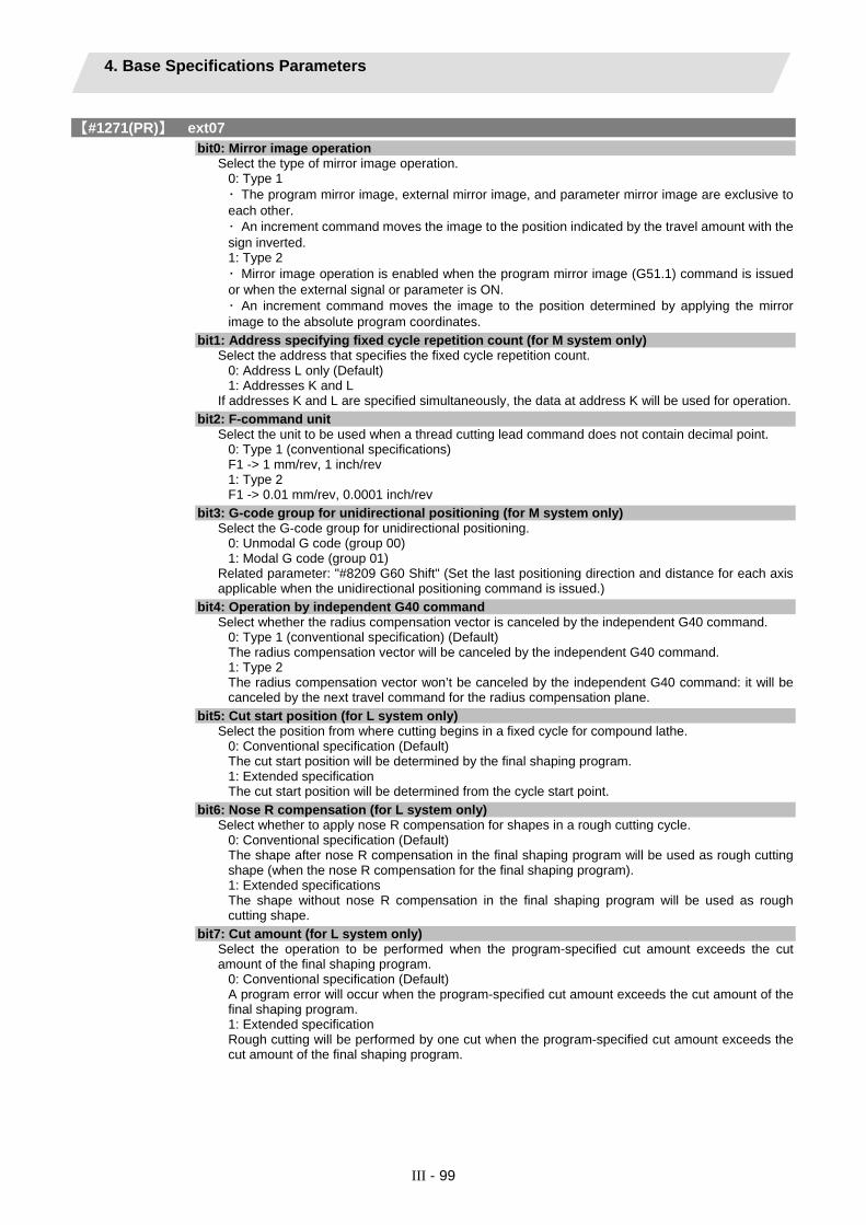
4. Base Specifications Parameters
III - 99
【#1271(PR)】 ext07
bit0: Mirror image operation Select the type of mirror image operation.
0: Type 1 ・ The program mirror image, external mirror image, and parameter mirror image are exclusive to each other. ・ An increment command moves the image to the position indicated by the travel amount with the sign inverted. 1: Type 2 ・ Mirror image operation is enabled when the program mirror image (G51.1) command is issued or when the external signal or parameter is ON. ・ An increment command moves the image to the position determined by applying the mirror image to the absolute program coordinates.
bit1: Address specifying fixed cycle repetition count (for M system only) Select the address that specifies the fixed cycle repetition count.
0: Address L only (Default) 1: Addresses K and L
If addresses K and L are specified simultaneously, the data at address K will be used for operation.
bit2: F-command unit Select the unit to be used when a thread cutting lead command does not contain decimal point.
0: Type 1 (conventional specifications) F1 -> 1 mm/rev, 1 inch/rev 1: Type 2 F1 -> 0.01 mm/rev, 0.0001 inch/rev
bit3: G-code group for unidirectional positioning (for M system only) Select the G-code group for unidirectional positioning.
0: Unmodal G code (group 00) 1: Modal G code (group 01)
Related parameter: "#8209 G60 Shift" (Set the last positioning direction and distance for each axis applicable when the unidirectional positioning command is issued.)
bit4: Operation by independent G40 command Select whether the radius compensation vector is canceled by the independent G40 command.
0: Type 1 (conventional specification) (Default) The radius compensation vector will be canceled by the independent G40 command. 1: Type 2 The radius compensation vector won’t be canceled by the independent G40 command: it will be canceled by the next travel command for the radius compensation plane.
bit5: Cut start position (for L system only) Select the position from where cutting begins in a fixed cycle for compound lathe.
0: Conventional specification (Default) The cut start position will be determined by the final shaping program. 1: Extended specification The cut start position will be determined from the cycle start point.
bit6: Nose R compensation (for L system only) Select whether to apply nose R compensation for shapes in a rough cutting cycle.
0: Conventional specification (Default) The shape after nose R compensation in the final shaping program will be used as rough cutting shape (when the nose R compensation for the final shaping program). 1: Extended specifications The shape without nose R compensation in the final shaping program will be used as rough cutting shape.
bit7: Cut amount (for L system only) Select the operation to be performed when the program-specified cut amount exceeds the cut amount of the final shaping program.
0: Conventional specification (Default) A program error will occur when the program-specified cut amount exceeds the cut amount of the final shaping program. 1: Extended specification Rough cutting will be performed by one cut when the program-specified cut amount exceeds the cut amount of the final shaping program.
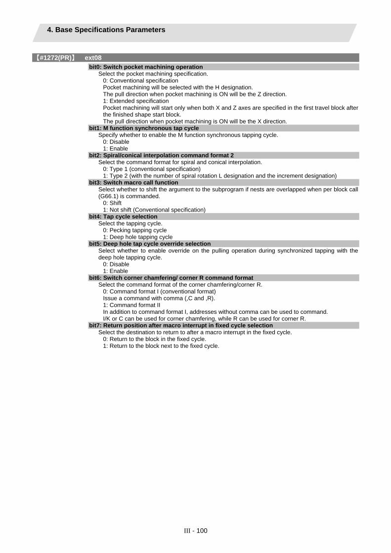
4. Base Specifications Parameters
III - 100
【#1272(PR)】 ext08
bit0: Switch pocket machining operation Select the pocket machining specification.
0: Conventional specification Pocket machining will be selected with the H designation. The pull direction when pocket machining is ON will be the Z direction. 1: Extended specification Pocket machining will start only when both X and Z axes are specified in the first travel block after the finished shape start block. The pull direction when pocket machining is ON will be the X direction.
bit1: M function synchronous tap cycle Specify whether to enable the M function synchronous tapping cycle.
0: Disable 1: Enable
bit2: Spiral/conical interpolation command format 2 Select the command format for spiral and conical interpolation.
0: Type 1 (conventional specification) 1: Type 2 (with the number of spiral rotation L designation and the increment designation)
bit3: Switch macro call function Select whether to shift the argument to the subprogram if nests are overlapped when per block call (G66.1) is commanded.
0: Shift 1: Not shift (Conventional specification)
bit4: Tap cycle selection Select the tapping cycle.
0: Pecking tapping cycle 1: Deep hole tapping cycle
bit5: Deep hole tap cycle override selection Select whether to enable override on the pulling operation during synchronized tapping with the deep hole tapping cycle.
0: Disable 1: Enable
bit6: Switch corner chamfering/ corner R command format Select the command format of the corner chamfering/corner R.
0: Command format I (conventional format) Issue a command with comma (,C and ,R). 1: Command format II In addition to command format I, addresses without comma can be used to command. I/K or C can be used for corner chamfering, while R can be used for corner R.
bit7: Return position after macro interrupt in fixed cycle selection Select the destination to return to after a macro interrupt in the fixed cycle.
0: Return to the block in the fixed cycle. 1: Return to the block next to the fixed cycle.

4. Base Specifications Parameters
III - 101
【#1273(PR)】 ext09
bit0: Switch ASIN calculation results range Select the ASIN calculation results range.
0: -90° to 90° 1: 90° to 270°
bit1: Switch system variable unit Select the unit for the system variable #3002 (time during automatic start).
0: 1 ms unit 1: 1 hour unit
bit2: Switch G71, G72, G73 cutting direction judgment Select the cutting direction when the longitudinal rough cutting cycle (G71), face rough cutting cycle (G72) or closed loop cutting cycle (G73) is commanded.
0: Conventional specification Determined according to the finished shape program. 1: Extended specification Determined according to the finishing allowance and cutting allowance commanded in the program.
bit3: Facing turret mirror image coordinate value type Select how to show the workpiece coordinate values of the axis for which the facing turret mirror image is valid.
0: Movements in the workpiece coordinate system are in the same direction as those in the workpiece machine coordinate system. 1: Movements in the workpiece coordinate system are in the opposite direction to those in the workpiece machine coordinate system.
bit4: Facing turret mirror image valid axis selection Select the axis for which the facing turret mirror image is valid.
0: Fixed to 1st axis. 1: Determined according to the plane selected when the facing turret mirror image is commanded.
【#1274(PR)】 ext10
bit7: Word range check Select whether to check that the operation expression of the word data in the program is enclosed in brackets ( [ ] ) when the machine program is executed. This check is also applied to the 08000 to 09999 and the machine tool builder macro program.
0: Check 1: Not check
【#1275(PR)】 ext11 Not used. Set to "0".
【#1276(PR)】 ext12 Not used. Set to "0".

4. Base Specifications Parameters
III - 102
【#1277(PR)】 ext13 bit0: Tool life management II count type 2
Select how and when the mount or use count will be incremented in tool life management II. The condition to output "tool group life over (TGLO)" signal will be changed accordingly.
0: Type 1 (Default) Counts up when the spindle tool is used for cutting. TGLO signal will be output when the last tool in selected group is judged as expired. 1: Type 2 Counts up by one for a tool used or mounted in a program at the time of resetting. TGLO signal will be output when any of tool groups has reached its lifetime limit.
bit1: Tool life management II life prediction Select whether to enable tool life prediction function in tool life management II.
0: Disable 1: Enable
bit2: Tool life management II life end signal timing Select the timing at which tool life prediction signal is output in tool life management II.
0: Output only when the ["life value" - "used value"] matches the remaining life. ("life value" - "used value" = "remaining life") 1: Output when the ["life value" - "used value"] is less than the remaining life. ("life value" - "used value" ≤ "remaining life")
bit3: Tool life management II life end signal tool Select the tool for which the tool life prediction signal is output in tool life management II.
0: Output the signal tool by tool. 1: Output the signal at the last tool in the group.
bit4: Tool life management II count changeover (For M system only) Select the tool life count method and its timing.
0: Conforms to "ext13/bit0" setting. 1: When "ext13/bit0" is set to "0": Counts up by one for a tool used or mounted in a program at the time of resetting. When "ext13/bit0" is set to "1": Follow the setting of "Method (Mthd)" on Tool life screen. The output condition of "tool group life over" signal conforms to "ext13/bit0".
【#1278(PR)】 ext14 bit0: Program restart method selection
Select the program restart type. 0: Restart type A 1: Restart type B
【#1279(PR)】 ext15
bit0: Part system synchronization method Select the part system synchronization method.
0: If one part system is not in the automatic operation, the synchronization command will be ignored and the next block will be executed. 1: Operate according to the "waiting ignore" signal. If the "waiting ignore" signal is set to "1", the synchronization command will be ignored. When set to "0", synchronization will be applied.
bit1: Interrupt amount during machine lock Select when to cancel the interruption amount during machine lock.
0: When resetting 1: During manual reference position return (not when resetting)
bit2: Selection of cutting start interlock target block Select whether to enable the cutting start interlock for successive cutting blocks. 0: Enable 1: Disable

4. Base Specifications Parameters
III - 103
【#1280(PR)】 ext16
bit0: I/F per axis during cross machining control Select how to handle the following PLC interface for axes interchanged with cross machining control. ・ Mirror image ・ Manual/automatic interlock ・ Manual/automatic machine lock
0: Follows axis configuration before cross machining control. 1: Follows axis configuration after cross machining control.
(Example) The device No. of automatic interlock (+) for X1 will be as follows when the cross machining is executed with the 1st axis (X1) in the 1st part system and 1st axis (X2) in the 2nd part system. When "0" is set: Y820 (interface for 1st axis in 1st part system) When "1" is set: Y828 (interface for 1st axis in 2nd part system) (Note) If the number of axes in the part system changes with cross machining, the interface of the target axis may change when this parameter is set to "1". (Example) When 1st part system's C axis is moved to 2nd part system with a 1st part system (X, Z, C, Y) and 2nd part system (X, Z) configuration: When "1" is set: Y82A, Y7CA, Y8AA and later will be the interface for the C axis moved to the 2nd part system. Y7C2, Y822, Y8A2 and later will be the interface of the Y axis in the 1st part system, because the axes following the removed C axis (third place) are shifted up.
bit1: Cross machining control cancel with reset Select whether to cancel the cross machining control when reset is applied.
0: Cancel. 1: Not cancel.
bit2: Interchange coordinate position display Select whether to display interchanged (or moved) coordinate positions in the cross machining control. This setting will be applied when the axes are moved, as well as when the axes are interchanged.
0: Display interchanged (or moved) coordinate positions. 1: Display coordinate positions without being interchanged (nor moved).
(Example) When 1st part system's C axis is moved to 2nd part system with a 1st part system (X, Z, C, Y) and 2nd part system (X, Z) configuration: 1st part system: X, Z and Y coordinate positions are displayed. 2nd part system: X, Z and C coordinate positions are displayed.
bit3: Reset operation for synchronization/super-imposition control Select whether to cancel synchronization/superimposition control when reset is applied.
0: Cancel. 1: Not cancel.
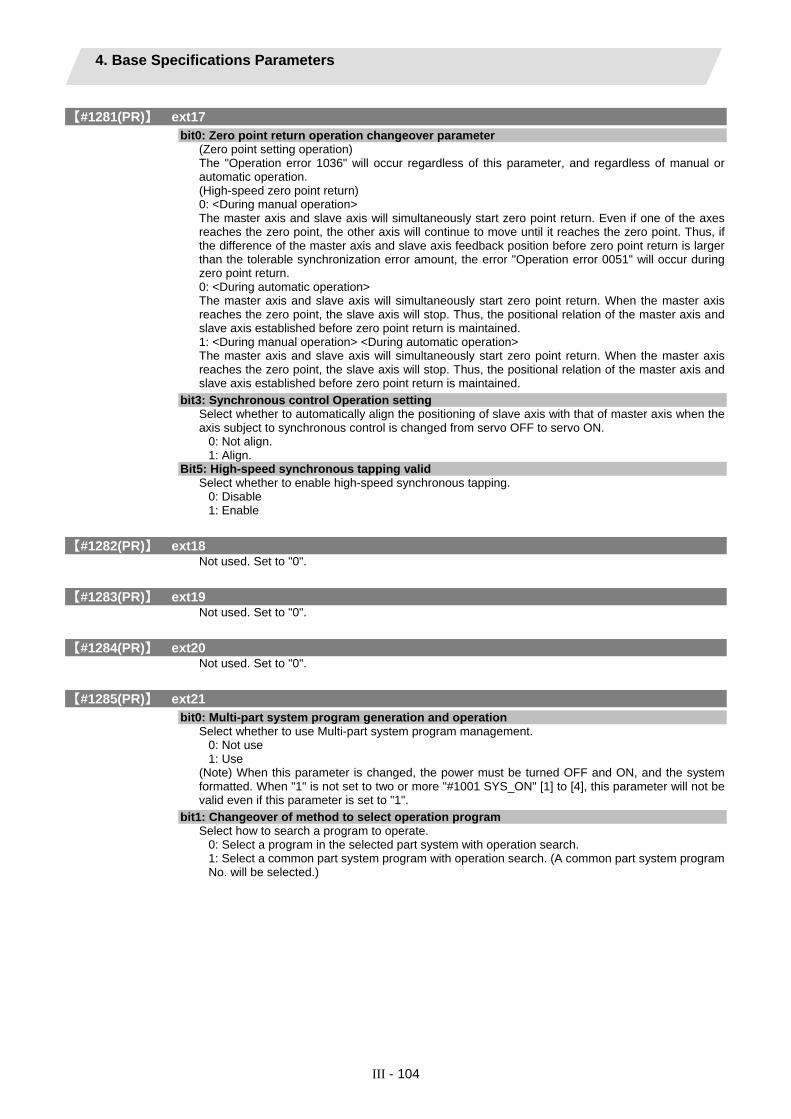
4. Base Specifications Parameters
III - 104
【#1281(PR)】 ext17
bit0: Zero point return operation changeover parameter (Zero point setting operation) The "Operation error 1036" will occur regardless of this parameter, and regardless of manual or automatic operation. (High-speed zero point return) 0: <During manual operation> The master axis and slave axis will simultaneously start zero point return. Even if one of the axes reaches the zero point, the other axis will continue to move until it reaches the zero point. Thus, if the difference of the master axis and slave axis feedback position before zero point return is larger than the tolerable synchronization error amount, the error "Operation error 0051" will occur during zero point return. 0: <During automatic operation> The master axis and slave axis will simultaneously start zero point return. When the master axis reaches the zero point, the slave axis will stop. Thus, the positional relation of the master axis and slave axis established before zero point return is maintained. 1: <During manual operation> <During automatic operation> The master axis and slave axis will simultaneously start zero point return. When the master axis reaches the zero point, the slave axis will stop. Thus, the positional relation of the master axis and slave axis established before zero point return is maintained.
bit3: Synchronous control Operation setting Select whether to automatically align the positioning of slave axis with that of master axis when the axis subject to synchronous control is changed from servo OFF to servo ON.
0: Not align. 1: Align.
Bit5: High-speed synchronous tapping valid Select whether to enable high-speed synchronous tapping.
0: Disable 1: Enable
【#1282(PR)】 ext18 Not used. Set to "0".
【#1283(PR)】 ext19 Not used. Set to "0".
【#1284(PR)】 ext20 Not used. Set to "0".
【#1285(PR)】 ext21
bit0: Multi-part system program generation and operation Select whether to use Multi-part system program management.
0: Not use 1: Use
(Note) When this parameter is changed, the power must be turned OFF and ON, and the system formatted. When "1" is not set to two or more "#1001 SYS_ON" [1] to [4], this parameter will not be valid even if this parameter is set to "1".
bit1: Changeover of method to select operation program Select how to search a program to operate.
0: Select a program in the selected part system with operation search. 1: Select a common part system program with operation search. (A common part system program No. will be selected.)

4. Base Specifications Parameters
III - 105
【#1286(PR)】 ext22
bit0: Program input/output method selection Select the program input/output method.
0: Only the programs in the selected part system are input/output. 1: The designated programs are output for all part systems.
bit2: O No. for program input No. Select the operation when the same program No. is input during data input.
0: The O No. is handled as a character string data. 1: The O No. is handled as a program No. Whether to overwrite the program or cause an error is decided by "#1218 bit7 Input by program overwrite".
bit3: No O No. at machining program input Select whether to enable the machining program input even if there is no program No. (O No.). The program No. is fixed to 01 in this case.
0: Disable 1: Enable
【#1287(PR)】 ext23
bit4: Relative coordinate display (M system)
0: Display the actual position including tool length offset. 1: Display the machining position in terms of a program command excluding tool length offset.
(L system) 0: Display the actual position including tool shape compensation. 1: Display the machining position in terms of a program command excluding tool shape compensation.
bit5: Relative coordinate display (M system)
0: Display the actual position including tool radius compensation. 1: Display the machining position in terms of a program command excluding tool radius compensation.
(L system) 0: Display the actual position including nose R compensation. 1: Display the machining position in terms of a program command excluding nose R compensation.
【#1288(PR)】 ext24
bit0: MDI program clear Select whether to clear the MDI programs when MDI operation ends, the power is turned ON again, reset is input, or emergency stop is canceled.
0: Not clear. 1: Clear (save only % programs).
【#1289(PR)】 ext25
bit0: Tool radius compensation switch corner judgment method (Nose R compensation) Select the criterion to execute the outer rounding at the small corner in tool radius compensation. (L system)
0: The corner angle is 0°; linear-linear; G02-G03/G03-G02; the radius is the same. (Conventional method) 1: The corner angle is 1° or smaller; linear-linear; G02-G03/G03-G02; the radius is almost the same. (Method for rounding minute corner angle)
(M system) 0: The corner angle is 1° or smaller; linear-linear; G02-G03/G03-G02. (Conventional method) 1: The corner angle is 1° or smaller; linear-linear; G02-G03/G03-G02; the radius is almost the same. (Method for rounding minute corner angle)
【#1290(PR)】 ext26 Not used. Set to "0".
【#1291(PR)】 ext27 Not used. Set to "0".

4. Base Specifications Parameters
III - 106
【#1292(PR)】 ext28 Not used. Set to "0".
【#1293(PR)】 ext29 Not used. Set to "0".
【#1294(PR)】 ext30 Not used. Set to "0".
【#1295(PR)】 ext31 Not used. Set to "0".
【#1296(PR)】 ext32 Not used. Set to "0".
【#1297(PR)】 ext33 Not used. Set to "0".
【#1298(PR)】 ext34 Not used. Set to "0".
【#1299(PR)】 ext35 Not used. Set to "0".
【#1300(PR)】 ext36
bit0: Multiple spindle control II Select multiple spindle control I or II.
0: Multiple spindle control I (L system only) 1: Multiple spindle control II (select from ladder)
bit7: Spindle synchronization command method Select the spindle synchronization command method.
0: Spindle synchronization with PLC I/F 1: Spindle synchronization with machining program
【#1301】 nrfchk Near reference position check method Select the method to judge the "near reference position".
0: Conventional method 1: Command machine position is used. 2: Feedback position is used.
【#1302】 AutoRP Automatic return by program restart Select the method to move to the restart position when restarting the program.
0: Move the system manually to the restart position and then restart the program. 1: The system automatically moves to the restart position at the first activation after the program restarts.
【#1303(PR)】 V1comN No. of #100 address part system common variables Set the number of common variables, common for part systems, starting from address #100. This is valid only when "#1052 MemVal" is set to "1".
---Setting range--- 0 to 100
【#1304(PR)】 V0comN No. of #500 address part system common variables Set the number of common variables, common for part systems, starting from address #500. This is valid only when "#1052 MemVal" is set to "1".
---Setting range--- 0 to 500

4. Base Specifications Parameters
III - 107
【#1306】 InpsTyp Deceleration check specification type Select the parameter specification type for the G0 or G1 deceleration check. 0: Deceleration check specification type 1 G0 is specified with "#1193 inpos", and G1+G9 with "#1223 aux07/bit1". 1: Deceleration check specification type 2 G0 or G1+G9 is specified with "#1193 inpos".
【#1309(PR)】 GType Switch command format Select which is used to command the reverse tap.
0: G84.1/G88.1 1: D command with the value changed to negative
【#1310】 WtMmin Minimum value for synchronization M code Set the minimum value for the M code. When "0" is set, the synchronization M code will be invalid.
---Setting range--- 0, 100 to 99999999
【#1311】 WtMmax Maximum value for synchronization M code Set the maximum value for the M code. When "0" is set, the synchronization M code will be invalid.
---Setting range--- 0, 100 to 99999999
【#1312】 T_base Tool life management standard number Set the standard No. for the tool life management. When the value specified by the T code command exceeds the set value in this parameter, the set value will be subtracted from the command value, which will be used as tool group No. for tool life management. When the value specified by the T code command is equal to or less than the set value, the T code will be handled as a normal T code and not subjected to tool life management. When "0" is set in this parameter, the T code command will always specify a group No. (Valid for M-system tool life management II.)
---Setting range--- 0 to 9999
【#1313】 TapDw1 Synchronous tap hole bottom wait time Set the hole bottom wait time for synchronous tapping. When P address is specified, the greater value will be used as the hole bottom wait time. When an in-position check is performed at the hole bottom, the wait time will be provided after the completion of the in-position check. (Note) This parameter is valid only when "1" is set in "#1223 aux07/bit3" (synchronous tap in-position check improvement) and "#1223 aux07/bit4" (synchronous tap hole bottom in-position check).
---Setting range--- 0 to 999 (ms)
【#1314】 TapInp Synchronous tap in-position check width (tap axis) Set the hole bottom in-position check width for synchronous tapping. (Note) This parameter is valid only when "1" is set in "#1223 aux07/bit3" (synchronous tap in-position check improvement) and "#1223 aux07/bit4" (synchronous tap hole bottom in-position check).
---Setting range--- 0.000 to 99.999

4. Base Specifications Parameters
III - 108
【#1316(PR)】 CrossCom Reference of common variables common for part systems Select whether to use the common variables from #100100 to #800199.
0: Not use 1: Use
This parameter is valid only when the number of variable sets is set to 600 or more. When this parameter is set to "1", variables from #100100 to #100110 will not be available as the system variables for PLC data read function, and the setting of "#1052 MemVal" will be invalid.
【#1324(PR)】 Chop_R Chopping compensation value fixing method Set the head No. of the R register used as the compensation amount save area during fixed compensation amount method. When the first number is an odd number, the operation message "Setting error" appears. When the value overlaps with the chopping control data area, the operation message "Setting error" appears.
---Setting range--- 8300 to 9782 (Only the even number) (Within backup area)
【#1326】 PLC Const Ext. Number PLC constant extension number Set the number of PLC constant extension points.
---Setting range--- 0 to 750
【#1327】 3D ATC type Tool change method specification Select the tool change method for determining the tool to draw solids. With 3D drawing, the tool will be changed by the method designated with this parameter, and then the image will be drawn.
0: With one standby tool 1: With two standby tools 2: With no standby tool
【#1328】 TLM type Tool measurement standard positions election Select the tool measurement method.
0: Use the machine position at TLM switch ON as 0. 1: Use the machine basic point as standard.
【#1329】 Emgcnt Emergency stop contactor shut-off time Set the time taken for the drive section's main power to be shut-off when the confirmation of all the axes' stop failed after the emergency stop state. The contactor shut-off signal is output as soon as all the axes are confirmed stopped if the confirmation is done prior to the set time. When there is no safety observation option or "0" is set, the shut-off time will be 30(s).
---Setting range--- 0 to 60 (s)
【#1330(PR)】 MC_dp1 Contactor weld detection device 1 When safety observation is executed, set the I/O device to input the contactor's auxiliary b contact signal used for the contactor weld detection. If "0" is set, weld detection will not be executed.
---Setting range--- 000 to 02FF (HEX)
【#1331(PR)】 MC_dp2 Contactor weld detection device 2 When safety observation is executed, set the I/O device to input the contactor's auxiliary B contact signal used for the contactor weld detection. If "0" is set, weld detection will not be executed.
---Setting range--- 000 to 02FF (HEX)

4. Base Specifications Parameters
III - 109
【#1332(PR)】 F-bus init delay Fieldbus communication error invalid time Tuning the power ON, start the communication, and then set the time where Fieldbus communication error is not detected. Set this in 0.1 second increment.
---Setting range--- 0 to 255 (0.1s) Standard: 0
【#1333】 LMC restrain Lost motion compensation restraint in handle mode Select whether to restrain the lost motion compensation in handle mode.
0: Restrain 1: Not restrain
【#1334】 DI/DO refresh cycl DI/DO refresh cycle Select the DI/DO refresh cycle.
0: Standard mode 1: High-speed mode 1 2: High-speed mode 2
(Note 1) This parameter is valid for M700 and M70 (typeA) series. "Standard mode" is applied to M70 (typeB) regardless of this parameter. (Note 2) The speed may not be high if number of ladder steps is excessive. (Note 3) If high-speed mode is selected, the fine segment processing performance may degrade.
【#1335】 man_smg Manual feed acceleration/deceleration selection Select the acceleration/deceleration mode in jog feed, incremental feed and manual reference position return (when rapid traverse signal OFF).
0: Acceleration/Deceleration for rapid traverse 1: Acceleration/Deceleration for cutting feed
【#1336(PR)】 #400_Valtype #400 address variable type Select whether the #400-level variables are used as machine tool builder macro variables or as common variables.
0: #400 to #449 are not available; #450 to #499 are used as machine tool builder macro variables. 1: #400 to #499 are used as common variables
(Note) 700 sets of common variables are required for using #400 to #499 as common variables. If this parameter is set to "1" while the number of common variables is not set to 700, this parameter setting will be regarded as "0".
【#1338(PR)】 rev data save trg Trigger switching to save arbitrary reverse run data Select the condition to start/stop saving reverse run data.
0: Start when the reverse run control mode signal is turned ON. Stop when turned OFF. 1: Start when the reverse run control mode signal is ON and macro interrupt is valid (M96/ION).
Stop when the reverse run control mode signal is OFF or macro interruption is finished (M97/IOF) (compatible with M500M).
【#1361(PR)】 aux_acc Auxiliary axis acceleration/deceleration type Select the acceleration/deceleration type of auxiliary axis in PLC axis indexing.
0: Acceleration/deceleration with constant time 1: Acceleration/deceleration with a constant angle of inclination
【#1493(PR)】 ref_syn Synchronization at zero point initialization 0: Master axis and slave axis determine their zero points individually. 1: The zero points of both master and slave axes are determined by initializing the master axis's zero point.
The slave axis moves in perfect synchronization with the master axis. Set this to "1" for speed/current command synchronization control.

4. Base Specifications Parameters
III - 110
【#1494(PR)】 dsp_ax_change Axis order of counter display Set this in order to change the axis order of counter display. The axes will be displayed in ascending order of the setting values "1" to "8". However, axis whose setting is "0" will be displayed after axes whose settings are between "1" and "8" are displayed. (Note 1) When the same value is set for more than one axis, axis that is displayed on the left side on the parameter screen will be first displayed. (Note 2) When both of mixed synchronization control (option) and interchange coordinate position display ("1280 ext16/bit2" OFF) are valid, and when there are two or more valid part systems, this parameter will be ignored.
---Setting range--- 1 to 8: Axes are displayed in ascending order. Other than 1 to 8: Axes are displayed after the display of the axes with setting value "1" to "8".
【#1501】 polyax Rotational tool axis number for L system only Set the number of the rotational tool axis used for polygon machining (G51.2). Set "0" when not using polygon machining (spindle-servo axis), or when using spindle-spindle polygon machining. A value exceeding the base specification parameter "#1002 axisno" cannot be specified. This parameter is valid when the G code system is 6 or 7 (7 or 8 is set in base specification parameter "#1037 cmdtyp").
【#1502】 G0Ipfg G1 -> G0 deceleration check Select whether to perform a deceleration check when the travel direction is changed from G1 to G0.
0: Not perform 1: Perform
【#1503】 G1Ipfg G1 -> G1 deceleration check Select whether to perform a deceleration check when the travel direction is changed from G1 to G1.
0: Not perform 1: Perform
【#1505】 ckref2 Second reference position return check Select whether the check is carried out at the specified position in manual second reference position return mode upon completion of spindle orientation or at second reference position return interlock signal.
0: Upon completion of spindle orientation 1: At second reference position return interlock signal
【#1506】 F1_FM Upper limit of F1 digit feedrate Set the maximum value up to which the F 1-digit feedrate can be changed.
---Setting range--- 0 to 60000 (mm/min)
【#1507】 F1_K F1 digit feedrate change constant Set the constant that determines the speed change rate per manual handle graduation in F 1-digit feedrate change mode.
---Setting range--- 0 to 32767
【#1510】 DOOR_H Shorten door interlock II axis stop time Select whether to shorten the time during which the axis is stopped when the door is opened. 0 : Use the conventional axis stop time. 1 : Shorten the axis stop time. (Note) When the door interlock II signal is input via a ladder, the conventional axis stop time will be used.

4. Base Specifications Parameters
III - 111
【#1511】 DOORPm Signal input device 1 for door interlock II: for each part system Set the fixed device number (X??) for door interlock II signal input for each part system. A device number from X01 to XFF can be specified. Device number "000" is invalid. Set device number "100" when using no fixed device number for door interlock II signal input. Related parameter: "#1154 pdoor (Door interlock II for each part system) "
---Setting range--- 000 to 2FF (hexadecimal)
【#1512】 DOORPs Signal input device 2 for door interlock II: for each part system Set the fixed device number (X??) for door interlock II signal input for each part system. (Set the same value as that of #1155.) Related parameter: "#1154 pdoor (Door interlock II for each part system)"
---Setting range--- 000 to 2FF (hexadecimal)
【#1513】 stapM M code for synchronous tap selection Set the M code for the synchronous tapping selection. Select the synchronous tapping mode using the miscellaneous function code of the value set in this parameter. The M function command can be issued immediately before the tap command or in the same block. This function is valid only when "1" is set in "#1272 ext08/bit1 (Enable/disable M-function synchronous tap cycle)". (Note) Do not use M00, 01 02, 30, 98, and 99.
---Setting range--- 0 to 99999999
【#1514】 expLinax Exponential function interpolation linear axis Set the axis name for the linear axis used in exponential function interpolation.
---Setting range--- A to Z
【#1515】 expRotax Exponential function interpolation rotary axis Set the axis name for the rotary axis used in exponential function interpolation.
---Setting range--- A to Z
【#1516】 mill_ax Milling axis name Set the name of the rotary axis used in milling interpolation. Only one rotary axis can be set. When there is no E command in issuing the G12.1 command, this parameter will be followed.
---Setting range--- A to Z
【#1517】 mill_C Milling interpolation hypothetical axis name Select the hypothetical axis command name for milling interpolation. When there is no D command in issuing the milling interpolation command, this parameter will be followed.
0: Y axis command 1: Command rotary axis name.
【#1518】 polm Spindle-spindle polygon Workpiece spindle No. Set the workpiece axis No. used in spindle-spindle polygon machining. (Note) The 1st spindle will be selected when "0" is set.

4. Base Specifications Parameters
III - 112
【#1519】 pols Spindle-spindle polygonTool spndle No. Set the number of the rotaty tool spindle used in spindle-spindle polygon machining. (Note) The 2nd spindle will be selected when "0" is set.
【#1520(PR)】 Tchg34 Additional axis tool compensation operation Select axis to carry out the additional axis' tool compensation function.
0: 3rd axis. 1: 4th axis.
【#1521】 C_min Minimum turning angle Set the minimum turning angle of the normal line control axis at the block joint during normal line control.
---Setting range--- 0.000 to 360.000 (°) (Input setting increment applies)
【#1522(PR)】 C_axis Normal line control axis Set the number of the axis for normal line control. Set a rotary axis No.
0: Normal line control disabled 1 to 8: Axis No. (number of control axes)
【#1523】 C_feed Normal line control axis turning speed Set the turning speed of the normal line control axis at the block joint during normal line control. Set a value that does not exceed the normal line control axis' clamp speed ("#2002 clamp"). This is valid with normal line control type I.
---Setting range--- 0 to 1000000 (°/min)
【#1524】 C_type Normal line control type Select the normal line control type.
0: Normal line control type I 1: Normal line control type II
【#1533】 millPax Pole coordinate linear axis name Set the linear axis name used for pole coordinate interpolation.
---Setting range--- Axis name such as X, Y or Z
【#1534】 SnG44.1 Spindle No. for G44.1 command Set the selected spindle No. for the G44.1 command. The setting range differs according to the model. If a spindle that does not exist is set, the 2nd spindle will be used. Note that if there is only one spindle, the 1st spindle will be used.
0: 2nd spindle 1: 1st spindle 2: 2nd spindle 3: 3rd spindle 4: 4th spindle
【#1535】 C_leng Minimum turning movement amount Set the minimum turning movement amount of the normal line control axis at the block joint during normal line control.
---Setting range--- 0.000 to 99999.999 (mm) (Input setting increment applies)

4. Base Specifications Parameters
III - 113
【#1537】 crsax[1] Cross machining control axis Set the axis to be interchanged during cross machining control. Using two digits, set the name of the axis to be interchanged with the axis in the part system where the mixed synchronization control (cross machining control) request signal is input, or the name of the axis to be shifted to that part system.
---Setting range--- Two digits between A to Z and 1 to 9 (Setting will be cleared when "0" is set)
【#1538】 crsax[2] Set the axis to be interchanged during cross machining control. Using two digits, set the name of the axis to be interchanged with the axis in the part system where the mixed synchronization control (cross machining control) request signal is input, or the name of the axis to be shifted to that part system.
---Setting range--- Two digits between A to Z and 1 to 9 (Setting will be cleared when "0" is set)
【#1539】 crsax[3] Set the axis to be interchanged during cross machining control. Using two digits, set the name of the axis to be interchanged with the axis in the part system where the mixed synchronization control (cross machining control) request signal is input, or the name of the axis to be shifted to that part system.
---Setting range--- Two digits between A to Z and 1 to 9 (Setting will be cleared when "0" is set)
【#1540】 crsax[4] Set the axis to be interchanged during cross machining control. Using two digits, set the name of the axis to be interchanged with the axis in the part system where the mixed synchronization control (cross machining control) request signal is input, or the name of the axis to be shifted to that part system.
---Setting range--- Two digits between A to Z and 1 to 9 (Setting will be cleared when "0" is set)
【#1541】 crsax[5] Set the axis to be interchanged during cross machining control. Using two digits, set the name of the axis to be interchanged with the axis in the part system where the mixed synchronization control (cross machining control) request signal is input, or the name of the axis to be shifted to that part system.
---Setting range--- Two digits between A to Z and 1 to 9 (Setting will be cleared when "0" is set)
【#1542】 crsax[6] Set the axis to be interchanged during cross machining control. Using two digits, set the name of the axis to be interchanged with the axis in the part system where the mixed synchronization control (cross machining control) request signal is input, or the name of the axis to be shifted to that part system.
---Setting range--- Two digits between A to Z and 1 to 9 (Setting will be cleared when "0" is set)

4. Base Specifications Parameters
III - 114
【#1543】 crsax[7] Set the axis to be interchanged during cross machining control. Using two digits, set the name of the axis to be interchanged with the axis in the part system where the mixed synchronization control (cross machining control) request signal is input, or the name of the axis to be shifted to that part system.
---Setting range--- Two digits between A to Z and 1 to 9 (Setting will be cleared when "0" is set)
【#1544】 crsax[8] Set the axis to be interchanged during cross machining control. Using two digits, set the name of the axis to be interchanged with the axis in the part system where the mixed synchronization control (cross machining control) request signal is input, or the name of the axis to be shifted to that part system.
---Setting range--- Two digits between A to Z and 1 to 9 (Setting will be cleared when "0" is set)
【#1561】 3Dcdc Switch workpiece coordinate display during 3D coordinate conversion Select the workpiece coordinate display during 3D coordinate conversion.
0: Workpiece coordinate system 1: G68 program coordinate system
(Note) The special display unit's absolute coordinates also follow this parameter setting.
【#1562】 3Dremc Switch remaining command display during 3D coordinate conversion Select the remaining command display during 3D coordinate conversion.
0: Workpiece coordinate system 1: G68 program coordinate system
【#1563】 3Dcdrc Switch coordinate reading during 3D coordinate conversion Select the coordinate system of the workpiece/skip coordinate read value in the 3D coordinate conversion modal.
0: G68 program coordinate system 1: Workpiece (local) coordinate system
【#1564】 3Dspd Hole drilling speed during 3D coordinate conversion Select the rapid traverse rate for the hole drilling cycle during 3D coordinate conversion.
0: The cutting feed clamp speed is used. Other than 0: The set speed is used.
Note that if the rapid traverse rate is exceeded, the speed will be clamped at the rapid traverse rate.
【#1565】 helgear Helical machining base axis Set the base axis for helix angle calculation in helical machining. When no setting, Z axis will be used.
---Setting range--- Axis name such as X, Y, Z, U, V, W, A, B, and C
【#1566】 3DSelctDrillaxMode Switch drill axis's mode from rapid traverse during 3D coordinate conversion
Select the rapid traverse mode in non-drilling blocks among a drilling cycle to the cutting feed mode during 3-dimensional coordinate conversion.
0: Rapid traverse mode. The speed follows the setting of "#2001 rapid". 1: Cutting feed mode. The speed follows the setting of "#1564 3Dspd".
【#1568】 SfiltG1 G01 soft acceleration/deceleration filter Set the filter time constant for smoothly changing the acceleration rate for the cutting feed acceleration/deceleration in pre-interpolation acceleration/deceleration.
---Setting range--- 0 to 200 (ms)

4. Base Specifications Parameters
III - 115
【#1569】 SfiltG0 G00 soft acceleration/deceleration filter Set the filter time constant for smoothly changing the acceleration rate for the rapid traverse acceleration/deceleration in pre-interpolation acceleration/deceleration.
---Setting range--- 0 to 200 (ms)
【#1570】 Sfilt2 Soft acceleration/deceleration filter 2 Set the filter time constant for smoothly changing the acceleration rate in pre-interpolation acceleration/deceleration. This will be invalid when "0" or "1" is set.
---Setting range--- 0 to 26 (ms)
【#1571】 SSSdis SSS control adjustment coefficient fixed value selection Fix the shape recognition range for SSS control.
【#1572】 Cirorp Arc command overlap This eliminates speed fluctuations at the joint of the arc and straight line and arc and arc. Set as a bit unit.
0: Do not overlap the arc command blocks 1: Overlap the arc command blocks
bit0 : Arc command during high-speed high-accuracy control II bit1 : Arc command during high-speed machining mode II bit2 : Arc command during high-accuracy control (G61.1) bit3 : Arc command during cutting mode (G64) The line command block and arc command block won't be overlapped during G61.2 modal regardless of this setting. (Note) This parameter is invalid during SSS control.
【#1573】 Ret1 Return type 1 Select the axis to be moved later after tool return. This is referred to with the movement path (transit point #1 -> interrupt point). Up to eight axes can be specified by expressing one axis with one bit. bit0 : Transit point #1 1st axis bit1 : Transit point #1 2nd axis bit2 : Transit point #1 3rd axis bit3 : Transit point #1 4th axis bit4 : Transit point #1 5th axis bit5 : Transit point #1 6th axis bit6 : Transit point #1 7th axis bit7 : Transit point #1 8th axis
---Setting range--- 00000000 to 11111111 (Binary)

4. Base Specifications Parameters
III - 116
【#1574】 Ret2 Return type 2 Select the axis to be moved later after tool return. This is referred to with the movement path (return start point -> transit point #2). Up to eight axes can be specified by expressing one axis with one bit. bit0 : Transit point #2 1st axis bit1 : Transit point #2 2nd axis bit2 : Transit point #2 3rd axis bit3 : Transit point #2 4th axis bit4 : Transit point #2 5th axis bit5 : Transit point #2 6th axis bit6 : Transit point #2 7th axis bit7 : Transit point #2 8th axis
---Setting range--- 00000000 to 11111111 (Binary)
【#1590】 Animate ax direct Machine status animated display axis ± direction
<bit0> 0: 1st axis + direction is set to the right direction. 1: 1st axis + direction is set to the left direction.
<bit1> 0: 2nd axis + direction is set to the rear direction. 1: 2nd axis + direction is set to the front direction.
<bit2> 0: 3rd axis + direction is set to the top direction. 1: 3rd axis + direction is set to the bottom direction.
【#1591】 Animate ax-1 Machine status animated display axis name (1st axis) Set the name of the 1st axis displayed with the machine status animation. When the axis name is not specified, the current 1st axis name ("#1013 axname") will be used.
---Setting range--- Axis name such as X, Y, Z
【#1592】 Animate ax-2 Machine status animated display axis name (2nd axis) Set the name of the 2nd axis displayed with the machine status animation. When the axis name is not specified, the current 2nd axis name ("#1013 axname") will be used.
---Setting range--- Axis name such as X, Y, Z
【#1593】 Animate ax-3 Machine status animated display axis name (3rd axis) Set the name of the 3rd axis displayed with the machine status animation. When the axis name is not specified, the current 3rd axis name ("#1013 axname") will be used.
---Setting range--- Axis name such as X, Y, Z
【#1901(PR)】 station addr Not used. Set to "0".
【#1902(PR)】 Din size Not used. Set to "0".
【#1903(PR)】 Dout size Not used. Set to "0".
【#1904(PR)】 data length Not used. Set to "0".

4. Base Specifications Parameters
III - 117
【#1905(PR)】 baud rate Not used. Set to "0".
【#1906(PR)】 stop bit Not used. Set to "0".
【#1907(PR)】 parity check Not used. Set to "0".
【#1908(PR)】 even parity Not used. Set to "0".
【#1909(PR)】 Tout (ini) Not used. Set to "0".
【#1910(PR)】 Tout (run) Not used. Set to "0".
【#1911(PR)】 clock select Not used. Set to "0".
【#1925】 EtherNet Start of service Start or stop the Ethernet communication function.
0: Stop 1: Start
【#1926(PR)】 Grobal IP address IP address Set the main CPU's IP address. Set the NC IP address seen from an external source.
【#1927(PR)】 Global Subnet mask Subnet mask Set the subnet mask for the IP address.
【#1928(PR)】 Global Gateway address Gateway Set the IP address for the gateway.
【#1929】 Port number Port No. Set the port No. for the service function.
---Setting range--- 1 to 9999 (Set 2000 when not connected to the Ethernet.)
【#1930(PR)】 Host address Host address Set the host's IP address.
【#1931(PR)】 Host number Host No. Set the host's port No.
---Setting range--- 1 to 9999
【#1934(PR)】 Local IP address Set the HMI side CPU's IP address.
【#1935(PR)】 Local Subnet mask Set the HMI side CPU's subnet mask.
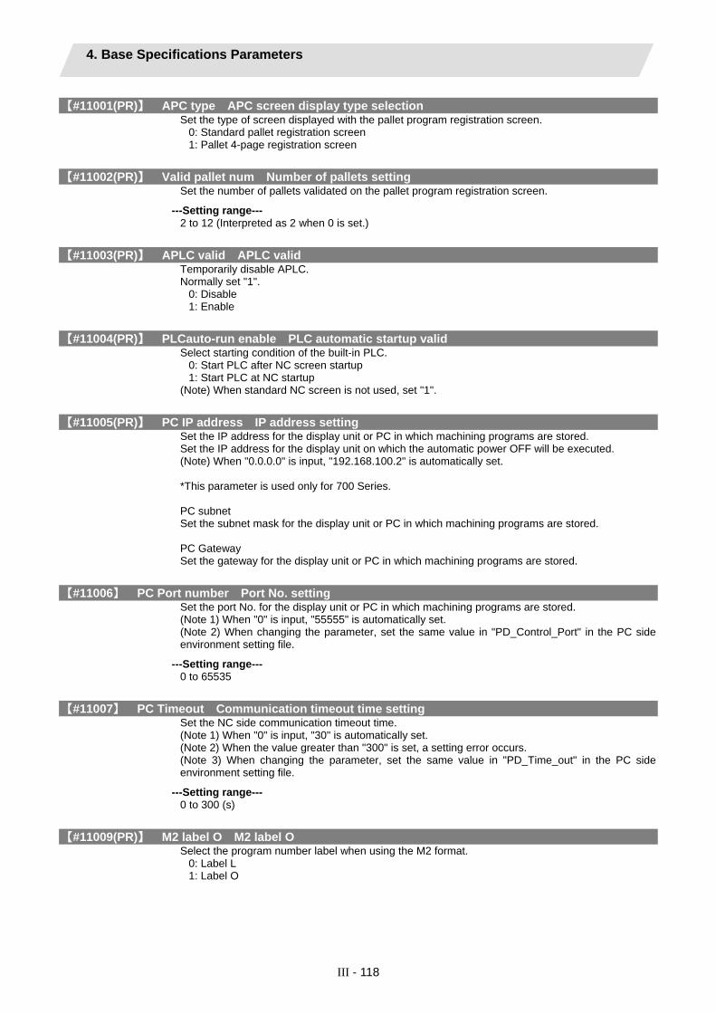
4. Base Specifications Parameters
III - 118
【#11001(PR)】 APC type APC screen display type selection Set the type of screen displayed with the pallet program registration screen.
0: Standard pallet registration screen 1: Pallet 4-page registration screen
【#11002(PR)】 Valid pallet num Number of pallets setting Set the number of pallets validated on the pallet program registration screen.
---Setting range--- 2 to 12 (Interpreted as 2 when 0 is set.)
【#11003(PR)】 APLC valid APLC valid Temporarily disable APLC. Normally set "1".
0: Disable 1: Enable
【#11004(PR)】 PLCauto-run enable PLC automatic startup valid Select starting condition of the built-in PLC.
0: Start PLC after NC screen startup 1: Start PLC at NC startup
(Note) When standard NC screen is not used, set "1".
【#11005(PR)】 PC IP address IP address setting Set the IP address for the display unit or PC in which machining programs are stored. Set the IP address for the display unit on which the automatic power OFF will be executed. (Note) When "0.0.0.0" is input, "192.168.100.2" is automatically set. *This parameter is used only for 700 Series. PC subnet Set the subnet mask for the display unit or PC in which machining programs are stored. PC Gateway Set the gateway for the display unit or PC in which machining programs are stored.
【#11006】 PC Port number Port No. setting Set the port No. for the display unit or PC in which machining programs are stored. (Note 1) When "0" is input, "55555" is automatically set. (Note 2) When changing the parameter, set the same value in "PD_Control_Port" in the PC side environment setting file.
---Setting range--- 0 to 65535
【#11007】 PC Timeout Communication timeout time setting Set the NC side communication timeout time. (Note 1) When "0" is input, "30" is automatically set. (Note 2) When the value greater than "300" is set, a setting error occurs. (Note 3) When changing the parameter, set the same value in "PD_Time_out" in the PC side environment setting file.
---Setting range--- 0 to 300 (s)
【#11009(PR)】 M2 label O M2 label O Select the program number label when using the M2 format.
0: Label L 1: Label O

4. Base Specifications Parameters
III - 119
【#11010(PR)】 Software keyboard Software keyboard Select with touch panel whether to use software keyboard.
0: Do not use 1: Use 2: Use (Note)
(Note) Software keyboard automatically appears on a specific screen. (for M70 Series only).
【#11011】 Handy TERM. PW. Handy terminal password Set the password used for the handy terminal customized downloading. Blank (when "0" is set) and "0000" are regarded as no password. Not the password of a new customizing file but the password of the customizing file downloaded to the last handy terminal is set. Set blank or "0000" when initially downloading.
---Setting range--- 0000 to 9999
【#11012(PR)】 16 axes for 1ch Connecting 16 axes for 1ch Select the maximum number of axes (sum of the NC axis, spindle, and PLC axis) connected to the drive unit interface (channel 1) when not using the extension unit (FCU7-EX891+HN552)
0: Up to 8 axes can be connected to channel 1. 1: Up to 16 axes can be connected to channel 1.
Note that "OMR-DD function" cannot be used. This parameter is disabled when the extension unit is connected. It is possible to connect only up to eight axes or less per channel.
【#11013】 3D_MChk Invalidate 3D machine interference check Select whether to enable the 3D machine interference check function.
0: Enable 1: Disable
【#11014】 Chk_len1 1st-step interference check distance Set the 1st-step check distance when in 3D machine interference check mode.
---Setting range--- 0.000 to 99999.999(mm)
【#11015】 Chk_len2 2nd-step interference check distance Set the 2nd-step check distance when in 3D machine interference check mode.
---Setting range--- 0.000 to 99999.999(mm)
【#11016】 Expand_Rate Shape expansion rate Set the model shape expansion rate to be used for 3D machine interference check. This parameter is used for expanding a model shape to be used for 3D machine interference check. The interference check is performed using a shape expanded by the amount of [Check length (mm) x Shape expansion rate (%)].
---Setting range--- 0 to 300(%)
【#11017】 T-ofs set at run Tool compensation amount setting during automatic operation valid Select whether to enable the tool compensation amount setting during automatic operation and operation pause.
0: Disable 1: Enable
【#11018】 M password hold Select whether to enable the "Machine user" password holding. When this is set to "1", the "Machine user" password will be held.
0: Enable 1: Disable

4. Base Specifications Parameters
III - 120
【#11019】 2-system display 2-part system simultaneous display Select whether to validate 2-part system simultaneous display on operation screen.
0: Display one part system on operation screen 1: Display two part systems simultaneously on operation screen
(Note 1) Unless you set "1" in two or more of "#1001 SYS_ON [1] to [4]", two-part system simultaneous display will fail regardless of this parameter.
【#11021】 PLC mesg disp type Format of PLC alarm and operator message Select the format of PLC alarms and operator messages to be displayed on the bottom right of the screen.
0: Display up to the first 40 characters. 1: If text is longer than 40 characters, divide it into two and display separately. (Classification No. is displayed together)
【#11028】 Tolerance Arc Cent Tolerable correction value of arc center error Set the tolerable correction value for the calculated coordinate value error of R-specified circular center. When a difference between "a line between the start and end points" and "commanded radius x 2" is the tolerance or smaller, the error is corrected so that the middle of a line between the start and end points will be the arc center. When [Setting value < 0] : 0 (Not correct) When [Setting value = 0] : 2 x minimum setting increment When [Setting value > 0] : Setting value
---Setting range--- -1 to 0.100(mm)
【#11029】 Arc to G1 no Cent Change command from arc to linear when no arc center designation Select the operation when arc center or radius designation is omitted from arc command.
0: Program error 1: Change into linear command
【#12001】 ManualB RectanA xH Manual feed rate B constant surface control intersecting part system axis name (horizontal)
Set the part system axis name ("#1013 axname") for the two axes that intersect with the rotary axis direction. When one of the two axes is blank, a constant speed will be applied without using constant surface speed control.
---Setting range--- Axis addresses such as X, Y, Z, U, V, W, A, B, and C
【#12002】 ManualB RectanA xV Manual feed rate B constant surface control intersecting part system axis name (vertical)
Set the part system axis name ("#1013 axname") for the two axes that intersect with the rotary axis direction. When one of the two axes is blank, a constant speed will be applied without using constant surface speed control.
---Setting range--- Axis addresses such as X, Y, Z, U, V, W, A, B, and C
【#12003】 ManualB RotCent erH Manual feed rate B constant surface control rotation center machine position (horizontal)
Set the machine coordinate position (horizontal axis) at the center of the rotary axis.
---Setting range--- -99999.999 to 99999.999 (mm)

4. Base Specifications Parameters
III - 121
【#12004】 ManualB RotCent erV Manual feed rate B constant surface control rotation center machine position (vertical)
Set the machine coordinate position (vertical axis) at the center of the rotary axis.
---Setting range--- -99999.999 to 99999.999 (mm)
【#12005(PR)】 Mfig Number of M Set the number of M that can be specified within the same block.
---Setting range--- 1 to 4
【#12006(PR)】 Mbin M binary Data type Output data 0 BCD 1 Unsigned binary -1 Singed binary For unsigned binary: The absolute value "1" is output for "-1". For singed binary: "-1" is output as "0xFFFFFFFF".
---Setting range--- Data type (-1,0,1)
【#12007(PR)】 Sfig Number of S Set the number of spindles. (Note 1) The setting range differs according to the model. (Note 2) Sfig is set in the range of 1 to 4. However, the number of outputs by Sfig cannot be controlled. Thus, only one S command is output regardless of the Sfig setting value.
---Setting range--- 1 to 6
【#12008(PR)】 Sbin S binary Data type Output data 0 BCD 1 Unsigned binary -1 Singed binary For unsigned binary: The absolute value "1" is output for "-1". For singed binary: "-1" is output as "0xFFFFFFFF". (Note 1) Sbin can be set with "-1", "0" and "1", but the S command cannot be BCD output. If BCD (0) is selected for Sbin, it will be handled as a singed binary (-1).
---Setting range--- Data type (-1,0,1)
【#12009(PR)】 Tfig Number of T Set the number of T that can be specified within the same block.
---Setting range--- 1 to 4

4. Base Specifications Parameters
III - 122
【#12010(PR)】 Tbin T binary Data type Output data 0 BCD 1 Unsigned binary -1 Singed binary For unsigned binary: The absolute value "1" is output for "-1". For singed binary: "-1" is output as "0xFFFFFFFF".
---Setting range--- Data type (-1,0,1)
【#12011(PR)】 Bfig Number of B Set the number of T that can be specified within the same block.
---Setting range--- 1 to 4
【#12012(PR)】 Bbin B binary Data type Output data 0 BCD 1 Unsigned binary -1 Singed binary For unsigned binary: The absolute value "1" is output for "-1". For singed binary: "-1" is output as "0xFFFFFFFF".
---Setting range--- Data type (-1,0,1)

5. Axis Specifications Parameters 5.1 Axis Specifications Parameters
III - 123
5. Axis Specifications Parameters 5.1 Axis Specifications Parameters
After setting up the parameter (PR) listed in the table, turn OFF the NC power. To validate the parameter, turn ON the power again.
【#2001】 rapid Rapid traverse rate Set the rapid traverse feedrate for each axis. (Note) The maximum value to be set depends on the machine specifications.
---Setting range--- 1 to 1000000 (mm/min)
【#2002】 clamp Cutting feedrate for clamp function Set the maximum cutting feedrate for each axis. Even if the feedrate in G01 exceeds this value, the clamp will be applied at this feedrate.
---Setting range--- 1 to 1000000 (mm/min)

5. Axis Specifications Parameters 5.1 Axis Specifications Parameters
III - 124
【#2003(PR)】 smgst Acceleration and deceleration modes Set acceleration and deceleration control modes.
bit F E D C B A 9 8 7 6 5 4 3 2 1 0OT3 OT2 OT1 C3 C1 L R3 R1 LR
(Note) Set "0" in null bits (excluding bit2 and bit6 when the soft acceleration/deceleration is selected.) <Combination of acceleration/deceleration patterns and bit patterns>
R3(bit3) -(bit2) R1(bit1) LR(bit0)C3(bit7) -(bit6) C1(bit5) LC(bit4)
Step 0 0 0 0Linear acceleration
/deceleration0 0 0 1
Primary delay 0 0 1 0Exponential accelerationand linear deceleration
1 0 0 0
Soft acceleration/deceleration
1 1 1 1
Rapid traverseCutting feed
Acceleration/deceleration
types
(Note) R1 > R3 when both R1 and R3 contain 1. <Stroke end stop types>
Type OT2 OT3Linear deceleration 0 0
Position loop step stop 1 0Speed loop step stop 0 1
Position loop step stop 1 1
G0t1
Speed Stroke end signal
Time
2 G0t1 (OT1=1,OT2=OT3=0)G0t1 (OT1=OT2=OT3=0)
(Note) OT1 is valid under the following conditions (valid for dog type zero point return): - Stop type: Linear deceleration - Acceleration/Deceleration mode: Exponential acceleration and Linear deceleration
---Setting range--- 0/1
【#2004】 G0tL G0 time constant (linear) Set a linear control time constant for rapid traverse acceleration and deceleration. The time constant will be enabled when LR (rapid traverse feed with linear acceleration/deceleration) or F (soft acceleration/deceleration) is selected in "#2003 smgst Acceleration and deceleration modes".
Speed
Time
G0tL G0tL
---Setting range--- 1 to 4000 (ms)

5. Axis Specifications Parameters 5.1 Axis Specifications Parameters
III - 125
【#2005】 G0t1 G0 time constant(primary delay) / Second-step time constant for soft acceleration/deceleration
Set a primary-delay time constant for rapid traverse acceleration and deceleration. The time constant will be enabled when R1 (rapid traverse feed with primary delay) or R3 (exponential acceleration and linear deceleration) is selected in "#2003 smgst Acceleration and deceleration modes". When the soft acceleration/deceleration is selected, the second-step time constant will be used. <Rapid traverse feed with primary delay>
Speed
Time
G0t1G0t1
<Rapid traverse feed with exponential acceleration and linear deceleration>
Time
2×G0t1G0t1
Speed
---Soft acceleration/deceleration>
G0tL
G0t1
G0tL
G0t1
Speed
Time G0t1
G0t1
---Setting range---
1 to 5000 (ms)
【#2006】 G0t2 Not used. Set to "0".
【#2007】 G1tL G1 time constant (linear) Set a linear control time constant for cutting acceleration and deceleration. The time constant will be enabled when LC (cutting feed with linear acceleration/deceleration) or F (soft acceleration/deceleration) is selected in "#2003 smgst Acceleration or deceleration modes".
Speed
Time
G1tL G1tL
---Setting range--- 1 to 4000 (ms)

5. Axis Specifications Parameters 5.1 Axis Specifications Parameters
III - 126
【#2008】 G1t1 G1 time constant (primary delay)/Second-step time constant for soft acceleration/deceleration
Set the primary delay time constant for cutting acceleration and deceleration. The time constant will be enabled when C1 (cutting feed with the primary delay) or C3 (cutting feed with exponential acceleration and linear deceleration) is selected in "#2003 smgst acceleration/deceleration modes". When the soft acceleration or deceleration is selected, the second-step time constant will be used. <Cutting feed with primary delay>
Speed
Time
G1t1G1t1
<Cutting feed with exponential acceleration and linear deceleration>
Speed
Time
2×G1t1G1t1
---Soft acceleration/deceleration>
G1t1G1t1
G1tL
G1t1
G1tL
G1t1
Speed
Time
---Setting range--- 1 to 5000 (ms)
【#2009】 G1t2 Not used. Set to "0".
【#2010】 fwd_g Feed forward gain Set a feed forward gain for pre-interpolation acceleration/deceleration. The larger the set value, the smaller the theoretical control error will be. However, if a machine vibration occurs, set the smaller value.
---Setting range--- 0 to 200 (%)
【#2011】 G0back G0 backlash Set up the backlash compensation amount when the direction is reversed with the movement command in rapid traverse feed mode or in manual mode.
---Setting range--- -9999999 to 9999999
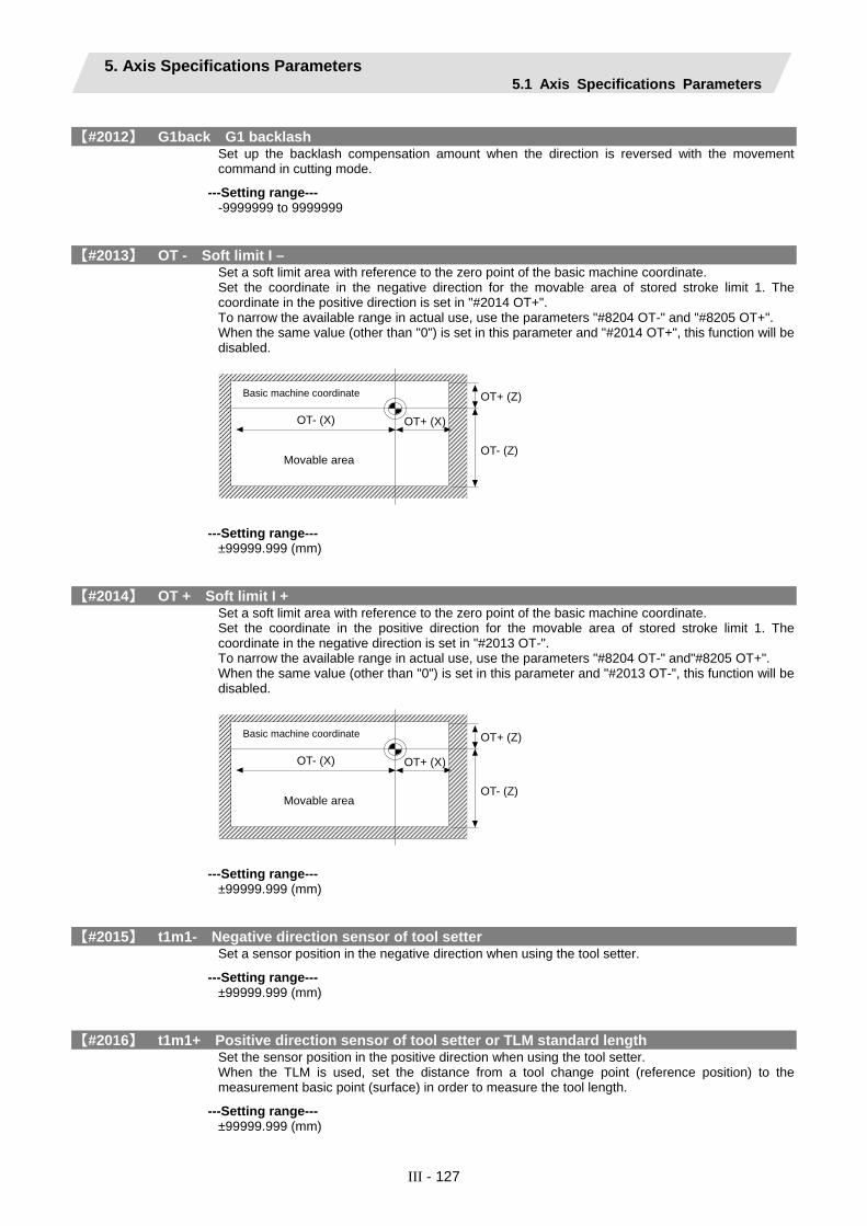
5. Axis Specifications Parameters 5.1 Axis Specifications Parameters
III - 127
【#2012】 G1back G1 backlash Set up the backlash compensation amount when the direction is reversed with the movement command in cutting mode.
---Setting range--- -9999999 to 9999999
【#2013】 OT - Soft limit I – Set a soft limit area with reference to the zero point of the basic machine coordinate. Set the coordinate in the negative direction for the movable area of stored stroke limit 1. The coordinate in the positive direction is set in "#2014 OT+". To narrow the available range in actual use, use the parameters "#8204 OT-" and "#8205 OT+". When the same value (other than "0") is set in this parameter and "#2014 OT+", this function will be disabled.
OT+ (X)
Basic machine coordinate OT+ (Z)
OT- (Z)
OT- (X)
Movable area
---Setting range---
±99999.999 (mm)
【#2014】 OT + Soft limit I + Set a soft limit area with reference to the zero point of the basic machine coordinate. Set the coordinate in the positive direction for the movable area of stored stroke limit 1. The coordinate in the negative direction is set in "#2013 OT-". To narrow the available range in actual use, use the parameters "#8204 OT-" and"#8205 OT+". When the same value (other than "0") is set in this parameter and "#2013 OT-", this function will be disabled.
OT+ (X)
Basic machine coordinate OT+ (Z)
OT- (Z)
OT- (X)
Movable area
---Setting range---
±99999.999 (mm)
【#2015】 t1m1- Negative direction sensor of tool setter Set a sensor position in the negative direction when using the tool setter.
---Setting range--- ±99999.999 (mm)
【#2016】 t1m1+ Positive direction sensor of tool setter or TLM standard length Set the sensor position in the positive direction when using the tool setter. When the TLM is used, set the distance from a tool change point (reference position) to the measurement basic point (surface) in order to measure the tool length.
---Setting range--- ±99999.999 (mm)

5. Axis Specifications Parameters 5.1 Axis Specifications Parameters
III - 128
【#2017】 tap_g Axis servo gain Set the position loop gain for special operations (synchronized tapping, interpolation with spindle C axis, etc.). Set the value in 0.25 increments. The standard setting value is "10".
---Setting range--- 0.25 to 200.00 (rad/s)
【#2018(PR)】 no_srv Operation with no servo control Select when performing test operation without connecting the drive unit and motor.
0: Normal operation 1: Test operation
When "1" is set, the operation will be possible even if drive units and motor are not connected, because the drive system alarm will be ignored. This parameter is used for test operation during start up: Do not use during normal operation. If "1" is set during normal operation‚ errors will not be detected even if they occur.
【#2019】 revnum Return steps Set the steps required for reference position return for each axis.
0: Not execute reference position return. 1 to max. number of NC axes: Steps required for reference position return
---Setting range--- 0 to max. number of NC axes
【#2020】 o_chkp Spindle orientation completion check during second reference position return Set the distance from the second reference position to the position for checking that the spindle orientation has completed during second reference position return. When the set value is "0", the above check will be omitted.
---Setting range--- 0 to 99999.999 (mm)
【#2021】 out_f Maximum speed outside soft limit range Set the maximum speed outside the soft limit range.
---Setting range--- 0 to 1000000 (mm/min)
【#2022】 G30SLX Validate soft limit (automatic and manual) Select whether to disable a soft limit check during the second to the fourth reference position return in both automatic and manual operation modes.
0: Enable 1: Disable
【#2023】 ozfmin Set up ATC speed lower limit Set the minimum speed outside the soft limit range during the second to the fourth reference position return.
---Setting range--- 0 to 1000000 (mm/min)
【#2024】 synerr Allowable error Set the maximum synchronization error, allowable at the synchronization error check, for the master axis. When "0" is set, the error check will not be carried out.
---Setting range--- 0 to 99999.999 (mm)

5. Axis Specifications Parameters 5.2 Zero Point Return Parameters
III - 129
5.2 Zero Point Return Parameters After setting up the parameter (PR) listed in the table, turn OFF the NC power. To validate the parameter, turn ON the power again.
【#2025】 G28rap G28 rapid traverse rate Set a rapid traverse rate for the dog type reference position return command. This is not used for the distance-coded reference position detection.
---Setting range--- 1 to 1000000 (mm/min)
【#2026】 G28crp G28 approach speed Set the approach speed to the reference position. (Note) The G28 approach speed unit is (10°/min) only when using the Z-phase type encoder (#1226 aux10/bit3=1) for the spindle/C-axis reference position return type. The same unit is used for both the micrometric and sub-micrometric specifications.
---Setting range--- 1 to 60000 (mm/min)
【#2027】 G28sft Reference position shift distance Set the distance from the electrical zero-point detection position to the reference position. This is not used for the distance-coded reference position detection. (Note) When "#1240 set12/bit2" is ON, a magnification (C: 10-fold, D: 100-fold and E: 1000-fold) corresponding to the input setting unit ("#1003 iunit") will be applied to the setting value.
---Setting range--- 0.000 to 99.999 (mm)
【#2028】 grmask Grip mask amount Set the distance where the grid point will be ignored when near-point dog OFF signals are close to that grid point during reference position return.
Grid mask setup distance
Near-point dog
The grid mask is valid for one grid. This is not used for the distance-coded reference position detection.
---Setting range--- 0.000 to 99.999 (mm)
【#2029】 grspc Grid interval Set a detector grid interval. Generally, set the value equal to the ball screw pitch. However, if the detector grid interval is not equal to the screw pitch when measured with a linear scale, set the detector grid interval. To reduce the grid interval, use its divisors. This is not used for the distance-coded reference position detection.
---Setting range--- 0.000 to 999.999 (mm)

5. Axis Specifications Parameters 5.2 Zero Point Return Parameters
III - 130
【#2030(PR)】 dir (-) Reference position direction (-) Select which side of the near-point dog the reference position is established.
0: Positive direction 1: Negative direction
Directions in which reference position is established as viewed from the near-point dog
- direction + direction
Near-point dog
Near-point dog
Grid
Grid
Reference position
Reference position
【#2031】 noref Axis without reference position Select whether the reference position is provided for the axis.
0: Reference position is provided. (Normal controlled axis) 1: No reference position is provided.
When "1" is set, reference position return is not required before automatic operation starts.
【#2032】 nochk Whether reference position return is completed not checked Select whether to check the reference position return completion.
0: Check the reference position return completion. 1: Not check the reference position return completion.
When "1" is set, the absolute and incremental commands can be executed even if dog type (or Z phase pulse system) reference position return is not completed. Note that this setting is available for a rotary axis only.
【#2033】 zp_no Z phase pulse system reference position return spindle encoder No. Set the spindle encoder No. to be used when the reference position return is performed with the Z phase pulse of the spindle encoder.
0: Dog type 1 to 6: Spindle No.
*The setting range differs according to the model.
---Setting range--- 0 to 6
【#2034】 rfpofs Distance-coded reference position detection offset Set the offset value from the position for the initial reference position setting to the machine's actual basic point in reference position return in the distance-coded reference position detection. Input the value of the machine value counter that is displayed immediately after the reference position is established. When the power is turned ON and this parameter is set to "0", the manual reference position return is regarded as initial reference position setting. If this parameter is set to "0", automatic operation won't be available.
---Setting range--- -99999.999 to 99999.999 (mm)

5. Axis Specifications Parameters 5.2 Zero Point Return Parameters
III - 131
【#2035】 srchmax Distance-coded reference position detection scan distance Set the maximum distance for scanning the reference marks when the reference position is not established in the distance-coded reference position detection. For the scan distance, set the distance that fully covers the number of reference marks as you wish to detect. (Example) When adding about 10% of additional coverage: Scan distance = Base reference mark interval [mm] * 2 * 1.1
---Setting range--- 0.000 to 99999.999 (mm)
【#2036】 slv_adjust Reference position adjustment value Set the distance from the first grid point after leaving the near point dog on the slave axis to the position where the reference position is actually established in dog-type reference position return in synchronous control. (Reference position shift amount is not included.) The adjustment value will be automatically set in the slave axis's parameter according to the reference position adjustment complete signal from PLC. Fine adjustment is also available from the parameter screen. In the distance-coded reference position detection, the reference position adjustment value will be invalid.
(1) (2) (3) (4) (5) (6)
Master axis start position
Slave axis start position (6) (7)
Reference position adjustment amountGrid
Basic machine coordinate system zero point
Master axis
Slave axis
Near-point dog
G28sft
Reference position adjustment
completion signal ON G28sft
(Note 1) This parameter is enabled when the synchronization at zero point initialization ("#1493 ref_syn" = "1" of the master axis) is applied. (Note 2) This parameter can be set when one of the following settings is applied. ● Relative position detection ("#2049 type" = "0") ● Dog-type absolute position detection ("#2049 type" = "3") ● Simple absolute position ("#2049 type" = "9") (Note 3) Set "0" when using the speed/current command synchronization control. (Note 4) A setting unit of this parameter is [mm]. It is not influenced by the content of the following parameters setting. ● "#1003 iunit" ● "#1004 ctrl_unit" ● "#1005 plcunit" ● "#1040 M_inch" ● "#1041 I_inch" ● "#1240 set12/bit2" (Zero point shift amount magnification) (Note 5) The number of the significant digits after decimal point follows "#1004 ctrl_unit" (Note 6) A change of this parameter requires reference position return. When the automatic operation starts without reference position return, an alarm will occur.
---Setting range--- 0 to 99999.999999 (mm)

5. Axis Specifications Parameters 5.2 Zero Point Return Parameters
III - 132
【#2037】 G53ofs Reference position #1 Set the position of the first reference position from the zero point of the basic machine coordinate.
Basic machine coordinate
Reference position #1 (#2037 G53ofs)
Reference position #2 (#2038 #2_rfp)
Reference position #3 (#2039 #3_rfp)
Reference position #4(#2040 #4_rfp)
M
---Setting range--- ±999999.999 (mm)
【#2038】 #2_rfp Reference position #2 Set the position of the second reference position from the zero point of the basic machine coordinate.
Basic machine coordinate
Reference position #1 (#2037 G53ofs)
Reference position #2 (#2038 #2_rfp)
Reference position #3 (#2039 #3_rfp)
Reference position #4(#2040 #4_rfp)
M
---Setting range--- ±999999.999 (mm)

5. Axis Specifications Parameters 5.2 Zero Point Return Parameters
III - 133
【#2039】 #3_rfp Reference position #3 Set the position of the third reference position from the zero point of the basic machine coordinate.
Basic machine coordinate
Reference position #1 (#2037 G53ofs)
Reference position #2 (#2038 #2_rfp)
Reference position #3 (#2039 #3_rfp)
Reference position #4(#2040 #4_rfp)
M
---Setting range--- ±999999.999 (mm)
【#2040】 #4_rfp Reference position #4 Set the position of the fourth reference position from the zero point of the basic machine coordinate.
Basic machine coordinate
Reference position #1 (#2037 G53ofs)
Reference position #2 (#2038 #2_rfp)
Reference position #3 (#2039 #3_rfp)
Reference position #4(#2040 #4_rfp)
M
---Setting range---
±999999.999 (mm)

5. Axis Specifications Parameters 5.3 Absolute Position Parameters
III - 134
5.3 Absolute Position Parameters After setting up the parameter (PR) listed in the table, turn OFF the NC power. To validate the parameter, turn ON the power again.
【#2049(PR)】 type Absolute position detection method Select the absolute position zero point alignment method.
0: Not absolute position detection 1: Stopper method (push against mechanical stopper) 2: Marked point alignment method (align to alignment point) 3: Dog-type (align with dog and near point detection switch) 4: Marked point alignment method II (Align to alignment mark. Grid return won't be performed after marked point alignment) 9: Simple absolute position (Not absolute position detection‚ but the position when the power is turned off is registered.)
【#2050】 absdir Basic point of Z direction Select the direction of the grid point immediately before the machine basic position (basic point of detector) in the marked point alignment.
0: Positive direction 1: Negative direction
【#2051】 check Check Set the tolerable range of travel distance (deviation distance) while the power is turned OFF. If the difference of the positions when the power is turned OFF and when turned ON again is larger than this value‚ an alarm will be output. Set "0" to omit the check.
---Setting range--- 0 to 99999.999 (mm)
【#2054】 clpush Current limit (%) Set the current limit value during the stopper operation in the dogless-type absolute position detection. The setting value is the ratio of the current limit value to the rated current value.
---Setting range--- 0 to 100 (%)
【#2055】 pushf Push speed Set the feedrate for the automatic initial setting during stopper method.
---Setting range--- 1 to 999 (mm/min)
【#2056】 aproch Approach Set the approach distance of the stopper when deciding the absolute position basic point with the stopper method. After using stopper once‚ the tool returns with this distance‚ and then use stopper again.
---Setting range--- 0 to 999.999 (mm)
5. Axis Specifications Parameters 5.3 Absolute Position Parameters
III - 135
【#2057】 nrefp Near zero point + Set the positive direction width where the near reference position signal is output. When set to "0"‚ the width will be equivalent to the grid width setting. (Note) When "#1240 set12/bit2" is ON, a magnification (C: 10-fold, D: 100-fold, E:1000-fold) corresponding to the input setting increment ("#1003 iunit") will be applied to the setting value.
---Setting range--- 0 to 999.999 (mm) (Input setting increment applied)
【#2058】 nrefn Near zero point - Set the negative direction width where the near reference position signal is output. When set to "0"‚ the width will be equivalent to the grid width setting. (Note) When "#1240 set12/bit2" is ON, a magnification (C: 10-fold, D: 100-fold, E:1000-fold) corresponding to the input setting increment ("#1003 iunit") will be applied to the setting value.
---Setting range--- 0 to 999.999 (mm) (Input setting increment applied)
【#2059】 zerbas Select zero point parameter and basic point Select which is to be the zero point coordinate position during absolute position initial setting.
0: Position where the axis was stopped. 1: Grid point just before stopper.

5. Axis Specifications Parameters 5.4 Axis Specifications Parameters 2
III - 136
5.4 Axis Specifications Parameters 2 After setting up the parameter (PR) listed in the table, turn OFF the NC power. To validate the parameter, turn ON the power again.
【#2061】 OT_1B- Soft limit IB- Set the coordinate of the lower limit of the area where the stored stroke limit IB is inhibited. Set a value from zero point in the basic machine coordinate system. If the same value (non-zero) with the same sign as that of "#2062 OT_IB+" is set, the stored stroke limit IB function will be disabled.
---Setting range--- ±99999.999 (mm)
【#2062】 OT_1B+ Soft limit IB+ Set the coordinate of the upper limit of the area where the stored stroke limit IB is inhibited. Set a value from zero point in the basic machine coordinate system.
---Setting range--- ±99999.999 (mm)
【#2063】 OT_1B type Soft limit IB type Select the type that applies the settings of "#2062 OT_IB+" and "#2061 OT_IB-" in stored stroke limit I.
0: Soft limit IB 1: The settings are invalid 2: Soft limit IC 3: Soft limit is checked for the inclined axis control axis with the program coordinate system.
(Note) This is valid only for inclined axis' base axis and inclined axis.
【#2068】 G0fwdg G00 feed forward gain Set a feed forward gain for G00 pre-interpolation acceleration/deceleration. The larger the setting value, the shorter the positioning time during in-position checking. If a machine vibration occurs, set the smaller value.
---Setting range--- 0 to 200 (%)
【#2069】 Rcoeff Axis arc radius error correction coefficient Set the percentage to increase or decrease the arc radius error correction amount for each axis.
---Setting range--- -100.0 to +100.0 (%)
【#2070(PR)】 div_RT Rotational axis division count Set the number of divisions of one turn of the rotary axis under control. (Example) When "36" is set, one turn is supposed to be 36.000. (Note 1) When "0" is set, the normal rotary axis (360.000 degrees for one turn) is assumed. (Note 2) If this parameter is changed when the absolute position detection specification is used, absolute position data will be lost. Initialization must be performed again.
---Setting range--- 0 to 999

5. Axis Specifications Parameters 5.4 Axis Specifications Parameters 2
III - 137
【#2071】 s_axis Inclined axis selection For L system only Select whether the axis is to be under the inclined-axis control or to be the base axis corresponding to the inclined axis.
0: Not to be under the inclined-axis control 1: Inclined axis 2: Base axis corresponding to inclined axis
(Note) Each of "1" and "2" values must be set for only one axis. If either value is set for two or more axes, inclined-axis control does not work.
【#2072】 rslimt Restart limit Set the most minus (-) side position where restart search is possible. If the machine is positioned on the more minus (-) side than the set value in T-command restart mode, restart search in type 3 will be disabled.
---Setting range--- ±9999.999 (mm)
【#2073】 zrn_dog Origin dog Random assignment device Under the standard specifications, the origin dog signal is assigned to a fixed device. Set the input device in this parameter when it is desired to assign the origin dog signal to a position other than the fixed device. (Note 1) This parameter is valid when "1" is set in "#1226 aux10/bit5". (Note 2) When this parameter is valid, do not set the existing device number. If the existing device number is set, an emergency stop will occur. However, no device number check will be performed for an axis to which the "near-point dog ignored" signal is input.
---Setting range--- 0000 to 02FF (HEX)
【#2074】 H/W_OT+ H/W OT+ Random assignment device Under the standard specifications, the OT (+) signal is assigned to a fixed device. Set the input device in this parameter when it is desired to assign the OT (+) g signal to a position other than the fixed device. (Note 1) This parameter is valid when "1" is set in "#1226 aux10/bit5". (Note 2) When this parameter is valid, do not set the existing device number. If the existing device number is set, an emergency stop will occur. However, no device number check will be performed for an axis to which the "OT ignored" signal is input.
---Setting range--- 0000 to 02FF (HEX)
【#2075】 H/W_OT- H/W OT- Random assignment device Under the standard specifications, the OT (-) signal is assigned to a fixed device. Set the input device in this parameter when it is desired to assign the OT (-) signal to a position other than the fixed device. (Note 1) This parameter is valid when "1" is set in "#1226 aux10/bit5". (Note 2) When this parameter is valid, do not set the existing device number. If the existing device number is set, an emergency stop will occur. However, no device number check will be performed for an axis to which the "OT ignored" signal is input.
---Setting range--- 0000 to 02FF (HEX)

5. Axis Specifications Parameters 5.4 Axis Specifications Parameters 2
III - 138
【#2076】 index_x Index table indexing axis Select whether the axis is a normal axis or an index table indexing axis.
0: Normal axis 1: Index table indexing axis
(Note) This parameter is valid only for the NC axis. The parameter is invalid if set for the PLC axis.
【#2077】 G0inps G0 in-position width Set the in-position width for G0. Between SV024 and this parameter, the parameter with a larger value will be applied. When "0" is set, this parameter will be invalid: only SV024 will be available.
---Setting range--- 0.000 to 99.999 (mm)
【#2078】 G1inps G1 in-position width Set the in-position width for G1. Between SV024 and this parameter, the parameter with a larger value will be applied. When "0" is set, this parameter will be invalid: only SV024 will be available.
---Setting range--- 0.000 to 99.999 (mm)
【#2079(PR)】 chcomp Chopping compensation coefficient Set the coefficient to be applied to the compensation amount for the insufficient amount caused by servo delay during chopping.
---Setting range--- 0 to 10 (standard value: 8)
【#2080】 chwid Bottom dead center position width Set the tolerance between the commanded stroke and actual stroke. Compensation will be applied during chopping so that the result of [command width - maximum stroke of top or bottom dead point/ 2] will be within this tolerance.
---Setting range--- 0 to 10.000 (mm)
【#2081】 chclsp Maximum chopping speed Set the clamp speed in chopping operation. When "0" is set‚ the clamp speed will be determined by "#2002 clamp".
---Setting range--- 0 to 60000 (mm/min)
【#2082】 a_rstax Restart position return order Set the No. for each axis in order from the 1st automatically returning axis to the restart position. When "0" is set, the axis will not return. Note that when "0" is set for all axes, all of the axes will return simultaneously.
---Setting range--- 0 to 8

5. Axis Specifications Parameters 5.4 Axis Specifications Parameters 2
III - 139
【#2084】 G60_ax Unidirectional positioning operation selection Select how to operate the unidirectional positioning when the positioning command (G00) is issued.
0: Carry out unidirectional positioning according to the command and modal. 1: Carry out unidirectional positioning regardless of the command and modal.
Set "1" for the axis to carry out the unidirectional positioning at every positioning command, regardless of whether the unidirectional positioning command and modal are issued. <Related parameters> "#8209 G60 SHIFT" and "#2076 index_x"
【#2087】 syncnt Synchronization/super-imposition control setting for each axis Set the polarity of synchronous axis with respect to basic axis to the bit corresponding to each axis.
0: Polarity with respect to basic axis is positive 1: Polarity with respect to basic axis is negative
---Setting range--- 0 to FF (hexadecimal)
【#2088】 bsax_sy Reference axis for synchronous control Set the basic axis for synchronous control with the 2nd axis name (axname2). A numerical character cannot be set as the 1st character.
---Setting range--- Axis name
【#2089】 bsax_pl Reference axis for superimposition control Set the basic axis for superimposition control with the 2nd axis name (axname2). A numerical character cannot be set as the 1st character.
---Setting range--- Axis name
【#2090】 plrapid Rapid traverse rate for super-imposition control Set the rapid traverse rate for superimposition control. (Equivalent to "#2001 rapid Rapid traverse rate".)
---Setting range--- 1 to 1000000 (mm/min)
【#2091】 plclamp Cutting feed clamp speed for super-imposition control Set the cutting feed clamp speed for superimposition control. (Equivalent to "#2002 clamp Cutting feed clamp speed".)
---Setting range--- 1 to 1000000 (mm/min)
【#2092】 plG0tL G0 time constant for superimposition control (linear) Set the G0 time constant (linear) for superimposition control. (Equivalent to "#2004 G0tL G0 time constant (linear)".)
---Setting range--- 1 to 4000 (ms)
【#2093】 plG0t1 G0 time constant for superimposition control (primary delay) Set the G0 time constant (primary delay) for superimposition control. (Equivalent to "#2005 G0t1 G0 time constant (primary delay".)
---Setting range--- 1 to 5000 (ms)
5. Axis Specifications Parameters 5.4 Axis Specifications Parameters 2
III - 140
【#2094】 plG1tL G1 time constant for superimposition control (linear) Set the G1 time constant (linear) for superimposition control. (Equivalent to "#2007 G1tL G1 time constant (linear)".)
---Setting range--- 1 to 4000 (ms)
【#2095】 plG1t1 G1 time constant for superimposition control (primary delay) Set the G1 time constant (primary delay) for superimposition control. (Equivalent to "#2008 G1t1 G1 time constant (primary delay)".)
---Setting range--- 1 to 5000 (ms)
【#2096】 crncsp Minimum corner deceleration speed Set the minimum clamp speed for corner deceleration in the high-accuracy control mode. Normally set "0". (Note) This parameter is invalid during SSS control.
---Setting range--- 0 to 1000000 (mm/min)
【#2097】 tlml2- Sub side tool setter - direction sensor Set the sensor position (on sub side) in the (-) direction when using the tool setter on the sub spindle side.
---Setting range--- ±99999.999 (mm)
【#2098】 tlml2+ Sub side tool setter + direction sensor Set the sensor position (on sub side) in (+) direction when using the tool setter on the sub spindle side.
---Setting range--- ±99999.999 (mm)
【#2102】 skip_tL Skip time constant linear Set a linear control time constant for variable speed skip acceleration and deceleration. The time constant will be enabled when LC (cutting feed with linear acceleration and deceleration) or "F" (soft acceleration/deceleration) is selected in "#2003 smgst Acceleration and deceleration modes".
---Setting range--- 1 to 4000 (ms)
【#2103】 skip_t1 Skip time constant primary delay / Second-step time constant for soft acceleration/deceleration Set a primary-delay time constant for variable speed skip acceleration and deceleration. The time constant will be enabled when C1 (cutting feed with primary delay) or C3 (exponential acceleration and linear deceleration) is selected in "#2003 smgst Acceleration and deceleration modes". When the soft acceleration/deceleration is selected, the second-step time constant will be used.
---Setting range--- 1 to 5000 (ms)
【#2106】 Index unit Indexing unit Set the indexing unit to which the rotary axis can be positioned.
---Setting range--- 0 to 360 (°)

5. Axis Specifications Parameters 5.4 Axis Specifications Parameters 2
III - 141
【#2109】 Rapid (H-precision) Rapid traverse rate for high-accuracy control mode Set the rapid traverse rate for each axis in the high-accuracy control mode. "#2001 rapid" will be used when "0" is set.
---Setting range--- 0 to 1000000 (mm/min)
【#2110】 Clamp (H-precision) Cutting feed clamp speed for high-accuracy control mode Set the cutting feed maximum speed for each axis in the high-accuracy control mode. "#2002 clamp" will be used when "0" is set.
---Setting range--- 0 to 1000000 (mm/min)
【#2111】 Blf valid Quadrant protrusion compensation valid Set whether to enable the quadrant protrusion compensation.
0: Disable 1: Enable
If either of "#2112 Blf motor inertia", "#2115 Blf motor stl trq" or "#2113 Blf visc friction" is set to "0", quadrant protrusion compensation will not work even if this parameter is set to "1".
【#2112】 Blf motor inertia Motor inertia Set the motor inertia for quadrant protrusion compensation. Refer to the servo manual and input the value appropriate for the motor.
---Setting range--- 1 to 32000 (10-6kgm2)
【#2113】 Blf visc friction Viscous friction Set the viscous friction for quadrant protrusion compensation. After setting the other parameters to the appropriate values, monitor the machine end and gradually adjust the value. If this parameter setting is small, a recess will form on the inner side of the circle, and if large, a protrusion will form on the outer side of the circle. When the value is appropriate, a spike-shaped quadrant protrusion will form based on normal step-shaped backlash.
---Setting range--- 1 to 32767 (1/16 Nm/(rad/s))
【#2114】 Blf fwdg Compensation FF gain Set the feed forward gain for quadrant protrusion compensation. After setting the other parameters to the appropriate values, monitor the machine end and gradually adjust the value. If this parameter setting is small, a large quadrant protrusion will form, and if large, a recess will form on the inner side of the circle.
---Setting range--- 0 to 1000 (%)
【#2115】 Blf motor stl trq Motor stall torque Set the motor rated current for quadrant protrusion compensation. Refer to the servo manual and input the value appropriate for the motor.
---Setting range--- 1 to 16000 (1/256 Nm)

5. Axis Specifications Parameters 5.4 Axis Specifications Parameters 2
III - 142
【#2118(PR) 】 SscDrSel Speed monitor Door selection Select which door group of the speed monitoring the spindle belongs to.
0000: Door 1 group. 0001: Door 1 group. 0002: Door 2 group. 0003: Door 1 and 2 group.
The speed monitoring will not be executed when "#2313 SV113 SSF8/BitF" is OFF regardless of this parameter. The selected door group must be set when setting the synchronous control. The spindle/C axis control enables the door selection in "#3071 SscDrSelSp" for the corresponding spindle.
【#2121】 vbacklash valid Variable backlash valid/continuous Select whether the variable backlash is to be invalid/valid/continuous.
0: Invalid 1: Valid 2: Continuous
("#2011 G0back" and "#2012 G1back" will not work when valid or continuous status is selected.)
【#2122】 G0vback+ Variable G0 backlash + Set the compensation amount for the range of each position during rapid traverse. (+: B1, =: B2, -: B3 on the compensation amount table)
---Setting range--- -99999999 to 99999999 (Interpolation unit)
【#2123】 G0vback= Variable G0 backlash = Set the compensation amount for the range of each position during rapid traverse. (+: B1, =: B2, -: B3 on the compensation amount table)
---Setting range--- -99999999 to 99999999 (Interpolation unit)
【#2124】 G0vback- Variable G0 backlash - Set the compensation amount for the range of each position during rapid traverse. (+: B1, =: B2, -: B3 on the compensation amount table)
---Setting range--- -99999999 to 99999999 (Interpolation unit)
【#2125】 G1vback+ Variable G1 backlash + Set the compensation amount for the range of each position during cutting feed. (+: A1, =: A2, -: A3 on the compensation amount table)
---Setting range--- -99999999 to 99999999(Interpolation unit)
【#2126】 G1vback= Variable G1 backlash = Set the compensation amount for the range of each position during cutting feed. (+: A1, =: A2, -: A3 on the compensation amount table)
---Setting range--- -99999999 to 99999999 (Interpolation unit)

5. Axis Specifications Parameters 5.4 Axis Specifications Parameters 2
III - 143
【#2127】 G1vback- Variable G1 backlash - Set the compensation amount for the range of each position during cutting feed. (+: A1, =: A2, -: A3 on the compensation amount table)
---Setting range--- -99999999 to 99999999 (Interpolation unit)
【#2128】 G1vback feed1 G1 variable backlash compensation amount changeover speed 1 Set the speed range during cutting feed. (The speed less than 1 is the low speed, and the speed exceeding 2 is the high speed.) Note that the speed range is identified in the order of low, high and medium speed. Consider whether the set value should be larger or smaller than other values.
---Setting range--- 0 to 480000 (mm/min)
【#2129】 G1vback feed2 G1 variable backlash compensation amount changeover speed 2 Set the range of the speed during cutting feed. (The speed less than 1 is the low speed, and the speed exceeding 2 is the high speed.) Note that the speed range is identified in the order of low, high and medium speed. Consider whether the set value should be larger or smaller than other values.
---Setting range--- 0 to 480000 (mm/min)
【#2130】 G1vback dist1 G1 variable backlash compensation amount changeover distance 1 Set the range of the distance during cutting feed. (The distance less than 1 is the small distance, and the distance exceeding 2 is the large distance.) Note that the distance range is identified in the order of small, large and medium. Consider whether the set value should be larger or smaller than other values.
---Setting range--- 0 to 999999.999999 (mm)
【#2131】 G1vback dist2 G1 variable backlash compensation amount changeover distance 2 Set the range of the distance during cutting feed. (The distance less than 1 is the small distance, and the distance exceeding 2 is the large distance.) Note that the distance range is identified in the order of small, large and medium. Consider whether the set value should be larger or smaller than other values.
---Setting range--- 0 to 999999.999999 (mm)
【#2132】 vback pos1 Variable backlash compensation amount changeover end point position 1 Set the range of the center of the end point position. (The range less than position 1 is the - range, and the range exceeding position 2 is the + range.) The end point position range is determined in the order of -, + , and center. Consider whether the set value should be larger or smaller than other values. (Note 1) If continuous variable backlash is set with "#2121 vbacklash valid", position 1 will be set as the position - point and position 2 will be set as the position + point. (Note 2) When the size relation of the compensation amount changeover speed and distance 1 and 2 is not appropriate while the variable backlash compensation is valid, the followings will be applied: If the backlash speed and distance are smaller than the compensation amount changeover speed and distance 1, both the speed and distance will be small; if larger than the compensation amount changeover speed and distance 2, both the speed and distance will be large.
---Setting range--- -999999.999999 to 999999.999999 (mm)

5. Axis Specifications Parameters 5.4 Axis Specifications Parameters 2
III - 144
【#2133】 vback pos2 Variable backlash compensation amount changeover end point position 2 Set the range of the center of the end point position. (The range less than position 1 is the - range, and the range exceeding position 2 is the + range.) The end point position range is determined in the order of -, + , and center. Consider whether the set value should be larger or smaller than other values. (Note 1) If continuous variable backlash is set with "#2121 vbacklash valid", position 1 will be set as the position - point and position 2 will be set as the position + point. (Note 2) When the size relation of the compensation amount changeover speed and distance 1 and 2 is not appropriate while the variable backlash compensation is valid, the followings will be applied: If the backlash speed and distance are smaller than the compensation amount changeover speed and distance 1, both the speed and distance will be small; if larger than the compensation amount changeover speed and distance 2, both the speed and distance will be large.
---Setting range--- -999999.999999 to 999999.999999 (mm)
【#2134】 vback arc K Variable backlash arc compensation coefficient Set the arc compensation coefficient.
---Setting range--- 0 to 300 (%)
【#2135】 vback feed refpt Variable backlash reference position selection (speed) Select the speed range to be used as the reference position.
0: Low speed 1: Medium speed 2: High speed
【#2136】 vback pos refpt Variable backlash reference position selection (end point position) Select the end point range to be used as the reference position.
0: Position + range 1: Position center range 2: Position - range
【#2137】 vback dir refpt Variable backlash reference position selection (entry direction) Select the entry direction to be used as the reference position.
0: Entry direction + 1: Entry direction -
【#2138】 vback pos center Continuous variable backlash position center point Set the position center point. (This is used only when continuous variable backlash is set with "#2121 vbacklash valid".) Set a value between "#2132 vback pos1" and "#2133 vbackpos2" for the position center point. (Note 1) When the size relation of the compensation amount changeover speed and distance 1 and 2 is not appropriate while the variable backlash compensation is valid, the followings will be applied: If the backlash speed and distance are smaller than the compensation amount changeover speed and distance 1, both the speed and distance will be small; if larger than the compensation amount changeover speed and distance 2, both the speed and distance will be large.
---Setting range--- -999999.999999 to 999999.999999 (mm)
【#2139】 omrff_off OMR-FF invalid Select whether to enable or temporarily disable the OMR-FF control when OMR-FF is valid.
0: Enable 1: Temporarily disable
When "1" is selected while OMR-FF is valid, OMR-FF can be temporarily disabled and conventional feed forward control can be applied instead.

5. Axis Specifications Parameters 5.4 Axis Specifications Parameters 2
III - 145
【#2140(PR)】 Ssc Svof Filter Speed monitor Error detection time during servo OFF Set the error detection time of command speed monitoring and feedback speed monitoring during servo OFF. An alarm will occur if the time, for which the speed has been exceeding the safe speed or safe rotation speed, exceeds the error detection time set in this parameter. If "0" is set, it will be handled as 200 (ms).
---Setting range--- 0 to 9999 (ms)
【#2141】 chtL Chopping first-step time constant for soft acceleration and deceleration Set the first-step time constant for the chopping axis when soft acceleration/deceleration is applied. Note that, however, there may be cases where actual time constant is shorter than the set time constant, because the time constant is automatically calculated according to the feedrate so that the acceleration rate during acceleration/deceleration (clamp speed/chopping time constant) will be constant. When "0" is set, "#2007 G1tL" will be valid.
chclsp
chtL
cht1
Speed [mm/min]
Time [ms]
---Setting range---
0 to 4000 (ms)
【#2142】 cht1 Chopping second-step time constant for soft acceleration and deceleration Set the second-step time constant for the chopping axis when soft acceleration/deceleration is applied. Note that, however, there may be cases where actual time constant is shorter than the set time constant, because the time constant is automatically calculated so that the ratio between first-step and second-step time constant will be constant. When "0" is set, "#2008 G1t1" will be valid.
---Setting range--- 0 to 4000 (ms)
【#2146】 Blf_L1 Reference distance for position-dependent increasing-type backlash compensation 1 Set the distance for specifying the compensation change rate in position-dependent increasing-type backlash compensation.
Blf_E1
Blf_E2
Blf_L2 Blf_L1
When "#2146 Blf_E1" is set to "0", the position-dependent increasing-type backlash compensation function will be disabled.
---Setting range--- 0 to 99999.999 (mm)

5. Axis Specifications Parameters 5.4 Axis Specifications Parameters 2
III - 146
【#2147】 Blf_L2 Reference distance for position-dependent increasing-type backlash compensation 2 Set the distance for specifying the compensation change rate in position-dependent increasing-type backlash compensation.
Blf_E1
Blf_E2
Blf_L2 Blf_L1
When "#2146 Blf_E1" is set to "0", the position-dependent increasing-type backlash compensation function will be disabled.
---Setting range--- 0 to 99999.999 (mm)
【#2148】 Blf_E1 Reference amount of position-dependent increasing-type backlash compensation 1 Set the compensation amount for specifying the compensation change rate in position-dependent increasing-type backlash compensation.
Blf_E1
Blf_E2
Blf_L2 Blf_L1
When "#2146 Blf_E1" is set to "0", the position-dependent increasing-type backlash compensation function will be disabled.
---Setting range--- 0 to 9999999 (Machine error compensation unit)
【#2149】 Blf_E2 Reference amount of position-dependent increasing-type backlash compensation 2 Set the compensation amount for specifying the compensation change rate in position-dependent increasing-type backlash compensation.
Blf_E1
Blf_E2
Blf_L2 Blf_L1
When "#2146 Blf_E1" is set to "0", the position-dependent increasing-type backlash compensation function will be disabled.
---Setting range--- 0 to 9999999 (Machine error compensation unit)
【#2150】 Rot_len Farthest distance from rotary axis center Set the farthest distance of the rotating part from the rotation center. When "0" is set, this distance will conform to the rotary axis' specification speed.
---Setting range--- 0.000 to 99999.999(mm)

5. Axis Specifications Parameters 5.4 Axis Specifications Parameters 2
III - 147
【#2151】 rated_spd Rated speed Set the maximum speed which can be driven with the motor's maximum torque. (Note 1) This parameter's setting value must be smaller than "#2001 rapid Rapid traverse". If bigger, constant inclination acceleration/deceleration will be applied. (Note 2) If rapid traverse constant inclination multi-step acceleration/deceleration is valid, and also if this parameter is set to "0", constant inclination acceleration/deceleration will be applied.
Speed
Torque
rated_spd rapid Time
Speed
rapid
rated_spd
G0t_rated
---Setting range---
0 to 1000000(mm/min)
【#2152】 acc_rate Acceleration rate in proportion to the maximum acceleration rate Set the rate in proportion to the maximum acceleration rate in rapid traverse. (Note) If this parameter is set to "0" or "100", constant inclination acceleration/deceleration will be applied.
Speed
Acceleration
amax
amin amax
aminacc_rate = x 100
rated_spd rapid
---Setting range--- 0 to 100(%)
【#2153】 G0t_rated G0 time constant up to rated speed (multi-step acceleration/deceleration) Set the acceleration rate up to the rated speed of rapid traverse constant inclination multi-step acceleration/deceleration. *If this parameter is set to "0", constant inclination acceleration/deceleration will be applied.
---Setting range--- 0 to 4000(ms) (G0t_rapid) G0 time constant up to rapid traverse speed (multi-step acceleration/deceleration) Set the acceleration time until the rapid traverse speed of rapid traverse constant inclination multi-step acceleration/deceleration is applied. (Note) Set the acceleration time when a pertinent axis is operated independently.
【#2155】 hob_fwd_g Feed forward gain for hobbing machining Set the feed forward gain when controlling as workpiece axis of tool spindle synchronization II (hobbing).
---Setting range--- 0 to 200 (%)

6. Servo Parameters 6.1 Details for servo parameters
III - 148
6. Servo Parameters 6.1 Details for servo parameters
For parameters marked with a (PR) in the table, turn the NC power OFF after setting. After the power is turned ON again, the parameter is validated.
! CAUTION
! In the explanation on bits, set all bits not used, including blank bits, to "0".
【#2201(PR)】 SV001 PC1 Motor side gear ratio Set the gear ratio in the motor side when there is the gear between the servomotor’s shaft and machine (ball screw, etc.). For the rotary axis, set the total deceleration (acceleration) ratio. Even if the gear ratio is within the setting range, the electronic gears may overflow and an initial parameter error (servo alarm 37) may occur.
---Setting range--- 1 - 32767
【#2202(PR)】 SV002 PC2 Machine side gear ratio Set the gear ratio in the motor side when there is the gear between the servomotor’s shaft and machine (ball screw, etc.). For the rotary axis, set the total deceleration (acceleration) ratio. Even if the gear ratio is within the setting range, the electronic gears may overflow and an initial parameter error (servo alarm 37) may occur.
---Setting range--- 1 - 32767
【#2203】 SV003 PGN1 Position loop gain 1 Set the position loop gain. The standard setting is "33". The higher the setting value is, the more accurately the command can be followed, and the shorter the settling time in positioning gets, however, note that a bigger shock will be applied to the machine during acceleration/deceleration. When using the SHG control, also set SV004 (PGN2) and SV057 (SHGC).
---Setting range--- 1 - 200 (rad/s)
【#2204】 SV004 PGN2 Position loop gain 2 When using the SHG control, set this parameter with SV003 (PGN1) and SV057 (SHGC). When not using the SHG control, set to "0".
---Setting range--- 0 - 999 (rad/s)
【#2205】 SV005 VGN1 Speed loop gain 1 Set the speed loop gain. The higher the setting value is, the more accurate the control will be; however, vibration tends to occur. When vibration occurs, adjust by lowering by 20 - 30%. The value should be determined to be 70 - 80% of the value at which the vibration stops.
---Setting range--- 1 - 9999
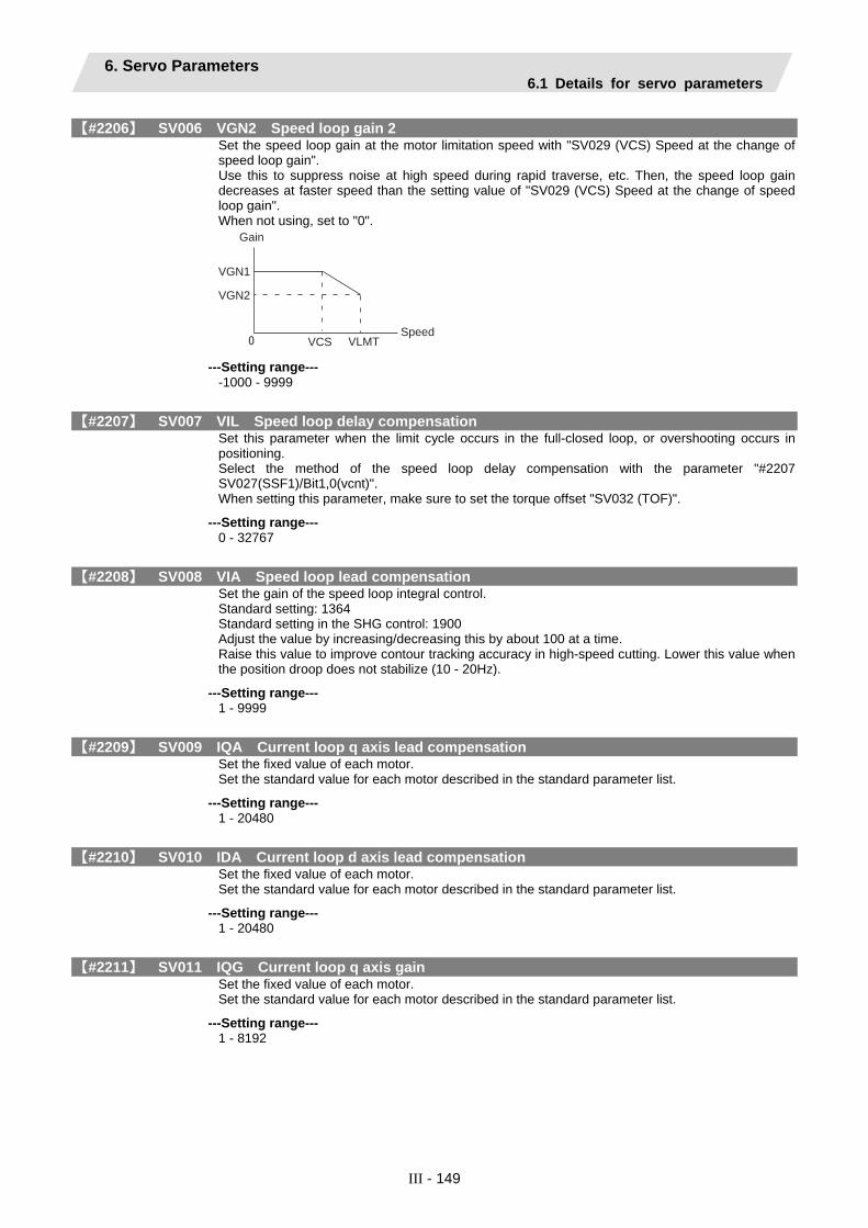
6. Servo Parameters 6.1 Details for servo parameters
III - 149
【#2206】 SV006 VGN2 Speed loop gain 2 Set the speed loop gain at the motor limitation speed with "SV029 (VCS) Speed at the change of speed loop gain". Use this to suppress noise at high speed during rapid traverse, etc. Then, the speed loop gain decreases at faster speed than the setting value of "SV029 (VCS) Speed at the change of speed loop gain". When not using, set to "0".
VGN1
VGN2
VCS VLMT
Gain
Speed
---Setting range---
-1000 - 9999
【#2207】 SV007 VIL Speed loop delay compensation Set this parameter when the limit cycle occurs in the full-closed loop, or overshooting occurs in positioning. Select the method of the speed loop delay compensation with the parameter "#2207 SV027(SSF1)/Bit1,0(vcnt)". When setting this parameter, make sure to set the torque offset "SV032 (TOF)".
---Setting range--- 0 - 32767
【#2208】 SV008 VIA Speed loop lead compensation Set the gain of the speed loop integral control. Standard setting: 1364 Standard setting in the SHG control: 1900 Adjust the value by increasing/decreasing this by about 100 at a time. Raise this value to improve contour tracking accuracy in high-speed cutting. Lower this value when the position droop does not stabilize (10 - 20Hz).
---Setting range--- 1 - 9999
【#2209】 SV009 IQA Current loop q axis lead compensation Set the fixed value of each motor. Set the standard value for each motor described in the standard parameter list.
---Setting range--- 1 - 20480
【#2210】 SV010 IDA Current loop d axis lead compensation Set the fixed value of each motor. Set the standard value for each motor described in the standard parameter list.
---Setting range--- 1 - 20480
【#2211】 SV011 IQG Current loop q axis gain Set the fixed value of each motor. Set the standard value for each motor described in the standard parameter list.
---Setting range--- 1 - 8192
6. Servo Parameters 6.1 Details for servo parameters
III - 150
【#2212】 SV012 IDG Current loop d axis gain Set the fixed value of each motor. Set the standard value for each motor described in the standard parameter list.
---Setting range--- 1 - 8192
【#2213】 SV013 ILMT Current limit value Set the current (torque) limit value in a normal operation. This is a limit value in both forward run and reverse run directions. When the standard setting value "800" is set, the maximum torque will be determined by the specification of the motor. Set this parameter as a proportion (%) to the stall torque.
---Setting range--- 0 - 999
【#2214】 SV014 ILMTsp Current limit value in special control Set the current (torque) limit value in a special operation (absolute position initial setting, stopper control, etc). This is a limit value in both forward run and reverse run directions. Set to "800" when not using. Set this parameter as a proportion (%) to the stall torque.
---Setting range--- 0 - 999
【#2215】 SV015 FFC Acceleration rate feed forward gain When a relative error in the synchronous control is large, set this parameter to the axis that is delaying. The standard setting value is "0". The standard setting in the SHG control is "100". To adjust a relative error in acceleration/deceleration, increase the value by 50 - 100 at a time.
---Setting range--- 0 - 999 (%)
【#2216】 SV016 LMC1 Lost motion compensation 1 Set this parameter when the protrusion (that occurs due to the non-sensitive band by friction, torsion, backlash, etc.) at quadrant change is too large. This compensates the torque at quadrant change (when an axis feed direction is reversed) by the proportion (%) to the stall torque. Select whether to enable the lost motion compensation and the compensation method with the parameter "#2227 SV027 (SSF1)/ Bit9, 8".
---Setting range--- -1 - 200 Note that the range will be "-1 - 20000" when SV082/bit2 is "1".
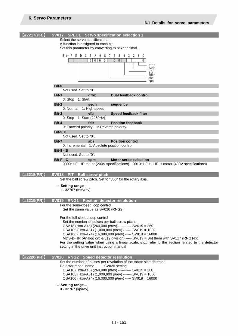
6. Servo Parameters 6.1 Details for servo parameters
III - 151
【#2217(PR)】 SV017 SPEC1 Servo specification selection 1 Select the servo specifications. A function is assigned to each bit. Set this parameter by converting to hexadecimal.
Bit-0 Not used. Set to "0".
Bit-1 dfbx Dual feedback control 0: Stop 1: Start
Bit-2 seqh sequence 0: Normal 1: High-speed
Bit-3 vfb Speed feedback filter 0: Stop 1: Start (2250Hz)
Bit-4 fdir Position feedback 0: Forward polarity 1: Reverse polarity
Bit-5, 6 Not used. Set to "0".
Bit-7 abs Position control 0: Incremental 1: Absolute position control
Bit-8 - B Not used. Set to "0".
Bit-F - C spm Motor series selection 0000: HF, HP motor (200V specifications) 0010: HF-H, HP-H motor (400V specifications)
【#2218(PR)】 SV018 PIT Ball screw pitch Set the ball screw pitch. Set to "360" for the rotary axis.
---Setting range--- 1 - 32767 (mm/rev)
【#2219(PR)】 SV019 RNG1 Position detector resolution For the semi-closed loop control
Set the same value as SV020 (RNG2). For the full-closed loop control
Set the number of pulses per ball screw pitch. OSA18 (Hxn-A48) (260,000 p/rev) ----------- SV019 = 260 OSA105 (Hxn-A51) (1,000,000 p/rev) ------- SV019 = 1000 OSA166 (Hxn-A74) (16,000,000 p/rev) ----- SV019 = 16000 MDS-B-HR (Analog cycle/512 division) ----- SV019 = Set them with SV117 (RNG1ex).
For the setting value when using a linear scale, etc., refer to the section related to the detector setting in the drive unit instruction manual
【#2220(PR)】 SV020 RNG2 Speed detector resolution Set the number of pulses per revolution of the motor side detector. Detector model name SV020 setting
OSA18 (Hxn-A48) (260,000 p/rev) ----------- SV019 = 260 OSA105 (Hxn-A51) (1,000,000 p/rev) ------- SV019 = 1000 OSA166 (Hxn-A74) (16,000,000 p/rev) ----- SV019 = 16000
---Setting range--- 0 - 32767 (kp/rev)

6. Servo Parameters 6.1 Details for servo parameters
III - 152
【#2221】 SV021 OLT Overload detection time constant Normally set this parameter to "60".
---Setting range--- 1 - 999 (s)
【#2222】 SV022 OLL Overload detection level Set the current detection level of "Overload 1" (Alarm 50) as a percentage in respect to the stall current. Normally set this parameter to "150". (For machine tool builder adjustment.)
---Setting range--- 110 - 500 (Stall current %)
【#2223】 SV023 OD1 Excessive error detection width during servo ON Set the excessive error detection width in servo ON. <Standard setting value> OD1=OD2= (Rapid traverse rate [mm/min]) / (60×PGN1) / 2 [mm] If this parameter is set to "0", the excessive error detection will not be performed.
---Setting range--- 0 - 32767 (mm)
【#2224】 SV024 INP In-position detection width Set the in-position detection width. Set the positioning accuracy required for the machine. The lower the setting is, the higher the positioning accuracy will be. However, the cycle time (settling time) becomes longer. The standard setting value is "50".
---Setting range--- 0 - 32767 (µm)

6. Servo Parameters 6.1 Details for servo parameters
III - 153
【#2225(PR)】 SV025 MTYP Motor/Detector type Set the position detector type, speed detector type and motor type. The setting value is a four-digit hex (HEX).
mtypentpen
1234HEX-
HEX-1, 2 mtyp Motor type Set the motor type. Set this according to SV017/bitC-F. For SV017/bitC-F(spm)=0 (200V standard motor series) HF75xxx-yyy : HEX2, 1 = 01h HP54xxx-yyy : HEX2, 1 = 11h HF105xxx-yyy : HEX2, 1 = 02h HP104xxx-yyy : HEX2, 1 = 12h HF54xxx-yyy : HEX2, 1 = 03h HP154xxx-yyy : HEX2, 1 = 13h HF104xxx-yyy : HEX2, 1 = 04h HP224xxx-yyy : HEX2, 1 = 1Bh HF154xxx-yyy : HEX2, 1 = 05h HP204xxx-yyy : HEX2, 1 = 14h HF204xxx-yyy : HEX2, 1 = 07h HP354xxx-yyy : HEX2, 1 = 15h HF354xxx-yyy : HEX2, 1 = 08h HP454xxx-yyy : HEX2, 1 = 16h HF453xxx-yyy : HEX2, 1 = 09h HP704xxx-yyy : HEX2, 1 = 17h HF703xxx-yyy : HEX2, 1 = 0Ah HP903xxx-yyy : HEX2, 1 = 18h HF903xxx-yyy : HEX2, 1 = 0Bh HP1103xxx-yyy : HEX2, 1 = 19h For SV017/bitC-F(spm)=2 (400V standard motor series) HF-H75xxx-yyy : HEX2, 1 = 01h HP-H 54xxx-yyy : HEX2, 1 = 11h HF-H 105xxx-yyy : HEX2, 1 = 02h HP-H 104xxx-yyy : HEX2, 1 = 12h HF-H 54xxx-yyy : HEX2, 1 = 03h HP-H 154xxx-yyy : HEX2, 1 = 13h HF-H 104xxx-yyy : HEX2, 1 = 04h HP-H 224xxx-yyy : HEX2, 1 = 1Bh HF-H 154xxx-yyy : HEX2, 1 = 05h HP-H 204xxx-yyy : HEX2, 1 = 14h HF-H 204xxx-yyy : HEX2, 1 = 07h HP-H 354xxx-yyy : HEX2, 1 = 15h HF-H 354xxx-yyy : HEX2, 1 = 08h HP-H 454xxx-yyy : HEX2, 1 = 16h HF-H 453xxx-yyy : HEX2, 1 = 09h HP-H 704xxx-yyy : HEX2, 1 = 17h HF-H 703xxx-yyy : HEX2, 1 = 0Ah HP-H 903xxx-yyy : HEX2, 1 = 18h HF-H 903xxx-yyy : HEX2, 1 = 0Bh HP-H 1103xxx-yyy : HEX2, 1 = 19h (xxx: Code of brake, shaft shape, etc., yyy: Detector code)
HEX-3 ent Speed detector OSA18(HFaaaxxx-A48): HEX3=2 OSA105(HFaaaxxx-A51): HEX3=2 OSA166(HFaaaxxx-A74): HEX3=2
HEX-4 pen Position detector For semi-closed loop OSA18(HFaaaxxx-A48): HEX4=2 OSA105(HFaaaxxx-A51): HEX4=2 OSA166(HFaaaxxx-A74): HEX4=2 For full-closed loop OSA105-ET2, OSA166-ET2: HEX4 = 6h MDS-B-HR: HEX4 = Ah
【#2226】 SV026 OD2 Excessive error detection width during servo OFF Set the excessive error detection width when servo OFF. For the standard setting, refer to the explanation of SV023 (OD1). When "0" is set, the excessive error detection will not be performed.
---Setting range--- 0 - 32767 (mm)

6. Servo Parameters 6.1 Details for servo parameters
III - 154
【#2227】 SV027 SSF1 Servo function selection 1 Select the servo specifications. A function is assigned to each bit. Set this parameter by converting to hexadecimal.
Bit-1,0 vcnt Speed loop delay compensation execution changeover 00: Disable 01: Changeover type 1 10: Changeover type 2 11: Setting prohibited
Bit-3,2 Not used. Set to "0".
Bit-5,4 vfct Jitter compensation pulse number 00: Disable 01: 1 pulse 10: 2 pulses 11: 3 pulses
Bit-7,6 Not used. Set to "0".
Bit-9,8 lmc Lost motion compensation type selection 00: Compensation stop 01: Setting prohibited 10: Type 2 11: Setting prohibited (Set the compensation amount in SV016 and SV041.) (Note) When "SV082/lmc3" is set to "1", the lost motion compensation type 3 will be selected.
Bit-B,A ovs Overshoot compensation type selection 00: Compensation stop 01: Setting prohibited 10: Setting prohibited 11: Type 3 (Set the compensation amount in SV031 and SV042.)
Bit-C Not used. Set to "0".
Bit-D Not used. Set to "0".
Bit-E zrn2 Set to "1". (Fixed)
Bit-F Not used. Set to "0".
【#2228】 SV028 Not used. Set to "0".
【#2229】 SV029 VCS Speed at the change of speed loop gain If the noise is bothersome at high speed during rapid traverse, etc, this noise can be reduced by lowering the speed loop gain at high speed. Set the speed at which the speed loop gain changes, and use this together with SV006 (VGN2). (Refer to SV006.) When not using, set to "0".
---Setting range--- 0 - 9999 (r/min)
【#2230】 SV030 IVC Voltage non-sensitive band compensation When 100% is set, the voltage equivalent to the logical non-energized time will be compensated. When "0" is set, 100% compensation will be performed. If adjustment is necessary, adjust the value by 10% at a time from 100%. If the value is too large, vibration or vibration noise may be generated.
---Setting range--- 0 - 255 (%)

6. Servo Parameters 6.1 Details for servo parameters
III - 155
【#2231】 SV031 OVS1 Overshooting compensation 1 Set the compensation amount of the motor torque during positioning. This is enabled only when the overshooting compensation SV027 (SSF1/ovs) is selected.
---Setting range--- -1 - 100 (Stall current %) Note that the range will be "-1 - 10000" (Stall current 0.01%) when"SV082/bit2" is "1",
【#2232】 SV032 TOF Torque offset 1 Set the unbalance torque of vertical axis and inclined axis. When the vertical axis pull up function is enabled, the pull up compensation direction is determined by this parameter's sign. When set to "0", the vertical axis pull up will not be executed.
---Setting range--- -100 - 100 (Stall current %)
【#2233】 SV033 SSF2 Servo function selection 2 Select the servo specifications. A function is assigned to each bit. Set this parameter by converting to hexadecimal.
Bit-0 Not used. Set to "0".
Bit-1,2,3 nfd1 Depth of Notch filter 1 Set the filter depth of Notch filter 1. Bit3,2,1=000: -∞ Bit3,2,1=001: -18.1[dB] Bit3,2,1=010: -12.0[dB] Bit3,2,1=011: -8.5[dB] Bit3,2,1=100: -6.0[dB] Bit3,2,1=101: -4.1[dB] Bit3,2,1=110: -2.5[dB] Bit3,2,1=111: -1.2[dB] Set the adaptive frequency of Notch filter 1 in "#2238 SV0038 FHz1".
Bit-4 nf3 Notch filter 3 0: Stop 1: Start (1125Hz)
Bit-5,6,7 nfd2 Depth of Notch filter 2 Set the filter depth of Notch filter 2. Bit7,6,5=000: -∞ Bit7,6,5=001: -18.1[dB] Bit7,6,5=010: -12.0[dB] Bit7,6,5=011: -8.5[dB] Bit7,6,5=100: -6.0[dB] Bit7,6,5=101: -4.1[dB] Bit7,6,5=110: -2.5[dB] Bit7,6,5=111: -1.2[dB] Set the adaptive frequency of Notch filter 2 in "#2246 SV0046 FHz2".
Bit-8,9,A,B,C Not used. Set to "0".
Bit-D rps Safety observation safety speed setting increment 0: mm/min 1: 100mm/min
Bit-E zup Vertical axis pull up function 0: Stop 1: Enable
Bit-F lmc2a Lost motion compensation 2 timing 0: Normal 1: Change

6. Servo Parameters 6.1 Details for servo parameters
III - 156
【#2234】 SV034 SSF3 Servo function selection 3 Select the servo specifications. A function is assigned to each bit. Set this parameter by converting to hexadecimal.
Bit-0 - B Not used. Set to "0".
Bit-C,D,E,F ovsn Overshooting compensation type 3 non-sensitive ban Set the non-sensitive band of the model position droop in increments of 2µm. When using feed forward control, set the non-sensitive band for the model position droop and ignore the model overshooting. Bit-F,E,D,C=0000: 0µm Bit-F,E,D,C=0001: 2µm Bit-F,E,D,C=0010: 4µm
【#2235】 SV035 SSF4 Servo function selection 4 Select the servo specifications. A function is assigned to each bit. Set this parameter by converting to hexadecimal.
Bit-0 - 6 Not used. Set to "0".
Bit-7 ckab No signal detection 2 0: Disable 1: Enable
Bit-8 - E Not used. Set to "0".
Bit-F clt Inertia ratio display 0: Setting for normal use 1: Display the total inertia ratio estimated at acceleration/deceleration at the inertia ratio on the servo monitor screen
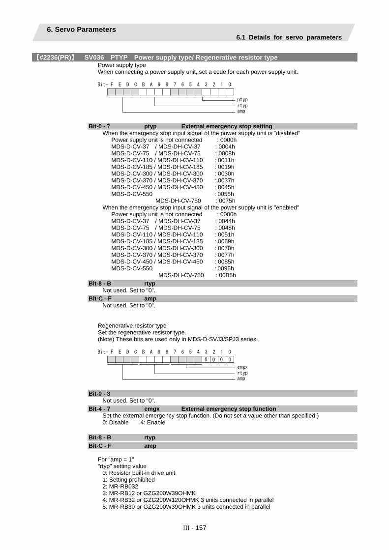
6. Servo Parameters 6.1 Details for servo parameters
III - 157
【#2236(PR)】 SV036 PTYP Power supply type/ Regenerative resistor type Power supply type When connecting a power supply unit, set a code for each power supply unit.
Bit-0 - 7 ptyp External emergency stop setting When the emergency stop input signal of the power supply unit is "disabled" Power supply unit is not connected : 0000h MDS-D-CV-37 / MDS-DH-CV-37 : 0004h MDS-D-CV-75 / MDS-DH-CV-75 : 0008h MDS-D-CV-110 / MDS-DH-CV-110 : 0011h MDS-D-CV-185 / MDS-DH-CV-185 : 0019h MDS-D-CV-300 / MDS-DH-CV-300 : 0030h MDS-D-CV-370 / MDS-DH-CV-370 : 0037h MDS-D-CV-450 / MDS-DH-CV-450 : 0045h MDS-D-CV-550 : 0055h MDS-DH-CV-750 : 0075h When the emergency stop input signal of the power supply unit is "enabled" Power supply unit is not connected : 0000h MDS-D-CV-37 / MDS-DH-CV-37 : 0044h MDS-D-CV-75 / MDS-DH-CV-75 : 0048h MDS-D-CV-110 / MDS-DH-CV-110 : 0051h MDS-D-CV-185 / MDS-DH-CV-185 : 0059h MDS-D-CV-300 / MDS-DH-CV-300 : 0070h MDS-D-CV-370 / MDS-DH-CV-370 : 0077h MDS-D-CV-450 / MDS-DH-CV-450 : 0085h MDS-D-CV-550 : 0095h MDS-DH-CV-750 : 00B5h
Bit-8 - B rtyp Not used. Set to "0".
Bit-C - F amp Not used. Set to "0".
Regenerative resistor type Set the regenerative resistor type. (Note) These bits are used only in MDS-D-SVJ3/SPJ3 series.
Bit-0 - 3 Not used. Set to "0".
Bit-4 - 7 emgx External emergency stop function Set the external emergency stop function. (Do not set a value other than specified.) 0: Disable 4: Enable
Bit-8 - B rtyp
Bit-C - F amp For "amp = 1" "rtyp" setting value
0: Resistor built-in drive unit 1: Setting prohibited 2: MR-RB032 3: MR-RB12 or GZG200W39OHMK 4: MR-RB32 or GZG200W120OHMK 3 units connected in parallel 5: MR-RB30 or GZG200W39OHMK 3 units connected in parallel
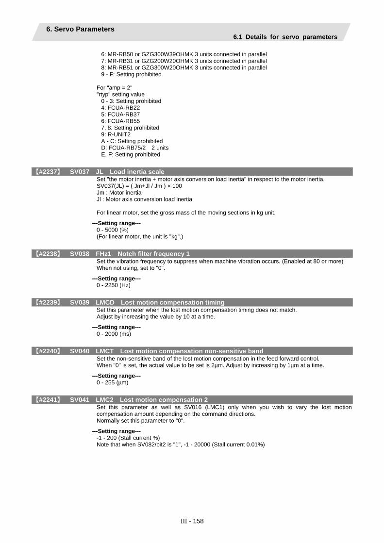
6. Servo Parameters 6.1 Details for servo parameters
III - 158
6: MR-RB50 or GZG300W39OHMK 3 units connected in parallel 7: MR-RB31 or GZG200W20OHMK 3 units connected in parallel 8: MR-RB51 or GZG300W20OHMK 3 units connected in parallel 9 - F: Setting prohibited
For "amp = 2" "rtyp" setting value
0 - 3: Setting prohibited 4: FCUA-RB22 5: FCUA-RB37 6: FCUA-RB55 7, 8: Setting prohibited 9: R-UNIT2 A - C: Setting prohibited D: FCUA-RB75/2 2 units E, F: Setting prohibited
【#2237】 SV037 JL Load inertia scale Set "the motor inertia + motor axis conversion load inertia" in respect to the motor inertia. SV037(JL) = ( Jm+Jl / Jm ) × 100 Jm : Motor inertia Jl : Motor axis conversion load inertia For linear motor, set the gross mass of the moving sections in kg unit.
---Setting range--- 0 - 5000 (%) (For linear motor, the unit is "kg".)
【#2238】 SV038 FHz1 Notch filter frequency 1 Set the vibration frequency to suppress when machine vibration occurs. (Enabled at 80 or more) When not using, set to "0".
---Setting range--- 0 - 2250 (Hz)
【#2239】 SV039 LMCD Lost motion compensation timing Set this parameter when the lost motion compensation timing does not match. Adjust by increasing the value by 10 at a time.
---Setting range--- 0 - 2000 (ms)
【#2240】 SV040 LMCT Lost motion compensation non-sensitive band Set the non-sensitive band of the lost motion compensation in the feed forward control. When "0" is set, the actual value to be set is 2µm. Adjust by increasing by 1µm at a time.
---Setting range--- 0 - 255 (µm)
【#2241】 SV041 LMC2 Lost motion compensation 2 Set this parameter as well as SV016 (LMC1) only when you wish to vary the lost motion compensation amount depending on the command directions. Normally set this parameter to "0".
---Setting range--- -1 - 200 (Stall current %) Note that when SV082/bit2 is "1", -1 - 20000 (Stall current 0.01%)

6. Servo Parameters 6.1 Details for servo parameters
III - 159
【#2242】 SV042 OVS2 Overshooting compensation 2 Set this parameter as well as SV031 (OVS1) only when you wish to vary the overshooting compensation amount depending on the command directions. Normally set this parameter to "0".
---Setting range--- -1 - 100 (Stall current %) Note that the range will be "-1 - 10000" (Stall current 0.01%) when SV082/bit2 is "1".
【#2243】 SV043 OBS1 Disturbance observer filter frequency Set the disturbance observer filter band. Normally set this parameter to "100". To use the disturbance observer, also set SV037 (JL) and SV044 (OBS2). When not using, set to "0".
---Setting range--- 0 - 1000 (rad/s)
【#2244】 SV044 OBS2 Disturbance observer gain Set the disturbance observer gain. The standard setting is "100 - 300". To use the disturbance observer, also set SV037 (JL) and SV043 (OBS1). When not using, set to "0".
---Setting range--- 0 - 500 (%)
【#2245】 SV045 Not used. Set to "0".
【#2246】 SV046 FHz2 Notch filter frequency 2 Set the vibration frequency to suppress when machine vibration occurs. (Enabled at 80 or more.) When not using, set to "0".
---Setting range--- 0 - 2250 (Hz)
【#2247】 SV047 EC Inductive voltage compensation gain Set the inductive voltage compensation gain. Normally set this parameter to "100". If the current FB peak exceeds the current command peak, lower the gain.
---Setting range--- 0 - 200 (%)
【#2248】 SV048 EMGrt Vertical axis drop prevention time Input a length of time to prevent the vertical axis from dropping by delaying READY OFF until the brake works when the emergency stop occurs. Increase the setting by 100ms at a time and set the value where the axis does not drop. When using a motor with a break of HF(-H) Series or HP(-H) Series, set to "200ms" as a standard.
---Setting range--- 0 - 20000 (ms)
【#2249】 SV049 PGN1sp Position loop gain 1 in spindle synchronous control Set the position loop gain during spindle synchronization control (synchronous tapping and synchronization control with spindle C-axis). Set the same value as the value of the position loop gain for spindle synchronous tapping control. When performing the SHG control, set this parameter with SV050 (PGN2sp) and SV058 (SHGCsp).
---Setting range--- 1 - 200 (rad/s)

6. Servo Parameters 6.1 Details for servo parameters
III - 160
【#2250】 SV050 PGN2sp Position loop gain 2 in spindle synchronous control When using SHG control during spindle synchronous control (synchronous tapping and synchronization control with spindle C-axis), set this parameter with SV049 (PGN1sp) and SV058 (SHGCsp). When not performing the SHG control, set to "0".
---Setting range--- 0 - 999 (rad/s)
【#2251】 SV051 DFBT Dual feed back control time constant Set the control time constant in dual feed back. When "0" is set, the actual value to be set is 1ms. The higher the time constant is, the closer it gets to the semi-closed control, so the limit of the position loop gain will be raised.
---Setting range--- 0 - 9999 (ms)
【#2252】 SV052 DFBN Dual feedback control non-sensitive band Set the non-sensitive band in the dual feedback control. Normally set this parameter to "0".
---Setting range--- 0 - 9999 (µm)
【#2253】 SV053 OD3 Excessive error detection width in special control Set the excessive error detection width when servo ON in a special control (initial absolute position setting, stopper control, etc.). When "0" is set, excessive error detection won’t be performed when servo ON during a special control.
---Setting range--- 0 - 32767 (mm)
【#2254】 SV054 ORE Overrun detection width in closed loop control Set the overrun detection width in the full-closed loop control. When the gap between the motor side detector and the linear scale (machine side detector) exceeds the value set by this parameter, it will be judged to be overrun and "Alarm 43" will be detected. When "-1" is set, the alarm detection will not be performed. When "0" is set, overrun will be detected with a 2mm width.
---Setting range--- -1 - 32767 (mm)
【#2255】 SV055 EMGx Max. gate off delay time after emergency stop Set a length of time from the point when the emergency stop is input to the point when READY OFF is compulsorily executed. Set the maximum value "+ 100ms" of the SV056 setting value of the servo drive unit which the power supply unit and the main circuit are connected with. In preventing the vertical axis from dropping, the gate off will be delayed for the length of time set by SV048 even if SV055’s value is smaller than that of SV048.
---Setting range--- 0 - 20000 (ms)
【#2256】 SV056 EMGt Deceleration time constant at emergency stop Set the time constant used for the deceleration control at emergency stop. Set the value of 0.9-fold rapid traverse acceleration/deceleration time constant used in the acceleration/deceleration. This is because the friction torque will act as a deceleration torque when the motor decelerates, which enables the machine to stop quickly. When preventing an impact at the acceleration/deceleration from being given to the machine, set the same value as the rapid traverse acceleration/deceleration time constant.
---Setting range--- 0 - 20000 (ms)
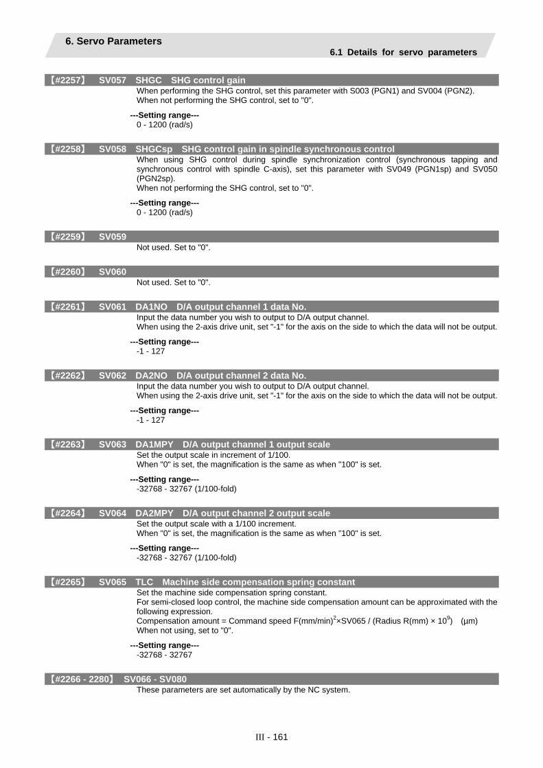
6. Servo Parameters 6.1 Details for servo parameters
III - 161
【#2257】 SV057 SHGC SHG control gain When performing the SHG control, set this parameter with S003 (PGN1) and SV004 (PGN2). When not performing the SHG control, set to "0".
---Setting range--- 0 - 1200 (rad/s)
【#2258】 SV058 SHGCsp SHG control gain in spindle synchronous control When using SHG control during spindle synchronization control (synchronous tapping and synchronous control with spindle C-axis), set this parameter with SV049 (PGN1sp) and SV050 (PGN2sp). When not performing the SHG control, set to "0".
---Setting range--- 0 - 1200 (rad/s)
【#2259】 SV059 Not used. Set to "0".
【#2260】 SV060 Not used. Set to "0".
【#2261】 SV061 DA1NO D/A output channel 1 data No. Input the data number you wish to output to D/A output channel. When using the 2-axis drive unit, set "-1" for the axis on the side to which the data will not be output.
---Setting range--- -1 - 127
【#2262】 SV062 DA2NO D/A output channel 2 data No. Input the data number you wish to output to D/A output channel. When using the 2-axis drive unit, set "-1" for the axis on the side to which the data will not be output.
---Setting range--- -1 - 127
【#2263】 SV063 DA1MPY D/A output channel 1 output scale Set the output scale in increment of 1/100. When "0" is set, the magnification is the same as when "100" is set.
---Setting range--- -32768 - 32767 (1/100-fold)
【#2264】 SV064 DA2MPY D/A output channel 2 output scale Set the output scale with a 1/100 increment. When "0" is set, the magnification is the same as when "100" is set.
---Setting range--- -32768 - 32767 (1/100-fold)
【#2265】 SV065 TLC Machine side compensation spring constant Set the machine side compensation spring constant. For semi-closed loop control, the machine side compensation amount can be approximated with the following expression. Compensation amount = Command speed F(mm/min)2×SV065 / (Radius R(mm) × 109) (µm) When not using, set to "0".
---Setting range--- -32768 - 32767
【#2266 - 2280】 SV066 - SV080 These parameters are set automatically by the NC system.

6. Servo Parameters 6.1 Details for servo parameters
III - 162
【#2281(PR)】 SV081 Not used. Set - "0".
【#2282】 SV082 SSF5 Servo function selection 5 Select the servo specifications. A function is assigned to each bit. Set this parameter by converting to hexadecimal.
Bit-F,E,D,C dis Digital signal input selection 0000(000xh): No signal 0001(100xh): Safety observation function door state signal
Bit-B - A dos3 Digital signal output selection 3 00: Not used 10: Contactor control signal output
Bit-9 - 3 Not used. Set to "0".
Bit-2 ccu Lost motion overshoot compensation compensation amount setting increment
0: Stall rated current % 1: Stall rated current 0.01%
Bit-1 lmc3 Lost motion compensation type3 0: Stop 1: Start
Bit-0 lmct Lost motion compensation 3 adjustment time measurement enabled 0: Setting for normal use 1: Adjustment time measurement enabled
【#2283】 SV083 SSF6 Servo function selection 6 Select the servo specifications. A function is assigned to each bit. Set this parameter by converting to hexadecimal.
Bit-0 Not used. Set to "0".
Bit-1,2,3 nfd4 Depth of Notch filter 4 Set the filter depth of Notch filter 4. Bit 3,2,1=000: -∞ Bit 3,2,1=001: -18.1[dB] Bit 3,2,1=010: -12.0[dB] Bit 3,2,1=011: -8.5[dB] Bit 3,2,1=100: -6.0[dB] Bit 3,2,1=101: -4.1[dB] Bit 3,2,1=110: -2.5[dB] Bit 3,2,1=111: -1.2[dB] Set the adaptive frequency of Notch filter 4 in "#2287 SV0087 FHz4".
Bit-4 Not used. Set to "0".
Bit-5,6,7 nfd5 Depth of Notch filter 5 Set the filter depth of Notch filter 5. Bit 7,6,5=000: -∞ Bit 7,6,5=001: -18.1[dB] Bit 7,6,5=010: -12.0[dB] Bit 7,6,5=011: -8.5[dB] Bit 7,6,5=100: -6.0[dB] Bit 7,6,5=101: -4.1[dB] Bit 7,6,5=110: -2.5[dB] Bit 7,6,5=111: -1.2[dB] Set the adaptive frequency of Notch filter 5 in "#2288 SV0088 FHz5".
Bit-8 - F Not used. Set to "0".

6. Servo Parameters 6.1 Details for servo parameters
III - 163
【#2284】 SV084 SSF7 Servo function selection 7 Select the servo specifications. A function is assigned to each bit. Set this parameter by converting to hexadecimal.
Bit-0 irms Motor current display 0: Normal motor current display 1: Effective motor current display
【#2285】 SV085 LMCk Lost motion compensation 3 spring constant Set the machine system's spring constant when using lost motion compensation type 3. When not using, set to "0".
---Setting range--- 0 - 32767 (0.01%/µm)
【#2286】 SV086 LMCc Lost motion compensation 3 viscous coefficient Set the machine system's viscous coefficient when using lost motion compensation type 3. When not using, set to "0".
---Setting range--- 0 - 32767 (0.01%/µm)
【#2287】 SV087 FHz4 Notch filter frequency 4 Set the vibration frequency to suppress when machine vibration occurs. (Enabled at 80 or more) When not using, set to "0".
---Setting range--- 0 - 2250 (Hz)
【#2288】 SV088 FHz5 Notch filter frequency 5 Set the vibration frequency to suppress when machine vibration occurs. (Enabled at 80 or more) When not using, set to "0".
---Setting range--- 0 - 2250 (Hz)
【#2289】 SV089 TQMAX Kq Torque maximizing control Kp Normally set this parameter to "0".
---Setting range--- 0 - 32767 (0.01%/µm)
【#2290】 SV090 TQMAX Kd Torque maximizing control Kd Normally set this parameter to "0".
---Setting range--- 0 - 32767 (0.01%/•s/mm)
【#2291 - 2293】 SV091 - SV093 Not used. Set to "0".

6. Servo Parameters 6.1 Details for servo parameters
III - 164
【#2294】 SV094 MPV Magnetic pole position error detection speed In the magnetic polar position detection function, the command motor speed and motor speed at the position command stop are monitored. The command motor speed level and motor speed level at the position command stop are set with "r/min" increment. When the command motor speed level is set to "0", the magnetic polar position error is detected at 10r/min. Set to “10” as a standard setting applied when the magnetic polar position error detection function is enabled. This will detect the magnetic polar position error when the motor speed is “100r/min”. When not using, set to "0". Ten-thousands digit, Thousands digit ----------- Command motor speed level (10r/min) Hundreds digit, Tens digit, Ones digit ----------- Motor speed level (10r/min)
---Setting range--- 0 - 31999
【#2295】 SV095 ZUPD Vertical axis pull up distance Set this parameter to adjust the pull up distance when the vertical axis pull up function is enabled. For a rotary motor, 8/1000 of a rotation at the motor end is internally set as the pull up distance, when the pull up function is enabled and this parameter is set to "0".
---Setting range--- 0 - 2000 (μm)
【#2296 - 2312】 SV096 - SV112 Not used. Set to "0".
【#2313】 SV113 SSF8 Servo function selection 8 Select the servo specifications. A function is assigned to each bit. Set this parameter by converting to hexadecimal.
0 0 0 0 0 0 0 0 0 0 0 0 0 0 0
Bit- F E D C B A 9 8 7 6 5 4 3 2 1 0
ssc
Bit-0 - E Not used. Set to "0".
Bit-F ssc Safety observation function 0: Stop 1: Start
【#2314】 SV114 SSF9 Servo function selection 9 Not used. Set to "0".
【#2315】 SV115 SSF10 Servo function selection 10 Not used. Set to "0".
【#2316】 SV116 SSF11 Servo function selection 11 Not used. Set to "0".
【#2317(PR)】 SV117 RNG1ex Expansion position detector resolution Set this parameter when using a special position detector. Normally set this parameter to "0". Refer to the section related to the detector setting in the drive unit instruction manual.

6. Servo Parameters 6.1 Details for servo parameters
III - 165
【#2318(PR)】 SV118 RNG2ex Expansion speed detector resolution Set the number of pulses per revolution of the motor side detector.
OSA18 ------ SV118 = 0 OSA105 ---- SV118 = 0 OSA166 ---- SV118 = 0
---Setting range--- 0 - 32767 ( x 216p/rev)
【#2319 - 2437】 SV119 - SV237 Not used. Set to "0".
【#2438】 SV238 SSCFEED Safety observation Safety speed Set the machine’s safety speed for the safety observation function. Set this parameter within the following setting ranges. For linear axis: 2000mm/min or less For rotary axis: 18000°/min (50r/min) or less When not using, set to "0".
---Setting range--- 0 - 18000 (mm/min) or (°/min)
【#2439】 SV239 SSCRPM Safety observation Safety motor speed Set the motor’s safety speed for the safety observation function. When not using, set to "0".
---Setting range--- 0 - 32767 (r/min)
【#2440 - 2456】 SV240 - SV256 Not used. Set to "0".

6. Servo Parameters 6.2 List of standard parameters for each servomotor
III - 166
6.2 List of standard parameters for each servomotor The standard parameters for each motor are given below. The standard parameters are set to drive the isolated motor. When setting the parameters with the actual machine, set the parameters according to the machine specifications and detector being used, etc. (a) 200V Standard motor HF Series
Motor HF75 HF105 HF54 HF104 HF154 HF204 HF354 HF453 HF703 HF903Drive unit
MDS-D-V1- 20 20 40 40 80 80 160 160 160W 320
SV001 PC1 - - - - - - - - - -SV002 PC2 - - - - - - - - - -SV003 PGN1 33 33 33 33 33 33 33 33 33 33SV004 PGN2 0 0 0 0 0 0 0 0 0 0SV005 VGN1 100 100 100 100 100 100 100 100 100 100SV006 VGN2 0 0 0 0 0 0 0 0 0 0SV007 VIL 0 0 0 0 0 0 0 0 0 0SV008 VIA 1364 1364 1364 1364 1364 1364 1364 1364 1364 1364SV009 IQA 20480 10240 20480 10240 10240 8192 8192 6144 6144 4096SV010 IDA 20480 10240 20480 10240 10240 8192 8192 6144 6144 4096SV011 IQG 768 512 3072 1280 1536 2048 2048 2048 2048 1536SV012 IDG 768 512 3072 1280 1536 2048 2048 2048 2048 1536SV013 ILMT 800 800 800 800 800 800 800 800 800 800SV014 ILMTsp 800 800 800 800 800 800 800 800 800 800SV015 FFC 0 0 0 0 0 0 0 0 0 0SV016 LMC1 0 0 0 0 0 0 0 0 0 0SV017 SPEC 0000 0000 0000 0000 0000 0000 0000 0000 0000 0000SV018 PIT - - - - - - - - - -SV019 RNG1 - - - - - - - - - -SV020 RNG2 - - - - - - - - - -SV021 OLT 60 60 60 60 60 60 60 60 60 60SV022 OLL 150 150 150 150 150 150 150 150 150 150SV023 OD1 6 6 6 6 6 6 6 6 6 6SV024 INP 50 50 50 50 50 50 50 50 50 50SV025 MTYP xx01 xx02 xx03 xx04 xx05 xx07 xx08 xx09 xx0A xx0BSV026 OD2 6 6 6 6 6 6 6 6 6 6SV027 SSF1 4000 4000 4000 4000 4000 4000 4000 4000 4000 4000SV028 0 0 0 0 0 0 0 0 0 0SV029 VCS 0 0 0 0 0 0 0 0 0 0SV030 IVC 0 0 0 0 0 0 0 0 0 0SV031 OVS1 0 0 0 0 0 0 0 0 0 0SV032 TOF 0 0 0 0 0 0 0 0 0 0

6. Servo Parameters 6.2 List of standard parameters for each servomotor
III - 167
Motor HF75 HF105 HF54 HF104 HF154 HF204 HF354 HF453 HF703 HF903
Drive unit MDS-D-V1- 20 20 40 40 80 80 160 160 160W 320
SV033 SSF2 0000 0000 0000 0000 0000 0000 0000 0000 0000 0000SV034 SSF3 0000 0000 0000 0000 0000 0000 0000 0000 0000 0000SV035 SSF4 0000 0000 0000 0000 0000 0000 0000 0000 0000 0000SV036 PTYP 0000 0000 0000 0000 0000 0000 0000 0000 0000 0000SV037 JL 0 0 0 0 0 0 0 0 0 0SV038 FHz1 0 0 0 0 0 0 0 0 0 0SV039 LMCD 0 0 0 0 0 0 0 0 0 0SV040 LMCT 0 0 0 0 0 0 0 0 0 0SV041 LMC2 0 0 0 0 0 0 0 0 0 0SV042 OVS2 0 0 0 0 0 0 0 0 0 0SV043 OBS1 0 0 0 0 0 0 0 0 0 0SV044 OBS2 0 0 0 0 0 0 0 0 0 0SV045 TRUB 0 0 0 0 0 0 0 0 0 0SV046 FHz2 0 0 0 0 0 0 0 0 0 0SV047 EC1 100 100 100 100 100 100 100 100 100 100SV048 EMGrt 0 0 0 0 0 0 0 0 0 0SV049 PGN1sp 15 15 15 15 15 15 15 15 15 15SV050 PGN2sp 0 0 0 0 0 0 0 0 0 0SV051 DFBT 0 0 0 0 0 0 0 0 0 0SV052 DFBN 0 0 0 0 0 0 0 0 0 0SV053 OD3 0 0 0 0 0 0 0 0 0 0SV054 ORE 0 0 0 0 0 0 0 0 0 0SV055 EMGx 0 0 0 0 0 0 0 0 0 0SV056 EMGt 0 0 0 0 0 0 0 0 0 0SV057 SHGC 0 0 0 0 0 0 0 0 0 0SV058 SHGCsp 0 0 0 0 0 0 0 0 0 0SV059 TCNV 0 0 0 0 0 0 0 0 0 0SV060 TLMT 0 0 0 0 0 0 0 0 0 0SV061 DA1NO 0 0 0 0 0 0 0 0 0 0SV062 DA2NO 0 0 0 0 0 0 0 0 0 0SV063 DA1MPY 0 0 0 0 0 0 0 0 0 0SV064 DA2MPY 0 0 0 0 0 0 0 0 0 0SV065 TLC 0 0 0 0 0 0 0 0 0 0SV066 : SV256
0 :
0
0 :
0
0:
0
0:
0
0:
0
0:
0
0 :
0
0 :
0
0:
0
0:
0
Note that a value other than "0" may be automatically set by the NC system for the system setting parameters.

6. Servo Parameters 6.2 List of standard parameters for each servomotor
III - 168
(b) 200V Standard motor HP Series
Motor HP54 HP104 HP154 HP204 HP354 HP454 HP704 HP903 HP1103Drive unit
MDS-D-V1- 40 40 80 80 160 160 160W 320 320W
SV001 PC1 - - - - - - - - -SV002 PC2 - - - - - - - - -SV003 PGN1 33 33 33 33 33 33 33 33 33SV004 PGN2 0 0 0 0 0 0 0 0 0SV005 VGN1 100 100 100 100 100 100 100 100 100SV006 VGN2 0 0 0 0 0 0 0 0 0SV007 VIL 0 0 0 0 0 0 0 0 0SV008 VIA 1364 1364 1364 1364 1364 1364 1364 1364 1364SV009 IQA 8192 4096 6144 3072 4096 3072 3072 2048 2048SV010 IDA 8192 4096 6144 3072 4096 3072 3072 2048 2048SV011 IQG 1280 768 1536 1024 1280 1024 1024 1280 1280SV012 IDG 1280 768 1536 1024 1280 1024 1024 1280 1280SV013 ILMT 800 800 800 800 800 800 800 800 800SV014 ILMTsp 800 800 800 800 800 800 800 800 800SV015 FFC 0 0 0 0 0 0 0 0 0SV016 LMC1 0 0 0 0 0 0 0 0 0SV017 SPEC 0000 0000 0000 0000 0000 0000 0000 0000 0000SV018 PIT - - - - - - - - -SV019 RNG1 - - - - - - - - -SV020 RNG2 - - - - - - - - -SV021 OLT 60 60 60 60 60 60 60 60 60SV022 OLL 150 150 150 150 150 150 150 150 150SV023 OD1 6 6 6 6 6 6 6 6 6SV024 INP 50 50 50 50 50 50 50 50 50SV025 MTYP xx11 xx12 xx13 xx14 xx15 xx16 xx17 xx18 xx19SV026 OD2 6 6 6 6 6 6 6 6 6SV027 SSF1 4000 4000 4000 4000 4000 4000 4000 4000 4000SV028 0 0 0 0 0 0 0 0 0SV029 VCS 0 0 0 0 0 0 0 0 0SV030 IVC 0 0 0 0 0 0 0 0 0SV031 OVS1 0 0 0 0 0 0 0 0 0SV032 TOF 0 0 0 0 0 0 0 0 0

6. Servo Parameters 6.2 List of standard parameters for each servomotor
III - 169
Motor HP54 HP104 HP154 HP204 HP354 HP454 HP704 HP903 HP1103
Drive unit MDS-D-V1- 40 40 80 80 160 160 160W 320 320W
SV033 SSF2 0000 0000 0000 0000 0000 0000 0000 0000 0000SV034 SSF3 0000 0000 0000 0000 0000 0000 0000 0000 0000SV035 SSF4 0000 0000 0000 0000 0000 0000 0000 0000 0000SV036 PTYP 0000 0000 0000 0000 0000 0000 0000 0000 0000SV037 JL 0 0 0 0 0 0 0 0 0SV038 FHz1 0 0 0 0 0 0 0 0 0SV039 LMCD 0 0 0 0 0 0 0 0 0SV040 LMCT 0 0 0 0 0 0 0 0 0SV041 LMC2 0 0 0 0 0 0 0 0 0SV042 OVS2 0 0 0 0 0 0 0 0 0SV043 OBS1 0 0 0 0 0 0 0 0 0SV044 OBS2 0 0 0 0 0 0 0 0 0SV045 TRUB 0 0 0 0 0 0 0 0 0SV046 FHz2 0 0 0 0 0 0 0 0 0SV047 EC1 100 100 100 100 100 100 100 100 100SV048 EMGrt 0 0 0 0 0 0 0 0 0SV049 PGN1sp 15 15 15 15 15 15 15 15 15SV050 PGN2sp 0 0 0 0 0 0 0 0 0SV051 DFBT 0 0 0 0 0 0 0 0 0SV052 DFBN 0 0 0 0 0 0 0 0 0SV053 OD3 0 0 0 0 0 0 0 0 0SV054 ORE 0 0 0 0 0 0 0 0 0SV055 EMGx 0 0 0 0 0 0 0 0 0SV056 EMGt 0 0 0 0 0 0 0 0 0SV057 SHGC 0 0 0 0 0 0 0 0 0SV058 SHGCsp 0 0 0 0 0 0 0 0 0SV059 TCNV 0 0 0 0 0 0 0 0 0SV060 TLMT 0 0 0 0 0 0 0 0 0SV061 DA1NO 0 0 0 0 0 0 0 0 0SV062 DA2NO 0 0 0 0 0 0 0 0 0SV063 DA1MPY 0 0 0 0 0 0 0 0 0SV064 DA2MPY 0 0 0 0 0 0 0 0 0SV065 TLC 0 0 0 0 0 0 0 0 0SV066 : SV256
0:
0
0 :
0
0:
0
0:
0
0:
0
0:
0
0 :
0
0 :
0
0:
0
Note that a value other than "0" may be automatically set by the NC system for the system setting parameters.
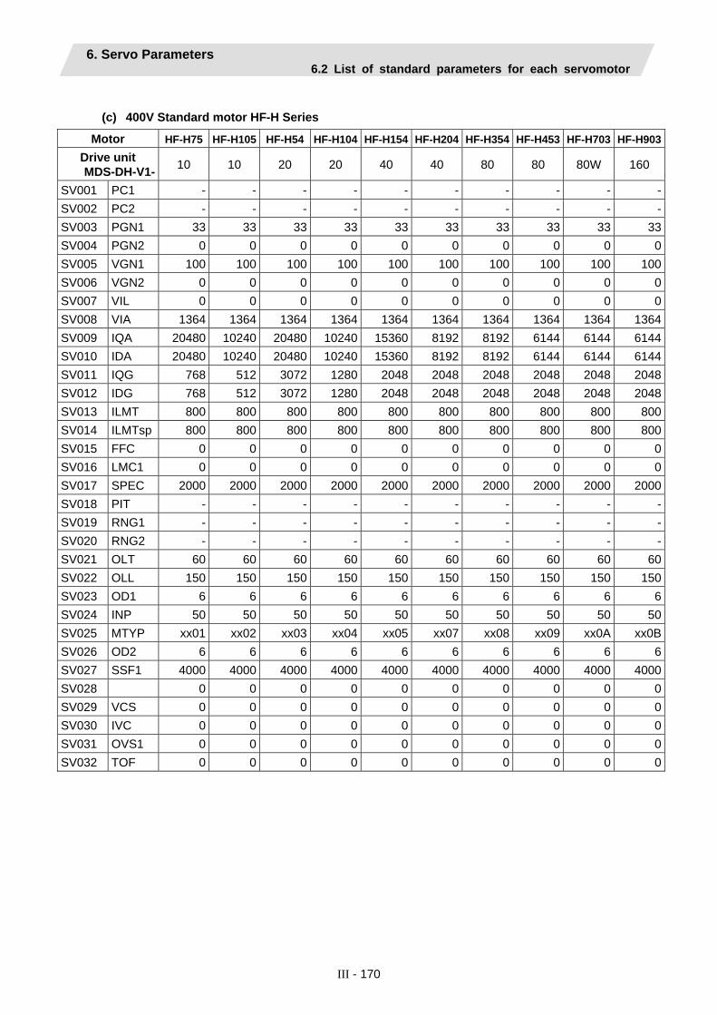
6. Servo Parameters 6.2 List of standard parameters for each servomotor
III - 170
(c) 400V Standard motor HF-H Series
Motor HF-H75 HF-H105 HF-H54 HF-H104 HF-H154 HF-H204 HF-H354 HF-H453 HF-H703 HF-H903Drive unit MDS-DH-V1- 10 10 20 20 40 40 80 80 80W 160
SV001 PC1 - - - - - - - - - -SV002 PC2 - - - - - - - - - -SV003 PGN1 33 33 33 33 33 33 33 33 33 33SV004 PGN2 0 0 0 0 0 0 0 0 0 0SV005 VGN1 100 100 100 100 100 100 100 100 100 100SV006 VGN2 0 0 0 0 0 0 0 0 0 0SV007 VIL 0 0 0 0 0 0 0 0 0 0SV008 VIA 1364 1364 1364 1364 1364 1364 1364 1364 1364 1364SV009 IQA 20480 10240 20480 10240 15360 8192 8192 6144 6144 6144SV010 IDA 20480 10240 20480 10240 15360 8192 8192 6144 6144 6144SV011 IQG 768 512 3072 1280 2048 2048 2048 2048 2048 2048SV012 IDG 768 512 3072 1280 2048 2048 2048 2048 2048 2048SV013 ILMT 800 800 800 800 800 800 800 800 800 800SV014 ILMTsp 800 800 800 800 800 800 800 800 800 800SV015 FFC 0 0 0 0 0 0 0 0 0 0SV016 LMC1 0 0 0 0 0 0 0 0 0 0SV017 SPEC 2000 2000 2000 2000 2000 2000 2000 2000 2000 2000SV018 PIT - - - - - - - - - -SV019 RNG1 - - - - - - - - - -SV020 RNG2 - - - - - - - - - -SV021 OLT 60 60 60 60 60 60 60 60 60 60SV022 OLL 150 150 150 150 150 150 150 150 150 150SV023 OD1 6 6 6 6 6 6 6 6 6 6SV024 INP 50 50 50 50 50 50 50 50 50 50SV025 MTYP xx01 xx02 xx03 xx04 xx05 xx07 xx08 xx09 xx0A xx0BSV026 OD2 6 6 6 6 6 6 6 6 6 6SV027 SSF1 4000 4000 4000 4000 4000 4000 4000 4000 4000 4000SV028 0 0 0 0 0 0 0 0 0 0SV029 VCS 0 0 0 0 0 0 0 0 0 0SV030 IVC 0 0 0 0 0 0 0 0 0 0SV031 OVS1 0 0 0 0 0 0 0 0 0 0SV032 TOF 0 0 0 0 0 0 0 0 0 0

6. Servo Parameters 6.2 List of standard parameters for each servomotor
III - 171
Motor HF-H75 HF-H105 HF-H54 HF-H104 HF-H154 HF-H204 HF-H354 HF-H453 HF-H703 HF-H903
Drive unit MDS-DH-V1- 10 10 20 20 40 40 80 80 80W 160
SV033 SSF2 0000 0000 0000 0000 0000 0000 0000 0000 0000 0000SV034 SSF3 0000 0000 0000 0000 0000 0000 0000 0000 0000 0000SV035 SSF4 0000 0000 0000 0000 0000 0000 0000 0000 0000 0000SV036 PTYP 0000 0000 0000 0000 0000 0000 0000 0000 0000 0000SV037 JL 0 0 0 0 0 0 0 0 0 0SV038 FHz1 0 0 0 0 0 0 0 0 0 0SV039 LMCD 0 0 0 0 0 0 0 0 0 0SV040 LMCT 0 0 0 0 0 0 0 0 0 0SV041 LMC2 0 0 0 0 0 0 0 0 0 0SV042 OVS2 0 0 0 0 0 0 0 0 0 0SV043 OBS1 0 0 0 0 0 0 0 0 0 0SV044 OBS2 0 0 0 0 0 0 0 0 0 0SV045 TRUB 0 0 0 0 0 0 0 0 0 0SV046 FHz2 0 0 0 0 0 0 0 0 0 0SV047 EC1 100 100 100 100 100 100 100 100 100 100SV048 EMGrt 0 0 0 0 0 0 0 0 0 0SV049 PGN1sp 15 15 15 15 15 15 15 15 15 15SV050 PGN2sp 0 0 0 0 0 0 0 0 0 0SV051 DFBT 0 0 0 0 0 0 0 0 0 0SV052 DFBN 0 0 0 0 0 0 0 0 0 0SV053 OD3 0 0 0 0 0 0 0 0 0 0SV054 ORE 0 0 0 0 0 0 0 0 0 0SV055 EMGx 0 0 0 0 0 0 0 0 0 0SV056 EMGt 0 0 0 0 0 0 0 0 0 0SV057 SHGC 0 0 0 0 0 0 0 0 0 0SV058 SHGCsp 0 0 0 0 0 0 0 0 0 0SV059 TCNV 0 0 0 0 0 0 0 0 0 0SV060 TLMT 0 0 0 0 0 0 0 0 0 0SV061 DA1NO 0 0 0 0 0 0 0 0 0 0SV062 DA2NO 0 0 0 0 0 0 0 0 0 0SV063 DA1MPY 0 0 0 0 0 0 0 0 0 0SV064 DA2MPY 0 0 0 0 0 0 0 0 0 0SV065 TLC 0 0 0 0 0 0 0 0 0 0SV066 : SV256
0:
0
0 :
0
0:
0
0:
0
0:
0
0:
0
0 :
0
0 :
0
0:
0
0:
0
Note that a value other than "0" may be automatically set by the NC system for the system setting parameters.

6. Servo Parameters 6.2 List of standard parameters for each servomotor
III - 172
(d) 400V Standard motor HP-H Series
Motor HP-H54 HP-H104 HP-H154 HP-H204 HP-H354 HP-H454 HP-H704 HP-H903 HP-H1103Drive unit MDS-DH-V1- 20 20 40 40 80 80 80W 160 160W
SV001 PC1 - - - - - - - - -SV002 PC2 - - - - - - - - -SV003 PGN1 33 33 33 33 33 33 33 33 33SV004 PGN2 0 0 0 0 0 0 0 0 0SV005 VGN1 100 100 100 100 100 100 100 100 100SV006 VGN2 0 0 0 0 0 0 0 0 0SV007 VIL 0 0 0 0 0 0 0 0 0SV008 VIA 1364 1364 1364 1364 1364 1364 1364 1364 1364SV009 IQA 8192 4096 6144 3072 4096 3072 3072 2048 2048SV010 IDA 8192 4096 6144 3072 4096 3072 3072 2048 2048SV011 IQG 1280 768 1536 1024 1280 1024 1024 1280 1280SV012 IDG 1280 768 1536 1024 1280 1024 1024 1280 1280SV013 ILMT 800 800 800 800 800 800 800 800 800SV014 ILMTsp 800 800 800 800 800 800 800 800 800SV015 FFC 0 0 0 0 0 0 0 0 0SV016 LMC1 0 0 0 0 0 0 0 0 0SV017 SPEC 2000 2000 2000 2000 2000 2000 2000 2000 2000SV018 PIT - - - - - - - - -SV019 RNG1 - - - - - - - - -SV020 RNG2 - - - - - - - - -SV021 OLT 60 60 60 60 60 60 60 60 60SV022 OLL 150 150 150 150 150 150 150 150 150SV023 OD1 6 6 6 6 6 6 6 6 6SV024 INP 50 50 50 50 50 50 50 50 50SV025 MTYP xx11 xx12 xx13 xx14 xx15 xx16 xx17 xx18 xx19SV026 OD2 6 6 6 6 6 6 6 6 6SV027 SSF1 4000 4000 4000 4000 4000 4000 4000 4000 4000SV028 0 0 0 0 0 0 0 0 0SV029 VCS 0 0 0 0 0 0 0 0 0SV030 IVC 0 0 0 0 0 0 0 0 0SV031 OVS1 0 0 0 0 0 0 0 0 0SV032 TOF 0 0 0 0 0 0 0 0 0

6. Servo Parameters 6.2 List of standard parameters for each servomotor
III - 173
Motor HP-H54 HP-H104 HP-H154 HP-H204 HP-H354 HP-H454 HP-H704 HP-H903 HP-H1103
Drive unit MDS-DH-V1- 20 20 40 40 80 80 80W 160 160W
SV033 SSF2 0000 0000 0000 0000 0000 0000 0000 0000 0000SV034 SSF3 0000 0000 0000 0000 0000 0000 0000 0000 0000SV035 SSF4 0000 0000 0000 0000 0000 0000 0000 0000 0000SV036 PTYP 0000 0000 0000 0000 0000 0000 0000 0000 0000SV037 JL 0 0 0 0 0 0 0 0 0SV038 FHz1 0 0 0 0 0 0 0 0 0SV039 LMCD 0 0 0 0 0 0 0 0 0SV040 LMCT 0 0 0 0 0 0 0 0 0SV041 LMC2 0 0 0 0 0 0 0 0 0SV042 OVS2 0 0 0 0 0 0 0 0 0SV043 OBS1 0 0 0 0 0 0 0 0 0SV044 OBS2 0 0 0 0 0 0 0 0 0SV045 TRUB 0 0 0 0 0 0 0 0 0SV046 FHz2 0 0 0 0 0 0 0 0 0SV047 EC1 100 100 100 100 100 100 100 100 100SV048 EMGrt 0 0 0 0 0 0 0 0 0SV049 PGN1sp 15 15 15 15 15 15 15 15 15SV050 PGN2sp 0 0 0 0 0 0 0 0 0SV051 DFBT 0 0 0 0 0 0 0 0 0SV052 DFBN 0 0 0 0 0 0 0 0 0SV053 OD3 0 0 0 0 0 0 0 0 0SV054 ORE 0 0 0 0 0 0 0 0 0SV055 EMGx 0 0 0 0 0 0 0 0 0SV056 EMGt 0 0 0 0 0 0 0 0 0SV057 SHGC 0 0 0 0 0 0 0 0 0SV058 SHGCsp 0 0 0 0 0 0 0 0 0SV059 TCNV 0 0 0 0 0 0 0 0 0SV060 TLMT 0 0 0 0 0 0 0 0 0SV061 DA1NO 0 0 0 0 0 0 0 0 0SV062 DA2NO 0 0 0 0 0 0 0 0 0SV063 DA1MPY 0 0 0 0 0 0 0 0 0SV064 DA2MPY 0 0 0 0 0 0 0 0 0SV065 TLC 0 0 0 0 0 0 0 0 0SV066 : SV256
0:
0
0 :
0
0:
0
0:
0
0:
0
0:
0
0 :
0
0 :
0
0:
0
Note that a value other than "0" may be automatically set by the NC system for the system setting parameters.

6. Servo Parameters 6.3 Supplement
III - 174
6.3 Supplement
6.3.1 D/A Output No.
6.3.1.1 MDS-D/DH Series (1) D/A output specifications
Item Explanation No. of channels 2ch Output cycle 0.8ms (min. value) Output precision 12bit Output voltage range 0V to 2.5V (zero) to +5V
Output magnification setting
-32768% to +32767% (1% scale)
Output pin (CN9 connector)
MO1 = Pin 9 MO2 = Pin 19 GND = Pins 1, 11
Others
The D/A output for the 2-axis unit (MDS-D/DH-V2) is also 2ch. When using the 2-axis unit, set -1 for the output data (SV061, 62) of the axis that is not to be measured.
MO19
NameLG
2
5
1Pin
6
43
10
78
CN9 connector
MO2 19
Name
LG
12
15
11Pin
16
1413
20
1718
(2) Setting the output data Input the No. of the data to be output to each D/A output channel.
# No. Abbrev. Parameter name 2261 SV061 DA1NO D/A output channel 1 data No.2262 SV062 DA2NO D/A output channel 2 data No.

6. Servo Parameters 6.3 Supplement
III - 175
<Standard output>
Standard output unit No. Output data
Linear axis Rotary axis
-1 D/A output not selected For 2-axis drive unit (MDS-D/DH-V2). Set the parameters to another axis in the drive unit that is not D/A output.
0 Commanded rotation speed 1000(r/min)/V 1 Motor rotation speed 1000(r/min)/V 2 Torque command Motor stall rated ratio 100%/V 3 Torque feedback Motor stall rated ratio 100%/V 8 Machine vibration frequency 500Hz/V
30 Collision detection estimated torque Motor stall rated ratio 100%
31 Collision detection disturbance estimated torque Motor stall rated ratio 100%
32(Note) Estimated load inertia ratio or moving sections gross weight 100% or 100kg
35 Disturbance observer estimated disturbance torque Motor stall rated ratio 100%
50 Position droop 1µm/V 1/1000°/V 51 Position command 1µm/V 1/1000°/V 52 Position feedback 1µm/V 1/1000°/V 53 Position F⊿T 1µm/s/V 1/1000°/s/V
54 Deviation from ideal position (considering servo tracking delay) 1µm/V 1/1000°/V
60 Position droop 1mm/V 1°/V 61 Position command 1mm/V 1°/V 62 Position feedback 1mm/V 1°/V 63 Position F⊿T 1mm/s/V 1°/s/V
64 Deviation from ideal position (considering servo tracking delay) 1mm/V 1°/V
70 Position droop 1m/V 1000°/V 71 Position command 1m/V 1000°/V 72 Position feedback 1m/V 1000°/V 73 Position F⊿T 1m/s/V 1000°/s/V
74 Deviation from ideal position (considering servo tracking delay) 1m/V 1000°/V
126 Saw tooth wave 0V to 5V 127 2.5V test data 2.5V
(Note) The estimated load inertia ratio (unit: 100%) is applied for the rotary motor, and the moving sections gross weight (unit: 100kg) for the linear motor.

6. Servo Parameters 6.3 Supplement
III - 176
<Servo control signal>
Servo control input (NC to V1/V2) Servo control output (V1/V2 to NC) No. Details No. Details
16384 Servo control input 1-0
READY ON command 16480 Servo control output 1-0
In READY ON
16385 Servo control input 1-1
Servo ON command 16481 Servo control output 1-1
In servo ON
16388 Servo control
input 1-4 Position loop gain changeover command
16484 Servo control output 1-4
In position loop gain changeover
16390 Servo control input 1-6
Excessive error detection width changeover command
16486 Servo control output 1-6
In excessive error detection width changeover
16391 Servo control
input 1-7 Alarm reset command 16487 Servo control
output 1-7 In alarm
16392 Servo control input 1-8
Current limit selection command
16488 Servo control output 1-8
In current limit selection
16492 Servo control
output 1-C In in-position
16493 Servo control output 1-D
In current limit
16494 Servo control output 1-E
In absolute position data loss
16495 Servo control output 1-F
In warning
16496 Servo control output 2-0
Z phase passed
16499 Servo control
output 2-3 In zero speed
16503 Servo control
output 2-7 In external emergency stop
16409 Servo control
input 2-9 Speed monitor command valid
16505 Servo control output 2-9
In speed monitor
16410 Servo control input 2-A
In door closed (controller)
16506 Servo control output 2-A
In door closed (controller)
16411 Servo control input 2-B
In door closed (all drive units)
16507 Servo control output 2-B
In door closed (self drive unit)
16416 Servo control
input 3-0 Control axis detachment command
16512 Servo control output 3-0
In control axis detachment

6. Servo Parameters 6.3 Supplement
III - 177
6.3.1.2 MDS-D-SVJ3 Series (1) D/A output specifications
Item Explanation
No. of channels 2ch Output cycle 0.8ms (min. value) Output precision 10bit Output voltage 0V to 2.5V (zero) to +5V Output magnification setting
-32768% to +32767% (1% scale)
Output pin (CN9 connector)
MO1 = Pin 4 MO2 = Pin 14 GND = Pins 1, 11
9
Name
MO1
LG
2
5
1Pin
6
43
10
78
CN9 connector
19
Name
MO2
LG12
15
11 Pin
16
14 13
20
17 18
(2) Setting the output data Input the No. of the data to be output to each D/A output channel.
# No. Abbrev. Parameter name 2261 SV061 DA1NO D/A output channel 1 data No.2262 SV062 DA2NO D/A output channel 2 data No.

6. Servo Parameters 6.3 Supplement
III - 178
<Standard output>
Standard output unit No. Output data
Linear axis Rotary axis 0 Commanded rotation speed 1000(r/min)/V 1 Motor rotation speed 1000(r/min)/V 2 Torque command Motor stall rated ratio 100%/V 3 Torque feedback Motor stall rated ratio 100%/V 8 Machine vibration frequency 500Hz/V
30 Collision detection estimated torque Motor stall rated ratio 100%
31 Collision detection disturbance estimated torque Motor stall rated ratio 100%
32(Note) Estimated load inertia ratio or moving sections gross weight 100% or 100kg
35 Disturbance observer estimated disturbance torque Motor stall rated ratio 100%
50 Position droop 1µm/V 1/1000°/V 51 Position command 1µm/V 1/1000°/V 52 Position feedback 1µm/V 1/1000°/V 53 Position F⊿T 1µm/s/V 1/1000°/s/V
54 Deviation from ideal position (considering servo tracking delay) 1µm/V 1/1000°/V
60 Position droop 1mm/V 1°/V 61 Position command 1mm/V 1°/V 62 Position feedback 1mm/V 1°/V 63 Position F⊿T 1mm/s/V 1°/s/V
64 Deviation from ideal position (considering servo tracking delay) 1mm/V 1°/V
70 Position droop 1m/V 1000°/V 71 Position command 1m/V 1000°/V 72 Position feedback 1m/V 1000°/V 73 Position F⊿T 1m/s/V 1000°/s/V
74 Deviation from ideal position (considering servo tracking delay) 1m/V 1000°/V
126 Saw tooth wave 0V to 5V 127 2.5V test data 2.5V
(Note) The estimated load inertia ratio (unit: 100%) is applied for the rotary motor, and the moving
sections gross weight (unit: 100kg) for the linear motor.

6. Servo Parameters 6.3 Supplement
III - 179
<Servo control signal>
Servo control input (NC to SVJ3) Servo control output (SVJ3 to NC) No. Details No. Details
16384 Servo control input 1-0
READY ON command 16480 Servo control output 1-0
In READY ON
16385 Servo control input 1-1
Servo ON command 16481 Servo control output 1-1
In servo ON
16388 Servo control
input 1-4 Position loop gain changeover command
16484 Servo control output 1-4
In position loop gain changeover
16390 Servo control input 1-6
Excessive error detection width changeover command
16486 Servo control output 1-6
In excessive error detection width changeover
16391 Servo control
input 1-7 Alarm reset command 16487 Servo control
output 1-7 In alarm
16392 Servo control input 1-8
Current limit selection command
16488 Servo control output 1-8
In current limit selection
16492 Servo control
output 1-C In in-position
16493 Servo control output 1-D
In current limit
16494 Servo control output 1-E
In absolute position data loss
16495 Servo control output 1-F
In warning
16496 Servo control output 2-0
Z phase passed
16499 Servo control
output 2-3 In zero speed
16503 Servo control
output 2-7 In external emergency stop
16409 Servo control
input 2-9 Speed monitor command valid
16505 Servo control output 2-9
In speed monitor
16410 Servo control input 2-A
In door closed (controller)
16506 Servo control output 2-A
In door closed (controller)
16411 Servo control input 2-B
In door closed (all drive units)
16507 Servo control output 2-B
In door closed (self drive unit)
16416 Servo control
input 3-0 Control axis detachment command
16512 Servo control output 3-0
In control axis detachment

6. Servo Parameters 6.3 Supplement
III - 180
6.3.2 Electronic Gears
The servo drive unit has internal electronic gears. The command value from the NC is converted into a detector resolution unit to carry out position control. The electronic gears are single gear ratios calculated from multiple parameters as shown below. However, each value (ELG1, ELG2) must be less than 32767. If the value overflows, the initial parameter error (alarm 37) or error parameter No.2301 will be output. If an alarm occurs, the mechanical specifications and electrical specifications must be revised so that the electronic gears are within the specifications range. (1) For semi-closed loop control
Reduced fraction of ELG1 ELG2
= PC2 × RNG1 PC1 × PIT × IUNIT
(reduced fraction)
IUNIT = 2/NC (μm) command unit
1µm : IUNIT = 2, 0.1µm : IUNIT = 20 When the above is calculated, the following conditions must be satisfied.
ELG1 ≤ 32767 ELG2 ≤ 32767
(2) For full-closed loop control
Reduced fraction of PGNX PGNY
= PC2 × RNG2 × PGN1
PC1 × RNG1 × 30 (reduced fraction)
When the above is calculated, the following conditions must be satisfied.
PGNX ≤ 32767 PGNY ≤ 32767
And,
Reduced fraction of PGNXsp PGNYsp
= PC2 × RNG2 × PGN1sp
PC1 × RNG1 × 30 (reduced fraction)
When the above is calculated, the following conditions must be satisfied.
PGNXsp ≤ 32767 PGNYsp ≤ 32767

6. Servo Parameters 6.3 Supplement
III - 181
6.3.3 Lost Motion Compensation
When the motor is to rotate in the clockwise direction (looking from the load side) at the command for the + direction, the command direction is CW. Conversely, when the motor is to rotate in the counterclockwise direction, the command direction is CCW. This rotation direction can be set with the CNC machine parameters. Note that the meaning of the ± will differ for some servo parameters according to this motor rotation direction. The servo parameters affected by CW/CCW are shown below.
SV016 (LMC1), SV041 (LMC2) (When different values are set for SV016 and SV041) <Example> If the lost motion compensation amount is to be changed according to the direction, the
compensation amount at the quadrant changeover point of each arc where the lost motion compensation is applied will be as shown below according to the command polarity.
CW CCW A X: SV041 X: SV016B Y: SV016 Y: SV041C X: SV016 X: SV041D Y: SV041 Y: SV016
+X-X
-Y
+Y
The Y axis command direction changes from the - to + direction.
The X axis command direction changes from the - to + direction.
The X axis command direction changes from the + to - direction.
The Y axis command direction changes from the + to - direction.
A
B
C
D
(Note) The setting value for the parameter is "0" or "-1", the compensation amount is determined as shown below.
Setting value for SV016
Setting value for SV041
Compensation amount
in + direction
Compensation amount
in - direction 0 0 No compensation No compensation n 0 n n 0 m m m n m n m n -1 n No compensation -1 m No compensation m

7. Spindle Parameters 7.1 Spindle Base Specifications Parameters
III - 182
7. Spindle Parameters 7.1 Spindle Base Specifications Parameters
For parameters indicated with a (PR) in the table, turn the NC power OFF after setting. The setting is validated after the power is turned ON again.
【#3001】 slimt 1 Limit rotation speed (Gear: 00) Set the spindle speed for maximum motor speed with gear 00. (Set the spindle speed for the S analog output 10V.)
---Setting range--- 0 - 99999 (r/min)
【#3002】 slimt 2 Limit rotation speed (Gear: 01) Set the spindle speed for maximum motor speed with gear 01. (Set the spindle speed for the S analog output 10V.)
---Setting range--- 0 - 99999 (r/min)
【#3003】 slimt 3 Limit rotation speed (Gear: 10) Set the spindle speed for maximum motor speed with gear 10. (Set the spindle speed for the S analog output 10V.)
---Setting range--- 0 - 99999 (r/min)
【#3004】 slimt 4 Limit rotation speed (Gear: 11) Set the spindle speed for maximum motor speed with gear 11. (Set the spindle speed for the S analog output 10V.)
---Setting range--- 0 - 99999 (r/min)
【#3005】 smax 1 Maximum rotation speed (Gear: 00) Set the maximum spindle speed with gear 00. Set this as slimt ≥ smax. By comparing the S command value and the values of gear 1 - 4, a spindle gear shift command will be output automatically.
---Setting range--- 0 - 99999 (r/min)
【#3006】 smax 2 Maximum rotation speed (Gear: 01) Set the maximum spindle speed with gear 01. Set this as slimt ≥ smax. By comparing the S command value and the values of gear 1 - 4, a spindle gear shift command will be output automatically.
---Setting range--- 0 - 99999 (r/min)
【#3007】 smax 3 Maximum rotation speed (Gear: 10) Set the maximum spindle speed with gear 10. Set this as slimt ≥ smax. By comparing the S command value and the values of gear 1 - 4, a spindle gear shift command will be output automatically.
---Setting range--- 0 - 99999 (r/min)

7. Spindle Parameters 7.1 Spindle Base Specifications Parameters
III - 183
【#3008】 smax 4 Maximum rotation speed (Gear: 11) Set the maximum spindle speed with gear 11. Set this as slimt ≥ smax. By comparing the S command value and the values of gear 1 - 4, a spindle gear shift command will be output automatically.
---Setting range--- 0 - 99999 (r/min)
【#3009】 ssift 1 Shift rotation speed (Gear: 00) Set the spindle speed for gear shifting with gear 00. (Note) Setting too large value may cause a gear nick when changing gears.
---Setting range--- 0 - 32767 (r/min)
【#3010】 ssift 2 Shift rotation speed (Gear: 01) Set the spindle speed for gear shifting with gear 01. (Note) Setting too large value may cause a gear nick when changing gears.
---Setting range--- 0 - 32767 (r/min)
【#3011】 ssift 3 Shift rotation speed (Gear: 10) Set the spindle speed for gear shifting with gear 10. (Note) Setting too large value may cause a gear nick when changing gears.
---Setting range--- 0 - 32767 (r/min)
【#3012】 ssift 4 Shift rotation speed (Gear: 11) Set the spindle speed for gear shifting with gear 11. (Note) Setting too large value may cause a gear nick when changing gears.
---Setting range--- 0 - 32767 (r/min)
【#3013】 stap 1 Tap rotation speed (Gear: 00) Set the maximum spindle speed during tapping cycle with gear 00.
---Setting range--- 0 - 99999 (r/min)
【#3014】 stap 2 Tap rotation speed (Gear: 01) Set the maximum spindle speed during tapping cycle with gear 01.
---Setting range--- 0 - 99999 (r/min)
【#3015】 stap 3 Tap rotation speed (Gear: 10) Set the maximum spindle speed during tapping cycle with gear 10.
---Setting range--- 0 - 99999 (r/min)

7. Spindle Parameters 7.1 Spindle Base Specifications Parameters
III - 184
【#3016】 stap 4 Tap rotation speed (Gear: 11) Set the maximum spindle speed during tapping cycle with gear 11.
---Setting range--- 0 - 99999 (r/min)
【#3017】 stapt 1 Tap time constant (Gear: 00) Set the time constant for constant inclination synchronous tapping cycle with gear 00 (linear acceleration/deceleration pattern).
---Setting range--- 1 - 5000 (ms)
【#3018】 stapt 2 Tap time constant (Gear: 01) Set the time constant for constant inclination synchronous tapping cycle with gear 01 (linear acceleration/deceleration pattern).
---Setting range--- 1 - 5000 (ms)
【#3019】 stapt 3 Tap time constant (Gear: 10) Set the time constant for constant inclination synchronous tapping cycle with gear 10 (linear acceleration/deceleration pattern).
---Setting range--- 1 - 5000 (ms)
【#3020】 stapt 4 Tap time constant (Gear: 11) Set the time constant for constant inclination synchronous tapping cycle with gear 11 (linear acceleration/deceleration pattern).
---Setting range--- 1 - 5000 (ms)

7. Spindle Parameters 7.1 Spindle Base Specifications Parameters
III - 185
<Relation of spindle limit rotation speed and spindle maximum rotation speed>
The spindle rotation speed which can be attained at the spindle motor's maximum rotation speed is set for the limit rotation speed (slimt). This value is obtained by multiplying the gear ratio on the spindle motor maximum rotation speed (SP017). Set the maximum rotation speed (smax) when the rotation speed is to be limited according to the machine specifications, such as the spindle gear specifications. Up to four value can be set for gear changeover.
<Relation of tap time constant and actual acceleration/deceleration time constant> (For constant inclination synchronous tap cycle)
Set the acceleration time up to the tap rotation speed (stap) in the tap time constant (stapt). Acceleration/deceleration is carried out at the same inclination for all speed commands. Up to four values can be set for gear changeover.
SP017
Spi
ndle
mot
or ro
tatio
n sp
eed
(r/m
in)
0smax1 slimt1 smax2 smax(n)slimt2 slimt(n)
Spindle rotation speed (r/min)
stap(n)
0 Actual time stapt(n)
Time (ms)
Actual command
Spi
ndle
spe
ed (r
/min
)

7. Spindle Parameters 7.1 Spindle Base Specifications Parameters
III - 186
【#3021】 sori Orientation rotation speed Set the spindle orientation speed. Set the speed for when the spindle rotates at the constant speed.
---Setting range--- 0 - 32767 (r/min)
【#3022】 sgear Encoder gear ratio Set the gear ratio of the spindle to the detector.
Setting value 0 ---> Detector : Spindle = 1:1 Setting value 1 ---> Detector : Spindle = 1:2 Setting value 2 ---> Detector : Spindle = 1:4 Setting value 3 ---> Detector : Spindle = 1:8
---Setting range--- 0 - 8
【#3023】 smini Minimum rotation speed Set the minimum spindle speed. If an S command below this setting is issued, the spindle will rotate at the minimum speed set by this parameter.
---Setting range--- 0 - 32767 (r/min)
【#3024(PR)】 sout Spindle connection Select the type of interface with a spindle drive unit.
0: No connection with a spindle 1: Dedicated network, dedicated optical communication 2 - 5: S-analog
---Setting range--- 0 - 5
【#3025(PR)】 enc-on Spindle encoder Set the connection condition of a spindle's detector.
Setting 0 ---> Not connected Setting 1 ---> Connected (Spindle detector connection check function is enabled.) Setting 2 ---> Serially connected
---Setting range--- 0 - 2
【#3026】 cs_ori Selection of winding in orientation mode 0: Perform orientation using the coil selected when the orientation command is issued. 1: Use the coil L whenever the orientation command is issued.
【#3027】 cs_syn Selection of winding in spindle synchronous mode 0: Select the coil H or L based on the actual spindle motor speed (calculated from commanded speed) when spindle synchronization starts. (Coil switch is not performed during spindle synchronous tapping control. This control is carried out using the coil selected at start.) If the actual spindle motor speed is less than the setting of SP020, the coil L is selected. But if the actual speed exceeds the setting of SP020, the coil H is selected. 1: Use the coil H whenever the spindle synchronization command is issued.
【#3028】 sprcmm Tap cycle spindle forward run/reverse run M command Set the M codes for the spindle forward run/reverse run commands. High-order 3 digits: Set the M code for spindle forward run command. Low-order 3 digits: Set the M code for spindle reverse run command. When "0" is set, the M code for spindle forward run command is handled as "3" and the M code for spindle reverse run command as "4".
---Setting range--- 0 - 999999
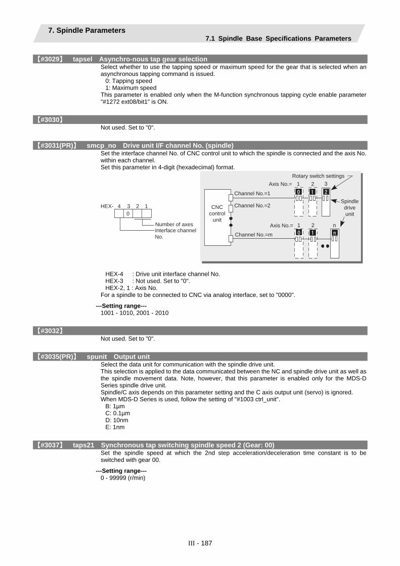
7. Spindle Parameters 7.1 Spindle Base Specifications Parameters
III - 187
【#3029】 tapsel Asynchro-nous tap gear selection Select whether to use the tapping speed or maximum speed for the gear that is selected when an asynchronous tapping command is issued.
0: Tapping speed 1: Maximum speed
This parameter is enabled only when the M-function synchronous tapping cycle enable parameter "#1272 ext08/bit1" is ON.
【#3030】 Not used. Set to "0".
【#3031(PR)】 smcp_no Drive unit I/F channel No. (spindle) Set the interface channel No. of CNC control unit to which the spindle is connected and the axis No. within each channel. Set this parameter in 4-digit (hexadecimal) format.
1 2 3
1234HEX-
0
Number of axesInterface channel
No.
Channel No.=1
Channel No.=2
Channel No.=m
Axis No.= 1 2 n
Axis No.=
Rotary switch settings
CNC
control
unit
Spindle
drive
unit
HEX-4 : Drive unit interface channel No. HEX-3 : Not used. Set to "0". HEX-2, 1 : Axis No.
For a spindle to be connected to CNC via analog interface, set to "0000".
---Setting range--- 1001 - 1010, 2001 - 2010
【#3032】 Not used. Set to "0".
【#3035(PR)】 spunit Output unit Select the data unit for communication with the spindle drive unit. This selection is applied to the data communicated between the NC and spindle drive unit as well as the spindle movement data. Note, however, that this parameter is enabled only for the MDS-D Series spindle drive unit. Spindle/C axis depends on this parameter setting and the C axis output unit (servo) is ignored. When MDS-D Series is used, follow the setting of "#1003 ctrl_unit".
B: 1µm C: 0.1µm D: 10nm E: 1nm
【#3037】 taps21 Synchronous tap switching spindle speed 2 (Gear: 00) Set the spindle speed at which the 2nd step acceleration/deceleration time constant is to be switched with gear 00.
---Setting range--- 0 - 99999 (r/min)
7. Spindle Parameters 7.1 Spindle Base Specifications Parameters
III - 188
【#3038】 taps22 Synchronous tap switching spindle speed 2 (Gear: 01) Set the spindle speed at which the 2nd step acceleration/deceleration time constant is to be switched with gear 01.
---Setting range--- 0 - 99999 (r/min)
【#3039】 taps23 Synchronous tap switching spindle speed 2 (Gear: 10) Set the spindle speed at which the 2nd step acceleration/deceleration time constant is to be switched with gear 10.
---Setting range--- 0 - 99999 (r/min)
【#3040】 taps24 Synchronous tap switching spindle speed 2 (Gear: 11) Set the spindle speed at which the 2nd step acceleration/deceleration time constant is to be switched with gear 11.
---Setting range--- 0 - 99999 (r/min)
【#3041】 tapt21 Synchronous tap switching time constant 2 (Gear: 00) Set the time constant to reach synchronous tapping switching spindle speed 2 (taps21- 24) with gear 00.
---Setting range--- 1 - 5000 (ms)
【#3042】 tapt22 Synchronous tap switching time constant 2 (Gear: 01) Set the time constant to reach synchronous tapping switching spindle rotation speed 2 (taps21 - 24) with gear 01.
---Setting range--- 1 - 5000 (ms)
【#3043】 tapt23 Synchronous tap switching time constant 2 (Gear: 10) Set the time constant to reach synchronous tapping switching spindle rotation speed 2 (taps21 - 24) with gear 10.
---Setting range--- 1 - 5000 (ms)
【#3044】 tapt24 Synchronous tap switching time constant 2 (Gear: 11) Set the time constant to reach synchronous tapping switching spindle rotation speed 2 (taps21 - 24) with gear 11.
---Setting range--- 1 - 5000 (ms)
【#3045】 tapt31 Synchronous tap switching time constant 3 (Gear: 00) Set the time constant to reach the maximum speed (smax1 - 4) with gear 00.
---Setting range--- 1 - 5000 (ms)
【#3046】 tapt32 Synchronous tap switching time constant 3 (Gear: 01) Set the time constant to reach the maximum speed (smax1 - 4) with gear 01.
---Setting range--- 1 - 5000 (ms)

7. Spindle Parameters 7.1 Spindle Base Specifications Parameters
III - 189
【#3047】 tapt33 Synchronous tap switching time constant 3 (Gear: 10) Set the time constant to reach the maximum speed (smax1 - 4) with gear 10.
---Setting range--- 1 - 5000 (ms)
【#3048】 tapt34 Synchronous tap switching time constant 3 (Gear: 11) Set the time constant to reach the maximum speed (smax1 - 4) with gear 11.
---Setting range--- 1 - 5000 (ms)
【#3049】 spt Spindle synchronization acceleration/deceleration time constant Set the acceleration/deceleration time constant for when the commanded spindle synchronization speed changes under spindle synchronization control.
---Setting range--- 0 - 9999 (ms)
【#3050】 sprlv Spindle synchronization rotation speed attainment level Set the level of difference between the commanded synchronization spindle speeds and actual speeds of both the basic and synchronous spindles during spindle synchronization, below which the spindle speed synchronization complete signal will go ON.
---Setting range--- 0 - 4095 (pulse) (1 pulse = 0.088°)
【#3051】 spplv Spindle phase synchroniza-tion attainment level Set the level of phase difference between the basic and synchronous spindles during spindle synchronization, below which the spindle phase synchronization complete signal will go ON.
---Setting range--- 0 - 4095 (pulse) (1 pulse = 0.088°)
【#3052】 spplr Spindle motor spindle relative polarity Set the spindle motor and spindle's relative polarity.
0: Positive polarity Spindle CW rotation at motor CW rotation
1: Negative polarity Spindle CCW rotation at motor CW rotation
---Setting range--- 0000/0001 (HEX)
【#3053】 sppst Spindle encoder Z -phase position Set the deviation amount from the spindle's basic point to the spindle detector's Z phase. Obtain the deviation amount, considering a clockwise direction as positive when viewed from the spindle's front side.
---Setting range--- 0 - 359999 (1/1000°)
【#3054】 sptc1 Spindle synchronization multi-step acceleration/deceleration changeover speed 1 Set the spindle speed for changing the 1st step's acceleration/deceleration time constant.
---Setting range--- 0 - 99999 (r/min)
【#3055】 sptc2 Spindle synchronization multi-step acceleration/deceleration changeover speed 2 Set the spindle speed for changing the 2nd step's acceleration/deceleration time constant.
---Setting range--- 0 - 99999 (r/min)

7. Spindle Parameters 7.1 Spindle Base Specifications Parameters
III - 190
【#3056】 sptc3 Spindle synchronization multi-step acceleration/deceleration changeover speed 3 Set the spindle speed for changing the 3rd step's acceleration/deceleration time constant.
---Setting range--- 0 - 99999 (r/min)
【#3057】 sptc4 Spindle synchronization multi-step acceleration/deceleration changeover speed 4 Set the spindle speed for changing the 4th step's acceleration/deceleration time constant.
---Setting range--- 0 - 99999 (r/min)
【#3058】 sptc5 Spindle synchronization multi-step acceleration/deceleration changeover speed 5 Set the spindle speed for changing the 5th step's acceleration/deceleration time constant.
---Setting range--- 0 - 99999 (r/min)
【#3059】 sptc6 Spindle synchronization multi-step acceleration/deceleration changeover speed 6 Set the spindle speed for changing the 6th step's acceleration/deceleration time constant.
---Setting range--- 0 - 99999 (r/min)
【#3060】 sptc7 Spindle synchronization multi-step acceleration/deceleration changeover speed 7 Set the spindle speed for changing the 7th step's acceleration/deceleration time constant.
---Setting range--- 0 - 99999 (r/min)
【#3061】 spdiv1 Magnification for time constant changeover speed 1 Set the acceleration/deceleration time constant from the spindle synchronization multi-step acceleration/deceleration changeover speed 1 (sptc1) to the spindle synchronization multi-step acceleration/deceleration changeover speed 2 (sptc2). Set this as a magnification in relation to the spindle synchronization acceleration/deceleration time constant (spt).
---Setting range--- 0 - 127
【#3062】 spdiv2 Magnification for time constant changeover speed 2 Set the acceleration/deceleration time constant from the spindle synchronization multi-step acceleration/deceleration changeover speed 2 (sptc2) to the spindle synchronization multi-step acceleration/deceleration changeover speed 3 (sptc3). Set this as a magnification in relation to the spindle synchronization acceleration/deceleration time constant (spt).
---Setting range--- 0 - 127
【#3063】 spdiv3 Magnification for time constant changeover speed 3 Set the acceleration/deceleration time constant from the spindle synchronization multi-step acceleration/deceleration changeover speed 3 (sptc3) to the spindle synchronization multi-step acceleration/deceleration changeover speed 4 (sptc4). Set this as a magnification in relation to the spindle synchronization acceleration/deceleration time constant (spt).
---Setting range--- 0 - 127
【#3064】 spdiv4 Magnification for time constant changeover speed 4 Set the acceleration/deceleration time constant from the spindle synchronization multi-step acceleration/deceleration changeover speed 4 (sptc4) to the spindle synchronization multi-step acceleration/deceleration changeover speed 5 (sptc5). Set this as a magnification in relation to the spindle synchronization acceleration/deceleration time constant (spt).
---Setting range--- 0 - 127
7. Spindle Parameters 7.1 Spindle Base Specifications Parameters
III - 191
【#3065】 spdiv5 Magnification for time constant changeover speed 5 Set the acceleration/deceleration time constant from the spindle synchronization multi-step acceleration/deceleration changeover speed 5 (sptc5) to the spindle synchronization multi-step acceleration/deceleration changeover speed 6 (sptc6). Set this as a magnification in relation to the spindle synchronization acceleration/deceleration time constant (spt).
---Setting range--- 0 - 127
【#3066】 spdiv6 Magnification for time constant changeover speed 6 Set the acceleration/deceleration time constant from the spindle synchronization multi-step acceleration/deceleration changeover speed 6 (sptc6) to the spindle synchronization multi-step acceleration/deceleration changeover speed 7 (sptc7). Set this as a magnification in relation to the spindle synchronization acceleration/deceleration time constant (spt).
---Setting range--- 0 - 127
【#3067】 spdiv7 Magnification for time constant changeover speed 7 Set the acceleration/deceleration time constant for the spindle synchronization multi-step acceleration/deceleration changeover speed 7 (sptc7) and higher. Set this as a magnification in relation to the spindle synchronization acceleration/deceleration time constant (spt).
---Setting range--- 0 - 127
【#3068】 symtm1 Phase synchronization start confirmation time Set the time to confirm that synchronization is attained before phase synchronization control is started. When "0" is set, the time will be 0.5 seconds. When "100" or less is set, the time will be 100ms.
---Setting range--- 0 - 9999 (ms)
【#3069】 symtm2 Phase synchronization end confirmation time Set a period of waiting time for phase synchronization control's completion as a time in which the speed stays within the attainment range. When "0" is set, the time will be 0.5 seconds. When "100" or less is set, the time will be 100ms.
---Setting range--- 0 - 9999 (ms)
【#3070】 syprt Phase synchronization speed Set the amount of speed fluctuation of synchronous spindle during phase synchronization control. Set this as a proportion to commanded speed. When "0" is set, the amount will be 100%.
---Setting range--- 0 - 100 (%)
【#3071(PR)】 SscDrSelSp Speed monitor Door selection Select which door group of the speed monitoring a spindle belongs to. 0000: Belong to the door 1 group. 0001: Belong to the door 1 group. 0002: Belong to the door 2 group. 0003: Belong to the door 1 and 2 groups. (Note) Speed monitoring is not executed when SP229:SFNC9/bitF is "OFF".
---Setting range--- 0000 - 0003 (HEX)

7. Spindle Parameters 7.1 Spindle Base Specifications Parameters
III - 192
【#3072(PR)】 Ssc Svof Filter Sp Speed monitor Error detection time during servo OFF Set the error detection time for when an error of command speed monitoring or feedback speed monitoring is detected during servo OFF. The alarm will occur if actual speed exceeds safe speed or safe rotation speed for a period of time longer than this setting. When "0" is set, the detection time will be 200 (ms).
---Setting range--- 0 - 9999 (ms)
【#3101】 sp_t 1 Time constant for spindle rotation with S command (Gear: 00) Set the acceleration/deceleration time constant for spindle rotation using the S command (spindle control mode = speed operation mode) with gear 00 (Linear acceleration/deceleration pattern).
---Setting range--- 0 - 30000 (ms)
【#3102】 sp_t 2 Time constant for spindle rotation with S command (Gear: 01) Set the acceleration/deceleration time constant for spindle rotation using the S command (spindle control mode = speed operation mode) with gear 01 (Linear acceleration/deceleration pattern).
---Setting range--- 0 - 30000 (ms)
【#3103】 sp_t 3 Time constant for spindle rotation with S command (Gear: 10) Set the acceleration/deceleration time constant for spindle rotation using the S command (spindle control mode = speed operation mode) with gear 10 (Linear acceleration/deceleration pattern).
---Setting range--- 0 - 30000 (ms)
【#3104】 sp_t 4 Time constant for spindle rotation with S command (Gear: 11) Set the acceleration/deceleration time constant for spindle rotation using the S command (spindle control mode = speed operation mode) with gear11 (Linear acceleration/deceleration pattern).
---Setting range--- 0 - 30000 (ms)
【#3105】 sut Speed reach range Set the speed deviation rate with respect to the commanded speed, at which the speed reach signal will be output.
---Setting range--- 0 - 100 (%)
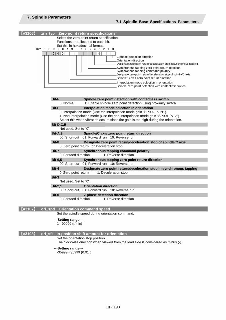
7. Spindle Parameters 7.1 Spindle Base Specifications Parameters
III - 193
【#3106】 zrn_typ Zero point return specifications Select the zero point return specification. Functions are allocated to each bit. Set this in hexadecimal format.
Bit-F Spindle zero point detection with contactless switch 0: Normal 1: Enable spindle zero point detection using proximity switch
Bit-E Interpolation mode selection in orientation 0: Interpolation mode (Use the interpolation mode gain "SP002 PGN".) 1: Non-interpolation mode (Use the non-interpolation mode gain "SP001 PGV") Select this when vibration occurs since the gain is too high during the orientation.
Bit-D,C,B Not used. Set to "0".
Bit-A,9 Spindle/C axis zero point return direction 00: Short-cut 01: Forward run 10: Reverse run
Bit-8 Designate zero point return/deceleration stop of spindle/C axis 0: Zero point return 1: Deceleration stop
Bit-7 Synchronous tapping command polarity 0: Forward direction 1: Reverse direction
Bit-6,5 Synchronous tapping zero point return direction 00: Short-cut 01: Forward run 10: Reverse run
Bit-4 Designate zero point return/deceleration stop in synchronous tapping 0: Zero point return 1: Deceleration stop
Bit-3 Not used. Set to "0".
Bit-2,1 Orientation direction 00: Short-cut 01: Forward run 10: Reverse run
Bit-0 Z phase detection direction 0: Forward direction 1: Reverse direction
【#3107】 ori_spd Orientation command speed Set the spindle speed during orientation command.
---Setting range--- 1 - 99999 (r/min)
【#3108】 ori_sft In-position shift amount for orientation Set the orientation stop position. The clockwise direction when viewed from the load side is considered as minus (-).
---Setting range--- -35999 - 35999 (0.01°)
Interpolation mode selection in orientation
Z phase detection directionOrientation directionDesignate zero point return/deceleration stop in synchronous tappingSynchronous tapping zero point return direction Synchronous tapping command polarity Designate zero point return/deceleration stop of spindle/C axisSpindle/C axis zero point return direction
Spindle zero point detection with contactless switch

7. Spindle Parameters 7.1 Spindle Base Specifications Parameters
III - 194
【#3109】 zdetspd Z phase detection speed When "#3106/bitF = 0" (Normal), set the spindle speed at initial Z phase detection. When "#3106/bitF = 1" (Spindle zero point proximity switch detection enabled), set the spindle speed at initial spindle zero point proximity switch detection. (Note) When spindle zero point proximity switch detection is enabled, the rotation direction of the orientation/zero point return (synchronous tapping, spindle/C axis) will follow Z phase detection direction. And the speed will follow Z phase detection speed.
---Setting range--- 1 - 99999 (r/min)
【#3110】 tap_spd Synchronous tapping zero point return speed Set the synchronous tapping zero point return speed.
---Setting range--- 1 - 99999 (r/min)
【#3111】 tap_sft Synchronous tapping zero point return shift amount Set the synchronous tapping zero point return shift amount.
---Setting range--- 0.00 - 35999 (0.01°)
【#3112】 cax_spd Spindle C axis zero point return speed Set the spindle C axis zero point return speed.
---Setting range--- 1 - 99999 (r/min)
【#3113】 cax_sft Spindle C axis zero point return shift amount Set the spindle C axis zero point return shift amount
---Setting range--- 0.00 - 359999 (0.001°)
【#3114】 cax_para_chg Spindle/C axis parameter switch Select whether to switch detector's parameters between spindle control and C axis control during spindle/C axis control. 0: Not switch 1: Switch
---Setting range--- 0/1 (Standard: 0)
【#3115】 sp2_t1 Time constant in orientation/position loop reference position return (Gear: 00) Set the acceleration/deceleration time constant to reach the spindle's limit speed (slimt) when spindle rotates in orientation/position loop zero point return method (C axis, tapping) using gear 00 (Linear acceleration/deceleration pattern). (Note) Set a value that is bigger than the values set by "#3101 sp_t1 - #3104 sp_t4".
---Setting range--- 0 - 30000 (ms)
【#3116】 sp2_t2 Time constant in orientation/position loop reference position return (Gear: 01) Set the acceleration/deceleration time constant to reach the spindle's limit speed (slimt), when spindle rotates in the orientation/position loop zero point return method (C axis, tapping) using gear 01 (Linear acceleration/deceleration pattern). (Note) Set a value that is bigger than the values set by "#3101 sp_t1 - #3104 sp_t4".
---Setting range--- 0 - 30000 (ms)
7. Spindle Parameters 7.1 Spindle Base Specifications Parameters
III - 195
【#3117】 sp2_t3 Time constant in orientation/position loop reference position return (Gear: 10) Set the acceleration/deceleration time constant to reach the spindle's limit speed (slimt), when spindle rotates in the orientation/position loop zero point return method (C axis, tapping) using gear 10 (Linear acceleration/deceleration pattern). (Note) Set a value that is bigger than the values set by "#3101 sp_t1 - #3104 sp_t4".
---Setting range--- 0 - 30000 (ms)
【#3118】 sp2_t4 Time constant in orientation/position loop reference position return (Gear: 11) Set the acceleration/deceleration time constant to reach the spindle's limit speed (slimt), when spindle rotates in the orientation/position loop zero point return method (C axis, tapping) using gear 11 (Linear acceleration/deceleration pattern). (Note) Set a value that is bigger than the values set by "#3101 sp_t1 - #3104 sp_t4".
---Setting range--- 0 - 30000 (ms)
【#3120】 staptr Time constant reduction rate in high-speed synchronous tapping When performing high-speed synchronous tapping, set the reduction rate ofthe time constant compared to the time constant in normal synchronous tapping. (Setting "0"or "100" will be regarded as reduction rate zero, so the time constant won't be reduced.) E.g.) When set to "10", time constant in high-speed synchronous tapping will be 90% of that in normal synchronous tapping.
---Setting range--- 0 to 100(%)
【#3121】 tret Turret indexing Select the validity of turret indexing.
---Setting range--- 0: Invalid 1: Valid
【#3122】 GRC Turret side gear ratio Set the number of teeth on the turret side when the gear selection command (control input 4/bit6, 5) is set to 00. Set a value of GRC so that the ratio of GRC to the spindle side gear ratio (#13057 SP057) will be 1:N (an integer). If this parameter is set to "0", it will be regarded as "1".
---Setting range--- 0 - 32767
【#3123】 tret_spd Turret indexing speed Set the turret end indexing speed when in turret indexing. When this parameter is set to 0, the value of Orientation command speed (#3107 ori_spd) will be used for the turret indexing speed.
---Setting range--- 0 - 32767(r/min)
【#3124】 tret_t Turret indexing time constant Set the acceleration/deceleration time constant to reach Limit rotation speed (#3001 slimt) at gear 00 when in turret indexing (linear acceleration/deceleration pattern). Set this parameter to a larger value than #3115 sp2_t1 at gear 00.
---Setting range--- 0 - 30000 (ms)
【#3125】 tret_inpos Turret indexing in-position width Set the position error range in which the index positioning complete signal is output when in turret indexing. When this parameter is set to 0, the value of In-position width (#13024 SP024) will be used for this width.
---Setting range--- 0 - 32767(1°/1000)

7. Spindle Parameters 7.1 Spindle Base Specifications Parameters
III - 196
【#3126】 tret_fin_off Index positioning complete signal OFF time Set the time to forcedly turn OFF the index positioning complete signal since the indexing start signal turns ON. If this period of time has not passed yet, the index positioning complete signal will not turn ON even at the completion of index positioning.
---Setting range--- 0 - 10000 (ms)
【#3127】 SPECSP Spindle specification bit0: Select the gear chanveover method. (0: Gear change type 1, 1: Gear change type 2)
---Setting range--- 0x0000 to 0xffff(hexadecimal)
【#3128】 ori_spec Orientation specification bit0: Orientation imposition advance output (0: Invalid, 1: Valid)
---Setting range--- 0x0000 to 0xffff(hexadecimal)
【#3129】 cax_spec Spindle/C axis specification Not used. Set to "0".
【#3130】 syn_spec Spindle synchronization specification bit0: Tool spindle synchronization II (hobbing) automatic compensation selection 1: Compensate hobbing axis delay (advance) with workpiece axis. 0: No compensation.
---Setting range--- 0/1
【#3131】 tap_spec Synchronous tapping specification Not used. Set to "0".
【#3132】 ori_inp2 2nd in-position width for orientation Use this when detecting a different in-position from the normal in-position detection, such as advancing the inposition signal. When using, set a bigger value than the valud of the spindle parameter SP024.
---Setting range--- 0 to 32767 (1deg/1000)
【#3133】 spherr Hobbing axis delay (advance) allowable angle Set the allowable angle between the commanded position and actual position of hobbing axis when it is in tool spindle synchronization II (hobbing) mode (X18AE ON), and also when hobbing axis and workpiece axis are synchronizing (X18A9 ON).
---Setting range--- 0 to 32767 (1deg/1000)
【#3134】 sphtc Primary delay time constant for hobbing axis automatic compensation Set the primary delay time constant of hobbing axis automatic compensation primary delay filter control in tool spindle synchronization II (hobbing). When set to 0, primary delay filter control is invalid.
---Setting range--- 0 to 32767 (ms)

7. Spindle Parameters 7.1 Spindle Base Specifications Parameters
III - 197
【#3135】 sfwd_g Feed forward gain for hobbing axis Set the feed forward gain for the hobbing axis in tool spindle synchronization II (hobbing) mode.
---Setting range--- 0 to 200 (%)
【#3137】 stap_ax_off High-speed synchronous tapping disabled axis Set the high-speed synchronous tapping disabled axis. bit0 to bit16: High-speed synchronous tapping disabled axis 0: Enabled 1: Disabled If communication between drive units is disabled for a certain axis, set the axis's bits of all the spindles as disabled. If communication between drive units is disabled for a certain spindle, set all the bits of the spindle as disabled (0xFFFF). (Note) Each bit (bit0 -) corresponds to the order of the axis name parameter (#1013 axname) setting.
7. Spindle Parameters 7.2 Spindle Parameters
III - 198
7.2 Spindle Parameters Parameters indicated as (PR) in the table will be validated when the NC power is turned OFF and ON after setting. The spindle parameter setting and display methods differ according to the NC being used. Refer to the instruction manuals for the NC and each spindle.
Mitsubishi CNC Control Unit MDS-D Series Specifications Manual ················ IB-1500011 Mitsubishi CNC Control Unit MDS-DH Series Specifications Manual·············· IB-1500003
! CAUTION
! In the explanation on bits, set all bits not used, including blank bits, to "0".
【#13001】 SP001 PGV Position loop gain Non-interpolation mode Set the position loop gain for "Non-interpolation" control mode. The standard setting is "33". When the setting value increases, the tracking ability to commands will be higher and the settling time during positioning can be shorter. However, the impact applied on the machine during acceleration/deceleration will increase. The position loop gain will be selected according to the control mode selection command set with control input 4/bit 2, 1, 0. Control input 4 bit2, 1, 0 = 000: Non-interpolation bit 2, 1, 0 = 001: Spindle synchronization bit 2, 1, 0 = 010: Interpolation bit 2, 1, 0 = 100: Interpolation (Note) Control mode is commanded from NC. When carrying out SHG control, set SP035 (SFNC3)/bitC (shgn) or SP036 (SFNC4)/bit4 (shgs) to "1".
---Setting range--- 1 - 200 (1/s)
【#13002】 SP002 PGN Position loop gain interpolation mode Set the position loop gain for "Interpolation" control mode. The standard setting is "33". When the setting value increases, the tracking ability to commands will be higher and the settling time during positioning can be shorter. However, the impact applied on the machine during acceleration/deceleration will increase. The position loop gain will be selected according to the control mode selection command set with control input 4/bit 2, 1, 0. Control input 4 bit2, 1, 0 = 000: Non-interpolation bit 2, 1, 0 = 001: Spindle synchronization bit 2, 1, 0 = 010: Interpolation bit 2, 1, 0 = 100: Interpolation (Note) Control mode is commanded from NC. When carrying out SHG control, set SP035 (SFNC3)/bitC (shgn) or SP036 (SFNC4)/bit4 (shgs) to "1".
---Setting range--- 1 - 200 (1/s)

7. Spindle Parameters 7.2 Spindle Parameters
III - 199
【#13003】 SP003 PGS Position loop gain spindle synchronization Set the position loop gain for "Spindle synchronization" control mode. The standard setting is "33". When the setting value increases, the tracking ability to commands will be higher and the settling time during positioning can be shorter. However, the impact applied on the machine during acceleration/deceleration will increase. The position loop gain can be selected according to the control mode selection command set with control input 4/bit 2, 1, 0. Control input 4 bit2, 1, 0 = 000: Non-interpolation bit 2, 1, 0 = 001: Spindle synchronization bit 2, 1, 0 = 010: Interpolation bit 2, 1, 0 = 100: Interpolation (Note) Control mode is commanded from NC. When carrying out SHG control, set SP035 (SFNC3)/bitC (shgn) or SP036 (SFNC4)/bit4 (shgs) to "1".
---Setting range--- 1 - 200 (1/s)
【#13004】 SP004 Not used. Set to "0".
【#13005】 SP005 VGN1 Speed loop gain 1 Set the speed loop gain. Set this according to the load inertia size. The higher the setting value is, the more accurate the control will be. However, vibration tends to occur. If vibration occurs, adjust by lowering by 20 - 30%. The value should be determined to be 70 to 80% of the value at which the vibration stops.
---Setting range--- 1 - 9999
【#13006】 SP006 VIA1 Speed loop lead compensation 1 Set the speed loop integral control gain. The standard setting is "1900". Adjust the value by increasing/decreasing by about 100 at a time. Raise this value to improve contour tracking accuracy in high-speed cutting. Lower this value when the position droop does not stabilize (10 - 20Hz).
---Setting range--- 1 - 9999
【#13007】 SP007 VIL1 Speed loop delay compensation 1 Set this parameter when the limit cycle occurs in the full-closed loop, or overshooting occurs in positioning. Select the control method with SP033 (SFNC1)/bit1, 0 (vcnt). Normally, use "Changeover type 2". When setting this parameter, make sure to set the torque offset "SP050 (TOF)". When not using, set to "0".
---Setting range--- 0 - 32767
【#13008】 SP008 VGN2 Speed loop gain 2 Normally, SP005 (VGN1), SP006 (VIA1) and SP007 (VIL1) are used. By setting SP035 (SFNC3)/bit1 (vgin), SP035 (SFNC3)/bit9 (vgn) or SP036 (SFNC4)/bit1 (vgs) to "1", Gain 2 can be used according to the application. Gain 2 can also be used by setting "Speed gain set 2 changeover request (control input 5/bitC)" to "1". Refer to SP005 (VGN1), SP006 (VIA1) and SP007 (VIL1) for the procedures.
---Setting range--- 1 - 9999
7. Spindle Parameters 7.2 Spindle Parameters
III - 200
【#13009】 SP009 VIA2 Speed loop lead compensation 2 Normally, SP005 (VGN1), SP006 (VIA1) and SP007 (VIL1) are used. By setting SP035 (SFNC3)/bit1 (vgin), SP035 (SFNC3)/bit9 (vgn) or SP036 (SFNC4)/bit1 (vgs) to "1", Gain 2 can be used according to the application. Gain 2 can also be used by setting "Speed gain set 2 changeover request (control input 5/bitC)" to "1". Refer to SP005 (VGN1), SP006 (VIA1) and SP007 (VIL1) for the procedures.
---Setting range--- 1 - 9999
【#13010】 SP010 VIL2 Speed loop delay compensation 2 Normally, SP005 (VGN1), SP006 (VIA1) and SP007 (VIL1) are used. By setting SP035 (SFNC3)/bit1 (vgin), SP035 (SFNC3)/bit9 (vgn) or SP036 (SFNC4)/bit1 (vgs) to "1", Gain 2 can be used according to the application. Gain 2 can also be used by setting "Speed gain set 2 changeover request (control input 5/bitC)" to "1". Refer to SP005 (VGN1), SP006 (VIA1) and SP007 (VIL1) for the procedures.
---Setting range--- 0 - 32767
【#13011-13013】 SP011 - SP013 Not used. Set to "0".
【#13014】 SP014 PY1 Minimum excitation rate 1 Set the minimum value for the variable excitation rate. The standard setting is "50". Set to "0" when using an IPM spindle motor. If the gear noise, etc., is large, select a small value. However, a larger setting value is more effective for impact response. (Note) When setting a value "50 or more", check if there is no gear noise, motor excitation noise, vibration during low-speed rotation or vibration when the servo is locked during orientation stop, etc.When setting a value "less than 50", check if there is no problem with the impact load response or rigidity during servo lock.
---Setting range--- 0 - 100 (%)
【#13015】 SP015 PY2 Minimum excitation rate 2 Normally, SP014 (PY1) is used. Excitation rate 2 can be used according to the application by setting SP035 (SFNC3)/bit2 (pyin), SP035 (SFNC3)/bitA (pyn) or SP036 (SFNC4)/bit2 (psy) to "1". Excitation rate 2 can also be used by setting "Minimum excitation rate 2 changeover request (control input 5/bitB)" to "1". Refer to SP014 (PY1) for the procedures. Set to "0" when using an IPM spindle motor.
---Setting range--- 0 - 100 (%)
【#13016】 SP016 DDT Phase alignment deceleration rate Set the single-rotation position alignment deceleration rate for orientation stopping, phase alignment during rotation and changing from non-interpolation to spindle synchronization mode during rotation. If the load inertia is large, decrease the setting. When the setting value increases, the orientation in-position and single-rotation position alignment will end earlier, but the impact applied on the machine will increase. To change the deceleration rate only during rotation command (command FΔT≠0), set this parameter together with SP070 (KDDT).
---Setting range--- 1 - 32767 (0.1 (r/mn)/ms)

7. Spindle Parameters 7.2 Spindle Parameters
III - 201
【#13017(PR)】 SP017 SPEC1 Spindle specifications 1 Select the spindle specifications. Functions are allocated to each bit. Set this in hexadecimal format.
Bit-F,E,D,C spm Motor series selection 0000(0xxxh): 200V specification IM spindle motor 0001(1xxxh): 200V specification IPM spindle motor 0010(2xxxh): 400V specification IM spindle motor 0011(3xxxh): 400V specification IPM spindle motor
Bit-5 - B Not used. Set to "0".
Bit-4 fdir Position feedback 0: Forward polarity 1: Reverse polarity
Bit-3 vfb Speed feedback filter 0: Disable 1: Enable (2250Hz)
Bit-2 seqh High-speed READY ON sequence 0: Disable 1: Enable
Bit-1 Not used. Set to "0".
Bit-0 fdir2 Speed feedback polarity 0: Forward polarity 1: Reverse polarity
【#13018(PR)】 SP018 SPEC2 Spindle specifications 2 Select the spindle specifications. Functions are allocated to each bit. Set this in hexadecimal format.
Bit-F - 9 Not used. Set to "0".
Bit-8 spsu Speed setting unit 0: rev/min 1: x4r/min
Bit-7,6 Not used. Set to "0".
Bit-5 mkch Coil switch function 0: Disable 1: Enable
Bit-4,3,2 Not used. Set to "0".
Bit-1 oplp Open loop 0: Disable 1: Enable
Bit-0 Not used. Set to "0".
【#13019(PR)】 SP019 RNG1 Position detector resolution Set the same value as SP020 (RNG2). (Refer to the explanation for SP020.)
---Setting range--- 0 - 32767 (kp/rev)

7. Spindle Parameters 7.2 Spindle Parameters
III - 202
【#13020(PR)】 SP020 RNG2 Speed detector resolution Set the number of pulses per revolution of the motor side detector. Detector TS5691 (128 teeth): SP020 = 2000 TS5691 (180 teeth): SP020 = 2880 TS5691 (256 teeth): SP020 = 4000 TS5691 (384 teeth): SP020 = 6000 TS5691 (512 teeth): SP020 = 8000 TS5690 (64 teeth): SP020 = 2000 TS5690 (128 teeth): SP020 = 4000 TS5690 (256 teeth): SP020 = 8000
【#13021(PR)】 SP021 OLT Overload detection time constant Set the detection time constant of the overload 1 (Alarm 50). Set to "60" as a standard. Set "300" when using an IPM spindle motor.
---Setting range--- 1 - 15300 (s)
【#13022】 SP022 OLL Overload detection level Set the current detection level of "Overload 1" (Alarm 50) as a percentage in respect to the motor short-time rated output current. Set to "120" as a standard. Set to "100" when using an IPM spindle motor.
---Setting range--- 1 - 200 (Short-time rated %)
【#13023】 SP023 OD1 Excessive error detection width (interpolation mode, spindle synchronization) Set the excessive error detection width for the interpolation mode and spindle synchronization. Set to "120" as a standard. If this parameter is set to "0", excessive error detection won't be performed.
---Setting range--- 0 - 32767 (°)
【#13024】 SP024 INP In-position width Set the in-position detection width. Set the positioning accuracy required for the machine. The lower the setting is, the higher the positioning accuracy will be. However, the cycle time (settling time) will be longer. The standard setting is "875".
---Setting range--- 0 - 32767 (1°/1000)
【#13025】 SP025 INP2 2nd in-position width Use this when detecting an in-position different from normal in-position width, such as advancing the in-position signal. The procedure is the same as SP024 (INP). The standard setting is "875".
---Setting range--- 0 - 32767 (°/1000)
【#13026(PR)】 SP026 TSP Maximum motor speed Set the maximum motor speed. If the actual motor speed exceeds the set maximum speed, an overspeed alarm will occur.
---Setting range--- 1 - 32767 (r/min)

7. Spindle Parameters 7.2 Spindle Parameters
III - 203
【#13027】 SP027 ZSP Motor zero speed Set the motor speed for detecting zero speed. If the actual motor speed drops below the set speed, the zero speed detection will go ON. The standard setting is "50".
---Setting range--- 1 - 1000 (r/min)
【#13028】 SP028 SDTS Speed detection set value Set the motor speed for detecting the speed. If the actual motor speed drops below the set value, the speed detection will go ON. The standard setting is 10% of the maximum motor speed.
---Setting range--- 10 - 32767 (r/min)
【#13029】 SP029 SDTR Speed detection reset width Set the hysteresis width in which the speed detection changes from ON to OFF. If the setting value is small, the speed detection will chatter easily. The standard setting is "30".
---Setting range--- 10 - 1000 (r/min)
【#13030】 SP030 Not used. Set to "0".
【#13031(PR)】 SP031 MTYP Motor type Set the position detector type, speed detector type and motor type. Set to "2200" (fixed value).

7. Spindle Parameters 7.2 Spindle Parameters
III - 204
【#13032(PR)】 SP032 PTYP Power supply type/ Regenerative resistor type Power supply type When connecting a power supply unit, set a code for each power supply unit.
Bit-0 - 7 ptyp External emergency stop setting When the emergency stop input signal of the power supply unit is "disabled" Power supply unit is not connected : 0000h MDS-D-CV-37 / MDS-DH-CV-37 : 0004h MDS-D-CV-75 / MDS-DH-CV-75 : 0008h MDS-D-CV-110 / MDS-DH-CV-110 : 0011h MDS-D-CV-185 / MDS-DH-CV-185 : 0019h MDS-D-CV-300 / MDS-DH-CV-300 : 0030h MDS-D-CV-370 / MDS-DH-CV-370 : 0037h MDS-D-CV-450 / MDS-DH-CV-450 : 0045h MDS-D-CV-550 : 0055h MDS-DH-CV-750 : 0075h When the emergency stop input signal of the power supply unit is "enabled" Power supply unit is not connected : 0000h MDS-D-CV-37 / MDS-DH-CV-37 : 0044h MDS-D-CV-75 / MDS-DH-CV-75 : 0048h MDS-D-CV-110 / MDS-DH-CV-110 : 0051h MDS-D-CV-185 / MDS-DH-CV-185 : 0059h MDS-D-CV-300 / MDS-DH-CV-300 : 0070h MDS-D-CV-370 / MDS-DH-CV-370 : 0077h MDS-D-CV-450 / MDS-DH-CV-450 : 0085h MDS-D-CV-550 : 0095h MDS-DH-CV-750 : 00B5h
Bit-8 - B rtyp Not used. Set to "0".
Bit-C - F amp Not used. Set to "0".
Regenerative resistor type Set the regenerative resistor type. (Note) These bits are used only in MDS-D-SVJ3/SPJ3 series.
Bit-0 - 3 Not used. Set to "0".
Bit-4 - 7 emgx External emergency stop function Set the external emergency stop function. (Do not set a value other than specified.) 0: Disable 4: Enable
Bit-8 - B rtyp
Bit-C - F amp For "amp = 1" "rtyp" setting value
0: Resistor built-in drive unit 1: Setting prohibited 2: MR-RB032 3: MR-RB12 or GZG200W39OHMK 4: MR-RB32 or GZG200W120OHMK 3 units connected in parallel 5: MR-RB30 or GZG200W39OHMK 3 units connected in parallel 6: MR-RB50 or GZG300W39OHMK 3 units connected in parallel

7. Spindle Parameters 7.2 Spindle Parameters
III - 205
7: MR-RB31 or GZG200W20OHMK 3 units connected in parallel 8: MR-RB51 or GZG300W20OHMK 3 units connected in parallel 9 - F: Setting prohibited
For "amp = 2" "rtyp" setting value
0 - 3: Setting prohibited 4: FCUA-RB22 5: FCUA-RB37 6: FCUA-RB55 7, 8: Setting prohibited 9: R-UNIT2 A - C: Setting prohibited D: FCUA-RB75/2 2 units E, F: Setting prohibited
【#13033】 SP033 SFNC1 Spindle function 1 Select the spindle functions. Functions are allocated to each bit. Set this in hexadecimal format.
Bit-F - C Not used. Set to "0".
Bit-B,A ovs Overshoot compensation 00: Compensation stop 01: Setting prohibited 10: Setting prohibited 11: Compensation type 3
(Note) Set the compensation amount in SP043(OVS1) and SP042(OVS2).
Bit-9,8 lmc Lost motion compensation 00: Compensation stop 01: Setting prohibited 10: Compensation type 2 11: Setting prohibited
(Note) Set the compensation amount in SP048(LMC1) and SP041(LMC2). When "SP227/lmc3" is set to "1", the lost motion compensation type 3 will be selected regardless of this setting.
Bit-7 lmc2a Lost motion compensation 2 timing 0: Normal timing 1: Timing changed
Bit-6 Not used. Set to "0".
Bit-5,4 vfct Jitter compensation 00: Disable 01: 1 pulse 10: 2 pulse 11: 3 pulse
Bit-3,2 Not used. Set to "0".
Bit-1,0 vcnt Delay compensation changeover 00: Disable 01: Changeover type 1 10: Changeover type 2 11: Changeover type 2

7. Spindle Parameters 7.2 Spindle Parameters
III - 206
【#13034】 SP034 SFNC2 Spindle function 2 Select the spindle functions. Functions are allocated to each bit. Set this in hexadecimal format.
Bit-F,E,D nfd5 Depth of Notch filter 5 Set the filter depth of Notch filter 5.
Bit F,E,D=000: -∞ Bit F,E,D=001: -18[dB] Bit F,E,D=010: -12[dB] Bit F,E,D=011: -9[dB] Bit F,E,D=100: -6[dB] Bit F,E,D=101: -4[dB] Bit F,E,D=110: -3[dB] Bit F,E,D=111: -1 [dB]
Bit-C Not used. Set to "0".
Bit-B,A,9 nfd4 Depth of Notch filter 4 Set the filter depth of Notch filter 4.
Bit B,A,9=000: -∞ Bit B,A,9=001: -18[dB] Bit B,A,9=010: -12[dB] Bit B,A,9=011: -9[dB] Bit B,A,9=100: -6[dB] Bit B,A,9=101: -4[dB] Bit B,A,9=110: -3[dB] Bit B,A,9=111: -1 [dB]
Bit-8 pwm Current control 0: Standard current control 1: High frequency current control
Bit-7,6,5 nfd2 Depth of Notch filter 2 Set the filter depth of Notch filter 2.
Bit 7,6,5=000: -∞ Bit 7,6,5=001: -18[dB] Bit 7,6,5=010: -12[dB] Bit 7,6,5=011: -9[dB] Bit 7,6,5=100: -6[dB] Bit 7,6,5=101: -4[dB] Bit 7,6,5=110: -3[dB] Bit 7,6,5=111: -1 [dB]
Bit-4 nfd3 Notch filter 3(1125Hz) 0: Stop 1: Start
Bit-3,2,1 nfd1 Depth of Notch filter 1 Set the filter depth of Notch filter 1.
Bit 3,2,1=000: -∞ Bit 3,2,1=001: -18[dB] Bit 3,2,1=010: -12[dB] Bit 3,2,1=011: -9[dB] Bit 3,2,1=100: -6[dB] Bit 3,2,1=101: -4[dB] Bit 3,2,1=110: -3[dB] Bit 3,2,1=111: -1 [dB]
Bit-0 zck Z phase check (ALM42) 0: Enable 1: Disable

7. Spindle Parameters 7.2 Spindle Parameters
III - 207
【#13035(PR)】 SP035 SFNC3 Spindle function 3 Select the spindle functions. Functions are allocated to each bit. Set this in hexadecimal format.
0 0 0 0 0 0 0 0 0 0
Bit- F E D C B A 9 8 7 6 5 4 3 2 1 0
vginpyinnopcvgnpynshgn
bit-F - D Not used. Set to "0".
bit-C shgn SHG control 0: Stop 1: Start
bit-B Not used. Set to "0".
bit-A pyn Excitation rate selection 0: Select Excitation rate 1 1: Select Excitation rate 2
bit-9 vgn Speed loop gain set selection 0: Select Set 1 1: Select Set 2
bit-8 Not used. Set to "0".
bit-7 nopc Phase alignment 0: Start 1: Stop
bit-6 - 3 Not used. Set to "0".
bit-2 pyin Excitation rate selection 0: Select Excitation rate 1 1: Select Excitation rate 2
bit-1 vgin Speed loop gain set selection 0: Select Set 1 1: Select Set 2
bit-0 Not used. Set to "0".
【#13036(PR)】 SP036 SFNC4 Spindle function 4 Select the spindle functions. Functions are allocated to each bit. Set this in hexadecimal format.
bit-F - 8 Not used. Set to "0".
bit-7 mksl Spindle coil selection 0: Select the coil commanded during synchronization 1: Select high-speed coil
bit-6,5 Not used. Set to "0".
bit-4 shgs SHG control 0: Stop 1: Start
bit-3 Not used. Set to "0".
bit-2 pys Excitation rate selection 0: Select Excitation rate 1 1: Select Excitation rate 2
bit-1 vgs Speed loop gain set selection 0: Select Gain set 1 1: Select Gain set 2
bit-0 Not used. Set to "0".

7. Spindle Parameters 7.2 Spindle Parameters
III - 208
【#13037】 SP037 JL Load inertia scale Set "the motor inertia + motor axis conversion load inertia" in respect to the motor inertia.
SP037(JL) = ( Jm+Jl / Jm ) × 100 Jm : Motor inertia Jl : Motor axis conversion load inertia
---Setting range--- 0 - 5000 (%)
【#13038】 SP038 FHz1 Notch filter frequency 1 Set the vibration frequency to suppress when machine vibration occurs. (Enabled at 50 or more) When not using, set to "0".
---Setting range--- 0 - 2250 (Hz)
【#13039】 SP039 LMCD Lost motion compensation timing Set this parameter when the lost motion compensation timing doest not match. Adjust by increasing the value by 10 at a time.
---Setting range--- 0 - 2000 (ms)
【#13040】 SP040 LMCT Lost motion compensation non-sensitive band Set the non-sensitive band of the lost motion compensation in the feed forward control. When "0" is set, the actual value to be set is 2°/1000. Adjust by increasing by 1°/1000 at a time.
---Setting range--- –32768 - 32767 (1°/1000)
【#13041】 SP041 LMC2 Lost motion compensation 2 Set this parameter as well as SP048 (LMC1) only when you wish to vary the lost motion compensation amount depending on the command directions. Normally set to "0".
---Setting range--- -1 - 200 (Short-time rated %) Note that the range will be" -1 - 20000" (Short-time rated 0.01%) when SP227/bit2 is "1".
【#13042】 SP042 OVS2 Overshooting compensation 2 Set this parameter as well as SP043 (OVS1) only when you wish to vary the overshooting compensation amount depending on the command directions. Normally set to "0".
---Setting range--- -1 - 100 (Short-time rated %) Note that the range will be "-1 - 10000" (Short-time rated 0.01%) when SP227/bit2 is "1".

7. Spindle Parameters 7.2 Spindle Parameters
III - 209
【#13043】 SP043 OVS1 Overshooting compensation 1 Set this parameter when overshooting occurs during positioning. This compensates the motor torque during positioning. This is enabled only when the overshooting compensation SP033 (SFNC1/ovs) is selected. Type 3: When "SP033 (SFNC1)/bitB, A (ovs) = 11" Set the compensation amount based on the motor short-time rated current. Increase in increments of 1%, and find the value where overshooting does not occur. Other than Type 3: When "SP033 (SFNC1)/bitB, A (ovs) ≠ 11" Overshooting compensation (Type 3) is not executed. When you wish to vary compensation amount depending on the direction When SP042 (OVS2) is "0", compensate with the value of SP043 (OVS1) in both of the + and - directions. If you wish to change the compensation amount depending on the command direction, set this parameter as well as SP042 (OVS2). (SP043: + direction, SV042: - direction. However, the directions may be opposite depending on other settings.) When "-1" is set, the compensation won’t be performed in the direction of the command.
---Setting range--- -1 - 100 (Short-time rated %) Note that the range will be "-1 - 10000" (Short-time rated 0.01%) when SP227/bit2 is "1".
【#13044】 SP044 OBS2 Disturbance observer gain Set the disturbance observer gain. The standard setting is "100". To use the disturbance observer, also set SP037 (JL) and SP045 (OBS1). When not using, set to "0".
---Setting range--- 0 - 500 (%)
【#13045】 SP045 OBS1 Disturbance observer filter frequency Set the disturbance observer filter band. Normally set to "100". To use the disturbance observer, also set SP037 (JL) and SP044 (OBS2). When not using, set to "0".
---Setting range--- 0 - 1000 (rad/s)
【#13046】 SP046 FHz2 Notch filter frequency 2 Set the vibration frequency to suppress when machine vibration occurs. (Enabled at 50 or more) When not using, set to "0".
---Setting range--- 0 - 2250 (Hz)
【#13047】 SP047 EC Inductive voltage compensation gain Set the inductive voltage compensation gain. Normally set to "100". If the current FB peak exceeds the current command peak, lower the gain.
---Setting range--- 0 - 200 (%)
7. Spindle Parameters 7.2 Spindle Parameters
III - 210
【#13048】 SP048 LMC1 Lost motion compensation 1 Set this parameter when the protrusion (that occurs due to the non-sensitive band by friction, torsion, backlash, etc) at quadrant change is too large. This compensates the torque at quadrant change. This is enabled only when the lost motion compensation SP033 (SFNC1/lmc) is selected. Type 2: When "SP033 (SFNC1)/bit9, 8 (lmc) = 10" Set the compensation amount based on the motor short-time rated current. The standard setting is double the friction torque. The compensation amount will be 0 when "0" is set. Other than type 2: When "SP033 (SFNC1)/bit9, 8 (lmc) ≠ 10" Lost motion compensation (Type 2) is not executed. When you wish to vary compensation amount depending on the direction When SP041 (LMC2) is "0", compensate with the value of SP048 (LMC1) in both of the + and - directions. If you wish to change the compensation amount depending on the command direction, set this parameter as well as SP041 (LMC2). (SP048: + direction, SP041: - direction. However, the directions may be opposite depending on other settings.) When "-1" is set, the compensation won’t be performed in the direction of the command.
---Setting range--- -1 - 200 (Short-time rated %) Note that the range will be "-1 - 20000" (Short-time rated 0.01%) when SP227/bit2 is "1".
【#13049】 SP049 FFC Acceleration rate feed forward gain When a relative error during synchronization control is too large, set this parameter to the axis that is delaying. The standard setting value is "0". The standard setting for the SHG control is "100". To adjust a relative error in acceleration/deceleration, increase the value by 50 - 100 at a time.
---Setting range--- 0 - 999 (%)
【#13050】 SP050 TOF Torque offset Set the unbalance torque.
---Setting range--- -100 - 100 (Short-time rated %)
【#13051】 SP051 Not used. Set to "0".
【#13052】 SP052 Not used. Set to "0".
【#13053】 SP053 ODS Excessive error detection width (non-interpola-tion mode) Set the excessive error detection width for the non-interpolation mode. Standard setting value: ODS = Maximum motor speed [r/min]×60/PGV/2 If this parameter is set to "0", excessive error detection won't be performed.
---Setting range--- 0 - 32767 (°)
【#13054】 SP054 Not used. Set to "0".

7. Spindle Parameters 7.2 Spindle Parameters
III - 211
【#13055】 SP055 EMGx Max. gate off delay time after emergency stop Set a period of time from the point when the emergency stop is input to the point when READY OFF is compulsorily executed. Normally, set the same value as the absolute value of SP056. When "0" is set, READY OFF is compulsorily executed after "7000ms".
---Setting range--- 0 - 20000 (ms)
【#13056】 SP056 EMGt Deceleration time constant at emergency stop Set the time constant used for deceleration control during emergency stop. Set the time to stop from the maximum motor speed (TSP). When "0" is set, the deceleration control is executed with "7000ms".
---Setting range--- -20000 - 20000 (ms)
【#13057(PR)】 SP057 GRA1 Spindle side gear ratio 1 Set the number of teeth on the spindle side when the gear selection command (control input 4/bit6, 5) is set to "00".
---Setting range--- 1 - 32767
【#13058(PR)】 SP058 GRA2 Spindle side gear ratio 2 Set the number of teeth on the spindle side when the gear selection command (control input 4/bit6, 5) is set to "01".
---Setting range--- 1 - 32767
【#13059(PR)】 SP059 GRA3 Spindle side gear ratio 3 Set the number of teeth on the spindle side when the gear selection command (control input 4/bit6, 5) is set to "10".
---Setting range--- 1 - 32767
【#13060(PR)】 SP060 GRA4 Spindle side gear ratio 4 Set the number of teeth on the spindle side when the gear selection command (control input 4/bit6, 5) is set to "11".
---Setting range--- 1 - 32767
【#13061(PR)】 SP061 GRB1 Motor side gear ratio 1 Set the number of teeth on the motor side when the gear selection command (control input 4/bit6, 5) is set to "00".
---Setting range--- 1 - 32767
【#13062(PR)】 SP062 GRB2 Motor side gear ratio 2 Set the number of teeth on the motor side when the gear selection command (control input 4/bit6, 5) is set to "01".
---Setting range--- 1 - 32767

7. Spindle Parameters 7.2 Spindle Parameters
III - 212
【#13063(PR)】 SP063 GRB3 Motor side gear ratio 3 Set the number of teeth on the motor side when the gear selection command (control input 4/bit6, 5) is set to "10".
---Setting range--- 1 - 32767
【#13064(PR)】 SP064 GRB4 Motor side gear ratio 4 Set the number of teeth on the motor side when the gear selection command (control input 4/bit6, 5) is set to "11".
---Setting range--- 1 - 32767
【#13065】 SP065 TLM1 Torque limit 1 Set the torque limit value when the torque limit (control input 1/bitA, 9, 8) is set to "001".
---Setting range--- 0 - 999 (Short-time rated %)
【#13066】 SP066 TLM2 Torque limit 2 Set the torque limit value when the torque limit (control input 1/bitA, 9, 8) is set to "010".
---Setting range--- 0 - 999 (Short-time rated %)
【#13067】 SP067 TLM3 Torque limit 3 Set the torque limit value when the torque limit (control input 1/bitA, 9, 8) is set to "011".
---Setting range--- 0 - 999 (Short-time rated %)
【#13068】 SP068 TLM4 Torque limit 4 Set the torque limit value when the torque limit (control input 1/bitA, 9, 8) is set to "100".
---Setting range--- 0 - 999 (Short-time rated %)
【#13069】 SP069 PCMP Phase alignment completion width Set the single-rotation position alignment completion width for phase alignment and changing from non-interpolation to spindle synchronization mode during rotation. Set the rotation error that is required for machine. When the setting value decreases, the rotation error will also decrease, but the cycle time (settling time) will increase. The standard setting is "875".
---Setting range--- 0 - 32767 (1°/1000)
【#13070】 SP070 KDDT Phase alignment deceleration rate scale Set the scale for SP016 (DDT) when you wish to change the deceleration rate only during rotation command (command F⊗T≠0). When the setting value increases, the single-rotation position alignment will be completed earlier, but the impact applied on the machine will also increase. Set to "0" when not using this function.
---Setting range--- 0 - 255 (1/16-fold)
7. Spindle Parameters 7.2 Spindle Parameters
III - 213
【#13071】 SP071 DIQM Variable current limit during deceleration, lower limit value Set this parameter to adjust the deceleration time by changing the current limit value during deceleration according to the motor speed. As shown below, set the lower limit rate of the current limit in SP071 (DIQM), and use this together with SP072 (DIQN). When DIQM is set to 100%, the current limit value for deceleration (TMRL) set in the motor constants will be applied.
DIQN0
DIQM
100%(TMLR)
Motor speed
---Setting range--- 0 - 999 (%)
【#13072】 SP072 DIQN Variable current limit during deceleration, break point speed Set this parameter to adjust the deceleration time by changing the current limit value during deceleration according to the motor speed. As shown below, set the lower limit rate of the current limit in SP071 (DIQM), and use this together with SP072 (DIQN). When DIQM is set to 100%, the current limit value for deceleration (TMRL) set in the motor constants will be applied.
DIQN0
DIQM
100%(TMLR)
Motor speed
---Setting range--- 1 - 32767 (r/min)
【#13073】 SP073 VGVN Variable speed gain target value If noise is bothersome during high-speed rotation, this noise can be reduced by lowering the speed loop gain at high speeds. As shown below, set the speed loop gain rate for the overspeed detection speed in SP073 (VGVN), and use this together with SP074 (VGVS). Set to "0" when not using this function. The overspeed detection speed (VLMT) is 115% of the maximum motor speed (TSP). This function can be used when either VGN1 or VGN2 is selected.
0 VGVS VLMT
VGVN
VGN1(VGN2)
(VLMT=Max. speed 1.15) ---Setting range---
0 - 100 (%)

7. Spindle Parameters 7.2 Spindle Parameters
III - 214
【#13074】 SP074 VGVS Variable speed gain change start speed If noise is bothersome during high-speed rotation, this noise can be reduced by lowering the speed loop gain at high speeds. As shown below, set the speed loop gain rate for the overspeed detection speed in SP073 (VGVN), and use this together with SP074 (VGVS). Set to "0" when not using this function. The overspeed detection speed (VLMT) is 115% of the maximum motor speed (TSP). This function can be used when either VGN1 or VGN2 is selected.
0 VGVS VLMT
VGVN
VGN1(VGN2)
(VLMT=Max. speed 1.15)
---Setting range--- 0 - 32767 (r/min)
【#13075】 SP075 DWSH Slip compensation scale during regeneration High-speed coil Set the slip frequency scale for deceleration. Normally, set this to "0".
---Setting range--- 0 - 255 (1/16-fold)
【#13076】 SP076 DWSL Slip compensation scale during regeneration Low-speed coil Set the slip frequency scale at deceleration when using the low-speed coil. Normally, set this to "0".
---Setting range--- 0 - 255 (1/16-fold)
【#13077】 SP077 IQA Q axis current advance compensation Set the current loop gain. When using coil switch function, set the current loop gain for when the high-speed coil is selected. The setting value is determined by the motor's electrical characteristics, so the value is fixed by the motor used. Set the value given in the spindle parameter list.
---Setting range--- 1 - 20480
【#13078】 SP078 IDA D axis current advance compensation Set the current loop gain. When using coil switch function, set the current loop gain for when the high-speed coil is selected. The setting value is determined by the motor's electrical characteristics, so the value is fixed by the motor used. Set the value given in the spindle parameter list.
---Setting range--- 1 - 20480
【#13079】 SP079 IQG Q axis current gain Set the current loop gain. When using coil switch function, set the current loop gain for when the high-speed coil is selected. The setting value is determined by the motor's electrical characteristics, so the value is fixed by the motor used. Set the value given in the spindle parameter list.
---Setting range--- 1 - 8192

7. Spindle Parameters 7.2 Spindle Parameters
III - 215
【#13080】 SP080 IDG D axis current gain Set the current loop gain. When using coil switch function, set the current loop gain for when the high-speed coil is selected. The setting value is determined by the motor's electrical characteristics, so the value is fixed by the motor used. Set the value given in the spindle parameter list.
---Setting range--- 1 - 8192
【#13081】 SP081 IQAL Q axis current advance compensation Low-speed coil When using coil switch function, set the current loop gain for when the low-speed coil is selected. The setting value is determined by the motor's electrical characteristics, so the value is fixed by the motor used. Set the value given in the spindle parameter list.
---Setting range--- 1 - 20480
【#13082】 SP082 IDAL D axis current advance compensation Low-speed coil When using coil switch function, set the current loop gain for when the low-speed coil is selected. The setting value is determined by the motor's electrical characteristics, so the value is fixed by the motor used. Set the value given in the spindle parameter list.
---Setting range--- 1 - 20480
【#13083】 SP083 IQGL Q axis current gain Low-speed coil When using coil switch function, set the current loop gain for when the low-speed coil is selected. The setting value is determined by the motor's electrical characteristics, so the value is fixed by the motor used. Set the value given in the spindle parameter list.
---Setting range--- 1 - 8192
【#13084】 SP084 IDGL D axis current gain Low-speed coil When using coil switch function, set the current loop gain for when the low-speed coil is selected. The setting value is determined by the motor's electrical characteristics, so the value is fixed by the motor used. Set the value given in the spindle parameter list.
---Setting range--- 1 - 8192
【#13085】 SP085 Not used. Set to "0".
【#13086】 SP086 Not used. Set to "0".
【#13087】 SP087 FHz4 Notch filter frequency 4 Set the vibration frequency to suppress if machine vibration occurs (Enabled at 50 or more). When not using, set to "0".
---Setting range--- 0 - 2250 (Hz)
【#13088】 SP088 FHz5 Notch filter frequency 5 Set the vibration frequency to suppress if machine vibration occurs (Enabled at 50 or more). When not using, set to "0".
---Setting range--- 0 - 2250 (Hz)

7. Spindle Parameters 7.2 Spindle Parameters
III - 216
【#13089 - 13112】 SP089 - SP112 Not used. Set to "0".
【#13113】 SP113 OPLP Current command value for open loop Set the current command value for when open loop control is enabled. When "0" is set, the state will be the same as when "50" is set. Set to "0" when not using this function. Open loop control is enabled when SP018 (SPEC2)/bit1 (oplp) is set to "1".
---Setting range--- 0 - 999 (Short-time rated %)
【#13114】 SP114 MKT Coil changeover gate cutoff timer Set the time to cut off the gate when turning the coil switch contactor OFF and ON. Set a value longer than the coil switch contactor's OFF/ON time. The standard setting is "150".
---Setting range--- 0 - 3500 (ms)
【#13115】 SP115 MKT2 Coil changeover current limit timer Set the time to limit the current immediately after the coil switch contactor ON/OFF is completed and the gate is turned ON. The standard setting is "25".
---Setting range--- 0 - 3500 (ms)
【#13116】 SP116 MKIL Coil changeover current limit value Set the time to limit the current immediately after the coil switch contactor ON/OFF is completed and the gate is turned ON. The standard setting is "120".
---Setting range--- 0 - 999 (Short-time rated %)
【#13117】 SP117 SETM Excessive speed deviation timer Set the time to detect the speed excessive error alarm. Set the time required for the machine. The standard setting is "12".
---Setting range--- 0 - 60 (s)
【#13118 - 13120】 SP118 - SP120 Not used. Set to "0".
【#13121】 SP121 MP Kpp Magnetic pole detection position loop gain Set the position loop gain for the magnetic polar detection loop. This is used for the initial magnetic polar detection when the IPM spindle motor is turned ON. Set to "0" when using an IM spindle motor.
---Setting range--- 0 - 32767
【#13122】 SP122 MP Kvp Magnetic pole detection speed loop gain Set the speed loop gain for the magnetic polar detection loop. This is used for the initial magnetic polar detection when the IPM spindle motor is turned ON. Set to "0" when using an IM spindle motor.
---Setting range--- 0 - 32767

7. Spindle Parameters 7.2 Spindle Parameters
III - 217
【#13123】 SP123 MP Kvi Magnetic pole detection speed loop advance compensation Set the speed loop advance compensation for the magnetic polar detection loop. This is used for the initial magnetic polar detection when the IPM spindle motor is turned ON. Set to "0" when using an IM spindle motor.
---Setting range--- 0 - 32767
【#13124】 SP124 ILMTsp Magnetic pole detection current limit value Set the current limit value for the magnetic polar detection loop. This is used for the initial magnetic polar detection when the IPM spindle motor is turned ON. Set to "0" when using an IM spindle motor.
---Setting range--- 0 - 999 (Short-time rated %)
【#13125】 SP125 DA1NO D/A output channel 1 data No. Set the data No. you wish to output to D/A output channel.
---Setting range--- -1 - 3, 50, 60 or 127
【#13126】 SP126 DA2NO D/A output channel 2 data No. Set the data No. you wish to output to D/A output channel.
---Setting range--- -1 - 3, 50, 60 or 127
【#13127】 SP127 DA1MPY D/A output channel 1 output scale Set the output scale in increments of 1/100. When "0" is set, the scale will be the same as when "100" is set.
---Setting range--- -32768 - 32767 (1/100-fold)
【#13128】 SP128 DA2MPY D/A output channel 2 output scale Set the output scale in increments of 1/100. When "0" is set, the scale will be the same as when "100" is set.
---Setting range--- -32768 - 32767 (1/100-fold)
【#13129(PR) - 13160(PR)】 SP129 - SP160 Set the unique constants for the spindle motor. (High-speed coil) The setting value is determined by the motor's mechanical and electrical characteristics and specifications, so normally set the value given in the spindle parameter list.
【#13161(PR)-13192(PR)】 SP161 - SP192 Set the unique constants for the spindle motor (Low-speed coil). The setting value is determined by the motor's mechanical and electrical characteristics and specifications, so normally set the value given in the spindle parameter list.
【#13193 - 13224】 SP193 - SP224 Not used. Set to "0".

7. Spindle Parameters 7.2 Spindle Parameters
III - 218
【#13225】 SP225 SFNC5 Spindle function 5 Select the spindle functions. Functions are allocated to each bit. Set this in hexadecimal format.
Bit-F,E,D,C ovsn Overshooting compensation type 3 non-sensitive band Set the non-sensitive band for overshooting compensation type 3 in increments of 2°/1000. When using feed forward control, set the non-sensitive band for the model position droop and ignore the model overshooting. Set to "2°/1000" as a standard.
Bit-B - 6 Not used. Set to "0".
Bit-5 ddir Proximity switch signal enable edge 0: Falling edge 1: Rising edge
Bit-4 - 0 Not used. Set to "0".
【#13226】 SP226 Not used. Set to "0".
【#13227】 SP227 SFNC7 Servo function 7 Select the spindle functions. Functions are allocated to each bit. Set this in hexadecimal format.
Bit-F,E,D,C dis Digital signal input selection 0: No signal 1: Safety observation function door state signal 4: Proximity switch signal detection
Bit-B - 3 Not used. Set to "0".
Bit-2 ccu Lost motion/overshoot compensation compensation amount setting unit 0: Short-time rated % 1: Short-time rated 0.01%
Bit-1,0 Not used. Set to "0".
【#13228】 SP228 SFNC8 Spindle function 8 Select the spindle functions. Functions are allocated to each bit. Set this in hexadecimal format.
Bit-F - 1 Not used. Set to "0".
Bit-0 irms Meter display 0: Display normal load meter 1: Display effective motor current

7. Spindle Parameters 7.2 Spindle Parameters
III - 219
【#13229】 SP229 SFNC9 Spindle function 9 Select the spindle functions. Functions are allocated to each bit. Set this in hexadecimal format.
Bit-F ssc Safety observation function 0: Stop 1: Start
Bit-E Not used. Set to "0".
Bit-D rps Safety observation speed setting unit 0: °/min 1: 100°/min
Bit-C - 0 Not used. Set to "0".
【#13230】 SP230 Not used. Set to "0".
【#13231】 SP231 Not used. Set to "0".
【#13232】 SP232 Not used. Set to "0".
【#13233】 SP233 IVC Voltage non-sensitive band compensation When "100%" is set, the voltage equivalent to the logical non-energized time will be compensated. When "0" is set, 100% compensation will be performed. Adjust in increments of 10% from the default value 100%. If the value is too large, vibration or vibration noise may be generated.
---Setting range--- 0 - 255 (%)
【#13234-13236】 SP234 - SP236 Not used. Set to "0".
【#13237(PR)】 SP237 TCF Torque command filter Set the filter for the torque command. Set to "0" when not using this function. The standard value is "500" when using the motor side detector TS5690 or TS5691.
---Setting range--- 0 - 4500 (Hz)
【#13238】 SP238 SSCFEED Safety observation safety speed Set to "0" when not using this function.
---Setting range--- 0 - 18000 (°/min)
【#13239】 SP239 SSCRPM Safety observation safety motor speed Set the motor's safety speed for the safety observation function. Set to "0" when not using this function.
---Setting range--- 0 - 32767 (r/min)
【#13240(PR)】 SP240 Not used. Set to "0".

7. Spindle Parameters 7.2 Spindle Parameters
III - 220
【#13241(PR) - 13256(PR)】 SP241 - SP256 This is automatically set by the NC system.
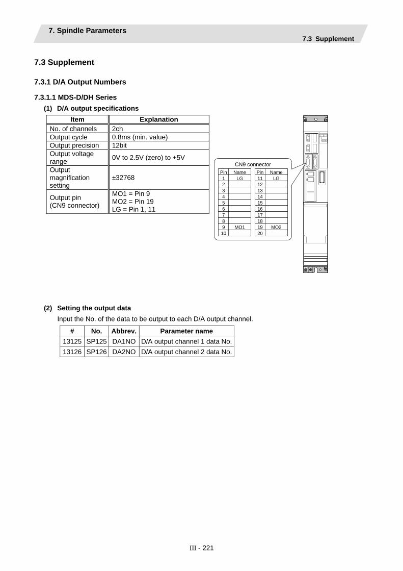
7. Spindle Parameters 7.3 Supplement
III - 221
7.3 Supplement
7.3.1 D/A Output Numbers
7.3.1.1 MDS-D/DH Series (1) D/A output specifications
MO19
NameLG
2
5
1Pin
6
43
10
78
CN9 connector
MO219
NameLG
12
15
11Pin
16
1413
20
1718
(2) Setting the output data Input the No. of the data to be output to each D/A output channel.
# No. Abbrev. Parameter name 13125 SP125 DA1NO D/A output channel 1 data No.13126 SP126 DA2NO D/A output channel 2 data No.
Item Explanation No. of channels 2ch Output cycle 0.8ms (min. value) Output precision 12bit Output voltage range 0V to 2.5V (zero) to +5V
Output magnification setting
±32768
Output pin (CN9 connector)
MO1 = Pin 9 MO2 = Pin 19 LG = Pin 1, 11

7. Spindle Parameters 7.3 Supplement
III - 222
<Standard output>
No. Output data Output unit
for standard setting -1 D/A output stop - 0 Commanded motor rotation speed 1000(r/min)/V 1 Motor rotation speed 1000(r/min)/V 2 Torque current command Short time rated ratio 100%/V 3 Torque current feedback Short time rated ratio 100%/V
35 Disturbance observer estimated disturbance torque
Short time rated torque current value ratio 100%/V
50 Position droop 1/1000°/V 51 Position command 1/1000°/V 52 Position feedback 1/1000°/V 53 Position F⊿T 1/1000°/s/V
54 Deviation from ideal position (considering spindle tracking delay) 1/1000°/V
60 Position droop 1°/V 61 Position command 1°/V 62 Position feedback 1°/V 63 Position F⊿T 1°/s/V
64 Deviation from ideal position (considering spindle tracking delay) 1°/V
70 Position droop 1000°/V 71 Position command 1000°/V 72 Position feedback 1000°/V 73 Position F⊿T 1000°/s/V
74 Deviation from ideal position (considering spindle tracking delay) 1000°/V
126 Saw tooth wave 0V to 5V 127 2.5V test data output 2.5V

7. Spindle Parameters 7.3 Supplement
III - 223
<Spindle control signal>
Spindle control input (NC to SP) Spindle control output (SP to NC) No. Details No. Details
16384 Spindle control input 1-0
READY ON command
16480 Spindle control output 1-0
In ready ON
16385 Spindle control input 1-1
Servo ON command 16481 Spindle control output 1-1
In servo ON
16391 Spindle control
input 1-7 Alarm reset command 16487 Spindle control
output 1-7 In alarm
16392 Spindle control input 1-8
Torque limit 1 selection command
16488 Spindle control output 1-8
In torque limit 1 selection
16393 Spindle control input 1-9
Torque limit 2 selection command
16489 Spindle control output 1-9
In torque limit 2 selection
16394 Spindle control input 1-A
Torque limit 3 selection command
16490 Spindle control output 1-A
In torque limit 3 selection
16492 Spindle control
output 1-C In in-position
16495 Spindle control
output 1-F In warning
16496 Spindle control output 2-0
Z phase passed
16499 Spindle control
output 2-3 In zero speed
16503 Spindle control
output 2-7 In external emergency stop
16409 Spindle control
input 2-9 Speed monitor command valid
16505 Spindle control output 2-9
In speed monitor
16410 Spindle control input 2-A
In door closed (controller)
16506 Spindle control output 2-A
In door closed (controller)
16411 Spindle control input 2-B
In door closed (all drive units)
16507 Spindle control output 2-B
In door closed (self drive unit)
16432 Spindle control
input 4-0 Spindle control mode selection command 1
16528 Spindle control output 4-0
In spindle control mode selection 1
16433 Spindle control input 4-1
Spindle control mode selection command 2
16529 Spindle control output 4-1
In spindle control mode selection 2
16434 Spindle control input 4-2
Spindle control mode selection command 3
16530 Spindle control output 4-2
In spindle control mode selection 3
16436 Spindle control input 4-4
Gear changeover command
16532 Spindle control output 4-4
In gear changeover command
16437 Spindle control input 4-5
Gear selection command 1
16533 Spindle control output 4-5
In gear selection 1
16438 Spindle control input 4-6
Gear selection command 2
16534 Spindle control output 4-6
In gear selection 2

7. Spindle Parameters 7.3 Supplement
III - 224
Spindle control input (NC to SP) Spindle control output (SP to NC) No. Details No. Details
16445 Spindle control input 4-D
L coil selection command
16541 Spindle control output 4-D
In L coil selection
16545 Spindle control
output 5-1 Speed detection
16550 Spindle control
output 5-6 In coil changeover
16458 Spindle control
input 5-A Phase synchronization suppression command
16554 Spindle control output 5-A
In phase synchronization suppression
16459 Spindle control input 5-B
Minimum excitation rate 2 changeover request
16555 Spindle control output 5-B
In minimum excitation rate 2 selection
16460 Spindle control input 5-C
Speed gain set 2 changeover request
16556 Spindle control output 5-C
In speed gain set 2 selection
16461 Spindle control input 5-D
Zero point re-detection request
16557 Spindle control output 5-D
Zero point re-detection complete
16462 Spindle control input 5-E
Spindle holding force up
16558 Spindle control output 5-E
Spindle holding force up completed
16559 Spindle control output 5-F
In 2nd in-position

7. Spindle Parameters 7.3 Supplement
III - 225
7.3.1.2 MDS-D-SPJ3 Series
(1) D/A output specifications
Item Explanation No. of channels 2ch Output cycle 0.8ms (min. value) Output precision 10bit Output voltage range 0V to 2.5V (zero) to +5V
Output magnification setting
±32768
Output pin (CN9 connector)
MO1 = Pin 4 MO2 = Pin 14 GND = Pins 1, 11
9
Name
MO1
LG
2
5
1 Pin
6
4 3
10
7 8
CN9 connector
19
Name
MO2
LG12
15
11 Pin
16
14 13
20
17 18

7. Spindle Parameters 7.3 Supplement
III - 226
(2) Setting the output data Input the No. of the data to be output to each D/A output channel.
# No. Abbrev. Parameter name 13125 SP125 DA1NO D/A output channel 1 data No.13126 SP126 DA2NO D/A output channel 2 data No.
<Standard output>
No. Output data Output unit
for standard setting 0 Commanded motor rotation speed 1000(r/min)/V 1 Motor rotation speed 1000(r/min)/V 2 Torque current command Short time rated ratio 100%/V 3 Torque current feedback Short time rated ratio 100%/V
35 Disturbance observer estimated disturbance torque
Short time rated torque current value ratio 100%/V
50 Position droop 1/1000°/V 51 Position command 1/1000°/V 52 Position feedback 1/1000°/V 53 Position F⊿T 1/1000°/s/V
54 Deviation from ideal position (considering spindle tracking delay) 1/1000°/V
60 Position droop 1°/V 61 Position command 1°/V 62 Position feedback 1°/V 63 Position F⊿T 1°/s/V
64 Deviation from ideal position (considering spindle tracking delay) 1°/V
70 Position droop 1000°/V 71 Position command 1000°/V 72 Position feedback 1000°/V 73 Position F⊿T 1000°/s/V
74 Deviation from ideal position (considering spindle tracking delay) 1000°/V
126 Saw tooth wave 0V to 5V 127 2.5V test data output 2.5V
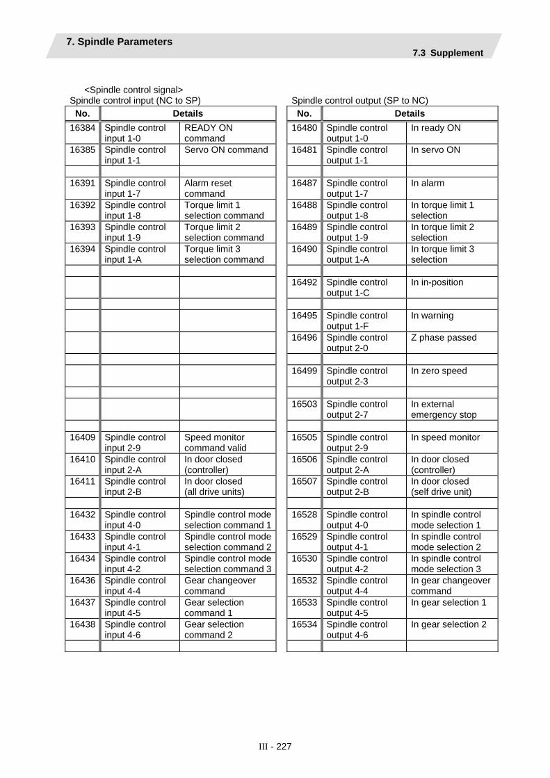
7. Spindle Parameters 7.3 Supplement
III - 227
<Spindle control signal>
Spindle control input (NC to SP) Spindle control output (SP to NC) No. Details No. Details
16384 Spindle control input 1-0
READY ON command
16480 Spindle control output 1-0
In ready ON
16385 Spindle control input 1-1
Servo ON command 16481 Spindle control output 1-1
In servo ON
16391 Spindle control
input 1-7 Alarm reset command
16487 Spindle control output 1-7
In alarm
16392 Spindle control input 1-8
Torque limit 1 selection command
16488 Spindle control output 1-8
In torque limit 1 selection
16393 Spindle control input 1-9
Torque limit 2 selection command
16489 Spindle control output 1-9
In torque limit 2 selection
16394 Spindle control input 1-A
Torque limit 3 selection command
16490 Spindle control output 1-A
In torque limit 3 selection
16492 Spindle control
output 1-C In in-position
16495 Spindle control
output 1-F In warning
16496 Spindle control output 2-0
Z phase passed
16499 Spindle control
output 2-3 In zero speed
16503 Spindle control
output 2-7 In external emergency stop
16409 Spindle control
input 2-9 Speed monitor command valid
16505 Spindle control output 2-9
In speed monitor
16410 Spindle control input 2-A
In door closed (controller)
16506 Spindle control output 2-A
In door closed (controller)
16411 Spindle control input 2-B
In door closed (all drive units)
16507 Spindle control output 2-B
In door closed (self drive unit)
16432 Spindle control
input 4-0 Spindle control mode selection command 1
16528 Spindle control output 4-0
In spindle control mode selection 1
16433 Spindle control input 4-1
Spindle control mode selection command 2
16529 Spindle control output 4-1
In spindle control mode selection 2
16434 Spindle control input 4-2
Spindle control mode selection command 3
16530 Spindle control output 4-2
In spindle control mode selection 3
16436 Spindle control input 4-4
Gear changeover command
16532 Spindle control output 4-4
In gear changeover command
16437 Spindle control input 4-5
Gear selection command 1
16533 Spindle control output 4-5
In gear selection 1
16438 Spindle control input 4-6
Gear selection command 2
16534 Spindle control output 4-6
In gear selection 2
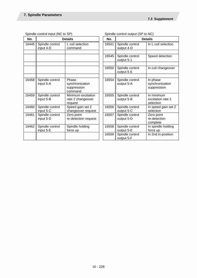
7. Spindle Parameters 7.3 Supplement
III - 228
Spindle control input (NC to SP) Spindle control output (SP to NC)
No. Details No. Details 16445 Spindle control
input 4-D L coil selection command
16541 Spindle control output 4-D
In L coil selection
16545 Spindle control
output 5-1 Speed detection
16550 Spindle control
output 5-6 In coil changeover
16458 Spindle control
input 5-A Phase synchronization suppression command
16554 Spindle control output 5-A
In phase synchronization suppression
16459 Spindle control input 5-B
Minimum excitation rate 2 changeover request
16555 Spindle control output 5-B
In minimum excitation rate 2 selection
16460 Spindle control input 5-C
Speed gain set 2 changeover request
16556 Spindle control output 5-C
In speed gain set 2 selection
16461 Spindle control input 5-D
Zero point re-detection request
16557 Spindle control output 5-D
Zero point re-detection complete
16462 Spindle control input 5-E
Spindle holding force up
16558 Spindle control output 5-E
In spindle holding force up
16559 Spindle control output 5-F
In 2nd in-position

8. Rotary Axis Configuration Parameters
III - 229
8. Rotary Axis Configuration Parameters Parameters indicated as (PR) in the table will be validated when the NC power is turned OFF and ON after setting.
【#7900(PR)】 RCDAX_I Orthogonal coordinate horizontal axis name Set the name of the horizontal axis in the orthogonal coordinate system.
---Setting range--- A,B,C,U,V,W,X,Y,Z
【#7901(PR)】 RCDAX_J Orthogonal coordinate vertical axis name Set the name of the vertical axis in the orthogonal coordinate system.
---Setting range--- A,B,C,U,V,W,X,Y,Z
【#7902(PR)】 RCDAX_K Orthogonal coordinate height axis name Set the name of the height axis in the orthogonal coordinate system.
---Setting range--- A,B,C,U,V,W,X,Y,Z
【#7903】 G92_CRD Origin zero set coordinate selection Select the coordinate to preset when issuing an origin zero command (G92X_Y_Z_;).
0: Tool center coordinate 1: Holder center coordinate
【#7904】 NO_TIP Tool handle feed function selection Select whether to enable the tool handle feed.
0: Enable (tool handle feed) 1: Disable (standard)
【#7905】 NO_ABS Selection of tool axis travel amount display at manual ABS switch ON/OFF Select how to update the display of tool axis travel amount.
0: Update at ABS switch OFF 1: Update at every ON and OFF of ABS switch
【#7906】 PASSTYP Singular point passage type Select the movement after passing a singular point.
0: Type 1 A/B axis rotation angle will be in the same sign direction as that when the tool center point control started. 1: Type 2 C axis rotation amount on the singular point will be smaller.
【#7907】 CHK_ANG Near singular judgment angle Set the angle for judging a position near the singular point.
---Setting range--- 0.000 to 5.000 (°)
【#7908】 SLCT_PRG_COORD Programming coordinate system selection Select the coordinate system for the programming coordinate.
0: Table coordinate system 1: Workpiece coordinate system (coordinate system that rotates together with workpiece)
【#7909】 IJK_VEC_MR Posture vector mirror image selection Select whether to enable the mirror image on the posture vector (IJK) when Type 2 is selected in "#7906 PASSTYP".
0: Disable 1: Enable

8. Rotary Axis Configuration Parameters
III - 230
【#7910】 SLCT_INT_MODE Interpolation method selection Select the interpolation method.
0: Joint interpolation method 1: Single axis rotation interpolation method
【#7911】 SLCT_STANDARD_POS Rotary axis basic position selection Select the basic position of the rotary axis.
0: Workpiece coordinate zero point 1: The position when the tool center point is commanded.
(Note) Even if the position is changed, it is not changed during tool center point control. It is
changed when next tool center point control will be commanded.
【#7913】 MCHN_SPEED_CTRL Machine speed fluctuation suppression Select whether to suppress the machine speed fluctuation due to rotary axis movement.
0: Suppress 1: Do not suppress
【#7920(PR)】 SLCT_T1 Rotary axis selection Select in which axis direction to rotate the tool rotating type base-side rotary axis. If the tool axis is inclined, use the second digit to set the axis direction in which the tool axis is inclined.
0: Invalid 1: I axis rotation 2: J axis rotation 3: K axis rotation (Note) 0 to 99 can be set from the screen, but if an invalid value is set, the operation error "M01
0127 Rot axis parameter error" will occur when the power supply is turned ON.
---Setting range--- 0 to 3 12, 13, 21, 23, 31, 32
【#7921(PR)】 TIANGT1 Inclination angle Set the inclination angle if the tool-rotation type base-side rotary axis is inclined. Set the angle regarding CCW direction of the inclined plane as plus direction.
---Setting range--- -359.999 to 359.999 (°) (Follow as "#1003 iunit Input setup unit".)
【#7922(PR)】 ROTAXT1 Rotary axis name Set the name of the tool rotating type base-side rotary axis. Set "0" when the axis has the mechanical axis specifications. (The setting is, however, invalid in the tool center point control.)
---Setting range--- 0, A, B, C, U, V, W, X, Y, Z
【#7923】 DIR_T1 Rotation direction Select the rotation direction of the tool rotating type base-side rotary axis.
0: CW 1: CCW
【#7924】 COFST1H Horizontal axis rotation center offset Set the distance in the horizontal axis direction between the rotation centers of the tool-side rotary axis and the base-side rotary axis.
---Setting range--- -99999.999 to 99999.999 (mm)

8. Rotary Axis Configuration Parameters
III - 231
【#7925】 COFST1V Vertical axis rotation center offset Set the distance in the vertical axis direction between the rotation centers of the tool-side rotary axis and the base-side rotary axis.
---Setting range--- -99999.999 to 99999.999 (mm)
【#7926】 COFST1T Height axis rotation center offset Set the distance in the height axis direction between the rotation centers of the tool-side rotary axis and the base-side rotary axis.
---Setting range--- -99999.999 to 99999.999 (mm)
【#7927】 CERRT1H Horizontal axis rotation center error compensation amount Set the error compensation amount in the horizontal axis direction of the tool rotating type base-side rotary axis rotation center.
---Setting range--- -99999.999 to 99999.999 (mm) (Follow as "#1006 mcmpunit Machine error compensation unit".)
【#7928】 CERRT1V Vertical axis rotation center error compensation amount Set the error compensation amount in the vertical axis direction of the tool rotating type base-side rotary axis rotation center.
---Setting range--- -99999.999 to 99999.999 (mm) (Follow as "#1006 mcmpunit Machine error compensation unit".)
【#7930(PR)】 SLCT_T2 Rotary axis center Select in which axis direction to rotate the tool rotating type tool-side rotary axis. If the tool axis is inclined, use the second digit to set the axis direction in which the tool axis is inclined.
0: Invalid 1: I axis rotation 2: J axis rotation 3: K axis rotation
(Note) 0 to 99 can be set from the screen, but if an invalid value is set, the operation error "M01 0127 Rot axis parameter error" will occur when the power supply is turned ON.
---Setting range--- 0 to 3 12, 13, 21, 23, 31, 32
【#7931(PR)】 TIANGT2 Inclination angle Set the inclination angle if the tool-rotation type tool-side rotary axis is inclined. Set the angle regarding CCW direction of the inclined plane as plus direction.
---Setting range--- -359.999 to 359.999 (°) (Follow as "#1003 iunit Input setup unit".)
【#7932(PR)】 ROTAXT2 Rotary axis name Set the name of the tool rotating type tool-side rotary axis. Set "0" when the axis has the mechanical axis specifications. (The setting is, however, invalid in the tool center point control.)
---Setting range--- 0, A, B, C, U, V, W, X, Y, Z
【#7933】 DIR_T2 Rotation direction Set the rotation direction of the tool rotating type tool-side rotary axis.
0: CW 1: CCW
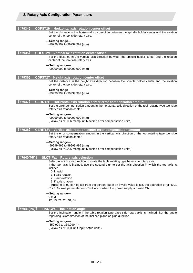
8. Rotary Axis Configuration Parameters
III - 232
【#7934】 COFST2H Horizontal axis rotation center offset Set the distance in the horizontal axis direction between the spindle holder center and the rotation center of the tool-side rotary axis.
---Setting range--- -99999.999 to 99999.999 (mm)
【#7935】 COFST2V Vertical axis rotation center offset Set the distance in the vertical axis direction between the spindle holder center and the rotation center of the tool-side rotary axis.
---Setting range--- -99999.999 to 99999.999 (mm)
【#7936】 COFST2T Height axis rotation center offset Set the distance in the height axis direction between the spindle holder center and the rotation center of the tool-side rotary axis.
---Setting range--- -99999.999 to 99999.999 (mm)
【#7937】 CERRT2H Horizontal axis rotation center error compensation amount Set the error compensation amount in the horizontal axis direction of the tool rotating type tool-side rotary axis rotation center.
---Setting range--- -99999.999 to 99999.999 (mm) (Follow as "#1006 mcmpunit Machine error compensation unit".)
【#7938】 CERRT2V Vertical axis rotation center error compensation amount Set the error compensation amount in the vertical axis direction of the tool rotating type tool-side rotary axis rotation center.
---Setting range--- -99999.999 to 99999.999 (mm) (Follow as "#1006 mcmpunit Machine error compensation unit".)
【#7940(PR)】 SLCT_W1 Rotary axis selection Select in which axis direction to rotate the table rotating type base-side rotary axis. If the tool axis is inclined, use the second digit to set the axis direction in which the tool axis is inclined.
0: Invalid 1: I axis rotation 2: J axis rotation 3: K axis rotation (Note) 0 to 99 can be set from the screen, but if an invalid value is set, the operation error "M01
0127 Rot axis parameter error" will occur when the power supply is turned ON.
---Setting range--- 0 to 3 12, 13, 21, 23, 31, 32
【#7941(PR)】 TIANGW1 Inclination angle Set the inclination angle if the table-rotation type base-side rotary axis is inclined. Set the angle regarding CCW direction of the inclined plane as plus direction.
---Setting range--- -359.999 to 359.999 (°) (Follow as "#1003 iunit Input setup unit".)

8. Rotary Axis Configuration Parameters
III - 233
【#7942(PR)】 ROTAXW1 Rotary axis name Set the name of the table rotating type base-side rotary axis. Set "0" when the axis has the mechanical axis specifications. (The setting is, however, invalid in the tool center point control.)
---Setting range--- 0, A, B, C, U, V, W, X, Y, Z
【#7943】 DIR_W1 Rotation direction Set the rotation direction for the table rotating type base-side rotary axis.
0: CW 1: CCW
【#7944】 COFSW1H Horizontal axis rotation center offset When all axes are at the machine basic point, set the distance in the horizontal axis direction from the machine basic point to the rotation center of the base-side rotary axis.
---Setting range--- -99999.999 to 99999.999 (mm)
【#7945】 COFSW1V Vertical axis rotation center offset When all axes are at the machine basic point, set the distance in the vertical axis direction from the machine basic point to the rotation center of the base-side rotary axis.
---Setting range--- -99999.999 to 99999.999 (mm)
【#7946】 COFSW1T Height axis rotation center offset When all axes are at the machine basic point, set the distance in the height axis direction from the machine basic point to the rotation center of the base-side rotary axis.
---Setting range--- -99999.999 to 99999.999 (mm)
【#7947】 CERRW1H Horizontal axis rotation center error compensation amount Set the error compensation amount in the horizontal axis direction of the table rotating type base-side rotary axis rotation center.
---Setting range--- -99999.999 to 99999.999 (mm) (Follow as "#1006 mcmpunit Machine error compensation unit".)
【#7948】 CERRW1V Vertical axis rotation center error compensation amount Set the error compensation amount in the vertical axis direction of the table rotating type base-side rotary axis rotation center.
---Setting range--- -99999.999 to 99999.999 (mm) (Follow as "#1006 mcmpunit Machine error compensation unit".)
【#7950(PR)】 SLCT_W2 Rotary axis selection Set in which direction to rotate the table rotating type workpiece-side rotary axis. If the tool axis is inclined, use the second digit to set the axis direction in which the tool axis is inclined.
0: Invalid 1: I axis rotation 2: J axis rotation 3: K axis rotation (Note) 0 to 99 can be set from the screen, but if an invalid value is set, the operation error "M01
0127 Rot axis parameter error" will occur when the power supply is turned ON.
---Setting range--- 0 to 3 12, 13, 21, 23, 31, 32

8. Rotary Axis Configuration Parameters
III - 234
【#7951(PR)】 TIANGW2 Inclination angle Set the inclination angle if the table rotatiing type workpiece-side rotary axis is inclined. Set the angle regarding CCW direction of the inclined plane as minus direction.
---Setting range--- -359.999 to 359.999 (°) (Follow as "#1003 iunit Input setup unit".)
【#7952(PR)】 ROTAXW2 Rotary axis name Set the name of the table rotating type workpiece-side rotary axis. Set "0" when the axis has the mechanical axis specifications. (The setting is, however, invalid in the tool center point control.)
---Setting range--- 0, A, B, C, U, V, W, X, Y, Z
【#7953】 DIR_W2 Rotation direction Set the rotation direction for the table rotating type workpiece-side rotary axis.
0: CW 1: CCW
【#7954】 COFSW2H Horizontal axis rotation center offset When all axes are at the machine basic point, set the distance in the horizontal axis direction between rotation centers of the base-side rotary axis and the workpiece-side rotary axis.
---Setting range--- -99999.999 to 99999.999 (mm)
【#7955】 COFSW2V Vertical axis rotation center offset When all axes are at the machine basic point, set the distance in the vertical axis direction between rotation centers of the base-side rotary axis and the workpiece-side rotary axis.
---Setting range--- -99999.999 to 99999.999 (mm)
【#7956】 COFSW2T Height axis rotation center offset When all axes are at the machine basic point, set the distance in the height axis direction between rotation centers of the base-side rotary axis and the workpiece-side rotary axis.
---Setting range--- -99999.999 to 99999.999 (mm)
【#7957】 CERRW2H Horizontal axis rotation center error compensation amount Set the error compensation amount in the horizontal axis direction of the table rotating type workpiece-side rotary axis rotation center.
---Setting range--- -99999.999 to 99999.999 (mm) (Follow as "#1006 mcmpunit Machine error compensation unit".)
【#7958】 CERRW2V Vertical axis rotation center error compensation amount Set the error compensation amount in the vertical axis direction of the table rotating type workpiece-side rotary axis rotation center.
---Setting range--- -99999.999 to 99999.999 (mm) (Follow as "#1006 mcmpunit Machine error compensation unit".)

9. Machine Error Compensation 9.1 Function Outline
III - 235
9. Machine Error Compensation 9.1 Function Outline
Machine error compensation includes two independent functions: memorized pitch error compensation and memorized relative position compensation. (1) Memorized pitch error compensation
According to the specified parameters‚ this method compensates an axis feed error caused by a ball screw pitch error‚ etc. With the reference position defined as the base‚ set the compensation amount in the division points obtained by equally dividing the machine coordinates. (See Fig. 1. 1) The compensation amount can be set by either the absolute or incremental system. Select the desired method with the #4000:Pinc. Machine position is compensated between division points n and n+1 as much as compensation amount between them by linear approximation.
Command machine position
Ideal machine position
Real machine position
Real machine position for which no compensation has been made
n n+1Command machine position
: Division point
Compensation amount
Reference position Compensation amount between division points
n+2
Fig. 1.1 Relationship between the compensation amount and machine position

9. Machine Error Compensation 9.1 Function Outline
III - 236
(2) Memorized relative position compensation
This method‚ according to the parameters specified in advance‚ compensates the relative position error between two orthogonal axes caused by deflection of the moving stand. For this‚ as shown in Fig. 1. 2‚ specify the compensation amount in the compensation axis direction in the division points obtained by equally dividing the machine coordinates of the base axis. The base axis is one of the two orthogonal axes to which relative position compensation applies. This axis is used as the criterion for relative-error measurement. The compensation axis is the coordinate axis that is orthogonal to the base axis. The compensation is actually made for this coordinate axis. The section between division points n and n+1 is compensated smoothly by linear approximation.
n n+1 n+2
Command machine position along base axis
Actual machine position of compensation axis
Actual machine position for which no compensation has been made
Command machine position
: Division point
Compensation amount
Reference position
Compensation amount between division points
Fig. 1.2 Relationship between the compensation amount and machine position
【#4000(PR)】 Pinc Machine error compensation increment method Select the method to set the machine error compensation data.
---Setting range--- 0: Absolute amount method 1: Incremental amount method

9. Machine Error Compensation 9.1 Function Outline
III - 237
<1st axis>
【#4001】 cmpax Basic axis Set a name of the basic axis for machine error compensation. (1) For pitch error compensation‚ set the name of the axis to be compensated. (2) For relative position compensation, set the name of the axis to be the basic axis. Set "system No. + axis name" when using the multi-part system. (Example) Z axis for 2nd part system: 2Z
---Setting range--- Axis name such as X, Y, Z, U, V, W, A, B, or C
【#4002】 drcax Compensation axis Set a name of the compensation axis for machine error compensation. (1) For pitch error compensation, set the same axis name as in "#4001 cmpax". (2) For relative position compensation, set the name of the axis to be actually compensated. Set "system No. + axis name" when using the multi-part system. (Example) Z axis for 2nd part system: 2Z
---Setting range--- Axis name such as X, Y, Z, U, V, W, A, B, or C
【#4003】 rdvno Division point number at reference position Set the compensation data No. corresponding to the reference position. As the reference position is actually the base position, there is no compensation No. Therefore set the number that is decremented by 1.
---Setting range--- 4101 to 5124
【#4004】 mdvno Division point number at the most negative side Set the compensation data No. at the farthest end on the negative side.
---Setting range--- 4101 to 5124
【#4005】 pdvno Division point number at the most positive side Set the compensation data No. at the farthest end on the positive side.
---Setting range--- 4101 to 5124
【#4006】 sc Compensation scale factor Set the scale factor for the compensation amount.
---Setting range--- 0 to 99
【#4007】 spcdv Division interval Set the interval to divide the basic axis. Each compensation data will be the compensation amount for each of these intervals.
---Setting range--- 1 to 9999999 (control unit applied)

9. Machine Error Compensation 9.1 Function Outline
III - 238
2nd axis 3rd axis 4th axis 5th axis 6th axis 7th axis 8th axis 9th axis 10th axis
4011 4012 4013 4014 4015 4016 4017
4021 4022 4023 4024 4025 4026 4027
4031 4032 4033 4034 4035 4036 4037
4041 4042 4043 4044 4045 4046 4047
4051 4052 4053 4054 4055 4056 4057
4061406240634064406540664067
4071407240734074407540764077
4081408240834084408540864087
4091409240934094409540964097
Set the parameters corresponding to the 1st axis’ parameters 4001 to 4007 for each axis. A maximum of 6 axes can be controlled‚ but as the relative position is compensated‚ settings for 10 axes can be made.
# Item Details Setting range
4101
5124
Set the compensation amount for each axis. -32768 to 32767 The actual compensa-tion amount will be the value obtained by multiplying the setting value with the compensation scale.
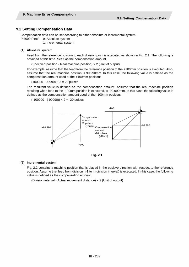
9. Machine Error Compensation 9.2 Setting Compensation Data
III - 239
9.2 Setting Compensation Data Compensation data can be set according to either absolute or incremental system. "#4000:Pinc" 0: Absolute system 1: Incremental system (1) Absolute system
Feed from the reference position to each division point is executed as shown in Fig. 2.1. The following is obtained at this time. Set it as the compensation amount.
(Specified position - Real machine position) × 2 (Unit of output) For example‚ assume that the feed from the reference position to the +100mm position is executed. Also‚ assume that the real machine position is 99.990mm. In this case‚ the following value is defined as the compensation amount used at the +100mm position:
(100000 - 99990) × 2 = 20 pulses The resultant value is defined as the compensation amount. Assume that the real machine position resulting when feed to the -100mm position is executed‚ is -99.990mm. In this case‚ the following value is defined as the compensation amount used at the -100mm position:
(-100000 - (-99990)) × 2 = -20 pulses
+99.990
+100
Compensation amount: 20 pulses (10um) -99.990
-100
Compensation amount: -20 pulses (-10um)
Fig. 2.1
(2) Incremental system
Fig. 2.2 contains a machine position that is placed in the positive direction with respect to the reference position. Assume that feed from division n-1 to n (division interval) is executed. In this case‚ the following value is defined as the compensation amount:
(Division interval - Actual movement distance) × 2 (Unit of output)

9. Machine Error Compensation 9.2 Setting Compensation Data
III - 240
(3) Fig. 2.3 contains a machine position that is placed in the negative direction with respect to the reference
position. Assume that feed from division point n+1 to n by the division interval is executed. In this case‚ the following value is defined as the compensation amount:
(Division interval + Actual movement distance) × 2 (Unit of output)
nn-1 1
n+1n1
n: Division point compensation number 1: Division interval
Fig. 2.2 Fig. 2.3
Unit : Unit of output Range : -128 to 127 (Note) The unit of output is used as the unit of setting. The actual unit of compensation pulses depends
on the compensation scale factor.

9. Machine Error Compensation 9.3 Example in Using a Linear Axis as the Base Axis
III - 241
9.3 Example in Using a Linear Axis as the Base Axis (1) When "mdvno" or "pdvno" exists at both ends of "rdvno":
#4101
Compensation amount in incremental system
#4103#4102 #4104 #4105 #4106
2
1
-1
Error
-2
-3
(1) (3) (-3) (-2) (0) (3)
(3) (-2)(0) (-2)
(-1) (1)
Base axis machine coordinate
3
Compensation amount in absolute system
Division point number #4101 #4102 #4103 #4104 #4105 #4106 rdvno 4103Specified machine position -300.000 -200.000 -100.000 100.000 200.000 300.000 mdvno 4101Real machine position -299.999 -200.000 -100.003 100.002 200.002 299.999 pdvno 4106
Incremental 2 6 -6 -4 0 6 Compensa- tion amount Absolute -2 0 6 -4 -4 2
If the setting range ("mdvno" to "pdvno") is exceeded‚ the compensation will be based on compensation amount at "mdvno" or "pdvno".

9. Machine Error Compensation 9.3 Example in Using a Linear Axis as the Base Axis
III - 242
(2) When the range compensated is only the positive range:
Compensation amount in incremental system
#4114#4113 #4116 #4117
2
1
-1
Error
-2
-3
(-2) (1) (0) (3) (1)
(-2) (-1)
(2)
Base axis machine coordinate
3 #4115
(-1)
(3)
Compensation amount in absolute system
Division point number #4113 #4114 #4115 #4116 #4117 rdvno 4112
Incremental -4 2 0 6 2 mdvno 4113Compensa-tion amount Absolute -4 -2 -2 4 6 pdvno 4117
If the machine position exceeds "pdvno"‚ the compensation will be based on the compensation amount at "pdvno". If the machine position is negative in this case‚ no compensation will be executed.

9. Machine Error Compensation 9.3 Example in Using a Linear Axis as the Base Axis
III - 243
(3) When the range compensated is only the negative range:
#4128#4127 #4130 #4126
2
1
-1
-2
-3
(3) (1) (0) (-3)
(3) (3)
(-1)
3 #4129
(2)
(-2)
(-1) (1)
#4125
(-1)
Compensation amount in incremental system
Error
Base axis machine coordinate
Compensation amount in absolute system
Division point number #4125 #4126 #4127 #4128 #4129 #4130 rdvno 4130Incremental -2 2 6 2 0 -6 mdvno 4125Compensa-ti
on amount Absolute -2 -4 -2 4 6 6 pdvno 4130 If the machine position exceeds "mdvno"‚ the compensation will be based on compensation amount at "mdvno".
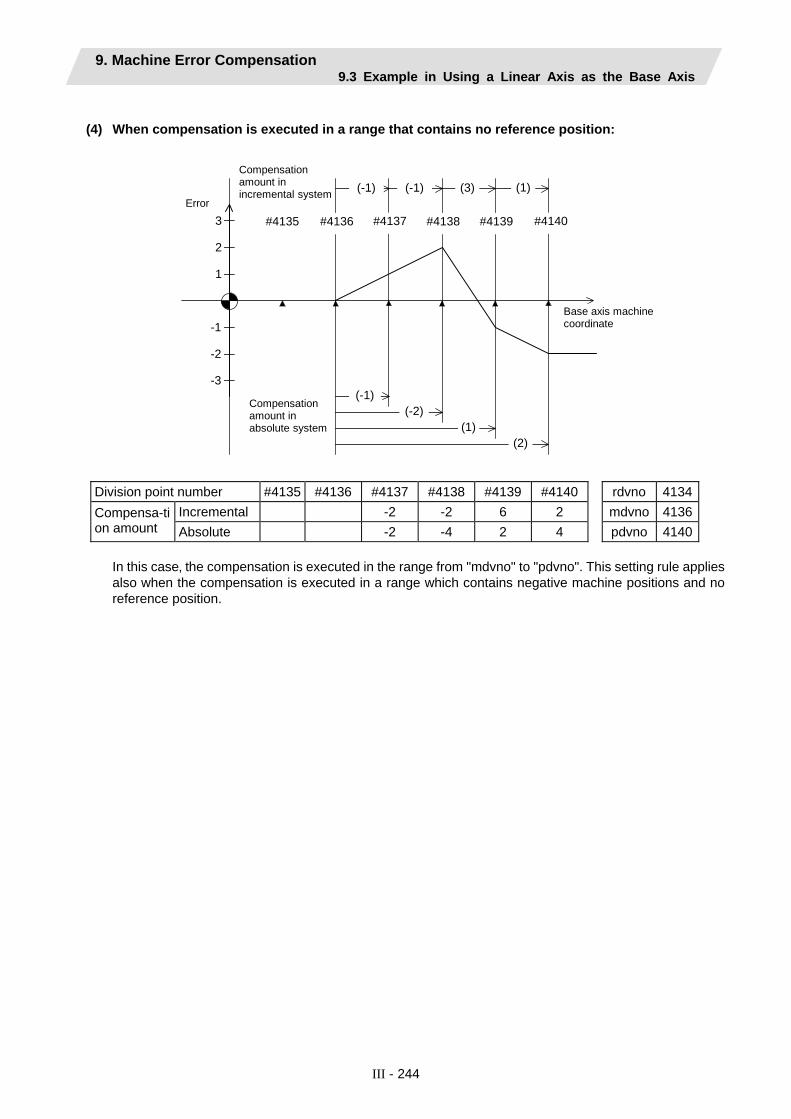
9. Machine Error Compensation 9.3 Example in Using a Linear Axis as the Base Axis
III - 244
(4) When compensation is executed in a range that contains no reference position:
#4136#4135 #4138 #4139
2
1
-1
-2
-3
(1)(-1) (-1) (3)
(-1)(-2)
(2)
3 #4137
(1)
#4140
Compensation amount in incremental system
Error
Base axis machine coordinate
Compensation amount in absolute system
Division point number #4135 #4136 #4137 #4138 #4139 #4140 rdvno 4134Incremental -2 -2 6 2 mdvno 4136Compensa-ti
on amount Absolute -2 -4 2 4 pdvno 4140 In this case‚ the compensation is executed in the range from "mdvno" to "pdvno". This setting rule applies also when the compensation is executed in a range which contains negative machine positions and no reference position.
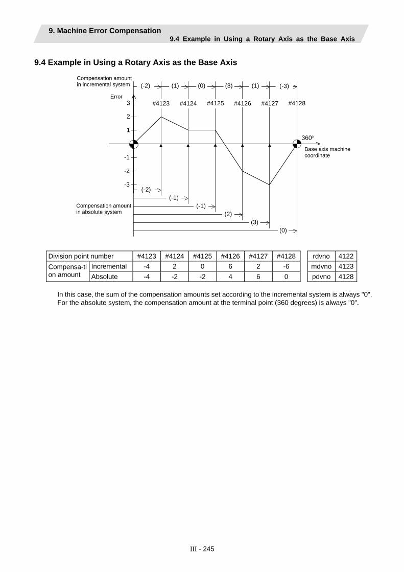
9. Machine Error Compensation 9.4 Example in Using a Rotary Axis as the Base Axis
III - 245
9.4 Example in Using a Rotary Axis as the Base Axis
#4124#4123 #4126 #4127
2
1
-1
-2
-3
(-2) (1) (0) (3) (1)
(-2) (-1)
(2)
3 #4125
(-1)
(3)
(-3)
#4128
(0)
360°
Compensation amount in incremental system
Error
Base axis machine coordinate
Compensation amount in absolute system
Division point number #4123 #4124 #4125 #4126 #4127 #4128 rdvno 4122
Incremental -4 2 0 6 2 -6 mdvno 4123Compensa-tion amount Absolute -4 -2 -2 4 6 0 pdvno 4128
In this case‚ the sum of the compensation amounts set according to the incremental system is always "0". For the absolute system‚ the compensation amount at the terminal point (360 degrees) is always "0".

10. PLC Constants 10.1 PLC Timer
III - 246
10. PLC Constants
10.1 PLC Timer # PLC device Item Details Setting range
16000 : : : :
16703
T0 : : : :
T703
PLC timer <10ms/100ms>
Set the time for the timer used in the PLC program (ladder). The 10ms timer and 100ms timer are identified by the command used. (Note) This setting value is valid when
parameter "#6449 bit0" in the following "[BIT SELECT]" is set to "0".
0 to 32767 (×10ms or ×100ms)
(Note 1) Setting the timer setting value from the setting and display unit The timer T setting value can be set with the following two methods. • Method to validate the setting value (Kn) programmed with the sequence program (fixed timer) • Method to validate the setting value set from the setting and display unit (variable timer) (Note 2) The fixed timer and variable timer range can be set with the bit selection parameters (#6454/bit0 to
bit3).
Bit selection parameter (#6454) No. of points Range
bit3 bit2 bit1 bit0 Fixed timer/
variable timer
0 None 0 0 0 0 All fixed timers 100 #16000 to #16099 0 0 0 1 200 #16000 to #16199 0 0 1 0 300 #16000 to #16299 0 0 1 1 400 #16000 to #16399 0 1 0 0 500 #16000 to #16499 0 1 0 1 600 #16000 to #16599 0 1 1 0
Variable timers in range on left
All points #16000 to #16703 0 1 1 1 All variable timers

10. PLC Constants 10.2 PLC Integrated Timer
III - 247
10.2 PLC Integrated Timer # PLC device Item Details Setting range
17000 : :
17063
ST0 : :
ST63
PLC integrated timer <100ms INC.>
Set the time for the integrated timer used with the PLC program (ladder). (Note) This setting value is valid when
parameter "#6449 bit0" in the following "[BIT SELECT]" is set to "0".
0 to 32767 (×100ms)
(Note 1) Setting the timer setting value from the setting and display unit The timer T setting value can be set with the following two methods.
• Method to validate the setting value (Kn) programmed with the sequence program (fixed integrated timer)
• Method to validate the setting value set from the setting and display unit (variable integrated timer)
(Note 2) The fixed integrated timer and variable integrated timer range can be set with the bit selection parameters (#6454/bit5 to bit7).
Bit selection parameter (#6453)No. of points Range
bit7 bit6 bit5 Fixed integrated timer/
variable integrated timer
0 None 0 0 0 All fixed integrated timers 20 #17000 to #17019 0 0 1 40 #17000 to #17039 0 1 0
Variable integrated timers in range on left
All points #17000 to #17063 0 1 1 All variable integrated timers
10.3 PLC Counter # PLC device Item Details Setting range
17200 : : :
17455
C000 : : :
C255
Counter Set the time for the counter used with the PLC program (ladder). (Note) This setting value is valid when
parameter "#6449 bit1" in the following "[BIT SELECT]" is set to "0".
0 to 32767
(Note 1) Setting the counter setting value from the setting and display unit The counter C setting value can be set with the following two methods.
• Method to validate the setting value (Kn) programmed with the sequence program (fixed counter) • Method to validate the setting value set from the setting and display unit (variable counter)
(Note 2) The fixed counter and variable counter range can be set with the bit selection parameters (#6454/bit4 to bit7).
Bit selection parameter (#6454) No. of points Range
bit7 bit6 bit5 bit4 Fixed counter/
variable counter
0 None 0 0 0 0 All fixed counters 40 #17200 to #17239 0 0 0 1 80 #17200 to #17279 0 0 1 0
120 #17200 to #17319 0 0 1 1 160 #17200 to #17359 0 1 0 0 200 #17200 to #17399 0 1 0 1 240 #17200 to #17439 0 1 1 0
Variable counter in range on left
All points #17200 to #17455 0 1 1 1 All variable counters

10. PLC Constants 10.4 PLC Constants
III - 248
10.4 PLC Constants # PLC device Item Details Setting range
18001 : : : :
18150
R7500,7501 : : : :
R7798,7799
PLC constant Set the value to be set in the data type R register used in the PLC program (ladder). Even if the data is set in the R register that corresponds to the PLC side when this parameter is displayed‚ the screen will not change. Enter a different screen once‚ and then select this screen again.
-99999999 to 99999999
10.5 Selecting the PLC Bit # PLC device Item Details Setting range
6401 6402
: : : : : : : :
6495 6496
R7800-Low R7800-High
: : : : : : : :
R7847-Low R7847-High
Bit selection This is the bit type parameter used in the PLC program (ladder). Even if the data is set in the R register that corresponds to the PLC side when this parameter is displayed‚ the screen will not change. Enter a different screen once‚ and then select this screen again. Some of the parameters following #6449 may be fixed according to the usage purpose. Refer to the PLC Program Development On-board Instruction Manual.
0: OFF 1: ON
6497 6498
: : : : :
6595 6596
R7848-Low R7848-High
: : : : :
R7897-Low R7897-High
Bit selection expansion
This is the bit type parameter (expansion) used in the PLC program (ladder). Even if the data is set in the R register that corresponds to the PLC side when this parameter is displayed‚ the screen will not change. Enter a different screen once‚ and then select this screen again.
0: OFF 1: ON

10. PLC Constants 10.5 Selecting the PLC Bit
III - 249
Table: "Contents of bit selection parameters #6449 to #6496"
Symbol name
7 6 5 4 3 2 1 0
0 #6449
R7824 L Control unit temperature alarm ON
- - - Counter Cretention
Integrating timer ST retention
PLC counter program ON
PLC timer program ON
1 0
1 #6450
R7824 H - - - - - Operator message ON R type F type
Alarm message ON
2 #6451
R7825 L - - Serial GPP communi- cation ON
- - - Simple mode ON -
3 #6452
R7825 H - - -
Serial handy terminal communication ON
- - - -
4 #6453
R7826 L PLC integrated timer
Number of variable integrated timer points setting
- - Message language selection code
5 #6454
R7826 H Counter C number of variable/fixed points setting Timer T number of variable/fixed points setting
6 #6455
R7827 L - - - - - - - -
7 #6456
R7827 H - - - - - - - -
8 #6457
R7828 L High-speed input specification 1
9 #6458
R7828 H High-speed input specification 2
A #6459
R7829 L High-speed input specification 3
B #6460
R7829 H High-speed input specification spare
C #6461
R7830 L High-speed output specification 1
D #6462
R7830 H High-speed output specification 2
E #6463
R7831 L High-speed output specification 3
F #6464
R7831 H High-speed output specification spare

10. PLC Constants 10.5 Selecting the PLC Bit
III - 250
Symbol name
7 6 5 4 3 2 1 0
0 #6465
R7832 L
1 #6466
R7832 H
2 #6467
R7833 L
3 #6468
R7833 H
High-speed input specification spare
4 #6469
R7834 L - - - - - - - -
5 #6470
R7834 H - - - - - - - -
6 #6471
R7835 L - - - - - - - -
7 #6472
R7835 H - - - - - - - -
8 #6473
R7836 L
9 #6474
R7836 H
A #6475
R7837 L
B #6476
R7837 H
High-speed output specification spare
C #6477
R7838 L - - - - - - - -
D #6478
R7838 H - - - - - - - -
E #6479
R7839 L - - - - - - - -
F #6480
R7839 H - - - - - - - -
(Note 1) Be sure to set the bits indicated - and blanks to 0. (Note 2) Parameters #6481 to #6496 are reserved for debugging by Mitsubishi.

11. Macro List
III - 251
11. Macro List
# Item Details Setting range (unit)7001
to 7091
M [01] to M [10]
<Code> Set the M code used for calling out the macro with the M command. This is valid when "#1195 Mmac" is set to 1.
1 to 9999
7002 to
7092
<Type> Set the macro call out type.
0 to 3
7003 to
7093
<Program No.> Set the No. of the program to be called out.
Program name or file name (up to 32 characters)
M2mac Set the type and program No. for when calling out the macro with the 2nd miscellaneous command. The macro will be called out with the "#1170 M2name" address command when "#1198 M2mac" is set to 1.
7102 <Type> Same as the M call macro.
0 to 3
7103 <Program No.> Same as the M call macro.
Program name or file name (up to 32 characters)
7201 to
7291
G [01] to G [10]
<Code> Set the G code to be used when calling the macro with a G command. Do not set a G code used in the system.
1 to 255
7202 to
7292
<Type> Same as the M call Marco.
0 to 3
7203 to
7293
<Program No.> Same as the M call Marco.
Program name or file name (up to 32 characters)
Smac Set the type and program No. for when calling the macro with an S command.This is valid when "#1196 Smac" is set to 1.
7302 <Type> Same as the M call Marco.
0 to 3
7303 <Program No.> Same as the M call Marco.
Program name or file name (up to 32 characters)
Tmac Set the type and program No. for when calling the macro with a T command.This is valid when "#1197 Tmac" is set to 1.
7312 <Type> Same as the M call macro.
0 to 3
7313 <Program No.> Same as the M call macro.
Program name or file name (up to 32 characters)
0 M98 PΔΔΔΔ; and equivalent value call 1 G65 PΔΔΔΔ; and equivalent value call 2 G66 PΔΔΔΔ; and equivalent value call 3 G66.1 PΔΔΔΔ; and equivalent value call
others M98 PΔΔΔΔ; and equivalent value call

11. Macro List
III - 252
# Item Details Setting range
7401 Valid The ASCII code macro parameters (#7402 to 7405) are validated. 0: Invalid 1: Valid
0/1
7402 Code Set the ASCII code used to call macros with the ASCII code.
L system: A, B, D, F, H, I, J, K, M, Q, R, S, T
M system: A, B, F, H, I, K, M, Q, R, S, T
7403 Type Set the macro call type. 0: M98, 1: G65, 2: G66, 3: G66.1
0 to 3
7404 Program No.
Set the program No. called with macro call. 0 to 99999999
7405
ASCII [01]
Variable When the call type is "0", set the variable No. set after the ASCII code.
100 to 149
7411 Valid The ASCII code macro parameters (#7412 to 7415) are validated. 0: Invalid 1: Valid
0/1
7412 Code Set the ASCII code used to call macros with the ASCII code.
L system: A, B, D, F, H, I, J, K, M, Q, R, S, T
M system: A, B, F, H, I, K, M, Q, R, S, T
7413 Type Set the macro call type. 0: M98, 1: G65, 2: G66, 3: G66.1
0 to 3
7414 Program No.
Set the program No. called with macro call. 0 to 99999999
7415
ASCII [02]
Variable When the call type is "0", set the variable No. set after the ASCII code.
100 to 149

12. Position Switch
III - 253
12. Position Switch The position switch (PSW) is used as an alternate switch for the dog switch provided on an axis of the machine. The position switch uses parameters by which the names of axes and their corresponding coordinates indicating imaginary dog positions are defined in advance. When the machine reaches the imaginary dog position‚ a signal is output to the PLC interface. The position switch thus works as an imaginary dog switch.
# Item Details Setting range (unit)
7500 Pcheck High-speed switching of position switch
Specify whether to perform position switch area checking at high speeds. 0: Do not perform position switch area
checking at high speed (do it the same as before).
1: Perform position switch area checking at high speed.
0/1
75 1 <axis> Axis name Specify the name of the axis for which a position switch is provided.
X, Y, Z, U, V, W, A, B, or C axis address
75 2 <dog1> Imaginary dog position 1
When the machine enters the range between imaginary dog positions 1 and 2, a signal is output to the PLC.
-99999.999 to 99999.999 (mm)
75 3 <dog2> Imaginary dog position 2
1st part system device : X1D00 2nd part system device : X1D20
75 4 <check> Selection of area check method
When position switch area checking at high speed is selected, specify the mode of area checking, i.e., whether to use the command type machine position or detector feedback position, for each position switch point. 0: Use the command type machine
position as the machine position for position switch area checking.
1: Use the detector feedback position as the machine position for position switch area checking.
(Note) This parameter is valid only when 1 set in "#7500 Pcheck. "
0/1
Position switch Nos. of PSW1 to PSW24 and signal devices
<axis>
<dog1>
<dog2>
<check>
Part system 1 device
Part system 2 device
PSW1 #7501 #7502 #7503 #7504 X1D00 X1D20 PSW2 #7511 #7512 #7513 #7514 X1D01 X1D21 PSW3 #7521 #7522 #7523 #7524 X1D02 X1D22 PSW4 #7531 #7532 #7533 #7534 X1D03 X1D23
: : : : : : : PSW24 #7731 #7732 #7733 #7734 X1D17 X1D37
Instead of the dog switch provided on the machine axis‚ the coordinates indicating imaginary dog positions (dog1 and dog2) on the coordinate axis of the axis name preset with axis are set with the position switches (PSW1 - PSW24). When the machine reaches the position‚ the signal is output to the device corresponding to the PLC interface.

12. Position Switch
III - 254
Example of settings of dog1 and dog2 and operation
Setting of dog1 and dog2 dog1, dog2 position Operation
dog1 < dog2 dog1 dog2
A signal is output between dog1 and dog2.
dog1 > dog2 dog2 dog1
A signal is output between dog2 and dog1.
dog1 = dog2 dog1 = dog2
If dog1 equals dog2‚ the dog1 position triggers a signal.
dog1
dog2
PSWwidth
Imaginary dog
Basic machine coordinate system zero point
Rotary axis
Setting of dog1 and dog2 dog1, dog2 position Description dog1 < dog2 dog2 dog1
(Example) dog1 = 30.000dog2 = 330.000
A signal is output between dog1 and dog2.
dog1 dog2
(Example) dog1 = -30.000dog2 = 30.000
A signal is also output when dog1 is negative.
dog1 > dog2 dog1 dog2
(Example) dog1 = 330.000dog2 = 30.000
A signal is output between dog2 and dog1.
|dog1 - dog2| ≥ 360 dog2 dog1
(Example) dog1 = 30.000dog2 = 390.000
A signal is kept output when the difference between dog1 and dog2 exceeds 360 degrees.

12. Position Switch 12.1 Canceling the Position Switch
III - 255
12.1 Canceling the Position Switch To cancel the position switch‚ enter the number (#75�1) of the position switch to be canceled in # ( ) of the setting field‚ enter a slash "/" in DATA ( )‚ then press the INPUT key. This deletes the axis name for the specified position switch‚ thus invalidating the position switch. The data specified for <dog1> and <dog2> are still stored in memory. To validate the position switch again‚ therefore‚ it is enough to specify the axis name only.

13. Auxiliary Axis Parameter
III - 256
13. Auxiliary Axis Parameter Turn the NC power OFF after setting parameters indicated with a (PR) in the table. The setting will be validated after the power is turned ON again.
【#50001(PR)】 MSR Motor series Set the motor series. When set to the default value ("0000"), the system will automatically judge the series.
---Setting range--- 0000 to FFFF (hexadecimal)
【#50002(PR)】 RTY Regeneration option type Set the regenerative resistor type.
Default value: 0000 0000: Drive unit standard built-in resistor (10CT has no built-in resistor) 0100: Setting prohibited 0200: MR-RB032 (30W) 0300: MR-RB12 (100W) 0400: MR-RB32 (300W) 0500: MR-RB30 (300W) 0600: MR-RB50 (500W) 0700 to 0F00: Setting prohibited
Do not set values that are not written here.
【#50003(PR)】 PC1 Motor side gear ratio (machine rotation ratio) Set the number of gear teeth on the motor side and the number of gear teeth on the machine side as an integer reduced to its lowest terms. Set the total gear ratio if there are multiple gear levels. For rotary axes, set the motor rotation speed per machine rotation. Default value: 1
---Setting range--- 1 to 32767
【#50004(PR)】 PC2 Machine side gear ratio (motor rotation ratio) Set the number of gear teeth on the motor side and the number of gear teeth on the machine side as an integer reduced to its lowest terms. Set the total gear ratio if there are multiple gear levels. For rotary axes, set the motor rotation speed per machine rotation. Default value: 1
---Setting range--- 1 to 32767
【#50005(PR)】 PIT Feed pitch Set the feed pitch. Set "360" (default value) for rotary axes. Set the feed lead for linear axes.
---Setting range--- 1 to 32767(° or mm)
【#50006】 INP In-position detection width Set the position droop for the in-position detection. In-position will be detected when the position droop reaches the setting value or less. Default value: 50
---Setting range--- 1 to 32767 (1/1000° or µm)

13. Auxiliary Axis Parameter
III - 257
【#50007】 ATU Auto-tuning Set the adjustment of the auto-tuning. Default value: 0102
***1: Low response (low-rigidity loads, loads which easily vibrate) ***2: Standard setting value ***3: ***4: ***5: High response (high-rigidity loads, loads which do not easily vibrate) **0*: Standard friction amount **1*: Large friction amount (set the position loop gain slightly lower) *0**: Only auto-tuning PG2, VG2, VIC, and GD2 *1**: Only auto-tuning PG1, PG2, VG1, VG2, VIC, and GD2 (total gain). (Standard setting) *2**: No auto-tuning
Do not set values that are not explained here.
【#50008】 PG1 Position loop gain 1 Set the position loop gain of the model loop. This parameter determines the trackability to a position command. Default value: 70
---Setting range--- 4 to 1000 (1/s)
【#50009】 Not used. Set to "0".
【#50010】 EMGt Deceleration control time constant Set the deceleration time from the clamp speed (Aspeed1). Set the same value as the acceleration/deceleration time constant used for the normal rapid traverse. Default value: 500
---Setting range--- 0 to 32768 (ms)
【#50011】 Not used. Set to "0".
【#50012】 Not used. Set to "0".
【#50013】 MBR Vertical axis drop prevention time Set the time to delay the servo OFF during servo OFF command. Increase the setting by 100ms at a time and set the minimum value where the axis does not drop. Default value: 100
---Setting range--- 0 to 1000 (ms)

13. Auxiliary Axis Parameter
III - 258
【#50014】 NCH Notch filter No. Set the frequency of the machine resonance suppression filter.
0: Not used 1: 1125 (Hz) 2: 563 3: 375 4: 282 5: 225 6: 188 7: 161
【#50015】 Not used. Set to "0".
【#50016】 JIT Jitter compensation Set the number of pulses that ignore the jitter compensation.
0: The function is not used. 1 to 3: 1 to 3 pulses ignore.
【#50017】 Not used. Set to "0".
【#50018】 Not used. Set to "0".
【#50019】 PG2 Position loop gain 2 Set the position loop gain of the actual loop. Determine the position responsiveness to external disturbance. Default value: 25
---Setting range--- 1 to 500 (1/s)
【#50020】 VG1 Speed loop gain 1 Set the speed loop gain of the model loop. This parameter determines the tracking ability to a speed command. Default value: 1200
---Setting range--- 20 to 5000 (1/s)
【#50021】 VG2 Speed loop gain 2 Set the speed loop gain of the actual loop. This parameter determines the speed responsiveness to external disturbance. Default value: 600
---Setting range--- 20 to 8000 (1/s)
【#50022】 VIC Speed integral compensation Set the characteristics of the speed low-frequency region. Default value: 20
---Setting range--- 1 to 1000 (ms)

13. Auxiliary Axis Parameter
III - 259
【#50023】 VDC Speed differential compensation Set the speed differential compensation to reduce overshoot. When the default value "1000" is set, the normal PI control will start. Adjust the overshoot amount by lowering in increments of 20.
---Setting range--- 0 to 1000
【#50024】 DG2 Load inertia ratio Set the ratio of load inertia to motor inertia. Default value: 2.0
---Setting range--- 0.0 to 50.0 (fold)
【#50025】 Not used. Set to "0".
【#50030(PR)】 MTY Motor type Set the motor type. When set to the default value ("0000"), the system will automatically judge the type.
---Setting range--- 0000 to FFFF (hexadecimal)
【#50050】 MD1 D/A output channel 1 data No. Set the Nos. of the data to output on D/A output channel 1.
Default value: 0000 0000: Speed feedback (with sign) Maximum speed = 8V 0001: Current feedback (with sign) Maximum current (torque) = 8V 0002: Speed feedback (without sign) Maximum speed = 8V 0003: Current feedback (without sign) Maximum current (torque) = 8V 0004: Current command Maximum current (torque) = 8V 0005: Command FΔT 100000 [degrees/min] = 10V 0006: Position droop 1 (1/1) 2048 [pulse] = 10V 0007: Position droop 2 (1/4) 8192 [pulse] = 10V 0008: Position droop 3 (1/16) 32768 [pulse] = 10V 0009: Position droop 4 (1/32) 65536 [pulse] = 10V 000A: Position droop 5 (1/64) 131072 [pulse] = 10V
【#50051】 MO1 D/A output channel 1 output offset Set this parameter when the zero level of D/A output channel 1 is not equal to zero.
---Setting range--- -999 to 999 (mV)
【#50052】 Not used. Set to "0".
【#50053】 MD2 D/A output channel 2 data No. Set the Nos. of the data to output on D/A output channel 2. Descriptions are the same as in "#50050 MD1". Default value: 0000
---Setting range--- 0000 to FFFF (hexadecimal)

13. Auxiliary Axis Parameter
III - 260
【#50054】 MO2 D/A output channel 2 output offset Set this parameter when the zero level of D/A output channel 2 is not equal to zero. Default value: 0
---Setting range--- -999 to 999 (mV)
【#50055】 Not used. Set to "0".
【#50100(PR)】 station Number of indexing stations Set the number of stations. For linear axes, this value is expressed by: number of divisions = number of stations - 1. Default value: 2
---Setting range--- 2 to 360
【#50101(PR)】 Cont1 Control parameter 1 The bits that are not explained here must be set to the default value.
bit F E D C B A 9 8 7 6 5 4 3 2 1 0
Default value 0 0 0 0 0 0 1 0 0 0 0 0 0 0 0 0
bit1: 0: High-speed zero point return after the establishment of zero point 1: Dog-type return for each reference position return
bit8: 0: Reference position return direction (+) 1: Reference position return direction (-)
bit9: 0: Rotation direction determined by operation control signal (DIR) 1: Rotation direction in the shortcut direction
bitA 0: Machine basic position becomes the basic point. 1: Electrical basic position becomes the basic point.
bitD 0: Creation of coordinate zero point is valid. 1: Zero point is established at power supply ON position.
bitE 0: Rotation direction in operation control signal (DIR) or in the shortcut direction 1: Rotation direction in the arbitrary position command sign direction
bitF 0: Stopper direction is in the positioning direction. 1: Stopper direction is in the sign direction of the stopper amount.

13. Auxiliary Axis Parameter
III - 261
【#50102(PR)】 Cont2 Control parameter 2 The bits that are not explained here must be set to the default value.
bit F E D C B A 9 8 7 6 5 4 3 2 1 0
Default value 0 0 0 0 0 0 0 0 1 0 0 0 0 1 1 0
bit1: 0: Error not corrected at servo OFF 1: Error corrected at servo OFF
bit2: 0: Linear axis 1: Rotary axis
bit3: 0: Station assignment direction CW 1: Station assignment direction CCW
bit4: 0: Uniform assignment 1: Non-uniform assignment
bit5: 0: DO channel standard assignment 1: DO channel reverse assignment
bit6: 0: 2-wire detector communication 1: 4-wire detector communication
bit7: 0: Incremental detection 1: Absolute position detection
【#50103(PR)】 EmgCont Emergency stop control The bits that are not explained here must be set to the default value.
bit F E D C B A 9 8 7 6 5 4 3 2 1 0
Default value 0 0 0 0 0 0 0 0 0 0 0 0 0 0 0 1
bit0: 0: Enable external emergency stop 1: Disable external emergency stop
bit1: 0: Dynamic brake stop at emergency stop 1: Deceleration control stop at emergency stop
bit2: 0: Enable NC bus emergency stop input 1: Disable NC bus emergency stop input
bit3: 0: Enable NC bus emergency stop output 1: Disable NC bus emergency stop output
【#50104(PR)】 tleng Linear axis stroke length Set the travel stroke length for linear axis. The set value for this parameter will be ignored when non-uniform assignments are set or random positions are commanded.
Default value: 100.000
---Setting range--- 0.001 to 99999.999 (mm)

13. Auxiliary Axis Parameter
III - 262
【#50110】 ZRNspeed Reference position return speed Set the clamp value of the feedrate when a reference position return is carried out. The feedrate applies the manual operation speed in the parameter group selected at the time, which is clamped by this parameter set value.
Default value: 1000
---Setting range--- 1 to 100000 (°/min or mm/min)
【#50111】 ZRNcreep Reference position return creep speed Set the approach speed to the reference position after dog detection during a reference position return.
Default value: 200
---Setting range--- 1 to 65535 (°/min or mm/min)
【#50112】 grid mask Grid mask Set the amount that the dog is artificially extended. Normally set the half amount of the grid spacing.
Default value: 0
---Setting range--- 0 to 65536 (1/1000° or µm)
【#50113(PR)】 grspc Grid spacing Select the number of divisions in the grid spacing that is the conventional motor rotation travel amount. The setting values "1", "2", "3" and "4" divide into 2, 4, 8 and 16 divisions respectively.
Default value: 0
---Setting range--- 0 to 4 ("1 / (n-th power of 2)" divisions)
【#50114】 ZRNshift Reference position shift amount Set the shift amount in a dog-type reference position return from the electrical basic position, which is determined on the grid, to the reference position.
Default value: 0.000
---Setting range--- 0 to 65536 (1/1000° or µm)
【#50115】 ST. ofset Station offset Set the distance (offset) from the reference position to station 1. Default value: 0
---Setting range--- -99999.999 to 99999.999 (° or mm)
【#50116(PR)】 ABS base Absolute position zero point Set the travel distance in shifting the machine coordinate basic point from the standard point during absolute position initializing. Default value: 0.000
---Setting range--- -99999.999 to 99999.999 (° or mm)

13. Auxiliary Axis Parameter
III - 263
【#50117】 Limit(+) Soft limit (+) Set the upper limit for commands in the plus direction. Commands in the plus direction beyond this set value are not possible. If the machine is in a position exceeding the setting value, commands in the minus direction will be possible. If "#50117 Limit(+)" and "#50118 Limit(-)" are set to the same value, the soft limit function will not operate. Default value: 1.000
---Setting range--- -99999.999 to 99999.999 (mm)
【#50118】 Limit(-) Soft limit (-) Set the lower limit for commands in the minus direction. Commands in the minus direction beyond this set value are not possible. If the machine is in a position exceeding the setting value, commands in the plus direction will be possible. Default value: 1.000
---Setting range--- -99999.999 to 99999.999 (mm)
【#50120】 ABS Type Absolute position detection parameter The bits that are not explained here must be set to the default value.
bit F E D C B A 9 8 7 6 5 4 3 2 1 0
Default value 0 0 0 0 0 0 0 0 0 0 0 0 0 1 0 0
bit1: 0: Dogless-type method initializing 1: Dog-type method initializing
bit2: 0: Machine end stopper method initializing 1: Marked point alignment method initializing
bit3: 0: Electrical basic position direction (+) 1: Electrical basic position direction (–)
【#50123(PR)】 ABS check Absolute position power OFF tolerable movement value Set the tolerable amount of travel for a machine that travels during power OFF in an absolute position detection system. The "Absolute position power OFF movement exceeded (ABS)" signal will turn ON if the machine travels more than this setting value during power OFF. The travel amount will not be checked when this parameter is set to "0.000". Default value: 0.000
---Setting range--- 0.000 to 99999.999 (° or mm)
【#50130】 backlash Backlash compensa-tion amount Set the backlash compensation amount. Default value: 0
---Setting range--- 0 to 9999 (1/1000° or µm)
【#50132】 Not used. Set to "0".
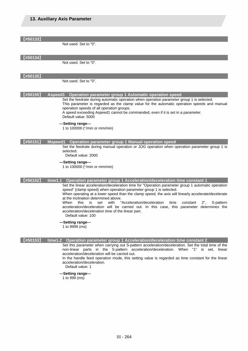
13. Auxiliary Axis Parameter
III - 264
【#50133】 Not used. Set to "0".
【#50134】 Not used. Set to "0".
【#50135】 Not used. Set to "0".
【#50150】 Aspeed1 Operation parameter group 1 Automatic operation speed Set the feedrate during automatic operation when operation parameter group 1 is selected. This parameter is regarded as the clamp value for the automatic operation speeds and manual operation speeds of all operation groups. A speed exceeding Aspeed1 cannot be commanded, even if it is set in a parameter. Default value: 5000
---Setting range--- 1 to 100000 (°/min or mm/min)
【#50151】 Mspeed1 Operation parameter group 1 Manual operation speed Set the feedrate during manual operation or JOG operation when operation parameter group 1 is selected.
Default value: 2000
---Setting range--- 1 to 100000 (°/min or mm/min)
【#50152】 time1.1 Operation parameter group 1 Acceleration/deceleration time constant 1 Set the linear acceleration/deceleration time for "Operation parameter group 1 automatic operation speed" (clamp speed) when operation parameter group 1 is selected. When operating at a lower speed than the clamp speed, the axis will linearly accelerate/decelerate at the inclination determined above. When this is set with "Acceleration/deceleration time constant 2", S-pattern acceleration/deceleration will be carried out. In this case, this parameter determines the acceleration/deceleration time of the linear part.
Default value: 100
---Setting range--- 1 to 9999 (ms)
【#50153】 time1.2 Operation parameter group 1 Acceleration/deceleration time constant 2 Set this parameter when carrying out S-pattern acceleration/deceleration. Set the total time of the non-linear parts in the S-pattern acceleration/deceleration. When "1" is set, linear acceleration/deceleration will be carried out. In the handle feed operation mode, this setting value is regarded as time constant for the linear acceleration/deceleration.
Default value: 1
---Setting range--- 1 to 999 (ms)

13. Auxiliary Axis Parameter
III - 265
【#50154】 TL1 Operation parameter group 1 Torque limit value Set the motor output torque limit value when operation parameter group 1 is selected. At the default value, the torque is limited at the maximum torque of the motor specifications. Set the default value when torque limit is not especially required. In the stopper positioning operation mode, this will be regarded as torque limit value when positioning to the stopper starting coordinates.
Default value: 500
---Setting range--- 1 to 500 (%)
【#50155】 OD1 Operation parameter group 1 Excessive error detection width Set the excessive error detection width when operation parameter group 1 is selected. The excessive error alarm (S03 0052) will be detected when the position droop becomes larger than this setting value. In the stopper positioning operation mode, this will be regarded as excessive error detection width when positioning to the stopper starting coordinates.
Default value: 100
---Setting range--- 0 to 32767 (° or mm)
【#50156】 just1 Operation parameter group 1 Set position output width Set the tolerable value at which "set position reached" (JST) or "automatic set position reached" (JSTA) signal is output when operation parameter group 1 is selected. "Set position reached" (JST) indicates that the machine position is at any station. During automatic operation, "automatic set position reached" (JSTA) is also output under the same condition. These signals will turn OFF when the machine position moves away from the station over this value.
Default value: 0.500
---Setting range--- 0.000 to 99999.999 (° or mm)
【#50157】 near1 Operation parameter group 1 Near set position output width Set the tolerable value at which "near set position" (NEAR) signal is output when operation parameter group 1 is selected. "Near set position" (NEAR) indicates that the machine position is near any station position. This value is generally set wider than the set position output width. During operations, this is related to the special commands when the station selection is set to "0".
Default value: 1.000
---Setting range--- 0.000 to 99999.999 (° or mm)
【#50158】 Aspeed2 Operation parameter group 2 Automatic operation speed Set the feedrate during automatic operation when operation parameter group 2 is selected.
Default value: 5000
---Setting range--- 1 to 100000 (°/min or mm/min)
【#50159】 Mspeed2 Operation parameter group 2 Manual operation speed Set the feedrate during manual operation or JOG operation when operation parameter group 2 is selected.
Default value: 2000
---Setting range--- 1 to 100000 (°/min or mm/min)
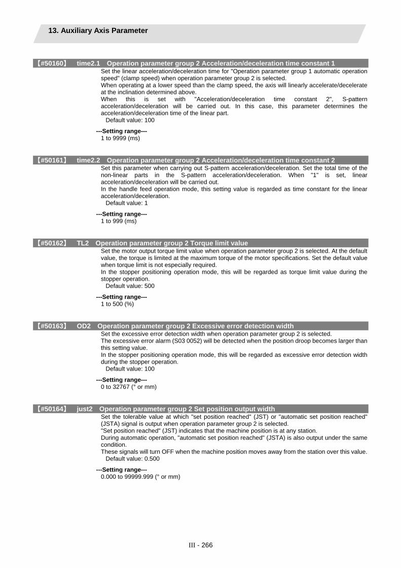
13. Auxiliary Axis Parameter
III - 266
【#50160】 time2.1 Operation parameter group 2 Acceleration/deceleration time constant 1 Set the linear acceleration/deceleration time for "Operation parameter group 1 automatic operation speed" (clamp speed) when operation parameter group 2 is selected. When operating at a lower speed than the clamp speed, the axis will linearly accelerate/decelerate at the inclination determined above. When this is set with "Acceleration/deceleration time constant 2", S-pattern acceleration/deceleration will be carried out. In this case, this parameter determines the acceleration/deceleration time of the linear part.
Default value: 100
---Setting range--- 1 to 9999 (ms)
【#50161】 time2.2 Operation parameter group 2 Acceleration/deceleration time constant 2 Set this parameter when carrying out S-pattern acceleration/deceleration. Set the total time of the non-linear parts in the S-pattern acceleration/deceleration. When "1" is set, linear acceleration/deceleration will be carried out. In the handle feed operation mode, this setting value is regarded as time constant for the linear acceleration/deceleration.
Default value: 1
---Setting range--- 1 to 999 (ms)
【#50162】 TL2 Operation parameter group 2 Torque limit value Set the motor output torque limit value when operation parameter group 2 is selected. At the default value, the torque is limited at the maximum torque of the motor specifications. Set the default value when torque limit is not especially required. In the stopper positioning operation mode, this will be regarded as torque limit value during the stopper operation.
Default value: 500
---Setting range--- 1 to 500 (%)
【#50163】 OD2 Operation parameter group 2 Excessive error detection width Set the excessive error detection width when operation parameter group 2 is selected. The excessive error alarm (S03 0052) will be detected when the position droop becomes larger than this setting value. In the stopper positioning operation mode, this will be regarded as excessive error detection width during the stopper operation.
Default value: 100
---Setting range--- 0 to 32767 (° or mm)
【#50164】 just2 Operation parameter group 2 Set position output width Set the tolerable value at which "set position reached" (JST) or "automatic set position reached" (JSTA) signal is output when operation parameter group 2 is selected. "Set position reached" (JST) indicates that the machine position is at any station. During automatic operation, "automatic set position reached" (JSTA) is also output under the same condition. These signals will turn OFF when the machine position moves away from the station over this value.
Default value: 0.500
---Setting range--- 0.000 to 99999.999 (° or mm)

13. Auxiliary Axis Parameter
III - 267
【#50165】 near2 Operation parameter group 2 Near set position output width Set the tolerable value at which "near set position" (NEAR) signal is output when operation parameter group 2 is selected. "Near set position" (NEAR) indicates that the machine position is near any station position. This value is generally set wider than the set position output width. During operations, this is related to the special commands when the station selection is set to "0".
Default value: 1.000
---Setting range--- 0.000 to 99999.999 (° or mm)
【#50166】 Aspeed3 Operation parameter group 3 Automatic operation speed Set the feedrate during automatic operation when operation parameter group 3 is selected.
Default value: 5000
---Setting range--- 1 to 100000 (°/min or mm/min)
【#50167】 Mspeed3 Operation parameter group 3 Manual operation speed Set the feedrate during manual operation or JOG operation when operation parameter group 3 is selected.
Default value: 2000
---Setting range--- 1 to 100000 (°/min or mm/min)
【#50168】 time3.1 Operation parameter group 3 Acceleration/deceleration time constant 1 Set the linear acceleration/deceleration time for "Operation parameter group 3 automatic operation speed" (clamp speed) when operation parameter group 1 is selected. When operating at a lower speed than the clamp speed, the axis will linearly accelerate/decelerate at the inclination determined above. When this is set with "Acceleration/deceleration time constant 2", S-pattern acceleration/deceleration will be carried out. In this case, this parameter determines the acceleration/deceleration time of the linear part.
Default value: 100
---Setting range--- 1 to 9999 (ms)
【#50169】 time3.2 Operation parameter group 3 Acceleration/deceleration time constant 2 Set this parameter when carrying out S-pattern acceleration/deceleration. Set the total time of the non-linear parts in the S-pattern acceleration/deceleration. When "1" is set, linear acceleration/deceleration will be carried out. In the handle feed operation mode, this setting value is regarded as time constant for the linear acceleration/deceleration.
Default value: 1
---Setting range--- 1 to 999 (ms)
【#50170】 TL3 Operation parameter group 3 Torque limit value Set the motor output torque limit value when operation parameter group 3 is selected. At the default value, the torque is limited at the maximum torque of the motor specifications. Set the default value when torque limit is not especially required. In the stopper positioning operation mode, this will be regarded as pressing torque limit value after completion of the positioning.
Default value: 500
---Setting range--- 1 to 500 (%)

13. Auxiliary Axis Parameter
III - 268
【#50171】 OD3 Operation parameter group 3 Excessive error detection width Set the excessive error detection width when operation parameter group 3 is selected. The excessive error alarm (S03 0052) will be detected when the position droop becomes larger than this setting value. In the stopper positioning operation mode, this will be regarded as excessive error detection width during pressing after completion of the positioning.
Default value: 100
---Setting range--- 0 to 32767 (° or mm)
【#50172】 just3 Operation parameter group 3 Set position output width Set the tolerable value at which "set position reached" (JST) or "automatic set position reached" (JSTA) signal is output when operation parameter group 3 is selected. "Set position reached" (JST) indicates that the machine position is at any station. During automatic operation, "automatic set position reached" (JSTA) is also output under the same condition. These signals will turn OFF when the machine position moves away from the station over this value.
Default value: 0.500
---Setting range--- 0.000 to 99999.999 (° or mm)
【#50173】 near3 Operation parameter group 3 Near set position output width Set the tolerable value at which "near set position" (NEAR) signal is output when operation parameter group 3 is selected. "Near set position" (NEAR) indicates that the machine position is near any station position. This value is generally set wider than the set position output width. During operations, this is related to the special commands when the station selection is set to "0".
Default value: 1.000
---Setting range--- 0.000 to 99999.999 (° or mm)
【#50174】 Aspeed4 Operation parameter group 4 Automatic operation speed Set the feedrate during automatic operation when operation parameter group 4 is selected.
Default value: 5000
---Setting range--- 1 to 100000 (°/min or mm/min)
【#50175】 Mspeed4 Operation parameter group 4 Manual operation speed Set the feedrate during manual operation or JOG operation when operation parameter group 4 is selected.
Default value: 2000
---Setting range--- 1 to 100000 (°/min or mm/min)
【#50176】 time4.1 Operation parameter group 4 Acceleration/deceleration time constant 1 Set the linear acceleration/deceleration time for "Operation parameter group 1 automatic operation speed" (clamp speed) when operation parameter group 4 is selected. When operating at a lower speed than the clamp speed, the axis will linearly accelerate/decelerate at the inclination determined above. When this is set with "Acceleration/deceleration time constant 2", S-pattern acceleration/deceleration will be carried out. In this case, this parameter determines the acceleration/deceleration time of the linear part.
Default value: 100
---Setting range--- 1 to 9999 (ms)

13. Auxiliary Axis Parameter
III - 269
【#50177】 time4.2 Operation parameter group 4 Acceleration/deceleration time constant 2 Set this parameter when carrying out S-pattern acceleration/deceleration. Set the total time of the non-linear parts in the S-pattern acceleration/deceleration. When "1" is set, linear acceleration/deceleration will be carried out. In the handle feed operation mode, this setting value is regarded as time constant for the linear acceleration/deceleration.
Default value: 1
---Setting range--- 1 to 999 (ms)
【#50178】 TL4 Operation parameter group 4 Torque limit value Set the motor output torque limit value when operation parameter group 4 is selected. At the default value, the torque is limited at the maximum torque of the motor specifications. Set the default value when torque limit is not especially required. In the stopper method initializing mode in absolute position detection system, this is regarded as torque limit value during stopper operation.
Default value: 500
---Setting range--- 1 to 500 (%)
【#50179】 OD4 Operation parameter group 4 Excessive error detection width Set the excessive error detection width when operation parameter group 4 is selected. The excessive error alarm (S03 0052) will be detected when the position droop becomes larger than this setting value. In the stopper method initializing mode in absolute position detection system, this is regarded as excessive error detection width during stopper operation.
Default value: 100
---Setting range--- 0 to 32767 (° or mm)
【#50180】 just4 Operation parameter group 4 Set position output width Set the tolerable value at which "set position reached" (JST) or "automatic set position reached" (JSTA) signal is output when operation parameter group 4 is selected. "Set position reached" (JST) indicates that the machine position is at any station. During automatic operation, "automatic set position reached" (JSTA) is also output under the same condition. These signals will turn OFF when the machine position moves away from the station over this value.
Default value: 0.500
---Setting range--- 0.000 to 99999.999 (° or mm)
【#50181】 near4 Operation parameter group 4 Near set position output width Set the tolerable value at which "near set position" (NEAR) signal is output when operation parameter group 4 is selected. "Near set position" (NEAR) indicates that the machine position is near any station position. This value is generally set wider than the set position output width. During operations, this is related to the special commands when the station selection is set to "0".
Default value: 1.000
---Setting range--- 0.000 to 99999.999 (° or mm)
【#50190】 stpos2 Station 2 coordinate Set the station 2 coordinate value when non-uniform assignment is selected. The station 1 coordinate value is fixed at "0.000" (machine coordinate zero point).
Default value: 0.000
---Setting range--- -99999.999 to 99999.999 (° or mm)

13. Auxiliary Axis Parameter
III - 270
【#50191】 stpos3 Station 3 coordinate Set the station 3 coordinate value when non-uniform assignment is selected. The station 1 coordinate value is fixed at "0.000" (machine coordinate zero point).
Default value: 0.000
---Setting range--- -99999.999 to 99999.999 (° or mm)
【#50192】 stpos4 Station 4 coordinate Set the station 4 coordinate value when non-uniform assignment is selected. The station 1 coordinate value is fixed at "0.000" (machine coordinate zero point).
Default value: 0.000
---Setting range--- -99999.999 to 99999.999 (° or mm)
【#50193】 stpos5 Station 5 coordinate Set the station 5 coordinate value when non-uniform assignment is selected. The station 1 coordinate value is fixed at "0.000" (machine coordinate zero point).
Default value: 0.000
---Setting range--- -99999.999 to 99999.999 (° or mm)
【#50194】 stpos6 Station 6 coordinate Set the station 6 coordinate value when non-uniform assignment is selected. The station 1 coordinate value is fixed at "0.000" (machine coordinate zero point).
Default value: 0.000
---Setting range--- -99999.999 to 99999.999 (° or mm)
【#50195】 stpos7 Station 7 coordinate Set the station 7 coordinate value when non-uniform assignment is selected. The station 1 coordinate value is fixed at "0.000" (machine coordinate zero point).
Default value: 0.000
---Setting range--- -99999.999 to 99999.999 (° or mm)
【#50196】 stpos8 Station 8 coordinate Set the station 8 coordinate value when non-uniform assignment is selected. The station 1 coordinate value is fixed at "0.000" (machine coordinate zero point).
Default value: 0.000
---Setting range--- -99999.999 to 99999.999 (° or mm)
【#50197】 stpos9 Station 9 coordinate Set the coordinate of each station when non-uniform assignment is selected. The station 1 coordinate value is fixed at "0.000" (machine coordinate zero point).
Default value: 0.000
---Setting range--- -99999.999 to 99999.999 (° or mm)

13. Auxiliary Axis Parameter
III - 271
【#50200】 PSWcheck PSW detection method Select the criterion for the output of position switches 1 to 8. bit0 to 7 correspond to position switches 1 to 8.
0: Judged by the machine position of the command system. 1: Judged by the machine FB position (actual position).
The bits that are not written here must be set to "0".
【#50201】 PSW1 dog1 PSW1 area setting 1 Set "PSW1 area setting" 1 and 2 to specify the area where the position switch 1 will turn ON when the machine is positioned. Whether the value of setting 1 is larger than setting 2 (or vice versa) does not affect the position switch operation. For rotary axes, the output turns ON in the area excluding 0.000 degree.
Default value: 0.000
---Setting range--- -99999.999 to 99999.999 (° or mm)
【#50202】 PSW1 dog2 PSW1 area setting 2 Set "PSW1 area setting" 1 and 2 to specify the area where the position switch 1 will turn ON when the machine is positioned. Whether the value of setting 1 is larger than setting 2 (or vice versa) does not affect the position switch operation. For rotary axes, the output turns ON in the area excluding 0.000 degree.
Default value: 0.000
---Setting range--- -99999.999 to 99999.999 (° or mm)
【#50203】 PSW2 dog1 PSW2 area setting 1 Set "PSW2 area setting" 1 and 2 to specify the area where the position switch 2 will turn ON when the machine is positioned. Whether the value of setting 1 is larger than setting 2 (or vice versa) does not affect the position switch operation. For rotary axes, the output turns ON in the area excluding 0.000 degree.
Default value: 0.000
---Setting range--- -99999.999 to 99999.999 (° or mm)
【#50204】 PSW2 dog2 PSW2 area setting 2 Set "PSW2 area setting" 1 and 2 to specify the area where the position switch 2 will turn ON when the machine is positioned. Whether the value of setting 1 is larger than setting 2 (or vice versa) does not affect the position switch operation. For rotary axes, the output turns ON in the area excluding 0.000 degree.
Default value: 0.000
---Setting range--- -99999.999 to 99999.999 (° or mm)
【#50205】 PSW3 dog1 PSW3 area setting 1 Set "PSW3 area setting" 1 and 2 to specify the area where the position switch 3 will turn ON when the machine is positioned. Whether the value of setting 1 is larger than setting 2 (or vice versa) does not affect the position switch operation. For rotary axes, the output turns ON in the area excluding 0.000 degree.
Default value: 0.000
---Setting range--- -99999.999 to 99999.999 (° or mm)

13. Auxiliary Axis Parameter
III - 272
【#50206】 PSW3 dog2 PSW3 area setting 2 Set "PSW3 area setting" 1 and 2 to specify the area where the position switch 3 will turn ON when the machine is positioned. Whether the value of setting 1 is larger than setting 2 (or vice versa) does not affect the position switch operation. For rotary axes, the output turns ON in the area excluding 0.000 degree.
Default value: 0.000
---Setting range--- -99999.999 to 99999.999 (° or mm)
【#50207】 PSW4 dog1 PSW4 area setting 1 Set "PSW4 area setting" 1 and 2 to specify the area where the position switch 4 will turn ON when the machine is positioned. Whether the value of setting 1 is larger than setting 2 (or vice versa) does not affect the position switch operation. For rotary axes, the output turns ON in the area excluding 0.000 degree.
Default value: 0.000
---Setting range--- -99999.999 to 99999.999 (° or mm)
【#50208】 PSW4 dog2 PSW4 area setting 2 Set "PSW4 area setting" 1 and 2 to specify the area where the position switch 4 will turn ON when the machine is positioned. Whether the value of setting 1 is larger than setting 2 (or vice versa) does not affect the position switch operation. For rotary axes, the output turns ON in the area excluding 0.000 degree.
Default value: 0.000
---Setting range--- -99999.999 to 99999.999 (° or mm)
【#50209】 PSW5 dog1 PSW5 area setting 1 Set "PSW5 area setting" 1 and 2 to specify the area where the position switch 5 will turn ON when the machine is positioned. Whether the value of setting 1 is larger than setting 2 (or vice versa) does not affect the position switch operation. For rotary axes, the output turns ON in the area excluding 0.000 degree.
Default value: 0.000
---Setting range--- -99999.999 to 99999.999 (° or mm)
【#50210】 PSW5 dog2 PSW5 area setting 2 Set "PSW5 area setting" 1 and 2 to specify the area where the position switch 5 will turn ON when the machine is positioned. Whether the value of setting 1 is larger than setting 2 (or vice versa) does not affect the position switch operation. For rotary axes, the output turns ON in the area excluding 0.000 degree.
Default value: 0.000
---Setting range--- -99999.999 to 99999.999 (° or mm)

13. Auxiliary Axis Parameter
III - 273
【#50211】 PSW6 dog1 PSW6 area setting 1 Set "PSW6 area setting" 1 and 2 to specify the area where the position switch 6 will turn ON when the machine is positioned. Whether the value of setting 1 is larger than setting 2 (or vice versa) does not affect the position switch operation. For rotary axes, the output turns ON in the area excluding 0.000 degree.
Default value: 0.000
---Setting range--- -99999.999 to 99999.999 (° or mm)
【#50212】 PSW6 dog2 PSW6 area setting 2 Set "PSW6 area setting" 1 and 2 to specify the area where the position switch 6 will turn ON when the machine is positioned. Whether the value of setting 1 is larger than setting 2 (or vice versa) does not affect the position switch operation. For rotary axes, the output turns ON in the area excluding 0.000 degree.
Default value: 0.000
---Setting range--- -99999.999 to 99999.999 (° or mm)
【#50213】 PSW7 dog1 PSW7 area setting 1 Set "PSW7 area setting" 1 and 2 to specify the area where the position switch 7 will turn ON when the machine is positioned. Whether the value of setting 1 is larger than setting 2 (or vice versa) does not affect the position switch operation. For rotary axes, the output turns ON in the area excluding 0.000 degree.
Default value: 0.000
---Setting range--- -99999.999 to 99999.999 (° or mm)
【#50214】 PSW7 dog2 PSW7 area setting 2 Set "PSW7 area setting" 1 and 2 to specify the area where the position switch 7 will turn ON when the machine is positioned. Whether the value of setting 1 is larger than setting 2 (or vice versa) does not affect the position switch operation. For rotary axes, the output turns ON in the area excluding 0.000 degree.
Default value: 0.000
---Setting range--- -99999.999 to 99999.999 (° or mm)
【#50215】 PSW8 dog1 PSW8 area setting 1 Set "PSW8 area setting" 1 and 2 to specify the area where the position switch 8 will turn ON when the machine is positioned. Whether the value of setting 1 is larger than setting 2 (or vice versa) does not affect the position switch operation. For rotary axes, the output turns ON in the area excluding 0.000 degree.
Default value: 0.000
---Setting range--- -99999.999 to 99999.999 (° or mm)

13. Auxiliary Axis Parameter
III - 274
【#50216】 PSW8 dog2 PSW8 area setting 2 Set "PSW8 area setting" 1 and 2 to specify the area where the position switch 8 will turn ON when the machine is positioned. Whether the value of setting 1 is larger than setting 2 (or vice versa) does not affect the position switch operation. For rotary axes, the output turns ON in the area excluding 0.000 degree.
Default value: 0.000
---Setting range--- -99999.999 to 99999.999 (° or mm)
【#50220】 push.1 Stopper amount Set the command stroke of the stopper operation in the stopper positioning.
Default value: 0.000
---Setting range--- 0.000 to 359.999 (° or mm)
【#50221】 push.t1 Stopper standby time Set the standby time from the stopper starting coordinate positioning to the stopper operation start in the stopper positioning.
Default value: 0
---Setting range--- 0 to 9999 (ms)
【#50222】 push.t2 Stopper torque release time Set the time from the completion of the stopper operation to the changeover of the stopper torque in the stopper positioning.
Default value: 0
---Setting range--- 0 to 9999 (ms)
【#50223】 push.t3 Set position signal output delay time Set the time from the completion of the stopper operation to the output of the “automatic set position reached” (JSTA), “set position reached” (JST) or “near set position” (NEAR) signal in the stopper positioning.
Default setting: 0
---Setting range--- 0 to 9999 (ms)

14. Open Parameter
III - 275
14. Open Parameter
【#29001】 Open param 1 Set LONG data. #29001 to #29896 are used as parameter range where C language modules can be used arbitrarily.
---Setting range--- -
【#29901】 Open param 2 Set DOUBLE data. #29901 to #29996 are used as parameter range where C language modules can be used arbitrarily.
---Setting range--- -

15. CC-Link Parameter 15.1 CC-Link Parameter 1
III - 276
15. CC-Link Parameter Be sure to stop the PLC ladder before changing the parameters. When the parameter has been changed, PLC ladder scanning starts and parameters are updated to set no need to turn the power ON. CC-Link parameters cannot be changed by G10 command.
(Note) “Master station” and “Local/standby master station” next to the Details column shows whether these settings are required or not. “×” means to set “0”.
15.1 CC-Link Parameter 1
“n” in the table represents the extenpansion slot No.(n=1 to 3). Turn the NC power OFF after setting parameters indicated with a (PR) in the table. The setting will be validated after the power is turned ON again.
【#24001+40(n-1)(PR)】 SLn station No. CC-Link station No. Set the station No. of the CC-Link I/F unit. "n" represents the expansion slot No.(n=1 to 3)
-1: Invalid 0: Master station 1 to 64: Slave station
---Master station--- Set a value within the setting range.
---Local/standby master station--- Set a value within the setting range.
---Setting range--- -1 to 64

15. CC-Link Parameter 15.1 CC-Link Parameter 1
III - 277
【#24002+40(n-1)(PR)】 SLn line-spd&Mode CC-Link transmission rate and mode Select the transmission rate and operation mode of the CC-Link I/F unit. "n" represents the expansion slot No.(n=1 to 3)
Setting value
Transmission rate (bps)
Mode
0 156K
1 625K
2 2.5M
3 5M
4 10M
Online
5 156K
6 625K
7 2.5M
8 5M
9 10M
Circuit test
10 156K
11 625K
12 2.5M
13 5M
14 10M
Hardware test (Note) Perform hardware
test after removing the CC-Link cable.
---Master station---
Set a value within the setting range.
---Local/standby master station--- Set a value within the setting range.
---Setting range--- 0 to 14
【#24003+40(n-1)(PR)】 SLn set fault sta Setting of data link faulty station Select whether to clear or hold the data input from the data link faulty station. "n" represents the expansion slot No.(n=1 to 3)
0: Clear 1: Hold
(Note) Refer to "CC-Link System Master/Local Module User's Manual (SH(NA)-080394E-E)" for the details of the functions.
---Master station--- Set to "0" or "1".
---Local/standby master station--- Set to "0" or "1".
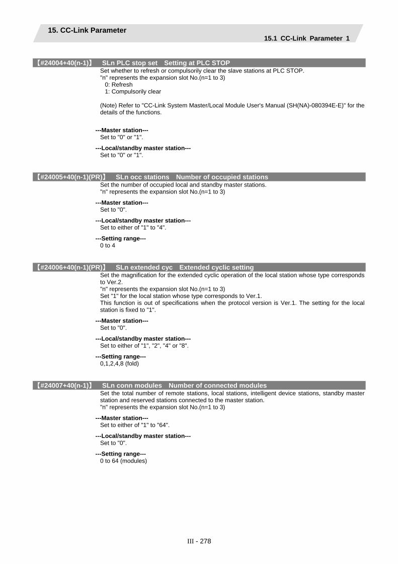
15. CC-Link Parameter 15.1 CC-Link Parameter 1
III - 278
【#24004+40(n-1)】 SLn PLC stop set Setting at PLC STOP Set whether to refresh or compulsorily clear the slave stations at PLC STOP. "n" represents the expansion slot No.(n=1 to 3)
0: Refresh 1: Compulsorily clear
(Note) Refer to "CC-Link System Master/Local Module User's Manual (SH(NA)-080394E-E)" for the details of the functions.
---Master station--- Set to "0" or "1".
---Local/standby master station--- Set to "0" or "1".
【#24005+40(n-1)(PR)】 SLn occ stations Number of occupied stations Set the number of occupied local and standby master stations. "n" represents the expansion slot No.(n=1 to 3)
---Master station--- Set to "0".
---Local/standby master station--- Set to either of "1" to "4".
---Setting range--- 0 to 4
【#24006+40(n-1)(PR)】 SLn extended cyc Extended cyclic setting Set the magnification for the extended cyclic operation of the local station whose type corresponds to Ver.2. "n" represents the expansion slot No.(n=1 to 3) Set "1" for the local station whose type corresponds to Ver.1. This function is out of specifications when the protocol version is Ver.1. The setting for the local station is fixed to "1".
---Master station--- Set to "0".
---Local/standby master station--- Set to either of "1", "2", "4" or "8".
---Setting range--- 0,1,2,4,8 (fold)
【#24007+40(n-1)】 SLn conn modules Number of connected modules Set the total number of remote stations, local stations, intelligent device stations, standby master station and reserved stations connected to the master station. "n" represents the expansion slot No.(n=1 to 3)
---Master station--- Set to either of "1" to "64".
---Local/standby master station--- Set to "0".
---Setting range--- 0 to 64 (modules)

15. CC-Link Parameter 15.1 CC-Link Parameter 1
III - 279
【#24008+40(n-1)】 SLn num of retries Number of retries Set the number of retries for when a communication error occurs. "n" represents the expansion slot No.(n=1 to 3)
---Master station--- Set to either of "1" or "7".
---Local/standby master station--- Set to "0".
---Setting range--- 0 to 7 (times)
【#24009+40(n-1)】 SLn auto ret mdls Number of automatic return modules Set the total number of remote stations, local stations, intelligent device stations and standby master station that can be returned to system operation by a single link scan. "n" represents the expansion slot No.(n=1 to 3) (Note) Refer to "CC-Link System Master/Local Module User's Manual (SH(NA)-080394E-E)" for the details of the functions.
---Master station--- Set to either of "1" or "10".
---Local/standby master station--- Set to "0".
---Setting range--- 0 to 10 (modules)
【#24010+40(n-1)(PR)】 SLn STBY master st Standby master station Set the station No. of the standby master station. "n" represents the expansion slot No.(n=1 to 3) Set "0" when no standby master station is provided.
---Master station--- Set a value within the setting range.
---Local/standby master station--- Set "0" (fixed) for the local station. Set "1" (fixed) for the standby station.
---Setting range--- 0 to 64
【#24011+40(n-1)】 SLn ope at NC down Operation at NC down Set the data link status for when the master station failure occurs. "n" represents the expansion slot No.(n=1 to 3) 0: Fixed to stop (Note) Refer to "CC-Link System Master/Local Module User's Manual (SH(NA)-080394E-E)" for the details of the functions.
---Master station--- Set to "0" (fixed).
---Local/standby master station--- Set to "0".

15. CC-Link Parameter 15.1 CC-Link Parameter 1
III - 280
【#24012+40(n-1)】 SLn scan mode Scan mode Select whether to synchronize the link scan with one ladder scan. "n" represents the expansion slot No.(n=1 to 3) 0: Fixed to synchronize
---Master station--- Set to "0" (fixed).
---Local/standby master station--- Set to "0".
【#24013+40(n-1)】 SLn delay time Delay time Set the delay time. "n" represents the expansion slot No.(n=1 to 3) 0: (Fixed value)
---Master station--- Set to "0" (fixed).
---Local/standby master station--- Set to "0".
【#24014+40(n-1)】 SLn RX dev name Remote input (RX) refresh device name Set the refresh device name of the remote input (RX) to be automatically refreshed. (Example) X "n" represents the expansion slot No.(n=1 to 3) Set "0" when no setting is required.
---Master station--- Set a value within the setting range.
---Local/standby master station--- Set a value within the setting range.
---Setting range--- 0,X,M,L,B,D,W,R

15. CC-Link Parameter 15.1 CC-Link Parameter 1
III - 281
【#24015+40(n-1)】 SLn RX dev No. Remote input (RX) refresh device No. Set the refresh device No. of the remote input (RX) to be automatically refreshed. "n" represents the expansion slot No.(n=1 to 3) (Note 1) When setting parameters in ALL.PRM with using the parameter input/output function, input the device No. of decimal digit. (Example) When setting "X400" for the remote input (RX) refresh device No., input as follows; #24014+40(n-1): "X" #24015+40(n-1): "1024" (Note 2) When the refresh device name has been set, the refresh device No. will be "0". Confirm the refresh device No. after changing the refresh device name. When specifying a bit device, set the address in increments of 16 points. The operation will not be guaranteed unless the address is set in increments of 16 points. (Example) 1000
---Master station--- Set a value within the setting range.
---Local/standby master station--- Set a value within the setting range.
---Setting range--- X: 0 to 5FF M: 0 to 10239 L: 0 to 511 B: 0 to 1FFF D: 0 to 2047 W: 0 to 1FFF R: 8300 to 9799, 9800 to 9899
【#24016+40(n-1)(PR)】 SLn RY dev name Remote output (RY) refresh device name Set the refresh device name of the remote output (RY) to be automatically refreshed. (Example) Y "n" represents the expansion slot No.(n=1 to 3) Set "0" when no setting is required.
---Master station--- Set a value within the setting range.
---Local/standby master station--- Set a value within the setting range.
---Setting range--- 0,Y,M,L,B,D,W,R

15. CC-Link Parameter 15.1 CC-Link Parameter 1
III - 282
【#24017+40(n-1)】 SLn RY dev No. Remote output (RY) refresh device No. Set the refresh device No. of the remote output (RY) to be automatically refreshed. "n" represents the expansion slot No.(n=1 to 3) (Note 1) When setting parameters in ALL.PRM with using the parameter input/output function, input the device No. of decimal digit. (Example) When setting "X400" for the remote input (RX) refresh device No., input as follows; #24014+40(n-1): "X" #24015+40(n-1): "1024" (Note 2) When the refresh device name has been set, the refresh device No. will be "0". Confirm the refresh device No. after changing the refresh device name. When specifying a bit device, set the address in increments of 16 points. The operation will not be guaranteed unless the address is set in increments of 16 points. (Example) 1000
---Master station--- Set a value within the setting range.
---Local/standby master station--- Set a value within the setting range.
---Setting range--- Y: 0 to 5FF M: 0 to 10239 L: 0 to 511 B: 0 to 1FFF D: 0 to 2047 W: 0 to 1FFF R: 8300 to 9799, 9800 to 9899
【#24018+40(n-1)】 SLn RWr dev name Remote register (RWr) refresh device name Set the refresh device name of the remote register (RWr) to be automatically refreshed. (Example) W "n" represents the expansion slot No.(n=1 to 3) Set "0" when no setting is required.
---Master station--- Set a value within the setting range.
---Local/standby master station--- Set a value within the setting range.
---Setting range--- 0,M,L,B,D,W,R

15. CC-Link Parameter 15.1 CC-Link Parameter 1
III - 283
【#24019+40(n-1)】 SLn RWr dev No. Remote register (RWr) refresh device No. Set the refresh device No. of the remote register (RWr) to be automatically refreshed. "n" represents the expansion slot No.(n=1 to 3) (Note 1) When setting parameters in ALL.PRM with using the parameter input/output function, input the device No. of decimal digit. (Example) When setting "X400" for the remote input (RX) refresh device No., input as follows; #24014+40(n-1): "X" #24015+40(n-1): "1024" (Note 2) When the refresh device name has been set, the refresh device No. will be "0". Confirm the refresh device No. after changing the refresh device name. When specifying a bit device, set the address in increments of 16 points. The operation will not be guaranteed unless the address is set in increments of 16 points. (Example) 1FF0
---Master station--- Set a value within the setting range.
---Local/standby master station--- Set a value within the setting range.
---Setting range--- M: 0 to 10239 L: 0 to 511 B: 0 to 1FFF D: 0 to 2047 W: 0 to 1FFF R: 8300 to 9799, 9800 to 9899
【#24020+40(n-1)】 SLn RWw dev name Remote register (RWw) refresh device name Set the refresh device name of the remote register (RWw) to be automatically refreshed. (Example) W "n" represents the expansion slot No.(n=1 to 3) Set "0" when no setting is required.
---Master station--- Set a value within the setting range.
---Local/standby master station--- Set a value within the setting range.
---Setting range--- 0,M,L,B,D,W,R

15. CC-Link Parameter 15.1 CC-Link Parameter 1
III - 284
【#24021+40(n-1)】 SLn RWw dev No. Remote register (RWw) refresh device No. Set the refresh device No. of the remote register (RWw) to be automatically refreshed. "n" represents the expansion slot No.(n=1 to 3) (Note 1) When setting parameters in ALL.PRM with using the parameter input/output function, input the device No. of decimal digit. (Example) When setting "X400" for the remote input (RX) refresh device No., input as follows; #24014+40(n-1): "X" #24015+40(n-1): "1024" (Note 2) When the refresh device name has been set, the refresh device No. will be "0". Confirm the refresh device No. after changing the refresh device name. When specifying a bit device, set the address in increments of 16 points. The operation will not be guaranteed unless the address is set in increments of 16 points. (Example) 1FF0
---Master station--- Set a value within the setting range.
---Local/standby master station--- Set a value within the setting range.
---Setting range--- M: 0 to 10239 L: 0 to 511 B: 0 to 1FFF D: 0 to 2047 W: 0 to 1FFF R: 8300 to 9799, 9800 to 9899
【#24022+40(n-1)】 SLn SB dev name Special relay (SB) refresh device name Set the refresh device name of the special relay (SB) to be automatically refreshed. (Example) SB "n" represents the expansion slot No.(n=1 to 3) Set "0" when no setting is required.
---Master station--- Set a value within the setting range.
---Local/standby master station--- Set a value within the setting range.
---Setting range--- 0,M,L,B,D,W,R,SB

15. CC-Link Parameter 15.1 CC-Link Parameter 1
III - 285
【#24023+40(n-1)】 SLn SB dev No. Special relay (SB) refresh device No. Set the refresh device No. of the special relay (SB) to be automatically refreshed. "n" represents the expansion slot No.(n=1 to 3) (Note 1) When setting parameters in ALL.PRM with using the parameter input/output function, input the device No. of decimal digit. (Example) When setting "X400" for the remote input (RX) refresh device No., input as follows; #24014+40(n-1): "X" #24015+40(n-1): "1024" (Note 2) When the refresh device name has been set, the refresh device No. will be "0". Confirm the refresh device No. after changing the refresh device name. When specifying a bit device, set the address in increments of 16 points. The operation will not be guaranteed unless the address is set in increments of 16 points. (Example) 1F0
---Master station--- Set a value within the setting range.
---Local/standby master station--- Set a value within the setting range.
---Setting range--- M: 0 to 10239 L: 0 to 511 B: 0 to 1FFF D: 0 to 2047 W: 0 to 1FFF SB: 0 to 1FF R: 8300 to 9799, 9800 to 9899
【#24024+40(n-1)】 SLn SW dev name Special relay (SW) refresh device name Set the refresh device name of the special relay (SW) to be automatically refreshed. "n" represents the expansion slot No.(n=1 to 3) (Example) SW Set "0" when no setting is required.
---Master station--- Set a value within the setting range.
---Local/standby master station--- Set a value within the setting range.
---Setting range--- 0,M,L,B,D,W,R,SW

15. CC-Link Parameter 15.1 CC-Link Parameter 1
III - 286
【#24025+40(n-1)】 SLn SW dev No. Special relay (SW) refresh device No. Set the refresh device No. of the special relay (SW) to be automatically refreshed. "n" represents the expansion slot No.(n=1 to 3) (Note 1) When setting parameters in ALL.PRM with using the parameter input/output function, input the device No. of decimal digit. (Example) When setting "X400" for the remote input (RX) refresh device No., input as follows; #24014+40(n-1): "X" #24015+40(n-1): "1024" (Note 2) When the refresh device name has been set, the refresh device No. will be "0". Confirm the refresh device No. after changing the refresh device name. When specifying a bit device, set the address in increments of 16 points. (Example) 1F0
---Master station--- Set a value within the setting range.
---Local/standby master station--- Set a value within the setting range.
---Setting range--- M: 0 to 10239 L: 0 to 511 B: 0 to 1FFF D: 0 to 2047 W: 0 to 1FFF SW: 0 to 1FF R: 8300 to 9799, 9800 to 9899
【#24026+40(n-1)(PR)】 SLn Protocol Ver Protocol version Select the CC-Link version mode that has been set to the slide switch SW1-2 on the CC-Link unit (HN566/HN567). "n" represents the expansion slot No.(n=1 to 3)
0: Ver.2 1: Ver.1
Ver.2 mode has been set to SW1-2 as default.
---Master station--- Set to "0" or "1".
---Local/standby master station--- Set to "0" or "1".

15. CC-Link Parameter 15.2 CC-Link Parameter 2
III - 287
15.2 CC-Link Parameter 2 Use these parameters when NC is master station. The ordinal number of the unit, assigned in ascending order of station No., is entered in “m” (m=1 to 64). Parameters for each station are set in series in the order of units regardless of each station No. (Example) When the 1st slave station occupies 4 stations, set the station No.5 to the parameters #24136 to
#24139 for the 2nd. Turn the NC power OFF after setting parameters indicated with a (PR) in the table. The setting will be validated after the power is turned ON again.
【#24121+15(m-1)】 CNm station type Station type Set the type of the connected remote station, local station, intelligent device station and standby master station.
0: No setting 1: Ver.1 remote I/O station 2: Ver.1 remote device station 3: Ver.1 intelligent device station 4: Ver.2 remote device station 5: Ver.2 intelligent device station
"m" means the m-th connected station in ascending order of station No. (m= 1 to 64)
---Master station--- Set to either of "0" to "5".
---Local/standby master station--- Set to "0".
【#24122+15(m-1)】 CNm extended cyc Extended cyclic setting Select the magnification for the extended cycling operation of the connected remote, local and intelligent stations. Set "1" when the protocol version is Ver.1. Set "0" when no setting is required. "m" means the m-th connected station in ascending order of station No. (m=1 to 64)
---Master station--- Set a value within the setting range.
---Local/standby master station--- Set to "0".
---Setting range--- 0,1,2,4,8 (times)
【#24123+15(m-1)】 CNm occ stations Number of occupied stations Set the number of the occupied stations by the connected remote, local and intelligent stations. Set 1 for 8 points I/O and 16 points I/O. Set "0" when no setting is required. "m" means the m-th connected station in ascending order of station No. (m= 1 to 64)
---Master station--- Set a value within the setting range.
---Local/standby master station--- Set to "0".
---Setting range--- 0 to 4 (stations occupied)

15. CC-Link Parameter 15.2 CC-Link Parameter 2
III - 288
【#24124+15(m-1)】 CNm station No. Station No. Set the station No. of the connected remote, local and intelligent stations. Set "0" when no setting is required. "m" means the m-th connected station in ascending order of station No. (m= 1 to 64)
---Master station--- Set a value within the setting range.
---Local/standby master station--- Set to "0".
---Setting range--- 0 to 64
【#24125+15(m-1)】 CNm remote sta pt Remote station points Select the number of points of the connected remote station. "m" means the m-th connected station in ascending order of station No. (m= 1 to 64) The details of setting values differ with each protocol version and station type. Protocol: Ver.2 (station type: Ver.1, remote I/O station)
0: 0 point (reserved station) 1: 8 points 2: 8 points + 8 points reserved 3: 16 points 4: 32 points
•Setting 0 is valid only for the reserved station. When 0 is set for the other stations, the number of points will be 32. • Set the value so that the total number of points of remote I/O stations connected in series will be multiple of 16. (Example 1) 2 units of 8 points I/O: Set "1" for each (Example 2) 3 units of 8 points I/O: Set "1" for the first and the second I/O, "2" for the third. Protocol: Ver.2 (station type: Ver.1 except remote I/O station) 0: 0 point (reserved station) 1 to 4: Automatically calculated • 0 point is valid only for the reserved station. When 0 is set for the other stations, the number of points will be automatically calculated. • Unless 0 is set, the number of points will be automatically calculated with the number of occupied stations and the setting value of the extended cycling. Protocol: Ver.1 (for all station types) 0 to 4: Automatically calculated • 0 cannot be set even for the reserved station. • Automatically calculated with the setting value of the number of occupied stations.
---Master station--- Set a value corresponding to the protocol version and the station type.
---Local/standby master station--- Set to "0".
【#24126+15(m-1)】 CNm set rsvd sta Reserved station Set the reserved/error invalid station. "m" means the m-th connected station in ascending order of station No. (m= 1 to 64)
0: No setting 1: Reserved station 2: Error invalid station
(Note) Refer to "CC-Link System Master/Local Module User's Manual (SH(NA)-080394E-E)" for the details of the functions.
---Master station--- Set either of "0" to "2".
---Local/standby master station--- Set to "0".

15. CC-Link Parameter 15.2 CC-Link Parameter 2
III - 289
【#24131+15(m-1)】 CNm send size Send buffer size Set the allocation of the buffer memory size to the local station, standby master station and intelligent device station when in transient transmission. "m" means the m-th connected station in ascending order of station No. (m= 1 to 64) Set "0" when no setting is required. (Note) The total size of the send/receive buffers must be 4096 (words) or less.
---Master station--- Set a value within the setting range.
---Local/standby master station--- Set to "0".
---Setting range--- 0, 64 to 4096 (words)
【#24132+15(m-1)】 CNm receive size Receive buffer size Set the allocation of the buffer memory size to the local station, standby master station and intelligent device station when in transient transmission. "m" means the m-th connected station in ascending order of station No. (m= 1 to 64) Set "0" when no setting is required. (Note) The total size of the send/receive buffers must be 4096 (words) or less.
---Master station--- Set a value within the setting range.
---Local/standby master station--- Set to "0".
---Setting range--- 0, 64 to 4096 (words)
【#24133+15(m-1)】 CNm auto bfr size Automatic update buffer size Set the allocation of the buffer memory size to the local station, standby master station and intelligent device station when in transient transmission. "m" means the m-th connected station in ascending order of station No. (m= 1 to 64) Set "0" when no setting is required.
---Master station--- Set a value within the setting range.
---Local/standby master station--- Set to "0".
---Setting range--- 0, 128 to 4096 (words)

16. Anshin-net Parameter 2 / MTB-net Parameter 2
III - 290
16. Anshin-net Parameter 2 / MTB-net Parameter 2 Although Anshin-net parameter 2 and MTB-net parameter 2 are set on the different screens, they share some items. “Anshin-net parameter 2” and “MTB-net parameter 2” column shows whether the item is displayed on their screens. Turn the NC power OFF after setting parameters indicated with a (PR) in the table. The setting will be validated after the power is turned ON again.
【#10901(PR)】 Modem tel num Set the PHS modem's registered No. (telephone No.). This is used for the authentication by the host. A hyphen "-" can be used as a delimiting character. This parameter is used as both Anshin-net parameter 2 and MTB-net parameter 2.
---Setting range--- Within 28 characters
【#10902(PR)】 Num dispatch call Set a call No. to Call Center. Enter from the area code for domestic calls. Enter from the communication company No. for international calls. A hyphen "-" can be used as a delimiting character.
---Setting range--- Within 28 characters
【#10903(PR)】 Num arrival call 1 Set the caller's No.: the other party’s telephone No. that is used for INIT authentication. Enter from the area code for domestic calls. Enter from the communication company No. for international calls. This is used to distinguish between received calls from Call Center and those from machine tool builder. A hyphen "-" can be used as a delimiting character.
---Setting range--- Within 28 characters
【#10904(PR)】 Num arrival call 2 Set the caller's No.: the other party’s telephone No. that is used for INIT authentication. Enter from the area code for domestic calls. Enter from the communication company No. for international calls. This is used to distinguish between received calls from Call Center and those from machine tool builder. A hyphen "-" can be used as a delimiting character.
---Setting range--- Within 28 characters
【#10905(PR)】 Num arrival call 3 Set the caller's No.: the other party’s telephone No. that is used for INIT authentication. Enter from the area code for domestic calls. Enter from the communication company No. for international calls. This is used to distinguish between received calls from Call Center and those from machine tool builder. A hyphen "-" can be used as a delimiting character.
---Setting range--- Within 28 characters

16. Anshin-net Parameter 2 / MTB-net Parameter 2
III - 291
【#10906(PR)】 Num arrival call 4 Set the caller's No.: the other party’s telephone No. that is used for INIT authentication. Enter from the area code for domestic calls. Enter from the communication company No. for international calls. This is used to distinguish between received calls from Call Center and those from machine tool builder. A hyphen "-" can be used as a delimiting character.
---Setting range--- Within 28 characters
【#10907(PR)】 Num arrival call 5 Set the caller's No.: the other party’s telephone No. that is used for INIT authentication. Enter from the area code for domestic calls. Enter from the communication company No. for international calls. This is used to distinguish between received calls from Call Center and those from machine tool builder. A hyphen "-" can be used as a delimiting character.
---Setting range--- Within 28 characters
【#10908(PR)】 Num dispatch call Set a call No. to a machine tool builder. Enter from the area code for domestic calls. Enter from the communication company No. for international calls. A hyphen "-" can be used as a delimiting character.
---Setting range--- Within 28 characters
【#10909(PR)】 Num arrival call 1 Set the caller's No.: the other party’s telephone No. that is used for INIT authentication. Enter from the area code for domestic calls. Enter from the communication company No. for international calls. This is used to distinguish between received calls from Call Center and those from machine tool builder. A hyphen "-" can be used as a delimiting character.
---Setting range--- Within 28 characters
【#10910(PR)】 Num arrival call 2 Set the caller's No.: the other party’s telephone No. that is used for INIT authentication. Enter from the area code for domestic calls. Enter from the communication company No. for international calls. This is used to distinguish between received calls from Call Center and those from machine tool builder. A hyphen "-" can be used as a delimiting character.
---Setting range--- Within 28 characters
【#10911(PR)】 Num arrival call 3 Set the caller's No.: the other party’s telephone No. that is used for INIT authentication. Enter from the area code for domestic calls. Enter from the communication company No. for international calls. This is used to distinguish between received calls from Call Center and those from machine tool builder. A hyphen "-" can be used as a delimiting character.
---Setting range--- Within 28 characters
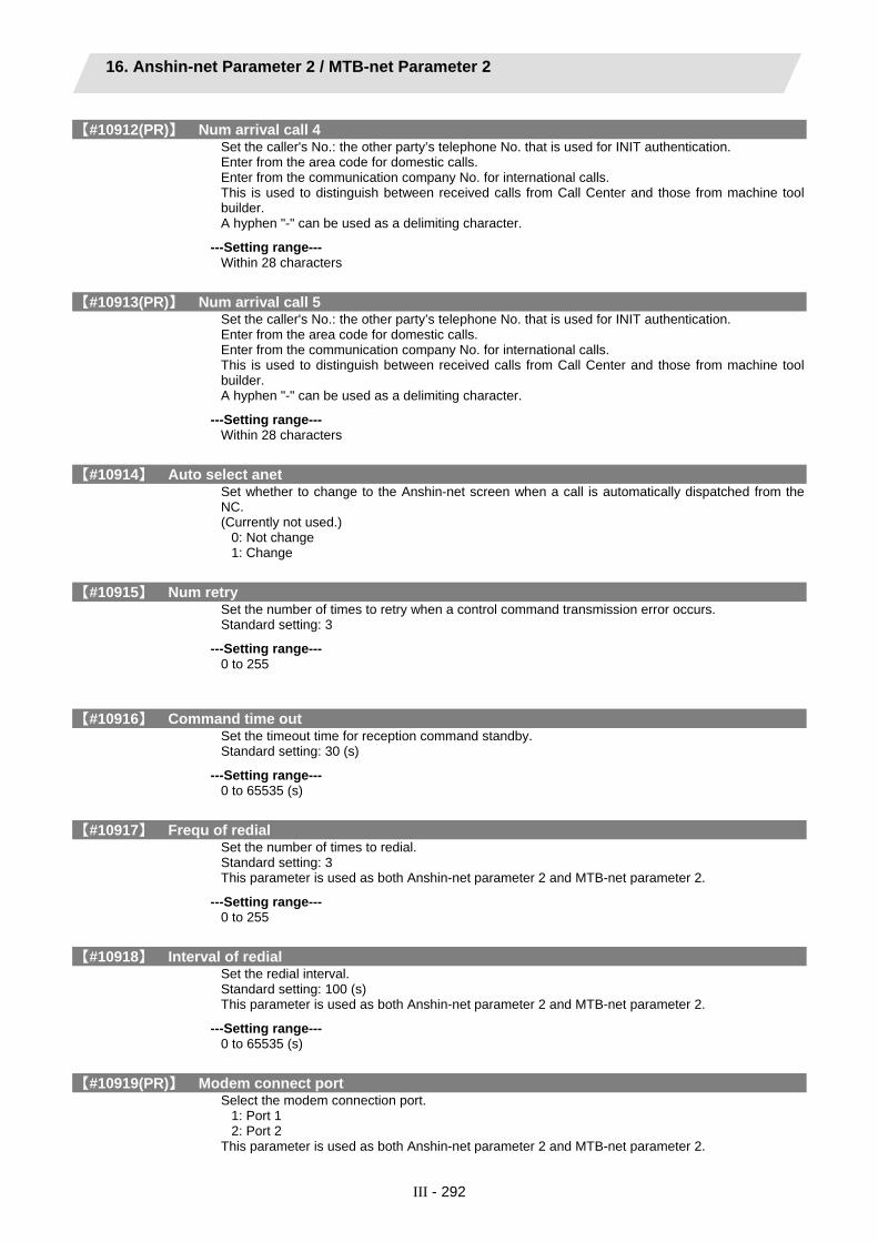
16. Anshin-net Parameter 2 / MTB-net Parameter 2
III - 292
【#10912(PR)】 Num arrival call 4 Set the caller's No.: the other party’s telephone No. that is used for INIT authentication. Enter from the area code for domestic calls. Enter from the communication company No. for international calls. This is used to distinguish between received calls from Call Center and those from machine tool builder. A hyphen "-" can be used as a delimiting character.
---Setting range--- Within 28 characters
【#10913(PR)】 Num arrival call 5 Set the caller's No.: the other party’s telephone No. that is used for INIT authentication. Enter from the area code for domestic calls. Enter from the communication company No. for international calls. This is used to distinguish between received calls from Call Center and those from machine tool builder. A hyphen "-" can be used as a delimiting character.
---Setting range--- Within 28 characters
【#10914】 Auto select anet Set whether to change to the Anshin-net screen when a call is automatically dispatched from the NC. (Currently not used.)
0: Not change 1: Change
【#10915】 Num retry Set the number of times to retry when a control command transmission error occurs. Standard setting: 3
---Setting range--- 0 to 255
【#10916】 Command time out Set the timeout time for reception command standby. Standard setting: 30 (s)
---Setting range--- 0 to 65535 (s)
【#10917】 Frequ of redial Set the number of times to redial. Standard setting: 3 This parameter is used as both Anshin-net parameter 2 and MTB-net parameter 2.
---Setting range--- 0 to 255
【#10918】 Interval of redial Set the redial interval. Standard setting: 100 (s) This parameter is used as both Anshin-net parameter 2 and MTB-net parameter 2.
---Setting range--- 0 to 65535 (s)
【#10919(PR)】 Modem connect port Select the modem connection port.
1: Port 1 2: Port 2
This parameter is used as both Anshin-net parameter 2 and MTB-net parameter 2.

16. Anshin-net Parameter 2 / MTB-net Parameter 2
III - 293
【#10920】 Dial mode select Select the dialing method.
0: Fixed by modem (default) 1: Dial with tone (push) method 2: Dial with pulse (dial) method
This parameter is used as both Anshin-net parameter 2 and MTB-net parameter 2.
【#10921】 Call wait time Set the call back waiting time. Default value: 0 This parameter is used as both Anshin-net parameter 2 and MTB-net parameter 2.
---Setting range--- 0 to 90 (s)
【#10922】 Machine Num Set the machine's serial number as information for the machine tool builder to recognize the machine. This parameter is supposed to be input by the machine tool builder (when shipping or when starting the machine tool builder network). If this is set to blank, the system cannot connect with remote diagnosis tool kit.
---Setting range--- Within 15 characters (one-byte alphanumeric characters)
【#10951(PR)】 Condition kind 1 Set the condition (alarm or PLC signal) for the automatic notification of alarms. Set the alarm type for alarm, device (register) name for PLC signal. <Alarm> Operation alarm (Mxx) Stop code (Txx) Servo alarm (Sxx) Spindle servo alarm (Sxx) System alarm (Zxx) Absolute position detection alarm (Zxx) Emergency stop (EMG) Auxiliary axis servo alarm (Sxx) Auxiliary axis absolute position detection alarm (Zxx) Auxiliary axis OP error (Mxx) Auxiliary axis MCP alarm (Yxx) Computer link error (Lxx) Operation error (Exx) User PLC alarm (PLxx) <Device (resister)> 1-bit data ... X,Y,U,W 16-bit data ... R (Note 1) Set "0" to cancel (set blank for) any setting of #10951 to #10970, "Condition kind" 1 to 10 and "Condition num" 1 to 10. Input "00" when setting "0" for "Condition num". When either of "Condition kind" or "Condition num" is canceled, the condition will not be available for the automatic notification of alarms.
---Setting range--- Within 5 characters

16. Anshin-net Parameter 2 / MTB-net Parameter 2
III - 294
【#10952(PR)】 Condition num 1 Set the condition (alarm or PLC signal) for the automatic notification of alarms. Set the alarm No. for alarm, status value for PLC signal. (Note) Set "0" to cancel (set blank for) any setting of #10951 to #10970, "Condition kind" 1 to 10 and "Condition num" 1 to 10. Input "00" to set "Condition num" to "0". When either of "Condition kind" or "Condition num" is canceled, the condition will not be available for the automatic notification of alarms.
---Setting range--- Within 4 characters
【#10953(PR)】 Condition kind 2 Set the condition (alarm or PLC signal) for the automatic notification of alarms. Set the alarm type for alarm, device (register) name for PLC signal. <Alarm> Operation alarm (Mxx) Stop code (Txx) Servo alarm (Sxx) Spindle servo alarm (Sxx) System alarm (Zxx) Absolute position detection alarm (Zxx) Emergency stop (EMG) Auxiliary axis servo alarm (Sxx) Auxiliary axis absolute position detection alarm (Zxx) Auxiliary axis OP error (Mxx) Auxiliary axis MCP alarm (Yxx) Computer link error (Lxx) Operation error (Exx) User PLC alarm (PLxx) <Device (resister)> 1-bit data ... X,Y,U,W 16-bit data ... R (Note) Set "0" to cancel (set blank for) any setting of #10951 to #10970, "Condition kind" 1 to 10 and "Condition num" 1 to 10. Input "00" to set "Condition num" to "0". When either of "Condition kind" or "Condition num" is canceled, the condition will not be available for the automatic notification of alarms.
---Setting range--- Within 5 characters
【#10954(PR)】 Condition num 2 Set the condition (alarm or PLC signal) for the automatic notification of alarms. Set the alarm No. for alarm, status value for PLC signal. (Note) Set "0" to cancel (set blank for) any setting of #10951 to #10970, "Condition kind" 1 to 10 and "Condition num" 1 to 10. Input "00" to set "Condition num" to "0". When either of "Condition kind" or "Condition num" is canceled, the condition will not be available for the automatic notification of alarms.
---Setting range--- Within 4 characters
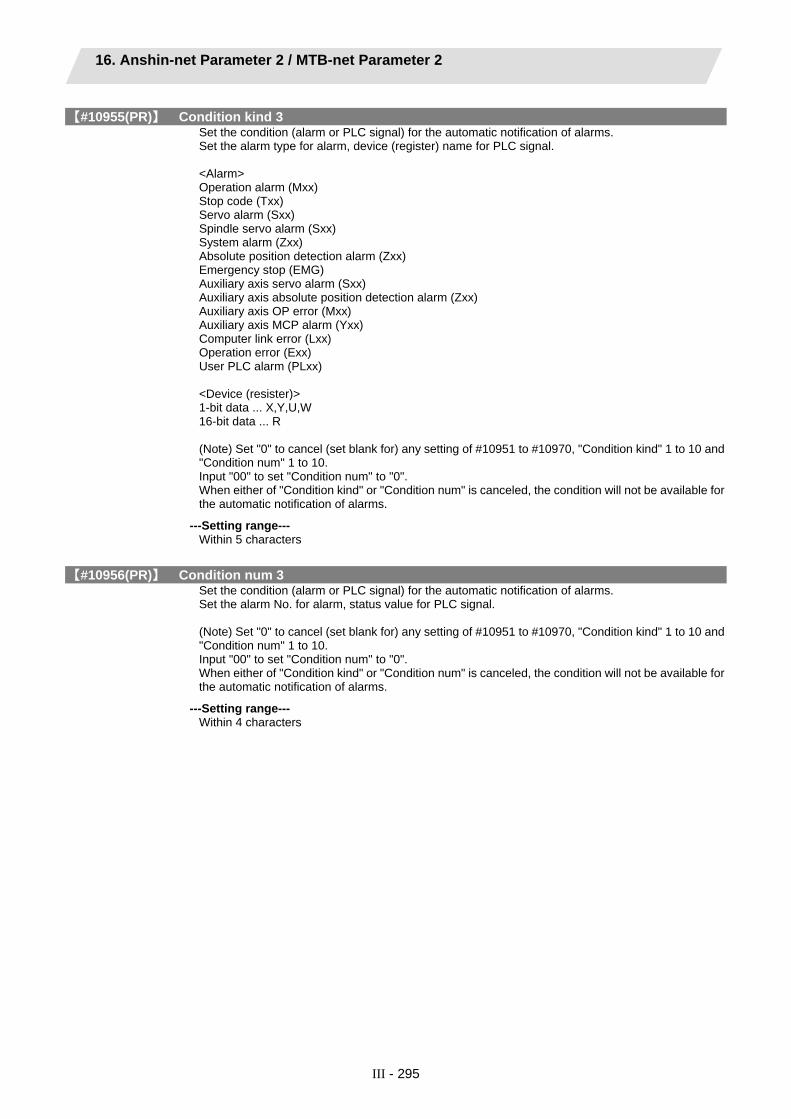
16. Anshin-net Parameter 2 / MTB-net Parameter 2
III - 295
【#10955(PR)】 Condition kind 3 Set the condition (alarm or PLC signal) for the automatic notification of alarms. Set the alarm type for alarm, device (register) name for PLC signal. <Alarm> Operation alarm (Mxx) Stop code (Txx) Servo alarm (Sxx) Spindle servo alarm (Sxx) System alarm (Zxx) Absolute position detection alarm (Zxx) Emergency stop (EMG) Auxiliary axis servo alarm (Sxx) Auxiliary axis absolute position detection alarm (Zxx) Auxiliary axis OP error (Mxx) Auxiliary axis MCP alarm (Yxx) Computer link error (Lxx) Operation error (Exx) User PLC alarm (PLxx) <Device (resister)> 1-bit data ... X,Y,U,W 16-bit data ... R (Note) Set "0" to cancel (set blank for) any setting of #10951 to #10970, "Condition kind" 1 to 10 and "Condition num" 1 to 10. Input "00" to set "Condition num" to "0". When either of "Condition kind" or "Condition num" is canceled, the condition will not be available for the automatic notification of alarms.
---Setting range--- Within 5 characters
【#10956(PR)】 Condition num 3 Set the condition (alarm or PLC signal) for the automatic notification of alarms. Set the alarm No. for alarm, status value for PLC signal. (Note) Set "0" to cancel (set blank for) any setting of #10951 to #10970, "Condition kind" 1 to 10 and "Condition num" 1 to 10. Input "00" to set "Condition num" to "0". When either of "Condition kind" or "Condition num" is canceled, the condition will not be available for the automatic notification of alarms.
---Setting range--- Within 4 characters

16. Anshin-net Parameter 2 / MTB-net Parameter 2
III - 296
【#10957(PR)】 Condition kind 4 Set the condition (alarm or PLC signal) for the automatic notification of alarms. Set the alarm type for alarm, device (register) name for PLC signal. <Alarm> Operation alarm (Mxx) Stop code (Txx) Servo alarm (Sxx) Spindle servo alarm (Sxx) System alarm (Zxx) Absolute position detection alarm (Zxx) Emergency stop (EMG) Auxiliary axis servo alarm (Sxx) Auxiliary axis absolute position detection alarm (Zxx) Auxiliary axis OP error (Mxx) Auxiliary axis MCP alarm (Yxx) Computer link error (Lxx) Operation error (Exx) User PLC alarm (PLxx) <Device (resister)> 1-bit data ... X,Y,U,W 16-bit data ... R (Note) Set "0" to cancel (set blank for) any setting of #10951 to #10970, "Condition kind" 1 to 10 and "Condition num" 1 to 10. Input "00" to set "Condition num" to "0". When either of "Condition kind" or "Condition num" is canceled, the condition will not be available for the automatic notification of alarms.
---Setting range--- Within 5 characters
【#10958(PR)】 Condition num 4 Set the condition (alarm or PLC signal) for the automatic notification of alarms. Set the alarm No. for alarm, status value for PLC signal. (Note) Set "0" to cancel (set blank for) any setting of #10951 to #10970, "Condition kind" 1 to 10 and "Condition num" 1 to 10. Input "00" to set "Condition num" to "0". When either of "Condition kind" or "Condition num" is canceled, the condition will not be available for the automatic notification of alarms.
---Setting range--- Within 4 characters

16. Anshin-net Parameter 2 / MTB-net Parameter 2
III - 297
【#10959(PR)】 Condition kind 5 Set the condition (alarm or PLC signal) for the automatic notification of alarms. Set the alarm type for alarm, device (register) name for PLC signal. <Alarm> Operation alarm (Mxx) Stop code (Txx) Servo alarm (Sxx) Spindle servo alarm (Sxx) System alarm (Zxx) Absolute position detection alarm (Zxx) Emergency stop (EMG) Auxiliary axis servo alarm (Sxx) Auxiliary axis absolute position detection alarm (Zxx) Auxiliary axis OP error (Mxx) Auxiliary axis MCP alarm (Yxx) Computer link error (Lxx) Operation error (Exx) User PLC alarm (PLxx) <Device (resister)> 1-bit data ... X,Y,U,W 16-bit data ... R (Note) Set "0" to cancel (set blank for) any setting of #10951 to #10970, "Condition kind" 1 to 10 and "Condition num" 1 to 10. Input "00" to set "Condition num" to "0". When either of "Condition kind" or "Condition num" is canceled, the condition will not be available for the automatic notification of alarms.
---Setting range--- Within 5 characters
【#10960(PR)】 Condition num 5 Set the condition (alarm or PLC signal) for the automatic notification of alarms. Set the alarm No. for alarm, status value for PLC signal. (Note) Set "0" to cancel (set blank for) any setting of #10951 to #10970, "Condition kind" 1 to 10 and "Condition num" 1 to 10. Input "00" to set "Condition num" to "0". When either of "Condition kind" or "Condition num" is canceled, the condition will not be available for the automatic notification of alarms.
---Setting range--- Within 4 characters
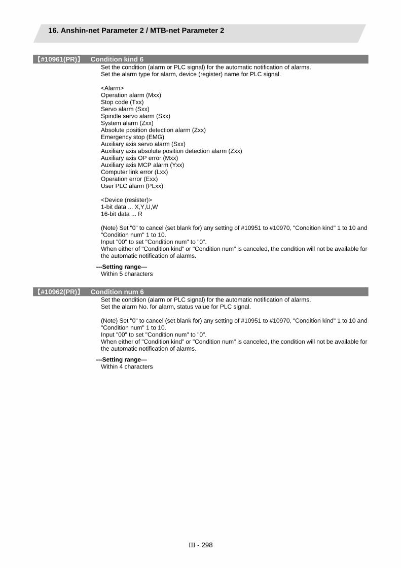
16. Anshin-net Parameter 2 / MTB-net Parameter 2
III - 298
【#10961(PR)】 Condition kind 6 Set the condition (alarm or PLC signal) for the automatic notification of alarms. Set the alarm type for alarm, device (register) name for PLC signal. <Alarm> Operation alarm (Mxx) Stop code (Txx) Servo alarm (Sxx) Spindle servo alarm (Sxx) System alarm (Zxx) Absolute position detection alarm (Zxx) Emergency stop (EMG) Auxiliary axis servo alarm (Sxx) Auxiliary axis absolute position detection alarm (Zxx) Auxiliary axis OP error (Mxx) Auxiliary axis MCP alarm (Yxx) Computer link error (Lxx) Operation error (Exx) User PLC alarm (PLxx) <Device (resister)> 1-bit data ... X,Y,U,W 16-bit data ... R (Note) Set "0" to cancel (set blank for) any setting of #10951 to #10970, "Condition kind" 1 to 10 and "Condition num" 1 to 10. Input "00" to set "Condition num" to "0". When either of "Condition kind" or "Condition num" is canceled, the condition will not be available for the automatic notification of alarms.
---Setting range--- Within 5 characters
【#10962(PR)】 Condition num 6 Set the condition (alarm or PLC signal) for the automatic notification of alarms. Set the alarm No. for alarm, status value for PLC signal. (Note) Set "0" to cancel (set blank for) any setting of #10951 to #10970, "Condition kind" 1 to 10 and "Condition num" 1 to 10. Input "00" to set "Condition num" to "0". When either of "Condition kind" or "Condition num" is canceled, the condition will not be available for the automatic notification of alarms.
---Setting range--- Within 4 characters

16. Anshin-net Parameter 2 / MTB-net Parameter 2
III - 299
【#10963(PR)】 Condition kind 7 Set the condition (alarm or PLC signal) for the automatic notification of alarms. Set the alarm type for alarm, device (register) name for PLC signal. <Alarm> Operation alarm (Mxx) Stop code (Txx) Servo alarm (Sxx) Spindle servo alarm (Sxx) System alarm (Zxx) Absolute position detection alarm (Zxx) Emergency stop (EMG) Auxiliary axis servo alarm (Sxx) Auxiliary axis absolute position detection alarm (Zxx) Auxiliary axis OP error (Mxx) Auxiliary axis MCP alarm (Yxx) Computer link error (Lxx) Operation error (Exx) User PLC alarm (PLxx) <Device (resister)> 1-bit data ... X,Y,U,W 16-bit data ... R (Note) Set "0" to cancel (set blank for) any setting of #10951 to #10970, "Condition kind" 1 to 10 and "Condition num" 1 to 10. Input "00" to set "Condition num" to "0". When either of "Condition kind" or "Condition num" is canceled, the condition will not be available for the automatic notification of alarms.
---Setting range--- Within 5 characters
【#10964(PR)】 Condition num 7 Set the condition (alarm or PLC signal) for the automatic notification of alarms. Set the alarm No. for alarm, status value for PLC signal. (Note) Set "0" to cancel (set blank for) any setting of #10951 to #10970, "Condition kind" 1 to 10 and "Condition num" 1 to 10. Input "00" to set "Condition num" to "0". When either of "Condition kind" or "Condition num" is canceled, the condition will not be available for the automatic notification of alarms.
---Setting range--- Within 4 characters

16. Anshin-net Parameter 2 / MTB-net Parameter 2
III - 300
【#10965(PR)】 Condition kind 8 Set the condition (alarm or PLC signal) for the automatic notification of alarms. Set the alarm type for alarm, device (register) name for PLC signal. <Alarm> Operation alarm (Mxx) Stop code (Txx) Servo alarm (Sxx) Spindle servo alarm (Sxx) System alarm (Zxx) Absolute position detection alarm (Zxx) Emergency stop (EMG) Auxiliary axis servo alarm (Sxx) Auxiliary axis absolute position detection alarm (Zxx) Auxiliary axis OP error (Mxx) Auxiliary axis MCP alarm (Yxx) Computer link error (Lxx) Operation error (Exx) User PLC alarm (PLxx) <Device (resister)> 1-bit data ... X,Y,U,W 16-bit data ... R (Note) Set "0" to cancel (set blank for) any setting of #10951 to #10970, "Condition kind" 1 to 10 and "Condition num" 1 to 10. Input "00" to set "Condition num" to "0". When either of "Condition kind" or "Condition num" is canceled, the condition will not be available for the automatic notification of alarms.
---Setting range--- Within 5 characters
【#10966(PR)】 Condition num 8 Set the condition (alarm or PLC signal) for the automatic notification of alarms. Set the alarm No. for alarm, status value for PLC signal. (Note) Set "0" to cancel (set blank for) any setting of #10951 to #10970, "Condition kind" 1 to 10 and "Condition num" 1 to 10. Input "00" to set "Condition num" to "0". When either of "Condition kind" or "Condition num" is canceled, the condition will not be available for the automatic notification of alarms.
---Setting range--- Within 4 characters

16. Anshin-net Parameter 2 / MTB-net Parameter 2
III - 301
【#10967(PR)】 Condition kind 9 Set the condition (alarm or PLC signal) for the automatic notification of alarms. Set the alarm type for alarm, device (register) name for PLC signal. <Alarm> Operation alarm (Mxx) Stop code (Txx) Servo alarm (Sxx) Spindle servo alarm (Sxx) System alarm (Zxx) Absolute position detection alarm (Zxx) Emergency stop (EMG) Auxiliary axis servo alarm (Sxx) Auxiliary axis absolute position detection alarm (Zxx) Auxiliary axis OP error (Mxx) Auxiliary axis MCP alarm (Yxx) Computer link error (Lxx) Operation error (Exx) User PLC alarm (PLxx) <Device (resister)> 1-bit data ... X,Y,U,W 16-bit data ... R (Note 1) Set "0" to cancel (set blank for) any setting of #10951 to #10970, "Condition kind" 1 to 10 and "Condition num" 1 to 10. Input "00" when setting "0" for "Condition num". When either of "Condition kind" or "Condition num" is canceled, the condition will not be available for the automatic notification of alarms.
---Setting range--- Within 5 characters
【#10968(PR)】 Condition num 9 Set the condition (alarm or PLC signal) for the automatic notification of alarms. Set the alarm No. for alarm, status value for PLC signal. (Note) Set "0" to cancel (set blank for) any setting of #10951 to #10970, "Condition kind" 1 to 10 and "Condition num" 1 to 10. Input "00" to set "Condition num" to "0". When either of "Condition kind" or "Condition num" is canceled, the condition will not be available for the automatic notification of alarms.
---Setting range--- Within 4 characters

16. Anshin-net Parameter 2 / MTB-net Parameter 2
III - 302
【#10969(PR)】 Condition kind 10 Set the condition (alarm or PLC signal) for the automatic notification of alarms. Set the alarm type for alarm, device (register) name for PLC signal. <Alarm> Operation alarm (Mxx) Stop code (Txx) Servo alarm (Sxx) Spindle servo alarm (Sxx) System alarm (Zxx) Absolute position detection alarm (Zxx) Emergency stop (EMG) Auxiliary axis servo alarm (Sxx) Auxiliary axis absolute position detection alarm (Zxx) Auxiliary axis OP error (Mxx) Auxiliary axis MCP alarm (Yxx) Computer link error (Lxx) Operation error (Exx) User PLC alarm (PLxx) <Device (resister)> 1-bit data ... X,Y,U,W 16-bit data ... R (Note) Set "0" to cancel (set blank for) any setting of #10951 to #10970, "Condition kind" 1 to 10 and "Condition num" 1 to 10. Input "00" to set "Condition num" to "0". When either of "Condition kind" or "Condition num" is canceled, the condition will not be available for the automatic notification of alarms.
---Setting range--- Within 5 characters
【#10970(PR)】 Condition num 10 Set the condition (alarm or PLC signal) for the automatic notification of alarms. Set the alarm No. for alarm, status value for PLC signal. (Note) Set "0" to cancel (set blank for) any setting of #10951 to #10970, "Condition kind" 1 to 10 and "Condition num" 1 to 10. Input "00" to set "Condition num" to "0". When either of "Condition kind" or "Condition num" is canceled, the condition will not be available for the automatic notification of alarms.
---Setting range--- Within 4 characters
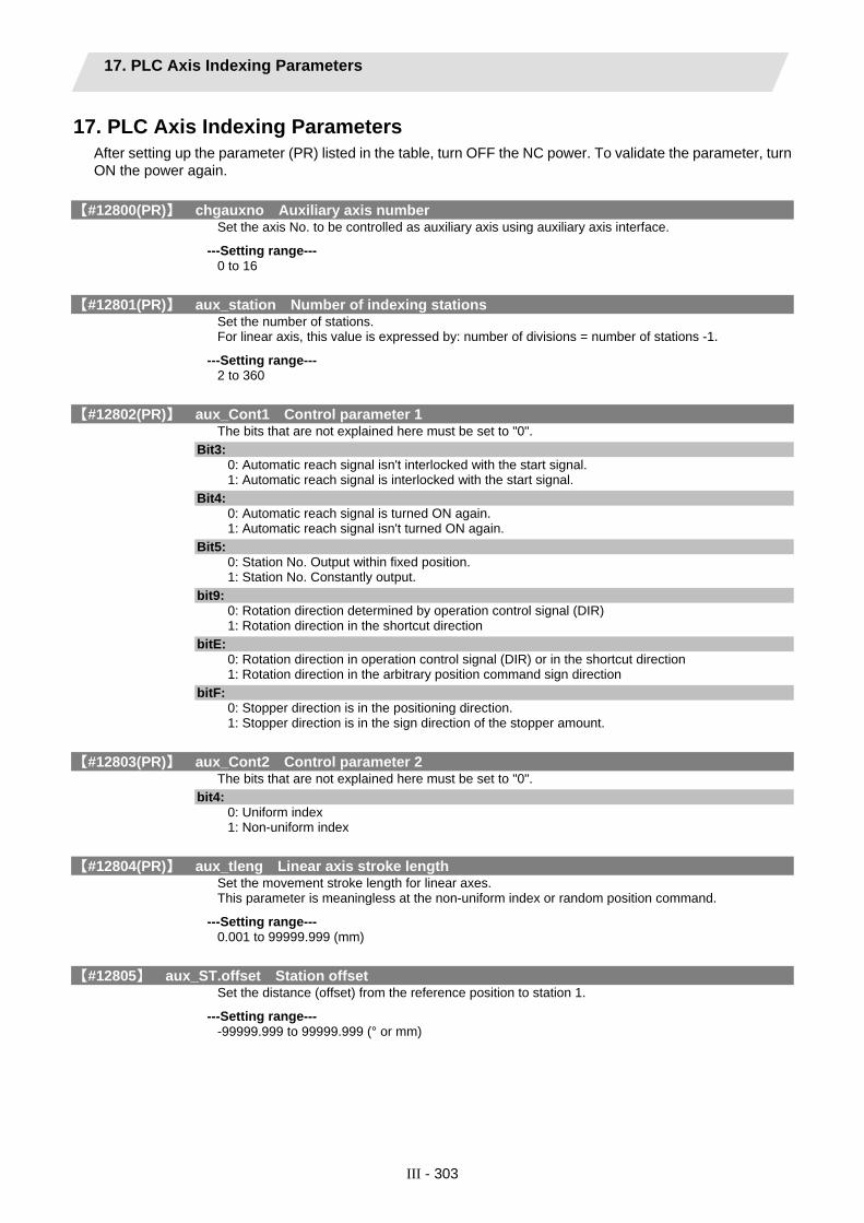
17. PLC Axis Indexing Parameters
III - 303
17. PLC Axis Indexing Parameters After setting up the parameter (PR) listed in the table, turn OFF the NC power. To validate the parameter, turn ON the power again.
【#12800(PR)】 chgauxno Auxiliary axis number Set the axis No. to be controlled as auxiliary axis using auxiliary axis interface.
---Setting range--- 0 to 16
【#12801(PR)】 aux_station Number of indexing stations Set the number of stations. For linear axis, this value is expressed by: number of divisions = number of stations -1.
---Setting range--- 2 to 360
【#12802(PR)】 aux_Cont1 Control parameter 1 The bits that are not explained here must be set to "0".
Bit3: 0: Automatic reach signal isn't interlocked with the start signal. 1: Automatic reach signal is interlocked with the start signal.
Bit4: 0: Automatic reach signal is turned ON again. 1: Automatic reach signal isn't turned ON again.
Bit5: 0: Station No. Output within fixed position. 1: Station No. Constantly output.
bit9: 0: Rotation direction determined by operation control signal (DIR) 1: Rotation direction in the shortcut direction
bitE: 0: Rotation direction in operation control signal (DIR) or in the shortcut direction 1: Rotation direction in the arbitrary position command sign direction
bitF: 0: Stopper direction is in the positioning direction. 1: Stopper direction is in the sign direction of the stopper amount.
【#12803(PR)】 aux_Cont2 Control parameter 2 The bits that are not explained here must be set to "0".
bit4: 0: Uniform index 1: Non-uniform index
【#12804(PR)】 aux_tleng Linear axis stroke length Set the movement stroke length for linear axes. This parameter is meaningless at the non-uniform index or random position command.
---Setting range--- 0.001 to 99999.999 (mm)
【#12805】 aux_ST.offset Station offset Set the distance (offset) from the reference position to station 1.
---Setting range--- -99999.999 to 99999.999 (° or mm)

17. PLC Axis Indexing Parameters
III - 304
【#12810+10(n-1)】 aux_Aspeedn Operation parameter group n Automatic operation speed Set the feedrate during automatic operation when "operation parameter group n" is selected. "#12810 aux_Aspeed1" is regarded as the clamp value for the automatic operation speeds and manual operation speeds of all operation groups. A speed exceeding "aux_Aspeed1" cannot be commanded, even if it is set in a parameter.
---Setting range--- 1 to 100000 (°/min or mm/min)
【#12811+10(n-1)】 aux_Mspeedn Operation parameter group n Manual operation speed Set the feedrate during manual operation or JOG operation when "operation parameter group n" is selected.
---Setting range--- 1 to 100000 (�/min or mm/min)
【#12812+10(n-1)】aux_timen.1 Operation parameter group n Acceleration/deceleration time constant 1 Set the linear acceleration/deceleration time for "Operation parameter group 1 automatic operation speed" (clamp speed) when "operation parameter group n" is selected. When this is set with "Acceleration/deceleration time constant 2", S-pattern acceleration/deceleration will be carried out. In this case, this parameter determines the acceleration/deceleration time of the linear part. When operating at a speed less than the clamp speed, if "#1361 aux_acc" is set to "0", the axis will accelerate/decelerate with the time constant set in this parameter. If "#1361 aux_acc" is set to "1", the axis will accelerate/decelerate at the constant inclination determined by this parameter and "aux_Aspeed1".
---Setting range--- 1 to 4000 (ms)
【#12813+10(n-1)】aux_timen.2 Operation parameter group n Acceleration/deceleration time constant 2 Set the total time of the non-linear parts in the S-pattern acceleration/deceleration. When "1" is set, linear acceleration/deceleration will be carried out. In the handle feed operation mode, this setting value is regarded as time constant for the linear acceleration/deceleration.
---Setting range--- 1 to 4000 (ms)
【#12814+10(n-1)】 aux_TLn Operation parameter group n Torque limit value Set the motor output torque limit value when "operation parameter group n" is selected. At the default value, the torque is limited at the maximum torque of the motor specifications. Set the default value when torque limit is not especially required. In the stopper positioning operation mode, this will be regarded as torque limit value when positioning to the stopper starting coordinates.
---Setting range--- 1 to 500(%)
【#12815+10(n-1)】 aux_ODn Operation parameter group n Excessive error detection width Set the excessive error detection width when "operation parameter group n" is selected. The excessive error alarm (S03 0052) will be detected when the position droop becomes larger than this setting value. In the stopper positioning operation mode, this will be regarded as excessive error detection width when positioning to the stopper starting coordinates. .
---Setting range--- 0 to 32767(� or mm)

17. PLC Axis Indexing Parameters
III - 305
【#12816+10(n-1)】 aux_justn Operation parameter group n Set position output width Set the tolerable value at which "set position reached" (JST) or "automatic set position reached" (JSTA) signal is output when "operation parameter group n" is selected. "Set position reached" (JST) indicates that the machine position is at any station. During automatic operation, "automatic set position reached" (JSTA) is also output under the same condition. These signals will turn OFF when the machine position moves away from the station over this value.
---Setting range--- 0.000 to 99999.999(� or mm)
【#12817+10(n-1)】 aux_nearn Operation parameter group n Near set position output width Set the tolerable value at which "near set position" (NEAR) signal is output when "operation parameter group n" is selected. "Near set position" (NEAR) indicates that the machine position is near any station position. This value is generally set wider than the set position output width. During operations, this is related to the special commands when the station selection is set to "0".
---Setting range--- 0.000 to 99999.999(° or mm)
【#12818+10(n-1)(PR)】 aux_smgstn Operation parameter group n Acceleration/Deceleration type Select the acceleration/deceleration type when "operation parameter group n" is selected. 1: Linear acceleration/deceleration F: S-pattern acceleration/deceleration
【#12850】 aux_stpos2 Station 2 coordinate Set the station 2 coordinate value when non-uniform assignment is selected. The station 1 coordinate value is fixed at "0.000" (machine coordinate zero point).
---Setting range--- -99999.999 to 99999.999(° or mm)
【#12851】 aux_stpos3 Station 3 coordinate Set the station 3 coordinate value when non-uniform assignment is selected. The station 1 coordinate value is fixed at "0.000" (machine coordinate zero point).
---Setting range--- -99999.999 to 99999.999(° or mm)
【#12852】 aux_stpos4 Station 4 coordinate Set the station 4 coordinate value when non-uniform assignment is selected. The station 1 coordinate value is fixed at "0.000" (machine coordinate zero point).
---Setting range--- -99999.999 to 99999.999(° or mm)
【#12853】 aux_stpos5 Station 5 coordinate Set the station 5 coordinate value when non-uniform assignment is selected. The station 1 coordinate value is fixed at "0.000" (machine coordinate zero point).
---Setting range--- -99999.999 to 99999.999(° or mm)
【#12854】 aux_stpos6 Station 6 coordinate Set the station 6 coordinate value when non-uniform assignment is selected. The station 1 coordinate value is fixed at "0.000" (machine coordinate zero point).
---Setting range--- -99999.999 to 99999.999(° or mm)

17. PLC Axis Indexing Parameters
III - 306
【#12855】 aux_stpos7 Station 7 coordinate Set the station 7 coordinate value when non-uniform assignment is selected. The station 1 coordinate value is fixed at "0.000" (machine coordinate zero point).
---Setting range--- -99999.999 to 99999.999(° or mm)
【#12856】 aux_stpos8 Station 8 coordinate Set the station 8 coordinate value when non-uniform assignment is selected. The station 1 coordinate value is fixed at "0.000" (machine coordinate zero point).
---Setting range--- -99999.999 to 99999.999(° or mm)
【#12857】 aux_stpos9 Station 9 coordinate Set the coordinate of each station when non-uniform assignment is selected. The station 1 coordinate value is fixed at "0.000" (machine coordinate zero point).
---Setting range--- -99999.999 to 99999.999(° or mm)
【#12858】 aux_stpos10 Station 10 coordinate Set the station 10 coordinate value when non-uniform assignment is selected. The station 1 coordinate value is fixed at "0.000" (machine coordinate zero point).
---Setting range--- -99999.999 to 99999.999(° or mm)
【#12859】 aux_stpos11 Station 11 coordinate Set the station 11 coordinate value when non-uniform assignment is selected. The station 1 coordinate value is fixed at "0.000" (machine coordinate zero point).
---Setting range--- -99999.999 to 99999.999(° or mm)
【#12860】 aux_stpos12 Station 12 coordinate Set the station 12 coordinate value when non-uniform assignment is selected. The station 1 coordinate value is fixed at "0.000" (machine coordinate zero point).
---Setting range--- -99999.999 to 99999.999(° or mm)
【#12861】 aux_stpos13 Station 13 coordinate Set the station 13 coordinate value when non-uniform assignment is selected. The station 1 coordinate value is fixed at "0.000" (machine coordinate zero point).
---Setting range--- -99999.999 to 99999.999(° or mm)
【#12862】 aux_stpos14 Station 14 coordinate Set the station 14 coordinate value when non-uniform assignment is selected. The station 1 coordinate value is fixed at "0.000" (machine coordinate zero point).
---Setting range--- -99999.999 to 99999.999(° or mm)
【#12863】 aux_stpos15 Station 15 coordinate Set the station 15 coordinate value when non-uniform assignment is selected. The station 1 coordinate value is fixed at "0.000" (machine coordinate zero point).
---Setting range--- -99999.999 to 99999.999(° or mm)
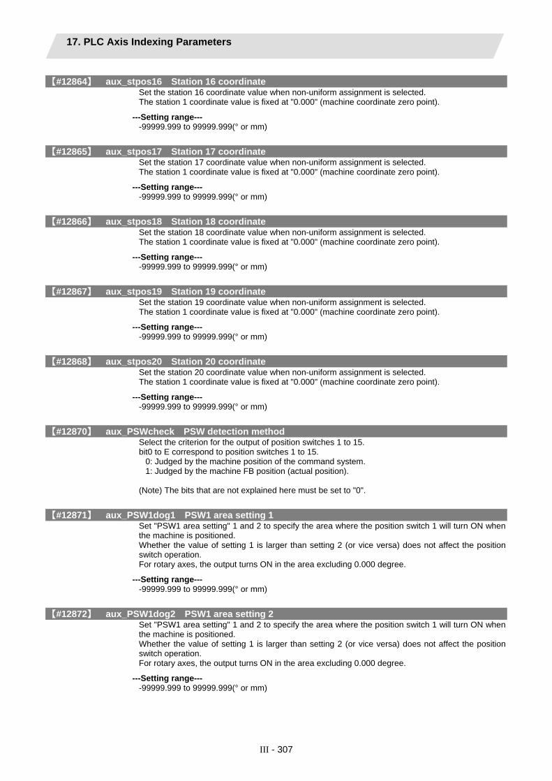
17. PLC Axis Indexing Parameters
III - 307
【#12864】 aux_stpos16 Station 16 coordinate Set the station 16 coordinate value when non-uniform assignment is selected. The station 1 coordinate value is fixed at "0.000" (machine coordinate zero point).
---Setting range--- -99999.999 to 99999.999(° or mm)
【#12865】 aux_stpos17 Station 17 coordinate Set the station 17 coordinate value when non-uniform assignment is selected. The station 1 coordinate value is fixed at "0.000" (machine coordinate zero point).
---Setting range--- -99999.999 to 99999.999(° or mm)
【#12866】 aux_stpos18 Station 18 coordinate Set the station 18 coordinate value when non-uniform assignment is selected. The station 1 coordinate value is fixed at "0.000" (machine coordinate zero point).
---Setting range--- -99999.999 to 99999.999(° or mm)
【#12867】 aux_stpos19 Station 19 coordinate Set the station 19 coordinate value when non-uniform assignment is selected. The station 1 coordinate value is fixed at "0.000" (machine coordinate zero point).
---Setting range--- -99999.999 to 99999.999(° or mm)
【#12868】 aux_stpos20 Station 20 coordinate Set the station 20 coordinate value when non-uniform assignment is selected. The station 1 coordinate value is fixed at "0.000" (machine coordinate zero point).
---Setting range--- -99999.999 to 99999.999(° or mm)
【#12870】 aux_PSWcheck PSW detection method Select the criterion for the output of position switches 1 to 15. bit0 to E correspond to position switches 1 to 15.
0: Judged by the machine position of the command system. 1: Judged by the machine FB position (actual position).
(Note) The bits that are not explained here must be set to "0".
【#12871】 aux_PSW1dog1 PSW1 area setting 1 Set "PSW1 area setting" 1 and 2 to specify the area where the position switch 1 will turn ON when the machine is positioned. Whether the value of setting 1 is larger than setting 2 (or vice versa) does not affect the position switch operation. For rotary axes, the output turns ON in the area excluding 0.000 degree.
---Setting range--- -99999.999 to 99999.999(° or mm)
【#12872】 aux_PSW1dog2 PSW1 area setting 2 Set "PSW1 area setting" 1 and 2 to specify the area where the position switch 1 will turn ON when the machine is positioned. Whether the value of setting 1 is larger than setting 2 (or vice versa) does not affect the position switch operation. For rotary axes, the output turns ON in the area excluding 0.000 degree.
---Setting range--- -99999.999 to 99999.999(° or mm)

17. PLC Axis Indexing Parameters
III - 308
【#12873】 aux_PSW2dog1 PSW2 area setting 1 Set "PSW2 area setting" 1 and 2 to specify the area where the position switch 2 will turn ON when the machine is positioned. Whether the value of setting 1 is larger than setting 2 (or vice versa) does not affect the position switch operation. For rotary axes, the output turns ON in the area excluding 0.000 degree.
---Setting range--- -99999.999 to 99999.999(° or mm)
【#12874】 aux_PSW2dog2 PSW2 area setting 2 Set "PSW2 area setting" 1 and 2 to specify the area where the position switch 2 will turn ON when the machine is positioned. Whether the value of setting 1 is larger than setting 2 (or vice versa) does not affect the position switch operation. For rotary axes, the output turns ON in the area excluding 0.000 degree.
---Setting range--- -99999.999 to 99999.999(° or mm)
【#12875】 aux_PSW3dog1 PSW3 area setting 1 Set "PSW3 area setting" 1 and 2 to specify the area where the position switch 3 will turn ON when the machine is positioned. Whether the value of setting 1 is larger than setting 2 (or vice versa) does not affect the position switch operation. For rotary axes, the output turns ON in the area excluding 0.000 degree.
---Setting range--- -99999.999 to 99999.999(° or mm)
【#12876】 aux_PSW3dog2 PSW3 area setting 2 Set "PSW3 area setting" 1 and 2 to specify the area where the position switch 3 will turn ON when the machine is positioned. Whether the value of setting 1 is larger than setting 2 (or vice versa) does not affect the position switch operation. For rotary axes, the output turns ON in the area excluding 0.000 degree.
---Setting range--- -99999.999 to 99999.999(° or mm)
【#12877】 aux_PSW4dog1 PSW4 area setting 1 Set "PSW4 area setting" 1 and 2 to specify the area where the position switch 4 will turn ON when the machine is positioned. Whether the value of setting 1 is larger than setting 2 (or vice versa) does not affect the position switch operation. For rotary axes, the output turns ON in the area excluding 0.000 degree.
---Setting range--- -99999.999 to 99999.999(° or mm)
【#12878】 aux_PSW4dog2 PSW4 area setting 2 Set "PSW4 area setting" 1 and 2 to specify the area where the position switch 4 will turn ON when the machine is positioned. Whether the value of setting 1 is larger than setting 2 (or vice versa) does not affect the position switch operation. For rotary axes, the output turns ON in the area excluding 0.000 degree.
---Setting range--- -99999.999 to 99999.999(° or mm)

17. PLC Axis Indexing Parameters
III - 309
【#12879】 aux_PSW5dog1 PSW5 area setting 1 Set "PSW5 area setting" 1 and 2 to specify the area where the position switch 5 will turn ON when the machine is positioned. Whether the value of setting 1 is larger than setting 2 (or vice versa) does not affect the position switch operation. For rotary axes, the output turns ON in the area excluding 0.000 degree.
---Setting range--- -99999.999 to 99999.999(° or mm)
【#12880】 aux_PSW5dog2 PSW5 area setting 2 Set "PSW5 area setting" 1 and 2 to specify the area where the position switch 5 will turn ON when the machine is positioned. Whether the value of setting 1 is larger than setting 2 (or vice versa) does not affect the position switch operation. For rotary axes, the output turns ON in the area excluding 0.000 degree.
---Setting range--- -99999.999 to 99999.999(° or mm)
【#12881】 aux_PSW6dog1 PSW6 area setting 1 Set "PSW6 area setting" 1 and 2 to specify the area where the position switch 6 will turn ON when the machine is positioned. Whether the value of setting 1 is larger than setting 2 (or vice versa) does not affect the position switch operation. For rotary axes, the output turns ON in the area excluding 0.000 degree.
---Setting range--- -99999.999 to 99999.999(° or mm)
【#12882】 aux_PSW6dog2 PSW6 area setting 2 Set "PSW6 area setting" 1 and 2 to specify the area where the position switch 6 will turn ON when the machine is positioned. Whether the value of setting 1 is larger than setting 2 (or vice versa) does not affect the position switch operation. For rotary axes, the output turns ON in the area excluding 0.000 degree.
---Setting range--- -99999.999 to 99999.999(° or mm)
【#12883】 aux_PSW7dog1 PSW7 area setting 1 Set "PSW7 area setting" 1 and 2 to specify the area where the position switch 7 will turn ON when the machine is positioned. Whether the value of setting 1 is larger than setting 2 (or vice versa) does not affect the position switch operation. For rotary axes, the output turns ON in the area excluding 0.000 degree.
---Setting range--- -99999.999 to 99999.999(° or mm)
【#12884】 aux_PSW7dog2 PSW7 area setting 2 Set "PSW7 area setting" 1 and 2 to specify the area where the position switch 7 will turn ON when the machine is positioned. Whether the value of setting 1 is larger than setting 2 (or vice versa) does not affect the position switch operation. For rotary axes, the output turns ON in the area excluding 0.000 degree.
---Setting range--- -99999.999 to 99999.999(° or mm)

17. PLC Axis Indexing Parameters
III - 310
【#12885】 aux_PSW8dog1 PSW8 area setting 1 Set "PSW8 area setting" 1 and 2 to specify the area where the position switch 8 will turn ON when the machine is positioned. Whether the value of setting 1 is larger than setting 2 (or vice versa) does not affect the position switch operation. For rotary axes, the output turns ON in the area excluding 0.000 degree.
---Setting range--- -99999.999 to 99999.999(° or mm)
【#12886】 aux_PSW8dog2 PSW8 area setting 2 Set "PSW8 area setting" 1 and 2 to specify the area where the position switch 8 will turn ON when the machine is positioned. Whether the value of setting 1 is larger than setting 2 (or vice versa) does not affect the position switch operation. For rotary axes, the output turns ON in the area excluding 0.000 degree.
---Setting range--- -99999.999 to 99999.999(° or mm)
【#12887】 aux_PSW9dog1 PSW9 area setting 1 Set "PSW9 area setting" 1 and 2 to specify the area where the position switch 9 will turn ON when the machine is positioned. Whether the value of setting 1 is larger than setting 2 (or vice versa) does not affect the position switch operation. For rotary axes, the output turns ON in the area excluding 0.000 degree.
---Setting range--- -99999.999 to 99999.999(° or mm)
【#12888】 aux_PSW9dog2 PSW9 area setting 2 Set "PSW9 area setting" 1 and 2 to specify the area where the position switch 9 will turn ON when the machine is positioned. Whether the value of setting 1 is larger than setting 2 (or vice versa) does not affect the position switch operation. For rotary axes, the output turns ON in the area excluding 0.000 degree.
---Setting range--- -99999.999 to 99999.999(° or mm)
【#12889】 aux_PSW10dog1 PSW10 area setting 1 Set "PSW10 area setting" 1 and 2 to specify the area where the position switch 10 will turn ON when the machine is positioned. Whether the value of setting 1 is larger than setting 2 (or vice versa) does not affect the position switch operation. For rotary axes, the output turns ON in the area excluding 0.000 degree.
---Setting range--- -99999.999 to 99999.999(° or mm)
【#12890】 aux_PSW10dog2 PSW10 area setting 2 Set "PSW10 area setting" 1 and 2 to specify the area where the position switch 10 will turn ON when the machine is positioned. Whether the value of setting 1 is larger than setting 2 (or vice versa) does not affect the position switch operation. For rotary axes, the output turns ON in the area excluding 0.000 degree.
---Setting range--- -99999.999 to 99999.999(° or mm)
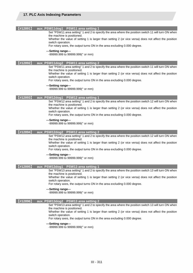
17. PLC Axis Indexing Parameters
III - 311
【#12891】 aux_PSW11dog1 PSW11 area setting 1 Set "PSW11 area setting" 1 and 2 to specify the area where the position switch 11 will turn ON when the machine is positioned. Whether the value of setting 1 is larger than setting 2 (or vice versa) does not affect the position switch operation. For rotary axes, the output turns ON in the area excluding 0.000 degree.
---Setting range--- -99999.999 to 99999.999(° or mm)
【#12892】 aux_PSW11dog2 PSW11 area setting 2 Set "PSW11 area setting" 1 and 2 to specify the area where the position switch 11 will turn ON when the machine is positioned. Whether the value of setting 1 is larger than setting 2 (or vice versa) does not affect the position switch operation. For rotary axes, the output turns ON in the area excluding 0.000 degree.
---Setting range--- -99999.999 to 99999.999(° or mm)
【#12893】 aux_PSW12dog1 PSW12 area setting 1 Set "PSW12 area setting" 1 and 2 to specify the area where the position switch 12 will turn ON when the machine is positioned. Whether the value of setting 1 is larger than setting 2 (or vice versa) does not affect the position switch operation. For rotary axes, the output turns ON in the area excluding 0.000 degree.
---Setting range--- -99999.999 to 99999.999(° or mm)
【#12894】 aux_PSW12dog2 PSW12 area setting 2 Set "PSW12 area setting" 1 and 2 to specify the area where the position switch 12 will turn ON when the machine is positioned. Whether the value of setting 1 is larger than setting 2 (or vice versa) does not affect the position switch operation. For rotary axes, the output turns ON in the area excluding 0.000 degree.
---Setting range--- -99999.999 to 99999.999(° or mm)
【#12895】 aux_PSW13dog1 PSW13 area setting 1 Set "PSW13 area setting" 1 and 2 to specify the area where the position switch 13 will turn ON when the machine is positioned. Whether the value of setting 1 is larger than setting 2 (or vice versa) does not affect the position switch operation. For rotary axes, the output turns ON in the area excluding 0.000 degree.
---Setting range--- -99999.999 to 99999.999(° or mm)
【#12896】 aux_PSW13dog2 PSW13 area setting 2 Set "PSW13 area setting" 1 and 2 to specify the area where the position switch 13 will turn ON when the machine is positioned. Whether the value of setting 1 is larger than setting 2 (or vice versa) does not affect the position switch operation. For rotary axes, the output turns ON in the area excluding 0.000 degree.
---Setting range--- -99999.999 to 99999.999(° or mm)

17. PLC Axis Indexing Parameters
III - 312
【#12897】 aux_PSW14dog1 PSW14 area setting 1 Set "PSW14 area setting" 1 and 2 to specify the area where the position switch 14 will turn ON when the machine is positioned. Whether the value of setting 1 is larger than setting 2 (or vice versa) does not affect the position switch operation. For rotary axes, the output turns ON in the area excluding 0.000 degree.
---Setting range--- -99999.999 to 99999.999(° or mm)
【#12898】 aux_PSW14dog2 PSW14 area setting 2 Set "PSW14 area setting" 1 and 2 to specify the area where the position switch 14 will turn ON when the machine is positioned. Whether the value of setting 1 is larger than setting 2 (or vice versa) does not affect the position switch operation. For rotary axes, the output turns ON in the area excluding 0.000 degree.
---Setting range--- -99999.999 to 99999.999(° or mm)
【#12899】 aux_PSW15dog1 PSW15 area setting 1 Set "PSW15 area setting" 1 and 2 to specify the area where the position switch 15 will turn ON when the machine is positioned. Whether the value of setting 1 is larger than setting 2 (or vice versa) does not affect the position switch operation. For rotary axes, the output turns ON in the area excluding 0.000 degree.
---Setting range--- -99999.999 to 99999.999(° or mm)
【#12900】 aux_PSW15dog2 PSW15 area setting 2 Set "PSW15 area setting" 1 and 2 to specify the area where the position switch 15 will turn ON when the machine is positioned. Whether the value of setting 1 is larger than setting 2 (or vice versa) does not affect the position switch operation. For rotary axes, the output turns ON in the area excluding 0.000 degree.
---Setting range--- -99999.999 to 99999.999(° or mm)
【#12910】 aux_push Stopper amount Set the command stroke of the stopper operation in the stopper positioning.
---Setting range--- 0.000 to 359.999(° or mm)
【#12911】 aux_pusht1 Stopper standby time Set the standby time from the stopper starting coordinate positioning to the stopper operation start in the stopper positioning.
---Setting range--- 0 to 9999(ms)
【#12912】 aux_pusht2 Stopper torque release time Set the time from the completion of the stopper operation to the changeover of the stopper torque in the stopper positioning.
---Setting range--- 0 to 9999(ms)

17. PLC Axis Indexing Parameters
III - 313
【#12913】 aux_pusht3 Set position signal output delay time Set the time from the completion of the stopper operation to the output of the “automatic set position reached” (JSTA), “set position reached” (JST) or “near set position” (NEAR) signal in the stopper positioning.
---Setting range--- 0 to 9999(ms)

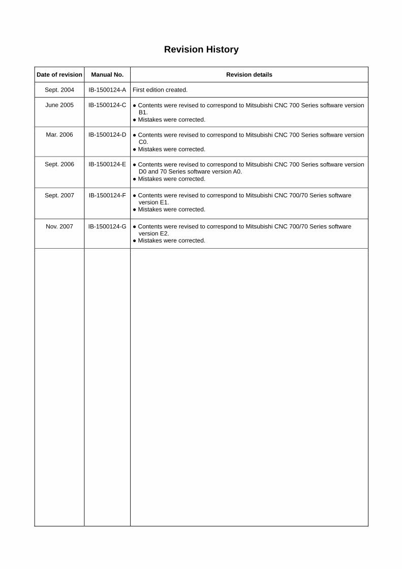
Revision History
Date of revision Manual No. Revision details
Sept. 2004 IB-1500124-A First edition created.
June 2005 IB-1500124-C ● Contents were revised to correspond to Mitsubishi CNC 700 Series software version B1.
● Mistakes were corrected.
Mar. 2006 IB-1500124-D ● Contents were revised to correspond to Mitsubishi CNC 700 Series software version C0.
● Mistakes were corrected.
Sept. 2006 IB-1500124-E ● Contents were revised to correspond to Mitsubishi CNC 700 Series software version D0 and 70 Series software version A0.
● Mistakes were corrected.
Sept. 2007 IB-1500124-F ● Contents were revised to correspond to Mitsubishi CNC 700/70 Series software version E1.
● Mistakes were corrected.
Nov. 2007 IB-1500124-G ● Contents were revised to correspond to Mitsubishi CNC 700/70 Series software version E2.
● Mistakes were corrected.


Global service network
NORTH AMERICA FA Center EUROPEAN FA Center
ASEAN FA Center
CHINA FA Center
TAIWAN FA Center
HONG KONG FA Center
KOREAN FA Center
North America FA Center (MITSUBISHI ELECTRIC AUTOMATION INC.)
Illinois CNC Service Center 500 CORPORATE WOODS PARKWAY, VERNON HILLS, IL. 60061, U.S.A. TEL: +1-847-478-2500 (Se FAX: +1-847-478-2650 (Se California CNC Service Center 5665 PLAZA DRIVE, CYPRESS, CA. 90630, U.S.A. TEL: +1-714-220-4796 FAX: +1-714-229-3818 Georgia CNC Service Center 2810 PREMIERE PARKWAY SUITE 400, DULUTH, GA., 30097, U.S.A. TEL: +1-678-258-4500 FAX: +1-678-258-4519 New Jersey CNC Service Center 200 COTTONTAIL LANE SOMERSET, NJ. 08873, U.S.A. TEL: +1-732-560-4500 FAX: +1-732-560-4531 Michigan CNC Service Satellite 2545 38TH STREET, ALLEGAN, MI., 49010, U.S.A. TEL: +1-847-478-2500 FAX: +1-269-673-4092 Ohio CNC Service Satellite 62 W. 500 S., ANDERSON, IN., 46013, U.S.A. TEL: +1-847-478-2608 FAX: +1-847-478-2690 Texas CNC Service Satellite 1000, NOLEN DRIVE SUITE 200, GRAPEVINE, TX. 76051, U.S.A. TEL: +1-817-251-7468 FAX: +1-817-416-1439 Canada CNC Service Center 4299 14TH AVENUE MARKHAM, ON. L3R OJ2, CANADA TEL: +1-905-475-7728 FAX: +1-905-475-7935 Mexico CNC Service Center MARIANO ESCOBEDO 69 TLALNEPANTLA, 54030 EDO. DE MEXICO TEL: +52-55-9171-7662 FAX: +52-55-9171-7698 Monterrey CNC Service Satellite ARGENTINA 3900, FRACC. LAS TORRES, MONTERREY, N.L., 64720, MEXICO TEL: +52-81-8365-4171 FAX: +52-81-8365-4171 Brazil MITSUBISHI CNC Agent Service Center (AUTOMOTION IND. COM. IMP. E EXP. LTDA.) ACESSO JOSE SARTORELLI, KM 2.1 18550-000 BOITUVA – SP, BRAZIL TEL: +55-15-3363-9900 FAX: +55-15-3363-9911
European FA Center (MITSUBISHI ELECTRIC EUROPE B.V.)
Germany CNC Service Center GOTHAER STRASSE 8, 40880 RATINGEN, GERMANY TEL: +49-2102-486-0 FAX:+49-2102486-591 South Germany CNC Service Center KURZE STRASSE. 40, 70794 FILDERSTADT-BONLANDEN, GERMANY TEL: +49-711-3270-010 FAX: +49-711-3270-0141 France CNC Service Center 25, BOULEVARD DES BOUVETS, 92741 NANTERRE CEDEX FRANCE TEL: +33-1-41-02-83-13 FAX: +33-1-49-01-07-25 Lyon CNC Service Satellite U.K CNC Service Center TRAVELLERS LANE, HATFIELD, HERTFORDSHIRE, AL10 8XB, U.K. TEL: +44-1707-282-846 FAX:-44-1707-278-992 Italy CNC Service Center VIALE COLLEONI 7 - PALAZZO SIRIO, CENTRO DIREZIONALE COLLEONI, 20041 AGRATE BRIANZA - (MI), ITALY TEL: +39-039-60531-342 FAX: +39-039-6053-206 Spain CNC Service Satellite CTRA. DE RUBI, 76-80 -APDO.420 08190 SAINT CUGAT DEL VALLES, BARCELONA SPAIN TEL: +34-935-65-2236 FAX: Turkey MITSUBISHI CNC Agent Service Center (GENEL TEKNIK SISTEMLER LTD. STI.) DARULACEZE CAD. FAMAS IS MERKEZI A BLOCK NO.43 KAT2 80270 OKMEYDANI ISTANBUL, TURKEY TEL: +90-212-320-1640 FAX: +90-212-320-1649 Poland MITSUBISHI CNC Agent Service Center (MPL Technology Sp. z. o. o) UL SLICZNA 34, 31-444 KRAKOW, POLAND TEL: +48-12-632-28-85 FAX: Wroclaw MITSUBISHI CNC Agent Service Satellite (MPL Technology Sp. z. o. o) UL KOBIERZYCKA 23, 52-315 WROCLAW, POLAND TEL: +48-71-333-77-53 FAX: +48-71-333-77-53 Czech MITSUBISHI CNC Agent Service Center (AUTOCONT CONTROL SYSTEM S.R.O. ) NEMOCNICNI 12, 702 00 OSTRAVA 2 CZECH REPUBLIC TEL: +420-596-152-426 FAX: +420-596-152-112
ASEAN FA Center (MITSUBISHI ELECTRIC ASIA PTE. LTD.) Singapore CNC Service Center 307 ALEXANDRA ROAD #05-01/02 MITSUBISHI ELECTRIC BUILDING SINGAPORE 159943 TEL: +65-6473-2308 FAX: +65-6476-7439 Thailand MITSUBISHI CNC Agent Service Center (F. A. TECH CO., LTD) 898/19,20,21,22 S.V. CITY BUILDING OFFICE TOWER 1 FLOOR 12,14 RAMA III RD BANGPONGPANG, YANNAWA, BANGKOK 10120. THAILAND TEL: +66-2-682-6522 FAX: +66-2-682-6020 Malaysia MITSUBISHI CNC Agent Service Center (FLEXIBLE AUTOMATION SYSTEM SDN. BHD.) 60, JALAN USJ 10/1B 47620 UEP SUBANG JAYA SELANGOR DARUL EHSAN MALAYSIA TEL: +60-3-5631-7605 FAX: +60-3-5631-7636 JOHOR MITSUBISHI CNC Agent Service Satellite (FLEXIBLE AUTOMATION SYSTEM SDN. BHD.) NO. 16, JALAN SHAHBANDAR 1, TAMAN UNGKU TUN AMINAH, 81300 SKUDAI, JOHOR MALAYSIA TEL: +60-7-557-8218 FAX: +60-7-557-3404 Indonesia MITSUBISHI CNC Agent Service Center (PT. AUTOTEKNINDO SUMBER MAKMUR) WISMA NUSANTARA 14TH FLOOR JL. M.H. THAMRIN 59, JAKARTA 10350 INDONESIA TEL: +62-21-3917-144 FAX: +62-21-3917-164 India MITSUBISHI CNC Agent Service Center (MESSUNG SALES & SERVICES PVT. LTD.) B-36FF, PAVANA INDUSTRIAL PREMISES M.I.D.C., BHOASRI PUNE 411026, INDIA TEL: +91-20-2711-9484 FAX: +91-20-2712-8115 BANGALORE MITSUBISHI CNC Agent Service Satellite (MESSUNG SALES & SERVICES PVT. LTD.) S 615, 6TH FLOOR, MANIPAL CENTER, BANGALORE 560001, INDIA TEL: +91-80-509-2119 FAX: +91-80-532-0480 Delhi MITSUBISHI CNC Agent Parts Center (MESSUNG SALES & SERVICES PVT. LTD.) 1197, SECTOR 15 PART-2, OFF DELHI-JAIPUR HIGHWAY BEHIND 32ND MILESTONE GURGAON 122001, INDIA TEL: +91-98-1024-8895 FAX: Philippines MITSUBISHI CNC Agent Service Center (FLEXIBLE AUTOMATION SYSTEM CORPORATION) UNIT No.411, ALABAMG CORPORATE CENTER KM 25. WEST SERVICE ROAD SOUTH SUPERHIGHWAY, ALABAMG MUNTINLUPA METRO MANILA, PHILIPPINES 1771 TEL: +63-2-807-2416 FAX: +63-2-807-2417 Vietnam MITSUBISHI CNC Agent Service Center (SA GIANG TECHNO CO., LTD) 47-49 HOANG SA ST. DAKAO WARD, DIST.1 HO CHI MINH CITY, VIETNAM TEL: +84-8-910-4763 FAX: +84-8-910-2593
China FA Center (MITSUBISHI ELECTRIC AUTOMATION (SHANGHAI) LTD.)
China CNC Service Center 2/F., BLOCK 5 BLDG.AUTOMATION INSTRUMENTATION PLAZA, 103 CAOBAO RD. SHANGHAI 200233, CHINA TEL: +86-21-6120-0808 FAX: +86-21-6494-0178 Shenyang CNC Service Center TEL: +86-24-2397-0184 FAX: +86-24-2397-0185 Beijing CNC Service Satellite 9/F, OFFICE TOWER1, HENDERSON CENTER, 18 JIANGUOMENNEI DAJIE, DONGCHENG DISTRICT, BEIJING 100005, CHINA TEL: +86-10-6518-8830 FAX: +86-10-6518-8030 China MITSUBISHI CNC Agent Service Center (BEIJING JIAYOU HIGHTECH TECHNOLOGY DEVELOPMENT CO.) RM 709, HIGH TECHNOLOGY BUILDING NO.229 NORTH SI HUAN ZHONG ROAD, HAIDIAN DISTRICT , BEIJING 100083, CHINA TEL: +86-10-8288-3030 FAX: +86-10-6518-8030 Tianjin CNC Service Satellite RM909, TAIHONG TOWER, NO220 SHIZILIN STREET, HEBEI DISTRICT, TIANJIN, CHINA 300143 TEL: -86-22-2653-9090 FAX: +86-22-2635-9050 Shenzhen CNC Service Satellite RM02, UNIT A, 13/F, TIANAN NATIONAL TOWER, RENMING SOUTH ROAD, SHENZHEN, CHINA 518005 TEL: +86-755-2515-6691 FAX: +86-755-8218-4776 Changchun Service Satellite TEL: +86-431-50214546 FAX: +86-431-5021690 Hong Kong CNC Service Center UNIT A, 25/F RYODEN INDUSTRIAL CENTRE, 26-38 TA CHUEN PING STREET, KWAI CHUNG, NEW TERRITORIES, HONG KONG TEL: +852-2619-8588 FAX: +852-2784-1323
Taiwan FA Center (MITSUBISHI ELECTRIC TAIWAN CO., LTD.) Taichung CNC Service Center NO.8-1, GONG YEH 16TH RD., TAICHUNG INDUSTIAL PARK TAICHUNG CITY, TAIWAN R.O.C. TEL: +886-4-2359-0688 FAX: +886-4-2359-0689 Taipei CNC Service Satellite TEL: +886-4-2359-0688 FAX: +886-4-2359-0689 Tainan CNC Service Satellite TEL: +886-4-2359-0688 FAX: +886-4-2359-0689
Korean FA Center (MITSUBISHI ELECTRIC AUTOMATION KOREA CO., LTD.)
Korea CNC Service Center 1480-6, GAYANG-DONG, GANGSEO-GU SEOUL 157-200, KOREA TEL: +82-2-3660-9631 FAX: +82-2-3664-8668

Notice
Every effort has been made to keep up with software and hardware revisions in the contents described in this manual. However, please understand that in some unavoidable cases simultaneous revision is not possible. Please contact your Mitsubishi Electric dealer with any questions or comments regarding the use of this product.
Duplication Prohibited This manual may not be reproduced in any form, in part or in whole, without written permission from Mitsubishi Electric Corporation.
© 2004-2007 MITSUBISHI ELECTRIC CORPORATION ALL RIGHTS RESERVED