Smart Card Connectors Series C 700
60
Amphenol Amphenol-Tuchel Electronics GmbH Smart Card Connectors Series C 700 www.amphenol-tuchel.com
-
Upload
khangminh22 -
Category
Documents
-
view
7 -
download
0
Transcript of Smart Card Connectors Series C 700

AmphenolAmphenol-Tuchel Electronics GmbH
Smart Card ConnectorsSeries C 700
ww
w.a
mp
heno
l-tu
chel
.co
m
2
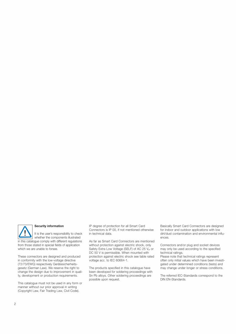
Security information
It is the user’s responsibility to checkwhether the components illustrated
in this catalogue comply with different regulationsfrom those stated in special fields of applicationwhich we are unable to forsee.
These connectors are designed and producedin conformity with the low-voltage directive(72/73/EWG) respectively Gerätesicherheits-gesetz (German Law). We reserve the right tochange the design due to improvement in quali-ty, development or production requirements.
This catalogue must not be used in any form ormanner without our prior approval in writing(Copyright Law, Fair Trading Law, Civil Code).
IP degree of protection for all Smart CardConnectors is IP 00, if not mentioned otherwisein technical data.
As far as Smart Card Connectors are mentionedwithout protection against electric shock, onlySafety Extra Low Voltage (SELF) of AC 25 Veff orDC 50 V is permissible. When mounted withprotection against electric shock see table ratedvoltage acc. to IEC 60664-1.
The products specified in this catalogue havebeen developed for soldering proceedings withSn Pb alloys. Other soldering proceedings arepossible upon request.
Basically Smart Card Connectors are designedfor indoor and outdoor applications with low dirt/dust contamination and environmental influ-ences.
Connectors and/or plug and socket devicesmay only be used according to the specifiedtechnical ratings. Please note that technical ratings representoften only initial values which have been investi-gated under determined conditions (tests) andmay change under longer or stress conditions.
The referred IEC-Standards correspond to theDIN EN-Standards.
3
The CompanyQualityLeading Technology
Worldwide Performance Page 4
Chip CardsSmart Card ConnectorsCard Handling SystemsContact Methods
General Information Page 6
Smart Card ConnectorsStandard Style Accessories
Series C702A Page 10
Smart Card ConnectorsPUSHMATIC® II Accessories
Series C702B Page 17
Smart Card Connectors Low Profile PUSHMATIC®
Series C702C Page 22
Smart Card ConnectorsSuperflat StyleAccessories
Series C702D Page 25
Smart Card Connectors with PCB Mount WipingContacts
Series C702E Page 31
Smart Card Connectors with Landing Card PCB Mount
Series C702F Page 39
Hybrid Reader
Series C703A Page 41
Smart Card Connectorswith Disk Drive Slot
Series C705A Page 44
Smart Card Connectors SIMLOCK®
Series C707A Page 46
Smart Card Connectors SIMBLOCK®
Series C707B Page 50
MultiMediaCard Connector
Series C709A Page 55
Keyword Index Page 58
Part No. Index Page 59
Contents
4
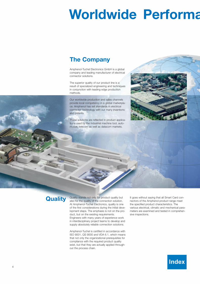
The CompanyAmphenol-Tuchel Electronics GmbH is a globalcompany and leading manufacturer of electricalconnector solutions.
The superior quality of our product line is aresult of specialized engineering and techniquesin conjunction with leading edge productionmethods.
Our worldwide production and sales channelsprovide local competency in a global marketpla-ce. Amphenol has set standards in electricalconnector technology with our many inventionsand patents.
These solutions are reflected in product applica-tions used by the industrial machine tool, auto-motive, telecom as well as datacom markets.
Worldwide Performa
Quality stands not only for product quality butalso for the quality of the connection solution.At Amphenol-Tuchel Electronics, quality is oneof the first considerations during the initial deve-lopment steps. The emphasis is not on the pro-duct, but on the existing requirements.Engineers with many years of experience workin interdisciplinary project teams to develop andsupply absolutely reliable connection solutions.
Amphenol-Tuchel is certified in accordance withISO 9001, QS 9000 and VDA 6.1, which meansthat not only the organizational prerequisites forcompliance with the required product qualityexist, but that they are actually applied through-out the process chain.
It goes without saying that all Smart Card con-nectors of the Amphenol product range meetthe specified product characteristics. Thevarious electrical, climatic and mechanical para-meters are examined and tested in comprehen-sive inspections.
Quality

5
nce
Samples can be produced in a very short time and it is also possible to execute the entire production cyclefrom the prototype to the finished product quickly.Customer-specific prototypes and small batches canalso be produced quickly.
The experience and competence gained through manydecades of work are displayed today in the wide rangeof proven products in the sectors of plug and socketconnectors and Smart Card Connectors.
An innovative internal product development depart-ment, a flexible, selective network of suppliers, coupledwith an internal laboratory for support of research andproduct development, together with 3D-CAD andsimulation work stations adds up to a company whichcan be measured by its own standards.
Technological LeadershipAmphenol-Tuchel Electronics derives its claims to technical advances and technological leadership fromvarious technical and technological advantages.
These include high-performance precision pressingtechnology, modern injection-molding technology and amanufacturing and inspection technology which ensu-res that all processes operate reliably.
Production flexibility is guaranteed by the use of eitherfully automatic production equipment, semi-automaticproduction lines or manual manufacture, depending onthe requirements.

C700 Smart Card Connectors: General Information
Chip Cards
Chip Cards, Smart Cards, IC Cards or whatever application specific term is used ...have one thing in common:
• the outside dimensions, standardized acc.to ISO 7810, the size of a common creditcard
• and the position of the contact pads,(which connect the embedded IC chip) arefixed according to ISO 7816.
The most used chip contacts are:
Amphenol Smart CardConnectorsSmart Card Connectors are integral com-ponents of a smart card reader or terminal,and provide electrical contact to the smartcard’s pads. The connector is not a standalone peripheral device.
An additional interface circuit is necessaryto be able to read and write to the smartcard whether a smart card is a memoryonly or a microprocessor card. AmphenolSmart Card Connectors are designed tomake secure contact to all cards designedaccording to ISO 7816 and thus ensure areliable data transmission.
The communication with the chip card canbegin when the card is fully inserted andthe data contacts are all connected. At thispoint an integral card presence switch isactivated and signals to the connected cir-cuitry that the card is ready to be read andwritten to.
Smart Card Connectors for paymentsystems according to EMV (EuropayMastercard Visa / Integrated Circuit CardSpecification for Payment Systems) have aspecific card end position switch whichdetects the insertion and removal of aSmart Card.
MultiMediaCard, acc. to MMCA - Spezification
SIM/SAM-Card, ID-000, GSM 11.11
Type ID-1, Chip outer position (AFNOR)
Type ID-1, Chip middle position (ISO)
6
Secure Digital Memory Card,acc. to SDA - Spezification

7
C700 Smart Card Connectors: General Information
Push-Only
The card is inserted manually and held in theactive position by hand. The card is ejectedimmediately after the user releases it. ThePush-Only is ideally suited for applicationswith short transaction cycles, ie. door accesscontrol.
Push-Pull
The card is inserted manually and held in theactive position by a card brake. After comple-tion of the transaction, the card is simply pul-led out of the Smart Card Connector.
This is the most common manual card hand-ling system.
Push-Push
The card is inserted manually and held in theactive position by the Smart Card Connector.When pushed again the card is returned tothe user (principle of a ballpoint pen).
PUSHMATIC®
This semi-automatic system combines amanual card insertion with an automatic cardejection. The card is manually pushed intothe Smart Card Connector until it is flush (or nearly flush) with the bezel. Upon completion of the transaction, softwaretriggers a solenoid and the card is ejectedback to the user.
Card Handling Systems

8
C700 Smart Card Connectors: General Information
Contact Methods
Landing Contacts
With this contact method a moveable contact set will
connect with the pads of the chip card upon insertion of
the card.
The card plastic surface is not scratched and high
mating cycles can be achieved.
Wiping Contacts
The contact set is fixed. When the card is inserted, it
wipes over the data contacts until they arrive at the card
pads. Depending upon the card surface, wiping traces
which do not influence the card function can occur after
some insertion cycles.
The advantage of wiping contacts is that they clean the
contact point with every mating cycle.
Landing Card
This method of contacting is based on a fixed contact
set. The chip card is lowered during its insertion.
The contact areas of the chip card land smoothly on the
reading contacts which results in the possibility of a high
number of mating cycles.
In addition this system makes sure that with each inser-
tion the contact surfaces are cleaned.
9
C700 Smart Card Connectors: General Information
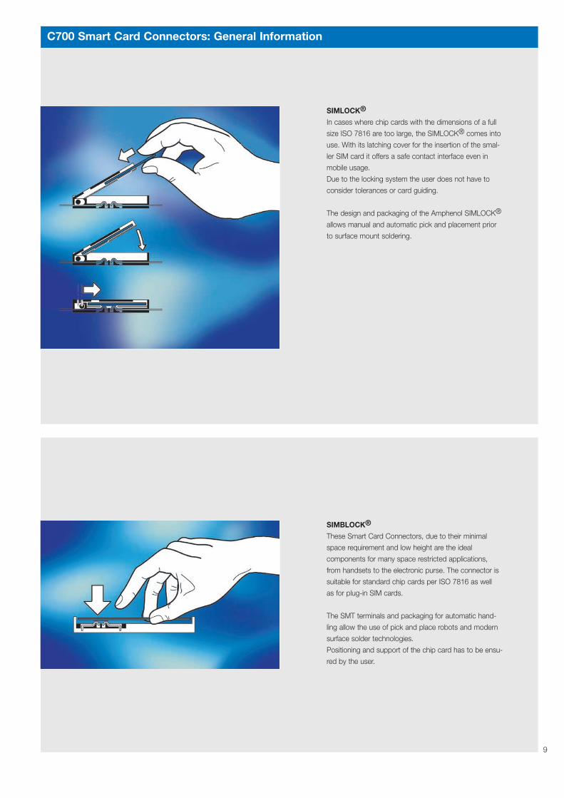
SIMLOCK®
In cases where chip cards with the dimensions of a full
size ISO 7816 are too large, the SIMLOCK® comes into
use. With its latching cover for the insertion of the smal-
ler SIM card it offers a safe contact interface even in
mobile usage.
Due to the locking system the user does not have to
consider tolerances or card guiding.
The design and packaging of the Amphenol SIMLOCK®
allows manual and automatic pick and placement prior
to surface mount soldering.
SIMBLOCK®
These Smart Card Connectors, due to their minimal
space requirement and low height are the ideal
components for many space restricted applications,
from handsets to the electronic purse. The connector is
suitable for standard chip cards per ISO 7816 as well
as for plug-in SIM cards.
The SMT terminals and packaging for automatic hand-
ling allow the use of pick and place robots and modern
surface solder technologies.
Positioning and support of the chip card has to be ensu-
red by the user.

10
Smart Card Connectors Standard Style
Series C702A
Push-Only Page 11
Accessories Page 16Bezel
Accessories Page 15Mounting Plate
Push-Push Page 12
Push-Pull Page 11
PUSHMATIC® Page 12
PUSHMATIC® Page 13with Locking Detector
PUSHMATIC® Page 13with Shutter
Assembly instructions:Please make sure that interfacecables are unrestricted and free tomove after assembly.
The Standard Style is our original first gene-ration product family featuring landing contactsfor rugged applications such as: Point of Salesystems, vending equipment and access con-trol.
Design features• high numbers of card insertion cycles, due
to the principle of landing and self-cleaningcontacts
• designed for harsh applications and environ-ments
• modular system with several operatingmethods from manual handling to automaticcard ejection
• various termination options: flat cable instandard and custom lengths with socketsaccording to IEC 60 603-13; and flexprints.For appropriate flexprint connectors seepage 29
• Accessories: Shutter and bezel, mountingplate

11
C702A Smart Card Connectors Standard Style Push-Only
SENKUNG DIN 74-AM 3
EIN- / AUSGABE
LESESTELLUNG
ISO
4,8 AUSLÖSEHUBRELEASE
18,1±1
==
58
±0,1
44,1
±0,1
42,1
132110
±0,412,550 ±0,1
1,2
4,8
1216,9
72,5
±132,5
1214
62,3
13,1
4,4
18
C8 C4C7 C3C6 C2C5 C1S S
4,5
COUNTERSINK
ACTIVE POSITION
INACTIVE POSITION
Description Contact position Part No.
Push-Only ISO C702 10M008 018 2
C702A Smart Card Connectors Standard Style Push-Pull
ACTIVE POSITION
Contacts in parallel
C4nc
C5C1
C8S
C8nc
C1C5
C4S
==
58
±0,1
44,1
±0,1
42,1
132
110
±0,412,550 ±0,1
1,2
4,8
1216,9
72,5
±113,3
±132,5
1214
62,3
13,1
4,4
18
4,5
SENKUNG DIN 74-AM 3COUNTERSINK
LESESTELLUNG
INACTIVE POSITIONEIN- / AUSGABE
Belegung Steckverbinder Connector terminationISO ISO + AFNOR AFNOR ISO + AFNOR
Kontakte in Reihe / Kontakte parallel /Contacts in series
C8 C4C7 C3C6 C2C5 C1S S
C1 C5C2 C6C3 C7C4 C8S S
C1 C5C2 C6C3 C7C4 C8S S ISO
AFNOR not
connected
C3C2
C6C7
C7C6
C2C3nc = frei
Description Contact position Additional information Part No.
Push-Pull ISO Standard C702 10M008 514 2AFNOR C702 10M008 522 2ISO + AFNOR Contacts in series C702 10M008 521 2ISO + AFNOR Contacts in parallel C702 10M008 523 2

12
C702A Smart Card Connectors Standard Style Push-Push
SENKUNG DIN 74-AM 3
EIN- / AUSGABE
LESESTELLUNG
ISO
4,8 AUSLÖSEHUBRELEASE
18,1±1
==
58
±0,1
44,1
±0,1
42,1
132110
±0,412,550 ±0,1
1,2
4,8
1216,9
72,5
±132,5
121462,3
13,1
4,4
18
C8 C4C7 C3C6 C2C5 C1S S
4,5
COUNTERSINK
ACTIVE POSITION
INACTIVE POSITION
Description Contact position Part No.
Push-Push ISO C702 10M008 015 2
C702A Smart Card Connectors Standard Style PUSHMATIC®
16,9
±1,5
18,4
13,1
SENKUNG DIN 74-AM 3
62
4,4
45
±12,8
20
99,2
71,5
14 12
2
±117,517,8
14,2 ±0,4±0,150
57,7
44,1
±0,1
42,1
±0,1
==
110
132 ±0,232
COUNTERSINK
SOLENOID LEADS 250 MM LONG±5
PRESTRIPPED, PRETINNED 4 MM
SPULENENDE 250 MM LANG4 MM VERZINNT
±5
INACTIVE POSITIONEIN- / AUSGABE
Contacts in parallel
C4nc
C5C1
C8S
C8nc
C1C5
C4S
Belegung Steckverbinder / Connector terminationISO ISO + AFNOR AFNOR ISO + AFNOR
Kontakte in Reihe / Kontakte parallel /Contacts in series
C8 C4C7 C3C6 C2C5 C1S S
C1 C5C2 C6C3 C7C4 C8S S
C1 C5C2 C6C3 C7C4 C8S S
ISO
AFNOR
C3C2
C6C7
C7C6
C2C3
notconnected
nc = frei
ACTIVE POSITIONLESESTELLUNG
Description Solenoid Contact Additional Part No.voltage position information
PUSHMATIC® 5 V ISO Standard C702 10M008 701 212 V ISO Standard C702 10M008 700 224 V ISO Standard C702 10M008 702 25 V ISO + AFNOR Contacts in series C702 10M008 703 2
12 V ISO + AFNOR Contacts in series C702 10M008 704 224 V ISO + AFNOR Contacts in series C702 10M008 705 25 V ISO + AFNOR Contacts in parallel C702 10M008 706 2
12 V ISO + AFNOR Contacts in parallel C702 10M008 707 224 V ISO + AFNOR Contacts in parallel C702 10M008 708 2
13
19,2
5
+0,
30
29,770,5
±0,3
69
64
ø3,6(111,3)
132
6,3
17,5
82 ±0,3
1
76
ACTIVE POSITIONLESESTELLUNG
INACTIVE POSITIONEIN- / AUSGABE
±0,282,5±0,2
14,5
MONTAGEAUSSCHNITT
M3
PANEL CUT OUT±0,174
26
55
82
3
3,1
4,474
52
7
±1,5
16,9
±0,29,5
2
1424
1214
2314
20,77,7
±115,5
93,5
SOLENOID LEADS 250 MM LONG±5
PRESTRIPPED, PRETINNED 4 MM
SPULENENDEN 250 MM LANG4 MM VERZINNT
±5
ISO
C8 C4C3C2C1S
C7C6C5S
C702A Smart Card Connectors Standard Style PUSHMATIC® with Locking Detector
14,2 ±0,4
17,8
20
23
62
13,1
4,4
2,8
16,471,5
±1
45
9,3
14 12
2
±117,5
110 ±0,150 ±0,232
13299,2
57,7
44,1
±0,1
42,1
±0,1
==
ACTIVE POSITIONLESESTELLUNG
INACTIVE POSITIONEIN- / AUSGABE
2. DATA CONTACTS IN ACTIVE POSITION
C8 C4C7 C3C6 C2C5 C1S S
ISO
SOLENOID LEADS 250 MM LONG±5
PRESTRIPPED, PRETINNED 4 MM
SPULENENDE 250 MM LANG4 MM VERZINNT
±5
TWO SWITCHES IN SERIES DETECT:1. CONTACT SYSTEM LOCKED
SCHALTER MELDET:1. SYSTEMVERRIEGELUNG2. KONTAKT IN LESESTELLUNG
COUNTERSINKSENKUNG DIN 74-AM 3
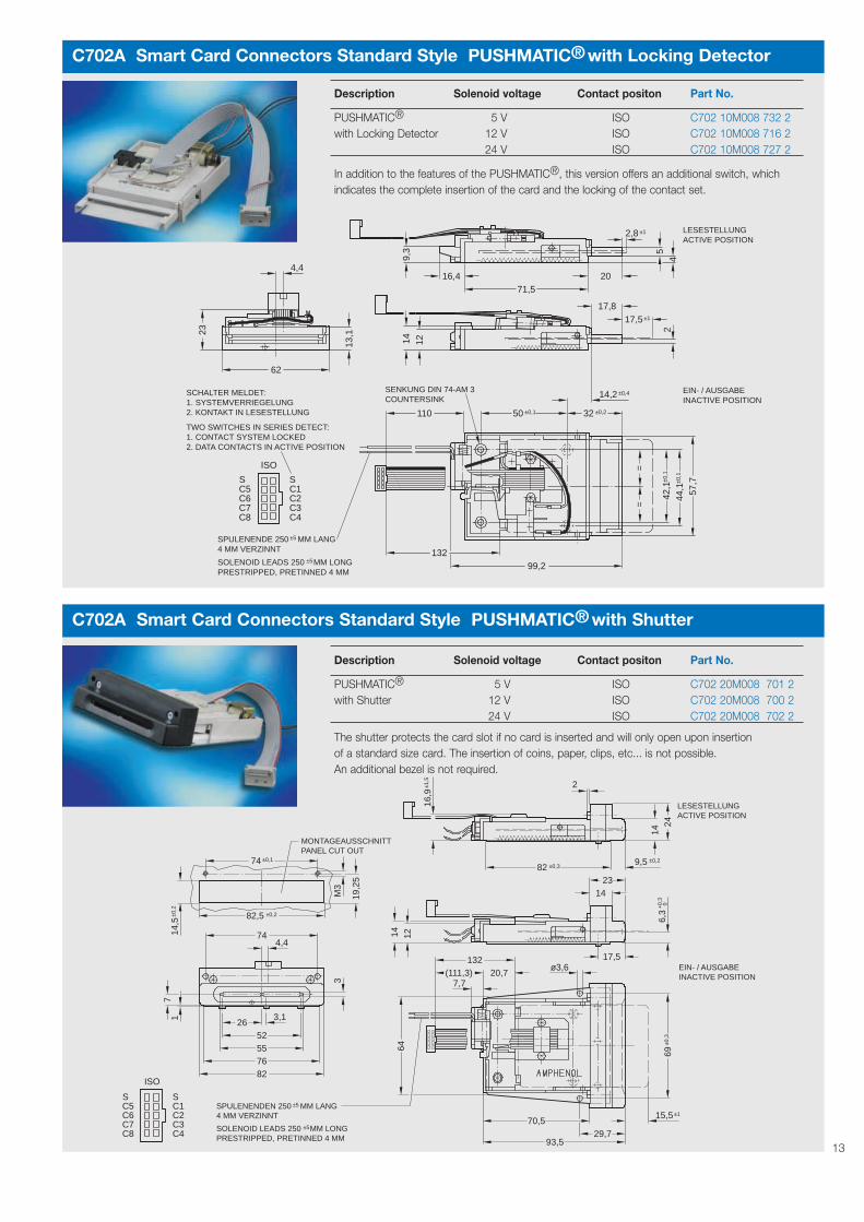
Description Solenoid voltage Contact positon Part No.
PUSHMATIC® 5 V ISO C702 10M008 732 2with Locking Detector 12 V ISO C702 10M008 716 2
24 V ISO C702 10M008 727 2
In addition to the features of the PUSHMATIC®, this version offers an additional switch, which indicates the complete insertion of the card and the locking of the contact set.
C702A Smart Card Connectors Standard Style PUSHMATIC® with Shutter
Description Solenoid voltage Contact positon Part No.
PUSHMATIC® 5 V ISO C702 20M008 701 2with Shutter 12 V ISO C702 20M008 700 2
24 V ISO C702 20M008 702 2
The shutter protects the card slot if no card is inserted and will only open upon insertion of a standard size card. The insertion of coins, paper, clips, etc... is not possible. An additional bezel is not required.
14
C702A Technical Data
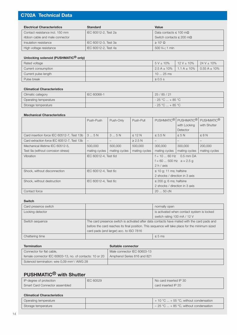
Electrical Characteristics Standard Value
Contact resistance incl. 150 mm IEC 60512-2, Test 2a Data contacts ≤ 100 mΩribbon cable and male connector Switch contacts ≤ 200 mΩ
Insulation resistance IEC 60512-3, Test 3a ≥ 109 Ω
High voltage resistance IEC 60512-2, Test 4a 500 VAC; 1 min
Unlocking solenoid (PUSHMATIC® only)
Rated voltage 5 V ± 10% 12 V ± 10% 24 V ± 10%
Current consumption 2.5 A ± 10% 1.1 A ± 10% 0.55 A ± 10%
Current pulse length 10 ... 25 ms
Pulse break ≥ 0.5 s
Climatical Characteristics
Climatic category IEC 60068-1 25 / 85 / 21
Operating temperature - 25 °C ... + 85 °C
Storage temperature - 25 °C ... + 85 °C
Mechanical Characteristics
Push-Push Push-Only Push-Pull PUSHMATIC® PUSHMATIC® PUSHMATIC®
with Locking with Shutter
Detector
Card insertion force IEC 60512-7, Test 13b 3 ... 5 N 3 ... 5 N ≤ 12 N ≤ 3.5 N ≤ 5 N ≤ 8 N
Card extraction force IEC 60512-7, Test 13b – – ≥ 2.5 N – – –
Mechanical lifetime IEC 60512-5, 500,000 500,000 500,000 300,000 300,000 200,000
Test 9a (without corrosion stress) mating cycles mating cycles mating cycles mating cycles mating cycles mating cycles
Vibration IEC 60512-4, Test 6d f = 10 ... 60 Hz 0.5 mm DA
f = 60 ... 500 Hz a = 2.5 g
2 h / axis
Shock, without disconnection IEC 60512-4, Test 6c ≤ 10 g; 11 ms; halfsine
2 shocks / direction in 3 axis
Shock, without destruction IEC 60512-4, Test 6c ≤ 200 g; 6 ms; halfsine
2 shocks / direction in 3 axis
Contact force 20 ... 50 cN
Switch
Card presence switch normally open
Locking detector is activated when contact system is locked
switch rating 100 mA / 12 V
Switch sequence The card presence switch is activated after data contacts have mated with the card pads and
before the card reaches its final position. This sequence will take place for the minimum sized
card pads (and larger) acc. to ISO 7816
Chattering time ≤ 5 ms
Termination Suitable connector
Connector for flat cable, Male connector IEC 60603-13
female connector IEC 60603-13, no. of contacts: 10 or 20 Amphenol Series 816 and 821
Solenoid termination: wire 0,09 mm2 / AWG 28
PUSHMATIC® with ShutterIP-degree of protection IEC 60529 No card inserted IP 30
Smart Card Connector assembled card inserted IP 20
Climatical Characteristics
Operating temperature + 10 °C ... + 55 °C, without condensation
Storage temperature – 25 °C ... + 85 °C, without condensation

15
C702A Smart Card Connectors Standard Style Accessories
2 x CROSS RECESSED COUNTERSUNK HEAD SCREW DIN 965 - M3 x 6
2)1)
3)
6
ø3,627,2
69±0
,3
76
M3
64
8923
0+0,1
FRONTPLATTE / FRONT PANEL (14,
5)63
,5±0
,3
80±0
,1
90
(22,
7)5571
14
-0,5020
420 ±1
±0,482
10
±122,8
37,5 ±1
3
ø3,3 2,5
80
6,4
EIN- / AUSGABE
INACTIVE CARD - POSITION
LESESTELLUNG
ACTIVE CARD - POSITION
2 x SENKSCHRAUBE MIT KREUZSCHLITZ DIN 965 - M3 x 6
1)
2 x SECHSKANTMUTTER DIN 439 - M32 x SCHEIBE DIN 125 - 3,22 x GEWINDEFURCHENDE SCHRAUBE DIN 7500 - AM 3 x 10 - ST
2)
2 x SECHSKANTMUTTER DIN 934/439 - M3
3)
LIEFERUNG OHNE SCHRAUBENUND MUTTERN
PANEL CUT - OUTMONTAGEAUSSCHNITT
1)
2 x HEXAGON NUT DIN 439 - M32 x WASHER DIN 125 - 3,22 x THREAD ROLLING SCREW DIN 7500 - AM 3 x 10 - ST
2)
2 x HEXAGON NUT DIN 934/439 - M3
3)
SHIPMENT WITHOUT SCREWSAND NUTS
1
Description Version Part No.
Metal bezel PUSHMATIC® C702 N13 030 E2
silver coloured
Metal bezel PUSHMATIC® C702 N13 031 E2
dull black
Mounting plate PUSHMATIC® C702 N15 100 G2
(metal)
for bezel
C702 N13 030 E2
C702 N13 031 E2
C702 N15 100 G2
Assembly intructions:Mounting plate (i.e. C702 N15 100 G2) is necessary for assembly of bezel.

C702A Smart Card Connectors Standard Style Accessories
18,5
7
M3
-0,5
+0,
020
4
10
23
55
90
16
Description Version Part No.
Metal bezel PUSHMATIC® C702 N14 030 E2
with ‘coin spacer’
silver coloured
Assembly instructions see page 15
C702A Smart Card Connectors Standard Style Accessories
DISTANZPLATTE, UMUNTERSCHIEDLICHEFRONTPLATTENSTÄRKENAUSZUGLEICHEN
a
6,0
74,2
±0,1
1,5
10
+29,8
26,2
8,2
bDISTANCE PLATE FOR DIFFERENTFRONT PANEL THICKNESS
22,5
28,5
51,5
98,5
56
LESESTELLUNG
ACTIVE CARD - POSITION
EIN- / AUSGABE
INACTIVE CARD - POSITION8,4 ±0,1
PANEL CUT - OUTMONTAGEAUSSCHNITT
Description Version Dimension without Dimension with Part No.distance plate distance plate
a b 0.5 mm 1 mm
Plastic bezel Push-Pull 7.0 mm 2.3 mm 1.8 mm 1.3 mm C702 N11 141 E2black Push-Only
Push-Push 11.8 mm 2.3 mm 1.8 mm 1.3 mmDistance plate 0.5 mm N06 702 000 2Distance plate 1 mm N06 702 000 1

17
Smart Card Connectors PUSHMATIC® II
Series C702B
without Page 18card locking
Accessories Page 20Bezel/Mounting Plate
Accessories Page 21Adaptor
with Page 18card locking
Assembly instructions:PUSHMATIC® II mounting devicesand card guide are provided to guarantee appropriate assembly.
Accessories are shown on the following pages.PUSHMATIC® II can be used with mountingadaptor and bezels if required by customerdesign.
PUSHMATIC® IIWhile smaller in size than our standard PUSHMATIC®, the PUSHMATIC® II providesadditional performance and “anti-vandal” features. With this added functionality thePUSHMATIC® II meets requirements of newand future applications for unattended terminalsused in payment and security system applica-tions.
Design features• miniaturized style, suitable for mobile interfa-
ce devices• card accessible during power failure• card locked in active position (option; see
ordering table)• card presence switch, also can be used for
system wake up• card end position switch acc. to EMV acts
as card locking sensor• additional sensor for card active position
detects abnormal termination of the trans-action
• self retracting and self cleaning data con-tacts provide protection against vandalism
• housing bottom features a large debris slotallowing the egrees of coins, paper, as wellas cut in half cards
• 16 way interface header allows for customcabling

C702B Smart Card Connectors PUSHMATIC® II
12
2
1012
1512
18,3
A
37,9
10,7
0,3
3,2
0,9
6,2
54,2
ø4,2101,2107
52,4
61,5
ACTIVE CARD - POSITION
24,8
LESESTELLUNG
EIN- / AUSGABE
INACTIVE CARD - POSITION
6,5
17,8
Ansicht AView
164
68
14
35
79
1311
Description Contact position Solenoid voltage Part No.
PUSHMATIC® II ISO 5 V C702 10M008 906 2without card locking ISO 12 V C702 10M008 904 2
ISO 24 V C702 10M008 909 2
C702B Smart Card Connectors PUSHMATIC® II
33,5
22,3
114,6
12
2
1012
1512
18,3
A
10,7
0,3
3,2
0,9
6,2
54,2
ø4,2101,2107
52,4
61,5
ACTIVE CARD - POSITION
24,8
LESESTELLUNG
EIN- / AUSGABE
INACTIVE CARD - POSITION
6,5
Ansicht AView
164
68
14
35
79
1311
18
Contact assignment see page 21
Contact assignment see page 21
Description Contact position Solenoid voltage Part No.
PUSHMATIC® II ISO 5 V C702 10M008 907 2with card locking ISO 12 V C702 10M008 905 2
ISO 24 V C702 10M008 910 2

19
C702B Technical Data
Electrical Characteristics contacts Standard Value
Contact resistance IEC 60512-2, Test 2a ≤ 100 mΩ
Insulation resistance IEC 60512-3, Test 3a ≥ 109 Ω
High voltage resistance IEC 60512-2, Test 4a 500 VAC; 1 min
Electrical Characteristics connector
Rated voltage 5 V ± 10%
Current consumption < 10 mA
Unlocking solenoid Version 5 V Version 12 V Version 24 V
Rated voltage 5 V ± 10% 12 V ± 10% 24 V ± 10%
Current consumption ≈ 5.3 A ≈ 2.2 A ≈ 1.1 A
Current pulse length 10 ... 25 ms 10 ... 25 ms 10 ... 25 ms
Pulse break ≥ 1 s ≥ 1 s ≥ 1 s
Power failure solenoid (detector)
Rated voltage 5 V ± 10% 12 V ± 10% 24 V ± 10%
Current consumption initial / holding ≈ 900 mA/270 mA 380 mA/110 mA ≈ 190 mA/55 mA
Current pulse length < 2 s < 2 s < 2 s
Pulse break to 50 °C Tamb / over 50 °C Tamb > 10 s / > 30 s > 10 s / > 30 s > 10 s / > 30 s
Climatical Characteristics
Climatic category IEC 60068-1 25 / 70 / 21
Operating temperature - 25 °C ... + 70 °C
Storage temperature - 40 °C ... + 85 °C
Mechanical Characteristics
Card insertion force IEC 60512-7, Test 3b ≤ 12 N
Mechanical lifetime IEC 60512-5, Test 9a 300,000 mating cycles
(without corrosion stress)
Vibration IEC 60512-4, Test 6d f = 10 ... 60 Hz 0,5 mm DA
f = 60 ... 500 Hz a = 2.5 g
2 h / axis
Shock, without disconnection IEC 60512-4, Test 6c ≤ 40 g; 11 ms; halfsine, 100 / direction in 3 axis
Shock, without destruction IEC 60512-4, Test 6c 200 g; 6 ms; halfsine, 2 / direction in 3 axis
Contact force 20 ... 60 cN
Switch Function Description
Card presence switch free from potential, Card detection, card in slot
≤ 5 ms chattering time
Card seated switch TTL high active Contacts locked, card in active position
EMV-switch TTL high active Card in active position,
detects early pull out
Chattering time ≤ 5 ms
Termination Suitable connector
Male connector - 2 x 8 contacts 2 mm pitch Female connector 2 x 8 contacts 2 mm pitch

C702B Smart Card Connectors PUSHMATIC® II Accessories
52,4
s
10
M4
ACTIVE CARD - POSITION
LESESTELLUNG 0,8
8EIN- / AUSGABE
INACTIVE CARD - POSITION
4,2
8
21,6
92
12,5
57,7
95
65,8
±0,293 s = min. 1,6max. 4,4
max. 2,5 Nm bei Druckfestigkeit des Werk-stoffs am Montageausschnitt > 320 N/mm2
a)
max. 0,3 Nm bei Druckfestigkeit des Werk-stoffs am Montageausschnitt < 320 N/mm2
b)
Anzugsdrehmoment für Mutter M4:
MONTAGEBLECH C702 G51 012 E2:LIEFERUNG OHNE- 2 x DIN SCHRAUBE M4 x 6- 2 x DIN MUTTER M4
EINFÜHRUNGSKRAGEN C702 G46 100 G2:LIEFERUNG OHNE- 2 x DIN MUTTER M4
max. 2,5 Nm at compression strengthof material mounting cut-out > 320 N/mm2
a)starting torque for nut M4:
MOUNTING PLATE C702 G51 012 E2:WITHOUT- 2 x DIN SCREW M4 x 6- 2 x DIN NUT M4
BEZEL C702 G46 100 G2:WITHOUT- 2 x DIN NUT M4
max. 0,3 Nm at compression strengthof material mounting cut-out < 320 N/mm2
b)
MONTAGE ERFORDERT LESER MIT GESTECKTER KARTEMAXIMALE ABMESSUNGEN NACH ISO 7810READER MOUNTING WITH INSERTED CARD OFMAXIMUM DIMENSIONS ACCORDING TO ISO 7810
(26,
9)
EINFÜHRKRAGEN
13,8
4,7
10
BEZELMOUNTING PLATEMONTAGEBLECH
54,6
26,9
1,1
2,925
8,9
0,75
(1,6
5)
ø4,
3
6,2m
in
69,6min
±0,180
15,8
min
PANEL CUT - OUTMONTAGEAUSSCHNITT
Description Part No.
Metal bezel with ‘coin spacer’, silver coloured C702 G46 100 G2
(26,
9)
52,4
(1,6
)
ø4,
3
s
10
M4
ACTIVE CARD - POSITION
LESESTELLUNG 0,8
8EIN- / AUSGABE
INACTIVE CARD - POSITION
EINFÜHRKRAGEN
13,8
4,2
8
6,3m
in
21,5
92
4,7
10
69,6min±0,180
12,5
57,7
9565
,815,8
min
±0,293
BEZEL
s = min. 1,6max. 4,4
MOUNTING PLATEMONTAGEBLECH
PANEL CUT - OUTMONTAGEAUSSCHNITT
MONTAGE ERFORDERT LESER MIT GESTECKTER KARTEMAXIMALE ABMESSUNGEN NACH ISO 7810READER MOUNTING WITH INSERTED CARD OFMAXIMUM DIMENSIONS ACCORDING TO ISO 7810
max. 2,5 Nm bei Druckfestigkeit des Werk-stoffs am Montageausschnitt > 320 N/mm2
a)
max. 0,3 Nm bei Druckfestigkeit des Werk-stoffs am Montageausschnitt < 320 N/mm2
b)
Anzugsdrehmoment für Mutter M4:
MONTAGEBLECH C702 G51 012 E2:LIEFERUNG OHNE- 2 x DIN SCHRAUBE M4 x 6- 2 x DIN MUTTER M4
EINFÜHRUNGSKRAGEN C702 G46 000 G2:LIEFERUNG OHNE- 2 x DIN MUTTER M4
max. 2,5 Nm at compression strengthof material mounting cut-out > 320 N/mm2
a)starting torque for nut M4:
MOUNTING PLATE C702 G51 012 E2:DELIVERY WITHOUT- 2 x DIN SCREW M4 x 6- 2 x DIN NUT M4
BEZEL C702 G46 000 G2:DELIVERY WITHOUT- 2 x DIN NUT M4
max. 0,3 Nm at compression strengthof material mounting cut-out < 320 N/mm2
b)
21
26,9
54,6
C702B Smart Card Connectors PUSHMATIC® II Accessories
Description Part No.
Metal bezel without ‘coin spacer’, silver coloured C702 G46 000 G2Mounting plate, tin plated C702 G51 012 E2
20

21
Contact assignment, pins in 2 rows, right-angled, 16 contacts
PIN-No. Contact assignment Remarks PIN-No. Contact assignment Remarks
PIN 1 M1+ positive power supply PIN 9 C7 I/O-Smart Card
unlocking solenoid
PIN 2 M1-, M2- negative power supply PIN 10 C3 Clk-Smart Card
solenoid
PIN 3 M2+ positive power supply PIN 11 C6 Vpp-Smart Card
power failure solenoid
PIN 4 S1 card presence switch PIN 12 C2 RST-Smart Card
PIN 5 +5 V reader supply voltage for PIN 13 C5 GND-Smart Card
PUSHMATIC® II (+5 V)
PIN 6 S1 card presence switch PIN 14 C1 +5 V-Smart Card
PIN 7 C8 reserved acc. to IEC 7816 PIN 15 S2 card seated switch
high active
PIN 8 C4 reserved acc. to IEC 7816 PIN 16 S3 EMV-switch
high active
C702B Smart Card Connectors PUSHMATIC® II Accessories
12,5
89,3
77,1
15,637,3
100,
1
2,7
65,1
126,3
14,4
22,64,
7
4,7
(6,6)27,6
22,5
4
3,9
4,7 B
SCHNITT A-BSECTION A-B
A
Description Part No.
Plastic adaptor C702 N25 040 E2
Adaptor for common standard bezels
C702B Smart Card Connectors PUSHMATIC® II Contact assignment

Smart Card Connectors Low Profile PUSHMATIC®
Series C702C
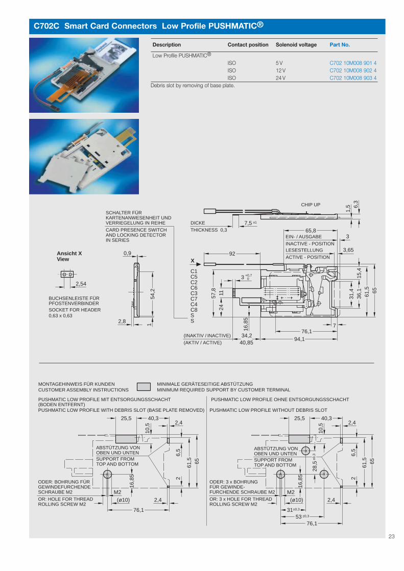
Low Profile PUSHMATIC®
The Smart Card Connector offers a super lowprofile height to enable the PUSHMATIC®-function also in such places where installationconditions are restricted in size. Main applications are handheld devices andnew generations of POS terminals.
Design features• miniature low profile size• landing and self-cleaning contact design• card locking in active position• card presence switch (normally open) acc.
to EMV• micro switch as locking sensor• automatic card eject after transaction• termination to application with flexible pcb• 2 way solenoid wire including 2.54 mm socket• manual unlocking after power failure possible• housing bottom removable to remove foreign
debris i.e. coins (optional)
Assembly instructions:For correct assembly please referto the instructions on the nextpage. Please make sure that
flexprints remain free and unrestricted afterassembly.
22
VConus
23
C702C Smart Card Connectors Low Profile PUSHMATIC®
Description Contact position Solenoid voltage Part No.
Low Profile PUSHMATIC®
ISO 5 V C702 10M008 901 4ISO 12 V C702 10M008 902 4ISO 24 V C702 10M008 903 4
Debris slot by removing of base plate.
34,240,85
1,5
CARD PRESENCE SWITCHAND LOCKING DETECTORIN SERIES
EIN- / AUSGABE
INACTIVE - POSITION
2,54
6,3
6561
,515
,436
,131
,4
16,8
5
241157
,8
154
,2
03
LESESTELLUNG
ACTIVE - POSITION
THICKNESS
DICKE
0,37,5 ±1
3
0,9
ACTIVE)
INACTIVE)
(AKTIV /
(INAKTIV /
2,8
92
7
94,176,1
65,8
3,65
X
SSC8C4C7C3C6C2C5C1
+0,7
Ansicht XView
SOCKET FOR HEADER0,63 x 0,63
BUCHSENLEISTE FÜRPFOSTENVERBINDER
SCHALTER FÜRKARTENANWESENHEIT UNDVERRIEGELUNG IN REIHE
CHIP UP
OR: 3 x HOLE FOR THREADROLLING SCREW M2
±0,3
±0,331±0,353
ODER: 3 x BOHRUNGFÜR GEWINDE-FURCHENDE SCHRAUBE M2
(ø10)
PUSHMATIC LOW PROFILE WITHOUT DEBRIS SLOT
SUPPORT FROMTOP AND BOTTOM
ABSTÜTZUNG VONOBEN UND UNTEN
10,5
2,4
16,8
5 26,
5
6561
,5
M2
76,1
2,425,5 40,3
MINIMUM REQUIRED SUPPORT BY CUSTOMER TERMINALMINIMALE GERÄTESEITIGE ABSTÜTZUNG
ODER: BOHRUNG FÜRGEWINDEFURCHENDESCHRAUBE M2
OR: HOLE FOR THREADROLLING SCREW M2
(ø10)
PUSHMATIC LOW PROFILE WITH DEBRIS SLOT (BASE PLATE REMOVED)
SUPPORT FROMTOP AND BOTTOM
ABSTÜTZUNG VONOBEN UND UNTEN
10,5
2,4
16,8
5 26,
5
6561
,5
M2
76,1
2,425,5 40,3
28,5
CUSTOMER ASSEMBLY INSTRUCTIONSMONTAGEHINWEIS FÜR KUNDEN
PUSHMATIC LOW PROFILE MIT ENTSORGUNGSSCHACHT(BODEN ENTFERNT)
PUSHMATIC LOW PROFILE OHNE ENTSORGUNGSSCHACHT

C702C Technical Data
Electrical Characteristics Standard Value
Contact resistance IEC 60512-2, Test 2a ≤ 100 mΩ
Insulation resistance IEC 60512-3, Test 3a ≥ 109 Ω
High voltage resistance IEC 60512-2, Test 4a 500 VAC; 1 min
Unlocking solenoid Version 5 V Version 12 V Version 24 V
Rated voltage 5 V ± 10% 12 V ± 10% 24 V ± 10%
Current consumption ≈ 2.6 A ≈ 1.5 A ≈ 1.0 A
Current pulse length 10 ... 30 ms 10 ... 30 ms 10 ... 30 ms
Pulse break ≥ 1 s ≥ 1 s ≥ 1 s
Climatical Characteristics (Preliminary)
Climatic category IEC 60068-1 20 / 60 / 21
Operating temperature without condensation - 20 °C ... + 60 °C
Storage temperature - 40 °C ... + 85 °C
Mechanical Characteristics (Preliminary)
Card insertion force IEC 60512-7, Test 13b ≤ 10 N
Mechanical lifetime IEC 60512-5, Test 9a (without corrosion stress) 300,000 mating cycles
Vibration IEC 60512-4, Test 6d f = 4 ... 11.2 Hz 10 mm DA
f = 11.2 ... 500 Hz a = 5 g
2 h / axis
Shock, without disconnection IEC 60512-4, Test 6c ≤ 40 g; 6 ms; halfsine
100 shocks / direction in 3 axis
Shock, without destruction IEC 60512-4, Test 6c 500 g; 1 ms; halfsine
2 shocks / direction in 3 axis
Contact force 20 ... 50 cN
Switch Description Function
Card presence switch and locking Card detection, card in slot free from potential; ≤ 10 ms chattering time
detector in series Contacts locked, card in active position
Switching capacity max. 12 V / 50 mA (200,000 switching cycles)
min. 5 V / 0.1 mA (300,000 switching cycles)
Termination Suitable connector
Flexprint 10 contacts; 1 mm pitch Flexprint connector 10 contacts; 1 mm pitch;
see page 29 «Accessories Flexprint Connectors»
24

25
Smart Card Connectors Superflat Style
Series C702D
Standard Page 26
Push-Lift Page 27
with board Page 27locksdip solder
with board Page 28locks
with card Page 26guide
Accessories Page 29Flexprint connectors
Assembly instructions:Please make sure that flexprintsremain free and unrestricted afterassembly.
Superflat Style Smart Card Connectoris a Push-Pull Series of 2nd generationconnectors with landing contacts providing ahigh degree of miniaturization. Suitable appli-cations include: point-of-sales systems, mobiledevices, access control, keyboards, etc.
Design features• miniature size ideally suited for mobile
devices• additional space saving possible by integra-
tion of base into customer housing• Versions acc. to EMV (see page 6)• dip solder version available featuring snap-in
mounting, chip side up card insertion, and adebris slot to provide egress of coins, paper,etc.
• snap-in version also available with flexprinttermination (both SMT and PCB)

26
C702D Smart Card Connectors Superflat Style
Description Contact position Part No.
with card guide ISO C702 10M008 023 4
(AKTIV / ACTIVE)(INAKTIV / INACTIVE)
3,8
2MA
X. 7
1,6
7,9 ±1
6254,2
7,6
1,1
2
±0,2
16,5
28,5
55,5
13,9±1
2
84,5
ACTIVE POSITIONLESESTELLUNG
INACTIVE POSITIONEIN- / AUSGABE
11
FOR FLAT HEAD COUNTERSUNK SCREWSENKUNG FÜR SENKSCHRAUBE M2
23,7
38,332,3
31±0,1
6020
7,5 ±1
±0,1
2
2
1,8
±0,4
SSC8C4C7C3C6C2C5C1
-0,0+0,73
DICKE / THICKNESS 0,3
6,0
+220,5
a1,5
22,5
98,5
56
74,2
±0,1
8,4 ±0,1
8,2
b
28,5
51,5
1
16PANEL CUT - OUTMONTAGEAUSSCHNITT
LESESTELLUNG
ACTIVE CARD - POSITION
EIN- / AUSGABE
INACTIVE CARD - POSITION
0
DISTANZPLATTE, UMUNTERSCHIEDLICHEFRONTPLATTENSTÄRKENAUSZUGLEICHEN
DISTANCE PLATE FOR DIFFERENTFRONT PANEL THICKNESS
C702D Smart Card Connectors Superflat Style
(AKTIV / ACTIVE)(INAKTIV / INACTIVE)
1,3
FOR FLAT HEAD COUNTERSUNK SCREWSENKUNG FÜR SENKSCHRAUBE M2
1,8
±0,4
6
16,5
±0,2
±0,1
28,5
18,523
,7
38,332,3
11
55,5
7,5 ±1
MAX. 75
-0,0+0,73
±138,531±0,1
±132,5
6020
SSC8C4C7C3C6C2C5C1
ACTIVE POSITIONLESESTELLUNG
INACTIVE POSITIONEIN- / AUSGABE
2
DICKE / THICKNESS 0,3
5,1
FRONT PANEL CUT OUT
EMPFOHLENERFRONTPLATTENAUSSCHNITTRECOMMENDED
55,7
2
Description Contact position Part No.
Standard ISO C702 10M008 001 4Standard, acc. to EMV ISO C702 10M008 065 4
Assembly instructions:To protect the reader please provide a card guide.

27
6,0
+220,5
a1,5
22,5
98,5
56
74,2
±0,1
8,4 ±0,1
8,2
b
28,5
51,5
1
16PANEL CUT - OUTMONTAGEAUSSCHNITT
LESESTELLUNG
ACTIVE CARD - POSITION
EIN- / AUSGABE
INACTIVE CARD - POSITION
0
DISTANZPLATTE, UMUNTERSCHIEDLICHEFRONTPLATTENSTÄRKENAUSZUGLEICHEN
DISTANCE PLATE FOR DIFFERENTFRONT PANEL THICKNESS
C702D Smart Card Connectors Superflat Style
7,316
,5±0
,128
,5
ø5
10ø
7
MAX. 7
15,5
15,5
21,5
42 56,5
5,5 ±1
94
ø1,510
±0,13154 ±0,12072
1,4
3,6
3
6,3
23,7
±1,1
18,5
2
92,7
1,3
ACTIVE POSITIONLESESTELLUNG
INACTIVE POSITIONEIN- / AUSGABE
55,5 11
6038,332,3
2,8
6
SSC8C4C7C3C6C2C5C1
FOR FILLISTER HEAD SCREWSENKUNG FÜR ZYLINDERSCHRAUBE M2 DIN 84
-0,0+0,73
(AKTIV / ACTIVE)(INAKTIV / INACTIVE)
DICKE / THICKNESS 0,3
Description Contact position Part No.
Push-Lift, acc. to EMV ISO C702 10M008 040 4
C702D Smart Card Connectors Superflat Style
60
EINZELHEIT XDETAIL X
X
9x1
(=9)
4,5
ø0,8
8,25
C5C6C7C8S
C1C2C3C4
6,2
19,5
21,3
(AKTIV / ACTIVE)MAX. 7,8
17,6
12,15,7
29,5
2
43,3
59,2
38,5 ±1
(INAKTIV / INACTIVE)
3,5 ±0,2
32,5
12
±0,4
2
±1
56,2
32
-0,0+0,1ø5
627,3
ø0,1
ACTIVE POSITIONLESESTELLUNG
INACTIVE POSITIONEIN- / AUSGABE
4220,2
S
2
-0,0+0,1
ø0,1
ÖFFNUNG FÜR EVENTUELLEPCB - KOMPONENTENODER AUSWURF - SCHACHT
CUT - OUT IF NECESSARYFOR PCB - COMPONENTSOR DEBRIS - SLOT
Description Contact position Part No.
with board locks, dip solder ISO C702 10M008 060 4with board locks, dip solder, ISO C702 10M008 063 4acc. to EMV
28
C702D Smart Card Connectors Superflat Style
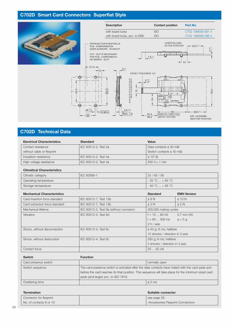
Description Contact position Part No.
with board locks ISO C702 10M008 061 4with board locks, acc. to EMV ISO C702 10M008 066 4
C702D Technical Data
Electrical Characteristics Standard Value
Contact resistance IEC 60512-2, Test 2a Data contacts ≤ 30 mΩwithout cable or flexprint Switch contacts ≤ 40 mΩ
Insulation resistance IEC 60512-2, Test 3a ≥ 109 Ω
High voltage resistance IEC 60512-2, Test 4a 500 VAC; 1 min
Climatical Characteristics
Climatic category IEC 60068-1 25 / 65 / 56
Operating temperature - 25 °C ... + 65 °C
Storage temperature - 40 °C ... + 85 °C
Mechanical Characteristics Standard EMV-Version
Card insertion force standard IEC 60512-7, Test 13b ≤ 8 N ≤ 10 N
Card extraction force standard IEC 60512-7, Test 13b ≥ 3 N ≥ 2 N
Mechanical lifetime IEC 60512-5, Test 9a (without corrosion) 300,000 mating cycles
Vibration IEC 60512-4, Test 6d f = 10 ... 60 Hz 0.7 mm DA
f = 60 ... 500 Hz a = 5 g
2 h / axis
Shock, without disconnection IEC 60512-4, Test 6c ≤ 40 g; 6 ms; halfsine
12 shocks / direction in 3 axis
Shock, without destruction IEC 60512-4, Test 6c 200 g; 6 ms; halfsine
2 shocks / direction in 3 axis
Contact force 20 ... 50 cN
Switch Function
Card presence switch normally open
Switch sequence The card presence switch is activated after the data contacts have mated with the card pads and
before the card reaches its final position. This sequence will take place for the minimum sized card
pads (and larger) acc. to ISO 7816.
Chattering time ≤ 5 ms
Termination Suitable connector
Connector for flexprint see page 29
No. of contacts 8 or 10 «Accessories Flexprint Connectors»
60
-0,0+0,73
56,2
32
-0,0+0,1ø5
627,3
59,2
38,5 ±1
(AKTIV / ACTIVE)(INAKTIV / INACTIVE)
38,332,3
24
11
32,5
12
7,5 ±1
±0,4
ACTIVE POSITIONLESESTELLUNG
INACTIVE POSITIONEIN- / AUSGABE
2
±1
5,7
MAX. 7,8
3,5 ±0,2
43,3
ø0,1
SSC8C4C7C3C6C2C5C1
ÖFFNUNG FÜR EVENTUELLEPCB - KOMPONENTENODER AUSWURF - SCHACHT
CUT - OUT IF NECESSARYFOR PCB - COMPONENTSOR DEBRIS - SLOT
DICKE / THICKNESS 0,3

29
C007 Smart Card Connectors Accessories Flexprint Connectors
2,5
6,5
4
B
A
( G
EÖ
FF
NE
T 7
,6 )
UN
LOC
KE
D
GERADETAUCHLÖTPIN
STRAIGHTDIP SOLDER PIN
Termination No. of contacts Part No.
dip solder pin straight 8 C007 10B008 000 1dip solder pin straight 10 C007 10B010 000 1Further versions upon request
ABGEWINKELT
( GEÖFFNET 10 )UNLOCKED
4
8,9AB
2,5
TAUCHLÖTPIN 90°
90° ANGLEDIP SOLDER PIN
Termination No. of contacts Part No.
dip solder pin 90° angle 8 C007 10B008 100 1dip solder pin 90° angle 10 C007 10B010 100 1Further versions upon request
C007 Smart Card Connectors Accessories Flexprint Connectors
A
B
4,6
6,5
4
( G
EÖ
FF
NE
T 7
,6 )
UN
LOC
KE
D
Termination No. of contacts Part No.
SMT straight 8 C007 10B008 100 2SMT straight 10 C007 10B010 100 2Further versions upon request
3
8,9
4
AB
( GEÖFFNET 10 )UNLOCKED
Termination No. of contacts Part No.
SMT 90° angle 8 C007 10B008 000 2SMT 90° angle 10 C007 10B010 000 2Further versions upon request
5,4
±0,1
-0,10,7 0
1 0+0,10,7
(p-1)x 1 = D 0,05
(p-1)x 1 = D
0,05
0,05
2
1
3,8
±0,1
LEITERPLATTELOCHBILD FÜR
PCB - LAYOUTDIP SOLDER
(TAUCHLÖTPIN)
LEITERPLATTELAYOUT FÜR
PCB - LAYOUTSMT
(SMT)
SM
T S
TR
AIG
HT
SM
T S
TE
HE
ND
SM
T 9
0° A
NG
LES
MT
LIE
GE
ND
C1
C5
C2
C6
C3
C7
C4
C8
SS C1
C5
C2
C6
C3
C7
SS
ISOISO+AFNOR
10 POLIGWAY
GSM 8 POLIGWAY
KONTAKTBELEGUNG: FLEXPRINT - LAYOUT
S = KARTENANWESENHEITSSCHALTER /C1 ... C8 = LESEKONTAKTE / READING CONTACTS
CARD PRESENCE SWITCH
No. of contacts p A B D
10 11.1 16.5 9
8 9.1 14.5 7

30
C007 Technical Data
Electrical Characteristics Standard Value
Contact resistance IEC 60512-2, Test 2a ≤ 20 mΩ
Current carrying capacity IEC 60512-3, Test 5b 0.5 A per contact at 70 °C
Rated voltage IEC 60664-1 63 V
Rated impulse withstand voltage IEC 60664-1 0.8 KV
Pollution degree IEC 60664-1 1
Installations (overvoltage) category IEC 60664-1 II
Comparative tracking index IEC 60664-1 CTI 175
Climatical Characteristics
Temperature - 40 °C to + 85 °C at 75% relative humidity
Reflow temperature ≤ 240 °C / 15 s
Mechanical Characteristics
Thickness of flexprint Thickness 0.3 mm ± 0.05 mm
Pitch of flexprint 1.0 mm
Pitch of PCB page 30
Materials
Contact body LCP
Contact spring CuSn
Contact plating tinned
31
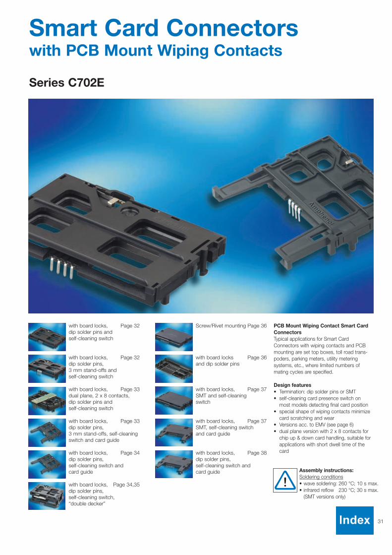
Smart Card Connectors with PCB Mount Wiping Contacts
Series C702E
Screw/Rivet mounting Page 36
with board locks, Page 37SMT and self-cleaningswitch
with board locks, Page 37SMT, self-cleaning switchand card guide
with board locks, Page 38dip solder pins,self-cleaning switch and card guide
with board locks Page 36and dip solder pins
with board locks, Page 32dip solder pins andself-cleaning switch
with board locks, Page 33dual plane, 2 x 8 contacts,dip solder pins and self-cleaning switch
with board locks, Page 33dip solder pins, 3 mm stand-offs, self-cleaning switch and card guide
with board locks, Page 34dip solder pins, self-cleaning switch andcard guide
with board locks, Page 34,35dip solder pins,self-cleaning switch, “double decker”
with board locks, Page 32dip solder pins, 3 mm stand-offs andself-cleaning switch
Assembly instructions:Soldering conditions• wave soldering: 260 °C; 10 s max.• infrared reflow 230 °C; 30 s max.
(SMT versions only)
PCB Mount Wiping Contact Smart CardConnectorsTypical applications for Smart CardConnectors with wiping contacts and PCBmounting are set top boxes, toll road trans-poders, parking meters, utility meteringsystems, etc., where limited numbers ofmating cycles are specified.
Design features• Termination: dip solder pins or SMT• self-cleaning card presence switch on
most models detecting final card position• special shape of wiping contacts minimize
card scratching and wear• Versions acc. to EMV (see page 6) • dual plane version with 2 x 8 contacts for
chip up & down card handling, suitable forapplications with short dwell time of thecard

32
C702E Smart Card Connectors with PCB Mount Wiping Contacts
ISO
22,0
8
2,9
428,7
1,4 - 1,68
-0,0+0,1ø3,24,6
6,7
3,81
LEITERPLATTENDICKE / PCB THICKNESS =
4
±0,4
BESTÜCKUNGSSEITE / COMPONENTS SIDE
C6C7C8
C5C2C3C4S
C1
20
S
62,8
40 50,5
38,1
-0,0
+0,
1ø
1ø
0,1
(62,
8)58
12,7
3 x
(=7,
62)
2,54
(40)
ø0,1
2,5
0,7
Description Contact position Termination Part No.
with board lock and ISO Dip solder pin C702 10M008 272 4self-cleaning switch, acc. to EMV
C702E Smart Card Connectors with PCB Mount Wiping Contacts
22,0
8 2624
,3
ø1
ø3
POSITION OF STAND - OFFS
LAGE DER ABSTANDSBOLZEN
1414
SPACE FOR GUIDING PIN
PLATZBEDARF ZAPFEN
10
ø5
24,4
25,8
17,317,3
2,9
3,5
7,5
40
42
7
8,7
3
-0,0+0,1ø3,2
6,7
3,81
LEITERPLATTENDICKE / PCB THICKNESS = 1,4 - 1,68
±0,4
BESTÜCKUNGSSEITE / COMPONENTS SIDE
ISO C6
C7C8
C5C2C3C4S
C1
20
S
62,8
50,5
38,1
-0,0
+0,
1
ø0,
1
(62,
8)58
12,7
3 x
(=7,
62)
2,54
(40)
ø0,1
Description Contact position Termination Part No.
with board lock and ISO Dip solder pin C702 10M008 255 4self-cleaning switch and 3 mm stand-offs, acc. to EMV

33
C702E Smart Card Connectors with PCB Mount Wiping Contacts
±0,450,5
CHIP
5,08
(2)
ISO
22,0
8
2,9
Kondensator 0,1 F zwischen C1(VCC) und C5(GND) bei Kartenlage Chip oben
OBEN / UPUNTEN / DOWN
-0,0+0,1ø3,2
3,81
12,7
(=7,
62)
3 x
2,54
-0,0
+0,
1ø
1
4,58,2
2
8,6
20,8
14,1
1,6
12
LEITERPLATTENDICKE / PCB THICKNESS = 1,4 ... 1,68
BESTÜCKUNGSSEITE / COMPONENTS SIDE
62,8
40
4
C4 C8
C6C5
C2
S
C1
S
38,1
(40)
ø0,1
C3 C7
20
C5 C1
C3C4
C7C8
C6 C2
58(6
2,8)
2,54
0,7
3 x
(=7,
62)
2,54
ø0,
1
0,7
Capacitor 0,1 F between C1(VCC) and C5(GND) in card position chip up
13,1
CHIP
Description Contact position Termination Part No.
with board lock and ISO Dip solder pin C702 10M008 271 4self-cleaning switch, (Data contacts top dual plane, 2 x 8 contacts, and bottom side)acc. to EMV
C702E Smart Card Connectors with PCB Mount Wiping Contacts
42
62,8
(62)
22,0
8
2,4
62
(62,
8)
2042,7
40
(66)
42
66
24,5 ±0,4
3 7
BESTÜCKUNGSSEITE / COMPONENTS SIDE
ISO
C6C7C8
C5C2C3C4S
C1
S
7,5
8,76,7
2,9
3,5
POSITION OF STAND - OFFS
LAGE DER ABSTANDSBOLZEN 17,317,3
LEITERPLATTENDICKE / PCB THICKNESS = 1,4 - 1,68
38,1
24,4
25,8
3,81
12,7
3 x
(=7,
62)
2,54
SPACE FOR GUIDING PIN
PLATZBEDARF ZAPFEN
10
ø5
-0,0+0,1ø3,2
ø0,1
1414
2624
,3
ø1
ø3
-0,0
+0,
1
ø0,
158
0,7
Description Contact position Termination Part No.
with board lock, self-cleaning ISO Dip solder pin C702 10M008 283 4switch and card guide, 3 mm stand-offs, acc. to EMV
34
C702E Smart Card Connectors with PCB Mount Wiping Contacts
(62,
8)
ISO
3,2
3,5
4,56,78,7
4
58
2,462
42,7
40
42
66
24,5 ±0,4
42
(62)
22,0
8
20
(66)
BESTÜCKUNGSSEITE / COMPONENTS SIDE
C6C7C8
C5C2C3C4S
C1
S
LEITERPLATTENDICKE / PCB THICKNESS = 1,4 - 1,68
38,1
3,81
12,7
3 x
(=7,
62)
2,54
10
-0,0+0,1ø3,2
ø0,1
ø1
-0,0
+0,
1
ø0,
1
0,7
62,8
Description Contact position Termination Part No.
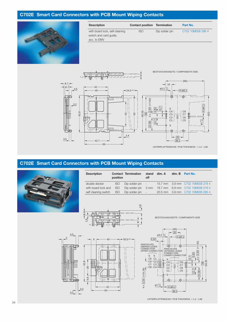
with board lock, self-cleaning ISO Dip solder pin C702 10M008 286 4switch and card guide, acc. to EMV
C702E Smart Card Connectors with PCB Mount Wiping Contacts
22,0
8
UPPER CONNECTORANSCHLUSS
CONNECTIONUNTERER LESER
LOWER CONNECTOR
4,8
AB
6,4
1,6
4,5
9,8
62,8
4250
±0,450,59 40
28
(62,
8)
(=7,
62)
58
3 x
12,7
C3C7
38,1
(40)
-0,0+0,1ø3,2
ø0,1
20
-0,0+0,1ø1
ø0,1
2,54
ISO
C4 C8
C6C5
C2
S
C1
S
C3 C7
C5 C1
C4C8
C6 C2
4 x
(=10
,16)
2,54
0,7 3,
81 2,54
BESTÜCKUNGSSEITE / COMPONENTS SIDE
1,4 - 1,68LEITERPLATTENDICKE / PCB THICKNESS =
S S
2
4,23,3
ANSCHLUSS
CONNECTIONOBERER LESER
Description Contact Termination stand dim. A dim. B Part No.position off
double decker ISO Dip solder pin - 15.7 mm 3.9 mm C702 10M008 278 4with board lock and ISO Dip solder pin 3 mm 18.7 mm 6.9 mm C702 10M008 279 4self cleaning switch ISO Dip solder pin - 20.5 mm 3.9 mm C702 10M008 295 4

35
C702E Smart Card Connectors with PCB Mount Wiping Contacts
3,9
20,8
4,8
48,4
9,8
65
3312
,468
,4
3,2
3,829,5
24,6 40
57,8
UNTERER LESERCONNECTION
LOWER CONNECTOR
ANSCHLUSS
OBERER LESER
12
ISO
4 x
(=10
,16)
2,54
C4 C8
C6C5
C2
S
C1
S
C3 C7
C3C7
C5 C1
C4C8
C6 C2
S S
CONNECTIONUPPER CONNECTOR
ANSCHLUSS
2,54
0+0,1ø3,2
ø0,1
20
43,6
38,1
0+0,1ø1
ø0,15,08
58
(=7,
62)
3 x
12,7
0,7 3,
81 2,54
(64)
BESTÜCKUNGSSEITE / COMPONENTS SIDE
1,4 - 1,68LEITERPLATTENDICKE / PCB THICKNESS =
ø0,10+0,1ø1
30
546
1,6
1,6
C702E Smart Card Connectors with PCB Mount Wiping Contacts
3,8
UNTERER LESERCONNECTION
LOWER CONNECTOR
ANSCHLUSS
OBERER LESER
3,34,2
12
ISO
4 x
(=10
,16)
2,54
C4 C8
2 1,6
40 ±0,450
64
55,9
62,8 31
,111
,1
C6C5
C2
S
C1
S
C3 C7
C3C7
C5 C1
C4C8
C6 C2
S S
CONNECTIONUPPER CONNECTOR
ANSCHLUSS
2,540
+0,1ø3,2ø0,1
20
43,6
38,1
0+0,1ø1
ø0,15,08
58
(=7,
62)
3 x
12,7
0,7 3,
81 2,54
(64)
BESTÜCKUNGSSEITE / COMPONENTS SIDE
9,4
29,424,5
4,5
1,6
1,6
20,3
1,4 - 1,68LEITERPLATTENDICKE / PCB THICKNESS =
Description Contact position Termination Part No.
double decker, with board lock ISO Dip solder pin C702 10M008 294 4and self cleaning switch, bottom part for double thickness cardsupper part, dual plan 2x8 contacts
Description Contact position Termination Part No.
double decker, with board lock ISO Dip solder pin C702 10M008 290 4and self cleaning switch, 5mm overhang, bottom part for double thickness cards, upper part, dual plan 2x8 contacts
36
C702E Smart Card Connectors with PCB Mount Wiping Contacts
-0,0+0,1ø3,2
4,05
2,8
4
4,1
3,2
6,8
62
40
(40)
S
ISO
AF
NO
R
BESTÜCKUNGSSEITE / COMPONENTS SIDE
LEITERPLATTENDICKE / PCB THICKNESS = 1,4 ... 1,68
C6C7C8
C4C3C2C1C5
C2C3C4S
C8C7C6C5C1
3,81
7 x
(=17
,78)
11,9
22,
54
2,54
3038,1
2,54±0,450,5
ø0,1
20
-0,0
+0,
1
(62)
58
ø1
ø0,
1-0
,0+
0,1
ø1
ø0,
1
0,7
C702E Smart Card Connectors with PCB Mount Wiping Contacts
AF
NO
R
-0,0
+0,
1
-0,0+0,1ø2,2
-0,05+0,00ø1,8
4
4,1
3,2
8,8
6,8
62
40
(62)
58
ø1
(40)20
19,05
15
S
ISO
BESTÜCKUNGSSEITE / COMPONENTS SIDE
LEITERPLATTENDICKE / PCB THICKNESS = 1,6 ... 2,4
C6C7C8
C4C3C2C1C5
C2C3C4S
C8C7C6C5C1
3,81
7 x
(=17
,78)
11,9
22,
54
2,54
3038,1
2,54 ø0,
1-0
,0+
0,1
ø1
ø0,
1
±0,450,5
0,7
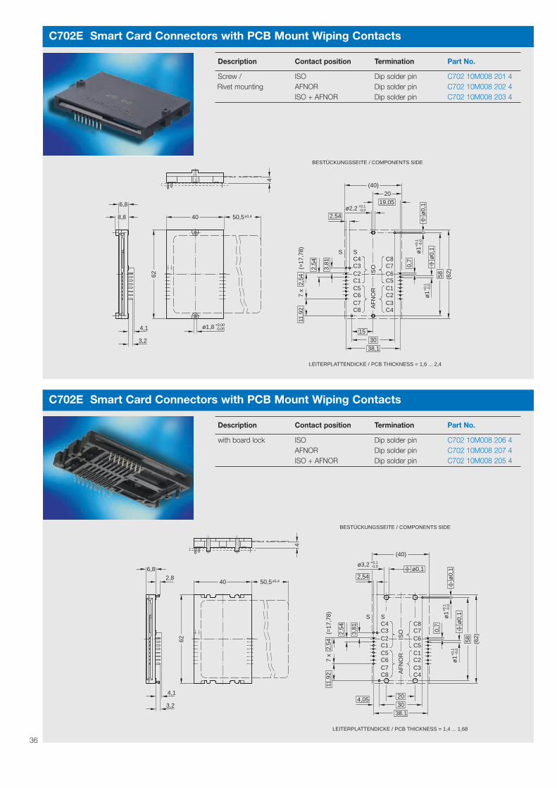
Description Contact position Termination Part No.
Screw / ISO Dip solder pin C702 10M008 201 4Rivet mounting AFNOR Dip solder pin C702 10M008 202 4
ISO + AFNOR Dip solder pin C702 10M008 203 4
Description Contact position Termination Part No.
with board lock ISO Dip solder pin C702 10M008 206 4AFNOR Dip solder pin C702 10M008 207 4ISO + AFNOR Dip solder pin C702 10M008 205 4

37
C702E Smart Card Connectors with PCB Mount Wiping Contacts
4,3
22,0
8
LEITERPLATTENDICKE / PCB THICKNESS = 1,4 - 1,68
1,2
12,7
5
-0,0+0,1ø3,2
2,8
6,8
62
40
(62)
58
-0,0
+0,
1ø
1
(40)
ISO
BESTÜCKUNGSSEITE / COMPONENTS SIDE
C6C7C8
C5C2C3C4S
C1
3,81
3 x
(=7,
62)
2,54
30
ø0,
10,
1
±0,450,5
ø0,1
20
S
0,7
C702E Smart Card Connectors with PCB Mount Wiping Contacts
10
(40)
11,9
2
0,1
6,83,2
4,3
5
1,2
58 (62)
20
30
3,81
2,54
7 x
(=17
,78)
2,54
-0,0+0,1ø3,2
(66)
AF
NO
RIS
O
C6C7C8
C4C3C2C1C5
C2C3C4S
C8C7C6C5
S
C1
ø0,1
ø0,1 -0,0+0,1ø1
BESTÜCKUNGSSEITE / COMPONENTS SIDE
LEITERPLATTENDICKE / PCB THICKNESS = 1,4 - 1,68
±0,424,5
4262
26
66
0,7
Description Contact position Termination Part No.
with board lock and ISO SMT C702 10M008 244 4self-cleaning switch
Description Contact position Termination Part No.
with board lock, ISO SMT C702 10M008 230 4self-cleaning switch ISO + AFNOR SMT C702 10M008 224 4and card guide
C702E Smart Card Connectors with PCB Mount Wiping Contacts
4
±0,424,56,8
4262
26
66
58 (62)
4,0520
30
38,1
3,81
2,54
7 x
(=17
,78)
11,9
22,
54
-0,0+0,1ø3,2
(66)
AF
NO
RIS
O
C6C7C8
C4C3C2C1C5
C2C3C4S
C8C7C6C5
S
C1
10
ø0,1
ø0,1 -0,0+0,1ø1
ø0,
1-0
,0+
0,1
ø1
3,2
BESTÜCKUNGSSEITE / COMPONENTS SIDE
LEITERPLATTENDICKE / PCB THICKNESS = 1,4 - 1,68
0,7
Description Contact position Termination Part No.
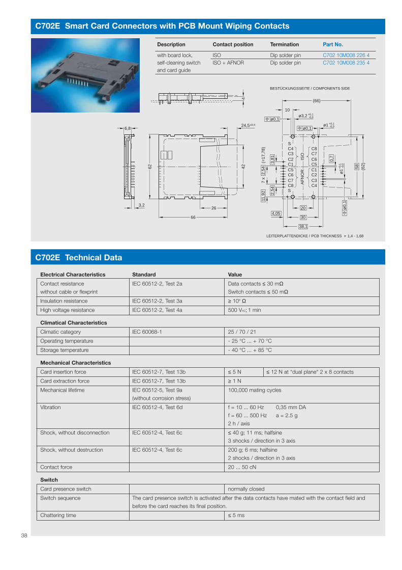
with board lock, ISO Dip solder pin C702 10M008 226 4self-cleaning switch ISO + AFNOR Dip solder pin C702 10M008 235 4and card guide
C702E Technical Data
Electrical Characteristics Standard Value
Contact resistance IEC 60512-2, Test 2a Data contacts ≤ 30 mΩwithout cable or flexprint Switch contacts ≤ 50 mΩ
Insulation resistance IEC 60512-2, Test 3a ≥ 109 Ω
High voltage resistance IEC 60512-2, Test 4a 500 VAC; 1 min
Climatical Characteristics
Climatic category IEC 60068-1 25 / 70 / 21
Operating temperature - 25 °C ... + 70 °C
Storage temperature - 40 °C ... + 85 °C
Mechanical Characteristics
Card insertion force IEC 60512-7, Test 13b ≤ 5 N ≤ 12 N at “dual plane“ 2 x 8 contacts
Card extraction force IEC 60512-7, Test 13b ≥ 1 N
Mechanical lifetime IEC 60512-5, Test 9a 100,000 mating cycles
(without corrosion stress)
Vibration IEC 60512-4, Test 6d f = 10 ... 60 Hz 0,35 mm DA
f = 60 ... 500 Hz a = 2.5 g
2 h / axis
Shock, without disconnection IEC 60512-4, Test 6c ≤ 40 g; 11 ms; halfsine
3 shocks / direction in 3 axis
Shock, without destruction IEC 60512-4, Test 6c 200 g; 6 ms; halfsine
2 shocks / direction in 3 axis
Contact force 20 ... 50 cN
Switch
Card presence switch normally closed
Switch sequence The card presence switch is activated after the data contacts have mated with the contact field and
before the card reaches its final position.
Chattering time ≤ 5 ms
38

39
Smart Card Connectors with landing card PCB Mount
Series C702F
The Smart Card Connector with landing card. Typical applications are Point-of-Sale systems, mobile devices, access con-trol etc.
Design features• high number of mating cycles due to
minimized wiping distance on card contacts• contact self-cleaning effect• short card insertion depth
Assembly instructions:For the provided Philip’s head screws, a power driven screw driver ( 500-600 r/rpm; 0.25 Nm max.) is recommended.
Soldering conditionsWave soldering: 260 °C, 10 s max.

C702F Smart Card Connectors with landing Card PCB Mount
GS
M
ø0,
1 -0+0,1
39,5
C8C7C6C5C1C2C3C4S
C4C3C2C1C5C6C7C8S
-0+0,1
8 x
2,54
(= 2
0,32
)
(30,
7)(6
1,4)
60,9
61,4
64,5
2,6
3,66,4
1,6
±0,2
30,318,2
14,3
ø2,1
36,4(50,1)
ø1,5
50,1 43
2,5
2,54
0,7
ø0,05ø1
AF
NO
RIS
O 7
816-
2
LESESTELLUNGACTIVE POSITION
EIN- / AUSGABESTELLUNGINACTIVE POSITION
LIEFERUNG ENTHÄLT 2 SCHRAUBENSHIPMENT INCLUDES 2 SCREWS
Description Contact position Termination Part No.
Landing card GSM Dip solder pin C702 10M008 120 4ISO Dip solder pin C702 10M008 121 4AFNOR Dip solder pin C702 10M008 122 4ISO + AFNOR Dip solder pin C702 10M008 123 4
C702F Technical Data
Electrical Characteristics Standard Value
Contact resistance IEC 60512-2, Test 2a Data contacts ≤ 35 mΩ, Switch contacts ≤ 70 mΩ
Insulation resistance IEC 60512-2, Test 3a ≥ 109 Ω
High voltage resistance IEC 60512-2, Test 4a 500 VAC; 1 min
Climatical Characteristics
Climatic category IEC 60068-1 25 / 85 / 21
Operating temperature - 25 °C ... + 85 °C
Storage temperature - 40 °C ... + 85 °C
Mechanical Characteristics
Card insertion force IEC 60512-7, Test 13b ≤ 12 N
Card extraction force IEC 60512-7, Test 13b ≥ 2.5 N
Mechanical lifetime IEC 60512-5, Test 9a 300,000 mating cycles
(without corrosion stress)
Vibration IEC 60512-4, Test 6d f = 10 ... 60 Hz 0.7 mm DA
f = 60 ... 500 Hz a = 5 g
2 h / axis
Shock, without disconnection IEC 60512-4, Test 6c ≤ 40 g; 6 ms; halfsine
3 shocks / direction in 3 axis
Shock, without destruction IEC 60512-4, Test 6c 200 g; 6 ms; halfsine
2 shocks / direction in 3 axis
Contact force – 20 ... 50 cN
Switch
Card presence switch normally open
Switch sequence The card presence switch is activated after the data contacts have mated with the card pads and before the
card reaches its final position. This sequence will take place for the minimum sized pads (and larger) acc. to
ISO 7816
Chattering time – ≤ 5 ms
40

41
Smart Card Connectors Hybrid Reader
Series C703A
Hybrid ReaderThe manual Hybrid Reader accepts both ISO7810 magstripe cards and ISO 7816 chip cards inthe same slot. Push-pull card handling allowsreading of the magnetic stripe on the way in orout, and reading/writing of the chip card when thecard is fully inserted. Standard product features adual head contact set (ISO & AFNOR) and track 2,1 + 2 or 2 + 3 reading options available for themagnetic head. The head is suspended by a unique gimballed (cardanian) system that assuresaccurate data transfer. The reader features adecoder circuit for each track and an 18 pin interface conncector.
Usable Cards
Magstripe cardsISO 7810, 7811, 7812; LOCO and HICO. The magstripe will be read 100% during insertionand extraction of the card.
ChipcardsISO 7816. Contact positions ISO, AFNOR and ISO& AFNOR can be read and written to.
Embossed cards acc. to ISO 7811, part 3 areaccepted.
Assembly instructions:The Smart Card Connector data con-tacts are connected to a pin header.F2F decoding of magstripe signal is
done on a system board while data and clock signal are available separately. Card Detector 1 (CD1) detects the movementover the maghead and is low active until 50 msafter last clock signal of magtracks. Card Detector 2 (CD2) detects card active posi-tion. Data and clock signal of magtracks as well asCD1 and CD2 are TTL / CMOS compatible. This hybrid reader is intended for integration intoelectronic equipment and systems. When integra-ted, the EMC requirements of the respectiveequipment or system acc. to EMC guidelines 89 / 336 EWG shall be followed.

42
C703A Hybrid Reader
Description Contact position Magnetic track Part No.
Magnetic head on bottom, ISO 2 C703 10M008 101 5with electronic and bezel ISO 1 + 2 C703 10M008 103 5
ISO 2 + 3 C703 10M008 104 5Magnetic head on bottom, ISO 1 + 2 + 3 C703 10M008 305 5without electronic without bezelBezel C703 G05 040 E 5
29
ø3,
21916
,5
10,3
7075
R1
MAGNETKOPFMAGNETIC HEAD
10
0
,6
0,5
1,78
2,513
1419
1
3258 64
50±0
,2
22,8
535
,5
55,5
24,6
54,1
15,5
37,51,5
ø5
20
1650 ±0,2
75 ±0,2
115,5CA. 108
105
CA. 43
5,84
0,9
60
1,27
2,25
2,54
30
2,54
SPUR 1TRACK 1
SPUR 2TRACK 2
SPUR 3TRACK 3
4 x M32 TIEFDEPTH 2
PCB
2 x M32 TIEFDEPTH 2
2 x M32 TIEFDEPTH 2
FRONTPLATTEFRONTPANEL
R1
2 REIHIGE STIFTLEISTEABGEWINKELT 18 - POLIGUNPROTECTED DOUBLEROW HEADERRIGHT ANGLE - 18 WAY
LESESTELLUNGACTIVE POSITION
EIN- / AUSGABEINACTIVE POSITION
5,9
58
1,0 DICK1,0 THICKREQUIRED CUSTOMER
PRINTED CIRCUIT BOARDDIMENSIONS
VORGABEN FÜRKUNDENLEITERPLATTE
C007 10B010 000 2FOLIENKLEMMVERBINDERSMT 90° WINKELFLEXPRINT CONNECTORSMT 90° ANGLE

C703A Hybrid Reader
C703A Technical Data
Electrical Characteristics Standard Value
Contact resistance IEC 60512-2, Test 2a Data contacts ≤ 30 mΩwithout cable or flexprint Switch contacts ≤ 40 mΩ
Insulation resistance IEC 60512-2, Test 3a ≥ 109 Ω
High voltage resistance IEC 60512-2, Test 4a 500 VAC; 1 min
Climatical Characteristics
Climatic category IEC 60068-1 25 / 65 / 56
Operating temperature - 25 °C ... + 65 °C
Storage temperature - 40 °C ... + 85 °C
Mechanical Characteristics
Card insertion force IEC 60512-7, Test 13b ≤ 8 N
Card extraction force IEC 60512-7, Test 13b ≥ 3 N
Mechanical lifetime IEC 60512-5, Test 9a 300,000 mating cycles
(no corrosion stress)
Contact force 20 ... 50 cN
Switch
Card presence switch Logical 0 with inserted card
Switch sequence The card presence switch is activated after the data contacts have mated with the contact field and
before the card reaches its final position.
Magstripe reader
Resistance of magnetic head 290 Ω ± 20 % (at f = 100 Hz)
Inductance of magnetic head 110 mH ± 25 % (at f = 1 KHz)
PIN-No. Contact assignment Remarks PIN-No. Contact assignment Remarks
PIN 1 C1 Chipcard contacts PIN 10 Card Detector 2 Chip card can be activated (direct circuit) (safety contact closed)
PIN 2 C2 Chipcard contacts PIN 11 +5 V –(direct circuit)
PIN 3 C3 Chipcard contacts PIN 12 – –(direct circuit)
PIN 4 C4 Chipcard contacts PIN 13 Data Track 1 –(direct circuit)
PIN 5 C5 = Ground Chipcard contacts PIN 14 Clock Track 1 –(direct circuit)
PIN 6 C6 Chipcard contacts PIN 15 Data Track 2 –(direct circuit)
PIN 7 C7 Chipcard contacts PIN 16 Clock Track 2 –(direct circuit)
PIN 8 C8 Chipcard contacts PIN 17 Data Track 3 –(direct circuit)
PIN 9 Card Detector 1 Magstripe is now PIN 18 Clock Track 3 –being read
The 2 Track Magstripe readers have PIN 13 + 14 dedicated with Track 1 or 3. Track 2 is PIN 15 + 16. PINs 17 + 18 are not connected. All digital signalsof the Magstripe readers are TTL low active.
43
44
Smart Card Connectors with Disk Drive Slot
Series C705A
Disk Drive Slot Page 453 1/2“
Disk Drive Slot Page 455 1/4“
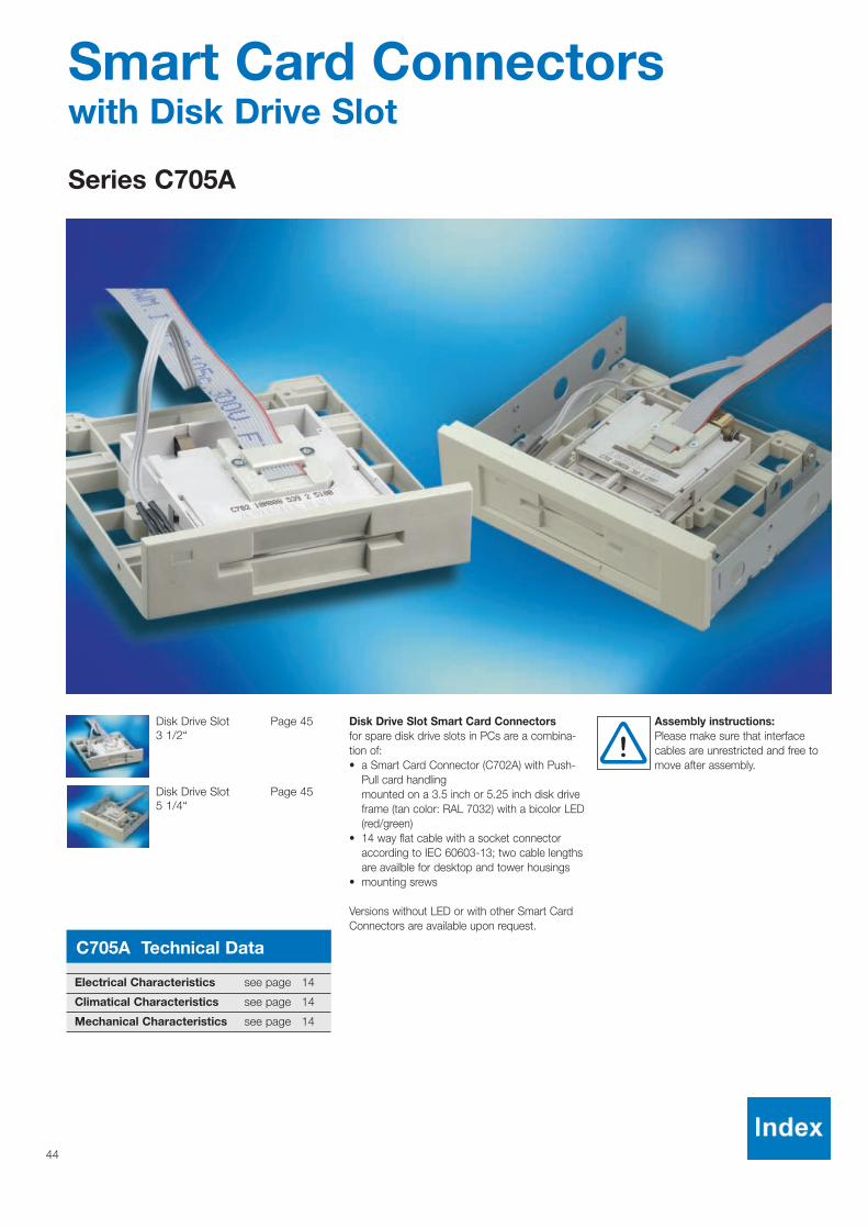
Disk Drive Slot Smart Card Connectorsfor spare disk drive slots in PCs are a combina-tion of:• a Smart Card Connector (C702A) with Push-
Pull card handlingmounted on a 3.5 inch or 5.25 inch disk driveframe (tan color: RAL 7032) with a bicolor LED(red/green)
• 14 way flat cable with a socket connectoraccording to IEC 60603-13; two cable lengthsare availble for desktop and tower housings
• mounting srews
Versions without LED or with other Smart CardConnectors are available upon request.
Assembly instructions:Please make sure that interfacecables are unrestricted and free tomove after assembly.
C705A Technical Data
Electrical Characteristics see page 14
Climatical Characteristics see page 14
Mechanical Characteristics see page 14
45
C705A Smart Card Connectors with Disk Drive Slot
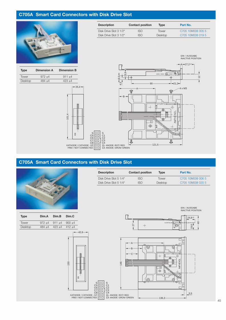
Description Contact position Type Part No.
Disk Drive Slot 3 1/2“ ISO Tower C705 10M008 005 5Disk Drive Slot 3 1/2“ ISO Desktop C705 10M008 019 5
4,5
4 x M3
128,5 23
,9
101,
44 ±227,2
B
A
21,290
121,5
25,4
SC5C6C7C8
SC1C2C3C4
INACTIVE POSITIONEIN- / AUSGABE
11-13-
KATHODE / CATHODEFREI / NOT CONNECTED
-12 ANODE: ROT/ REDANODE: GRÜN/ GREEN
Type Dimension A Dimension B
Tower 972 ±4 911 ±4Desktop 484 ±4 423 ±4
C705A Smart Card Connectors with Disk Drive Slot
Description Contact position Type Part No.
Disk Drive Slot 5 1/4“ ISO Tower C705 10M008 006 5Disk Drive Slot 5 1/4“ ISO Desktop C705 10M008 020 5
±224,8
19,6
5,5-12
A
B
C
40
27
146
150
42,6
136,3
SC5C6C7C8
SC1C2C3C411-13-
INACTIVE POSITIONEIN- / AUSGABE
FREI / NOT CONNECTEDANODE: ROT/ REDANODE: GRÜN/ GREEN
KATHODE / CATHODE
Type Dim.A Dim.B Dim.C
Tower 972 ±4 911 ±4 900 ±4Desktop 484 ±4 423 ±4 412 ±4

46
Smart Card Connectors SIMLOCK®
Series C707A
6 contacts Page 47Low Profilewith card presence switch
6 contacts Page 47Low Profile
with or without Page 48locking detector4 positioning pins
with or without Page 48locking detector2 positioning pins
SIMLOCK®
designed for SIM/SAM card applications.
Design features• size: same footprint as SIM card• reliable function in locked state during mobile
use• designer does not have to be concerned with
housing tolerances and card guiding due to self contained system
• polarization notch does not allow incorrect card positioning
• SIMLOCK® with locking detector (or card presence switch) available
• suitable for automatic assembly processes(Pick & Place, Tape & Reel and Reflow)
• contact carrier and lid can be delivered separately upon request
• custom geometries and layout designs possible
For your special requirements please contactAmphenol-Tuchel Electronics GmbH (see backpage).
Assembly instructions:Versions with locking detector lid must be unlocked during reflow process or lid can be packaged separately and snapped in place after reflow.
Soldering conditions:Infrared reflow: 245°C; 10 s max.

47
C707A Smart Card Connectors SIMLOCK®
Description Packaging Part No.
6 contacts (3+3), low profile, 800 pieces on “Tape & Reel“ C707 10M006 522 2with card presence switch, 20 mm pitchwithout positioning pins2 different positioning pins1) 800 pieces on “Tape & Reel“ C707 10M006 523 2
20 mm pitch
1)±0
,05
±0,0515,8 1)
ø1,6
S1S2
SIM - KARTESIM - CARD
DER PLATINE IN DIESEMBEREICH ZULÄSSIG
IN THIS AREA ALLOWED
KEINE LEITERBAHNEN AUF
NO TRACKS ON THE PCB
27,4
C5
C7C6
C3C2C1
1,7
MA
X 1
7,3
2,54
14,811,8
ANSCHLUßSEITE
(OH
NE
LÖ
TP
INS
)(E
XC
LUD
ING
SO
LDE
R P
INS
)
5,55,5
0,5
3,65
5,08
-0,2
013
,314
,4-0
,05
0+0,
0514
,6 0
0
(0,4)
(0,4
5)
(3,6
5)
1,9
9,64
5
0+0,313,4
9,2 -0,3 0
±0,0510,7
±0,0511,126,5
30
±0,1
2,5
(24,
3)
+0,
215
,7
EMPFOHLENE LÖTFLÄCHERECOMMENDED SOLDER LANDS
KARTENEINFÜHRUNGSBEREICHCARD INPUT AREA
4°...180°
CONNECTION SIDEAu 0,8 OBERFLÄCHE
COVER LOCKEDDECKEL VERRIEGELT
Au 0,8 PADS
PAD
PADPOTENTIALFREI
FREE OF POTENTIAL
0,1
1,3
OPTIONAL HOLES FOR PRODUCTION LINEOPTIONAL LÖCHER FÜR PRODUKTIONSLINIE
1) 1)ø1,5ø1
1)5,4
-0+0,05
-0+0,05ø1,1
12
1)
1)
C707A Smart Card Connectors SIMLOCK®
Description Packaging Part No.
6 contacts (3+3), low profile, 800 pieces on “Tape & Reel“ C707 10M006 049 22 different positioning pins1) 20 mm pitch6 contacts (3+3), low profile, 800 pieces on “Tape & Reel“ C707 10M006 500 2without positioning pins1), 20 mm pitchindex dimensions unnecessary
1)
30
5
12,2 -0+0,05ø1,6
15,2
1,9
5,5
1)5,4
1)
1) 1)
MA
X. 1
7,3
C6C5
C7C3
(6)
2,1
5,089,64
3,65
15,1
24,3
2,5
0,7
27,4
1,7
5,81
26,5
2,421,8
ø1,5ø1
0,5
2,54
1,3
KARTENEINSCHIEBE - BEREICHCARD INPUT AREA
4°...180°
SIM - KARTESIM - CARD
C2C1
DECKEL VERRIEGELTLID LOCKED
0,1
-0+0,05ø1,1
5,5
KEINE LEITERBAHNEN
NO CONDUCTOR
IN DIESEM BEREICHZULÄSSIG.
ALLOWED IN THIS AREA.
LEITERPLATTEN - BESTÜCKUNGPCB - LAYOUT
±0,0515,8 1)
1)
1)±0
,05
12

48
C707A Smart Card Connectors SIMLOCK®
Description Packaging Part No.
with locking detector, 140 pieces per C707 10M006 007 22 positioning pins styrofoam tray with locking detector, 600 pieces on "Tape & Reel" C707 10M006 503 22 positioning pins, without lid 20 mm pitchwithout locking detector, 600 pieces on "Tape & Reel" C707 10M006 021 22 positioning pins 24 mm pitchwithout locking detector, 140 pieces per C707 10M006 031 22 positioning pins styrofoam tray Lid for SIMLOCK® 600 pieces in bag C707 10M006 027 2with locking detector
ø1,5
17,2
8,1
2,25
DECKEL GESCHLOSSENLOCKED POSITION(LESEPOSITION / ACTIVE POSITION)
11,5
0,8
25,9
1,3
S
C5C1C6C2C7C3 5
x1,
27=
(6,
35)
0,9
0,1
9,35
-0,00+0,05ø1,6
22
3,4
33
2,7
ø0,05
1,27
1,27
3,72
S
19,9
1
1,5
2
22,427,9
0,5
1
2,1
3
30,8
3,2
0,15
SIM - KARTESIM - CARD
KARTENEINSCHIEBE - BEREICHCARD INPUT AREA
4°...180° LEITERPLATTEN - BESTÜCKUNGPCB - LAYOUT
DECKEL IN ENTRIEGELTERPOSITION
LID UNLOCKEDPOSITION
C707A Smart Card Connectors SIMLOCK®
Description Packaging Part No.
with locking detector, 140 pieces per C707 10M006 000 24 positioning pins styrofoam tray with locking detector, 600 pieces on "Tape & Reel" C707 10M006 026 24 positioning pins, without lid 24 mm pitchwithout locking detector, 140 pieces per C707 10M006 001 24 positioning pins styrofoam tray Lid for SIMLOCK® 600 pieces in bag C707 10M006 027 2with locking detector
ø1,5
SIM - KARTESIM - CARD
2,1
3
1,6
25,9
30,8
3,2
1,3
0,15
KARTENEINSCHIEBE - BEREICHCARD INPUT AREA
4°...180°
17,2
19,9
DECKEL IN ENTRIEGELTER
1,2(6,3
5)
S
C5C1C6C2C7C3 5
x1,
27=
(6,
35)
0,9
0,1
9,3512
,7
1
1,5
-0,00+0,05ø1,6
22
3,4
33
2
22,427,9
2,7
ø0,05
0,5
1
1,27
1,27
3,72
S
1,6
POSITIONLID UNLOCKED
POSITION
DECKEL GESCHLOSSENLOCKED POSITION(LESEPOSITION / ACTIVE POSITION)
LEITERPLATTEN - BESTÜCKUNGPCB - LAYOUT

49
C707A Technical Data
Electrical Characteristics Standard Value
Contact resistance IEC 60512-2, Test 2a Data contacts ≤ 30 mΩSwitch contacts ≤ 60 mΩ
Insulation resistance IEC 60512-2, Test 3a ≥ 109 Ω
High voltage resistance IEC 60512-2, Test 4a 500 VAC; 1 min
Climatical Characteristics
Climatic category IEC 60068-1 40 / 85 / 21
Operating temperature - 40 °C ... + 85 °C
Storage temperature - 40 °C ... + 85 °C
Mechanical Characteristics
Lid locking force 4 ... 8 N
Mechanical lifetime IEC 60512-5, Test 9a 5,000 operations
Vibration IEC 60512-4, Test 6d f = 10 ... 60 Hz 0.8 mm DA
f = 60 ... 500 Hz a = 6 g
2 h / axis
Shock, without disconnection IEC 60512-4, Test 6c ≤ 100 g; 6 ms; halfsine
100 shocks / direction in 3 axis
Shock, without destruction IEC 60512-4, Test 6c 500 g; 1 ms; halfsine,
2 shocks / direction in 3 axis
Contact force 20 ... 50 cN
Switch
Security switch closed, when lid locked
Chattering time ≤ 5 ms
C707A Smart Card Connectors SIMLOCK®
pitch see descriptionof products
“Tape & Reel” packaging for SIMLOCK®

50
Smart Card Connectors SIMBLOCK®
Series C707B
without switch Page 516 contacts
U-form Page 516 contacts
without switch Page 52
with switch Page 52(normally closed)
with switch Page 53(normally open)
Wingblock Page 53with cardguide andcard stop
SIMBLOCK®
Due to miniature size, SIMBLOCK® is suitable formobile applications from handsets to e-purses.
Design features• contacts chip cards according to ISO 7816
and Plug-In SIM-Cards• suitable for automatic assembly processes
(packaging designed for Pick & Place processand Reflow)
• low height (2 mm standard)• high co-planarity accuracy• SMT-Version with 6 contacts especially desi-
gned for GSM 11.11 interfaces• solderfree versions with float contacts for
PCB mount• versions with spoon contacts available for any
operation direction of the chip card
Assembly instructions:For reliable function make sure thatcard is positioned and supported asshown on drawing.
Soldering conditions:Infrared reflow: 245 °C; 10 s max.
230 °C SIMBLOCK®
with switch

51
C707B Smart Card Connectors SIMBLOCK®
C707B Smart Card Connectors SIMBLOCK®
Description usable chipcards Part No.ISO 7816, contact position
ISO AFNOR SIM-Cardswithout switch, • – • C707 10M006 094 26 contacts (3+3)
Description usable chipcards Part No.ISO 7816, contact position
ISO AFNOR SIM-CardsU-form, without switch, • – • C707 10M006 092 26 spoon contacts (3+3) with float contacts for solderfree PCB mount
2,0
0,6
11,6
(6,1
4)
(22,
62)
(15,06)
7,6
0,9
10,7
7,112,4
1,2
LEITERPLATTEN - BESTÜCKUNGPCB - LAYOUT
KUNDENGEHÄUSEINNEN MIT KARTEN-
CARD STOP HASTO BE PROVIDEDWITHIN THE CUSTOMER
ANSCHLAG
HOUSING
IDENTIFIKATIONSKARTENACH ISO 7816 - 2IDENTIFICATION CARDACCORDING TO ISO 7816 - 2
SIM - KARTESIM - CARD
NIVEAU FÜR KARTENAUFLAGELEVEL FOR CARD - SUPPORT
PLANAR AREA5,2x4,0
PLANARE FLÄCHE
C7
C6
C5
C3
C2
C1
0,1 2,
54
2,54
(8,81)
0,9
(CONTACTS DEFLECTED)
0,8 ±0,05
0
1,5
-0,1
+0,
2
-0,1
07,
3550,8
8,8
±0,1
0,1(0
,6)
(0,6
)±0
,15
±0,152,54 ±0,152,54
1,2
(8 )
±0,3
9,3
MAX. 13,2
0,8 ±0,05
±0,112,6±0,059,3
7,4
10,5
-0,2
+0,
18
7,8
±0,1
0,9
+0,
1
MOVE TO THE OUTSIDEDEFLECTED CONTACTS
MOVE EACH 0,15 mm
THE MAX. DEFLECTED
TO THE OUTSIDE (7,7)
DATA CONTACTS
-0,1+0,2
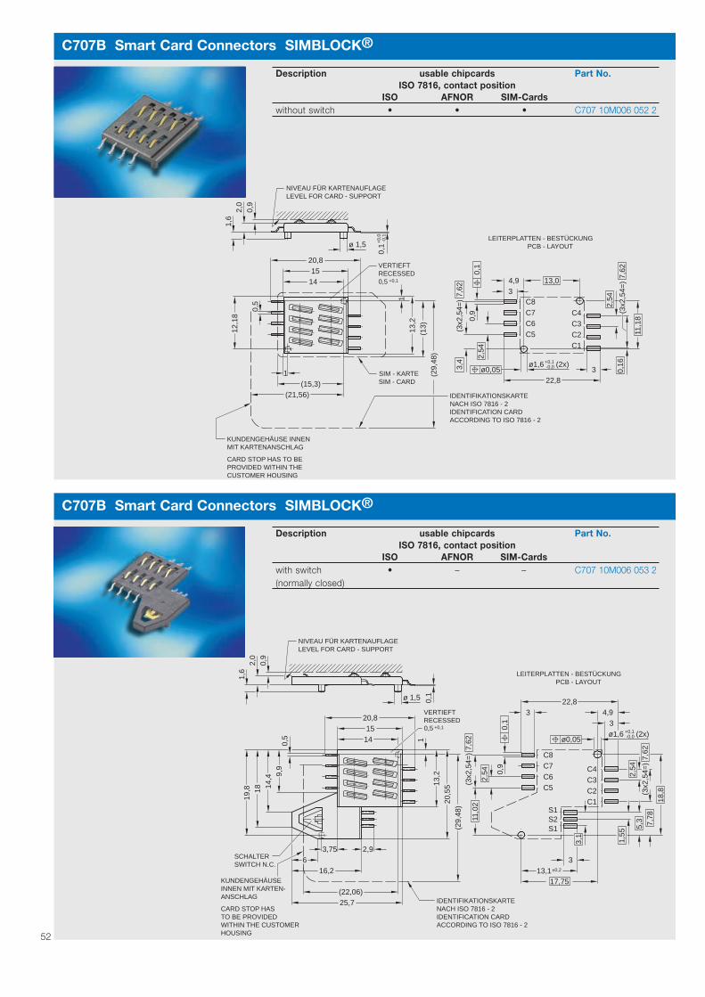
52
C707B Smart Card Connectors SIMBLOCK®
Description usable chipcards Part No.ISO 7816, contact position
ISO AFNOR SIM-Cardswith switch • – – C707 10M006 053 2(normally closed)
2,54
+0,1
22,83
KUNDENGEHÄUSEINNEN MIT KARTEN-
CARD STOP HASTO BE PROVIDEDWITHIN THE CUSTOMER
ANSCHLAG
HOUSING
0,1ø 1,5
0,9
2,0
1,6
25,7(22,06)
16,2
3,756
2,9
(29,
48)
20,5
513,2
1
19,8 18 14
,4 9,9
0,5 14
1520,8
17,7513,1±0,2
C4C3C2C1
3
18,8(3
x2,5
4=)
7,62
7,78
1,55
5,3
+0,1-0,0ø1,6
34,9
ø0,05
(3x2
,54=
)
2,54
11,0
2
S2S1
S1
NIVEAU FÜR KARTENAUFLAGELEVEL FOR CARD - SUPPORT
C8C7C6C5
7,62
0,1
0,9
(2x)
3,1
IDENTIFIKATIONSKARTENACH ISO 7816 - 2IDENTIFICATION CARDACCORDING TO ISO 7816 - 2
SWITCH N.C.
LEITERPLATTEN - BESTÜCKUNGPCB - LAYOUT
VERTIEFTRECESSED0,5
SCHALTER
C707B Smart Card Connectors SIMBLOCK®
Description usable chipcards Part No.ISO 7816, contact position
ISO AFNOR SIM-Cardswithout switch • • • C707 10M006 052 2
(21,56)
34,9
322,8
0,1
ø0,05
0,5
(15,3)
C8C7C6C5
C4C3C2C1
2,54
0,16
11,1
8
(3x2
,54=
)
2,54
(3x2
,54=
)7,
62
+0,1-0,0ø1,6 (2x)
13,0
1,6
+0,
0-0
,10,
1ø 1,5
1415
20,8
(13)13
,21
12,1
8
1 (29,
48)
VERTIEFTRECESSED0,5 +0,1
SIM - KARTE
IDENTIFIKATIONSKARTENACH ISO 7816 - 2IDENTIFICATION CARDACCORDING TO ISO 7816 - 2
0,9
2,0
NIVEAU FÜR KARTENAUFLAGELEVEL FOR CARD - SUPPORT
3,4
0,9
7,62
LEITERPLATTEN - BESTÜCKUNGPCB - LAYOUT
KUNDENGEHÄUSE INNENMIT KARTENANSCHLAG
CARD STOP HAS TO BEPROVIDED WITHIN THECUSTOMER HOUSING
SIM - CARD

C707B Smart Card Connectors SIMBLOCK®
Description usable chipcards Part No.ISO 7816, contact position
ISO AFNOR SIM-Cardswith switch • – – C707 10M006 065 2(normally open)
4,75
ø0,05(2x)
+0,1-0,0ø1,6
17,9±0,2
(9,06)
1
2,54
+0,1
22,8
3
KUNDENGEHÄUSEINNEN MIT KARTEN-
CARD STOP HASTO BE PROVIDEDWITHIN THE CUSTOMER
ANSCHLAG
HOUSING
25,7
16,2
3,756
2,9
(29,
48)
20,5
513,2
1
19,8 18 14
,1 9,9
0,5
1520,8
13,1±0,2
C4C3C2C1
3
19,0
5
(3x2
,54=
)7,
627,
78
1,55
5,3
34,9
(3x2
,54=
)
2,54
11,0
2
S2S1
S1
C8C7C6C5
7,62
0,1
0,9
3,1
IDENTIFIKATIONSKARTENACH ISO 7816 - 2IDENTIFICATION CARDACCORDING TO ISO 7816 - 2
SWITCH N.O.
LEITERPLATTEN - BESTÜCKUNGPCB - LAYOUT
VERTIEFTRECESSED0,5
0,8
0,1ø 1,5
0,9
2,0
1,0
NIVEAU FÜR KARTENAUFLAGELEVEL FOR CARD - SUPPORT
SCHALTER
53
C707B Smart Card Connectors SIMBLOCK®
Description usable chipcards Part No.ISO 7816, contact position
ISO AFNOR SIM-CardsWINGBLOCK with – – • C707 10M006 097 2card guide andcard stop
CLIP FORCE > 8N
CLIPHALTEKRAFT > 8N
HALTECLIPMETAL CLIP
3,5
X
A A
0,6
±0,1
±0,1
52,
54
0,6
±0,0
7
±0,1
54,
3
±0,2
1±0
,24,
2
2,5
±0,1
16,411
,4+0,
1515
,15
0
±0,2
0,97
(9,8)
±0,2
0,84 min
2,55 min
MAX. 2,9
+0,210 0
2,08 ±0,15
-0,21,8
±0,211,5
±0,159,7
11,815,2 ±0,1
±0,115,7
00,15 ±0,1
±0,1
52,
54
A-AX 20:1
ANSICHT VON UNTENVEREINFACHT DARGESTELLTSIMPLIFIED VIEWBOTTOM SIDE
PICK AND PLACEAREA MIN.
LÖTPINS MAX. 0,1KOPLANARITÄT DER
SOLDER PINS MAX. 0,1COPLANARITY OF
ERFOLGT DURCH DEN KUNDENKARTEN-VERRIEGELUNG
CONTROLLED BY CUSTOMERLOCKING OF THE CARD
SPEZIFIKATION: N50 707 0010KONTAKTKRAFT: 30-70 cN
SPECIFICATION: N50 707 0010CONTACT FORCE: 30-70 cN
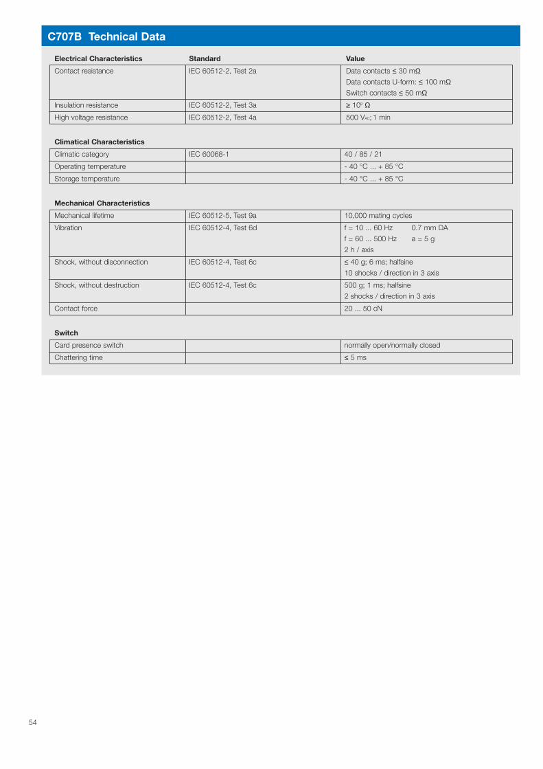
54
C707B Technical Data
Electrical Characteristics Standard Value
Contact resistance IEC 60512-2, Test 2a Data contacts ≤ 30 mΩData contacts U-form: ≤ 100 mΩSwitch contacts ≤ 50 mΩ
Insulation resistance IEC 60512-2, Test 3a ≥ 109 Ω
High voltage resistance IEC 60512-2, Test 4a 500 VAC; 1 min
Climatical Characteristics
Climatic category IEC 60068-1 40 / 85 / 21
Operating temperature - 40 °C ... + 85 °C
Storage temperature - 40 °C ... + 85 °C
Mechanical Characteristics
Mechanical lifetime IEC 60512-5, Test 9a 10,000 mating cycles
Vibration IEC 60512-4, Test 6d f = 10 ... 60 Hz 0.7 mm DA
f = 60 ... 500 Hz a = 5 g
2 h / axis
Shock, without disconnection IEC 60512-4, Test 6c ≤ 40 g; 6 ms; halfsine
10 shocks / direction in 3 axis
Shock, without destruction IEC 60512-4, Test 6c 500 g; 1 ms; halfsine
2 shocks / direction in 3 axis
Contact force 20 ... 50 cN
Switch
Card presence switch normally open/normally closed
Chattering time ≤ 5 ms
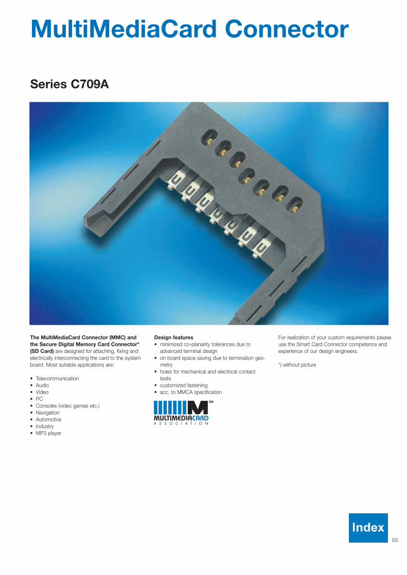
55
MultiMediaCard Connector
Series C709A
The MultiMediaCard Connector (MMC) andthe Secure Digital Memory Card Connector*(SD Card) are designed for attaching, fixing andelectrically interconnecting the card to the systemboard. Most suitable applications are:
• Telecommunication• Audio• Video• PC• Consoles (video games etc.)• Navigation• Automotive• Industry• MP3 player
Design features• minimized co-planarity tolerances due to
advanced terminal design• on board space saving due to termination geo-
metry• holes for mechanical and electrical contact
tests• customized fastening• acc. to MMCA specification
For realization of your custom requirements pleaseuse the Smart Card Connector competence andexperience of our design engineers.
*) without picture

56
C709A MultiMediaCard Connector
Description Part No.
MultiMediaCard Connector C709 10A007 100 1
Other designs and Secure Digital Card Connectors upon request.
9,9
19,2
1,2
2,5
4,23,2
±0,05ø1,4
2119
,29,
91,
25
0,6
3,1
3,2
4,8
x 45
°13
,35
26,7
ø1,2
11,622,8
10ACTIVE POSITION
LESESTELLUNG
ø0,1
0,62
5
6 x
2,5
15,0 0,
1
LEITERPLATTEN - BESTÜCKUNGPCB - LAYOUT
C709A Technical Data
Electrical Characteristics Standard Value
Contact resistance IEC 60512-2, Test 2a ≤ 30 mΩ
Insulation resistance IEC 60512-2, Test 3a ≥ 109 Ω
High voltage resistance IEC 60512-2, Test 4a 500 V
Climatical Characteristics
Climatical category IEC 60068-1 25 / 85 / 21
Operating temperature - 25 °C ... + 85 °C
Storage temperature - 40 °C ... + 90 °C
Mechanical Characteristics
Card insertion force IEC 60512-7, Test 13b max. 40 N
Card extraction force IEC 60512-7, Test 13b > 1 N
Mechanical lifetime 10,000 mating cycles
Random vibration IEC 60512-6, Test 6e f = 10 Hz ... 2 kHz a = 6 g RMS
15 min / axis
Shock, without disconnection IEC 60512-4, Test 6c 40 g; 11 ms
100 shocks / direction in 3 axis
Shock, without destruction IEC 60512-4, Test 6c 500 g; 1 ms
3 shocks / direction in 3 axis
Contact force 20 ... 60 cN
No. of contacts 7
Contacts Wiping contacts with 2 premating contacts
Termination SMT
Mounting style upon customer request

57

Keyword Page
58
Adaptor 17/21
AFNOR 6
Automatic assembly process 46/50
Bezel 10/13/15/16/17/20
Card handling systems 2/4/7/10/31
Card lock 17/18
Card locking detector 13/14
Card presence switch 17/19/21/22/23
46/47/49/54
Chip card sizes 6
Company information 4
Contact methods 8
Contents 3
Debris slot 22/23
Disk drive slot 44/45
EMV 6
Flexprint connector 24/28/29
Hybrid reader 41/42/43
ISO 6
Landing card 8/39
Low Profile PUSHMATIC 22/23
Magstripe cards 41
Manufacturing reference 5
Mounting plate 10/16
MultiMediaCard 6/55/56
PCB mount 31/32/33/34/35
37/38/39/40
Push-Lift SSC 25/27
PUSHMATIC® 7/12/13/14/15/16
PUSHMATIC® II 10/17/18/20/21
Push-Only SCC 7/11/14/15
Push-Pull SCC 7/11/14/15/25
Push-Push SCC 7/10/12
Quality certifications 4
Quality reference 4
Secure Digital Memory Card 6/55
Security information 2
Shutter 13/14
SIMBLOCK® 9/50/51/52/53
SIMLOCK® 9/46/47/48/49
Keyword IndexKeyword Page
Smart Card Connector function 6
Snap-in hooks 31/32/33/34
36/37/38
Standard style 10/11/12/13
15/16/44
Superflat style 25/26/27/28
Wiping contacts 8/31/32/33/34
35/36/37/38/56

5 9
Part No. - IndexPart No. Page
C007 10B008 000 1 29
C007 10B008 000 2 29
C007 10B008 100 1 29
C007 10B008 100 2 29
C007 10B010 000 1 29
C007 10B010 000 2 29
C007 10B010 100 1 29
C007 10B010 100 2 29
C702 10M008 001 4 26
C702 10M008 015 2 12
C702 10M008 018 2 11
C702 10M008 023 4 26
C702 10M008 040 4 27
C702 10M008 060 4 27
C702 10M008 061 4 28
C702 10M008 063 4 27
C702 10M008 065 4 26
C702 10M008 066 4 28
C702 10M008 120 4 40
C702 10M008 121 4 40
C702 10M008 122 4 40
C702 10M008 123 4 40
C702 10M008 201 4 36
C702 10M008 202 4 36
C702 10M008 203 4 36
C702 10M008 205 4 36
C702 10M008 206 4 36
C702 10M008 207 4 36
C702 10M008 224 4 37
C702 10M008 226 4 38
C702 10M008 230 4 37
C702 10M008 235 4 38
C702 10M008 244 4 37
C702 10M008 255 4 32
C702 10M008 271 4 33
C702 10M008 272 4 32
C702 10M008 278 4 34
C702 10M008 279 4 34
C702 10M008 283 4 33
C702 10M008 286 4 34
C702 10M008 290 4 35
C702 10M008 294 4 35
C702 10M008 295 4 34
C702 10M008 514 2 11
C702 10M008 521 2 11
C702 10M008 522 2 11
C702 10M008 523 2 11
C702 10M008 700 2 12
C702 10M008 701 2 12
C702 10M008 702 2 12
C702 10M008 703 2 12
C702 10M008 704 2 12
C702 10M008 705 2 12
C702 10M008 706 2 12
C702 10M008 707 2 12
C702 10M008 708 2 12
C702 10M008 716 2 13
C702 10M008 727 2 13
C702 10M008 732 2 13
C702 10M008 901 4 23
C702 10M008 902 4 23
C702 10M008 903 4 23
C702 10M008 904 2 18
C702 10M008 905 2 18
C702 10M008 906 2 18
C702 10M008 907 2 18
C702 10M008 909 2 18
C702 10M008 910 2 18
C702 20M008 700 2 13
C702 20M008 701 2 13
C702 20M008 702 2 13
C702 G46 000 G2 20
C702 G46 100 G2 20
C702 G51 012 E2 20
C702 N11 141 E2 16
C702 N13 030 E2 15
C702 N13 031 E2 15
C702 N14 030 E2 16
C702 N15 100 G2 15
C702 N25 040 E2 21
C703 10M008 101 5 42
C703 10M008 103 5 42
C703 10M008 104 5 42
C703 10M008 305 5 42
C703 G05 040 E 5 42
C705 10M008 005 5 45
C705 10M008 006 5 45
C705 10M008 019 5 45
C705 10M008 020 5 45
C707 10M006 000 2 48
C707 10M006 001 2 48
C707 10M006 007 2 48
C707 10M006 021 2 48
C707 10M006 026 2 48
C707 10M006 027 2 48
C707 10M006 031 2 48
C707 10M006 049 2 47
C707 10M006 052 2 52
C707 10M006 053 2 52
C707 10M006 065 2 53
C707 10M006 092 2 51
C707 10M006 094 2 51
C707 10M006 097 2 53
C707 10M006 500 2 47
C707 10M006 503 2 48
C707 10M006 522 2 47
C707 10M006 523 2 47
C709 10A007 100 1 56
N06 702 0001 16
N06 702 0002 16
Part No. Page
International
ArgentinaAmphenol ArgentinaAv. Callao 9302nd Floor Office B “Plaza“C1023 AAP Buenos AiresPhone +54 / 11 / 4815 35 79Fax +54 / 11 / 4814 57 79
AustraliaAmphenol Australia Ltd.2 Fiveways BlvdKeysboroughVictoria 3173Phone +61 / 3 / 8796 / 88 88Fax +61 / 3 / 8796 / 88 01
AustriaAmphenol Ges. m. b. H.Johnstraße 42, Top 3A1150 WienPhone +43 / 1 / 9 85 15 11Fax +43 / 1 / 9 82 61 01
BrazilAmphenol do Brasil Ltda.Ave. Roque Petroni Jr. 999, 13th FloorCEP 04707-910 Sao Paulo-SPPhone +55 / 11 / 5185.2881Fax +55 / 11 / 5185.2812
FranceAmphenol Socapex France21 Chemin du DéfoisB.P. 34939105 Dôle CedexPhone +33 / 3 / 8482 9400Fax +33 / 3 / 8482 9411
GermanyAmphenol-Tuchel Electronics GmbHAugust-Häusser-Str. 1074080 HeilbronnPhone +49 / 71 31 / 929-0Fax +49 / 71 31 / 929-486
Great BritainAmphenol-Tuchel Electronics39 Rowlands Castle RoadHorndeanWaterlooville,Hants, PO8 0DFPhone: +44 / 2392 / 571791Fax +44 / 2392 / 571791
Hong KongAmphenol East Asia LimitedUnits 2201-02, Railway Plaza39 Chatham Road SouthTsimshatsui, KowloonPhone +8 52 / 26 99 / 26 63Fax +8 52 / 26 88 / 09 74
IndiaAmphetronix LimitedPlot No.105 Bhosari Industrial AreaPune - 411 026Phone +91 / 20 / 7121418Fax +91 / 20 / 712 05 81
ItalyAmphenol Italia S.p.A.Via Barbaiana n. 5I-20020 Lainate (MI)Phone +39 / 2 / 93 254.1Fax +39 / 2 / 93 254.445
JapanAmphenol Japan, K.K.2-3-27, Kudan MinamiChiyoda-KuTokyo 102Phone +81 / 3 / 32 63 / 56 11Fax +81 / 3 / 52 76 / 70 59
KoreaAmphenol DaeShin Limited#802 Joong-Dong 1131-5Wonmi-KuBucheon-CityKyunggi-DoKorea 420-020Phone +82 / 2 / 785 / 15 88Fax +82 / 2 / 589 / 15 14
MexicoAmphenol MexicoPresidente Masaryk 61, Piso 2C.P. 11560 Mexico D.F.Phone +52 / 5 / 203.2178Fax +52 / 5 / 531.96 59
South AfricaAmphenol International LtdChislehurston30 Impala RoadChislehurstonSandton, 2146Phone +27 / 11 / 783 95 17Fax +27 / 11 / 783 95 19
SpainAmphenol IbéricaC/Comunidad de Madrid, 35-bisoficina NO 55 “Edificio Burgosol“E-28230 Las Rozas MadridPhone +34 / 91 64 07 30 2Fax +34 / 62 90 54 62 9
SwedenAmphenol Scandinavia Johanneslundsvägen 2194 61 Upplands VäsbyPhone +46 / 8 / 59 41 04 40Fax +46 / 8 / 59 03 38 00
SwitzerlandAmphenol SwitzerlandHintermättli 3Gewerbepark5506 MägenwillPhone ++41 / 628962525Fax ++41 / 628962526
TaiwanAmphenol Kai JackNo. 110, Sec 1Bao-An RoadRen-Der ShiangTainanPhone +886 / 6 / 266 / 10 11Fax +886 / 6 / 266 / 46 33
The NetherlandsAmphenol Benelux b.v.Hoofdveste 193992 AK HoutenPhone +31 / 30 / 6 35 80 00Fax +31 / 30 / 6 37 78 99
USAAmphenol CorporationCorporate Headquarters358 Hall AvenueWallingford, CT 06492Phone +1 / 2 03 / 2 65 / 89 00Fax +1 / 2 03 / 2 65 / 86 28
Your engineering sales representative:
ATE
5030
C 0
7.02
Prin
ted
on c
hlor
in-f
ree
blea
ched
pap
er, s
peci
ficat
ions
may
be
chan
ged
with
out n
otic
e.
Cop
yrig
ht 0
7/02
by
Am
phen
ol-T
uche
l Ele
ctro
nics
Gm
bH, G
erm
any
AmphenolAmphenol-Tuchel Electronics Representative Office
6900 Haggerty Road . Suite 200 . Canton, Michigan 48197 . Phone +1 / 734 / 451-6400 . Fax +1 / 734 / 451-7197 · http://www.amphenol.com
Toll free in the US: (800) 380 80 52