Industrial Connectors Han - Steven Engineering
687
02 6 HARTING People | Power | Partnership Industrial Connectors Han® Courtesy of Steven Engineering, Inc.-230 Ryan Way, South San Francisco, CA 94080-6370-Main Office: (650) 588-9200-Outside Local Area: (800) 258-9200-www.stevenengineering.com
-
Upload
khangminh22 -
Category
Documents
-
view
1 -
download
0
Transcript of Industrial Connectors Han - Steven Engineering

02 6
HARTING
People | Power | Partnership
Industrial Connectors Han®
Courtesy of Steven Engineering, Inc.-230 Ryan Way, South San Francisco, CA 94080-6370-Main Office: (650) 588-9200-Outside Local Area: (800) 258-9200-www.stevenengineering.com

Transforming customer wishes into concrete solutions
The HARTING Technology Group is skilled in the fields of electrical, electronic and optical
connection, transmission and networking, as well as in manufacturing, mechatronics and
software creation. The Group uses these skills to develop customized solutions and products
such as connectors for energy and data transmission applications including, for example,
mechanical engineering, rail technology, wind energy plants, factory automation and the
telecommunications sector. In addition, HARTING also produces electro-magnetic components
for the automobile industry and offers solutions in the field of Enclosures and Shop Systems.
The HARTING Group currently comprises 32 subsidiary companies and worldwide distributors
employing a total of approximately 3,000 staff.
H A R T I N G w o r l d w i d eIn
tro
duct
ion
Courtesy of Steven Engineering, Inc.-230 Ryan Way, South San Francisco, CA 94080-6370-Main Office: (650) 588-9200-Outside Local Area: (800) 258-9200-www.stevenengineering.com

HARTING RepresentativesHARTING Subsidiary company
We aspire to top performance.
Connectors ensure functionality. As core elements
of electrical and optical wiring, connection and
infrastructure technologies, they are essential in
enabling the modular construction of devices, machines
and systems across a very wide range of industrial
applications. Their reliability is a crucial factor
guaranteeing smooth functioning in the manufacturing
area, in telecommunications, applications in medical
technology – in fact, connectors are at work in virtually
every conceivable application area. Thanks to the
consistent further development of our technologies,
customers enjoy investment security and benefit from
durable, long term functionality.
Always at hand, wherever our customers may be.
Increasing industrialization is creating growing
markets characterized by widely diverging demands and
requirements. The search for perfection, increasingly
efficient processes and reliable technologies is a common
factor in all sectors across the globe.
HARTING is providing these technologies – in Europe,
America and Asia. The HARTING professionals at our
international subsidiaries engage in close, partnership
based interaction with our customers, right from the very
early product development phases, in order to realize
customer demands and requirements in the best possible
manner.
Our people on location form the interface to the centrally
coordinated development and production departments.
In this way, our customers can rely on consistently high,
superior product quality – worldwide.
Our claim: pushing performance.
HARTING provides more than optimally attuned
components. In order to serve our customers with the best
possible solutions, HARTING is able to contribute a great
deal more and play a closely integrative role in the value
creation process.
From ready assembled cables through to control racks
or ready-to-go control desks: Our aim is to generate
the maximum benefits for our customers – without
compromise!
Quality creates reliability – and warrants trust.
The HARTING brand stands for superior quality and
reliability – worldwide. The standards we set are the
result of consistent, stringent quality management that is
subject to regular certifications and audits.
EN ISO 9001, the EU Eco-Audit and ISO 14001:2004 are
key elements here. We take a proactive stance to new
requirements, which is why HARTING ranks among the
first companies worldwide to have obtained the new IRIS
quality certificate for rail vehicles.
Intro
du
ctio
n
Courtesy of Steven Engineering, Inc.-230 Ryan Way, South San Francisco, CA 94080-6370-Main Office: (650) 588-9200-Outside Local Area: (800) 258-9200-www.stevenengineering.com
H A R T I N G w o r l d w i d e
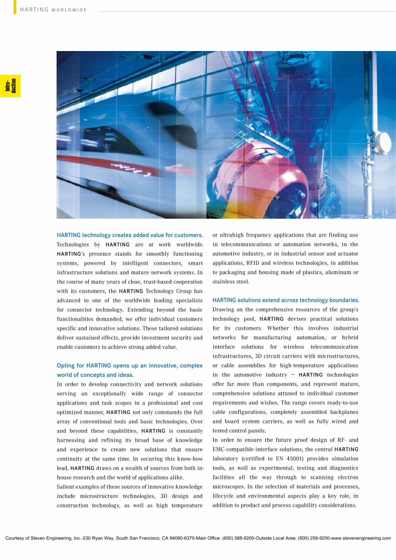
HARTING technology creates added value for customers.
Technologies by HARTING are at work worldwide.
HARTING’s presence stands for smoothly functioning
systems, powered by intelligent connectors, smart
infrastructure solutions and mature network systems. In
the course of many years of close, trust-based cooperation
with its customers, the HARTING Technology Group has
advanced to one of the worldwide leading specialists
for connector technology. Extending beyond the basic
functionalities demanded, we offer individual customers
specific and innovative solutions. These tailored solutions
deliver sustained effects, provide investment security and
enable customers to achieve strong added value.
Opting for HARTING opens up an innovative, complex
world of concepts and ideas.
In order to develop connectivity and network solutions
serving an exceptionally wide range of connector
applications and task scopes in a professional and cost
optimized manner, HARTING not only commands the full
array of conventional tools and basic technologies. Over
and beyond these capabilities, HARTING is constantly
harnessing and refining its broad base of knowledge
and experience to create new solutions that ensure
continuity at the same time. In securing this know-how
lead, HARTING draws on a wealth of sources from both in-
house research and the world of applications alike.
Salient examples of these sources of innovative knowledge
include microstructure technologies, 3D design and
construction technology, as well as high temperature
or ultrahigh frequency applications that are finding use
in telecommunications or automation networks, in the
automotive industry, or in industrial sensor and actuator
applications, RFID and wireless technologies, in addition
to packaging and housing made of plastics, aluminum or
stainless steel.
HARTING solutions extend across technology boundaries.
Drawing on the comprehensive resources of the group’s
technology pool, HARTING devises practical solutions
for its customers. Whether this involves industrial
networks for manufacturing automation, or hybrid
interface solutions for wireless telecommunication
infrastructures, 3D circuit carriers with microstructures,
or cable assemblies for high-temperature applications
in the automotive industry – HARTING technologies
offer far more than components, and represent mature,
comprehensive solutions attuned to individual customer
requirements and wishes. The range covers ready-to-use
cable configurations, completely assembled backplanes
and board system carriers, as well as fully wired and
tested control panels.
In order to ensure the future proof design of RF- and
EMC-compatible interface solutions, the central HARTING
laboratory (certified to EN 45001) provides simulation
tools, as well as experimental, testing and diagnostics
facilities all the way through to scanning electron
microscopes. In the selection of materials and processes,
lifecycle and environmental aspects play a key role, in
addition to product and process capability considerations.
Intro
du
ctio
n
Courtesy of Steven Engineering, Inc.-230 Ryan Way, South San Francisco, CA 94080-6370-Main Office: (650) 588-9200-Outside Local Area: (800) 258-9200-www.stevenengineering.com
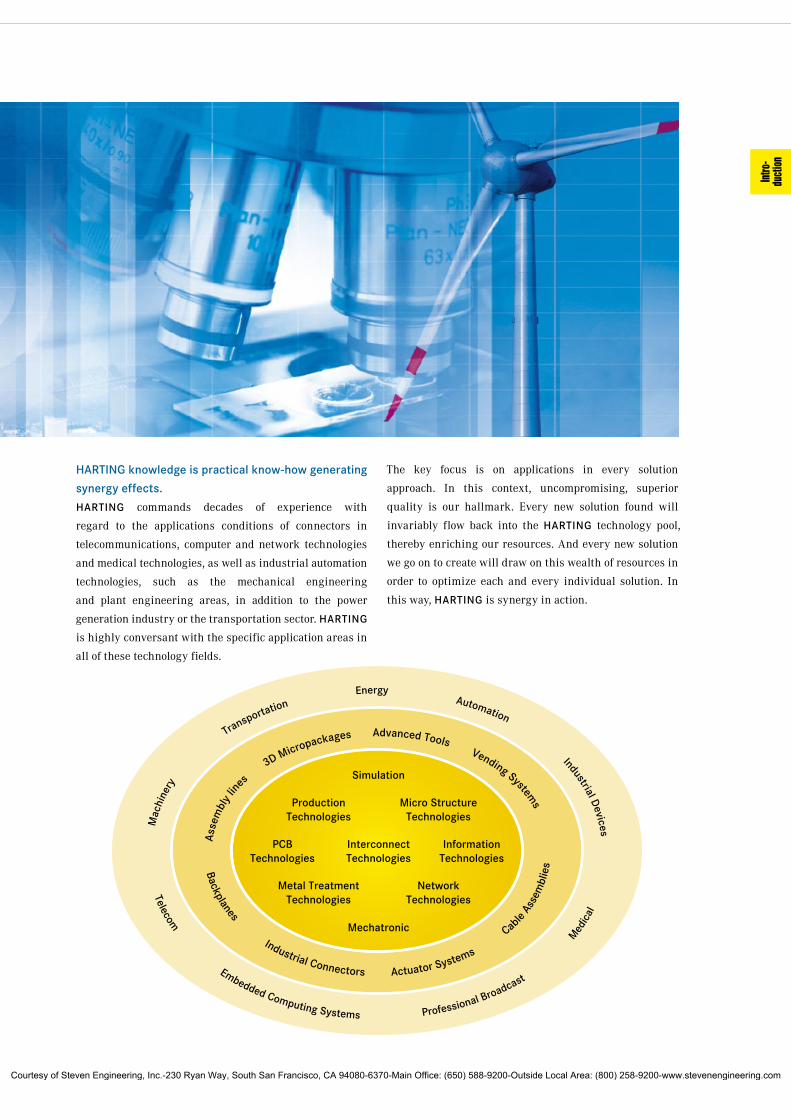
HARTING knowledge is practical know-how generating
synergy effects.
HARTING commands decades of experience with
regard to the applications conditions of connectors in
telecommunications, computer and network technologies
and medical technologies, as well as industrial automation
technologies, such as the mechanical engineering
and plant engineering areas, in addition to the power
generation industry or the transportation sector. HARTING
is highly conversant with the specific application areas in
all of these technology fields.
The key focus is on applications in every solution
approach. In this context, uncompromising, superior
quality is our hallmark. Every new solution found will
invariably flow back into the HARTING technology pool,
thereby enriching our resources. And every new solution
we go on to create will draw on this wealth of resources in
order to optimize each and every individual solution. In
this way, HARTING is synergy in action.
Intro
du
ctio
n
Courtesy of Steven Engineering, Inc.-230 Ryan Way, South San Francisco, CA 94080-6370-Main Office: (650) 588-9200-Outside Local Area: (800) 258-9200-www.stevenengineering.com

Industrial Connectors Han®
Economicand ReliableConnectionsSpecifications
DIN EN 60 664-1 (VDE 0110-1) Principles, requirements and tests
DIN EN 61 984 (VDE 0627) Connectors, Safety requirements and tests
Note:
The connectors included in this ca-talogue should not be coupled or de-coupled under electrical load unless otherwise stated.
The provision of protection against electric shock is the responsibility of the user. Protection can be achieved by the use of HARTING hoods and housings coupled with/or alternatively appropriate installation methods provi-ded by the user.
The female connector in a HARTING hood or housing offers finger safe pro-tection according to relevant standards for the mating face, even in the unma-ted condition, unless otherwise stated.
Connectors of the same or different series being mounted side by side may be protected against incorrect mating by the use of coding options.
Standard
DIN EN 175 301-801
Approvals
UL File No. E 23 50 76 (www.ul.com)
CSA File No. LR 18 753, SEV for inserts
For "non standard applications" we can manufacture designs to match your requirements.Please discuss requirements with us.
HARTING components help you to construct top quality products – economically and in line with market requirements.
Certified according to EN ISO 9001in design/development, production,
installation and servicing
Terminations• Screw terminal
• Crimp terminal
• Cage-clamp terminal
• Wrap terminal
• Solder terminal
• Axial-screw terminal
• Rapid terminal
• IDC termination
Inserts• Leading protective ground
• Polarised for correct mating
• Interchangeability of male and female inserts in hoods and housings
• Captive fixing screws
• Can be used with hoods and housings, or for rack and panel applications
Hoods/Housings• Standard Hoods/Housings
• Hoods/Housings for harsh environmen-tal requirements
• Hoods/Housings for intrinsically safe plant
• Degree of protection IP 65
• Electrical connection with protective ground
• High mechanical strength and vibration-resistance ensured by locking levers
• Spring-loaded covers in shockproof thermoplastic or metal covers, both lockable
Accessories• Extensive range of cable protection
and sealing accessories
• Protective covers available
• Coding options for incorrect mating protection
General information
It is the customer's responsibility to check whether the components illus-trated in this catalogue comply with different regulations from those stated in special fields of application which we are unable to foresee.
We reserve the right to modify designs in order to improve quality, keep pace with technological advancement or meet particular requirements in pro-duction.
No part of this catalogue may be reproduced in any form (print, photocopy, microfilm or any other proc-ess) or processed, duplicated or distributed by means of electronic systems without the written permission of HARTING Electric GmbH & Co. KG, Espelkamp. We are bound by the German version only.
© HARTING Electric GmbH & Co. KG, Espelkamp – All rights reserved, including those of the translation.
Courtesy of Steven Engineering, Inc.-230 Ryan Way, South San Francisco, CA 94080-6370-Main Office: (650) 588-9200-Outside Local Area: (800) 258-9200-www.stevenengineering.com

ChapterContents
Industrial Connectors Han® – Series Summary
Industrial Connectors Han® . . . . . . . . . . . . . . . . . . . Technical Characteristics 00
Slim Construction Size (up to 16 amperes) . . . . . . . . . . . . . . . . . . . . . . . Han A® 01
High pin count connectors up to 216 contacts . . . . . . . . . . . . . . Han D® / DD® 02
for 16 amperes –Connectors . . . . . . . . . Han E® / Han® ES/ESS/EE/EEE 03 proven and reliable
Connectors for higher voltages . . . . . . . . . . . . . . . . . . Han Hv E® / Han® Hv ES 04
Combination Connectors . . . . . . . . . . . . . . . . . . . . . . . . . . . . . . . . . . . Han-Com® 05
Modular Connectors . . . . . . . . . . . . . . . . . . . . . . . . . . . . . . . . . . . . Han-Modular® 06
Connectors for higher currents . . . . . . . . . . . . . . . . . . . . . . . . . . . . . . . . Han® HsB 07
Terminal Block Connectors . . . . . . . . . . . . . . . . . . . . . . . . . . . . . . . . . . . Han® AV 08
Connectors for low voltages . . . . . . . . . . . . . . . . . . . . . . . . . . . . . . . . . . . . . . . Staf® 09
Circular Connectors . . . . . . . . . . . . . . . . . . . . . . . . . . . . . . . . . . . . . . . . . . . . . R 15 10
Connectors for the use in switch cabinets . . . . . . . . . . . . . . . . . . . . . . Han-Snap® 11
Interface for power and signals . . . . . . . . . . . . . . . . . . . . . . . . . . . . . . . . Han-Port® 12
Connectors (not only for drives) . . . . . . . . . . . . . . . . . . . . . . . . . . . . . . . . . . Han® Q 13
High Current Connectors . . . . . . . . . . . Han® K 3/0, K 3/2 / Han® HC-Modular 14
Energy Bus Components . . . . . . . . . . . . . . . . . . . . . . . . . . . . . . . . . . . . Han-Power® 15
Industrial Bus Interface . . . . . . . . . . . . . . . . . . . . . . . . . . . . . . . . . . . . . . . Han-Brid® 19
Han® PCB-Adapter . . . . . . . . . . . . . . . . . . . . . . . . . . . . . . . . . . . . . . . . . . . . . . . . . . . 20
for shielding, for harsh environments Han® Hoods and Housings with Pg entries 30 with various locking systems for shielding, for harsh environments Han® Hoods and Housings with metric thread 31 with various locking systems
Accessories for Hoods and Housings / Han® Inserts . . . . . . . . . . . . . . . . . . . . . . . . 40
Han® Thermocouple . . . . . . . . . . . . . . . . . . . . . . . . . . . . . . . . . . . . . . . . . . . . . . . . . . 41
Tools . . . . . . . . . . . . . . . . . . . . . . . . . . . . . . . . . . . . . . . . . . . . . . . . . . . . . . . . . . . . . . . . . 99
Application Overview . . . . . . . . . . . . . . . . . . . . . . . . . . . . . . . . . . . . . . . . . . . . . . . . .
List of Part-Numbers . . . . . . . . . . . . . . . . . . . . . . . . . . . . . . . . . . . . . . . . . . . . . . . . .
Han
HanA
HanD / DD
HanE / EE
Part No.
HanHvE
HanCom
HanModular
HanHsB
HanAV
Staf
R 15
HanSnap
Han-Port
HanQ
Han HC- Modular
Power Distribution
Han- Brid
PCB- Adapter
Han HoodsHousings
Han HoodsHousings
Accessories
Thermo- couple
Tools
Applica- tions
Courtesy of Steven Engineering, Inc.-230 Ryan Way, South San Francisco, CA 94080-6370-Main Office: (650) 588-9200-Outside Local Area: (800) 258-9200-www.stevenengineering.com

Han
00.02
Notes
Courtesy of Steven Engineering, Inc.-230 Ryan Way, South San Francisco, CA 94080-6370-Main Office: (650) 588-9200-Outside Local Area: (800) 258-9200-www.stevenengineering.com
Han
00.03
Contents
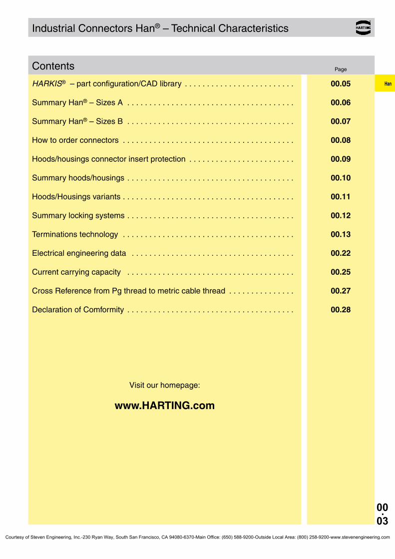
Industrial Connectors Han® – Technical Characteristics
Page
HARKIS® – part configuration/CAD library . . . . . . . . . . . . . . . . . . . . . . . . . 00.05
Summary Han® – Sizes A . . . . . . . . . . . . . . . . . . . . . . . . . . . . . . . . . . . . . . 00.06
Summary Han® – Sizes B . . . . . . . . . . . . . . . . . . . . . . . . . . . . . . . . . . . . . . 00.07
How to order connectors . . . . . . . . . . . . . . . . . . . . . . . . . . . . . . . . . . . . . . . 00.08
Hoods/housings connector insert protection . . . . . . . . . . . . . . . . . . . . . . . . 00.09
Summary hoods/housings . . . . . . . . . . . . . . . . . . . . . . . . . . . . . . . . . . . . . . 00.10
Hoods/Housings variants . . . . . . . . . . . . . . . . . . . . . . . . . . . . . . . . . . . . . . . 00.11
Summary locking systems . . . . . . . . . . . . . . . . . . . . . . . . . . . . . . . . . . . . . . 00.12
Terminations technology . . . . . . . . . . . . . . . . . . . . . . . . . . . . . . . . . . . . . . . 00.13
Electrical engineering data . . . . . . . . . . . . . . . . . . . . . . . . . . . . . . . . . . . . . 00.22
Current carrying capacity . . . . . . . . . . . . . . . . . . . . . . . . . . . . . . . . . . . . . . 00.25
Cross Reference from Pg thread to metric cable thread . . . . . . . . . . . . . . . 00.27
Declaration of Comformity . . . . . . . . . . . . . . . . . . . . . . . . . . . . . . . . . . . . . . 00.28
Visit our homepage:
www.HARTING.com
Courtesy of Steven Engineering, Inc.-230 Ryan Way, South San Francisco, CA 94080-6370-Main Office: (650) 588-9200-Outside Local Area: (800) 258-9200-www.stevenengineering.com

Han
00.04
Notes
Courtesy of Steven Engineering, Inc.-230 Ryan Way, South San Francisco, CA 94080-6370-Main Office: (650) 588-9200-Outside Local Area: (800) 258-9200-www.stevenengineering.com
Han
00.05
HARKIS ®
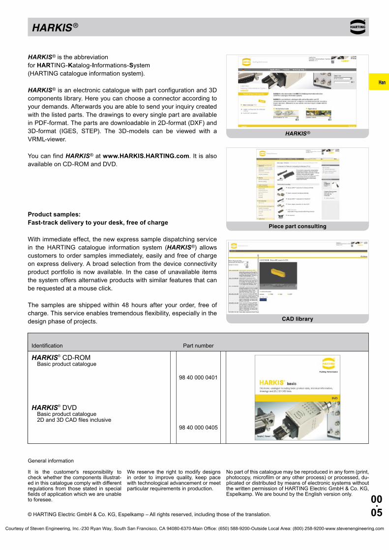
98 40 000 0401
98 40 000 0405
HARKIS® CD-ROMBasic product catalogue
HARKIS® DVDBasic product catalogue 2D and 3D CAD files inclusive
Identification Part number
General information
It is the customer's responsibility to check whether the components illustrat-ed in this catalogue comply with different regulations from those stated in special fields of application which we are unable to foresee.
We reserve the right to modify designs in order to improve quality, keep pace with technological advancement or meet particular requirements in production.
No part of this catalogue may be reproduced in any form (print, photocopy, microfilm or any other process) or processed, du-plicated or distributed by means of electronic systems without the written permission of HARTING Electric GmbH & Co. KG, Espelkamp. We are bound by the English version only.
© HARTING Electric GmbH & Co. KG, Espelkamp – All rights reserved, including those of the translation.
HARKIS® is the abbreviation for HARTING-Katalog-Informations-System (HARTING catalogue information system).
HARKIS® is an electronic catalogue with part configuration and 3D components library. Here you can choose a connector according to your demands. Afterwards you are able to send your inquiry created with the listed parts. The drawings to every single part are available in PDF-format. The parts are downloadable in 2D-format (DXF) and 3D-format (IGES, STEP). The 3D-models can be viewed with a VRML-viewer.
You can find HARKIS® at www.HARKIS.HARTING.com. It is also available on CD-ROM and DVD.
Product samples: Fast-track delivery to your desk, free of charge
With immediate effect, the new express sample dispatching service in the HARTING catalogue information system (HARKIS®) allows customers to order samples immediately, easily and free of charge on express delivery. A broad selection from the device connectivity product portfolio is now available. In the case of unavailable items the system offers alternative products with similar features that can be requested at a mouse click.
The samples are shipped within 48 hours after your order, free of charge. This service enables tremendous flexibility, especially in the design phase of projects.
HARKIS ®
Piece part consulting
CAD library
Courtesy of Steven Engineering, Inc.-230 Ryan Way, South San Francisco, CA 94080-6370-Main Office: (650) 588-9200-Outside Local Area: (800) 258-9200-www.stevenengineering.com
Han
00.06
3 / 4 + 6 7 + 8 5 + 7 + 4 + 2
16 + 25 + 20
10 + 15 + 14
A
3
10
16
32
1 module
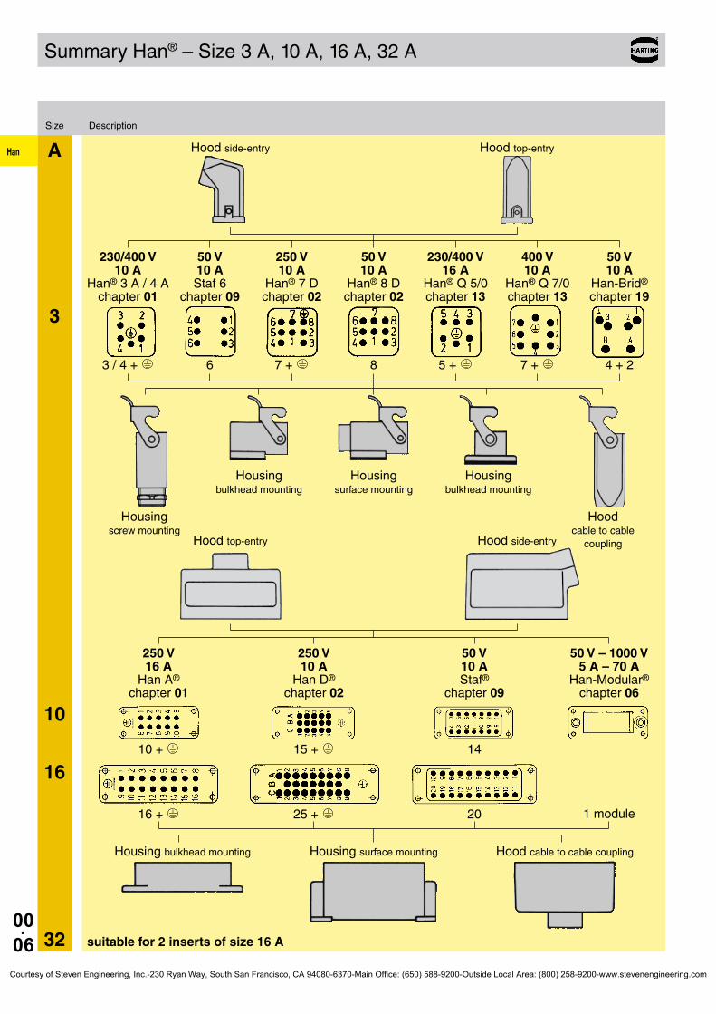
Summary Han® – Size 3 A, 10 A, 16 A, 32 A
Size Description
Hood side-entry Hood top-entry
230/400 V 50 V 250 V 50 V 230/400 V 400 V 50 V 10 A 10 A 10 A 10 A 16 A 10 A 10 A Han® 3 A / 4 A Staf 6 Han® 7 D Han® 8 D Han® Q 5/0 Han® Q 7/0 Han-Brid® chapter 01 chapter 09 chapter 02 chapter 02 chapter 13 chapter 13 chapter 19
Housing Housing Housing bulkhead mounting surface mounting bulkhead mounting
Housing Hood screw mounting cable to cable coupling Hood top-entry Hood side-entry
250 V 250 V 50 V 50 V – 1000 V 16 A 10 A 10 A 5 A – 70 A Han A® Han D® Staf® Han-Modular® chapter 01 chapter 02 chapter 09 chapter 06
Housing bulkhead mounting Housing surface mounting Hood cable to cable coupling
suitable for 2 inserts of size 16 A
Courtesy of Steven Engineering, Inc.-230 Ryan Way, South San Francisco, CA 94080-6370-Main Office: (650) 588-9200-Outside Local Area: (800) 258-9200-www.stevenengineering.com

Han
00.07
6
B
10
16
24
32 48
24 + 6 + 10 +
42 + 10 + 18 + 3 + 4/4 + 8/24 +
40 + 72 + 16 + 32 + 6 + 6 +
64 + 108 + 24 + 46 + 10 +
16 + 4/8 + 6/6 +
6/36 + 4/2 +
…
…
…
…
…
…
…
…
…
…
Han
Summary Han® – Size 6 B, 10 B, 16 B, 24 B, 32 B, 48 B
Size Description
Hood side-entry Hood top-entry
250 V 250 V 500 V 500 V 400/690 V 830 V 160 V – 690 V 50 V – 5000 V 10 A 10 A 16 A 16 A 35 A 16 A 10 A – 100 A 5 A – 200 A Han D® Han DD® Han E® Han® EE Han® HsB Han Hv E® Han-Com® Han- Han® ES Han® Hv ES Modular® chapter 02 chapter 02 chapter 03 chapter 03 chapter 07 chapter 04 chapter 05 chapter 06
Housing surface mounting Housing bulkhead mounting Hood cable to cable coupling
suitable for 2 inserts of size 16 B
suitable for 2 inserts of size 24 B
2 modules
3 modules
4 modules
6 modules
Courtesy of Steven Engineering, Inc.-230 Ryan Way, South San Francisco, CA 94080-6370-Main Office: (650) 588-9200-Outside Local Area: (800) 258-9200-www.stevenengineering.com
Han
00.08
26010243309
Part number explanation
Our computerized ordering system uses the following code:
Product-group (connectors)
Series (i. e. Han E®)
Number of contacts (i. e. 6, 10, 16, 24)
Part of connector assembly (hoods/housings, inserts)
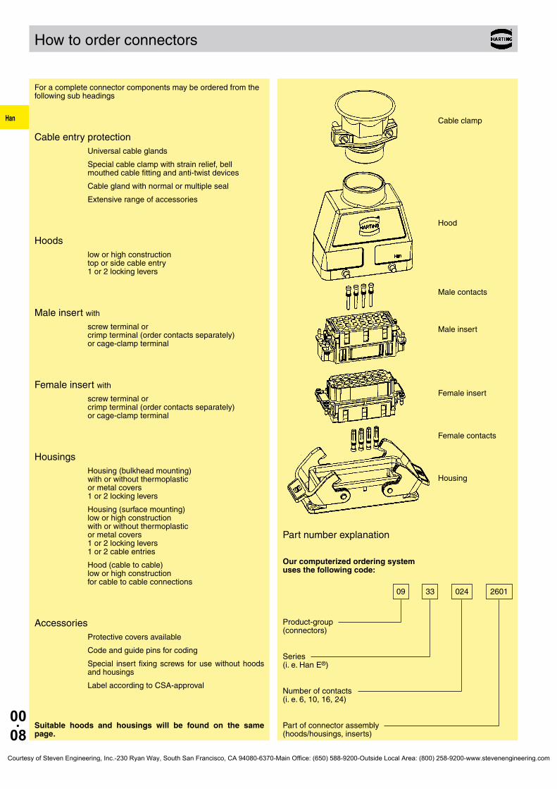
How to order connectors
For a complete connector components may be ordered from the following sub headings
Cable entry protectionUniversal cable glands
Special cable clamp with strain relief, bell mouthed cable fitting and anti-twist devices
Cable gland with normal or multiple seal
Extensive range of accessories
Hoodslow or high construction top or side cable entry 1 or 2 locking levers
Male insert with
screw terminal or crimp terminal (order contacts separately) or cage-clamp terminal
Female insert with
screw terminal or crimp terminal (order contacts separately) or cage-clamp terminal
HousingsHousing (bulkhead mounting) with or without thermoplastic or metal covers 1 or 2 locking levers
Housing (surface mounting) low or high construction with or without thermoplastic or metal covers 1 or 2 locking levers 1 or 2 cable entries
Hood (cable to cable) low or high construction for cable to cable connections
AccessoriesProtective covers available
Code and guide pins for coding
Special insert fixing screws for use without hoods and housings
Label according to CSA-approval
Suitable hoods and housings will be found on the same page.
Cable clamp
Hood
Male contacts
Male insert
Female insert
Female contacts
Housing
Courtesy of Steven Engineering, Inc.-230 Ryan Way, South San Francisco, CA 94080-6370-Main Office: (650) 588-9200-Outside Local Area: (800) 258-9200-www.stevenengineering.com
Han
00.09
0 0
1 1
2 2
3 3
4 4
5 5
6 6
7
8
9k *
Hoods/housings connector insert protection
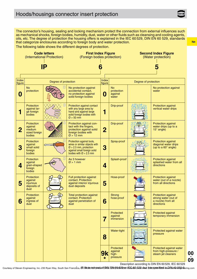
The connector’s housing, sealing and locking mechanism protect the connection from external influences such as mechanical shocks, foreign bodies, humidity, dust, water or other fluids such as cleansing and cooling agents, oils, etc. The degree of protection the housing offers is explained in the IEC 60 529, DIN EN 60 529, standards that categorize enclosures according to foreign body and water protection.The following table shows the different degrees of protection.
Code letters First Index Figure Second Index Figure (International Protection) (Foreign bodies protection) (Water protection)
IP 6 5
Description according to DIN EN 60 529, IEC 60 529 * ... IP 9k is not part of DIN EN 60 529 or IEC 60 529, but it is specified in DIN 40 050-9.
Index Degree of protection figure Index Degree of protection figure
No protection against accidental contact, no protection against solid foreign bodies
No protection
No protection against water
No protection against water
Protection against contact with any large area by hand and against large solid foreign bodies with Ø > 50 mm
Protection against lar-ge foreign bodies
Protection against vertical water drips
Drip-proof
Protection against con-tact with the fingers, protection against solid foreign bodies with Ø > 12 mm
Protection against medium sized foreign bodies
Protection against water drips (up to a 15° angle)
Drip-proof
Protection against tools, wires or similar objects with Ø > 2.5 mm, protection against small foreign solid bodies with Ø > 2.5 mm
Protection against small solid foreign bodies
Protection against diagonal water drips (up to a 60° angle)
Spray-proof
As 3 however Ø > 1 mm
Protection against grain-shaped foreign bodies
Protection against splashed water from all directions
Splash-proof
Full protection against contact. Protection against interior injurious dust deposits
Protection against injurious deposits of dust
Protection against water (out of a nozzle) from all directions
Hose-proof
Total protection against contact. Protection against penetration of dust
Protection against ingress of dust
Protection against strong water (out of a nozzle) from all directions
Strong hose-proof
Protected against temporary immersion
Protected against immersion
Protected against water pressure
Protected against water from high-pressure / steam jet cleaners
Water-tight
Protected against high- pressure
Courtesy of Steven Engineering, Inc.-230 Ryan Way, South San Francisco, CA 94080-6370-Main Office: (650) 588-9200-Outside Local Area: (800) 258-9200-www.stevenengineering.com

Han
00.10
Summary hoods/housings
Standard Hoods/Housings Field of application for excellent mechanical and electrical
protection in demanding environments, for example, in the automobile and mechanical engineering industries also for process and regulation control appli-cations
Distinguishing feature hoods/housings colour-coded grey (RAL 7037)
Material of hoods/housings Die cast light alloy
Locking levers Han-Easy Lock®
Cable entry protection Optional special cable clamp for hoods with strain relief, bell mouthed cable fitting and anti-twist devices
Han® M Hoods/Housings for harsh environmental requirements
Field of application for all applications where aggressive environmental conditions and extreme climatic atmospheres are encountered
Distinguishing feature hoods/housings colour-coded black (RAL 9005)
Material of hoods/housings Die cast light alloy, corrosion resistant
Locking levers Corrosion resistant stainless steel
Cable entry protection Special cable clamp for hoods with strain relief, bell mouthed cable fitting and anti-twist devices
Han® EMC Hoods/Housings with high shielding efficiency
Field of application For sensitive interconnections that have to be shielded against electrical, magnetic or electro-magnetic inter ferences
Distinguishing feature Electrically conductive surface, internal seal
Material of hoods/housings Die cast light alloy
Locking levers Han-Easy Lock®
Cable entry protection EMC cable clamp in order to connect the cable shielding to the hood without interruption of the shielding
Han® HPR Hoods/Housings, pressure tight Field of application For external electrical interconnec-
tions in vehicles, in highly demanding environments and wet areas, as well as for sensitive interconnections that have to be shielded
Distinguishing feature hoods/housings colour-coded black, internal seal (RAL 9005)
Locking parts Stainless steel
Material of hoods/housings Die cast light alloy, corrosion resistant
Cable entry protection Optional universal cable clamp for hoods with strain relief, or special cable clamp with bell mouthed cable fitting and anti-twist devices (use of adapter is necessary)
Courtesy of Steven Engineering, Inc.-230 Ryan Way, South San Francisco, CA 94080-6370-Main Office: (650) 588-9200-Outside Local Area: (800) 258-9200-www.stevenengineering.com
Han
00.11
Hoods/Housings variants
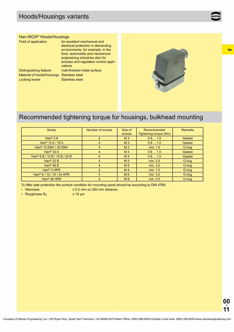
Han-INOX® Hoods/Housings Field of application for excellent mechanical and
electrical protection in demanding environments, for example, in the food, automobile and mechanical engineering industries also for process and regulation control appli-cations
Distinguishing feature matt-finished metal surfaceMaterial of hoods/housings Stainless steelLocking levers Stainless steel
Recommended tightening torque for housings, bulkhead mounting
Series Number of screws Size of screws
Recommended Tightening torque (Nm)
Remarks
Han® 3 A 2 M 3 0.8 ... 1.0 GasketHan® 10 A / 16 A 4 M 3 0.8 ... 1.0 Gasket
Han® 15 EMV / 25 EMV 4 M 3 min. 1.0 O-ringHan® 32 A 4 M 4 0.8 ... 1.0 Gasket
Han® 6 B / 10 B / 16 B / 24 B 4 M 4 0.8 ... 1.0 GasketHan® 32 B 4 M 5 min. 2.5 O-ringHan® 48 B 4 M 6 min. 3.0 O-ring
Han® 3 HPR 2 M 4 min. 1.0 O-ringHan® 6 / 10 / 16 / 24 HPR 4 M 6 min. 3.0 O-ring
Han® 48 HPR 4 M 8 min. 5.0 O-ring
To offer safe protection the surface condition for mounting panel should be according to DIN 4766: • Waviness ≤ 0.2 mm on 200 mm distance • Roughness Ra ≤ 16 µm
Courtesy of Steven Engineering, Inc.-230 Ryan Way, South San Francisco, CA 94080-6370-Main Office: (650) 588-9200-Outside Local Area: (800) 258-9200-www.stevenengineering.com

Han
00.12
Summary locking systems
Housing with 2 levers Han-Easy Lock®
❑ easy operation ❑ high degree of pressure tightness ❑ reliable locking guaranteed by 4 locking points ❑ space saving mounting ❑ ideal for mounting side by side ❑ cable to cable connection is possible ❑ high seal force
Details of Han-Easy Lock® see chapter 30 and chapter 31
Housing with 1 lever Han-Easy Lock®
❑ easily accessible, even with side entry
❑ possibility to lock protective covers on the housing
❑ cable to cable connection is possible
❑ 2 locking points on the longitudinal axis
1 lever in central position
❑ easily accessible, even with side entry
❑ 2 locking points on the lateral axis
❑ space saving mounting
❑ ideal for mounting side by side
❑ single hand operation
Screw locking / toggle locking ❑ hexagon nuts tightened with spanner ❑ highest degree of pressure tightness ❑ easily accessible, also with side entry ❑ use of tools avoids
access by unauthorized persons
Hood with 2 levers Han-Easy Lock®
❑ easy operation ❑ high degree of pressure tightness ❑ ideal for mating to housings with protection cover ❑ high seal force
Details of Han-Easy Lock® see chapter 30 and chapter 31
Courtesy of Steven Engineering, Inc.-230 Ryan Way, South San Francisco, CA 94080-6370-Main Office: (650) 588-9200-Outside Local Area: (800) 258-9200-www.stevenengineering.com

Han
00.13
Terminations technology
Screw terminal
Screw terminals meet VDE 0609 /EN 60 999. Dimensions and tightening torques for testing are shown in following table.Screw dimensions and tightening torque for screw terminals
Wire gauge (mm²) 1.5 2.5 4 6 10 16
Screw thread M3 M3 M3.5 M4 M4 M6
Test moment of torque (Nm)
0.5 0.5 0.8 1.2 1.2 1.2*
min. pull-out for stranded wire (N)
40 50 60 80 90 100
* for screws without heads
The relevant regulations state that in the case of● Terminals with wire protection
the use of ferrules is not necessary. Series Han E®,
Han® HsB, Han Hv E®, Han® K 6/12, Han® K 6/6
● Terminals without wire protection
The insulation is first stripped and then a wire ferrule must be
used. Series Han® K 4/x, Han A®, Staf®
Inserts max. wire gauge Stripping length
(mm²) AWG l (mm)
Han® 3 A, Han® 4 A 2.5 14 4.5
Han E®, Han A®, Han Hv E®, Han® K (signal contacts)
2.5 14 7.5
Han® HsB 6.0 10 11.5
Staf® 1.5 16 4.5
Han® K (power contacts) 16.0 6 14.0
Screw size Connector type Ø Tightening torque* (Nm)
Ø Tightening torque (lbft)
Recommended size of screw driver
M 3 • Screw terminal Han® 3 A /4 A /Q 5/0 / Staf® 0.25 0.20 0.4 x 2.5M 3 • Screw terminal Han®10 A –32 A 0.50 0.40 0.5 x 3.5
or ± size 1M 3 • Screw terminal Han E®, Hv E®
• Fixing screws of all kinds, • Guiding pins and bushes
0.50 0.40 0.5 x 3.5 or ± size 1 + 2
M 4 • Ground terminal Han A®, Han E®, Han D®, DD®, • Ground terminal Han® K 8/24, K 6/6, K 8/0
1.20 0.90 0.5 x 3.5 or ± size 1 + 2
M 4 • Screw terminal Han®HsB 1.20 0.90 0.8 x 4.5M 5 • Ground terminal Han® HsB, Han® K 12/2,
K4/x, K 6/12, K 6/362.00 1.40 0.8 x 4.5
1.2 x 8M 6 • Screw terminal Han® K (power contacts)0 see chapter 05 0.8 x 4.5
Increasing the tightening torque does not improve considerably the contact resistances.The torque moments were determined when optimum mechanical, thermal and electrical circumstances were given. If the recommended figures are considerably exceeded the wire or the termination can be damaged.
Recommended tightening torque and size of screw driver
Courtesy of Steven Engineering, Inc.-230 Ryan Way, South San Francisco, CA 94080-6370-Main Office: (650) 588-9200-Outside Local Area: (800) 258-9200-www.stevenengineering.com

Han
00.14
Terminations technology
Crimp connectionHan DD®
Han D®
R 15Han-Modular® (10 A)Han E®
Han A®
Han Hv E®
Han-Com® (40 A)Han-Modular® ( 40 A)Han E®
Han A®
Han Hv E®
Han® EEHan® EEEHan-Modular® (16 A)Han® Q
A perfect crimp connection is gastight, therefore corrosion free and amounts to a cold weld of the parts being connected. For this reason, major features in achieving high quality crimp connections are the design of the contact crimping parts and of course the crimping tool itself. Wires to be connected must be carefully matched with the correct size of crimp contacts. If these basic requirements are met, users will be assured of highly relia-ble connections with low contact resistance and high resistance to corrosive attack.The economic and technical advantages are:● Constant contact resistance as a result of precisely repeated
crimp connection quality● Corrosion free connections as a result of cold weld action● Pre-preparation of cable forms with crimp contacts fitted● Optimum cost cable connectionRequirements for crimp connectors are laid down in DIN EN 60 352-2 as illustrated in the table.Pull out force of stranded wireThe main criterion by which to judge the quality of a crimp con-nection is the retention force achieved by the wire conductor in the terminal section of the contact. DIN EN 60 352-2 defines the extraction force in relation to the cross-section of the conductor. When fitted using HARTING crimping tools and subject to their utilization in an approved manner, our crimp connectors comply with the required extraction forces.Crimping toolsCrimping tools (hand operated or automatic) are carefully desi-gned to produce with high pressure forming parts a symmetrical connection of the crimping part of the contact and the wire being connected with the minimum increase in size at the connection point. The positioner automatically locates the crimp and wire at the correct point in the tool.A ratchet in the tool performs 2 functions:● It prevents insertion of the crimp into the tool for crimping
before the jaws are fully open● It prevents the tool being opened before the crimping action is
completed
Identical, perfectly formed, connections can be produced using this crimping system.Crimp-cross section
HARTING-crimp profile BUCHANAN crimp profile
Tensile strength of crimped connections (Table 1 of the DIN EN 60 352-2)
Conductor cross-section Tensile strengthmm² AWG N0.05 30 60.08 28 110.12 26 150.14 180.22 24 280.25 320.32 22 400.5 20 600.75 850.82 18 901.0 1081.3 16 1351.5 1502.1 14 2002.5 2303.3 12 2754.0 3105.3 10 3556.0 3608.4 8 37010.0 380
Wire gauge Internal diameter Stripping length l (mm)
(mm²) AWG Ø (mm)
Han® DDHan® D
R15Han-Modular®
(10 A)
Han E®
Han A®
Han Hv E®
Han® C
0.14 ... 0.37 26 ... 22 0.9 8 - -0.5 20 1.15 8 7.5 -0.75 18 1.3 8 7.5 -
1 18 1.45 8 7.5 -1.5 16 1.75 8 7.5 92.5 14 2.25 6 7.5 94 12 2.85 - 7.5 9.66 10 3.5 - - 9.6
Conductor cross-section
ø Stripping length
Han® 100 A Modul 16 mm² 5.5 mm 19.0 mm 25 mm² 7.0 mm 19.0 mm 35 mm² 8.2 mm 16.0 mm
Han® HC Modular 350
35 mm² 8.2 mm 26.0 mm 50 mm² 10.0 mm 28.0 mm 70 mm² 11.5 mm 28.0 mm 95 mm² 13.5 mm 30.0 mm120 mm² 15.5 mm 24.0 mm
Han® HC Modular 650 240 mm² 22.5 mm 50.0 mmfor fine stranded wires according to IEC 60 228 class 5
Courtesy of Steven Engineering, Inc.-230 Ryan Way, South San Francisco, CA 94080-6370-Main Office: (650) 588-9200-Outside Local Area: (800) 258-9200-www.stevenengineering.com
Han
00.15
Terminations technology
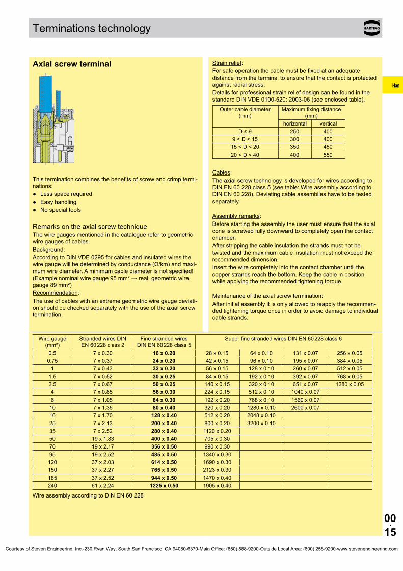
Axial screw terminal
This termination combines the benefits of screw and crimp termi-nations:● Less space required● Easy handling● No special tools
Remarks on the axial screw techniqueThe wire gauges mentioned in the catalogue refer to geometric wire gauges of cables.Background:According to DIN VDE 0295 for cables and insulated wires the wire gauge will be determined by conductance (Ω/km) and maxi-mum wire diameter. A minimum cable diameter is not specified! (Example:nominal wire gauge 95 mm² → real, geometric wire gauge 89 mm²)Recommendation:The use of cables with an extreme geometric wire gauge deviati-on should be checked separately with the use of the axial screw termination.
Strain relief:For safe operation the cable must be fixed at an adequate distance from the terminal to ensure that the contact is protected against radial stress. Details for professional strain relief design can be found in the standard DIN VDE 0100-520: 2003-06 (see enclosed table).
Outer cable diameter (mm)
Maximum fixing distance (mm)
horizontal verticalD ≤ 9 250 400
9 < D < 15 300 40015 < D < 20 350 45020 < D < 40 400 550
Cables:The axial screw technology is developed for wires according to DIN EN 60 228 class 5 (see table: Wire assembly according to DIN EN 60 228). Deviating cable assemblies have to be tested separately.
Assembly remarks:Before starting the assembly the user must ensure that the axial cone is screwed fully downward to completely open the contact chamber.After stripping the cable insulation the strands must not be twisted and the maximum cable insulation must not exceed the recommended dimension.Insert the wire completely into the contact chamber until the copper strands reach the bottom. Keep the cable in position while applying the recommended tightening torque.
Maintenance of the axial screw termination:After initial assembly it is only allowed to reapply the recommen-ded tightening torque once in order to avoid damage to individual cable strands.
Wire gauge (mm²)
Stranded wires DIN EN 60 228 class 2
Fine stranded wires DIN EN 60 228 class 5
Super fine stranded wires DIN EN 60 228 class 6
0.5 7 x 0.30 16 x 0.20 28 x 0.15 64 x 0.10 131 x 0.07 256 x 0.050.75 7 x 0.37 24 x 0.20 42 x 0.15 96 x 0.10 195 x 0.07 384 x 0.05
1 7 x 0.43 32 x 0.20 56 x 0.15 128 x 0.10 260 x 0.07 512 x 0.051.5 7 x 0.52 30 x 0.25 84 x 0.15 192 x 0.10 392 x 0.07 768 x 0.052.5 7 x 0.67 50 x 0.25 140 x 0.15 320 x 0.10 651 x 0.07 1280 x 0.054 7 x 0.85 56 x 0.30 224 x 0.15 512 x 0.10 1040 x 0.076 7 x 1.05 84 x 0.30 192 x 0.20 768 x 0.10 1560 x 0.07
10 7 x 1.35 80 x 0.40 320 x 0.20 1280 x 0.10 2600 x 0.0716 7 x 1.70 128 x 0.40 512 x 0.20 2048 x 0.1025 7 x 2.13 200 x 0.40 800 x 0.20 3200 x 0.1035 7 x 2.52 280 x 0.40 1120 x 0.2050 19 x 1.83 400 x 0.40 705 x 0.3070 19 x 2.17 356 x 0.50 990 x 0.3095 19 x 2.52 485 x 0.50 1340 x 0.30
120 37 x 2.03 614 x 0.50 1690 x 0.30150 37 x 2.27 765 x 0.50 2123 x 0.30185 37 x 2.52 944 x 0.50 1470 x 0.40240 61 x 2.24 1225 x 0.50 1905 x 0.40
Wire assembly according to DIN EN 60 228
Courtesy of Steven Engineering, Inc.-230 Ryan Way, South San Francisco, CA 94080-6370-Main Office: (650) 588-9200-Outside Local Area: (800) 258-9200-www.stevenengineering.com

Han
00.16
Terminations technology
Insert Wire gauge
Stripping length Tightening torque
Max. cable insulation diameter
Size hexagon recess
Insert dimension for cable
indication (ISK)(mm²) (mm) (Nm) (mm) (SW) (mm)
Han® K 4/4 finger proofed 6 ... 16 6 mm²: 10 mm²: 16 mm²:
11+1 11+1 11+1
6 mm²: 10 mm²: 16 mm²:
2 3 4
8.9 2.5 7.4 PE: 8.9
10 ... 22 10 mm²: 16 mm²: 22 mm²:
11+1 11+1 11+1
10 mm²: 16 mm²: 22 mm²
3 4 5
8.9 8.9 11
2.5 7.4 7.4 5.4
PE: 8.9 Han® K 4/4 6 ... 16 6 mm²:
10 mm²: 16 mm²:
11+1 11+1 11+1
6 mm²: 10 mm²: 16 mm²:
2 3 4
8.9 2.5 7.4 PE: 8.9
10 ... 22 10 mm²: 16 mm²: 22 mm²:
11+1 11+1 11+1
10 mm²: 16 mm²: 22 mm²
3 4 5
8.9 8.9 11
2.5 7.4 7.4 5.4
PE: 8.9Han® K 6/12 2.5 ... 8 2.5 mm²:
4 mm²: 6 mm²: 8 mm²:
8+1 8+1 8+1 8+1
2.5 mm² 4 mm²: 6 mm²: 8 mm²:
1.5 1.5 2 2
6.2 2 7.4
6 ... 10 6 mm²: 8 mm²:
10 mm²:
8+1 8+1 8+1
6 mm²: 8 mm²:
10 mm²:
2 2 2
6.2 2 4.7
Han® K 6/6 10 ... 25 10 mm²: 16 mm²: 25 mm²:
13+/-1 13+/-1 13+/-1
10 mm²: 16 mm²: 25 mm²:
6 6 7
11.4 4 4.9
16 ... 35 16 mm²: 25 mm²: 35 mm²:
13+/-1 13+/-1 13+/-1
16 mm²: 25 mm²: 35 mm²:
6 7 8
11.4 4 4.9
Han® K 8/0 10 ... 25 10 mm²: 16 mm²: 25 mm²:
13+/-1 13+/-1 13+/-1
10 mm²: 16 mm²: 25 mm²:
6 6 7
11.4 4 4.75
Han® Q 2/0 Han® Q 2/0 High Voltage
2.5 ... 10 2.5 mm²: 4 mm²: 6 mm²:
10 mm²:
8+1 8+1 8+1 8+1
2.5 mm²: 4 mm²: 6 mm²:
10 mm²:
1.8 1.8 1.8 1.8
7.3 2 5.6
Han® Q 4/2 Han® Q 4/2 with Han-Quick Lock®
4 ... 10 4 mm²: 6 mm²:
10 mm²:
8+1 8+1 8+1
4 mm²: 6 mm²:
10 mm²:
1.8 1.8 1.8
7.3 2 5.6
Han® 200 A module without PE Han® 200 A module with PE
25 ... 40 25 mm²: 40 mm²:
16 16
25 mm²: 40 mm²:
8 8
12 16
5 3
40 ...70 40 mm²: 70 mm²:
16 16
40 mm²: 70 mm²:
9 10
12 16
5 3
Han® 100 A module 6 ... 10 6 mm²: 8 mm²:
10 mm²:
13+/-1 13+/-1 13+/-1
6 mm²: 8 mm²: 10 mm²
4 4 4
11.4 2.5 4.9
10 ... 25 10 mm²: 16 mm²: 25 mm²:
13+/-1 13+/-1 13+/-1
10 mm²: 16 mm²: 25 mm²:
6 6 7
11.4 4 4.9
16 ... 35 16 mm²: 25 mm²: 35 mm²:
13+/-1 13+/-1 13+/-1
16 mm²: 25 mm²: 35 mm²:
6 7 8
11.4 4 4.9
38 38 mm²: 13+/-1 38 mm²: 8 11.4 4 4.9Han® 70 A module 6 ... 16 6 mm²:
10 mm²: 16 mm²:
11+1 11+1 11+1
6 mm²: 10 mm²: 16 mm²:
2 3 4
8.9 2.5 7.4
14 ... 22 14 mm²: 16 mm²: 22 mm²:
12.5+1 12.5+1 12.5+1
14 mm²: 16 mm²: 22 mm²:
4 4 4
10 2.5 5.9
Han® 40 A module 2.5 ... 8 2.5 mm²: 4 mm²: 6 mm²: 8 mm²:
5+1 5+1 8+1 11+1
2.5 mm²: 4 mm²: 6 mm²:
10 mm²:
1.5 1.5 2 2
4 4 6
10.5
2 4.7
6 ... 10 6 mm²: 10 mm²:
8+1 11+1
6 mm²: 10 mm²:
2 2
6 10.5
2 4.7
Courtesy of Steven Engineering, Inc.-230 Ryan Way, South San Francisco, CA 94080-6370-Main Office: (650) 588-9200-Outside Local Area: (800) 258-9200-www.stevenengineering.com

Han
00.17
Terminations technology
Insert Wire gauge
Stripping length Tightening torque
Max. cable insulation diameter
Size hexagon recess
Insert dimension for cable
indication (ISK)(mm²) (mm) (Nm) (mm) (SW) (mm)
Han® C module with axial screw terminal
2.5 ... 8 2.5 mm²: 4 mm²: 6 mm²: 8 mm²:
5+1 5+1 8+1 8+1
2.5 mm²: 4 mm²: 6 mm²: 8 mm²:
1.5 1.5 2 2
4 4 6
8.2
2 5.2
6 ... 10 6 mm²: 10 mm²:
8+1 11+1
6 mm²: 10 mm²:
2 2
6 8.2
2 5.2
Han® K3/0 straight 25 ... 40 25 mm²: 40 mm²:
22 22
25 mm²: 40 mm²:
8 8
15 5 8.2
35 ... 70 35 mm²: 50 mm²: 70 mm²:
22 22 22
35 mm²: 50 mm²: 70 mm²:
8 9 10
15 5 8.2
Han® K3/0 angled 25 ... 40 25 mm²: 40 mm²:
22 22
25 mm²: 40 mm²:
8 8
15 5 9
35 ... 70 35 mm²: 50 mm²: 70 mm²:
22 22 22
35 mm²: 50 mm²: 70 mm²:
8 9 10
15 5 9
Han® K3/2 straight 35 ... 70 PE: 25 ... 40
35 mm²: 50 mm²: 70 mm²:
PE:
22 22 22 14
35 mm²: 50 mm²: 70 mm²:
8 9 10
power: 15
PE: 10
5 power: 8.2
PE: 7.2Han® K3/2 angled 25 ... 40 25 mm²:
40 mm²: PE:
22 22 14
25 mm²: 40 mm²:
8 8
power: 15
PE: 10
5 power: 9.0
PE: 7.235 ... 70
PE: 25 ... 4035 mm²: 50 mm²: 70 mm²:
22 22 22
35 mm²: 50 mm²: 70 mm²:
8 9 10
power: 15 PE: 10
5 power: 9.0 PE: 7.2
Han® HC Modular 350 20 ... 35 20 mm²: 35 mm²:
19+1 19+1
20 mm²: 35 mm²:
8 8
19.5 5 13
35 ... 70 35 mm²: 50 mm²: 70 mm²:
19+1 19+1 19+1
35 mm²: 50 mm²: 70 mm²:
8 10 12
19.5 5 13
95 ... 120 95 mm² 120 mm²
19+1 19+1
95 mm² 120 mm²
14 16
19.5 5 13
Ground contact for Han® HC Modular
35 ... 70 35 mm²: 50 mm²: 70 mm²:
19+1 19+1 19+1
35 mm²: 50 mm²: 70 mm²:
8 10 12
- 5 -
Han® HC Modular 650 60 ... 70 60 mm²: 70 mm²:
23+2 23+2
60 mm²: 70 mm²:
12 12
27 8 28
70 ... 120 70 mm²: 95 mm²:
120 mm²:
23+2 23+2 23+2
70 mm²: 95 mm²:
120 mm²:
12 14 16
26.5 8 28
150 ... 185 150 mm²: 185 mm²:
23+2 23+2
150 mm²: 185 mm²:
17 18
26.5 8 28
Overview inserts with axial screw terminal
Insulating base dimension for the cable marking (ISK)Marking the proper cable position for the axial screw connection contact point:The user can attach a marker to the cable sheathing in order to specify the proper point for tightening the axial screw on the connecting cable. If the cable in pushed into the insulating base up to the marker (where the marker is flush with the upper edge of the insulating base), then the cable is in the proper position and may be connected. The following figure (on the next page) illustrates this process when using the Han® HC Modular 350 contact. The marker and the upper edge of the insulating base are at the same level (as indicated by the dashed line).
Courtesy of Steven Engineering, Inc.-230 Ryan Way, South San Francisco, CA 94080-6370-Main Office: (650) 588-9200-Outside Local Area: (800) 258-9200-www.stevenengineering.com

Han
00.18
① stripping length② insulator dimension (ISK dimension)③ max. cable insulation diameter④ sink line
Terminations technology
Courtesy of Steven Engineering, Inc.-230 Ryan Way, South San Francisco, CA 94080-6370-Main Office: (650) 588-9200-Outside Local Area: (800) 258-9200-www.stevenengineering.com
Han
00.19
Terminations technology
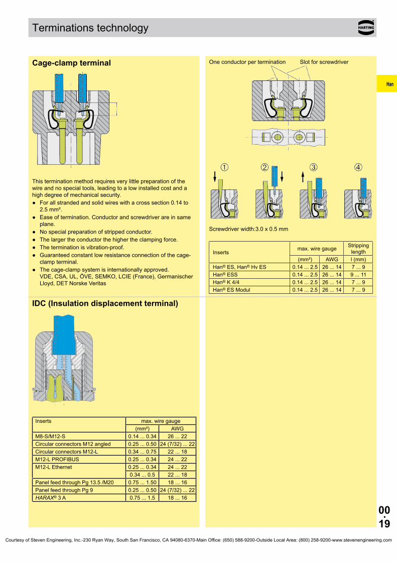
Cage-clamp terminal
This termination method requires very little preparation of the wire and no special tools, leading to a low installed cost and a high degree of mechanical security.● For all stranded and solid wires with a cross section 0.14 to
2.5 mm².● Ease of termination. Conductor and screwdriver are in same
plane.● No special preparation of stripped conductor.● The larger the conductor the higher the clamping force.● The termination is vibration-proof.● Guaranteed constant low resistance connection of the cage-
clamp terminal.● The cage-clamp system is internationally approved.
VDE, CSA, UL, ÖVE, SEMKO, LCIE (France), Germanischer Lloyd, DET Norske Veritas
One conductor per termination Slot for screwdriver
Screwdriver width:3.0 x 0.5 mm
Insertsmax. wire gauge Stripping
length(mm²) AWG l (mm)
Han® ES, Han® Hv ES 0.14 ... 2.5 26 ... 14 7 ... 9Han® ESS 0.14 ... 2.5 26 ... 14 9 ... 11Han® K 4/4 0.14 ... 2.5 26 ... 14 7 ... 9Han® ES Modul 0.14 ... 2.5 26 ... 14 7 ... 9
IDC (Insulation displacement terminal)
Inserts max. wire gauge(mm²) AWG
M8-S/M12-S 0.14 ... 0.34 26 ... 22Circular connectors M12 angled 0.25 ... 0.50 24 (7/32) ... 22Circular connectors M12-L 0.34 ... 0.75 22 ... 18M12-L PROFIBUS 0.25 ... 0.34 24 ... 22M12-L Ethernet 0.25 ... 0.34 24 ... 22
0.34 ... 0.5 22 ... 18Panel feed through Pg 13.5 /M20 0.75 ... 1.50 18 ... 16Panel feed through Pg 9 0.25 ... 0.50 24 (7/32) ... 22HARAX® 3 A 0.75 ... 1.5 18 ... 16
Courtesy of Steven Engineering, Inc.-230 Ryan Way, South San Francisco, CA 94080-6370-Main Office: (650) 588-9200-Outside Local Area: (800) 258-9200-www.stevenengineering.com

Han
00.20
① ② ③ ④
Terminations technology
Han-Quick Lock® termination technique This new termination technique from HARTING combines the re-liability and the simple operation of the cage clamp termination with the low space requirements of crimp technology.Han-Quick Lock® is ideally suited to high contact densities and is considerably superior over other termination techniques. No other technology is so simple, space saving and fast. For this vibration safe termination, no special tools are necessary.● Fast, simple and robust termination technique● Field assembly without a special tool● Compatible also to inserts with other termination
technologies● Combines high contact density similar to crimp termination
with the simple connection like a cage clamp terminal
Insert connectors: Han® 3 A Han® 4 A Han® 7 D Han® 8 D Han® Q 4/2 Han® Q 5/0 Han® Q 8/0 Han® Q 12/0 Han® EE modules Han® DD modules Han® PushPull Power 4/0
Technical characteristics:Material Isolation body - polycarbonate
Active termination element - poly-carbonate Quick-Lock spring - stainless steel Contact - copper alloy
Terminal cross-section 0.25 ... 2.5 mm² (AWG 23 ... 14)Stripping length 10 mmInsulating resistance > 1010 OhmFlammability according to UL 94 V 0Mechanical working life ≥ 500 mating cyclesScrewdriver 0.4 x 2.5 mm or 0.5 x 3.0 mm
Courtesy of Steven Engineering, Inc.-230 Ryan Way, South San Francisco, CA 94080-6370-Main Office: (650) 588-9200-Outside Local Area: (800) 258-9200-www.stevenengineering.com

Han
00.21
Notes
Courtesy of Steven Engineering, Inc.-230 Ryan Way, South San Francisco, CA 94080-6370-Main Office: (650) 588-9200-Outside Local Area: (800) 258-9200-www.stevenengineering.com
Han
00.22
Electrical engineering data
General
The choice of connectors entails more than just considering factors such as functionality, the number of contacts, current and voltage ratings. It is equally important to take account of where the con-nectors are to be used and the prevailing ambient conditions. This in turn means that, dependent on the conditions under which they are to be installed and pursuant to the relevant standards, different voltage and current ratings may apply for the same connectors.
The most important influencing factors and the corresponding electrical characteristics of the associated connectors are illus-trated here in greater detail.
Overvoltage category
The overvoltage category is dependent on the mains voltage and the location at which the equipment is installed. It describes the maximum overvoltage resistance of a device in the event of a pow-er supply system fault, e. g. in the event of a lightening strike.
The overvoltage category affects the dimensioning of components in that it determines the clearance air gap. Pursuant to the relevant standards, there are 4 overvoltage categories.
Equipment for industrial use, such as fall HARTING heavy duty Han connector, fall into Overvoltage Category III.
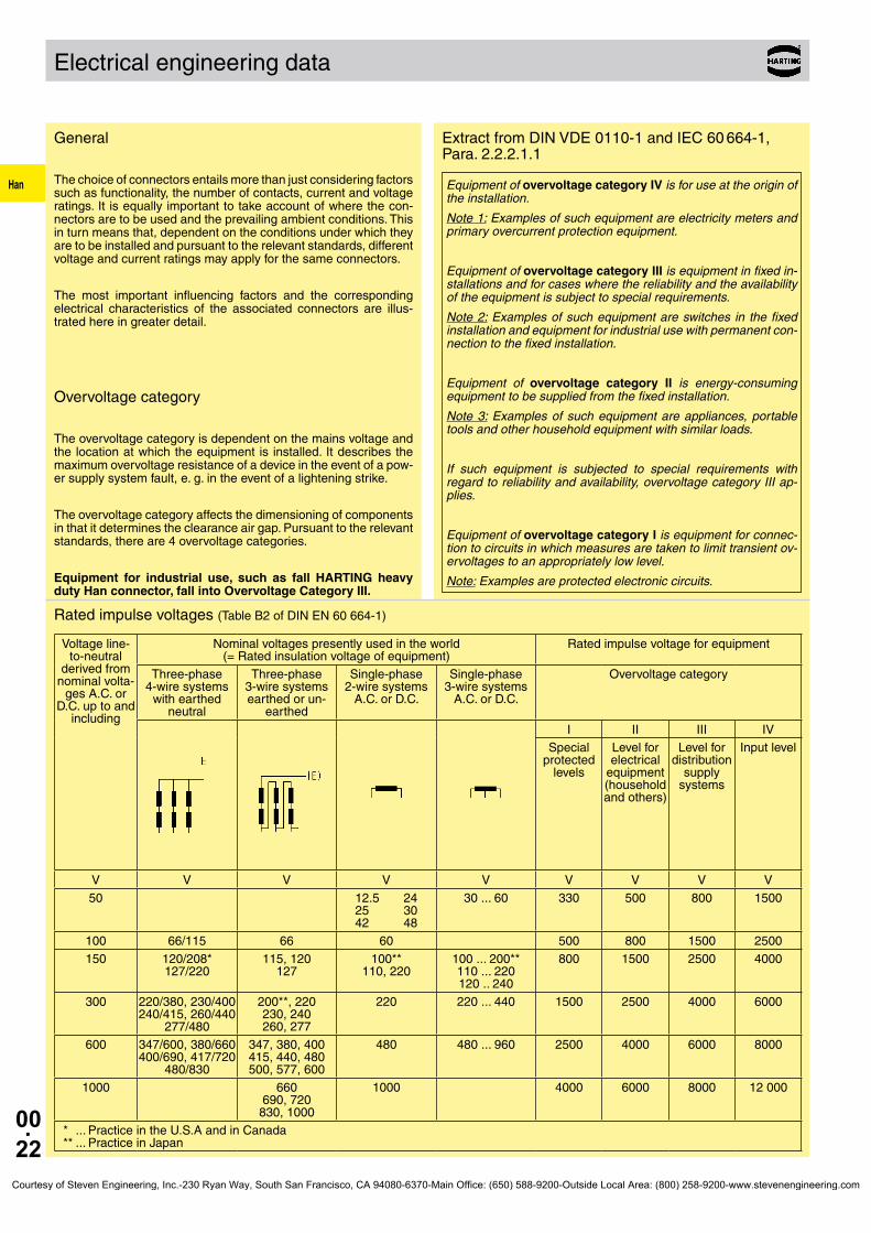
Extract from DIN VDE 0110-1 and IEC 60 664-1, Para. 2.2.2.1.1
Rated impulse voltages (Table B2 of DIN EN 60 664-1)
Equipment of overvoltage category IV is for use at the origin of the installation.
Note 1: Examples of such equipment are electricity meters and primary overcurrent protection equipment.
Equipment of overvoltage category III is equipment in fixed in-stallations and for cases where the reliability and the availability of the equipment is subject to special requirements.
Note 2: Examples of such equipment are switches in the fixed installation and equipment for industrial use with permanent con-nection to the fixed installation.
Equipment of overvoltage category II is energy-consuming equipment to be supplied from the fixed installation.
Note 3: Examples of such equipment are appliances, portable tools and other household equipment with similar loads.
If such equipment is subjected to special requirements with regard to reliability and availability, overvoltage category III ap-plies.
Equipment of overvoltage category I is equipment for connec-tion to circuits in which measures are taken to limit transient ov-ervoltages to an appropriately low level.
Note: Examples are protected electronic circuits.
Voltage line-to-neutral
derived from nominal volta-
ges A.C. or D.C. up to and
including
Nominal voltages presently used in the world(= Rated insulation voltage of equipment)
Rated impulse voltage for equipment
Three-phase 4-wire systems
with earthed neutral
Three-phase 3-wire systems earthed or un-
earthed
Single-phase 2-wire systems
A.C. or D.C.
Single-phase 3-wire systems
A.C. or D.C.
Overvoltage category
I II III IVSpecial
protected levels
Level for electrical
equipment (household and others)
Level for distribution
supply systems
Input level
V V V V V V V V V50 12.5 24
25 30 42 48
30 ... 60 330 500 800 1500
100 66/115 66 60 500 800 1500 2500150 120/208*
127/220115, 120
127100**
110, 220100 ... 200** 110 ... 220 120 .. 240
800 1500 2500 4000
300 220/380, 230/400 240/415, 260/440
277/480
200**, 220 230, 240 260, 277
220 220 ... 440 1500 2500 4000 6000
600 347/600, 380/660 400/690, 417/720
480/830
347, 380, 400 415, 440, 480 500, 577, 600
480 480 ... 960 2500 4000 6000 8000
1000 660 690, 720
830, 1000
1000 4000 6000 8000 12 000
* ... Practice in the U.S.A and in Canada** ... Practice in Japan
Courtesy of Steven Engineering, Inc.-230 Ryan Way, South San Francisco, CA 94080-6370-Main Office: (650) 588-9200-Outside Local Area: (800) 258-9200-www.stevenengineering.com

Han
00.23
Electrical engineering data
Pollution degree
The dimensioning of operating equipment is dependent on envi-ronmental conditions. Any pollution or contamination may give rise to conductivity that, in combination with moisture, may affect the insulating properties of the surface on which it is deposited. The pollution degree influences the design of components in terms of the creepage distance.
The pollution degree is defined for exposed, unprotected insula-tion on the basis of environmental conditions.
HARTING heavy duty Han connectors are designed as stand-ard for Pollution Degree 3.
Pollution degree 1 in air-conditioned or clean, dry rooms, such as computer and measuring instrument rooms, for example.
Pollution degree 2 in residential, sales and other business premises, precision en-gineering workshops, laboratories, testing bays, rooms used for medical purposes. As a result of occasional moisture condensa-tion, it is to be anticipated that pollution/contamination may be tem-porarily conductive.
Pollution degree 3 in industrial, commercial and agricultural premises, unheated storage premises, workshops or boiler rooms, also for the electrical components of assembly or mounting equipment and machine tools.
Pollution degree 4 in outdoor or exterior areas such as equipment mounted on the roofs of locomotives or tramcars.
Extract from DIN EN 60 664-1 (VDE 0110-1), Para. 4.6.2
Pollution degree 1: No pollution or only dry, non-conductive pollution occurs. The pollution has no influence.
Pollution degree 2: Only non-conductive pollution occurs except that occasionally a temporary conductivity caused by condensa-tion is to be excepted.
Pollution degree 3: Conductive pollution occurs or dry non-conductive pollution occurs which becomes conductive due to condensation which is to be expected.
Pollution degree 4: Continuous conductivity occurs due to con-ductive dust, rain or other wet conditions.
Special ruling for connectors
Subject to compliance with certain preconditions, the stand-ard for connectors permits a lower pollution degree than that which applies to the installation as a whole. This means that in a pollution degree 3 environment, connectors may be used which are electrically rated for pollution degree 2. The basis for this is contained in DIN EN 61 984, Para. 6.19.2.3.
Extract form DIN EN 61 984, Para. 6.19.2.3
For a connector with a degree of protection IP 54 or higher according to IEC 60 529 the insulating parts inside the enclosure may be dimensioned for a lower pollution degree.
This also applies to mated connectors where enclosure is ensured by the connector housing and which may only be disengaged for test and maintenance purposes.
The conditions fulfills,
● a connector which is protected to at least IP 54 as per IEC 60 529,
● a connector which is installed in a housing and which as described in the standard is disconnected for testing and main-tenance purposes only,
● a connector which is installed in a housing and which when disconnected is protected by a cap or cover to at least IP 54,
● a connector located inside a switching cabinet to at least IP 54.
These conditions do not extend to connectors which when dis-connected remain exposed to the industrial atmosphere for an indefinite period.
It should be noted that pollution can affect a connector from the inside of an installation outwards.
Typical applications in which to choose pollution degree 2 connectors:
● A connector serving a drive motor which is disconnected only for the purpose of replacing a defective motor, even when the plant or system otherwise calls for pollution degree 3.
● Connectors serving a machine of modular design which are dis-connected for transport purposes only and enable rapid erection and reliable commissioning. In transit, protective covers or ad-equate packing must be provided to ensure that the connectors are not affected by pollution/contamination.
● Connectors located inside a switching cabinet to IP 54. In such cases, it is even possible to dispense with the IP 54 housings of the connectors themselves.
Specifying electrical data
Electrical data for connectors are specified as per DIN EN 61 984.
This example identifies a connector suitable for use in an unearthed power system or earthed delta circuit (see page 00.22, Table B2 of DIN EN 60 664-1):
16 A 400 V 6 kV 3 Working current Working voltage Rated impulse voltage Pollution degree
This example identifies a connector suitable exclusively for use in earthed power systems (see page 00.22, Table B2 of DIN EN 60 664-1):
10 A 230/400 V 4 kV 3 Working current Working voltage conductor – ground Working voltage conductor – conductor Rated impulse voltage Pollution degree
Courtesy of Steven Engineering, Inc.-230 Ryan Way, South San Francisco, CA 94080-6370-Main Office: (650) 588-9200-Outside Local Area: (800) 258-9200-www.stevenengineering.com
Han
00.24
Electrical engineering data
Other terms explained
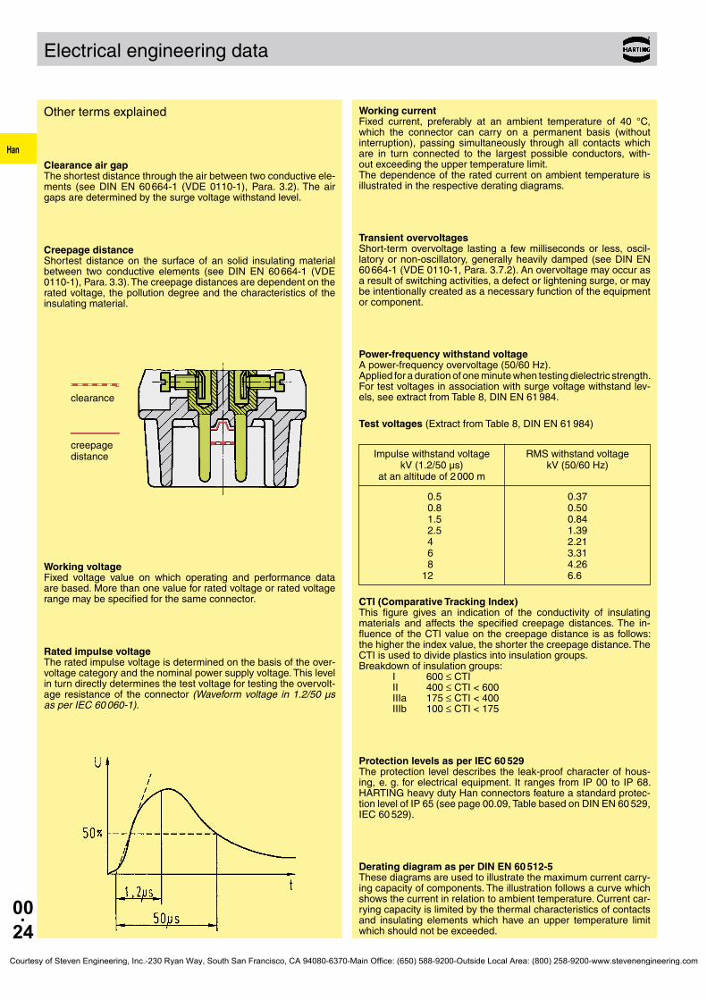
Clearance air gap The shortest distance through the air between two conductive ele-ments (see DIN EN 60 664-1 (VDE 0110-1), Para. 3.2). The air gaps are determined by the surge voltage withstand level.
Creepage distance Shortest distance on the surface of an solid insulating material between two conductive elements (see DIN EN 60 664-1 (VDE 0110-1), Para. 3.3). The creepage distances are dependent on the rated voltage, the pollution degree and the characteristics of the insulating material.
Working voltage Fixed voltage value on which operating and performance data are based. More than one value for rated voltage or rated voltage range may be specified for the same connector.
Rated impulse voltage The rated impulse voltage is determined on the basis of the over-voltage category and the nominal power supply voltage. This level in turn directly determines the test voltage for testing the overvolt-age resistance of the connector (Waveform voltage in 1.2/50 µs as per IEC 60 060-1).
Working current Fixed current, preferably at an ambient temperature of 40 °C, which the connector can carry on a permanent basis (without interruption), passing simultaneously through all contacts which are in turn connected to the largest possible conductors, with-out exceeding the upper temperature limit. The dependence of the rated current on ambient temperature is illustrated in the respective derating diagrams.
Transient overvoltages Short-term overvoltage lasting a few milliseconds or less, oscil-latory or non-oscillatory, generally heavily damped (see DIN EN 60 664-1 (VDE 0110-1, Para. 3.7.2). An overvoltage may occur as a result of switching activities, a defect or lightening surge, or may be intentionally created as a necessary function of the equipment or component.
Power-frequency withstand voltage A power-frequency overvoltage (50/60 Hz). Applied for a duration of one minute when testing dielectric strength. For test voltages in association with surge voltage withstand lev-els, see extract from Table 8, DIN EN 61 984.
Test voltages (Extract from Table 8, DIN EN 61 984)
Impulse withstand voltage RMS withstand voltage kV (1.2/50 µs) kV (50/60 Hz) at an altitude of 2 000 m
0.5 0.37 0.8 0.50 1.5 0.84 2.5 1.39 4.0 2.21 6.0 3.31 8.0 4.26 12.0 6.60
CTI (Comparative Tracking Index) This figure gives an indication of the conductivity of insulating materials and affects the specified creepage distances. The in-fluence of the CTI value on the creepage distance is as follows: the higher the index value, the shorter the creepage distance. The CTI is used to divide plastics into insulation groups. Breakdown of insulation groups: I 600 ≤ CTI II 400 ≤ CTI < 600 IIIa 175 ≤ CTI < 400 IIIb 100 ≤ CTI < 175
Protection levels as per IEC 60 529 The protection level describes the leak-proof character of hous-ing, e. g. for electrical equipment. It ranges from IP 00 to IP 68. HARTING heavy duty Han connectors feature a standard protec-tion level of IP 65 (see page 00.09, Table based on DIN EN 60 529, IEC 60 529).
Derating diagram as per DIN EN 60 512-5 These diagrams are used to illustrate the maximum current carry-ing capacity of components. The illustration follows a curve which shows the current in relation to ambient temperature. Current car-rying capacity is limited by the thermal characteristics of contacts and insulating elements which have an upper temperature limit which should not be exceeded.
clearance
creepage distance
Courtesy of Steven Engineering, Inc.-230 Ryan Way, South San Francisco, CA 94080-6370-Main Office: (650) 588-9200-Outside Local Area: (800) 258-9200-www.stevenengineering.com

Han
00.25
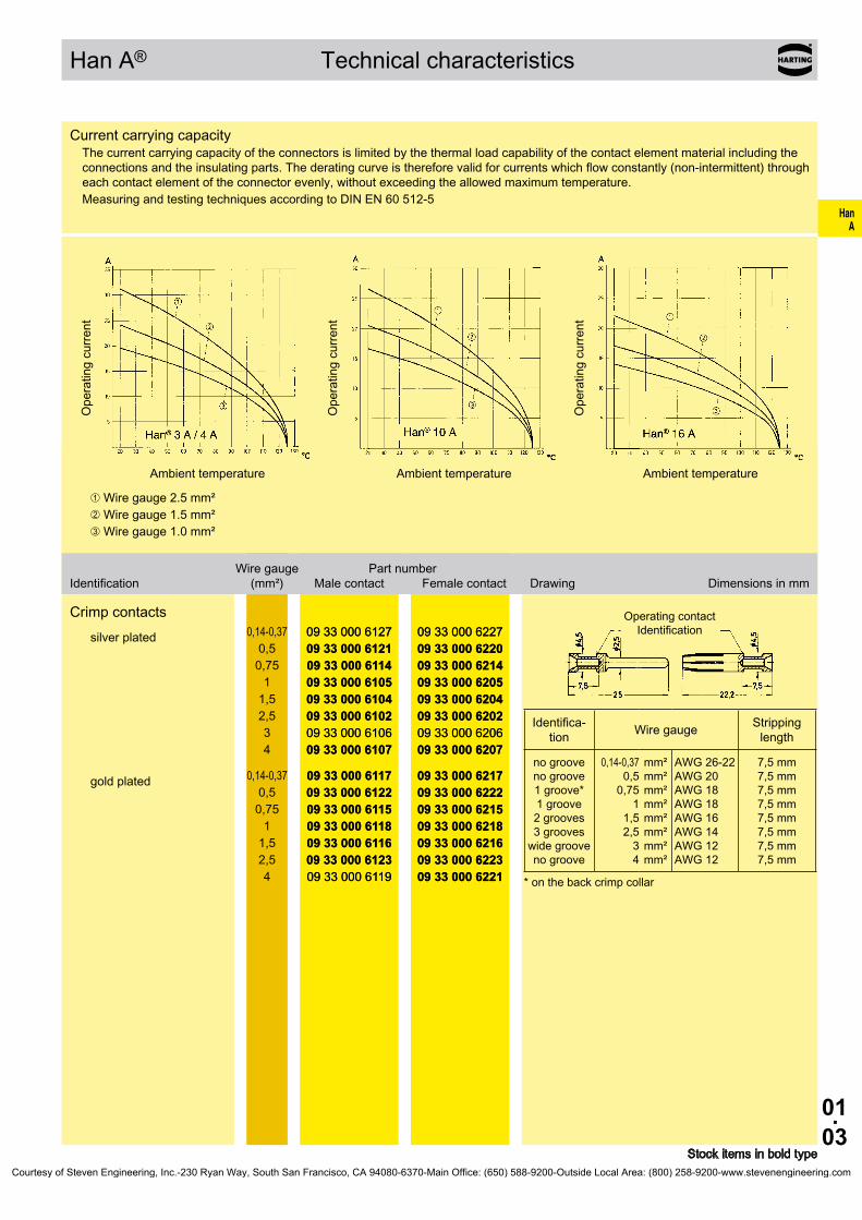
Current carrying capacity
Current carrying capacity
The current carrying capacity is determined in tests which are conducted on the basis of the DIN EN 60 512-5. The current carry-ing capacity is limited by the thermal properties of materials which are used for inserts as well as by the insulating materials. These components have a limiting temperature which should not be ex-ceeded.
The relationship between the current, the temperature rise (loss at the contact resistance) and the ambient temperature of the connector is represented by a curve. On a linear coordinate system the current lies on the vertical line (ordinate) and the ambient temperature on the horizontal line (abscissa) which ends at the upper limiting temperature.
In another measurement the self-heating (∆t) at different currents is determined.
At least 3 points are determined which are connected to a parabolic curve, the basic curve.
The corrected current carrying capacity curve is derived from this basic curve. The reasons for the correction are external factors that bring an additional limitation to the current carrying capacity, i.e. connectable wire gauge or an unequal dispersion of current.
Example of a current capacity curve
Definition: The rated current is the continuous, not interrupted current a connector can take when simultaneous power on all con-tacts is given, without exceeding the maximum temperature.
Example of a current carrying curve
Acc. to DIN EN 61 984 the sum of ambient temperature and the temperature rise of a connector shall not exceed the upper limiting temperature. The limiting temperature is valid for a complete con-nector, that means insert plus housing.
As a result the insert gives the limit for the temperature of a com-plete connector and thus housings as well.
In practice it is not usual to load all terminals simultaneously with the maximum current. In such a case one contact can be loaded with a higher current as permitted by the current capacity curve, if less than 20 % of the whole is loaded.
However, for these cases there are no universal rules. The limits have to be determined individually from case to case. It is recommended to proceed in accordance with the relevant rules of the DIN EN 60 512-5.
Current carrying capacity of copper wires
Ambient temperature
Permissible upper temperature-limit set by applied materials
Permissible upper limiting temperature set by applied materials
basic curve
corrected curve
permissible operation range
Upper current limit set by external factors, i.e. connectable wire gauge, given current limit
Cur
rent
car
ryin
g ca
paci
ty
Depiction in accordance with DIN EN 60 204-1 for PVC-insulated copper wires in an ambient temperature of + 40 °C under permanent operating conditions.For different conditions and temperatures, installations, insulation materials or conductors the relevant corrections have to be carried out.
Diameter [mm²] of single wires in a three-phase system 0.75 1.0 1.5 2.5 4 6 10 16 25 35 Type of installation
B1 Conductors/single core cables in conduit and cable trunking systems 8.6 10.3 13.5 18.3 24 31 44 59 77 96
B2 Cables in conduit and cable trunking systems 8.5 10.1 13.1 17.4 23 30 40 54 70 86
C Cables on walls 9.8 11.7 15.2 21.0 28 36 50 66 84 104
E Cables on open cable trays 10.4 12.4 16.1 22.0 30 37 52 70 88 110
Courtesy of Steven Engineering, Inc.-230 Ryan Way, South San Francisco, CA 94080-6370-Main Office: (650) 588-9200-Outside Local Area: (800) 258-9200-www.stevenengineering.com

Han
00.26
➀ Han D® IN = 10 A
➁ Han® 3 A / 4 A IN = 10 A
➂ Han A® / Han E®, Han® ES, EE, Q 5/0 IN = 16 A
➃ Han® 6 HsB IN = 35 A
➄ Han® C/K axial IN = 40 A
➅ Han® K 4/8 IN = 80 A
➆ Han® K 6/6 IN = 100 A
➇ Han® K 3/0 IN = 200 A
➈ Han® HC-Modular 350 IN = 350 A
➉ Han® HC-Modular 650 IN = 650 A
5 V
5 mA
Current carrying capacity
Transient current carrying capacity
A transient current in circuits can be generated by switching operations such as the starting of a motor or a short circuit in a faulty installation. This can cause thermal stress at the contact. These short and very high increases cannot be dissipated quickly and therefore a local heating effect at the contact is the result. Contact design is an important feature when transient currents are encountered. HARTING contacts are machined from solid material and are therefore relatively unaffected by short overloads when compared to stamped and formed designs. For guidance please see the table below.
Short circuit carrying capacity
Low currents and voltages
HARTING’s standard contacts have a silver plated surface. This precious metal has excellent conductive properties. In the course of a contact’s lifetime, the silver surface generates a black oxide layer due to its affinity to sulphur. This layer is smooth and very thin and is partly interrupted when the contacts are mated and unmated, thus guaranteeing very low contact resistances. In the case of very low currents or voltages small changes to the transmitted signal may be encountered. This is illustrated below where an artifically aged contact representing a twenty year life is compared with a new contact.
In systems where such a change to the transmitted signal could lead to faulty functions and also in extremely aggressive environ-ments, HARTING recommend the use of gold plated contacts.
Below is a table derived from actual experiences.
Recommendation
Changes to the transmitted signal after artifical ageing
➀ new contact
➁ after ageing
5 V
5 mA
Gold
Silver
Courtesy of Steven Engineering, Inc.-230 Ryan Way, South San Francisco, CA 94080-6370-Main Office: (650) 588-9200-Outside Local Area: (800) 258-9200-www.stevenengineering.com

Han
00.27
M 20M 25M 32M 40M 50
1 2 3 4 5 6 7 8 9 10 11 12 13 14 15 16 17 18 19 20 21 22 23 24 25 26 27 28 29 30 31 32 mm
M 40M 40
M 32M 32
M 25M 25
M 20M 20
M 20
1 2 3 4 5 6 7 8 9 10 11 12 13 14 15 16 17 18 19 20 21 22 23 24 25 26 27 28 29 30 31 32 mm
Pg 11Pg 13.5Pg 16Pg 21Pg 29Pg 36Pg 42
Pg
Pg 29Pg 29
Pg 29
Pg 21Pg 21
Pg 16Pg 16
Pg 13.5
Pg 11Pg 11
Cross Reference from Pg thread to metric cable thread
The Cross Reference table shows the correlation between the Pg versions and the new metric types.
Please notice that the maximum cable diameter will be reduced by the new metric cable glands.
Below is shown the cable range of metric glands:
The reason for the new product offerings is the publication of the international DIN EN 50262 metric thread specification. The existing Pg series, Pg 7 to Pg 48 will be, in time, replaced by the metric series M 12 to M 63.
The adoption of metric threads considerably simplifies the understanding and specification of glands as the product type description contains the thread dimension. E.g. M 20 refers to 20 mm thread diameter.
To differentiate the metric threaded hoods and housings from the previous Pg versions metric types will be marked with M .
Cross ReferenceMetric
CableThe diagram shows different cable-diameters, being dependent on wire gauges and number of conductors. All data are averages for commercial cables.
Cable-Ø
Con
duct
ors
Courtesy of Steven Engineering, Inc.-230 Ryan Way, South San Francisco, CA 94080-6370-Main Office: (650) 588-9200-Outside Local Area: (800) 258-9200-www.stevenengineering.com
Han
00.28
Declaration of Conformity
Courtesy of Steven Engineering, Inc.-230 Ryan Way, South San Francisco, CA 94080-6370-Main Office: (650) 588-9200-Outside Local Area: (800) 258-9200-www.stevenengineering.com

HanA
01.01
Han A®
Contents
Technical characteristics Han A® . . . . . . . . . . . . . . . . . . . . . . . . . . . . . . . . . 01.02
Technical characteristics Han® 3 A with HARAX® Termination . . . . . . . . . . 01.04
Han® 3 A, 3 A with HARAX® Termination . . . . . . . . . . . . . . . . . . . . . . . . . 01.05
Han® 4 A . . . . . . . . . . . . . . . . . . . . . . . . . . . . . . . . . . . . . . . . . . . . . . . . . . 01.06
Han® 10 A . . . . . . . . . . . . . . . . . . . . . . . . . . . . . . . . . . . . . . . . . . . . . . . . . . 01.07
Han® 16 A . . . . . . . . . . . . . . . . . . . . . . . . . . . . . . . . . . . . . . . . . . . . . . . . . . 01.08
Han® 32 A . . . . . . . . . . . . . . . . . . . . . . . . . . . . . . . . . . . . . . . . . . . . . . . . . . 01.09
Page
Courtesy of Steven Engineering, Inc.-230 Ryan Way, South San Francisco, CA 94080-6370-Main Office: (650) 588-9200-Outside Local Area: (800) 258-9200-www.stevenengineering.com

HanA
01.02
Technical characteri-stics Han A®
Han A® Technical characteristics
Features• Metalandplasticversionavailable• Han®3Ahoods/housingsmetalandplasticversion
available• Han®3A/4AinsertsalsowithHan-QuickLock®
terminationtechnologyavailable• Han®10Aand16Ainsertsavailableincrimpand
screwtermination• Forcurrentsupto10A(Han®3A/Han®4A)and
16A(Han®10A/Han®16A)
Specifications DINEN60664-1 DINEN61984 Approvals ,
InsertsNumberofcontacts 3,4,10,16,32(2x16)+PE
Electricaldataacc.toEN61984Han®3A/Han®4A 10 A 230/400 V 4 kV 3 Ratedcurrent 10ARatedvoltageconductor-ground230VRatedvoltageconductor-conductor 400VRatedimpulsevoltage 4kVPollutiondegree 3or 10A 250V 4kV 3
Han®10A/Han®16A 16 A 250 V 4 kV 3 Ratedcurrent 16ARatedvoltage 250VRatedimpulsevoltage 4kVPollutiondegree 3Pollutiondegree2also 16A 230/400V 4kV 2
Ratedvoltage acc.toUL/CSA 600VInsulationresistance ≥1010ΩMaterial polycarbonateLimitingtemperatures -40°C...+125°CFlammabilityacc.toUL94 V0Mechanicalworkinglife -matingcycles ≥500
ContactsMaterial copperalloySurface-hard-goldplated 2µmAuover3µmNiSurface-hard-silverplated 3µmAgContactresistance ≤1mΩCrimpterminal-min 0,14mm²/AWG26 Crimpterminal-max 4mm²/AWG12 Screwterminal-min 1mm²/AWG18 Screwterminal-max 2,5mm²/AWG14 Tightening/testtorque 0,25NmHan®3A/4A 0,5NmHan®10A/16A Han-QuickLock®-min 0,5mm²/AWG20 Han-QuickLock®-max 2,5mm²/AWG14
Hoods/Housings,thermoplasticHan®3A/Han®4AMaterial polycarbonateRAL7032 Lockingelement PolyamideRAL7032 Flammabilityacc.toUL94 V0 Hoods/Housingsseal NBR Limitingtemperatures -40°C...+125°C Degreeofprotectionacc.toDINEN60529 forcoupledconnector IP65/IP67
Hoods/Housings,metalMaterialHan®3A/4A zincdie-cast MaterialHan®10A/16A aluminiumdie-cast Lockingelement Han®3A/4A steel,zinc-plated Han®10A/16A Han-EasyLock® Hoods/Housingsseal NBR Limitingtemperatures -40°C...+125°C Degreeofprotectionacc.toDINEN60529 forcoupledconnector Han®3A/4A IP44 IP67isachievedwithseal screw09200009918 Han®10A/16A IP65
Furtherselectionofhoods/housingsseechapter30/chapter31
AccessoriesCrimpingtools chapter99 Cableclamps chapter40 Sealingscrew chapter40 Codingofhoods/housings chapter40 Labelacc.toCSA-approval chapter40 Assemblyplatesfortestconnector chapter40
Courtesy of Steven Engineering, Inc.-230 Ryan Way, South San Francisco, CA 94080-6370-Main Office: (650) 588-9200-Outside Local Area: (800) 258-9200-www.stevenengineering.com
HanA
01.03
09 33 000 612709 33 000 612109 33 000 611409 33 000 610509 33 000 610409 33 000 610209 33 000 610609 33 000 6107
09 33 000 622709 33 000 622009 33 000 621409 33 000 620509 33 000 620409 33 000 620209 33 000 620609 33 000 6207
09 33 000 611709 33 000 612209 33 000 611509 33 000 611809 33 000 611609 33 000 612309 33 000 6119
09 33 000 621709 33 000 622209 33 000 621509 33 000 621809 33 000 621609 33 000 622309 33 000 6221
Han A® Technical characteristics
Stockitemsinboldtype
Wiregauge Partnumber Identification (mm²) Malecontact Femalecontact Drawing Dimensionsinmm
Crimpcontacts
silverplated 0,14-0,370,50,75
11,52,534
09 33 000 612709 33 000 612109 33 000 611409 33 000 610509 33 000 610409 33 000 610209 33 000 610609 33 000 6107
09 33 000 622709 33 000 622009 33 000 621409 33 000 620509 33 000 620409 33 000 620209 33 000 620609 33 000 6207
goldplated 0,14-0,370,50,75
11,52,54
09 33 000 611709 33 000 612209 33 000 611509 33 000 611809 33 000 611609 33 000 612309 33 000 6119
09 33 000 621709 33 000 622209 33 000 621509 33 000 621809 33 000 621609 33 000 622309 33 000 6221
Operatingcontact Identification
Identifica-tion Wiregauge Stripping
length
nogroovenogroove1groove*1groove2grooves3grooveswidegroovenogroove
0,14-0,370,50,75
11,52,5
34
mm²mm²mm²mm²mm²mm²mm²mm²
AWG26-22AWG20AWG18AWG18AWG16AWG14AWG12AWG12
7,5mm7,5mm7,5mm7,5mm7,5mm7,5mm7,5mm7,5mm
*onthebackcrimpcollar
CurrentcarryingcapacityThecurrentcarryingcapacityoftheconnectorsislimitedbythethermalloadcapabilityofthecontactelementmaterialincludingtheconnectionsandtheinsulatingparts.Thederatingcurveisthereforevalidforcurrentswhichflowconstantly(non-intermittent)througheachcontactelementoftheconnectorevenly,withoutexceedingtheallowedmaximumtemperature.MeasuringandtestingtechniquesaccordingtoDINEN60512-5
Operatingcurre
nt
Ambienttemperature
Operatingcurre
nt
Ambienttemperature
Operatingcurre
nt
Ambienttemperature
➀Wiregauge2.5mm²➁Wiregauge1.5mm²➂Wiregauge1.0mm²
Courtesy of Steven Engineering, Inc.-230 Ryan Way, South San Francisco, CA 94080-6370-Main Office: (650) 588-9200-Outside Local Area: (800) 258-9200-www.stevenengineering.com

HanA
01.04
Technical characte-ristics Han® 3 A with HARAX® termination
Han®3A withHARAX®termination
Features• TimesavingrapidterminationtechniqueHARAX®
• AdvantagesofHARAX®firstinanindustrialcon-nector
• Reconnectiontothesameorbiggerwiregaugeupto10times
• Nospecialtoolsrequired
Specifications DINEN61984 DINEN60352-4 DINEN60664-1 Approvals ,
Technical characteristicsConductorcrosssection 0,75-1,5mm² Cableoutsidediameter 6-9mm Wirediameter ≤2,8mm Wireofind.strands ≥0,2mm Insulationmaterial PVC Degreeofprotection IP65/IP67 Ratedcurrent 10A Ratedvoltage 230/400V Tighteningtorque ofscrewcap 8Nm Limitingtemperatures -40°C...+85°C
Assemblyinstructions1. Stripoffcablemantle
2. AssembleHARAX®elements
3. Cutoffcableends
4. Thenutmustbescrewedcompletelydownuntilthenotchesengageonthecontactcarriernutlatch
a=Screwcap
b=Sealing
c=Splicering
Includedindelivery:Screwcap,sealing,splicering
Courtesy of Steven Engineering, Inc.-230 Ryan Way, South San Francisco, CA 94080-6370-Main Office: (650) 588-9200-Outside Local Area: (800) 258-9200-www.stevenengineering.com
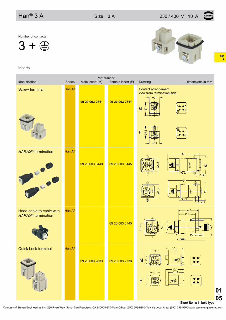
HanA
01.05
Han® 3 A / Han® 3 A with HARAX® termination
Han® 3 A Size 3A 230/400 V10 A
Stockitemsinboldtype
Numberofcontacts
3+Inserts
Partnumber Identification Series Maleinsert(M) Femaleinsert(F) Drawing Dimensionsinmm
Screwterminal Han A®
09 20 003 2611 09 20 003 2711
Contactarrangement viewfromterminationside
HARAX®termination Han A®
09 20 003 0440 09 20 003 0445
HoodcabletocablewithHARAX®termination
Han A®
09 20 003 0745
QuickLockterminal Han A®
09 20 003 2633 09 20 003 2733
Courtesy of Steven Engineering, Inc.-230 Ryan Way, South San Francisco, CA 94080-6370-Main Office: (650) 588-9200-Outside Local Area: (800) 258-9200-www.stevenengineering.com

HanA
01.06
Han® 4 A
Han®4A Size 3A 230/400 V10 A
Stockitemsinboldtype
Numberofcontacts
4+Inserts
Partnumber Identification Series Maleinsert(M) Femaleinsert(F) Drawing Dimensionsinmm
Screwterminal Han A®
09 20 004 2611 09 20 004 2711
Contactarrangement viewfromterminationside
QuickLocktermination Han A®
09 20 004 2633 09 20 004 2733
Contactarrangement viewfromterminationside
Courtesy of Steven Engineering, Inc.-230 Ryan Way, South San Francisco, CA 94080-6370-Main Office: (650) 588-9200-Outside Local Area: (800) 258-9200-www.stevenengineering.com

HanA
01.07
Han® 10 A
Han® 10 A Size 10A 250 V16 A
Stockitemsinboldtype
Numberofcontacts
10+Inserts
Partnumber Identification Series Maleinsert(M) Femaleinsert(F) Drawing Dimensionsinmm
Screwterminal Han A®
09 20 010 2612 09 20 010 2812
Crimpterminal Ordercrimpcontacts separately(see Technical characteristics onpage01.03)
Han A®
09 20 010 3001 09 20 010 3101
Screwterminal
1)Distanceforcontactmax.24mm
Contactarrangement viewfromterminationside
Panelcutoutforinserts forusewithouthoods/housings
Crimpterminal
1)Distanceforcontactmax.24mm
Courtesy of Steven Engineering, Inc.-230 Ryan Way, South San Francisco, CA 94080-6370-Main Office: (650) 588-9200-Outside Local Area: (800) 258-9200-www.stevenengineering.com

HanA
01.08
Han® 16 A
Han®16A Size 16A 250 V16 A
Stockitemsinboldtype
Numberofcontacts
16+Inserts
Partnumber Identification Series Maleinsert(M) Femaleinsert(F) Drawing Dimensionsinmm
Screwterminal Han A®
09 20 016 2612 09 20 016 2812
Crimpterminal Ordercrimpcontacts separately(see Technical characteristics onpage01.03)
Han A®
09 20 016 3001 09 20 016 3101
Screwterminal
1)Distanceforcontactmax.24mm
Contactarrangement viewfromterminationside
Panelcutoutforinserts forusewithouthoods/housings
Crimpterminal
1)Distanceforcontactmax.24mm
Courtesy of Steven Engineering, Inc.-230 Ryan Way, South San Francisco, CA 94080-6370-Main Office: (650) 588-9200-Outside Local Area: (800) 258-9200-www.stevenengineering.com
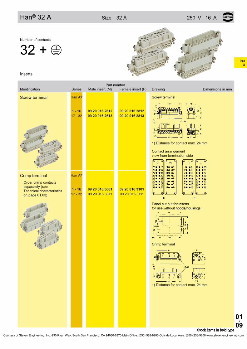
HanA
01.09
Han® 32 A
Han®32A Size 32A 250 V16 A
Stockitemsinboldtype
Numberofcontacts
32+Inserts
Partnumber Identification Series Maleinsert(M) Femaleinsert(F) Drawing Dimensionsinmm
Screwterminal Han A®
1-1617-32
09 20 016 261209 20 016 2613
09 20 016 281209 20 016 2813
Crimpterminal Ordercrimpcontacts separately(see Technical characteristics onpage01.03)
Han A®
1-1617-32
09 20 016 300109 20 016 3011
09 20 016 310109 20 016 3111
Screwterminal
1)Distanceforcontactmax.24mm
Contactarrangement viewfromterminationside
Panelcutoutforinserts forusewithouthoods/housings
Crimpterminal
1)Distanceforcontactmax.24mm
Courtesy of Steven Engineering, Inc.-230 Ryan Way, South San Francisco, CA 94080-6370-Main Office: (650) 588-9200-Outside Local Area: (800) 258-9200-www.stevenengineering.com
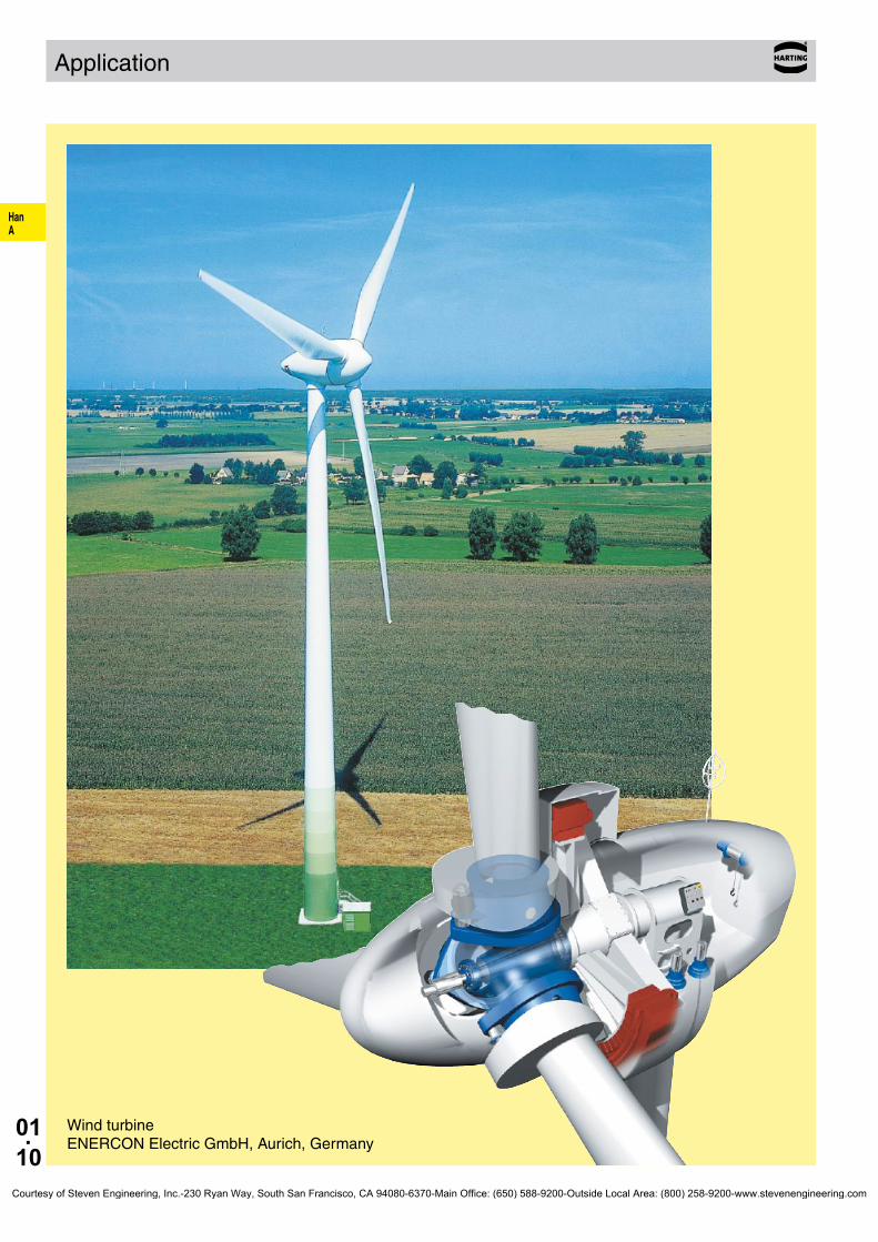
HanA
01.10
Application
Wind turbineENERCON Electric GmbH, Aurich, Germany
Courtesy of Steven Engineering, Inc.-230 Ryan Way, South San Francisco, CA 94080-6370-Main Office: (650) 588-9200-Outside Local Area: (800) 258-9200-www.stevenengineering.com

HanD / DD
02.01
Han D® / Han DD®
Contents Page
Technical characteristics Han D® . . . . . . . . . . . . . . . . . . . . . . . . . . . . . . . . 02.02
Technical characteristics Han DD® . . . . . . . . . . . . . . . . . . . . . . . . . . . . . . . 02.05
Han® 7 DD . . . . . . . . . . . . . . . . . . . . . . . . . . . . . . . . . . . . . . . . . . . . . . . . 02.07
Han® 8 DD . . . . . . . . . . . . . . . . . . . . . . . . . . . . . . . . . . . . . . . . . . . . . . . . 02.08
Han® 15 DD . . . . . . . . . . . . . . . . . . . . . . . . . . . . . . . . . . . . . . . . . . . . . . . . 02.09
Han® 25 DD . . . . . . . . . . . . . . . . . . . . . . . . . . . . . . . . . . . . . . . . . . . . . . . . 02.10
Han® 50 DD . . . . . . . . . . . . . . . . . . . . . . . . . . . . . . . . . . . . . . . . . . . . . . . . 02.11
Han® 24 DD . . . . . . . . . . . . . . . . . . . . . . . . . . . . . . . . . . . . . . . . . . . . . . . . 02.12
Han® 42 DD . . . . . . . . . . . . . . . . . . . . . . . . . . . . . . . . . . . . . . . . . . . . . . . . 02.13
Han® 40 DD . . . . . . . . . . . . . . . . . . . . . . . . . . . . . . . . . . . . . . . . . . . . . . . . 02.14
Han® 72 DD . . . . . . . . . . . . . . . . . . . . . . . . . . . . . . . . . . . . . . . . . . . . . . . . 02.15
Han® 64 DD . . . . . . . . . . . . . . . . . . . . . . . . . . . . . . . . . . . . . . . . . . . . . . . . 02.16
Han® 108 DD . . . . . . . . . . . . . . . . . . . . . . . . . . . . . . . . . . . . . . . . . . . . . . . . 02.17
Han® 80 DD . . . . . . . . . . . . . . . . . . . . . . . . . . . . . . . . . . . . . . . . . . . . . . . . 02.18
Han® 144 DD . . . . . . . . . . . . . . . . . . . . . . . . . . . . . . . . . . . . . . . . . . . . . . . . 02.19
Han® 128 DD . . . . . . . . . . . . . . . . . . . . . . . . . . . . . . . . . . . . . . . . . . . . . . . . 02.20
Han® 216 DD . . . . . . . . . . . . . . . . . . . . . . . . . . . . . . . . . . . . . . . . . . . . . . . . 02.21
Modified contact arrangements . . . . . . . . . . . . . . . . . . . . . . . . . . . . . . . . . . 02.22
Accessories . . . . . . . . . . . . . . . . . . . . . . . . . . . . . . . . . . . . . . . . . . . . . . . . . 02.23
Courtesy of Steven Engineering, Inc.-230 Ryan Way, South San Francisco, CA 94080-6370-Main Office: (650) 588-9200-Outside Local Area: (800) 258-9200-www.stevenengineering.com

HanD / DD
02.02
Han D® Technical characteristics
Features• Highdensityofcrimpingcontacts,upto128
contacts/connector• Timesavingrapidterminationbyuseofcrimping
contacts• Forrequirementsupto250V/10A• Goldandsilvercontactsavailable• Suitableforthermo-and1mmF.O.contacts
Specifications DINEN175301-801 DINEN60664-1 DINEN61984
Approvals ,
InsertsNumberofcontacts 7,15,25,40,50,64,80,128,
50(2x25),80(2x40), 128(2x64)+PE
Electricaldata acc.toEN61984 10 A 250 V 4 kV 3 Ratedcurrent 10ARatedvoltage 250VRatedimpulsevoltage 4kVPollutiondegree 3Pollutiondegree2also 10A 230/400V 4kV 2
Ratedvoltage acc.toUL/CSA 600VRatedvoltage forwrapterminalacc.toCSA 2A 30V
Contactarrangementforhighervoltageseepage02.22Insulationresistance ≥1010ΩMaterial polyamide -Han®40D/Han®64D polycarbonateLimitingtemperatures -40°C...+125°CFlammabilityacc.toUL94 HB -Han®40D/Han®64D V0Mechanicalworkinglife -matingcycles ≥500
ContactsMaterial copperalloySurface-hard-goldplated 2µmAuover3µmNiSurface-hard-silverplated 3µmAgContactresistance ≤3mΩCrimpterminal-min 0.14mm²/AWG26Crimpterminal-max 2.5mm²/AWG14Wirewrapterminal 1x1mm-length22mm
Diagonal1.34-1.45mmContactspacing5.08mm(40+64poles)Contactspacing5.3mm(15+25poles)
Han-QuickLock®-min 0.25mm²/AWG24Han-QuickLock®-max 1.5mm²/AWG16
Hoods/HousingsMaterial aluminiumdie-castSurface powdercoated RAL7037(grey)Lockingelement Han-EasyLock®
Flammabilityacc.toUL94 V0Hoods/Housingsseal NBRLimitingtemperatures -40°C...+125°CDegreeofprotectionacc.toDINEN60529 forcoupledconnector IP65
VariantsforHan®3Ahousings(seepage02.03)Material polycarbonate RAL7032(lightgrey)Lockingelement Polyamide RAL7032(lightgrey)
AccessoriesCrimpingtools chapter99Cableclamps chapter40Codingofhoods/housings chapter40Labelacc.toCSA-approval chapter40Han-Snap® chapter11Assemblyplatesfortestconnector chapter40
ATTENTION!Guidepinsandbushesareprescribedforthefollowingconnectors:15,25,40,50,64,80and128poles(seechapter40).
Courtesy of Steven Engineering, Inc.-230 Ryan Way, South San Francisco, CA 94080-6370-Main Office: (650) 588-9200-Outside Local Area: (800) 258-9200-www.stevenengineering.com

HanD / DD
02.03
Han®8D Technicalcharacteristics
Features• Highdensityofcrimpingcontacts,upto8contacts/
connector• Timesavingrapidterminationbyuseofcrimping
contacts• Forrequirementsupto∼50V/—120V/10A• Goldandsilvercontactsavailable• Suitableforthermo-and1mmF.O.contacts
Specifications DINEN60664-1 DINEN61984 DINEN175301-801Approvals ,
InsertsNumberofcontacts 8
Electricaldata acc.toEN61984 10 A ~50 V / – 120 V 0.8 kV 3Ratedcurrent 10ARatedvoltage ~50VRatedvoltageDC –120VRatedimpulsevoltage 0.8kVPollutiondegree 3
Ratedvoltage acc.toUL/CSA 50VRatedvoltage (directvoltage) 120VInsulationresistance ≥1010ΩMaterial polyamideLimitingtemperatures -40°C...+125°CFlammabilityacc.toUL94 HBMechanicalworkinglife -matingcycles ≥500
ContactsMaterial copperalloySurface-hard-goldplated 2µmAuover3µmNiSurface-hard-silverplated 3µmAgContactresistance ≤3mΩCrimpterminal-min 0.14mm²/AWG26Crimpterminal-max 2.5mm²/AWG14Han-QuickLock®-min 0.25mm²/AWG24Han-QuickLock®-max 1.5mm²/AWG16
Hoods/HousingsHan®3AThermoplasticMaterial polycarbonateSurface RAL7032(lightgrey) RAL9005(black)Lockingelement lever,plasticFlammabilityacc.toUL94 V0Hoods/Housingsseal NBRLimitingtemperatures -40°C...+125°CDegreeofprotectionacc.toDINEN60529 forcoupledconnector IP65/IP67
MetalMaterial zincdie-castSurface powdercoated RAL7037(grey)Lockingelement lever,metalFlammabilityacc.toUL94 V0Hoods/Housingsseal NBRLimitingtemperatures -40°C...+125°CDegreeofprotectionacc.toDINEN60529 forcoupledconnector IP44 IP67isachievedwithseal screw09200009918
AccessoriesCrimpingtools chapter99Cableclamps chapter40Codingofhoods/housings chapter40Labelacc.toCSA-approval chapter40Han-Snap® chapter11Assemblyplatesfortestconnector chapter40
Courtesy of Steven Engineering, Inc.-230 Ryan Way, South San Francisco, CA 94080-6370-Main Office: (650) 588-9200-Outside Local Area: (800) 258-9200-www.stevenengineering.com

HanD / DD
02.04
09 15 000 610409 15 000 610309 15 000 610509 15 000 610209 15 000 610109 15 000 6106
09 15 000 620409 15 000 620309 15 000 620509 15 000 620209 15 000 620109 15 000 6206
09 15 000 612409 15 000 612309 15 000 612509 15 000 612209 15 000 612109 15 000 6126
09 15 000 622409 15 000 622309 15 000 622509 15 000 622209 15 000 622109 15 000 6226
20 10 001 3212
20 10 001 3213
20 10 001 3222
20 10 001 3222
20100013212 20100013222
20100013213 20100013222
Han D® Technical characteristics
CurrentcarryingcapacityThecurrentcarryingcapacityoftheconnectorsislimitedbythethermalloadcapabilityofthecontactelementmaterialincludingtheconnectionsandtheinsulatingparts.Thederatingcurveisthereforevalidforcurrentswhichflowconstantly(non-intermittent)througheachcontactelementoftheconnectorevenly,withoutexceedingtheallowedmaximumtemperature.MeasuringandtestingtechniquesaccordingtoDINEN60512-5
Operatingcurre
nt
Ambienttemperature
Operatingcurre
nt
Ambienttemperature
➀Han®7D➁Han®15D➂Han®25D➃Han®40D➄Han®64D
Wiregauge Partnumber Identification (mm²) Malecontact Femalecontact Drawing Dimensionsinmm
Crimpcontacts
silverplated 0.14-0.370.50.7511.52.5
goldplated 0.14-0.370.50.7511.52.5
Wiregauge D Strippinglength
0.14-0.370.50.75
11.52.5
mm²mm²mm²mm²mm²mm²
AWG26-22AWG20AWG18AWG18AWG16AWG14
0.91.11.31.451.752.25
mmmmmmmmmmmm
8mm8mm8mm8mm8mm6mm
F.O.contacts for1mm plasticfibre
Partnumber Series
20100013212 Han®7D,Han®8D,Han®40D,Han®64D,Han®80D,Han®128D
20100013213 Han®15D,Han®25D,Han®50D
20100013222Han®7D,Han®8D,Han®15D,Han®25D,Han®50D,Han®40D,Han®64D,Han®80D,Han®128D
StockitemsinboldtypeCourtesy of Steven Engineering, Inc.-230 Ryan Way, South San Francisco, CA 94080-6370-Main Office: (650) 588-9200-Outside Local Area: (800) 258-9200-www.stevenengineering.com

HanD / DD
02.05
Han DD® Technical characteristics
Features• Highdensityofcrimpingcontacts,upto216
contacts/connector• Timesavingrapidterminationbyuseofcrimping
contacts• Forrequirementsupto250V/10A• Goldandsilvercontactsavailable• Suitableforthermo-and1mmF.O.contacts
Specifications DINEN60664-1 DINEN61984
Approvals ,
InsertsNumberofcontacts 24,42,72,108,144,216,
144(2x72),216(2x10⁸) +PE
Electricaldata acc.toEN61984 10 A 250 V 4 kV 3 Ratedcurrent 10ARatedvoltage 250VRatedimpulsevoltage 4kVPollutiondegree 3Pollutiondegree2also 10A 230/400V 4kV 2
Ratedvoltage acc.toUL/CSA 600VInsulationresistance ≥1010ΩMaterial polycarbonateLimitingtemperatures -40°C...+125°CFlammabilityacc.toUL94 V0Mechanicalworkinglife -matingcycles ≥500
ContactsMaterial copperalloySurface-hard-goldplated 2µmAuover3µmNiSurface-hard-silverplated 3µmAgContactresistance ≤3mΩCrimpterminal-min 0.14mm²/AWG26Crimpterminal-max 2.5mm²/AWG14
Hoods/HousingsMaterial aluminiumdie-castSurface powdercoated RAL7037(grey)Lockingelement Han-EasyLock®
Flammabilityacc.toUL94 V0Hoods/Housingsseal NBRLimitingtemperatures -40°C/125°CDegreeofprotectionacc.toDINEN60529 forcoupledconnector IP65
AccessoriesCrimpingtools chapter99Cableclamps chapter40Codingofhoods/housings chapter40Labelacc.toCSA-approval chapter40Han-Snap® chapter11Assemblyplatesfortestconnector chapter40
ATTENTION!Guidepinsandbushesareprescribedforthefollowingconnectors:15,25,40,50,64,80and128poles(seechapter40).
Courtesy of Steven Engineering, Inc.-230 Ryan Way, South San Francisco, CA 94080-6370-Main Office: (650) 588-9200-Outside Local Area: (800) 258-9200-www.stevenengineering.com

HanD / DD
02.06
20100013211 20100013221
20 10 001 3211 20 10 001 3221
09 15 000 612409 15 000 612309 15 000 612509 15 000 612209 15 000 612109 15 000 6126
09 15 000 622409 15 000 622309 15 000 622509 15 000 622209 15 000 622109 15 000 6226
09 15 000 610409 15 000 610309 15 000 610509 15 000 610209 15 000 610109 15 000 6106
09 15 000 620409 15 000 620309 15 000 620509 15 000 620209 15 000 620109 15 000 6206
Han DD® Technical characteristics
CurrentcarryingcapacityThecurrentcarryingcapacityoftheconnectorsislimitedbythethermalloadcapabilityofthecontactelementmaterialincludingtheconnectionsandtheinsulatingparts.Thederatingcurveisthereforevalidforcurrentswhichflowconstantly(non-intermittent)througheachcontactelementoftheconnectorevenly,withoutexceedingtheallowedmaximumtemperature.MeasuringandtestingtechniquesaccordingtoDINEN60512-5
Operatingcurre
nt
Ambienttemperature
Operatingcurre
nt
Ambienttemperature
➀Han®24DD➁Han®42DD➂Han®72DD➃Han®108DD
Wiregauge Partnumber Identification (mm²) Malecontact Femalecontact Drawing Dimensionsinmm
Crimpcontacts
silverplated 0.14-0.370.50.7511.52.5
goldplated 0.14-0.370.50.7511.52.5
Wiregauge D Strippinglength
0.14-0.370.50.75
11.52.5
mm²mm²mm²mm²mm²mm²
AWG26-22AWG20AWG18AWG18AWG16AWG14
0.91.11.31.451.752.25
mmmmmmmmmmmm
8mm8mm8mm8mm8mm6mm
F.O.contacts for1mm plasticfibre
Partnumber Series
20100013211Han®24DD,Han®42DD,Han®72DD,Han®144DD,Han®108DD,Han®216DD
20100013221Han®24DD,Han®42DD,Han®72DD,Han®144DD,Han®108DD,Han®216DD
StockitemsinboldtypeCourtesy of Steven Engineering, Inc.-230 Ryan Way, South San Francisco, CA 94080-6370-Main Office: (650) 588-9200-Outside Local Area: (800) 258-9200-www.stevenengineering.com

HanD / DD
02.07
Han®7D Size 3A 250 V10 A
Stockitemsinboldtype
Numberofcontacts
7+Inserts
Partnumber Identification Series Maleinsert(M) Femaleinsert(F) Drawing Dimensionsinmm
Crimpterminal Ordercrimpcontacts separately(see Technical characteristics onpage02.04)
Han D®
09 21 007 3031 09 21 007 3131
Attention Onlyforthermoplastic hoods/housings
Contactarrangementviewfromterminationside
Han®7DQuickLock Han D®
09 21 007 2632 09 21 007 2732
Attention Onlyforthermoplastic hoods/housings
Contactarrangementviewfromterminationside
Codingpin
09 33 000 9915
Codingpin
Useofthecodingpinpreventsincorrectmatingtootherconnectorsofthesametype.Themalepinshouldbeomittedfromtheopposingcavityinthemaleinsert.
Courtesy of Steven Engineering, Inc.-230 Ryan Way, South San Francisco, CA 94080-6370-Main Office: (650) 588-9200-Outside Local Area: (800) 258-9200-www.stevenengineering.com

HanD / DD
02.08
Han®8D Size 3A —120 V/∼50 V10 A
Stockitemsinboldtype
Numberofcontacts
8Inserts
Partnumber Identification Series Maleinsert(M) Femaleinsert(F) Drawing Dimensionsinmm
Crimpterminal Ordercrimpcontacts separately(see Technical characteristics onpage02.04)
Han D®
09 36 008 3001 09 36 008 3101
Forthermoplasticsand metalhoods/housings
Contactarrangementviewfromterminationside
Han®8DQuickLock Han D®
09 36 008 2632 09 36 008 2732
Forthermoplasticsand metalhoods/housings
Contactarrangementviewfromterminationside
Codingpin
09 33 000 9915
Codingpin
Useofthecodingpinpreventsincorrectmatingtootherconnectorsofthesametype.Themalepinshouldbeomittedfromtheopposingcavityinthemaleinsert.
Courtesy of Steven Engineering, Inc.-230 Ryan Way, South San Francisco, CA 94080-6370-Main Office: (650) 588-9200-Outside Local Area: (800) 258-9200-www.stevenengineering.com

HanD / DD
02.09
Han®15D Size 10A 250 V10 A
Stockitemsinboldtype
Numberofcontacts
15+Inserts
Partnumber Identification Series Maleinsert(M) Femaleinsert(F) Drawing Dimensionsinmm
CrimpterminalOrdercrimpcontacts separately(see Technical characteristics onpage02.04)
Han D®
09 21 015 3001 09 21 015 3101
Wrapterminal1x1mm
09 21 015 2601 09 21 015 2701
1)Distanceforcontactmax.24mm
Contactarrangement viewfromterminationside
Panelcutoutforinserts forusewithouthoods/housings
Codingpin
09 33 000 9915
Codingpin
Useofthecodingpinpreventsincorrectmatingtootherconnectorsofthesametype.Themalepinshouldbeomittedfromtheopposingcavityinthemaleinsert.
Courtesy of Steven Engineering, Inc.-230 Ryan Way, South San Francisco, CA 94080-6370-Main Office: (650) 588-9200-Outside Local Area: (800) 258-9200-www.stevenengineering.com

HanD / DD
02.10
Han®25D Size 16A 250 V10 A
Stockitemsinboldtype
Numberofcontacts
25+Inserts
Partnumber Identification Series Maleinsert(M) Femaleinsert(F) Drawing Dimensionsinmm
Crimpterminal Ordercrimpcontacts separately(see Technical characteristics onpage02.04)
Han D®
09 21 025 3001 09 21 025 3101
Wrapterminal 1x1mm
09 21 025 2601 09 21 025 2701
1)Distanceforcontactmax.24mm
Contactarrangement viewfromterminationside
Panelcutoutforinserts forusewithouthoods/housings
Codingpin
09 33 000 9915
Codingpin
Useofthecodingpinpreventsincorrectmatingtootherconnectorsofthesametype.Themalepinshouldbeomittedfromtheopposingcavityinthemaleinsert.
Courtesy of Steven Engineering, Inc.-230 Ryan Way, South San Francisco, CA 94080-6370-Main Office: (650) 588-9200-Outside Local Area: (800) 258-9200-www.stevenengineering.com
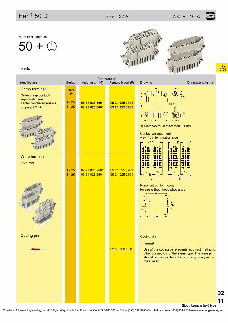
HanD / DD
02.11
Han®50D Size 32A 250 V10 A
Stockitemsinboldtype
Numberofcontacts
50+Inserts
Partnumber Identification Series Maleinsert(M) Femaleinsert(F) Drawing Dimensionsinmm
CrimpterminalOrdercrimpcontacts separately(see Technical characteristics onpage02.04)
Han D®
1-251-25
09 21 025 300109 21 025 3001
09 21 025 310109 21 025 3101
Wrapterminal1x1mm
1-251-25
09 21 025 260109 21 025 2601
09 21 025 270109 21 025 2701
1)Distanceforcontactmax.24mm
Contactarrangement viewfromterminationside
Panelcutoutforinserts forusewithouthoods/housings
Codingpin
09 33 000 9915
Codingpin
Useofthecodingpinpreventsincorrectmatingtootherconnectorsofthesametype.Themalepinshouldbeomittedfromtheopposingcavityinthemaleinsert.
Courtesy of Steven Engineering, Inc.-230 Ryan Way, South San Francisco, CA 94080-6370-Main Office: (650) 588-9200-Outside Local Area: (800) 258-9200-www.stevenengineering.com

HanD / DD
02.12
Han®24DD Size 6B 250 V10 A
Stockitemsinboldtype
Numberofcontacts
24+Inserts
Partnumber Identification Series Maleinsert(M) Femaleinsert(F) Drawing Dimensionsinmm
Crimpterminal Ordercrimpcontacts separately(see Technical characteristics onpage02.06)
Han DD®
09 16 024 3001 09 16 024 3101
1)Distanceforcontactmax.21mm
Contactarrangement viewfromterminationside
Panelcutoutforinserts forusewithouthoods/housings
Codingpin
09 33 000 9915
Codingpin
Useofthecodingpinpreventsincorrectmatingtootherconnectorsofthesametype.Themalepinshouldbeomittedfromtheopposingcavityinthemaleinsert.
Courtesy of Steven Engineering, Inc.-230 Ryan Way, South San Francisco, CA 94080-6370-Main Office: (650) 588-9200-Outside Local Area: (800) 258-9200-www.stevenengineering.com

HanD / DD
02.13
Han®42DD Size 10B 250 V10 A
Stockitemsinboldtype
Numberofcontacts
42+Inserts
Partnumber Identification Series Maleinsert(M) Femaleinsert(F) Drawing Dimensionsinmm
CrimpterminalOrdercrimpcontacts separately(see Technical characteristics onpage02.06)
Han DD®
09 16 042 3001 09 16 042 3101
1)Distanceforcontactmax.21mm
Contactarrangement viewfromterminationside
Panelcutoutforinserts forusewithouthoods/housings
Codingpin
09 33 000 9915
Codingpin
Useofthecodingpinpreventsincorrectmatingtootherconnectorsofthesametype.Themalepinshouldbeomittedfromtheopposingcavityinthemaleinsert.
Courtesy of Steven Engineering, Inc.-230 Ryan Way, South San Francisco, CA 94080-6370-Main Office: (650) 588-9200-Outside Local Area: (800) 258-9200-www.stevenengineering.com

HanD / DD
02.14
Han®40D Size 16B 250 V10 A
Stockitemsinboldtype
Numberofcontacts
40+Inserts
Partnumber Identification Series Maleinsert(M) Femaleinsert(F) Drawing Dimensionsinmm
Crimpterminal Ordercrimpcontacts separately(see Technical characteristics onpage02.04)
Han D®
09 21 040 3001 09 21 040 3101
Wrapterminal 1x1mm
09 21 040 2601 09 21 040 2701
1)Distanceforcontactmax.21mm
Contactarrangement viewfromterminationside
Panelcutoutforinserts forusewithouthoods/housings
Codingpin
09 33 000 9915
Codingpin
Useofthecodingpinpreventsincorrectmatingtootherconnectorsofthesametype.Themalepinshouldbeomittedfromtheopposingcavityinthemaleinsert.
Courtesy of Steven Engineering, Inc.-230 Ryan Way, South San Francisco, CA 94080-6370-Main Office: (650) 588-9200-Outside Local Area: (800) 258-9200-www.stevenengineering.com

HanD / DD
02.15
Han®72DD Size 16B 250 V10 A
Stockitemsinboldtype
Numberofcontacts
72+Inserts
Partnumber Identification Series Maleinsert(M) Femaleinsert(F) Drawing Dimensionsinmm
CrimpterminalOrdercrimpcontacts separately(see Technical characteristics onpage02.06)
Han DD®
09 16 072 3001 09 16 072 3101
1)Distanceforcontactmax.21mm
Contactarrangement viewfromterminationside
Panelcutoutforinserts forusewithouthoods/housings
Codingpin
09 33 000 9915
Codingpin
Useofthecodingpinpreventsincorrectmatingtootherconnectorsofthesametype.Themalepinshouldbeomittedfromtheopposingcavityinthemaleinsert.
Courtesy of Steven Engineering, Inc.-230 Ryan Way, South San Francisco, CA 94080-6370-Main Office: (650) 588-9200-Outside Local Area: (800) 258-9200-www.stevenengineering.com

HanD / DD
02.16
Han®64D Size 24B 250 V10 A
Stockitemsinboldtype
Numberofcontacts
64+Inserts
Partnumber Identification Series Maleinsert(M) Femaleinsert(F) Drawing Dimensionsinmm
Crimpterminal Ordercrimpcontacts separately(see Technical characteristics onpage02.04)
Han D®
09 21 064 3001 09 21 064 3101
Wrapterminal 1x1mm
09 21 064 2601 09 21 064 2701
1)Distanceforcontactmax.21mm
Contactarrangement viewfromterminationside
Panelcutoutforinserts forusewithouthoods/housings
Codingpin
09 33 000 9915
Codingpin
Useofthecodingpinpreventsincorrectmatingtootherconnectorsofthesametype.Themalepinshouldbeomittedfromtheopposingcavityinthemaleinsert.
Courtesy of Steven Engineering, Inc.-230 Ryan Way, South San Francisco, CA 94080-6370-Main Office: (650) 588-9200-Outside Local Area: (800) 258-9200-www.stevenengineering.com

HanD / DD
02.17
Han®108DD Size 24B 250 V10 A
Stockitemsinboldtype
Numberofcontacts
108+Inserts
Partnumber Identification Series Maleinsert(M) Femaleinsert(F) Drawing Dimensionsinmm
CrimpterminalOrdercrimpcontacts separately(see Technical characteristics onpage02.06)
Han DD®
09 16 108 3001 09 16 108 3101
1)Distanceforcontactmax.21mm
Contactarrangement viewfromterminationside
Panelcutoutforinserts forusewithouthoods/housings
Codingpin
09 33 000 9915
Codingpin
Useofthecodingpinpreventsincorrectmatingtootherconnectorsofthesametype.Themalepinshouldbeomittedfromtheopposingcavityinthemaleinsert.
Courtesy of Steven Engineering, Inc.-230 Ryan Way, South San Francisco, CA 94080-6370-Main Office: (650) 588-9200-Outside Local Area: (800) 258-9200-www.stevenengineering.com

HanD / DD
02.18
Han®80D Size 32B 250 V10 A
Stockitemsinboldtype
Numberofcontacts
80+Inserts
Partnumber Identification Series Maleinsert(M) Femaleinsert(F) Drawing Dimensionsinmm
Crimpterminal Ordercrimpcontacts separately(see Technical characteristics onpage02.04)
Han D®
1-401-40
09 21 040 300109 21 040 3001
09 21 040 310109 21 040 3101
Wrapterminal 1x1mm
1-401-40
09 21 040 260109 21 040 2601
09 21 040 270109 21 040 2701
1)Distanceforcontactmax.21mm
Contactarrangement viewfromterminationside
Panelcutoutforinserts forusewithouthoods/housings
Codingpin
09 33 000 9915
Codingpin
Useofthecodingpinpreventsincorrectmatingtootherconnectorsofthesametype.Themalepinshouldbeomittedfromtheopposingcavityinthemaleinsert.
Courtesy of Steven Engineering, Inc.-230 Ryan Way, South San Francisco, CA 94080-6370-Main Office: (650) 588-9200-Outside Local Area: (800) 258-9200-www.stevenengineering.com

HanD / DD
02.19
Han®144DD Size 32B 250 V10 A
Stockitemsinboldtype
Numberofcontacts
144+Inserts
Partnumber Identification Series Maleinsert(M) Femaleinsert(F) Drawing Dimensionsinmm
CrimpterminalOrdercrimpcontacts separately(see Technical characteristics onpage02.06)
Han DD®
1-7273-144
09 16 072 300109 16 072 3011
09 16 072 310109 16 072 3111
1)Distanceforcontactmax.21mm
Contactarrangement viewfromterminationside
Panelcutoutforinserts forusewithouthoods/housings
Codingpin
09 33 000 9915
Codingpin
Useofthecodingpinpreventsincorrectmatingtootherconnectorsofthesametype.Themalepinshouldbeomittedfromtheopposingcavityinthemaleinsert.
Courtesy of Steven Engineering, Inc.-230 Ryan Way, South San Francisco, CA 94080-6370-Main Office: (650) 588-9200-Outside Local Area: (800) 258-9200-www.stevenengineering.com

HanD / DD
02.20
Han®128D Size 48B 250 V10 A
Stockitemsinboldtype
Numberofcontacts
128+Inserts
Partnumber Identification Series Maleinsert(M) Femaleinsert(F) Drawing Dimensionsinmm
Crimpterminal Ordercrimpcontacts separately(see Technical characteristics onpage02.04)
Han D®
1-641-64
09 21 064 300109 21 064 3001
09 21 064 310109 21 064 3101
Wrapterminal 1x1mm
1-641-64
09 21 064 260109 21 064 2601
09 21 064 270109 21 064 2701
1)Distanceforcontactmax.21mm
Contactarrangement viewfromterminationside
Panelcutoutforinserts forusewithouthoods/housings
Codingpin
09 33 000 9915
Codingpin
Useofthecodingpinpreventsincorrectmatingtootherconnectorsofthesametype.Themalepinshouldbeomittedfromtheopposingcavityinthemaleinsert.
Courtesy of Steven Engineering, Inc.-230 Ryan Way, South San Francisco, CA 94080-6370-Main Office: (650) 588-9200-Outside Local Area: (800) 258-9200-www.stevenengineering.com

HanD / DD
02.21
Han®216DD Size 48B 250 V10 A
Stockitemsinboldtype
Numberofcontacts
216+Inserts
Partnumber Identification Series Maleinsert(M) Femaleinsert(F) Drawing Dimensionsinmm
CrimpterminalOrdercrimpcontacts separately(see Technical characteristics onpage02.06)
Han DD®
1-108109-216
09 16 108 300109 16 108 3011
09 16 108 310109 16 108 3111
1)Distanceforcontactmax.21mm
Contactarrangement viewfromterminationside
Panelcutoutforinserts forusewithouthoods/housings
Codingpin
09 33 000 9915
Codingpin
Useofthecodingpinpreventsincorrectmatingtootherconnectorsofthesametype.Themalepinshouldbeomittedfromtheopposingcavityinthemaleinsert.
Courtesy of Steven Engineering, Inc.-230 Ryan Way, South San Francisco, CA 94080-6370-Main Office: (650) 588-9200-Outside Local Area: (800) 258-9200-www.stevenengineering.com
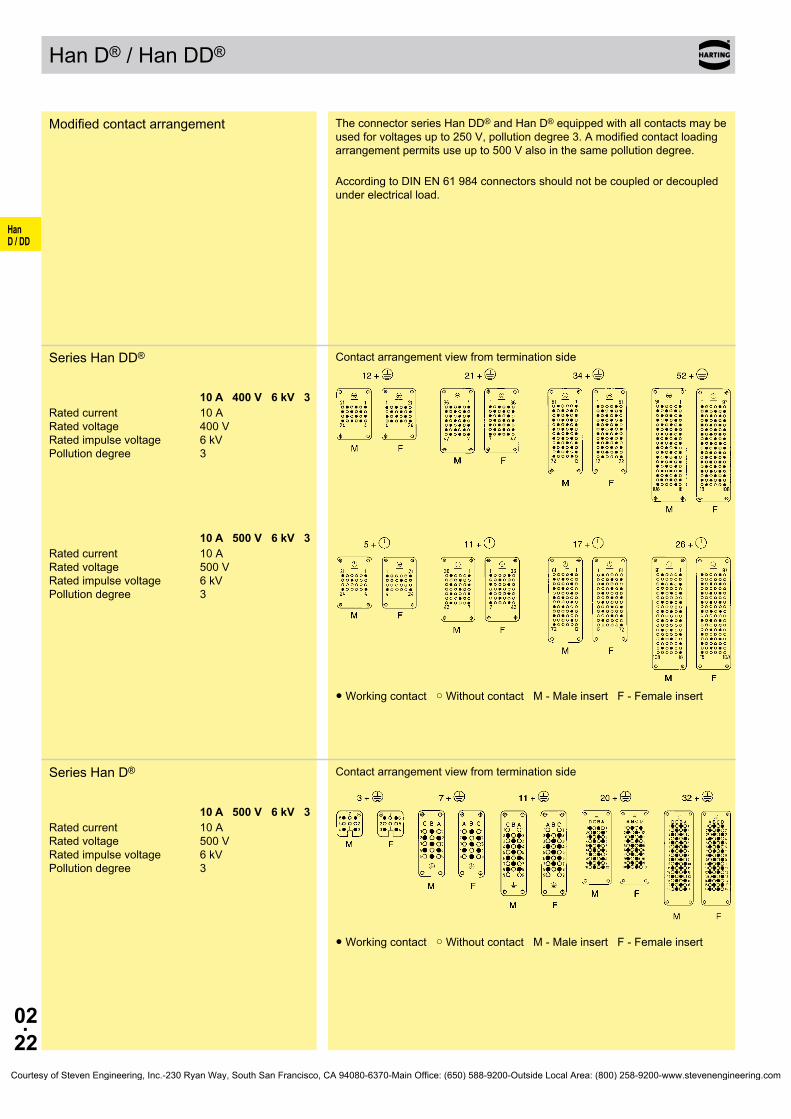
HanD / DD
02.22
Han D®/HanDD®
Modifiedcontactarrangement TheconnectorseriesHanDD®andHanD®equippedwithallcontactsmaybeusedforvoltagesupto250V,pollutiondegree3.Amodifiedcontactloadingarrangementpermitsuseupto500Valsointhesamepollutiondegree.
AccordingtoDINEN61984connectorsshouldnotbecoupledordecoupledunderelectricalload.
SeriesHanDD®
10 A 400 V 6 kV 3Ratedcurrent 10A Ratedvoltage 400V Ratedimpulsevoltage 6kV Pollutiondegree 3
Contactarrangementviewfromterminationside
10 A 500 V 6 kV 3Ratedcurrent 10A Ratedvoltage 500V Ratedimpulsevoltage 6kV Pollutiondegree 3
●Workingcontact○WithoutcontactM-MaleinsertF-Femaleinsert
SeriesHanD®
10 A 500 V 6 kV 3Ratedcurrent 10A Ratedvoltage 500V Ratedimpulsevoltage 6kV Pollutiondegree 3
Contactarrangementviewfromterminationside
●Workingcontact○WithoutcontactM-MaleinsertF-Femaleinsert
Courtesy of Steven Engineering, Inc.-230 Ryan Way, South San Francisco, CA 94080-6370-Main Office: (650) 588-9200-Outside Local Area: (800) 258-9200-www.stevenengineering.com

HanD / DD
02.23
Accessories
Stockitemsinboldtype
Han®PCBAdapter
Identification Partnumber Drawing Dimensionsinmm
PCBAdapter(contactsincluded) canbeusedincombinationwithallHanDD® inserts
forPCB:
Partnumber a
09160009905 1.6
09160009908 2.4
upto1.6mm 09 16 000 9905
upto2.4mm 09 16 000 9908
Han DD®
Malecontact
09 15 000 6191
Femalecontact
09 15 000 6291
ApplicationThePCBadapterisusedtoterminatecontrolanddatalinesviapcbtotheabo-vementionedconnectorinserts.
➀PCBadapter ➁Printedcircuitboard(PCB) ➂Switchboardpanel ➃HanDD®doublecontact ➄HanDD® insert ➅Han®Bbulkheadmountedhousing
1)forHan®BEMChousingsspacingof12.5±0.2mmisnecessaryasnoflangesealisused
Courtesy of Steven Engineering, Inc.-230 Ryan Way, South San Francisco, CA 94080-6370-Main Office: (650) 588-9200-Outside Local Area: (800) 258-9200-www.stevenengineering.com

HanD / DD
02.24
Notes
Courtesy of Steven Engineering, Inc.-230 Ryan Way, South San Francisco, CA 94080-6370-Main Office: (650) 588-9200-Outside Local Area: (800) 258-9200-www.stevenengineering.com

03.01
HanE / EE
Han E® / Han® EE / Han® EEE / Han® ES / Han® ESS
Contents Page
Technical characteristics Han E® . . . . . . . . . . . . . . . . . . . . . . . . . . . . . . . . . 03.02
Technical characteristics Han® EE . . . . . . . . . . . . . . . . . . . . . . . . . . . . . . . 03.04
Technical characteristics Han® EEE . . . . . . . . . . . . . . . . . . . . . . . . . . . . . . 03.06
Technical characteristics Han® ES . . . . . . . . . . . . . . . . . . . . . . . . . . . . . . . 03.08
Technical characteristics Han® ESS . . . . . . . . . . . . . . . . . . . . . . . . . . . . . . 03.10
Han® 6 E / Han® 6 ES / Han® 6 ESS . . . . . . . . . . . . . . . . . . . . . . . . . . . . . . 03.12
Han® 10 EE . . . . . . . . . . . . . . . . . . . . . . . . . . . . . . . . . . . . . . . . . . . . . . . . . 03.13
Han® 10 E / Han® 10 ES / Han® 10 ESS . . . . . . . . . . . . . . . . . . . . . . . . . . . 03.14
Han® 18 EE . . . . . . . . . . . . . . . . . . . . . . . . . . . . . . . . . . . . . . . . . . . . . . . . . 03.15
Han® 16 E / Han® 16 ES / Han® 16 ESS . . . . . . . . . . . . . . . . . . . . . . . . . . . 03.16
Han® 32 EE . . . . . . . . . . . . . . . . . . . . . . . . . . . . . . . . . . . . . . . . . . . . . . . . . 03.17
Han® 40 EEE . . . . . . . . . . . . . . . . . . . . . . . . . . . . . . . . . . . . . . . . . . . . . . . . 03.18
Han® 24 E / Han® 24 ES / Han® 24 ESS . . . . . . . . . . . . . . . . . . . . . . . . . . . 03.19
Han® 46 EE . . . . . . . . . . . . . . . . . . . . . . . . . . . . . . . . . . . . . . . . . . . . . . . . . 03.20
Han® 64 EEE . . . . . . . . . . . . . . . . . . . . . . . . . . . . . . . . . . . . . . . . . . . . . . . . 03.21
Han® 32 E / Han® 32 ES / Han® 32 ESS . . . . . . . . . . . . . . . . . . . . . . . . . . . 03.22
Han® 64 EE . . . . . . . . . . . . . . . . . . . . . . . . . . . . . . . . . . . . . . . . . . . . . . . . . 03.23
Han® 48 E / Han® 48 ES / Han® 48 ESS . . . . . . . . . . . . . . . . . . . . . . . . . . . 03.24
Han® 92 EE . . . . . . . . . . . . . . . . . . . . . . . . . . . . . . . . . . . . . . . . . . . . . . . . . 03.25
Han® EE Modified contact arrangements . . . . . . . . . . . . . . . . . . . . . . . . . . 03.26
Courtesy of Steven Engineering, Inc.-230 Ryan Way, South San Francisco, CA 94080-6370-Main Office: (650) 588-9200-Outside Local Area: (800) 258-9200-www.stevenengineering.com

03.02
HanE / EE
Han E® Technical characteristics
Features• Availableindifferentterminationtechniques
• HanE® Crimpterminal • HanE® Screwterminal • Han®ES Cage-clampterminal • Han®ESS Cage-clampterminal • Han®EE Crimpterminal • Han®EEE Crimpterminal• HanE®coversawiderangeofcrosscoresections• WireprotectionforHanE® screw
Specifications DIN EN 60 664-1 DIN EN 61 984
Approvals ,
InsertsNumberofcontacts 6,10,16,24,32(2x16),
48(2x24)+PE
Electricaldata acc.toEN61984 16 A 500 V 6 kV 3 Ratedcurrent 16ARatedvoltage 500VRatedimpulsevoltage 6kVPollutiondegree 3Pollutiondegree2also 16A400/690V6kV2
Ratedvoltage acc.toUL/CSA 600VInsulationresistance ≥1010ΩMaterial polycarbonateLimitingtemperatures -40°C...+125°CFlammabilityacc.toUL94 V0Mechanicalworkinglife -matingcycles ≥500
ContactsMaterial copperalloySurface-hard-goldplated 2µmAuover3µmNiSurface-hard-silverplated 3µmAgContactresistance ≤1mΩCrimpterminal-min 0.14mm²/AWG26Crimpterminal-max 4mm²/AWG12Screwterminal-min 0.14mm²/AWG26Screwterminal-max 2.5mm²/AWG14Tightening/testtorque 0.5NmStrippinglength 7mm
Hoods/HousingsMaterial aluminiumdie-castSurface powder-coatedLockingelement Han-EasyLock®
Flammabilityacc.toUL94 V0Hoods/Housingsseal NBRLimitingtemperatures -40°C...+125°CDegreeofprotectionacc.toDINEN60529 forcoupledconnector IP65
Furtherselectionofhoods/housingsseechapter30/chapter31
AccessoriesCrimpingtools chapter99Cableclamps chapter40Codingofhoods/housings chapter40Labelacc.toCSA-approval chapter40Han-Snap® chapter11Assemblyplatesfortestconnector chapter40Specialinsertfixingscrews chapter40
Courtesy of Steven Engineering, Inc.-230 Ryan Way, South San Francisco, CA 94080-6370-Main Office: (650) 588-9200-Outside Local Area: (800) 258-9200-www.stevenengineering.com
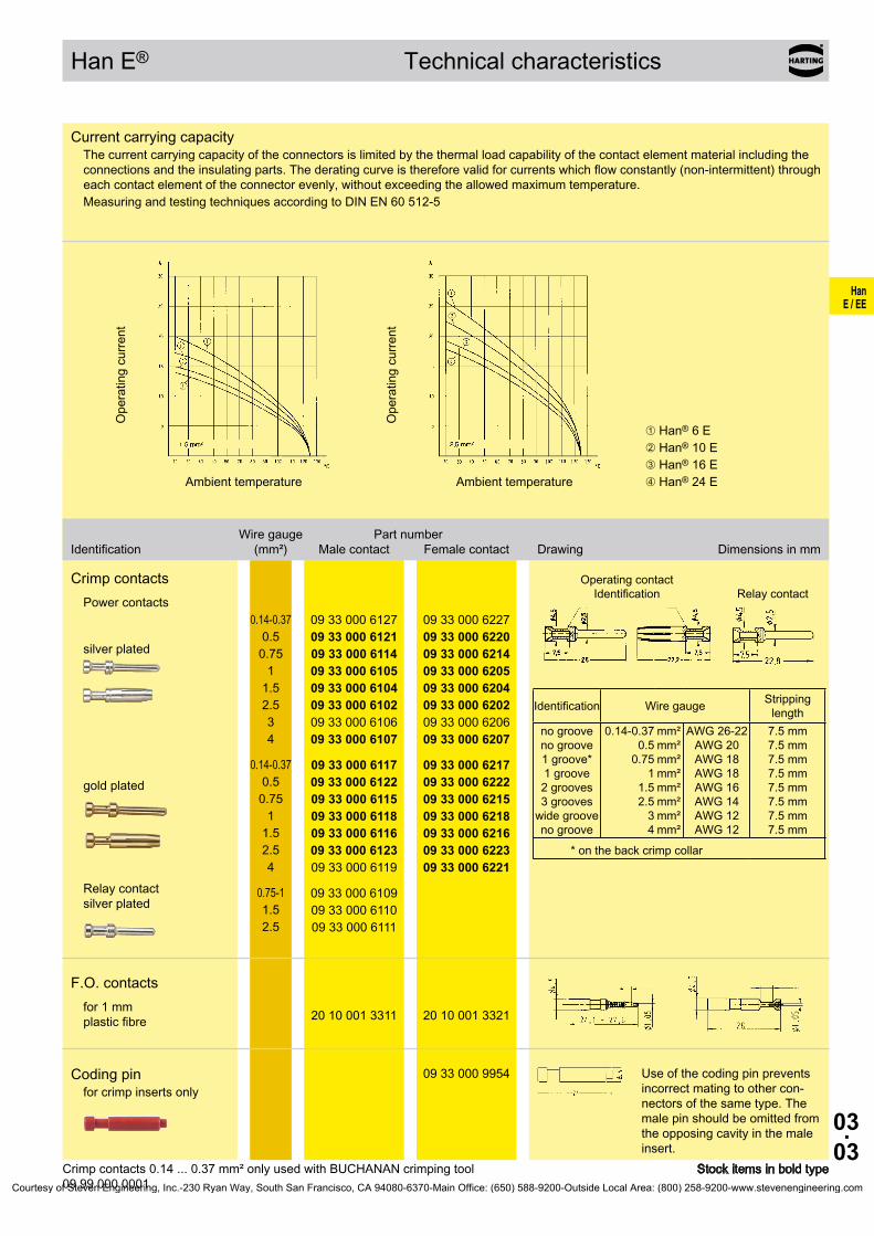
03.03
HanE / EE
mm²mm²mm²mm²mm²mm²mm²mm²
AWG26-22AWG20AWG18AWG18AWG16AWG14AWG12AWG12
09 33 000 612709 33 000 612109 33 000 611409 33 000 610509 33 000 610409 33 000 610209 33 000 610609 33 000 6107
09 33 000 622709 33 000 622009 33 000 621409 33 000 620509 33 000 620409 33 000 620209 33 000 620609 33 000 6207
09 33 000 611709 33 000 612209 33 000 611509 33 000 611809 33 000 611609 33 000 612309 33 000 6119
09 33 000 621709 33 000 622209 33 000 621509 33 000 621809 33 000 621609 33 000 622309 33 000 6221
09 33 000 610909 33 000 611009 33 000 6111
20 10 001 3311 20 10 001 3321
09 33 000 9954
Han E® Technical characteristics
Crimpcontacts0.14...0.37mm²onlyusedwithBUCHANANcrimpingtool 09 99 000 0001
CurrentcarryingcapacityThecurrentcarryingcapacityoftheconnectorsislimitedbythethermalloadcapabilityofthecontactelementmaterialincludingtheconnectionsandtheinsulatingparts.Thederatingcurveisthereforevalidforcurrentswhichflowconstantly(non-intermittent)througheachcontactelementoftheconnectorevenly,withoutexceedingtheallowedmaximumtemperature.MeasuringandtestingtechniquesaccordingtoDINEN60512-5
Operatingcurre
nt
Ambienttemperature
Operatingcurre
nt
Ambienttemperature
➀Han® 6 E➁Han® 10 E➂Han® 16 E➃Han®24E
Wiregauge Partnumber Identification (mm²) Malecontact Femalecontact Drawing Dimensionsinmm
Crimpcontacts Powercontacts
Operatingcontact Identification Relaycontact
Identification Wiregauge Strippinglength
nogroovenogroove1groove*1groove2grooves3grooveswidegroovenogroove
0.14-0.370.50.75
11.52.534
7.5mm7.5mm7.5mm7.5mm7.5mm7.5mm7.5mm7.5mm
*onthebackcrimpcollar
silverplated
0.14-0.370.50.75
11.52.534
goldplated 0.14-0.370.50.75
11.52.54
Relaycontact silverplated
0.75-11.52.5
F.O.contacts for1mm plasticfibre
Codingpinforcrimpinsertsonly
Useofthecodingpinpreventsincorrectmatingtoothercon-nectorsofthesametype.Themalepinshouldbeomittedfromtheopposingcavityinthemaleinsert.
StockitemsinboldtypeCourtesy of Steven Engineering, Inc.-230 Ryan Way, South San Francisco, CA 94080-6370-Main Office: (650) 588-9200-Outside Local Area: (800) 258-9200-www.stevenengineering.com

03.04
HanE / EE
Han® EE Technical characteristics
Features• HanE®contactswithcrimptermination• Highdensityofcrimpingcontacts• Polarisedinsert• Contactsavailablewitheitherhardsilverplatedor
hardgoldplatedsurface• Suitableforhoods/housingsofseriesHan®B,
Han® M, Han®EMV,Han®HPR
Specifications DIN EN 60 664-1 DIN EN 61 984
Approvals ,
InsertsNumberofcontacts 10,18,32,46,64(2x32),
92(2x46)+PE
Electricaldata acc.toEN61984 16 A 500 V 6 kV 3 Ratedcurrent 16ARatedvoltage 500VRatedimpulsevoltage 6kVPollutiondegree 3Pollutiondegree2also 16A830V8kV2
Ratedvoltage acc.toUL/CSA 600VInsulationresistance ≥1010ΩMaterial polycarbonateLimitingtemperatures -40°C...+125°CFlammabilityacc.toUL94 V0Mechanicalworkinglife -matingcycles ≥500
ContactsMaterial copperalloySurface-hard-goldplated 2µmAuover3µmNiSurface-hard-silverplated 3µmAgContactresistance ≤1mΩCrimpterminal-min 0.14mm²/AWG26Crimpterminal-max 4mm²/AWG12
Hoods/HousingsMaterial aluminiumdie-castSurface powder-coatedLockingelement Han-EasyLock®
Flammabilityacc.toUL94 V0Hoods/Housingsseal NBRLimitingtemperatures -40°C...+125°CDegreeofprotectionacc.toDINEN60529 forcoupledconnector IP65
Furtherselectionofhoods/housingsseechapter30/chapter31
AccessoriesCrimpingtools chapter99Cableclamps chapter40Codingofhoods/housings chapter40Labelacc.toCSA-approval chapter40Han-Snap® chapter11Assemblyplatesfortestconnector chapter40Specialinsertfixingscrews chapter40
Courtesy of Steven Engineering, Inc.-230 Ryan Way, South San Francisco, CA 94080-6370-Main Office: (650) 588-9200-Outside Local Area: (800) 258-9200-www.stevenengineering.com

03.05
HanE / EE
mm²mm²mm²mm²mm²mm²mm²mm²
AWG26-22AWG20AWG18AWG18AWG16AWG14AWG12AWG12
09 33 000 612709 33 000 612109 33 000 611409 33 000 610509 33 000 610409 33 000 610209 33 000 610609 33 000 6107
09 33 000 622709 33 000 622009 33 000 621409 33 000 620509 33 000 620409 33 000 620209 33 000 620609 33 000 6207
09 33 000 611709 33 000 612209 33 000 611509 33 000 611809 33 000 611609 33 000 612309 33 000 6119
09 33 000 621709 33 000 622209 33 000 621509 33 000 621809 33 000 621609 33 000 622309 33 000 6221
09 33 000 610909 33 000 611009 33 000 6111
20 10 001 3311 20 10 001 3321
09 33 000 9954
Han® EE Technical characteristics
Crimpcontacts0.14...0.37mm²onlyusedwithBUCHANANcrimpingtool 09 99 000 0001
CurrentcarryingcapacityThecurrentcarryingcapacityoftheconnectorsislimitedbythethermalloadcapabilityofthecontactelementmaterialincludingtheconnectionsandtheinsulatingparts.Thederatingcurveisthereforevalidforcurrentswhichflowconstantly(non-intermittent)througheachcontactelementoftheconnectorevenly,withoutexceedingtheallowedmaximumtemperature.MeasuringandtestingtechniquesaccordingtoDINEN60512-5
Operatingcurre
nt
Ambienttemperature
Operatingcurre
nt
Ambienttemperature
➀Han® 10 EE➁Han® 18 EE➂Han®32EE➃Han® 46 EE
Wiregauge Partnumber Identification (mm²) Malecontact Femalecontact Drawing Dimensionsinmm
Crimpcontacts Powercontacts
Operatingcontact Identification Relaycontact
Identification Wiregauge Strippinglength
nogroovenogroove1groove*1groove2grooves3grooveswidegroovenogroove
0.14-0.370.50.75
11.52.534
7.5mm7.5mm7.5mm7.5mm7.5mm7.5mm7.5mm7.5mm
*onthebackcrimpcollar
silverplated
0.14-0.370.50.75
11.52.534
goldplated 0.14-0.370.50.75
11.52.54
Relaycontact silverplated
0.75-11.52.5
F.O.contacts for1mm plasticfibre
Codingpinforcrimpinsertsonly
Useofthecodingpinpreventsincorrectmatingtoothercon-nectorsofthesametype.Themalepinshouldbeomittedfromtheopposingcavityinthemaleinsert.
StockitemsinboldtypeCourtesy of Steven Engineering, Inc.-230 Ryan Way, South San Francisco, CA 94080-6370-Main Office: (650) 588-9200-Outside Local Area: (800) 258-9200-www.stevenengineering.com
03.06
HanE / EE
Features• HanE®contactswithcrimptermination• Polarisedinsert• Contactsavailablewitheitherhardsilverplatedor
hardgoldplatedsurface• Suitableforhoods/housingsofseriesHan®B,
Han® M, Han®EMV,Han®HPR
Specifications DIN EN 60 664-1 DIN EN 61 984
Approvals
InsertsNumberofcontacts 40,64+PE
Electricaldata acc.toEN61984 16 A 500 V 6 kV 3 Ratedcurrent 16ARatedvoltage 500VRatedimpulsevoltage 6kVPollutiondegree 3
Insulationresistance ≥1010ΩMaterial polycarbonateLimitingtemperatures -40°C...+125°CFlammabilityacc.toUL94 V0Mechanicalworkinglife -matingcycles ≥500
ContactsMaterial copperalloySurface-hard-goldplated 2µmAuover3µmNiSurface-hard-silverplated 3µmAgContactresistance ≤1mΩCrimpterminal-min 0.14mm²/AWG26Crimpterminal-max 4mm²/AWG12
Hoods/HousingsMaterial aluminiumdie-castSurface powder-coatedLockingelement Han-EasyLock®
Flammabilityacc.toUL94 V0Hoods/Housingsseal NBRLimitingtemperatures -40°C...+125°CDegreeofprotectionacc.toDINEN60529 forcoupledconnector IP65
Furtherselectionofhoods/housingsseechapter30/chapter31
AccessoriesCrimpingtools chapter99Cableclamps chapter40Codingofhoods/housings chapter40Labelacc.toCSA-approval chapter40Han-Snap® chapter11Assemblyplatesfortestconnector chapter40Specialinsertfixingscrews chapter40
Han® EEE Technical characteristics
Courtesy of Steven Engineering, Inc.-230 Ryan Way, South San Francisco, CA 94080-6370-Main Office: (650) 588-9200-Outside Local Area: (800) 258-9200-www.stevenengineering.com

03.07
HanE / EE
mm²mm²mm²mm²mm²mm²mm²mm²
AWG26-22AWG20AWG18AWG18AWG16AWG14AWG12AWG12
09 33 000 612709 33 000 612109 33 000 611409 33 000 610509 33 000 610409 33 000 610209 33 000 610609 33 000 6107
09 33 000 622709 33 000 622009 33 000 621409 33 000 620509 33 000 620409 33 000 620209 33 000 620609 33 000 6207
09 33 000 611709 33 000 612209 33 000 611509 33 000 611809 33 000 611609 33 000 612309 33 000 6119
09 33 000 621709 33 000 622209 33 000 621509 33 000 621809 33 000 621609 33 000 622309 33 000 6221
09 33 000 610909 33 000 611009 33 000 6111
20 10 001 3311 20 10 001 3321
09 33 000 9954
Crimpcontacts0.14...0.37mm²onlyusedwithBUCHANANcrimpingtool 09 99 000 0001
Wiregauge Partnumber Identification (mm²) Malecontact Femalecontact Drawing Dimensionsinmm
Crimpcontacts Powercontacts
Operatingcontact Identification Relaycontact
Identification Wiregauge Strippinglength
nogroovenogroove1groove*1groove2grooves3grooveswidegroovenogroove
0.14-0.370.50.75
11.52.534
7.5mm7.5mm7.5mm7.5mm7.5mm7.5mm7.5mm7.5mm
*onthebackcrimpcollar
silverplated
0.14-0.370.50.75
11.52.534
goldplated 0.14-0.370.50.75
11.52.54
Relaycontact silverplated
0.75-11.52.5
F.O.contacts for1mm plasticfibre
Codingpinforcrimpinsertsonly
Useofthecodingpinpreventsincorrectmatingtoothercon-nectorsofthesametype.Themalepinshouldbeomittedfromtheopposingcavityinthemaleinsert.
Stockitemsinboldtype
CurrentcarryingcapacityThecurrentcarryingcapacityoftheconnectorsislimitedbythethermalloadcapabilityofthecontactelementmaterialincludingtheconnectionsandtheinsulatingparts.Thederatingcurveisthereforevalidforcurrentswhichflowconstantly(non-intermittent)througheachcontactelementoftheconnectorevenly,withoutexceedingtheallowedmaximumtemperature.MeasuringandtestingtechniquesaccordingtoDINEN60512-5
Operatingcurre
nt
Ambienttemperature
➀Han®64EEE/1.5mm² ➁Han®64EEE/2.5mm² ➂Han®64EEE/4.0mm² ➃Han®40EEE/1.5mm² ➄Han®40EEE/2.5mm²
Han® EEE Technical characteristics
Courtesy of Steven Engineering, Inc.-230 Ryan Way, South San Francisco, CA 94080-6370-Main Office: (650) 588-9200-Outside Local Area: (800) 258-9200-www.stevenengineering.com
03.08
HanE / EE
Han® ES Technical characteristics
Features• Reliabelcageclamptermination• Nospecialtoolsrequired• Vibrationprooved
Specifications DIN EN 60 664-1 DIN EN 61 984
Approvals ,
InsertsNumberofcontacts 6,10,16,24,32(2x16),
48(2x24)+PE
Electricaldata acc.toEN61984 16 A 500 V 6 kV 3 Ratedcurrent 16ARatedvoltage 500VRatedimpulsevoltage 6kVPollutiondegree 3Pollutiondegree2also 16A400/690V6kV2
Ratedvoltage acc.toUL/CSA 600VInsulationresistance ≥1010ΩMaterial polycarbonateLimitingtemperatures -40°C...+125°CFlammabilityacc.toUL94 V0Mechanicalworkinglife -matingcycles ≥500
ContactsMaterial copperalloySurface-hard-silverplated 3µmAgContactresistance ≤1mΩCageclampterminal-min 0.14mm²/AWG26Cageclampterminal-max 2.5mm²/AWG14
Hoods/HousingsMaterial aluminiumdie-castSurface powder-coatedLockingelement Han-EasyLock®
Flammabilityacc.toUL94 V0Hoods/Housingsseal NBRLimitingtemperatures -40°C...+125°CDegreeofprotectionacc.toDINEN60529 forcoupledconnector IP65
Furtherselectionofhoods/housingsseechapter30/chapter31
AccessoriesCableclamps chapter40Codingofhoods/housings chapter40Labelacc.toCSA-approval chapter40Han-Snap® chapter11Assemblyplatesfortestconnector chapter40Specialinsertfixingscrews chapter40
Courtesy of Steven Engineering, Inc.-230 Ryan Way, South San Francisco, CA 94080-6370-Main Office: (650) 588-9200-Outside Local Area: (800) 258-9200-www.stevenengineering.com
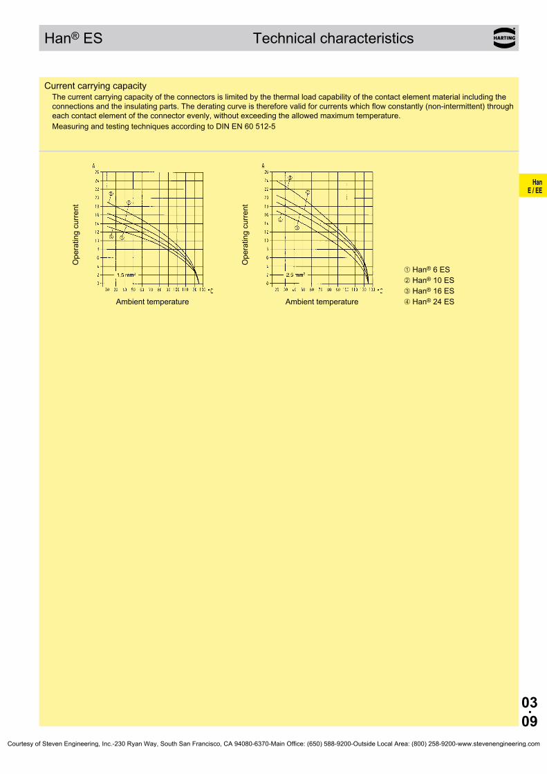
03.09
HanE / EE
Han® ES Technical characteristics
CurrentcarryingcapacityThecurrentcarryingcapacityoftheconnectorsislimitedbythethermalloadcapabilityofthecontactelementmaterialincludingtheconnectionsandtheinsulatingparts.Thederatingcurveisthereforevalidforcurrentswhichflowconstantly(non-intermittent)througheachcontactelementoftheconnectorevenly,withoutexceedingtheallowedmaximumtemperature.MeasuringandtestingtechniquesaccordingtoDINEN60512-5
Operatingcurre
nt
Ambienttemperature
Operatingcurre
nt
Ambienttemperature
➀Han® 6 ES➁Han® 10 ES➂Han® 16 ES➃Han®24ES
Courtesy of Steven Engineering, Inc.-230 Ryan Way, South San Francisco, CA 94080-6370-Main Office: (650) 588-9200-Outside Local Area: (800) 258-9200-www.stevenengineering.com

03.10
HanE / EE
Han® ESS Technical characteristics
Features• Reliabelcageclamptermination• Nospecialtoolsrequired• Vibrationprooved• 2terminationpointspercontact• Possibleforstardeltabridges
Specifications DIN EN 60 664-1 DIN EN 61 984
Approvals ,
InsertsNumberofcontacts 6,10,16,24,32(2x16),
48(2x24)+PE
Electricaldata acc.toEN61984 16 A 500 V 6 kV 3 Ratedcurrent 16ARatedvoltage 500VRatedimpulsevoltage 6kVPollutiondegree 3Pollutiondegree2also 16A400/690V6kV2
Ratedvoltage acc.toUL/CSA 600VInsulationresistance ≥1010ΩMaterial polycarbonateLimitingtemperatures -40°C...+125°CFlammabilityacc.toUL94 V0Mechanicalworkinglife -matingcycles ≥500
ContactsMaterial copperalloySurface-hard-silverplated 3µmAgContactresistance ≤1mΩCageclampterminal-min 0.14mm²/AWG26Cageclampterminal-max 2.5mm²/AWG14
Hoods/HousingsMaterial aluminiumdie-castSurface powder-coatedLockingelement Han-EasyLock®
Flammabilityacc.toUL94 V0Hoods/Housingsseal NBRLimitingtemperatures -40°C...+125°CDegreeofprotectionacc.toDINEN60529 forcoupledconnector IP65
Furtherselectionofhoods/housingsseechapter30/chapter31
AccessoriesCableclamps chapter40Codingofhoods/housings chapter40Labelacc.toCSA-approval chapter40Han-Snap® chapter11Assemblyplatesfortestconnector chapter40Specialinsertfixingscrews chapter40
Courtesy of Steven Engineering, Inc.-230 Ryan Way, South San Francisco, CA 94080-6370-Main Office: (650) 588-9200-Outside Local Area: (800) 258-9200-www.stevenengineering.com
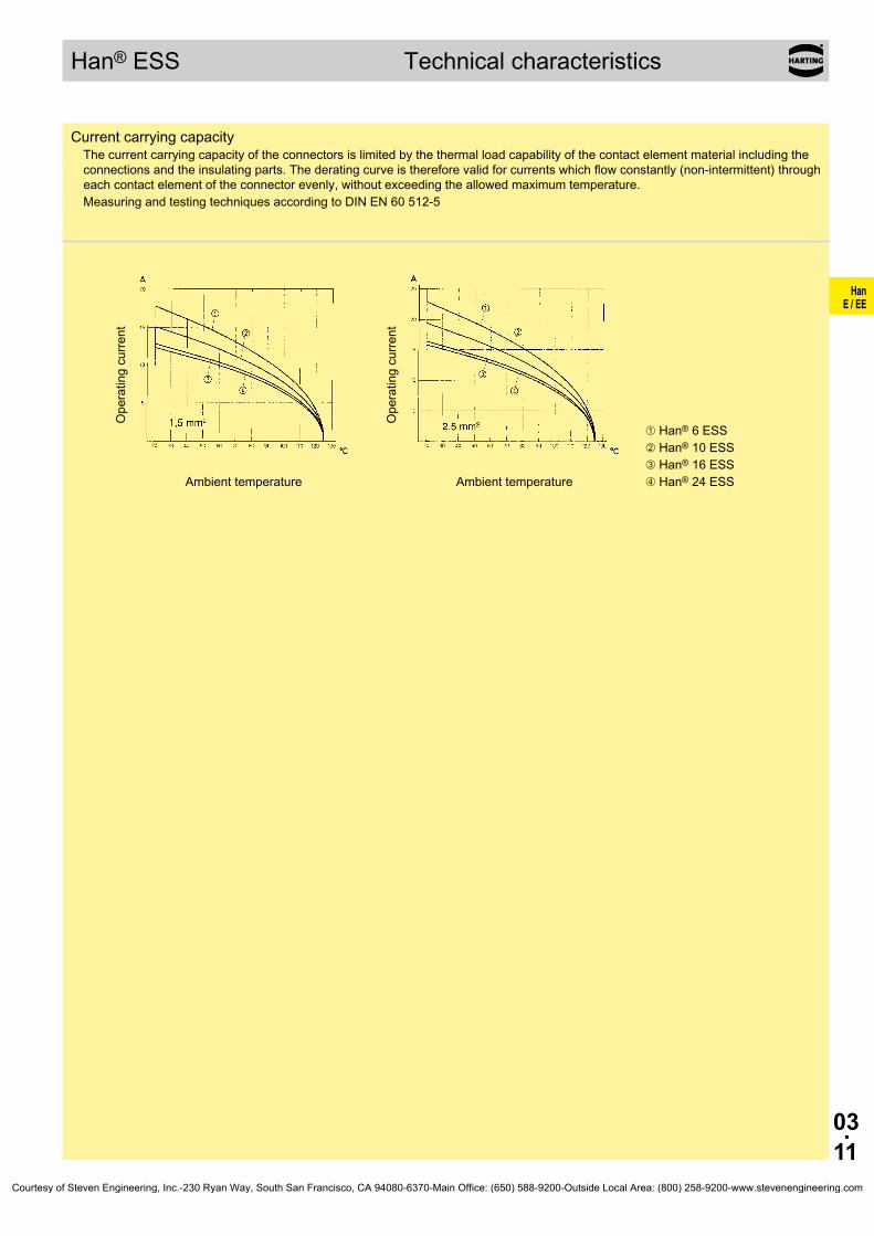
03.11
HanE / EE
Han® ESS Technical characteristics
CurrentcarryingcapacityThecurrentcarryingcapacityoftheconnectorsislimitedbythethermalloadcapabilityofthecontactelementmaterialincludingtheconnectionsandtheinsulatingparts.Thederatingcurveisthereforevalidforcurrentswhichflowconstantly(non-intermittent)througheachcontactelementoftheconnectorevenly,withoutexceedingtheallowedmaximumtemperature.MeasuringandtestingtechniquesaccordingtoDINEN60512-5
Operatingcurre
nt
Ambienttemperature
Operatingcurre
nt
Ambienttemperature
➀Han® 6 ESS➁Han® 10 ESS➂Han® 16 ESS➃Han®24ESS
Courtesy of Steven Engineering, Inc.-230 Ryan Way, South San Francisco, CA 94080-6370-Main Office: (650) 588-9200-Outside Local Area: (800) 258-9200-www.stevenengineering.com

03.12
HanE / EE
Han® 6 E Size 6B 500 V16 A
Stockitemsinboldtype
Numberofcontacts
6+Inserts
Partnumber Identification Series Maleinsert(M) Femaleinsert(F) Drawing Dimensionsinmm
CrimpterminalOrdercrimpcontacts separately(see Technical characteristics onpage03.03)
Han E®
09 33 006 2602 09 33 006 2702
Screwterminalwithwireprotection
Han E®
09 33 006 2601 09 33 006 2701
Cage-clampterminal Han® ES
09 33 006 2616 09 33 006 2716
Cage-clampterminaltwoterminalspercontact
Han® ESS
09 33 006 2672 09 33 006 2772
1)Distanceforcontactmax.21mm
a b c dHan E® screw 18 33 18 35Han®ES/HanE®crimp 19 34 19 36Han® ESS 34 49 32 49
Contactarrangement viewfromterminationside
Panelcutout
Courtesy of Steven Engineering, Inc.-230 Ryan Way, South San Francisco, CA 94080-6370-Main Office: (650) 588-9200-Outside Local Area: (800) 258-9200-www.stevenengineering.com

03.13
HanE / EE
Han® 10 EE Size 6B 500 V16 A
Stockitemsinboldtype
Numberofcontacts
10+Inserts
Partnumber Identification Series Maleinsert(M) Femaleinsert(F) Drawing Dimensionsinmm
Crimptermination Ordercrimpcontacts separately(see Technical characteristics onpage03.05)
Han® EE
09 32 010 3001 09 32 010 3101
1)Distanceforcontactmax.21mm
Contactarrangement viewfromterminationside
Panelcutout
Courtesy of Steven Engineering, Inc.-230 Ryan Way, South San Francisco, CA 94080-6370-Main Office: (650) 588-9200-Outside Local Area: (800) 258-9200-www.stevenengineering.com

03.14
HanE / EE
Han® 10 E Size 10B 500 V16 A
Stockitemsinboldtype
Numberofcontacts
10+Inserts
Partnumber Identification Series Maleinsert(M) Femaleinsert(F) Drawing Dimensionsinmm
CrimpterminalOrdercrimpcontacts separately(see Technical characteristics onpage03.03)
Han E®
09 33 010 2602 09 33 010 2702
Screwterminalwithwireprotection
Han E®
09 33 010 2601 09 33 010 2701
Cage-clampterminal Han® ES
09 33 010 2616 09 33 010 2716
Cage-clampterminaltwoterminalspercontact
Han® ESS
09 33 010 2672 09 33 010 2772
1)Distanceforcontactmax.21mm
a b c dHan E® screw 18 33 18 35Han®ES/HanE®crimp 19 34 19 36Han® ESS 34 49 32 49
Contactarrangement viewfromterminationside
Panelcutout
Courtesy of Steven Engineering, Inc.-230 Ryan Way, South San Francisco, CA 94080-6370-Main Office: (650) 588-9200-Outside Local Area: (800) 258-9200-www.stevenengineering.com

03.15
HanE / EE
Han® 18 EE Size 10B 500 V16 A
Stockitemsinboldtype
Numberofcontacts
18+Inserts
Partnumber Identification Series Maleinsert(M) Femaleinsert(F) Drawing Dimensionsinmm
Crimptermination Ordercrimpcontacts separately(see Technical characteristics onpage03.05)
Han® EE
09 32 018 3001 09 32 018 3101
1)Distanceforcontactmax.21mm
Contactarrangement viewfromterminationside
Panelcutout
Courtesy of Steven Engineering, Inc.-230 Ryan Way, South San Francisco, CA 94080-6370-Main Office: (650) 588-9200-Outside Local Area: (800) 258-9200-www.stevenengineering.com
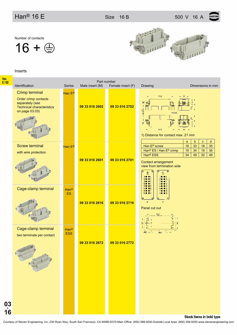
03.16
HanE / EE
Han® 16 E Size 16B 500 V16 A
Stockitemsinboldtype
Numberofcontacts
16+Inserts
Partnumber Identification Series Maleinsert(M) Femaleinsert(F) Drawing Dimensionsinmm
CrimpterminalOrdercrimpcontacts separately(see Technical characteristics onpage03.03)
Han E®
09 33 016 2602 09 33 016 2702
Screwterminalwithwireprotection
Han E®
09 33 016 2601 09 33 016 2701
Cage-clampterminal Han® ES
09 33 016 2616 09 33 016 2716
Cage-clampterminaltwoterminalspercontact
Han® ESS
09 33 016 2672 09 33 016 2772
1)Distanceforcontactmax.21mm
a b c dHan E® screw 18 33 18 35Han®ES/HanE®crimp 19 34 19 36Han® ESS 34 49 32 49
Contactarrangement viewfromterminationside
Panelcutout
Courtesy of Steven Engineering, Inc.-230 Ryan Way, South San Francisco, CA 94080-6370-Main Office: (650) 588-9200-Outside Local Area: (800) 258-9200-www.stevenengineering.com
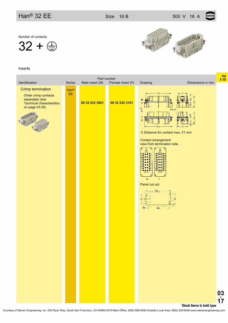
03.17
HanE / EE
Han®32EE Size 16B 500 V16 A
Stockitemsinboldtype
Numberofcontacts
32+Inserts
Partnumber Identification Series Maleinsert(M) Femaleinsert(F) Drawing Dimensionsinmm
Crimptermination Ordercrimpcontacts separately(see Technical characteristics onpage03.05)
Han® EE
09 32 032 3001 09 32 032 3101
1)Distanceforcontactmax.21mm
Contactarrangement viewfromterminationside
Panelcutout
Courtesy of Steven Engineering, Inc.-230 Ryan Way, South San Francisco, CA 94080-6370-Main Office: (650) 588-9200-Outside Local Area: (800) 258-9200-www.stevenengineering.com
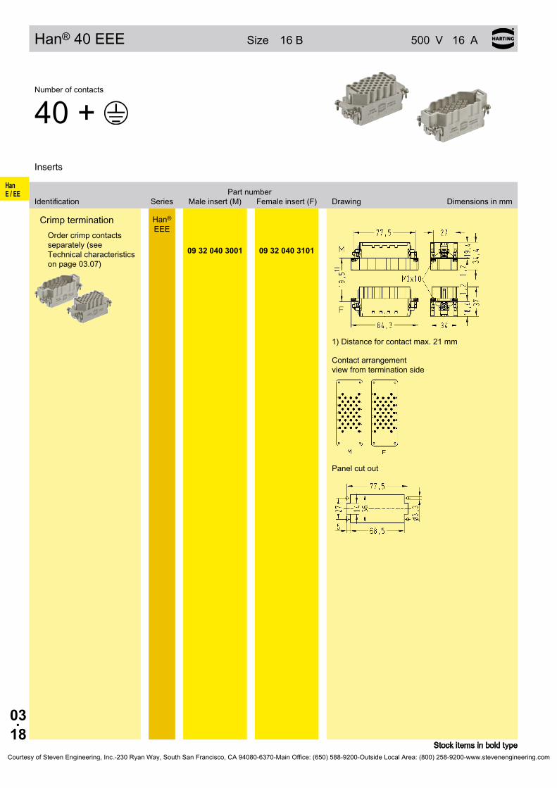
03.18
HanE / EE
Han® 40 EEE Size 16B 500 V16 A
Stockitemsinboldtype
Numberofcontacts
40+Inserts
Partnumber Identification Series Maleinsert(M) Femaleinsert(F) Drawing Dimensionsinmm
Crimptermination Ordercrimpcontacts separately(see Technical characteristics onpage03.07)
Han® EEE
09 32 040 3001 09 32 040 3101
1)Distanceforcontactmax.21mm
Contactarrangement viewfromterminationside
Panelcutout
Courtesy of Steven Engineering, Inc.-230 Ryan Way, South San Francisco, CA 94080-6370-Main Office: (650) 588-9200-Outside Local Area: (800) 258-9200-www.stevenengineering.com

03.19
HanE / EE
Han®24E Size 24B 500 V16 A
Stockitemsinboldtype
Numberofcontacts
24+Inserts
Partnumber Identification Series Maleinsert(M) Femaleinsert(F) Drawing Dimensionsinmm
CrimpterminalOrdercrimpcontacts separately(see Technical characteristics onpage03.03)
Han E®
09 33 024 2602 09 33 024 2702
Screwterminalwithwireprotection
Han E®
09 33 024 2601 09 33 024 2701
Cage-clampterminal Han® ES
09 33 024 2616 09 33 024 2716
Cage-clampterminaltwoterminalspercontact
Han® ESS
09 33 024 2672 09 33 024 2772
1)Distanceforcontactmax.21mm
a b c dHan E® screw 18 33 18 35Han®ES/HanE®crimp 19 34 19 36Han® ESS 34 49 32 49
Contactarrangement viewfromterminationside
Panelcutout
Courtesy of Steven Engineering, Inc.-230 Ryan Way, South San Francisco, CA 94080-6370-Main Office: (650) 588-9200-Outside Local Area: (800) 258-9200-www.stevenengineering.com
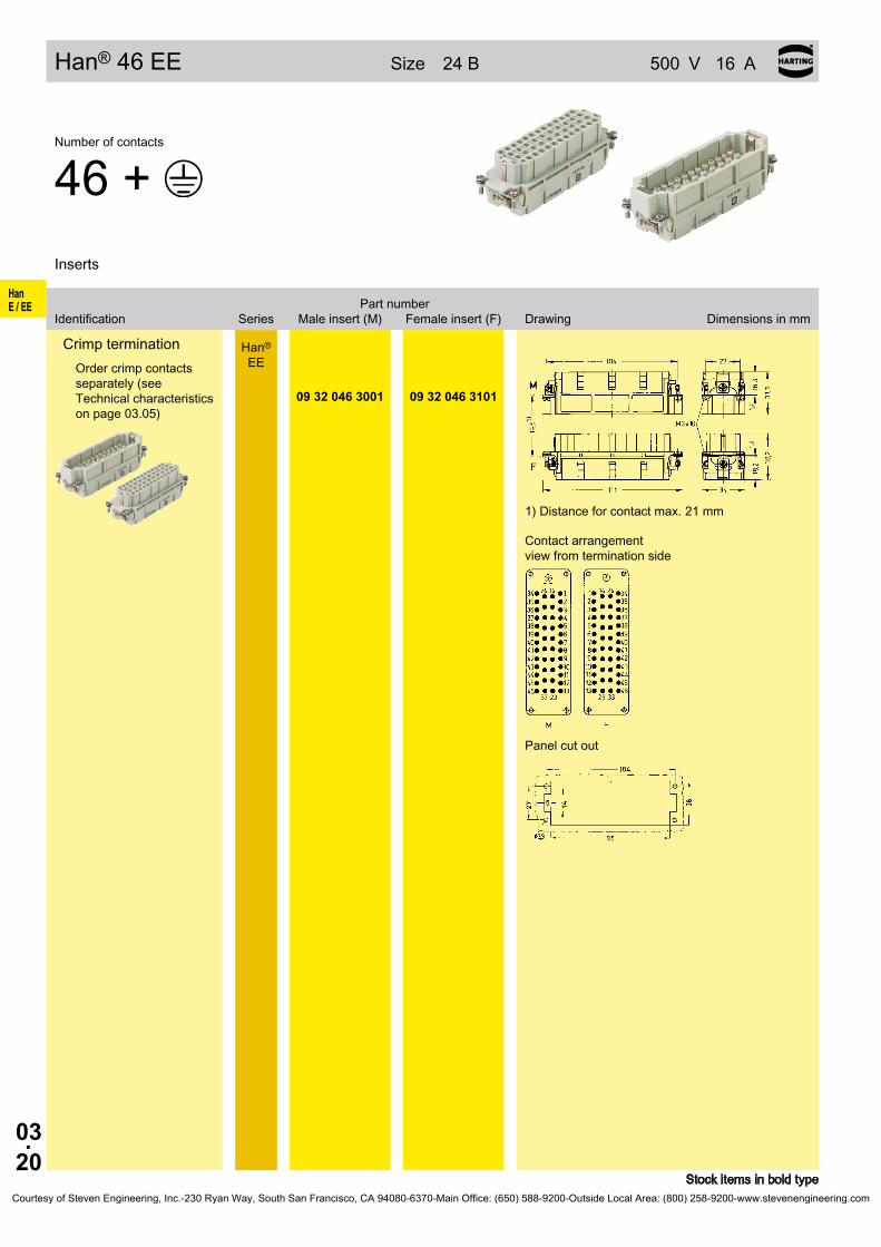
03.20
HanE / EE
Han® 46 EE Size 24B 500 V16 A
Stockitemsinboldtype
Numberofcontacts
46+Inserts
Partnumber Identification Series Maleinsert(M) Femaleinsert(F) Drawing Dimensionsinmm
Crimptermination Ordercrimpcontacts separately(see Technical characteristics onpage03.05)
Han® EE
09 32 046 3001 09 32 046 3101
1)Distanceforcontactmax.21mm
Contactarrangement viewfromterminationside
Panelcutout
Courtesy of Steven Engineering, Inc.-230 Ryan Way, South San Francisco, CA 94080-6370-Main Office: (650) 588-9200-Outside Local Area: (800) 258-9200-www.stevenengineering.com

03.21
HanE / EE
Han® 64 EEE Size 24B 500 V16 A
Stockitemsinboldtype
Numberofcontacts
64+Inserts
Partnumber Identification Series Maleinsert(M) Femaleinsert(F) Drawing Dimensionsinmm
CrimpterminationOrdercrimpcontacts separately(see Technical characteristics onpage03.07)
Han® EEE
09 32 064 3001 09 32 064 3101
1)Distanceforcontactmax.21mm
Contactarrangement viewfromterminationside
Panelcutout
Courtesy of Steven Engineering, Inc.-230 Ryan Way, South San Francisco, CA 94080-6370-Main Office: (650) 588-9200-Outside Local Area: (800) 258-9200-www.stevenengineering.com

03.22
HanE / EE
Han®32E Size 32B 500 V16 A
Stockitemsinboldtype
Numberofcontacts
32+Inserts
Partnumber Identification Series Maleinsert(M) Femaleinsert(F) Drawing Dimensionsinmm
CrimpterminalOrdercrimpcontacts separately(see Technical characteristics onpage03.03)
Han E®
1 - 1617-32
09 33 016 260209 33 016 2612
09 33 016 270209 33 016 2712
Screwterminalwithwireprotection
Han E®
1 - 1617-32
09 33 016 260109 33 016 2611
09 33 016 270109 33 016 2711
Cage-clampterminal Han® ES
1 - 1617-32
09 33 016 261609 33 016 2626
09 33 016 271609 33 016 2726
Cage-clampterminaltwoterminalspercontact
Han® ESS
1 - 161 - 16
09 33 016 267209 33 016 2672
09 33 016 277209 33 016 2772
1)Distanceforcontactmax.21mm
a b c dHan E® screw 18 33 18 35Han®ES/HanE®crimp 19 34 19 36Han® ESS 34 49 32 49
Contactarrangement viewfromterminationside
Panelcutout
Courtesy of Steven Engineering, Inc.-230 Ryan Way, South San Francisco, CA 94080-6370-Main Office: (650) 588-9200-Outside Local Area: (800) 258-9200-www.stevenengineering.com

03.23
HanE / EE
Han® 64 EE Size 32B 500 V16 A
Stockitemsinboldtype
Numberofcontacts
64+Inserts
Partnumber Identification Series Maleinsert(M) Femaleinsert(F) Drawing Dimensionsinmm
Crimptermination Ordercrimpcontacts separately(see Technical characteristics onpage03.05)
Han® EE
1-3233-64
09 32 032 300109 32 032 3011
09 32 032 310109 32 032 3111
1)Distanceforcontactmax.21mm
Contactarrangement viewfromterminationside
Panelcutout
Courtesy of Steven Engineering, Inc.-230 Ryan Way, South San Francisco, CA 94080-6370-Main Office: (650) 588-9200-Outside Local Area: (800) 258-9200-www.stevenengineering.com

03.24
HanE / EE
Han® 48 E Size 48B 500 V16 A
Stockitemsinboldtype
Numberofcontacts
48+Inserts
Partnumber Identification Series Maleinsert(M) Femaleinsert(F) Drawing Dimensionsinmm
CrimpterminalOrdercrimpcontacts separately(see Technical characteristics onpage03.03)
Han E®
1-2425-48
09 33 024 260209 33 024 2612
09 33 024 270209 33 024 2712
Screwterminalwithwireprotection
Han E®
1-2425-48
09 33 024 260109 33 024 2611
09 33 024 270109 33 024 2711
Cage-clampterminal Han® ES
1-2425-48
09 33 024 261609 33 024 2626
09 33 024 271609 33 024 2726
Cage-clampterminaltwoterminalspercontact
Han® ESS
1-241-24
09 33 024 267209 33 024 2672
09 33 024 277209 33 024 2772
1)Distanceforcontactmax.21mm
a b c dHan E® screw 18 33 18 35Han®ES/HanE®crimp 19 34 19 36Han® ESS 34 49 32 49
Contactarrangement viewfromterminationside
Panelcutout
Courtesy of Steven Engineering, Inc.-230 Ryan Way, South San Francisco, CA 94080-6370-Main Office: (650) 588-9200-Outside Local Area: (800) 258-9200-www.stevenengineering.com

03.25
HanE / EE
Han®92EE Size 48B 500 V16 A
Stockitemsinboldtype
Numberofcontacts
92+Inserts
Partnumber Identification Series Maleinsert(M) Femaleinsert(F) Drawing Dimensionsinmm
Crimptermination Ordercrimpcontacts separately(see Technical characteristics onpage03.05)
Han® EE
1 - 4647-92
09 32 046 300109 32 046 3011
09 32 046 310109 32 046 3111
1)Distanceforcontactmax.21mm
Contactarrangement viewfromterminationside
Panelcutout
Courtesy of Steven Engineering, Inc.-230 Ryan Way, South San Francisco, CA 94080-6370-Main Office: (650) 588-9200-Outside Local Area: (800) 258-9200-www.stevenengineering.com
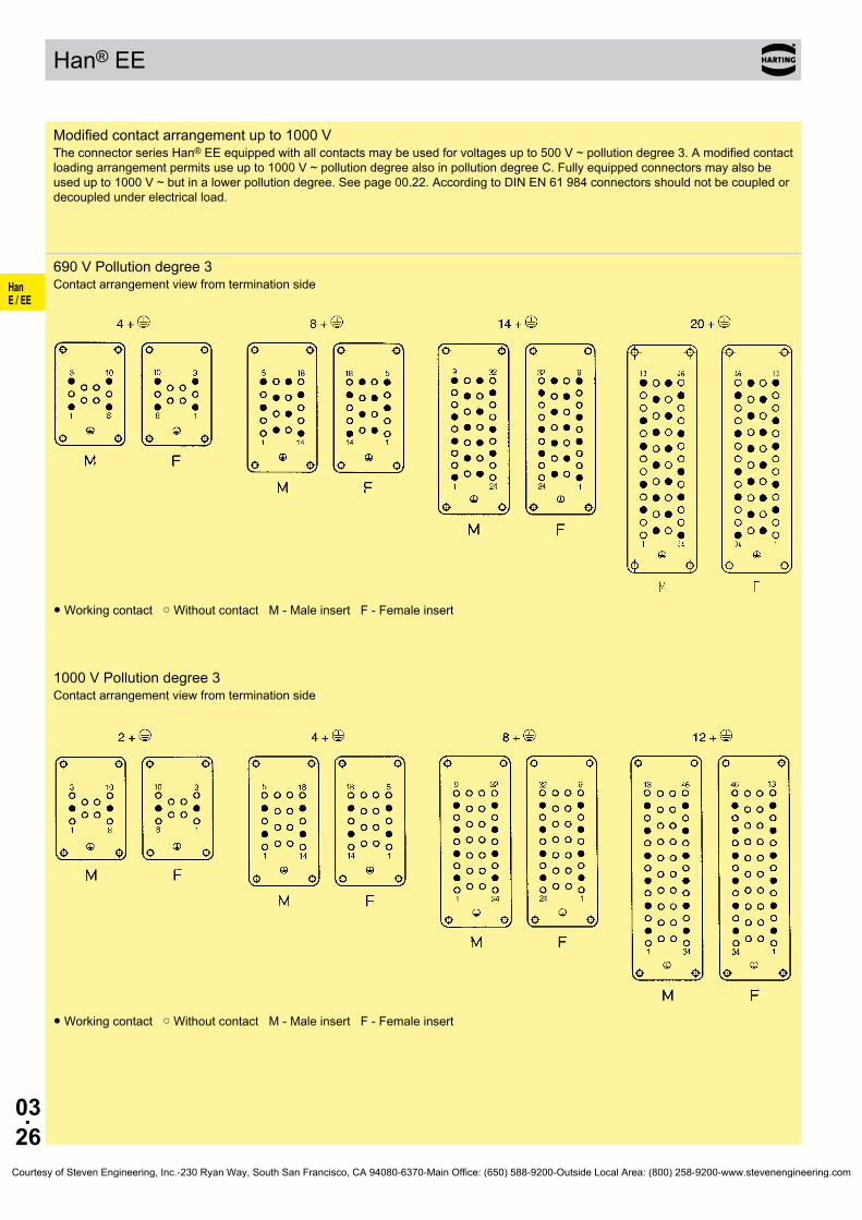
03.26
HanE / EE
Han® EE
Modifiedcontactarrangementupto1000VTheconnectorseriesHan®EEequippedwithallcontactsmaybeusedforvoltagesupto500V~pollutiondegree3.Amodifiedcontactloadingarrangementpermitsuseupto1000V~pollutiondegreealsoinpollutiondegreeC.Fullyequippedconnectorsmayalsobeusedupto1000V~butinalowerpollutiondegree.Seepage00.22.AccordingtoDINEN61984connectorsshouldnotbecoupledordecoupledunderelectricalload.
690VPollutiondegree3Contactarrangementviewfromterminationside
●Workingcontact○WithoutcontactM-MaleinsertF-Femaleinsert
1000VPollutiondegree3Contactarrangementviewfromterminationside
●Workingcontact○WithoutcontactM-MaleinsertF-Femaleinsert
Courtesy of Steven Engineering, Inc.-230 Ryan Way, South San Francisco, CA 94080-6370-Main Office: (650) 588-9200-Outside Local Area: (800) 258-9200-www.stevenengineering.com

HanHv E
04.01
Han® Hv ES / Han Hv E®
PageContents
Technical characteristics Han Hv E® . . . . . . . . . . . . . . . . . . . . . . . . . . . . . . 04.02
Technical characteristics Han® Hv ES . . . . . . . . . . . . . . . . . . . . . . . . . . . . . 04.03
Contacts Han Hv E® . . . . . . . . . . . . . . . . . . . . . . . . . . . . . . . . . . . . . . . . . . 04.04
Han® 3 Hv E/ES . . . . . . . . . . . . . . . . . . . . . . . . . . . . . . . . . . . . . . . . . . . . . 04.05
Hoods/Housings Han® 10 Hv E . . . . . . . . . . . . . . . . . . . . . . . . . . . . . . . . . . 04.06
Han® 6 Hv E/ES . . . . . . . . . . . . . . . . . . . . . . . . . . . . . . . . . . . . . . . . . . . . . 04.07
Hoods/Housings Han® 16 Hv E . . . . . . . . . . . . . . . . . . . . . . . . . . . . . . . . . . 04.08
Han® 10 Hv E/ES . . . . . . . . . . . . . . . . . . . . . . . . . . . . . . . . . . . . . . . . . . . . 04.09
Hoods/Housings Han® 24 Hv E . . . . . . . . . . . . . . . . . . . . . . . . . . . . . . . . . . 04.10
Han® 16 Hv E . . . . . . . . . . . . . . . . . . . . . . . . . . . . . . . . . . . . . . . . . . . . . . . 04.11
Han® 12 Hv E/ES . . . . . . . . . . . . . . . . . . . . . . . . . . . . . . . . . . . . . . . . . . . . 04.12
Han® 20 Hv E/ES . . . . . . . . . . . . . . . . . . . . . . . . . . . . . . . . . . . . . . . . . . . . 04.13
Han® 32 Hv E . . . . . . . . . . . . . . . . . . . . . . . . . . . . . . . . . . . . . . . . . . . . . . . 04.14
Difference: Han Hv E® to Standard Hoods/Housings . . . . . . . . . . . . . . . . . 04.15
Courtesy of Steven Engineering, Inc.-230 Ryan Way, South San Francisco, CA 94080-6370-Main Office: (650) 588-9200-Outside Local Area: (800) 258-9200-www.stevenengineering.com

HanHv E
04.02
Han Hv E®
Features• Designed for application up to 830 V• Available in several termination techniques• No special tools required• Han Hv E® screw requires special Han Hv E®
housings
Current carrying capacityThe current carrying capacity of the connectors is limited by the thermal load capability of the contact element material including the connections and the insulating parts. The derating curve isthereforevalidforcurrentswhichflowconstantly(non-inter-mittent) through each contact element of the connector evenly, without exceeding the allowed maximum temperature.Measuring and testing techniques according to DINEN60512-5
Ope
ratin
g cu
rrent
Ambient temperature
Ope
ratin
g cu
rrent
Ambient temperature
➀Han® 3 Hv E ➁Han® 6 Hv E ➂Han® 10 Hv E / Han® 16 Hv E
Technical characteristicsSpecifications DINEN61984
DINEN60664-1Approvals ,
InsertsNumberofcontacts 3,6,10,12(2x6),16,20
(2x10),32(2x16)+PE +2additionalcontactsforsafe high voltage connections
Electricaldataacc.toDINEN61984
Han Hv E®3,6,10,12,20+PE 16 A 830 V 8 kV 3 Rated current 16 A Rated voltage 830 V Rated impulse voltage 8 kV Pollutiondegree 3Pollutiondegree2also 16A1000V8kV2or 16 A 720/1250 V 8 kV 2 Relay contacts 16 A 500 V 6 kV 3
Han Hv E®16,32+PE 16 A 400/690 V 6 kV 3 Rated current 16 A Ratedvoltageconductor-ground 400V Ratedvoltageconductor-conductor690V Rated impulse voltage 6 kV Pollutiondegree 3or 16 A 500 V 6 kV 3
Rated voltage acc. to UL/CSA 600 VRelay contacts 250 V
Insulationresistance ≥1010ΩMaterial polycarbonateLimitingtemperatures -40°C...+125°CFlammabilityacc.toUL94 V0Mechanical working life
-matingcycles ≥500
ContactsMaterial copper alloySurface
-hard-silverplated 3µmAgContactresistance ≤1mΩCrimp terminal
-Wiregauge1) 0.5...4mm² -AWG 20...12
Screw terminal -Wiregauge1) 2.5mm² -AWG 14 -Tightening/testtorque 0.5Nm
Hoods/HousingsTechnicalcharacteristics seepage04.03
AccessoriesCrimpingtools chapter99 Cableclamps chapter40 Codingofhoods/housings chapter40 Labelacc.toCSA-approval chapter40 Han-Snap® chapter 11
1) geometric wire gaugeCourtesy of Steven Engineering, Inc.-230 Ryan Way, South San Francisco, CA 94080-6370-Main Office: (650) 588-9200-Outside Local Area: (800) 258-9200-www.stevenengineering.com

HanHv E
04.03
Han® Hv ES
Features• Designed for application up to 830 V• Reliable cage clamp termination• No special tools required• Vibration prooved• Not plug compatible to Han Hv E® screw/crimp
terminal
Current carrying capacityThe current carrying capacity of the connectors is limited by the thermal load capability of the contact element material including the connections and the insulating parts. The derating curve isthereforevalidforcurrentswhichflowconstantly(non-inter-mittent) through each contact element of the connector evenly, without exceeding the allowed maximum temperature.Measuring and testing techniques according to DINEN60512-5
Ope
ratin
g cu
rrent
Ambient temperature
Ope
ratin
g cu
rrent
Ambient temperature
➀Han® 3 Hv ES ➁Han® 6 Hv ES ➂Han® 10 Hv ES
Technical characteristicsSpecifications DINEN61984
DINEN60664-1Approvals ,
InsertsNumberofcontacts 3,6,10,12(2x6),20(2x10)
+PE +2additionalcontactsforsafe high voltage connections
Electrical data acc.toDINEN61984 16 A 830 V 8 kV 3 Rated current 16 A Rated voltage 830 V Rated impulse voltage 8 kV Pollutiondegree 3Pollutiondegree2also 16A1000V8kV2or 16 A 720/1250 V 8 kV 2 Relay contacts 16 A 500 V 6 kV 3
Rated voltage acc. to UL/CSA 600 VRelay contacts 250 V
Insulationresistance ≥1010ΩMaterial polycarbonateLimitingtemperatures -40°C...+125°CFlammabilityacc.toUL94 V0Mechanical working life
-matingcycles ≥500
ContactsMaterial copper alloySurface
-hard-silverplated 3µmAgContactresistance ≤3mΩCage clamp terminal
-Wiregauge1) 0.14...2.5mm² -AWG 26...14
Hoods/HousingsMaterial aluminiumdie-castSurface powder-coated
RAL 7037 Lockingelement Han-EasyLock® Hoods/Housings sealing NBR Limitingtemperatures -40°C...+125°C Degree of protection acc. to DINEN60529 forcoupledconnector IP65 Further selection of hoods/housings see chapter 30 / chapter 31
AccessoriesCableclamps chapter40 Codingofhoods/housings chapter40 Labelacc.toCSA-approval chapter40 Han-Snap® chapter 11
1) geometric wire gaugeCourtesy of Steven Engineering, Inc.-230 Ryan Way, South San Francisco, CA 94080-6370-Main Office: (650) 588-9200-Outside Local Area: (800) 258-9200-www.stevenengineering.com

HanHv E
04.04
Han Hv E® (Crimpterminal) Contacts
Wiregauge(mm²)
PartnumberIdentification Male contacts Female contacts Drawing Dimensions in mm
Crimp contacts Operating contact IdentificationOperating contacts
silver plated
0.5 0.75
1 1.5 2.5 3 4
09 33 000 6121 09 33 000 6114 09 33 000 6105 09 33 000 6104 09 33 000 6102 09 33 000 6106 09 33 000 6107
09 33 000 6220 09 33 000 6214 09 33 000 6205 09 33 000 6204 09 33 000 6202 09 33 000 6206 09 33 000 6207
Crimpcontactidentification
Identification Wiregauge Stripping length
no groove 1 groove* 1 groove 2 grooves 3 grooves wide groove no groove
0.5mm² 0.75mm² 1mm² 1.5mm² 2.5mm² 3mm² 4mm²
AWG20 AWG18 AWG18 AWG16 AWG14 AWG12 AWG12
7.5 mm 7.5 mm 7.5 mm 7.5 mm 7.5 mm 7.5 mm 7.5 mm
* on the back crimp collar
Relay contact 0.75-1 1.5 2.5
09 33 000 6109 09 33 000 6110 09 33 000 6111
For a fully equipped crimp connector the following contacts are required:Type Contacts total Operating contacts Relay contacts
Han® 3 Hv E Han® 6 Hv E Han® 10 Hv E Han® 12 Hv E Han® 20 Hv E
5 8
12 16 24
3 6
10 12 20
2 2 2 4 4
Courtesy of Steven Engineering, Inc.-230 Ryan Way, South San Francisco, CA 94080-6370-Main Office: (650) 588-9200-Outside Local Area: (800) 258-9200-www.stevenengineering.com

HanHv E
04.05
Han® 3 Hv E/ES Size 10 B 830 V 16 A
Stock items in bold type
Number of contacts
3++2additionalcontactsfor safe high voltage connections
SeriesPartnumber
Identification Maleinsert(M) Femaleinsert(F) Drawing Dimensions in mm
Cage clamp terminal Han® Hv ES
a b c dCage clamp terminal 18,4 33,4 18,4 35,6Screw terminal Crimp terminal 18,5 33,5 18 34,5
1) Distance for contact max. 21 mm
Contact arrangement (view from termination side)
Han® 3 Hv ES
Han® 3 Hv E
●Workingcontact ◐Relaycontact ○Withoutcontact
Panelcutoutforinsertsforusewithouthoods/housings
1-3 09 34 003 2616 09 34 003 2716
not plug compatible to screw/crimp terminal
Screw terminal Han Hv E®
1-3 09 34 003 2601 09 34 003 2701
Crimp terminal Han Hv E®
1-3 09 34 003 2602 09 34 003 2702
Order crimp contacts separately (seepage04.04)
Crimp terminal and cage clamp terminal could also be used with 10 B standard hood/housingCourtesy of Steven Engineering, Inc.-230 Ryan Way, South San Francisco, CA 94080-6370-Main Office: (650) 588-9200-Outside Local Area: (800) 258-9200-www.stevenengineering.com
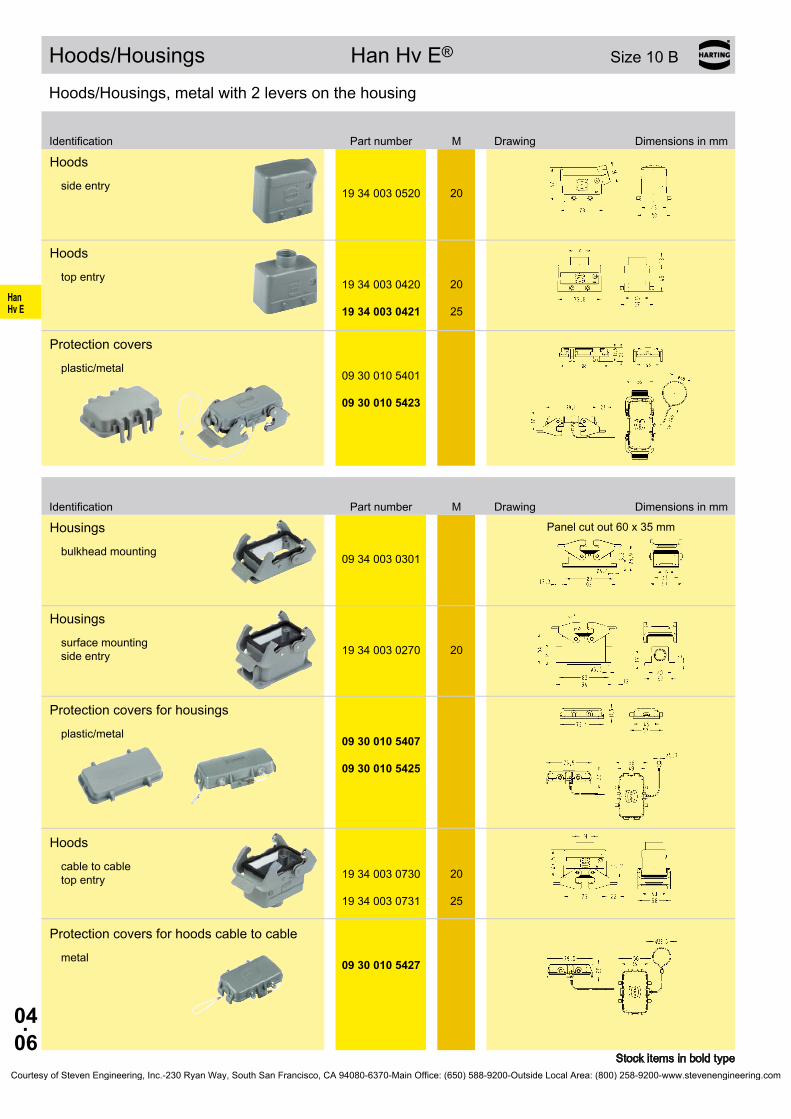
HanHv E
04.06
Hoods/Housings Han Hv E® Size 10 B
Hoods/Housings, metal with 2 levers on the housing
Stock items in bold type
Hoodsside entry
19 34 003 0520 20
Hoodstop entry
19 34 003 0420
19 34 003 0421
20
25
Protectioncoversplastic/metal
09 30 010 5401
09 30 010 5423
Housings Panelcutout60x35mm
bulkhead mounting 09 34 003 0301
Housingssurface mounting side entry 19 34 003 0270 20
Protectioncoversforhousingsplastic/metal 09 30 010 5407
09 30 010 5425
Hoodscable to cable top entry 19 34 003 0730
19 34 003 0731
20
25
Protectioncoversforhoodscabletocablemetal 09 30 010 5427
Identification Partnumber M Drawing Dimensions in mm
Identification Partnumber M Drawing Dimensions in mm
Courtesy of Steven Engineering, Inc.-230 Ryan Way, South San Francisco, CA 94080-6370-Main Office: (650) 588-9200-Outside Local Area: (800) 258-9200-www.stevenengineering.com

HanHv E
04.07
Han® 6 Hv E/ES Size 16 B 830 V 16 A
Stock items in bold type
Number of contacts
6++2additionalcontactsfor safe high voltage connections
SeriesPartnumber
Identification Maleinsert(M) Femaleinsert(F) Drawing Dimensions in mm
Cage-clampterminal Han® Hv ES
a b c dCage clamp terminal 18,4 33,4 18,4 35,6Screw terminal 18,5 32,4 18 34,6Crimp terminal 18,5 34,2 18 37
1) Distance for contact max. 21 mm
Contact arrangement (view from termination side)
Han® 6 Hv ES
Han® 6 Hv E
●Workingcontact ◐Relaycontact ○Withoutcontact
Panelcutoutforinsertsforusewithouthoods/housings
1-6 09 34 006 2616 09 34 006 2716
not plug compatible to screw/crimp terminal
Screw terminal Han Hv E®
1-6 09 34 006 2601 09 34 006 2701
Crimp terminal Han Hv E®
1-6 09 34 006 2602 09 34 006 2702
Order crimp contacts separately (seepage04.04)
Crimp terminal and cage clamp terminal could also be used with 16 B standard hood/housingCourtesy of Steven Engineering, Inc.-230 Ryan Way, South San Francisco, CA 94080-6370-Main Office: (650) 588-9200-Outside Local Area: (800) 258-9200-www.stevenengineering.com

HanHv E
04.08
Hoods/Housings Han Hv E® Size 16 B
Hoods/Housings, metal with 2 levers on the housing
Stock items in bold type
Hoodstop entry
19 34 006 0521 25
Hoodsside entry
19 34 006 0421 25
Protectioncoversplastic/metal
09 30 016 5401
09 30 016 5422
Housings Panelcutout82x35mm
bulkhead mounting 09 34 006 0301
Housingssurface mounting side entry 19 34 006 0271 25
Protectioncoversforhousingsplastic/metal 09 30 016 5405
09 30 016 5425
Hoodscable to cable top entry 19 34 006 0731
19 34 006 0732
25
32
Protectioncoversmetal 09 30 016 5426
Identification Partnumber M Drawing Dimensions in mm
Identification Partnumber M Drawing Dimensions in mm
Courtesy of Steven Engineering, Inc.-230 Ryan Way, South San Francisco, CA 94080-6370-Main Office: (650) 588-9200-Outside Local Area: (800) 258-9200-www.stevenengineering.com
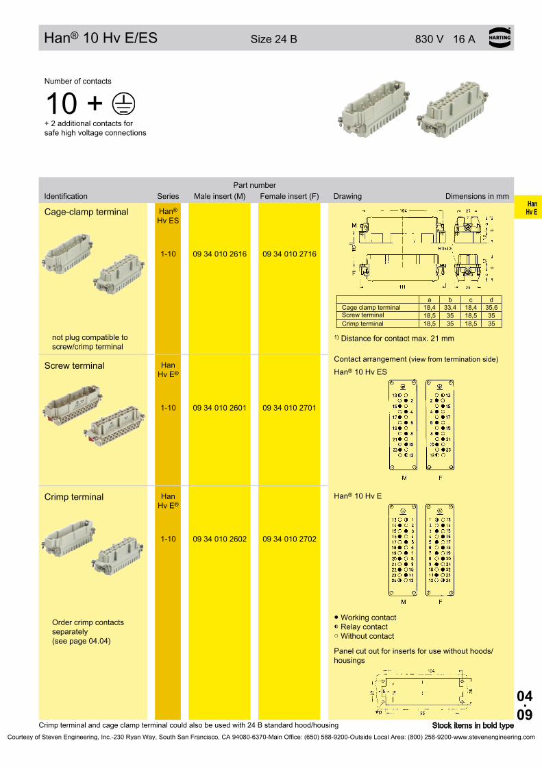
HanHv E
04.09
Han® 10 Hv E/ES Size24B 830V16A
Stock items in bold type
Number of contacts
10++2additionalcontactsfor safe high voltage connections
SeriesPartnumber
Identification Maleinsert(M) Femaleinsert(F) Drawing Dimensions in mm
Cage-clampterminal Han® Hv ES
a b c dCage clamp terminal 18,4 33,4 18,4 35,6Screw terminal 18,5 35 18,5 35Crimp terminal 18,5 35 18,5 35
1) Distance for contact max. 21 mm
Contact arrangement (view from termination side)
Han® 10 Hv ES
Han® 10 Hv E
●Workingcontact ◐Relaycontact ○Withoutcontact
Panelcutoutforinsertsforusewithouthoods/housings
1-10 09 34 010 2616 09 34 010 2716
not plug compatible to screw/crimp terminal
Screw terminal Han Hv E®
1-10 09 34 010 2601 09 34 010 2701
Crimp terminal Han Hv E®
1-10 09 34 010 2602 09 34 010 2702
Order crimp contacts separately (seepage04.04)
Crimpterminalandcageclampterminalcouldalsobeusedwith24Bstandardhood/housingCourtesy of Steven Engineering, Inc.-230 Ryan Way, South San Francisco, CA 94080-6370-Main Office: (650) 588-9200-Outside Local Area: (800) 258-9200-www.stevenengineering.com

HanHv E
04.10
Hoods/Housings Han Hv E® Size24B
Hoods/Housings, metal with 2 levers on the housing
Stock items in bold type
Housingssurface mounting side entry 19 34 010 0521 25
Hoodstop entry
19 34 010 0422 32
Protectioncoversplastic/metal 09 30 024 5401
09 30 024 5422
Housings Panelcutout108x35mm
bulkhead mounting 09 34 010 0301
Housingssurface mounting top entry 19 34 010 0271 25
Protectioncoversforhousingsplastic/metal 09 30 024 5405
09 30 024 5425
Hoodscable to cable top entry 19 34 010 0732 32
Protectioncoversmetal
09 30 024 5426
Identification Partnumber M Drawing Dimensions in mm
Identification Partnumber M Drawing Dimensions in mm
Courtesy of Steven Engineering, Inc.-230 Ryan Way, South San Francisco, CA 94080-6370-Main Office: (650) 588-9200-Outside Local Area: (800) 258-9200-www.stevenengineering.com
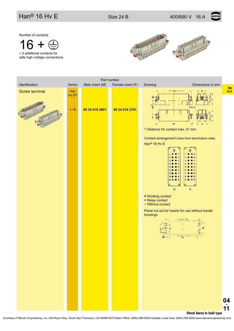
HanHv E
04.11
Han® 16 Hv E Size24B 400/690V16A
Stock items in bold type
Number of contacts
16++2additionalcontactsfor safe high voltage connections
SeriesPartnumber
Identification Maleinsert(M) Femaleinsert(F) Drawing Dimensions in mm
Screw terminal Han Hv E®
1) Distance for contact max. 21 mm
Contact arrangement (view from termination side)
Han® 16 Hv E
●Workingcontact ◐Relaycontact ○Withoutcontact
Panelcutoutforinsertsforusewithouthoods/housings
1-16 09 34 016 2601 09 34 016 2701
Courtesy of Steven Engineering, Inc.-230 Ryan Way, South San Francisco, CA 94080-6370-Main Office: (650) 588-9200-Outside Local Area: (800) 258-9200-www.stevenengineering.com

HanHv E
04.12
Han® 12 Hv E/ES Size 32 B 830 V 16 A
Stock items in bold type
Number of contacts
12++4additionalcontactsfor safe high voltage connections
SeriesPartnumber
Identification Maleinsert(M) Femaleinsert(F) Drawing Dimensions in mm
Cage-clampterminal Han® Hv ES Dimensionsforinsertsseepage04.07
Contact arrangement (view from termination side)
Han® 12 Hv ES
Han® 12 Hv E
●Workingcontact ◐Relaycontact ○Withoutcontact
Panelcutoutforinsertsforusewithouthoods/housings
1-6 1-6
09 34 006 2616 09 34 006 2616
09 34 006 2716 09 34 006 2716
not plug compatible to screw/crimp terminal
Screw terminal Han Hv E®
1-6 1-6
09 34 006 2601 09 34 006 2601
09 34 006 2701 09 34 006 2701
Crimp terminal Han Hv E®
1-6 1-6
09 34 006 2602 09 34 006 2602
09 34 006 2702 09 34 006 2702
Order crimp contacts separately (seepage04.04)
Courtesy of Steven Engineering, Inc.-230 Ryan Way, South San Francisco, CA 94080-6370-Main Office: (650) 588-9200-Outside Local Area: (800) 258-9200-www.stevenengineering.com

HanHv E
04.13
Han® 20 Hv E/ES Size48B 830V16A
Stock items in bold type
Number of contacts
20++4additionalcontactsfor safe high voltage connections
SeriesPartnumber
Identification Maleinsert(M) Femaleinsert(F) Drawing Dimensions in mm
Cage clamp terminal Han® Hv ES Dimensionsforinsertsseepage04.09
Contact arrangement (view from termination side)
Han® 20 Hv ES
Han® 20 Hv E
●Workingcontact ◐Relaycontact ○Withoutcontact
Panelcutoutforinsertsforusewithouthoods/housings
1-10 1-10
09 34 010 2616 09 34 010 2616
09 34 010 2716 09 34 010 2716
not plug compatible to screw/crimp terminal
Screw terminal Han Hv E®
1-10 1-10
09 34 010 2601 09 34 010 2601
09 34 010 2701 09 34 010 2701
Crimp terminal Han Hv E®
1-10 1-10
09 34 010 2602 09 34 010 2602
09 34 010 2702 09 34 010 2702
Order crimp contacts separately (seepage04.04)
Courtesy of Steven Engineering, Inc.-230 Ryan Way, South San Francisco, CA 94080-6370-Main Office: (650) 588-9200-Outside Local Area: (800) 258-9200-www.stevenengineering.com

HanHv E
04.14
Han® 32 Hv E Size48B 400/690V16A
Stock items in bold type
Number of contacts
32++4additionalcontactsfor safe high voltage connections
SeriesPartnumber
Identification Maleinsert(M) Femaleinsert(F) Drawing Dimensions in mm
Screw terminal Han Hv E® Dimensionsforinsertsseepage04.11
Contact arrangement (view from termination side)
Han® 32 Hv E
●Workingcontact ◐Relaycontact ○Withoutcontact
Panelcutoutforinsertsforusewithouthoods/housings
1-16 1-16
09 34 016 2601 09 34 016 2601
09 34 016 2701 09 34 016 2701
Courtesy of Steven Engineering, Inc.-230 Ryan Way, South San Francisco, CA 94080-6370-Main Office: (650) 588-9200-Outside Local Area: (800) 258-9200-www.stevenengineering.com

HanHv E
04.15
Difference:HanHvE® to Standard Hoods/Housings
Standard Hoods/Housings Han® BSuitable for inserts Han®HvEScage-clampterminal and Han Hv E® crimp terminal
Coding bar
Special hood/housing Han Hv E® Han Hv E® inserts may be used together with the corresponding Han Hv E® hoods/housings only
Milled coding bar
Insulation tape
Coding pin
Courtesy of Steven Engineering, Inc.-230 Ryan Way, South San Francisco, CA 94080-6370-Main Office: (650) 588-9200-Outside Local Area: (800) 258-9200-www.stevenengineering.com
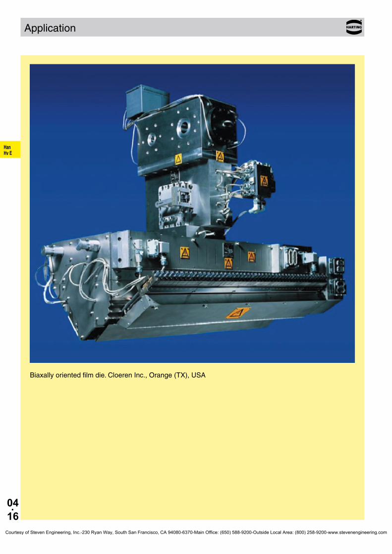
HanHv E
04.16
Application
Biaxally oriented film die . Cloeren Inc ., Orange (TX), USA
Courtesy of Steven Engineering, Inc.-230 Ryan Way, South San Francisco, CA 94080-6370-Main Office: (650) 588-9200-Outside Local Area: (800) 258-9200-www.stevenengineering.com

05.01
HanCom
Han-Com®
PageContents
Han-Com® Summary . . . . . . . . . . . . . . . . . . . . . . . . . . . . . . . . . . . . . . . . . . 05.02
Han® K 8/24 . . . . . . . . . . . . . . . . . . . . . . . . . . . . . . . . . . . . . . . . . . . . . . . . . 05.04
Han® K 4/4 . . . . . . . . . . . . . . . . . . . . . . . . . . . . . . . . . . . . . . . . . . . . . . . . . . 05.06
Han® K 4/2 . . . . . . . . . . . . . . . . . . . . . . . . . . . . . . . . . . . . . . . . . . . . . . . . . . 05.08
Han® K 6/12 . . . . . . . . . . . . . . . . . . . . . . . . . . . . . . . . . . . . . . . . . . . . . . . . . 05.10
Han® K 6/36 . . . . . . . . . . . . . . . . . . . . . . . . . . . . . . . . . . . . . . . . . . . . . . . . . 05.12
Han® K 12/2 . . . . . . . . . . . . . . . . . . . . . . . . . . . . . . . . . . . . . . . . . . . . . . . . . 05.14
Han® K 4/8 . . . . . . . . . . . . . . . . . . . . . . . . . . . . . . . . . . . . . . . . . . . . . . . . . . 05.16
Han® K 6/6 . . . . . . . . . . . . . . . . . . . . . . . . . . . . . . . . . . . . . . . . . . . . . . . . . . 05.18
Han® K 8/0 . . . . . . . . . . . . . . . . . . . . . . . . . . . . . . . . . . . . . . . . . . . . . . . . . . 05.20
Assembly instructions Han® K 4/4 / Han® K 6/12 / Han® K 6/6 / Han® K 8/0 05.22
Courtesy of Steven Engineering, Inc.-230 Ryan Way, South San Francisco, CA 94080-6370-Main Office: (650) 588-9200-Outside Local Area: (800) 258-9200-www.stevenengineering.com

05.02
HanCom
Han-Com® Summary
Size Description
10 B
Power area Signal area
Han® K 8/24 16 A / 230/400 V 10 A / 160 V Page 05.04
Han® K 4/4 63 A / 690 V 16 A / 230 V Page 05.06
16 B
Power area Signal area
Han® K 4/0, 4/2 80 A / 830 V 16 A / 400 V Page 05.08
Han® K 6/12 40 A / 690 V 10 A / 230/400 V Page 05.10
Han® K 6/36 40 A / 690 V 10 A / 160 V Page 05.12
Han® K 12/2 40 A / 690 V 10 A / 250 V Page 05.14
24 B
Power area Signal area
Han® K 4/8 80 A / 400 V 16 A / 400 V Page 05.16
Han® K 6/6 100 A / 690 V 16 A / 400 V Page 05.18
Han® K 8/0 100 A / 690 V Page 05.20
32 B suitable for 2 inserts of size 16 B
48 B suitable for 2 inserts of size 24 B
Courtesy of Steven Engineering, Inc.-230 Ryan Way, South San Francisco, CA 94080-6370-Main Office: (650) 588-9200-Outside Local Area: (800) 258-9200-www.stevenengineering.com

05.03
HanCom
Han-Com® Summary
Summary
Type
Technical characteristics Suitable Hoods/HousingsPower area Signal area
Number of
contactsA V ∼ Termination
Number of
contactsA V ∼ Termination Size
Han® K 4/0 4+PE 80 830 screw — — — — 16 B, 32 B
Han® K 4/2 4+PE 80 830 screw 2 16 400 screw 16 B, 32 B
Han® K 4/4 4+PE 63 690 axial screw 4 16 250 cage clamp 10 B
Han® K 4/8 4+PE 80 400 screw 8 16 400 screw 24 B, 48 B
Han® K 6/6 6+PE 100 690 axial screw 6 16 400 screw 24 B, 48 B
Han® K 6/12 6+PE 40 690 axial screw 12 10 230/400 screw 16 B, 32 B
Han® K 6/36 6+PE 40 690 crimp 36 10 160 crimp 16 B, 32 B
Han® K 8/0 8+PE 100 690 axial screw — — — — 24 B, 48 B
Han® K 8/24 8+PE 16 230/400 crimp 24 10 160 crimp 10 B
Han® K 12/2 12+PE 40 690 crimp 2 10 250 crimp 16 B, 32 B
Type identificationHan® K 6/12 Han® Industrial connectors Han®
K Series Han® K / Han-Com®
6 Number of power contacts 12 Number of signal contacts
Identification of contact positionHan® K connectors from 1 to ... (power area) from 11 to... (signal area)ExceptionsHan® K 4/8 and Han® K 8/24 from 1 to ... (consecutively)Han® K 12/2 from 1 to 12 (power area) with „a“ and „b“ (signal area)
Comment for usersFor the combination of several circuits in one cable and/or e.g. one connector the following standards are valid:
VDE 0100-410/06.2007 § 411.1.3.2 and EN 60 204/06.2007 § 13.1.3
AccessoriesCrimping tools chapter 99 Cable clamps chapter 40 Coding of hoods/housings chapter 40 Label acc. to CSA-approval chapter 40 Han-Snap® chapter 11 PCB adapter chapter 40
Courtesy of Steven Engineering, Inc.-230 Ryan Way, South San Francisco, CA 94080-6370-Main Office: (650) 588-9200-Outside Local Area: (800) 258-9200-www.stevenengineering.com

05.04
HanCom
Han® K 8/24
Features• Combination of power and signal area in one con-
nector• Crimp termination for power and signal area• Use of standard Han E® and Han D® contacts
Removal of power contacts (Han E®)
➀ Push cross-slotted screw driver ( size 0 acc. to DIN 5260) in the relevant hole of the contact until it reaches the bottom
➁ Withdraw the crimped contact from the insert
Removal of signal contacts (Han D®)Description see removal tool chapter 99
Current carrying capacityThe current carrying capacity of the connectors is limited by the thermal load capability of the contact element material including the connections and the insulating parts. The derating curve is therefore valid for currents which flow constantly (non-inter-mittent) through each contact element of the connector evenly, without exceeding the allowed maximum temperature.Measuring and testing techniques according to DIN EN 60 512-5
Ope
ratin
g cu
rrent
Ambient temperature
Wire gauge: ➀ 4 mm²➁ 2.5 mm²
Technical characteristicsSpecifications DIN EN 60 664-1
DIN EN 61 984
Approvals ,
InsertsNumber of contacts 8 / 24 + PE Electrical data acc. to EN 61 984 Power area 16 A 230/400 V 4 kV 3 Rated current 16 A Rated voltage conductor - ground 230 V Rated voltage conductor - conductor 400 V Rated impulse voltage 4 kV Pollution degree 3Pollution degree 2 also 10 A 250 V 4 kV 2
Signal area 10 A 160 V 2.5 kV 3 Rated current 10 A Rated voltage 160 V Rated impulse voltage 2.5 kV Pollution degree 3Rated voltage acc. to UL/CSA 600 V / 300 V Insulation resistance ≥ 1010 Ω Material Polyamide Limiting temperatures -40 °C ... +125 °C Flammability acc. to UL 94 HB Mechanical working life - mating cycles ≥ 500
ContactsPower contactsMaterial copper alloy Surface - hard-silver plated 3 µm Ag - hard-gold plated 2 µm Au over 3 µm Ni Contact resistance ≤ 1 mΩ Crimp terminal - mm² 0.5 ... 4 mm² - AWG 20 ... 12Signal contactsMaterial copper alloy Surface - hard-silver plated 3 µm Ag - hard-gold plated 2 µm Au over 3 µm Ni Contact resistance ≤ 3 mΩ Crimp terminal - mm² 0.14 ... 2.5 mm² - AWG 25 ... 14
Hoods/Housings see chapter 30 / 31
Courtesy of Steven Engineering, Inc.-230 Ryan Way, South San Francisco, CA 94080-6370-Main Office: (650) 588-9200-Outside Local Area: (800) 258-9200-www.stevenengineering.com
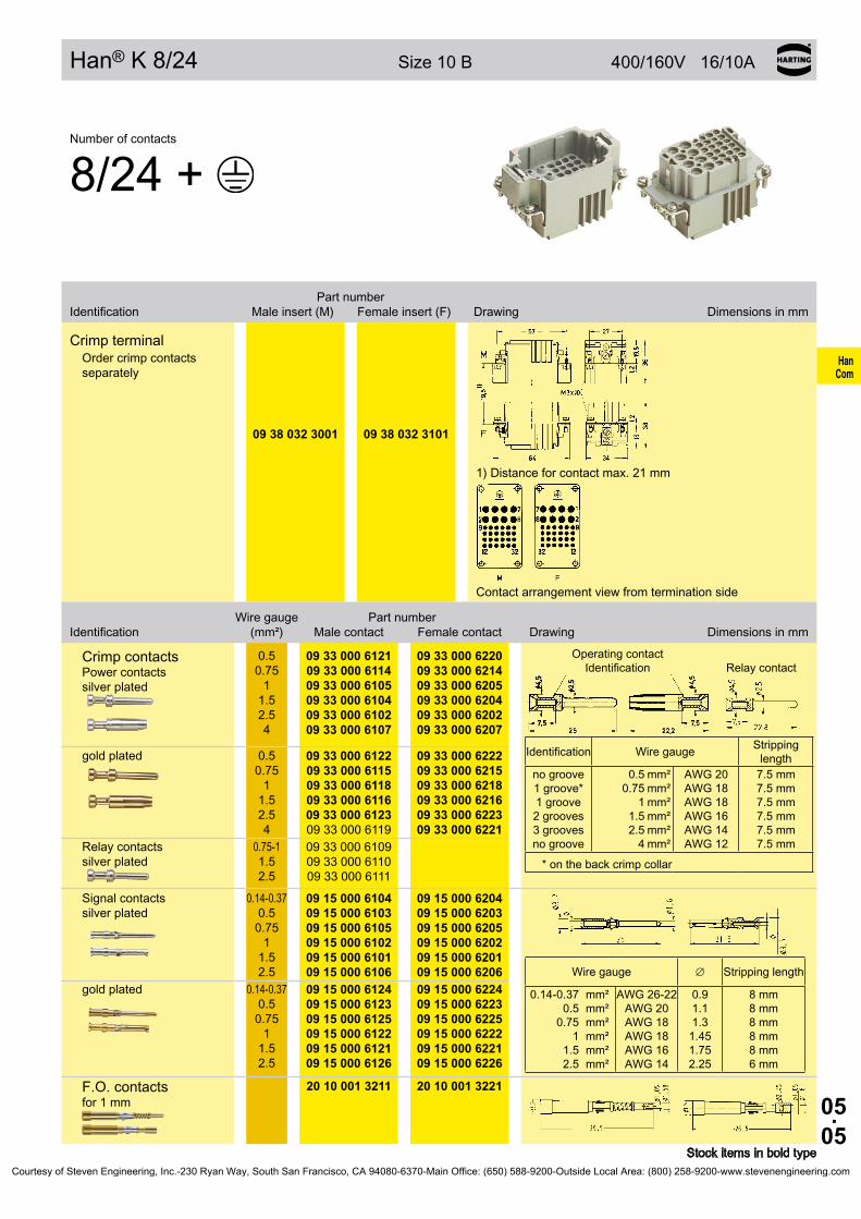
05.05
HanCom
Han® K 8/24 Size 10 B 400/160V 16/10A
Stock items in bold type
Number of contacts
8/24 +
Part number Identification Male insert (M) Female insert (F) Drawing Dimensions in mm
Crimp terminalOrder crimp contacts separately
1) Distance for contact max. 21 mm
Contact arrangement view from termination side
09 38 032 3001 09 38 032 3101
Wire gauge Part number Identification (mm²) Male contact Female contact Drawing Dimensions in mm
Crimp contacts Power contacts silver plated
0.5 0.75
1 1.5 2.5 4
09 33 000 6121 09 33 000 6114 09 33 000 6105 09 33 000 6104 09 33 000 6102 09 33 000 6107
09 33 000 6220 09 33 000 6214 09 33 000 6205 09 33 000 6204 09 33 000 6202 09 33 000 6207
Operating contact Identification Relay contact
Identification Wire gauge Stripping length
no groove 1 groove* 1 groove 2 grooves 3 grooves no groove
0.5 0.75
1 1.5 2.5
4
mm² mm² mm² mm² mm² mm²
AWG 20 AWG 18 AWG 18 AWG 16 AWG 14 AWG 12
7.5 mm 7.5 mm 7.5 mm 7.5 mm 7.5 mm 7.5 mm
* on the back crimp collar
gold plated 0.5 0.75
1 1.5 2.5 4
09 33 000 6122 09 33 000 6115 09 33 000 6118 09 33 000 6116 09 33 000 6123 09 33 000 6119
09 33 000 6222 09 33 000 6215 09 33 000 6218 09 33 000 6216 09 33 000 6223 09 33 000 6221
Relay contacts silver plated
0.75-1 1.5 2.5
09 33 000 6109 09 33 000 6110 09 33 000 6111
Signal contacts silver plated
0.14-0.37 0.5
0.75 1
1.5 2.5
09 15 000 6104 09 15 000 6103 09 15 000 6105 09 15 000 6102 09 15 000 6101 09 15 000 6106
09 15 000 6204 09 15 000 6203 09 15 000 6205 09 15 000 6202 09 15 000 6201 09 15 000 6206
Wire gauge ∅ Stripping length
0.14-0.37 0.5
0.75 1
1.5 2.5
mm² mm² mm² mm² mm² mm²
AWG 26-22 AWG 20 AWG 18 AWG 18 AWG 16 AWG 14
0.9 1.1 1.3 1.45 1.75 2.25
8 mm 8 mm 8 mm 8 mm 8 mm 6 mm
gold plated 0.14-0.37 0.5
0.75 1
1.5 2.5
09 15 000 6124 09 15 000 6123 09 15 000 6125 09 15 000 6122 09 15 000 6121 09 15 000 6126
09 15 000 6224 09 15 000 6223 09 15 000 6225 09 15 000 6222 09 15 000 6221 09 15 000 6226
F.O. contacts for 1 mm
20 10 001 3211 20 10 001 3221
Courtesy of Steven Engineering, Inc.-230 Ryan Way, South San Francisco, CA 94080-6370-Main Office: (650) 588-9200-Outside Local Area: (800) 258-9200-www.stevenengineering.com

05.06
HanCom
Han® K 4/4
Features• Combination of power area and signal area in the
same connector• Axial screw termination for power area • Cage clamp termination for signal area• Finger safe• Same range of wire gauge for PE contact and
power contacts
Assembly instructions see page 05.22
Current carrying capacityThe current carrying capacity of the connectors is limited by the thermal load capability of the contact element material including the connections and the insulating parts. The derating curve is therefore valid for currents which flow constantly (non-inter-mittent) through each contact element of the connector evenly, without exceeding the allowed maximum temperature.Measuring and testing techniques according to DIN EN 60 512-5
Ope
ratin
g cu
rrent
Ambient temperature
Wire gauge: ➀ 16 mm²➁ 22 mm²
Technical characteristicsSpecifications DIN EN 60 664-1
DIN EN 61 984
Approvals
InsertsNumber of contacts 4 / 4 + PE Electrical data acc. to EN 61 984 Power area 63 A 690 V 8 kV 3 Rated current 63 A Rated voltage 690 V Rated impulse voltage 8 kV Pollution degree 3Signal area 16 A 250 V 4 kV 3 Rated current 16 A Rated voltage 250 V Rated impulse voltage 4 kV Pollution degree 3Rated voltage acc. to UL 600 V / 230 V Insulation resistance ≥ 1010 Ω Material polycarbonate Limiting temperatures -40 °C ... +125 °C Flammability acc. to UL 94 V 0 Mechanical working life - mating cycles ≥ 500
ContactsPower contactsMaterial copper alloy Surface - hard-silver plated 3 µm Ag Contact resistance ≤ 0.5 mΩ Axial screw termination - geometric wire gauge 6 ... 22 mm² - AWG 8 ... 4 Max. insulation diameter 6 ... 16 mm² 8.9 mm 22 mm² 11 mm Tightening tourque mm² 6 10 16 22
Nm 2 3 4 5
Stripping length mm² 6 10 16 22
mm 11+1 11+1 11+1 13+1
Signal contactsMaterial copper alloy Surface - hard-silver plated 3 µm Ag Contact resistance ≤ 3 mΩ Cage clamp terminal - geometric wire gauge 0.14 ... 2.5 mm² - AWG 26 ... 14 Stripping length 7 ... 9 mm
Hoods/Housings see chapter 30 / 31
Courtesy of Steven Engineering, Inc.-230 Ryan Way, South San Francisco, CA 94080-6370-Main Office: (650) 588-9200-Outside Local Area: (800) 258-9200-www.stevenengineering.com

05.07
HanCom
Han® K 4/4 Size 10 B 690/230 V 63/16 A
Identification Part number Drawing Dimensions in mm
Stock items in bold type
Number of contacts
4/4 +
Part number Identification Male insert (M) Female insert (F) Drawing Dimensions in mm
Han® K 4/4 Axial screw terminal / Cage clamp terminal
1) Distance for contact max. 21 mm
Contact arrangement view from termination side
finger safe 6 ... 16 mm²
09 38 008 2601 09 38 008 2701
finger safe 10 ... 22 mm²
09 38 008 2602 09 38 008 2702
not finger safe 6 ... 16 mm²
09 38 008 2611
not finger safe 10 ... 22 mm²
09 38 008 2612
Hex key SW 2.5 for axial setscrew
adapter 1/4“ 09 99 000 0375
Courtesy of Steven Engineering, Inc.-230 Ryan Way, South San Francisco, CA 94080-6370-Main Office: (650) 588-9200-Outside Local Area: (800) 258-9200-www.stevenengineering.com
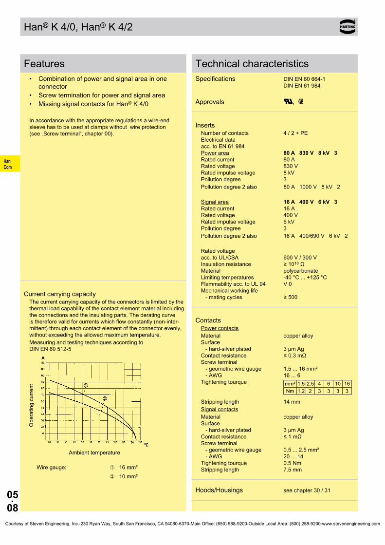
05.08
HanCom
Han® K 4/0, Han® K 4/2
Features• Combination of power and signal area in one
connector• Screw termination for power and signal area• Missing signal contacts for Han® K 4/0
In accordance with the appropriate regulations a wire-end sleeve has to be used at clamps without wire protection (see „Screw terminal“, chapter 00).
Current carrying capacityThe current carrying capacity of the connectors is limited by the thermal load capability of the contact element material including the connections and the insulating parts. The derating curve is therefore valid for currents which flow constantly (non-inter-mittent) through each contact element of the connector evenly, without exceeding the allowed maximum temperature.Measuring and testing techniques according to DIN EN 60 512-5
Ope
ratin
g cu
rrent
Ambient temperature
Wire gauge: ➀ 16 mm²➁ 10 mm²
Technical characteristicsSpecifications DIN EN 60 664-1
DIN EN 61 984
Approvals ,
InsertsNumber of contacts 4 / 2 + PE Electrical data acc. to EN 61 984 Power area 80 A 830 V 8 kV 3 Rated current 80 A Rated voltage 830 V Rated impulse voltage 8 kV Pollution degree 3Pollution degree 2 also 80 A 1000 V 8 kV 2
Signal area 16 A 400 V 6 kV 3 Rated current 16 A Rated voltage 400 V Rated impulse voltage 6 kV Pollution degree 3Pollution degree 2 also 16 A 400/690 V 6 kV 2
Rated voltage acc. to UL/CSA 600 V / 300 V Insulation resistance ≥ 1010 Ω Material polycarbonate Limiting temperatures -40 °C ... +125 °C Flammability acc. to UL 94 V 0 Mechanical working life - mating cycles ≥ 500
ContactsPower contactsMaterial copper alloy Surface - hard-silver plated 3 µm Ag Contact resistance ≤ 0.3 mΩ Screw terminal - geometric wire gauge 1.5 ... 16 mm² - AWG 16 ... 6 Tightening tourque mm² 1.5 2.5 4 6 10 16
Nm 1.2 2 3 3 3 3
Stripping length 14 mmSignal contactsMaterial copper alloy Surface - hard-silver plated 3 µm Ag Contact resistance ≤ 1 mΩ Screw terminal - geometric wire gauge 0.5 ... 2.5 mm² - AWG 20 ... 14 Tightening tourque 0.5 Nm Stripping length 7.5 mm
Hoods/Housings see chapter 30 / 31
Courtesy of Steven Engineering, Inc.-230 Ryan Way, South San Francisco, CA 94080-6370-Main Office: (650) 588-9200-Outside Local Area: (800) 258-9200-www.stevenengineering.com

05.09
HanCom
Han K 4/0, Han® K 4/2 Size 16 B 830/400 V 80/16 A
Stock items in bold type
Number of contacts
4/0, 4/2 +
Part number Identification Male insert (M) Female insert (F) Drawing Dimensions in mm
Han K 4/0, Han® K 4/2 Screw terminal
1) Distance for contact max. 21 mm
Han K 4/0 Han® K 4/2Contact arrangement view from termination side
Han® K 4/2 09 38 006 2601 09 38 006 2701
Han® K 4/0 09 38 006 2611 09 38 006 2711
Courtesy of Steven Engineering, Inc.-230 Ryan Way, South San Francisco, CA 94080-6370-Main Office: (650) 588-9200-Outside Local Area: (800) 258-9200-www.stevenengineering.com

05.10
HanCom
Han® K 6/12
Features• Combination of power and signal area in one
connector• Axial screw termination for power area• Screw termination for signal area
Assembly instructions see page 05.23
Current carrying capacityThe current carrying capacity of the connectors is limited by the thermal load capability of the contact element material including the connections and the insulating parts. The derating curve is therefore valid for currents which flow constantly (non-inter-mittent) through each contact element of the connector evenly, without exceeding the allowed maximum temperature.Measuring and testing techniques according to DIN EN 60 512-5
Ope
ratin
g cu
rrent
Ambient temperature
Wire gauge: ➀ 10 mm²➁ 6 mm²➂ 4 mm²
Technical characteristicsSpecifications DIN EN 60 664-1
DIN EN 61 984
Approvals ,
InsertsNumber of contacts 6 / 12 + PE Electrical data acc. to EN 61 984 Power area 40 A 690 V 8 kV 3 Rated current 40 A Rated voltage 690 V Rated impulse voltage 8 kV Pollution degree 3Signal area 10 A 230/400 V 4 kV 3 Rated current 10 A Rated voltage conductor - ground 230 V Rated voltage conductor - conductor 400 V Rated impulse voltage 4 kV Pollution degree 3Rated voltage acc. to UL/CSA 600 V / 300 V Insulation resistance ≥ 1010 Ω Material polycarbonate Limiting temperatures -40 °C ... +125 °C Flammability acc. to UL 94 V 0 Mechanical working life - mating cycles ≥ 500
ContactsPower contactsMaterial copper alloy Surface - hard-silver plated 3 µm Ag Contact resistance ≤ 0.5 mΩ Axial screw termination - geometric wire gauge 2.5 ... 10 mm² - AWG 14 ... 8 Max. insulation diameter 6.1 mm Tightening tourque mm² 2.5 4 6 10
Nm 1.5 1.5 2 2
Stripping length mm² 2.5 4 6 10
mm 5+1 5+1 8+1 8+1
Signal contactsMaterial copper alloy Surface - hard-silver plated 3 µm Ag Contact resistance ≤ 3 mΩ Screw terminal - geometric wire gauge 0.2 ... 2.5 mm² - AWG 24 ... 14 Tightening tourque 0.8 Nm Stripping length 7.5 mm
Hoods/Housings see chapter 30 / 31
Courtesy of Steven Engineering, Inc.-230 Ryan Way, South San Francisco, CA 94080-6370-Main Office: (650) 588-9200-Outside Local Area: (800) 258-9200-www.stevenengineering.com

05.11
HanCom
Han® K 6/12 Size 16 B 690/400 V 40/10 A
Identification Part number Drawing Dimensions in mm
Stock items in bold type
Number of contacts
6/12 +
Part number Identification Male insert (M) Female insert (F) Drawing Dimensions in mm
Han® K 6/12 Axial screw terminal / Screw terminal
1) Distance for contact max. 21 mm
Contact arrangement view from termination side
2.5 ... 8 mm² 09 38 018 2601 09 38 018 2701
6 ... 10 mm² 09 38 018 2602 09 38 018 2702
Hex key SW 2 for axial setscrew
adapter 1/4“ 09 99 000 0369
Courtesy of Steven Engineering, Inc.-230 Ryan Way, South San Francisco, CA 94080-6370-Main Office: (650) 588-9200-Outside Local Area: (800) 258-9200-www.stevenengineering.com

05.12
HanCom
Han® K 6/36
Features• Combination of power and signal area in one
connector• Crimp termination for power and signal area• Use of standard Han® C and Han D® contacts
Removal of power contacts (Han® C)Description see removal tool chapter 99
Removal of signal contacts (Han D®)Description see removal tool chapter 99
Current carrying capacityThe current carrying capacity of the connectors is limited by the thermal load capability of the contact element material including the connections and the insulating parts. The derating curve is therefore valid for currents which flow constantly (non-inter-mittent) through each contact element of the connector evenly, without exceeding the allowed maximum temperature.Measuring and testing techniques according to DIN EN 60 512-5
Ope
ratin
g cu
rrent
Ambient temperature
Wire gauge: ➀ 6 mm²➁ 4 mm²
Technical characteristicsSpecifications DIN EN 60 664-1
DIN EN 61 984
Approvals ,
InsertsNumber of contacts 6 / 36 + PE Electrical data acc. to EN 61 984 Power area 40 A 690 V 8 kV 3 Rated current 40 A Rated voltage 690 V Rated impulse voltage 8 kV Pollution degree 3Signal area 10 A 160 V 2.5 kV 3 Rated current 10 A Rated voltage 160 V Rated impulse voltage 2.5 kV Pollution degree 3Pollution degree 2 also 10 A 250 V 4 kV 2
Rated voltage acc. to UL/CSA 600 V / 300 V Insulation resistance ≥ 1010 Ω Material polycarbonate Limiting temperatures -40 °C ... +125 °C Flammability acc. to UL 94 V 0 Mechanical working life - mating cycles ≥ 500
ContactsPower contactsMaterial copper alloy Surface - hard-silver plated 3 µm Ag - hard-gold plated 2 µm Au over 3 µm Ni Contact resistance ≤ 0.3 mΩ Crimp terminal - mm² 1.5 ... 6 mm² - AWG 16 ... 10 Max. insulation diameter 5 mmSignal contactsMaterial copper alloy Surface - hard-silver plated 3 µm Ag - hard-gold plated 2 µm Au over 3 µm Ni Contact resistance ≤ 3 mΩ Crimp terminal - mm² 0.14 ... 2.5 mm² - AWG 26 ... 14
Hoods/Housings see chapter 30 / 31
Courtesy of Steven Engineering, Inc.-230 Ryan Way, South San Francisco, CA 94080-6370-Main Office: (650) 588-9200-Outside Local Area: (800) 258-9200-www.stevenengineering.com
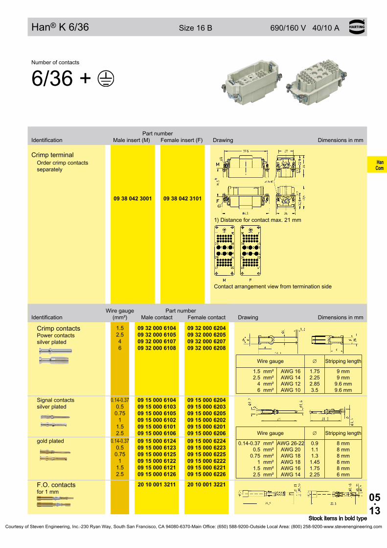
05.13
HanCom
Han® K 6/36 Size 16 B 690/160 V 40/10 A
Stock items in bold type
Number of contacts
6/36 +
Part number Identification Male insert (M) Female insert (F) Drawing Dimensions in mm
Crimp terminalOrder crimp contacts separately
1) Distance for contact max. 21 mm
Contact arrangement view from termination side
09 38 042 3001 09 38 042 3101
Wire gauge Part number Identification (mm²) Male contact Female contact Drawing Dimensions in mm
Crimp contacts Power contacts silver plated
1.5 2.5 4 6
09 32 000 6104 09 32 000 6105 09 32 000 6107 09 32 000 6108
09 32 000 6204 09 32 000 6205 09 32 000 6207 09 32 000 6208
Wire gauge ∅ Stripping length
1.5 2.5
4 6
mm² mm² mm² mm²
AWG 16 AWG 14 AWG 12 AWG 10
1.75 2.25 2.85 3.5
9 mm 9 mm
9.6 mm 9.6 mm
Signal contacts silver plated
0.14-0.37 0.5
0.75 1
1.5 2.5
09 15 000 6104 09 15 000 6103 09 15 000 6105 09 15 000 6102 09 15 000 6101 09 15 000 6106
09 15 000 6204 09 15 000 6203 09 15 000 6205 09 15 000 6202 09 15 000 6201 09 15 000 6206
Wire gauge ∅ Stripping length
0.14-0.37 0.5
0.75 1
1.5 2.5
mm² mm² mm² mm² mm² mm²
AWG 26-22 AWG 20 AWG 18 AWG 18 AWG 16 AWG 14
0.9 1.1 1.3 1.45 1.75 2.25
8 mm 8 mm 8 mm 8 mm 8 mm 6 mm
gold plated 0.14-0.37 0.5
0.75 1
1.5 2.5
09 15 000 6124 09 15 000 6123 09 15 000 6125 09 15 000 6122 09 15 000 6121 09 15 000 6126
09 15 000 6224 09 15 000 6223 09 15 000 6225 09 15 000 6222 09 15 000 6221 09 15 000 6226
F.O. contacts for 1 mm
20 10 001 3211 20 10 001 3221
Courtesy of Steven Engineering, Inc.-230 Ryan Way, South San Francisco, CA 94080-6370-Main Office: (650) 588-9200-Outside Local Area: (800) 258-9200-www.stevenengineering.com
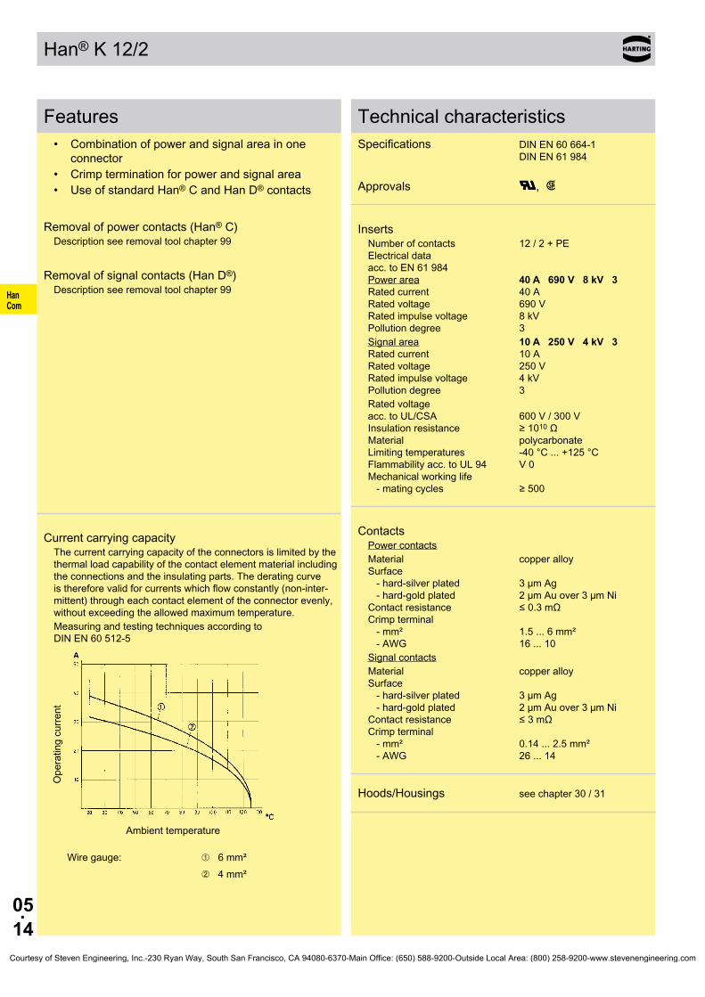
05.14
HanCom
Han® K 12/2
Features• Combination of power and signal area in one
connector• Crimp termination for power and signal area• Use of standard Han® C and Han D® contacts
Removal of power contacts (Han® C)Description see removal tool chapter 99
Removal of signal contacts (Han D®)Description see removal tool chapter 99
Current carrying capacityThe current carrying capacity of the connectors is limited by the thermal load capability of the contact element material including the connections and the insulating parts. The derating curve is therefore valid for currents which flow constantly (non-inter-mittent) through each contact element of the connector evenly, without exceeding the allowed maximum temperature.Measuring and testing techniques according to DIN EN 60 512-5
Ope
ratin
g cu
rrent
Ambient temperature
Wire gauge: ➀ 6 mm²➁ 4 mm²
Technical characteristicsSpecifications DIN EN 60 664-1
DIN EN 61 984
Approvals ,
InsertsNumber of contacts 12 / 2 + PE Electrical data acc. to EN 61 984 Power area 40 A 690 V 8 kV 3 Rated current 40 A Rated voltage 690 V Rated impulse voltage 8 kV Pollution degree 3Signal area 10 A 250 V 4 kV 3 Rated current 10 A Rated voltage 250 V Rated impulse voltage 4 kV Pollution degree 3Rated voltage acc. to UL/CSA 600 V / 300 V Insulation resistance ≥ 1010 Ω Material polycarbonate Limiting temperatures -40 °C ... +125 °C Flammability acc. to UL 94 V 0 Mechanical working life - mating cycles ≥ 500
ContactsPower contactsMaterial copper alloy Surface - hard-silver plated 3 µm Ag - hard-gold plated 2 µm Au over 3 µm Ni Contact resistance ≤ 0.3 mΩ Crimp terminal - mm² 1.5 ... 6 mm² - AWG 16 ... 10Signal contactsMaterial copper alloy Surface - hard-silver plated 3 µm Ag - hard-gold plated 2 µm Au over 3 µm Ni Contact resistance ≤ 3 mΩ Crimp terminal - mm² 0.14 ... 2.5 mm² - AWG 26 ... 14
Hoods/Housings see chapter 30 / 31
Courtesy of Steven Engineering, Inc.-230 Ryan Way, South San Francisco, CA 94080-6370-Main Office: (650) 588-9200-Outside Local Area: (800) 258-9200-www.stevenengineering.com

05.15
HanCom
Han® K 12/2 Size 16 B 690/250 V 40/10 A
Stock items in bold type
Number of contacts
12/2 +
Part number Identification Male insert (M) Female insert (F) Drawing Dimensions in mm
Crimp terminalOrder crimp contacts separately
1) Distance for contact max. 21 mm
Contact arrangement view from termination side
09 32 012 3001 09 32 012 3101
Wire gauge Part number Identification (mm²) Male contact Female contact Drawing Dimensions in mm
Crimp contacts Power contacts silver plated
1.5 2.5 4 6
09 32 000 6104 09 32 000 6105 09 32 000 6107 09 32 000 6108
09 32 000 6204 09 32 000 6205 09 32 000 6207 09 32 000 6208
Wire gauge ∅ Stripping length
1.5 2.5
4 6
mm² mm² mm² mm²
AWG 16 AWG 14 AWG 12 AWG 10
1.75 2.25 2.85 3.5
9 mm 9 mm
9.6 mm 9.6 mm
Signal contacts silver plated
0.14-0.37 0.5
0.75 1
1.5 2.5
09 15 000 6104 09 15 000 6103 09 15 000 6105 09 15 000 6102 09 15 000 6101 09 15 000 6106
09 15 000 6204 09 15 000 6203 09 15 000 6205 09 15 000 6202 09 15 000 6201 09 15 000 6206
Wire gauge ∅ Stripping length
0.14-0.37 0.5
0.75 1
1.5 2.5
mm² mm² mm² mm² mm² mm²
AWG 26-22 AWG 20 AWG 18 AWG 18 AWG 16 AWG 14
0.9 1.1 1.3 1.45 1.75 2.25
8 mm 8 mm 8 mm 8 mm 8 mm 6 mm
gold plated 0.14-0.37 0.5
0.75 1
1.5 2.5
09 15 000 6124 09 15 000 6123 09 15 000 6125 09 15 000 6122 09 15 000 6121 09 15 000 6126
09 15 000 6224 09 15 000 6223 09 15 000 6225 09 15 000 6222 09 15 000 6221 09 15 000 6226
F.O. contacts for 1 mm
20 10 001 3211 20 10 001 3221
Courtesy of Steven Engineering, Inc.-230 Ryan Way, South San Francisco, CA 94080-6370-Main Office: (650) 588-9200-Outside Local Area: (800) 258-9200-www.stevenengineering.com

05.16
HanCom
Han® K 4/8
Features• Combination of power and signal area in one
connector• Screw termination for power and signal area
In accordance with the appropriate regulations a wire-end sleeve has to be used at clamps without wire protection (see „Screw terminal“, chapter 00).
Current carrying capacityThe current carrying capacity of the connectors is limited by the thermal load capability of the contact element material including the connections and the insulating parts. The derating curve is therefore valid for currents which flow constantly (non-inter-mittent) through each contact element of the connector evenly, without exceeding the allowed maximum temperature.Measuring and testing techniques according to DIN EN 60 512-5
Ope
ratin
g cu
rrent
Ambient temperature
Wire gauge: ➀ 16 mm²➁ 10 mm²
Technical characteristicsSpecifications DIN EN 60 664-1
DIN EN 61 984
Approvals ,
InsertsNumber of contacts 4 / 8 + PE Electrical data acc. to EN 61 984 Power area 80 A 400 V 6 kV 3 Rated current 80 A Rated voltage 400 V Rated impulse voltage 6 kV Pollution degree 3Pollution degree 2 also 80 A 400/690 V 6 kV 2
Signal area 16 A 400 V 6 kV 3 Rated current 16 A Rated voltage 400 V Rated impulse voltage 6 kV Pollution degree 3Rated voltage acc. to UL/CSA 600 V / 600 V Insulation resistance ≥ 1010 Ω Material Polyamide Limiting temperatures -40 °C ... +125 °C Flammability acc. to UL 94 HB Mechanical working life - mating cycles ≥ 500
ContactsPower contactsMaterial copper alloy Surface - hard-silver plated 3 µm Ag Contact resistance ≤ 0.3 mΩ Screw terminal - geometric wire gauge 1.5 ... 16 mm² - AWG 16 ... 6 Tightening tourque mm² 1.5 2.5 4 6 10 16
Nm 1.2 2 3 3 3 3
Stripping length 14 mmSignal contactsMaterial copper alloy Surface - hard-silver plated 3 µm Ag Contact resistance ≤ 1 mΩ Screw terminal - geometric wire gauge 0.5 ... 2.5 mm² - AWG 20 ... 14 Tightening tourque 0.5 Nm Stripping length 7.5 mm
Hoods/Housings see chapter 30 / 31
Courtesy of Steven Engineering, Inc.-230 Ryan Way, South San Francisco, CA 94080-6370-Main Office: (650) 588-9200-Outside Local Area: (800) 258-9200-www.stevenengineering.com
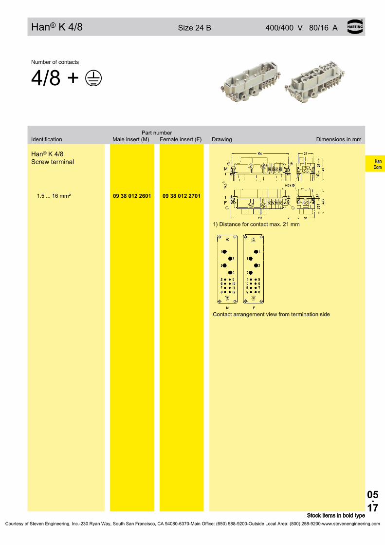
05.17
HanCom
Han® K 4/8 Size 24 B 400/400 V 80/16 A
Stock items in bold type
Number of contacts
4/8 +
Part number Identification Male insert (M) Female insert (F) Drawing Dimensions in mm
Han® K 4/8 Screw terminal
1) Distance for contact max. 21 mm
Contact arrangement view from termination side
1.5 ... 16 mm² 09 38 012 2601 09 38 012 2701
Courtesy of Steven Engineering, Inc.-230 Ryan Way, South San Francisco, CA 94080-6370-Main Office: (650) 588-9200-Outside Local Area: (800) 258-9200-www.stevenengineering.com

05.18
HanCom
Han® K 6/6
Features• Combination of power and signal area in one con-
nector• Axial screw termination for power area• Screw termination for signal area
Assembly instructions see page 05.24
Hoods/Housings see chapter 30 / 31
Current carrying capacityThe current carrying capacity of the connectors is limited by the thermal load capability of the contact element material including the connections and the insulating parts. The derating curve is therefore valid for currents which flow constantly (non-inter-mittent) through each contact element of the connector evenly, without exceeding the allowed maximum temperature.Measuring and testing techniques according to DIN EN 60 512-5
Ope
ratin
g cu
rrent
Ambient temperature
Wire gauge: ➀ 35 mm²➁ 25 mm²➂ 16 mm²
Technical characteristicsSpecifications DIN EN 60 664-1
DIN EN 61 984
Approvals ,
InsertsNumber of contacts 6 / 6 + PE Electrical data acc. to EN 61 984 Power area 100 A 690 V 8 kV 3 Rated current 100 A Rated voltage 690 V Rated impulse voltage 8 kV Pollution degree 3Pollution degree 2 also 100 A 1000 V 8 kV 2
Signal area 16 A 400 V 6 kV 3 Rated current 16 A Rated voltage 400 V Rated impulse voltage 6 kV Pollution degree 3Rated voltage acc. to UL 600 V / 300 V Rated voltage acc. to CSA 600 V / 600 V Rated current acc. to CSA 100 A / 15 A Insulation resistance ≥ 1010 Ω Material polycarbonate Limiting temperatures -40 °C ... +125 °C Flammability acc. to UL 94 V 0 Mechanical working life - mating cycles ≥ 500
ContactsPower contactsMaterial copper alloy Surface - hard-silver plated 3 µm Ag Contact resistance ≤ 0.5 mΩ Axial screw termination - geometric wire gauge 16 ... 35 mm² - AWG 5 ... 2 Max. insulation diameter 11.4 mm Tightening tourque mm² 16 25 35
Nm 6 7 8
Stripping length 13±1 mmSignal contactsMaterial copper alloy Surface - hard-silver plated 3 µm Ag Contact resistance ≤ 3 mΩ Screw terminal - geometric wire gauge 0.2 ... 2.5 mm² - AWG 24 ... 13 Tightening tourque 0.8 Nm Stripping length 7.5 mm
Courtesy of Steven Engineering, Inc.-230 Ryan Way, South San Francisco, CA 94080-6370-Main Office: (650) 588-9200-Outside Local Area: (800) 258-9200-www.stevenengineering.com
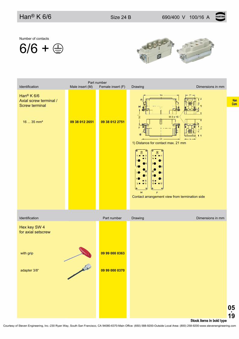
05.19
HanCom
Han® K 6/6 Size 24 B 690/400 V 100/16 A
Identification Part number Drawing Dimensions in mm
Stock items in bold type
Number of contacts
6/6 +
Part number Identification Male insert (M) Female insert (F) Drawing Dimensions in mm
Han® K 6/6 Axial screw terminal / Screw terminal
1) Distance for contact max. 21 mm
Contact arrangement view from termination side
16 ... 35 mm² 09 38 012 2651 09 38 012 2751
Hex key SW 4 for axial setscrew
with grip 09 99 000 0363
adapter 3/8“ 09 99 000 0370
Courtesy of Steven Engineering, Inc.-230 Ryan Way, South San Francisco, CA 94080-6370-Main Office: (650) 588-9200-Outside Local Area: (800) 258-9200-www.stevenengineering.com

05.20
HanCom
Han® K 8/0
Features• Axial screw termination for power area• No signal contacts
Assembly instructions see page 05.25
Current carrying capacityThe current carrying capacity of the connectors is limited by the thermal load capability of the contact element material including the connections and the insulating parts. The derating curve is therefore valid for currents which flow constantly (non-inter-mittent) through each contact element of the connector evenly, without exceeding the allowed maximum temperature.Measuring and testing techniques according to DIN EN 60 512-5
Ope
ratin
g cu
rrent
Ambient temperature
Wire gauge: ➀ 25 mm²➁ 16 mm²➂ 10 mm²
Technical characteristicsSpecifications DIN EN 60 664-1
DIN EN 61 984
Approvals
InsertsNumber of contacts 8 + PE Electrical data acc. to EN 61 984 Power area 100 A 690 V 8 kV 3 Rated current 100 A Rated voltage 690 V Rated impulse voltage 8 kV Pollution degree 3Pollution degree 2 also 100 A 1000 V 8 kV 2
Rated voltage acc. to UL 600 V Rated current acc. to UL 82 A Insulation resistance ≥ 1010 Ω Material polycarbonate Limiting temperatures -40 °C ... +125 °C Flammability acc. to UL 94 V 0 Mechanical working life - mating cycles ≥ 500
ContactsMaterial copper alloy Surface - hard-silver plated 3 µm Ag Contact resistance ≤ 0.5 mΩ Axial screw termination - geometric wire gauge 10 ... 25 mm² - AWG 7 ... 3 Max. insulation diameter 11.4 mm Tightening tourque mm² 10 16 25
Nm 6 6 7
Stripping length 13±1 mm
Hoods/Housings see chapter 30 / 31
Courtesy of Steven Engineering, Inc.-230 Ryan Way, South San Francisco, CA 94080-6370-Main Office: (650) 588-9200-Outside Local Area: (800) 258-9200-www.stevenengineering.com

05.21
HanCom
Han® K 8/0 Size 24 B 690 V 100 A
Identification Part number Drawing Dimensions in mm
Stock items in bold type
Number of contacts
8/0 +
Part number Identification Male insert (M) Female insert (F) Drawing Dimensions in mm
Han® K 8/0 Axial screw terminal
1) Distance for contact max. 21 mm
Contact arrangement view from termination side
10 ... 25 mm² 09 38 008 2653 09 38 008 2753
Hex key SW 4 for axial setscrew
with grip 09 99 000 0363
adapter 3/8“ 09 99 000 0370
Courtesy of Steven Engineering, Inc.-230 Ryan Way, South San Francisco, CA 94080-6370-Main Office: (650) 588-9200-Outside Local Area: (800) 258-9200-www.stevenengineering.com

05.22
HanCom
Assembly instructions Han® K 4/4
Description Depiction Dimensions in mm
Step 1:Signal contacts: Push screwdriver (0.5 x 3.5) into rectangular chamber. Strip insulation from the wire with a length given on page 05.06 and insert the wire into the round contact chamber. Power contacts: Strip insulation from the wire with a length given on page 05.06 and insert the wire into the contact chamber until insulation is flush with contact. Do not twist the strands of the wire.
l: Stripping length for signal contacts
L: Stripping length for power contacts
Step 2:Signal contacts: Push screwdriver (0.5 x 3.5) out of rectangu-lar chamber. Power contacts: Hold the wire in position and tighten by a he-xagonal driver (SW 2.5) from the mating side with a tightening torque given on page 05.06.
Step 3:Complete connection
The male insert is shown. The same method is applicable for female inserts.Courtesy of Steven Engineering, Inc.-230 Ryan Way, South San Francisco, CA 94080-6370-Main Office: (650) 588-9200-Outside Local Area: (800) 258-9200-www.stevenengineering.com

05.23
HanCom
Assembly instructions Han® K 6/12
Description Depiction Dimensions in mm
Step 1:Signal contacts: Strip insulation from the wire with a length given on page 05.10 and insert the wire into the rectangular contact chamber. Power contacts: Strip insulation from the wire with a length given on page 05.10 and insert the wire into the contact chamber until insulation is flush with contact. Do not twist the strands of the wire.
l: Stripping length for signal contacts
L: Stripping length for power contacts
Step 2:Signal contacts: Tighten screw termination with screwdriver (0.5 x 3.5) with a tightening torque given on page 05.10. Power contacts: Hold the wire in position and tighten by a hexagonal driver (SW 2) from the mating side with a tightening torque given on page 05.10.
Step 3:Complete connection
The male insert is shown. The same method is applicable for female inserts.Courtesy of Steven Engineering, Inc.-230 Ryan Way, South San Francisco, CA 94080-6370-Main Office: (650) 588-9200-Outside Local Area: (800) 258-9200-www.stevenengineering.com
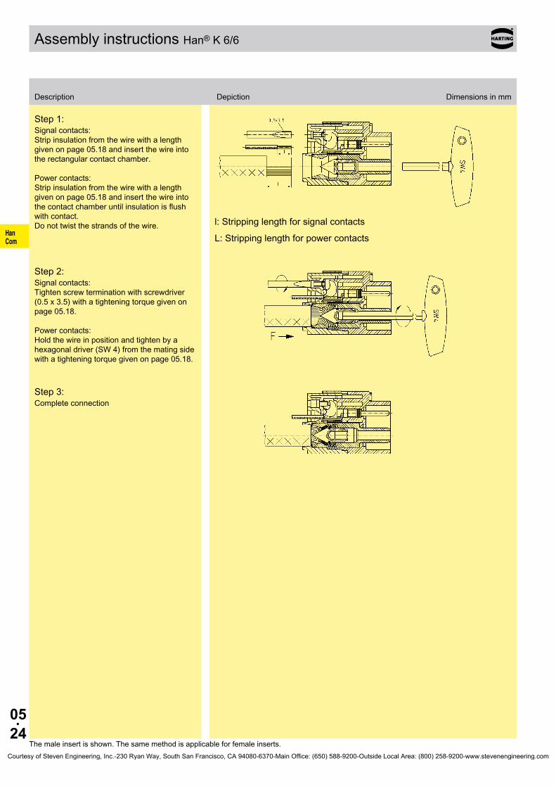
05.24
HanCom
Assembly instructions Han® K 6/6
Description Depiction Dimensions in mm
Step 1:Signal contacts: Strip insulation from the wire with a length given on page 05.18 and insert the wire into the rectangular contact chamber. Power contacts: Strip insulation from the wire with a length given on page 05.18 and insert the wire into the contact chamber until insulation is flush with contact. Do not twist the strands of the wire. l: Stripping length for signal contacts
L: Stripping length for power contacts
Step 2:Signal contacts: Tighten screw termination with screwdriver (0.5 x 3.5) with a tightening torque given on page 05.18. Power contacts: Hold the wire in position and tighten by a hexagonal driver (SW 4) from the mating side with a tightening torque given on page 05.18.
Step 3:Complete connection
The male insert is shown. The same method is applicable for female inserts.Courtesy of Steven Engineering, Inc.-230 Ryan Way, South San Francisco, CA 94080-6370-Main Office: (650) 588-9200-Outside Local Area: (800) 258-9200-www.stevenengineering.com
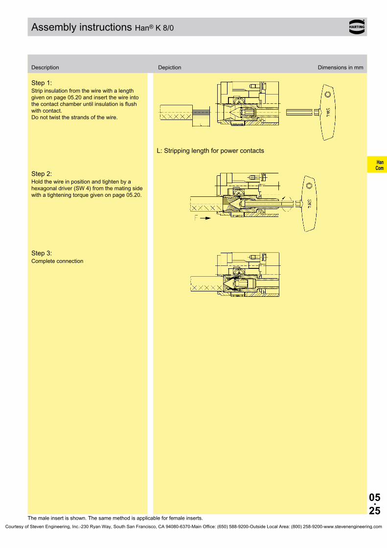
05.25
HanCom
Assembly instructions Han® K 8/0
Description Depiction Dimensions in mm
Step 1:Strip insulation from the wire with a length given on page 05.20 and insert the wire into the contact chamber until insulation is flush with contact. Do not twist the strands of the wire.
L: Stripping length for power contacts
Step 2:Hold the wire in position and tighten by a hexagonal driver (SW 4) from the mating side with a tightening torque given on page 05.20.
Step 3:Complete connection
The male insert is shown. The same method is applicable for female inserts.Courtesy of Steven Engineering, Inc.-230 Ryan Way, South San Francisco, CA 94080-6370-Main Office: (650) 588-9200-Outside Local Area: (800) 258-9200-www.stevenengineering.com

05.26
HanCom
Application
Welding robots in automotive productionABB Robotics AB, Västeras, Sweden
Courtesy of Steven Engineering, Inc.-230 Ryan Way, South San Francisco, CA 94080-6370-Main Office: (650) 588-9200-Outside Local Area: (800) 258-9200-www.stevenengineering.com
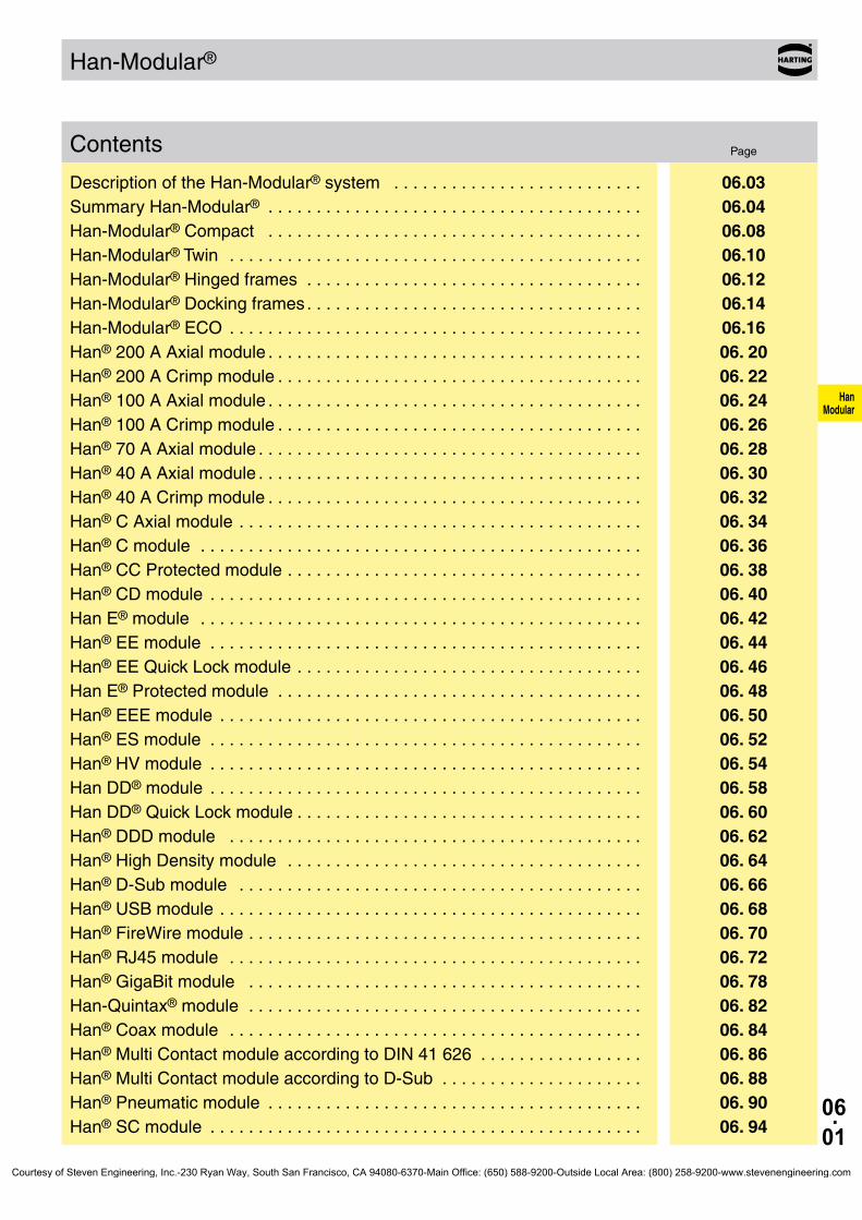
06.01
HanModular
Han-Modular®
PageContents
Description of the Han-Modular® system . . . . . . . . . . . . . . . . . . . . . . . . . . 06.03Summary Han-Modular® . . . . . . . . . . . . . . . . . . . . . . . . . . . . . . . . . . . . . . . 06.04Han-Modular® Compact . . . . . . . . . . . . . . . . . . . . . . . . . . . . . . . . . . . . . . . 06.08Han-Modular® Twin . . . . . . . . . . . . . . . . . . . . . . . . . . . . . . . . . . . . . . . . . . . 06.10Han-Modular® Hinged frames . . . . . . . . . . . . . . . . . . . . . . . . . . . . . . . . . . . 06.12Han-Modular® Docking frames . . . . . . . . . . . . . . . . . . . . . . . . . . . . . . . . . . . 06.14Han-Modular® ECO . . . . . . . . . . . . . . . . . . . . . . . . . . . . . . . . . . . . . . . . . . . 06.16Han® 200 A Axial module . . . . . . . . . . . . . . . . . . . . . . . . . . . . . . . . . . . . . . . 06. 20Han® 200 A Crimp module . . . . . . . . . . . . . . . . . . . . . . . . . . . . . . . . . . . . . . 06. 22Han® 100 A Axial module . . . . . . . . . . . . . . . . . . . . . . . . . . . . . . . . . . . . . . . 06. 24Han® 100 A Crimp module . . . . . . . . . . . . . . . . . . . . . . . . . . . . . . . . . . . . . . 06. 26Han® 70 A Axial module . . . . . . . . . . . . . . . . . . . . . . . . . . . . . . . . . . . . . . . . 06. 28Han® 40 A Axial module . . . . . . . . . . . . . . . . . . . . . . . . . . . . . . . . . . . . . . . . 06. 30Han® 40 A Crimp module . . . . . . . . . . . . . . . . . . . . . . . . . . . . . . . . . . . . . . . 06. 32Han® C Axial module . . . . . . . . . . . . . . . . . . . . . . . . . . . . . . . . . . . . . . . . . . 06. 34Han® C module . . . . . . . . . . . . . . . . . . . . . . . . . . . . . . . . . . . . . . . . . . . . . . 06. 36Han® CC Protected module . . . . . . . . . . . . . . . . . . . . . . . . . . . . . . . . . . . . . 06. 38Han® CD module . . . . . . . . . . . . . . . . . . . . . . . . . . . . . . . . . . . . . . . . . . . . . 06. 40Han E® module . . . . . . . . . . . . . . . . . . . . . . . . . . . . . . . . . . . . . . . . . . . . . . 06. 42Han® EE module . . . . . . . . . . . . . . . . . . . . . . . . . . . . . . . . . . . . . . . . . . . . . 06. 44Han® EE Quick Lock module . . . . . . . . . . . . . . . . . . . . . . . . . . . . . . . . . . . . 06. 46Han E® Protected module . . . . . . . . . . . . . . . . . . . . . . . . . . . . . . . . . . . . . . 06. 48Han® EEE module . . . . . . . . . . . . . . . . . . . . . . . . . . . . . . . . . . . . . . . . . . . . 06. 50Han® ES module . . . . . . . . . . . . . . . . . . . . . . . . . . . . . . . . . . . . . . . . . . . . . 06. 52Han® HV module . . . . . . . . . . . . . . . . . . . . . . . . . . . . . . . . . . . . . . . . . . . . . 06. 54Han DD® module . . . . . . . . . . . . . . . . . . . . . . . . . . . . . . . . . . . . . . . . . . . . . 06. 58Han DD® Quick Lock module . . . . . . . . . . . . . . . . . . . . . . . . . . . . . . . . . . . . 06. 60Han® DDD module . . . . . . . . . . . . . . . . . . . . . . . . . . . . . . . . . . . . . . . . . . . 06. 62Han® High Density module . . . . . . . . . . . . . . . . . . . . . . . . . . . . . . . . . . . . . 06. 64Han® D-Sub module . . . . . . . . . . . . . . . . . . . . . . . . . . . . . . . . . . . . . . . . . . 06. 66Han® USB module . . . . . . . . . . . . . . . . . . . . . . . . . . . . . . . . . . . . . . . . . . . . 06. 68Han® FireWire module . . . . . . . . . . . . . . . . . . . . . . . . . . . . . . . . . . . . . . . . . 06. 70Han® RJ45 module . . . . . . . . . . . . . . . . . . . . . . . . . . . . . . . . . . . . . . . . . . . 06. 72Han® GigaBit module . . . . . . . . . . . . . . . . . . . . . . . . . . . . . . . . . . . . . . . . . 06. 78Han-Quintax® module . . . . . . . . . . . . . . . . . . . . . . . . . . . . . . . . . . . . . . . . . 06. 82Han® Coax module . . . . . . . . . . . . . . . . . . . . . . . . . . . . . . . . . . . . . . . . . . . 06. 84Han® Multi Contact module according to DIN 41 626 . . . . . . . . . . . . . . . . . 06. 86Han® Multi Contact module according to D-Sub . . . . . . . . . . . . . . . . . . . . . 06. 88Han® Pneumatic module . . . . . . . . . . . . . . . . . . . . . . . . . . . . . . . . . . . . . . . 06. 90Han® SC module . . . . . . . . . . . . . . . . . . . . . . . . . . . . . . . . . . . . . . . . . . . . . 06. 94
Courtesy of Steven Engineering, Inc.-230 Ryan Way, South San Francisco, CA 94080-6370-Main Office: (650) 588-9200-Outside Local Area: (800) 258-9200-www.stevenengineering.com

06.02
HanModular
Han-Modular®
Han-Elisa® . . . . . . . . . . . . . . . . . . . . . . . . . . . . . . . . . . . . . . . . . . . . . . . . . . 06. 96Han-Elisa® Pt100 Modul . . . . . . . . . . . . . . . . . . . . . . . . . . . . . . . . . . . . . . . 06. 98Han-Elisa® Output module . . . . . . . . . . . . . . . . . . . . . . . . . . . . . . . . . . . . . 06.100Han-Elisa® ID module . . . . . . . . . . . . . . . . . . . . . . . . . . . . . . . . . . . . . . . . . 06.102Han-Modular® Accessories . . . . . . . . . . . . . . . . . . . . . . . . . . . . . . . . . . . . . 06.104
Courtesy of Steven Engineering, Inc.-230 Ryan Way, South San Francisco, CA 94080-6370-Main Office: (650) 588-9200-Outside Local Area: (800) 258-9200-www.stevenengineering.com

06.03
HanModular
Han-Modular®
Description of the Han-Modular® system
The Han-Modular® series is a new system of inserts designed to meet the specific requirements of individual customers. In close cooperation with potential users a range of modular inserts have been developed allow-ing the simple assembly of custom designed complete connectors which meet the diverse requirements encountered by designers today.
Han-Modular® is a logical development of the Han-Com® series which already offers the combination of power and signal circuits in one con-nector.
The individual modules of this series now allow the integration of electri-cal, optical and gaseous signal and power connections in one connector assembly.
The pneumatic contacts are also suitable for the connection of liquid media. However it must be stated that a combination of electrical and liquid connections in one connector is not allowed according to VDE regulations.
The individual contacts used in this system are all from existing well proven ranges and it is possible to use combinations of 1 to 12 modules depending on the size of the hoods and housings chosen.
The basic modules snap into a mounting frame and can be exchanged separately at any time.
Advantages:❑ Custom designs can be simply assembled❑ Optimum solutions can be reached❑ Stock can be minimized
Assembly details
Courtesy of Steven Engineering, Inc.-230 Ryan Way, South San Francisco, CA 94080-6370-Main Office: (650) 588-9200-Outside Local Area: (800) 258-9200-www.stevenengineering.com

06.04
HanModular
Han-Modular® Compact
Han-Modular® Twin
Han-Modular® ECO
Summary Han-Modular®
Page 06.08
Page 06.10
Han-Modular® Hinged frames in Han® B hoods and housings
Han-Modular® Docking frame
Page 06.14
Page 06.16
Page 06.12
Courtesy of Steven Engineering, Inc.-230 Ryan Way, South San Francisco, CA 94080-6370-Main Office: (650) 588-9200-Outside Local Area: (800) 258-9200-www.stevenengineering.com

06.05
HanModular
1 1 2 2
2 2 2 3
3 4 3 / 4 6
8 8 6 20
Summary Han-Modular®
Series Han® 200 A Axial module Han® 200 A Crimp module Han® 100 A Axial module Han® 100 A Crimp module
Number of contacts
Modules Axial screw terminal Crimp terminal Axial screw terminal Crimp terminal
Rated currentRated voltageWire gaugePage
200 A1000 V
25 ... 70 mm²06.20
200 A1000 / 1000 V25 ... 70 mm²
06.22
100 A1000 V
10 ... 38 mm²06.24
100 A1000 V
10 ... 35 mm²06.26
Series Han® 70 A Axial module Han® 40 A Axial module Han® 40 A Crimp module Han® C Axial module
Number of contacts
Modules Axial screw terminal Axial screw terminal Crimp terminal Axial screw terminal
Rated currentRated voltageWire gaugePage
70 A1000 V
6 ... 22 mm²06.28
40 A1000 V
2.5 ... 10 mm²06.30
40 A1000 V
1.5 ... 10 mm²06.32
40 A690 V
2.5 ... 10 mm²06.34
Series Han® C module Han® CC Protected module Han® CD module Han E® module
Number of contacts
Modules Crimp terminal Crimp terminal Crimp terminal Crimp terminal
Rated currentRated voltageWire gaugePage
40 A400 / 690 V
1.5 ... 10 mm²06.36
40 A830 V
1.5 ... 6 mm²06.38
40 A / 10 A830 V / 830 V
1.5 ... 6 mm² / 0.14 ... 2.5 mm²06.40
16 A500 V
0.14 ... 4 mm²06.42
Series Han® EE module Han® EE Quick Lock module Han E® Protected module Han® EEE module
Number of contacts
Modules Crimp terminal Quick Lock terminal Crimp terminal Crimp terminal
Rated currentRated voltageWire gaugePage
16 A400 V
0.14 ... 4 mm²06.44
16 A400 V
0.5 ... 2.5 mm²06.46
16 A830 V
0.14 ... 4 mm²06.48
16 A500 V
0.14 ... 4 mm²06.50
Courtesy of Steven Engineering, Inc.-230 Ryan Way, South San Francisco, CA 94080-6370-Main Office: (650) 588-9200-Outside Local Area: (800) 258-9200-www.stevenengineering.com

06.06
HanModular
5 2 2 12
12 17 25 9
4 6 8 8
USB 2.0 IEEE 1394
06.68 06.70 06.72 06.78
2 4
06.82 06.84 06.86 06.88
75 Ω 50 Ω50 Ω RG 174 75 Ω RG 179 50 Ω RG 58
Summary Han-Modular®
* HCS®=Hard Clad Silica (is registered trade mark of the SpecTran Corporation)
Series Han® ES module Han® HV module Han® HV module Han DD® module
Number of contacts
Modules Cage-clamp terminal Crimp terminal Crimp terminal Crimp terminal
Rated currentRated voltageWire gaugePage
16 A400 V
0.14 ... 2.5 mm²06.52
16 A2900 / 5000 V0.5 ... 4 mm²
06.54
40 A2900 / 5000 V1.5 ... 10 mm²
06.56
10 A250 V
0.14 ... 2.5 mm²06.58
Series Han DD® Quick Lock module Han® DDD module Han® High Density module Han® D-Sub module
Number of contacts
Modules Quick Lock terminal Crimp terminal Crimp terminal Crimp terminal
Rated currentRated voltageWire gaugePage
10 A250 V
0.25 ... 1.5 mm²06.60
10 A160 V
0.14 ... 2.5 mm²06.62
4 A50 V
0.08 ... 0.52 mm²06.64
5 A50 V
0.08 ... 0.52 mm²06.66
Series Han® USB module Han® FireWire module Han® RJ45 module Han® GigaBit module
Number of contacts
Modules Ethernet Cat. 5e Ethernet Cat. 6
Page
Series Han-Quintax® module Han® Multi Contact module
Number of contacts
Modules
Page
Contacts Quintax contact4 + shielding
High Density Quintax contact
8 + shielding
Han D® D Coax contact
1 + shielding
Han E® E Coax contact
1 + shieldingFOC contacts Coaxial contact
Multimode F.O. HCS®*/PCF F.O.
1 mm POF
Courtesy of Steven Engineering, Inc.-230 Ryan Way, South San Francisco, CA 94080-6370-Main Office: (650) 588-9200-Outside Local Area: (800) 258-9200-www.stevenengineering.com

06.07
HanModular
2 3 4
06.90 06.92 06.94 06.96 06.104
Series Han® Pneumatic module Han® SC module Han-Elisa® Dummy module
Number of contacts
Modules
Page
Contacts SC contactTemperature I/O modules ID module
∅ 6.0 mm∅ 1.6 mm ∅ 3.0 mm ∅ 4.0 mm
Summary Han-Modular®
Courtesy of Steven Engineering, Inc.-230 Ryan Way, South San Francisco, CA 94080-6370-Main Office: (650) 588-9200-Outside Local Area: (800) 258-9200-www.stevenengineering.com

06.08
HanModular
Han-Modular® Compact
Features• Compact design saves space• Modular structure increases flexibility• Simple and quick assembly• Robust design• Two part grommet housing
Current carrying capacityThe current carrying capacity of the connectors is limited by the thermal load capability of the contact element material including the connections and the insulating parts. The derating curve is therefore valid for currents which flow constantly (non-inter-mittent) through each contact element of the connector evenly, without exceeding the allowed maximum temperature.Measuring and testing techniques according to DIN EN 60 512-5
Ope
ratin
g cu
rrent
Ambient temperature
➀ Han® Axial screw module, Wire gauge: 10 mm²
➁ Han® C module, Wire gauge: 6 mm²
Technical characteristicsHoods/Housings
Material zinc die-cast Surface nickel plated Locking element stainless steel Hoods/Housings sealing NBR Limiting temperatures -40 °C ... +125 °C Degree of protection acc. to DIN EN 60 529 for coupled connector IP 65 Mechanical working life - mating cycles 500 PE contact wire gauge 10 mm² / AWG 8 Stripping length 10 mm Tightening tourque 1 Nm
Protection covers for housings, bulkhead mountingMaterial polycarbonate Locking element Polyamide Hoods/Housings sealing NBR Limiting temperatures -40 °C ... +125 °C Degree of protection acc. to DIN EN 60 529 for coupled connector IP 65 Flammability acc. to UL 94 V 0
➀ Hood with side entry ➁ Thread M25 ➂ Bulkhead mounted housing with locking lever ➃ Carrier hood
Courtesy of Steven Engineering, Inc.-230 Ryan Way, South San Francisco, CA 94080-6370-Main Office: (650) 588-9200-Outside Local Area: (800) 258-9200-www.stevenengineering.com

06.09
HanModular
Han-Modular® Compact
19 14 001 0501
19 14 001 0401
19 14 001 0402
09 14 001 0311
09 14 001 5402
09 14 001 0301
09 14 001 5401
Stock items in bold type
Identification Part number Drawing Dimensions in mm
Hoods side entry M25
4 screws are included in the delivery range
Hoods top entry M25
4 screws are included in the delivery range
Hoods top entry M32
4 screws are included in the delivery range
Carrier hood
Protection covers
Housings, bulkhead mounting
Panel cut out
Protection covers for housings, bulkhead mounting
Courtesy of Steven Engineering, Inc.-230 Ryan Way, South San Francisco, CA 94080-6370-Main Office: (650) 588-9200-Outside Local Area: (800) 258-9200-www.stevenengineering.com

06.10
HanModular
Han-Modular® Twin
Features• Compact and space saving• High degree of flexibility due to modular assembly• Easy and quick assembly• Robust design• Hood consists of two parts
Technical characteristicsHoods/Housings
Material aluminium die-cast Surface powder-coated Locking element Han-Easy Lock® Material Panel feed through housing / Shielding frame zinc die-cast Hoods/Housings seal NBR Limiting temperatures -40 °C ... +125 °C Degree of protection acc. to DIN EN 60 529 for coupled connector IP 65 Mechanical working life - mating cycles ≥ 500 PE contact wire gauge 10 mm² / AWG 8 Stripping length 10 mm Tightening torque 1 Nm
➀ Hood with top entry ➁ Carrier hood ➂ Bulkhead mounted housing with locking lever ➃ Switch board panel ➄ Split Hood ➅ Thread M32
Courtesy of Steven Engineering, Inc.-230 Ryan Way, South San Francisco, CA 94080-6370-Main Office: (650) 588-9200-Outside Local Area: (800) 258-9200-www.stevenengineering.com
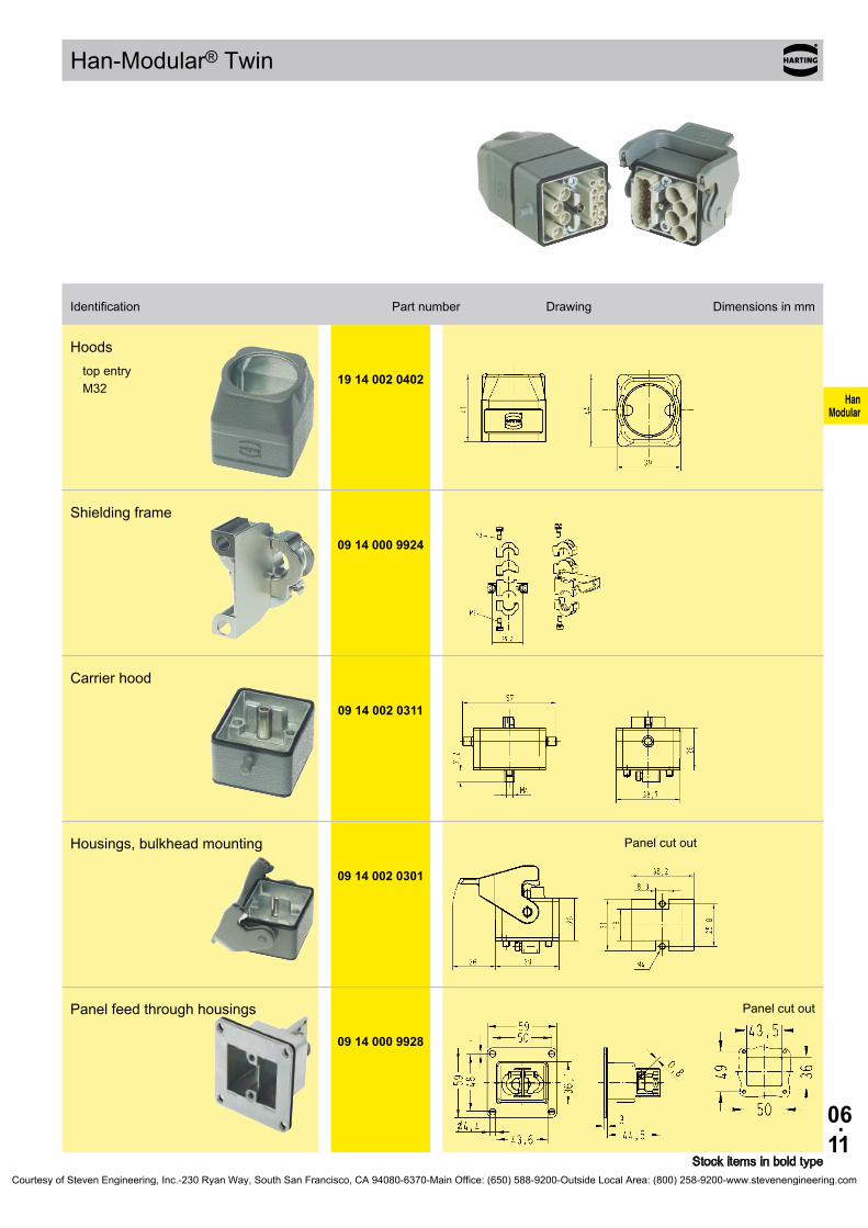
06.11
HanModular
Han-Modular® Twin
19 14 002 0402
09 14 000 9924
09 14 002 0311
09 14 002 0301
09 14 000 9928
Stock items in bold type
Identification Part number Drawing Dimensions in mm
Hoods top entry M32
Shielding frame
Carrier hood
Housings, bulkhead mounting Panel cut out
Panel feed through housings Panel cut out
Courtesy of Steven Engineering, Inc.-230 Ryan Way, South San Francisco, CA 94080-6370-Main Office: (650) 588-9200-Outside Local Area: (800) 258-9200-www.stevenengineering.com

06.12
HanModular
Han-Modular® Hinged frames
Features• Pre-leading grounding system according VDE• Modules can only be assembled polarized to
guarantee a correct orientation• Alphabetical marking of module position• High mechanical reliability of modules in case of
vibration and impact stress• No tools necessary to remove modules
Technical characteristicsSpecifications DIN EN 60 664-1 DIN EN 61 984 Approvals ,
Hinged framesNumber of modules 2, 3, 4, 6 PE contact Wire gauge - Power side * 4 ... 10 mm² AWG 12 ... 8 - Signal side 1 ... 2.5 mm² AWG 18 ... 14 Material zinc die-cast Limiting temperatures -40 °C ... +125 °C Mechanical working life - mating cycles ≥ 500
Hoods/HousingsSelection of hoods/housings see chapter 30 / chapter 31Material aluminium die-cast Surface powder-coated RAL 7037 Locking element Han-Easy Lock® Hoods/Hosuings seal NBR Limiting temperatures -40 °C ... +125 °C Degree of protection acc. to DIN EN 60 529 for coupled connector IP 65
AccessoriesCoding of hoods/housings chapter 40
* 10 mm² / AWG 8 only with ferrule crimp tool 09 99 000 0374
Courtesy of Steven Engineering, Inc.-230 Ryan Way, South San Francisco, CA 94080-6370-Main Office: (650) 588-9200-Outside Local Area: (800) 258-9200-www.stevenengineering.com
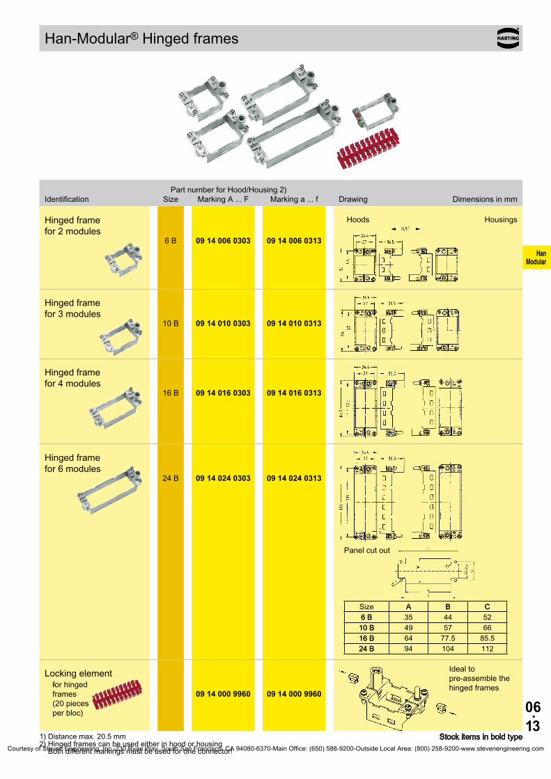
06.13
HanModular
6 B 09 14 006 0303 09 14 006 0313
10 B 09 14 010 0303 09 14 010 0313
16 B 09 14 016 0303 09 14 016 0313
24 B 09 14 024 0303 09 14 024 0313
A B C6 B10 B16 B24 B
-
09 14 000 9960 09 14 000 9960
Han-Modular® Hinged frames
Stock items in bold type1) Distance max. 20.5 mm2) Hinged frames can be used either in hood or housing
Both different markings must be used for one connector!
Part number for Hood/Housing 2) Identification Size Marking A ... F Marking a ... f Drawing Dimensions in mm
Locking elementfor hinged frames (20 pieces per bloc)
Ideal to pre-assemble the hinged frames
Hinged frame for 2 modules
Hoods Housings
Hinged frame for 3 modules
Hinged frame for 4 modules
Hinged frame for 6 modules
Panel cut out
Size A B C6 B 35 44 52
10 B 49 57 6616 B 64 77.5 85.524 B 94 104 112
Courtesy of Steven Engineering, Inc.-230 Ryan Way, South San Francisco, CA 94080-6370-Main Office: (650) 588-9200-Outside Local Area: (800) 258-9200-www.stevenengineering.com
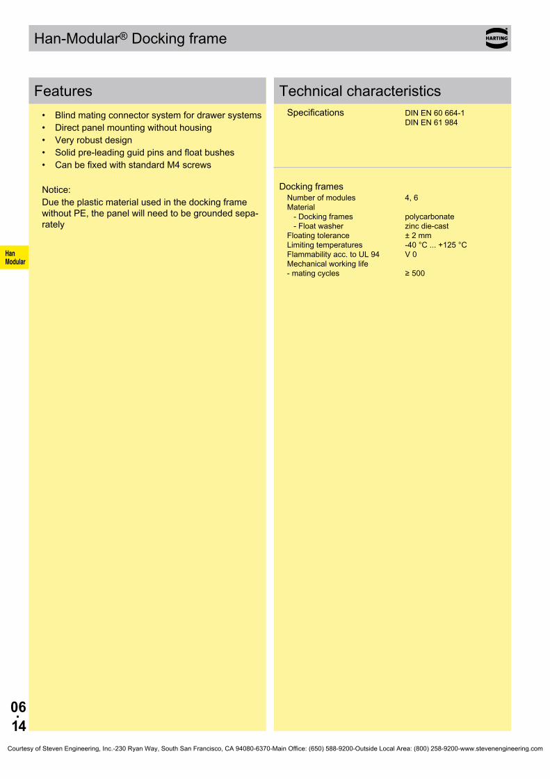
06.14
HanModular
Han-Modular® Docking frame
Features• Blind mating connector system for drawer systems• Direct panel mounting without housing• Very robust design• Solid pre-leading guid pins and float bushes• Can be fixed with standard M4 screws
Notice:Due the plastic material used in the docking frame without PE, the panel will need to be grounded sepa-rately
Technical characteristicsSpecifications DIN EN 60 664-1 DIN EN 61 984
Docking framesNumber of modules 4, 6 Material - Docking frames polycarbonate - Float washer zinc die-cast Floating tolerance ± 2 mm Limiting temperatures -40 °C ... +125 °C Flammability acc. to UL 94 V 0 Mechanical working life - mating cycles ≥ 500
Courtesy of Steven Engineering, Inc.-230 Ryan Way, South San Francisco, CA 94080-6370-Main Office: (650) 588-9200-Outside Local Area: (800) 258-9200-www.stevenengineering.com

06.15
HanModular
09 14 016 1701
09 14 016 1711
09 14 024 1701
09 14 024 1711
09 14 000 9936
Han-Modular® Docking frame
Stock items in bold type1) Float mount2) Fixed
Part number Identification Marking A ... F 1) Marking a ... f 2) Drawing Dimensions in mm
Docking frame for 4 modules
① floating tolerance ±2 mm
Docking frame for 4 modules
Panel cut out
Docking frame for 6 modules
① floating tolerance ±2 mm
Docking frame for 6 modules
Panel cut out
Float washerto enable the frame to be float mounted using standard M4 fixing screws
Courtesy of Steven Engineering, Inc.-230 Ryan Way, South San Francisco, CA 94080-6370-Main Office: (650) 588-9200-Outside Local Area: (800) 258-9200-www.stevenengineering.com

06.16
HanModular
Han-Modular® ECO
Features• Suitable for all Han-Modular® single modules• The variant with PE connection uses pin 1 of the
module as PE• Slim, space saving design• Low cost plastic hoods and housings
Technical characteristicsSpecifications DIN EN 60 664-1 DIN EN 61 984
Hoods/HousingsMaterial - Hoods/Housings polycarbonate - Seal NBR - Cable seal Polyamide Limiting temperatures -40 °C ... +85 °C Flammability acc. to UL 94 V 0 Degree of protection acc. to DIN EN 60 529 for coupled connector IP 20 / IP 65 Mechanical working life - mating cycles ≥ 500
Courtesy of Steven Engineering, Inc.-230 Ryan Way, South San Francisco, CA 94080-6370-Main Office: (650) 588-9200-Outside Local Area: (800) 258-9200-www.stevenengineering.com

06.17
HanModular
Han-Modular® ECO
09 14 001 0421
09 14 001 0423
09 14 001 0321
09 14 000 9929
Stock items in bold type
Plastic hoods/housings
with PE marking
Identification Part number Drawing Dimensions in mm
Hoodswith PE marking (pin 1 = PE)IP 65top entry
Hoodswith PE marking (pin 1 = PE)IP 20top entry
Hoodswith PE marking (pin 1 = PE)IP 20 / IP 65top entry
Panel cut out
Coding pin Range of delivery: 8 pieces per frame
Courtesy of Steven Engineering, Inc.-230 Ryan Way, South San Francisco, CA 94080-6370-Main Office: (650) 588-9200-Outside Local Area: (800) 258-9200-www.stevenengineering.com

06.18
HanModular
Han-Modular® ECO
09 14 001 0420
09 14 001 0422
09 14 001 0320
09 14 000 9929
Stock items in bold type
Plastic hoods/housings
without PE
Identification Part number Drawing Dimensions in mm
Hoodswithout PEIP 65top entry
Hoodswithout PEIP 20top entry
Hoodswithout PEIP 20 / IP 65top entry
Panel cut out
Coding pin Range of delivery: 8 pieces per frame
Courtesy of Steven Engineering, Inc.-230 Ryan Way, South San Francisco, CA 94080-6370-Main Office: (650) 588-9200-Outside Local Area: (800) 258-9200-www.stevenengineering.com
06.19
HanModular
Notes
Courtesy of Steven Engineering, Inc.-230 Ryan Way, South San Francisco, CA 94080-6370-Main Office: (650) 588-9200-Outside Local Area: (800) 258-9200-www.stevenengineering.com

06.20
HanModular
Han® 200 A Axial module
Features• Axial-screw termination• No special tools required• Power module for big wire gauge up to 70 mm²• Suitable as a 3 + PE connector in a Han® 32 B
housing• Compatible to the Han® 200 A module with crimp
terminal
Current carrying capacityThe current carrying capacity of the connectors is limited by the thermal load capability of the contact element material including the connections and the insulating parts. The derating curve is therefore valid for currents which flow constantly (non-inter-mittent) through each contact element of the connector evenly, without exceeding the allowed maximum temperature.Measuring and testing techniques according to DIN EN 60 512-5
Ope
ratin
g cu
rrent
Ambient temperature
➀ 24 B hoods/housings with 3 modules; wire gauge: 50 mm²
➁ 24 B hoods/housings with 3 modules; wire gauge: 70 mm²
Technical characteristicsSpecifications DIN EN 60 664-1 DIN EN 61 984 Approvals
InsertsNumber of contacts 1 Electrical data acc. to EN 61 984 200 A 1000 V 8 kV 3 Rated current 200 A Rated voltage 1000 V Rated impulse voltage 8 kV Pollution degree 3
Rated voltage acc. to UL 600 V Insulation resistance ≥ 1010 Ω Material polycarbonate Limiting temperatures -40 °C ... +125 °C Flammability acc. to UL 94 V 0 Mechanical working life - mating cycles ≥ 500
ContactsMaterial copper alloy Surface - hard-silver plated 3 µm Ag Contact resistance 0.2 mΩ Screw terminal - Wire gauge 1) 25 ... 70 mm² - AWG 2 ... 00 - Hexagonal driver SW 5 - Stripping length 16 mm - Tightening tourque mm² 25 35 50 70
Nm 8 8 9 10
1) geometric wire gaugeCourtesy of Steven Engineering, Inc.-230 Ryan Way, South San Francisco, CA 94080-6370-Main Office: (650) 588-9200-Outside Local Area: (800) 258-9200-www.stevenengineering.com

06.21
HanModular
09 14 001 2663 09 14 001 2763
09 14 001 2662 09 14 001 2762
09 14 001 2668 09 14 001 2768
09 14 001 2667 09 14 001 2767
09 99 000 0364
09 99 000 0371
Han® 200 A Axial module 1000 V 200 A
Identification Part number Drawing Dimensions in mm
Stock items in bold type
Number of contacts
1
Part number Identification Male insert (M) Female insert (F) Drawing Dimensions in mm
Axial screw terminal 200 A
25 ... 40 mm²
40 ... 70 mm²
Axial screw terminal 200 A PE (Ground)
25 ... 40 mm²
40 ... 70 mm²
Hex key SW 5for axial setscrew
with grip
adapter 3/8“
Courtesy of Steven Engineering, Inc.-230 Ryan Way, South San Francisco, CA 94080-6370-Main Office: (650) 588-9200-Outside Local Area: (800) 258-9200-www.stevenengineering.com

06.22
HanModular
Han® 200 A Crimp module
Features• Crimp termination• Contacts can be unlocked from the mating side• Compatible with Han® 200 A modules with axial
screw terminal
Current carrying capacityThe current carrying capacity of the connectors is limited by the thermal load capability of the contact element material including the connections and the insulating parts. The derating curve is therefore valid for currents which flow constantly (non-inter-mittent) through each contact element of the connector evenly, without exceeding the allowed maximum temperature.Measuring and testing techniques according to DIN EN 60 512-5
Ope
ratin
g cu
rrent
Ambient temperature ➀ 24 B hoods/housings with 3 modules; wire gauge: 50 mm²➁ 24 B hoods/housings with 3 modules; wire gauge: 70 mm²
Technical characteristicsSpecifications EN 50 124-1 DIN EN 60 664-1 DIN EN 61 984
InsertsNumber of contacts 1 Electrical data acc. to EN 61 984 200 A 1000 V 8 kV 3 Rated current 200 A Rated voltage 1000 V Rated impulse voltage 8 kV Pollution degree 3Insulation resistance ≥ 1010 Ω Material polycarbonate Limiting temperatures -40 °C ... +125 °C Flammability acc. to UL 94 V 0 Mechanical working life - mating cycles ≥ 500
ContactsMaterial copper alloy Surface - hard-silver plated 3 µm Ag Contact resistance ≤ 0.3 mΩ Crimp terminal - mm² 25 ... 70 mm² Stripping length 22.5 mm Max. insulation diameter 18 mm
Courtesy of Steven Engineering, Inc.-230 Ryan Way, South San Francisco, CA 94080-6370-Main Office: (650) 588-9200-Outside Local Area: (800) 258-9200-www.stevenengineering.com
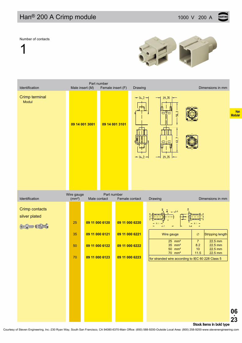
06.23
HanModular
09 14 001 3001 09 14 001 3101
∅
25355070
mm²mm²mm²mm²
25 09 11 000 6120 09 11 000 6220
35 09 11 000 6121 09 11 000 6221
50 09 11 000 6122 09 11 000 6222
70 09 11 000 6123 09 11 000 6223
Han® 200 A Crimp module 1000 V 200 A
Stock items in bold type
Number of contacts
1
Part number Identification Male insert (M) Female insert (F) Drawing Dimensions in mm
Crimp terminalModul
Wire gauge Part number Identification (mm²) Male contact Female contact Drawing Dimensions in mm
Crimp contacts
silver plated
Wire gauge Stripping length
78.210
11.5
22.5 mm22.5 mm22.5 mm22.5 mm
for stranded wire according to IEC 60 228 Class 5
Courtesy of Steven Engineering, Inc.-230 Ryan Way, South San Francisco, CA 94080-6370-Main Office: (650) 588-9200-Outside Local Area: (800) 258-9200-www.stevenengineering.com

06.24
HanModular
Han® 100 A Axial module
Features• Axial-screw termination• No special tools required• Connect PE contact with special cable shoe• Compatible to the Han® 100 A module with crimp
terminal
Current carrying capacityThe current carrying capacity of the connectors is limited by the thermal load capability of the contact element material including the connections and the insulating parts. The derating curve is therefore valid for currents which flow constantly (non-inter-mittent) through each contact element of the connector evenly, without exceeding the allowed maximum temperature.Measuring and testing techniques according to DIN EN 60 512-5
Ope
ratin
g cu
rrent
Ambient temperature
➀ 24 B hoods/housings with 3 modules; wire gauge: 35 mm²
➁ 24 B hoods/housings with 3 modules; wire gauge: 25 mm²
Technical characteristicsSpecifications DIN EN 60 664-1 DIN EN 61 984 Approvals
InsertsNumber of contacts 2 Electrical data acc. to EN 61 984 100 A 1000 V 8 kV 3 Rated current 100 A Rated voltage 1000 V Rated impulse voltage 8 kV Pollution degree 3
Rated voltage acc. to UL 600 V Insulation resistance ≥ 1010 Ω Material polycarbonate Limiting temperatures -40 °C ... +125 °C Flammability acc. to UL 94 V 0 Mechanical working life - mating cycles ≥ 500
ContactsMaterial copper alloy Surface - hard-silver plated 3 µm Ag Contact resistance 0.3 mΩ Screw terminal - Wire gauge 1) 10 ... 38 mm² - AWG 6 ... 2 - Hexagonal driver SW 4 - Stripping length 13 mm - Tightening tourque mm² 10 16 25 35
Nm 6 6 7 8
1) geometric wire gaugeCourtesy of Steven Engineering, Inc.-230 Ryan Way, South San Francisco, CA 94080-6370-Main Office: (650) 588-9200-Outside Local Area: (800) 258-9200-www.stevenengineering.com

06.25
HanModular
09 14 002 2653 09 14 002 2753
09 14 002 2651 09 14 002 2751
09 14 002 2650 09 14 002 2750
09 99 000 0363
09 99 000 0370
09 14 000 9912
Han® 100 A Axial module 1000 V 100 A
Identification Part number Drawing Dimensions in mm
Stock items in bold type
Number of contacts
2
Part number Identification Male insert (M) Female insert (F) Drawing Dimensions in mm
Axial screw terminal 100 A
10 ... 25 mm²
16 ... 35 mm²
38 mm²
Hex key SW 4for axial setscrew
with grip
adapter 3/8“
Cable shoe 16 mm²
for PE extension
Comment for hoods/housings high construction only
Please use pressing tools for non-insulated cable shoes fol-lowing DIN 46 230 with 16 mm² range (eg. K25, co. Klauke)
Courtesy of Steven Engineering, Inc.-230 Ryan Way, South San Francisco, CA 94080-6370-Main Office: (650) 588-9200-Outside Local Area: (800) 258-9200-www.stevenengineering.com
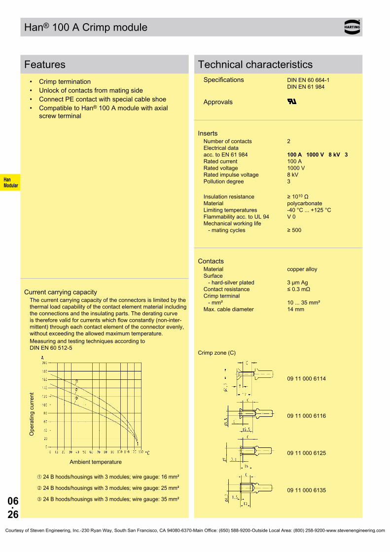
06.26
HanModular
09 11 000 6114
09 11 000 6116
09 11 000 6125
09 11 000 6135
Han® 100 A Crimp module
Features• Crimp termination• Unlock of contacts from mating side• Connect PE contact with special cable shoe• Compatible to Han® 100 A module with axial
screw terminal
Current carrying capacityThe current carrying capacity of the connectors is limited by the thermal load capability of the contact element material including the connections and the insulating parts. The derating curve is therefore valid for currents which flow constantly (non-inter-mittent) through each contact element of the connector evenly, without exceeding the allowed maximum temperature.Measuring and testing techniques according to DIN EN 60 512-5
Ope
ratin
g cu
rrent
Ambient temperature
➀ 24 B hoods/housings with 3 modules; wire gauge: 16 mm²
➁ 24 B hoods/housings with 3 modules; wire gauge: 25 mm²
➂ 24 B hoods/housings with 3 modules; wire gauge: 35 mm²
Technical characteristicsSpecifications DIN EN 60 664-1 DIN EN 61 984 Approvals
InsertsNumber of contacts 2 Electrical data acc. to EN 61 984 100 A 1000 V 8 kV 3 Rated current 100 A Rated voltage 1000 V Rated impulse voltage 8 kV Pollution degree 3
Insulation resistance ≥ 1010 Ω Material polycarbonate Limiting temperatures -40 °C ... +125 °C Flammability acc. to UL 94 V 0 Mechanical working life - mating cycles ≥ 500
ContactsMaterial copper alloy Surface - hard-silver plated 3 µm Ag Contact resistance ≤ 0.3 mΩ Crimp terminal - mm² 10 ... 35 mm² Max. cable diameter 14 mm
Crimp zone (C)
Courtesy of Steven Engineering, Inc.-230 Ryan Way, South San Francisco, CA 94080-6370-Main Office: (650) 588-9200-Outside Local Area: (800) 258-9200-www.stevenengineering.com

06.27
HanModular
09 14 002 3051 09 14 002 3151
09 99 000 0383 09 99 000 0383
09 11 000 6114 09 11 000 6214
09 11 000 6116 09 11 000 6216
09 11 000 6125 09 11 000 6225
09 11 000 6135 09 11 000 6235
∅
10162535
mm²mm²mm²mm²
19 mm19 mm19 mm16 mm
Han® 100 A Crimp module 1000 V 100 A
Stock items in bold type
Number of contacts
2
Part number Identification Male insert (M) Female insert (F) Drawing Dimensions in mm
Crimp terminalModul
Removal toolfor TC contacts
Wire gauge Part number Identification (mm²) Male contact Female contact Drawing Dimensions in mm
Crimp contacts
silver plated
10
16
25
35
Wire gauge Stripping length
4.35.57
8.2
for stranded wire according to IEC 60 228 Class 5
Courtesy of Steven Engineering, Inc.-230 Ryan Way, South San Francisco, CA 94080-6370-Main Office: (650) 588-9200-Outside Local Area: (800) 258-9200-www.stevenengineering.com

06.28
HanModular
Han® 70 A Axial module
Features• Axial-screw termination• 2 contacts (70 A) for power circuits• Male inserts with protection collar• Polarisation of module• Male and female contacts are finger safe
Current carrying capacityThe current carrying capacity of the connectors is limited by the thermal load capability of the contact element material including the connections and the insulating parts. The derating curve is therefore valid for currents which flow constantly (non-inter-mittent) through each contact element of the connector evenly, without exceeding the allowed maximum temperature.Measuring and testing techniques according to DIN EN 60 512-5
Ope
ratin
g cu
rrent
Ambient temperature
➀ 24 B hoods/housings with 6 modules; wire gauge: 6 mm²
➁ 24 B hoods/housings with 6 modules; wire gauge: 16 mm²
➂ 24 B hoods/housings with 6 modules; wire gauge: 22 mm²
Technical characteristicsSpecifications DIN EN 60 664-1 DIN EN 61 984 Approvals
InsertsNumber of contacts 2 Electrical data acc. to EN 61 984 70 A 1000 V 8 kV 3 Rated current 70 A Rated voltage 1000 V Rated impulse voltage 8 kV Pollution degree 3
Rated voltage acc. to UL 600 V Insulation resistance ≥ 1010 Ω Material polycarbonate Limiting temperatures -40 °C ... +125 °C Flammability acc. to UL 94 V 0 Mechanical working life - mating cycles ≥ 500
ContactsMaterial copper alloy Surface - hard-silver plated 3 µm Ag Contact resistance 0.5 mΩ Screw terminal - Wire gauge 1) 6 ... 22 mm² - AWG 8 ... 4 - Hexagonal driver SW 2.5 - Stripping length mm² 6 10 16 22
mm 11+1 11+1 11+1 12.5+1
- Tightening tourque mm² 6 10 16 22
Nm 2 3 4 5
1) geometric wire gaugeCourtesy of Steven Engineering, Inc.-230 Ryan Way, South San Francisco, CA 94080-6370-Main Office: (650) 588-9200-Outside Local Area: (800) 258-9200-www.stevenengineering.com

06.29
HanModular
09 99 000 0375
6 ... 16 mm² 09 14 002 2646 09 14 002 2741
14 ... 22 mm² 09 14 002 2647 09 14 002 2742
6 ... 16 mm² 09 14 002 2641
14 ... 22 mm² 09 14 002 2642
Han® 70 A Axial module 1000 V 70 A
Identification Part number Drawing Dimensions in mm
Stock items in bold type
Number of contacts
2
Part number Identification Male insert (M) Female insert (F) Drawing Dimensions in mm
Axial screw terminal 70 A
6 ... 16 mm²
14 ... 22 mm²
Hex key SW 2.5for axial setscrew
Bit 1/4“
Axial screw terminal 70 A with finger protected male contacts
Courtesy of Steven Engineering, Inc.-230 Ryan Way, South San Francisco, CA 94080-6370-Main Office: (650) 588-9200-Outside Local Area: (800) 258-9200-www.stevenengineering.com

06.30
HanModular
Han® 40 A Axial module
Features• Axial-screw termination• No special tools required• Compatible to Han® 40 A module with crimp
terminal
Current carrying capacityThe current carrying capacity of the connectors is limited by the thermal load capability of the contact element material including the connections and the insulating parts. The derating curve is therefore valid for currents which flow constantly (non-inter-mittent) through each contact element of the connector evenly, without exceeding the allowed maximum temperature.Measuring and testing techniques according to DIN EN 60 512-5
Ope
ratin
g cu
rrent
Ambient temperature
➀ 24 B hoods/housings with 6 modules; wire gauge: 10 mm²
➁ 24 B hoods/housings with 6 modules; wire gauge: 6 mm²
Technical characteristicsSpecifications DIN EN 60 664-1 DIN EN 61 984 Approvals
InsertsNumber of contacts 2 Electrical data acc. to EN 61 984 40 A 1000 V 8 kV 3 Rated current 40 A Rated voltage 1000 V Rated impulse voltage 8 kV Pollution degree 3
Rated voltage acc. to UL 600 V Insulation resistance ≥ 1010 Ω Material polycarbonate Limiting temperatures -40 °C ... +125 °C Flammability acc. to UL 94 V 0 Mechanical working life - mating cycles ≥ 500
ContactsMaterial copper alloy Surface - hard-silver plated 3 µm Ag Contact resistance 0.5 mΩ Screw terminal - Wire gauge 1) 2.5 ... 10 mm² - AWG 14 ... 8 - Hexagonal driver SW 2 - Stripping length mm² 2.5 4 6 10
mm 5+1 5+1 8+1 11+1
- Tightening tourque mm² 2.5 4 6 10
Nm 1.5 1.5 2 2
1) geometric wire gaugeCourtesy of Steven Engineering, Inc.-230 Ryan Way, South San Francisco, CA 94080-6370-Main Office: (650) 588-9200-Outside Local Area: (800) 258-9200-www.stevenengineering.com
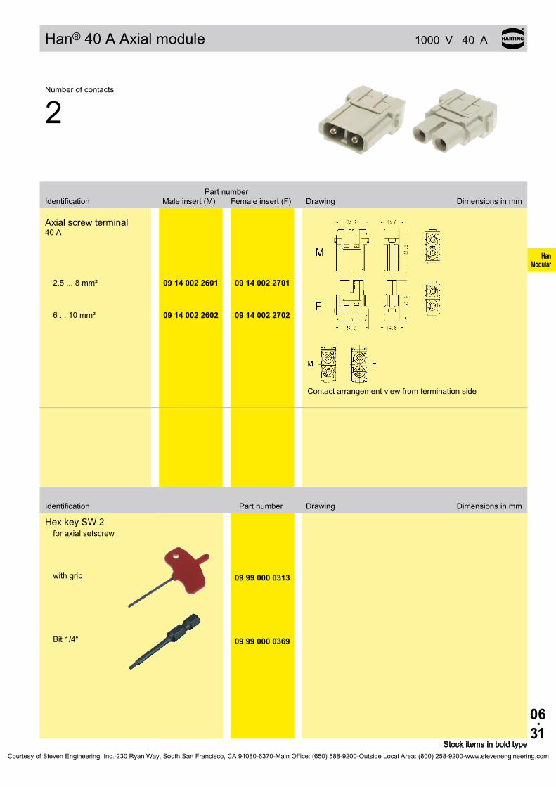
06.31
HanModular
09 14 002 2601 09 14 002 2701
09 14 002 2602 09 14 002 2702
09 99 000 0313
09 99 000 0369
Han® 40 A Axial module 1000 V 40 A
Identification Part number Drawing Dimensions in mm
Stock items in bold type
Number of contacts
2
Part number Identification Male insert (M) Female insert (F) Drawing Dimensions in mm
Axial screw terminal 40 A
Contact arrangement view from termination side
2.5 ... 8 mm²
6 ... 10 mm²
Hex key SW 2for axial setscrew
with grip
Bit 1/4“
Courtesy of Steven Engineering, Inc.-230 Ryan Way, South San Francisco, CA 94080-6370-Main Office: (650) 588-9200-Outside Local Area: (800) 258-9200-www.stevenengineering.com
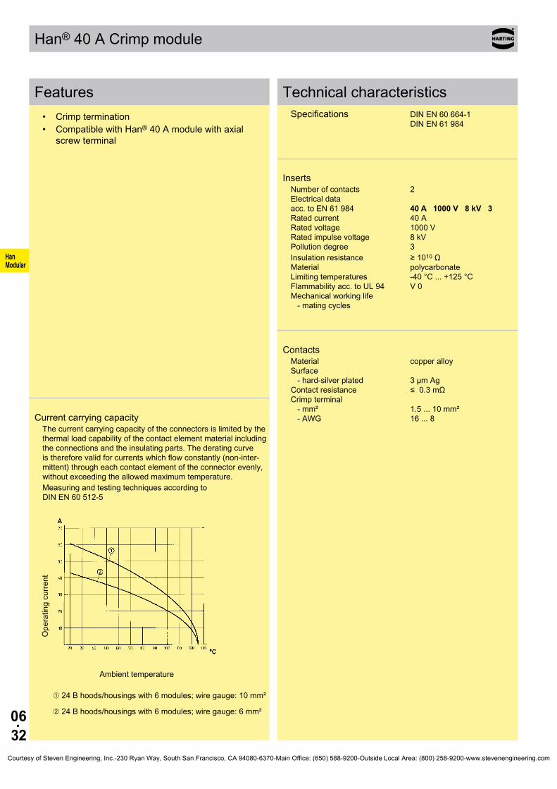
06.32
HanModular
Han® 40 A Crimp module
Features• Crimp termination• Compatible with Han® 40 A module with axial
screw terminal
Current carrying capacityThe current carrying capacity of the connectors is limited by the thermal load capability of the contact element material including the connections and the insulating parts. The derating curve is therefore valid for currents which flow constantly (non-inter-mittent) through each contact element of the connector evenly, without exceeding the allowed maximum temperature.Measuring and testing techniques according to DIN EN 60 512-5
Ope
ratin
g cu
rrent
Ambient temperature
➀ 24 B hoods/housings with 6 modules; wire gauge: 10 mm²
➁ 24 B hoods/housings with 6 modules; wire gauge: 6 mm²
Technical characteristicsSpecifications DIN EN 60 664-1 DIN EN 61 984
InsertsNumber of contacts 2 Electrical data acc. to EN 61 984 40 A 1000 V 8 kV 3 Rated current 40 A Rated voltage 1000 V Rated impulse voltage 8 kV Pollution degree 3Insulation resistance ≥ 1010 Ω Material polycarbonate Limiting temperatures -40 °C ... +125 °C Flammability acc. to UL 94 V 0 Mechanical working life - mating cycles
ContactsMaterial copper alloy Surface - hard-silver plated 3 µm Ag Contact resistance ≤ 0.3 mΩ Crimp terminal - mm² 1.5 ... 10 mm² - AWG 16 ... 8
Courtesy of Steven Engineering, Inc.-230 Ryan Way, South San Francisco, CA 94080-6370-Main Office: (650) 588-9200-Outside Local Area: (800) 258-9200-www.stevenengineering.com

06.33
HanModular
09 14 002 3002 09 14 002 3102
∅
mm²mm²mm²mm²mm²
AWG 16AWG 14AWG 12AWG 10AWG 8
09 32 000 610409 32 000 610509 32 000 610709 32 000 610809 32 000 6109
09 32 000 620409 32 000 620509 32 000 620709 32 000 620809 32 000 6209
Han® 40 A Crimp module 1000 V 40 A
Stock items in bold type
Number of contacts
2
Part number Identification Male insert (M) Female insert (F) Drawing Dimensions in mm
Crimp terminalOrder crimp contacts separately
Contact arrangement view from termination side
Wire gauge Part number Identification (mm²) Male contact Female contact Drawing Dimensions in mm
Crimp contacts Power contacts
Wire gauge Stripping length
1.52.5
46
10
1.752.252.853.54.3
9 mm9 mm
9.6 mm9.6 mm15 mm
Stripping length a = 15 mm for cables ≥ 5 mm Stripping length a = 18 mm for cables ≥ 6.4 mm
silver plated 1.52.546
10
Courtesy of Steven Engineering, Inc.-230 Ryan Way, South San Francisco, CA 94080-6370-Main Office: (650) 588-9200-Outside Local Area: (800) 258-9200-www.stevenengineering.com

06.34
HanModular
Han® C Axial module
Features• Axial screw terminal• No special tools required for assembly• Compatible to Han® C module with crimp terminal
Current carrying capacityThe current carrying capacity of the connectors is limited by the thermal load capability of the contact element material including the connections and the insulating parts. The derating curve is therefore valid for currents which flow constantly (non-inter-mittent) through each contact element of the connector evenly, without exceeding the allowed maximum temperature.Measuring and testing techniques according to DIN EN 60 512-5
Ope
ratin
g cu
rrent
Ambient temperature
➀ 24 B hoods/housings with 6 modules; wire gauge: 4 mm²
➁ 24 B hoods/housings with 6 modules; wire gauge: 6 mm²
➂ 24 B hoods/housings with 6 modules; wire gauge: 10 mm²
Technical characteristicsSpecifications DIN EN 60 664-1 DIN EN 61 984 Approvals
InsertsNumber of contacts 3 Electrical data acc. to EN 61 984 40 A 690 V 8 kV 3 Rated current 40 A Rated voltage 690 V Rated impulse voltage 8 kV Pollution degree 3
Rated voltage acc. to UL 600 V Insulation resistance ≥ 1010 Ω Material polycarbonate Limiting temperatures -40 °C ... +125 °C Flammability acc. to UL 94 V 0 Mechanical working life - mating cycles ≥ 500
ContactsMaterial copper alloy Surface - hard-silver plated 3 µm Ag Contact resistance 0.3 mΩ Screw terminal - Wire gauge 1) 2.5 ... 10 mm² - AWG 14 ... 8 - Hexagonal driver SW 2 - Stripping length mm² 2.5 4 6 10
mm 5+1 5+1 8+1 11+1
- Tightening tourque mm² 2.5 4 6 10
Nm 1.5 1.5 2 2
1) geometric wire gaugeCourtesy of Steven Engineering, Inc.-230 Ryan Way, South San Francisco, CA 94080-6370-Main Office: (650) 588-9200-Outside Local Area: (800) 258-9200-www.stevenengineering.com

06.35
HanModular
09 14 003 2601 09 14 003 2701
09 14 003 2602 09 14 003 2702
09 99 000 0313
09 99 000 0369
Han® C Axial module 690 V 40 A
Identification Part number Drawing Dimensions in mm
Stock items in bold type
Number of contacts
3
Part number Identification Male insert (M) Female insert (F) Drawing Dimensions in mm
Axial screw terminal 40 A
2.5 ... 8 mm²
6 ... 10 mm²
Hex key SW 2for axial setscrew
with grip
Bit 1/4“
Courtesy of Steven Engineering, Inc.-230 Ryan Way, South San Francisco, CA 94080-6370-Main Office: (650) 588-9200-Outside Local Area: (800) 258-9200-www.stevenengineering.com

06.36
HanModular
Han® C module
Features• Suitable for Han® C crimp contacts• Standard module for power up to 40 A• Compatible to Han® C module with axial screw
terminal
Current carrying capacityThe current carrying capacity of the connectors is limited by the thermal load capability of the contact element material including the connections and the insulating parts. The derating curve is therefore valid for currents which flow constantly (non-inter-mittent) through each contact element of the connector evenly, without exceeding the allowed maximum temperature.Measuring and testing techniques according to DIN EN 60 512-5
Ope
ratin
g cu
rrent
Ambient temperature
➀ 24 B hoods/housings with 6 modules; wire gauge: 4 mm²
➁ 24 B hoods/housings with 6 modules; wire gauge: 6 mm²
➂ 24 B hoods/housings with 6 modules; wire gauge: 10 mm²
Technical characteristicsSpecifications DIN EN 60 664-1 DIN EN 61 984 Approvals ,
InsertsNumber of contacts 3 Electrical data acc. to EN 61 984 Cable diameter up to 5 mm 40 A 400/690 V 6 kV 3 Rated current 40 A Rated voltage conductor - ground 400 V Rated voltage conductor - conductor 690 V Rated impulse voltage 6 kV Pollution degree 3
Cable diameter up to 7.5 mm 40 A 500 V 6 kV 3 Rated current 40 A Rated voltage 500 V Rated impulse voltage 6 kV Pollution degree 3
Rated voltage acc. to UL/CSA 600 VRated current acc. to UL/CSA 32 AInsulation resistance ≥ 1010 Ω Material polycarbonate Limiting temperatures -40 °C ... +125 °C Flammability acc. to UL 94 V 0 Mechanical working life - mating cycles ≥ 500
ContactsMaterial copper alloy Surface - hard-silver plated 3 µm Ag Contact resistance ≤ 0.3 mΩ Crimp terminal - mm² 1.5 ... 10 mm² - AWG 16 ... 8
Courtesy of Steven Engineering, Inc.-230 Ryan Way, South San Francisco, CA 94080-6370-Main Office: (650) 588-9200-Outside Local Area: (800) 258-9200-www.stevenengineering.com

06.37
HanModular
hM
09 14 003 3001
09 14 003 3002
hF
09 14 003 3101
09 14 003 3102
09 14 003 3001 09 14 003 3101
09 14 003 3002 09 14 003 3102
∅
mm²mm²mm²mm²mm²
AWG 16AWG 14AWG 12AWG 10AWG 8
09 32 000 610409 32 000 610509 32 000 610709 32 000 610809 32 000 6109
09 32 000 620409 32 000 620509 32 000 620709 32 000 620809 32 000 6209
Han® C module 400 / 690 V 40 A
Stock items in bold type* for modules 09 14 003 3002 and 09 14 003 3102 only
Number of contacts
3
Part number Identification Male insert (M) Female insert (F) Drawing Dimensions in mm
Crimp terminalOrder crimp contacts separately
Contact arrangement view from termination side
39.1 mm
43.1 mm
40.7 mm
44.7 mm
Cable diameter up to 5 mm
Cable diameter up to 7.5 mm
Wire gauge Part number Identification (mm²) Male contact Female contact Drawing Dimensions in mm
Crimp contacts Power contacts
Wire gauge Stripping length
1.52.5
46
10
1.752.252.853.54.3
9 mm9 mm
9.6 mm9.6 mm15 mm
Stripping length a = 15 mm for cables ≥ 5 mm Stripping length a = 18 mm for cables ≥ 6.4 mm
silver plated 1.52.546
10*
Courtesy of Steven Engineering, Inc.-230 Ryan Way, South San Francisco, CA 94080-6370-Main Office: (650) 588-9200-Outside Local Area: (800) 258-9200-www.stevenengineering.com

06.38
HanModular
Han® CC Protected module
Features• Suitable for Han® C crimp contacts• Designed for a high working voltage up to 830 V• Finger safe male and female contacts• High contact density
Current carrying capacityThe current carrying capacity of the connectors is limited by the thermal load capability of the contact element material including the connections and the insulating parts. The derating curve is therefore valid for currents which flow constantly (non-inter-mittent) through each contact element of the connector evenly, without exceeding the allowed maximum temperature.Measuring and testing techniques according to DIN EN 60 512-5
Ope
ratin
g cu
rrent
Ambient temperature
➀ 24 B hoods/housings with 6 modules; wire gauge: 4 mm²
➁ 24 B hoods/housings with 6 modules; wire gauge: 6 mm²
Technical characteristicsSpecifications DIN EN 60 664-1 DIN EN 61 984 Approvals
InsertsNumber of contacts 4 Electrical data acc. to EN 61 984 40 A 830 V 8 kV 3 Rated current 40 A Rated voltage 830 V Rated impulse voltage 8 kV Pollution degree 3
Rated voltage acc. to UL 600 V Insulation resistance ≥ 1010 Ω Material polycarbonate Limiting temperatures -40 °C ... +125 °C Flammability acc. to UL 94 V 0 Mechanical working life - mating cycles ≥ 500
ContactsMaterial copper alloy Surface - hard-silver plated 3 µm Ag Contact resistance ≤ 0.3 mΩ Crimp terminal - mm² 1.5 ... 6 mm² - AWG 16 ... 10
Courtesy of Steven Engineering, Inc.-230 Ryan Way, South San Francisco, CA 94080-6370-Main Office: (650) 588-9200-Outside Local Area: (800) 258-9200-www.stevenengineering.com

06.39
HanModular
09 14 004 3041 09 14 004 3141
∅
mm²mm²mm²mm²
AWG 16AWG 14AWG 12AWG 10
09 32 000 610409 32 000 610509 32 000 610709 32 000 6108
09 32 000 620409 32 000 620509 32 000 620709 32 000 6208
Han® CC Protected module 830 V 40 A
Stock items in bold type
Number of contacts
4
Part number Identification Male insert (M) Female insert (F) Drawing Dimensions in mm
Crimp terminalOrder crimp contacts separately
Contact arrangement view from termination side
Wire gauge Part number Identification (mm²) Male contact Female contact Drawing Dimensions in mm
Crimp contacts Power contacts
Wire gauge Stripping length
1.52.5
46
1.752.252.853.5
9 mm9 mm
9.6 mm9.6 mm
silver plated 1.52.546
Courtesy of Steven Engineering, Inc.-230 Ryan Way, South San Francisco, CA 94080-6370-Main Office: (650) 588-9200-Outside Local Area: (800) 258-9200-www.stevenengineering.com
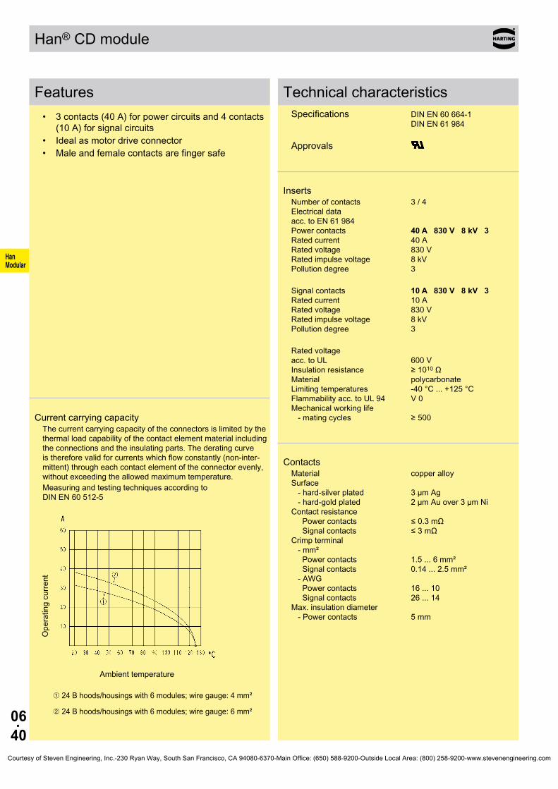
06.40
HanModular
Han® CD module
Features• 3 contacts (40 A) for power circuits and 4 contacts
(10 A) for signal circuits• Ideal as motor drive connector• Male and female contacts are finger safe
Current carrying capacityThe current carrying capacity of the connectors is limited by the thermal load capability of the contact element material including the connections and the insulating parts. The derating curve is therefore valid for currents which flow constantly (non-inter-mittent) through each contact element of the connector evenly, without exceeding the allowed maximum temperature.Measuring and testing techniques according to DIN EN 60 512-5
Ope
ratin
g cu
rrent
Ambient temperature
➀ 24 B hoods/housings with 6 modules; wire gauge: 4 mm²
➁ 24 B hoods/housings with 6 modules; wire gauge: 6 mm²
Technical characteristicsSpecifications DIN EN 60 664-1 DIN EN 61 984 Approvals
InsertsNumber of contacts 3 / 4 Electrical data acc. to EN 61 984 Power contacts 40 A 830 V 8 kV 3 Rated current 40 A Rated voltage 830 V Rated impulse voltage 8 kV Pollution degree 3
Signal contacts 10 A 830 V 8 kV 3 Rated current 10 A Rated voltage 830 V Rated impulse voltage 8 kV Pollution degree 3
Rated voltage acc. to UL 600 V Insulation resistance ≥ 1010 Ω Material polycarbonate Limiting temperatures -40 °C ... +125 °C Flammability acc. to UL 94 V 0 Mechanical working life - mating cycles ≥ 500
ContactsMaterial copper alloy Surface - hard-silver plated 3 µm Ag - hard-gold plated 2 µm Au over 3 µm Ni Contact resistance Power contacts ≤ 0.3 mΩ Signal contacts ≤ 3 mΩ Crimp terminal - mm² Power contacts 1.5 ... 6 mm² Signal contacts 0.14 ... 2.5 mm² - AWG Power contacts 16 ... 10 Signal contacts 26 ... 14 Max. insulation diameter - Power contacts 5 mm
Courtesy of Steven Engineering, Inc.-230 Ryan Way, South San Francisco, CA 94080-6370-Main Office: (650) 588-9200-Outside Local Area: (800) 258-9200-www.stevenengineering.com

06.41
HanModular
09 14 007 3001 09 14 007 3101
∅
mm²mm²mm²mm²
AWG 16AWG 14AWG 12AWG 10
09 32 000 610409 32 000 610509 32 000 610709 32 000 6108
09 32 000 620409 32 000 620509 32 000 620709 32 000 6208
∅
mm²mm²mm²mm²mm²mm²
AWG 26-22AWG 20AWG 18AWG 18AWG 16AWG 14
8 mm8 mm8 mm8 mm8 mm6 mm
09 15 000 610409 15 000 610309 15 000 610509 15 000 610209 15 000 610109 15 000 6106
09 15 000 620409 15 000 620309 15 000 620509 15 000 620209 15 000 620109 15 000 6206
09 15 000 612409 15 000 612309 15 000 612509 15 000 612209 15 000 612109 15 000 6126
09 15 000 622409 15 000 622309 15 000 622509 15 000 622209 15 000 622109 15 000 6226
Han® CD module 830 / 830 V 10 / 40 A
Stock items in bold type
Number of contacts
3 / 4
Part number Identification Male insert (M) Female insert (F) Drawing Dimensions in mm
Crimp terminalOrder crimp contacts separately
Contact arrangement view from termination side
Wire gauge Part number Identification (mm²) Male contact Female contact Drawing Dimensions in mm
Crimp contacts Power contacts
Wire gauge Stripping length
1.52.5
46
1.752.252.853.5
9 mm9 mm
9.6 mm9.6 mm
silver plated 1.52.546
Wire gauge Stripping length
0.14-0.370.5
0.751
1.52.5
0.91.11.31.451.752.25
Signal contacts silver plated
0.14-0.370.5
0.751
1.52.5
gold plated 0.14-0.370.5
0.751
1.52.5
Courtesy of Steven Engineering, Inc.-230 Ryan Way, South San Francisco, CA 94080-6370-Main Office: (650) 588-9200-Outside Local Area: (800) 258-9200-www.stevenengineering.com

06.42
HanModular
Han E® module
Features• Suitable for Han E® crimp contacts• Standard module for power up to 40 A
Current carrying capacityThe current carrying capacity of the connectors is limited by the thermal load capability of the contact element material including the connections and the insulating parts. The derating curve is therefore valid for currents which flow constantly (non-inter-mittent) through each contact element of the connector evenly, without exceeding the allowed maximum temperature.Measuring and testing techniques according to DIN EN 60 512-5
Ope
ratin
g cu
rrent
Ambient temperature
➀ 24 B hoods/housings with 6 modules; wire gauge: 2.5 mm²
➁ 24 B hoods/housings with 6 modules; wire gauge: 1.5 mm²
Technical characteristicsSpecifications DIN EN 60 664-1 DIN EN 61 984 Approvals ,
InsertsNumber of contacts 6 Electrical data acc. to EN 61 984 16 A 500 V 6 kV 3 Rated current 16 A Rated voltage 500 V Rated impulse voltage 6 kV Pollution degree 3
Rated voltage acc. to UL/CSA 600 V Insulation resistance ≥ 1010 Ω Material polycarbonate Limiting temperatures -40 °C ... +125 °C Flammability acc. to UL 94 V 0 Mechanical working life - mating cycles ≥ 500
ContactsMaterial copper alloy Surface - hard-silver plated 3 µm Ag - hard-gold plated 2 µm Au over 3 µm Ni Contact resistance ≤ 1 mΩ Crimp terminal - mm² 0.14 ... 4 mm² - AWG 26 ... 12
Courtesy of Steven Engineering, Inc.-230 Ryan Way, South San Francisco, CA 94080-6370-Main Office: (650) 588-9200-Outside Local Area: (800) 258-9200-www.stevenengineering.com

06.43
HanModular
09 14 006 3001 09 14 006 3101
mm²mm²mm²mm²mm²mm²mm²mm²
AWG 26-22AWG 20AWG 18AWG 18AWG 16AWG 14AWG 12AWG 12
0,14-0,37
0,50,75
11,52,534
09 33 000 612709 33 000 612109 33 000 611409 33 000 610509 33 000 610409 33 000 610209 33 000 610609 33 000 6107
09 33 000 622709 33 000 622009 33 000 621409 33 000 620509 33 000 620409 33 000 620209 33 000 620609 33 000 6207
0,14-0,37
0,50,75
11,52,54
09 33 000 611709 33 000 612209 33 000 611509 33 000 611809 33 000 611609 33 000 612309 33 000 6119
09 33 000 621709 33 000 622209 33 000 621509 33 000 621809 33 000 621609 33 000 622309 33 000 6221
0,75-1
1,52,5
09 33 000 610909 33 000 611009 33 000 6111
Han E® module 500 V 16 A
Stock items in bold typeCrimp contacts 0.14 ... 0.37 mm² only used with BUCHANAN crimping tool 09 99 000 0001
Number of contacts
6
Part number Identification Male insert (M) Female insert (F) Drawing Dimensions in mm
Crimp terminalOrder crimp contacts separately
Contact arrangement view from termination side
Wire gauge Part number Identification (mm²) Male contact Female contact Drawing Dimensions in mm
Crimp contacts Power contacts
Operating contact Identification Relay contact
Identification Wire gauge Stripping length
no grooveno groove1 groove*1 groove2 grooves3 grooves
wide grooveno groove
0.14-0.370.5
0.751
1.52.5
34
7.5 mm7.5 mm7.5 mm7.5 mm7.5 mm7.5 mm7.5 mm7.5 mm
* on the back crimp collar
silver plated 0.14-0.37
0.50.75
11.52.534
gold plated 0.14-0.37
0.50.75
11.52.54
Relay contact silver plated 0.75-1
1.52.5
Courtesy of Steven Engineering, Inc.-230 Ryan Way, South San Francisco, CA 94080-6370-Main Office: (650) 588-9200-Outside Local Area: (800) 258-9200-www.stevenengineering.com
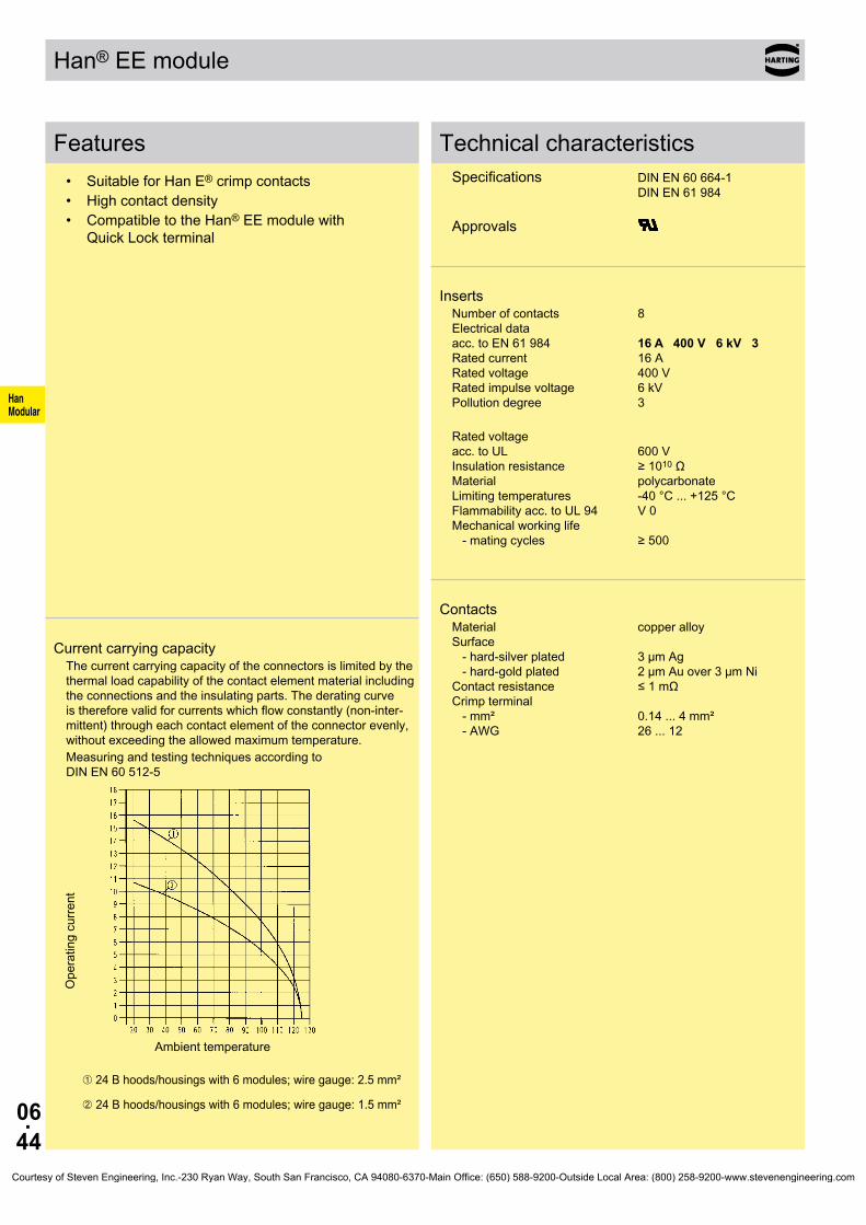
06.44
HanModular
Han® EE module
Features• Suitable for Han E® crimp contacts• High contact density• Compatible to the Han® EE module with
Quick Lock terminal
Current carrying capacityThe current carrying capacity of the connectors is limited by the thermal load capability of the contact element material including the connections and the insulating parts. The derating curve is therefore valid for currents which flow constantly (non-inter-mittent) through each contact element of the connector evenly, without exceeding the allowed maximum temperature.Measuring and testing techniques according to DIN EN 60 512-5
Ope
ratin
g cu
rrent
Ambient temperature
➀ 24 B hoods/housings with 6 modules; wire gauge: 2.5 mm²
➁ 24 B hoods/housings with 6 modules; wire gauge: 1.5 mm²
Technical characteristicsSpecifications DIN EN 60 664-1 DIN EN 61 984 Approvals
InsertsNumber of contacts 8 Electrical data acc. to EN 61 984 16 A 400 V 6 kV 3 Rated current 16 A Rated voltage 400 V Rated impulse voltage 6 kV Pollution degree 3
Rated voltage acc. to UL 600 V Insulation resistance ≥ 1010 Ω Material polycarbonate Limiting temperatures -40 °C ... +125 °C Flammability acc. to UL 94 V 0 Mechanical working life - mating cycles ≥ 500
ContactsMaterial copper alloy Surface - hard-silver plated 3 µm Ag - hard-gold plated 2 µm Au over 3 µm Ni Contact resistance ≤ 1 mΩ Crimp terminal - mm² 0.14 ... 4 mm² - AWG 26 ... 12
Courtesy of Steven Engineering, Inc.-230 Ryan Way, South San Francisco, CA 94080-6370-Main Office: (650) 588-9200-Outside Local Area: (800) 258-9200-www.stevenengineering.com

06.45
HanModular
09 14 008 3001 09 14 008 3101
mm²mm²mm²mm²mm²mm²mm²mm²
AWG 26-22AWG 20AWG 18AWG 18AWG 16AWG 14AWG 12AWG 12
09 33 000 612709 33 000 612109 33 000 611409 33 000 610509 33 000 610409 33 000 610209 33 000 610609 33 000 6107
09 33 000 622709 33 000 622009 33 000 621409 33 000 620509 33 000 620409 33 000 620209 33 000 620609 33 000 6207
09 33 000 611709 33 000 612209 33 000 611509 33 000 611809 33 000 611609 33 000 612309 33 000 6119
09 33 000 621709 33 000 622209 33 000 621509 33 000 621809 33 000 621609 33 000 622309 33 000 6221
09 33 000 6109
09 33 000 611009 33 000 6111
Han® EE module 400 V 16 A
Stock items in bold typeCrimp contacts 0.14 ... 0.37 mm² only used with BUCHANAN crimping tool 09 99 000 0001
Number of contacts
8
Part number Identification Male insert (M) Female insert (F) Drawing Dimensions in mm
Crimp terminalOrder crimp contacts separately
Contact arrangement view from termination side
Wire gauge Part number Identification (mm²) Male contact Female contact Drawing Dimensions in mm
Crimp contacts Power contacts
Operating contact Identification Relay contact
Identification Wire gauge Stripping length
no grooveno groove1 groove*1 groove2 grooves3 grooves
wide grooveno groove
0.14-0.370.5
0.751
1.52.5
34
7.5 mm7.5 mm7.5 mm7.5 mm7.5 mm7.5 mm7.5 mm7.5 mm
* on the back crimp collar
silver plated 0.14-0.37
0.50.75
11.52.534
gold plated 0.14-0.37
0.50.75
11.52.54
Relay contact silver plated 0.75-1
1.52.5
Courtesy of Steven Engineering, Inc.-230 Ryan Way, South San Francisco, CA 94080-6370-Main Office: (650) 588-9200-Outside Local Area: (800) 258-9200-www.stevenengineering.com
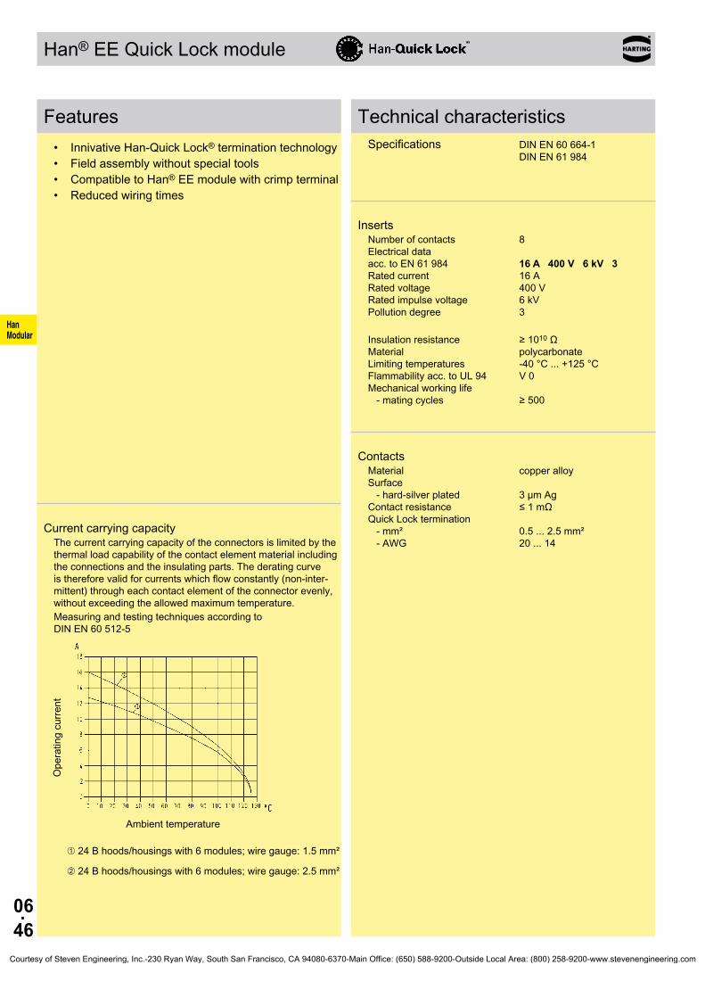
06.46
HanModular
Han® EE Quick Lock module
Features• Innivative Han-Quick Lock® termination technology• Field assembly without special tools• Compatible to Han® EE module with crimp terminal• Reduced wiring times
Technical characteristicsSpecifications DIN EN 60 664-1 DIN EN 61 984
InsertsNumber of contacts 8 Electrical data acc. to EN 61 984 16 A 400 V 6 kV 3 Rated current 16 A Rated voltage 400 V Rated impulse voltage 6 kV Pollution degree 3
Insulation resistance ≥ 1010 Ω Material polycarbonate Limiting temperatures -40 °C ... +125 °C Flammability acc. to UL 94 V 0 Mechanical working life - mating cycles ≥ 500
ContactsMaterial copper alloy Surface - hard-silver plated 3 µm Ag Contact resistance ≤ 1 mΩ Quick Lock termination - mm² 0.5 ... 2.5 mm² - AWG 20 ... 14
Current carrying capacityThe current carrying capacity of the connectors is limited by the thermal load capability of the contact element material including the connections and the insulating parts. The derating curve is therefore valid for currents which flow constantly (non-inter-mittent) through each contact element of the connector evenly, without exceeding the allowed maximum temperature.Measuring and testing techniques according to DIN EN 60 512-5
Ope
ratin
g cu
rrent
Ambient temperature
➀ 24 B hoods/housings with 6 modules; wire gauge: 1.5 mm²
➁ 24 B hoods/housings with 6 modules; wire gauge: 2.5 mm²
Courtesy of Steven Engineering, Inc.-230 Ryan Way, South San Francisco, CA 94080-6370-Main Office: (650) 588-9200-Outside Local Area: (800) 258-9200-www.stevenengineering.com

06.47
HanModular
09 14 008 2633 09 14 008 2733
Han® EE Quick Lock module 400 V 16 A
Stock items in bold type
Number of contacts
8
Part number Identification Male insert (M) Female insert (F) Drawing Dimensions in mm
Quick Lock termination
Contact arrangement view from termination side
Courtesy of Steven Engineering, Inc.-230 Ryan Way, South San Francisco, CA 94080-6370-Main Office: (650) 588-9200-Outside Local Area: (800) 258-9200-www.stevenengineering.com
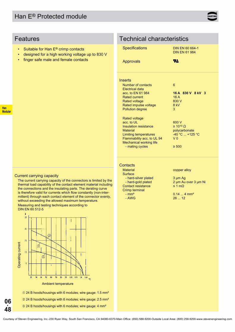
06.48
HanModular
Han E® Protected module
Features• Suitable for Han E® crimp contacts• designed for a high working voltage up to 830 V• finger safe male and female contacts
Current carrying capacityThe current carrying capacity of the connectors is limited by the thermal load capability of the contact element material including the connections and the insulating parts. The derating curve is therefore valid for currents which flow constantly (non-inter-mittent) through each contact element of the connector evenly, without exceeding the allowed maximum temperature.Measuring and testing techniques according to DIN EN 60 512-5
Ope
ratin
g cu
rrent
Ambient temperature
➀ 24 B hoods/housings with 6 modules; wire gauge: 1.5 mm²
➁ 24 B hoods/housings with 6 modules; wire gauge: 2.5 mm²
➂ 24 B hoods/housings with 6 modules; wire gauge: 4 mm²
Technical characteristicsSpecifications DIN EN 60 664-1 DIN EN 61 984 Approvals
InsertsNumber of contacts 6 Electrical data acc. to EN 61 984 16 A 830 V 8 kV 3 Rated current 16 A Rated voltage 830 V Rated impulse voltage 8 kV Pollution degree 3
Rated voltage acc. to UL 600 V Insulation resistance ≥ 1010 Ω Material polycarbonate Limiting temperatures -40 °C ... +125 °C Flammability acc. to UL 94 V 0 Mechanical working life - mating cycles ≥ 500
ContactsMaterial copper alloy Surface - hard-silver plated 3 µm Ag - hard-gold plated 2 µm Au over 3 µm Ni Contact resistance ≤ 1 mΩ Crimp terminal - mm² 0.14 ... 4 mm² - AWG 26 ... 12
Courtesy of Steven Engineering, Inc.-230 Ryan Way, South San Francisco, CA 94080-6370-Main Office: (650) 588-9200-Outside Local Area: (800) 258-9200-www.stevenengineering.com

06.49
HanModular
09 14 006 3041 09 14 006 3141
mm²mm²mm²mm²mm²mm²mm²mm²
AWG 26-22AWG 20AWG 18AWG 18AWG 16AWG 14AWG 12AWG 12
09 33 000 612709 33 000 612109 33 000 611409 33 000 610509 33 000 610409 33 000 610209 33 000 610609 33 000 6107
09 33 000 622709 33 000 622009 33 000 621409 33 000 620509 33 000 620409 33 000 620209 33 000 620609 33 000 6207
09 33 000 611709 33 000 612209 33 000 611509 33 000 611809 33 000 611609 33 000 612309 33 000 6119
09 33 000 621709 33 000 622209 33 000 621509 33 000 621809 33 000 621609 33 000 622309 33 000 6221
09 33 000 6109
09 33 000 611009 33 000 6111
Han E® Protected module 830 V 16 A
Stock items in bold typeCrimp contacts 0.14 ... 0.37 mm² only used with BUCHANAN crimping tool 09 99 000 0001
Number of contacts
6
Part number Identification Male insert (M) Female insert (F) Drawing Dimensions in mm
Crimp terminalOrder crimp contacts separately
Contact arrangement view from termination side
Wire gauge Part number Identification (mm²) Male contact Female contact Drawing Dimensions in mm
Crimp contacts Power contacts
Operating contact Identification Relay contact
Identification Wire gauge Stripping length
no grooveno groove1 groove*1 groove2 grooves3 grooves
wide grooveno groove
0.14-0.370.5
0.751
1.52.5
34
7.5 mm7.5 mm7.5 mm7.5 mm7.5 mm7.5 mm7.5 mm7.5 mm
* on the back crimp collar
silver plated 0.14-0.37
0.50.75
11.52.534
gold plated 0.14-0.37
0.50.75
11.52.54
Relay contact silver plated 0.75-1
1.52.5
Courtesy of Steven Engineering, Inc.-230 Ryan Way, South San Francisco, CA 94080-6370-Main Office: (650) 588-9200-Outside Local Area: (800) 258-9200-www.stevenengineering.com

06.50
HanModular
Han® EEE module
Features• Suitable for Han E® crimp contacts• High contact density• Up to 16 A per contact• Also suitable as a reliable signal connector
Current carrying capacityThe current carrying capacity of the connectors is limited by the thermal load capability of the contact element material including the connections and the insulating parts. The derating curve is therefore valid for currents which flow constantly (non-inter-mittent) through each contact element of the connector evenly, without exceeding the allowed maximum temperature.Measuring and testing techniques according to DIN EN 60 512-5
Ope
ratin
g cu
rrent
Ambient temperature
➀ 24 B hoods/housings with 3 modules; wire gauge: 1.5 mm²
➁ 24 B hoods/housings with 3 modules; wire gauge: 2.5 mm²
➂ 24 B hoods/housings with 3 modules; wire gauge: 4 mm²
Technical characteristicsSpecifications DIN EN 60 664-1 DIN EN 61 984 Approvals
InsertsNumber of contacts 20 Electrical data acc. to EN 61 984 16 A 500 V 6 kV 3 Rated current 16 A Rated voltage 500 V Rated impulse voltage 6 kV Pollution degree 3
Rated voltage acc. to UL 600 V Insulation resistance ≥ 1010 Ω Material polycarbonate Limiting temperatures -40 °C ... +125 °C Flammability acc. to UL 94 V 0 Mechanical working life - mating cycles ≥ 500
ContactsMaterial copper alloy Surface - hard-silver plated 3 µm Ag - hard-gold plated 2 µm Au over 3 µm Ni Contact resistance ≤ 1 mΩ Crimp terminal - mm² 0.14 ... 4 mm² - AWG 26 ... 12
Courtesy of Steven Engineering, Inc.-230 Ryan Way, South San Francisco, CA 94080-6370-Main Office: (650) 588-9200-Outside Local Area: (800) 258-9200-www.stevenengineering.com
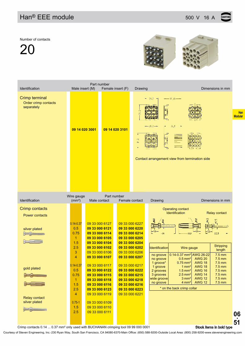
06.51
HanModular
09 14 020 3001 09 14 020 3101
mm²mm²mm²mm²mm²mm²mm²mm²
AWG 26-22AWG 20AWG 18AWG 18AWG 16AWG 14AWG 12AWG 12
09 33 000 612709 33 000 612109 33 000 611409 33 000 610509 33 000 610409 33 000 610209 33 000 610609 33 000 6107
09 33 000 622709 33 000 622009 33 000 621409 33 000 620509 33 000 620409 33 000 620209 33 000 620609 33 000 6207
09 33 000 611709 33 000 612209 33 000 611509 33 000 611809 33 000 611609 33 000 612309 33 000 6119
09 33 000 621709 33 000 622209 33 000 621509 33 000 621809 33 000 621609 33 000 622309 33 000 6221
09 33 000 6109
09 33 000 611009 33 000 6111
Han® EEE module 500 V 16 A
Stock items in bold typeCrimp contacts 0.14 ... 0.37 mm² only used with BUCHANAN crimping tool 09 99 000 0001
Number of contacts
20
Part number Identification Male insert (M) Female insert (F) Drawing Dimensions in mm
Crimp terminalOrder crimp contacts separately
Contact arrangement view from termination side
Wire gauge Part number Identification (mm²) Male contact Female contact Drawing Dimensions in mm
Crimp contacts Power contacts
Operating contact Identification Relay contact
Identification Wire gauge Stripping length
no grooveno groove1 groove*1 groove2 grooves3 grooves
wide grooveno groove
0.14-0.370.5
0.751
1.52.5
34
7.5 mm7.5 mm7.5 mm7.5 mm7.5 mm7.5 mm7.5 mm7.5 mm
* on the back crimp collar
silver plated 0.14-0.37
0.50.75
11.52.534
gold plated 0.14-0.37
0.50.75
11.52.54
Relay contact silver plated 0.75-1
1.52.5
Courtesy of Steven Engineering, Inc.-230 Ryan Way, South San Francisco, CA 94080-6370-Main Office: (650) 588-9200-Outside Local Area: (800) 258-9200-www.stevenengineering.com

06.52
HanModular
Han® ES module
Features• Cage-clamp terminal• No special tools required
Current carrying capacityThe current carrying capacity of the connectors is limited by the thermal load capability of the contact element material including the connections and the insulating parts. The derating curve is therefore valid for currents which flow constantly (non-inter-mittent) through each contact element of the connector evenly, without exceeding the allowed maximum temperature.Measuring and testing techniques according to DIN EN 60 512-5
Ope
ratin
g cu
rrent
Ambient temperature
➀ 24 B hoods/housings with 6 modules; wire gauge: 2.5 mm²
➁ 24 B hoods/housings with 6 modules; wire gauge: 1.5 mm²
Technical characteristicsSpecifications DIN EN 60 664-1 DIN EN 61 984 Approvals
InsertsNumber of contacts 5 Electrical data acc. to EN 61 984 16 A 400 V 6 kV 3 Rated current 16 A Rated voltage 400 V Rated impulse voltage 6 kV Pollution degree 3
Rated voltage acc. to UL 600 V Insulation resistance ≥ 1010 Ω Material polycarbonate Limiting temperatures -40 °C ... +125 °C Flammability acc. to UL 94 V 0 Mechanical working life - mating cycles ≥ 500
ContactsMaterial copper alloy Surface - hard-silver plated 3 µm Ag Contact resistance ≤ 3 mΩ Cage clamp terminal - mm² 0.14 ... 2.5 mm² - AWG 26 ... 14
Courtesy of Steven Engineering, Inc.-230 Ryan Way, South San Francisco, CA 94080-6370-Main Office: (650) 588-9200-Outside Local Area: (800) 258-9200-www.stevenengineering.com
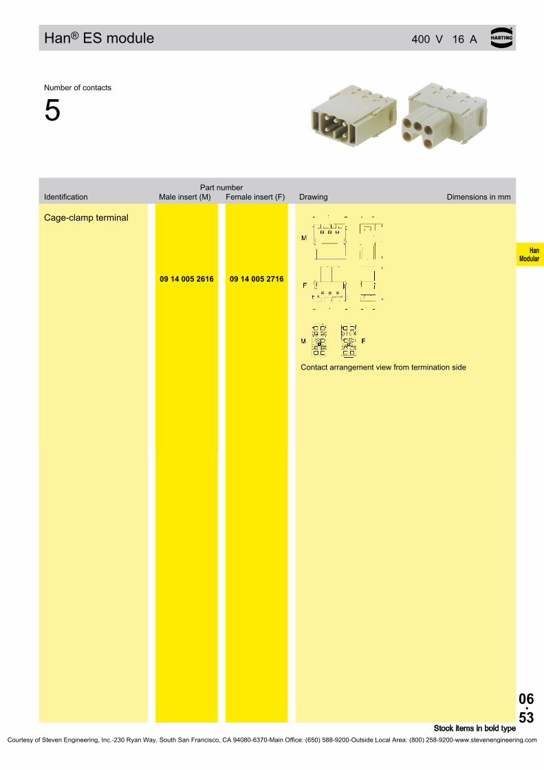
06.53
HanModular
09 14 005 2616 09 14 005 2716
Han® ES module 400 V 16 A
Stock items in bold type
Number of contacts
5
Part number Identification Male insert (M) Female insert (F) Drawing Dimensions in mm
Cage-clamp terminal
Contact arrangement view from termination side
Courtesy of Steven Engineering, Inc.-230 Ryan Way, South San Francisco, CA 94080-6370-Main Office: (650) 588-9200-Outside Local Area: (800) 258-9200-www.stevenengineering.com

06.54
HanModular
Han® HV module
Features• Suitable for Han E® crimp contacts• 2 contacts up to 5000 V• Insulator out of a voltage resistant teflon material• Combination of all other modules (pneumatic,
signal etc.)
Current carrying capacityThe current carrying capacity of the connectors is limited by the thermal load capability of the contact element material including the connections and the insulating parts. The derating curve is therefore valid for currents which flow constantly (non-inter-mittent) through each contact element of the connector evenly, without exceeding the allowed maximum temperature.Measuring and testing techniques according to DIN EN 60 512-5
Ope
ratin
g cu
rrent
Ambient temperature ➀ Housing Han® 16 B with 1 Han® HV module, wire gauge: 2.5 mm²
Technical characteristicsSpecifications DIN EN 61 984 DIN VDE 0115 DIN EN 60 664-1
Approvals
InsertsNumber of contacts 2 Electrical data acc. to EN 61 984 16 A 2900/5000 V 15 kV 3 Rated current 16 A Rated voltage conductor - ground 2900 V Rated voltage conductor - conductor 5000 V Rated impulse voltage 15 kV Pollution degree 3
Insulation resistance ≥ 1010 Ω Material polycarbonate/Teflon (PTFE) Limiting temperatures -40 °C ... +125 °C Flammability acc. to UL 94 V 0 Mechanical working life - mating cycles ≥ 500
ContactsMaterial copper alloy Surface - hard-silver plated 3 µm Ag - hard-gold plated 2 µm Au over 3 µm Ni Contact resistance ≤ 1 mΩ Crimp terminal - mm² 0.5 ... 4 mm² - AWG 20 ... 12
Assembly instructionsHan E®
Crimp contactLocking sleeve Cable
Crimp with BUCHANAN crimping tool 09 99 000 0001 Snap crimped cable in the insert
shrink the heat shrink tube over the rear of contact
Courtesy of Steven Engineering, Inc.-230 Ryan Way, South San Francisco, CA 94080-6370-Main Office: (650) 588-9200-Outside Local Area: (800) 258-9200-www.stevenengineering.com
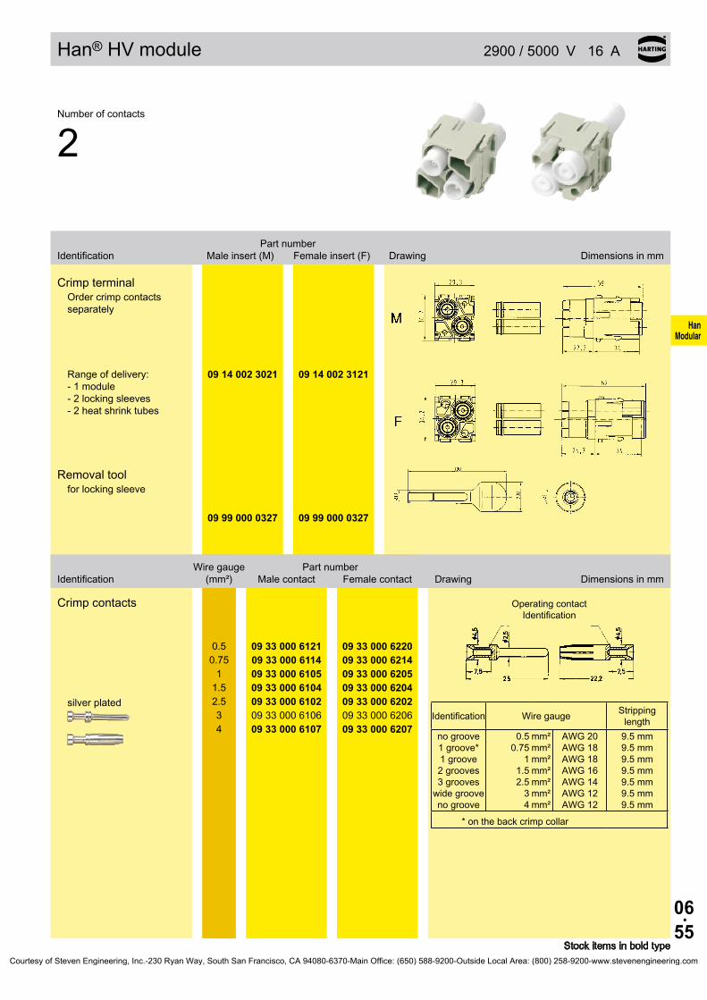
06.55
HanModular
09 14 002 3021 09 14 002 3121
09 99 000 0327 09 99 000 0327
mm²mm²mm²mm²mm²mm²mm²
AWG 20AWG 18AWG 18AWG 16AWG 14AWG 12AWG 12
09 33 000 612109 33 000 611409 33 000 610509 33 000 610409 33 000 610209 33 000 610609 33 000 6107
09 33 000 622009 33 000 621409 33 000 620509 33 000 620409 33 000 620209 33 000 620609 33 000 6207
Han® HV module 2900 / 5000 V 16 A
Stock items in bold type
Number of contacts
2
Part number Identification Male insert (M) Female insert (F) Drawing Dimensions in mm
Crimp terminalOrder crimp contacts separately
Range of delivery: - 1 module - 2 locking sleeves - 2 heat shrink tubes
Removal toolfor locking sleeve
Wire gauge Part number Identification (mm²) Male contact Female contact Drawing Dimensions in mm
Crimp contacts
Operating contact Identification
Identification Wire gauge Stripping length
no groove1 groove*1 groove2 grooves3 grooves
wide grooveno groove
0.50.75
11.52.5
34
9.5 mm9.5 mm9.5 mm9.5 mm9.5 mm9.5 mm9.5 mm
* on the back crimp collar
silver plated
0.50.75
11.52.534
Courtesy of Steven Engineering, Inc.-230 Ryan Way, South San Francisco, CA 94080-6370-Main Office: (650) 588-9200-Outside Local Area: (800) 258-9200-www.stevenengineering.com

06.56
HanModular
Han® HV module
Features• Suitable for Han® C crimp contacts• 2 contacts up to 5000 V• Insulator out of a voltage resistant teflon material• Combination of all other modules (pneumatic,
signal etc.)
Technical characteristicsSpecifications DIN EN 61 984 DIN VDE 0115 DIN EN 60 664-1
InsertsNumber of contacts 2 Electrical data acc. to EN 61 984 40 A 2900/5000 V 15 kV 3 Rated current 40 A Rated voltage conductor - ground 2900 V Rated voltage conductor - conductor 5000 V Rated impulse voltage 15 kV Pollution degree 3
Insulation resistance ≥ 1010 Ω Material polycarbonate/Teflon (PTFE) Limiting temperatures -40 °C ... +125 °C Flammability acc. to UL 94 V 0 Max. cable diameter 9 mm Mechanical working life - mating cycles ≥ 500
ContactsMaterial copper alloy Surface - hard-silver plated 3 µm Ag Contact resistance ≤ 0.3 mΩ Crimp terminal - mm² 1.5 ... 10 mm² - AWG 16 ... 8
Assembly instructionsHan® C
Crimp contactLocking sleeve Cable
Crimp with tool 0999 000 0001, 0999 000 0110 or 0999 000 0377 Snap crimped cable in the insert
shrink the heat shrink tube over the rear of contact
Courtesy of Steven Engineering, Inc.-230 Ryan Way, South San Francisco, CA 94080-6370-Main Office: (650) 588-9200-Outside Local Area: (800) 258-9200-www.stevenengineering.com
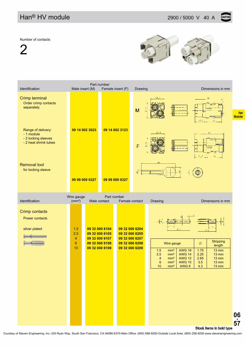
06.57
HanModular
:
09 14 002 3023 09 14 002 3123
09 99 000 0327 09 99 000 0327
∅
mm²mm²mm²mm²mm²
AWG 16AWG 14AWG 12AWG 10AWG 8
09 32 000 610409 32 000 610509 32 000 610709 32 000 610809 32 000 6109
09 32 000 620409 32 000 620509 32 000 620709 32 000 620809 32 000 6209
Han® HV module 2900 / 5000 V 40 A
Stock items in bold type
Number of contacts
2
Part number Identification Male insert (M) Female insert (F) Drawing Dimensions in mm
Crimp terminalOrder crimp contacts separately
Range of delivery: - 1 module - 2 locking sleeves - 2 heat shrink tubes
Removal toolfor locking sleeve
Wire gauge Part number Identification (mm²) Male contact Female contact Drawing Dimensions in mm
Crimp contacts Power contacts
Wire gauge Stripping length
1.52.5
46
10
1.752.252.853.54.3
13 mm13 mm13 mm13 mm13 mm
silver plated 1.52.546
10
Courtesy of Steven Engineering, Inc.-230 Ryan Way, South San Francisco, CA 94080-6370-Main Office: (650) 588-9200-Outside Local Area: (800) 258-9200-www.stevenengineering.com
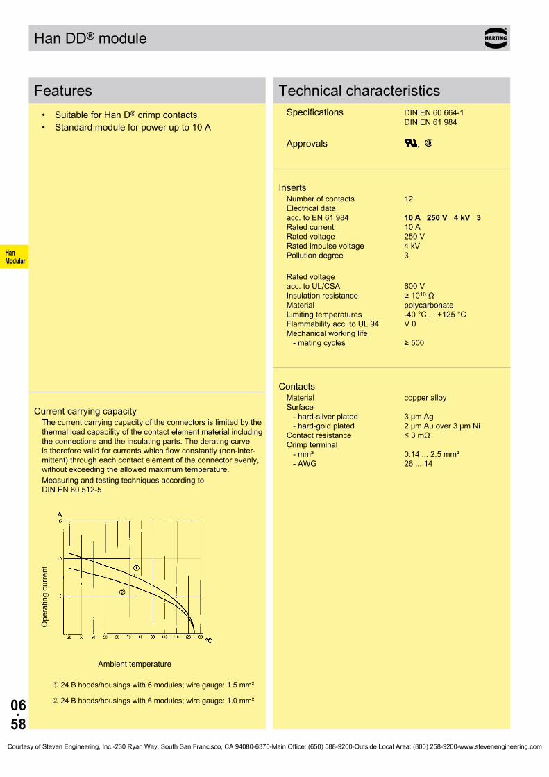
06.58
HanModular
Han DD® module
Features• Suitable for Han D® crimp contacts• Standard module for power up to 10 A
Current carrying capacityThe current carrying capacity of the connectors is limited by the thermal load capability of the contact element material including the connections and the insulating parts. The derating curve is therefore valid for currents which flow constantly (non-inter-mittent) through each contact element of the connector evenly, without exceeding the allowed maximum temperature.Measuring and testing techniques according to DIN EN 60 512-5
Ope
ratin
g cu
rrent
Ambient temperature
➀ 24 B hoods/housings with 6 modules; wire gauge: 1.5 mm²
➁ 24 B hoods/housings with 6 modules; wire gauge: 1.0 mm²
Technical characteristicsSpecifications DIN EN 60 664-1 DIN EN 61 984 Approvals ,
InsertsNumber of contacts 12 Electrical data acc. to EN 61 984 10 A 250 V 4 kV 3 Rated current 10 A Rated voltage 250 V Rated impulse voltage 4 kV Pollution degree 3
Rated voltage acc. to UL/CSA 600 V Insulation resistance ≥ 1010 Ω Material polycarbonate Limiting temperatures -40 °C ... +125 °C Flammability acc. to UL 94 V 0 Mechanical working life - mating cycles ≥ 500
ContactsMaterial copper alloy Surface - hard-silver plated 3 µm Ag - hard-gold plated 2 µm Au over 3 µm Ni Contact resistance ≤ 3 mΩ Crimp terminal - mm² 0.14 ... 2.5 mm² - AWG 26 ... 14
Courtesy of Steven Engineering, Inc.-230 Ryan Way, South San Francisco, CA 94080-6370-Main Office: (650) 588-9200-Outside Local Area: (800) 258-9200-www.stevenengineering.com

06.59
HanModular
09 14 012 3001 09 14 012 3101
∅
mm²mm²mm²mm²mm²mm²
AWG 26-22AWG 20AWG 18AWG 18AWG 16AWG 14
8 mm8 mm8 mm8 mm8 mm6 mm
09 15 000 610409 15 000 610309 15 000 610509 15 000 610209 15 000 610109 15 000 6106
09 15 000 620409 15 000 620309 15 000 620509 15 000 620209 15 000 620109 15 000 6206
09 15 000 612409 15 000 612309 15 000 612509 15 000 612209 15 000 612109 15 000 6126
09 15 000 622409 15 000 622309 15 000 622509 15 000 622209 15 000 622109 15 000 6226
20 10 001 3211 20 10 001 3221
Han DD® module 250 V 10 A
Stock items in bold type
Number of contacts
12
Part number Identification Male insert (M) Female insert (F) Drawing Dimensions in mm
Crimp terminalOrder crimp contacts separately
Contact arrangement view from termination side
Wire gauge Part number Identification (mm²) Male contact Female contact Drawing Dimensions in mm
Crimp contacts Power contacts
Wire gauge Stripping length
0.14-0.370.5
0.751
1.52.5
0.91.11.31.451.752.25
silver plated 0.14-0.370.5
0.751
1.52.5
gold plated 0.14-0.370.5
0.751
1.52.5
F.O. contacts for 1 mm plastic fibre
Courtesy of Steven Engineering, Inc.-230 Ryan Way, South San Francisco, CA 94080-6370-Main Office: (650) 588-9200-Outside Local Area: (800) 258-9200-www.stevenengineering.com

06.60
HanModular
①
Han DD® Quick Lock module
Features• Innovative Han-Quick Lock® termination technology• Field assembly without special tools• Mating compatible with standard Han® DD module
with crimp terminal• Reduced wiring times
Current carrying capacityThe current carrying capacity of the connectors is limited by the thermal load capability of the contact element material including the connections and the insulating parts. The derating curve is therefore valid for currents which flow constantly (non-inter-mittent) through each contact element of the connector evenly, without exceeding the allowed maximum temperature.Measuring and testing techniques according to DIN EN 60 512-5
Ope
ratin
g cu
rrent
Ambient temperature
➀ 24 B hoods/housings with 6 modules; wire gauge: 1.5 mm²
Technical characteristicsSpecifications DIN EN 60 664-1 DIN EN 61 984
InsertsNumber of contacts 12 Electrical data acc. to EN 61 984 10 A 250 V 4 kV 3 Rated current 10 A Rated voltage 250 V Rated impulse voltage 4 kV Pollution degree 3
Insulation resistance ≥ 1010 Ω Material polycarbonate Limiting temperatures -40 °C ... +125 °C Flammability acc. to UL 94 V 0 Mechanical working life - mating cycles
ContactsMaterial copper alloy Surface - hard-silver plated 3 µm Ag Contact resistance ≤ 3 mΩ Quick Lock termination - mm² 0.25 ... 1.5 mm² - AWG 22 ... 16
Courtesy of Steven Engineering, Inc.-230 Ryan Way, South San Francisco, CA 94080-6370-Main Office: (650) 588-9200-Outside Local Area: (800) 258-9200-www.stevenengineering.com

06.61
HanModular
09 14 012 2632 09 14 012 2732
Han DD® Quick Lock module 250 V 10 A
Stock items in bold type
Number of contacts
12
Part number Identification Male insert (M) Female insert (F) Drawing Dimensions in mm
Quick Lock termination
Contact arrangement view from termination side
Courtesy of Steven Engineering, Inc.-230 Ryan Way, South San Francisco, CA 94080-6370-Main Office: (650) 588-9200-Outside Local Area: (800) 258-9200-www.stevenengineering.com

06.62
HanModular
Han® DDD module
Features• Suitable for Han D® crimp contacts• High contact density
Current carrying capacityThe current carrying capacity of the connectors is limited by the thermal load capability of the contact element material including the connections and the insulating parts. The derating curve is therefore valid for currents which flow constantly (non-inter-mittent) through each contact element of the connector evenly, without exceeding the allowed maximum temperature.Measuring and testing techniques according to DIN EN 60 512-5
Ope
ratin
g cu
rrent
Ambient temperature
➀ 24 B hoods/housings with 6 modules; wire gauge: 1.5 mm²
➁ 24 B hoods/housings with 6 modules; wire gauge: 1.0 mm²
Technical characteristicsSpecifications DIN EN 60 664-1 DIN EN 61 984 Approvals
InsertsNumber of contacts 17 Electrical data acc. to EN 61 984 10 A 160 V 2.5 kV 3 Rated current 10 A Rated voltage 160 V Rated impulse voltage 2.5 kV Pollution degree 3
Rated voltage acc. to UL 250 V Insulation resistance ≥ 1010 Ω Material polycarbonate Limiting temperatures -40 °C ... +125 °C Flammability acc. to UL 94 V 0 Mechanical working life - mating cycles ≥ 500
ContactsMaterial copper alloy Surface - hard-silver plated 3 µm Ag - hard-gold plated 2 µm Au over 3 µm Ni Contact resistance ≤ 3 mΩ Crimp terminal - mm² 0.14 ... 2.5 mm² - AWG 26 ... 14
Courtesy of Steven Engineering, Inc.-230 Ryan Way, South San Francisco, CA 94080-6370-Main Office: (650) 588-9200-Outside Local Area: (800) 258-9200-www.stevenengineering.com

06.63
HanModular
09 14 017 3001 09 14 017 3101
∅
mm²mm²mm²mm²mm²mm²
AWG 26-22AWG 20AWG 18AWG 18AWG 16AWG 14
8 mm8 mm8 mm8 mm8 mm6 mm
09 15 000 610409 15 000 610309 15 000 610509 15 000 610209 15 000 610109 15 000 6106
09 15 000 620409 15 000 620309 15 000 620509 15 000 620209 15 000 620109 15 000 6206
09 15 000 612409 15 000 612309 15 000 612509 15 000 612209 15 000 612109 15 000 6126
09 15 000 622409 15 000 622309 15 000 622509 15 000 622209 15 000 622109 15 000 6226
20 10 001 3211 20 10 001 3221
Han® DDD module 160 V 10 A
Stock items in bold type
Number of contacts
17
Part number Identification Male insert (M) Female insert (F) Drawing Dimensions in mm
Crimp terminalOrder crimp contacts separately
Contact arrangement view from termination side
Wire gauge Part number Identification (mm²) Male contact Female contact Drawing Dimensions in mm
Crimp contacts Power contacts
Wire gauge Stripping length
0.14-0.370.5
0.751
1.52.5
0.91.11.31.451.752.25
silver plated 0.14-0.370.5
0.751
1.52.5
gold plated 0.14-0.370.5
0.751
1.52.5
F.O. contacts for 1 mm plastic fibre
Courtesy of Steven Engineering, Inc.-230 Ryan Way, South San Francisco, CA 94080-6370-Main Office: (650) 588-9200-Outside Local Area: (800) 258-9200-www.stevenengineering.com

06.64
HanModular
Han® High Density module
Features• Suitable for D-Sub crimp contacts• High contact density• Using of guiding pins (male and female) is
recommended (see chapter 40).
Current carrying capacityThe current carrying capacity of the connectors is limited by the thermal load capability of the contact element material including the connections and the insulating parts. The derating curve is therefore valid for currents which flow constantly (non-inter-mittent) through each contact element of the connector evenly, without exceeding the allowed maximum temperature.Measuring and testing techniques according to DIN EN 60 512-5
Ope
ratin
g cu
rrent
Ambient temperature ➀ 24 B hoods/housings with 6 modules; wire gauge: 0.5 mm² turned contacts➁ 24 B hoods/housings with 6 modules; wire gauge: 0.5 mm² stamped contacts
Technical characteristicsSpecifications DIN EN 60 664-1 DIN EN 61 984
InsertsNumber of contacts 25 Electrical data acc. to EN 61 984 4 A 50 V 0.8 kV 3 Rated current 4 A Rated voltage 50 V Rated impulse voltage 0.8 kV Pollution degree 3
Insulation resistance ≥ 1010 Ω Material polycarbonate Limiting temperatures -40 °C ... +125 °C Flammability acc. to UL 94 V 0 Mechanical working life - mating cycles ≥ 500
ContactsCrimp terminal - mm² 0.08 ... 0.52 mm² - AWG 28 ... 20turned contacts Performance level 1
as per CECC 75 301-802, 500 mating cycles, 10 days 4 mixed gas test - IEC 60 512
Courtesy of Steven Engineering, Inc.-230 Ryan Way, South San Francisco, CA 94080-6370-Main Office: (650) 588-9200-Outside Local Area: (800) 258-9200-www.stevenengineering.com
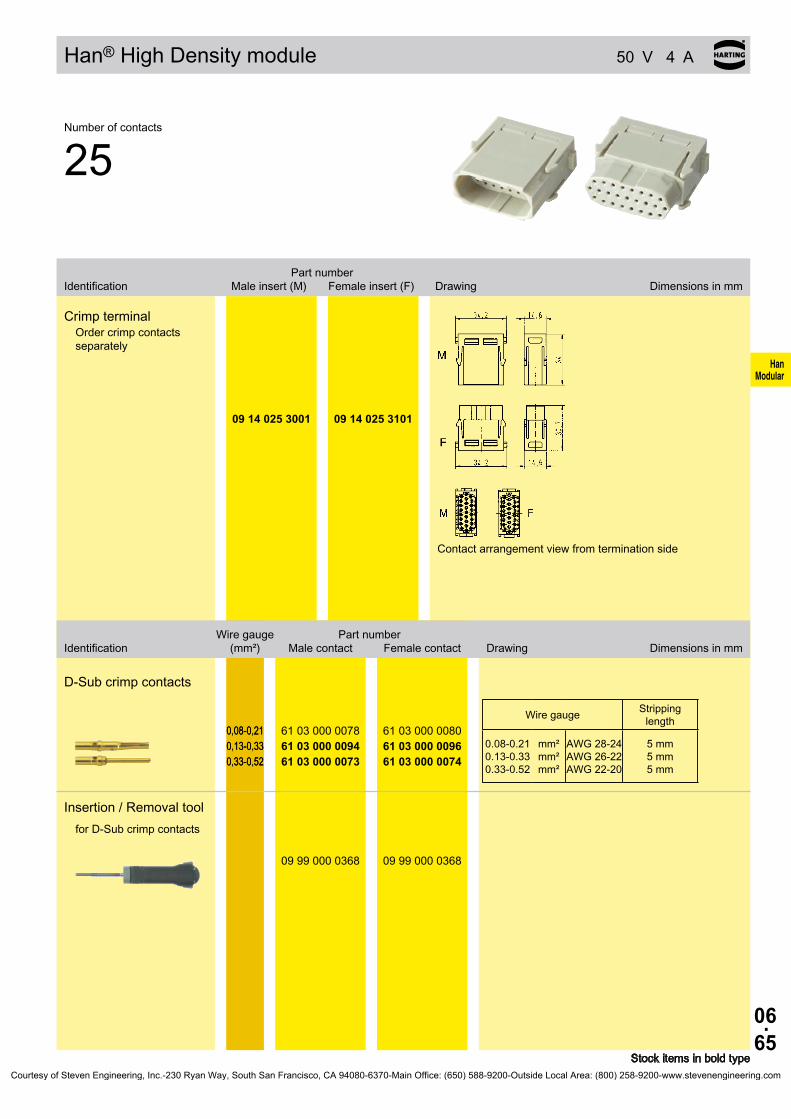
06.65
HanModular
09 14 025 3001 09 14 025 3101
mm²mm²mm²
AWG 28-24AWG 26-22AWG 22-20
5 mm5 mm5 mm
0,08-0,210,13-0,330,33-0,52
61 03 000 007861 03 000 009461 03 000 0073
61 03 000 008061 03 000 009661 03 000 0074
09 99 000 0368 09 99 000 0368
Han® High Density module 50 V 4 A
Stock items in bold type
Number of contacts
25
Part number Identification Male insert (M) Female insert (F) Drawing Dimensions in mm
Crimp terminalOrder crimp contacts separately
Contact arrangement view from termination side
Wire gauge Part number Identification (mm²) Male contact Female contact Drawing Dimensions in mm
D-Sub crimp contacts
Wire gauge Stripping length
0.08-0.210.13-0.330.33-0.52
0.08-0.210.13-0.330.33-0.52
Insertion / Removal tool for D-Sub crimp contacts
Courtesy of Steven Engineering, Inc.-230 Ryan Way, South San Francisco, CA 94080-6370-Main Office: (650) 588-9200-Outside Local Area: (800) 258-9200-www.stevenengineering.com

06.66
HanModular
Han® D-Sub module
Features• 9-pin D-Sub connector of the Han-Modular® system• Ideal for the transmission of sensetive signals• Compatible to crimp, solder or IDC termination• Using of guiding pins (male and female) is
recommended (see chapter 40).
Technical characteristicsSpecifications DIN EN 60 664-1 DIN EN 61 984
InsertsNumber of contacts 9 Electrical data acc. to EN 61 984 5 A 50 V 0.8 kV 3 Rated current 5 A Rated voltage 50 V Rated impulse voltage 0.8 kV Pollution degree 3Insulation resistance ≥ 1010 Ω Material polycarbonate Limiting temperatures -40 °C ... +125 °C Flammability acc. to UL 94 V 0 Mechanical working life - mating cycles ≥ 500
Courtesy of Steven Engineering, Inc.-230 Ryan Way, South San Francisco, CA 94080-6370-Main Office: (650) 588-9200-Outside Local Area: (800) 258-9200-www.stevenengineering.com
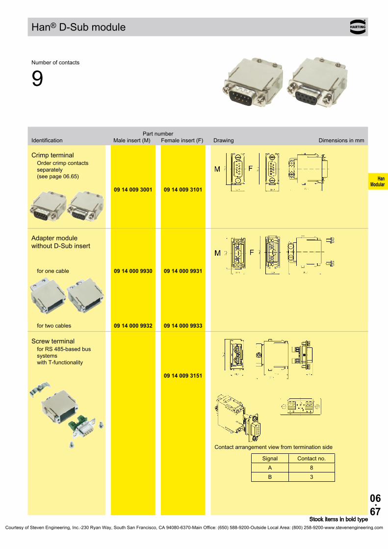
06.67
HanModular
09 14 009 3001 09 14 009 3101
09 14 000 9930 09 14 000 9931
09 14 000 9932 09 14 000 9933
A 8B 3
09 14 009 3151
Han® D-Sub module
Stock items in bold type
Number of contacts
9
Part number Identification Male insert (M) Female insert (F) Drawing Dimensions in mm
Crimp terminalOrder crimp contacts separately (see page 06.65)
Adapter module without D-Sub insert
for one cable
for two cables
Screw terminalfor RS 485-based bus systems with T-functionality
Contact arrangement view from termination side
Signal Contact no.
Courtesy of Steven Engineering, Inc.-230 Ryan Way, South San Francisco, CA 94080-6370-Main Office: (650) 588-9200-Outside Local Area: (800) 258-9200-www.stevenengineering.com
06.68
HanModular
Han® USB module
Features• According to USB 2.0 specification• Simple and cost effective termination by plug in
patch cable• Cable tie strain relief
Technical characteristicsSpecifications DIN EN 60 664-1 DIN EN 61 984
InsertsNumber of contacts 4 Electrical data acc. to EN 61 984 1 A 50 V 0.8 kV 3 Rated current 1 A Rated voltage 50 V Rated impulse voltage 0.8 kV Pollution degree 3Insulation resistance ≥ 1010 Ω Material polycarbonate Limiting temperatures -40 °C ... +85 °C Flammability acc. to UL 94 V 0 Mechanical working life - mating cycles ≥ 500
Courtesy of Steven Engineering, Inc.-230 Ryan Way, South San Francisco, CA 94080-6370-Main Office: (650) 588-9200-Outside Local Area: (800) 258-9200-www.stevenengineering.com

06.69
HanModular
09 14 001 4601
09 14 001 4701
09 14 001 4651
2 m 39 50 903 0050
5 m
39 50 903 0051
2 m 39 50 903 0050
5 m
39 50 903 0051
Han® USB module
Stock items in bold type
Number of contacts
4
Part number Identification Male insert (M) Female insert (F) Drawing Dimensions in mm
Module for patch cableMale insert
Module for patch cableFemale insert
Module for screw termi-nation
Male insert
Patch cable USBmale / male Style A
Courtesy of Steven Engineering, Inc.-230 Ryan Way, South San Francisco, CA 94080-6370-Main Office: (650) 588-9200-Outside Local Area: (800) 258-9200-www.stevenengineering.com

06.70
HanModular
Han® FireWire module
Features• Compatibel to IEEE 1394• Simple and cost effective termination by plug in
patch cable• Cable tie strain relief
Technical characteristicsSpecifications DIN EN 60 664-1 DIN EN 61 984
InsertsNumber of contacts 6 Electrical data acc. to EN 61 984 1 A 50 V 0.8 kV 3 Rated current 1 A Rated voltage 50 V Rated impulse voltage 0.8 kV Pollution degree 3Insulation resistance ≥ 1010 Ω Material polycarbonate Limiting temperatures -40 °C ... +85 °C Flammability acc. to UL 94 V 0 Mechanical working life - mating cycles ≥ 500
Courtesy of Steven Engineering, Inc.-230 Ryan Way, South San Francisco, CA 94080-6370-Main Office: (650) 588-9200-Outside Local Area: (800) 258-9200-www.stevenengineering.com
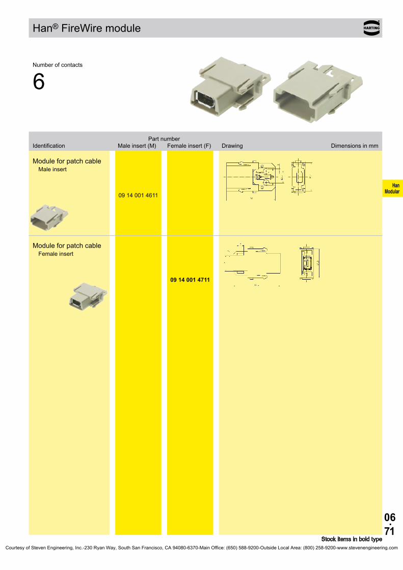
06.71
HanModular
09 14 001 4611
09 14 001 4711
Han® FireWire module
Stock items in bold type
Number of contacts
6
Part number Identification Male insert (M) Female insert (F) Drawing Dimensions in mm
Module for patch cableMale insert
Module for patch cableFemale insert
Courtesy of Steven Engineering, Inc.-230 Ryan Way, South San Francisco, CA 94080-6370-Main Office: (650) 588-9200-Outside Local Area: (800) 258-9200-www.stevenengineering.com

06.72
HanModular
Han® RJ45 module Technical characteristics
Features• Single module with standard shielded RJ45 plug
and jack• Cat 5e for all data pairs (all 8 pins)• Conforming to the RoHS directive• The RJ45 inserts are protected by a reliable
plastic insulator• Patch cables are assembled/removed without
tools
Technical characteristicsSpecifications DIN EN 60 664-1 DIN EN 61 984
InsertsNumber of contacts 8 Electrical data acc. to EN 61 984 1 A 50 V 0.8 kV 3 Rated current 1 A Rated voltage 50 V Rated impulse voltage 0.8 kV Pollution degree 3Transmission features Category 5 / Class D up to 100 MHz; acc. to ISO/IEC 11 801:2002 and EN 50 173-1 Transmission rate 10/100 Mbit/sInsulation resistance ≥ 1010 Ω Material polycarbonate Limiting temperatures -40 °C ... +85 °C Flammability acc. to UL 94 V 0 Mechanical working life - mating cycles ≥ 500
Courtesy of Steven Engineering, Inc.-230 Ryan Way, South San Francisco, CA 94080-6370-Main Office: (650) 588-9200-Outside Local Area: (800) 258-9200-www.stevenengineering.com
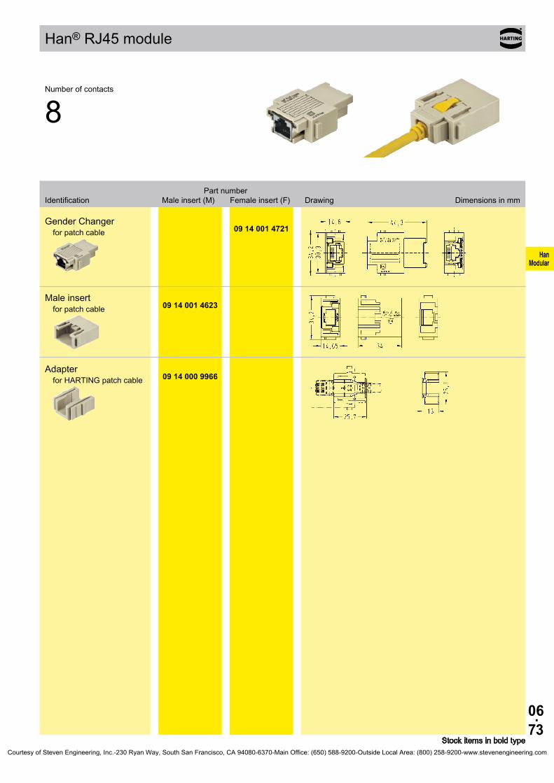
06.73
HanModular
09 14 001 4721
09 14 001 4623
09 14 000 9966
Han® RJ45 module
Stock items in bold type
Number of contacts
8
Part number Identification Male insert (M) Female insert (F) Drawing Dimensions in mm
Gender Changerfor patch cable
Male insertfor patch cable
Adapterfor HARTING patch cable
Courtesy of Steven Engineering, Inc.-230 Ryan Way, South San Francisco, CA 94080-6370-Main Office: (650) 588-9200-Outside Local Area: (800) 258-9200-www.stevenengineering.com

06.74
HanModular
Han® RJ45 module Patch cables
Features• Locking lever protection for RJ45 connector latch• Very short plug design in combination with robust
bend protection• RoHS compliant• Fully EMC screened (aluminium-clad foil and braid)
Technical characteristicsSpecifications ISO/IEC 24 702 ISO/IEC 11 801 ISO/IEC 61 935-2
Cat. 5 e RJ45 patch cableTransmission features Category 5 / Class D up to 100 MHz; acc. to ISO/IEC 24 702 or ISO/IEC 11 801 Transmission rate 10/100/1000 Mbit/s Cable type 1:1 EIA/TIA 568 B, 8 polesMaterial cables SF/UTP, PUR, yellow Limiting temperatures - mobile 0 °C ... +60 °C - stationary -40 °C ... +80 °CFlammability flame retardant, halogen-free Degree of protection IP 20
Cat. 6 RJ45 patch cableTransmission features Category 6 / Class E up to 250 MHz; acc. to ISO/IEC 24 702 or ISO/IEC 11 801 Transmission rate 10/100/1000 Mbit/s Cable type 1:1 EIA/TIA 568 B, 8 polesMaterial cables SF/UTP, PUR, yellow Limiting temperatures - mobile 0 °C ... +60 °C - stationary -20 °C ... +80 °CFlammability flame retardant, halogen-free Degree of protection IP 20
Courtesy of Steven Engineering, Inc.-230 Ryan Way, South San Francisco, CA 94080-6370-Main Office: (650) 588-9200-Outside Local Area: (800) 258-9200-www.stevenengineering.com
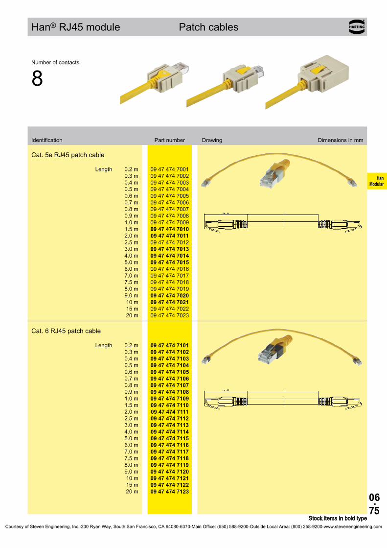
06.75
HanModular
09 47 474 7001 09 47 474 7002 09 47 474 7003 09 47 474 7004 09 47 474 7005 09 47 474 7006 09 47 474 7007 09 47 474 7008 09 47 474 7009 09 47 474 7010 09 47 474 7011 09 47 474 7012 09 47 474 7013 09 47 474 7014 09 47 474 7015 09 47 474 7016 09 47 474 7017 09 47 474 7018 09 47 474 7019 09 47 474 7020 09 47 474 7021 09 47 474 7022 09 47 474 7023
09 47 474 7101 09 47 474 7102 09 47 474 7103 09 47 474 7104 09 47 474 7105 09 47 474 7106 09 47 474 7107 09 47 474 7108 09 47 474 7109 09 47 474 7110 09 47 474 7111 09 47 474 7112 09 47 474 7113 09 47 474 7114 09 47 474 7115 09 47 474 7116 09 47 474 7117 09 47 474 7118 09 47 474 7119 09 47 474 7120 09 47 474 7121 09 47 474 7122 09 47 474 7123
Han® RJ45 module Patch cables
Stock items in bold type
Number of contacts
8
Identification Part number Drawing Dimensions in mm
Cat. 5e RJ45 patch cable
Length 0.2 m 0.3 m 0.4 m 0.5 m 0.6 m 0.7 m 0.8 m 0.9 m 1.0 m 1.5 m 2.0 m 2.5 m 3.0 m 4.0 m 5.0 m 6.0 m 7.0 m 7.5 m 8.0 m 9.0 m 10 m 15 m 20 m
Cat. 6 RJ45 patch cable
Length 0.2 m 0.3 m 0.4 m 0.5 m 0.6 m 0.7 m 0.8 m 0.9 m 1.0 m 1.5 m 2.0 m 2.5 m 3.0 m 4.0 m 5.0 m 6.0 m 7.0 m 7.5 m 8.0 m 9.0 m 10 m 15 m 20 m
Courtesy of Steven Engineering, Inc.-230 Ryan Way, South San Francisco, CA 94080-6370-Main Office: (650) 588-9200-Outside Local Area: (800) 258-9200-www.stevenengineering.com

06.76
HanModular
Han® RJ45 module RJ Industrial
FeaturesHan-Modular® RJ Industrial RJ45 connector set
• Conforming to the RoHS directive• 360° shielded contact• Field assembly without tools possible by means of
HARAX® rapid termination in IDC technology• Suitable for termination of massive and flexible
wires
Han-Modular® RJ Industrial Gigalink RJ45 connector set• Conforming to the RoHS directive• 360° shielded contact• Field assembly by means of piercing contacts• Suitable for termination of flexible wires
Technical characteristicsSpecifications IEC 60 603-7 DIN EN 60 664-1 DIN EN 61 984
HARTING RJ Industrial®, 4 pinsNumber of contacts 4Transmission features Category 5 / Class D up to 100 MHz; acc. to ISO/IEC 11 801:2002 and EN 50 173-1 Transmission rate 10/100 Mbit/s Wire termination IDC contacts; without toolsTerminated cable - Conductor cross section flexible AWG 24/7 ... AWG 22/7 solid AWG 23/1 ... AWG 22/1 - Cable outside diameter ≤ 1.6 mmMaterial insert polyamide Limiting temperatures -40 °C ... +70 °C
HARTING RJ Industrial® Gigalink, 8 pinsNumber of contacts 8Transmission features Category 6 / Class E up to 250 MHz; acc. to ISO/IEC 11 801:2002 and EN 50 173-1 Transmission rate 10/100/1000 Mbit/s Wire termination Piercing contactsTerminated cable - Conductor cross section flexible AWG 28/7 ... AWG 24/7 - Cable outside diameter ≤ 1.05 mmMaterial insert polyamide Limiting temperatures -40 °C ... +70 °C
HARTING RJ Industrial® 10G, 8 pinsNumber of contacts 8Transmission features Category 6 / Class E up to 250 MHz; acc. to ISO/IEC 11 801:2002 and EN 50 173-1 Transmission rate 10/100/1000 Mbit/s Wire termination IDC contacts; without toolsTerminated cable - Conductor cross section flexible AWG 27/7 ... AWG 22/7 solid AWG 27/1 ... AWG 22/1 - Cable outside diameter ≤ 1.5 mmMaterial insert polyamide Limiting temperatures -40 °C ... +70 °C
Courtesy of Steven Engineering, Inc.-230 Ryan Way, South San Francisco, CA 94080-6370-Main Office: (650) 588-9200-Outside Local Area: (800) 258-9200-www.stevenengineering.com

06.77
HanModular
09 45 400 1100
09 45 400 1109
09 45 400 1500
09 45 400 1510
09 45 400 1560
09 45 800 0500
Han® RJ45 module RJ Industrial
Stock items in bold type
Number of contacts
4 / 8
Part number Identification Male insert (M) Drawing Dimensions in mm
Han-Modular® RJ Industrial RJ45 connector set
Cat. 54 pins for AWG 24 ... 224 pins for AWG 26
Cat. 6Gigalink, 8 pinsGigalink, 8 pins
Cat. 610G, 8 pins
Set consists of the relevant RJ45 insert and the suitable adapter for Han® RJ45 module, male, part number 09 14 001 4623
HARTING RJ Industrial® Gigalink Assembly tool
* usuable with male insert 09 14 001 4623 (see page 06.73)Courtesy of Steven Engineering, Inc.-230 Ryan Way, South San Francisco, CA 94080-6370-Main Office: (650) 588-9200-Outside Local Area: (800) 258-9200-www.stevenengineering.com

06.78
HanModular
Han® GigaBit module
Features• Shielding bus separate from housing potential• Ideal for the transmission of sensetive signals
(e.g. bus signals)• Usuable for Gigabit Ethernet Cat. 6
Technical characteristicsSpecifications DIN EN 60 664-1 DIN EN 61 984
InsertsNumber of contacts 8 Insulation resistance ≥ 1010 Ω Material polycarbonate Limiting temperatures -40 °C ... +125 °C Flammability acc. to UL 94 V 0 Mechanical working life - mating cycles ≥ 500
GigaBit contactsNumber of contacts 8 + shielding Electrical data acc. to EN 61 984 5 A 50 V 0.8 kV 3 Rated current 5 A Rated voltage 50 V Rated impulse voltage 0.8 kV Pollution degree 3
Material - Insulator polycarbonate - Outer conductor zinc alloy Contact resistance ≤ 4 mΩ Limiting temperatures -40 °C ... +85 °C Flammability acc. to UL 94 V 0 Outer surface finish nickel Cable diameter 5 ... 12 mm
D-Sub crimp contactsCrimp terminal - mm² 0.08 ... 0.52 mm² - AWG 28 ... 20turned contacts Performance level 1
Courtesy of Steven Engineering, Inc.-230 Ryan Way, South San Francisco, CA 94080-6370-Main Office: (650) 588-9200-Outside Local Area: (800) 258-9200-www.stevenengineering.com

06.79
HanModular
09 14 001 3011 09 14 001 3111
09 14 008 3011 09 14 008 3111
mm²mm²mm²
AWG 28-24AWG 26-22AWG 22-20
5 mm5 mm5 mm
61 03 000 007861 03 000 009461 03 000 0073
61 03 000 008061 03 000 009661 03 000 0074
Han® GigaBit module 50 V 5 A
Stock items in bold type
Number of contacts
8
Part number Identification Male insert (M) Female insert (F) Drawing Dimensions in mm
Han® GigaBit module
Wire gauge Part number Identification (mm²) Male contact Female contact Drawing Dimensions in mm
GigaBit contacts8 + shielding Order crimp contacts separately
D-Sub crimp contacts Wire gauge Stripping length
0,08-0,210,13-0,330,33-0,52
0,08-0,210,13-0,330,33-0,52
Courtesy of Steven Engineering, Inc.-230 Ryan Way, South San Francisco, CA 94080-6370-Main Office: (650) 588-9200-Outside Local Area: (800) 258-9200-www.stevenengineering.com

06.80
HanModular
61 03 000 0062 61 03 000 0063 61 03 000 0064 61 03 000 0065 61 03 000 0066 61 03 000 0166 61 03 000 0067 61 03 000 0068 61 03 000 0069 61 03 000 0070 61 03 000 0071 61 03 000 0165 61 03 000 0072
61 03 000 0045 61 03 000 0046 61 03 000 0047 61 03 000 0048 61 03 000 0049 61 03 000 0050 61 03 000 0051 61 03 000 0052 61 03 000 0053 61 03 000 0054 61 03 000 0055 61 03 000 0056 61 03 000 0057 61 03 000 0058 61 03 000 0142 61 03 000 0059 61 03 000 0127
61 03 000 0141 61 03 000 0044 61 03 000 0143
Han® GigaBit module / Accessories
Stock items in bold type
Identification Part number Drawing Dimensions in mm
Crimp flange
D1 3.0 3.5 4.0 4.5 5.0 5.5 6.0 6.5 7.0 7.5 8.0 8.5 9.0
D2 4.0 4.5 5.0 5.5 6.0 6.5 7.0 7.5 8.0 8.5 9.0 9.5
10.0
Crimp ferrule
D3 5.0 5.5 6.0 6.5 7.0 7.5 8.0 8.5 9.0 9.5
10.0 10.5 11.0 11.5 12.0 12.5 13.0
D4 6.0 6.5 7.0 7.5 8.0 8.5 9.0 9.5
10.0 10.5 11.0 11.5 12.0 12.5 13.0 13.5 14.0
Cable clamp
cable diameter approx. 5 ... 7 mm cable diameter approx. 7 ... 10 mm
cable diameter approx. 10 ... 12 mm
Courtesy of Steven Engineering, Inc.-230 Ryan Way, South San Francisco, CA 94080-6370-Main Office: (650) 588-9200-Outside Local Area: (800) 258-9200-www.stevenengineering.com

06.81
HanModular
Notes
Courtesy of Steven Engineering, Inc.-230 Ryan Way, South San Francisco, CA 94080-6370-Main Office: (650) 588-9200-Outside Local Area: (800) 258-9200-www.stevenengineering.com

06.82
HanModular
Han-Quintax® module
Features• Shielding bus separate from housing potential• Perfect for transmission of sensitive signals
(eg. bus signals)• The four pole Han® Quintax contact is suitable for
Ethernet Cat. 5e and PROFIBUS when diagonally wiring of the data pairs.
Technical characteristicsSpecifications DIN EN 60 664-1 DIN EN 61 984 Approvals
InsertsNumber of contacts 2 Insulation resistance ≥ 1010 Ω Material polycarbonate Limiting temperatures -40 °C ... +125 °C Flammability acc. to UL 94 V 0 Mechanical working life - mating cycles ≥ 500
Quintax contactsNumber of contacts - Quintax 4 + shielding - High Density Quintax 8 + shielding
Electrical data acc. to EN 61 984 - Quintax 10 A 50 V 0.8 kV 3 - High Density Quintax 5 A 50 V 0.8 kV 3 Rated current 10 A / 5 A Rated voltage 50 V Rated impulse voltage 0.8 kV Pollution degree 3 Material - Insulator polycarbonate - Outer conductor zinc alloy Contact resistance ≤ 4 mΩ Limiting temperatures -40 °C ... +85 °C Flammability acc. to UL 94 V 0 Outer surface finish nickel Cable diameter 3 ... 9.5 mm
Han D® contactsMaterial copper alloy Surface - hard-gold plated 2 µm Au over 3 µm Ni Contact resistance ≤ 3 mΩ Crimp terminal - mm² 0.14 ... 2.5 mm² - AWG 26 ... 14
D-Sub crimp contactsCrimp terminal - mm² 0.08 ... 0.52 mm² - AWG 28 ... 20 turned contacts Performance level 1
Courtesy of Steven Engineering, Inc.-230 Ryan Way, South San Francisco, CA 94080-6370-Main Office: (650) 588-9200-Outside Local Area: (800) 258-9200-www.stevenengineering.com

06.83
HanModular
09 14 002 3001 09 14 002 3101
09 14 000 9915 09 14 000 9915
09 15 004 3013 09 15 004 3113
09 15 000 6124
09 15 000 612309 15 000 612509 15 000 612209 15 000 612109 15 000 6126
09 15 000 622409 15 000 622309 15 000 622509 15 000 622209 15 000 622109 15 000 6226
09 15 008 3013 09 15 008 3113
61 03 000 007861 03 000 009461 03 000 0073
61 03 000 008061 03 000 009661 03 000 0074
Han-Quintax® module
Stock items in bold typeOrder crimp contacts separately
Number of contacts
2
Part number Identification Male insert (M) Female insert (F) Drawing Dimensions in mm
Crimp terminal
Contact arrangement view from termination side
Quintax metal adapteroption
Wire gauge Part number Identification (mm²) Male contact Female contact Drawing Dimensions in mm
Quintax contact 4 + shielding Han D® crimp contacts
Han D® Crimp contact gold plated 0.14-0.37
0.50.75
11.52.5
High Density Quintax contact 8 + shielding Han® D-Sub contacts
D-Sub crimp contact0.08-0.210.13-0.330.33-0.52
Courtesy of Steven Engineering, Inc.-230 Ryan Way, South San Francisco, CA 94080-6370-Main Office: (650) 588-9200-Outside Local Area: (800) 258-9200-www.stevenengineering.com

06.84
HanModular
Han® Coax module
Features• Well known Quintax concept• Suitable for contacts with large diameters• Han E® coax is applicable to the ETCS Eurobalise
cable
RF transmission characteristics
Technical characteristicsSpecifications DIN EN 60 664-1 DIN EN 61 984 Approvals
InsertsNumber of contacts 2 Insulation resistance ≥ 1010 Ω Material polycarbonate Limiting temperatures -40 °C ... +125 °C Flammability acc. to UL 94 V 0 Mechanical working life - mating cycles ≥ 500
Coax contactsNumber of contacts 1 + shielding
Electrical data acc. to EN 61 984 - Han D® Coax 10 A 50 V 0.8 kV 3 - Han E® Coax 16 A 50 V 0.8 kV 3 Rated current 10 A / 16 A Rated voltage 50 V Rated impulse voltage 0.8 kV Pollution degree 3 Impedance - Han D® Coax 75 Ω - Han E® Coax 50 Ω Material - Insulator polycarbonate - Outer conductor zinc alloy Contact resistance ≤ 4 mΩ Limiting temperatures -40 °C ... +85 °C Flammability acc. to UL 94 V 0 Outer surface finish nickel Cable diameter 3 ... 9.5 mm
Han D® contactsMaterial copper alloy Surface - hard-gold plated 2 µm Au over 3 µm Ni Contact resistance ≤ 3 mΩ Crimp terminal - mm² 0.14 ... 2.5 mm² - AWG 26 ... 14
Han E® contactsMaterial copper alloy Surface - hard-gold plated 2 µm Au over 3 µm Ni Contact resistance ≤1 mΩ Crimp terminal - mm² 0.14 ... 5.5 mm² - AWG 26 ... 10
Impedance 75 Ω
Atte
nuat
ion
[db]
/m
Frequency
75 Ω cable 75 Ω cable with Han D® Coax
75 Ω coax cable diameter shielding: 7.3 mm
Impedance 50 Ω
Han E® Coax with ETCS S21 Eurobali-se cable (4 mm²)
27 MHz
Return loss [db] 35.4
Attenuation [db] 0.017
Han E® Coax with RG 213 cable (2.5 mm²)
200 MHz
500 MHz
1.0 GHz
1.2 GHz
1.5 GHz
2.0 GHz
2.5 GHz
Return loss [db] 23.8 21.1 >18.7 >17.7 >16.4 >14.1 >12.0
Attenuation [db] 0.07 0.11 0.17 0.2 <0.23 <0.53 <2.0
Courtesy of Steven Engineering, Inc.-230 Ryan Way, South San Francisco, CA 94080-6370-Main Office: (650) 588-9200-Outside Local Area: (800) 258-9200-www.stevenengineering.com

06.85
HanModular
Bestell-Nummer Bezeichnung Stifteinsatz (M) Buchseneinsatz (F) Maßzeichnung Maße in mm
09 14 002 3001 09 14 002 3101
Leiterquerschnitt Bestell-Nummer Bezeichnung (mm²) Kontaktstift Kontaktbuchse Maßzeichnung Maße in mm
09 15 001 3013 09 15 001 3113
09 15 000 6124
09 15 000 612309 15 000 612509 15 000 612209 15 000 612109 15 000 6126
09 15 000 622409 15 000 622309 15 000 622509 15 000 622209 15 000 622109 15 000 6226
09 15 001 3023 09 15 001 3123
09 33 000 6117
09 33 000 612209 33 000 611509 33 000 611809 33 000 611609 33 000 612309 33 000 611909 33 000 6139
09 33 000 621709 33 000 622209 33 000 621509 33 000 621809 33 000 621609 33 000 622309 33 000 622109 33 000 6239
Han® Coax module
Stock items in bold typeOrder crimp contacts separately
Number of contacts
2
Part number Identification Male insert (M) Female insert (F) Drawing Dimensions in mm
Crimp terminal
Contact arrangement view from termination side
Wire gauge Part number Identification (mm²) Male contact Female contact Drawing Dimensions in mm
Han® D Coax contact 1 + shielding, 75 Ω Han D® crimp contacts
Han D® Crimp contact gold plated 0.14-0.37
0.50.75
11.52.5
Han® E Coax contact 1 + shielding, 50 Ω Han E® crimp contacts
Han E® contacts gold plated 0.14-0.37
0.50.75
11.52.54
5.5
Courtesy of Steven Engineering, Inc.-230 Ryan Way, South San Francisco, CA 94080-6370-Main Office: (650) 588-9200-Outside Local Area: (800) 258-9200-www.stevenengineering.com
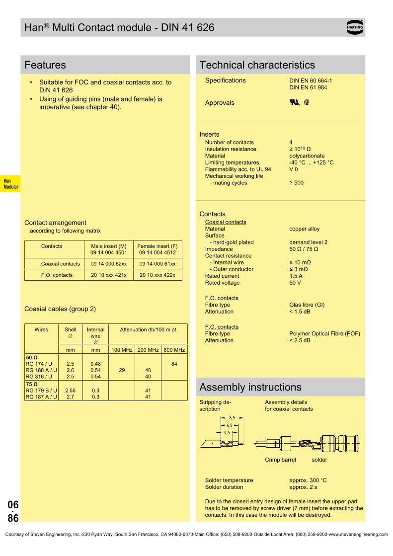
06.86
HanModular
Han® Multi Contact module - DIN 41 626
Features• Suitable for FOC and coaxial contacts acc. to
DIN 41 626• Using of guiding pins (male and female) is
imperative (see chapter 40).
Contact arrangementaccording to following matrix
Contacts Male insert (M) 09 14 004 4501
Female insert (F) 09 14 004 4512
Coaxial contacts 09 14 000 62xx 09 14 000 61xx
F.O. contacts 20 10 xxx 421x 20 10 xxx 422x
Coaxial cables (group 2)
Wires Shell ∅
Internal wire ∅
Attenuation db/100 m at
mm mm 100 MHz 200 MHz 800 MHz50 Ω RG 174 / U RG 188 A / U RG 316 / U
2.5 2.6 2.5
0.48 0.54 0.54
29
40 40
84
75 Ω RG 179 B / U RG 187 A / U
2.55 2.7
0.3 0.3
41 41
Technical characteristicsSpecifications DIN EN 60 664-1 DIN EN 61 984 Approvals ,
InsertsNumber of contacts 4 Insulation resistance ≥ 1010 Ω Material polycarbonate Limiting temperatures -40 °C ... +125 °C Flammability acc. to UL 94 V 0 Mechanical working life - mating cycles ≥ 500
ContactsCoaxial contacts Material copper alloy Surface - hard-gold plated demand level 2 Impedance 50 Ω / 75 Ω Contact resistance - Internal wire ≤ 10 mΩ - Outer conductor ≤ 3 mΩ Rated current 1.5 A Rated voltage 50 V
F.O. contacts Fibre type Glas fibre (GI) Attenuation < 1.5 dB
F.O. contacts Fibre type Polymer Optical Fibre (POF) Attenuation < 2.5 dB
Assembly instructionsStripping de-scription
Assembly details for coaxial contacts
Crimp barrel solder
Solder temperature approx. 300 °C Solder duration approx. 2 s
Due to the closed entry design of female insert the upper part has to be removed by screw driver (7 mm) before extracting the contacts. In this case the module will be destroyed.
Courtesy of Steven Engineering, Inc.-230 Ryan Way, South San Francisco, CA 94080-6370-Main Office: (650) 588-9200-Outside Local Area: (800) 258-9200-www.stevenengineering.com

06.87
HanModular
09 14 004 4501 09 14 004 4512
50 Ω75 Ω
09 14 000 621109 14 000 6221
09 14 000 611109 14 000 6121
20 10 230 4211 20 10 230 4221
20 10 125 4212 20 10 125 4222
20 10 001 4211 20 10 001 4221
Han® Multi Contact module
Stock items in bold type
Number of contacts
4
Part number Identification Male insert (M) Female insert (F) Drawing Dimensions in mm
Multicontact module acc. to DIN 41 626
Order contacts separately
Contact arrangement view from termination side
Identification Impedance Part number Drawing Dimensions in mm
* Using of guiding pins is imperative (see chapter 40).
Coaxial contacts acc. to DIN 41 626*Solder / crimp contact
For cable group 2 flexible wires
50 Ω75 Ω
09 14 000 621109 14 000 6221
09 14 000 611109 14 000 6121
F.O. contacts acc. to DIN 41 626
for SI fibre (HCS®) 200/230 µm
20 10 230 4211 20 10 230 4221
for GI fibre 50/125 µm or 62.5/125 µm ceramic ferrule
20 10 125 4212 20 10 125 4222
for 1 mm plastic fibre
20 10 001 4211 20 10 001 4221
Courtesy of Steven Engineering, Inc.-230 Ryan Way, South San Francisco, CA 94080-6370-Main Office: (650) 588-9200-Outside Local Area: (800) 258-9200-www.stevenengineering.com

06.88
HanModular
Han® Multi Contact module - D-Sub
Features• Suitable for coaxial contacts acc. to D-Sub
(DIN 41 652)• Using of guiding pins (male and female) is recom-
mended (see chapter 40).
Contact arrangementaccording to following matrix
Contacts Male insert (M) 09 14 004 4501
Female insert (F) 09 14 004 4513
Coaxial contacts 09 14 000 62xx 09 14 000 61xx
Coaxial contacts 09 69 28x 5xxx 09 69 18x 5xxx
Technical characteristicsSpecifications DIN EN 60 664-1 DIN EN 61 984 Approvals ,
InsertsNumber of contacts 4 Insulation resistance ≥ 1010 Ω Material polycarbonate Limiting temperatures -40 °C ... +125 °C Flammability acc. to UL 94 V 0 Mechanical working life - mating cycles ≥ 500
ContactsCoaxial contacts Material copper alloy Surface - hard-gold plated demand level 2, S4 Impedance 50 Ω / 75 Ω Contact resistance - Internal wire ≤ 10 mΩ - Outer conductor ≤ 3 mΩ Rated current 1.5 A Rated voltage 50 V
Courtesy of Steven Engineering, Inc.-230 Ryan Way, South San Francisco, CA 94080-6370-Main Office: (650) 588-9200-Outside Local Area: (800) 258-9200-www.stevenengineering.com
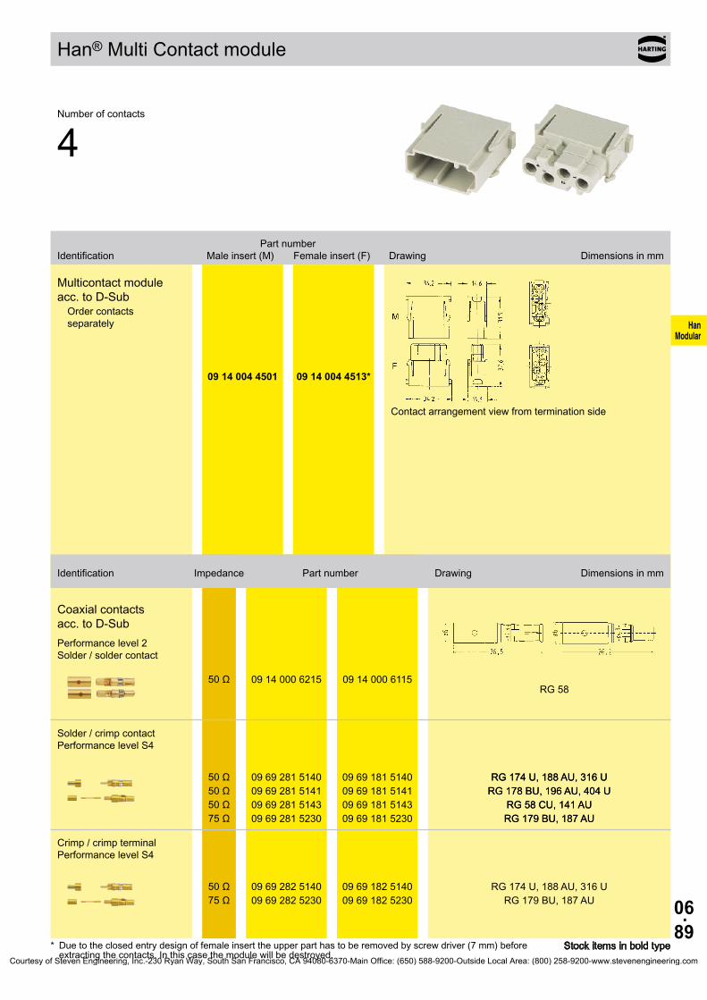
06.89
HanModular
09 14 004 4501 09 14 004 4513*
RG 5850 Ω 09 14 000 6215 09 14 000 6115
50 Ω50 Ω50 Ω75 Ω
09 69 281 514009 69 281 514109 69 281 514309 69 281 5230
09 69 181 514009 69 181 514109 69 181 514309 69 181 5230
RG 174 U, 188 AU, 316 URG 178 BU, 196 AU, 404 U
RG 58 CU, 141 AURG 179 BU, 187 AU
50 Ω75 Ω
09 69 282 514009 69 282 5230
09 69 182 514009 69 182 5230
RG 174 U, 188 AU, 316 URG 179 BU, 187 AU
Han® Multi Contact module
Stock items in bold type* Due to the closed entry design of female insert the upper part has to be removed by screw driver (7 mm) before extracting the contacts. In this case the module will be destroyed.
Number of contacts
4
Part number Identification Male insert (M) Female insert (F) Drawing Dimensions in mm
Multicontact module acc. to D-Sub
Order contacts separately
Contact arrangement view from termination side
Identification Impedance Part number Drawing Dimensions in mm
Coaxial contacts acc. to D-SubPerformance level 2 Solder / solder contact
Solder / crimp contact Performance level S4
RG 174 U, 188 AU, 316 URG 178 BU, 196 AU, 404 U
RG 58 CU, 141 AURG 179 BU, 187 AU
Crimp / crimp terminal Performance level S4
Courtesy of Steven Engineering, Inc.-230 Ryan Way, South San Francisco, CA 94080-6370-Main Office: (650) 588-9200-Outside Local Area: (800) 258-9200-www.stevenengineering.com

06.90
HanModular
Han® Pneumatic module
Features• For the transmission of clean and dry compressed• Female contacts with / without shut off• Removal of tubes from pre-assembled pneumatic
contacts is possible
Shut off principle: In the disconnected position the spring integrated in the female contact is active, thus the O-ring of the valve seals the opening of the air-way. During the mating process, when the defined depth of insertion is reached the male contact presses on the valve head and moves it backwards against the spring tension, so that the air-way opens.
Using of guiding pins in connection with pneumatic modules is imperative.In addition to this guiding pins guarantee a coding, if pneumatic modules are used exclusively.
Technical characteristicsApprovals ,
Inserts *Number of contacts 2 Colour blue Material polycarbonate Limiting temperatures -40 °C ... +80 °C Flammability acc. to UL 94 V 0 Mechanical working life - mating cycles ≥ 500
ContactsMaterial delrin acetal Colour black Tube termination - Internal diameter (ID) 6.0 mm / 1/4“ Working pressure up to 8 bar / 116 psi
SealingMaterial Buna-N
Shut off valveMaterial Polypropylen
* Assemble contacts before module is fixed into the frameCourtesy of Steven Engineering, Inc.-230 Ryan Way, South San Francisco, CA 94080-6370-Main Office: (650) 588-9200-Outside Local Area: (800) 258-9200-www.stevenengineering.com

06.91
HanModular
09 14 002 4501* 09 14 002 4501*
09 14 000 6174 09 14 000 6274
09 14 000 6279
Han® Pneumatic module
Stock items in bold type
Number of contacts
2
Part number Identification Male insert (M) Female insert (F) Drawing Dimensions in mm
for 6 mmOrder contacts separately
Contact arrangement view from termination side
ID Part number Identification (mm) Male contact Female contact Drawing Dimensions in mm
Pneumatic contacts without shut offfor tube internal diameter (ID)
Male contact Female contact6.0
Pneumatic contacts with shut offfor tube internal diameter (ID)
female contact with shut off in closed position6.0
* Using of guiding pins is imperative (see chapter 40).Courtesy of Steven Engineering, Inc.-230 Ryan Way, South San Francisco, CA 94080-6370-Main Office: (650) 588-9200-Outside Local Area: (800) 258-9200-www.stevenengineering.com
06.92
HanModular
Han® Pneumatic module
Features• For the transmission of clean and dry compressed• Female contacts with / without shut off• Removal of tubes from pre-assembled pneumatic
contacts is possible
Shut off principle: In the disconnected position the spring integrated in the female contact is active, thus the O-ring of the valve seals the opening of the air-way. During the mating process, when the defined depth of insertion is reached the male contact presses on the valve head and moves it backwards against the spring tension, so that the air-way opens.
Using of guiding pins in connection with pneumatic modules is imperative.In addition to this guiding pins guarantee a coding, if pneumatic modules are used exclusively.
Technical characteristicsApprovals ,
Inserts *Number of contacts 3 Colour blue Material polycarbonate Limiting temperatures -40 °C ... +80 °C Flammability acc. to UL 94 V 0 Mechanical working life - mating cycles ≥ 500
ContactsMaterial delrin acetal Colour black Tube termination - Internal diameter (ID) 1.6 mm / 1/16“ 3.0 mm 4.0 mm / 1/8“ Working pressure up to 8 bar / 116 psi
SealingMaterial Buna-N
Shut off valveMaterial Polypropylen
* Assemble contacts before module is fixed into the frameCourtesy of Steven Engineering, Inc.-230 Ryan Way, South San Francisco, CA 94080-6370-Main Office: (650) 588-9200-Outside Local Area: (800) 258-9200-www.stevenengineering.com
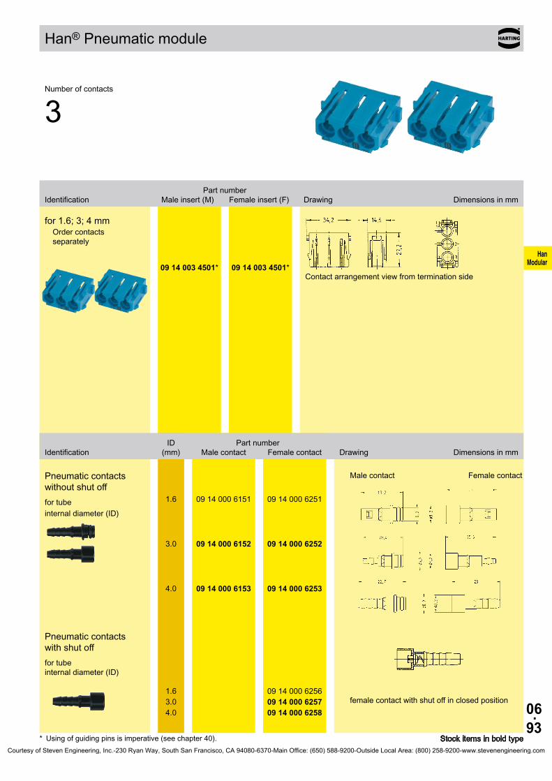
06.93
HanModular 09 14 003 4501* 09 14 003 4501*
09 14 000 6151 09 14 000 6251
09 14 000 6152 09 14 000 6252
09 14 000 6153 09 14 000 6253
09 14 000 625609 14 000 625709 14 000 6258
Han® Pneumatic module
Stock items in bold type
Number of contacts
3
Part number Identification Male insert (M) Female insert (F) Drawing Dimensions in mm
for 1.6; 3; 4 mmOrder contacts separately
Contact arrangement view from termination side
ID Part number Identification (mm) Male contact Female contact Drawing Dimensions in mm
Pneumatic contacts without shut offfor tube internal diameter (ID)
Male contact Female contact
1.6
3.0
4.0
Pneumatic contacts with shut offfor tube internal diameter (ID)
female contact with shut off in closed position1.63.04.0
* Using of guiding pins is imperative (see chapter 40).Courtesy of Steven Engineering, Inc.-230 Ryan Way, South San Francisco, CA 94080-6370-Main Office: (650) 588-9200-Outside Local Area: (800) 258-9200-www.stevenengineering.com

06.94
HanModular
Han® SC module
Features• Suitable for HARTING SC contacts• For GI-Fibre 50 - 62.5 / 125µm• Using of guiding pins (male and female) is recom-
mended (see chapter 40).
Assembly instructionsMale insert (09 14 004 4701)
A Assemble the SC contact Push the SC contact from the side into the relevant insert (1)Push the fixing plate from the side over the contacts (2)
B SC contact fixed in the module
Female insert (09 14 004 4711)
A Assemble the SC contact Push the centering ferrule (included in delivery) on the SC contact (1)Push the SC contact from the side into the relevant insert (2)Push the fixing plate from the side over the contacts (3)
B SC contact fixed in the module
Technical characteristicsInserts
Number of contacts 4 Insertion loss < 0.5 dB Material polycarbonate Limiting temperatures -40 °C ... +85 °C Flammability acc. to UL 94 V 0 Mechanical working life - mating cycles ≥ 500
Courtesy of Steven Engineering, Inc.-230 Ryan Way, South San Francisco, CA 94080-6370-Main Office: (650) 588-9200-Outside Local Area: (800) 258-9200-www.stevenengineering.com

06.95
HanModular
09 14 004 4701 09 14 004 4711*
09 14 000 9965 09 14 000 9965
20 10 125 5211 20 10 125 5211
20 10 230 5211 20 10 230 5211
20 10 001 5217 20 10 001 5217
20 10 001 5211 20 10 001 5211
Han® SC module
Stock items in bold type* The female inserts are equipped with centering ferrules. 4 ferrules are included in delivery range.
Number of contacts
4
Part number Identification Male insert (M) Female insert (F) Drawing Dimensions in mm
SC moduleOrder contacts separately
Contact arrangement view from termination side
Part number Identification Male contact Female contact Drawing Dimensions in mm
SC contact
for GI fibre 50/125 µm or 62.5/125 µm ceramic ferrule
for SI fibre (HCS®) 200/230 µm
with quick assembly technique for 1 mm POF
with crimp technique for 1 mm POF
Fixing plate
Courtesy of Steven Engineering, Inc.-230 Ryan Way, South San Francisco, CA 94080-6370-Main Office: (650) 588-9200-Outside Local Area: (800) 258-9200-www.stevenengineering.com

06.96
HanModular
Han-Elisa®
Features• Signal pre-processing and conversion do fit into
the connector• Individual combination of input and output modules
for optimal signal pre-processing• Minimum size for integration in Han® industrial
connectors (Han-Modular® and Han-Snap®)• Economy of space by reduction the number of
terminal blocks and interface modules in the switch cabinet
General descriptionThe Han-Elisa® modules are a flexible I/O system - directly in the connector.The input and output modules are developed for 1 or 2 channels and can be combined variously and flexible for optimal signal pre-processing. Within the product family modules are available for current/voltage converison, temperature, relay and timer.Due to the minimized size thes modules can be integrated into the Han-Modular® and Han-Snap® system.Signal pre-processing and conversion do fit into the connector and this will reduce installation space for terminal blocks and the number of interface modules. So the switch cabinets can be made smaller.
Technical characteristicsPower supply (combination input and output module)
Supply voltage 24 V (-10 % ... +25 %) Current consumption < 0.08 A Power consumption < 2 W Total transmission error < 0.2 %
Courtesy of Steven Engineering, Inc.-230 Ryan Way, South San Francisco, CA 94080-6370-Main Office: (650) 588-9200-Outside Local Area: (800) 258-9200-www.stevenengineering.com
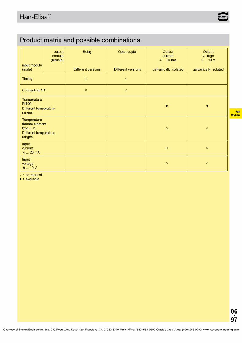
06.97
HanModular
Han-Elisa®
Product matrix and possible combinations
input module (male)
output module
(female)
Relay Optocoupler Output current
4 ... 20 mA
Output voltage
0 ... 10 V
Different versions Different versions galvanically isolated galvanically isolated
Timing ○ ○
Connecting 1:1 ○ ○
Temperature Pt100Different temperature ranges
● ●
Temperature thermo element type J, KDifferent temperature ranges
○ ○
Input current 4 ... 20 mA
○ ○
Input voltage 0 ... 10 V
○ ○
○ = on request ● = available
Courtesy of Steven Engineering, Inc.-230 Ryan Way, South San Francisco, CA 94080-6370-Main Office: (650) 588-9200-Outside Local Area: (800) 258-9200-www.stevenengineering.com

06.98
HanModular
Han-Elisa® Pt100 module
Features• Minimum size for integration in Han® industrial
connectors (Han-Modular® and Han-Snap®)• Economy of space by reduction the number of
terminal blocks and interface modules in the switch cabinet
• Male module for signal input
Technical characteristicsInserts
Sensor Pt100 acc. to IEC 751 Termination technology 2-, 3-, 4 wire technology Sensor input current 0.8 mA, constant Conductor resistance, max. permissible 10 Ω per conductor Min. measuring range 100 °C Open circuit detection integrated
Material polycarbonate / LCP Termination Cage-clamp terminal - mm² 0.14 ... 1.5 mm² - AWG 26 ... 16
Power diagnostic LED (green)
Temperature rangeWorking temperature -20 °C ... +65 °C Stock temperature -40 °C ... +85 °C
Courtesy of Steven Engineering, Inc.-230 Ryan Way, South San Francisco, CA 94080-6370-Main Office: (650) 588-9200-Outside Local Area: (800) 258-9200-www.stevenengineering.com

06.99
HanModular
20 75 108 1101
20 75 108 1103
Han-Elisa® Pt100 module
Stock items in bold type
Pt100 Input module
Part number Identification Male insert (M) Drawing Dimensions in mm
Temperature module Pt100
Input
Measuring range 0 ... 100 °C
0 ... 200 °C
Additional measuring ranges on request
Courtesy of Steven Engineering, Inc.-230 Ryan Way, South San Francisco, CA 94080-6370-Main Office: (650) 588-9200-Outside Local Area: (800) 258-9200-www.stevenengineering.com

06.100
HanModular
Han-Elisa® Output module
Features• Minimum size for integration in Han® industrial
connectors (Han-Modular® and Han-Snap®)• Economy of space by reduction the number of
terminal blocks and interface modules in the switch cabinet
• Female module for signal output
Technical characteristicsInserts
Supply voltage 24 V (-10 % ... +25 %) Load Iout < 500 Ω Load Uout ≥ 10 kΩ Residual ripple < 20 mV (500 Ω) Step response (0 ... 99 %) < 30 ms
Material polycarbonate / LCP Termination Cage-clamp terminal - mm² 0.14 ... 1.5 mm² - AWG 26 ... 16
Power diagnostic LED (green)
Temperature rangeWorking temperature -20 °C ... +65 °C Stock temperature -40 °C ... +125 °C
Courtesy of Steven Engineering, Inc.-230 Ryan Way, South San Francisco, CA 94080-6370-Main Office: (650) 588-9200-Outside Local Area: (800) 258-9200-www.stevenengineering.com

06.101
HanModular
20 75 104 2201
20 75 105 2201
Han-Elisa® Output module
Stock items in bold type
Output module
Part number Identification Female insert (F) Drawing Dimensions in mm
Output module, current 3-ways-isolating amplifier; galvanically isolated
OutputOutput signal 4 ... 20 mA
Additional output signal ranges on request
Output module, voltage 3-ways-isolating amplifier; galvanically isolated
OutputOutput signal 0 ... 10 V
Additional output signal ranges on request
Courtesy of Steven Engineering, Inc.-230 Ryan Way, South San Francisco, CA 94080-6370-Main Office: (650) 588-9200-Outside Local Area: (800) 258-9200-www.stevenengineering.com
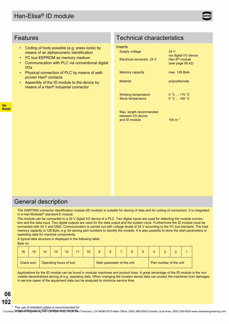
06.102
HanModular
Han-Elisa® ID module
Features• Coding of tools possible (e.g. press tools) by
means of an alphanumeric identification• I²C bus EEPROM as memory medium• Communication with PLC via conventional digital
I/Os• Physical connection of PLC by means of well-
proven Han® contacts• Assembly of the ID module to the device by
means of a Han® industrial connector
Technical characteristicsInserts
Supply voltage 24 V via digital I/O device Electrical connector, 24 V Han E® module (see page 06.42)
Memory capacity max. 128 Byte
Material polycarbonate
Working temperature 0 °C ... +70 °C Stock temperature 0 °C ... +85 °C
Max. length recommended between I/O device and ID module 100 m *
General descriptionThe HARTING connector identification module (ID module) is suitable for storing of data and for coding of connectors. It is integrated in a Han-Modular® standard E module.The module can be connected to a 24 V digital I/O device of a PLC. Two digital inputs are used for detecting the module connec-tion and the data input. Two digital outputs are used for the data output and the system clock. Furthermore the ID module must be connected with 24 V and GND. Communication is carried out with voltage levels of 24 V according to the I²C bus standard. The total memory capacity is 128 Byte, e.g. for storing part numbers to identify the module. It is also possible to store the start parameters or operating data for machine components.A typical data structure is displayed in the following table:Byte no.
16 15 14 13 12 11 10 9 8 7 6 5 4 3 2 1
Check sum Operating hours of tool Start parameter of the unit Part number of the unit
Applications for the ID module can be found in modular machines and product lines. A great advantage of the ID module is the non volatile decentralized storing of e.g. operating data. When changing the location stored data can protect the machines from damages. In service cases of the equipment data can be analyzed to minimize service time.
* The use of shielded cables is recommended for longer distances or EMC loaded environments.Courtesy of Steven Engineering, Inc.-230 Ryan Way, South San Francisco, CA 94080-6370-Main Office: (650) 588-9200-Outside Local Area: (800) 258-9200-www.stevenengineering.com

06.103
HanModular
20 70 001 1001
Han-Elisa® ID module
Stock items in bold type
Input module
Part number Identification Male insert (M) Drawing Dimensions in mm
Electronic identification module
Block diagram / Wiring plan
Meaning of the connections
Pin no. Name Meaning/Function
1 Data IN Input for data and control signals from PLC2 DC 24 V Power connection of the ID module3 Data OUT Output for data signals from ID module to PLC
4 GND Ground5 CLK System clock for synchronisation6 Connection Output of the ID module for connection detection
Courtesy of Steven Engineering, Inc.-230 Ryan Way, South San Francisco, CA 94080-6370-Main Office: (650) 588-9200-Outside Local Area: (800) 258-9200-www.stevenengineering.com
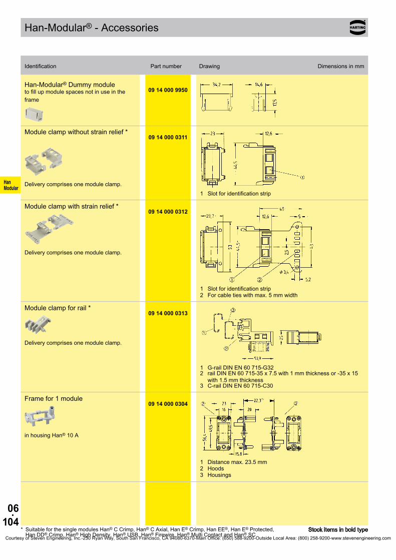
06.104
HanModular
09 14 000 9950
09 14 000 0311
09 14 000 0312
09 14 000 0313
09 14 000 0304
Stock items in bold type
Han-Modular® - Accessories
Identification Part number Drawing Dimensions in mm
* Suitable for the single modules Han® C Crimp, Han® C Axial, Han E® Crimp, Han EE®, Han E® Protected, Han DD® Crimp, Han® High Density, Han® USB, Han® Firewire, Han® Multi Contact and Han® SC
Identification Part number Drawing Dimensions in mm
Han-Modular® Dummy module to fill up module spaces not in use in the frame
Module clamp without strain relief *
Delivery comprises one module clamp.1 Slot for identification strip
Module clamp with strain relief *
Delivery comprises one module clamp.
1 Slot for identification strip2 For cable ties with max. 5 mm width
Module clamp for rail *
Delivery comprises one module clamp.
1 G-rail DIN EN 60 715-G322 rail DIN EN 60 715-35 x 7.5 with 1 mm thickness or -35 x 15
with 1.5 mm thickness3 C-rail DIN EN 60 715-C30
Frame for 1 module
in housing Han® 10 A
1 Distance max. 23.5 mm2 Hoods3 Housings
Courtesy of Steven Engineering, Inc.-230 Ryan Way, South San Francisco, CA 94080-6370-Main Office: (650) 588-9200-Outside Local Area: (800) 258-9200-www.stevenengineering.com
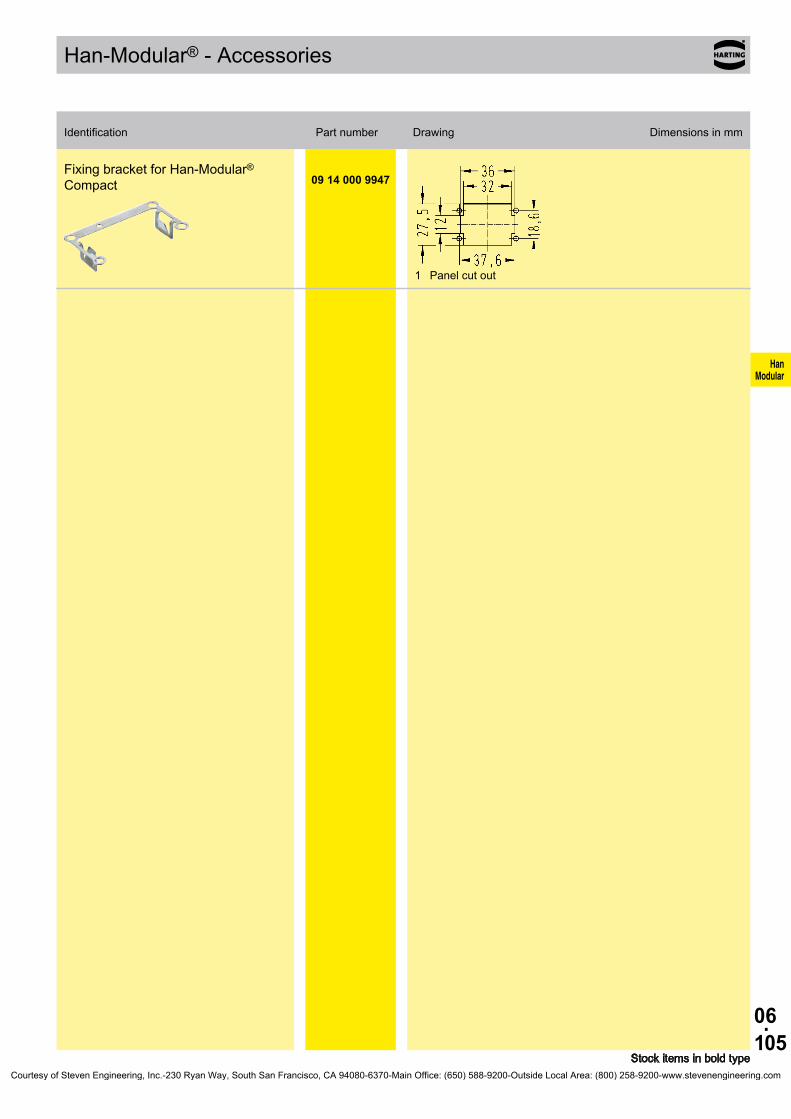
06.105
HanModular
09 14 000 9947
Han-Modular® - Accessories
Identification Part number Drawing Dimensions in mm
Stock items in bold type
Fixing bracket for Han-Modular® Compact
1 Panel cut out
Courtesy of Steven Engineering, Inc.-230 Ryan Way, South San Francisco, CA 94080-6370-Main Office: (650) 588-9200-Outside Local Area: (800) 258-9200-www.stevenengineering.com

06.106
HanModular
Notes
Courtesy of Steven Engineering, Inc.-230 Ryan Way, South San Francisco, CA 94080-6370-Main Office: (650) 588-9200-Outside Local Area: (800) 258-9200-www.stevenengineering.com

07.01
HanHsB
Han® HsB
Contents Page
Technical characteristics Han® HsB . . . . . . . . . . . . . . . . . . . . . . . . . . . . . . 07.02
Han® 6 HsB . . . . . . . . . . . . . . . . . . . . . . . . . . . . . . . . . . . . . . . . . . . . . . . . 07.03
Han® 12 HsB . . . . . . . . . . . . . . . . . . . . . . . . . . . . . . . . . . . . . . . . . . . . . . . . 07.04
Courtesy of Steven Engineering, Inc.-230 Ryan Way, South San Francisco, CA 94080-6370-Main Office: (650) 588-9200-Outside Local Area: (800) 258-9200-www.stevenengineering.com

07.02
HanHsB
Han® HsB
FeaturesFeatures• screw termination• wire-protection included• ideal for power supply applications• termination with standard screw driver
Current carrying capacityThe current carrying capacity of the connectors is limited by the thermal load capability of the contact element material including the connections and the insulating parts. The derating curve isthereforevalidforcurrentswhichflowconstantly(non-inter-mittent) through each contact element of the connector evenly, without exceeding the allowed maximum temperature.Measuring and testing techniques according to DIN EN 60 512-5
Ope
ratin
g cu
rrent
Ambient temperature
➀wiregauge:4mm²➁wiregauge:6mm²
Technical characteristicsSpecifications DINEN60664-1
DINEN61984Approvals ,
InsertsNumberofcontacts 6,12(2x6),+PEElectrical data acc.toEN61984 35 A 400/690 V 6 kV 3Rated current 35 A Ratedvoltageconductor-ground 400V Ratedvoltageconductor-conductor690V Ratedimpulsevoltage 6kV Pollutiondegree 3
or 35A500V6kV3
Rated voltage acc.toUL/CSA 600V
Insulationresistance ≥1010Ω Material polycarbonate Limitingtemperatures -40°C...+125°C Flammabilityacc.toUL94 V0Mechanical working life
-matingcycles ≥500
ContactsMaterial copper alloySurface
- hard-silver plated 3 µm AgContactresistance ≤1mΩScrew terminal
- Wire gauge1) 6mm² - AWG 10 - Tightening torque 1.2 Nm
Hoods/HousingsMaterial aluminium die-cast Surface powder-coated RAL 7037 Locking element Han-Easy Lock® Hoods/Housings sealing NBR Limitingtemperatures -40°C...+125°CDegree of protection acc. to DIN EN 60 529 for coupled connector IP65Further selection of hoods/housings see chapter 30 / chapter 31
AccessoriesCableclamps chapter40 Codingofhoods/housings chapter40 Labelacc.toCSA-approval chapter40 Han-Snap® chapter 11
1) geometric wire gaugeCourtesy of Steven Engineering, Inc.-230 Ryan Way, South San Francisco, CA 94080-6370-Main Office: (650) 588-9200-Outside Local Area: (800) 258-9200-www.stevenengineering.com

07.03
HanHsB
Han® 6 HsB Size16B 400/690V35A
Stock items in bold type
Number of contacts
6+
SeriesPartnumber
Identification Maleinsert(M) Femaleinsert(F) Drawing Dimensions in mm
Screw terminal Han® HsB
1) Distance for contact max. 21 mm
Contact arrangement (view from termination side)
Panelcutoutforinserts for use without hoods/housings
1-6 09 31 006 2601 09 31 006 2701
Courtesy of Steven Engineering, Inc.-230 Ryan Way, South San Francisco, CA 94080-6370-Main Office: (650) 588-9200-Outside Local Area: (800) 258-9200-www.stevenengineering.com

07.04
HanHsB
Han® 12 HsB Size32B 400/690V35A
Stock items in bold type
Number of contacts
12+
SeriesPartnumber
Identification Maleinsert(M) Femaleinsert(F) Drawing Dimensions in mm
Screw terminal Han® HsB
1) Distance for contact max. 21 mm
Contact arrangement (view from termination side)
Panelcutoutforinserts for use without hoods/housings
1-6
7-1209 31 006 2601 09 31 006 2611
09 31 006 2701 09 31 006 2711
Courtesy of Steven Engineering, Inc.-230 Ryan Way, South San Francisco, CA 94080-6370-Main Office: (650) 588-9200-Outside Local Area: (800) 258-9200-www.stevenengineering.com
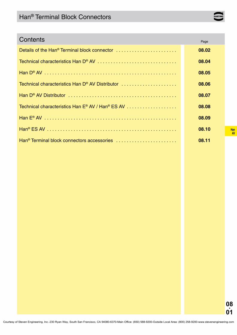
08.01
HanAV
Contents
Han® Terminal Block Connectors
Page
Details of the Han® Terminal block connector . . . . . . . . . . . . . . . . . . . . . . . 08.02
Technical characteristics Han D® AV . . . . . . . . . . . . . . . . . . . . . . . . . . . . . . 08.04
Han D® AV . . . . . . . . . . . . . . . . . . . . . . . . . . . . . . . . . . . . . . . . . . . . . . . . . . 08.05
Technical characteristics Han D® AV Distributor . . . . . . . . . . . . . . . . . . . . . 08.06
Han D® AV Distributor . . . . . . . . . . . . . . . . . . . . . . . . . . . . . . . . . . . . . . . . . 08.07
Technical characteristics Han E® AV / Han® ES AV . . . . . . . . . . . . . . . . . . . 08.08
Han E® AV . . . . . . . . . . . . . . . . . . . . . . . . . . . . . . . . . . . . . . . . . . . . . . . . . . 08.09
Han® ES AV . . . . . . . . . . . . . . . . . . . . . . . . . . . . . . . . . . . . . . . . . . . . . . . . . 08.10
Han® Terminal block connectors accessories . . . . . . . . . . . . . . . . . . . . . . . 08.11
Courtesy of Steven Engineering, Inc.-230 Ryan Way, South San Francisco, CA 94080-6370-Main Office: (650) 588-9200-Outside Local Area: (800) 258-9200-www.stevenengineering.com

08.02
HanAV
Han D® AV Details
Possibilities in switch cabinet The terminal block connectors can be supplied for left hand or right hand applications. Hence the ground and connecting terminal for contact no. 1 will always be accessible from above in both types of installation.
Left or right hand mounting in the switch cabinet, therefore allows use of the same pre-prepared interface cable
left hand version
right hand version
DistributorTerminal block connector Han D® AV
Internal use on standard rails in the switch cabinet in conjunction with Han-Snap®
versions for rail mounting
Distributor
Distributor lockable on standard rails or mountable at terminal block connector Han D® AV
Assembly of terminal block connectors
Terminal block connectors can be mounted from the inside of the switch cabinet into standard bulkhead housings. Therefore pre-assembly is possible.
Standard bulkhead housing Terminal block connector Han D® AV
IdentificationThe individual terminals have the same identifica-tion as on the mating face. In addition each circuit may be separately labelled with identification strips fitted in the adjacent slots.
CounterpartsFor suitable mating inserts of serie Han D® with crimp terminal please refer to the chapter 02.
Courtesy of Steven Engineering, Inc.-230 Ryan Way, South San Francisco, CA 94080-6370-Main Office: (650) 588-9200-Outside Local Area: (800) 258-9200-www.stevenengineering.com

08.03
HanAV
Han E® AV / Han® ES AV Details
Possibilities in switch cabinet The terminal block connectors can be supplied for left hand or right hand applications. Hence the ground and connecting terminal for contact no. 1 will always be accessible from above in both types of installation.
Left or right hand mounting in the switch cabinet, therefore allows use of the same pre-prepared interface cable
left hand version
right hand version
Terminal block con-nector Han E® AV, Han® ES AV
Internal use on standard rails in the switch cabinet in conjunction with Han-Snap®
versions for rail mounting
Assembly of terminal block connectors Male or female insert Housings bulkhead mounting
The terminal block connector is fixed in the stan-dard bulkhead housing in the normal way.
Han E® AV and Han® ES AV with 16 and 24 pins can be mounted from the inside of the switch ca-binet into standard bulkhead housings. Therefore pre-assembly is possible.
Standard bulkhead housing Terminal block connector Han E® AV
IdentificationThe individual terminals have the same identifica-tion as on the mating face. In addition each circuit may be separately labelled with identification strips fitted in the adjacent slots.
CounterpartsFor suitable mating inserts of series Han E® and Han® ES with screw, cage-clamp or crimp terminals please refer to the chapter 03.
Courtesy of Steven Engineering, Inc.-230 Ryan Way, South San Francisco, CA 94080-6370-Main Office: (650) 588-9200-Outside Local Area: (800) 258-9200-www.stevenengineering.com

08.04
HanAV
Han D® AV
Features• For left hand or right hand applications available• PE and connecting terminal for contact no.1 are at
the top in both types of installation• Mountable in standard bulkhead housing and on
standard rails by using of fixing elements• Screw terminal with integrated wire protection
Current carrying capacityThe current carrying capacity of the connectors is limited by the thermal load capability of the contact element material including the connections and the insulating parts. The derating curve is therefore valid for currents which flow constantly (non-inter-mittent) through each contact element of the connector evenly, without exceeding the allowed maximum temperature.Measuring and testing techniques according to DIN EN 60 512-5
Han® 40 D AV
Ope
ratin
g cu
rrent
Ambient temperature
Han® 64 D AV
Ope
ratin
g cu
rrent
Ambient temperature
➀ wire gauge: 0.75 mm²➁ wire gauge: 1.5 mm²
Technical characteristicsSpecifications DIN EN 60 664-1
DIN EN 61 984Approvals ,
InsertsNumber of contacts 40, 64 + PE
Electrical data acc. to EN 61 984 10 A 250 V 4 kV 3 Rated current 10 A Rated voltage 250 V Rated impulse voltage 4 kV Pollution degree 3
Pollution degree 2 also 10 A 230/400 V 4 kV 2
Rated voltage acc. to UL/CSA 600 V
Insulation resistance ≥ 1010 ΩMaterial polycarbonateLimiting temperatures -40 °C ... +125 °CFlammability acc. to UL 94 V 0Mechanical working life
- mating cycles ≥ 500
ContactsMaterial copper alloySurface
- mating side 3 µm Ag - termination side tin plated
Contact resistance ≤ 4 mΩ
Screw terminal - Wire gauge1) 0.2 ... 2.5 mm² - AWG 24 ... 14 - Tightening/test torque 0.5 Nm
Hoods/Housings see chapter 30 / 31
Identification strips the following identifcation strips may be used
Multi-Contour (MK)
HARTING 09 21 000 9971 Murrplastik KPX 5/10-5 Weidmüller DEK 5
Phoenix 4K-DST 5 DS 5 ZB 5
WAGO WSB 5
Single-Contour (SK)
Murrplastik KWI 5/10 KWI 5/10-5 KWI 8,6-5
Wieland 9705 A/5/10 WAGO Mini-WSB
1) geometric wire gaugeCourtesy of Steven Engineering, Inc.-230 Ryan Way, South San Francisco, CA 94080-6370-Main Office: (650) 588-9200-Outside Local Area: (800) 258-9200-www.stevenengineering.com

08.05
HanAV
Han D® AV 250 V 10 A
Stock items in bold type
Number of contacts
Part numberIdentification Male insert Female insert Drawing Dimensions in mm
Number of contacts
40, 64 +
Left hand versionMulti contour (MK)
40 64
09 21 040 4601 09 21 064 4601
09 21 040 4701 09 21 064 4701
Left hand versionSingle contour (SK)
40 64
09 21 040 4602 09 21 064 4602
09 21 040 4702 09 21 064 4702
Right hand versionMulti contour (MK)
40 64
09 21 040 4611 09 21 064 4611
09 21 040 4711 09 21 064 4711
Right hand versionSingle contour (SK)
40 64
09 21 040 4612 09 21 064 4612
09 21 040 4712 09 21 064 4712
a b Han® 40 D AV 51 77.5 Han® 64 D AV 81.5 104
➀ Contact arrangement for male insert➁ Contact arrangement for female insert
Courtesy of Steven Engineering, Inc.-230 Ryan Way, South San Francisco, CA 94080-6370-Main Office: (650) 588-9200-Outside Local Area: (800) 258-9200-www.stevenengineering.com

08.06
HanAV
Han D® AV Distributor
Features• Easy mounting direct adjacent to terminal block
connector Han D® AV• By using of fixing elements mountable on standard
rails• Screw terminal with integrated wire protection
Mounting example
Distributor on standard rail
Distributor with teminal block connector Han D® AV
IdentificationThe individual terminals have the same identification as on the mating face. In addition each circuit may be separately labelled with identification strips fitted in the adjacent slots.
Technical characteristicsSpecifications DIN EN 60 664-1
DIN EN 61 984Approvals ,
DistributorNumber of contacts 20, 2 x 10, 4 x 4
Electrical data acc. to EN 61 984 16 A 400/690 V 6 kV 3 Rated current 16 A Rated voltage conductor - ground 400 V Rated voltage conductor - conductor 690 V Rated impulse voltage 6 kV Pollution degree 3
Pollution degree 2 also 16 A 480/830 V 6 kV 2
Rated voltage acc. to UL/CSA 600 V
Insulation resistance ≥ 1010 ΩMaterial polycarbonateLimiting temperatures -40 °C ... +125 °CFlammability acc. to UL 94 V 0Mechanical working life
- mating cycles ≥ 500
ContactsContactsMaterial copper alloySurface
- termination side tin plated
Screw terminal - Wire gauge1) 0.2 ... 2.5 mm² - AWG 24 ... 14 - Tightening/test torque 0.5 Nm
Identification strips the following identification strips may be used HARTING 09 21 000 9971 Murrplastik KPX 5/10-5
Phoenix 4K-DST 5 ZB 5 DS 5
1) geometric wire gaugeCourtesy of Steven Engineering, Inc.-230 Ryan Way, South San Francisco, CA 94080-6370-Main Office: (650) 588-9200-Outside Local Area: (800) 258-9200-www.stevenengineering.com

08.07
HanAV
Han D® AV Distributor 400/690 V 16 A
Stock items in bold type
Identification Terminals Part number Drawing Dimensions in mm
Number of contacts
20, 2x10, 4x4
Distributor with screw terminals
20 09 42 020 0111
2x10 09 42 020 0121
4x4 09 42 020 0131
Optionally mountable on terminal block connectors Han D® AV
Courtesy of Steven Engineering, Inc.-230 Ryan Way, South San Francisco, CA 94080-6370-Main Office: (650) 588-9200-Outside Local Area: (800) 258-9200-www.stevenengineering.com

08.08
HanAV
Han E® AV / Han® ES AV
Features• For left hand or right hand applications available• PE and connecting terminal for contact no.1 are at
the top in both types of installation• Mountable in standard bulkhead housing and on
standard rails by using of fixing elements• Screw terminal with integrated wire protection at
Han E® AV• Cage-clamp terminal at Han® ES AV
Current carrying capacityThe current carrying capacity of the connectors is limited by the thermal load capability of the contact element material including the connections and the insulating parts. The derating curve is therefore valid for currents which flow constantly (non-inter-mittent) through each contact element of the connector evenly, without exceeding the allowed maximum temperature.Measuring and testing techniques according to DIN EN 60 512-5
Ope
ratin
g cu
rrent
Ambient temperature
Ope
ratin
g cu
rrent
Ambient temperature
➀ Han® 6 E AV / Han® 6 ES AV➁ Han® 10 E AV / Han® 10 ES AV➂ Han® 16 E AV / Han® 16 ES AV➃ Han® 24 E AV / Han® 24 ES AV
Technical characteristicsSpecifications DIN EN 60 664-1
DIN EN 61 984Approvals ,
InsertsNumber of contacts 6, 10, 16, 24, 32 (2 x 16),
48 (2 x 24) + PE
Electrical data acc. to EN 61 984 16 A 500 V 6 kV 3 Rated current 16 A Rated voltage 500 V Rated impulse voltage 6 kV Pollution degree 3
Pollution degree 2 also 16 A 400/690 V 6 kV 2
Rated voltage acc. to UL/CSA 600 VRated current acc. to UL/CSA 12 A (only for Han® ES)
Insulation resistance ≥ 1010 ΩMaterial polycarbonateLimiting temperatures -40 °C ... +125 °CFlammability acc. to UL 94 V 0Mechanical working life
- mating cycles ≥ 500
ContactsMaterial copper alloySurface
- mating side 3 µm Ag - termination side tin plated
Contact resistance ≤ 4 mΩ
Screw terminal - Wire gauge1) 0.2 ... 2.5 mm² - AWG 24 ... 14 - Tightening/test torque 0.5 Nm
Cage clamp terminal - Wire gauge1) 0.14 ... 2.5 mm² - AWG 26 ... 14
Identification strips Han E® AV the following identification strips may be used
Multi contour (MK)
HARTING (6x10) 09 33 000 9971Murrplastik KPX 6/10Weidmüller DEK 6,5Phoenix 4K-DST 6WAGO WSB
Single contour (SK)Murrplastik KWI 6/10Wieland 9705 A/6,7WAGO Mini-WSB
Identification strips Han® ES AVthe following identification strips may be used
Single contour (SK)
HARTING (6x15) 09 33 000 9973Murrplastik KWI 6/15Wieland 9705 A/6.7WAGO Mini-WSB
1) geometric wire gaugeCourtesy of Steven Engineering, Inc.-230 Ryan Way, South San Francisco, CA 94080-6370-Main Office: (650) 588-9200-Outside Local Area: (800) 258-9200-www.stevenengineering.com

08.09
HanAV
Han E® AV 500 V 16 A
Stock items in bold type
Number of contacts
Part numberIdentification Male insert Female insert Drawing Dimensions in mm
Number of contacts
6, 10, 16, 24 +
Left hand versionMulti contour (MK)
6 10 16 24
09 33 006 4625 09 33 010 4625 09 33 016 4625 09 33 024 4625
09 33 006 4725 09 33 010 4725 09 33 016 4725 09 33 024 4725
Left hand versionSingle contour (SK)
6 10 16 24
09 33 006 4626 09 33 010 4626 09 33 016 4626 09 33 024 4626
09 33 006 4726 09 33 010 4726 09 33 016 4726 09 33 024 4726
Right hand versionMulti contour (MK)
6 10 16 24
09 33 006 4635 09 33 010 4635 09 33 016 4635 09 33 024 4635
09 33 006 4735 09 33 010 4735 09 33 016 4735 09 33 024 4735
Right hand versionSingle contour (SK)
6 10 16 24
09 33 006 4636 09 33 010 4636 09 33 016 4636 09 33 024 4636
09 33 006 4736 09 33 010 4736 09 33 016 4736 09 33 024 4736
a b Han® 6 E AV 20 44 Han® 10 E AV 34 57 Han® 16 E AV 54 77.5 Han® 24 E AV 81 104
➀ Contact arrangement for male insert➁ Contact arrangement for female insert
Courtesy of Steven Engineering, Inc.-230 Ryan Way, South San Francisco, CA 94080-6370-Main Office: (650) 588-9200-Outside Local Area: (800) 258-9200-www.stevenengineering.com

08.10
HanAV
Han® ES AV 500 V 16 A
Stock items in bold type
Number of contacts
Part numberIdentification Male insert Female insert Drawing Dimensions in mm
Number of contacts
6, 10, 16, 24 +
Left hand versionSingle contour (SK)
6 10 16 24
09 33 006 4629 09 33 010 4629 09 33 016 4629 09 33 024 4629
09 33 006 4729 09 33 010 4729 09 33 016 4729 09 33 024 4729
Right hand versionSingle contour (SK)
6 10 16 24
09 33 006 4639 09 33 010 4639 09 33 016 4639 09 33 024 4639
09 33 006 4739 09 33 010 4739 09 33 016 4739 09 33 024 4739
a b Han® 6 ES AV 20 44 Han® 10 ES AV 34 57 Han® 16 ES AV 54 77.5 Han® 24 ES AV 81 104
➀ Contact arrangement for male insert➁ Contact arrangement for female insert
Courtesy of Steven Engineering, Inc.-230 Ryan Way, South San Francisco, CA 94080-6370-Main Office: (650) 588-9200-Outside Local Area: (800) 258-9200-www.stevenengineering.com
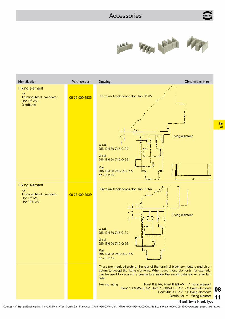
08.11
HanAV
Accessories
Identification Part number Drawing Dimensions in mm
Fixing elementfor Terminal block connector Han D® AV, Distributor
09 33 000 9928
Terminal block connector Han D® AV
Fixing element
C-rail DIN EN 60 715-C 30
G-rail DIN EN 60 715-G 32
Rail DIN EN 60 715-35 x 7.5 or -35 x 15
Fixing elementfor Terminal block connector Han E® AV, Han® ES AV
09 33 000 9929
Terminal block connector Han E® AV
Fixing element
C-rail DIN EN 60 715-C 30
G-rail DIN EN 60 715-G 32
Rail DIN EN 60 715-35 x 7.5 or -35 x 15
There are moulded slots at the rear of the terminal block connectors and distri-butors to accept the fixing elements. When used these elements, for example, can be used to secure the connectors inside the switch cabinets on standard rails.
For mounting Han® 6 E AV, Han® 6 ES AV = 1 fixing element Han® 10/16/24 E AV, Han® 10/16/24 ES AV = 2 fixing elements
Han® 40/64 D AV = 2 fixing elements Distributor = 1 fixing element
Stock items in bold typeCourtesy of Steven Engineering, Inc.-230 Ryan Way, South San Francisco, CA 94080-6370-Main Office: (650) 588-9200-Outside Local Area: (800) 258-9200-www.stevenengineering.com
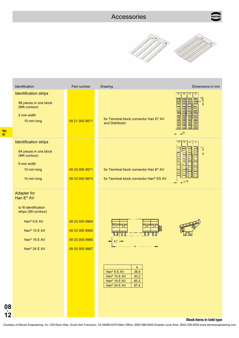
08.12
HanAV
Accessories
Identification Part number Drawing Dimensions in mm
Identification strips
88 pieces in one block (MK-contour) 5 mm width
10 mm long 09 21 000 9971 for Terminal block connector Han D® AV and Distributor
Identification strips
64 pieces in one block (MK-contour) 6 mm width
10 mm long 09 33 000 9971 for Terminal block connector Han E® AV
15 mm long 09 33 000 9973 for Terminal block connector Han® ES AV
Adapter for Han E® AV
to fit identification strips (SK-contour)
Han® 6 E AV 09 33 000 9964
Han® 10 E AV 09 33 000 9965
Han® 16 E AV 09 33 000 9966
Han® 24 E AV 09 33 000 9967
a Han® 6 E AV 26.8 Han® 10 E AV 40.2 Han® 16 E AV 60.3 Han® 24 E AV 87.4
Stock items in bold typeCourtesy of Steven Engineering, Inc.-230 Ryan Way, South San Francisco, CA 94080-6370-Main Office: (650) 588-9200-Outside Local Area: (800) 258-9200-www.stevenengineering.com
09.01
Staf
Staf ®
PageContents Page
Technical characteristics Staf® . . . . . . . . . . . . . . . . . . . . . . . . . . . . . . . . . . 09.02
Staf® 6 . . . . . . . . . . . . . . . . . . . . . . . . . . . . . . . . . . . . . . . . . . . . . . . . . . . . 09.03
Staf® 14 . . . . . . . . . . . . . . . . . . . . . . . . . . . . . . . . . . . . . . . . . . . . . . . . . . . . 09.04
Staf® 20 . . . . . . . . . . . . . . . . . . . . . . . . . . . . . . . . . . . . . . . . . . . . . . . . . . . . 09.05
Staf® 40 . . . . . . . . . . . . . . . . . . . . . . . . . . . . . . . . . . . . . . . . . . . . . . . . . . . . 09.06
Courtesy of Steven Engineering, Inc.-230 Ryan Way, South San Francisco, CA 94080-6370-Main Office: (650) 588-9200-Outside Local Area: (800) 258-9200-www.stevenengineering.com

09.02
Staf
Staf®
Features• Degree of protection for hoods/housings for coupled
connector: IP 44
Current carrying capacityThe current carrying capacity of the connectors is limited by the thermal load capability of the contact element material including the connections and the insulating parts. The derating curve isthereforevalidforcurrentswhichflowconstantly(non-inter-mittent) through each contact element of the connector evenly, without exceeding the allowed maximum temperature.Measuring and testing techniques according to DINEN60512-5
Ope
ratin
g cu
rrent
Ambient temperature
➀Staf® 6➁Staf® 14➂Staf® 20
FeaturesSpecifications DINEN60664-1
DIN EN 61 984Approvals ,
InsertsNumberofcontacts 6,14,20,40(2x20)
Electrical data acc. to EN 61 984
Rated current 10 A Ratedvoltage ∼25V/−60V
Rated voltage acc.toUL/CSA 50V
Insulationresistance ≥1010ΩMaterial polyamideLimitingtemperatures -40°C...+100°CFlammability acc. to UL 94 HBMechanical working life
-matingcycles ≥500
ContactsMaterial copper alloySurface
-hard-silverplated 3µmAgContactresistance ≤2mΩ
Screw terminal -Wiregauge1) 1.5 mm² -AWG 16 -Tightening/testtorque 0.25Nm
Solder terminal -Wiregauge1) 2.5 mm² -AWG 14
Inaccordancewiththeappropriateregulationsawire-endsleevehastobeusedatclampswithoutwireprotection(see„Screw terminal“, chapter 00).
Hoods/Housings seechapter30/31
AccessoriesCable clamps chapter 40 Coding of hoods/housings chapter 40 Labelacc.toCSA-approval chapter40
1) geometric wire gaugeCourtesy of Steven Engineering, Inc.-230 Ryan Way, South San Francisco, CA 94080-6370-Main Office: (650) 588-9200-Outside Local Area: (800) 258-9200-www.stevenengineering.com
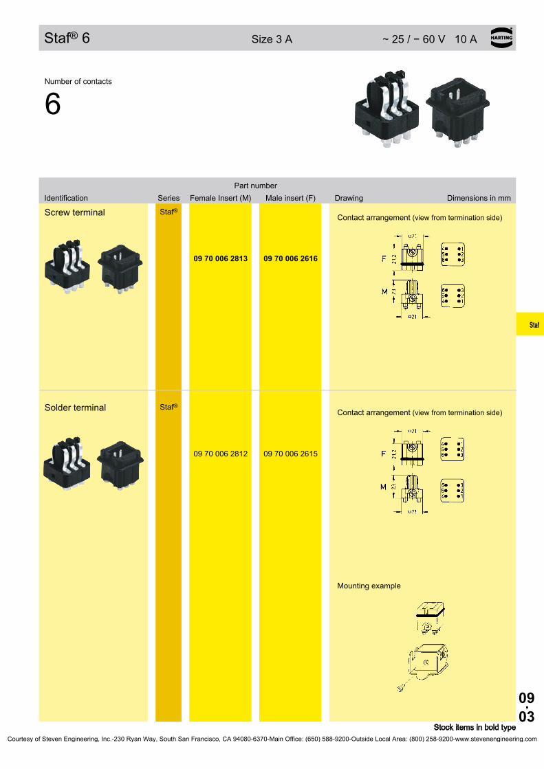
09.03
Staf
Staf® 6 Size3A ∼25/−60V10A
Stock items in bold type
SeriesPart number
Identification FemaleInsert(M) Maleinsert(F) Drawing Dimensions in mm
Number of contacts
6
Screw terminal
Staf® Contact arrangement (view from termination side)
09 70 006 2813 09 70 006 2616
Solder terminal
Staf® Contact arrangement (view from termination side)
Mounting example
09 70 006 2812 09 70 006 2615
Courtesy of Steven Engineering, Inc.-230 Ryan Way, South San Francisco, CA 94080-6370-Main Office: (650) 588-9200-Outside Local Area: (800) 258-9200-www.stevenengineering.com

09.04
Staf
Staf® 14 Size10A ∼25/−60V10A
Stock items in bold type
SeriesPart number
Identification FemaleInsert(M) Maleinsert(F) Drawing Dimensions in mm
Number of contacts
14
Screw terminal Staf®
1) Distance for contact max. 24 mm
Contact arrangement (view from termination side)
Panel cut out for inserts for use without hoods/housings
09 70 014 2811 09 70 014 2614
Solder terminal Staf®
09 70 014 2810 09 70 014 2613
Courtesy of Steven Engineering, Inc.-230 Ryan Way, South San Francisco, CA 94080-6370-Main Office: (650) 588-9200-Outside Local Area: (800) 258-9200-www.stevenengineering.com
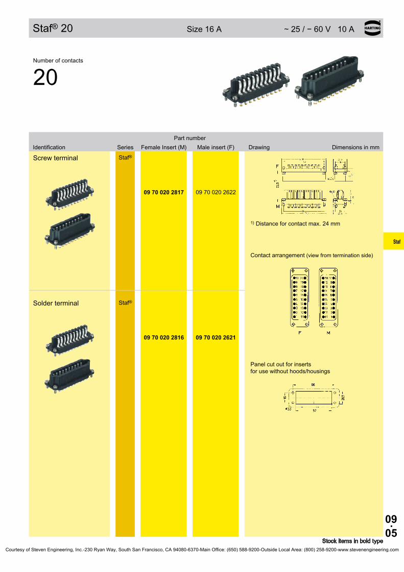
09.05
Staf
Staf® 20 Size16A ∼25/−60V10A
Stock items in bold type
SeriesPart number
Identification FemaleInsert(M) Maleinsert(F) Drawing Dimensions in mm
Number of contacts
20
Screw terminal Staf®
1) Distance for contact max. 24 mm
Contact arrangement (view from termination side)
Panel cut out for inserts for use without hoods/housings
09 70 020 2817 09 70 020 2622
Solder terminal Staf®
09 70 020 2816 09 70 020 2621
Courtesy of Steven Engineering, Inc.-230 Ryan Way, South San Francisco, CA 94080-6370-Main Office: (650) 588-9200-Outside Local Area: (800) 258-9200-www.stevenengineering.com
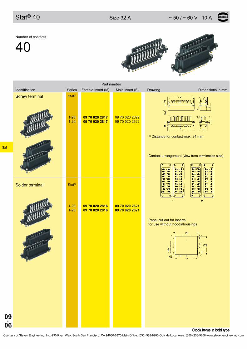
09.06
Staf
Staf® 40 Size32A ∼50/−60V10A
Stock items in bold type
SeriesPart number
Identification FemaleInsert(M) Maleinsert(F) Drawing Dimensions in mm
Number of contacts
40
Screw terminal Staf®
1) Distance for contact max. 24 mm
Contact arrangement (view from termination side)
Panel cut out for inserts for use without hoods/housings
1-20 1-20
09 70 020 2817 09 70 020 2817
09 70 020 2622 09 70 020 2622
Solder terminal Staf®
1-20 1-20
09 70 020 2816 09 70 020 2816
09 70 020 2621 09 70 020 2621
Courtesy of Steven Engineering, Inc.-230 Ryan Way, South San Francisco, CA 94080-6370-Main Office: (650) 588-9200-Outside Local Area: (800) 258-9200-www.stevenengineering.com

10.01
R 15
R 15
PageContents
Technical characteristics R 15 . . . . . . . . . . . . . . . . . . . . . . . . . . . . . . . . . . . 10.02
Inserts R 15 . . . . . . . . . . . . . . . . . . . . . . . . . . . . . . . . . . . . . . . . . . . . . . . . . 10.03
Hoods/Housings R 15 . . . . . . . . . . . . . . . . . . . . . . . . . . . . . . . . . . . . . . . . . . 10.04
Courtesy of Steven Engineering, Inc.-230 Ryan Way, South San Francisco, CA 94080-6370-Main Office: (650) 588-9200-Outside Local Area: (800) 258-9200-www.stevenengineering.com

10.02
R 15
① ③⑤②
④ ⑥⑦
R 15
FeaturesMounting example
➀ Male contact➁ Housings screw mounting➂ Male insert (M)➃ Female insert (F)➄ Hoods➅ Female contact➆ Cable seal
Current carrying capacityThe current carrying capacity of the connectors is limited by the thermal load capability of the contact element material including the connections and the insulating parts. The derating curve is therefore valid for currents which flow constantly (non-inter-mittent) through each contact element of the connector evenly, without exceeding the allowed maximum temperature.Measuring and testing techniques according to DIN EN 60 512-5
Operating curre
nt
Ambient temperature
Technical characteristicsSpecifications DIN EN 60 664-1
DIN EN 61 984Approvals ,
InsertsNumber of contacts 7 + PE
Electrical data acc. to EN 61 984 10 A 250 V 4 kV 3
Rated current 10 A Rated voltage 250 V Rated impulse voltage 4 kV Pollution degree 3
Rated voltage acc. to UL/CSA 600 V
Insulation resistance ≥ 1010 ΩMaterial polyamideLimiting temperatures -40 °C ... +125 °CFlammability acc. to UL 94 HBMechanical working life
- mating cycles ≥ 500
ContactsMaterial copper alloySurface
- hard-silver plated 3 µm Ag - hard-gold plated 2 µm Au over 3 µm Ni
Contact resistance ≤ 3 mΩ
Crimp terminal - Wire gauge1) 0.14 ... 2.5 mm² - AWG 26 ... 14
Hoods/HousingsMaterial polycarbonate
aluminium die-cast zinc die-cast
Hoods/Housings sealing NBR Limiting temperatures -40 °C ... +125 °C Degree of protection acc. to DIN 40 050 for coupled connector IP 65
AccessoriesCrimping tools chapter 99 Cable clamps chapter 40 Label acc. to CSA-approval chapter 40
1) geometric wire gaugeCourtesy of Steven Engineering, Inc.-230 Ryan Way, South San Francisco, CA 94080-6370-Main Office: (650) 588-9200-Outside Local Area: (800) 258-9200-www.stevenengineering.com

10.03
R 15
R 15 250 V 10 A
Stock items in bold type
Number of contacts
7 +
SeriesPart number
Identification Male insert (M) Female insert (F) Drawing Dimensions in mm
Wire gauge(mm²)
Part numberIdentification Male contacts Female contacts Drawing Dimensions in mm
Crimp terminal Contact arrangement (view from termination side)
Inserts for plastic hoods/housings Order crimp contacts separately
R 15 09 15 007 3001 09 15 007 3101
Male insert (M) Female insert (F)
Inserts for metal hoods/housings Order crimp contacts separately
R 15 09 15 007 3021 09 15 007 3121
Crimp contacts
silver plated0.14-0.37 0.5 0.75
1 1.5 2.5
09 15 000 6104 09 15 000 6103 09 15 000 6105 09 15 000 6102 09 15 000 6101 09 15 000 6106
09 15 000 6204 09 15 000 6203 09 15 000 6205 09 15 000 6202 09 15 000 6201 09 15 000 6206
gold plated0.14-0.37 0.5 0.75
1 1.5 2.5
09 15 000 6124 09 15 000 6123 09 15 000 6125 09 15 000 6122 09 15 000 6121 09 15 000 6126
09 15 000 6224 09 15 000 6223 09 15 000 6225 09 15 000 6222 09 15 000 6221 09 15 000 6226
Wire gauge ∅ Stripping length
0.14-0.37 mm² 0.5 mm² 0.75 mm²
1 mm² 1.5 mm² 2.5 mm²
AWG 26-22 AWG 20 AWG 18 AWG 18 AWG 16 AWG 14
0.9 mm 1.1 mm 1.3 mm 1.45 mm 1.75 mm 2.25 mm
8 mm 8 mm 8 mm 8 mm 8 mm 6 mm
F.O. contactsfor 1 mm plastic fibre 20 10 001 3211 20 10 001 3221
Courtesy of Steven Engineering, Inc.-230 Ryan Way, South San Francisco, CA 94080-6370-Main Office: (650) 588-9200-Outside Local Area: (800) 258-9200-www.stevenengineering.com

10.04
R 15
R 15 Hoods/Housings
Part numberIdentification Thermoplastic Metal Drawing Dimensions in mm
Part numberIdentification Thermoplastic Metal Drawing Dimensions in mm
Hoods
09 15 000 0401
19 15 000 0401
Pg 11
M 16
09 15 000 0421 Pg 11
M Pga 16 11
Housings bulkhead mounting
09 15 000 0301
Housings screw mounting
09 15 000 0101
09 15 000 0121
Housings angled
09 15 000 0102
09 15 000 0122
Cover screw mounting
09 15 000 5401
Mounting example
R 15 insert fixing screw(for replacement)
09 15 000 9905
09 15 000 9921
Stock items in bold typeCourtesy of Steven Engineering, Inc.-230 Ryan Way, South San Francisco, CA 94080-6370-Main Office: (650) 588-9200-Outside Local Area: (800) 258-9200-www.stevenengineering.com

11.01
HanSnap
Han-Snap®
Contents Page
Features Han-Snap® . . . . . . . . . . . . . . . . . . . . . . . . . . . . . . . . . . . . . . . . . . 11.02
Component range Han-Snap® . . . . . . . . . . . . . . . . . . . . . . . . . . . . . . . . . . 11.03
Description of parts . . . . . . . . . . . . . . . . . . . . . . . . . . . . . . . . . . . . . . . . . . . 11.04
Latching parts without/with Strain relief and Panel mounting parts . . . . . . . 11.06
Panel mounting . . . . . . . . . . . . . . . . . . . . . . . . . . . . . . . . . . . . . . . . . . . . . . 11.08
Insert mounting without/with Carrier element . . . . . . . . . . . . . . . . . . . . . . . 11.12
Plastic housings . . . . . . . . . . . . . . . . . . . . . . . . . . . . . . . . . . . . . . . . . . . . . . 11.16
Accessories . . . . . . . . . . . . . . . . . . . . . . . . . . . . . . . . . . . . . . . . . . . . . . . . . 11.18
Courtesy of Steven Engineering, Inc.-230 Ryan Way, South San Francisco, CA 94080-6370-Main Office: (650) 588-9200-Outside Local Area: (800) 258-9200-www.stevenengineering.com

11.02
HanSnap
Han-Snap® Features
Note:A connector mounted with Han-Snap® elements does not offer finger safe protection to the relevant standards. In this case protection against electric shock must be provided by the installation methods of the user.
❏ The Han-Snap® system is ideal for connectors within closed electrical operating environments.These can be rooms, cabinets or termination boxes.
❏ The Han-Snap® components are an innovative design which offer the following advantages and characteristics:- reduction of material and assembly costs;- fast and easy installation;- preassembly of Han connectors;- secure and rigid mounting of Han connectors;- frequent use of latching systems is possible (up to several thousand cycles).
❏ The Han-Snap® elements are compatible with the standard inserts and terminal block connectors of the following series (named series Han B as follows)
- Han D®, 40 and 64 pins- Han DD® - Han E® - Han® EE- Han® EEE- Han® ES- Han Hv E® - Han® Hv ES- Han® HsB- Han® HsC- Han-Com® - Han-Modular®
❏ With the Han-Snap® adapter the following standard inserts are compatible (named series Han A as follows):- Han D®, 15 and 25 pins- Han A®, 10 and 16 pins
❏ The Han-Snap® elements are a mechanical system for the mounting assembly and security of Han connectors.Normally the elements are assembled to the connector insert using the standard insert fixing screws.If coding is required the standard fixing screws may be replaced by either code pins or guide pins and bushes.
❏ On free connectors the wires or cables can be secured to the strain relief element with standard cable ties of 5 mm width maximum.
Courtesy of Steven Engineering, Inc.-230 Ryan Way, South San Francisco, CA 94080-6370-Main Office: (650) 588-9200-Outside Local Area: (800) 258-9200-www.stevenengineering.com

11.03
HanSnap
Han-Snap® Component range
Figure Han-Snap® Component Application
Latching parts For free connector.
Latching parts with strain relief For free connector.
Latching parts with strain relief and Panel mounting parts
For free coupling of male and female inserts.
Plastic housings For free connector.
Insert mounting with carrier element
For fixing of Han connectors on standard rails, cross direction.
Insert mounting For fixing of Han connectors on caprail, in line.
Fixing elementFor mating of free connector with terminal block connector, whereby terminal block connector is fixed by means of the combi-fixing element on standard rail.
Panel mounting partsFixing elements for fixed connectors, standard inserts or terminal block connec-tors, for fixing in sheet metal panel.
Courtesy of Steven Engineering, Inc.-230 Ryan Way, South San Francisco, CA 94080-6370-Main Office: (650) 588-9200-Outside Local Area: (800) 258-9200-www.stevenengineering.com

11.04
HanSnap
Han-Snap® Description of parts
Han-Snap® on standard rail
➀ Latching parts ➁ Strain relief ➂ Carrier element ➃ Standard rail ➄ Cable tie ➅ Insert mounting
Han-Snap® in Panel cut out
➀ Latching parts ➁ Strain relief ➂ Assembly panel 1.3 ... 3 mm thick ➃ Panel mounting parts
Courtesy of Steven Engineering, Inc.-230 Ryan Way, South San Francisco, CA 94080-6370-Main Office: (650) 588-9200-Outside Local Area: (800) 258-9200-www.stevenengineering.com

11.05
HanSnap
Han-Snap® Application
Cigarette packing machine C 800,G . D . S . p . A ., Bologna, Italy
Courtesy of Steven Engineering, Inc.-230 Ryan Way, South San Francisco, CA 94080-6370-Main Office: (650) 588-9200-Outside Local Area: (800) 258-9200-www.stevenengineering.com

11.06
HanSnap
Han-Snap® Latching parts without/with Strain relief
Features• Space saving• Practical and easy handling• Reduction of material and assembly costs• For all standard Han® B inserts and terminal block
connectors
Inserts can be mounted on the panel mounting part and the latching part with the standard insert mounting screws.
High mechanical security of the fixings.
No functional impairment is caused by slight over tightening of the fixing screws.
Alternatively, Han coding elements (code pins or guide pins and bushes) may be used.
Please note: The strain relief element should be assembled to the latching part at the end of the insert opposite to the ground screw.
Up to 2 cable ties with max. 5 mm width can be used on the strain relief.
Label 9 x 20 mm may be fitted in both sides of each latching element.
Label 7 x 20 mm may be fitted to the top of the latching part without the strain relief element.(more information page 11.19)
Technical characteristics
Range of delivery
Range of delivery comprises:
09 33 000 9987 2 latching parts
09 33 000 9991 1 latching part with strain relief 1 latching part
09 33 000 9990 1 latching part with strain relief 1 panel mounting part
Min. retention force on counter part - without guiding 200 N - with guiding 300 NVibration resistance IEC 60 068, part 2-6 BN 74018Resistance to shock IEC 60 068, part 2-27 BN 74018Tightening torque of fixing screws/ coding elements 0.8 NmMaterial Thermoplastic resin, polycarbonate, RAL 7032, greyFlammability acc. to UL 94 V 0Limiting temperatures -40 °C ... +125 °CDegree of protection acc. to DIN EN 60 529 for coupled connector IP 20
Courtesy of Steven Engineering, Inc.-230 Ryan Way, South San Francisco, CA 94080-6370-Main Office: (650) 588-9200-Outside Local Area: (800) 258-9200-www.stevenengineering.com

11.07
HanSnap
Han-Snap®
Latching parts
09 33 000 9987
Latching parts with strain relief
Size a b 6 B 78.5 105 10 B 91.5 118 16 B 112 138.524 B 138.5 165
09 33 000 9991
Latching parts with strain relief and Panel mounting parts
Size a b 6 B 75 101 10 B 88 114 16 B 108.5 134.524 B 135 161
09 33 000 9990
➀ Slot for identification strips 7 mm ➁ Slot for identification strips 9 mm ➂ Distance bush
Identification Part number Drawing Dimensions in mm
Courtesy of Steven Engineering, Inc.-230 Ryan Way, South San Francisco, CA 94080-6370-Main Office: (650) 588-9200-Outside Local Area: (800) 258-9200-www.stevenengineering.com
11.08
HanSnap
Han-Snap® Panel mounting (Thermoplastic)
Features• Snap element for sheet-metal cut out• practical and easy handling• Reduction of material and assembly costs• For all standard Han® B inserts and terminal block
connectors• Space saving
Connector inserts and terminal block connectors can be fixed on elements for panel mounting with standard insert mounting screws.
High mechanical security of the fixings. No functional impair-ment is caused by slight over tightening of the fixing screws.
Alternatively, Han coding elements (code pins or guide pins and bushes) may be used.
Connector assembly into the panel (sheet-metal) cut out or two parallel mounted rails is possible from mating or termination side.
Technical characteristics
Range of delivery
Range of delivery comprises:
2 panel plastic mounting parts sufficient for one insert or terminal block connector
Min. retention force in sheet-metal cut out - Mating without guiding 250 N with guiding 400 N - Unmating without guiding 400 N with guiding 500 NVibration resistance IEC 60 068, part 2-6 BN 74018Resistance to shock IEC 60 068, part 2-27 BN 74018Tightening torque of fixing screws/ coding elements 0.8 NmMaterial Thermoplastic resin, polycarbonate, RAL 7032, greyFlammability acc. to UL 94 V 0Limiting temperatures -40 °C ... +125 °C
Courtesy of Steven Engineering, Inc.-230 Ryan Way, South San Francisco, CA 94080-6370-Main Office: (650) 588-9200-Outside Local Area: (800) 258-9200-www.stevenengineering.com

11.09
HanSnap
Han-Snap®
Panel mounting partsThermoplastic
Panel cut out Sheet-metal thickness 1.3 - 3 mm
Size a+0.5
6 B 65 10 B 78 16 B 98 24 B 125 10 A* 81.516 A* 98
09 33 000 9985
* with corresponding adapter (see page 11.18-19)
Identification Part number Drawing Dimensions in mm
Courtesy of Steven Engineering, Inc.-230 Ryan Way, South San Francisco, CA 94080-6370-Main Office: (650) 588-9200-Outside Local Area: (800) 258-9200-www.stevenengineering.com
11.10
HanSnap
Han-Snap® Panel mounting (Metal)
Features• Snap element for sheet-metal cut out• practical and easy handling• Reduction of material and assembly costs• For all standard Han® B inserts and terminal block
connectors• Space saving
Connector inserts and terminal block connectors can be fixed on elements for panel mounting with standard insert mounting screws.
High mechanical security of the fixings.
Alternatively, Han coding elements (code pins or guide pins and bushes) may be used.
Connector assembly into the panel (sheet-metal) cut out or two parallel mounted rails is possible from mating or termination side.
Technical characteristics
Range of delivery
Range of delivery comprises:
2 panel metallic mounting parts sufficient for one insert or terminal block connector
Min. retention force in sheet-metal cut out - Mating without guiding 250 N with guiding 400 N - Unmating without guiding 400 N with guiding 500 NVibration resistance IEC 60 068, part 2-6 BN 74018Resistance to shock IEC 60 068, part 2-27 BN 74018Tightening torque of fixing screws/ coding elements 0.8 NmMaterial zinc die-castLimiting temperatures -40 °C ... +125 °C
Courtesy of Steven Engineering, Inc.-230 Ryan Way, South San Francisco, CA 94080-6370-Main Office: (650) 588-9200-Outside Local Area: (800) 258-9200-www.stevenengineering.com

11.11
HanSnap
Han-Snap®
Panel mounting partsMetal
Panel cut out
Size a c 6 B 44 36 10 B 57 49 16 B 77.5 69.524 B 104 96
09 33 000 9984
Identification Part number Drawing Dimensions in mm
Courtesy of Steven Engineering, Inc.-230 Ryan Way, South San Francisco, CA 94080-6370-Main Office: (650) 588-9200-Outside Local Area: (800) 258-9200-www.stevenengineering.com
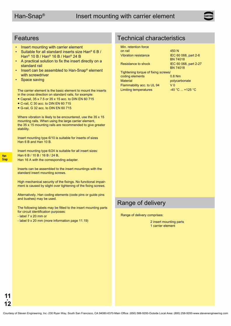
11.12
HanSnap
Han-Snap® Insert mounting with carrier element
Features• Insert mounting with carrier element• Suitable for all standard inserts size Han® 6 B /
Han® 10 B / Han® 16 B / Han® 24 B• A practical solution to fix the insert directly on a
standard rail• Insert can be assembled to Han-Snap® element
with screwdriver• Space saving
The carrier element is the basic element to mount the inserts in the cross direction on standard rails, for example:● Caprail, 35 x 7.5 or 35 x 15 acc. to DIN EN 60 715● C-rail, C 30 acc. to DIN EN 60 715● G-rail, G 32 acc. to DIN EN 60 715
Where vibration is likely to be encountered, use the 35 x 15 mounting rails. When using the large carrier element, the 35 x 15 mounting rails are recommended to give greater stability.
Insert mounting type 6/10 is suitable for inserts of sizes Han 6 B and Han 10 B.
Insert mounting type 6/24 is suitable for all insert sizes:Han 6 B / 10 B / 16 B / 24 B, Han 16 A with the corresponding adapter.
Inserts can be assembled to the insert mountings with the standard insert mounting screws.
High mechanical security of the fixings. No functional impair-ment is caused by slight over tightening of the fixing screws.
Alternatively, Han coding elements (code pins or guide pins and bushes) may be used.
The following labels may be fitted to the insert mounting parts for circuit identification purposes: - label 7 x 20 mm or - label 9 x 20 mm (more information page 11.19)
Technical characteristics
Range of delivery
Range of delivery comprises:
2 insert mounting parts 1 carrier element
Min. retention force on rail 450 NVibration resistance IEC 60 068, part 2-6 BN 74018Resistance to shock IEC 60 068, part 2-27 BN 74018Tightening torque of fixing screws/ coding elements 0.8 NmMaterial polycarbonateFlammability acc. to UL 94 V 0Limiting temperatures -40 °C ... +125 °C
Courtesy of Steven Engineering, Inc.-230 Ryan Way, South San Francisco, CA 94080-6370-Main Office: (650) 588-9200-Outside Local Area: (800) 258-9200-www.stevenengineering.com

11.13
HanSnap
Han-Snap®
Insert mounting, swinging
for standard inserts
09 33 000 9801
for Han-Modular® hinged frames
09 33 000 9803
Insert mounting with carrier element Type 6/10
for size 6 B, 10 B
09 33 000 9988
Type 6/24*for size 6 B, 10 B, 16 B, 24 B
09 33 000 9989
➀ Slot for identification strip ➁ Rail DIN EN 60 715-35 x 7.5 or -35 x 15 ➂ C-rail DIN EN 60 715-C 30 ➃ G-rail DIN EN 60 715-G 32
Can be used with inserts of size Han® B (e.g. Han D®, DD®, E®, ES, EE, Hv E®, Hv ES, Com, HsB) and for Han-Modular® hinged frames
Identification Part number Drawing Dimensions in mm
* Han A-size 16 by using the corresponding adapter (see page 11.18-19)Courtesy of Steven Engineering, Inc.-230 Ryan Way, South San Francisco, CA 94080-6370-Main Office: (650) 588-9200-Outside Local Area: (800) 258-9200-www.stevenengineering.com
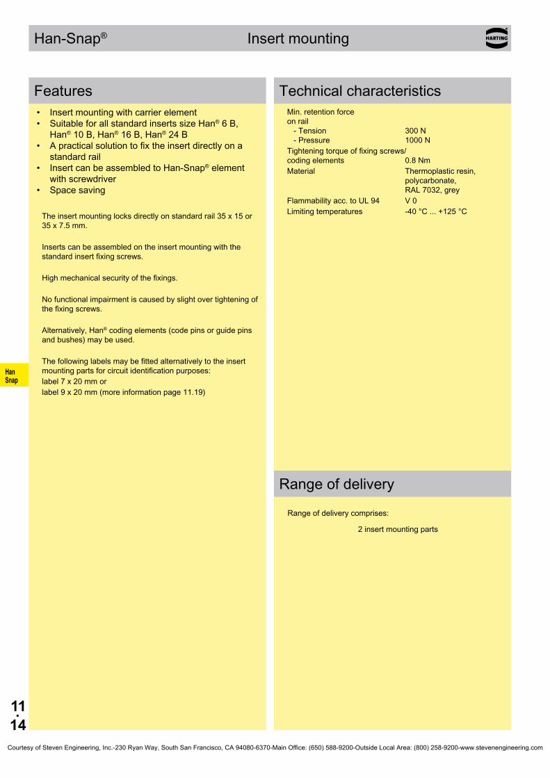
11.14
HanSnap
Han-Snap® Insert mounting
Features• Insert mounting with carrier element• Suitable for all standard inserts size Han® 6 B,
Han® 10 B, Han® 16 B, Han® 24 B• A practical solution to fix the insert directly on a
standard rail• Insert can be assembled to Han-Snap® element
with screwdriver• Space saving
The insert mounting locks directly on standard rail 35 x 15 or 35 x 7.5 mm.
Inserts can be assembled on the insert mounting with the standard insert fixing screws.
High mechanical security of the fixings.
No functional impairment is caused by slight over tightening of the fixing screws.
Alternatively, Han® coding elements (code pins or guide pins and bushes) may be used.
The following labels may be fitted alternatively to the insert mounting parts for circuit identification purposes:label 7 x 20 mm or label 9 x 20 mm (more information page 11.19)
Technical characteristics
Range of delivery
Range of delivery comprises:
2 insert mounting parts
Min. retention force on rail - Tension 300 N - Pressure 1000 NTightening torque of fixing screws/ coding elements 0.8 NmMaterial Thermoplastic resin, polycarbonate, RAL 7032, greyFlammability acc. to UL 94 V 0Limiting temperatures -40 °C ... +125 °C
Courtesy of Steven Engineering, Inc.-230 Ryan Way, South San Francisco, CA 94080-6370-Main Office: (650) 588-9200-Outside Local Area: (800) 258-9200-www.stevenengineering.com

11.15
HanSnap
Han-Snap®
Insert mounting
Size a 6 B 57 10 B 70 16 B 90.524 B 117 10 A* 74 16 A* 90.5
09 33 000 9980
➀ Slot for identification strip ➁ Rail DIN EN 60 715-35 x 7.5 or -35 x 15 * with corresponding adapter (see page 11.18-19)
Identification Part number Drawing Dimensions in mm
Courtesy of Steven Engineering, Inc.-230 Ryan Way, South San Francisco, CA 94080-6370-Main Office: (650) 588-9200-Outside Local Area: (800) 258-9200-www.stevenengineering.com

11.16
HanSnap
Han-Snap® Plastic housings
Features• Ideal for use within closed electrical operation
enviroments• Allows use off preassembled cables• Optimised cost of material and assembly• Insert can be assembled to Han-Snap® element
with screwdriver
2 identical half shells form a shell housing.
Each housing has 3 cable entries, one on top and one at each end. 2 x cable entries can be closed by enclosed blind plugs.
In the area of cable entries there are rectangular openings for mounting of cable ties up to max. 5 mm width.
In the mating area both housing shells are fixed by the stan-dard insert fixing screws.
To release the half shells use screw driver (3.5 x 0.5).
Alternatively, Han® coding elements (code pins or guide pins and bushings) may be used.
High mechanical security of the fixings.No functional impairment is caused by slight over tightening of the fixing screws. The blind plugs have slots for identification strips.
The following labels can be fitted:label 7 x 20 mm or label 9 x 20 mm (more information page 11.19)
Technical characteristics
Range of delivery
Range of delivery comprises:
2 half shells with blind plugs
Min. retention force, fixed 300 NVibration resistance IEC 60 068, part 2-6 BN 74018Resistance to shock IEC 60 068, part 2-27 BN 74018Tightening torque of fixing screws/ coding elements 0.8 NmMaterial Thermoplastic resin, polycarbonate, RAL 7032, greyFlammability acc. to UL 94 V 0Limiting temperatures -40 °C ... +125 °C
Courtesy of Steven Engineering, Inc.-230 Ryan Way, South San Francisco, CA 94080-6370-Main Office: (650) 588-9200-Outside Local Area: (800) 258-9200-www.stevenengineering.com
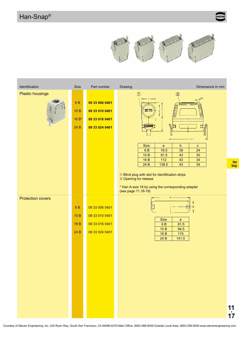
11.17
HanSnap
Han-Snap®
Plastic housings
Size a b c 6 B 78.5 39 24 10 B 91.5 43 30 16 B 112 43 34 24 B 138.5 43 34
6 B
10 B
16 B*
24 B
09 33 006 0401
09 33 010 0401
09 33 016 0401
09 33 024 0401
➀ Blind plug with slot for identification strips ➁ Opening for release * Han A-size 16 by using the corresponding adapter (see page 11.18-19)
Protection covers
Size a 6 B 81.510 B 94.516 B 115 24 B 141.5
6 B
10 B
16 B
24 B
09 33 006 5401
09 33 010 5401
09 33 016 5401
09 33 024 5401
SizeIdentification Part number Drawing Dimensions in mm
Courtesy of Steven Engineering, Inc.-230 Ryan Way, South San Francisco, CA 94080-6370-Main Office: (650) 588-9200-Outside Local Area: (800) 258-9200-www.stevenengineering.com

11.18
HanSnap
Han-Snap® Accessories
Features• Accessories compatible for all contact inserts se-
ries Han A®, 10 and 16 pins; series Han D®, 15 and 25 pins
• Practical and easy handling• Reduction of material and assembly costs• Compatible with Han-Snap® elements: Panel
mounting parts, Latching parts, Insert mountings, Plastic hood size 16 for Han 25 D® and Han A® 16 poles
Inserts can be assembled to the adapters with the standard insert fixing screws.
With the included screws the adapter can be fixed to the se-lected Han-Snap® element.
Technical characteristics
Range of delivery
Range of delivery comprises:
2 adapters 4 fixing screws
Tightening torque of fixing screws/ coding elements 0.8 NmMaterial Thermoplastic resin, polycarbonate, RAL 7032, greyFlammability acc. to UL 94 V 0Limiting temperatures -40 °C ... +125 °C
Courtesy of Steven Engineering, Inc.-230 Ryan Way, South San Francisco, CA 94080-6370-Main Office: (650) 588-9200-Outside Local Area: (800) 258-9200-www.stevenengineering.com

11.19
HanSnap
Han-Snap® Accessories
AdapterHan A®
09 20 000 9933
Identification stripssingle 7 mm wide / 20 mm long
09 33 000 9981
Identification strips20 pieces in one block 9 mm width / 20 mm length
09 33 000 9982
Guide pin Guide bushing
09 33 000 9956
09 33 000 9957
Identification Part number Drawing Dimensions in mm
Courtesy of Steven Engineering, Inc.-230 Ryan Way, South San Francisco, CA 94080-6370-Main Office: (650) 588-9200-Outside Local Area: (800) 258-9200-www.stevenengineering.com

11.20
HanSnap
Notes
Courtesy of Steven Engineering, Inc.-230 Ryan Way, South San Francisco, CA 94080-6370-Main Office: (650) 588-9200-Outside Local Area: (800) 258-9200-www.stevenengineering.com
12.01
Han-Port
Han-Port®
Contents
Features . . . . . . . . . . . . . . . . . . . . . . . . . . . . . . . . . . . . . . . . . . . . . . . . . . . 12.02
Technical characteristics . . . . . . . . . . . . . . . . . . . . . . . . . . . . . . . . . . . . . . . 12.03
Frame . . . . . . . . . . . . . . . . . . . . . . . . . . . . . . . . . . . . . . . . . . . . . . . . . . . . . 12.04
Accessories . . . . . . . . . . . . . . . . . . . . . . . . . . . . . . . . . . . . . . . . . . . . . . . . . 12.04
Plug sockets . . . . . . . . . . . . . . . . . . . . . . . . . . . . . . . . . . . . . . . . . . . . . . . . 12.05
Data connectors . . . . . . . . . . . . . . . . . . . . . . . . . . . . . . . . . . . . . . . . . . . . . 12.07
Wires . . . . . . . . . . . . . . . . . . . . . . . . . . . . . . . . . . . . . . . . . . . . . . . . . . . . . . 12.10
Gender Changer . . . . . . . . . . . . . . . . . . . . . . . . . . . . . . . . . . . . . . . . . . . . . 12.10
Page
Courtesy of Steven Engineering, Inc.-230 Ryan Way, South San Francisco, CA 94080-6370-Main Office: (650) 588-9200-Outside Local Area: (800) 258-9200-www.stevenengineering.com
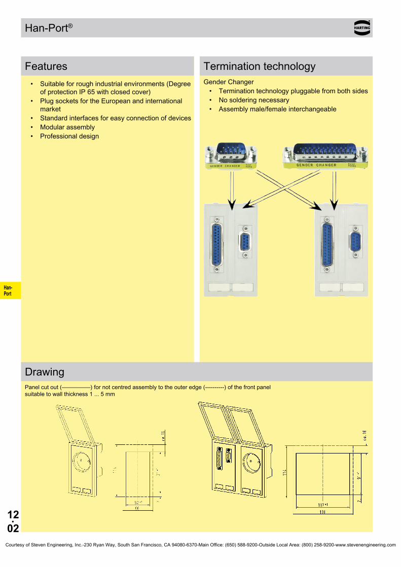
12.02
Han-Port
Han-Port®
Features
Features• Suitableforroughindustrialenvironments(Degree
ofprotectionIP65withclosedcover)• PlugsocketsfortheEuropeanandinternational
market• Standardinterfacesforeasyconnectionofdevices• Modularassembly• Professionaldesign
Drawing
GenderChanger• Terminationtechnologypluggablefrombothsides• Nosolderingnecessary• Assemblymale/femaleinterchangeable
Panelcutout(—————)fornotcentredassemblytotheouteredge(----------)ofthefrontpanel suitabletowallthickness1...5mm
Terminationtechnology
Courtesy of Steven Engineering, Inc.-230 Ryan Way, South San Francisco, CA 94080-6370-Main Office: (650) 588-9200-Outside Local Area: (800) 258-9200-www.stevenengineering.com
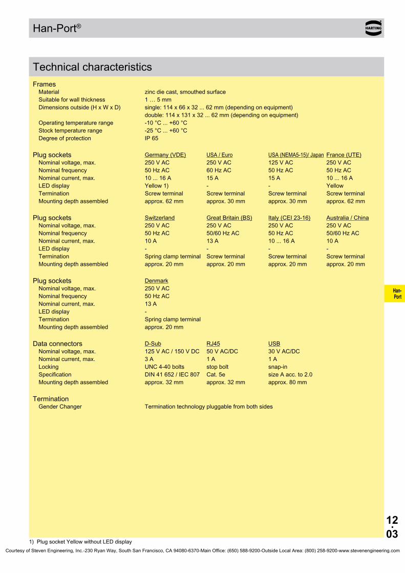
12.03
Han-Port
Han-Port®
Technical characteri-stics
TechnicalcharacteristicsFramesMaterial zincdiecast,smouthedsurfaceSuitableforwallthickness 1…5mmDimensionsoutside(HxWxD) single:114x66x32...62mm(dependingonequipment)
double:114x131x32...62mm(dependingonequipment)Operatingtemperaturerange -10°C...+60°CStocktemperaturerange -25°C...+60°CDegreeofprotection IP65
Plugsockets Germany(VDE) USA/Euro USA(NEMA5-15)/Japan France(UTE)Nominalvoltage,max. 250VAC 250VAC 125VAC 250VACNominalfrequency 50HzAC 60HzAC 50HzAC 50HzACNominalcurrent,max. 10...16A 15A 15A 10...16ALEDdisplay Yellow1) - - YellowTermination Screwterminal Screwterminal Screwterminal ScrewterminalMountingdepthassembled approx.62mm approx.30mm approx.30mm approx.62mm
Plugsockets Switzerland GreatBritain(BS) Italy(CEI23-16) Australia/ChinaNominalvoltage,max. 250VAC 250VAC 250VAC 250VACNominalfrequency 50HzAC 50/60HzAC 50HzAC 50/60HzACNominalcurrent,max. 10A 13A 10...16A 10ALEDdisplay - - - -Termination Springclampterminal Screwterminal Screwterminal ScrewterminalMountingdepthassembled approx.20mm approx.20mm approx.20mm approx.20mm
Plugsockets DenmarkNominalvoltage,max. 250VACNominalfrequency 50HzACNominalcurrent,max. 13ALEDdisplay -Termination SpringclampterminalMountingdepthassembled approx.20mm
Dataconnectors D-Sub RJ45 USBNominalvoltage,max. 125VAC/150VDC 50VAC/DC 30VAC/DCNominalcurrent,max. 3A 1A 1ALocking UNC4-40bolts stopbolt snap-inSpecification DIN41652/IEC807 Cat.5e sizeAacc.to2.0Mountingdepthassembled approx.32mm approx.32mm approx.80mm
TerminationGenderChanger Terminationtechnologypluggablefrombothsides
1)PlugsocketYellowwithoutLEDdisplayCourtesy of Steven Engineering, Inc.-230 Ryan Way, South San Francisco, CA 94080-6370-Main Office: (650) 588-9200-Outside Local Area: (800) 258-9200-www.stevenengineering.com
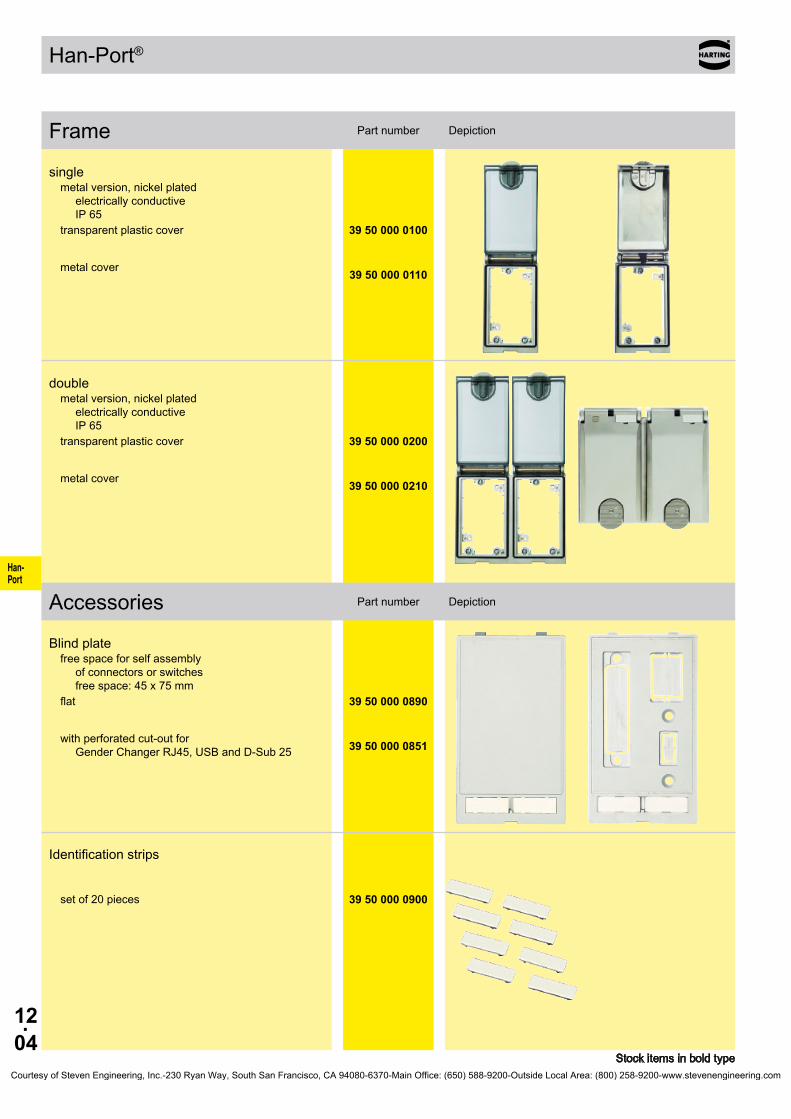
12.04
Han-Port
Han-Port®
39 50 000 0100
39 50 000 0110
39 50 000 0200
39 50 000 0210
39 50 000 0890
39 50 000 0851
39 50 000 0900
FrameAccessories
Partnumber DepictionFrame
Stockitemsinboldtype
singlemetalversion,nickelplated
electricallyconductive IP65
transparentplasticcover
metalcover
doublemetalversion,nickelplated
electricallyconductive IP65
transparentplasticcover
metalcover
Partnumber DepictionAccessories
Blindplatefreespaceforselfassembly
ofconnectorsorswitches freespace:45x75mm
flat
withperforatedcut-outfor GenderChangerRJ45,USBandD-Sub25
Identificationstrips
setof20pieces
Courtesy of Steven Engineering, Inc.-230 Ryan Way, South San Francisco, CA 94080-6370-Main Office: (650) 588-9200-Outside Local Area: (800) 258-9200-www.stevenengineering.com

12.05
Han-Port
Han-Port®
39 50 001 0001
39 50 001 0002
39 50 001 0010
39 50 001 0004
39 50 001 0005
39 50 001 0006
Plug sockets
Partnumber DepictionPlugsockets
Stockitemsinboldtype
Germany(VDE)withLEDdisplayscrewterminalsformax.6mm²connectionattherear
Germany(VDE)forassemblyinfrontofmainswitchflourescentcolouryellow(RAL1016)withoutLEDdisplayscrewterminalsformax.6mm²connectionattherear
USA/Eurofingerprotectedscrewterminalsformax.AWG14(2.5mm²)
USA(NEMA5-15)/Japanfingerprotectedscrewterminalsformax.AWG14(2.5mm²)
France(UTE)withLEDdisplayscrewterminalsformax.6mm²connectionattherear
GreatBritain(BS)fingerprotectedscrewterminalsformax.4mm²
Courtesy of Steven Engineering, Inc.-230 Ryan Way, South San Francisco, CA 94080-6370-Main Office: (650) 588-9200-Outside Local Area: (800) 258-9200-www.stevenengineering.com

12.06
Han-Port
Han-Port®
39 50 001 0007
39 50 001 0009
39 50 001 0017
39 50 001 0012
Partnumber DepictionPlugsockets
Stockitemsinboldtype
Italy(CEI23-16)doublefingerprotectedscrewterminalsformax.2.5mm²
Australia/Chinascrewterminalsformax.2.5mm²
Denmarkspringclampterminalsformax.2.5mm²
Switzerlandspringclampterminalsformax.1.5mm²
Courtesy of Steven Engineering, Inc.-230 Ryan Way, South San Francisco, CA 94080-6370-Main Office: (650) 588-9200-Outside Local Area: (800) 258-9200-www.stevenengineering.com

12.07
Han-Port
Han-Port®
39 50 003 0020
39 50 003 0024
39 50 003 0040
39 50 003 0074
Data con-nectors
Partnumber DepictionDataconnectors
Stockitemsinboldtype
2xD-Sub92xfemale/male
GenderChangernotscreened
1xD-Sub91xfemale/female
GenderChangernotscreened
1xD-Sub9,D-Sub252xfemale/male
GenderChangernotscreened
1xD-Sub251xfemale/male
GenderChangernotscreened
Courtesy of Steven Engineering, Inc.-230 Ryan Way, South San Francisco, CA 94080-6370-Main Office: (650) 588-9200-Outside Local Area: (800) 258-9200-www.stevenengineering.com

12.08
Han-Port
Han-Port®
39 50 003 0111
39 50 003 0170
39 50 002 0093
39 50 002 0120
Partnumber DepictionDataconnectors
Stockitemsinboldtype
1xRJ45,2xD-Sub91xRJ45,8-pins,metal,Cat.5e
female/female,GenderChanger1xD-Sub9
female/female,GenderChanger1xD-Sub9
male/male,GenderChangernotscreened
1xRJ45,D-Sub9,D-Sub251xRJ45,8-pins,metal,Cat.5e
female/female,GenderChanger1xD-Sub9
female/male,GenderChanger1xD-Sub25
female/male,GenderChangernotscreened
2xUSBsizeA2xUSBsizeAacc.tospecification2.0
female/female,GenderChangerscreened
2xRJ452xRJ45,8-pins,metal,Cat.5e
female/female,GenderChangerscreened
Courtesy of Steven Engineering, Inc.-230 Ryan Way, South San Francisco, CA 94080-6370-Main Office: (650) 588-9200-Outside Local Area: (800) 258-9200-www.stevenengineering.com

12.09
Han-Port
Han-Port®
39 50 002 0143
39 50 002 0145
39 50 002 0117
Partnumber DepictionDataconnectors
Stockitemsinboldtype
1xUSBsizeA,RJ45,D-Sub91xUSBsizeAacc.tospecification2.0
female/female,GenderChanger1xRJ45,8-pins,metal,Cat.5e
female/female,GenderChanger1xD-Sub9
female/male,GenderChangerscreened
1xUSBsizeA,RJ45,D-Sub251xUSBsizeAacc.tospecification2.0
female/female,GenderChanger1xRJ45,8-pins,metal,Cat.5e
female/female,GenderChanger1xD-Sub25
female/male,GenderChangerscreened
1xUSBsizeA,RJ45,2xD-Sub91xUSBsizeAacc.tospecification2.0
female/female,GenderChanger1xRJ45,8-pins,metal,Cat.5e
female/female,GenderChanger2xD-Sub9
male/male,GenderChangerscreened
Courtesy of Steven Engineering, Inc.-230 Ryan Way, South San Francisco, CA 94080-6370-Main Office: (650) 588-9200-Outside Local Area: (800) 258-9200-www.stevenengineering.com

12.10
Han-Port
Han-Port®
2m 5m 2m 5m
39 50 903 0010 39 50 903 0011 39 50 903 0020 39 50 903 0021
39 50 903 0040 39 50 903 0041
2m 5m
39 50 903 0050 39 50 903 0051
2m 5m
39 50 903 0060 39 50 903 0061
39 50 904 0030 39 50 904 0031 39 50 904 0032
39 50 904 0050
39 50 904 0020
39 50 904 0010
WiresGender Changer
Partnumber DepictionWires
Stockitemsinboldtype
Length Termination
D-Sub9male/male male/male female/male female/male
D-Sub25 1.8m 5m
female/male female/male
USB USB USB
RJ45 8-pins,metal,Cat.5e 8-pins,metal,Cat.5e
Partnumber DepictionGenderChanger
Termination
D-Sub9female/female female/male male/male
D-Sub25 female/female
USB female/female,sizeAacc.tospecification2.0
RJ45 female/female,8-pins,Cat.5e
Courtesy of Steven Engineering, Inc.-230 Ryan Way, South San Francisco, CA 94080-6370-Main Office: (650) 588-9200-Outside Local Area: (800) 258-9200-www.stevenengineering.com
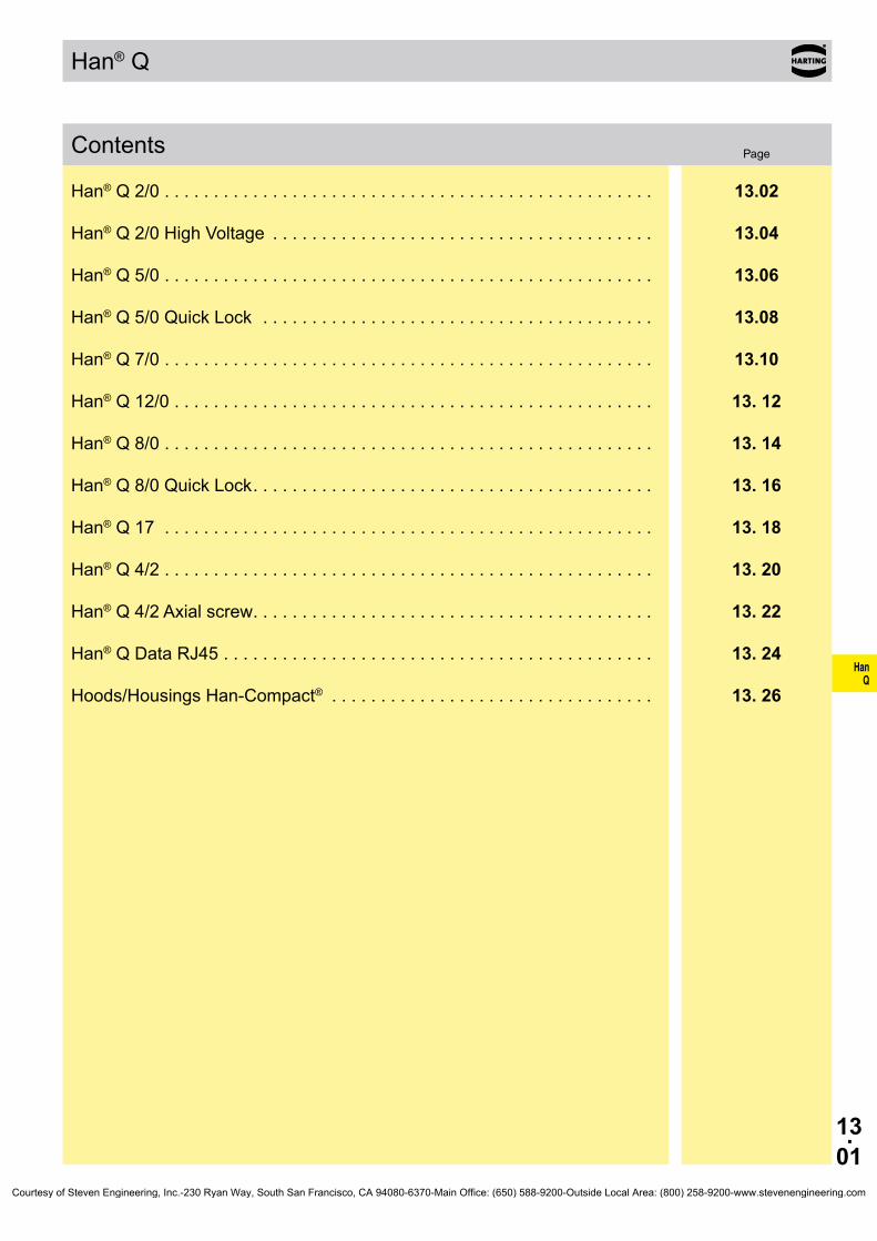
HanQ
13.01
Han® Q
Contents
Han® Q 2/0 . . . . . . . . . . . . . . . . . . . . . . . . . . . . . . . . . . . . . . . . . . . . . . . . . . 13.02
Han® Q 2/0 High Voltage . . . . . . . . . . . . . . . . . . . . . . . . . . . . . . . . . . . . . . . 13.04
Han® Q 5/0 . . . . . . . . . . . . . . . . . . . . . . . . . . . . . . . . . . . . . . . . . . . . . . . . . . 13.06
Han® Q 5/0 Quick Lock . . . . . . . . . . . . . . . . . . . . . . . . . . . . . . . . . . . . . . . . 13.08
Han® Q 7/0 . . . . . . . . . . . . . . . . . . . . . . . . . . . . . . . . . . . . . . . . . . . . . . . . . . 13.10
Han® Q 12/0 . . . . . . . . . . . . . . . . . . . . . . . . . . . . . . . . . . . . . . . . . . . . . . . . . 13. 12
Han® Q 8/0 . . . . . . . . . . . . . . . . . . . . . . . . . . . . . . . . . . . . . . . . . . . . . . . . . . 13. 14
Han® Q 8/0 Quick Lock . . . . . . . . . . . . . . . . . . . . . . . . . . . . . . . . . . . . . . . . . 13. 16
Han® Q 17 . . . . . . . . . . . . . . . . . . . . . . . . . . . . . . . . . . . . . . . . . . . . . . . . . . 13. 18
Han® Q 4/2 . . . . . . . . . . . . . . . . . . . . . . . . . . . . . . . . . . . . . . . . . . . . . . . . . . 13. 20
Han® Q 4/2 Axial screw . . . . . . . . . . . . . . . . . . . . . . . . . . . . . . . . . . . . . . . . . 13. 22
Han® Q Data RJ45 . . . . . . . . . . . . . . . . . . . . . . . . . . . . . . . . . . . . . . . . . . . . 13. 24
Hoods/Housings Han-Compact® . . . . . . . . . . . . . . . . . . . . . . . . . . . . . . . . . 13. 26
Page
Courtesy of Steven Engineering, Inc.-230 Ryan Way, South San Francisco, CA 94080-6370-Main Office: (650) 588-9200-Outside Local Area: (800) 258-9200-www.stevenengineering.com

HanQ
13.02
Han® Q 2/0
Features
Current carrying capacityThe current carrying capacity of the connectors is limited by the thermal load capability of the contact element material including the connections and the insulating parts. The derating curve is therefore valid for currents which flow constantly (non-inter-mittent) through each contact element of the connector evenly, without exceeding the allowed maximum temperature.Measuring and testing techniques according to DIN EN 60 512-5
Ope
ratin
g cu
rrent
Ambient temperature
Wire gauge: ➀ 2.5 mm²➁ 4 mm²➂ 6 mm²➃ 10 mm²
Technical characteristicsSpecifications DIN EN 60 664-1 DIN EN 61 984 Approvals
InsertsNumber of contacts 2 + PE Electrical data acc. to EN 61 984 40 A 400 V 6 kV 3 Rated current 40 A Rated voltage 400 V Rated impulse voltage 6 kV Pollution degree 3
Rated voltage acc. to UL/CSA 400 VInsulation resistance ≥ 1010 Ω Material polycarbonate Limiting temperatures -40 °C ... 125 °C Flammability acc. to UL 94 V 0 Mechanical working life - mating cycles ≥ 500
ContactsMaterial copper alloy Surface - hard-silver plated 3 µm Ag Contact resistance ≤ 1 mΩ Axial screw termination - mm² 2.5 ... 10 mm² - AWG 14 ... 8 Tightening torque 1.8 Nm Stripping length 8 mm +1
Hoods/HousingsSelection of hoods/housings see chapter 30 / chapter 31
Plastic hoods/housings
Material polycarbonate Flammability acc. to UL 94 V 0 Degree of protection acc. to DIN EN 60 529 for coupled connector IP 67
Hoods/Housings, metalMaterial zinc die-cast Degree of protection acc. to DIN EN 60 529 for coupled connector IP 44 IP 67 is achieved with seal screw 09 20 000 9918
AccessoriesCable clamps chapter 40 Sealing screw chapter 40
• Compact designed connector for high current ratings
• 16 coding options• For hoods/housings size Han® 3 A• Finger protected male and female contacts• Assembly without special tool by axial screw
termination
Attention• By using in Han® 3 A HPR hoods/housings the sealing on the insert has to be removed.• For termination please use only hexagonal screw driver with wrench size SW 2.• If PE contact is not used: Please screw the PE contact maximal on both sides clockwise with a hexagonal screwdriver, wrench size SW 2.
Courtesy of Steven Engineering, Inc.-230 Ryan Way, South San Francisco, CA 94080-6370-Main Office: (650) 588-9200-Outside Local Area: (800) 258-9200-www.stevenengineering.com

HanQ
13.03
09 12 002 2653 09 12 002 2753
09 12 002 2651 09 12 002 2751
09 12 000 9922 09 12 000 9922
09 99 000 0313
09 99 000 0369
Han® Q 2/0 Size 3 A 400 V 40 A
Identification Part number Drawing Dimensions in mm
Stock items in bold type
Number of contacts
2 +
Part number Identification Male insert (M) Female insert (F) Drawing Dimensions in mm
Axial screw terminal
2.5 ... 6 mm²
4 ... 10 mm²
Coding element
Hex key SW 2 for axial setscrew
with grip
adapter 1/4“
Courtesy of Steven Engineering, Inc.-230 Ryan Way, South San Francisco, CA 94080-6370-Main Office: (650) 588-9200-Outside Local Area: (800) 258-9200-www.stevenengineering.com
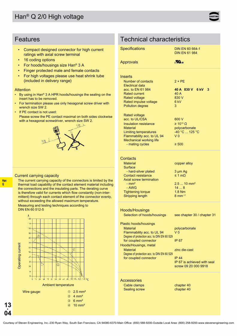
HanQ
13.04
Han® Q 2/0 High voltage
Features
Current carrying capacityThe current carrying capacity of the connectors is limited by the thermal load capability of the contact element material including the connections and the insulating parts. The derating curve is therefore valid for currents which flow constantly (non-inter-mittent) through each contact element of the connector evenly, without exceeding the allowed maximum temperature.Measuring and testing techniques according to DIN EN 60 512-5
Ope
ratin
g cu
rrent
Ambient temperature
Wire gauge: ➀ 2.5 mm²➁ 4 mm²➂ 6 mm²➃ 10 mm²
Technical characteristicsSpecifications DIN EN 60 664-1 DIN EN 61 984 Approvals
InsertsNumber of contacts 2 + PE Electrical data acc. to EN 61 984 40 A 830 V 6 kV 3 Rated current 40 A Rated voltage 830 V Rated impulse voltage 6 kV Pollution degree 3
Rated voltage acc. to UL/CSA 600 VInsulation resistance ≥ 1010 Ω Material polycarbonate Limiting temperatures -40 °C ... 125 °C Flammability acc. to UL 94 V 0 Mechanical working life - mating cycles ≥ 500
ContactsMaterial copper alloy Surface - hard-silver plated 3 µm Ag Contact resistance ≤ 1 mΩ Axial screw termination - mm² 2.5 ... 10 mm² - AWG 14 ... 8 Tightening torque 1.8 Nm Stripping length 8 mm +1
Hoods/HousingsSelection of hoods/housings see chapter 30 / chapter 31
Plastic hoods/housings
Material polycarbonate Flammability acc. to UL 94 V 0 Degree of protection acc. to DIN EN 60 529 for coupled connector IP 67
Hoods/Housings, metalMaterial zinc die-cast Degree of protection acc. to DIN EN 60 529 for coupled connector IP 44 IP 67 is achieved with seal screw 09 20 000 9918
AccessoriesCable clamps chapter 40 Sealing screw chapter 40
• Compact designed connector for high current ratings with axial screw terminal
• 16 coding options• For hoods/housings size Han® 3 A• Finger protected male and female contacts• For high voltages please use heat shrink tube
(included in delivery range)
Attention• By using in Han® 3 A HPR hoods/housings the sealing on the insert has to be removed.• For termination please use only hexagonal screw driver with wrench size SW 2.• If PE contact is not used: Please screw the PE contact maximal on both sides clockwise with a hexagonal screwdriver, wrench size SW 2.
Courtesy of Steven Engineering, Inc.-230 Ryan Way, South San Francisco, CA 94080-6370-Main Office: (650) 588-9200-Outside Local Area: (800) 258-9200-www.stevenengineering.com

HanQ
13.05
09 12 002 2654 09 12 002 2754
09 12 002 2652 09 12 002 2752
09 12 000 9922 09 12 000 9922
09 99 000 0313
09 99 000 0369
Han® Q 2/0 High voltage Size 3 A 830 V 40 A
Identification Part number Drawing Dimensions in mm
Stock items in bold type
Number of contacts
2 +
Part number Identification Male insert (M) Female insert (F) Drawing Dimensions in mm
Axial screw terminalwith heat shrink tube
2.5 ... 6 mm²
4 ... 10 mm²
Coding element
Hex key SW 2 for axial setscrew
with grip
adapter 1/4“
Courtesy of Steven Engineering, Inc.-230 Ryan Way, South San Francisco, CA 94080-6370-Main Office: (650) 588-9200-Outside Local Area: (800) 258-9200-www.stevenengineering.com
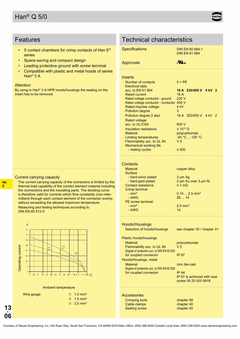
HanQ
13.06
Han® Q 5/0
Features• 5 contact chambers for crimp contacts of Han E®
series• Space-saving and compact design• Leading protective ground with screw terminal• Compatible with plastic and metal hoods of series
Han® 3 A
AttentionBy using in Han® 3 A HPR hoods/housings the sealing on the insert has to be removed.
Current carrying capacityThe current carrying capacity of the connectors is limited by the thermal load capability of the contact element material including the connections and the insulating parts. The derating curve is therefore valid for currents which flow constantly (non-inter-mittent) through each contact element of the connector evenly, without exceeding the allowed maximum temperature.Measuring and testing techniques according to DIN EN 60 512-5
Ope
ratin
g cu
rrent
Ambient temperature
Wire gauge: ➀ 1.0 mm²➁ 1.5 mm²➂ 2.5 mm²
Technical characteristicsSpecifications DIN EN 60 664-1 DIN EN 61 984 Approvals
InsertsNumber of contacts 5 + PE Electrical data acc. to EN 61 984 16 A 230/400 V 4 kV 3 Rated current 16 A Rated voltage conductor - ground 230 V Rated voltage conductor - conductor 400 V Rated impulse voltage 4 kV Pollution degree 3Pollution degree 2 also 16 A 320/500 V 4 kV 2Rated voltage acc. to UL/CSA 600 VInsulation resistance ≥ 1010 Ω Material polycarbonate Limiting temperatures -40 °C ... 125 °C Flammability acc. to UL 94 V 0 Mechanical working life - mating cycles ≥ 500
ContactsMaterial copper alloy Surface - hard-silver plated 3 µm Ag - hard-gold plated 2 µm Au over 3 µm Ni Contact resistance ≤ 1 mΩ Crimp terminal - mm² 0.14 ... 2.5 mm² - AWG 26 ... 14 PE screw terminal - mm² 2.5 mm² - AWG 14
Hoods/HousingsSelection of hoods/housings see chapter 30 / chapter 31
Plastic hoods/housings
Material polycarbonate Flammability acc. to UL 94 V 0 Degree of protection acc. to DIN EN 60 529 for coupled connector IP 67
Hoods/Housings, metalMaterial zinc die-cast Degree of protection acc. to DIN EN 60 529 for coupled connector IP 44 IP 67 is achieved with seal screw 09 20 000 9918
AccessoriesCrimping tools chapter 99 Cable clamps chapter 40 Sealing screw chapter 40
Courtesy of Steven Engineering, Inc.-230 Ryan Way, South San Francisco, CA 94080-6370-Main Office: (650) 588-9200-Outside Local Area: (800) 258-9200-www.stevenengineering.com

HanQ
13.07
09 12 005 3001 09 12 005 3101
09 33 000 9954
mm²mm²mm²mm²mm²mm²
AWG 26-22AWG 20AWG 18AWG 18AWG 16AWG 14
09 33 000 6127 09 33 000 6121 09 33 000 6114 09 33 000 6105 09 33 000 6104 09 33 000 6102
09 33 000 6227 09 33 000 6220 09 33 000 6214 09 33 000 6205 09 33 000 6204 09 33 000 6202
09 33 000 6117 09 33 000 6122 09 33 000 6115 09 33 000 6118 09 33 000 6116 09 33 000 6123
09 33 000 6217 09 33 000 6222 09 33 000 6215 09 33 000 6218 09 33 000 6216 09 33 000 6223
09 33 000 6109
09 33 000 6110 09 33 000 6111
20 10 001 3311 20 10 001 3321
Han® Q 5/0 Size 3 A 230/400 V 16 A
Stock items in bold type Crimp contacts 0.14 ... 0.37 mm² only used with BUCHANAN crimping tool 09 99 000 0001
Number of contacts
5 +
Part number Identification Male insert (M) Female insert (F) Drawing Dimensions in mm
Crimp terminalOrder crimp contacts separately
Contact arrangement view from termination side
Coding pin Use of the coding pin prevents incor-rect mating to other connectors of the same type. The male pin should be omitted from the opposing cavity in the male insert.
Wire gauge Part number Identification (mm²) Male contact Female contact Drawing Dimensions in mm
Crimp contacts Power contacts
Operating contact Identification Relay contact
Identification Wire gauge Stripping length
no grooveno groove1 groove*1 groove2 grooves3 grooves
0.14-0.370.5
0.751
1.52.5
7.5 mm7.5 mm7.5 mm7.5 mm7.5 mm7.5 mm
* on the back crimp collar
silver plated 0.14-0.37 0.5
0.75 1
1.5 2.5
gold plated 0.14-0.37 0.5
0.75 1
1.5 2.5
Relay contact silver plated 0.75-1
1.5 2.5
F.O. contacts for 1 mm plastic fibre
Crimp zone Crimp zone
Courtesy of Steven Engineering, Inc.-230 Ryan Way, South San Francisco, CA 94080-6370-Main Office: (650) 588-9200-Outside Local Area: (800) 258-9200-www.stevenengineering.com
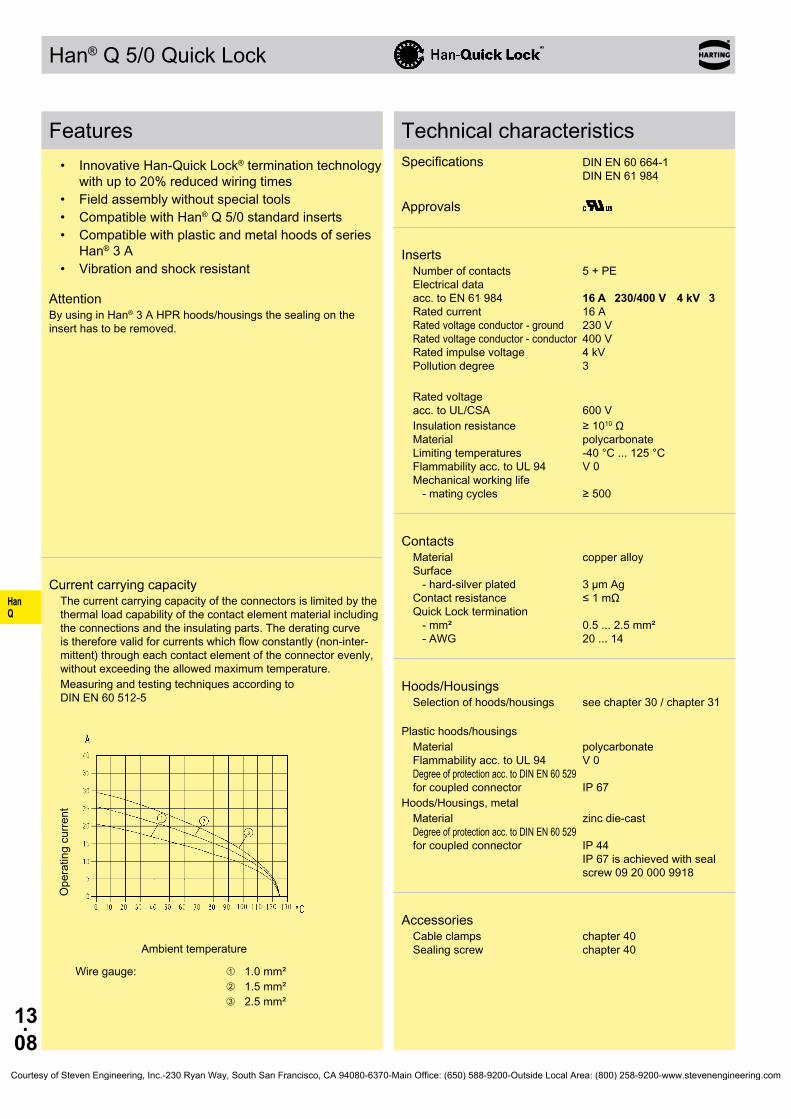
HanQ
13.08
Han® Q 5/0 Quick Lock
Features• Innovative Han-Quick Lock® termination technology
with up to 20% reduced wiring times• Field assembly without special tools• Compatible with Han® Q 5/0 standard inserts• Compatible with plastic and metal hoods of series
Han® 3 A• Vibration and shock resistant
AttentionBy using in Han® 3 A HPR hoods/housings the sealing on the insert has to be removed.
Current carrying capacityThe current carrying capacity of the connectors is limited by the thermal load capability of the contact element material including the connections and the insulating parts. The derating curve is therefore valid for currents which flow constantly (non-inter-mittent) through each contact element of the connector evenly, without exceeding the allowed maximum temperature.Measuring and testing techniques according to DIN EN 60 512-5
Ope
ratin
g cu
rrent
Ambient temperature
Wire gauge: ➀ 1.0 mm²➁ 1.5 mm²➂ 2.5 mm²
Technical characteristicsSpecifications DIN EN 60 664-1 DIN EN 61 984 Approvals
InsertsNumber of contacts 5 + PE Electrical data acc. to EN 61 984 16 A 230/400 V 4 kV 3 Rated current 16 A Rated voltage conductor - ground 230 V Rated voltage conductor - conductor 400 V Rated impulse voltage 4 kV Pollution degree 3
Rated voltage acc. to UL/CSA 600 VInsulation resistance ≥ 1010 Ω Material polycarbonate Limiting temperatures -40 °C ... 125 °C Flammability acc. to UL 94 V 0 Mechanical working life - mating cycles ≥ 500
ContactsMaterial copper alloy Surface - hard-silver plated 3 µm Ag Contact resistance ≤ 1 mΩ Quick Lock termination - mm² 0.5 ... 2.5 mm² - AWG 20 ... 14
Hoods/HousingsSelection of hoods/housings see chapter 30 / chapter 31
Plastic hoods/housings
Material polycarbonate Flammability acc. to UL 94 V 0 Degree of protection acc. to DIN EN 60 529 for coupled connector IP 67
Hoods/Housings, metalMaterial zinc die-cast Degree of protection acc. to DIN EN 60 529 for coupled connector IP 44 IP 67 is achieved with seal screw 09 20 000 9918
AccessoriesCable clamps chapter 40 Sealing screw chapter 40
Courtesy of Steven Engineering, Inc.-230 Ryan Way, South San Francisco, CA 94080-6370-Main Office: (650) 588-9200-Outside Local Area: (800) 258-9200-www.stevenengineering.com

HanQ
13.09
Han-Quick Lock®
09 12 005 2633 09 12 005 2733
Han® Q 5/0 Quick Lock Size 3 A 230/400 V 16 A
Stock items in bold type
Number of contacts
5 +
Part number Identification Male insert (M) Female insert (F) Drawing Dimensions in mm
Courtesy of Steven Engineering, Inc.-230 Ryan Way, South San Francisco, CA 94080-6370-Main Office: (650) 588-9200-Outside Local Area: (800) 258-9200-www.stevenengineering.com

HanQ
13.10
Han® Q 7/0
Features• 7 contact chambers for crimp contacts of Han D®
series• Space-saving and compact design• Leading protective ground with screw terminal• Compatible with plastic and metal hoods of series
Han® 3 A• 6 different coding possibilities by means of coding
pin
AttentionBy using in Han® 3 A HPR hoods/housings the sealing on the insert has to be removed.
Current carrying capacityThe current carrying capacity of the connectors is limited by the thermal load capability of the contact element material including the connections and the insulating parts. The derating curve is therefore valid for currents which flow constantly (non-inter-mittent) through each contact element of the connector evenly, without exceeding the allowed maximum temperature.Measuring and testing techniques according to DIN EN 60 512-5
Ope
ratin
g cu
rrent
Ambient temperature
Wire gauge: ➀ 0.75 mm²➁ 1.5 mm²➂ 2.5 mm²
Technical characteristicsSpecifications DIN EN 60 664-1 DIN EN 61 984 Approvals
InsertsNumber of contacts 7 + PE Electrical data acc. to EN 61 984 10 A 400 V 6 kV 3 Rated current 10 A Rated voltage 400 V Rated impulse voltage 6 kV Pollution degree 3Pollution degree 2 also 10 A 400/690 V 6 kV 2Rated voltage acc. to UL/CSA 600 VInsulation resistance ≥ 1010 Ω Material polycarbonate Limiting temperatures -40 °C ... 125 °C Flammability acc. to UL 94 V 0 Mechanical working life - mating cycles ≥ 500
ContactsMaterial copper alloy Surface - hard-silver plated 3 µm Ag - hard-gold plated 2 µm Au over 3 µm Ni Contact resistance ≤ 3 mΩ Crimp terminal - mm² 0.14 ... 2.5 mm² - AWG 26 ... 14 PE screw terminal - mm² 2.5 mm² - AWG 14
Hoods/HousingsSelection of hoods/housings see chapter 30 / chapter 31
Plastic hoods/housings
Material polycarbonate Flammability acc. to UL 94 V 0 Degree of protection acc. to DIN EN 60 529 for coupled connector IP 67
Hoods/Housings, metalMaterial zinc die-cast Degree of protection acc. to DIN EN 60 529 for coupled connector IP 44 IP 67 is achieved with seal screw 09 20 000 9918
AccessoriesCrimping tools chapter 99 Cable clamps chapter 40 Sealing screw chapter 40
Courtesy of Steven Engineering, Inc.-230 Ryan Way, South San Francisco, CA 94080-6370-Main Office: (650) 588-9200-Outside Local Area: (800) 258-9200-www.stevenengineering.com

HanQ
13.11
09 12 007 3001 09 12 007 3101
09 12 000 9901 09 12 000 9902
∅
mm²mm²mm²mm²mm²mm²
AWG 26-22AWG 20AWG 18AWG 18AWG 16AWG 14
8 mm8 mm8 mm8 mm8 mm6 mm
09 15 000 6104 09 15 000 6103 09 15 000 6105 09 15 000 6102 09 15 000 6101 09 15 000 6106
09 15 000 6204 09 15 000 6203 09 15 000 6205 09 15 000 6202 09 15 000 6201 09 15 000 6206
09 15 000 6124 09 15 000 6123 09 15 000 6125 09 15 000 6122 09 15 000 6121 09 15 000 6126
09 15 000 6224 09 15 000 6223 09 15 000 6225 09 15 000 6222 09 15 000 6221 09 15 000 6226
20 10 001 3211 20 10 001 3221
Han® Q 7/0 Size 3 A 400 V 10 A
Stock items in bold type
Number of contacts
7 +
Part number Identification Male insert (M) Female insert (F) Drawing Dimensions in mm
Crimp terminalOrder crimp contacts separately
Contact arrangement view from termination side
Coding pins
Wire gauge Part number Identification (mm²) Male contact Female contact Drawing Dimensions in mm
Crimp contacts Power contacts
Wire gauge Stripping length
0.14-0.370.5
0.751
1.52.5
0.91.11.31.451.752.25
silver plated 0.14-0.37 0.5
0.75 1
1.5 2.5
gold plated 0.14-0.37 0.5
0.75 1
1.5 2.5
F.O. contacts for 1 mm plastic fibre
Courtesy of Steven Engineering, Inc.-230 Ryan Way, South San Francisco, CA 94080-6370-Main Office: (650) 588-9200-Outside Local Area: (800) 258-9200-www.stevenengineering.com
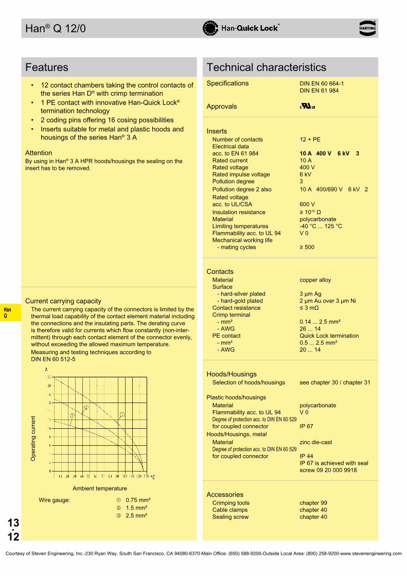
HanQ
13.12
Han® Q 12/0
Features• 12 contact chambers taking the control contacts of
the series Han D® with crimp termination• 1 PE contact with innovative Han-Quick Lock®
termination technology• 2 coding pins offering 16 cosing possibilities• Inserts suitable for metal and plastic hoods and
housings of the series Han® 3 A
AttentionBy using in Han® 3 A HPR hoods/housings the sealing on the insert has to be removed.
Current carrying capacityThe current carrying capacity of the connectors is limited by the thermal load capability of the contact element material including the connections and the insulating parts. The derating curve is therefore valid for currents which flow constantly (non-inter-mittent) through each contact element of the connector evenly, without exceeding the allowed maximum temperature.Measuring and testing techniques according to DIN EN 60 512-5
Ope
ratin
g cu
rrent
Ambient temperature
Wire gauge: ➀ 0.75 mm²➁ 1.5 mm²➂ 2.5 mm²
Technical characteristicsSpecifications DIN EN 60 664-1 DIN EN 61 984 Approvals
InsertsNumber of contacts 12 + PE Electrical data acc. to EN 61 984 10 A 400 V 6 kV 3 Rated current 10 A Rated voltage 400 V Rated impulse voltage 6 kV Pollution degree 3Pollution degree 2 also 10 A 400/690 V 6 kV 2Rated voltage acc. to UL/CSA 600 VInsulation resistance ≥ 1010 Ω Material polycarbonate Limiting temperatures -40 °C ... 125 °C Flammability acc. to UL 94 V 0 Mechanical working life - mating cycles ≥ 500
ContactsMaterial copper alloy Surface - hard-silver plated 3 µm Ag - hard-gold plated 2 µm Au over 3 µm Ni Contact resistance ≤ 3 mΩ Crimp terminal - mm² 0.14 ... 2.5 mm² - AWG 26 ... 14 PE contact Quick Lock termination - mm² 0.5 ... 2.5 mm² - AWG 20 ... 14
Hoods/HousingsSelection of hoods/housings see chapter 30 / chapter 31
Plastic hoods/housings
Material polycarbonate Flammability acc. to UL 94 V 0 Degree of protection acc. to DIN EN 60 529 for coupled connector IP 67
Hoods/Housings, metalMaterial zinc die-cast Degree of protection acc. to DIN EN 60 529 for coupled connector IP 44 IP 67 is achieved with seal screw 09 20 000 9918
AccessoriesCrimping tools chapter 99 Cable clamps chapter 40 Sealing screw chapter 40
Courtesy of Steven Engineering, Inc.-230 Ryan Way, South San Francisco, CA 94080-6370-Main Office: (650) 588-9200-Outside Local Area: (800) 258-9200-www.stevenengineering.com
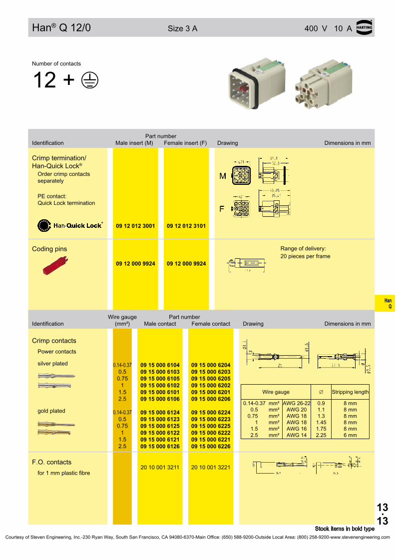
HanQ
13.13
Bestell-Nummer Bezeichnung Stifteinsatz (M) Buchseneinsatz (F) Maßzeichnung Maße in mm
09 12 012 3001 09 12 012 3101
09 12 000 9924 09 12 000 9924
∅
mm²mm²mm²mm²mm²mm²
AWG 26-22AWG 20AWG 18AWG 18AWG 16AWG 14
8 mm8 mm8 mm8 mm8 mm6 mm
09 15 000 6104 09 15 000 6103 09 15 000 6105 09 15 000 6102 09 15 000 6101 09 15 000 6106
09 15 000 6204 09 15 000 6203 09 15 000 6205 09 15 000 6202 09 15 000 6201 09 15 000 6206
09 15 000 6124 09 15 000 6123 09 15 000 6125 09 15 000 6122 09 15 000 6121 09 15 000 6126
09 15 000 6224 09 15 000 6223 09 15 000 6225 09 15 000 6222 09 15 000 6221 09 15 000 6226
20 10 001 3211 20 10 001 3221
Han® Q 12/0 Size 3 A 400 V 10 A
Stock items in bold type
Number of contacts
12 +
Part number Identification Male insert (M) Female insert (F) Drawing Dimensions in mm
Crimp termination/ Han-Quick Lock®
Order crimp contacts separately
PE contact: Quick Lock termination
Coding pins Range of delivery:20 pieces per frame
Wire gauge Part number Identification (mm²) Male contact Female contact Drawing Dimensions in mm
Crimp contacts Power contacts
Wire gauge Stripping length
0.14-0.370.5
0.751
1.52.5
0.91.11.31.451.752.25
silver plated 0.14-0.37 0.5
0.75 1
1.5 2.5
gold plated 0.14-0.37 0.5
0.75 1
1.5 2.5
F.O. contacts for 1 mm plastic fibre
Courtesy of Steven Engineering, Inc.-230 Ryan Way, South San Francisco, CA 94080-6370-Main Office: (650) 588-9200-Outside Local Area: (800) 258-9200-www.stevenengineering.com
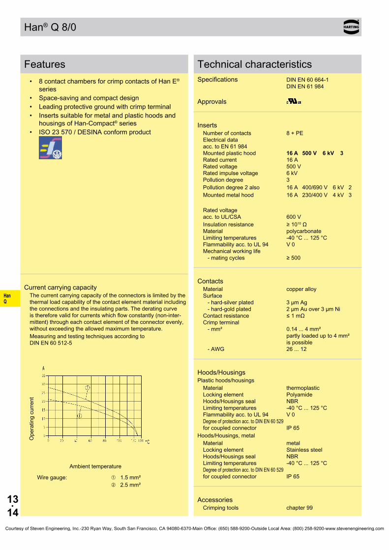
HanQ
13.14
Han® Q 8/0
Features• 8 contact chambers for crimp contacts of Han E®
series• Space-saving and compact design• Leading protective ground with crimp terminal• Inserts suitable for metal and plastic hoods and
housings of Han-Compact® series• ISO 23 570 / DESINA conform product
Current carrying capacityThe current carrying capacity of the connectors is limited by the thermal load capability of the contact element material including the connections and the insulating parts. The derating curve is therefore valid for currents which flow constantly (non-inter-mittent) through each contact element of the connector evenly, without exceeding the allowed maximum temperature.Measuring and testing techniques according to DIN EN 60 512-5
Ope
ratin
g cu
rrent
Ambient temperature
Wire gauge: ➀ 1.5 mm²➁ 2.5 mm²
Technical characteristicsSpecifications DIN EN 60 664-1 DIN EN 61 984 Approvals
InsertsNumber of contacts 8 + PE Electrical data acc. to EN 61 984 Mounted plastic hood 16 A 500 V 6 kV 3 Rated current 16 A Rated voltage 500 V Rated impulse voltage 6 kV Pollution degree 3Pollution degree 2 also 16 A 400/690 V 6 kV 2Mounted metal hood 16 A 230/400 V 4 kV 3
Rated voltage acc. to UL/CSA 600 VInsulation resistance ≥ 1010 Ω Material polycarbonate Limiting temperatures -40 °C ... 125 °C Flammability acc. to UL 94 V 0 Mechanical working life - mating cycles ≥ 500
ContactsMaterial copper alloy Surface - hard-silver plated 3 µm Ag - hard-gold plated 2 µm Au over 3 µm Ni Contact resistance ≤ 1 mΩ Crimp terminal - mm² 0.14 ... 4 mm² partly loaded up to 4 mm² is possible - AWG 26 ... 12
Hoods/HousingsPlastic hoods/housings
Material thermoplastic Locking element Polyamide Hoods/Housings seal NBR Limiting temperatures -40 °C ... 125 °C Flammability acc. to UL 94 V 0 Degree of protection acc. to DIN EN 60 529 for coupled connector IP 65
Hoods/Housings, metalMaterial metal Locking element Stainless steel Hoods/Housings seal NBR Limiting temperatures -40 °C ... 125 °C Degree of protection acc. to DIN EN 60 529 for coupled connector IP 65
AccessoriesCrimping tools chapter 99
Courtesy of Steven Engineering, Inc.-230 Ryan Way, South San Francisco, CA 94080-6370-Main Office: (650) 588-9200-Outside Local Area: (800) 258-9200-www.stevenengineering.com

HanQ
13.15
09 12 008 3001 09 12 008 3101
09 33 000 9954
mm²mm²mm²mm²mm²mm²mm²
AWG 26-22AWG 20AWG 18AWG 18AWG 16AWG 14AWG 12
09 33 000 6127 09 33 000 6121 09 33 000 6114 09 33 000 6105 09 33 000 6104 09 33 000 6102 09 33 000 6107
09 33 000 6227 09 33 000 6220 09 33 000 6214 09 33 000 6205 09 33 000 6204 09 33 000 6202 09 33 000 6207
09 33 000 6117 09 33 000 6122 09 33 000 6115 09 33 000 6118 09 33 000 6116 09 33 000 6123 09 33 000 6119
09 33 000 6217 09 33 000 6222 09 33 000 6215 09 33 000 6218 09 33 000 6216 09 33 000 6223 09 33 000 6221
09 33 000 6109
09 33 000 6110 09 33 000 6111
20 10 001 3311 20 10 001 3321
Han® Q 8/0 Size Han-Compact® 500 V 16 A
Stock items in bold type Crimp contacts 0.14 ... 0.37 mm² only used with BUCHANAN crimping tool 09 99 000 0001
Number of contacts
8 +
Part number Identification Male insert (M) Female insert (F) Drawing Dimensions in mm
Crimp terminalOrder crimp contacts separately
Coding pin Use of the coding pin prevents incor-rect mating to other connectors of the same type. The male pin should be omitted from the opposing cavity in the male insert.
Wire gauge Part number Identification (mm²) Male contact Female contact Drawing Dimensions in mm
Crimp contacts Power contacts Operating contact
Identification Relay contact
Identification Wire gauge Stripping length
no grooveno groove1 groove*1 groove2 grooves3 groovesno groove
0.14-0.370.5
0.751
1.52.5
4
7.5 mm7.5 mm7.5 mm7.5 mm7.5 mm7.5 mm7.5 mm
* on the back crimp collar
silver plated 0.14-0.37 0.5
0.75 1
1.5 2.5 4
gold plated 0.14-0.37 0.5
0.75 1
1.5 2.5 4
Relay contact silver plated 0.75-1
1.5 2.5
F.O. contacts for 1 mm plastic fibre
Crimp zone Crimp zone
Courtesy of Steven Engineering, Inc.-230 Ryan Way, South San Francisco, CA 94080-6370-Main Office: (650) 588-9200-Outside Local Area: (800) 258-9200-www.stevenengineering.com

HanQ
13.16
Han® Q 8/0 Quick Lock
Features• Innovative Han-Quick Lock® termination• Reduced wiring times; field assembly without spe-
cial tools• Compatible to Han® Q 8/0 inserts with crimp termi-
nal• Insert suitable for standard plastic hoods/housings
and metal hoods/housings with additional PE contact of the size Han-Compact®
• Leading protective ground contact
Current carrying capacityThe current carrying capacity of the connectors is limited by the thermal load capability of the contact element material including the connections and the insulating parts. The derating curve is therefore valid for currents which flow constantly (non-inter-mittent) through each contact element of the connector evenly, without exceeding the allowed maximum temperature.Measuring and testing techniques according to DIN EN 60 512-5
Ope
ratin
g cu
rrent
Ambient temperature
Wire gauge: ➀ 0.5 mm²➁ 1.5 mm²➂ 2.5 mm²
Technical characteristicsSpecifications DIN EN 60 664-1 DIN EN 61 984
InsertsNumber of contacts 8 + PE Electrical data acc. to EN 61 984 16 A 500 V 6 kV 3 Rated current 16 A Rated voltage 500 V Rated impulse voltage 6 kV Pollution degree 3
Insulation resistance ≥ 1010 Ω Material polycarbonate Limiting temperatures -40 °C ... 125 °C Flammability acc. to UL 94 V 0 Mechanical working life - mating cycles ≥ 500
ContactsMaterial copper alloy Surface - hard-silver plated 3 µm Ag Contact resistance ≤ 3 mΩ Quick Lock termination - mm² 0.5 ... 2.5 mm² - AWG 20 ... 14 Max. insulation diameter 3.6 mm
Hoods/HousingsSelection of hoods/housings see chapter 30 / chapter 31
Plastic hoods/housings
Material polycarbonate Flammability acc. to UL 94 V 0 Degree of protection acc. to DIN EN 60 529 for coupled connector IP 67
Hoods/Housings, metal, with additional PE contact
Material zinc die-cast Degree of protection acc. to DIN EN 60 529 for coupled connector IP 44 IP 67 is achieved with seal screw 09 20 000 9918
Courtesy of Steven Engineering, Inc.-230 Ryan Way, South San Francisco, CA 94080-6370-Main Office: (650) 588-9200-Outside Local Area: (800) 258-9200-www.stevenengineering.com

HanQ
13.17
Han-Quick Lock®
09 12 008 2633 09 12 008 2733
Han® Q 8/0 Quick Lock Size Han-Compact® 500 V 16 A
Stock items in bold type
Number of contacts
8 +
Part number Identification Male insert (M) Female insert (F) Drawing Dimensions in mm
Courtesy of Steven Engineering, Inc.-230 Ryan Way, South San Francisco, CA 94080-6370-Main Office: (650) 588-9200-Outside Local Area: (800) 258-9200-www.stevenengineering.com

HanQ
13.18
Han® Q 17
Features• 17 contact chambers for crimp contacts of Han D®
series• Space-saving and compact design• Leading protective ground with crimp terminal• Inserts suitable for metal and plastic hoods and
housings of Han-Compact® series• 3 coding possibilities by using a coding pin instead
of fixing screw
Current carrying capacityThe current carrying capacity of the connectors is limited by the thermal load capability of the contact element material including the connections and the insulating parts. The derating curve is therefore valid for currents which flow constantly (non-inter-mittent) through each contact element of the connector evenly, without exceeding the allowed maximum temperature.Measuring and testing techniques according to DIN EN 60 512-5
Ope
ratin
g cu
rrent
Ambient temperature
Wire gauge: ➀ 0.5 mm²➁ 1.0 mm²➂ 1.5 mm²
Technical characteristicsSpecifications DIN EN 60 664-1 DIN EN 61 984 Approvals
InsertsNumber of contacts 17 + PE Electrical data acc. to EN 61 984 10 A 250 V 4 kV 2 Rated current 10 A Rated voltage 250 V Rated impulse voltage 4 kV Pollution degree 2
Rated voltage acc. to UL/CSA 250 VInsulation resistance ≥ 1010 Ω Material polycarbonate Limiting temperatures -40 °C ... 125 °C Flammability acc. to UL 94 V 0 Mechanical working life - mating cycles ≥ 500
ContactsMaterial copper alloy Surface - hard-silver plated 3 µm Ag - hard-gold plated 2 µm Au over 3 µm Ni Contact resistance ≤ 3 mΩ Crimp terminal - mm² 0.14 ... 2.5 mm² - AWG 26 ... 14
Hoods/HousingsPlastic hoods/housings
Material thermoplastic Locking element Polyamide Hoods/Housings seal NBR Limiting temperatures -40 °C ... 125 °C Flammability acc. to UL 94 V 0 Degree of protection acc. to DIN EN 60 529 for coupled connector IP 65
Hoods/Housings, metalMaterial metal Locking element Stainless steel Hoods/Housings seal NBR Limiting temperatures -40 °C ... 125 °C Degree of protection acc. to DIN EN 60 529 for coupled connector IP 65
AccessoriesCrimping tools chapter 99
Courtesy of Steven Engineering, Inc.-230 Ryan Way, South San Francisco, CA 94080-6370-Main Office: (650) 588-9200-Outside Local Area: (800) 258-9200-www.stevenengineering.com
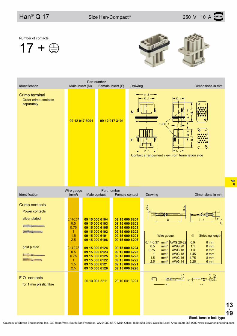
HanQ
13.19
09 12 017 3001 09 12 017 3101
∅
mm²mm²mm²mm²mm²mm²
AWG 26-22AWG 20AWG 18AWG 18AWG 16AWG 14
8 mm8 mm8 mm8 mm8 mm6 mm
09 15 000 6104 09 15 000 6103 09 15 000 6105 09 15 000 6102 09 15 000 6101 09 15 000 6106
09 15 000 6204 09 15 000 6203 09 15 000 6205 09 15 000 6202 09 15 000 6201 09 15 000 6206
09 15 000 6124 09 15 000 6123 09 15 000 6125 09 15 000 6122 09 15 000 6121 09 15 000 6126
09 15 000 6224 09 15 000 6223 09 15 000 6225 09 15 000 6222 09 15 000 6221 09 15 000 6226
20 10 001 3211 20 10 001 3221
Han® Q 17 Size Han-Compact® 250 V 10 A
Stock items in bold type
Number of contacts
17 +
Part number Identification Male insert (M) Female insert (F) Drawing Dimensions in mm
Crimp terminalOrder crimp contacts separately
Contact arrangement view from termination side
Wire gauge Part number Identification (mm²) Male contact Female contact Drawing Dimensions in mm
Crimp contacts Power contacts
Wire gauge Stripping length
0.14-0.370.5
0.751
1.52.5
0.91.11.31.451.752.25
silver plated 0.14-0.37 0.5
0.75 1
1.5 2.5
gold plated 0.14-0.37 0.5
0.75 1
1.5 2.5
F.O. contacts for 1 mm plastic fibre
Courtesy of Steven Engineering, Inc.-230 Ryan Way, South San Francisco, CA 94080-6370-Main Office: (650) 588-9200-Outside Local Area: (800) 258-9200-www.stevenengineering.com

HanQ
13.20
Han® Q 4/2
Features• 4 power contacts Han® C and 2 signal contacts
Han D®
• Finger protection• Leading protective ground with crimp terminal• Inserts suitable for standard plastic and metal
hoods/housings with additional PE contact from the Han-Compact® size
• 3 coding possibilities by using a coding pin instead of fixing screw
Current carrying capacityThe current carrying capacity of the connectors is limited by the thermal load capability of the contact element material including the connections and the insulating parts. The derating curve is therefore valid for currents which flow constantly (non-inter-mittent) through each contact element of the connector evenly, without exceeding the allowed maximum temperature.Measuring and testing techniques according to DIN EN 60 512-5
Ope
ratin
g cu
rrent
Ambient temperature
Wire gauge: ➀ 2.5 mm²
➁ 4 mm²
Technical characteristicsSpecifications DIN EN 60 664-1 DIN EN 61 984 Approvals
InsertsNumber of contacts 4 / 2 + PE Electrical data acc. to EN 61 984 Power side 40 A 400/690 V 6 kV 3 Rated current 40 A Rated voltage conductor - ground 400 V Rated voltage conductor - conductor 690 V Rated impulse voltage 6 kV Pollution degree 3 Signal side 10 A 250 V 4 kV 3 Rated current 10 A Rated voltage 250 V Rated impulse voltage 4 kV Pollution degree 3
Rated voltage acc. to UL/CSA 600 / 250 V Insulation resistance ≥ 1010 Ω Material polycarbonate Limiting temperatures -40 °C ... 125 °C Flammability acc. to UL 94 V 0 Mechanical working life - mating cycles ≥ 500
ContactsMaterial copper alloy Surface - hard-silver plated 3 µm Ag - hard-gold plated 2 µm Au over 3 µm Ni Contact resistance ≤ 0.3 mΩ Crimp terminal - mm² 1.5 ... 6 mm² / 0.14 ... 2.5 mm² - AWG 16 ... 10 / 26 ... 14 Max. insulation diameter - Power contacts 5 mm
Hoods/HousingsPlastic hoods/housings
Material thermoplastic Locking element Polyamide Hoods/Housings seal NBR Limiting temperatures -40 °C ... 125 °C Flammability acc. to UL 94 V 0 Degree of protection acc. to DIN EN 60 529 for coupled connector IP 65
AccessoriesCrimping tools chapter 99
Courtesy of Steven Engineering, Inc.-230 Ryan Way, South San Francisco, CA 94080-6370-Main Office: (650) 588-9200-Outside Local Area: (800) 258-9200-www.stevenengineering.com
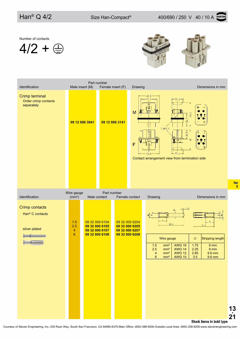
HanQ
13.21
09 12 006 3041 09 12 006 3141
∅
mm²mm²mm²mm²
AWG 16AWG 14AWG 12AWG 10
09 32 000 6104 09 32 000 6105 09 32 000 6107 09 32 000 6108
09 32 000 6204 09 32 000 6205 09 32 000 6207 09 32 000 6208
Han® Q 4/2 Size Han-Compact® 400/690 / 250 V 40 / 10 A
Stock items in bold type
Number of contacts
4/2 +
Part number Identification Male insert (M) Female insert (F) Drawing Dimensions in mm
Crimp terminalOrder crimp contacts separately
Contact arrangement view from termination side
Wire gauge Part number Identification (mm²) Male contact Female contact Drawing Dimensions in mm
Crimp contacts Han® C contacts
Wire gauge Stripping length
1.52.5
46
1.752.252.853.5
9 mm9 mm
9.6 mm9.6 mm
silver plated
1.5 2.5 4 6
Courtesy of Steven Engineering, Inc.-230 Ryan Way, South San Francisco, CA 94080-6370-Main Office: (650) 588-9200-Outside Local Area: (800) 258-9200-www.stevenengineering.com

HanQ
13.22
Features• Field assembly without special tools - reduced
wiring times• Compatible with Han® Q 4/2 standard inserts with
crimp terminations• Space-saving and compact design• Inserts suitable for standard plastic and metal
hoods/housings with additional PE contact from the Han-Compact® size
• With or without Han-Quick Lock® signal contacts as an option
Attention• For termination please use only hexagonal screw driver with wrench size SW 2.• If PE contact is not used: Please screw the PE contact maximal on both sides clockwise with a hexagonal screwdriver, wrench size SW 2.
Current carrying capacityThe current carrying capacity of the connectors is limited by the thermal load capability of the contact element material including the connections and the insulating parts. The derating curve is therefore valid for currents which flow constantly (non-inter-mittent) through each contact element of the connector evenly, without exceeding the allowed maximum temperature.Measuring and testing techniques according to DIN EN 60 512-5
Ope
ratin
g cu
rrent
Ambient temperature
Wire gauge: ➀ 4 mm²
➁ 6 mm²
Technical characteristicsSpecifications DIN EN 60 664-1 DIN EN 61 984
InsertsNumber of contacts 4 / 2 + PE Electrical data acc. to EN 61 984 Power side 40 A 400/690 V 6 kV 3 Rated current 40 A Rated voltage conductor - ground 400 V Rated voltage conductor - conductor 690 V Rated impulse voltage 6 kV Pollution degree 3 Signal side 10 A 250 V 4 kV 3 Rated current 10 A Rated voltage 250 V Rated impulse voltage 4 kV Pollution degree 3
Insulation resistance ≥ 1010 Ω Material polycarbonate Limiting temperatures -40 °C ... 125 °C Flammability acc. to UL 94 V 0 Mechanical working life - mating cycles ≥ 500
ContactsMaterial copper alloy Surface - hard-silver plated 3 µm AgPower contacts Contact resistance ≤ 0.3 mΩ Axial screw termination - mm² 4 ... 10 mm² - AWG 12 ... 8 Max. insulation diameter 7.3 mm Stripping length 8 mm Tightening torque 1.8 NmSignal contacts Contact resistance ≤ 3 mΩ Han-Quick Lock® - mm² 0.25 ... 1.5 mm² - AWG 23 ... 16 Max. insulation diameter 3 mm Stripping length 10 mm
Hoods/HousingsPlastic hoods/housings
Material thermoplastic Locking element Polyamide Hoods/Housings seal NBR Limiting temperatures -40 °C ... 125 °C Flammability acc. to UL 94 V 0 Degree of protection acc. to DIN EN 60 529 for coupled connector IP 65
Han® Q 4/2 Axial screw
Courtesy of Steven Engineering, Inc.-230 Ryan Way, South San Francisco, CA 94080-6370-Main Office: (650) 588-9200-Outside Local Area: (800) 258-9200-www.stevenengineering.com
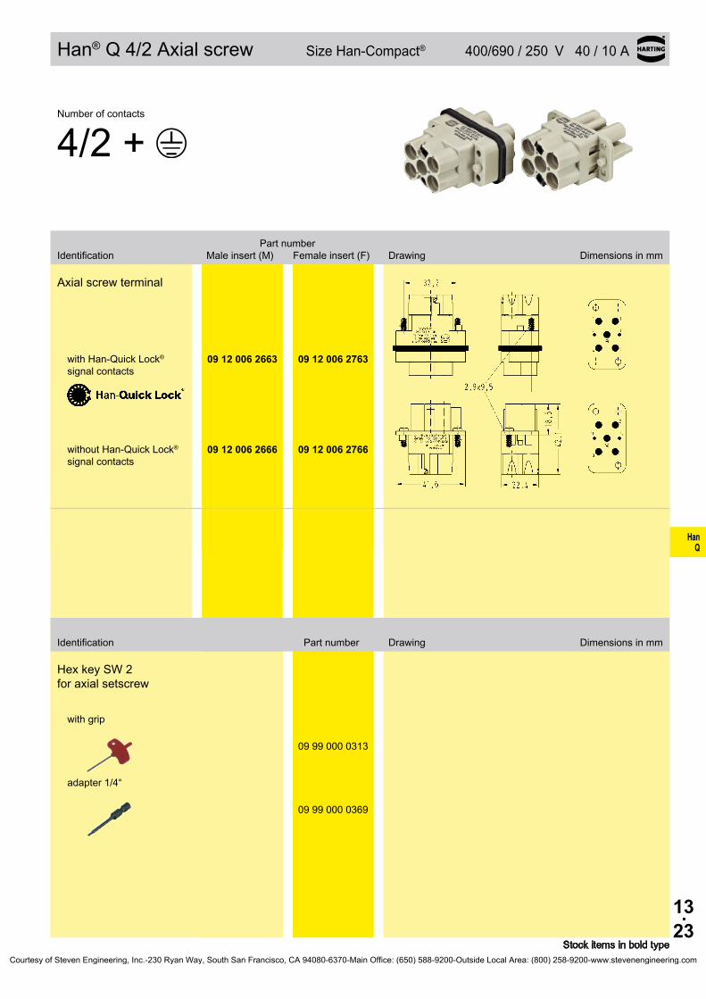
HanQ
13.23
09 12 006 2663 09 12 006 2763
09 12 006 2666 09 12 006 2766
09 99 000 0313
09 99 000 0369
Han® Q 4/2 Axial screw Size Han-Compact® 400/690 / 250 V 40 / 10 A
Stock items in bold type
Number of contacts
4/2 +
Part number Identification Male insert (M) Female insert (F) Drawing Dimensions in mm
Axial screw terminal
with Han-Quick Lock® signal contacts
without Han-Quick Lock® signal contacts
Hex key SW 2 for axial setscrew
with grip
adapter 1/4“
Identification Part number Drawing Dimensions in mm
Courtesy of Steven Engineering, Inc.-230 Ryan Way, South San Francisco, CA 94080-6370-Main Office: (650) 588-9200-Outside Local Area: (800) 258-9200-www.stevenengineering.com

HanQ
13.24
Han® Q Data RJ45
Features• Combination connector / Ethernet connector
based on RJ45 / additionally maximum 10 signal D-Sub contacts, crimp terminal
• Compact design• High contact density• Turned D-Sub contacts of performance level 1*• Suitable for hoods and housings of series
Han-Compact®
Technical characteristicsSpecifications DIN EN 60 664-1 DIN EN 61 984
InsertsEthernet connectorTerminal RJ45 acc. to IEC 60 603-7 Wire gauge - flexible Transmission features Cat. 5e Number of contacts 8Signal sideNumber of contacts 10 Electrical data acc. to EN 61 984 5 A 50 V 0.8 kV 3 Rated current 5 A Rated voltage 50 V Rated impulse voltage 0.8 kV Pollution degree 3
Insulation resistance ≥ 1010 Ω Material polycarbonate Limiting temperatures -40 °C ... 85 °C Flammability acc. to UL 94 V 0 Mechanical working life - mating cycles ≥ 500
Contacts Crimp terminal - mm² 0.13 ... 0.52 mm² - AWG 26 ... 20turned contacts Performance level 1
as per CECC 75 301-802, 500 mating cycles, 10 days 4 mixed gas test - IEC 60 512
Hoods/HousingsPlastic hoods/housings
Material thermoplastic Locking element Polyamide Hoods/Housings seal NBR Limiting temperatures -40 °C ... 125 °C Flammability acc. to UL 94 V 0 Degree of protection acc. to DIN EN 60 529 for coupled connector IP 65
Hoods/Housings, metalMaterial metal Locking element Stainless steel Hoods/Housings seal NBR Limiting temperatures -40 °C ... 125 °C Degree of protection acc. to DIN EN 60 529 for coupled connector IP 65
* Performance level 1 acc. to CECC 75 301-802, 500 mating cycles, 10 days 4 mixed gas test as per IEC 60 512Courtesy of Steven Engineering, Inc.-230 Ryan Way, South San Francisco, CA 94080-6370-Main Office: (650) 588-9200-Outside Local Area: (800) 258-9200-www.stevenengineering.com

HanQ
13.25
09 12 011 3001 09 12 011 3111
∅
mm²mm²
AWG 26-22AWG 22-20
61 03 000 0094 61 03 000 0073
61 03 000 0096 61 03 000 0074
09 12 000 9958
Han® Q RJ45 Size Han-Compact® 50 V 5 A
Stock items in bold type
Number of contacts
8
Part number Identification Male insert (M) Female insert (F) Drawing Dimensions in mm
Han® Q Data RJ45Order crimp contacts separately female insert usable for pa-nel feed through for patch cables
Wire gauge Part number Identification (mm²) Male contact Female contact Drawing Dimensions in mm
Individual contacts Han® D-Sub contacts
Wire gauge Stripping length
0.13-0.330.33-0.52
0.91.12
5 mm5 mm
gold plated 0.13-0.33
0.33-0.52
RJ45 plug AMP(for replacement)
AWG 24 ... 26Ø 0.89 mm ... 0.99 mm
Courtesy of Steven Engineering, Inc.-230 Ryan Way, South San Francisco, CA 94080-6370-Main Office: (650) 588-9200-Outside Local Area: (800) 258-9200-www.stevenengineering.com

HanQ
13.26
19 12 708 0511
19 12 008 0511
M25
M25
19 12 708 0501
19 12 008 0501
M25
M25
19 12 008 0526
M25
19 12 708 0411
19 12 008 0411
M25
M25
19 12 008 0426
M25
Hoods/Housings Han-Compact®
Stock items in bold type
Identification Part number Drawing Dimensions in mm
Metal
Hoods
• side-entry for Han-Compact® half gland
• with separate PE termination
• for all inserts of size Han-Compact®
black powder coated
black chromated
Hoods
• side-entry for Han-Compact® half gland
• for Han® Q 8/0 Crimp, Han® Q 17/0 and Han® Q Data RJ45
black powder coated
black chromated
Hoods
• side-entry for standard cable glands
• with separate PE termination
• for all inserts of size Han-Compact®
black powder coated
Hoods
• top-entry for Han-Compact® half gland
• with separate PE termination
• for all inserts of size Han-Compact®
black powder coated
black chromated
Hoods
• top-entry for standard cable glands
• with separate PE termination
• for all inserts of size Han-Compact®
black powder coated
Courtesy of Steven Engineering, Inc.-230 Ryan Way, South San Francisco, CA 94080-6370-Main Office: (650) 588-9200-Outside Local Area: (800) 258-9200-www.stevenengineering.com

HanQ
13.27
09 12 708 0301
09 12 008 0301
Hoods/Housings Han-Compact®
Stock items in bold type
Identification Part number Drawing Dimensions in mm
Metal
Housings, bulkhead mounting
black powder coated
black chromated
Courtesy of Steven Engineering, Inc.-230 Ryan Way, South San Francisco, CA 94080-6370-Main Office: (650) 588-9200-Outside Local Area: (800) 258-9200-www.stevenengineering.com

HanQ
13.28
09 12 008 0527 Pg 16
19 12 008 0429 09 12 008 0427 09 12 008 0429
M25 Pg 16 Pg 21
09 12 008 0428 PAFS 18
Hoods/Housings Han-Compact®
Stock items in bold type
Identification Part number Drawing Dimensions in mm
Thermoplastic
Hoods
• side-entry for Han-Compact® half gland
Hoods
• top-entry for Han-Compact® half gland
Hoods
• top-entry for flexible conduits Adaptaflex PAFS18
Courtesy of Steven Engineering, Inc.-230 Ryan Way, South San Francisco, CA 94080-6370-Main Office: (650) 588-9200-Outside Local Area: (800) 258-9200-www.stevenengineering.com

HanQ
13.29
09 12 008 0327 –
09 12 008 0902 –
09 12 008 0901 Pg 16
19 12 008 0729 09 12 008 0727
M25 Pg 16
09 12 008 0728 PAFS 18
Hoods/Housings Han-Compact®
Stock items in bold type
Identification Part number Drawing Dimensions in mm
Thermoplastic
Housings, bulkhead mounting
straight
Housings, bulkhead mounting
angled
Housings, surface mounting
• for Han-Compact® half gland
Hoods, cable to cable
• for Han-Compact® half gland
Hoods, cable to cable
• for flexible conduits Adaptaflex PAFS18
Courtesy of Steven Engineering, Inc.-230 Ryan Way, South San Francisco, CA 94080-6370-Main Office: (650) 588-9200-Outside Local Area: (800) 258-9200-www.stevenengineering.com

HanQ
13.30
19 12 008 0512 M25
19 12 008 0502 M25
19 12 008 0528 M25
19 12 008 0412 M25
19 12 008 0428 M25
Hoods/Housings Han-Compact®
Stock items in bold type
Identification Part number Drawing Dimensions in mm
Metal nickel-plated for EMC applications
Hoods
• side-entry for Han-Compact® EMC half gland
• with separate PE termination
• for all inserts of size Han-Compact®
Hoods
• side-entry for Han-Compact® EMC half gland
• for Han® Q 8/0 Crimp, Han® Q 17/0 and Han® Q Data RJ45
Hoods
• side-entry for standard EMC cable glands
• with separate PE termination
• for all inserts of size Han-Compact®
Hoods
• top-entry for Han-Compact® EMC half gland
• with separate PE termination
• for all inserts of size Han-Compact®
Hoods
• top-entry for standard EMC cable glands
• with separate PE termination
• for all inserts of size Han-Compact®
Courtesy of Steven Engineering, Inc.-230 Ryan Way, South San Francisco, CA 94080-6370-Main Office: (650) 588-9200-Outside Local Area: (800) 258-9200-www.stevenengineering.com
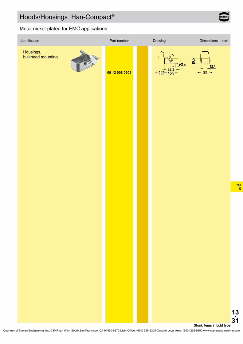
HanQ
13.31
09 12 008 0303
Hoods/Housings Han-Compact®
Stock items in bold type
Identification Part number Drawing Dimensions in mm
Metal nickel-plated for EMC applications
Housings, bulkhead mounting
Courtesy of Steven Engineering, Inc.-230 Ryan Way, South San Francisco, CA 94080-6370-Main Office: (650) 588-9200-Outside Local Area: (800) 258-9200-www.stevenengineering.com

HanQ
13.32
19 12 000 5057 19 12 000 5058
M25 M25
19 12 000 5057 28 19 12 000 5058 28
19 12 000 5157 19 12 000 5158 09 00 000 5059 09 00 000 5157 09 00 000 5158
M25 M25
Pg 16 Pg 21 Pg 21
19 12 000 5157 30 19 12 000 5158 30 09 00 000 5059 27 09 00 000 5157 33 09 00 000 5158 33
09 00 000 5058 09 00 000 5057
Pg 16 Pg 16
09 00 000 5058 27 09 00 000 5057 27
19 62 000 5056 19 62 000 5057 19 62 000 5058
M25 M25 M25
19 62 000 5056 28 19 62 000 5057 28 19 62 000 5058 28
19 62 000 505619 62 000 505719 62 000 5058
Hoods/Housings Han-Compact®
Stock items in bold type
Identification Part number Drawing Dimensions in mm
Accessories
Han-Compact® half gland
• Metal• for hoods
cableSW
min. max.10,5 mm 14 mm14 mm 17 mm
Han-Compact® half gland
• Thermoplastic• for hoods
cableSW
min. max.10,5 mm 14 mm14 mm 17 mm
11,5 mm 15,5 mm14 mm 18 mm17 mm 20,5 mm
Han-Compact® half gland
• Thermoplastic• for housings
cableSW
min. max.11,5 mm 15,5 mm6,5 mm 9,5 mm
Han-Compact® EMC half gland
• Metal• for hoods
cableSW
min. max.10,5 mm 14 mm10,5 mm 14 mm14 mm 17 mm
shieldingmin. max.
9 mm 13 mm6 mm 11 mm9 mm 13 mm
Courtesy of Steven Engineering, Inc.-230 Ryan Way, South San Francisco, CA 94080-6370-Main Office: (650) 588-9200-Outside Local Area: (800) 258-9200-www.stevenengineering.com

HanQ
13.33
09 12 008 5407
09 12 008 5408
09 12 000 9912
09 12 000 9911
Hoods/Housings Han-Compact®
Stock items in bold type
Identification Part number Drawing Dimensions in mm
Accessories
Protection covers
• Thermoplastic• for housings
for mounted male insert
Protection covers
• Thermoplastic• for housings
for mounted female insert
Gasket for plastic housings, bulkhead mounting, straight
Gasket for plastic housings, bulkhead mounting, angled, and for housings, surface mounting
Courtesy of Steven Engineering, Inc.-230 Ryan Way, South San Francisco, CA 94080-6370-Main Office: (650) 588-9200-Outside Local Area: (800) 258-9200-www.stevenengineering.com

HanQ
13.34
Application
ET 200pro distributed I/O system with degree of protection IP 65 / IP 67Siemens AG, Erlangen, Germany
Courtesy of Steven Engineering, Inc.-230 Ryan Way, South San Francisco, CA 94080-6370-Main Office: (650) 588-9200-Outside Local Area: (800) 258-9200-www.stevenengineering.com

Han HC Modular
14.01
Han® K 3/0, K 3/2 / Han® HC Modular
Contents Page
Technical characteristics Han® K 3/0, Han® K 3/2 . . . . . . . . . . . . . . . . . . . 14.02
Inserts Han® K 3/0, Han® K 3/2 . . . . . . . . . . . . . . . . . . . . . . . . . . . . . . . . . . 14.03
Hoods/Housings Han® 24 HPR for Han® K 3/0, Han® K 3/2 . . . . . . . . . . . . 14.04
Technical characteristics Han® HC Modular 350 . . . . . . . . . . . . . . . . . . . . 14.08
Contacts Han® HC Modular 350 . . . . . . . . . . . . . . . . . . . . . . . . . . . . . . . . . 14.09
Technical characteristics Han® HC Modular 350 Crimp . . . . . . . . . . . . . . . . 14.10
Contacts Han® HC Modular 350 Crimp . . . . . . . . . . . . . . . . . . . . . . . . . . . . 14.11
Hoods/Housings for Han® HC Modular 350 . . . . . . . . . . . . . . . . . . . . . . . . 14.12
Hoods/Housings for Han® HC Modular 350 enlarged . . . . . . . . . . . . . . . . . 14.15
Technical characteristics Han® HC Modular 650 . . . . . . . . . . . . . . . . . . . . 14.18
Contacts Han® HC Modular 650 . . . . . . . . . . . . . . . . . . . . . . . . . . . . . . . . . 14.19
Technical characteristics Han® HC Modular 650 Crimp . . . . . . . . . . . . . . . . 14.20
Contacts Han® HC Modular 650 Crimp . . . . . . . . . . . . . . . . . . . . . . . . . . . . 14.21
Hoods/Housings for Han® HC Modular 650 . . . . . . . . . . . . . . . . . . . . . . . . 14.22
Hoods/Housings for Han® HC Modular 650 enlarged . . . . . . . . . . . . . . . . . 14.23
Hoods/Housings Han® 48 HPR . . . . . . . . . . . . . . . . . . . . . . . . . . . . . . . . . 14.25
Han® 48 HPR . . . . . . . . . . . . . . . . . . . . . . . . . . . . . . . . . . . . . . . . . . . . . . . 14.26
Courtesy of Steven Engineering, Inc.-230 Ryan Way, South San Francisco, CA 94080-6370-Main Office: (650) 588-9200-Outside Local Area: (800) 258-9200-www.stevenengineering.com

Han HC Modular
14.02
Han® K 3/0, Han® K 3/2
Features• Only to be used with Han® 24 HPR special hoods
and housings (see page 14.04)• The ideal connector for transmission of high cur-
rents requiring little space• Theverticalandangledversionsoffersolutionsfor
almost all applications• Theangledversionsofferaspace-saving90°cable
wiring
Current carrying capacityThe current carrying capacity of the connectors is limited by the thermal load capability of the contact element material including the connections and the insulating parts. The derating curve isthereforevalidforcurrentswhichflowconstantly(non-inter-mittent) through each contact element of the connector evenly, without exceeding the allowed maximum temperature.Measuring and testing techniques according to DIN EN 60 512-5
Ope
ratin
g cu
rrent
Ambient temperature
➀Wiregauge35mm²➁Wiregauge50mm²➂Wiregauge70mm²
Technical characteristicsSpecifications DINEN61984
DIN EN 60 664-1 Inserts
Number of contacts 3, 3/2 + PE
Electricaldataacc.toEN61984
Power area 200 A 1150/2000 V 8 kV 3 Rated current 200 A Rated voltage conductor - ground 1150 V Rated voltage conductor - conductor 2000 V Ratedimpulsevoltage 8kV Pollution degree 3
Pollutiondegree2also 200A2000V12kV2
Signal area 16 A 400 V 6 kV 3 Rated current 16 A Rated voltage 400 V Ratedimpulsevoltage 6kV Pollution degree 3
Pollutiondegree2also 16A500V6kV2
Insulationresistance ≥1010ΩMaterial polycarbonateLimitingtemperatures -40°C...+125°CFlammabilityacc.toUL94 V0Mechanicalworkinglife
-matingcycles ≥500
ContactsMaterial copper alloySurface silverContactresistance ≤0.2mΩ
Axial screw termination Power contacts
-Wiregauge1) 35...70mm²-AWG 2 ... 00- Hexagonal driver SW5,09990000371,
Page99.05- Stripping length 22 mm
- Tightening torquemm² 35 50 70Nm 8 9 10
PE contact (only Han® K 3/2)-Wiregauge1) 16...35mm²-AWG 5 ... 2- Hexagonal driver SW4,09990000370,
Page99.05- Stripping length 14 mm- Tightening torque 6 Nm
Signal contact (only Han® K 3/2)-Wiregauge1) 2.5mm²-AWG 14- Stripping length 7mm- Tightening torque 0.5 Nm
Hoods/HousingsFor technical details see chapter 31
1) geometric wire gaugeCourtesy of Steven Engineering, Inc.-230 Ryan Way, South San Francisco, CA 94080-6370-Main Office: (650) 588-9200-Outside Local Area: (800) 258-9200-www.stevenengineering.com
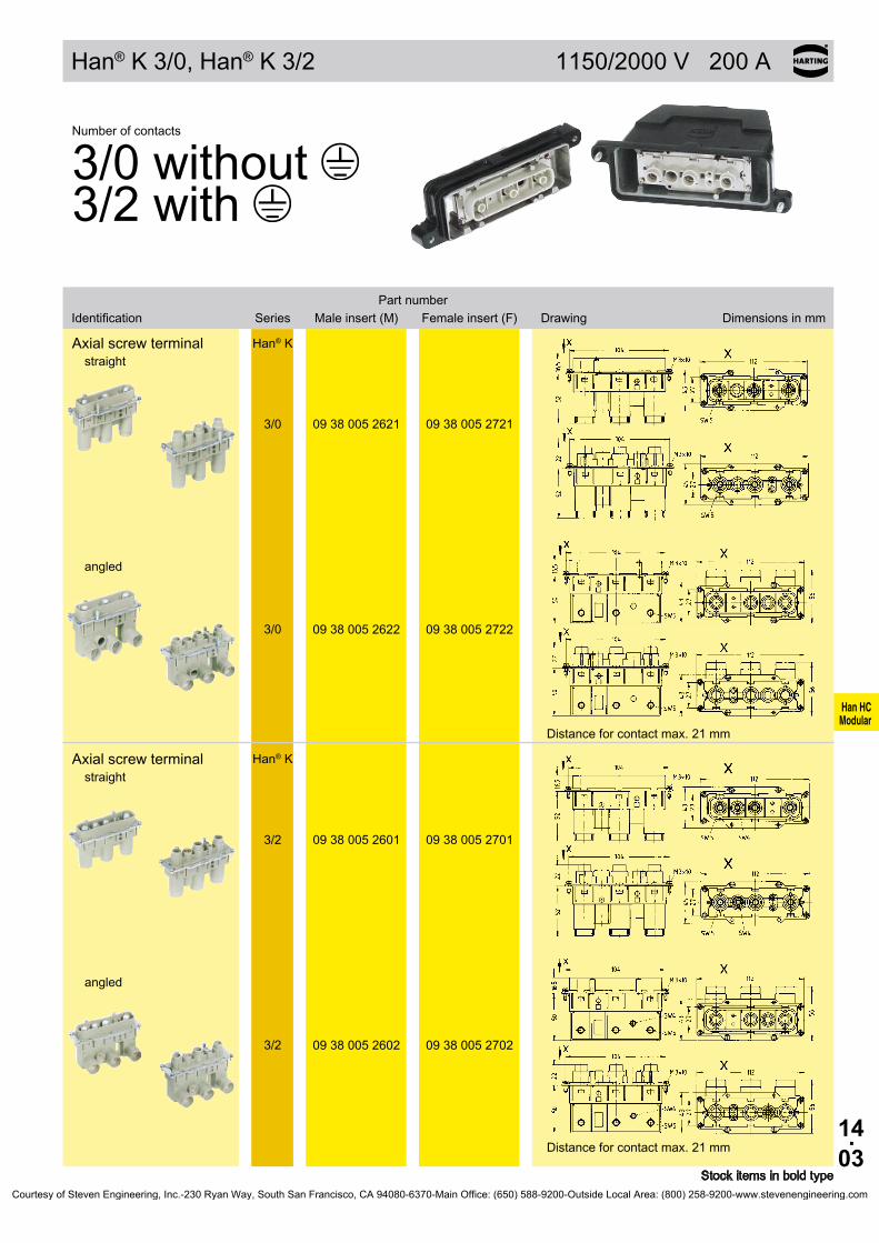
Han HC Modular
14.03
Han® K 3/0, Han® K 3/2 1150/2000 V 200 A
Stockitemsinboldtype
Number of contacts
3/0 without 3/2 with
SeriesPart number
Identification Male insert (M) Female insert (F) Drawing Dimensions in mm
Axial screw terminal Han® Kstraight
3/0 09380052621 09380052721
angled
3/0 09 38 005 2622 09 38 005 2722
Distance for contact max. 21 mm
Axial screw terminal Han® Kstraight
3/2 09380052601 09380052701
angled
3/2 09 38 005 2602 09 38 005 2702
Distance for contact max. 21 mm
Courtesy of Steven Engineering, Inc.-230 Ryan Way, South San Francisco, CA 94080-6370-Main Office: (650) 588-9200-Outside Local Area: (800) 258-9200-www.stevenengineering.com

Han HC Modular
14.04
Hoods/Housings Han® HPR Size 24 B
Stockitemsinboldtype
Identification Part number M Drawing Dimensions in mm
Special hood/housing for Han® K 3/0, Han® K 3/2
Hoodstop entry
19 40 024 0461 3 x 25
top entry
19 40 024 0471 3 x 251 x 20
angled entryView X
19 40 024 0631 3 x 25
top entry
19 40 024 0420 1 x 63
Courtesy of Steven Engineering, Inc.-230 Ryan Way, South San Francisco, CA 94080-6370-Main Office: (650) 588-9200-Outside Local Area: (800) 258-9200-www.stevenengineering.com
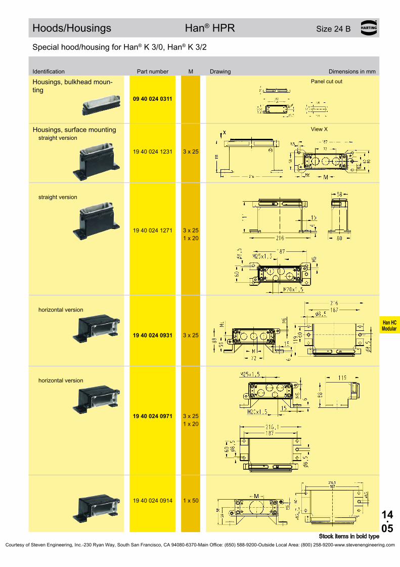
Han HC Modular
14.05
Hoods/Housings Han® HPR Size 24 B
Stockitemsinboldtype
Identification Part number M Drawing Dimensions in mm
Special hood/housing for Han® K 3/0, Han® K 3/2
Housings,bulkheadmoun-ting
Panel cut out
09 40 024 0311
Housings, surface mountingstraight version
View X
19 40 024 1231 3 x 25
straight version
19 40 024 1271 3 x 251 x 20
horizontal version
19 40 024 0931 3 x 25
horizontal version
19 40 024 0971 3 x 251 x 20
19 40 024 0914 1 x 50
Courtesy of Steven Engineering, Inc.-230 Ryan Way, South San Francisco, CA 94080-6370-Main Office: (650) 588-9200-Outside Local Area: (800) 258-9200-www.stevenengineering.com

Han HC Modular
14.06
Application
Motor connection of the traction bogie with Han® K 3/0 and Han® HPR hood/housingBombardier Transportation, Siemens AG, ALSTOM
Regional Express Railcars of the series ET 424-426Bombardier Transportation, Siemens AG, ALSTOM
Courtesy of Steven Engineering, Inc.-230 Ryan Way, South San Francisco, CA 94080-6370-Main Office: (650) 588-9200-Outside Local Area: (800) 258-9200-www.stevenengineering.com

Han HC Modular
14.07
Notes
Courtesy of Steven Engineering, Inc.-230 Ryan Way, South San Francisco, CA 94080-6370-Main Office: (650) 588-9200-Outside Local Area: (800) 258-9200-www.stevenengineering.com
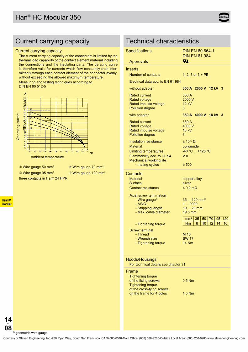
Han HC Modular
14.08
Han® HC Modular 350
Current carrying capacityCurrent carrying capacity
The current carrying capacity of the connectors is limited by the thermal load capability of the contact element material including the connections and the insulating parts. The derating curve isthereforevalidforcurrentswhichflowconstantly(non-inter-mittent) through each contact element of the connector evenly, without exceeding the allowed maximum temperature.Measuring and testing techniques according to DIN EN 60 512-5
Ope
ratin
g cu
rrent
Ambient temperature
➀Wiregauge50mm² ➁Wiregauge70mm²➂Wiregauge95mm² ➃Wiregauge120mm²three contacts in Han® 24 HPR
Technical characteristicsSpecifications DINEN60664-1
DINEN61984Approvals
Inserts Number of contacts 1, 2, 3 or 3 + PE
Electricaldataacc.toEN61984
without adapter 350 A 2000 V 12 kV 3
Rated current 350 A Rated voltage 2000 V Ratedimpulsevoltage 12kV Pollution degree 3
with adapter 350 A 4000 V 18 kV 3
Rated current 350 A Rated voltage 4000 V Ratedimpulsevoltage 18kV Pollution degree 3
Insulationresistance ≥1010ΩMaterial polyamideLimitingtemperatures -40°C...+125°CFlammabilityacc.toUL94 V0Mechanicalworkinglife
-matingcycles ≥500
Contacts Material copper alloySurface silverContactresistance ≤0.2mΩ
Axial screw termination-Wiregauge1) 35...120mm²-AWG 1 ... 0000- Stripping length 19...20mm- Max. cable diameter 19.5mm
- Tightening torquemm2 35 50 70 95 120Nm 8 10 12 14 16
Screw terminal- Thread -Wrenchsize - Tightening torque
M 10 SW17 14 Nm
Hoods/HousingsFor technical details see chapter 31
FrameTightening torque ofthefixingscrews 0.5Nm Tightening torque of the cross-tying screws on the frame for 4 poles 1.5 Nm
1) geometric wire gaugeCourtesy of Steven Engineering, Inc.-230 Ryan Way, South San Francisco, CA 94080-6370-Main Office: (650) 588-9200-Outside Local Area: (800) 258-9200-www.stevenengineering.com
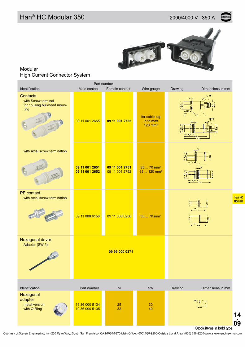
Han HC Modular
14.09
Han® HC Modular 350 2000/4000 V 350 A
Stockitemsinboldtype
Modular High Current Connector System
Part numberWiregaugeIdentification Male contact Female contact Drawing Dimensions in mm
Contactswith Screw terminal forhousingbulkheadmoun-ting
09 11 001 2655 09 11 001 2755for cable lug up to max. 120mm²
with Axial screw termination
09 11 001 2651 09 11 001 2652
09 11 001 2751 09 11 001 2752
35...70mm² 95...120mm²
PE contactwith Axial screw termination
09 11 000 6156 09 11 000 6256 35...70mm²
Hexagonal driverAdapter(SW5)
09 99 000 0371
Identification Part number M SW Drawing Dimensions in mm
Hexagonal adapter
19360005134 19360005135
25 32
30 40
metal version with O-Ring
Courtesy of Steven Engineering, Inc.-230 Ryan Way, South San Francisco, CA 94080-6370-Main Office: (650) 588-9200-Outside Local Area: (800) 258-9200-www.stevenengineering.com
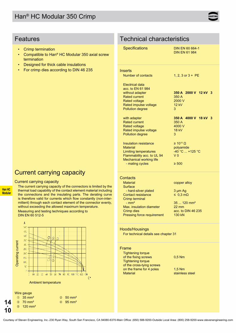
Han HC Modular
14.10
Han® HC Modular 350 Crimp
Features• Crimptermination• CompatibletoHan® HC Modular 350 axial screw
termination• Designedforthickcableinsulations• ForcrimpdiesaccordingtoDIN46235
Technical characteristicsSpecifications DIN EN 60 664-1 DINEN61984
InsertsNumber of contacts 1, 2, 3 or 3 + PE
Electrical data acc.toEN61984 without adapter 350 A 2000 V 12 kV 3 Rated current 350 A Rated voltage 2000 V Ratedimpulsevoltage 12kV Pollution degree 3
with adapter 350 A 4000 V 18 kV 3 Rated current 350 A Rated voltage 4000 V Ratedimpulsevoltage 18kV Pollution degree 3
Insulationresistance ≥1010Ω Material polyamide Limitingtemperatures -40°C...+125°C Flammabilityacc.toUL94 V0 Mechanicalworkinglife -matingcycles ≥500
ContactsMaterial copper alloy Surface - hard-silver plated 3 µm Ag Contactresistance ≤0,3mΩ Crimp terminal -mm² 35...120mm² Max. insulation diameter 22 mm Crimp dies acc. to DIN 46 235 Pressingforcerequirement 130kN
Hoods/HousingsFor technical details see chapter 31
FrameTightening torque ofthefixingscrews 0,5Nm Tightening torque of the cross-tying screws on the frame for 4 poles 1,5 Nm Material stainless steel
Current carrying capacityCurrent carrying capacity
The current carrying capacity of the connectors is limited by the thermal load capability of the contact element material including the connections and the insulating parts. The derating curve isthereforevalidforcurrentswhichflowconstantly(non-inter-mittent) through each contact element of the connector evenly, without exceeding the allowed maximum temperature.Measuring and testing techniques according to DIN EN 60 512-5
Ope
ratin
g cu
rrent
Ambient temperature
Wiregauge➀ 35mm² ➁ 50mm²➂ 70mm² ➃ 95mm²➄ 120mm²
Courtesy of Steven Engineering, Inc.-230 Ryan Way, South San Francisco, CA 94080-6370-Main Office: (650) 588-9200-Outside Local Area: (800) 258-9200-www.stevenengineering.com
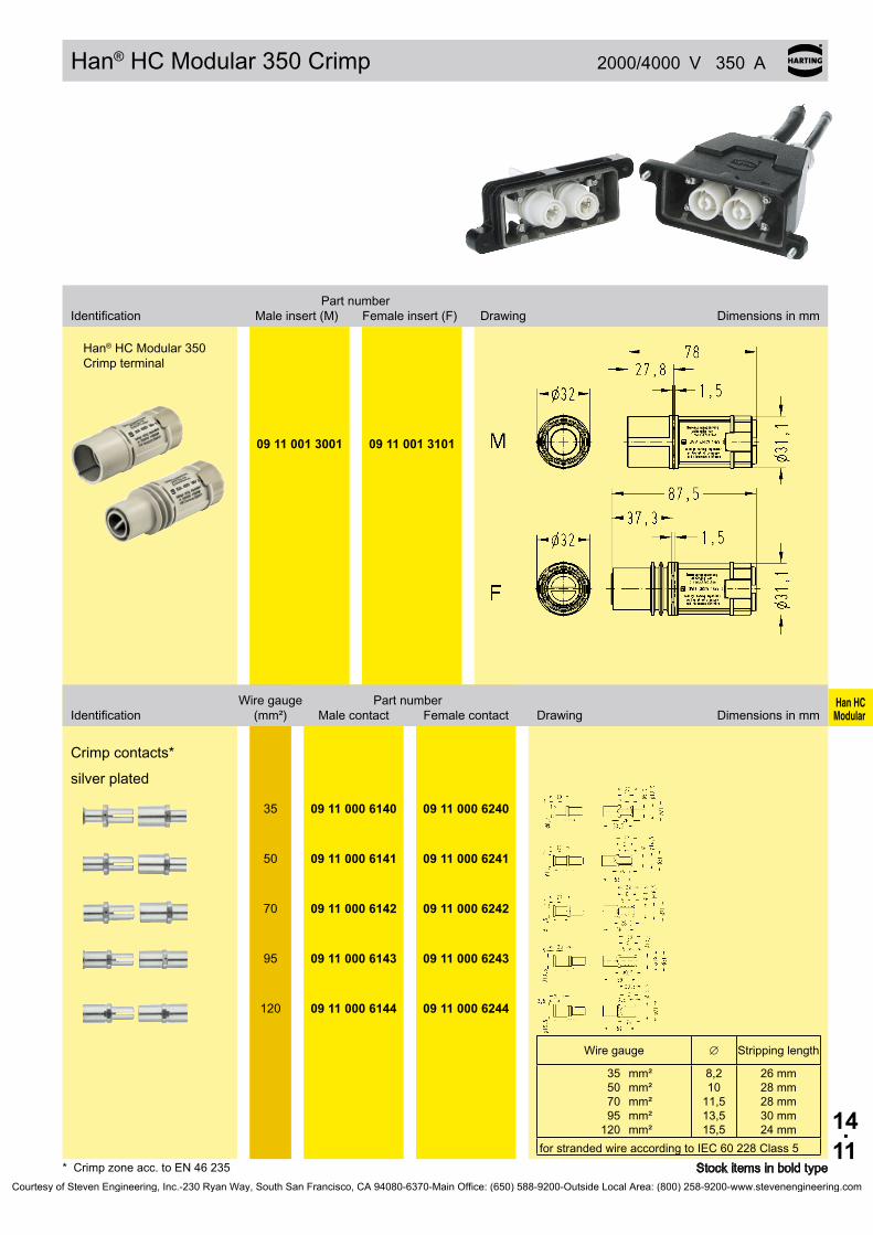
Han HC Modular
14.11
Han® HC Modular 350 Crimp 2000/4000 V 350 A
09 11 001 3001 09 11 001 3101
35 09 11 000 6140 09 11 000 6240
50 09 11 000 6141 09 11 000 6241
70 09 11 000 6142 09 11 000 6242
95 09 11 000 6143 09 11 000 6243
120 09 11 000 6144 09 11 000 6244
∅
35507095
120
mm²mm²mm²mm²mm²
26 mm28mm28mm30 mm24 mm
Stockitemsinboldtype* Crimp zone acc. to EN 46 235
Part number Identification Maleinsert(M) Femaleinsert(F) Drawing Dimensionsinmm
Han® HC Modular 350 Crimp terminal
Wiregauge Partnumber Identification (mm²) Malecontact Femalecontact Drawing Dimensionsinmm
Crimp contacts*
silver plated
Wiregauge Stripping length
8,210
11,513,515,5
forstrandedwireaccordingtoIEC60228Class5
Courtesy of Steven Engineering, Inc.-230 Ryan Way, South San Francisco, CA 94080-6370-Main Office: (650) 588-9200-Outside Local Area: (800) 258-9200-www.stevenengineering.com

Han HC Modular
14.12
Han® HC Modular 350 2000 V
1 pole
09 11 000 9951
Hoods Han® HPR 6 B
25 32
19 40 006 0411 19 40 006 0412
Housings,bulk-head mounting Han® HPR 6 B
– 09 40 006 0311
4 poles
09 11 000 9954
Hoods Han®M48B
4 x 25 19 37 048 0401
4 poles
09 11 000 9955
Housings,bulk-head mounting Han®M48B
– 09 37 048 0301
Frame Part number Hoods/Housings M Part number
StockitemsinboldtypeCourtesy of Steven Engineering, Inc.-230 Ryan Way, South San Francisco, CA 94080-6370-Main Office: (650) 588-9200-Outside Local Area: (800) 258-9200-www.stevenengineering.com
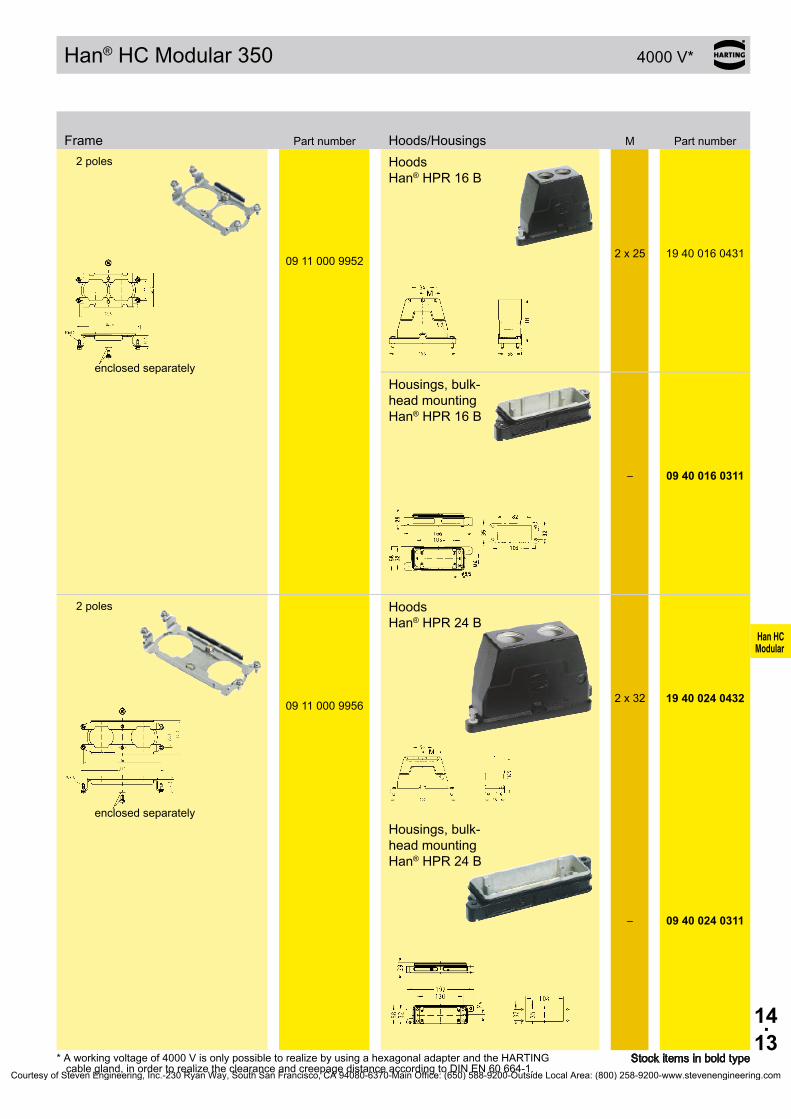
Han HC Modular
14.13
Han® HC Modular 350 4000 V*
2 poles
09 11 000 9952
Hoods Han® HPR 16 B
2 x 25 19400160431
enclosed separatelyHousings,bulk-head mounting Han® HPR 16 B
– 09 40 016 0311
2 poles
09 11 000 9956
Hoods Han® HPR 24 B
2 x 32 19 40 024 0432
enclosed separatelyHousings,bulk-head mounting Han® HPR 24 B
– 09 40 024 0311
Frame Part number Hoods/Housings M Part number
*Aworkingvoltageof4000VisonlypossibletorealizebyusingahexagonaladapterandtheHARTINGcable gland, in order to realize the clearance and creepage distance according to DIN EN 60 664-1.
StockitemsinboldtypeCourtesy of Steven Engineering, Inc.-230 Ryan Way, South San Francisco, CA 94080-6370-Main Office: (650) 588-9200-Outside Local Area: (800) 258-9200-www.stevenengineering.com

Han HC Modular
14.14
Han® HC Modular 350 4000 V*
3 poles
09 11 000 9963
Hoods Han® HPR 24 B
3 x 25 19 40 024 0461
enclosed separatelyHoods Han® HPR 24 B
3 x 32 19 40 024 0467
Housings,bulk-head mounting Han® HPR 24 B – 09 40 024 0311
Drawingseepage14.09
Housings, sur-face mounting Han® HPR 24 Bhorizontal version
3 x 25 19 40 024 0931
Housings, sur-face mounting Han® HPR 24 Bstraight version
3 x 25 19 40 024 1231
Frame Part number Hoods/Housings M Part number
*Aworkingvoltageof4000VisonlypossibletorealizebyusingahexagonaladapterandtheHARTINGcable gland, in order to realize the clearance and creepage distance according to DIN EN 60 664-1.
StockitemsinboldtypeCourtesy of Steven Engineering, Inc.-230 Ryan Way, South San Francisco, CA 94080-6370-Main Office: (650) 588-9200-Outside Local Area: (800) 258-9200-www.stevenengineering.com

Han HC Modular
14.15
Han® HC Modular 350 enlarged 4000 V
09 11 000 9957
09 11 000 9958
3x 32 19 40 024 0468
3x 32 19 40 024 0968
09 40 024 0368
*Aworkingvoltageof4000VisonlypossibletorealizebyusingahexagonaladapterandtheHARTINGcable gland, in order to realize the clearance and creepage distance according to DIN EN 60 664-1.
Stockitemsinboldtype
Frame Part number Hoods/Housings M Part number3 poles, male
3 poles, female
Hoods* Han® 24 HPR enlarged
Housings, surface mounting Han® 24 HPR enlarged, horizontal version
Requiredhousing,bulkheadmounting,09400240368notincluded,mustbeordered separately
Housings,bulkheadmounting Han® 24 HPR enlarged
Courtesy of Steven Engineering, Inc.-230 Ryan Way, South San Francisco, CA 94080-6370-Main Office: (650) 588-9200-Outside Local Area: (800) 258-9200-www.stevenengineering.com

Han HC Modular
14.16
Han® HC Modular 350 enlarged 4000 V
09 11 000 9964
09 11 000 9965
4x 25 19 40 024 0478
4x 25 19 40 024 0978
09 40 024 0368
Frame Part number Hoods/Housings M Part number4 poles, male
4 poles, female
Hoods* Han® 24 HPR enlarged
Housings, surface mounting Han® 24 HPR enlarged, horizontal version
Requiredhousing,bulkheadmounting,09400240368notincluded,mustbeordered separately
Housings,bulkheadmounting Han® 24 HPR enlarged
*Aworkingvoltageof4000VisonlypossibletorealizebyusingahexagonaladapterandtheHARTINGcable gland, in order to realize the clearance and creepage distance according to DIN EN 60 664-1.
StockitemsinboldtypeCourtesy of Steven Engineering, Inc.-230 Ryan Way, South San Francisco, CA 94080-6370-Main Office: (650) 588-9200-Outside Local Area: (800) 258-9200-www.stevenengineering.com
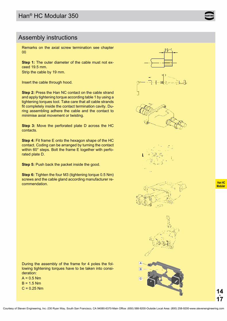
Han HC Modular
14.17
Han® HC Modular 350
Assembly instructionsRemarks on the axial screw termination see chapter00
Step 1: The outer diameter of the cable must not ex-ceed19.5mm.Stripthecableby19mm.
Insert the cable through hood.
Step 2: Press the Han NC contact on the cable strand and apply tightening torque according table 1 by using a tighteningtorquestool.Takecarethatallcablestrandsfitcompletelyinsidethecontactterminationcavity.Du-ring assembling adhere the cable and the contact to minimise axial movement or twisting.
Step 3: Move the perforated plate D across the HC contacts.
Step 4: Fit frame E onto the hexagon shape of the HC contact. Coding can be arranged by turning the contact within60°steps.BolttheframeEtogetherwithperfo-rated plate D.
Step 5: Pushbackthepacketinsidethegood.
Step 6: Tighten the four M3 (tightening torque 0.5 Nm) screws and the cable gland according manufacturer re-commendation.
During the assembly of the frame for 4 poles the fol-lowingtighteningtorqueshavetobetakenintoconsi-deration:A = 0.5 NmB = 1.5 NmC = 0.25 Nm
Courtesy of Steven Engineering, Inc.-230 Ryan Way, South San Francisco, CA 94080-6370-Main Office: (650) 588-9200-Outside Local Area: (800) 258-9200-www.stevenengineering.com
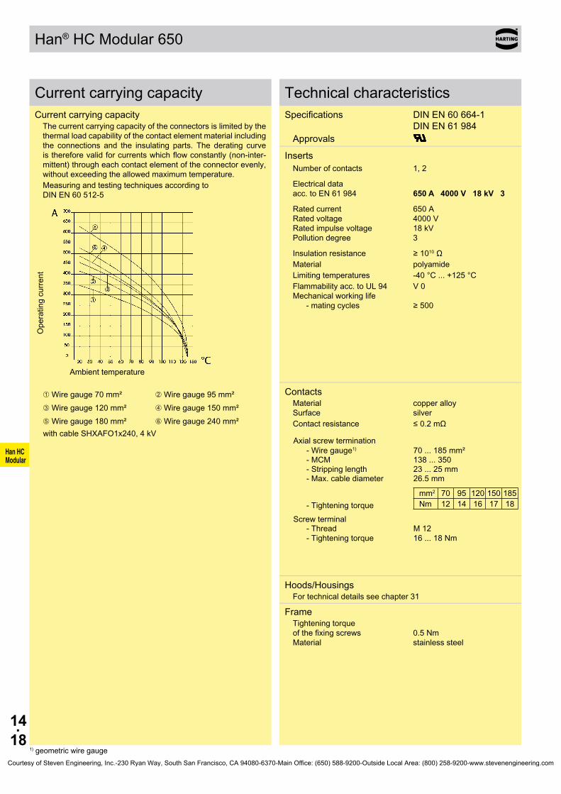
Han HC Modular
14.18
Han® HC Modular 650
Current carrying capacityCurrent carrying capacity
The current carrying capacity of the connectors is limited by the thermal load capability of the contact element material including the connections and the insulating parts. The derating curve isthereforevalidforcurrentswhichflowconstantly(non-inter-mittent) through each contact element of the connector evenly, without exceeding the allowed maximum temperature.Measuring and testing techniques according to DIN EN 60 512-5
Ope
ratin
g cu
rrent
Ambient temperature
➀Wiregauge70mm² ➁Wiregauge95mm²➂Wiregauge120mm² ➃Wiregauge150mm²➄Wiregauge180mm² ➅Wiregauge240mm²withcableSHXAFO1x240,4kV
Technical characteristicsSpecifications DINEN60664-1
DINEN61984Approvals
Inserts Number of contacts 1, 2
Electrical data acc.toEN61984 650 A 4000 V 18 kV 3
Rated current 650 A Rated voltage 4000 V Ratedimpulsevoltage 18kV Pollution degree 3
Insulationresistance ≥1010ΩMaterial polyamideLimitingtemperatures -40°C...+125°CFlammabilityacc.toUL94 V0Mechanicalworkinglife
-matingcycles ≥500
Contacts Material copper alloySurface silverContactresistance ≤0.2mΩ
Axial screw termination-Wiregauge1) 70...185mm²- MCM 138...350- Stripping length 23 ... 25 mm- Max. cable diameter 26.5 mm
- Tightening torquemm2 70 95 120 150 185Nm 12 14 16 17 18
Screw terminal- Thread - Tightening torque
M 12 16...18Nm
Hoods/HousingsFor technical details see chapter 31
FrameTightening torque ofthefixingscrews 0.5Nm Material stainless steel
1) geometric wire gaugeCourtesy of Steven Engineering, Inc.-230 Ryan Way, South San Francisco, CA 94080-6370-Main Office: (650) 588-9200-Outside Local Area: (800) 258-9200-www.stevenengineering.com

Han HC Modular
14.19
Han® HC Modular 650 4000 V 650 A
Stockitemsinboldtype
Modular High Current Connector System
Part numberWiregaugeIdentification Male contact Female contact Drawing Dimensions in mm
Contactswith screw terminal for housingbulkheadmounting
09 11 001 2675 09 11 001 2775 70...240mm²
Please ensure to hold up the contact with a wrench size 24 to apply the tightening torque
with axial screw terminal
09 11 001 2671 09 11 001 2672
09 11 001 2771 09 11 001 2772
70...120mm² 150...185mm²
min. length of wrench: 60 mm
Hexagonal driverAdapter(SW8)
09 99 000 0372
Courtesy of Steven Engineering, Inc.-230 Ryan Way, South San Francisco, CA 94080-6370-Main Office: (650) 588-9200-Outside Local Area: (800) 258-9200-www.stevenengineering.com

Han HC Modular
14.20
Han® HC Modular 650 Crimp
Features• Crimptermination• PlugcompatibletoHan® HC Modular 650 with axial
screw terminal• Contactinonepiece
Current carrying capacityThe current carrying capacity of the connectors is limited by the thermal load capability of the contact element material including the connections and the insulating parts. The derating curve isthereforevalidforcurrentswhichflowconstantly(non-inter-mittent) through each contact element of the connector evenly, without exceeding the allowed maximum temperature.Measuring and testing techniques according to DIN EN 60 512-5
Ope
ratin
g cu
rrent
Ambient temperature
➀wiregauge:240mm²
in a Han® 24 HPR hood/housing with 2 modules
Technical characteristicsSpecifications DINEN61984 DIN EN 60 664-1
InsertsNumber of contacts 1 or 2
Electrical data acc.toEN61984 without adapter 650 A 2000 V 12 kV 3 Rated current 650 A Rated voltage 2000 V Ratedimpulsevoltage 12kV Pollution degree 3
with adapter 650 A 4000 V 18 kV 3 Rated current 650 A Rated voltage 4000 V Ratedimpulsevoltage 18kV Pollution degree 3
Insulationresistance ≥1010Ω Material polyamide Limitingtemperatures -40°C...+125°C Flammabilityacc.toUL94 V0 Mechanicalworkinglife -matingcycles ≥500
ContactsMaterial copper alloy Surface - hard-silver plated 3 µm Ag Contactresistance ≤0,3mΩ Crimp terminal -mm² 240mm² Max. insulation diameter Pressingforcerequirement 130kN
Hoods/HousingsFor technical details see chapter 31
FrameTightening torque ofthefixingscrews 0,5Nm Material stainless steel
Courtesy of Steven Engineering, Inc.-230 Ryan Way, South San Francisco, CA 94080-6370-Main Office: (650) 588-9200-Outside Local Area: (800) 258-9200-www.stevenengineering.com

Han HC Modular
14.21
Han® HC Modular 650 Crimp 2000/4000 V 650 A
09 11 001 3011 09 11 001 3111
240 09 11 000 6167 09 11 000 6267
∅
240 mm² 46 mm
Stockitemsinboldtype* Crimp zone acc. to EN 46 235
Part number Identification Maleinsert(M) Femaleinsert(F) Drawing Dimensionsinmm
Han® HC Modular 650
Wiregauge Partnumber Identification (mm²) Malecontact Femalecontact Drawing Dimensionsinmm
Crimp contacts*
silver plated
Additional wire gauges ranges on request
Wiregauge Stripping length
22,5forstrandedwireaccordingtoIEC60228Class5
Courtesy of Steven Engineering, Inc.-230 Ryan Way, South San Francisco, CA 94080-6370-Main Office: (650) 588-9200-Outside Local Area: (800) 258-9200-www.stevenengineering.com
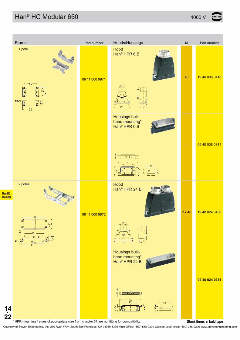
Han HC Modular
14.22
Han® HC Modular 650 4000 V
1 pole
09 11 000 9971
Hood Han® HPR 6 B
40 19 40 006 0418
Housingsbulk-head mounting* Han® HPR 6 B
– 09 40 006 0314
2 poles
09 11 000 9972
Hood Han® HPR 24 B
2 x 40 19 40 024 0438
Housingsbulk-head mounting* Han® HPR 24 B
– 09 40 024 0311
Frame Part number Hoods/Housings M Part number
*HPRmountingframesofappropriatesizefromchapter31arenotfittingforcompatibility StockitemsinboldtypeCourtesy of Steven Engineering, Inc.-230 Ryan Way, South San Francisco, CA 94080-6370-Main Office: (650) 588-9200-Outside Local Area: (800) 258-9200-www.stevenengineering.com

Han HC Modular
14.23
Han® HC Modular 650 enlarged 4000 V
09 11 000 9973
09 11 000 9974
3x 32 19 40 024 0468
3x 32 19 40 024 0968
09 40 024 0368
Frame Part number Hoods/Housings M Part number3 pins, male
3 pins, female
Hoods** Han® 24 HPR enlarged
Housings, surface mounting** Han® 24 HPR enlarged, horizontal version
Requiredhousing,bulkheadmounting,09400240368notincluded,mustbeordered separately
Housings,bulkheadmounting* Han® 24 HPR enlarged
*Aworkingvoltageof4000VisonlypossibletorealizebyusingahexagonaladapterandtheHARTINGcable gland, in order to realize the clearance and creepage distance according to DIN EN 60 664-1.
StockitemsinboldtypeCourtesy of Steven Engineering, Inc.-230 Ryan Way, South San Francisco, CA 94080-6370-Main Office: (650) 588-9200-Outside Local Area: (800) 258-9200-www.stevenengineering.com
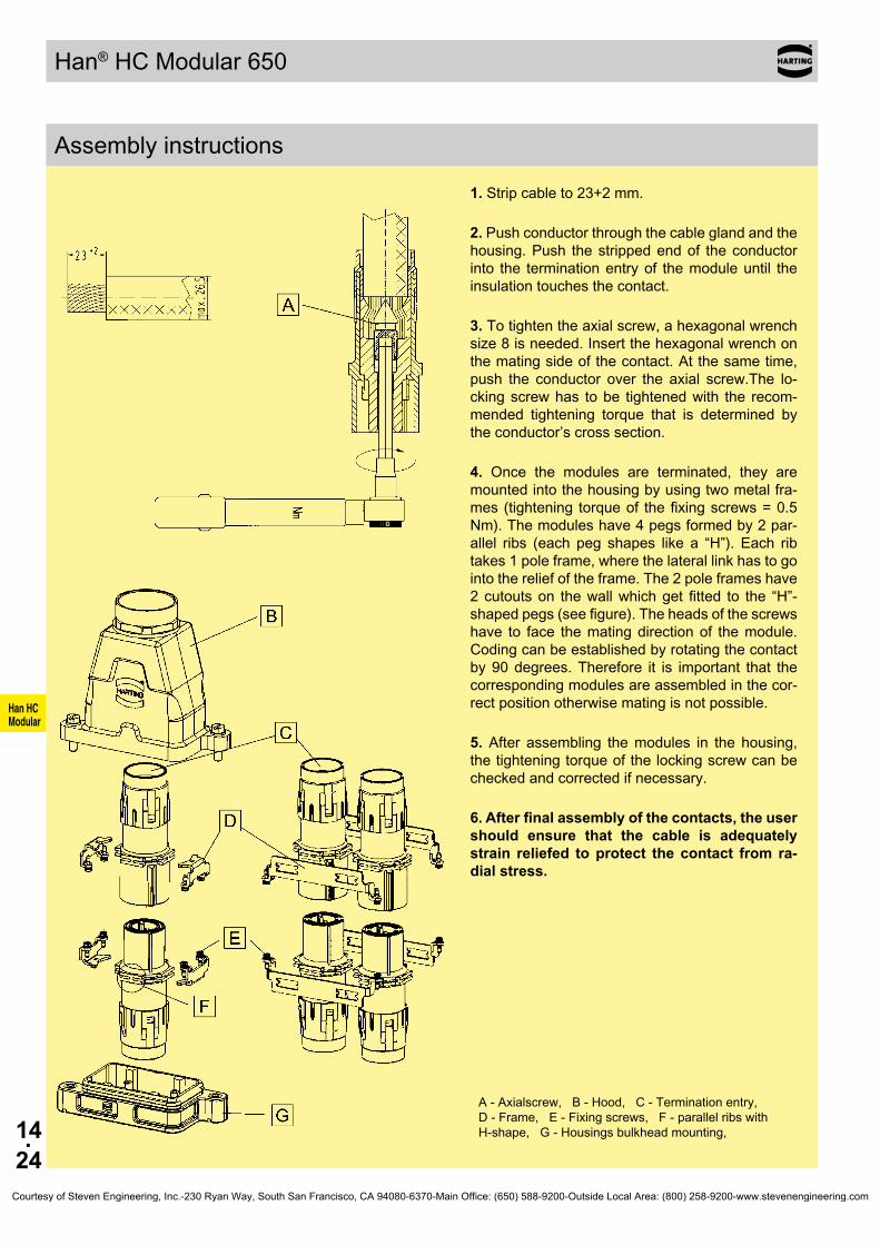
Han HC Modular
14.24
Han® HC Modular 650
Assembly instructions
1. Strip cable to 23+2 mm.
2. Push conductor through the cable gland and the housing. Push the stripped end of the conductor into the termination entry of the module until the insulation touches the contact.
3. To tighten the axial screw, a hexagonal wrench size8isneeded.Insertthehexagonalwrenchonthe mating side of the contact. At the same time, push the conductor over the axial screw.The lo-ckingscrewhas tobe tightenedwith the recom-mended tightening torque that is determined by the conductor’s cross section.
4. Once the modules are terminated, they are mounted into the housing by using two metal fra-mes(tightening torqueof thefixingscrews=0.5Nm). The modules have 4 pegs formed by 2 par-allel ribs (each peg shapes like a “H”). Each ribtakes1poleframe,wherethelaterallinkhastogointo the relief of the frame. The 2 pole frames have 2cutoutson thewallwhichget fitted to the “H”-shapedpegs(seefigure).Theheadsofthescrewshave to face the mating direction of the module. Coding can be established by rotating the contact by90degrees.Therefore it is important that thecorresponding modules are assembled in the cor-rect position otherwise mating is not possible.
5. After assembling the modules in the housing, thetighteningtorqueofthelockingscrewcanbecheckedandcorrectedifnecessary.
6. After final assembly of the contacts, the user should ensure that the cable is adequately strain reliefed to protect the contact from ra-dial stress.
A - Axialscrew, B - Hood, C - Termination entry, D - Frame, E - Fixing screws, F - parallel ribs with H-shape,G-Housingsbulkheadmounting,
Courtesy of Steven Engineering, Inc.-230 Ryan Way, South San Francisco, CA 94080-6370-Main Office: (650) 588-9200-Outside Local Area: (800) 258-9200-www.stevenengineering.com
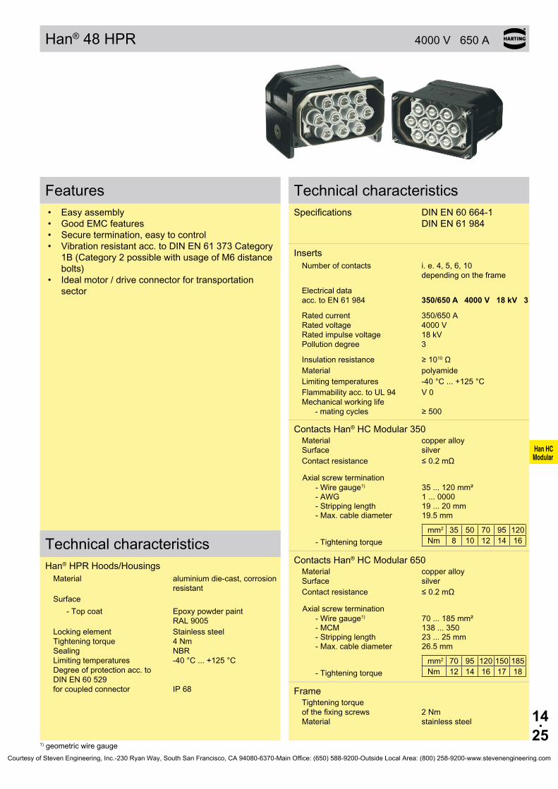
Han HC Modular
14.25
Han®48HPR 4000 V 650 A
Features• Easy assembly• GoodEMCfeatures• Secure termination, easy to control• Vibrationresistantacc.toDINEN61373Category
1B (Category 2 possible with usage of M6 distance bolts)
• Ideal motor / drive connector for transportation sector
Technical characteristicsSpecifications DINEN60664-1
DINEN61984
Inserts Number of contacts i. e. 4, 5, 6, 10
depending on the frame
Electrical data acc.toEN61984 350/650 A 4000 V 18 kV 3
Rated current 350/650 A Rated voltage 4000 V Ratedimpulsevoltage 18kV Pollution degree 3
Insulationresistance ≥1010ΩMaterial polyamideLimitingtemperatures -40°C...+125°CFlammabilityacc.toUL94 V0Mechanicalworkinglife
-matingcycles ≥500
Contacts Han® HC Modular 350 Material copper alloySurface silverContactresistance ≤0.2mΩ
Axial screw termination-Wiregauge1) 35...120mm²-AWG 1 ... 0000- Stripping length 19...20mm- Max. cable diameter 19.5mm
- Tightening torquemm2 35 50 70 95 120Nm 8 10 12 14 16
Contacts Han® HC Modular 650 Material copper alloySurface silverContactresistance ≤0.2mΩ
Axial screw termination-Wiregauge1) 70...185mm²- MCM 138...350- Stripping length 23 ... 25 mm- Max. cable diameter 26.5 mm
- Tightening torquemm2 70 95 120 150 185Nm 12 14 16 17 18
FrameTightening torque ofthefixingscrews 2Nm Material stainless steel
Technical characteristicsHan® HPR Hoods/Housings
Material aluminium die-cast, corrosion resistant
Surface- Top coat Epoxy powder paint
RAL9005Lockingelement Stainlesssteel Tightening torque 4 Nm Sealing NBR Limitingtemperatures -40°C...+125°C Degree of protection acc. to DINEN60529 forcoupledconnector IP68
1) geometric wire gaugeCourtesy of Steven Engineering, Inc.-230 Ryan Way, South San Francisco, CA 94080-6370-Main Office: (650) 588-9200-Outside Local Area: (800) 258-9200-www.stevenengineering.com

Han HC Modular
14.26
Han®48HPR Hoods/Housings
Stockitemsinboldtype
Identification Part number Drawing Dimensions in mm
Hoods
09 40 048 0451
Housings, surface mounting
09 40 048 0951
Housings,bulkheadmounting
09 40 048 0311
Panel cut out
Housings,bulkheadmountingfor 4 inserts size 16 B
09 40 048 0331
Panel cut out
Protection covers
09 40 048 5401
Courtesy of Steven Engineering, Inc.-230 Ryan Way, South San Francisco, CA 94080-6370-Main Office: (650) 588-9200-Outside Local Area: (800) 258-9200-www.stevenengineering.com
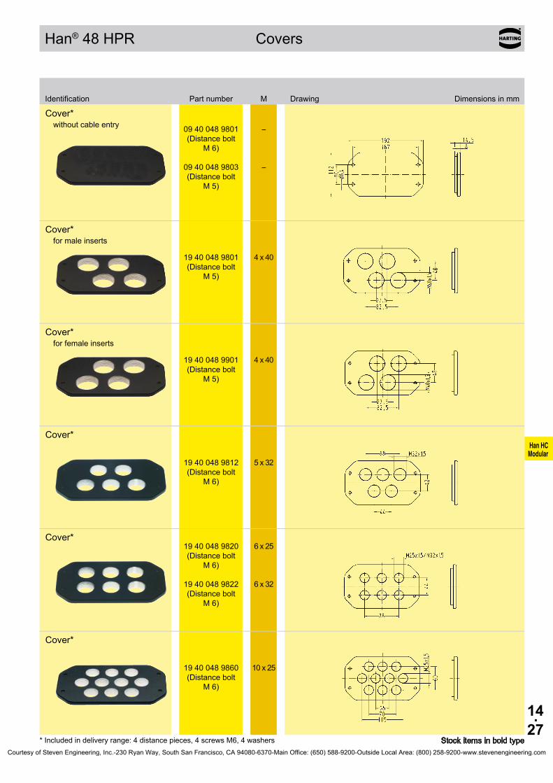
Han HC Modular
14.27
Han®48HPR Covers
Stockitemsinboldtype* Included in delivery range: 4 distance pieces, 4 screws M6, 4 washers
Identification Part number M Drawing Dimensions in mm
Cover*without cable entry
09 40 048 9801 (Distance bolt
M 6)
09 40 048 9803 (Distance bolt
M 5)
– –
Cover*for male inserts
19 40 048 9801 (Distance bolt
M 5)
4 x 40
Cover*for female inserts
19 40 048 9901 (Distance bolt
M 5)
4 x 40
Cover*
19 40 048 9812 (Distance bolt
M 6)
5 x 32
Cover* 19 40 048 9820 (Distance bolt
M 6)
19 40 048 9822 (Distance bolt
M 6)
6 x 25
6 x 32
Cover*
19 40 048 9860 (Distance bolt
M 6)
10 x 25
Courtesy of Steven Engineering, Inc.-230 Ryan Way, South San Francisco, CA 94080-6370-Main Office: (650) 588-9200-Outside Local Area: (800) 258-9200-www.stevenengineering.com

Han HC Modular
14.28
IdentificationPart number
male female
Framefor 4 inserts size 16 B
suitable for hoods and surface mounted nousings (p. 14.16) inconjunctionwithcover09400489803/ 19400489801/19400489901only
09 40 048 9912
09 40 048 9912
Framefor 4 x HC 350 contacts + 2 x Han® Q 5/0
09 40 048 9810
09 40 048 9910
Framefor 4 x HC 650 contacts + 2 x Han® Q 5/0
09 40 048 9811
09 40 048 9911
Framefor 6 x HC 350 contacts
09 40 048 9806
09 40 048 9906
Framefor 4 x HC 350 contacts + PE
09 40 048 9809
09 40 048 9909
Framefor 10 x HC 350 contacts
09 40 048 9860
09 40 048 9960
Han®48HPR Frame
StockitemsinboldtypeCourtesy of Steven Engineering, Inc.-230 Ryan Way, South San Francisco, CA 94080-6370-Main Office: (650) 588-9200-Outside Local Area: (800) 258-9200-www.stevenengineering.com

15.01
Han-Power®
Power Distribution
ContentsHan-Power® S with 1x Han® Q 4/2 . . . . . . . . . . . . . . . . . . . . . . . . . . . . . . . 15.02
Han-Power® S with 2x Han® Q 4/2 . . . . . . . . . . . . . . . . . . . . . . . . . . . . . . . 15.04
Han-Power® S with 1x Han® Q 8/0 . . . . . . . . . . . . . . . . . . . . . . . . . . . . . . . 15.06
Han-Power® S with 2x Han® Q 8/0 . . . . . . . . . . . . . . . . . . . . . . . . . . . . . . . 15.08
Han-Power® S with 1x Han® Q 4/2, metal . . . . . . . . . . . . . . . . . . . . . . . . . . 15.10
Han-Power® T with 3x Han® Q 4/2 . . . . . . . . . . . . . . . . . . . . . . . . . . . . . . . 15.12
Han-Power® T with 3x Han-Modular® Twin . . . . . . . . . . . . . . . . . . . . . . . . . 15.14
Han-Power® T with 3x Han® Q 2/0 . . . . . . . . . . . . . . . . . . . . . . . . . . . . . . . 15.16
Han-Power® T with 3x Han® Q 5/0 . . . . . . . . . . . . . . . . . . . . . . . . . . . . . . . 15.18
Han® Q 4/2 . . . . . . . . . . . . . . . . . . . . . . . . . . . . . . . . . . . . . . . . . . . . . . . . . 15.20
Han® Q 8/0 . . . . . . . . . . . . . . . . . . . . . . . . . . . . . . . . . . . . . . . . . . . . . . . . . 15.22
Han® Q 5/0 . . . . . . . . . . . . . . . . . . . . . . . . . . . . . . . . . . . . . . . . . . . . . . . . . 15.24
Han® Q 2/0 . . . . . . . . . . . . . . . . . . . . . . . . . . . . . . . . . . . . . . . . . . . . . . . . . 15.26
Hoods/Housings Han-Compact® . . . . . . . . . . . . . . . . . . . . . . . . . . . . . . . . . 15.28
Han-Power® Accessories . . . . . . . . . . . . . . . . . . . . . . . . . . . . . . . . . . . . . . 15.34
Page
Courtesy of Steven Engineering, Inc.-230 Ryan Way, South San Francisco, CA 94080-6370-Main Office: (650) 588-9200-Outside Local Area: (800) 258-9200-www.stevenengineering.com

15.02
Power Distribution
Han-Power® S with 1x Han® Q 4/2
Features• 6IDCs+PEfor2.5mm²upto6mm²wiregauge• Nointeruptionoftheenergysupply• Space-savingandcompactdesign• Leadingprotectivegroundwithintheinsert• Assemblywithstandardtools
DescriptionThe Han-Power®Sconnectorissuitablefortheassemblyofserialpowerbus.HavingassembledtheenergysupplyHan-Power®Scanbeinsertedatanyplaceofthepowercable.Thecablemantlehastoberemoved,theconductorisplacedwithoutinterruptionintheIDC. Han-Power®Sissuitableforcableswithsinglestrandsmanuf-acturedacc.toDINVDE0281/DINEN60228withwiregau-gesof2.5mm²upto6mm².ForthedistributionofthedeviceHan-Compact®hoodsorcabletocablehousingsareused. ThispowersupplyhastoberealizedwithoneHan-Compact® cabletocablehood.
CurrentcarryingcapacityThecurrentcarryingcapacityoftheconnectorsislimitedbythethermalloadcapabilityofthecontactelementmaterialincludingtheconnectionsandtheinsulatingparts.Thederatingcurveisthereforevalidforcurrentswhichflowconstantly(non-inter-mittent)througheachcontactelementoftheconnectorevenly,withoutexceedingtheallowedmaximumtemperature.Measuringandtestingtechniquesaccordingto DINEN60512-5
Operatingcurre
nt
Ambienttemperature
➀Han®Q4/2Wiregauge:4mm²
➁Han®Q4/2Wiregauge:6mm²
Han®Q4/2fullyloaded withwiregauge4x6mm²
TechnicalcharacteristicsSpecifications DINEN61984 DINEN60664-1
Han-Power® SNumberofcontacts -Powercontacts 4+PE -Signalcontacts 2 Electricaldata acc.toEN61984 Powerside 40 A 400/690 V 6 kV 3 Ratedcurrent 40A Ratedvoltageconductor-ground 400V Ratedvoltageconductor-conductor690V Ratedimpulsevoltage 6kV Pollutiondegree 3 Signalside 10 A 250 V 4 kV 3 Ratedcurrent 10A Ratedvoltage 250V Ratedimpulsevoltage 4kV Pollutiondegree 3
Ratedvoltage acc.toUL/CSA 600/250V Insulationresistance ≥1010kΩ Material polycarbonate Limitingtemperatures -40°C...+125°C Flammabilityacc.toUL94 V0 Mechanicalworkinglife -matingcycles ≥500 Degreeofprotectionacc.toDINEN60529 IP65
ContactsMaterial copperalloy Surface -hard-silverplated 3µmAg -hard-goldplated 2µmAuover3µmNi Contactresistance ≤0.3mΩ Crimpterminal -mm² 2.5...6mm²/ 0.14...2.5mm² -AWG 14...10/26...14 Max.insulationdiameter -Powercontacts 5mm
CablesDesignofconductoracc.to DINVDE0281 DINEN60228 Singlestrand Wiregauge 2.5mm² -Numberofsinglestrands 50x0.25mm∅ -Outerdiameter 3.6mm Wiregauge 4mm² -Numberofsinglestrands 56x0.3mm∅ -Outerdiameter 4.2mm Wiregauge 6mm² -Numberofsinglestrands 84x0.3mm∅ -Outerdiameter 4.8mm
Courtesy of Steven Engineering, Inc.-230 Ryan Way, South San Francisco, CA 94080-6370-Main Office: (650) 588-9200-Outside Local Area: (800) 258-9200-www.stevenengineering.com

15.03
Han-Power® S 400/690/250 V40/10 A
09 12 008 4804
09 12 008 4806
20 88 641 1015 20 88 641 1030 20 88 641 1050 20 88 641 1100 20 88 641 1150 20 88 641 1300
Power Distribution
Stockitemsinboldtype
with 1x Han® Q 4/2
Identification Partnumber Drawing Dimensionsinmm
Han-Power® SPowersupply Han®Q4/2;1moulded Han-Compact®Hoods 2.5-4mm²
4-6mm²
Identification Partnumber Drawing Dimensionsinmm
SystemcablesinfixedlengthsCablelengths(totallength)inm pre-assembledonbothsides plastichood,black topentry cabletocablehoodwithmaleinsertandhoodwithfemaleinsert cable:5x4mm²
1.5 3 5 10 15 30
male female
totallength
Courtesy of Steven Engineering, Inc.-230 Ryan Way, South San Francisco, CA 94080-6370-Main Office: (650) 588-9200-Outside Local Area: (800) 258-9200-www.stevenengineering.com

15.04
Power Distribution
Han-Power® S with 2x Han® Q 4/2
Features• 6IDCs+PEfor4mm²upto6mm²wiregauge• Nointeruptionoftheenergysupply• Space-savingandcompactdesign• Leadingprotectivegroundwithintheinsert• Assemblywithstandardtools
DescriptionThe Han-Power®Sconnectorissuitablefortheassemblyofserialpowerbus.HavingassembledtheenergysupplyHan-Power®Scanbeinsertedatanyplaceofthepowercable.Thecablemantlehastoberemoved,theconductorisplacedwithoutinterruptionintheIDC. Han-Power®Sissuitableforcableswithsinglestrandsmanuf-acturedacc.toDINVDE0281/DINEN60228withwiregau-gesof2.5mm²upto6mm².ForthedistributionofthedeviceHan-Compact®hoodsorcabletocablehousingsareused. ThispowersupplyhastoberealizedwithoneHan-Compact® hood.
CurrentcarryingcapacityThecurrentcarryingcapacityoftheconnectorsislimitedbythethermalloadcapabilityofthecontactelementmaterialincludingtheconnectionsandtheinsulatingparts.Thederatingcurveisthereforevalidforcurrentswhichflowconstantly(non-inter-mittent)througheachcontactelementoftheconnectorevenly,withoutexceedingtheallowedmaximumtemperature.Measuringandtestingtechniquesaccordingto DINEN60512-5
Operatingcurre
nt
Ambienttemperature
➀Han®Q4/2Wiregauge:4mm²
➁Han®Q4/2Wiregauge:6mm²
Han®Q4/2fullyloaded withwiregauge4x6mm²
TechnicalcharacteristicsSpecifications DINEN61984 DINEN60664-1
Han-Power® SNumberofcontacts -Powercontacts 4+PE -Signalcontacts 2 Electricaldata acc.toEN61984 Powerside 40 A 400/690 V 6 kV 3 Ratedcurrent 40A Ratedvoltageconductor-ground 400V Ratedvoltageconductor-conductor690V Ratedimpulsevoltage 6kV Pollutiondegree 3 Signalside 10 A 250 V 4 kV 3 Ratedcurrent 10A Ratedvoltage 250V Ratedimpulsevoltage 4kV Pollutiondegree 3
Ratedvoltage acc.toUL/CSA 600/250V Insulationresistance ≥1010kΩ Material polycarbonate Limitingtemperatures -40°C...+125°C Flammabilityacc.toUL94 V0 Mechanicalworkinglife -matingcycles ≥500 Degreeofprotectionacc.toDINEN60529 IP65
ContactsMaterial copperalloy Surface -hard-silverplated 3µmAg -hard-goldplated 2µmAuover3µmNi Contactresistance ≤0.3mΩ Crimpterminal -mm² 4...6mm²/ 0.14...2.5mm² -AWG 14...10/26...14 Max.insulationdiameter -Powercontacts 5mm
CablesDesignofconductoracc.to DINVDE0281 DINEN60228 Singlestrand Wiregauge 4mm² -Numberofsinglestrands 56x0.3mm∅ -Outerdiameter 4.2mm Wiregauge 6mm² -Numberofsinglestrands 84x0.3mm∅ -Outerdiameter 4.8mm
Courtesy of Steven Engineering, Inc.-230 Ryan Way, South San Francisco, CA 94080-6370-Main Office: (650) 588-9200-Outside Local Area: (800) 258-9200-www.stevenengineering.com
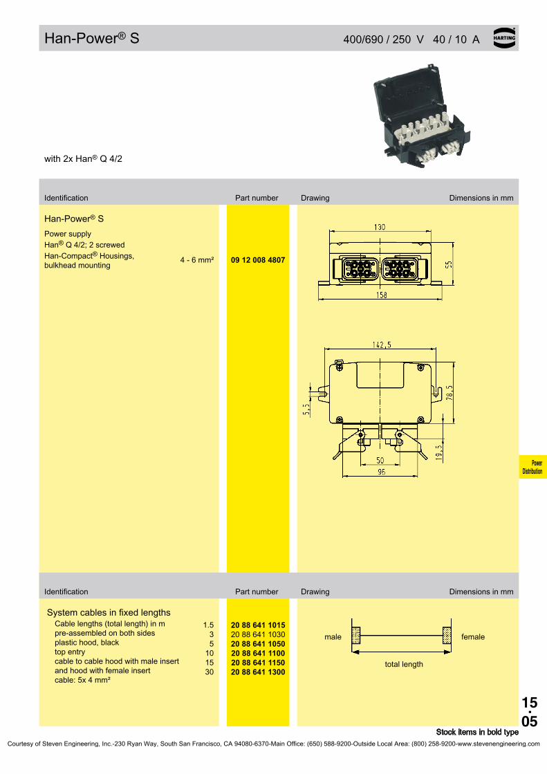
15.05
Han-Power® S 400/690/250 V40/10 A
09 12 008 4807
20 88 641 1015 20 88 641 1030 20 88 641 1050 20 88 641 1100 20 88 641 1150 20 88 641 1300
Power Distribution
Stockitemsinboldtype
with 2x Han® Q 4/2
Identification Partnumber Drawing Dimensionsinmm
Han-Power® SPowersupply Han®Q4/2;2screwed Han-Compact®Housings,bulkheadmounting 4-6mm²
Identification Partnumber Drawing Dimensionsinmm
SystemcablesinfixedlengthsCablelengths(totallength)inm pre-assembledonbothsides plastichood,black topentry cabletocablehoodwithmaleinsertandhoodwithfemaleinsert cable:5x4mm²
1.5 3 5 10 15 30
male female
totallength
Courtesy of Steven Engineering, Inc.-230 Ryan Way, South San Francisco, CA 94080-6370-Main Office: (650) 588-9200-Outside Local Area: (800) 258-9200-www.stevenengineering.com

15.06
Power Distribution
Han-Power® S with 1x Han®Q8/0
Features• 6IDCs+PEfor2.5mm²upto6mm²wiregauge• Nointeruptionoftheenergysupply• Space-savingandcompactdesign• Leadingprotectivegroundwithintheinsert• Assemblywithstandardtools
DescriptionThe Han-Power®Sconnectorissuitablefortheassemblyofserialpowerbus.HavingassembledtheenergysupplyHan-Power®Scanbeinsertedatanyplaceofthepowercable.Thecablemantlehastoberemoved,theconductorisplacedwithoutinterruptionintheIDC. Han-Power®Sissuitableforcableswithsinglestrandsmanuf-acturedacc.toDINVDE0281/DINEN60228withwiregau-gesof2.5mm²upto6mm².ForthedistributionofthedeviceHan-Compact®hoodsorcabletocablehousingsareused. ThispowersupplyhastoberealizedwithoneHan-Compact® cabletocablehood.
CurrentcarryingcapacityThecurrentcarryingcapacityoftheconnectorsislimitedbythethermalloadcapabilityofthecontactelementmaterialincludingtheconnectionsandtheinsulatingparts.Thederatingcurveisthereforevalidforcurrentswhichflowconstantly(non-inter-mittent)througheachcontactelementoftheconnectorevenly,withoutexceedingtheallowedmaximumtemperature.Measuringandtestingtechniquesaccordingto DINEN60512-5
Operatingcurre
nt
Ambienttemperature
➀Han®Q4/2Wiregauge:2.5mm²➁Han®Q4/2Wiregauge:4mm²➁Han®Q4/2Wiregauge:6mm²
Han®Q8/0partlyloaded withwiregauge7x4mm²
TechnicalcharacteristicsSpecifications DINEN61984 DINEN60664-1
Han-Power® SNumberofcontacts -Powercontacts 6+PE Electricaldata acc.toEN61984 25 A 500 V 6 kV 3 Ratedcurrent 25A Ratedvoltage 500V Ratedimpulsevoltage 6kV Pollutiondegree 3
Ratedvoltage acc.toUL/CSA 600V Insulationresistance ≥1010kΩ Material polycarbonate Limitingtemperatures -40°C...+125°C Flammabilityacc.toUL94 V0 Mechanicalworkinglife -matingcycles ≥500 Degreeofprotectionacc.toDINEN60529 IP65
ContactsMaterial copperalloy Surface -hard-silverplated 3µmAg Contactresistance ≤1mΩ Crimpterminal -mm² 2.5...6mm² -AWG 14...10
CablesDesignofconductoracc.to DINVDE0281 DINEN60228 Singlestrand Wiregauge 2.5mm² -Numberofsinglestrands 50x0.25mm∅ -Outerdiameter 3.6mm Wiregauge 4mm² -Numberofsinglestrands 56x0.3mm∅ -Outerdiameter 4.2mm Wiregauge 6mm² -Numberofsinglestrands 84x0.3mm∅ -Outerdiameter 4.8mm
Courtesy of Steven Engineering, Inc.-230 Ryan Way, South San Francisco, CA 94080-6370-Main Office: (650) 588-9200-Outside Local Area: (800) 258-9200-www.stevenengineering.com

15.07
Han-Power® S 500 V25 A
09 12 008 4801
09 12 008 4811
20 88 841 0015 20 88 841 0030 20 88 841 0050 20 88 841 0100 20 88 841 0150 20 88 841 0300
Power Distribution
Stockitemsinboldtype
with 1x Han®Q8/0
Identification Partnumber Drawing Dimensionsinmm
Han-Power® SPowersupply Han®Q8/0;1moulded Han-Compact®Hoods 2.5-4mm²
4-6mm²
Identification Partnumber Drawing Dimensionsinmm
SystemcablesinfixedlengthsCablelengths(totallength)inm pre-assembledonbothsides plastichood,black topentry cabletocablehoodwithmaleinsertandhoodwithfemaleinsert cable:7x2.5mm²
1.5 3 5 10 15 30
male female
totallength
Courtesy of Steven Engineering, Inc.-230 Ryan Way, South San Francisco, CA 94080-6370-Main Office: (650) 588-9200-Outside Local Area: (800) 258-9200-www.stevenengineering.com
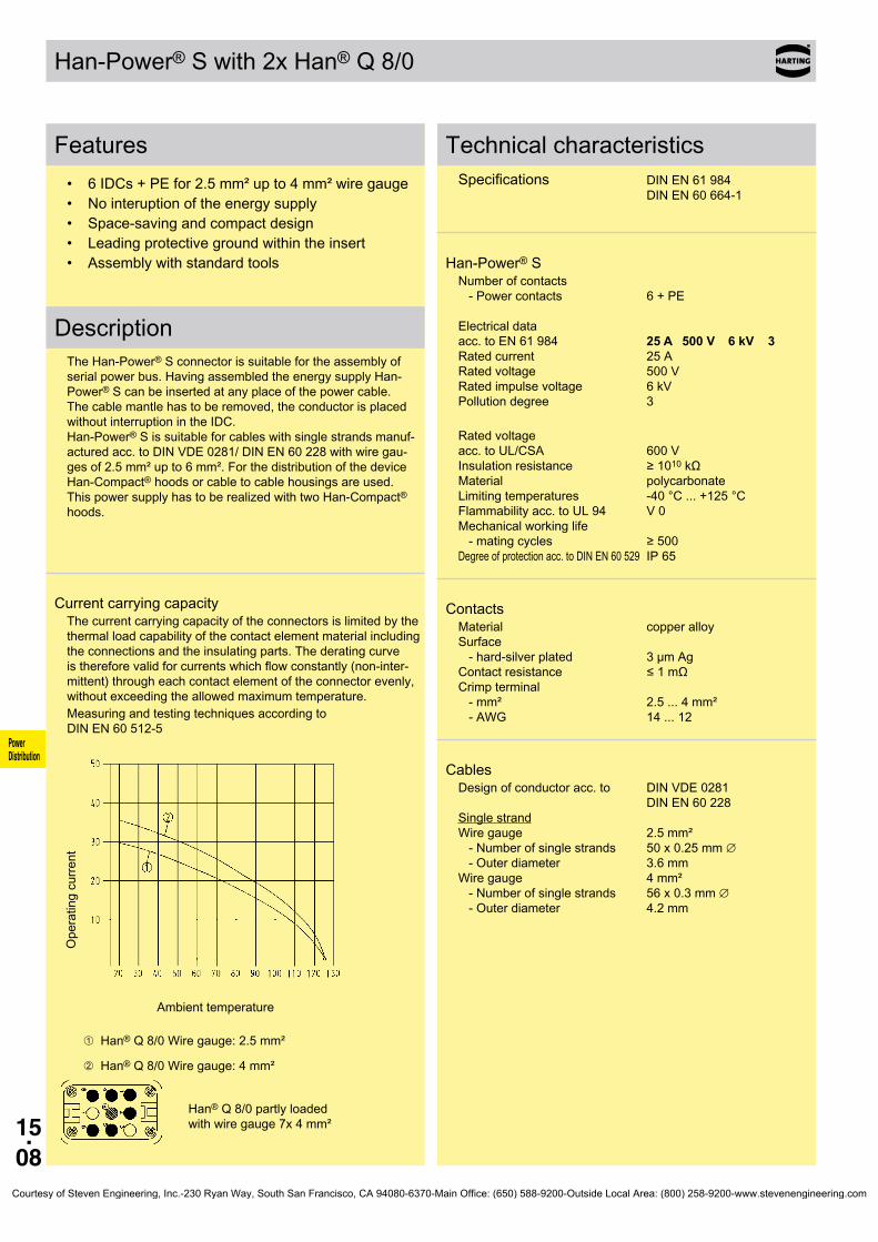
15.08
Power Distribution
Han-Power® S with 2x Han®Q8/0
Features• 6IDCs+PEfor2.5mm²upto4mm²wiregauge• Nointeruptionoftheenergysupply• Space-savingandcompactdesign• Leadingprotectivegroundwithintheinsert• Assemblywithstandardtools
DescriptionThe Han-Power®Sconnectorissuitablefortheassemblyofserialpowerbus.HavingassembledtheenergysupplyHan-Power®Scanbeinsertedatanyplaceofthepowercable.Thecablemantlehastoberemoved,theconductorisplacedwithoutinterruptionintheIDC. Han-Power®Sissuitableforcableswithsinglestrandsmanuf-acturedacc.toDINVDE0281/DINEN60228withwiregau-gesof2.5mm²upto6mm².ForthedistributionofthedeviceHan-Compact®hoodsorcabletocablehousingsareused. ThispowersupplyhastoberealizedwithtwoHan-Compact® hoods.
CurrentcarryingcapacityThecurrentcarryingcapacityoftheconnectorsislimitedbythethermalloadcapabilityofthecontactelementmaterialincludingtheconnectionsandtheinsulatingparts.Thederatingcurveisthereforevalidforcurrentswhichflowconstantly(non-inter-mittent)througheachcontactelementoftheconnectorevenly,withoutexceedingtheallowedmaximumtemperature.Measuringandtestingtechniquesaccordingto DINEN60512-5
Operatingcurre
nt
Ambienttemperature
➀Han®Q8/0Wiregauge:2.5mm²
➁Han®Q8/0Wiregauge:4mm²
Han®Q8/0partlyloaded withwiregauge7x4mm²
TechnicalcharacteristicsSpecifications DINEN61984 DINEN60664-1
Han-Power® SNumberofcontacts -Powercontacts 6+PE Electricaldata acc.toEN61984 25 A 500 V 6 kV 3 Ratedcurrent 25A Ratedvoltage 500V Ratedimpulsevoltage 6kV Pollutiondegree 3
Ratedvoltage acc.toUL/CSA 600V Insulationresistance ≥1010kΩ Material polycarbonate Limitingtemperatures -40°C...+125°C Flammabilityacc.toUL94 V0 Mechanicalworkinglife -matingcycles ≥500 Degreeofprotectionacc.toDINEN60529 IP65
ContactsMaterial copperalloy Surface -hard-silverplated 3µmAg Contactresistance ≤1mΩ Crimpterminal -mm² 2.5...4mm² -AWG 14...12
CablesDesignofconductoracc.to DINVDE0281 DINEN60228 Singlestrand Wiregauge 2.5mm² -Numberofsinglestrands 50x0.25mm∅ -Outerdiameter 3.6mm Wiregauge 4mm² -Numberofsinglestrands 56x0.3mm∅ -Outerdiameter 4.2mm
Courtesy of Steven Engineering, Inc.-230 Ryan Way, South San Francisco, CA 94080-6370-Main Office: (650) 588-9200-Outside Local Area: (800) 258-9200-www.stevenengineering.com

15.09
Han-Power® S 500 V25 A
09 12 008 4802
20 88 821 0015 20 88 821 0030 20 88 821 0050 20 88 821 0100 20 88 821 0150 20 88 821 0300
Power Distribution
Stockitemsinboldtype
with 2x Han®Q8/0
Identification Partnumber Drawing Dimensionsinmm
Han-Power® SPowersupply Han®Q8/0;2screwed Han-Compact®Housings,bulkheadmounting 2.5-4mm²
Identification Partnumber Drawing Dimensionsinmm
SystemcablesinfixedlengthsCablelengths(totallength)inm pre-assembledonbothsides plastichood,black topentry hoodonbothsides cable:7x2.5mm²
1.5 3 5 10 15 30
male female
totallength
Courtesy of Steven Engineering, Inc.-230 Ryan Way, South San Francisco, CA 94080-6370-Main Office: (650) 588-9200-Outside Local Area: (800) 258-9200-www.stevenengineering.com
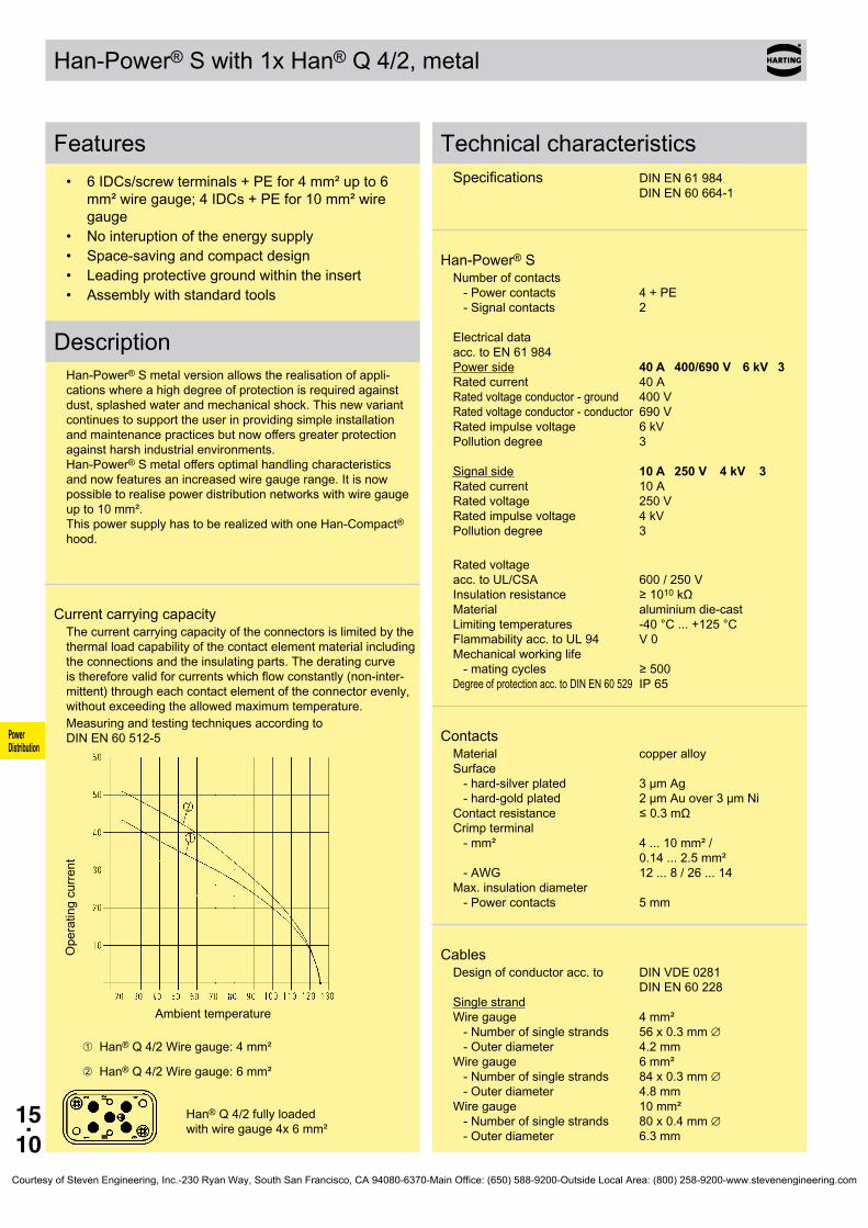
15.10
Power Distribution
Han-Power® S with 1x Han®Q4/2,metal
Features• 6IDCs/screwterminals+PEfor4mm²upto6
mm²wiregauge;4IDCs+PEfor10mm²wiregauge
• Nointeruptionoftheenergysupply• Space-savingandcompactdesign• Leadingprotectivegroundwithintheinsert• Assemblywithstandardtools
DescriptionHan-Power®Smetalversionallowstherealisationofappli-cationswhereahighdegreeofprotectionisrequiredagainstdust,splashedwaterandmechanicalshock.Thisnewvariantcontinuestosupporttheuserinprovidingsimpleinstallationandmaintenancepracticesbutnowoffersgreaterprotectionagainstharshindustrialenvironments. Han-Power®Smetaloffersoptimalhandlingcharacteristicsandnowfeaturesanincreasedwiregaugerange.Itisnowpossibletorealisepowerdistributionnetworkswithwiregaugeupto10mm². ThispowersupplyhastoberealizedwithoneHan-Compact® hood.
CurrentcarryingcapacityThecurrentcarryingcapacityoftheconnectorsislimitedbythethermalloadcapabilityofthecontactelementmaterialincludingtheconnectionsandtheinsulatingparts.Thederatingcurveisthereforevalidforcurrentswhichflowconstantly(non-inter-mittent)througheachcontactelementoftheconnectorevenly,withoutexceedingtheallowedmaximumtemperature.Measuringandtestingtechniquesaccordingto DINEN60512-5
Operatingcurre
nt
Ambienttemperature
➀Han®Q4/2Wiregauge:4mm²
➁Han®Q4/2Wiregauge:6mm²
Han®Q4/2fullyloaded withwiregauge4x6mm²
TechnicalcharacteristicsSpecifications DINEN61984 DINEN60664-1
Han-Power® SNumberofcontacts -Powercontacts 4+PE -Signalcontacts 2 Electricaldata acc.toEN61984 Powerside 40 A 400/690 V 6 kV 3 Ratedcurrent 40A Ratedvoltageconductor-ground 400V Ratedvoltageconductor-conductor690V Ratedimpulsevoltage 6kV Pollutiondegree 3 Signalside 10 A 250 V 4 kV 3 Ratedcurrent 10A Ratedvoltage 250V Ratedimpulsevoltage 4kV Pollutiondegree 3
Ratedvoltage acc.toUL/CSA 600/250V Insulationresistance ≥1010kΩ Material aluminiumdie-cast Limitingtemperatures -40°C...+125°C Flammabilityacc.toUL94 V0 Mechanicalworkinglife -matingcycles ≥500 Degreeofprotectionacc.toDINEN60529 IP65
ContactsMaterial copperalloy Surface -hard-silverplated 3µmAg -hard-goldplated 2µmAuover3µmNi Contactresistance ≤0.3mΩ Crimpterminal -mm² 4...10mm²/ 0.14...2.5mm² -AWG 12...8/26...14 Max.insulationdiameter -Powercontacts 5mm
CablesDesignofconductoracc.to DINVDE0281 DINEN60228 Singlestrand Wiregauge 4mm² -Numberofsinglestrands 56x0.3mm∅ -Outerdiameter 4.2mm Wiregauge 6mm² -Numberofsinglestrands 84x0.3mm∅ -Outerdiameter 4.8mm Wiregauge 10mm² -Numberofsinglestrands 80x0.4mm∅ -Outerdiameter 6.3mm
Courtesy of Steven Engineering, Inc.-230 Ryan Way, South San Francisco, CA 94080-6370-Main Office: (650) 588-9200-Outside Local Area: (800) 258-9200-www.stevenengineering.com

15.11
Han-Power® S 400/690/250 V40/10 A
09 12 008 4901
09 12 008 4951
Power Distribution
Stockitemsinboldtype
with 1x Han®Q4/2,metal
Identification Partnumber Drawing Dimensionsinmm
Han-Power® SPowersupply Han®Q4/2;1screwed Han-Compact®Housings,bulkheadmounting 4-6mm²
10mm²
Courtesy of Steven Engineering, Inc.-230 Ryan Way, South San Francisco, CA 94080-6370-Main Office: (650) 588-9200-Outside Local Area: (800) 258-9200-www.stevenengineering.com

15.12
Power Distribution
Han-Power®Twith3xHan® Q 4/2
Features• Per1connectionforpowerinput,poweroutputand
todevice• Maleandfemaleinsertsfingerprotected• 4powercontacts;2signalcontacts• Metalhousing• Lockingleverstainlesssteel
CurrentcarryingcapacityThecurrentcarryingcapacityoftheconnectorsislimitedbythethermalloadcapabilityofthecontactelementmaterialincludingtheconnectionsandtheinsulatingparts.Thederatingcurveisthereforevalidforcurrentswhichflowconstantly(non-inter-mittent)througheachcontactelementoftheconnectorevenly,withoutexceedingtheallowedmaximumtemperature.Measuringandtestingtechniquesaccordingto DINEN60512-5
Operatingcurre
nt
Ambienttemperature
Wiregauge: 4mm²
TechnicalcharacteristicsSpecifications DINEN61984 DINEN60664-1
Han-Power® TNumberofcontacts -Powercontacts 4+PE -Signalcontacts 2 Electricaldata acc.toEN61984 Powerside 40 A 400/690 V 6 kV 3 Ratedcurrent 40A Ratedvoltageconductor-ground 400V Ratedvoltageconductor-conductor690V Ratedimpulsevoltage 6kV Pollutiondegree 3 Signalside 10 A 250 V 4 kV 3 Ratedcurrent 10A Ratedvoltage 250V Ratedimpulsevoltage 4kV Pollutiondegree 3
Ratedvoltage acc.toUL/CSA 600/250V Insulationresistance ≥1010Ω Material zincdie-cast Limitingtemperatures -40°C...+125°C Flammabilityacc.toUL94 V0 Mechanicalworkinglife -matingcycles ≥500 Degreeofprotectionacc.toDINEN60529 IP65
ContactsMaterial copperalloy Surface -hard-silverplated 3µmAg -hard-goldplated 2µmAuover3µmNi Contactresistance ≤0.3mΩ Crimpterminal -mm² 4...6mm²/ 0.14...2.5mm² -AWG 12...10/26...14 Max.insulationdiameter -Powercontacts 5mm
Courtesy of Steven Engineering, Inc.-230 Ryan Way, South San Francisco, CA 94080-6370-Main Office: (650) 588-9200-Outside Local Area: (800) 258-9200-www.stevenengineering.com

15.13
Han-Power® T 400/690/250 V40/10 A
09 12 008 4720
Power Distribution
Stockitemsinboldtype
with3xHan® Q 4/2
Identification Partnumber Drawing Dimensionsinmm
Han-Power® T Powersupply with3xHan® Q 4/2 inHan-Compact® Housings,bulkheadmounting 4mm²
Courtesy of Steven Engineering, Inc.-230 Ryan Way, South San Francisco, CA 94080-6370-Main Office: (650) 588-9200-Outside Local Area: (800) 258-9200-www.stevenengineering.com
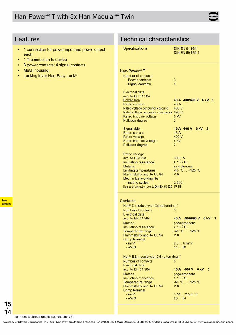
15.14
Power Distribution
Han-Power®Twith3xHan-Modular® Twin
Features• 1connectionforpowerinputandpoweroutput
each• 1T-connectiontodevice• 3powercontacts;4signalcontacts• Metalhousing• LockingleverHan-EasyLock®
TechnicalcharacteristicsSpecifications DINEN61984 DINEN60664-1
Han-Power® TNumberofcontacts -Powercontacts 3 -Signalcontacts 4 Electricaldata acc.toEN61984 Powerside 40 A 400/690 V 6 kV 3 Ratedcurrent 40A Ratedvoltageconductor-ground 400V Ratedvoltageconductor-conductor690V Ratedimpulsevoltage 6kV Pollutiondegree 3 Signalside 16 A 400 V 6 kV 3 Ratedcurrent 16A Ratedvoltage 400V Ratedimpulsevoltage 6kV Pollutiondegree 3
Ratedvoltage acc.toUL/CSA 600/V Insulationresistance ≥1010Ω Material zincdie-cast Limitingtemperatures -40°C...+125°C Flammabilityacc.toUL94 V0 Mechanicalworkinglife -matingcycles ≥500 Degreeofprotectionacc.toDINEN60529 IP65
ContactsHan®CmodulewithCrimpterminal*Numberofcontacts 3 Electricaldata acc.toEN61984 40 A 400/690 V 6 kV 3Material polycarbonate Insulationresistance ≥1010Ω Temperaturerange -40°C...+125°C Flammabilityacc.toUL94 V0 Crimpterminal -mm² 2.5...6mm² -AWG 14...10
Han®EEmodulewithCrimpterminal*Numberofcontacts 8 Electricaldata acc.toEN61984 16 A 400 V 6 kV 3Material polycarbonate Insulationresistance ≥1010Ω Temperaturerange -40°C...+125°C Flammabilityacc.toUL94 V0 Crimpterminal -mm² 0.14...2.5mm² -AWG 26...14
* formoretechnicaldetailsseechapter06Courtesy of Steven Engineering, Inc.-230 Ryan Way, South San Francisco, CA 94080-6370-Main Office: (650) 588-9200-Outside Local Area: (800) 258-9200-www.stevenengineering.com
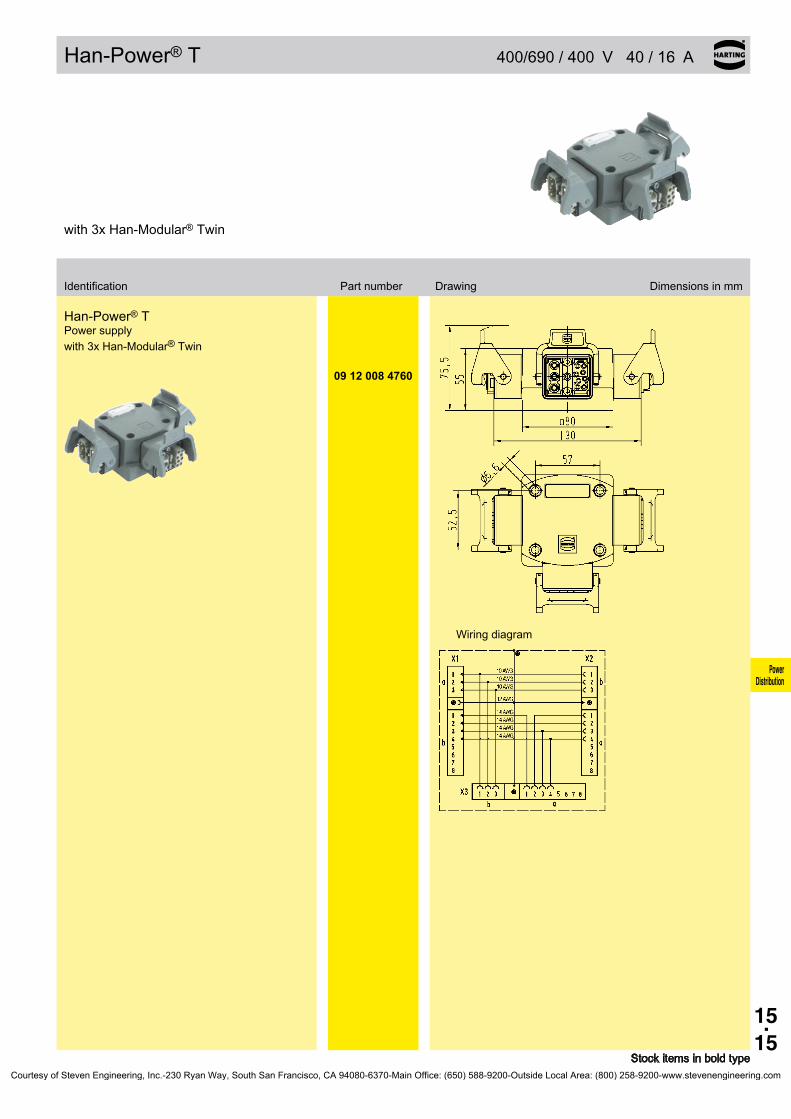
15.15
Han-Power® T 400/690/400 V40/16 A
09 12 008 4760
Power Distribution
Stockitemsinboldtype
with3xHan-Modular® Twin
Identification Partnumber Drawing Dimensionsinmm
Han-Power® T Powersupply with3xHan-Modular® Twin
Wiringdiagram
Courtesy of Steven Engineering, Inc.-230 Ryan Way, South San Francisco, CA 94080-6370-Main Office: (650) 588-9200-Outside Local Area: (800) 258-9200-www.stevenengineering.com

15.16
Power Distribution
Han-Power®Twith3xHan®Q2/0
Features• Per1connectionforpowerinput,poweroutput
andtodevice• 2powercontacts• Plastichousingsareintegratedinthemoulding• Compactdesign
CurrentcarryingcapacityThecurrentcarryingcapacityoftheconnectorsislimitedbythethermalloadcapabilityofthecontactelementmaterialincludingtheconnectionsandtheinsulatingparts.Thederatingcurveisthereforevalidforcurrentswhichflowconstantly(non-inter-mittent)througheachcontactelementoftheconnectorevenly,withoutexceedingtheallowedmaximumtemperature.Measuringandtestingtechniquesaccordingto DINEN60512-5
Operatingcurre
nt
Ambienttemperature
Wiregauge: 6mm²
TechnicalcharacteristicsSpecifications DINEN61984 DINEN60664-1
Han-Power® TNumberofcontacts -Powercontacts 2+PE Electricaldata acc.toEN61984 Powerside 40 A 400 V 6 kV 3 Ratedcurrent 40A Ratedvoltage 400V Ratedimpulsevoltage 6kV Pollutiondegree 3
Ratedvoltage acc.toUL/CSA 600V Insulationresistance ≥1010Ω Material polycarbonate Limitingtemperatures -40°C...+125°C Flammabilityacc.toUL94 V0 Mechanicalworkinglife -matingcycles ≥500 Degreeofprotectionacc.toDINEN60529 IP65/IP67
ContactsMaterial copperalloy Surface -hard-silverplated 3µmAg Contactresistance ≤1mΩ Crimpterminal -mm² 2.5...10mm² -AWG 14...8
Courtesy of Steven Engineering, Inc.-230 Ryan Way, South San Francisco, CA 94080-6370-Main Office: (650) 588-9200-Outside Local Area: (800) 258-9200-www.stevenengineering.com
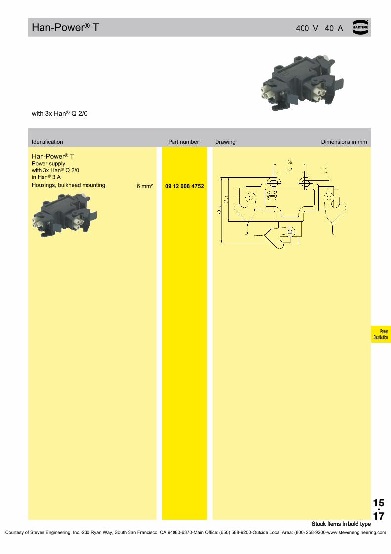
15.17
Han-Power® T 400 V40 A
6mm² 09 12 008 4752
Power Distribution
Stockitemsinboldtype
with3xHan®Q2/0
Identification Partnumber Drawing Dimensionsinmm
Han-Power® T Powersupply with3xHan®Q2/0 in Han®3A Housings,bulkheadmounting
Courtesy of Steven Engineering, Inc.-230 Ryan Way, South San Francisco, CA 94080-6370-Main Office: (650) 588-9200-Outside Local Area: (800) 258-9200-www.stevenengineering.com
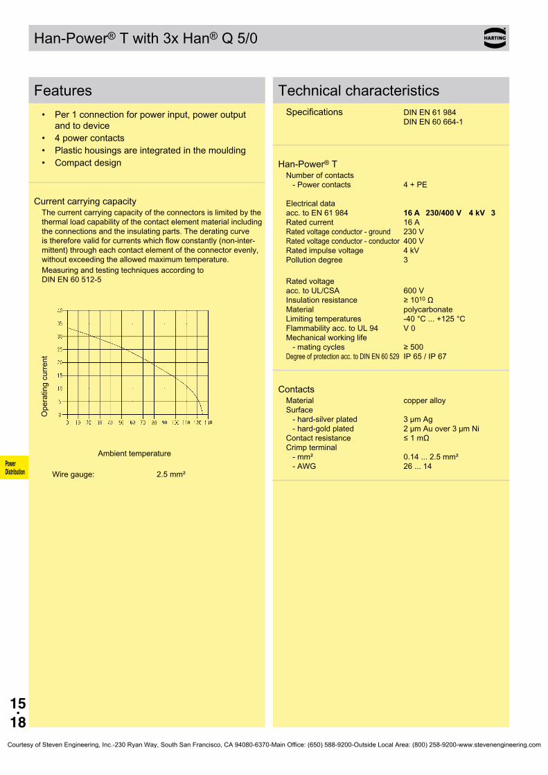
15.18
Power Distribution
Han-Power®Twith3xHan®Q5/0
Features• Per1connectionforpowerinput,poweroutput
andtodevice• 4powercontacts• Plastichousingsareintegratedinthemoulding• Compactdesign
CurrentcarryingcapacityThecurrentcarryingcapacityoftheconnectorsislimitedbythethermalloadcapabilityofthecontactelementmaterialincludingtheconnectionsandtheinsulatingparts.Thederatingcurveisthereforevalidforcurrentswhichflowconstantly(non-inter-mittent)througheachcontactelementoftheconnectorevenly,withoutexceedingtheallowedmaximumtemperature.Measuringandtestingtechniquesaccordingto DINEN60512-5
Operatingcurre
nt
Ambienttemperature
Wiregauge: 2.5mm²
TechnicalcharacteristicsSpecifications DINEN61984 DINEN60664-1
Han-Power® TNumberofcontacts -Powercontacts 4+PE Electricaldata acc.toEN61984 16 A 230/400 V 4 kV 3 Ratedcurrent 16A Ratedvoltageconductor-ground 230V Ratedvoltageconductor-conductor400V Ratedimpulsevoltage 4kV Pollutiondegree 3
Ratedvoltage acc.toUL/CSA 600V Insulationresistance ≥1010Ω Material polycarbonate Limitingtemperatures -40°C...+125°C Flammabilityacc.toUL94 V0 Mechanicalworkinglife -matingcycles ≥500 Degreeofprotectionacc.toDINEN60529 IP65/IP67
ContactsMaterial copperalloy Surface -hard-silverplated 3µmAg -hard-goldplated 2µmAuover3µmNi Contactresistance ≤1mΩ Crimpterminal -mm² 0.14...2.5mm² -AWG 26...14
Courtesy of Steven Engineering, Inc.-230 Ryan Way, South San Francisco, CA 94080-6370-Main Office: (650) 588-9200-Outside Local Area: (800) 258-9200-www.stevenengineering.com

15.19
Han-Power® T 230/400 V16 A
09 12 008 4751
Power Distribution
Stockitemsinboldtype
with3xHan®Q5/0
Identification Partnumber Drawing Dimensionsinmm
Han-Power® T Powersupply with3xHan®Q5/0 in Han®3A Housings,bulkheadmounting 2,5mm²
Courtesy of Steven Engineering, Inc.-230 Ryan Way, South San Francisco, CA 94080-6370-Main Office: (650) 588-9200-Outside Local Area: (800) 258-9200-www.stevenengineering.com

15.20
Han® Q 4/2
Power Distribution
Features• 4powercontactsHan®Cand2signalcontacts
HanD®
• Fingerprotection• Leadingprotectivegroundwithcrimpterminal• Insertssuitableformetalandplastichoodsand
housingsofHan-Compact®series(notsuitable for19120080501,19127080501and 19120080502)
• 3codingpossibilitiesbyusingacodingpininsteadoffixingscrew
CurrentcarryingcapacityThecurrentcarryingcapacityoftheconnectorsislimitedbythethermalloadcapabilityofthecontactelementmaterialincludingtheconnectionsandtheinsulatingparts.Thederatingcurveisthereforevalidforcurrentswhichflowconstantly(non-inter-mittent)througheachcontactelementoftheconnectorevenly,withoutexceedingtheallowedmaximumtemperature.Measuringandtestingtechniquesaccordingto DINEN60512-5
Operatingcurre
nt
Ambienttemperature
Wiregauge: ➀2.5mm²
➁4mm²
TechnicalcharacteristicsSpecifications DINEN60664-1 DINEN61984 Approvals
InsertsNumberofcontacts 4/2+PE Electricaldata acc.toEN61984 Powerside 40 A 400/690 V 6 kV 3 Ratedcurrent 40A Ratedvoltageconductor-ground 400V Ratedvoltageconductor-conductor690V Ratedimpulsevoltage 6kV Pollutiondegree 3 Signalside 10 A 250 V 4 kV 3 Ratedcurrent 10A Ratedvoltage 250V Ratedimpulsevoltage 4kV Pollutiondegree 3
Ratedvoltage acc.toUL/CSA 600/250V Insulationresistance ≥1010Ω Material polycarbonate Limitingtemperatures -40°C...+125°C Flammabilityacc.toUL94 V0 Mechanicalworkinglife -matingcycles ≥500
ContactsMaterial copperalloy Surface -hard-silverplated 3µmAg -hard-goldplated 2µmAuover3µmNi Contactresistance ≤0.3mΩ Crimpterminal -mm² 1.5...6mm²/ 0.14...2.5mm² -AWG 16...10/ 26...14 Max.insulationdiameter -Powercontacts 5mm
Hoods/HousingsPlastichoods/housingsMaterial polycarbonate Lockingelement Polyamide Hoods/Housingssealing NBR Limitingtemperatures -40°C...+125°C Flammabilityacc.toUL94 V0 Degreeofprotectionacc.toDINEN60529 forcoupledconnector IP65
AccessoriesCrimpingtools chapter99
Courtesy of Steven Engineering, Inc.-230 Ryan Way, South San Francisco, CA 94080-6370-Main Office: (650) 588-9200-Outside Local Area: (800) 258-9200-www.stevenengineering.com
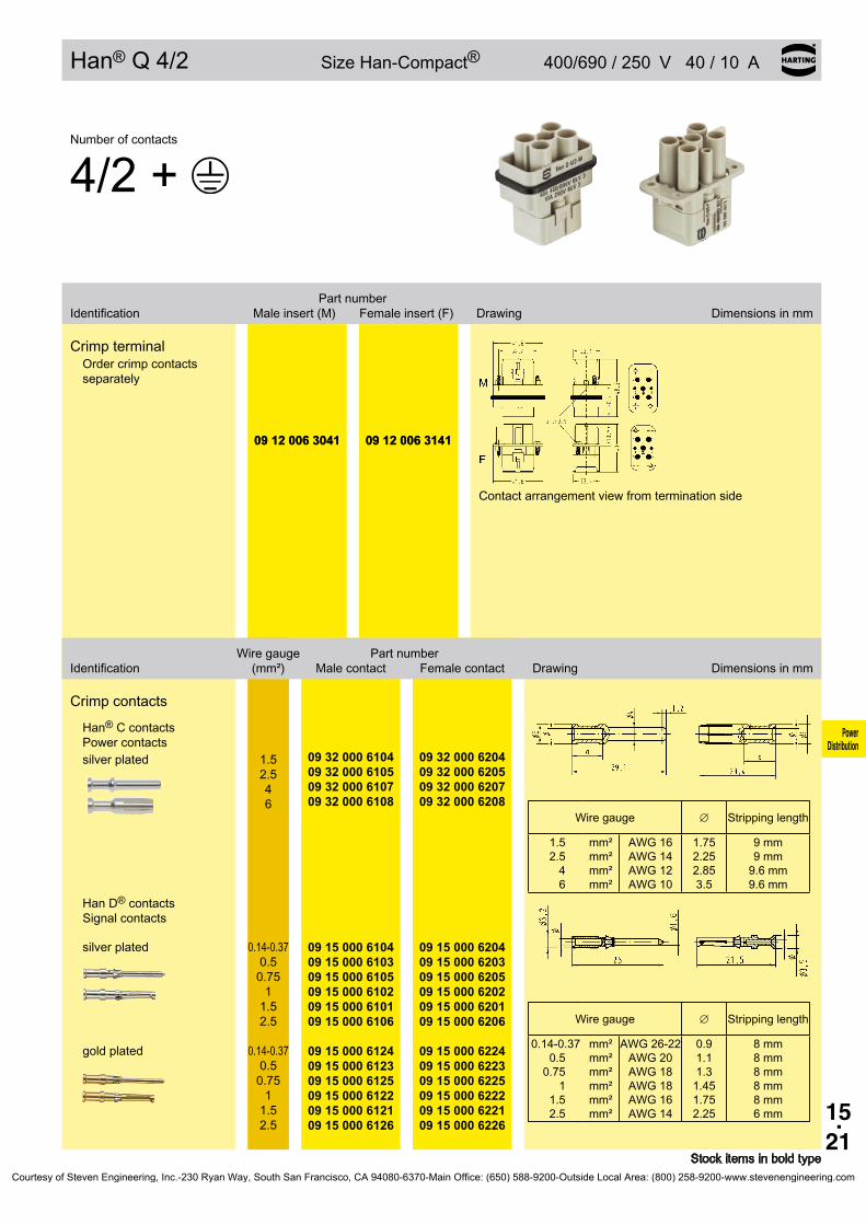
15.21
09 12 006 3041 09 12 006 3141
∅
mm²mm²mm²mm²
AWG16AWG14AWG12AWG10
09 32 000 6104 09 32 000 6105 09 32 000 6107 09 32 000 6108
09 32 000 6204 09 32 000 6205 09 32 000 6207 09 32 000 6208
∅
mm²mm²mm²mm²mm²mm²
AWG26-22AWG20AWG18AWG18AWG16AWG14
8mm8mm8mm8mm8mm6mm
09 15 000 6104 09 15 000 6103 09 15 000 6105 09 15 000 6102 09 15 000 6101 09 15 000 6106
09 15 000 6204 09 15 000 6203 09 15 000 6205 09 15 000 6202 09 15 000 6201 09 15 000 6206
09 15 000 6124 09 15 000 6123 09 15 000 6125 09 15 000 6122 09 15 000 6121 09 15 000 6126
09 15 000 6224 09 15 000 6223 09 15 000 6225 09 15 000 6222 09 15 000 6221 09 15 000 6226
Power Distribution
Han® Q 4/2 SizeHan-Compact® 400/690/250 V40/10 A
Stockitemsinboldtype
Numberofcontacts
4/2+
Partnumber Identification Maleinsert(M) Femaleinsert(F) Drawing Dimensionsinmm
CrimpterminalOrdercrimpcontactsseparately
Contactarrangementviewfromterminationside
09 12 006 3041 09 12 006 3141
Wiregauge Partnumber Identification (mm²) Malecontact Femalecontact Drawing Dimensionsinmm
Crimpcontacts
Han®Ccontacts Powercontacts
Wiregauge Strippinglength
1.52.5
46
1.752.252.853.5
9mm9mm9.6mm9.6mm
silverplated 1.5 2.5 4 6
HanD®contacts Signalcontacts
Wiregauge Strippinglength
0.14-0.370.50.75
11.52.5
0.91.11.31.451.752.25
silverplated 0.14-0.37 0.5 0.75
1 1.5 2.5
goldplated 0.14-0.37 0.5 0.75
1 1.5 2.5
Courtesy of Steven Engineering, Inc.-230 Ryan Way, South San Francisco, CA 94080-6370-Main Office: (650) 588-9200-Outside Local Area: (800) 258-9200-www.stevenengineering.com

15.22
Han®Q8/0
Power Distribution
Features• 8contactchambersforcrimpcontactsofHanE®
series• Space-savingandcompactdesign• Leadingprotectivegroundwithcrimpterminal• Insertssuitableformetalandplastichoodsand
housingsofHan-Compact® series• ISO23570/DESINAconformproduct
CurrentcarryingcapacityThecurrentcarryingcapacityoftheconnectorsislimitedbythethermalloadcapabilityofthecontactelementmaterialincludingtheconnectionsandtheinsulatingparts.Thederatingcurveisthereforevalidforcurrentswhichflowconstantly(non-inter-mittent)througheachcontactelementoftheconnectorevenly,withoutexceedingtheallowedmaximumtemperature.Measuringandtestingtechniquesaccordingto DINEN60512-5
Operatingcurre
nt
Ambienttemperature
Wiregauge: ➀1.5mm²
➁2.5mm²
TechnicalcharacteristicsSpecifications DINEN60664-1 DINEN61984 Approvals
InsertsNumberofcontacts 8+PE Electricaldata acc.toEN61984 Mountedplastichood 16 A 500 V 6 kV 3 Ratedcurrent 16A Ratedvoltage 500V Ratedimpulsevoltage 6kV Pollutiondegree 3Pollutiondegree2also 16A 400/690V 6kV 2Mountedmetalhood 16A 230/400V 4kV 3
Ratedvoltage acc.toUL/CSA 500VInsulationresistance ≥1010Ω Material polycarbonate Limitingtemperatures -40°C...125°C Flammabilityacc.toUL94 V0 Mechanicalworkinglife -matingcycles ≥500
ContactsMaterial copperalloy Surface -hard-silverplated 3µmAg -hard-goldplated 2µmAuover3µmNi Contactresistance ≤1mΩ Crimpterminal -mm² 0.14...4mm² partlyloadedupto4mm² ispossible -AWG 26...12
Hoods/HousingsPlastichoods/housingsMaterial polycarbonate Lockingelement Polyamide Hoods/Housingssealing NBR Limitingtemperatures -40°C...125°C Flammabilityacc.toUL94 V0 Degreeofprotectionacc.toDINEN60529 forcoupledconnector IP65
Hoods/Housings,metalMaterial zincdie-cast Lockingelement Stainlesssteel Hoods/Housingssealing NBR Limitingtemperatures -40°C...125°C Degreeofprotectionacc.toDINEN60529 forcoupledconnector IP65
AccessoriesCrimpingtools chapter99
Courtesy of Steven Engineering, Inc.-230 Ryan Way, South San Francisco, CA 94080-6370-Main Office: (650) 588-9200-Outside Local Area: (800) 258-9200-www.stevenengineering.com

15.23
09 12 008 3001 09 12 008 3101
09 33 000 9954
mm²mm²mm²mm²mm²mm²mm²
AWG26-22AWG20AWG18AWG18AWG16AWG14AWG12
09 33 000 6127 09 33 000 6121 09 33 000 6114 09 33 000 6105 09 33 000 6104 09 33 000 6102 09 33 000 6107
09 33 000 6227 09 33 000 6220 09 33 000 6214 09 33 000 6205 09 33 000 6204 09 33 000 6202 09 33 000 6207
09 33 000 6117 09 33 000 6122 09 33 000 6115 09 33 000 6118 09 33 000 6116 09 33 000 6123 09 33 000 6119
09 33 000 6217 09 33 000 6222 09 33 000 6215 09 33 000 6218 09 33 000 6216 09 33 000 6223 09 33 000 6221
09 33 000 6109
09 33 000 6110 09 33 000 6111
20 10 001 3311 20 10 001 3321
Power Distribution
Han®Q8/0 SizeHan-Compact® 500 V16 A
Stockitemsinboldtype Crimpcontacts0.14...0.37mm²onlyusedwithBUCHANANcrimpingtool09990000001
Numberofcontacts
8+
Partnumber Identification Maleinsert(M) Femaleinsert(F) Drawing Dimensionsinmm
CrimpterminalOrdercrimpcontactsseparately
Contactarrangementviewfromterminationside
Codingpin Useofthecodingpinpreventsincor-rectmatingtootherconnectorsofthesametype.Themalepinshouldbeomittedfromtheopposingcavityinthemaleinsert.
Wiregauge Partnumber Identification (mm²) Malecontact Femalecontact Drawing Dimensionsinmm
Crimpcontacts Powercontacts
Operatingcontact Identification Relaycontact
Identification Wiregauge Strippinglength
nogroovenogroove1groove*1groove2grooves3groovesnogroove
0.14-0.370.50.75
11.52.5
4
7.5mm7.5mm7.5mm7.5mm7.5mm7.5mm7.5mm
*onthebackcrimpcollar
silverplated 0.14-0.37 0.5 0.75
1 1.5 2.5 4
goldplated 0.14-0.37 0.5 0.75
1 1.5 2.5 4
Relaycontact silverplated 0.75-1
1.5 2.5
F.O.contacts for1mmplasticfibre
Crimpzone Crimpzone
Courtesy of Steven Engineering, Inc.-230 Ryan Way, South San Francisco, CA 94080-6370-Main Office: (650) 588-9200-Outside Local Area: (800) 258-9200-www.stevenengineering.com
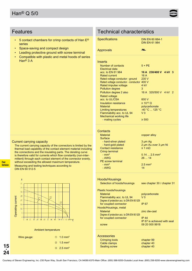
15.24
Han®Q5/0
Power Distribution
Features• 5contactchambersforcrimpcontactsofHanE®
series• Space-savingandcompactdesign• Leadingprotectivegroundwithscrewterminal• Compatiblewithplasticandmetalhoodsofseries
Han®3A
CurrentcarryingcapacityThecurrentcarryingcapacityoftheconnectorsislimitedbythethermalloadcapabilityofthecontactelementmaterialincludingtheconnectionsandtheinsulatingparts.Thederatingcurveisthereforevalidforcurrentswhichflowconstantly(non-inter-mittent)througheachcontactelementoftheconnectorevenly,withoutexceedingtheallowedmaximumtemperature.Measuringandtestingtechniquesaccordingto DINEN60512-5
Operatingcurre
nt
Ambienttemperature
Wiregauge: ➀1.0mm²
➁1.5mm²
➂2.5mm²
TechnicalcharacteristicsSpecifications DINEN60664-1 DINEN61984 Approvals
InsertsNumberofcontacts 5+PE Electricaldata acc.toEN61984 16 A 230/400 V 4 kV 3 Ratedcurrent 16A Ratedvoltageconductor-ground 230V Ratedvoltageconductor-conductor400V Ratedimpulsevoltage 4kV Pollutiondegree 3Pollutiondegree2also 16A 320/500V 4kV 2Ratedvoltage acc.toUL/CSA 600VInsulationresistance ≥1010Ω Material polycarbonate Limitingtemperatures -40°C...125°C Flammabilityacc.toUL94 V0 Mechanicalworkinglife -matingcycles ≥500
ContactsMaterial copperalloy Surface -hard-silverplated 3µmAg -hard-goldplated 2µmAuover3µmNi Contactresistance ≤1mΩ Crimpterminal -mm² 0.14...2.5mm² -AWG 26...14 PEscrewterminal -mm² 2.5mm² -AWG 14
Hoods/HousingsSelectionofhoods/housings seechapter30/chapter31
Plastichoods/housingsMaterial polycarbonate Flammabilityacc.toUL94 V0 Degreeofprotectionacc.toDINEN60529 forcoupledconnector IP67
Hoods/Housings,metalMaterial zincdie-cast Degreeofprotectionacc.toDINEN60529 forcoupledconnector IP44 IP67isachievedwithsealscrew 09200009918
AccessoriesCrimpingtools chapter99 Cableclamps chapter40 Sealingscrew chapter40
Courtesy of Steven Engineering, Inc.-230 Ryan Way, South San Francisco, CA 94080-6370-Main Office: (650) 588-9200-Outside Local Area: (800) 258-9200-www.stevenengineering.com
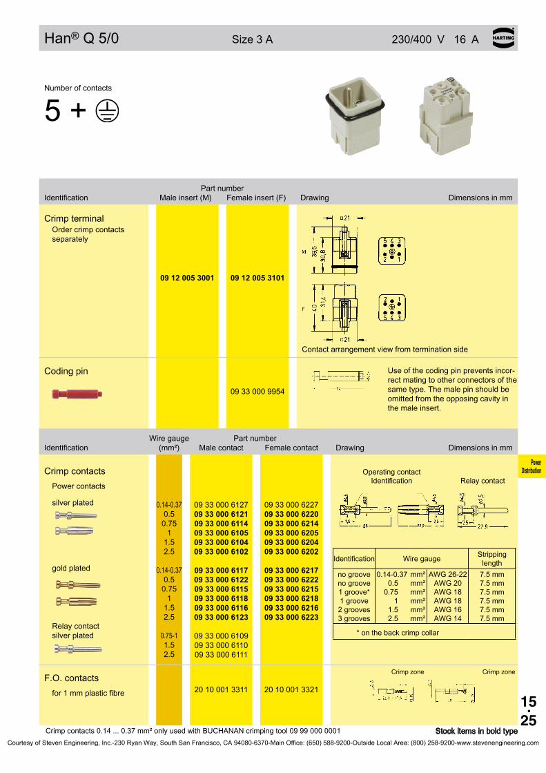
15.25
09 12 005 3001 09 12 005 3101
09 33 000 9954
mm²mm²mm²mm²mm²mm²
AWG26-22AWG20AWG18AWG18AWG16AWG14
09 33 000 6127 09 33 000 6121 09 33 000 6114 09 33 000 6105 09 33 000 6104 09 33 000 6102
09 33 000 6227 09 33 000 6220 09 33 000 6214 09 33 000 6205 09 33 000 6204 09 33 000 6202
09 33 000 6117 09 33 000 6122 09 33 000 6115 09 33 000 6118 09 33 000 6116 09 33 000 6123
09 33 000 6217 09 33 000 6222 09 33 000 6215 09 33 000 6218 09 33 000 6216 09 33 000 6223
09 33 000 6109
09 33 000 6110 09 33 000 6111
20 10 001 3311 20 10 001 3321
Power Distribution
Han®Q5/0 Size3A 230/400 V16 A
Stockitemsinboldtype Crimpcontacts0.14...0.37mm²onlyusedwithBUCHANANcrimpingtool09990000001
Numberofcontacts
5+
Partnumber Identification Maleinsert(M) Femaleinsert(F) Drawing Dimensionsinmm
CrimpterminalOrdercrimpcontactsseparately
Contactarrangementviewfromterminationside
Codingpin Useofthecodingpinpreventsincor-rectmatingtootherconnectorsofthesametype.Themalepinshouldbeomittedfromtheopposingcavityinthemaleinsert.
Wiregauge Partnumber Identification (mm²) Malecontact Femalecontact Drawing Dimensionsinmm
Crimpcontacts Powercontacts
Operatingcontact Identification Relaycontact
Identification Wiregauge Strippinglength
nogroovenogroove1groove*1groove2grooves3grooves
0.14-0.370.50.75
11.52.5
7.5mm7.5mm7.5mm7.5mm7.5mm7.5mm
*onthebackcrimpcollar
silverplated 0.14-0.37 0.5 0.75
1 1.5 2.5
goldplated 0.14-0.37 0.5 0.75
1 1.5 2.5
Relaycontact silverplated 0.75-1
1.5 2.5
F.O.contacts for1mmplasticfibre
Crimpzone Crimpzone
Courtesy of Steven Engineering, Inc.-230 Ryan Way, South San Francisco, CA 94080-6370-Main Office: (650) 588-9200-Outside Local Area: (800) 258-9200-www.stevenengineering.com

15.26
Han®Q2/0
Power Distribution
Features• Compactdesignedconnectorforhighcurrent
ratings• 16codingoptions• Forhoods/housingssizeHan®3A• Fingerprotectedmaleandfemalecontacts• Assemblywithoutspecialtoolbyaxialscrew
termination
Attention• ByusinginHan®3AHPRhoods/housingsthesealingontheinserthastoberemoved.• ForterminationpleaseuseonlyhexagonalscrewdriverwithwrenchsizeSW2.• IfPEcontactisnotused: PleasescrewthePEcontactmaximalonbothsidesclockwisewithahexagonalscrewdriver,wrenchsizeSW2.
CurrentcarryingcapacityThecurrentcarryingcapacityoftheconnectorsislimitedbythethermalloadcapabilityofthecontactelementmaterialincludingtheconnectionsandtheinsulatingparts.Thederatingcurveisthereforevalidforcurrentswhichflowconstantly(non-inter-mittent)througheachcontactelementoftheconnectorevenly,withoutexceedingtheallowedmaximumtemperature.MeasuringandtestingtechniquesaccordingtoDINEN60512-5
Operatingcurre
nt
Ambienttemperature
Wiregauge: ➀2.5mm²➁4mm²➂6mm²➃10mm²
TechnicalcharacteristicsSpecifications DINEN60664-1 DINEN61984 Approvals
InsertsNumberofcontacts 2+PE Electricaldata acc.toEN61984 40 A 400 V 6 kV 3 Ratedcurrent 40A Ratedvoltage 400V Ratedimpulsevoltage 6kV Pollutiondegree 3
Ratedvoltage acc.toUL/CSA 400VInsulationresistance ≥1010Ω Material polycarbonate Limitingtemperatures -40°C...125°C Flammabilityacc.toUL94 V0 Mechanicalworkinglife -matingcycles ≥500
ContactsMaterial copperalloy Surface -hard-silverplated 3µmAg Contactresistance ≤1mΩ Axialscrewtermination -mm² 2,5...10mm² -AWG 14...8 Tighteningtorque 1,8Nm Strippinglength 8mm+1
Hoods/HousingsSelectionofhoods/housings seechapter30/chapter31
Plastichoods/housingsMaterial polycarbonate Flammabilityacc.toUL94 V0 Degreeofprotectionacc.toDINEN60529 forcoupledconnector IP67
Hoods/Housings,metalMaterial zincdie-cast Degreeofprotectionacc.toDINEN60529 forcoupledconnector IP44 IP67isachievedwithseal screw09200009918
AccessoriesCableclamps chapter40 Sealingscrew chapter40
Courtesy of Steven Engineering, Inc.-230 Ryan Way, South San Francisco, CA 94080-6370-Main Office: (650) 588-9200-Outside Local Area: (800) 258-9200-www.stevenengineering.com
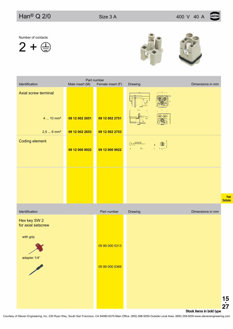
15.27
09 12 002 2651 09 12 002 2751
09 12 002 2653 09 12 002 2753
09 12 000 9922 09 12 000 9922
09 99 000 0313
09 99 000 0369
Power Distribution
Han®Q2/0 Size3A 400 V40 A
Identification Partnumber Drawing Dimensionsinmm
Stockitemsinboldtype
Numberofcontacts
2+
Partnumber Identification Maleinsert(M) Femaleinsert(F) Drawing Dimensionsinmm
Axialscrewterminal
4...10mm²
2,5...6mm²
Codingelement
HexkeySW2 foraxialsetscrew
withgrip
adapter1/4“
Courtesy of Steven Engineering, Inc.-230 Ryan Way, South San Francisco, CA 94080-6370-Main Office: (650) 588-9200-Outside Local Area: (800) 258-9200-www.stevenengineering.com

15.28
19 12 708 0511
19 12 008 0511
M25
M25
19 12 708 0501
19 12 008 0501
M25
M25
19 12 008 0526
M25
19 12 708 0411
19 12 008 0411
M25
M25
19 12 008 0426
M25
Power Distribution
Hoods/HousingsHan-Compact®
Stockitemsinboldtype
Identification Partnumber Drawing Dimensionsinmm
Metal
Hoods
• side-entry forHan-Compact® halfgland
• withseparatePE termination
• forallinsertsofsize Han-Compact®
black powder coated
black chromated
Hoods
• side-entry forHan-Compact® halfgland
• forHan®Q8/0Crimp, Han®Q17/0and Han®QDataRJ45
black powder coated
black chromated
Hoods
• side-entry forstandardcableglands
• withseparatePE termination
• forallinsertsofsize Han-Compact®
black powder coated
Hoods
• top-entry forHan-Compact® halfgland
• withseparatePE termination
• forallinsertsofsize Han-Compact®
black powder coated
black chromated
Hoods
• top-entry forstandardcableglands
• withseparatePE termination
• forallinsertsofsize Han-Compact®
black powder coated
Courtesy of Steven Engineering, Inc.-230 Ryan Way, South San Francisco, CA 94080-6370-Main Office: (650) 588-9200-Outside Local Area: (800) 258-9200-www.stevenengineering.com
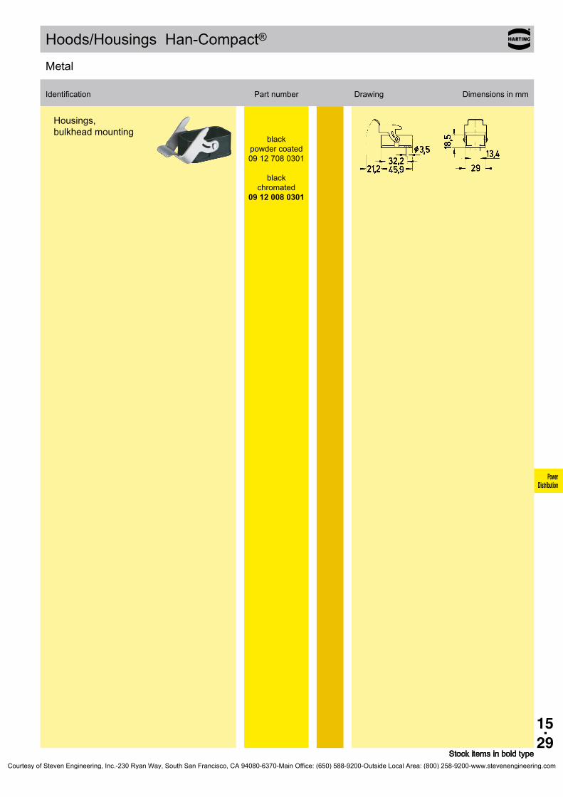
15.29
09 12 708 0301
09 12 008 0301
Power Distribution
Hoods/HousingsHan-Compact®
Stockitemsinboldtype
Identification Partnumber Drawing Dimensionsinmm
Metal
Housings, bulkheadmounting
black powder coated
black chromated
Courtesy of Steven Engineering, Inc.-230 Ryan Way, South San Francisco, CA 94080-6370-Main Office: (650) 588-9200-Outside Local Area: (800) 258-9200-www.stevenengineering.com

15.30
09 12 008 0527 Pg 16
19 12 008 0429 09 12 008 0427 09 12 008 0429
M25 Pg 16 Pg 21
09 12 008 0428 PAFS 18
Power Distribution
Hoods/HousingsHan-Compact®
Stockitemsinboldtype
Identification Partnumber Drawing Dimensionsinmm
Thermoplastic
Hoods
• side-entry forHan-Compact® halfgland
Hoods
• top-entry forHan-Compact® halfgland
Hoods
• top-entry forflexibleconduits AdaptaflexPAFS18
Courtesy of Steven Engineering, Inc.-230 Ryan Way, South San Francisco, CA 94080-6370-Main Office: (650) 588-9200-Outside Local Area: (800) 258-9200-www.stevenengineering.com

15.31
09 12 008 0327 –
09 12 008 0902 –
09 12 008 0901 Pg 16
19 12 008 0729 09 12 008 0727
M25 Pg 16
09 12 008 0728 PAFS 18
Power Distribution
Hoods/HousingsHan-Compact®
Stockitemsinboldtype
Identification Partnumber Drawing Dimensionsinmm
Thermoplastic
Housings, bulkheadmounting
• straight
Housings, bulkheadmounting
• angled
Housings, surfacemounting
• forHan-Compact® halfgland
Hoods,cabletocable
• forHan-Compact® halfgland
Hoods,cabletocable
• forflexibleconduits AdaptaflexPAFS18
Courtesy of Steven Engineering, Inc.-230 Ryan Way, South San Francisco, CA 94080-6370-Main Office: (650) 588-9200-Outside Local Area: (800) 258-9200-www.stevenengineering.com

15.32
19 12 008 0512 M25
19 12 008 0502 M25
19 12 008 0528 M25
19 12 008 0412 M25
19 12 008 0428 M25
Power Distribution
Hoods/HousingsHan-Compact®
Stockitemsinboldtype
Identification Partnumber Drawing Dimensionsinmm
Metalnickel-platedforEMCapplications
Hoods
• side-entry forHan-Compact® EMChalfgland
• withseparatePE termination
• forallinsertsofsize Han-Compact®
Hoods
• side-entry forHan-Compact® EMChalfgland
• forHan®Q8/0Crimp, Han®Q17/0and Han®QDataRJ45
Hoods
• side-entry forstandardEMC cableglands
• withseparatePE termination
• forallinsertsofsize Han-Compact®
Hoods
• top-entry forHan-Compact® EMChalfgland
• withseparatePE termination
• forallinsertsofsize Han-Compact®
Hoods
• top-entry forstandardEMC cableglands
• withseparatePE termination
• forallinsertsofsize Han-Compact®
Courtesy of Steven Engineering, Inc.-230 Ryan Way, South San Francisco, CA 94080-6370-Main Office: (650) 588-9200-Outside Local Area: (800) 258-9200-www.stevenengineering.com

15.33
09 12 008 0303
Power Distribution
Hoods/HousingsHan-Compact®
Stockitemsinboldtype
Identification Partnumber Drawing Dimensionsinmm
Metalnickel-platedforEMCapplications
Housings,bulkheadmounting
Courtesy of Steven Engineering, Inc.-230 Ryan Way, South San Francisco, CA 94080-6370-Main Office: (650) 588-9200-Outside Local Area: (800) 258-9200-www.stevenengineering.com

15.34
19 12 000 5057 19 12 000 5058
M25 M25
SW
19120005057 2819120005058 28
19 12 000 5157 19 12 000 5158 09 00 000 5059 09 00 000 5157 09 00 000 5158
M25 M25
Pg 16 Pg 21 Pg 21
SW
19120005157 3019120005158 3009000005059 2709000005157 3309000005158 33
09 00 000 5058 09 00 000 5057
Pg 16 Pg 16
SW
09000005058 2709000005057 27
19 62 000 5056 19 62 000 5057 19 62 000 5058
M25 M25 M25
SW
19620005056 2819620005057 2819620005058 28
19620005056 9mm 13mm19620005057 6mm 11mm19620005058 9mm 13mm
Power Distribution
Hoods/HousingsHan-Compact®
Stockitemsinboldtype
Identification Partnumber Drawing Dimensionsinmm
Accessories
Han-Compact®halfgland
• Metal• forhoods
cable
min. max.10,5mm 14mm14mm 17mm
Han-Compact®halfgland
• Thermoplastic• forhoods
cable
min. max.10,5mm 14mm14mm 17mm11,5mm 15,5mm14mm 18mm17mm 20,5mm
Han-Compact®halfgland
• Thermoplastic• forhousings
cable
min. max.11,5mm 15,5mm6,5mm 9,5mm
Han-Compact®EMChalfgland
• Metal• forhoods
cablemin. max.
10,5mm 14mm10,5mm 14mm14mm 17mm
shieldingmin. max.
Courtesy of Steven Engineering, Inc.-230 Ryan Way, South San Francisco, CA 94080-6370-Main Office: (650) 588-9200-Outside Local Area: (800) 258-9200-www.stevenengineering.com

15.35
09 12 008 5407
09 12 008 5408
09 12 000 9912
09 12 000 9911
Power Distribution
Hoods/HousingsHan-Compact®
Stockitemsinboldtype
Identification Partnumber Drawing Dimensionsinmm
Accessories
Protectioncovers
• Thermoplastic• forhousings• formountedmaleinsert
Protectioncovers
• Thermoplastic• forhousings• formountedfemaleinsert
Gasketforplastichousings, bulkheadmounting,straight
Gasketforplastichousings, bulkheadmounting,angled, andforhousings, surfacemounting
Courtesy of Steven Engineering, Inc.-230 Ryan Way, South San Francisco, CA 94080-6370-Main Office: (650) 588-9200-Outside Local Area: (800) 258-9200-www.stevenengineering.com

15.36
7...10mm 10...13mm 13...16mm 16...19mm 19...22mm
09 12 000 9969 09 12 000 9970 09 12 000 9971 09 12 000 9972 09 12 000 9973
09 12 000 9974
Power Distribution
Han-Power®-Accessories
Stockitemsinboldtype
Identification Partnumber Drawing Dimensionsinmm
Panelfeedthroughseals Cablediameter
blindgrommet
Courtesy of Steven Engineering, Inc.-230 Ryan Way, South San Francisco, CA 94080-6370-Main Office: (650) 588-9200-Outside Local Area: (800) 258-9200-www.stevenengineering.com

Han- Brid
19.01
Han-Brid®
Contents
Han-Brid® Features . . . . . . . . . . . . . . . . . . . . . . . . . . . . . . . . . . . . . . . . . . . 19.02
Han-Brid® Data interfaces . . . . . . . . . . . . . . . . . . . . . . . . . . . . . . . . . . . . . . 19.03
Han-Brid® Overview . . . . . . . . . . . . . . . . . . . . . . . . . . . . . . . . . . . . . . . . . . 19.04
Han-Brid® Cu . . . . . . . . . . . . . . . . . . . . . . . . . . . . . . . . . . . . . . . . . . . . . . . . 19.06
Han-Brid® F .O . . . . . . . . . . . . . . . . . . . . . . . . . . . . . . . . . . . . . . . . . . . . . . . . 19.08
Han-Brid® Quintax 3 A . . . . . . . . . . . . . . . . . . . . . . . . . . . . . . . . . . . . . . . . . 19.10
Han-Brid® RJ45 C . . . . . . . . . . . . . . . . . . . . . . . . . . . . . . . . . . . . . . . . . . . . 19.12
Han-Brid® USB / Han-Brid® FireWire . . . . . . . . . . . . . . . . . . . . . . . . . . . . . 19.14
Han® 4 A SC . . . . . . . . . . . . . . . . . . . . . . . . . . . . . . . . . . . . . . . . . . . . . . . . 19.16
Han-Brid® Hoods/Housings . . . . . . . . . . . . . . . . . . . . . . . . . . . . . . . . . . . . . 19.18
Page
Courtesy of Steven Engineering, Inc.-230 Ryan Way, South San Francisco, CA 94080-6370-Main Office: (650) 588-9200-Outside Local Area: (800) 258-9200-www.stevenengineering.com

Han- Brid
19.02
Han-Brid® Features
FeaturesGeneral Description
The Han-Brid® series allows the connection of a data interface and a power supply in a single space saving connector. This means that it is now possible to provide data transmission and power to devices in a single bus structure. This hybrid connector family includes provisi-on for connection of a max. 50 V, 10 A power supply to-gether with a range of inserts for connection of a variety of data protocols and transmission medias:
• Han-Brid® F.O. for plastic (POF) or for HCS®* opticalfibre
• Han-Brid® Cu for shielded twisted pair.
• Han-Brid® Quintax 3 A for shielded 4 wire bus systems (2 pair STP)
• Han-Brid® RJ45 C for Ethernet application
• Han-Brid® USB / Firewire for fast data transmission
Han-Brid®insertsfitintothestandardplasticaswellasmetal hoods and housings with seal of the Han® 3 A seriesofferingadegreeofprotectionIP65accordingtoDINEN60529.ForharsherenvironmentsHan® 3 HPR hoodsandhousingswithadegreeofprotectionofIP68can be used.
Power supply• HanD® male and female with standard crimp
contacts (Order crimp contacts separately)• Ratedcurrent 10A• Ratedvoltage 50V• terminationside 0.14-2.5mm²• Approval
* HCS® Hard Clad Silica (is registered trade mark of the SpecTran Corporation)Courtesy of Steven Engineering, Inc.-230 Ryan Way, South San Francisco, CA 94080-6370-Main Office: (650) 588-9200-Outside Local Area: (800) 258-9200-www.stevenengineering.com

Han- Brid
19.03
Han-Brid® Data interfaces
Data interfaces
Han-Brid® F.O.• IssuitableforallHPVersatileLink(Horizontal
Package) transmitters and receivers• Datarates:Standard12Mbit/s,suitableforallcom-
monfieldbussystems• InsertallowsintegrationofHPstandardcontactsfor
POF and HCS®*fibres• Temperaturerange -40°C...+70°C
Han-Brid® Cu• Forterminationofashieldedtwistedpair• Insertfor2xHanD® male or female contacts• Connectionoftheshieldbymeansofshieldingplate
andfixingclamps• Connectionofthedevicesidecanberealizedeither
by a printed circuit board as a modular version or as part of the appliance PCB
• Insertforbulkheadmountedhousingorthecou-pling housing are always equipped with a screening spring
Bus Terminator• Activebusterminatorinmaleandfemaleversion• StandardHan® 3 A hoods and housings• Powersupplytotheterminationnetworkviaelectri-
cal contacts of Han-Brid®
• Integrated,galvanicallyseparatedDC/DCconverter24 V / 5 V
Han-Brid® Quintax 3 A• Possibilitytoterminateshielded4wiresconductors
(2 pair STP)• Suitableforall4-wirebussystems• Suitableforshieldedcableconductordiameter3–9.5mm• Transmissionofshieldingseparatelyfromthe
hood’s ground• Connectionsarecarriedoutacc.toDINEN50173,
Cat. 5• Temperaturerange -40°C...+70°C
Han-Brid® RJ45 C• SuitableforstandardRJ45PlugandJack,shielded
version• Connectionsprovidedforconductorsacc.to
DINEN50173,Cat.5• Terminationfromthedevicesideiscarriedoutviaa
PCB, two versions are possible: modular version or as part of the appliance PCB
• Assemblywithstandardtools• Insertfor2Han-D®maleorfemalecontactsoffers
the combination with electrical bus connector• Ratedcurrent 10A• Ratedvoltage 24V• terminationside 0.14-2.5mm²
Han-Brid® USB• InsertforallHan® 3 A hoods and housings• Hoodwithgluedsealing• Simpleandlow-costterminationviainsertofapatch
cable• Strain-reliefviacabletie
Han-Brid® FireWire• InsertforallHan® 3 A hoods and housings• Hoodwithgluedsealing• Simpleandlow-costterminationviainsertofapatch
cable• Strain-reliefviacabletie• CompatibletoIEEE1394
Han® 4 A SC• Suitablewithhousings,sizeHan® 3 A including
versions Han®M,Han®EMVandHan® HPR• DegreeofprotectionuptoIP68• ForfibreopticSCcontacts;upto4SCcontactsper
connector• ForMultimodefibre50-62.5/125µmandSingle-
modefibre9/125µm• Fullceramicsleevesforaminimalinsertionloss
* HCS® Hard Clad Silica (is registered trade mark of the SpecTran Corporation)Courtesy of Steven Engineering, Inc.-230 Ryan Way, South San Francisco, CA 94080-6370-Main Office: (650) 588-9200-Outside Local Area: (800) 258-9200-www.stevenengineering.com
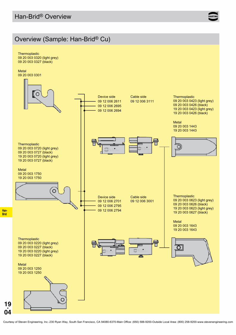
Han- Brid
19.04
Han-Brid® Overview
Overview (Sample: Han-Brid® Cu)
Thermoplastic 09200030320(lightgrey) 09200030327(black)
Metal 09200030301
Thermoplastic 09200030720(lightgrey) 09200030727(black) 19200030720(lightgrey) 19200030727(black)
Metal 09200031750 19200031750
Thermoplastic 09200030220(lightgrey) 09200030227(black) 19200030220(lightgrey) 19200030227(black)
Metal 09200031250 19200031250
Thermoplastic 09200030423(lightgrey) 09200030426(black) 19200030423(lightgrey) 19200030426(black)
Metal 09200031443 19200031443
Thermoplastic 09200030623(lightgrey) 09200030626(black) 19200030623(lightgrey) 19200030627(black)
Metal 09200031643 19200031643
Device side091200626110912006269509120062694
Device side 091200627010912006279509120062794
Cable side09120063111
Cable side 09120063001
Courtesy of Steven Engineering, Inc.-230 Ryan Way, South San Francisco, CA 94080-6370-Main Office: (650) 588-9200-Outside Local Area: (800) 258-9200-www.stevenengineering.com

Han- Brid
19.05
Han-Brid® Overview
Overview (Sample: Han-Brid® RJ45 C)
Thermoplastic 09200030320(lightgrey) 09200030327(black)
Metal 09200030301
Device side09120032770 09120032774 09120032776
Cable side09120033011 09120033021 09120033031
Thermoplastic 09200030423(lightgrey) 09200030426(black) 19200030423(lightgrey) 19200030427(black)
Metal 09200031443 19200031443
Thermoplastic 09200030623(lightgrey) 09200030626(black) 19200030623(lightgrey) 19200030627(black)
Metal 09200031643 19200031643
Courtesy of Steven Engineering, Inc.-230 Ryan Way, South San Francisco, CA 94080-6370-Main Office: (650) 588-9200-Outside Local Area: (800) 258-9200-www.stevenengineering.com
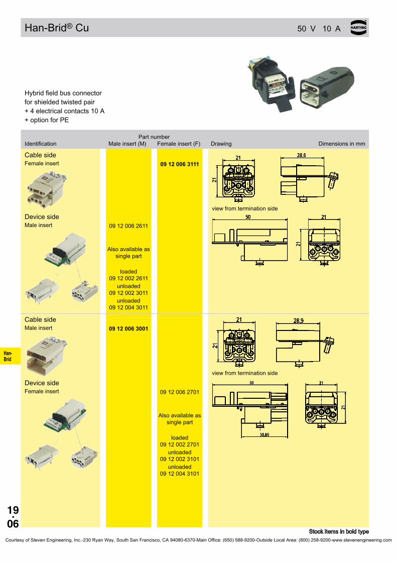
Han- Brid
19.06
Han-Brid® Cu 50 V 10 A
09 12 006 3111
09 12 006 2611
09 12 002 2611
09 12 002 3011
09 12 004 3011
09 12 006 3001
09 12 006 2701
09 12 002 2701
09 12 002 3101
09 12 004 3101
Stock items in bold type
Hybridfieldbusconnectorfor shielded twisted pair+4electricalcontacts10A+optionforPE
Part number Identification Maleinsert(M) Femaleinsert(F) Drawing Dimensionsinmm
Cable side Female insert
view from termination side
Device side Maleinsert
Also available as single part
loaded
unloaded
unloaded
Cable side Maleinsert
view from termination side
Device side Female insert
Also available as single part
loaded
unloaded
unloaded
Courtesy of Steven Engineering, Inc.-230 Ryan Way, South San Francisco, CA 94080-6370-Main Office: (650) 588-9200-Outside Local Area: (800) 258-9200-www.stevenengineering.com

Han- Brid
19.07
Han-Brid® Cu
09 12 006 2695
09 12 006 2795
09 12 006 2694
09 12 006 2794
09 12 006 2691 09 12 006 2791
09 12 006 2692 09 12 006 2792
Stock items in bold type
Part number Identification Maleinsert(M) Femaleinsert(F) Drawing Dimensionsinmm
Panel feed through with cage clamp
Coupling / Panel feed through
X=Cuttingoffthefinallowsthe use in cable to cable housings
Bus terminator
Plastic hoods/housings
Hoods/Housings, metal
Courtesy of Steven Engineering, Inc.-230 Ryan Way, South San Francisco, CA 94080-6370-Main Office: (650) 588-9200-Outside Local Area: (800) 258-9200-www.stevenengineering.com

Han- Brid
19.08
09 12 004 2711
09 12 004 2713
09 12 004 2716
09 12 004 3111
09 12 004 3113
09 12 004 3116
09 12 004 2611
09 12 004 3011
Stock items in bold type* HCS®=Hard Clad Silica (is registered trade mark of the SpecTran Corporation)
Hybridfieldbusconnectorwith F.O. transmitter and receiver+4electricalcontacts10A+optionforPE
Part number Identification Maleinsert(M) Femaleinsert(F) Drawing Dimensionsinmm
Cable side, female F.O.(m)+HanD® (f)
view from termination side
with F.O. contacts for POF
for POF crimpless
for HCS®* fibre
without F.O. contacts for POF
for POF crimpless
for HCS®* fibre
Device side, male F.O.(f)+HanD® (m)
view from termination side
with PCB
without PCB
Han-Brid® F.O. 50 V 10 A
Courtesy of Steven Engineering, Inc.-230 Ryan Way, South San Francisco, CA 94080-6370-Main Office: (650) 588-9200-Outside Local Area: (800) 258-9200-www.stevenengineering.com
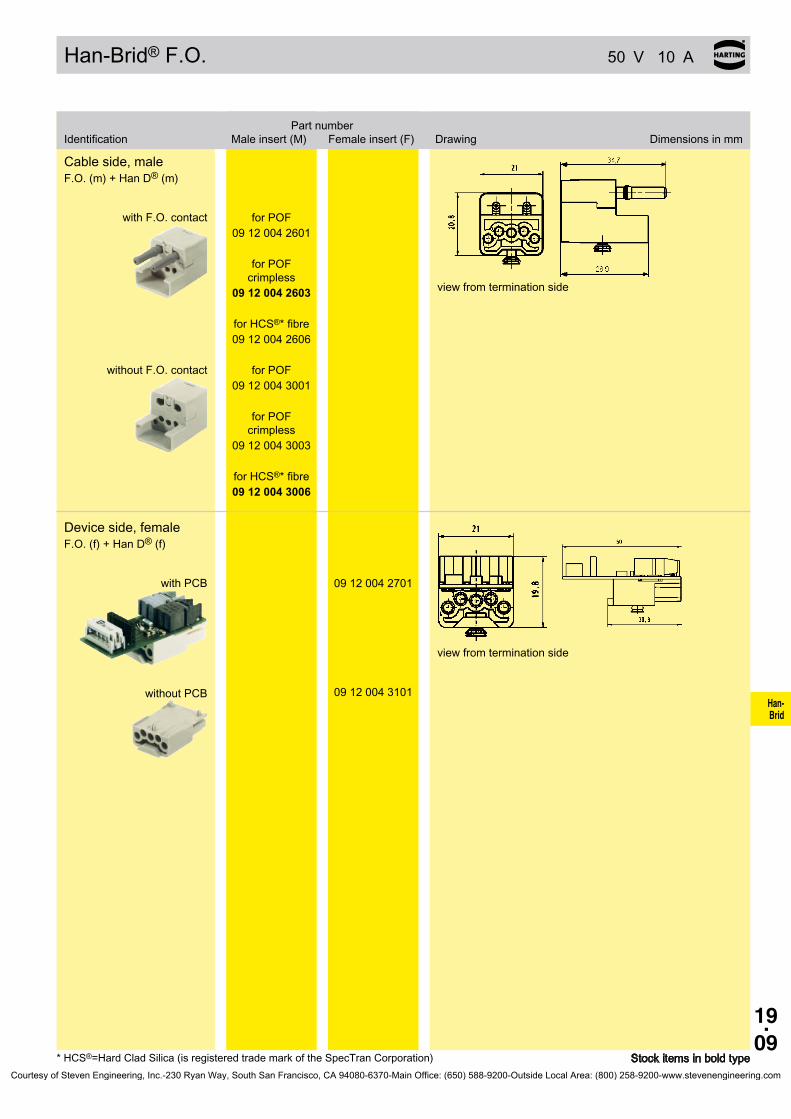
Han- Brid
19.09
09 12 004 2601
09 12 004 2603
09 12 004 2606
09 12 004 3001
09 12 004 3003
09 12 004 3006
09 12 004 2701
09 12 004 3101
Stock items in bold type* HCS®=Hard Clad Silica (is registered trade mark of the SpecTran Corporation)
Part number Identification Maleinsert(M) Femaleinsert(F) Drawing Dimensionsinmm
Cable side, male F.O.(m)+HanD® (m)
view from termination side
with F.O. contact for POF
for POF crimpless
for HCS®* fibre
without F.O. contact for POF
for POF crimpless
for HCS®* fibre
Device side, female F.O.(f)+HanD® (f)
view from termination side
with PCB
without PCB
Han-Brid® F.O. 50 V 10 A
Courtesy of Steven Engineering, Inc.-230 Ryan Way, South San Francisco, CA 94080-6370-Main Office: (650) 588-9200-Outside Local Area: (800) 258-9200-www.stevenengineering.com
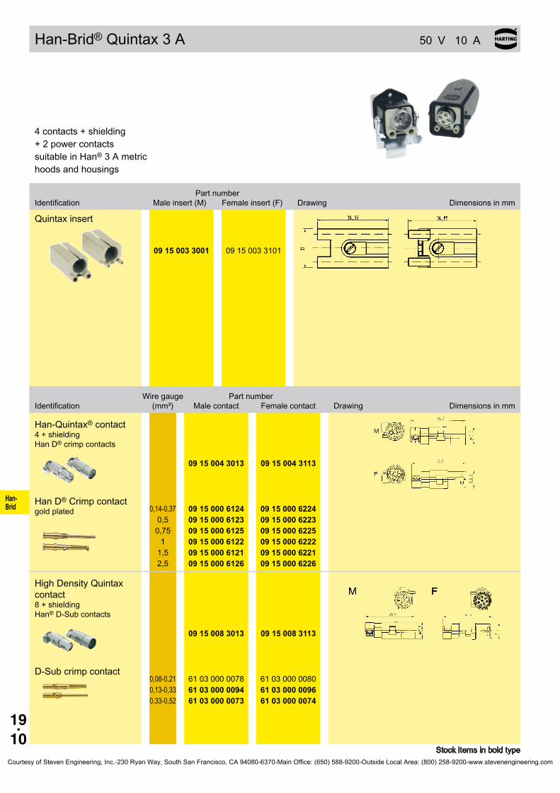
Han- Brid
19.10
Han-Brid® Quintax 3 A 50 V 10 A
09 15 003 3001 09 15 003 3101
09 15 004 3013 09 15 004 3113
09 15 000 6124
09 15 000 612309 15 000 612509 15 000 612209 15 000 612109 15 000 6126
09 15 000 622409 15 000 622309 15 000 622509 15 000 622209 15 000 622109 15 000 6226
09 15 008 3013 09 15 008 3113
61 03 000 007861 03 000 009461 03 000 0073
61 03 000 008061 03 000 009661 03 000 0074
Stock items in bold type
4contacts+shielding+2powercontactssuitable in Han® 3 A metric hoods and housings
Part number Identification Maleinsert(M) Femaleinsert(F) Drawing Dimensionsinmm
Quintax insert
Wire gauge Part number Identification (mm²) Malecontact Femalecontact Drawing Dimensionsinmm
Han-Quintax® contact 4+shielding Han D® crimp contacts
Han D® Crimp contact gold plated 0,14-0,37
0,50,75
11,52,5
High Density Quintax contact 8+shielding Han® D-Sub contacts
D-Sub crimp contact0,08-0,210,13-0,330,33-0,52
Courtesy of Steven Engineering, Inc.-230 Ryan Way, South San Francisco, CA 94080-6370-Main Office: (650) 588-9200-Outside Local Area: (800) 258-9200-www.stevenengineering.com
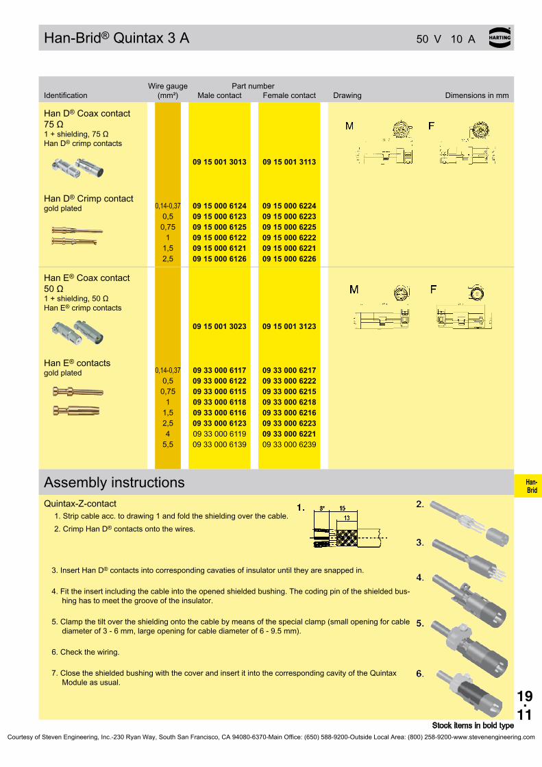
Han- Brid
19.11
Han-Brid® Quintax 3 A 50 V 10 A
09 15 001 3013 09 15 001 3113
09 15 000 6124
09 15 000 612309 15 000 612509 15 000 612209 15 000 612109 15 000 6126
09 15 000 622409 15 000 622309 15 000 622509 15 000 622209 15 000 622109 15 000 6226
09 15 001 3023 09 15 001 3123
09 33 000 6117
09 33 000 612209 33 000 611509 33 000 611809 33 000 611609 33 000 612309 33 000 611909 33 000 6139
09 33 000 621709 33 000 622209 33 000 621509 33 000 621809 33 000 621609 33 000 622309 33 000 622109 33 000 6239
Stock items in bold type
Wire gauge Part number Identification (mm²) Malecontact Femalecontact Drawing Dimensionsinmm
Han D® Coax contact 75Ω 1+shielding,75Ω Han D® crimp contacts
Han D® Crimp contact gold plated 0,14-0,37
0,50,75
11,52,5
Han E® Coax contact 50Ω 1+shielding,50Ω Han E® crimp contacts
Han E® contacts gold plated 0,14-0,37
0,50,75
11,52,54
5,5
Assembly instructionsQuintax-Z-contact
1. Strip cable acc. to drawing 1 and fold the shielding over the cable.2. Crimp Han D® contacts onto the wires.
3.InsertHanD® contacts into corresponding cavaties of insulator until they are snapped in.
4. Fit the insert including the cable into the opened shielded bushing. The coding pin of the shielded bus-hing has to meet the groove of the insulator.
5. Clamp the tilt over the shielding onto the cable by means of the special clamp (small opening for cable diameterof3-6mm,largeopeningforcablediameterof6-9.5mm).
6.Checkthewiring.
7.ClosetheshieldedbushingwiththecoverandinsertitintothecorrespondingcavityoftheQuintaxModuleasusual.
Courtesy of Steven Engineering, Inc.-230 Ryan Way, South San Francisco, CA 94080-6370-Main Office: (650) 588-9200-Outside Local Area: (800) 258-9200-www.stevenengineering.com

Han- Brid
19.12
Han-Brid® RJ45 C 24 V 10 A
09 12 003 3011
09 12 003 3021
09 12 003 3031
09 12 003 2774
09 12 003 2776
09 12 003 2770
Stock items in bold type
Hybrid network connector+2electricalcontacts10A
Identification Partnumber Drawing Dimensionsinmm
Han-Brid® RJ45 C withRJIndustrial
Han-Brid® RJ45 C with Stewart RJ45
Han-Brid® RJ45 C withHIROSERJ45
Panel feed through straight
Panel feed through angled
Panel feed through with 4 pole terminal block
Courtesy of Steven Engineering, Inc.-230 Ryan Way, South San Francisco, CA 94080-6370-Main Office: (650) 588-9200-Outside Local Area: (800) 258-9200-www.stevenengineering.com

Han- Brid
19.13
Notes
Courtesy of Steven Engineering, Inc.-230 Ryan Way, South San Francisco, CA 94080-6370-Main Office: (650) 588-9200-Outside Local Area: (800) 258-9200-www.stevenengineering.com

Han- Brid
19.14
Han-Brid® USB / Han-Brid® FireWire
Han-Brid® USB Han-Brid® FireWireFeatures• InsertforallHan® 3 A hoods and housings• Hoodwithgluedsealing• Simpleandlow-costterminationviainsertofa
patch cable• Strain-reliefviacabletie
Technical characteristicsUSB style A, 2.0 StandardSpecifications DINEN60664-1 DINEN61984 Numberofcontacts 4 Electrical data acc.toEN61984 1 A 50 V 0.8 kV 3 Rated current 1 A Rated voltage 50 V Ratedimpulsevoltage 0.8kV Pollution degree 3Material polycarbonate Insulationresistance ≥1010Ω Contactresistance ≥4mΩ Temperaturerange -40°C...+85°C Flammabilityacc.toUL94 V0 Mechanicalworkinglife -matingcycles ≥500
Features• InsertforallHan® 3 A hoods and housings• Hoodwithgluedsealing• Simpleandlow-costterminationviainsertofa
patch cable• Strain-reliefviacabletie• CompatibletoIEEE1394
Technical characteristicsFirewireIEEE1394Specifications DINEN60664-1 DINEN61984 Numberofcontacts 6 Electrical data acc.toEN61984 1 A 50 V 0.8 kV 3 Rated current 1 A Rated voltage 50 V Ratedimpulsevoltage 0.8kV Pollution degree 3Material polycarbonate Insulationresistance ≥1010Ω Contactresistance ≥4mΩ Temperaturerange -40°C...+85°C Flammabilityacc.toUL94 V0 Mechanicalworkinglife -matingcycles ≥500
Courtesy of Steven Engineering, Inc.-230 Ryan Way, South San Francisco, CA 94080-6370-Main Office: (650) 588-9200-Outside Local Area: (800) 258-9200-www.stevenengineering.com

Han- Brid
19.15
Han-Brid® USB / Han-Brid® FireWire 50 V 1 A
09 12 001 3091
09 12 001 2794
09 12 001 3071
09 12 001 2774
Stock items in bold type
Part number Identification Maleinsert(M) Femaleinsert(F) Drawing Dimensionsinmm
Han-Brid® USBCable side Female insert
Device side Maleinsert
Han-Brid® FireWireCable side Female insert
Device side Maleinsert
Courtesy of Steven Engineering, Inc.-230 Ryan Way, South San Francisco, CA 94080-6370-Main Office: (650) 588-9200-Outside Local Area: (800) 258-9200-www.stevenengineering.com

Han- Brid
19.16
Han® 4 A SC Technical characteristics
Features• Suitablewithhousings,sizeHan® 3 A including
versions Han®M,Han®EMVandHan® HPR• DegreeofprotectionuptoIP68• ForHARTINGfibreopticSCcontacts;upto4SC
contacts per connector• ForMultimodefibre50-62.5/125µmandSingle-
modefibre9/125µm• Fullceramicsleevesforaminimalinsertionloss
Assembly instructionsMaleinsert(09200044701)
Assemble the SC contact(1) Push the SC contact from the side into the relevant insert(2) Push the spring clip over the contact body.
Femaleinsert(09200044711)
Assemble the SC contact(1) Push the centering ferrule (included in delivery) on the SC contact(2) Push the SC contact from the side into the relevant insert(3) Push the spring clip over the contact body.
Courtesy of Steven Engineering, Inc.-230 Ryan Way, South San Francisco, CA 94080-6370-Main Office: (650) 588-9200-Outside Local Area: (800) 258-9200-www.stevenengineering.com

Han- Brid
19.17
09 20 004 4701 09 20 004 4711
20 10 125 5211 20 10 125 5211
20 10 230 5211 20 10 230 5211
20 10 001 5217 20 10 001 5217
20 10 001 5211 20 10 001 5211
Han® 4 A SC Size3A
Stock items in bold type
Numberofcontacts
4
Part number Identification Maleinsert(M) Femaleinsert(F) Drawing Dimensionsinmm
SC moduleOrder SC contacts separately
Contact arrangement view from termination side
The female inserts are equipped with centering ferrules. 4 ferrules are included in delivery range.
Part number Identification Malecontact Femalecontact Drawing Dimensionsinmm
SC contactforGIfibre 50/125µmor 62.5/125µm ceramic ferrule
forSIfibre(HCS®) 200/230µm
with quick assembly tech-nique for 1 mm POF
with crimp technique for 1 mm POF
Courtesy of Steven Engineering, Inc.-230 Ryan Way, South San Francisco, CA 94080-6370-Main Office: (650) 588-9200-Outside Local Area: (800) 258-9200-www.stevenengineering.com

Han- Brid
19.18
Technical characteristics
Han® 3 A Standard Hoods/Housings Metalhoods/housingsforindustrialapplicationsMaterial zincdie-castColour RAL7037(grey)Surface powder-coatedLockingelement steel,zinc-platedLevertype lever, metalHoods/Housings sealing NBRLimitingtemperatures -40°C...+125°CFlammabilityacc.toUL94 V 0Degree of protection acc. toDINEN60529 for coupled connector
IP44 IP67isachievedwithsealscrew09200009918
Han® 3 A Hoods/Housings Plastic hoods/housings for industrial applicationsMaterial polycarbonateColour RAL7032(lightgrey)
RAL9005(black)Lockingelement PolyamideLevertype Lever,plasticHoods/Housings sealing NBRLimitingtemperatures -40°C...+125°CApprovalacc.toUL50 NEMA4/12Flammabilityacc.toUL94 V 0Degree of protection acc. toDINEN60529 for coupled connector IP67
Han®MHoods/Housings Hoods/Housings for higher environmental require-mentsMaterial -SizeHan® 3 A
aluminium die-cast zincdie-cast
Colour RAL9005(black)Surface - Top coat
Epoxy powder paint
Lockingelement Stainless steelLevertype lever, metalHoods/Housings sealing FPMLimitingtemperatures -40°C...+125°CApprovalacc.toUL50 NEMA4/12Degree of protection acc. toDINEN60529 for coupled connector IP65-SizeHan® 3 A IP44
IP67isachievedwithsealscrew09200009918
Han®3AEMCHoods/Housings Hoods/HousingsforhigherEMCrequirementsMaterial zincdie-castColour non colouredSurface electrical conductiveLockingelement steel,zinc-platedLevertype lever, metalHoods/Housings sealing NBRLimitingtemperatures -40°C...+125°CDegree of protection acc. toDINEN60529 for coupled connector
IP44 IP67isachievedwithsealscrew09200009918
Han-INOX® Hoods/Housings for higher corrosion requirementsMaterial stainless steelColour non colouredSurface electrical conductiveLockingelement Stainless steelLevertype lever, metalHoods/Housings sealing NBRLimitingtemperatures -40°C...+125°CDegree of protection acc. toDINEN60529 for coupled connector IP65-SizeHan® 3 A IP44
IP67isachievedwithsealscrew09200009918
Courtesy of Steven Engineering, Inc.-230 Ryan Way, South San Francisco, CA 94080-6370-Main Office: (650) 588-9200-Outside Local Area: (800) 258-9200-www.stevenengineering.com
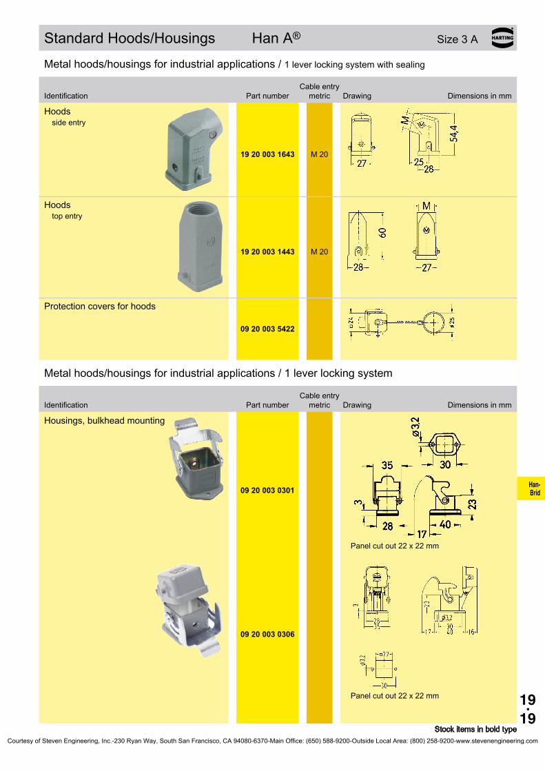
Han- Brid
19.19
19 20 003 1643
M 20
19 20 003 1443
M 20
09 20 003 5422
09 20 003 0301
09 20 003 0306
Standard Hoods/Housings Han A® Size3A
Metalhoods/housingsforindustrialapplications/1 lever locking system with sealing
Cable entry Identification Partnumber metric Drawing Dimensionsinmm
Stock items in bold type
Hoodsside entry
Hoodstop entry
Protection covers for hoods
Metalhoods/housingsforindustrialapplications/1leverlockingsystem
Cable entry Identification Partnumber metric Drawing Dimensionsinmm
Housings, bulkhead mounting
Panel cut out 22 x 22 mm
Panel cut out 22 x 22 mm
Courtesy of Steven Engineering, Inc.-230 Ryan Way, South San Francisco, CA 94080-6370-Main Office: (650) 588-9200-Outside Local Area: (800) 258-9200-www.stevenengineering.com
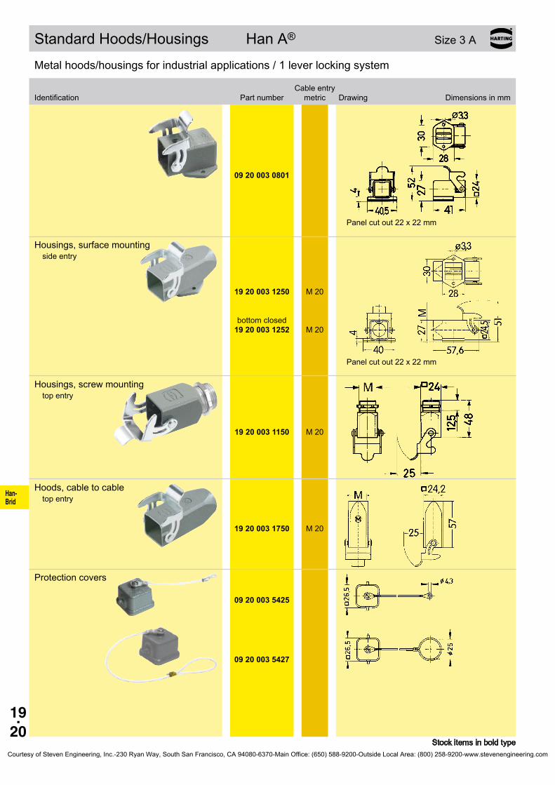
Han- Brid
19.20
09 20 003 0801
19 20 003 1250
19 20 003 1252
M 20
M 20
19 20 003 1150
M 20
19 20 003 1750
M 20
09 20 003 5425
09 20 003 5427
Standard Hoods/Housings Han A® Size3A
Metalhoods/housingsforindustrialapplications/1leverlockingsystem
Cable entry Identification Partnumber metric Drawing Dimensionsinmm
Stock items in bold type
Panel cut out 22 x 22 mm
Housings, surface mountingside entry
bottom closed
Panel cut out 22 x 22 mm
Housings, screw mountingtop entry
Hoods, cable to cabletop entry
Protection covers
Courtesy of Steven Engineering, Inc.-230 Ryan Way, South San Francisco, CA 94080-6370-Main Office: (650) 588-9200-Outside Local Area: (800) 258-9200-www.stevenengineering.com

Han- Brid
19.21
19 20 003 0623
19 20 003 0626
M 20
M 20
19 20 003 0423
19 20 003 0426
M 20
M 20
09 20 003 5442
09 20 003 0320
09 20 003 0327
09 20 003 0820
09 20 003 0827
Standard Hoods/Housings Han A® Size3A
Plastic hoods/housings for industrial applications / 1 lever locking system with sealing
Cable entry Identification Partnumber metric Drawing Dimensionsinmm
Stock items in bold type
Hoodsside entry
light grey
black
Hoodstop entry
light grey
black
Protection covers for hoods
light grey
Plastic hoods/housings for industrial applications / 1 lever locking system
Cable entry Identification Partnumber metric Drawing Dimensionsinmm
Housings, bulkhead mounting
light grey
black
Panel cut out 22 x 22 mm
light grey
black
Panel cut out 22 x 22 mm
Courtesy of Steven Engineering, Inc.-230 Ryan Way, South San Francisco, CA 94080-6370-Main Office: (650) 588-9200-Outside Local Area: (800) 258-9200-www.stevenengineering.com
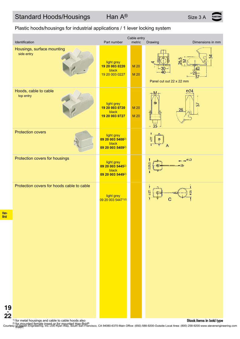
Han- Brid
19.22
19 20 003 0220
19 20 003 0227
M 20
M 20
19 20 003 0720
19 20 003 0727
M 20
M 20
09 20 003 54082)
09 20 003 54092)
09 20 003 54452)
09 20 003 54492)
09 20 003 54471)2)
Standard Hoods/Housings Han A® Size3A
Plastic hoods/housings for industrial applications / 1 lever locking system
Cable entry Identification Partnumber metric Drawing Dimensionsinmm
1) for metal housings and cable to cable hoods also2) for mounted female insert or for mounted Han-Brid®
insert
Stock items in bold type
Housings, surface mountingside entry
light grey
black
Panel cut out 22 x 22 mm
Hoods, cable to cabletop entry
light grey
black
Protection coverslight grey
black
Protection covers for housingslight grey
black
Protection covers for hoods cable to cable
light grey
Courtesy of Steven Engineering, Inc.-230 Ryan Way, South San Francisco, CA 94080-6370-Main Office: (650) 588-9200-Outside Local Area: (800) 258-9200-www.stevenengineering.com
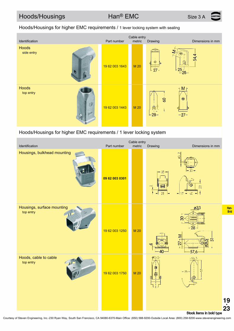
Han- Brid
19.23
19 62 003 1643
M 20
19 62 003 1443
M 20
09 62 003 0301
19 62 003 1250
M 20
19 62 003 1750
M 20
Hoods/Housings Han®EMC Size3A
Hoods/HousingsforhigherEMCrequirements/1 lever locking system with sealing
Cable entry Identification Partnumber metric Drawing Dimensionsinmm
Stock items in bold type
Hoodsside entry
Hoodstop entry
Hoods/HousingsforhigherEMCrequirements/1leverlockingsystem
Cable entry Identification Partnumber metric Drawing Dimensionsinmm
Housings, bulkhead mounting
Housings, surface mountingtop entry
Hoods, cable to cabletop entry
Courtesy of Steven Engineering, Inc.-230 Ryan Way, South San Francisco, CA 94080-6370-Main Office: (650) 588-9200-Outside Local Area: (800) 258-9200-www.stevenengineering.com

Han- Brid
19.24
19 37 003 1643
M 20
19 37 003 1443
M 20
09 37 003 0301
19 37 003 1250
M 20
19 37 003 1750
M 20
Hoods/Housings Han®M Size3A
Hoods/Housings for higher environmental requirements / 1 lever locking system with sealing
Cable entry Identification Partnumber metric Drawing Dimensionsinmm
Stock items in bold type
Hoodsside entry
Hoodstop entry
Hoods/Housings for higher environmental requirements / 1 lever locking system
Cable entry Identification Partnumber metric Drawing Dimensionsinmm
Housings, bulkhead mountingtop entry
Housings, surface mountingtop entry
Hoods, cable to cabletop entry
Courtesy of Steven Engineering, Inc.-230 Ryan Way, South San Francisco, CA 94080-6370-Main Office: (650) 588-9200-Outside Local Area: (800) 258-9200-www.stevenengineering.com

Han- Brid
19.25
19 44 003 1443
M 20
19 44 003 0301
19 44 000 5082
M 20
Hoods/Housings Han-INOX® Size3A
Hoods/Housings made of stainless steel / 1 lever locking system with sealing
Cable entry Identification Partnumber metric Drawing Dimensionsinmm
Stock items in bold type
Hoodstop entry
Hoods/Housings made of stainless steel / 1 lever locking system
Cable entry Identification Partnumber metric Drawing Dimensionsinmm
Housings, bulkhead mounting
Panel cut out 22 x 22 mm
Cable gland
Courtesy of Steven Engineering, Inc.-230 Ryan Way, South San Francisco, CA 94080-6370-Main Office: (650) 588-9200-Outside Local Area: (800) 258-9200-www.stevenengineering.com
Han- Brid
19.26
Notes
Courtesy of Steven Engineering, Inc.-230 Ryan Way, South San Francisco, CA 94080-6370-Main Office: (650) 588-9200-Outside Local Area: (800) 258-9200-www.stevenengineering.com

20.01
PCB- Adapter
Contents
Han® PCB adapter
Page
Technical characteristics PCB adapter for Han DD® . . . . . . . . . . . . . . . . . . 20.02
Han DD® Inserts with PCB adapter . . . . . . . . . . . . . . . . . . . . . . . . . . . . . . . 20.03
Technical characteristics PCB adapter for Han E® . . . . . . . . . . . . . . . . . . . 20.04
Han E® Inserts with PCB adapter . . . . . . . . . . . . . . . . . . . . . . . . . . . . . . . . 20.05
Technical characteristics PCB adapter for Han® Q 4/2 . . . . . . . . . . . . . . . . 20.06
Han® Q 4/2 Inserts with PCB adapter . . . . . . . . . . . . . . . . . . . . . . . . . . . . . 20.07
Technical characteristics PCB adapter for Han® Q 5/0 . . . . . . . . . . . . . . . . 20.08
Han® Q 5/0 Inserts with PCB adapter . . . . . . . . . . . . . . . . . . . . . . . . . . . . . 20.09
Technical characteristics PCB adapter for Han® Q 7/0 . . . . . . . . . . . . . . . . 20.10
Han® Q 7/0 Inserts with PCB adapter . . . . . . . . . . . . . . . . . . . . . . . . . . . . . 20.11
Technical characteristics PCB adapter for Han® Q 8/0 . . . . . . . . . . . . . . . . 20.12
Han® Q 8/0 Inserts with PCB adapter . . . . . . . . . . . . . . . . . . . . . . . . . . . . . 20.13
Technical characteristics PCB adapter for Han-Modular® . . . . . . . . . . . . . . 20.14
Han-Modular® Inserts with PCB adapter . . . . . . . . . . . . . . . . . . . . . . . . . . . 20.15
Applications . . . . . . . . . . . . . . . . . . . . . . . . . . . . . . . . . . . . . . . . . . . . . . . . . 20.16
Courtesy of Steven Engineering, Inc.-230 Ryan Way, South San Francisco, CA 94080-6370-Main Office: (650) 588-9200-Outside Local Area: (800) 258-9200-www.stevenengineering.com

20.02
Han® 42 DD Han® 24 DD Han® 72 DD Han® 108 DD
PCB- Adapter
PCB adapter for Han DD®
Features• Robust design• Suitable for standard and EMC housings• Low wiring costs• High contact density
Technical characteristicsApprovals
Electrical data acc. to EN 61 984 7.5 A 250 V 4 kV 3 Rated current 7.5 A Rated voltage 250 V Rated impulse voltage 4 kV Pollution degree 3
Rated voltage acc. to UL/CSA 250 V
Insulationresistance ≥1010ΩMaterial polyamideLimiting temperatures -40 °C ... +125 °CFlammability acc. to UL 94 HB
Layout of PCB
Assembly situation
1) for Han®BEMChousingsspacingof12.5±0.2mmisnecessaryasnoflangesealisused
Courtesy of Steven Engineering, Inc.-230 Ryan Way, South San Francisco, CA 94080-6370-Main Office: (650) 588-9200-Outside Local Area: (800) 258-9200-www.stevenengineering.com

20.03
a b
24 DD42 DD72 DD108 DD
Han® 24 DD 6 B 09 16 024 3001 09 16 024 3101Han® 42 DD 10 B 09 16 042 3001 09 16 042 3101Han® 72 DD 16 B 09 16 072 3001 09 16 072 3101Han® 108 DD 24 B 09 16 108 3001 09 16 108 3101
09 15 000 6191 09 15 000 6291
a09 16 000 990509 16 000 9908
09 16 000 9905 09 16 000 9908
a b6 B 70 80 48 x 3510 B 83 93 60 x 3516 B 103 113 82 x 3524 B 130 140 108 x 35
6 B 10 B 16 B 24 B
09 30 006 0301 09 30 010 0301 09 30 016 0301 09 30 024 0301
PCB- Adapter
Han DD® Inserts with PCB adapter 250 V 7.5 A
Stock items in bold type
SizePart number
insert Male insert (M) Female insert (F) Drawing Dimensions in mm
Order contacts separately
44 5157 64
77.5 84.5104 111
1) Distance for contact max. 21 mm
Part numberHan DD® double contact Male contacts Female contacts Drawing Dimensions in mm
to connect the PCP-Adapter
PCB adapterPCB thick-
ness Part number Drawing Dimensions in mm
Part number2.63.4
1.6 mm 2.4 mm
Housings bulkhead mounting Size Part number Drawing Dimensions in mm
Size Panel cut out
Size 6 B with 1 locking lever
Further informations see chapter 02 (Han D®/Han DD®)
Courtesy of Steven Engineering, Inc.-230 Ryan Way, South San Francisco, CA 94080-6370-Main Office: (650) 588-9200-Outside Local Area: (800) 258-9200-www.stevenengineering.com

20.04
Han® 6 E Han® 10 E Han® 16 E Han® 24 E
PCB- Adapter
PCB adapter for Han E®
Features• Robust design• Suitable for standard and EMC housings• Low wiring costs• Counter connector available with screw or crimp or
cage clamp termination
Technical characteristics
Electrical data acc. to EN 61 984 16 A 500 V 6 kV 3 Rated current 16 A Rated voltage 500 V Rated impulse voltage 6 kV Pollution degree 3
Insulationresistance ≥1010ΩMaterial polycarbonateLimiting temperatures -40 °C ... +125 °CFlammability acc. to UL 94 V 0
Layout of PCB
Assembly situation
1) for Han®BEMChousingsspacingof12.5±0.7mmisnecessaryasnoflangesealisused
Courtesy of Steven Engineering, Inc.-230 Ryan Way, South San Francisco, CA 94080-6370-Main Office: (650) 588-9200-Outside Local Area: (800) 258-9200-www.stevenengineering.com

20.05
e f
6 E10 E16 E24 E
Han® 6 E 6 B 09 33 006 2602 09 33 006 2702Han® 10 E 10 B 09 33 010 2602 09 33 010 2702Han® 16 E 16 B 09 33 016 2602 09 33 016 2702Han® 24 E 24 B 09 33 024 2602 09 33 024 2702
09 33 000 6180 09 33 000 6280
09 33 000 9996
a b6 B 70 80 48 x 3510 B 83 93 60 x 3516 B 103 113 82 x 3524 B 130 140 108 x 35
6 B 10 B 16 B 24 B
09 30 006 0301 09 30 010 0301 09 30 016 0301 09 30 024 0301
PCB- Adapter
Han E® Inserts with PCB adapter 500 V 16 A
Stock items in bold type
SizePart number
insert Male insert (M) Female insert (F) Drawing Dimensions in mm
Order contacts separately
44 5157 64
77.5 84.5104 111
1) Distance for contact max. 21 mm
Part numberHan E® double contacts Male contacts Female contacts Drawing Dimensions in mm
to connect the PCP-Adapter
PCB adapter Part number Drawing Dimensions in mm
Housings bulkhead mounting Size Part number Drawing Dimensions in mm
Size a b Panel cut out
Size 6 B with 1 locking lever
Further informations see chapter 03 (Han E®)
Courtesy of Steven Engineering, Inc.-230 Ryan Way, South San Francisco, CA 94080-6370-Main Office: (650) 588-9200-Outside Local Area: (800) 258-9200-www.stevenengineering.com

20.06
PCB- Adapter
PCB adapter for Han® Q 4/2
Features• Robust Design• Suitable for Han-Compact® hoods and housings• Low wiring costs• High contact density
Technical characteristicsApprovals ,
Power area 30 A 400/690 V 6 kV 2 Rated current 30 A Rated voltage conductor - ground 400 V Rated voltage conductor - conductor 690 V Rated impulse voltage 6 kV Pollution degree 2Signal area 7.5 A 250 V 4 kV 2 Rated current 7.5 A Rated voltage 250 V Rated impulse voltage 4 kV Pollution degree 2
Insulationresistance ≥1010ΩMaterial LCPLimiting temperatures -40 °C ... +125 °CFlammability acc. to UL 94 V 0
Layout of PCBDimensions in mm
Assembly situationX = 16+1 with signal contact or 16+2 without signal contact
Courtesy of Steven Engineering, Inc.-230 Ryan Way, South San Francisco, CA 94080-6370-Main Office: (650) 588-9200-Outside Local Area: (800) 258-9200-www.stevenengineering.com
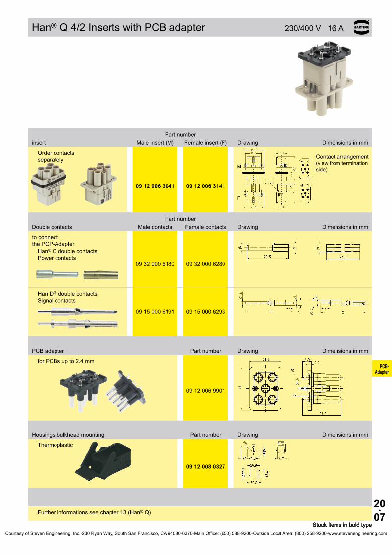
20.07
09 12 006 3041 09 12 006 3141
09 32 000 6180 09 32 000 6280
09 15 000 6191 09 15 000 6293
09 12 006 9901
09 12 008 0327
PCB- Adapter
Han® Q 4/2 Inserts with PCB adapter 230/400 V 16 A
Stock items in bold type
Part numberinsert Male insert (M) Female insert (F) Drawing Dimensions in mm
Order contacts separately Contact arrangement
(view from termination side)
Part numberDouble contacts Male contacts Female contacts Drawing Dimensions in mm
to connect the PCP-Adapter
Han® C double contacts Power contacts
Han D® double contacts Signal contacts
PCB adapter Part number Drawing Dimensions in mm
for PCBs up to 2.4 mm
Housings bulkhead mounting Part number Drawing Dimensions in mm
Thermoplastic
Further informations see chapter 13 (Han® Q)
Courtesy of Steven Engineering, Inc.-230 Ryan Way, South San Francisco, CA 94080-6370-Main Office: (650) 588-9200-Outside Local Area: (800) 258-9200-www.stevenengineering.com
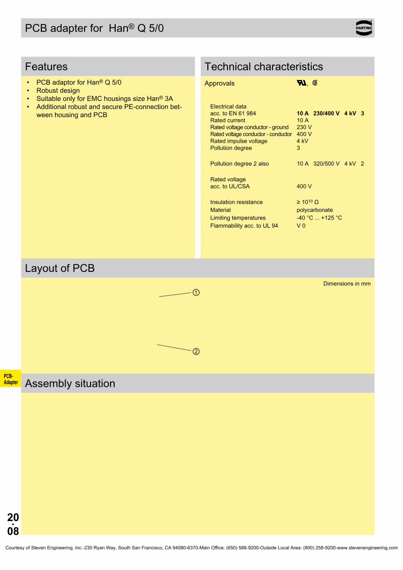
20.08
①
②
PCB- Adapter
PCB adapter for Han® Q 5/0
Features• PCB adaptor for Han® Q 5/0• Robust design• Suitable only for EMC housings size Han® 3A• Additional robust and secure PE-connection bet-
ween housing and PCB
Technical characteristicsApprovals ,
Electrical data acc. to EN 61 984 10 A 230/400 V 4 kV 3 Rated current 10 A Rated voltage conductor - ground 230 V Rated voltage conductor - conductor 400 V Rated impulse voltage 4 kV Pollution degree 3
Pollution degree 2 also 10 A 320/500 V 4 kV 2
Rated voltage acc. to UL/CSA 400 V
Insulationresistance ≥1010ΩMaterial polycarbonateLimiting temperatures -40 °C ... +125 °CFlammability acc. to UL 94 V 0
Layout of PCBDimensions in mm
Assembly situation
Courtesy of Steven Engineering, Inc.-230 Ryan Way, South San Francisco, CA 94080-6370-Main Office: (650) 588-9200-Outside Local Area: (800) 258-9200-www.stevenengineering.com

20.09
09 12 005 3001 09 12 005 3101
09 33 000 6195 09 33 000 6295
09 12 000 9905
09 62 003 0304
PCB- Adapter
Han® Q 5/0 Inserts with PCB adapter 230/400 V 10 A
Stock items in bold type
Part numberinsert Male insert (M) Female insert (F) Drawing Dimensions in mm
Order contacts separately
Distance for contact max. 21 mm
Part numberSolder contacts Male contacts Female contacts Drawing Dimensions in mm
to connect the PCP-Adapter
PCB adapter Part number Drawing Dimensions in mm
with PE contact panel
Adapter PE contact panel
Housings bulkhead mounting Part number Drawing Dimensions in mm
Metal
Further informations see chapter 13 (Han® Q)
Courtesy of Steven Engineering, Inc.-230 Ryan Way, South San Francisco, CA 94080-6370-Main Office: (650) 588-9200-Outside Local Area: (800) 258-9200-www.stevenengineering.com

20.10
PCB- Adapter
PCB adapter for Han® Q 7/0
Features• PCB adaptor for Han® Q 7/0• Robust design• Suitable for standard and EMC housings size
Han® 3A• High contact density
Technical characteristicsApprovals ,
Electrical data acc. to EN 61 984 7.5 A 250 V 4 kV 3 Rated current 7.5 A Rated voltage 250 V Rated impulse voltage 4 kV Pollution degree 3
Insulationresistance ≥1010ΩMaterial polycarbonateLimiting temperatures -40 °C ... +125 °CFlammability acc. to UL 94 V 0
Layout of PCBDimensions in mm
Assembly situation
Courtesy of Steven Engineering, Inc.-230 Ryan Way, South San Francisco, CA 94080-6370-Main Office: (650) 588-9200-Outside Local Area: (800) 258-9200-www.stevenengineering.com

20.11
09 12 007 3001 09 12 007 3101
09 12 000 9901 09 12 000 9902
09 15 000 6190 09 15 000 6290
09 12 000 9908
09 20 003 0301
PCB- Adapter
Han® Q 7/0 Inserts with PCB adapter 250 V 7.5 A
Stock items in bold type
Part numberinsert Male insert (M) Female insert (F) Drawing Dimensions in mm
Order contacts separately
Contact arrangement (view from termination side)
Coding pins
Part numberHan D® double contacts Male contacts Female contacts Drawing Dimensions in mm
to connect the PCP-Adapter
PCB adapter Part number Drawing Dimensions in mm
for PCBs up to 2.4 mm
Housings bulkhead mounting Part number Drawing Dimensions in mm
Further informations see chapter 13 (Han® Q)
Courtesy of Steven Engineering, Inc.-230 Ryan Way, South San Francisco, CA 94080-6370-Main Office: (650) 588-9200-Outside Local Area: (800) 258-9200-www.stevenengineering.com
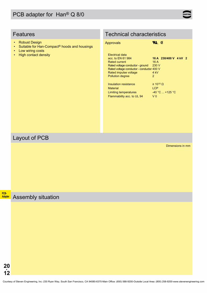
20.12
PCB- Adapter
PCB adapter for Han® Q 8/0
Features• Robust Design• Suitable for Han-Compact® hoods and housings• Low wiring costs• High contact density
Technical characteristicsApprovals ,
Electrical data acc. to EN 61 984 16 A 230/400 V 4 kV 2 Rated current 16 A Rated voltage conductor - ground 230 V Rated voltage conductor - conductor 400 V Rated impulse voltage 4 kV Pollution degree 2
Insulationresistance ≥1010ΩMaterial LCPLimiting temperatures -40 °C ... +125 °CFlammability acc. to UL 94 V 0
Layout of PCBDimensions in mm
Assembly situation
Courtesy of Steven Engineering, Inc.-230 Ryan Way, South San Francisco, CA 94080-6370-Main Office: (650) 588-9200-Outside Local Area: (800) 258-9200-www.stevenengineering.com

20.13
09 12 008 3001 09 12 008 3101
09 33 000 6180 09 33 000 6280
09 12 008 9901
09 12 008 0327
PCB- Adapter
Han® Q 8/0 Inserts with PCB adapter 230/400 V 16 A
Stock items in bold type
Part numberinsert Male insert (M) Female insert (F) Drawing Dimensions in mm
Order contacts separately
Contact arrange-ment (view from termination side)
Part numberHan E® double contacts Male contacts Female contacts Drawing Dimensions in mm
to connect the PCP-Adapter
PCB adapter Part number Drawing Dimensions in mm
for PCBs up to 1.6 mm
Housings bulkhead mounting Part number Drawing Dimensions in mm
Thermoplastic
Further informations see chapter 13 (Han® Q)
Courtesy of Steven Engineering, Inc.-230 Ryan Way, South San Francisco, CA 94080-6370-Main Office: (650) 588-9200-Outside Local Area: (800) 258-9200-www.stevenengineering.com

20.14
PCB- Adapter
PCB adapter for Han-Modular®
Features• Modular assembly• Robust design• Suitable for standard and EMC housings• Low wiring costs
Technical characteristicsHan DD® module with PCB-Adapter
Electrical data acc. to EN 61 984 7.5 A 250 V 4 kV 3 Rated current 7.5 A Rated voltage 250 V Rated impulse voltage 4 kV Pollution degree 3
Han® 40 A module for PCB adaptions Electrical data acc. to EN 61 984 40 A 500 V Rated current 40 A Rated voltage 500 V
Layout of PCBDimensions in mm
Han DD® module Han® 40 A module
Assembly situation
1) for Han®BEMChousingsspacingof12.5±0.7mmisnecessaryasnoflangesealisused
Courtesy of Steven Engineering, Inc.-230 Ryan Way, South San Francisco, CA 94080-6370-Main Office: (650) 588-9200-Outside Local Area: (800) 258-9200-www.stevenengineering.com

20.15
10 A 09 14 000 0304 09 14 000 0304 16 B 09 14 006 0303 09 14 006 0313 210 B 09 14 010 0303 09 14 010 0313 316 B 09 14 016 0303 09 14 016 0313 424 B 09 14 024 0303 09 14 024 0313 6
09 14 012 3001 09 14 012 3101
09 15 000 6191 09 15 000 6291
a09 16 000 990509 16 000 9908
09 16 000 9905 09 16 000 9908
09 14 002 2601 09 14 002 2701
09 14 002 2603 09 14 002 2703
09 32 000 6295
PCB- Adapter
Inserts with PCB adapter
Stock items in bold type
SizePart number Numbers of
modulesIdentification Marking A ... F Marking a ... f Drawing Dimensions in mm
Drawings and further details see chapter 06
Part numberIdentification Male insert (M) Female insert (F) Drawing Dimensions in mm
Han DD® modulePCB termination / crimp termination
09 14 012 3001 09 14 012 3101
Han D® double contactsto connect the PCP-Adapter
IdentificationPCB thick-
ness Part number Drawing Dimensions in mm
PCB adapter
2.63.4
1.6 mm 2.4 mm
Part numberHan® 40 A module Male insert (M) Female insert (F) Drawing Dimensions in mm
PCB adapter Device side
Axial screw termination Cable side
Han® C Solder contact
Contact arrangement (view from termination side)
Courtesy of Steven Engineering, Inc.-230 Ryan Way, South San Francisco, CA 94080-6370-Main Office: (650) 588-9200-Outside Local Area: (800) 258-9200-www.stevenengineering.com

20.16
①
②
③
④
PCB- Adapter
Han® PCB-adapter Applications
● Secondary mating between industrial connector and printed circuit board.
● Ho higher force is applied on the soldering joint when ma-ting the industrial connector due to an additional matting point.
● No wiring between printed circuit board and industrial connector necessary.
● Thisnowiringfaults➪notesting,nocosts● Connecting times are minimized.● Easy handling is time and cost saving.● The production of mechanical and electrical / electronical-
ly components can be completely separated.● Possibility to reach a higher degree of automation in the
production (i. E. wave soldering of the PCBs).
➀PCB adapter for Han E®
➁Han E® connector in a bulkhead mounted housing
➂Switch board panel➃Printed circuit board (PCB)
Han DD® dnd Han® Q 5/0 PCB adapter Wilhelm Fette GmbH, Germany
Courtesy of Steven Engineering, Inc.-230 Ryan Way, South San Francisco, CA 94080-6370-Main Office: (650) 588-9200-Outside Local Area: (800) 258-9200-www.stevenengineering.com

30.01
Han HoodsHousings
Contents
Hoods/Housings with Pg entries
Page
Technical Characteristics . . . . . . . . . . . . . . . . . . . . . . . . . . . . . . . . . . . . . . . 30.02
Size Han® 3 A Standard Hoods/Housings . . . . . . . . . . . . . . . . . . . . . 30.04 Han® M . . . . . . . . . . . . . . . . . . . . . . . . . . . . . . . . . . . 30.09 Han® EMC . . . . . . . . . . . . . . . . . . . . . . . . . . . . . . . . . 30.11 Han® HPR . . . . . . . . . . . . . . . . . . . . . . . . . . . . . . . . . . 30.13
Size Han® 10 A Standard Hoods/Housings . . . . . . . . . . . . . . . . . . . . . 30.14 Han® EMC . . . . . . . . . . . . . . . . . . . . . . . . . . . . . . . . . 30.16
Size Han® 16 A Standard Hoods/Housings . . . . . . . . . . . . . . . . . . . . . 30.17 Han® EMC . . . . . . . . . . . . . . . . . . . . . . . . . . . . . . . . . 30.19
Size Han® 32 A Standard Hoods/Housings . . . . . . . . . . . . . . . . . . . . . 30.20
Size Han® 6 B Standard Hoods/Housings . . . . . . . . . . . . . . . . . . . . . 30.24 Han® M . . . . . . . . . . . . . . . . . . . . . . . . . . . . . . . . . . . 30.29 Han® EMC . . . . . . . . . . . . . . . . . . . . . . . . . . . . . . . . . 30.31 Han® EMC/B . . . . . . . . . . . . . . . . . . . . . . . . . . . . . . . 30.32 Han® HPR . . . . . . . . . . . . . . . . . . . . . . . . . . . . . . . . . . 30.33
Size Han® 10 B Standard Hoods/Housings . . . . . . . . . . . . . . . . . . . . . 30.35 Han-Drive® . . . . . . . . . . . . . . . . . . . . . . . . . . . . . . . . . 30.41 Han® M . . . . . . . . . . . . . . . . . . . . . . . . . . . . . . . . . . . 30.45 Han® EMC . . . . . . . . . . . . . . . . . . . . . . . . . . . . . . . . . 30.47 Han® EMC/B . . . . . . . . . . . . . . . . . . . . . . . . . . . . . . . 30.48 Han® HPR . . . . . . . . . . . . . . . . . . . . . . . . . . . . . . . . . . 30.49
Size Han® 16 B Standard Hoods/Housings . . . . . . . . . . . . . . . . . . . . . 30.51 Han® Easy Hood . . . . . . . . . . . . . . . . . . . . . . . . . . . . . 30.54 Han® M . . . . . . . . . . . . . . . . . . . . . . . . . . . . . . . . . . . 30.61 Han® EMC . . . . . . . . . . . . . . . . . . . . . . . . . . . . . . . . . 30.63 Han® EMC/B . . . . . . . . . . . . . . . . . . . . . . . . . . . . . . . 30.64 Han® HPR . . . . . . . . . . . . . . . . . . . . . . . . . . . . . . . . . . 30.65
Size Han® 24 B Standard Hoods/Housings . . . . . . . . . . . . . . . . . . . . . 30.67 Han® Easy Hood . . . . . . . . . . . . . . . . . . . . . . . . . . . . . 30.70 Han® M . . . . . . . . . . . . . . . . . . . . . . . . . . . . . . . . . . . 30.76 Han® EMC . . . . . . . . . . . . . . . . . . . . . . . . . . . . . . . . . 30.78 Han® EMC/B . . . . . . . . . . . . . . . . . . . . . . . . . . . . . . . 30.79 Han® HPR . . . . . . . . . . . . . . . . . . . . . . . . . . . . . . . . . . 30.80
Size Han® 32 B Standard Hoods/Housings . . . . . . . . . . . . . . . . . . . . . 30.82
Size Han® 48 B Standard Hoods/Housings . . . . . . . . . . . . . . . . . . . . . 30.84Note: Han® hoods and housing with NPT-thread also available by HARTING Inc . of North America, USA
Technical Characteristics . . . . . . . . . . . . . . . . . . . . . . . . . . . . . . . . . . . . . . . 30.02
Size Han® 3 A Standard Hoods/Housings . . . . . . . . . . . . . . . . . . 30.04 Han® M . . . . . . . . . . . . . . . . . . . . . . . . . . . . . . . . . 30.09 Han® EMC . . . . . . . . . . . . . . . . . . . . . . . . . . . . . . . 30.11 Han® HPR . . . . . . . . . . . . . . . . . . . . . . . . . . . . . . . . 30.13
Size Han® 10 A Standard Hoods/Housings . . . . . . . . . . . . . . . . . . 30.14 Han® EMC . . . . . . . . . . . . . . . . . . . . . . . . . . . . . . . 30.16
Size Han® 16 A Standard Hoods/Housings . . . . . . . . . . . . . . . . . . 30.17 Han® EMC . . . . . . . . . . . . . . . . . . . . . . . . . . . . . . . 30.19
Size Han® 32 A Standard Hoods/Housings . . . . . . . . . . . . . . . . . . 30.20
Size Han® 6 B Standard Hoods/Housings . . . . . . . . . . . . . . . . . . 30.24 Han® M . . . . . . . . . . . . . . . . . . . . . . . . . . . . . . . . . 30.29 Han® EMC . . . . . . . . . . . . . . . . . . . . . . . . . . . . . . . 30.31 Han® EMC/B . . . . . . . . . . . . . . . . . . . . . . . . . . . . . 30.32 Han® HPR . . . . . . . . . . . . . . . . . . . . . . . . . . . . . . . . 30.34
Size Han® 10 B Standard Hoods/Housings . . . . . . . . . . . . . . . . . . 30.36 Han-Drive® . . . . . . . . . . . . . . . . . . . . . . . . . . . . . . . 30.42 Han® M . . . . . . . . . . . . . . . . . . . . . . . . . . . . . . . . . 30.47 Han® EMC . . . . . . . . . . . . . . . . . . . . . . . . . . . . . . . 30.49 Han® EMC/B . . . . . . . . . . . . . . . . . . . . . . . . . . . . . 30.50 Han® HPR . . . . . . . . . . . . . . . . . . . . . . . . . . . . . . . . 30.52
Size Han® 16 B Standard Hoods/Housings . . . . . . . . . . . . . . . . . . 30.54 Han® Easy Hood . . . . . . . . . . . . . . . . . . . . . . . . . . . 30.57 Han® M . . . . . . . . . . . . . . . . . . . . . . . . . . . . . . . . . 30.65 Han® EMC . . . . . . . . . . . . . . . . . . . . . . . . . . . . . . . 30.67 Han® EMC/B . . . . . . . . . . . . . . . . . . . . . . . . . . . . . 30.68 Han® HPR . . . . . . . . . . . . . . . . . . . . . . . . . . . . . . . . 30.69
Size Han® 24 B Standard Hoods/Housings . . . . . . . . . . . . . . . . . . 30.72 Han® Easy Hood . . . . . . . . . . . . . . . . . . . . . . . . . . . 30.76 Han® M . . . . . . . . . . . . . . . . . . . . . . . . . . . . . . . . . 30.83 Han® EMC . . . . . . . . . . . . . . . . . . . . . . . . . . . . . . . 30.85 Han® EMC/B . . . . . . . . . . . . . . . . . . . . . . . . . . . . . 30.86 Han® HPR . . . . . . . . . . . . . . . . . . . . . . . . . . . . . . . . 30.87
Size Han® 32 B Standard Hoods/Housings . . . . . . . . . . . . . . . . . . 30.89
Size Han® 48 B Standard Hoods/Housings . . . . . . . . . . . . . . . . . . 30.91
Hoods/Housings with Pg entries
Contents Page
Courtesy of Steven Engineering, Inc.-230 Ryan Way, South San Francisco, CA 94080-6370-Main Office: (650) 588-9200-Outside Local Area: (800) 258-9200-www.stevenengineering.com

30.02
Han HoodsHousings
Technical characteristics
Han® 3 A Standard Hoods/Housings Metal hoods/housings for industrial applications
Material zinc die-castColour RAL 7037 (grey)Surface powder-coatedLocking element steel, zinc-platedLever type lever, metalHoods/Housings seal NBRLimiting temperatures -40 °C . . . +125 °CFlammability acc . to UL 94 V 0Degree of protection acc . to DIN EN 60 529 for coupled connector
IP 44 IP 67 is achieved with seal screw 09 20 000 9918
Han® 3 A Hoods/Housings Plastic hoods/housings for industrial applications
Material thermoplasticColour RAL 7032 (light grey) /
RAL 9005 (black)Lever type lever, plasticHoods/Housings seal NBRLimiting temperatures -40 °C . . . +125 °CApproval acc . to UL 50 NEMA Type 4/4X/12Flammability acc . to UL 94 V 0Degree of protection acc . to DIN EN 60 529 for coupled connector IP 67
Han® Standard Hoods/Housings Metal hoods/housings for industrial applications
Material aluminium die-castColour RAL 7037 (grey)Surface powder-coatedLocking element Stainless steelLever type Han-Easy Lock®
Hoods/Housings seal NBRLimiting temperatures -40 °C . . . +125 °CApproval acc . to UL 50 NEMA Type 4/4X/12Degree of protection acc . to DIN EN 60 529 for coupled connector IP 65
Han-Drive® Housings for motor applicationsMaterial aluminium die-castColour non coloured /
RAL 7037 (grey)Surface electrical conductive /
powder-coated / unpaintedLocking element Stainless steelLever type Han-Easy Lock®
Hoods/Housings seal NBRLimiting temperatures -40 °C . . . +125 °CApproval acc . to UL 50 NEMA Type 4/4X/12Degree of protection acc . to DIN EN 60 529 for coupled connector IP 65
Han® 3 M Hoods/Housings Hoods/Housings for higher environmental requirements
Material zinc die-castColour RAL 9005 (black)Surface - Top coat
Epoxy powder paint
Locking element Stainless steelLever type lever, metalHoods/Housings seal FPMLimiting temperatures -40 °C . . . +125 °CCorrosion resistanceDegree of protection acc . to DIN EN 60 529 for coupled connector
ASTM B117-09 (500 h) IP 44 IP 67 is achieved with seal screw 09 20 000 9918
Han® M Hoods/Housings Hoods/Housings for higher environmental requirements
Material aluminium die-castColour RAL 9005 (black)Surface - Top coat
Epoxy powder paint
Locking element Stainless steelLever type lever, metalHoods/Housings seal FPMLimiting temperatures -40 °C . . . +125 °CApproval acc . to UL 50 NEMA Type 4/4X/12Corrosion resistanceDegree of protection acc . to DIN EN 60 529 for coupled connector
ASTM B117-09 (500 h) IP 65
Courtesy of Steven Engineering, Inc.-230 Ryan Way, South San Francisco, CA 94080-6370-Main Office: (650) 588-9200-Outside Local Area: (800) 258-9200-www.stevenengineering.com
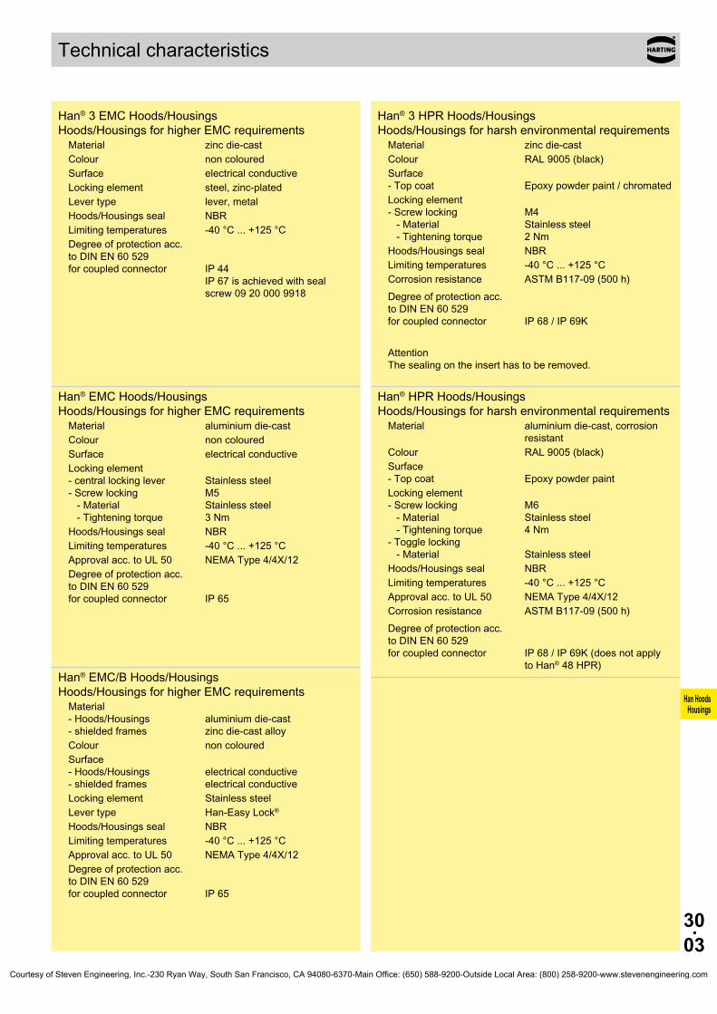
30.03
Han HoodsHousings
Technical characteristics
Han® 3 EMC Hoods/Housings Hoods/Housings for higher EMC requirements
Material zinc die-castColour non colouredSurface electrical conductiveLocking element steel, zinc-platedLever type lever, metalHoods/Housings seal NBRLimiting temperatures -40 °C . . . +125 °CDegree of protection acc . to DIN EN 60 529 for coupled connector
IP 44 IP 67 is achieved with seal screw 09 20 000 9918
Han® EMC Hoods/Housings Hoods/Housings for higher EMC requirements
Material aluminium die-castColour non colouredSurface electrical conductiveLocking element - central locking lever - Screw locking - Material - Tightening torque
Stainless steel M5 Stainless steel 3 Nm
Hoods/Housings seal NBRLimiting temperatures -40 °C . . . +125 °CApproval acc . to UL 50 NEMA Type 4/4X/12Degree of protection acc . to DIN EN 60 529 for coupled connector IP 65
Han® EMC/B Hoods/Housings Hoods/Housings for higher EMC requirements
Material - Hoods/Housings - shielded frames
aluminium die-cast zinc die-cast alloy
Colour non colouredSurface - Hoods/Housings - shielded frames
electrical conductive electrical conductive
Locking element Stainless steelLever type Han-Easy Lock®
Hoods/Housings seal NBRLimiting temperatures -40 °C . . . +125 °CApproval acc . to UL 50 NEMA Type 4/4X/12Degree of protection acc . to DIN EN 60 529 for coupled connector IP 65
Han® 3 HPR Hoods/Housings Hoods/Housings for harsh environmental requirements
Material zinc die-castColour RAL 9005 (black)Surface - Top coat
Epoxy powder paint / chromated
Locking element - Screw locking - Material - Tightening torque
M4 Stainless steel 2 Nm
Hoods/Housings seal NBRLimiting temperatures -40 °C . . . +125 °CCorrosion resistanceDegree of protection acc . to DIN EN 60 529 for coupled connector
ASTM B117-09 (500 h) IP 68 / IP 69K
Attention The sealing on the insert has to be removed .
Han® HPR Hoods/Housings Hoods/Housings for harsh environmental requirements
Material aluminium die-cast, corrosion resistant
Colour RAL 9005 (black)Surface - Top coat
Epoxy powder paint
Locking element - Screw locking - Material - Tightening torque - Toggle locking - Material
M6 Stainless steel 4 Nm Stainless steel
Hoods/Housings seal NBRLimiting temperatures -40 °C . . . +125 °CApproval acc . to UL 50 NEMA Type 4/4X/12Corrosion resistanceDegree of protection acc . to DIN EN 60 529 for coupled connector
ASTM B117-09 (500 h) IP 68 / IP 69K (does not apply to Han® 48 HPR)
Courtesy of Steven Engineering, Inc.-230 Ryan Way, South San Francisco, CA 94080-6370-Main Office: (650) 588-9200-Outside Local Area: (800) 258-9200-www.stevenengineering.com

30.04
Han HoodsHousings
09 20 003 1640 1 x 11
09 20 003 1440 1 x 11
09 20 003 54222) 09 20 003 54211)
Standard Hoods/Housings Han A® Size 3 A
Stock items in bold type1) for mounted female insert2) for mounted male insert
Metal hoods/housings for industrial applications / 1 lever locking system
Identification Part number Pg Drawing Dimensions in mm
Hoods side entry
Hoods top entry
Protection covers for hoods
Courtesy of Steven Engineering, Inc.-230 Ryan Way, South San Francisco, CA 94080-6370-Main Office: (650) 588-9200-Outside Local Area: (800) 258-9200-www.stevenengineering.com
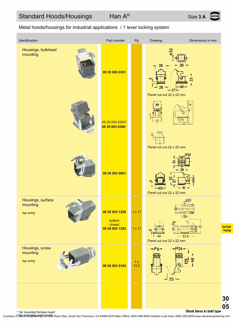
30.05
Han HoodsHousings
Bezeichnung Bestell-Nummer Pg Maßzeichnung Maße in mm
09 20 003 0301
09 20 003 03052) 09 20 003 03061)
09 20 003 0801
09 20 003 1250 1 x 11
09 20 003 1252
1 x 11
09 20 003 0102
Standard Hoods/Housings Han A® Size 3 A
Stock items in bold type
Metal hoods/housings for industrial applications / 1 lever locking system
Identification Part number Pg Drawing Dimensions in mm
1) for mounted female insert2) for mounted male insert
Metal hoods/housings for industrial applications / 1 lever locking system
Housings, bulkhead mounting
Panel cut out 22 x 22 mm
Panel cut out 22 x 22 mm
Panel cut out 22 x 22 mm
Housings, surface mounting top entry
bottom closed
Panel cut out 22 x 22 mm
Housings, screw mounting top entry 1 x
13.5
Courtesy of Steven Engineering, Inc.-230 Ryan Way, South San Francisco, CA 94080-6370-Main Office: (650) 588-9200-Outside Local Area: (800) 258-9200-www.stevenengineering.com

30.06
Han HoodsHousings
09 20 003 1750 1 x 11
09 20 003 54262)
09 20 003 54251)
09 20 003 54282)
09 20 003 54271)
Standard Hoods/Housings Han A® Size 3 A
Stock items in bold type
Metal hoods/housings for industrial applications / 1 lever locking system
1) for mounted female insert2) for mounted male insert
Hoods, cable to cable top entry
Protection covers for housings
for housings
for hoods cable to cable
for hoods cable to cable
Identification Part number Pg Drawing Dimensions in mm
Courtesy of Steven Engineering, Inc.-230 Ryan Way, South San Francisco, CA 94080-6370-Main Office: (650) 588-9200-Outside Local Area: (800) 258-9200-www.stevenengineering.com

30.07
Han HoodsHousings
09 20 003 0620
1 x 11
09 20 003 0627
1 x 11
09 20 003 0420
1 x 11
09 20 003 0427
1 x 11
09 20 003 54423)
09 20 003 54412)
09 20 003 0320
09 20 003 0327
09 20 003 0820
09 20 003 0827
Hoods/Housings Han A® Size 3 A
Stock items in bold type1) for metal housings and cable to cable hoods also2) for mounted female insert or for mounted Han-
Brid® insert
3) for mounted male insert
Plastic hoods/housings for industrial applications / 1 lever locking system
Hoods side entry light grey
black
Hoods top entry light grey
black
Protection covers for hoods light grey
light grey
Plastic hoods/housings for industrial applications / 1 lever locking system
Housings, bulkhead mounting
light grey
black
Panel cut out 22 x 22 mm
light grey
black
Panel cut out 22 x 22 mm
Identification
Identification
Part number
Part number
Pg
Pg
Drawing Dimensions in mm
Drawing Dimensions in mm
Courtesy of Steven Engineering, Inc.-230 Ryan Way, South San Francisco, CA 94080-6370-Main Office: (650) 588-9200-Outside Local Area: (800) 258-9200-www.stevenengineering.com
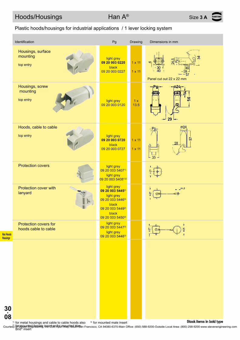
30.08
Han HoodsHousings
09 20 003 0220
1 x 11
09 20 003 0227
1 x 11
09 20 003 0120
09 20 003 0720
1 x 11
09 20 003 0727
1 x 11
09 20 003 54071)
09 20 003 54081)2)
09 20 003 54452)
09 20 003 54463)
09 20 003 54492)
09 20 003 54503)
09 20 003 54472)
09 20 003 54483)
Hoods/Housings Han A® Size 3 A
Stock items in bold type
Plastic hoods/housings for industrial applications / 1 lever locking system
Identification Pg Drawing Dimensions in mm
1) for metal housings and cable to cable hoods also2) for mounted female insert or for mounted Han-
Brid® insert
3) for mounted male insert
Housings, surface mounting top entry
light grey
black
Panel cut out 22 x 22 mm
Housings, screw mounting top entry light grey 1 x
13.5
Hoods, cable to cable top entry light grey
black
Protection covers light grey
light grey
Protection cover with lanyard
light grey
light grey
black
black
Protection covers for hoods cable to cable
light grey
light grey
Courtesy of Steven Engineering, Inc.-230 Ryan Way, South San Francisco, CA 94080-6370-Main Office: (650) 588-9200-Outside Local Area: (800) 258-9200-www.stevenengineering.com
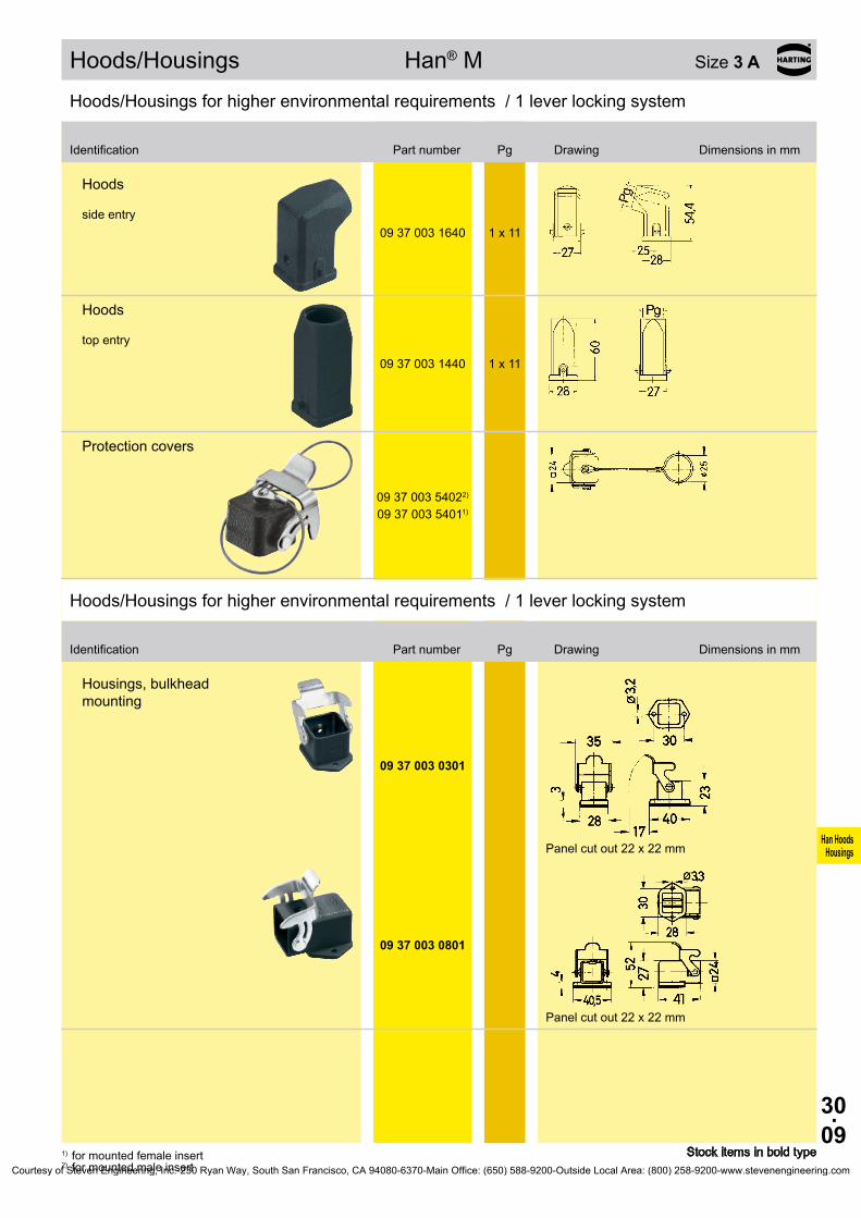
30.09
Han HoodsHousings
09 37 003 1640 1 x 11
09 37 003 1440 1 x 11
09 37 003 54022) 09 37 003 54011)
09 37 003 0301
09 37 003 0801
Hoods/Housings Han® M Size 3 A
Stock items in bold type1) for mounted female insert2) for mounted male insert
Hoods/Housings for higher environmental requirements / 1 lever locking system
Identification Part number Pg Drawing Dimensions in mm
Hoods side entry
Hoods top entry
Protection covers
Hoods/Housings for higher environmental requirements / 1 lever locking system
Identification Part number Pg Drawing Dimensions in mm
Housings, bulkhead mounting
Panel cut out 22 x 22 mm
Panel cut out 22 x 22 mm
Courtesy of Steven Engineering, Inc.-230 Ryan Way, South San Francisco, CA 94080-6370-Main Office: (650) 588-9200-Outside Local Area: (800) 258-9200-www.stevenengineering.com

30.10
Han HoodsHousings
09 37 003 1250 1 x 11
09 37 003 1750 1 x 11
09 37 003 54051) 09 37 003 54062)
Hoods/Housings Han® M Size 3 A
Stock items in bold type
Hoods/Housings for higher environmental requirements / 1 lever locking system
Identification Part number Pg Drawing Dimensions in mm
1) for mounted female insert2) for mounted male insert
Housings, surface mounting top entry
Panel cut out 22 x 22 mm
Hoods, cable to cable top entry
Protection covers for housings
Courtesy of Steven Engineering, Inc.-230 Ryan Way, South San Francisco, CA 94080-6370-Main Office: (650) 588-9200-Outside Local Area: (800) 258-9200-www.stevenengineering.com

30.11
Han HoodsHousings
09 62 003 1640 1 x 11
09 62 003 1440 1 x 11
09 62 003 0301
09 62 003 0801
09 62 003 1250 1 x 11
09 62 003 1252
1 x 11
Hoods/Housings Han® EMC Size 3 A
Stock items in bold type
Hoods/Housings for higher EMC requirements / 1 lever locking system
Identification Part number Pg Drawing Dimensions in mm
Hoods side entry
Hoods top entry
Hoods/Housings for higher EMC requirements / 1 lever locking system
Identification Part number Pg Drawing Dimensions in mm
Housings, bulkhead mounting
Panel cut out 22 x 22 mm
Panel cut out 22 x 22 mm
Housings, surface mounting top entry
bottom closed
Panel cut out 22 x 22 mm
Courtesy of Steven Engineering, Inc.-230 Ryan Way, South San Francisco, CA 94080-6370-Main Office: (650) 588-9200-Outside Local Area: (800) 258-9200-www.stevenengineering.com
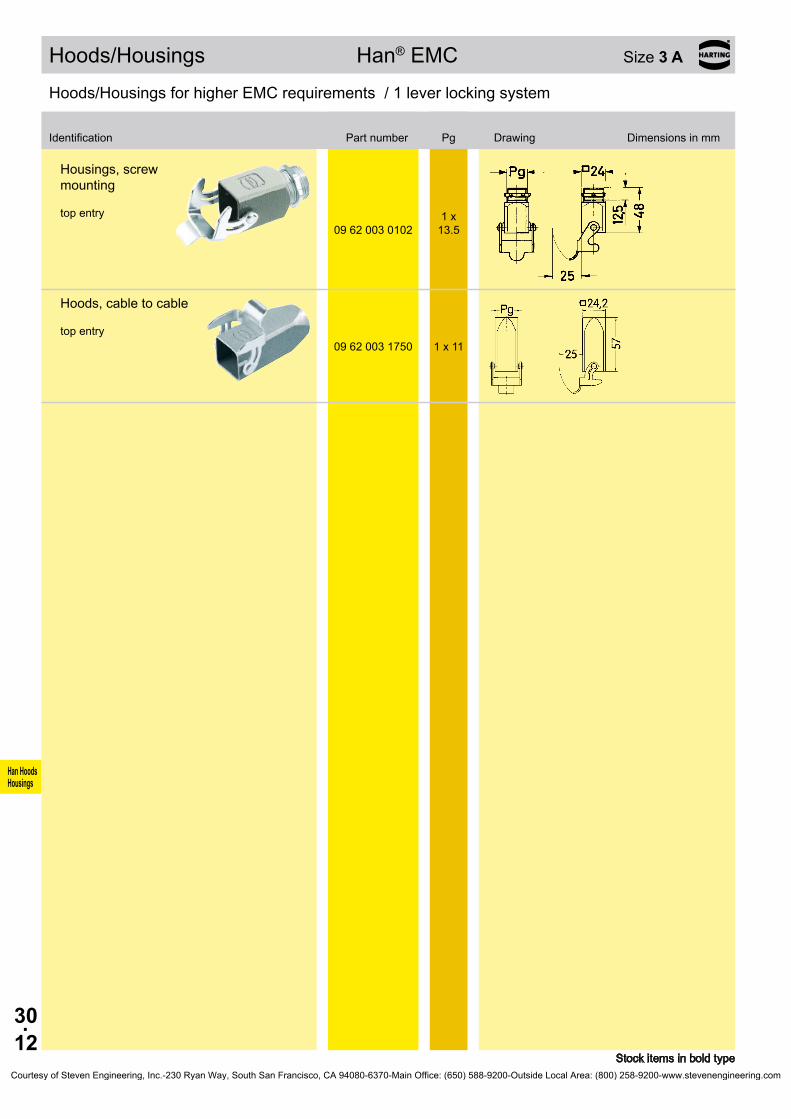
30.12
Han HoodsHousings
09 62 003 0102
09 62 003 1750 1 x 11
Hoods/Housings Han® EMC Size 3 A
Stock items in bold type
Hoods/Housings for higher EMC requirements / 1 lever locking system
Identification Part number Pg Drawing Dimensions in mm
Housings, screw mounting top entry 1 x
13.5
Hoods, cable to cable top entry
Courtesy of Steven Engineering, Inc.-230 Ryan Way, South San Francisco, CA 94080-6370-Main Office: (650) 588-9200-Outside Local Area: (800) 258-9200-www.stevenengineering.com
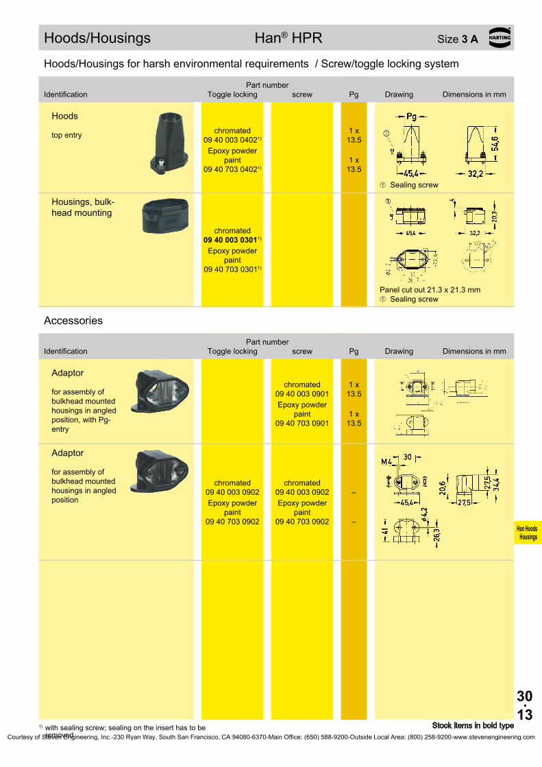
30.13
Han HoodsHousings
09 40 003 04021)
09 40 703 04021)
09 40 003 03011)
09 40 703 03011)
09 40 003 0901
09 40 703 0901
09 40 003 0902
09 40 003 0902 –
09 40 703 0902
09 40 703 0902 –
Hoods/Housings Han® HPR Size 3 A
Stock items in bold type1) with sealing screw; sealing on the insert has to be removed
Hoods/Housings for harsh environmental requirements / Screw/toggle locking system
Identification
Toggle locking
screwPart number
Pg Drawing Dimensions in mm
Hoods top entry chromated
1 x
13.5Epoxy powder
paint
1 x 13.5
➀ Sealing screw
Housings, bulk-head mounting
chromated
Epoxy powder paint
Panel cut out 21 .3 x 21 .3 mm ➀ Sealing screw
Accessories
Identification
Toggle locking
screwPart number
Pg Drawing Dimensions in mm
Adaptor for assembly of bulkhead mounted housings in angled position, with Pg-entry
chromated 1 x
13.5
Epoxy powder paint 1 x
13.5
Adaptor for assembly of bulkhead mounted housings in angled position
chromated chromated
Epoxy powder paint
Epoxy powder paint
Courtesy of Steven Engineering, Inc.-230 Ryan Way, South San Francisco, CA 94080-6370-Main Office: (650) 588-9200-Outside Local Area: (800) 258-9200-www.stevenengineering.com

30.14
Han HoodsHousings
09 20 010 1541 1 x 16
09 20 010 0540 1 x 16 09 20 010 0541 1 x 21
09 20 010 1440
09 20 010 0440 1 x 16 09 20 010 0441 1 x 21 09 20 010 0801 –
09 20 010 5423
09 20 010 5423
09 20 010 0301
09 20 010 0321
Standard Hoods/Housings Han A® Size 10 A
Stock items in bold type
Metal hoods/housings for industrial applications / 1 lever locking system
Identification
Low construction
High constructionPart number
Pg Drawing Dimensions in mm
Hoods side entry
side entry
Hoods top entry
1 x
13.5
top entry
Protection covers
metal metal
Metal hoods/housings for industrial applications / 1 lever locking system
Identification
Low construction
High constructionPart number
Pg Drawing Dimensions in mm
Housings, bulkhead mounting
with thermo- plastic cover
Panel cut out
Courtesy of Steven Engineering, Inc.-230 Ryan Way, South San Francisco, CA 94080-6370-Main Office: (650) 588-9200-Outside Local Area: (800) 258-9200-www.stevenengineering.com

30.15
Han HoodsHousings
09 20 010 0251 1 x 1609 20 010 0291 2 x 16
09 20 010 0221
1 x 16
09 20 010 0296
2 x 16
09 20 010 5425
Standard Hoods/Housings Han A® Size 10 A
Stock items in bold type
Metal hoods/housings for industrial applications / 1 lever locking system
Identification
Low construction
High constructionPart number
Pg Drawing Dimensions in mm
Housings, surface mounting side entry
side entry
with thermo- plastic cover
with thermo- plastic cover
Protection covers metal
Courtesy of Steven Engineering, Inc.-230 Ryan Way, South San Francisco, CA 94080-6370-Main Office: (650) 588-9200-Outside Local Area: (800) 258-9200-www.stevenengineering.com

30.16
Han HoodsHousings
09 62 015 0540 1 x 1609 62 015 0541 1 x 21
09 62 015 0440 1 x 1609 62 015 0441 1 x 21
09 62 015 0301
Hoods/Housings Han® EMC Size 10 A
Stock items in bold type
Hoods/Housings for higher EMC requirements / 1 lever locking system
Identification Part number Pg Drawing Dimensions in mm
Hoods side entry
Hoods top entry
Hoods/Housings for higher EMC requirements / 1 lever locking system
Identification Part number Pg Drawing Dimensions in mm
Housings, bulkhead mounting
Panel cut out
Courtesy of Steven Engineering, Inc.-230 Ryan Way, South San Francisco, CA 94080-6370-Main Office: (650) 588-9200-Outside Local Area: (800) 258-9200-www.stevenengineering.com

30.17
Han HoodsHousings
09 20 016 1541 1 x 16
09 20 016 0540 1 x 16 09 20 016 0541 1 x 21
09 20 016 1441 1 x 16
09 20 016 0440 1 x 16 09 20 016 0441 1 x 21 09 20 016 0801 –
09 20 016 5423
09 20 016 5423
09 20 016 0301
09 20 016 0321
Standard Hoods/Housings Han A® Size 16 A
Stock items in bold type
Metal hoods/housings for industrial applications / 1 lever locking system
Identification
Low construction
High constructionPart number
Pg Drawing Dimensions in mm
Hoods side entry
side entry
Hoods top entry
top entry
Protection covers
metal metal
Metal hoods/housings for industrial applications / 1 lever locking system
Identification
Low construction
High constructionPart number
Pg Drawing Dimensions in mm
Housings, bulkhead mounting
with thermo- plastic cover
Panel cut out
Courtesy of Steven Engineering, Inc.-230 Ryan Way, South San Francisco, CA 94080-6370-Main Office: (650) 588-9200-Outside Local Area: (800) 258-9200-www.stevenengineering.com

30.18
Han HoodsHousings
09 20 016 0251 1 x 1609 20 016 0252 1 x 2109 20 016 0291 2 x 16
09 20 016 0221
1 x 16
09 20 016 0222
1 x 21
09 20 016 0296
2 x 16
09 20 016 5425
Standard Hoods/Housings Han A® Size 16 A
Stock items in bold type
Metal hoods/housings for industrial applications / 1 lever locking system
Identification
Low construction
High constructionPart number
Pg Drawing Dimensions in mm
Housings, surface mounting side entry
side entry
with thermo- plastic cover
with thermo- plastic cover
with thermo- plastic cover
Protection covers metal
Courtesy of Steven Engineering, Inc.-230 Ryan Way, South San Francisco, CA 94080-6370-Main Office: (650) 588-9200-Outside Local Area: (800) 258-9200-www.stevenengineering.com
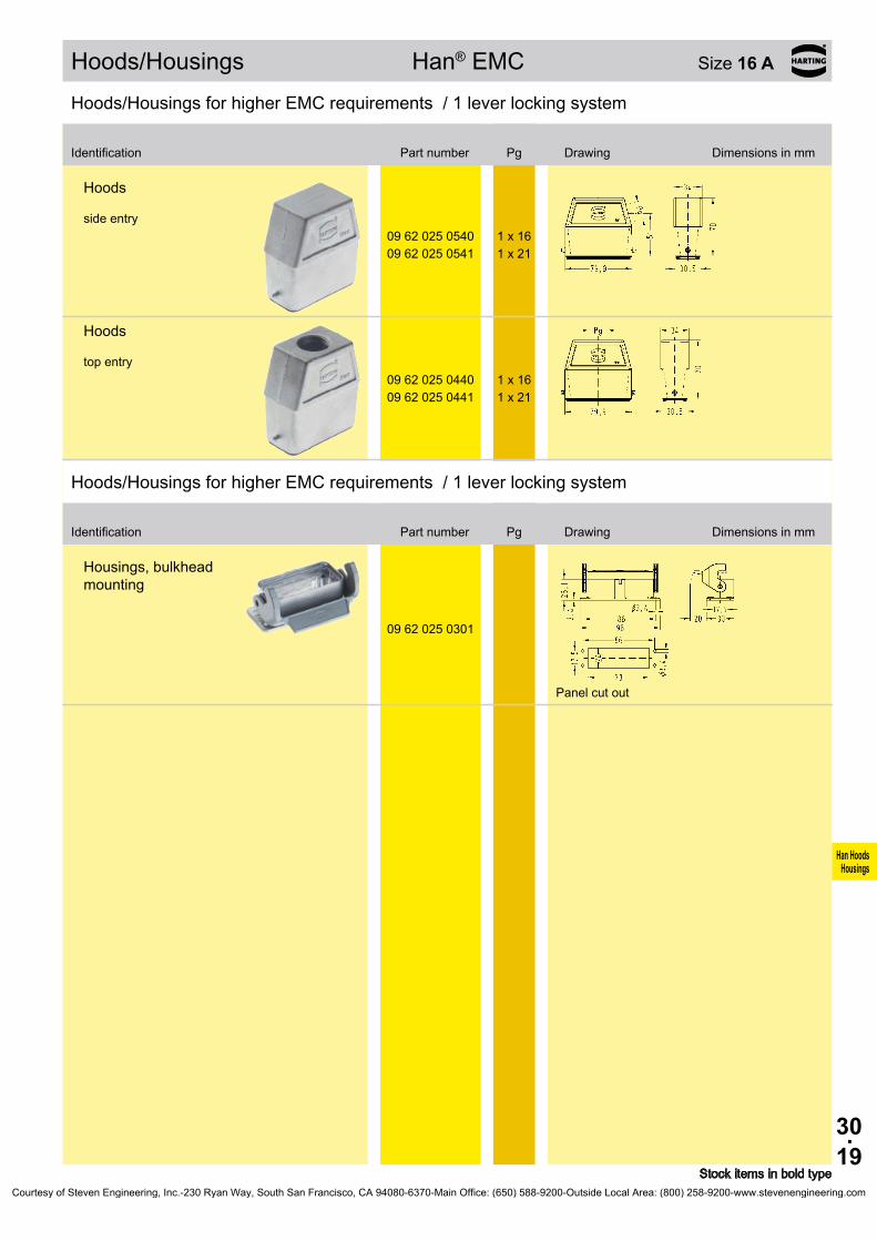
30.19
Han HoodsHousings
09 62 025 0540 1 x 1609 62 025 0541 1 x 21
09 62 025 0440 1 x 1609 62 025 0441 1 x 21
09 62 025 0301
Hoods/Housings Han® EMC Size 16 A
Stock items in bold type
Hoods/Housings for higher EMC requirements / 1 lever locking system
Identification Part number Pg Drawing Dimensions in mm
Hoods side entry
Hoods top entry
Hoods/Housings for higher EMC requirements / 1 lever locking system
Identification Part number Pg Drawing Dimensions in mm
Housings, bulkhead mounting
Panel cut out
Courtesy of Steven Engineering, Inc.-230 Ryan Way, South San Francisco, CA 94080-6370-Main Office: (650) 588-9200-Outside Local Area: (800) 258-9200-www.stevenengineering.com

30.20
Han HoodsHousings
09 20 032 1520 1 x 21
09 20 032 0520 1 x 21 09 20 032 0521 1 x 29
09 20 032 0420 1 x 21 09 20 032 0421 1 x 29
09 20 032 5401 09 20 032 5401
09 20 032 0301
Standard Hoods/Housings Han A® Size 32 A *
* usable for two inserts of size 16 A Stock items in bold type
Metal hoods/housings for industrial applications / 2 lever locking system
Identification
Low construction
High constructionPart number
Pg Drawing Dimensions in mm
Hoods side entry
side entry
Hoods top entry
Dust protection cover
Metal hoods/housings for industrial applications / 2 lever locking system
Identification
Low construction
High constructionPart number
Pg Drawing Dimensions in mm
Housings, bulkhead mounting
Panel cut out
Courtesy of Steven Engineering, Inc.-230 Ryan Way, South San Francisco, CA 94080-6370-Main Office: (650) 588-9200-Outside Local Area: (800) 258-9200-www.stevenengineering.com

30.21
Han HoodsHousings
09 20 032 0230 1 x 21 09 20 032 0231 1 x 29 09 20 032 0270 2 x 21 09 20 032 0271 2 x 29
09 20 032 5405 09 20 032 5405
Standard Hoods/Housings Han A® Size 32 A *
* usable for two inserts of size 16 A Stock items in bold type
Metal hoods/housings for industrial applications / 2 lever locking system
Identification
Low construction
High constructionPart number
Pg Drawing Dimensions in mm
Housings, surface mounting side entry
Blind way for one cable entry
Dust protection cover
Courtesy of Steven Engineering, Inc.-230 Ryan Way, South San Francisco, CA 94080-6370-Main Office: (650) 588-9200-Outside Local Area: (800) 258-9200-www.stevenengineering.com

30.22
Han HoodsHousings
09 20 032 1530 1 x 21
09 20 032 0530 1 x 21 09 20 032 0531 1 x 29
09 20 032 0430 1 x 21 09 20 032 0431 1 x 29
09 20 032 0302
Standard Hoods/Housings Han A® Size 32 A *
* usable for two inserts of size 16 A Stock items in bold type
Metal hoods/housings for industrial applications / 2 lever locking system
Identification
Low construction
High constructionPart number
Pg Drawing Dimensions in mm
Hoods side entry
side entry
Hoods top entry
Metal hoods/housings for industrial applications / 2 lever locking system
Identification
Low construction
High constructionPart number
Pg Drawing Dimensions in mm
Housings, bulkhead mounting
with thermo- plastic cover
Panel cut out
Courtesy of Steven Engineering, Inc.-230 Ryan Way, South San Francisco, CA 94080-6370-Main Office: (650) 588-9200-Outside Local Area: (800) 258-9200-www.stevenengineering.com

30.23
Han HoodsHousings
09 20 032 0220
1 x 21
09 20 032 0221
1 x 29
09 20 032 0260
2 x 21
09 20 032 0261
2 x 29
09 20 032 0581 1 x 29
09 20 032 0381
Standard Hoods/Housings Han A® Size 32 A *
* usable for two inserts of size 16 A Stock items in bold type
Metal hoods/housings for industrial applications / 2 lever locking system
Identification
Low construction
High constructionPart number
Pg Drawing Dimensions in mm
Housings, surface mounting side entry
with thermo- plastic cover
with thermo- plastic cover
with thermo- plastic cover
with thermo- plastic cover
1) Blind way for one cable entry
Metal hoods/housings for industrial applications / 1 central locking lever locking system
Identification
Low construction
High constructionPart number
Pg Drawing Dimensions in mm
Hoods side entry
Housings, bulkhead mounting
Panel cut out
Courtesy of Steven Engineering, Inc.-230 Ryan Way, South San Francisco, CA 94080-6370-Main Office: (650) 588-9200-Outside Local Area: (800) 258-9200-www.stevenengineering.com
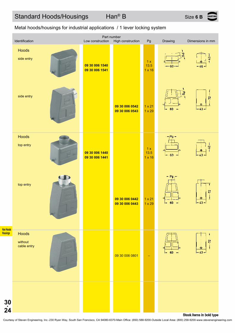
30.24
Han HoodsHousings
09 30 006 1540
09 30 006 1541 1 x 16
09 30 006 0542 1 x 21 09 30 006 0543 1 x 29
09 30 006 1440
09 30 006 1441 1 x 16
09 30 006 0442 1 x 21 09 30 006 0443 1 x 29
09 30 006 0801 –
Standard Hoods/Housings Han® B Size 6 B
Stock items in bold type
Metal hoods/housings for industrial applications / 1 lever locking system
Identification
Low construction
High constructionPart number
Pg Drawing Dimensions in mm
Hoods side entry
1 x
13.5
side entry
Hoods top entry
1 x
13.5
top entry
Hoods without cable entry
Courtesy of Steven Engineering, Inc.-230 Ryan Way, South San Francisco, CA 94080-6370-Main Office: (650) 588-9200-Outside Local Area: (800) 258-9200-www.stevenengineering.com

30.25
Han HoodsHousings
09 30 006 5423
09 30 006 5423
09 30 006 5401 09 30 006 5401
09 30 006 0301
09 30 006 0302
09 30 006 0318
Standard Hoods/Housings Han® B Size 6 B
Stock items in bold type
Metal hoods/housings for industrial applications / 1 lever locking system
Identification
Low construction
High constructionPart number
Pg Drawing Dimensions in mm
Protection covers
metal metal
Dust protection cover
Metal hoods/housings for industrial applications / 1 lever locking system
Identification
Low construction
High constructionPart number
Pg Drawing Dimensions in mm
Housings, bulkhead mounting
Panel cut out
with thermo- plastic cover
with
metal cover
Panel cut out
Courtesy of Steven Engineering, Inc.-230 Ryan Way, South San Francisco, CA 94080-6370-Main Office: (650) 588-9200-Outside Local Area: (800) 258-9200-www.stevenengineering.com

30.26
Han HoodsHousings
09 30 006 1251 1 x 1609 30 006 1291 2 x 16
09 30 006 0292 2 x 21 09 30 006 0293 2 x 29
09 30 006 1256
1 x 16
09 30 006 1296
2 x 16
09 30 006 2256
1 x 16
09 30 006 2296
2 x 16
09 30 006 0297
2 x 21
09 30 006 0298
2 x 29
09 30 006 2297
2 x 21
09 30 006 5404
09 30 006 5404
09 30 006 5425
09 30 006 5425
Standard Hoods/Housings Han® B Size 6 B
Stock items in bold type
Metal hoods/housings for industrial applications / 1 lever locking system
Identification
Low construction
High constructionPart number
Pg Drawing Dimensions in mm
Housings, surface mounting side entry
side entry
side entry
with thermo- plastic cover
with thermo- plastic cover
with metal cover
with metal cover
side entry
with thermo- plastic cover
with thermo- plastic cover
with
metal cover
Protection covers plastic plastic
metal metal
Courtesy of Steven Engineering, Inc.-230 Ryan Way, South San Francisco, CA 94080-6370-Main Office: (650) 588-9200-Outside Local Area: (800) 258-9200-www.stevenengineering.com

30.27
Han HoodsHousings
09 30 006 1750
09 30 006 0752 1 x 21 09 30 006 0753 1 x 29
09 30 006 5427
09 30 006 5427
09 30 006 0757 1 x 21
Standard Hoods/Housings Han® B Size 6 B
Stock items in bold type
Metal hoods/housings for industrial applications / 1 lever locking system
Identification
Low construction
High constructionPart number
Pg Drawing Dimensions in mm
Hoods, cable to cable top entry
1 x 13.5
top entry
Protection covers
metal metal
Flange housings top entry
Courtesy of Steven Engineering, Inc.-230 Ryan Way, South San Francisco, CA 94080-6370-Main Office: (650) 588-9200-Outside Local Area: (800) 258-9200-www.stevenengineering.com

30.28
Han HoodsHousings
09 30 006 0581 1 x 16
09 30 006 0381
Standard Hoods/Housings Han® B Size 6 B
Stock items in bold type
Metal hoods/housings for industrial applications / 1 central locking lever locking system
Identification Part number Pg Drawing Dimensions in mm
Hoods side entry
Metal hoods/housings for industrial applications / 1 central locking lever locking system
Identification Part number Pg Drawing Dimensions in mm
Housings, bulkhead mounting
Panel cut out
Courtesy of Steven Engineering, Inc.-230 Ryan Way, South San Francisco, CA 94080-6370-Main Office: (650) 588-9200-Outside Local Area: (800) 258-9200-www.stevenengineering.com

30.29
Han HoodsHousings
09 37 006 1540
09 37 006 0542 1 x 21
09 37 006 1440
09 37 006 1441 1 x 16
09 37 006 0301
09 37 006 1291 2 x 16
Hoods/Housings Han® M Size 6 B
Stock items in bold type
Hoods/Housings for higher environmental requirements / 1 lever locking system
Identification Part number Pg Drawing Dimensions in mm
Hoods side entry
1 x 13.5
side entry
Hoods top entry
1 x 13.5
Hoods/Housings for higher environmental requirements / 1 lever locking system
Identification Part number Pg Drawing Dimensions in mm
Housings, bulkhead mounting
Panel cut out
Housings, surface mounting side entry
Courtesy of Steven Engineering, Inc.-230 Ryan Way, South San Francisco, CA 94080-6370-Main Office: (650) 588-9200-Outside Local Area: (800) 258-9200-www.stevenengineering.com

30.30
Han HoodsHousings
09 37 006 5405
09 37 006 1750
09 37 006 5407
Hoods/Housings Han® M Size 6 B
Stock items in bold type
Hoods/Housings for higher environmental requirements / 1 lever locking system
Identification Part number Pg Drawing Dimensions in mm
Protection covers
metal
Hoods, cable to cable top entry
1 x 13.5
Protection covers
metal
Courtesy of Steven Engineering, Inc.-230 Ryan Way, South San Francisco, CA 94080-6370-Main Office: (650) 588-9200-Outside Local Area: (800) 258-9200-www.stevenengineering.com

30.31
Han HoodsHousings
09 62 006 0540 1 x 1609 62 006 0541 1 x 21
09 62 006 0440 1 x 1609 62 006 0441 1 x 21
09 62 006 0301
09 62 006 1205 2 x 16
Hoods/Housings Han® EMC Size 6 B
Stock items in bold type
Hoods/Housings for higher EMC requirements / Screw locking system
Identification Part number Pg Drawing Dimensions in mm
Hoods side entry
Hoods top entry
Hoods/Housings for higher EMC requirements / Screw locking system
Identification Part number Pg Drawing Dimensions in mm
Housings, bulkhead mounting
Panel cut out
Housings, surface mounting side entry
Courtesy of Steven Engineering, Inc.-230 Ryan Way, South San Francisco, CA 94080-6370-Main Office: (650) 588-9200-Outside Local Area: (800) 258-9200-www.stevenengineering.com

30.32
Han HoodsHousings
09 62 806 1541 1 x 16
09 62 806 0542 1 x 21
09 62 806 1441 1 x 16
09 62 806 0442 1 x 21
09 62 806 0801 –
Hoods/Housings Han® EMC/B Size 6 B
Stock items in bold type
Hoods/Housings for higher EMC requirements / 1 lever locking system
Identification
Low construction
High constructionPart number
Pg Drawing Dimensions in mm
Hoods side entry
side entry
Hoods top entry
top entry
Hoods without cable entry
Courtesy of Steven Engineering, Inc.-230 Ryan Way, South San Francisco, CA 94080-6370-Main Office: (650) 588-9200-Outside Local Area: (800) 258-9200-www.stevenengineering.com

30.33
Han HoodsHousings
Bezeichnung
Niedrige Bauform
Hohe BauformBestell-Nummer
Pg Maßzeichnung Maße in mm
09 62 806 0301
Hoods/Housings Han® EMC/B Size 6 B
Stock items in bold type
Hoods/Housings for higher EMC requirements / 1 lever locking system
Identification
Low construction
High constructionPart number
Pg Drawing Dimensions in mm
Hoods/Housings for higher EMC requirements / 1 lever locking system
Housings, bulkhead mounting
Panel cut out
Courtesy of Steven Engineering, Inc.-230 Ryan Way, South San Francisco, CA 94080-6370-Main Office: (650) 588-9200-Outside Local Area: (800) 258-9200-www.stevenengineering.com

30.34
Han HoodsHousings
09 40 006 0501 1 x 1609 40 006 0502 1 x 21
09 40 006 0511 1 x 16 09 40 006 0512 1 x 21 09 40 006 0513 1 x 29
09 40 006 0401 1 x 1609 40 006 0402 1 x 21
09 40 006 0411 1 x 16 09 40 006 0412 1 x 21 09 40 006 0413 1 x 29
09 40 006 0811 –
Hoods/Housings Han® HPR Size 6 B
Stock items in bold type
Hoods/Housings for harsh environmental requirements / Screw/toggle locking system
Identification
Toggle locking
screwPart number
Pg Drawing Dimensions in mm
Hoods side entry
Hoods top entry
Hoods without cable entry
Courtesy of Steven Engineering, Inc.-230 Ryan Way, South San Francisco, CA 94080-6370-Main Office: (650) 588-9200-Outside Local Area: (800) 258-9200-www.stevenengineering.com
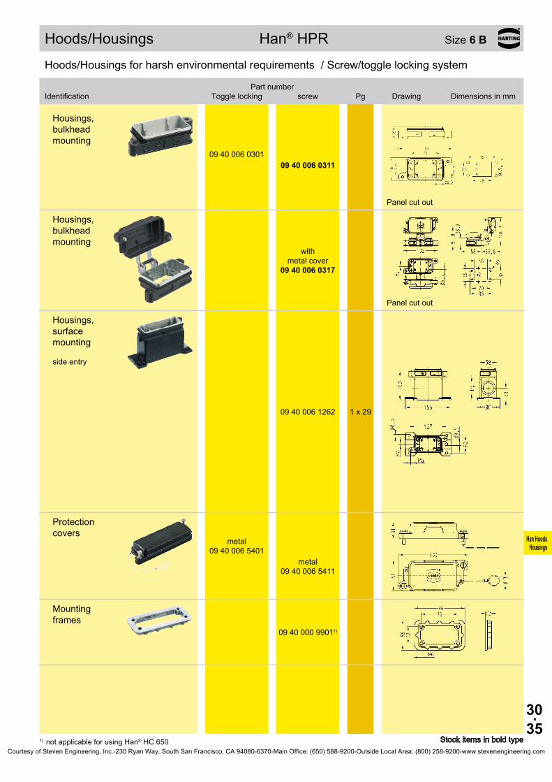
30.35
Han HoodsHousings
09 40 006 0301 09 40 006 0311
09 40 006 0317
09 40 006 1262 1 x 29
09 40 006 5401
09 40 006 5411
09 40 000 99011)
Hoods/Housings Han® HPR Size 6 B
Stock items in bold type1) not applicable for using Han® HC 650
Hoods/Housings for harsh environmental requirements / Screw/toggle locking system
Identification
Toggle locking
screwPart number
Pg Drawing Dimensions in mm
Housings, bulkhead mounting
Panel cut out
Housings, bulkhead mounting
with
metal cover
Panel cut out
Housings, surface mounting side entry
Protection covers
metal
metal
Mounting frames
Courtesy of Steven Engineering, Inc.-230 Ryan Way, South San Francisco, CA 94080-6370-Main Office: (650) 588-9200-Outside Local Area: (800) 258-9200-www.stevenengineering.com
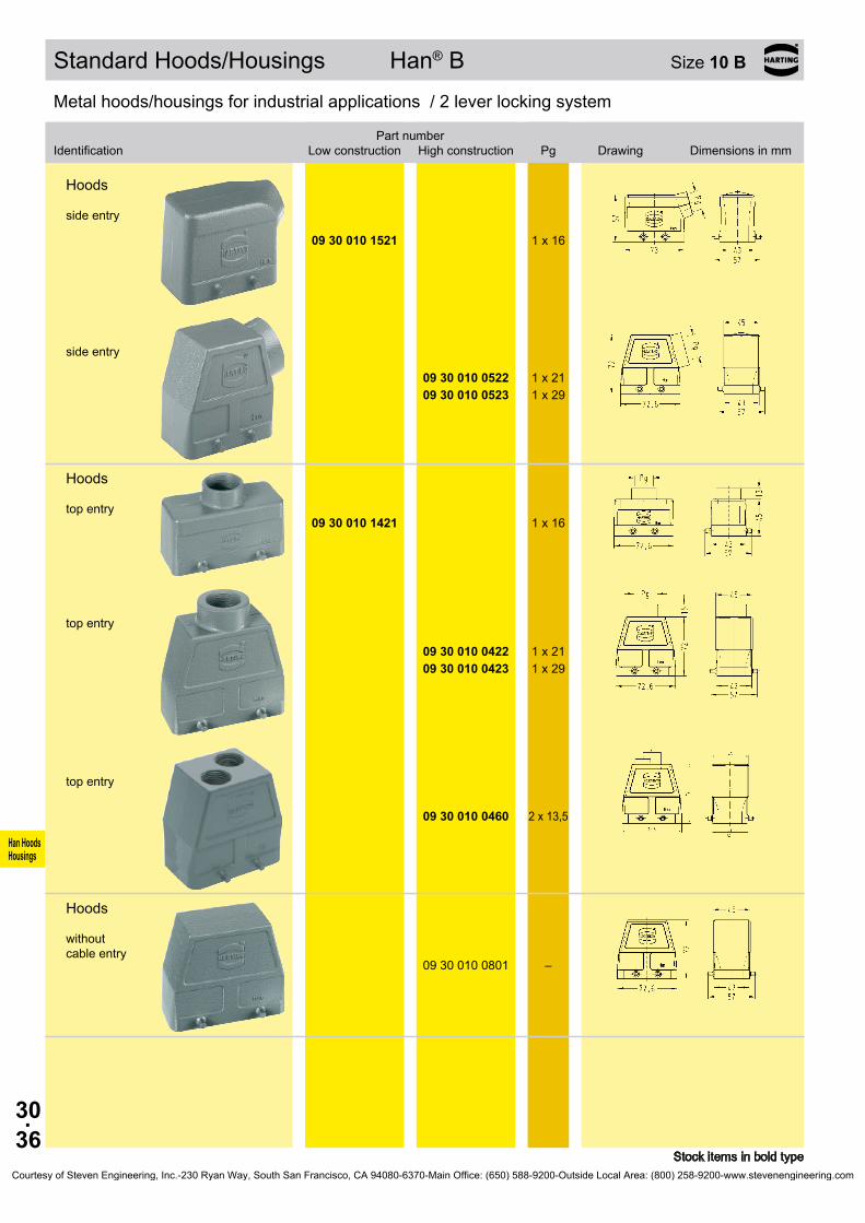
30.36
Han HoodsHousings
09 30 010 1521 1 x 16
09 30 010 0522 1 x 21 09 30 010 0523 1 x 29
09 30 010 1421 1 x 16
09 30 010 0422 1 x 21 09 30 010 0423 1 x 29
09 30 010 0460 2 x 13,5
09 30 010 0801 –
Standard Hoods/Housings Han® B Size 10 B
Stock items in bold type
Metal hoods/housings for industrial applications / 2 lever locking system
Identification
Low construction
High constructionPart number
Pg Drawing Dimensions in mm
Hoods side entry
side entry
Hoods top entry
top entry
top entry
Hoods without cable entry
Courtesy of Steven Engineering, Inc.-230 Ryan Way, South San Francisco, CA 94080-6370-Main Office: (650) 588-9200-Outside Local Area: (800) 258-9200-www.stevenengineering.com

30.37
Han HoodsHousings
09 30 010 5423
09 30 010 5423
09 30 010 5401
09 30 010 5401
09 30 010 0301
09 30 010 1231 1 x 1609 30 010 1271 2 x 16
09 30 010 0232 1 x 21 09 30 010 0233 1 x 29 09 30 010 0272 2 x 21 09 30 010 0273 2 x 29
Standard Hoods/Housings Han® B Size 10 B
Stock items in bold type
Metal hoods/housings for industrial applications / 2 lever locking system
Identification
Low construction
High constructionPart number
Pg Drawing Dimensions in mm
Protection covers
metal metal
Protection covers
plastic plastic
Metal hoods/housings for industrial applications / 2 lever locking system
Identification
Low construction
High constructionPart number
Pg Drawing Dimensions in mm
Housings, bulkhead mounting
Panel cut out
Housings, surface mounting side entry
Blind way for one cable entry
side entry
Blind way for one cable entry
Courtesy of Steven Engineering, Inc.-230 Ryan Way, South San Francisco, CA 94080-6370-Main Office: (650) 588-9200-Outside Local Area: (800) 258-9200-www.stevenengineering.com
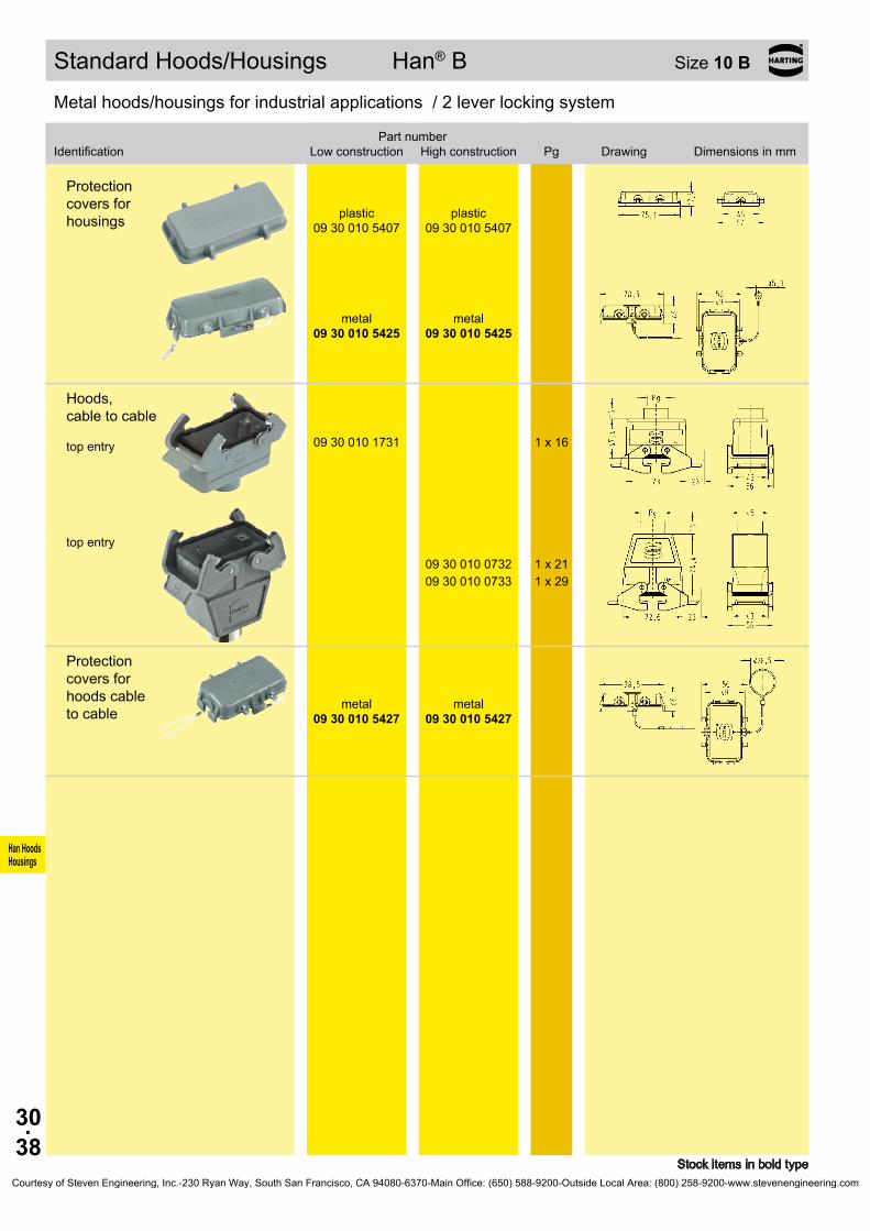
30.38
Han HoodsHousings
09 30 010 5407
09 30 010 5407
09 30 010 5425
09 30 010 5425
09 30 010 1731 1 x 16
09 30 010 0732 1 x 21 09 30 010 0733 1 x 29
09 30 010 5427
09 30 010 5427
Standard Hoods/Housings Han® B Size 10 B
Stock items in bold type
Metal hoods/housings for industrial applications / 2 lever locking system
Identification
Low construction
High constructionPart number
Pg Drawing Dimensions in mm
Protection covers for housings
plastic plastic
metal metal
Hoods, cable to cable top entry
top entry
Protection covers for hoods cable to cable
metal metal
Courtesy of Steven Engineering, Inc.-230 Ryan Way, South San Francisco, CA 94080-6370-Main Office: (650) 588-9200-Outside Local Area: (800) 258-9200-www.stevenengineering.com
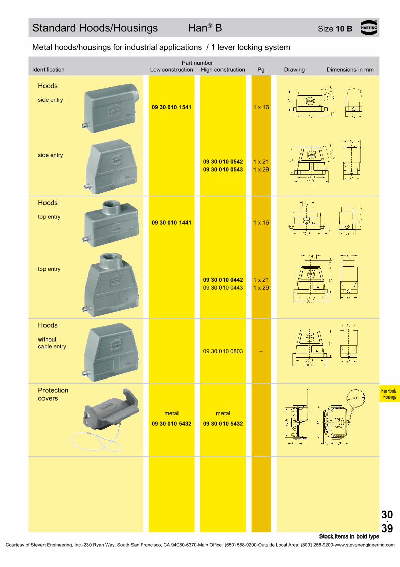
30.39
Han HoodsHousings
09 30 010 1541 1 x 16
09 30 010 0542 1 x 21 09 30 010 0543 1 x 29
09 30 010 1441 1 x 16
09 30 010 0442 1 x 21 09 30 010 0443 1 x 29
09 30 010 0803 –
09 30 010 5432
09 30 010 5432
Standard Hoods/Housings Han® B Size 10 B
Stock items in bold type
Metal hoods/housings for industrial applications / 1 lever locking system
Identification
Low construction
High constructionPart number
Pg Drawing Dimensions in mm
Hoods side entry
side entry
Hoods top entry
top entry
Hoods without cable entry
Protection covers
metal metal
Courtesy of Steven Engineering, Inc.-230 Ryan Way, South San Francisco, CA 94080-6370-Main Office: (650) 588-9200-Outside Local Area: (800) 258-9200-www.stevenengineering.com
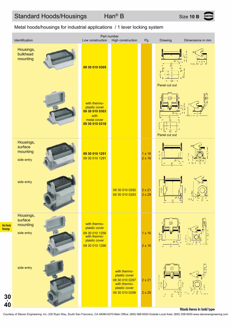
30.40
Han HoodsHousings
09 30 010 0305
09 30 010 0303
09 30 010 0318
09 30 010 1251 1 x 1609 30 010 1291 2 x 16
09 30 010 0292 2 x 21 09 30 010 0293 2 x 29
09 30 010 1256
1 x 16
09 30 010 1296
2 x 16
09 30 010 0297
2 x 21
09 30 010 0298
2 x 29
Standard Hoods/Housings Han® B Size 10 B
Stock items in bold type
Metal hoods/housings for industrial applications / 1 lever locking system
Identification
Low construction
High constructionPart number
Pg Drawing Dimensions in mm
Housings, bulkhead mounting
Panel cut out
with thermo- plastic cover
with
metal cover
Panel cut out
Housings, surface mounting side entry
side entry
Housings, surface mounting side entry
with thermo- plastic cover
with thermo- plastic cover
side entry
with thermo- plastic cover
with thermo- plastic cover
Courtesy of Steven Engineering, Inc.-230 Ryan Way, South San Francisco, CA 94080-6370-Main Office: (650) 588-9200-Outside Local Area: (800) 258-9200-www.stevenengineering.com

30.41
Han HoodsHousings
09 30 010 2296
2 x 16
09 30 010 2297
2 x 21
09 30 010 5412
09 30 010 5412
09 30 010 1751 1 x 16
09 30 010 0752 1 x 21 09 30 010 0753 1 x 29
Standard Hoods/Housings Han® B Size 10 B
Stock items in bold type
Metal hoods/housings for industrial applications / 1 lever locking system
Identification
Low construction
High constructionPart number
Pg Drawing Dimensions in mm
Housings, surface mounting side entry
with metal cover
side entry
with
metal cover
Protection covers
plastic plastic
Hoods, cable to cable top entry
top entry
Courtesy of Steven Engineering, Inc.-230 Ryan Way, South San Francisco, CA 94080-6370-Main Office: (650) 588-9200-Outside Local Area: (800) 258-9200-www.stevenengineering.com
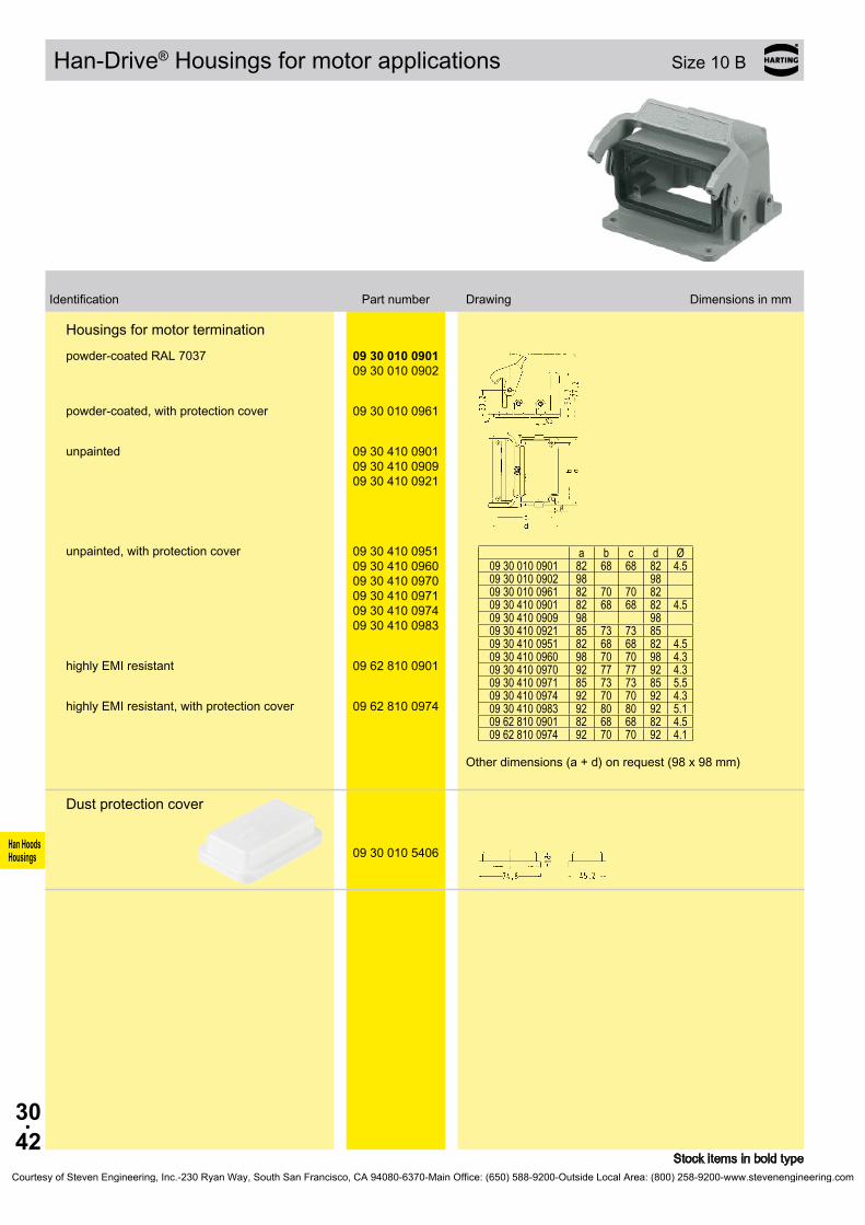
30.42
Han HoodsHousings
09 30 010 0901 09 30 010 0902
a b c d Ø
09 30 010 0901 82 68 68 8209 30 010 0902 98 9809 30 010 0961 82 70 70 8209 30 410 0901 82 68 68 8209 30 410 0909 98 9809 30 410 0921 85 73 73 8509 30 410 0951 82 68 68 8209 30 410 0960 98 70 70 9809 30 410 0970 92 77 77 9209 30 410 0971 85 73 73 8509 30 410 0974 92 70 70 9209 30 410 0983 92 80 80 9209 62 810 0901 82 68 68 8209 62 810 0974 92 70 70 92
09 30 010 0961
09 30 410 0901 09 30 410 0909 09 30 410 0921
09 30 410 0951 09 30 410 0960 09 30 410 0970 09 30 410 0971 09 30 410 0974 09 30 410 0983
09 62 810 0901
09 62 810 0974
09 30 010 5406
Han-Drive® Housings for motor applications Size 10 B
Stock items in bold type
Identification Part number Drawing Dimensions in mm
Housings for motor terminationpowder-coated RAL 7037
4 .5
4 .5
4 .54 .34 .35 .54 .35 .14 .54 .1
Other dimensions (a + d) on request (98 x 98 mm)
powder-coated, with protection cover
unpainted
unpainted, with protection cover
highly EMI resistant
highly EMI resistant, with protection cover
Dust protection cover
Courtesy of Steven Engineering, Inc.-230 Ryan Way, South San Francisco, CA 94080-6370-Main Office: (650) 588-9200-Outside Local Area: (800) 258-9200-www.stevenengineering.com
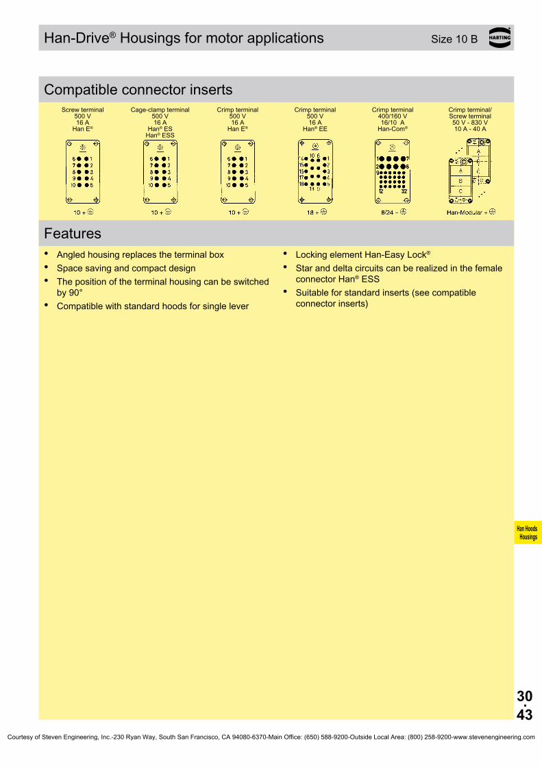
30.43
Han HoodsHousings
500 V16 A
Han E®
500 V16 A
Han® ESHan® ESS
500 V16 A
Han E®
500 V16 A
Han® EE
400/160 V16/10 A
Han-Com®50 V - 830 V10 A - 40 A
Han-Drive® Housings for motor applications Size 10 B
Compatible connector insertsScrew terminal Cage-clamp terminal Crimp terminal Crimp terminal Crimp terminal Crimp terminal/
Screw terminal
Features• Angled housing replaces the terminal box• Space saving and compact design• The position of the terminal housing can be switched
by 90°• Compatible with standard hoods for single lever
• Locking element Han-Easy Lock®
• Star and delta circuits can be realized in the female connector Han® ESS
• Suitable for standard inserts (see compatible connector inserts)
Courtesy of Steven Engineering, Inc.-230 Ryan Way, South San Francisco, CA 94080-6370-Main Office: (650) 588-9200-Outside Local Area: (800) 258-9200-www.stevenengineering.com

30.44
Han HoodsHousings
09 30 010 1531 1 x 16
09 30 010 0532 1 x 21 09 30 010 0533 1 x 29
09 30 010 1431 1 x 16
09 30 010 0432 1 x 21 09 30 010 0433 1 x 29
09 30 010 5457
09 30 010 5457
09 30 010 0302
09 30 010 0317
Standard Hoods/Housings Han® B Size 10 B
Stock items in bold type
Metal hoods/housings for industrial applications / 2 lever locking system
Identification
Low construction
High constructionPart number
Pg Drawing Dimensions in mm
Hoods side entry
side entry
Hoods top entry
top entry
Protection covers
metal metal
Metal hoods/housings for industrial applications / 2 lever locking system
Identification
Low construction
High constructionPart number
Pg Drawing Dimensions in mm
Housings, bulkhead mounting with thermo-
plastic cover
with metal cover
Panel cut out
Courtesy of Steven Engineering, Inc.-230 Ryan Way, South San Francisco, CA 94080-6370-Main Office: (650) 588-9200-Outside Local Area: (800) 258-9200-www.stevenengineering.com
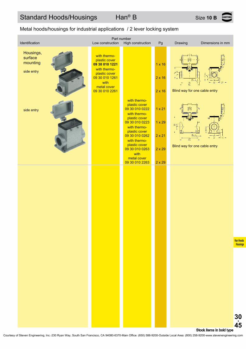
30.45
Han HoodsHousings
09 30 010 1221
1 x 16
09 30 010 1261
2 x 16
09 30 010 2261
2 x 16
09 30 010 0222
1 x 21
09 30 010 0223
1 x 29
09 30 010 0262
2 x 21
09 30 010 0263
2 x 29
09 30 010 2263
2 x 29
Standard Hoods/Housings Han® B Size 10 B
Stock items in bold type
Metal hoods/housings for industrial applications / 2 lever locking system
Identification
Low construction
High constructionPart number
Pg Drawing Dimensions in mm
Housings, surface mounting side entry
with thermo- plastic cover
with thermo- plastic cover
with metal cover
Blind way for one cable entry
side entry
with thermo- plastic cover
with thermo- plastic cover
with thermo- plastic cover
with thermo- plastic cover
with
metal cover
Blind way for one cable entry
Courtesy of Steven Engineering, Inc.-230 Ryan Way, South San Francisco, CA 94080-6370-Main Office: (650) 588-9200-Outside Local Area: (800) 258-9200-www.stevenengineering.com

30.46
Han HoodsHousings
09 30 010 0581 1 x 16 09 30 010 0582 1 x 21
09 30 010 0381
Standard Hoods/Housings Han® B Size 10 B
Stock items in bold type
Metal hoods/housings for industrial applications / 1 central locking lever locking system
Identification
Low construction
High constructionPart number
Pg Drawing Dimensions in mm
Hoods side entry
Metal hoods/housings for industrial applications / 1 central locking lever locking system
Identification
Low construction
High constructionPart number
Pg Drawing Dimensions in mm
Housings, bulkhead mounting
Panel cut out
Courtesy of Steven Engineering, Inc.-230 Ryan Way, South San Francisco, CA 94080-6370-Main Office: (650) 588-9200-Outside Local Area: (800) 258-9200-www.stevenengineering.com
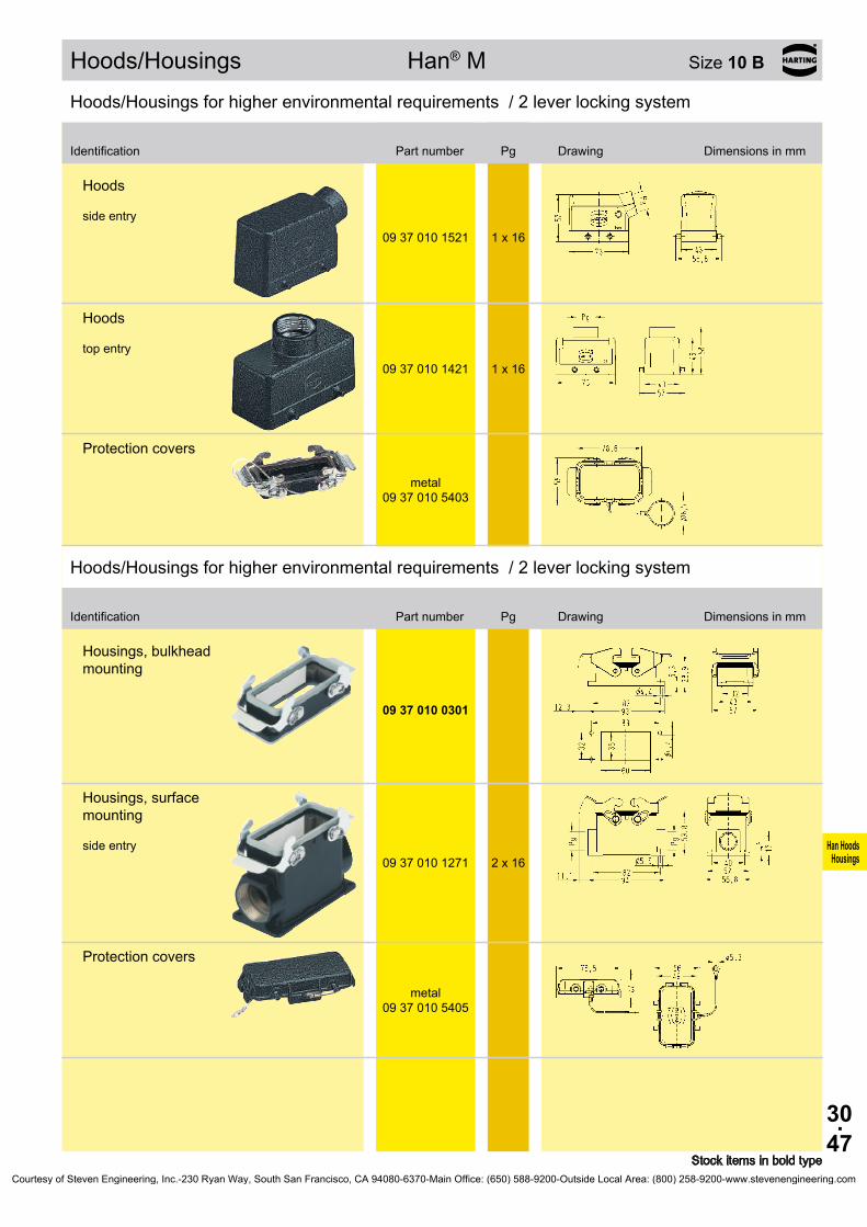
30.47
Han HoodsHousings
09 37 010 1521 1 x 16
09 37 010 1421 1 x 16
09 37 010 5403
09 37 010 0301
09 37 010 1271 2 x 16
09 37 010 5405
Hoods/Housings Han® M Size 10 B
Stock items in bold type
Hoods/Housings for higher environmental requirements / 2 lever locking system
Identification Part number Pg Drawing Dimensions in mm
Hoods side entry
Hoods top entry
Protection covers
metal
Hoods/Housings for higher environmental requirements / 2 lever locking system
Identification Part number Pg Drawing Dimensions in mm
Housings, bulkhead mounting
Housings, surface mounting side entry
Protection covers
metal
Courtesy of Steven Engineering, Inc.-230 Ryan Way, South San Francisco, CA 94080-6370-Main Office: (650) 588-9200-Outside Local Area: (800) 258-9200-www.stevenengineering.com
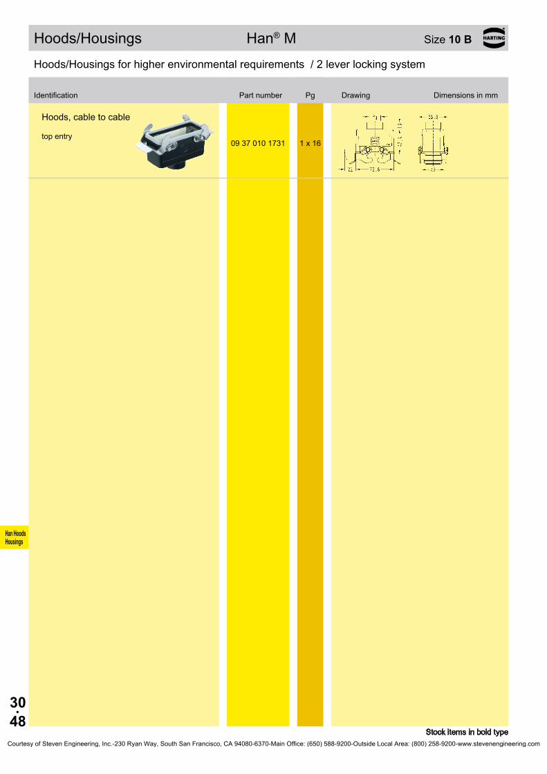
30.48
Han HoodsHousings
09 37 010 1731 1 x 16
Hoods/Housings Han® M Size 10 B
Stock items in bold type
Hoods/Housings for higher environmental requirements / 2 lever locking system
Identification Part number Pg Drawing Dimensions in mm
Hoods, cable to cable top entry
Courtesy of Steven Engineering, Inc.-230 Ryan Way, South San Francisco, CA 94080-6370-Main Office: (650) 588-9200-Outside Local Area: (800) 258-9200-www.stevenengineering.com

30.49
Han HoodsHousings
09 62 010 0540 1 x 1609 62 010 0541 1 x 2109 62 010 0542 1 x 29
09 62 010 0580
1 x 16
09 62 010 0581
1 x 21
09 62 010 0582
1 x 29
09 62 010 0440 1 x 1609 62 010 0441 1 x 2109 62 010 0442 1 x 29
09 62 010 0481
1 x 21
09 62 010 0301
09 62 010 0381
Hoods/Housings Han® EMC Size 10 B
Stock items in bold type
Hoods/Housings for higher EMC requirements / Screw/1 central locking lever locking system
Identification Part number Pg Drawing Dimensions in mm
Hoods side entry
Hoods side entry
with central locking lever
with central locking lever
with central locking lever
Hoods top entry
Hoods top entry with central
locking lever
Hoods/Housings for higher EMC requirements / Screw/1 central locking lever locking system
Identification Part number Pg Drawing Dimensions in mm
Housings, bulkhead mounting
Panel cut out
Housings, bulkhead mounting
with central locking lever
Panel cut out
Courtesy of Steven Engineering, Inc.-230 Ryan Way, South San Francisco, CA 94080-6370-Main Office: (650) 588-9200-Outside Local Area: (800) 258-9200-www.stevenengineering.com

30.50
Han HoodsHousings
09 62 810 1521 1 x 16
09 62 810 0522 1 x 21
09 62 810 1421 1 x 16
09 62 810 0422 1 x 21
09 62 810 0801 –
Hoods/Housings Han® EMC/B Size 10 B
Stock items in bold type
Hoods/Housings for higher EMC requirements / 2 lever locking system
Identification
Low construction
High constructionPart number
Pg Drawing Dimensions in mm
Hoods side entry
side entry
Hoods top entry
top entry
Hoods without cable entry
Courtesy of Steven Engineering, Inc.-230 Ryan Way, South San Francisco, CA 94080-6370-Main Office: (650) 588-9200-Outside Local Area: (800) 258-9200-www.stevenengineering.com

30.51
Han HoodsHousings
Bezeichnung
Niedrige Bauform
Hohe BauformBestell-Nummer
Pg Maßzeichnung Maße in mm
09 62 810 0301
Hoods/Housings Han® EMC/B Size 10 B
Stock items in bold type
Hoods/Housings for higher EMC requirements / 2 lever locking system
Identification
Low construction
High constructionPart number
Pg Drawing Dimensions in mm
Hoods/Housings for higher EMC requirements / 2 lever locking system
Housings, bulkhead mounting
Panel cut out
Courtesy of Steven Engineering, Inc.-230 Ryan Way, South San Francisco, CA 94080-6370-Main Office: (650) 588-9200-Outside Local Area: (800) 258-9200-www.stevenengineering.com

30.52
Han HoodsHousings
09 40 010 0502 1 x 2109 40 010 0503 1 x 29
09 40 010 0511 1 x 16 09 40 010 0512 1 x 21 09 40 010 0513 1 x 29
09 40 010 0401 1 x 16
09 40 010 0402 1 x 2109 40 010 0403 1 x 29
09 40 010 0411 1 x 16 09 40 010 0412 1 x 21 09 40 010 0413 1 x 29
09 40 010 0811 –
Hoods/Housings Han® HPR Size 10 B
Stock items in bold type
Hoods/Housings for harsh environmental requirements / Screw/toggle locking system
Identification
Toggle locking
screwPart number
Pg Drawing Dimensions in mm
Hoods side entry
Hoods top entry
Hoods without cable entry
Courtesy of Steven Engineering, Inc.-230 Ryan Way, South San Francisco, CA 94080-6370-Main Office: (650) 588-9200-Outside Local Area: (800) 258-9200-www.stevenengineering.com
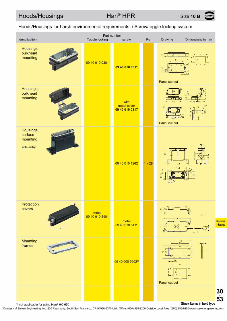
30.53
Han HoodsHousings
09 40 010 0301 09 40 010 0311
09 40 010 0317
09 40 010 1262 1 x 29
09 40 010 5401
09 40 010 5411
09 40 000 99021)
Hoods/Housings Han® HPR Size 10 B
Stock items in bold type1) not applicable for using Han® HC 650
Hoods/Housings for harsh environmental requirements / Screw/toggle locking system
Identification
Toggle locking
screwPart number
Pg Drawing Dimensions in mm
Housings, bulkhead mounting
Panel cut out
Housings, bulkhead mounting
with
metal cover
Panel cut out
Housings, surface mounting side entry
Protection covers
metal
metal
Mounting frames
Panel cut out
Courtesy of Steven Engineering, Inc.-230 Ryan Way, South San Francisco, CA 94080-6370-Main Office: (650) 588-9200-Outside Local Area: (800) 258-9200-www.stevenengineering.com
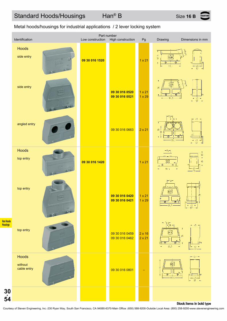
30.54
Han HoodsHousings
09 30 016 1520 1 x 21
09 30 016 0520 1 x 21 09 30 016 0521 1 x 29
09 30 016 0663 2 x 21
09 30 016 1420 1 x 21
09 30 016 0420 1 x 21 09 30 016 0421 1 x 29
09 30 016 0459 2 x 16 09 30 016 0462 2 x 21
09 30 016 0801 –
Standard Hoods/Housings Han® B Size 16 B
Stock items in bold type
Metal hoods/housings for industrial applications / 2 lever locking system
Identification
Low construction
High constructionPart number
Pg Drawing Dimensions in mm
Hoods side entry
side entry
angled entry
Hoods top entry
top entry
top entry
Hoods without cable entry
Courtesy of Steven Engineering, Inc.-230 Ryan Way, South San Francisco, CA 94080-6370-Main Office: (650) 588-9200-Outside Local Area: (800) 258-9200-www.stevenengineering.com
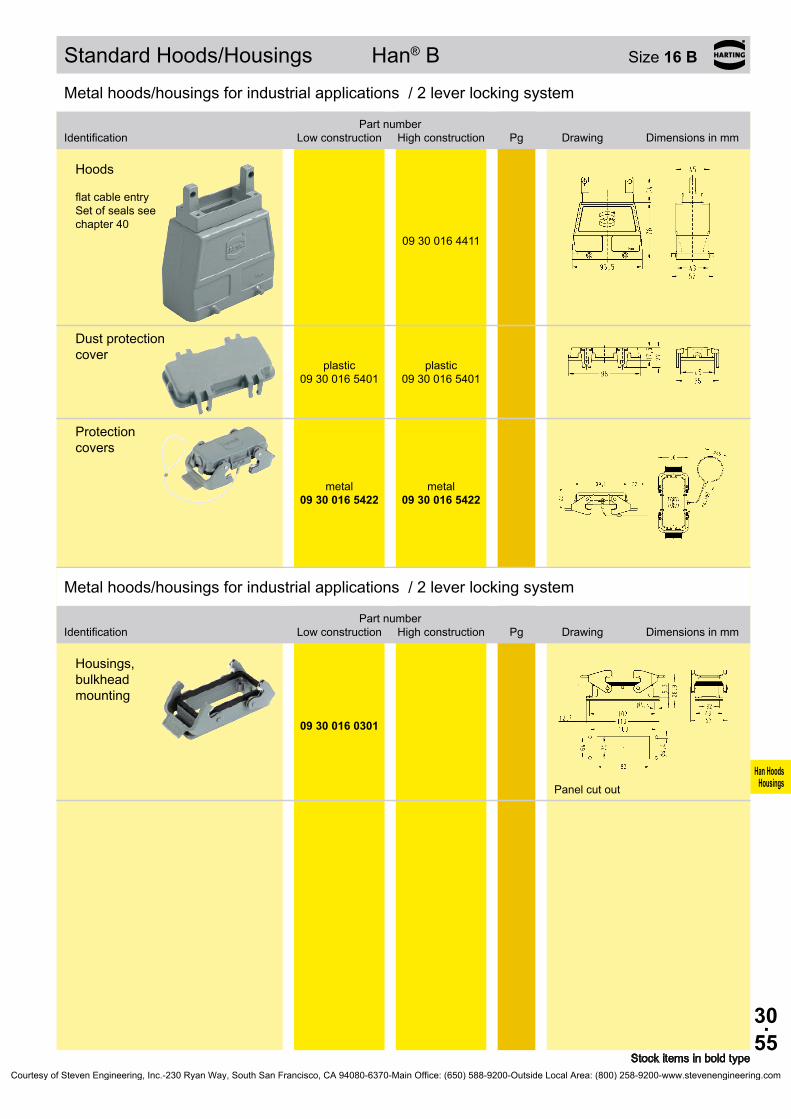
30.55
Han HoodsHousings
09 30 016 4411
09 30 016 5401
09 30 016 5401
09 30 016 5422
09 30 016 5422
09 30 016 0301
Standard Hoods/Housings Han® B Size 16 B
Stock items in bold type
Metal hoods/housings for industrial applications / 2 lever locking system
Identification
Low construction
High constructionPart number
Pg Drawing Dimensions in mm
Hoods flat cable entry Set of seals see chapter 40
Dust protection cover
plastic plastic
Protection covers
metal metal
Metal hoods/housings for industrial applications / 2 lever locking system
Identification
Low construction
High constructionPart number
Pg Drawing Dimensions in mm
Housings, bulkhead mounting
Panel cut out
Courtesy of Steven Engineering, Inc.-230 Ryan Way, South San Francisco, CA 94080-6370-Main Office: (650) 588-9200-Outside Local Area: (800) 258-9200-www.stevenengineering.com

30.56
Han HoodsHousings
09 30 016 1230 1 x 2109 30 016 1270 2 x 21
09 30 016 0230 1 x 21 09 30 016 0231 1 x 29 09 30 016 0270 2 x 21 09 30 016 0271 2 x 29
09 30 016 5405
09 30 016 5405
09 30 016 5425
09 30 016 5425
09 30 016 1730 1 x 21
09 30 016 0730 1 x 21 09 30 016 0731 1 x 29
09 30 016 5426
09 30 016 5426
Standard Hoods/Housings Han® B Size 16 B
Stock items in bold type
Metal hoods/housings for industrial applications / 2 lever locking system
Identification
Low construction
High constructionPart number
Pg Drawing Dimensions in mm
Housings, surface mounting side entry
side entry
Protection covers
plastic plastic
metal metal
Hoods, cable to cable top entry
top entry
Protection covers
metal metal
Courtesy of Steven Engineering, Inc.-230 Ryan Way, South San Francisco, CA 94080-6370-Main Office: (650) 588-9200-Outside Local Area: (800) 258-9200-www.stevenengineering.com

30.57
Han HoodsHousings
11 30 016 0520
20 ... 22 mm 11 30 000 9955
23 ... 25 mm 11 30 000 9956
26 ... 28 mm 11 30 000 9957
29 ... 31 mm 11 30 000 9958
32 ... 34 mm 11 30 000 9959
Hoods/Housings Han® Easy Hood Size 16 B
Stock items in bold type
Metal hoods/housings for industrial applications / 2 lever locking system
Identification Part number Pg Drawing Dimensions in mm
Han® Easy Hood side entry
Cable seal
Courtesy of Steven Engineering, Inc.-230 Ryan Way, South San Francisco, CA 94080-6370-Main Office: (650) 588-9200-Outside Local Area: (800) 258-9200-www.stevenengineering.com

30.58
Han HoodsHousings
09 30 016 1540 1 x 21
09 30 016 0540 1 x 21 09 30 016 0541 1 x 29
09 30 016 1440 1 x 21
09 30 016 0440 1 x 21 09 30 016 0441 1 x 29
09 30 016 0803 –
09 30 016 4441
09 30 016 5432
09 30 016 5432
Standard Hoods/Housings Han® B Size 16 B
Stock items in bold type
Metal hoods/housings for industrial applications / 1 lever locking system
Identification
Low construction
High constructionPart number
Pg Drawing Dimensions in mm
Hoods side entry
side entry
Hoods top entry
top entry
Hoods without cable entry
Hoods flat cable entry Set of seals see chapter 40
Protection covers
metal metal
Courtesy of Steven Engineering, Inc.-230 Ryan Way, South San Francisco, CA 94080-6370-Main Office: (650) 588-9200-Outside Local Area: (800) 258-9200-www.stevenengineering.com

30.59
Han HoodsHousings
Bezeichnung
Niedrige Bauform
Hohe BauformBestell-Nummer
Pg Maßzeichnung Maße in mm
09 30 016 0307
09 30 016 0306
09 30 016 0318
09 30 016 1250 1 x 2109 30 016 1290 2 x 21
09 30 016 0250 1 x 21 09 30 016 0251 1 x 29 09 30 016 0290 2 x 21 09 30 016 0291 2 x 29
Standard Hoods/Housings Han® B Size 16 B
Stock items in bold type
Metal hoods/housings for industrial applications / 1 lever locking system
Identification
Low construction
High constructionPart number
Pg Drawing Dimensions in mm
Metal hoods/housings for industrial applications / 1 lever locking system
Housings, bulkhead mounting
Panel cut out
with thermo- plastic cover
with
metal cover
Panel cut out
Housings, surface mounting side entry
Blind way for one cable entry
side entry
Blind way for one cable entry
Courtesy of Steven Engineering, Inc.-230 Ryan Way, South San Francisco, CA 94080-6370-Main Office: (650) 588-9200-Outside Local Area: (800) 258-9200-www.stevenengineering.com

30.60
Han HoodsHousings
09 30 016 1255
1 x 21
09 30 016 1295
2 x 21
09 30 016 0255
1 x 21
09 30 016 0256
1 x 29
09 30 016 0295
2 x 21
09 30 016 0296
2 x 29
09 30 016 2295
2 x 21
09 30 016 2297
2 x 21
09 30 016 2298
2 x 29
Standard Hoods/Housings Han® B Size 16 B
Stock items in bold type
Metal hoods/housings for industrial applications / 1 lever locking system
Identification
Low construction
High constructionPart number
Pg Drawing Dimensions in mm
Housings, surface mounting side entry
with thermo- plastic cover
with thermo- plastic cover
side entry
with thermo- plastic cover
with thermo- plastic cover
with thermo- plastic cover
with thermo- plastic cover
Housings, surface mounting side entry
with metal cover
side entry
with
metal cover
with
metal cover
Courtesy of Steven Engineering, Inc.-230 Ryan Way, South San Francisco, CA 94080-6370-Main Office: (650) 588-9200-Outside Local Area: (800) 258-9200-www.stevenengineering.com

30.61
Han HoodsHousings
09 30 016 1750 1 x 21
09 30 016 0750 1 x 21 09 30 016 0751 1 x 29
Standard Hoods/Housings Han® B Size 16 B
Stock items in bold type
Metal hoods/housings for industrial applications / 1 lever locking system
Identification
Low construction
High constructionPart number
Pg Drawing Dimensions in mm
Hoods, cable to cable top entry
top entry
Courtesy of Steven Engineering, Inc.-230 Ryan Way, South San Francisco, CA 94080-6370-Main Office: (650) 588-9200-Outside Local Area: (800) 258-9200-www.stevenengineering.com

30.62
Han HoodsHousings
09 30 016 1530 1 x 21
09 30 016 0530 1 x 21 09 30 016 0531 1 x 29
09 30 016 1430 1 x 21
09 30 016 0430 1 x 21 09 30 016 0431 1 x 29
09 30 016 4431
Standard Hoods/Housings Han® B Size 16 B
Stock items in bold type
Metal hoods/housings for industrial applications / 2 lever locking system
Identification
Low construction
High constructionPart number
Pg Drawing Dimensions in mm
Hoods side entry
side entry
Hoods top entry
top entry
Hoods flat cable entry Set of seals see chapter 40
Courtesy of Steven Engineering, Inc.-230 Ryan Way, South San Francisco, CA 94080-6370-Main Office: (650) 588-9200-Outside Local Area: (800) 258-9200-www.stevenengineering.com
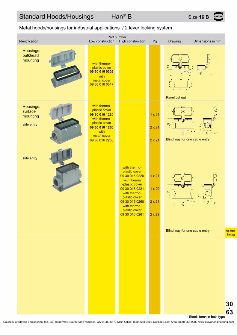
30.63
Han HoodsHousings
Bezeichnung
Niedrige Bauform
Hohe BauformBestell-Nummer
Pg Maßzeichnung Maße in mm
09 30 016 0302
09 30 016 0317
09 30 016 1220
1 x 21
09 30 016 1260
2 x 21
09 30 016 2260
2 x 21
09 30 016 0220
1 x 21
09 30 016 0221
1 x 29
09 30 016 0260
2 x 21
09 30 016 0261
2 x 29
Standard Hoods/Housings Han® B Size 16 B
Stock items in bold type
Metal hoods/housings for industrial applications / 2 lever locking system
Identification
Low construction
High constructionPart number
Pg Drawing Dimensions in mm
Metal hoods/housings for industrial applications / 2 lever locking system
Housings, bulkhead mounting
with thermo- plastic cover
with
metal cover
Panel cut out
Housings, surface mounting side entry
with thermo- plastic cover
with thermo- plastic cover
with metal cover
Blind way for one cable entry
side entry
with thermo- plastic cover
with thermo -plastic cover
with thermo- plastic cover
with thermo- plastic cover
Blind way for one cable entry
Courtesy of Steven Engineering, Inc.-230 Ryan Way, South San Francisco, CA 94080-6370-Main Office: (650) 588-9200-Outside Local Area: (800) 258-9200-www.stevenengineering.com
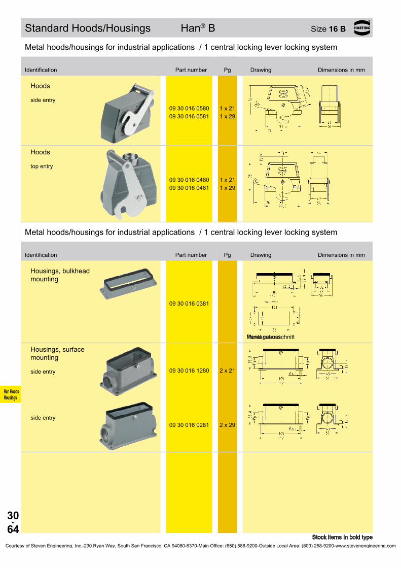
30.64
Han HoodsHousings
09 30 016 0580 1 x 2109 30 016 0581 1 x 29
09 30 016 0480 1 x 2109 30 016 0481 1 x 29
09 30 016 0381
Montageausschnitt
09 30 016 1280 2 x 21
09 30 016 0281 2 x 29
Standard Hoods/Housings Han® B Size 16 B
Stock items in bold type
Metal hoods/housings for industrial applications / 1 central locking lever locking system
Identification Part number Pg Drawing Dimensions in mm
Hoods side entry
Hoods top entry
Metal hoods/housings for industrial applications / 1 central locking lever locking system
Identification Part number Pg Drawing Dimensions in mm
Housings, bulkhead mounting
Panel cut out
Housings, surface mounting side entry
side entry
Courtesy of Steven Engineering, Inc.-230 Ryan Way, South San Francisco, CA 94080-6370-Main Office: (650) 588-9200-Outside Local Area: (800) 258-9200-www.stevenengineering.com

30.65
Han HoodsHousings
09 37 016 1520 1 x 21
09 37 016 0521 1 x 29
09 37 016 0421 1 x 29
09 37 016 5402
09 37 016 0301
Hoods/Housings Han® M Size 16 B
Stock items in bold type
Hoods/Housings for higher environmental requirements / 2 lever locking system
Hoods side entry
side entry
Hoods top entry
Protection covers
metal
Hoods/Housings for higher environmental requirements / 2 lever locking system
Housings, bulkhead mounting
Identification Part number Pg Drawing Dimensions in mm
Identification Part number Pg Drawing Dimensions in mm
Courtesy of Steven Engineering, Inc.-230 Ryan Way, South San Francisco, CA 94080-6370-Main Office: (650) 588-9200-Outside Local Area: (800) 258-9200-www.stevenengineering.com

30.66
Han HoodsHousings
09 37 016 1230 1 x 21
09 37 016 0271 2 x 29
09 37 016 5405
09 37 016 1730 1 x 21
Hoods/Housings Han® M Size 16 B
Stock items in bold type
Hoods/Housings for higher environmental requirements / 2 lever locking system
Housings, surface mounting side entry
side entry
Protection covers
metal
Hoods, cable to cable top entry
Identification Part number Pg Drawing Dimensions in mm
Courtesy of Steven Engineering, Inc.-230 Ryan Way, South San Francisco, CA 94080-6370-Main Office: (650) 588-9200-Outside Local Area: (800) 258-9200-www.stevenengineering.com

30.67
Han HoodsHousings
09 62 040 0540 1 x 2109 62 040 0541 1 x 29
09 62 040 0580
1 x 21
09 62 040 0581
1 x 29
09 62 040 0440 1 x 2109 62 040 0441 1 x 29
09 62 040 0481
1 x 29
09 62 040 0301
09 62 040 0381
Hoods/Housings Han® EMC Size 16 B
Stock items in bold type
Hoods/Housings for higher EMC requirements / Screw/1 central locking lever locking system
Identification Part number Pg Drawing Dimensions in mm
Hoods side entry
Hoods side entry
with central locking lever
with central locking lever
Hoods top entry
Hoods top entry with central
locking lever
Hoods/Housings for higher EMC requirements / Screw/1 central locking lever locking system
Identification Part number Pg Drawing Dimensions in mm
Housings, bulkhead mounting
Panel cut out
Housings, bulkhead mounting
with central locking lever
Panel cut out
Courtesy of Steven Engineering, Inc.-230 Ryan Way, South San Francisco, CA 94080-6370-Main Office: (650) 588-9200-Outside Local Area: (800) 258-9200-www.stevenengineering.com

30.68
Han HoodsHousings
09 62 816 1520 1 x 21
09 62 816 0521 1 x 29
09 62 816 1420 1 x 21
09 62 816 0421 1 x 29
09 62 816 0801 –
09 62 816 0301
Hoods/Housings Han® EMC/B Size 16 B
Stock items in bold type
Hoods/Housings for higher EMC requirements / 2 lever locking system
Identification Part number Pg Drawing Dimensions in mm
Hoods side entry
side entry
Hoods top entry
top entry
Hoods without cable entry
Hoods/Housings for higher EMC requirements / 2 lever locking system
Identification Part number Pg Drawing Dimensions in mm
Housings, bulkhead mounting
Panel cut out
Courtesy of Steven Engineering, Inc.-230 Ryan Way, South San Francisco, CA 94080-6370-Main Office: (650) 588-9200-Outside Local Area: (800) 258-9200-www.stevenengineering.com

30.69
Han HoodsHousings
09 40 016 0502 1 x 2109 40 016 0503 1 x 2909 40 016 0504 1 x 36
09 40 016 0512 1 x 21 09 40 016 0513 1 x 29 09 40 016 0514 1 x 36
09 40 016 0402 1 x 21
09 40 016 0403 1 x 2909 40 016 0404 1 x 36
09 40 016 0412 1 x 21 09 40 016 0413 1 x 29 09 40 016 0414 1 x 36 09 40 016 0432 2 x 21
09 40 016 0811 –
Hoods/Housings Han® HPR Size 16 B
Stock items in bold type
Hoods/Housings for harsh environmental requirements / Screw/toggle locking system
Identification
Toggle locking
screwPart number
Pg Drawing Dimensions in mm
Hoods side entry
Hoods top entry
Hoods without cable entry
Courtesy of Steven Engineering, Inc.-230 Ryan Way, South San Francisco, CA 94080-6370-Main Office: (650) 588-9200-Outside Local Area: (800) 258-9200-www.stevenengineering.com

30.70
Han HoodsHousings
09 40 016 0301 09 40 016 0311
09 40 016 0317
09 40 016 1263 1 x 36
09 40 016 1201 –
09 40 016 5401
09 40 016 5411
Hoods/Housings Han® HPR Size 16 B
Stock items in bold type1) not applicable for using Han® HC 650
Hoods/Housings for harsh environmental requirements / Screw/toggle locking system
Identification
Toggle locking
screwPart number
Pg Drawing Dimensions in mm
Housings, bulkhead mounting
Panel cut out
Housings, bulkhead mounting
with
metal cover
Panel cut out
Housings, surface mounting side entry
Housings, surface mounting without cable entry
Protection covers
metal
metal
Courtesy of Steven Engineering, Inc.-230 Ryan Way, South San Francisco, CA 94080-6370-Main Office: (650) 588-9200-Outside Local Area: (800) 258-9200-www.stevenengineering.com

30.71
Han HoodsHousings
09 40 000 99031)
Hoods/Housings Han® HPR Size 16 B
Stock items in bold type
Hoods/Housings for harsh environmental requirements / Screw/toggle locking system
Identification
Toggle locking
screwPart number
Pg Drawing Dimensions in mm
1) not applicable for using Han® HC 650
Mounting frames
Panel cut out
Courtesy of Steven Engineering, Inc.-230 Ryan Way, South San Francisco, CA 94080-6370-Main Office: (650) 588-9200-Outside Local Area: (800) 258-9200-www.stevenengineering.com
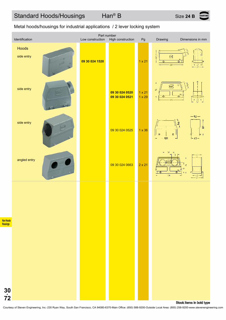
30.72
Han HoodsHousings
09 30 024 1520 1 x 21
09 30 024 0520 1 x 21 09 30 024 0521 1 x 29
09 30 024 0525 1 x 36
09 30 024 0663 2 x 21
Standard Hoods/Housings Han® B Size 24 B
Stock items in bold type
Metal hoods/housings for industrial applications / 2 lever locking system
Identification
Low construction
High constructionPart number
Pg Drawing Dimensions in mm
Hoods side entry
side entry
side entry
angled entry
Courtesy of Steven Engineering, Inc.-230 Ryan Way, South San Francisco, CA 94080-6370-Main Office: (650) 588-9200-Outside Local Area: (800) 258-9200-www.stevenengineering.com
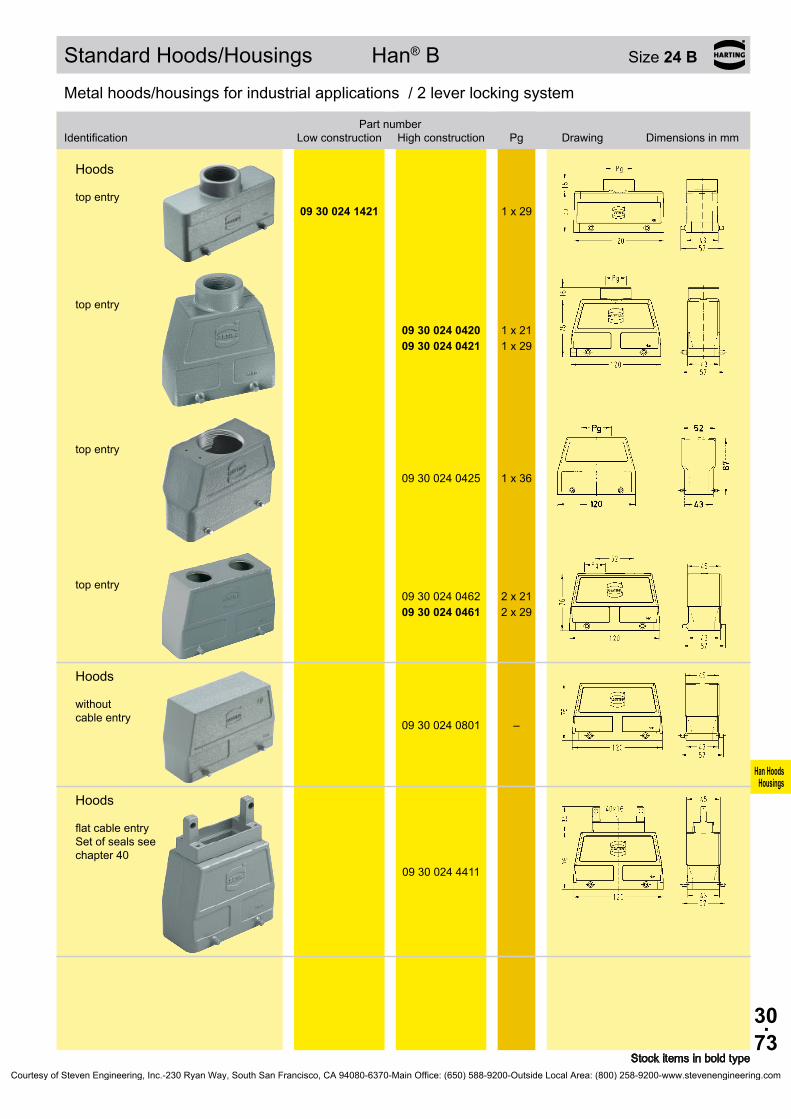
30.73
Han HoodsHousings
09 30 024 1421 1 x 29
09 30 024 0420 1 x 21 09 30 024 0421 1 x 29
09 30 024 0425 1 x 36
09 30 024 0462 2 x 21 09 30 024 0461 2 x 29
09 30 024 0801 –
09 30 024 4411
Standard Hoods/Housings Han® B Size 24 B
Stock items in bold type
Metal hoods/housings for industrial applications / 2 lever locking system
Identification
Low construction
High constructionPart number
Pg Drawing Dimensions in mm
Hoods top entry
top entry
top entry
top entry
Hoods without cable entry
Hoods flat cable entry Set of seals see chapter 40
Courtesy of Steven Engineering, Inc.-230 Ryan Way, South San Francisco, CA 94080-6370-Main Office: (650) 588-9200-Outside Local Area: (800) 258-9200-www.stevenengineering.com

30.74
Han HoodsHousings
09 30 024 5422
09 30 024 5422
09 30 024 5401
09 30 024 5401
09 30 024 0301
09 30 024 1230 1 x 2109 30 024 1270 2 x 21
09 30 024 0230 1 x 21 09 30 024 0231 1 x 29 09 30 024 0270 2 x 21 09 30 024 0271 2 x 29
Standard Hoods/Housings Han® B Size 24 B
Stock items in bold type
Metal hoods/housings for industrial applications / 2 lever locking system
Identification
Low construction
High constructionPart number
Pg Drawing Dimensions in mm
Protection covers
metal metal
Dust protection cover
plastic plastic
Metal hoods/housings for industrial applications / 2 lever locking system
Identification
Low construction
High constructionPart number
Pg Drawing Dimensions in mm
Housings, bulkhead mounting
Panel cut out
Housings, surface mounting side entry
Blind way for one cable entry
side entry
Blind way for one cable entry
Courtesy of Steven Engineering, Inc.-230 Ryan Way, South San Francisco, CA 94080-6370-Main Office: (650) 588-9200-Outside Local Area: (800) 258-9200-www.stevenengineering.com
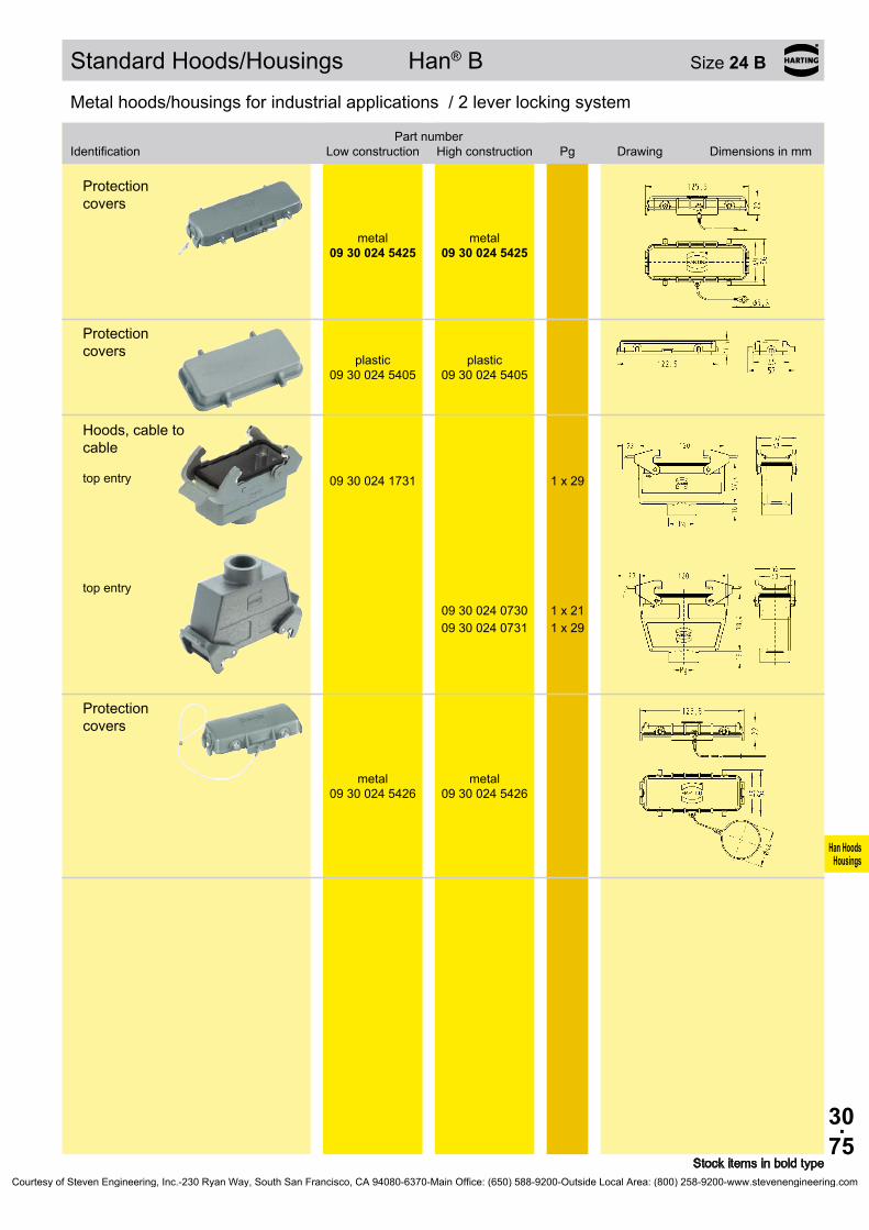
30.75
Han HoodsHousings
09 30 024 5425
09 30 024 5425
09 30 024 5405
09 30 024 5405
09 30 024 1731 1 x 29
09 30 024 0730 1 x 21 09 30 024 0731 1 x 29
09 30 024 5426
09 30 024 5426
Standard Hoods/Housings Han® B Size 24 B
Stock items in bold type
Metal hoods/housings for industrial applications / 2 lever locking system
Identification
Low construction
High constructionPart number
Pg Drawing Dimensions in mm
Protection covers
metal metal
Protection covers
plastic plastic
Hoods, cable to cable top entry
top entry
Protection covers
metal metal
Courtesy of Steven Engineering, Inc.-230 Ryan Way, South San Francisco, CA 94080-6370-Main Office: (650) 588-9200-Outside Local Area: (800) 258-9200-www.stevenengineering.com

30.76
Han HoodsHousings
11 30 024 0520
20 ... 22 mm 11 30 000 9955
23 ... 25 mm 11 30 000 9956
26 ... 28 mm 11 30 000 9957
29 ... 31 mm 11 30 000 9958
32 ... 34 mm 11 30 000 9959
Hoods/Housings Han® Easy Hood Size 24 B
Stock items in bold type
Metal hoods/housings for industrial applications / 2 lever locking system
Identification Part number Pg Drawing Dimensions in mm
Hoods side entry
Cable seal
Courtesy of Steven Engineering, Inc.-230 Ryan Way, South San Francisco, CA 94080-6370-Main Office: (650) 588-9200-Outside Local Area: (800) 258-9200-www.stevenengineering.com

30.77
Han HoodsHousings
09 30 024 1540 1 x 21
09 30 024 0540 1 x 21 09 30 024 0541 1 x 29 09 30 024 0546 1 x 36
09 30 024 1441 1 x 29
09 30 024 0440 1 x 21 09 30 024 0441 1 x 29 09 30 024 0446 1 x 36
09 30 024 0803 –
09 30 024 5432
09 30 024 5432
Standard Hoods/Housings Han® B Size 24 B
Stock items in bold type
Metal hoods/housings for industrial applications / 1 lever locking system
Identification
Low construction
High constructionPart number
Pg Drawing Dimensions in mm
Hoods side entry
side entry
Hoods top entry
top entry
Hoods without cable entry
Protection covers
metal metal
Courtesy of Steven Engineering, Inc.-230 Ryan Way, South San Francisco, CA 94080-6370-Main Office: (650) 588-9200-Outside Local Area: (800) 258-9200-www.stevenengineering.com

30.78
Han HoodsHousings
Bezeichnung
Niedrige Bauform
Hohe BauformBestell-Nummer
Pg Maßzeichnung Maße in mm
09 30 024 0307
09 30 024 0304
09 30 024 0318
09 30 024 1250 1 x 2109 30 024 1290 2 x 21
09 30 024 0250 1 x 21 09 30 024 0251 1 x 29 09 30 024 0290 2 x 21 09 30 024 0291 2 x 29
09 30 024 1255
1 x 21
09 30 024 1295
2 x 21
09 30 024 0255
1 x 21
09 30 024 0256
1 x 29
09 30 024 0295
2 x 21
09 30 024 0296
2 x 29
Standard Hoods/Housings Han® B Size 24 B
Stock items in bold type
Metal hoods/housings for industrial applications / 1 lever locking system
Identification
Low construction
High constructionPart number
Pg Drawing Dimensions in mm
Metal hoods/housings for industrial applications / 1 lever locking system
Housings, bulkhead mounting
Panel cut out
with thermo- plastic cover
with
metal cover
Panel cut out
Housings, surface mounting side entry
Blind way for one cable entry
side entry
Blind way for one cable entry
Housings, surface mounting side entry
with thermo- plastic cover
with thermo- plastic cover
side entry
with thermo- plastic cover
09 30 024 0255
with thermo- plastic cover
09 30 024 0256
with thermo- plastic cover
09 30 024 0295
with thermo- plastic cover
09 30 024 0296
Courtesy of Steven Engineering, Inc.-230 Ryan Way, South San Francisco, CA 94080-6370-Main Office: (650) 588-9200-Outside Local Area: (800) 258-9200-www.stevenengineering.com

30.79
Han HoodsHousings
09 30 024 2295
2 x 21
09 30 024 2297
2 x 21
09 30 024 2298
2 x 29
09 30 024 1751 1 x 29
09 30 024 0751 1 x 29
09 30 024 5436
09 30 024 5436
Standard Hoods/Housings Han® B Size 24 B
Stock items in bold type
Metal hoods/housings for industrial applications / 1 lever locking system
Identification
Low construction
High constructionPart number
Pg Drawing Dimensions in mm
Housings, surface mounting side entry
with m etal cover
side entry
with
metal cover
with
metal cover
Hoods, cable to cable top entry
top entry
Protection covers
metal metal
Courtesy of Steven Engineering, Inc.-230 Ryan Way, South San Francisco, CA 94080-6370-Main Office: (650) 588-9200-Outside Local Area: (800) 258-9200-www.stevenengineering.com

30.80
Han HoodsHousings
09 30 024 1530 1 x 21
09 30 024 0530 1 x 21 09 30 024 0531 1 x 29
09 30 024 1431 1 x 29
09 30 024 0430 1 x 21 09 30 024 0431 1 x 29
09 30 024 5442
09 30 024 5442
Standard Hoods/Housings Han® B Size 24 B
Stock items in bold type
Metal hoods/housings for industrial applications / 2 lever locking system
Identification
Low construction
High constructionPart number
Pg Drawing Dimensions in mm
Hoods side entry
side entry
Hoods top entry
top entry
Protection covers
metal metal
Courtesy of Steven Engineering, Inc.-230 Ryan Way, South San Francisco, CA 94080-6370-Main Office: (650) 588-9200-Outside Local Area: (800) 258-9200-www.stevenengineering.com
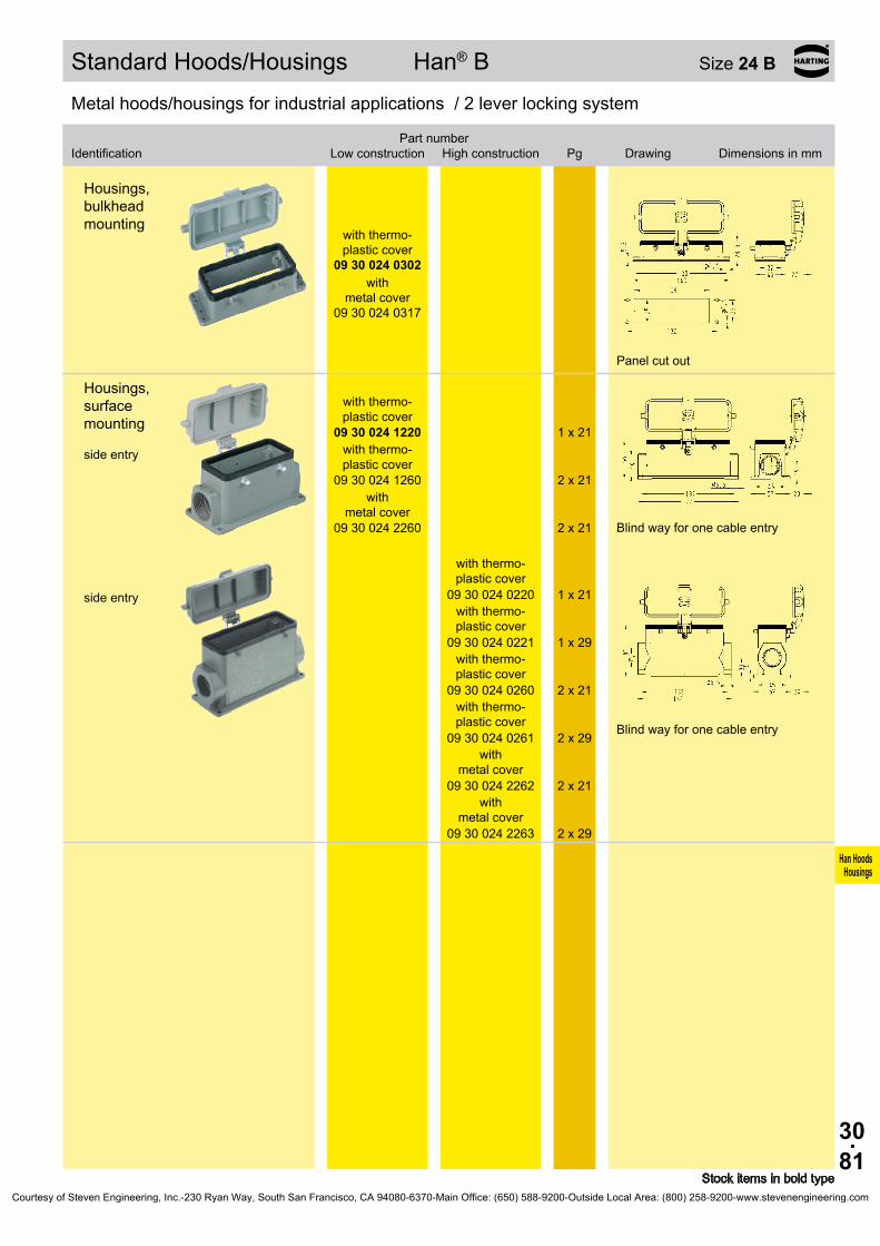
30.81
Han HoodsHousings
Bezeichnung
Niedrige Bauform
Hohe BauformBestell-Nummer
Pg Maßzeichnung Maße in mm
09 30 024 0302
09 30 024 0317
09 30 024 1220
1 x 21
09 30 024 1260
2 x 21
09 30 024 2260
2 x 21
09 30 024 0220
1 x 21
09 30 024 0221
1 x 29
09 30 024 0260
2 x 21
09 30 024 0261
2 x 29
09 30 024 2262
2 x 21
09 30 024 2263
2 x 29
Standard Hoods/Housings Han® B Size 24 B
Stock items in bold type
Metal hoods/housings for industrial applications / 2 lever locking system
Identification
Low construction
High constructionPart number
Pg Drawing Dimensions in mm
Metal hoods/housings for industrial applications / 2 lever locking system
Housings, bulkhead mounting
with thermo- plastic cover
with
metal cover
Panel cut out
Housings, surface mounting side entry
with thermo- plastic cover
with thermo- plastic cover
with metal cover
Blind way for one cable entry
side entry
with thermo- plastic cover
with thermo- plastic cover
with thermo- plastic cover
with thermo- plastic cover
with
metal cover
with
metal cover
Blind way for one cable entry
Courtesy of Steven Engineering, Inc.-230 Ryan Way, South San Francisco, CA 94080-6370-Main Office: (650) 588-9200-Outside Local Area: (800) 258-9200-www.stevenengineering.com

30.82
Han HoodsHousings
09 30 024 0580 1 x 21 09 30 024 0581 1 x 29
09 30 024 0480 1 x 21 09 30 024 0481 1 x 29
09 30 024 0381
09 30 024 0281 2 x 29
Standard Hoods/Housings Han® B Size 24 B
Stock items in bold type
Metal hoods/housings for industrial applications / 1 central locking lever locking system
Identification
Low construction
High constructionPart number
Pg Drawing Dimensions in mm
Hoods side entry
Hoods top entry
Metal hoods/housings for industrial applications / 1 central locking lever locking system
Identification
Low construction
High constructionPart number
Pg Drawing Dimensions in mm
Housings, bulkhead mounting
Panel cut out
Housings, surface mounting side entry
Courtesy of Steven Engineering, Inc.-230 Ryan Way, South San Francisco, CA 94080-6370-Main Office: (650) 588-9200-Outside Local Area: (800) 258-9200-www.stevenengineering.com

30.83
Han HoodsHousings
09 37 024 1520 1 x 21
09 37 024 0521 1 x 29
09 37 024 0421 1 x 29
09 37 024 5402
09 37 024 0301
09 37 024 0271 2 x 29
Hoods/Housings Han® M Size 24 B
Stock items in bold type
Hoods/Housings for higher environmental requirements / 2 lever locking system
Identification Part number Pg Drawing Dimensions in mm
Hoods side entry
side entry
Hoods top entry
Protection covers
metal
Hoods/Housings for higher environmental requirements / 2 lever locking system
Identification Part number Pg Drawing Dimensions in mm
Housings, bulkhead mounting
Panel cut out
Housings, surface mounting side entry
Courtesy of Steven Engineering, Inc.-230 Ryan Way, South San Francisco, CA 94080-6370-Main Office: (650) 588-9200-Outside Local Area: (800) 258-9200-www.stevenengineering.com

30.84
Han HoodsHousings
09 37 024 5405
Hoods/Housings Han® M Size 24 B
Stock items in bold type
Hoods/Housings for higher environmental requirements / 2 lever locking system
Identification Part number Pg Drawing Dimensions in mm
Protection covers
metal
Courtesy of Steven Engineering, Inc.-230 Ryan Way, South San Francisco, CA 94080-6370-Main Office: (650) 588-9200-Outside Local Area: (800) 258-9200-www.stevenengineering.com
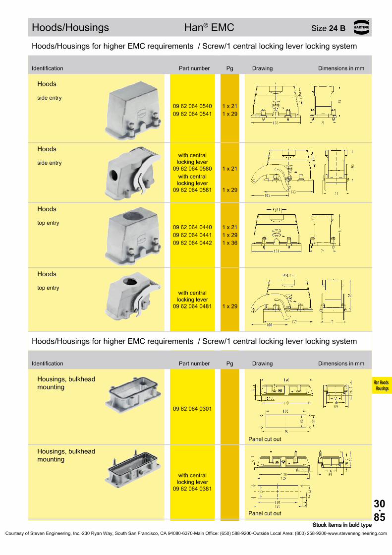
30.85
Han HoodsHousings
09 62 064 0540 1 x 2109 62 064 0541 1 x 29
09 62 064 0580
1 x 21
09 62 064 0581
1 x 29
09 62 064 0440 1 x 2109 62 064 0441 1 x 2909 62 064 0442 1 x 36
09 62 064 0481
1 x 29
09 62 064 0301
09 62 064 0381
Hoods/Housings Han® EMC Size 24 B
Stock items in bold type
Hoods/Housings for higher EMC requirements / Screw/1 central locking lever locking system
Identification Part number Pg Drawing Dimensions in mm
Hoods side entry
Hoods side entry
with central locking lever
with central locking lever
Hoods top entry
Hoods top entry
with central locking lever
Hoods/Housings for higher EMC requirements / Screw/1 central locking lever locking system
Identification Part number Pg Drawing Dimensions in mm
Housings, bulkhead mounting
Panel cut out
Housings, bulkhead mounting
with central locking lever
Panel cut out
Courtesy of Steven Engineering, Inc.-230 Ryan Way, South San Francisco, CA 94080-6370-Main Office: (650) 588-9200-Outside Local Area: (800) 258-9200-www.stevenengineering.com

30.86
Han HoodsHousings
09 62 824 1520 1 x 21
09 62 824 0521 1 x 29
09 62 824 1421 1 x 29
09 62 824 0421 1 x 29
09 62 824 0801 –
09 62 824 0301
Hoods/Housings Han® EMC/B Size 24 B
Stock items in bold type
Hoods/Housings for higher EMC requirements / 2 lever locking system
Identification
Low construction
High constructionPart number
Pg Drawing Dimensions in mm
Hoods side entry
side entry
Hoods top entry
top entry
Hoods without cable entry
Hoods/Housings for higher EMC requirements / 2 lever locking system
Identification
Low construction
High constructionPart number
Pg Drawing Dimensions in mm
Housings, bulkhead mounting
Panel cut out
Courtesy of Steven Engineering, Inc.-230 Ryan Way, South San Francisco, CA 94080-6370-Main Office: (650) 588-9200-Outside Local Area: (800) 258-9200-www.stevenengineering.com

30.87
Han HoodsHousings
09 40 024 0503 1 x 2909 40 024 0504 1 x 36
09 40 024 0513 1 x 29 09 40 024 0514 1 x 36
09 40 024 0403 1 x 29
09 40 024 0404 1 x 36 09 40 024 0412 1 x 21 09 40 024 0413 1 x 29 09 40 024 0414 1 x 36 09 40 024 0433 2 x 29
09 40 024 0811 –
Hoods/Housings Han® HPR Size 24 B
Stock items in bold type
Hoods/Housings for harsh environmental requirements / Screw/toggle locking system
Identification
Toggle locking
screwPart number
Pg Drawing Dimensions in mm
Hoods side entry
Hoods top entry
Hoods without cable entry
Courtesy of Steven Engineering, Inc.-230 Ryan Way, South San Francisco, CA 94080-6370-Main Office: (650) 588-9200-Outside Local Area: (800) 258-9200-www.stevenengineering.com
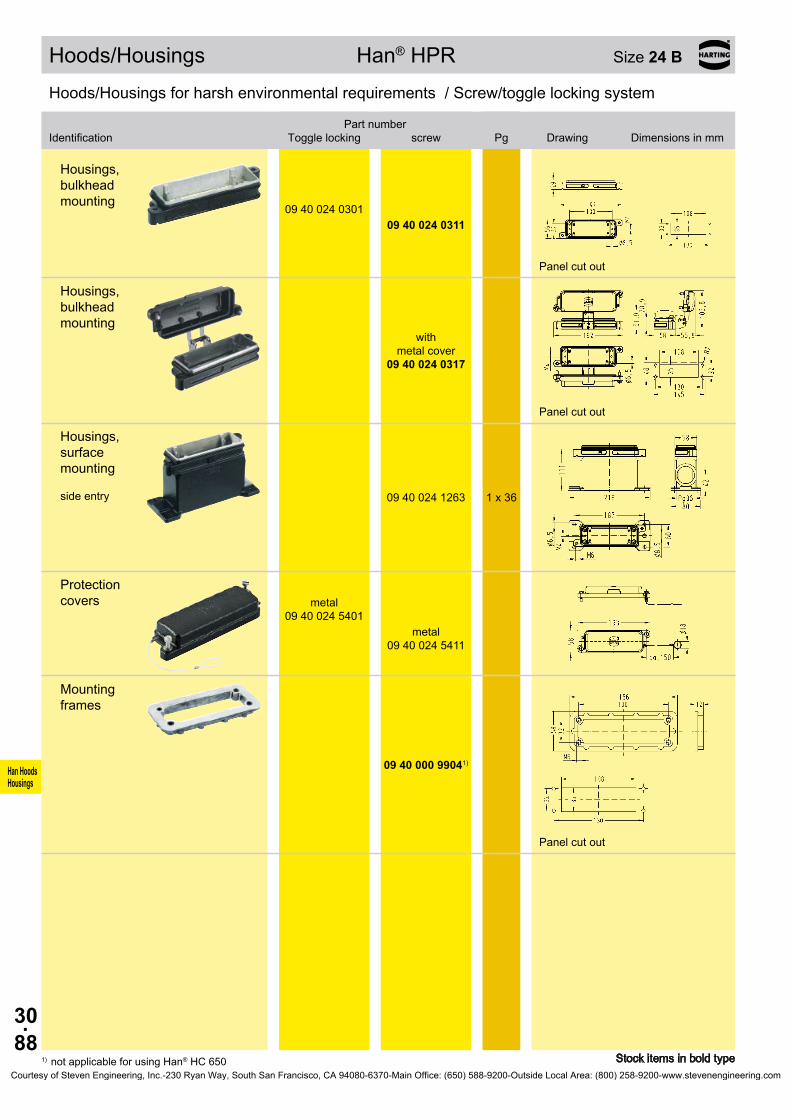
30.88
Han HoodsHousings
09 40 024 0301 09 40 024 0311
09 40 024 0317
09 40 024 1263 1 x 36
09 40 024 5401
09 40 024 5411
09 40 000 99041)
Hoods/Housings Han® HPR Size 24 B
Stock items in bold type1) not applicable for using Han® HC 650
Hoods/Housings for harsh environmental requirements / Screw/toggle locking system
Identification
Toggle locking
screwPart number
Pg Drawing Dimensions in mm
Housings, bulkhead mounting
Panel cut out
Housings, bulkhead mounting
with
metal cover
Panel cut out
Housings, surface mounting side entry
Protection covers metal
metal
Mounting frames
Panel cut out
Courtesy of Steven Engineering, Inc.-230 Ryan Way, South San Francisco, CA 94080-6370-Main Office: (650) 588-9200-Outside Local Area: (800) 258-9200-www.stevenengineering.com

30.89
Han HoodsHousings
09 30 032 0521 1 x 2909 30 032 0522 1 x 3609 30 032 0523 1 x 42
09 30 032 0421 1 x 2909 30 032 0422 1 x 3609 30 032 0423 1 x 42
09 30 032 5420
09 30 032 0301
09 30 032 0231 1 x 2909 30 032 0232 1 x 3609 30 032 0271 2 x 2909 30 032 0272 2 x 3609 30 032 0273 2 x 42
Standard Hoods/Housings Han® B Size 32 B *
* usable for two inserts of size 16 B Stock items in bold type
Metal hoods/housings for industrial applications / 2 lever locking system
Identification Part number Pg Drawing Dimensions in mm
Hoods side entry
Hoods top entry
Protection covers
metal
Metal hoods/housings for industrial applications / 2 lever locking system
Identification Part number Pg Drawing Dimensions in mm
Housings, bulkhead mounting
Panel cut out
Housings, surface mounting side entry
Blind way for one cable entry
Courtesy of Steven Engineering, Inc.-230 Ryan Way, South San Francisco, CA 94080-6370-Main Office: (650) 588-9200-Outside Local Area: (800) 258-9200-www.stevenengineering.com

30.90
Han HoodsHousings
09 30 032 0731 1 x 2909 30 032 0732 1 x 3609 30 032 0733 1 x 42
09 30 032 5425
09 30 032 5426
09 30 032 5427
Standard Hoods/Housings Han® B Size 32 B *
* usable for two inserts of size 16 B Stock items in bold type
Metal hoods/housings for industrial applications / 2 lever locking system
Identification Part number Pg Drawing Dimensions in mm
Hoods, cable to cable top entry
Protection covers
metal
Protection covers for hoods cable to cable metal
metal
Courtesy of Steven Engineering, Inc.-230 Ryan Way, South San Francisco, CA 94080-6370-Main Office: (650) 588-9200-Outside Local Area: (800) 258-9200-www.stevenengineering.com

30.91
Han HoodsHousings
09 30 048 0540 1 x 2909 30 048 0541 1 x 3609 30 048 0542 1 x 42
09 30 048 0440 1 x 2909 30 048 0441 1 x 3609 30 048 0442 1 x 42
09 30 048 0301
09 30 048 0317
09 30 048 0290 2 x 2909 30 048 0291 2 x 36
09 30 048 0295 2 x 2909 30 048 0296 2 x 3609 30 048 2295 2 x 2909 30 048 2296 2 x 36
Standard Hoods/Housings Han® B Size 48 B *
* usable for two inserts of size 24 B Stock items in bold type
Metal hoods/housings for industrial applications / 1 lever locking system
Identification Part number Pg Drawing Dimensions in mm
Hoods side entry
Hoods top entry
Metal hoods/housings for industrial applications / 1 lever locking system
Identification Part number Pg Drawing Dimensions in mm
Housings, bulkhead mounting
with thermo- plastic cover
with metal cover
Panel cut out
Housings, surface mounting side entry
1) Blind way
side entry
1) Blind way
Courtesy of Steven Engineering, Inc.-230 Ryan Way, South San Francisco, CA 94080-6370-Main Office: (650) 588-9200-Outside Local Area: (800) 258-9200-www.stevenengineering.com

30.92
Han HoodsHousings
Notes
Courtesy of Steven Engineering, Inc.-230 Ryan Way, South San Francisco, CA 94080-6370-Main Office: (650) 588-9200-Outside Local Area: (800) 258-9200-www.stevenengineering.com

31.01
Han HoodsHousings
Hoods/Housings with metric thread
Contents Page
Technical characteristics . . . . . . . . . . . . . . . . . . . . . . . . . . . . . . . . . . . . . . . 31.02
Size Han® 3 A Standard Hoods/Housings . . . . . . . . . . . . . . . . . 31.04 Han® M . . . . . . . . . . . . . . . . . . . . . . . . . . . . . . . 31.08 Han® EMC . . . . . . . . . . . . . . . . . . . . . . . . . . . . . 31.10 Han® HPR . . . . . . . . . . . . . . . . . . . . . . . . . . . . . 31.12 Han-INOX® . . . . . . . . . . . . . . . . . . . . . . . . . . . . . 31.14
Size Han® 10 A Standard-Gehäuse . . . . . . . . . . . . . . . . . . . . . . . 31.15 Han® EMC . . . . . . . . . . . . . . . . . . . . . . . . . . . . . 31.17
Size Han® 16 A Standard Hoods/Housings . . . . . . . . . . . . . . . . . 31.18 Han® EMC . . . . . . . . . . . . . . . . . . . . . . . . . . . . . 31.20
Size Han® 32 A Standard Hoods/Housings . . . . . . . . . . . . . . . . . 31.21
Size Han® 6 B Standard Hoods/Housings . . . . . . . . . . . . . . . . . 31.25 Han® M . . . . . . . . . . . . . . . . . . . . . . . . . . . . . . . 31.30 Han® EMC . . . . . . . . . . . . . . . . . . . . . . . . . . . . . 31.32 Han® EMC/B . . . . . . . . . . . . . . . . . . . . . . . . . . . 31.33 Han® HPR . . . . . . . . . . . . . . . . . . . . . . . . . . . . . 31.35
Size Han® 10 B Standard Hoods/Housings . . . . . . . . . . . . . . . . . 31.37 Han-Drive® . . . . . . . . . . . . . . . . . . . . . . . . . . . . 31.44 Han® M . . . . . . . . . . . . . . . . . . . . . . . . . . . . . . . 31.49 Han® EMC . . . . . . . . . . . . . . . . . . . . . . . . . . . . . 31.52 Han® EMC/B . . . . . . . . . . . . . . . . . . . . . . . . . . . 31.53 Han® HPR . . . . . . . . . . . . . . . . . . . . . . . . . . . . . 31.56 Han-INOX® . . . . . . . . . . . . . . . . . . . . . . . . . . . . . 31.58
Size Han® 16 B Standard Hoods/Housings . . . . . . . . . . . . . . . . . 31.59 Han® Easy Hood . . . . . . . . . . . . . . . . . . . . . . . . 31.62 Han® M . . . . . . . . . . . . . . . . . . . . . . . . . . . . . . . 31.70 Han® EMC . . . . . . . . . . . . . . . . . . . . . . . . . . . . . 31.73 Han® EMC/B . . . . . . . . . . . . . . . . . . . . . . . . . . . 31.74 Han® HPR . . . . . . . . . . . . . . . . . . . . . . . . . . . . . 31.76
Size Han® 24 B Standard Hoods/Housings . . . . . . . . . . . . . . . . . 31.78 Han® Easy Hood . . . . . . . . . . . . . . . . . . . . . . . . 31.81 Han® M . . . . . . . . . . . . . . . . . . . . . . . . . . . . . . . 31.89 Han® EMC . . . . . . . . . . . . . . . . . . . . . . . . . . . . . 31.92 Han® EMC/B . . . . . . . . . . . . . . . . . . . . . . . . . . . 31.93 Han® HPR . . . . . . . . . . . . . . . . . . . . . . . . . . . . . 31.94
Size Han® 32 B Standard Hoods/Housings . . . . . . . . . . . . . . . . . 31.96
Size Han® 48 B Standard Hoods/Housings . . . . . . . . . . . . . . . . . 31.98 Han® M . . . . . . . . . . . . . . . . . . . . . . . . . . . . . . . 31.99Note: Han® hoods and housings with NPT-thread also available by HARTING Inc . of North America, USA
Courtesy of Steven Engineering, Inc.-230 Ryan Way, South San Francisco, CA 94080-6370-Main Office: (650) 588-9200-Outside Local Area: (800) 258-9200-www.stevenengineering.com
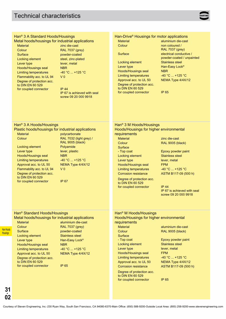
31.02
Han HoodsHousings
Technical characteristics
Han® 3 A Standard Hoods/Housings Metal hoods/housings for industrial applications
Material zinc die-castColour RAL 7037 (grey)Surface powder-coatedLocking element steel, zinc-platedLever type lever, metalHoods/Housings seal NBRLimiting temperatures -40 °C . . . +125 °CFlammability acc . to UL 94 V 0Degree of protection acc . to DIN EN 60 529 for coupled connector
IP 44 IP 67 is achieved with seal screw 09 20 000 9918
Han® 3 A Hoods/Housings Plastic hoods/housings for industrial applications
Material polycarbonateColour RAL 7032 (light grey) /
RAL 9005 (black)Locking element PolyamideLever type lever, plasticHoods/Housings seal NBRLimiting temperatures -40 °C . . . +125 °CApproval acc . to UL 50 NEMA Type 4/4X/12Flammability acc . to UL 94 V 0Degree of protection acc . to DIN EN 60 529 for coupled connector IP 67
Han® Standard Hoods/Housings Metal hoods/housings for industrial applications
Material aluminium die-castColour RAL 7037 (grey)Surface powder-coatedLocking element Stainless steelLever type Han-Easy Lock®
Hoods/Housings seal NBRLimiting temperatures -40 °C . . . +125 °CApproval acc . to UL 50 NEMA Type 4/4X/12Degree of protection acc . to DIN EN 60 529 for coupled connector IP 65
Han-Drive® Housings for motor applicationsMaterial aluminium die-castColour non coloured /
RAL 7037 (grey)Surface electrical conductive /
powder-coated / unpaintedLocking element Stainless steelLever type Han-Easy Lock®
Hoods/Housings seal NBRLimiting temperatures -40 °C . . . +125 °CApproval acc . to UL 50 NEMA Type 4/4X/12Degree of protection acc . to DIN EN 60 529 for coupled connector IP 65
Han® 3 M Hoods/Housings Hoods/Housings for higher environmental requirements
Material zinc die-castColour RAL 9005 (black)Surface - Top coat
Epoxy powder paint
Locking element Stainless steelLever type lever, metalHoods/Housings seal FPMLimiting temperatures -40 °C . . . +125 °CCorrosion resistanceDegree of protection acc . to DIN EN 60 529 for coupled connector
ASTM B117-09 (500 h) IP 44 IP 67 is achieved with seal screw 09 20 000 9918
Han® M Hoods/Housings Hoods/Housings for higher environmental requirements
Material aluminium die-castColour RAL 9005 (black)Surface - Top coat
Epoxy powder paint
Locking element Stainless steelLever type lever, metalHoods/Housings seal FPMLimiting temperatures -40 °C . . . +125 °CApproval acc . to UL 50 NEMA Type 4/4X/12Corrosion resistanceDegree of protection acc . to DIN EN 60 529 for coupled connector
ASTM B117-09 (500 h) IP 65
Courtesy of Steven Engineering, Inc.-230 Ryan Way, South San Francisco, CA 94080-6370-Main Office: (650) 588-9200-Outside Local Area: (800) 258-9200-www.stevenengineering.com

31.03
Han HoodsHousings
Technical characteristics
Han® 3 EMC Hoods/Housings Hoods/Housings for higher EMC requirements
Material zinc die-castColour non colouredSurface electrical conductiveLocking element steel, zinc-platedLever type lever, metalHoods/Housings seal NBRLimiting temperatures -40 °C . . . +125 °CDegree of protection acc . to DIN EN 60 529 for coupled connector
IP 44 IP 67 is achieved with seal screw 09 20 000 9918
Han® EMC Hoods/Housings Hoods/Housings for higher EMC requirements
Material aluminium die-castColour non colouredSurface electrical conductiveLocking element - Screw locking - Material - Tightening torque
M5 Stainless steel 3 Nm
Hoods/Housings seal NBRLimiting temperatures -40 °C . . . +125 °CApproval acc . to UL 50 NEMA Type 4/4X/12Degree of protection acc . to DIN EN 60 529 for coupled connector IP 65
Han® EMC/B Hoods/Housings Hoods/Housings for higher EMC requirements
Material - Hoods/Housings - shielded frames
aluminium die-cast zinc die-cast alloy
Colour non colouredSurface - Hoods/Housings - shielded frames
electrical conductive electrical conductive
Locking element Stainless steelLever type Han-Easy Lock®
Hoods/Housings seal NBRLimiting temperatures -40 °C . . . +125 °CApproval acc . to UL 50 NEMA Type 4/4X/12Degree of protection acc . to DIN EN 60 529 for coupled connector IP 65
Han-INOX® Hoods/Housings for higher corrosion requirements
Material stainless steelColour non colouredSurface electrical conductiveLocking element Stainless steelLever type lever, metalHoods/Housings seal NBRLimiting temperatures -40 °C . . . +125 °CDegree of protection acc . to DIN EN 60 529 for coupled connector IP 65- Size Han® 3 A IP 44
IP 67 is achieved with seal screw 09 20 000 9918
Han® 3 HPR Hoods/Housings Hoods/Housings for harsh environmental requirements
Material zinc die-castColour RAL 9005 (black)Surface - Top coat
Epoxy powder paint / chromated
Locking element - Screw locking - Material - Tightening torque
M4 Stainless steel 2 Nm
Hoods/Housings seal NBRLimiting temperatures -40 °C . . . +125 °CCorrosion resistanceDegree of protection acc . to DIN EN 60 529 for coupled connector
ASTM B117-09 (500 h) IP 68 / IP 69K
Attention The sealing on the insert has to be removed .
Han® HPR Hoods/Housings Hoods/Housings for harsh environmental requirements
Material aluminium die-cast, corrosion resistant
Colour RAL 9005 (black)Surface - Top coat
Epoxy powder paint
Locking element - Screw locking - Material - Tightening torque - Toggle locking - Material
M6 Stainless steel 4 Nm Stainless steel
Hoods/Housings seal NBRLimiting temperatures -40 °C . . . +125 °CApproval acc . to UL 50 NEMA Type 4/4X/12Corrosion resistanceDegree of protection acc . to DIN EN 60 529 for coupled connector
ASTM B117-09 (500 h) IP 68 / IP 69K (does not apply to Han® 48 HPR)
Courtesy of Steven Engineering, Inc.-230 Ryan Way, South San Francisco, CA 94080-6370-Main Office: (650) 588-9200-Outside Local Area: (800) 258-9200-www.stevenengineering.com

31.04
Han HoodsHousings
19 20 003 1640 1 x 20
19 20 003 1440 1 x 20
19 20 003 1425
1 x 20
6 . . . 12 mm 19 20 003 1421
11 . . . 17 mm 19 20 003 1422
09 20 003 54222) 09 20 003 54211)
09 20 003 0301
Standard Hoods/Housings Han A® Size 3 A
Stock items in bold type1) for mounted female insert2) for mounted male insert
Metal hoods/housings for industrial applications / 1 lever locking system
Identification
Identification
Part number
Part number
Cable entry metric
Cable entry metric
Drawing Dimensions in mm
Drawing Dimensions in mm
Hoods side entry
Hoods top entry with
glued sealing
Hoods top entry
Protection covers for hoods
Metal hoods/housings for industrial applications / 1 lever locking system
Housings, bulkhead mounting
Panel cut out 22 x 22 mm
Courtesy of Steven Engineering, Inc.-230 Ryan Way, South San Francisco, CA 94080-6370-Main Office: (650) 588-9200-Outside Local Area: (800) 258-9200-www.stevenengineering.com

31.05
Han HoodsHousings
19 20 003 1250 1 x 20
19 20 003 1252
1 x 20
19 20 003 1150 1 x 20
19 20 003 1750 1 x 20
09 20 003 54262)
09 20 003 54251)
09 20 003 54282)
09 20 003 54271)
Identification Part numberCable entry
metric Drawing Dimensions in mm
Standard Hoods/Housings Han A® Size 3 A
Stock items in bold type
Metal hoods/housings for industrial applications / 1 lever locking system
1) for mounted female insert2) for mounted male insert
Housings, surface mounting top entry
bottom closed
1 x 20
Panel cut out 22 x 22 mm
Housings, screw mounting top entry
Hoods, cable to cable top entry
Protection covers
for housings
for
housings
for hoods cable to cable
for hoods
cable to cable
Courtesy of Steven Engineering, Inc.-230 Ryan Way, South San Francisco, CA 94080-6370-Main Office: (650) 588-9200-Outside Local Area: (800) 258-9200-www.stevenengineering.com

31.06
Han HoodsHousings
19 20 003 0620
1 x 20
19 20 003 0627
1 x 20
19 20 003 0420
1 x 20
19 20 003 0427
1 x 20
9 . . . 17 mm
19 20 003 0410
09 20 003 54423)
09 20 003 54412)
Standard Hoods/Housings Han A® Size 3 A
Stock items in bold type1) for metal housings and cable to cable hoods also2) for mounted female insert or for mounted Han-
Brid® insert
3) for mounted male insert
Plastic hoods/housings for industrial applications / 1 lever locking system
Hoods side entry light grey
black
Hoods top entry light grey
black
Hoods top entry
light grey
Protection covers for hoods light grey
light grey
Identification Part numberCable entry
metric Drawing Dimensions in mm
Courtesy of Steven Engineering, Inc.-230 Ryan Way, South San Francisco, CA 94080-6370-Main Office: (650) 588-9200-Outside Local Area: (800) 258-9200-www.stevenengineering.com
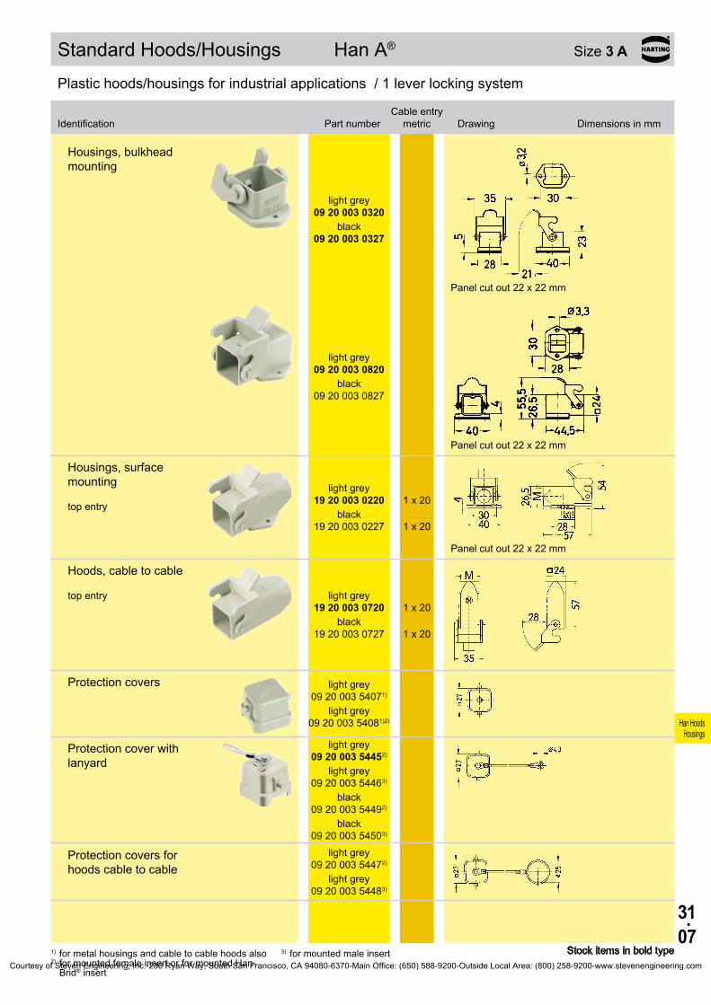
31.07
Han HoodsHousings
09 20 003 0320
09 20 003 0327
09 20 003 0820
09 20 003 0827
19 20 003 0220
1 x 20
19 20 003 0227
1 x 20
19 20 003 0720
1 x 20
19 20 003 0727
1 x 20
09 20 003 54071)
09 20 003 54081)2)
09 20 003 54452)
09 20 003 54463)
09 20 003 54492)
09 20 003 54503)
09 20 003 54472)
09 20 003 54483)
Standard Hoods/Housings Han A® Size 3 A
Stock items in bold type
Plastic hoods/housings for industrial applications / 1 lever locking system
1) for metal housings and cable to cable hoods also2) for mounted female insert or for mounted Han-
Brid® insert
3) for mounted male insert
Plastic hoods/housings for industrial applications / 1 lever locking system
Housings, bulkhead mounting
light grey
black
Panel cut out 22 x 22 mm
light grey
black
Panel cut out 22 x 22 mm
Housings, surface mounting top entry
light grey
black
Panel cut out 22 x 22 mm
Hoods, cable to cable top entry light grey
black
Protection covers light grey
light grey
Protection cover with lanyard
light grey
light grey
black
black
Protection covers for hoods cable to cable
light grey
light grey
Identification Part numberCable entry
metric Drawing Dimensions in mm
Courtesy of Steven Engineering, Inc.-230 Ryan Way, South San Francisco, CA 94080-6370-Main Office: (650) 588-9200-Outside Local Area: (800) 258-9200-www.stevenengineering.com

31.08
Han HoodsHousings
19 37 003 1640 1 x 20
19 37 003 1440 1 x 20
09 37 003 54022) 09 37 003 54011)
09 37 003 0301
09 37 003 0801
Hoods/Housings Han® M Size 3 A
Stock items in bold type1) for mounted female insert2) for mounted male insert
Hoods/Housings for higher environmental requirements / 1 lever locking system
Identification Part numberCable entry
metric Drawing Dimensions in mm
Hoods side entry
Hoods top entry
Protection covers
Hoods/Housings for higher environmental requirements / 1 lever locking system
Identification Part numberCable entry
metric Drawing Dimensions in mm
Housings, bulkhead mounting
Panel cut out 22 x 22 mm
Panel cut out 22 x 22 mm
Courtesy of Steven Engineering, Inc.-230 Ryan Way, South San Francisco, CA 94080-6370-Main Office: (650) 588-9200-Outside Local Area: (800) 258-9200-www.stevenengineering.com

31.09
Han HoodsHousings
19 37 003 1250 1 x 20
19 37 003 1150 1 x 20
19 37 003 1750 1 x 20
09 37 003 54051) 09 37 003 54062)
Hoods/Housings Han® M Size 3 A
Stock items in bold type
Hoods/Housings for higher environmental requirements / 1 lever locking system
Identification Part numberCable entry
metric Drawing Dimensions in mm
1) for mounted female insert2) for mounted male insert
Housings, surface mounting top entry
Panel cut out 22 x 22 mm
Housings, screw mounting top entry
Hoods, cable to cable top entry
Protection covers for housings
Courtesy of Steven Engineering, Inc.-230 Ryan Way, South San Francisco, CA 94080-6370-Main Office: (650) 588-9200-Outside Local Area: (800) 258-9200-www.stevenengineering.com

31.10
Han HoodsHousings
19 62 003 1640 1 x 20
19 62 003 1440 1 x 20
09 62 003 0301
09 62 003 0801
19 62 003 1250 1 x 20
Hoods/Housings Han® EMC Size 3 A
Stock items in bold type
Hoods/Housings for higher EMC requirements / 1 lever locking system
Identification Part numberCable entry
metric Drawing Dimensions in mm
Hoods side entry
Hoods top entry
Hoods/Housings for higher EMC requirements / 1 lever locking system
Identification Part numberCable entry
metric Drawing Dimensions in mm
Housings, bulkhead mounting
Panel cut out 22 x 22 mm
Panel cut out 22 x 22 mm
Housings, surface mounting top entry
Panel cut out 22 x 22 mm
Courtesy of Steven Engineering, Inc.-230 Ryan Way, South San Francisco, CA 94080-6370-Main Office: (650) 588-9200-Outside Local Area: (800) 258-9200-www.stevenengineering.com

31.11
Han HoodsHousings
19 62 003 1750 1 x 20
Hoods/Housings Han® EMC Size 3 A
Stock items in bold type
Hoods/Housings for higher EMC requirements / 1 lever locking system
Identification Part numberCable entry
metric Drawing Dimensions in mm
Hoods, cable to cable top entry
Courtesy of Steven Engineering, Inc.-230 Ryan Way, South San Francisco, CA 94080-6370-Main Office: (650) 588-9200-Outside Local Area: (800) 258-9200-www.stevenengineering.com

31.12
Han HoodsHousings
19 40 003 04001) 1 x 20
19 40 703 04001) 1 x 20
19 40 003 04101) 1 x 20
19 40 703 04101) 1 x 20
19 40 003 04111) 1 x 25
19 40 703 04111) 1 x 25
09 40 003 03011)
09 40 703 03011)
09 40 003 03111)
09 40 703 03111)
09 40 003 09501)
09 40 703 09501)
19 40 003 09501) 1 x 20
19 40 703 09501) 1 x 20
Hoods/Housings Han® HPR Size 3 A
Stock items in bold type1) with sealing screw; sealing on the insert has to be removed
Hoods/Housings for harsh environmental requirements / Screw/toggle locking system
Identification
Toggle locking
screwPart number Cable entry
metric Drawing Dimensions in mm
Hoods top entry
chromated
Epoxy powder paint
chromated
Epoxy powder paint
➀ Sealing screw
Hoods top entry
chromated
Epoxy powder paint
Housings, bulkhead mounting
chromated
Epoxy powder paint
chromated
Epoxy powder paint
Panel cut out 21 .3 x 21 .3 mm ➀ Sealing screw
chromated
Epoxy powder paint
Panel cut out 21 .3 x 21 .3 mm ➀ Sealing screw
Housings, surface mounting top entry bottom closed
chromated
Epoxy powder paint
➀ Sealing screw
Courtesy of Steven Engineering, Inc.-230 Ryan Way, South San Francisco, CA 94080-6370-Main Office: (650) 588-9200-Outside Local Area: (800) 258-9200-www.stevenengineering.com

31.13
Han HoodsHousings
09 40 003 0902
09 40 003 0902 –
09 40 703 0902
09 40 703 0902 –
19 40 003 0900
19 40 003 0900 1 x 20
19 40 703 0900
19 40 703 0900 1 x 20
Hoods/Housings Han® HPR Size 3 A
Stock items in bold type
Hoods/Housings for harsh environmental requirements / Screw/toggle locking system
Identification
Toggle locking
screwPart number Cable entry
metric Drawing Dimensions in mm
1) with sealing screw; sealing on the insert has to be removed
Accessories
Adapter for assembly of bulkhead mounted housings in angled position
chromated chromated
Epoxy powder paint
Epoxy powder paint
Adapter for assembly of bulkhead mounted housings in angled position, with metric entry
chromated chromated
Epoxy powder paint
Epoxy powder paint
Courtesy of Steven Engineering, Inc.-230 Ryan Way, South San Francisco, CA 94080-6370-Main Office: (650) 588-9200-Outside Local Area: (800) 258-9200-www.stevenengineering.com
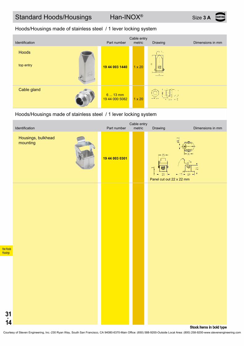
31.14
Han HoodsHousings
19 44 003 1440 1 x 20
6 . . . 13 mm
19 44 000 5082
1 x 20
19 44 003 0301
Standard Hoods/Housings Han-INOX® Size 3 A
Stock items in bold type
Hoods/Housings made of stainless steel / 1 lever locking system
Identification Part numberCable entry
metric Drawing Dimensions in mm
Hoods top entry
Cable gland
Hoods/Housings made of stainless steel / 1 lever locking system
Identification Part numberCable entry
metric Drawing Dimensions in mm
Housings, bulkhead mounting
Panel cut out 22 x 22 mm
Courtesy of Steven Engineering, Inc.-230 Ryan Way, South San Francisco, CA 94080-6370-Main Office: (650) 588-9200-Outside Local Area: (800) 258-9200-www.stevenengineering.com

31.15
Han HoodsHousings
19 20 010 1540 1 x 20
19 20 010 0546 1 x 25
19 20 010 1440 1 x 20
19 20 010 0446 1 x 25
09 20 010 5423
09 20 010 5423
Standard Hoods/Housings Han A® Size 10 A
Stock items in bold type
Metal hoods/housings for industrial applications / 1 lever locking system
Identification
Low construction
High constructionPart number Cable entry
metric Drawing Dimensions in mm
Hoods side entry
side entry
Hoods top entry
top entry
Protection covers
metal metal
Courtesy of Steven Engineering, Inc.-230 Ryan Way, South San Francisco, CA 94080-6370-Main Office: (650) 588-9200-Outside Local Area: (800) 258-9200-www.stevenengineering.com

31.16
Han HoodsHousings
09 20 010 0301
09 20 010 0321
19 20 010 02511) 1 x 2519 20 010 0290 2 x 20
19 20 010 0295
2 x 20
09 20 010 5425
Standard Hoods/Housings Han A® Size 10 A
Stock items in bold type1) only metal glands
Metal hoods/housings for industrial applications / 1 lever locking system
Identification
Low construction
High constructionPart number Cable entry
metric Drawing Dimensions in mm
Housings, bulkhead mounting
with thermo- plastic cover
Panel cut out
Housings, surface mounting side entry
side entry with thermo-
plastic cover
Protection covers metal
Courtesy of Steven Engineering, Inc.-230 Ryan Way, South San Francisco, CA 94080-6370-Main Office: (650) 588-9200-Outside Local Area: (800) 258-9200-www.stevenengineering.com

31.17
Han HoodsHousings
19 62 015 0546 1 x 25
19 62 015 0446 1 x 25
09 62 015 0301
Hoods/Housings Han® EMC Size 10 A
Stock items in bold type
Hoods/Housings for higher EMC requirements / 1 lever locking system
Identification Part numberCable entry
metric Drawing Dimensions in mm
Hoods side entry
Hoods top entry
Hoods/Housings for higher EMC requirements / 1 lever locking system
Identification Part numberCable entry
metric Drawing Dimensions in mm
Housings, bulkhead mounting
Panel cut out
Courtesy of Steven Engineering, Inc.-230 Ryan Way, South San Francisco, CA 94080-6370-Main Office: (650) 588-9200-Outside Local Area: (800) 258-9200-www.stevenengineering.com

31.18
Han HoodsHousings
19 20 016 1540 1 x 20
19 20 016 0546 1 x 25
19 20 016 1440 1 x 20
19 20 016 0446 1 x 25
09 20 016 5423
09 20 016 5423
Standard Hoods/Housings Han A® Size 16 A
Stock items in bold type
Metal hoods/housings for industrial applications / 1 lever locking system
Identification
Low construction
High constructionPart number Cable entry
metric Drawing Dimensions in mm
Hoods side entry
side entry
Hoods top entry
top entry
Protection covers
metal metal
Courtesy of Steven Engineering, Inc.-230 Ryan Way, South San Francisco, CA 94080-6370-Main Office: (650) 588-9200-Outside Local Area: (800) 258-9200-www.stevenengineering.com

31.19
Han HoodsHousings
09 20 016 0301
09 20 016 0321
19 20 016 02511) 1 x 25
19 20 016 0290 2 x 2019 20 016 0291 2 x 25
19 20 016 0295
2 x 20
09 20 016 5425
Standard Hoods/Housings Han A® Size 16 A
Stock items in bold type1) only metal glands
Metal hoods/housings for industrial applications / 1 lever locking system
Identification
Low construction
High constructionPart number Cable entry
metric Drawing Dimensions in mm
Housings, bulkhead mounting
with thermo- plastic cover
Panel cut out
Housings, surface mounting side entry
with thermo- plastic cover
Protection covers metal
Courtesy of Steven Engineering, Inc.-230 Ryan Way, South San Francisco, CA 94080-6370-Main Office: (650) 588-9200-Outside Local Area: (800) 258-9200-www.stevenengineering.com

31.20
Han HoodsHousings
19 62 025 0546 1 x 25
19 62 025 0446 1 x 25
09 62 025 0301
Hoods/Housings Han® EMC Size 16 A
Stock items in bold type
Hoods/Housings for higher EMC requirements / 1 lever locking system
Identification Part numberCable entry
metric Drawing Dimensions in mm
Hoods side entry
Hoods top entry
Hoods/Housings for higher EMC requirements / 1 lever locking system
Identification Part numberCable entry
metric Drawing Dimensions in mm
Housings, bulkhead mounting
Panel cut out
Courtesy of Steven Engineering, Inc.-230 Ryan Way, South San Francisco, CA 94080-6370-Main Office: (650) 588-9200-Outside Local Area: (800) 258-9200-www.stevenengineering.com

31.21
Han HoodsHousings
19 20 032 1521 1 x 25
19 20 032 0527 1 x 32
19 20 032 0426 1 x 25 19 20 032 0427 1 x 32
09 20 032 5401 09 20 032 5401
09 20 032 0301
19 20 032 0231 1 x 25 19 20 032 0232 1 x 32 19 20 032 0272 2 x 32
Standard Hoods/Housings Han A® Size 32 A *
* usable for two inserts of size 16 A Stock items in bold type
Metal hoods/housings for industrial applications / 2 lever locking system
Identification
Low construction
High constructionPart number Cable entry
metric Drawing Dimensions in mm
Hoods side entry
side entry
Hoods top entry
Dust protection cover
Metal hoods/housings for industrial applications / 2 lever locking system
Identification
Low construction
High constructionPart number Cable entry
metric Drawing Dimensions in mm
Housings, bulkhead mounting
Panel cut out
Housings, surface mounting side entry
Blind way for one cable entry
Courtesy of Steven Engineering, Inc.-230 Ryan Way, South San Francisco, CA 94080-6370-Main Office: (650) 588-9200-Outside Local Area: (800) 258-9200-www.stevenengineering.com

31.22
Han HoodsHousings
09 20 032 5405 09 20 032 5405
Standard Hoods/Housings Han A® Size 32 A *
* usable for two inserts of size 16 A Stock items in bold type
Metal hoods/housings for industrial applications / 2 lever locking system
Identification
Low construction
High constructionPart number Cable entry
metric Drawing Dimensions in mm
Dust protection cover
Courtesy of Steven Engineering, Inc.-230 Ryan Way, South San Francisco, CA 94080-6370-Main Office: (650) 588-9200-Outside Local Area: (800) 258-9200-www.stevenengineering.com
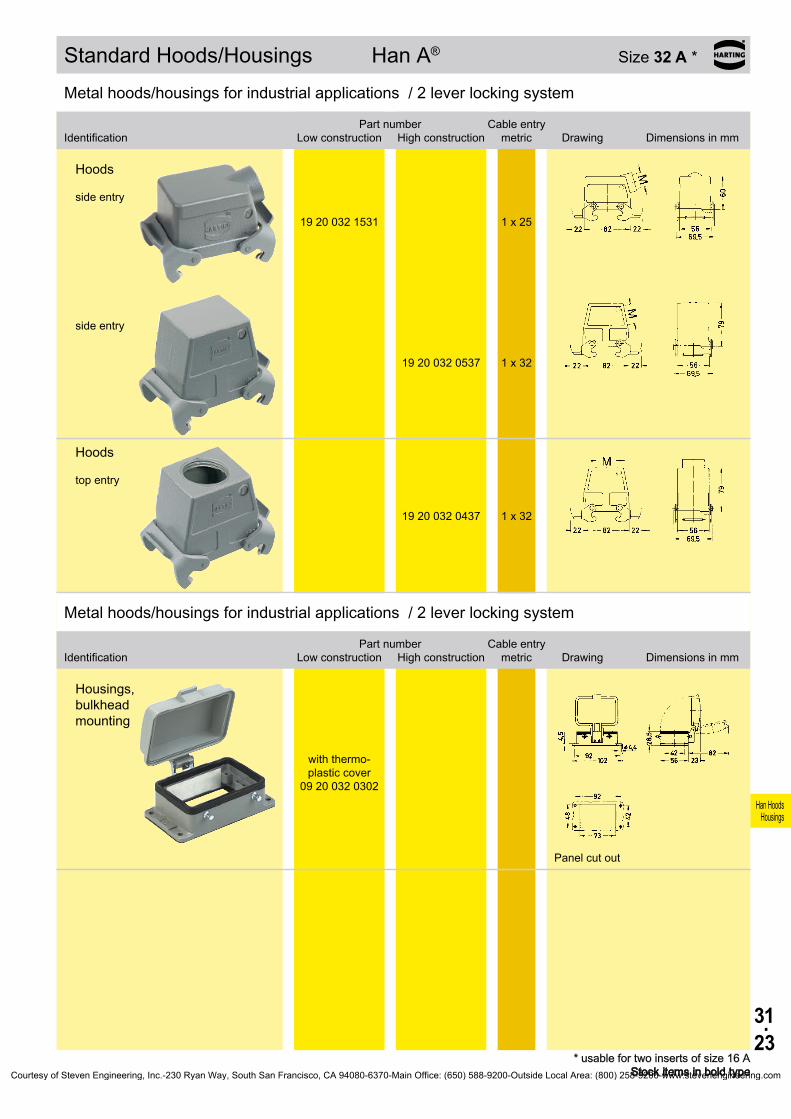
31.23
Han HoodsHousings
19 20 032 1531 1 x 25
19 20 032 0537 1 x 32
19 20 032 0437 1 x 32
09 20 032 0302
Standard Hoods/Housings Han A® Size 32 A *
* usable for two inserts of size 16 A Stock items in bold type
Metal hoods/housings for industrial applications / 2 lever locking system
Identification
Low construction
High constructionPart number Cable entry
metric Drawing Dimensions in mm
Hoods side entry
side entry
Hoods top entry
Metal hoods/housings for industrial applications / 2 lever locking system
Identification
Low construction
High constructionPart number Cable entry
metric Drawing Dimensions in mm
Housings, bulkhead mounting
with thermo- plastic cover
Panel cut out
Courtesy of Steven Engineering, Inc.-230 Ryan Way, South San Francisco, CA 94080-6370-Main Office: (650) 588-9200-Outside Local Area: (800) 258-9200-www.stevenengineering.com
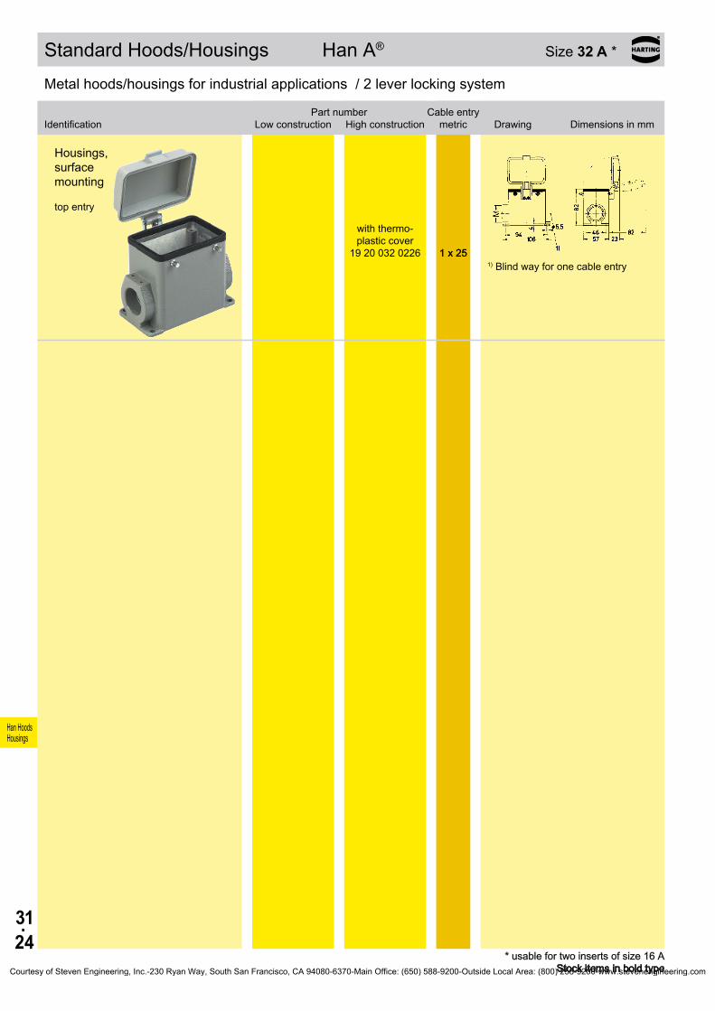
31.24
Han HoodsHousings
19 20 032 0226
1 x 25
Standard Hoods/Housings Han A® Size 32 A *
* usable for two inserts of size 16 A Stock items in bold type
Metal hoods/housings for industrial applications / 2 lever locking system
Identification
Low construction
High constructionPart number Cable entry
metric Drawing Dimensions in mm
Housings, surface mounting top entry
with thermo- plastic cover
1 x 25 1) Blind way for one cable entry
Courtesy of Steven Engineering, Inc.-230 Ryan Way, South San Francisco, CA 94080-6370-Main Office: (650) 588-9200-Outside Local Area: (800) 258-9200-www.stevenengineering.com
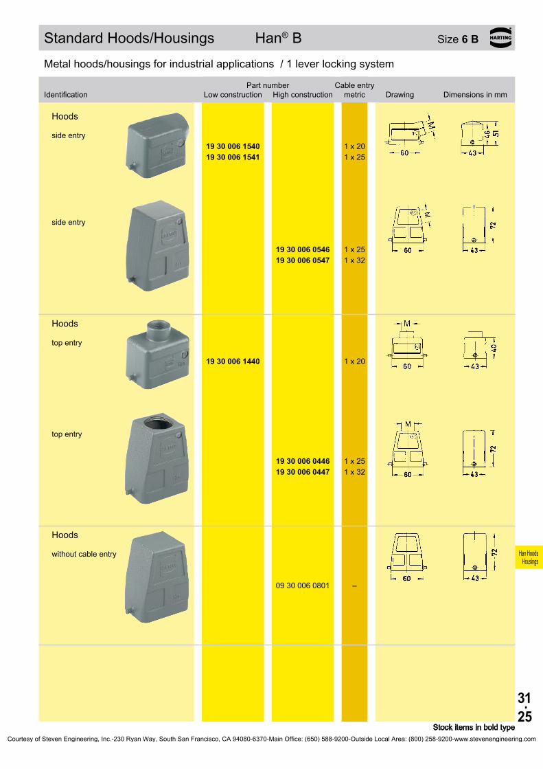
31.25
Han HoodsHousings
19 30 006 1540 1 x 2019 30 006 1541 1 x 25
19 30 006 0546 1 x 25 19 30 006 0547 1 x 32
19 30 006 1440 1 x 20
19 30 006 0446 1 x 25 19 30 006 0447 1 x 32
09 30 006 0801 –
Standard Hoods/Housings Han® B Size 6 B
Stock items in bold type
Metal hoods/housings for industrial applications / 1 lever locking system
Identification
Low construction
High constructionPart number Cable entry
metric Drawing Dimensions in mm
Hoods side entry
side entry
Hoods top entry
top entry
Hoods without cable entry
Courtesy of Steven Engineering, Inc.-230 Ryan Way, South San Francisco, CA 94080-6370-Main Office: (650) 588-9200-Outside Local Area: (800) 258-9200-www.stevenengineering.com
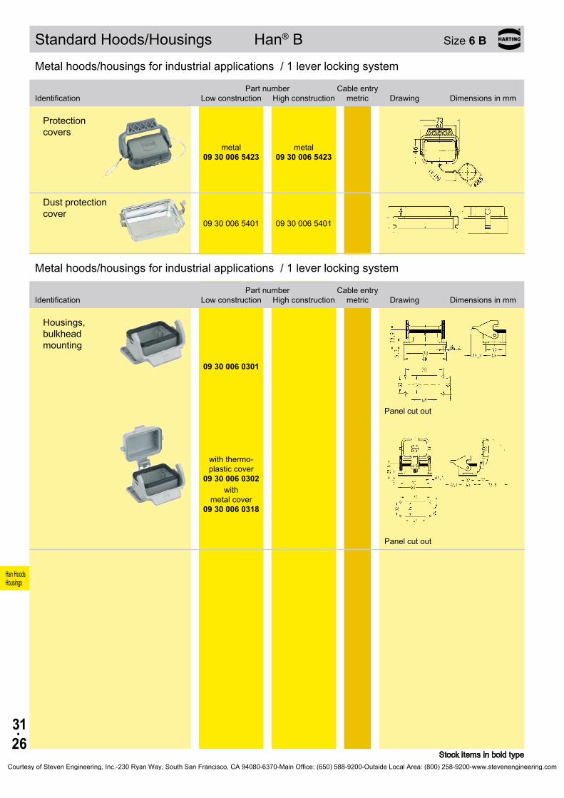
31.26
Han HoodsHousings
09 30 006 5423
09 30 006 5423
09 30 006 5401 09 30 006 5401
09 30 006 0301
09 30 006 0302
09 30 006 0318
Standard Hoods/Housings Han® B Size 6 B
Stock items in bold type
Metal hoods/housings for industrial applications / 1 lever locking system
Identification
Low construction
High constructionPart number Cable entry
metric Drawing Dimensions in mm
Protection covers
metal metal
Dust protection cover
Metal hoods/housings for industrial applications / 1 lever locking system
Identification
Low construction
High constructionPart number Cable entry
metric Drawing Dimensions in mm
Housings, bulkhead mounting
Panel cut out
with thermo- plastic cover
with
metal cover
Panel cut out
Courtesy of Steven Engineering, Inc.-230 Ryan Way, South San Francisco, CA 94080-6370-Main Office: (650) 588-9200-Outside Local Area: (800) 258-9200-www.stevenengineering.com

31.27
Han HoodsHousings
19 30 006 1250 1 x 2019 30 006 1290 2 x 20
19 30 006 0291 2 x 25 19 30 006 0292 2 x 32
19 30 006 1255
1 x 20
19 30 006 1295
2 x 20
19 30 006 2255
1 x 20
19 30 006 2295
2 x 20
19 30 006 0296
2 x 25
19 30 006 0297
2 x 32
19 30 006 7296
2 x 25
09 30 006 5404
09 30 006 5404
09 30 006 5425
09 30 006 5425
Standard Hoods/Housings Han® B Size 6 B
Stock items in bold type
Metal hoods/housings for industrial applications / 1 lever locking system
Identification
Low construction
High constructionPart number Cable entry
metric Drawing Dimensions in mm
Housings, surface mounting side entry
Blind way for one cable entry
side entry
Blind way for one cable entry
side entry
with thermo- plastic cover
with thermo- plastic cover
with metal cover
with metal cover
Blind way for one cable entry
side entry
with thermo- plastic cover
with thermo- plastic cover
with
metal cover
Blind way for one cable entry
Protection covers Plastic
plastic plastic
metal
metal metal
Courtesy of Steven Engineering, Inc.-230 Ryan Way, South San Francisco, CA 94080-6370-Main Office: (650) 588-9200-Outside Local Area: (800) 258-9200-www.stevenengineering.com

31.28
Han HoodsHousings
19 30 006 1750 1 x 20
19 30 006 0756 1 x 25
09 30 006 5427
09 30 006 5427
19 30 006 0716 1 x 25
Standard Hoods/Housings Han® B Size 6 B
Stock items in bold type
Metal hoods/housings for industrial applications / 1 lever locking system
Identification
Low construction
High constructionPart number Cable entry
metric Drawing Dimensions in mm
Hoods, cable to cable top entry
top entry
Protection covers
metal metal
Flange housings top entry
Courtesy of Steven Engineering, Inc.-230 Ryan Way, South San Francisco, CA 94080-6370-Main Office: (650) 588-9200-Outside Local Area: (800) 258-9200-www.stevenengineering.com
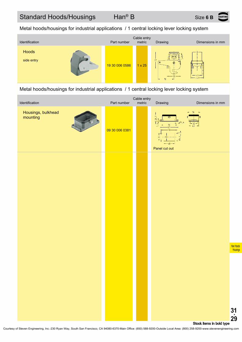
31.29
Han HoodsHousings
19 30 006 0586 1 x 25
09 30 006 0381
Standard Hoods/Housings Han® B Size 6 B
Stock items in bold type
Metal hoods/housings for industrial applications / 1 central locking lever locking system
Hoods side entry
Metal hoods/housings for industrial applications / 1 central locking lever locking system
Identification
Identification
Part number
Part number
Cable entry metric
Cable entry metric
Drawing Dimensions in mm
Drawing Dimensions in mm
Housings, bulkhead mounting
Panel cut out
Courtesy of Steven Engineering, Inc.-230 Ryan Way, South San Francisco, CA 94080-6370-Main Office: (650) 588-9200-Outside Local Area: (800) 258-9200-www.stevenengineering.com

31.30
Han HoodsHousings
19 37 006 1540 1 x 20
19 37 006 0545 1 x 20 19 37 006 0546 1 x 25
19 37 006 1440 1 x 20
19 37 006 0445 1 x 20 19 37 006 0446 1 x 25
Hoods/Housings Han® M Size 6 B
Stock items in bold type
Hoods/Housings for higher environmental requirements / 1 lever locking system
Identification
Low construction
High constructionPart number Cable entry
metric Drawing Dimensions in mm
Hoods side entry
side entry
Hoods top entry
top entry
Courtesy of Steven Engineering, Inc.-230 Ryan Way, South San Francisco, CA 94080-6370-Main Office: (650) 588-9200-Outside Local Area: (800) 258-9200-www.stevenengineering.com

31.31
Han HoodsHousings
Bezeichnung
Niedrige Bauform
Hohe BauformBestell-Nummer Kabelausgang
metrisch Maßzeichnung Maße in mm
09 37 006 0301
09 37 006 0318
19 37 006 1290 2 x 20
19 37 006 0296
2 x 25
09 37 006 5405
09 37 006 5405
Hoods/Housings Han® M Size 6 B
Stock items in bold type
Hoods/Housings for higher environmental requirements / 1 lever locking system
Identification
Low construction
High constructionPart number Cable entry
metric Drawing Dimensions in mm
Hoods/Housings for higher environmental requirements / 1 lever locking system
Housings, bulkhead mounting
Panel cut out
with metal cover
Housings, surface mounting side entry
side entry
with thermo- plastic cover
Protection covers
metal metal
Courtesy of Steven Engineering, Inc.-230 Ryan Way, South San Francisco, CA 94080-6370-Main Office: (650) 588-9200-Outside Local Area: (800) 258-9200-www.stevenengineering.com

31.32
Han HoodsHousings
19 62 006 0541 1 x 25
19 62 006 0441 1 x 2519 62 006 0442 1 x 32
09 62 006 0301
Hoods/Housings Han® EMC Size 6 B
Stock items in bold type
Hoods/Housings for higher EMC requirements / Screw locking system
Identification Part numberCable entry
metric Drawing Dimensions in mm
Hoods side entry
Hoods top entry
Hoods/Housings for higher EMC requirements / Screw locking system
Identification Part numberCable entry
metric Drawing Dimensions in mm
Housings, bulkhead mounting
Panel cut out
Courtesy of Steven Engineering, Inc.-230 Ryan Way, South San Francisco, CA 94080-6370-Main Office: (650) 588-9200-Outside Local Area: (800) 258-9200-www.stevenengineering.com

31.33
Han HoodsHousings
19 62 806 1540 1 x 20
19 62 806 0546 1 x 25 19 62 806 0547 1 x 32
19 62 806 1440 1 x 20
19 62 806 0446 1 x 25 19 62 806 0447 1 x 32
09 62 806 0301
Hoods/Housings Han® EMC/B Size 6 B
Stock items in bold type
Hoods/Housings for higher EMC requirements / 1 lever locking system
Identification
Low construction
High constructionPart number Cable entry
metric Drawing Dimensions in mm
Hoods side entry
side entry
Hoods top entry
top entry
Hoods/Housings for higher EMC requirements / 1 lever locking system
Identification
Low construction
High constructionPart number Cable entry
metric Drawing Dimensions in mm
Housings, bulkhead mounting
Panel cut out
Courtesy of Steven Engineering, Inc.-230 Ryan Way, South San Francisco, CA 94080-6370-Main Office: (650) 588-9200-Outside Local Area: (800) 258-9200-www.stevenengineering.com
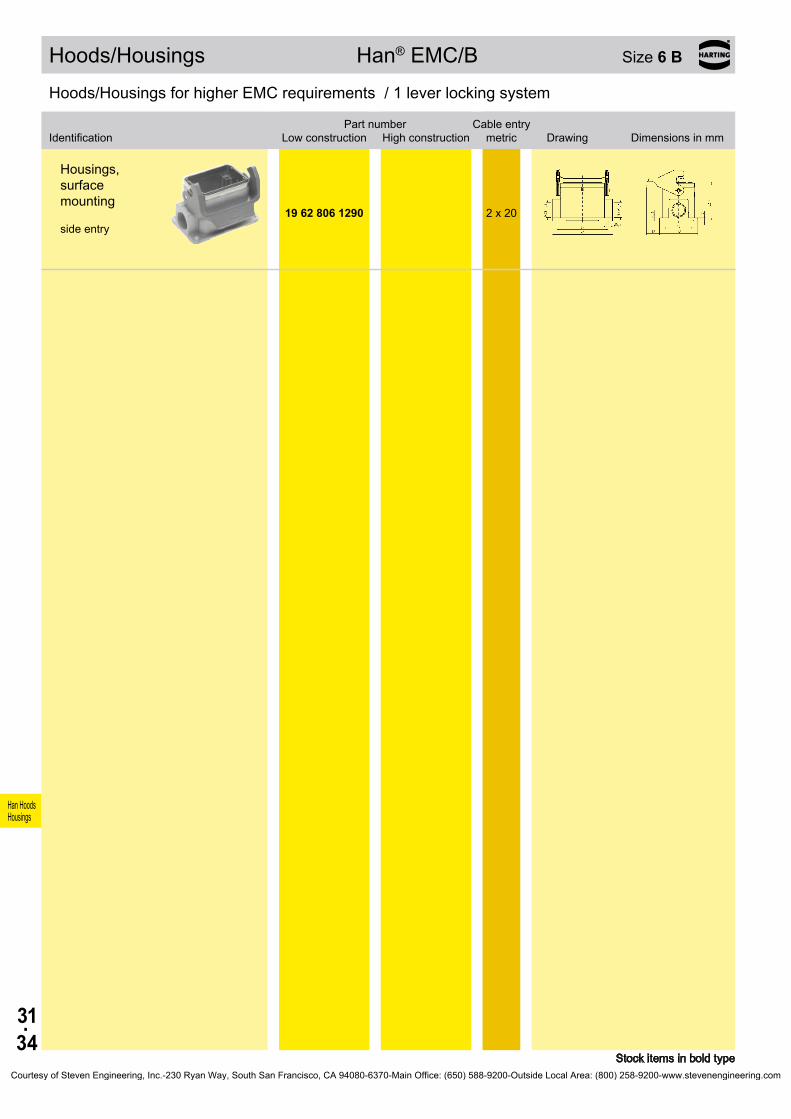
31.34
Han HoodsHousings
19 62 806 1290 2 x 20
Hoods/Housings Han® EMC/B Size 6 B
Stock items in bold type
Hoods/Housings for higher EMC requirements / 1 lever locking system
Identification
Low construction
High constructionPart number Cable entry
metric Drawing Dimensions in mm
Housings, surface mounting side entry
Courtesy of Steven Engineering, Inc.-230 Ryan Way, South San Francisco, CA 94080-6370-Main Office: (650) 588-9200-Outside Local Area: (800) 258-9200-www.stevenengineering.com

31.35
Han HoodsHousings
19 40 006 0510 1 x 2019 40 006 0501 1 x 25
19 40 006 0511 1 x 25 19 40 006 0512 1 x 32
19 40 006 0513 1 x 40
19 40 006 0410 1 x 2019 40 006 0401 1 x 25
19 40 006 0411 1 x 25 19 40 006 0412 1 x 32 19 40 006 0413 1 x 40
09 40 006 0811 –
Hoods/Housings Han® HPR Size 6 B
Stock items in bold type
Hoods/Housings for harsh environmental requirements / Screw/toggle locking system
Identification
Toggle locking
screwPart number Cable entry
metric Drawing Dimensions in mm
Hoods side entry
Hoods top entry
Hoods without cable entry
–
Courtesy of Steven Engineering, Inc.-230 Ryan Way, South San Francisco, CA 94080-6370-Main Office: (650) 588-9200-Outside Local Area: (800) 258-9200-www.stevenengineering.com

31.36
Han HoodsHousings
09 40 006 0301 09 40 006 0311
09 40 006 0317
19 40 006 1260 1 x 20 19 40 006 1261 1 x 25 19 40 006 1262 1 x 32
09 40 006 5401
09 40 006 5411
09 40 000 99011)
Hoods/Housings Han® HPR Size 6 B
Stock items in bold type1) not applicable for using Han® HC 650
Hoods/Housings for harsh environmental requirements / Screw/toggle locking system
Identification
Toggle locking
screwPart number Cable entry
metric Drawing Dimensions in mm
Housings, bulkhead mounting
Panel cut out
Housings, bulkhead mounting
with
metal cover
Panel cut out
Housings, surface mounting side entry
Protection covers
metal
metal
Mounting frames
Courtesy of Steven Engineering, Inc.-230 Ryan Way, South San Francisco, CA 94080-6370-Main Office: (650) 588-9200-Outside Local Area: (800) 258-9200-www.stevenengineering.com
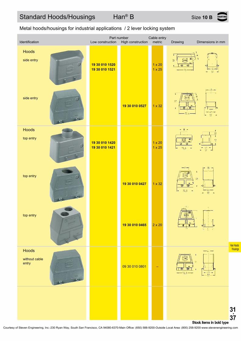
31.37
Han HoodsHousings
19 30 010 1520 1 x 2019 30 010 1521 1 x 25
19 30 010 0527 1 x 32
19 30 010 1420 1 x 2019 30 010 1421 1 x 25
19 30 010 0427 1 x 32
19 30 010 0465 2 x 20
09 30 010 0801 –
Standard Hoods/Housings Han® B Size 10 B
Stock items in bold type
Metal hoods/housings for industrial applications / 2 lever locking system
Identification
Low construction
High constructionPart number Cable entry
metric Drawing Dimensions in mm
Hoods side entry
side entry
Hoods top entry
top entry
top entry
Hoods without cable entry
–
Courtesy of Steven Engineering, Inc.-230 Ryan Way, South San Francisco, CA 94080-6370-Main Office: (650) 588-9200-Outside Local Area: (800) 258-9200-www.stevenengineering.com
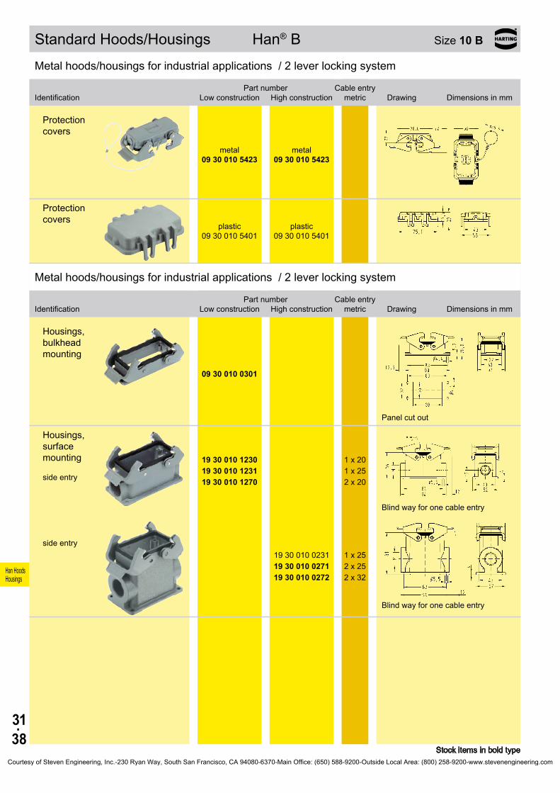
31.38
Han HoodsHousings
09 30 010 5423
09 30 010 5423
09 30 010 5401
09 30 010 5401
09 30 010 0301
19 30 010 1230 1 x 2019 30 010 1231 1 x 2519 30 010 1270 2 x 20
19 30 010 0231 1 x 25 19 30 010 0271 2 x 25 19 30 010 0272 2 x 32
Standard Hoods/Housings Han® B Size 10 B
Stock items in bold type
Metal hoods/housings for industrial applications / 2 lever locking system
Identification
Low construction
High constructionPart number Cable entry
metric Drawing Dimensions in mm
Protection covers
metal metal
Protection covers
plastic plastic
Metal hoods/housings for industrial applications / 2 lever locking system
Identification
Low construction
High constructionPart number Cable entry
metric Drawing Dimensions in mm
Housings, bulkhead mounting
Panel cut out
Housings, surface mounting side entry
Blind way for one cable entry
side entry
Blind way for one cable entry
Courtesy of Steven Engineering, Inc.-230 Ryan Way, South San Francisco, CA 94080-6370-Main Office: (650) 588-9200-Outside Local Area: (800) 258-9200-www.stevenengineering.com
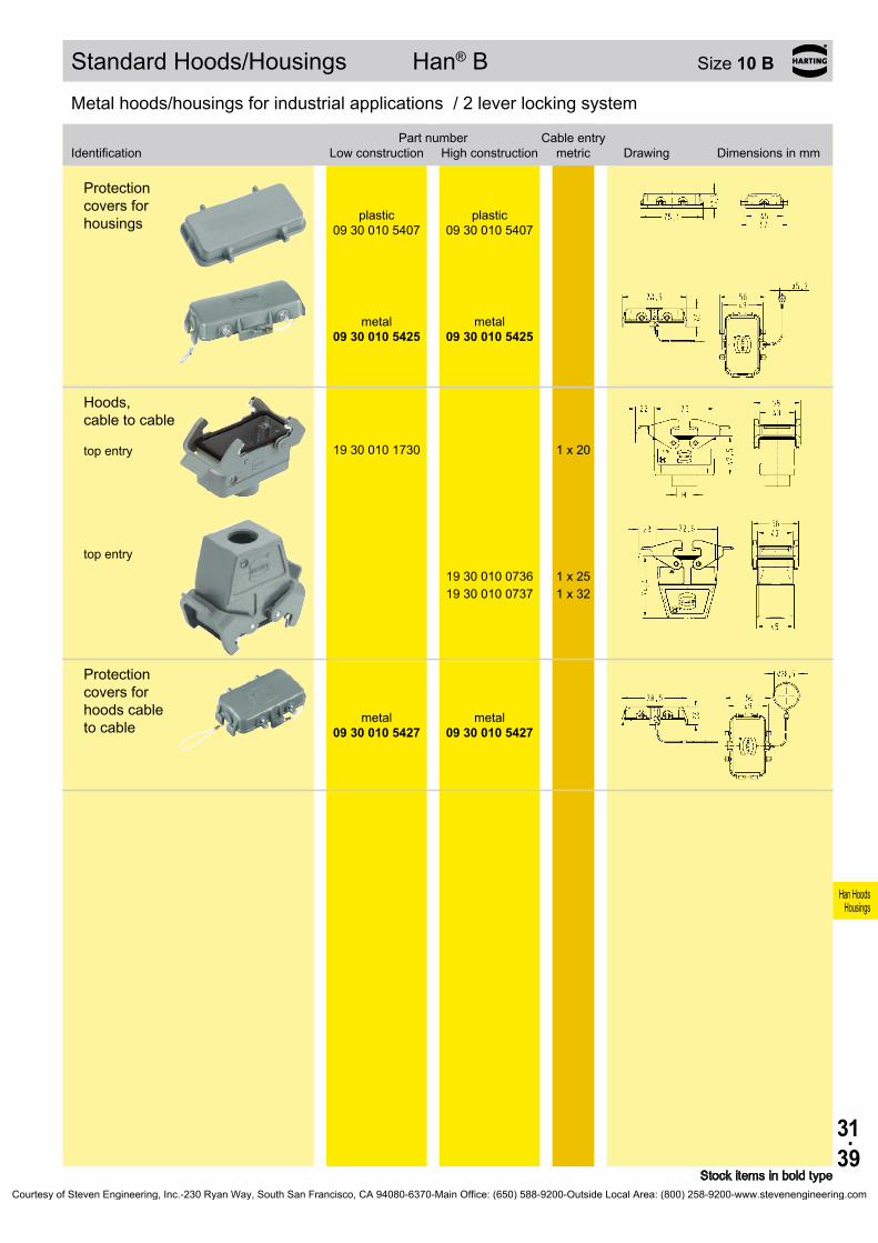
31.39
Han HoodsHousings
09 30 010 5407
09 30 010 5407
09 30 010 5425
09 30 010 5425
19 30 010 1730 1 x 20
19 30 010 0736 1 x 25 19 30 010 0737 1 x 32
09 30 010 5427
09 30 010 5427
Standard Hoods/Housings Han® B Size 10 B
Stock items in bold type
Metal hoods/housings for industrial applications / 2 lever locking system
Identification
Low construction
High constructionPart number Cable entry
metric Drawing Dimensions in mm
Protection covers for housings
plastic plastic
metal metal
Hoods, cable to cable top entry
top entry
Protection covers for hoods cable to cable
metal metal
Courtesy of Steven Engineering, Inc.-230 Ryan Way, South San Francisco, CA 94080-6370-Main Office: (650) 588-9200-Outside Local Area: (800) 258-9200-www.stevenengineering.com

31.40
Han HoodsHousings
19 30 010 1540 1 x 2019 30 010 1541 1 x 25
19 30 010 0547 1 x 32
19 30 010 1440 1 x 2019 30 010 1441 1 x 25
19 30 010 0447 1 x 32
09 30 010 0803 –
09 30 010 5432
09 30 010 5432
Standard Hoods/Housings Han® B Size 10 B
Stock items in bold type
Metal hoods/housings for industrial applications / 1 lever locking system
Identification
Low construction
High constructionPart number Cable entry
metric Drawing Dimensions in mm
Hoods side entry
side entry
Hoods top entry
top entry
Hoods without cable entry
Protection covers
metal metal
Courtesy of Steven Engineering, Inc.-230 Ryan Way, South San Francisco, CA 94080-6370-Main Office: (650) 588-9200-Outside Local Area: (800) 258-9200-www.stevenengineering.com

31.41
Han HoodsHousings
Bezeichnung
Niedrige Bauform
Hohe BauformBestell-Nummer Kabelausgang
metrisch Maßzeichnung Maße in mm
09 30 010 0305
09 30 010 0303
09 30 010 0318
Standard Hoods/Housings Han® B Size 10 B
Stock items in bold type
Metal hoods/housings for industrial applications / 1 lever locking system
Identification
Low construction
High constructionPart number Cable entry
metric Drawing Dimensions in mm
Metal hoods/housings for industrial applications / 1 lever locking system
Housings, bulkhead mounting
Panel cut out
with thermo- plastic cover
with
metal cover
Panel cut out
Courtesy of Steven Engineering, Inc.-230 Ryan Way, South San Francisco, CA 94080-6370-Main Office: (650) 588-9200-Outside Local Area: (800) 258-9200-www.stevenengineering.com
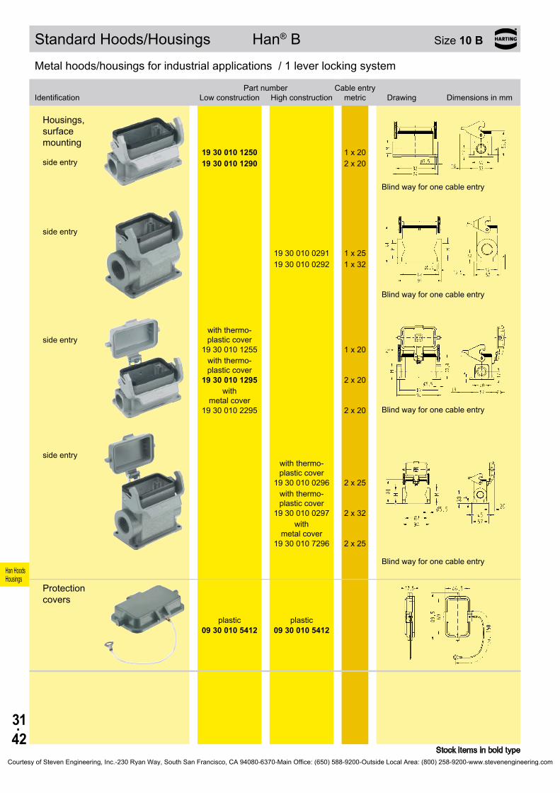
31.42
Han HoodsHousings
19 30 010 1250 1 x 2019 30 010 1290 2 x 20
19 30 010 0291 1 x 25 19 30 010 0292 1 x 32
19 30 010 1255
1 x 20
19 30 010 1295
2 x 20
19 30 010 2295
2 x 20
19 30 010 0296
2 x 25
19 30 010 0297
2 x 32
19 30 010 7296
2 x 25
09 30 010 5412
09 30 010 5412
Standard Hoods/Housings Han® B Size 10 B
Stock items in bold type
Metal hoods/housings for industrial applications / 1 lever locking system
Identification
Low construction
High constructionPart number Cable entry
metric Drawing Dimensions in mm
Housings, surface mounting side entry
Blind way for one cable entry
side entry
Blind way for one cable entry
side entry
with thermo- plastic cover
with thermo- plastic cover
with metal cover
Blind way for one cable entry
side entry
with thermo- plastic cover
with thermo- plastic cover
with
metal cover
Blind way for one cable entry
Protection covers
plastic plastic
Courtesy of Steven Engineering, Inc.-230 Ryan Way, South San Francisco, CA 94080-6370-Main Office: (650) 588-9200-Outside Local Area: (800) 258-9200-www.stevenengineering.com

31.43
Han HoodsHousings
19 30 010 1750 1 x 20
19 30 010 0756 1 x 25
Standard Hoods/Housings Han® B Size 10 B
Stock items in bold type
Metal hoods/housings for industrial applications / 1 lever locking system
Identification
Low construction
High constructionPart number Cable entry
metric Drawing Dimensions in mm
Hoods, cable to cable top entry
top entry
Courtesy of Steven Engineering, Inc.-230 Ryan Way, South San Francisco, CA 94080-6370-Main Office: (650) 588-9200-Outside Local Area: (800) 258-9200-www.stevenengineering.com

31.44
Han HoodsHousings
09 30 010 0901 09 30 010 0902
a b c d Ø
09 30 010 0901 82 68 68 8209 30 010 0902 98 9809 30 010 0961 82 70 70 8209 30 410 0901 82 68 68 8209 30 410 0909 98 9809 30 410 0921 85 73 73 8509 30 410 0951 82 68 68 8209 30 410 0960 98 70 70 9809 30 410 0970 92 77 77 9209 30 410 0971 85 73 73 8509 30 410 0974 92 70 70 9209 30 410 0983 92 80 80 9209 62 810 0901 82 68 68 8209 62 810 0974 92 70 70 92
09 30 010 0961
09 30 410 0901 09 30 410 0909 09 30 410 0921
09 30 410 0951 09 30 410 0960 09 30 410 0970 09 30 410 0971 09 30 410 0974 09 30 410 0983
09 62 810 0901
09 62 810 0974
09 30 010 5406
Han-Drive® Housings for motor applications Size 10 B
Stock items in bold type
Identification Part number Drawing Dimensions in mm
Housings for motor terminationpowder-coated RAL 7037
4 .5
4 .5
4 .54 .34 .35 .54 .35 .14 .54 .1
Other dimensions (a + d) on request (98 x 98 mm)
powder-coated, with protection cover
unpainted
unpainted, with protection cover
highly EMI resistant
highly EMI resistant, with protection cover
Dust protection cover
Courtesy of Steven Engineering, Inc.-230 Ryan Way, South San Francisco, CA 94080-6370-Main Office: (650) 588-9200-Outside Local Area: (800) 258-9200-www.stevenengineering.com

31.45
Han HoodsHousings
500 V16 A
Han E®
500 V16 A
Han® ESHan® ESS
500 V16 A
Han E®
500 V16 A
Han® EE
400/160 V16/10 A
Han-Com®50 V - 830 V10 A - 40 A
Han-Drive® Housings for motor applications Size 10 B
Compatible connector insertsScrew terminal Cage-clamp terminal
Crimp terminal Crimp terminal Crimp terminal Crimp terminal/Screw terminal
Features• Angled housing replaces the terminal box• Space saving and compact design• The position of the terminal housing can be switched
by 90°• Compatible with standard hoods for single lever
• Locking element Han-Easy Lock®
• Star and delta circuits can be realized in the female connector Han® ESS
• Suitable for standard inserts (see compatible con-nector inserts)
Courtesy of Steven Engineering, Inc.-230 Ryan Way, South San Francisco, CA 94080-6370-Main Office: (650) 588-9200-Outside Local Area: (800) 258-9200-www.stevenengineering.com

31.46
Han HoodsHousings
19 30 010 1530 1 x 20
19 30 010 0537 1 x 32
19 30 010 1430 1 x 20
19 30 010 0436 1 x 25
09 30 010 5457
09 30 010 5457
09 30 010 0302
09 30 010 0317
Standard Hoods/Housings Han® B Size 10 B
Stock items in bold type
Metal hoods/housings for industrial applications / 2 lever locking system
Identification
Low construction
High constructionPart number Cable entry
metric Drawing Dimensions in mm
Hoods side entry
side entry
Hoods top entry
top entry
Protection covers
metal metal
Metal hoods/housings for industrial applications / 2 lever locking system
Identification
Low construction
High constructionPart number Cable entry
metric Drawing Dimensions in mm
Housings, bulkhead mounting with thermo-
plastic cover
with metal cover
Panel cut out
Courtesy of Steven Engineering, Inc.-230 Ryan Way, South San Francisco, CA 94080-6370-Main Office: (650) 588-9200-Outside Local Area: (800) 258-9200-www.stevenengineering.com

31.47
Han HoodsHousings
19 30 010 1225
1 x 20
19 30 010 1265
2 x 20
19 30 010 0266
2 x 25
Standard Hoods/Housings Han® B Size 10 B
Stock items in bold type
Metal hoods/housings for industrial applications / 2 lever locking system
Identification
Low construction
High constructionPart number Cable entry
metric Drawing Dimensions in mm
Housings, surface mounting side entry
with thermo- plastic cover
with thermo- plastic cover
Blind way for one cable entry
side entry
with thermo- plastic cover
Blind way for one cable entry
Courtesy of Steven Engineering, Inc.-230 Ryan Way, South San Francisco, CA 94080-6370-Main Office: (650) 588-9200-Outside Local Area: (800) 258-9200-www.stevenengineering.com

31.48
Han HoodsHousings
19 30 010 0586 1 x 25
09 30 010 0381
Standard Hoods/Housings Han® B Size 10 B
Stock items in bold type
Metal hoods/housings for industrial applications / 1 central locking lever locking system
Identification Part numberCable entry
metric Drawing Dimensions in mm
Hoods side entry
Metal hoods/housings for industrial applications / 1 central locking lever locking system
Identification Part numberCable entry
metric Drawing Dimensions in mm
Housings, bulkhead mounting
Panel cut out
Courtesy of Steven Engineering, Inc.-230 Ryan Way, South San Francisco, CA 94080-6370-Main Office: (650) 588-9200-Outside Local Area: (800) 258-9200-www.stevenengineering.com
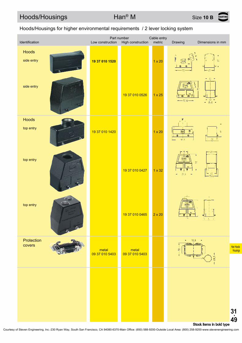
31.49
Han HoodsHousings
19 37 010 1520 1 x 20
19 37 010 0526 1 x 25
19 37 010 1420 1 x 20
19 37 010 0427 1 x 32
19 37 010 0465 2 x 20
09 37 010 5403
09 37 010 5403
Hoods/Housings Han® M Size 10 B
Stock items in bold type
Hoods/Housings for higher environmental requirements / 2 lever locking system
Identification
Low construction
High constructionPart number Cable entry
metric Drawing Dimensions in mm
Hoods side entry
side entry
Hoods top entry
top entry
top entry
Protection covers
metal metal
Courtesy of Steven Engineering, Inc.-230 Ryan Way, South San Francisco, CA 94080-6370-Main Office: (650) 588-9200-Outside Local Area: (800) 258-9200-www.stevenengineering.com

31.50
Han HoodsHousings
Bezeichnung
Niedrige Bauform
Hohe BauformBestell-Nummer Kabelausgang
metrisch Maßzeichnung Maße in mm
09 37 010 0301
19 37 010 1270 2 x 20
19 37 010 0272 2 x 32
09 37 010 5405
09 37 010 5405
Hoods/Housings Han® M Size 10 B
Stock items in bold type
Hoods/Housings for higher environmental requirements / 2 lever locking system
Identification
Low construction
High constructionPart number Cable entry
metric Drawing Dimensions in mm
Hoods/Housings for higher environmental requirements / 2 lever locking system
Housings, bulkhead mounting
Panel cut out
Housings, surface mounting side entry
side entry
Protection covers
metal metal
Courtesy of Steven Engineering, Inc.-230 Ryan Way, South San Francisco, CA 94080-6370-Main Office: (650) 588-9200-Outside Local Area: (800) 258-9200-www.stevenengineering.com

31.51
Han HoodsHousings
19 37 010 0447 1 x 32
19 37 010 0291 1 x 25
Hoods/Housings Han® M Size 10 B
Stock items in bold type
Hoods/Housings for higher environmental requirements / 1 lever locking system
Identification Part numberCable entry
metric Drawing Dimensions in mm
Hoods top entry
Hoods/Housings for higher environmental requirements / 1 lever locking system
Identification Part numberCable entry
metric Drawing Dimensions in mm
Housings, surface mounting side entry
Courtesy of Steven Engineering, Inc.-230 Ryan Way, South San Francisco, CA 94080-6370-Main Office: (650) 588-9200-Outside Local Area: (800) 258-9200-www.stevenengineering.com

31.52
Han HoodsHousings
19 62 010 0542 1 x 3219 62 010 0543 1 x 40
19 62 010 0442 1 x 32
09 62 010 0301
Hoods/Housings Han® EMC Size 10 B
Stock items in bold type
Hoods/Housings for higher EMC requirements / Screw locking system
Identification Part numberCable entry
metric Drawing Dimensions in mm
Hoods side entry
Hoods top entry
Hoods/Housings for higher environmental requirements / Screw locking system
Identification Part numberCable entry
metric Drawing Dimensions in mm
Housings, bulkhead mounting
Panel cut out
Courtesy of Steven Engineering, Inc.-230 Ryan Way, South San Francisco, CA 94080-6370-Main Office: (650) 588-9200-Outside Local Area: (800) 258-9200-www.stevenengineering.com

31.53
Han HoodsHousings
19 62 810 1520 1 x 20
19 62 810 0526 1 x 25 19 62 810 0527 1 x 32
19 62 810 1420 1 x 2019 62 810 1421 1 x 25
19 62 810 0426 1 x 25 19 62 810 0427 1 x 32
09 62 810 0301
Hoods/Housings Han® EMC/B Size 10 B
Stock items in bold type
Hoods/Housings for higher EMC requirements / 2 lever locking system
Identification
Low construction
High constructionPart number Cable entry
metric Drawing Dimensions in mm
Hoods side entry
side entry
Hoods top entry
top entry
Hoods/Housings for higher EMC requirements / 2 lever locking system
Identification
Low construction
High constructionPart number Cable entry
metric Drawing Dimensions in mm
Housings, bulkhead mounting
Panel cut out
Courtesy of Steven Engineering, Inc.-230 Ryan Way, South San Francisco, CA 94080-6370-Main Office: (650) 588-9200-Outside Local Area: (800) 258-9200-www.stevenengineering.com
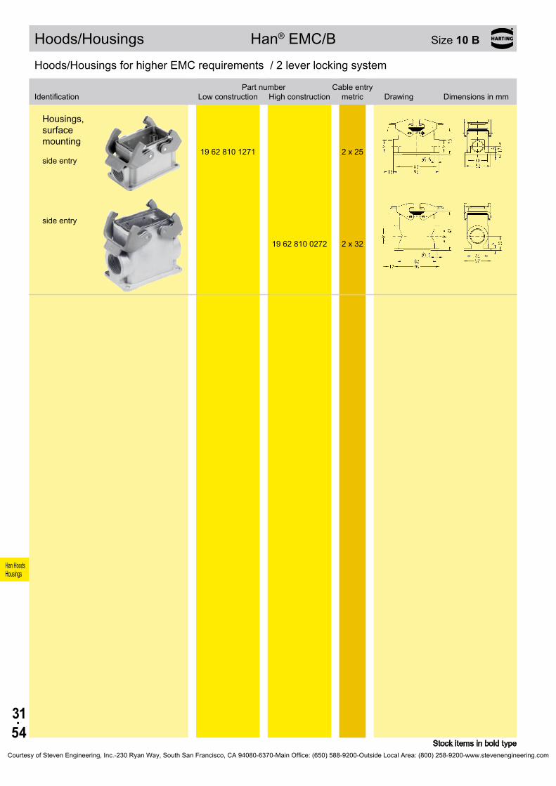
31.54
Han HoodsHousings
19 62 810 1271 2 x 25
19 62 810 0272 2 x 32
Hoods/Housings Han® EMC/B Size 10 B
Stock items in bold type
Hoods/Housings for higher EMC requirements / 2 lever locking system
Identification
Low construction
High constructionPart number Cable entry
metric Drawing Dimensions in mm
Housings, surface mounting side entry
side entry
Courtesy of Steven Engineering, Inc.-230 Ryan Way, South San Francisco, CA 94080-6370-Main Office: (650) 588-9200-Outside Local Area: (800) 258-9200-www.stevenengineering.com

31.55
Han HoodsHousings
19 62 810 0547 1 x 32
19 62 810 0446 1 x 25 19 62 810 0447 1 x 32
09 62 810 0305
19 62 810 0757 1 x 32
Hoods/Housings Han® EMC/B Size 10 B
Stock items in bold type
Hoods/Housings for higher EMC requirements / 1 lever locking system
Identification
Low construction
High constructionPart number Cable entry
metric Drawing Dimensions in mm
Hoods side entry
Hoods top entry
Hoods/Housings for higher EMC requirements / 1 lever locking system
Identification
Low construction
High constructionPart number Cable entry
metric Drawing Dimensions in mm
Housings, bulkhead mounting
with 2 locking levers and
1 adapter frame
Panel cut out
Hoods, cable to cable top entry
Courtesy of Steven Engineering, Inc.-230 Ryan Way, South San Francisco, CA 94080-6370-Main Office: (650) 588-9200-Outside Local Area: (800) 258-9200-www.stevenengineering.com

31.56
Han HoodsHousings
19 40 010 0501 1 x 25 19 40 010 0511 1 x 25 19 40 010 0512 1 x 32 19 40 010 0513 1 x 40
19 40 010 0401 1 x 25 19 40 010 0411 1 x 25 19 40 010 0412 1 x 32 19 40 010 0413 1 x 40 19 40 010 0430 2 x 20
09 40 010 0811 –
Hoods/Housings Han® HPR Size 10 B
Stock items in bold type
Hoods/Housings for harsh environmental requirements / Screw/toggle locking system
Identification
Toggle locking
screwPart number Cable entry
metric Drawing Dimensions in mm
Hoods side entry
Hoods top entry
Hoods without cable entry
Courtesy of Steven Engineering, Inc.-230 Ryan Way, South San Francisco, CA 94080-6370-Main Office: (650) 588-9200-Outside Local Area: (800) 258-9200-www.stevenengineering.com
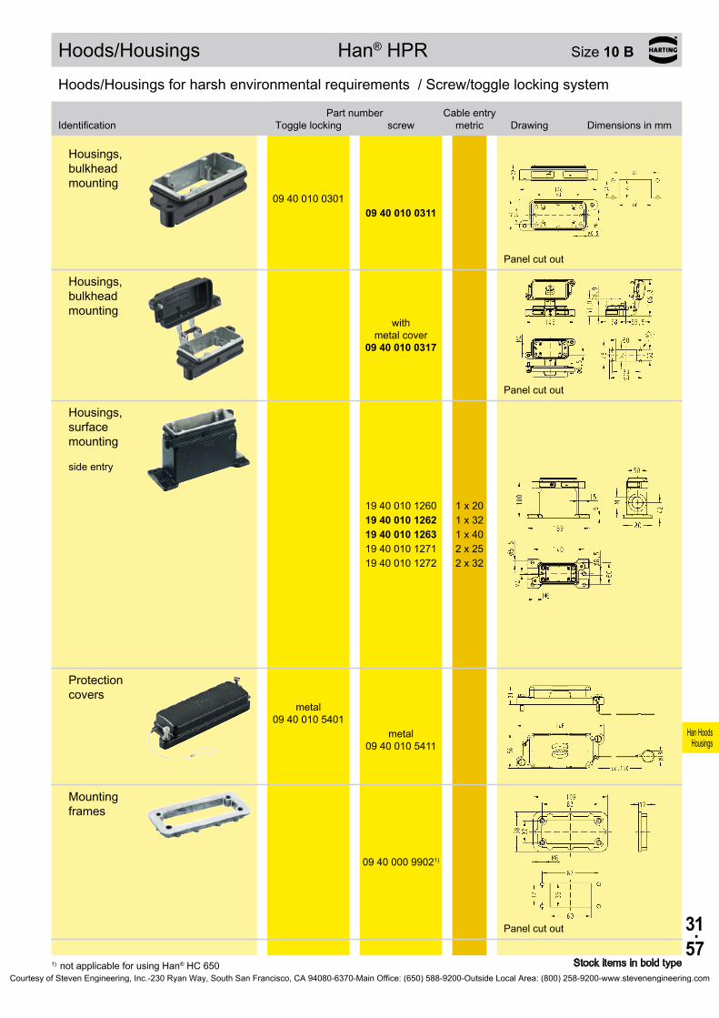
31.57
Han HoodsHousings
09 40 010 0301 09 40 010 0311
09 40 010 0317
19 40 010 1260 1 x 20 19 40 010 1262 1 x 32 19 40 010 1263 1 x 40 19 40 010 1271 2 x 25 19 40 010 1272 2 x 32
09 40 010 5401
09 40 010 5411
09 40 000 99021)
Hoods/Housings Han® HPR Size 10 B
Stock items in bold type1) not applicable for using Han® HC 650
Hoods/Housings for harsh environmental requirements / Screw/toggle locking system
Identification
Toggle locking
screwPart number Cable entry
metric Drawing Dimensions in mm
Housings, bulkhead mounting
Panel cut out
Housings, bulkhead mounting
with
metal cover
Panel cut out
Housings, surface mounting side entry
Protection covers
metal
metal
Mounting frames
Panel cut out
Courtesy of Steven Engineering, Inc.-230 Ryan Way, South San Francisco, CA 94080-6370-Main Office: (650) 588-9200-Outside Local Area: (800) 258-9200-www.stevenengineering.com

31.58
Han HoodsHousings
19 44 310 0547 1 x 32
19 44 310 0447 1 x 32
19 44 310 0305
19 44 000 9902
Standard Hoods/Housings Han-INOX® Size 10 B
Stock items in bold type
Hoods/Housings made of stainless steel / 1 lever locking system
Identification Part numberCable entry
metric Drawing Dimensions in mm
Hoods side entry
Hoods top entry
Hoods/Housings made of stainless steel / 1 lever locking system
Identification Part numberCable entry
metric Drawing Dimensions in mm
Housings, bulkhead mounting
Panel cut out
Gasket
Courtesy of Steven Engineering, Inc.-230 Ryan Way, South San Francisco, CA 94080-6370-Main Office: (650) 588-9200-Outside Local Area: (800) 258-9200-www.stevenengineering.com
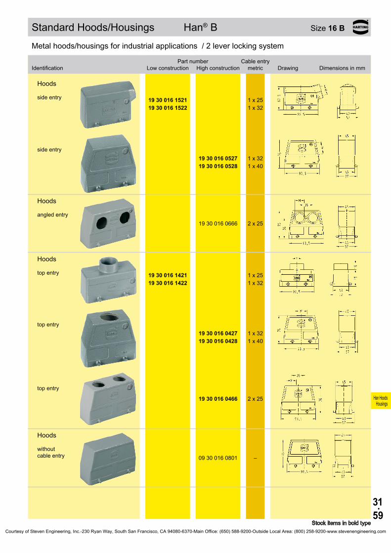
31.59
Han HoodsHousings
19 30 016 1521 1 x 2519 30 016 1522 1 x 32
19 30 016 0527 1 x 32 19 30 016 0528 1 x 40
19 30 016 0666 2 x 25
19 30 016 1421 1 x 2519 30 016 1422 1 x 32
19 30 016 0427 1 x 32 19 30 016 0428 1 x 40
19 30 016 0466 2 x 25
09 30 016 0801 –
Standard Hoods/Housings Han® B Size 16 B
Stock items in bold type
Metal hoods/housings for industrial applications / 2 lever locking system
Identification
Low construction
High constructionPart number Cable entry
metric Drawing Dimensions in mm
Hoods side entry
side entry
Hoods angled entry
Hoods top entry
top entry
top entry
Hoods without cable entry
Courtesy of Steven Engineering, Inc.-230 Ryan Way, South San Francisco, CA 94080-6370-Main Office: (650) 588-9200-Outside Local Area: (800) 258-9200-www.stevenengineering.com

31.60
Han HoodsHousings
09 30 016 5401
09 30 016 5401
09 30 016 5422
09 30 016 5422
09 30 016 0301
19 30 016 1231 1 x 2519 30 016 1271 2 x 25
19 30 016 0232 1 x 32 19 30 016 0271 2 x 25 19 30 016 0272 2 x 32 19 30 016 0273 2 x 40
Standard Hoods/Housings Han® B Size 16 B
Stock items in bold type
Metal hoods/housings for industrial applications / 2 lever locking system
Identification
Low construction
High constructionPart number Cable entry
metric Drawing Dimensions in mm
Dust protection cover
plastic plastic
Protection covers
metal metal
Metal hoods/housings for industrial applications / 2 lever locking system
Identification
Low construction
High constructionPart number Cable entry
metric Drawing Dimensions in mm
Housings, bulkhead mounting
Panel cut out
Housings, surface mounting side entry
side entry
Courtesy of Steven Engineering, Inc.-230 Ryan Way, South San Francisco, CA 94080-6370-Main Office: (650) 588-9200-Outside Local Area: (800) 258-9200-www.stevenengineering.com

31.61
Han HoodsHousings
09 30 016 5405
09 30 016 5405
09 30 016 5425
09 30 016 5425
19 30 016 1731 1 x 2519 30 016 1732 1 x 32
19 30 016 0736 1 x 25 19 30 016 0737 1 x 32
09 30 016 5426
09 30 016 5426
Standard Hoods/Housings Han® B Size 16 B
Stock items in bold type
Metal hoods/housings for industrial applications / 2 lever locking system
Identification
Low construction
High constructionPart number Cable entry
metric Drawing Dimensions in mm
Protection covers
plastic plastic
metal metal
Hoods, cable to cable top entry
top entry
Protection covers
metal metal
Courtesy of Steven Engineering, Inc.-230 Ryan Way, South San Francisco, CA 94080-6370-Main Office: (650) 588-9200-Outside Local Area: (800) 258-9200-www.stevenengineering.com
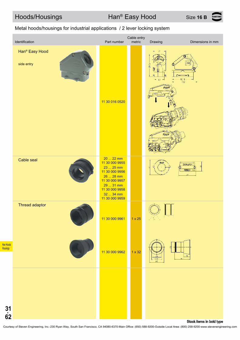
31.62
Han HoodsHousings
11 30 016 0520
20 . . . 22 mm 11 30 000 9955
23 . . . 25 mm 11 30 000 9956
26 . . . 28 mm 11 30 000 9957
29 . . . 31 mm 11 30 000 9958
32 . . . 34 mm 11 30 000 9959
11 30 000 9961 1 x 25
11 30 000 9962 1 x 32
Hoods/Housings Han® Easy Hood Size 16 B
Stock items in bold type
Metal hoods/housings for industrial applications / 2 lever locking system
Identification Part numberCable entry
metric Drawing Dimensions in mm
Han® Easy Hood side entry
Cable seal
Thread adaptor
Courtesy of Steven Engineering, Inc.-230 Ryan Way, South San Francisco, CA 94080-6370-Main Office: (650) 588-9200-Outside Local Area: (800) 258-9200-www.stevenengineering.com
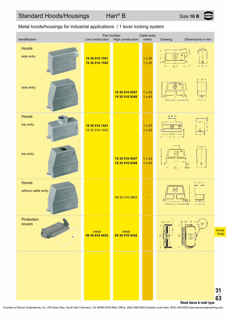
31.63
Han HoodsHousings
19 30 016 1541 1 x 2519 30 016 1542 1 x 32
19 30 016 0547 1 x 32 19 30 016 0548 1 x 40
19 30 016 1441 1 x 2519 30 016 1442 1 x 32
19 30 016 0447 1 x 32 19 30 016 0448 1 x 40
09 30 016 0803 –
09 30 016 5432
09 30 016 5432
Standard Hoods/Housings Han® B Size 16 B
Stock items in bold type
Metal hoods/housings for industrial applications / 1 lever locking system
Identification
Low construction
High constructionPart number Cable entry
metric Drawing Dimensions in mm
Hoods side entry
side entry
Hoods top entry
top entry
Hoods without cable entry
Protection covers
metal metal
Courtesy of Steven Engineering, Inc.-230 Ryan Way, South San Francisco, CA 94080-6370-Main Office: (650) 588-9200-Outside Local Area: (800) 258-9200-www.stevenengineering.com

31.64
Han HoodsHousings
Bezeichnung
Niedrige Bauform
Hohe BauformBestell-Nummer Kabelausgang
metrisch Maßzeichnung Maße in mm
09 30 016 0307
09 30 016 0306
09 30 016 0318
Standard Hoods/Housings Han® B Size 16 B
Stock items in bold type
Metal hoods/housings for industrial applications / 1 lever locking system
Identification
Low construction
High constructionPart number Cable entry
metric Drawing Dimensions in mm
Metal hoods/housings for industrial applications / 1 lever locking system
Housings, bulkhead mounting
Panel cut out
with thermo- plastic cover
with
metal cover
Panel cut out
Courtesy of Steven Engineering, Inc.-230 Ryan Way, South San Francisco, CA 94080-6370-Main Office: (650) 588-9200-Outside Local Area: (800) 258-9200-www.stevenengineering.com

31.65
Han HoodsHousings
19 30 016 1251 1 x 2519 30 016 1291 2 x 25
19 30 016 0252 1 x 32 19 30 016 0291 2 x 25 19 30 016 0292 2 x 32
19 30 016 1256
1 x 25
19 30 016 1296
2 x 25
19 30 016 2296
2 x 25
19 30 016 0297
2 x 32
19 30 016 7297
2 x 32
Standard Hoods/Housings Han® B Size 16 B
Stock items in bold type
Metal hoods/housings for industrial applications / 1 lever locking system
Identification
Low construction
High constructionPart number Cable entry
metric Drawing Dimensions in mm
Housings, surface mounting side entry
Blind way for one cable entry
side entry
Blind way for one cable entry
side entry
with thermo- plastic cover
with thermo- plastic cover
with metal cover
Blind way for one cable entry
side entry
with thermo- plastic cover
with
metal cover
Blind way for one cable entry
Courtesy of Steven Engineering, Inc.-230 Ryan Way, South San Francisco, CA 94080-6370-Main Office: (650) 588-9200-Outside Local Area: (800) 258-9200-www.stevenengineering.com

31.66
Han HoodsHousings
19 30 016 1751 1 x 2519 30 016 1752 1 x 32
19 30 016 0757 1 x 32
Standard Hoods/Housings Han® B Size 16 B
Metal hoods/housings for industrial applications / 1 lever locking system
Identification
Low construction
High constructionPart number Cable entry
metric Drawing Dimensions in mm
Hoods, cable to cable top entry
top entry
Courtesy of Steven Engineering, Inc.-230 Ryan Way, South San Francisco, CA 94080-6370-Main Office: (650) 588-9200-Outside Local Area: (800) 258-9200-www.stevenengineering.com

31.67
Han HoodsHousings
19 30 016 1531 1 x 25
19 30 016 0537 1 x 32 19 30 016 0538 1 x 40
19 30 016 1431 1 x 2519 30 016 1432 1 x 32
19 30 016 0437 1 x 32 19 30 016 0438 1 x 40
09 30 016 4431
Standard Hoods/Housings Han® B Size 16 B
Stock items in bold type
Metal hoods/housings for industrial applications / 2 lever locking system
Identification
Low construction
High constructionPart number Cable entry
metric Drawing Dimensions in mm
Hoods side entry
side entry
Hoods top entry
top entry
Hoods flat cable entry Set of seals see chapter 40
Courtesy of Steven Engineering, Inc.-230 Ryan Way, South San Francisco, CA 94080-6370-Main Office: (650) 588-9200-Outside Local Area: (800) 258-9200-www.stevenengineering.com
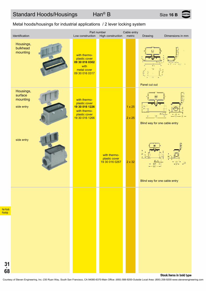
31.68
Han HoodsHousings
Bezeichnung
Niedrige Bauform
Hohe BauformBestell-Nummer Kabelausgang
metrisch Maßzeichnung Maße in mm
09 30 016 0302
09 30 016 0317
19 30 016 1226
1 x 25
19 30 016 1266
2 x 25
19 30 016 0267
2 x 32
Standard Hoods/Housings Han® B Size 16 B
Stock items in bold type
Metal hoods/housings for industrial applications / 2 lever locking system
Identification
Low construction
High constructionPart number Cable entry
metric Drawing Dimensions in mm
Metal hoods/housings for industrial applications / 2 lever locking system
Housings, bulkhead mounting
with thermo- plastic cover
with
metal cover
Panel cut out
Housings, surface mounting side entry
with thermo- plastic cover
with thermo- plastic cover
Blind way for one cable entry
side entry
with thermo- plastic cover
Blind way for one cable entry
Courtesy of Steven Engineering, Inc.-230 Ryan Way, South San Francisco, CA 94080-6370-Main Office: (650) 588-9200-Outside Local Area: (800) 258-9200-www.stevenengineering.com

31.69
Han HoodsHousings
19 30 016 0586 1 x 2519 30 016 0587 1 x 32
19 30 016 0487 1 x 32
09 30 016 0381
19 30 016 0282 2 x 32
Standard Hoods/Housings Han® B Size 16 B
Stock items in bold type
Metal hoods/housings for industrial applications / 1 central locking lever locking system
Identification Part numberCable entry
metric Drawing Dimensions in mm
Hoods side entry
Hoods top entry
Metal hoods/housings for industrial applications / 1 central locking lever locking system
Identification Part numberCable entry
metric Drawing Dimensions in mm
Housings, bulkhead mounting
Panel cut out
Housings, surface mounting side entry
Courtesy of Steven Engineering, Inc.-230 Ryan Way, South San Francisco, CA 94080-6370-Main Office: (650) 588-9200-Outside Local Area: (800) 258-9200-www.stevenengineering.com
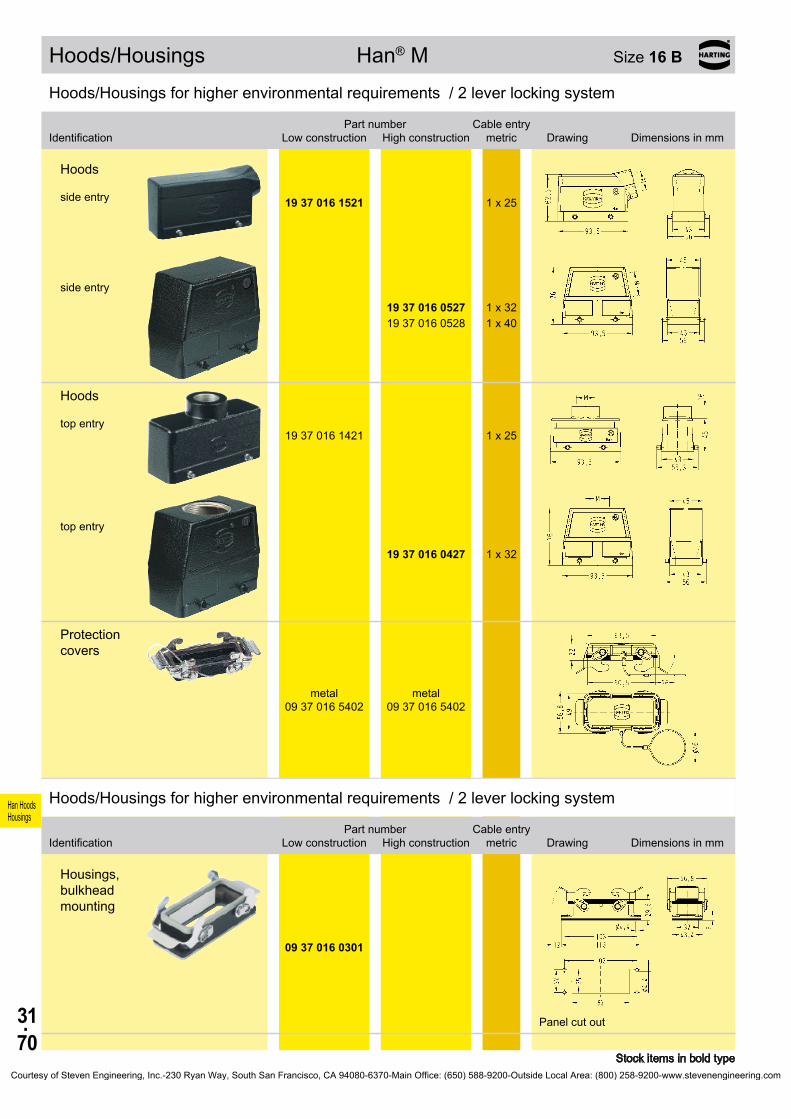
31.70
Han HoodsHousings
19 37 016 1521 1 x 25
19 37 016 0527 1 x 32 19 37 016 0528 1 x 40
19 37 016 1421 1 x 25
19 37 016 0427 1 x 32
09 37 016 5402
09 37 016 5402
09 37 016 0301
Hoods/Housings Han® M Size 16 B
Stock items in bold type
Hoods/Housings for higher environmental requirements / 2 lever locking system
Identification
Low construction
High constructionPart number Cable entry
metric Drawing Dimensions in mm
Hoods side entry
side entry
Hoods top entry
top entry
Protection covers
metal metal
Hoods/Housings for higher environmental requirements / 2 lever locking system
Identification
Low construction
High constructionPart number Cable entry
metric Drawing Dimensions in mm
Housings, bulkhead mounting
Panel cut out
Courtesy of Steven Engineering, Inc.-230 Ryan Way, South San Francisco, CA 94080-6370-Main Office: (650) 588-9200-Outside Local Area: (800) 258-9200-www.stevenengineering.com

31.71
Han HoodsHousings
19 37 016 1231 1 x 25
19 37 016 0272 2 x 32 19 37 016 0273 2 x 40
09 37 016 5405
09 37 016 5405
Hoods/Housings Han® M Size 16 B
Stock items in bold type
Hoods/Housings for higher environmental requirements / 2 lever locking system
Identification
Low construction
High constructionPart number Cable entry
metric Drawing Dimensions in mm
Housings, surface mounting side entry
side entry
Protection covers
metal metal
Courtesy of Steven Engineering, Inc.-230 Ryan Way, South San Francisco, CA 94080-6370-Main Office: (650) 588-9200-Outside Local Area: (800) 258-9200-www.stevenengineering.com

31.72
Han HoodsHousings
19 37 016 0587 1 x 32
19 37 016 0487 1 x 32
19 37 016 0282 2 x 32
Hoods/Housings Han® M Size 16 B
Stock items in bold type
Hoods/Housings for higher environmental requirements / 1 central locking lever locking system
Identification Part numberCable entry
metric Drawing Dimensions in mm
Hoods side entry
Hoods top entry
Hoods/Housings for higher environmental requirements / 1 central locking lever locking system
Identification Part numberCable entry
metric Drawing Dimensions in mm
Housings, surface mounting side entry
Courtesy of Steven Engineering, Inc.-230 Ryan Way, South San Francisco, CA 94080-6370-Main Office: (650) 588-9200-Outside Local Area: (800) 258-9200-www.stevenengineering.com
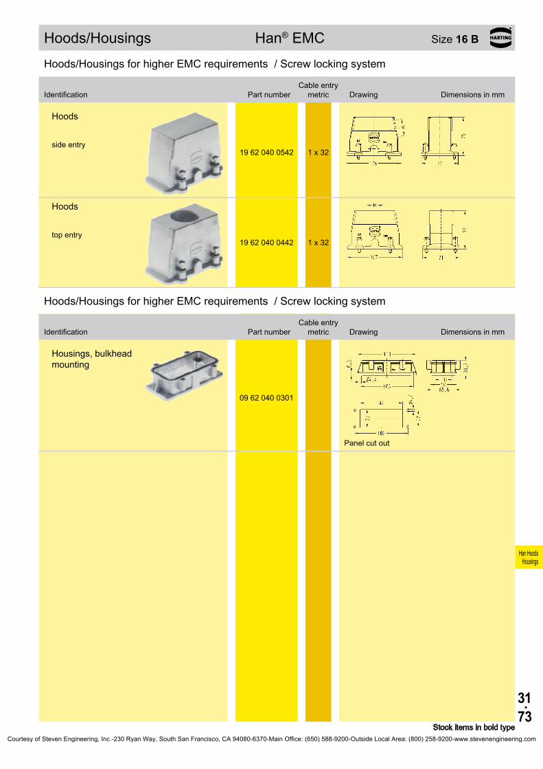
31.73
Han HoodsHousings
19 62 040 0542 1 x 32
19 62 040 0442 1 x 32
09 62 040 0301
Hoods/Housings Han® EMC Size 16 B
Stock items in bold type
Hoods/Housings for higher EMC requirements / Screw locking system
Identification Part numberCable entry
metric Drawing Dimensions in mm
Hoods side entry
Hoods top entry
Hoods/Housings for higher EMC requirements / Screw locking system
Identification Part numberCable entry
metric Drawing Dimensions in mm
Housings, bulkhead mounting
Panel cut out
Courtesy of Steven Engineering, Inc.-230 Ryan Way, South San Francisco, CA 94080-6370-Main Office: (650) 588-9200-Outside Local Area: (800) 258-9200-www.stevenengineering.com
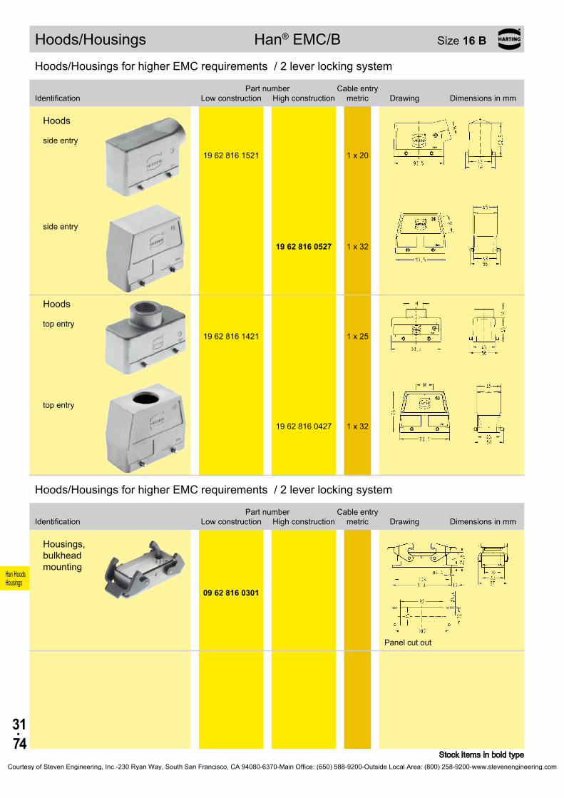
31.74
Han HoodsHousings
19 62 816 1521 1 x 20
19 62 816 0527 1 x 32
19 62 816 1421 1 x 25
19 62 816 0427 1 x 32
09 62 816 0301
Hoods/Housings Han® EMC/B Size 16 B
Stock items in bold type
Hoods/Housings for higher EMC requirements / 2 lever locking system
Identification
Low construction
High constructionPart number Cable entry
metric Drawing Dimensions in mm
Hoods side entry
side entry
Hoods top entry
top entry
Hoods/Housings for higher EMC requirements / 2 lever locking system
Identification
Low construction
High constructionPart number Cable entry
metric Drawing Dimensions in mm
Housings, bulkhead mounting
Panel cut out
Courtesy of Steven Engineering, Inc.-230 Ryan Way, South San Francisco, CA 94080-6370-Main Office: (650) 588-9200-Outside Local Area: (800) 258-9200-www.stevenengineering.com

31.75
Han HoodsHousings
19 62 816 1271 2 x 25
19 62 816 0273 2 x 40
Hoods/Housings Han® EMC/B Size 16 B
Stock items in bold type
Hoods/Housings for higher EMC requirements / 2 lever locking system
Identification
Low construction
High constructionPart number Cable entry
metric Drawing Dimensions in mm
Housings, surface mounting side entry
side entry
Courtesy of Steven Engineering, Inc.-230 Ryan Way, South San Francisco, CA 94080-6370-Main Office: (650) 588-9200-Outside Local Area: (800) 258-9200-www.stevenengineering.com
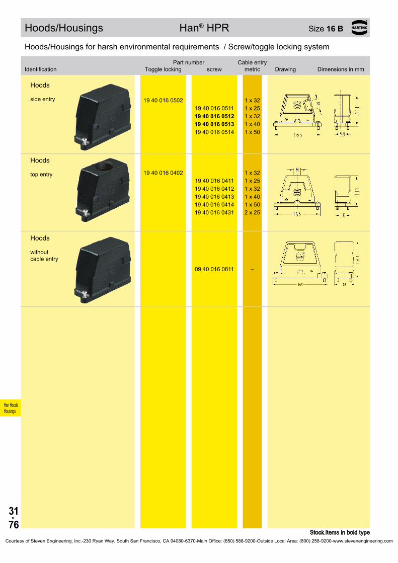
31.76
Han HoodsHousings
19 40 016 0502 1 x 32 19 40 016 0511 1 x 25 19 40 016 0512 1 x 32 19 40 016 0513 1 x 40 19 40 016 0514 1 x 50
19 40 016 0402 1 x 32 19 40 016 0411 1 x 25 19 40 016 0412 1 x 32 19 40 016 0413 1 x 40 19 40 016 0414 1 x 50 19 40 016 0431 2 x 25
09 40 016 0811 –
Hoods/Housings Han® HPR Size 16 B
Stock items in bold type
Hoods/Housings for harsh environmental requirements / Screw/toggle locking system
Identification
Toggle locking
screwPart number Cable entry
metric Drawing Dimensions in mm
Hoods side entry
Hoods top entry
Hoods without cable entry
Courtesy of Steven Engineering, Inc.-230 Ryan Way, South San Francisco, CA 94080-6370-Main Office: (650) 588-9200-Outside Local Area: (800) 258-9200-www.stevenengineering.com
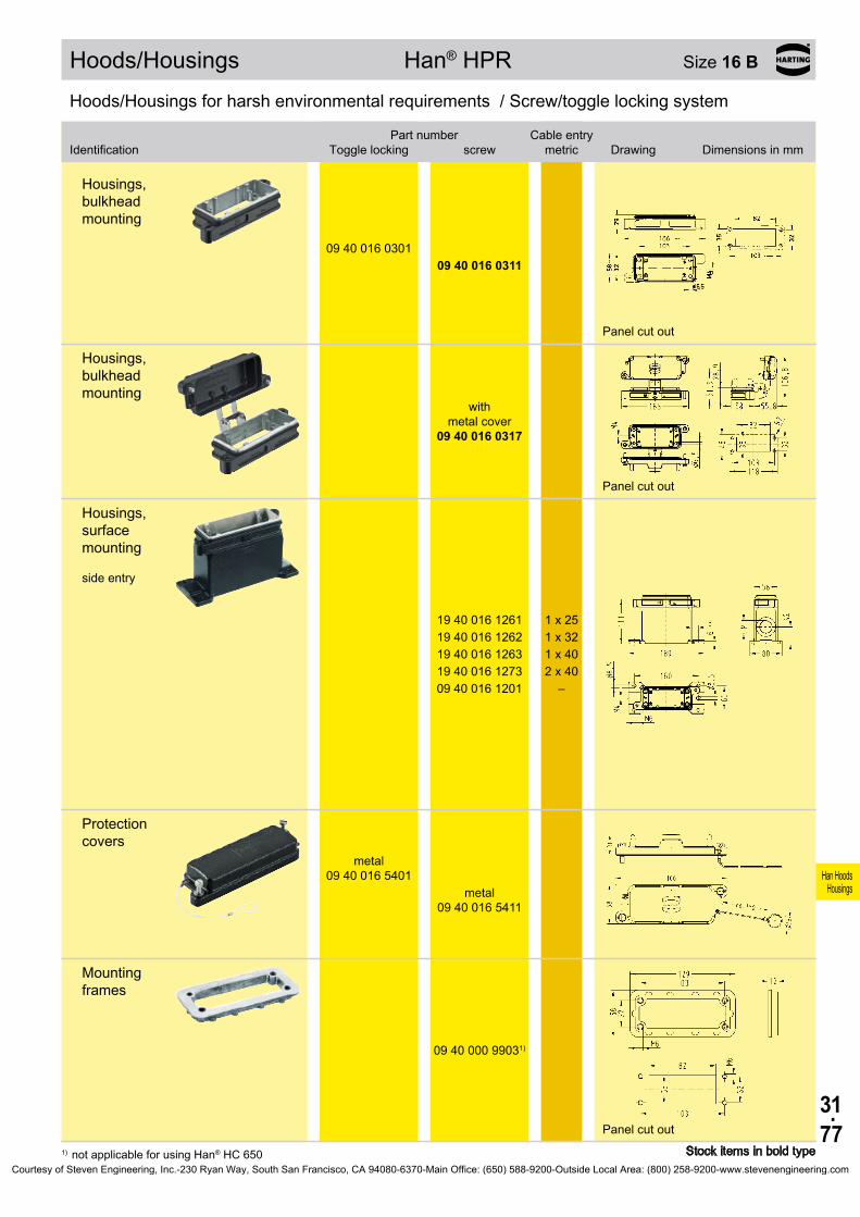
31.77
Han HoodsHousings
09 40 016 0301 09 40 016 0311
09 40 016 0317
19 40 016 1261 1 x 25 19 40 016 1262 1 x 32 19 40 016 1263 1 x 40 19 40 016 1273 2 x 40 09 40 016 1201 –
09 40 016 5401
09 40 016 5411
09 40 000 99031)
Hoods/Housings Han® HPR Size 16 B
Stock items in bold type1) not applicable for using Han® HC 650
Hoods/Housings for harsh environmental requirements / Screw/toggle locking system
Identification
Toggle locking
screwPart number Cable entry
metric Drawing Dimensions in mm
Housings, bulkhead mounting
Panel cut out
Housings, bulkhead mounting
with
metal cover
Panel cut out
Housings, surface mounting side entry
Protection covers
metal
metal
Mounting frames
Panel cut out
Courtesy of Steven Engineering, Inc.-230 Ryan Way, South San Francisco, CA 94080-6370-Main Office: (650) 588-9200-Outside Local Area: (800) 258-9200-www.stevenengineering.com

31.78
Han HoodsHousings
19 30 024 1521 1 x 2519 30 024 1522 1 x 32
19 30 024 0527 1 x 32 19 30 024 0528 1 x 40
19 30 024 0666 2 x 25
19 30 024 1422 1 x 32
19 30 024 0427 1 x 32 19 30 024 0428 1 x 40
19 30 024 0467 2 x 32
09 30 024 0801 –
Standard Hoods/Housings Han® B Size 24 B
Stock items in bold type
Metal hoods/housings for industrial applications / 2 lever locking system
Identification
Low construction
High constructionPart number Cable entry
metric Drawing Dimensions in mm
Hoods side entry
side entry
angled entry
Hoods top entry
top entry
top entry
Hoods without cable entry
Courtesy of Steven Engineering, Inc.-230 Ryan Way, South San Francisco, CA 94080-6370-Main Office: (650) 588-9200-Outside Local Area: (800) 258-9200-www.stevenengineering.com

31.79
Han HoodsHousings
09 30 024 5422
09 30 024 5422
09 30 024 5401
09 30 024 5401
09 30 024 0301
19 30 024 1231 1 x 2519 30 024 1271 2 x 25
19 30 024 0232 1 x 32 19 30 024 0272 2 x 32 19 30 024 0273 2 x 40
Standard Hoods/Housings Han® B Size 24 B
Stock items in bold type
Metal hoods/housings for industrial applications / 2 lever locking system
Identification
Low construction
High constructionPart number Cable entry
metric Drawing Dimensions in mm
Protection covers
metal metal
Dust protection cover
plastic plastic
Metal hoods/housings for industrial applications / 2 lever locking system
Identification
Low construction
High constructionPart number Cable entry
metric Drawing Dimensions in mm
Housings, bulkhead mounting
Panel cut out
Housings, surface mounting side entry
Blind way for one cable entry
side entry
Blind way for one cable entry
Courtesy of Steven Engineering, Inc.-230 Ryan Way, South San Francisco, CA 94080-6370-Main Office: (650) 588-9200-Outside Local Area: (800) 258-9200-www.stevenengineering.com

31.80
Han HoodsHousings
09 30 024 5425
09 30 024 5425
09 30 024 5405
09 30 024 5405
19 30 024 1732 1 x 32
19 30 024 0737 1 x 32 19 30 024 0738 1 x 40
09 30 024 5426
09 30 024 5426
Standard Hoods/Housings Han® B Size 24 B
Stock items in bold type
Metal hoods/housings for industrial applications / 2 lever locking system
Identification
Low construction
High constructionPart number Cable entry
metric Drawing Dimensions in mm
Protection covers
metal metal
Protection covers
plastic plastic
Hoods, cable to cable top entry
top entry
Protection covers
metal metal
Courtesy of Steven Engineering, Inc.-230 Ryan Way, South San Francisco, CA 94080-6370-Main Office: (650) 588-9200-Outside Local Area: (800) 258-9200-www.stevenengineering.com

31.81
Han HoodsHousings
11 30 024 0520
20 . . . 22 mm 11 30 000 9955
23 . . . 25 mm 11 30 000 9956
26 . . . 28 mm 11 30 000 9957
29 . . . 31 mm 11 30 000 9958
32 . . . 34 mm 11 30 000 9959
11 30 000 9961 1 x 25
11 30 000 9962 1 x 32
Hoods/Housings Han® Easy Hood Size 24 B
Stock items in bold type
Metal hoods/housings for industrial applications / 2 lever locking system
Identification Part numberCable entry
metric Drawing Dimensions in mm
Hoods side entry
Cable seal
Thread adaptor
Courtesy of Steven Engineering, Inc.-230 Ryan Way, South San Francisco, CA 94080-6370-Main Office: (650) 588-9200-Outside Local Area: (800) 258-9200-www.stevenengineering.com

31.82
Han HoodsHousings
19 30 024 1541 1 x 2519 30 024 1542 1 x 32
19 30 024 0547 1 x 32 19 30 024 0548 1 x 40
19 30 024 1442 1 x 32
19 30 024 0447 1 x 32 19 30 024 0448 1 x 40
09 30 024 0803 –
09 30 024 5432
09 30 024 5432
Standard Hoods/Housings Han® B Size 24 B
Stock items in bold type
Metal hoods/housings for industrial applications / 1 lever locking system
Identification
Low construction
High constructionPart number Cable entry
metric Drawing Dimensions in mm
Hoods side entry
side entry
Hoods top entry
top entry
Hoods without cable entry
Protection covers
metal metal
Courtesy of Steven Engineering, Inc.-230 Ryan Way, South San Francisco, CA 94080-6370-Main Office: (650) 588-9200-Outside Local Area: (800) 258-9200-www.stevenengineering.com
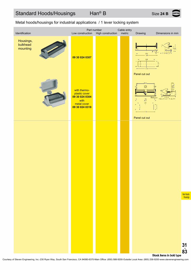
31.83
Han HoodsHousings
Bezeichnung
Niedrige Bauform
Hohe BauformBestell-Nummer Kabelausgang
metrisch Maßzeichnung Maße in mm
09 30 024 0307
09 30 024 0304
09 30 024 0318
Standard Hoods/Housings Han® B Size 24 B
Stock items in bold type
Metal hoods/housings for industrial applications / 1 lever locking system
Identification
Low construction
High constructionPart number Cable entry
metric Drawing Dimensions in mm
Metal hoods/housings for industrial applications / 1 lever locking system
Housings, bulkhead mounting
Panel cut out
with thermo- plastic cover
with
metal cover
Panel cut out
Courtesy of Steven Engineering, Inc.-230 Ryan Way, South San Francisco, CA 94080-6370-Main Office: (650) 588-9200-Outside Local Area: (800) 258-9200-www.stevenengineering.com
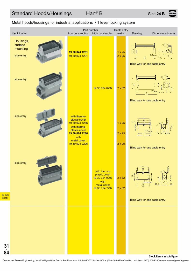
31.84
Han HoodsHousings
19 30 024 1251 1 x 2519 30 024 1291 2 x 25
19 30 024 0292 2 x 32
19 30 024 1256
1 x 25
19 30 024 1296
2 x 25
19 30 024 2296
2 x 25
19 30 024 0297
2 x 32
19 30 024 7297
2 x 32
Standard Hoods/Housings Han® B Size 24 B
Stock items in bold type
Metal hoods/housings for industrial applications / 1 lever locking system
Identification
Low construction
High constructionPart number Cable entry
metric Drawing Dimensions in mm
Housings, surface mounting side entry
Blind way for one cable entry
side entry
Blind way for one cable entry
side entry with thermo-
plastic cover
with thermo- plastic cover
with metal cover
Blind way for one cable entry
side entry
with thermo- plastic cover
with
metal cover
Blind way for one cable entry
Courtesy of Steven Engineering, Inc.-230 Ryan Way, South San Francisco, CA 94080-6370-Main Office: (650) 588-9200-Outside Local Area: (800) 258-9200-www.stevenengineering.com
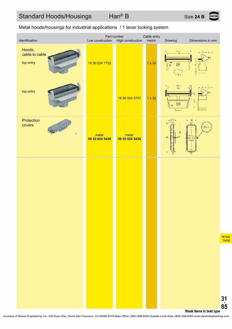
31.85
Han HoodsHousings
19 30 024 1752 1 x 32
19 30 024 0757 1 x 32
09 30 024 5436
09 30 024 5436
Standard Hoods/Housings Han® B Size 24 B
Stock items in bold type
Metal hoods/housings for industrial applications / 1 lever locking system
Identification
Low construction
High constructionPart number Cable entry
metric Drawing Dimensions in mm
Protection covers
metal metal
Hoods, cable to cable top entry
top entry
Courtesy of Steven Engineering, Inc.-230 Ryan Way, South San Francisco, CA 94080-6370-Main Office: (650) 588-9200-Outside Local Area: (800) 258-9200-www.stevenengineering.com

31.86
Han HoodsHousings
19 30 024 1531 1 x 25
19 30 024 0537 1 x 32 19 30 024 0538 1 x 40
19 30 024 1432 1 x 32
19 30 024 0437 1 x 32 19 30 024 0438 1 x 40
09 30 024 5442
09 30 024 5442
Standard Hoods/Housings Han® B Size 24 B
Stock items in bold type
Metal hoods/housings for industrial applications / 2 lever locking system
Identification
Low construction
High constructionPart number Cable entry
metric Drawing Dimensions in mm
Hoods side entry
side entry
Hoods top entry
top entry
Protection covers
metal metal
Courtesy of Steven Engineering, Inc.-230 Ryan Way, South San Francisco, CA 94080-6370-Main Office: (650) 588-9200-Outside Local Area: (800) 258-9200-www.stevenengineering.com
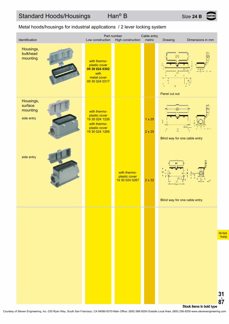
31.87
Han HoodsHousings
Bezeichnung
Niedrige Bauform
Hohe BauformBestell-Nummer Kabelausgang
metrisch Maßzeichnung Maße in mm
09 30 024 0302
09 30 024 0317
19 30 024 1226
1 x 25
19 30 024 1266
2 x 25
19 30 024 0267
2 x 32
Standard Hoods/Housings Han® B Size 24 B
Stock items in bold type
Metal hoods/housings for industrial applications / 2 lever locking system
Identification
Low construction
High constructionPart number Cable entry
metric Drawing Dimensions in mm
Metal hoods/housings for industrial applications / 2 lever locking system
Housings, bulkhead mounting
with thermo- plastic cover
with
metal cover
Panel cut out
Housings, surface mounting side entry
with thermo- plastic cover
with thermo- plastic cover
Blind way for one cable entry
side entry
with thermo- plastic cover
Blind way for one cable entry
Courtesy of Steven Engineering, Inc.-230 Ryan Way, South San Francisco, CA 94080-6370-Main Office: (650) 588-9200-Outside Local Area: (800) 258-9200-www.stevenengineering.com

31.88
Han HoodsHousings
19 30 024 0586 1 x 2519 30 024 0587 1 x 3219 30 024 0588 1 x 40
19 30 024 0487 1 x 32
09 30 024 0381
19 30 024 0282 2 x 32
Standard Hoods/Housings Han® B Size 24 B
Stock items in bold type
Metal hoods/housings for industrial applications / 1 central locking lever locking system
Identification Part numberCable entry
metric Drawing Dimensions in mm
Hoods side entry
Hoods top entry
Metal hoods/housings for industrial applications / 1 central locking lever locking system
Identification Part numberCable entry
metric Drawing Dimensions in mm
Housings, bulkhead mounting
Panel cut out
Housings, surface mounting side entry
Courtesy of Steven Engineering, Inc.-230 Ryan Way, South San Francisco, CA 94080-6370-Main Office: (650) 588-9200-Outside Local Area: (800) 258-9200-www.stevenengineering.com
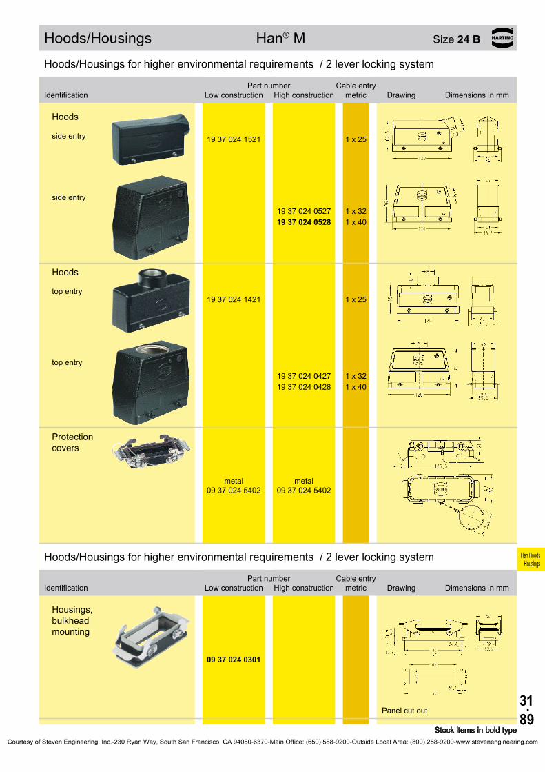
31.89
Han HoodsHousings
19 37 024 1521 1 x 25
19 37 024 0527 1 x 32 19 37 024 0528 1 x 40
19 37 024 1421 1 x 25
19 37 024 0427 1 x 32 19 37 024 0428 1 x 40
09 37 024 5402
09 37 024 5402
09 37 024 0301
Hoods/Housings Han® M Size 24 B
Stock items in bold type
Hoods/Housings for higher environmental requirements / 2 lever locking system
Identification
Low construction
High constructionPart number Cable entry
metric Drawing Dimensions in mm
Hoods side entry
side entry
Hoods top entry
top entry
Protection covers
metal metal
Hoods/Housings for higher environmental requirements / 2 lever locking system
Identification
Low construction
High constructionPart number Cable entry
metric Drawing Dimensions in mm
Housings, bulkhead mounting
Panel cut out
Courtesy of Steven Engineering, Inc.-230 Ryan Way, South San Francisco, CA 94080-6370-Main Office: (650) 588-9200-Outside Local Area: (800) 258-9200-www.stevenengineering.com
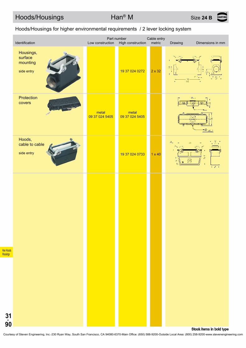
31.90
Han HoodsHousings
19 37 024 0272 2 x 32
09 37 024 5405
09 37 024 5405
19 37 024 0733 1 x 40
Hoods/Housings Han® M Size 24 B
Stock items in bold type
Hoods/Housings for higher environmental requirements / 2 lever locking system
Identification
Low construction
High constructionPart number Cable entry
metric Drawing Dimensions in mm
Housings, surface mounting side entry
Protection covers
metal metal
Hoods, cable to cable side entry
Courtesy of Steven Engineering, Inc.-230 Ryan Way, South San Francisco, CA 94080-6370-Main Office: (650) 588-9200-Outside Local Area: (800) 258-9200-www.stevenengineering.com
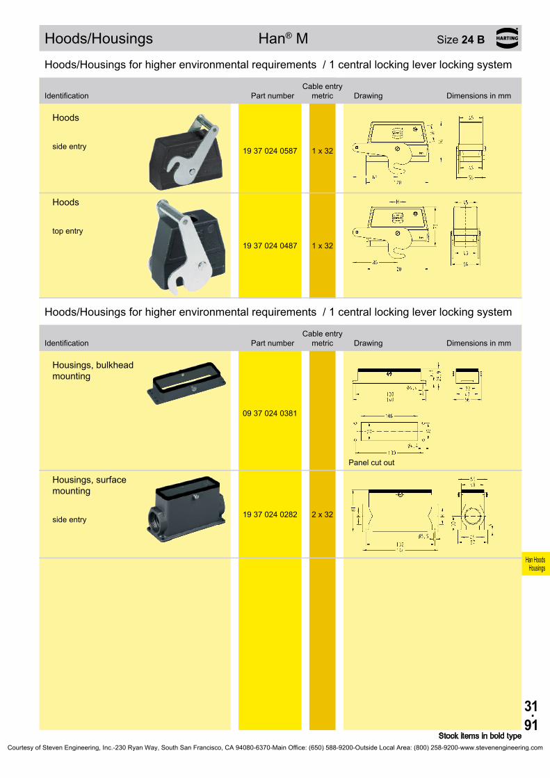
31.91
Han HoodsHousings
19 37 024 0587 1 x 32
19 37 024 0487 1 x 32
09 37 024 0381
19 37 024 0282 2 x 32
Hoods/Housings Han® M Size 24 B
Stock items in bold type
Hoods/Housings for higher environmental requirements / 1 central locking lever locking system
Identification Part numberCable entry
metric Drawing Dimensions in mm
Hoods side entry
Hoods top entry
Hoods/Housings for higher environmental requirements / 1 central locking lever locking system
Identification Part numberCable entry
metric Drawing Dimensions in mm
Housings, bulkhead mounting
Panel cut out
Housings, surface mounting side entry
Courtesy of Steven Engineering, Inc.-230 Ryan Way, South San Francisco, CA 94080-6370-Main Office: (650) 588-9200-Outside Local Area: (800) 258-9200-www.stevenengineering.com
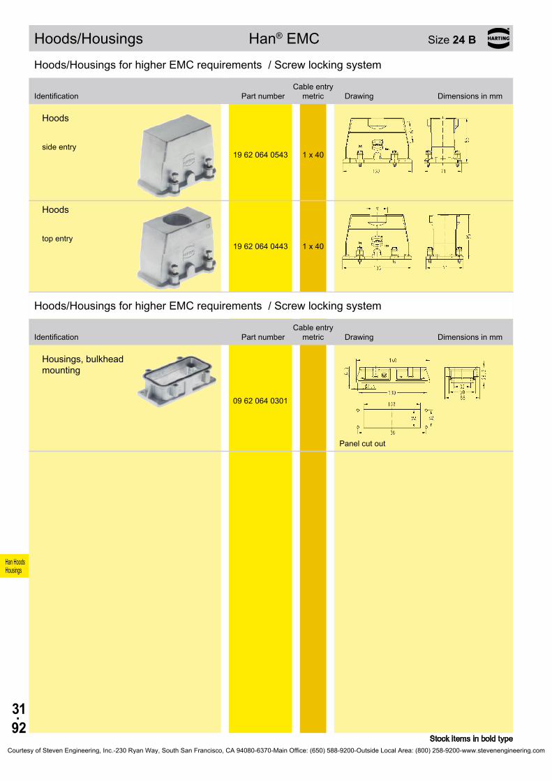
31.92
Han HoodsHousings
19 62 064 0543 1 x 40
19 62 064 0443 1 x 40
09 62 064 0301
Hoods/Housings Han® EMC Size 24 B
Stock items in bold type
Hoods/Housings for higher EMC requirements / Screw locking system
Identification Part numberCable entry
metric Drawing Dimensions in mm
Hoods side entry
Hoods top entry
Hoods/Housings for higher EMC requirements / Screw locking system
Identification Part numberCable entry
metric Drawing Dimensions in mm
Housings, bulkhead mounting
Panel cut out
Courtesy of Steven Engineering, Inc.-230 Ryan Way, South San Francisco, CA 94080-6370-Main Office: (650) 588-9200-Outside Local Area: (800) 258-9200-www.stevenengineering.com

31.93
Han HoodsHousings
19 62 824 1521 1 x 25 19 62 824 0527 1 x 32 19 62 824 0528 1 x 40
19 62 824 1422 1 x 32
19 62 824 0427 1 x 32
09 62 824 0301
19 62 824 1271 2 x 25
19 62 824 0273 2 x 40
Hoods/Housings Han® EMC/B Size 24 B
Stock items in bold type
Hoods/Housings for higher EMC requirements / 2 lever locking system
Identification
Low construction
High constructionPart number Cable entry
metric Drawing Dimensions in mm
Hoods side entry
Hoods top entry
top entry
Hoods/Housings for higher EMC requirements / 2 lever locking system
Identification
Low construction
High constructionPart number Cable entry
metric Drawing Dimensions in mm
Housings, bulkhead mounting
Panel cut out
Housings, surface mounting side entry
side entry
Courtesy of Steven Engineering, Inc.-230 Ryan Way, South San Francisco, CA 94080-6370-Main Office: (650) 588-9200-Outside Local Area: (800) 258-9200-www.stevenengineering.com

31.94
Han HoodsHousings
19 40 024 0503 1 x 40 19 40 024 0512 1 x 32 19 40 024 0513 1 x 40 19 40 024 0514 1 x 50 19 40 024 0537 2 x 32
19 40 024 0402 1 x 32
19 40 024 0412 1 x 32 19 40 024 0413 1 x 40 19 40 024 0414 1 x 50 19 40 024 0431 2 x 25 19 40 024 0432 2 x 32 19 40 024 0433 2 x 40 19 40 024 0461 3 x 25
19 40 024 0419 1 x 50 19 40 024 0467 3 x 32
19 40 024 0410 1 x 63 19 40 024 0420 1 x 63
09 40 024 0811 –
Hoods/Housings Han® HPR Size 24 B
Stock items in bold type
Hoods/Housings for harsh environmental requirements / Screw/toggle locking system
Identification
Toggle locking
screwPart number Cable entry
metric Drawing Dimensions in mm
Hoods side entry
Hoods top entry
top entry
top entry
Hoods without cable entry
Courtesy of Steven Engineering, Inc.-230 Ryan Way, South San Francisco, CA 94080-6370-Main Office: (650) 588-9200-Outside Local Area: (800) 258-9200-www.stevenengineering.com

31.95
Han HoodsHousings
09 40 024 0301 09 40 024 0311
09 40 024 0317
19 40 024 1263 1 x 40 19 40 024 1273 2 x 40
09 40 024 5401
09 40 024 5411
09 40 000 99041)
Hoods/Housings Han® HPR Size 24 B
Stock items in bold type1) not applicable for using Han® HC 650
Hoods/Housings for harsh environmental requirements / Screw/toggle locking system
Identification
Toggle locking
screwPart number Cable entry
metric Drawing Dimensions in mm
Housings, bulkhead mounting
Panel cut out
Housings, bulkhead mounting
with
metal cover
Panel cut out
Housings, surface mounting side entry
Protection covers metal
metal
Mounting frames
Panel cut out
Courtesy of Steven Engineering, Inc.-230 Ryan Way, South San Francisco, CA 94080-6370-Main Office: (650) 588-9200-Outside Local Area: (800) 258-9200-www.stevenengineering.com

31.96
Han HoodsHousings
19 30 032 0527 1 x 3219 30 032 0528 1 x 4019 30 032 0529 1 x 50
19 30 032 0427 1 x 3219 30 032 0428 1 x 4019 30 032 0429 1 x 50
09 30 032 5420
09 30 032 0301
19 30 032 0232 1 x 3219 30 032 0272 2 x 3219 30 032 0273 2 x 40
09 30 032 5425
Standard Hoods/Housings Han® B Size 32 B *
* usable for two inserts of size 16 B Stock items in bold type
Metal hoods/housings for industrial applications / 2 lever locking system
Identification Part numberCable entry
metric Drawing Dimensions in mm
Hoods side entry
Hoods top entry
Protection covers
metal
Metal hoods/housings for industrial applications / 2 lever locking system
Identification Part numberCable entry
metric Drawing Dimensions in mm
Housings, bulkhead mounting
Panel cut out
Housings, surface mounting side entry
Protection covers
metal
Courtesy of Steven Engineering, Inc.-230 Ryan Way, South San Francisco, CA 94080-6370-Main Office: (650) 588-9200-Outside Local Area: (800) 258-9200-www.stevenengineering.com

31.97
Han HoodsHousings
19 30 032 0738 1 x 40
Standard Hoods/Housings Han® B Size 32 B *
* usable for two inserts of size 16 B Stock items in bold type
Metal hoods/housings for industrial applications / 2 lever locking system
Identification Part numberCable entry
metric Drawing Dimensions in mm
Hoods, cable to cable top entry
Courtesy of Steven Engineering, Inc.-230 Ryan Way, South San Francisco, CA 94080-6370-Main Office: (650) 588-9200-Outside Local Area: (800) 258-9200-www.stevenengineering.com
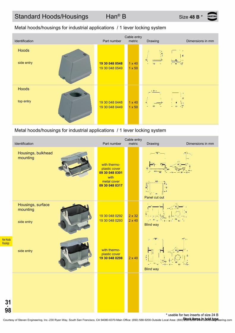
31.98
Han HoodsHousings
19 30 048 0548 1 x 4019 30 048 0549 1 x 50
19 30 048 0448 1 x 4019 30 048 0449 1 x 50
09 30 048 0301
09 30 048 0317
19 30 048 0292 2 x 3219 30 048 0293 2 x 40
19 30 048 0298
2 x 40
Standard Hoods/Housings Han® B Size 48 B *
* usable for two inserts of size 24 B Stock items in bold type
Metal hoods/housings for industrial applications / 1 lever locking system
Identification Part numberCable entry
metric Drawing Dimensions in mm
Hoods side entry
Hoods top entry
Metal hoods/housings for industrial applications / 1 lever locking system
Identification Part numberCable entry
metric Drawing Dimensions in mm
Housings, bulkhead mounting
with thermo- plastic cover
with
metal cover
Panel cut out
Housings, surface mounting side entry
Blind way
side entry with thermo-
plastic cover
Blind way
Courtesy of Steven Engineering, Inc.-230 Ryan Way, South San Francisco, CA 94080-6370-Main Office: (650) 588-9200-Outside Local Area: (800) 258-9200-www.stevenengineering.com
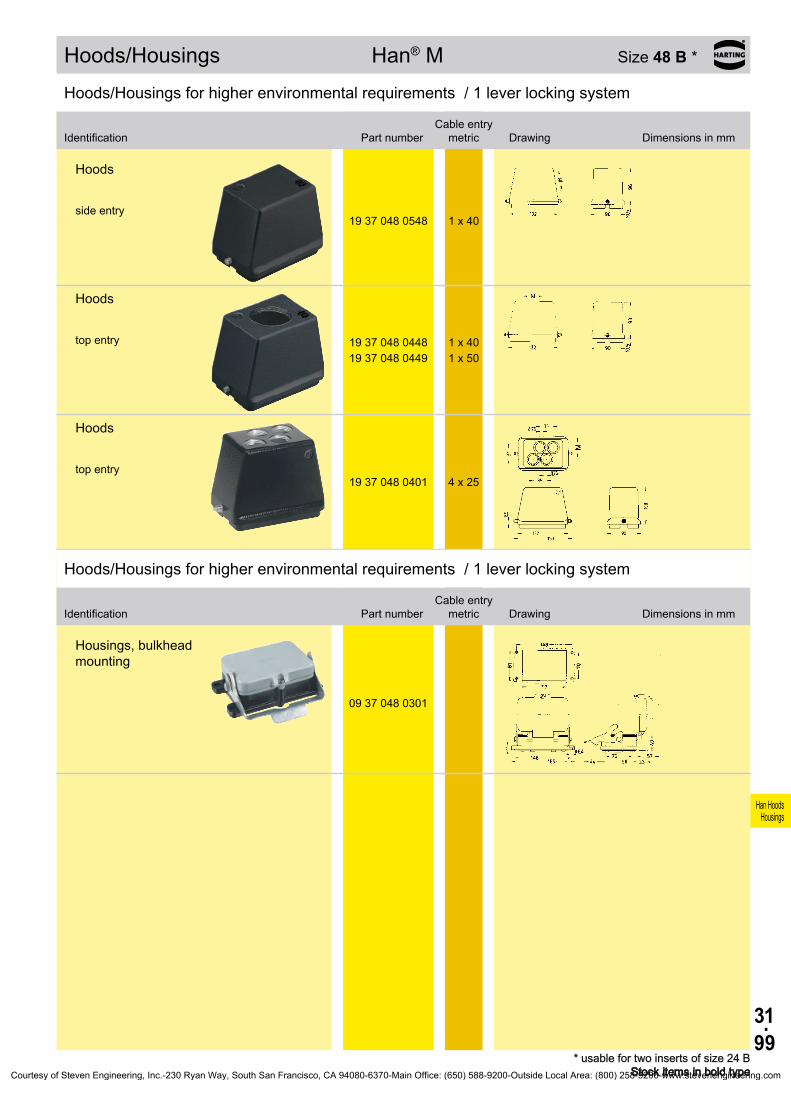
31.99
Han HoodsHousings
19 37 048 0548 1 x 40
19 37 048 0448 1 x 4019 37 048 0449 1 x 50
19 37 048 0401 4 x 25
09 37 048 0301
Hoods/Housings Han® M Size 48 B *
* usable for two inserts of size 24 B Stock items in bold type
Hoods/Housings for higher environmental requirements / 1 lever locking system
Identification Part numberCable entry
metric Drawing Dimensions in mm
Hoods side entry
Hoods top entry
Hoods top entry
Hoods/Housings for higher environmental requirements / 1 lever locking system
Identification Part numberCable entry
metric Drawing Dimensions in mm
Housings, bulkhead mounting
Courtesy of Steven Engineering, Inc.-230 Ryan Way, South San Francisco, CA 94080-6370-Main Office: (650) 588-9200-Outside Local Area: (800) 258-9200-www.stevenengineering.com
31.100
Han HoodsHousings
Notes
Courtesy of Steven Engineering, Inc.-230 Ryan Way, South San Francisco, CA 94080-6370-Main Office: (650) 588-9200-Outside Local Area: (800) 258-9200-www.stevenengineering.com
40.01
Accessories
D-Sub adapter . . . . . . . . . . . . . . . . . . . . . . . . . . . . . . . . . . . . . . . . . . . . . . . 40.02
Han® Split Hood . . . . . . . . . . . . . . . . . . . . . . . . . . . . . . . . . . . . . . . . . . . . . 40.04
Cable entry protection with metric cable entries . . . . . . . . . . . . . . . . . . . . . 40.06
Cable entry protection with Pg cable entries . . . . . . . . . . . . . . . . . . . . . . . . 40.08
Coding for Hoods/Housings and inserts . . . . . . . . . . . . . . . . . . . . . . . . . . 40.11
PE Multiple ground connection . . . . . . . . . . . . . . . . . . . . . . . . . . . . . . . . . . 40.12
Han® Docking frame . . . . . . . . . . . . . . . . . . . . . . . . . . . . . . . . . . . . . . . . . . 40.14
Grip frame . . . . . . . . . . . . . . . . . . . . . . . . . . . . . . . . . . . . . . . . . . . . . . . . . . 40.16
Ground terminal . . . . . . . . . . . . . . . . . . . . . . . . . . . . . . . . . . . . . . . . . . . . . . 40.18
Clamps . . . . . . . . . . . . . . . . . . . . . . . . . . . . . . . . . . . . . . . . . . . . . . . . . . . . 40.19
Special insert fixing screws . . . . . . . . . . . . . . . . . . . . . . . . . . . . . . . . . . . . . 40.21
Screws . . . . . . . . . . . . . . . . . . . . . . . . . . . . . . . . . . . . . . . . . . . . . . . . . . . . . 40.23
Locking levers . . . . . . . . . . . . . . . . . . . . . . . . . . . . . . . . . . . . . . . . . . . . . . . 40.24
Protection covers . . . . . . . . . . . . . . . . . . . . . . . . . . . . . . . . . . . . . . . . . . . . . 40.25
Gaskets, seals . . . . . . . . . . . . . . . . . . . . . . . . . . . . . . . . . . . . . . . . . . . . . . . 40.26
Contents
Accessories
Page
Courtesy of Steven Engineering, Inc.-230 Ryan Way, South San Francisco, CA 94080-6370-Main Office: (650) 588-9200-Outside Local Area: (800) 258-9200-www.stevenengineering.com

40.02
10 A 09 20 000 9932 9
10 A 09 20 000 9928 15
10 A 09 20 000 9929 25 c10 A 1510 A 25
16 A 09 20 000 9931 50
10 A
16 A09 20 000 9925
25
37
Accessories
Plastic adapterfor 1 x D-Sub1)
Size D-Sub c10 A 15 33.310 A 25 47
Range of delivery: 1 adapter 4 fixing srcews for adapter 2 fixing srcews for D-Sub connector
Metal adapterfor 1 x D-Sub1)
Range of delivery: 1 adapter 4 fixing srcews for adapter 2 fixing srcews for D-Sub connector
D-Sub adapters
Stock items in bold type
Number of contacts
9 - 50
D-Sub adapters for Han A® hoods/housings
Identification Size Part numberD-Sub size Drawing Dimensions in mm
1) only for standard D-Sub, not for HD D-SubCourtesy of Steven Engineering, Inc.-230 Ryan Way, South San Francisco, CA 94080-6370-Main Office: (650) 588-9200-Outside Local Area: (800) 258-9200-www.stevenengineering.com
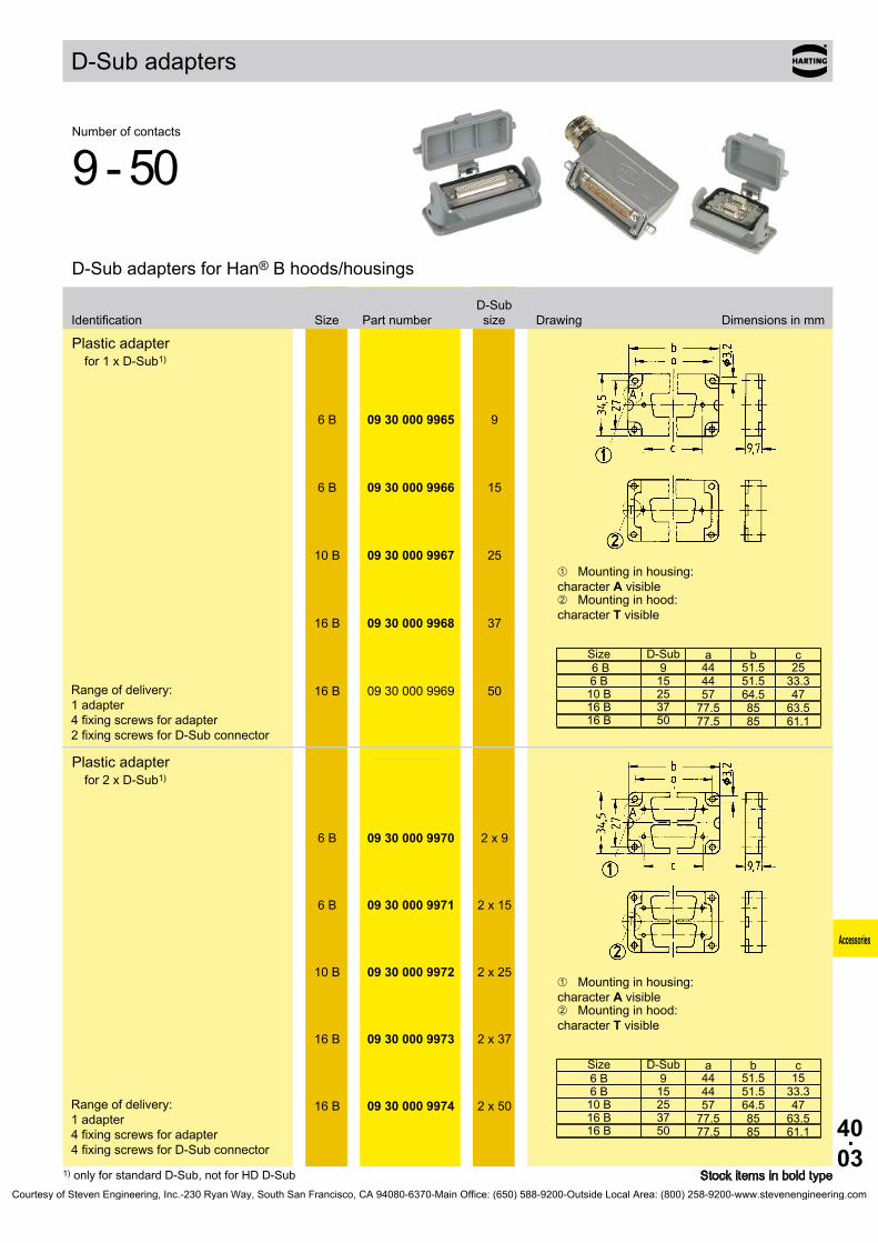
40.03
a b c 6 B 96 B 1510 B 2516 B 3716 B 50
6 B 09 30 000 9965 9
6 B 09 30 000 9966 15
10 B 09 30 000 9967 25
16 B 09 30 000 9968 37
16 B 09 30 000 9969 50
a b c6 B 96 B 1510 B 2516 B 3716 B 50
6 B 09 30 000 9970 2 x 9
6 B 09 30 000 9971 2 x 15
10 B 09 30 000 9972 2 x 25
16 B 09 30 000 9973 2 x 37
16 B 09 30 000 9974 2 x 50
Accessories
Plastic adapterfor 1 x D-Sub1)
➀ Mounting in housing: character A visible➁ Mounting in hood: character T visible
Size D-Sub44 51.5 2544 51.5 33.357 64.5 47
77.5 85 63.577.5 85 61.1
Range of delivery: 1 adapter 4 fixing screws for adapter 2 fixing screws for D-Sub connector
Plastic adapterfor 2 x D-Sub1)
➀ Mounting in housing: character A visible➁ Mounting in hood: character T visible
Size D-Sub44 51.5 1544 51.5 33.357 64.5 47
77.5 85 63.577.5 85 61.1
Range of delivery: 1 adapter 4 fixing screws for adapter 4 fixing screws for D-Sub connector
D-Sub adapters
Stock items in bold type
Number of contacts
9 - 50
D-Sub adapters for Han® B hoods/housings
Identification Size Part numberD-Sub size Drawing Dimensions in mm
1) only for standard D-Sub, not for HD D-SubCourtesy of Steven Engineering, Inc.-230 Ryan Way, South San Francisco, CA 94080-6370-Main Office: (650) 588-9200-Outside Local Area: (800) 258-9200-www.stevenengineering.com
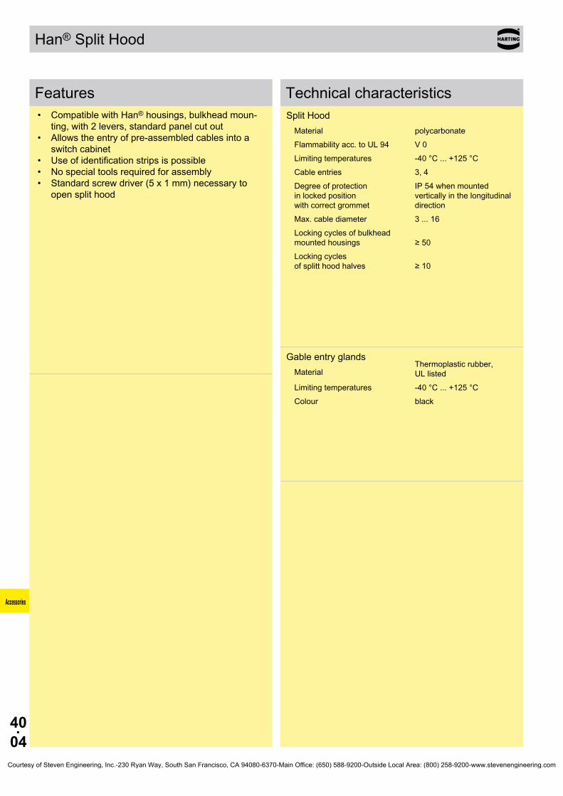
40.04
Accessories
Han® Split Hood
Features• Compatible with Han® housings, bulkhead moun-
ting, with 2 levers, standard panel cut out• Allows the entry of pre-assembled cables into a
switch cabinet• Use of identification strips is possible• No special tools required for assembly• Standard screw driver (5 x 1 mm) necessary to
open split hood
Technical characteristicsSplit Hood
Material polycarbonateFlammability acc. to UL 94 V 0Limiting temperatures -40 °C ... +125 °CCable entries 3, 4Degree of protection in locked position with correct grommet
IP 54 when mounted vertically in the longitudinal direction
Max. cable diameter 3 ... 16Locking cycles of bulkhead mounted housings ≥ 50Locking cycles of splitt hood halves ≥ 10
Gable entry glandsMaterial
Thermoplastic rubber, UL listed
Limiting temperatures -40 °C ... +125 °CColour black
Courtesy of Steven Engineering, Inc.-230 Ryan Way, South San Francisco, CA 94080-6370-Main Office: (650) 588-9200-Outside Local Area: (800) 258-9200-www.stevenengineering.com

40.05
16 B 09 30 016 0408
24 B 09 30 024 0408
3 ... 4 09 00 000 53514 ... 5 09 00 000 53525 ... 6 09 00 000 53536 ... 7 09 00 000 53547 ... 8 09 00 000 53558 ... 9 09 00 000 5356
9 ... 10 09 00 000 5357
10 ... 11 09 00 000 535811 ... 12 09 00 000 535912 ... 13 09 00 000 536013 ... 14 09 00 000 536114 ... 15 09 00 000 536215 ... 16 09 00 000 5363
- 09 00 000 5364
- 09 00 000 5350
- 09 33 000 9982
16 B 09 30 016 0301
24 B 09 30 024 0301a b
16 B 103 113 82 x 3524 B 130 140 108 x 35
Accessories
Split Hood
Range of delivery: 2 split hood halves Cable entry glands order separately
for 3 cable entries
for 4 cable entries
Housings bulkhead mounting
Size Panel cut out
Cable entry glands
from ∅ 10 mm upwards additional strain relief can be provided by cable ties (max. width 8 mm)
for ASI cable
blind grommet
Identification stripsorder separately 20 pieces in one block 9 mm width / 20 mm length
Han® Split Hood
Stock items in bold typeStock items in bold type
with up to 4 cable entries
Identification Size Part number Drawing Dimensions in mm
Identification cable ∅ Part number Drawing Dimensions in mm
Courtesy of Steven Engineering, Inc.-230 Ryan Way, South San Francisco, CA 94080-6370-Main Office: (650) 588-9200-Outside Local Area: (800) 258-9200-www.stevenengineering.com

40.06
SW E Nm
19 00 000 5080 20 22 5 ... 9 mm 1019 00 000 5081 20 22 5 ... 9 mm
6 ... 12 mm10
19 00 000 5082 20 22 6 ... 12 mm 1019 00 000 5084 20 24 10 ... 14 mm 1019 00 000 5090 25 30 9 ... 16 mm 1519 00 000 5091 25 30 9 ... 16 mm
13 ... 18 mm15
19 00 000 5092 25 30 13 ... 18 mm 1519 00 000 5094 32 40 13 ... 20 mm 1519 00 000 5095 32 40 13 ... 20 mm
18 ... 25 mm15
19 00 000 5096 32 40 18 ... 25 mm 1519 00 000 5097 40 50 20 ... 26 mm 2019 00 000 5098 40 50 22 ... 32 mm 2019 00 000 5099 40 50 20 ... 26 mm
22 ... 32 mm20
19 00 000 5086 50 57 32 ... 38 mm 24
19 00 000 5180 20 24 5 ... 9 mm 819 00 000 5182 20 24 6 ... 12 mm 819 00 000 5184 20 27 10 ... 14 mm 1019 00 000 5190 25 33 9 ... 16 mm 1519 00 000 5192 25 33 13 ... 18 mm 1519 00 000 5194 32 42 13 ... 20 mm 1519 00 000 5196 32 42 18 ... 25 mm 1519 00 000 5197 40 53 20 ... 26 mm 1519 00 000 5198 40 53 22 ... 32 mm 15
SW E
19 62 000 5080 20 22
19 62 000 5081 20 22
19 62 000 5082 20 22
19 62 000 5084 20 22
19 62 000 5090 25 22
19 62 000 5092 25 28
19 62 000 5094 32 35
19 62 000 5096 32 35
19 62 000 5097 40 43
19 62 000 5098 40 43
Accessories
Cable entry protection with metric cable entries
Stock items in bold type
Identification Part number M Drawing Dimensions in mm
Cable entry protection with metric cable entries (IP 68)
metal Outer cable ∅
24.424.4
24.426.533.533.5
33.54444
44555555
60
thermoplastic
26.426.429.833.536.546.846.858.858.8
EMC clamp with metric cable entries (IP 68) cable-∅ D shield-∅ B
24.4 6.5 ... 9.5 3.5 ... 8.5
24.4 4 ... 6.5 2.5 ... 6.5
24.4 7 ... 10.5 6.5 ... 10.5
24.4 9 ... 13 6.5 ... 10.5
31.2 6.5 ... 9.5 3 ... 8
31.2 9 ... 13 4.8 ... 8
38.5 11.5 ... 15.5 8 ... 13.5
38.5 14 ... 18 9 ... 14.5
47.3 17 ... 20.5 15 ... 20
47.3 20 ... 25 15 ... 20
Courtesy of Steven Engineering, Inc.-230 Ryan Way, South San Francisco, CA 94080-6370-Main Office: (650) 588-9200-Outside Local Area: (800) 258-9200-www.stevenengineering.com

40.07
SW E
19 00 000 5070 20 22
19 00 000 5071 25 28
19 00 000 5072 32 35
19 00 000 5073 40 44
∅
19 00 000 517219 00 000 5173
3240
D
19 00 000 5060 20 16
19 00 000 5067 32 20
19 00 000 5068 32 25
①②③④
19 20 000 9962 20
①②
③④
Accessories
Cable entry protection with metric cable entries
Stock items in bold type
Identification Part number M Drawing Dimensions in mm
Blanking piece for metric cable entries
metal 25.4
32.3
40.4
50.8
3546.2
Reducers for metric cable entries
metal
Adapter Han® 3 Afor motor connection
sample for mounting:
Han® 3 A housing, bulkhead mountingsealingadapterhousing for motor applications
Courtesy of Steven Engineering, Inc.-230 Ryan Way, South San Francisco, CA 94080-6370-Main Office: (650) 588-9200-Outside Local Area: (800) 258-9200-www.stevenengineering.com

40.08
SW09 62 000 5023 11 20
09 62 000 5024 11 20
09 62 000 5025 11 22
09 62 000 5003 22
09 62 000 5004 22
09 62 000 5005 16 24
09 62 000 5006 16 24
09 62 000 5007 21 30
09 62 000 5008 21 30
09 62 000 5009 29 40
09 62 000 5010 29 40
09 62 000 5011 36 50
09 62 000 5012 36 50
SW09 00 000 5080 11 2009 00 000 5081 11 2009 00 000 5082 11 2009 00 000 5083 2209 00 000 5084 2209 00 000 5085 2209 00 000 5086 16 2409 00 000 5087 16 2409 00 000 5088 16 2409 00 000 5089 16 2409 00 000 5090 21 3009 00 000 5091 21 3009 00 000 5092 21 3009 00 000 5093 21 3009 00 000 5094 29 4009 00 000 5095 29 4009 00 000 5096 29 4009 00 000 5097 29 4009 00 000 5098 36 5009 00 000 5099 36 50
SW
09 00 000 5183 11 21 7 ... 12
09 00 000 5182 11 24 7 ... 12
09 00 000 5153 21 33 13 ... 18
Accessories
EMC clamp with Pg cable entries (IP 68) cable-∅ D shield-∅ B
4 ... 6.5 2.5 ... 6.56.5 ... 8.5 3.5 ... 8.58 ... 10.5 6.5 ... 10.5
13.5 6.5 ... 9.5 2.5 ... 6.5
13.5 9 ... 13 6.5 ... 10.56.5 ... 9.5 3.5 ... 8
9 ... 13 4.5 ... 811.5 ... 15.5 9.5 ... 13.5
14 ... 18 10.5 ... 14.517 ... 20.5 15 ... 2020 ... 25 15 ... 2024 ... 28 18 ... 25.527 ... 32 24 ... 31
Universal cable gland Pg (IP 68)Metal Colour cable-∅ D
grey 5 ... 8black 6.5 ... 9.5green 7 ... 10.5
13.5 black 6.5 ... 9.513.5 green 7 ... 10.513.5 red 9 ... 13
black 6.5 ... 9.5green 7 ... 10.5
red 9 ... 13white 11.5 ... 15.5green 7 ... 10.5
red 9 ... 13white 11.5 ... 15.5blue 14 ... 18blue 14 ... 18
brown 17 ... 21orange 20 ... 25
light yellow 24 ... 28light blue 29 ... 34
pink 32 ... 36
Cable entry protection with Pg cable entries (IP 68) cable-∅ D
Metal
Thermoplastic
Thermoplastic
Cable entry protection with Pg cable entries
Stock items in bold type
Identification Part number Pg Drawing Dimensions in mm
Courtesy of Steven Engineering, Inc.-230 Ryan Way, South San Francisco, CA 94080-6370-Main Office: (650) 588-9200-Outside Local Area: (800) 258-9200-www.stevenengineering.com
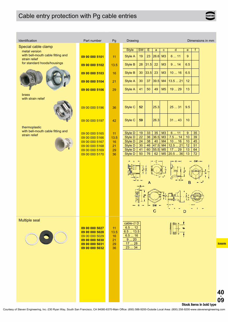
40.09
SW E a c d e f
09 00 000 5101 11 19 M3
09 00 000 5102 28 M3
09 00 000 5103 16 30 M3
09 00 000 5104 21 30 M4
09 00 000 5106 29 41 M5
09 00 000 5196 36 52
09 00 000 5197 42 59
09 00 000 5165 11 19 M309 00 000 5166 22 M309 00 000 5167 16 24 M409 00 000 5168 21 30 M409 00 000 5169 29 41 M509 00 000 5170 36 50 M5
09 00 000 5027 1109 00 000 502809 00 000 5029 1609 00 000 5030 2109 00 000 5031 2909 00 000 5032 36
Accessories
Special cable clampmetal version with bell-mouth cable fitting and strain relief for standard hoods/housings
brass with strain relief
thermoplastic with bell-mouth cable fitting and strain relief
Style
Style A 23 26.6 6 ... 11 9
13.5 Style B 31.5 22 9 ... 14 6.5
Style B 33.5 23 10 ... 16 6.5
Style A 37 39.5 13.5 ... 21 12
Style A 50 49 19 ... 29 13
Style C 52 25.3 25 ... 31 9.5
Style C 59 26.3 31 ... 43 10
Style D 33 35 6 ... 11 9 3513.5 Style D 36 36.5 7.5 ... 14 10 39
Style D 38 40 10 ... 16 10 45Style D 46 47.5 12.5 ... 21 12 51Style D 60 55.5 17 ... 29 13 64Style D 76 62 20.5 ... 36 13 72
Multiple sealcable-∅ D6.5 ... 12
13.5 6.5 ... 13.56.5 ... 169 ... 20
17 ... 2823 ... 34
Cable entry protection with Pg cable entries
Stock items in bold type
Identification Part number Pg Drawing Dimensions in mm
Courtesy of Steven Engineering, Inc.-230 Ryan Way, South San Francisco, CA 94080-6370-Main Office: (650) 588-9200-Outside Local Area: (800) 258-9200-www.stevenengineering.com

40.10
SW
09 00 000 5164
11
19
10 ... 12
09 00 000 5185
11
19
10 ... 12
SW09 00 000 5013 11 1809 00 000 5014 2009 00 000 5015 16 2209 00 000 5016 21 2809 00 000 5017 29 3709 00 000 5018 36 4709 00 000 5019 42 54
Pg1
09 00 000 5050 1109 00 000 505109 00 000 5052 1609 00 000 5053 2109 00 000 5054 2909 00 000 5055 3609 00 000 5056 42
SW Pg109 00 000 5060 11 2009 00 000 5061 11 2009 00 000 5062 2209 00 000 5063 2209 00 000 5064 16 2409 00 000 5065 21 3009 00 000 5066 21 3009 00 000 5067 29 4009 00 000 5068 29 40
SW09 00 000 5070 11 2009 00 000 5071 2209 00 000 5072 16 2409 00 000 5073 21 3009 00 000 5074 29 4009 00 000 5075 36 50
09 20 000 9962
Accessories
Cable gland (IP 65)Thermoplastic with normal seal cable-∅ D
grey
black
Cable gland (IP 65)Metal with multiple seal
cable-∅ D6.5 ... 12
13.5 6.5 ... 13.56.5 ... 169 ... 20
17 ... 2823 ... 3429 ... 40
Increasers for Pg cable entriesMetal
13.513.5 16
2129364248
Reducers for Pg cable entries
Metal79
13.5 913.5 11
13.513.5161621
Blanking piece for Pg cable entries
Metal13.5
Adapter Han® 3 Afor motor connection
see also page 40.07
13.5
Cable entry protection with Pg cable entries
Stock items in bold type
Identification Part number Pg Drawing Dimensions in mm
Courtesy of Steven Engineering, Inc.-230 Ryan Way, South San Francisco, CA 94080-6370-Main Office: (650) 588-9200-Outside Local Area: (800) 258-9200-www.stevenengineering.com
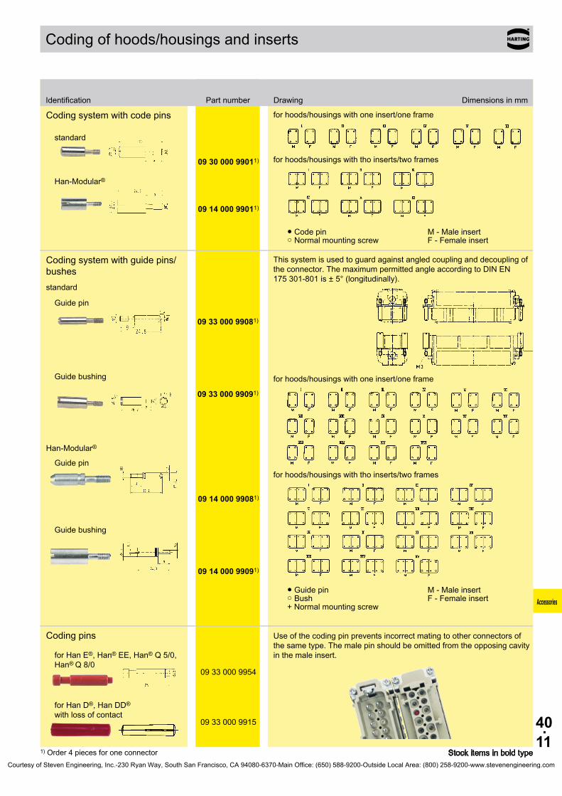
40.11
09 30 000 99011)
09 14 000 99011)
09 33 000 99081)
09 33 000 99091)
09 14 000 99081)
09 14 000 99091)
09 33 000 9954
09 33 000 9915
Accessories
Coding of hoods/housings and inserts
Stock items in bold type
Identification Part number Drawing Dimensions in mm
1) Order 4 pieces for one connector
Coding system with code pins for hoods/housings with one insert/one frame
for hoods/housings with tho inserts/two frames
● Code pin M - Male insert○ Normal mounting screw F - Female insert
standard
Han-Modular®
Coding system with guide pins/bushes
This system is used to guard against angled coupling and decoupling of the connector. The maximum permitted angle according to DIN EN 175 301-801 is ± 5° (longitudinally).
for hoods/housings with one insert/one frame
for hoods/housings with tho inserts/two frames
● Guide pin M - Male insert○ Bush F - Female insert+ Normal mounting screw
standard
Han-Modular®
Guide pin
Guide bushing
Guide pin
Guide bushing
Coding pins Use of the coding pin prevents incorrect mating to other connectors of the same type. The male pin should be omitted from the opposing cavity in the male insert.for Han E®, Han® EE, Han® Q 5/0,
Han® Q 8/0
for Han D®, Han DD®
with loss of contact
Courtesy of Steven Engineering, Inc.-230 Ryan Way, South San Francisco, CA 94080-6370-Main Office: (650) 588-9200-Outside Local Area: (800) 258-9200-www.stevenengineering.com

40.12
Accessories
Han® Accessories - PE Multiple ground connection
Features• 3 PE terminations• Screws with ± head• Self lifting washer• Suitable for use with all inserts of the Han® 6 B to
24 B size (except Han® ESS-inserts)• Suitable in hood high construction
Technical characteristicsTermination points 3Termination wire gauge - mm² 0.5 ... 2.5 mm² - AWG AWG 20 ... 14Material copper alloySurface nickelContact resistance ≤ 3 mΩ
ApplicationsThe PE-multiple ground connection may be used to terminate three PE-wires on one connector. Each PE-wire can be terminated and removed separately (acc. VDE 0113 DIN EN 60204 Pt. 14.1.1).
Courtesy of Steven Engineering, Inc.-230 Ryan Way, South San Francisco, CA 94080-6370-Main Office: (650) 588-9200-Outside Local Area: (800) 258-9200-www.stevenengineering.com

40.13
3 +
09 33 000 9992
Accessories
PE Multiple ground connection
Range of delivery: Multiple ground connection Fixing screw M4 with washer
Han® Accessories
Stock items in bold type
Identification Part number Drawing Dimensions in mm
Courtesy of Steven Engineering, Inc.-230 Ryan Way, South San Francisco, CA 94080-6370-Main Office: (650) 588-9200-Outside Local Area: (800) 258-9200-www.stevenengineering.com

40.14
Accessories
Han® Accessories - Han® Docking frame
Features• Suitable for all inserts of the series Han® B,
Han E®, Han® ES, Han DD®, Han-Com® and Han-Modular®
• Ideal for applications in the field of transportation, as well as in the printing industry
• Due to the floating system of the docking frame the PE connection of the mounting base has to be installed separately
• Inserts are protected against mechanical damage
Technical characteristicsMaterial Docking frame stainless steel Fixing screws steel, zinc-platedPull-in-range x-axis ± 1.5 mm y-axis ± 1.5 mmMechanical working life - mating cycles 500
Courtesy of Steven Engineering, Inc.-230 Ryan Way, South San Francisco, CA 94080-6370-Main Office: (650) 588-9200-Outside Local Area: (800) 258-9200-www.stevenengineering.com

40.15
6 B 09 30 006 1701
10 B 09 30 010 1701
16 B 09 30 016 1701
24 B 09 30 024 1701
a b e f6 B10 B16 B24 B
Accessories
Han® Docking frame
Range of delivery: 1 frame 4 cheese head shoulder screws to fix the docking frame
Distance for electrical and F.O. contacts max. 27 mm; for pneumatic contacts max. 26.5 mm
Size86 69 54.5 8499 82 67.5 97
119.5 102.5 88 117.5146 129 114.5 144
Han® Accessories
Stock items in bold type
Identification Size Part number Drawing Dimensions in mm
Courtesy of Steven Engineering, Inc.-230 Ryan Way, South San Francisco, CA 94080-6370-Main Office: (650) 588-9200-Outside Local Area: (800) 258-9200-www.stevenengineering.com

40.16
Accessories
Han® Accessories - Grip frame
Features• Grip frame suitable for Han® 64 D, Han® 108 DD,
Han® 24 E/ES/ESS, Han® 46 EE• Multiple shield connections via grip frame• Cable can be fixed with clamps or cable tie
Technical characteristicsGrip frame Material metal Surface 8 µm Zn
Adapter Material zinc die-cast Surface 5 µm Ni over 8 µm Cu
ApplicationThe grip frame can be used for termination of several shielded cables to be fixed on one connector.
Courtesy of Steven Engineering, Inc.-230 Ryan Way, South San Francisco, CA 94080-6370-Main Office: (650) 588-9200-Outside Local Area: (800) 258-9200-www.stevenengineering.com

40.17
16 B 09 00 016 5603
24 B 09 00 024 5601
24 B 09 00 024 5611
- 09 00 000 5603
a b6 B10 B16 B24 B
- 09 00 000 5602
Han® 6 B Han® 10 B Han® 16 B Han® 24 Bab
Accessories
Grip frame
Grip frame
with screw adapter and screw to use in connection with 09 00 000 5602
Screw adapterbulkhead mounting
Size65 5278 65
98.5 85.5125 112
Screw adapterbulkhead mounting
to use in connection with 09 00 024 5611
Size44 57 77.5 10435 48 68.5 95
Han® Accessories
Stock items in bold type
Identification Size Part number Drawing Dimensions in mm
Courtesy of Steven Engineering, Inc.-230 Ryan Way, South San Francisco, CA 94080-6370-Main Office: (650) 588-9200-Outside Local Area: (800) 258-9200-www.stevenengineering.com

40.18
6 B 09 00 000 5256
10 B 09 00 000 5257
16 B 09 00 000 5258
24 B 09 00 000 5211
24 B 09 00 000 5298
24 B 09 00 000 5235
Accessories
Ground terminalfor Han-Modular®
in housings bulkhead mounting
Ground terminalfor Han-Modular®
in housings bulkhead mounting and hoods high construction
Ground terminalfor Han-Quintax® in housings bulkhead mounting
Han® Accessories
Stock items in bold type
Identification Size Part number Drawing Dimensions in mm
Courtesy of Steven Engineering, Inc.-230 Ryan Way, South San Francisco, CA 94080-6370-Main Office: (650) 588-9200-Outside Local Area: (800) 258-9200-www.stevenengineering.com

40.19
6 B 09 00 000 5206
10 B 09 00 000 5207
16 B 09 00 000 5208
24 B 09 00 000 5210
24 B 09 00 000 5280
24 B 09 00 000 5209
Accessories
Ground terminalsteel, zinc plated for Han E®, Han® EE and Han DD®
in housings and hoods, high construction and Han-Snap®
Range of delivery: Ground terminal frame with M4 screws for fixing at insert
PE terminalsteel, zinc plated for Han-Modular®
in housings bulkhead mounting and hoods high construction
Han® Accessories
Stock items in bold type
Identification Size Part number Drawing Dimensions in mm
Courtesy of Steven Engineering, Inc.-230 Ryan Way, South San Francisco, CA 94080-6370-Main Office: (650) 588-9200-Outside Local Area: (800) 258-9200-www.stevenengineering.com
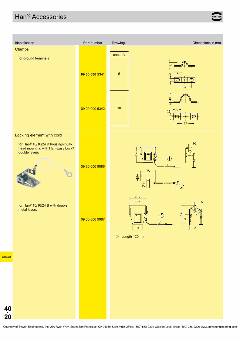
40.20
09 00 000 5341 5
09 00 000 5342 10
09 30 000 9986
09 30 000 9987
Accessories
Clamps for ground terminals
cable ∅
Locking element with cord for Han® 10/16/24 B housings bulk-head mounting with Han-Easy Lock® double levers
for Han® 10/16/24 B with double metal levers
➀ Length 120 mm
Han® Accessories
Identification Part number Drawing Dimensions in mm
Courtesy of Steven Engineering, Inc.-230 Ryan Way, South San Francisco, CA 94080-6370-Main Office: (650) 588-9200-Outside Local Area: (800) 258-9200-www.stevenengineering.com
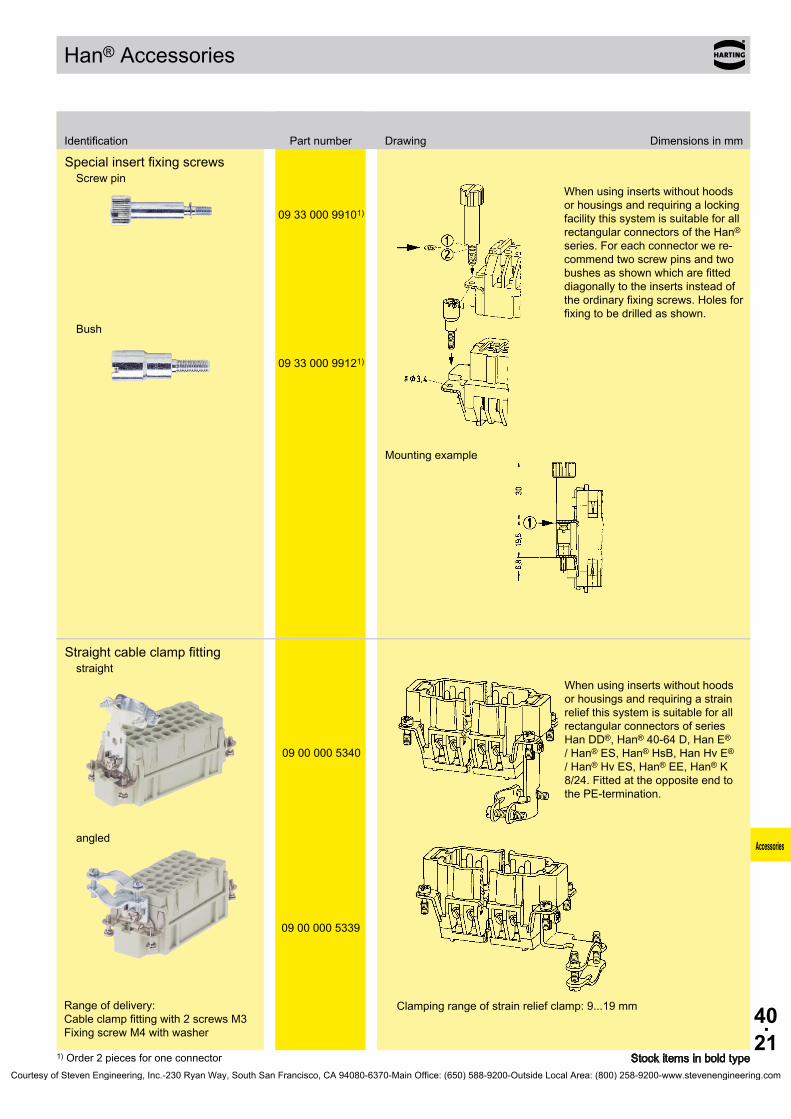
40.21
09 33 000 99101)
09 33 000 99121)
09 00 000 5340
09 00 000 5339
Accessories
Special insert fixing screwsScrew pin
Bush
When using inserts without hoods or housings and requiring a locking facility this system is suitable for all rectangular connectors of the Han® series. For each connector we re-commend two screw pins and two bushes as shown which are fitted diagonally to the inserts instead of the ordinary fixing screws. Holes for fixing to be drilled as shown.
Mounting example
Straight cable clamp fittingstraight
angled
When using inserts without hoods or housings and requiring a strain relief this system is suitable for all rectangular connectors of series Han DD®, Han® 40-64 D, Han E® / Han® ES, Han® HsB, Han Hv E® / Han® Hv ES, Han® EE, Han® K 8/24. Fitted at the opposite end to the PE-termination.
Range of delivery: Cable clamp fitting with 2 screws M3 Fixing screw M4 with washer
Clamping range of strain relief clamp: 9...19 mm
Han® Accessories
Stock items in bold type
Identification Part number Drawing Dimensions in mm
1) Order 2 pieces for one connectorCourtesy of Steven Engineering, Inc.-230 Ryan Way, South San Francisco, CA 94080-6370-Main Office: (650) 588-9200-Outside Local Area: (800) 258-9200-www.stevenengineering.com
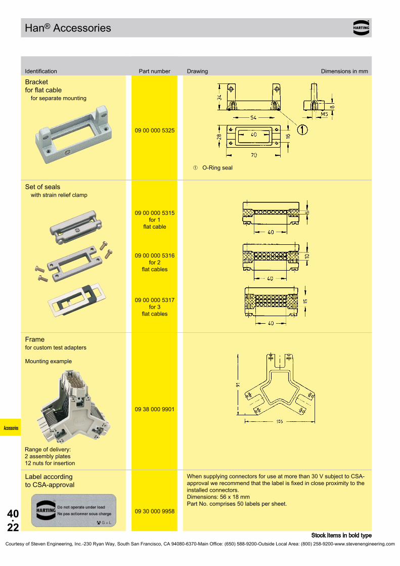
40.22
09 00 000 5325
09 00 000 5315
09 00 000 5316
09 00 000 5317
09 38 000 9901
09 30 000 9958
Accessories
Bracket for flat cable
for separate mounting
➀ O-Ring seal
Set of sealswith strain relief clamp
for 1
flat cable
for 2
flat cables
for 3
flat cables
Framefor custom test adapters Mounting example
Range of delivery: 2 assembly plates 12 nuts for insertion
Label according to CSA-approval
When supplying connectors for use at more than 30 V subject to CSA-approval we recommend that the label is fixed in close proximity to the installed connectors. Dimensions: 56 x 18 mm Part No. comprises 50 labels per sheet.
Han® Accessories
Stock items in bold type
Identification Part number Drawing Dimensions in mm
Courtesy of Steven Engineering, Inc.-230 Ryan Way, South San Francisco, CA 94080-6370-Main Office: (650) 588-9200-Outside Local Area: (800) 258-9200-www.stevenengineering.com

40.23
M3 09 30 000 9997
M3 09 14 000 9953
M4 09 14 000 9954
09 20 000 9919M4 09 33 000 9925M5 09 33 000 9926
M3 09 16 000 9903
M3 09 20 000 9995
M3 09 20 000 9918
09 12 000 9921
M6 09 40 000 9932
M4 09 40 000 9929
M6 09 40 000 9937
- 09 40 000 9931
- 09 40 000 9933
Accessories
Han® Accessories
Stock items in bold type
Identification Size Part number Drawing Dimensions in mm
Contact screw for Han® 3 A, 4 A, Staf®, for PE in Han® Q 5/0, Q 7/0
PE screw
for Han-Modular®
hinged frames
for Han A®, Han® 15, 25 D M3.5for Han E® etc.for Han-Com®, Han® HsB
Fixing screws
standard
for Han® 3 A
for Han® 3 AIP 65/67
for Han-Compact® ST
2.9x9.5 F-H
Locking screwfor Han® HPR
for Han® 6/10/16/24 HPR
for Han® 3 A
for Han® 48 HPR
Toggle locking screwfor Han® HPR
for Han® 6/10/16/24 HPR
for Han® 3 HPR
Courtesy of Steven Engineering, Inc.-230 Ryan Way, South San Francisco, CA 94080-6370-Main Office: (650) 588-9200-Outside Local Area: (800) 258-9200-www.stevenengineering.com

40.24
3 A 09 00 000 5241
3 A 09 00 000 5242
10 A 09 00 000 522416 A 09 00 000 52256 B 09 00 000 5222
10 B 09 00 000 522816 B 09 00 000 522924 B 09 00 000 5230
10/16/ 24 B 09 00 000 5221
32 A 09 00 000 5223
32 B 09 00 000 5231
a b6 B 70 96
10 B 83 10916 B 103 12924 B 130 156
6 B 09 40 000 9921
10 B 09 40 000 9922
16 B 09 40 000 9923
24 B 09 40 000 9924
- 09 30 000 9964
Accessories
Locking leversThermoplastic for Han® 3 A
Han-Easy Lock®
single levers
Han-Easy Lock®
double levers
grey
black
Mounting framesfor standard hoods/housings
Size
Bearing pedestalfor Han® 10 A, 16 A, 32 A, 6 B, 10 B, 16 B, 24 B
-
Han® Accessories
Stock items in bold type
Identification Size Part number Drawing Dimensions in mm
Courtesy of Steven Engineering, Inc.-230 Ryan Way, South San Francisco, CA 94080-6370-Main Office: (650) 588-9200-Outside Local Area: (800) 258-9200-www.stevenengineering.com

40.25
6 B 09 30 006 5403
10 B 09 30 010 5404
16 B 09 30 016 5404
24 B 09 30 024 5404
10 A 09 20 010 541016 A 09 20 016 54106 B 09 30 006 5410
10 B 09 30 010 541016 B 09 30 016 541024 B 09 30 024 5410
a b h10 B16 B24 B3 A6 B 55 29
10 B 55 2916 B 55 2924 B 55 29
10 B 09 30 010 5406
16 B 09 30 016 5406
24 B 09 30 024 5406
3 A 09 40 003 5406
6 B 09 40 006 5406
10 B 09 40 010 5406
16 B 09 40 016 5406
24 B 09 40 024 5406
Accessories
Cover for bearing pedestalMetal
Thermoplastic
Dust protection cover
Size45.2 74.8 1845.2 95.3 1845.2 121.8 1827.8 45.7 12.5
93.2106.2126.2153.2
for Han® B housings
for Han® HPR housings
Han® Accessories
Stock items in bold type
Identification Size Part number Drawing Dimensions in mm
Courtesy of Steven Engineering, Inc.-230 Ryan Way, South San Francisco, CA 94080-6370-Main Office: (650) 588-9200-Outside Local Area: (800) 258-9200-www.stevenengineering.com

40.26
6 B 09 30 000 9936
10 B 09 30 000 9935
16 B 09 30 000 9934
24 B 09 30 000 9933
Modular Compact 09 14 000 9940
3 A 09 20 000 9991 09 37 000 9912
10 A 09 20 000 9992
16 A 09 20 000 9993
32 A 09 20 000 9994
Han-Drive® 09 30 000 9903
6 B 09 30 000 9801 09 37 000 9946
10 B 09 30 000 9802 09 37 000 9947
16 B 09 30 000 9803 09 37 000 9948
24 B 09 30 000 9804 09 37 000 9949
48 B 09 30 000 9996
3 HPR 09 40 000 9980
Accessories
Han® Accessories
Stock items in bold type
Identification Size Material NBR Material FPM
L-sealfor hoods cable to cable
Gasket
Courtesy of Steven Engineering, Inc.-230 Ryan Way, South San Francisco, CA 94080-6370-Main Office: (650) 588-9200-Outside Local Area: (800) 258-9200-www.stevenengineering.com
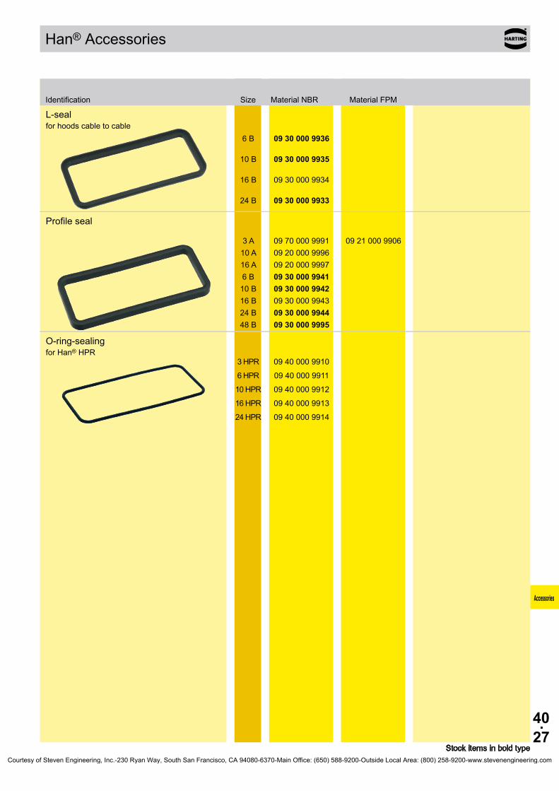
40.27
6 B 09 30 000 9936
10 B 09 30 000 9935
16 B 09 30 000 9934
24 B 09 30 000 9933
3 A 09 70 000 9991 09 21 000 990610 A 09 20 000 999616 A 09 20 000 99976 B 09 30 000 9941
10 B 09 30 000 994216 B 09 30 000 994324 B 09 30 000 994448 B 09 30 000 9995
3 HPR 09 40 000 9910
6 HPR 09 40 000 9911
10 HPR 09 40 000 9912
16 HPR 09 40 000 9913
24 HPR 09 40 000 9914
Accessories
L-sealfor hoods cable to cable
Profile seal
O-ring-sealingfor Han® HPR
Han® Accessories
Stock items in bold type
Identification Size Material NBR Material FPM
Courtesy of Steven Engineering, Inc.-230 Ryan Way, South San Francisco, CA 94080-6370-Main Office: (650) 588-9200-Outside Local Area: (800) 258-9200-www.stevenengineering.com

40.28
Accessories
Notes
Courtesy of Steven Engineering, Inc.-230 Ryan Way, South San Francisco, CA 94080-6370-Main Office: (650) 588-9200-Outside Local Area: (800) 258-9200-www.stevenengineering.com
41.01
Thermo- couple
Contents
Technical characteristics . . . . . . . . . . . . . . . . . . . . . . . . . . . . . . . . . . . . . . . 41.02
Screw terminal . . . . . . . . . . . . . . . . . . . . . . . . . . . . . . . . . . . . . . . . . . . . . . . 41.03
Crimp termination Han E® . . . . . . . . . . . . . . . . . . . . . . . . . . . . . . . . . . . . . . 41.04
Crimp termination Han D® . . . . . . . . . . . . . . . . . . . . . . . . . . . . . . . . . . . . . . 41.05
Page
Han® Thermocouple
Courtesy of Steven Engineering, Inc.-230 Ryan Way, South San Francisco, CA 94080-6370-Main Office: (650) 588-9200-Outside Local Area: (800) 258-9200-www.stevenengineering.com
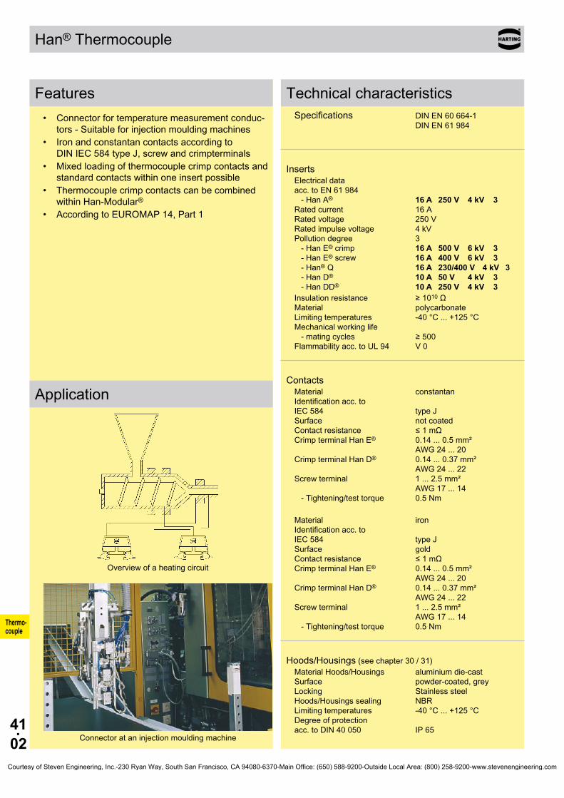
41.02
Han® Thermocouple
Thermo- couple
Features• Connectorfortemperaturemeasurementconduc-
tors-Suitableforinjectionmouldingmachines• Ironandconstantancontactsaccordingto
DINIEC584typeJ,screwandcrimpterminals• Mixedloadingofthermocouplecrimpcontactsand
standardcontactswithinoneinsertpossible• Thermocouplecrimpcontactscanbecombined
withinHan-Modular®• AccordingtoEUROMAP14,Part1
Application
Overviewofaheatingcircuit
Connectorataninjectionmouldingmachine
Technical characteristicsSpecifications DINEN60664-1 DINEN61984
InsertsElectricaldata acc.toEN61984 -HanA® 16 A 250 V 4 kV 3 Ratedcurrent 16A Ratedvoltage 250V Ratedimpulsevoltage 4kV Pollutiondegree 3 -HanE® crimp 16 A 500 V 6 kV 3 -HanE®screw 16 A 400 V 6 kV 3 - Han® Q 16 A 230/400 V 4 kV 3 - Han D® 10 A 50 V 4 kV 3 - Han DD® 10 A 250 V 4 kV 3Insulationresistance ≥1010Ω Material polycarbonate Limitingtemperatures -40°C...+125°C Mechanicalworkinglife -matingcycles ≥500 Flammabilityacc.toUL94 V0
ContactsMaterial constantan Identificationacc.to IEC584 typeJ Surface notcoated Contactresistance ≤1mΩ CrimpterminalHanE® 0.14...0.5mm² AWG24...20 Crimp terminal Han D® 0.14...0.37mm² AWG24...22 Screwterminal 1...2.5mm² AWG17...14 -Tightening/testtorque 0.5Nm
Material iron Identificationacc.to IEC584 typeJ Surface gold Contactresistance ≤1mΩ CrimpterminalHanE® 0.14...0.5mm² AWG24...20 Crimp terminal Han D® 0.14...0.37mm² AWG24...22 Screwterminal 1...2.5mm² AWG17...14 -Tightening/testtorque 0.5Nm
Hoods/Housings(seechapter30/31)MaterialHoods/Housings aluminiumdie-cast Surface powder-coated,grey Locking Stainlesssteel Hoods/Housingssealing NBR Limitingtemperatures -40°C...+125°C Degreeofprotection acc.toDIN40050 IP65
Courtesy of Steven Engineering, Inc.-230 Ryan Way, South San Francisco, CA 94080-6370-Main Office: (650) 588-9200-Outside Local Area: (800) 258-9200-www.stevenengineering.com

41.03
Han® Thermocouple
Han A® 16 A 09 20 016 2691 09 20 016 2891
Han E®
10 E 16 E 24 E
09 33 010 2691 09 33 016 2691 09 33 024 2691
09 33 010 2791 09 33 016 2791 09 33 024 2791
Han E®
24 E 09 33 024 2689 09 33 024 2789
Thermo- couple
StockitemsinboldtypeDimensionsforinsertsseechapterofcorrespondingseries
Partnumber Contactarrangement Identification Series Maleinsert(M) Femaleinsert(F) viewterminationside Dimensionsinmm
Screwterminal
Contacts Fe ContactsCuNi
Screwterminalwithwireprotection
Contacts Fe ContactsCuNi
Screwterminalwithwireprotection
Standardcontacts Contacts Fe ContactsCuNi
Courtesy of Steven Engineering, Inc.-230 Ryan Way, South San Francisco, CA 94080-6370-Main Office: (650) 588-9200-Outside Local Area: (800) 258-9200-www.stevenengineering.com

41.04
Han® Thermocouple
Han E®
6 E 10 E 16 E 24 E
09 33 006 2602 09 33 010 2602 09 33 016 2602 09 33 024 2602
09 33 006 2702 09 33 010 2702 09 33 016 2702 09 33 024 2702
Han® Q09 12 005 3001 09 12 005 3101
Han A® 10 A 16 A
09 20 010 3001 09 20 016 3001
09 20 010 3101 09 20 016 3101
09 33 000 6163 09 33 000 6162
09 33 000 6263 09 33 000 6262
09 33 000 6173 09 33 000 6172
09 33 000 6273 09 33 000 6272
09 33 000 6121 09 33 000 6114 09 33 000 6105 09 33 000 6104 09 33 000 6102 09 33 000 6107
09 33 000 6220 09 33 000 6214 09 33 000 6205 09 33 000 6204 09 33 000 6202 09 33 000 6207
Thermo- couple
StockitemsinboldtypeDimensionsforinsertsseechapterofcorrespondingseries
Partnumber Contactarrangement Identification Series Maleinsert(M) Femaleinsert(F) viewterminationside Dimensionsinmm
Crimp terminalOrdercrimpcontactsseparately
Crimp terminalOrdercrimpcontactsseparately
Crimp terminalOrdercrimpcontactsseparately
Wiregauge Partnumber Identification (mm²) Malecontact Femalecontact Drawing Dimensionsinmm
Crimp contactsHanE®
Constantan 0.14-0.37
0.5
Iron;goldplated 0.14-0.37
0.5
Standardcontacts; silverplated
0.5 0.75
1 1.5 2.5 4
Courtesy of Steven Engineering, Inc.-230 Ryan Way, South San Francisco, CA 94080-6370-Main Office: (650) 588-9200-Outside Local Area: (800) 258-9200-www.stevenengineering.com

41.05
Han® Thermocouple
Han D®
8 D 09 36 008 3001 09 36 008 3101
Han DD®
24 DD 42 DD 72 DD 108 DD
09 16 024 3001 09 16 042 3001 09 16 072 3001 09 16 108 3001
09 16 024 3101 09 16 042 3101 09 16 072 3101 09 16 108 3101
09 15 000 6161 09 15 000 6261
09 15 000 6171 09 15 000 6271
09 15 000 6104 09 15 000 6103 09 15 000 6105 09 15 000 6102 09 15 000 6101 09 15 000 6106
09 15 000 6204 09 15 000 6203 09 15 000 6205 09 15 000 6202 09 15 000 6201 09 15 000 6206
Thermo- couple
StockitemsinboldtypeDimensionsforinsertsseechapterofcorrespondingseries
Partnumber Contactarrangement Identification Series Maleinsert(M) Femaleinsert(F) viewterminationside Dimensionsinmm
Crimp terminalOrdercrimpcontactsseparately
Crimp terminalOrdercrimpcontactsseparately
Wiregauge Partnumber Identification (mm²) Malecontact Femalecontact Drawing Dimensionsinmm
Crimp contacts Han D®
Constantan 0.14-0.37
Iron;goldplated 0.14-0.37
Standardcontacts; silverplated
0.14-0.37 0.5
0.75 1
1.5 2.5
Courtesy of Steven Engineering, Inc.-230 Ryan Way, South San Francisco, CA 94080-6370-Main Office: (650) 588-9200-Outside Local Area: (800) 258-9200-www.stevenengineering.com

41.06
Thermo- couple
Notes
Courtesy of Steven Engineering, Inc.-230 Ryan Way, South San Francisco, CA 94080-6370-Main Office: (650) 588-9200-Outside Local Area: (800) 258-9200-www.stevenengineering.com
99.01
Tools
Contents
Tools
Page
Tools for contacts Han D ® . . . . . . . . . . . . . . . . . . . . . . . . . . . . . . . . . . . . . . 99.02
Tools for contacts Han E ® . . . . . . . . . . . . . . . . . . . . . . . . . . . . . . . . . . . . . . 99.04
Tools for contacts Han ® C . . . . . . . . . . . . . . . . . . . . . . . . . . . . . . . . . . . . . . 99.06
Tools for other contacts . . . . . . . . . . . . . . . . . . . . . . . . . . . . . . . . . . . . . . . . 99.08
Tools for FOC contacts . . . . . . . . . . . . . . . . . . . . . . . . . . . . . . . . . . . . . . . . . 99.10
Tools for Han ® high current contacts . . . . . . . . . . . . . . . . . . . . . . . . . . . . . . 99.12
Summary Han ® Crimping tools . . . . . . . . . . . . . . . . . . . . . . . . . . . . . . . . . . 99.14
Crimping machine TK . . . . . . . . . . . . . . . . . . . . . . . . . . . . . . . . . . . . . . . . . . 99.16
Crimping machine TC-C01 . . . . . . . . . . . . . . . . . . . . . . . . . . . . . . . . . . . . . . 99.18
Courtesy of Steven Engineering, Inc.-230 Ryan Way, South San Francisco, CA 94080-6370-Main Office: (650) 588-9200-Outside Local Area: (800) 258-9200-www.stevenengineering.com

99.02
09 99 000 0021
09 99 000 0001
09 99 000 0311
09 99 000 0379
mm² Ømm² Ømm² Ømm² Ømm² Ømm² Ø
09 99 000 0110
09 99 000 0810
09 99 000 0813
09 99 000 0811
09 99 000 0812
Tools
Tools for contacts Han D® (09 15 ...)
Identification Partnumber Drawing Dimensionsinmm
Stockitemsinboldtype1)Forwiregauge0.14and0.25mm²useonlymalecontact09150006107orfemalecontact09150006207.
HARTINGServicecrimpingtoolwithlocator set for Han D®, Han E® WiregaugeHanD®
0.14...1.5mm²
BUCHANANcrimpingtool
Wiregauge 0.14...2.5mm²
Locator Han D®
Multiplecrimpingtool depthadjustmentgauge
Wiregauge0.14 1.001)
0.25 1.001)
0.37 1.300.5 ... 1.0 1.551.5 1.802.5 1.55
HARTINGcrimpingtoolwithlocator for Han D®, Han E®, Han® C WiregaugeHanD®
0.14...1.5mm²
HARTINGPneumaticcrimpingtool CP600
CrimpdieHanD®, Han E®, Han® C WiregaugeHanD® 0.14...1.5mm²
Footswitch
Tablefixing
Courtesy of Steven Engineering, Inc.-230 Ryan Way, South San Francisco, CA 94080-6370-Main Office: (650) 588-9200-Outside Local Area: (800) 258-9200-www.stevenengineering.com
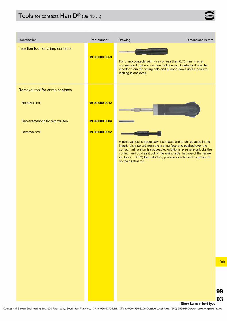
99.03
09 99 000 0059
09 99 000 0012
09 99 000 0004
09 99 000 0052
Tools
Tools for contacts Han D® (09 15 ...)
Identification Partnumber Drawing Dimensionsinmm
Stockitemsinboldtype
Insertiontoolforcrimpcontacts
Forcrimpcontactswithwiresoflessthan0.75mm²itisre-commendedthataninsertiontoolisused.Contactsshouldbeinsertedfromthewiringsideandpusheddownuntilapositivelockingisachieved.
Removaltoolforcrimpcontacts
Removal tool
Replacement-tipforremovaltool
Removal tool
Aremovaltoolisnecessaryifcontactsaretobereplacedintheinsert.Itisinsertedfromthematingfaceandpushedoverthecontactuntilastopisnoticeable.Additionalpressureunlocksthecontactandpushesitoutofthewiringside.Incaseoftheremo-valtool(..0052)theunlockingprocessisachievedbypressureonthecentralrod.
Courtesy of Steven Engineering, Inc.-230 Ryan Way, South San Francisco, CA 94080-6370-Main Office: (650) 588-9200-Outside Local Area: (800) 258-9200-www.stevenengineering.com
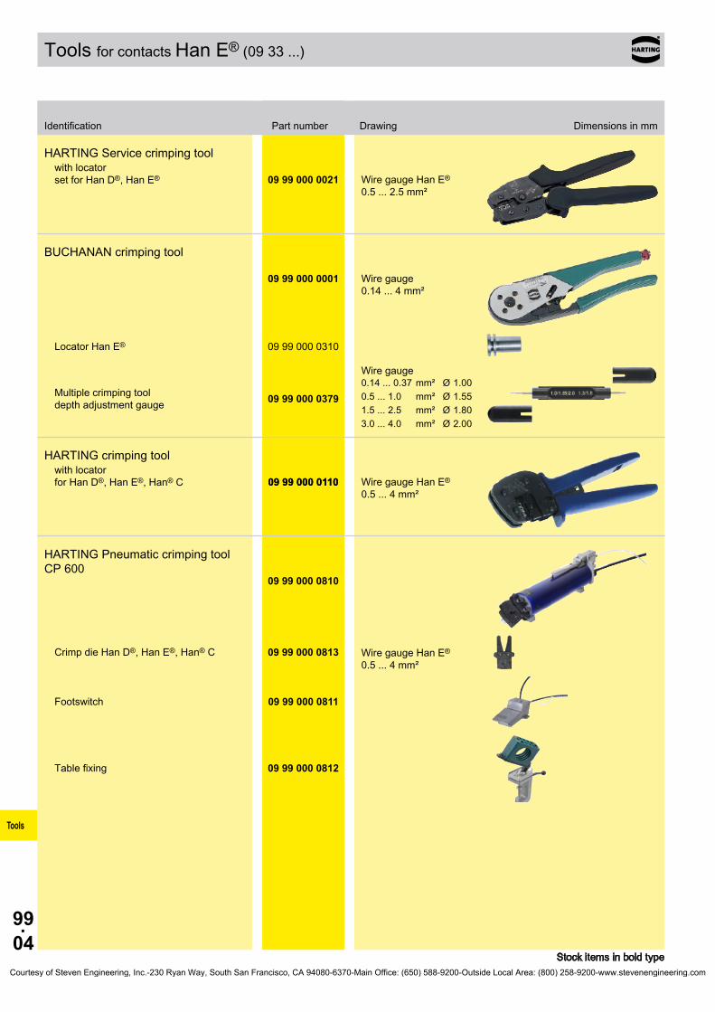
99.04
09 99 000 0021
09 99 000 0001
09 99 000 0310
09 99 000 0379
mm² Ømm² Ømm² Ømm² Ø
09 99 000 0110
09 99 000 0810
09 99 000 0813
09 99 000 0811
09 99 000 0812
Tools
Tools for contacts Han E® (09 33 ...)
Identification Partnumber Drawing Dimensionsinmm
Stockitemsinboldtype
HARTINGServicecrimpingtoolwithlocator set for Han D®, Han E® WiregaugeHanE®
0.5...2.5mm²
BUCHANANcrimpingtool
Wiregauge 0.14...4mm²
Locator Han E®
Multiplecrimpingtool depthadjustmentgauge
Wiregauge0.14...0.37 1.000.5 ... 1.0 1.551.5...2.5 1.803.0...4.0 2.00
HARTINGcrimpingtoolwithlocator for Han D®, Han E®, Han® C 09 99 000 0110 WiregaugeHanE®
0.5...4mm²
HARTINGPneumaticcrimpingtool CP600
CrimpdieHanD®, Han E®, Han® C WiregaugeHanE® 0.5...4mm²
Footswitch
Tablefixing
Courtesy of Steven Engineering, Inc.-230 Ryan Way, South San Francisco, CA 94080-6370-Main Office: (650) 588-9200-Outside Local Area: (800) 258-9200-www.stevenengineering.com

99.05
09 99 000 0059
09 99 000 0367
09 99 000 0319
Tools
Tools for contacts Han E® (09 33 ...)
Identification Partnumber Drawing Dimensionsinmm
Stockitemsinboldtype
Insertiontoolforcrimpcontacts
Forcrimpcontactswithwiresoflessthan0.75mm²itisre-commendedthataninsertiontoolisused.Contactsshouldbeinsertedfromthewiringsideandpusheddownuntilapositivelockingisachieved.
Insertion tool for Han® ES inserts
Removaltoolforcrimpcontactsfor Han® EE, Han® Q 5/0, Han® Q 8/0, Han E® and Han A®
Aremovaltoolisnecessaryifcontactsaretobereplacedintheinsert.Thetoolisinsertedfromthewiringsideuntilastopisnoticeable.Thewirewiththecrimpcontactcanthenbepulledoutfromthesamesideoftheinsert.
Courtesy of Steven Engineering, Inc.-230 Ryan Way, South San Francisco, CA 94080-6370-Main Office: (650) 588-9200-Outside Local Area: (800) 258-9200-www.stevenengineering.com
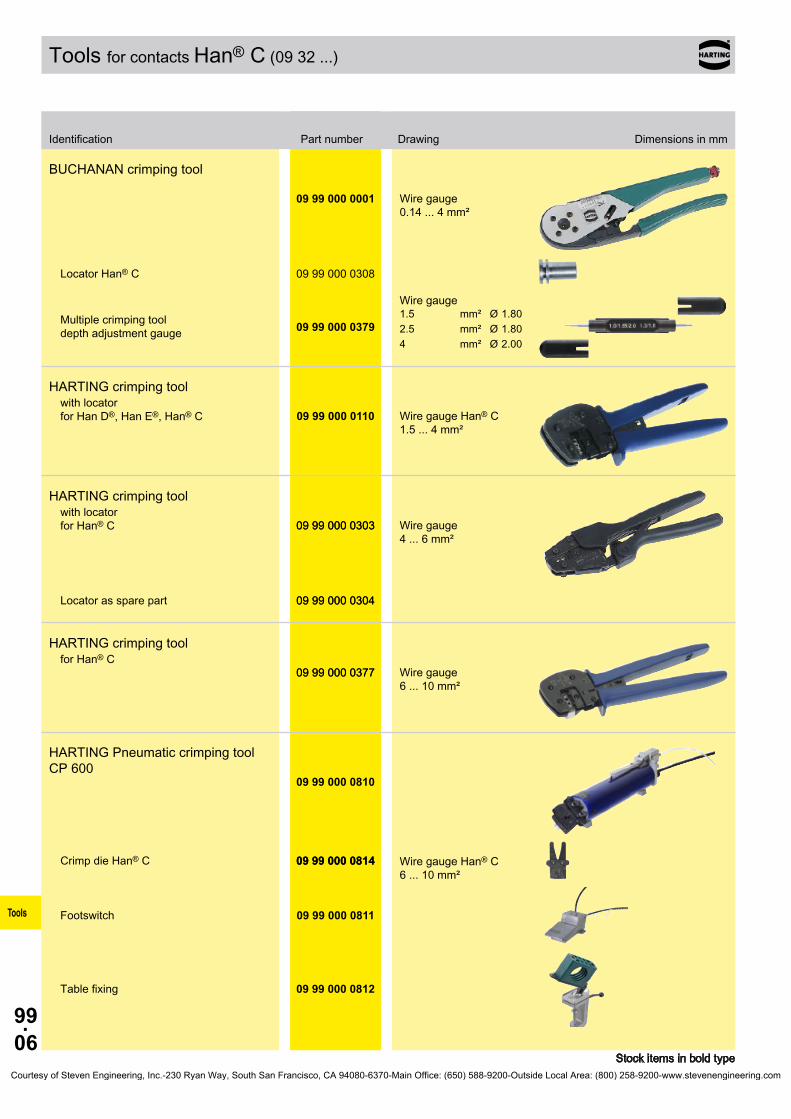
99.06
09 99 000 0001
09 99 000 0308
09 99 000 0379
mm² Ømm² Ømm² Ø
09 99 000 0110
09 99 000 0303
09 99 000 0304
09 99 000 0377
09 99 000 0810
09 99 000 0814
09 99 000 0811
09 99 000 0812
Tools
Tools for contacts Han® C(0932...)
Identification Partnumber Drawing Dimensionsinmm
Stockitemsinboldtype
BUCHANANcrimpingtool
Wiregauge 0.14...4mm²
Locator Han® C
Multiplecrimpingtool depthadjustmentgauge
Wiregauge1.5 1.802.5 1.804 2.00
HARTINGcrimpingtoolwithlocator for Han D®, Han E®, Han® C WiregaugeHan® C
1.5...4mm²
HARTINGcrimpingtoolwithlocator for Han® C 09 99 000 0303 Wiregauge
4...6mm²
Locatorassparepart 09 99 000 0304
HARTINGcrimpingtoolfor Han® C
09 99 000 0377 Wiregauge 6...10mm²
HARTINGPneumaticcrimpingtool CP600
CrimpdieHan® C 09 99 000 0814 WiregaugeHan® C 6...10mm²
Footswitch
Tablefixing
Courtesy of Steven Engineering, Inc.-230 Ryan Way, South San Francisco, CA 94080-6370-Main Office: (650) 588-9200-Outside Local Area: (800) 258-9200-www.stevenengineering.com

99.07
09 99 000 030509 99 000 0381
Tools
Tools for contacts Han® C(0932...)
Identification Partnumber Drawing Dimensionsinmm
Stockitemsinboldtype
Removaltoolforcrimpcontacts
Aremovaltoolisnecessarytoremovethecontacts.Foreach„C“contactcavity,thelocationoftheinternallockingleversaremarkedonthewiringsidewithtwoblackarcs.Thesidesofthetoolmustbefirstproperlyalignedsothattheedgesofthetoolengagebothleverssimultaneouslyandtheninserteduntilastopisnoticeable➀.Onceithasbeeninserted,thetoolmustnotbeturned.Thewiretogetherwiththetoolcanthenbepulledoutfromthewiringsideoftheinsert➁.
a...levermarking
Removal tool1.5...6mm²
10 mm²
Courtesy of Steven Engineering, Inc.-230 Ryan Way, South San Francisco, CA 94080-6370-Main Office: (650) 588-9200-Outside Local Area: (800) 258-9200-www.stevenengineering.com

99.08
09 99 000 0194
09 99 000 0374
09 99 000 0327
09 99 000 0323
09 99 000 0159
09 99 000 0328
09 99 000 0368
Tools
Tools for othercontacts
Identification Partnumber Drawing Dimensionsinmm
Stockitemsinboldtype
HARTINGcrimpingtoolforcoaxialcontacts
Usethemiddlecrimpingposition.
HARTINGcrimpingtoolforwireendferrules10mm²
Removal toolsfor contacts inthemulti-contactmodule
Insertion / removal toolforD-Subcrimpcontacts
Removal toolsforlockingsleeves intheHVmodule
Removal toolsforQuintaxcontact
Strippingtool
Forstrandedfinewiresandsolidwires0.08upto10mm²
Courtesy of Steven Engineering, Inc.-230 Ryan Way, South San Francisco, CA 94080-6370-Main Office: (650) 588-9200-Outside Local Area: (800) 258-9200-www.stevenengineering.com

99.09
09 99 000 0313
09 99 000 0363
09 99 000 0364
09 99 000 0365
09 99 000 0369
09 99 000 0375
09 99 000 0370
09 99 000 0371
09 99 000 0372
Tools
Tools for othercontacts
Identification Partnumber Drawing Dimensionsinmm
Stockitemsinboldtype
Hexagonaldriverforaxialscrew
withgrip40Acontacts(SW2)100Acontacts(SW4)
200+350Acontacts(SW5)650Acontacts(SW8)
Bit1/4“40Acontacts(SW2)
70Acontacts(SW2.5)
adapter3/8“100Acontacts(SW4)
200+350Acontacts(SW5)650Acontacts(SW8)
Courtesy of Steven Engineering, Inc.-230 Ryan Way, South San Francisco, CA 94080-6370-Main Office: (650) 588-9200-Outside Local Area: (800) 258-9200-www.stevenengineering.com

99.10
20 99 000 1092
20 99 000 1093
20 99 000 1041
20 99 000 104520 99 000 1046
20 99 000 1035
20 99 000 1033
20 99 000 1031
20 80 001 9902
Tools
Tools forF.O.contactshingedframes
Identification Partnumber Drawing Dimensionsinmm
Stockitemsinboldtype1)POF=Polymeropticalfibre
Polishingtool
DIN41626
POF1)cable∅2.2
Fibrestripper
0.3 mm1 mm0.18 / 0.3 mm
Crimpingtoolforfollowing1mmPOF1) contactsHan D®, Han E® DIN41626 Ferrule F-SMA, -ST
HARTINGcrimpingtoolforF.O.connector(glassfibre)SW4.3mm SW 3.8 mm SW4.95mm
forcrimpingthestrainrelieftotheconnector F.O.cableforglassfibre
HARTINGcrimpingtoolforF.O.connector(plasticfibre)SW6.95mm SW4.95mm SW 3.0 mm
forcrimpingthestrainrelieftotheconnector F.O.cableforglassfibre
Epoxyadhesiveglassfibre 2mlEPO-TEK360withhardener(10:1),4gfoilpack
Courtesy of Steven Engineering, Inc.-230 Ryan Way, South San Francisco, CA 94080-6370-Main Office: (650) 588-9200-Outside Local Area: (800) 258-9200-www.stevenengineering.com

99.11
20 80 001 991120 80 001 9912
20 80 001 9913
Tools
Tools forF.O.contactshingedframes
Identification Partnumber Drawing Dimensionsinmm
Stockitemsinboldtype1)POF=Polymeropticalfibre
PolishingpaperRangeofdelivery Eachpartnumbermeans5pieces.
forPOF1)grainsize1000forGI9µ-grainsizeforGI1µ-grainsize
Courtesy of Steven Engineering, Inc.-230 Ryan Way, South San Francisco, CA 94080-6370-Main Office: (650) 588-9200-Outside Local Area: (800) 258-9200-www.stevenengineering.com

99.12
09 99 000 0385
09 99 000 0389
09 99 000 039809 99 000 038609 99 000 038709 99 000 038809 99 000 039109 99 000 039209 99 000 039309 99 000 0394
a b c d
09 99 000 0398 10 mm² B6DIN 8 1309990000386 16mm² B8 DIN 8 1309990000387 25mm² B10 DIN 10 1309 99 000 0388 35 mm² B12DIN 10 1309 99 000 0391 50 mm² B14DIN 10 1309990000392 70mm² B16DIN 13 1309 99 000 0393 95 mm² B18 DIN 15 1509990000394 120mm² B20DIN 15 15
09 99 000 0801
Tools
Tools for Han®highcurrentcontacts
Identification Partnumber Drawing Dimensionsinmm
Stockitemsinboldtype
HARTINGcrimpingtoolHydraulichandtool;Pressingforce:130kN
•fastforwardaction •storagebox •weight:6.4kg •Length:620mm
Dieholder
CrimpdiesDIN46235(suppliedasapair)usein combinationwithdieholder
Partnumber Wiregauge acc. to DIN46235
5.5 2.18 3.210 3.812 4.714 5.516 618 7.320 8
CrimpdieWiregauge240mm²
C...Crimpzoneacc.toEN46235 2crimps
Courtesy of Steven Engineering, Inc.-230 Ryan Way, South San Francisco, CA 94080-6370-Main Office: (650) 588-9200-Outside Local Area: (800) 258-9200-www.stevenengineering.com
99.13
09 99 000 0383
Tools
Tools for Han®highcurrentcontacts
Identification Partnumber Drawing Dimensionsinmm
Stockitemsinboldtype
Removaltoolforcrimpcontacts100 A
Courtesy of Steven Engineering, Inc.-230 Ryan Way, South San Francisco, CA 94080-6370-Main Office: (650) 588-9200-Outside Local Area: (800) 258-9200-www.stevenengineering.com

99.14
mm² AWG
09 9
9 00
0 00
0109
99
000
0110
09990000021
09 9
9 00
0 03
0309990000377
20990001035
09 9
9 00
0 08
13 3
)
09990000814
3)
09980006001
1)
09980006002
1)
09 9
8 00
0 90
0109980009002
09 9
8 00
0 90
03
0932000....
6104 6204 x x x x
09 9
9 00
0 03
0509
99
000
0381
6105 6205 x x x x
6107 6207 x x x x x
6108 6208 x x x x
6109 6209 x x x
09 15 000 ....
6107 6207 6127 6227 x x
09990000012
09990000052
6104 6204 6124 6224 x x x
6107 6207 6127 6227 x x x
6104 6204 6124 6224 x x x x x x
6103 6203 6123 6223 x x x x x x
6105 6205 6125 6225 x x x x x x
6102 6202 6122 6222 x x x x x x
6101 6201 6121 6221 x x x x x x
6106 6206 6126 6226 x x x x
2010001....
3211
3212/3213
3221 3222
x
09 33 000 ....
6127 6227 6117 6217 x x x
09 9
9 00
0 03
19
6121 6220 6122 6222 x x x x x x
6114 6214 6115 6215 x x x x x x
6105 6205 6118 6218 x x x x x x
6104 6204 6116 6216 x x x x x x
6102 6202 6123 6223 x x x x x x
6106 6206 x x x x x
6107 6207 6119 6221 x x x x x
2010001....
3311
3321 x
Han® C
09 99 000 0308 x x
09990000304 x
Han D®
09 99 000 0311 x x
09990000022 x
Han E®
09 99 000 0310 x x
09990000022 x
Tools
Crimpcontacts Series Partnumber mm² AWG Crimpingtools Crimpingmachines Tools
mal
e co
ntac
t silverplated
fem
ale
cont
act
silverplated
mal
e co
ntac
t silverplated
fem
ale
cont
act
goldplated
adjustment gauge
09990000379
2)
rem
oval
tool
s
Han® C
Powercontacts
1.5 16 1.80
2.5 14 1.80
4.0 12 2.00
6.0 10
10.0 8
Han D®
Signalcontacts
0.14-0.25 26-24
1.00
0.37 221.00
1.30
0.5 20 1.55
0.75 18 1.55
1.0 18 1.55
1.5 16 1.80
2.5 14 1.55Han D®
F.O.contacts Male contact
Female contact
1mmPOF
Han E®
Powercontacts
0.14-0.37 26-22 1.00
0.5 20 1.55
0.75 18 1.55
1.0 18 1.55
1.5 16 1.80
2.5 14 1.80
3.0 12 2.00
4.0 12 2.00Han E®
F.O.contacts Male contact Female contact 1mmPOF
Description
Locator
Locator
Locator
OverviewHan®crimpingtools
1)Forusingchangeableunits09990006001/6002basicunit09990006000isrequired.2)AdjustmentgaugewithØ1.00mm;1.30mm;1.55mm;1.80mm;2.00mm3) ForusingoftoolheadthebasicunitCP600(09990000810)isrequired.Courtesy of Steven Engineering, Inc.-230 Ryan Way, South San Francisco, CA 94080-6370-Main Office: (650) 588-9200-Outside Local Area: (800) 258-9200-www.stevenengineering.com

99.15
Tools
Notes
Courtesy of Steven Engineering, Inc.-230 Ryan Way, South San Francisco, CA 94080-6370-Main Office: (650) 588-9200-Outside Local Area: (800) 258-9200-www.stevenengineering.com

99.16
Tools
Crimping machine TK
Features Technical characteristics
❏ Fast stripping and crimping in one operation
❏ Basic unit in compact construction
❏ Simple handling due to ergonomic design
❏ For individual, turned male and female con-tacts (for the HARTING series Han D ®, Han E ®)
❏ Selective processing of male and female contacts (Wire gauge from 0 .34 mm² to 4 .0 mm², AWG 22 to AWG 12)
❏ Contact magazine with filling control
❏ Reproducible, top quality gas-tight crimp connections
❏ Infinitely variable adjustment parameters – Stripping depth – Stripping length – Crimping depth – Crimp contact feed rate
❏ Magazine empties automatically
❏ Low noise level
❏ For oil-free compressed air
❏ Air servicing unit with water separator and pressure reducer
❏ Very low setup effort
❏ Low maintenance costs
Dimensions: Height 400 mm Width 555 mm Depth 440 mm
Total weight: Approx . 60 kg
Local noise level: < 70 dB (A)
Drive: Electro-pneumatic
Electrical connection: 230 V, 50 Hz
Power rating: 0 .75 kW
Pneumatic pressure: 6 bar
Compressed air connection: 3 dm³ / work cycle
Control system: PLC
Work cycle trigger: Sensor
Machine work cycle: 2 seconds (stripping and crimping)
Crimp type: Four-notch crimping
Contact feed: Vibratory bowl feed
Stroke counters: Resettable daily counter and permanent counter
Courtesy of Steven Engineering, Inc.-230 Ryan Way, South San Francisco, CA 94080-6370-Main Office: (650) 588-9200-Outside Local Area: (800) 258-9200-www.stevenengineering.com

99.17
Tools
Crimping machine TK (Basic machine without interchangeable unit) 09 98 000 6000
interchangeable units for Han D ® 09 98 000 6001 Han E ® 09 98 000 6002
Crimping machine TK
Identification Part No .
Stock items in bold type
Pack contents Options
❏ Crimping machine TK
– with one mounted interchangeable unit
– with 2 .0 m connection cable and grounding plug
– with 2 .0 m pneumatic hose with plug-in nipple N9
❏ Plug gauge for setting the crimping depth
❏ Centering bushing for positioning the plug gauges
❏ Drawer for insulation pieces
❏ Drawer for holding contacts when the magazine is emptied
❏ Tool set for adjustments
❏ 1 set of stripping blades
❏ Operating instructions
❏ Declaration of conformity
Interchangeable unit with plug gauges
Forming blades with feeding funnel
Courtesy of Steven Engineering, Inc.-230 Ryan Way, South San Francisco, CA 94080-6370-Main Office: (650) 588-9200-Outside Local Area: (800) 258-9200-www.stevenengineering.com

99.18
Tools
Crimping machine TC-C01
Features Technical characteristics
❏ Basic unit in compact construction for pre-stripped wire
❏ Simple handling due to ergonomic design
❏ For individual, turned male and female con-tacts
❏ Selective processing of male and female HARTING contacts (wire gauge from 0 .14 mm² to 10 .0 mm², AWG 26 to AWG 8)
❏ Automatic contact feed
❏ Reproducible, top quality gas-tight crimp connections
❏ Non-slip, anti-vibration adjustable feet for setting the height
❏ Low noise level
❏ Can be transported with carrying handle
❏ Removable electric and pneumatic supply connections
❏ Maintenance interval counter
❏ Minimal setup effort
❏ Crimping depth can be set without tools
❏ Low maintenance costs
❏ Low follow-up costs for maintenance and repair
❏ Easy replacement of wearing components
Dimensions: Height 345 mm Width 230 mm Depth 400 mm
Total weight: app . 24 kg
Local noise level: 62 dB (A)
Electrical connection: 230 V, 50 Hz
Power rating: 0 .20 kW
Compressed air connection: 6 bar
Control system: PLC
Work cycle trigger: Footswitch
Machine work cycle: 1 second
Crimp type: Four-point crimping
Contact feed: Vibratory bowl feed
Stroke counters: Resettable daily counter and permanent counter
Courtesy of Steven Engineering, Inc.-230 Ryan Way, South San Francisco, CA 94080-6370-Main Office: (650) 588-9200-Outside Local Area: (800) 258-9200-www.stevenengineering.com

99.19
Tools
Crimping machine TC-C01 for Han D ® contacts 09 98 000 9001
Han E ® contacts 09 98 000 9002 Han ® C contacts 09 98 000 9003 Other On request
Crimping machine TC-C01
Identification Part No .
Stock items in bold type
Included in the delivery Options
❏ Crimping machine TC-C01
– with 2 .5 m connection cable and grounding plug
– with 2 .5 m pneumatic hose, quick-release coupling and N6 plug-in nipple
❏ Footswitch
❏ Carrying handle
❏ Operating instructions
❏ Declaration of conformity
Pneumatic maintenance unit
Wire guide
Working light
Courtesy of Steven Engineering, Inc.-230 Ryan Way, South San Francisco, CA 94080-6370-Main Office: (650) 588-9200-Outside Local Area: (800) 258-9200-www.stevenengineering.com

99.20
Tools
Notes
Courtesy of Steven Engineering, Inc.-230 Ryan Way, South San Francisco, CA 94080-6370-Main Office: (650) 588-9200-Outside Local Area: (800) 258-9200-www.stevenengineering.com
Espelkamp / Germany – Plant 1
Espelkamp / Germany – Plant 2
Espelkamp / Germany – Plant 3
Espelkamp / Germany – Plant 4
Espelkamp / Germany – Plant 5
Zhuhai / China
Biel / SwitzerlandNorthampton / Great Britain
Sibiu / Romania
Production plants – worldwide
Sales partner – worldwide
ArgentinaCondelectric S.A.Hipólito Yrigoyen 2591(B1640HFY) Martínez, Buenos AiresPhone + Fax +54 11 4836-1053E-Mail: [email protected]
CanadaChartwell Electronics Inc.140 Duffield DriveMarkham, Ontario L6G 1B5Phone 905-513-7100Toll Free 877-513-7769Fax 905-513-7101Internet: www.chartwell.ca
DenmarkWexøe A/SLejrvej 31, DK-3500 VaerloesePhone +4545465800Fax +4545465801E-Mail: [email protected]: www.wexoe.dk
EstoniaSKS Tehnika OÜLiimi 1, EE-10621 TallinnPhone +372 699 0171Fax +372 699 0170 E-Mail: [email protected]: www.sks.fi
FinlandSKS Automaatio OyMartinkyläntie 50, FI-01720 VantaaPhone +358 (0) 20 764 61Fax +358 (0) 20 764 6820E-Mail: [email protected]: www.sks.fi
IslandSmith & Norland, Nóatún 4IS – 105 ReykjavíkPhone +354 520 3000Fax +354 520 3011E-Mail: [email protected]: www.sminor.is
IsraelCOMTEL Israel Electronics Solutions Ltd.Bet Hapamon, 20 Hataas st.P.O.Box 66, Kefar-Saba 44425Phone +972-9-7677240Fax +972-9-7677243E-Mail: [email protected]: www.comtel.co.il
Elgin / USA
Courtesy of Steven Engineering, Inc.-230 Ryan Way, South San Francisco, CA 94080-6370-Main Office: (650) 588-9200-Outside Local Area: (800) 258-9200-www.stevenengineering.com

Subsidiary companies – worldwide
AustraliaHARTING Pty LtdSuite 11 / 2 Enterprise DriveBundoora 3083, AUS-VictoriaPhone +61 9466 7088, Fax +61 9466 7099E-Mail: [email protected] Ges. m. b. H.Deutschstraße 19, A-1230 WienPhone +431 6162121, Fax +431 6162121-21E-Mail: [email protected] N.V./S.A.Z.3 Doornveld 23, B-1731 ZellikPhone +32 2 466 0190, Fax +32 2 466 7855E-Mail: [email protected] Ltda.Av. Dr. Lino de Moraes, Pq. Jabaquara, 255CEP 04360-001 – São Paulo – SP – BrazilPhone +55 11 5035 0073Fax +55 11 5034 4743E-Mail: [email protected] HARTING Limited, Shanghai branchRoom 5403, HK New World Tower300 Huai Hai Road (M.)Shanghai 200021, ChinaPhone +86 21 6386 2200Fax +86 21 6386 8636E-Mail: [email protected] RepublicHARTING spol. s.r.o.Ml´ynská 2, CZ-160 00 Praha 6Phone +420 220 380 460Fax +420 220 380 461E-Mail: [email protected]
FinlandHARTING OyTeknobulevardi 3-5, PL 35, FI-01530 VantaaPhone +358 9 350 87 300Fax +358 9 350 87 320E-Mail: [email protected]
FranceHARTING France181 avenue des Nations, Paris Nord 2BP 66058 Tremblay en FranceF-95972 Roissy Charles de Gaulle CédexPhone +33 1 4938 3400Fax +33 1 4863 2306E-Mail: [email protected]
GermanyHARTING Deutschland GmbH & Co. KGPostfach 2451, D-32381 MindenSimeonscarré 1, D-32427 MindenPhone +49 571 8896 0Fax +49 571 8896 282E-Mail: [email protected]
Office GermanyHARTING Deutschland GmbH & Co. KGBlankenauer Straße 99, D-09113 Chemnitz Phone +49 0371 429211Fax +49 0371 429222 E-Mail: [email protected]
Great BritainHARTING Ltd., Caswell RoadBrackmills Industrial EstateGB-Northampton, NN4 7PWPhone +44 1604 827 500Fax +44 1604 706 777E-Mail: [email protected]
Hong KongHARTING (HK) Limited, Regional Office Asia Pacific3512 Metroplaza Tower 1223 Hing Fong RoadKwai Fong, N. T., Hong KongPhone +852 2423 7338, Fax +852 2480 4378E-Mail: [email protected]
HungaryHARTING Magyarország Kft.Fehérvári út 89-95, H-1119 BudapestPhone +36 1 205 34 64, Fax +36 1 205 34 65E-Mail: [email protected]
IndiaHARTING India Private LimitedNo. D, 4th Floor, ‚Doshi Towers‘No. 156 Poonamallee High Road, Kilpauk, Chennai 600 010, Tamil Nadu, ChennaiPhone +91 44 435604 15Fax +91 44 435604 17E-Mail: [email protected]
ItalyHARTING SpAVia dell‘Industria 7I-20090 Vimodrone (Milano)Phone +39 02 250801, Fax +39 02 2650 597E-Mail: [email protected], www.HARTING.it
JapanHARTING K. K.Yusen Shin-Yokohama 1 Chome Bldg., 2F1-7-9, Shin-Yokohama, Kohoku-ku, Yokohama, Yokohama 222-0033 JapanPhone +81 45 476 3456Fax +81 45 476 3466E-Mail: [email protected]
Sales partner – worldwide
South Africa HellermannTyton Pty Ltd.Private Bag X158 Rivonia 212834 Milky Way AvenueLinbro Business Park 2065Johannesburg, South AfricaPhone +27(0)11879-6600Fax +27(0)11879-6606E-Mail: [email protected]
TurkeyGökhan Elektrik San. Tic. Ltd. Sti.Perpa Elektrikçiler Is Merkezi A Blok Kat:7-8-9 No.694TR – 80270 Okmeydani/Istanbul Phone +90(212) 2213236 (pbx)Fax +90(212) 2213240E-Mail:[email protected]: www.gokhanelektrik.com.tr
Courtesy of Steven Engineering, Inc.-230 Ryan Way, South San Francisco, CA 94080-6370-Main Office: (650) 588-9200-Outside Local Area: (800) 258-9200-www.stevenengineering.com

Subsidiary companies – worldwide
KoreaHARTING Korea Limited#308 Yatap Leaders Building342-1, Yatap-dong, Bundang-gu,Sungnam-Si Gyeonggi-Do463-828 Republic of KoreaPhone +82 31 781 4613Fax +82 31 781 4616E-Mail: [email protected]/kr
NetherlandsHARTING B.V.Larenweg 44, NL-5234 KA ‚s-HertogenboschPostbus 3526, NL-5203 DM ‚s-Hertogen-boschPhone +31 736 410 404Fax +31 736 440 699E-Mail: [email protected]
NorwayHARTING A/SØstensjøveien 36, N-0667 OsloPhone +47 22 700 555Fax +47 22 700 570E-Mail: [email protected]
PolandHARTING Polska Sp. z o. o
Phone +48 71 352 81 71Fax +48 71 320 74 44E-Mail: [email protected]
PortugalHARTING Iberia, S. A.Avda. Josep Tarradellas, 20-30, 4o 6a
E-08029 BarcelonaPhone +34 93 363 84 75Fax +34 93 419 95 85E-Mail: [email protected]/pt
RussiaHARTING ZAOMaily Sampsoniyevsky prospect 2A194044 Saint Petersburg, Russia Phone +7 812 327 6477Fax +7 812 327 6478E-Mail: [email protected]
SingaporeHARTING Singapore Pte Ltd.25 International Business Park#02-06 German Centre, Singapore 609916Phone +65 6225 5285, Fax +65 6225 9947E-Mail: [email protected]
SpainHARTING Iberia S.A.Josep Tarradellas 20-30 4o 6a
E-08029 BarcelonaPhone +34 93 363 84 75Fax +34 93 419 95 85E-Mail: [email protected]
SwedenHARTING ABGustavslundsvägen 141 B 4trS-167 51 BrommaPhone +46 8 445 7171Fax +46 8 445 7170E-Mail: [email protected]
SwitzerlandHARTING AGIndustriestrasse 26, CH-8604 VolketswilPhone +41 44 908 20 60Fax +41 44 908 20 69E-Mail: [email protected]
TaiwanHARTING R.O.C. LimitedRoom 1, 5/F, 495 GuangFu South RoadRC-110 Taipei, TaiwanPhone +886 227 586 177Fax +886 227 587 177E-Mail: [email protected]
USAHARTING Inc. of North America1370 Bowes Road, USA-Elgin, Illinois 60123Phone +1 877 741-1500 (toll free)Fax +1 866 278-0307 (Inside Sales)Fax +1 847 717-9430 (Sales and Marketing)E-Mail: [email protected]
Eastern-EuropeHARTING Eastern Europe GmbHBamberger Straße 7, D-01187 DresdenPhone +49 351 4361 760Fax +49 351 4361 770E-Mail: [email protected]
Distributor– Switzerland
Distrelec AGGrabenstrasse 6CH-8606 NänikonPhone +41 1 944 99 11Fax +41 1 944 99 88E-Mail: [email protected]: www.distrelec.com
Distributors– worldwide
Farnell:www.farnell.com; in US: Newark: www.newark.com
RS Components: www.rs-components.com; in US: Allied Electronics: www.alliedelec.com
Other countries
HARTING Electric GmbH & Co. KGP.O. Box 1473, D-32328 EspelkampPhone +495772/47-97100Fax + 495772/47-495E-Mail:[email protected]
HARTING Electric GmbH & Co. KG
P.O. Box 14 73D-32328 Espelkamp
Phone +49 57 72 / 47-97 100Fax +49 57 72 / 47- 4 95
E-Mail: [email protected]: www.HARTING.com
Global Business UnitElectric
MO/20.05.09/13.5 98 41 002 0201Courtesy of Steven Engineering, Inc.-230 Ryan Way, South San Francisco, CA 94080-6370-Main Office: (650) 588-9200-Outside Local Area: (800) 258-9200-www.stevenengineering.com