Product catalogue 2020 - Pitzl Connectors
148
-
Upload
khangminh22 -
Category
Documents
-
view
0 -
download
0
Transcript of Product catalogue 2020 - Pitzl Connectors


Innovation and proximity to our customers are par-ticularly important to us. We are always interested in implementing the consumer‘s wishes and finding optimal solutions for the individual requirements of our customers.
Wood is one of the oldest building materials and is still highly topical, modern and versatile. More than any other natural material, wood conveys comfort, is ecological and ensures healthy living.
With our products, we have placed our focus on timber construction. Environmental and climate protection is very important to us. For this reason we contribute our part to sustainability and ecology with our worldwide projects.
Thomas Pitzl CEO

2 Pitzl
As one of the leading suppliers of timber connecting sys-tems, Pitzl can look back on over 30 years of experience.
Starting like many companies in a garage, the first post bases and balcony posts were manufactured almost 35 years ago by the present-day senior boss.
The proven HVP connectors have been a success on the market since 2001, since when they have been continu-ously developed. Like almost all products from our timber connector range, they naturally come with a comprehen-sive European Technical Approval.
The credo at Pitzl is „For each use, a suitable concept“. In addition to our extensive range of stock articles, we will also be glad to produce bespoke items to suit your individual requirements.
Pitzl products undergo a genuine testing marathon in order to meet the strict requirements. All products are put to the acid test in cooperation with universities.
As one of only a few manufacturers, Pitzl offers you its post bases, connectors and balcony posts with a compre-hensive ETA and in conjunction with that the legally binding CE mark.
It goes without saying that „Made in Germany“ stands for the highest quality guidelines. This way we maximise the product safety for the processor and minimise the risks for the tradesman.
Welcome to the world of Pitzl

3Welcome to the world of Pitzl
A secure feeling
We ensure your safety by subjecting all our products to numerous tests.
Subsequently, our products are issued with an approval.
Up to the requirements
Pitzl stands for flexibility. Apart from its extensive range of post bases, etc., Pitzl has the agility to manufacture bespoke products according to the customer‘s specifica-tions.
Individual special products are still offered today, just as they were 30 years ago, and ensure that every processor receives a proposal for a solution for an effective timber connection, even in the case of tricky requirements.
Innovation, research and development also remain important factors at Pitzl. Constant contact with our cus-tomers and with scientific institutes in the timber cons-truction industry guarantees that solution-oriented new developments can still be expected from Pitzl in future.

4 Pitzl
Certified safety
With the CE mark on its products, the manufacturer declares that all legal requi-rements for these products are fulfilled. The aim of the CE marking is to document com-pliance with the basic safety requirements of the applica-ble EU regulations.
CE certified
products
1090
Metal construction compa-nies must comply with tech-nical standards valid throug-hout Europe for welding work in the building inspectorate sector. Contracts for metal construction work may only be awarded to specialist companies that meet the requirements of DIN EN 1090 and are tested and certified by a recognised body.
Manufacturing
according to DIN 1090
Nothing is left to chance at Pitzl when it comes to quality and safety.
That is proven by the fact that, in the complete product range for structural applications, virtually all eventualities and challenges are covered by comprehensive European Technical Approvals.
This was preceded by intensive development and testing, which Pitzl carried out together with renowned accredited institutes in Germany and Austria.
For over 30 years Pitzl has proven itself to be an innovative, efficient and reliable partner in the timber construction sector.
The ETA is a product perfor-mance certificate that leads to CE marking. An ETA can be applied for any construc-tion product that is not or not completely covered by a harmonised standard. In order to guarantee our customers the highest safety standard, we have equipped almost all statically used products with such a standard.
European Technical
Assessment

5Certified safety
Extra safety for you
Pitzl has up to now a clear uni-que selling proposition and of-fer users – designers, structural engineers, as well as executing companies – maximal safety and comprehensive support.
It is not only the case for the new generation of HVP connec-tors but for the complete range of post bases, balcony and fence posts and accessories.
Assured from A to Z - Pitzl has indeed considered with the current ETA extension of the HVP connectors all the points in detail: from C like Concrete connection, D like Distances to the edges, F like Fire protection, L like Lift-off protection, M like Moment transmission, P like Perpendicular load to S like optimized Screws lengths.

6 Pitzl
ConnectorsNo matter whether you connect your secondary beam to wood, concrete or even steel. Pitzl offers the right connector for everything.
ToolsPitzl offers the right tool for all products. Make processing as simple as possible.
Sound insulationCounteract sound transmission specifically. Quite simply with the Pitzl sound insulation concept.
Screws and AccessoriesWe offer the right screws for all Pitzl products. Whether plate head or countersunk head.
Balcony and fance postsWhether balcony, privacy screen or fence. All from one source. The first balcony columns with ETA approval.
Our product line
Post basesFrom carport to canopy. The areas of application are versatile. Approved for service classes 1, 2 and 3.

7For each use, a suitable concept.
085478
106
130122
For each use, a suitable concept.Pitzl has been developing innovative ideas for timber construction for over 30 years in accordance with this credo. Always with the end customer in view.
Haven‘t found the right product? Individual special products are still offered today, just as they were 30 years ago, and ensure that every processor receives a proposal for a solution for an effective timber connection, even in the case of tricky requirements.
For questions and technical support please contact our support team at [email protected]

Post bases

9
ContentIndividual order numbers 12
PTP easy Post bases, Plug-in system Z 14
PTP easy Post bases System 10930 16
PTP easy Post bases System 10931 18
PTP easy Post bases Right / left threaded 20
PTP easy Post bases Stainless steel 26
PTP easy Post bases inclinable 28
PTP plus Post bases Heavy-duty version 30
PTP easy Post bases Threaded rods 38
PTP easy Post bases Rigid version 40
PTP easy Post bases for screw-in foundations 42
PTP easy / plus Post bases Rigid version for embedding in concrete 43
PAP Post anchors, hot-dip galvanized 46
Accessories for post bases 48
Decorative covers 50
Timber construction accessories 51
Corrosion protection 52

10 Post bases
Installation instruction• The carrier plate is centered at the front with 4 pcs. VG screws Ø 10 mm.
The length of the screws must be selected depending on the load require-ment, but at least 120 mm.
• The constructive wood protection can be improved by countersinking the carrier plate or attaching a drip nose.
• The anchoring of the base plate is carried out either with anchor bolts or concrete screws. For installations in service class 3, these are to be used in stainless steel.
• The installation height is always specified from the lower edge of the base plate to the upper edge of the support plate.
• Wet concrete and silicones containing vinegar can react extremely aggres-sively to any type of zinc coating. For gluing or grouting work, it is recom-mended to apply additional corrosion protection to the affected area of the post base. We recommend our PIKO spray on page 52.

11

12 Post bases
Example:
Post bases system 10930 / 10931
and right / left threaded
Individual order numbersPitzl offers with the switch to the new order number system a unique service.
Define your needs and create the post base that you want. After the choice of the base item the lower and upper plates, the height and the version as well can be freely chosen.
If you do not find the accurate one, you can then customize our post base. The follo-wing description explains the Pitzl order numbers system.
If you have questions do not hesitate to contact us.
10930.1 2 3 4Base item
Lower part
0 = 100 x 100 mm
1 = 160 x 100 mm
2 = 220 x 100 mm*
3 = For embedding in concrete 250
4 = For embedding in concrete 330
5 = For embedding in concrete 500
6 = Corner form version
7 = 110 x 110 mm
9 = For screw-in foundations
8 = 80 x 80 mm / Ø 80 mm
0 = 100 x 100 mm / Ø 100 mm
3 = 130 x 100 mm with lateral latches
* with short delivery time available
0 = Standard
3 = M30 with plates thickness 10 mm
6 = M30 with plates thickness 15 mm
2 = Version M 20
4 = Carport post base
8 = Inclinable
Height Upper part Version
x
xx
M 20
0
-
-
-
-
-
-
M 24
-
0
1
2
3
4
6
M 30
-
0
1
2
3
4
-
Lower threaded part
55
65
90
150
180
250
35
10931.1 0 8 2Post bases
1 = 160 x 100 mm 0 = Standard 8 = 80 x 80 mm / Ø 80 mm 2 = Version M 20
Lower Part Height Upper Part Version

13Individual order numbers
Post bases thread rods
Example:
11009.1 2 8 2Base item
Lower Part
0 = 100 x 100 mm
1 = 160 x 100 mm
2 = 220 x 100 mm*
6 = Corner form version
1 = 150 mm
2 = 250 mm
3 = 330 mm
5 = 500 mm
0 = 100 x 100 x 6 mm
8 = 80 x 80 x 5 mm
* with short delivery time available
0 = without uplift protection
1 = with welded adjusting nut
2 = with locking latch
Height Upper part Uplift protection
M 20 = 11009M 24 = 11013M 30 = 11016Inclinable = 12013
11009.0 1 8 0Post base
1 = 150 mm 8 = 80 x 80 x 5 mm 0 = without uplift protection0 = 100 x 100 mm
Lower part Height Upper part Version

14 Post bases
Post bases Plug-in system ZProductgroup Upper plate mm Lower plate mm Borehole Ø 13 mm bottom Borehole Ø 10,5 mm top
10529.1___ Ø 96 x 8 160 x 100 x 8 4 4
Art-No. Thread, M24 low. Adjustment range, mm max. characteristic pres-sure bearing capacity (kN) *
CE
10529.1690 55 99 - 119 -
10529.1090 90 141 - 201 140,0 *
10529.1990 150 203 - 318 140,0 *
10529.1490 250 303 - 418 -
* For further static values see design manual or ETA 10/0413
PTP easy Post bases, Plug-in system ZTurn – Click, the new innovative post base system.
With few handlings, without time-consuming and inconvenient screwing the new plug-in system allows an effi cient solution of assembly. Maximal load capacities in compression, traction and horizontal stresses are guaranteed through the optimal material thickness of the post base. A height adjustment is possible even when mounted and under heavy load.
10529.109010529.1690 10529.1990 10529.1490
Art-No. Description Page
50934.1000 Grooving cutter Ø 10 mm 117
50934.2000 Grooving cutter Ø 20 mm 117
58000.0000 Milling and assembly template FM8 115
58000.1100 Milling template FM8 115
99210.1012 Washer-head screw 10 x 120 mm 128
Accessories

15PTP easy Post bases, Plug-in system Z
Installation instructionThe pre-assembly of the post base is already performed in the workshop and pro-vides for a quick and comfortable work on the building site. The innovative Pitzl‘s plug-in system can be smoothly and fast locked and unlocked. The upper plate can with only few gestures be separated from the rest of the post base.
1. Turn the fastening anticlockwise up to stop.2. Press fastening down.3. Press fastening further anticlockwise.
Also availableOur plug-in system Z is also available as a heavy duty version. You will find more information on page 30.

16 Post bases
Post bases system 10930
PTP easy Post bases System 10930
Productgroup Upper plate mm Lower plate mm Thread, M24 upp. Borehole Ø 12 mm top
Borehole Ø 13 mm bottom
CE
10930.1___ Ø 100 x 8 160 x 100 x 8 150 4 4 *
Art-No. Mandrel, tube Ø 42.4 mm
Thread, M24 low. Adjustment range, mm
max. characteristic pressure bearing capacity (kN) *
Suitable cover sleeve item no. 10834.____
Special features
10930.1000 130 65 170 - 285 110,0 .3001
10930.1100 130 90 195 - 310 110,0 .3001/.1012
10930.1200 130 150 255 - 370 110,0 .3020
10930.1300 130 200 305 - 420 110,0 .3030
10930.1600 130 35 110 - 200 110,0 .2000 / .1060 short version
10930.1005 70 65 170 - 285 110,0 .3001 short tube
* for further static values see design manual or ETA 10/0413
To simplify assembly still further, we have developed the 10930 item range. The upper parts have a tube diameter of 42.4 mm. They are simply inserted into the wood post and fastened with 4 fully-threaded Ø 10 x 120 mm wood screws. This saves you valuable assembly time while providing the typical values regarding compressive, tensile and transverse forces, and you can still continue to use our wood twist drill bit or your joinery machine to make the requi-red borehole in the support. The upper part makes for an exceptionally wide adjustment range in the post bases of the 10930 / 10931 series. Of course, the upper part can also be used as a post-purlin connection. A versatile and combi-nable support foot, which remains height-adjustable even when mounted and under heavy load. The use of additional lock nuts increases the rigidity of the connection.
10930.1000 10930.1600 10930.1005
Art-No. Upper plate mm
Lower plate mm
Thread, M20 low.
Thread, M20 upp.
Borehole Ø 13 mm bottom
Borehole Ø 7 mm top
Adjust-ment range, mm
Mandrel, tube Ø 42,4 mm
Suitable cover sleeve item no. 10832.____
10930.1082 Ø 80 x 6 160 x 100 x 6 55 150 4 4 150 - 250 130 .0000/.0010
Version with thread M 20
10930.1082

17PTP easy Post bases System 10930
Installation instruction 10930For post bases with Ø 42.4 mm tube, drill a 130 mm hole in the cross-grained wood using the Ø 42.5 mm drill item no. 50938.0000 or a joinery machine. The tube is manually inserted into the cross-grained wood and fastened with 4 fully-threaded plate screws, Ø 10 x 120 mm. No additional assembly tools required!! The upper threaded rod (M24 x 150 mm right) is screwed in through the upper plate and secured with a nut. This enables rough adjustment of 50 mm and fine adjustment of up to 65 mm following assembly via the right/left socket (complete continuous adjustability of 115 mm).
Art-No. Description Page
50938.0000 Twist drill for post bases Ø 42,5 mm 112
58000.0000 Milling and assembly template FM8 115
58000.1100 Milling template FM8 115
99210.1012 Washer-head screw 10 x 120 mm 128
Accessories

18 Post bases
Post bases system 10931
PTP easy Post bases System 10931
Productgroup Upper plate mm Lower plate mm Thread, M24 upp. Borehole Ø 13 mm bottom
Borehole Ø 12 mm top
CE
10931.1___ Ø 100 x 8 160 x 100 x 8 150 4 4 *
Art-No. Mandrel, tube thread M44
Thread, M24 low. Adjustment range, mm
max. characteristic pressure bearing capacity (kN) *
Suitable cover sleeve item no. 10834.____
Special features
10931.1000 130 65 170 - 285 110,0 .3001
10931.1100 130 90 195 - 310 110,0 .3001/.1012
10931.1200 130 150 255 - 370 110,0 .3020
10931.1300 130 200 305 - 420 110,0 .3030
10931.1600 130 35 110 - 200 110,0 .2000 / .1060 short version
10931.1005 70 65 170 - 285 110,0 .3001 short threaded tube
* for further static values see design manual or ETA 10/0413
The leading post base series for joinery stations and carpenters. A versatile post base system accepting compressive, tensile and transverse forces. Height-adjustable even when installed and under heavy load. The use of additional lock nuts increases the rigidity of the connection.
10931.1000 10931.1600 10931.1005
Art-No. Upper plate mm
Lower plate mm
Thread, M20 low.
Thread, M20 upp.
Borehole Ø 13 mm bottom
Borehole Ø 7 mm top
Adjust-ment range, mm
Mandrel, tube thread M44
Suitable cover sleeve item no. 10832.____
10931.1082 Ø 80 x 6 160 x 100 x 6 55 150 4 4 150 - 250 130 .0000/.0010
Version with thread M 20
10931.1082

19PTP easy Post bases System 10931
Assembly instruction 10931For post bases with a M 44 tube thread, drill a 130 mm hole in the cross-grained wood using the Ø 42.5 mm drill - item no. 50938.0000 (joinery machine: Ø 43.5 mm). The tube thread can be screwed into the cross-grained wood manually or with an impact wrench and fastened with 4 fully-threaded plate screws, Ø 10 x 120 mm. No additional assembly tools required!
Alternatively: With a drill of Ø 44 mm the threaded tube can be plugged in. The up-per threaded rod (M24 x 150 mm right) is screwed in through the upper plate and secured with a nut. This enables rough adjustment of 50 mm and fine adjustment of up to 65 mm following assembly via the right/left socket (complete continuous adjustability of 115 mm).
Art-No. Description Page
50938.0000 Twist drill for post bases Ø 42,5 mm 112
58000.0000 Milling and assembly template FM8 115
58000.1100 Milling template FM8 115
99210.1012 Washer-head screw 10 x 120 mm 128
Accessories

20 Post bases
PTP easy Post bases Right / left threaded
Art-No. Upper plate mm
Lower plate mm
Thread, M20 low.
Thread, M20 upp.
Borehole Ø 12 mm bottom
Borehole Ø 12 mm top
Adjust-ment ran-ge, mm
max. characteristic pressure bearing capacity (kN) *
Suitable cover sleeve item no. 10832.____
10980.0080 80 x 80 x 5 100 x 100 x 6 55 55 4 4 121 - 181 34,1** .0000
10900.0000 100 x 100 x 6 100 x 100 x 6 55 55 4 4 122 - 182 54,0** .0000
A system for all applications! Threads of 20 to 30 mm and the most varied plate sizes with 6 to 15 mm material thick-ness - we have the perfect solution for any application (you will find M30 threads and 10 to 15 mm material thickness on pages 14-17). Lift-off and lateral impacts can be counteracted with a straight screw connection into the cross-grai-ned wood using fully-threaded 10 x 120 mm wood screws (with European Technical Approval) or a strut or lateral latches. Of course, post bases of the right/left-threaded system are still height-adjustable when mounted and under heavy load. The use of additional lock nuts increases the rigidity of the connection.
10980.0080 10900.0000
Productgroup Upper plate in mm Lower plate in mm Borehole Ø 13 mm bottom Borehole Ø 12 mm top
10920.1_00 100 x 100 x 6 160 x 100 x 6 4 4
Art-Nr. Thread, M24 upp.
Thread, M24 low.
Adjustment range, mm
Special features max. characteristic pressure bearing capacity (kN) *
CE Suitable cover sleeve item no. 10834.____
10920.1000 65 65 142 - 207 120,0 * .2000
10920.1100 65 90 167 - 232 120,0 * .2010
10920.1200 65 150 227 - 292 120,0 * .1012
10920.1300 65 200 277 - 342 120,0 * .2035
10920.1400 65 250 327 - 392 69,0** * .2040
10920.1600 35 35 82 - 92 short version .1060
10920.1000 10920.1600
Version with square upper plate
* For further static values see design manual or ETA 10/0413 ** Steel failure partial safety factor is recommended γM 1.0

21PTP easy Post bases Right / left threaded
Art-No. Description Page
99210.1012 Washer-head screw 10 x 120 mm 128
Accessories
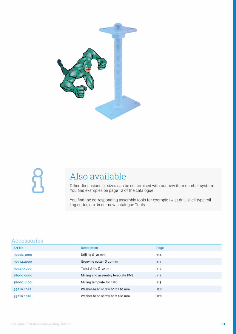
Also availableOther dimensions or sizes can be customised with our new item number system. You find examples on page 12 of the catalogue.
You find the corresponding assembly tools for example twist drill, shell-type mil-ling cutter, etc. in our new catalogue Tools.

22 Post bases
Productgroup Upper plate mm Lower plate mm Thread, M24 upp. Borehole Ø 13 mm bottom
Borehole Ø 10,5 mm top
CE
10920.1_90 Ø 96 x 6 160 x 100 x 6 65 4 4 *
Art-No. Thread, M24 low. Adjustment range, mm max. characteristic pres-sure bearing capacity (kN) *
Suitable cover sleeve item no. 10834.____
10920.1090 65 142 - 207 120,0 .2000
10920.1190 90 167 - 232 120,0 .2010
10920.1290 150 227 - 292 120,0 .1012
10920.1390 200 277 - 342 120,0 .2035
10920.1490 250 327 - 392 120,0 .2040
* For further static values see design manual or ETA 10/0413
10920.1090
Version with centring tip
10920.149010920.139010920.1290

23PTP easy Post bases Right / left threaded
Productgroup Upper plate mm Lower plate mm Borehole Ø 13 mm bottom
Borehole Ø 12 mm top
CE
10921.1_00 Ø 100 x 6 160 x 100 x 6 4 4 *
Art-No. Thread, M24 upp.
Thread, M24 low.
Adjustment range, mm
Special features max. characteristic pressure bearing capacity (kN) *
Suitable cover sleeve item no. 10834.____
10921.1000 65 65 142 - 207 100,0 .2000
10921.1100 65 90 167 - 232 100,0 .2010
10921.1200 65 150 227 - 292 100,0 .1012
10921.1300 65 200 277 - 342 100,0 .2035
10921.1400 65 250 327 - 392 100,0 .2040
10921.1600 35 35 82 - 92 short version 100,0 .1060
For lateral fixation, the mandrel M24 x 110 mm is inserted into the timber column.
10921.1100 10921.1600
Art-No. Upper plate mm
Lower plate mm
Thread, M24 low.
Thread, M24 upp.
Borehole Ø 13 mm bottom
Borehole Ø 12 mm top
Adjust-ment range, mm
max. characte-ristic pressure bearing capacity (kN) *
CE Suitable cover sleeve item no. 10834.____
10921.1104 Ø 100 x 6 160 x 100 x 6 90 85 4 4 190 - 255 105,0 * .2010
Special feature: Carport post base With two lock nuts, one left and one right nut, a higher bracing is achieved. For lateral fixation, the mandrel M24 x 110 mm is inserted into the timber column.
10921.1104
Carport post base
Art-No. Upper plate mm
Lower plate mm
Thread, M20 low.
Thread, M20 upp.
Borehole Ø 12 mm bottom
Borehole Ø 12 mm top
Adjust-ment ran-ge, mm
max. characteristic pressure bearing capacity (kN) *
Suitable cover sleeve item no. 10832.____
10901.0000 Ø 100 x 6 100 x 100 x 6 55 55 4 4 122 - 182 54,0** .0000
For lateral fixation, the mandrel M20 x 90 mm is inserted into the timber column.
Version with thread pin
10901.0000
* For further static values see design manual or ETA 10/0413 ** Steel failure partial safety factor is recommended γM 1.0

24 Post bases
Productgroup Upper plate mm Lower plate mm Thread, M24 upp. Borehole Ø 13 mm bottom
Borehole Ø 12 mm top
10922.1_00 100 x 100 x 6 160 x 100 x 6 65 4 4
Art-No. Thread, M24 low. Adjustment range, mm Suitable cover sleeve item no. 10834.____
10922.1000 65 142 - 207 .2000
10922.1100 90 167 - 232 .2010
10922.1200 150 227 - 292 .1012
10922.1300 200 277 - 342 .2035
10922.1400 250 327 - 392 .2040
Strut 120 x 60 x 6 with a borehole Ø 12,5 mm.
10922.1000
10020
Version with strut
10922.1200
Assembly instructionThe precisely fitting slot can be made with a standard slotting device.
Any required lift values are taken over by rod dowels (fitting bolts). These are to be processed according to the specifications of the respective producer.
10922.1400

25PTP easy Post bases Right / left threaded
Productgroup Upper plate in mm Lower plate in mm Thread, M24 upp. Borehole Ø 13 mm bottom
Borehole Ø 12 mm top
Laterally adjustable, mm
10924.1_30 130 x 100 x 5 160 x 100 x 6 65 4 2 130 - 190
Art-No. Thread, M24 low. Adjustment range, mm Suitable cover sleeve item no. 10834.____
10924.1030 65 141 - 206 .2000
10924.1130 90 166 - 231 .2010
10924.1230 150 226 - 291 .1012
10924.1330 200 276 - 341 .2035
10924.1430 250 326 - 391 .2040
Individual adaptation to the timber column is possible with lateral latches that can be hooked in.
10924.1030
Productgroup Upper plate mm Lower plate mm Thread, M24 upp. Borehole Ø 13 mm bottom
Borehole Ø 12 mm top
Laterally adjustable, mm
10923.1_00 100 x 100 x 5 160 x 100 x 6 65 4 2 100 - 160
Art-No. Thread, M24 low. Adjustment range, mm Suitable cover sleeve item no. 10834.____
10923.1000 65 141 - 206 .2000
10923.1100 90 166 - 231 .2010
10923.1200 150 226 - 291 .1012
10923.1300 200 276 - 341 .2035
10923.1400 250 326 - 391 .2040
Individual adaptation to the timber column is possible with lateral latches that can be hooked in.
10923.1000
Version with lateral latches

26 Post bases
Art-No. Upper plate mm
Lower plate mm
Thread, M24 low.
Thread, M24 upp.
Borehole Ø 13 mm bottom
Borehole Ø 12 mm top
Adjustment range, mm
max. characteristic pressure bearing capacity (kN) *
CE
10952.1000 Ø 100 x 8 160 x 100 x 8 65 65 4 4 146 - 211 90,0 *
For lateral fixation, the mandrel M24 x 110 mm is inserted into the timber column. * for further static values see design manual or ETA 10/0413
10952.1000 10951.1000
PTP easy Post bases Stainless steel
Art-No. Upper plate mm
Lower plate mm
Thread, M24 low.
Thread, M24 upp.
Borehole Ø 13 mm bottom
Borehole Ø 12 mm top
Adjustment range, mm
10951.1000 100 x 100 x 8 160 x 100 x 8 65 65 4 4 146 - 211
Proven technology with increased corrosion resistance! Post supports made of high-quality V4A stainless steel allow you to install the system in accordance with standards, even in unusual areas of application such as corrosiveness category C5-I / C5-M.

27PTP easy Post bases Stainless steel
Assembly instructionWhen fixing the stainless steel post supports, the connection to the wood must be made with stainless steel screws plate head VG.
The connection to the foundation must be separately verified according to ETA 10/0413 and should also be carried out with concrete screws or anchor bolts made of stainless steel.
Art-No. Description Page
99110.1012 Washer-head screw 10 x 120 mm Stainless steel 128
Accessories

28 Post bases
Art-No. Upper plate mm
Lower plate mm
Thread, M24 low.
Borehole Ø 12 mm bottom
Borehole Ø 10,5 mm top
Adjustment range, mm
Version CE max. characteristic pressure bearing capacity (kN) *
10529.7098 Ø 96 x 8 110 x 110 x 6 90 4 4 175 - 235 Centring tip * 41,3**
PTP easy Post bases inclinable
10529.7098
PTP easy post base plug system Z
Art-No. Upper plate mm
Lower plate mm
Thread, M24 low.
Thread, M24 upp.
Borehole Ø 12 mm bottom
Borehole Ø 12 mm top
Adjustment range, mm
Mandrel, tube thread M42,4 mm
CE max. characteristic pressure bearing capacity (kN) *
10930.7008 Ø 100 x 8 110 x 110 x 6 65 150 4 4 204 - 319 130 * 41,3**
PTP easy Post bases System 10930 / 10931
10930.7008
Art-No. Upper plate mm
Lower plate mm
Thread, M24 low.
Thread, M24 upp.
Borehole Ø 12 mm bottom
Borehole Ø 10,5 mm top
Borehole Ø 12 mm top
Adjustment range, mm
Version CE max. characteristic pressure bearing capacity (kN) *
10920.7098 Ø 96 x 6 110 x 110 x 6
65 65 4 4 178 - 243 Centring tip * 41,3**
10921.7008 Ø 100 x 6 110 x 110 x 6
65 65 4 4 178 - 243 Thread pin M24 x 110 mm
* 41,3**
Post base right-/left-handed thread
10920.7098
Art-No. Upper plate mm
Lower plate mm
Thread, M24 low.
Borehole Ø 12 mm bottom
Borehole Ø 12 mm top
Version CE max. characteristic pressure bearing capacity (kN) *
12013.7301 100 x 100 x 6 110 x 110 x 6 330 4 4 Welded with nut * 41,3**
* For further static values see design manual or ETA 10/0413. ** Steel failure partial safety factor is recommended γM 1.0 for a maximal adjustment height of 215 mm
PTP easy post base threaded rods
12013.7301

29PTP easy Post bases inclinable
Assembly instructionThe system developed by Pitzl enables the approved installa-tion of vertical supports even on sloping foundations.
Observe the maximum installation height of 215 mm, from the joint to the lower edge of the upper part. Further technical details can be found in our statics handbook.
max
imum
215
mm

30 Post bases
PTP plus Post bases Heavy-duty version
Productgroup Upper plate mm Lower plate mm Borehole Ø 13 mm bottom
Borehole Ø 12 mm top
CE
10529.1_93 Ø 120 x 12 140 x 140 x 12 4 4 *
Art-No. Thread, M30 low. Adjustment range, mm max. characteristic pressure be-aring capacity (kN) *
10529.1093 90 149 - 209 226,0
10529.1993 150 215 - 325 226,0
Plug system Z with centring tip
Productgroup Upper plate mm Lower plate mm Borehole Ø 13 mm bottom
Borehole Ø 12 mm top
CE
11016.1_00 100 x 100 x 10 160 x 100 x 10 4 4 *
Art-No. Thread, M30 max. characteristic pressure bearing capacity (kN) *
11016.1200 250 160,0
11016.1300 330 160,0
11016.1500 500 160,0
* For further static values see design manual or ETA 10/0413
Threaded rods
10529.1093 11016.1200
In order to fulfill the increasing load requirements for column feet in timber construction we have developed the PTP plus series. Vertical load bearing capacities of 515 KN, horizontal load bearing capacities of up to 18 KN or lift-off values of 72 KN guarantee the Pitzl post supports an absolute unique selling point.
A solution for every requirement - that is our absolute credo, even in the heavy duty sector.
11016.150010529.1993
31PTP plus Post bases Heavy-duty version
Also availableOther dimensions or sizes can be customised with our new item number system. You find examples on page 12 of the catalogue.
You find the corresponding assembly tools for example twist drill, shell-type mil-ling cutter, etc. in our new catalogue Tools.
Art-No. Description Page
50020.3000 Drill jig Ø 30 mm 114
50934.2000 Grooving cutter Ø 20 mm 117
50937.3000 Twist drills Ø 30 mm 112
58000.0000 Milling and assembly template FM8 115
58000.1100 Milling template for FM8 115
99210.1012 Washer-head screw 10 x 120 mm 128
99210.1016 Washer-head screw 10 x 160 mm 128
Accessories

32 Post bases
Productgroup Upper plate mm
Lower plate mm
Thread, M30 upp.
Borehole Ø 13 mm bottom
Borehole Ø 12 mm top
CE
10920.1_93 Ø 100 x 10 160 x 100 x 10 65 4 4 *
Art-No. Thread, M30 low. Adjustment range, mm max. characteristic pres-sure bearing capacity (kN) *
Suitable cover sleeve item no. 10833.____
10920.1093 65 150 - 210 169,0 .2000
10920.1193 90 175 - 235 169,0 .3000
10920.1293 150 235 - 295 169,0 .3000
10920.1393 200 285 - 345 169,0
10920.1493 250 335 - 395 169,0
Heavy duty version with centring tip
* For further static values see design manual or ETA 10/0413
10920.1093 10920.1193
Productgroup Upper plate mm Lower plate mm Thread, M 30 upp. Borehole Ø 13 mm bottom Borehole Ø 12 mm top
10920.1_03 100 x 100 x 10 160 x 100 x 10 65 4 4
Art-No. Thread, M 30 low. Adjustment range, mm
max. characteristic pressure bearing capacity (kN) *
CE Suitable cover sleeve item no. 10833.____
10920.1003 65 150 - 210 158,5 * .2000
10920.1103 90 175 - 235 .3000
10920.1203 150 235 - 295 .3000
10920.1303 200 285 - 345
10920.1403 250 335 - 395
Heavy duty version with square upper plate
10920.1003

33PTP plus Post bases Heavy-duty version
Productgroup Upper plate mm Lower plate mm Thread M 30 upp. Borehole Ø 13 mm bottom Borehole Ø 12 mm top
10921.1_03 Ø 100 x 10 160 x 100 x 10 65 4 4
Art-No. Thread M 30 low.
Adjustment range, mm
max. characteristic pressure bearing capacity (kN) *
CE Suitable cover sleeve item no. 10833.____
10921.1003 65 150 - 210 131,1 * .2000
10921.1103 90 175 - 235 .3000
10921.1203 150 235 - 295 .3000
10921.1303 200 285 - 345
10921.1403 250 335 - 395
For lateral fixation, the mandrel M 30 x 110 mm is inserted into the timber column.
Heavy duty version with threaded mandrel
10921.1003
Productgroup Upper plate mm Lower plate mm Thread, M30 upp. Borehole Ø 15 mm bottom
Borehole Ø 12 mm top
CE
10921.1_06 100 x 100 x 15 160 x 100 x 15 65 4 4 *
Art-No. Thread, M30 low. Adjustment range, mm max. characteristic pres-sure bearing capacity (kN) *
Suitable cover sleeve item no. 10833.____
10921.1006 65 160 - 220 185,7 .2000
10921.1106 90 185 - 245 185,7 .3000
10921.1206 150 245 - 305 185,7 .3000
10921.1306 200 295 - 355 185,7
10921.1406 250 345 - 405 185,7
For lateral fixation, the mandrel M 30 x 110 mm is inserted into the timber column.
* For further static values see design manual or ETA 10/0413
10921.1006

34 Post bases
Productgroup Upper plate mm
Lower plate mm
Thread, M30 upp.
Borehole Ø 12 mm top
Borehole Ø 15 mm bottom
Mandrel, tube Ø 42,4 mm
CE
10930.1_06 100 x 100 x 15 160 x 100 x 15 150 4 4 130 *
Art-No. Thread, M30 low. Adjustment range, mm max. characteristic pres-sure bearing capacity (kN) *
Suitable cover sleeve item no. 10833.____
10930.1006 65 205 - 300 168,6 .3000
10930.1106 90 230 - 325 168,6 .3000
10930.1206 150 290 - 385 168,6
10930.1306 200 340 - 435 168,6
Art-No. Upper plate mm
Lower plate mm
Thread, M 30 low.
Thread, M 30 upp.
Borehole Ø 13 mm bottom
Borehole Ø 12 mm top
Adjust-ment range, mm
Mandrel, tube Ø 42,4 mm
max. characte-ristic pressure bearing capa-city (kN) *
CE Suitable cover sleeve item no. 10833.____
10930.1003 Ø 100 x 10 160 x 100 x 10
65 150 4 4 195 - 285 130 125,8 * .3000
Also availableOther dimensions or sizes can be customised with our new item number system. You find examples on page 12 of the catalogue.
You find the corresponding assembly tool for example twist drill, shell-type milling cutter, etc. in our new catalogue Tools.
Heavy duty version with tube
10930.1003 10930.1006
* For further static values see design manual or ETA 10/0413

35PTP plus Post bases Heavy-duty version
Heavy duty version with tube thread
Productgroup Upper plate mm Lower plate mm Thread, M30 upp.
Borehole Ø 12 mm top
Borehole Ø 15 mm bottom
Mandrel, tube thread M 44
CE
10931.1_06 100 x 100 x 15 160 x 100 x 15 150 4 4 130 *
Art-No. Thread, M30 low. Adjustment range, mm max. characteristic pres-sure bearing capacity (kN) *
Suitable cover sleeve item no. 10833.____
10931.1006 65 205 - 300 168,6 .3000
10931.1106 90 230 - 325 168,6 .3000
10931.1206 150 290 - 385 168,6
10931.1306 200 340 - 435 168,6
With tube thread.
Art-No. Upper plate mm
Lower plate mm
Thread, M 30 low.
Thread, M30 upp.
Borehole Ø 13 mm bottom
Borehole Ø 12 mm top
Adjust-ment range, mm
Mandrel, tube thread M 44
max. characte-ristic pressure bearing capa-city (kN) *
CE Suitable cover sleeve item no. 10833.____
10931.1003 Ø 100 x 10 160 x 100 x 10
65 150 4 4 195 - 285 130 125,8 * .3000
* For further static values see design manual or ETA 10/0413
10931.1003 10931.1006

36 Post bases
Productgroup Upper plate mm Lower plate mm Tube Ø mm Borehole Ø 17 mm bottom
Borehole Ø 12 mm top
CE
11008.1__0 140 x 140 x 15 140 x 140 x 15 82,5 x 5 4 4 *
Art-No. Height mm max. characteristic pressure bearing capacity (kN) *
11008.1160 160 400,0
11008.1250 250 381,5
Threaded mandrel M 24 x 150 mm.
The in-house manufacturing allows Pitzl to react quickly and flexibly to customers‘s requests. Because of snow quan-tities that disproportionally fell in large parts of Europe it was necessary to develop and manufacture quickly a fitted post base.
The most massive produced post base 11008.____ is available as of now rigid as well as adjustable. The optimally de-signed constructive form allows very high load capacities for compression up to 515 kN and also for horizontal load actions up to 18,2 kN. The tried and trusted Pitzl screw connection concept or a strut with dowel boreholes guarantee a lift-off value up to 50 kN.
Rigid version hot-dip galvanised
11008.1160
Productgroup Upper plate mm Lower plate mm Tube Ø mm Borehole Ø 17 mm bottom
Borehole Ø 17 mm top
CE
11008.2__0 140 x 140 x 15 140 x 140 x 15 82,5 x 5 4 4 *
Art-No. Height mm max. characteristic pressure bearing capacity (kN) *
11008.2160 160 376,0
11008.2250 250 376,0
With strut 120 x 140 x 10 mm, two boreholes Ø 13 mm including.
* For further static values see design manual or ETA 10/0413
11008.2160

37PTP plus Post bases Heavy-duty version
Productgroup Upper plate mm Tube Ø mm Borehole Ø 13 mm bottom
Borehole Ø 11 mm top
Adjustment range mm
CE
11008._190 160 x 160 x 12 M 64 4 4 190 - 260 *
Art-No. Lower plate mm max. characteristic pressure bearing capacity (kN) *
11008.7190 160 x 160 x 12 515,0
11008.8190 280 x 160 x 12 515,0
Heavy-duty post base adjustable, in order to enable with heavy load action a quick and precise assembly and compensate eventual height differences.
* For further static values see design manual or ETA 10/0413
Adjustable versionProductgroup Upper plate
mmLower plate mm
Tube Ø mm
Internal thread mm
Tube mandrel Ø 42,4 mm
Borehole Ø 13 mm bottom
Borehole Ø 11 mm top
CE
11008.6__0 Ø 140 x 8 140 x 140 x 10 76,1 x 6,3 M30 x 90 70 4 4 *
Art-No. Adjustment range mm max. characteristic pressure bearing capacity (kN) *
11008.6150 150 - 200 260,0
11008.6200 200 - 250 260,0
11008.6250 250 - 300 260,0
11008.6150 11008.7190 11008.8190

38 Post bases
PTP easy Post bases Threaded rods
Art-No. Upper plate mm
Lower plate mm
Thread mm Borehole Ø 12 mm top
Borehole Ø 12 mm bottom
Borehole Ø 13 mm bottom
Special features
max. characteristic pres-sure bearing capacity (kN) *
11009.0180 80 x 80 x 5 100 x 100 x 6 150 4 4 34,1**
11009.0100 100 x 100 x 6 100 x 100 x 6 150 4 4 90,0
11009.1100 100 x 100 x 6 160 x 100 x 6 150 4 4 90,0
11009.0200 100 x 100 x 6 100 x 100 x 6 250 4 4 37,3**
11009.1200 100 x 100 x 6 160 x 100 x 6 250 4 4 37,3**
11009.6200 100 x 100 x 6 200 x 100 x 6 250 4 3 1 side cut to 2 x 45°
Designed for compressive, tensile and transverse forces
Thread M 20
11009.010011009.0180 11009.1100 11009.6200
Art-No. Upper plate mm
Lower plate mm
Thread mm
Borehole Ø 12 mm top
Borehole Ø 12 mm bottom
Borehole Ø 13 mm bottom
CE Special features
max. characteristic pres-sure bearing capacity (kN) *
11013.0100 100 x 100 x 6 100 x 100 x 6 150 4 4 90,0
11013.1100 100 x 100 x 6 160 x 100 x 6 150 4 4 * 100,0
11013.0200 100 x 100 x 6 100 x 100 x 6 250 4 4 * 100,0
11013.1200 100 x 100 x 6 160 x 100 x 6 250 4 4 * 100,0
11013.1300 100 x 100 x 6 160 x 100 x 6 330 4 4 * 100,0
11013.1500 100 x 100 x 6 160 x 100 x 6 500 4 4 * 100,0
11013.6200 100 x 100 x 6 200 x 100 x 6 250 4 3 1 side cut to 2 x 45°
* For further static values see design manual or ETA 10/0413 ** Steel failure partial safety factor is recommended γM 1.0
Thread M 24

39PTP easy Post bases Threaded rods
Assembly instructions• The post base is fastened to the cross-grained wood with fully threaded plate
screws, 10 x 120 mm.• The lift-off value can be increased by increasing the effective thread length.
Please refer to our design manual for the formula.• Fasten to foundation with tie bolts, Multi Monti etc.
(must be verified separately).
Also available• Lift-off protection either by welding the adjusting nut to the upper plate (order
example: 11013.1201) or alternatively with a locking latch (order example: 11013.1202).
• You can find separate parts like 5-boreholes-plates on page 49.
With locking latchWelded with nut

40 Post bases
PTP easy Post bases Rigid version
Productgroup Upper plate mm Lower plate mm Tube Ø mm Borehole Ø 12 mm bottom Borehole Ø 12 mm top
11001._000 100 x 100 x 6 100 x 100 x 6 42 4 4
Art-No. Height mm max. characteristic pressure bearing capacity (kN) * CE
11001.0000 125 100,0 *
11001.1000 160 -
11001.2000 200 90,0
Art-No. Upper plate mm
Lower plate mm
Height mm
Tube Ø mm
Borehole Ø 10,5 mm bottom
Borehole Ø 10,5 mm top
max. characteristic pres-sure bearing capacity (kN) *
11000.0000 80 x 80 x 5 80 x 80 x 5 100 27 4 4 59,2
11000.0000 11001.0000
Art-No. Upper plate mm Lower plate mm Height mm Tube Ø mm Borehole Ø 12 mm bottom Borehole Ø 12 mm top
11001.0001 100 x 100 x 6 100 x 100 x 6 125 42 4 4
Upper plate offset by 45°.
11001.0001
Art-No. Upper plate mm
Lower plate mm
Height mm
Tube Ø mm
Borehole Ø 12 mm bottom
Borehole Ø 12 mm top
max. characteristic pressure bearing capacity (kN) *
11002.0000 100 x 100 x 6 250 x 60 x 6 125 42 2 4 90,0
* For further static values see design manual or ETA 10/0413
11002.0000
Rigid version with square upper plate

41PTP easy Post bases Rigid version
Art-No. Upper plate mm
Lower plate mm
Height mm
Tube Ø mm
Borehole Ø 12 mm bottom
Borehole Ø 12 mm top
max. characteristic pressure bearing capacity (kN) *
CE
11003.0000 100 x 100 x 6 100 x 100 x 6 125 42 4 4 100,0 *
Strut 120 x 60 x 6 mm with a borehole Ø 12,5 mm.
Rigid version with strut
Rigid version with lateral latches
Art-No. Upper plate mm
Lower plate mm
Height mm
Tube Ø mm
Borehole Ø 12 mm bottom
Borehole Ø 12 mm top
max. characteristic pressure bearing capacity (kN) *
CE
11007.0000 120 x 120 x 6 120 x 120 x 6 160 42 4 4 100,0 *
Strut 120 x 60 x 6 mm with a borehole Ø 12,5 mm.
11003.0000 11007.0000
Art-No. Upper plate mm
Lower plate mm
Height mm
Tube Ø mm
Borehole Ø 12 mm bottom
Borehole Ø 12 mm top
Laterally adjustable, mm
max. characteristic pres-sure bearing capacity (kN) *
11020.0000 120 x 120 x 5 120 x 120 x 6 160 42 4 2 120 - 180 73,6**
Individual adaptation to the timber column is possible with lateral latches that can be hooked in.
* For further static values see design manual or ETA 10/0413 ** Steel failure partial safety factor is recommended γM 1.0
11020.0000
10020

42 Post bases
PTP easy Post bases for screw-in foundations
Productgroup Lower plate mm Oblong hole bottom 11 x 60 mm
10___.9___ 140 x 189 x 6 4
Art-No. Upper plate mm
Thread, M 24 low.
Thread, M 24 upp.
Borehole top Adjustment range, mm
Suitable cover sleeve item no. 10834.____
10529.9090 Ø 96 x 8 90 - 4x Ø 10,5 mm 139 - 199 -
10529.9990 Ø 96 x 8 150 - 4x Ø 10,5 mm 201 - 316 -
10920.9090 Ø 96 x 6 65 65 4x Ø 10,5 mm 142 - 207 .2000
10921.9000 Ø 100 x 6 65 65 4x Ø 12 mm 142 - 207 .2000
10922.9000 100 x 100 x 6 65 65 4x Ø 12 mm 142 - 207 .2000
10923.9000 100 x 100 x 5 65 65 4x Ø 12 mm 141 - 206 .2000
10930.9000 Ø 100 x 8 65 150 4x Ø 12 mm 168 - 283 .3001
The screw-in foundation or rather the connection with it has to be proven separately.
We offer the manufacturing industries of screw-in foundations the opportunity to execute timber connections with high-quality post bases. The PTP-Series is designed to absorb vertical and horizontal stresses as well as lift-off forces. A height adjustment is possible even when mounted and under heavy load.
10529.9090 10921.9000 10923.900010922.9000
Naturally, we also offer individual, custom-made solutions for your specific range of applications.

43PTP easy / plus Post bases Rigid version for embedding in concrete
PTP easy / plus Post bases Rigid version for embedding in concrete
Productgroup Upper plate mm Tube Ø mm Borehole Ø 12 mm top
11022._000 100 x 100 x 6 42 4
Art-No. Tube length mm max. characteristic pressure bearing capacity (kN) *
11022.0000 200 90,0
11022.1000 300 90,0
11022.2000 400 90,0
Strut 120 x 60 x 6 mm with a borehole Ø 12,5 mm.
Rigid version with strut, hot-dip galvanized
Productgroup Upper plate mm Concrete reinforcement steel Ø mm
11023._000 80 x 80 x 5 20
Art-No. Length of concrete reinforcement steel mm max. characteristic pressure bearing capacity (kN) *
11023.0000 200 55,4
11023.1000 300 55,4
Strut 120 x 60 x 6 mm with a borehole Ø 12,5 mm.
Installation instructionMinimal embedding depth in concrete: 150 mm
* For further static values see design manual or ETA 10/0413. The concrete foundation has to be proven separately!
11022.0000 11022.2000 11023.1000
Art-No. Upper plate mm Lower plate mm Tube Ø mm Tube length mm Borehole Ø 13 mm top
11010.5000 Ø 100 x 8 60 x 70 x 5 42,4 500 4
11010.5000

44 Post bases
Productgroup Borehole Ø 12 mm top Mandrel, tube Ø 42,4 mm
10934.___2 4 130
Art-No. Upper plate mm
Thread, M 24 low.
Thread, M 30 low.
Special feature max. characteristic pressure bearing capacity (kN) *
CE
10934.2482 Ø 80 x 6 250
10934.2402 Ø 100 x 8 250 110,0 *
10934.3402 Ø 100 x 8 330 110,0 *
10934.2302 Ø 100 x 10 250 heavy-duty version 122,8 *
10934.3302 Ø 100 x 10 330 heavy-duty version 122,8 *
Productgroup Borehole Ø 12 mm top Mandrel tube Ø 44 mm
10934.___3 4 130
Art-No. Upper plate mm
Thread, M 24 low.
Thread, M 30 low.
Special feature max. characteristic pressure bearing capacity (kN) *
CE
10934.2483 Ø 80 x 6 250
10934.2403 Ø 100 x 8 250 110,0 *
10934.3403 Ø 100 x 8 330 110,0 *
10934.2303 Ø 100 x 10 250 heavy-duty version 122,8 *
10934.3303 Ø 100 x 10 330 heavy-duty version 122,8 *
Installation instructionMinimal embedding depth in concrete: 150 mm.
* For further static values see design manual or ETA 10/0413. The concrete foundation has to be proven separately!
10934.2482 10934.2483 10934.2403 10934.2303
Rigid version with tube
Rigid version with tube thread
45PTP easy / plus Post bases Rigid version for embedding in concrete
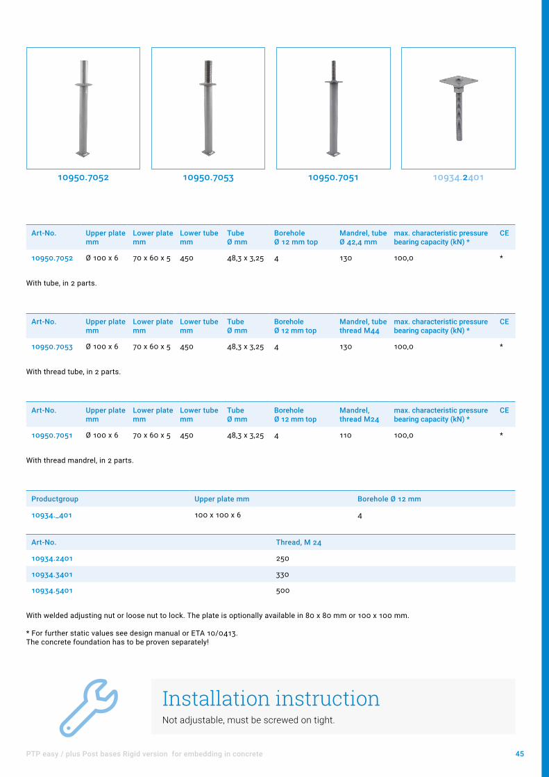
Art-No. Upper plate mm
Lower plate mm
Lower tube mm
Tube Ø mm
Borehole Ø 12 mm top
Mandrel, tube Ø 42,4 mm
max. characteristic pressure bearing capacity (kN) *
CE
10950.7052 Ø 100 x 6 70 x 60 x 5 450 48,3 x 3,25 4 130 100,0 *
With tube, in 2 parts.
10950.7052
Art-No. Upper plate mm
Lower plate mm
Lower tube mm
Tube Ø mm
Borehole Ø 12 mm top
Mandrel, tube thread M44
max. characteristic pressure bearing capacity (kN) *
CE
10950.7053 Ø 100 x 6 70 x 60 x 5 450 48,3 x 3,25 4 130 100,0 *
With thread tube, in 2 parts.
10950.7053
Art-No. Upper plate mm
Lower plate mm
Lower tube mm
Tube Ø mm
Borehole Ø 12 mm top
Mandrel, thread M24
max. characteristic pressure bearing capacity (kN) *
CE
10950.7051 Ø 100 x 6 70 x 60 x 5 450 48,3 x 3,25 4 110 100,0 *
With thread mandrel, in 2 parts.
Installation instructionNot adjustable, must be screwed on tight.
10950.7051
Productgroup Upper plate mm Borehole Ø 12 mm
10934._401 100 x 100 x 6 4
Art-No. Thread, M 24
10934.2401 250
10934.3401 330
10934.5401 500
With welded adjusting nut or loose nut to lock. The plate is optionally available in 80 x 80 mm or 100 x 100 mm.
* For further static values see design manual or ETA 10/0413. The concrete foundation has to be proven separately!
10934.2401

46 Post bases
PAP Post anchors, hot-dip galvanized
Art-No. Dimensions mm Support height mm Borehole Ø 12 mm Oblong hole Ø 11 x 22 mm
11041.0000 85 x 200 x 80 x 6 65 4 2
Support bracket
11041.0000
Art-No. Dimensions mm Borehole Ø 12.5 mm
15700.0000 160 x 100 x 60 x 6 4
15710.0000 180 x 100 x 80 x 8 4
15720.0000 200 x 100 x 100 x 10 4
Mounting bracket
15700.0000
Post anchor H-shapeContinuously adjustable up to 145 mm
Productgroup Boreholes Ø 12.5 mm (per flat iron)
11042._000 4
Art-No. Flat iron mm
11042.0000 600 x 60 x 6
11042.8000 800 x 60 x 6
Including 8 nuts M12 and 2 threaded rods M12 x 180 mm.
11042.0000
47PAP Post anchors, hot-dip galvanized
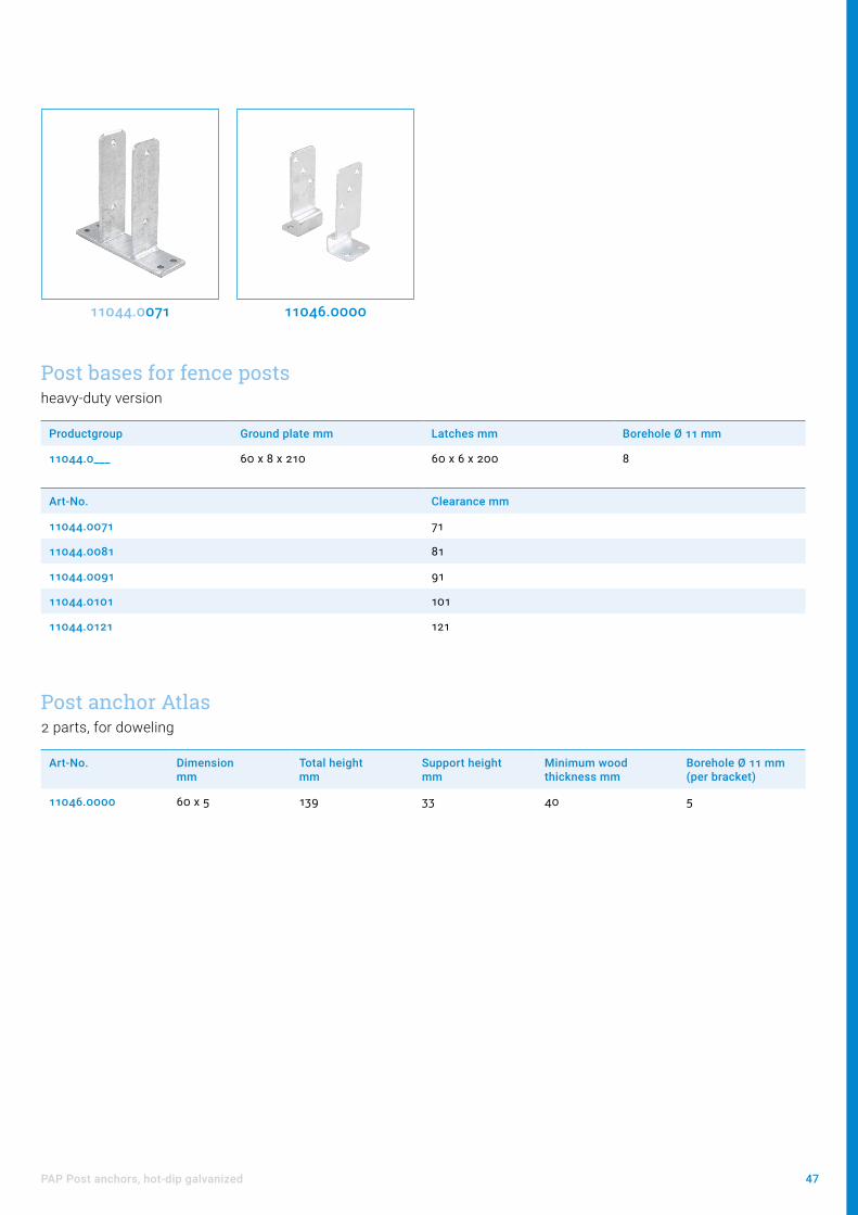
Post bases for fence postsheavy-duty version
Productgroup Ground plate mm Latches mm Borehole Ø 11 mm
11044.0___ 60 x 8 x 210 60 x 6 x 200 8
Art-No. Clearance mm
11044.0071 71
11044.0081 81
11044.0091 91
11044.0101 101
11044.0121 121
Post anchor Atlas2 parts, for doweling
Art-No. Dimension mm
Total height mm
Support height mm
Minimum wood thickness mm
Borehole Ø 11 mm (per bracket)
11046.0000 60 x 5 139 33 40 5
11044.0071 11046.0000

48 Post bases
Accessories for post bases
Art-No. For threads Adjustment range mm
10832.0000 M20 100 - 185
10832.0010 M20 190 - 275
10834.1060 M24 60 - 105
10834.2000 M24 115 - 215
10834.2010 M24 140 - 240
10834.3001 M24 140 - 265
10834.1012 M24 180 - 305
10834.2030 M24 200 - 325
10834.2035 M24 220 - 345
10834.3020 M24 200 - 385
10834.3030 M24 220 - 405
10834.2040 M24 270 - 395
10833.2000 M30 115 - 215
10833.3000 M30 155 - 295
Cover sleeves
10832.0000 Installation example
Adj
ustm
ent r
ange

49Accessories for post bases
Art-No. Plate M 20 mm Plate M 24 mm Borehole Ø 12 mm Note
90000.2080 80 x 80 x 5 4
90000.2000 100 x 100 x 6 4
90000.2082 80 x 80 x 5 4 With locking latch
90000.2002 100 x 100 x 6 4 With locking latch
90000.2081 80 x 80 x 5 4 Welded with nut
90000.2001 100 x 100 x 6 4 Welded with nut
90000.4080 80 x 80 x 5 4
90000.4000 100 x 100 x 6 4
90000.4082 80 x 80 x 5 4 With locking latch
90000.4002 100 x 100 x 6 4 With locking latch
90000.4081 80 x 80 x 5 4 Welded with nut
90000.4001 100 x 100 x 6 4 Welded with nut
5-hole plate
Lock nutfor retroactive mounting to installed post bases
Art-No. Description
98024.0002 Nut M24, 2 parts, right
98124.0002 Nut M24, 2 parts, left
90000.4000 90000.400290000.4001 98024.0002

50 Post bases
Decorative covers
Decorative connectors
11017.0000
Art-No. Dimension mm Borehole mm
11125.0000 Ø 64 x 5 Ø 12,5
11165.0000 Ø 64 x 5 Ø 16,5
Round anchor plates
11125.0000
Art-No. Dimension mm Borehole mm
11017.0000 250 x 60 x 5 2x Ø 12 mm
11018.0000 300 x 60 x 5 2x Ø 12 mm

51Timber construction accessories
Timber construction accessories
Carport - bracing V2A2 parts, with washers 60 x 3 mm and nuts M12
Art-No. Dimensions mm Adjustment range mm Connection thread mm
15500.0000 12 x 3400 3380 - 3420 M12x250 + M12x330
15500.0000
Chimney fasteningContinuously adjustable up to 900 mm rafter clearance
Art-No. Description
15920.0000 in pairs
15920.0000
Threaded rod for the extension of the chimney fastening (Art-Nr. 15920.0000) up to 1900 mm (M12 x 1000 mm)
Art-No. Description
15921.0000 in pairs
15921.0000

52 Post bases
Corrosion protectionAccording to the European Technical Approval ETA-10/0413, the metallic components of the post bases are optionally hot-dip galvanized (z350) or provided with a ZiNiP® coating for use in service class 3 according to Eurocodes 5.
In practice, there are always exceptional situations for corrosion protection. We recommend, for example, that additio-nal corrosion protection be applied to the affected area of the column base after the installation of tiles or paving and the use of cement-containing materials during bonding.
Art-No. Filling quantity Color
56100.0000 400 ml RAL 9007
„PIKO - Corrosion protection for extraordinary requirements“
56100.0000

53Corrosion protection
Product informationWhen applying three layers of PIKO, you achieve the highest corrosivity category of C5-M.
C5-M examples: Inside: Buildings with constant condensation; Exterior: Coastal and offshore areas
Application1. Clean
First clean the post base. It should be largely dry and free of oil, grease and dust. It should also be free of cleaning agents, acids and salts.
2. Shake Shake the can for at least 3 minutes before use.
3. Spray Spray the post base at the bottom and endangered areas. Allow the layer to dry before applying another.

Connectors

55
ContentAssembly instructions 56
Minimal distances to the edges 58
HVP fire protection concept 59
HVP Connectors 60
HVP Heavy-duty Connectors 64
HVP Double Connectors 66
HVP Connectors for steel or concrete connections 68
SVP connectors 70
WVP connectors 71
SPP connectors 72
ISO-CONNECT 74
RIGID 76

56 Connectors
Assembly instructionsArrangement with shadow jointFirst mount the straight screw connection of the connectors and then provide all holes with screws. Make sure that the surface is flat and that the minimum edge distances are observed. You will find these on page 58.
Hidden arrangementOur HVP connectors can be milled into the main or secondary beam. Please make sure that the total thickness of the connector is not exceeded. We recommend milling in less than 1 - 3 mm to ensure easier insertion.

57Assembly instructions
Arrangement variantsHidden column connection
Hidden connection of secondary beams on both sides
Replacements: Stairs, skylight, chimney

58 Connectors
Minimal distances to the edgesFor a flush perpendicular connectionOptimised screws lengths and minimal distances to the edges, higher load capacity, accuracy of fi t for little timber sections, double connectors and end-grain-to-end-grain connections bring the advantages of the new HVP connector directly to the customer.
Valid for Heco screws, for other screws indications from the manufacturer apply.
HVP series 880 - 881
HVP series Lateral "A" Up and down „B“ with screws:
Ø 4,5 x 50 Ø 4,5 x 60 Ø 4,5 x 70 Ø 4,5 x 80
880 10 mm
5 mm 10 mm 15 mm 20 mm881 Part 1: 10 mm Part 2: 5 mm
HVP series 882 - 883
HVP series Lateral "A" Up and down „B“ with screws:
Ø 5 x 60 Ø 5 x 80 Ø 5 x 100
882 und 883 10 mm 10 mm 25 mm 40 mm
Heavy Duty HVP series 884 - 885
HVP series
Lateral "A"
Up and down „B“ with screws:
Ø 8 x 160 Ø 8 x 180 Ø 8 x 200
884 10 mm10 mm 25 mm 40 mm
885 15 mm
Part 1: with the groove
Part 2: with the tongue
H: Header
C: Column
J: Joist

59HVP fire protection concept
HVP fire protection conceptPreventive fire protection is becoming increasingly important. Particularly in structural wood construction a maximal safety must be respected in order to be able to offer an optimal protection. As a leading full-range supplier of wood connection systems, we have thoroughly tested the fire protection offered by our HVP connector system and included the results in our European Technical Approval.
Fire behaviour tests at the TU Munich - 60 minutes
Rückfrageinweise: Hr. Herbert Schaffer [email protected] Pitzl Metallbau GmbH & Co.KG; Siemensstraße 26 - D 84051 Tel. 0049 (0) 8703 9346-0
Brandversuche an der TUM – 60 min
Verbinderteil an Trägerplatte Verbinderteil am NT
Rückfrageinweise: Hr. Herbert Schaffer [email protected] Pitzl Metallbau GmbH & Co.KG; Siemensstraße 26 - D 84051 Tel. 0049 (0) 8703 9346-0
Brandversuche an der TUM – 60 min
Verbinderteil an Trägerplatte Verbinderteil am NT
Connector part at the header
Connector part at the joist

60 Connectors
Productgroup Screws size CE
88___.0000 Ø 4,5 x 50 - 80 *
Art-No. Dimensions w x h x d (mm)
Number of screws
Minimal timber section with screws Ø 4.5 x 50 (mm)
Characteristic load capacity * (kN)
Packing unit
Header Joist Ø 4,5 x 50 Ø 4,5 x 80
88004.0000 25 x 40 x 12 6 60 x 50 45 x 50 2,44 3,82 20
88006.0000 25 x 60 x 12 8 60 x 70 45 x 70 4,88 7,64 20
88008.0000 25 x 80 x 12 10 60 x 90 45 x 90 7,32 11,46 20
88010.0000 25 x 100 x 12 12 60 x 110 45 x 110 9,77 15,28 20
88107.0000 40 x 70 x 12 10 60 x 80 50** x 80 7,32 11,46 10
88109.0000 40 x 90 x 12 14 60 x 100 50** x 100 9,77 15,28 10
88111.0000 40 x 110 x 12 16 60 x 120 50** x 120 12,21 19,10 10
88113.0000 40 x 130 x 12 18 60 x 140 50** x 140 14,65 22,92 10
88115.0000 40 x 150 x 12 22 60 x 160 50** x 160 19,53 30,56 10
* F2,Rk (kN) for GL24h with fully threaded screws: Ø 4,5 x 50 with effective thread length of 45 mm and Ø 4,5 x 80 with effective thread length of 74 mm. For other screws and thread lengths or wood based materials: cf. design manual.
** Valid for part 2 (with the tongue) fixed at the end grain, otherwise 60 mm.
HVP Connectors
88004.0000 88006.0000 88107.0000 88115.0000
Wood-to-wood connectionsOptimal distances to the edges and variable screws length ensure accuracy of fit for each timber section.

61HVP Connectors
Art-No. Description Page
50934.1000 Grooving cutter Ø 10 mm 117
58000.0000 Milling and assembly template FM8 115
58396.0000 Collet holder 117
58396.0008 Collet Ø 8 mm 117
58399.0000 Milling unit consisting of milling drill, Mil-ling template and hand overhead router
116
Art-No. Description Page
99211.4550 Countersunk screws Ø 4,5 x 50 mm 124
99211.4560 Countersunk screws Ø 4,5 x 60 mm 124
99211.4580 Countersunk screws Ø 4,5 x 80 mm 124
Accessories Screws
Uplift protectionAlternatively the Pitzl HVP series 88004.0000 to 88115.0000 can be ordered with uplift protection.
Option uplift protection: With uplift protection: „.1000“ Order example: 88115.1000
Included in delivery: Series 880 1 drilled hole + 1 self-tapping screw Ø 4 x 10 mm Series 881 2 threaded drilled holes + 2 screws Ø 5 x 20 mm
+ 1 uplift protection flat steel

62 Connectors
Productgroup Screws size Packing unit CE
8____.0000 Ø 5 x 60 - 100 10 *
Art-No. Dimensions w x h x d (mm)
Number of screws
Minimal timber section with screws Ø 5 x 60 (mm)
Characteristic load capacity * (kN)
Header Joist Ø 5 x 60 Ø 5 x 100
88210.0000 60 x 100 x 12 18 70 x 120 80 x 120 19,81 32,63
88214.0000 60 x 140 x 12 24 70 x 160 80 x 160 31,70 52,21
88318.0000 80 x 180 x 12 34 70 x 200 100 x 200 47,55 78,32
88322.0000 80 x 220 x 12 44 70 x 240 100 x 240 63,41 104,42
* F2,Rk (kN) for GL24h with fully threaded screws: Ø 5 x 60 with effective thread length of 54 mm and Ø 5 x 100 with effective thread length of 94 mm. For other screws and thread lengths or wood based materials: cf. design manual.
88210.0000 88214.0000 88318.0000 88322.0000
Uplift protectionAlternatively the Pitzl HVP series 88210.0000 to 88322.0000 can be ordered with uplift protection.
Option uplift protection: With uplift protection: „.1000“ Order example: 88214.1000
Included in delivery: Series 882 - 883 2 threaded drilled holes + 2 screws Ø 5 x 20 mm
+ 1 uplift protection flat steel

63HVP Connectors
Also availableConnectors of the series 882 - 884 in double version (on page 66 and 67). Double width for double load capacity. The perfect connection for square timber sections or wide beams with low height.
Art-No. Description Page
50934.2000 Grooving cutter Ø 20 mm 117
58000.0000 Milling and assembly template FM8 115
58396.0000 Collet holder 117
58396.0012 Collet Ø 12 mm 117
58399.0000 Milling unit consisting of milling drill, Mil-ling template and hand overhead router
116
Art-No. Description Page
99211.5060 Countersunk screws Ø 5 x 60 mm 124
99211.5080 Countersunk screws Ø 5 x 80 mm 124
99211.5100 Countersunk screws Ø 5 x 100 mm 124
Accessories Screws

64 Connectors
Productgroup Screws size Packing unit CE
884__.1000 Ø 8 x 100 - 200 4 *
Art-No. Dimensions w x h x d (mm)
Number of screws
Minimal timber section with screws Ø 8 x 160 (mm)
Characteristic load capacity * (kN)
Header Joist Ø 8 x 160 Ø 8 x 200
88420.1000 120 x 200 x 20 16 160 x 220 140 x 220 50,29 62,21
88425.1000 120 x 250 x 20 20 160 x 270 140 x 270 75,43 93,31
88430.1000 120 x 300 x 20 24 160 x 320 140 x 320 100,58 124,42
88435.1000 120 x 350 x 20 28 160 x 370 140 x 370 125,72 155,52
88440.1000 120 x 400 x 20 32 170 x 420 140 x 420 150,86 186,63
88445.1000 120 x 450 x 20 36 170 x 470 140 x 470 176,01 217,73
88450.1000 120 x 500 x 20 40 170 x 520 140 x 520 201,15 248,84
88455.1000 120 x 550 x 20 44 170 x 570 140 x 570 226,29 279,94
88460.1000 120 x 600 x 20 48 170 x 620 140 x 620 251,44 311,05
* F2,Rk (kN) for GL24h with fully threaded screws: Ø 8 x 160 with effective thread length of 150 mm and Ø 8 x 200 with effective thread length of 190 mm. For other screws and thread lengths or wood based materials: cf. design manual.
The new disposed inclined drilled holes as well as the possibility of using different screws lengths guarantee the adaptability to the small timber cross-sections too.
88420.1000 88430.1000 88440.1000 88450.1000
HVP Heavy-duty Connectors
Product informationHeavy-duty HVP connectors are automatically delivered with uplift protection (2 screws Ø 6 x 20 mm and flat steel for uplift protection included).
65HVP Heavy-duty Connectors
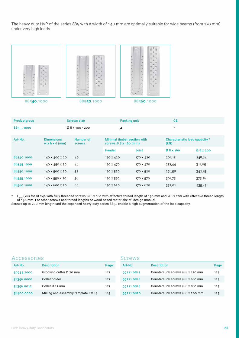
Productgroup Screws size Packing unit CE
885__.1000 Ø 8 x 100 - 200 4 *
Art-No. Dimensions w x h x d (mm)
Number of screws
Minimal timber section with screws Ø 8 x 160 (mm)
Characteristic load capacity * (kN)
Header Joist Ø 8 x 160 Ø 8 x 200
88540.1000 140 x 400 x 20 40 170 x 420 170 x 420 201,15 248,84
88545.1000 140 x 450 x 20 48 170 x 470 170 x 470 251,44 311,05
88550.1000 140 x 500 x 20 52 170 x 520 170 x 520 276,58 342,15
88555.1000 140 x 550 x 20 56 170 x 570 170 x 570 301,73 373,26
88560.1000 140 x 600 x 20 64 170 x 620 170 x 620 352,01 435,47
* F2,Rk (kN) for GL24h with fully threaded screws: Ø 8 x 160 with effective thread length of 150 mm and Ø 8 x 200 with effective thread length of 190 mm. For other screws and thread lengths or wood based materials: cf. design manual.
Screws up to 200 mm length und the expanded heavy-duty series 885.. enable a high augmentation of the load capacity.
The heavy-duty HVP of the series 885 with a width of 140 mm are optimally suitable for wide beams (from 170 mm) under very high loads.
88540.1000 88550.1000 88560.1000
Art-No. Description Page
50934.2000 Grooving cutter Ø 20 mm 117
58396.0000 Collet holder 117
58396.0012 Collet Ø 12 mm 117
58400.0000 Milling and assembly template FM84 115
Art-No. Description Page
99211.0812 Countersunk screws Ø 8 x 120 mm 125
99211.0816 Countersunk screws Ø 8 x 160 mm 125
99211.0818 Countersunk screws Ø 8 x 180 mm 125
99211.0820 Countersunk screws Ø 8 x 200 mm 125
Accessories Screws

66 Connectors
HVP Double Connectors
Productgroup Screws size Packing unit CE
88___.2000 Ø 5 x 60 - 100 4 *
Art-No. Dimensions w x h x d (mm)
Number of screws
Minimal timber section with screws Ø 5 x 60 (mm)
Characteristic load capacity * (kN)
Header Joist Ø 5 x 60 Ø 5 x 100
88210.2000 120 x 100 x 12 32 70 x 120 140 x 120 39,63 65,26
88214.2000 120 x 140 x 12 44 70 x 160 140 x 160 63,41 104,42
88318.2000 160 x 180 x 12 64 70 x 200 180 x 200 95,11 156,63
88322.2000 160 x 220 x 12 84 70 x 240 180 x 240 126,81 208,85
* F2,Rk (kN) for GL24h with fully threaded screws: Ø 5 x 60 with effective thread length of 54 mm and Ø 5 x 100 with effective thread length of 94 mm. For other screws and thread lengths or wood based materials: cf. design manual.
88210.2000 88214.2000 88318.2000 88322.2000
Standard double HVP connectors
Better safe than sorry. Strong, up to 615 kN.
Product noteDouble HVP connectors are automatically delivered with uplift protection

67HVP Double Connectors
Productgroup Screws size Packing unit CE
884__.2000 Ø 8 x 100 - 200 4 *
Art-No. Dimensions w x h x d (mm)
Number of screws
Minimal timber section with screws Ø 8 x 160 (mm)
Characteristic load capacity * (kN)
Header Joist Ø 8 x 160 Ø 8 x 200
88420.2000 240 x 200 x 20 28 160 x 220 260 x 220 100,58 124,42
88425.2000 240 x 250 x 20 36 160 x 270 260 x 270 150,86 186,63
88430.2000 240 x 300 x 20 44 160 x 320 260 x 320 201,15 248,84
88435.2000 240 x 350 x 20 52 160 x 370 260 x 370 251,44 311,05
88440.2000 240 x 400 x 20 60 170 x 420 260 x 420 301,73 373,26
88445.2000 240 x 450 x 20 68 170 x 470 260 x 470 352,01 435,47
88450.2000 240 x 500 x 20 76 170 x 520 260 x 520 402,30 497,68
88455.2000 240 x 550 x 20 84 170 x 570 260 x 570 452,59 559,89
88460.2000 240 x 600 x 20 92 170 x 620 260 x 620 502,88 622,10
* F2,Rk (kN) for GL24h with fully threaded screws: Ø 8 x 160 with effective thread length of 150 mm and Ø 8 x 200 with effective thread length of 190 mm. For other screws and thread lengths or wood based materials: cf. design manual.
88420.2000 88435.2000 88450.2000 88460.2000
Heavy-duty double HVP connectors
Art-No. Description Page
50934.2000 Grooving cutter Ø 20 mm 117
58396.0000 Collet holder 117
58396.0012 Collet Ø 12 mm 117
Art-No. Description Page
99211.0812 Countersunk screws Ø 8 x 120 mm 125
99211.0816 Countersunk screws Ø 8 x 160 mm 125
99211.0818 Countersunk screws Ø 8 x 180 mm 125
99211.0820 Countersunk screws Ø 8 x 200 mm 125
Accessories Screws

68 Connectors
HVP Connectors for steel or concrete connections
Productgroup Total thickness (mm) Number of anchors Header (Concrete)
Packing unit CE
88___.3000 18 4 4 *
Art-No. Width (mm) Connector height (mm)
Screws Joist (Wood)
Minimal timber section with screws Ø 5 x 60 (mm)
Joist plate Header plate
88210.3000 60 90 100 9 pc. Ø 5 x 60 - 100 80 x 120
88214.3000 60 90 140 12 pc. Ø 5 x 60 - 100 80 x 160
88318.3000 80 110 180 17 pc. Ø 5 x 60 - 100 100 x 200
88322.3000 80 110 220 22 pc. Ø 5 x 60 - 100 100 x 240
88210.3000 88322.3000 88440.3000 88460.3000
Productgroup Width (mm) Total thickness (mm) Packing unit CE
Joist plate Header plate
884__.3000 120 150 25 4 *
Art-No. Connector height (mm) Screws Joist (Wood)
Number of anchors Header (Concrete)
Minimal timber section with screws Ø 8 x 160 (mm)
88420.3000 200 8 pc. Ø 8 x 100 - 200 4 140 x 220
88430.3000 300 12 pc. Ø 8 x 100 - 200 4 140 x 320
88440.3000 400 16 pc. Ø 8 x 100 - 200 4 140 x 420
88450.3000 500 20 pc. Ø 8 x 100 - 200 6 140 x 520
88460.3000 600 24 pc. Ø 8 x 100 - 200 6 140 x 620
Heavy-duty HVP connectors
Equally sturdy and simple HVP connection to concrete or steel up to about 307 kN. An anchor plate with concrete anchors ensures that the forces are applied properly into the concrete element. The secondary joist connection is realised with a normal HVP connector part.
Standard HVP connectors

69HVP Connectors for steel or concrete connections
Product informationStandard HVP connectors for steel or concrete connection are automatically deli-vered with uplift protection (2 screws Ø 5 x 20 mm and flat steel for uplift protec-tion included).
RemarkCharacteristic load capacity wood part: cf. Wood-to-wood connections.
The load capacity of the concrete part (anchor and concrete) must be verified separately.
70 Connectors
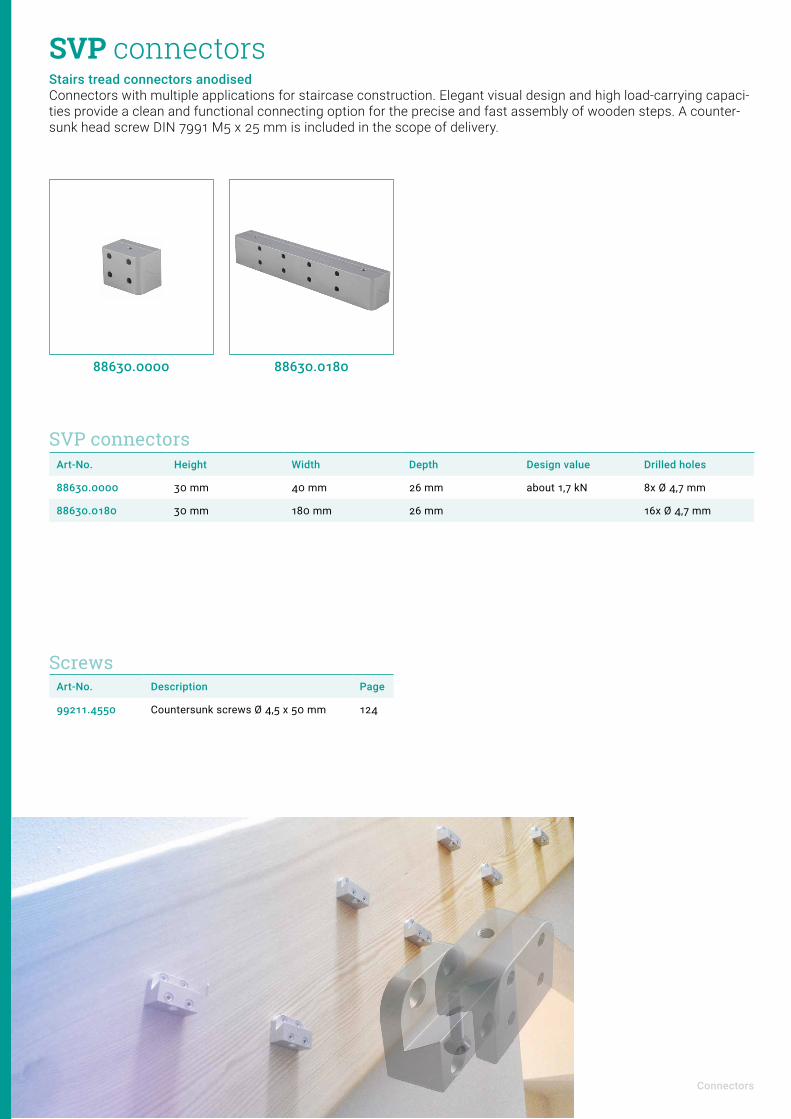
Art-No. Height Width Depth Design value Drilled holes
88630.0000 30 mm 40 mm 26 mm about 1,7 kN 8x Ø 4,7 mm
88630.0180 30 mm 180 mm 26 mm 16x Ø 4,7 mm
SVP connectorsStairs tread connectors anodised Connectors with multiple applications for staircase construction. Elegant visual design and high load-carrying capaci-ties provide a clean and functional connecting option for the precise and fast assembly of wooden steps. A counter-sunk head screw DIN 7991 M5 x 25 mm is included in the scope of delivery.
88630.0000
SVP connectors
88630.0180
Art-No. Description Page
99211.4550 Countersunk screws Ø 4,5 x 50 mm 124
Screws

71WVP connectors
Item no. Base plate with suspension hook
Borehole Base plate
Anchor plate with recess for hook
Borehole Anchor plate
Overall thickness when combined
Characteristic value*
traction shearing to the side
88060.0000 60 x 80 x 5 mm 6x Ø 6,5 mm 60 x 80 x 3 mm 4x Ø 6,5 mm 19 mm 9,6 kN 11,4 kN
* tested with fully threaded screws Spax 6 x 60 mm.
Wall connectors The ideal connection for prefabricated wood wall elements - easy, quick and cost-effective. When combined with solid workmanship, our wall connectors ensure high resilience (static values are available). Easy handling implies important savings for the user - thanks either to quick and easy assembly on site or to pre-as-sembly in the workshop. Materiel: S355 galvanised
WVP connectors
88060.0000
WVP Connectors
Art-No. Description Page
99210.6060 Washer-head screws Ø 6 x 60 mm 128
Screws

72 Connectors
Productgroup Borehole Ø 12 mm, countersunk Material CE
8871_.0000 4 zinc plated steel *
Art-No. Upper plate mm Tube mm Core thread max. characteristic tension load carrying capacity (kN) *
88710.0000 Ø 90 x 10 - M 10 16,3
88712.0000 Ø 100 x 6 Ø 42,4 x 70 M 12 16,3
88716.0000 Ø 100 x 6 Ø 42,4 x 70 M 16 21,9
The SPP connectors can be installed with the existing tool for the Pitzl post base systems 10930.____ or 10931.____.
SPP connectorsSPP post-purlin connectors You need stabile and reliable connections that you can process as well as re-stress in a quick and precise way. The Pitzl SPP connectors ensure a perfect hold. SPP post-purlin connectors - the ideal solution for tensile connections or wood connections with combined load types, such as post-purlin connections. SPP is a retensionable wood connection that can be loosened and removed without problems. According to the ETA, a straight screw connection is permitted even in cross-grained wood. This makes it possible to increase the tensile load-carrying capacity by increasing the effective thread length at the wood screw. Dimensioning details can be found in the Pitzl Design Manual at www.pitzl-connectors.com
88710.0000 88712.0000
Art-No. Upper plate mm Borehole Ø 10,5 mm, countersunk
Tenon mm Minimal timber dimensions mm
Material Core thread CE
88715.0000 Ø 80 x 8 4 Ø 24 x 20 90 x 90 anodised aluminium M 16 *
Metal fastening not included in the delivery contents. The load carrying capacity can be increased by using longer full-threaded screws or rather change the dimensions of the washers (see Table on the next site)
* For further static values see design manual or ETA 10/0413
88715.0000
SPP 80 connector

73SPP connectors
Advantages of the SPP connectors• Easy and precisely fitting process• Problem-free disassembly• Can be re-stressed• Usable at the end grain too
Art-No. Ø mm Central bore
99906.0068 68 x 6 18 mm
99908.0100 100 x 8 16,5 mm
Zinc Plated.
Washers
Technical data
Art-No. Description Page
99211.1012 Countersunk screws Ø 10 x 120 mm 125
99211.1016 Countersunk screws Ø 10 x 160 mm 125
99211.1028 Countersunk screws Ø 10 x 280 mm 125
Screws
Post-purlin connectors related to C24
Art-No. Washers (mm) Screws (mm) max. characteristic tension load carrying capacity (kN) *
88710.0000 Ø 58 x 4 10 x 120 16,3
88712.0000 Ø 58 x 4 10 x 120 16,3
88716.0000 Ø 68 x 4 10 x 120 21,9
88715.0000 Ø 68 x 4 10 x 160 21,9
88715.0000 Ø 68 x 4 10 x 280 31,5
88715.0000 Ø 100 x 4 10 x 280 52,9
88715.0000 Ø 100 x 4 10 x 280 + 10 x 120 62,5
* For further static values see design manual or ETA 10/0413

74 Connectors
ISO-CONNECT
Art-Nr. Description Dimension B x H x D [mm] Threaded hole
M8 M12 M16 M20
83100.0___ Connection to HVP 88210.3000 90 x 100 x 15 - 4 -
83200.0___ Connection to french balcony Ø 80 x 15 4 1 -
83600.0___ Universal connection Uni 1 90 x 100 x 15 - 4 1 -
83300.0___ Universal connection Uni 2 120 x 155 x 15 4 - - 1
83400.0___ Awning connection V1 80 x 220 x 15 - 2 - -
83400.1___ Awning connection V2 80 x 220 x 15 - 2 - -
83500.0___ Awning connection Uni 1 220 x 220 x 15 Threaded holes as required
83500.1___ Awning connection Uni 2 220 x 220 x 15 Threaded holes as required
The ISO-CONNECT is only available as a set with the appropriate screws. The insulation thickness must be specified for this reason.Example for insulation 160 mm: 83100.0160
83100.0___ 83200.0___
The connector for additional connections on thermally insulated timber facades. The ISO-CONNECT system offers, due to the combination of tension and compression screws perpendicular to the facade and inclined screws to transfer shear loads, a connection point on thermally insulated facades of timber constructions. Areas of application are for example purlins, rafters, french balconies etc. . The compatibility with the HVP connector system extends the applications of the ISO-CONNECT. So also a direct connection of beams to the fa-cade is possible. As a further option, the connection concept offers the possibility to mount purlin with threaded rods directly to the ISO-CONNECT and the facade.
The ISO-CONNECT can be mounted on solid timber, glulam and cross laminated timber.
83600.0___ 83300.0___
83400.0___ 83500.0___ 83500.1___83400.1___

75ISO-CONNECT
Assembling1. Positioning of the connector and optionally the rubber mat2. Fix the connector plate first with the screws perpendicular (horizontal) to the
facade until contact to the facade surface is reached. If using the rubber mat screw in until low deformations are reached.
3. Screw in inclined screws.4. Installation of the balcony railing, the HVP connector or the counter plate of
the universal connector.5. The gap between ISO-CONNECT and the facade should be filled with silicone
(acetic-free).
Product informationThe ISO-CONNECT connection plates may only be used in combination with the including screws with countersunk head.
The deformation of the rubber mat (3 mm thick) included in the scope of delivery indicates the contact pressure of the connection plate. In addition, this ensures a reliable effect of the seal, as three-flank adhesion of the adhesive and sealant is avoided.
Scope of delivery: connection plate, rubber mat and suitable screws for your insulation.

76 ConnectorsSource: www.holzon.de
Art-No. Dimension w x h x d Minimum dimensions b x h Characteristic value
HVP [mm]
Tension plate [mm]
Column [cm]
Beam [cm]
NRk [kN]
VRk [kN]
My,Rk [kNm]
Kφ [kNm/rad]
88318.4000 80 x 180 x 12 80 x 215 x 15 14 x 14 14 x 24 31,4 72,6 6,5 249
88430.4000 120 x 300 x 15 120 x 250 x 15 16 x 16 16 x 36 48,3 93,2 10,9 415
88555.4000 140 x 550 x 20 120 x 325 x 15 16 x 21 16 x 68 59,8 345,9 18,2 692
The load carrying-capacities were experimentally determined at the TVFA-Innsbruck.
Connection system for rigid frame corners With the Pitzl - RIGID system connector allows to build bending resistance connections between timber columns and beams (frame corners). The combination of the well - known HVP connector with an tension plate on the upper side replaces braces for example in carports. Larger versions may are also able to brace hall constructions in combination. With the Pitzl - RIGID, the designer has the possibility to work with joints with a very high rotational spring stiffness.
RIGID
88318.4000 88430.4000 88555.4000

77RIGID
AssemblingThe HVP connector is mounted to the column and girding beam (milled into the column). During assembling, the columns are mounted and then the girders are hang in with the HVP-connectors. Afterwards the the tension plate is screwed in with inclined screws. Also in that case the plate can milled in.

Balcony / Fence posts

79Content
ContentAssembly guide 80
BSP Balcony posts C-profile, hot-dip galvanized CE 82
GSP Railing posts T-iron and brackets 84
GSP Railing posts C-profile, hot-dip galvanized 85
GSP railing posts / BSP balcony postsAccessories for C-profile 87
GSP Railing posts with square tube30 x 30 x 2 mm, hot-dip galvanize 90
GSP Railing postsAccessories for tube 30 x 30 x 2 mm 92
GSP Railing posts with rectangular tube50 x 30 x 2 mm, hot-dip galvanized 93
GSP Railing posts Accessories for tubes 50 x 30 x 2 mm 94
Accessories for GSP railing / BSP balcony posts 95
SLP Columns for privacy and noise barriers 96
ZSP Fence posts C-profile, hot-dip galvanized 98
Accessories for ZSP fence posts 100

80 Balcony / Fence posts
Assembly guide1. Measure required distance from balcony post and balustrade
2. Cut the C-profile to the corresponding length, seal the cut if required, for instance by cold zinc-plating
3. Mounting the base plate to the balustrade: „ Plug the pressing plate with the stuid into the bottom opening of the metal column and slide them together over the mounted C-profile. Using a hexagonal wrench, tighten the adjusting screw at the required distance from the metal column and balustrade from below, through the slot of the C-profile. Done! „

81Assembly guide

82 Balcony / Fence posts
BSP Balcony posts C-profile, hot-dip galvanized CE
Productgroup Lower plate mm C-profile mm Oblong hole Ø 11 x 26 mm CE
3151_.0000 160 x 100 x 10 50 x 40 x 3 2 *
Art-No. Height C-profile mm
31510.0000 1000
31512.0000 1200
For front-side doweling, including a latch 285 x 50 x 5 mm with two drilling holes Ø 11 mm.
Henceforth we also offer our customers a maximum security along balcony constructions. The development of a special C-profil, produced as usual with a high quality in our own manufacture and prepared for approval by the Insti-tut for Construction and Material sciences of the Universität Innsbruck, Arbeitsbreich Holzbau. The BSP (Balkonsäule Pitzl), another top product of Pitzl wood connectors. For doweling or front-side mounting, with or without bend and for every required high the BSP always offers a functional, efficient and user-friendly solution. A high-quality hot-dip gal-vanization provides a perfect optics and the required corrosion protection, also in service class 3. The characteristic maximum power the holm can take is 2,12 kN. A ETA-certification enables an assembly conforming to standards.
3 drilling holes are provided for fixing the crossbeam.
31510.0000
Productgroup Lower plate mm C-profile mm Oblong hole Ø 11 x 26 mm Fixed bend mm CE
3151_.1060 160 x 100 x 10 50 x 40 x 3 2 60 *
Art-No. Height C-profile mm
31510.1060 1000
31512.1060 1200
For front-side doweling, including a latch 335 x 50 x 5 mm with two drilling holes Ø 11 mm.
31510.1060
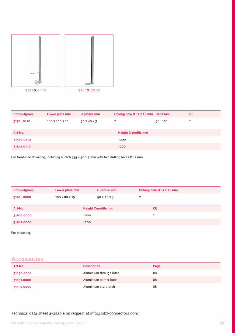
83BSP Balcony posts C-profile, hot-dip galvanized CE
Technical data sheet available on request at [email protected].
Productgroup Lower plate mm C-profile mm Oblong hole Ø 11 x 26 mm Bend mm CE
3151_.0110 160 x 100 x 10 50 x 40 x 3 2 30 - 110 *
Art-No. Height C-profile mm
31510.0110 1000
31512.0110 1200
For front-side doweling, including a latch 335 x 50 x 5 mm with two drilling holes Ø 11 mm.
31510.0110
Productgroup Lower plate mm C-profile mm Oblong hole Ø 11 x 26 mm
3161_.0000 180 x 80 x 15 50 x 40 x 3 2
31610.0000
Art-No. Description Page
31150.0000 Aluminium through-latch 88
31151.0000 Aluminium corner latch 88
31152.0000 Aluminium start latch 88
Accessories
Art-No. Height C-profile mm CE
31610.0000 1000 *
31612.0000 1200
For doweling.

84 Balcony / Fence posts
T - iron, hot-dip galvanised
GSP Railing posts T-iron and brackets
31105.0000
Art-No. Bottom plate mm Height mm Boreholes Ø 12 mm bottom T-iron mm Boreholes Ø 6,5 mm
31105.0000 100 x 100 x 10 400 4 45 x 45 x 5 6
Brackets, hot-dip galvanizedProductgroup Oblong boreholes Ø 11 x 26 mm Boreholes Ø 11 mm
369__.0000 2 2
Art-No. Base plate mm Side Strut mm
36905.0000 290 x 45 x 8 li 370 x 45 x 8
36906.0000 290 x 45 x 8 re 370 x 45 x 8
36907.0000 290 x 45 x 8 li 500 x 45 x 8
36908.0000 290 x 45 x 8 re 500 x 45 x 8
36910.0000 350 x 380 x 45 x 8
36905.0000 36906.0000 36910.0000

85GSP Railing posts C-profile, hot-dip galvanized
GSP Railing posts C-profile, hot-dip galvanized
Productgroup Bottom plate mm C-profile mm Oblong boreholes Ø 11 x 26 mm
311__.0000 180 x 60 x 10 50 x 30 x 15 x 3 2
Art-No. Height mm
31180.0000 800
31190.0000 900
31110.0000 1000
For doweling, including a plastic cap and two aluminium clip latches 160 x 40 x 5 mm.
31180.0000
Productgroup Bottom plate mm C-profile mm Oblong boreholes Ø 11 x 26 mm
312__.0000 160 x 100 x 10 50 x 30 x 15 x 3 2
Art-No. Height mm
31290.0000 900
31210.0000 1000
For front-side doweling, including a plastic cap and two aluminium clip latches 160 x 40 x 5 mm.
31290.0000
C-Profile for doweling
C-Profile for front-side doweling

86 Balcony / Fence posts
Productgroup Bottom plate mm Height mm C - profile mm Oblong boreholes Ø 11 x 26 mm
31210.0___ 160 x 100 x 10 1000 50 x 30 x 15 x 3 2
Art-No. Bend mm
31210.0110 30 - 110
31210.0200 30 - 200
For front-side doweling, including a plastic cap and two aluminium clip latches 160 x 40 x 5 mm.
31210.0110
Art-No. Bottom plate mm Height mm C - profile Boreholes Ø 12 mm bottom
Clearance from ground mm
31107.0000 100 x 100 x 8 800 50 x 30 x 15 x 3 4 140
2 parts, for insulation bridge.Including a plastic cap and two aluminium clip latches 160 x 40 x 5.Special heights of the fastener for other insulation thicknesses are available at request.
31107.0000
Variable bendVariable balcony posts for fastening timber balconies from the Pitzl system. Our variable balcony posts, being continuously adjustable, are ideally suited for different clearances or adverse as-sembly conditions (e. g. at eaves gutters).

87GSP railing posts / BSP balcony posts Accessories for C-profile
GSP railing posts / BSP balcony posts Accessories for C-profile
Productgroup Height mm U-profile
31170.0___ 300 22 x 42 x 22 x 2
Art-No. Upper plate mm
31170.0000 135 x 30 x 5
31170.0080 80 x 80 x 5
31170.0100 100 x 100 x 5
For fastening handrails, welded with flat sheet. ZiNiP-coated.
31170.0000
Art-No. Angle plate mm Height mm U-profile
31171.0000 30 x 45 x 160 300 22 x 42 x 22 x 2
For fastening handrails, welded with angle plate. ZiNiP-coated.
Art-No. Upper plate mm Height mm U-profile
31172.0000 135 x 30 x 5 300 22 x 42 x 22 x 2
For fastening handrails, welded with laterally inclinable flat sheet. ZiNiP-coated.
31172.000031171.0000
Extension piece
31174.0000
Threaded joint for extension piece, ZiNiP-coatedfor item no. 31170.0000 - 31172.0000
Art-No.
31174.0000

88 Balcony / Fence posts
Art-No. Dimensions mm Boreholes Ø 9,5 mm
31140.0000 160 x 40 x 5 2
31150.0000 160 x 40 x 5 2
31140.0000
Art-No. Dimensions mm Boreholes Ø 9,5 mm
31141.0000 110 x 75 x 40 x 5 2
31151.0000 110 x 75 x 40 x 5 2
31141.0000
Art-No. Dimensions mm Boreholes Ø 9,5 mm
31142.0000 125 x 40 x 5 2
31152.0000 125 x 40 x 5 2
31142.0000
Aluminium through-latch
Aluminium corner latch
Aluminium start latch

89
Art-No. Dimensions mm Special features
31175.1000 110 x 216 x 150 x 40 x 8 for fastening at the C-profile
Height-adjustable through the clamping elements.
31175.1000
Aluminium flower box holder

90 Balcony / Fence posts
GSP Railing posts with square tube 30 x 30 x 2 mm, hot-dip galvanize
Art-No. Bottom plate mm Height mm Tube mm Boreholes Ø 12 mm bottom
31100.0000 100 x 100 x 6 1000 30 x 30 x 2 4
For doweling, incl. a plastic cap.
31100.0000 31101.0000
Art-No. Bottom plate mm Height mm Tube mm Oblong boreholes Ø 11 x 26 mm
31101.0000 160 x 100 x 10 1000 30 x 30 x 2 2
For front-side doweling, incl. a plastic cap.
Art-No. Bottom plate mm Height mm Tube mm Oblong boreholes Ø 11 x 26 mm
31102.0000 180 x 60 x 10 1000 30 x 30 x 2 2
For doweling, incl. a plastic cap.
31102.0000

91GSP Railing posts with square tube 30 x 30 x 2 mm, hot-dip galvanize
Productgroup Bottom plate mm Height mm Tube mm Oblong boreholes Ø 11 x 26 mm
31101.0___ 160 x 100 x 10 1000 30 x 30 x 2 2
Art-No. Bend mm
31101.0110 30 - 110
31101.0200 30 - 200
For front-side doweling, incl. a plastic cap.
Assembly guide for variable bend• Measure required distance from balcony post and balustrade• Cut the C-profile to the corresponding length, seal the cut if required, for in-
stance by cold zinc-plating• Mounting the base plate to the balustrade: „ Plug the pressing plate with the
stuid into the bottom opening of the metal column and slide them together over the mounted C-profile. Using a hexagonal wrench, tighten the adjusting screw at the required distance from the metal column and balustrade from below, through the slot of the C-profile. Done! „
31101.0110
Variable bend Variable balcony posts for fastening timber balconies from the Pitzl system legally protected. Our variable balcony posts, being continuously adjustable, are ideally suited for different clearances or adverse as-sembly conditions (e. g. at eaves gutters).

92 Balcony / Fence posts
GSP Railing posts Accessories for tube 30 x 30 x 2 mm
Art-No. Upper plate mm Height mm Tube mm
32525.0000 135 x 30 x 5 300 25 x 25 x 2
For handrail fastening, welded with flat iron, ZiNiP coated.
32525.0000
Art-No. Bottom plate mm Tube mm Boreholes Ø 6,5 mm
31111.0000 200 x 30 x 5 35 x 35 x 1,5 x 30 2
For additional doweling onto the ground plate. Hot-dip galvanized.
31111.0000
Art-No. 31111.0000
Art-No. 31101.0110
Extension piece
Holding latch

93GSP Railing posts with rectangular tube 50 x 30 x 2 mm, hot-dip galvanized
GSP Railing posts with rectangular tube 50 x 30 x 2 mm, hot-dip galvanized
Art-No. Bottom plate mm Height mm Tube mm Oblong boreholes Ø 11 x 26 mm
31153.0000 180 x 60 x 10 1000 50 x 30 x 2 2
For doweling, including a plastic cap.
31153.0000
Art-No. Bottom plate mm Height mm Tube mm Oblong boreholes Ø 11 x 26 mm
31253.0000 160 x 100 x 10 1000 50 x 30 x 2 2
For front-side doweling., including a plastic cap.
31253.0000
Productgroup Bottom plate mm Height mm Tube mm Oblong boreholes Ø 11 x 26 mm
31253.0___ 160 x 100 x 10 1000 50 x 30 x 2 2
Art-No. Bend mm
31253.0110 30 - 110
31253.0200 30 - 200
For front-side doweling, including a plastic cap
31253.0110
Variable bendVariable balcony posts for fastening timber balconies from the Pitzl system legally protected. Our variable balcony posts, being continuously adjustable, are ideally suited for different clearances or adverse as-sembly conditions (e. g. at eaves gutters).

94 Balcony / Fence posts
GSP Railing posts Accessories for tubes 50 x 30 x 2 mm
Art-No. Upper plate mm Height mm Tube mm
34525.0000 135 x 30 x 5 300 45 x 25 x 2
For handrail fastening, welded with flat steel. ZiNiP-coated.
34525.0000
Extension piece
Commodities noteAdditionnally for the balcony posts with rectangular tube C-profile extension pie-ces (item no. 31170.0000 - 31172.0000) can be used combined with the threaded joint (item no. 31174.0000).
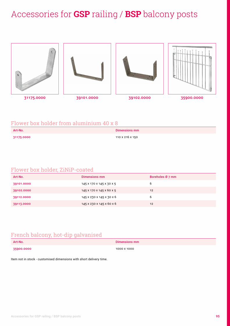
95Accessories for GSP railing / BSP balcony posts
Art-No. Dimensions mm
31175.0000 110 x 216 x 150
31175.0000
Art-No. Dimensions mm Boreholes Ø 7 mm
39101.0000 145 x 170 x 145 x 30 x 5 6
39102.0000 145 x 170 x 145 x 60 x 5 12
39112.0000 145 x 230 x 145 x 30 x 6 6
39113.0000 145 x 230 x 145 x 60 x 6 12
39101.0000
Art-No. Dimensions mm
35900.0000 1000 x 1000
Item not in stock - customised dimensions with short delivery time.
39102.0000 35900.0000
Accessories for GSP railing / BSP balcony posts
Flower box holder from aluminium 40 x 8
Flower box holder, ZiNiP-coated
French balcony, hot-dip galvanised

96 Balcony / Fence posts
SLP Columns for privacy and noise barriers
Art-No. Fixing plate mm Boreholes Ø 13 mm Length C-Profil mm (80 x 50 x 3)
Special features
38516.2000 240 x 210 x 15 4 2000 Start- and end-column
38516.2001 240 x 240 x 15 4 2000 Middle-column
The concrete foundation must be verified separately.
Screens made of sandwich panels or wooden elements are becoming more and more popular. Whether for dowel-ling, concreting or mounting on screw-in foundations, the innovation from the innovation forge Pitzl offers the perfect solution for every requirement as usual. In order to be able to guarantee you absolute safety, the privacy pillars have been thoroughly tested and approved for this purpose by the Institute for Construction and Materials Science at the University of Innsbruck. Mount the privacy pillars, slide the panels into the C-profile, which is adjusted to the standard panel thickness, and the assembly is finished.
38516.2000 38516.2001
SLP for dowelling, hot-dip galvanised

97SLP Columns for privacy and noise barriers
We are also happy to manufacture individual special solutions for your
area of application.
Art-No. Fixing plate mm Oblong hole 11 x 60 mm
Length C-Profil mm (80 x 50 x 3)
Special features
38516.2090 140 x 189 x 10 4 2000 Start- and end-column
38516.2091 140 x 189 x 10 4 2000 Middle-column
The screw-in foundation or rather the connection with it has to be proven separately.
Art-No. Length C-Profil mm (80 x 50 x 3) Special features
38514.2000 2500 Start- and end-column
38514.2001 2500 Middle-column
The concrete foundation must be verified separately.
Product informationOptionally also available powder-coated for an extra charge.
SLP for screw-in foundations, hot-dip galvanised
SLP to encased in concrete, hot-dip galvanised

98 Balcony / Fence posts
ZSP Fence posts C-profile, hot-dip galvanized
Productgroup C-profile mm
32___.0000 50 x 30 x 15 x 3
Art-No. Height mm
32080.0000 800
32100.0000 1000
32120.0000 1200
32150.0000 1500
For embedding in concrete, including a plastic cap and two aluminium clip latches 160 x 40 x 5 mm.
• Fence posts from stabile hot-dip galvanised C-profile for a quick assembly of fences.• Clip latches are afterwards removable and can be continuously adjusted on the fence height.• The product range includes fence posts for for doweling, embedding and laterally inclinable versions.
32080.0000
Productgroup Bottom plate mm C-profile Boreholes Ø 12 mm bottom
33___.0000 160 x 60 x 5 50 x 30 x 15 x 3 4
Art-No. Height mm
33080.0000 800
33100.0000 1000
For doweling, including a plastic cap and two aluminium clip latches 160 x 40 x 5 mm.
33080.0000

99ZSP Fence posts C-profile, hot-dip galvanized
Productgroup C-profile mm
34___.0000 50 x 30 x 15 x 3
Art-No. Height mm
34080.0000 800
34100.0000 1000
For embedding, laterally inclinable up to 18°. Including a plastic cap and two clip latches from aluminium 160 x 40 x 5 mm.
34080.0000
Productgroup Bottom plate mm C-profile mm Boreholes Ø 12 mm bottom
35___.0000 160 x 60 x 5 50 x 30 x 15 x 3 4
Art-No. Height mm
35080.0000 800
35100.0000 1000
For embedding, laterally inclinable up to 18°. Including a plastic cap and two clip latches from aluminium 160 x 40 x 5 mm.
Product informationAdditional clip latches page 88.
35080.0000
Fence posts, laterally inclinable

100 Balcony / Fence posts
Accessories for ZSP fence posts
Art-No. Dimensions mm
31312.0000 M 12 x 100
31313.0000 M 12 x 120
31314.0000 M 12 x 180
Art-No. Dimensions mm
31322.0000 M 12 x 100
31323.0000 M 12 x 120
31324.0000 M 12 x 180
31312.0000
Art-No. Dimensions mm
31316.0000 M 16 x 120
31317.0000 M 16 x 180
Art-No. Dimensions mm
31412.0000 M 12 x 100
31413.0000 M 12 x 120
31414.0000 M 12 x 180
31412.0000
Art-No. Dimensions mm
31422.0000 M 12 x 100
31423.0000 M 12 x 120
31424.0000 M 12 x 180
Art-No. Dimensions mm
31432.0000 M 12 x 100
31433.0000 M 12 x 120
31434.0000 M 12 x 180
Art-No. Dimensions mm
31416.0000 M 16 x 120
31417.0000 M 16 x 180
Cone Ø 12 mm
Cone Ø 13 mm
Cone Ø 16 mm
Hinge Ø 12 mm
Hinge Ø 13 mm
Hinge Ø 14 mm
Hinge Ø 17 mm
Product informationOur cones and hinges are provided with a high-quality ZiNiP® coating.
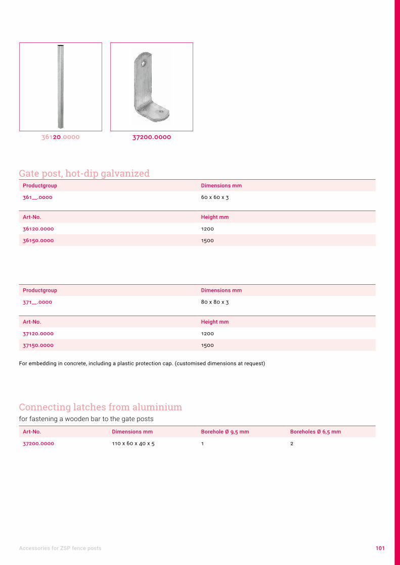
101Accessories for ZSP fence posts
Productgroup Dimensions mm
361__.0000 60 x 60 x 3
Art-No. Height mm
36120.0000 1200
36150.0000 1500
36120.0000
Productgroup Dimensions mm
371__.0000 80 x 80 x 3
Art-No. Height mm
37120.0000 1200
37150.0000 1500
For embedding in concrete, including a plastic protection cap. (customised dimensions at request)
Art-No. Dimensions mm Borehole Ø 9,5 mm Boreholes Ø 6,5 mm
37200.0000 110 x 60 x 40 x 5 1 2
37200.0000
Gate post, hot-dip galvanized
Connecting latches from aluminiumfor fastening a wooden bar to the gate posts

102 Balcony / Fence posts
Art-No. Dimensions mm Boreholes Ø 6,5 mm countersunk
36070.0000 250 x 35 x 35 3
36070.0000
Art-No. Dimensions mm Borehole Ø 5 mm Borehole Ø 11 mm Suspension slot 9 x 18 mm
Borehole Ø 8,5 mm
36700.0000 60 x 35 x 2,5 4 1 1
36701.0000 60 x 27 x 35 x 2,5 4 1 1
36702.0000 83 x 35 x 2,5 4 1 1
36710.0000 44 x 44 x 36 x 3 4
36700.0000 36702.0000 36710.0000
Door stop, hot-dip galavanizedfor tube frames 60 x 30
Fence suspension hook, ZiNiP

103Accessories for ZSP fence posts
Productgroup Dimension mm
39200.07__ 71 x 71
Art-No. Version Color / Material
39200.0701 flat stainless steel
39200.0703 flat green
39200.0711 with sphere stainless steel
39200.0712 with sphere hot-dip galvanised
Productgroup Dimension mm
39200.09__ 91 x 91
Art-No. Version Color / Material
39200.0901 flat stainless steel
39200.0903 flat green
39200.0904 flat copper
39200.0902 flat hot-dip galvanised
39200.0911 with sphere stainless steel
39200.0913 with sphere green
39200.0912 with sphere hot-dip galvanised
39200.0701 39200.0703 39200.0904 39200.0902
Post capsDecoration and protection for squared timber posts

104 Balcony / Fence posts
Productgroup Dimension mm
39200.10__ 101 x 101
Art-No. Version Color / Material
39200.1001 flat stainless steel
39200.1003 flat green
39200.1004 flat cupper
39200.1002 flat hot-dip galvanised
39200.1011 with sphere stainless steel
39200.1012 with sphere hot-dip galvanised
39200.1011 39200.1012
Productgroup Dimension mm
39200.12__ 121 x 121
Art-No. Version Color / Material
39200.1201 flat stainless steel
39200.1202 flat hot-dip galvanised
39200.1211 with sphere stainless steel

105Accessories for ZSP fence posts
Art-No. Dimensions mm Borehole Ø 6,5 mm countersunk
31176.0000 100 x 50 x 5 4
31177.0000 100 x 55 x 55 x 50 4
For fastening fence panels.
31176.0000 31177.0000
Art-No. Dimensions mm Thread mm Borehole Ø 11 mm
31178.0000 120 x 30 x 5 Ø 8 x 75 2
For fastening fence panels.
31178.0000
Productgroup Tube mm Suitable cone Ø mm
360__.0000 60 x 30 x 2 12
Art-No. Dimensions mm
36060.0000 1000 x 600
36080.0000 1000 x 800
Complete with lock, without lock cylinder, bolt 8 mm. (customised dimensions at request)
36060.0000
Suspension clips, ZiNiP
Screw latch
Garden door, hot-dip galvanised

Tools

107
ContentLifting clamps PowerClamp 108
Beam puller and accessories 110
Drills 112
Drilling device and accessories 114
Milling and assembly templates 115
Milling unit and accessories 116
Wall support and accessories 118
Assembly jig and Pry bar 119
Useful gadgets 120

108 Tools
Lifting clamps PowerClamp
Art-No. Description Max. Load capacity Weight per clamp Borehole Ø mm
55870.1000 D25/70 up to 500 kg 1,00 kg 26
55890.1000 D40/90 up to 1500 kg 1,80 kg 40
The lifting clamps - the latest innovation in timber construction. Enables you easily to raise wooden beams and massive edge glued panels through a simple and quick fastening of the lifting clamps. Depending on the demand the D40/90 is appropriate for a load carrying capacity up to 1500 kg, the D25/70 for a load carrying capacity up to 500 kg. Drill, apply, lift!
PowerClamp single
55890.100055870.1000
Art-No. Description
55870.0000 2x D25/70 incl. Drill, Drill Stopper and transport case
55890.0000 2x D40/90 incl. Drill and trans-port case
Art-No. Description
55870.4000 4x D25/70 incl. Drill, Drill Stopper and transport case
55890.4000 4x D40/90 incl. Drill and trans-port case
PowerClamp 2-piece set PowerClamp 4-piece set
Accessories for PowerClampArt-No. Description Page
55865.0000 Drill bit "Spur Bit" 113
55875.0025 Drill "auger bit" 112
55875.2025 Drill „auger bit“ incl. Drill Stopper 112
55895.0000 Adapter ring for ceiling elements 80 mm on visibility
55895.0000

109Lifting clamps PowerClamp
Advantages of PowerClamp• Major time savings• No other lifting gear needed• No damage of wood surface• No soiling• -Transponder for digital recording and theft protection (D40/90)
Scope of supply• 2x or 4x PowerClamp (D40/90 or D25/70)• 1x Drill (40 mm or 26 mm)• 1x High quality transport box
The low-maintenance lifting clamp is your optimal partner for each construction project. Despite the low weight it is extremely robust.
ApplicationApplication is easy as can be. A drill-hole size of just 40 mm or 26 mm is suffi-cient. Insert the clamps and you can already effortless lift the structural element.
With 80 mm ceiling elements, the adapter ring can be used to avoid a visible hole on the underside.

110 Tools
Beam puller with turn-adapter
Beam puller and accessories
55850.0000
Fix, tighten, done!
Convenient work Lay the turn-adaptor on the object and screw. Differently arranged boreholes allow a smoothly fastening on timber or masonry. The mounted to the adaptor butt strap serves for the fastening in grooves or to edges.
Therefore Pitzl beam puller provides a perfect stability for the processing of solid wood elements, alveolar elements and wood soft fiber elements.
Art-No. Span mm Boreholes Ø 8 mm Max. load capacity
55850.0000 720 -570 16 20 kN
Product informationBoth beam pullers are delivered with our high quality transport box.
Beam puller with hooksFix, tighten, ready!
Art-No. Span mm Boreholes Ø 8 mm Max. load capacity
55851.0000 600 - 460 2 20 kN
55851.0000 55850.1000 55850.2000

111Balkenzüge und Zubehör
Accessories for beam pullerArt-No. Description
55850.1000 Hook
55850.2000 Bracing strip tensioner 1 - 8 mm
55850.2100 Adapter ring for bracing strip tensioner 55850.200
Advantages of the turn-adapter• Can be fixed everywhere• Slight damage of timber• Easy handling• Fastening in every angles
Advantages of the hook• Through the additional bore fastening by one screw is possible.• Special Pitzl hooks for easy and non destructive removal.
Easy setup for gentle and precise processing of wooden surfaces and wooden be-ams. Both timber puller ratchets allow quick switch between different tool attach-ments.
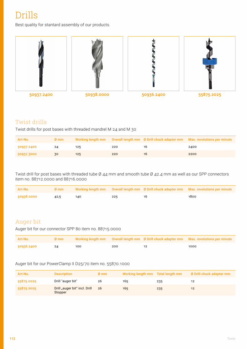
112 Tools
Drills
Twist drills for post bases with threaded mandrel M 24 and M 30
Art-No. Ø mm Working length mm Overall length mm Ø Drill chuck adapter mm Max. revolutions per minute
50937.2400 24 125 220 16 2400
50937.3000 30 125 220 16 2200
Best quality for stantard assembly of our products.
50937.2400
Twist drill for post bases with threaded tube Ø 44 mm and smooth tube Ø 42.4 mm as well as our SPP connectors item no. 88712.0000 and 88716.0000
Art-No. Ø mm Working length mm Overall length mm Ø Drill chuck adapter mm Max. revolutions per minute
50938.0000 42,5 140 225 16 1800
50938.0000
Auger bit for our connector SPP 80 item no. 88715.0000
Art-No. Ø mm Working length mm Overall length mm Ø Drill chuck adapter mm Max. revolutions per minute
50936.2400 24 100 200 12 1000
50936.2400 55875.2025
Twist drills
Auger bit
Auger bit for our PowerClamp II D25/70 item no. 55870.1000
Art-No. Description Ø mm Working length mm Total length mm Ø Drill chuck adapter mm
55875.0025 Drill "auger bit" 26 165 235 12
55875.2025 Drill „auger bit“ incl. Drill Stopper
26 165 235 12
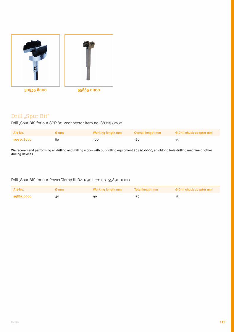
113Drills
Drill „Spur Bit“ for our SPP 80-Vconnector item-no. 88715.0000
Art-No. Ø mm Working length mm Overall length mm Ø Drill chuck adapter mm
50935.8000 80 100 160 13
We recommend performing all drilling and milling works with our drilling equipment 59420.0000, an oblong hole drilling machine or other drilling devices.
50935.8000
Drill „Spur Bit“
Drill „Spur Bit“ for our PowerClamp III D40/90 item no. 55890.1000
Art-No. Ø mm Working length mm Total length mm Ø Drill chuck adapter mm
55865.0000 40 90 150 13
55865.0000

114 Tools
Drilling deviceArt-No. Ø Drilling machine adapter in mm
59420.0000 57
Perform drilling and milling operations in the cross-grained wood with efficiency and precision. Continuous adjust-ment enables the processing of timber dimensions between 120 x 120 and 240 x 240 mm. A sturdy rack and the depth stop make for a uniform drilling and milling result.
59420.0000
Drill jig for precise guidance of the drill bitArt-No. Ø mm
50020.2000 20
50020.2400 24
50020.3000 30
50020.4200 42,5
50020.2000
Support for drill jigArt-No. Ø mm
50018.2000 20
50018.2400 24
50018.3000 30
50018.4200 42,5
50018.2000
Drilling device and accessories
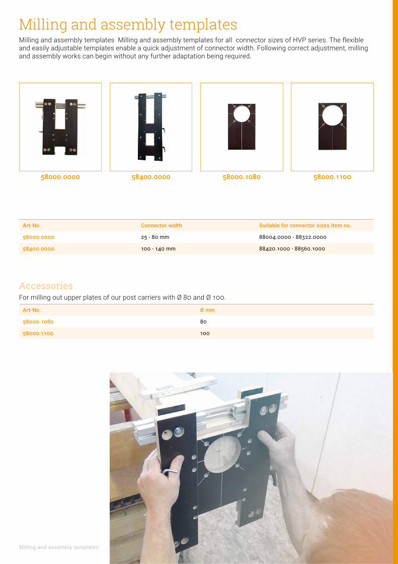
115Milling and assembly templates
Milling and assembly templatesMilling and assembly templates Milling and assembly templates for all connector sizes of HVP series. The flexible and easily adjustable templates enable a quick adjustment of connector width. Following correct adjustment, milling and assembly works can begin without any further adaptation being required.
Art-No. Connector width Suitable for connector sizes item no.
58000.0000 25 - 80 mm 88004.0000 - 88322.0000
58400.0000 100 - 140 mm 88420.1000 - 88560.1000
58000.0000
Art-No. Ø mm
58000.1080 80
58000.1100 100
58400.0000 58000.1080 58000.1100
AccessoriesFor milling out upper plates of our post carriers with Ø 80 and Ø 100.

116 Tools
58399.0000
The milling unit is composed of the following items: - Milling template item no. 58390.0000 - Scheer hand overhead router item no. 58391.0000 - Milling bit item no. 58392.0000
Art-No.
58399.0000
Milling unit
Milling unit and accessories
Art-No.
58390.0000
Milling template to mill in our HVP connectors
58390.0000
Scheer hand overhead router HM 14The Scheer hand overhead router HM 14 is suitable for moderately difficult milling works and is ideal for milling metal mount. It is equipped with a universal motor for light flux.
Art-No. Output Net weight Stop Male thread Speed Max. lift
58391.0000 1200 Watt 4,7 kg 3 x M 10 1800 60 mm
58391.0000
Easy handling, precise and fast. Thanks to its compact build, the milling device can be applied in all main and secondary joist connections for all HVP sizes with 12 mm thickness. It ensures accurate milling for the connectors through harmonised components. Linear guides enable an absolutely clean and accurate milling cut-out. The eccentric clamping device allows for fast and precise fastening. The ergonomic design makes for comfortable and time-saving work.
Milling bitArt-No. Ø mm Working length mm Overall length mm Material
58392.0000 20 45 75 HSS
58395.1000 20 45 75 HM
Appropriate for milling device Scheer HM 14.
58392.0000

117Milling unit and accessories
Art-No. Mounting internal thread Mounting external thread
58396.0000 M10 M16
Appropriate for milling device Scheer HM 14.
58396.0000
Art-No. Ø mm Description
58396.0008 8 suitable for grooving cutter Art-No. 50934.1000
58396.0012 12 suitable for grooving cutter Art-No. 50934.2000
58396.0008
Art-No. Ø mm Working length mm
Overall length mm
Depth adjusting collar Ø mm
Ball bearing closed mm
suitable for con-nector widths mm
50934.1000 10 20 52 8 20 x 8 x 5 25, 40
50934.2000 20 20 60 12 30 x 12 x 8 60, 80, 120, 140
50934.1000
Collet holder without collet
Collet
Grooving cutter
50934.2000
Product informationThese combinations are essential for a optimum milling grove. The exact milling texture for the respective connector is obtained. Therefore a quick installation of our connectors without an additional calibration is feasible.
In combination with our milling templates (page 115) you can also mill in the upper parts of our post bases.

118 Tools
Wall support and accessories
Wall support3 parts, electroplated, fine adjustment via left/right thread, tube 45 x 45 mm
Art-No. Adjustment range mm Thread Weight
55650.0000 1600 - 4200 M 20 12,5 kg
3-part galvanised with variable distance piece length 1300 - 1970 mm
Art-No. Adjustment range mm Thread Weight
55650.0100 1600 - 4200 M 20 18,2 kg
Indication: Calculation software available on request.
55650.0100
Art-No.
55650.1000
Distance piece variable Adjustable with ratchet
Art-No. Adjustment range mm
55650.1100 1300 - 1970
Lever for easier adjustment of the wall support
Art-No.
55650.2000
55650.1000 55650.1100 55650.2000
Accessories for wall support
Distance piece from tube 40 x 40 x 2 x 1265 mm for optimum alignment of the wall elements

119Assembly jig and Pry bar
Assembly jig and Pry bar
Assembly jigvariable for nailed trusses, electrogalvanised
Art-No. Description
55600.0000 M 16 x 700 - 1200 mm
55600.0000
Pry barwith rubber handle for removing planks from rafters without straining your back (not for rafter / post connections)
Art-No. Weight Length Load capacity
55800.0000 2,54 kg 1 meter 60 kg at the height of the handle
Care has to be taken that during the use the pressure is oriented in the roof direction.
55800.0000

120 Tools
Useful gadgets
54803.000054801.0000 54803.0060 54804.0000
Characterised by its particularly high load capacity (welded steel frame) despite its extremely low weight, and wide range ofpanel material types that it can be used for. The clamping force automatically adapts to the weight of the element that is beingcarried.
Art-No. Span Load capacity
54803.0000 0 - 65 mm approx. 120 kg
54803.0060 60 - 120 mm approx. 120 kg
Sold in pairs.
UNIVERSAL – Panel carrier
Floor clamp – Board tightenerThe board tightener is one of our own inventions and produced by us. It provides an innovative solution even for experien-ced floor layers. The laying of materials with tongue and groove connections, floorboards and decking etc. can be done quicker and more accurately than by conventional methods.
Art-No. Span Material clamping jaws
54801.0000 30 - 120 mm Metal
54801.0001 30 - 120 mm Rubber
A practical tool for the exact scribing and transferring of irregularities in walls and cut-outs for cover panels, skirting boards, worktops, covers etc.
Art-No. Model
54804.0000 Parallel scribe with compass point
Parallel scribe
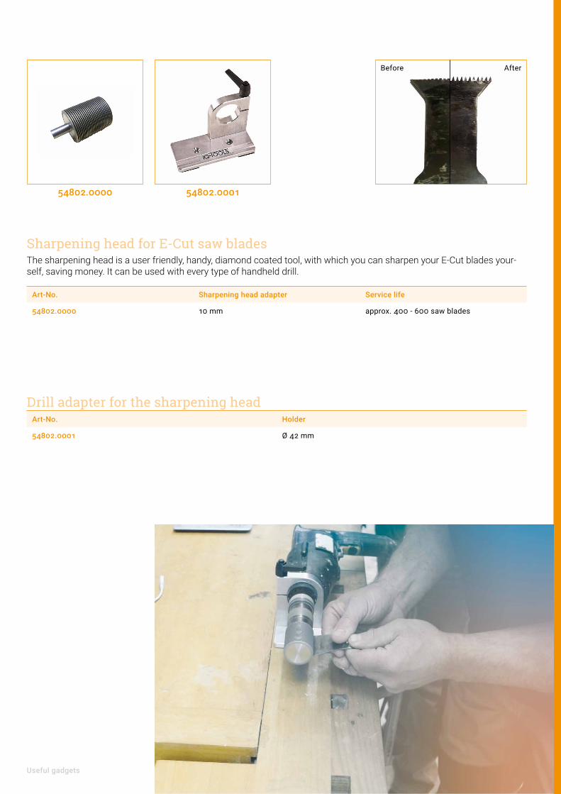
121Useful gadgets
The sharpening head is a user friendly, handy, diamond coated tool, with which you can sharpen your E-Cut blades your-self, saving money. It can be used with every type of handheld drill.
Art-No. Sharpening head adapter Service life
54802.0000 10 mm approx. 400 - 600 saw blades
54802.000154802.0000
Sharpening head for E-Cut saw blades
Drill adapter for the sharpening headArt-No. Holder
54802.0001 Ø 42 mm
Before After

Fasteners

123Content
ContentCountersunk screws 124
Concrete or steel connections 126
Washer-head screws 128
Simply SAF special screws 129

124 Fasteners
Countersunk screws
Art-No. d l lg dk Drive train
99211.4550 4,5 50 45 8,9 T-Drive
99211.4560 4,5 60 54 8,9 T-Drive
99211.4580 4,5 80 74 8,9 T-Drive
99211.5060 5 60 54 9,6 T-Drive
99211.5080 5 80 74 9,6 T-Drive
99211.5100 5 100 94 9,6 T-Drive
hardened, blue zinc plated.
Art-No. d l lg dk Drive train
99111.4550 4,5 50 45 8,9 POZI-Drive
99111.4560 4,5 60 54 8,9 POZI-Drive
99111.5060 5 60 54 9,6 POZI-Drive
99111.5070 5 70 60 9,6 POZI-Drive
Blank, glide.
Countersunk head screws stainless steel A2
Countersunk screwsfor our HVP connectors 880 - 883 and stairs tread connectors

125Countersunk screws
Art-No. d l lg dk Drive train
99211.0812 8 120 110 14,8 T-Drive
99211.0816 8 160 150 14,8 T-Drive
99211.0818 8 180 170 14,8 T-Drive
99211.0820 8 200 190 14,8 T-Drive
hardened, blue zinc plated.
Countersunk screwsfor our heavy-duty HVP connectors 884 - 885 and our GePi-Connect
for our SPP connectors
Art-No. d l lg dk Drive train
99211.1012 10 120 110 18,5 T-Drive
99211.1016 10 160 150 18,5 T-Drive
99211.1028 10 280 270 18,5 T-Drive
hardened, blue zinc plated.
Countersunk screws

126 Fasteners
Concrete or steel connections
Art-No. Dimensions mm Socket head SW Description for Art-No.
99812.0090 12 x 90 5 FH II 12/15 SK 88210.3000 - 88322.3000
99812.0100 12 x 100 5 FH ll 12/25 SK 88420.3000 - 88460.3000
blue zinc plated
Art-No. Dimensions mm Female thread
99818.0125 18 x 125 M 12
blue zinc plated
Art-No. Dimensions mm Description for Art-No.
99810.0100 12,5 x 100 FBS II 10x100 mm, 45/35/15, SK 88210.3000 - 88322.3000
99810.0120 12,5 x 120 FBS II 10x120 mm, 65/55/35, SK 88420.3000 - 88460.3000
blue zinc plated
99812.0090 99818.0125 99810.0100
Fischer Ultracut
Fischer female-threaded anchor RG MI(for Art-No. 88420.3000 - 88460.3000)
Fischer high-performance anchor

127Concrete or steel connections
Art-No. d l lg dk Drive train Description for Art-No.
99212.0100 12 100 89 24 T-Drive MMS-plus F 12x100/25 88210.3000 - 88322.3000
99212.0120 12 120 109 24 T-Drive MMS-plus F 12x120/30 88420.3000 - 88460.3000
galvanized blue
Heco MULTI-MONTI-plus
Mounting set for steel connection(for Art-No. 88420.3000 - 88460.3000)
Art-No. Dimensions mm Hexagon socket SW Description
29804.1250 12 x 50 8 4-piece set
29804.1260 12 x 60 8 4-piece set
29806.1250 12 x 50 8 6-piece set
29806.1260 12 x 60 8 6-piece set
blue zinc plated
29806.1250 29806.126099212.0120 99216.1212
Art-No. d l lg SW Description for post bases
99216.1080 10 80 76 13 MMS-plus SS 10x80/15 M20, M24
99216.1212 12 120 115 15 MMS-plus SS 12x120/30 M30
99216.1613 16 130 125 21 MMS-plus SS 16x130/15 M30
galvanized blue

128 Fasteners
Washer-head screws
Product noticeAn increase of tensile load bearing is feasible by using a timber screw with a longer effective thread legth. For assessment details see Pitzl-Statik-Handbuch at www.pitzl-connectors.com/statikhandbuch.
Art-No. d l lg dk Drive train
99210.1012 10 120 110 22,5 T-Drive
99210.1016 10 160 150 22,5 T-Drive
Hardened, galvanised.
Art-No. d l lg dk Drive train
99110.1012 10 120 100 22,5 T-Drive
Blank, glide, for mounting in service class 3.
Washer-head screws T-Drive full-thread A2
99210.1012 99110.1012
for our post bases
Art-No. d l lg dk Drive train
99210.6060 6 60 53 14 T-Drive
Art-No. d l lg dk Drive train
99200.0880 8 80 60 18 T-Drive
Washer-head screws T-Drive full-threadfor our wall connectors
for our GePi-Connect

129Simply SAF special screws
Simply SAF special screws
Art-No. d l dk Drive train Minimum width of the secondary beam
98907.0073 7 73 15 T40 80
98907.0093 7 93 15 T40 100
98907.0113 7 113 15 T40 120
98907.0133 7 133 15 T40 140
98907.0153 7 153 15 T40 160
98907.0173 7 173 15 T40 180
98907.0193 7 193 15 T40 200
98907.0213 7 213 15 T40 220
98907.0233 7 233 15 T40 240
98907.0073
Sound Protection

131Content
ContentSound protection angle bracket with power 132
Sylodyn® and Sylomer® insulation band 134
Elastic washers 136

132 Sound Protection
Art-No. Description
81010.0000 Fitting tool, 2-parts for GePi angle bracket
Art-No. Description Page
99200.0880 Washer-head screw Ø 8 x 80 mm 128
99211.0816 Counter-sunk screw Ø 8 x 160 mm 125
Sound protection angle bracket with powerThe „GePi- Connect“, developed in the course of the cooperation with Getzner Werkstoffe has a much higher load-be-aring capacity than comparable concepts. On the basis of test results the TVFA-Innsbruck confirms characteristic loads up to 60 kN for the GePi 240. An additional advantage of this system is the energy dissipation without any breakage in the earthquake case. Cyclic stresses impressively confirm the efficiency due to acting dynamic loads of the revolutionary GePi-concept.
Art-No. Labeling Dimension Screwing 8 mm Characteristic load-bearing capacity [kN] *)
A B H s Horizontal (TK 8 x 80 TG)
Vertical (SK 8 x 160 VG)
F1,k F2/3,k F4/5,k
81000.0100 GePi 100 100 mm 100 mm 100 mm 3 5 4 16 12 12
81000.0240 GePi 240 100 mm 240 mm 100 mm 3 16 11 50 60 40
* Values determined with experimental tests from the University Innsbruck. European Technical Assessment (ETA) applied.
Art-No. Labeling Material
Angle bracket Sylodyn® Supporting plate
81000.0100 GePi 100 Steel S250GD + Z275 Closed cellular pore structure Steel S235
81000.0240 GePi 240 Steel S250GD + Z275 Closed cellular pore structure Aluminium EN AW 6082
In coparision to a lot of other conventional building materials, elastomers have a distinctive pronounced non-linear material behavior. That means, material parameters such as static- and dynamic stiffnesses are dependent on the particular load situation. In order for an ideal use of the material Sylodyn®, we recommend a mounting kit to ensure a defined preload.
81000.0100 81000.0240 81010.0000
GePi - Connect
Screws
Fitting toolAccessories

133Sound protection angle bracket with power
Characteristic Load-bearing capacity up to 60 kNacc. to EN 1995:2014
Advantages and benefits• High shear- and tensile strength• Sound transmission decoupled connection• Proofed sound insulation• Resistant to earthquakes (GePi 240)• Reliability for Engineers and users• Approved product quality
ApplicationsAngle brackets for shear loads with decoupled flanks• Connection timber-timber• High wind forces• Earthquake loads (GePi 240)• Lifting forces• Increased requirements on sound insulation

134 Sound Protection
Sylodyn® and Sylomer® insulation bandWork against sound transmission.
Sylodyn® tapes in different thicknesses, widths and designs ensures an efficient sound insulation for all kind of constructions.
The decades-long experience of the company Getzner with vibration insulation-systems in the applications of railway, construction and industry allows architects, designers and building physicists as well as carpentries, to fulfill the high sound insulation and structural requirements on buildings where people live.
The tapes are as required 6.25, 12.5 or 25 mm thick and are available in different dimensions depending to customer requirements. To ensure an optimized sound insulation for a wide range of load levels products with different stiffe-nesses are manufactured and installed between the wall- and slab elements. For highly stressed components with high compression forces also spezial Sylodyn® grades are available on demand.
Art-No. Description Static application1 in MPa Load peaks1 in MPa
81100 NB 0,075 2,00
81200 NC 0,150 3,00
81300 ND 0,350 4,00
81400 NE 0,750 6,00
81500 NF 1,500 8,00
81601 HRB HS 3000 3,000 12,00
81602 HRB HS 6000 6,000 18,00
81600 HRB HS 12000 12,000 24,00
Closed cellular pore structure (Polyurethan)
Art-No. Description Static application1 in MPa Load peaks1 in MPa
84200 SR 11 0,011 0,50
84700 SR 18 0,018 0,75
84400 SR 28 0,028 1,00
84000 SR 42 0,042 2,00
84300 SR 55 0,055 2,00
84110 SR 110 0,110 3,00
84100 SR 220 0,220 4,00
84800 SR 450 0,450 5,00
84900 SR 850 0,850 6,00
84500 SR 1200 1,200 6,00
Mixed cellular pore structure (Polyurethan)
Sylodyn®
Sylomer®
1 values are valid for form factor q = 3

135Sylodyn® and Sylomer® insulation band
Product informationWe supply Sylodyn® or Sylomer® strips exactly according to customer requirements. Put together your insulation strips according to your requirements as follows:
1. Selecting the elastomer2. Selecting the strength
(1: 12.5 mm; 4: 6.25 mm; 5: 25 mm)3. Specification of the required width
Example 81400.1250: A strip of Sylodyn® NE, 12.5 mm thick and 250 mm wide, and 1500 mm length.

136 Sound Protection
Elastic washersElastic washers EW are used to decouple screw connections to avoid any kind of structure-borne sound. The poly-urethane material Sylodyn® effectively isolates vibrations and have a long working period. In addition to the sound insulation, the elastic washers also electrically non-conductive and resistant to common oils and greases.
Art-No. Description Thickness Screw dimension Ø A Ø B
81900.0806 EW M8-6 6 mm M8 35 mm 9 mm
81900.1006 EW M10-6 6 mm M10 40 mm 11 mm
81900.1206 EW M12-6 6 mm M12 50 mm 13 mm
81900.1606 EW M16-6 6 mm M16 55 mm 17 mm
81901.0808 EW M8-8 8 mm M8 28 mm 9 mm
81901.1008 EW M10-8 8 mm M10 34 mm 11 mm
81901.1208 EW M12-8 8 mm M12 44 mm 13 mm
81901.1608 EW M16-8 8 mm M16 56 mm 17 mm
81900.0812 EW M8-12 12 mm M8 35 mm 9 mm
81900.1012 EW M10-12 12 mm M10 40 mm 11 mm
81900.1212 EW M12-12 12 mm M12 50 mm 13 mm
81900.1612 EW M16-12 12 mm M16 55 mm 17 mm
81901.0821 EW M8-21 21 mm M8 28 mm 9 mm
81901.1021 EW M10-21 21 mm M10 34 mm 11 mm
81901.1221 EW M12-21 21 mm M12 44 mm 13 mm
81901.1621 EW M16-21 21 mm M16 56 mm 17 mm
81900.081281900.0812 81900.1612 81901.1008 81901.1208
Standard solution With centering
DB
Ela
stis
che
Un
terl
agsc
hei
be
EW
de
© C
opy
rig
ht
by G
etzn
er W
erks
toff
e G
mb
H l
12-2
016
Än
der
un
gen
vo
rbeh
alte
n.
Die Angaben der Daten beruhen auf unserem derzeitigen Wissenstand. Sie können als Rechen- bzw. Richtwerte herangezogen werden und unterliegen üblichen Toleranzen konform ISO 3302-1; Irrtum und Änderungen vorbehalten.
Typ EW XX-6 Typ EW XX-12
Typ EW XX-21
AUSTRIA — Bürs GERMANY — Berlin — Munich — Stuttgart FRANCE — Lyon JORDAN — Amman
JAPAN — Tokyo INDIA — Pune CHINA — Beijing USA — Charlotte www.getzner.com
6
12
21 25
Schnitt A–A (2 : 1)
Schnitt A–A (2 : 1)
A–A
øB øB
øB + 4,0
øB
øA
øA øA
A
A A
A A A
Typ EW XX-8
8
12
A–A
øB + 4,0
øB
øA
A A

137Elastic washers
Advantages• Effective sound- and vibration insulation• Durable material properties• No embrittlement (free of plasticizers)• Assortment for different screw sizes• Variants with centering aid• Fire behavior according to DIN EN 13501-1• Surface protection• Electrically non-conductive• Resistant to oils and greases• Thermally insulating
ExecutionIn addition to the standard solution are also washers with centering (fold) availa-ble to facilitate installation and accurate positioning of the screw to the borehole. For screw sizes M8, M10, M12 and M16 are different dimensions available, adap-ted on different bearing thicknesses and various stifnesses. Please ask for the maximum torsional moment.

138 Pitzl

139

140 Pitzl

141

142 Pitzl

143

144 Pitzl
ImprintPitzl Metallbau GmbH & Co. KG Siemensstr. 26 84051 Altheim Germany
Telephone: +49 (0) 8703 / 9346-0 Telefax: +49 (0) 8703 / 9346-55
[email protected] www.pitzl-connectors.com
CEO: Anna Pitzl, Thomas Pitzl USt-IdNr.: DE814783594
CopyrightAll rights reserved. Reprinting and publication - even in parts - only with the permission of Pitzl Metallbau GmbH & Co. KG and with exact reference to the source.
Changes and errors excepted. Similar pictures.
PrintF&W Druck- und Mediencenter GmbH, Holzhauser Feld 2 83361 Kienberg Germany
natureOffice.com DE-248-1VPZNCY |


Pitzl Metallbau GmbH & Co. KGSiemensstr. 26 84051 Altheim Germany
Telephone: +49 (0) 8703 / 9346-0 Telefax: +49 (0) 8703 / 9346-55 [email protected] www.pitzl-connectors.com