Mechanical Connectors - Electrical Solutions Corp
42
www.tnb.com In This Section… Mechanical Connectors — Quick Reference ............................C-38 Split-Bolt Connectors......................................................C-39–C-41 Service Post Connectors .................................................C-42–C-43 Mechanical Service Entrance Connectors .................................C-44 Parallel Groove Connectors .............................................C-45–C-48 Insulated Conductor Connectors ...............................................C-49 Two-Bolt Connectors ......................................................C-50–C-51 Cross Tap Clamps/Dead End Clamps ........................................C-52 Hot Line Clamps .......................................................................C-53 Multi-Bolt Connectors...............................................................C-54 AMT Connectors .............................................................C-55–C-59 Power Distribution Blocks ...............................................C-60–C-61 Anti-Rotational Connectors .......................................................C-62 Dual-Rated Mechanical Connectors ................................C-63–C-69 Copper Mechanical Connectors ......................................C-70–C-71 LOCKTITE ® Connectors — Code Copper Conductor (for 600V)..................................................................C-72–C-78 Tap Connectors — Code Copper Conductor .............................C-78 Mechanical Mechanical United States Tel: 901.252.8000 800.816.7809 Fax: 901.252.1354 Canada Tel: 450.347.5318 Fax: 450.347.1976 Technical Services Tel: 888.862.3289
-
Upload
khangminh22 -
Category
Documents
-
view
0 -
download
0
Transcript of Mechanical Connectors - Electrical Solutions Corp

www.tnb.com
In This Section…
Mechanical Connectors — Quick Reference ............................C-38
Split-Bolt Connectors......................................................C-39–C-41
Service Post Connectors.................................................C-42–C-43
Mechanical Service Entrance Connectors.................................C-44
Parallel Groove Connectors.............................................C-45–C-48
Insulated Conductor Connectors...............................................C-49
Two-Bolt Connectors ......................................................C-50–C-51
Cross Tap Clamps/Dead End Clamps........................................C-52
Hot Line Clamps.......................................................................C-53
Multi-Bolt Connectors...............................................................C-54
AMT Connectors .............................................................C-55–C-59
Power Distribution Blocks...............................................C-60–C-61
Anti-Rotational Connectors.......................................................C-62
Dual-Rated Mechanical Connectors................................C-63–C-69
Copper Mechanical Connectors ......................................C-70–C-71
LOCKTITE® Connectors — Code Copper Conductor (for 600V)..................................................................C-72–C-78
Tap Connectors — Code Copper Conductor .............................C-78
Mechanical
Mechanical
United StatesTel: 901.252.8000
800.816.7809Fax: 901.252.1354
CanadaTel: 450.347.5318Fax: 450.347.1976
Technical ServicesTel: 888.862.3289
tnb06_wrtrm_secc_p36_37 8/9/07 11:42 AM Page C-37

Mechanical Connectors — Quick Reference
MechanicalM
echa
nica
l
Type H, HPS, HPW
Copper Split-Bolt ConnectorsSee Pages C-39–C-40
Type APS, AAW, CA
Aluminum Split-Bolt ConnectorsSee Pages C-40–C-41
Type SP
Service Post Connectors
See Pages C-42–C-43
Type N, NPW
Service EntranceConnectorsSee Page C-44
Type MS
Neutral Span ClampSee Page C-44
ViceLock™
See Page C-45
Type PAA, PAC, PAE,PC, K
Parallel Groove ConnectorsSee Pages C-46–C-48
Type IPC
Insulation PiercingConnectorsSee Page C-49
Type 2B, 2BX, 2BW,2BPW
Two-Bolt Connectors
See Pages C-48–C-49
Type XT
Cross Tap Clamp
See Page C-52
Type DLC
Dead-End ClampsSee Page C-52
Hot Line Clamps
See Page C-53
Type 4B, 6B
Multi-Bolt ConnectorsSee Page C-54
AMT
AMT Connectors
See Pages C-55–C-59
PDS
Power Distribution BlocksSee Pages C-60–C-61
Copper MechanicalConnectorsSee Page C-70
Type S
Copper Splice
See Page C-70
Type STC, BTC
Copper MechanicalConnectorsSee Page C-71
UFSK, DBSK
Direct-Burial Splice KitsSee Page C-71
Type ADR
Dual-Rated MechanicalConnectorsSee Pages C-62–C-66
Type ASL
Dual-Rated MechanicalConnectorsSee Pages C-66–C-67
Type ASR
Splicer Reducer
See Page C-68
Type BX
RectangularConnectorsSee Page C-68
Type GP, GT
Aluminum ParallelTap ConnectorsSee Pages C-68–C-69
Type TC
Insulating Covers
See Page C-69
LOCKTITE®
LOCKTITE®
Connectors
See Page C-72–C-78
Tap
Tap Connectors
See Page C-78
Type HLC, PGH
Type L, TL
C-38
United StatesTel: 901.252.8000
800.816.7809Fax: 901.252.1354
CanadaTel: 450.347.5318Fax: 450.347.1976
Technical ServicesTel: 888.862.3289
www.tnb.com
tnb06_wrtrm_secc_p38_39 8/9/07 11:42 AM Page C-38

Split-Bolt Connectors
For copper-to-copper connections.
• Bolt and nut of high-strengthcorrosion-resistant bronze alloy
• Pressure bar is copper through 40H,copper alloy for 350 kcmil and above
• Bolt and nut of hex design up to 350 kcmil
• Tested and Listed to UL 486A requirements
MechanicalM
echanical
CONDUCTOR RANGE (AWG OR KCMIL)RANGE FOR MIN. TAPEQUAL MAIN WITH ONE DIMENSIONS (IN.)
CAT. NO. AND TAP MAX. MAIN A B C D
9H 10 Str.–12 Sol. 14 Sol. 3⁄8 .146 1⁄2 25⁄32
8H 8 Str.–10 Sol. 14 Sol. 3⁄8 .146 1⁄2 25⁄32
8H3* 8 Str.–12 Sol. 16 Str. 3⁄8 .146 1⁄2 29⁄32
6H 6 Sol.–8 Sol. 14 Sol. 15⁄32 .170 21⁄3231⁄32
6H3* 6 Sol.–10 Sol. 16 Str. 15⁄32 .170 21⁄32 11⁄84H 4 Sol.–8 Sol. 14 Sol. 17⁄32 .235 23⁄32 11⁄16
4H3* 4 Sol.–8 Sol. 16 Str. 17⁄32 .235 23⁄32 19⁄32
3H 3 Sol.–8 Sol. 16 Str. 17⁄32 .235 23⁄32 11⁄16
3H3* 4 Str.–8 Sol. 16 Str. 17⁄32 .235 23⁄32 19⁄32
2H 2 Sol.–6 Sol. 14 Sol. 19⁄32 .271 25⁄32 11⁄42H3* 2 Sol.–6 Sol. 14 Sol. 19⁄32 .271 25⁄32 115⁄32
1H 2 Str.–6 Sol. 14 Sol. 11⁄16 .330 7⁄8 111⁄32
1H3** 2 Str.–6 Sol. 14 Sol. 11⁄16 .330 7⁄8 15⁄810H 1/0 Str.–4 Sol. 14 Sol. 3⁄4 .385 15⁄16 119⁄32
20H 2/0 Str.–2 Sol. 14 Sol. 7⁄8 .443 11⁄16 113⁄16
30H 4/0 Str.–2 Sol. 6 Sol. 1 .580 15⁄16 25⁄32
40H 250 kcmil–1 Str. 8 Sol. 1 .580 15⁄16 25⁄32
350M 350 kcmil–250 kcmil 1/0 Str. 15⁄16 .717 121⁄32 211⁄16
500M 500 kcmil–400 kcmil 2/0 Str. 11⁄2 .842 17⁄8 31⁄32
750M 750 kcmil–600 kcmil 4/0 Str. 115⁄16 1.029 21⁄4 321⁄32
1000M 1,000 kcmil–800 kcmil 4/0 Str. 21⁄4 1.185 217⁄32 41⁄32
* Will accommodate 3 wires of maximum size. The H3 bolts are not UL Listed or CSA Certified.
** Will accommodate 3 #2 Stranded wires. UL recognizes solid and stranded conductor configurations for sizes #8 and smaller and stranded configurations only for sizes #6 and larger.
CONDUCTOR RANGE (AWG OR KCMIL)RANGE FOR RANGE FOR MIN. TAPEQUAL MAIN EQUAL MAIN WITH ONE
AND TAP AND TAP MAX. MAIN DIMENSIONS (IN.)CAT. NO. ACSR COPPER OR ALUMINUM A B C D
9HPS — 10 Str.–12 Sol. 12 Sol. 3⁄8 .146 1⁄2 29⁄32
8HPS — 8 Str.–12 Sol. 12 Sol. 3⁄8 .146 1⁄2 29⁄32
6HPS 8 6 Sol.–12 Sol. 12 Sol. 15⁄32 .170 21⁄32 11⁄84HPS 6–8 4 Sol.–12 Sol. 12 Sol. 17⁄32 .235 23⁄32 19⁄32
2HPS 4–8 2 Sol.–8 Sol. 8 Sol. 19⁄32 .271 25⁄32 115⁄32
1HPS 2–8 1 Str.–8 Sol. 8 Sol. 11⁄16 .330 7⁄8 15⁄810HPS 1–6 1/0 Str.–6 Sol. 6 Sol. 3⁄4 .385 15⁄16 113⁄16
20HPS 1/0–6 2/0 Str.–6 Str. 6 Sol. 7⁄8 .443 11⁄16 21⁄16
40HPS 4/0–4 4/0 Str.–4 Sol. 4 Sol. 1 .580 15⁄16 215⁄32
350HPS 266.8–1/0 350 kcmil–1/0 Str. 2 Sol. 15⁄16 .717 121⁄32 211⁄16
500HPS* 397.5–1/0 500 kcmil–1/0 Str. 1/0 Str. 11⁄2 .842 17⁄8 31⁄32
750HPS* 666.6–4/0 750 kcmil–4/0 Str. 2/0 Str. 115⁄16 1.029 21⁄4 321⁄32
1000HPS* 900–477 1,000 kcmil–500 kcmil 4/0 Str. 21⁄4 1.185 217⁄32 41⁄32
* Not CSA Certified. UL 486A
• Bolt and pressure bar of copper alloy, completely tin plated forcorrosion resistance
• Contoured spacer of electrolytic copper up through 4/0, bronze alloy for 350 kcmil and above, all tin plated
• Most connectors are UL Listed and CSA Certified for copper conductor only
• Blackburn Contax recommended when used on aluminum conductor
Type H — High StrengthSplit-Bolt Connectors
For use on copper, aluminum and ACSR conductors.
Type HPS — Plated Split-Bolt Connectors with Spacer
C-39
United StatesTel: 901.252.8000
800.816.7809Fax: 901.252.1354
CanadaTel: 450.347.5318Fax: 450.347.1976
Technical ServicesTel: 888.862.3289
www.tnb.com
tnb06_wrtrm_secc_p38_39 8/9/07 11:42 AM Page C-39

Split-Bolt Connectors
Type HPW — Plated Split-Bolt Connectors with Spacer and WasherFor combinations of copper, aluminum and ACSR conductors.
Type APS — Aluminum Dual-Rated Split Bolts
• 6 bolts cover range from #10 to 4/0 AWG
• Install with standard wrenches
• Corrosion-resistant tin-plated aluminum
• Tested and Listed to UL® 486B, 90° C requirements
MechanicalM
echa
nica
l
CONDUCTOR RANGE (AWG)RANGE FOR EQUAL RANGE FOR EQUAL MIN. TAP WITH
MAIN AND TAP MAIN AND TAP ONE MAX. MAIN DIMENSIONS (IN.)CAT. NO. ACSR COPPER OR ALUMINUM A B C D
6HPW 8 6 Sol.–12 Sol. 12 Sol. 15⁄32 .170 21⁄32 11⁄84HPW 6–8 4 Sol.–12 Sol. 12 Sol. 17⁄32 .235 23⁄32 19⁄32
2HPW 4–8 2 Sol.–8 Sol. 8 Sol. 19⁄32 .271 25⁄32 115⁄32
1HPW 2–8 1 Str.–8 Sol. 8 Sol. 11⁄16 .330 7⁄8 15⁄810HPW 1–6 1/0 Str.–6 Sol. 6 Sol. 3⁄4 .385 15⁄16 113⁄16
20HPW 1/0–6 2/0 Str.–6 Sol. 6 Sol. 7⁄8 .443 11⁄16 21⁄16
40HPW 4/0–4 4/0 Str.–4 Sol. 4 Sol. 1 .580 15⁄16 215⁄32
®
®
CONDUCTOR RANGE DIMENSIONS (IN.)CAT. NO. EQUAL MAIN & TAP A B C D E
APS06 6–10 Str. 17⁄32 .21 23⁄32 1.27 11⁄4APS04 4–10 Str. 19⁄32 .27 25⁄32 1.48 11⁄4APS02 2–8 Str. 11⁄16 .33 7⁄8 1.63 11⁄4APS11 1/0–4 Str. 7⁄8 .44 11⁄8 2.07 11⁄2APS21 2/0–4 Str. 7⁄8 .44 11⁄8 2.07 11⁄2APS41 4/0–2 Str. 11⁄8 .54 11⁄2 2.47 1.55APS350* 350 kcmil–4 Str. 17⁄16 .70 111⁄16 3.36 21⁄4APS500* 500 kcmil–2 Str. 111⁄16 .84 2 3.62 25⁄8
* Square head design not CSA certified
Accommodates all aluminum and copper conductor combinations.
• Bolt and pressure bar of high-strength copper alloy completely tin plated
• Spacer and washer of electrolytic copper up through 4/0, bronze alloy 350 kcmil and above, all tin plated
• Contoured spacer and bell mouth washer distribute pressure over large area of conductor
• Large contoured spacer provides wide separation between copper and aluminum conductors
• Blackburn Contax recommended when used with aluminum conductor
C-40
United StatesTel: 901.252.8000
800.816.7809Fax: 901.252.1354
CanadaTel: 450.347.5318Fax: 450.347.1976
Technical ServicesTel: 888.862.3289
www.tnb.com
tnb06_wrtrm_secc_p40_41 8/9/07 11:42 AM Page C-40

Split-Bolt Connectors
MechanicalM
echanical
Type AAW — Aluminum Split-Bolt Connectors with Spacer and Washers• Bolt, nut, pressure bar and contoured spacer of aluminum alloy
• Large contoured spacer provides wide separation
• Nut anodized to prevent thread galling
• Blackburn Contax recommended when used on aluminum conductor
For all aluminum applications.
Type CA — Aluminum Split-Bolt Connectors with Spacer and Washer• Bolt, nut and washer made of high-strength aluminum alloy
• Pressure bar and contoured spacer made of electrolytic copper
• Spacer is completely tin plated
• Bolt and nut are anodized to prevent seizing of threads and reduce galvanic corrosion when in contact with copper conductor
• Blackburn Contax recommended with this connector
Contoured spacer and bell-mouth washer distribute pressure over large area of conductor.
CONDUCTOR RANGE (AWG)RANGE FOR EQUAL RANGE FOR EQUAL MIN. TAP WITH
MAIN AND TAP MAIN AND TAP ONE MAX. MAIN DIMENSIONS (IN.)CAT. NO. ACSR ALUMINUM A B C D
6AAW 6–8 4 Sol.–8 Sol. 10 Sol. 17⁄32 .236 23⁄32 19⁄32
4AAW 4–8 2 Sol.–8 Sol. 8 Sol. 19⁄32 .272 25⁄32 115⁄32
2AAW 2–8 1 Str.–8 Sol. 8 Sol. 11⁄16 .330 7⁄8 15⁄81AAW 1–4 1/0 Str.–2 Sol. 4 Sol. 7⁄8 .443 11⁄8 21⁄16
10AAW 1/0–4 2/0 Str.–2 Sol. 4 Sol. 7⁄8 .443 11⁄8 21⁄16
40AAW 4/0–4 4/0 Str.–4 Sol. 4 Sol. 1 .580 11⁄4 215⁄32
CONDUCTOR RANGE (AWG)RANGE FOR MIN. TAPEQUAL MAIN WITH ONE
AND TAP MAX. MAIN DIMENSIONS (IN.)CAT. NO. COPPER OR ALUMINUM A B C D
6CA 4 Sol.–6 Sol. 4 Sol.–12 Sol. 17⁄32 .236 23⁄32 19⁄32
4CA 2 Sol.–4 Sol. 2 Sol.–10 Sol. 19⁄32 .272 25⁄32 115⁄32
2CA 1 Str.–4 Sol. 1 Str.–8 Sol. 11⁄16 .330 7⁄8 15⁄81CA 1/0 Str.–2 Sol. 1/0 Str.–6 Sol. 7⁄8 .443 11⁄8 21⁄16
10CA 2/0 Str.–2 Sol. 2/0 Str.–6 Sol. 7⁄8 .443 11⁄8 21⁄16
40CA 4/0 Str.–2/0 Sol. 4/0 Str.–4 Sol. 1 .580 11⁄4 215⁄32
C-41
United StatesTel: 901.252.8000
800.816.7809Fax: 901.252.1354
CanadaTel: 450.347.5318Fax: 450.347.1976
Technical ServicesTel: 888.862.3289
www.tnb.com
tnb06_wrtrm_secc_p40_41 8/9/07 11:42 AM Page C-41

Service Post Connectors
MechanicalM
echa
nica
l
Single- and Double-Conductor Service Post Connectors, Short StudCONDUCTOR RANGE
AWG MAXIMUMMM2 DIAMETER
CAT. NO. STRANDED SOLID RANGE DIMENSIONS (IN.)SP-D SP-S MAX. MIN. MAX. MIN. (IN.) STUD SIZE A AA B C D E
SP0DS SP0SS 8 12 8 12 .146–.080 1⁄4–20 x 1⁄2 11⁄1613⁄16
1⁄2 55⁄6415⁄32
1⁄2— 4mm2 10mm2 4mm2
SP1DS SP1SS 7 10 6 10 .170–.102 1⁄4–20 x 1⁄2 13⁄1631⁄32
1⁄2 55⁄6415⁄32
21⁄32
10mm2 6mm2 10mm2 6mm2
SP2DS SP2SS 5 10 4 10 .217–.102 5⁄16–18 x 5⁄8 15⁄16 11⁄8 5⁄8 53⁄6417⁄32
23⁄32
16mm2 6mm2 16mm2 6mm2
SP3DS SP3SS 3 10 2 10 .271–.102 3⁄8–16 x 5⁄8 1⁄2 11⁄4 5⁄8 61⁄645⁄8 25⁄32
25mm2 6mm2 35mm2 6mm2
SP4DS SP4SS 1 8 2 8 .332–.128 3⁄8–16 x 5⁄8 11⁄16 13⁄8 5⁄8 61⁄6411⁄16
7⁄835mm2 6mm2 35mm2 10mm2
SP5DS SP5SS 1/0 2 2 — .385–.258 1⁄2–13 x 3⁄4 11⁄4 119⁄323⁄4 15⁄64
3⁄4 15⁄16
50mm2 35mm2 35mm2 —SP6DS SP6SS 2/0 2 2 — .443.258 1⁄2–13 x 3⁄4 113⁄32 113⁄16
3⁄4 15⁄647⁄8 11⁄16
70mm2 35mm2 35mm2 —SP8DS SP8SS 4/0 1 — — .570–.289 5⁄8–11 x 1 19⁄16 21⁄16 1 119⁄64 1 15⁄16
95mm2 35mm2 — —SP9DS SP9SS 350 1/0 — — .715–.373 5⁄8–11 x 1 2 23⁄4 11⁄4 119⁄64 15⁄16 111⁄16
150mm2 70mm2 — —SP10DS SP10SS 500 3/0 — — .840–.464 3⁄4–10 x 11⁄4 21⁄4 31⁄8 13⁄4 131⁄64 11⁄2 17⁄8
240mm2 95mm2 — —
Single-ConductorShort Stud
Double-ConductorsShort Stud
Blackburn Service Post Connectors are designedfor applications including steel structure, fencepost or transformer grounding involving one ortwo cables. They can also be used to tap one or two cables from bus bar.
Bolts used in the Service Post Connectors aremachined from high-conductivity bronze alloywhile the nuts are cold-formed from highstrength, corrosion-resistant copper alloy.Pressure bars are copper through 4/0 size,while copper alloy is used for 350 mcm size and above. Bolts and nuts are of the traditionalBlackburn hex design for easy installation.
For grounding of steel structures, fence posts
Service Post Connectors• For copper-to-copper connections
• For tapping one or two cables from bus bar
• Hex design bolts machined from high-conductivity bronze alloy
• Nuts and pressure bars cold-formed from high-strength copper or copper alloy
C-42
United StatesTel: 901.252.8000
800.816.7809Fax: 901.252.1354
CanadaTel: 450.347.5318Fax: 450.347.1976
Technical ServicesTel: 888.862.3289
www.tnb.com
tnb06_wrtrm_secc_p42_43 8/9/07 11:41 AM Page C-42

Service Post Connectors
MechanicalM
echanical
Single-ConductorLong Stud
Double-ConductorsLong Stud
Single- and Double-Conductor Service Post Connectors, Long StudCONDUCTOR RANGE
AWG MAXIMUMMM2 DIAMETER
CAT NO. STRANDED SOLID RANGE DIMENSIONS (IN.)SP-S SP-D MAX. MIN. MAX. MIN. (IN.) STUD SIZE A AA B C D E
SP0SL SP0DL 8 12 8 12 .146–.080 1⁄4–20 x 1 11⁄1613⁄16 1 55⁄64
15⁄321⁄2
— 4mm2 10mm2 4mm2
SP1SL SP1DL 7 10 6 10 .170–.102 1⁄4–20 x 1 13⁄1631⁄32 1 55⁄64
15⁄3221⁄32
10mm2 6mm2 10mm2 6mm2
SP2SL SP2DL 5 10 4 10 .217–.102 5⁄16–18 x 1 15⁄16 11⁄8 1 53⁄6417⁄32
23⁄32
16mm2 6mm2 16mm2 6mm2
SP3SL SP3DL 3 10 2 10 .271–.102 3⁄8–16 x 11⁄8 1 11⁄4 11⁄8 61⁄645⁄8 25⁄32
25mm2 6mm2 35mm2 6mm2
SP4SL SP4DL 1 8 2 8 .332–.128 3⁄8–16 x 11⁄8 11⁄16 13⁄8 11⁄8 61⁄6411⁄16
7⁄835mm2 6mm2 35mm2 10mm2
SP5SL SP5DL 1/0 2 2 — .385–.258 1⁄2–13 x 11⁄4 11⁄4 119⁄32 11⁄4 15⁄643⁄4 15⁄16
50mm2 35mm2 35mm2 —SP6SL SP6DL 2/0 2 2 — .443.258 1⁄2–13 x 11⁄4 113⁄32 113⁄16 11⁄4 15⁄64
7⁄8 11⁄16
70mm2 35mm2 35mm2 —SP8SL SP8DL 4/0 1 — — .570–.289 5⁄8–11 x 11⁄2 19⁄16 21⁄16 11⁄2 119⁄64 1 15⁄16
95mm2 35mm2 — —SP9SL SP9DL 350 1/0 — — .715–.373 5⁄8–11 x 11⁄2 2 23⁄4 11⁄2 119⁄64 15⁄16 111⁄16
150mm2 70mm2 — —SP10SL SP10DL 500 3/0 — — .840–.464 3⁄4–10 x 13⁄4 21⁄4 31⁄8 11⁄2 131⁄64 11⁄2 17⁄8
240mm2 95mm2 — —
or transformers using one or two cables.
• Available in sizes for #12 – 500 kcmil stranded and #12 – #2 solid copper conductor
• Available in both single- and double-conductor versions
• UL® 486A and UL 467 Listed
C-43
United StatesTel: 901.252.8000
800.816.7809Fax: 901.252.1354
CanadaTel: 450.347.5318Fax: 450.347.1976
Technical ServicesTel: 888.862.3289
www.tnb.com
tnb06_wrtrm_secc_p42_43 8/9/07 11:41 AM Page C-43

Mechanical Service Entrance Connectors
Types N and NPW — Service Entrance Connectors
• NPW has tin-plated bodies and screws
• Type NPW has phosphor bronze washer, tin plated to protect conductor and distribute pressure
• Type NPW can be used on ACSR conductor
• Slotted hex head screw
Bodies and screws constructed of high-strength copper alloy.
Type MS — Neutral Span ClampAccommodates up to four service drops.
MechanicalM
echa
nica
l
Type N Type NPW
Washer onType NPW onlyA A
CONDUCTOR RANGE (AWG)CAT. CAT. ACSR COPPER DIMENSIONS (IN.) BOLT NO. NO. MAX. MIN. MAX. MIN. A B C H HEAD
10N 10NPW — — 10 Str. 14 Sol. 3⁄8 .337 .156 .562 9⁄32
6N 6NPW 8 8 6 Str. 10 Sol. 7⁄16 .415 .191 .656 5⁄16
4N 4NPW 6 8 4 Str. 6 Sol. 1⁄2 .515 .243 .775 3⁄8— 2NPW 4 8 2 Str. 6 Sol. 21⁄32 .643 .304 .970 1⁄8
CONDUCTOR RANGEACSR AWG
CAT. NO. MAIN TAP MAIN TAP
MS4 4/0–4 1/0–6 4/0 Str.–2 Sol. 1/0 Str.–6 Sol.
21⁄8"
5"
27⁄16"
3⁄8"9⁄16"
• A combination aerial cable neutral parallel groove connector and dead-ending clamp
• Used in applications where house is not adjacent to pole
• Taps may be installed later, independent of existing connections
• Castings are of high-strength aluminum alloy with galvanized-steel hardware
• One-piece construction
C-44
United StatesTel: 901.252.8000
800.816.7809Fax: 901.252.1354
CanadaTel: 450.347.5318Fax: 450.347.1976
Technical ServicesTel: 888.862.3289
www.tnb.com
tnb06_wrtrm_secc_p44_45 8/9/07 11:41 AM Page C-44

Parallel Groove Connectors
Blackburn® BronzeViceLock® Connectors
• Offer superior electrical performance
• Make a permanent connection
• Vibration-resistant
• Install quickly and easily with no need for special or heavy tools
• Can be installed with live line tools
• V-grooves enable easy conductor alignment
• Simple to install without cross-threading
• Full thread engagement design increases bolt strength
• High-pressure/torque ratio ensures a low electricalresistance connection
• Helps reduce inventory by accepting a wide range of conductors
Specifications• Silicon bronze material (CDA956000)
for higher yield strength
• Large sizes include stainless steel hardware
• Bellcore approved
• ANSI standard
Typical Applications• Distribution loads
• Service bonding
• Tap connections
• Ground connections
• Also has grounding capability with a variety of cable tray, channel and strut applications
Create a superior electrical connection — while saving time and money.
MechanicalM
echanical
2 CONDUCTORS WIRE RANGE* INNER MASTER COMPETITOR CROSS REF.CAT. NO. MAX. MIN. DECIMAL (IN.) CTN. QTY. CTN. QTY. FARGO RELIABLE
VGC68 #6 Sol. #10 Sol. .162–.101 50 250 GC-5006 BVC-6VGC68SH #6 Sol. #10 Sol. .162–.101 50 250 GC-5006SH —VGC44 #4 Str. #8 Sol. .232–.128 50 250 GC-5004 BVC-4VGC23 #2 Sol. #6 Sol. .286–.162 50 250 GC-5002 BVC-2VGC12 #2 Str. #5 Sol. .320–.181 50 250 GC-5002S BVC-2SVGC2010 1/0 Str. #4 Sol. .390–.204 50 250 GC-5020 BVC-20VGC3020 2/0 Str. #3 Sol. .438–.229 25 125 GC-5020S BVC-20SVGC4040 4/0 Str. #1 Sol. .552–.289 25 125 GC-5040 BVC-40
*Wire range indicates each connector’s ability to accommodate two wires of the same size shown in the “MAX” or “MIN” columns.
C-45
United StatesTel: 901.252.8000
800.816.7809Fax: 901.252.1354
CanadaTel: 450.347.5318Fax: 450.347.1976
Technical ServicesTel: 888.862.3289
www.tnb.com
tnb06_wrtrm_secc_p44_45 8/9/07 11:41 AM Page C-45
Parallel Groove Connectors
MechanicalM
echa
nica
l
Cast PAA
PAA339
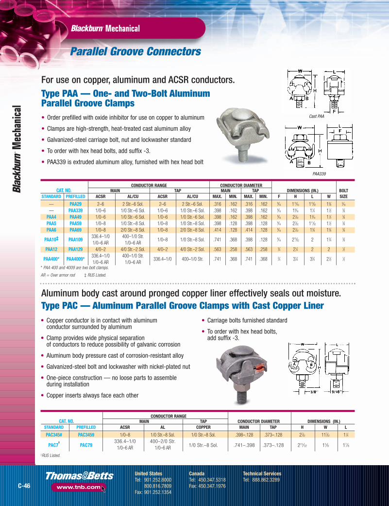
CONDUCTOR RANGE CONDUCTOR DIAMETERCAT. NO. MAIN TAP MAIN TAP DIMENSIONS (IN.) BOLT
STANDARD PREFILLED ACSR AL/CU ACSR AL/CU MAX. MIN. MAX. MIN. F H L W SIZE
— PAA29 2–6 2 Str.–6 Sol. 2–6 2 Str.–6 Sol. .316 .162 .316 .162 9⁄16 113⁄16 113⁄32 13⁄8 5⁄16
— PAA339 1/0–6 1/0 Str.–6 Sol. 1/0–6 1/0 Str.–6 Sol. .398 .162 .398 .162 9⁄16 19⁄16 11⁄4 11⁄2 3⁄8PAA4 PAA49 1/0–6 1/0 Str.–6 Sol. 1/0–6 1/0 Str.–6 Sol. .398 .162 .398 .162 9⁄16 27⁄32 13⁄16 11⁄2 3⁄8PAA5 PAA59 1/0–8 1/0 Str.–8 Sol. 1/0–8 1/0 Str.–8 Sol. .398 .128 .398 .128 9⁄16 27⁄32 111⁄32 11⁄2 3⁄8PAA6 PAA69 1/0–8 2/0 Str.–8 Sol. 1/0–8 2/0 Str.–8 Sol. .414 .128 .414 .128 9⁄16 27⁄32 13⁄8 15⁄8 3⁄8
PAA10‡ PAA109336.4–1/0 400–1/0 Str.
1/0–8 1/0 Str.–8 Sol. .741 .368 .398 .128 9⁄16 215⁄32 2 13⁄4 3⁄81/0–6 AR 1/0–6 AR
PAA12 PAA129 4/0–2 4/0 Str.–2 Sol. 4/0–2 4/0 Str.–2 Sol. .563 .258 .563 .258 3⁄4 21⁄4 2 2 1⁄2
PAA400* PAA4009*336.4–1/0 400–1/0 Str.
336.4–1/0 400–1/0 Str. .741 .368 .741 .368 3⁄4 31⁄4 33⁄4 21⁄2 1⁄21/0–6 AR 1/0–6 AR
* PAA 400 and 4009 are two bolt clamps.
AR = Over armor rod ‡ RUS Listed.
CONDUCTOR RANGECAT. NO. MAIN TAP CONDUCTOR DIAMETER DIMENSIONS (IN.)
STANDARD PREFILLED ACSR AL COPPER MAIN TAP H W L
PAC345# PAC3459 1/0–8 1/0 Str.–8 Sol. 1/0 Str.–8 Sol. .398–.128 .373–.128 27⁄32 117⁄32 11⁄4
PAC7‡
PAC79336.4–1/0 400–2/0 Str.
1/0 Str.–8 Sol. .741–.398 .373–.128 215⁄32 15⁄8 17⁄81/0–6 AR 1/0–6 AR‡RUS Listed.
• Copper conductor is in contact with aluminum conductor surrounded by aluminum
• Clamp provides wide physical separation of conductors to reduce possibility of galvanic corrosion
• Aluminum body pressure cast of corrosion-resistant alloy
• Galvanized-steel bolt and lockwasher with nickel-plated nut
• One-piece construction — no loose parts to assemble during installation
• Copper inserts always face each other
• Carriage bolts furnished standard
• To order with hex head bolts,add suffix -3.
For use on copper, aluminum and ACSR conductors.Type PAA — One- and Two-Bolt Aluminum Parallel Groove Clamps• Order prefilled with oxide inhibitor for use on copper to aluminum
• Clamps are high-strength, heat-treated cast aluminum alloy
• Galvanized-steel carriage bolt, nut and lockwasher standard
• To order with hex head bolts, add suffix -3.
• PAA339 is extruded aluminum alloy, furnished with hex head bolt
Aluminum body cast around pronged copper liner effectively seals out moisture.Type PAC — Aluminum Parallel Groove Clamps with Cast Copper Liner
C-46
United StatesTel: 901.252.8000
800.816.7809Fax: 901.252.1354
CanadaTel: 450.347.5318Fax: 450.347.1976
Technical ServicesTel: 888.862.3289
www.tnb.com
tnb06_wrtrm_secc_p46_47 8/9/07 11:40 AM Page C-46

Parallel Groove Connectors
MechanicalM
echanical
Fig. 1
Fig. 2 Fig. 3 Fig. 4 Fig. 5 Fig. 6
CONDUCTOR DIAMETER (IN.) GALVANIZED ALUMINUMCONDUCTOR RANGE MAIN TAP DIMENSIONS (IN.) STEEL BOLT BOLT
CAT. NO. MAIN TAP MAX. MIN. MAX. MIN. FIG. H W L F B A THD. SIZE. THD. SIZE
PAE-2121-9‡
2/0 ACSR–6 Sol. 6 AR 2/0 ACSR–6 Sol. 6 AR .447 .162 .447 .162 1 2 15⁄8 13⁄8 9⁄167⁄8 — 3⁄8–16 UNC 3⁄8–16 UNC
PAE-4141-9‡
4/0 ACSR–2 Sol. 4-6 AR 4/0 ACSR–2 Sol. 4-6 AR .563 .258 .563 .258 1 2 2 13⁄8 9⁄167⁄8 — 3⁄8–16 UNC 3⁄8–16 UNC
397.5 ACSR–3/0 Str. 2/0 Str.–6 Sol.PAE-3921-9-22/0–6 AR 6 AR
.743 .464 .414 .162 2 29⁄16 21⁄4 15⁄8 3⁄4 11⁄8 — 1⁄2–13 UNC 1⁄2–13 UNC
1000 kcmil–397.5 4/0 ACSR–2 Sol.PAE-9941-9ACSR 336.4–2/0 AR 4–6 AR
1.152 .743 .563 .258 3 213⁄16 259⁄64 21⁄4 3⁄4 — — 1⁄2–13 UNC 1⁄2–13 UNC
397.5 ACSR–3/0 Str. 3/0 ACSR–2 Str.PAE-3931-9-22/0–6 AR 6 AR
.743 .464 .502 .292 4 2 25⁄16 33⁄8 3⁄4 — 13⁄4 1⁄2–13 UNC 1⁄2–13 UNC
397.5 ACSR–3/0 Str. 397.5 ACSR–3/0 Str.PAE-3939-9-22/0–6 AR 2/0–6 AR
.743 .464 .743 .464 5 29⁄16 29⁄16 35⁄8 3⁄4 — 17⁄8 1⁄2–13 UNC 5⁄8–11 UNC
1000 kcmil–397.5 2/0 Str.–6 Sol.PAE-9921-9ACSR 336.4–2/0 AR 6 AR
1.152 .743 .414 .162 3 213⁄16 23⁄16 21⁄4 3⁄4 — — 1⁄2–13 UNC 5⁄8–11 UNC
1000 kcmil–397.5 397.5 ACSR–3/0 Str.PAE-9939-9ACSR 336.4–2/0 AR 2/0–6 AR
1.152 .743 .743 .464 4 23⁄16 37⁄64 31⁄2 3⁄4 — 11⁄2 1⁄2–13 UNC 5⁄8–11 UNC
1000 kcmil–397.5 1000 kcmil–397.5PAE-9999-9ACSR 336.4–2/ AR ACSR 336.4–2/0 AR
1.152 .743 1.152 .743 6 213⁄16 31⁄2 6 3⁄4 — 2 1⁄2–13 UNC 5⁄8–11 UNC
‡ RUS Listed.
For use on aluminum-to-aluminum or aluminum-to-copperconnections with oxide inhibitor.
Type PAE — Parallel Groove Clamps, Extruded Type• Can be installed with live line tools
• Standard PAE clamp is supplied with Contax (-9) and galvanized-steel hardware
• Tin plating (-P) or wax dip (-6) must be specified for without oxide inhibitor-filled connectors
Options: • 7 Aluminum hardware
• P Tin plating
• 6 Wax dip for oxide protection
Example: Cat. Number for PAE-2121 with Contax and aluminum hardware is PAE-2121-79.
C-47
United StatesTel: 901.252.8000
800.816.7809Fax: 901.252.1354
CanadaTel: 450.347.5318Fax: 450.347.1976
Technical ServicesTel: 888.862.3289
www.tnb.com
tnb06_wrtrm_secc_p46_47 8/9/07 11:41 AM Page C-47

Parallel Groove Connectors
Easy to install — no special tools required.Type PC — Two-Bolt ParallelGroove Clamp
• Made of high-strength copper alloy
• Hex head bolts with square shank of silicon bronze
• Spring washers also of silicon bronze
• Square shank bolts prevent turning while tightening
• Contour of casting permits use of socket wrench if desired
• Large contact area increases conductance
• Not recommended for use with aluminum conductor
One size fits all requirements from #8solid copper to 1/0 ACSR or 2/0 copper.Type K — Jumper Clamps
MechanicalM
echa
nica
l
CONDUCTOR RANGE AWG OR KCMIL (IN.) CONDUCTOR DIAMETERMAIN TAP A B
CAT. NO. MAX. MIN. MAX. MIN. MAX. MIN. MAX. MIN.
PC250 250 Str. 4 Sol. 250 Str. 4 Sol. .575 .204 .575 .204
2"
13⁄4"
5⁄64"
25⁄16"
5⁄8"
3⁄8"
PLATED GROOVE COPPER GROOVECAT. NO. MAX. MIN. MAX. MIN.
Plated with plating removed from one groove
2/0 str.1/0 ASCR
6 ACSR copper8 solid
2 SCG12SCG 7⁄16
copperK1 amerductor
amerductor Copperweld*9-12D
7⁄16 galv.8 solid iron 2A
Copperweld*strand
Copperweld*etc.
For use with aluminum, amerductor or galvanized steel strand to copper or copper-bonded steel wires.
Clamp platedEITHER GROOVE
CAT. NO. MAX. MIN.
1/0 ACSR 6 ACSR2 SCG amerductor 12 SCG
K2 7⁄16 galvanized amerductorsteel strand 8 solid iron
For use with amerductor, aluminum or galvanized steel stranding.
Clamp, not plated
8 solid copper2/0 str. copper
91⁄2DK3 7⁄16 copperweld*
copperweld*2A copperweld*
etc.
For copper-to-copper connections.
* Trademark of Copperweld.
• Cast of high-strength copper alloy
• Furnished with silicon bronze hex washer head bolt
• Parallel groove design — no need to remove bolt for installation
• Available plated, unplated or with plating in one groove
121⁄64"
11⁄8"
19⁄32"
C-48
United StatesTel: 901.252.8000
800.816.7809Fax: 901.252.1354
CanadaTel: 450.347.5318Fax: 450.347.1976
Technical ServicesTel: 888.862.3289
www.tnb.com
tnb06_wrtrm_secc_p48_49 8/9/07 11:40 AM Page C-48

Insulated Conductor Connectors
No need to strip conductor insulation or use tape after installation.Type IPC — Talon™ Insulation Piercing Connectors
• For copper-to-copper, copper-to-aluminum and aluminum-to-aluminum applications (insulated conductor only)
• Performs as splice or tap for non-tension applications up to 600 volts, depending on size of connector
• Self-insulated for hot line applications
• 6 sizes cover range from #10–500 kcmil
• UL® 486B Listed AL9CU (90° C rated)
MechanicalM
echanical
Fig. 1 Fig. 2
AL OR CUCONDUCTOR RANGE
AWG/MM 2 NO. DIMENSIONS (IN.)CAT. NO. MAIN TAP BOLTS FIG. W H L
1/0–8 2–8IPC1102* 50–6 35–6
1 1 29⁄16 2 117⁄32
4/0–1/0 1/0–6IPC4111 95–50 50–16
2 2 21⁄2 3 119⁄32
4/0–1/0 4/0–1/0IPC4141 95–50 95–50
2 2 25⁄8 31⁄4 129⁄32
500–350 4/0–4IPC5041* 240–185 90–25
1 1 2 21⁄2 21⁄8
350–4/0 350–4/0IPC3535 185–95 185–95
2 2 21⁄16 21⁄2 21⁄8
350–4/0 4/0–10IPC3541 185–95 95–6
1 1 23⁄4 3 25⁄8
* 600V Rating (All others 300V).
®
®
C-49
United StatesTel: 901.252.8000
800.816.7809Fax: 901.252.1354
CanadaTel: 450.347.5318Fax: 450.347.1976
Technical ServicesTel: 888.862.3289
www.tnb.com
tnb06_wrtrm_secc_p48_49 8/9/07 11:40 AM Page C-49

Two-Bolt Connectors
MechanicalM
echa
nica
l
CONDUCTOR RANGE(AWG OR KCMIL) CONDUCTORMAIN TAP DIAMETER (B) BOLT DIMENSIONS (IN.)
CAT. NO. MAX. MIN. MAX. MIN. MAX. MIN. HEAD L H D
2B10X 1/0 Str. 2 Str. 1/0 Str. 10 Sol. .746 .394 1⁄2 15⁄16 11⁄2 5⁄16
2B20X 2/0 Str. 2 Str. 2/0 Str. 8 Sol. .838 .420 1⁄2 15⁄16 11⁄2 5⁄16
2B40X 4/0 Str. 1/0 Str. 4/0 Str. 6 Sol. 1.056 .530 9⁄16 123⁄32 17⁄8 3⁄82B350X 350 kcmil 4/0 Str. 350 kcmil 4 Sol. 1.362 .726 3⁄4 21⁄8 21⁄4 1⁄22B500X 500 kcmil 350 kcmil 500 kcmil 4 Sol. 1.626 .883 3⁄4 21⁄4 21⁄2 1⁄22B800X 800 kcmil 600 kcmil 800 kcmil 2 Sol. 2.062 1.149 3⁄4 21⁄2 23⁄4 1⁄22B1000X 1000 kcmil 750 kcmil 1000 kcmil 2 Sol. 2.304 1.255 15⁄16 231⁄32 31⁄4 5⁄8
UL 486A
CONDUCTOR RANGE (AWG OR KCMIL) CONDUCTORMAIN TAP DIAMETER (B) BOLT DIMENSIONS (IN.)
CAT. NO. MAX. MIN. MAX. MIN. MAX. MIN. HEAD L H D
2B10 1/0 Str. 2 Str. 1/0 Str. 10 Sol. .746 .394 1⁄2 15⁄16 13⁄4 5⁄16
2B20BB 2/0 Str. 2 Str. 2/0 Str. 8 Sol. .838 .420 1⁄2 15⁄16 11⁄4 5⁄16
2B40 4/0 Str. 1/0 Str. 4/0 Str. 6 Sol. 1.056 .530 9⁄16 123⁄32 13⁄4 3⁄82B350 350 kcmil 4/0 Str. 350 kcmil 4 Sol. 1.362 .726 3⁄4 21⁄8 2 1⁄22B500 500 kcmil 350 kcmil 500 kcmil 4 Sol. 1.626 .883 3⁄4 21⁄4 21⁄2 1⁄22B800 800 kcmil 600 kcmil 800 kcmil 2 Sol. 2.062 1.149 3⁄4 21⁄2 21⁄2 1⁄22B1000 1000 kcmil 750 kcmil 1000 kcmil 2 Sol. 2.304 1.255 15⁄16 231⁄32 23⁄4 5⁄8
UL 486A
• Single-piece construction
• Castings and bolts of high-strength copper alloy
• Neoprene washer holds free bolt in place during installation
• UL 486A Listed for copper conductor only
Neoprene washers capture bolts in bottom casting for easy installation.Type 2B — Two-Bolt Connectors without Spacer
Extra-long bolt enables top casting to swing free over two conductors of maximum range.
Type 2BX — One-Piece Two-Bolt Connectors without Spacer
• Castings and bolts of high-strength copper alloy
• Removable cap
• UL® 486A Listed for copper conductor only
C-50
United StatesTel: 901.252.8000
800.816.7809Fax: 901.252.1354
CanadaTel: 450.347.5318Fax: 450.347.1976
Technical ServicesTel: 888.862.3289
www.tnb.com
tnb06_wrtrm_secc_p50_51 8/9/07 11:40 AM Page C-50

Two-Bolt Connectors
MechanicalM
echanical
• For use on copper conductors only
• Single-piece construction spacer
• Castings and bolts made of high-strength copper alloy
• Spacer made of ductile, high-conductivity copper alloy
• UL 486A Listed for copper conductor only
CONDUCTOR RANGE (AWG OR KCMIL) CONDUCTOR DIAMETERMAIN TAP A B BOLT DIMENSIONS (IN.)
CAT. NO. MAX. MIN. MAX. MIN. MAX. MIN. MAX. MIN. HEAD L H E
2B10W 1/0 Str. 2 Str. 1/0 Str. 10 Sol. .373 .292 .373 .102 1⁄2 15⁄16 15⁄8 5⁄16
2B20W 2/0 Str. 2 Str. 2/0 Str. 8 Sol. .419 .292 .419 .128 1⁄2 15⁄16 15⁄8 5⁄16
2B40W 4/0 Str. 1/0 Str. 4/0 Str. 6 Sol. .528 .368 .528 .162 9⁄16 123⁄32 21⁄8 3⁄82B350W 350 kcmil 4/0 Str. 350 kcmil 4 Sol. .681 .522 .681 .204 3⁄4 21⁄8 21⁄2 1⁄22B500W 500 kcmil 350 kcmil 500 kcmil 4 Sol. .813 .679 .813 .204 3⁄4 21⁄4 23⁄4 1⁄22B800W 800 kcmil 600 kcmil 800 kcmil 2 Sol. 1.031 .891 1.031 .258 3⁄4 21⁄2 31⁄4 1⁄22B1000W 1000 kcmil 750 kcmil 1000 kcmil 2 Sol. 1.152 .997 1.152 .258 15⁄16 231⁄32 33⁄4 5⁄8
Ringed, contoured spacer swings easily over conductor.
Type 2BW — Two-Bolt Connector with Spacer
For use on copper, aluminum and ACSR conductors.
Type 2BPW —Two-Bolt Connector with Spacer• Single-piece construction spacer
• UL 486A Listed for copper conductor only
CONDUCTOR RANGE (AWG OR KCMIL) CONDUCTOR DIAMETERMAIN TAP A B BOLT DIMENSIONS (IN.)
CAT. NO. MAX. MIN. MAX. MIN. MAX. MIN. MAX. MIN. HEAD L H E
2B10PW 1/0–2 1/0–6 1/0 Str.–2 Str. 1/0 Str.–2 Sol. 0.398 0.292 0.398 0.102 1⁄2 15⁄16 15⁄8 5⁄16
2B20PW 2/0–2 2/0–6 2/0 Str.–2 Str. 1/0 Str.–2 Sol. 0.447 0.292 0.447 0.128 1⁄2 15⁄16 15⁄8 5⁄16
2B40PW 4/0–1/0 4/0–6 4/0 Str.–1/0 Str. 4/0 Str.–1/0 Sol. 0.563 0.368 0.563 0.162 9⁄16 123⁄32 21⁄8 3⁄82B350PW 350–4/0 350–4 350–4/0 350–4 Sol. 0.680 0.522 0.680 0.204 3⁄4 21⁄8 21⁄2 1⁄22B500PW 397.5–336.4 397.5–4 500–350 500–4 Sol. 0.813 0.679 0.813 0.204 3⁄4 21⁄4 23⁄4 1⁄22B800PW 666.6–397.5 666.6–2 800–600 800–2 Sol. 1.031 0.891 1.031 0.258 3⁄4 21⁄2 31⁄4 1⁄22B1000PW 900–666.6 900–2 1000–750 1000–2 Sol. 1.162 0.997 1.162 0.258 15⁄16 231⁄32 33⁄4 5⁄8
C-51
United StatesTel: 901.252.8000
800.816.7809Fax: 901.252.1354
CanadaTel: 450.347.5318Fax: 450.347.1976
Technical ServicesTel: 888.862.3289
www.tnb.com
tnb06_wrtrm_secc_p50_51 8/9/07 11:40 AM Page C-51

Cross Tap Clamps/Dead-End Clamps
MechanicalM
echa
nica
l
CONDUCTOR RANGE (AWG OR KCMIL) CONDUCTOR DIAMETERMAIN TAP A B DIMENSIONS (IN.) BOLT
CAT. NO. MAX. MIN. MAX. MIN. MAX. MIN. MAX. MIN. L H W SIZE
XT12 4/0 Str. 1 Str. 2 Str. 6 Sol. .528 .328 .292 .162 11⁄2 113⁄16 11⁄2 5⁄16
XT13 4/0 Str. 1 Str. 4/0 Str. 1 Str. .528 .328 .528 .328 17⁄8 2 17⁄8 3⁄8XT21 500 kcmil 250 kcmil 2 Str. 6 Sol. .813 .574 .292 .162 21⁄16 23⁄16 15⁄8 3⁄8XT22 500 kcmil 250 kcmil 4/0 Str. 1 Str. .813 .574 .528 .328 21⁄8 23⁄16 27⁄8 3⁄8XT23* 500 kcmil 250 kcmil 500 kcmil 250 kcmil .813 .574 .813 .574 21⁄8 23⁄16 21⁄26
3⁄8XT33* 1000 kcmil 500 kcmil 500 kcmil 250 kcmil 1.152 .811 .813 .574 21⁄4 3 215⁄16
3⁄8XT34* 1000 kcmil 500 kcmil 1000 kcmil 500 kcmil 1.152 .811 1.152 .811 211⁄16 31⁄8 211⁄16
7⁄16
* 4 bolt clamps
Spacer interlocks with U-bolt — won’t drop out.Type DLC — Single U-Bolt Aluminum Fittings
• Suitable for dead-end loopconnections
• Spring action counteracts cold flow
• No special tools required for installation
• Top and bottom pressure pads cast of high-strength, heat-treatedaluminum silicon alloy
• Extra-long separating spacer madeof highly conductive aluminum
CONDUCTOR RANGE CONDUCTOR DIAMETERACSR AWG OR KCMIL A B DIMENSIONS (IN.)
CAT. NO. MAIN TAP MAIN TAP MAX. MIN. MAX. MIN. W L H F E
DLC2106‡
2/0–6 2/0–6 2/0 Str.–6 Sol. 2/0 Str.–6 Sol. .447 .162 .447 .162 17⁄8 11⁄2 31⁄4 9⁄163⁄8
DLC23‡ 4/0–1 4/0–1/0 266.8–1/0 Str. 266.8–1/0 Str. .563 .368 .609 .368 23⁄8 27⁄8 4 3⁄4 1⁄2
2–6 AR336.4–1/0 336.4–1/0DLC251/0–6 AR 1/0–6 AR
397.5–1/0 Str. 397.5–1/0 Str. .684 .368 .743 .368 23⁄8 33⁄16 4 3⁄4 1⁄2
‡RUS Listed.
• Hardware of high-strengthgalvanized steel
• For use on copper, aluminum and ACSR conductors
• Order prefilled with oxide inhibitor(suffix 9) for use on aluminum-to-copper connections
Type XT — Clamp for Tee-Tap, Cross, Parallel and End-to-End ConnectorsA versatile, multipurpose connector.
• Castings of copper alloy
• Bolts of silicon bronze
• Designed to enable free wrenchrotation for faster installation
• To order tin-plated style, add suffixP (e.g., XT12P)
C-52
United StatesTel: 901.252.8000
800.816.7809Fax: 901.252.1354
CanadaTel: 450.347.5318Fax: 450.347.1976
Technical ServicesTel: 888.862.3289
www.tnb.com
tnb06_wrtrm_secc_p52_53 8/9/07 11:39 AM Page C-52

Hot Line Clamps
MechanicalM
echanical
CONDUCTOR RANGEFOR WIRE MAIN TAP
CAT. NO. COMBINATION ACSR AWG OR KCMIL ACSR AWG
Bronze BodyHLC2108
‡Copper to Copper — 2/0–8 — 2/0
Plated Bronze BodyHLC2108P General Purpose 2/0–6 2/0–8 2/0–6 2/0–8Plated Aluminum BodyHLC2108AP9 General Purpose 2/0–6 2/0–8 2/0–6 2/0–8Bronze BodyHLC3974 Copper to Copper — 400–6 Sol. — 4/0–6 Sol.Plated Bronze BodyHLC3974P General Purpose — 400–6 Sol. 3/0–6 4/0–6 Sol.Plated Aluminum BodyHLC3974AP General Purpose 397.5–6 400–6 Sol. 3/0–6 4/0–6 Sol.‡RUS Listed.
Fig. 2
Fig. 3
• Wide temperature range lubricant prevents seizingof protected threads
• Tap wire positively secured to clamp duringinstallation and removal by hex head bolt and pressure pad
• Main and tap clamped securely as clamp is tightened
• Available prefilled with oxide-inhibiting Contax (add suffix 9 to catalog number)
• Copper clamps for use on copper conductors only
• HLC2108 Series for 2/0–8 main line conductor
• HLC3974 Series for 397.5kcmil–6 main line conductor
• Available prefilled with oxide-inhibiting Contax andindividually packaged (add suffix 9 to catalog number)
Eye-bolt coated with high-temperature grease to ensure easy turning in all weather conditions.Type HLC — Hot Line Clamps (Protected Thread)
Incorporates the superior design features of parallelgroove clamps, time-proven for reliable performance.
Type PGH — Center Bolt ParallelGroove Hot Tap Clamps
Fig. 1
CONDUCTOR RANGE CONDUCTOR DIAMETER CENTER DIMENSIONSCAT. NO. MAIN TAP MAIN TAP BOLTS (IN.)
STD. PREFILLED ACSR AWG ACSR AWG MAX. MIN. MAX. MIN. NO. DIA. FIG. W H L
Aluminum ClampsPGH29 2/0–8 2/0 Str.–8 Sol. 1/0–8 1/0 Str.–8 Sol. .447 .128 .398 .128 1 1⁄2 1 23⁄8 53⁄4 23⁄8
PGH4 PGH49 397.5–6 450–4 Sol. 3/0–6 4/0 Str.–6 Sol. .781 .198 .528 .162 1 1⁄2 1 35⁄16 65⁄16 27⁄16
2/0–6 AR874–4/0PGH69
397.518⁄1–2 AR1000–4/0 Str. 266–6 300–6 Sol. 1.152 .522 .657 .162 2 1⁄2 2 4 63⁄4 41⁄4
PGH6129* 874–4/0 1000–4/0 Str. 266–6 300–6 Sol. 1.152 .522 .657 .162 1 1⁄2 3 35⁄8 63⁄4 31⁄16
397.518⁄1–2 AR
Copper ClampsPGH3 PGH39 — 2/0 Str.–8 Sol. — 2/0 Str.–8 Sol. .419 .419 .128 .128 1 7⁄16 1 23⁄8 51⁄4 11⁄4
*PGH6129 has two hex head bolt and pressure pad tap conductor retainers.AR-with Armor Rod.
C-53
United StatesTel: 901.252.8000
800.816.7809Fax: 901.252.1354
CanadaTel: 450.347.5318Fax: 450.347.1976
Technical ServicesTel: 888.862.3289
www.tnb.com
tnb06_wrtrm_secc_p52_53 8/9/07 11:39 AM Page C-53

Multi-Bolt Connectors
MechanicalM
echa
nica
l
CONDUCTOR RANGE CONDUCTOR DIAMETER NO.ACSR AWG OR KCMIL A B DIMENSIONS (IN.) OF
CAT. NO. MAIN TAP MAIN TAP MAX. MIN. MAX. MIN. W F H T L E BOLTS
4B29 4/0–4 4/0–4 250–2 Str. 250–2 Sol. .575 .250 .575 .250 25⁄165⁄8 39⁄16 11⁄32 31⁄4 7⁄16 4
4B49 397.5–1/0 397.5–1/0 477–1/0 Str. 477–1/0 Str. .795 .368 .795 .368 23⁄4 3⁄4 45⁄1613⁄32 43⁄4 1⁄2 4
6B89 795–300 795–300 800–350 800–336.4 1.108 .679 1.108 .679 31⁄2 15⁄16 59⁄647⁄16 63⁄4 5⁄8 6
• For use on copper, aluminum and ACSR conductors
• Cap and pressure plate of cast aluminum alloy
• Spacer of high-conductivity aluminum
• High-strength aluminum alloy bolts and lockwashersprevent seizing
• Factory prefilled with Contax oxide inhibitor
Single-piece construction eliminates loose parts during installation.
Types 4B, 6B — One-Piece Multi-Bolt Connectors
C-54
United StatesTel: 901.252.8000
800.816.7809Fax: 901.252.1354
CanadaTel: 450.347.5318Fax: 450.347.1976
Technical ServicesTel: 888.862.3289
www.tnb.com
tnb06_wrtrm_secc_p54_55 8/9/07 11:39 AM Page C-54

AMT Connectors
MechanicalM
echanical
CAT. NO. FIGURE NO. OF PORTS WIRE RANGE LENGTH WIDTH HEIGHT HEX SIZE STD. PKG. QTY.
AMTSR10 1 — 1/0–14 STR. 3.25 0.94 1.63 3⁄16 4AMTSR250 1 — 250MCM–6 STR. 3.96 1.19 2.17 5⁄16 4AMTSR350 1 — 350MCM–6 STR. 4.43 1.31 2.62 5⁄16 2AMTSR500 1 — 500MCM–4 STR. 5.38 1.44 3.03 3⁄8 2AMTSR750 1 — 750MCM–250MCM 7.25 1.75 3.16 1⁄2 2
AMT SPLICE OFFSETAMTTC4 3 2 4–14 STR. 1.24 1.25 1.42 1⁄8 12AMTT10 3 2 1/0–14 STR. 1.63 1.63 1.63 3⁄16 6AMTT30 3 2 3/0–6 STR. 1.89 1.68 1.86 3⁄16 6
AMT MULTI-PORT CONNECTOR “SAME SIDE”
AMTS4142 2 2 4–14 STR. 1.24 1.22 1.42 1⁄8 12AMTS4143 4 3 4–14 STR. 1.7 1.22 1.42 1⁄8 12AMTS4144 4 4 4–14 STR. 2.16 1.22 1.42 1⁄8 6AMTS4145 4 5 4–14 STR. 2.61 1.22 1.42 1⁄8 6AMTS4146 4 6 4–14 STR. 3.07 1.22 1.42 1⁄8 6AMTS4147 4 7 4–14 STR. 3.53 1.22 1.42 1⁄8 4AMTS4148 4 8 4–14 STR. 3.99 1.22 1.42 1⁄8 4AMTS4149 4 9 4–14 STR. 4.45 1.22 1.42 1⁄8 4AMTS41410 4 10 4–14 STR. 4.9 1.22 1.42 1⁄8 4AMTS41411 4 11 4–14 STR. 5.36 1.22 1.42 1⁄8 3AMTS41412 4 12 4–14 STR. 5.82 1.22 1.42 1⁄8 3AMTS41413 4 13 4–14 STR. 6.28 1.22 1.42 1⁄8 2AMTS41414 4 14 4–14 STR. 6.74 1.22 1.42 1⁄8 2AMTS10142 2 2 1/0–14 STR. 1.67 1.53 1.63 3⁄16 12AMTS10143 4 3 1/0–14 STR. 2.29 1.53 1.63 3⁄16 12AMTS10144 4 4 1/0–14 STR. 2.92 1.53 1.63 3⁄16 6AMTS10145 4 5 1/0–14 STR. 3.54 1.53 1.63 3⁄16 6AMTS10146 4 6 1/0–14 STR. 4.17 1.53 1.63 3⁄16 6AMTS10147 4 7 1/0–14 STR. 4.79 1.53 1.63 3⁄16 4
Fig.1 Fig.3 Fig. 5Fig. 2 Fig. 4
• PVC insulation eliminates insulation failures and reduces outage costs
• UV-resistant material
• Compact design provides space efficiencies
• UL® Listed
The high quality and built-in flexibility of Blackburn® AMT Connectorsreduce the cost of field installations on splices, taps and terminations.They’re easy and quick to install, and provide superior insulation thatlasts the life of the connection.
Superior connections with lowerinstallation costs.AMT Connectors
NEW!NEW!
C-55
United StatesTel: 901.252.8000
800.816.7809Fax: 901.252.1354
CanadaTel: 450.347.5318Fax: 450.347.1976
Technical ServicesTel: 888.862.3289
www.tnb.com
tnb06_wrtrm_secc_p54_55 8/9/07 11:39 AM Page C-55

AMT Connectors (continued)
MechanicalM
echa
nica
l
CAT. NO. FIG. NO. OF PORTS WIRE RANGE LENGTH WIDTH HEIGHT HEX SIZE STD. PKG. QTY.
AMT MULTI-PORT CONNECTOR “SAME SIDE” (continued)
AMTS10148 4 8 1/0–14 STR. 5.42 1.53 1.63 3⁄16 4AMTS10149 4 9 1/0–14 STR. 6.04 1.53 1.63 3⁄16 4AMTS101410 4 10 1/0–14 STR. 6.67 1.53 1.63 3⁄16 4AMTS101411 4 11 1/0–14 STR. 7.29 1.53 1.63 3⁄16 3AMTS101412 4 12 1/0–14 STR. 7.92 1.53 1.63 3⁄16 3AMTS101413 4 13 1/0–14 STR. 8.54 1.53 1.63 3⁄16 2AMTS101414 4 14 1/0–14 STR. 9.17 1.53 1.63 3⁄16 2AMTS3062 2 2 3/0–6 STR. 1.89 1.58 1.86 3⁄16 12AMTS3063 4 3 3/0–6 STR. 2.65 1.58 1.86 3⁄16 6AMTS3064 4 4 3/0–6 STR. 3.42 1.58 1.86 3⁄16 6AMTS3065 4 5 3/0–6 STR. 4.18 1.58 1.86 3⁄16 4AMTS3066 4 6 3/0–6 STR. 4.95 1.58 1.86 3⁄16 4AMTS3067 4 7 3/0–6 STR. 5.71 1.58 1.86 3⁄16 3AMTS3068 4 8 3/0–6 STR. 6.48 1.58 1.86 3⁄16 3AMTS3069 4 9 3/0–6 STR. 7.24 1.58 1.86 3⁄16 3AMTS30610 4 10 3/0–6 STR. 8 1.58 1.86 3⁄16 2AMTS30611 4 11 3/0–6 STR. 8.77 1.58 1.86 3⁄16 2AMTS30612 4 12 3/0–6 STR. 9.54 1.58 1.86 3⁄16 2AMTS30613 4 13 3/0–6 STR. 10.3 1.58 1.86 3⁄16 2AMTS30614 4 14 3/0–6 STR. 11.07 1.58 1.86 3⁄16 2AMTS25062 4 2 250MCM–6 STR. 2.17 1.91 2.17 5⁄16 6AMTS25063 4 3 250MCM–6 STR. 3.07 1.91 2.17 5⁄16 6AMTS25064 4 4 250MCM–6 STR. 3.96 1.91 2.17 5⁄16 6AMTS25065 4 5 250MCM–6 STR. 4.85 1.91 2.17 5⁄16 4AMTS25066 4 6 250MCM–6 STR. 5.75 1.91 2.17 5⁄16 4AMTS25067 4 7 250MCM–6 STR. 6.64 1.91 2.17 5⁄16 3AMTS25068 4 8 250MCM–6 STR. 7.53 1.91 2.17 5⁄16 3AMTS25069 4 9 250MCM–6 STR. 8.42 1.91 2.17 5⁄16 3AMTS250610 4 10 250MCM–6 STR. 9.32 1.91 2.17 5⁄16 2AMTS250611 4 11 250MCM–6 STR. 10.21 1.91 2.17 5⁄16 2AMTS250612 4 12 250MCM–6 STR. 11.1 1.91 2.17 5⁄16 2AMTS250613 4 13 250MCM–6 STR. 12 1.91 2.17 5⁄16 1AMTS250614 4 14 250MCM–6 STR. 12.89 1.91 2.17 5⁄16 1AMTS35062 2 2 350MCM–6 STR. 2.51 2.03 2.62 5⁄16 4AMTS35063 4 3 350MCM–6 STR. 3.56 2.03 2.62 5⁄16 4AMTS35064 4 4 350MCM–6 STR. 4.61 2.03 2.62 5⁄16 3AMTS35065 4 5 350MCM–6 STR. 5.66 2.03 2.62 5⁄16 3AMTS35066 4 6 350MCM–6 STR. 6.71 2.03 2.62 5⁄16 2AMTS35067 4 7 350MCM–6 STR. 7.76 2.03 2.62 5⁄16 2AMTS35068 4 8 350MCM–6 STR. 8.81 2.03 2.62 5⁄16 2AMTS35069 4 9 350MCM–6 STR. 9.86 2.03 2.62 5⁄16 2AMTS350610 4 10 350MCM–6 STR. 10.91 2.03 2.62 5⁄16 2AMTS350611 4 11 350MCM–6 STR. 11.96 2.03 2.62 5⁄16 1AMTS350612 4 12 350MCM–6 STR. 13.01 2.03 2.62 5⁄16 1AMTS350613 4 13 350MCM–6 STR. 14.06 2.03 2.62 5⁄16 1AMTS350614 4 14 350MCM–6 STR. 15.11 2.03 2.62 5⁄16 1AMTS50042 2 2 500MCM–4 STR. 2.97 2.28 3.04 3⁄8 3AMTS50043 4 3 500MCM–4 STR. 4.12 2.28 3.04 3⁄8 3AMTS50044 4 4 500MCM–4 STR. 5.28 2.28 3.04 3⁄8 3AMTS50045 4 5 500MCM–4 STR. 6.44 2.28 3.04 3⁄8 2AMTS50046 4 6 500MCM–4 STR. 7.59 2.28 3.04 3⁄8 2AMTS50047 4 7 500MCM–4 STR. 8.75 2.28 3.04 3⁄8 2AMTS50048 4 8 500MCM–4 STR. 9.9 2.28 3.04 3⁄8 2AMTS50049 4 9 500MCM–4 STR. 11.06 2.28 3.04 3⁄8 2AMTS500410 4 10 500MCM–4 STR. 12.22 2.28 3.04 3⁄8 1AMTS500411 4 11 500MCM–4 STR. 13.37 2.28 3.04 3⁄8 1
Fig.1
Fig.3
Fig. 5
Fig. 2
Fig. 4
C-56
United StatesTel: 901.252.8000
800.816.7809Fax: 901.252.1354
CanadaTel: 450.347.5318Fax: 450.347.1976
Technical ServicesTel: 888.862.3289
www.tnb.com
tnb06_wrtrm_secc_p56_57 8/9/07 11:38 AM Page C-56

AMT Connectors (continued)
MechanicalM
echanical
CAT. NO. FIG. NO. OF PORTS WIRE RANGE LENGTH WIDTH HEIGHT HEX SIZE STD. PKG. QTY.
AMT MULTI-PORT CONNECTOR “SAME SIDE” (continued)
AMTS500412 4 12 500MCM–4 STR. 14.53 2.28 3.04 3⁄8 1AMTS500413 4 13 500MCM–4 STR. 15.68 2.28 3.04 3⁄8 1AMTS500414 4 14 500MCM–4 STR. 16.84 2.28 3.04 3⁄8 1AMTS7502502 4 2 750MCM–250MCM 3.47 2.75 3.31 1⁄2 3AMTS7502503 4 3 750MCM–250MCM 4.89 2.75 3.31 1⁄2 3AMTS7502504 4 4 750MCM–250MCM 6.32 2.75 3.31 1⁄2 2AMTS7502505 4 5 750MCM–250MCM 7.74 2.75 3.31 1⁄2 1AMTS7502506 4 6 750MCM–250MCM 9.16 2.75 3.31 1⁄2 1AMTS7502507 4 7 750MCM–250MCM 10.58 2.75 3.31 1⁄2 1AMTS7502508 4 8 750MCM–250MCM 12 2.75 3.31 1⁄2 1AMTS7502509 4 9 750MCM–250MCM 13.43 2.75 3.31 1⁄2 1AMTS75025010 4 10 750MCM–250MCM 14.85 2.75 3.31 1⁄2 1AMTS75025011 4 11 750MCM–250MCM 16.27 2.75 3.31 1⁄2 1AMTS75025012 4 12 750MCM–250MCM 17.69 2.75 3.31 1⁄2 1AMTS75025013 4 13 750MCM–250MCM 19.11 2.75 3.31 1⁄2 1AMTS75025014 4 14 750MCM–250MCM 20.54 2.75 3.31 1⁄2 1
AMT MULTI-PORT CONNECTOR “DOUBLE” BOTH SIDES
AMTD4142 5 2 4–14 STR. 1.24 1.25 1.42 1⁄8 12AMTD4143 5 3 4–14 STR. 1.7 1.25 1.42 1⁄8 12AMTD4144 5 4 4–14 STR. 2.16 1.25 1.42 1⁄8 6AMTD4145 5 5 4–14 STR. 2.61 1.25 1.42 1⁄8 6AMTD4146 5 6 4–14 STR. 3.07 1.24 1.42 1⁄8 6AMTD4147 5 7 4–14 STR. 3.53 1.25 1.42 1⁄8 4AMTD4148 5 8 4–14 STR. 3.99 1.25 1.42 1⁄8 4AMTD4149 5 9 4–14 STR. 4.45 1.25 1.42 1⁄8 4AMTD41410 5 10 4–14 STR. 4.9 1.25 1.42 1⁄8 4AMTD41411 5 11 4–14 STR. 5.36 1.25 1.42 1⁄8 3AMTD41412 5 12 4–14 STR. 5.82 1.25 1.42 1⁄8 3AMTD41413 5 13 4–14 STR. 6.28 1.25 1.42 1⁄8 2AMTD41414 5 14 4–14 STR. 6.74 1.25 1.42 3⁄16 2AMTD10142 5 2 1/0–14 STR. 1.67 1.63 1.63 3⁄16 12AMTD10143 5 3 1/0–14 STR. 2.29 1.63 1.63 3⁄16 12AMTD10144 5 4 1/0–14 STR. 2.92 1.63 1.63 3⁄16 6AMTD10145 5 5 1/0–14 STR. 3.54 1.63 1.63 3⁄16 6AMTD10146 5 6 1/0–14 STR. 4.17 1.63 1.63 3⁄16 6AMTD10147 5 7 1/0–14 STR. 4.79 1.63 1.63 3⁄16 4AMTD10148 5 8 1/0–14 STR. 5.42 1.63 1.63 3⁄16 4AMTD10149 5 9 1/0–14 STR. 6.04 1.63 1.63 3⁄16 4AMTD101410 5 10 1/0–14 STR. 6.67 1.63 1.63 3⁄16 4AMTD101411 5 11 1/0–14 STR. 7.29 1.63 1.63 3⁄16 3AMTD101412 5 12 1/0–14 STR. 7.92 1.63 1.63 3⁄16 3AMTD101413 5 13 1/0–14 STR. 8.54 1.63 1.63 3⁄16 2AMTD101414 5 14 1/0–14 STR. 9.17 1.63 1.63 3⁄16 2AMTD3062 5 2 3/0–6 STR. 1.89 1.68 1.86 3⁄16 6AMTD3063 5 3 3/0–6 STR. 2.65 1.68 1.86 3⁄16 6AMTD3064 5 4 3/0–6 STR. 3.42 1.68 1.86 3⁄16 6AMTD3065 5 5 3/0–6 STR. 4.18 1.68 1.86 3⁄16 4AMTD3066 5 6 3/0–6 STR. 4.95 1.68 1.86 3⁄16 4AMTD3067 5 7 3/0–6 STR. 5.71 1.68 1.86 3⁄16 3AMTD3068 5 8 3/0–6 STR. 6.48 1.68 1.86 3⁄16 3AMTD3069 5 9 3/0–6 STR. 7.24 1.68 1.86 3⁄16 3AMTD30610 5 10 3/0–6 STR. 8.01 1.68 1.86 3⁄16 2AMTD30611 5 11 3/0–6 STR. 8.77 1.68 1.86 3⁄16 2AMTD30612 5 12 3/0–6 STR. 9.54 1.68 1.86 3⁄16 2AMTD30613 5 13 3/0–6 STR. 10.3 1.68 1.86 3⁄16 2AMTD30614 5s 14 3/0–6 STR. 11.07 1.68 1.86 3⁄16 2
Fig.1
Fig.3
Fig. 5
Fig. 2
Fig. 4
C-57
United StatesTel: 901.252.8000
800.816.7809Fax: 901.252.1354
CanadaTel: 450.347.5318Fax: 450.347.1976
Technical ServicesTel: 888.862.3289
www.tnb.com
tnb06_wrtrm_secc_p56_57 8/9/07 11:39 AM Page C-57

AMT Connectors (continued)
MechanicalM
echa
nica
l
CAT. NO. FIG. NO. OF PORTS WIRE RANGE LENGTH WIDTH HEIGHT HEX SIZE STD. PKG. QTY.
AMT MULTI-PORT CONNECTOR “DOUBLE” BOTH SIDES (continued)
AMTD25062 5 2 250MCM–6 STR. 2.17 2.13 2.17 5⁄16 6AMTD25063 5 3 250MCM–6 STR. 3.07 2.13 2.17 5⁄16 6AMTD25064 5 4 250MCM–6 STR. 3.96 2.13 2.17 5⁄16 6AMTD25065 5 5 250MCM–6 STR. 4.85 2.13 2.17 5⁄16 4AMTD25066 5 6 250MCM–6 STR. 5.75 2.13 2.17 5⁄16 4AMTD25067 5 7 250MCM–6 STR. 6.64 2.13 2.17 5⁄16 3AMTD25068 5 8 250MCM–6 STR. 7.53 2.13 2.17 5⁄16 3AMTD25069 5 9 250MCM–6 STR. 8.42 2.13 2.17 5⁄16 3AMTD250610 5 10 250MCM–6 STR. 9.32 2.13 2.17 5⁄16 2AMTD250611 5 11 250MCM–6 STR. 10.21 2.13 2.17 5⁄16 2AMTD250612 5 12 250MCM–6 STR. 11.1 2.13 2.17 5⁄16 2AMTD250613 5 13 250MCM–6 STR. 12 2.13 2.17 5⁄16 1AMTD250614 5 14 250MCM–6 STR. 12.89 2.13 2.17 5⁄16 1AMTD35062 5 2 350MCM–6 STR. 2.51 2.25 2.62 5⁄16 4AMTD35063 5 3 350MCM–6 STR. 3.56 2.25 2.62 5⁄16 4AMTD35064 5 4 350MCM–6 STR. 4.61 2.25 2.62 5⁄16 3AMTD35065 5 5 350MCM–6 STR. 5.67 2.25 2.62 5⁄16 3AMTD35066 5 6 350MCM–6 STR. 6.71 2.25 2.62 5⁄16 3AMTD35067 5 7 350MCM–6 STR. 7.76 2.25 2.62 5⁄16 2AMTD35068 5 8 350MCM–6 STR. 8.81 2.25 2.62 5⁄16 2AMTD35069 5 9 350MCM–6 STR. 9.86 2.25 2.62 5⁄16 2AMTD350610 5 10 350MCM–6 STR. 10.91 2.25 2.62 5⁄16 2AMTD350611 5 11 350MCM–6 STR. 11.96 2.25 2.62 5⁄16 1AMTD350612 5 12 350MCM–6 STR. 13.01 2.25 2.62 5⁄16 1AMTD350613 5 13 350MCM–6 STR. 14.06 2.25 2.62 5⁄16 1AMTD350614 5 14 350MCM–6 STR. 15.11 2.25 2.62 5⁄16 1AMTD50042 5 2 500MCM–4 STR. 2.97 2.63 3.04 3⁄8 3AMTD50043 5 3 500MCM–4 STR. 4.12 2.63 3.04 3⁄8 3AMTD50044 5 4 500MCM–4 STR. 5.28 2.63 3.04 3⁄8 3AMTD50045 5 5 500MCM–4 STR. 6.44 2.63 3.04 3⁄8 2AMTD50046 5 6 500MCM–4 STR. 7.59 2.63 3.04 3⁄8 2AMTD50047 5 7 500MCM–4 STR. 8.75 2.63 3.04 3⁄8 2AMTD50048 5 8 500MCM–4 STR. 9.9 2.63 3.04 3⁄8 2AMTD50049 5 9 500MCM–4 STR. 11.06 2.63 3.04 3⁄8 2AMTD500410 5 10 500MCM–4 STR. 12.22 2.63 3.04 3⁄8 1AMTD500411 5 11 500MCM–4 STR. 13.37 2.63 3.04 3⁄8 1AMTD500412 5 12 500MCM–4 STR. 14.53 2.63 3.04 3⁄8 1AMTD500413 5 13 500MCM–4 STR. 15.68 2.63 3.04 3⁄8 1AMTD500414 5 14 500MCM–4 STR. 16.84 2.63 3.04 3⁄8 1AMTD7502502 5 2 750MCM–250MCM 3.47 3.25 3.31 1⁄2 3AMTD7502503 5 3 750MCM–250MCM 4.89 3.25 3.31 1⁄2 3AMTD7502504 5 4 750MCM–250MCM 6.32 3.25 3.31 1⁄2 2AMTD7502505 5 5 750MCM–250MCM 7.74 3.25 3.31 1⁄2 1AMTD7502506 5 6 750MCM–250MCM 9.16 3.25 3.31 1⁄2 1AMTD7502507 5 7 750MCM–250MCM 10.58 3.25 3.31 1⁄2 1AMTD7502508 5 8 750MCM–250MCM 12 3.25 3.31 1⁄2 1AMTD7502509 5 9 750MCM–250MCM 13.43 3.25 3.31 1⁄2 1AMTD75025010 5 10 750MCM–250MCM 14.85 3.25 3.31 1⁄2 1AMTD75025011 5 11 750MCM–250MCM 16.27 3.25 3.31 1⁄2 1AMTD75025012 5 12 750MCM–250MCM 17.69 3.25 3.31 1⁄2 1AMTD75025013 5 13 750MCM–250MCM 19.11 3.25 3.31 1⁄2 1AMTD75025014 5 14 750MCM–250MCM 20.54 3.25 3.31 1⁄2 1
Fig.1
Fig.3
Fig. 5
Fig. 2
Fig. 4
C-58
United StatesTel: 901.252.8000
800.816.7809Fax: 901.252.1354
CanadaTel: 450.347.5318Fax: 450.347.1976
Technical ServicesTel: 888.862.3289
www.tnb.com
tnb06_wrtrm_secc_p58_59 8/9/07 11:38 AM Page C-58

AMT Connectors (continued)
MechanicalM
echanical
CAT. NO. FIG. NO. OF PORTS WIRE RANGE LENGTH WIDTH HEIGHT HEX SIZE STD. PKG. QTY.
AMT MOUNTABLE MULTI-PORT CONNECTOR "DOUBLE" BOTH SIDES
AMTDM3062 5 2 3/0–6 STR. 3.42 1.68 1.86 3⁄16 6AMTDM3063 5 3 3/0–6 STR. 4.18 1.68 1.86 3⁄16 4AMTDM3064 5 4 3/0–6 STR. 4.95 1.68 1.86 3⁄16 4AMTDM3065 5 5 3/0–6 STR. 5.71 1.68 1.86 3⁄16 3AMTDM3066 5 6 3/0–6 STR. 6.48 1.68 1.86 3⁄16 3AMTDM3067 5 7 3/0–6 STR. 7.24 1.68 1.86 3⁄16 3AMTDM3068 5 8 3/0–6 STR. 8.01 1.68 1.86 3⁄16 2AMTDM3069 5 9 3/0–6 STR. 8.77 1.68 1.86 3⁄16 2AMTDM30610 5 10 3/0–6 STR. 9.54 1.68 1.86 3⁄16 2AMTDM30611 5 11 3/0–6 STR. 10.3 1.68 1.86 3⁄16 2AMTDM30612 5 12 3/0–6 STR. 11.07 1.68 1.86 3⁄16 2AMTDM25062 5 2 250MCM–6 STR. 3.96 2.13 2.17 5⁄16 6AMTDM25063 5 3 250MCM–6 STR. 4.85 2.13 2.17 5⁄16 4AMTDM25064 5 4 250MCM–6 STR. 5.73 2.13 2.17 5⁄16 4AMTDM25065 5 5 250MCM–6 STR. 6.64 2.13 2.17 5⁄16 3AMTDM25066 5 6 250MCM–6 STR. 7.53 2.13 2.17 5⁄16 3AMTDM25067 5 7 250MCM–6 STR. 8.42 2.13 2.17 5⁄16 3AMTDM25068 5 8 250MCM–6 STR. 9.32 2.13 2.17 5⁄16 2AMTDM25069 5 9 250MCM–6 STR. 10.21 2.13 2.17 5⁄16 2AMTDM250610 5 10 250MCM–6 STR. 11.1 2.13 2.17 5⁄16 2AMTDM250611 5 11 250MCM–6 STR. 12 2.13 2.17 5⁄16 1AMTDM250612 5 12 250MCM–6 STR. 12.89 2.13 2.17 5⁄16 1AMTDM35062 5 2 350MCM–6 STR. 4.61 2.25 2.62 5⁄16 3AMTDM35063 5 3 350MCM–6 STR. 5.67 2.25 2.62 5⁄16 3AMTDM35064 5 4 350MCM–6 STR. 6.71 2.25 2.62 5⁄16 3AMTDM35065 5 5 350MCM–6 STR. 7.76 2.25 2.62 5⁄16 2AMTDM35066 5 6 350MCM–6 STR. 8.81 2.25 2.62 5⁄16 2AMTDM35067 5 7 350MCM–6 STR. 9.86 2.25 2.62 5⁄16 2AMTDM35068 5 8 350MCM–6 STR. 10.91 2.25 2.62 5⁄16 2AMTDM35069 5 9 350MCM–6 STR. 11.96 2.25 2.62 5⁄16 1AMTDM350610 5 10 350MCM–6 STR. 13.01 2.25 2.62 5⁄16 1AMTDM350611 5 11 350MCM–6 STR. 14.06 2.25 2.62 5⁄16 1AMTDM350612 5 12 350MCM–6 STR. 15.11 2.25 2.62 5⁄16 1AMTDM50042 5 2 500MCM–4 STR. 5.25 2.63 3.04 3⁄8 3AMTDM50043 5 3 500MCM–4 STR. 6.44 2.63 3.04 3⁄8 2AMTDM50044 5 4 500MCM–4 STR. 7.59 2.63 3.04 3⁄8 2AMTDM50045 5 5 500MCM–4 STR. 8.75 2.63 3.04 3⁄8 2AMTDM50046 5 6 500MCM–4 STR. 9.9 2.63 3.04 3⁄8 2AMTDM50047 5 7 500MCM–4 STR. 11.06 2.63 3.04 3⁄8 2AMTDM50048 5 8 500MCM–4 STR. 12.22 2.63 3.04 3⁄8 1AMTDM50049 5 9 500MCM–4 STR. 13.37 2.63 3.04 3⁄8 1AMTDM500410 5 10 500MCM–4 STR. 14.53 2.63 3.04 3⁄8 1AMTDM500411 5 11 500MCM–4 STR. 15.68 2.63 3.04 3⁄8 1AMTDM500412 5 12 500MCM–4 STR. 16.84 2.63 3.04 3⁄8 1AMTDM7502502 5 2 750MCM–250MCM 6.32 3.25 3.31 1⁄2 2AMTDM7502503 5 3 750MCM–250MCM 7.74 3.25 3.31 1⁄2 1AMTDM7502504 5 4 750MCM–250MCM 9.16 3.25 3.31 1⁄2 1AMTDM7502505 5 5 750MCM–250MCM 10.58 3.25 3.31 1⁄2 1AMTDM7502506 5 6 750MCM–250MCM 12 3.25 3.31 1⁄2 1AMTDM7502507 5 7 750MCM–250MCM 13.43 3.25 3.31 1⁄2 1AMTDM7502508 5 8 750MCM–250MCM 14.85 3.25 3.31 1⁄2 1AMTDM7502509 5 9 750MCM–250MCM 16.27 3.25 3.31 1⁄2 1AMTDM75025010 5 10 750MCM–250MCM 17.69 3.25 3.31 1⁄2 1AMTDM75025011 5 11 750MCM–250MCM 19.11 3.25 3.31 1⁄2 1AMTDM75025012 5 12 750MCM–250MCM 20.54 3.25 3.31 1⁄2 1
Fig.1
Fig.3
Fig. 5
Fig. 2
Fig. 4
C-59
United StatesTel: 901.252.8000
800.816.7809Fax: 901.252.1354
CanadaTel: 450.347.5318Fax: 450.347.1976
Technical ServicesTel: 888.862.3289
www.tnb.com
tnb06_wrtrm_secc_p58_59 8/9/07 11:38 AM Page C-59

Power Distribution Blocks
MechanicalM
echa
nica
l
Power Distribution BlocksFeatures• Insulated housing provides
fast, clean, safe installationand controlled dielectricstrength
• Grooved contact surfacespenetrate conductor oxidesfor best contact
• Easily installed and position-locked with DIN rail or screw mounting
• Requirements of a specificapparatus may restrict the number of conductors
• Usually a maximum of threeadjacent standard cross-sections in one space
• In general, the conductorsconnected to one conductor space of a connector must be of the same type
• Table values require carefulinstallation
• We recommend use of ferruleswhen using fine-strandedconductors
• After installation, check that allconductors are pressed into a connection
• The nominal current of the powerdistribution blocks must not beexceeded
• According to some installationstandards, each incoming andoutgoing protection and neutralconductor in a panel must have its own separate power distributionblocks
• The conductor numbers belowrefer only to industrially installedpower distribution blocks (internalconnections in a panel)
Conductor TableConductors that can be used with the Power Distribution Blocks —number, cross-section and type.
AWG/CAT. NO. KCMIL 8 6 4 3 2 1 1/0 2/0 3/0 4/0 250 300 350 400 500
Al 1 1 1 1 1Cu 1 1 1 1 1
PDS610Cu 2Cu 3Al 1 1 1 1 1Cu 1 1 1 1 1
PDS3610Cu 2Cu 3Al 1 1 1 1 1 1 1 1Cu 1 1 1 1 1 1 1 1
PDS440Cu 2 2 2 2Cu 3Al 1 1 1 1 1 1 1 1Cu 1 1 1 1 1 1 1 1
PDS2300Cu 2 2 2Cu 3Al 1 1 1 1 1 1 1Cu 1 1 1 1 1 1 1
PDS30500Cu 2 2 2 2Cu 3 3 3Al 1 1 1 1 1Cu 1 1 1 1 1
PDS2610Cu 2Cu 3Al 1 1 1 1 1 1 1 1Cu 1 1 1 1 1 1 1 1
PDS2440Cu 2 2 2 2Cu 3Al 1 1 1 1 1 1 1 1Cu 1 1 1 1 1 1 1 1
PDS22300Cu 2 2 2Cu 3Al 1 1 1 1 1 1 1Cu 1 1 1 1 1 1 1
PDS230500Cu 2 2 2 2Cu 3 3 3
Blackburn Power Distributon Blocks are suitable for all panel building applications andvarious terminal enclosure solutions; for extending or branching the cables or changingthe conductor type.
• Max. Voltage: 600V
• Max. Temperature: 80˚ C
• Flammability Rating: V-2 (UL94)
• Standards & Testing:
UL1059, Category XCFR2, FileNumber E66436; SFS 2663; VDE 0220, Teil 1/11.71, Teil 2/11.71,SEN 241510, SEN 245012; IEC 61238 class B
. . . . . . . . . . . . . . . . . . Specifications . . . . . . . . . . . . . . . . . .
Terminal Blocks• One-pole feedthrough
terminal blocks• Three-pole version
(Cat. No. PDS3610) supports three-phase systems
• Designed for connecting or extending both aluminum and copper conductors
Tapping Blocks• One pole, four identical terminals• Suitable for extending or
branching both aluminum and copper conductors
Cross-sections of conductors (AWG/kcmil) and number of conductors/space The conductor numbers below refer only to industrially installed
Tapping BlocksTerminal Blocks
Typical Applications• Ideal for OEM use in electrical, electronics, panel, switchboard,
switchgear, automation and control manufacturing
• Also suitable for industrial/commercial retrofit contractors,installation technicians, maintenance and service providers
• Use in distribution panels, control boxes, automation products,ESS centers and more
C-60
United StatesTel: 901.252.8000
800.816.7809Fax: 901.252.1354
CanadaTel: 450.347.5318Fax: 450.347.1976
Technical ServicesTel: 888.862.3289
www.tnb.com
tnb06_wrtrm_secc_p60_61 8/9/07 11:38 AM Page C-60

Power Distribution Blocks (continued)
MechanicalM
echanical
ALLEN HEXWIRE MAX. TIGHTENING SOCKET HEAD OVERALL PKG.
CAT. NO. RANGE CURRENT TORQUE TERMINAL SCREW MOUNTING DIMENSIONS COLOR QTY.
Terminal Blocks
PDS610 1/0 – 6 AWG 150A Cu/ 90 lb.-in. 5mm Top Hat rail 0.7"W x 1.9"H x 1.7"D Gray 30Cu or Al 120A Al
PDS610B 1/0 – 6 AWG 150A Cu/ 90 lb.-in. 5mm Top Hat rail 0.7"W x 1.9"H x 1.7"D Blue 30Cu or Al 120A Al
PDS610G 1/0 – 6 AWG 150A Cu/ 90 lb.-in. 5mm Top Hat rail 0.7"W x 1.9"H x 1.7"D Yellow-Green 30Cu or Al 120A Al
PDS3610 1/0 – 6 AWG 150A Cu/ 90 lb.-in. 5mm Top Hat rail 1.9"W x 1.9"H x 1.7"D Gray 30Cu or Al 120A Al
PDS440 4/0 – 4 AWG 230A Cu/ 126 lb.-in. 5mm Top Hat rail 0.9"W x 3.4"H x 1.9"D Gray 30Cu or Al 180A Al or screw
PDS440B 4/0 – 4 AWG 230A Cu/ 126 lb.-in. 5mm Top Hat rail 0.9"W x 3.4"H x 1.9"D Blue 30Cu or Al 180A Al or screw
PDS440G 4/0 – 4 AWG 230A Cu/ 126 lb.-in. 5mm Top Hat rail 0.9"W x 3.4"H x 1.9"D Yellow-Green 30Cu or Al 180A Al or screw
PDS2300 300 – 2 AWG 285A Cu/ 216 lb.-in. 8mm Top Hat rail 1.2"W x 3.7"H x 2.3"D Gray 30Cu or Al 230A Al or screw
PDS2300B 300 – 2 AWG 285A Cu/ 216 lb.-in. 8mm Top Hat rail 1.2"W x 3.7"H x 2.3"D Blue 30Cu or Al 230A Al or screw
PDS2300G 300 – 2 AWG 285A Cu/ 216 lb.-in. 8mm Top Hat rail 1.2"W x 3.7"H x 2.3"D Yellow-Green 30Cu or Al 230A Al or screw
PDS30500 500 – 3/0 380A Cu/ 360 lb.-in. 8mm Screw 1.5"W x 5.1"H x 2.6"D Gray 30AWG Cu or Al 310A Al
PDS30500B 500 – 3/0 380A Cu/ 360 lb.-in. 8mm Screw 1.5"W x 5.1"H x 2.6"D Blue 30AWG Cu or Al 310A Al
PDS30500G 500 – 3/0 380A Cu/ 360 lb.-in. 8mm Screw 1.5"W x 5.1"H x 2.6"D Yellow-Green 30AWG Cu or Al 310A Al
Tapping Blocks
PDS2610 1/0 – 6 AWG 150A Cu/ 90 lb.-in. 5mm Top Hat Rail 1.2"W x 1.9"H x 1.7"D Gray 30Cu or Al 120A Al
PDS2610B 1/0 – 6 AWG 150A Cu/ 90 lb.-in. 5mm Top Hat Rail 1.2"W x 1.9"H x 1.7"D Blue 30Cu or Al 120A Al
PDS2610G 1/0 – 6 AWG 150A Cu/ 90 lb.-in. 5mm Top Hat Rail 1.2"W x 1.9"H x 1.7"D Yellow-Green 30Cu or Al 120A Al
PDS2440 4/0 – 4 AWG 230A Cu/ 126 lb.-in. 5mm Top Hat rail 1.7"W x 3.4"H x 1.9"D Gray 30Cu or Al 180A Al or screw
PDS2440B 4/0 – 4 AWG 230A Cu/ 126 lb.-in. 5mm Top Hat rail 1.7"W x 3.4"H x 1.9"D Blue 30Cu or Al 180A Al or screw
PDS2440G 4/0 – 4 AWG 230A Cu/ 126 lb.-in. 5mm Top Hat rail 1.7"W x 3.4"H x 1.9"D Yellow-Green 30Cu or Al 180A Al or screw
PDS22300 300 – 2 AWG 285A Cu/ 216 lb.-in. 8mm Top Hat rail 2"W x 3.7"H x 2.3"D Gray 30Cu or Al 230A Al or screw
PDS22300B 300 – 2 AWG 285A Cu/ 216 lb.-in. 8mm Top Hat rail 2"W x 3.7"H x 2.3"D Blue 30Cu or Al 230A Al or screw
PDS22300G 300 – 2 AWG 285A Cu/ 216 lb.-in. 8mm Top Hat rail 2"W x 3.7"H x 2.3"D Yellow-Green 30Cu or Al 230A Al or screw
PDS230500 500 – 3/0 380A Cu/ 360 lb.-in. 8mm Screw 2.5"W x 5.1"H x 2.6"D Gray 30AWG Cu or Al 310A Al
PDS230500B 500 – 3/0 380A Cu/ 360 lb.-in. 8mm Screw 2.5"W x 5.1"H x 2.6"D Blue 30AWG Cu or Al 310A Al
PDS230500G 500 – 3/0 380A Cu/ 360 lb.-in. 8mm Screw 2.5"W x 5.1"H x 2.6"D Yellow-Green 30AWG Cu or Al 310A Al
Gray
Blue
Yellow-Green
Gray
Gray
Blue
Yellow-Green
Gray
Blue
Yellow-Green
Gray
Blue
Yellow-Green
Gray
Blue
Yellow-Green
Gray
Blue
Yellow-Green
Gray
Blue
Yellow-Green
Gray
Blue
Yellow-Green
C-61
United StatesTel: 901.252.8000
800.816.7809Fax: 901.252.1354
CanadaTel: 450.347.5318Fax: 450.347.1976
Technical ServicesTel: 888.862.3289
www.tnb.com
tnb06_wrtrm_secc_p60_61 8/9/07 11:38 AM Page C-61

CAT. NO. WIRE RANGE MOUNTING HOLE NET EACH WT./100 FIG.
ADR21-AR 2/0–14AWG 1⁄4 Bolt Hole 25/250 3.48 1ADR30-AR 300MCM–6AWG 7⁄16 Bolt Hole 25/250 10 1ADR35-AR 350MCM–6AWG 5⁄16 Bolt Hole 12/120 15 1ADR60-AR 600MCM–2AWG 1⁄2 Bolt Hole 6/60 37.5 1ADR35-21-AR 350MCM–6AWG 3⁄8 Bolt Hole 6/60 29.7 2ADR60-21-AR 600MCM–2AWG 1⁄2 Bolt Hole 4/40 75.1 2
Anti-Rotational Connector
MechanicalM
echa
nica
l
Fig. 1
Fig. 2
Blackburn® Anti-Rotational Connectors aredesigned with a rib on the bottom that keeps the connectors from turning, so there’s no need to apply excessive torque and there’s no danger of loosening connectors.
The unique “no-turn” rib provides a secureconnection that eliminates the conductor pinching that results from connector movement.
The “no-turn” design solves a unique problem forelectricians and installers. Larger conductors tend
to get damaged in over-torque conditions, andconnectors are prone to loosen in applicationswhere there is vibration, such as motor loads.
Inspectors and local standards boards arerequiring electricians and installers to makeprovisions to eliminate these conditions, andBlackburn® Anti-Rotational Connectors are the solution.
Anti-Rotational Connector• Unique bottom rib keeps
connector from turning
• Eliminates the need for excessivetorque, which can damage largeconductors
• Prevents connector loosening,even in heavy-vibration applications
“No-turn” design keeps connector securely in place — even under vibration.
C-62
United StatesTel: 901.252.8000
800.816.7809Fax: 901.252.1354
CanadaTel: 450.347.5318Fax: 450.347.1976
Technical ServicesTel: 888.862.3289
www.tnb.com
tnb06_wrtrm_secc_p62_63 8/9/07 11:37 AM Page C-62

Dual-Rated Mechanical Connectors
MechanicalM
echanical
D
L
E Bolt Hole
W
BKBCU9AL
“E” Bolt Size
Type ADR— ALCÜL™ Single-Conductor, Two-Hole Mount*
CONDUCTOR RANGE(AL OR CU) DIMENSIONS (IN.)
CAT. NO. MAX. MIN. L W H D E F G
ADR35-12 # 350 kcmil 6 Str. 41⁄4 11⁄4 13⁄8 5⁄8 1⁄2 5⁄16 3ADR60-12D 600 kcmil 2 Str. 55⁄16 11⁄2 11⁄2 5⁄8 1⁄2 3⁄8 31⁄16
ADR80-12D 800 kcmil 300 kcmil 63⁄16 13⁄4 17⁄8 5⁄8 1⁄2 9⁄16 37⁄16
ADR99-12D 1,000 kcmil 500 kcmil 63⁄16 13⁄4 17⁄8 5⁄8 1⁄2 9⁄16 37⁄16
* NEMA spacing: 13⁄4" centers
# UL Listed.
Connectors accommodating conductors 600 kcmil and larger have double row of set screws (D suffix).
All-aluminum-body lugs for use on copper and aluminum conductors.Dual-Rated Mechanical Connectors• Easy installation — no special
tools required
• Tin plated for low contact resistance
• UL 486B tested, AL9CU rated
• Slotted screw on lugs up through 2/0 str.; 5⁄16" socket screw on sizes 250 through 350 kcmil; 3⁄8" hex socketon sizes 500 kcmil and above
Type ADR — ALCÜL™ Single-Conductor, One-Hole MountCONDUCTOR RANGE
(AL OR CU) DIMENSIONS (IN.)CAT. NO. MAX. MIN. L W H D E F G
Slotted ScrewADR6 6 Str. 14 AWG 13⁄64
1⁄2 31⁄6415⁄64
1⁄4 5⁄6443⁄64
ADR2 2 Str. 14 AWG 15⁄321⁄2 9⁄16
19⁄641⁄4 7⁄64
11⁄16
ADR11 1/0 Str. 14 AWG 115⁄325⁄8 25⁄32
7⁄161⁄4 3⁄16
27⁄32
ADR21 2/0 Str. 14 AWG 115⁄325⁄8 25⁄32
7⁄161⁄4 3⁄16
27⁄32
Socket ScrewADR25 250 kcmil 6 Str. 2 1 11⁄8 15⁄32
5⁄161⁄4 1
ADR30 300 kcmil 6 Str. 2 1 11⁄8 15⁄325⁄16
1⁄4 1ADR35 350 kcmil 6 Str. 21⁄4 11⁄8 11⁄4 1⁄2 3⁄8 1⁄4 11⁄8ADR50 500 kcmil 4 Str. 213⁄16 11⁄2 19⁄16
3⁄4 3⁄8 5⁄16 119⁄32
ADR60 600 kcmil 2 Str. 33⁄16 11⁄2 19⁄1613⁄16
3⁄8 7⁄16 113⁄16
ADR6004* 600 kcmil 4 Str.(2) 250 kcmil (2) 1/0 Str. 213⁄16 13⁄8 113⁄16
5⁄8 3⁄8 5⁄16 11⁄2ADR80 800 kcmil 300 kcmil 33⁄8 13⁄4 115⁄16
5⁄8 5⁄8 1⁄2 13⁄4ADR99 1,000 kcmil 500 kcmil 33⁄8 13⁄4 115⁄16
5⁄8 5⁄8 1⁄2 13⁄4
* Not UL or CSA Listed.
C-63
United StatesTel: 901.252.8000
800.816.7809Fax: 901.252.1354
CanadaTel: 450.347.5318Fax: 450.347.1976
Technical ServicesTel: 888.862.3289
www.tnb.com
tnb06_wrtrm_secc_p62_63 8/9/07 11:37 AM Page C-63

Dual-Rated Mechanical Connectors
Type ADR — ALCÜL™ Two-Conductor, One-Hole Mount
MechanicalM
echa
nica
l
CONDUCTOR RANGE(AL OR CU) DIMENSIONS (IN.)
CAT. NO. MAX. MIN. L W H D E F G
ADR25-12S 250 kcmil 3/0 Str. 3 1 13⁄161⁄2 3⁄8 1⁄4 2
ADR35-12S 350 kcmil 4 Str. 411⁄16 11⁄4 19⁄1623⁄32
1⁄2 7⁄16 35⁄16
ADR50-12S 500 kcmil 400 kcmil 411⁄16 11⁄4 19⁄1623⁄32
1⁄2 7⁄16 35⁄16
ADR80-12DS 800 kcmil 300 kcmil 63⁄16 15⁄8 17⁄8 23⁄321⁄2 9⁄16 37⁄16
ADR99-12DS 1,000 kcmil 350 kcmil 63⁄16 15⁄8 17⁄8 23⁄321⁄2 9⁄16 37⁄16
* NEMA Spacing: 13⁄4" centers except ADR25-12S: 1" centers.
Connectors accommodating conductors 600 kcmil and larger have double row of set screws ( D suffix).
®
®
“E” Bolt Size
Type ADR — ALCÜL™ Single-Conductor,Switchgear Mount*
CONDUCTOR RANGE(AL OR CU) DIMENSIONS (IN.)
CAT. NO. MAX. MIN. L W H D E F G I
ADR11-21 1/0 str. 14 AWG 115⁄32 17⁄3225⁄32
7⁄161⁄4 3⁄16
27⁄3235⁄64
ADR21-21* 2/0 str. 14 AWG 115⁄32 11⁄4 25⁄3227⁄64
1⁄4 3⁄1627⁄32
21⁄32
ADR25-21 250 kcmil 6 Str. 29⁄16 141⁄64 13⁄167⁄8 3⁄8 1⁄4 19⁄16
13⁄16
ADR35-21 350 kcmil 6 Str. 27⁄8 159⁄64 11⁄4 7⁄8 1⁄2 1⁄4 13⁄4 61⁄64
ADR60-21 600 kcmil 2 Str. 33⁄16 213⁄32 19⁄165⁄8 1⁄2 7⁄16 113⁄16 17⁄32
ADR80-21 800 kcmil 300 kcmil 33⁄8 33⁄16 115⁄167⁄8 5⁄8 1⁄2 13⁄4 15⁄8
ADR99-21 1,000 kcmil 500 kcmil 33⁄8 33⁄16 115⁄167⁄8 5⁄8 1⁄2 13⁄4 15⁄8
* Not CSA Listed.
UL 486B
AL9CU
®
®
“E” Bolt Size
C-64
United StatesTel: 901.252.8000
800.816.7809Fax: 901.252.1354
CanadaTel: 450.347.5318Fax: 450.347.1976
Technical ServicesTel: 888.862.3289
www.tnb.com
tnb06_wrtrm_secc_p64_65 8/9/07 11:37 AM Page C-64

Dual-Rated Mechanical Connectors
Type ADR — ALCÜL™ Two-Conductor, Two-Hole Mount*
MechanicalM
echanical
L
I
D
W G
H
CONDUCTOR RANGE(AL OR CU) DIMENSIONS (IN.)
CAT. NO. FIG. MAX. MIN. L W H D E F G I
ADR35-22 1 350 kcmil 6 Str. 41⁄4 219⁄64 13⁄8 5⁄8 1⁄2 5⁄16 3 17⁄32
ADR60-22D 2 600 kcmil 2 Str. 55⁄16 23⁄4 11⁄2 5⁄8 1⁄2 3⁄8 31⁄16 17⁄16
ADR80-22D 2 800 kcmil 300 kcmil 63⁄16 31⁄2 17⁄8 5⁄8 1⁄2 9⁄16 37⁄16 113⁄16
ADR99-22D 2 1,000 kcmil 500 kcmil 63⁄16 31⁄2 17⁄8 5⁄8 1⁄2 9⁄16 37⁄16 113⁄16
* NEMA Spacing: 13⁄4" centers.
Connectors accommodating conductors 600 kcmil and larger have double row of set screws (D suffix).
UL 486B, AL9CU
®
®
“E” Bolt Size
13⁄4
CONDUCTOR RANGE(AL OR CU) DIMENSIONS (IN.)
CAT. NO. FIG. MAX. MIN. L W H D E F G I
ADR02-32 1 2 Str. 14 AWG 23⁄16 15⁄8 5⁄8 11⁄325⁄16
3⁄16 111⁄169⁄16
ADR11-32 1 1/0 Str. 14 AWG 229⁄32 2 7⁄8 11⁄323⁄8 1⁄4 25⁄32
45⁄64
ADR31-32 1 3/0 Str. 6 Str. 4 213⁄16 13⁄165⁄8 1⁄2 5⁄16 3 31⁄32
ADR25-32 1 250 kcmil 6 Str. 43⁄16 213⁄16 11⁄4 5⁄8 1⁄2 1⁄4 31⁄1631⁄32
ADR35-32 1 350 kcmil 6 Str. 43⁄16 33⁄16 11⁄4 5⁄8 1⁄2 1⁄4 31⁄16 11⁄32
ADR50-32 1 500 kcmil 4 Str. 411⁄16 33⁄4 19⁄165⁄8 1⁄2 7⁄16 35⁄16 11⁄4
ADR60-32D 2 600 kcmil 2 Str. 55⁄16 43⁄16 11⁄2 5⁄8 1⁄2 3⁄8 31⁄16 17⁄16
ADR80-32 2 800 kcmil 300 kcmil 63⁄16 41⁄2 17⁄8 5⁄8 1⁄2 9⁄16 37⁄16 19⁄16
ADR99-32 2 1,000 kcmil 500 kcmil 63⁄16 43⁄4 17⁄8 5⁄8 1⁄2 9⁄16 37⁄16 141⁄64
* NEMA Spacing: 13⁄4" centers except ADR02-32; 7⁄8" centers and ADR11-32; 1" centers.
Connectors accommodating conductors 600 kcmil and larger have double row of set screws (D suffix).
UL 486B, AL9CU
®
®
“E” Bolt Size
Fig. 1 Fig. 2
Type ADR — ALCÜL™ Three-Conductor, Two-Hole Mount*
Fig. 2
Fig. 1
13⁄4"
C-65
United StatesTel: 901.252.8000
800.816.7809Fax: 901.252.1354
CanadaTel: 450.347.5318Fax: 450.347.1976
Technical ServicesTel: 888.862.3289
www.tnb.com
tnb06_wrtrm_secc_p64_65 8/9/07 11:37 AM Page C-65

Dual-Rated Mechanical Connectors
MechanicalM
echa
nica
l
Type ADR—ALCÜL™ Three-Conductor, Four-Hole Mount**
CONDUCTOR RANGE(AL OR CU) DIMENSIONS (IN.)
CAT. NO. FIG. MAX. MIN. L W H D E F G I
ADR02-34 1 2 Str. 14 AWG 23⁄16 15⁄8 5⁄8 11⁄325⁄16
3⁄16 111⁄169⁄16
ADR11-34 1 1/0 Str. 14 AWG 229⁄32 2 7⁄8 11⁄323⁄8 1⁄4 25⁄32
45⁄64
ADR31-34 1 3/0 Str. 6 Str. 4 213⁄16 13⁄165⁄8 1⁄2 5⁄16 3 31⁄32
ADR25-34* 1 250 kcmil 6 Str. 43⁄16 213⁄16 11⁄4 5⁄8 1⁄2 1⁄4 31⁄1631⁄32
ADR35-34* 1 350 kcmil 6 Str. 43⁄16 33⁄16 11⁄4 5⁄8 1⁄2 1⁄4 31⁄16 11⁄32
ADR50-34* 1 500 kcmil 4 Str. 411⁄16 33⁄4 19⁄165⁄8 1⁄2 7⁄16 35⁄16 11⁄4
ADR60-34D 2 600 kcmil 2 Str. 55⁄16 43⁄16 11⁄2 5⁄8 1⁄2 3⁄8 31⁄16 17⁄16
ADR80-34* 2 800 kcmil 300 kcmil 63⁄16 41⁄2 17⁄8 5⁄8 1⁄2 9⁄16 37⁄16 19⁄16
ADR99-34* 2 1,000 kcmil 500 kcmil 63⁄16 43⁄4 17⁄8 5⁄8 1⁄2 9⁄16 37⁄16 141⁄64
Type ADR— ALCÜL™ Four-Conductor, Four-Hole Mount*
CONDUCTOR RANGE(AL OR CU) DIMENSIONS (IN.)
CAT. NO. FIG. MAX. MIN. L W H D E F G I
ADR25-44 1 250 kcmil 6 Str. 4 41⁄16 13⁄165⁄8 1⁄2 5⁄16 3 13⁄64
ADR35-44 1 350 kcmil 6 Str. 41⁄4 423⁄32 13⁄8 5⁄8 1⁄2 5⁄16 3 17⁄32
ADR60-44D 2 600 kcmil 2 Str. 55⁄16 55⁄8 11⁄2 5⁄8 1⁄2 3⁄8 31⁄16 17⁄16
ADR80-44D 2 800 kcmil 350 kcmil 63⁄16 71⁄8 17⁄8 5⁄8 1⁄2 9⁄16 37⁄16 113⁄16
13⁄4
13⁄4
“E” Bolt Size
Bolt Size
“E”
13⁄32 DIA. 13⁄16
13⁄8
* UL Listed.
** NEMA Spacing: 13⁄4" centers except ADR02-34;7⁄8" centers and ADR11-34; 1" centers.
Connectors accommodating conductors 600 kcmiland larger have double row of set screws.
UL 486B
AL9CU
* NEMA Spacing: 13⁄4" centers.
Connectors accommodating conductors600 kcmil and larger have double row ofset screws (D suffix).
Type ASL— ALCÜL™ Two-Conductor, One-Hole Mount
CONDUCTOR RANGE(AL OR CU) DIMENSIONS (IN.)
CAT. NO. MAX. MIN. L W H D F MTG. HOLE DIA.
ASL30-21 300 kcmil 6 Str. 3 11⁄8 2 15⁄321⁄2 5⁄16
Fig. 1
Fig. 2
Fig. 1
Fig. 2
C-66
United StatesTel: 901.252.8000
800.816.7809Fax: 901.252.1354
CanadaTel: 450.347.5318Fax: 450.347.1976
Technical ServicesTel: 888.862.3289
www.tnb.com
tnb06_wrtrm_secc_p66_67 8/9/07 11:36 AM Page C-66
Dual-Rated Mechanical Connectors
MechanicalM
echanical
13⁄32 DIA.2 HOLES
13⁄16 13⁄813⁄8
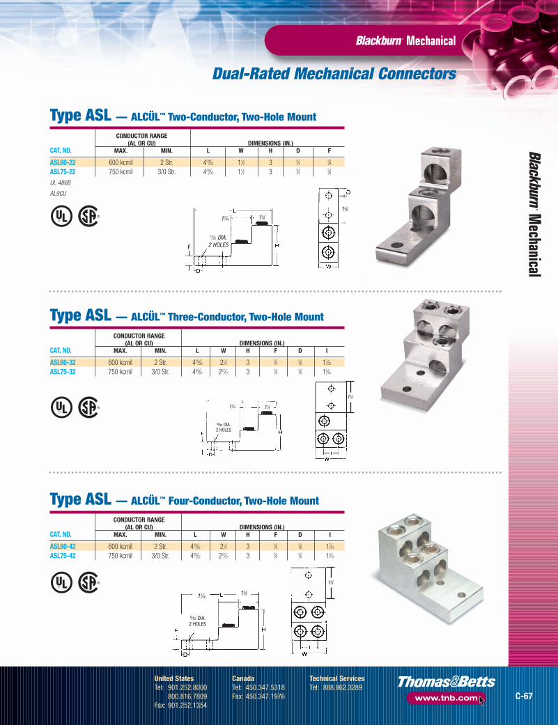
Type ASL — ALCÜL™ Two-Conductor, Two-Hole Mount
CONDUCTOR RANGE(AL OR CU) DIMENSIONS (IN.)
CAT. NO. MAX. MIN. L W H D F
ASL60-22 600 kcmil 2 Str. 429⁄32 11⁄2 3 3⁄4 3⁄8ASL75-22 750 kcmil 3/0 Str. 429⁄32 11⁄2 3 3⁄4 3⁄8
UL 486B
AL9CU
Type ASL — ALCÜL™ Three-Conductor, Two-Hole Mount
CONDUCTOR RANGE(AL OR CU) DIMENSIONS (IN.)
CAT. NO. MAX. MIN. L W H F D I
ASL60-32 600 kcmil 2 Str. 429⁄32 21⁄2 3 3⁄4 3⁄8 17⁄32
ASL75-32 750 kcmil 3/0 Str. 429⁄32 227⁄21 3 3⁄4 3⁄8 15⁄16
13⁄16 13⁄8
Type ASL — ALCÜL™ Four-Conductor, Two-Hole Mount
CONDUCTOR RANGE(AL OR CU) DIMENSIONS (IN.)
CAT. NO. MAX. MIN. L W H F D I
ASL60-42 600 kcmil 2 Str. 429⁄32 21⁄2 3 3⁄4 3⁄8 17⁄32
ASL75-42 750 kcmil 3/0 Str. 429⁄32 227⁄21 3 3⁄4 3⁄8 15⁄16
u DIA.2 HOLES
13⁄1613⁄8
u DIA.2 HOLES
13⁄8
13⁄8
C-67
United StatesTel: 901.252.8000
800.816.7809Fax: 901.252.1354
CanadaTel: 450.347.5318Fax: 450.347.1976
Technical ServicesTel: 888.862.3289
www.tnb.com
tnb06_wrtrm_secc_p66_67 8/9/07 11:36 AM Page C-67

Dual-Rated Mechanical Connectors
Type ASR — ALCÜL™
Splicer Reducer withSolid Barrier Wire Stop
• Features anti-rotational boss
• UL486B Recognized (90°C rating)
Type BX — ALCÜL™ Rectangular Connectors
Type GP — Aluminum Dual-Rated Mechanical Parallel Tap Connectors
MechanicalM
echa
nica
l ®
®
HW
LI
CONDUCTOR RANGE(AL OR CU) DIMENSIONS (IN.)
CAT. NO. MAX. MIN. L W H I
ASR0214* 2 Str. 14 AWG 11⁄4 33⁄6439⁄64
21⁄32
ASR1114* 1/0 Str. 14 AWG 11⁄2 39⁄6423⁄32
51⁄64
ASR2506 250 kcmil 6 Str. 21⁄8 55⁄6431⁄32 17⁄64
ASR3506 350 kcmil 6 Str. 23⁄8 11⁄32 11⁄8 11⁄4ASR7525** 750 kcmil 250 kcmil 61⁄4 15⁄8 13⁄4 15⁄8
* Slotted screws
** Two set screws per end. Not CSA Certified.
UL 486B
AL9CU
®WL
H
CONDUCTOR STYLE & BOSSRANGE SIZE OF HOLE DIMENSIONS (IN.)
CAT. NO. MAX. MIN. BOSS TAPPED L W H
14CU SquareBX0214 2
12AL .229 in.10-32 15⁄32
15⁄329⁄16
BX1114 14CU Square1/0 12AL .229 in. 10-32 5⁄8 17⁄32
39⁄64
CONDUCTOR RANGE(AL OR CU) DIMENSIONS (IN.)
CAT. NO. MAIN TAP W L H
GP-2* 2–12 Str. 4–14 5⁄8 13⁄8 7⁄8GP-0 1/0–2 1/0–14 3⁄4 13⁄4 1GP-250-0 250–1/0 1/0–14 11⁄16 21⁄32 15⁄16
GP-250 250–1/0 250–6 11⁄16 29⁄32 15⁄16
GP-350 350–4/0 350–6 11⁄4 29⁄16 17⁄16
GP-500 500–350 500–2 13⁄8 31⁄8 13⁄4GP-750 750–500 500–2 11⁄2 33⁄8 2
* Slotted screw, tap side.
To include insulating cover, add suffix WC.
C-68
United StatesTel: 901.252.8000
800.816.7809Fax: 901.252.1354
CanadaTel: 450.347.5318Fax: 450.347.1976
Technical ServicesTel: 888.862.3289
www.tnb.com
tnb06_wrtrm_secc_p68_69 8/9/07 11:36 AM Page C-68

Dual-Rated Mechanical Connectors
Type GT — Aluminum Dual-Rated Mechanical Parallel Tap Connectors
Type TC — Insulating Covers for GP-GT
MechanicalM
echanical
Tightening Torque Values for Aluminum Dual-Rated Socket Screw Connectors
CONDUCTOR RANGE(AL OR CU) DIMENSIONS (IN.)
CAT. NO. MAIN TAP W L H
GT-2* 2–12 Str. 4–14 5⁄8 13⁄8 7⁄8GT-0 1/0–2 1/0–14 3⁄4 13⁄4 1GT-250-0 250–1/0 1/0–14 11⁄16 29⁄32 15⁄16
GT-250 250–1/0 250–6 11⁄16 29⁄32 15⁄16
GT-350 350–4/0 350–6 11⁄4 29⁄16 17⁄16
GT-500 500–350 500–2 13⁄8 31⁄8 13⁄4GT-750 750–500 500–2 11⁄2 33⁄8 2
* Slotted screw, tap side.
To include insulating cover, add suffix WC.
DIMENSIONS (IN.) USE WITHCAT. NO. COLOR L W H CONNECTOR
TC-2 YELLOW 21⁄8 13⁄4 11⁄16 GP-2, GT-2TC-10 GRAY 21⁄2 213⁄32 11⁄4 GP-0, GT-0
GP-250, GT-250, GP-350,TC250350 RED 31⁄8 217⁄32 119⁄32
GP-250-0, GT-250-0, GT-350TC-500 BLUE 41⁄4 31⁄8 21⁄16 GP-500, GT-500TC-750 ORANGE 45⁄8 37⁄8 21⁄2 GP-750, GT-750
AWG OR AWG ORCIRCULAR TIGHTENING TORQUE IN IN.-LB. CIRCULAR TIGHTENING TORQUE IN IN.-LB.MIL SIZE SCREW DRIVER WRENCH MIL SIZE SCREW DRIVER WRENCH
12 20 75 4/0 — 20010 20 75 250 — 2508 20 75 350 — 2506 35 100 500 — 3004 35 100 600 — 3002 50 125 700 — 3001 50 125 750 — 300
1/0 50 150 800 — 4002/0 50 150 1,000 — 4003/0 — 200
YELLOWGRAY
RED
BLUEORANGE
C-69
United StatesTel: 901.252.8000
800.816.7809Fax: 901.252.1354
CanadaTel: 450.347.5318Fax: 450.347.1976
Technical ServicesTel: 888.862.3289
www.tnb.com
tnb06_wrtrm_secc_p68_69 8/9/07 11:36 AM Page C-69

Copper Mechanical Connectors
MechanicalM
echa
nica
l
• For use where large contact area is required to provide more secure mounting
• Cast from high strength bronze alloy
Type L— Single-Conductor, One-Hole Mount
CAT. NO. CONDUCTOR RANGE DIMENSIONS (IN.)SOCKET HEX MAX. MIN. L W H F D J E G
L35* — 8 Str. 14 Sol. 13⁄163⁄8 3⁄8 3⁄32
13⁄6411⁄64
13⁄641⁄2
L70* — 4 Str. 14 Sol. 11⁄8 17⁄3235⁄64
3⁄329⁄32
9⁄329⁄32
21⁄32
L125 L125H 1/0 Str. 8 Sol. 11⁄2 47⁄643⁄4 3⁄32
3⁄8 27⁄6421⁄64
27⁄32
L250 L250H 250 kcmil 6 Str. 161⁄6415⁄16 11⁄16
1⁄8 29⁄645⁄8 13⁄32 13⁄32
L400BB L400H 500 kcmil 4/0 Str. 3 113⁄32 115⁄329⁄32
5⁄8 7⁄8 9⁄16 15⁄8L650 L650H 1,000 kcmil 500 kcmil 4 2 23⁄16
17⁄323⁄4 11⁄4 9⁄16 2
* Sizes L35 and L70 have screwdriver slot head screws only. UL 486A.
Type L— Single-Conductor, Two-Hole Mount
CAT. NO. CONDUCTOR RANGE DIMENSIONS (IN.)SOCKET HEX MAX. MIN. L W H F D K E G J
L1252 L1252H 1/0 Str. 4 Str. 213⁄1625⁄32
13⁄163⁄16
7⁄16 1 11⁄32 2 27⁄64
L2502 L2502H 250 kcmil 1/0 Str. 3 11⁄16 11⁄3215⁄64
7⁄16 1 13⁄32 17⁄8 5⁄8L4002 L4002H 500 kcmil 4/0 Str. 33⁄8 113⁄32 115⁄32
5⁄167⁄16 1 13⁄32 115⁄16
57⁄64
L6502 L6502H 1000 kcmil 500 kcmil 415⁄16 2 2 3⁄8 9⁄16 11⁄2 9⁄16 23⁄4 11⁄4
UL 486A.
• Cast of high-strength copper alloy • Plated steel socket head set screws
Type S— Copper End-to-End Splice Connector
CONDUCTOR RANGE DIMENSIONS (IN.)CAT. NO. MAX. MIN. L W H J I
S100BB 1 Str. 4 Sol. 111⁄165⁄8 11⁄16
3⁄8 15⁄16
S225BB* 4/0 Str. 1 Str. 23⁄1627⁄32
31⁄329⁄16 13⁄16
S400BB 500 kcmil 4/0 Str. 27⁄8 13⁄16 15⁄167⁄8 15⁄8
* Not UL Listed.
• Cat. Nos. L400 and L650 cast fromhigh-strength bronze alloy
• Cat. Nos. L35, L70, L125 and L250cold forged from pure electrolyticcopper with 99% conductivity
Type TL— Two-Conductor, Two-Hole Mount
CAT. NO. CONDUCTOR RANGE DIMENSIONS (IN.)SOCKET HEX MAX. MIN. L W H F K D E G J
TL250 TL250H 250 kcmil 1/0 Str. 45⁄16 17⁄8 9⁄325⁄8 13⁄4 9⁄16 11⁄16 33⁄16
5⁄8TL400 TL400H 500 kcmil 4/0 Str. 43⁄4 29⁄16
13⁄3211⁄16 13⁄4 9⁄16 19⁄16 3 7⁄8
TL650 TL650H 1,000 kcmil 500 kcmil 59⁄16 31⁄4 9⁄165⁄8 13⁄4 9⁄16 23⁄16 33⁄8 11⁄4
Four hole NEMA tang on TL650.
UL 486A.
• Conveniently terminates parallel conductors
C-70
United StatesTel: 901.252.8000
800.816.7809Fax: 901.252.1354
CanadaTel: 450.347.5318Fax: 450.347.1976
Technical ServicesTel: 888.862.3289
www.tnb.com
tnb06_wrtrm_secc_p70_71 8/9/07 11:35 AM Page C-70

Copper Mechanical Connectors
MechanicalM
echanical
Type STC—Copper Single-Conductor, One-Hole Mount (Straight Tang)
FIG. CONDUCTOR RANGE DIMENSIONS (IN.)CAT. NO. NO. MAX. MIN. L W H F E D
STC1014* 1 10 AWG 14 AWG 1 5⁄161⁄2 5⁄64
5⁄323⁄16
STC0614 2 6 Str. 14 AWG 19⁄643⁄8 11⁄16
5⁄6413⁄64
7⁄32
STC0414 2 4 Str. 14 AWG 11⁄4 1⁄2 27⁄323⁄32
17⁄641⁄4
STC0208 3 2 Str. 8 Str. 115⁄321⁄2 31⁄32
3⁄3217⁄64
1⁄4STC1102 3 1/0 Str. 2 Str. 115⁄16
5⁄8 11⁄4 1⁄8 17⁄647⁄16
STC3104 3 3/0 Str. 4 Str. 21⁄4 3⁄4 19⁄161⁄8 13⁄32
7⁄16
STC4102 3 4/0 Str. 2 Str. 23⁄8 1 121⁄321⁄8 11⁄32
1⁄2STC3511 3 350 kcmil 1/0 Str. 31⁄4 1 15⁄8 3⁄16
13⁄325⁄8
STC5011 3 500 kcmil 1/0 Str. 37⁄8 11⁄2 113⁄163⁄16
13⁄3215⁄16
STC9960 3 1,000 kcmil 600 kcmil 5 2 25⁄8 1⁄4 17⁄32 11⁄8
* Not CSA Listed.
• Uniquely designed pressure bar and notched v-bottom collar provide vise-like grip between conductor and terminal
• Made of electrolytic seamless copper• Screws are zinc-plated steel• UL 486A tested for copper conductor
Fig. 2
Fig. 1
Fig. 3
W
E
D
Type BTC—Copper Single-Conductor, One-Hole Mount (Offset Tang)
FIG. CONDUCTOR RANGE DIMENSIONS (IN.)CAT. NO. NO. MAX. MIN. L W H F E D
BTC1014* 1 10 AWG 14 AWG 1 5⁄1643⁄64
5⁄645⁄32
3⁄16
BTC0614 2 6 Str. 14 AWG 13⁄323⁄8 25⁄32
5⁄6413⁄64
7⁄32
BTC0208 2 2 Str. 8 Str. 115⁄321⁄2 27⁄32
3⁄3217⁄64
1⁄4BTC1102 3 1/0 Str. 2 Str. 125⁄32
5⁄8 113⁄321⁄8 17⁄64
7⁄16
BTC3104 3 3/0 Str. 4 Str. 23⁄643⁄4 19⁄16
1⁄8 13⁄327⁄16
BTC4102 3 4/0 Str. 2 Str. 29⁄16 1 161⁄641⁄8 11⁄32
1⁄2BTC3511 3 350 kcmil 1/0 Str. 31⁄4 1 21⁄2 3⁄16
13⁄325⁄8
BTC5011 3 500 kcmil 1/0 Str. 41⁄4 11⁄2 221⁄323⁄16
13⁄3215⁄16
BTC9960 3 1,000 kcmil 600 kcmil 43⁄4 2 39⁄161⁄4 17⁄32 11⁄8
* Not CSA Listed.
Fig. 1 Fig. 2
Fig. 3
“E” DIA.
WIRE STD. PKG.Cat. NO. DESCRIPTION RANGE QTY.
UFSK148DB UF Direct-Burial Splice Kit 14–8 AWG 10DBSK82 Direct-Burial Splice Kit (non-UF) 8–2 AWG 10
Direct-Burial Splice Kits• Includes outer heat-shrink tubing insulator with
adhesive sealant for rugged, watertight protection
• For underground feeder (UF) cable, UFSK148DB’s four-in-one connector supports four-conductor, three-phase-plus-neutral or single-phase wiring systems
• For non-UF cable, DBSK82 offers easy-to-install,one-piece, aluminum alloy connector
Fast, easy installation. NEW!NEW!
DBSK82
UFSK148DB
C-71
United StatesTel: 901.252.8000
800.816.7809Fax: 901.252.1354
CanadaTel: 450.347.5318Fax: 450.347.1976
Technical ServicesTel: 888.862.3289
www.tnb.com
tnb06_wrtrm_secc_p70_71 8/9/07 11:36 AM Page C-71

LOCKTITE® Connectors — Code Copper Conductor (for 600V)
Only nine lug sizes fit cables from #14 to 1,000 kcmil.
• Easily installed with key wrench
• Saddle and cable socket make direct, all-around,low-resistance contact with cable
• Convenient peephole permits easy inspection
One-Hole Lugs
MechanicalM
echa
nica
l
CABLE DIMENSIONS (IN.)CAT. NO. SIZE G A B C D J F
31003† 14 to 8 1⁄2 11⁄8 9⁄161⁄2 1⁄8 17⁄32
9⁄32
31005† 8 to 4 1⁄2 11⁄8 5⁄8 1⁄2 1⁄8 17⁄329⁄32
31007 4 to 1 1⁄2 15⁄8 13⁄165⁄8 7⁄32 1 11⁄32
31009 1 to 2/0 3⁄8 115⁄16 1 13⁄161⁄4 13⁄16
7⁄16
31011 2/0 to 4/0 3⁄8 23⁄8 11⁄4 1 9⁄32 113⁄3217⁄32
31013 4/0 to 300 1⁄2 23⁄4 11⁄2 13⁄165⁄16 117⁄32
5⁄831015 300 to 500 1⁄2 31⁄16 111⁄16 13⁄8 11⁄32 113⁄16
3⁄431017 500 to 750 1⁄2 325⁄32 23⁄16 15⁄8 13⁄32 21⁄8 131019 750 to 1000 5⁄8 45⁄16 215⁄32 17⁄8 15⁄32 211⁄32 13⁄16
†With Filister Head Screw. All others, hex socket screws.
CABLE DIMENSIONS (IN.)CAT. NO. SIZE G A B C D J F E
31005-AL† 8 to 4 1⁄4 11⁄8 5⁄8 1⁄2 1⁄8 17⁄329⁄32
1⁄2†With Filister Head Screw.
Bolt holes and spacings listed are standard, but lugs with blank tongues can be furnished.
For torque requirements, see page C-77.
®
®
®
®
A
G Bolt Size
D
C
BJ
F
G Bolt Size
A
D
C
B
J
F
E
One-Hole Flag-Type Lugs
C-72
United StatesTel: 901.252.8000
800.816.7809Fax: 901.252.1354
CanadaTel: 450.347.5318Fax: 450.347.1976
Technical ServicesTel: 888.862.3289
www.tnb.com
tnb06_wrtrm_secc_p72_73 8/9/07 11:35 AM Page C-72

LOCKTITE® Connectors — Code Copper Conductor (for 600V)
MechanicalM
echanical
All the outstanding LOCKTITE® lug features — plus two-bolt capacity.One-Hole 90° Upright Lugs
Two-Hole Lugs• Easy installation
• High conductivity
• Wide cable range
• Long tongue adapted for 2 bolts
Two-Hole NEMA-Drilled Lugs
CABLE DIMENSIONS (IN.)CAT. NO. SIZE G A B C D J F H
32003† 14 to 8 1⁄4 111⁄16 11⁄4 1⁄2 1⁄8 15⁄329⁄32
5⁄832005† 8 to 4 1⁄4 13⁄4 11⁄4 1⁄2 1⁄8 17⁄32
9⁄325⁄8
32007 4 to 1 1⁄4 21⁄4 17⁄165⁄8 7⁄32
7⁄8 9⁄323⁄4
32009 1 to 2/0 3⁄8 27⁄8 115⁄1613⁄16
1⁄4 13⁄327⁄16 1
32011 2/0 to 4/0 3⁄8 31⁄8 2 1 9⁄3215⁄16
7⁄16 132013 4/0 to 300 3⁄8 33⁄8 21⁄8 13⁄16
5⁄16 19⁄167⁄16 1
32015 300 to 500 3⁄8 31⁄2 21⁄8 13⁄8 11⁄32 127⁄327⁄16 1
32017 500 to 750 1⁄2 419⁄32 3 13⁄4 13⁄32 21⁄8 9⁄16 11⁄232019 750 to 1,000 1⁄2 427⁄32 3 17⁄8 15⁄32 211⁄32
9⁄16 11⁄2†With Filister Head Screw. All others, hex head screws.
For torque requirements, see page C77.
CABLE DIMENSIONS (IN.)CAT. NO. SIZE G A B C D J F
31005-UAL† 8 to 4 1⁄4 11⁄8 5⁄8 1⁄2 1⁄8 1⁄2 9⁄32
31007-UAL 4 to 1 1⁄4 121⁄3213⁄16
5⁄8 7⁄3213⁄16
11⁄32
31009-UAL 1 to 2/0 3⁄8 21⁄32 1 13⁄161⁄4 15⁄16
7⁄16
31011-UAL 2/0 to 4/0 3⁄8 21⁄2 11⁄4 1 9⁄32 11⁄8 17⁄32
†With Filister Head Screw. All others, hex head screws.Bolt holes and spacings listed are standard, but lugs with blank tongues can be furnished.
®
®
®
®
®
®
H
A
G Bolt Size
D
C
B
J
F
CABLE DIMENSIONS (IN.)CAT. NO. SIZE G A B C D J F H
32207 4 to 1 3⁄8 213⁄16 2 3⁄4 7⁄327⁄8 7⁄16 1
32209 1 to 2/0 1⁄2 315⁄16 3 1 1⁄4 11⁄169⁄16 13⁄4
32211 2/0 to 4/0 1⁄2 41⁄8 3 1 9⁄32 19⁄329⁄16 13⁄4
32213 4/0 to 300 1⁄2 43⁄16 3 13⁄165⁄16 115⁄32
9⁄16 13⁄432215 300 to 500 1⁄2 47⁄8 31⁄2 13⁄8 11⁄32 113⁄16
9⁄16 13⁄432217 500 to 750 1⁄2 53⁄32 31⁄2 13⁄4 13⁄32 21⁄8 9⁄16 13⁄432219 750 to 1,000 1⁄2 51⁄4 31⁄2 3 15⁄32 21⁄8 9⁄16 13⁄4
For torque requirements, see page C77.
H
A
G Bolt Size
D
C
BJ
F
• Furnished with bolt holes and spacings to fit equipmentwith NEMA-type connector mounting pads
C-73
United StatesTel: 901.252.8000
800.816.7809Fax: 901.252.1354
CanadaTel: 450.347.5318Fax: 450.347.1976
Technical ServicesTel: 888.862.3289
www.tnb.com
tnb06_wrtrm_secc_p72_73 8/9/07 11:35 AM Page C-73

LOCKTITE® Connectors — Code Copper Conductor (for 600V)
Double-Barrel/Triple-Barrel NEMA-Drilled Lugs for 600V Applications
• Screw tightening
• Serrated saddle
• Built-in lockwasher
MechanicalM
echa
nica
l
®
®
Bolt Size
E
A
B
D
FH
C
J
Bolt Size
E
A
B
D
FH
C
J
H
Bolt Size
E
AB
D
FH
C
J
Bolt Size
E
AB
D
FH
C
J
H
Fig. A Fig. BFig. C
Fig. D
CABLEDIMENSIONS (IN.)
CAT. NO. SIZE FIG.BOLT
A B C D E F H JSIZE
32003BD† 14 to 8 A 1⁄4 23⁄16 13⁄4 5⁄8 1⁄8 11⁄169⁄32
5⁄8 15⁄32
32005BD† 8 to 4 A 1⁄4 21⁄2 2 1 1⁄8 1 9⁄325⁄8 17⁄32
32007BD 4 to 1 A 3⁄8 213⁄16 2 11⁄4 7⁄32 11⁄4 7⁄16 1 29⁄32
32009BD 1 to 2/0 A 1⁄2 47⁄16 31⁄2 11⁄2 1⁄4 19⁄165⁄8 13⁄4 13⁄32
32011BD 2/0 to 4/0 A 1⁄2 45⁄8 31⁄2 13⁄4 9⁄32 13⁄4 5⁄8 13⁄4 15⁄16
32013BD 4/0 to 300 A 1⁄2 43⁄4 31⁄2 2 5⁄16 21⁄8 5⁄8 133⁄4 19⁄16
32015BD 300 to 500 A 1⁄2 53⁄8 315⁄16 21⁄2 11⁄32 21⁄2 5⁄8 13⁄4 113⁄16
32017BD 500 to 700 B 1⁄2 519⁄32 4 4 13⁄32 215⁄165⁄8 13⁄4 21⁄8
32019BD 750 to 1000 B 1⁄2 527⁄32 4 4 15⁄32 31⁄4 5⁄8 13⁄4 211⁄32
32011TB 2/0 to 4/0 C 1⁄2 45⁄8 33⁄8 21⁄2 9⁄32 23⁄4 5⁄8 13⁄4 15⁄16
32013TB 4/0 to 300 C 1⁄2 43⁄4 31⁄2 3 5⁄16 31⁄4 5⁄8 13⁄4 117⁄32
32015TB 300 to 500 D 1⁄2 53⁄8 4 4 11⁄32 33⁄4 5⁄8 13⁄4 113⁄16
32017TB 500 to 750 D 1⁄2 519⁄32 4 4 13⁄32 43⁄8 5⁄8 13⁄4 21⁄832019TB 750 to 1,000 D 1⁄2 527⁄32 4 4 15⁄32 413⁄16
5⁄8 13⁄4 211⁄32
†With Filister Head Screw.
For torque requirements, see page C-77.
All the same features as the standardLOCKTITE® lug — with two or three barrels.
C-74
United StatesTel: 901.252.8000
800.816.7809Fax: 901.252.1354
CanadaTel: 450.347.5318Fax: 450.347.1976
Technical ServicesTel: 888.862.3289
www.tnb.com
tnb06_wrtrm_secc_p74_75 8/9/07 11:35 AM Page C-74

LOCKTITE® Connectors — Code Copper Conductor (for 600V)
MechanicalM
echanical
Join two cables end-to-end.Two-Way Connectors• Cables held by saddle and tightened by screws
• Built-in lockwashers
Designed for easy, one-person installation.Tee-Parallel Taps
• Tap hangs on main while branch is inserted
• Simply tighten screw to lock in place
CABLE DIMENSIONS (IN.)CAT. NO. SIZE A E J
32503† 14 Sol. to 8 Sol. 11⁄8 3⁄8 15⁄32
32505† 8 Sol. to 4 Str. 13⁄8 1⁄2 17⁄32
32507 4 Sol. to 1 Str. 15⁄8 5⁄8 27⁄32
32509 1 sol. to 2/0 17⁄8 3⁄4 11⁄32
32511 2/0 to 4/0 25⁄1615⁄16 11⁄4
32513 4/0 to 300 29⁄16 11⁄8 11⁄232515 300 to 500 23⁄4 11⁄4 125⁄32
32517 500 to 750 31⁄8 11⁄2 21⁄16
32519 750 to 1,000 37⁄8 111⁄16 29⁄32
†With Filister Head Screw.
For torque requirements, see page C-77.
®®
A
E
J
CABLE SIZE DIMENSIONS (IN.)CAT. NO. MAIN BRANCH A B C
35011 300 to 500 2 to 3/0 21⁄2 13⁄4 11⁄435013 300 to 500 4/0 to 500 31⁄16 17⁄8 15⁄835015 500 to 750 2 to 3/0 213⁄16 115⁄16 11⁄435017 500 to 750 4/0 to 500 33⁄8 21⁄16 15⁄835019 500 to 750 500 to 750 4 21⁄16 21⁄16
For torque requirements, see page C-77.
®®
A
C B
C-75
United StatesTel: 901.252.8000
800.816.7809Fax: 901.252.1354
CanadaTel: 450.347.5318Fax: 450.347.1976
Technical ServicesTel: 888.862.3289
www.tnb.com
tnb06_wrtrm_secc_p74_75 8/9/07 11:35 AM Page C-75

LOCKTITE® Connectors — Code Copper Conductor (for 600V)
Tandem-Type Two-Hole NEMA-Drilled Lugs• Each lug takes a range of wire sizes
• Bolt holes and spacings listed are standard
For stranded, solid, flexible and othertypes of cables.
MechanicalM
echa
nica
l
Ground Bus Taps — for 1⁄4" Copper Bus Bar• Eliminate the need to drill holes in the ground bus• Can be placed quickly at any location• Install with only a key wrench• Standard LOCKTITE® lug grip securely holds tapping cable
For easy installation in hard-to-reach places.
Pigtail Connectors
CABLE DIMENSIONS (IN.)CAT. NO. SIZE G A B C D J F H
32007TL 4 to 1 3⁄8 39⁄16 2 3⁄4 7⁄3229⁄32
7⁄16 132009TL 1 to 2/0 1⁄2 415⁄16 3 1 1⁄4 13⁄32
9⁄16 13⁄432011TL 2/0 to 4/0 1⁄2 53⁄8 3 1 9⁄32 15⁄16
9⁄16 13⁄432013TL 4/0 to 300 1⁄2 55⁄8 3 13⁄16
5⁄16 19⁄169⁄16 13⁄4
32015TL 300 to 500 1⁄2 611⁄32 31⁄2 13⁄8 11⁄32 — 5⁄8 13⁄432017TL 500 to 750 1⁄2 623⁄32 31⁄2 13⁄4 13⁄32 21⁄8 5⁄8 13⁄4
®
®
®
®G Bolt Size
J
H
C
D
A
B
F
B
A
CABLE DIMENSIONS (IN.)CAT. NO. SIZE FIG. A J
31305 10 to 8 A 1⁄2 17⁄32
31307 8 to 6 A 3⁄4 27⁄32
31309 6 to 4 B 7⁄8 11⁄32
31311 4 to 2 B 11⁄16 11⁄431313 1 to 2/0 B 13⁄16 11⁄231315 2/0 to 4/0 B 15⁄16 125⁄32
For torque requirements, see page C-77.
NOTE: To order with hex head screws (available on all except 14-10 and 10-8 code sizes),add prefix H to catalog number.
J
A
WIRESIZE DIMENSIONS (IN.)
CAT. NO. (IN.) A B BUS THICKNESS
31207 8 to 4 21⁄4 13⁄4 1⁄431208 4 to 1 29⁄16 13⁄4 1⁄431209 1 to 2/0 23⁄4 13⁄4 1⁄431210 2/0 to 4/0 23⁄4 13⁄4 1⁄431211 4/0 to 300 27⁄8 13⁄4 1⁄431212 300 to 500 3 13⁄4 1⁄4
For torque requirements, see page C-77.
®
®
Fig. A Fig. B
C-76
United StatesTel: 901.252.8000
800.816.7809Fax: 901.252.1354
CanadaTel: 450.347.5318Fax: 450.347.1976
Technical ServicesTel: 888.862.3289
www.tnb.com
tnb06_wrtrm_secc_p76_77 8/9/07 11:34 AM Page C-76

MechanicalM
echanical
Stud Connectors
T&B Recommended Tightening Torque
SCREWSIZE OF WRENCH DRIVER
CONDUCTOR TORQUE TORQUERANGES IN.-LBS. IN.-LBS.
14 to 8 — 208 to 4 — 354 to 1 125 —
1 to 2/0 150 — 2/0 to 4/0 200 — 4/0 to 300 250 — 300 to 500 300 — 500 to 750 300 —
750 to 1,000 400 —
LUG-IT® One-Hole Lugs, Offset Tongue
Designed to grip cable firmly between its strongbody and serrated copper tongue.
®®
CABLE DIMENSIONS (IN.)CAT. NO. SIZE G A B C D F
35301 14 to 6 #10 13⁄161⁄2 3⁄8 .064 7⁄32
35401 8 to 2 1⁄4 17⁄165⁄8 1⁄2 .081 1⁄4
*35501† 4 to 2/0 1⁄4 113⁄1613⁄16
3⁄4 .101 3⁄8*35601† 1/0 to 4/0 3⁄8 217⁄32 13⁄32 1 .128 1⁄2
D
F
B
C
A
TYPE MSCABLE DIMENSIONS (IN.) STUD
CAT. NO. SIZE A B D E F SIZE (IN.)
31007-T 4 to 1 13⁄8 25⁄327⁄8 5⁄8 3⁄4 3⁄8–16
31009-T 1 to 2/0 15⁄8 7⁄8 1 3⁄4 3⁄4 3⁄8–1631011-T 2/0 to 4/0 15⁄8 11⁄16 13⁄16
7⁄8 1 1⁄2–1331013-T 4/0 to 300 17⁄8 13⁄16 13⁄8 11⁄16 1 1⁄2–1331015-T 300 to 500 25⁄32 15⁄16 11⁄2 11⁄4 1 1⁄2–13
®®
GB
A A
GB
Fig. A Fig. B
Type FL
• Double laps at top give greaterthread strength and lock screwwhen tightened
• Copper tongue makes a low-resistance terminal
• Fast, simple installation
• Convenient pigtail is easy to tape
• To order with hex head screws (available on all except 14-10 and 10-8 code sizes), add prefix H to catalog number
• Standard tapping shown in diagrams
• Other tapping to meet specific requirements available on requestD
F
A
E B
Type MS
FEMALE — TYPE FLCABLE DIMENSIONS (IN.)
CAT. NO. SIZE FIG. G A B
31262† 8 to 4 A 3⁄8–16 11⁄165⁄8
31263 4 to 1 B 3⁄8–16 115⁄323⁄4
31265 4 to 1 B 1⁄2–13 115⁄323⁄4
31267 2/0 to 4/0 B 1⁄2–13 23⁄1613⁄16
†With Filister Head Screw.
LOCKTITE® Connectors — Code Copper Conductor (for 600V)
Each connector accommodates a wide range of conductor sizes.
Type MS Type FL
* Aluminum body.†Hex head bolt.
Add suffix G to above Cat. Nos. for lug connector with green screw for grounding identification.
For torque requirements, see table at right.
C-77
United StatesTel: 901.252.8000
800.816.7809Fax: 901.252.1354
CanadaTel: 450.347.5318Fax: 450.347.1976
Technical ServicesTel: 888.862.3289
www.tnb.com
tnb06_wrtrm_secc_p76_77 8/9/07 11:34 AM Page C-77
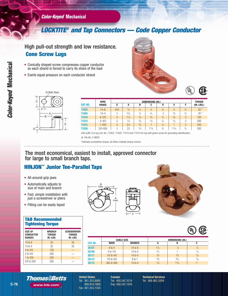
LOCKTITE® and Tap Connectors — Code Copper Conductor
MechanicalM
echa
nica
l
Cone Screw Lugs
• Conically shaped screw compresses copper conductor so each strand is forced to carry its share of the load
• Exerts equal pressure on each conductor strand
®®
WIRE DIMENSIONS (IN.) TORQUE CAT. NO. RANGE G A B C D E F (IN.-LBS.)
71003 14–8 #10 13⁄167⁄16
3⁄8 3⁄323⁄8 3⁄16 20 *
71005 14–4 1⁄4 15⁄325⁄8 9⁄16
1⁄8 19⁄329⁄32 35 *
71010 4–2/0 3⁄8 121⁄3227⁄32
23⁄323⁄16
25⁄323⁄8 150
71014 2–4/0 3⁄8 17⁄8 29⁄3215⁄16
3⁄1631⁄32
3⁄8 200 71015 1–250 3⁄8 21⁄32
29⁄32 1 7⁄32 1 3⁄8 250 71020 2/0–500 1⁄2 23⁄4 11⁄4 111⁄32
9⁄32 115⁄329⁄16 300
Add suffix G to lug Cat. No. 71003, 71005, 71010 and 71014 for lug with green screw for grounding identification.
UL File No. E-9609.
*Indicates screwdriver torque; all others indicate torque wrench.
G Bolt Size
E
A
F
B
C
D
High pull-out strength and low resistance.
T&B Recommended Tightening Torque
SIZE OF WRENCH SCREWDRIVERCONDUCTOR TORQUE TORQUERANGES IN.-LBS. IN.-LBS.
14 to 8 20 2014 to 4 35 354 to 2/0 150 —2 to 4/0 200 —1 to 250 250 —2/0 to 500 300 —
Bmax.
Amax.
C
CABLE SIZE DIMENSIONS (IN.)CAT. NO. MAIN BRANCH A B C
35107 8 to 4 14 to 8 11⁄167⁄8 5⁄8
35109 4 to 1/0 14 to 4 11⁄4 1 11⁄16
35111 1/0 to 4/0 14 to 4 13⁄4 13⁄8 27⁄32
35112 1/0 to 4/0 8 to 1 15⁄8 19⁄1627⁄32
35115 300 to 500 14 to 4 17⁄8 113⁄16 1
The most economical, easiest to install, approved connector for large to small branch taps.
HINJON™ Junior Tee-Parallel Taps
• All-around-grip jaws
• Automatically adjusts to size of main and branch
• Fast, simple installation with just a screwdriver or pliers
• Fitting can be easily taped
C-78
United StatesTel: 901.252.8000
800.816.7809Fax: 901.252.1354
CanadaTel: 450.347.5318Fax: 450.347.1976
Technical ServicesTel: 888.862.3289
www.tnb.com
tnb06_wrtrm_secc_p78_79 8/9/07 11:34 AM Page C-78