1Pin and Socket Connectors
252
1-1 Pin and Socket Connectors Catalog 7-1773446-2 Dimensions are in inches and Dimensions are shown for USA: 1-800-522-6752 South America: 55-11-2103-6000 Revised 10-07 millimeters unless otherwise reference purposes only. Canada: 1-905-470-4425 Hong Kong: 852-2735-1628 specified. Values in brackets Specifications subject Mexico: 52-55-1106-0800 Japan: 81-44-844-8013 www.tycoelectronics.com are metric equivalents. to change. C. America: 57-1-254-4444 UK: 44-208-420-8341 1 Pin and Socket Connectors Table of Contents Circular Connectors NANONICS Environmentally Sealed Circular Connectors Quick Disconnect . . . . . . . . . . . . . . . . . . . . . . . . . . . . . . . . . . . . .5-5 to 5-10, 5-15 to 5-18 Threaded Coupling . . . . . . . . . . . . . . . . . . . . . . . . . . . . . . . . . . . . . . . . . . . . . .5-11 to 5-18 Part numbering guideline . . . . . . . . . . . . . . . . . . . . . . . . . . . . . . . . . . . . . . . . . . . . . . .5-19 Microdot Circular Connectors Introduction . . . . . . . . . . . . . . . . . . . . . . . . . . . . . . . . . . . . . . . . . . . . . . . . . . . . .1-20, 1-21 MARC 43 Series Connectors . . . . . . . . . . . . . . . . . . . . . . . . . . . . . . . . . . . . . .1-22 to 1-28 MARC 53 Series Connectors . . . . . . . . . . . . . . . . . . . . . . . . . . . . . . . . . . . . . .1-29 to 1-38 MARC 63 Series Connectors . . . . . . . . . . . . . . . . . . . . . . . . . . . . . . . . . . . . . .1-39 to 1-42 Contacts for MARC 43, MARC 53 and MARC 63 Connectors . . . . . . . . . . . .1-43 to 1-44 Contact Cavity Sealing Plugs . . . . . . . . . . . . . . . . . . . . . . . . . . . . . . . . . . . . . . . . . . . .1-45 Assembly Tools . . . . . . . . . . . . . . . . . . . . . . . . . . . . . . . . . . . . . . . . . . . . . . . . . . . . . . .1-46 MARC 73 Series Connectors . . . . . . . . . . . . . . . . . . . . . . . . . . . . . . . . . . . . . .1-47 to 1-51 MQR Series — Microminiature Circular Connectors . . . . . . . . . . . . . . . . . . . . . .1-52, 1-53 MTC Series — Microminiature Circular Connectors . . . . . . . . . . . . . . . . . . . .1-54 to 1-55 AMP Micro CPC . . . . . . . . . . . . . . . . . . . . . . . . . . . . . . . . . . . . . . . . . . . . . . . . .1-56 to 1-58 AMP Metal-Shell Micro Circular Connectors Metal-Shell Micro Circular Connectors . . . . . . . . . . . . . . . . . . . . . . . . . . . . . . .1-59 to 1-61 Metal-Shell Micro Circular Connectors with Spring-Loaded Contacts . . . . . . .1-62 to 1-66 AMP Circular Connectors for Commercial Signal and Power Applications Introduction . . . . . . . . . . . . . . . . . . . . . . . . . . . . . . . . . . . . . . . . . . . . . . . . . . . . . . . . . .1-67 Connector Series and Types . . . . . . . . . . . . . . . . . . . . . . . . . . . . . . . . . . . . . . . .1-68, 1-69 Performance Characteristics — CPC and Metal-Shell CPC Connectors . . . . . . . . . . .1-70 Levels of Protection for Electric Operating Material . . . . . . . . . . . . . . . . . . . . . . . . . . .1-71 Current Carrying Capabilities . . . . . . . . . . . . . . . . . . . . . . . . . . . . . . . . . . . . . . . . . . . .1-72 Presentation — An Example . . . . . . . . . . . . . . . . . . . . . . . . . . . . . . . . . . . . . . . . . . . . .1-73 Circular Plastic Connectors Series 1 . . . . . . . . . . . . . . . . . . . . . . . . . . . . . . . . . . . . . . . . . . . . . . . . . . . . .1-74 to 1-80 Series 2 . . . . . . . . . . . . . . . . . . . . . . . . . . . . . . . . . . . . . . . . . . . . . . . . . . . . .1-90 to 1-92 Series 3 . . . . . . . . . . . . . . . . . . . . . . . . . . . . . . . . . . . . . . . . . . . . . . . . . . . . . . . . . . .1-97 Series 4 . . . . . . . . . . . . . . . . . . . . . . . . . . . . . . . . . . . . . . . . . . . . . . . . . . . . . . . . . .1-101 Signal Contacts . . . . . . . . . . . . . . . . . . . . . . . . . . . . . . . . . . . . . . . . . . . . . . . .1-81 to 1-85 Coaxial Contacts . . . . . . . . . . . . . . . . . . . . . . . . . . . . . . . . . . . . . . . . . . . . . . .1-86, to 1-87 Contact Arrangements Series 1 . . . . . . . . . . . . . . . . . . . . . . . . . . . . . . . . . . . . . . . . . . . . . . . . . . . . . . . . . . .1-88 Series 2 . . . . . . . . . . . . . . . . . . . . . . . . . . . . . . . . . . . . . . . . . . . . . . . . . . . . . . . . . . .1-95 Component Dimensions Series 1 . . . . . . . . . . . . . . . . . . . . . . . . . . . . . . . . . . . . . . . . . . . . . . . . . . . . . . . . . . .1-89 Series 2 . . . . . . . . . . . . . . . . . . . . . . . . . . . . . . . . . . . . . . . . . . . . . . . . . . . . . . . . . . .1-96 Series 3 . . . . . . . . . . . . . . . . . . . . . . . . . . . . . . . . . . . . . . . . . . . . . . . . . . . . . . . . . .1-100 Signal Contacts . . . . . . . . . . . . . . . . . . . . . . . . . . . . . . . . . . . . . . . . . . . . . . . . . .1-93, 1-94 Power Contacts, Series 3 . . . . . . . . . . . . . . . . . . . . . . . . . . . . . . . . . . . . . . . . . .1-98. 1-99 CPC Connector Accessories . . . . . . . . . . . . . . . . . . . . . . . . . . . . . . . . . . . .1-102 to 1-106 One-Piece Sealed Circular Plastic Connectors . . . . . . . . . . . . . . . . . . . . . . . . . . . . .1-107 Series 1 . . . . . . . . . . . . . . . . . . . . . . . . . . . . . . . . . . . . . . . . . . . . . . . . . . . . . . . . . .1-108 Series 5, Series 6 . . . . . . . . . . . . . . . . . . . . . . . . . . . . . . . . . . . . . . . . . . . . . . . . . .1-109
-
Upload
khangminh22 -
Category
Documents
-
view
0 -
download
0
Transcript of 1Pin and Socket Connectors

1-1
Pin and Socket Connectors
Catalog 7-1773446-2 Dimensions are in inches and Dimensions are shown for USA: 1-800-522-6752 South America: 55-11-2103-6000Revised 10-07 millimeters unless otherwise reference purposes only. Canada: 1-905-470-4425 Hong Kong: 852-2735-1628
specified. Values in brackets Specifications subject Mexico: 52-55-1106-0800 Japan: 81-44-844-8013www.tycoelectronics.com are metric equivalents. to change. C. America: 57-1-254-4444 UK: 44-208-420-8341
1
Pin and Socket Connectors
Table of Contents
Circular ConnectorsNANONICS Environmentally Sealed Circular ConnectorsQuick Disconnect . . . . . . . . . . . . . . . . . . . . . . . . . . . . . . . . . . . . .5-5 to 5-10, 5-15 to 5-18Threaded Coupling . . . . . . . . . . . . . . . . . . . . . . . . . . . . . . . . . . . . . . . . . . . . . .5-11 to 5-18Part numbering guideline . . . . . . . . . . . . . . . . . . . . . . . . . . . . . . . . . . . . . . . . . . . . . . .5-19
Microdot Circular ConnectorsIntroduction . . . . . . . . . . . . . . . . . . . . . . . . . . . . . . . . . . . . . . . . . . . . . . . . . . . . .1-20, 1-21MARC 43 Series Connectors . . . . . . . . . . . . . . . . . . . . . . . . . . . . . . . . . . . . . .1-22 to 1-28MARC 53 Series Connectors . . . . . . . . . . . . . . . . . . . . . . . . . . . . . . . . . . . . . .1-29 to 1-38MARC 63 Series Connectors . . . . . . . . . . . . . . . . . . . . . . . . . . . . . . . . . . . . . .1-39 to 1-42Contacts for MARC 43, MARC 53 and MARC 63 Connectors . . . . . . . . . . . .1-43 to 1-44Contact Cavity Sealing Plugs . . . . . . . . . . . . . . . . . . . . . . . . . . . . . . . . . . . . . . . . . . . .1-45Assembly Tools . . . . . . . . . . . . . . . . . . . . . . . . . . . . . . . . . . . . . . . . . . . . . . . . . . . . . . .1-46MARC 73 Series Connectors . . . . . . . . . . . . . . . . . . . . . . . . . . . . . . . . . . . . . .1-47 to 1-51MQR Series — Microminiature Circular Connectors . . . . . . . . . . . . . . . . . . . . . .1-52, 1-53MTC Series — Microminiature Circular Connectors . . . . . . . . . . . . . . . . . . . .1-54 to 1-55
AMP Micro CPC . . . . . . . . . . . . . . . . . . . . . . . . . . . . . . . . . . . . . . . . . . . . . . . . .1-56 to 1-58
AMP Metal-Shell Micro Circular Connectors
Metal-Shell Micro Circular Connectors . . . . . . . . . . . . . . . . . . . . . . . . . . . . . . .1-59 to 1-61
Metal-Shell Micro Circular Connectors with Spring-Loaded Contacts . . . . . . .1-62 to 1-66
AMP Circular Connectors for Commercial Signal and Power ApplicationsIntroduction . . . . . . . . . . . . . . . . . . . . . . . . . . . . . . . . . . . . . . . . . . . . . . . . . . . . . . . . . .1-67Connector Series and Types . . . . . . . . . . . . . . . . . . . . . . . . . . . . . . . . . . . . . . . .1-68, 1-69Performance Characteristics — CPC and Metal-Shell CPC Connectors . . . . . . . . . . .1-70Levels of Protection for Electric Operating Material . . . . . . . . . . . . . . . . . . . . . . . . . . .1-71Current Carrying Capabilities . . . . . . . . . . . . . . . . . . . . . . . . . . . . . . . . . . . . . . . . . . . .1-72Presentation — An Example . . . . . . . . . . . . . . . . . . . . . . . . . . . . . . . . . . . . . . . . . . . . .1-73Circular Plastic Connectors
Series 1 . . . . . . . . . . . . . . . . . . . . . . . . . . . . . . . . . . . . . . . . . . . . . . . . . . . . .1-74 to 1-80Series 2 . . . . . . . . . . . . . . . . . . . . . . . . . . . . . . . . . . . . . . . . . . . . . . . . . . . . .1-90 to 1-92Series 3 . . . . . . . . . . . . . . . . . . . . . . . . . . . . . . . . . . . . . . . . . . . . . . . . . . . . . . . . . . .1-97Series 4 . . . . . . . . . . . . . . . . . . . . . . . . . . . . . . . . . . . . . . . . . . . . . . . . . . . . . . . . . .1-101
Signal Contacts . . . . . . . . . . . . . . . . . . . . . . . . . . . . . . . . . . . . . . . . . . . . . . . .1-81 to 1-85Coaxial Contacts . . . . . . . . . . . . . . . . . . . . . . . . . . . . . . . . . . . . . . . . . . . . . . .1-86, to 1-87Contact Arrangements
Series 1 . . . . . . . . . . . . . . . . . . . . . . . . . . . . . . . . . . . . . . . . . . . . . . . . . . . . . . . . . . .1-88Series 2 . . . . . . . . . . . . . . . . . . . . . . . . . . . . . . . . . . . . . . . . . . . . . . . . . . . . . . . . . . .1-95
Component DimensionsSeries 1 . . . . . . . . . . . . . . . . . . . . . . . . . . . . . . . . . . . . . . . . . . . . . . . . . . . . . . . . . . .1-89Series 2 . . . . . . . . . . . . . . . . . . . . . . . . . . . . . . . . . . . . . . . . . . . . . . . . . . . . . . . . . . .1-96Series 3 . . . . . . . . . . . . . . . . . . . . . . . . . . . . . . . . . . . . . . . . . . . . . . . . . . . . . . . . . .1-100
Signal Contacts . . . . . . . . . . . . . . . . . . . . . . . . . . . . . . . . . . . . . . . . . . . . . . . . . .1-93, 1-94Power Contacts, Series 3 . . . . . . . . . . . . . . . . . . . . . . . . . . . . . . . . . . . . . . . . . .1-98. 1-99CPC Connector Accessories . . . . . . . . . . . . . . . . . . . . . . . . . . . . . . . . . . . .1-102 to 1-106One-Piece Sealed Circular Plastic Connectors . . . . . . . . . . . . . . . . . . . . . . . . . . . . .1-107
Series 1 . . . . . . . . . . . . . . . . . . . . . . . . . . . . . . . . . . . . . . . . . . . . . . . . . . . . . . . . . .1-108Series 5, Series 6 . . . . . . . . . . . . . . . . . . . . . . . . . . . . . . . . . . . . . . . . . . . . . . . . . .1-109

1-2
Pin and Socket Connectors
Catalog 7-1773446-2 Dimensions are in inches and Dimensions are shown for USA: 1-800-522-6752 South America: 55-11-2103-6000Revised 10-07 millimeters unless otherwise reference purposes only. Canada: 1-905-470-4425 Hong Kong: 852-2735-1628
specified. Values in brackets Specifications subject Mexico: 52-55-1106-0800 Japan: 81-44-844-8013www.tycoelectronics.com are metric equivalents. to change. C. America: 57-1-254-4444 UK: 44-208-420-8341
Table of Contents (Continued)
Two-Piece Sealed Circular Plastic Connectors . . . . . . . . . . . . . . . . . . . . . . . . . . . . . .1-110Series 5 . . . . . . . . . . . . . . . . . . . . . . . . . . . . . . . . . . . . . . . . . . . . . . . . . . . . . . . . . .1-112Series 6 . . . . . . . . . . . . . . . . . . . . . . . . . . . . . . . . . . . . . . . . . . . . . . . . . . . . . . . . . .1-113Special Series 1 . . . . . . . . . . . . . . . . . . . . . . . . . . . . . . . . . . . . . . . . . . . . . . . . . . .1-114Sealing Accessories . . . . . . . . . . . . . . . . . . . . . . . . . . . . . . . . . . . . . . . . . . . . . . . .1-115
Sealed Circular Plastic Connectors . . . . . . . . . . . . . . . . . . . . . . . . . . . . . . . . . . . . . .1-111Circular Plastic Connector Sealing Accessories . . . . . . . . . . . . . . . . . . . . .1-116 to 1-118MIL-C-5015 Style Circular Plastic Connectors (CPC) . . . . . . . . . . . . . . . . . . . . . . . .1-119
Shell Size 20-14 . . . . . . . . . . . . . . . . . . . . . . . . . . . . . . . . . . . . . . . . . . . . . . . . . . .1-120Shell Size 18-10 . . . . . . . . . . . . . . . . . . . . . . . . . . . . . . . . . . . . . . . . . . . . . . . . . . .1-121
Metal-Shell Circular Plastic Connectors . . . . . . . . . . . . . . . . . . . . . . . . . . . . . . . . . . .1-122Series 1 . . . . . . . . . . . . . . . . . . . . . . . . . . . . . . . . . . . . . . . . . . . . . . . . . . .1-123 to 1-125Series 2 . . . . . . . . . . . . . . . . . . . . . . . . . . . . . . . . . . . . . . . . . . . . . . . . . . .1-126 to 1-128Series 3 . . . . . . . . . . . . . . . . . . . . . . . . . . . . . . . . . . . . . . . . . . . . . . . . . . .1-129 to 1-131Series 4 . . . . . . . . . . . . . . . . . . . . . . . . . . . . . . . . . . . . . . . . . . . . . . . . . . . .1-132, 1-133Component Dimensions . . . . . . . . . . . . . . . . . . . . . . . . . . . . . . . . . . . . . . . . . . . . .1-134Connector Accessories . . . . . . . . . . . . . . . . . . . . . . . . . . . . . . . . . . . . . . . . . . . . . .1-135
Miniature Circular Plastic Connectors (CPC) . . . . . . . . . . . . . . . . . . . . . . . .1-136 to 1-139Application Tooling . . . . . . . . . . . . . . . . . . . . . . . . . . . . . . . . . . . . . . . . . .1-140 to 1-143Technical Documents . . . . . . . . . . . . . . . . . . . . . . . . . . . . . . . . . . . . . . . . . . . . . . .1-144
AMP Industrial Ethernet — Circular Sealed RJ-45 ConnectorsIntroduction . . . . . . . . . . . . . . . . . . . . . . . . . . . . . . . . . . . . . . . . . . . . . . . . . . . . . . . . . . . . . . . . . .1-145
Receptacles . . . . . . . . . . . . . . . . . . . . . . . . . . . . . . . . . . . . . . . . . . . . . . . . . . . . . . . . . .1-146 to 1-148
Female-to-Female Adapters . . . . . . . . . . . . . . . . . . . . . . . . . . . . . . . . . . . . . . . . . . . . . . . . . . . . .1-149
Cordsets . . . . . . . . . . . . . . . . . . . . . . . . . . . . . . . . . . . . . . . . . . . . . . . . . . . . . . . . . . . . . . . . . . . .1-150
Field-Attachable Plug . . . . . . . . . . . . . . . . . . . . . . . . . . . . . . . . . . . . . . . . . . . . . . . . . . . . . . . . . .1-151
Nanonics Rectangular ConnectorsDUALOBE Rectangular Connectors . . . . . . . . . . . . . . . . . . . . . . . . . . . . . . . . . . . . . . .1-152 to 1-180
Microdot Rectangular ConnectorsMicrominiature D Connectors . . . . . . . . . . . . . . . . . . . . . . . . . . . . . . . . . . . . . . . . . . . . .1-181 to 1-206
IMCE Series Plastic Shell Edgeboard Connectors . . . . . . . . . . . . . . . . . . . . . . . . . . . .1-207 to 1-210
MCEM Series Metal Shell Edgeboard Connectors . . . . . . . . . . . . . . . . . . . . . . . . . . . .1-211 to 1-214
JACKMATE MCJ(M) Series Plastic (Metal) Shell Center Jackscrew Connectors . . . . .1-215 to 1-218
MCS Series Plastic Strip Connectors . . . . . . . . . . . . . . . . . . . . . . . . . . . . . . . . . . . . . . . . . . . . . .1-219
High Density Standard Module (HDSM) Connectors . . . . . . . . . . . . . . . . . . . . . . . . . . .1-220 to 1-223
Raychem Rectangular ConnectorsMTC High-Performance Modular Rectangular Connectors with Removable Contacts . . . . . . . .1-224
20-Cavity Inserts . . . . . . . . . . . . . . . . . . . . . . . . . . . . . . . . . . . . . . . . . . . . . . . . . . . . . .1-225, 1-226
5-Cavity Inserts . . . . . . . . . . . . . . . . . . . . . . . . . . . . . . . . . . . . . . . . . . . . . . . . . . . . . . . . . . . . .1-227
Hybrid Inserts . . . . . . . . . . . . . . . . . . . . . . . . . . . . . . . . . . . . . . . . . . . . . . . . . . . . . . . . . . . . . .1-228
MTC Shells Ordering Information . . . . . . . . . . . . . . . . . . . . . . . . . . . . . . . . . . . . . . . . . . . . . . .1-229
Accessories . . . . . . . . . . . . . . . . . . . . . . . . . . . . . . . . . . . . . . . . . . . . . . . . . . . . . . . . . . . . . . .1-230
NANONICS Strip ConnectorsIntroduction . . . . . . . . . . . . . . . . . . . . . . . . . . . . . . . . . . . . . . . . . . . . . . . . . . . . . . . . . . . . . . . . . .1-231
Wired Connectors . . . . . . . . . . . . . . . . . . . . . . . . . . . . . . . . . . . . . . . . . . . . . . . . . . . . . . . . . . . . .1-232
Part Numbering Guideline for Strip Wired Connectors . . . . . . . . . . . . . . . . . . . . . . . . . . . . . . . . .1-233
Surface Mount Connectors . . . . . . . . . . . . . . . . . . . . . . . . . . . . . . . . . . . . . . . . . . . . . . . . . . . . . .1-234
Thru-Hole Connectors . . . . . . . . . . . . . . . . . . . . . . . . . . . . . . . . . . . . . . . . . . . . . . . . . . . . . . . . .1-235
1-3
Pin and Socket Connectors
Catalog 7-1773446-2 Dimensions are in inches and Dimensions are shown for USA: 1-800-522-6752 South America: 55-11-2103-6000Revised 10-07 millimeters unless otherwise reference purposes only. Canada: 1-905-470-4425 Hong Kong: 852-2735-1628
specified. Values in brackets Specifications subject Mexico: 52-55-1106-0800 Japan: 81-44-844-8013www.tycoelectronics.com are metric equivalents. to change. C. America: 57-1-254-4444 UK: 44-208-420-8341
1
Pin and Socket Connectors
Table of Contents (Continued)
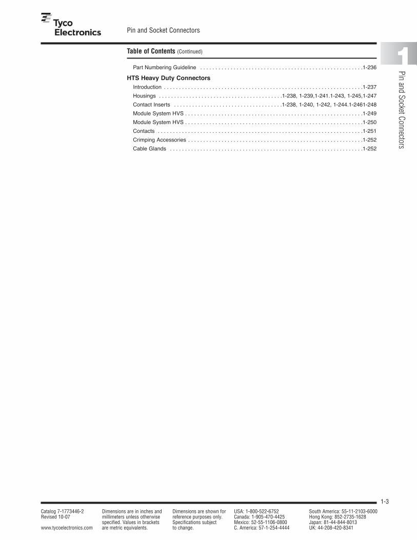
Part Numbering Guideline . . . . . . . . . . . . . . . . . . . . . . . . . . . . . . . . . . . . . . . . . . . . . . . . . . . . . .1-236
HTS Heavy Duty ConnectorsIntroduction . . . . . . . . . . . . . . . . . . . . . . . . . . . . . . . . . . . . . . . . . . . . . . . . . . . . . . . . . . . . . . . . . .1-237
Housings . . . . . . . . . . . . . . . . . . . . . . . . . . . . . . . . . . . . . . . . .1-238, 1-239,1-241.1-243, 1-245,1-247
Contact Inserts . . . . . . . . . . . . . . . . . . . . . . . . . . . . . . . . . . . .1-238, 1-240, 1-242, 1-244.1-2461-248
Module System HVS . . . . . . . . . . . . . . . . . . . . . . . . . . . . . . . . . . . . . . . . . . . . . . . . . . . . . . . . . . .1-249
Module System HVS . . . . . . . . . . . . . . . . . . . . . . . . . . . . . . . . . . . . . . . . . . . . . . . . . . . . . . . . . . .1-250
Contacts . . . . . . . . . . . . . . . . . . . . . . . . . . . . . . . . . . . . . . . . . . . . . . . . . . . . . . . . . . . . . . . . . . . .1-251
Crimping Accessories . . . . . . . . . . . . . . . . . . . . . . . . . . . . . . . . . . . . . . . . . . . . . . . . . . . . . . . . . .1-252
Cable Glands . . . . . . . . . . . . . . . . . . . . . . . . . . . . . . . . . . . . . . . . . . . . . . . . . . . . . . . . . . . . . . . .1-252

1-4
NANONICS Circular Connectors
Catalog 7-1773446-2 Dimensions are in inches and Dimensions are shown for USA: 1-800-522-6752 South America: 55-11-2103-6000Revised 10-07 millimeters unless otherwise reference purposes only. Canada: 1-905-470-4425 Hong Kong: 852-2735-1628
specified. Values in brackets Specifications subject Mexico: 52-55-1106-0800 Japan: 81-44-844-8013www.tycoelectronics.com are metric equivalents. to change. C. America: 57-1-254-4444 UK: 44-208-420-8341
Environmentally Sealed Circular Connectors
NANONICS environmentallysealed circular offering represents one of theindustry's smallest andmost reliable connectordesigns. These connectorsare ideally suited for appli-cations where high densityand reliability, and reducedsize and weight are seriousdesign parameters. Alongwith these attributes, theyalso meet the immersionrequirements of IP67, morespecifically, one meter ofwater for two hours.Utilizing the same contact
system and materials asthe DUALOBE rectangularseries of connectors, thecircular connectors aremanufactured to the per-formance specifications ofMIL-DTL-83513.
The plug connectors areoffered in both a quick dis-connect or threaded cou-pling configuration, and thereceptacle connectors areoffered in either a flushmount or panel mount con-figuration. The quick dis-connect plug will mate withboth the flush and panel
mount receptacles, whilethe threaded coupling plugwill only mate with the panelmount receptacle. Theseconnectors are available in pin counts of 7, 19, and44. Optional backshells arealso available for the plugconnectors and the panelmount receptacle. Ideal for cable-to-cable or cable-to-panel applications,Tyco Electronics can alsoaccommodate harnessassemblies and customconfigurations.
Technical and PerformanceDataElectricalContact Resistance — .003 - .008ohmsCurrent Rating — 1 amp max. per contactDielectric Withstanding Voltage —Volts RMS 60 Hz at room ambient condi-tions. At sea level 500V. At 70,000 ft.150V.Insulation Resistance — 5000megohms min. (@ 500 VDC) at roomambient conditions.
Magnetic Permeability — 2 mu max.Temperature Range — –55°C to+200°CDurability — 250 mates/dematesJam Nut Torque– 7 Pos. - 6 in-lbs. max.19 Pos. - 8 in-lbs. max.44 Pos. - 10 in-lbs. max.Coupling Nut Torque — 7 Pos. - 6 in-lbs. max.19 Pos. - 8 in-lbs. max.44 Pos. - 10 in-lbs. max.

1-5
NANONICS Circular Connectors
Catalog 7-1773446-2 Dimensions are in inches and Dimensions are shown for USA: 1-800-522-6752 South America: 55-11-2103-6000Revised 10-07 millimeters unless otherwise reference purposes only. Canada: 1-905-470-4425 Hong Kong: 852-2735-1628
specified. Values in brackets Specifications subject Mexico: 52-55-1106-0800 Japan: 81-44-844-8013www.tycoelectronics.com are metric equivalents. to change. C. America: 57-1-254-4444 UK: 44-208-420-8341
1
Pin and Socket Connectors
Environmentally Sealed Quick Disconnect — Plug Assemblies
Coupling SleeveO-Ring Seal
Locking Ring
Position 1
Ø.25 [6.35]
.25 [6.35]
.525 [13.34]
Ø.165 [4.19]
Product Facts
■ Metal Shell■ Positions: 7, 19 and 44■ Environmental O-ring seal■ Push-Pull quick-disconnect
coupling■ Factory wired to your
specifications■ Contact Tyco Electronics for
custom configurations
O-Ring Seal Coupling Sleeve
Locking Ring
Position 1
Ø .30 [7.62]
Ø .215 [5.46]
.525 [13.34]
.25 [6.35]
7 PositionDrawing Number 1589055
19 PositionDrawing Number 1589057
19 Position

1-6
NANONICS Circular Connectors
Catalog 7-1773446-2 Dimensions are in inches and Dimensions are shown for USA: 1-800-522-6752 South America: 55-11-2103-6000Revised 10-07 millimeters unless otherwise reference purposes only. Canada: 1-905-470-4425 Hong Kong: 852-2735-1628
specified. Values in brackets Specifications subject Mexico: 52-55-1106-0800 Japan: 81-44-844-8013www.tycoelectronics.com are metric equivalents. to change. C. America: 57-1-254-4444 UK: 44-208-420-8341
Environmentally Sealed Quick Disconnect — Plug Assemblies (Continued)
.25 [6.35]
.525 [13.34]
Ø.315 [8.00]
Ø.395 [10.03]
Coupling SleeveO-Ring Seal
Locking Ring
Position 1
44 PositionDrawing Number 1589059

1-7
NANONICS Circular Connectors
Catalog 7-1773446-2 Dimensions are in inches and Dimensions are shown for USA: 1-800-522-6752 South America: 55-11-2103-6000Revised 10-07 millimeters unless otherwise reference purposes only. Canada: 1-905-470-4425 Hong Kong: 852-2735-1628
specified. Values in brackets Specifications subject Mexico: 52-55-1106-0800 Japan: 81-44-844-8013www.tycoelectronics.com are metric equivalents. to change. C. America: 57-1-254-4444 UK: 44-208-420-8341
1
Pin and Socket Connectors
Environmentally Sealed Quick Disconnect — Plug Assemblies with Backshells
Ø.25 [6.35]
.25 [6.35]
.525 [13.34]
.215 [5.46]
Ø.165 [4.19]
Ø.130 [3.30]
.275 [6.99]
O-Ring Seal Coupling Sleeve
Locking Ring
Backshell
Position 1
Product Facts
■ Metal Shell■ Positions: 7, 19 and 44■ Environmental O-ring seal■ Factory wired to your
specifications■ Backshell installed at
factory■ Contact Tyco Electronics for
custom configurations
.25 [6.35]
.215 [5.46]
.525 [13.34]
.275 [6.99]
Ø.215 [5.46]
Ø.30 [7.62]
O-Ring Seal Coupling Sleeve
Locking Ring Backshell
Position 1
Ø.180 [4.57]
7 PositionDrawing Number 1589691
19 PositionDrawing Number 1589692

1-8
NANONICS Circular Connectors
Catalog 7-1773446-2 Dimensions are in inches and Dimensions are shown for USA: 1-800-522-6752 South America: 55-11-2103-6000Revised 10-07 millimeters unless otherwise reference purposes only. Canada: 1-905-470-4425 Hong Kong: 852-2735-1628
specified. Values in brackets Specifications subject Mexico: 52-55-1106-0800 Japan: 81-44-844-8013www.tycoelectronics.com are metric equivalents. to change. C. America: 57-1-254-4444 UK: 44-208-420-8341
Environmentally Sealed Quick Disconnect — Plug Assemblies with Backshells (Continued)
.25 [6.35]
.265 [6.73]
Ø.240 [6.10]
.525 [13.34]
Ø .395 [10.03]
.325 [8.26]
Ø.315 [8.00]
O-Ring Seal Coupling Sleeve
Locking Ring Backshell
Position 1
44 PositionDrawing Number 1589693

1-9
NANONICS Circular Connectors
Catalog 7-1773446-2 Dimensions are in inches and Dimensions are shown for USA: 1-800-522-6752 South America: 55-11-2103-6000Revised 10-07 millimeters unless otherwise reference purposes only. Canada: 1-905-470-4425 Hong Kong: 852-2735-1628
specified. Values in brackets Specifications subject Mexico: 52-55-1106-0800 Japan: 81-44-844-8013www.tycoelectronics.com are metric equivalents. to change. C. America: 57-1-254-4444 UK: 44-208-420-8341
1
Pin and Socket Connectors
Environmentally Sealed Quick Disconnect — Receptacle Assemblies, Flush Mount
Jam Nut
O-Ring Seal Position 1
.425 [10.80]
.060 [1.52]
Ø.312 [7.92]
.065 [1.65]
.250 [6.35] Max Panel Thickness
.312 [7.92] Hex (Jam Nut) .204
[5.18]
Product Facts
■ Metal Shell■ Positions: 7, 19 and 44 ■ Bulkhead O-ring seal ■ Factory wired to your
specifications■ Contact Tyco Electronics for
custom configurations
Jam Nut
.425 [10.80]
.060 [1.52]
Ø.375 [9.53]
.065 [1.65]
.250 [6.35] Max Panel Thickness
O-Ring SealPosition 1
.375 [9.53] Hex (Jam Nut) .258
[6.55]
7 PositionDrawing Number 1589056
19 PositionDrawing Number 1589058
19 Position

1-10
NANONICS Circular Connectors
Catalog 7-1773446-2 Dimensions are in inches and Dimensions are shown for USA: 1-800-522-6752 South America: 55-11-2103-6000Revised 10-07 millimeters unless otherwise reference purposes only. Canada: 1-905-470-4425 Hong Kong: 852-2735-1628
specified. Values in brackets Specifications subject Mexico: 52-55-1106-0800 Japan: 81-44-844-8013www.tycoelectronics.com are metric equivalents. to change. C. America: 57-1-254-4444 UK: 44-208-420-8341
Environmentally Sealed Quick Disconnect — Receptacle Assemblies, Flush Mount (Continued)
.500[12.7] Hex (Jam Nut) .375
[9.53]
.250 [6.35] Max Panel Thickness
O-Ring Seal Position 1
Jam Nut
.425 [10.80]
.065 [1.65]
.060 [1.52]
Ø.500 [12.7]
44 PositionDrawing Number 1589690

1-11
NANONICS Circular Connectors
Catalog 7-1773446-2 Dimensions are in inches and Dimensions are shown for USA: 1-800-522-6752 South America: 55-11-2103-6000Revised 10-07 millimeters unless otherwise reference purposes only. Canada: 1-905-470-4425 Hong Kong: 852-2735-1628
specified. Values in brackets Specifications subject Mexico: 52-55-1106-0800 Japan: 81-44-844-8013www.tycoelectronics.com are metric equivalents. to change. C. America: 57-1-254-4444 UK: 44-208-420-8341
1
Pin and Socket Connectors
Environmentally Sealed Threaded Coupling — Plug Assemblies
Ø.165[4.19]
.375[9.53]
.525[13.34]
Ø.315[8.00]
Position 1O-Ring Seal
Coupling NutProduct Facts
■ Metal Shell■ Positions: 7, 19 and 44■ Environmental O-ring seal■ Factory wired to your
specifications■ Contact Tyco Electronics for
custom configurations
.375 [9.53]
Ø.355 [9.02]
Ø .215 [5.46]
.525 [13.34]
O-Ring SealCoupling Nut
Position 1
7 PositionDrawing Number 1589063
19 PositionDrawing Number 1589064
19 Position

1-12
NANONICS Circular Connectors
Catalog 7-1773446-2 Dimensions are in inches and Dimensions are shown for USA: 1-800-522-6752 South America: 55-11-2103-6000Revised 10-07 millimeters unless otherwise reference purposes only. Canada: 1-905-470-4425 Hong Kong: 852-2735-1628
specified. Values in brackets Specifications subject Mexico: 52-55-1106-0800 Japan: 81-44-844-8013www.tycoelectronics.com are metric equivalents. to change. C. America: 57-1-254-4444 UK: 44-208-420-8341
Environmentally Sealed Threaded Coupling — Plug Assemblies (Continued)
O-Ring SealPosition 1 Coupling Nut
.375 [9.53]
.525 [13.34]
Ø.315 [8.00]
Ø .475 [12.07]
44 PositionDrawing Number 1589065

1-13
NANONICS Circular Connectors
Catalog 7-1773446-2 Dimensions are in inches and Dimensions are shown for USA: 1-800-522-6752 South America: 55-11-2103-6000Revised 10-07 millimeters unless otherwise reference purposes only. Canada: 1-905-470-4425 Hong Kong: 852-2735-1628
specified. Values in brackets Specifications subject Mexico: 52-55-1106-0800 Japan: 81-44-844-8013www.tycoelectronics.com are metric equivalents. to change. C. America: 57-1-254-4444 UK: 44-208-420-8341
1
Pin and Socket Connectors
Environmentally Sealed Threaded Coupling — Plug Assemblies with Backshells
.275 [6.99]
.525 [13.34]
.215 [5.46]
Ø.25 [6.35]
Ø.130 [3.30]
Ø.315[8.00]
Ø.165 [4.19]
.375 [9.53]
O-Ring SealCoupling Sleeve
Backshell
Position 1
Product Facts
■ Metal Shell■ Positions: 7, 19 and 44■ Environmental O-ring seal■ Factory wired to your
specifications■ Backshell installed at
factory■ Contact Tyco Electronics for
custom configurations
.275[6.99]
.215 [5.46]
.525 [13.34]
Ø.215 [5.46]
.375 [9.53]
Ø.30 [7.62]
Ø.180 [4.57]
Ø.355 [9.02]
Position 1 O-Ring Seal
Backshell
Coupling Nut
7 PositionDrawing Number 1589686
19 PositionDrawing Number 1589688

1-14
NANONICS Circular Connectors
Catalog 7-1773446-2 Dimensions are in inches and Dimensions are shown for USA: 1-800-522-6752 South America: 55-11-2103-6000Revised 10-07 millimeters unless otherwise reference purposes only. Canada: 1-905-470-4425 Hong Kong: 852-2735-1628
specified. Values in brackets Specifications subject Mexico: 52-55-1106-0800 Japan: 81-44-844-8013www.tycoelectronics.com are metric equivalents. to change. C. America: 57-1-254-4444 UK: 44-208-420-8341
Environmentally Sealed Threaded Coupling — Plug Assemblies with Backshells (Continued)
.325 [8.26]
Ø.395[10.03]
Ø.475 [12.07]
Ø.315 [8.00]
.375 [9.53]
.265 [6.73]
Ø.240 [6.10]
.525 [13.34]
O-Ring Seal
Backshell
Coupling NutPosition 1
44 PositionDrawing Number 1589694

1-15
NANONICS Circular Connectors
Catalog 7-1773446-2 Dimensions are in inches and Dimensions are shown for USA: 1-800-522-6752 South America: 55-11-2103-6000Revised 10-07 millimeters unless otherwise reference purposes only. Canada: 1-905-470-4425 Hong Kong: 852-2735-1628
specified. Values in brackets Specifications subject Mexico: 52-55-1106-0800 Japan: 81-44-844-8013www.tycoelectronics.com are metric equivalents. to change. C. America: 57-1-254-4444 UK: 44-208-420-8341
1
Pin and Socket Connectors
Environmentally Sealed Threaded Coupling/Quick Disconnect — Receptacle Assemblies, Panel Mount
.550 [13.97]
.350 [8.89]
.065 [1.65]
Ø.25 [6.35]
.060 [1.52]
O-Ring Seal
Jam Nut
Position 1
.258 [6.55]
.406 [10.31] Hex
Product Facts
■ Metal Shell■ Positions: 7, 19 and 44■ Bulkhead O-ring seal■ Factory wired to your
specifications■ Panel Mount receptacle
mates with the QuickDisconnect Plug and theThreaded Coupling Plug
■ Contact Tyco Electronics forcustom configurations
.065 [1.65]
.550 [13.97]
.350 [8.89]
.060 [1.52]
Ø.30 [7.62]
O-Ring Seal
Jam Nut
Position 1
.298 [7.57]
.469 [11.91] Hex
7 PositionDrawing Number 1589060
19 PositionDrawing Number 1589061
19 Position

1-16
NANONICS Circular Connectors
Catalog 7-1773446-2 Dimensions are in inches and Dimensions are shown for USA: 1-800-522-6752 South America: 55-11-2103-6000Revised 10-07 millimeters unless otherwise reference purposes only. Canada: 1-905-470-4425 Hong Kong: 852-2735-1628
specified. Values in brackets Specifications subject Mexico: 52-55-1106-0800 Japan: 81-44-844-8013www.tycoelectronics.com are metric equivalents. to change. C. America: 57-1-254-4444 UK: 44-208-420-8341
Environmentally Sealed Threaded Coupling/Quick Disconnect — Receptacle Assemblies, Panel Mount (Continued)
.065 [1.65]
.550 [13.97]
.350 [8.89]
.060 [1.52]
Ø .395 [10.03]
O-Ring Seal
Jam Nut
Position 1
.414 [10.52]
.563[14.30] Hex
44 PositionDrawing Number 1589062

1-17
NANONICS Circular Connectors
Catalog 7-1773446-2 Dimensions are in inches and Dimensions are shown for USA: 1-800-522-6752 South America: 55-11-2103-6000Revised 10-07 millimeters unless otherwise reference purposes only. Canada: 1-905-470-4425 Hong Kong: 852-2735-1628
specified. Values in brackets Specifications subject Mexico: 52-55-1106-0800 Japan: 81-44-844-8013www.tycoelectronics.com are metric equivalents. to change. C. America: 57-1-254-4444 UK: 44-208-420-8341
1
Pin and Socket Connectors
Environmentally Sealed Threaded Coupling/Quick Disconnect — Panel Mount Recp. Assemblies w/Backshells
.550 [13.97]
.350 [8.89]
Ø.25 [6.35] Ø.130
[3.30]
.215 [5.46]
.065 [1.65]
.060 [1.52]
.275 [6.99]
Position 1
.258 [6.55]
O-Ring Seal
Backshell
Jam Nut
.406 [10.31] Hex
Product Facts
■ Metal Shell■ Positions: 7, 19 and 44■ Bulkhead O-ring seal■ Factory wired to your
specifications■ Panel Mount receptacle
mates with the QuickDisconnect Plug and theThreaded Coupling Plug
■ Contact Tyco Electronics forcustom configurations
.275 [6.99]
.550 [13.97]
.350 [8.89]
.065 [1.65]
.215 [5.46]
Ø.30 [7.62] Ø.180
[4.57] .060 [1.52]
O-Ring Seal
Jam Nut
Backshell
Position 1
.298 [7.57]
.469 [11.91] Hex
Receptacle Assembly 7 PositionDrawing Number 1589685
Receptacle Assembly 19 PositionDrawing Number 1589687

1-18
NANONICS Circular Connectors
Catalog 7-1773446-2 Dimensions are in inches and Dimensions are shown for USA: 1-800-522-6752 South America: 55-11-2103-6000Revised 10-07 millimeters unless otherwise reference purposes only. Canada: 1-905-470-4425 Hong Kong: 852-2735-1628
specified. Values in brackets Specifications subject Mexico: 52-55-1106-0800 Japan: 81-44-844-8013www.tycoelectronics.com are metric equivalents. to change. C. America: 57-1-254-4444 UK: 44-208-420-8341
Environmentally Sealed Threaded Coupling/Quick Disconnect — Panel Mount Recp. Assemblies w/Backshells (Continued)
.325 [8.26]
.065 [1.65]
.550 [13.97]
.350 [8.89]
.060 [1.52]
Ø.395 [10.03]
Ø.240 [6.10]
O-Ring Seal
BackshellJam Nut
Position 1
.414 [10.52]
.563 [14.30] Hex
Receptacle Assembly 44 PositionDrawing Number 1589695

1-19
NANONICS Circular Connectors
Catalog 7-1773446-2 Dimensions are in inches and Dimensions are shown for USA: 1-800-522-6752 South America: 55-11-2103-6000Revised 10-07 millimeters unless otherwise reference purposes only. Canada: 1-905-470-4425 Hong Kong: 852-2735-1628
specified. Values in brackets Specifications subject Mexico: 52-55-1106-0800 Japan: 81-44-844-8013www.tycoelectronics.com are metric equivalents. to change. C. America: 57-1-254-4444 UK: 44-208-420-8341
1
Pin and Socket Connectors
Part Numbering Guideline for Environmentally Sealed Circular Connectors
Circular Connectors - Wire Terminations
XXX XX X XX XXX X(X)
Conductor Size/Strands0 28 AWG Solid
1 30 AWG Solid
2 30 AWG 7 Strand
3 32 AWG 7 Strand
4 34 AWG 7 Strand
ConfigurationPC Plug
SC Receptacle
Positions007 7 Position
019 19 Position
044 44 Position
Class/TypeQCM Quick Disconnect, Circular, Metal
TCM Threaded Coupling, Circular, Metal
(TCM leadoff for plug only)
Circular Mounting/FeaturesMounting (Receptacles Only)
P Panel Mount
F Flush Mount
Features (Optional)
B Backshell (cannot be used with flush mount)
Conductor LengthXXX Three numbers only, length is in inches ( i.e. 012 = twelve inches)
CXX A “C” follwed by two numbers, length is in centimeters ( i.e. C06 = 6 centimeters)
MXX An “M” followed by two numbers, length is in meters ( i.e. M02 = 2 meters)
Conductor TypeDX White Teflon
DY White PTFE per M16878/6
DC Color Coded Teflon
DM Color Coded Teflon per MIL-STD-681
DT White Tefzel per M22759/33
XXX

1-20
MICRODOT Circular Connectors
Catalog 7-1773446-2 Dimensions are in inches and Dimensions are shown for USA: 1-800-522-6752 South America: 55-11-2103-6000Revised 10-07 millimeters unless otherwise reference purposes only. Canada: 1-905-470-4425 Hong Kong: 852-2735-1628
specified. Values in brackets Specifications subject Mexico: 52-55-1106-0800 Japan: 81-44-844-8013www.tycoelectronics.com are metric equivalents. to change. C. America: 57-1-254-4444 UK: 44-208-420-8341
Introduction
Our high density, light-weight Multi-Pin CircularConnectors are the industry’s most advancedand are ideally suited toapplications where manyconductors must be accom-modated in a minimum ofspace with minimum weight.
All series of connectors feature a crimp contactretention method, requiringno insertion or removal tools.
The MARC 43 SeriesConnectors conform toapplicable performancerequirements of MIL-C-26482and has seen extensiveservice on many leadingaerospace and ground sup-port equipment programs.
The MARC 53 SeriesConnectors, designed toconform to the USAF highreliability specification MIL-C-38300, as offers high density connector performance. The positivelock coupling mechanism,combined with our exclu-sive floating interfacial seal,offers outstanding perform-ance under rigorous service conditions.
The MARC 63 SeriesConnectors, our BayonetCoupling Series, accommo-dates all insert patterns and layouts available in theMARC 43 Series Connectors,MARC 53 Series Connectors,and RMD Series Connectors.All insert assemblies are
completely interchange-able. Lighter in weight andsmaller in size than anycomparable connector onthe market, it requires up to 50% less engagement/separation force. Conversionto bayonet coupling shellfrom MARC 43 SeriesConnectors or MARC 53Series Connectors is donewithout tools by merelytransferring the contactsand insert assemblies intothe MARC 63 SeriesConnectors shell.
The newest addition to theMulti-Pin product line is theMARC 73 Series Connectors.The twist pin CircularConnector combines thelightweight, bayonet
High Density CircularConnectorsProduct Facts■ High density, light-weight
Multi-Pin CircularConnectors feature a crimpcontact retention method,requiring no insertion orremoval tools
■ Reverse gender available
■ Ideal for harsh environment
■ Sealed — Silicon rubbergrommet/o-ring
■ Unsealed — No grommet/o-ring
■ Meets MIL Standards (highquality) but is not QPL qualified
■ Ideally suited to applicationswhere many conductorsmust be accommodated in a minimum of space withminimum weight
■ MARC Series Connectorsare non-magnetic
■ Contact rating 2.5A

1-21
MICRODOT Circular Connectors
Catalog 7-1773446-2 Dimensions are in inches and Dimensions are shown for USA: 1-800-522-6752 South America: 55-11-2103-6000Revised 10-07 millimeters unless otherwise reference purposes only. Canada: 1-905-470-4425 Hong Kong: 852-2735-1628
specified. Values in brackets Specifications subject Mexico: 52-55-1106-0800 Japan: 81-44-844-8013www.tycoelectronics.com are metric equivalents. to change. C. America: 57-1-254-4444 UK: 44-208-420-8341
1
Pin and Socket Connectors
Introduction (Continued)
coupling feature of theMARC 63 Series Connectorswith the twist pin high den-sity, center-to-center contactspacing of 0.065 [1.65]inch. The utilization of 22AWG twist pin and socketcontacts provide for 50%greater contact densities
than presently offered in theMARC 43 Series Connectors,MARC 53 Series Connectors,or MARC 63 SeriesConnectors.
The MQR Series is a line ofcircular quick disconnectconnectors for rugged environmental use.
Consult Tyco Electronics fordetailed information.
SHM ReceptacleMARC 43 Series Connectors &
MARC 53 Series Connectors
Mated MARC 53 Series Connectors
SHM ReceptacleMARC 43 Series Connectors & MARC 53 Series Connectors
Mated MARC 43 SeriesConnectors
Mated MARC 63 Series Connectors

1-22
MICRODOT Circular Connectors
Catalog 7-1773446-2 Dimensions are in inches and Dimensions are shown for USA: 1-800-522-6752 South America: 55-11-2103-6000Revised 10-07 millimeters unless otherwise reference purposes only. Canada: 1-905-470-4425 Hong Kong: 852-2735-1628
specified. Values in brackets Specifications subject Mexico: 52-55-1106-0800 Japan: 81-44-844-8013www.tycoelectronics.com are metric equivalents. to change. C. America: 57-1-254-4444 UK: 44-208-420-8341
MARC 43 Series Connectors
Materials and Finishes MARC 43 Series Connectorhousings and quick disconnect couplings aremachined from bar stockaluminum to combine maxi-mum strength with minimumweight. Threaded couplingsare machined from non-magnetic, stainless steelbar stock for durability ofthe coupling threads.Contacts are manufacturedfrom high conductivity copper alloys which havebeen selected for low contact resistance over theoperating range of the
connectors. Inserts aremolded from flame-resistant,glass-filled diallyl phthalate,meeting ASTM D5948requirements. All resilientparts are made of high tem-perature, silicone rubbers.Fuel resistant compoundsare used where swellingaffects the performance of the connector. All materi-als are carefully selectedfor their non-magnetic properties.
The standard finish is clear,non-conductive anodize on
connector housings andquick disconnect couplings.For threaded couplingapplications, aluminumcomponents are hard, blackanodized, and stainlesssteel plug coupling is passivated with black oxidefinish. Conductive finishmodifications include gold,cadmium, and iridite finishes. Contacts are goldplated per MIL-G-45204requirements. See page 1-28for modification information.
General Information
Service and Performance Data
A high density (.080 [2.03]contact centers), lightweight,subminiature, cylindricalconnector series featuringcrimp contacts and finger-tip, push-pull, quick discon-nect coupling. This seriesconforms to the applicableperformance requirementsof MIL-C-26482 and is available in unsealed, environmentally sealed, andhermetic types.
A large assortment in insertarrangements — accommo-dating AWG 12 through 32gauge wire and miniaturecoaxial cables — is availablefor the design engineer’schoice. The contacts are
retained by shoulderentrapment and can becrimped with the standardM22520 tools, using appro-priate locators.
This proven series of con-nectors has a long history of outstanding performance
on many military and aero-space programs. MARC 43Series Connectors are idealfor applications where highperformance must beachieved at low cost.
I. Electrical — Electrical RatingsCurrent Rating Dielectric Working Voltage
Contact Amperes, Withstanding Sea 70,000 ft. Size Max., +27°C1 Voltage (RMS) Level [21,336 m] Alt.
22 AWG 5 amps 1000 750 30016 AWG 20 amps 1000 750 30012 AWG 50 amps 1000 750 30050 ohm 3 amps 1000 750 30075 ohm 3 amps 1250 1000 30095 ohm 3 amps 1500 1250 300
1 Consult nomograph.
II. Mechanical — Durability: 500 Cycles Mate/Unmate. Coupling/Uncoupling Forces and Tightening Torques:
Coupling/Shell Uncoupling Tightening Torque (In-Lbs.)Size Force Retaining Nut Mounting Nut
(In-Lbs.) Max.A 13 [57.8 N] 20, Max. [2.26 Nm] 30-45 [3.39 Nm – 5.08 Nm]B 17 [75.6 N] 20, Max. [2.26 Nm] 40-55 [4.52 Nm – 6.21 Nm]C 21 [93.4 N] 20, Max. [2.26 Nm] 55-70 [6.21 Nm – 7.91 Nm]
Operating Temperature: –85°F to 257°F [–65°C to +125°C].
Contact Wire Conductor Dielectric Shield JacketSize Size Dia. Dia. Dia. Dia.2
(Stranded)1 (Teflon)
22 22, 24, 26 .019-.032 — — .039-.054.482-.813 .990-1.37
163 16, 18, 20 .038-.061 — — .065-.081.965-1.55 1.65-2.06
12 12 AWG .071-.093 — — .096-.1201.80-2.36 2.44-3.05
50 ohm 50 ohm .013 Max. .032-.036 .048-.054 .065-.087.330 .813-.914 1.22-1.37 1.65-2.21
75 ohm 75 ohm .013 Max. .060-.066 .078-.084 .096-.109.330 1.52-1.68 1.98-2.13 2.44-2.77
95 ohm 95 ohm .013 Max. .100-.104 .115-.123 .137-.154.330 2.54-2.64 2.92-3.12 3.48-3.91
1 Tolerance of conductor diameters required for a reliable crimp. Smallersizes readily accommodated — consult Tyco Electronics.
2 Smaller jacketed cable can be accommodated but environmental seal maybe impaired. Smooth extruded jacket should be used for consistent wiresealing.
3 Size 16 AWG Contact for size 20 AWG Wire – Use Tool 010-0080-0000.
1-23
MICRODOT Circular Connectors
Catalog 7-1773446-2 Dimensions are in inches and Dimensions are shown for USA: 1-800-522-6752 South America: 55-11-2103-6000Revised 10-07 millimeters unless otherwise reference purposes only. Canada: 1-905-470-4425 Hong Kong: 852-2735-1628
specified. Values in brackets Specifications subject Mexico: 52-55-1106-0800 Japan: 81-44-844-8013www.tycoelectronics.com are metric equivalents. to change. C. America: 57-1-254-4444 UK: 44-208-420-8341
1
Pin and Socket Connectors
MARC 43 Series Connectors (Continued)
Test Data
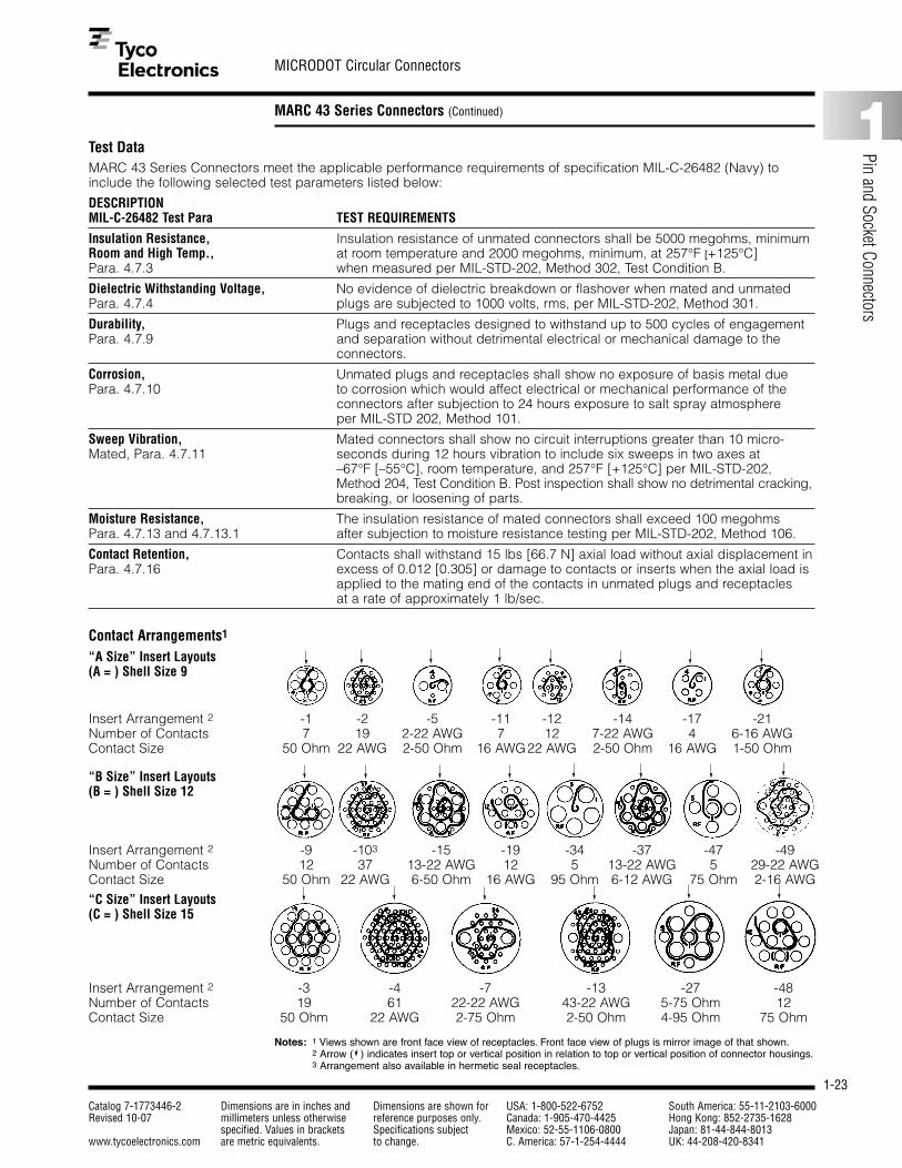
Contact Arrangements1
“A Size” Insert Layouts(A = ) Shell Size 9
MARC 43 Series Connectors meet the applicable performance requirements of specification MIL-C-26482 (Navy) toinclude the following selected test parameters listed below:
DESCRIPTIONMIL-C-26482 Test Para TEST REQUIREMENTS
Insulation Resistance, Insulation resistance of unmated connectors shall be 5000 megohms, minimumRoom and High Temp., at room temperature and 2000 megohms, minimum, at 257°F [+125°C]Para. 4.7.3 when measured per MIL-STD-202, Method 302, Test Condition B.
Dielectric Withstanding Voltage, No evidence of dielectric breakdown or flashover when mated and unmatedPara. 4.7.4 plugs are subjected to 1000 volts, rms, per MIL-STD-202, Method 301.
Durability, Plugs and receptacles designed to withstand up to 500 cycles of engagement Para. 4.7.9 and separation without detrimental electrical or mechanical damage to the
connectors.
Corrosion, Unmated plugs and receptacles shall show no exposure of basis metal duePara. 4.7.10 to corrosion which would affect electrical or mechanical performance of the
connectors after subjection to 24 hours exposure to salt spray atmosphereper MIL-STD 202, Method 101.
Sweep Vibration, Mated connectors shall show no circuit interruptions greater than 10 micro-Mated, Para. 4.7.11 seconds during 12 hours vibration to include six sweeps in two axes at
–67°F [–55°C], room temperature, and 257°F [+125°C] per MIL-STD-202, Method 204, Test Condition B. Post inspection shall show no detrimental cracking,breaking, or loosening of parts.
Moisture Resistance, The insulation resistance of mated connectors shall exceed 100 megohmsPara. 4.7.13 and 4.7.13.1 after subjection to moisture resistance testing per MIL-STD-202, Method 106.
Contact Retention, Contacts shall withstand 15 lbs [66.7 N] axial load without axial displacement inPara. 4.7.16 excess of 0.012 [0.305] or damage to contacts or inserts when the axial load is
applied to the mating end of the contacts in unmated plugs and receptaclesat a rate of approximately 1 lb/sec.
“B Size” Insert Layouts(B = ) Shell Size 12
Notes: 1 Views shown are front face view of receptacles. Front face view of plugs is mirror image of that shown.2 Arrow ( ) indicates insert top or vertical position in relation to top or vertical position of connector housings.3 Arrangement also available in hermetic seal receptacles.
“C Size” Insert Layouts(C = ) Shell Size 15
Insert Arrangement 2 -1 -2 -5 -11 -12 -14 -17 -21Number of Contacts 7 19 2-22 AWG 7 12 7-22 AWG 4 6-16 AWGContact Size 50 Ohm 22 AWG 2-50 Ohm 16 AWG22 AWG 2-50 Ohm 16 AWG 1-50 Ohm
Insert Arrangement 2 -9 -103 -15 -19 -34 -37 -47 -49Number of Contacts 12 37 13-22 AWG 12 5 13-22 AWG 5 29-22 AWGContact Size 50 Ohm 22 AWG 6-50 Ohm 16 AWG 95 Ohm 6-12 AWG 75 Ohm 2-16 AWG
Insert Arrangement 2 -3 -4 -7 -13 -27 -48Number of Contacts 19 61 22-22 AWG 43-22 AWG 5-75 Ohm 12Contact Size 50 Ohm 22 AWG 2-75 Ohm 2-50 Ohm 4-95 Ohm 75 Ohm

1-24
MICRODOT Circular Connectors
Catalog 7-1773446-2 Dimensions are in inches and Dimensions are shown for USA: 1-800-522-6752 South America: 55-11-2103-6000Revised 10-07 millimeters unless otherwise reference purposes only. Canada: 1-905-470-4425 Hong Kong: 852-2735-1628
specified. Values in brackets Specifications subject Mexico: 52-55-1106-0800 Japan: 81-44-844-8013www.tycoelectronics.com are metric equivalents. to change. C. America: 57-1-254-4444 UK: 44-208-420-8341
MARC 43 Series Connectors (Continued)
Part Number and OrderingInformation
MARC 43 Series Connectorpart numbers indicate size,shape, insert layout, type ofseal, style of contact andpolarization. Note: Pin orsocket (power or coaxial)contacts may be used ineither plugs or receptacles.However, it is recommendedthat pins be placed in thereceptacle when possible
to take advantage of our“scoop-proof” design. (Thestyle—pin or socket—of acoaxial contact refers to theouter contact body.)
Alternate Keying. Standardalternate polarizing key posi-tions are shown below. Addi-tional polarizing keyways areavailable upon request.
Supplemental AccessoryHardware. We also manufac-ture supplemental acces-sory hardware (protectivecovers, cable clamps, etc.)to adapt these connectorsto almost any application.For modifications to fit your requirements, contactTyco Electronics.
Polarizing Key PositionsAll MARC 43 SeriesConnector multi-pin plugsand receptacles are avail-able in alternate polarizingpositions as listed below:(1) Arrow ( ) indicates top or vertical position (masterkey-keyway) and coincideswith top or vertical positionof insert. This relationshipremains constant with alter-nate polarizing key positions.
N—for Normal
Typical Part Number
Size APart Number X° Y°A43****N 130 110A43****-1 130 150A43****-2 90 110A43****-3 210 110A43****-4 130 35A43****-5 90 230
Size BPart Number X° Y°B43****N 130 110B43****-1 130 90B43****-2 130 145B43****-3 105 110B43****-4 155 110B43****-5 80 110B43****-6 190 110B43****-7 130 170B43****-8 215 110B43****-9 80 230B43****-10 130 30
Size CPart Number X° Y°C43****N 130 110C43****-1 130 90C43****-2 130 150C43****-3 130 170C43****-4 190 110C43****-5 150 110C43****-6 90 110C43****-7 70 110C43****-8 70 230C43****-9 90 230C43****-10 210 110C43****11 30 110C43****12 250 30C43****13 130 30C43****14 30 230
YX
(1)
A 43 E H 14 P 5 (***)
ModificationDesignator
whenApplicable
(See Page 1-28)
P = Plug
PF = Plug, sq. flange mtg.
PT = Plug, threaded cpl. ring
H = Receptacle, single hole mtg.
F = Receptacle, box mtg.
FT = Receptacle, box mtg. (threaded coupl.)
J= Receptacle, line cord
S = Receptacle, solder mount (Hermetic)
B = Receptacle, thru-bulkhead, double end (Hermetic)
P = Pin (male) power contacts
PP = Double end pins (type B only)
S = Socket (female) power
CP = Coaxial pin contact, or combination of coaxial pin and pin power contacts
CS = Coaxial socket contact, or combination of coaxial socket and socket power contacts
Note: If P, S, CP, or CS does not appear in the numbering system, no contacts will be supplied with order (order separately).
PolarizingPosition
N, 1, 2, 3, 4,etc.
Layout numberDenotesMicrodotSeries
Unsealed AHermetic H
Sealed E
Size ACircular Size B
Size C
Use one only
Plug Receptacle
YX
(1)

1-25
MICRODOT Circular Connectors
Catalog 7-1773446-2 Dimensions are in inches and Dimensions are shown for USA: 1-800-522-6752 South America: 55-11-2103-6000Revised 10-07 millimeters unless otherwise reference purposes only. Canada: 1-905-470-4425 Hong Kong: 852-2735-1628
specified. Values in brackets Specifications subject Mexico: 52-55-1106-0800 Japan: 81-44-844-8013www.tycoelectronics.com are metric equivalents. to change. C. America: 57-1-254-4444 UK: 44-208-420-8341
1
Pin and Socket Connectors
MARC 43 Series Connectors (Continued)
Configurations
Type P
Straight Plug, Push-PullCoupling, Sealed orUnsealed (Mates withReceptacles, All Types)
Shell DimensionsSize A B
A .766 1.57819.46 40.08
B .953 1.65624.21 42.06
C 1.141 1.7528.98 44.45
B
A
1.266[32.16]
Type PF
Straight Plug, SquareFlange Mounting, Push-PullCoupling, Sealed orUnsealed (Mates withReceptacles, all Types.)
Shell DimensionsSize A B C D
A .730 .664 .875 .75018.54 16.86 22.23 19.05
B .920 .786 1.000 .94023.37 19.96 25.40 23.88
C 1.110 .924 1.125 1.13028.19 23.47 28.58 28.70
.175[4.44] .062
[1.57]
A Dia. B Typ. C Typ.
.110 – .130[2.79 – 3.30]
Typ.1.266[32.16]
Type PT
Straight Plug, ThreadedCoupling, Sealed orUnsealed (Mates withReceptacles, Types H, HH,and FT)
1.500[38.1]
A
Lockwire Holes
Master Keyway
T Thread
Max.
D
Panel Cutout
Shell DimensionsSize A T (Class 2B)
A .813 5/8-32 UN20.65
B 1.000 13/16-28 UN25.40
C 1.19 1-28 UN30.23

1-26
MICRODOT Circular Connectors
Catalog 7-1773446-2 Dimensions are in inches and Dimensions are shown for USA: 1-800-522-6752 South America: 55-11-2103-6000Revised 10-07 millimeters unless otherwise reference purposes only. Canada: 1-905-470-4425 Hong Kong: 852-2735-1628
specified. Values in brackets Specifications subject Mexico: 52-55-1106-0800 Japan: 81-44-844-8013www.tycoelectronics.com are metric equivalents. to change. C. America: 57-1-254-4444 UK: 44-208-420-8341
MARC 43 Series Connectors (Continued)
Configurations (Continued)
Type H
Receptacle, Single HoleMounting Sealed or Unsealed (Mates with Plugs, Types P,PF and PT)
Type 43F
Receptacle, Box Mounting,Sealed or Unsealed (Mateswith Plugs, Types P and PF)
Shell DimensionsSize A B C D
A .875 .594 .562 .59522.23 15.08 14.27 15.11
B 1.000 .786 .75 .78325.40 19.96 19.05 19.89
C 1.125 .906 .875 .96028.58 23.01 22.23 24.38
Max. panel thickness is .375 [9.53].
AHex.
BHex.
.065–.085[1.65–2.16] .080–.100
[2.03–2.54]
CHex.
1.36[34.54]
.125[3.17]
T Thread
MasterKey
E
D
Panel Cutout
D
Panel Cutout
.065–.085[1.65–2.16] .052–.072
[2.03–2.54]
CHex.
1.36[34.54]
BTyp.
ATyp.
.110–.130[2.79–3.30]
Dia.Typ.
Master PolarizingKey
Note: Unless otherwise shown, tolerances are: Decimals ±.015 [±.381], fractions ±1⁄32.
Shell DimensionsSize A B C D E T (Class 2A)
A .75 .687 .562 .607-.611 .625-.629 5/8-32 UN19.05 17.45 14.27 15.42-15.52 15.8-15.97
B .937 .875 .75 .794-.798 .812-.816 13/16-28 UN23.80 22.23 19.05 20.17-20.27 20.62-20.72
C 1.125 1.062 .875 .975-.979 .999-1.003 1-28 UN28.58 26.97 22.23 24.77-24.87 25.37-25.47
.313 [7.95] max. panel for P & PF
.109 [2.77] max. panel. for PT

1-27
MICRODOT Circular Connectors
Catalog 7-1773446-2 Dimensions are in inches and Dimensions are shown for USA: 1-800-522-6752 South America: 55-11-2103-6000Revised 10-07 millimeters unless otherwise reference purposes only. Canada: 1-905-470-4425 Hong Kong: 852-2735-1628
specified. Values in brackets Specifications subject Mexico: 52-55-1106-0800 Japan: 81-44-844-8013www.tycoelectronics.com are metric equivalents. to change. C. America: 57-1-254-4444 UK: 44-208-420-8341
1
Pin and Socket Connectors
MARC 43 Series Connectors (Continued)
Type J
Receptacle, Line Cord,Sealed or Unsealed (Mateswith Plugs, Types P and PF)
A
B
C
Type FT
Receptacle, Box Mounting,Threaded Coupling, Sealedor Unsealed (Mates withPlugs, Types PT, P and PF)
Shell DimensionsSize A B C T (Class 2A) D
A .875 .594 .562 5/8-32 UN .64522.23 15.08 14.27 16.38
B 1.000 .786 .75 13/16-28 UN .83225.40 19.96 19.05 21.13
C 1.125 .906 .875 1-28 UN 1.02028.58 23.01 22.23 25.90
Max. panel thickness is .125 [3.18].
.065–.085[1.65–2.16] .052–.072
[2.03–2.54]
CHex.
1.36[34.54]
BTyp.
ATyp.
.110–.130[2.79–3.30]
Dia.Typ.
Master PolarizingKey
T Thread
D
Panel Cutout
Shell DimensionsSize A B C
A 1.703 1.36 .76643.26 34.54 19.46
B 1.781 1.36 .95345.24 34.54 24.21
C 1.875 1.36 1.14147.63 34.54 28.98
Configurations (Continued)
Note: Unless otherwise shown, tolerances are: Decimals ±.015 [±.381], fractions ±1⁄32.

1-28
MICRODOT Circular Connectors
Catalog 7-1773446-2 Dimensions are in inches and Dimensions are shown for USA: 1-800-522-6752 South America: 55-11-2103-6000Revised 10-07 millimeters unless otherwise reference purposes only. Canada: 1-905-470-4425 Hong Kong: 852-2735-1628
specified. Values in brackets Specifications subject Mexico: 52-55-1106-0800 Japan: 81-44-844-8013www.tycoelectronics.com are metric equivalents. to change. C. America: 57-1-254-4444 UK: 44-208-420-8341
MARC 43 Series Connectors (Continued)
AccessoriesCable Clamps
A
B
.156[3.96]
.156[3.96]
C
D
A
B
Shell Size Part Number A [Max.] B [Max.]
A 086-0099-00X1 .704 .75017.88 19.05
B 086-0100-00X1 .773 .93219.63 23.67
C 086-0101-00X1 .829 1.07821.05 27.38
Shell Size Part Number A [Max.] B [Max.] C [Max.] D [Max.]
A 086-0103-00X1 .737 .600 1.100 .87918.72 15.24 27.94 22.33
B 086-0104-00X1 .913 .770 1.250 1.06723.19 19.55 31.75 27.10
C 086-0105-00X1 1.048 .962 1.469 1.23326.62 24.43 37.31 31.32
Straight Right-Angle
Contact Cavity Sealing Plugs (see page 1-45)
Contact Size Sealed Connector Unsealed ConnectorPart Number Part Number
22 AWG 086-0055-0000 086-0001-000016 AWG 086-0056-0000 086-0014-000012 AWG 086-0057-0000 086-0015-0000
50 ohm Coaxial 086-0058-0000 086-0061-000075 ohm Coaxial 086-0059-0000 086-0062-000095 ohm Coaxial 086-0060-0000 086-0063-0000
Protective Covers
Shell Receptacle Cover Part Number1 Plug Cover Part Number1 Dimensions (Max.)Size With Chain Without Chain With Chain Without Chain A B C D
A 086-0049-00J2 086-0073-00P1 086-0052-00J2 086-0076-00P1 .766 .950 .969 .91319.46 24.13 24.62 23.19
B 086-0050-00J2 086-0074-00P1 086-0053-00J2 086-0077-00P1 .953 .950 1.156 .91324.21 24.13 29.36 23.19
C 086-0051-00J2 086-0075-00P1 086-0054-00J2 086-0078-00P1 1.141 .950 1.344 .91328.98 24.13 34.14 23.19
1 For threaded plug (PT) and receptacle (FT) covers, consult Tyco Electronics. Wire rope/lanyard attachments and plastic protective caps also available, consult Tyco Electronics.
A
B
C
D
Receptacle Cover Plug Cover
ModificationsThe MARC 43 Series Connector modi-fication identification system providesalteration of standard MARC 43 SeriesConnectors to include special fin-ishes, accessories, MARC 53 SeriesConnector housings, and customquality assurance provisions — processing, testing, serialization,traceability. Consult your sales representative or Tyco Electronics foradditional modification information.
Standard modifications include:(009): MARC 43 Series Connector,
anodized finish — black.(048): MARC 43 Series Connector,
iridite finish — gold.(056): MARC 43 Series Connector,
cadmium plated — clear.(057): MARC 43 Series Connector
including cable clamp, straighttype.
(078): MARC 43 Series Connectorinsert arrangement plus MARC 53 Series Connectorpositive lock coupling.
(094): MARC 43 Series Connectorcoaxial insert arrangement toinclude all-crimp coaxial con-tacts plus MARC 53 SeriesConnector positive lock cou-pling.
(098): MARC 43 Series Connectorconnector including cableclamp, right-angle type.
Contacts (see pages 1-43 and 1-44)
Contact Size Pin Part Number Socket Part Number22 AWG 083-0009-00R4 082-0464-00Y916 AWG 083-0158-00R4 082-0113-00T112 AWG 083-0173-00R4 082-0132-00T1
50 ohm Coaxial 084-0024-00T2 084-0027-00T2(Solder Type)50 ohm Coaxial 141-1500-0001 142-1500-0001(Crimp Type)75 ohm Coaxial 084-0025-00T2 084-0028-00T295 ohm Coaxial 084-0026-00T2 084-0029-00T2

1-29
MICRODOT Circular Connectors
Catalog 7-1773446-2 Dimensions are in inches and Dimensions are shown for USA: 1-800-522-6752 South America: 55-11-2103-6000Revised 10-07 millimeters unless otherwise reference purposes only. Canada: 1-905-470-4425 Hong Kong: 852-2735-1628
specified. Values in brackets Specifications subject Mexico: 52-55-1106-0800 Japan: 81-44-844-8013www.tycoelectronics.com are metric equivalents. to change. C. America: 57-1-254-4444 UK: 44-208-420-8341
1
Pin and Socket Connectors
MARC 53 Series Connectors
Materials and FinishesHousings and quick disconnect couplings aremachined from bar stockaluminum to combine maxi-mum strength with minimumweight. Threaded couplingsare machined from non-magnetic, stainless steel barstock for durability of thecoupling threads. Contactsare manufactured from highconductivity copper alloyswhich have been selected
for low contact resistanceover the operating range ofthe connectors. Inserts aremolded from flame-resistant,glass-filled diallyl phthalate,meeting ASTM D5948requirements. All resilientparts are made of high-temperature, silicone elastomers. Fuel resistantcompounds are used where swelling affects theperformance of the
connector. All materials areselected for their non-magnetic properties.
The standard finish is hardblack, non-conductive,anodized finish on connectorhousings and quick discon-nect couplings; stainlesssteel threaded coupling ispassivated with black oxidefinish. Conductive finishmodifications include gold
finish and electroless nickelfinish. Multi-finish modifica-tions for connector plugsinclude black anodized disconnect coupling withconductive finish on shellgrounding members.Contacts are gold platedper MIL-G-45204 require-ments. See page 1-38 formodification information.
General InformationThe MARC 53 SeriesConnector family representsa major advancement in thedesign of high density (.080[2.03] contact centers), sub-miniature, power and coax-ial contact connectors. TheMARC 53 Series Connectorsconsists of two connectorstyles — the Militaryapproved MD53 featuringshoulder entrapped con-tacts, and the new RMD53utilizing rear insertable/removable contacts.MARC 53 Series Connectorscombine positive lock —the rugged, push-pull, lock-coupling mechanism — withthe unique positive sealmultiple sealing system.
Positive lock is our new fin-ger-tip, push-pull couplingwith the safety lock feature,and is the only connectormade with positive “blindmating” indication. When theplug is fully engaged, thecoupling ring can be rotated45° to the safety lock position; if the plug is not
completely engaged, thecoupling ring cannot beturned to the safety lockposition. Consequently,under “blindmating” condi-tions, it is always possibleto determine if the plug isproperly engaged withoutvisual reference, damage, oraccidental disengagement.
The environmental integrityis guaranteed by multipleseal construction using sili-cone rubber “0” rings and afloating, voidless insert con-struction. The floating insertdesign allows the inserts tomove within the connectorhousing to control interfacialsealing pressure in spite oftolerance accumulation, anda compression interfacialseal with minimum engagingforce. Both the primary “0”ring system and the contin-uous dielectric constructionwithstand the MIL-C-38300Aaltitude breathing test. Thesealing system meets theair leakage requirements ofnot more than 1 cubic inch
of air per hour at a 30 P.S.l.pressure differential. Thisredundant sealing methodis indicative of the inherentreliability built into our connectors.
MARC 53 Series Connectorpower contacts are manu-factured from high gradecopper alloys, and aredesigned to be crimpedwith standard M22520 tooling using subminiaturecontact locators.
MARC 53 Series Connectorsincorporate hard insulatorsin both the plug and recep-tacle inserts for exceptionalcontact stability. Shoulderentrapment positivelyretains the front insertableMD53 contacts between the front and rear insulators.The new RMD53 contactsare rear insertable andremovable and are retainedwithin the connector insula-tors by clips which can bevisually inspected. No inser-tion or extraction tools are
required for either the MD53or RMD53 contacts usingnominal size wire.
MARC 53 Series Connectorsare truly field serviceable…no special tools are requiredfor maintainability. In addi-tion, connector subcompo-nents damaged throughhandling or misuse can be procured separatelygenerally without the needto scrap entire connectorunits.
Weight reductions as highas 67% are achieved with-out loss of performance.
MARC 53 Series Connectorsare available in both environ-mental and hermetic styles.In addition to the positivelock plug, a threaded cou-pling plug is also available.Part numbers for configura-tions offering various finishesand accessories plus otherdesign variations to satisfyspecial requirements arealso available.
MD53Shoulder Entrapped Contacts
RMD53Rear Insertable Contacts

1-30
MICRODOT Circular Connectors
Catalog 7-1773446-2 Dimensions are in inches and Dimensions are shown for USA: 1-800-522-6752 South America: 55-11-2103-6000Revised 10-07 millimeters unless otherwise reference purposes only. Canada: 1-905-470-4425 Hong Kong: 852-2735-1628
specified. Values in brackets Specifications subject Mexico: 52-55-1106-0800 Japan: 81-44-844-8013www.tycoelectronics.com are metric equivalents. to change. C. America: 57-1-254-4444 UK: 44-208-420-8341
MARC 53 Series Connectors (Continued)
Service and PerformanceData
I. Electrical — Electrical Ratings
Current Rating Dielectric Working Voltage ContactContact (Amperes, Withstanding Sea 110,0001 ResistanceSize Max., 81°F [+27°C]) Voltage (RMS) Level Ft. Alt. (Millivolts, Max.)
22 AWG 5 1000 750 300 1516 AWG 20 1000 750 300 20
1 10,000 ft equals 33,528 m altitude.
Wire Sizes Accommodated
Contact Cond. Dia. JacketSize (Stranded)1 Size2
22 AWG .019-.032 .039-.054[.483-.813] [.991-1.37]
16 AWG .038-.061 065-.081[.965-1.55] [1.65-2.05]
1 Tolerance of conductor diameters required for a reliable crimp. Smallersizes readily accommodated — consult Tyco Electronics.
2 Smaller jacketed cable can be accommodated but environmental seal may be impaired. Smooth extruded jacket should be used for consistent wire sealing.
Insulation Resistance: 5000 megohms, minimum, at room ambient conditions.
II. Mechanical — Durability: 500 Cycles Mate/Unmate.Coupling/Uncoupling Forces and Tightening Torques:
Coupling/Shell Uncoupling Tightening Torque (In-Lbs.)Size Force Retaining Nut Mounting Nut
(In-Lbs.) Max.9 18 [80.07 N] 20 [2.26 Nm], Max. 30-45 [3.39 – 5.08 Nm]12 22 [97.86 N] 20 [2.26 Nm], Max. 40-55 [4.52 – 6.21 Nm]15 27 [120.10 N] 20 [2.26 Nm], Max. 55-70 [6.21 – 7.91 Nm]18 32 [142.34 N] 20 [2.26 Nm], Max. 70-85 [7.91 – 9.60 Nm]
Operating Temperature: –67°F to 257°F [–55°C to +125°C]Connector Mated Length: MD Plug (06) mated to MD Receptacles (00) (01)(02) (12): 2.031 [51.58], max. RMD Plug (06) mated to RMD Receptacles:2.217 [56.31], max.

1-31
MICRODOT Circular Connectors
Catalog 7-1773446-2 Dimensions are in inches and Dimensions are shown for USA: 1-800-522-6752 South America: 55-11-2103-6000Revised 10-07 millimeters unless otherwise reference purposes only. Canada: 1-905-470-4425 Hong Kong: 852-2735-1628
specified. Values in brackets Specifications subject Mexico: 52-55-1106-0800 Japan: 81-44-844-8013www.tycoelectronics.com are metric equivalents. to change. C. America: 57-1-254-4444 UK: 44-208-420-8341
1
Pin and Socket Connectors
MARC 53 Series Connectors (Continued)
Test DataMARC 53 Series Connectors exceed the requirements of specification MIL-C-38300A (USAF) as detailed in the applicableM38300A (USAF) military specification sheets.
MARC 53 Series Connectors meet the following selected test parameters as specified below:
DESCRIPTIONMIL-C-38300 Test Para TEST REQUIREMENTS
Contact Retention MD Contacts shall withstand 15 lbs [66.72 N] axial load and RMD contacts Para. 4.10.3 10 lbs [44.48 N] axial load without axial displacement in excess of 0.012 [.305]
or damage to contacts or inserts when the axial load is applied to the matingend of the contacts in unmated plugs and receptacles at a rate of approximately1 lb/sec. [4.45 N].
Contact Resistance The potential drop across normally mated contacts shall not exceed 25 mv Para. 4.10.8 under room ambient and high temperature service conditions when measured
as specified in MIL-C-26636, Fig. 2, with maximum rated current.
Dielectric Withstanding Voltage, No evidence of dielectric breakdown or flashover when mated and unmated Altitude and Sea Level plugs are subjected to 645 and 180 volts RMS, respectively, at altitudes up to Para. 4.10.10 110,000 feet [33,528 m] and 1000 volts RMS at sea level.
Insulation Resistance, Insulation resistance of mated plugs and receptacles shall be 5000 megohms, Room and High Temp. minimum, at room temperature and 1000 megohms, minimum, at 257°F Para. 4.10.13 and 4.10.13.1 [+125°C] when measured per MIL-STD-202, Method 302, Test Condition B.
Coupling and Uncoupling Plugs and receptacles shall withstand up to 500 cycles of engagement andPara. 4.11.3 separation (locking mechanism actuated with each cycle) without detrimental
damage to plugs or receptacles or not satisfying subsequent tests of MIL-C-38300.
Fluid Immersion Mating and unmating forces shall not exceed 27 Ibs, [120.10 N] maximum, Para. 4.11.5 (15 shell size) after fully wired plugs and receptacles are immersed for 20 hours,
each, in hydraulic fluid (MIL-H-5606) and high temperature lubricating oil (MIL-L-9236) followed by a one-hour dry.
Sweep Vibration, Mated Mated connectors shall show no circuit interruptions greater than one microsec-Para. 4.11.6 ond during 12 hours vibration to include six sweeps in each axis at extreme
temperatures of –85°F [–65°C] and 257°F [+125°C] per MIL-STD-202, Method204, Test Condition D. Post inspection shall show no detrimental cracking,breaking, or loosening of parts.
Moisture Resistance The insulation resistance of mated connectors shall exceed 1000 megohms Para. 4.11.8 after subjection to moisture resistance testing per MIL-STD-202, Method 106, as
amended by MIL-C-38300.
Altitude Breathing The insulation resistance of wired and mated connectors shall be 5000 Para. 4.11.12 megohms, minimum, and there shall be no flashover or breakdown at a test
voltage of 1000 volts RMS after the third cycle and while immersed in 5% saltwater solution at 68°F [20°C] and room ambient pressure pressure at 68°F[20°C].
Salt Spray Unmated plugs and receptacles shall show no excessive corrosion which Para. 4.11.13 would detrimentally affect the electrical and mechanical performance of the
connectors after subjection to 24 hours exposure to salt spray atmosphere perMlL-STD-202, Method 101.

1-32
MICRODOT Circular Connectors
Catalog 7-1773446-2 Dimensions are in inches and Dimensions are shown for USA: 1-800-522-6752 South America: 55-11-2103-6000Revised 10-07 millimeters unless otherwise reference purposes only. Canada: 1-905-470-4425 Hong Kong: 852-2735-1628
specified. Values in brackets Specifications subject Mexico: 52-55-1106-0800 Japan: 81-44-844-8013www.tycoelectronics.com are metric equivalents. to change. C. America: 57-1-254-4444 UK: 44-208-420-8341
MARC 53 Series Connectors (Continued)
Shell Size 9 Shell Size 12 Shell Size 15 Shell Size 186Contact Arrangements 1,2
1 Views shown are front face view of receptacles. Front face view of plugs is mirror image of that shown.2 In addition to those inserts shown, MARC 43 Series Connector inserts may be utilized in MARC 53 Series
Connector housings. See page 1-28, MARC 43 Series Connector modifications.3 Arrow ( ) indicates insert top or vertical position in relation to top or vertical position of connector housings.4 Arrangement also available in RMD style.5 Arrangement also available in hermetic seal receptacles.6 Arrangement available in 06, 00, 01.
Part Number and Ordering InformationMARC 53 Series Connectorpart numbers indicate size,shape, insert layout, type ofseal, style of contact andpolarization.
Note: Pin or socket (poweror coaxial) contacts may beused in either plugs orreceptacles. However, it isrecommended that pins beplaced in the receptacleswhen possible to takeadvantage of our “scoop-proof” design.
Alternate Keying — Standardalternate polarizing keypositions are shown below.Additional polarizing key-ways are available uponrequest.
Supplemental AccessoryHardware — We also manu-
facture supplemental acces-sory hardware (protectivecovers, shield adapters,etc.) to adapt these connec-tors to almost any applica-tion. For modifications to fityour requirements, contactTyco Electronics.
Typical Part Number MD53 06 E 15 61 S N (***)
ModificationDesignatorwhen applicable(See page 1-38)
Polarizing positionN, 1, 2, 3, 4, etc.
P — Pin, Power Pin, Coaxial PinS — Socket, Power Socket, Coaxial Socket
NOTE: If P or S does not appear in the numbering system, no contacts will be supplied with order (order separately)
Insert arrangement number
Shell Size — O.D. of receptaclebarrel to nearest .063 [1.60]
E — Environmentally sealedH — Hermetic seal (receptacle only).
Single hole mntng. 00receptacle Line cord recept. 01
Box mntng. recpt. 02
Straight plug, 06positive lock quickdisconnect
Box mntng. recept., thd 12
Straight plug, 16threaded coupling
Series — MD53or RMD53 style
Insert Arrangement 3 9-19 4,5 12-37 4,5 15-31 5 18-91 4,5
Number of Contacts 19 37 31 91Contact Size 22 AWG 22 AWG 16 AWG 22 AWG
Shell Size 15 Shell Size 15 Shell Size 15
Shell Size 9
Insert Arrangement 3 9-7 5 15-61 4,5 15-55 15-43Number of Contacts 7 61 55 1-95 ohmContact Size 16 AWG 22 AWG 22-20 AWG 42-22 AWG

1-33
MICRODOT Circular Connectors
Catalog 7-1773446-2 Dimensions are in inches and Dimensions are shown for USA: 1-800-522-6752 South America: 55-11-2103-6000Revised 10-07 millimeters unless otherwise reference purposes only. Canada: 1-905-470-4425 Hong Kong: 852-2735-1628
specified. Values in brackets Specifications subject Mexico: 52-55-1106-0800 Japan: 81-44-844-8013www.tycoelectronics.com are metric equivalents. to change. C. America: 57-1-254-4444 UK: 44-208-420-8341
1
Pin and Socket Connectors
MARC 53 Series Connectors (Continued)
Polarizing Key PositionsAll of our multi-pin plugsand receptacles are avail-able in alternate polarizingpositions as listed below:
Shell Size 9Part Number X° Y°
(R) MD53-***9-***-N 130 110(R) MD53-***9-***-1 130 150(R) MD53-***9-***-2 90 110(R) MD53-***9-***-3 210 110(R) MD53-***9-***-4 130 35(R) MD53-***9-***-5 90 230
Shell Size 12Part Number X° Y°
(R) MD53-***12-***-N 130 110(R) MD53-***12-***-1 130 90(R) MD53-***12-***-2 130 145(R) MD53-***12-***-3 105 110(R) MD53-***12-***-4 155 110(R) MD53-***12-***-5 80 110(R) MD53-***12-***-6 190 110(R) MD53-***12-***-7 130 170(R) MD53-***12-***-8 215 110(R) MD53-***12-***-9 80 230(R) MD53-***12-***-10 130 30
Shell Size 15Part Number X° Y°
(R) MD53-***15-***-N 130 110(R) MD53-***15-***-1 130 90(R) MD53-***15-***-2 130 150(R) MD53-***15-***-3 130 170(R) MD53-***15-***-4 190 110(R) MD53-***15-***-5 150 110(R) MD53-***15-***-6 90 110(R) MD53-***15-***-7 70 110(R) MD53-***15-***-8 70 230(R) MD53-***15-***-9 90 230(R) MD53-***15-***-10 210 110(R) MD53-***15-***-11 30 110(R) MD53-***15-***-12 250 30(R) MD53-***15-***-13 130 30(R) MD53-***15-***-14 30 230
Shell Size 18Part Number A° B° C° D° E°
(R) MD53-***18-***-N 60 130 185 250 325(R) MD53-***18-***-1 70 130 205 270 320(R) MD53-***18-***-2 55 130 210 250 310(R) MD53-***18-***-3 50 130 190 235 305(R) MD53-***18-***-4 75 125 190 250 320(R) MD53-***18-***-5 80 150 205 250 300(R) MD53-***18-***-6 50 90 175 250 315(R) MD53-***18-***-7 70 120 175 250 295(R) MD53-***18-***-8 70 130 205 260 325(R) MD53-***18-***-9 35 90 130 215 285(R) MD53-***18-***-10 75 140 210 250 310
YX
(1)
E
A
B
D
C
(1)
E
A
B
DC
(1)
YX
(1)
Plug(Shell sizes 9, 12, 15 only)
Receptacle(Shell sizes 9, 12, 15 only)
Plug(Shell size 18 only)
Receptacle(Shell size 18 only)
(1) Arrow ( ) indicates top or vertical position (master key/keyway) and coincides with top or vertical position of insertshown on page 1-24. This relationship remains constant with alternate polarizing key positions.
(R) Rear insertable and removable.

1-34
MICRODOT Circular Connectors
Catalog 7-1773446-2 Dimensions are in inches and Dimensions are shown for USA: 1-800-522-6752 South America: 55-11-2103-6000Revised 10-07 millimeters unless otherwise reference purposes only. Canada: 1-905-470-4425 Hong Kong: 852-2735-1628
specified. Values in brackets Specifications subject Mexico: 52-55-1106-0800 Japan: 81-44-844-8013www.tycoelectronics.com are metric equivalents. to change. C. America: 57-1-254-4444 UK: 44-208-420-8341
MARC 53 Series Connectors (Continued)
Configurations
MD53-06E/RMD53-06E
Straight Plug, positive lockCoupling, Environmental(Mates with Receptacles,All Types)
B
.093[2.36]
C
Max.,RMD only
Master Keyway
A
MD53-16E/RMD53-16E
Straight Plug, ThreadedCoupling, Environmental(Mates with Receptacles,Types 00 and 12; Not avail-able in 18 Shell Size)
B
.093[2.36]
C
Max.,RMD only
A
T ThreadLockwire
Holes
MasterKeyway
Shell DimensionsSize A B (Max.) C (Max.)
9 .890 1.000 1.28122.60 25.4 32.54
12 1.078 1.000 1.28127.38 25.4 32.54
15 1.262 1.000 1.28132.05 25.4 32.54
18 1.577 1.000 1.28140.06 25.4 32.54
Shell DimensionsSize A B (Max.) C (Max.) T (Class 2B)
9 .812 1.125 1.500 5/8-32UN20.62 28.57 38.1
12 1.000 1.125 1.500 13/16-28UN25.4 28.57 38.1
15 1.187 1.125 1.500 1-28UN30.15 28.57 38.1
18 1.437 1.125 1.437 1-1⁄4-28UN36.50 28.57 36.50
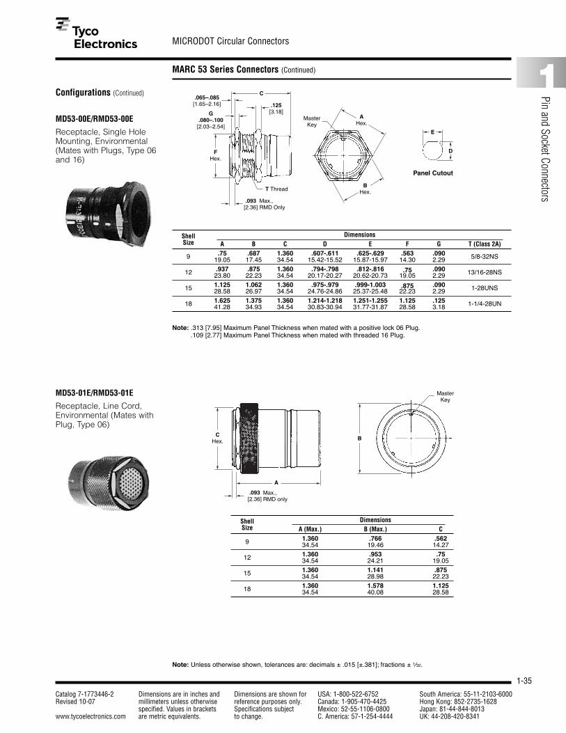
1-35
MICRODOT Circular Connectors
Catalog 7-1773446-2 Dimensions are in inches and Dimensions are shown for USA: 1-800-522-6752 South America: 55-11-2103-6000Revised 10-07 millimeters unless otherwise reference purposes only. Canada: 1-905-470-4425 Hong Kong: 852-2735-1628
specified. Values in brackets Specifications subject Mexico: 52-55-1106-0800 Japan: 81-44-844-8013www.tycoelectronics.com are metric equivalents. to change. C. America: 57-1-254-4444 UK: 44-208-420-8341
1
Pin and Socket Connectors
MARC 53 Series Connectors (Continued)
MD53-00E/RMD53-00E
Receptacle, Single HoleMounting, Environmental(Mates with Plugs, Type 06and 16)
C
E
DFHex.
AHex.
BHex.
Max.,RMD Only
MasterKey
.065–.085[1.65–2.16]
.093[2.36]
T Thread
G.080–.100[2.03–2.54]
.125[3.18]
Note: .313 [7.95] Maximum Panel Thickness when mated with a positive lock 06 Plug..109 [2.77] Maximum Panel Thickness when mated with threaded 16 Plug.
Panel Cutout
Shell DimensionsSize A B C D E F G T (Class 2A)
9 .75 .687 1.360 .607-.611 .625-.629 .563 .090 5/8-32NS19.05 17.45 34.54 15.42-15.52 15.87-15.97 14.30 2.29
12 .937 .875 1.360 .794-.798 .812-.816 .75 .090 13/16-28NS23.80 22.23 34.54 20.17-20.27 20.62-20.73 19.05 2.29
15 1.125 1.062 1.360 .975-.979 .999-1.003 .875 .090 1-28UNS28.58 26.97 34.54 24.76-24.86 25.37-25.48 22.23 2.29
18 1.625 1.375 1.360 1.214-1.218 1.251-1.255 1.125 .125 1-1/4-28UN41.28 34.93 34.54 30.83-30.94 31.77-31.87 28.58 3.18
MD53-01E/RMD53-01E
Receptacle, Line Cord,Environmental (Mates withPlug, Type 06)
.093[2.36]
Max.,RMD only
B
MasterKey
CHex.
A
Note: Unless otherwise shown, tolerances are: decimals ± .015 [±.381]; fractions ± 1⁄32.
Shell DimensionsSize A (Max.) B (Max.) C
9 1.360 .766 .56234.54 19.46 14.27
12 1.360 .953 .7534.54 24.21 19.05
15 1.360 1.141 .87534.54 28.98 22.23
18 1.360 1.578 1.12534.54 40.08 28.58
Configurations (Continued)

1-36
MICRODOT Circular Connectors
Catalog 7-1773446-2 Dimensions are in inches and Dimensions are shown for USA: 1-800-522-6752 South America: 55-11-2103-6000Revised 10-07 millimeters unless otherwise reference purposes only. Canada: 1-905-470-4425 Hong Kong: 852-2735-1628
specified. Values in brackets Specifications subject Mexico: 52-55-1106-0800 Japan: 81-44-844-8013www.tycoelectronics.com are metric equivalents. to change. C. America: 57-1-254-4444 UK: 44-208-420-8341
MARC 53 Series Connectors (Continued)
MD53-02E/RMD53-02E
Receptacle, Box Mounting,Environmental (Mates withPlug, Type 06)
.065–.085[1.65–2.16] .052–.072
[1.32–1.80]
CHex.
1.36[34.54]
BTyp.
ATyp.
.110–.130[2.79–3.30]
Dia.Typ.
Master PolarizingKey
.093[2.36] Max. RMD only
D
Shell DimensionsSize A B C D
9 .875 .594 .563 .59522.23 15.09 14.30 15.11
12 1.000 .786 .75 .78325.40 19.96 19.05 19.89
15 1.125 .906 .875 .96028.58 23.01 22.23 24.38
18 1.344 1.062 1.125 1.21234.14 26.97 28.58 30.78
MD53-12E/RMD53-12EThreaded Coupling
Receptacle, Box Mounting,Environmental (Mates withPlugs, Type 06 and 16; notavailable in 18 Shell Size)
.065–.085[1.65–2.16] .052–.072
[1.32–1.80]
CHex.
1.36[34.54]
BTyp.
ATyp.
.110–.130[2.79–3.30]
Dia.Typ.
Master PolarizingKey
.093[2.36] Max. RMD only
T Thread
D
Shell DimensionsSize A B C T (Class 2A) D
9 .875 .594 .563 5/8-32UN .64522.23 15.09 14.30 16.38
12 1.000 .786 .75 13/16-28UN .83225.40 19.96 19.05 21.13
15 1.125 .906 .875 1-28UN 1.02028.58 23.01 22.23 25.91
.375 [9.53] Max. Panel Thickness forrear-mount applications.
Note: Unless otherwise shown, tolerances are: decimals ± .015 [±.381]; fractions ± 1⁄32.
Configurations (Continued)
Panel Cutout
.125 [3.18] Max. Panel Thicknesswhen mated with threaded 16 Plugfor rear mount applications.
Panel Cutout

1-37
MICRODOT Circular Connectors
Catalog 7-1773446-2 Dimensions are in inches and Dimensions are shown for USA: 1-800-522-6752 South America: 55-11-2103-6000Revised 10-07 millimeters unless otherwise reference purposes only. Canada: 1-905-470-4425 Hong Kong: 852-2735-1628
specified. Values in brackets Specifications subject Mexico: 52-55-1106-0800 Japan: 81-44-844-8013www.tycoelectronics.com are metric equivalents. to change. C. America: 57-1-254-4444 UK: 44-208-420-8341
1
Pin and Socket Connectors
MARC 53 Series Connectors (Continued)
AccessoriesTest Adapter
The test adapter accessoryis utilized primarily as a con-nector simulator to preservethe end-use connectorwhere this connector wouldbe subjected to extensivetesting, matings, or probings.The test adapter, whenmated, provides the exactmating interface as that ofthe end-use connector and iscompletely field serviceable.
Test Adapter Product Part Number SystemHow to Specify
Protective Covers
Shell Receptacle Cover Part Number1 Plug Cover Part Number1 Dimensions (Max.)Size With Chain Without Chain With Chain Without Chain A B C D
9 086-0049-00AL 086-0073-00W3 086-0052-00L6 086-0076-00P2 .766 .950 .969 .91319.46 24.13 24.61 23.19
12 086-0050-00AL 086-0074-00W3 086-0053-00L6 086-0077-00P2 .953 .950 1.156 .91324.21 24.13 29.36 23.19
15 086-0051-00AL 086-0075-00W3 086-0054-00L6 086-0078-00P2 1.141 .950 1.344 .91328.98 24.13 34.14 23.19
18 086-0146-00AL 086-0139-00W3 086-0147-00L6 086-0140-00P2 1.578 1.000 1.781 .91340.08 25.4 45.24 23.19
1 For threaded plug (PT) cover, consult Tyco Electronics. Wire rope/lanyard attachments and plastic protective caps also available, consult Tyco Electronics.
B
A
D
C
Receptacle Cover Plug Cover
B
ADia.
Shell DimensionSize A (Max.) B (Max.)
9 .906 2.67023.01 67.82
12 1.094 2.67027.79 67.82
15 1.281 2.67032.54 67.82
18 1.594 2.67040.49 67.82
T 53 E 15 61 SP N (XXX)Modification Designator
Polarizing Position
Contact SexSP — Sockets Plug end, Pins Receptacle endPS — Pins Plug end, Sockets Receptacle end
Layout
Shell Size
Adapter TypeE — SealedA — Unsealed
Series or Style53 — MARC 53 Series Connector63 — MARC 63 Series Connector
Test Adapter

1-38
MICRODOT Circular Connectors
Catalog 7-1773446-2 Dimensions are in inches and Dimensions are shown for USA: 1-800-522-6752 South America: 55-11-2103-6000Revised 10-07 millimeters unless otherwise reference purposes only. Canada: 1-905-470-4425 Hong Kong: 852-2735-1628
specified. Values in brackets Specifications subject Mexico: 52-55-1106-0800 Japan: 81-44-844-8013www.tycoelectronics.com are metric equivalents. to change. C. America: 57-1-254-4444 UK: 44-208-420-8341
MARC 53 Series Connectors (Continued)
Accessories (Continued)
Cable Clamps
Shell Clamp Part NumberA B T
Size MD RMD Thd. 2A
9 086-0099-00F5 086-0175-00F3 .704 .750 1/2-20 UNF17.88 19.05
12 086-0100-00F5 086-0176-00F3 .773 .932 11/16-24 UNEF19.63 23.67
15 086-0101-00F5 086-0177-00F3 .829 1.078 13/16-24 UNEF21.06 27.38
18 086-0142-00F5 086-0178-00F3 .890 1.250 1-28 UN22.61 31.75
Contact Cavity Sealing Plugs (see page 1-45)
Contact Standard Length Part Number Short Length Part NumberSize MD RMD MD RMD
22 AWG 086-0055-0000 086-0148-0000 082-0009-0000 086-0009-000016 AWG 086-0056-0000 — 082-0010-0000 —
Note: Standard length plug occupies contact cavity and wire sealing grommet. Short lengthplug occupies wire sealing grommet only (to be used behind non-wired contacts andin plugs which mate to hermetic receptacles).
We offer a unique modifica-tion identification systemwhich provides alteration ofstandard MARC 53 SeriesConnectors to include spe-cial finishes, accessories,MARC 43 Series Connectorcontact arrangements, andcustom quality assuranceprovisions — processing,testing, serialization, traceability. Consult Tyco Electronics for additional modificationinformation.
Standard modificationsinclude:
(503): MARC 53 SeriesConnector includingcable clamp, straighttype
(504): MARC 53 SeriesConnector includingcable clamp, right-angle type
(506): MARC 53 SeriesConnector, gold finish
(507): MARC 53 SeriesConnector, electro-less nickel finish
(508): MARC 53 SeriesConnector, blackanodized couplingring, gold over elec-troless nickel hous-ings, retaining nutsand hardware.
Contacts (see pages 1-43 and 1-44)
Contact Pin Part Number Socket Part NumberSize MD RMD MD RMD
22 AWG 083-0009-00R4 083-1200-00R4 082-0464-00Y9 082-0462-00Y916 AWG 083-0158-00R4 — 082-0113-00T1 —
Note: Standard packaging includes same quantity of contacts as contact cavities in insert.
.156[3.96]
T
A
B
Shell Clamp Part Number TSize MD RMD
A B (Max.) C (Max.) D Thd. 2A
9 086-0103-00F5 086-0179-00F3 .737 .600 1.100 .879 1/2-20 UNF18.72 15.24 27.94 22.32
12 086-0104-00F5 086-0180-00F3 .913 .775 1.250 1.067 11/16-24 UNEF23.19 19.68 31.75 27.10
15 086-0105-00F5 086-0181-00F3 1.048 .962 1.469 1.233 13/16-20 UNEF26.62 24.43 37.31 31.32
18 086-0143-00F5 086-0182-00F3 1.225 1.185 1.550 1.550 1-28 UN31.12 30.01 39.37 39.37
.156[3.96]
C
TA
B
D
Right-Angle
Straight
Modifications

1-39
MICRODOT Circular Connectors
Catalog 7-1773446-2 Dimensions are in inches and Dimensions are shown for USA: 1-800-522-6752 South America: 55-11-2103-6000Revised 10-07 millimeters unless otherwise reference purposes only. Canada: 1-905-470-4425 Hong Kong: 852-2735-1628
specified. Values in brackets Specifications subject Mexico: 52-55-1106-0800 Japan: 81-44-844-8013www.tycoelectronics.com are metric equivalents. to change. C. America: 57-1-254-4444 UK: 44-208-420-8341
1
Pin and Socket Connectors
MARC 63 Series Connectors
MARC 63 Series Connectors RMD63 Performance DataMARC 63 Series Connectors,0 RMD63 Series meet or exceed the performance requirements of specification MIL-C-38300A (USAF) as detailed in the M38300A (USAF) military specification sheets covering the MARC 53 SeriesConnectors. Tyco Electronics can supply detailed, cross reference information. MARC 63 Series Connectors, RMD63Series meet the following selected test parameters as specified below:
DESCRIPTION TEST REQUIREMENTS
Contact Retention Contacts are to withstand 15 lbs. [66.72 N] axial load and RMD contacts 10 lbs.[44.48 N] axial load without axial displacement in excess of 0.012 [.305] or damage to contacts or inserts when the axial load is applied to the mating endof the contacts in unmated plugs and receptacles at a rate of approximately 1 lb/sec. [4.45 N].
Contact Resistance The potential drop across normally mated contacts shall not exceed 25 mvunder room ambient and high temperature service conditions when measuredas specified in MIL-C-26636, Fig. 2, with maximum rated current.
Dielectric Withstanding Voltage, No evidence of dielectric breakdown or flashover when mated and unmated Altitude and Sea Level plugs are subjected to 645 and 180 volts RMS, respectively, at altitudes up to
110,000 [33,528 m] feet and 1000 volts RMS at sea level.
Insulation Resistance, Insulation resistance of mated plugs and receptacles shall be 5000 megohms,Room and High Temp. minimum, at room temperature and 1000 megohms, minimum, at 257°F
[+125°C] when measured per MIL-STD-202, Method 302, Test Condition B.
Coupling and Uncoupling Plugs and receptacles shall withstand up to 500 cycles of engagement and separation without detrimental damage to plugs or receptacles or not satisfyingsubsequent tests of MIL-C-38300.
Fluid Immersion Mating and unmating forces shall not exceed 27 lbs. [120.10 N], maximum, (15 shell size) after fully wired plugs and receptacles are immersed for 20 hours,each, in hydraulic fluid (MIL-H-5606) and high temperature lubricating oil (MIL-L-9236) followed by a one-hour dry.
Sweep Vibration, Mated Mated connectors shall show no circuit interruptions greater than one microsecond during 12 hours vibration to include six sweeps in each axis atextreme temperatures of –85°F [–65°C] and 257°F [+125°C] per MIL-STD-202,Method 204, Test Condition D. Post inspection shall show no detrimental crack-ing, breaking, or loosening of parts.
Moisture Resistance The insulation resistance of mated connectors shall exceed 1000 megohms aftersubjection to moisture resistance testing per MIL-STD-202, Method 106, asamended by MIL-C-38300.
Altitude Breathing The insulation resistance of wired and mated connectors shall be 5000megohms, minimum, and there shall be no flashover or breakdown at test voltageof 1000 volts RMS after the third cycle and while immersed in 5% salt water solution at 68°F [20°C] and room ambient pressure at 68°F [20°C].
Salt Spray Unmated plugs and receptacles shall show no excessive corrosion which would detrimentally affect the electrical and mechanical performance of the connectors after subjection to 24 hours exposure to salt spray atmosphere perMIL-STD-202, Method 101.

1-40
MICRODOT Circular Connectors
Catalog 7-1773446-2 Dimensions are in inches and Dimensions are shown for USA: 1-800-522-6752 South America: 55-11-2103-6000Revised 10-07 millimeters unless otherwise reference purposes only. Canada: 1-905-470-4425 Hong Kong: 852-2735-1628
specified. Values in brackets Specifications subject Mexico: 52-55-1106-0800 Japan: 81-44-844-8013www.tycoelectronics.com are metric equivalents. to change. C. America: 57-1-254-4444 UK: 44-208-420-8341
MARC 63 Series Connectors (Continued)
Part Number and OrderingInformation
Typical Part Number
Connector part numbersindicate size, shape, insertlayout, type of seal, style ofcontact and polarization.Note: Pin or socket (power or coaxial)contacts may be used in eitherplugs or receptacles. However, it isrecommended that pins be placed inthe receptacle when possible to takeadvantage of our “scoop-proof”design.
(1) For polarizing key positions see MARC 53 Series Connectors.(2) For contact arrangements see MARC 53 Series Connectors.Note: If P or S does not appear in the numbering system, no contacts will be supplied with order (order separately).
MD63 06 E 15 61 S N (***)
ModificationDesignatorwhen applicable(See page 1-42)
Polarizing position (1)N, 1, 2, 3, 4, etc. . . .
P — Pin power contactS — Socket power contact
Insert arrangement number (2)
Shell Size — O.D. of receptacle barrel to nearest 1/16 inch
E — Environmentally sealedH — Hermetic seal (receptacle only).
Single hole mntng. 00receptacle Line cord recept. 01
Box mntng. recpt. 02
Straight plug, bayonet 06quick disconnect
Series — MD63or RMD63 style
ConfigurationsMD63-06E/RMD63-06E
Straight Plug, BayonetCoupling, Environmentaland Non-Environmental(Mates with Receptacles02, 00 and 01) A
Master PolarizingKeyway
B
C
.093[2.36]
Max.
Shell DimensionsSize A B (Max.) C (Max.)
9 .813 1.000 1.28820.65 25.4 32.72
12 1.000 1.000 1.28825.40 25.4 32.72
15 1.125 1.000 1.28828.58 25.4 32.72
18 1.594 1.000 1.28840.49 25.4 32.72

1-41
MICRODOT Circular Connectors
Catalog 7-1773446-2 Dimensions are in inches and Dimensions are shown for USA: 1-800-522-6752 South America: 55-11-2103-6000Revised 10-07 millimeters unless otherwise reference purposes only. Canada: 1-905-470-4425 Hong Kong: 852-2735-1628
specified. Values in brackets Specifications subject Mexico: 52-55-1106-0800 Japan: 81-44-844-8013www.tycoelectronics.com are metric equivalents. to change. C. America: 57-1-254-4444 UK: 44-208-420-8341
1
Pin and Socket Connectors
MARC 63 Series Connectors (Continued)
Configurations (Continued)
MD63-02E/RMD63-02E
Receptacle, Box Mounting,Environmental and Non-Environmental (Mates withPlug, Type 06)
BTyp.
ATyp.
CHex.
.093[2.36]
1.360[34.54]
.052–.072[1.32–1.83]
.065–.085[1.65–2.16]
Max.D
.110–.130[2.79–3.302]
Dia.4 Holes
Master PolarizingKey
Shell DimensionsSize A B C D
9 .875 .662 .562 .693-.69722.23 16.81 14.27 17.60-17.70
12 1.000 .786 .75 .881-.88525.40 19.96 19.05 22.38-22.48
15 1.125 .906 .875 1.006-1.01128.58 23.01 22.23 25.55-25.68
18 1.344 1.062 1.125 1.250-1.26034.14 26.97 28.58 30.48-32.00
Panel Cutout
MD63-00E/RMD63-00E
Receptacle, Single HoleMounting, Environmentaland Non-Environmental(Mates with Plug, Type 06)
BHex.
AHex.
FHex.
C
TThread
.093[2.36]
.125[3.18]
Max.
D
E
Master PolarizingKey
Panel Cutout
Shell DimensionsSize A B C D E F T (Class 2A)
9 .813 .75 1.360 .669-.673 .693-.697 .562 11/16-32UN20.65 19.05 34.54 16.99-17.09 17.60-17.70 14.27
12 1.000 .937 1.360 .850-.856 .881-.885 .75 7/8-28UN25.40 23.80 34.54 21.59-21.74 22.38-22.48 19.05
15 1.125 1.062 1.360 .975-.979 1.006-1.010 .875 1-28UN28.58 26.97 34.54 24.76-24.87 25.55-25.65 22.23
18 1.625 1.375 1.360 1.212-1.216 1.251-1.255 1.125 1-1/4-28UN41.28 34.93 34.54 30.78-30.88 31.78-31.88 28.58
MD63-01E/RMD63-01E
Receptacle, Line Cord,Environmental (Mates withPlug, Type 06)
B
Master Polarizing Key
CHex.
A
.093[2.36]
Max.
Shell DimensionsSize A B (Max.) C
9 1.360 .703 .56234.54 17.86 14.27
12 1.360 .891 .7534.54 22.63 19.05
15 1.360 1.016 .87534.54 25.81 22.23
18 1.360 1.203 1.12534.54 30.56 28.58
.375 [9.53] Max. Panel Thicknessfor rear mount applications.

1-42
MICRODOT Circular Connectors
Catalog 7-1773446-2 Dimensions are in inches and Dimensions are shown for USA: 1-800-522-6752 South America: 55-11-2103-6000Revised 10-07 millimeters unless otherwise reference purposes only. Canada: 1-905-470-4425 Hong Kong: 852-2735-1628
specified. Values in brackets Specifications subject Mexico: 52-55-1106-0800 Japan: 81-44-844-8013www.tycoelectronics.com are metric equivalents. to change. C. America: 57-1-254-4444 UK: 44-208-420-8341
MARC 63 Series Connectors (Continued)
AccessoriesCable Clamps
.156[3.96].225
[5.72]Max.
A
TThread
B
D
C.156[3.96].225
[5.72]Max.
TThread
B
A
Shell Size Part Number A B T Thread
9 086-0175-00N1 .704 .750 1/2-20UNF-2A17.88 19.05
12 086-0176-00N1 .773 .932 11/16-24UNEF-2A19.63 23.67
15 086-0177-00N1 .829 1.078 13/16-20UNEF-2A21.06 27.38
18 086-0178-00N1 .890 1.250 1-28UN-2A22.61 31.75
Shell Size Part Number A B (Max.) C (Max.) D T Thread
9 086-0179-00N1 .737 .600 1.100 .879 1/2-20UNF-2A18.72 15.24 27.94 22.32
12 086-0180-00N1 .913 .785 1.250 1.067 11/16-24UNEF-2A23.19 19.94 31.75 27.10
15 086-0181-00N1 1.048 .962 1.469 1.233 13/16-20UNEF-2A26.62 24.43 37.31 31.21
18 086-0182-00N1 1.225 1.185 1.550 1.550 1-28UN-2A31.12 30.10 39.37 39.37
Straight
Angle
Protective Covers
Shell Receptacle Part Number Plug Part Number DimensionsSize Without Chain With Chain Without Chain With Chain A B C D
9 086-0253-00P2 086-0257-00L6 086-0261-00F5 086-0265-00L6 .813 .950 .813 .91320.65 24.13 20.65 23.19
12 086-0254-00P2 086-0258-00L6 086-0262-00F5 086-0266-00L6 1.000 .950 1.000 .91325.40 24.13 25.40 23.19
15 086-0255-00P2 086-0259-00L6 086-0263-00F5 086-0267-00L6 1.125 .950 1.125 .91328.58 24.13 28.58 23.19
18 086-0256-00P2 086-0260-00L6 086-0264-00F5 086-0268-00L6 1.594 .950 1.594 .91340.49 24.13 40.49 23.19
Plastic Protective Covers also available; consult Tyco Electronics.
A
B
C
D
ModificationsWe offer a unique modifica-tion system which providesalteration of standardMARC 63 Series Connectorsto include special finishes,accessories, and custom
quality assurance provisions — processing,testing, serialization, traceability. Consult yoursales representative or Tyco Electronics for additional modificationinformation.
Standard modificationsinclude:
(801): MARC 63 SeriesConnector, electrolessnickel finish
(803): MARC 63 SeriesConnector includingcable clamp, straighttype
(804): MARC 63 SeriesConnector includingcable clamp, right-angle type

1-43
MICRODOT Circular Connectors
Catalog 7-1773446-2 Dimensions are in inches and Dimensions are shown for USA: 1-800-522-6752 South America: 55-11-2103-6000Revised 10-07 millimeters unless otherwise reference purposes only. Canada: 1-905-470-4425 Hong Kong: 852-2735-1628
specified. Values in brackets Specifications subject Mexico: 52-55-1106-0800 Japan: 81-44-844-8013www.tycoelectronics.com are metric equivalents. to change. C. America: 57-1-254-4444 UK: 44-208-420-8341
1
Pin and Socket Connectors
Contacts for MARC 43, MARC 53 and MARC 63 Connectors
MARC 43, MD53, MD63 Series
MARC RMD53, RMD63 Series
Part Number 083-0009-00R4(6-1532030-1) 22 AWG Pin
.702[17.83]
.452[11.48]
Wire Inspection Hole.060–.064[1.52–1.63]
Dia..030–.032[0.76–0.81]
Dia.
Part Number 083-1200-00R4(4-1532036-8) 22 AWG Pin
.767[19.48]
.515[13.08]
Wire Inspection Hole.055–.058[1.40–1.47]
Dia..030–.032
[0.76–.0.81]Dia.
Part Number 082-0461-00Y9(5-1532030-6) 22 AWG Socket
.505–.525[12.83–13.33]
Wire Inspection Hole
.051–.055[1.30–1.40]
Dia. .055–.058[1.40–1.47]
Dia.
MARC 43, MD53, MD63 Series
Part Number 083-0158-00R4 (8-1532030-1) 16 AWG Pin
.702[17.83]
.452[11.48]
Wire Inspection Hole.086–.090[2.18–2.29]
Dia..061–.063[1.55–1.60]
Dia.
Part Number 082-0113-00T1(3-1532030-3) 16 AWG Socket
.445–.460[11.30–11.68]
Wire Inspection Hole.086–.092[2.18–2.34] Dia.
MARC 43 Series
Part Number 083-0173-00R412 AWG Pin
.702[17.83]
.452[11.48]
Wire Inspection Hole.139–.143[3.53–3.63]
Dia..093–.096[2.36–2.44]
Dia.
.121–.126[3.07–3.20]
Dia.
MARC MD53, MD63 Series
Part Number 083-1435-00R4(7-1532037-3) 22-20 AWG Pin
.702[17.83]
.452[11.48]
Wire Inspection Hole.068–.072[1.73–1.83]
Dia..030–.032[0.76–0.81] Dia.
.049–.053[1.24–1.35]
Dia.
Part Number 082-0132-00T1(3-1532030-4) 12 AWG Socket
.445–.460[11.30–11.68]
Wire Inspection Hole.121–.126[3.07–3.20]
Dia.
.139–.143[3.53–3.63]
Dia.

1-44
MICRODOT Circular Connectors
Catalog 7-1773446-2 Dimensions are in inches and Dimensions are shown for USA: 1-800-522-6752 South America: 55-11-2103-6000Revised 10-07 millimeters unless otherwise reference purposes only. Canada: 1-905-470-4425 Hong Kong: 852-2735-1628
specified. Values in brackets Specifications subject Mexico: 52-55-1106-0800 Japan: 81-44-844-8013www.tycoelectronics.com are metric equivalents. to change. C. America: 57-1-254-4444 UK: 44-208-420-8341
Contacts for MARC 43, MARC 53 and MARC 63 Connectors (Continued)
MARC 43, MD53, MD63 Series
Part Number 082-0464-00Y9(5-1532030-7) 22 AWG Socket
.451–.462[11.46–11.73]
Wire Inspection Hole.060–.064[1.52–1.63]
Dia..051–.055[1.30–1.40]
Dia.
MARC 43, MD53, MD63 Series
Solder Type CoaxialContacts
B
A
MARC MD53, MD63 Series
Part Number 082-0466-00Y922-20 AWG Socket
.451–.462[11.46–11.73]
Wire Inspection Hole.068–.072[1.73–1.83]
Dia..051–.055[1.30–1.40]
Dia.
CP Type
B
A
CS Type
MARC 43 Series
LEPRA/CON Crimp Type,50 Ohm Coaxial Contacts
Part Number 142-1500-0001CS Socket
.425[10.80]
.120[3.05]
Crimp Approx.
Part Number 141-1500-0001CP Pin
.600[15.24]
.210–.240[5.33–6.10]
Crimp Length
Contact Part Number Type A Dia. B084-0027-00T2 CS .109 .452
50 Ω(5-1532129-8) 2.77 11.48084-0024-00T2 CP .093 .600(5-1532129-7) 2.36 15.24084-0028-00T2 CS .123 .452
75 Ω(5-1532129-9) 3.12 11.48084-0025-00T2 CP .106 .600(7-1532155-0) 2.69 15.24084-0029-00T2 CS .168 .452
95 Ω(5-1532168-1) 4.27 11.48
084-0026-00T2 CP .149 .6003.78 15.24
Coaxial Contacts

1-45
MICRODOT Circular Connectors
Catalog 7-1773446-2 Dimensions are in inches and Dimensions are shown for USA: 1-800-522-6752 South America: 55-11-2103-6000Revised 10-07 millimeters unless otherwise reference purposes only. Canada: 1-905-470-4425 Hong Kong: 852-2735-1628
specified. Values in brackets Specifications subject Mexico: 52-55-1106-0800 Japan: 81-44-844-8013www.tycoelectronics.com are metric equivalents. to change. C. America: 57-1-254-4444 UK: 44-208-420-8341
1
Pin and Socket Connectors
Contact Cavity Sealing Plugs
Size Part Number Application Description
086-0001-0000 Unsealed 43 Series
Sealed 43 Series22 AWG 086-0009-0000 MD53, RMD53
MD63, RMD63
086-0148-0000 RMD53, RMD63
086-0056-0000 Sealed 43 SeriesMD53, MD63
16 AWG 086-0010-0000 Sealed 43 SeriesMD53, MD63
086-0014-0000 Unsealed 43 Series
086-0057-0000 Sealed 43 Series
12 AWG
086-0015-0000 Unsealed 43 Series
22/20 AWG 086-0251-0000 MD53, MD63
.447[11.35].047–.055
[1.19–1.40]Dia.
.057–.065[1.45–1.65]
Dia.
.940[23.88]
.046–.054[1.17–1.37]
Dia.
.940[23.88].075–.083
[1.91–2.11]Dia.
.452[11.48]
.086–.094[2.18–2.39]
Dia.
.940[23.88]
.125–.133[3.18–3.38]
Dia..140–.148[3.56–3.76]
Dia.
.940[23.88]
.069–.073[1.75–1.85]
.052–.055[1.32–1.40]
.049–.053[1.24–1.35]
Dia.Dia.
Dia.
.421[10.70]
.075–.083[1.91–2.11]
Dia.
.447[11.35]
.140–.148[3.56–3.76]
.121–.129[3.07–3.28]
Dia.Dia.
.421[10.70]
.045–.053[1.14–1.35]
Dia.
Size Part Number Application A Dia. B Dia. Description
5052 086-0061-0000 .112-.120 —2.84-3.05
7552 086-0062-0000 Unsealed 43 Series .135-.143 —3.43-3.63
9552 086-0063-0000 .178-.186 —4.52-4.72
5052 086-0058-0000 .081-.089 .112-.1202.06-2.26 2.84-3.05
7552 086-0059-0000 Sealed 43 Series .106-.114 .135-.1432.69-2.90 3.43-3.63
9552 086-0060-0000 .151-.159 .178-.1863.84-4.04 4.52-4.72
.388[9.86]
ADia.
.913[23.19]
ADia.

1-46
MICRODOT Circular Connectors
Catalog 7-1773446-2 Dimensions are in inches and Dimensions are shown for USA: 1-800-522-6752 South America: 55-11-2103-6000Revised 10-07 millimeters unless otherwise reference purposes only. Canada: 1-905-470-4425 Hong Kong: 852-2735-1628
specified. Values in brackets Specifications subject Mexico: 52-55-1106-0800 Japan: 81-44-844-8013www.tycoelectronics.com are metric equivalents. to change. C. America: 57-1-254-4444 UK: 44-208-420-8341
Assembly Tools
MARC 43, 53 and 63 SeriesConnectors
Removal Tool — None required.Crimp Tools — Turret style tool(M22520/1-01 and TH88) MICRODOTPart Number 010-0080-0000 — Crimpsall power contacts.Locator Style Tool — MICRODOTPart Number 010-0070-0000 with locators.
Contact Size Wire Size Locator22 22, 24 010-0072-000022 26 010-0087-000016 16, 18 010-0075-0000
For MARC 43 Series Connector Crimp Coax ContactsUse 010-0132-0000 & 010-0169-0000.
MARC 73 Series Connectors
Description Part NumberCrimp Tool w/ Locator 010-3008-0000
Crimp Tool Only 010-3009-0000M22520/2-01
Locator Only 010-3010-0000
Description Part NumberCrimp Tool w/ Locator 010-3002-0000
Crimp Tool Only 010-0190-0000Locator Only 010-3007-0000

1-47
MICRODOT Circular Connectors
Catalog 7-1773446-2 Dimensions are in inches and Dimensions are shown for USA: 1-800-522-6752 South America: 55-11-2103-6000Revised 10-07 millimeters unless otherwise reference purposes only. Canada: 1-905-470-4425 Hong Kong: 852-2735-1628
specified. Values in brackets Specifications subject Mexico: 52-55-1106-0800 Japan: 81-44-844-8013www.tycoelectronics.com are metric equivalents. to change. C. America: 57-1-254-4444 UK: 44-208-420-8341
1
Pin and Socket Connectors
MARC 73 Series Connectors
Service and Performance DataMARC 73 Series Connectors meet or exceed the performance requirements of specification MIL-C-38999. Your salesrepresentative or field engineer can supply detailed, cross-reference information. MARC 73 Series Connectors meet thefollowing selected test parameters as specified below:
DESCRIPTION TEST REQUIREMENTS
Contact Retention Contacts are to withstand 10 lbs [44.48 N] axial load without axial displacementin excess of 0.012 [0.30] or damage to contacts or inserts when the axial load isapplied to the mating end of the contacts in unmated plugs and receptacles at arate of approximately 1 lb/sec. [4.45 N].
Contact Resistance The potential drop across normally mated contacts shall not exceed 25 mvunder room ambient and high temperature service conditions when measuredas specified in MIL C-39029 with maximum rated current.
Dielectric Withstanding No evidence of dielectric breakdown or flashover when mated and unmated Voltage, Altitude and Sea Level plugs are subjected to 645 and 180 volts RMS, respectively, at altitudes up to
70,000 feet [21,336 m] and 1000 volts RMS at sea level.
Insulation Resistance, Insulation resistance of mated plugs and receptacles shall be 5000 megohms, Room and High Temp. minimum, at room temperature and 1000 megohms, minimum, at 257°F
[+125°C] when measured per MIL-STD 202, Method 302, Test Condition B.
Coupling and Uncoupling Plugs and receptacles shall withstand up to 500 cycles of engagement and separation without detrimental damage to plugs or receptacles or not satisfyingsubsequent tests.
Fluid Immersion Mating and unmating forces shall not exceed 27 Ibs [120.10 N] maximum, (15 shell size) after fully wired plugs and receptacles are immersed for 20 hours,each, in hydraulic fluid (MIL-H-5606) and high temperature lubricating oil (MIL-L-9236) followed by a one-hour dry.
Sweep Vibration, Mated Mated connectors shall show no circuit interruptions greater than one microsec-ond during 12 hours vibration to include six sweeps in each axis at extreme tem-peratures of –85°F [–65°C] and 257°F [+125°C] per MIL-STD-202, Method 204,Test Condition D. Post inspection shall show no detrimental cracking, breaking,or loosening of parts.
Moisture Resistance The insulation resistance of mated connectors shall exceed 1000 megohms aftersubjection to moisture resistance testing per MIL-STD-202, Method 106.
Altitude Breathing The insulation resistance of wired and mated connectors shall be 5000megohms, minimum, and there shall be no flashover or breakdown at test voltageof 1000 volts RMS after the third cycle and while immersed in 5% salt water solution at 68°F [20°C] and room ambient pressure at 68°F [20°C].
Salt Spray Unmated plugs and receptacles shall show no excessive corrosion which would detrimentally affect the electrical and mechanical performance of the connectors after subjection to 24 hours exposure to salt spray atmosphere perMIL-STD-202, Method 101.

1-48
MICRODOT Circular Connectors
Catalog 7-1773446-2 Dimensions are in inches and Dimensions are shown for USA: 1-800-522-6752 South America: 55-11-2103-6000Revised 10-07 millimeters unless otherwise reference purposes only. Canada: 1-905-470-4425 Hong Kong: 852-2735-1628
specified. Values in brackets Specifications subject Mexico: 52-55-1106-0800 Japan: 81-44-844-8013www.tycoelectronics.com are metric equivalents. to change. C. America: 57-1-254-4444 UK: 44-208-420-8341
MARC 73 Series Connectors (Continued)
Service and Performance DataI. Electrical — Electrical Ratings
Current Rating Dielectric Working Voltage ContactContact (Amperes, Withstanding ResistanceSize Max., 81°F [+27°C]) Voltage (RMS) Sea Level 110,000 Ft. Alt.1 (Millivolts, Max.)22 AWG 5 1000 750 300 8
1 110,000 ft = 33,528 m
II. Mechanical — Durability: 500 Cycles Mate/Unmate. Coupling/Uncoupling Forces and Tightening Torques:
Coupling/Shell Uncoupling Tightening Torque (In-Lbs.)Size Force Retaining Nut Mounting Nut
(In-Lbs.) Max.9 10 [44.48] 20 [2.26 N] Max. 30-45 [3.39 Nm – 5.08 Nm]12 15 [66.72] 20 [2.26 N] Max. 40-55 [4.52 Nm – 6.21 Nm]15 22 [97.86] 20 [2.26 N] Max. 55-70 [6.21 Nm – 7.91 Nm]18 28 [124.55] 20 [2.26 N] Max. 70-85 [7.91 Nm – 9.60 Nm]
Operating Temperature: –67°F to 257°F [–55°C to +125°C].Connector Mated Length: 2.217 [56.31] Max.
Part Number and Ordering Information
MARC 73 Series Connectorpart numbers indicate size,shape, insert layout, type ofseal, style of contact andpolarization.
MD73 06 E 15 91 P N (***)
ModificationDesignatorwhen applicable
Polarizing positionN, 1, 2, 3, 4, etc. . . .
P — Pin power contactS — Socket power contact
Insert arrangement number
Shell Size — O.D. of receptacle barrel to nearest .062 [19.05] inch
E — Environmentally sealed
Single hole mntng. 00receptacle Line cord receptacle 01
Box mntng. receptacle 02
Straight plug, bayonet 06quick disconnect
Series — MD73
Notes: Pin contacts in plug; socket contacts in receptacle.If P or S does not appear in the numbering system, no contacts will be supplied with order (order separately).
Contact Arrangements1
Insert Arrangement 2 9-273 12-613 15-913
Number of Contacts 27 61 91Contact Size 22 AWG 22 AWG 22 AWG
1 Views shown are front face views of receptacles. Front face view of plug is mirror image of that shown.2 Arrow ( ) indicates insert top or vertical position in relation to top or vertical position of housing.3 The 22 AWG contact arrangements will accommodate MIL-W-16878 Type ET, 22, 24, 26 AWG wire. Contact spacing
is on 0.065 [1.65] centers.
Shell Size 9 Shell Size 12 Shell Size 15
Wire Range AccommodationsWire Wire O.D. of Finished Wire Wire Spec.Barrel SizeSize (AWG) Range Nominal MIL-W-16878
26 .029 Min. .031 Nom. Type “E” or “ET”0.74 0.79
22 AWG 24 — .036 Nom. Type “ET”0.91
22 .044 Max. .042 Nom. Type “ET”1.12 1.07

1-49
MICRODOT Circular Connectors
Catalog 7-1773446-2 Dimensions are in inches and Dimensions are shown for USA: 1-800-522-6752 South America: 55-11-2103-6000Revised 10-07 millimeters unless otherwise reference purposes only. Canada: 1-905-470-4425 Hong Kong: 852-2735-1628
specified. Values in brackets Specifications subject Mexico: 52-55-1106-0800 Japan: 81-44-844-8013www.tycoelectronics.com are metric equivalents. to change. C. America: 57-1-254-4444 UK: 44-208-420-8341
1
Pin and Socket Connectors
MARC 73 Series Connectors (Continued)
ConfigurationsMD73-06E
Straight Plug, BayonetCoupling, Environmentaland Non-Environmental(Mates with Receptacles02, 00 and 01)
A
Master PolarizingKeyway
B
C
.093[2.36]
Max.
Shell DimensionsSize A B (Max.) C (Max.)
9 .813 1.000 1.28820.65 25.40 32.72
12 1.000 1.000 1.28825.40 25.40 32.72
15 1.125 1.000 1.28828.58 25.40 32.72
18 1.594 1.000 1.28840.49 25.40 32.72
MD73-02E
Receptacle, Box Mounting,Environmental and Non-Environmental (Mates withPlug, Type 06)
.052–.072[1.32–1.83] .065–.085
[1.65–2.16]
.093[2.36]
.110–.130[2.79–3.30]
4 Holes
BTyp.
ATyp.
Dia.
Master PolarizingKey
CHex.
1.360[34.54]
Max.
D
Shell DimensionsSize A B C D
9 .875 .662 .562 .693-.69722.23 16.81 14.27 17.60-17.70
12 1.000 .786 .75 .881-.88525.40 19.96 19.05 22.38-22.48
15 1.125 .906 .875 1.006-1.01128.58 23.01 22.23 25.55-25.68
18 1.344 1.062 1.125 1.250-1.26034.14 26.97 28.58 31.75-32.00
MD73-00E
Receptacle, Single HoleMounting, Environmentaland Non-Environmental(Mates with Plug, Type 06)
.093[2.36]
BHex.
AHex.
Master PolarizingKey
CT
Thread
FHex.
Max.
D
E
.125[3.18]
Shell DimensionsSize A B C D E F T (Class 2A)
9 .813 .75 1.360 .669-.673 .693-.697 .562 11/16-32UN20.65 19.05 34.54 16.99-17.09 17.60-17.70 14.27
12 1.000 .937 1.360 .850-.856 .881-.885 .75 7/8-28UN25.40 23.80 34.54 21.59-21.74 22.38-22.48 19.05
15 1.125 1.062 1.360 .975-.979 1.006-1.010 .875 1-28UN28.58 26.97 34.54 24.77-24.87 25.55-25.65 22.23
18 1.625 1.375 1.360 1.212-1.216 1.251-1.255 1.125 1-1/4-28UN41.28 34.93 34.54 30.78-30.89 31.78-31.88 28.58
Panel Cutout
Panel Cutout
.375 [9.53] Max. Panel Thickness

1-50
MICRODOT Circular Connectors
Catalog 7-1773446-2 Dimensions are in inches and Dimensions are shown for USA: 1-800-522-6752 South America: 55-11-2103-6000Revised 10-07 millimeters unless otherwise reference purposes only. Canada: 1-905-470-4425 Hong Kong: 852-2735-1628
specified. Values in brackets Specifications subject Mexico: 52-55-1106-0800 Japan: 81-44-844-8013www.tycoelectronics.com are metric equivalents. to change. C. America: 57-1-254-4444 UK: 44-208-420-8341
MARC 73 Series Connectors (Continued)
Configurations (Continued)
MD73-01E
Receptacle, Line Cord,Environmental (Mates withPlug, Type 06)
BC
Hex.
.093[2.36]A
Max.
Master PolarizingKey
Shell DimensionsSize A B (Max.) C
9 1.360 .703 .56234.54 17.86 14.27
12 1.360 .891 .7534.54 20.57 19.05
15 1.360 1.016 .87534.54 25.81 22.23
18 1.360 1.203 1.12534.54 30.56 28.58
AccessoriesCable Clamps
.156[3.96]
.225[5.72]
B
A
Max.
T Thread
Shell Size Clamp Part Number A B T Thd. 2A
9 086-0341-00N1 .704 .750 1/2-20 UNF17.88 19.05
12 086-0342-00N1 .773 .932 11/16-24 UNEF19.63 23.67
15 086-0343-00N1 .829 1.078 13/16-20 UNEF21.06 27.38
18 086-0344-00N1 .890 1.250 1-28 UN22.61 31.75
.225[5.72]
.156[3.96]
D
T Thread
C
Max.B
A
Shell Size Clamp Part Number A B (Max.) C (Max.) D T Thd. 2A
9 086-0337-00N1 .737 .600 1.100 .879 1/2-20 UNF18.72 15.24 27.94 22.33
12 086-0338-00N1 .913 .785 1.250 1.067 11/16-24 UNEF23.19 19.94 31.75 27.10
15 086-0339-00N1 1.048 .962 1.469 1.233 13/16-20 UNEF26.62 24.43 37.31 31.32
18 086-0340-00N1 1.225 1.185 1.550 1.550 1-28 UN31.12 30.10 39.37 39.37

1-51
MICRODOT Circular Connectors
Catalog 7-1773446-2 Dimensions are in inches and Dimensions are shown for USA: 1-800-522-6752 South America: 55-11-2103-6000Revised 10-07 millimeters unless otherwise reference purposes only. Canada: 1-905-470-4425 Hong Kong: 852-2735-1628
specified. Values in brackets Specifications subject Mexico: 52-55-1106-0800 Japan: 81-44-844-8013www.tycoelectronics.com are metric equivalents. to change. C. America: 57-1-254-4444 UK: 44-208-420-8341
1
Pin and Socket Connectors
MARC 73 Series Connectors (Continued)
Accessories (Continued)
Contacts
Twist pin — 22 Pins andSocketsCopper alloy plated .000050 [0.00127]gold over copper flash per MIL-G-45204, Type IIRating — 5 ampsContact Resistance — .008 ohmsmax.
Engineering/Separation Forces —6 oz. [1.67 N] max. / .502 [.139 N] min.Durability — 2000 cycles
Contact Cavity Sealing Plugs
.250[6.35]
.415[10.54]
.035[0.89]
.034[0.86] .050
[1.27]Dia.
Dia. Dia.
.680[17.27]
.250[6.35]
.042[1.07]
.030[0.76]
.050[1.27]
Dia.
Dia.
.030–.032[0.76–0.81]
Dia.
Dia.
.800[20.32]
.035–.041[0.89–1.04]
.264[6.71]
.437[11.10]
.264[6.70]
.036–.044[0.91–1.10]
Contact Size Sealing Plug Filler PlugPart Number Part Number
22 AWG 086-0331-0000 086-0330-0000
Note: Sealing plug occupies insert and grommet cavities.Filler plug occupies insert cavity only.
Part Number 096-0526-0000
Part Number 086-0331-0000 Part Number 086-0330-0000
Part Number 096-0626-0001
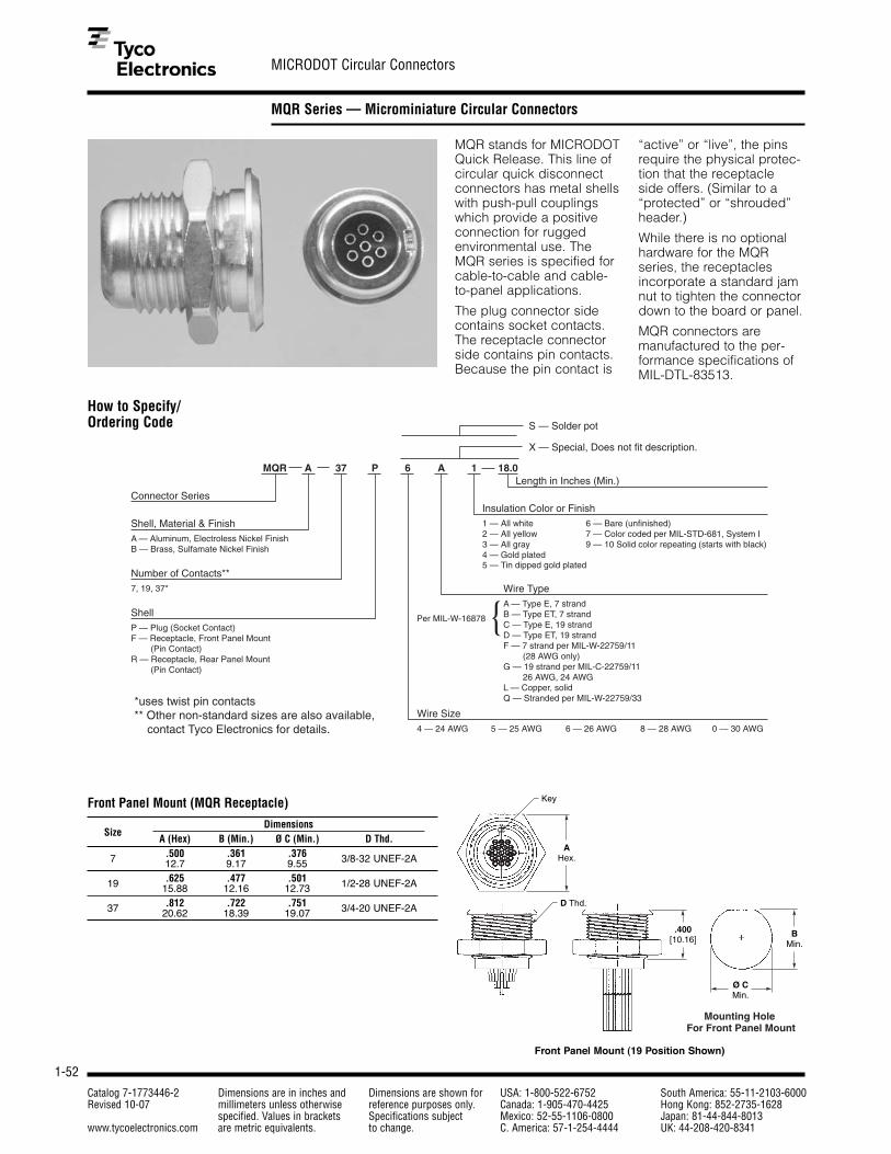
1-52
MICRODOT Circular Connectors
Catalog 7-1773446-2 Dimensions are in inches and Dimensions are shown for USA: 1-800-522-6752 South America: 55-11-2103-6000Revised 10-07 millimeters unless otherwise reference purposes only. Canada: 1-905-470-4425 Hong Kong: 852-2735-1628
specified. Values in brackets Specifications subject Mexico: 52-55-1106-0800 Japan: 81-44-844-8013www.tycoelectronics.com are metric equivalents. to change. C. America: 57-1-254-4444 UK: 44-208-420-8341
MQR Series — Microminiature Circular Connectors
MQR stands for MICRODOTQuick Release. This line ofcircular quick disconnectconnectors has metal shellswith push-pull couplingswhich provide a positiveconnection for rugged environmental use. TheMQR series is specified forcable-to-cable and cable-to-panel applications.
The plug connector sidecontains socket contacts.The receptacle connectorside contains pin contacts.Because the pin contact is
“active” or “live”, the pinsrequire the physical protec-tion that the receptacle side offers. (Similar to a“protected” or “shrouded”header.)
While there is no optionalhardware for the MQRseries, the receptaclesincorporate a standard jamnut to tighten the connectordown to the board or panel.
MQR connectors are manufactured to the per-formance specifications ofMIL-DTL-83513.
How to Specify/Ordering Code
MQR A 37 P 6 A 1 18.0Length in Inches (Min.)
X — Special, Does not fit description.
Insulation Color or Finish1 — All white 6 — Bare (unfinished)2 — All yellow 7 — Color coded per MIL-STD-681, System I3 — All gray 9 — 10 Solid color repeating (starts with black)4 — Gold plated 5 — Tin dipped gold plated
Wire TypeA — Type E, 7 strandB — Type ET, 7 strandC — Type E, 19 strandD — Type ET, 19 strandF — 7 strand per MIL-W-22759/11 (28 AWG only)G — 19 strand per MIL-C-22759/11 26 AWG, 24 AWGL — Copper, solidQ — Stranded per MIL-W-22759/33
Wire Size4 — 24 AWG 5 — 25 AWG 6 — 26 AWG 8 — 28 AWG 0 — 30 AWG
Per MIL-W-16878 {
Connector Series
Shell, Material & FinishA — Aluminum, Electroless Nickel FinishB — Brass, Sulfamate Nickel Finish
Number of Contacts**7, 19, 37*
ShellP — Plug (Socket Contact)F — Receptacle, Front Panel Mount (Pin Contact)R — Receptacle, Rear Panel Mount (Pin Contact)
S — Solder pot
*uses twist pin contacts** Other non-standard sizes are also available, contact Tyco Electronics for details.
Front Panel Mount (MQR Receptacle)
DimensionsSize
A (Hex) B (Min.) Ø C (Min.) D Thd.
7 .500 .361 .376 3/8-32 UNEF-2A12.7 9.17 9.55
19 .625 .477 .501 1/2-28 UNEF-2A15.88 12.16 12.73
37 .812 .722 .751 3/4-20 UNEF-2A20.62 18.39 19.07
AHex.
.400[10.16]
BMin.
Ø CMin.
Key
D Thd.
Mounting Hole For Front Panel Mount
Front Panel Mount (19 Position Shown)

1-53
MICRODOT Circular Connectors
Catalog 7-1773446-2 Dimensions are in inches and Dimensions are shown for USA: 1-800-522-6752 South America: 55-11-2103-6000Revised 10-07 millimeters unless otherwise reference purposes only. Canada: 1-905-470-4425 Hong Kong: 852-2735-1628
specified. Values in brackets Specifications subject Mexico: 52-55-1106-0800 Japan: 81-44-844-8013www.tycoelectronics.com are metric equivalents. to change. C. America: 57-1-254-4444 UK: 44-208-420-8341
1
Pin and Socket Connectors
MQR Series — Microminiature Circular Connectors (Continued)
.795[20.19]
LMin.
Ø A Ø B
.0433[1.10] Typ.
.050[1.27] Typ.
Keyway
.025[0.64] Typ.
.130–.144[3.30–3.66] Typ.
7 Position
17
6
5
2
3
4
19 Position
23 1
1718
4
13
7
1619
12 8
37 Position
22
159
4
2833
37
16
105
1
2329
343536
23
Circular MQR Series Quick Release Plug
7 Position(Stamped Pin)
12
3
4
7
6
5
19 Position(Stamped Pin)
21 3
1918
7
16
4
1317
8 12
37 Position(Twist Pin)
16
105
1
2329
34
22
159
4
2833
373635
32
Circular MQR Series Quick Release Receptacle
AHex.
.250[6.35]
LMin.
.0433[1.10] Typ.
.050[1.27] Typ.
.025[0.64] Typ.
.036 ±.005
[0.91± 0.13] Typ.
BMin.
Ø CMin.
Key
D Thd.
Mounting Hole For Rear Panel Mount
Rear Panel Mount (19 Position Shown)
Rear Panel Mount (MQR Receptacle)
DimensionsSize
A (Hex) B (Min.) Ø C (Min.) D Thd.
7 .500 .422 .440 7/16-28 UNEF-2A12.7 10.72 11.18
19 .687 .531 .564 9/16-24 UNEF-2A17.45 13.49 14.33
37 .812 .722 .751 3/4-20 UNEF-2A20.62 18.39 19.07
Plug (19 Position Shown)
MQR Plug
DimensionsSize
Ø A Ø B
7 .375 .3009.53 7.62
19 .475 .40012.07 10.16
37 .750 .63019.05 16.00

1-54
MICRODOT Circular Connectors
Catalog 7-1773446-2 Dimensions are in inches and Dimensions are shown for USA: 1-800-522-6752 South America: 55-11-2103-6000Revised 10-07 millimeters unless otherwise reference purposes only. Canada: 1-905-470-4425 Hong Kong: 852-2735-1628
specified. Values in brackets Specifications subject Mexico: 52-55-1106-0800 Japan: 81-44-844-8013www.tycoelectronics.com are metric equivalents. to change. C. America: 57-1-254-4444 UK: 44-208-420-8341
MTC Series — Microminiature Circular Connectors
How to Specify/Ordering Code
MTC 19 P 6 A 1 18.0Length in Inches (Min.)
X — Special, Does not fit description.
Insulation Color or Finish1 — All white 6 — Bare (unfinished)2 — All yellow 7 — Color coded per MIL-STS-681, System I3 — All gray 9 — 10 Solid color repeating (starts with black)4 — Gold plated 5 — Tin dipped gold plated
Wire Size4 — 24 AWG 5 — 25 AWG 6 — 26 AWG 8 — 28 AWG 0 — 30 AWG
MICRODOT Threaded Coupling Series
Number of Contacts9, 19
Contact TypeP — Twist Pin (Plug)S — Socket (Receptacle) Wire Type
A — Type E, 7 strand G — 19 strand per MIL-C-22759/11B — Type ET, 7 strand (26 AWG and 24 AWG only)C — Type E, 19 strand L — Copper, solidD — Type ET, 19 strand Q — Stranded per MIL-W-22759/33F — 7 strand per MIL-W-22759/11 (28 AWG only)
Per MIL-W-16878 {
Material and FinishShell — Aluminum, nickel platedContact — Copper alloy, gold platedInsulator — RYTON
MTC Series Plug
DimensionsSize
Ø A Ø B C Thd.
9 .227 .456 M10 x 0.75 5.77 11.58 19.05
19 .308 .545 M12 x 17.82 13.84 25.40
.800[20.32]
LMin.
.036 ±.005
[0.91 ±0.13] Typ. Ø A
Key
C Thd.
Ø B 9 Position
1 2
3
4
56
7
8
9
19 Position
23 1
1718
4
13
7
16
19
12 8
MTC Series Plug (19 Position Shown)

1-55
MICRODOT Circular Connectors
Catalog 7-1773446-2 Dimensions are in inches and Dimensions are shown for USA: 1-800-522-6752 South America: 55-11-2103-6000Revised 10-07 millimeters unless otherwise reference purposes only. Canada: 1-905-470-4425 Hong Kong: 852-2735-1628
specified. Values in brackets Specifications subject Mexico: 52-55-1106-0800 Japan: 81-44-844-8013www.tycoelectronics.com are metric equivalents. to change. C. America: 57-1-254-4444 UK: 44-208-420-8341
1
Pin and Socket Connectors
MTC Series — Microminiature Circular Connectors (Continued)
.130–.144[3.30–3.66]
LMin.
.900[22.86]
Ø A
Keyway
C Thd.
Typ.
BHex.
9 Position
1 9
8
7
65
4
3
2
19 Position
21 3
1918
7
16
4
13
17
8 12
D
Ø E
MTC Series Receptacle (19 Position Shown)
Panel Cut Out
MTC Series Receptacle
DimensionsSize
Ø A B Hex. C Thd. D Min. Ø E Min.
9 .562 .500 M10 x 0.75 .370 .394 14.27 12.70 19.05 9.40 10.01
19 .625 .625 M12 x 1 .445 .47415.88 15.88 25.40 11.30 12.04

1-56
AMP Micro CPC
Catalog 7-1773446-2 Dimensions are in inches and Dimensions are shown for USA: 1-800-522-6752 South America: 55-11-2103-6000Revised 10-07 millimeters unless otherwise reference purposes only. Canada: 1-905-470-4425 Hong Kong: 852-2735-1628
specified. Values in brackets Specifications subject Mexico: 52-55-1106-0800 Japan: 81-44-844-8013www.tycoelectronics.com are metric equivalents. to change. C. America: 57-1-254-4444 UK: 44-208-420-8341
Micro CPC
Product Facts
Description■ Connector system available
in wire-to-wire, wire-to-board and wire-to-panelconfigurations
■ Two shell sizes: 9.5 mm (2 to 7 positions) and 13.5 mm (12 to 19 positions)
■ Spring probe or screwmachine pin and socketcontact systems available
Applications■ Ideal for Medical,
Instrumentation andIndustrial applicationswhere size, contactdensity and durability areprimary concerns. Thenylon housings offer goodresistance to a widerange of chemical agentswhile the IP65 sealinghelps prevent ingress ofdirt or fluids that wouldhave an adverse effect onthe contact interface.
Key Features■ Squeeze-to-release coupling
mechanism offerspositive latch or optionalbreakaway locking feature
■ Panel mount receptacleoffers jam nut mounting
■ Keyed and polarized ■ Sealed to IP65■ No assembly required ■ No application tooling
required■ Ink marked positive
alignment indicators
Electrical■ Current Carrying Capacity:
2-3 Amps■ Operating Voltage:
250 VAC minimum■ Dielectric Withstanding
Voltage:1500 VAC minimum
Mechanical■ 5000 minimum mating
cycles (Spring probe contactsystem)
■ 500 mating cycles (Screwmachine pin and socketcontacts)
■ Mating Application:- Wire-to-wire, wire-topanel, wire-to-board - Wire-to-panel – Sealed atthe panel, jam nut mt. - Wire-to-board – verticaland right angle- Plugs loaded with socketcontacts. Receptaclesloaded with pin contacts.
■ Housing:Single piece design, nylon
■ Environmental Sealing:Splash proof IP65
■ Wire Size:24-30 AWG
■ Wire Termination:Solder cup
■ Strain Relief Options:Overmolded Strain Relief
■ Operating Temperature:- 67˚F to +221˚F [-55˚C to +105˚C]
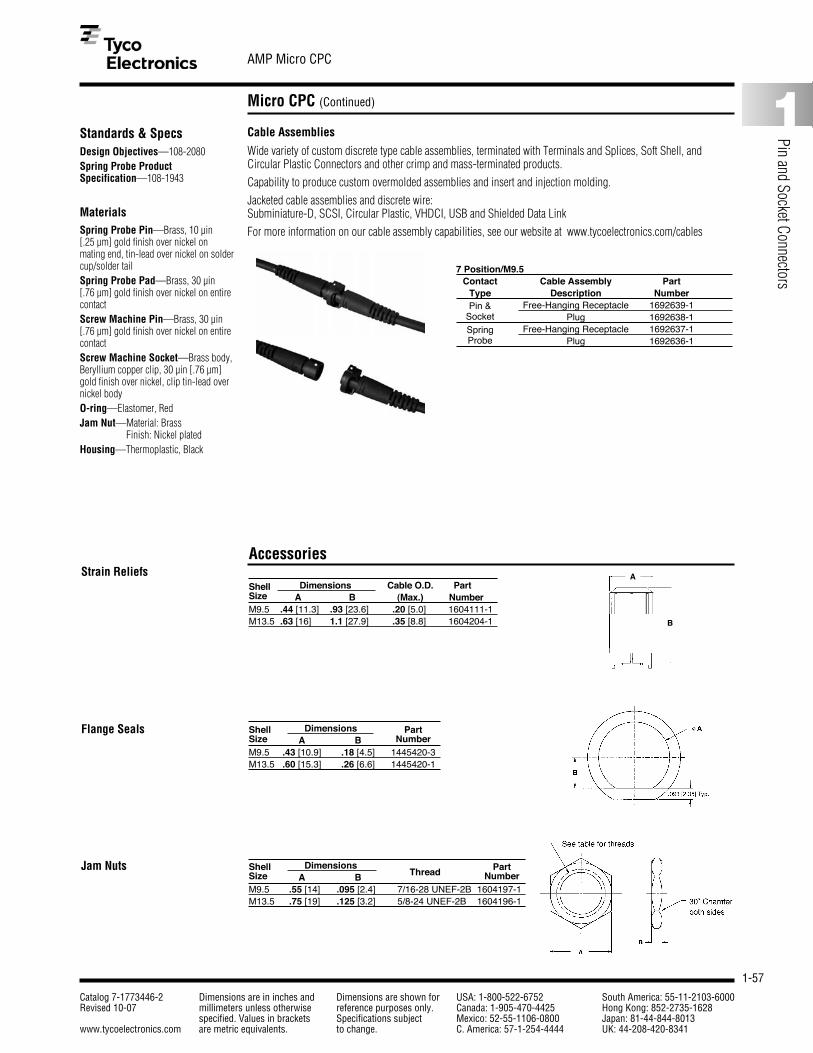
1-57
AMP Micro CPC
Catalog 7-1773446-2 Dimensions are in inches and Dimensions are shown for USA: 1-800-522-6752 South America: 55-11-2103-6000Revised 10-07 millimeters unless otherwise reference purposes only. Canada: 1-905-470-4425 Hong Kong: 852-2735-1628
specified. Values in brackets Specifications subject Mexico: 52-55-1106-0800 Japan: 81-44-844-8013www.tycoelectronics.com are metric equivalents. to change. C. America: 57-1-254-4444 UK: 44-208-420-8341
1
Pin and Socket Connectors
Micro CPC (Continued)
Jam Nuts Shell Dimensions PartSize A B Thread NumberM9.5 .55 [14] .095 [2.4] 7/16-28 UNEF-2B 1604197-1M13.5 .75 [19] .125 [3.2] 5/8-24 UNEF-2B 1604196-1
AccessoriesStrain Reliefs
Shell Dimensions Cable O.D. PartSize A B (Max.) NumberM9.5 .44 [11.3] .93 [23.6] .20 [5.0] 1604111-1M13.5 .63 [16] 1.1 [27.9] .35 [8.8] 1604204-1
Flange Seals Shell Dimensions PartSize A B NumberM9.5 .43 [10.9] .18 [4.5] 1445420-3M13.5 .60 [15.3] .26 [6.6] 1445420-1
A
B
Standards & SpecsDesign Objectives—108-2080Spring Probe ProductSpecification—108-1943
MaterialsSpring Probe Pin—Brass, 10 µin [.25 µm] gold finish over nickel onmating end, tin-lead over nickel on soldercup/solder tailSpring Probe Pad—Brass, 30 µin [.76 µm] gold finish over nickel on entirecontactScrew Machine Pin—Brass, 30 µin[.76 µm] gold finish over nickel on entirecontactScrew Machine Socket—Brass body,Beryllium copper clip, 30 µin [.76 µm]gold finish over nickel, clip tin-lead overnickel bodyO-ring—Elastomer, Red Jam Nut—Material: Brass
Finish: Nickel platedHousing—Thermoplastic, Black
Cable Assemblies
Wide variety of custom discrete type cable assemblies, terminated with Terminals and Splices, Soft Shell, andCircular Plastic Connectors and other crimp and mass-terminated products.Capability to produce custom overmolded assemblies and insert and injection molding.Jacketed cable assemblies and discrete wire: Subminiature-D, SCSI, Circular Plastic, VHDCI, USB and Shielded Data LinkFor more information on our cable assembly capabilities, see our website at www.tycoelectronics.com/cables
7 Position/M9.5Contact Cable Assembly Part
Type Description NumberPin & Free-Hanging Receptacle 1692639-1
Socket Plug 1692638-1Spring Free-Hanging Receptacle 1692637-1Probe Plug 1692636-1

1-58
AMP Micro CPC
Catalog 7-1773446-2 Dimensions are in inches and Dimensions are shown for USA: 1-800-522-6752 South America: 55-11-2103-6000Revised 10-07 millimeters unless otherwise reference purposes only. Canada: 1-905-470-4425 Hong Kong: 852-2735-1628
specified. Values in brackets Specifications subject Mexico: 52-55-1106-0800 Japan: 81-44-844-8013www.tycoelectronics.com are metric equivalents. to change. C. America: 57-1-254-4444 UK: 44-208-420-8341
Micro CPC (Continued)
Shell Size 9.5 mm (7 Position shown)
Plug Assembly, Solder Cup Receptacle Assembly, Flange Mount
Shell Size 13.5 mm (19 Position shown)
Receptacle Assembly, Free-Hanging Solder Tail Receptacle Assembly, Flange Mount
Receptacle Assembly, Free-Hanging Solder Cup Plug Assembly, Solder Cup
Receptacle Assembly, Free-Hanging Solder Cup Receptacle Assembly, Free-Hanging Solder Tail
.482±.014[12.25±0.36]
.246±.010[6.25±0.25] .260
[6.61]REF.
.531±.004[13.5±0.1]
.100±.007[2.55±0.18]19 PLC.
∅.817[20.75]
.417[10.6]
.05[1.25]
.608.014[15.45±0.36]
.169.008[4.3±0.2] 19 Plc.
Jam Nut & Flange Sealshown for reference only.Must be ordered separately.
.531±.004[13.5±0.1]
.482±.014[12.25±0.36]
.260[6.61]REF. .246±.010
[6.25±0.25]
.169±.008[4.3±0.2]19 PLC.
.614±.014[15.6±0.35]
.732±.026[18.6±0.65]
.234±.010[6±0.25]
.291[7.4]
.498[12.65]
.126±.014[3.2±0.35]19 PLC

1-59
AMP Metal-Shell Micro Circular Connectors
Catalog 7-1773446-2 Dimensions are in inches and Dimensions are shown for USA: 1-800-522-6752 South America: 55-11-2103-6000Revised 10-07 millimeters unless otherwise reference purposes only. Canada: 1-905-470-4425 Hong Kong: 852-2735-1628
specified. Values in brackets Specifications subject Mexico: 52-55-1106-0800 Japan: 81-44-844-8013www.tycoelectronics.com are metric equivalents. to change. C. America: 57-1-254-4444 UK: 44-208-420-8341
1
Pin and Socket Connectors
Metal-Shell Micro Circular Connectors
Push/Pull CouplingProduct Facts■ Push to mate, pull to
release coupling mechanism
■ High performance at lowercost
■ High density for limitedspace applications
■ Multiple shell sizes andkeying configurations
■ Resistant to autoclaving(1000 cycles @ 275°F[135°C]) or chemicalsterilization (500 cycles)
■ Precision, screw machinecontacts
■ No assembly or applicationtools required
■ Environmentally sealed(IP67) and shielded
Small, circular connector for Medical and Industrialapplications available in 2 shell sizes M11 (7 pos.)and M14 (19 pos.)
Applications
■ Medical Equipment,Instrumentation, Militaryand Aerospace
■ Rugged industrial environments
■ Outdoor applications
Electrical CharacteristicsCurrent Carrying Capacity — 1 AmpOperating Voltage — 200 VAC max.Termination Resistance — 20 mOhm max.
Mechanical Characteristics■ Push/pull, positive lock coupling■ 500 minimum mating cycles with
screw machine pin and socket contacts■ 5000 minimum mating cycles with
spring probe contacts■ Overmold or heat-shrink tubing for
sealing and strain relievingWire Size — 24–30 AWG [0.2–0.06 mm2]Termination — SolderMax. Operating Temperature —300°F [149°C]
Material and FinishSpring Probe Pin — Brass, 10 µin.[.25 µm] gold finish over nickel on mat-ing end, tin-lead over nickel on soldercup/tailSpring Probe Pad — Brass, 30 µin.[.76 µm] gold finish over nickel onentire contactScrew Machine Pin — Brass, 30 µin.[.76 µm] gold finish over nickel onentire contactScrew Machine Socket — Brass Body — beryllium copper clip, 30 µin. [.76 µm] gold flash over nickelClip — tin-lead over nickel bodyHousing — Nickel plated brassInsulator — High temperature thermo-plastic, white

1-60
AMP Metal-Shell Micro Circular Connectors
Catalog 7-1773446-2 Dimensions are in inches and Dimensions are shown for USA: 1-800-522-6752 South America: 55-11-2103-6000Revised 10-07 millimeters unless otherwise reference purposes only. Canada: 1-905-470-4425 Hong Kong: 852-2735-1628
specified. Values in brackets Specifications subject Mexico: 52-55-1106-0800 Japan: 81-44-844-8013www.tycoelectronics.com are metric equivalents. to change. C. America: 57-1-254-4444 UK: 44-208-420-8341
Metal-Shell Micro Circular Connectors (Continued)
Shell Size M11(7 Position shown)
Shell Size M14(19 Position shown)
Receptacle Assembly, Front Panel Mount, Solder Cup
Receptacle Assembly, Rear Panel Mount, Solder Tail
Plug Assembly
Plug Assembly
Push/Pull Coupling(Continued)
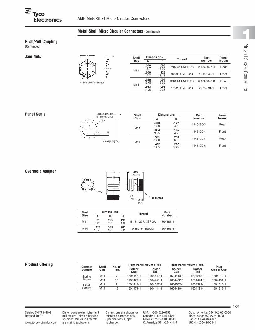
1-61
AMP Metal-Shell Micro Circular Connectors
Catalog 7-1773446-2 Dimensions are in inches and Dimensions are shown for USA: 1-800-522-6752 South America: 55-11-2103-6000Revised 10-07 millimeters unless otherwise reference purposes only. Canada: 1-905-470-4425 Hong Kong: 852-2735-1628
specified. Values in brackets Specifications subject Mexico: 52-55-1106-0800 Japan: 81-44-844-8013www.tycoelectronics.com are metric equivalents. to change. C. America: 57-1-254-4444 UK: 44-208-420-8341
1
Pin and Socket Connectors
Metal-Shell Micro Circular Connectors (Continued)
Front Panel Mount Rcpt. Rear Panel Mount Rcpt.Contact Shell No. of
Solder Solder Solder SolderPlug
System Size Pos.Cup Tail Cup Tail
Solder Cup
Spring M11 7 1604446-1 1604440-1 1604443-1 1604215-1 1604213-1Probe M14 19 1738477-1 1604449-1 1604472-1 1604444-1 1604481-1
Pin & M11 7 1604448-1 1604527-1 1604502-1 1604392-1 1604515-1Socket M14 19 1604471-1 1604441-1 1604480-1 1604131-1 1604512-1
Product Offering
.093 [2.35] Typ.
.125+0.03/-0.02 [3.18+0.78/-0.40]
B
Ø A
Shell Dimensions Part PanelSize A B
Thread Number Mount
.500 .093
M1112.7 2.36 7/16-28 UNEF-2B 2-1532077-4 Rear
.500 .12512.7 3.18 3/8-32 UNEF-2B 1-330249-1 Front
.750 .093
M1419.05 2.36 9/16-24 UNEF-2B 3-1532042-8 Rear
.563 .09314.29 2.36 1/2-28 UNEF-2B 2-329631-1 Front
Jam Nuts
Shell Dimensions Part PanelSize A B Number Mount
.430 .177
M1110.9 4.5 1445420-3 Rear
.364 .1659.25 4.2 1445420-4 Front
.551 .236
M1414.0 6.0 1445420-5 Rear
.492 .20712.5 5.25 1445420-6 Front
Panel Seals
Shell DimensionsThread Part
Size A B C Number
M11 .326 .295 .1938.29 7.5 4.9 5-16 - 32 UNEF-2A 1604366-4
M14 .424 .385 .28310.76 9.8 7.2 0.380-64 Special 1604366-3
Overmold Adapter
Push/Pull Coupling(Continued)

1-62
AMP Metal-Shell Micro Circular Connectors
Catalog 7-1773446-2 Dimensions are in inches and Dimensions are shown for USA: 1-800-522-6752 South America: 55-11-2103-6000Revised 10-07 millimeters unless otherwise reference purposes only. Canada: 1-905-470-4425 Hong Kong: 852-2735-1628
specified. Values in brackets Specifications subject Mexico: 52-55-1106-0800 Japan: 81-44-844-8013www.tycoelectronics.com are metric equivalents. to change. C. America: 57-1-254-4444 UK: 44-208-420-8341
Metal-Shell Micro Circular Connectors with Spring-Loaded Contacts
Small, rugged circular connector for Military andAerospace, Medical andIndustrial, applications in 2 shell sizes M11 (7 pos.)and M14 (19 pos.).
Applications
■ Military & Aerospace
■ Medical Equipment
■ Instrumentation & TestEquipment
■ Portable Computing,Data Management, Communications andSensing Devices
■ Rugged Solution forGigabit Ethernet andUSB 2.0
■ Outdoor Applications
Threaded Coupling Product Facts■ High cycle life spring probe
and pad contact interface—5000+ mating cycles
■ Threaded couplingmechanism
■ High density for limitedspace applications
■ Multiple shell sizes andkeying configurations
■ Resistant to autoclaving(1000 cycles @ 275°F[135°C]) or chemicalsterilization (500 cycles)
■ Jam nut style, rear panelmounting
■ Precision, screw machinecontacts
■ No assembly or applicationtools required
■ Environmentally sealed(IP67) and shielded
■ High performance at lowercost
■ Alternate pin and socketcontact interface available
■ Matte black, low reflectivityfinish
■ Optimized wiring pattern of standard connector configuration — 8 positionEthernet
■ Single piece adapter forshield termination and overmolding
Mechanical Characteristics■ Threaded coupling ■ 5000 minimum mating cycles with
spring probe contacts■ Environmentally sealed, IP 67 -
water immersion, 1M for 30 minutes(in mated condition)
■ Overmold or heat-shrink tubing forsealing and strain relieving
Wire Size — 30–24 AWG [0.06–0.2 mm2] (24 AWG wire is solidor 7-strand only)Termination — SolderMax. Operating Temperature — 392°F [200°C]
Material and FinishSpring Probe Pin — Brass, 10 µin.[.25 µm] gold finish over nickel on mating end, tin-lead over nickel on solder cup/tailSpring Probe Pad — Brass, 30 µin.[.76 µm] gold finish over nickel onentire contactShell — Black chrome plated (Nickelplated brass option)Insulator — High temperature thermo-plastic, white
Standards and SpecificationsDesign Objectives108-2169Spring Probe Product Specification108-1943

1-63
AMP Metal-Shell Micro Circular Connectors
Catalog 7-1773446-2 Dimensions are in inches and Dimensions are shown for USA: 1-800-522-6752 South America: 55-11-2103-6000Revised 10-07 millimeters unless otherwise reference purposes only. Canada: 1-905-470-4425 Hong Kong: 852-2735-1628
specified. Values in brackets Specifications subject Mexico: 52-55-1106-0800 Japan: 81-44-844-8013www.tycoelectronics.com are metric equivalents. to change. C. America: 57-1-254-4444 UK: 44-208-420-8341
1
Pin and Socket Connectors
Metal-Shell Micro Circular Connectors with Spring-Loaded Contacts (Continued)
Electrical CharacteristicsCurrent Carrying Capacity — 2 AMP — UL1.3 AMP — CSAOperating Voltage — 200 VAC max.Termination Resistance — 20 mOhm max.
Eye Pattern (Time Domain Measurement of Voltage vs. Time)Pin and Socket Contact System
Eye Pattern Mask Created per USB 2.0 Specification480 Mb/s Data Rate
Eye Pattern (Time Domain Measurement of Voltage vs. Time)Spring Probe Contact System
Eye Pattern Mask Created per USB 2.0 Specification480 Mb/s Data Rate
Am
plit
ud
e [V
]A
mp
litu
de
[V]
Threaded Coupling(Continued)

1-64
AMP Metal-Shell Micro Circular Connectors
Catalog 7-1773446-2 Dimensions are in inches and Dimensions are shown for USA: 1-800-522-6752 South America: 55-11-2103-6000Revised 10-07 millimeters unless otherwise reference purposes only. Canada: 1-905-470-4425 Hong Kong: 852-2735-1628
specified. Values in brackets Specifications subject Mexico: 52-55-1106-0800 Japan: 81-44-844-8013www.tycoelectronics.com are metric equivalents. to change. C. America: 57-1-254-4444 UK: 44-208-420-8341
Metal-Shell Micro Circular Connectors with Spring-Loaded Contacts (Continued)
Shell Size M11 (7 Position shown)
Receptacle Assembly, Solder Cups
Plug Assembly, Pin Contacts
Receptacle Assembly, Board Mount
Rear Panel MountContact Shell No. of
Solder Cup Solder TailSystem Size Pos.Receptacle Plug Receptacle
SpringM11 7 1604750-2 1738548-2 1811577-1
Probe M14 8* 1877236-1 1877007-1 1877666-1M14 19 1738553-2 1738552-2 1811547-1
Pin & M11 7 1738547-2 1738541-2 1811578-1Socket M14 19 1738551-2 1738550-2 1811579-1
Note: Bright Nickel finish available.*Ethernet configuration
Threaded Coupling(Continued)

1-65
AMP Metal-Shell Micro Circular Connectors
Catalog 7-1773446-2 Dimensions are in inches and Dimensions are shown for USA: 1-800-522-6752 South America: 55-11-2103-6000Revised 10-07 millimeters unless otherwise reference purposes only. Canada: 1-905-470-4425 Hong Kong: 852-2735-1628
specified. Values in brackets Specifications subject Mexico: 52-55-1106-0800 Japan: 81-44-844-8013www.tycoelectronics.com are metric equivalents. to change. C. America: 57-1-254-4444 UK: 44-208-420-8341
1
Pin and Socket Connectors
Metal-Shell Micro Circular Connectors with Spring-Loaded Contacts (Continued)
Shell Size M14 (19 Position shown)
Receptacle Assembly, Solder Cup
Plug Assembly
Receptacle Assembly, Board Mount
Ethernet Assembly, 8 Position
Threaded Coupling(Continued)
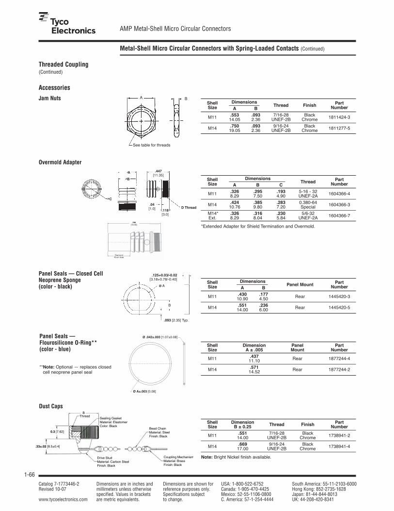
1-66
AMP Metal-Shell Micro Circular Connectors
Catalog 7-1773446-2 Dimensions are in inches and Dimensions are shown for USA: 1-800-522-6752 South America: 55-11-2103-6000Revised 10-07 millimeters unless otherwise reference purposes only. Canada: 1-905-470-4425 Hong Kong: 852-2735-1628
specified. Values in brackets Specifications subject Mexico: 52-55-1106-0800 Japan: 81-44-844-8013www.tycoelectronics.com are metric equivalents. to change. C. America: 57-1-254-4444 UK: 44-208-420-8341
Metal-Shell Micro Circular Connectors with Spring-Loaded Contacts (Continued)
Accessories
.093 [2.35] Typ.
.125+0.03/-0.02 [3.18+0.78/-0.40]
B
Ø AShell Dimensions PartSize A B
Panel Mount Number
M11 .430 .17710.90 4.50 Rear 1445420-3
M14 .551 .23614.00 6.00 Rear 1445420-5
Shell Dimension Panel PartSize A ± .005 Mount Number
M11 .43711.10 Rear 1877244-4
M14 .57114.52 Rear 1877244-2
Shell Dimension Thread Finish Part Size B ± 0.25 Number
M11 .551 7/16-28 Black 14.00 UNEF-2B Chrome 1738941-2
M14 .669 9/16-24 Black 17.00 UNEF-2B Chrome 1738941-4
Note: Bright Nickel finish available.
Shell DimensionsThread Part
Size A B C Number
M11 .326 .295 .193 5-16 - 32 8.29 7.50 4.90 UNEF-2A 1604366-4
M14 .424 .385 .283 0.380-64 10.76 9.80 7.20 Special 1604366-3
M14* .326 .316 .230 5/6-32 Ext. 8.29 8.04 5.84 UNEF-2A 1604366-7
*Extended Adapter for Shield Termination and Overmold.
Shell Dimensions PartSize A B
Thread Finish Number
M11 .553 .093 7/16-28 Black 1811424-314.05 2.36 UNEF-2B Chrome
M14 .750 .093 9/16-24 Black 1811277-519.05 2.36 UNEF-2B Chrome
Jam Nuts
Overmold Adapter
Panel Seals — Flourosilicone O-Ring**(color - blue)
**Note: Optional — replaces closedcell neoprene panel seal
Panel Seals — Closed CellNeoprene Sponge(color - black)
Dust Caps
Threaded Coupling(Continued)

Note: All part numbersare RoHS Compliant.
1-67
AMP Circular Connectors forCommercial Signal and Power Applications
Catalog 7-1773446-2 Dimensions are in inches and Dimensions are shown for USA: 1-800-522-6752 South America: 55-11-2103-6000Revised 10-07 millimeters unless otherwise reference purposes only. Canada: 1-905-470-4425 Hong Kong: 852-2735-1628
specified. Values in brackets Specifications subject Mexico: 52-55-1106-0800 Japan: 81-44-844-8013www.tycoelectronics.com are metric equivalents. to change. C. America: 57-1-254-4444 UK: 44-208-420-8341
1
Pin and Socket Connectors
Introduction
Note: All part numbersare RoHS Compliant.
■ Certified by Canadian Standards Association,File No. LR 7189
■ Certain products meetVDE Standard 062
Six connector series fordifferent interconnectionrequirements:■ Series 1—Standard density,
signal and low-currentapplications using durableMultimate contacts (.062 [1.57]pin diameter)
■ Series 2—High densityapplications using Size 20 DM and 20 DF contacts (.040[1.02] pin diameter)
■ Series 3—Low density, powerapplications with Type XIIcontacts capable of carrying up to35 amperes of current
■ Series 4—Combination ofstandard and power densityapplication with Type III+ andType XII contacts
■ Series 5—Power densityapplication with Size 8 screwmachined and precision formedcontacts
■ Series 6—Combination ofstandard and power densityapplication with Type III+ andSize 8 contacts
Product Facts■ Lightweight, all-plastic and
metal-shell connectors
■ CPC connectors are UL 94V-0 rated and made ofstabilized, heat resistant, self-extinguishing thermoplasticmaterial
■ Metal-shell CPC connectorhousings made of UL 94V-0 ratedthermoplastic
■ Operating temperature range: -40°C to +105°C
■ Available in panel or chassismount and free-hangingconfigurations
■ Quick connect/disconnectcapability with thread assist,positive detent coupling
■ Built-in pin and socket protection
■ Polarized for proper mating ofconnector halves
■ Special connector configurationsoffer special solder and postedcontacts, special receptacleswith or without threaded inserts
■ Full complement of optionalaccessories
■ Recognized under theComponent Program ofUnderwriters Laboratories Inc. for 250 VAC, rms or 250 VDC, Service‡;Series 1 and Series 3 (600 V);Series 4 (600 V) and Series 2, Series 6 (250 V) File No. E28476
‡Select connectors are recognizedfor 600 volts service.
MIL-C-5015 Style CircularPlastic Connectors (CPC)
Product Facts■ Intermateable with Metal-Shell
sizes 20-14 and 18-10, MIL-C-5015 Styleconnectors
■ High impact resistantplastic housing made ofUL 94V-0 rated material
■ Lightweight
■ Lower cost than standard MIL-C-5015 connectors
■ Industry accepted Type III+ pinand socket contacts, availableon reels in strip form for highvolume, low cost, automaticmachine terminations, or inloose piece form for lowvolume, prototype ormaintenance and repair
■ Improved alignment (U.S.Standard MIL-C-5015Connectors) prevents mismatingwith other housing insertarrangements
■ Recognized under theComponent Program ofUnderwriters Laboratories Inc., File No. E28476
■ Certified by Canadian StandardsAssociation,File No. LR 7189
Miniature CPCConnectors
Product Facts■ Compact, high contact density,
environmentally sealedconnectors
■ Uses existing Mini-UniversalMATE-N-LOK stamped andformed pin and socket contacts
■ Two shell sizes—availablein 1 to 4 and 5 to 9 positionconfigurations
R�
R�
R�
R�
■ Produced under a QualityManagement System certifiedto ISO 9001
■ A copy of the certificate is available upon request.
ISO 9001
Certified
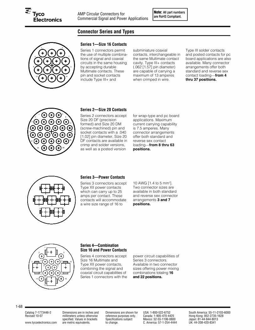
Note: All part numbersare RoHS Compliant.
1-68
AMP Circular Connectors forCommercial Signal and Power Applications
Catalog 7-1773446-2 Dimensions are in inches and Dimensions are shown for USA: 1-800-522-6752 South America: 55-11-2103-6000Revised 10-07 millimeters unless otherwise reference purposes only. Canada: 1-905-470-4425 Hong Kong: 852-2735-1628
specified. Values in brackets Specifications subject Mexico: 52-55-1106-0800 Japan: 81-44-844-8013www.tycoelectronics.com are metric equivalents. to change. C. America: 57-1-254-4444 UK: 44-208-420-8341
Note: All part numbersare RoHS Compliant.
Connector Series and Types
Series 1—Size 16 ContactsSeries 1 connectors permitthe use of multiple combina-tions of signal and coaxialcircuits in the same housingby accepting durableMultimate contacts. Thesepin and socket contactsinclude Type III+ and
Series 2—Size 20 ContactsSeries 2 connectors acceptSize 20 DF (precisionformed) and Size 20 DM(screw-machined) pin andsocket contacts with a .040[1.02] pin diameter, Size 20DF contacts are available incrimp and solder versions,as well as a posted version
Series 3—Power ContactsSeries 3 connectors acceptType XII power contactswhich can carry up to 25amps per contact. Thesecontacts will accommodatea wire size range of 16 to
Series 4—Combination Size 16 and Power ContactsSeries 4 connectors acceptSize 16 Multimate and Type XII power contacts,combining the signal andcoaxial circuit capabilities ofSeries 1 connectors with the
subminiature coaxialcontacts, interchangeable inthe same Multimate contactcavity. Type III+ contacts(.062 [1.57] pin diameter)are capable of carrying amaximum of 13 ampereswhen crimped in wire.
for wrap-type and pc boardapplications. Maximumcurrent carrying capabilityis 7.5 amperes. Manyconnector arrangementsoffer both standard andreverse sex contactloading—from 8 thru 63positions.
10 AWG [1.4 to 5 mm2]. Two connector sizes areavailable in both standardand reverse sex connectorarrangements 3 and 7 positions.
power circuit capabilities ofSeries 3 connectors.Available in two connectorsizes offering power mixingcombinations totaling 16and 22 positions.
Type III solder contacts and posted contacts for pcboard applications are alsoavailable. Many connectorarrangements offer bothstandard and reverse sexcontact loading—from 4thru 37 positions.
1
4
6
12
3
7
11
14
1
9
15
21
26 28
25
20
14
84
3
1 2
3
6
5
7
1
2 3
4 5
6
11
14 16
13
8
107
15

Note: All part numbersare RoHS Compliant.
1-69
AMP Circular Connectors forCommercial Signal and Power Applications
Catalog 7-1773446-2 Dimensions are in inches and Dimensions are shown for USA: 1-800-522-6752 South America: 55-11-2103-6000Revised 10-07 millimeters unless otherwise reference purposes only. Canada: 1-905-470-4425 Hong Kong: 852-2735-1628
specified. Values in brackets Specifications subject Mexico: 52-55-1106-0800 Japan: 81-44-844-8013www.tycoelectronics.com are metric equivalents. to change. C. America: 57-1-254-4444 UK: 44-208-420-8341
1
Pin and Socket Connectors Note: All part numbersare RoHS Compliant.Note: All part numbersare RoHS Compliant.
Connector Series and Types (Continued)
Miniature CPC ConnectorsThese compact connectorsaccept existing Mini-Universal MATE-N-LOK pinand socket contacts, 30-18 AWG [.05-.8 mm2].
Two shell sizes (8 or 11) areavailable, accommodatingfrom 1 to 4 and 5 to 9positions.
Featuring high contactdensity and IP67 sealing,these durable connectorsare well suited for manywire-to-wire, wire-to-board,and wire-to-panelapplications.
Series 5—Power Contacts.125 POWERBANDSeries 5 connectors combinethe revolutionaryperformance of the newAMP POWERBANDContact, high currentcontact in configurationssimilar to the Series 3connectors. AMPPOWERBAND contactsoffer the electrical
Series 6—Combination,Size 16 and .125POWERBAND ContactsSeries 6 combines the highcurrent and environmentalsealing capability of Series 5, POWERBANDcontacts, and the reliabilityof signal carrying, lowcurrent Type III+ contacts.
MIL-C-5015 Style—Size 16ContactsThis new addition to the AMPCircular Plastic Connector Lineis specifically designed to beintermateable with Metal-Shell size 20-14 and 18-10,MIL-C-5015 Style connectorsystems. The high impactresistant plastic housing offersthe advantages of light weight
Metal-Shell, CircularPlastic ConnectorsMetal-Shell CPC connectorsconsist of a blackthermoplastic insert in anickel-plated, zinc alloyshell. These connectors are currently available in
performance of the best MilSpec Size 8 screw-machinedcontacts with the economyand productivity of strip-fed,precision formed contacts.
Series 5 connectors areenvironmentally sealable tomeet IEC IP 65 and IP 67specifications.
This combination of powerand signal contacts isoffered in one connectorconfiguration containingtwo .125 POWERBANDcontacts and eight Type III+ signal pin andsocket contacts.
and lower cost than existingmetal-shell connectors. Inaddition the connector designprevents mismating whenused with other insertarrangements. As part ofthe AMP Multimate family ofconnectors, the MIL-C-5015style connector offers the
shell sizes 14, 22 and 28,and in two basicconfigurations consistingof plugs and squareflange receptacles.
Rated at 600 VAC or VDC,45 amperes maximum ina single contact, theconnectors are available infree-hanging and panel-mount applications—oneconnector configurationcontaining three .125POWERBAND contacts.
economies of crimp Type III+ pin and socketcontacts in reel-mounted,strip-form for high volumeautomatic machinetermination, as well as in loosepiece-form for low volume,prototype or maintenance andrepair.
1 2
3
12
3
89
10

Note: All part numbersare RoHS Compliant.
1-70
AMP Circular Connectors forCommercial Signal and Power Applications
Catalog 7-1773446-2 Dimensions are in inches and Dimensions are shown for USA: 1-800-522-6752 South America: 55-11-2103-6000Revised 10-07 millimeters unless otherwise reference purposes only. Canada: 1-905-470-4425 Hong Kong: 852-2735-1628
specified. Values in brackets Specifications subject Mexico: 52-55-1106-0800 Japan: 81-44-844-8013www.tycoelectronics.com are metric equivalents. to change. C. America: 57-1-254-4444 UK: 44-208-420-8341
Note: All part numbersare RoHS Compliant.
Performance Characteristics — CPC and Metal-Shell CPC Connectors
Note: All part numbersare RoHS Compliant.
More information on theperformance of AMP CPCand metal-shell CPCconnectors is available byrequesting the followingAMP Product Specifications:
108-10024––CPC Connectors108-10037––Type XII Contacts108-10020––Size 20 DM and 20 DFContacts108-10040––Metal-Shell CPCConnectors108-10042––Type III+ Contacts108-1579––Sealed CPC Connectorswith Removeable Contacts
Test Description Procedure RequirementsMaintenance Contacts removed and No damage to contactsAging reinserted 10 times using or housings. Contact
applicable tools retention maintained
Contact Retention Axial load applied to Contacts remain incontact to displace to the place when subjected torear of the connector a minimum 10 lb. load*
Dielectric Withstanding Connectors subjected to No breakdown orVoltage (MIL-STD-1344, 1500 volts rms at sea flashoverMethod 3001) level
Thermal Shock Connectors subjected to No damagefive cycles of temperaturechange (-55°C and +125°C)
Vibration Connectors vibrated No damage or loosening of (MIL-STD-202, (wired and mated). parts. No interruptionMethod 204, Contacts wired in series of electrical continuityTest Condition B) with 100 milliamperes longer than 10 microseconds
flowing during the test
Physical Shock Connectors shocked No damage or loosening(MIL-STD-202, 50 G (wired and mated). of parts. No interruption ofMethod 213A, Contacts wired in series electrical continuity longerTest Condition A) with 100 milliamperes than 10 microseconds
flowing during the test
Durability Connectors mated and No wear throughunmated 25 times with tin damage to platingplated contacts and 500 times with gold plated contacts
Corrosion (Salt Spray) Mated connectors No damage(MIL-STD-202, Method 101, subjected to 5% saltTest Condition B) spray for 48 hours
Protection Against a. Test wire is pushed a. Must not touch live partsSolids into mated connectors b. No dust deposits
b. Mated connectors observed on mating subjected to circulating surfaces talcum powder
Protection Against Water is projected through No water deposits shallWater jets against mated be observed on mating
connector from any direction surfaces of contactsand then temporarily or housingsimmersed in water
Temperature Life Mated connectors No damagesubjected to a temperature of +125°C for 200 hours
Insulation Resistance Measurement made 5000 megohms(MIL-STD-1344, between adjacent contacts minimum ambientMethod 3003) with connector mated temperature
Humidity Mated connectors Minimum insulation(MIL-STD-202, Method 103, subjected to 10 days resistance ofTest Condition B) moisture test 100 megohms
*For size 16 contacts. Size 8 contacts 25 lb. load, min.

Note: All part numbersare RoHS Compliant.
1-71
AMP Circular Connectors forCommercial Signal and Power Applications
Catalog 7-1773446-2 Dimensions are in inches and Dimensions are shown for USA: 1-800-522-6752 South America: 55-11-2103-6000Revised 10-07 millimeters unless otherwise reference purposes only. Canada: 1-905-470-4425 Hong Kong: 852-2735-1628
specified. Values in brackets Specifications subject Mexico: 52-55-1106-0800 Japan: 81-44-844-8013www.tycoelectronics.com are metric equivalents. to change. C. America: 57-1-254-4444 UK: 44-208-420-8341
1
Pin and Socket Connectors Note: All part numbersare RoHS Compliant.Note: All part numbersare RoHS Compliant.
Levels of Protection for Electric Operating Material According to IEC 60529 and IEC 60947, Appendix C
X1Degree of Protection
against ingress of solidforeign objects
X2
Degree of Protectionagainst ingress of water
IP Codes
Environmentally ProtectedCircular Plastic Connectors,for Mated CPC ConnectorsUtilizing Peripheral Sealsand either Wire Entry Seals(for Discrete WireApplications) or HeatShrink Boots (for JacketedCable Applications).Available are VariousSizes, Series 1, 5 and 6.
Degree ofProtection, X1
1
2
3
4
5
6
Protection against ingress ofsolid foreign objects
No Protection
Protection against objects>50mm diameter—
including inadvertentlytouched by hands
Protection against objects>12.5mm—including fingers
Protection against objects>2.5mm diameter including tools
Protection against objects>1.0mm diameter—
including grains
Protection against ingress of solid foreign bodies
Protection against ingress of dust
Degree ofProtection, X2
0
1
2
3
4
5
6
7
Protection againstingress of water
No Protection
Vertical Dripping—Protection against vertical
drops of water
Dripping <15°—Protection against drippingwater when the enclosure is
tilted 15° from vertical
Spraying at an angle upto 60° from vertical
Splashing—Protectionagainst water splashed
from any direction
Jetting—Protection againstwater stream out of a nozzle,
from any direction
Powerful Jetting—Protectionagainst temporary flooding dueto powerful jet streams out ofa nozzle from any direction
Temporary immersion—Protectionagainst temporary immersion
Internal Protection (IP)Definition:■ Per IEC 60947, Appendix C—
Pertains to low voltage switchgear andcontrol gear.
■ Per IEC 60529—Pertains to degreesof protection provided by enclosures(IP code).
Sample Designation:(Where x is a numeral value), i.e. IP 65
IPIndex Letter

Note: All part numbersare RoHS Compliant.
1-72
AMP Circular Connectors forCommercial Signal and Power Applications
Catalog 7-1773446-2 Dimensions are in inches and Dimensions are shown for USA: 1-800-522-6752 South America: 55-11-2103-6000Revised 10-07 millimeters unless otherwise reference purposes only. Canada: 1-905-470-4425 Hong Kong: 852-2735-1628
specified. Values in brackets Specifications subject Mexico: 52-55-1106-0800 Japan: 81-44-844-8013www.tycoelectronics.com are metric equivalents. to change. C. America: 57-1-254-4444 UK: 44-208-420-8341
Note: All part numbersare RoHS Compliant.
Current Carrying Capabilities
Note: All part numbersare RoHS Compliant.
The total current capacity ofeach contact in a givenconnector is dependent uponthe heat rise resulting from thecombination of electrical loadsof the contacts in the connectorarrangement and the maximumambient temperature in whichthe connector will be operating.Caution must be taken so thatthis combination of conditionsdoes not cause the internaltemperature of the connector toexceed the maximum operatingtemperature of the housingmaterial. Several variableswhich must be consideredwhen determining thismaximum current capability foryour application are:
■ Wire Size—Larger wire willcarry more current since ithas less internal resistance to current flow and generatesless heat. The wire alsoconducts heat away from theconnector.
■ Connector Size—In general,with more circuits in aconnector, less current percontact can be carried.
■ Current Load Distribution—Spreading those lines withgreater current loads through-out the connector, particularlyaround the outer perimeter,will enhance heat dissipation.
■ Ambient Temperature—Withhigher ambient temperatures,less current can be carried.
Current Rating VerificationCan a contact rated at 10 ampscarry 10 amps?Maybe yes, but probably not.The reason lies in the testconditions used to rate thecontact. If these conditions donot adequately reflect the appli-cation conditions, the actualallowable current levels may belower than specified levels. Forexample, many manufacturers,including Tyco Electronics, testa single contact in air. Thisgives an accurate measure ofthe basic current-carryingcapacity of the contact. Use thecontact alone in air and it cancertainly carry 10 ampere. Useit in a multi-position connectorsurrounded by other current-carrying contacts or in highambient temperatures, and thecontact should carry lesscurrent.
Similarly, as the contact agesand stress relaxation, environ-mental cycling, and otherdegradation factors take theirtoll, the contact’s current-carrying capacity decreases.A prudent design must setcurrent levels for such end-of-
design-life (EODL) conditions.Practical current-carrying capac-ity is not an absolute, but anapplication-dependent condition.
New Method Simplifies RatingsTo help the designer set theappropriate current level, TycoElectronics has developed amethod of specifying current-carrying capacity. This methodtakes into account the variousapplication factors that influ-ence current rating.
The method can be summarized as follows:■ The contact is aged to EODL
conditions by durabilitycycling, thermal cycling, andenvironmental exposure.
■ The contact’s resistancestability is verified.
■ The current necessary toproduce the specified tempera-ture rise is measured. This T-rise is usually 30°C.
■ A rating factor is determinedto allow derating of multiplecontacts in the same housingand for different conductorsizes.
TemperatureOne other factor influencingcurrent levels is the maximumoperating temperature, forexample, 105°C. If the appli-cation has a high ambienttemperature (over 75°C) thecontact’s T-rise is limited bythe maximum operatingtemperature. For example, anapplication temperature of90°C limits the contact T-riseto 15°C. Since currentproduces heat (the I2R law), thecurrent must be lowered tolimit the T-rise.
A contact’s T-rise depends notonly on its I2R Joule heating, but also on its ability to dissipatethe heat. Consider a contact ina multi-contact housing. Jouleheating in multiple contacts willraise the local ambient temper-ature. Since the contact will notbe able to dissipate its ownheat as well by convection, themaximum T-rise will be realizedat a lower current level. Conse-quently, the allowable currentlevel must be lower to maintainan acceptable T-rise.
For a given connector, thecurrent level will be set by the
loading density. A connectorcontaining 50% current-carryingcontacts will permit highercurrents (per contact) than aconnector will at 75% loading.The loading percentage assumesan even distribution of contactswithin the housing. If all 10contacts are grouped together inone section of a 20-positionconnector, the loading densitymay approach 100%.
The Importance of EODLAs stated, T-rise in a contactdepends on both resistance andcurrent. As it ages, a contact’sresistance will increase. Thecontact designer will specify amaximum resistance for thecontact, this level is the end-of-design-life resistance. Beforethe contact is tested for current,Tyco Electronics subjects it to asequence of tests that exercisesthe major failure mechanismsand thereby simulates EODLconditions. Conditioningincludes mating cycling, indus-trial mixed-flowing gases,humidity and temperaturecycling, and vibration tosequentially introduce wear,corrosion, stress relaxation,and mechanical disturbance.
75
6056
50
45
35
23
7.5
60
45
30
15
0
Type XII Upgrade
Size 8 Upgrade
.125 POWERBAND Contact
Size 8
Type XII
Type I, Type II/III+Upgrade
Type III+, Type II, Type III+ Posted
Size 20 Upgrade
20 DF
CONTACT CURRENT GUIDE Maximum Current (Amperes) for Largest Wire Size
1311.85

Note: All part numbersare RoHS Compliant.
1-73
AMP Circular Connectors forCommercial Signal and Power Applications
Catalog 7-1773446-2 Dimensions are in inches and Dimensions are shown for USA: 1-800-522-6752 South America: 55-11-2103-6000Revised 10-07 millimeters unless otherwise reference purposes only. Canada: 1-905-470-4425 Hong Kong: 852-2735-1628
specified. Values in brackets Specifications subject Mexico: 52-55-1106-0800 Japan: 81-44-844-8013www.tycoelectronics.com are metric equivalents. to change. C. America: 57-1-254-4444 UK: 44-208-420-8341
1
Pin and Socket Connectors Note: All part numbersare RoHS Compliant.
Presentation — An Example*
Note: All part numbersare RoHS Compliant.
The presentation of current-carrying capacity in AMP product specifications includestwo parts:
■ First, a base curve showingcurrent levels versus T-rise fora single circuit and the largestwire size (See figure 1). Thisrepresents the maximumcurrent capacity of thecontact. The curve is usuallyflat up to 75°C ambient andthen drops off. Up to 75°C, the30°C T-rise limits the amountof current, and above 75°Cthe current must be reducedto keep the combination ofambient temperature and T-rise from exceeding themaximum operating tempera-ture of 105°C.
■ Next are rating factors, atable of multipliers to accountfor connector loading and forsmaller wire sizes (See figure 2).The designer first determinesthe base current for theambient conditions of theapplication; then multipliesthis base current by the ratingfactors to find the currentlevel for the application’sloading factor and wire size.
Graph shows the relationship between base current, ambient temperature, and contact T-rise.
Figure 1
Rating factors allow the base current to be adjusted for various connector loading and wire sizes.
Practical ValuesThe current-rating methodgives designers practicalvalues applicable to their appli-cations. While the specifiedcurrent levels for a contact maybe lower than for other testingmethods, they are more practi-cal and simplify the systemdesign process.“Spec-manship” is replacedby a realistic assessment of thecurrent-carrying capacity of acontact under varying condi-tions of temperature, connectorloading, and wire size.Specific current-carrying databased on EOL and % loading isavailable from Tyco Electronics.Please contact your local Tyco Electronics Sales Engineeror call Tyco Electronics.
Connector/Contact AcceptabilityAs previously stated, choosingthe correct connector/contactcombination is fundamentalto the successful function ofall connectors. The SelectorChart shown at right, isdesigned to simplify your choice
*Note: Data is not typical of aspecific CPC connector configu-ration. For specific current rating information based on %connector loading, contact Tyco Electronics.
To demonstrate the method ofspecifying current, consider thefollowing application conditions;an ambient temperature of 65°C,a 50% loading of contacts inthe housing, and 20 AWG[0.6mm2] wire.
■ From Figure 1, the basecurrent rating is 14 amperewith 18 AWG [0.8mm2] wire.
■ Figure 2, the rating factor for50% loading and 20 AWG[0.6mm2] wire is 0.68.
■ The specific rating for thisapplication is the product ofthe base rating and the ratingfactor:
14 x 0.68 = 9.5 ampere
■ Each of the contacts cancarry 9.5 ampere.
■ However, if the ambient temper-ature is 80°C the allowable T-rise becomes 25°C. The basecurrent must be lowered to 12.8 ampere so that the 105°Cmaximum operating tempera-ture is not exceeded. Thecurrent rating then becomes:
12.8 x 0.68 = 8.7 ampere.
Connector Posted Sub-Mini POWERBANDType 20 DF Type I Type II Type III+ Type III+ Type XII Coax Contacts
CPC Series 1 ✔ ✔ ✔ ✔
CPC Series 2 ✔
CPC Series 3 ✔
CPC Series 4 ✔ ✔ ✔ ✔
CPC Series 5 ✔
CPC Series 6 ✔ ✔ ✔ ✔
CPC 5015 ✔
CMC Series 1 ✔ ✔ ✔ ✔
CMC Series 2 ✔
CMC Series 3 ✔
CMC Series 4 ✔ ✔ ✔ ✔
18 20 22 24 26
Single 1 .83 .69 .59 .50
30% .97 .80 .66 .57 .49
50% .83 .68 .57 .48 .42
70% .65 .53 .45 .38 .33
100% .55 .45 .38 .32 .28
AWG%
Lo
adin
g
Figure 2
Contact Selector Chart
Current Rating
0� �10� �20� �30� �40� �50� �60� �70� �80� �90� �100� �0�
5
10�
15�
Single Contact�18 AWG
Ambient Temperature (°C)
Cu
rren
t R
atin
g (
Am
per
es)
of connectors and their accept-able contacts. Once you haveselected the wire size, current-carrying capacity need,number of positions required,and the type of contactsneeded in your choice ofconnector, refer to this matrixfor a quick look at exactly whatis acceptable in a givenconnector type.

Note: All part numbersare RoHS Compliant.
1-74
AMP Circular Connectors forCommercial Signal and Power Applications
Catalog 7-1773446-2 Dimensions are in inches and Dimensions are shown for USA: 1-800-522-6752 South America: 55-11-2103-6000Revised 10-07 millimeters unless otherwise reference purposes only. Canada: 1-905-470-4425 Hong Kong: 852-2735-1628
specified. Values in brackets Specifications subject Mexico: 52-55-1106-0800 Japan: 81-44-844-8013www.tycoelectronics.com are metric equivalents. to change. C. America: 57-1-254-4444 UK: 44-208-420-8341
Circular Plastic Connectors, Size 1
CPC Connectors, Series 1for Cable or Panel Mount(Accepts Type III+, High-Current Power, Type II andSubminiature CoaxContacts)
Listed part numbers are forconnectors only; contactsmust be ordered separately.
MaterialHousing—Thermoplastic, 94V-0 rated,black
Replacement Coupling RingsShell Size Part No.
11 213811-113 213813-117 213810-123 213812-1
*M Max.
*N Max.
*Thread Size(See chart)
*J Dia.
Panel Cutout
*L Max.
*KMax.
Free-Hanging Receptacle
*Panel Thk..125[3.18] Max.
*EMax.
*AMax.
*Thread Size(See chart)
*Thread Size(See chart)
*E Max.
Standard Sex Connectors (Receptacles accept pin contacts, Plugs accept socket contacts)
Square Flange ReceptacleFree-Hanging
Arrangement Keying With Threaded With Mounting ReceptaclePlugShell No. of
Inserts1 HolesSize Positions
11-4 A 208130-1 206061-1 206153-1 206060-113-9 A 208131-1 206705-1 206705-2 206708-1
17-16A 206036-8 206036-1 206036-3 206037-1B — 213862-1 — 213849-1
23-24A 211839-1 206838-1 206838-2 206837-1B — 213866-1 — 213851-1
23-37A 787610-1 206151-1 206151-2 206150-1B — 213860-1 — 213848-1
Reverse Sex Connectors (Receptacles accept socket contacts, Plugs accept pin contacts)
Square Flange ReceptacleFree-Hanging
Arrangement Keying With Threaded With Mounting ReceptaclePlugShell No. of
Inserts1 HolesSize Positions
11-4 A 211102-1 206430-1 206430-2 206429-1
17-14A 211103-1 206043-1 206043-3 206044-1B — 796437-2 — 796449-1
23-37A 206306-5 206306-1 206306-2 206305-1B — 213864-1 — 213850-1
1Four 4-40 threaded inserts per receptacle.Key Style “A” is the Standard 5 Locating Key arrangement. Key Style “B” is the 4 Locating Key arrangement.
*Note:See page 1-89 for callout dimensions
1Four 4-40 threaded inserts per receptacle.
KeyingMolded-in keying in two configurations:
A—Standard Configuration: 5 Keys
B—Optional Configuration: 4 Keys toprevent mismating of standard andreverse sex.
*D ±.010[±0.25]
*D ±.010[±0.25]
*H +.007–.000[+0.18]
Dia.
*B ±.015[±0.38]
*C ±.010[±0.25]
*G ±.025[±0.64]
*F ±.010[±0.25]
*F ±.010[±0.25]
Plug
Square Flange Receptacle
*AMax.
*B ±.015[±0.38]
*C ±.010[±0.25]

Note: All part numbersare RoHS Compliant.
1-75
AMP Circular Connectors forCommercial Signal and Power Applications
Catalog 7-1773446-2 Dimensions are in inches and Dimensions are shown for USA: 1-800-522-6752 South America: 55-11-2103-6000Revised 10-07 millimeters unless otherwise reference purposes only. Canada: 1-905-470-4425 Hong Kong: 852-2735-1628
specified. Values in brackets Specifications subject Mexico: 52-55-1106-0800 Japan: 81-44-844-8013www.tycoelectronics.com are metric equivalents. to change. C. America: 57-1-254-4444 UK: 44-208-420-8341
1
Pin and Socket Connectors
Standard Sex Connectors (Receptacles accept pin contacts, Plugs accept socket contacts)
Arrangement Square Flange ReceptacleShell No. of Keying With Threaded With Mounting PlugSize Positions Inserts1 Holes
13-7 A 211401-4 211401-1 211399-117-9 A 211767-2 211767-1 211766-1
23-19A 211771-2 211771-1 211770-2B — 213870-1 213853-1
Reverse Sex Connectors (Receptacles accept socket contacts, Plugs accept pin contacts)
Arrangement Square Flange ReceptacleFree-Hanging
Shell No. of Keying With Threaded With Mounting Receptacle PlugSize Positions Inserts1 Holes
13-7 A 211398-4 211398-1 211398-2 211400-1
17-9A — 211769-1 211769-3 211768-1B — 796439-2 — 796450-1
23-19A — 211773-1 — 211772-1B — 213868-1 — 213852-1
1Four 4-40 threaded inserts per receptacle.Key Style “A” is the Standard 5 Locating Key arrangement. Key Style “B” is the 4 Locating Key arrangement.
Circular Plastic Connectors, Series 1, VDE Tested
KeyingA—Standard Configuration: 5 KeysB—Optional Configuration: 4 Keys
CPC Connectors, Series 1,for Cable or Panel Mount(Accepts Type III+, High-Current Power, Type II andSubminiature CoaxContacts)
■ Designed to meetrequirements of VDE asshown in DINSpecification 57627
■ Recognized under theComponent Program ofUnderwritersLaboratories Inc. for 600 VAC and 600 VDC service, File No. E28476
■ Certified by Canadian StandardsAssociation, File No. LR 7189
Listed part numbers are forconnectors only; contactsmust be ordered separately.
MaterialHousing—Thermoplastic, 94V-0 rated,black
Replacement Coupling RingsShell Size Part No.
13 213813-117 213810-123 213812-1
R�
R� Plug*M Max.
*N Max.
*Thread Size(See chart)
*J Dia.
Panel Cutout
*L Max.
*KMax.
Free-Hanging Receptacle
*Panel Thk..125[3.18] Max.
*E Max.
*AMax.
*AMax.
*Thread Size(See chart)
*Thread Size(See chart)
*E Max.
*Note:See page 1-89 for callout dimensions
*D ±.010[±0.25]
*B ±.015[±0.38]
*B ±.015[±0.38]
*C ±.010[±0.25]
*C ±.010[±0.25]
*D ±.010[±0.25]
*G ±.025[±0.64]
*F ±.010[±0.25]
*F ±.010[±0.25]
*H +.007–.000[+0.18]
Dia.
1Four 4-40 threaded inserts per receptacle.
Square Flange Receptacle

Note: All part numbersare RoHS Compliant.
1-76
AMP Circular Connectors forCommercial Signal and Power Applications
Catalog 7-1773446-2 Dimensions are in inches and Dimensions are shown for USA: 1-800-522-6752 South America: 55-11-2103-6000Revised 10-07 millimeters unless otherwise reference purposes only. Canada: 1-905-470-4425 Hong Kong: 852-2735-1628
specified. Values in brackets Specifications subject Mexico: 52-55-1106-0800 Japan: 81-44-844-8013www.tycoelectronics.com are metric equivalents. to change. C. America: 57-1-254-4444 UK: 44-208-420-8341
Circular Plastic Connectors, Series 1
Standard Sex (Posted Pin Contacts)Receptacle Assemblies Dimensions ContactArrangement
Mounting 4-40 ThreadedKeying
A BFinish Peripheral
No.Holes Inserts
Style Code Seal
11-4 — 207825-9 .119 .816 A NA 3.02 20.73
13-7 — 1-796433-1 .220 .816 A NA 5.59 20.73
208223-9 — .220 .816 A N13-9
A 5.59 20.73
— 1-208223-0 .220 .816 A NA 5.59 20.73— 1-207303-4 .220 .816 A
N17-16
1-207303-5 — A 5.59 20.73 C1-207303-3 — A .220 .816 A N213855-4 213855-3 B 5.59 20.73
213782-4 — .429 .679 A NA 10.90 17.2423-19
213859-2 — .618 .674 A NB 15.70 17.12
— 213588-2 .220 .654 C NA 5.59 16.61
213798-3 — .618 .679 A NA 15.70 17.2423-24
213780-2 — .220 .654 A NA 5.59 16.61
213857-2 — .429 .679 A NB 10.90 17.24
1-206934-1 — .220 .654 A NA 5.59 16.61206934-5 — .119 .654 A N
— 1-206934-7 A 3.02 16.61 Y
23-37 208132-2 — A.429 .654
C1-206934-8 — A A N213854-3 — B
10.90 16.61A
1-206934-9 — .618 .654 A NA 15.70 16.61
Note: Posts are .017 [0.43] offset from centerline of contacts. All posts must be oriented in the same plane for propercontact/post location.
Square FlangeReceptacles, PrintedCircuit Board Mountwith .025 [0.64] sq. solder tails
Material and FinishHousing—Thermoplastic, 94V-0 rated,blackContacts—A—Duplex plated gold flash on entirecontact with .000030 [0.00076] min.gold on contact engagement area, tin onthe termination areaC—Plated tin on the entire contact, tinon the termination area
Other Available PostedContacts
Tyco Electronics can makeavailable contacts withvarious solder tail lengthsfor loading into the standardor reverse sex, squareflange receptacles forapplications requiringcustom solder tail lengths.
.150[3.81]
Dia.
4 Holes
1.125±.010
[28.58±0.25]Typ.
1.435±.015
[36.45±0.38]
1.125±.010
[28.58±0.25]Typ.
.420±.015
[10.67±0.38]
.094[2.39]
1.050±.010
[26.67±0.25]Dia.
.125[3.18]
Max.
Panel Thk.
A
B
KeyingMolded-in keying in two configurations:
A—Standard Configuration: 5 Keys
B—Optional Configuration: 4 Keys toprevent mismating of standard andreverse sex.
1.435±.015
[36.45±0.38]
.119�[3.02]
Min.
.618�[15.70]
Max.

Note: All part numbersare RoHS Compliant.
1-77
AMP Circular Connectors forCommercial Signal and Power Applications
Catalog 7-1773446-2 Dimensions are in inches and Dimensions are shown for USA: 1-800-522-6752 South America: 55-11-2103-6000Revised 10-07 millimeters unless otherwise reference purposes only. Canada: 1-905-470-4425 Hong Kong: 852-2735-1628
specified. Values in brackets Specifications subject Mexico: 52-55-1106-0800 Japan: 81-44-844-8013www.tycoelectronics.com are metric equivalents. to change. C. America: 57-1-254-4444 UK: 44-208-420-8341
1
Pin and Socket Connectors
Circular Plastic Connectors, Series 1 (Continued)
Special CPC Connectors,Square Flange Receptacles, Printed Circuit Board MountWith Round Posted Contacts(Size 16), ContactArrangement 17-16
Material and FinishHousing—Thermoplastic, 94V-0 rated,heat-stabilized, fire-resistant, self-extinguishing, blackContacts—BrassPlating—Connector Part No. 207292-1—Plated tin over .000050 [0.00127] min.nickel on entire contact Connector Part No. 207292-2—Plated .000030 [0.00076] min. goldover .000050 [0.00127] min. nickel onentire contactNotes: 1. Connector can be used for
pressure bulkhead feed-thru (sealed) applications.
Notes: 2. Receptacle is StandardSex, supplied preloadedwith 16 special roundposted pin contacts,.030 [0.76] diameter.
Reverse Sex (Posted Socket Contacts)Receptacle Assemblies Dimensions ContactArrangement
Mounting 4-40 ThreadedKeying
A BFinish Peripheral
No.Holes Inserts
Style Code Seal
208283-4 — A .159 .536 A N4.04 13.6111-4
1-788130-1 — A .704 .541 C N17.88 13.74
17-9 1-213826-1 — A .220 .536 C Y5.59 13.61
213729-9 213729-6 A .368 .536 A N9.35 13.61
17-14 1-213825-7 — A .220 .536 C Y5.59 13.61
— 213729-8 A .159 .536 C N4.04 13.61
213858-3 — B .645 .394 A N16.38 10.00
23-19 213781-9 — A .557 .374 C N14.15 9.50
213827-8 — A .368 .374 C Y9.35 9.502-208224-1 — A .557 .374 A N213856-4 — B 14.15 9.50
1-208224-2 — A .368 .374 C N23-37 9.35 9.50
1-213828-6 — A .368 .374 C Y9.35 9.50
207890-2 — A .159 .374 A N4.04 9.50
Note: Posts are .017 [0.43] offset from centerline of contacts. All posts must be oriented in the same plane for propercontact/post location.
Square FlangeReceptacles, PrintedCircuit Board Mountwith .025 [0.64] sq. solder tails
Material and FinishHousing—Thermoplastic, 94V-0 rated,blackContacts—A—Duplex plated gold flash on entirecontact with .000030 [0.00076] min.gold on contact engagement area, tin onthe termination areaC—Plated tin on the entire contact, tinon the termination area
1.435±.015[36.45±0.38]
1.125±.005[28.58±0.13]
1.435±.015[36.45±0.38]
1.125±.005[28.58±0.13]
1.110[28.19]
Max. Dia.
.125[3.18]Max.Thk.
Panel
B
1.050±.005[26.67±0.13]
Dia.
±.030 A [±0.76] Typ.
.094±.005[2.39±0.13]
.420±.005[10.67±0.13]
1.050[26.67]

Note: All part numbersare RoHS Compliant.
1-78
AMP Circular Connectors forCommercial Signal and Power Applications
Catalog 7-1773446-2 Dimensions are in inches and Dimensions are shown for USA: 1-800-522-6752 South America: 55-11-2103-6000Revised 10-07 millimeters unless otherwise reference purposes only. Canada: 1-905-470-4425 Hong Kong: 852-2735-1628
specified. Values in brackets Specifications subject Mexico: 52-55-1106-0800 Japan: 81-44-844-8013www.tycoelectronics.com are metric equivalents. to change. C. America: 57-1-254-4444 UK: 44-208-420-8341
Circular Plastic Connectors, Series 1 (Continued)
Special CPC Connectors,Feed-ThruPressure Rating up to 30 psi
Material and FinishHousing—Thermoplastic, 94V-0 rated,blackContacts—Copper alloy, gold overnickel plated
ArrangementStandard Reverse
Numbering Numbering Feed-ThruPlug Plug Receptacle
11-4 206060-1 206516-1 206518-217-16 206037-1 206554-1 206552-1
H Max.
J Max.
Thread Size(See Chart)
Note: Feed-Thru Receptacles arefully loaded with Size 16,feed-thru pin contacts. OrderSize 16 crimp, snap-in socketcontacts for plugs separately.
ArrangementDimensions Thread
A B C D E F G H J Size
11-4 1.209 .687 .094 .844 1.125 .125 .840 1.080 .975 5/8-2430.71 17.45 2.39 21.44 28.58 3.18 21.34 27.43 24.77 UNEF-2A
17-16 1.209 1.050 .094 1.125 1.435 .150 1.210 1.080 1.349 15/16-2030.71 26.67 2.39 28.58 36.45 3.81 30.73 27.43 34.26 UNEF-2A
Receptacle, Feed-Thru
Plug
Part Numbers
Dimensions
Panel Thk..125[3.18]
Max.
G Dia.
F Dia.(4 Holes)
A Max.
Pin Both Sides
B .010[0.25]
C .010[0.25]
D .010[0.25]
E .025[0.64]
Panel Cutout
Special CPC Connectors,Square Flange Receptacles,With Solder Type Contacts(Size 16), ContactArrangement 17-16
Notes: 1. Connector can be used forpressure bulkhead feed-thru (sealed) applications.
Notes: 2. Receptacle is standardsex, supplied preloadedwith 16 special solder cuppin contacts.
Material and FinishHousing—Thermoplastic, 94V-0 rated,heat-stabilized, fire-resistant, self-extinguishing, blackContacts—BrassPlating—Connector Part No. 206404-1—Plated .000030 [0.00076] min. gold over.000030 [0.00076] min. nickel on entirecontactConnector Part No. 206404-2—Plated tin over .000100 [0.00254] min.copper on entire contact
.250±.015
[6.35±0.38]
.420±.015
[10.67±0.38]
.094±.010
[2.39±0.25]
1.090±.010
[27.69±0.25] Dia.
.156[3.96]
Solder CupContact
Panel Thk..125[3.18]
Max.
1.050±.010
[26.67±0.25] Dia.

Note: All part numbersare RoHS Compliant.
1-79
AMP Circular Connectors forCommercial Signal and Power Applications
Catalog 7-1773446-2 Dimensions are in inches and Dimensions are shown for USA: 1-800-522-6752 South America: 55-11-2103-6000Revised 10-07 millimeters unless otherwise reference purposes only. Canada: 1-905-470-4425 Hong Kong: 852-2735-1628
specified. Values in brackets Specifications subject Mexico: 52-55-1106-0800 Japan: 81-44-844-8013www.tycoelectronics.com are metric equivalents. to change. C. America: 57-1-254-4444 UK: 44-208-420-8341
1
Pin and Socket Connectors
Circular Plastic Connectors, Series 1 (Continued)Square Flange Receptacles,Right-Angle, Postedwith .025 [0.64] sq. solder tails
Material and FinishHousing—Thermoplastic, 94V-0 rated,blackLocation Wafer—Phenolic, blackContact Posts—.000100 [0.00254]min. tin over .000100 [0.00254] min.copperContact Body—A—.000100 [0.00254] min. tin over.000050 [0.00127] min. nickelB—.000030 [0.000762] min. gold for alength of .200 [5.08] min. from matingend, with remainder gold flash, bothover .000050 [0.00127] min. nickel
Standard Sex (Posted Pin Contacts)
ArrangementReceptacle Assemblies
Contact BodyMounting 4-40 Threaded Finish CodeMating Plug
No. Holes Inserts Part No.
11-4 1-796403-1 1-796403-2 B 206060-113-7 1-796435-1 1-796435-2 B 211399-113-9 1-796375-1 1-796375-2 B 206708-117-9 1-796497-1 — B 211766-117-16 1-796404-1 — B 206037-123-19 1-796405-1 — B 211770-2
23-24 1-796387-1 — A 206837-11-796387-2 — B
23-37 1-796406-1 — B 206150-1
Reverse Sex (Posted Socket Contacts)
ArrangementReceptacle Assemblies
Contact BodyMounting 4-40 Threaded Finish CodeMating Plug
No. Holes Inserts Part No.
11-4 1-796407-1 — B 206429-113-7 1-796500-1 — B 211400-117-9 1-796501-1 — B 211768-1
17-14 (shown) 796348-3 — A 206044-1796348-2 — B
23-19 1-796502-1 — B 211772-123-37 1-796409-1 — B 206305-1
*A Max.
*C*B
*D Max. *E Max.
.125[3.18] Max.
Thk. Panel.025[0.64]
Sq.
Post Typ. Contact
Location Wafer
*G
*F
4 Holes
.150[3.81]
*F
*H Dia.
*J Dia.
Panel Cutout
*Note:See page 1-89 for callout dimensions
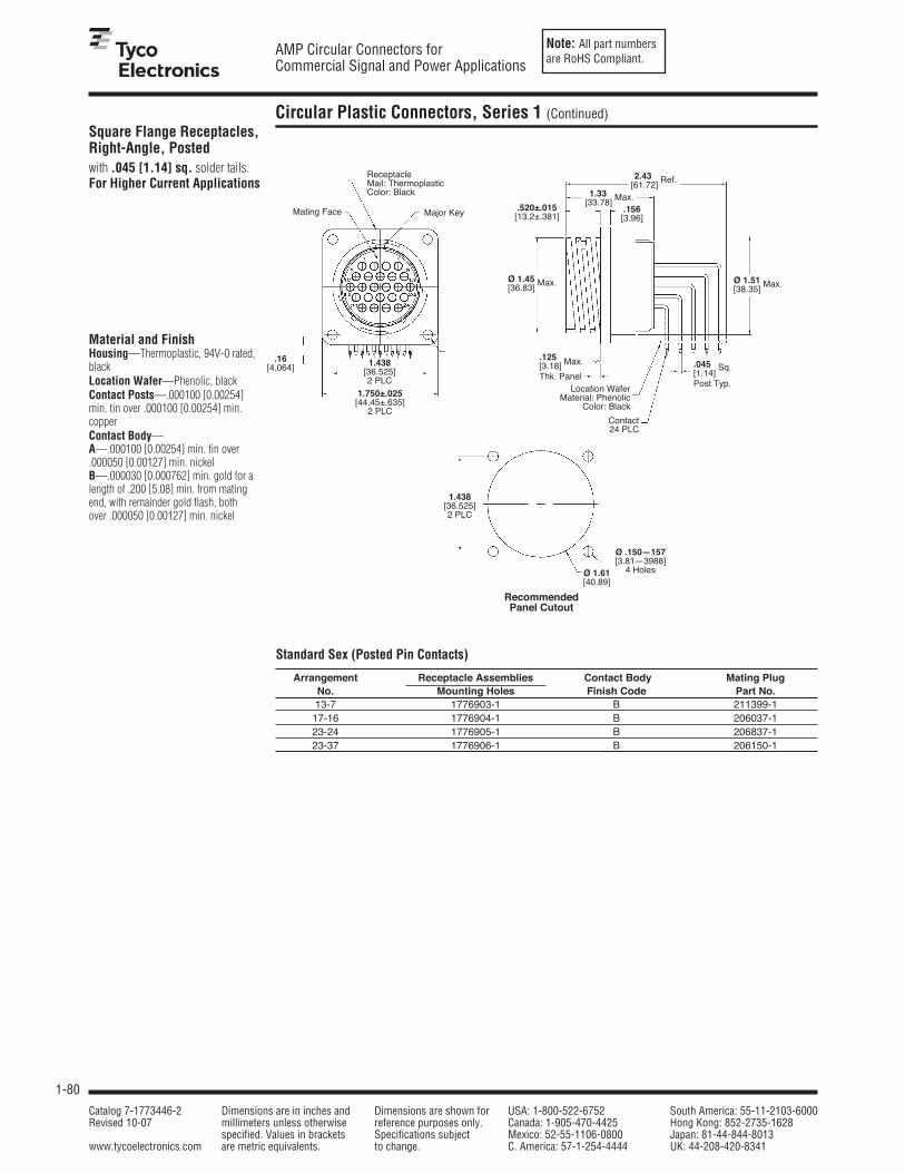
Note: All part numbersare RoHS Compliant.
1-80
AMP Circular Connectors forCommercial Signal and Power Applications
Catalog 7-1773446-2 Dimensions are in inches and Dimensions are shown for USA: 1-800-522-6752 South America: 55-11-2103-6000Revised 10-07 millimeters unless otherwise reference purposes only. Canada: 1-905-470-4425 Hong Kong: 852-2735-1628
specified. Values in brackets Specifications subject Mexico: 52-55-1106-0800 Japan: 81-44-844-8013www.tycoelectronics.com are metric equivalents. to change. C. America: 57-1-254-4444 UK: 44-208-420-8341
Circular Plastic Connectors, Series 1 (Continued)
Material and FinishHousing—Thermoplastic, 94V-0 rated,blackLocation Wafer—Phenolic, blackContact Posts—.000100 [0.00254]min. tin over .000100 [0.00254] min.copperContact Body—A—.000100 [0.00254] min. tin over.000050 [0.00127] min. nickelB—.000030 [0.000762] min. gold for alength of .200 [5.08] min. from matingend, with remainder gold flash, bothover .000050 [0.00127] min. nickel
Square Flange Receptacles,Right-Angle, Postedwith .045 [1.14] sq. solder tails.For Higher Current Applications
Standard Sex (Posted Pin Contacts)
Arrangement Receptacle Assemblies Contact Body Mating PlugNo. Mounting Holes Finish Code Part No.13-7 1776903-1 B 211399-117-16 1776904-1 B 206037-123-24 1776905-1 B 206837-123-37 1776906-1 B 206150-1
.125[3.18] Max.
Thk. Panel.045[1.14]
Sq.
Post Typ.
Ø .150—157[3.81—3988]
4 Holes
.16[4.064]
RecommendedPanel Cutout
Mating Face
ReceptacleMail: ThermoplasticColor: Black
Major Key
1.438[36.525]2 PLC
1.750±.025[44.45±.635]
2 PLC
Location WaferMaterial: Phenolic
Color: Black
Contact24 PLC
2.43[61.72]
Ref.
1.33[33.78]
Max..520±.015[13.2±.381]
Ø 1.45[36.83]
Max. Ø 1.51[38.35]
Max.
.156[3.96]
1.438[36.525]2 PLC
Ø 1.61[40.89]

Note: All part numbersare RoHS Compliant.
1-81
AMP Circular Connectors forCommercial Signal and Power Applications
Catalog 7-1773446-2 Dimensions are in inches and Dimensions are shown for USA: 1-800-522-6752 South America: 55-11-2103-6000Revised 10-07 millimeters unless otherwise reference purposes only. Canada: 1-905-470-4425 Hong Kong: 852-2735-1628
specified. Values in brackets Specifications subject Mexico: 52-55-1106-0800 Japan: 81-44-844-8013www.tycoelectronics.com are metric equivalents. to change. C. America: 57-1-254-4444 UK: 44-208-420-8341
1
Pin and Socket Connectors
Signal Contacts
Material and Finish — See chart.Contact Body—Brass or phosphor bronzeRetention Spring—Stainless steel
Technical Documents114-10004 Application Specification108-10042 Product Specification
Type III+, Crimp, Snap-In
Pin
Socket
[.0625+.0010–.0020
[1.588+0.025]–0.051
Dia.
Max.Dia.
Pin BodySpring, Stainless Steel
Spring,Stainless Steel
Ferrule, Brass,Nickel Flash
.530±.010
[13.46±0.25]
.113[2.87]
.390[9.91]
Min.
Contact Size 16—Pin Diameter .062 [1.57] (Test Current, 13 Ampere)‡ Wire Size Ins. Contact
Strip Form Loose Piece Tooling Part No.Range Dia. Finish
Contact No. Contact No. Loose Piece Strip FormAWG mm2 Range Pin Socket Pin Socket Hand Tool Applicators
.015-.030 Gold/Nickel2 788085-3 788088-2 — — 567867-1***30-28 0.05-0.09
0.38-0.76 Sel. Gold/Nickel3 788085-1 788088-1 788085-4 788088-390716-1 or 567947-1***
or 680602-□***Bright Tin 1-66425-2 1-66424-1 — —
.040-.0601Gold/Nickel2 66425-7 66424-7 66429-3 66428-3 91515-16 466598-□***
30-26 0.05-0.15 1.02-1.52 Sel. Gold/Nickel3 66425-8 66424-8 66429-4 66428-4.014-.0301 Gold/Nickel2 66393-7 66394-7 — —0.36-0.76 Sel. Gold/Nickel3 66393-8 66394-8 66406-4 66405-4
90225-26 466585-3***
Bright Tin 1-66106-5 1-66108-5 1-66107-1 1-66109-791515-16 466321-□***
26-24 0.12-0.2 .035-.0551 Gold/Nickel2 66106-7 66108-7 66107-3 66109-3or or
0.89-1.40 Sel. Gold/Nickel3 66106-8 66108-8 66107-4 66109-458495-1* 466908-2***Sel. Gold/Nickel4 — 66108-1 — 66109-1
Bright Tin 2-66102-5 3-66104-0 1-66103-8 1-66105-9.040-.0801 Gold/Nickel2 66102-8 66104-8 66103-3 66105-3 91515-16 466323-□***1.02-2.03 Sel. Gold/Nickel3
66102-9 66104-9 66103-4 66105-4 or or2-66102-2 2-66104-3 1-66103-2 1-66105-3 58495-1* 466907-2***
Sel. Gold/Nickel4 — 66104-1 — 66105-124-20 0.2-0.6
.060-.120 5 Bright Tin 1-66564-2 1-66563-1 66566-7 66565-7 466383-4***
1.52-3.05 Sel. Gold/Nickel3 66564-8 66563-8 66566-4 66565-491542-16 or 466979-1***
or 567363-□***Bright Tin 1-66332-4 1-66331-4 1-66400-0 1-66399-0
91523-16 466324-□***.080-.1001 Gold/Nickel2 66332-7 66331-7 66400-3 66399-3
or or2.03-2.54 Sel. Gold/Nickel3 66332-8 66331-8 66400-4 66399-4 90225-26 466942-1***
Sel. Gold/Nickel4 — 66331-2 — 66399-21-66098-9S
Bright Tin1-66098-8
1-66100-9 1-66099-5 1-66101-991505-16 or 466325-□***
18-16 0.8-1.4.080-.1001
Gold/Nickel2 66098-8 66100-8 66099-3 66101-3 91523-16 or or2.03-2.54Sel. Gold/Nickel3 66098-9 66100-9 66099-4 66101-4 58495-1* 466906-1***Sel. Gold/Nickel4 66098-6 — 66099-1 —
1-66359-4 1-66358-6 1-66361-2 1-66360-2.080-.1001 Bright Tin 1-66359-5 1-66358-8 66361-7 66360-7
466326-□***Gold/Nickel2 66359-9 66358-9 66361-3 66360-391519-16 or2.03-2.54
Sel. Gold/Nickel31-66359-0 1-66358-0 66361-4 66360-4 466923-2***18-14 0.8-2.0 1-66359-2 1-66358-3 66361-8 66360-8
Sel. Gold/Nickel4 — 66358-1 — 66360-1
.110-.150 5 Bright Tin 66597-866598-9
66602-8 66601-9 466958-1***1-66598-0 91521-16 or2.79-3.81
Sel. Gold/Nickel3 66597-2 66598-2 66602-2 66601-2 567364-□***1Overall insulation crimp diameter, including crimp barrel, must notexceed .125 [3.18].
2.000015 [0.00038] gold in the mating area over .000050 [0.00127]min. nickel.
3.000030 [0.00076] gold in the mating area, with gold flash onremainder, over .000050 [0.00127] min. nickel.
4.000030 [0.00076] gold in the mating area, with gold gradient onremainder, over .000050 [0.00127] min. nickel.
5Contacts can ONLY be used in: Metrimate; CPC Series 1 (Arr. 23-24), Series 4 (Arr. 23-13M, 23-16M, 23-22M), and VDE connectors.
6To use with the 626 Pneumatic Tool: remove crimping head from StraightAction Hand Tool (SAHT), order SAHT Adapter Part No. 217201-1,Adapter Holder Part No. 356304-1 (with ratchet) or 189928-1 (without),and Power Unit Part No. 189721-1 (hand actuated) or 189722-1 (footactuated).
SStandard reeling of strip form contacts.*Commercial PRO-CRIMPER II hand tool for field repair only. Note:Die Set can be adapted for use with 626 Pneumatic Tool System.
Insertion Tool Part No. 91002-1 (for insulation diameters .070 [1.78]or less), No. 200893-2 (for insulation diameters .090 [2.29] max.). Extraction Tool Part No. 305183. (Instruction Sheet 408-1216)***Call Technical Support for Machine Applicator Part Numbers.
Socket
Pin
‡Single contact, free-air test current is not to be construed as contact rating current. Use only for testing.Refer to contact current carrying capability information on page 1-72.

Note: All part numbersare RoHS Compliant.
1-82
AMP Circular Connectors forCommercial Signal and Power Applications
Catalog 7-1773446-2 Dimensions are in inches and Dimensions are shown for USA: 1-800-522-6752 South America: 55-11-2103-6000Revised 10-07 millimeters unless otherwise reference purposes only. Canada: 1-905-470-4425 Hong Kong: 852-2735-1628
specified. Values in brackets Specifications subject Mexico: 52-55-1106-0800 Japan: 81-44-844-8013www.tycoelectronics.com are metric equivalents. to change. C. America: 57-1-254-4444 UK: 44-208-420-8341
Signal Contacts (Continued)
Material and Finish — See chart.Contact Body—Copper Nickel AlloyRetention Spring—Stainless steel
Enhanced High CurrentType III+, Crimp, Snap-In
Ratings
Multiplication Rating Factor (F)
Pin
Socket
[.0625+.0010–.0020
[1.588+0.025]–0.051
Dia.
Max.Dia.
Pin BodySpring, Stainless Steel
Spring,Stainless Steel
Ferrule, Brass,Nickel Flash
.530±.010
[13.46±0.25]
.113[2.87]
.390[9.91]
Min.
Contact Size 16—Pin Diameter .062 [1.57] Wire Size Ins. Contact
Strip Form Loose Piece Tooling Part No.Range Dia. Finish
Contact No. Contact No. Loose Piece Strip FormAWG mm2 Range Pin Socket Pin Socket Hand Tool Applicators
466326-□***.080-.1001 Gold 1-66359-6 1-66358-9 1-66361-4 1-66360-4
91519-13 or
18-14 0.8-2.02.03-2.54 Tin 1-66359-9 2-66358-1 1-66361-6 1-66360-6 466923-2***
.110-.1502 Gold 1-66597-0 1-66598-1 66602-9 1-66601-0 466958-1***
2.79-3.81 Tin 1-66597-1 1-66598-2 1-66602-0 1-66601-291521-13 or
567364-□***
Socket
Pin
1 Overall insulation crimp diameter, including crimp barrel, must not exceed .125 [3.18].2 Contacts can ONLY be used in CPC, Series 1 (Arr. 23-24), Series 4 (Arr. 23-13M, 23-16M, 23-22M), and VDE connectors.3 To use with the 626 Pneumatic Tool System: remove the crimping head from the Straight Action Hand Tool (SAHT) Assembly,
order SAHT Adapter Part No. 217201-1, Adapter Holder Part No. 356304-1 (with ratchet) or 189928-1 (without), and Power Unit Part No. 189721-1 (hand actuated) or 189722-1 (foot actuated).
*** Call Technical Support for Automatic Machine Applicator Part Numbers.
Voltage: 250 Volts AC/DC600 Volts AC/DC, Series I, VDE tested and select loaded only
Base Current: Type III+ contacts: 17 amperes, 30˚C temperature rise with single contact on 14 AWG wireEnhanced High Current Type III+ contacts: 25 amperes, 30˚C temperature rise with single contact on 14 AWG wire
Temperature: -55˚C to +105˚CVDE 0627: XA/630/4KV/2 - Series I, VDE tested only
Type III+ Contacts (Note: 1 = 17 amperes)Single Circuit ≅ 50% 100%
Shell Size Wire Size Wire Size Wire Size30 AWG 14 AWG 30 AWG 14 AWG 30 AWG 14 AWG
11-4 .291 1 .212 .905 .140 .68413-9 .278 .995 .175 .750 .134 .56717-16 .270 .990 .146 .625 .127 .47223-24 .281 .985 .138 .550 .120 .41623-37 .275 .985 .131 .497 .114 .376
Enhanced High Current Type III+ Contacts (14 AWG wire only - Note: 1 = 25 amperes)
Single Circuit ≅ 50% 100%Shell Size14 AWG 14 AWG 14 AWG
11-4 .880 .840 .64013-9 .880 .640 .48017-16 .880 .520 .40023-24 .880 .520 .40023-37 .880 .440 .320
Percent Connector Loading
Percent Connector Loading

Note: All part numbersare RoHS Compliant.
1-83
AMP Circular Connectors forCommercial Signal and Power Applications
Catalog 7-1773446-2 Dimensions are in inches and Dimensions are shown for USA: 1-800-522-6752 South America: 55-11-2103-6000Revised 10-07 millimeters unless otherwise reference purposes only. Canada: 1-905-470-4425 Hong Kong: 852-2735-1628
specified. Values in brackets Specifications subject Mexico: 52-55-1106-0800 Japan: 81-44-844-8013www.tycoelectronics.com are metric equivalents. to change. C. America: 57-1-254-4444 UK: 44-208-420-8341
1
Pin and Socket Connectors
Wire Size Range Ins. Grounding Pin Part No. Strip Form Loose PieceDia. Contact Applicator Hand Tool
mm2 AWG Range1 Finish Strip Form Loose Piece Part No. Part No.
.035-.055 Tin 164159-3 164162-1— 91515-15 or0.12-0.2 26-24 0.89-1.4 Sel. Gold/Nickel4 164159-4 164162-2 58495-1*
.045-.070 Bright Tin 164160-3 164163-1 466323-□*** 91515-15 or0.2-0.6 24-20 1.14-1.78 or 91505-15 or
Sel. Gold/Nickel4 164160-4 164163-2 466907-2*** 58495-1*
.078-.098 Tin 164161-3 164164-1 466741-□*** 91523-15 or0.8-1.4 18-16 1.98-2.49 or 91505-15 or
Sel. Gold/Nickel4 164161-4 164164-2 680114-3*** 58495-1*
1Overall insulation crimp diameter, including crimp barrel, must not exceed .125 [3.18].4Gold flash over .000030 [0.00076] min. nickel on entire contact, with .000030 [0.00076] gold in contact area.5To use with the 626 Pneumatic Tool System: remove the crimping head from the Straight Action Hand Tool (SAHT) Assembly, order SAHT Adapter Part No. 217201-1,Adapter Holder Part No. 356304-1 (with ratchet) or 189928-1 (without), and Power Unit Part No. 189721-1 (hand actuated) or 189722-1 (foot actuated).
*Commercial PRO-CRIMPER II hand tool for field repair only. Note: Die Set can be adapted for use with the 626 Pneumatic Tool System.***Call Technical Support for Automatic Machine Applicator Part Numbers.Extraction Tool Part No. 539972-1.
Signal Contacts (Continued)
Type III+ (PrecisionFormed, Crimp)
Contact Size—16Pin Diameter—.062 [1.57]
Material and FinishContact Body—Copper alloy, platedtin or goldSpring—Stainless steel
Grounding Pin(make first - break last)
High Current PowerContact—Size 16
The features of the HighCurrent Size 16 contacthave been designed toretrofit into the existingAMP Connectors such asCPC (Circular PlasticConnector), CMC (CircularMetal Connector), G Series,M Series, Metrimate SquareGrid and Drawer Connectorhousings. An initial T-Risetest in free air has showna 23 amp capability with a30° T-Rise. The contact maybe crimped onto14 AWG wire with anAMP hand tool Part No.601967-1. Use turret TH502(1-601967-6) for thepin and turret TH501(1-601967-5) for the socket.
MaterialBody—Copper alloyLouvertac Band—Beryllium copperRetention Spring—Stainless steel
FinishBody—SilverLouvertac Band—Gold
Contact Part Nos. Crimping ToolWire Range Pin Socket Turret
mm2 AWG Loose Tape Loose Tape Tool for forPiece Mounted Piece Mounted Pins Sockets
0.8-1.4 18-16 796964-1 796964-2 796966-1 796966-2 601967-1 1-601967-5 1-601967-52 14 193844-1 193844-2 193846-1 193846-2 601967-1 1-601967-6 1-601967-5
Extraction Tool Part No. 305183

Note: All part numbersare RoHS Compliant.
1-84
AMP Circular Connectors forCommercial Signal and Power Applications
Catalog 7-1773446-2 Dimensions are in inches and Dimensions are shown for USA: 1-800-522-6752 South America: 55-11-2103-6000Revised 10-07 millimeters unless otherwise reference purposes only. Canada: 1-905-470-4425 Hong Kong: 852-2735-1628
specified. Values in brackets Specifications subject Mexico: 52-55-1106-0800 Japan: 81-44-844-8013www.tycoelectronics.com are metric equivalents. to change. C. America: 57-1-254-4444 UK: 44-208-420-8341
Signal Contacts (Continued)
Wire SizeContact
Loose PieceRange
FinishContact No.
AWG mm2 Pin Socket26-20 0.12-0.6 Gold/Nickel1 266182-1 266183-118-16 0.8-1.4 Gold/Nickel1 266180-1 266181-1
Solder Tab4 Duplex2 202236-7 202237-7Bright Tin 202236-5 202237-5
1.000030 [0.00076] gold in mating area over .000030 [0.00076] min. nickel.2Duplex plated .000030 [0.00076] gold in mating area over .000030 [0.00076] min. nickel on contact body; bright tin onsolder tab.
3Bright tin on entire contact.4Designed for up to 14 AWG; but, not to exceed current limitation of contact.Note: These contacts can be used in Multimate contact cavities of all connector housings.‡Single contact, free-air test current is not to be construed as contact rating current. Use only for testing.Refer to contact current carrying capability information on page 1-72.
Extraction Tool Part No. 305183
Solder-Type(with Preformed Wire Barrel/Insulation Support)
Solder-Tab
Solder-Tab
Type III+ (PrecisionFormed, Solder)
Pin
Pin
Socket
Pin Socket
SocketContact Size 16—Pin Diameter .062 [1.57] (Test Current, 13 Ampere)‡
Contact Size—16Pin Diameter—.062 [1.57]
Material and FinishContact Body—Copper alloy, platedtin or goldSpring—Stainless steel
Pin Socket
Solder-Type

Note: All part numbersare RoHS Compliant.
1-85
AMP Circular Connectors forCommercial Signal and Power Applications
Catalog 7-1773446-2 Dimensions are in inches and Dimensions are shown for USA: 1-800-522-6752 South America: 55-11-2103-6000Revised 10-07 millimeters unless otherwise reference purposes only. Canada: 1-905-470-4425 Hong Kong: 852-2735-1628
specified. Values in brackets Specifications subject Mexico: 52-55-1106-0800 Japan: 81-44-844-8013www.tycoelectronics.com are metric equivalents. to change. C. America: 57-1-254-4444 UK: 44-208-420-8341
1
Pin and Socket Connectors
Signal Contacts (Continued)
Contact Size 16—Pin Diameter .062 [1.57] (Test Current, 13 Ampere)‡Tooling Part No.
Wire Size Ins. Tape Mounted Loose Piece Contact Tape Mounted Loose PieceRange Dia. Contact No.2 Contact No. Color Dies for Die Set for HandAWG mm2 Range1 Pin Socket Pin Socket Code AMP-TAPETRONIC 626 Pneumatic ToolMachine 69875 Tool System
.035-.055 —0.89-1.40 201611-4 201611-14 201613-15 Red/Red91538-1*
.048-.065 — —90230-17
or 601967-1*28-24 0.08-0.20 1.22-1.65 201334-14 201332-15 Red/Red 90249-2
.095-.110 — — — 601967-1*2.41-2.79 202410-14 202411-15 Green
.040-.062 — 91538-1*1.02-1.57 201578-4 201578-14 201580-15 Yellow/Red or 58541-1*
24-20 0.2-0.6.055-.088
90249-2 90230-17
or 601967-1*1.40-2.16 201330-6 201328-9 201330-14 201328-15 Yellow/Red
18 0.9-0.9 No. Ins. — — 91539-1*(Two) (Two) Support 202725-14 202726-14 Blue — 90231-27
or 601967-1*.080-.105 — — — 90136-1*2.03-2.67 202507-14 202508-15 — — or 601967-1*
18-16 0.8-1.4 200336-6 200333-8 200336-14 200333-14 Blue/Blue 90250-1 90231-27 91539-1*No Ins.
— — — — —58541-1*
Support ,6204219-15,6 Blue/Blue or 601967-1*3212618-23 201568-3 201570-14 201568-15 Violet/Blue 90250-1 90231-27 91539-1-
No Ins.201570-2 — — — — —
58541-1*14 2 Support †,6,3212618-13,6,† or 601967-1*
1Overall insulation crimp diameter, including crimp barrel, must not exceed .125 [3.18].2For AMP-TAPETRONIC Machine No. 69875, order contacts by Tape Mounted Contact No., plus packaging code “IM REEL” (5000 parts per reel).3Grounding pin is used to provide a make-first/break-last condition when mating and unmating connector halves.4Use turret TH502 (1-601967-6) with hand tool 601967-1.5Use turret TH501 (1-601967-5) with hand tool 601967-1.6Pin length is .630±.005 [16.002±.127] on these two pins.7Die Set requires “C” Head Adapter Part No. 318161-1; Adapter Holder Part No. 356304-1 (with ratchet) or 189928-1 (without); and Power Unit Part No. 189721-2 (hand actuated) or 189722-2 (foot actuated).
*Commercial PRO-CRIMPER II Hand Tool for field repair use only. Note: Die Set can be adapted for use with the 626 Pneumatic Tool System.†Does not use Hand Tool 91539-1 or 601967-1.‡Single contact, free-air test current is not to be construed as contact rating current. Use only for testing. Refer to contact current carrying capabilityinformation on page 1-72.
Insertion Tool Part No. 200893-2 (for insulation diameters .070 [1.78] or less).Extraction Tool Part No. 305183.
Type II, Screw Machined,Crimp
MaterialContact Body—BrassRetention Spring—Stainless steel
FinishContact Body—.000030 [0.00076]gold over .000050 [0.00127]nickel. Gold thickness controlledon socket O.D.Retention Spring—Stainless steel
Pin
Pin
Socket
Socket
.795±.010
[20.19±0.25]
.472±.005
[11.99±0.13]
.062±.001
[1.57±0.03]Dia.
Spring
Spring
Socket Body
Pin Body.107 Max. Dia.[2.72]
1.087±.010
[27.61±0.25]

Note: All part numbersare RoHS Compliant.
1-86
AMP Circular Connectors forCommercial Signal and Power Applications
Catalog 7-1773446-2 Dimensions are in inches and Dimensions are shown for USA: 1-800-522-6752 South America: 55-11-2103-6000Revised 10-07 millimeters unless otherwise reference purposes only. Canada: 1-905-470-4425 Hong Kong: 852-2735-1628
specified. Values in brackets Specifications subject Mexico: 52-55-1106-0800 Japan: 81-44-844-8013www.tycoelectronics.com are metric equivalents. to change. C. America: 57-1-254-4444 UK: 44-208-420-8341
Coaxial Contacts
.112+.005
[2.845+.127]Dia.
Subminiature Coax, Size 16Precision Formed, Crimp
MaterialOuter Shell—Brass per MIL-C-50Center Conductor—Beryllium copperper QQ-C-533 (Pin); Brass perQQ-B-626 (Socket)Inner Dielectric—PolypropyleneRetention Spring—Stainless steel perQQ-S-766Ferrule—Copper per QQ-C-576
FinishOuter Shell, Center Conductor—See chartsFerrule†—Bright tin perMIL-T-10727
Pin
FerrulePart No. 5-225088-1—
Part No. 225088-3—
Socket
Socket
Selection Chart for Coaxial CableTooling Part No.
Loose Piece Die Sets forCable Size Contact Contact No. FerruleHand Tool 69710-1 Hand
(RG/U) FinishPin Socket
Part No.or 626 Pneumatic Tool
Tool System or Die Set*
Gold/NickelGold/Copper1 226537-2 51565-2
178, 196Gold/Nickel †
1-332057-0† 69690-27 69656-2
Gold/Copper2 — 51565-5
Gold/Nickel196 Gold/Copper1 226537-2 51565-2
(Double Braid) Gold/Nickel †1-5-225088-1† — 69656-9
Gold/Copper2 — 51565-5
Gold/NickelGold/Copper1 226537-1 51565-1
174, 188, 316Gold/Nickel
1-332056-0 696907-2 91911-3*-9
Gold/Copper2 226537-4 51565-4
Gold/Nickel174 Gold/Copper1 226537-1 51565-1
(Double Braid) Gold/Nickel1-5-225088-3 — 69656-7
Gold/Copper2 226537-4 51565-4
Gold/NickelGold/Copper1 226537-1 51565-1
179, 187Gold/Nickel
1-332056-0 69690-17 91911-4*
Gold/Copper2 226537-4 51565-4
Gold/Nickel187 Gold/Copper1 226537-1 51565-1
(Double Braid) Gold/Nickel †1-5-225088-1† — 69656-8
Gold/Copper2 226537-4 51565-4
Gold/NickelGold/Copper1 226537-1 51565-1
161Gold/Nickel
1-332056-0 — —
Gold/Copper2 226537-4 51565-4
1.000030 [0.00076] gold over .000050 [0.00127] nickel—outer shell and socket center conductor; .000030 [0.00076]gold over .000100 [0.00254] copper—pin center conductor.
2.000050 [0.00127] gold over .000050 [0.00127] nickel—outer shell and socket center conductor; .000050 [0.00127]gold over .000100 [0.00254] copper—pin center conductor.
7Die Set requires “C” Head Adapter Part No. 318161-1; Adapter Holder Part No. 356304-1 (with ratchet) or 189928-1(without); and Power Unit Part No. 189721-2 (hand actuated) or 189722-2 (foot actuated).
†Does not use Hand Tool 91539-1 or 601967-1.*Used with PRO-CRIMPER II Hand Tool Frame Part No. 354940-1.Extraction Tool Part No. 305183
1.010Ref.
[25.65]
Pin
.250[6.35]
.084
.086[2.134][2.184]
Dia..235
[5.969] Max.
0 .107+.005–.000
[2.718+.127]–.000
A±.003±.076
Dia.Dia.
A .120[3.05] Dia.
A .123[3.12]
Dia. FerrulePart No. 1-332057-0
.650 Ref.[16.51]

Note: All part numbersare RoHS Compliant.
1-87
AMP Circular Connectors forCommercial Signal and Power Applications
Catalog 7-1773446-2 Dimensions are in inches and Dimensions are shown for USA: 1-800-522-6752 South America: 55-11-2103-6000Revised 10-07 millimeters unless otherwise reference purposes only. Canada: 1-905-470-4425 Hong Kong: 852-2735-1628
specified. Values in brackets Specifications subject Mexico: 52-55-1106-0800 Japan: 81-44-844-8013www.tycoelectronics.com are metric equivalents. to change. C. America: 57-1-254-4444 UK: 44-208-420-8341
1
Pin and Socket Connectors
Coaxial Contacts (Continued)
Subminiature Coax, Size 16Precision Formed, Crimp(Continued)
FinishFerrule†—Bright tin perMIL-T-10727
Selection Chart for Twisted Pair and Shielded WireTooling Part No.
Wire Size ContactLoose Piece Die Sets for
AWG mm2 FinishContact No. Ferrule Hand Tool 69710-1 Hand
Pin Socket Part No. or 626 Pneumatic Tool
Tool System or Die Set*
Gold/Nickel30 0.05 Gold/Copper1 226537-3 51565-3
(Twisted Pair, Solid) Gold/Nickel1-332057-0† 69690-27 69656-2
Gold/Copper2 226537-6 51565-6
Gold/Nickel28 0.08-0.09 Gold/Copper1 226537-3 51565-3
(Twisted Pair, Solid) Gold/Nickel1-332057-0† 696907-2 91911-3*-2
Gold/Copper2 226537-6 51565-6
28 0.08-0.09 Gold/Nickel(Twisted Pair, Gold/Copper1 226537-3 51565-3 69690-17 91911-4*
Stranded 7 Str., Gold/Nickel1-332057-0† or or
.0050 [0.13] Dia.) Gold/Copper2 226537-6 51565-6 69690-27 69656-2
26 0.12-0.15 Gold/Nickel(Twisted Pair, Solid Gold/Copper1 226537-3 51565-3
or Stranded 7 Str., Gold/Nickel1-332057-0† 696907-2 91911-3*-2
.0063 [0.16] Dia.) Gold/Copper2 226537-6 51565-6
26 0.12-0.15Gold/Nickel
(Shielded, .075 [1.91]Gold/Copper1 226537-1 51565-1
Max. O.D.) Gold/Nickel1-332057-0† 69690-37 69656-3
Gold/Copper2 226537-4 51565-4
1.000030 [0.00076] gold over .000050 [0.00127] nickel—outer shell and socket center conductor; .000030 [0.00076]gold over .000100 [0.00254] copper—pin center conductor.
2.000050 [0.00127] gold over .000050 [0.00127] nickel—outer shell and socket center conductor; .000050 [0.00127]gold over .000100 [0.00254] copper—pin center conductor.
7Die Set requires “C” Head Adapter Part No. 318161-1; Adapter Holder Part No. 356304-1 (with ratchet) or 189928-1(without); and Power Unit Part No. 189721-2 (hand actuated) or 189722-2 (foot actuated).
*Used with PRO-CRIMPER II Hand Tool Frame Part No. 354940-1.Note: A ferrule is required for each pin and socket. Extraction Tool Part No. 305183.

Note: All part numbersare RoHS Compliant.
1-88
AMP Circular Connectors forCommercial Signal and Power Applications
Catalog 7-1773446-2 Dimensions are in inches and Dimensions are shown for USA: 1-800-522-6752 South America: 55-11-2103-6000Revised 10-07 millimeters unless otherwise reference purposes only. Canada: 1-905-470-4425 Hong Kong: 852-2735-1628
specified. Values in brackets Specifications subject Mexico: 52-55-1106-0800 Japan: 81-44-844-8013www.tycoelectronics.com are metric equivalents. to change. C. America: 57-1-254-4444 UK: 44-208-420-8341
Contact Arrangements, Series 1
Shell Sizes 11 and 13.150 .000 .150[3.81] [3.81].110 .000 .110
[2.79] [2.79]
.110 [2.79]
.000
.110 [2.79]
.150 [3.81]
.000
.150 [3.81]
.155[3.94]
.160 [4.06]
.000
.160 [4.06]
Shell Size 17
.205 [5.21]
.075 [1.91]
.000
.075 [1.91]
.205 [5.21]
.260 [6.6]
.130 [3.3]
.000
.130 [3.3]
.260 [6.6]
Arrangement 17-14 Arrangement 17-16Max. Wire Ins. Dia. = .100 [2.54] Max. Wire Ins. Dia. = .100 [2.54]
.455 .273 .091 .091 .273 .455[11.56] [6.93] [2.31] [2.31] [6.93] [11.56]
.390 [9.91]
.260 [6.6]
.130 [3.3]
.000
.130 [3.3]
.260 [6.6]
.390 [9.91]
Shell Size 23
.150[3.81] .150 [3.81]
.150[3.81]
.150[3.81]
.225[5.72]
.225[5.72]
.193[4.9]
.268[6.81]
.118[3]
.107[2.72]
.257[6.53]
.043[1.09]
.182[4.62]
.032[0.81]
.075[1.90]
.075[1.90]
.000 .000
.150 [3.81].182 [4.62]
.093[2.36]
Arrangement 13-7 Arrangement 13-9Max. Wire Ins. Dia. = .100 [2.54] Max. Wire Ins. Dia. = .100 [2.54]
Arrangement 23-24 Arrangement 23-37Max. Wire Ins. Dia. = .150 [3.81] Max. Wire Ins. Dia. = .100 [2.54]
Arrangement 23-19Max. Wire Ins. Dia. = .150 [3.81]
.316 [8.03]
.158 [4.01]
.000
.158 [4.01]
.316 [8.03]
.364 .182 .000 .182 .364[9.25] [4.62] [4.62] [9.25]
.450 .300 .150 .000 .150 .300 .450[11.43] [7.62] [3.81] [3.81] [7.62] [11.43]
.375 .225 .075 .075 .225 .375[9.52] [5.72][1.90] [1.90] [5.72][9.52]
Arrangement 11-4Max. Wire Ins. Dia. = .100 [2.54]
Arrangement 17-9Max. Wire Ins. Dia. = .150 [3.81]
.197 .197[5] .000 [5]
.197 [5]
.000
.197 [5]
.342 [8.69]
.171 [4.34]
.000
.171 [4.34]
.342 [8.69]
.394 .197 .000 .197 .394[10.01] [5] [5] [10.01]
.296 .098 .098 .296[7.52] [2.49] [2.49] [7.52]
.185[4.7]
.000
.093[2.36]
.185[4.7]
1 2
3 5
6 7
Note: Contact arrangements shown are for pin mating face (plug or receptacle). Socket mating face is mirror image.

Note: All part numbersare RoHS Compliant.
1-89
AMP Circular Connectors forCommercial Signal and Power Applications
Catalog 7-1773446-2 Dimensions are in inches and Dimensions are shown for USA: 1-800-522-6752 South America: 55-11-2103-6000Revised 10-07 millimeters unless otherwise reference purposes only. Canada: 1-905-470-4425 Hong Kong: 852-2735-1628
specified. Values in brackets Specifications subject Mexico: 52-55-1106-0800 Japan: 81-44-844-8013www.tycoelectronics.com are metric equivalents. to change. C. America: 57-1-254-4444 UK: 44-208-420-8341
1
Pin and Socket Connectors
Component Dimensions, Series 1
PlugM Max.
N Max.
Thread Size(See chart)
Shell Dimensions ThreadSize Sex
A B C D E F G H J K L M N Size
1.070 1.365Rev. 27.18 .420 .094 .687 .740 .844 1.125 .125 .840 .817 .935 34.67 .975 5/8-24111.350 10.67 2.39 17.45 18.8 21.44 28.58 3.18 21.34 20.75 23.75 1.080 24.77 UNEF-2A
Std. 34.29 27.431.350 .420 .094 .812 .879 .969 1.281 .125 .979 .874 1.072 1.080 1.105 3/4-2013 Std. 34.29 10.67 2.39 20.62 22.33 24.61 32.54 3.18 24.87 22.2 27.23 27.43 28.07 UNEF-2A1.070 1.365
17Rev. 27.18 .420 .094 1.050 1.110 1.125 1.435 .150 1.210 1.161 1.310 34.67 1.349 15/16-20
1.350 10.67 2.39 26.67 28.19 28.58 36.45 3.81 30.73 29.49 33.27 1.080 34.26 UNEF-2AStd. 34.29 27.43
1.070 1.365Rev. 27.18 .520 .156 1.438 1.510 1.438 1.750 .150 1.610 1.505 1.733 34.67 1.788 1-3/8-18231.350 13.21 3.96 36.53 38.35 36.53 44.45 3.81 40.89 38.23 44.02 1.080 45.42 UNEF-2A
Std. 34.29 27.43
Panel Thk..125[3.18] Max.
E Max.
AMax.
J Dia.
Thread Size(See chart)
Thread Size(See chart)
Panel Cutout
E Max. L Max.
KMax.
Free-Hanging Receptacle
D ±.010[±0.25]
B ±.015[±0.38]
C ±.010[±0.25]
AMax.
B ±.015[±0.38]
C ±.010[±0.25]
D ±.010[±0.25]
F ±.010[±0.25]
F ±.010[±0.25]
G ±.025[±0.64]
*H +.007–.000[+0.18]
Dia.
Square Flange Receptacle

Note: All part numbersare RoHS Compliant.
1-90
AMP Circular Connectors forCommercial Signal and Power Applications
Catalog 7-1773446-2 Dimensions are in inches and Dimensions are shown for USA: 1-800-522-6752 South America: 55-11-2103-6000Revised 10-07 millimeters unless otherwise reference purposes only. Canada: 1-905-470-4425 Hong Kong: 852-2735-1628
specified. Values in brackets Specifications subject Mexico: 52-55-1106-0800 Japan: 81-44-844-8013www.tycoelectronics.com are metric equivalents. to change. C. America: 57-1-254-4444 UK: 44-208-420-8341
CPC Connectors, Series 2for Cable or Panel Mount(Accepts Size 20 DM or DF Crimp,Snap-In Contacts)
Listed part numbers are for connectors only; contacts must be ordered separately.
MaterialHousing—Thermoplastic, 94V-0 rated,black
Replacement Coupling Rings
Shell Size Part No.11 213811-117 213810-123 213812-1
Standard Sex Connectors(Receptacles accept Size 20 DM or DF pin contacts, Plugs accept Size 20 DM or DF socket contacts)
Square Flange ReceptacleFree-HangingArrangement With Mounting With Threaded Receptacle Plug
Holes Inserts1
11-8 205841-1 205841-3 205841-2 205838-111-9 206486-1 206852-8 206486-2 206485-117-28 205840-3 205840-4 206152-1 205839-323-63 205843-1 — 205843-2 205842-1
Reverse Sex Connectors(Receptacles accept Size 20 DM or DF socket contacts, Plugs accept Size 20 DM or DF pin contacts)
Square Flange ReceptacleFree-HangingArrangement With Mounting With Threaded Receptacle Plug
Holes Inserts1
11-8 206433-1 206433-3 206433-2 206434-117-28 206038-1 206038-4 206038-2 206039-123-57 206438-1 — 206438-2 206437-1
1Four 4-40 threaded inserts per receptacle.Note: For Standard and Reverse Sex Connectors the maximum wire insulation diameter is .068 [1.73].
Square Flange Receptacle
Free-Hanging Receptacle
Plug
Panel Thk..125
[3.18] Max.
*E Max.
*E Max. *L Max.
*K Max.
*M Max.
*N Max.
*A Max.
*J Dia.
*Thread Size(See chart)
*Thread Size(See chart)
*Thread Size(See chart)
Panel Cutout*A
Max.
*Note:See page 1-172 for callout dimensions
1Four 4-40 threaded inserts per receptacle.
*C ±.010[±0.25]
*B ±.015[±0.38]
*D ±.010[±0.25]
*D ±.010[±0.25]
*B ±.015[±0.38]
*C ±.010[±0.25]
*F ±.010[±0.25]
*G ±.035[±0.64]
*F ±.010[±0.25]
*H +.007–.000[+0.18]
Dia.
Circular Plastic Connectors, Series 2

Note: All part numbersare RoHS Compliant.
1-91
AMP Circular Connectors forCommercial Signal and Power Applications
Catalog 7-1773446-2 Dimensions are in inches and Dimensions are shown for USA: 1-800-522-6752 South America: 55-11-2103-6000Revised 10-07 millimeters unless otherwise reference purposes only. Canada: 1-905-470-4425 Hong Kong: 852-2735-1628
specified. Values in brackets Specifications subject Mexico: 52-55-1106-0800 Japan: 81-44-844-8013www.tycoelectronics.com are metric equivalents. to change. C. America: 57-1-254-4444 UK: 44-208-420-8341
1
Pin and Socket Connectors
Circular Plastic Connectors, Series 2 (Continued)
Receptacles, PrintedCircuit Board Mountwith .025 [0.64] sq. solder tails
Material and FinishHousing—Thermoplastic, 94V-0 rated,black
Contacts—A—Duplex plated gold flash on entirecontact with .000030 [0.00076] min.gold on contact engagement area, tin on the termination area, all over.000050 [0.00127] min. nickel under-platingB—Plated gold flash on the entirecontact, tin on the termination area
Other Available Posted Contacts
Tyco Electronics can make available contactswith various solder taillengths for loading into thestandard or reverse sex,square flange receptaclesfor applications requiringcustom solder tail lengths.
Standard Sex (Posted Pin Contacts)Arrangement Receptacle Assemblies Dimensions Contact
Shell No. of Mounting 4-40 Threaded A BFinish
Size Positions Holes Inserts1 Code
1-206852-2 — .125 .230 A11-9 3.18 5.84
1-206852-1 — .352 .230 A8.94 5.84
1-207369-1 — .125 .230 A17-28
3.18 5.84
1-207369-3 — .352 .230 A8.94 5.84
1-206455-2 — .227 .338 A23-63 5.77 8.59
1-206455-1 — .449 .338 A11.40 8.591Four 4-40 threaded inserts per receptacle.
Reverse Sex (Posted Socket Contacts)Arrangement Receptacle Assemblies Dimensions Contact
Shell No. of Mounting 4-40 Threaded A BFinish
Size Positions Holes Inserts1 Code
1-208657-1 — .352 .285 A11-8 8.94 7.24
— 1-208657-0 .574 .230 A14.58 7.24
1-207216-6 — .125 .230 B17-28 3.18 5.84
1-207216-7 — .352 .230 A8.94 5.84
23-57 1-796329-1 — .232 .333 A5.89 8.461Four 4-40 threaded inserts per receptacle.
.125 [3.18] Min.
.574 [14.58] Max.
B
A
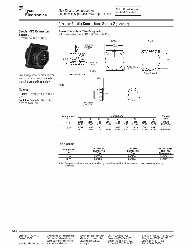
Note: All part numbersare RoHS Compliant.
1-92
AMP Circular Connectors forCommercial Signal and Power Applications
Catalog 7-1773446-2 Dimensions are in inches and Dimensions are shown for USA: 1-800-522-6752 South America: 55-11-2103-6000Revised 10-07 millimeters unless otherwise reference purposes only. Canada: 1-905-470-4425 Hong Kong: 852-2735-1628
specified. Values in brackets Specifications subject Mexico: 52-55-1106-0800 Japan: 81-44-844-8013www.tycoelectronics.com are metric equivalents. to change. C. America: 57-1-254-4444 UK: 44-208-420-8341
Special CPC Connectors,Series 2(Pressure rated up to 30 psi)
Listed plug connector part numbersare for connectors only; contactsmust be ordered separately.
MaterialHousing—Thermoplastic, 94V-0 rated,blackFeed-Thru Contacts—Copper alloy,plated gold over nickel
Part Numbers
Arrangement Standard Reverse Square Flange
No. Numbering Numbering Feed-ThruPlug Plug Receptacle
11-8 205838-1 206460-1 206458-117-28 206125-1 206126-1 206127-1
Note: One plug must have standard numbering of cavities, and the other plug must have reverse numberingof cavities.
Square Flange Feed-Thru Receptacles(with Permanently Sealed .040 [1.02] Dia. Solid Pins)
A Max.
G Dia.
Panel Thk..125 Max.
[3.18]
Pin BothSides
Plug
Panel Cutout
Arrangement Dimensions ThreadNo. A B C D E F G H J Size
1.035 .688 .188 .844 1.125 .125 .840 .800 .975 5/8-2411-8 26.29 17.48 4.78 21.44 28.58 3.18 21.34 20.32 24.77 UNEF-2A1.040 1.050 .188 1.125 1.435 .150 1.210 .800 1.349 15/16-2017-28 26.42 26.67 4.78 28.58 36.45 3.81 30.73 20.32 34.26 UNEF-2A
H Max.
J Max.
Thread Size(See chart)
D ±.010[±0.25]
E ±.025[±0.64]
B ±.010[±0.25]
C ±.010[±0.25]
F +.007–.000[+0.18]
Dia.
D ±.010[±0.25]
Circular Plastic Connectors, Series 2 (Continued)

Note: All part numbersare RoHS Compliant.
1-93
AMP Circular Connectors forCommercial Signal and Power Applications
Catalog 7-1773446-2 Dimensions are in inches and Dimensions are shown for USA: 1-800-522-6752 South America: 55-11-2103-6000Revised 10-07 millimeters unless otherwise reference purposes only. Canada: 1-905-470-4425 Hong Kong: 852-2735-1628
specified. Values in brackets Specifications subject Mexico: 52-55-1106-0800 Japan: 81-44-844-8013www.tycoelectronics.com are metric equivalents. to change. C. America: 57-1-254-4444 UK: 44-208-420-8341
1
Pin and Socket Connectors
Signal Contacts
.150[3.81]
MaterialPin Body—BrassSocket—Phosphor bronze
Contact FinishA—Select gold flash over nickelon entire contact, with additional.000030 [0.00076] gold onmating endB—Duplex plated .000030[0.00076] gold on mating end, tinon termination end, with entirecontact nickel underplatedC—Gold flash over nickel on entirecontactD—Duplex plated gold flash onmating end, tin on termination end,with entire contact nickelunderplated
Insertion/Extraction Tool Part No. 91285-1Instruction Sheet—408-9404This tool includes interchangeabletips to Insert/Extract:Size 22, 28-22 AWG[0.08-0.03 mm2] Crimp ContactsSize 20, 28-20 AWG [0.08-0.6 mm2]Crimp and Solder Cup ContactsSize 20, Posted Contacts
With Insulation Support
Pin
Socket
Contact Part Nos. Tooling ColorWire Ins. ContactPin Socket CodeSize Dia. Code Strip Form Hand (LooseRange Max. Finish
Strip Form Loose Piece Strip Form Loose Piece Applicator†† Tool Piece)
A 66507-3 66507-9 66505-3 66505-9
.040 B 1658540-4 1658540-5 1658538-2 — 466423-□††Blue
28-24 1.02 C 66507-4 1-66507-0 66505-4 1-66505-0 or 466901-1†† 91503-15Dot
AWGD 1658540-1 1658540-2 1658538-3 5-66505-9
or 1016015-1††
[0.08-0.2A 66682-2 66682-4 66683-2 66683-4 466758-2††mm2]
.060B 5066682-9 — 1-5066683-0 — or 466963-1†† 91549-15 Black
1.52D 5066682-6 — 5066683-7 — or 567804-1†† Dot
26-22A 745254-2 745254-6 745253-2 745253-6
AWG .050 B 1658544-2 1658544-1 1658543-2 1658543-1 466968-1††Yellow
[0.12-0.4 1.27 C 745254-3 745254-7 745253-3 745253-7 or 567036-□†† 91525-15Dot
mm2]D 1658544-3 1-745254-6 1658543-3 1-745253-6
or 567849-1††
24-20A 66506-3 66506-9 66504-3 66504-9 466422-□††
AWG .060 B 1658539-1 1658539-3 1658537-3 1658537-4 or 466900-1†† Red[0.2-0.6 1.52 C 66506-4 1-66506-0 66504-4 1-66504-0 or 567801-1††
91503-15Dot
mm2]D 1658539-2 1658539-4 1658537-1 1658537-2 or 1016002-1††
5To use with the 626 Pneumatic Tool System: remove the crimping head from the Straight Action Hand Tool (SAHT)Assembly, order SAHT Adapter Part No 217201-1, Adapter Holder Part No. 356304-1 (with ratchet) or 189928-1(without), and Power Unit Part No. 189721-1 (hand actuated) or 189722-1 (foot actuated).
††For complete information on AMP Strip Form Applicators for fully automatic and semiautomatic machines,contact Technical Support.
Note: Commercial PRO-CRIMPER III Maintenance and Repair Hand Tool for Wire Size 28-24 AWG [0.08-0.2 mm2](Ins. Dia. Max. .040 [1.02]), and Wire Size 24-20 AWG [0.2-0.6 mm2] (Ins. Dia. Max. .060 [1.52])—Part No. 58448-2.Note: Die Set Part No. 58448-3 can be adapted for use with the 626 Pneumatic Tool System.
Size 20 DF,Precision Formed, Crimp Contacts
Contact Size—20Pin Diameter—.040 [1.02]*Test Current—7.5 ampere (Single contact, free-air test current; not to be construed as contact ratingcurrent. Use only for testing.)*Note: Total current capacity of eachcontact in any given connector isdependent on the heat rise resultingfrom the combination of electrical loadsof all contacts in the connectorarrangement and the maximum ambienttemperature in which the connector willbe operating. See page 1-72.
.085[2.16]
Dia.
Max.
.085[2.16]
Dia.
Max.
.390[9.91]
.370[9.34]
.555[14.1]
.575[14.61]
.0400±.0015
[1.02±0.034] Dia.
Localized Gold Plate Area
Localized Gold Plate Area
.100[2.54]
Socket
Pin

Note: All part numbersare RoHS Compliant.
1-94
AMP Circular Connectors forCommercial Signal and Power Applications
Catalog 7-1773446-2 Dimensions are in inches and Dimensions are shown for USA: 1-800-522-6752 South America: 55-11-2103-6000Revised 10-07 millimeters unless otherwise reference purposes only. Canada: 1-905-470-4425 Hong Kong: 852-2735-1628
specified. Values in brackets Specifications subject Mexico: 52-55-1106-0800 Japan: 81-44-844-8013www.tycoelectronics.com are metric equivalents. to change. C. America: 57-1-254-4444 UK: 44-208-420-8341
Size 20 DM, Screw-Machined, Crimp ContactsPin Diameter—.040 [1.02]
Test Current*—7.5 amperes (Singlecontact, free-air test current; not to beconstrued as contact rating current. Use only for testing.)
Material and FinishPin Body—Copper alloy per QQ-B-626Socket Body—Beryllium copper per QQ-C-530Socket Sleeve—Passivated stainlesssteel per QQ-S-766Plating pin and socket body—.000050-.000100 [0.00127-0.00254]min. gold over .000100-.000150[0.00254-0.00381] min. copper
Gold plating per MIL-G-45204Copper plating per MIL-C-14550
Type 20 DF, SolderContactsPin Diameter—.040 [1.02]
Test Current*—7.5 amperes (Singlecontact, free-air test current; not to beconstrued as contact rating current. Useonly for testing.)
Material and FinishPin—Brass, plated gold flash over nickel on entire contact with additional.000030 [0.00076] min. gold on mating endSocket—Phosphor bronze, plated gold flash over nickel on entire contactwith additional .000030 [0.00076] min.gold on mating end
*Note: Total current capacity ofeach contact in a given connector isdependent on the heat rise resultingfrom the combination of electricalloads of all contacts in the connectorarrangement and the maximumambient temperature in which theconnector will be operating. See page 1-72.
Pin
Socket
PinM39029/64-369
(Supersedes M24308/11-1)
SocketM39029/63-368
(Supersedes M24308/10-1)
Wire Size Tape Mounted Loose Piece Contacts Hand Tool Nos. Positioner Nos.Range1 Ins. Dia. Contact Contacts2
(Max.) Configuration Part Military Part Military Part Military PartAWG mm2 No. No. (M39029/) No. (M22520/) No. (M22520/) No.
24-20 0.2-0.6 .068 Pin 205089-2 64-369 205089-102-01 601966-1 2-08 601966-51.73 Socket 205090-2 63-368 205090-1
1Overall insulation crimp diameter, including crimp barrel, must not exceed .125 [3.18].2.000015 [0.00038] gold in the mating area over .000050 [0.00127] nickel.
Strip Form Loose PieceContact No. Contact No.
Pin Socket Pin Socket66570-2 66569-2 66570-3 66569-3
Note: Contacts to be soldered to wire before being inserted intohousing, 18 AWG [0.8 - 0.9 mm2] max. wire size.
.133[9.58]Max. .580
[14.73]
.390[9.91]
.085[2.16]
Dia.
Max.
.0400±.0015
[1.02±0.034] Dia.
.150[3.81]
LocalizedGold Plate
Area
.085[2.16]
Dia.
Max.
.070[1.78]
Dia.
Max.
.560[14.23]
Ref.
Signal Contacts (Continued)

Note: All part numbersare RoHS Compliant.
1-95
AMP Circular Connectors forCommercial Signal and Power Applications
Catalog 7-1773446-2 Dimensions are in inches and Dimensions are shown for USA: 1-800-522-6752 South America: 55-11-2103-6000Revised 10-07 millimeters unless otherwise reference purposes only. Canada: 1-905-470-4425 Hong Kong: 852-2735-1628
specified. Values in brackets Specifications subject Mexico: 52-55-1106-0800 Japan: 81-44-844-8013www.tycoelectronics.com are metric equivalents. to change. C. America: 57-1-254-4444 UK: 44-208-420-8341
1
Pin and Socket Connectors
Contact Arrangements, Series 2
Shell Size 11
Shell Size 17
Note: Contact arrangementsshown are of pin mating face(plug or receptacle). Socketmating face is mirror image.
.124.000
.124[3.15] [3.15]
.141 [3.58]
.033 [0.84].000
.091 [2.31][.334[8.48] Dia.
.124 [3.15]
Arrangement 11-8 Arrangement 11-9Max. Wire Ins. Dia. = .068 [1.73] Max. Wire Ins. Dia. = .068 [1.73]
.248 .124.000
.124 .248[6.3] [3.15] [3.15] [6.3]
.294 [7.47]
.170 [4.32]
.062 [1.57]
.000.062 [1.57]
.170 [4.32]
.294 [7.47] .124 [3.15]
Arrangement 17-28Max. Wire Ins. Dia. = .068 [1.73]
Shell Size 23
.372 .248 .124.000
.124 .248 .372[9.45] [6.3] [3.15] [3.15] [6.3] [9.45]
.434 .310 .186 .062 .062 .186 .310 .434[11.02] [7.87] [4.72] [1.57] [1.57] [4.72] [7.87] [11.02]
.434 .310 .186 .062 .062 .186 .310 .434[11.02] [7.87] [4.72] [1.57] [1.57] [4.72] [7.87] [11.02]
.443 [11.25]
.319 [8.1]
.212 [5.38]
.105 [2.67]
.019 [0.48]
.143 [3.63]
.250 [6.35]
.357 [9.07]
.464 [11.79]
.448 [11.38]
.340 [8.64]
.232 [5.89]
.108 [2.74]
.000
.108 [2.74]
.232 [5.89]
.340 [8.64]
.448 [11.38]
Arrangement 23-57 Arrangement 23-63Max. Wire Ins. Dia. = .068 [1.73] Max. Wire Ins. Dia. = .068 [1.73]
.062 .062[1.57] [1.57]
45°
.496 .372 .248 .124.000
.124 .248 .372 .496[12.6] [9.45] [6.3] [3.15] [3.15] [6.3] [9.45] [12.6]
.000
.124 [3.15].124 [3.15]
.310[7.87]
.310[7.87]
.186[4.72]
.186[4.72]
.062[1.57]
.062[1.57]

Note: All part numbersare RoHS Compliant.
1-96
AMP Circular Connectors forCommercial Signal and Power Applications
Catalog 7-1773446-2 Dimensions are in inches and Dimensions are shown for USA: 1-800-522-6752 South America: 55-11-2103-6000Revised 10-07 millimeters unless otherwise reference purposes only. Canada: 1-905-470-4425 Hong Kong: 852-2735-1628
specified. Values in brackets Specifications subject Mexico: 52-55-1106-0800 Japan: 81-44-844-8013www.tycoelectronics.com are metric equivalents. to change. C. America: 57-1-254-4444 UK: 44-208-420-8341
Square Flange Receptacle
Free-Hanging Receptacle
Plug
Panel Thk..125
[3.18] Max.
E Max.
E Max. L Max.
KMax.
M Max.
N Max.
A Max.
J Dia.
Thread Size(See chart)
Thread Size(See chart)
Panel Cutout
Arrangement Dimensions ThreadNo. A B C D E F G H J K L M N Size11-8 .809 .420 .094 .688 .630 .844 1.125 .125 .840 .817 .935 .800 .975 5/8-2411-9 20.55 10.67 2.39 17.48 16 21.44 28.58 3.18 21.34 20.75 23.75 20.32 24.77 UNEF-2A
.809 .420 .094 1.050 .943 1.125 1.435 .150 1.210 1.161 1.310 .800 1.349 15/16-2017-28 20.55 10.67 2.39 26.67 23.95 28.58 36.45 3.81 30.73 29.49 33.27 20.32 34.26 UNEF-2A23-57 .924 .420 .156 1.438 1.515 1.438 1.750 .150 1.610 1.500 1.733 .915 1.788 1-3/8-1823-63 23.47 10.67 3.96 36.53 38.48 36.53 44.45 3.81 40.89 38.1 44.02 23.24 45.42 UNEF-2A
Note: All dimensions apply to both standard and reverse sex connectors.
AMax.
Thread Size(See chart)
F ±.010[±0.25]
G ±.025[±0.64]
D ±.010[±0.25]
B ±.015[±0.38]
C ±.010[±0.25]
F ±.010[±0.25]
*H +.007–.000[+0.18]
Dia.
D ±.010[±0.25]
C ±.010[±0.25]
B ±.015[±0.38]
Component Dimensions, Series 2

Note: All part numbersare RoHS Compliant.
1-97
AMP Circular Connectors forCommercial Signal and Power Applications
Catalog 7-1773446-2 Dimensions are in inches and Dimensions are shown for USA: 1-800-522-6752 South America: 55-11-2103-6000Revised 10-07 millimeters unless otherwise reference purposes only. Canada: 1-905-470-4425 Hong Kong: 852-2735-1628
specified. Values in brackets Specifications subject Mexico: 52-55-1106-0800 Japan: 81-44-844-8013www.tycoelectronics.com are metric equivalents. to change. C. America: 57-1-254-4444 UK: 44-208-420-8341
1
Pin and Socket Connectors
Circular Plastic Connectors, Series 3
CPC Connectors, Series 3
Listed part numbers are for connectors only; contacts must be ordered separately.
MaterialHousing—Thermoplastic, 94V-0 rated,black
Standard Sex Connectors(Receptacles accept Type XII Male/pin contacts, Plugs accept Type XII Female/socket contacts)
Square Flange ReceptacleArrangement With With Free-Hanging Plug
Mounting Holes Threaded Inserts1 Receptacle
17-3 206036-2 213581-1 206207-1 206037-223-7 206137-1 206137-5 206137-2 206136-1
Reverse Sex Connectors(Receptacles accept Type XII Female/socket contacts, Plugs accepts Type XII Male/pin contacts)
Square Flange ReceptacleArrangement With With Free-Hanging Plug
Mounting Holes Threaded Inserts1 Receptacle
17-3 206425-1 206425-5 206425-2 206426-123-7 206227-1 206227-6 206227-2 206226-1
1Four 4-40 threaded inserts per receptacle.Note: Maximum wire insulation diameter is .220 [5.59].
Replacement Coupling Rings
Shell Size Part No.17 213810-123 213812-1
Square Flange Receptacle
Free-Hanging Receptacle
Plug
*J Dia.
Panel Cutout
Panel Thk..125[3.18] Max.
*E Max.
*E Max. *L Max.
*KMax.
*AMax.
*Thread Size(See chart)
*Thread Size(See chart)
*M Max.
*N Max.
*Thread Size(See chart)
*Note:See page 1-100 for Callout Dimensions
Plug
*F ±.010[±0.25]
*G ±.025[±0.64]
*H +.007–.000[+0.18]
Dia.
*F ±.010[±0.25]*D ±.010
[±0.25]
*D ±.010[±0.25]
*C ±.010[±0.25]
*B ±.015[±0.38]
*AMax.
*C ±.010[±0.25]
*B ±.015[±0.38]
1Four 4-40 threaded inserts per receptacle.

Note: All part numbersare RoHS Compliant.
1-98
AMP Circular Connectors forCommercial Signal and Power Applications
Catalog 7-1773446-2 Dimensions are in inches and Dimensions are shown for USA: 1-800-522-6752 South America: 55-11-2103-6000Revised 10-07 millimeters unless otherwise reference purposes only. Canada: 1-905-470-4425 Hong Kong: 852-2735-1628
specified. Values in brackets Specifications subject Mexico: 52-55-1106-0800 Japan: 81-44-844-8013www.tycoelectronics.com are metric equivalents. to change. C. America: 57-1-254-4444 UK: 44-208-420-8341
Type XII, PrecisionFormed, Crimp
MaterialCopper
FinishA—TinB—.000030 [0.00076] selective goldover .000030 [0.00076] nickelC—.000100 [0.00254] silver platedcontacts with lubricant added
Test Current RatingSilver or Gold—35 amperes ‡Tin—15 amperes ‡
‡Single contact, free-air test current;not to be construed as contact rating current. Use only for testing.Refer to contact current carryingcapability information, page 1-72.
Male
Female
Female
Male
Strip Form Contact Part Nos. Loose Piece ToolingWire Size Ins. Heavy Duty Contact Heavy Duty Die Set forRange1 Dia. Contact Standard*** Miniature*** Part Nos. Miniature Hand Tool 69710-1
Range FinishApplicator or 626 Pneumatic
AWG mm2 Male Female Male Female Male Female Tool System66255-1 66740-7 66255-5 1-66740-2 66261-1 66740-8
A266256-12 — 266256-52 — 266262-12 —
16 1.25-1.4 .135-.160 66255-2 66740-5 66255-6 1-66740-1 66261-2 66740-6 90145-23,7
and and3.43-4.06 B
266256-22 — 266256-42 — 266262-22 —567455-□*** and
14-12 2-366255-7 66740-1 66255-8 1-66740-9 66261-4 66740-2
90145-14,7
5C5266256-62 — 266256-72 — 266262-42 —66253-1 66741-7 66253-5 1-66741-2 66259-1 66741-8
A266254-12 — — — 266260-12 —
.190-.220 66253-2 66741-5 66253-6 1-66741-1 66259-2 66741-610 5-64.83-5.59 B
266254-22 — — — 266260-22 —567021-□*** 90140-17
66253-4 66741-1 66253-8 1-66741-9 66259-4 66741-25C5
266254-42 — — — 266260-42 —
1Wire strip length—.281 [7.14].2Ground contact.3Die insert Part No. 90145-2 is for crimping 16 AWG [1.25-1.4 mm2] wire.4Die insert Part No. 90145-1 is for crimping 14-12 AWG [2-3 mm2] wire.5Recommended for high current/vibration applications where fretting corrosion is a problem.7Die Set requires “C” Head Adapter Part No. 318161-1; Adapter Holder Part No. 356304-1 (with ratchet) or 189928-1 (without); and Power Unit Part No. 189721-2 (hand actuated) or 189722-2 (foot actuated).
Extraction Tool No. 91019-3.***Call Technical Support for Automatic Machine Applicator Part Numbers.
.615[15.62]
.637[16.18]
.185[4.7]
.085[2.16]
.200[5.08]
Min.
.230[5.84]
Max.
.230[5.84]
Max.
.230[5.84]
Max.
.978[24.84]
Ref.
1.500[38.1]
Ref.
1.267[32.18]
Ref.
.287±.006
[7.29±0.152]
.287[7.29]
.230[5.84]
Max.
.015[0.38]
Cutoff
(Loose Piece Only)
.027[0.686]
Ref.
.027[0.686]
Ref.
Extraction Tool Part No. 91019-3
Power Contacts, Series 3

Note: All part numbersare RoHS Compliant.
1-99
AMP Circular Connectors forCommercial Signal and Power Applications
Catalog 7-1773446-2 Dimensions are in inches and Dimensions are shown for USA: 1-800-522-6752 South America: 55-11-2103-6000Revised 10-07 millimeters unless otherwise reference purposes only. Canada: 1-905-470-4425 Hong Kong: 852-2735-1628
specified. Values in brackets Specifications subject Mexico: 52-55-1106-0800 Japan: 81-44-844-8013www.tycoelectronics.com are metric equivalents. to change. C. America: 57-1-254-4444 UK: 44-208-420-8341
1
Pin and Socket Connectors
Power Contacts, Series 3 (Continued)
Contact Arrangements, Series 3
Shell Size 17 Shell Size 23
Note: Contact arrangements shown are of pin mating face (plug or receptacle).Socket mating face is mirror image.
.148 .000 .148[3.76] [3.76]
.107 [2.72]
.213 [5.41]
.000
Arrangement 17-3Max. Wire Ins. Dia. = .220 [5.59]
Arrangement 23-7Max. Wire Ins. Dia. = .220 [5.59]
.343 .172 .000 .172 .343[8.71] [4.37] [4.37] [8.71]
.296 [7.52]
.000
.296 [7.52]
High Current Type XII Crimp ContactsThe Multimate features of the HighCurrent Type XII contact have beendesigned to fit into the existing AMPConnectors such as CPC (CircularPlastic Connector), CMC (CircularPlastic Metal-Shell Connector),G Series, M Series, and CMPC(Circular Multipin Connector)housings. An initial T-Rise test infree air has shown a 60 ampcapability with a 30° T-Rise with 8 gage wires. The contact may becrimped onto 8 AWG wire with aDaniels Hand Tool M310 or AMPP/N 356114-1 and PositionerTP1068 or AMP P/N 356119-1.
Current-Carrying CapacityThe graph shows current-carryingcapacity versus temperature rise fora fully energized 3 position CPCplug P/N 206037-2 and receptacleP/N 206036-2. These initialrepresentative amperage ratingswere conducted with 8 AWG wiresthat were 3 feet long.
MaterialBody — Copper AlloyLouvertac Band — Beryllium CopperRetention Spring — Stainless SteelFinishBody — SilverLouvertac Band — Gold
Extraction Tool Part No. 224155-1
Current Rating for 30°C Temperature Rise 100% Energized
3 Circuit Connector (Wire-to-Wire)
CURRENT IN AMPS
TE
MP
ER
AT
UR
E R
ISE
(D
EG
RE
ES
C)
0
10
20
30
40
50
0 10 20 30 40 50 60 70
High Current Type XII Socket
Part No. 193990-2
High Current Type XII Pin
Part No. 193991-4
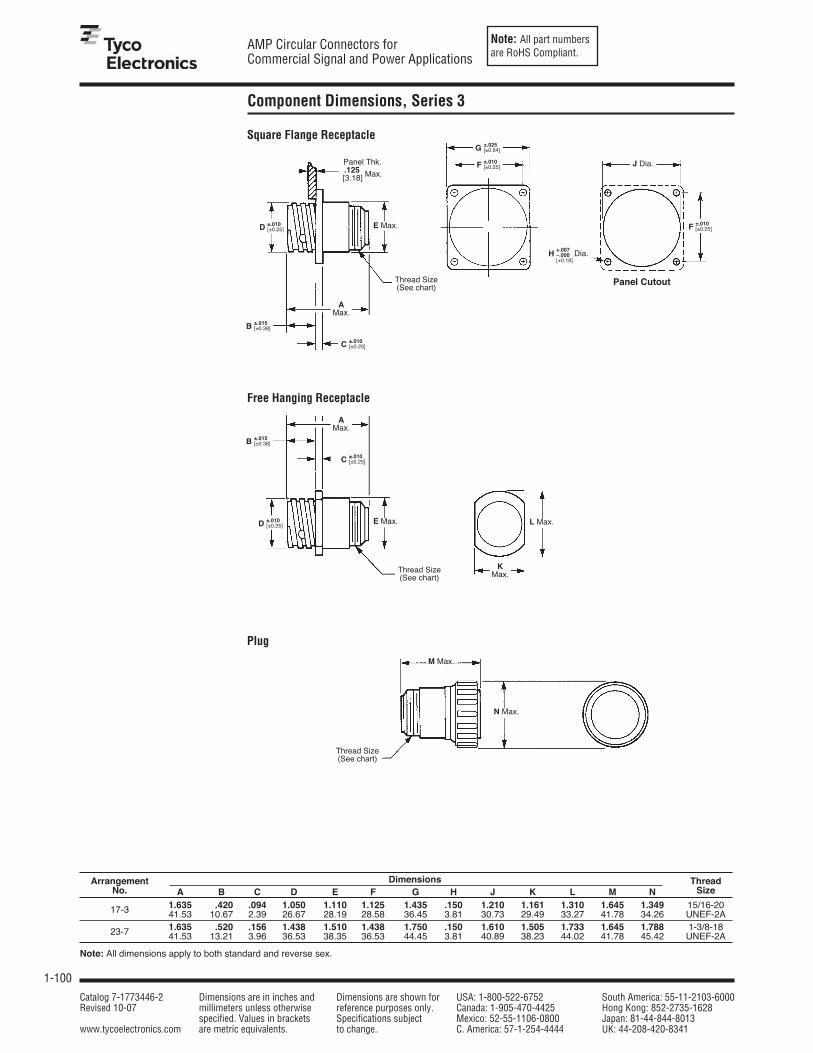
Note: All part numbersare RoHS Compliant.
1-100
AMP Circular Connectors forCommercial Signal and Power Applications
Catalog 7-1773446-2 Dimensions are in inches and Dimensions are shown for USA: 1-800-522-6752 South America: 55-11-2103-6000Revised 10-07 millimeters unless otherwise reference purposes only. Canada: 1-905-470-4425 Hong Kong: 852-2735-1628
specified. Values in brackets Specifications subject Mexico: 52-55-1106-0800 Japan: 81-44-844-8013www.tycoelectronics.com are metric equivalents. to change. C. America: 57-1-254-4444 UK: 44-208-420-8341
Square Flange Receptacle
Free Hanging Receptacle
Free-Hanging Receptacle
Plug
J Dia.
Panel Cutout
Panel Thk..125[3.18] Max.
E Max.
E Max. L Max.
KMax.
AMax.
Thread Size(See chart)
Thread Size(See chart)
M Max.
N Max.
Thread Size(See chart)
Arrangement Dimensions ThreadNo. A B C D E F G H J K L M N Size
1.635 .420 .094 1.050 1.110 1.125 1.435 .150 1.210 1.161 1.310 1.645 1.349 15/16-2017-3 41.53 10.67 2.39 26.67 28.19 28.58 36.45 3.81 30.73 29.49 33.27 41.78 34.26 UNEF-2A1.635 .520 .156 1.438 1.510 1.438 1.750 .150 1.610 1.505 1.733 1.645 1.788 1-3/8-1823-7 41.53 13.21 3.96 36.53 38.35 36.53 44.45 3.81 40.89 38.23 44.02 41.78 45.42 UNEF-2A
Note: All dimensions apply to both standard and reverse sex.
F ±.010[±0.25]
G ±.025[±0.64]
F ±.010[±0.25]
*H +.007–.000[+0.18]
Dia.
D ±.010[±0.25]
C ±.010[±0.25]
B ±.015[±0.38]
AMax.
C ±.010[±0.25]
B ±.015[±0.38]
D ±.010[±0.25]
Component Dimensions, Series 3

Note: All part numbersare RoHS Compliant.
1-101
AMP Circular Connectors forCommercial Signal and Power Applications
Catalog 7-1773446-2 Dimensions are in inches and Dimensions are shown for USA: 1-800-522-6752 South America: 55-11-2103-6000Revised 10-07 millimeters unless otherwise reference purposes only. Canada: 1-905-470-4425 Hong Kong: 852-2735-1628
specified. Values in brackets Specifications subject Mexico: 52-55-1106-0800 Japan: 81-44-844-8013www.tycoelectronics.com are metric equivalents. to change. C. America: 57-1-254-4444 UK: 44-208-420-8341
1
Pin and Socket Connectors
Circular Plastic Connectors, Series 4
Panel Thk..125
[3.18] Max.
1.438±.010
[36.53±0.25]1.510 Max.
[38.35] Max.
Thread Size1-3/8-18 UNEF-2A
CPC Connectors, Series 4,Standard Sex
Listed part numbers are forconnectors only; contacts mustbe ordered separately.
MaterialHousing—Thermoplastic, 94V-0 rated,black; 23-9M – Nylon 6/6, glass filled,black
Related Product Data
Arrangement No. of Cavities Square Flange Free-Hanging PlugPower Multimate Receptacle Receptacle
23-9M 6 (POWERBAND) 3 1776247-21 — 206136-423-13M 5 (Type XII) 8 211825-1 211825-2 211824-123-16M 4 (Type XII) 12 207486-1 207486-2 207485-123-22M 2 (Type XII) 20 206613-1 206613-3 206612-1
1Four 4-40 threaded inserts per receptacle. Note: Maximum wire insulation diameter is .150 [3.81] for Multimate contacts; .220 [5.59] for Power contacts.
Contact Arrangements,Series 4Shell Size 23
Square Flange Receptacle (Accepts Type XII Male and Multimate pin contacts)
Free-Hanging Receptacle (Accepts Type XII Male and Multimate pin contacts)
Replacement Coupling RingShell Size Part No.
23 213812-1
.400 [10.16]
.316 [8.03]
.158 [4.01]
.000
.158 [4.01]
.316 [8.03]
.400 [10.16]
.364 .182 .182 .364[9.25] [4.62] .000 [4.62] [9.25]
.382 [9.7]
.316 [8.03]
.158 [4.01]
.000
.158 [4.01]
.316 [8.03]
.382 [9.7]
Arrangement 23-16M Arrangement 23-22MMax. Wire Ins. Dia. = Max. Wire Ins. Dia. =
.150 [3.81] for Multimate Contacts, .150 [3.81] for Multimate Contacts,.220 [5.59] for Power Contacts .220 [5.59] for Power Contacts
.276[7.01]
.276[7.01]
.400[10.16]
.400[10.16]
.455[11.56]
.091[2.31]
.091[2.31]
.455[11.56]
.273[6.93]
.273[6.93]
.184[4.67]
.184[4.67].000
.092[2.34]
.092[2.34]
Panel Cutout
1.438±.010
[36.53±0.25]
1.750±.025
[44.45±0.64]1.438±.010
[36.53±0.25]1.610[40.89] Max.
.520±.015
[13.21±0.38]
.156±.010
[3.96±0.25]
1.438±.010
[36.53±0.25]1.510 Max
[38.35] Max. 1.733 Max.
[44.02] Max.
1.505 Max.
[38.23] Max.Thread Size
1-3/8-18 UNEF-2A
1.635[41.53]Max.
.520±.015
[13.21±0.38].156±.010
[3.96±0.25]
1.635[41.53]Max.
1.645 Max.
[41.78] Max.
1.788Max.
[45.42] Max.
ThreadSize
1-3/8-18UNEF-2A
.407[10.34]
.307[9.4]
.255[6.48]
.407[10.34]
.307[9.4]
.255[6.48].000
.407 [10.34].360 [9.14]
.254 [6.45]
.000
.254 [6.45]
.360 [9.14].407 [10.34]
Note: Contact arrangementsshown are of pin mating face(plug or receptacle). Socketmating face is mirror image.
Arrangement 23-13MMax. Wire Ins. Dia. =
.150 [3.81] for Multimate Contacts,.220 [5.59] for Power Contacts
.150 +.007–.000
[3.81+0.18]Dia.
Plug (Accepts Type XII Female and Multimate socket contacts)
.296[7.52]
.343[8.71]
.343[8.71]
.296[7.52]
.079[2.01]
.000
.000
.079[2.01]
.172[4.37]
.172[4.37]
NEW
Arrangement 23-9M

Note: All part numbersare RoHS Compliant.
1-102
AMP Circular Connectors forCommercial Signal and Power Applications
Catalog 7-1773446-2 Dimensions are in inches and Dimensions are shown for USA: 1-800-522-6752 South America: 55-11-2103-6000Revised 10-07 millimeters unless otherwise reference purposes only. Canada: 1-905-470-4425 Hong Kong: 852-2735-1628
specified. Values in brackets Specifications subject Mexico: 52-55-1106-0800 Japan: 81-44-844-8013www.tycoelectronics.com are metric equivalents. to change. C. America: 57-1-254-4444 UK: 44-208-420-8341
CPC Connector Accessories
Cable ClampsCable clamps provide strainrelief and can be used onall series receptacles andplugs.
MaterialBlack thermoplastic heat-stabilized, fire-resistant, self-extinguishing, UL94V-0 rated
Standard Size
For additional informationconcerning cable clamps, referto Instruction Sheet408-7582.
ClampingInsert
Plug(See Note 3)
ClampingInsert
CableClamp
Cable Part No.Shell Dimensions
O.D. ThreadIndividually BulkSize A B (Max.) SizePackaged Packaged*
.825 1.250 .329 1-206062-7**11 20.96 31.75 8.36 5/8-24 UNEF-2B 1-206062-4 (400)
.950 1.400 .453 206966-9**13 24.13 35.56 11.51 3/4-20 UNEF-2B 206966-7 (200)1.125 1.400 .453 1-206070-0**17 28.58 35.56 11.51 15/16-20 UNEF-2B 206070-8 (200)1.600 1.555 .703 1-206138-0**23 40.64 39.5 17.86 1-3/8-18 UNEF-2B 206138-8 (100)
**Numbers in parentheses specify, in multiples, the minimum quantity of parts that can be ordered.**Packaging includes two screws: shell sizes 11-17, screw length .500 [12.7]; shell size 23, screw length .625 [15.88].Notes: 1. Clamping areas adjustable by inverting or changing clamping inserts. The quantity of inserts supplied with
each assembly is as follows: for size 11 cable clamps, one insert; for all other cable clamps, two inserts.Notes: 2. Components for all cable clamps are packaged unassembled. This includes the cable clamp, two screws
and the clamping inserts.Notes: 3. Cable clamps can be threaded directly onto plugs or receptacles, or onto back-shell extenders.
4. Replacement screws are available in the following sizes: 3/8 in. [9.52]—5019024-1, 1/2 in. [12.7]—5019024-2, 5/8 in. [15.88]—5019024-3, 1 in. [25.4]—5019024-4, 3/4 in. [19.05]—5019024-5.
Notes: 5. Cable clamp inserts not sold separately.
Large Size
Cable Part No.Shell Dimensions
O.D. ThreadIndividually BulkSize A B (Max.) SizePackaged Packaged*
.850 1.450 .453 206358-6**11 21.59 36.83 11.51 5/8-24 UNEF-2B 206358-5 (200)1.131 1.655 .703 207008-6**13 28.73 42.04 17.86 3/4-20 UNEF-2B 207008-5 (100)1.131 1.655 .703 1-206322-0**17 28.73 42.04 17.86 15/16-20 UNEF-2B 206322-9 (100)1.600 1.655 1.125 206512-6**23 40.64 42.04 28.58 1-3/8-18 UNEF-2B 206512-5 (75)
**Numbers in parentheses specify, in multiples, the minimum quantity of parts that can be ordered.**Packaging includes two screws: shell size 11, screw length .500 [12.7]; shell sizes 13-23, screw length .625 [15.88].Notes: 1. Clamping areas adjustable by inverting or changing clamping inserts. The quantity of inserts supplied with
each assembly is as follows: for size 23 cable clamps, four inserts; for all other cable clamps, two inserts.Notes: 2. Components for all cable clamps are packaged unassembled. This includes the cable clamp, two screws
and the clamping inserts.Notes: 3. Cable clamps can be threaded directly onto plugs or receptacles, or onto back-shell extenders.
4. Replacement screws are available in the following sizes: 3/8 in. [9.52]—5019024-1, 1/2 in. [12.7]—5019024-2, 5/8 in. [15.88]—5019024-3, 1 in. [25.4]—5019024-4, 3/4 in. [19.05]—5019024-5.
Notes: 5. Cable clamp inserts not sold separately.
±.025 Dia.A [±0.64] Dia.
±.030B [±0.76]
ClampingInsert
Plug(See Note 3)
ClampingInsert
CableClamp
The clamping area can beadjusted by reversing theclamping insert as shownbelow.
A ±.025[±0.64] Dia.
B ±.030[±0.76]
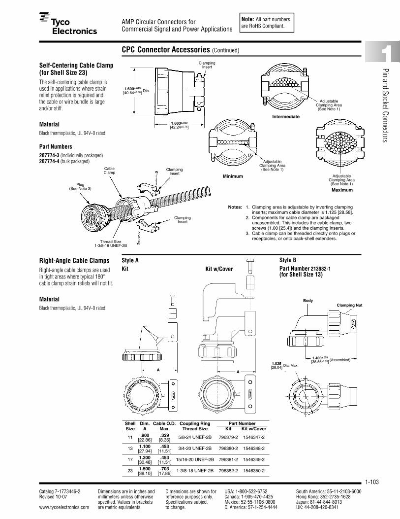
Note: All part numbersare RoHS Compliant.
1-103
AMP Circular Connectors forCommercial Signal and Power Applications
Catalog 7-1773446-2 Dimensions are in inches and Dimensions are shown for USA: 1-800-522-6752 South America: 55-11-2103-6000Revised 10-07 millimeters unless otherwise reference purposes only. Canada: 1-905-470-4425 Hong Kong: 852-2735-1628
specified. Values in brackets Specifications subject Mexico: 52-55-1106-0800 Japan: 81-44-844-8013www.tycoelectronics.com are metric equivalents. to change. C. America: 57-1-254-4444 UK: 44-208-420-8341
1
Pin and Socket Connectors
CPC Connector Accessories (Continued)
Self-Centering Cable Clamp (for Shell Size 23)The self-centering cable clamp isused in applications where strainrelief protection is required andthe cable or wire bundle is largeand/or stiff.
MaterialBlack thermoplastic, UL 94V-0 rated
Part Numbers207774-3 (individually packaged)207774-4 (bulk packaged)
Right-Angle Cable ClampsRight-angle cable clamps are usedin tight areas where typical 180°cable clamp strain reliefs will not fit.
MaterialBlack thermoplastic, UL 94V-0 rated
1.600±.015 Dia.
[40.64±0.38] Dia.
1.663±.030
[42.24±0.76]
ClampingInsert
Plug(See Note 3)
CableClamp
ClampingInsert
ClampingInsert
Thread Size1-3/8-18 UNEF-2B
AdjustableClamping Area(See Note 1)
Intermediate
AdjustableClamping Area(See Note 1)
Minimum AdjustableClamping Area(See Note 1)
Maximum
Notes: 1. Clamping area is adjustable by inverting clampinginserts; maximum cable diameter is 1.125 [28.58].
2. Components for cable clamp are packagedunassembled. This includes the cable clamp, twoscrews (1.00 [25.4]) and the clamping inserts.
3. Cable clamp can be threaded directly onto plugs orreceptacles, or onto back-shell extenders.
Shell Dim. Cable O.D. Coupling Ring Part NumberSize A Max. Thread Size Kit Kit w/Cover
11 .900 .329 5/8-24 UNEF-2B 796379-2 1546347-2[22.86] [8.36]
13 1.100 .453 3/4-20 UNEF-2B 796380-2 1546348-2[27.94] [11.51]
17 1.200 .453 15/16-20 UNEF-2B 796381-2 1546349-2[30.48] [11.51]
23 1.500 .703 1-3/8-18 UNEF-2B 796382-2 1546350-2[38.10] [17.86]
Style A Style BPart Number 213982-1(for Shell Size 13)
A
1.025 Dia. Max.[28.04]
Body
1.400±.070 (Assembled)[35.56±1.78]
Clamping Nut
Kit Kit w/Cover
A

Note: All part numbersare RoHS Compliant.
1-104
AMP Circular Connectors forCommercial Signal and Power Applications
Catalog 7-1773446-2 Dimensions are in inches and Dimensions are shown for USA: 1-800-522-6752 South America: 55-11-2103-6000Revised 10-07 millimeters unless otherwise reference purposes only. Canada: 1-905-470-4425 Hong Kong: 852-2735-1628
specified. Values in brackets Specifications subject Mexico: 52-55-1106-0800 Japan: 81-44-844-8013www.tycoelectronics.com are metric equivalents. to change. C. America: 57-1-254-4444 UK: 44-208-420-8341
CPC Connector Accessories (Continued)
Back-Shell Extender(for Shell Size 23)A back-shell extender is used with acable clamp in applications whereadded length and/or additional wirebreakout are required.
MaterialBlack glass-filled thermoplastic
Part No. 207055-1
Panel Mount Flanges(for Plugs only)A panel mount flange is used inapplications that require the plughalf of a connector to be panelmounted.
MaterialBlack thermoplastic
D Dia.
C Dia. Max.
Panel MountFlangePlug
1.200±.015
[30.48±0.38]
1.620[41.15]
Dia. Max.
1.450 Max.
[36.83] Max.
CableClampThread Size
1-3/8-18 UNEF-2A
Plug(See Note)
Back-ShellExtender
Thread Size1-3/8-18 UNEF-2B
Note: Back-shell extenders can be threaded directly onto plugs or receptacles and will accept cable clamps of theappropriate size.
.156[3.96]Ref.
.280[7.11]
Shell Dimensions PartSize A B C D No.
.844 1.125 .750 .12511 21.44 28.58 19.05 3.18 207299-1
.969 1.280 .875 .12513 24.61 32.51 22.22 3.18 207299-2
1.125 1.435 1.110 .15017 28.58 36.45 28.19 3.81 207299-3
1.438 1.750 1.510 .15023 36.53 44.45 38.35 3.81 207299-4
A ±.010[±0.25]
(2 Places)
B ±.015[±0.38]
(2 Places)

Note: All part numbersare RoHS Compliant.
1-105
AMP Circular Connectors forCommercial Signal and Power Applications
Catalog 7-1773446-2 Dimensions are in inches and Dimensions are shown for USA: 1-800-522-6752 South America: 55-11-2103-6000Revised 10-07 millimeters unless otherwise reference purposes only. Canada: 1-905-470-4425 Hong Kong: 852-2735-1628
specified. Values in brackets Specifications subject Mexico: 52-55-1106-0800 Japan: 81-44-844-8013www.tycoelectronics.com are metric equivalents. to change. C. America: 57-1-254-4444 UK: 44-208-420-8341
1
Pin and Socket Connectors
CPC Connector Accessories (Continued)
Flexible Cable Boot andInternal Cable Grip(for Shell Size 11)Flexible cable boots, with internalcable grip installed, provide strainrelief capabilities for jacketed cablein applications where aestheticappearance is essential. Theycan be threaded onto plugs orreceptacles.
MaterialBlack thermoplastic
Cable Range.150-.250 [3.81-6.35] Dia.
Part Numbers207489-1 (Cable Boot)207490-1 (Cable Grip)
Flexible Cable Boot andInternal Cable Grip(for Shell Size 17)Flexible cable boots, with internalcable grip installed, provide strainrelief capabilities for jacketed cablein applications where aestheticappearance is essential. Theycan be threaded onto plugs orreceptacles.
MaterialBlack thermoplastic
Part Numbers207241-1 (Cable Boot)207387-1 (Cable Grip)
A Dia. = .325 [8.26] for cable rangeof .200-.250 [5.08-6.35]
207387-2 (Cable Grip)A Dia. = .385 [9.78] for cable rangeof .250-.350 [6.35-8.89]
2.750±.031
[69.85±0.79]
2.750±.031
[69.85±0.79]
1.090±.010
[27.69±0.25] Dia.
.400±.010
[10.16±0.25]Dia.
1.795±.010
[45.59±0.25]
.265[6.73] Dia.
.360[9.14] Dia.
.885[22.48] Dia.
.345[8.76] Dia.
.265[6.73] Dia.
.850[21.59]
Dia. 1.795[45.59]
.390[9.91]
Flexible Cable Boot
Flexible Cable Boot
Internal Cable Grip
Internal Cable Grip
Plug
InternalCable Grip
FlexibleCable Boot
JacketedCable
Plug
InternalCable Grip
FlexibleCable Boot
JacketedCable
.050[1.27]
.390[9.91]
A Dia.
1.090[27.69]
Dia.

Note: All part numbersare RoHS Compliant.
1-106
AMP Circular Connectors forCommercial Signal and Power Applications
Catalog 7-1773446-2 Dimensions are in inches and Dimensions are shown for USA: 1-800-522-6752 South America: 55-11-2103-6000Revised 10-07 millimeters unless otherwise reference purposes only. Canada: 1-905-470-4425 Hong Kong: 852-2735-1628
specified. Values in brackets Specifications subject Mexico: 52-55-1106-0800 Japan: 81-44-844-8013www.tycoelectronics.com are metric equivalents. to change. C. America: 57-1-254-4444 UK: 44-208-420-8341
CPC Connector Accessories (Continued)
Keying PlugsKeying plugs are used toprovide keying capabilitiesfor all connector series.Keying plugs are used insocket cavities of standardsex plugs and reverse sexreceptacles, except whenused with sealing caps.
1.000[25.4]
Series 1 and Series 4 Keying Plug(for Types III+ and Subminiature COAXICON Contacts)
Series 2 Keying Plug(for Size 20 DM and 20 DF Contacts)
Series 3 and Series 4 Keying Plugs(for Type XII Contacts)
Part No. 200821-1
Part No. 206509-1
Part Nos. 206508-1 (Socket Cavities)—Shown Above207597-1 (Pin Cavities)
.116 Max.[2.95] Dia.
.200±.010
[5.08±0.25]
.053±.001
[1.35±0.03]Dia.
1.733[44.01] Max.
MaterialNylon, natural, UL 94V-2 rated
MaterialPolyphenylene oxide, white, UL 94V-1 rated
Material(206508-1) Nylon, natural, UL 94V-2rated(207597-1) Thermoplastic, black, UL 94V-0 rated

Note: All part numbersare RoHS Compliant.
1-107
AMP Circular Connectors forCommercial Signal and Power Applications
Catalog 7-1773446-2 Dimensions are in inches and Dimensions are shown for USA: 1-800-522-6752 South America: 55-11-2103-6000Revised 10-07 millimeters unless otherwise reference purposes only. Canada: 1-905-470-4425 Hong Kong: 852-2735-1628
specified. Values in brackets Specifications subject Mexico: 52-55-1106-0800 Japan: 81-44-844-8013www.tycoelectronics.com are metric equivalents. to change. C. America: 57-1-254-4444 UK: 44-208-420-8341
1
Pin and Socket Connectors
One-Piece Sealed Circular Plastic Connectors
Product Facts■ Economical environmentally
sealed connector designedfor industrial applications
■ Meets major IndustrialStandards
■ High strength, impact resistant thermoplastichousing, rated UL 94V-0
■ Contains wire entry and peripheral seals
■ AMP POWERBAND precisionformed power contact (Series 5 and 6)
■ Type III+ precision formedsignal/low current contacts(Series 1 and Series 6)
■ Other configurations inSeries 1 can be made available, contact Tyco Electronics
The new Sealed One-PieceCircular Plastic Connectorsare the latest productinnovation to the sealedCPC product family. Thisdesign allows for easyassembly. The housing andthe seal are attached. Anewly designed wire entryseal protects the rear of theconnector and a peripheralseal protects the connectorinterface. Simply crimp thecontact onto a wire andinsert the crimped wirecontact through the sealand into the housing cavity.The connector loads thesame as if the seal wasn’tthere. All connector cavitiescome in a sealed condition.No plugs are required ifyou do not use a positioncavity. We have the
capability to provide thisproduct sealing to you in allthe shell sizes. If you don’tsee your particular sizeconfiguration, contact yourlocal Tyco ElectronicsSales Engineer or call TycoElectronics for the latestinformation.
Industry Standards
One-Piece Sealed CPCproducts meet –
■ IP 67 (Temporaryimmersion)
Fluid Protection Against –diesel fuel, gear andengine lubricants, gasoline,anti-freeze, hydraulic fluid,water, salt sprays, etc.
Performance Characteristicsmeets the sameperformance characteristicsas shown on page 1-146.Operating Temperature Range—-50°C to +125°C [-58˚F to +257˚F]UL Voltage Rating—
Series 1 600 V (AC or DC)Series 6 250 V (AC or DC)
.125 POWERBAND Power Contact –45 amps, single contact rating at 30°C T-Rise
Type III+ Contacts – 13 amps, single contact rating at 30°C T-Rise
Flammability Rating—UL 94V-0 ratedSealing Capability—Per IP 67Housing Material—High strength, impact resistant thermoplasticFluid Resistance—Diesel fuel, gear and engine lubricants,gasoline, anti-freeze, hydraulic fluid,water

Note: All part numbersare RoHS Compliant.
1-108
AMP Circular Connectors forCommercial Signal and Power Applications
Catalog 7-1773446-2 Dimensions are in inches and Dimensions are shown for USA: 1-800-522-6752 South America: 55-11-2103-6000Revised 10-07 millimeters unless otherwise reference purposes only. Canada: 1-905-470-4425 Hong Kong: 852-2735-1628
specified. Values in brackets Specifications subject Mexico: 52-55-1106-0800 Japan: 81-44-844-8013www.tycoelectronics.com are metric equivalents. to change. C. America: 57-1-254-4444 UK: 44-208-420-8341
One-Piece Sealed Circular Plastic Connectors, Series 1
1.705[43.31]
Max.
.094±.010[2.39±0.25]
.844±.010[21.44±0.25]
.844±.010[21.44±0.25]
.687±.010[17.45±0.25
Dia.
.420±.015[10.67±0.38
.844±.010 [21.44±0.25]
Typ.
1.750±.025[44.45±0.64]
.844±.010[21.44±0.25]
Typ.
1.125±.025[28.58±0.64]
1.705[43.31]
Max.
.420±.015[10.67±0.38]
.094±.010[2.39±0.25]
.687±.01017.45±0.25
Dia.
1.425[36.20]
Max.
.453[11.5]
ArrangementSex
Square Flange RecptacleFree-Hanging Plug InsulationShell No. of With Mounting With Threaded
Receptacle DiameterSize Positions Holes Inserts1
11-4Standard 796095-2 – 796096-2 796094-2 .065-.100 [1.65-2.54]Reverse 788154-2 – 788155-2 788153-2 .065-.100 [1.65-2.54]
13-9 Standard 788158-2 – 788159-2 788157-2 .065-.100 [1.65-2.54]17-14 Reverse 796272-1 – 796273-1 796271-1 .065-.100 [1.65-2.54]
17-16Standard 796275-1 796275-3 796276-1 796274-1 .065-.100 [1.65-2.54]Standard 796275-2 – 796276-2 796274-2 .040-.080 [1.01-2.03]
23-24 Standard 796190-1 – 796291-1 796188-1 .065-.120 [1.65-3.04]23-37 Standard 796286-1 – 796287-1 796288-1 .065-.100 [1.65-2.54]
1Four 4-40 threaded inserts per receptacle.
Sealed CPC Receptacles,Special Series 1 with Pre-Installed, BondedPeripheral Seal
Listed part numbers are forconnectors only; contacts mustbe ordered separately.
Material and FinishHousing—Thermoplastic, UL 94V-0rated, blackSeal—Elastomer, gray
Square Flange Receptacle (Uses Flange Seal Part No. 81665-■■)
Plug
.935[23.75]
Dia. Max.
.817[20.75]
Max.
Free-Hanging Receptacle
.975[24.77]
Dia. Max.
Assembly AccessoriesSeal Protectors are recommended to aidcontact insertion through the wire entryseal. They are reusable.
Wire Entry Seal PlugPart Number 796075-1 (6 per carrier strip)Material—Polypropylene, natural
Recommended Panel Cutout
Part Number 208337-1 (Insert Pins)Part Number 208338-1 (Insert Sockets)

Note: All part numbersare RoHS Compliant.
1-109
AMP Circular Connectors forCommercial Signal and Power Applications
Catalog 7-1773446-2 Dimensions are in inches and Dimensions are shown for USA: 1-800-522-6752 South America: 55-11-2103-6000Revised 10-07 millimeters unless otherwise reference purposes only. Canada: 1-905-470-4425 Hong Kong: 852-2735-1628
specified. Values in brackets Specifications subject Mexico: 52-55-1106-0800 Japan: 81-44-844-8013www.tycoelectronics.com are metric equivalents. to change. C. America: 57-1-254-4444 UK: 44-208-420-8341
1
Pin and Socket Connectors
One-Piece Sealed Circular Plastic Connectors, Series 5
1.683[42.75]
Max.
1.783[45.29]
Max.
CPC Connectors, Series 6Sealed
Listed part numbers are for connectors only; contacts mustbe ordered separately.
MaterialHousing—Nylon, glass-filled UL rated94V-0, black
1.625[41.28]
Max.
.520[13.21]
.156[3.96]
1.505[38.23]
Max.1.438[36.53]
1.625[41.28]
Max.
.520[13.21]
.156[3.96]
1.505[38.23]
Max.1.438[36.53]
1.500[38.10]
Max.
1.728[43.89]
Max.
Arrangement Insulation Diameter Square Flange Free-Hanging Shell No. of Sex Receptacle PlugSize Positions Power Signal w/Mounting Holes Receptacle
23-16 .095-.205 .065-.100 Standard 796466-1 796207-1 796203-1[2.41-5.21] [1.65-2.54] Reverse — 796330-1 796332-1
ArrangementInsulation Square Flange Free-Hanging
PlugShell No. of Diameter Receptacle ReceptacleSize Positions
17-3.095-.205 [2.41-5.21] 788189-1 796112-1 788188-1.150-.265 [3.81-6.73] 788189-2 796112-2 788188-2
Plug
Free-Hanging Receptacle Square Flange Receptacle
One-Piece Sealed Circular Plastic Connectors, Series 6
CPC Connectors, Series 5Sealed – Reverse Sex
Listed part numbers are for connectors only; contacts mustbe ordered separately.
MaterialHousing—Nylon, glass-filled UL rated94V-0, black
Plug
1.435[36.45]
1.125±.010
[28.58±0.25].514
[13.06]
1.050[26.67]
Dia.
.094[2.39]
1.690Max.[42.93]
1.105Dia. Max.[28.07]
1.105 Dia.[28.07]
1.690Max.[42.93]
1.349[34.26]
Max.
Dia.
1.435[36.45]
1.750[44.45] 1.438
[36.53]
1.125±.010
[28.58±0.25]
Square Flange Receptacle (Uses Flange Seal Part No. 81665-2)

Note: All part numbersare RoHS Compliant.
1-110
AMP Circular Connectors forCommercial Signal and Power Applications
Catalog 7-1773446-2 Dimensions are in inches and Dimensions are shown for USA: 1-800-522-6752 South America: 55-11-2103-6000Revised 10-07 millimeters unless otherwise reference purposes only. Canada: 1-905-470-4425 Hong Kong: 852-2735-1628
specified. Values in brackets Specifications subject Mexico: 52-55-1106-0800 Japan: 81-44-844-8013www.tycoelectronics.com are metric equivalents. to change. C. America: 57-1-254-4444 UK: 44-208-420-8341
Two-Piece Sealed Circular Plastic Connectors
Product Facts■ Economical environmentally
sealed connector designedfor industrial applications
■ Meets major IndustrialStandards
■ High strength, impact resistant thermoplastichousing, rated UL 94V-0
■ Contains wire entry, peripheral, and full interfacial seals
■ AMP POWERBAND precisionformed power contact (Series 5 and 6)
■ Type III+ precision formedsignal/low current contacts(Series 6)
■ Other configurations inSeries 1 can be made available, contact your localTyco Electronics SalesEngineer or Tyco Electronics,Harrisburg, PA
Sealed CPC connectors arethe latest additions to thegrowing family of AMPCircular Plastic Connectors.Sealed CPC connectorswere developed as part ofthe Series 5 and 6 productline, specifically to meet theincreasing demand for aneconomical environmentallysealed connector.
Sealed CPC connectorsare designed to meet therequirements of UL, CSA,and VDE forenvironmentally sealedconnectors used inindustrial applications.
In addition, sealed CPCconnectors are designedto meet the latest SAE andASAE requirements asoutlined in the standardslisted here.
Sealed CPC connectorsincorporated the latesttechnology in thermoplasticdesign and use the newAMP POWERBANDprecision formed highcurrent contact.
Illustrated above are theSeries 5 (power) and Series 6
(power/signal mix) sealedconnector configurations.Other sizes are available ina Series 1 (signal/low current) configuration.Contact your local TycoElectronics Sales Engineer,or call Tyco Electronics forthe latest designinformation.
Industry Standards
Two-Piece Sealed CPCconnectors meet—■ IP65
Performance CharacteristicsOperating Temperature Range—-50°C to +125°C [-58˚F to +257˚F]UL Voltage Rating—
Series 5 600 V (AC or DC)Series 6 250 V (AC or DC)
.125 POWERBAND Power Contact –45 amps, single contact rating at 30°C T-Rise
Type III+ Contacts – 13 amps, single contact rating at 30°C T-Rise
Flammability Rating—UL 94V-0 ratedSealing Capability—Per IP 65Housing Material—High strength, impact resistant thermoplasticFluid Resistance—Diesel fuel, gear and engine lubricants,gasoline, anti-freeze, hydraulic fluid,water
Technical DocumentsInstruction Sheet 408-4317 Two-Piece Sealed CPC
ConnectorsProduct Specification108-1579 Sealed CPC Connectors
with Removable Contacts

Note: All part numbersare RoHS Compliant.
1-111
AMP Circular Connectors forCommercial Signal and Power Applications
Catalog 7-1773446-2 Dimensions are in inches and Dimensions are shown for USA: 1-800-522-6752 South America: 55-11-2103-6000Revised 10-07 millimeters unless otherwise reference purposes only. Canada: 1-905-470-4425 Hong Kong: 852-2735-1628
specified. Values in brackets Specifications subject Mexico: 52-55-1106-0800 Japan: 81-44-844-8013www.tycoelectronics.com are metric equivalents. to change. C. America: 57-1-254-4444 UK: 44-208-420-8341
1
Pin and Socket Connectors
Sealed Circular Plastic Connectors
Multimate Size 16 ContactsPrecision formed signal/low current
Pin Diameter—.062 [1.57]Test Current—13 amps max.
Specifically designed forAMP CPC Connectors,Series 5 and 6, the new.125 POWERBAND contactoffers the performance of a
MIL-Spec screw machinedSize 8 contact with theeconomy of a stampedand formed, strip-feedcontact. Strip-feed contacts
offer maximum productioncapabilities using standardAMP bench-mount, semi-automatic terminationequipment. For low volume,
prototype or maintenanceand repair requirements,the .125 POWERBANDcontact is available in loosepiece form.
.125 POWERBANDPin Contact
.125 POWERBANDSocket Contact
.125 POWERBAND ContactsPrecision formed high current
Pin Diameter—.125 [3.175] Test Current—50 amps max.
Extraction ToolPart Number 318813-1(Instruction Sheet 408-4374)
Material and FinishContacts—Copper with berylliumcopper spring
Plating CodeA — Post plated .000200 [0.00508]min. silver in mating area with .000050[0.00127] min. silver on remainder ofcontact, all over .000050 [0.00127] min.nickelB — Post plated .000030 [0.00076]min. gold in mating area with gold flashon remainder of contact, all over.000050 [0.00127] min. nickel
See pages 1-81 to 1-85 for complete product information and part numbers of Size 16 contacts applicable in Sealed CPC Connectors.
Type III+Precision Formed Contacts
Type IIScrew-Machined Contacts
.125[3.18]Dia.
.400[10.16]
Standard
Extended1
.485[12.32]
.206[5.23]
Dia.
.206[5.23]Dia.
ContactStrip
Serrations
1For use in One-Piece or Two-Piece Sealed Circular Plastic Connectors (CPC), Series 5 and 6.‡Single contact, free-air test current; not to be construed as contact rating current. Use only for testing.Refer to contact current carrying capability information, page 1-72.
Note: Standard Size 8, High Current Upgrade Size 8, and .125 POWERBAND contacts are not intermateable.*A typical 626 Pneumatic Tool System requires: a power unit (Part No. 189721-2, hand actuated or 189722-2, foot actuated), an adapterholder (Part No. 356304-1, with ratchet), and “C” Head adapter Part No. 318161-1.
Contact Part No. Tooling Part No.Heavy Duty Miniature (HDM) Die Sets forWire Size Contact Pin Strip Loose Piece Applicators (for AMP-O-LECTRIC Hand Tool 69710-1
AWG/mm2 Finish LengthPin Socket Pin Socket
Model G Machine, or 626 Pneumatic ToolBase Part No. 354500) System*
A Standard 213845-1 213847-1 213845-3 213847-3
14-12 B Standard 213845-2 213847-2 213845-4 213847-4680195-3 356612-12-3 A Extended1 213845-5 — 213845-7 —
B Extended1 213845-6 — 213845-8 —A Standard 213841-1 213843-1 213841-3 213843-3
10-8 B Standard 213841-2 213843-2 213841-4 213843-4356611-1 (8 AWG)
5-8 A Extended1 213841-5 — 213841-7 —680197-3 356611-2 (10 AWG)
B Extended1 213841-6 — 213841-8 —

Note: All part numbersare RoHS Compliant.
1-112
AMP Circular Connectors forCommercial Signal and Power Applications
Catalog 7-1773446-2 Dimensions are in inches and Dimensions are shown for USA: 1-800-522-6752 South America: 55-11-2103-6000Revised 10-07 millimeters unless otherwise reference purposes only. Canada: 1-905-470-4425 Hong Kong: 852-2735-1628
specified. Values in brackets Specifications subject Mexico: 52-55-1106-0800 Japan: 81-44-844-8013www.tycoelectronics.com are metric equivalents. to change. C. America: 57-1-254-4444 UK: 44-208-420-8341
Two-Piece Sealed Circular Plastic Connectors, Series 5
CPC Connectors, Series 5Sealed – Reverse Sex
Listed part numbers are for connectors only; contacts mustbe ordered separately.
MaterialHousing—Nylon, glass-filled UL rated94V-0, black
Free-Hanging Receptacle
Reverse Sex (Receptacles accept socket contacts, Plugs accept pin contacts)
Arrangement Square Flange Free-Hanging PlugReceptacle Receptacle17-3 - Connector 213889-2 213890-2 213905-1
17-3 - Wire Entry Seal Kit 213899-1 213899-1 213899-1Kit includes (1) Silicon Wire Entry Seal and (1) Pressure Plate.*Wire entry seals require cable clamp kits.
Wire Entry Seals**Cable clamp kit 213902-3required. (Similar to 206322-9) orcable clamp kit 213904-3. (Similarto 206070-8).
Note: Minimum insulation diameter is .156 [3.96]; Maximum insulation diameter is .260 [6.60].
Replacement Coupling RingShell Size Part No.
17-3 213810-1
Plug (With Full Interfacial Seal)
1.435±.015
[36.45±0.38]
1.125±.010
[28.58±0.25]Typ.
.420[10.67]
.280±.010
[7.11±0.25]
1.090±0.15
[27.69±0.38]Dia.
1.050[26.67]
Dia.
.094[2.39].065±.003
[1.65±0.08]Typ.
1.675±.013
[42.54±0.33]Typ.
.094[2.39]
1.050[26.67]
Dia.
1.090±.015
[27.69±0.38]Dia.
.065±.003
[1.65±0.08]Typ.
1.146±.010
[29.11±0.25]
1.295±.010
[32.89±0.25]Dia.
1.675±.013
[42.54±0.33]Typ.
.420[10.67]
.280±.010
[7.11±0.25]
.995[25.27]
.280±.010
[7.11±0.25]
1.609±.015
[40.87±0.38]
1.349[34.26]
Max.
Dia.
Rear ViewReceptacles
.880[22.35]
Dia.
.325[8.26]
1.435±.015
[36.45±0.38]
1.125±.010
[28.58±0.25]Typ.
WhenFlush
Rear ViewPlugs
Side ViewPlugs/Receptacles
Square Flange Receptacle (Uses Flange Seal Part No. 81665-2)

Note: All part numbersare RoHS Compliant.
1-113
AMP Circular Connectors forCommercial Signal and Power Applications
Catalog 7-1773446-2 Dimensions are in inches and Dimensions are shown for USA: 1-800-522-6752 South America: 55-11-2103-6000Revised 10-07 millimeters unless otherwise reference purposes only. Canada: 1-905-470-4425 Hong Kong: 852-2735-1628
specified. Values in brackets Specifications subject Mexico: 52-55-1106-0800 Japan: 81-44-844-8013www.tycoelectronics.com are metric equivalents. to change. C. America: 57-1-254-4444 UK: 44-208-420-8341
1
Pin and Socket Connectors
Two-Piece Sealed Circular Plastic Connectors, Series 6
Square Flange Receptacle (Uses Flange Seal Part No. 81665-2)
Free-Hanging Receptacle
Plug
Reverse Sex (Receptacles accept socket contacts, Plugs accept pin contacts)
Arrangement Square Flange Free-Hanging PlugReceptacle Receptacle17-10 Connector 213893-2 213894-2 213906-1
17-10 Wire Entry Seal Kit 213900-1 213900-1 213900-1
Wire Entry Seal**Cable clamp kit 213902-3required. (Similar to 206322-9) orcable clamp kit 213904-3. (Similarto 206070-8).
Rear ViewReceptacles
Rear ViewPlugs
Side ViewPlugs/Receptacles
Note: Minimum insulation diameter is .156 [3.96]; maximum insulation diameter is .260 [6.60] for power contacts.Minimum insulation diameter is .060 [1.50]; maximum insulation diameter is .130 [3.30] for signal contacts.
Replacement Coupling RingShell Size Part No.
17-10 213810-1
CPC Connectors, Series 6Sealed – Reverse Sex
Listed part numbers are for connectors only; contacts mustbe ordered separately.
MaterialHousing—Nylon, glass-filled UL rated94V-0, black
1.435±.015
[36.45±0.38]
.420[10.67]
.280[7.11]
1.090±.015
[27.69±0.38]Dia.
.280±.010
[7.11±0.25]
.065±.003
[1.65±0.08]Typ.
.280±.010
[7.11±0.25]
1.675±.013
[42.55±0.33]
1.675±.013
[42.55±0.33]
.094[2.39]
.420[10.67]
.995[25.27]
1.090[27.69]
Dia.
1.146±.010
[29.11±0.25]
1.295±.010
[32.89±0.25]Dia.
1.349 Max.[34.26] Dia.
.880[22.35]
Dia.
.094[2.39].065
[1.65]
1.609±.015
[40.87±0.38]
1.435±.015
[36.45±0.38]
1.125±.010
[28.58±0.25]Typ.
1.125±.010
[28.58±0.25]Typ.
Kit includes (1) Silicon Wire Entry Seal and (1) Pressure Plate.*Wire entry seals require cable clamp kits.
.325[8.26]
WhenFlush

Note: All part numbersare RoHS Compliant.
1-114
AMP Circular Connectors forCommercial Signal and Power Applications
Catalog 7-1773446-2 Dimensions are in inches and Dimensions are shown for USA: 1-800-522-6752 South America: 55-11-2103-6000Revised 10-07 millimeters unless otherwise reference purposes only. Canada: 1-905-470-4425 Hong Kong: 852-2735-1628
specified. Values in brackets Specifications subject Mexico: 52-55-1106-0800 Japan: 81-44-844-8013www.tycoelectronics.com are metric equivalents. to change. C. America: 57-1-254-4444 UK: 44-208-420-8341
Two-Piece Sealed Circular Plastic Connectors, Special Series 1
Sealed CPC Receptacles,Special Series 1 with Pre-Installed, BondedPeripheral Seal
Listed part numbers are forconnectors only; contacts mustbe ordered separately.
Material and FinishHousing—Thermoplastic, UL 94V-0rated, blackSeal—Elastomer, gray
Square Flange Receptacle (Uses Flange Seal Part No. 81665- ■■)
Free-Hanging Receptacle
Series I Receptacles with Peripheral SealArrangement
Dimensions Square Flange Part No. Dimensions Free-HangingMates with
Shell No. of A BSex
With Mounting With Threaded C D Part No.Plug Part No.
Size Positions Holes Inserts1
11-4 1.125 .607 Std. 206061-2 – .935 .817 206153-2 206060-128.58 15.42 Rev. 206430-3 – 23.75 20.75 206430-4 206429-1
13-7 1.281 .812 Std. 211401-3 – 1.072 .874 – 211399-113-9 32.54 20.62 Std. 206705-3 208131-2 27.23 22.20 206705-4 206708-117-16 1.435 1.050 Std. 206036-4 – 1.310 1.161 206036-5 206037-117-14 36.45 26.67 Rev. 206043-4 – 33.27 29.49 206043-5 206044-1
23-24 1.750 1.438 Std. 206838-3 – 1.733 1.505 206838-4 206837-1
44.45 36.53 44.02 38.2323-37 Std. 206151-3 – 206151-4 206150-1Rev. 206306-3 – 206306-4 206305-1
1Four 4-40 threaded inserts per receptacle.
Notes: 1. For detailed performance data on peripheral seals, refer to Product Specification No. 108-10024.2. Receptacles mate with Series 1 plugs.
Receptacles with pre-installed, bonded peripheral seals are recommended for use in sealing/splash-proof applications, or where connectors will be subjected to vibration.
Seal shown outside of connector for illustration purposes only.
A
Recommended Panel Cutout
Shell DimensionSize E
11 .84421.44
13 .96924.61
17 1.12528.58
23 1.43836.53
E4 Plc.
B
C
D

Note: All part numbersare RoHS Compliant.
1-115
AMP Circular Connectors forCommercial Signal and Power Applications
Catalog 7-1773446-2 Dimensions are in inches and Dimensions are shown for USA: 1-800-522-6752 South America: 55-11-2103-6000Revised 10-07 millimeters unless otherwise reference purposes only. Canada: 1-905-470-4425 Hong Kong: 852-2735-1628
specified. Values in brackets Specifications subject Mexico: 52-55-1106-0800 Japan: 81-44-844-8013www.tycoelectronics.com are metric equivalents. to change. C. America: 57-1-254-4444 UK: 44-208-420-8341
1
Pin and Socket Connectors
Two-Piece Circular Plastic Connector Sealing Accessories
One-Piece or Two-Piece Sealed CPC Sealing Accessories
Wire Entry Seal Kitsfor Plug and ReceptacleHousings
Material and FinishSeal—Silicon, blackPressure Plate—Nylon, black
Flange Seals
Material Neoprene, black
Related Product DataDimensions—Shell Size 17 shown;request Customer Drawings for othersizes
Arrangement Insulation Dimension Kit for Kit forNo. Dia. Range A Pins Sockets
13-9 .075-.125 .6811.91-3.18 17.30 213926-1 213925-1
17-3 .178-.265 .7904.52-6.73 20.07 213899-1 213899-1
.178-.2654.52-6.73 .79017-10.075-.125 20.07 213900-1 213900-1
1.91-3.18
17-14 .075-.125 .790 .1.91-3.16 20.07 213919-2 213919-1
17-16 .075-.125 .7901.91-3.16 20.07 213920-2 213920-1
Notes: 1. Kits include one Gang Seal and one Pressure Plate marked for cavityidentification.
Notes: 2. Arrangement No. 17-10 Insulation Dia. Range .176-.265 [4.52-6.73] fortwo holes, .075-125 [1.95-3.18] for eight holes.
.250±.010
[6.35±0.25]Dia.
.075[1.94]
1.125[28.58]
1.125[28.58]
1.500[38.1]
1.500[38.1]
Dia.
Shell Size Part No.11 81665-313 81665-417 (shown) 81665-223 81665-5
A ±.010[±0.254]
Seal Pressure Plate

Note: All part numbersare RoHS Compliant.
1-116
AMP Circular Connectors forCommercial Signal and Power Applications
Catalog 7-1773446-2 Dimensions are in inches and Dimensions are shown for USA: 1-800-522-6752 South America: 55-11-2103-6000Revised 10-07 millimeters unless otherwise reference purposes only. Canada: 1-905-470-4425 Hong Kong: 852-2735-1628
specified. Values in brackets Specifications subject Mexico: 52-55-1106-0800 Japan: 81-44-844-8013www.tycoelectronics.com are metric equivalents. to change. C. America: 57-1-254-4444 UK: 44-208-420-8341
Circular Plastic Connector Sealing Accessories
Sealing Caps for Receptacles only
Sealing caps are used to protectexposed contacts of unmated receptacles.
Material and FinishCap—Thermoplastic, heat stabilized,fire resistant, self-extinguishing, 94V-1rated, blackSealing Gasket—Neoprene, blackBead Chain—Steel, nickel platedBead Chain Coupling—Brass, platednickel
Cable Entry SealsHeat Shrinkable Sealing Boots
Cable entry seals are used withjacketed cable to provide anenvironmentally sealed wire-to-connector system. They can be usedwith either plugs or receptacles.
Thick Wall Boots
MaterialInternal Sleeve—NylonOuter Tubing—Polyolefin, black
Shell SeriesDimensions Plastic Strap Metal Bead Chain
Size A B Part No. Part No.
11 1 & 2 .360 .927 206903-1 208800-19.14 23.55
13 1 .360 1.055 211870-1 213485-19.14 26.80
17 1,2,& 3 .360 1.295 207445-1 208652-19.14 32.89
23 1, 3, & 4 .460 1.728 207446-1 208680-12 11.68 43.89 207446-2 208680-2
.143[3.63]
Dia.
Plastic Strap
Jacketed Cable
B Dia.Min.
A Min.
3.000±.030
[76.2±0.76]
Thin Wall Boot
MaterialInter Sleeve—NylonOuter Tubing—PolyolefinExpanded Wall Thickness—.020 [0.51]Max. Recovered Wall Thickness—.040 [10.16]Sealing Range—.250 [6.35]-.500 [12.70] Dia.
.625±.015
[15.88±0.38]Dia.
1.027[26.09]
Dia.
Threaded Sleeve
Tubing with Sealant
.875±.010
[22.22±0.25] 2.000±.025
[50.80±0.64]
15/16-20 UNEF 38 THD
Shell Size 17Part No. 213933-1
B ±.015[±0.38]
A
Shell Dimensions Expanded Sealing Max. Recovered
Size Wall Range Inside PartA B Thickness (Dia.) Diameter No.
112.500 .625 .050 Ref. .250 - .600
.160 54010-463.50 15.88 1.27 Ref. 6.35 - 15.24
4.06 .250 54010-16.35
13 2.500 .775 .060Ref. .250 - .375 .220 54123-2
63.50 19.68 1.52 Ref. 6.35 - 9.53 5.59 .375 - .725 .300 54123-19.53- 18.42 7.62
17
2.500.975 .060 Ref. .400 - .875 .375
ef. 54011-163.5024.76 1.52 Ref. 10.16 - 22.22 9.523.000 . 54011-376.20
23 3.000 1.250 .070 Ref. .550 - 1.250 .500 54012-176.20 31.75 1.78 Ref. 13.97 - 31.75 12.70

Note: All part numbersare RoHS Compliant.
1-117
AMP Circular Connectors forCommercial Signal and Power Applications
Catalog 7-1773446-2 Dimensions are in inches and Dimensions are shown for USA: 1-800-522-6752 South America: 55-11-2103-6000Revised 10-07 millimeters unless otherwise reference purposes only. Canada: 1-905-470-4425 Hong Kong: 852-2735-1628
specified. Values in brackets Specifications subject Mexico: 52-55-1106-0800 Japan: 81-44-844-8013www.tycoelectronics.com are metric equivalents. to change. C. America: 57-1-254-4444 UK: 44-208-420-8341
1
Pin and Socket Connectors
Circular Plastic Connector Sealing Accesories (Continued)
Female
Jacketed Cable Seals(for Shell Size 23)A jacketed cable seal kit provides anenvironmentally sealed connectionfor jacketed cable.
MaterialPeripheral Seal—Grey elastomerCollar—AluminumJacketed Cable Seal—BlackrubberBack-Shell Extender—Blackglass-filled thermoplasticSpecial Clamp Saddle—Black thermoplastic
Note: Jacketed cable seals must beused with large cable clamps and can be used on plugs or receptacles.Large cable clamps are to be ordered separately. Each jacketedcable seal kit includes:• Peripheral Seal—to be
discarded if kit is used on plug.Additional seals may be purchased
• Collar—provides bearing surfacefor back-shell extender
• Jacketed Cable Seal• Back-Shell Extender• Special Clamp Saddle—to be
used in lieu of clamping insertsupplied with large cable clamp
Rubber BootRubber boots are used with jacketed cable to provide splash-proof connections for Series 1 and Series 3 connectors.(Not for Metal Shell Connectors.)
MaterialBlack neoprene
3.500±.030
[88.9±0.76]
1.095[27.81]
Dia.
See SealingRange (Dia.)
SpecialClampSaddle
Large Cable ClampPart No. 206512-5
(See Note)
Back-ShellExtender
Collar
JacketedCable Seal*
Plug(See Note)
SealingRange Kit
(Dia.) Number
.300-.4507.62-11.43 207052-1
.450-.60011.43-15.24 207052-2
.600-.87515.24-22.22 207052-3
*Jacketed cable seal is pressed flush against rearconnector face when back-shell extender is threadedonto rear of connector.
1.800±.020
[45.72±0.51]
Plug(See Note 1)
RubberBoot
JacketedCable
D C
Shell Cable Dia. Dimensions PartSize Sealing Range A B C D No.
.219-.438 .750 .300 .600 .17011 5.56-11.13 19.05 7.62 15.24 4.32 206304-1
Notes: 1. Rubber boots are recommended for use with jacketed cable and can be used on plugs or receptacles,except Series 2 connectors.
Notes: 2. For detailed performance data on rubber boots, refer to Product Specification No. 108-10024.
+.0001.290–0.15
[32.77–0.38]Dia.
B ±.010[±0.25]
A ±.010[±0.25]

Note: All part numbersare RoHS Compliant.
1-118
AMP Circular Connectors forCommercial Signal and Power Applications
Catalog 7-1773446-2 Dimensions are in inches and Dimensions are shown for USA: 1-800-522-6752 South America: 55-11-2103-6000Revised 10-07 millimeters unless otherwise reference purposes only. Canada: 1-905-470-4425 Hong Kong: 852-2735-1628
specified. Values in brackets Specifications subject Mexico: 52-55-1106-0800 Japan: 81-44-844-8013www.tycoelectronics.com are metric equivalents. to change. C. America: 57-1-254-4444 UK: 44-208-420-8341
Circular Plastic Connector Sealing Accesories (Continued)
Flexible Cable ProtectionSystem
Product Facts■ For cables that require
better protection
■ Fittings allow more reliable connections to be made
■ Sealed fittings enhance reliability of machineryoperating under manyextreme environmental conditions encountered in manufacturing and construction industries
■ High-quality, completesystems are available combining innovative technology with rapid in-stock availability
■ Conforms with the latestindustry standards
■ Recognized under theComponent Program ofUnderwriters Laboratories Inc. on applied products asmarked.
■ Certified by CanadianStandards Association onapplied products as marked.
■ Certified by VDE on applied products as marked.
R�
R�
Technical Documents
Product Specifications108-1696 FLEXAgraff Metal Conduits108-1696-1 ROHRflex Plastic Tubing108-1696-2 AIRflex Plastic Conduits
Application Specifications114-18274 FLEXAgraff-AS, -PU-AS,
-ME-ASF Metal Conduits114-18275 FLEXAgraff-CU Metal
Conduits114-18276 AIRflex-KUW-PU
Plastic Conduits114-18277 ROHRflex-PA 6,
ROHRflex-PA 6 S, ROHRflex-PA 12 Plastic Tubing
Circular Plastic Connectors (CPC) / FLEXAquick-System Selection Aid
CPC Female ROHRflex-PA 6 Male Male FlatShell ROHRflex quick Plastic ROHRflex quick ROHRflex quick Counternut SealingSize Connector Tubing Connector Elbow Connector Washer11 1-969807-2 969789-2 969803-2 969817-2 796260-2 796257-213 1-969809-3 969789-3 969803-3 969817-3 796260-3 796257-717 1-969811-4 969789-4 969803-4 969817-4 796260-5 796257-823 2-969813-5 969789-5 969803-5 969817-5 796260-6 796257-9
Typical Industrial Application
NOTE:Request Flexible Cable ProtectionSystem Catalog 1307244.

Note: All part numbersare RoHS Compliant.
1-119
AMP Circular Connectors forCommercial Signal and Power Applications
Catalog 7-1773446-2 Dimensions are in inches and Dimensions are shown for USA: 1-800-522-6752 South America: 55-11-2103-6000Revised 10-07 millimeters unless otherwise reference purposes only. Canada: 1-905-470-4425 Hong Kong: 852-2735-1628
specified. Values in brackets Specifications subject Mexico: 52-55-1106-0800 Japan: 81-44-844-8013www.tycoelectronics.com are metric equivalents. to change. C. America: 57-1-254-4444 UK: 44-208-420-8341
1
Pin and Socket Connectors
MIL-C-5015 Style Circular Plastic Connectors (CPC)
Product Facts� Intermateable with other
manufacturers’ Metal-ShellSizes 20-14 and 18-10, MIL-C-5015 StyleConnectors
� High impact resistant plastichousing
� Lighter weight� Lower cost� Industry accepted, Type III+
pin and socket contacts,available on reels in strip-form for high volume, lowcost, automatic machine terminations
� Contacts also available inloose piece form for lowvolume, prototype ormaintenance and repair
� Housing designed to preventmismating with other insertarrangements
� Recognized under theComponent Program ofUnderwriters Laboratories Inc., File No. E28476
� Certified by Canadian StandardsAssociation,File No. LR 7189
This new addition to theAMP Circular PlasticConnector Line isspecifically designed to beintermateable with othermanufacturers’ Metal-Shellsizes 20-14 and 18-10, MIL-C-5015 Style ConnectorSystems. The high impactresistant plastic housingoffers the advantages oflighter weight and lowercost than existing metalshell connectors. Inaddition, the connectordesign prevents mismatingwhen used with other insertarrangements. As part ofthe AMP Multimate Family ofConnectors, the MIL-C-5015style connector offers theadditional economies ofcrimp Type III+ Pin andSocket contacts in reel-mounted, strip-form for highvolume automatic machinetermination, as well as inloose piece form for lowvolume, prototype ormaintenance and repair.
Technical DocumentsApplication Specification114-10004 Contacts, Type III+Product Specifications108-10024 CPC Connectors108-10042 Contacts, Type III+Instruction Sheets408-7582 Accessories for
CPC Connectors408-7592-A Improved Strain
Relief Clamps forCPC Connectors
408-7593 CPC Connectors
R�
R�

Note: All part numbersare RoHS Compliant.
1-120
AMP Circular Connectors forCommercial Signal and Power Applications
Catalog 7-1773446-2 Dimensions are in inches and Dimensions are shown for USA: 1-800-522-6752 South America: 55-11-2103-6000Revised 10-07 millimeters unless otherwise reference purposes only. Canada: 1-905-470-4425 Hong Kong: 852-2735-1628
specified. Values in brackets Specifications subject Mexico: 52-55-1106-0800 Japan: 81-44-844-8013www.tycoelectronics.com are metric equivalents. to change. C. America: 57-1-254-4444 UK: 44-208-420-8341
MIL-C-5015 Style Circular Plastic Connectors (CPC), Shell Size 20-14
[ ]
Plug Kit, Unassembled
Reverse Sex (Accepts pins)Part Number 213571-2 without Cable Clamp
Standard Sex (Accepts sockets)Part Number 213652-1 without Cable Clamp
Cable Clamps O.D.Part No. Type Max.
206070-8 standard .453[11.51]
206322-9 large .703[17.86]
Receptacle, Square Flange
Reverse Sex (Accepts sockets)Part Number 213570-1
Standard Sex (Accepts pins)Part Number 213651-1
Receptacle, Free-Hanging
Reverse Sex (Accepts sockets)Part Number 213650-1
5-20 Self Tapping Screw,Quantity 2
1.180[29.97]
Dia.
.578[14.68]
.625[15.88]
1.410/1.350[35.81/34.29]
Dia.
2.839±.040
[72.11±1.02]
Panel Cutout
1.565[39.75]
Max. Dia.
Mating Face
Clamping Inserts.703
[17.86]Max. Outside Dia.
1.210[30.73]
Max.
.161[4.09]
1.156±.010
[29.36±.025]Typ.
1.131±.025
[28.73]Dia.
1.665±.030
[42.04±0.76]
1.174±.010
[29.82±0.25]
1.156±.010
[29.36±0.25]Typ.
Assembled with Cable Clamp
1.635[41.53]Max.
15/16-20 UNEF
1.180[29.97]
Dia.
1.045±.003
[26.54±0.08]Dia.
1.635[41.53]Max.
15/16-20 UNEF
Standard Sex
Reverse Sex
Coupling Ring
1.470[37.34]
Max. Dia.
1 1/4-18 UNEF
1.500±.025
[38.10±0.64]
1.165±.010
[29.59±0.25]Dia.
1.156±.010
[29.36±.025]Typ.
1.500±.025
[38.10±0.64]
Reverse Sex
Standard SexMating Face
1.560[39.62]
Max.1.156±.010
[29.36±.025]Typ.
1 1/4-18 UNEF
1.500±.025
[38.10±0.64]
Mating Face
1 1/4-18 UNEF15/16-20 UNEF
1.210[30.73]
Max.
1.165[29.59]
Dia.
1.500±.025
[38.10±0.64]
1.156±.010
[29.36±0.25]Typ.
.578[14.68]
.125+.007- 0.00
3.18+.018- 0.00
4 Plc.
1.045±.003
[26.54±0.08]Dia.
1.165±.010
[29.59±0.25]Dia.
1.156±.010
[29.36±.025]Typ.
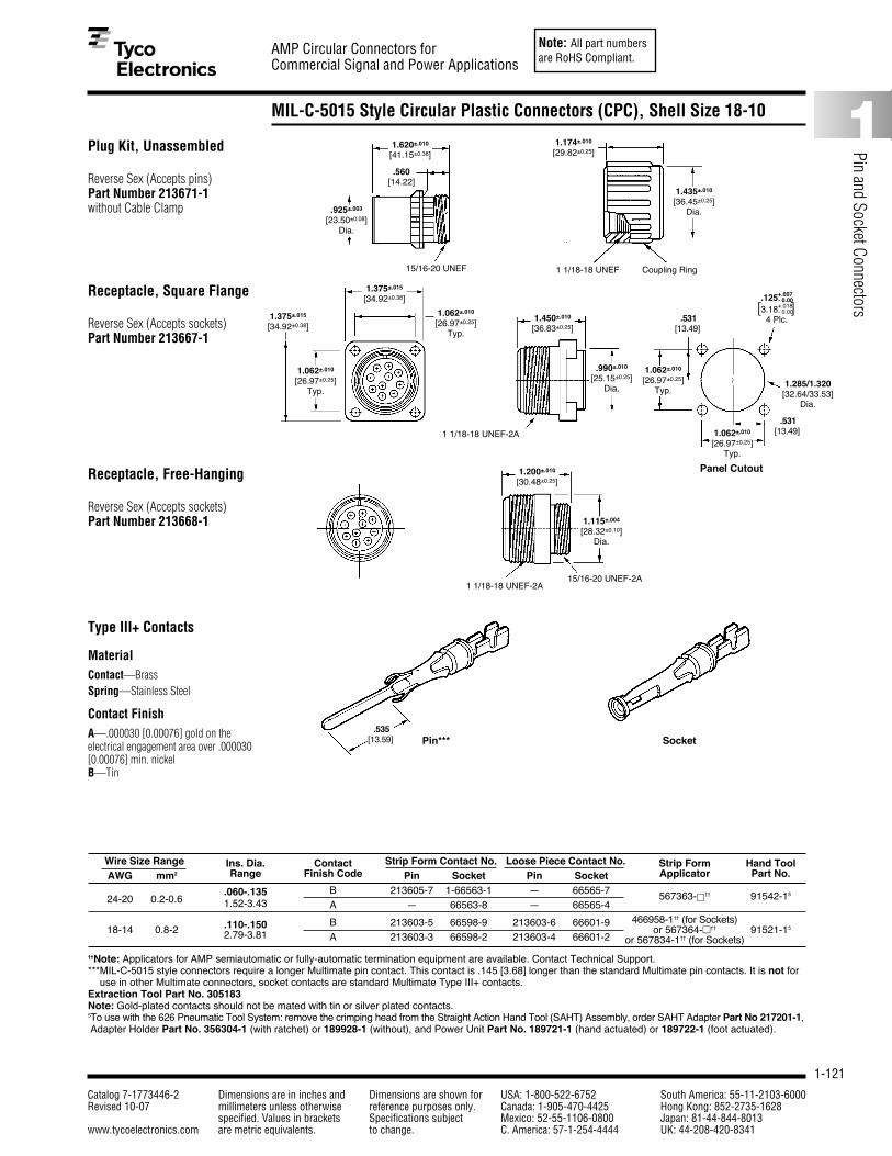
Note: All part numbersare RoHS Compliant.
1-121
AMP Circular Connectors forCommercial Signal and Power Applications
Catalog 7-1773446-2 Dimensions are in inches and Dimensions are shown for USA: 1-800-522-6752 South America: 55-11-2103-6000Revised 10-07 millimeters unless otherwise reference purposes only. Canada: 1-905-470-4425 Hong Kong: 852-2735-1628
specified. Values in brackets Specifications subject Mexico: 52-55-1106-0800 Japan: 81-44-844-8013www.tycoelectronics.com are metric equivalents. to change. C. America: 57-1-254-4444 UK: 44-208-420-8341
1
Pin and Socket Connectors
MIL-C-5015 Style Circular Plastic Connectors (CPC), Shell Size 18-10
Plug Kit, Unassembled
Reverse Sex (Accepts pins)Part Number 213671-1 without Cable Clamp
Wire Size Range Ins. Dia. Contact Strip Form Contact No. Loose Piece Contact No. Strip Form Hand ToolAWG mm2 Range Finish Code Pin Socket Pin Socket Applicator Part No.
.060-.135 B 213605-7 1-66563-1 — 66565-7 567363-□†† 91542-1524-20 0.2-0.6 1.52-3.43 A — 66563-8 — 66565-4
.110-.150 B 213603-5 66598-9 213603-6 66601-9 466958-1†† (for Sockets)18-14 0.8-2 2.79-3.81 or 567364-□†† 91521-15
A 213603-3 66598-2 213603-4 66601-2 or 567834-1†† (for Sockets)
††Note: Applicators for AMP semiautomatic or fully-automatic termination equipment are available. Contact Technical Support.***MIL-C-5015 style connectors require a longer Multimate pin contact. This contact is .145 [3.68] longer than the standard Multimate pin contacts. It is not for
use in other Multimate connectors, socket contacts are standard Multimate Type III+ contacts.Extraction Tool Part No. 305183Note: Gold-plated contacts should not be mated with tin or silver plated contacts.5To use with the 626 Pneumatic Tool System: remove the crimping head from the Straight Action Hand Tool (SAHT) Assembly, order SAHT Adapter Part No 217201-1,Adapter Holder Part No. 356304-1 (with ratchet) or 189928-1 (without), and Power Unit Part No. 189721-1 (hand actuated) or 189722-1 (foot actuated).
.560[14.22]
1.174±.010
[29.82±0.25]
15/16-20 UNEF
1.620±.010
[41.15±0.38]
.925±.003
[23.50±0.08]Dia.
1 1/18-18 UNEF Coupling Ring
1.435±.010
[36.45±0.25]Dia.
1.375±.015
[34.92±0.38]
1.375±.015
[34.92±0.38]
1.062±.010
[26.97±0.25]Typ.
1.062±.010
[26.97±0.25]Typ.
1 1/18-18 UNEF-2A
1.450±.010
[36.83±0.25]
.990±.010
[25.15±0.25]Dia.
15/16-20 UNEF-2A
1.200±.010
[30.48±0.25]
1.115±.004
[28.32±0.10]Dia.
[ ]
1.285/1.320[32.64/33.53]
Dia.
Panel Cutout
1.062±.010
[26.97±0.25]Typ.
.531[13.49]
.125+.007- 0.00
3.18+.018- 0.00
4 Plc.
.531[13.49]1.062±.010
[26.97±0.25]Typ.
1 1/18-18 UNEF-2A
.535[13.59] Pin*** Socket
Receptacle, Square Flange
Reverse Sex (Accepts sockets)Part Number 213667-1
Receptacle, Free-Hanging
Reverse Sex (Accepts sockets)Part Number 213668-1
Type III+ Contacts
MaterialContact—BrassSpring—Stainless Steel
Contact FinishA—.000030 [0.00076] gold on theelectrical engagement area over .000030[0.00076] min. nickelB—Tin
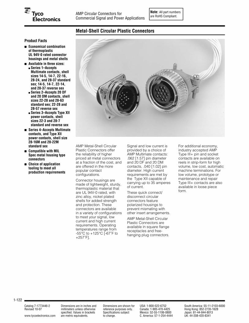
Note: All part numbersare RoHS Compliant.
1-122
AMP Circular Connectors forCommercial Signal and Power Applications
Catalog 7-1773446-2 Dimensions are in inches and Dimensions are shown for USA: 1-800-522-6752 South America: 55-11-2103-6000Revised 10-07 millimeters unless otherwise reference purposes only. Canada: 1-905-470-4425 Hong Kong: 852-2735-1628
specified. Values in brackets Specifications subject Mexico: 52-55-1106-0800 Japan: 81-44-844-8013www.tycoelectronics.com are metric equivalents. to change. C. America: 57-1-254-4444 UK: 44-208-420-8341
Metal-Shell Circular Plastic Connectors
Product Facts■ Economical combination
of thermoplastic UL 94V-0 rated connectorhousings and metal shells
■ Available in three sizes:■ Series 1–Accepts
Multimate contacts, shellsizes 14-5, 14-7, 22-16,28-24, and 28-37 standardsex; 14-5, 14-7, 22-14,and 28-37 reverse sex
■ Series 2–Accepts 20 DFand 20 DM contacts, shellsizes 22-28 and 28-63standard sex; 22-28 and28-57 reverse sex
■ Series 3–Accepts Type XIIpower contacts, shellsizes 22-3 and 28-7standard and reverse sex
■ Series 4–Accepts Multimatecontacts, and Type XIIpower contacts, shell size28-16M and 28-22Mstandard sex
■ Compatible with MIL Spec metal housing typeconnectors
■ Choice of applicationtooling to meet allproduction requirements
AMP Metal-Shell CircularPlastic Connectors offer the reliability of higherpriced all metal connectorsat a fraction of the cost, andare offered in the morepopular contactconfigurations.
Connector housings aremade of lightweight, sturdy,thermoplastic material thatare UL 94V-0 rated, withzinc alloy, nickel platedshells for added strengthand protection. These connectors are available in a variety of configurations to meet your signal, low current and high currentrequirements. Operatingtemperatures range from-55°C to +125°C [-67˚F to+257˚F].
Signal and low current isprovided by a choice ofAMP Multimate contacts:.062 [1.57] pin diameterand 20 DF and 20 DMcontacts, .040 [1.02] pindiameter. High currentrequirements are met by the Type XII capable ofcarrying up to 35 amperesof current.
These quick connect/disconnect circularconnectors featurepolarized housings toprevent mismating withother insert arrangements.
AMP Metal-Shell CircularPlastic Connectors areavailable in square flangereceptacles and free-hanging plug connectors.
For additional economy,industry accepted AMPType III+ pin and socketcontacts are available onreels in strip-form for highvolume, low cost, automaticmachine terminations. Forlow volume, prototype ormaintenance and repairType III+ contacts are alsoavailable in loose pieceform.
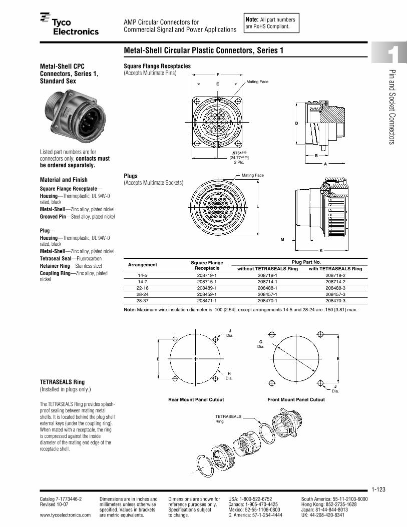
Note: All part numbersare RoHS Compliant.
1-123
AMP Circular Connectors forCommercial Signal and Power Applications
Catalog 7-1773446-2 Dimensions are in inches and Dimensions are shown for USA: 1-800-522-6752 South America: 55-11-2103-6000Revised 10-07 millimeters unless otherwise reference purposes only. Canada: 1-905-470-4425 Hong Kong: 852-2735-1628
specified. Values in brackets Specifications subject Mexico: 52-55-1106-0800 Japan: 81-44-844-8013www.tycoelectronics.com are metric equivalents. to change. C. America: 57-1-254-4444 UK: 44-208-420-8341
1
Pin and Socket Connectors
Metal-Shell Circular Plastic Connectors, Series 1
Metal-Shell CPCConnectors, Series 1,Standard Sex
Listed part numbers are forconnectors only; contacts mustbe ordered separately.
Material and FinishSquare Flange Receptacle—Housing—Thermoplastic, UL 94V-0rated, blackMetal-Shell—Zinc alloy, plated nickelGrooved Pin—Steel alloy, plated nickel
Plug—Housing—Thermoplastic, UL 94V-0rated, blackMetal-Shell—Zinc alloy, plated nickelTetraseal Seal—FluorocarbonRetainer Ring—Stainless steelCoupling Ring—Zinc alloy, platednickel
TETRASEALS Ring (Installed in plugs only.)
The TETRASEALS Ring provides splash-proof sealing between mating metalshells. It is located behind the plug shell external keys (under the coupling ring).When mated with a receptacle, the ringis compressed against the inside diameter of the mating end edge of thereceptacle shell.
Rear Mount Panel Cutout Front Mount Panel Cutout
Square Flange Receptacles(Accepts Multimate Pins)
Plugs(Accepts Multimate Sockets)
F
E
JDia.
HDia.
D
A
K
Mating Face
Mating Face
E
.975±.010
[24.77±0.03]2 Plc.
L
M
B
Arrangement Square Flange Plug Part No.Receptacle without TETRASEALS Ring with TETRASEALS Ring
14-5 208719-1 208718-1 208718-214-7 208715-1 208714-1 208714-222-16 208489-1 208488-1 208488-328-24 208459-1 208457-1 208457-328-37 208471-1 208470-1 208470-3
Note: Maximum wire insulation diameter is .100 [2.54], except arrangements 14-5 and 28-24 are .150 [3.81] max.
JDia.
GDia.
E
TETRASEALSRing

Note: All part numbersare RoHS Compliant.
1-124
AMP Circular Connectors forCommercial Signal and Power Applications
Catalog 7-1773446-2 Dimensions are in inches and Dimensions are shown for USA: 1-800-522-6752 South America: 55-11-2103-6000Revised 10-07 millimeters unless otherwise reference purposes only. Canada: 1-905-470-4425 Hong Kong: 852-2735-1628
specified. Values in brackets Specifications subject Mexico: 52-55-1106-0800 Japan: 81-44-844-8013www.tycoelectronics.com are metric equivalents. to change. C. America: 57-1-254-4444 UK: 44-208-420-8341
Metal-Shell Circular Plastic Connectors, Series 1 (Continued)
Metal-Shell CPCConnectors, Series 1,Reverse Sex
Listed part numbers are forconnectors only; contacts mustbe ordered separately.
Material and FinishSquare Flange Receptacle—Housing—Thermoplastic, UL 94V-0rated, blackMetal-Shell—Zinc alloy, plated nickelGrooved Pin—Steel alloy, plated nickel
Plug—Housing—Thermoplastic, UL 94V-0rated, blackMetal-Shell—Zinc alloy, plated nickelTetraseal Seal—FluorocarbonRetainer Ring—Retainer RingCoupling Ring—Zinc alloy, platednickel
TETRASEALS Ring(Installed in plugs only.)
The TETRASEALS Ring provides splash-proof sealing between mating metalshells. It is located behind the plug shellexternal keys (under the coupling ring).When mated with a receptacle, the ringis compressed against the insidediameter of the mating end edge of thereceptacle shell.
Arrangement Square Flange Plug Part No.Receptacle without TETRASEALS Ring with TETRASEALS Ring
14-5 208721-1 208720-1 —14-7 208717-1 208716-1 208716-222-14 208487-1 208486-1 208486-328-37 208473-1 208472-1 208472-3
Note: Maximum wire insulation diameter is .100 [2.54], except arrangements 14-5 and 28-24 are .150 [3.81] max.
Square Flange Receptacles(Accepts Multimate Sockets)
Rear Mount Panel Cutout Front Mount Panel Cutout
Plugs(Accepts Multimate Pins)
Mating Face
Mating Face
F
E
JDia.
HDia.
D
A
K
E
L
M
B
JDia.
GDia.
E
TETRASEALSRing

Note: All part numbersare RoHS Compliant.
1-125
AMP Circular Connectors forCommercial Signal and Power Applications
Catalog 7-1773446-2 Dimensions are in inches and Dimensions are shown for USA: 1-800-522-6752 South America: 55-11-2103-6000Revised 10-07 millimeters unless otherwise reference purposes only. Canada: 1-905-470-4425 Hong Kong: 852-2735-1628
specified. Values in brackets Specifications subject Mexico: 52-55-1106-0800 Japan: 81-44-844-8013www.tycoelectronics.com are metric equivalents. to change. C. America: 57-1-254-4444 UK: 44-208-420-8341
1
Pin and Socket Connectors
Metal-Shell CPC Connectors, Series 1, Contact Arrangements
Note: Contact arrangementsshown are of pin mating face (plugor receptacle). Socket mating faceis mirror image.
Shell Size 14
Shell Size 22
Shell Size 28
.170.000
.170[4.32] [4.32]
.094 .094[2.39] [2.39]
.172.000
.172[4.37] [4.37]
.086 .086[2.18] [2.18]
.126[3.2]
.047[1.19]
.000
.126[3.2]
.130[3.3]
.130[3.3]
.000
Arrangement 14-5 Arrangement 14-7Max. Wire Ins. Dia. = .150 [3.81] Max. Wire Ins. Dia. = .100 [2.54]
.150 .150[3.81] .000 [3.81]
.225 .075 .075 .225[5.72] [1.90] [1.90] [5.72]
.000
.193 .043 .032 .182[4.9] [1.09] [0.81] [4.62]
.268 .118 .107 .257[6.81] [3] [2.72] [6.53]
.205 [5.21]
.075 [1.91]
.000
.075 [1.91]
.205 [5.21]
.260 [6.6]
.130 [3.3]
.000
.130 [3.3]
.260 [6.6].150[3.81] .150 [3.81]
Arrangement 22-14 Arrangement 22-16Max. Wire Ins. Dia. = .100 [2.54] Max. Wire Ins. Dia. = .100 [2.54]
.375 .225 .075 .075 .225 .375[9.52] [5.72] [1.90] [1.90] [5.72] [9.52]
.450 .300 .150 .000 .150 .300 .450[11.43] [7.62] [3.81] [3.81] [7.62] [11.43]
.364 .182 .000 .182 .364[9.25] [4.62] [4.62] [9.25]
.455 .273 .091 .091 .273 .455[11.56] [6.93] [2.31] [2.31] [6.93] [11.56]
.316 [8.03]
.158 [4.01]
.000
.158 [4.01]
.316 [8.03]
.390 [9.91]
.260 [6.6]
.130 [3.3]
.000
.130 [3.3]
.260 [6.6]
.390 [9.91]
.150 [3.81]
Arrangement 28-24 Arrangement 28-37Max. Wire Ins. Dia. = .150 [3.81] Max. Wire Ins. Dia. = .100 [2.54]

Note: All part numbersare RoHS Compliant.
1-126
AMP Circular Connectors forCommercial Signal and Power Applications
Catalog 7-1773446-2 Dimensions are in inches and Dimensions are shown for USA: 1-800-522-6752 South America: 55-11-2103-6000Revised 10-07 millimeters unless otherwise reference purposes only. Canada: 1-905-470-4425 Hong Kong: 852-2735-1628
specified. Values in brackets Specifications subject Mexico: 52-55-1106-0800 Japan: 81-44-844-8013www.tycoelectronics.com are metric equivalents. to change. C. America: 57-1-254-4444 UK: 44-208-420-8341
Metal-Shell Circular Plastic Connectors, Series 2
Metal-Shell CPCConnectors, Series 2,Standard Sex
Listed part numbers are forconnectors only; contacts mustbe ordered separately.
Material and FinishSquare Flange Receptacle—Housing and Retention Insert—Thermoplastic, UL 94V-0 rated, blackMetal-Shell—Zinc alloy, plated nickelGrooved Pin—Steel alloy, plated nickel
Plug—Housing—Thermoplastic, UL 94V-0rated, blackMetal-Shell—Zinc alloy, plated nickelTetraseal Seal—FluorocarbonRetainer Ring—Stainless steelCoupling Ring—Zinc alloy, platednickel
Part No.Arrangement Square Flange Plug
Receptacle without Tetraseals Ring
22-28 208491-1 208490-128-63 208477-1 208476-1
Recommended Panel Cutout
Square Flange Receptacles(Accepts 20 DF and 20 DM Pins)
Plugs(Accepts 20 DF and 20 DM Sockets)
Mating Face
F
E
JDia.
D
A
K
E
L
M
B
GDia.

Note: All part numbersare RoHS Compliant.
1-127
AMP Circular Connectors forCommercial Signal and Power Applications
Catalog 7-1773446-2 Dimensions are in inches and Dimensions are shown for USA: 1-800-522-6752 South America: 55-11-2103-6000Revised 10-07 millimeters unless otherwise reference purposes only. Canada: 1-905-470-4425 Hong Kong: 852-2735-1628
specified. Values in brackets Specifications subject Mexico: 52-55-1106-0800 Japan: 81-44-844-8013www.tycoelectronics.com are metric equivalents. to change. C. America: 57-1-254-4444 UK: 44-208-420-8341
1
Pin and Socket Connectors
Metal-Shell Circular Plastic Connectors, Series 2 (Continued)
Metal-Shell CPCConnectors, Series 2,Reverse Sex
Listed part numbers are forconnectors only; contacts mustbe ordered separately.
Material and FinishSquare Flange Receptacle—Housing and Retention Insert—Thermoplastic, UL 94V-0 rated, blackMetal-Shell—Zinc alloy, plated nickelGrooved Pin—Steel alloy, plated nickel
Plug—Housing—Thermoplastic, UL 94V-0rated, blackMetal-Shell—Zinc alloy, plated nickelTetraseal Seal—FluorocarbonRetainer Ring—Stainless steelCoupling Ring—Zinc alloy, platednickel
Part No.Arrangement Square Flange Plug
Receptacle without Tetraseals Ring
22-28 208493-1 208492-128-57 208475-1 208474-1
Rear Mount Panel Cutout Front Mount Panel Cutout
Square Flange Receptacles(Accepts 20 DF and 20 DM Sockets)
Plugs(Accepts 20 DF and 20 DM Pins)
Mating Face
Mating Face
FE
JDia.
D
A
K
E
L
M
B
JDia.
GDia.
E
GDia.

Note: All part numbersare RoHS Compliant.
1-128
AMP Circular Connectors forCommercial Signal and Power Applications
Catalog 7-1773446-2 Dimensions are in inches and Dimensions are shown for USA: 1-800-522-6752 South America: 55-11-2103-6000Revised 10-07 millimeters unless otherwise reference purposes only. Canada: 1-905-470-4425 Hong Kong: 852-2735-1628
specified. Values in brackets Specifications subject Mexico: 52-55-1106-0800 Japan: 81-44-844-8013www.tycoelectronics.com are metric equivalents. to change. C. America: 57-1-254-4444 UK: 44-208-420-8341
Metal-Shell CPC Connectors, Series 2, Contact Arrangements
Note: Contact arrangementsshown are of pin mating face (plugor receptacle). Socket mating faceis mirror image.
.372 .248 .124 .000 .124 .248 .372[9.45] [6.3] [3.15] [3.15] [6.3] [9.45]
.434 .310 .186 .062 .062 .186 .310 .434[11.02] [7.87] [4.72] [1.57] [1.57] [4.72] [7.87] [11.02]
.124[3.15]
Arrangement 28-57 Arrangement 28-63Max. Wire Ins. Dia. = .068 [1.73] Max. Wire Ins. Dia. = .068 [1.73]
Shell Size 22
Shell Size 28
.443 [11.25]
.319 [8.1]
.212 [5.38]
.105 [2.67]
.019 [0.48]
.143 [3.63]
.250 [6.35]
.357 [9.07]
.464 [11.79]
.000
.248 .124 .000 .124 .248[6.3] [3.15] [3.15] [6.3]
.310 .186 .062 .062 .186 .310[7.87] [4.72] [1.57] [1.57] [4.72] [7.87]
.294 [7.47]
.170 [4.32]
.062 [1.57]
.000
.062 [1.57]
.170 [4.32]
.294 [7.47] .124[3.15]
.434 .310 .186 .062 .062 .186 .310 .434[11.02] [7.87] [4.72] [1.57] [1.57] [4.72] [7.87] [11.02]
.496 .372 .248 .124 .000 .124 .248 .372 .496[12.6] [9.45] [6.3] [3.15] [3.15] [6.3] [9.45] [12.6]
.448 [11.38]
.340 [8.64]
.232 [5.89]
.108 [2.74]
.000
.108 [2.74]
.232 [5.89]
.340 [8.64]
.448 [11.38]
.124 [3.15]
Arrangement 22-28Max. Wire Ins. Dia. = .068 [1.73]

Note: All part numbersare RoHS Compliant.
1-129
AMP Circular Connectors forCommercial Signal and Power Applications
Catalog 7-1773446-2 Dimensions are in inches and Dimensions are shown for USA: 1-800-522-6752 South America: 55-11-2103-6000Revised 10-07 millimeters unless otherwise reference purposes only. Canada: 1-905-470-4425 Hong Kong: 852-2735-1628
specified. Values in brackets Specifications subject Mexico: 52-55-1106-0800 Japan: 81-44-844-8013www.tycoelectronics.com are metric equivalents. to change. C. America: 57-1-254-4444 UK: 44-208-420-8341
1
Pin and Socket Connectors
Metal-Shell Circular Plastic Connectors, Series 3
Metal-Shell CPCConnectors, Series 3,Standard Sex
Listed part numbers are forconnectors only; contacts mustbe ordered separately.
Material and FinishSquare Flange Receptacle—Housing—Thermoplastic, UL 94V-0rated, blackMetal-Shell—Zinc alloy, plated nickelPeripheral Seal—Elastomer, greyGrooved Pin—Stainless steel
Plug—Housing—Thermoplastic, UL 94V-0rated, blackMetal-Shell—Zinc alloy, plated nickelTetraseal Seal—FluorocarbonRetainer Rings—Stainless SteelCoupling Ring—Zinc alloy, plated nickel
TETRASEALS Ring (Installed in Plugs only)
The TETRASEALS Ring provides splash-proof sealing between connector metal-shells. It is located behind the plug-shellexternal keys (under the coupling ring).When mated with a receptacle, the ring iscompressed against the inside diameterof the mating end edge of the receptacleshell.
Arrangement Square Flange Plug Part No.Receptacle without TETRASEALS Ring with TETRASEALS Ring
22-3 208495-1 208494-1 208494-328-7 208483-1 208482-1 —
Recommended Panel Cutout
Square Flange Receptacles(Accepts Type XII Male Pins)
Plugs(Accepts Type XII Female Sockets)
Mating Face
F
E
D
A
K
E
L
M
B
JDia.
GDia.
TETRASEALSRing
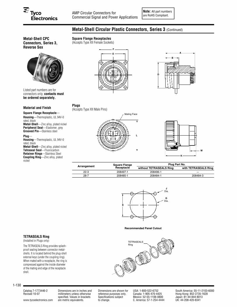
Note: All part numbersare RoHS Compliant.
1-130
AMP Circular Connectors forCommercial Signal and Power Applications
Catalog 7-1773446-2 Dimensions are in inches and Dimensions are shown for USA: 1-800-522-6752 South America: 55-11-2103-6000Revised 10-07 millimeters unless otherwise reference purposes only. Canada: 1-905-470-4425 Hong Kong: 852-2735-1628
specified. Values in brackets Specifications subject Mexico: 52-55-1106-0800 Japan: 81-44-844-8013www.tycoelectronics.com are metric equivalents. to change. C. America: 57-1-254-4444 UK: 44-208-420-8341
Metal-Shell Circular Plastic Connectors, Series 3 (Continued)
Metal-Shell CPCConnectors, Series 3,Reverse Sex
Listed part numbers are forconnectors only; contacts mustbe ordered separately.
Material and FinishSquare Flange Receptacle—Housing—Thermoplastic, UL 94V-0rated, blackMetal-Shell—Zinc alloy, plated nickelPeripheral Seal—Elastomer, greyGrooved Pin—Stainless steel
Plug—Housing—Thermoplastic, UL 94V-0rated, blackMetal-Shell—Zinc alloy, plated nickelTetraseal Seal—FluorocarbonRetainer Rings—Stainless SteelCoupling Ring—Zinc alloy, plated nickel
TETRASEALS Ring(Installed in Plugs only)
The TETRASEALS Ring provides splash-proof sealing between connector metal-shells. It is located behind the plug-shellexternal keys (under the coupling ring).When mated with a receptacle, the ring iscompressed against the inside diameterof the mating end edge of the receptacleshell.
Arrangement Square Flange Plug Part No.Receptacle without TETRASEALS Ring with TETRASEALS Ring
22-3 208497-1 208496-1 —28-7 208485-1 208484-1 208484-3
Recommended Panel Cutout
Square Flange Receptacles(Accepts Type XII Female Sockets)
Plugs(Accepts Type XII Male Pins)
Mating Face
F
E
D
A
K
L
M
B
JDia.
GDia.
E
TETRASEALSRing

Note: All part numbersare RoHS Compliant.
1-131
AMP Circular Connectors forCommercial Signal and Power Applications
Catalog 7-1773446-2 Dimensions are in inches and Dimensions are shown for USA: 1-800-522-6752 South America: 55-11-2103-6000Revised 10-07 millimeters unless otherwise reference purposes only. Canada: 1-905-470-4425 Hong Kong: 852-2735-1628
specified. Values in brackets Specifications subject Mexico: 52-55-1106-0800 Japan: 81-44-844-8013www.tycoelectronics.com are metric equivalents. to change. C. America: 57-1-254-4444 UK: 44-208-420-8341
1
Pin and Socket Connectors
Metal-Shell CPC Connectors, Series 3, Contact Arrangements
Note: Contact arrangementsshown are of pin mating face (plugor receptacle). Socket mating faceis mirror image.
Shell Size 22
Shell Size 28
.148 .000 .148[3.76] [3.76]
.107 [2.72]
.000
.213 [5.41]
Arrangement 22-3Max. Wire Ins. Dia. = .220 [5.59]
.343 .172 .000 .172 .343[8.71] [4.37] [4.37] [8.71]
.296 [7.52]
.000
.296 [7.52]
Arrangement 28-7Max. Wire Ins. Dia. = .220 [5.59]

Note: All part numbersare RoHS Compliant.
1-132
AMP Circular Connectors forCommercial Signal and Power Applications
Catalog 7-1773446-2 Dimensions are in inches and Dimensions are shown for USA: 1-800-522-6752 South America: 55-11-2103-6000Revised 10-07 millimeters unless otherwise reference purposes only. Canada: 1-905-470-4425 Hong Kong: 852-2735-1628
specified. Values in brackets Specifications subject Mexico: 52-55-1106-0800 Japan: 81-44-844-8013www.tycoelectronics.com are metric equivalents. to change. C. America: 57-1-254-4444 UK: 44-208-420-8341
Metal-Shell Circular Plastic Connectors, Series 4
Metal-Shell CPCConnectors, Series 4
Listed part numbers are forconnectors only; contacts mustbe ordered separately.
Material and FinishSquare Flange Receptacle—Housing—Thermoplastic, UL 94V-0rated, blackMetal-Shell—Zinc alloy, plated nickelGrooved Pin—Stainless steel
Plug—Housing—Thermoplastic, UL 94V-0rated, blackMetal-Shell—Zinc alloy, plated nickelTetraseal Seal—FluorocarbonRetainer Rings—Stainless SteelCoupling Ring—Zinc alloy, plated nickel
TETRASEALS Ring (Installed in Plugs only)
The TETRASEALS Ring provides splash-proof sealing between connector metal-shells. It is located behind the plug-shellexternal keys (under the coupling ring).When mated with a receptacle, the ring iscompressed against the inside diameterof the mating end edge of the receptacleshell.
Arrangement Square Flange Plug Part No.Receptacle without TETRASEALS Ring with TETRASEALS Ring
Standard Sex Reverse Sex Standard Sex Reverse Sex Standard Sex28-16M 208479-1 1776088-1 208478-1 1776089-1 208478-328-22M 208481-1 — 208480-1 — 208480-3
Rear Mount Panel Cutout
Square Flange Receptacles(Standard Sex Receptacles accept Type XII Male and Multimate Pins. Reverse Sex Receptacles accept Type XIIFemale and Multimate Sockets.)
Plugs(Standard Sex Plugs accept Type XII Female and Multimate Sockets. Reverse Sex Plugs accept Type XII Male andMultimate Pins.)
Front Mount Panel Cutout
Mating Face
F
E
JDia.
D
A
K
E
L
M
B
JDia.
GDia.
E
GDia.
TETRASEALSRing

Note: All part numbersare RoHS Compliant.
1-133
AMP Circular Connectors forCommercial Signal and Power Applications
Catalog 7-1773446-2 Dimensions are in inches and Dimensions are shown for USA: 1-800-522-6752 South America: 55-11-2103-6000Revised 10-07 millimeters unless otherwise reference purposes only. Canada: 1-905-470-4425 Hong Kong: 852-2735-1628
specified. Values in brackets Specifications subject Mexico: 52-55-1106-0800 Japan: 81-44-844-8013www.tycoelectronics.com are metric equivalents. to change. C. America: 57-1-254-4444 UK: 44-208-420-8341
1
Pin and Socket Connectors
Metal-Shell CPC Connectors, Series 4, Contact Arrangements
Note: Contact arrangementsshown are of pin mating face (plugor receptacle). Socket mating faceis mirror image.
Shell Size 28
.276 .092 .092 .276[7.01][2.34][2.34][7.01]
.400 .184 .000 .184 .400[10.16][4.67] [4.67] [10.16]
.400 [10.16]
.316 [8.03]
.158 [4.01]
.000
.158 [4.01]
.316 [8.03]
.400 [10.16]
Arrangement 28-16MMax. Wire Ins. Dia. =
.150 [3.81] for Multimate Contacts,.220 [5.59] for Power Contacts
.364 .182 .000 .182 .364[9.25][4.62] [4.62][9.25]
.455 .273 .091 .091 .273 .455[11.56][6.93][2.31][2.31][6.93][11.56]
.382 [9.7]
.316 [8.03]
.158 [4.01]
.000
.158 [4.01]
.316 [8.03]
.382 [9.7]
Arrangement 28-22MMax. Wire Ins. Dia. =
.150 [3.81] for Multimate Contacts,.220 [5.59] for Power Contacts
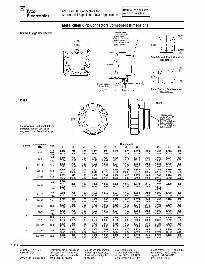
Note: All part numbersare RoHS Compliant.
1-134
AMP Circular Connectors forCommercial Signal and Power Applications
Catalog 7-1773446-2 Dimensions are in inches and Dimensions are shown for USA: 1-800-522-6752 South America: 55-11-2103-6000Revised 10-07 millimeters unless otherwise reference purposes only. Canada: 1-905-470-4425 Hong Kong: 852-2735-1628
specified. Values in brackets Specifications subject Mexico: 52-55-1106-0800 Japan: 81-44-844-8013www.tycoelectronics.com are metric equivalents. to change. C. America: 57-1-254-4444 UK: 44-208-420-8341
Metal-Shell CPC Connectors Component Dimensions
For drawings, technical data orsamples, contact your salesengineer or call Technical Support.
Square Flange Receptacles
Plugs
Thread-Size:7/8-20 UNEF-2A(Shell Size 14)
15/16-20 UNEF-2A(Shell Size 22)
1-3/8-18 UNEF-2A(Shell Size 28)
D Max.
A Max.
H Dia.
Panel Cutout, Front MountedReceptacle
Panel Cutout, Rear MountedReceptacle
Arrangement DimensionsSeries No. Sex
A B C D E F G H J K L MStd. 1.415 .745 .100 1.031 .906 1.185 1.070 1.070 .125 1.400 1.225 .380
14-5Rev. 35.94 18.92 2.54 26.19 23.01 30.1 27.18 27.18 3.18 35.56 31.12 9.65
Std. 1.415 .745 .100 1.031 .906 1.185 1.070 1.070 .125 1.400 1.225 .38014-7
Rev. 35.94 18.92 2.54 26.19 23.01 30.1 27.18 27.18 3.18 35.56 31.12 9.65
1.190 .790 .103 1.503 1.250 1.534 1.156 1.554 .120 1.560 1.750 .38022-14 Rev. 30.22 20.07 2.62 38.18 31.75 38.96 29.36 39.47 3.05 39.62 44.45 9.651
1.470 .790 .103 1.503 1.250 1.534 1.156 1.554 .120 1.265 1.750 .38022-16 Std. 37.34 20.07 2.62 38.18 31.75 38.96 29.36 39.47 3.05 32.13 44.45 9.651.555 .875 .125 1.900 1.562 1.950 1.610 1.970 .145 1.560 2.170 .38028-24 Std. 39.5 22.23 3.18 48.26 39.67 49.53 40.89 50.04 3.68 39.62 55.12 9.651.540 1.560Std. 39.12 .875 .125 1.900 1.562 1.950 1.610 1.970 .145 39.62 2.170 .380
28-371.260 22.23 3.18 48.26 39.67 49.53 40.89 50.04 3.68 1.840 55.12 9.65
Rev. 31.00 46.74Std. .934 .790 .103 1.503 1.250 1.534 1.156 1.554 .120 1.295 1.750 .380
22-28Rev. 23.72 20.07 2.62 38.18 31.75 38.96 29.36 39.47 3.05 32.89 44.45 9.65
1.229 .875 .125 1.900 1.562 1.950 1.610 1.970 .145 1.408 2.170 .3802 28-57 Rev. 31.22 22.22 3.18 48.26 39.67 49.53 40.89 50.04 3.68 35.76 55.12 9.651.229 .875 .125 1.900 1.562 1.950 1.610 1.970 .145 1.408 2.170 .38028-63 Std. 31.22 22.22 3.18 48.26 39.67 49.53 40.89 50.04 3.68 35.76 55.12 9.65
Std. 1.755 .790 .103 1.503 1.250 1.534 1.156 1.554 .120 1.805 1.750 .38022-3
Rev. 44.58 20.07 2.62 38.18 31.75 38.96 29.36 39.47 3.05 45.85 44.45 9.653
Std. 1.825 .875 .125 1.900 1.562 1.950 1.610 1.970 .145 2.125 2.170 .38028-7
Rev. 46.36 22.22 3.18 48.26 39.67 49.53 40.89 50.04 3.68 53.98 55.12 9.65
1.825 .875 .125 1.900 1.562 1.950 1.610 1.970 .145 2.125 2.170 .38028-13M Std. 46.36 22.22 3.18 48.26 39.67 49.53 40.89 50.04 3.68 53.98 55.12 9.651.825 .875 .125 1.900 1.562 1.950 1.610 1.970 .145 2.125 2.170 .3804 28-16M Std. 46.36 22.22 3.18 48.26 39.67 49.53 40.89 50.04 3.68 53.98 55.12 9.651.825 .875 .125 1.900 1.562 1.950 1.610 1.970 .145 2.125 2.170 .38028-22M Std. 46.36 22.22 3.18 48.26 39.67 49.53 40.89 50.04 3.68 53.98 55.12 9.65
Front and RearPanel Thk..125
[3.18] Max.
Dia.
Thread-Size:7/8-20 UNEF-2A(Shell Size 14)
1-3/16-18 UNEF-2A(Shell Size 22)
1-7/16-18 UNEF-2A(Shell Size 28)
K Max.
F ±.015[±0.38]
E ±.005[±0.13]
C ±.010[±0.25]
B ±.010[±0.25]
L ±.015[±0.38]
M ±.010[±0.25]
E ±.005[±0.13]
J ±.005[±0.13]
E ±.005[±0.13]
Dia.J ±.005
[±0.13]
Dia.G ±.010
[±0.25]

Note: All part numbersare RoHS Compliant.
1-135
AMP Circular Connectors forCommercial Signal and Power Applications
Catalog 7-1773446-2 Dimensions are in inches and Dimensions are shown for USA: 1-800-522-6752 South America: 55-11-2103-6000Revised 10-07 millimeters unless otherwise reference purposes only. Canada: 1-905-470-4425 Hong Kong: 852-2735-1628
specified. Values in brackets Specifications subject Mexico: 52-55-1106-0800 Japan: 81-44-844-8013www.tycoelectronics.com are metric equivalents. to change. C. America: 57-1-254-4444 UK: 44-208-420-8341
1
Pin and Socket Connectors
Metal-Shell CPC Connector Accessories
Cable Clamps
Material and FinishBody and Clamp Halves—Zinc alloy,nickel platedScrews and Washers—Stainlesssteel
Protective Cap Assemblies(for Metal-Shell CPCReceptacles Only)
Material and FinishZinc alloy, nickel plated
Shell Dimensions CableSize A B C O.D. Range Thread Size Part No.
.938 1.175 1.165 .225-.56214 23.83 29.85 29.59 5.71-14.27 7/8-20 UNEF-3B 208945-5
.938 1.432 1.469 .325-.75022 23.83 36.37 37.31 8.26-19.05 1-3/16-18 UNEF-3B 208945-7
1.031 1.593 1.688 .450-.93828 26.19 40.46 42.88 11.43-23.83 1-7/16-18 UNEF-3B 208945-8
Shell Dimensions Expanded Sealing Range Max. RecoveredSize A B Wall Thickness (Dia.) Inside Dia. Part No.
22 3.000 1.250 .070 .550 - 1.250 .500 54012-3
28 76.20 31.75 1.78 13.97 - 31.75 12.70 54012-4
Notes: 1. For Shell Size 22 Receptacle use plastic cable clamp Size 17, for Shell Size 28 Receptacle use plastic cable clamp Size 23.Use Size 14 metal cable clamp for both plug and receptacle Size 14 connectors.
2. Metal cable clamps (Sizes 22 and 28) are for use with Metal-Shell CPC plugs ONLY.
Shell Dimensions PartSize A B No.
1.225 .51514 31.11 13.08 213823-2
1.750 .63522 44.45 16.13 211903-1
2.170 .63528 55.12 16.13 211904-1
Cable Dia.Range
InternalThreads
Screw withLock Washer
(Two Supplied)
CableClampBody
Clamp Half(Two Supplied)
Plug (Shown forreference only)
3.000±.010
[76.2±0.25] BeadChain
B ±.031[±0.79]
A ±.031[±0.79]
C ±.031[±0.79]
A ±.010[±0.25]
B ±.010[±0.25]
Cable Entry SealsHeat Shrinkable Sealing Boots
Cable entry seals are used withjacketed cable to provide anenvironmentally sealed wire-to-connector system. They can be usedwith plugs.
Thick Wall Boots
MaterialInternal Sleeve—Nylon
Outer Tubing—Polyolefin, black

Note: All part numbersare RoHS Compliant.
1-136
AMP Circular Connectors forCommercial Signal and Power Applications
Catalog 7-1773446-2 Dimensions are in inches and Dimensions are shown for USA: 1-800-522-6752 South America: 55-11-2103-6000Revised 10-07 millimeters unless otherwise reference purposes only. Canada: 1-905-470-4425 Hong Kong: 852-2735-1628
specified. Values in brackets Specifications subject Mexico: 52-55-1106-0800 Japan: 81-44-844-8013www.tycoelectronics.com are metric equivalents. to change. C. America: 57-1-254-4444 UK: 44-208-420-8341
Miniature Circular Plastic Connectors (CPC)
Product Facts■ Two shell sizes: Size 8 (1-4)
or Size 11 (5-9) contactpositions
■ Pre-positioned 1/4 turncoupling ring with positivelock and alignment feature
■ Unique contact pattern foreach position size helpsprevent accidental matingwith other position sizes
■ Sealed to IP67 (Protectedagainst immersion in waterup to 1 meter for 1/2 hour)
■ Front or rear jam nut panelmounting
■ No assembly required■ Receptacle available in
free-hanging or panel mountversions
■ Alternate keys available
AMP Miniature CircularPlastic Connectors (CPC)are available in wire-to-wire and wire-to-panel configurations.
Utilizes existing Mini-Universal MATE-N-LOKstamped and formed con-tacts designed for up to 500 mating cycles whenplated with gold or up to 50cycles with tin plating.
Material and FinishSeal, Wire Entry—Elastomer, yellowor whiteSeal, Peripheral—Elastomer, grayHousing—Thermoplastic, black or redProtector, Seal—Thermoplastic,naturalRing, Coupling—Thermoplastic,blackNut, Jam—Brass, nickel platedPlate, Seal Retention—Thermoplastic, black
Technical DocumentsProduct Specification108-2079 Miniature CPC Connectors
■ Wide variety of customdiscrete type cableassemblies, terminatedwith Terminals andSplices, Soft Shell, and Circular PlasticConnectors and othercrimp and mass-terminated products.
■ Capability to producecustom overmoldedassemblies and insertand injection molding.
■ Jacketed cableassemblies and discretewire: Subminiature-D,SCSI, Circular Plastic,VHDCI, USB andShielded Data Link
Nylon housings offer goodresistance to a wide rangeof chemical agents whilethe IP67 sealing helps prevent ingress of dirt or fluids that could have anadverse effect on the contact interface.
Ideal for Industrial,Instrumentation andTransportation applicationswhere size, contact densityand environmental expo-sure are primary concerns.
Cable Assemblies

Note: All part numbersare RoHS Compliant.
1-137
AMP Circular Connectors forCommercial Signal and Power Applications
Catalog 7-1773446-2 Dimensions are in inches and Dimensions are shown for USA: 1-800-522-6752 South America: 55-11-2103-6000Revised 10-07 millimeters unless otherwise reference purposes only. Canada: 1-905-470-4425 Hong Kong: 852-2735-1628
specified. Values in brackets Specifications subject Mexico: 52-55-1106-0800 Japan: 81-44-844-8013www.tycoelectronics.com are metric equivalents. to change. C. America: 57-1-254-4444 UK: 44-208-420-8341
1
Pin and Socket Connectors
Miniature Circular Plastic Connectors (CPC) (Continued)
Receptacle Assembly, Panel Mount(Order pin contacts separately— see page 1-139)
.827[21.00]
5/8-24 UNEF-2A Thread Jam Nut shown for
reference only.Must be orderedseparately.
Flange Seal shown for reference only.Must be orderedseparately.
1/2-20 UNF-2A
White Alignment Dot
AlignmentIndicator
.555[14.10]
1.142[29.00]
Plug Assembly(Order socket contactsseparately — see page 1-139)
Positive Lock
Indicator
WhiteAignmentDots
Alignment Indicator Slots
.413[10.48]
1.142±.010[29.00±0.25]
.669 [17.00]
Receptacle Assembly,Free-Hanging(Order pin contacts separately— see page 1-139)
.551[14.00]
.551[14.00]
.606[15.39]
1/2-20 UNF-2AThread
WhiteAlignment
Dot
.55[14.10]
.06[1.50]
1.14[29.00]
Shell Size 8(4 Position shown)

Note: All part numbersare RoHS Compliant.
1-138
AMP Circular Connectors forCommercial Signal and Power Applications
Catalog 7-1773446-2 Dimensions are in inches and Dimensions are shown for USA: 1-800-522-6752 South America: 55-11-2103-6000Revised 10-07 millimeters unless otherwise reference purposes only. Canada: 1-905-470-4425 Hong Kong: 852-2735-1628
specified. Values in brackets Specifications subject Mexico: 52-55-1106-0800 Japan: 81-44-844-8013www.tycoelectronics.com are metric equivalents. to change. C. America: 57-1-254-4444 UK: 44-208-420-8341
Miniature Circular Plastic Connectors (CPC) (Continued)
Shell Size 11(9 Position shown)
Receptacle Assembly, Free-Hanging(Order pin contacts separately — see page 1-139)
Receptacle Assembly, Panel-Mount(Order pin contacts separately— see page 1-139)
3/4-20 UNEF-2AThread
Jam Nut & Flange Seal shown for reference
only. Must be ordered separately..689
[17.50]
.059[1.50]
1.14[29.00]
.555[14.10]
Positive LockIndicator
3/4-20UNEF-2AThread
.555[14.10]
.689[17.50]
.059 [1.50]
1.14[29.00]
.902[22.90]
.413[10.48]
PositiveLock
IndicatorAlignmentIndicatorSlots
WhiteAlignment
Dots
1.14 ± .010[29.00 ± 0.25]
Plug Assembly(Order socket contactsseparately — see page 1-139)
Housing Part Numbers Arrangement Housing Part NumbersShell No. of
InsulationPanel Mount Free-Hanging
Size Pos.Diameter Range
Receptacle Receptacle Plug
8 1 .035-.059 [.89-1.5]* 1445539-1 1445526-1 1445536-1.059-.110 [1.5-2.39] 1445539-3 1445526-3 1445536-3
8 2 .035-.059 [.89-1.5]* 1445538-1 1445522-1 1445535-1.059-.110 [1.5-2.39] 1445538-3 1445522-3 1445535-3
8 3 .035-.059 [.89-1.5]* 1445537-1 1445510-1 1445534-1.059-.110 [1.5-2.39] 1445537-3 1445510-3 1445534-3
8 4 .035-.059 [.89-1.5]* 1445421-1 1445389-1 1445390-1.059-.110 [1.5-2.39] 1445421-3 1445389-3 1445390-3
11 5 .035-.059 [.89-1.5]* 1445824-1 1445829-1 1445820-1.059-.110 [1.5-2.39] 1445824-3 1445829-3 1445820-3
11 6 .035-.059 [.89-1.5]* 1445823-1 1445828-1 1445819-1.059-.110 [1.5-2.39] 1445823-3 1445828-3 1445819-3
11 7 .035-.059 [.89-1.5]* 1445822-1 1445827-1 1445818-1.059-.110 [1.5-2.39] 1445822-3 1445827-3 1445818-3
11 8 .035-.059 [.89-1.5]* 1445821-1 1445826-1 1445817-1.059-.110 [1.5-2.39] 1445821-3 1445826-3 1445817-3
11 9 .035-.059 [.89-1.5]* 1445816-1 1445825-1 1445807-1.059-.110 [1.5-2.39] 1445816-3 1445825-3 1445807-3
Note: Alternate keys available (115˚ part numbers shown in above chart)*Insertion Tip (Seal Protector) Part No. 1604816-1 recommended for use when inserting socket contacts within this insulation range.
Standard stocked PartNumbers in BOLD type.
Z
Z
K REFSEE TABLE
Ø21.75

Note: All part numbersare RoHS Compliant.
1-139
AMP Circular Connectors forCommercial Signal and Power Applications
Catalog 7-1773446-2 Dimensions are in inches and Dimensions are shown for USA: 1-800-522-6752 South America: 55-11-2103-6000Revised 10-07 millimeters unless otherwise reference purposes only. Canada: 1-905-470-4425 Hong Kong: 852-2735-1628
specified. Values in brackets Specifications subject Mexico: 52-55-1106-0800 Japan: 81-44-844-8013www.tycoelectronics.com are metric equivalents. to change. C. America: 57-1-254-4444 UK: 44-208-420-8341
1
Pin and Socket Connectors
Miniature Circular Plastic Connectors (CPC) (Continued)
Jam Nuts Shell Dimensions PartSize A B Thread Number
8 .75 [19.0] .125 [3.2] 5/8-24 UNEF-2B 1604196-111 .875 [22.25] .125 [3.2] 3/4-20 UNEF-2B 1445904-1
A
Bsee chart
for Threads
Dust Caps Shell Dimensions PartSize A B Number8 .795 [20.2] .551 [14.0] 1604089-1
11 .89 [22.6] .736 [18.7] 1604089-2
∅ A ±.025[±0.64] ∅ B ±.025
[±0.64]
1.49±.010[37.9±0.25]
.094[2.4]
.146[3.70]
Contacts and ApplicationToolingPin (for Receptacles)
Socket (for Plugs)
.671 [17.04]
.659 [16.74]
Accessories (All accessories must be ordered separately.)Strain Reliefs
Shell Dimensions Part Number Size A B Straight Right-Angle8 .925 [23.5] .709 [18.0] 1445730-1 1445771-1
11 1.10 [28.0] .964 [24.5] 1445856-1 1546746-31
1546746-42
1 Open Style 2 With Cover A
B
Flange Seals Shell Dimensions PartSize A B Number8 .60 [15.3] .26 [6.6] 1445420-1
11 .73 [18.5] .33 [8.5] 1445420-2
Heat Shrink Boots Shell Dimensions PartSize A B Number
8 2.00 [50.8] .75 [19.0] 1546997-111 2.50 [63.5] 1.00 [25.4] 1546921-1
AB
Sealant Length
Contact Part NumbersWire Size Ins. Dia. Material Pin Socket HDM Hand
Range Range and Finish Strip Loose Strip LooseApplicator Tool
AWG [mm2]Form Piece Form Piece
Part No. Part No.
Brass, Pre-tin 770835-1 794059-1 770834-1 794058-1567418-12
30-26 .035-.050 Phos. Brz., Pre-tin — — 770834-4 —567418-22 90717-2[.05-.12] .889-1.27 Brass, Duplex1 1-770835-0 1-794059-0 1-770834-0 1-794058-0567418-32
Phos. Brz., Duplex1 — — 1-770834-1 —Brass, Pre-tin 770901-1 770985-1 770902-1 770986-1
567066-3326-22 .047-.069 Phos. Brz., Pre-tin — — 770902-4 —
567066-43 91529-1[.12-.3] 1.19-1.75 Brass, Duplex1 1-770901-0 1-770985-0 1-770902-0 1-770986-0567066-53
Phos. Brz., Duplex1 — — 1-770902-1 —
22-18 .059-.094 Brass, Pre-tin 770903-1 770987-1 770904-1 770988-1[.3-.8] 1.50-2.39 Phos. Brz., Pre-tin — — 770904-4 — 567067-12
or or Brass, Duplex1 1-770903-0 1-770987-0 1-770904-0 1-770988-0567067-22 91522-1
22 x (2) .067 x (2)Phos. Brz., Duplex1 — — 1-770904-1 —
567067-32
[.3] 3.381Duplex Finish – Plated with .000030 [.000762] min. gold in mating area and .000100 [.00254] min. tin in crimping areaover .000050 [.00127] min. nickel underplate on entire contact.
2HDM Applicator part number ending in -1 is used on AMPOMATOR CLS Machine with T or G Terminators, -2 is usedon AMP-O-LECTRIC Model K Machine, -3 is used on AMP-O-LECTRIC Model G Machine.
3HDM Applicator part number ending in -3 is used on AMPOMATOR CLS Machine with T or G Terminators, -4 is usedon AMP-O-LECTRIC Model K Machine, -5 is used on AMP-O-LECTRIC Model G Machine.
Note: All part numbers are RoHS Compliant.
Contact Extraction ToolPart No. 189727-1Instruction Sheet 408-4118Contact Insertion ToolPart No. 455830-1Instruction Sheet 408-7984(For inserting contacts applied to small diameterwire)
Insertion Tip (Seal Protector)Part No. 1604816-1(For inserting socket contacts applied to smalldiameter wire)

Note: All part numbersare RoHS Compliant.
1-140
AMP Circular Connectors forCommercial Signal and Power Applications
Catalog 7-1773446-2 Dimensions are in inches and Dimensions are shown for USA: 1-800-522-6752 South America: 55-11-2103-6000Revised 10-07 millimeters unless otherwise reference purposes only. Canada: 1-905-470-4425 Hong Kong: 852-2735-1628
specified. Values in brackets Specifications subject Mexico: 52-55-1106-0800 Japan: 81-44-844-8013www.tycoelectronics.com are metric equivalents. to change. C. America: 57-1-254-4444 UK: 44-208-420-8341
Application Tooling
CERTI-CRIMP “C” HeadStraight Action Hand Tool(SAHT), Part No. 69710-1
Premium grade hand tool.Features ratchet control toprovide complete crimpcycle. The interchangeabledie sets close in a straightline to minimize contact orterminal rotation duringcrimping. When applicable,user-assist features such as
a contact or terminal locatorand a wire stop, are builtinto the die set. Approximateweight 1.9 lb [0.86 kg].
For more information, request Catalog65780, Instruction Sheet 408-2095.
PRO-CRIMPER III HandTool, Part No. 58495-1
Commercial grade handtool for crimping variousproducts. Features ratchetcontrol to provide completecrimp cycle. Accepts bothpinned- and shouldered-style die sets. Locators areprovided with pinned-styledie sets for proper contactand wire positioning, and to
help minimize contactrotation and bending duringcrimping. Approximateweight 1.3 lb [0.60 kg].
For more information, request Catalog1773380, Instruction Sheet 408-9930.
SDE (Standard DieEnvelope) Die Sets
SDE die sets provide cost-effective flexibility, throughmany options for a commondie-set outline. The SDE diesets can be adapted for usewith CERTI-CRIMP handtools, PRO-CRIMPER IIIhand tools, the SDETerminator and the 626Pneumatic Tool System.
For more information, request Catalog1654003.
626 Pneumatic Tool System Lightweight, air-operatedmodular tooling system.Accepts a wide variety ofinterchangeable heads forcrimping various types ofcontacts, terminals andsplices onto wires ranging6-26 AWG [13-0.12 mm2],plus coaxial and fiber opticcable. Available with either
hand- or foot-actuationswitch. Optional ratchetcontrol available to providecomplete crimp cycle.
For more information, request Catalog124208.
Mechanical Hand Tools forInterchangeable Die Sets
These tools are ideal for small produc-tion, prototype and experimental applica-tions. They are used for terminating pinand socket contacts to wire and feature aratchet device to provide consistentlyformed crimps.
Pneumatic Hand Tool forInterchangeable Die Sets
SDE Terminator,Part No. 1490076-2
An electric crimp terminatorwith compact designfeatures a die set holderthat is compatible with allAMP SDE (PRO-CRIMPER IIITool) die sets. Hand- orfoot-actuated options areavailable. CE Approved.
For more information, request Catalog1654714.
Electric Machine forInterchangeable Die Sets
9293
6-8
1123
83
CERTI-CRIMP StraightAction Hand Tools (SAHT)
Premium grade hand tools.Feature ratchet control toprovide complete crimpcycle. Die sets close in astraight line. Include a con-tact locator and wire stop,plus an insulation crimp
adjustment lever, whenapplicable. Approximateweight 1.3 lb [0.59 kg]
For more information, request Catalog65780.
1120
76

Note: All part numbersare RoHS Compliant.
1-141
AMP Circular Connectors forCommercial Signal and Power Applications
Catalog 7-1773446-2 Dimensions are in inches and Dimensions are shown for USA: 1-800-522-6752 South America: 55-11-2103-6000Revised 10-07 millimeters unless otherwise reference purposes only. Canada: 1-905-470-4425 Hong Kong: 852-2735-1628
specified. Values in brackets Specifications subject Mexico: 52-55-1106-0800 Japan: 81-44-844-8013www.tycoelectronics.com are metric equivalents. to change. C. America: 57-1-254-4444 UK: 44-208-420-8341
1
Pin and Socket Connectors
Application Tooling (Continued)
AMP-O-LECTRIC Model “G”Terminating Machines, Part Nos. 354500-1, -9, -11
Semiautomatic benchmachines for crimpingreeled terminals and con-tacts, featuring a quiet andreliable direct motor drive,microprocessor controls forease of setup and opera-tion, and guarding andlighting designed for opera-tor convenience and safety.All models are equippedwith either manual or auto-matic precision adjustmentof crimp height. Machine-mounted sensors are avail-able for crimp quality moni-toring using conventionalminiature-style applicators.For more information, request Catalog 1654956-2, Video 198116, Catalog 82275 [Crimp QualityMonitor (CQM)], Video 198094.Note: New Stripping Moduleavailable, see page 1-143.
Crimp Machines
Crimp Quality Monitor (CQM)Part No. 1320420-2
The unique system provides100% on-the-fly crimpinspection. It measures thecrimp height of eachtermination, and evaluatesthe quality of each crimp. Ifa crimp is questionable, themonitor alerts the operatorwith both visual and audiblealarms. It also providesports for printing andnetworking. When used withAMP-O-LECTRIC Model “G”Termination Machines, themonitor is mounted to themachine. When used withAMPOMATOR CLS IV LeadMaking Machines, it isintegrated into themachine’s operatingsystem.
For more information, request Catalog 82275.
System III Applicator The System III Applicatorintroduces several newtechnologies into theapplicator including aprecision servo-electricmotorized feeding system,a built-in data module forstoring terminal crimp andset-up information, aprecision fit round ram, anda newly designed terminaldepressor. It still utilizes theproven quality of the HD-Mcrimper and anvil tooling.
AMP-TAPETRONIC Machine, Part No. 69875
AMP-O-LECTRIC Model “K”Terminating Machine with apermanently-mountedapplicator that acceptsinterchangeable die sets toapply a variety of tape-mounted terminals andsplices. Many of the diesets can also be used inAMP-O-LECTRICTerminating Machines witha tape applicator.
For more information, contact TycoElectronics.
AMP 3K/40 and AMP 5K/40Terminating Machines
The AMP 3K/40 and AMP5K/40 Terminators aredesigned for customers thatrequire the increasedoutput and quality of asemiautomatic machine at a competitive price. Byincorporating the mostcommonly requestedfeatures as standard andoffering a long list ofoptional equipment, theseterminators offer flexibility tomeet the specific needs ofvarious applications at thelowest possible cost.
1033
30
■ 3,000 lb [1361 kg] max.crimp force (AMP 3K/40);5,000 lb [2268 kg] max.crimp force (AMP 5K/40)
■ Toolless removal ofapplicators and guards
■ Jog capability■ Quiet, fast operation —
80/76 dBA and cycle timeless than 0.400 seconds
■ Accepts Heavy Duty Ministye applicators
■ Wide range of optionalequipment such as toollessprecision crimp heightadjust, batch counter, CQMcapability and work light
For more information, request Catalog 1654956-2.Note: New Stripping Moduleavailable, see page 1-143.
For more information, request Catalog1654956-8

Note: All part numbersare RoHS Compliant.
1-142
AMP Circular Connectors forCommercial Signal and Power Applications
Catalog 7-1773446-2 Dimensions are in inches and Dimensions are shown for USA: 1-800-522-6752 South America: 55-11-2103-6000Revised 10-07 millimeters unless otherwise reference purposes only. Canada: 1-905-470-4425 Hong Kong: 852-2735-1628
specified. Values in brackets Specifications subject Mexico: 52-55-1106-0800 Japan: 81-44-844-8013www.tycoelectronics.com are metric equivalents. to change. C. America: 57-1-254-4444 UK: 44-208-420-8341
Application Tooling (Continued)
AMPOMATOR CLS IV+ Lead-Making Machines,Part Nos. 356500-1, -2;1213400-1, -2
Fully-automatic machinesthat measure, cut, strip andterminate single leads.Microprocessor-controlled,and programmed andoperated using an easy-to-follow, menu-driven touch-screen. Features includedirect-drive terminatingunits with precision crimpheight adjustment, fullyprogrammable setups, wirerunout and splice detection,and motorized pre-feed withwire straightener. Crimpquality monitoring is alsoavailable.For more information, request Catalog 124324, Video 198142(NTSC), 199609 (PAL).
The AMPOMATOR System IIILeadmaker is designed forthe demands of low-volume/high mixmanufacturing and precisionquality. This leadmakercombines the best wireprocessing capabilities withnew technologies in terminalfeeding and machine set-upfound in the System IIIApplicator to offer significantadvantages for higherthroughput and efficiencies.See catalog 1654956-5 for moreinformation.
End-Feed Heavy-DutyMiniature Applicators(coded HDM)
Interchangeable applicatorsfor crimping productsreeled end-to-end (primarilyopen-barrel terminals).Used in bench and lead-making machines; mostdesigns can be used, oradapted for use with minortooling changes, dial-in set-tings for different wire sizesand insulation diameters.Mechanical or air-poweredfeed systems, dependingon the product applied.For more information, request Catalog 296393-2 and Instruction Sheet 408-8039.
EDGE Applicator Counter The new EDGE counter trackswearable tool usage for themost effective maintenanceplanning. The completelyelectronic counter, with clearLCD display, indicates cyclessince installation. Byperforming maintenance atmeasured intervals with pre-set limits, operators avoidbreakdowns and rejectscaused by tool wear or mis-adjustment. A wirelessinterface transfers counters toa PC running the optionalEdge Counter Software Pack. The EDGE is standard on allnew applicators and can beretrofitted to most existingTyco Electronics applicators. See catalog 1773385 for more information.
Lead Makers
1102
34
Applicators
Komax 433-S alpha Lead-Making Machine
The 433-S alpha offersmaximum flexibility forapplying seals to one or bothends of the wire with thecorresponding terminal. Whenequipped with the mci 711crimp terminator and mci 761seal applicator, the fully-automated 433-S alpha formsa highly compact system withoptimum accessibility.Dynamic servo-drives providefine travel settings on all motoraxes and the wire straighteningunit with quick-release lock andautomatic lead-in featurereduces wire changeover time.The TopWin software providesfor fast, simple data input.For more information, request Catalog 1307801.
Komax gamma 333 PCLead-Making Machine
AMPOMATOR System IIILeadmaker
This fully-automatic, PC-controlled leadmaker can beequipped with up to threeprocessing stations enablingthe crimping of both ends ofthe wire, double-crimpconnections with threedifferent contacts, single-ended seal applications,tinning or ink-jet marking.Features include ultra-shortconversions times, easy-to-use graphic-based TopWininterface with multiple-language capability, crimpforce analyzer with statisticalanalysis, seal monitoring, andintegrated good/bad sorting.For more information, request Catalog 1307901.

Note: All part numbersare RoHS Compliant.
1-143
AMP Circular Connectors forCommercial Signal and Power Applications
Catalog 7-1773446-2 Dimensions are in inches and Dimensions are shown for USA: 1-800-522-6752 South America: 55-11-2103-6000Revised 10-07 millimeters unless otherwise reference purposes only. Canada: 1-905-470-4425 Hong Kong: 852-2735-1628
specified. Values in brackets Specifications subject Mexico: 52-55-1106-0800 Japan: 81-44-844-8013www.tycoelectronics.com are metric equivalents. to change. C. America: 57-1-254-4444 UK: 44-208-420-8341
1
Pin and Socket Connectors
Application Tooling (Continued)
Stripper-CrimperApplicators (coded SCA)
Interchangeable applicatorsfor crimping products inAMP-O-MATIC Stripper-Crimper Machines. Consistof separate ram and lowertooling assemblies. Similardial-in settings for differentwire sizes and insulationdiameters as HDMapplicators. Available withsensors for use with theCrimp Quality Monitor.
For more information, request Catalog65004 (AMP-O-MATIC Stripper-Crimper Machines), Catalog 82275[Crimp Quality Monitor (CQM)].
AMP-O-MATIC Stripper-Crimper Machines, Part Nos. 1320895-1, -2
Semiautomatic benchcrimping machines that alsostrip the wire, and are there-fore used for terminatingjacketed cable. Featuremanual precision adjust-ment of crimp height, keyedstrip blades for faster, moreaccurate setups, and anefficient scrap removal sys-tem. All adjustments can bemade from the front of themachines without specialtools. Available with crimpquality monitoring.
For more information, request Catalog 65004, Video 198075, Catalog82275 [Crimp Quality Monitor(CQM)], Video 198094.
Stripper-Crimper Machines
Komax Delta 60Wire Stripper
The semiautomatic Delta 60 isdesigned to strip single- andmultiple-pole conductors withpull-off lengths of .984 [25] or3.78 [96]. Thanks to theelectric drive and non-pneumatic design, the deviceis quick and quiet in operationand can be utilized virtuallyanywhere. The Delta 60 candesheath or strip strandedconductors and multiple wirecables with external diametersof up to .433 [11].See catalog 1654956 for more information.
Cosmic 927R Micro-CableStripper
The compact, lightweight,benchtop Cosmic 927R wasdesigned and developed toreliably strip various insulationmaterials and micro-cable.From conductor diameter 36 to 10 AWG, the strippingdiameter display can be set towithin 0.1 mm increments. See catalog 1773385-4 for moreinformation.
Cosmic 30M Wire StrippingMachine, 5-528367-0
The Cosmic 30M is a highprecision, high speedelectrical wire stripper that isvery easy to operate. It’sequipped with a four bladesystem and an optionalgripper for more difficult wires.There is a digital display forthe wire diameter that can beset at 0.01 mm increments. See catalog 1773385-2 for moreinformation.
8982
7
Stripping Module (for theAMP 3K/40 and AMP 5K/40Terminating Machines andAMP-O-LECTRIC Model “G”Terminator)
The combination of theStripping Module with theAMP 3K/40 and AMP 5K/40Terminating Machines orthe AMP-O-LECTRIC Model “G” Terminatorprovides an economic andproficient method ofstripping the wire andcrimping terminals on thesame machine. The moduleaccepts End- and Side-Feed HDM Applicators (32-14 AWG) and operatesin three modes: crimp only,strip only, or strip andcrimp. It can be installed on existing machines in thefield or purchased as oneunit from the factory.
1120
75-2
For more information, request Catalog 1309085.
Side-Feed Heavy-DutyMiniature Applicators(coded HDM)
Interchangeable applicatorsfor crimping productsreeled side-by-side on sin-gle or dual carrier strips(primarily closed-barrel ter-minals and open-barrel con-tacts). Similar design as theend-feed version. All side-feed applicators include awire stop to help correctlyposition the wire end in thecrimping target area.For more information, request Catalog 296393-2 and Instruction Sheet 408-8040.
8982
8

Note: All part numbersare RoHS Compliant.
1-144
AMP Circular Connectors forCommercial Signal and Power Applications
Catalog 7-1773446-2 Dimensions are in inches and Dimensions are shown for USA: 1-800-522-6752 South America: 55-11-2103-6000Revised 10-07 millimeters unless otherwise reference purposes only. Canada: 1-905-470-4425 Hong Kong: 852-2735-1628
specified. Values in brackets Specifications subject Mexico: 52-55-1106-0800 Japan: 81-44-844-8013www.tycoelectronics.com are metric equivalents. to change. C. America: 57-1-254-4444 UK: 44-208-420-8341
Technical Documents
Various technical documents are available for your use:
Product Specifications describe technical performance characteristics and verification tests. They are intended forthe Design, Component and Quality Engineer.
108-1579 Sealed CPC Connectors with Removable Contacts108-2079 Miniature CPC Connectors108-10024 CPC Connectors108-10024-2 (Series 1)108-10024-3 (Series 2)108-10024-4 (Series 3 & 4)108-10037 Contacts, Type XII108-10040 Metal-Shell CPC Connectors108-10042 Contacts, Type III +108-40005 Contacts, Size 20 DF
Application Specifications describe requirements for using the product in its intended application and/or crimping information. They are intended for the Packaging and Design Engineer and the Machine Setup Person.
114-10000 Contacts, Size 20 DF114-10004 Contacts, Type III +114-10005 Contacts, Type XII114-10038 CPC Connectors
Instruction Sheets provide instructions for assembling or applying the product. They are intended for theManufacturing Assembler or Operator.
408-4317 Two-Piece Sealed CPC Connectors408-6641 Metal-Shell CPC Connectors408-7582 Accessories for CPC Connectors408-7593 CPC Connectors408-7901 Application and Maintenance for AMP Hand Crimp Tool408-8416 CPC Right-Angle Cable Clamp Assembly
Tool Part No. Instruction Sheet58495-1 408-981969710-1 408-209591019-3 408-727691067-2 408-7508
Tool Part No. Instruction Sheet91285-1 408-9404
305183 408-1216318813-1 408-4374
Application Tooling/Instruction Sheet Cross Reference

1-145
AMP Industrial Ethernet — Circular Sealed RJ-45 Connectors
Catalog 7-1773446-2 Dimensions are in inches and Dimensions are shown for USA: 1-800-522-6752 South America: 55-11-2103-6000Revised 10-07 millimeters unless otherwise reference purposes only. Canada: 1-905-470-4425 Hong Kong: 852-2735-1628
specified. Values in brackets Specifications subject Mexico: 52-55-1106-0800 Japan: 81-44-844-8013www.tycoelectronics.com are metric equivalents. to change. C. America: 57-1-254-4444 UK: 44-208-420-8341
1
Pin and Socket Connectors
Product Facts■ Threaded outer connection
contributes to:■ Environmental sealing
(IP67 rated)■ Vibration resistance■ Secure, robust
connections
■ Provide for reliableperformance in electricallynoisy conditions found onmost factory floors
■ Compatible with Category5e cable
■ Fully intermateable withunshielded product
The Tyco Electronics family of Industrial Ethernetconnectors and cableassemblies is designed tomeet the many demandingmanufacturing, processing,and commercial applicationrequirements. Combiningexisting RJ-45 connectortechnology with theIndustry’s proven mini-circular format connectors,offers a series of productsthat greater protect theintegrity of your datatransmission — in manychallenging operatingenvironments.
The Tyco Electronics line ofReceptacles offers a varietyof packaging solutions:from widely accepted 110 Punchdown Block,Printed Circuit Board (PCB)Mount configurations, andBulkhead Passthrough.Plug Assemblies are offeredin complete overmoldedcordsets in various lengthsand configurations. A Field-Attachable Plug connector,that utilizes standardtermination tooling, isavailable to producecustom cable lengths.
Related Catalogs82066 — Modular Jacks1307282 — Modular Plugs
Introduction

1-146
AMP Industrial Ethernet — Circular Sealed RJ-45 Connectors
Catalog 7-1773446-2 Dimensions are in inches and Dimensions are shown for USA: 1-800-522-6752 South America: 55-11-2103-6000Revised 10-07 millimeters unless otherwise reference purposes only. Canada: 1-905-470-4425 Hong Kong: 852-2735-1628
specified. Values in brackets Specifications subject Mexico: 52-55-1106-0800 Japan: 81-44-844-8013www.tycoelectronics.com are metric equivalents. to change. C. America: 57-1-254-4444 UK: 44-208-420-8341
1.500�[38.10]
1.732�[43.99]
.675�[17.10]
.125�[3.18]
Ref.
Ref..090�[2.29]
Ref.2 Plcs.
Ref.
Ref.
RJ45Connector
1.650�[41.91]
Ref.
ThickHex Nut
.200�[5.08]
1 1/4-16 UN-2AThread
1-14 UN-2AThread
Viton O-RingViton O-Ring
Ø .095 [2.41]
2 Plcs.
Ø .100 [2.54]
Ø 1.650 [41.91]
Keep Out Area
4 Plcs.
Ø .034 [0.86]
8 Plcs.
.650[16.51]
2.85[7.24]
.570[14.48]
.325[8.26]
1.035[26.29]
.354[8.99]
.518[13.16]
.178[4.52]
.100[2.54]
.100 [2.54].060 [1.52]
.020 [0.51]
.140 [3.56].100 [2.54].060 [1.52].020 [0.51]
.140 [3.56]
.018[0.46]
PCB Layout
Receptacles
Direct PCB MountReceptacleLow profile receptacle thatsolders directly to a printedcircuit board (PCB) —intended for OEMs whowish to incorporate arobust, sealed connectioninto their field equipment.Ideal for OEMs who wish toincorporate a sealed RJ-45in the smallest possiblepackage.
Description Part NumberDirect PCB mount 8 pin through-hole receptacle, 1546405-1front coupling hex nut
Closure Cap Maintains better sealingintegrity when a connectoris not mated with thereceptacle.
MaterialClosure Cap — Delrin (black)
Description Part NumberClosure Cap for Receptacles, IP67 rated(with 3.63 [92.2] lanyard) 1-1546406-1
Closure Cap for Receptacles, IP65 rated 1-1546407-1Closure Cap for Plug cordset, IP67 rated 1-1546408-1(with 3.63 [92.2] lanyard)
Material and FinishReceptacle Shell — Acrylonitrile-Butadiene-Styrene (ABS) in standardversion; Acrylonitrile-Styrene-Acrylate in UV stabilized versionO-Ring — Vition Rubber
1-14 UNC Thread
The Tyco Electronics line ofreceptacles offers solutionsfor Ethernet field deviceconnectivity, in many
challenging operatingenvironments. Allreceptacles are compatiblewith standard commercial
RJ-45 connectors, enablinga better solution for bothharsh and benignenvironments.

1-147
AMP Industrial Ethernet — Circular Sealed RJ-45 Connectors
Catalog 7-1773446-2 Dimensions are in inches and Dimensions are shown for USA: 1-800-522-6752 South America: 55-11-2103-6000Revised 10-07 millimeters unless otherwise reference purposes only. Canada: 1-905-470-4425 Hong Kong: 852-2735-1628
specified. Values in brackets Specifications subject Mexico: 52-55-1106-0800 Japan: 81-44-844-8013www.tycoelectronics.com are metric equivalents. to change. C. America: 57-1-254-4444 UK: 44-208-420-8341
1
Pin and Socket Connectors
Receptacles (Continued)
.195[4.95]
1.050[26.67]
1.004[25.50] Dia.
Backend Dimensionsof Receptacle
Receptacle with PCB and Cable
Receptacle with PCB
.940[23.90]
Ref.
12.00[304.8]
Cat. 5 CableConduit Nut
.062[1.57]
Thick NitrileGasket
.620[15.70]
1-14 UNCThread
.062[1.57]
Thick NitrileGasket
PCB
NitrileO-Ring
ConduitNut
1-14 UNCThread
NitrileO-Ring
.940[23.90]
Ref.
Ref.
1.960[49.80]
Ref.
1.500[38.10]
1.300[33.00]
Ref.
Ref.
PCB
Standard PCB BoardReceptacleHighly flexible solution thatenables an OEM or end-user to solder a cable leadto an internal Ethernetconnection.
Description Part NumberReceptacle with PC Board 1-1546409-1Receptacle with PCB & 12" of cable 1-1546410-1(10 Base-T)Receptacle with PCB & 12" of cable 1-1546411-1(568A)Receptacle with PCB & 12" of cable 1-1546412-1(568B)
Material and FinishReceptacle Shell — Acrylonitrile-Butadiene-Styrene (ABS) in standardversion; Acrylonitrile-Styrene-Acrylate in UV stabilized versionO-Ring — Nitrile Rubber

1-148
AMP Industrial Ethernet — Circular Sealed RJ-45 Connectors
Catalog 7-1773446-2 Dimensions are in inches and Dimensions are shown for USA: 1-800-522-6752 South America: 55-11-2103-6000Revised 10-07 millimeters unless otherwise reference purposes only. Canada: 1-905-470-4425 Hong Kong: 852-2735-1628
specified. Values in brackets Specifications subject Mexico: 52-55-1106-0800 Japan: 81-44-844-8013www.tycoelectronics.com are metric equivalents. to change. C. America: 57-1-254-4444 UK: 44-208-420-8341
Receptacles (Continued)
Bulkhead PassthroughThe perfect solution to bringEthernet into a cabinet orcontrol box. Simply mountbulkhead product in a panelcutout, mate a sealedconnector on the outside ofthe enclosure, and run acommercial patch cord fromthe backside RJ-45 jack toyour PLC, I/O, or EthernetControl Board. No conduitentry is required.
Contact Tyco Electronics for UV stabilized versionsfor outdoor use.
Description Part NumberRJ-45 Bulkhead passthrough with 1546413-3backside RJ-45 jackRJ-45 Bulkhead passthrough with 1546413-4backside jack and grounding strapRJ-45 Bulkhead passthrough with 1-1546414-412" of patch cordRJ-11 Bulkhead passthrough with 1-1546415-1backside RJ-11 jack
1.500�[38.10]
1.300�[33.00]�
Ref.
.840�[21.30]�
Ref.
.940�[23.90]�
Ref.
.195�[4.95]
1.050�[26.67]
.620�[15.70]
Ref.
.520�[13.20]�
Ref.RJ45�Connector
1-14 UNC Thread.062�[1.57]
Thick Nitrile�GasketNitrile O-Ring
Conduit�Nut
.750�[19.05] .940�
[23.90]Ref.
Length
Cat. 5 Cable
Conduit�Nut
.750�[19.05]
Nitrile O-Ring
1-14 UNC Thread
.062�[1.57]
Thick Nitrile�Gasket
Ref. 1.004�[25.50]
Dia.
Backend of Receptacle
Material and FinishReceptacle Shell — Acrylonitrile-Butadiene-Styrene (ABS) in standardversion; Acrylonitrile-Styrene-Acrylate in UV stabilized versionO-Ring — Nitrile Rubber
Performance CharacteristicsOperating Temperature — -4° to 176°F [-20° to 80°C]Return Loss — 5 dB @ 100 MHzShock/Vibration — Per IEC 60068-2-6Environmental Rating — IEC IP67TIA/EIA Rating — 110 Punchdown and BulkheadPassthrough are Category 5e compliant;Direct PCB Mount is Category 5compliant; Standard PC Board is notrated — additional customer terminationis requiredKnockout Hole for Receptacle —1.031 [26.19]Mating Thread — UNC 1" - 14
Backside RJ-45 JackSpecifications Base Material — Copper alloy w/30 µ-inches gold alloyUnderplating — 2.54 microns ofnickelMating Cycles — 250 min.Current Rating — 1.5 AmpVoltage Rating — 125 V DC
Receptacle withBackside RJ-45 Jack
Receptacle with 12" Patch Cord

1-149
AMP Industrial Ethernet — Circular Sealed RJ-45 Connectors
Catalog 7-1773446-2 Dimensions are in inches and Dimensions are shown for USA: 1-800-522-6752 South America: 55-11-2103-6000Revised 10-07 millimeters unless otherwise reference purposes only. Canada: 1-905-470-4425 Hong Kong: 852-2735-1628
specified. Values in brackets Specifications subject Mexico: 52-55-1106-0800 Japan: 81-44-844-8013www.tycoelectronics.com are metric equivalents. to change. C. America: 57-1-254-4444 UK: 44-208-420-8341
1
Pin and Socket Connectors
Female-to-Female Adapters
Female-to-Female Adapter Description Part NumberFemale-to-Female Adapter 1546574-1
Viton O-Ring1" – 14 UNS Thread
Delrin CoverFemale RJ45 Jack
1.97[50.0]
Nom.
1.3[33.0]
Threaded-through PanelInterconnect (M40)
Description Part NumberThreaded-through Panel InterconnectM40 thread size 1546641-1
Female RJ45 JackFront View
Locknut not shown
Recommended Max. Panel Thickness: .236 [6.0]
1.3[33.0]
Viton O-Ring
1.97[50.0]
Nom.
1" – 14 UNS Thread
M40 x 1.5 Thread
M40 x 1.5 Locknut1.81 [46.0] A/F, .39 [10.0] Thick
Performance CharacteristicsOperating Temperature — -4° to 176°F [-20° to 80°C]Shock/Vibration — Per IEC 60068-2-6Environmental Rating — IEC IP67Mating Thread — UNC 1" - 14
Material and FinishReceptacle Shell — Acrylonitrile-Butadiene-Styrene (ABS) in standardversion; Acrylonitrile-Styrene-Acrylatein UL stabilized versionO-Ring — Nitrile Rubber
Material and FinishReceptacle Shell — Acrylonitrile-Butadiene-Styrene (ABS) in standardversion; Acrylonitrile-Styrene-Acrylatein UL stabilized versionO-Ring — Nitrile Rubber
Performance CharacteristicsOperating Temperature — -4° to 176°F [-20° to 80°C]Shock/Vibration — Per IEC 60068-2-6Environmental Rating — IEC IP67Mating Thread — UNC 1" - 14

1-150
AMP Industrial Ethernet — Circular Sealed RJ-45 Connectors
Catalog 7-1773446-2 Dimensions are in inches and Dimensions are shown for USA: 1-800-522-6752 South America: 55-11-2103-6000Revised 10-07 millimeters unless otherwise reference purposes only. Canada: 1-905-470-4425 Hong Kong: 852-2735-1628
specified. Values in brackets Specifications subject Mexico: 52-55-1106-0800 Japan: 81-44-844-8013www.tycoelectronics.com are metric equivalents. to change. C. America: 57-1-254-4444 UK: 44-208-420-8341
Cordsets
Overmolded Cordsets,Double-ended
Overmolded Cordsets are available in twoconfigurations. When both
cord ends are in a harshenvironment, order thedouble-ended configurationwith two industrial sealedplug connectors; for a cablewith one end in a harshenvironment, and the otherin a sealed or office area,order with one industrialplug connector and onecommercial grade plug fora better fit into a standardpatch panel. Various cabletypes are available to bestmatch the requirements ofthe applications. Solid core
shielded PUR cable is usedfor longer “horizontal crossconnection runs”, whilestranded PVC is moreappropriate for shorter“patch cord” applicationswhere greater cableflexibility is desired. Forextreme environmentalconditions, Proplex™ cableprovides a Kevlar innerwrap and an unmatchedtemperature range -94°F to+221°F [-70°C to +105°C].Plugs are available in bothRJ-45 and RJ-11 formats.
Tyco Electronics cordsetsutilize a standard RJ-45plug, but add strain reliefand a locking mechanismthat creates a seal when
mated with a receptacle.Cordsets can be ordered instandard or custom lengthsas an overmolded cordset(see chart below), or Plug.
2.260�[57.40]
1.120�[28.40]Ref.
Length
Ref.2.260�[57.40]
Ref.
Material and FinishInsert — Acrylonitrile-Butadiene-Styrene (ABS)Overmold — Polyurethane (Solid Core& Proplex), PVC (Stranded)Coupling Nut — Acrylonitrile-Butadiene-Styrene (ABS) in standardversion; Acrylonitrile-Styrene-Acrylate inUV stabilized version
Connector SpecificationsRecommended Mating Torque —12 inch-lbs. [1.36 N-m]
Double-ended Cordsets
Cable RJ-45 Plug EndsLength
Part Numberm ft
Solid core Industrial (both ends) 1 [3.3] 1-1546451-1Solid core Industrial (both ends) 5 [16.4] 1-1546451-2Solid core Industrial (both ends) 10 [32.8] 1-1546451-3Solid core Industrial/Commercial 2 [6.6] 1-1546451-4Proplex Industrial (both ends) 2 [6.6] 1-1546452-1Proplex Industrial (both ends) 5 [16.4] 1-1546452-2Stranded Industrial (both ends) 2 [6.6] 1-1546453-1Stranded Industrial (both ends) 5 [16.4] 1-1546453-2

1-151
AMP Industrial Ethernet — Circular Sealed RJ-45 Connectors
Catalog 7-1773446-2 Dimensions are in inches and Dimensions are shown for USA: 1-800-522-6752 South America: 55-11-2103-6000Revised 10-07 millimeters unless otherwise reference purposes only. Canada: 1-905-470-4425 Hong Kong: 852-2735-1628
specified. Values in brackets Specifications subject Mexico: 52-55-1106-0800 Japan: 81-44-844-8013www.tycoelectronics.com are metric equivalents. to change. C. America: 57-1-254-4444 UK: 44-208-420-8341
1
Pin and Socket Connectors
Field-Attachable Plug
Description Part NumberField-attachable RJ-45 Plug connector, 1546440-10.1-0.26 [2.5-6.5] acceptable cable dia.
Solid Core Cable Conductors — 24 AWG solid barecopper, .020 [0.51]Insulation — .009 [0.23] of cellularpolyethylene; .040 [1.00] nominal dia.Pair — 2 insulated conductors twistedtogether, lay lengths varied betweenpairs to minimize cross talkCore — 4 pairs cabled togetherBinder — Polyester tape, minimum20% overlay min.Shield — Aluminum/polyester tape,20% overlay min.Drain Wire — 24 AWG stranded(7/32) tin plated copperJacket — Black polyurethane .025[0.64] nom. thicknessOperating Temperature — -4° to 176°F [-20° to 80°C]Diameter — .245 [6.22] nom.Wiring Sequence — Choice of TIA/EIA 568A or 10 Base-T
Electrical @ 20°CCapacitance — 5.6 nF/100 meter,max.Velocity of Propagation — 72% nom.Conductor DC Resistance — 9.38 Ω/100 meter, max.Impedance — 100 Ω ± 15 ΩDelay Skew — 45 nS/100 meter, max.TIA/EIA Rating — Category 5eFrequency Attenuation NEXT
(MHz) (dB/100 M nom.) (dB nom.)1 2.0 65.34 4.1 56.3
10 6.5 50.316 8.2 47.320 9.3 45.831.25 11.7 42.962.5 17.0 38.4
100 22.0 35.3
Stranded Cable Conductors — 24 AWG strandedtinned copperInsulation — Polyolefin .037 [0.94]nominal dia.Pair — 2 insulated conductors twistedtogether, lay lengths varied betweenpairs to minimize cross talkCore — 4 pairs cabled togetherBinder — Polyester tape, minimum20% overlay min.
Jacket — Black PVC .025 [0.64] nom.thicknessOperating Temperature — -4° to 176°F [-20° to 80°C]Diameter — .220 [5.59] nom.Wiring Sequence — Choice of TIA/EIA 568A or 10 Base-T
Electrical @ 20°CCapacitance — 15 pF/FTVelocity of Propagation — 70% nom.Conductor DC Resistance — 9.0 Ω/100 meter, max.Impedance — 100 Ω ± 15 ΩDelay Skew — 10 nS/100 meter, typ.;25 nS/100 meter max.TIA/EIA Rating — Category 5eFrequency Attenuation NEXT
(MHz) (dB/100 M nom.) (dB nom.)1 1.9 764 3.9 72
16 7.9 6120 9.0 6031.25 11.0 5562.5 15.9 53
100 20.7 50
Kevlar Wrapped Cable Conductors — 26 AWG stranded barecopperInsulation — Color coded HFFR,halogen free, .035 [0.90] nominal dia.Pair — Cabled w/ Kevlar strengthmember and tape wrapped
Core — 4 pairs cabled together
Shield — Inner — Aluminum mylar,100% coverage; Outer — Tinned copperbraid, 80% coverage
Jacket — Black urethane .059 [1.50]nom. thicknessOperating Temperature — -94° to 221°F [-70° to 105°C]Diameter — .287 [7.30] nom.Wiring Sequence — Choice of TIA/EIA 568A or 10 Base-T
Electrical @ 20°CCapacitance — 4.6 nF/100 metersPropagation Delay — 5.2 ns/m max.Conductor DC Resistance — 15.0 Ω/100 meter, max.Impedance — 100 Ω ± 15 ΩDelay Skew — 20 nS/100 meter, typ.;25 nS/100 meter max.TIA/EIA Rating — Category 5Frequency Attenuation NEXT
(MHz) (dB/100 M nom.) (dB nom.)1 3.15 624 6.45 53
16 12.3 4420 13.8 4231.25 17.7 4062.5 25.6 35
100 33.0 32
2.300�[58.40]
2.000�[50.80]
Ref.
.100–.260�[2.50–6.50]
O.D. Cable�Range
Ref.
1.120�[28.40]Ref.
Assemble the connection in the field using a standardcrimping tool, and still enjoythe same IP67 sealed con-nection as the overmoldedcordset. Bulk cable (1,000 ft[304.8 m]) put-ups areavailable for both Solid CorePUR and Proplex cable.
Contact Tyco Electronics for UV stabilized versionsfor outdoor use.Material and FinishReceptacle Shell — Acrylonitrile-Butadiene-Styrene (ABS) in standardversion; Acrylonitrile-Styrene-Acrylate in UV stabilized versionO-Ring — Nitrile Rubber
Bulk Cable Specifications

1-152
NANONICS Rectangular Connectors
Catalog 7-1773446-2 Dimensions are in inches and Dimensions are shown for USA: 1-800-522-6752 South America: 55-11-2103-6000Revised 10-07 millimeters unless otherwise reference purposes only. Canada: 1-905-470-4425 Hong Kong: 852-2735-1628
specified. Values in brackets Specifications subject Mexico: 52-55-1106-0800 Japan: 81-44-844-8013www.tycoelectronics.com are metric equivalents. to change. C. America: 57-1-254-4444 UK: 44-208-420-8341
DUALOBE Rectangular Connectors
NANONICS D-style rectan-gular connectors haveearned the distinction ofbeing the most popular andwidely utilized style of Nanoconnectors. These connec-tors incorporate theDUALOBE polarizationscheme. This polarization schemenegates the need for matingguide pins and does notincrease the package size.The DUALOBE series ofconnectors are available inboth machined aluminumand molded plastic shells,both in one and two rowconnector housings. Singlerow configurations com-monly have standard pincounts from 5 to 51, whilethe higher density two rowconfigurations have pincounts from 9 to 65. Theseconnectors can be termi-nated in many differentways. Standard configura-tions include wires, surface
mount, thru-hole, soldercup, “duckbill”, and panelmount. Wired harnessassemblies and customconfigurations can also beaccommodated. Such custom configurationsinclude filtered, hermetic,environmentally sealed, andblind mate connectors.
This family of connectors is designed to meet therequirements of MIL-DTL-83513, with a few sizerelated modifications.Designed primarily for themilitary and aerospaceindustry, the DUALOBEseries is especially wellsuited when high reliability,coupled with reduced sizeand weight, are seriousdesign parameters. A clearexample of this is the use ofNANONICS connectors insuch applications as smartmunitions, missile defense,aircraft communications,
and UAV’s. In addition tothe above applications, withthe wide temperature rangeof the DUALOBE connector(–200°C to +200°C), thespace and petroleumindustries have also foundmany uses for this connec-tor. The performance andreliability at cryogenic temperatures, along withthe low outgassing materialproperties, has led to anincreased usage in spaceapplications. Such applica-tions include nitrogen-cooled optics, low and highearth orbiting satellites, telescopes, deep spaceprobes, orbiters, androvers. On the oppositeend of the spectrum, thepetroleum explorationindustry utilizes these connectors for their per-formance and reliability indownhole environments attemperatures exceeding150°C.

1-153
NANONICS Rectangular Connectors
Catalog 7-1773446-2 Dimensions are in inches and Dimensions are shown for USA: 1-800-522-6752 South America: 55-11-2103-6000Revised 10-07 millimeters unless otherwise reference purposes only. Canada: 1-905-470-4425 Hong Kong: 852-2735-1628
specified. Values in brackets Specifications subject Mexico: 52-55-1106-0800 Japan: 81-44-844-8013www.tycoelectronics.com are metric equivalents. to change. C. America: 57-1-254-4444 UK: 44-208-420-8341
1
Pin and Socket Connectors
DUALOBE Rectangular Connectors (Continued)
Wired Connectors —Single Row, Flying Leads
Position 1
.205 [5.21]
.117 [2.97]
.086 [2.18]
.075 [1.91] 2 Plcs.
.043 [1.09] 2 Plcs.
.038 [0.97] Typ.
B
C
L
Position 1
.223 [5.66]
.086 [2.18]
.112 [2.84] 2 Plcs.
.043 [1.09] 2 Plcs.
.038 [0.97] Typ.
B
C
L
Product Facts
■ Plastic or Metal Shell■ Standard Sizes: 5, 9, 15,
25, 37, and 51■ Factory wired to your
specifications■ Contact Tyco Electronics for
custom configurations
Plug with Flying LeadsDrawing Number 1589455
Receptacle with Flying LeadsDrawing Number 1589457
Plug
Receptacle
DimensionsSize
B C L5 0.233 [5.92] 0.3085 [7.84] 0.100 [2.54]9 0.333 [8.46] 0.4085 [10.38] 0.200 [5.08]15 0.483 [12.27] 0.5585 [14.19] 0.350 [8.89]25 0.733 [18.62] 0.8085 [20.54] 0.600 [15.24]37 1.033 [26.24] 1.1085 [28.16] 0.900 [22.86]51 1.383 [35.13] 1.4585 [37.05] 1.250 [31.75]
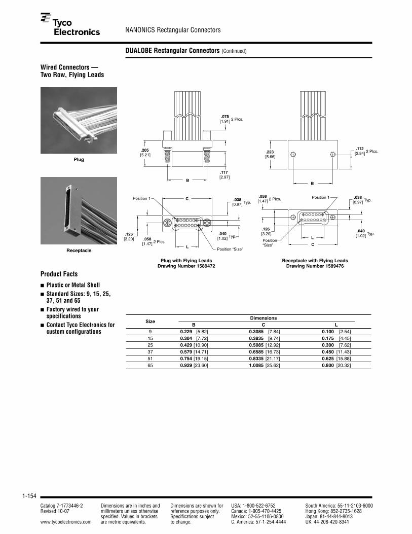
1-154
NANONICS Rectangular Connectors
Catalog 7-1773446-2 Dimensions are in inches and Dimensions are shown for USA: 1-800-522-6752 South America: 55-11-2103-6000Revised 10-07 millimeters unless otherwise reference purposes only. Canada: 1-905-470-4425 Hong Kong: 852-2735-1628
specified. Values in brackets Specifications subject Mexico: 52-55-1106-0800 Japan: 81-44-844-8013www.tycoelectronics.com are metric equivalents. to change. C. America: 57-1-254-4444 UK: 44-208-420-8341
DUALOBE Rectangular Connectors (Continued)
Wired Connectors — Two Row, Flying Leads
Position 1
Position “Size”
.205 [5.21]
.117 [2.97]
.126[3.20]
.040[1.02] Typ.
.075 [1.91] 2 Plcs.
.058 [1.47] 2 Plcs.
.038 [0.97] Typ.
B
C
L
Position 1
Position “Size”
.223 [5.66]
.126 [3.20]
.112 [2.84] 2 Plcs.
.058 [1.47] 2 Plcs. .038
[0.97] Typ.
.040 [1.02] Typ.
B
L
C
DimensionsSize
B C L9 0.229 [5.82] 0.3085 [7.84] 0.100 [2.54]15 0.304 [7.72] 0.3835 [9.74] 0.175 [4.45]25 0.429 [10.90] 0.5085 [12.92] 0.300 [7.62]37 0.579 [14.71] 0.6585 [16.73] 0.450 [11.43]51 0.754 [19.15] 0.8335 [21.17] 0.625 [15.88]65 0.929 [23.60] 1.0085 [25.62] 0.800 [20.32]
Product Facts
■ Plastic or Metal Shell■ Standard Sizes: 9, 15, 25,
37, 51 and 65■ Factory wired to your
specifications■ Contact Tyco Electronics for
custom configurations
Plug with Flying LeadsDrawing Number 1589472
Receptacle with Flying LeadsDrawing Number 1589476
Plug
Receptacle

1-155
NANONICS Rectangular Connectors
Catalog 7-1773446-2 Dimensions are in inches and Dimensions are shown for USA: 1-800-522-6752 South America: 55-11-2103-6000Revised 10-07 millimeters unless otherwise reference purposes only. Canada: 1-905-470-4425 Hong Kong: 852-2735-1628
specified. Values in brackets Specifications subject Mexico: 52-55-1106-0800 Japan: 81-44-844-8013www.tycoelectronics.com are metric equivalents. to change. C. America: 57-1-254-4444 UK: 44-208-420-8341
1
Pin and Socket Connectors
DUALOBE Rectangular Connectors (Continued)
Part Numbering Guidelinefor Wired Connectors
DUALOBE Connectors - Wire Terminations
S X X XXX XX X XX XXX X
Positions005 5 Position (single row only)
009 9 Position
015 15 Position
025 25 Position
037 37 Position
051 51 Position
065 65 Position (two row only)
TypeL LCP (Plastic)
M Metal (Al, Ni Plate)
RowsS 1 Row
T 2 Row
ClassS Dualobe
Threads/JackscrewThreads (Receptacles Only)
N Thread for 1.0 mm Jackscrews
Q Thread for 1.2 mm Jackscrews
Conductor TypeDX White TEFLON
DY White PTFE M16878/6
DC Color Coded TEFLON
DM Color Coded TEFLON per MIL-STD-681
DT White TEFZEL M22759/33
GX TEFLON Ribbon Cable FEP
Conductor LengthXXX Three numbers only, length is in inches ( i.e. 012 = twelve inches)
CXX A "C" followed by two numbers, length is in centimeters ( i.e. C06 = six centimeters)
MXX An "M" followed by two numbers, length is in meters ( i.e. M02 = two meters)
Conductor Size/Strands0 28 AWG Solid
1 30 AWG Solid
2 30 AWG 7 Strand
3 32 AWG 7 Strand
4 34 AWG 7 Strand
ConfigurationsPC Plug
SC Receptacle
Jackscrews (Plugs Only)
M 1.0 mm Non Captive Jackscrew
N 1.0 mm Captive Jackscrew
Q 1.2 mm Captive Jackscrew

1-156
NANONICS Rectangular Connectors
Catalog 7-1773446-2 Dimensions are in inches and Dimensions are shown for USA: 1-800-522-6752 South America: 55-11-2103-6000Revised 10-07 millimeters unless otherwise reference purposes only. Canada: 1-905-470-4425 Hong Kong: 852-2735-1628
specified. Values in brackets Specifications subject Mexico: 52-55-1106-0800 Japan: 81-44-844-8013www.tycoelectronics.com are metric equivalents. to change. C. America: 57-1-254-4444 UK: 44-208-420-8341
DUALOBE Rectangular Connectors (Continued)
Jumper AssemblyConnectors — Single Row
.205 [5.21]
Length as Specifiedin Part Number
.117 [2.97]
.086 [2.18]
B C L
.038 [.97] Typ.
.075 [1.91] 2 Plcs. Position 1
.043 [1.09] 2 Plcs.
DimensionsSize
B C L5 0.233 [5.92] 0.3085 [7.84] 0.100 [2.54]9 0.333 [8.46] 0.4085 [10.38] 0.200 [5.08]15 0.483 [12.27] 0.5585 [14.19] 0.350 [8.89]25 0.733 [18.62] 0.8085 [20.54] 0.600 [15.24]37 1.033 [26.24] 1.1085 [28.16] 0.900 [22.86]51 1.383 [35.13] 1.4585 [37.05] 1.250 [31.75]
Product Facts
■ Plastic or Metal Shell■ Standard Sizes: 5, 9, 15,
25, 37, and 51■ Factory wired to your
specifications■ Contact Tyco Electronics for
custom configurations
Position 1
Position 1
Length as Specifiedin Part Number.086
[2.18]
.223[5.66]
.205[5.21]
.086 [2.18]
.117[2.97]
CL
.038 [.97] Typ.
.075 [1.91] 2 Plcs.
.038 [.97] Typ.
.043 [1.09] 2 Plcs.
.112 [2.85]2 Plcs.
.043 [1.09] 2 Plcs.
C LBBB
Plug to PlugDrawing Number 1589735
Plug to ReceptacleDrawing Number 1589736
Plug to Receptacle
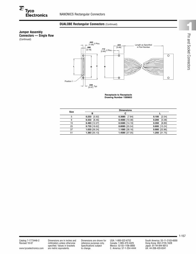
1-157
NANONICS Rectangular Connectors
Catalog 7-1773446-2 Dimensions are in inches and Dimensions are shown for USA: 1-800-522-6752 South America: 55-11-2103-6000Revised 10-07 millimeters unless otherwise reference purposes only. Canada: 1-905-470-4425 Hong Kong: 852-2735-1628
specified. Values in brackets Specifications subject Mexico: 52-55-1106-0800 Japan: 81-44-844-8013www.tycoelectronics.com are metric equivalents. to change. C. America: 57-1-254-4444 UK: 44-208-420-8341
1
Pin and Socket Connectors
DUALOBE Rectangular Connectors (Continued)
Jumper AssemblyConnectors — Single Row(Continued)
Position 1
Length as Specifiedin Part Number.086
[2.18]
.223[5.66]
.038 [0.97] Typ.
CL B B
.043 [1.09] 2 Plcs.
.112 [2.85] 2 Plcs.
Receptacle to ReceptacleDrawing Number 1589803
DimensionsSize
B C L5 0.233 [5.92] 0.3085 [7.84] 0.100 [2.54]9 0.333 [8.46] 0.4085 [10.38] 0.200 [5.08]15 0.483 [12.27] 0.5585 [14.19] 0.350 [8.89]25 0.733 [18.62] 0.8085 [20.54] 0.600 [15.24]37 1.033 [26.24] 1.1085 [28.16] 0.900 [22.86]51 1.383 [35.13] 1.4585 [37.05] 1.250 [31.75]

1-158
NANONICS Rectangular Connectors
Catalog 7-1773446-2 Dimensions are in inches and Dimensions are shown for USA: 1-800-522-6752 South America: 55-11-2103-6000Revised 10-07 millimeters unless otherwise reference purposes only. Canada: 1-905-470-4425 Hong Kong: 852-2735-1628
specified. Values in brackets Specifications subject Mexico: 52-55-1106-0800 Japan: 81-44-844-8013www.tycoelectronics.com are metric equivalents. to change. C. America: 57-1-254-4444 UK: 44-208-420-8341
DUALOBE Rectangular Connectors (Continued)
Jumper AssemblyConnectors — Two Row
Plug to Receptacle
Product Facts
■ Plastic or Metal Shell■ Standard Sizes: 9, 15, 25,
37, 51 and 65■ Factory wired to your
specifications■ Contact Tyco Electronics for
custom configurations
Length as Specifiedin Part Number
.205[5.21]
.117[2.97]
Position 1
.126[3.20]
.075 [1.91] 2 Plcs.
.058 [1.47] 2 Plcs.
.038 [.97] Typ.
.040 [1.02] Typ.
C LB
Position 1
Length as Specifiedin Part Number
.205[5.21]
.126[3.20]
.223[5.66]
.117[2.97]
Position 1
.126[3.20]
.038 [.97] Typ.
.040 [1.02] Typ.
.058 [1.47]2 Plcs.
CL BB
.112 [2.85]2 Plcs.
B C L
.058 [1.47] 2 Plcs.
.038 [.97] Typ.
.040 [1.02] Typ.
.075 [1.91] 2 Plcs.
Plug to PlugDrawing Number 1589737
Plug to ReceptacleDrawing Number 1589738
DimensionsSize
B C L9 0.229 [5.82] 0.3085 [7.84] 0.100 [2.54]15 0.304 [7.72] 0.3835 [9.74] 0.175 [4.45]25 0.429 [10.90] 0.5085 [12.92] 0.300 [7.62]37 0.579 [14.71] 0.6585 [16.73] 0.450 [11.43]51 0.754 [19.15] 0.8335 [21.17] 0.625 [15.88]65 0.929 [23.60] 1.0085 [25.62] 0.800 [20.32]

1-159
NANONICS Rectangular Connectors
Catalog 7-1773446-2 Dimensions are in inches and Dimensions are shown for USA: 1-800-522-6752 South America: 55-11-2103-6000Revised 10-07 millimeters unless otherwise reference purposes only. Canada: 1-905-470-4425 Hong Kong: 852-2735-1628
specified. Values in brackets Specifications subject Mexico: 52-55-1106-0800 Japan: 81-44-844-8013www.tycoelectronics.com are metric equivalents. to change. C. America: 57-1-254-4444 UK: 44-208-420-8341
1
Pin and Socket Connectors
DUALOBE Rectangular Connectors (Continued)
Jumper AssemblyConnectors — Two Row(Continued)
Position 1
Length as Specifiedin Part Number
.223[5.66]
.126[3.20]
.038 [.97] Typ.
.040 [1.02] Typ.
CL BB
.112 [2.85] 2 Plcs.
.058 [1.47] 2 Plcs.
Receptacle to ReceptacleDrawing Number 1589804
DimensionsSize
B C L9 0.229 [5.82] 0.3085 [7.84] 0.100 [2.54]15 0.304 [7.72] 0.3835 [9.74] 0.175 [4.45]25 0.429 [10.90] 0.5085 [12.92] 0.300 [7.62]37 0.579 [14.71] 0.6585 [16.73] 0.450 [11.43]51 0.754 [19.15] 0.8335 [21.17] 0.625 [15.88]65 0.929 [23.60] 1.0085 [25.62] 0.800 [20.32]

1-160
NANONICS Rectangular Connectors
Catalog 7-1773446-2 Dimensions are in inches and Dimensions are shown for USA: 1-800-522-6752 South America: 55-11-2103-6000Revised 10-07 millimeters unless otherwise reference purposes only. Canada: 1-905-470-4425 Hong Kong: 852-2735-1628
specified. Values in brackets Specifications subject Mexico: 52-55-1106-0800 Japan: 81-44-844-8013www.tycoelectronics.com are metric equivalents. to change. C. America: 57-1-254-4444 UK: 44-208-420-8341
DUALOBE Rectangular Connectors (Continued)
Part Numbering Guidelinefor Jumper Assemblies
DUALOBE Connectors - Jumper Terminations
J X X XXX XX X XX XXX X
Positions005 5 Position (single row only)
009 9 Position
015 15 Position
025 25 Position
037 37 Position
051 51 Position
065 65 Position (two row only)
TypeL LCP (Plastic)
M Metal (Al, Ni Plate)
RowsS 1 Row
T 2 Row
ClassJ Jumper
Threads/JackscrewsThreads (Receptacles Only)
N Thread for 1.0 mm Jackscrews
Q Thread for 1.2 mm Jackscrews
Conductor TypeDX White Teflon
DY White PTFE M16878/6
DC Color Coded Teflon
DM Color Coded Teflon per MIL-STD-681
DT White Tefzel M22759/33
GX Telfon Ribbon Cable
Conductor LengthXXX Three numbers only, length is in inches ( i.e. 012 = twelve inches)
CXX A "C" followed by two numbers, length is in centimeters ( i.e. C06 = 6 centimeters)
MXX An "M" followed by two numbers, length is in meters ( i.e. M02 = 2 meters)
Conductor Size/Strands0 28 AWG Solid
1 30 AWG Solid
2 30 AWG 7 Strand
3 32 AWG 7 Strand
4 34 AWG 7 Strand
ConfigurationPP Plug to Plug, 1 to 1
PR Plug to Receptacle, 1 to 1
PD Plug to Plug, low to high in row
RR Receptacle to Receptacle, 1 to 1
Jackscrews (Plugs Only)
M 1.0 mm Non Captive Jackscrews
N 1.0 mm Captive Jackscrews
Q 1.2 mm Captive Jackscrews

1-161
NANONICS Rectangular Connectors
Catalog 7-1773446-2 Dimensions are in inches and Dimensions are shown for USA: 1-800-522-6752 South America: 55-11-2103-6000Revised 10-07 millimeters unless otherwise reference purposes only. Canada: 1-905-470-4425 Hong Kong: 852-2735-1628
specified. Values in brackets Specifications subject Mexico: 52-55-1106-0800 Japan: 81-44-844-8013www.tycoelectronics.com are metric equivalents. to change. C. America: 57-1-254-4444 UK: 44-208-420-8341
1
Pin and Socket Connectors
DUALOBE Rectangular Connectors (Continued)
Surface Mount Connectors —Horizontal, Single Row
Product Facts
■ Plastic or Metal Shell■ Standard Sizes: 5, 9, 15,
25, 37, and 51■ Contact Tyco Electronics for
custom configurations■ Suggested pad layouts
are available on thereferenced drawings on theTyco Electronics website
Receptacle
.038 [.97] Typ.
Position 1 B
L
C
.086[2.18]
.043 [1.09] 2 Plcs.
.205[5.21]
A
.075 [.69] 2 Plcs.
.117[2.97]
.025 [.64] Pitch
.255 [6.48] Typ.
.020 [.51] Typ.
Plug AssemblyDrawing Number 1589460
Jackscrews Omitted for Clarity
A.025 [.64] Pitch
.223[5.66]
B
.112 [2.84] 2 Plcs.
B
L
C
.038 [.97] Typ.
Position 1
.086[2.18]
.043 [1.09] 2 Plcs.
.273[6.93] Typ.
.020 [.51] Typ.
Receptacle AssemblyDrawing Number 1589462
DimensionsSize
A B C L5 0.050 [1.27] 0.233 [5.92] 0.3085 [7.84] 0.100 [2.54]9 0.100 [2.54] 0.333 [8.46] 0.4085 [10.38] 0.200 [5.08]15 0.175 [4.45] 0.483 [12.27] 0.5585 [14.19] 0.350 [8.89]25 0.300 [7.62] 0.733 [18.62] 0.8085 [20.54] 0.600 [15.24]37 0.450 [11.43] 1.085 [26.24] 1.1085 [28.16] 0.900 [22.86]51 0.625 [15.88] 1.383 [35.13] 1.4585 [37.05] 1.250 [31.75]

1-162
NANONICS Rectangular Connectors
Catalog 7-1773446-2 Dimensions are in inches and Dimensions are shown for USA: 1-800-522-6752 South America: 55-11-2103-6000Revised 10-07 millimeters unless otherwise reference purposes only. Canada: 1-905-470-4425 Hong Kong: 852-2735-1628
specified. Values in brackets Specifications subject Mexico: 52-55-1106-0800 Japan: 81-44-844-8013www.tycoelectronics.com are metric equivalents. to change. C. America: 57-1-254-4444 UK: 44-208-420-8341
DUALOBE Rectangular Connectors (Continued)
Surface Mount Connectors —Horizontal, Two Row A
.025 [.64] Pitch
.0125 [.318] Offset
.223[5.66]
B
.112 [2.84] 2 Plcs. .323
[8.20] Typ. .273[6.93] Typ.
.020[.51] Typ.
Position 1B .038
[.97] Typ. .040 [1.02] Typ.
C
LPosition ‘Size’
.126[3.20]
.058 [1.47] 2 Plcs.
Product Facts
■ Plastic or Metal Shell■ Standard Sizes: 9, 15, 25,
37, 51 and 65■ Contact Tyco Electronics for
custom configurations■ Suggested pad layouts
are available on thereferenced drawings on theTyco Electronics website
A
.025 [.64] Pitch
.0125 [.318] Offset
.205[5.21]
.075 [.69] 2 Plcs.
.117[2.97]
Position 1
.058 [1.47] 2 Plcs.
.126[3.20]
.038 [.97] Typ.
.040 [1.02] Typ.
B
L
CPosition ‘Size’
.305 [7.75] Typ. .255
[6.48] Typ.
.020[.51] Typ.
Receptacle AssemblyDrawing Number 1589483
Jackscrews Omitted for Clarity
Plug AssemblyDrawing Number 1589490
Receptacle
DimensionsSize
A B C L9 0.050 [1.27] 0.229 [5.82] 0.3085 [7.84] 0.100 [2.54]15 0.875 [2.23] 0.304 [7.72] 0.3835 [9.74] 0.175 [4.45]25 0.150 [3.81] 0.429 [10.90] 0.5085 [12.92] 0.300 [8.89]37 0.225 [5.72] 0.579 [14.71] 0.6585 [16.73] 0.450 [11.43]51 0.313 [7.95] 0.754 [19.15] 0.8335 [21.17] 0.625 [15.88]65 0.400 [10.16] 0.929 [23.60] 1.0085 [25.62] 0.800 [20.32]

1-163
NANONICS Rectangular Connectors
Catalog 7-1773446-2 Dimensions are in inches and Dimensions are shown for USA: 1-800-522-6752 South America: 55-11-2103-6000Revised 10-07 millimeters unless otherwise reference purposes only. Canada: 1-905-470-4425 Hong Kong: 852-2735-1628
specified. Values in brackets Specifications subject Mexico: 52-55-1106-0800 Japan: 81-44-844-8013www.tycoelectronics.com are metric equivalents. to change. C. America: 57-1-254-4444 UK: 44-208-420-8341
1
Pin and Socket Connectors
DUALOBE Rectangular Connectors (Continued)
Surface Mount Connectors —Vertical, Single Row
Receptacle
Product Facts
■ Plastic or Metal Shell■ Standard Sizes: 5, 9, 15,
25, 37, and 51■ Contact Tyco Electronics for
custom configurations■ Suggested pad layouts
are available on thereferenced drawings on theTyco Electronics website
.025 [.64] Pitch
A
L
CPosition 1
.038 [.97] Typ.
.043 [1.09] 2 Plcs.
.086[2.18]
B
B
.223[5.66]
.112 [2.84] 2 Plcs.
.030[.76] Typ.
L
C
Position 1
.043 [1.09] 2 Plcs.
A
B
.025 [.64] Pitch
.038 [.97] Typ.
.086[2.18]
.205[5.21]
.030[.76] Typ.
.117[2.97]
.075 [1.91] 2 Plcs.
Receptacle AssemblyDrawing Number 1589463
Plug AssemblyDrawing Number 1589465
DimensionsSize
A B C L5 0.050 [1.27] 0.233 [5.92] 0.3085 [7.84] 0.100 [2.54]9 0.100 [2.54] 0.333 [8.46] 0.4085 [10.38] 0.200 [5.08]15 0.175 [4.45] 0.483 [12.27] 0.5585 [14.19] 0.350 [8.89]25 0.300 [7.62] 0.733 [18.62] 0.8085 [20.54] 0.600 [15.24]37 0.450 [11.43] 1.085 [26.24] 1.1085 [28.16] 0.900 [22.86]51 0.625 [15.88] 1.383 [35.13] 1.4585 [37.05] 1.250 [31.75]

1-164
NANONICS Rectangular Connectors
Catalog 7-1773446-2 Dimensions are in inches and Dimensions are shown for USA: 1-800-522-6752 South America: 55-11-2103-6000Revised 10-07 millimeters unless otherwise reference purposes only. Canada: 1-905-470-4425 Hong Kong: 852-2735-1628
specified. Values in brackets Specifications subject Mexico: 52-55-1106-0800 Japan: 81-44-844-8013www.tycoelectronics.com are metric equivalents. to change. C. America: 57-1-254-4444 UK: 44-208-420-8341
DUALOBE Rectangular Connectors (Continued)
Surface Mount Connectors —Vertical, Single Row withAlternating Leads
L
C
.043 [1.09] 2 Plcs.
A
.038 [.97] Typ.
Position 1
.050 [1.27] Pitch
.025[.64]
.086[2.18]
B
.223[5.66]
.112 [2.84] 2 Plcs.
.030 [.76] Typ.
B
Product Facts
■ Plastic or Metal Shell■ Standard Sizes: 5, 9, 15,
25, 37, and 51■ Contact Tyco Electronics for
custom configurations■ Suggested pad layouts
are available on thereferenced drawings on theTyco Electronics website
L
C
.043 [1.09] 2 Plcs.
Position 1
B
A
.050 [1.27] Pitch
.038 [.97] Typ.
.030 [.76] Typ.
.025[.64]
.086[2.18]
.075 [1.91] 2 Plcs.
.205[5.21]
.117[2.97]
Receptacle AssemblyDrawing Number 1589464
Plug AssemblyDrawing Number 1589466
DimensionsSize
A B C L5 0.050 [1.27] 0.233 [5.92] 0.3085 [7.84] 0.100 [2.54]9 0.100 [2.54] 0.333 [8.46] 0.4085 [10.38] 0.200 [5.08]15 0.175 [4.45] 0.483 [12.27] 0.5585 [14.19] 0.350 [8.89]25 0.300 [7.62] 0.733 [18.62] 0.8085 [20.54] 0.600 [15.24]37 0.450 [11.43] 1.085 [26.24] 1.1085 [28.16] 0.900 [22.86]51 0.625 [15.88] 1.383 [35.13] 1.4585 [37.05] 1.250 [31.75]

1-165
NANONICS Rectangular Connectors
Catalog 7-1773446-2 Dimensions are in inches and Dimensions are shown for USA: 1-800-522-6752 South America: 55-11-2103-6000Revised 10-07 millimeters unless otherwise reference purposes only. Canada: 1-905-470-4425 Hong Kong: 852-2735-1628
specified. Values in brackets Specifications subject Mexico: 52-55-1106-0800 Japan: 81-44-844-8013www.tycoelectronics.com are metric equivalents. to change. C. America: 57-1-254-4444 UK: 44-208-420-8341
1
Pin and Socket Connectors
DUALOBE Rectangular Connectors (Continued)
Surface Mount Connectors —Vertical, Single Row withIntegrated Standoffs
L
CPosition 1
.038 [.97] Typ.
.086[2.18]
.025 [.64] Pitch
A
B
.043 [1.09] 2 Plcs.
.253[6.43]
.223[5.66]
.072 [1.83] 2 Plcs.
Product Facts
■ Metal Shell■ Standard Sizes: 5 , 9, 15,
25, 37, and 51■ Contact Tyco Electronics for
custom configurations■ Suggested pad layouts
are available on thereferenced drawings on theTyco Electronics website
Receptacle AssemblyDrawing Number 1589467
DimensionsSize
A B C L5 0.050 [1.27] 0.233 [5.92] 0.3085 [7.84] 0.100 [2.54]9 0.100 [2.54] 0.333 [8.46] 0.4085 [10.38] 0.200 [5.08]15 0.175 [4.45] 0.483 [12.27] 0.5585 [14.19] 0.350 [8.89]25 0.300 [7.62] 0.733 [18.62] 0.8085 [20.54] 0.600 [15.24]37 0.450 [11.43] 1.085 [26.24] 1.1085 [28.16] 0.900 [22.86]51 0.625 [15.88] 1.383 [35.13] 1.4585 [37.05] 1.250 [31.75]

1-166
NANONICS Rectangular Connectors
Catalog 7-1773446-2 Dimensions are in inches and Dimensions are shown for USA: 1-800-522-6752 South America: 55-11-2103-6000Revised 10-07 millimeters unless otherwise reference purposes only. Canada: 1-905-470-4425 Hong Kong: 852-2735-1628
specified. Values in brackets Specifications subject Mexico: 52-55-1106-0800 Japan: 81-44-844-8013www.tycoelectronics.com are metric equivalents. to change. C. America: 57-1-254-4444 UK: 44-208-420-8341
DUALOBE Rectangular Connectors (Continued)
Surface Mount Connectors —Vertical, Two Row
L
C
Position 1
.038 [.97] Typ.
.0125 [.318]Offset .040
[1.02] Typ.
.025 [.64] Pitch
A
B
.126[3.20]
.058 [1.47] 2 Plcs.
B
.112 [2.84] 2 Plcs.
.030[.76] Typ.
.223[5.66]
Product Facts
■ Plastic or Metal Shell■ Standard Sizes: 9, 15, 25,
37, 51 and 65■ Contact Tyco Electronics for
custom configurations■ Suggested pad layouts
are available on thereferenced drawings on theTyco Electronics website
L
C
Position 1
.058[1.47]2 Plcs.
.126[3.20]
.025 [.64] Pitch
.030 [.76] Typ.
.040 [1.02] Typ.
.038 [.97] Typ.
.0125 [.318] Offset
A
B
.205[5.21]
.075 [1.91] 2 Plcs.
.117[2.97]
Receptacle AssemblyDrawing Number 1589484
Plug AssemblyDrawing Number 1589485
DimensionsSize
A B C L9 0.050 [1.27] 0.229 [5.82] 0.3085 [7.84] 0.100 [2.54]15 0.875 [2.23] 0.304 [7.72] 0.3835 [9.74] 0.175 [4.45]25 0.150 [3.81] 0.429 [10.90] 0.5085 [12.92] 0.300 [8.89]37 0.225 [5.72] 0.579 [14.71] 0.6585 [16.73] 0.450 [11.43]51 0.313 [7.95] 0.754 [19.15] 0.8335 [21.17] 0.625 [15.88]65 0.400 [10.16] 0.929 [23.60] 1.0085 [25.62] 0.800 [20.32]
Receptacle

1-167
NANONICS Rectangular Connectors
Catalog 7-1773446-2 Dimensions are in inches and Dimensions are shown for USA: 1-800-522-6752 South America: 55-11-2103-6000Revised 10-07 millimeters unless otherwise reference purposes only. Canada: 1-905-470-4425 Hong Kong: 852-2735-1628
specified. Values in brackets Specifications subject Mexico: 52-55-1106-0800 Japan: 81-44-844-8013www.tycoelectronics.com are metric equivalents. to change. C. America: 57-1-254-4444 UK: 44-208-420-8341
1
Pin and Socket Connectors
DUALOBE Rectangular Connectors (Continued)
Surface Mount Connectors —Vertical, Two Row withIntegrated Standoffs
L
C
.058 [1.47] 2 Plcs.
.126[3.20]
.025 [.64] Pitch
.0125 [.318]Offset
A
B
.038 [.97] Typ.
.040 [1.02] Typ.
Position 1
.223[5.66].253
[6.43]
.072 [1.83] 2 Plcs.
Product Facts
■ Metal Shell■ Standard Sizes: 9, 15, 25,
37, 51 and 65■ Contact Tyco Electronics for
custom configurations■ Suggested pad layouts
are available on thereferenced drawings on theTyco Electronics website
Receptacle AssemblyDrawing Number 1589486
DimensionsSize
A B C L9 0.050 [1.27] 0.229 [5.82] 0.3085 [7.84] .100 [2.54]15 0.875 [2.23] 0.304 [7.72] 0.3835 [9.74] .175 [4.45]25 0.150 [3.81] 0.429 [10.90] 0.5085 [12.92] .300 [8.89]37 0.225 [5.72] 0.579 [14.71] 0.6585 [16.73] .450 [11.43]51 0.313 [7.95] 0.754 [19.15] 0.8335 [21.17] .625 [15.88]65 0.400 [10.16] 0.929 [23.60] 1.0085 [25.62] .800 [20.32]

1-168
NANONICS Rectangular Connectors
Catalog 7-1773446-2 Dimensions are in inches and Dimensions are shown for USA: 1-800-522-6752 South America: 55-11-2103-6000Revised 10-07 millimeters unless otherwise reference purposes only. Canada: 1-905-470-4425 Hong Kong: 852-2735-1628
specified. Values in brackets Specifications subject Mexico: 52-55-1106-0800 Japan: 81-44-844-8013www.tycoelectronics.com are metric equivalents. to change. C. America: 57-1-254-4444 UK: 44-208-420-8341
DUALOBE Rectangular Connectors (Continued)
Thru-Hole Connectors —Horizontal, 1 Row to 2Row, .050 Spacing
B
.223[5.66]
.140 [3.56]
.112 [2.84] 2 Plcs.
Position 1
.038 [.97] Typ.
.273[6.93] Typ.
.050[1.27] Typ.
.090[2.29] Typ.
L
B
C
.086[2.18]
.043 [1.09] 2 Plcs.
Product Facts
■ Plastic or Metal Shell■ Standard Sizes: 5, 9, 15,
25, 37, and 51■ Contact Tyco Electronics for
custom configurations■ Suggested thru-hole
layouts are available on thereferenced drawings on theTyco Electronics website
B
.205[5.21]
.140[3.56]
.075 [1.91] 2 Plcs.
.050 [1.27] Typ.
.255[6.48] Typ.
.117[2.97]
L
C
.038 [.97] Typ.
.090 [2.29] Typ.
.043 [1.09] 2 Plcs.
.086[2.18]
Position 1
Receptacle AssemblyDrawing Number 1589469
Plug AssemblyDrawing Number 1589471
DimensionsSize
B C L5 0.233 [5.92] 0.3085 [7.84] 0.100 [2.54]9 0.333 [8.46] 0.4085 [10.38] 0.200 [5.08]15 0.483 [12.27] 0.5585 [14.19] 0.350 [8.89]25 0.733 [18.62] 0.8085 [20.54] 0.600 [15.24]37 1.033 [26.24] 1.1085 [28.16] 0.900 [22.86]51 1.383 [35.13] 1.4585 [37.05] 1.250 [31.75]
Receptacle
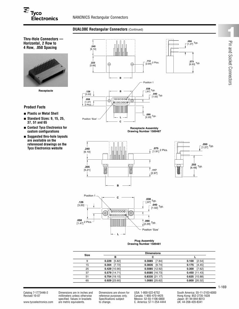
1-169
NANONICS Rectangular Connectors
Catalog 7-1773446-2 Dimensions are in inches and Dimensions are shown for USA: 1-800-522-6752 South America: 55-11-2103-6000Revised 10-07 millimeters unless otherwise reference purposes only. Canada: 1-905-470-4425 Hong Kong: 852-2735-1628
specified. Values in brackets Specifications subject Mexico: 52-55-1106-0800 Japan: 81-44-844-8013www.tycoelectronics.com are metric equivalents. to change. C. America: 57-1-254-4444 UK: 44-208-420-8341
1
Pin and Socket Connectors
DUALOBE Rectangular Connectors (Continued)
Thru-Hole Connectors —Horizontal, 2 Row to 4 Row, .050 Spacing
B
.205[5.21]
.240[6.10]
.075 [1.91] 2 Plcs.
.050 [1.27] Typ.
.255[6.48] Typ.
.117[2.97]
.038 [.97] Typ.
.058 [1.47] 2 Plcs.
L
C
.040 [1.02] Typ.
.126 [3.20]
.090 [2.29] Typ.
Position ‘Size’
Position 1
Product Facts
■ Plastic or Metal Shell■ Standard Sizes: 9, 15, 25,
37, 51 and 65■ Contact Tyco Electronics for
custom configurations■ Suggested thru-hole layouts
are available on thereferenced drawings on theTyco Electronics website
B
.112 [2.84] 2 Plcs..223
[5.66]
.240[6.10]
B
L
C
.038 [.97] Typ.
.050[1.27] Typ.
.273[6.93] Typ.
.040 [1.02] Typ.
.090 [2.29] Typ.
.058 [1.47]2 Plcs.
.126[3.20]
Position ‘Size’
Position 1
Plug AssemblyDrawing Number 1589481
Receptacle AssemblyDrawing Number 1589487
DimensionsSize
B C L9 0.229 [5.82] 0.3085 [7.84] 0.100 [2.54]15 0.304 [7.72] 0.3835 [9.74] 0.175 [4.45]25 0.429 [10.90] 0.5085 [12.92] 0.300 [7.62]37 0.579 [14.71] 0.6585 [16.73] 0.450 [11.43]51 0.754 [19.15] 0.8335 [21.17] 0.625 [15.88]65 0.929 [23.60] 1.0085 [25.62] 0.800 [20.32]
Receptacle
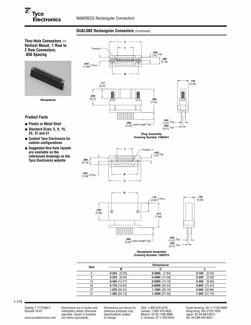
1-170
NANONICS Rectangular Connectors
Catalog 7-1773446-2 Dimensions are in inches and Dimensions are shown for USA: 1-800-522-6752 South America: 55-11-2103-6000Revised 10-07 millimeters unless otherwise reference purposes only. Canada: 1-905-470-4425 Hong Kong: 852-2735-1628
specified. Values in brackets Specifications subject Mexico: 52-55-1106-0800 Japan: 81-44-844-8013www.tycoelectronics.com are metric equivalents. to change. C. America: 57-1-254-4444 UK: 44-208-420-8341
DUALOBE Rectangular Connectors (Continued)
Thru-Hole Connectors —Vertical Mount, 1 Row to 2 Row Connectors, .050 Spacing
Product Facts
■ Plastic or Metal Shell■ Standard Sizes: 5, 9, 15,
25, 37 and 51■ Contact Tyco Electronics for
custom configurations■ Suggested thru-hole layouts
are available on thereferenced drawings on theTyco Electronics website
B
L
C
Position 1
.038 [.97] Typ.
.043 [1.09] 2 Plcs.
.086[2.18]
.090 [2.29] Lead Length Typ.
.050 [1.27] Typ.
.020 [0.51] Typ.
.205 [5.21]
.117 [2.97]
.296 [7.52]
.140 [3.56]
L
B
C
.043 [1.09] 2 Plcs.
.086[2.18]
.038 [.97] Typ.
Position 1
B
.223[5.66] .314
[7.98]
.140[3.56]
.090 [2.29] Lead Length Typ.
.112 [2.84] 2 Plcs.
.020[0.51] Typ.
.050[1.27] Typ.
Plug AssemblyDrawing Number 1589461
Receptacle AssemblyDrawing Number 1589470
DimensionsSize
B C L5 0.233 [5.92] 0.3085 [7.84] 0.100 [2.54]9 0.333 [8.46] 0.4085 [10.38] 0.200 [5.08]15 0.483 [12.27] 0.5585 [14.19] 0.350 [8.89]25 0.733 [18.62] 0.8085 [20.54] 0.600 [15.24]37 1.033 [26.24] 1.1085 [28.16] 0.900 [22.86]51 1.383 [35.13] 1.4585 [37.05] 1.250 [31.75]
Receptacle

1-171
NANONICS Rectangular Connectors
Catalog 7-1773446-2 Dimensions are in inches and Dimensions are shown for USA: 1-800-522-6752 South America: 55-11-2103-6000Revised 10-07 millimeters unless otherwise reference purposes only. Canada: 1-905-470-4425 Hong Kong: 852-2735-1628
specified. Values in brackets Specifications subject Mexico: 52-55-1106-0800 Japan: 81-44-844-8013www.tycoelectronics.com are metric equivalents. to change. C. America: 57-1-254-4444 UK: 44-208-420-8341
1
Pin and Socket Connectors
DUALOBE Rectangular Connectors (Continued)
Thru-Hole Connectors —Vertical Mount, 2 Row to 4 Row Connectors, .050 Spacing
Product Facts
■ Plastic or Metal Shell■ Standard Sizes: 9, 15, 25,
37, 51 and 65■ Contact Tyco Electronics for
custom configurations■ Suggested thru-hole layouts
are available on thereferenced drawings on theTyco Electronics website
B
L
CPosition 1
.058 [1.47] 2 Plcs.
.126[3.20]
.038 [.97] Typ.
.040 [1.02] Typ.
.117[2.97]
.205[5.21] .286
[7.26]
.24[6.10]
.090 [2.29] Lead Length Typ.
.020 [0.51] Typ.
.050 [1.27] Typ.
C
B
LPosition ‘Size’
.126[3.20]
.058[1.47]2 Plcs.
.038 [.97] Typ.
.040 [1.02] Typ.
B
.223[5.66] .304
[7.72]
.24[6.10]
.090 [2.29] Lead Length Typ.
.050 [1.27] Typ.
.020 [0.51] Typ.
Plug AssemblyDrawing Number 1589482
Receptacle AssemblyDrawing Number 1589488
DimensionsSize
B C L9 0.229 [5.82] 0.3085 [7.84] 0.100 [2.54]15 0.304 [7.72] 0.3835 [9.74] 0.175 [4.45]25 0.429 [10.90] 0.5085 [12.92] 0.300 [7.62]37 0.579 [14.71] 0.6585 [16.73] 0.450 [11.43]51 0.754 [19.15] 0.8335 [21.17] 0.625 [15.88]65 0.929 [23.60] 1.0085 [25.62] 0.800 [20.32]
Receptacle

1-172
NANONICS Rectangular Connectors
Catalog 7-1773446-2 Dimensions are in inches and Dimensions are shown for USA: 1-800-522-6752 South America: 55-11-2103-6000Revised 10-07 millimeters unless otherwise reference purposes only. Canada: 1-905-470-4425 Hong Kong: 852-2735-1628
specified. Values in brackets Specifications subject Mexico: 52-55-1106-0800 Japan: 81-44-844-8013www.tycoelectronics.com are metric equivalents. to change. C. America: 57-1-254-4444 UK: 44-208-420-8341
DUALOBE Rectangular Connectors (Continued)
Part Numbering Guidelinefor Surface Mount andThru-Hole Connectors
DUALOBE Connectors - Surface Mount and Thru Hole Terminations
S X X XXX XX(X) X X
Positions005 5 Position (single row only)
009 9 Position
015 15 Position
025 25 Position
037 37 Position
051 51 Position
065 65 Position (two row only)
TypeL LCP (Plastic)
M Metal (Al, Ni Plate)
RowsS 1 Row
T 2 Row
ClassS Dualobe
Threads/JackscrewThreads (Receptacles Only)
N Thread for 1.0 mm Jackscrews
Q Thread for 1.2 mm Jackscrews
Mounting HardwareA 1.2 mm x .160”
C 1.0 mm x .200” w/ 2 standoffs
D 1.2 mm x .160” w/ 2 standoffs
H 1.0 mm x .160”
I 1.2 mm x .200”
K 1.0 mm x .200” w/ 4 standoffs
L 1.2 mm x .200” w/ 2 standoffs
P 1.2 mm x .200” w/ 4 standoffs
S 1.0 mm x .160” w/ 2 standoffs
ConfigurationsB2 Plug, Horizontal SMT
B4 Plug, Vertical SMT
B42 Plug, Vertical SMT, .020” Extended Leads
B44 Plug, Vertical SMT, .040” Extended Leads
B43 Plug, Vertical SMT, .020” Extended Leads, 2 side exit (single row only)
B45 Plug, Vertical SMT, .040” Extended Leads, 2 side exit (single row only)
L2 Receptacle, Horizontal SMT
L4 Receptacle, Vertical SMT
L42 Receptacle, Vertical SMT, .020” Extended Leads
L44 Receptacle, Vertical SMT, .040” Extended Leads
L43 Receptacle, Vertical SMT, .020” Extended Leads, 2 side exit (single row only)
L45 Receptacle, Vertical SMT, .040” Extended Leads, 2 side exit (single row only)
L8 Receptacle, Vertical SMT, w/ integrated standoffs (metal shell only)
L82 Receptacle, Vertical SMT, w/ integrated standoffs, .020” Extended Leads (metal shell only)
L84 Receptacle, Vertical SMT, w/ integrated standoffs, .040” Extended Leads (metal shell only)
L83 Receptacle, Vertical SMT, w/ integrated standoffs, .020” Extended Leads (single row and metal shell only)
L85 Receptacle, Vertical SMT, w/ integrated standoffs, .040” Extended Leads (single row and metal shell only)
C5 Plug, Vertical Mount, Thru Hole
C6 Plug, Horizontal Mount, Thru Hole
M5 Receptacle, Vertical Mount, Thru Hole
M6 Receptacle, Horizontal Mount, Thru Hole
Jackscrews (Plugs Only)
M 1.0 mm Non Captive Jackscrews
N 1.0 mm Captive Jackscrews
Q 1.2 mm Captive Jackscrews

1-173
NANONICS Rectangular Connectors
Catalog 7-1773446-2 Dimensions are in inches and Dimensions are shown for USA: 1-800-522-6752 South America: 55-11-2103-6000Revised 10-07 millimeters unless otherwise reference purposes only. Canada: 1-905-470-4425 Hong Kong: 852-2735-1628
specified. Values in brackets Specifications subject Mexico: 52-55-1106-0800 Japan: 81-44-844-8013www.tycoelectronics.com are metric equivalents. to change. C. America: 57-1-254-4444 UK: 44-208-420-8341
1
Pin and Socket Connectors
DUALOBE Rectangular Connectors (Continued)
Flex Termination“Duckbill” Connectors —Two Row
Product Facts
■ Plastic or Metal Shell■ Standard Sizes: 9, 15, 25,
37, 51 and 65■ Contact Tyco Electronics for
custom configurations
C
L
B
.075 [1.91] 2 Plcs.
.010[0.25] Typ. .100
[2.54] Typ.
.086[2.18] Typ.
.205[5.21]
.117[2.97]
.058 [1.47] 2 Plcs.
.126[3.20]
AMax.
E
Position 1
Flex Top ViewSize 15 shown for referencePosition ‘Size’
Position 1.038 [.97] Typ.
.040 [1.02] Typ.
.025 [0.64] Typ.
.050 [1.27] Typ.
.08[2.1
.017[0.43]
AMax.
DE
Position 1 Position‘Size’
Flex Top ViewSize 15 shown for reference
Flex Bottom View
.025 [0.64] Typ.
.050 [1.27] Typ.
.086 [2.18] Typ.
.017[0.43]
Typical Flex Pad Layout
DimensionsSize
A B C D E L 9 0.150 [3.81] 0.229 [5.82] 0.3085 [ 7.84] 0.0500 [1.27] 0.0375 [0.95] 0.100 [ 2.54]15 0.225 [5.72] 0.304 [7.72] 0.3835 [ 9.74] 0.0875 [2.22] 0.0750 [1.90] 0.175 [ 4.45]25 0.350 [8.89] 0.429 [10.90] 0.5085 [12.92] 0.1500 [3.81] 0.1375 [3.49] 0.300 [ 7.62]37 0.500 [12.7] 0.579 [14.71] 0.6585 [16.73] 0.2250 [5.72] 0.2125 [5.40] 0.450 [11.43]51 0.675 [17.1] 0.754 [19.15] 0.8335 [21.17] 0.3125 [7.94] 0.3000 [7.62] 0.625 [15.88]65 0.850 [21.6] 0.929 [23.60] 1.0085 [25.62] 0.4000 [10.2] 0.3875 [9.84] 0.800 [20.32]
Jackscrews Omitted forClarity
Plug AssemblyDrawing Number 1589066

1-174
NANONICS Rectangular Connectors
Catalog 7-1773446-2 Dimensions are in inches and Dimensions are shown for USA: 1-800-522-6752 South America: 55-11-2103-6000Revised 10-07 millimeters unless otherwise reference purposes only. Canada: 1-905-470-4425 Hong Kong: 852-2735-1628
specified. Values in brackets Specifications subject Mexico: 52-55-1106-0800 Japan: 81-44-844-8013www.tycoelectronics.com are metric equivalents. to change. C. America: 57-1-254-4444 UK: 44-208-420-8341
DUALOBE Rectangular Connectors (Continued)
Flex Termination“Duckbill” Connectors —Two Row (Continued)
Part Numbering Guideline for Flex Termination “Duckbill” Connectors
DUALOBE Connectors - “Duckbill” Termination
S T X XXX 11378 XX X
Positions009 9 Position
015 15 Position
025 25 Position
037 37 Position
051 51 Position
065 65 Position
TypeL LCP (Plastic)
M Metal (Al, Ni Plate)
RowsT 2 Row
ClassS Dualobe
Threads/JackscrewThreads (Receptacles Only)
N Thread for 1.0 mm Jackscrews
Q Thread for 1.2 mm Jackscrews
ConfigurationPC Plug
SC Receptacle
Termination Code11378 “Duckbill” Termination
Jackscrews (Plugs Only)
M 1.0 mm Non Captive Jackscrews
N 1.0 mm Captive Jackscrews
Q 1.2 mm Captive Jackscrews
Typical Flex Pad Layout
.223[5.66]
B
.112 [2.84] 2 Plcs.
B
C
LPosition ‘Size’
Position 1.038 [.97] Typ.
.040 [1.02] Typ.
.126[3.20]
.058 [1.47] 2 Plcs.
.010[0.25] Typ.
.100[2.54] Typ. .086
[2.18] Typ.
F
.050 [1.27] Typ.
.017[0.43]
AMax.
DE
Position 1 Position‘Size’
Flex Top ViewSize 15 shown for reference
Flex Bottom View
.025 [0.64] Typ.
.050 [1.27] Typ.
.086 [2.18] Typ.
.017[0.43]
Receptacle AssemblyDrawing Number 1589067

1-175
NANONICS Rectangular Connectors
Catalog 7-1773446-2 Dimensions are in inches and Dimensions are shown for USA: 1-800-522-6752 South America: 55-11-2103-6000Revised 10-07 millimeters unless otherwise reference purposes only. Canada: 1-905-470-4425 Hong Kong: 852-2735-1628
specified. Values in brackets Specifications subject Mexico: 52-55-1106-0800 Japan: 81-44-844-8013www.tycoelectronics.com are metric equivalents. to change. C. America: 57-1-254-4444 UK: 44-208-420-8341
1
Pin and Socket Connectors
DUALOBE Rectangular Connectors (Continued)
L.025 [.64] Pitch Type
.038 [.97] Typ.
Position 1
Position 1
.055 [1.40] Typ.
.117[2.97]
.205[5.21]
.075 [1.91] 2 Plcs.
.043 [1.09] 2 Plcs.
.086[2.18]
C
B
Product Facts
■ Plastic or Metal Shell■ Standard Sizes: 5, 9, 15,
25, 37 and 51■ Contact Tyco Electronics for
custom configurations
Position 1
Position 1
L.025 [.64] Pitch Type
.038 [.97] Typ.
.075[1.91] Typ.
B
B
.223[5.66]
.112 [2.84] 2 Plcs.
C
.043 [1.09] 2 Plcs.
.086[2.18]
Plug AssemblyDrawing Number 1589051
Receptacle AssemblyDrawing Number 1589052
DimensionsSize
B C L5 0.233 [5.92] 0.3085 [7.84] 0.100 [2.54]9 0.333 [8.46] 0.4085 [10.38] 0.200 [5.08]15 0.483 [12.27] 0.5585 [14.19] 0.350 [8.89]25 0.733 [18.62] 0.8085 [20.54] 0.600 [15.24]37 1.033 [26.24] 1.1085 [28.16] 0.900 [22.86]51 1.383 [35.13] 1.4585 [37.05] 1.250 [31.75]
Solder Cup Connectors —Single Row

1-176
NANONICS Rectangular Connectors
Catalog 7-1773446-2 Dimensions are in inches and Dimensions are shown for USA: 1-800-522-6752 South America: 55-11-2103-6000Revised 10-07 millimeters unless otherwise reference purposes only. Canada: 1-905-470-4425 Hong Kong: 852-2735-1628
specified. Values in brackets Specifications subject Mexico: 52-55-1106-0800 Japan: 81-44-844-8013www.tycoelectronics.com are metric equivalents. to change. C. America: 57-1-254-4444 UK: 44-208-420-8341
DUALOBE Rectangular Connectors (Continued)
L.025 [.64] Pitch Type .038
[.97] Typ. .040 [1.02] Typ
.0125 [0.32] Offset
.055 [1.40] Typ
.117[2.97]
.075 [1.91] 2 Plcs.
.205[5.21]
C
B
Position ‘Size’
Position 1
.126[3.20]
.058 [1.47] 2 Plcs.
Product Facts
■ Plastic or Metal Shell■ Standard Sizes: 9, 15, 25,
37, 51 and 65■ Contact Tyco Electronics for
custom configurations
L .025 [.64] Pitch Type
.038 [.97] Typ.
.0125 [.32] Offset
.040 [1.02] Typ.
.075[1.91] Typ.
.223[5.66]
.112 [2.84] 2 Plcs.
B
B
.058 [1.47] 2 Plcs.
C
.126[3.20]
Position ‘Size’
Position 1
Plug AssemblyDrawing Number 1589053
Receptacle AssemblyDrawing Number 1589054
DimensionsSize
B C L9 0.229 [5.82] 0.3085 [7.84] 0.100 [2.54]15 0.304 [7.72] 0.3835 [9.74] 0.175 [4.45]25 0.429 [10.90] 0.5085 [12.92] 0.300 [7.62]37 0.579 [14.71] 0.6585 [16.73] 0.450 [11.43]51 0.754 [19.15] 0.8335 [21.17] 0.625 [15.88]65 0.929 [23.60] 1.0085 [25.62] 0.800 [20.32]
Plug
Receptacle
Solder Cup Connectors —Two Row

1-177
NANONICS Rectangular Connectors
Catalog 7-1773446-2 Dimensions are in inches and Dimensions are shown for USA: 1-800-522-6752 South America: 55-11-2103-6000Revised 10-07 millimeters unless otherwise reference purposes only. Canada: 1-905-470-4425 Hong Kong: 852-2735-1628
specified. Values in brackets Specifications subject Mexico: 52-55-1106-0800 Japan: 81-44-844-8013www.tycoelectronics.com are metric equivalents. to change. C. America: 57-1-254-4444 UK: 44-208-420-8341
1
Pin and Socket Connectors
DUALOBE Rectangular Connectors (Continued)
Part Numbering Guidelinefor Solder Cup Connectors
DUALOBE Connectors - Solder Cup Termination
S X X XXX 11500 XX X
Positions005 5 Position (single row only)
009 9 Position
015 15 Position
025 25 Position
037 37 Position
051 51 Position
065 65 Position (two row only)
TypeL LCP (Plastic)
M Metal (Al, Ni Plate)
RowsS 1 Row
T 2 Row
ClassS Dualobe
Threads/JackscrewThreads (Receptacles Only)
N Thread for 1.0 mm Jackscrews
Q Thread for 1.2 mm Jackscrews
ConfigurationPC Plug
SC Receptacle
Termination Code11500 Solder Cup Termination
Jackscrews (Plugs Only)
M 1.0 mm Non Captive Jackscrews
N 1.0 mm Captive Jackscrews
Q 1.2 mm Captive Jackscrews

1-178
NANONICS Rectangular Connectors
Catalog 7-1773446-2 Dimensions are in inches and Dimensions are shown for USA: 1-800-522-6752 South America: 55-11-2103-6000Revised 10-07 millimeters unless otherwise reference purposes only. Canada: 1-905-470-4425 Hong Kong: 852-2735-1628
specified. Values in brackets Specifications subject Mexico: 52-55-1106-0800 Japan: 81-44-844-8013www.tycoelectronics.com are metric equivalents. to change. C. America: 57-1-254-4444 UK: 44-208-420-8341
DUALOBE Rectangular Connectors (Continued)
Panel Mount Connectors —Single Row, Flying Leads
Position 1
.223 [5.66]
.166 [4.22]
.062 [1.57]
.050 [1.27]
.086 [2.18] 2 Plcs.
.038 [.97] Typ.
D
A
B
L
C
.043 [1.09] 4 Plcs.
.083 [2.11] 2 Plcs.
Product Facts
■ Metal Shell■ Standard Sizes: 5, 9, 15,
25, 37 and 51■ Factory wired to your
specifications■ Contact Tyco Electronics for
custom configurations
Receptacle AssemblyDrawing Number 1589851
DimensionsSize
A B C D L5 0.470 [11.94] 0.233 [5.92] 0.310 [7.87] 0.620 [15.75] 0.100 [2.54]9 0.570 [14.48] 0.333 [8.46] 0.410 [10.41] 0.720 [18.29] 0.200 [5.08]15 0.720 [18.29] 0.483 [12.27] 0.560 [14.22] 0.870 [22.10] 0.350 [8.89]25 0.970 [24.64] 0.733 [18.62] 0.810 [20.57] 1.120 [28.45] 0.600 [15.24]37 1.270 [32.26] 1.033 [26.24] 1.110 [28.19] 1.420 [36.07] 0.900 [22.86]51 1.620 [14.15] 1.383 [35.13] 1.460 [37.08] 1.770 [44.96] 1.250 [31.75]
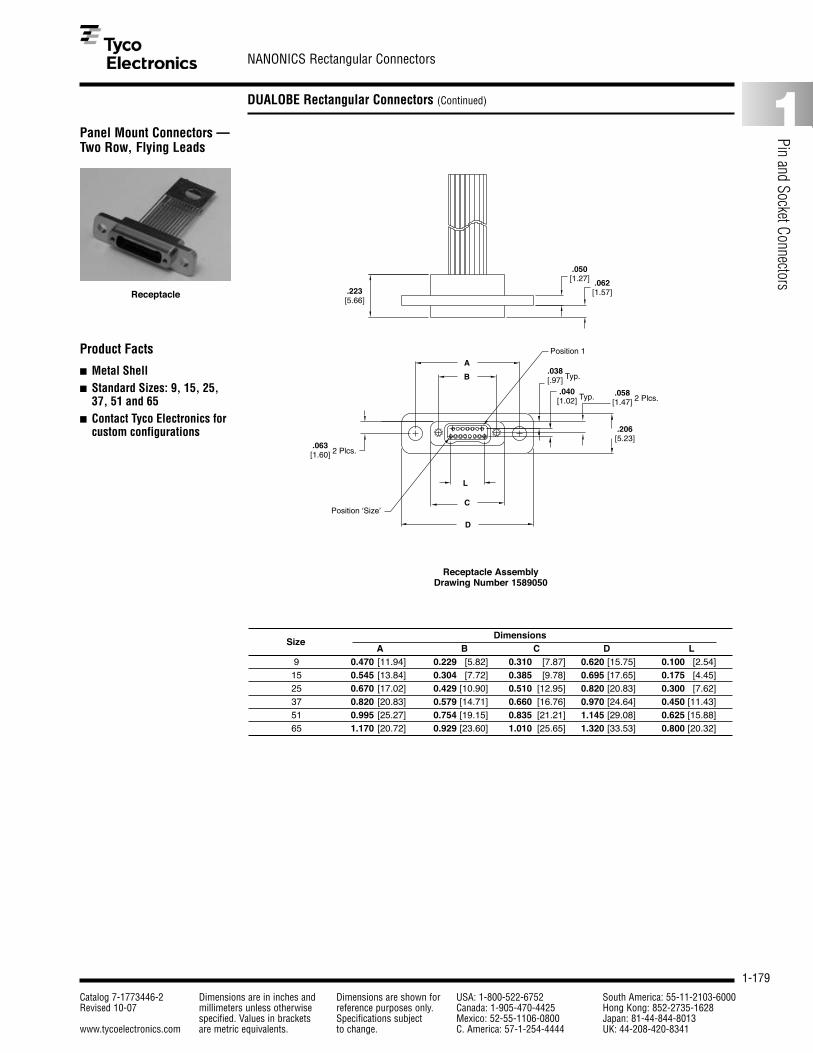
1-179
NANONICS Rectangular Connectors
Catalog 7-1773446-2 Dimensions are in inches and Dimensions are shown for USA: 1-800-522-6752 South America: 55-11-2103-6000Revised 10-07 millimeters unless otherwise reference purposes only. Canada: 1-905-470-4425 Hong Kong: 852-2735-1628
specified. Values in brackets Specifications subject Mexico: 52-55-1106-0800 Japan: 81-44-844-8013www.tycoelectronics.com are metric equivalents. to change. C. America: 57-1-254-4444 UK: 44-208-420-8341
1
Pin and Socket Connectors
DUALOBE Rectangular Connectors (Continued)
Panel Mount Connectors —Two Row, Flying Leads
.223 [5.66]
.050 [1.27] .062
[1.57]
B
A.038 [.97] Typ.
.040 [1.02] Typ.
.063 [1.60] 2 Plcs.
.058 [1.47] 2 Plcs.
L
C
D
.206 [5.23]
Position ‘Size’
Position 1Product Facts
■ Metal Shell■ Standard Sizes: 9, 15, 25,
37, 51 and 65■ Contact Tyco Electronics for
custom configurations
Receptacle AssemblyDrawing Number 1589050
DimensionsSize
A B C D L9 0.470 [11.94] 0.229 [5.82] 0.310 [7.87] 0.620 [15.75] 0.100 [2.54]15 0.545 [13.84] 0.304 [7.72] 0.385 [9.78] 0.695 [17.65] 0.175 [4.45]25 0.670 [17.02] 0.429 [10.90] 0.510 [12.95] 0.820 [20.83] 0.300 [7.62]37 0.820 [20.83] 0.579 [14.71] 0.660 [16.76] 0.970 [24.64] 0.450 [11.43]51 0.995 [25.27] 0.754 [19.15] 0.835 [21.21] 1.145 [29.08] 0.625 [15.88]65 1.170 [20.72] 0.929 [23.60] 1.010 [25.65] 1.320 [33.53] 0.800 [20.32]
Receptacle

1-180
NANONICS Rectangular Connectors
Catalog 7-1773446-2 Dimensions are in inches and Dimensions are shown for USA: 1-800-522-6752 South America: 55-11-2103-6000Revised 10-07 millimeters unless otherwise reference purposes only. Canada: 1-905-470-4425 Hong Kong: 852-2735-1628
specified. Values in brackets Specifications subject Mexico: 52-55-1106-0800 Japan: 81-44-844-8013www.tycoelectronics.com are metric equivalents. to change. C. America: 57-1-254-4444 UK: 44-208-420-8341
DUALOBE Connectors - Panel Mount
P X M XXX XX XXX X
Positions005 5 Position (single row only)
009 9 Position
015 15 Position
025 25 Position
037 37 Position
051 51 Position
065 65 Position (two row only)
TypeM Metal (Al, Ni Plate)
RowsS 1 Row
T 2 Row
ClassP Panel Mount
Jackscrew ThreadsThreads
N Thread for 1.0 mm Jackscrews
Q Thread for 1.2 mm Jackscrews
Conductor LengthXXX Three numbers only, length is in inches ( i.e. 012 = twelve inches)
CXX A “C” follwed by two numbers, length is in centimeters ( i.e. C06 = 6 centimeters)
MXX An “M” followed by two numbers, length is in meters ( i.e. M02 = 2 meters)
Conductor TypeDX White Teflon
DY White PTFE per M16878/6
DC Color Coded Teflon
DM Color Coded Teflon per MIL-STD-681
DT White Tefzel per M22759/33
GX Teflon Ribbon Cable
SC
ConfigurationSC Receptacle
X
Conductor Size/Strands0 28 AWG Solid
1 30 AWG Solid
2 30 AWG 7 Strand
3 32 AWG 7 Strand
4 34 AWG 7 Strand
DUALOBE Rectangular Connectors (Continued)
Part Numbering Guidelinefor Panel MountConnectors
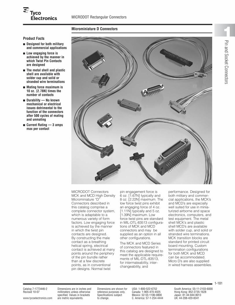
1-181
MICRODOT Rectangular Connectors
Catalog 7-1773446-2 Dimensions are in inches and Dimensions are shown for USA: 1-800-522-6752 South America: 55-11-2103-6000Revised 10-07 millimeters unless otherwise reference purposes only. Canada: 1-905-470-4425 Hong Kong: 852-2735-1628
specified. Values in brackets Specifications subject Mexico: 52-55-1106-0800 Japan: 81-44-844-8013www.tycoelectronics.com are metric equivalents. to change. C. America: 57-1-254-4444 UK: 44-208-420-8341
1
Pin and Socket Connectors
Microminiature D Connectors (Continued)Microminiature D Connectors
MICRODOT ConnectorsMCK and MCD High DensityMicrominiature “D”Connectors described inthis catalog comprise acomplete connector system,which is adaptable to anumerous variety of formfactors. Low engaging forceis achieved by the mannerin which the twist pin contacts are designed. By constructing the malecontact as a breathing helical spring, electricalcontact is achieved at manypoints around the peripheryof the pin bundle rather than at a few discretepoints, as in conventionalpin designs. Normal twist
pin engagement force is 6 oz. [1.67N] typically and 8 oz. [2.22N] maximum. Thelow force twist pins exhibitan engaging force of 4 oz.[1.11N] typically and 5 oz.[1.39N] maximum. Lowforce twist pins are standardin MIL-DTL-83513 configura-tions of MCK and MCD connectors and may besupplied as an option in allother configurations.
The MCK and MCD Seriesof connectors featured inthis catalog are designed tomeet the applicable require-ments of MlL-DTL-83513, for intermateability, inter-changeability, and
performance. Designed forboth military and commer-cial applications, the MCK’sand MCD’s are especiallywell suited for use in minia-turized airborne and spaceelectronics, computers, andtest equipment. The metalshell MCK’s and plasticshell MCD’s are availablewith solder cup, and solid orstranded wire terminations.MCK transition blocks arestandard for printed circuitboard mounting. Customtermination configurationsfor both MCK and MCD can be accommodated.Micro D’s are also suppliedin wired harness assemblies.
Product Facts■ Designed for both military
and commercial applications
■ Low engaging force isachieved by the manner inwhich Twist Pin Contactsare designed
■ The metal shell and plasticshell are available with solder cup and solid orstranded wire terminations
■ Mating force maximum is 10 oz. [2.78N] times thenumber of contacts
■ Durability — No knownmechanical or electricalissues detrimental to thefunction of the connectorsafter 500 cycles of matingand unmating
■ Current Rating — 3 ampsmax per contact

1-182
MICRODOT Rectangular Connectors
Catalog 7-1773446-2 Dimensions are in inches and Dimensions are shown for USA: 1-800-522-6752 South America: 55-11-2103-6000Revised 10-07 millimeters unless otherwise reference purposes only. Canada: 1-905-470-4425 Hong Kong: 852-2735-1628
specified. Values in brackets Specifications subject Mexico: 52-55-1106-0800 Japan: 81-44-844-8013www.tycoelectronics.com are metric equivalents. to change. C. America: 57-1-254-4444 UK: 44-208-420-8341
Microminiature D Connectors (Continued)
MCK/MCD/MCDM Series Metaland Plastic Shell Connectors
Electrical
Contacts — Pin 24 AWG twist pin,Socket 24 AWG precision machined barrel, Wire Range 24 AWG to 30 AWGsolid and stranded.
Contact Resistance — (voltage drop) 25 millivolts max. at 3 amps, 77°± 7.4°F[25°± 3° C].
Current Rating — 3 amps max. percontact.
Dielectric Withstanding Voltage —Volts RMS 60 Hz at room ambient. At sea level 600V solder pots, 750V wire terminations & transition blocks. At 70,000 ft. [21,336 m] 150V solderpots, 200V wire terminations & transi-tion blocks.
Insulation Resistance — 5,000megohms min. (@ 500 VDC) at ambientroom temperature.
Magnetic Permeability — 2 mu max.
Mechanical
Contact Spacing — .050 [1.27mm]centers.
Contact Engagement & Separation — Standard contactengaging force is 6.0 oz. [1.67N] (8.0 oz.[2.22N] max.). Separation force is 0.5[.14N] oz. min.
Mating Force Maximum —Calculated as 10 oz. times the number of contacts.
Environmental
Temperature Range — –67°F to 257°F [–55° C to +125°C] forMCK/MCD, –67°F to 302°F [–55°C to+150°C] for MCDM.
Vibration — No discontinuity inexcess of 1 µ sec. when tested in accor-dance with MIL-STD-1344, Method2005, test Condition IV.
Solderability — Connectors shallpass the test requirements of MIL-STD-202, Method 208
Shock — No discontinuity in excess of1 µ sec. when tested in accordance withMIL-STD-1344, Method 2004, testCondition E.
Durability — No mechanical or electri-cal defects detrimental to the function ofthe connectors after 500 cycles of matingand unmating.
Humidity — After exposure to humidityas specified by MIL-STD-1344, Method1002, Type II, IR shall be 1 megohmmin. following step 7a of Method 1002and 1000 megohms min. after 24 hoursof conditioning per Method 1002.
Salt Spray — Connectors shall meetthe performance requirements of contactresistance, mating and unmating forces,and contact retention after being sub-jected to the 48-hour 5% solution saltspray test per MIL-STD-1344, Method1001, Condition B.
Fluid Immersion — Unmated con-nectors after being fully immersed in oneof the following fluids, for the prescribedtime, will mate at a force of 10 oz.[2.78N] times the number of contacts
or less: Perchloroethylene, 2 hours;Lubricating oil per MIL-L-23699, 20 hours.
Insert Retention — Inserts will with-stand a 50 lb. [34N/cm2] per square inchload in either direction.
Crimp Termination TensileStrength — (Unassembled contactswith crimped stranded wire terminations)Wires will not pull out of contacts whenthe following axial loads are applied: 24 AWG, 5 lbs. [22.24N]; 26 AWG, 4 lbs. [17.79N]; 28 AWG, 3 lbs.[13.34N]
Outgassing — When tested in accor-dance with SP-R-0022, Total Mass Loss(TML) shall be less than 1.0% andVolatile Condensable Material (VCM)shall be less than 0.1% of the originalspecimen.
Materials and Finishes
Contacts — Copper alloy plated with.000050 [.00127] gold over copper flashper MIL-G-45204 Type II.
Hardware — see pages 1-190 and 1-191.
MCK-Metal Shell —Insulator — Liquid crystal polymer
(LCP) per ASTM D5138, or Polyphenylene sulfide GST-40F perASTM D5927 or MIL-M-24519
Interfacial Seal — Fluorosilicone Rubberper MIL-R-25988 (socket side only)
Body Shell — Aluminum alloy-highgrade plated
Cadmium per QQ-P-416Nickel, electroless per AMS 2404
Transition Block Shell —Liquid crystal polymer (LCP) per ASTM
D5138, or Polyphenylene sulfideGST-40F per ASTM D5927 or MIL-M-24519
Potting Material — Epoxy, BlackMCD-Plastic Shell — Insulator/Body — Polyester, glass filled
per MIL-M-24519, Liquid crystalpolymer (LCP) per ASTM D5138, orPolyphenylene sulfide GST-40F perASTM D5927 or MIL-M-24519
Wire Terminations — Solid copper per QQ-W-343 gold plated
per MIL-G-45204Stranded TEFLON insulated per MIL-W-
16878Stranded TEFLON insulated per MIL-W-
22759/11, /33Solid copper per QQ-W-343, solder
dipped (Transition block)
MCDM-Metal Shell — Insulator — Diallyl Phthalate per MIL-
M-14, Type SDG-FBody Shell — Aluminum alloy—high
grade, nickel plated
Technical and Performance Data (Applicable to MCK, MCD and MCDM unless otherwise noted)
MIL-DTL-83513 — Only the descriptive legend in bold italic is applicable to current MIL-DTL-83513 configurations;MIL-DTL-83513/1 through /4 — MCK metal shell; MIL-DTL-83513/6 through /9 — MCD plastic shell.In addition, MIL-DTL-83513 solid copper wire termination is specified 25 AWG, 0.5; and 1.0 [25.4] lengths only andstranded insulated wire termination is specified 26 AWG, 18.0 [457.2] and 36.0 [914.4] lead lengths only. Hardwarefor MIL-DTL-83513 configurations is specified separately by the M83513/5-XX designation. M83513/1 through /4 and/6 through /9 specify no hardware (B). Mounting/mating hardware is shown on page 1-191 with the applicable militarynomenclature. The MICRODOT catalog part number for a MIL-DTL-83513 configuration may be constructed to include the desired hardware.
Twist Pin, Pin and SocketContacts
The contact spring membernormally found in socketcontacts has been eliminat-ed by creating a breathinghelical spring principle onthe pin contact — smaller,more durable contacts can be manufactured economically.
Wire range 24-36 AWG solid & stranded.

1-183
MICRODOT Rectangular Connectors
Catalog 7-1773446-2 Dimensions are in inches and Dimensions are shown for USA: 1-800-522-6752 South America: 55-11-2103-6000Revised 10-07 millimeters unless otherwise reference purposes only. Canada: 1-905-470-4425 Hong Kong: 852-2735-1628
specified. Values in brackets Specifications subject Mexico: 52-55-1106-0800 Japan: 81-44-844-8013www.tycoelectronics.com are metric equivalents. to change. C. America: 57-1-254-4444 UK: 44-208-420-8341
1
Pin and Socket Connectors
Microminiature D Connectors (Continued)
How To Specify MCK andMCD Connectors
Metal Shell
Plastic Shell
MCK- C2 B 37 P 6 A 1 18.0 Lead Length in Inches (Min.)
X — Special, not described by legend.
Insulation Color or Finish 1 — All white wire 6 — Bare (unfinished) 2 — All yellow wire 7 — Color coded per MIL-STD-681, System 1 3 — All gray wire 8 — Special color code 4 — Gold plated 9 — 10 Solid color repeating per M-83513 5 — Tin dipped gold plated
Wire Type A — Type E, 7 strand B — Type ET, 7 strand C — Type E, 19 strand D — Type ET, 19 strand F — 7 strand per MIL-W-22759/11 (28 AWG only) G — 19 strand per MIL-C-22759/11 (26 AWG only), 24 AWG L — Copper, Solid (25 AWG only) Q — Stranded per MIL-W-22759/33 (26 AWG only)
Wire Size 4 — 24 AWG 5 — 25 AWG 6 — 26 AWG 8 — 28 AWG 0 — 30 AWG
Per MIL-W-16878 {
Connector Series
Shell FinishC1 — Cadmium, ClearC2 — Cadmium, Yellow ChromateN1 — Nickel, Electroless
Hardware (See Pages 5-135 and 5-136)B — No HardwareF — Float BushingK, KM — Jackscrew, Slotted Head, High Profile (9-51)H, HM — Jackscrew, Slotted Head, High Profile (100)L, LM — Jackscrew, Slotted Head, Low Profile (9-51)J, JM — Jackscrew, Slotted Head, Low Profile (100)Q, QM — Jackscrew, Allen Head, High Profile (9-51)T, TM — Jackscrew, Allen Head, High Profile (100)R, RM — Jackscrew, Allen Head, Low Profile (9-51)N, NM — Jackscrew, Allen Head, Low Profile (100)P — Jackpost Assembly (9-51)S — Jackpost Assembly (100)X — Lockscrew, Slotted HeadY — Lockscrew, Allen HeadZ — Clip and Key (Clip Mount Only)
Layout9, 15, 21, 25, 31, 37, 51, 100See contact arrangement
Contact TypeP — Pin (Plug)S — Socket (Receptacle)
S — Solder pots 26 AWG max.
MCD R3 B 37 P 6 A 1 18.0 Lead Length in Inches (Min.)
X — Special — Does not fit description below.
Insulation Color or Finish 1 — All white wire 6 — Bare (unfinished) 2 — All yellow wire 7 — Color coded per MIL-STD-681, System 1 3 — All gray wire 8 — Special color code 4 — Gold plated 9 — 10 Solid color repeating per M-83513 5 — Tin dipped gold plated
Wire Type A — Type E, 7 strand B — Type ET, 7 strand C — Type E, 19 strand D — Type ET, 19 strand F — 7 strand per MIL-W-22759/11 (28 AWG only) G — 19 strand per MIL-C-22759/11 (26 AWG only), 24 AWG L — Copper, Solid (25 AWG only) Q — Stranded per MIL-W-22759/33 (26 AWG only)
Wire Size 4 — 24 AWG 5 — 25 AWG 6 — 26 AWG 8 — 28 AWG 0 — 30 AWG
Per MIL-W-16878 {
Connector Series
Insulator Type/MaterialG2 — Clip Mount, polyester, naturalG3 — Screw Mount, polyester, natural, .093 Flg.R2 — Clip Mount, RytonR3 — Screw Mount Liquid Crystal Polymer or Polyphenylene Sulfide
Hardware (See Pages 5-135 and 5-136)B — No HardwareF — Float BushingK, KM — Jackscrew, Slotted Head, High ProfileL, LM — Jackscrew, Slotted Head, Low ProfileQ, QM — Jackscrew, Allen Head, High ProfileR, RM — Jackscrew, Allen Head, Low ProfileP — Jackpost AssemblyX — Lockscrew, Slotted HeadY — Lockscrew, Allen HeadZ — Clip and Key (Clip Mount Only)
Layout9, 15, 21, 25, 31, 37, 51See contact arrangement
Contact TypeP — Pin (Plug)S — Socket (Receptacle)
S — Solder pots 26 AWG max.
Note: Items in bold italic are qualified to MIL-DTL-83513.

1-184
MICRODOT Rectangular Connectors
Catalog 7-1773446-2 Dimensions are in inches and Dimensions are shown for USA: 1-800-522-6752 South America: 55-11-2103-6000Revised 10-07 millimeters unless otherwise reference purposes only. Canada: 1-905-470-4425 Hong Kong: 852-2735-1628
specified. Values in brackets Specifications subject Mexico: 52-55-1106-0800 Japan: 81-44-844-8013www.tycoelectronics.com are metric equivalents. to change. C. America: 57-1-254-4444 UK: 44-208-420-8341
Microminiature D Connectors (Continued)
Contact Arrangements
Note: MCK metal shells are not designed to intermate or interchange with MCD plastic shells. If metal/plastic intermating is desired, use MCDM Series MetalShell on pages 1-201 and 1-202 with MCD Series Plastic Shell on page 1-183.
1 13
2514
1 19
20 37
51
96
81
9 15
1 11
2112
1 16
17 31
1 18
19 35
36 51
1
916
24
8
1523
30
26
5175
100
1
2752
76
100 Contacts(MCK Only)
37 Contacts 51 Contacts
31 Contacts30 Contacts
(MCDM Only)
25 Contacts
9 Contacts 15 Contacts 21 Contacts
Face View of Pin Insert(Socket Side is Mirror Image)

1-185
MICRODOT Rectangular Connectors
Catalog 7-1773446-2 Dimensions are in inches and Dimensions are shown for USA: 1-800-522-6752 South America: 55-11-2103-6000Revised 10-07 millimeters unless otherwise reference purposes only. Canada: 1-905-470-4425 Hong Kong: 852-2735-1628
specified. Values in brackets Specifications subject Mexico: 52-55-1106-0800 Japan: 81-44-844-8013www.tycoelectronics.com are metric equivalents. to change. C. America: 57-1-254-4444 UK: 44-208-420-8341
1
Pin and Socket Connectors
Microminiature D Connectors (Continued)
MCK Series Metal ShellConnectors
A C E FPart B Max. + .010 [.254] D MaxNumber ± .010 [.254] – .018 [.457] ± .010 [.254] ± 005 [.127]
MCK**- 9P*** .775 .3338 .390 .270 .298 .56519.68 8.48 9.91 6.86 7.57 14.35
MCK**- 9S*** .775 .4018 .390 .270 .298 .56519.68 10.21 9.91 6.86 7.57 14.35
MCK**- 15P*** .925 .4838 .540 .270 .298 .71523.50 12.29 13.72 6.86 7.57 18.16
MCK**- 15S*** .925 .5518 .540 .270 .298 .71523.50 14.02 13.72 6.86 7.57 18.16
MCK**- 21P*** 1.075 .6338 .690 .270 .298 .86527.30 16.10 17.53 6.86 7.57 21.97
MCK**- 21S*** 1.075 .7018 .690 .270 .298 .86527.30 18.05 17.53 6.86 7.57 21.97
MCK**- 25P*** 1.175 .7338 .790 .270 .298 .96529.84 18.64 20.07 6.86 7.57 24.51
MCK**- 25S*** 1.175 .8018 .790 .270 .298 .96529.84 20.37 20.07 6.86 7.57 24.51
MCK**- 31P*** 1.325 .8838 .940 .270 .298 1.11533.66 22.45 23.88 6.86 7.57 28.32
MCK**- 31S*** 1.325 .9518 .940 .270 .298 1.11533.66 24.18 23.88 6.86 7.57 28.32
MCK**- 37P*** 1.475 1.0338 1.090 .270 .298 1.26537.46 26.26 27.69 6.86 7.57 32.13
MCK**- 37S*** 1.475 1.1018 1.090 .270 .298 1.26537.46 27.99 27.69 6.86 7.57 32.13
MCK**- 51P*** 1.425 .9838 1.040 .310 .341 1.21536.20 24.99 26.42 7.87 8.66 30.86
MCK**- 51S*** 1.425 1.0518 1.040 .310 .341 1.21536.20 26.72 26.42 7.87 8.66 30.86
MCK**- 100P*** 2.160 1.3838 1.432 .360 .384 1.80054.86 35.15 36.37 9.15 9.75 45.71
MCK**- 100S*** 2.160 1.508 1.432 .360 .384 1.80054.86 38.30 36.37 9.15 9.75 45.71
P = Pin, S = Socket
Dimensions per MIL-DTL-83513
Plug(Pin Side)
Receptacle(Socket Side)
FContact #1
Pin E
A
Two Mtg. Holes
Pin
B
Pin
D
.183±.003[4.65±0.08]
.093±.005[2.36±0.13]
Ø.092±.004[2.34±0.10]
Ø.145 – .150[3.68 – 3.81]
.406±.010[10.31±0.25]
C
Crimp or Solder
Crimp or Solder
Socket
Socket Socket
FContact #1
E
A
.419±.010[10.64±0.25]
C
.195±.003[4.95±0.08]
.093±.005[2.36±0.13]
D
B
(9-51)
(100)
Two Mtg. HolesØ.092±.004[2.34±0.10]
Ø.145 – .150[3.68 – 3.81]
(9-51)
(100)

1-186
MICRODOT Rectangular Connectors
Catalog 7-1773446-2 Dimensions are in inches and Dimensions are shown for USA: 1-800-522-6752 South America: 55-11-2103-6000Revised 10-07 millimeters unless otherwise reference purposes only. Canada: 1-905-470-4425 Hong Kong: 852-2735-1628
specified. Values in brackets Specifications subject Mexico: 52-55-1106-0800 Japan: 81-44-844-8013www.tycoelectronics.com are metric equivalents. to change. C. America: 57-1-254-4444 UK: 44-208-420-8341
Microminiature D Connectors (Continued)
MCK Series Metal ShellConnectors Panel Mounting —Cutout Dimensions
Panel Mounting Dimensions —MCK
Plug and ReceptacleRear Mounted
Plug and ReceptacleFront Mounted
Plug Front MountedReceptacle Rear Mounted
.200[5.08]
.395[10.03] .300
[7.62]
A
A
C
C
B
B
.095[2.41]
.095[2.41]
.122[3.10]
.122[3.10]
.015[.381]
Max.Typ.
Full Radius(Typ.)
Full Radius(Typ.)
Full Radius(Typ.)
Full Radius(Typ.)
116 Typ.
R
R 4 Plcs.
9-51
9-51
100
100
Figure 1Front Mounting
Figure 2Rear Mounting
Front Mounting
Rear Mounting
.015[.381]
.369/.364[9.37/9.24]
.403/.398[10.24/10.11]
1.810/1.805[45.98/45.85]
1.810/1.805[45.98/45.85]
1.448 .002
[36.83/36.73]
1.514 .002
[38.51/38.40]
Max.Typ.
R
.055[1.40]
Max.Typ.
R
+ .005– .000+ .127– .000
.101
[2.56 ]
Number A B Cof Fig. + .004 [.102] + .004 [.102] + .005 [.127]
Contacts – .000 [.000] – .000 [.000] – .000 [.000]
1 .404 .274 .570
910.26 6.96 14.48
2 .406 .257 .57010.31 6.53 14.48
1 .554 .274 .720
1514.07 6.96 18.29
2 .556 .257 .72014.12 6.53 18.29
1 .704 .274 .870
2117.88 6.96 22.10
2 .706 .257 .87017.93 6.53 22.10
1 .804 .274 .970
2520.42 6.96 24.64
2 .806 .257 .97020.47 6.53 24.64
1 .954 .274 1.120
3124.23 6.96 28.45
2 .956 .257 1.12024.28 6.53 28.45
1 1.104 .274 1.270
3728.04 6.96 32.26
2 1.106 .257 1.27028.09 6.53 32.26
1 1.054 .314 1.220
5126.77 7.98 30.99
2 1.056 .300 1.22026.82 7.62 30.99
Panel Cutout Dimensions — MCK

1-187
MICRODOT Rectangular Connectors
Catalog 7-1773446-2 Dimensions are in inches and Dimensions are shown for USA: 1-800-522-6752 South America: 55-11-2103-6000Revised 10-07 millimeters unless otherwise reference purposes only. Canada: 1-905-470-4425 Hong Kong: 852-2735-1628
specified. Values in brackets Specifications subject Mexico: 52-55-1106-0800 Japan: 81-44-844-8013www.tycoelectronics.com are metric equivalents. to change. C. America: 57-1-254-4444 UK: 44-208-420-8341
1
Pin and Socket Connectors
Microminiature D Connectors (Continued)
MCD Series Plastic ShellConnectors
Part A C E F Avg. Weight
Number B Max. + .010 [.254] D Max lbs. ± 5%± .010 [.254] – .018 [.457] ± .010 [.254] ± 005 [.127] [grams]
MCD**- 9P*** .778 .2918 .398 .173 .208 .565 .001719.76 7.412 10.11 4.39 5.28 14.35 0.77
MCD**- 9S*** .778 .3798 .398 .173 .208 .565 .001619.76 9.647 10.11 4.39 5.28 14.35 0.72
MCD**- 15P*** .928 .4418 .548 .173 .208 .715 .002423.57 11.222 13.92 4.39 5.28 18.16 1.08
MCD**- 15S*** .928 .5298 .548 .173 .208 .715 .002323.57 13.457 13.92 4.39 5.28 18.16 1.04
MCD**- 21P*** 1.078 .5918 .698 .173 .208 .865 .003527.38 15.032 17.73 4.39 5.28 21.97 1.59
MCD**- 21S*** 1.078 .6798 .698 .173 .208 .865 .003427.38 17.267 17.73 4.39 5.28 21.97 1.54
MCD**- 25P*** 1.178 .6918 .798 .173 .208 .965 .004229.92 17.572 20.27 4.39 5.28 24.51 1.90
MCD**- 25S*** 1.178 .7798 .798 .173 .208 .965 .003729.92 19.807 20.27 4.39 5.28 24.51 1.67
MCD**- 31P*** 1.328 .8418 .948 .173 .208 1.115 .005333.73 21.382 24.08 4.39 5.28 28.32 2.40
MCD**- 31S*** 1.328 .9298 .948 .173 .208 1.115 .004833.73 23.617 24.08 4.39 5.28 28.32 2.17
MCD**- 37P*** 1.478 .9918 1.098 .173 .208 1.265 .005737.54 25.192 27.89 4.39 5.28 32.13 2.58
MCD**- 37S*** 1.478 1.0798 1.098 .173 .208 1.265 .005137.54 27.427 27.89 4.39 5.28 32.13 2.31
MCD**- 51P*** 1.428 .9418 1.048 .220 .250 1.215 .007236.27 23.922 26.62 5.59 6.35 30.86 3.26
MCD**- 51S*** 1.428 1.0298 1.048 .220 .250 1.215 .006336.27 26.157 26.62 5.59 6.35 30.86 2.85
P = Pin, S = SocketNote: Weight given is with .500 [12.7] uninsulated, solid, 24 AWG gold plated copper pigtails.
Screw Mount Dimensions Per MIL-DTL-83513
Plug(Pin Side)
Receptacle(Socket Side)
FContact #1
Pin E
A
Two Mtg. Holes
Pin
B
Pin
D
.199±.005[5.05±.13]
.094±.006[2.39±0.15]
Ø.092±.004[2.34±.10]
.395/.360[10.03/9.14]
C
Crimp or Solder
Crimp or Solder
FContact #1
E
A
Two Mtg. HolesØ.092±.004[2.34±0.10]
.375/.340[9.52/8.64]
C
.180±.005[4.57±0.13]
.094±.006[2.39±0.15]
D
B
Socket
Socket Socket
Liquid Crystal Polymer orPolyphenylene Sulfide — MCDR3* perMIL-DTL-83513
Note: MCD Plastic Screw Mount Series is intermateable with MCDM Metal Series Connectors (pages 1-201 and 1-202).

1-188
MICRODOT Rectangular Connectors
Catalog 7-1773446-2 Dimensions are in inches and Dimensions are shown for USA: 1-800-522-6752 South America: 55-11-2103-6000Revised 10-07 millimeters unless otherwise reference purposes only. Canada: 1-905-470-4425 Hong Kong: 852-2735-1628
specified. Values in brackets Specifications subject Mexico: 52-55-1106-0800 Japan: 81-44-844-8013www.tycoelectronics.com are metric equivalents. to change. C. America: 57-1-254-4444 UK: 44-208-420-8341
Microminiature D Connectors (Continued)
MCD Series Plastic ShellConnectors (Continued)
Part A C D E Avg. Weight
Number ± .005 [.127] B Max. ± .010 [.254] ± .010 [.254] ± .005 [.127] lbs. ± 5%[grams]
MCD**- 9P*** .506 .2918 .398 .165 .208 .001712.85 74.12 10.11 4.19 5.28 0.77
MCD**- 9S*** .506 .3798 .398 .165 .208 .001612.85 96.47 10.11 4.19 5.28 0.72
MCD**- 15P*** .656 .4418 .548 .165 .208 .002416.66 112.22 13.92 4.19 5.28 1.08
MCD**- 15S*** .656 .5298 .548 .165 .208 .002316.66 134.57 13.92 4.19 5.28 1.04
MCD**- 21P*** .806 .5918 .698 .165 .208 .003520.47 150.32 17.73 4.19 5.28 1.59
MCD**- 21S*** .806 .6798 .698 .165 .208 .003420.47 172.67 17.73 4.19 5.28 1.54
MCD**- 25P*** .906 .6918 .798 .165 .208 .004223.01 175.72 20.27 4.19 5.28 1.90
MCD**- 25S*** .906 .7798 .798 .165 .208 .003723.01 198.07 20.27 4.19 5.28 1.67
MCD**- 31P*** 1.056 .8418 .948 .165 .208 .005326.82 213.82 24.08 4.19 5.28 2.40
MCD**- 31S*** 1.056 .9298 .948 .165 .208 .004826.82 236.17 24.08 4.19 5.28 2.17
MCD**- 37P*** 1.206 .9918 1.098 .165 .208 .005730.63 251.92 27.89 4.19 5.28 2.58
MCD**- 37S*** 1.206 1.0798 1.098 .165 .208 .005130.63 274.27 27.89 4.19 5.28 2.31
MCD**- 51P*** 1.156 .9418 1.048 .208 .250 .007229.36 239.22 26.62 5.28 6.35 3.26
MCD**- 51S*** 1.156 1.0298 1.048 .208 .250 .006329.36 261.57 26.62 5.28 6.35 2.85
P = Pin, S = SocketNote: Weight given is with .500 [12.7] uninsulated, solid, 24 AWG gold plated copper pigtails.
Clip Mount — MCD
Plug(Pin Side)
Receptacle(Socket Side)
Contact #1
Pin E
A
Pin
B
Pin
D
.199[5.05]
.395/.360[10.03/9.14]
C
Crimp or Solder
Crimp or Solder
.093 ± .003
[2.44/2.29]
Contact #1
Socket E
A
Socket
B
Socket
D
.180[4.57]
.375/.340[9.52/8.64]
C
.093 ± .003
[2.44/2.29]
.019[.483]
.019[.483]
.060[1.52]
.060[1.52]
Note: Clip Mount not covered bycurrent issue of MIL-DTL-83513.

1-189
MICRODOT Rectangular Connectors
Catalog 7-1773446-2 Dimensions are in inches and Dimensions are shown for USA: 1-800-522-6752 South America: 55-11-2103-6000Revised 10-07 millimeters unless otherwise reference purposes only. Canada: 1-905-470-4425 Hong Kong: 852-2735-1628
specified. Values in brackets Specifications subject Mexico: 52-55-1106-0800 Japan: 81-44-844-8013www.tycoelectronics.com are metric equivalents. to change. C. America: 57-1-254-4444 UK: 44-208-420-8341
1
Pin and Socket Connectors
Microminiature D Connectors (Continued)
MCD Series Plastic Shell Connectors Panel Mounting —Cutout Dimensions
Panel Mounting Dimensions — MCDClip Mount Screw Mount
Plug and ReceptacleRear Mounted
.200±.005
[5.08±0.13]
Plug and ReceptacleFront Mounted
Plug Front MountedReceptacle Rear Mounted
.330±.005
[8.38±0.13]
.265±.005
[6.73±0.13]
Plug and ReceptacleRear Mounted
.200±.005
[5.08±0.13]
Plug and ReceptacleFront Mounted
Plug Front MountedReceptacle Rear Mounted
.395±.005
[10.03±0.13]
.300±.005
[7.62±0.13]
Front
FullRadius(Typ.)
R
R
A
A
C
B
Figure 2
Front
Figure 1
Rear
Figure 4
Rear
Figure 3
B
B
FullRadius(Typ.)
116 Typ.
A
C
+ .005– .000+ 0.13– 0.00
.089
[2.26 ]
+ .005– .000+ 0.13– 0.00
.075
[1.90 ]
.015[.381]
Max. Typ.
R .015[.381]
.089[2.26]
Max.Typ.
BA
R .015[.381]
Max.Typ.
Number A B Cof Fig. + .004 [.102] + .004 [.102] + .005 [.127]
Contacts – .000 [.000] – .000 [.000] – .000 [.000]1 .438 [11.13] .177 [4.50] —
92 .412 [10.46] .177 [4.50] .570 [14.48]3 .438 [11.13] .222 [5.64] —4 .384 [9.75] .222 [5.64] .570 [14.48]1 .588 [14.93] .177 [4.50] —
152 .562 [14.27] .177 [4.50] .720 [18.29]3 .588 [14.93] .222 [5.64] —4 .534 [13.56] .222 [5.64] .720 [18.29]1 .738 [18.75] .177 [4.50] —
212 .712 [18.08] .177 [4.50] .870 [22.10]3 .738 [18.75] .222 [5.64] —4 .684 [17.37] .222 [5.64] .870 [22.10]1 .838 [21.29] .177 [4.50] —
252 .812 [20.62] .177 [4.50] .970 [24.64]3 .838 [21.29] .222 [5.64] —4 .784 [19.91] .222 [5.64] .970 [24.64]1 .988 [25.10] .177 [4.50] —
312 .962 [24.43] .177 [4.50] 1.120 [28.45]3 .988 [25.10] .222 [5.64] —4 .934 [23.72] .222 [5.64] 1.120 [28.45]1 1.138 [28.91] .177 [4.50] —
372 1.112 [28.24] .177 [4.50] 1.270 [32.26]3 1.138 [28.91] .222 [5.64] —4 1.084 [27.53] .222 [5.64] 1.270 [32.26]1 1.088 [27.64] .224 [5.69] —
512 1.062 [26.97] .224 [5.69] 1.220 [30.99]3 1.088 [27.64] .264 [6.71] —4 1.034 [26.26] .264 [6.71] 1.220 [30.99]
Panel Cutout Dimensions — MCD
Clip Mounting Screw Mounting
Notes: Front mounting preferred.

1-190
MICRODOT Rectangular Connectors
Catalog 7-1773446-2 Dimensions are in inches and Dimensions are shown for USA: 1-800-522-6752 South America: 55-11-2103-6000Revised 10-07 millimeters unless otherwise reference purposes only. Canada: 1-905-470-4425 Hong Kong: 852-2735-1628
specified. Values in brackets Specifications subject Mexico: 52-55-1106-0800 Japan: 81-44-844-8013www.tycoelectronics.com are metric equivalents. to change. C. America: 57-1-254-4444 UK: 44-208-420-8341
Microminiature D Connectors (Continued)
Mounting and Coupling Hardware
Ø .156 [3.96]
Max.Over Knurl
Jackscrew
.086-56UNC-2A[2.18]
RetainingRing
.853 ± .015
[21.67 ± 0.38]
.600[15.24]
For Screw Mount MCK, MCD and MCDM9-51 ContactsSlot Head
(K)(KM)
Part Number 5-1532137-8Jackscrew Assembly
High Profile(K) 096-0002-0010
M83513/5-06(KM) S96-0002-0084
Ø .125 [3.18]
Jackscrew
.086-56UNC-2A[2.18]
RetainingRing
.340–.360[8.64–9.14]
.098[2.29]
(L)(LM)
Part Number 5-1532137-7Jackscrew Assembly
Low Profile(L) 096-0002-0011
M83513/5-05(LM) S96-0002-0085
Lockwasher
Bushing
.086-56UNC-2A[2.18]
.086-56UNC-2B[2.18]
Hex Nut
.475[12.07]
.187[4.75]
Hex..125[3.18]
(P)
Part Number 5-1532137-9Jackpost Assembly(P) S96-0002-0009
M83513/5-07P mates with K,KM, L,LM, Q,QMand R,RM Jackscrew Assemblies.
Ø .156 [3.96]
Max.Over Knurl
Jackscrew
.086-56UNC-2A[2.18]
RetainingRing
.853 ± .015
[21.67 ± 0.38]
.600[15.24]
9-51 Contacts1/16" Allen Head
(Q)(QM)
Part Number 5-1532137-6Jackscrew Assembly
High Profile(Q) 096-0002-0014
M83513/5-03(QM) S96-0002-0086
Ø .125 [3.18]
Jackscrew
.086-56UNC-2A[2.18]
RetainingRing
.340–.360[8.64–9.14]
.098[2.29]
(R)(RM)
Part Number 5-1532137-5Jackscrew Assembly
Low Profile(R) 096-0002-0015
M83513/5-02(RM) S96-0002-0087
Ø .200 [3.96]
Max.Over Knurl
Max.
Jackscrew
.112-40UNC-2A[2.84]
RetainingRing
.920[23.37]
.585[14.86]
100 ContactsSlot Head
(H)(HM)
Part Number 6-1532137-3Jackscrew Assembly
High Profile(H) 096-0002-0061
M83513/5-16(HM) S96-0002-0088
Ø .187 [4.75]
Jackscrew
Max.
.112-40UNC-2A[2.84]
RetainingRing
.415[10.54]
.100[2.54]
(J)(JM)
Part Number 6-1532137-2Jackscrew Assembly
Low Profile(J) 096-0002-0062
M83513/5-15(JM) S96-0002-0089
Lockwasher
Bushing
.112-40UNC-2A[2.84]
.112-40UNC-2B[2.84]
Hex Nut
.475[12.07]
Max..185[4.70]
Hex..187[4.75]
(S)
Part Number 6-1532137-4Jackpost Assembly(S) S96-0002-0060
M83513/5-17S mates with H,HM, J,JM, T,TM andN,NM Jackscrew Assemblies.
Ø .200 [3.96]
Max.Over Knurl
Max.
Jackscrew
.112-40UNC-2A[2.84]
RetainingRing
.920[23.37]
.585[14.86]
100 Contacts1/16" Allen Head
(T)(TM)
Part Number 6-1532137-1Jackscrew Assembly
High Profile(T) 096-0002-0064
M83513/5-13(TM) S96-0002-0090
Ø .187 [4.75]
Jackscrew
Max.
.112-40UNC-2A[2.84]
RetainingRing
.415[10.54]
.100[2.54]
(N)(NM)
Part Number 6-1532137-0Jackscrew Assembly
Low Profile(N) 096-0002-0065
M83513/5-12(NM) S96-0002-0091
Notes:1. Jackpost Assemblies will accom-
modate .094 [2.39] max. thick-ness panel.
2. Letter(s) in parentheses is toassist in ordering hardware withthe connector (See “How ToSpecify” page 5-128).
3. Single letters (e.g. K) designatehardware kits (2 pcs. per kit) thatmeets M83513/05 requirementsexcept the material is 303 stain-less steel, passivated.
4. Add M suffix (e.g. KM) to desig-nate hardware that meets allM83513/05 requirements.Material is corrosion resistantsteel, non-magnetic, 125,000 PSItensile strength minimum (Appliesto jackscrews only).
5. Non-MIL hardware ordered sepa-rately should be ordered in pairs;i.e. 2 pcs. P/N 096-0002-0009 perconnector half.
6. Items in bold italic are qualifiedto MIL-DTL-83513.

1-191
MICRODOT Rectangular Connectors
Catalog 7-1773446-2 Dimensions are in inches and Dimensions are shown for USA: 1-800-522-6752 South America: 55-11-2103-6000Revised 10-07 millimeters unless otherwise reference purposes only. Canada: 1-905-470-4425 Hong Kong: 852-2735-1628
specified. Values in brackets Specifications subject Mexico: 52-55-1106-0800 Japan: 81-44-844-8013www.tycoelectronics.com are metric equivalents. to change. C. America: 57-1-254-4444 UK: 44-208-420-8341
1
Pin and Socket Connectors
Microminiature D Connectors (Continued)
Mounting and Coupling Hardware (Continued)
.356[9.04]
.600[15.24]
For Clip Mount — MCD (Z)
(X)
Part Number 1466018-1Mounting Key and Clip
P/N 096-0001-0000(2 Required)
.075[1.91]
Ø .125 [3.18]
Retaining Clip
.086[2.18]
-56UNC-2A
Lockscrew
Part Number 4-1532137-3Lockscrew Assembly
096-0002-0008
.075[1.91]
Ø .125 [3.18]
Lockscrew
Retaining Clip
.086[2.18]
.343 ± .010
[8.71 ± 0.25]-56UNC-2A
Part Number 1495164-1Lockscrew Assembly
096-0002-0013
Slot Head 1/16" Allen Head
Notes:1. Jackpost Assemblies will accommodate .094 [2.39] max. thickness panel.2. Letter(s) in parentheses is to assist in ordering hardware with the connector (See “How To Specify” page 1-192).3. Hardware ordered separately should be ordered in pairs; i.e. 2 pcs. P/N 096-0002-0013 per connector half.
For Screw Mount MCK,MCD and MCDM (Continued) (Y)
For Float Mount — MCK,MCD and MCDM
(F)
Float Mount Bushing(Factory Installed)
Washer
Bushing
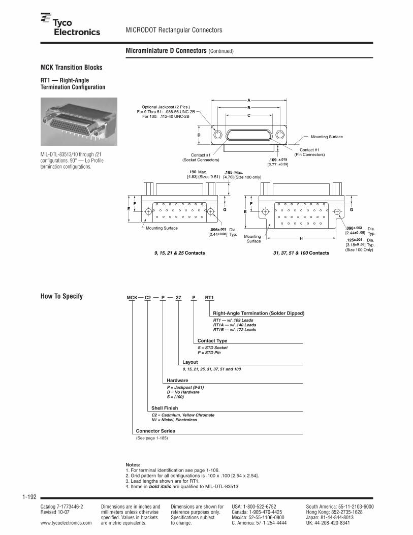
1-192
MICRODOT Rectangular Connectors
Catalog 7-1773446-2 Dimensions are in inches and Dimensions are shown for USA: 1-800-522-6752 South America: 55-11-2103-6000Revised 10-07 millimeters unless otherwise reference purposes only. Canada: 1-905-470-4425 Hong Kong: 852-2735-1628
specified. Values in brackets Specifications subject Mexico: 52-55-1106-0800 Japan: 81-44-844-8013www.tycoelectronics.com are metric equivalents. to change. C. America: 57-1-254-4444 UK: 44-208-420-8341
Microminiature D Connectors (Continued)
MCK Transition Blocks
RT1 — Right-AngleTermination Configuration
Notes:1. For terminal identification see page 1-106.2. Grid pattern for all configurations is .100 x .100 [2.54 x 2.54].3. Lead lengths shown are for RT1.4. Items in bold italic are qualified to MIL-DTL-83513.
.109 ±.015
[2.77 ±0.39]
.185[4.70]
9, 15, 21 & 25 Contacts 31, 37, 51 & 100 Contacts
Contact #1(Socket Connectors)
Optional Jackpost (2 Plcs.)For 9 Thru 51: .086-56 UNC-2B
For 100: .112-40 UNC-2B
Mounting Surface
Mounting Surface
Max.(Size 100 only)
.190[4.83]
Max.(Sizes 9-51)
.096±.003
[2.44±0.08]Dia.Typ.
.125±.003
[3.18±0 .08]Dia.Typ.
MountingSurface
Contact #1(Pin Connectors)
A
B
C
D
EF
E
F
H
G G
(Size 100 Only)
.096±.003
[2.44±0 .08] Dia. Typ.
MIL-DTL-83513/10 through /21 configurations. 90° — Lo Profile termination configurations.
How To Specify MCK C2 P 37 P RT1
Right-Angle Termination (Solder Dipped) RT1 — w/ .109 LeadsRT1A — w/ .140 LeadsRT1B — w/ .172 Leads
Contact TypeS = STD SocketP = STD Pin
Layout9, 15, 21, 25, 31, 37, 51 and 100
Hardware P = Jackpost (9-51)B = No HardwareS = (100)
Shell FinishC2 = Cadmium, Yellow ChromateN1 = Nickel, Electroless
Connector Series(See page 1-185)

1-193
MICRODOT Rectangular Connectors
Catalog 7-1773446-2 Dimensions are in inches and Dimensions are shown for USA: 1-800-522-6752 South America: 55-11-2103-6000Revised 10-07 millimeters unless otherwise reference purposes only. Canada: 1-905-470-4425 Hong Kong: 852-2735-1628
specified. Values in brackets Specifications subject Mexico: 52-55-1106-0800 Japan: 81-44-844-8013www.tycoelectronics.com are metric equivalents. to change. C. America: 57-1-254-4444 UK: 44-208-420-8341
1
Pin and Socket Connectors
Microminiature D Connectors (Continued)
MCK Transition Blocks(Continued)
RT1 — Right-AngleTermination Configuration(Continued)
Part Number A B C D E F G HMax. ± 005 [.127] Max. Max. Max. +.010 [.254] +.010 [.254] Max.
MCK-**- *- 9PRT1 .787 .565 .3338 .308 .425 .250 .230 —19.99 14.35 8.48 7.83 10.80 6.35 5.84
MCK-**- *- 9SRT1 .787 .565 .4018 .308 .425 .250 .230 —19.99 14.35 10.21 7.83 10.80 6.35 5.84
MCK-**- *- 15PRT1 .937 .715 .4838 .308 .425 .250 .130 —23.80 18.16 12.29 7.83 10.80 6.35 3.30
MCK-**- *- 15SRT1 .937 .715 .5518 .308 .425 .250 .130 —23.80 18.16 14.02 7.83 10.80 6.35 3.30
MCK-**- *- 21PRT1 1.087 .865 .6338 .308 .425 .250 .130 —27.61 21.97 16.10 7.83 10.80 6.35 3.30
MCK-**- *- 21SRT1 1.087 .865 .7018 .308 .425 .250 .130 —27.61 21.97 17.83 7.83 10.80 6.35 3.30
MCK-**- *- 25PRT1 1.187 .965 .7338 .308 .425 .250 .130 —30.15 24.51 18.64 7.83 10.80 6.35 3.30
MCK-**- *- 25SRT1 1.187 .965 .8018 .308 .425 .250 .130 —30.15 24.51 20.37 7.83 10.80 6.35 3.30
MCK-**- *- 31PRT1 1.337 1.115 .8838 .308 .525 .250 .130 1.09033.96 28.32 22.45 7.83 13.34 6.35 3.30 27.69
MCK-**- *- 31SRT1 1.337 1.115 .9518 .308 .525 .250 .130 1.09033.96 28.32 24.18 7.83 13.34 6.35 3.30 27.69
MCK-**- *- 37PRT1 1.487 1.265 1.0338 .308 .525 .250 .130 1.19037.77 32.13 26.26 7.83 13.34 6.35 3.30 30.23
MCK-**- *- 37SRT1 1.487 1.265 1.1018 .308 .525 .250 .130 1.19037.77 32.13 27.99 7.83 13.34 6.35 3.30 30.23
MCK-**- *- 51PRT1 1.435 1.215 .9838 .351 .660 .300 .150 1.23036.45 30.86 24.99 8.92 16.76 7.62 3.81 31.24
MCK-**- *- 51SRT1 1.435 1.215 1.0518 .351 .660 .300 .150 1.23036.45 30.86 26.72 8.92 16.76 7.62 3.81 31.24
MCK-**- *- 100PRT1 2.175 1.800 1.3838 .394 1.010 .400 .200 1.82555.25 45.72 35.15 10.01 25.65 10.16 5.08 46.36
MCK-**- *- 100SRT1 2.175 1.800 1.508 .394 1.010 .400 .200 1.82555.25 45.72 38.30 10.01 25.65 10.16 5.08 46.36
P = Pin, S = Socket
Note: Items in bold italic are qualified to MIL-DTL-83513.

1-194
MICRODOT Rectangular Connectors
Catalog 7-1773446-2 Dimensions are in inches and Dimensions are shown for USA: 1-800-522-6752 South America: 55-11-2103-6000Revised 10-07 millimeters unless otherwise reference purposes only. Canada: 1-905-470-4425 Hong Kong: 852-2735-1628
specified. Values in brackets Specifications subject Mexico: 52-55-1106-0800 Japan: 81-44-844-8013www.tycoelectronics.com are metric equivalents. to change. C. America: 57-1-254-4444 UK: 44-208-420-8341
Microminiature D Connectors (Continued)
MCK Transition Blocks(Continued)
RT1 — Right-AngleTermination Configuration(Continued)
View is from mounting surface of connector. Plug configuration shown.For receptacle, use mirror image.(Except 100 contacts)
12 11 10 8 6 4 3 2
25 23 21 20 19 18 16 14
13 24 22 9 7 5 17 15 1
11 9 7 17 4 14 1
21 20 19 18 16 15 13 12
10 8 6 5 3 27 5 4 2
8 6 12 3 1
15 14 13 11 10 9
17 15 13 11 27 8 6 4 2
18 16 14 12 10 9 7 5 3 1
35 33 31 29 46 43 41 25 23 21 19
34 32 30 28 45 42 26 24 22 20
51 50 49 48 47 44 40 39 38 37 36
5 4 2 1
9 8 3 7 6
36 34 32 30 27 25 2 21
37 35 33 31 29 28 26 24 22 20
19 17 15 13 11 9 7 5 3 1
18 16 14 12 10 8 6 4 2
15 13 11 9 8 6 4 2
16 14 12 10 24 7 5 3 1
30 29 27 25 23 21 9 17
3 28 26 22 20 18
2 4 6 8 10 12 14 16 18 20 22 24 26
77 79 81 83 85 87 89 91 93 95 97 99
1 3 5 7 9 11 13 15 17 19 21 23 25
27 29 31 33 35 37 39 41 43 45 47 49 51
28 30 32 34 36 38 40 42 44 46 48 50
52 54 56 58 60 62 64 66 68 70 72 74
53 55 57 59 61 63 65 67 69 71 73 75
76 78 80 82 84 86 88 90 92 94 96 98 100
25 23 21 19 17 15 13 11 9 7 5 3 1
26 24 22 20 18 16 14 12 10 8 6 4 2
51 49 47 45 43 41 39 37 35 33 31 29 27
50 48 46 44 42 40 38 36 34 32 30 28
75 73 71 69 67 65 63 61 59 57 55 53
74 72 70 68 66 64 62 60 58 56 54 52
100 98 96 94 92 90 88 86 84 82 80 78 76
99 97 95 93 91 89 87 85 83 81 79 77
CL
CL
CL
.100[2.54]
Typ. .050[1.27]
.020[0.51]
.020[0.51]
.020[0.51]
.083[2.11]
Typ.
Typ..100[2.54] .158
[4.01]
Typ.
CL CL
CL
CL
CL
.100[2.54]
Typ. .050[1.27]
.108[2.74]
.020[0.51]
.020[0.51]
.183[4.65]
.100[2.54]
Typ.
.100[2.54]
Typ.
1.800[45.72]
Ref..275[6.99]
Ref..100[2.54]
Typ.Ref.
.100[2.54]
Typ.
.100[2.54]
Ref.
Socket #1 Ref.(Receptacle Connector)
.025[0.64]
Ref.
.050[1.27]
Typ.Ref.
1.800[45.72]
Ref..275
[6.99]Ref.
.100[2.54]
Typ.Ref.
.100[2.54]
Ref.
.050[1.27]
Typ.Ref.
.050[1.27]
Typ..050[1.27]
Typ..050[1.27]
.100[2.54]
.050[1.27]
.108[2.74]
Typ.Typ..050
[1.27]
.083[2.11]
Typ.
9 Contacts
31 Contacts
37 Contacts
100 Contacts(Socket Connector)
.100[2.54]
Ref.
Pin #1 Ref.(Plug Connector)
.025[0.64]
Ref.
100 Contacts(Pin Connector)
51 Contacts
.100[2.54]
Typ. .050[1.27]
.020[0.51]
.083[2.11]
Typ.
21 Contacts
25 Contacts
15 Contacts
CL
1.266[32.16]
Ref. 1.216[30.89]
Ref.
.966[24.54]
Ref.1.116[28.35]
Ref.
.866[22.00]
Ref..716
[18.19]Ref..566
[14.38]Ref.

1-195
MICRODOT Rectangular Connectors
Catalog 7-1773446-2 Dimensions are in inches and Dimensions are shown for USA: 1-800-522-6752 South America: 55-11-2103-6000Revised 10-07 millimeters unless otherwise reference purposes only. Canada: 1-905-470-4425 Hong Kong: 852-2735-1628
specified. Values in brackets Specifications subject Mexico: 52-55-1106-0800 Japan: 81-44-844-8013www.tycoelectronics.com are metric equivalents. to change. C. America: 57-1-254-4444 UK: 44-208-420-8341
1
Pin and Socket Connectors
Microminiature D Connectors (Continued)
How To Specify
ST1 — Straight TerminationConfiguration
.185[4.70]
.190[4.83]
Max. (Sizes 9-51)
(Sizes 9-51)
Max. (Size100 only)
.550[13.97]
Max. .355[9.02]
Max.
.100[2.54]
Typ.
.050[1.27]
Typ.
.165[4.20]
Max. (Sizes 9-51) .303[7.70]
Max. (Size 100 only)
.096±.003[2.44±.076]
Dia. Typ.(For Size 9 Thru 51)
.125±.003[3.18±.076]
Dia. Typ.(For Size 100 Only)
Contact #1(Socket Connector)
Contact #1(Pin Connector)
Lead #1(Pin Connector)
Lead #1(Socket Connector)
Optional Jackpost (2 Plcs.)For 9 Thru 51: .086-56 UNC-2B
For 100: .112-40 UNC-2B
AB
F
C
D
E
.109 ±.015
[2.77 ±0.39](Lead Length For ST1 Shown)
(Size100 only)
MIL-DTL-83513/22 through /27 configurations. 180° — Lo Profile termination configurations.
MCK C2 P 37 P ST1
Straight Termination (Solder Dipped) ST1 — w/ .109 LeadsST1A — w/ .140 LeadsST1B — w/ .172 Leads
Contact TypeS = STD SocketP = STD Pin
Layout9, 15, 21, 25, 31, 37, 51 and 100
Hardware P = Jackpost (9-51)B = No HardwareS = (100)
Shell FinishC2 = Cadmium, Yellow ChromateN1 = Nickel, Electroless
Connector Series
Notes:1. For terminal identification see page 1-197.2. Grid pattern for all configurations is .100 x .100 [2.54 x 2.54].3. Lead lengths shown are for ST1.4. Items in bold italic are qualified to MIL-DTL-83513.
MCK Transition Blocks(Continued)
(See page 1-185)

1-196
MICRODOT Rectangular Connectors
Catalog 7-1773446-2 Dimensions are in inches and Dimensions are shown for USA: 1-800-522-6752 South America: 55-11-2103-6000Revised 10-07 millimeters unless otherwise reference purposes only. Canada: 1-905-470-4425 Hong Kong: 852-2735-1628
specified. Values in brackets Specifications subject Mexico: 52-55-1106-0800 Japan: 81-44-844-8013www.tycoelectronics.com are metric equivalents. to change. C. America: 57-1-254-4444 UK: 44-208-420-8341
Microminiature D Connectors (Continued)
ST1 — Straight TerminationConfiguration (Continued)
MCK Transition Blocks(Continued)
Part Number A B C D E FMax. ± .007 [.178] ± .005 [.127] Max. Max. Max.
MCK-**- *- 9PST1 1.390 1.150 .565 .885 .3338 .30835.31 29.21 14.35 22.48 8.48 7.83
MCK-**- *- 9SST1 1.390 1.150 .565 .885 .4018 .30835.31 29.21 14.35 22.48 10.21 7.83
MCK-**- *- 15PST1 1.390 1.150 .715 .945 .4838 .30835.31 29.21 18.16 24.00 12.29 7.83
MCK-**- *- 15SST1 1.390 1.150 .715 .945 .5518 .30835.31 29.21 18.16 24.00 14.02 7.83
MCK-**- *- 21PST1 1.690 1.450 .865 1.185 .6338 .30842.93 36.83 21.97 30.10 16.10 7.83
MCK-**- *- 21SST1 1.690 1.450 .865 1.185 .7018 .30842.93 36.83 21.97 30.10 17.83 7.83
MCK-**- *- 25PST1 1.740 1.500 .965 1.275 .7338 .30844.20 38.10 24.51 32.39 18.64 7.83
MCK-**- *- 25SST1 1.740 1.500 .965 1.275 .8018 .30844.20 38.10 24.51 32.39 20.37 7.83
MCK-**- *- 31PST1 2.040 1.800 1.115 1.575 .8838 .30851.82 45.72 28.32 40.01 22.45 7.83
MCK-**- *- 31SST1 2.040 1.800 1.115 1.575 .9518 .30851.82 45.72 28.32 40.01 24.18 7.83
MCK-**- *- 37PST1 2.340 2.100 1.265 1.875 1.0338 .30859.44 53.34 32.13 47.63 26.26 7.83
MCK-**- *- 37SST1 2.340 2.100 1.265 1.875 1.1018 .30859.44 53.34 32.13 47.63 27.99 7.83
MCK-**- *- 51PST1 2.270 2.000 1.215 1.775 .9838 .35157.66 50.80 30.86 45.09 24.99 8.92
MCK-**- *- 51SST1 2.280 2.000 1.215 1.775 1.0518 .35157.91 50.80 30.86 45.09 26.72 8.92
MCK-**- *- 100PST1 3.250 2.800 1.800 2.585 1.3838 .46082.55 71.12 45.72 65.66 35.15 11.68
MCK-**- *- 100SST1 3.250 2.800 1.800 2.585 1.508 .46082.55 71.12 45.72 65.66 38.30 11.68
P = Pin, S = Socket
Note: Items in bold italic are qualified to MIL-DTL-83513.

1-197
MICRODOT Rectangular Connectors
Catalog 7-1773446-2 Dimensions are in inches and Dimensions are shown for USA: 1-800-522-6752 South America: 55-11-2103-6000Revised 10-07 millimeters unless otherwise reference purposes only. Canada: 1-905-470-4425 Hong Kong: 852-2735-1628
specified. Values in brackets Specifications subject Mexico: 52-55-1106-0800 Japan: 81-44-844-8013www.tycoelectronics.com are metric equivalents. to change. C. America: 57-1-254-4444 UK: 44-208-420-8341
1
Pin and Socket Connectors
Microminiature D Connectors (Continued)
ST1 — Straight TerminationConfiguration (Continued)
View is from mounting surface of connector. Plug configuration shown.For receptacle, use mirror image.
MCK Transition Blocks(Continued)
1 5
6 9
17 31
1 16
20 37
1 19
9 15
1 8
12 21
1 11
14 25
1 13
36 51
19 35
1 18
76 100
52 75
27 51
1 26
CLCL
CL
CL
CL
.100[2.54]
Typ.
.050[1.27]
CL
CL
CL
.100[2.54]
Typ.
.050[1.27]
.050[1.27]
.050[1.27]
.375[9.53]
.225[5.72]
.050[1.27]
.225[5.72]
.050[1.27]
.150[3.81]
.050[1.27]
.150[3.81]
.050[1.27]
.150[3.81]
Typ.
.100[2.54]
Typ.
.050[1.27]
Typ.
.100[2.54]
Typ.
.050[1.27]
Typ.
.100[2.54]
Typ.
.050[1.27]
Typ.
.100[2.54]
Typ.
.050[1.27]
Typ.
Typ.
.100[2.54]
Typ.
.050[1.27]
Typ.
.100[2.54]
Typ.
.050[1.27]Typ.
9 Contacts
15 Contacts
21 Contacts
25 Contacts
31 Contacts
37 Contacts
51 Contacts
100 Contacts
.050[1.27]
.150[3.81]
.100[2.54]
.150[3.81]
Socket #1 Ref.(Receptacle Connector)
Pin #1 Ref.(Plug Connector)

1-198
MICRODOT Rectangular Connectors
Catalog 7-1773446-2 Dimensions are in inches and Dimensions are shown for USA: 1-800-522-6752 South America: 55-11-2103-6000Revised 10-07 millimeters unless otherwise reference purposes only. Canada: 1-905-470-4425 Hong Kong: 852-2735-1628
specified. Values in brackets Specifications subject Mexico: 52-55-1106-0800 Japan: 81-44-844-8013www.tycoelectronics.com are metric equivalents. to change. C. America: 57-1-254-4444 UK: 44-208-420-8341
Microminiature D Connectors (Continued)
MCK ST2 Series StraightMount PCB Connectors
MCK with Cactus BendTermination
■ Meets MIL-DTL-83513Performance requirements
■ Single metal shell with noTransition Block
■ Low profile and light weight
■ .100 [2.54] x .075 [1.91]grid pattern
■ Design allows lower costconstruction
Pin
Pin
Contact #12-56 UNC-2B Thd.
Opt. Jackpost2 Plcs.
2-56 Thd.Studs. Opt.
A
C
B
.308[7.83] Max.
.190[4.83] Max.
.400[10.16]
.210 ±.02
[5.33 ±0.5]
.182 ±.004
[4.62 ±0.10]
#25 AWG, Copper, Hard,Gold Plated, Solder Dipped
Metal MountingSurface
Max.
.100[2.54] Typ.
.075[1.91] Typ.
.075[1.91] Typ.
.109[2.76] Min.
.160[4.06] Min.
.050[1.27] Typ.
.025[0.64] Typ.
.038[0.97] Typ.
.225[5.72] Ref.
Socket
Socket
Contact #12-56 UNC-2B Thd.
Opt. Jackpost2 Plcs.
2-56 Thd.Studs. Opt.
A
C
B
.308[7.83] Max.
.190[4.83] Max.
.400[10.16]
.210 ±.02
[5.33 ±0.5]
.195 ±.003
[4.95 ±0.08]
#25 AWG, Copper, Hard,Gold Plated, Solder Dipped
Metal MountingSurface
Max.
.100[2.54] Typ.
.075[1.91] Typ.
.075[1.91] Typ.
.109[2.76] Min.
.160[4.06] Min.
.050[1.27] Typ.
.025[0.64] Typ.
.038[0.97] Typ.
.225[5.72] Ref.

1-199
MICRODOT Rectangular Connectors
Catalog 7-1773446-2 Dimensions are in inches and Dimensions are shown for USA: 1-800-522-6752 South America: 55-11-2103-6000Revised 10-07 millimeters unless otherwise reference purposes only. Canada: 1-905-470-4425 Hong Kong: 852-2735-1628
specified. Values in brackets Specifications subject Mexico: 52-55-1106-0800 Japan: 81-44-844-8013www.tycoelectronics.com are metric equivalents. to change. C. America: 57-1-254-4444 UK: 44-208-420-8341
1
Pin and Socket Connectors
Microminiature D Connectors (Continued)
MCK ST2 Series StraightMount PCB Connectors(Continued)
Part Number A B ± .005 CMax. Max.
MCK-**-*- 9 PST2 .785 .565 .33319.94 14.35 8.46
MCK-**-*- 9 SST2 .785 .565 .40219.94 14.35 10.21
MCK-**-*- 15 PST2 .935 .715 .48323.75 18.16 12.27
MCK-**-*- 15 SST2 .935 .715 .55223.75 18.16 14.02
MCK-**-*- 21 PST2 1.085 .865 .63327.56 21.97 16.08
MCK-**-*- 21 SST2 1.085 .865 .70227.56 21.97 17.83
MCK-**-*- 25 PST2 1.185 .965 .73330.10 24.51 18.62
MCK-**-*- 25 SST2 1.185 .965 .80230.10 24.51 20.37
MCK-**-*- 31 PST2 1.335 1.115 .88333.91 28.32 22.43
MCK-**-*- 31 SST2 1.335 1.115 .95233.91 28.32 24.18
MCK-**-*- 37 PST2 1.485 1.265 1.03337.72 32.13 26.24
MCK-**-*- 37 SST2 1.485 1.265 1.10237.72 32.13 27.99
MCK C2 P 37 P ST2
Straight Termination
Contact TypeS = Standard SocketP = Standard Pin
Layout9, 15, 21, 25, 31, 37
HardwareP = Jackpost (2-56 THD)B = No Hardware
Shell FinishC2 = Cadmium, Yellow ChromateN1 = Nickel, Electroless
Connector Series
How To Specify
(See page 1-185)

1-200
MICRODOT Rectangular Connectors
Catalog 7-1773446-2 Dimensions are in inches and Dimensions are shown for USA: 1-800-522-6752 South America: 55-11-2103-6000Revised 10-07 millimeters unless otherwise reference purposes only. Canada: 1-905-470-4425 Hong Kong: 852-2735-1628
specified. Values in brackets Specifications subject Mexico: 52-55-1106-0800 Japan: 81-44-844-8013www.tycoelectronics.com are metric equivalents. to change. C. America: 57-1-254-4444 UK: 44-208-420-8341
Microminiature D Connectors (Continued)
.183[4.65]
.183[4.65]
CL
CL
CL
CL
CL
CL
6 8
7 9
2 4
1 3 5
10 12 14
9 11 13 15
12 14 16 18 20
14 16 18 20 22 24
2 4 6 8 10 12
1 3 5 7 9 11 13
18 20 22 24 26 28 30
17 19 21 23 25 27 29 31
2 4 6 8 10 12 14 16 18
1 3 5 7 9 11 13 15 17 19
21 23 25 27 29 31 33 35 37
20 22 24 26 28 30 32 34 36
1 3 5 7 9 11 13 15
2 4 6 8 10 12 14 16
15 17 19 21 23 25
2 4 6 8 10
1 3 5 7 9 11
13 15 17 19 21
1 3 5 7
2 4 6 8
.183[4.65]
.183[4.65]
.183[4.65]
.183[4.65]
Size 9
Size 15
Size 21
Size 25
Size 31
Size 37
.183[4.65]
.183[4.65]
CL
CL
CL
CL
CL
CL
9 7
8 6
4 2
5 3 1
14 12 10
15 13 11 9
21 19 17 15 13
25 23 21 19 17 15
12 10 8 6 4 2
13 11 9 7 5 3 1
30 28 26 24 22 20 18
31 29 27 25 23 21 19 17
18 16 14 12 10 8 6 4 2
19 17 15 13 11 9 7 5 3 1
36 34 32 30 28 26 24 22 20
37 35 33 31 29 27 25 23 21
16 14 12 10 8 6 4 2
15 13 11 9 7 5 3 1
24 22 20 18 16 14
10 8 6 4 2
11 9 7 5 3 1
20 18 16 14 12
8 6 4 2
7 5 3 1
.183[4.65]
.183[4.65]
.183[4.65]
.183[4.65]
Size 9
Size 15
Size 21
Size 25
Size 31
Size 37
Socket #1 Ref.(Receptacle Connector)
Pin #1 Ref.(Plug Connector)
View is of mounting surface of pin connector View is of mounting surface of socket connector
MCK ST2 Series StraightMount PCB Connectors(Continued)

1-201
MICRODOT Rectangular Connectors
Catalog 7-1773446-2 Dimensions are in inches and Dimensions are shown for USA: 1-800-522-6752 South America: 55-11-2103-6000Revised 10-07 millimeters unless otherwise reference purposes only. Canada: 1-905-470-4425 Hong Kong: 852-2735-1628
specified. Values in brackets Specifications subject Mexico: 52-55-1106-0800 Japan: 81-44-844-8013www.tycoelectronics.com are metric equivalents. to change. C. America: 57-1-254-4444 UK: 44-208-420-8341
1
Pin and Socket Connectors
Microminiature D Connectors (Continued)
PerformanceContact Resistance — The averagemated contact resistance is 4 milliohms,with a maximum value of 8 milliohms,using standard #24 solid copper leadswhen measured directly behind thecrimp joints of the mated pin and socketcontacts. The average resistance value at100 microvolts is 4.8 milliohms.Dielectric Withstanding Voltage(60 Hz rms room temperature) — Solder Pots: 600 VAC at sea level; 150 VAC at 70,000 feet [21,336 m].Wire Terminations: 750 VAC at sea level;200 VAC at 70,000 feet [21,336m]Vibration (Per MIL-STD-202C,Method 204-A, Condition D) — Nodiscontinuity in excess of 1 microsecondduring twelve 20 minute sweeps from 10 to 2,000 CPS at .06 double amplitudeor 20 G forces, whichever is less.Corrosion Resistance (Per MIL-STD-202C, Method 101B,Condition B) — Both mated andunmated samples do not exceed themaximum allowable contact resistance
(8 milliohms) when subjected to the 48 hour salt spray test.Durability — The contact resistanceafter 500 mating cycles is less than themaximum allowable, 8 milliohms.Insulation Resistance — Greater than 5,000 megohms at roomtemperature for the materials listedunder “Materials”.Maximum Current CarryingCapacity — No. 24 contact, 3amperes. It must be recognized, however, that all the wires to a connectorwill not carry their maximum currentunder all environmental conditions dueto wire temperature.Contact Engaging and SeparationForces — 6 oz. [1.67N] maximum(eng.); 0.5 oz. [.14N] minimum (sep.).Temperature Range (Operating) —Diallyl phthalate –67°F to 257°F [–55°C to +125°C].
MaterialsInsulator — Diallyl phthalate per MIL-M-14, Type SDG-F or LiquidCrystal Polymer (LCP) per ASTMD5138.Contacts — Pin Contact: Copper alloyand beryllium copper alloy make up thecomplete construction. Socket Contact:Copper alloy.Body Shell — High grade aluminumalloy.
FinishesContacts — Standard finish is0.000050 [0.00127] gold over copperflash per MIL-G-45204, Type II.Body Shell — Electroless nickel perAMS 2404.
Note:Insulators are molded into their metalshells — No bonded joint is used.
Technical & Performance Data
The only metal shell con-nector that mates with allexisting plastic types. Thisline is ideal for external useand other applicationsrequiring frequent discon-nect and remating. Whendurability and reliability areparamount the metal shellconnector is unsurpassed —it eliminates the need forretrofitting where new metalshell varieties must matewith older plastic types.
Originally designed for mili-tary applications, they arecurrently used for commer-cial requirements, includingcomputers.
Screw Mount
B
C
A
F
E
D
A
F
Contact #1
Pin
Pin
Contact #1
Socket
Socket
Pin
Socket
.089–.094[2.26–2.39]
.093[2.36]
D
Dia.2 Plcs.
.089–.094[2.26–2.39] Dia.
.193[4.90]
.379[9.63]
.180[4.57]
.365[9.27]
.798[20.27]
B
.093[2.36]
E
MCDM Series Metal ShellConnectors

1-202
MICRODOT Rectangular Connectors
Catalog 7-1773446-2 Dimensions are in inches and Dimensions are shown for USA: 1-800-522-6752 South America: 55-11-2103-6000Revised 10-07 millimeters unless otherwise reference purposes only. Canada: 1-905-470-4425 Hong Kong: 852-2735-1628
specified. Values in brackets Specifications subject Mexico: 52-55-1106-0800 Japan: 81-44-844-8013www.tycoelectronics.com are metric equivalents. to change. C. America: 57-1-254-4444 UK: 44-208-420-8341
Microminiature D Connectors (Continued)
MCDM Series Metal ShellConnectors (Continued)
Part NumberA B C D E F Avg. Weight
± .005 ± .005 ± .010 ± .010 ± .005 ± .005 lbs. ± 5%[± .127] [± .127] [± .254] [± .254] [± .127] [± .127] [grams]
MCDM1-9P*** .780 .290 .398 .165 .208 .565 .00319.81 7.36 10.11 4.19 5.28 14.35 1.36
MCDM1-9S*** .780 .365 .398 .165 .208 .565 .00319.81 9.27 10.11 4.19 5.28 14.35 1.36
MCDM1-15P*** .930 .440 .548 .165 .208 .715 .00423.62 11.18 13.92 4.19 5.28 18.16 1.81
MCDM1-15S*** .930 .515 .548 .165 .208 .715 .00423.62 13.08 13.92 4.19 5.28 18.16 1.81
MCDM1-21P*** 1.080 .590 .698 .165 .208 .865 .00527.43 14.99 17.73 4.19 5.28 21.97 2.26
MCDM1-21S*** 1.080 .665 .698 .165 .208 .865 .00527.43 16.89 17.73 4.19 5.28 21.97 2.26
MCDM1-25P*** 1.180 .690 .798 .165 .208 .965 .00629.97 17.53 20.27 4.19 5.28 24.51 2.72
MCDM1-25S*** 1.180 .765 .798 .165 .208 .965 .00529.97 19.43 20.27 4.19 5.28 24.51 2.26
MCDM1-30P*** .930 .435 .548 .252 .295 .715 .00723.62 11.05 13.92 6.40 7.49 18.16 3.17
MCDM1-30S*** .930 .515 .548 .252 .295 .715 .00723.62 13.08 13.92 6.40 7.49 18.16 3.17
MCDM1-31P*** 1.330 .840 .948 .165 .208 1.115 .00733.78 21.34 16.46 4.19 5.28 28.32 3.17
MCDM1-31S*** 1.330 .915 .948 .165 .208 1.115 .00633.78 23.24 16.46 4.19 5.28 28.32 2.72
MCDM1-37P*** 1.480 .990 1.098 .165 .208 1.270 .00737.59 25.15 27.89 4.19 5.28 32.26 3.17
MCDM1-37S*** 1.480 1.065 1.098 .165 .208 1.270 .00737.59 27.05 27.89 4.19 5.28 32.26 3.17
MCDM1-51P*** 1.430 .940 1.048 .208 .250 1.215 .00936.32 23.88 26.62 5.28 6.35 30.86 4.08
MCDM1-51S*** 1.430 1.015 1.048 .208 .250 1.215 .00836.32 25.78 26.62 5.28 6.35 30.86 3.62
Note: Weight given is with .500 [12.7] uninsulated, solid, 24 AWG gold plated copper pigtails.
How To Specify
MCD- M1 B 37 P 6 A 1 18.0 Lead Length in Inches (min.)
X — Special, does not fit description below.
Insulation Color or Finish 1 — All white wire 4 — Gold plated 7 — Color coded per MIL-STD-681, 2 — All yellow wire 5 — Tin dipped gold plated System 1 3 — All gray wire 6 — Bare (unfinished) 8 — Special color code 9 — 10 color repeating (solid) per M83513
Wire Type *A — Type E, 7 strand *D — Type ET, 19 strand G — 19 strand per MIL-22759/11 *B — Type ET, 7 strand F — 7 strand per MIL 22759/11 #26 AWG, #24 AWG *C — Type E, 19 strand (#28 AWG only) L — Copper, solid Q — Stranded per MIL-W-22759/33 *Per MIL-W-16878
Wire Size 4 — #24 5 — #25 6 — #26 8 — #28 0 — #30
Connector Series
Shell Type and MaterialM1 — Metal Shell Screw Mount Diallyl Phthalate or LCP Insulator
Hardware (See Pages 5-135 and 5-136)B — No HardwareF — Float BushingK — Jackscrew, Slotted Head, High ProfileL — Jackscrew, Slotted Head, Low ProfileQ — Jackscrew, Allen Head, High ProfileR — Jackscrew, Allen Head, Low ProfileX — Lockscrew, Slotted HeadY — Lockscrew, Allen HeadP — Jackpost
S — Solder pot for #26 max. stranded wire
Contact Type P — Pin S — Socket
Layout 9, 15, 21, 25, 30, 31, 37, 51
Screw Mount (Continued)
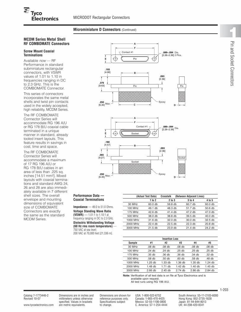
1-203
MICRODOT Rectangular Connectors
Catalog 7-1773446-2 Dimensions are in inches and Dimensions are shown for USA: 1-800-522-6752 South America: 55-11-2103-6000Revised 10-07 millimeters unless otherwise reference purposes only. Canada: 1-905-470-4425 Hong Kong: 852-2735-1628
specified. Values in brackets Specifications subject Mexico: 52-55-1106-0800 Japan: 81-44-844-8013www.tycoelectronics.com are metric equivalents. to change. C. America: 57-1-254-4444 UK: 44-208-420-8341
1
Pin and Socket Connectors
Microminiature D Connectors (Continued)
Screw Mount CoaxialTerminations
Available now — RFPerformance in standardsubminiature rectangularconnectors, with VSWR values of 1.01 to 1.10 in frequencies ranging in DCto 2.3 GHz. This is theCOMBOMATE Connector.
This series of connectorsincorporates the same metalshells and twist pin contactsused in the widely accepted,high reliability, MCDM Series.
The RF COMBOMATEConnector Series willaccommodate RG 196 A/Uor RG 178 B/U coaxial cableterminated in a unique manner in standard, alreadytooled insert layouts. Thisfeature results in savings incost, time and space.
The RF COMBOMATEConnector Series willaccommodate a maximumof 17 RG 196 A/U or RG 178 B/U cables in anarea of less than .225 sq.inches [14.51 mm2]. Mixedlayouts with coaxial termina-tions and standard AWG 24,26 and 28 are also immedi-ately available in 7 differentshell sizes. The overallenvelope and mountingdimensions of equivalentsize of COMBOMATEConnectors are exactly the same as the standardMCDM Series.
C
B
A
F
E
D
Contact #1
Pin
Pin
Epoxy
Pin
.089–.094[2.26–2.39]
.093[2.36]
Dia.2 Plcs.
.193[4.90]
.379[9.63]
.250[6.35] Max.
Contact #1
Socket
A
F
E
.089–.094[2.26–2.39] Dia.
B
Epoxy
.093[2.36]
.180[4.57]
.365[9.27]
.250[6.35] Max.
D
Socket
Socket
Performance Data — Coaxial Terminations
Impedance — 49.0 to 51.0 Ohms.Voltage Standing Wave Ratio(VSWR) — 1.01:1 to 1.10:1 at frequency ranging in DC to 2.3 GHz.Dielectric Withstanding Voltage(60 Hz rms room temperature) —750 VAC at sea level;200 VAC at 70,000 feet [21,336 m].
(Actual Test Data) Crosstalk (Between Adjacent Lines)1 to 2 2 to 3 3 to 4 4 to 5
30 MHz 60.0 db 59.8 db 60.7 db 60.0 db100 MHz 49.1 db 48.3 db 51.7 db 50.6 db175 MHz 42.6 db 41.4 db 47.2 db 47.0 db500 MHz 38.0 db 38.8 db 39.5 db 40.0 db1000 MHz 31.6 db 32.0 db 30.0 db 32.5 db2000 MHz 22.4 db 22.5 db 22.3 db 20.8 db3000 MHz 21.5 db 23.9 db 21.4 db 24.2 db
Insertion LossSample #1 #2 #3 #4 #530 MHz .08 db .08 db .08 db .08 db .08 db100 MHz .24 db .24 db .25 db .25 db .25 db175 MHz .35 db .36 db .36 db .34 db .32 db500 MHz .58 db .50 db .60 db .58 db .48 db1000 MHz 1.25 db 1.33 db 1.36 db 1.35 db 1.24 db2000 MHz 1.48 db 1.71 db 1.42 db 1.40 db 1.45 db3000 MHz 2.66 db 2.45 db 2.74 db 2.86 db 2.84 db
Note: Verification of all test data is on file at Tyco Electronics and is available upon request.All test runs using RG 196 A/U.
MCDM Series Metal Shell RF COMBOMATE Connectors

1-204
MICRODOT Rectangular Connectors
Catalog 7-1773446-2 Dimensions are in inches and Dimensions are shown for USA: 1-800-522-6752 South America: 55-11-2103-6000Revised 10-07 millimeters unless otherwise reference purposes only. Canada: 1-905-470-4425 Hong Kong: 852-2735-1628
specified. Values in brackets Specifications subject Mexico: 52-55-1106-0800 Japan: 81-44-844-8013www.tycoelectronics.com are metric equivalents. to change. C. America: 57-1-254-4444 UK: 44-208-420-8341
Microminiature D Connectors (Continued)
MCDM Series Metal ShellRF COMBOMATE Connectors(Continued)
Part NumberA B C D E F
± .005 ± .005 Max. Max. ± .005 ± .005[± .127] [± .127] [± .127] [± .127]
MCDM3-3P** .780 .290 .408 .200 .208 .56519.81 7.36 10.36 5.08 5.28 14.35
MCDM3-3S** .780 .365 .408 .200 .208 .56519.81 9.27 10.36 5.08 5.28 14.35
MCDM3-5P** .930 .440 .558 .200 .208 .71523.62 11.18 14.17 5.08 5.28 18.16
MCDM3-5S** .930 .515 .558 .200 .208 .71523.62 13.08 14.17 5.08 5.28 18.16
MCDM3-7P** 1.080 .590 .708 .200 .208 .86527.43 14.99 17.98 5.08 5.28 21.97
MCDM3-7S** 1.080 .665 .708 .200 .208 .86527.43 16.89 17.98 5.08 5.28 21.97
MCDM3-8P** 1.180 .690 .808 .200 .208 .96529.97 17.53 20.52 5.08 5.28 24.51
MCDM3-8S** 1.180 .765 .808 .200 .208 .96529.97 19.43 20.52 5.08 5.28 24.51
MCDM3-10P** 1.330 .840 .958 .200 .208 1.11533.78 21.34 24.33 5.08 5.28 28.32
MCDM3-10S** 1.330 .915 .958 .200 .208 1.11533.78 23.24 24.33 5.08 5.28 28.32
MCDM3-12P** 1.480 .990 1.108 .200 .208 1.27037.59 25.15 27.89 5.08 5.28 32.26
MCDM3-12S** 1.480 1.065 1.108 .200 .208 1.27037.59 27.05 27.89 5.08 5.28 32.26
MCDM3-17P** 1.430 .940 1.058 .245 .250 1.21536.32 23.88 26.87 6.22 6.35 30.86
MCDM3-17S** 1.430 1.015 1.058 .245 .250 1.21536.32 25.78 26.87 6.22 6.35 30.86
Screw Mount CoaxialTerminations (Continued)
How To SpecifyMCD M3 7 P 3 18.0
Lead Length in Inches (min.)
Wire Size 3 — RG 196 A/U (White insulation) 2 — RG 178 B/U (Brown insulation) X — Special, does not fit description*
Connector Series
Contact Type P — Pin S — Socket
Layout 3, 5, 7, 8, 10, 12, 17 Maximum RF combinations using RG 196 A/U and RG 178 B/U cable
Shell Type and Material M3 — Metal Shell Screw Mount Diallyl Phthalate or LCP Insulator
*Ordering Criteria: A wide variety of contact combinations, coaxial and power mixed, are available.Contact Tyco Electronics for additional arrangement numbers.

1-205
MICRODOT Rectangular Connectors
Catalog 7-1773446-2 Dimensions are in inches and Dimensions are shown for USA: 1-800-522-6752 South America: 55-11-2103-6000Revised 10-07 millimeters unless otherwise reference purposes only. Canada: 1-905-470-4425 Hong Kong: 852-2735-1628
specified. Values in brackets Specifications subject Mexico: 52-55-1106-0800 Japan: 81-44-844-8013www.tycoelectronics.com are metric equivalents. to change. C. America: 57-1-254-4444 UK: 44-208-420-8341
1
Pin and Socket Connectors
Microminiature D Connectors (Continued)
Contact Arrangement asViewed from the EngagingFace of the Pin Side
3RG196 A/U orRG 178 B/U
8RG196 A/U orRG 178 B/U
12RG196 A/U orRG 178 B/U
17RG196 A/U orRG 178 B/U
Termination Pattern
10RG196 A/U orRG 178 B/U
1
1
1
1 18
35
5136
19
20 37
Shield
Center Conductor
19
13 1 16
14 25 17 31
5 1 1 118
6 9 159 12 21
5RG196 A/U orRG 178 B/U
7RG196 A/U orRG 178 B/U
Note: The above contact arrangements are the maximum densities that can be obtained in each shell size whenusing RG 196 A/U or RG 178 B/U cable.
MCDM Series Metal ShellRF COMBOMATE Connectors(Continued)

1-206
MICRODOT Rectangular Connectors
Catalog 7-1773446-2 Dimensions are in inches and Dimensions are shown for USA: 1-800-522-6752 South America: 55-11-2103-6000Revised 10-07 millimeters unless otherwise reference purposes only. Canada: 1-905-470-4425 Hong Kong: 852-2735-1628
specified. Values in brackets Specifications subject Mexico: 52-55-1106-0800 Japan: 81-44-844-8013www.tycoelectronics.com are metric equivalents. to change. C. America: 57-1-254-4444 UK: 44-208-420-8341
Microminiature D Connectors (Continued)
Plug and ReceptacleRear Mounted
Plug and ReceptacleFront Mounted
.200 ± .005
[5.08 ± 0.13]
.395 ± .005
[10.03 ± 0.13]
.300 ± .005
[7.62 ± 0.13]
Panel Mounting Dimensions —MCDM
Plug and Receptacle Rear Mounted
Plug and Receptacle Front Mounted
Plug Front Mounted Receptacle Rear Mounted
Front
FullRadius(Typ.)
R
R
A
A
C
B
Figure 1
Rear
Figure 2
B
FullRadius(Typ.)
116/117
C
+ .005– .000+ 0.13– 0.00
.089
[2.26 ]
+ .005– .000+ 0.13– 0.00
.075
[1.90 ]
.015[.381]
Max. Typ.
.089[2.26]
Number A B Cof Fig. + .004 [+ .102] + .004 [+ .102] + .005 [+ .127]
Contacts – .000 [– .000] – .000 [– .000] – .000 [– .000]
91 .412 [10.46] .177 [4.50] .570 [14.48]2 .384 [9.75] .222 [5.64] .570 [14.48]
151 .562 [14.27] .177 [4.50] .720 [18.29]2 .534 [13.56] .222 [5.64] .720 [18.29]
211 .712 [18.08] .177 [4.50] .870 [22.10]2 .684 [17.37] .222 [5.64] .870 [22.10]
251 .812 [20.62] .177 [4.50] .970 [24.64]2 .784 [19.91] .222 [5.64] .970 [24.64]
311 .962 [24.43] .177 [4.50] 1.120 [28.45]2 .934 [23.72] .222 [5.64] 1.120 [28.45]
371 1.112 [28.24] .177 [4.50] 1.270 [32.26]2 1.084 [27.53] .222 [5.64] 1.270 [32.26]
511 1.062 [26.97] .224 [5.69] 1.220 [30.99]2 1.034 [26.26] .264 [6.71] 1.220 [30.99]
Panel Cutout Dimensions
Screw Mounting
Note: Front mounting preferred.
MCDM Series Metal ShellConnectors Panel Mounting —Cutout Dimensions

1-207
MICRODOT Rectangular Connectors
Catalog 7-1773446-2 Dimensions are in inches and Dimensions are shown for USA: 1-800-522-6752 South America: 55-11-2103-6000Revised 10-07 millimeters unless otherwise reference purposes only. Canada: 1-905-470-4425 Hong Kong: 852-2735-1628
specified. Values in brackets Specifications subject Mexico: 52-55-1106-0800 Japan: 81-44-844-8013www.tycoelectronics.com are metric equivalents. to change. C. America: 57-1-254-4444 UK: 44-208-420-8341
1
Pin and Socket Connectors
Introduction
Twist Pin contact HighDensity MicrominiatureConnectors described inthis catalog comprise acomplete contact systemwhich is adaptable to anumerous variety of formfactors. Precise contactalignment, with extremelylow engaging forces, resultsfrom the manner in whichthe Twist Pin contact system is packaged — by constructing the male contact as a breathing helical spring, electricalcontact is achieved at manypoints around the peripheryof the pin bundle.
Featured in this catalog isthe twist pin contact line,which accommodates round wire and FlatConductor Cable (FCC),Edgeboard Connectors.
Applications requiring frequent mating and discon-nect call for the metal shellconnector version. This style connector promoteshigh durability and reliability.
Designed for both militaryand commercial applica-tions, this latest innovation is especially well-suited touse in external conditions.
This catalog also featureslight-weight plastic
connectors in a strip (MCS)format as well as JACKMATEConnectors (MCJ Series)format for small packageapplication requiring highreliability.
Edgeboard applications are covered in this catalogwith a special High DensityStandard Module (HDSM)Connector as well as MIL-DTL-55302 (MCEM)Connectors. The high mating forces of these largerconnectors are greatlyreduced with the use of the low force twist pins andsockets which are standardfor this product line.
Product Facts■ Designed for both military
and commercial applications
■ Well-suited for external conditions
■ Precise contact alignmentwith extremely low engagingforces
■ Product offering consists of metal shell, plastic shell,panel mount, printed circuitboard and strip connectors
■ Metal shell connector promotes high durabilityand reliability

1-208
MICRODOT Rectangular Connectors
Catalog 7-1773446-2 Dimensions are in inches and Dimensions are shown for USA: 1-800-522-6752 South America: 55-11-2103-6000Revised 10-07 millimeters unless otherwise reference purposes only. Canada: 1-905-470-4425 Hong Kong: 852-2735-1628
specified. Values in brackets Specifications subject Mexico: 52-55-1106-0800 Japan: 81-44-844-8013www.tycoelectronics.com are metric equivalents. to change. C. America: 57-1-254-4444 UK: 44-208-420-8341
MCE Series Plastic Shell Edgeboard Connectors
Designed for commercialapplications requiring frequent disconnect andconnect, including datarecorders and computers.Motherboard connector canbe ordered to fit any patternon your circuit board.
This new connector featuresthe proven twist pin contactwith precision contact align-ment with extremely lowengaging forces.
Units are available with con-tacts as few as 40 and asmany as 110. Wire sizes 28through 24, any type of plat-ing or color coding, anykind of wire terminationincluding wire wrap — ahigh degree of flexibility foryour military or commercialapplication.
Two hexagonal polarizingkeys can provide up to 36different key combinationsare supplied.
40 Contacts
Technical & Performance Data — Twist Pin Plastic Shell Connectors
ElectricalContact Resistance — The averagemated contact resistance is 4 milliohms,with a maximum value of 8 milliohms,using standard 24 AWG solid copperleads when measured directly behind thecrimp joints of the mated pin and socketcontacts. The average resistance value at100 microvolts is 4.8 milliohms.Dielectric Withstanding Voltage — 800 VAC RMS at sea level(600 for solder pots); 200 VAC RMS at70,000 feet [21,336m] (150 for solderpots).Corrosion Resistance (Per MIL-STD-202C, Method 101B, ConditionB) — Both mated and unmated samplesdo not exceed the maximum allowablecontact resistance (8 milliohms) whensubjected to the 48 hour salt spray test.Durability — The contact resistanceafter 500 mating cycles is less than themaximum allowable, 8 milliohms.
Insulation Resistance — Greater than5,000 megohms at room temperature.Maximum Current CarryingCapacity — No. 24 contact 3 amperes.It must be recognized however, that all thewires to a connector will not carry theirmaximum current under all environmen-tal conditions due to wire temperature.
MechanicalContact Engaging & SeparationForces — 8.0 oz. max. [2.24N] (eng.),0.5 oz. min.[.14N] (sep.)
EnvironmentalTemperature Range (Operating) — –67°F to 257°F [–55°C to +125°C].Vibration (Per MIL-STD-202C,Method 204A, Condition D) — No discontinuity in excess of 1 µ sec.during twelve 20 minute sweeps from 10 to 2000 CPS at .06 double amplitudeor 20 G forces, whichever is less.
MaterialsInsulator — Liquid Crystal Polymer (LCP) per ASTM D5138 orPolyphenylene Sulfide per MIL-M-24519.Contacts — Pin-contact: Copper alloyand beryllium copper alloy make up thecomplete construction. Socket contact:Copper alloy.Hardware — Corrosion resistant stainless steel.
FinishesInsulator — None.Contacts — Standard finish is0.000050 [0.00127] gold over copperflash per MIL-G-45204, Type II.Hardware — Passivated per QQ-P-35.
Twist Pin — 24 GaugePin and Socket Contacts
The contact spring membernormally found in socketcontacts has been eliminat-ed by creating a breathinghelical spring principle onthe pin contact — smaller,more durable contacts can be manufactured economically. Wire range 24-36 AWG solid & stranded.

1-209
MICRODOT Rectangular Connectors
Catalog 7-1773446-2 Dimensions are in inches and Dimensions are shown for USA: 1-800-522-6752 South America: 55-11-2103-6000Revised 10-07 millimeters unless otherwise reference purposes only. Canada: 1-905-470-4425 Hong Kong: 852-2735-1628
specified. Values in brackets Specifications subject Mexico: 52-55-1106-0800 Japan: 81-44-844-8013www.tycoelectronics.com are metric equivalents. to change. C. America: 57-1-254-4444 UK: 44-208-420-8341
1
Pin and Socket Connectors
MCE Series Plastic Shell Edgeboard Connectors (Continued)
C
A.071–.076[1.80–1.93]
B
A
A
#24 AWG Copper Wire
.250[6.35]
.250[6.35]Max.Typ.
.100[2.54]
Solder Dip Typ.
Min.
.200 ±.015
[5.08 ±.381]Typ.
Epoxy
Insulator
Socket Contact/Lead Assembly
Section A-A
.250[6.35]
.450[11.43]
.030[.762]
Max.
Polarization Key Location2 Plcs.
.275[6.99]2 Plcs.
Ø .093–.098 Thru .187 [2.36–2.49 Thru 4.75]
(2 Plcs.)(Far ear only)
.300[7.62]
.180[4.57]
.075[1.91]
.050[1.27]
Ø.187 [4.75]
Thru2 Plcs.
(Near Ear Only)
B4B3
B2B1
A1A2
A3A4
Motherboard (Pin Side) .050[1.27]
Typ.
.075[1.91]
.050[1.27]
.100[2.54]
Typ.
.075[1.91]
Typ.
A
B
C
A
A
B
Polarization Key Location2 Plcs.
.250[6.35]
Ø .091–.098 [2.31–2.49]
2 Plcs.
B4
B3B2
B1
A1
A2A3
A4
Section A-A
Epoxy
25 AWG Copper Wire, Gold Plated,
Solder Dipped
Insulator
Pin Contact/Lead Assembly
.150[3.81]
Typ.
.250–.300[6.35–7.62] Typ.
Detail B
.325–.375[8.26–9.53] Typ.
.225[5.72]
#2-56 UNC-2B Thd.
Hex Polarizing Key2 Supplied (Loose Packed)
Daughterboard (Socket Side)
#2-56 UNC-2B Thd.
Hex Polarizing Key2 Supplied (Loose Packed)

1-210
MICRODOT Rectangular Connectors
Catalog 7-1773446-2 Dimensions are in inches and Dimensions are shown for USA: 1-800-522-6752 South America: 55-11-2103-6000Revised 10-07 millimeters unless otherwise reference purposes only. Canada: 1-905-470-4425 Hong Kong: 852-2735-1628
specified. Values in brackets Specifications subject Mexico: 52-55-1106-0800 Japan: 81-44-844-8013www.tycoelectronics.com are metric equivalents. to change. C. America: 57-1-254-4444 UK: 44-208-420-8341
MCE Series Plastic Shell Edgeboard Connectors (Continued)
Dimensions for .062 [1.57] PC Board
No. of A B CContacts ± .010 ± .005 Basic[± .254] [± .127]
40 1.750 1.500 .95044.45 38.10 24.13
44 1.850 1.600 1.05046.99 40.64 26.67
80 2.750 2.500 1.95069.85 63.50 49.53
110 3.500 3.250 2.70088.90 82.55 68.58
Note: For PC Boards of different widths, consult Tyco Electronics.
How To Specify
MCE R1 40 P 6 L 4 0.5Lead Length in Inches (min.)
X — Special, does not fit description below.
Insulation Color or Finish1 — All white wire 4 — Gold plated 7 — Color coded per 2 — All yellow wire 5 — Tin dipped gold plated MIL-STD-681, System 13 — All gray wire 6 — Bare (unfinished) 8 — Special color code 9 — Ten solid color repeating (starts with black)
Wire Size4-24 AWG 5-25 AWG 6-26AWG 8-28 AWG 0-30 AWG
Connector Series
MaterialR1 — Liquid Crystal Polymer or
Polyphenylene Sulfide
Layout40, 44, 80, 110
Contact Type P — Pin (Motherboard Connector)S — Socket (Daughterboard Connector)
Z — Wire layout as shown on page 1-209.
S — Solder pots 26 AWG max.
Wire Type *A — Type E, 7 strand *D — Type ET, 19 strand G — 19 strand per MIL-22759/11*B — Type ET, 7 strand F — 7 strand per MIL-22759/11 26 AWG, 24 AWG*C — Type E, 19 strand (#28 AWG only) L — Copper, solid Q — Stranded per MIL-W-22759/33*Per MIL-W-16878
Mounting — Holes on the Daughterboard side can be modified.

1-211
MICRODOT Rectangular Connectors
Catalog 7-1773446-2 Dimensions are in inches and Dimensions are shown for USA: 1-800-522-6752 South America: 55-11-2103-6000Revised 10-07 millimeters unless otherwise reference purposes only. Canada: 1-905-470-4425 Hong Kong: 852-2735-1628
specified. Values in brackets Specifications subject Mexico: 52-55-1106-0800 Japan: 81-44-844-8013www.tycoelectronics.com are metric equivalents. to change. C. America: 57-1-254-4444 UK: 44-208-420-8341
1
Pin and Socket Connectors
MCEM Series Metal Shell Edgeboard Connectors
Product Facts■ Meets MIL-DTL-55302
performance requirements
■ Layouts 128 and 184 are QPLto slash sheets 120, 121,122 and 123
■ Connectors are available in40, 44, 80, 110, 128, 152,and 184 positions
■ Utilizes low force twist pinsand our low force sockets.Mating forces in the 3 to 4oz. [.83 to 1.11N] range percontact are typical with lowforce pin and low forcesocket
■ Designed for surfacemounting and through-the-board mounting
■ Available termination■ Motherboard (pin side) —
cactus bend■ Daughterboard (socket
side) — coke bottle, right-angle bend to “A” or “B” side
■ Solder pots, and varietyof other wire terminationsfor pin and socketconnectors available atcustomer’s request
■ Two hexagonal polarizingkeys (per MIL-DTL-55302slash sheet 124) areprovided. Jackscrewhardware is available. For programmable keying/jacking modificationsconsult Tyco Electronics
In addition to the plasticversions of the 2 pieceedgeboard connectors, a metal shell assembly isdesigned and tooled. Themetal shells are made ofaluminum alloy per QQ-A-591. The insert material is Diallyl phthalate,Polyphenylene sulfide(Ryton) or Liquid CrystalPolymer (LCP). The techni-
cal and performance data isessentially the same as thatshown for the MCDM Serieson page 5-146. These arerugged, durable connectorsand are ideal for use inareas of high density pack-aging and where frequentconnect and disconnectsare required. Designed initially for applications inairborne data recorders,
computers and associatedequipment in navigationalsystems. The motherboardconnector can be orderedto fit any pattern on the circuit board. The units canalso be provided with con-tacts on .100 [2.54] spacingwhich results in .100 [2.54]grid pattern.
Performance Data
ElectricalContact Resistance — The averagemated contact resistance is 4 milliohms,with a maximum value of 8 milliohms.The average resistance value at 100microvolts is 4.8 milliohms.Dielectric Withstanding Voltage —800 VAC RMS at sea level (600 for solder pots); 200 VAC RMS at 70,000feet [21,336m] (150 for solder pots).Durability — Less than the maximumallowable, 8 milliohms after 500 matingcycles.Insulation Resistance — Greater than 5,000 megohms at room ambienttemperature.Maximum Current CarryingCapacity — No. 24 contact 3 amperes.
MechanicalContact Engaging & SeparationForces — 5.0 oz. max. [1.39N] (eng.),0.5 oz. min. [.14N] (sep.).
EnvironmentalTemperature Range — –67°F to 302°F [–55°C to +150°C] forDiallyl Phthalate; –67°F to 257°F [–55°Cto +125°C] for Polyphenylene Sulfide.Vibration — No discontinuity inexcess of 1 µ sec. during twelve 20minute sweeps from 10 to 2000 CPS at.06 double amplitude or 20 G forces,whichever is less.
Materials and FinishShells — High grade aluminum alloy,electroless nickel plated per AMS 2404.Insulator — Diallyl Phthalate per MIL-M-14, Type SDG-F (for 128 & 184);Polyphenylene Sulfide per MIL-M-24519 (for 40, 44, 80, 110 & 152), orLiquid Crystal Polymer per ASTMD5138.Contacts — Pin (low force): berylliumand OFHC copper, gold plated. Socket(low force): Copper alloy, gold plated.Hardware — Corrosion resistantstainless steel passivated.

1-212
MICRODOT Rectangular Connectors
Catalog 7-1773446-2 Dimensions are in inches and Dimensions are shown for USA: 1-800-522-6752 South America: 55-11-2103-6000Revised 10-07 millimeters unless otherwise reference purposes only. Canada: 1-905-470-4425 Hong Kong: 852-2735-1628
specified. Values in brackets Specifications subject Mexico: 52-55-1106-0800 Japan: 81-44-844-8013www.tycoelectronics.com are metric equivalents. to change. C. America: 57-1-254-4444 UK: 44-208-420-8341
MCEM Series Metal Shell Edgeboard Connectors (Continued)
Motherboard (Pin Side)40, 44, 80, 110 & 128 Positions
No. of A B
Contacts ± .010 ± .005[± .254] [± .127]
40 1.750 1.50044.45 38.10
44 1.850 1.60046.99 40.64
80 2.750 2.50069.85 63.50
110 3.500 3.25088.90 82.55
128 3.950 3.700100.33 93.98
Note: For PC Boards of different widths, consult Tyco Electronics.
Dimensions for .062 [1.57] PC Board
Note: Items in bold italic are qualified to MIL-DTL-55302.Configuration shown is per MIL-DTL-55302/120.
Section A-A
.325–.375[8.26–9.53]
Typ.
.260–.300[6.60–7.62]
Typ.
Polarizing Key Location2 Plcs.
#2-56 UNC-2B Thd.
Pin Contact/Lead Assy.
Insulator Assy.
Epoxy
25 AWG CopperWire, Gold Plated,
Solder Dipped
Hex Polarizing Key2 Supplied (Loose Packed)
A
A
A
B
.400[10.16]
.050[1.27]
.050[1.27]
.250[6.35]
Ø .091–.098 [2.31–2.49]
.100[2.54]
Typ.
Typ.
.075[1.91] Typ.
.075[1.91] Typ.
.050[1.27]
Typ.
B4B3
A1A2A3
A4
B2B1
Thru2 Plcs.

1-213
MICRODOT Rectangular Connectors
Catalog 7-1773446-2 Dimensions are in inches and Dimensions are shown for USA: 1-800-522-6752 South America: 55-11-2103-6000Revised 10-07 millimeters unless otherwise reference purposes only. Canada: 1-905-470-4425 Hong Kong: 852-2735-1628
specified. Values in brackets Specifications subject Mexico: 52-55-1106-0800 Japan: 81-44-844-8013www.tycoelectronics.com are metric equivalents. to change. C. America: 57-1-254-4444 UK: 44-208-420-8341
1
Pin and Socket Connectors
MCEM Series Metal Shell Edgeboard Connectors (Continued)
Daughterboard (Socket Side)40, 44, 80, 110 & 128 Positions
MCE M1 128 L 6 L 4 0.5 Lead Length in Inches (min.)
Z — Wire layout as illustrated.
Insulation Color or Finish 1 — All white wire 4 — Gold plated 7 — Color coded per 2 — All yellow wire 5 — Tin dipped gold plated MIL-STD-681, System 1 3 — All gray wire 6 — Bare (unfinished) 8 — Special color code 9 — Ten solid color repeating (starts with black)
Wire Size 4–24 AWG 5–25 AWG 6–26 AWG 8–28 AWG 0–30 AWG
Connector Series
MaterialM1 — Metal Shell
Layout40, 44, 80, 110, 128, 152, 184
Contact Type L — Low Force Pin (Motherboard Connector)SL — Low Force Socket* (Daughterboard Connector)
X — Special, does not fit description below.
S — Solder pots for 26 AWG max.
Wire Type *A — Type E, 7 strand *D — Type ET, 19 strand G — 19 strand per MIL-C-22759/11*B — Type ET, 7 strand F — 7 strand per MIL-C-22759/11 26 AWG, 24 AWG *C — Type E, 19 strand (#28 AWG only) L — Copper, solid Q — Stranded per MIL-W-22759/33 *Per MIL-W-16878
Note: Items in bold italic are qualified to MIL-DTL-55302.Configuration shown is per MIL-DTL-55302/121.
Polarization – Hexagonal hardware is supplied with connector.Mounting — Standard mounting holes are shown. Consult Tyco Electronics for modifications.
How To Specify
.125[3.18]
Section B-B
Section A-A
Retaining Pin4 Supplied
(Loose Packed)Polarizing Key
2 Supplied(Loose Packed)
2 Plcs.
.060[1.52] 3 Plcs.
.030[0.76] Max.
.250[6.35] Max.
.050[1.27] Typ.
Typ.
.250[6.35]
.050[1.27]
.050[1.27]
2 Plcs.
.180[4.57]2 Plcs.
.330[8.38]2 Plcs.
Retaining Pin Holes4 Plcs.
Polarizing Key Location2 Plcs.
.275[6.99]
.150[3.81]
Min.Solder Dip Typ.
.071[1.80]
.200 ±.015
[5.08 ± .381]Min.at B
Epoxy
Insulator Assy.
Skt. Contact/Lead Assy.
24 AWG Copper Wire,Gold Plated
Ø .187 [4.75]
Thru 1 Wall
Ø .091–.098 [2.31–2.49]
C’Bore Ø .187 [4.75] x.045 [1.14] Deep
(A Side Only)
.071–.076[1.80–1.93]
2 Plcs.
.250[6.35]
BA
B
B2
A2A1
B1
A
A
B
Thru Hole2 Plcs.
Note: Board thickness .070 [1.78] Max.

1-214
MICRODOT Rectangular Connectors
Catalog 7-1773446-2 Dimensions are in inches and Dimensions are shown for USA: 1-800-522-6752 South America: 55-11-2103-6000Revised 10-07 millimeters unless otherwise reference purposes only. Canada: 1-905-470-4425 Hong Kong: 852-2735-1628
specified. Values in brackets Specifications subject Mexico: 52-55-1106-0800 Japan: 81-44-844-8013www.tycoelectronics.com are metric equivalents. to change. C. America: 57-1-254-4444 UK: 44-208-420-8341
MCEM Series Metal Shell Edgeboard Connectors (Continued)
Motherboard (Pin Side)152 & 184 Positions
A
B
C
.250[6.35]
.270[6.86]
.400[10.16]
Retaining Pin Hole4 Plcs.
.343[8.71]
.500[1.27]
B/2
.050[1.27]
.075[1.91]
Polarizing Key Location2 Plcs.
A
A
A
B
B4B3 B2
B1
A1A2A3
A4
Typ.D
2 Plcs
.075[1.91]
.250[6.35]
.700[17.78]
.242[6.15]
.500[12.70]
Ø .187 Thru [4.75] 3 Plcs.
(B Side Only)
.125[3.18]
.060[1.52]3 Plcs.
.071[1.80]
.343[8.71]
Min.
Retaining Pin Hole4 Plcs.
Polarizing Key Locations2 Plcs.
A
B
A
B
B
A
C
B3 B2B1B4
A4
A3
A1
A2
Typ.
.050[1.27] Typ.
2 Plcs.
2 Plcs.
2 Plcs.D B/2
Ø .091-.098 [2.31-2.49] Thru C'Bore Ø .187 [4.75] x .045 [1.14], 3 Plcs.,
(A Side Only)
Section B-B
Daughterboard (Socket Side)152 & 184 Positions
No. of A B C DContacts ± .010 ± .005 Basic Basic[± .254] [± .127]
152 4.550 4.300 4.750 1.850115.57 109.22 120.65 46.99
184 5.800 5.550 5.000 2.250147.32 140.97 127.00 57.15
.250–.300[6.35–7.62]
.325–.375[8.26–9.53]
.075[1.91]
25 AWG Copper Wire,Gold Plated, Solder Dipped
InsulatorSubassembly
#2-56 UNC-2B Thd.
Hex Polarizing Key2 Supplied (Loose Packed)
Section A-A
B2B1 A1
A2
Pin Contact/Lead Assembly
.075[1.91] Typ.
Typ.
Typ.
Typ.
.200[5.08]
.030[.762]
.053[1.35]
Min. at B
.250[6.35]
24 AWGCopper Wire,Gold Plated
Section A-A
Polarizing Key2 Supplied
(Loose Packed)
Retaining Pin4 Supplied
(Loose Packed)
Max.Typ.
Max.
Typ.
Epoxy
Skt. Contact/Lead Assy.
InsulatorAssy.
.150[3.81]
Min. Typ.
Solder Dip
Note:Items in bold italic are qualified toMIL-DTL-55302.Configurationshown is per MIL-DTL-55302/121.

1-215
MICRODOT Rectangular Connectors
Catalog 7-1773446-2 Dimensions are in inches and Dimensions are shown for USA: 1-800-522-6752 South America: 55-11-2103-6000Revised 10-07 millimeters unless otherwise reference purposes only. Canada: 1-905-470-4425 Hong Kong: 852-2735-1628
specified. Values in brackets Specifications subject Mexico: 52-55-1106-0800 Japan: 81-44-844-8013www.tycoelectronics.com are metric equivalents. to change. C. America: 57-1-254-4444 UK: 44-208-420-8341
1
Pin and Socket Connectors
JACKMATE MCJ(M) Series Plastic (Metal) Shell Center Jackscrew Connectors
10 & 14 Contact Layout
.075[1.91]
.165[4.19]
.050[1.27]
Typ..570[14.00]
.285[7.24]
30
.165[4.19]
.235[5.97]
.075[1.91]
.050[1.27]
.470[11.94]
Typ.
30
Bushing
Guide Pin2 Plcs.
.120[3.05]
Jackscrew(.050 hex wrenchreq'd to turn screw)
.300[7.62]
JACKMATE Connectors arethe first Twist Pin contactassemblies designed toaccommodate centerjackscrews that providejacking action when matingor unmating the connectors.Although the units were initially developed for highdensity cord-to-cord or in-line applications, eitherplug or receptacle can be
adapted to a PC board. Thejacking hardware consist ofa threaded bushing and acaptivated jackscrew whichare made of corrosionresistant stainless steel and are molded into theJACKMATE ConnectorInsulator.
The twist pin contacts areon .050 [1.27] center-to-
center linear spacing andcontact terminations areavailable in solid wire orstranded wire. There is ahigh degree of flexibilitywith this JACKMATE con-nector design for commer-cial or military applications.
Available in MCJ(M) SeriesPlastic (Metal) Shells.
10 Layout14 Layout Receptacle Plug
Technical & Performance DataElectricalContact Resistance — The averagemated contact resistance is 4 milliohms,with a maximum value of 8 milliohms,using standard 24 AWG solid copperleads when measured directly behind thecrimp joints of the mated pin and socketcontacts. The average resistance value at100 microvolts is 4.8 milliohms.Dielectric Withstanding Voltage(60 Hz rms room temperature) —Solder Pots: 600 VAC at sea level; 150 VAC at 70,000 feet [21,336m] Wire Terminations: 750 VAC at sea level;200 VAC at 70,000 feet [21,336m].
Corrosion Resistance (Per MIL-STD-202C, Method 101B, Condition B) —Both mated and unmated samples do notexceed the maximum allowable contactresistance (8 milliohms) when subjectedto the 48 hour salt spray test.Durability — The contact resistanceafter 500 mating cycles is less than themaximum allowable, 8 milliohms.Insulation Resistance — Greater than5,000 megohms at room temperature forthe materials listed under “Materials”.Maximum Current CarryingCapacity — No. 24 contact 3 amperes.It must be recognized, however, that all the wires to a connector will not carry their maximum current under all environmental conditions due to wiretemperature.
MechanicalContact Engaging & SeparationForces — 8.0 oz. max. [2.22N] (eng.),0.5 oz. min. [.14N] (sep.).
EnvironmentalTemperature Range (Operating) — –67°F to 257°F [–55°C to 125°C].Vibration (Per MIL-STD-202C,Method 204-A, Condition D) — No discontinuity in excess of 1 µ sec.during twelve 20 minute sweeps from 10 to 2000 CPS at .06 double amplitudeor 20 G forces, whichever is less.
MaterialsInsulator — Glass filled Nylon Type 6.Contacts — Pin contact: copper alloyand beryllium copper alloy make up thecomplete construction; Socket contact:copper alloy.Hardware — Corrosive resistant stainless steel.FinishesContacts — Standard finish is0.000050 [0.00127] gold over copperflash per MIL-G-45204, Type II.Hardware — Passivated Per QQ-P-35.
JACKMATE MCJ Series Plastic Shell Center Jackscrew Connectors

1-216
MICRODOT Rectangular Connectors
Catalog 7-1773446-2 Dimensions are in inches and Dimensions are shown for USA: 1-800-522-6752 South America: 55-11-2103-6000Revised 10-07 millimeters unless otherwise reference purposes only. Canada: 1-905-470-4425 Hong Kong: 852-2735-1628
specified. Values in brackets Specifications subject Mexico: 52-55-1106-0800 Japan: 81-44-844-8013www.tycoelectronics.com are metric equivalents. to change. C. America: 57-1-254-4444 UK: 44-208-420-8341
JACKMATE MCJ Series Plastic Shell Center Jackscrew Connectors (Continued)
26, 38 & 46 Contact Layout.075[1.91]
.050[1.27]Typ.
.165[4.19]
1.270[32.26]
.635[16.13]
.165�[4.19]
.585�[14.86]
1.170�[29.72]
.165�[4.19]
.870�[22.10]
.438�[11.13]
Guide Pin
.120[3.05]
Jackscrew#0-80UNF-2AThd.
AA
Bushing#0-80 UNF-2B Thd.
.300[7.62]
42 Layout 38 Layout 26 Layout Receptacle Section A-APlug
.305�[7.75]
.610�[15.49]
.285�[7.24]
.050�[1.27]
Typ. .050�[1.27]
Typ.
.120[3.05]
Guide Pin
Bushing#0-80 UNF-2BThd.
.300[7.62]
Jackscrew#0-80 UNF-2AThd.
10
6 1
7
7
1 6
141
20
3646
27
11
26
14 1
15
1
21
20
42
38
20
21
1
Guide Pin
Guide Pin
Guide Pin Guide PinGuide Pin Guide Pin
Guide PinGuide Pin
Guide Pin
46 Layout Receptacle Plug
38 Positions 26 Positions 10 Positions
46 Positions 14 Positions 42 Positions
Contact Arrangement as Viewed from the Engaging Face of the Pin Side
Guide pin locations illustrated are for standards configuration only. Any location is available.Guide pins are supplied in socket connectors and blank cavities are in pin connector.
MCJ B2 10 P 4 L 4 0.5Lead Length in Inches (min.)
Insulation Color or Finish1 � All white wire� 4 � Gold plated� 7 � Color coded per �2 � All yellow wire� 5 � Tin dipped gold plated�� MIL-STD-681, System 13 � All gray wire� 6 � Bare (unfinished)� 8 � Special color code�� 9 � Ten solid color repeating��� (starts with black)
Wire Size4—24 AWG 5—25 AWG 6—26 AWG 8—28 AWG �0—30 AWG
Connector Series
Shell MaterialB2 � Glass filled nylon, type 6/10, blue
Layout (Positions)10, 14, 26, 38, 42, 46
Contact Type P � PinS � Socket
X � Special, does not fit description below.
S � Solder pot for 26 AWG maximum stranded wire.
Wire Type *A � Type E, 7 strand� *D � Type ET, 19 strand� G � 19 strand per MIL-C-22759/11*B � Type ET, 7 strand� F � 7 strand per MIL-C-22759/11� 26 AWG, 24 AWG*C � Type E, 19 strand� (#28 AWG only)� L � Copper, solid�� Q � Stranded per MIL-W-22759/33*Per MIL-W-16878
How To Specify
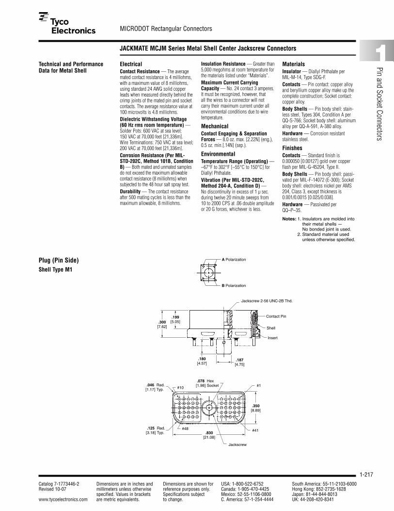
1-217
MICRODOT Rectangular Connectors
Catalog 7-1773446-2 Dimensions are in inches and Dimensions are shown for USA: 1-800-522-6752 South America: 55-11-2103-6000Revised 10-07 millimeters unless otherwise reference purposes only. Canada: 1-905-470-4425 Hong Kong: 852-2735-1628
specified. Values in brackets Specifications subject Mexico: 52-55-1106-0800 Japan: 81-44-844-8013www.tycoelectronics.com are metric equivalents. to change. C. America: 57-1-254-4444 UK: 44-208-420-8341
1
Pin and Socket Connectors
JACKMATE MCJM Series Metal Shell Center Jackscrew Connectors
Technical and PerformanceData for Metal Shell
ElectricalContact Resistance — The averagemated contact resistance is 4 milliohms,with a maximum value of 8 milliohms,using standard 24 AWG solid copperleads when measured directly behind thecrimp joints of the mated pin and socketcontacts. The average resistance value at100 microvolts is 4.8 milliohms.Dielectric Withstanding Voltage(60 Hz rms room temperature) —Solder Pots: 600 VAC at sea level; 150 VAC at 70,000 feet [21,336m].Wire Terminations: 750 VAC at sea level;200 VAC at 70,000 feet [21,336m].Corrosion Resistance (Per MIL-STD-202C, Method 101B, ConditionB) — Both mated and unmated samplesdo not exceed the maximum allowablecontact resistance (8 milliohms) whensubjected to the 48 hour salt spray test.Durability — The contact resistanceafter 500 mating cycles is less than themaximum allowable, 8 milliohms.
Insulation Resistance — Greater than5,000 megohms at room temperature forthe materials listed under “Materials”.Maximum Current CarryingCapacity — No. 24 contact 3 amperes.It must be recognized, however, that all the wires to a connector will not carry their maximum current under allenvironmental conditions due to wiretemperature.
MechanicalContact Engaging & SeparationForces — 8.0 oz. max. [2.22N] (eng.),0.5 oz. min.[.14N] (sep.).
EnvironmentalTemperature Range (Operating) — –67°F to 302°F [–55°C to 150°C] forDiallyl Phthalate.Vibration (Per MIL-STD-202C,Method 204-A, Condition D) — No discontinuity in excess of 1 µ sec.during twelve 20 minute sweeps from 10 to 2000 CPS at .06 double amplitudeor 20 G forces, whichever is less.
MaterialsInsulator — Diallyl Phthalate per MIL-M-14, Type SDG-F.Contacts — Pin contact: copper alloyand beryllium copper alloy make up thecomplete construction; Socket contact:copper alloy.Body Shells — Pin body shell: stain-less steel, Types 304, Condition A perQQ-S-766; Socket body shell: aluminumalloy per QQ-A-591, A-380 alloy.Hardware — Corrosion resistantstainless steel.
FinishesContacts — Standard finish is0.000050 [0.00127] gold over copperflash per MIL-G-45204, Type II.Body Shells — Pin body shell: passi-vated per MIL-F-14072 (E-300); Socketbody shell: electroless nickel per AMS204, Class 3, except thickness is0.001/0.0015 [0.025/0.038].Hardware — Passivated perQQ–P–35.
Notes: 1. Insulators are molded intotheir metal shells — No bonded joint is used.
2. Standard material usedunless otherwise specified.
B Polarization
A Polarization
Insert
Shell
Contact Pin
Jackscrew 2-56 UNC-2B Thd.
.300[7.62]
.199[5.05]
.180[4.57]
.187[4.75]
.830[21.08]
.125[3.18]
.350[8.89]
#41
#1
#48Rad.Typ.
.046[1.17] #10
Rad.Typ.
.078[1.98]
HexSocket
Jackscrew
Plug (Pin Side)Shell Type M1

1-218
MICRODOT Rectangular Connectors
Catalog 7-1773446-2 Dimensions are in inches and Dimensions are shown for USA: 1-800-522-6752 South America: 55-11-2103-6000Revised 10-07 millimeters unless otherwise reference purposes only. Canada: 1-905-470-4425 Hong Kong: 852-2735-1628
specified. Values in brackets Specifications subject Mexico: 52-55-1106-0800 Japan: 81-44-844-8013www.tycoelectronics.com are metric equivalents. to change. C. America: 57-1-254-4444 UK: 44-208-420-8341
JACKMATE MCJM Series Metal Shell Center Jackscrew Connectors (Continued)
Receptacle (Socket Side)Shell Type M1
Bushing
A Polarization
B Polarization
Rad.2 Plcs.
#48
#1 #10
#41
Sq.
.125[3.18]
Rad.2 Plcs.
.046[1.17]
Rad.4 Plcs.
.030[0.76]
2 Plcs..050[1.27]
2 Plcs..160 .005
[4.06 0.13]
BSCTyp.
.050[1.27]
BSCTyp.
.050[1.27]
.830[21.08]
.125[3.18]
+ .010– .005+ 0.25– 0.13
.355
[9.02]
Full Rad. Typ.
Interfacial Seal Silicon Rubber
.310[7.87]
2 Plcs..108 ±.005
[2.74 ±0.13]
2 Plcs..094 ±.005
[2.39 ±0.13]
Insert
Contact Skt.
Bushing Stainless Steel 2-56 UNC-2B Thd.Rad.2 Plcs.
.094[2.39]
.070 ±.005
[1.78 ±0.13]2 Plcs. .200 ±.005
[5.08 ±0.13]2 Plcs.
Shell Type M2
#48
#1 #10
#41
48 P 4 L 4 0.5Lead Length in Inches (min.)
Insulation Color or Finish1 � All white wire� 4 � Gold plated� 7 � Color coded per �2 � All yellow wire� 5 � Tin dipped gold plated�� MIL-STD-681, System 13 � All gray wire� 6 � Bare (unfinished)� 8 � Special color code�� 9 � Ten solid color repeating��� (starts with black)
Wire Size4—24 AWG� 5—25 AWG� 6—26 AWG� 8—28 AWG� 0—30 AWG
MCJ M1 AJACKMATE Connector Series
Shell MaterialM1 � Metal Shell (Standard)M2 � Metal Shell (Special � receptacles only)
Polarizing PositionA, B
Layout (Positions)48
Contact Type P � PinS � Socket
X � Special, does not fit description below.
S � Solder pot for 26 AWG maximum stranded wire.
Wire Type*A � Type E, 7 strand� *D � Type ET, 19 strand� G � 19 strand per MIL-C-22759/11*B � Type ET, 7 strand� F � 7 strand per � 26 AWG, 24 AWG*C � Type E, 19 strand� MIL-C-22759/11� L � Copper, solid�� (#28 AWG only)� Q � Stranded per MIL-W-22759/33*Per MIL-W-16878
How To Specify
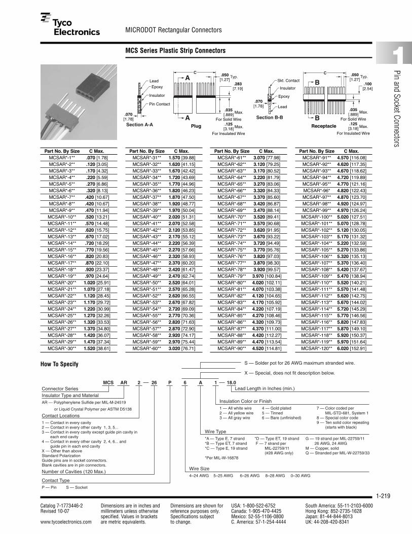
1-219
MICRODOT Rectangular Connectors
Catalog 7-1773446-2 Dimensions are in inches and Dimensions are shown for USA: 1-800-522-6752 South America: 55-11-2103-6000Revised 10-07 millimeters unless otherwise reference purposes only. Canada: 1-905-470-4425 Hong Kong: 852-2735-1628
specified. Values in brackets Specifications subject Mexico: 52-55-1106-0800 Japan: 81-44-844-8013www.tycoelectronics.com are metric equivalents. to change. C. America: 57-1-254-4444 UK: 44-208-420-8341
1
Pin and Socket Connectors
MCS Series Plastic Strip Connectors
How To Specify
26 P 6 A 1 18.0Lead Length in Inches (min.)
Insulation Color or Finish1 — All white wire 4 — Gold plated 7 — Color coded per 2 — All yellow wire 5 — Tinned MIL-STD-681, System 13 — All gray wire 6 — Bare (unfinished) 8 — Special color code 9 — Ten solid color repeating (starts with black)
Wire Size4–24 AWG 5–25 AWG 6–26 AWG 8–28 AWG 0–30 AWG
MCS AR 2Connector SeriesInsulator Type and MaterialAR — Polyphenylene Sulfide per MIL-M-24519
or Liquid Crystal Polymer per ASTM D5138
Contact Locations1 — Contact in every cavity 2 — Contact in every other cavity 1, 3, 5...3 — Contact in every cavity except guide pin cavity in each end cavity4 — Contact in every other cavity 2, 4, 6... and guide pin in each end cavityX — Other than aboveStandard PolarizationGuide pins are in socket connectors.Blank cavities are in pin connectors.
Number of Cavities (120 Max.)
Contact TypeP — Pin S — Socket
X — Special, does not fit description below.
S — Solder pot for 26 AWG maximum stranded wire.
Wire Type *A — Type E, 7 strand *D — Type ET, 19 strand G — 19 strand per MIL-22759/11*B — Type ET, 7 strand F — 7 strand per 26 AWG, 24 AWG*C — Type E, 19 strand MIL-22759/11 M — Copper, solid (#28 AWG only) Q — Stranded per MIL-W-22759/33*Per MIL-W-16878
A
A
.283[7.19]
.070[1.78]
Lead
Epoxy
Insulator
Pin Contact
Typ.
.035[.889]
For Solid Wire.125[3.18]
For Insulated Wire
.050[1.27]
Max.
Max.Section A-A
C
Plug
B
B
Typ.
.070[1.78]
Skt. Contact
Insulator
Epoxy
Lead.035
[.889]For Solid Wire
.125[3.18]
For Insulated Wire
.050[1.27]
.100[2.54]
Max.
Max.
Section B-B
C
Receptacle
Part No. By Size C Max.MCSAR*-1** .070 [1.78]MCSAR*-2** .120 [3.05]MCSAR*-3** .170 [4.32]MCSAR*-4** .220 [5.59]MCSAR*-5** .270 [6.86]MCSAR*-6** .320 [8.13]MCSAR*-7** .420 [10.67]MCSAR*-8** .420 [10.67]MCSAR*-9** .470 [11.94]MCSAR*-10** .520 [13.21]MCSAR*-11** .570 [14.48]MCSAR*-12** .620 [15.75]MCSAR*-13** .670 [17.02]MCSAR*-14** .720 [18.29]MCSAR*-15** .770 [19.56]MCSAR*-16** .820 [20.83]MCSAR*-17** .870 [22.10]MCSAR*-18** .920 [23.37]MCSAR*-19** .970 [24.64]MCSAR*-20** 1.020 [25.91]MCSAR*-21** 1.070 [27.18]MCSAR*-22** 1.120 [28.45]MCSAR*-23** 1.170 [29.72]MCSAR*-24** 1.220 [30.99]MCSAR*-25** 1.270 [32.26]MCSAR*-26** 1.320 [33.53]MCSAR*-27** 1.370 [34.80]MCSAR*-28** 1.420 [36.07]MCSAR*-29** 1.470 [37.34]MCSAR*-30** 1.520 [38.61]
Part No. By Size C Max.MCSAR*-31** 1.570 [39.88]MCSAR*-32** 1.620 [41.15]MCSAR*-33** 1.670 [42.42]MCSAR*-34** 1.720 [43.69]MCSAR*-35** 1.770 [44.96]MCSAR*-36** 1.820 [46.23]MCSAR*-37** 1.870 [47.50]MCSAR*-38** 1.920 [48.77]MCSAR*-39** 1.970 [50.04]MCSAR*-40** 2.020 [51.31]MCSAR*-41** 2.070 [52.58]MCSAR*-42** 2.120 [53.85]MCSAR*-43** 2.170 [55.12]MCSAR*-44** 2.220 [56.39]MCSAR*-45** 2.270 [57.66]MCSAR*-46** 2.320 [58.93]MCSAR*-47** 2.370 [60.20]MCSAR*-48** 2.420 [61.47]MCSAR*-49** 2.470 [62.74]MCSAR*-50** 2.520 [64.01]MCSAR*-51** 2.570 [65.28]MCSAR*-52** 2.620 [66.55]MCSAR*-53** 2.670 [67.82]MCSAR*-54** 2.720 [69.09]MCSAR*-55** 2.770 [70.36]MCSAR*-56** 2.820 [71.63]MCSAR*-57** 2.870 [72.90]MCSAR*-58** 2.920 [74.17]MCSAR*-59** 2.970 [75.44]MCSAR*-60** 3.020 [76.71]
Part No. By Size C Max.MCSAR*-61** 3.070 [77.98]MCSAR*-62** 3.120 [79.25]MCSAR*-63** 3.170 [80.52]MCSAR*-64** 3.220 [81.79]MCSAR*-65** 3.270 [83.06]MCSAR*-66** 3.320 [84.33]MCSAR*-67** 3.370 [85.60]MCSAR*-68** 3.420 [86.87]MCSAR*-69** 3.470 [88.14]MCSAR*-70** 3.520 [89.41]MCSAR*-71** 3.570 [90.68]MCSAR*-72** 3.620 [91.95]MCSAR*-73** 3.670 [93.22]MCSAR*-74** 3.720 [94.49]MCSAR*-75** 3.770 [95.76]MCSAR*-76** 3.820 [97.03]MCSAR*-77** 3.870 [98.30]MCSAR*-78** 3.920 [99.57]MCSAR*-79** 3.970 [100.84]MCSAR*-80** 4.020 [102.11]MCSAR*-81** 4.070 [103.38]MCSAR*-82** 4.120 [104.65]MCSAR*-83** 4.170 [105.92]MCSAR*-84** 4.220 [107.19]MCSAR*-85** 4.270 [108.46]MCSAR*-86** 4.320 [109.73]MCSAR*-87** 4.370 [111.00]MCSAR*-88** 4.420 [112.27]MCSAR*-89** 4.470 [113.54]MCSAR*-90** 4.520 [114.81]
Part No. By Size C Max.MCSAR*-91** 4.570 [116.08]MCSAR*-92** 4.620 [117.35]MCSAR*-93** 4.670 [118.62]MCSAR*-94** 4.720 [119.89]MCSAR*-95** 4.770 [121.16]MCSAR*-96* 4.820 [122.43]MCSAR*-97** 4.870 [123.70]MCSAR*-98** 4.920 [124.97]MCSAR*-99** 4.970 [126.24]MCSAR*-100** 5.020 [127.51]MCSAR*-101** 5.070 [128.78]MCSAR*-102** 5.120 [130.05]MCSAR*-103** 5.170 [131.32]MCSAR*-104** 5.220 [132.59]MCSAR*-105** 5.270 [133.86]MCSAR*-106** 5.320 [135.13]MCSAR*-107** 5.370 [136.40]MCSAR*-108** 5.420 [137.67]MCSAR*-109** 5.470 [138.94]MCSAR*-110** 5.520 [140.21]MCSAR*-111** 5.570 [141.48]MCSAR*-112** 5.620 [142.75]MCSAR*-113** 5.670 [144.02]MCSAR*-114** 5.720 [145.29]MCSAR*-115** 5.770 [146.56]MCSAR*-116** 5.820 [147.83]MCSAR*-117** 5.870 [149.10]MCSAR*-118** 5.920 [150.37]MCSAR*-119** 5.970 [151.64]MCSAR*-120** 6.020 [152.91]
How To Specify

1-220
MICRODOT Rectangular Connectors
Catalog 7-1773446-2 Dimensions are in inches and Dimensions are shown for USA: 1-800-522-6752 South America: 55-11-2103-6000Revised 10-07 millimeters unless otherwise reference purposes only. Canada: 1-905-470-4425 Hong Kong: 852-2735-1628
specified. Values in brackets Specifications subject Mexico: 52-55-1106-0800 Japan: 81-44-844-8013www.tycoelectronics.com are metric equivalents. to change. C. America: 57-1-254-4444 UK: 44-208-420-8341
High Density Standard Module (HDSM) Connectors
Product Facts■ Designed for surface
mounting on bothdaughterboard andmotherboard for increasedcircuit density
■ Basic design offers 38, 78,120, 152, 200, 304, and 400contact designs
■ High reliability twist pin andsocket per MIL-DTL-83513and MIL-DTL-55302
■ Connector permits lateralmovement of daughterboardto accommodate clampingof the heatsink
■ Plated through-holemounting available
■ Available with flying leads
■ Extender card optionavailable
■ Typical mating force for 304contacts is 38 pounds
■ Designed to withstand vaporphase soldering
■ Two rotatable (six position)polarizing keys are providedaccommodating 36 possiblecombinations
■ Jackscrew hardwareavailable; consult Tyco Electronics
■ Different modular insertsmay be specified to includecoax (Pixi/Con), fiber opticor other special contacts
■ Inserts may be partially orfully loaded and installed in the connector shell invarious configurations
The MICRODOT HDSMconnector is designed for 4 row .050 [1.27] pitch density with a special lowforce twist pin that meets all requirements of MIL-DTL-55302 and MIL-DTL-83513. This high densityconnector allows the use ofconstruction to double thepackaging density with surface mount capability.
Performance Data Summary
ElectricalContacts — Pin 24 AWG twist pin,Socket #24 AWG, Wire range 24 AWG to32 AWG solid and stranded.Contact Resistance (voltage drop) —25 millivolts max. at 3 amps, 25° ± 3°C.Current Rating — 3 amps max. percontactDielectric Withstanding Voltage —Volts RMS 60 Hz at room ambient: 600 V for solder pots at sea level. 150 V for solder pots at 70,000 ft.
[21,336m].500 V for wire terminations at sea level.200 V for wire terminations at 70,000 ft.Insulation Resistance — 5,000 megohms min. at room ambient.Magnetic Permeability — 2 mµ max.
MechanicalContact Spacing — .050 [1.27] centersContact Engagement & Separation — 5.0 oz max. [1.39N](eng.) 0.5 oz. min. [.14N] 3.5 oz. typ.[.97N] (sep.) force.
Materials and FinishesContacts — Copper alloy plated with.000050 [0.00127] gold over copperflash per MIL-G-45204, Type II.Metal Shell — Insulator — Liquid Crystal Polymer
(LCP) per ASTM D5138 or Polyphenylene Sulfide per MIL-M-24519
Body Shell — Aluminum alloy plated Nickel, electroless per MIL-C-26074.
EnvironmentalTemperature Range — –67°F to 257°F [–55°C to +125°C].Vibration — No discontinuity inexcess of 1 micro sec. when tested inaccordance with MIL-STD-1344,Method 2005, test Condition IV.Insulator Retention — Inserts willwithstand a 50 lb. per square inch loadin either direction.Shock — No discontinuity in excess of1 micro sec. when tested in accordancewith MIL-STD-1344, Method 2004, testCondition E.
Durability — No mechanical or electri-cal defects detrimental to the function ofthe connectors after 500 cycles of matingand unmating. (Caution: Mating forceincreases during durability cycling maybe noted).Humidity — After exposure to humidityas specified by MIL-STD-1344, Method1002, Type II, IR shall be 1 megohmmin. immediately following step 7a ofMethod 1002 and 1000 megohms min.after 24 hours of conditioning perMethod 1002.Salt Spray — Connectors shall meetthe performance requirements of contactresistance, mating and unmating forces,and contact retention after being sub-jected to the 48-hour 5% solution saltspray test per MIL-STD-1344, Method1001, Condition B.Crimp Termination TensileStrength — Unassembled contactswith crimped stranded wire terminations.Wires will not pull out of contacts whenthe following axial loads are applied: 24 AWG, 5 lbs., 26 AWG, 4 lbs., 28 AWG, 3 lbs.

1-221
MICRODOT Rectangular Connectors
Catalog 7-1773446-2 Dimensions are in inches and Dimensions are shown for USA: 1-800-522-6752 South America: 55-11-2103-6000Revised 10-07 millimeters unless otherwise reference purposes only. Canada: 1-905-470-4425 Hong Kong: 852-2735-1628
specified. Values in brackets Specifications subject Mexico: 52-55-1106-0800 Japan: 81-44-844-8013www.tycoelectronics.com are metric equivalents. to change. C. America: 57-1-254-4444 UK: 44-208-420-8341
1
Pin and Socket Connectors
High Density Standard Module (HDSM) Connectors (Continued)
A
B
38 & 78 Position Plug
Keying Hardware
.360[9.14]
.050[1.27]
BA
Typ. Typ..050[1.27]
Typ..025[0.64]
.150[3.81]
.050[1.27]
120, 152 & 200 Position Plug
(38 & 78) (120, 152 & 200)
A
C Ref.A
A
A1
Mtg. Nut/Polarizing Key (Customer Installed)2 Supplied (Packed Loose)
End Cav. A1 Near SideEnd Cav. D1 Far Side
.290[7.34]
.165[4.19]
.505[12.83]
.350[8.89]
Marked As Shown}
Min.Ref.
2-56 UNC-2B Thd.x .125 [3.17] DP
.290[7.37]
Ref.
.350[8.89]
Min.
Insulator
Pin Contact
Housing
Lead Organizer
28 AWG WireSolder Dipped
Ø.010 [0.25] (All Leads)
Section A-A
C
C1D1
C10 (20)D9 (19)
A9 (19)B10 (20)
A1B1
C
C16 (20) (26)C30 (38) (50)
A30 (38) (50)B30 (38) (50)
D30 (38) (50) D1
A1
B1
C1C15 (19) (25)
D15 (19) (25)
A15 (19) (25)
B15 (19) (25)
D16 (20) (26)
A16 (20) (26)B16 (20) (26)
.050[.127]
.050[.127]
.025[0.64]
D .200[5.08]
.300[7.62]
.490[12.50]
Max.
Socket Side
Pin Side
Flat Screw2-56 UNC-2AThd.
Flat Screw2-56 UNC-2AThd.
Receptacle Polarizing Key2-56 UNC-2BThd.
PlugPolarizing Key2-56 UNC-2BThd.
ABCD�
.250�[6.35]
.050�[1.27]2 Plcs.
.025�[0.64]
.050�[1.27]
Typ.
Typ.
BA
.050�[1.27]
.150�[3.81]
.360�[9.14]
304 & 400 Position Plug
A***
’A76’ (304) ’A100’ (400) Near Side Marking
’A1’ Near Side Marking’D1’ Far Side Marking
’D76’ (304) ’D100’ (400) Far Side Marking
Mtg. Nut/Polarizing Key(Customer To Install)2 Supplied (Packed Loose) A
A
A1
.050�[1.27]
Ref. D Ref.Standoff, 2-56 UNC-2B Thd. x .125 [3.17] Min. Thd.
.165�[4.19]
.290�[7.34]
.505�[12.83]
2-56 UNC-2B Thd.x .125 [3.17] DP
.290�[7.37]
.350�[8.89]Min.
Ref.
.060�[1.52]
.062�[1.58]
Thick
Pin Contact
Insulator
Housing
LeadOrganizer
28 AWG WireSolder Dipped
fl.010 [0.25] (All Leads)Section A-A
B76(100)D76(100)C75(99)D75(99)
C76(100)D76(100)C75(99)D75(99)
.100�[2.54]
.025�[0.64].050�
[1.27] .075�[1.91]
Typ.Typ.
Typ.
Typ.
B59(77)A59(77)B58(76)A58(76)
B56(74)A56(74)B57(75)A57(75)
D58(76)C58(76)D59(77)C59(77)
D57(75)C57(75)D56(74)C56(74)
A40(52)
B39(51)A39(51)B40(52)
D40(52)
C39(51)D39(51)C40(52)
D Typ..050�[1.27]
C (2 Plcs.)
A37(49)B37(49)A38(50)B38(50)
D37(49)C37(49)D38(50)C38(50)
B21(27)A21(27)B20(26)A20(26)
B18(24)A18(24)B19(25)A19(25)
D20(26)C20(26)D21(27)C21(27)
D19(25)C19(25)D18(24)C18(24)
B1
A2B2A1
A4
B3A3B4
D4
C3D3C4
C1
D2C2D1
CL
.250�[6.35].125�
[3.18]Ref.
.460�[11.68]
.590�[14.99]
.220�[5.59]
.100�[2.54]
.340�[8.64]
Max.
Size 304 & 400 (Terminal Ident In Parentheses Is For Size 400)
2 Plcs.
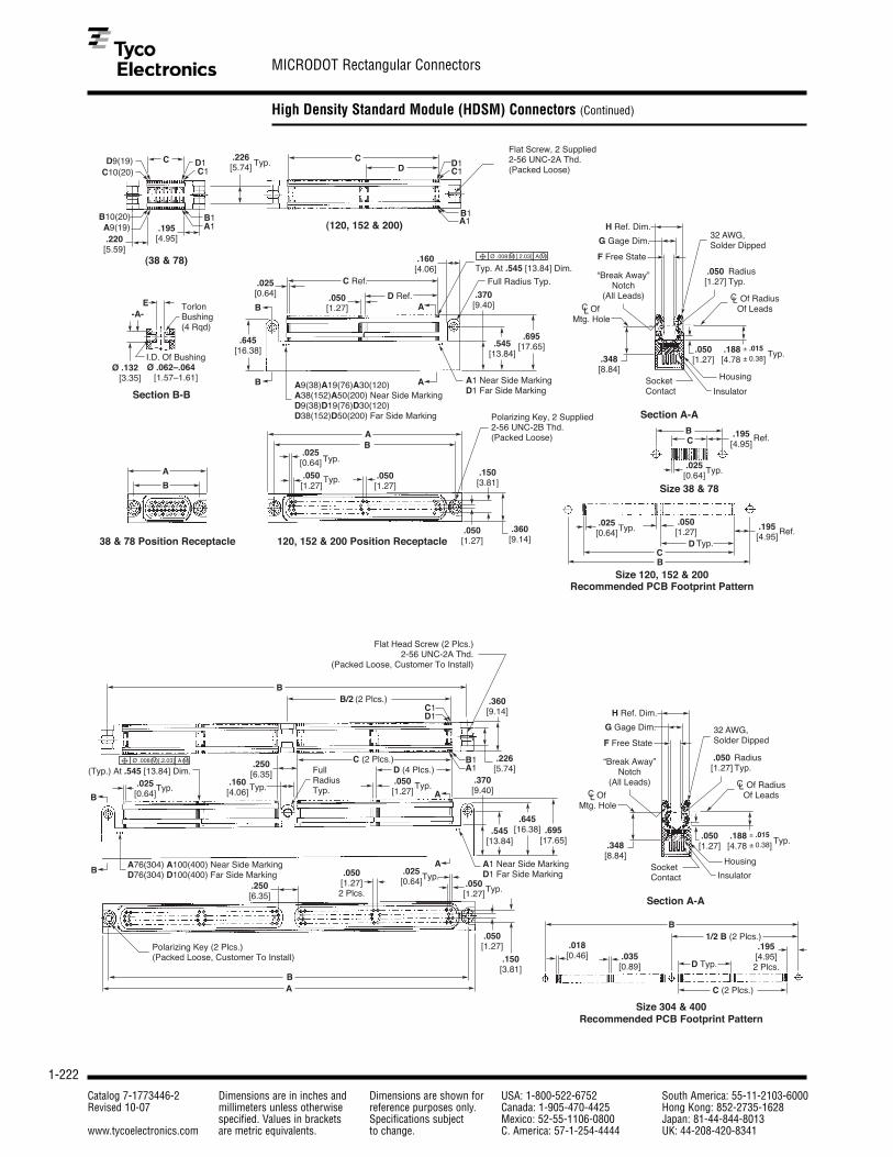
1-222
MICRODOT Rectangular Connectors
Catalog 7-1773446-2 Dimensions are in inches and Dimensions are shown for USA: 1-800-522-6752 South America: 55-11-2103-6000Revised 10-07 millimeters unless otherwise reference purposes only. Canada: 1-905-470-4425 Hong Kong: 852-2735-1628
specified. Values in brackets Specifications subject Mexico: 52-55-1106-0800 Japan: 81-44-844-8013www.tycoelectronics.com are metric equivalents. to change. C. America: 57-1-254-4444 UK: 44-208-420-8341
High Density Standard Module (HDSM) Connectors (Continued)
.220[5.59]
I.D. Of BushingØ .062–.064
[1.57–1.61]
.195[4.95]
CD9(19)C10(20)
A9(19)B10(20)
C1D1C1
B1A1
B1A1
(38 & 78)
.226[5.74] Typ. C
D
(120, 152 & 200)
Flat Screw, 2 Supplied2-56 UNC-2A Thd.(Packed Loose)
Ø .132 [3.35]
E Torlon Bushing(4 Rqd)
Section B-B
-A-
.025[0.64] .050
[1.27]
C Ref.
D Ref.
A
AB
B A9(38)A19(76)A30(120)A38(152)A50(200) Near Side MarkingD9(38)D19(76)D30(120)D38(152)D50(200) Far Side Marking
.645[16.38]
A1 Near Side MarkingD1 Far Side Marking
.160[4.06]
.370[9.40]
.545[13.84]
.695[17.65]
.348[8.84]
.050[1.27]
Typ. At .545 [13.84] Dim.
.188 ± .015
[4.78 ± 0.38]
Full Radius Typ.
Ø .008 M [.2.03] A M
.050[1.27]
H Ref. Dim.
G Gage Dim.
F Free State
32 AWG,Solder Dipped
Radius Typ.
Typ.
CL Of RadiusOf Leads
“Break Away”Notch
(All Leads)
Housing
InsulatorSocket Contact
Section A-A
B
.025[0.64]
C
Typ.
.195[4.95]
Ref.
Size 38 & 78B
A
38 & 78 Position Receptacle
AB
.050[1.27]
.025[0.64]
Typ.
Typ.
.050[1.27]
120, 152 & 200 Position Receptacle.050[1.27]
.150[3.81]
.360[9.14]
Polarizing Key, 2 Supplied2-56 UNC-2B Thd. (Packed Loose)
.050[1.27]
.195[4.95]
.025[0.64]Typ.
DC
Typ.Ref.
B
Size 120, 152 & 200Recommended PCB Footprint Pattern
D1
OfMtg. Hole
CL
BB/2 (2 Plcs.)
D1C1
B1A1
Flat Head Screw (2 Plcs.)2-56 UNC-2A Thd.
(Packed Loose, Customer To Install)
.226[5.74]
.360[9.14]
C (2 Plcs.)
.035[0.89]
.018[0.46]
D Typ.
.195[4.95]2 Plcs.
1/2 B (2 Plcs.)B
C (2 Plcs.)
Size 304 & 400Recommended PCB Footprint Pattern
.025[0.64]
Typ.
Ø .008 M [.2.03] A M
(Typ.) At .545 [13.84] Dim..160[4.06]
.250[6.35] Full
Radius Typ.
.050[1.27]
D (4 Plcs.)
Typ.Typ.
B
B
A
A
.370[9.40]
.545[13.84]
.645[16.38] .695
[17.65]
A1 Near Side MarkingD1 Far Side Marking
A76(304) A100(400) Near Side MarkingD76(304) D100(400) Far Side Marking
Polarizing Key (2 Plcs.)(Packed Loose, Customer To Install)
BA
.250[6.35]
.050[1.27]2 Plcs.
.025[0.64] .050
[1.27]
Typ.Typ.
.150[3.81]
.050[1.27]
.348[8.84]
.050[1.27]
.188 ± .015
[4.78 ± 0.38].050[1.27]
H Ref. Dim.
G Gage Dim.
F Free State
32 AWG,Solder Dipped
Radius Typ.
Typ.
CL Of RadiusOf Leads
“Break Away”Notch
(All Leads)
Housing
InsulatorSocketContact
Section A-A
OfMtg. Hole
CL
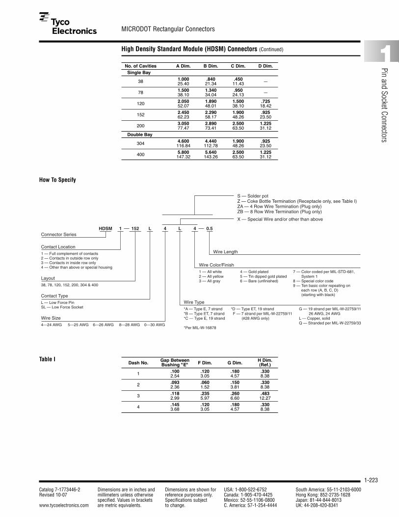
1-223
MICRODOT Rectangular Connectors
Catalog 7-1773446-2 Dimensions are in inches and Dimensions are shown for USA: 1-800-522-6752 South America: 55-11-2103-6000Revised 10-07 millimeters unless otherwise reference purposes only. Canada: 1-905-470-4425 Hong Kong: 852-2735-1628
specified. Values in brackets Specifications subject Mexico: 52-55-1106-0800 Japan: 81-44-844-8013www.tycoelectronics.com are metric equivalents. to change. C. America: 57-1-254-4444 UK: 44-208-420-8341
1
Pin and Socket Connectors
High Density Standard Module (HDSM) Connectors (Continued)
No. of Cavities A Dim. B Dim. C Dim. D Dim.Single Bay
38 1.000 .840 .450 —25.40 21.34 11.43
78 1.500 1.340 .950 —38.10 34.04 24.13
120 2.050 1.890 1.500 .72552.07 48.01 38.10 18.42
152 2.450 2.290 1.900 .92562.23 58.17 48.26 23.50
200 3.050 2.890 2.500 1.22577.47 73.41 63.50 31.12
Double Bay
304 4.600 4.440 1.900 .925116.84 112.78 48.26 23.50
400 5.800 5.640 2.500 1.225147.32 143.26 63.50 31.12
Dash No. Gap Between F Dim. G Dim. H Dim.Bushing "E" (Ref.)
1 .100 .120 .180 .3302.54 3.05 4.57 8.38
2 .093 .060 .150 .3302.36 1.52 3.81 8.38
3 .118 .235 .260 .4832.99 5.97 6.60 12.27
4 .145 .120 .180 .3303.68 3.05 4.57 8.38
How To Specify
Table I
L 4 L 4 0.5
Wire Length
Wire Type*A — Type E, 7 strand *D — Type ET, 19 strand G — 19 strand per MIL-W-22759/11*B — Type ET, 7 strand F — 7 strand per MIL-W-22759/11 26 AWG, 24 AWG*C — Type E, 19 strand (#28 AWG only) L — Copper, solid Q — Stranded per MIL-W-22759/33*Per MIL-W-16878
HDSM 1 152Connector Series
Contact Location1 — Full complement of contacts2 — Contacts in outside row only3 — Contacts in inside row only4 — Other than above or special housing
Layout38, 78, 120, 152, 200, 304 & 400
Contact TypeL — Low Force PinSL — Low Force Socket
Wire Size4—24 AWG 5—25 AWG 6—26 AWG 8—28 AWG 0—30 AWG
X — Special Wire and/or other than above
S — Solder pot Z — Coke Bottle Termination (Receptacle only, see Table I)ZA — 4 Row Wire Termination (Plug only)ZB — 8 Row Wire Termination (Plug only)
Wire Color/Finish1 — All white 4 — Gold plated 7 — Color coded per MIL-STD-681, 2 — All yellow 5 — Tin dipped gold plated System 13 — All gray 6 — Bare (unfinished) 8 — Special color code 9 — Ten basic color repeating on each row (A, B, C, D) (starting with black)

1-224
RAYCHEM Rectangular Connectors
Catalog 7-1773446-2 Dimensions are in inches and Dimensions are shown for USA: 1-800-522-6752 South America: 55-11-2103-6000Revised 10-07 millimeters unless otherwise reference purposes only. Canada: 1-905-470-4425 Hong Kong: 852-2735-1628
specified. Values in brackets Specifications subject Mexico: 52-55-1106-0800 Japan: 81-44-844-8013www.tycoelectronics.com are metric equivalents. to change. C. America: 57-1-254-4444 UK: 44-208-420-8341
MTC High-Performance Modular Rectangular Connectors with Removable Contacts
System
The Raychem MTC productline is a complete modularconnector system consist-ing of lightweight, environ-mentally sealed miniaturerectangular connectors(shell housings with remov-able inserts) and individuallyremovable rear-release contacts.
Components
MTC connectors are now available with quick-disconnect mating hard-ware, EME shielding acces-sories, and modular insertsthat can accommodate amix of signal and powercrimp contacts and coaxialcontacts. The need for spe-cial termination tooling has
been minimized, while theease of manufacturing andmaintenance has beenimproved.
Configurations
MTC rectangular connectorsusing jack screws or quick-disconnect hardware can bestacked or panel-mountednext to each other withoutany provision for gripspace, a feature that cansave significant panel area.
MTC connectors are avail-able in 1-inch and 2-inchconfigurations. Modularremovable inserts with size22 and/or size 16 contactcavities can be combinedinto the 1-inch and 2-inchMTC housings.
Inserts
MTC inserts are available in 20-cavity and 5-cavityversions. The 20-cavityinsert accepts size 20-22 (24 AWG to 20 AWG wire)crimp contacts. The 5-cavity insert accepts size16–14 crimp contacts.Insertion/extraction of thecontacts is rear release.
Note:Other configurations are available in the MTC family (size 12 contacts;50 mil spacing for double density;accessories). Please contact Tyco Electronics.
Product Facts■ Low-profile rectangular
design for high packagingdensity
■ Environmental sealing foraerospace applications
■ Modular components fordesign versatility andlogistics savings
■ Lightweight materials forweight savings
■ Quick-disconnect matinghardware
METRICDimensions in this sectionare millimeters over inches

1-225
RAYCHEM Rectangular Connectors
Catalog 7-1773446-2 Dimensions are in inches and Dimensions are shown for USA: 1-800-522-6752 South America: 55-11-2103-6000Revised 10-07 millimeters unless otherwise reference purposes only. Canada: 1-905-470-4425 Hong Kong: 852-2735-1628
specified. Values in brackets Specifications subject Mexico: 52-55-1106-0800 Japan: 81-44-844-8013www.tycoelectronics.com are metric equivalents. to change. C. America: 57-1-254-4444 UK: 44-208-420-8341
1
Pin and Socket Connectors
MTC High-Performance Modular Rectangular Connectors with Removable Contacts (Continued)
20-Cavity Inserts
Pin Insert Socket InsertMTCP-122-20P1 MTCP-122-20S1MTCP-122-20P2 MTCP-122-20S2
10 5 1
27 max.
1051
27 max.
A1Raychem
20 15
A2Raychem
2015
A2Raychem
2-inch Shell with Inserts
MTCP-122-20 inserts are used with MTC100 1-inch and 2-inch shells. The 1-inch shell takes:
■ One MTCP-122-20P (pin contact) or
■ One MTCP-122-20S (socket contact)
The 2-inch shell takes:
■ One MTCP-122-20P1 and one MTCP-122-20P2 (pin contact) or
■ One MTCP-122-20S1 and one MTCP-122-20S2 (socket contact)
2 x 20 Cavity Inserts (Size 20–22) — 2-Inch Shell

1-226
RAYCHEM Rectangular Connectors
Catalog 7-1773446-2 Dimensions are in inches and Dimensions are shown for USA: 1-800-522-6752 South America: 55-11-2103-6000Revised 10-07 millimeters unless otherwise reference purposes only. Canada: 1-905-470-4425 Hong Kong: 852-2735-1628
specified. Values in brackets Specifications subject Mexico: 52-55-1106-0800 Japan: 81-44-844-8013www.tycoelectronics.com are metric equivalents. to change. C. America: 57-1-254-4444 UK: 44-208-420-8341
MTC High-Performance Modular Rectangular Connectors with Removable Contacts (Continued)
20-Cavity Inserts (Continued)
Pin Insert Socket InsertMTCP-122-20P MTCP-122-20S
Contacts for 20-Cavity InsertsThe contacts for 20-cavity inserts must be ordered separately. They are:■ CTA-0166—pin contact■ CTA-0165—socket contact
Contacts accept 24 AWG to 20 AWG wires.
Tools ToolsPositioner for pin contact CE-1605900 Positioner for socket contact CE-1606000Installation process ES-61413 Installation process ES-61413Contact removal tool (plastic) CTA-1160 Contact removal tool (plastic) CTA-1160Extraction tool for MTCP inserts CTA-0161 Extraction tool for MTCP inserts CTA-0161
10 3 1
27 max.
ARaychem
ARaychem
101 5
27 max.
1-inch Shell with Insert
1 x 20 Cavity Inserts (Size 20–22) — 1-Inch Shell
Pin ContactCTA-0166
Socket ContactCTA-0165

1-227
RAYCHEM Rectangular Connectors
Catalog 7-1773446-2 Dimensions are in inches and Dimensions are shown for USA: 1-800-522-6752 South America: 55-11-2103-6000Revised 10-07 millimeters unless otherwise reference purposes only. Canada: 1-905-470-4425 Hong Kong: 852-2735-1628
specified. Values in brackets Specifications subject Mexico: 52-55-1106-0800 Japan: 81-44-844-8013www.tycoelectronics.com are metric equivalents. to change. C. America: 57-1-254-4444 UK: 44-208-420-8341
1
Pin and Socket Connectors
MTC High-Performance Modular Rectangular Connectors with Removable Contacts (Continued)
5-Cavity Inserts (Size 16)
Pin Insert Socket InsertMTCP-116-05P1 MTCP-116-05S1MTCP-116-05P2 MTCP-116-05S2
The contacts for 5-cavity inserts must be ordered separately. They include:■ CTA-0079 — pin contact (MS 27493-16) (MIL-C-39029/58 intermateable) ■ CTA-0078 — socket contact (MS 27491-16) (MIL-C-39029/57 intermateable)■ D-602-0140 — coaxial pin contact (MIL-C-39029/76 intermateable)■ D-602-0171 — coaxial socket contact (MIL-C-39029/78 intermateable)
Other contacts designed for M38999 Series II connectors can be used.
Pin Contact Socket ContactD-602-0140 (coaxial) D-602-0171 (coaxial)CTA-0079 (power) CTA-0078 (power)
A B C D E
27 max. 27 max.
A1
A B C D E
A2
A B C D E
A B C D E
A B C D E
A2
F G H J K
KF G H J
F G H J K
MTCP-116-05 inserts are used with MTC100 1-inch and 2-inch shells.The 1-inch shell takes:
■ One MTCP-116-05-P1 (pin contact) or
■ One MTCP-116-05-S1 (socket contact)
The 2-inch shell takes:
■ One MTCP-116-05P1 and one MTC-116-05P2 (pin contact) or
■ One MTCP-116-05-S1 and one MTCP-116-05-S2 (socket contact)
5-Cavity Inserts (Size 16)
Contacts for 5-Cavity Inserts

1-228
RAYCHEM Rectangular Connectors
Catalog 7-1773446-2 Dimensions are in inches and Dimensions are shown for USA: 1-800-522-6752 South America: 55-11-2103-6000Revised 10-07 millimeters unless otherwise reference purposes only. Canada: 1-905-470-4425 Hong Kong: 852-2735-1628
specified. Values in brackets Specifications subject Mexico: 52-55-1106-0800 Japan: 81-44-844-8013www.tycoelectronics.com are metric equivalents. to change. C. America: 57-1-254-4444 UK: 44-208-420-8341
MTC High-Performance Modular Rectangular Connectors with Removable Contacts (Continued)
Hybrid Inserts
Hybrid insert combinations of size 22 and size 16 contact cavities are also possible.
2-Inch Shell—Hybrid AssemblyPower and signal
F G H J K
1 A1 10
10B11
A B C D E
11 A2 20
20B211
Shells
MTC connector housingshells are available withnickel plating (48-hr saltspray performance) or cadmium over nickel plating (500-hr salt sprayperformance).
MTC connector housingsare offered with quick-disconnect or jack-screwmating hardware. Each connector shell is polarizedand has 64 user-definedkeying combinations.Lightweight, low-profileEME backshells are alsoavailable for increasedshielding effectiveness ofthe connector.
Receptacle
1" = 1.752" = 2.75
1" = 2.002" = 3.00
MTC100-JH1-P32 XXXX
RaychemA
.34
1.09
.39max.
1" = 1.752" = 2.75
1" = 1.752" = 2.75
flanged
1" = 2.062" = 3.06
flangeless
MTC100-JH1-R32 XXXX
RaychemA
.394 max.flangeless
.60max.
flanged
.34
1.09
Plug
Hybrids

1-229
RAYCHEM Rectangular Connectors
Catalog 7-1773446-2 Dimensions are in inches and Dimensions are shown for USA: 1-800-522-6752 South America: 55-11-2103-6000Revised 10-07 millimeters unless otherwise reference purposes only. Canada: 1-905-470-4425 Hong Kong: 852-2735-1628
specified. Values in brackets Specifications subject Mexico: 52-55-1106-0800 Japan: 81-44-844-8013www.tycoelectronics.com are metric equivalents. to change. C. America: 57-1-254-4444 UK: 44-208-420-8341
1
Pin and Socket Connectors
MTC High-Performance Modular Rectangular Connectors with Removable Contacts (Continued)
*Some combinations of shells, mating hardware and EME shielding accessories are not available.Contact Tyco Electronics for product information.
2 = Nickel plating.�48-hr salt spray test performance��3 = Cadmium over nickel plating.* �500-hr salt spray test performance��P = Plug housing�R = Receptacle housing, flangeless�F = Receptacle housing, flanged��1 = 1"�2 = 2"��J = Standard housing�S = EMI housing��Q = Quick-disconnect mating hardware � (connector performance per Raychem � specification C-6114)��Blank = Jack-screw mating hardware � (connector performance per � Raychem specification C-6115)
M T C 1 0 0 X - X H X - X X 2MTC Shells OrderingInformation

1-230
RAYCHEM Rectangular Connectors
Catalog 7-1773446-2 Dimensions are in inches and Dimensions are shown for USA: 1-800-522-6752 South America: 55-11-2103-6000Revised 10-07 millimeters unless otherwise reference purposes only. Canada: 1-905-470-4425 Hong Kong: 852-2735-1628
specified. Values in brackets Specifications subject Mexico: 52-55-1106-0800 Japan: 81-44-844-8013www.tycoelectronics.com are metric equivalents. to change. C. America: 57-1-254-4444 UK: 44-208-420-8341
MTC High-Performance Modular Rectangular Connectors with Removable Contacts (Continued)
Accessories Low-Profile EME Backshells
Lightweight rectangularEME backshells connectthe overall bundle shield tothe MTC connector hous-ing. Individual cable shieldscan also be terminated tothe backshell braid byusing RaychemSolderSleeve devices.
The backshell is mountedon the MTC housing via thecable clamp screws.
MTC backshell featuresinclude a low profile, lightweight, and Level II EMEperformance.
EME Backshell Adapters
CHA-0275 2-inch adapter(plug or recep-tacle)
CHA-0276 1-inch adapter(plug or recep-tacle)
MTC Shield-GroundingBusbars
Raychem MTC shield-grounding busbars allow forsimple, cost-effective termi-nation of cable shielding toMTC aluminum housings.
Two-inch shield-groundingbusbars terminate up to 20shielded twisted pairs on a2-inch MTC connector. Theindividual shields are termi-nated to “fingers” on thebusbar with RaychemSolderSleeve devices.
The busbar is mounted onthe MTC housing via cableclamp screws.
MTC busbar featuresinclude a simple termina-tion, cost effectiveness, lightweight, and Level I EMEperformance.
EME Shielding Accessories forMTC Connectors
Grounding BlockAllows for cable shield ter-mination grounding on theMTC shell housing viacrimp-removable contacts.This grounding schemeallows individual cables tobe removed from the con-nector without cutting aganged ground connection.Sufficient ground contactsare available to handleshielded twisted-paircables.
Grounding Block
CHA-0301 1-inch ground-ing block recep-tacle shell
CHA-0302 2-inch ground-ing block recep-tacle shell
CHA-0303 1-inch ground-ing block plugshell
CHA-0304 2-inch ground-ing block plugshell
Shield-Grounding Busbars
CTA-0022 1-inch busbar(with 5SolderSleeveterminators)
CTA-0023 2-inch busbar(with 10SolderSleeveterminators)

1-231
NANONICS Strip Connectors
Catalog 7-1773446-2 Dimensions are in inches and Dimensions are shown for USA: 1-800-522-6752 South America: 55-11-2103-6000Revised 10-07 millimeters unless otherwise reference purposes only. Canada: 1-905-470-4425 Hong Kong: 852-2735-1628
specified. Values in brackets Specifications subject Mexico: 52-55-1106-0800 Japan: 81-44-844-8013www.tycoelectronics.com are metric equivalents. to change. C. America: 57-1-254-4444 UK: 44-208-420-8341
1
Pin and Socket Connectors
Introduction
The NANONICS strip con-nectors are the smallest connectors in the NANONICSproduct line. They aremolded from LCP and areideal for applications wherethe height and weight of the connector is a seriousdesign parameter. Just.040" in height, these
connectors are well suitedfor low-profile applications.Standard sizes are 4, 9,and 15, while 25, 37, and 51 are also availableupon request. Standard configurations includewired, surface mount, orthru-hole terminations.
Guide pins are available for polarization. Harnessassemblies and customconfigurations can also beaccommodated.
Polarization Polarization of the strips isaccomplished with the useof optional polarizing guideposts.
Polarization Position“T” Shown

1-232
NANONICS Strip Connectors
Catalog 7-1773446-2 Dimensions are in inches and Dimensions are shown for USA: 1-800-522-6752 South America: 55-11-2103-6000Revised 10-07 millimeters unless otherwise reference purposes only. Canada: 1-905-470-4425 Hong Kong: 852-2735-1628
specified. Values in brackets Specifications subject Mexico: 52-55-1106-0800 Japan: 81-44-844-8013www.tycoelectronics.com are metric equivalents. to change. C. America: 57-1-254-4444 UK: 44-208-420-8341
Wired Connectors — Unshrouded, Flying Leads
.205 [5.21]
Position 1
C
L
.040 [1.02]
.060[1.52] Typ.
.111[2.82]
Position 1
C
L
.040 [1.02]
DimensionsSize
C L4 0.115 [2.92] 0.075 [1.91]9 0.240 [6.10] 0.200 [5.08]15 0.390 [9.91] 0.350 [8.89]25 0.640 [16.26] 0.600 [15.24]37 0.940 [23.88] 0.900 [22.86]51 1.290 [32.77] 1.250 [31.75]
Product Facts
■ Plastic Shell■ Standard Sizes: 4, 9, 15,
25, 37 and 51■ Factory wired to your
specifications■ Contact Tyco Electronics for
custom configurations
Plug AssemblyDrawing Number 1589448
Receptacle AssemblyDrawing Number 1589449

1-233
NANONICS Strip Connectors
Catalog 7-1773446-2 Dimensions are in inches and Dimensions are shown for USA: 1-800-522-6752 South America: 55-11-2103-6000Revised 10-07 millimeters unless otherwise reference purposes only. Canada: 1-905-470-4425 Hong Kong: 852-2735-1628
specified. Values in brackets Specifications subject Mexico: 52-55-1106-0800 Japan: 81-44-844-8013www.tycoelectronics.com are metric equivalents. to change. C. America: 57-1-254-4444 UK: 44-208-420-8341
1
Pin and Socket Connectors
Part Numbering Guideline for Strip Wired Connectors
Strip Connectors - Wire Terminations
USS XXX X
Positions004 4 Position
009 9 Position
015 15 Position
025 25 Position
Class/Row/TypeUSS Unshrouded, 1 row, strip
Polarization (optional)Plug contains guide post
Receptacle accepts guide post
Conductor LengthXXX Three numbers only, length is in inches ( i.e. 012 = twelve inches)
CXX A “C” followed by two numbers, length is in centimeters ( i.e. C06 = 6 centimeters)
MXX An “M” followed by two numbers, length is in meters ( i.e. M02 = 2 meters)
XX
Conductor TypeDX White Teflon
DY White PTFE per M16878/6
DC Color Coded Teflon
DM Color Coded Teflon per MIL-STD-681
DT White Tefzel per M22759/33
XXX
ConfigurationPC Plug
SC Receptacle
XX
Conductor Size/Strands0 28 AWG Solid
1 30 AWG Solid
2 30 AWG 7 Strand
3 32 AWG 7 Strand
4 34 AWG 7 Strand
X
Polarization (Strip Type Only)
T = One Pin ���������
U = One Pin ���������
V = One Pin ���������
W = Two Pin ���������
Y = Two Pin ���������
Z = Two Pin ���������

1-234
NANONICS Strip Connectors
Catalog 7-1773446-2 Dimensions are in inches and Dimensions are shown for USA: 1-800-522-6752 South America: 55-11-2103-6000Revised 10-07 millimeters unless otherwise reference purposes only. Canada: 1-905-470-4425 Hong Kong: 852-2735-1628
specified. Values in brackets Specifications subject Mexico: 52-55-1106-0800 Japan: 81-44-844-8013www.tycoelectronics.com are metric equivalents. to change. C. America: 57-1-254-4444 UK: 44-208-420-8341
Surface Mount Connectors — Unshrouded
A
.025 [.64] Pitch
.255 [6.48] Typ.
.020 [.51] Typ.
.205 [5.21]
C
LPosition 1
.040 [1.02]
Position 1
C
L
A
.025 [.64] Pitch
.111 [2.82]
.060[1.52] Typ.
.020 [.51] Typ.
.161 [4.09] Typ.
.040 [1.02]
Product Facts
■ Plastic Shell■ Standard Sizes: 4, 9, 15,
25, 37 and 51■ Factory wired to your
specifications■ Contact Tyco Electronics for
custom configurations■ Suggested Pad Layouts
are available on thereferenced drawings on theTyco Electronics website
Plug AssemblyDrawing Number 1589451
Receptacle AssemblyDrawing Number 1589452
DimensionsSize
A C L4 0.0375 [.95] 0.115 [2.92] 0.075 [1.91]9 0.1000 [2.54] 0.240 [6.10] 0.200 [5.08]15 0.1750 [4.45] 0.390 [9.91] 0.350 [8.89]25 0.3000 [7.62] 0.640 [16.26] 0.600 [15.24]37 0.4500 [11.43] 0.940 [23.88] 0.900 [22.86]51 0.6250 [15.88] 1.290 [32.77] 1.250 [31.75]

1-235
NANONICS Strip Connectors
Catalog 7-1773446-2 Dimensions are in inches and Dimensions are shown for USA: 1-800-522-6752 South America: 55-11-2103-6000Revised 10-07 millimeters unless otherwise reference purposes only. Canada: 1-905-470-4425 Hong Kong: 852-2735-1628
specified. Values in brackets Specifications subject Mexico: 52-55-1106-0800 Japan: 81-44-844-8013www.tycoelectronics.com are metric equivalents. to change. C. America: 57-1-254-4444 UK: 44-208-420-8341
1
Pin and Socket Connectors
Thru-Hole Connectors — Unshrouded, Horizontal, 1 Row to 2 Row, .050 Spacing
.205 [5.21]
C
L
Position 1
.090 [2.29] Typ.
.050 [1.27] Typ.
.255 [1.27] Typ.
.040 [1.02]
.111 [2.82]
.060 [1.52] Typ.
.050 [1.27] Typ.
.161 [4.09] Typ.
C
L Position 1
.090 [2.29] Typ.
.040 [1.02]
Product Facts
■ Plastic Shell■ Standard Sizes: 4, 9, 15,
25, 37 and 51■ Factory wired to your
specifications■ Contact Tyco Electronics for
custom configurations■ Suggested Thru-Hole
Layouts are available onthe referenced drawings onthe Tyco Electronicswebsite
Plug AssemblyDrawing Number 1589453
Receptacle AssemblyDrawing Number 1589454
DimensionsSize
C L4 0.115 [2.92] 0.075 [1.91]9 0.240 [6.10] 0.200 [5.08]15 0.390 [9.91] 0.350 [8.89]25 0.640 [16.26] 0.600 [15.24]37 0.940 [23.88] 0.900 [22.86]51 1.290 [32.77] 1.250 [31.75]

1-236
NANONICS Strip Connectors
Catalog 7-1773446-2 Dimensions are in inches and Dimensions are shown for USA: 1-800-522-6752 South America: 55-11-2103-6000Revised 10-07 millimeters unless otherwise reference purposes only. Canada: 1-905-470-4425 Hong Kong: 852-2735-1628
specified. Values in brackets Specifications subject Mexico: 52-55-1106-0800 Japan: 81-44-844-8013www.tycoelectronics.com are metric equivalents. to change. C. America: 57-1-254-4444 UK: 44-208-420-8341
Part Numbering Guideline for Surface Mount and Thru Hole Termination
Strip Connectors - Surface Mount and Thru Hole Terminations
USS XX X
Positions004 4 Position
009 9 Position
015 15 Position
025 25 Position
Class/Row/TypeUSS Unshrouded, 1 row, strip
Polarization (optional)Plug contains guide post
Receptacle accepts guide post
ConfigurationB2 Plug, Horizontal SMT
L2 Receptacle, Horizontal SMT
C6 Plug, Horizontal Mount, Thru Hole
M6 Receptacle, Horizontal Mount, Thru Hole
XXX
Polarization (Strip Type Only)
T = One Pin ���������
U = One Pin ���������
V = One Pin ���������
W = Two Pin ���������
Y = Two Pin ���������
Z = Two Pin ���������

1-237
HTS Heavy Duty ConnectorsOverview
Catalog 7-1773446-2 Dimensions are in inches and Dimensions are shown for USA: 1-800-522-6752 South America: 55-11-2103-6000Revised 10-07 millimeters unless otherwise reference purposes only. Canada: 1-905-470-4425 Hong Kong: 852-2735-1628
specified. Values in brackets Specifications subject Mexico: 52-55-1106-0800 Japan: 81-44-844-8013www.tycoelectronics.com are metric equivalents. to change. C. America: 57-1-254-4444 UK: 44-208-420-8341
1
Pin and Socket Connectors
Introduction
HTS a part of Tyco Electronicshas knowledge in developingand manufacturing heavyduty connectors for morethan 50 years.
The German specialist for industrial connectors isbased in Neunkirchen nearCologne and serves cus-tomers world wide in themarkets industrial machinery,railway and electrical powerutilities.
Customers appreciate the great offer, high quality ofthe products, logistic capabilities as well as theindividual support from specialists.
Content Page
Size 1 1
Size 3 2–3
Size 4 4–5
Size 5 6–7
Size 6 8–9
Size 8 10–11
HVS System 12–13
Contacts 14
Accessories 15
Numerical Index 16
The technical expertise andthe global presence of Tyco Electronics ensures an excellent customer service.
To guarantee the highest quality all products aretested in laboratories. Theproduct portfolio includesstandard products, latestinnovations as well as customer specific solutionsto support customers in all needs.
Product Information Center (PIC)You can rely on the support of ourPIC Team. Apart from the PIC Team which hasbeen specially trained to answerany technical questions you mighthave, our experienced staff is anadditional source of information:Phone: +49-2247-305-147Fax: +49-2247-305-122E-Mail: [email protected]
For further product information please order our catalog
Tyco Electronics Industrie-Steckverbinder Heavy Duty Connectors Lit. No. 889745-2
Housings
■ Material: Aluminum die-cast alloy; Zinc die-cast alloy
■ Protection Class: IP 44 – IP 65
■ Locking Systems: Locking clip; Side clip
■ Surface: Powder coated
Contact Inserts
■ Material: Thermoplastic, glass-fiberreinforced acc. UL 94 V-0
■ Rated Current: to 16 A
■ Rated Voltage: to 500 V
■ Types of Wire Connections: Screw terminal; Spring clamp terminal; Crimp terminal
■ Contact Material: Copper alloy
■ Contact Surfaces: Hard silver-plated; Hard gold-plated
■ UL, CSA, VDE approved

1-238
HTS Heavy Duty ConnectorsOverview
Catalog 7-1773446-2 Dimensions are in inches and Dimensions are shown for USA: 1-800-522-6752 South America: 55-11-2103-6000Revised 10-07 millimeters unless otherwise reference purposes only. Canada: 1-905-470-4425 Hong Kong: 852-2735-1628
specified. Values in brackets Specifications subject Mexico: 52-55-1106-0800 Japan: 81-44-844-8013www.tycoelectronics.com are metric equivalents. to change. C. America: 57-1-254-4444 UK: 44-208-420-8341
Housings and Contact Inserts – Size 1
Top Housings
1 Straight cable entry
2 Angled cable entry 1 2
3
Bottom Housings
3 Surface mounted housing (bulkhead)
4 Surface mount (side entry)
5 Cable-to-cable housing
Series: HA.3
■ Standard Design
■ Locking System: Side locking device
■ Zinc die-cast alloy
■ Powder coated
■ IP 44
A
B
C
3+Gnd/4+Gnd 10 A/250 V, 4 kV 3 Screw terminal
5+Gnd 16 A/400 V, 6 kV 3 Crimp terminal
7+Gnd 10 A/250 V, 4 kV 3 Crimp terminal
Series: HA.3 HA.4 HE-Q.5 HN.D.7
■ Material: Polycarbonate
■ Flammability Rating: acc. UL 94 V-0
4 5
Male Insert Female Insert
Style Product Description Thread Width Length Height Part Package(mm) (mm) (mm) Number Quantity
1 HA.3.STO.1.M16.Z M16 26.5 26.5 52.0 0-1106405-1 10
2 HA.3.STW.1.M16.Z M16 26.5 40.0 49.0 0-1106406-1 10
3HA.3.AG-LB – 28.0 40.0 23.0 1-1102105-2 10
HA.3.AGD*-LB – 28.0 40.0 23.0 1-1102106-2 10
4 HA.3.SG-LB.1.M16.G M16 40.0 40.0 25.0 0-1106404-1 10
5 HA.3.KDO-LB.1.M16.Z M16 24.0 24.0 46.0 0-1106403-1 10
*) AGD = Surface mounted housing with lid
HA.3.Sti.S Screw 1-1103400-1 10
AHA.3.Bu.S Screw 1-1103401-1 10
HA.4.Sti.S Screw 1-1103402-1 10
HE.4.Bu.S Screw 1-1103403-1 10
BHE-Q.5.Sti.C HE/HA Crimp Contact* 0-1102195-1 10
HE-Q.5.Bu.C HE/HA Crimp Contact* 0-1102194-1 10
CHN.D.7.Sti.C HN.D Crimp Contact* 2-1103100-3 10
HN.D.7.Bu.C HN.D Crimp Contact* 2-1103101-3 10
*) Mating Contacts please see Page 14 Crimp Tooling please see Page 15
No. Product Description Termination Style Part PackageNumber Quantity
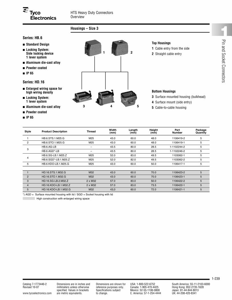
1-239
HTS Heavy Duty ConnectorsOverview
Catalog 7-1773446-2 Dimensions are in inches and Dimensions are shown for USA: 1-800-522-6752 South America: 55-11-2103-6000Revised 10-07 millimeters unless otherwise reference purposes only. Canada: 1-905-470-4425 Hong Kong: 852-2735-1628
specified. Values in brackets Specifications subject Mexico: 52-55-1106-0800 Japan: 81-44-844-8013www.tycoelectronics.com are metric equivalents. to change. C. America: 57-1-254-4444 UK: 44-208-420-8341
1
Pin and Socket Connectors
Housings – Size 3
*) AGD = Surface mounted housing with lid / SGD = Socket housing with lid
High construction with enlarged wiring space
Series: HB.6
■ Standard Design
■ Locking System: Side locking device 1 lever system
■ Aluminum die-cast alloy
■ Powder coated
■ IP 65
Series: HD.16
■ Enlarged wiring space for high wiring density
■ Locking System: 1 lever system
■ Aluminum die-cast alloy
■ Powder coated
■ IP 65
1 2
3 4 5
Top Housings
1 Cable entry from the side
2 Straight cable entry
Bottom Housings
3 Surface mounted housing (bulkhead)
4 Surface mount (side entry)
5 Cable-to-cable housing
Style Product Description Thread Width Length Height Part Package(mm) (mm) (mm) Number Quantity
1 HB.6.STS.1.M25.G M25 43.0 60.0 48.0 0-1106419-2 5
2 HB.6.STO.1.M25.G M25 43.0 60.0 48.0 0-1106419-1 5
3HB.6.AG-LB – 43.5 80.0 28.5 1-1102244-2 5
HB.6.AGD*-LB – 43.5 80.0 28.5 1-1102246-2 5
4HB.6.SG-LB.1.M25.Z M25 52.0 83.0 49.5 0-1103062-1 5
HB.6.SGD*-LB.1.M25.Z M25 52.0 82.0 49.5 0-1103062-2 5
5 HB.6.KDO-LB.1.M25.G M25 43.0 60.0 50.0 0-1106417-1 5
1 HD.16.STS.1.M32.G M32 43.0 60.0 70.0 0-1106423-2 5
2 HD.16.STO.1.M32.G M32 43.0 60.0 70.0 0-1106423-1 5
3 HD.16.SG-LB.2.M32.Z 2 x M32 57.0 83.0 50.0 0-1106422-2 5
4 HD.16.KDO-LB.1.M32.Z 2 x M32 57.0 83.0 73.5 0-1106422-1 5
5 HD.16.KDO-LB.1.M32.G M32 43,0 60.0 72.0 0-1106421-1 5
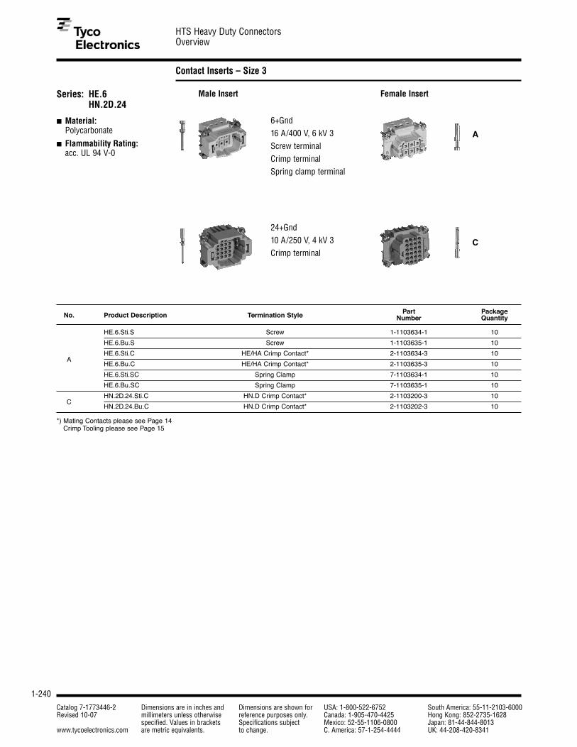
1-240
HTS Heavy Duty ConnectorsOverview
Catalog 7-1773446-2 Dimensions are in inches and Dimensions are shown for USA: 1-800-522-6752 South America: 55-11-2103-6000Revised 10-07 millimeters unless otherwise reference purposes only. Canada: 1-905-470-4425 Hong Kong: 852-2735-1628
specified. Values in brackets Specifications subject Mexico: 52-55-1106-0800 Japan: 81-44-844-8013www.tycoelectronics.com are metric equivalents. to change. C. America: 57-1-254-4444 UK: 44-208-420-8341
Contact Inserts – Size 3
Series: HE.6HN.2D.24
■ Material: Polycarbonate
■ Flammability Rating: acc. UL 94 V-0
6+Gnd 16 A/400 V, 6 kV 3 Screw terminal Crimp terminal Spring clamp terminal
24+Gnd 10 A/250 V, 4 kV 3 Crimp terminal
A
C
Male Insert Female Insert
HE.6.Sti.S Screw 1-1103634-1 10
HE.6.Bu.S Screw 1-1103635-1 10
AHE.6.Sti.C HE/HA Crimp Contact* 2-1103634-3 10
HE.6.Bu.C HE/HA Crimp Contact* 2-1103635-3 10
HE.6.Sti.SC Spring Clamp 7-1103634-1 10
HE.6.Bu.SC Spring Clamp 7-1103635-1 10
CHN.2D.24.Sti.C HN.D Crimp Contact* 2-1103200-3 10
HN.2D.24.Bu.C HN.D Crimp Contact* 2-1103202-3 10
*) Mating Contacts please see Page 14 Crimp Tooling please see Page 15
No. Product Description Termination Style Part PackageNumber Quantity

1-241
HTS Heavy Duty ConnectorsOverview
Catalog 7-1773446-2 Dimensions are in inches and Dimensions are shown for USA: 1-800-522-6752 South America: 55-11-2103-6000Revised 10-07 millimeters unless otherwise reference purposes only. Canada: 1-905-470-4425 Hong Kong: 852-2735-1628
specified. Values in brackets Specifications subject Mexico: 52-55-1106-0800 Japan: 81-44-844-8013www.tycoelectronics.com are metric equivalents. to change. C. America: 57-1-254-4444 UK: 44-208-420-8341
1
Pin and Socket Connectors
Housings – Size 4
1 2
3 4 5
Series: HB.10
■ Standard Design
■ Locking Systems: 1 Lever System 2 Levers System
■ Aluminum die-cast alloy
■ Powder coated
■ IP 65
Series: HD.24
■ Enlarged wiring space
■ Locking Systems: 1 Lever System 2 Levers System
■ Aluminum die-cast alloy
■ Powder coated
■ IP 65
Top Housings
1 Cable entry from the side
2 Straight cable entry
Bottom Housings
3 Surface mounted housing (bulkhead)
4 Surface mount (side entry)
5 Cable-to-cable housing
6 7
8 9 10
Top Housings
6 Cable entry from the side
7 Straight cable entry
Bottom Housings
18 Surface mounted housing (bulkhead)
19 Surface mount (side entry)
10 Cable-to-cable housing
Style Product Description Thread Width Length Height Part Package(mm) (mm) (mm) Number Quantity
*) AGD = Surface mounted housing with lid / SGD = Socket housing with lid
High construction with enlarged wiring space
1 HB.10.STS-GR.1.M25.G M25 43.0 73.0 50.0 0-1106430-5 5
2 HB.10.STO-GR.1.M25.G M25 43.0 73.0 50.0 0-1106430-2 5
3HB.10.AG-LB – 43.5 93.0 28.5 1-1102271-2 5
HB.10.AGD*-LB – 43.5 93.0 28.5 1-1102283-2 5
4HB.10.SG-LB.2.M25.Z 2 x M25 52.0 94.0 53.5 0-1106429-3 5
HB.10.SGD*-LB.2.M25.Z 2 x M25 52.0 94.0 53.5 0-1106429-2 5
5 HB.10.KDO-LB.1.M25.G M25 43.0 73.0 55.5 0-1106428-1 5
1 HD.24.STS-GR.1.M32.G M32 43.0 73.0 57.0 0-1106434-5 5
2 HD.24.STO-GR.1.M32.G M32 43.0 73.0 70.0 0-1106434-2 5
3 HD.24.SG-LB.2.M32.Z 2 x M32 57.0 94.0 73.5 0-1106433-3 5
6 HB.10.STS.1.M25.G M25 43.0 73.0 50.0 0-1106430-4 5
7 HB.10.STO.1.16G – 43.0 73.0 50.0 1-1102267-6 5
8 HB.10.AG-VS – 57.0 93.0 28.5 1-1102271-1 5
9 HB.10.SG-VS.1.M25.Z M25 57.0 94.0 55.5 0-1103059-1 5
10 HB.10.KDO-VS.1.M25.G M25 57.0 73.0 55.5 0-1106428-2 5
6 HD.24.STS.1.M32.G M32 43.0 73.0 70.0 0-1106434-4 5
7 HD.24.STO.1.M32.G M32 43.0 73.0 70.0 0-1106434-1 5
9 HD.24.SG-VS.2.M32.Z 2 x M32 56.0 94.0 74.0 0-1106433-4 5
10 HD.24.KDO-VS.1.M32.G M32 57.0 73.0 55.5 0-1106432-2 5

1-242
HTS Heavy Duty ConnectorsOverview
Catalog 7-1773446-2 Dimensions are in inches and Dimensions are shown for USA: 1-800-522-6752 South America: 55-11-2103-6000Revised 10-07 millimeters unless otherwise reference purposes only. Canada: 1-905-470-4425 Hong Kong: 852-2735-1628
specified. Values in brackets Specifications subject Mexico: 52-55-1106-0800 Japan: 81-44-844-8013www.tycoelectronics.com are metric equivalents. to change. C. America: 57-1-254-4444 UK: 44-208-420-8341
Contact Inserts – Size 4
Series: HE.10 HN.2D.42
■ Material: Polycarbonate
■ Flammability Rating: acc. UL 94 V-0
10+Gnd 16 A/400 V, 6 kV 3 Screw terminal Crimp terminal Spring clamp terminal
42+Gnd 10 A/250 V, 4 kV 3 Crimp terminal
A
C
Male Insert Female Insert
HE.10.Sti.S Screw 1-1103636-1 10
HE.10.Bu.S Screw 1-1103637-1 10
AHE.10.Sti.C HE/HA Crimp Contact* 2-1103636-3 10
HE.10.Bu.C HE/HA Crimp Contact* 2-1103637-3 10
HE.10.Sti.SC Spring Clamp 7-1103636-1 10
HE.10.Bu.SC Spring Clamp 7-1103637-1 10
CHN.2D.42.Sti.C HN.D Crimp Contact* 2-1103204-3 10
HN.2D.42.Bu.C HN.D Crimp Contact* 2-1103206-3 10
*) Mating Contacts please see Page 14 Crimp Tooling please see Page 15
No. Product Description Termination Style Part PackageNumber Quantity

1-243
HTS Heavy Duty ConnectorsOverview
Catalog 7-1773446-2 Dimensions are in inches and Dimensions are shown for USA: 1-800-522-6752 South America: 55-11-2103-6000Revised 10-07 millimeters unless otherwise reference purposes only. Canada: 1-905-470-4425 Hong Kong: 852-2735-1628
specified. Values in brackets Specifications subject Mexico: 52-55-1106-0800 Japan: 81-44-844-8013www.tycoelectronics.com are metric equivalents. to change. C. America: 57-1-254-4444 UK: 44-208-420-8341
1
Pin and Socket Connectors
Housings – Size 5
1 2
3 4 5
Top Housings
1 Cable entry from the side
2 Straight cable entry
Bottom Housings
3 Surface mounted housing (bulkhead)
4 Surface mount (side entry)
5 Cable-to-cable housing
Series: HA.16
■ Standard Design
■ Locking System: 1 Lever System
■ Aluminum die-cast alloy
■ Powder coated
■ IP 65
*) AGD = Surface mounted housing with lid
*) SGD = Socket housing with lid
Style Product Description Thread Width Length Height Part Package(mm) (mm) (mm) Number Quantity
1 HA.16.STS.1.M20.G M20 29.0 79.5 57.0 0-1106439-2 5
2 HA.16.STO.1.M20.G M20 29.0 79.5 57.0 0-1106439-1 5
3HA.16.AG-LB – 29.0 96.0 28.0 1-1102140-2 5
HA.16.AGD*-LB – 29.0 96.0 28.0 1-1102141-2 5
4HA.16.SG-LB.1.M20.Z M20 50.0 102.00 50.0 0-1103058-1 5
HA.16.SGD*-LB.2.M20.Z M20 50.0 102.00 50.0 0-1103058-2 5
5 HA.16.KDO-LB.1.M20.G M20 29.0 92.0 52.0 0-1106437-1 5
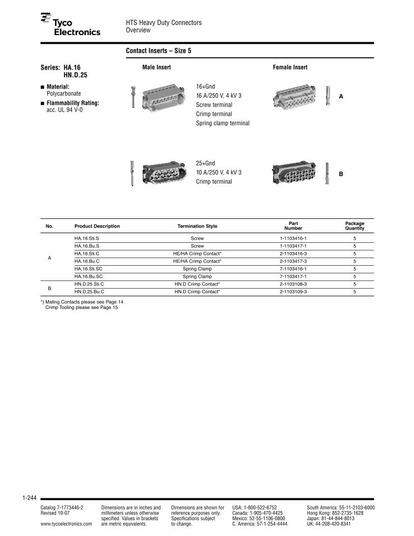
1-244
HTS Heavy Duty ConnectorsOverview
Catalog 7-1773446-2 Dimensions are in inches and Dimensions are shown for USA: 1-800-522-6752 South America: 55-11-2103-6000Revised 10-07 millimeters unless otherwise reference purposes only. Canada: 1-905-470-4425 Hong Kong: 852-2735-1628
specified. Values in brackets Specifications subject Mexico: 52-55-1106-0800 Japan: 81-44-844-8013www.tycoelectronics.com are metric equivalents. to change. C. America: 57-1-254-4444 UK: 44-208-420-8341
Contact Inserts – Size 5
16+Gnd 16 A/250 V, 4 kV 3 Screw terminal Crimp terminal Spring clamp terminal
25+Gnd 10 A/250 V, 4 kV 3 Crimp terminal
A
B
Male Insert Female InsertSeries: HA.16HN.D.25
■ Material: Polycarbonate
■ Flammability Rating: acc. UL 94 V-0
HA.16.Sti.S Screw 1-1103416-1 5
HA.16.Bu.S Screw 1-1103417-1 5
AHA.16.Sti.C HE/HA Crimp Contact* 2-1103416-3 5
HA.16.Bu.C HE/HA Crimp Contact* 2-1103417-3 5
HA.16.Sti.SC Spring Clamp 7-1103416-1 5
HA.16.Bu.SC Spring Clamp 7-1103417-1 5
BHN.D.25.Sti.C HN.D Crimp Contact* 2-1103108-3 5
HN.D.25.Bu.C HN.D Crimp Contact* 2-1103109-3 5
*) Mating Contacts please see Page 14 Crimp Tooling please see Page 15
No. Product Description Termination Style Part PackageNumber Quantity

1-245
HTS Heavy Duty ConnectorsOverview
Catalog 7-1773446-2 Dimensions are in inches and Dimensions are shown for USA: 1-800-522-6752 South America: 55-11-2103-6000Revised 10-07 millimeters unless otherwise reference purposes only. Canada: 1-905-470-4425 Hong Kong: 852-2735-1628
specified. Values in brackets Specifications subject Mexico: 52-55-1106-0800 Japan: 81-44-844-8013www.tycoelectronics.com are metric equivalents. to change. C. America: 57-1-254-4444 UK: 44-208-420-8341
1
Pin and Socket Connectors
Housings – Size 6
Top Housings
1 Cable entry from the side
2 Straight cable entry
Bottom Housings
3 Surface mounted housing (bulkhead)
4 Surface mount (side entry)
5 Cable-to-cable housing
1 2
3 4 5
Series: HB.16
■ Standard Design
■ Locking Systems: 1 Lever System 2 Levers System
■ Aluminum die-cast alloy
■ Powder coated
■ IP 65
Series: HD.40
■ Enlarged wiring space for high wiring density
■ Locking Systems: 1 Lever System 2 Levers System
■ Aluminum die-cast alloy
■ Powder coated
■ IP 65
6 7
8 9 10
Top Housings
6 Cable entry from the side
7 Straight cable entry
Bottom Housings
18 Surface mounted housing (bulkhead)
19 Surface mount (side entry)
10 Cable-to-cable housing
Style Product Description Thread Width Length Height Part Package(mm) (mm) (mm) Number Quantity
*) AGD = Surface mounted housing with lid / SGD = Socket housing with lid
High construction with enlarged wiring space
1 HB.16.STS-GR.1.M25.G M25 43.0 093.5 60.0 3-1106449-4 5
2 HB.16.STO-GR.1.M32.G M32 43.0 033.5 60.0 0-1106449-2 5
3HB.16.AG-LB – 43.5 113.0 28.5 1-1102296-2 5
HB.16.AGD*-LB – 43.5 113.0 28.5 1-1102305-2 5
4HB.16.SG-LB.2.M25.Z 2 x M25 52.0 117.0 55.5 0-1106448-3 5
HB.16.SGD*-LB.1.M25.Z M25 52.0 117.0 55.5 0-1103060-3 5
1 HD.40.STS-GR.1.M32.G M32 43.0 093.5 76.0 0-1106452-5 5
2 HD.40.STO-GR.1.M32.G M32 43.0 093.5 76.0 0-1106452-2 5
4HD.40.SG-LB.2.M32.Z 2 x M32 57.0 117.0 76.5 0-1106451-3 5
HD.40.SGD*-LB.2.M32.Z 2 x M32 57.0 117.0 76.5 0-1106451-2 5
5 HD.40.KDO-LB.1.M32.G M32 43.0 93.5 79.5 0-1106450-1 5
6 HB.16.STS.1.M25.G M25 43.0 093.5 60.0 2-1106449-5 5
7 HB.16.STO.1.M32.G M32 43.0 093.5 60.0 0-1106449-1 5
8 HB.16.AG-VS – 57.0 113.0 28.5 1-1102296-1 5
9 HB.16.SG-VS.1.M25.Z M25 57.0 117.0 55.5 0-1103060-1 5
6 HD.40.STS.1.M32.G M32 43.0 093.5 76.0 0-1106452-4 5
7 HD.40.STO.1.M32.G M32 43.0 093.5 76.0 0-1106452-1 5
9 HD.40.SG-VS.1.M32.Z M32 57.0 117.0 76.5 0-1103082-1 5
10 HD.40.KDO-VS.1.M32.G M32 57.0 093.5 79.5 0-1106450-2 5

1-246
HTS Heavy Duty ConnectorsOverview
Catalog 7-1773446-2 Dimensions are in inches and Dimensions are shown for USA: 1-800-522-6752 South America: 55-11-2103-6000Revised 10-07 millimeters unless otherwise reference purposes only. Canada: 1-905-470-4425 Hong Kong: 852-2735-1628
specified. Values in brackets Specifications subject Mexico: 52-55-1106-0800 Japan: 81-44-844-8013www.tycoelectronics.com are metric equivalents. to change. C. America: 57-1-254-4444 UK: 44-208-420-8341
Contact Inserts – Size 6
16+Gnd 16 A/400 V, 6 kV 3 Screw terminal
Crimp terminal
Spring clamp terminal
A
40+Gnd
10 A/250 V, 4 kV 3 Crimp terminal
B
72+Gnd
10 A/250 V, 4 kV 3 Crimp terminal
C
6+Gnd
35 A/400 V, 6 kV 3
Screw terminalD
Series: HE.16HN.D.40HN.2D.72HSB.6/35
■ Material: Polycarbonate
■ Flammability Rating: acc. UL 94 V-0
Male Insert Female Insert
HE.16.Sti.S Screw 1-1103638-1 5
HE.16.Bu.S Screw 1-1103639-1 5
AHE.16.Sti.C HE/HA Crimp Contact* 2-1103638-3 5
HE.16.Bu.C HE/HA Crimp Contact* 2-1103639-3 5
HE.16.Sti.SC Spring Clamp 7-1103638-1 5
HE.16.Bu.SC Spring Clamp 7-1103639-1 5
BHN.D.40.Sti.C HN.D Crimp Contact* 2-1103110-3 5
HN.D.40.Bu.C HN.D Crimp Contact* 2-1103111-3 5
CHN.2D.72.Sti.C HN.D Crimp Contact* 2-1103208-3 5
HN.2D.72.Bu.C HN.D Crimp Contact* 2-1103212-3 5
DHSB.6/35.Sti.S Screw 1-1104204-1 5
HSB.6/35.Bu.S Screw 1-1104205-1 5
*) Mating Contacts please see Page 14 Crimp Tooling please see Page 15
No. Product Description Termination Style Part PackageNumber Quantity

1-247
HTS Heavy Duty ConnectorsOverview
Catalog 7-1773446-2 Dimensions are in inches and Dimensions are shown for USA: 1-800-522-6752 South America: 55-11-2103-6000Revised 10-07 millimeters unless otherwise reference purposes only. Canada: 1-905-470-4425 Hong Kong: 852-2735-1628
specified. Values in brackets Specifications subject Mexico: 52-55-1106-0800 Japan: 81-44-844-8013www.tycoelectronics.com are metric equivalents. to change. C. America: 57-1-254-4444 UK: 44-208-420-8341
1
Pin and Socket Connectors
Housings – Size 8
1 2
3 4 5
Series: HB.24
■ Standard Design
■ Locking Systems: 1 Lever System 2 Levers System
■ Aluminum die-cast alloy
■ Powder coated
■ IP 65
Series: HD.64
■ Enlarged wiring space
■ Locking Systems: 1 Lever System 2 Levers System
■ Aluminum die-cast alloy
■ Powder coated
■ IP 65
Top Housings
1 Cable entry from the side
2 Straight cable entry
Bottom Housings
3 Surface mounted housing (bulkhead)
4 Surface mount housing (side entry)
5 Cable-to-cable housing
6 7
8 9 10
Top Housings
6 Cable entry from the side
7 Straight cable entry
Bottom Housings
18 Surface mounted housing (bulkhead)
19 Surface mount housing (side entry)
10 Cable-to-cable housing
Style Product Description Thread Width Length Height Part Package(mm) (mm) (mm) Number Quantity
*) AGD = Surface mounted housing with lid / SGD = Socket housing with lid
High construction with enlarged wiring space
1 HB.24.STS-GR.1.M32.G M32 43.0 120.0 70.0 0-1106465-5 5
2 HB.24.STO-GR.1.M32.G M32 43.0 120.0 70.0 0-1106465-2 5
3HB.24.AG-LB – 43.5 140.0 28.5 1-1102291-2 5
HB.24.AGD*-LB – 43.5 140.0 28.5 1-1102340-2 5
4HB.24.SG-LB.2.M25.Z 2 x M25 57.0 144.0 55.5 0-1106464-3 5
HB.24.SGD*-LB.1.M25.Z M25 57.0 144.0 55.5 0-1103061-3 5
1 HD.64.STS-GR.1.M32.G M32 43.0 120.0 78.0 0-1106470-5 5
2 HD.64.STO-GR.1.M32.G M32 43.0 120.0 78.0 0-1106470-2 5
4HD.64.SG-LB.2.M32.Z 2 x M32 57.0 144.0 78.5 0-1106469-3 5
HD.64.SGD*-LB.2.M32.Z 2 x M32 57.0 144.0 78.5 0-1106469-2 5
5 HD.64.KDO-LB.1.M32.G M32 42.75 120.0 81.5 0-1106468-1 5
6 HB.24.STS.1.M32.G M32 43.0 120.0 70.0 0-1106465-4 5
7 HB.24.STO.1.M32.G M32 43.0 120.0 70.0 0-1106465-1 5
8 HB.24.AG-VS – 57.0 140.0 28.5 1-1102291-1 5
9 HB.24.SG-VS.1.M25.Z M25 57.0 144.0 55.5 0-1103061-1 5
6 HD.64.STS.1.M40.G M40 43.0 120.0 78.0 1-1106470-9 5
7 HD.64.STO.1.M40.G M40 43.0 120.0 78.0 3-1106470-0 5
9 HD.64.SG-VS.1.M32.Z M32 57.0 144.0 78.5 0-1103083-1 5
10 HD.64.KDO-VS.1.M32.G M32 57.0 120.0 81.5 0-1106468-2 5
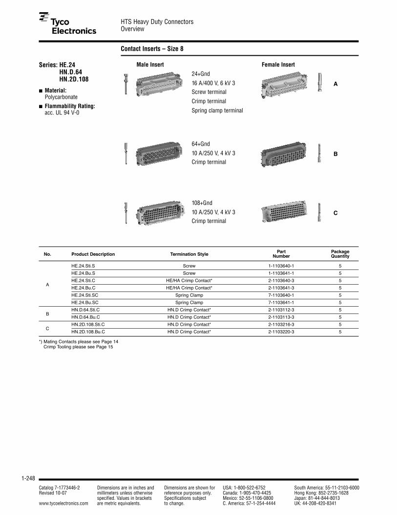
1-248
HTS Heavy Duty ConnectorsOverview
Catalog 7-1773446-2 Dimensions are in inches and Dimensions are shown for USA: 1-800-522-6752 South America: 55-11-2103-6000Revised 10-07 millimeters unless otherwise reference purposes only. Canada: 1-905-470-4425 Hong Kong: 852-2735-1628
specified. Values in brackets Specifications subject Mexico: 52-55-1106-0800 Japan: 81-44-844-8013www.tycoelectronics.com are metric equivalents. to change. C. America: 57-1-254-4444 UK: 44-208-420-8341
Contact Inserts – Size 8
24+Gnd
16 A/400 V, 6 kV 3 Screw terminal
Crimp terminal
Spring clamp terminal
A
64+Gnd
10 A/250 V, 4 kV 3 Crimp terminal
B
108+Gnd
10 A/250 V, 4 kV 3 Crimp terminal
C
Series: HE.24HN.D.64HN.2D.108
■ Material: Polycarbonate
■ Flammability Rating: acc. UL 94 V-0
Male Insert Female Insert
HE.24.Sti.S Screw 1-1103640-1 5
HE.24.Bu.S Screw 1-1103641-1 5
AHE.24.Sti.C HE/HA Crimp Contact* 2-1103640-3 5
HE.24.Bu.C HE/HA Crimp Contact* 2-1103641-3 5
HE.24.Sti.SC Spring Clamp 7-1103640-1 5
HE.24.Bu.SC Spring Clamp 7-1103641-1 5
BHN.D.64.Sti.C HN.D Crimp Contact* 2-1103112-3 5
HN.D.64.Bu.C HN.D Crimp Contact* 2-1103113-3 5
CHN.2D.108.Sti.C HN.D Crimp Contact* 2-1103216-3 5
HN.2D.108.Bu.C HN.D Crimp Contact* 2-1103220-3 5
*) Mating Contacts please see Page 14 Crimp Tooling please see Page 15
No. Product Description Termination Style Part PackageNumber Quantity

1-249
HTS Heavy Duty ConnectorsOverview
Catalog 7-1773446-2 Dimensions are in inches and Dimensions are shown for USA: 1-800-522-6752 South America: 55-11-2103-6000Revised 10-07 millimeters unless otherwise reference purposes only. Canada: 1-905-470-4425 Hong Kong: 852-2735-1628
specified. Values in brackets Specifications subject Mexico: 52-55-1106-0800 Japan: 81-44-844-8013www.tycoelectronics.com are metric equivalents. to change. C. America: 57-1-254-4444 UK: 44-208-420-8341
1
Pin and Socket Connectors
Module System HVS
To offer a maximum of flexibility and reliability witha minimum of installation or maintenance effort Tyco Electronics developedthe HVS product range(high variable system).
This system enables customers to build their ownapplication specific con-nection and due the combi-nation variety of the differentmodules customers benefitin terms of reduced costs(cost efficiency) and lessmounting space.
The HVS range comprises more than 25 different mod-ules and the particular zincframes which can then bemounted into all standardhoods and housings fromTyco Electronics. There isno tooling needed to putthe modules in and out ofthe frame due to leversnap-in technology.
Up to 6 single modulescan be used in a size 8frame whereby the cus-tomer can individuallydefine the combination ofmodules.
Signal, high current andhigh voltage, high density,Fire Wire, RJ45, USB,Coax, twisted pair, highspeed and also pressureair are only some of thedifferent connector mod-ules. According to theinsert contacts can beused individually.
In combination with the Tyco Electronics hoodsand housings IP ratings ofIP65 or even IP68 can berealised. Customers alsobenefit from EMI- and corrosion-protectiondependent on housing.
A large variety of customer specific applications com-plete the product range.
Contact Inserts Series HVS
■ High Variable System
■ Zinc Frames Size 3 to 8 (acc. to Housing)
■ For up to 6 Single Modules
Material
■ PBT
■ Flammability Rating: acc. UL 94 V-0
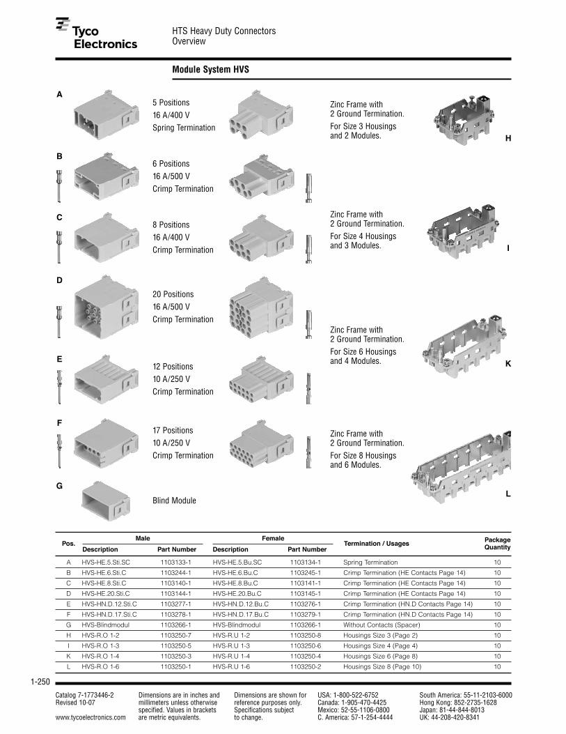
1-250
HTS Heavy Duty ConnectorsOverview
Catalog 7-1773446-2 Dimensions are in inches and Dimensions are shown for USA: 1-800-522-6752 South America: 55-11-2103-6000Revised 10-07 millimeters unless otherwise reference purposes only. Canada: 1-905-470-4425 Hong Kong: 852-2735-1628
specified. Values in brackets Specifications subject Mexico: 52-55-1106-0800 Japan: 81-44-844-8013www.tycoelectronics.com are metric equivalents. to change. C. America: 57-1-254-4444 UK: 44-208-420-8341
Module System HVS
5 Positions 16 A/400 V Spring Termination
6 Positions 16 A/500 V Crimp Termination
Zinc Frame with 2 Ground Termination. For Size 3 Housings and 2 Modules.
Zinc Frame with 2 Ground Termination. For Size 4 Housings and 3 Modules.
Zinc Frame with 2 Ground Termination. For Size 6 Housings and 4 Modules.
Zinc Frame with 2 Ground Termination. For Size 8 Housings and 6 Modules.
8 Positions 16 A/400 V Crimp Termination
20 Positions 16 A/500 V Crimp Termination
12 Positions 10 A/250 V Crimp Termination
17 Positions 10 A/250 V Crimp Termination
Blind ModuleL
K
I
H
A
B
C
D
E
F
G
Male
Description Part Number
Female
Description Part NumberPos. Termination / Usages Package
Quantity
A HVS-HE.5.Sti.SC 1103133-1 HVS-HE.5.Bu.SC 1103134-1 Spring Termination 10
B HVS-HE.6.Sti.C 1103244-1 HVS-HE.6.Bu.C 1103245-1 Crimp Termination (HE Contacts Page 14) 10
C HVS-HE.8.Sti.C 1103140-1 HVS-HE.8.Bu.C 1103141-1 Crimp Termination (HE Contacts Page 14) 10
D HVS-HE.20.Sti.C 1103144-1 HVS-HE.20.Bu.C 1103145-1 Crimp Termination (HE Contacts Page 14) 10
E HVS-HN.D.12.Sti.C 1103277-1 HVS-HN.D.12.Bu.C 1103276-1 Crimp Termination (HN.D Contacts Page 14) 10
F HVS-HN.D.17.Sti.C 1103278-1 HVS-HN.D.17.Bu.C 1103279-1 Crimp Termination (HN.D Contacts Page 14) 10
G HVS-Blindmodul 1103266-1 HVS-Blindmodul 1103266-1 Without Contacts (Spacer) 10
H HVS-R.O 1-2 1103250-7 HVS-R.U 1-2 1103250-8 Housings Size 3 (Page 2) 10
I HVS-R.O 1-3 1103250-5 HVS-R.U 1-3 1103250-6 Housings Size 4 (Page 4) 10
K HVS-R.O 1-4 1103250-3 HVS-R.U 1-4 1103250-4 Housings Size 6 (Page 8) 10
L HVS-R.O 1-6 1103250-1 HVS-R.U 1-6 1103250-2 Housings Size 8 (Page 10) 10
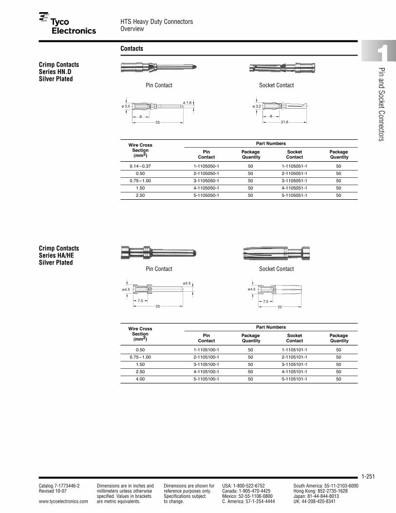
1-251
HTS Heavy Duty ConnectorsOverview
Catalog 7-1773446-2 Dimensions are in inches and Dimensions are shown for USA: 1-800-522-6752 South America: 55-11-2103-6000Revised 10-07 millimeters unless otherwise reference purposes only. Canada: 1-905-470-4425 Hong Kong: 852-2735-1628
specified. Values in brackets Specifications subject Mexico: 52-55-1106-0800 Japan: 81-44-844-8013www.tycoelectronics.com are metric equivalents. to change. C. America: 57-1-254-4444 UK: 44-208-420-8341
1
Pin and Socket Connectors
Contacts
Crimp Contacts Series HN.D Silver Plated
25
8
ø 1.6ø 3.5 ø 3.2
21.6
8
Pin Contact Socket Contact
Part Numbers
Pin Package Socket PackageContact Quantity Contact Quantity
Wire Cross Section(mm2)
0.14–0.37 1-1105050-1 50 1-1105051-1 50
0.50 2-1105050-1 50 2-1105051-1 50
0.75–1.00 3-1105050-1 50 3-1105051-1 50
1.50 4-1105050-1 50 4-1105051-1 50
2.50 5-1105050-1 50 5-1105051-1 50
Crimp Contacts Series HA/HE Silver Plated
7.5
25
ø2.5
ø4.5 ø4.5
22
7.5
Pin Contact Socket Contact
Part Numbers
Pin Package Socket PackageContact Quantity Contact Quantity
Wire Cross Section(mm2)
0.50 1-1105100-1 50 1-1105101-1 50
0.75–1.00 2-1105100-1 50 2-1105101-1 50
1.50 3-1105100-1 50 3-1105101-1 50
2.50 4-1105100-1 50 4-1105101-1 50
4.00 5-1105100-1 50 5-1105101-1 50

1-252
HTS Heavy Duty ConnectorsOverview
Catalog 7-1773446-2 Dimensions are in inches and Dimensions are shown for USA: 1-800-522-6752 South America: 55-11-2103-6000Revised 10-07 millimeters unless otherwise reference purposes only. Canada: 1-905-470-4425 Hong Kong: 852-2735-1628
specified. Values in brackets Specifications subject Mexico: 52-55-1106-0800 Japan: 81-44-844-8013www.tycoelectronics.com are metric equivalents. to change. C. America: 57-1-254-4444 UK: 44-208-420-8341
Crimping Accessories
Cable Glands
Description Part Number PackageQuantity
RSZ.HE-HN.D-HVT 1-1105851-8 1
Description Part Number PackageQuantity
AWZG-HN.D-RSZ 1102855-2 1
AWZG-HE-Q5-RSZ 1102855-7 1
Description Part Number PackageQuantity
EWZG-RSZ 1102855-6 1
Crimping Tool (with Locator and Die)
Extraction Tool (for HN.D and HE)
Hand Tools
for HE, HD, HN.D Contacts
Insertion Tool
Cable Glands Plastic – IP 68
Metric Thread
SW
PGD
HUT.M16.P M16 4 8 20 1-1102771-6 10
HUT.M20.P M20 6 12 24 2-1102771-0 10
HUT.M25.P M25 10 14 29 2-1102771-5 10
HUT.M32.P M32 13 18 36 3-1102771-2 10
HUT.M40.P M40 18 25 46 4-1102771-0 10
Description Size D D Hex Part PackagePG (min.) (max.) Number Quantity
SW
PG
Cable Glands Metal – IP 68
Metric Thread
HUT.M16.MS M16 5 10 17 1-1102770-6 10
HUT.M20.MS M20 6 12 22 2-1102770-0 10
HUT.M25.MS M25 13 18 27 2-1102770-5 10
HUT.M32.MS M32 18 25 34 3-1102770-2 10
HUT.M40.MS M40 22 32 43 4-1102770-0 10
Description Size D D Hex Part PackagePG (min.) (max.) Number Quantity