Free vibration response of two-dimensional magneto-electro-elastic laminated plates
Upload
khangminh22Category
view
5download
0
Journal of Engineering and Development, Vol.20, No. 3,march 2015, ISSN 1813- 7822
110
Stress Relaxation on Prosthetic Laminated Socket Materials
Asst. Prof. Dr. KADHIM KAMIL RESAN Dr. YASIR KHALIL IBRAHIM
SHIREEN HASAN CHALLOOB
Department of Materials Engineering, Al-Mustansiriyah University, Baghdad, Iraq
Abstract The mechanical properties of socket materials are decreasing with time because they have a time dependent nature. This research evaluated mechanical properties of the composite materials that used to fabricate prosthetic sockets. Stress relaxation, the time-dependent property, was evaluated from creep test by testing two types of socket materials at 50 P
oPC and
by using Burger viscoelastic model; the equation of stress relaxation modulus was obtained and it found that the stress relaxation modulus decreasing with time. In addition a pressure between the residual limb and the prosthetic below knee socket measured by using F-socket system. Besides this study include a numerical approach to find the deformation distribution on socket that resulting from decreasing in stress relaxation modulus by using ANSYS workbench 15, it found the socket materials were deformed with time, the deformation of material A was increased from (2.03 to 24.4 mm) during 150 minute, while material B increased from (5.2 to 31.2 mm). The difference in resistance to deformation in the socket materials due to the types and numbers of reinforcement used in these materials.
االصطناعياالسترخاء في المواد المركبة للوقب إجهاد
د كــاظم كــامل رســن.م.شــيرين حســن جـــلوب أ
ياسر خليل ابراهيم. د
الخالصةيدرس . تقل الخصائص الميكانيكية لمواد الوقب مع الوقت وذلك الن هذه المواد تمتلك خصائص اعتمادية على الزمن
خاصية تعتمد على (إجهاد االسترخاء . هذا البحث الخصائص الميكانيكية للمواد المركبة الداخلة في صناعة الوقب الصناعيP 50ن من الوقب عند درجة حرارة ُحلل من خالل فحص الزحف وذلك بفحص نوعا) الزمن
0P م و باستخدام نموذج بركر
باالضافة فان . تم الحصول على معادلة معامل اجهاد االسترخاء ووجد ان معامل اجهاد االسترخاء يقل مع الزمن، للزوجةاسة تضمنت باالضافة فان هذه الدر.الضغط بين الساق المبتورة والوقب الصناعي تم قياسة باستخدام جهاز االف سوكت
الطريقة العددية اليجاد توزيع التشوه على الوقب الناتج من انخفاض معامل اجهاد االسترخاء وذلك باستخدام برنامج دقيقة بينما 150مم خالل 24.4الى 2.03ووجد ان مواد الوقب تتشوه مع الزمن وان التشوه لمادة أ يزداد من . االنسز
االختالف في مقاومة المواد للتشوه يعزى الى انواع وعدد . مم خالل نفس الزمن 31.2الى 5.2التشوه لمادة ب تزداد من . المواد المقوية المستخدمة في صناعة هذه المواد

Journal of Engineering and Development, Vol.20, No. 3,march 2015, ISSN 1813- 7822
111
1- Introduction
Prosthetic sockets serves as the connection between an amputee’s residual limb and the prosthetic components that enable him or her to walk [1]. An amputation of a lower limb is most commonly occurred due to landmines or limb diseases. The two most often amputation procedures are truncation of the femur bone above the knee (AK) and truncation of the tibia bone below the knee (BK). The BK socket that supports the residual limb (or stump) is normally custom built to the individual's anthropometric specifications [2].All major lower-limb prostheses are constructed with three main parts: the socket, the leg section, and the foot [3]. Materials and mechanical properties of the prosthetic socket were studied by investigators. Jweeg, et al. [4] examined the effect of increasing and decreasing of perlon and fiber glass layers on mechanical and physical properties by subjecting sample of lamination to tensile and flexural test. Ismail, et al. [2] studied the effect of temperature in hot climate countries on a socket made of composite materials during the gait. They concluded that as temperature rises, the mechanical properties decrease over time due to creep which causes a socket failure due to fatigue and creep interaction. A report by Smith [5] was written to determine the typical laminations which would be manufactured and tested. He attempted to vary the fiber /resin ratio by increasing and decreasing the amount of resin used. The study of Gerschutz, et al. [1]
The Prosthetic Socket manufactures from polymer or polymer-based composite materials (polypropylene sheets or laminate socket) P
[6]P. As a result of high temperatures in summer and
the movement of limbs during amputee walking the mechanical properties of socket materials is decreasing with time, because these materials have a time dependent properties. This research studied the effect of stress relaxation and creep with time at the socket materials and how socket materials deform with time as a result of the effect of stress relaxation. 2. Theoretical work Almost, all materials possess viscoelastic properties. Deformation in polymer is not only a function of applied load, but it also depends on time (loading rate) P
[7]P.Viscoelasticity is the
study of materials which exhibit features of both elastic and viscous behavior. Elastic materials deform instantaneously when a load is applied, and remembers its original conjuration, returning their instantaneously when the load is removed. On the other hand, viscous materials do not show such behavior; instead they exhibit time dependent behavior. While under stress, a viscous body strains at a constant rate, and when its load is removed, the material fails to return to its initial conjuration P
[8]P.P
PThe most characteristic features of
viscoelastic materials are that they exhibit a time dependent strain response to a constant stress (creep) and a time dependent stress response to a constant strain (relaxation) P
[9]P.
The stress strain time relation of viscoelastic material has been analyzed with the aid of mechanical models where the stress and strain instead of force and deformation of model are be used. All linear viscoelasticity models are made up of linear spring and linear viscoelastic dashpot P
[10]P.One viscoelastic model, called the Maxwell model predicts behavior akin to a
spring (elastic element) being in series with a dashpot (viscous element).This model is intended to model a combination of elastic deformation and viscous flow, while the Voigt

Journal of Engineering and Development, Vol.20, No. 3,march 2015, ISSN 1813- 7822
112
model places these elements in parallel
evaluated tensile and impact properties of the current state-of-the-art materials used to fabricate prosthetic check sockets, copolymer sockets, and definitive laminated sockets.
[8]. In Burgers model the Maxwell and Kelvin model are connected in series, and is the most accurate model that it predicates creep and stress relaxation behaviors [11]
ԑ = ԑ
. This research used the Burgers model which is shown in Fig.1 where the Maxwell and Kelvin model are connected in series. The total strain can be writing as following:
1 + ԑ2 + ԑ3
In which: ԑ: is the total strain in Burgers four -element model, ԑ R1R: is the strain in spring for Maxwell model, ԑ R2R: is the strain in dashpot for Maxwell model, ԑR3: Ris the strain in Kelvin model. That is: ԑ1 = σ
E1R R(2)
ԑ̇2 = ση1
(3)
ε̇3 + 𝐸𝐸2η2
ԑ3 = ση2
R R(4)
From Eq.1 and Eq.4, the following second order differential equation between stress and strain can be expressed as:
σ + � η1 𝐸𝐸1
+ η1𝐸𝐸2
+ η2𝐸𝐸2
� σ̇ + η1η2 𝐸𝐸1 𝐸𝐸2
σ̈ = η1 ԑ̇ + 𝜂𝜂1𝜂𝜂2 𝐸𝐸2
ԑ̈ (5) The creep behavior of Burgers four – element model under constant stress (σ = σRoR) can be obtained from Eq.5 by solving this second order differential equation with two initial conditions: At t=0; ԑ= ԑR1 R= σo
𝐸𝐸1 , ԑR2 R= ԑR3R = 0 (6)
ԑ̇ = σoη1
+ σoη2
(7)
Fig.1. Burger Model with the behavior of Creep and Recovery [10]
The Laplace transformation method of solving differential equation is used to solve Eq.5 as follows: ԑ(t) = σo
𝐸𝐸1 + σo
η1 t + σo
𝐸𝐸2 ( 1 − 𝑒𝑒−
𝐸𝐸2𝑡𝑡 η2� ) (8)
Thus, equation (5) becomes: σ + P1σ̇ + P2 σ̈ = q1 ԑo δ(t) + q2 ԑo 𝑑𝑑δ(𝑡𝑡) 𝑑𝑑𝑡𝑡
(9)
Where: P1 = � η1𝐸𝐸1
+ η1𝐸𝐸2
+ η2𝐸𝐸2
�, 𝑃𝑃2 = η1η2 𝐸𝐸1 𝐸𝐸2
, qR1 R= ηR1R and qR2R = η1η2 𝐸𝐸2
. Taking Laplace transformation of Eq.9 yields:
Journal of Engineering and Development, Vol.20, No. 3,march 2015, ISSN 1813- 7822
113
σ(s) + pR1Rs σ(s) + pR2R s P
2P σ(s) = qR1R εRoR + qR2 RεRoR s
(10) Solving for σ(s): σ(s) = ԑo (𝑞𝑞1+𝑞𝑞2 )
1+𝑃𝑃1 𝑆𝑆+𝑃𝑃2𝑆𝑆 (11)
Expanding Eq.11 by partial fractions and performing the inverse Laplace transformation yields the stress relaxation P
[9]P:
σ(t) = ԑo𝐴𝐴
[ (qR1R –qR2R rR1R ) 𝑒𝑒−𝑟𝑟1𝑡𝑡 -( qR1R –qR2R rR2R ) 𝑒𝑒−𝑟𝑟2𝑡𝑡 ] (12) Where: rR1R = 𝑃𝑃1−𝐴𝐴
2𝑃𝑃2 , rR2 R= 𝑃𝑃1+𝐴𝐴
2 𝑃𝑃2 , A = �𝑃𝑃1
2 + 4𝑃𝑃2 The stress relaxation modulus can be written as: E(t) = σ(t)
εo = 1
A [ (qR1R –qR2R rR1R ) e−r1t - ( qR1R – qR2R rR2R ) e−r2t ] (13)
The material constant (ER1R, ER2R, ηR1R, ηR2R) may be determined from the experimental data for creep test in linear viscoelasticity behavior. They are calculated according to the method explained as follows:
1- Determination ηR1R: The slop of creep function at an infinite time (t=tR1R) represent (tan B). From curve fitting B can be measured and ηR1R can be calculated from the following equation P
[10]P:
𝜀𝜀 .(𝑡𝑡1 ) = 𝜎𝜎0𝜂𝜂1
= tan𝐵𝐵 (14) Where: 𝜀𝜀 .(𝑡𝑡1 ) = The slope of Eq.8 at (t=tR1R)
2- Determination ηR2R: The creep rate starts at t=0 with finite value. By measuring, the value of ηR2R can be evaluated from the following equation:
𝜀𝜀 .(0) = � 1𝜂𝜂1
+ 1𝜂𝜂2�𝜎𝜎𝑜𝑜 (15)
3- Determination ER1,RER2R : From creep curve Fig.1 , the initial creep strain is P
[10]P:
ε (0) = OA =𝜎𝜎𝑜𝑜𝐸𝐸1
(16 ) And also: AĂ = 𝜎𝜎0
𝐸𝐸2
(17) 3. Modeling of Prosthetic Socket Using ANSYS The finite element method (FEM) is now widely used in a variety of fields in engineering and science. The analysis of socket models was achieved by FEM software to compute the equivalent modulus stress and temperature. In this work, the patient socket was drawn using AutoCAD 2014 program and then exported the drawing to ANSYS program. Finite element analysis was done with aid of ANSYS Workbench 15 software that used as a numerical tool to illustrate the effect of the decreasing of stress relaxation modulus in a structure element to determine the deformation. The meshing process has been done by choosing the volume then the shape of element was selected as tetrahedron (Automatic meshing), as shown in Fig.2.

Journal of Engineering and Development, Vol.20, No. 3,march 2015, ISSN 1813- 7822
114
(1)
Fig.2 The model of below knee socket with mesh
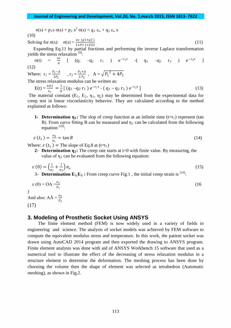
The load which used in the ANSYS Workbench software will be fixed support at the adapter of socket, while interface pressure was distributed according to particular positions. The total number of elements (solid, brick 8node 45) was (18719) with total number of nodes of (38142). 4. Experimental Analysis 4.1 Materials This research used composite materials which are used in large scale in rehabilitation centers; these composite materials contain perlon, n-glass, and/or fiberglass as a reinforcement and acrylic as a resin with hardener materials. The method of preparation of composite specimen is called vacuum method which prevents cavities or defects and it is as follows: 1- At first stage, the aluminum negative mold is made, in order to insure that surface of the final positive mold is smooth and no defects. The aluminum mold have dimensions of (10, 10, 20) cm Fig.3A.Preparing the positive mold by pouring the plaster of paris into the negative aluminum mold which contains steel Fig.3B. 2- Soaking the PVA (polyvinyl acetate) bag for 10 min and covering the positive block (polyvinyl acetate) Fig.3C. Addressing the required numbers of Perlon with fiberglass and/or n-glass layers Fig.3D. And Covering the block by a second PVA Fig.3E. 3- The acrylic resin with hardener are stirred slowly for (1-2) minute. With using the vacuum device, acrylic material is added and let the composite to cure Fig.3F and Fig.3G.After the resin curing, a cubic composite material is obtained which it will be cut according to required dimensions of specimens Fig.3H. The manufacturing steps repeated for two times with other different layers and at different rehabilitation centers. Two types of socket materials are used in this work as shown in Table (1):
Journal of Engineering and Development, Vol.20, No. 3,march 2015, ISSN 1813- 7822
115
Fig.3. Steps of preparing socket materials
Table1. Types of socket materials
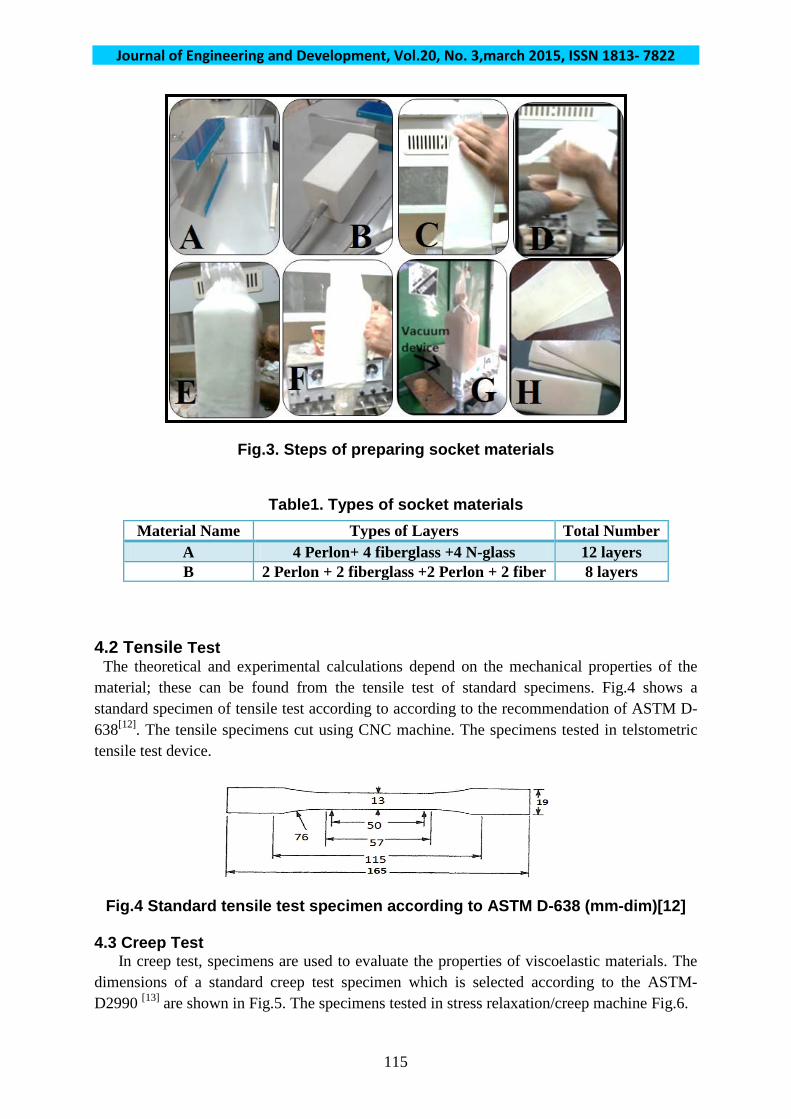
4.2 Tensile Test The theoretical and experimental calculations depend on the mechanical properties of the material; these can be found from the tensile test of standard specimens. Fig.4 shows a standard specimen of tensile test according to according to the recommendation of ASTM D-638P
[12]P. The tensile specimens cut using CNC machine. The specimens tested in telstometric
tensile test device.
Fig.4 Standard tensile test specimen according to ASTM D-638 (mm-dim)[12] 4.3 Creep Test In creep test, specimens are used to evaluate the properties of viscoelastic materials. The dimensions of a standard creep test specimen which is selected according to the ASTM-D2990 P
[13]P are shown in Fig.5. The specimens tested in stress relaxation/creep machine Fig.6.
Material Name Types of Layers Total Number A 4 Perlon+ 4 fiberglass +4 N-glass 12 layers B 2 Perlon + 2 fiberglass +2 Perlon + 2 fiber 8 layers

Journal of Engineering and Development, Vol.20, No. 3,march 2015, ISSN 1813- 7822
116
Fig.5. Standard creep test specimen [14].
Fig.6 Stress relaxation/creep machine 4.4 Interface Pressure between Socket and Residual Limb Socket interface pressure is essential in prosthetics and plays an important role in the control of function and delivery of comfort and the strength of the prosthetic parts. The gait could be described as a dynamic system, where the reaction force and the surface of contact changes according to the cadence of the patient. During the gait phase, from the back of heel to the lifting of the forefoot, there are forces widely higher than the corporal weight and also generate foot plantar pressure more elevated than stand on natural and relaxed position P
[14]P.
This force affects on the socket and other prosthetic parts. F-Scan pressure measurement System sensors were used in this study to measure the interface pressure between the stump and socket. This sensor is made up of 960 individual pressure sensing locations, which are referred to as ‘sensing elements’, ‘sensels’, or ‘cells’. The sensels are arranged in rows and columns on the sensor. F-socket sensors were carefully calibrated before the test. At the beginning of the test, the sensors were placed on the residual limb covering the anterior of the limb; the patient can then put on the socket Fig.7. When the patient starts to move the devise starts to record this movement. During the movement of patient, the devise was records the pressure.

Journal of Engineering and Development, Vol.20, No. 3,march 2015, ISSN 1813- 7822
117
Fig.7 F-socket device with patient 5. Experimental Results and Discussion 5.1 Tensile test results The results of the mechanical properties (tensile test) of the socket material are as shown in Table 2 .
Table2. Mechanical properties of socket materials Material σRyR (MPa) σRult R(MPa) E (MPa)
A 119.5 140.65 1812 C 26.5 36.76 1292.8
5.2 Creep Test Results The materials tested in creep/stress relaxation machine with stress (7 MPa) for (200 minute) at temperature (50 P
oPC).The result curve from creep test of the material A with
specimen thickness (5.3 mm) and applied force (178.08 N) will be shown as follows in Fig.8 and the result curve of the material B with thickness (3.39 mm) with the applied force (113.9 N) are shows in Fig.9. From Fig.8 and Fig.9 of creep test, the creep curve stages (primary and secondary stages) of groups can indicate the strength of materials. The primary and secondary stages of material A have lower deflection than material B. This means that the group A has high creep resistance.

Journal of Engineering and Development, Vol.20, No. 3,march 2015, ISSN 1813- 7822
118
Fig.8 Creep behavior curve of group A Fig.9 Creep behavior curve of
groupB 5.3 The creep compliance Results The creep compliance equation is evaluated according to Burger four elements, where Eq.8 with Fig.1 is used here. From Fig.1 and Fig.8 with specimen length (38.1mm) and stress (σRo R= 7 MPa). The material constant of material A was determined from the experimental data of creep test as shows in Table3 and Table 4,and from Fig.1 and Fig.9 with specimen length (38.1mm) and stress (σRo R= 7 MPa) The material constant of material B was determined from the experimental data of creep test as shows in Table5 and Table 6:
Table3. Strain at the different points from creep curve (Material A)
Table4. The material constant determined from the experimental data of creep
test (Material A) Equation Symbol Result tan B = 3.57*10P
-5P= 𝜎𝜎𝜂𝜂1
ηR1 R = 196078 MPa.min
tan 𝛼𝛼 = 2.5 * 10P
-4 P= σRo R[ 1
𝜂𝜂1+ 1
𝜂𝜂2 ] ηR2 R= 32664 MPa.min
OA = 2.335 *10P
-3P = 𝜎𝜎𝑜𝑜
𝐸𝐸1 ER1 R = 2997 MPa
AĂ =2.62 * 10P
-5P = 𝜎𝜎0
𝐸𝐸2 ER2 R= 267175 MPa
Table5. Strain at the different points from creep curve (material B)
Point Deflection mm Strain OA 0.089 2.335 * 10-3 A Ă 1 * 10P
-3 2.62 * 10-5
Point Deflection mm Strain OA 0.229 6.01 * 10P
-3 A Ă 0.025 6.56 * 10P
-4

Journal of Engineering and Development, Vol.20, No. 3,march 2015, ISSN 1813- 7822
119
Table6. The material constant determined from the experimental data for creep
test (Material B) The creep compliance equations: Group A: D(t) = 3.2336*10P
-4P + 5.1 *10P
-6P t + 3.74 *10 P
-6 P(1- 𝑒𝑒−8.17 𝑡𝑡 )
Group B: D(t) = 8.59 *10P
-4P + 1.33 *10P
-5P t + 9.37 *10 P
-5 P(1- 𝑒𝑒−3.1 𝑡𝑡 )
Fig.10 shows the graph of these functions.
Fig.10. Creep compliance behavior of the two materials
From Fig.10, it showed that all materials are affected by creep and the creep compliance of all materials increase linearly with time; this is due to viscoelastic behavior. Although the materials tested at the same condition, the creep compliance of group B increased at high rate than A. 5.3.2 The stress relaxation modulus results A relation between the creep compliance and relaxation stress modulus can be established. By using the constants in Table 4 the other parameters for group A can be calculated as follows. By using the constants in Table 6 the other parameters can be calculated as follows:
Equation Symbol Result tan B = 9.33*10P
-5P= 𝜎𝜎𝜂𝜂1
ηR1 R = 75026 MPa.min
tan 𝛼𝛼 = 2.13 * 10P
-3 P= σRo R[ 1
𝜂𝜂1+ 1
𝜂𝜂2 ] ηR2 R= 3436.9 MPa.min
OA = 6.01 *10P
-3P = 𝜎𝜎𝑜𝑜
𝐸𝐸1 ER1 R = 1164 MPa
AĂ =6.65 * 10P
-4P = 𝜎𝜎0
𝐸𝐸2 ER2 R= 10670 MPa

Journal of Engineering and Development, Vol.20, No. 3,march 2015, ISSN 1813- 7822
120
Table7. Constants to calculate stress relaxation modulus (Material A)
Equation Result P1 57.17 MPa = 𝜂𝜂1
𝐸𝐸1+ 𝜂𝜂1
𝐸𝐸2+ 𝜂𝜂2
𝐸𝐸2
P2 6.897 min= 𝜂𝜂1 𝜂𝜂2 𝐸𝐸1 𝐸𝐸2
2
q1 = η 196078 MPa.min 1 q2 20670.9 MPa.min = 𝜂𝜂1 𝜂𝜂2
𝐸𝐸2
2
A= �𝑝𝑝22 − 4 𝑝𝑝2 56.928
r1 0.0175 = 𝑝𝑝1 −𝐴𝐴2𝑃𝑃2
r2 8.27 = 𝑃𝑃1+𝐴𝐴2𝑃𝑃2
Table8. Constants to calculate stress relaxation modulus (Material B)
The creep relaxation stress modules of the two materials are according to Eq.13: Group A: E(t) = 3437.95 𝑒𝑒−0.0175 𝑡𝑡 − 27 𝑒𝑒− 8.27 𝑡𝑡 Group B: E(t) = 1048.83 𝑒𝑒−0.014 𝑡𝑡 + 113.84 𝑒𝑒−3.44𝑡𝑡 Fig.11 shows the graph of these functions.
Fig.11 Stress relaxation modulus with time of the two materials From Fig.11, it showed that all materials are affected by stress relaxation and the stress relaxation modulus decreased with time. This mean that these materials loss their strength and
Equation Result P1 71.8 MPa = 𝜂𝜂1
𝐸𝐸1+ 𝜂𝜂1
𝐸𝐸2+ 𝜂𝜂2
𝐸𝐸2
P2 20.76 min= 𝜂𝜂1 𝜂𝜂2 𝐸𝐸1 𝐸𝐸2
2
q1 = η 75026 MPa.min 1 q2 24166.5 MPa.min = 𝜂𝜂1 𝜂𝜂2
𝐸𝐸2
2
A= �𝑝𝑝22 − 4 𝑝𝑝2 71.21
r1 0.014 = 𝑝𝑝1 −𝐴𝐴2𝑃𝑃2
r2 3.44 = 𝑃𝑃1+𝐴𝐴2𝑃𝑃2

Journal of Engineering and Development, Vol.20, No. 3,march 2015, ISSN 1813- 7822
121
stiffness with time. The resistance to stress relaxation is different from a material to another. Curve showed that material group A has higher resistance to decreasing in modulus than group C. 5.5.1 Interface Pressure Result between Socket and Residual Limb The pressure resulted by patient on socket is determined by F-socket device that it was reached the peak value to about 218 KPa as shown in Fig.12A. The distribution of this stress had been determined by using an ANSYS program Workbench 15 software as show in Fig.12B.
Fig.12 Interface pressure between socket and stump 5.5.2 The Deformation on Socket materials Results The deformation on socket materials must not increase more than 10 % because the deformation is causing sagging of socket. The sagging of socket can cause contacting between stump (amputation region) and socket that result the pain of patient. In this study by using ANSYS software program the results show that all groups deformed at certain scale as a result in the decreasing of stress relaxation modulus. Material A has the high strength and high resistance to deformation as shows from Fig.13 and group B has higher deformation as show from Fig.14. From Fig.15 it indicate that group A has higher resistance to deformation .This high resistance was due to the number and type of reinforcement layers. This type of reinforcements gives to this materials high strength, stiffness and resistance to deformation, so the socket that manufacturing from this materials has optimum properties. This means that to produce a perfect socket with good properties, it must choose the type of reinforcement materials that resistance all type of deformation.

Journal of Engineering and Development, Vol.20, No. 3,march 2015, ISSN 1813- 7822
122
Fig.13 Deformation of material A at different time
Fig.14 Deformation of material B at different time
Fig.15 Deformation curve of materials A and B with time

Journal of Engineering and Development, Vol.20, No. 3,march 2015, ISSN 1813- 7822
123
6. Conclusion 1- Martial A (4 Perlon+ 4 fiberglass +4 N-glass) has lower elongation with higher strength high creep resistance than material B (2 Perlon + 2 fiberglass +2 Perlon + 2 fiber) although these materials tested at same conditions. 2- The stress relaxation modulus of the material B has high decreasing rate with time than A this means that material A has high stress relaxation resistance. 4- F- socket system was more successful and accurate method to measure the distribution of stress on socket than old methods. From ANSYS program results, all materials deformed with time as a result of the drop in the stress relaxation modulus of these materials. It found that the material of group B has high deformation compared with other and the materials group A have the lower deformation. This means the materials groups A have high resistance to stress relaxation, deformation and creep effects. Nomenclature D(t) Creep compliance E(t) Stress relaxation modulus[MPa] E1, E2, η1, η2
t: time [minute] Materials constants
σy Yield stress [MPa] Reference 1. Gerschutz M. J., Haynes M. L.; Nixon D. M., Colvin J. M. "Tensile strength and Impact Resistance Properties of Materials Used in Prosthetic Check sockets, Copolymer Sockets, and Definitive Laminated Sockets " JRRD, Vol. 48, No. 8, 2011. 2- Ismail M. T. , Jweeg M. J. and Resan K. K. “Study of Creep-Fatigue Interaction in the Prosthetic Socket below Knee” Innovative Systems Design and Engineering , Vol.4, No.5, 2013. 3- Herbert N., Simpson D., Spence W. D., Ion W., “A Preliminary Investigation into The Development of 3-D Printing of Prosthetic Sockets” JRRD, Vol. 42, No. 2, 2005. 4- Jweeg M.J., Hasan S.S. and Chiad J.S. “Effects of Lamination Layers on the Mechanical Properties for Above Knee Prosthetic Socket” Eng.&Tech.Journal,Vol.27,No.4,2009. 5- smith k. “Laminated Socket Properties ” monash rehabilitation technology research unit, Australia ‘s international university, Australia, 1998. 6. Resan K. K. "Analysis and Design Optimization of Prosthetic Below Knee" Ph.D. thesis, Mechanical Engineering Department, University of Technology, Baghdad, 2007. 7. Golzar M., Khalighi A.R. "Tensile and Relaxation Properties of PA6/Nanoclay Nanocomposites" Proceedings of the World Congress on Engineering and Computer Science, Vol. 2, San Francisco, USA, 2010. 8. Bruschi G., Nishioka T., Tsang K., Wang R. " Polymer Behavior Under Applied Stress" January 31, 2003. 3-D printing of prosthetic sockets” JRRD, Vol. 42, NO. 2, 2005. 9. Crawford R.J. “Plastics Engineering" Third Edition , 1998.

Journal of Engineering and Development, Vol.20, No. 3,march 2015, ISSN 1813- 7822
124
10. Hussein S. k. “Linear and Nonlinear Behavior of Viscoelasticity Thin Plates Subjected to Uniform Distributed Loading " Ph. thesis in mechanical engineering ,Al-Mustansiriya university, Iraq, 2006. 11. Nour M. R. “Creep and Stress Relaxation Behavior of Polypropylene Metallocene-Prepared Polyethylene and their Blend “ Iranian Journal of Chemical Engineering ,Vol. 9, No. 1 ,2012 . 12. American Society for Testing and Materials Information Handling Services, 2000"Standard Test Method for Tensile Properties". 13. Standard Creep test of plastics ASTM-D2990. 14. Mejia E., Aviles O., Hernandez J., Jimenez S. and Caldas O. “Design Process OF A Mechatronic Device For Measuring The Stump Stresses on A Lower Limb Amputee “ 22nd International Congress of Mechanical Eng
Copyright © 2022 FDOKUMEN