MITC nite elements for laminated composite plates
32
INTERNATIONAL JOURNAL FOR NUMERICAL METHODS IN ENGINEERING Int. J. Numer. Meth. Engng 2001; 50:707–738 MITC nite elements for laminated composite plates G. Alfano 1 , F. Auricchio 2 , L. Rosati 1; *; † and E. Sacco 3 1 Dip. di Scienza delle Costruzioni; Univ. dli. Napoli “Federico II ”; Italy 2 Dip. di Meccanica Strutturale; Univ. di Pavia; Italy 3 Dip. di Meccanica; Strutture; Territorio ed Ambiente; Univ. di Cassino; Italy SUMMARY Within the framework of the rst-order shear deformation theory, 4- and 9-node elements for the analysis of laminated composite plates are derived from the MITC family developed by Bathe and coworkers. To this end the bases of the MITC formulation are illustrated and suitably extended to incorporate the laminate theory. The proposed elements are locking-free, they do not have zero-energy modes and provide accurate in-plane deformations. Two consecutive regularizations of the extensional and exural strain elds and the correction of the resulting out-of-plane stress proles necessary to enforce exact fulllment of the boundary conditions are shown to yield very satisfactory results in terms of transverse and normal stresses. The features of the proposed elements are assessed through several numerical examples, either for regular and highly distorted meshes. Comparisons with analytical solutions are also shown. Copyright ? 2001 John Wiley & Sons, Ltd. KEY WORDS: composites; plates; nite elements 1. INTRODUCTION Fibre-reinforced composite plates and shells are nding an increasing interest in engineering applications. Consequently, ecient and robust computational tools are required for the analy- sis of such structural models. As a matter of fact, a large amount of laminate nite elements have been developed and incorporated in most commercial codes for structural analysis. Finite elements for the analysis of laminated composite plates have been derived by using dierent laminate theories proposed in the literature, see References [1; 2] and references cited therein; such theories are usually referred to as equivalent single layer (ESL), layerwise and three dimensional. In the context of the ESL theory, the simplest one is the classical laminate theory (CLT) which neglects the shear deformation in the laminate thickness. However, at structures made of * Correspondence to: L. Rosati; Dipartimento di Scienza delle Costruzioni; Universit a di Napoli “Federico II”; Via Claudio 21; 80124 Napoli; Italy † E-mail: [email protected] Contract=grant sponsor: National Council of Research (CNR) Contract=grant sponsor: Italian Ministry of University and Research (MURST) Received 22 February 1999 Copyright ? 2001 John Wiley & Sons, Ltd. Revised 9 March 2000
Transcript of MITC nite elements for laminated composite plates

INTERNATIONAL JOURNAL FOR NUMERICAL METHODS IN ENGINEERINGInt. J. Numer. Meth. Engng 2001; 50:707–738
MITC �nite elements for laminated composite plates
G. Alfano1, F. Auricchio2, L. Rosati1;∗;† and E. Sacco3
1Dip. di Scienza delle Costruzioni; Univ. dli. Napoli “Federico II ”; Italy2Dip. di Meccanica Strutturale; Univ. di Pavia; Italy
3Dip. di Meccanica; Strutture; Territorio ed Ambiente; Univ. di Cassino; Italy
SUMMARY
Within the framework of the �rst-order shear deformation theory, 4- and 9-node elements for the analysis oflaminated composite plates are derived from the MITC family developed by Bathe and coworkers. To this endthe bases of the MITC formulation are illustrated and suitably extended to incorporate the laminate theory.The proposed elements are locking-free, they do not have zero-energy modes and provide accurate in-planedeformations. Two consecutive regularizations of the extensional and exural strain �elds and the correctionof the resulting out-of-plane stress pro�les necessary to enforce exact ful�llment of the boundary conditionsare shown to yield very satisfactory results in terms of transverse and normal stresses. The features of theproposed elements are assessed through several numerical examples, either for regular and highly distortedmeshes. Comparisons with analytical solutions are also shown. Copyright ? 2001 John Wiley & Sons, Ltd.
KEY WORDS: composites; plates; �nite elements
1. INTRODUCTION
Fibre-reinforced composite plates and shells are �nding an increasing interest in engineeringapplications. Consequently, e�cient and robust computational tools are required for the analy-sis of such structural models. As a matter of fact, a large amount of laminate �nite elements havebeen developed and incorporated in most commercial codes for structural analysis.Finite elements for the analysis of laminated composite plates have been derived by using
di�erent laminate theories proposed in the literature, see References [1; 2] and references citedtherein; such theories are usually referred to as equivalent single layer (ESL), layerwise and threedimensional.In the context of the ESL theory, the simplest one is the classical laminate theory (CLT)
which neglects the shear deformation in the laminate thickness. However, at structures made of
∗Correspondence to: L. Rosati; Dipartimento di Scienza delle Costruzioni; Universit�a di Napoli “Federico II”; Via Claudio21; 80124 Napoli; Italy
†E-mail: [email protected]
Contract=grant sponsor: National Council of Research (CNR)Contract=grant sponsor: Italian Ministry of University and Research (MURST)
Received 22 February 1999Copyright ? 2001 John Wiley & Sons, Ltd. Revised 9 March 2000

708 G. ALFANO ET AL.
�bre-reinforced composite materials are characterized by non-negligible shear deformations in thethickness since the longitudinal elastic modulus is much higher than the shear and the transversalmoduli; hence the use of a shear deformation laminate theory is recommended. The extension ofthe Reissner [3] and Mindlin [4] model to the case of laminated anisotropic plates is known as�rst-order shear-deformation theory (FSDT) [5; 6], and accounts for the shear deformation in thethickness in the simplest way. This approach gives satisfactory results for a wide class of structuralproblems, even for moderately thick laminates; moreover, due to computational e�ciency, it iscurrently used in large-scale computations typical of industrial applications.More sophisticated laminate theories are the layerwise ones [7]. They lead to accurate results,
especially for very thick laminates [8–11] and are particularly useful for analysing local e�ects[12; 13]. On the other hand, �nite element formulations for layerwise theories are expensive interms of CPU time.In other words the FSDT provides a good compromise between numerical accuracy and com-
putational burden. In fact, a current research topic concerns the development of e�ective �niteelements for laminated plates and shells, within the framework of the FSDT, which are able toproperly describe the structural behaviour in terms of displacements and stresses. The present studyis a contribution in this direction and refers to the case of laminated composite plates under thehypotheses of linear elasticity, small strains and displacements.Two basic issues have to be properly addressed in the formulation of laminated plate elements
based on the FSDT: locking and a satisfactory evaluation of the stresses.Several locking-free plate and laminate elements based on the FSDT have been proposed in
the literature. The �rst elements exploited the selective reduced integration within a displacementformulation [14; 15]. This approach, equivalent to some special mixed formulations [16], presentshowever pathologies like spurious zero-energy modes [17]. Additional plate and laminate elementsare based on mixed formulations obtained by adding internal modes to interpolate the stress re-sultants and to enhance the kinematic �elds [18; 19]. Excellent numerical performances are thenachieved at the expense of an increased computational burden. For instance, in References [18; 19]locking is avoided by introducing four internal bubble modes for the rotation �eld, four internallinear modes interpolating the shear forces and special linked shape functions relating the transversedisplacement �eld to the nodal rotations.In the FSDT, the issue concerning the evaluation of the stresses presents two separate aspects.
Actually, while the computation of the in-plane stresses can be generally considered as satisfac-tory, the recovery of the out-of-plane transverse and normal stresses represents a critical aspect,although this usually occurs also for more re�ned ESL higher-order and layerwise theories. Infact, the constitutive law provides unacceptable layerwise constant values for the transverse shearstresses and would leave the out-of-plane normal stress unde�ned. Accurate values of the trans-verse shear stresses as well as of the out-of-plane normal stress are recovered only by using thethree-dimensional di�erential equilibrium equations [20]. Accordingly, second and third derivativesof the displacement and rotation �elds are required, a circumstance which usually leads to lack ofaccuracy in �nite element models since interpolation functions do not satisfy the required continuityconditions. To overcome this di�culty the enhanced modes technique [21] has been successfullyemployed in Reference [19] to derive a 4-node laminated �nite element. This technique providedgood results in terms of shear stresses calculated by a direct use of the equilibrium equation, butresulted in an increase of computational e�ort.In this paper we address the family of MITC elements (mixed interpolated tensorial compo-
nents) proposed in References [22–24], since it leads to a very e�ective solution procedure for
Copyright ? 2001 John Wiley & Sons, Ltd. Int. J. Numer. Meth. Engng 2001; 50:707–738

LAMINATED COMPOSITE PLATES 709
homogeneous plates. An extension of the MITC plate elements to the case of composite laminateshas been �rst proposed in Reference [25]. Herein we present 4- and 9-node composite laminatedMITC plate elements with an investigation on their numerical performances.In particular a new procedure is proposed for the evaluation of the out-of-plane stresses. It is
based on a regularization of the extensional and exural strain �elds obtained by projecting ontothe space of continuous �elds, through a least-square technique [15], the �nite element solutiontypically discontinuous at the interelement boundary.Speci�cally, one regularization procedure is su�cient to provide satisfactory values of the trans-
verse shear stresses while a further projection of the derivatives of the extensional and exuralstrains is necessary to evaluate the out-of-plane normal stresses.The outline of the paper is as follows. In Section 2 the �rst-order shear-deformation theory
for composite laminated plates is recalled in a form suitable for the ensuing developments. Thenthe derivation of the out-of-plane stresses via the di�erential equilibrium equations is addressed inSection 3. The variational derivation of the MITC elements and their implementation are outlinedin Section 4 while the post-processing procedure for recovering the out-of-plane stresses from the�nite element solution is illustrated in Section 5. Numerical results are presented in Section 6; theyshow the good convergence properties of the MITC laminate elements as well as the excellentaccuracy entailed by the proposed procedure in terms of the out-of-plane stresses. In particularaccuracy turns out to be comparable with the one obtained by integrating the equilibrium equationsfor the exact two-dimensional solution of the FSDT. In this respect we remind that, for moderatelythick plates, the transverse and the normal out-of-plane stresses evaluated in this way are in goodagreement with the exact three-dimensional solution.In order to simplify the notation we will assume throughout the paper that Greek indices range
between 1 and 2, indices i and j range between 1 and 3 and that summation must be performedon repeated indices, unless otherwise speci�ed.
2. FIRST-ORDER LAMINATE THEORY (FSDT)
Let us consider a laminated composite plate de�ned by
V= {(x1; x2; x3) ∈ R3=x3 ∈ (−h=2; h=2); (x1; x2) ∈ ⊂R2} (1)
where xi are the co-ordinates with respect to an orthonormal basis {ei}, h is the thickness and denotes the undeformed mid-plane identi�ed by the intersection between V and the plane x3 = 0.The laminate is made up of nl layers; the bottom and top surfaces of the kth one are, respectively,
de�ned by the two vertical abscissas xk3 and xk+13 , being x13 =−h=2 and xnl+13 = h=2.Distributed transverse loads q−3 and q+3 as well as distributed tangential loads q−� and q+� can
be applied on the bottom (−) and top (+) surfaces of the plate.
2.1. The FSDT model
The First-order Shear Deformation Theory, originally presented in References [3; 4] for homoge-neous plates and in References [5; 6] for laminated composites, is based on the following assump-tions [26]:
(i) the transverse strain component �33 is zero;(ii) the transverse shear strain components ��3 are constant in the thickness, that is ��3;3 = 0;
Copyright ? 2001 John Wiley & Sons, Ltd. Int. J. Numer. Meth. Engng 2001; 50:707–738
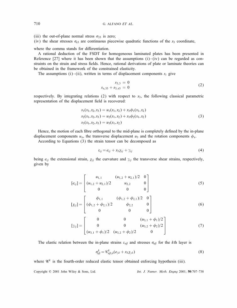
710 G. ALFANO ET AL.
(iii) the out-of-plane normal stress �33 is zero;(iv) the shear stresses ��3 are continuous piecewise quadratic functions of the x3 coordinate,
where the comma stands for di�erentiation.A rational deduction of the FSDT for homogeneous laminated plates has been presented in
Reference [27] where it has been shown that the assumptions (i)–(iv) can be regarded as con-straints on the strain and stress �elds. Hence, rational derivations of plate or laminate theories canbe obtained in the framework of the constrained elasticity.The assumptions (i)–(ii), written in terms of displacement components si give
s3;3 = 0s�;33 + s3; �3 = 0
(2)
respectively. By integrating relations (2) with respect to x3, the following classical parametricrepresentation of the displacement �eld is recovered:
s1(x1; x2; x3) = u1(x1; x2) + x3�1(x1; x2)
s2(x1; x2; x3) = u2(x1; x2) + x3�2(x1; x2)
s3(x1; x2; x3) = u3(x1; x2)
(3)
Hence, the motion of each �bre orthogonal to the mid-plane is completely de�ned by the in-planedisplacement components u�, the transverse displacement u3 and the rotation components ��.According to Equations (3) the strain tensor can be decomposed as
�ij = eij + x3�ij + ij (4)
being eij the extensional strain, �ij the curvature and ij the transverse shear strains, respectively,given by
[eij] =
u1;1 (u1;2 + u2;1)=2 0
(u1;2 + u2;1)=2 u2;2 0
0 0 0
(5)
[�ij] =
�1;1 (�1;2 + �2;1)=2 0
(�1;2 + �2;1)=2 �2;2 0
0 0 0
(6)
[ ij] =
0 0 (u3;1 + �1)=2
0 0 (u3;2 + �2)=2
(u3;1 + �1)=2 (u3;2 + �2)=2 0
(7)
The elastic relation between the in-plane strains ��� and stresses ��� for the kth layer is
�k��=Ck
�� �(e � + x3� �) (8)
where Ck is the fourth-order reduced elastic tensor obtained enforcing hypothesis (iii).
Copyright ? 2001 John Wiley & Sons, Ltd. Int. J. Numer. Meth. Engng 2001; 50:707–738

LAMINATED COMPOSITE PLATES 711
By integrating the constitutive relation (8) through the thickness we get[NM
]=[A BB D
] [ef
](9)
where N and M are the stress resultants de�ned by
N��=∫ h=2
−h=2���(x3) dx3; M��=
∫ h=2
−h=2x3���(x3) dx3 (10)
and the fourth-order constitutive tensors A; B and D are given by
A�� � =nl∑
k=1
(xk+13 − xk3
)Ck�� �
B�� � =12
nl∑k=1
[(xk+13
)2 − (xk3)2]Ck�� � (11)
D�� � =13
nl∑k=1
[(xk+13
)3 − (xk3)3]Ck�� �
The tensor B accounts for the coupling between extension and bending; it vanishes for symmetriclaminates.In plate or laminate FSDT, the relation between the resultant shear forces, de�ned as
Q�=∫ h=2
−h=2��3(x3) dx3 (12)
and the shear strains �3 is a�ected by the so-called shear correction factors. In fact, the shearsti�ness H, given by
H��=nl∑
k=1(xk+13 − xk3 )C
k�3�3 (13)
must be corrected by the fourth-order tensor Z de�ned as
Z= ���d��d� (14)
where
d1 =[1 00 0
]; d2 =
[0 00 1
](15)
and the tensorial product � between second-order tensors is de�ned by: (a�b)c= acbt , being a, band c arbitrary second-order tensors. Finally, the relation between Q and is written in the form
Q= HS with H= ZH (16)
Copyright ? 2001 John Wiley & Sons, Ltd. Int. J. Numer. Meth. Engng 2001; 50:707–738

712 G. ALFANO ET AL.
We emphasize that the presence of the shear factors is due to assumption (iv) on the shearstress pro�le in the laminate thickness.In fact, according to hypothesis (iv) the shear stress can be represented in the form
��3(x1; x2; x3)= g�(x3)Q�(x1; x2) (17)
where g�(x3) is a piecewise quadratic shape function de�ning the shear stress pro�le in the thick-ness. The shear strain energy computed in the whole thickness of the laminate is
E=12
∫ h=2
−h=2��3 �3 dx3 (18)
Since �3 is constant in the thickness, taking into account relations (12) and (16), Equation (18)is written as
E= 12Q� �3 = 1
2 (H−1)�� Q�Q� (19)
On the other hand, recalling position (17), the complementary shear strain energy in the thickness is
E* =12
∫ h=2
−h=2��3S�3�3��3 dx3
=12
[∫ h=2
−h=2g�S�3�3g� dx3
]Q�Q� (20)
where S=C−1 is the compliance tensor of the typical lamina.By enforcing the equality between expressions (19) and (20) it results
(H−1)��=
∫ h=2
−h=2g�S�3�3g� dx3 no sum (21)
Thus, the shear correction factors ��� depends on the shape functions g� and g�. If x1 and x2are principal material directions of orthotropy, i.e. S1323 = 0 and H12 = 0, Equation (21) gives
1���H��
=∫ h=2
−h=2
1C�3�3
(g�)2 dx3 no sum (22)
and hence, explicitly, it is
���=1
H��
∫ h=2
−h=2
(g�)2
C�3�3dx3 no sum (23)
The shear factors represent an additional unknown of the problem, since the shear pro�le g�
is not known a priori for composite laminates. The common choice �11 = �22 = 56 and �12 = 0 is
correct only for homogeneous plates; conversely for laminated plates it is usually adopted as astarting value, to be used in an iterative predictor-corrector procedure, as suggested in References[19; 28].
Copyright ? 2001 John Wiley & Sons, Ltd. Int. J. Numer. Meth. Engng 2001; 50:707–738

LAMINATED COMPOSITE PLATES 713
2.2. Displacement-based variational formulations
The total potential energy functional for the laminate FSDT model is given by
F(u; u3;M) =12
∫A∇su .∇su d +
∫B∇su .∇sM d
+12
∫D∇sM .∇sM d
+12
∫H(∇u3 + M) . (∇u3 + M) d−Fext(u; u3;M) (24)
where the external load potential is
Fext(u; u3;M) =∫(q−3 + q+3 )u3 d +
∫(q−� + q+� )u� d
+∫
h2(q+� − q−� )�� d +Fbou (25)
The term Fbou accounts for the boundary conditions on @. The vectors u and M collect thein-plane displacement and rotation components u� and �� while the symbol ∇s indicates thesymmetric part of the gradient operator.The �eld and boundary equations for the FSDT are then obtained as stationary conditions for
F. In particular, by making use of Equations (9) and (16) the following di�erential �eld equations
N��;� + q−� + q+� = 0; Q�;� + q−3 + q+3 =0
M��;� +h2(q+� − q−� ) = Q�
(26)
are ful�lled by the exact solution of the boundary value problem.
3. RECOVERING OF THE OUT-OF-PLANE STRESSES
The solution provided by the FSDT does not directly provide the out-of-plane stresses, that is thetransverse shear stress components �13 and �23 and the normal stress �33.In fact the constitutive elastic law of the composite laminate would provide unacceptable values
of the transverse shear stresses, while the component �33 would remain unde�ned.For this reason it is common practice to recover the out-of-plane stress by using the three-
dimensional equilibrium equations. In the absence of body forces, they read
�kij; j =0; i; j=1; 2; 3; k =1; 2; : : : ; nl (27)
where the in-plane components �k�� in the kth layer are related to the extensional and exural
strains e and f through the elastic law (8).
Copyright ? 2001 John Wiley & Sons, Ltd. Int. J. Numer. Meth. Engng 2001; 50:707–738

714 G. ALFANO ET AL.
3.1. The transverse shear stresses
Starting from Equation (27) (i=1; 2) and making use of Equation (8), we get the followingrecursive expression for the transverse shear stresses �k
�3 in the kth layer:
�k�3(x3)= �k−1
�3 (xk3 )−∫ x3
xk3
Ck�� �(e �;� + �3� �;�) d�3; k =1; 2; : : : ; nl (28)
supplemented by the nl equilibrium conditions
�0�3(x13 )= − q−� ; �k
�3(xk3 )= �k−1
�3 (xk3 ); k =2; : : : ; nl (29)
With a slight abuse of notation we have denoted by �0�3(x13 ) the value of the component ��3 at the
bottom face of the plate, i.e. �0�3(x13 )= �1�3(−h=2).
Notice that in this section, for brevity, the explicit dependence of the functions upon the in-planeco-ordinates x1 and x2 is omitted.By computing the integrals in Equation (28) we get
�k�3(x3)= �k−1
�3 (xk3 )− Ck�� �
[(x3 − xk3 )e �;� +
(x3)2 − (xk3 )22
� �;�
]; k =1; : : : ; nl (30)
The further condition �nl�3(h=2)= q+� is dependent upon the ones in (29). Actually the value
�nl�3(h=2) is given by
�nl�3(h=2) =−q−� −
(∫ h=2
−h=2C�� � d�3
)e �;� −
(∫ h=2
−h=2�3C�� � d�3
)� �;�
=−q−� − (A�� �e � + B�� �� �);� = − q−� − N��;�= q+� (31)
The last equality follows from relations (26).Equilibrium condition (12) is exactly satis�ed too. Actually, an integration by parts (28) yields
∫ h=2
−h=2��3(x3) dx3 =
∫ h=2
−h=2
[−q−� −
∫ x3
−h=2C�� �(e �;� + �3� �;�) d�3
]dx3
=−q−� h−[x3
∫ x3
−h=2C�� �(e �;� + �3� �;�)d�3
]h=2−h=2
+∫ h=2
−h=2C�� � x3(e �;� + x3� �;�) dx3
=−q−� h− h2
[(∫ h=2
−h=2C�� � dx3
)e � +
(∫ h=2
−h=2x3C�� � dx3
)� �
];�
+
[(∫ h=2
−h=2x3C�� � dx3
)e � +
(∫ h=2
−h=2x23C�� � dx3
)� �
];�
=−q−� h− N��;�h2+M��;� (32)
Copyright ? 2001 John Wiley & Sons, Ltd. Int. J. Numer. Meth. Engng 2001; 50:707–738

LAMINATED COMPOSITE PLATES 715
From Equations (26)3 we then deduce∫ h=2
−h=2��3(x3) dx3 =M��;� + (q+� − q−� )
h2=Q� (33)
In order to get the explicit expression of the transverse shear stresses as function of the in-planedisplacement and rotation �elds, we substitute relations (5) and (6) in Equation (30) to get
�k�3(x3) = �k−1
�3 (xk3 )−[Ck
�� �(x3 − xk3 )(u ;�� + u�; �
2
)
+x23 − (xk3 )2
2
(� ;�� + ��; �
2
)]; k =1; : : : ; nl (34)
where �0�3(x13 )=−q−� .
3.2. The out-of-plane normal stresses
Equation (27), for i=3, provides the following expression of the stress component �33 as a functionof the out-of-plane components �13 and �23:
�k33(x3)= �k−1
33 (xk3 )−∫ x3
xk3
��3;�(�3) d�3; k =1; : : : ; nl (35)
where the nl equilibrium conditions
�033(x13 )=−q−3 ; �k
33(xk3 )= �k−1
33 (xk3 ); k =2; : : : ; nl (36)
have to be taken into account and �033(x13 ) denotes the value of �33 at the bottom face of the plate.
By substituting Equation (30) into Equation (35) we get
�k33(x3) = �k−1
33 (xk3 ) + ck(x3 − xk3 )
+Ck�� �
[(x3 − xk3 )
2
2e �;�� +
x33 − 3 (xk3 )2x3 + 2 (xk3 )36
� �;��
]; k =1; : : : ; nl (37)
The nl integration constants ck can be evaluated by the relation
ck = �k33;3(x
k3 )=−�k
�3; �(xk3 )
Actually, since the conditions �0�3(x13 )=−q−� and �k
�3(xk3 )= �k−1
�3 (xk3 ) hold for any x1 and x2, it turnsout to be �0�3; �(x
13 )=−q−�; � and �k
�3; �(xk3 )= �k−1
�3; � (xk3 ). Hence �133;3(x
13 )=q−�; � and �k
33;3(xk3 )=�k−1
33;3 (xk3 ),
so that
c1 = q−�; �
ck = ck−1 + Ck−1�� �
[(xk3 − xk−13 )e �;�� +
(xk3 )2 − (xk−13 )2
2� �;��
]; k =2; : : : ; nl (38)
Copyright ? 2001 John Wiley & Sons, Ltd. Int. J. Numer. Meth. Engng 2001; 50:707–738

716 G. ALFANO ET AL.
The further conditions �nl33(h=2)= q+3 and �nl
33;3(h=2)=−q+�; � are dependent upon the ones in (36)and (38). Actually
�nl33(h=2) =−q−3 −
∫ h=2
−h=2��3; �(�3) d�3 = − q−3 −
(∫ h=2
−h=2��3(�3) d�3
); �
(39)
=−q−3 − Q�;�= q+3
while, by making use of Equation (31), we obtain
�nl33;3(h=2)=−�nl
�3;3(h=2)= q−�; � + N��; ��=−q+�; � (40)
Notice again that the last identities in the previous two equations follow from Equation (26)since we are considering the exact solution of the two-dimensional problem.Finally, substituting relations Equations (5) and (6) into formulas (37) and (38) we get the
expression depending upon the in-plane displacement and rotation �elds:
ck = ck−1 + Ck−1�� �
[(xk3 − xk−13
)(u ;��� + u�; ��
2
)
+
(xk3)2 − (xk−13
)22
(� ;��� + ��; ��
2
)]
�k33
(x3)= �k−1
33
(xk3)+ ck
(x3 − xk3
)(41)
+Ck�� �
[(x3 − xk3
)22
(u ;��� + u�; ��
2
)
+x33 − 3
(xk3)2x3 + 2
(xk3)3
6
(� ;��� + ��; ��
2
)]
for each k =1; : : : ; nl, where �033(x13 )=−q−3 and c1 = q−�; �.
4. THE MITC 4- AND 9-NODE LAMINATED PLATE ELEMENTS
The MITC family of plates and shell elements has been conceived by Bathe and coworkers [22–24]as a re�ned tool to satisfy the usual isotropy and convergence requirements of �nite elementformulations [15]. In particular the MITC elements are locking-free, do not contain any spuriouszero-energy modes and have a good predictive capability for displacements, bending moments andmembrane forces.Further, they are relatively insensitive to element distorsions and have been deeply investigated
from the theoretical point of view; in fact their convergence properties have been mathematicallyanalyzed in Reference [29].In spite of the acronymous MITC, which stands for mixed interpolation of tensorial components,
the formulation does not require any additional parameter with respect to the strictly necessary
Copyright ? 2001 John Wiley & Sons, Ltd. Int. J. Numer. Meth. Engng 2001; 50:707–738

LAMINATED COMPOSITE PLATES 717
kinematical nodal ones. Hence, for a plate element belonging to the MITC family, the number ofelement parameters is equal to 5ne, where ne is the number of nodes per element.An extension of the MITC plate elements to the case of composite laminates has been �rst
proposed in Reference [25]. In-plane displacement components must be introduced as additionalkinematic parameters and the laminate constitutive equations (9) and (16) must be used in placeof the corresponding ones for the homogenous plate.The variational framework is still represented by the extremum principle for the total potential
energy (25) and the key idea of the MITC approach consists in interpolating the transverse shearstrain �eld di�erently from the one which can be derived from the displacement and rotation �eldsvia Equation (8).For the sake of completeness the basic elements of such treatment are addressed for a 4- and
9-node composite laminated plate element and, with a view towards computer implementation, therelated formulas are detailed.The �nite element equations for the proposed MITC formulation are derived as stationary
conditions for the discretized form of the following functional (25):
FMITCept (ud; ud
3 ;Md) =12
∫A∇sud .∇sud d +
∫B∇sud .∇sMd d
+12
∫D∇sMd .∇sMd d
+12
∫H (∇ud
3 ;Md). (∇ud3 ;Md) d−Fext(ud; ud
3 ;Md) (42)
where the apex d refers to interpolated �elds and denotes a characteristic size of the �nite elementdiscretization.The interpolated �elds ud
� , ud3 and �d
� are given in each element by
ud�(x1; x2) = �n(x1; x2)un
�; ud3(x1; x2)=�
n(x1; x2)un3
�d�(x1; x2) = �n(x1; x2)�n
� n=1; : : : ; ne(43)
where un�, u
n3, �
n� denote the numerical parameters and �
n the shape function pertaining to the nthnode.The transverse shear strains �3 in Equation (42) are evaluated from a suitable interpolation of
the covariant components �3 exactly computed from ud3 and �d
� via Equation (7) in a set of nt
tying points.The covariant basis {g�} at the tth tying point is assumed as
(g�)�=@x�@r�
(44)
where r� is the �th local co-ordinate in the reference domain. In a local co-ordinate systemr=(r1; r2), the covariant components of the trasverse shear strains are then given by
�3(r)= (g�)�(r) �3(r)= J��(r) �3(r) (45)
where J(r) is the jacobian of the isoparametric mapping evaluated at the point r.
Copyright ? 2001 John Wiley & Sons, Ltd. Int. J. Numer. Meth. Engng 2001; 50:707–738

718 G. ALFANO ET AL.
The values of t�3 at the tth tying point, of local co-ordinates rt , are then computed as follows:
t�3 =ne∑
n=1J��(rt)(�n
;�(rt)un
3 + �n(rt)�n
�)=ne∑
n=1Wnt
� un3 + Znt
���n� (46)
where
Wnt� = J��(rt)�n
;�(rt); Znt
��= J��(rt)�n(rt) (47)
and the summation has been now denoted explicitly.The values t�3 are then interpolated in natural co-ordinates by means of nt shape functions t
�
�3(r)=nt∑t=1
t�(r)
t�3 =
ne∑n=1[(Bn
sw)�(r)un3 + (B
ns�)��(r)�
n� ] (no sum on �) (48)
The matrices Bnsw and B
ns� have, respectively, dimensions 2×1 and 2×2 and provide the covariant
representation of the transverse shear strain �eld as a function of the kinematic parameters un3 and
�n pertaining to the nth node of the element. Their expressions can be obtained by substitutingEquation (46) into Equation (48):
(Bnsw)�(r)=
nt∑t=1
t�(r)W
nt� ; (Bn
s�)��(r)=nt∑t=1
t�(r)Z
nt�� (no sum on �) (49)
The relevant expressions of the matrices Bnsw and B
ns�, which are associated with the interpolation
of the cartesian representation �3, are obtained by inverting relations (45):
Bnsw(r)= [J
t(r)]−1Bnsw(r); Bn
s�(r)= [Jt(r)]−1Bn
s�(r) (50)
For the 4- and 9-node elements 2 and 6 tying points have been used, respectively, for eachshear strain component.The shape functions t
� for the 4-node element are
11 =12 (1 + r2); 12 =
12 (1 + r1)
21 =12 (1− r2); 22 =
12 (1− r1)
For the sake of completeness we also provide the expressions of the shape functions for the 9-nodeelement since they were not explicitly reported in the original paper [24]:
11 (r1; r2)=14(1 +
√3r1)
(1 +
1√0:6
r2
)− 12 51 (r1; r2)
21 (r1; r2)=14(1−
√3r1)
(1 +
1√0:6
r2
)− 12 61 (r1; r2)
Copyright ? 2001 John Wiley & Sons, Ltd. Int. J. Numer. Meth. Engng 2001; 50:707–738

LAMINATED COMPOSITE PLATES 719
31 (r1; r2)=14(1−
√3r1)
(1− 1√
0:6r2
)− 12 61 (r1; r2)
41 (r1; r2)=14(1 +
√3r1)
(1− 1√
0:6r2
)− 12 51 (r1; r2)
51 (r1; r2)=12(1 +
√3r1)
[1−
(1√0:6
r2
)2]
61 (r1; r2)=12(1−
√3r1)
[1−
(1√0:6
r2
)2]
and
12 (r1; r2)=14
(1 +
1√0:6
r1
)(1 +
√3r2)− 1
2 52 (r1; r2)
22 (r1; r2)=14
(1− 1√
0:6r1
)(1 +
√3r2)− 1
2 52 (r1; r2)
32 (r1; r2) =14
(1− 1√
0:6r1
)(1−
√3r2)− 1
2 62 (r1; r2)
42 (r1; r2) =14
(1 +
1√0:6
r1
)(1−
√3r2)− 1
2 62 (r1; r2)
52 (r1; r2)=12
[1−
(1√0:6
r1
)2](1 +
√3r2)
62 (r1; r2) =12
[1−
(1√0:6
r1
)2](1−
√3r2)
For further details the reader is referred to the original papers [22–24].
5. RECOVERING OF THE OUT-OF-PLANE STRESS FROM THEFINITE ELEMENT SOLUTION
Formulas (34) and (41) require, respectively, the evaluation of the second and third derivatives ofthe in-plane displacement and rotation �elds. Hence they cannot be used for the MITC elements,as well as for all the �nite element formulations which ensure continuity of the displacement androtation �elds only up to their �rst derivatives.A �rst way to address this problem clearly amounts to developing a kinematically richer lami-
nated plate element, so as to improve the accuracy of the derivatives required by Equations (34)and (41). This approach has been exploited in Reference [19] to evaluate the transverse shearstresses.
Copyright ? 2001 John Wiley & Sons, Ltd. Int. J. Numer. Meth. Engng 2001; 50:707–738
720 G. ALFANO ET AL.
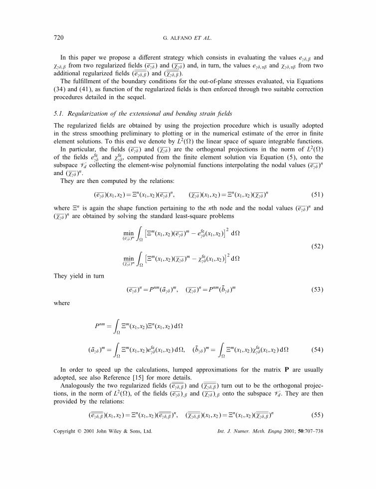
In this paper we propose a di�erent strategy which consists in evaluating the values e �; � and� �; � from two regularized �elds (e �) and (� �) and, in turn, the values e �; �� and � �; �� from twoadditional regularized �elds (e �; �) and (� �; �).The ful�llment of the boundary conditions for the out-of-plane stresses evaluated, via Equations
(34) and (41), as function of the regularized �elds is then enforced through two suitable correctionprocedures detailed in the sequel.
5.1. Regularization of the extensional and bending strain �elds
The regularized �elds are obtained by using the projection procedure which is usually adoptedin the stress smoothing preliminary to plotting or in the numerical estimate of the error in �niteelement solutions. To this end we denote by L2() the linear space of square integrable functions.In particular, the �elds (e �) and (� �) are the orthogonal projections in the norm of L2()
of the �elds efe � and �fe �, computed from the �nite element solution via Equation (5), onto thesubspace Vd collecting the element-wise polynomial functions interpolating the nodal values (e �)n
and (� �)n.They are then computed by the relations:
(e �)(x1; x2)=�n(x1; x2)(e �)n; (� �)(x1; x2)=�n(x1; x2)(� �)n (51)
where �n is again the shape function pertaining to the nth node and the nodal values (e �)n and(� �)n are obtained by solving the standard least-square problems
min(e �)m
∫
[�m(x1; x2)(e �)m − efe �(x1; x2)
]2d
min(� �)m
∫
[�m(x1; x2)(� �)m − �fe �(x1; x2)
]2d
(52)
They yield in turn
(e �)n=Pnm( �a �)m; (� �)n=Pnm(�b �)m (53)
where
Pnm =∫�m(x1; x2)�n(x1; x2) d
( �a �)m =∫�m(x1; x2)efe �(x1; x2) d; (�b �)m=
∫�m(x1; x2)�fe �(x1; x2) d (54)
In order to speed up the calculations, lumped approximations for the matrix P are usuallyadopted, see also Reference [15] for more details.Analogously the two regularized �elds (e �; �) and (� �; �) turn out to be the orthogonal projec-
tions, in the norm of L2(), of the �elds (e �); � and (� �); � onto the subspace Vd. They are thenprovided by the relations:
(e �; �)(x1; x2)=�n(x1; x2)(e �; �)n; (� �; �)(x1; x2)=�n(x1; x2)(� �; �)n (55)
Copyright ? 2001 John Wiley & Sons, Ltd. Int. J. Numer. Meth. Engng 2001; 50:707–738

LAMINATED COMPOSITE PLATES 721
where the nodal values (e �; �)n and (� �; �)n are given by
(e �; �)n=Pnm(a ��)m; (� �; �)n=Pnm(b ��)m (56)
In the above relations Pnm is still supplied by (54)1 while (a ��)m and (b ��)m are now expressed as
(a ��)m=∫�m(x1; x2)(e �); �(x1; x2) d; (b ��)m=
∫�m(x1; x2)(� �); �(x1; x2) d (57)
The evaluation of the transverse shear stresses can now be performed by substituting expressions(51) of the regularized �elds (e �) and (� �) in place of e � and � � in Equation (30):
�k�3(x3)= �k−1
�3 (xk3 ) + Ck�� �
ne∑n=1�n
; �
[(x3 − xk3 )(e �)
n +x23 − (xk3 )2
2(� �)n
]k =1; : : : ; nl (58)
where we remind that �0�3(x13 )=− q−� .
Similarly, the out-of-plane normal stress is obtained by substituting expressions (55) of the twiceregularized �elds (e �; �) and (� �; �) in place of e �; � and � �; � in Equations (37) and (38):
ck = ck−1 + Ck−1�� �
ne∑n=1�n
; �
(xk3 − xk−13 )(e �; �)n +
(xk3 )2 − (xk−13 )2
2(� �; �)n
�k33(x3) = �k−1
33 (xk3 ) + ck(x3 − xk3 ) + Ck�� �
ne∑n=1�n
; �
[(x3 − xk3 )
2
2(e �; �)n
+x33 − 3(xk3 )2x3 + 2(xk3 )3
6(� �; �)n
](59)
with the positions �033(x13 )=− q−3 and c1 = q−�; �.
Remark 1. The overall procedure requires the additional storage of 18Nn nodal parameters,being Nn the number of nodes of the whole discretized structure. Actually, 6Nn parameters areneeded for allocating the values (e �)n and (� �)n, while 12Nn are required for the values (e �; �)n
and (� �; �)n.
5.2. A correction of the out-of-plane stress pro�les
In general, due to the error which a�ects the �nite element solution, relations (26) no longerhold. Accordingly, the conditions �nl
�3(h=2)= q+� ; �nl33(h=2)= q+3 and �nl
33;3(h=2)= − q+�; � could notbe exactly satis�ed.It is then necessary to correct the stress pro�les, as shown in Reference [19] for the transverse
shear stress. We thus propose a correction procedure for the shear stresses, slightly di�erent withrespect to the one presented in Reference [19], and a new one for the out-of-plane stress. Namely,denoting by �nc�3 the non-corrected solution provided by Equation (58), we compute the correctedone �c�3 by adding a second-degree polynomial function
���3(x3)= �c�3(x3)− �nc�3 (x3)= a0 + a1
(x3 +
h2
)+ a2
(h2
4− x23
)(60)
Copyright ? 2001 John Wiley & Sons, Ltd. Int. J. Numer. Meth. Engng 2001; 50:707–738

722 G. ALFANO ET AL.
which satis�es the three conditions
���3(−h=2)=0; ���3(h=2)=�q+� ;∫ h=2
−h=2���3(x3) dx3 =�Q�
where
�q+� = q+� − �nc�3(h=2); �Q�=Q� −∫ h=2
−h=2�nc�3 (x3) dx3
We thus have
a0 = 0; a1 =�q+�h
; a2 =6h3
(�Q� − �q+� h
2
)(61)
Proceeding as above, we denote by �nc33 the non-corrected expression of out-of-plane normalstress, provided by (59), and by �c33 the corrected one. This is obtained by adding a third-degreepolynomial function:
��33(x3)= �c33(x3)− �nc33(x3)= b0 + b1
(x3 +
h2
)+ b2
(x3 +
h2
)2+ b3
(x3 +
h2
)3(62)
which ful�lls the four conditions
��33(−h=2)=0; ��33;3(−h=2) = 0
��33(h=2)=�q+3 ; ��33;3(h=2)=�q+�; �
where
�q+3 = q+3 − �nc33(h=2); �q+�; �= − [q+�; � + �nc33;3(h=2)]
In this way, the following values:
b0 = b1 = 0; b2 =3h2�q+3 − �q+�; �
h; b3 =− 2
h3�q+3 +
�q+�; �h2
(63)
are obtained.Some considerations, in addition to the ones already reported in Remark 1, are in order for
what concerns the computational burden of the proposed procedure. In fact, each one of thepostprocessing phases detailed above is operatively similar to the one currently employed forplotting �elds which are discontinuous between elements; this is the case, for instance, of thestress �eld in a displacement-based �nite element formulation.
Remark 2. Once the out-of-plane stresses have been recovered, the shear stress pro�le can beevaluated by using formula (17). As a consequence, updated values of the shear correction factorscan be obtained through formula (21). Hence they can be used as starting values of the iterativetechnique presented in Reference [19] within the framework of a di�erent plate element.
Copyright ? 2001 John Wiley & Sons, Ltd. Int. J. Numer. Meth. Engng 2001; 50:707–738

LAMINATED COMPOSITE PLATES 723
Figure 1. Simply supported plate: �nite element meshes and geometric data:(a) regular mesh 5× 5; (b) distorted meshes.
6. NUMERICAL RESULTS
The MITC laminate element formulation and the proposed strategy for recovering the out-of-planestress components have been implemented in the �nite element code FEAP (Finite Element Anal-ysis Program) [15] and their numerical performances have been assessed by several applications.Hereafter we report some results obtained for the benchmark problem of a simply supported
square cross-ply laminated plate subjected to a sinusoidal transversal load with maximum valueq. For symmetry reasons only a quarter of the plate has been discretized and the �nite elementmeshes which have been adopted are illustrated in Figure 1.Denoting by h and a the thickness and the width of the laminate, respectively, a constant value
for the thickness-to-side ratio h=a=0:12 is assumed. The examples refer to the layer sequences0=90 and 0=90=0.Each layer is characterized by the following mechanical properties: EL=ET = 25, �=0:25,
GLT=ET = 0:5, GTT=ET = 0:2, where L stands for longitudinal and T for transversal, characteris-tic of a high modulus orthotropic graphite=epoxy composite material.In order to thoroughly investigate on the convergence properties of the laminated MITC elements,
the relative error of the �nite element solution is plotted in Figures 2–7 versus the number n ofnodes per edge. For completeness we also report, in the log–log scale, the error which characterizesthe element EML4 [19], based on a mixed formulation and the use of the enhanced modes. Therelative error has been conventionally de�ned as the ratio (u− u∗)=u∗ where u is the value of adisplacement component obtained in the �nite element solution and u∗ is the analogous quantityprovided by the continuum FSDT theory [30]. Both u and u∗ have been evaluated at a given pointof the mesh as detailed hereafter.Figures 2–5, 6 and 7 refer to the layer sequences 0=90 and 0=90=0, respectively. In particular
Figures 2 and 3 show in turn the results concerning the vertical displacement of the mid-plate,see point A of Figure 1, for regular and distorted meshes. Analogously Figures 4 and 5 illustrate
Copyright ? 2001 John Wiley & Sons, Ltd. Int. J. Numer. Meth. Engng 2001; 50:707–738

724 G. ALFANO ET AL.
Figure 2. Convergence analysis for mid-plate vertical displacement (Point A)—regular mesh.
Figure 3. Convergence analysis for mid-plate vertical displacement (Point A)—distorted mesh.
Copyright ? 2001 John Wiley & Sons, Ltd. Int. J. Numer. Meth. Engng 2001; 50:707–738

LAMINATED COMPOSITE PLATES 725
Figure 4. Convergence analysis for mid-side horizontal displacement (Point B)—regular mesh.
Figure 5. Convergence analysis for mid-side horizontal displacement (Point B)—distorted mesh.
Copyright ? 2001 John Wiley & Sons, Ltd. Int. J. Numer. Meth. Engng 2001; 50:707–738

726 G. ALFANO ET AL.
Figure 6. Convergence analysis for mid-plate vertical displacement (Point A)—regular mesh.
Figure 7. Convergence analysis for mid-plate vertical displacement (Point A)—distorted mesh.
Copyright ? 2001 John Wiley & Sons, Ltd. Int. J. Numer. Meth. Engng 2001; 50:707–738

LAMINATED COMPOSITE PLATES 727
Figure 8. Through-the-thickness distributions of stress �13 at x= y= a=4; Laminate 0=90.
the results in terms of the horizontal displacement of point B, see Figure 1, situated at the mid-side of the plate. Notice that non-linear diagrams in the log–log scale have been found only forlower-order elements, EML4 in Figure 3 and MITC4 in Figure 5, and for the severely distortedmeshes considered in numerical simulations.Figures 8–12 report the out-of-plane stress pro�les, evaluated at the centre of the quarter of
plate, versus the through-the-thickness adimensional abscissa x3=a. The graphs refer to MITC4and MITC9 elements for di�erent meshes, both regular (reg) and distorted (dis), characterizedby n× n number of elements. In particular we have considered coarse meshes characterized byn=5 and 3 for the MITC4 and MITC9 elements, respectively. For completeness the closed-form solution obtained by a two-dimensional [30] and a three-dimensional [20] approach are alsoincluded.The results have been obtained by applying the correction procedure outlined in Section 5; this
is indicated through the abbreviation (c). It is apparent that very accurate results, close to theexact two-dimensional solutions, are obtained both for the out-of-plane shear stresses, see Figures8–10, and normal stresses, Figures 11 and 12.In order to investigate on the modi�cation entailed by the correction procedure of the out-of-
plane stress pro�les resulting from the �nite element solution, we report the corrected (c) andnon-corrected (nc) pro�les in the same graph. Speci�cally Figures 13 and 14 refer to the out-of-plane shear stress in the laminate 0=90 for regular and distorted meshes, respectively. Analogously,Figures 15–18 illustrate the results obtained for the shear stresses �13 and �23 with reference to thelaminate 0=90=0. The importance of the correction procedure is also illustrated for the out-of-planenormal stress in Figures 19 and 20 and Figures 21 and 22 for the layer sequences 0=90 and 0=90=0,respectively.
Copyright ? 2001 John Wiley & Sons, Ltd. Int. J. Numer. Meth. Engng 2001; 50:707–738

728 G. ALFANO ET AL.
Figure 9. Through-the-thickness distributions of stress �13 at x= y= a=4; Laminate 0=90=0.
Figure 10. Through-the-thickness distributions of stress �23 at x= y= a=4; Laminate 0=90=0.
Copyright ? 2001 John Wiley & Sons, Ltd. Int. J. Numer. Meth. Engng 2001; 50:707–738

LAMINATED COMPOSITE PLATES 729
Figure 11. Through-the-thickness distributions of stress �33 at x= y= a=4; Laminate 0=90.
Figure 12. Through-the-thickness distributions of stress �33 at x= y= a=4; Laminate 0=90=0.
Copyright ? 2001 John Wiley & Sons, Ltd. Int. J. Numer. Meth. Engng 2001; 50:707–738

730 G. ALFANO ET AL.
Figure 13. Through-the-thickness distributions of corrected (c) and non-corrected (nc) stress �13at x= y= a=4; Laminate 0=90, regular mesh.
Figure 14. Through-the-thickness distributions of corrected (c) and non-corrected (nc) stress �13at x= y= a=4; Laminate 0=90, distorted mesh.
Copyright ? 2001 John Wiley & Sons, Ltd. Int. J. Numer. Meth. Engng 2001; 50:707–738

LAMINATED COMPOSITE PLATES 731
Figure 15. Through-the-thickness distributions of corrected (c) and non-corrected (nc) stress �13at x= y= a=4; Laminate 0=90=0, regular mesh.
Figure 16. Through-the-thickness distributions of corrected (c) and non-corrected (nc) stress �13at x= y= a=4; Laminate 0=90=0, distorted mesh.
Copyright ? 2001 John Wiley & Sons, Ltd. Int. J. Numer. Meth. Engng 2001; 50:707–738

732 G. ALFANO ET AL.
Figure 17. Through-the-thickness distributions of corrected (c) and non-corrected (nc) stress �23at x= y= a=4; Laminate 0=90=0, regular mesh.
Figure 18. Through-the-thickness distributions of corrected (c) and non-corrected (nc) stress �23at x= y= a=4; Laminate 0=90=0, distorted mesh.
Copyright ? 2001 John Wiley & Sons, Ltd. Int. J. Numer. Meth. Engng 2001; 50:707–738

LAMINATED COMPOSITE PLATES 733
Figure 19. Through-the-thickness distributions of corrected (c) and non-corrected (nc) stress �33at x= y= a=4; Laminate 0=90, regular mesh.
Figure 20. Through-the-thickness distributions of corrected (c) and non-corrected (nc) stress �33at x= y= a=4; Laminate 0=90, distorted mesh.
Copyright ? 2001 John Wiley & Sons, Ltd. Int. J. Numer. Meth. Engng 2001; 50:707–738

734 G. ALFANO ET AL.
Figure 21. Through-the-thickness distributions of corrected (c) and non-corrected (nc) stress �33at x= y= a=4; Laminate 0=90=0, regular mesh.
Figure 22. Through-the-thickness distributions of corrected (c) and non-corrected (nc) stress �33at x= y= a=4; Laminate 0=90=0, distorted mesh.
Copyright ? 2001 John Wiley & Sons, Ltd. Int. J. Numer. Meth. Engng 2001; 50:707–738

LAMINATED COMPOSITE PLATES 735
Figure 23. Through-the-thickness distributions of corrected (c) stress �13 at x= y= a=4 for regular (Reg)and distorted (Dis) meshes; Laminate (0=90= − 45=45= − 45=45=90=0)sym.
The results of Figures 13–22 are further elaborated upon in Figures 23 and 24, referred in turnto regular and distorted meshes, by plotting the correction procedure error (cpe) conventionallyde�ned as follows:
cpe=
∫ h=2
−h=2(��)2 dx3∫ h=2
−h=2�2 dx3
both for the shear and normal out-of-plane stresses. In the previous formula � denotes the exactvalue of the out-of-plane stress of the two-dimensional theory and �� the di�erence between the�nite element solution and the exact one provided by in turn by (60) and (61) for the shearstresses and by (62) and (63) for the normal stress.A comparative examination of Tables I–II and Figures 13–22 shows that the error associated
with the recovery of the out-of-plane stresses through the three-dimensional equilibrium equationsis usually negligible and almost completely compensated by the proposed correction procedure.Further, the cpe value for regular meshes is two orders of magnitude lower than the one whichcharacterizes the distorted ones. Finally, for both kinds of meshes, the cpe value for the MITC9 isone order of magnitude lower than the one pertaining to the MITC4 and, as was to be expected,by far more pronounced for the normal stress than for the shear stresses.Furthermore, the comparisons reported in Figures 8–22, between the �nite element solution and
the exact analytical 3D one, appear to be particularly satisfactory. It can be emphasized that thiskind of comparison is by far preferable with respect to other 3D numerical solutions which requirea heavy computational burden and not necessarily provide a satisfactory solution.
Copyright ? 2001 John Wiley & Sons, Ltd. Int. J. Numer. Meth. Engng 2001; 50:707–738

736 G. ALFANO ET AL.
Figure 24. Through-the-thickness distributions of corrected (c) stress �23 at x= y= a=4 for regular (Reg)and distorted (Dis) meshes; Laminate (0=90= − 45=45= − 45=45=90=0)sym.
Table I. Correction procedure error (cpe) for the out-of-plane stresses; regular mesh.
Laminate 0=90 Laminate 0=90=0
MITC4 - Mesh 5× 5 MITC9 - Mesh 3× 3 MITC4 - Mesh 5× 5 MITC9 - Mesh 3× 3�13 1.467E−3 1.59E−4 1.571E−3 2.06E−4
�23 1.623E−3 2.41E−4 1.518E−3 1.75E−4
�33 6.370E−3 3.50E−4 6.163E−3 5.05E−4
Table II. Correction procedure error (cpe) for the out-of-plane stresses; distorted mesh.
Laminate 0=90 Laminate 0=90=0
MITC4 - Mesh 5× 5 MITC9 - Mesh 3× 3 MITC4 - Mesh 5× 5 MITC9 - Mesh 3× 3�13 7.5090E−2 1.8376E−2 1.01909E−1 2.1436E−2
�23 1.30312E−1 2.2754E−2 2.010E−3 1.6501E−2
�33 3.25479E−1 3.339E−3 3.15343E−1 9.637E−3
In order to evaluate the predicting capabilities of the proposed element for more complex caseswe consider the stacking sequence (0=90= − 45=45= − 45=45=90=0)sym.The calculations refer to regular and distorted 3× 3 and 5× 5 meshes by using the 9- and
4-node MITC elements, respectively. Figures 23–25 show the shear stresses and the normal stresspro�les. It is apparent that both the regular and distorted meshes provide similar results.
Copyright ? 2001 John Wiley & Sons, Ltd. Int. J. Numer. Meth. Engng 2001; 50:707–738

LAMINATED COMPOSITE PLATES 737
Figure 25. Through-the-thickness distributions of corrected (c) stress �33 at x= y= a=4 for regular (Reg)and distorted (Dis) meshes; Laminate (0=90= − 45=45= − 45=45=90=0)sym.
As a �nal remark we note that both the 4- and 9-node proposed elements provide satisfactoryout-of-plane stress pro�les, also for distorted meshes. In particular, for meshes having the samenumber of nodes, the 9-node element behaves better than the 4-node one.
7. CONCLUSIONS
The excellent performances of the 4- and 9-node plate elements belonging to the MITC family[22–24], well known in the literature for the analysis of homogeneous plates, have been shown tocarry over also to the case of composite laminates, both for the in-plane and transverse behaviour,within a FSDT framework.The derived elements are locking free and allow a very accurate evaluation of the out-of-
plane stresses, usually a delicate point in the FSDT, especially when coupled with the correctionprocedures of the stress pro�les which have been presented in the paper.The �rst one, which refers to the correction of the shear stresses, is a viable alternative to
the one proposed in Reference [19] while the second one turned out to be very e�ective for thecorrect estimate of the normal stresses. This last result is particularly remarkable for the analysisof delamination e�ects in composites.The e�ectiveness of the proposed approach in the evaluation of the stress state in laminated
composite plates has been validated by the very satisfactory agreement of the closed-form solutionswith the numerical results obtained either with regular and distorted meshes.
ACKNOWLEDGEMENTS
The �nancial support of the National Council of Research (CNR) and the Italian Ministry of University andResearch (MURST) are gratefully acknowledged.
Copyright ? 2001 John Wiley & Sons, Ltd. Int. J. Numer. Meth. Engng 2001; 50:707–738
738 G. ALFANO ET AL.
REFERENCES
1. Reddy JN. On re�ned theories of composite laminates. Meccanica 1990; 25:230–238.2. Reddy JN. A generalization of two-dimensional theories of laminated plates. Communications in Applied NumericalMethods 1987; 3:173–180.
3. Reissner E. The e�ect of transverse shear deformation on the bending of elastic plates. Journal of Applied Mechanics1945; 12:69–77.
4. Mindlin RD. In uence of rotatory inertia and shear on exural motions of isotropic, elastic plates. Journal of AppliedMechanics 1951; 38:31–38.
5. Yang PC, Norris CH, Stavsky Y. Elastic wave propagation in heterogeneous plates. International Journal of Solidsand Structures 1996; 2:665–684.
6. Whitney JM, Pagano NJ. Shear deformation in heterogeneous anisotropic plates. Journal of Applied MechanicsTransactions of ASME 92=E 1970; 37:1031–1036.
7. Seide P. An improved approximate theory for the bending of laminated plates. Mechanics Today 1980; 5:451–466.8. Di Sciuva M. Bending, vibration and buckling of simply supported thick multilayered orthotropic plates: an evaluationof a new displacement model. Journal of Sound and Vibration 1986; 105:425–442.
9. Di Sciuva M. An improved shear deformation theory for moderately thick multi-layered anisotropic shells and plates.Journal of Applied Mechanics 1987; 54:589–596.
10. Barbero EJ, Reddy JN. An accurate determination of stresses in thick laminates using a generalized plate theory.International Journal for Numerical Methods in Engineering 1990; 29:1–14.
11. Carrera E. Evaluation of layerwise mixed theories for laminated plate analysis. AIAA Journal 1998; 36(5):830–839.12. Robbins Jr DH, Reddy JN. Modelling of thick composites using a layerwise laminate theory. International Journal
for Numerical Methods in Engineering 1993; 36:655–677.13. Gaudenzi P, Mannini A, Carbonaro R. Multi-layer higher order �nite elements for the analysis of free-edge stresses in
composite laminates. International Journal for Numerical Methods in Engineering 1998; 41:851–873.14. Zienkiewicz OC, Taylor RL, Too JM. Reduced integration techniques in general analysis of plates and shells.
International Journal for Numerical Methods in Engineering 1971; 3:275–290.15. Zienkiewicz OC, Taylor RL. The Finite Element Method, vols. I, II. McGraw Hill: New York, 1991.16. Malkus DS, Hughes TJR. Mixed �nite-element methods—reduced integration techniques: a uni�cation of concepts.
Computer Methods in Applied Mechanics and Engineering 1978; 15:63–81.17. Pugh EDL, Hinton E, Zienkiewicz OC. A study of quadrilateral plate bending elements with reduced integration.
International Journal for Numerical Methods in Engineering 1978; 12:1059–1079.18. Auricchio F, Taylor RL. A shear-deformable plate element with an exact thin limit. Computer Methods in Applied
Mechanics and Engineering 1994; 118:393–412.19. Auricchio F, Sacco E. A mixed-enhanced �nite-element for the analysis of laminated composite plates. International
Journal for Numerical Methods in Engineering 1999; 44:1481–1504.20. Pagano NJ. Exact solutions for rectangular bidirectional composites and sandwich plates. Journal of Composite
Materials 1970; 4:20–34.21. Simo JC, Rifai MS. A class of mixed assumed strain methods and the method of incompatible modes. International
Journal for Numerical Methods in Engineering 1990; 29:1595–1638.22. Bathe KJ, Dvorkin EN. A four-node plate bending element based on Mindlin=Reissner plate theory and a mixed
interpolation. International Journal for Numerical Methods in Engineering 1985; 21:367–383.23. Bathe KJ, Dvorkin EN. A formulation of general shell elements. The use of mixed interpolation of tensorial components.
International Journal for Numerical Methods in Engineering 1986; 22:697–722.24. Bucalem ML, Bathe KJ. Higher-order MITC general shell elements. International Journal for Numerical Methods in
Engineering 1993; 36:3729–3754.25. Guillermin O, Kojic M, Bathe KJ. Linear and nonlinear analysis of composite shells. Proceedings of STRUCOME
90, DATAID AS & I, Paris, 1990.26. Auricchio F, Sacco E. Partial mixed formulation and re�ned models for the analysis of composite laminates within a
FSDT. Composite and Structures 1999; 46:103–113.27. Bisegna P, Sacco E. A rational deduction of plate theories from the three-dimensional linear elasticity. Zeitschrift f�ur
Angewandte Mathematik und Mechanik 1997; 77:349–366.28. Noor AK, Burton WS, Peters JM. Predictor-corrector procedures for stress and free-vibration analyses of multylayered
composite plates and shells. Computer Methods in Applied Mechanics and Engineering 1990; 82:341–363.29. Brezzi F, Bathe KJ, Fortin M. Mixed interpolated elements for Reissner-Mindlin plates. International Journal for
Numerical Methods in Engineering 1989; 28:1787–1801.30. Reddy JN. Energy and Variational Methods in Applied Mechanics. Wiley: New York, 1984.
Copyright ? 2001 John Wiley & Sons, Ltd. Int. J. Numer. Meth. Engng 2001; 50:707–738


![Prediction of the elastic–plastic behavior of thermoplastic composite laminated plates ([0°/θ°]2) with square hole](https://static.fdokumen.com/doc/165x107/6333426da290d455630a0e97/prediction-of-the-elasticplastic-behavior-of-thermoplastic-composite-laminated.jpg)