Free vibration response of two-dimensional magneto-electro-elastic laminated plates
19
JOURNAL OF SOUND AND VIBRATION Journal of Sound and Vibration 292 (2006) 626–644 Free vibration response of two-dimensional magneto-electro-elastic laminated plates Fernando Ramirez a, , Paul R. Heyliger a , Ernian Pan b a Department of Civil Engineering, Colorado State University, Fort Collins, CO 80523, USA b Department of Civil Engineering, University of Akron, Akron, OH 44325, USA Received 25 October 2004; received in revised form 20 May 2005; accepted 20 August 2005 Available online 21 October 2005 Abstract An approximate solution for the free vibration problem of two-dimensional magneto-electro-elastic laminates is presented to determine their fundamental behavior. The laminates are composed of linear homogeneous elastic, piezoelectric, or magnetostrictive layers with perfect bonding between each interface. The solution for the elastic displacements, electric potential, and magnetic potential is obtained by combining a discrete layer approach with the Ritz method. The model developed here is not dependent on specific boundary conditions, and it is presented as an alternative to the exact or analytical approaches which are limited to a very specific set of edge conditions. The natural frequencies and through-thickness modal behavior are computed for simply supported and cantilever laminates. Solutions for the simply supported case are compared with the known exact solution for piezoelectric laminates, and excellent agreement is obtained. The present approach is also validated by comparing the natural frequencies of a two-layer cantilever plate with known analytical solution and with results obtained using commercial finite element software. r 2005 Elsevier Ltd. All rights reserved. 1. Introduction Magneto-electro-elastic laminates show significant interactions between the elastic, electric, and magnetic fields due to the coupled nature of the constitutive equations. These laminates have direct application in sensing and actuating devices, such as damping and control of vibrations in structures. There have been several studies on the electric and mechanical behavior of piezoelectric laminates. Lee [1–4] published a series of papers incorporating the piezoelectric effect into the classical laminate theory. Tzou and Gadre [5] presented the dynamic equations for generalized multi-layered thin shells based on Love’s theory and Hamilton’s principle. More recently, Heyliger [6] and Heyliger and Brooks [7] presented an exact solution for the static behavior of laminated piezoelectric plates with simple supports. Heyliger and Brooks [8] also obtained the exact solution for the free vibration behavior of piezoelectric plates in cylindrical bending, by extending the free vibration solution of purely elastic simply supported plates to the corresponding piezoelectric case. ARTICLE IN PRESS www.elsevier.com/locate/jsvi 0022-460X/$ - see front matter r 2005 Elsevier Ltd. All rights reserved. doi:10.1016/j.jsv.2005.08.004 Corresponding author. Tel.: +1 970 4912801. E-mail address: [email protected] (F. Ramirez).
-
Upload
independent -
Category
Documents
-
view
0 -
download
0
Transcript of Free vibration response of two-dimensional magneto-electro-elastic laminated plates

ARTICLE IN PRESS
JOURNAL OFSOUND ANDVIBRATION
0022-460X/$ - s
doi:10.1016/j.js
�CorrespondE-mail addr
Journal of Sound and Vibration 292 (2006) 626–644
www.elsevier.com/locate/jsvi
Free vibration response of two-dimensionalmagneto-electro-elastic laminated plates
Fernando Ramireza,�, Paul R. Heyligera, Ernian Panb
aDepartment of Civil Engineering, Colorado State University, Fort Collins, CO 80523, USAbDepartment of Civil Engineering, University of Akron, Akron, OH 44325, USA
Received 25 October 2004; received in revised form 20 May 2005; accepted 20 August 2005
Available online 21 October 2005
Abstract
An approximate solution for the free vibration problem of two-dimensional magneto-electro-elastic laminates is
presented to determine their fundamental behavior. The laminates are composed of linear homogeneous elastic,
piezoelectric, or magnetostrictive layers with perfect bonding between each interface. The solution for the elastic
displacements, electric potential, and magnetic potential is obtained by combining a discrete layer approach with the Ritz
method. The model developed here is not dependent on specific boundary conditions, and it is presented as an alternative
to the exact or analytical approaches which are limited to a very specific set of edge conditions. The natural frequencies and
through-thickness modal behavior are computed for simply supported and cantilever laminates. Solutions for the simply
supported case are compared with the known exact solution for piezoelectric laminates, and excellent agreement is
obtained. The present approach is also validated by comparing the natural frequencies of a two-layer cantilever plate with
known analytical solution and with results obtained using commercial finite element software.
r 2005 Elsevier Ltd. All rights reserved.
1. Introduction
Magneto-electro-elastic laminates show significant interactions between the elastic, electric, and magneticfields due to the coupled nature of the constitutive equations. These laminates have direct application insensing and actuating devices, such as damping and control of vibrations in structures. There have beenseveral studies on the electric and mechanical behavior of piezoelectric laminates. Lee [1–4] published a seriesof papers incorporating the piezoelectric effect into the classical laminate theory. Tzou and Gadre [5]presented the dynamic equations for generalized multi-layered thin shells based on Love’s theory andHamilton’s principle. More recently, Heyliger [6] and Heyliger and Brooks [7] presented an exact solution forthe static behavior of laminated piezoelectric plates with simple supports. Heyliger and Brooks [8] alsoobtained the exact solution for the free vibration behavior of piezoelectric plates in cylindrical bending, byextending the free vibration solution of purely elastic simply supported plates to the correspondingpiezoelectric case.
ee front matter r 2005 Elsevier Ltd. All rights reserved.
v.2005.08.004
ing author. Tel.: +1 970 4912801.
ess: [email protected] (F. Ramirez).

ARTICLE IN PRESSF. Ramirez et al. / Journal of Sound and Vibration 292 (2006) 626–644 627
Research on the behavior of magneto-electro-elastic laminates is relatively recent. Problems involvingmagneto-electro-elastic media have been considered by Harshe [9], Nan [10], and Benveniste [11] bydeveloping expressions to determine the effective magnetoelectric effect in composites having piezoelectric andmagnetostrictive phases. The exact closed-form solution for three-dimensional simply supported magneto-electro-elastic laminates was presented by Pan [12] based on the quasi-Stroh formalism and the propagatormatrix method. Later, Pan and Heyliger [13,14] extended that solution to the corresponding free vibrationproblem, and to the static cylindrical bending of magneto-electro-elastic laminates. An approximate solutionbased on a discrete layer model was also obtained by Heyliger and Pan [15] and Heyliger et al. [16] for thecases of two- and three-dimensional magneto-electro-elastic laminates. More recently, Jiang and Ding [17]presented an analytical solution for the study of beams, Lage et al. [18] developed a layerwise mixed finiteelement model for plates, Buchanan [19] published a comparison between layered and multiphase models forthe static and dynamic analysis of magneto-electro-elastic plates, Latheswary et al. [20] studied the dynamicresponse of moderately thick composite plates.
In this study, the governing equations of motion for two-dimensional linear magneto-electro-elasticlaminates are solved using a discrete layer approximate model. Approximations for the three displacementsand electric and magnetic potentials are constructed for each homogeneous layer such that the dependence onthe in-plane directions and that on the thickness direction of the laminated plate can be separated. Thisseparation allows for breaks in the gradients of the three displacement components and the two potentialsacross a dissimilar material interface. The free vibration behavior of a single homogeneous piezoelectric layeris studied first to check the present formulation with the known exact solution. The present approach is alsovalidated by comparing the natural frequencies and mode shapes of a two-layer PZT-5A/graphite-epoxycantilever plate with the analytical solution presented by Vel et al. [21], and with several finite element models.Finally, the natural frequencies, through-thickness modes shapes, and the influence of the piezoelectric andpiezomagnetic coefficients on the natural frequencies of a two-layer BaTiO3/CoFe2O4 cantilever plate areanalyzed.
2. Theory
2.1. Geometry
Laminates are considered with the z-axis out of the laminate plane and the x- and y-axes are thecorresponding in-plane axes of the laminate. This is shown in Fig. 1. The laminates are considered to be eithervery thin or infinitely long in the y-direction and are composed of an arbitrary number of elastic, piezoelectric,or magnetostrictive layers. The laminate has dimensions Lx in the x-direction and has total thickness H, withindividual layer thicknesses h1, h2, and so on. Layer 1 is the bottom layer of the laminate and layer n is the toplayer.
z
y
x
h
Lx
hi
Layer i
Fig. 1. Laminate geometry.
ARTICLE IN PRESSF. Ramirez et al. / Journal of Sound and Vibration 292 (2006) 626–644628
2.2. Governing equations
Magneto-electro-elastic laminates possess coupled field behavior between the elastic, electric, and magneticfield variables. For an anisotropic and linearly magneto-electro-elastic solid, the coupled constitutive relationfor each layer can be written as [9]
si ¼ Cikgk � ekiEk � qkiHk, (1)
Di ¼ eikgk þ �ikEk þ dikHk, (2)
Bi ¼ qikgk þ dikEk þ mikHk. (3)
Here Eqs. (1)–(3) describe the stress, electric displacement, and magnetic flux fields, respectively, and si, Di,and Bi denote the components of stress, electric displacement, and magnetic flux. The symbols Cij , �ij , and mij
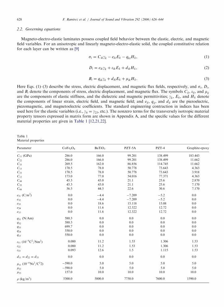
are the components of elastic stiffness, and the dielectric and magnetic permittivities; gk, Ek, and Hk denotethe components of linear strain, electric field, and magnetic field; and eij, qij , and dij are the piezoelectric,piezomagnetic, and magnetoelectric coefficients. The standard engineering contraction in indices has beenused here for the elastic variables (i.e., g4 ¼ g23, etc.). The nonzero terms for the transversely isotropic materialproperty tensors expressed in matrix form are shown in Appendix A, and the specific values for the differentmaterial properties are given in Table 1 [12,21,22].
Table 1
Material properties
Parameter CoFe2O4 BaTiO3 PZT-5A PZT-4 Graphite-epoxy
C11 (GPa) 286.0 166.0 99.201 138.499 183.443
C22 286.0 166.0 99.201 138.499 11.662
C33 269.5 162.0 86.856 114.745 11.662
C13 170.5 78.0 50.778 73.643 4.363
C23 170.5 78.0 50.778 73.643 3.918
C12 173.0 77.0 54.016 77.371 4.363
C44 45.3 43.0 21.1 25.6 2.870
C55 45.3 43.0 21.1 25.6 7.170
C66 56.5 44.5 22.6 30.6 7.170
e31 (C/m2) 0.0 �4.4 �7.209 �5.2 0.0
e32 0.0 �4.4 �7.209 �5.2 0.0
e33 0.0 18.6 15.118 15.08 0.0
e24 0.0 11.6 12.322 12.72 0.0
e15 0.0 11.6 12.322 12.72 0.0
q31 (N/Am) 580.3 0.0 0.0 0.0 0.0
q32 580.3 0.0 0.0 0.0 0.0
q33 699.7 0.0 0.0 0.0 0.0
q24 550.0 0.0 0.0 0.0 0.0
q15 550.0 0.0 0.0 0.0 0.0
�11 ð10�9C2=Nm2Þ 0.080 11.2 1.53 1.306 1.53
�22 0.080 11.2 1.53 1.306 1.53
�33 0.093 12.6 1.5 1.115 1.53
d11 ¼ d22 ¼ d33 0.0 0.0 0.0 0.0 0.0
m11 ð10�6Ns2=C22Þ �590.0 5.0 5.0 5.0 5.0
m22 �590.0 5.0 5.0 5.0 5.0
m33 157.0 10.0 10.0 10.0 10.0
r ðkg=m3Þ 5300.0 5800.0 7750.0 7600.0 1590.0

ARTICLE IN PRESSF. Ramirez et al. / Journal of Sound and Vibration 292 (2006) 626–644 629
The components of strain, electric field, and magnetic field are related to the displacement field ui, and theelectric and magnetic potentials f and c by the relations
gij ¼1
2
qui
qxj
þquj
qxi
� �, (4)
Ei ¼ �f;i, (5)
Hi ¼ �c;i. (6)
In the case of free vibration, the absence of body force, free charge density, and free current density areassumed. Under these conditions, the equations of motion can then be written as
sij;j ¼ rui;tt, (7)
Di;i ¼ 0, (8)
Bi;i ¼ 0. (9)
2.3. Variational formulation
Following the standard variational method of approximation (see Ref. [23]), we multiply each of the threegoverning equations by the first variation of the displacements, electric and magnetic potential, respectively,we then integrate the result over the volume of the plate, which is the domain bounding the magneto-electro-elastic medium, and set the result equal to zero, resulting inZ
V
duiðsij;j � rui;ttÞdV ¼ 0, (10)
ZV
dfðDi;iÞdV ¼ 0, (11)
ZV
dcðBi;iÞdV ¼ 0. (12)
Integrating each of these equations by parts and applying the divergence theorem yields the final weak form ofthe governing equations.
0 ¼
ZV
ðsijdgij þ duirui;ttÞdV �
IS
sijnjdui dS, (13)
0 ¼
ZV
Djdf;j dV �
IS
DjnjdfdS, (14)
0 ¼
ZV
Bjdc;j dV �
IS
BjnjdcdS. (15)
Substituting the governing constitutive equations into final weak form yields
0 ¼
ZV
C11qu
qxþ C13
qw
qzþ C14
qv
qzþ C16
qv
qxþ e11
qfqxþ e31
qfqzþ q11
qcqxþ q31
qcqz
� �qdu
qx
�
þ C12qu
qxþ C23
qw
qzþ C24
qv
qzþ C26
qv
qxþ e12
qfqxþ e32
qfqzþ q12
qcqxþ q32
qcqz
� �qdv
qy
þ C13qu
qxþ C33
qw
qzþ C36
qv
qxþ e33
qfqzþ q33
qcqz
� �qdw
qz

ARTICLE IN PRESSF. Ramirez et al. / Journal of Sound and Vibration 292 (2006) 626–644630
þ C14qu
qxþ C44
qv
qzþ C45
qu
qzþ
qw
qx
� �þ e14
qfqxþ q14
qcqx
� �qdv
qz
þ C45qv
qzþ C55
qu
qzþ
qw
qx
� �þ e15
qfqxþ q15
qcqx
� �qdu
qzþ
qdw
qx
� �
þ C16qu
qxþ C36
qw
qzþ C66
qv
qxþ e16
qfqxþ e36
qfqzþ q16
qcqxþ q36
qcqz
� �qdv
qx
�rq2uqt2
duþq2v
qt2dvþ
q2zqt2
dw
� ��dV �
IS
ðtxduþ tydvþ tzdzÞdS, ð16Þ
0 ¼
ZV
e11qu
qxþ e14
qv
qzþ e15
qu
qzþ
qw
qx
� �þ e16
qv
qx� �11
qfqx� d11
qcqx
� �qdfqx
�
þ e21qu
qxþ e24
qv
qzþ e25
qu
qzþ
qw
qx
� �þ e26
qv
qx� �12
qfqx� d12
qcqx
� �qdfqy
þ e31qu
qxþ e33
qw
qzþ e36
qv
qx� �33
qfqz� d33
qcqz
� �qdfqz
�dV �
IS
DjnjdfdS, ð17Þ
0 ¼
ZV
q11
qu
qxþ q14
qv
qzþ q15
qu
qzþ
qw
qx
� �þ q16
qv
qx� d11
qfqx� m11
qcqx
� �qdcqx
�
þ q21
qu
qxþ q24
qv
qzþ q25
qu
qzþ
qw
qx
� �þ q26
qv
qx� d12
qfqx� m12
qcqx
� �qdcqy
þ q31
qu
qxþ q33
qw
qzþ q36
qv
qx� d33
qfqz� m33
qcqz
� �qdcqz
�dV �
IS
BjnjdcdS, ð18Þ
where u, v, and w represent the displacement components in the x-, y-, and z-directions, respectively, and fand c represent the electric and magnetic potentials. It is important to mention here that Eq. (16) will actuallyresult in three different equations when the coefficients of the variations of the mechanical displacements arecollected.
2.4. Discrete-layer approximation and solution
The basic idea behind the Ritz method is to approximate the displacements ui, and the electric and magneticpotentials f and c by a finite linear combination of the form (see Refs. [23,24])
uiðx; y; z; tÞ ¼Xn
j¼1
cijG
ui
j ðx; y; z; tÞ þ Gui
0 ,
fðx; y; z; tÞ ¼Xn
j¼1
cjGfj ðx; y; z; tÞ þ Gf
0 ,
cðx; y; z; tÞ ¼Xn
j¼1
cjGcj ðx; y; z; tÞ þ Gc
0 (19)
and then determine the parameters cj to satisfy the principle of virtual displacements. Here, cj denotes theundetermined coefficients, and Gj the approximation functions which must satisfy the boundary conditionsand be continuous, as required by the variational principle.
Approximations to the three displacements (for elastic media), the three displacements and electrostaticpotential (for piezoelectric media), and the three displacement and magnetic potential (for magnetostrictivemedia) are generated in terms of the global (x; y; z)-coordinates. In this study, the approximations for eachof the five field quantities are constructed in such a way as to separate the dependence in the plane with thatin the direction perpendicular to the interface. Additionally, the laminates are considered infinitely long in the

ARTICLE IN PRESSF. Ramirez et al. / Journal of Sound and Vibration 292 (2006) 626–644 631
y-direction, eliminating the dependence of the approximations on the y-coordinate. Hence approximations forthe five unknown field quantities are sought in the form
uðx; z; tÞ ¼Xn
j¼1
Ujðx; tÞGuj ðzÞ ¼
Xm
i¼1
Xn
j¼1
UjiðtÞGui ðxÞG
uj ðzÞ,
vðx; z; tÞ ¼Xn
j¼1
V jðx; tÞGvj ðzÞ ¼
Xm
i¼1
Xn
j¼1
VjiðtÞGvi ðxÞG
vj ðzÞ,
wðx; z; tÞ ¼Xn
j¼1
W jðx; tÞGwj ðzÞ ¼
Xm
i¼1
Xn
j¼1
W jiðtÞGwi ðxÞG
wj ðzÞ,
fðx; z; tÞ ¼Xn
j¼1
Fjðx; tÞGfj ðzÞ ¼
Xm
i¼1
Xn
j¼1
FjiðtÞGfi ðxÞG
fj ðzÞ,
cðx; z; tÞ ¼Xn
j¼1
Cjðx; tÞGcj ðzÞ ¼
Xm
i¼1
Xn
j¼1
CjiðtÞGci ðxÞG
cj ðzÞ. (20)
In the thickness direction, one-dimensional Lagrangian interpolation polynomials are used for GjðzÞ foreach of the five variables. For the in-plane approximations (i.e., that in the x-direction), different types ofapproximations can be used for the one-dimensional functions GjðxÞ. Power and Fourier series are those mostcommonly selected. For a laminate with N layers through the parallelepiped thickness (typically taken equal toor greater than the number of different material laminae in the parallelepiped), ðN þ 1Þ is the number of layerinterfaces through the parallelepiped thickness, and Uji, V ji, W ji, Fji, and Cji are constants associated with jthlayer of the discretized laminate corresponding to the ith term of the in-plane approximation function for eachof the five variables [25].
Substituting these approximations, Eq. (20), into the weak form in Eqs. (16)–(18), integrating with respectto the thickness coordinate z, collecting the coefficients of the variations of the displacements, and placing theresults in matrix form yields the result
½Muu� ½0� ½0� ½0� ½0�
½0� ½Mvv� ½0� ½0� ½0�
½0� ½0� ½Mww� ½0� ½0�
½0� ½0� ½0� ½0� ½0�
½0� ½0� ½0� ½0� ½0�
2666666664
3777777775
f €ug
f€vg
f €wg
f0g
f0g
8>>>>>>>><>>>>>>>>:
9>>>>>>>>=>>>>>>>>;
þ
½Kuu� ½Kuv� ½Kuw� ½Kuf� ½Kuc�
½Kvu� ½Kvv� ½Kvw� ½Kvf� ½Kvc�
½Kwu� ½Kwv� ½Kww� ½Kwf� ½Kwc�
½Kfu� ½Kfv� ½Kfw� ½Kff� ½Kfc�
½Kcu� ½Kcv� ½Kcw� ½Kcf� ½Kcc�
2666666664
3777777775
fug
fvg
fwg
ffg
fcg
8>>>>>>>><>>>>>>>>:
9>>>>>>>>=>>>>>>>>;¼
f f ug
f f vg
f f wg
f f fg
f f cg
8>>>>>>>><>>>>>>>>:
9>>>>>>>>=>>>>>>>>;. ð21Þ
The elements of each of these matrices have a very specific form as a result of the pre-integration of thethickness dependence. The matrices are in fact composed of smaller sub-matrices that consist of the fullyintegrated thickness approximation functions multiplied by the various in-plane functions. The explicit formof each of these sub-matrices contained in the stiffness matrix ½K � and the inertial mass matrix ½M� are given inAppendix B before integrating with respect to thickness coordinate and before the insertion of the specificdiscrete-layer approximations.
ARTICLE IN PRESSF. Ramirez et al. / Journal of Sound and Vibration 292 (2006) 626–644632
The dynamic analysis of the laminates is developed assuming harmonic motion. Therefore, the solutions forthe primary unknowns have the form
uiðx; z; tÞ ¼ uiðx; zÞeiot, (22)
fðx; z; tÞ ¼ fðx; zÞeiot, (23)
cðx; z; tÞ ¼ cðx; zÞeiot, (24)
where o is the natural frequency.Taking second derivative with respect to time of Eqs. (22)–(24) gives
€uiðx; z; tÞ ¼ �o2uiðx; zÞeiot, (25)
€fðx; z; tÞ ¼ �o2fðx; zÞeiot, (26)
€cðx; z; tÞ ¼ �o2cðx; zÞeiot. (27)
Replacing Eqs. (25)–(27) into Eq. (21), and simplifying the dynamic problem becomes the following e-valueproblem:
½Kuu� ½Kuv� ½Kuw� ½Kuf� ½Kuc�
½Kvu� ½Kvv� ½Kvw� ½Kvf� ½Kvc�
½Kwu� ½Kwv� ½Kww� ½Kwf� ½Kwc�
½Kfu� ½Kfv� ½Kfw� ½Kff� ½Kfc�
½Kcu� ½Kcv� ½Kcw� ½Kcf� ½Kcc�
2666666664
3777777775
fug
fvg
fwg
ffg
fcg
8>>>>>>>><>>>>>>>>:
9>>>>>>>>=>>>>>>>>;
� o2
½Muu� ½0� ½0� ½0� ½0�
½0� ½Mvv� ½0� ½0� ½0�
½0� ½0� ½Mww� ½0� ½0�
½0� ½0� ½0� ½0� ½0�
½0� ½0� ½0� ½0� ½0�
2666666664
3777777775
fug
fvg
fwg
f0g
f0g
8>>>>>>>><>>>>>>>>:
9>>>>>>>>=>>>>>>>>;¼
f0g
f0g
f0g
f0g
f0g
8>>>>>>>><>>>>>>>>:
9>>>>>>>>=>>>>>>>>;. ð28Þ
The natural frequencies and the corresponding shape functions can be found by solving this eigenvalueproblem with no external forces since free vibration analysis is assumed. The electric and magnetic potentialsare eliminated from this equation by following a standard matrix condensation procedure, allowing solutionby using direct eigensolvers. First, we consider the following partition of the matrix equation (28):
½KUU � ½KUF�
½KFU � ½KFF�
" #fUg
fFg
( )� o2
½MUU � ½0�
½0� ½0�
" #fUg
f0g
( )¼f0g
f0g
( )(29)
expanding Eq. (29) gives the matrix equations
½KUU �fUg þ ½KUF�fFg � o2½MUU �fUg ¼ f0g, (30)
½KFU �fUg þ ½KFF�fFg ¼ f0g. (31)
Solving for F from Eq. (31) and substituting back in Eq. (29) results in the following general eigenvalueproblem:
ð½K̄ � � o2½M�ÞfUg ¼ f0g, (32)

ARTICLE IN PRESSF. Ramirez et al. / Journal of Sound and Vibration 292 (2006) 626–644 633
where U represents the modes shapes, o is the natural frequency, and the condensed stiffness matrix ½K̄ � iscalculated as
½K̄ � ¼ ð½KUU � � ½KUF�½KFF��1½KFU �Þ. (33)
3. Numerical examples
Three examples are considered in this section to study the free vibration behavior of linear magneto-electro-elastic laminates. First, a single-layer linear elastic piezoelectric plate, with known exact solution [8] isexamined in order to validate the approximate model presented here. Then, a two-layer cantilever compositeplate with the bottom layer made of the linear elastic graphite-epoxy, and the top layer made of the linearelastic piezoelectric PZT-5A is studied and results are compared to those presented by Vel et al. [21]. Finally, atwo-layer cantilever magneto-electro-elastic plate with the bottom layer made of the linear magnetostrictivematerial CoFe2O4 and the top layer of the linear piezoelectric BaTiO3 is analyzed.
3.1. Single-layer simply supported piezoelectric plate
The first example considered is a single-layer homogeneous plate made of the piezoelectric PZT-4 withmaterial properties shown in Table 1. A plate with dimensions Lx ¼ 0:04m and total thickness H ¼ 0:01m ismodelled. The edge boundary conditions are consistent with those of simple support. Hence, the transversedisplacement w is specified to be zero, with zero normal traction also specified along the edge length and alongthe top and bottom surfaces of the laminate. In terms of the electric and magnetic field variables, they are zeroalong the edges, as well as along the top and bottom surfaces of the laminate.
The in-plane approximation functions for each of the five field variables are given in the form
Guj ðxÞ ¼ cos px, (34)
Gvj ðxÞ ¼ cos px, (35)
Gwj ðxÞ ¼ sin px, (36)
Gfj ðxÞ ¼ sin px, (37)
GCj ðxÞ ¼ sin px, (38)
where p ¼ np=Lx. Here, the index j is a single integer that represents the axial mode number denoted by p ineach of the terms. In this example, only one term is required to match the exact solution corresponding to thefirst axial mode (i.e., n ¼ 1) as published by Heyliger and Brooks [8].
The natural frequencies are normalized as
on ¼ onðL2x=HÞ
ffiffiffiffiffiffiffiffiffiffiffiffiffiffiffiffiðr=C11Þ
p, (39)
where Lx is the span length of the plate, H is the thickness, r and C11 are the mass density and thecorresponding element of the elastic stiffness matrix (see Table 1), and on is the nth frequency found in theanalysis.
The first 5 natural frequencies obtained using the present approach are shown in Table 2 and are in excellentagreement with the exact frequencies reported by Heyliger and Brooks [8], and with finite elements resultsobtained using ABAQUS 6.1 [26]. A convergence analysis using different number of layers for the discretelayer approximation was also performed and is shown in Table 3. The corresponding mode shapes are shownin Fig. 2 for the first four vibration modes.
It can be determined from Table 3 that when 16 layers are used in the discrete layer solution, the calculatedfrequencies can be within an error of only 0.5%, and within 0.2% when the laminate is discretized into 128layers. Using 16 layers results in a system of equations with 68 degrees of freedom, and using 128 layers the

ARTICLE IN PRESS
Table 2
Normalized natural frequencies for the simply supported PZT-4 one-layer plate
Mode Present solution Heyliger and Brooks ABAQUS
discrete layer exact solution finite elements
1 2.265 2.261 2.265
2 10.087 10.082 10.087
3 24.089 24.086 24.089
4 41.675 41.700 41.679
5 49.524 49.616 49.522
Fig. 2. First 4 mode shapes for the simply supported PZT-4 one-layer plate (side views): (a) Mode 1, (b) Mode 2, (c) Mode 3, and (d)
Mode 4.
Table 3
Convergence analysis for the simply supported PZT-4 one-layer plate
Frequency 4 Layers 8 Layers 16 Layers 32 Layers 64 Layers 128 Layers
1 2.286 2.271 2.266 2.265 2.265 2.265
2 10.090 10.088 10.087 10.087 10.087 10.087
3 24.721 24.246 24.128 24.099 24.091 24.089
4 44.910 42.549 41.893 41.727 41.685 41.675
5 51.952 50.072 49.656 49.555 49.531 49.524
F. Ramirez et al. / Journal of Sound and Vibration 292 (2006) 626–644634
number of degrees of freedom is 516. Although not shown here, a convergence analysis using finite elementswas also performed and showed that 1024 (4420 dof) elements are required to obtain an error within 0.5%when using 4-node elements, or 64 elements (932 dof) when 8-node elements are used. In order to obtain anerror smaller than 0.2% 4096 (17 028 dof) 4-node elements are required, or 256 (3396 dof) 8-node elements. Itis clear then, that a significant reduction in the computational requirements is achieved when the presentdiscrete model is employed, without losing accuracy in the calculated frequencies.
3.2. Two-layer PZT-5A/graphite-epoxy cantilever plate
This example is considered here in order to give a second validation to the present model by comparing thenatural frequencies to those published by Vel et al. [21] using an analytical solution.
The problem considered in this example is a cantilever two-layer laminated plate with the top layer made ofthe piezoelectric material PZT-5A, and the bottom layer made of graphite-epoxy with the fibers oriented in thedirection of the span of the laminate. The plate has dimensions Lx ¼ 0:1m, total thickness H ¼ 0:025m, andthe two dissimilar layers have equal thickness. The support of the plate is at the left edge with mechanicaldisplacements specified to zero. The right edge, top, and bottom surfaces are traction free. The edges and top
ARTICLE IN PRESSF. Ramirez et al. / Journal of Sound and Vibration 292 (2006) 626–644 635
surface of the PZT-5A are grounded to zero electric and magnetic potential, as well as the interface betweenthe two different materials. The corresponding material properties can be found in Table 1.
For this example, the approximation functions are different to those used in the previous example. In thiscase, in order to satisfy the boundary conditions, the in-plane functions for u, w, f, and c are selected as powerseries in x given as
Guj ðxÞ ¼ xn, (40)
Gvj ðxÞ ¼ xn, (41)
Gwj ðxÞ ¼ xn, (42)
Gfj ðxÞ ¼ xnðx� LxÞ, (43)
GCj ðxÞ ¼ xnðx� LxÞ. (44)
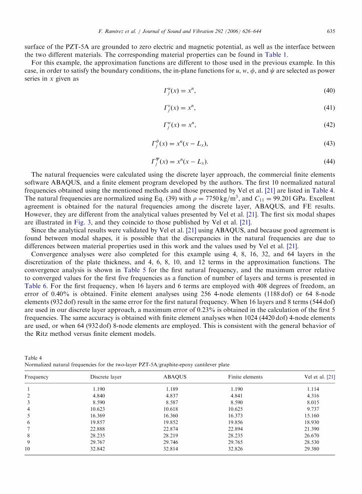
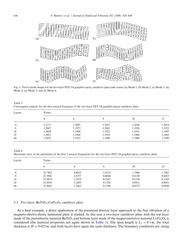
The natural frequencies were calculated using the discrete layer approach, the commercial finite elementssoftware ABAQUS, and a finite element program developed by the authors. The first 10 normalized naturalfrequencies obtained using the mentioned methods and those presented by Vel et al. [21] are listed in Table 4.The natural frequencies are normalized using Eq. (39) with r ¼ 7750 kg=m3, and C11 ¼ 99:201GPa. Excellentagreement is obtained for the natural frequencies among the discrete layer, ABAQUS, and FE results.However, they are different from the analytical values presented by Vel et al. [21]. The first six modal shapesare illustrated in Fig. 3, and they coincide to those published by Vel et al. [21].
Since the analytical results were validated by Vel et al. [21] using ABAQUS, and because good agreement isfound between modal shapes, it is possible that the discrepancies in the natural frequencies are due todifferences between material properties used in this work and the values used by Vel et al. [21].
Convergence analyses were also completed for this example using 4, 8, 16, 32, and 64 layers in thediscretization of the plate thickness, and 4, 6, 8, 10, and 12 terms in the approximation functions. Theconvergence analysis is shown in Table 5 for the first natural frequency, and the maximum error relativeto converged values for the first five frequencies as a function of number of layers and terms is presented inTable 6. For the first frequency, when 16 layers and 6 terms are employed with 408 degrees of freedom, anerror of 0.40% is obtained. Finite element analyses using 256 4-node elements (1188 dof) or 64 8-nodeelements (932 dof) result in the same error for the first natural frequency. When 16 layers and 8 terms (544 dof)are used in our discrete layer approach, a maximum error of 0.23% is obtained in the calculation of the first 5frequencies. The same accuracy is obtained with finite element analyses when 1024 (4420 dof) 4-node elementsare used, or when 64 (932 dof) 8-node elements are employed. This is consistent with the general behavior ofthe Ritz method versus finite element models.
Table 4
Normalized natural frequencies for the two-layer PZT-5A/graphite-epoxy cantilever plate
Frequency Discrete layer ABAQUS Finite elements Vel et al. [21]
1 1.190 1.189 1.190 1.114
2 4.840 4.837 4.841 4.316
3 8.590 8.587 8.590 8.015
4 10.623 10.618 10.625 9.737
5 16.369 16.360 16.373 15.160
6 19.857 19.852 19.856 18.930
7 22.888 22.874 22.894 21.390
8 28.235 28.219 28.235 26.670
9 29.767 29.746 29.765 28.530
10 32.842 32.814 32.826 29.380
ARTICLE IN PRESS
Fig. 3. First 6 mode shapes for the two-layer PZT-5A/graphite-epoxy cantilever plate (side views): (a) Mode 1, (b) Mode 2, (c) Mode 3, (d)
Mode 4, (e) Mode 5, and (f) Mode 6.
Table 5
Convergence analysis for the first natural frequency of the two-layer PZT-5A/graphite-epoxy cantilever plate
Layers Terms
4 6 8 10 12
4 1.2117 1.2045 1.2023 1.2016 1.2014
8 1.2047 1.1973 1.1945 1.1936 1.1932
16 1.2028 1.1949 1.1922 1.1912 1.1907
32 1.2023 1.1944 1.1916 1.1906 1.1903
64 1.2022 1.1915 1.1908 1.1904 1.1899
Table 6
Maximum error in the calculation of the first 5 natural frequencies for the two-layer PZT-5A/graphite-epoxy cantilever plate
Layers Terms
4 6 8 10 12
4 23.7482 4.0053 1.8572 1.7966 1.7887
8 22.3941 2.8357 0.6844 0.6138 0.6025
16 21.9979 2.3819 0.2347 0.1556 0.1383
32 21.8932 2.2493 0.1326 0.0412 0.0031
64 21.8663 2.2463 0.1198 0.0272 0.0030
F. Ramirez et al. / Journal of Sound and Vibration 292 (2006) 626–644636
3.3. Two-layer BaTiO3/CoFe2O4 cantilever plate
As a final example, a direct application of the presented discrete layer approach to the free vibration of amagneto-electro-elastic laminated plate is studied. In this case a two-layer cantilever plate with the top layermade of the piezoelectric material BaTiO3 and bottom layer made of the magnetostrictive material CoFe2O4 isconsidered (the material properties are again shown in Table 1). The span length is Lx ¼ 0:1m, the totalthickness is H ¼ 0:025m, and both layers have again the same thickness. The boundary conditions are: along

ARTICLE IN PRESSF. Ramirez et al. / Journal of Sound and Vibration 292 (2006) 626–644 637
the left edge of the laminate the mechanical displacements u, v, and w are set to zero, and the right edge, top,and bottom surfaces are traction free. Both edges of the plate, as well as the top and bottom surfaces, aregrounded to zero electric and magnetic potential. The approximation functions for this example are the sameas those used in the previous example and they are shown in Eqs. (40)–(44).
The natural frequencies are normalized according to Eq. (39) with r ¼ 5800 kg=m3, and C11 ¼ 286:0GPa.The first 10 natural frequencies calculated using the discrete layer approach are listed in Table 7 along withresults using the finite element method, excellent agreement is obtained. The first 6 modal shapes are presentedin Fig. 4, with a significant change in the laminate thickness observed for modes 3 and 5.
In Table 8, the convergence analysis for the first frequency is shown. Using 16 layers, 8 terms, and544 degrees of freedom in our approximation resulted in an error of 0.38% for the first natural frequency. Inorder to obtain a smaller error using finite elements, 1024 (4420 dof) 4-node elements or 64 (932 dof) 8-nodeelements are required. The maximum error found in the calculation of first 5 frequencies for different numberof layers and terms in our discrete layer approximation are listed in Table 9. Once again the computationaladvantages of the present approach are clear. The discrete layer approach results in 1584 degrees of freedomwith a maximum error of 0.09%, while the finite element approach requires 4420 or 3396 degrees of freedomwhen 4-node or 8-node elements are used.
Fig. 4. First 6 mode shapes for the two-layer BaTiO3/CoFe2O4 cantilever plate (side views): (a) Mode 1, (b) Mode 2, (c) Mode 3, (d) Mode
4, (e) Mode 5, and (f) Mode 6.
Table 7
Normalized natural frequencies for the two-layer BaTiO3/CoFe2O4 cantilever plate
Frequency Discrete layer Finite elements
1 0.729 0.729
2 3.581 3.581
3 4.817 4.816
4 8.161 8.157
5 12.959 12.956
6 14.155 14.152
7 17.952 17.946
8 21.213 21.212
9 22.451 22.447
10 24.011 24.003

ARTICLE IN PRESS
Table 8
Convergence analysis for the first natural frequency of the two-layer BaTiO3/CoFe2O4 cantilever plate
Layers Terms
4 6 8 10 12
4 0.7511 0.7432 0.7408 0.7401 0.7398
8 0.7441 0.7357 0.7331 0.7321 0.7316
16 0.7423 0.7337 0.7309 0.7295 0.7294
32 0.7419 0.7333 0.7304 0.7293 0.7288
64 0.7417 0.7331 0.7302 0.7291 0.7286
Table 9
Maximum error in the calculation of the first 5 natural frequencies for the two-layer BaTiO3/CoFe2O4 cantilever plate
Layers Terms
4 6 8 10 12
4 16.6287 3.8082 1.8683 1.8251 1.8198
8 15.9857 2.5843 0.6691 0.5649 0.5534
16 15.8178 2.2053 0.3842 0.1906 0.1736
32 15.7755 2.1042 0.313 0.1589 0.0901
64 15.7649 2.0785 0.2951 0.1395 0.0703
F. Ramirez et al. / Journal of Sound and Vibration 292 (2006) 626–644638
The through-thickness variations of the in-plane displacement u, out-of-plane displacement w, electricpotential f, and magnetic potential c at x ¼ L=4 and 3L=4 are shown in Fig. 5 for the first 4 natural modes.The electric potential displays a nonlinear variation in the piezoelectric media, while its variation is linear inthe magnetostrictive media. The opposite behavior is observed for the magnetic potential, that is, nonlinear inthe magnetostrictive media, and linear in the piezoelectric media. The through-thickness behavior of thevertical displacement w is effectively constant for modes 1, 2, and 4, indicating that those modes are primarybending modes. For mode 3, the through-thickness variation of the in-plane displacement is constant,indicating that this mode is a predominant axial vibration mode.
The influence of the piezoelectric and piezomagnetic coefficients on the natural frequencies of the canti-lever plate was also studied. Each of these coefficients was allowed to vary from zero to four timesits actual value, and the natural frequencies were calculated while keeping the other coefficients unchanged.Results of this analysis are shown in Figs. 6 and 7. In these figures, o=o0 represents the ratio of thecalculated frequency to the frequency obtained using the actual coefficients for the corresponding vibrationmode, e=e0 represents the ratio of the used value of the corresponding piezoelectric coefficient to itsactual value, and q=q0 represents the ratio of the used value of the corresponding piezomagnetic coefficientto its actual value. Not surprisingly, the magnitude of the natural frequencies increases as the piezoelectricand piezomagnetic coefficients become higher, indicating a stiffening effect caused by the couplingamong elastic, electric and magnetic fields. The piezoelectric and piezomagnetic coefficients have a similarlevel of influence on the natural frequencies of the plate, with e31 and q31 having the highest impact forthe first three vibration modes. The natural frequency corresponding to the fourth vibration mode is moreaffected by the e15 and q15 coefficients which represent the coupling between electric and magnetic fields withthe shear strain. In this mode shape, as well as in mode 2, there is an important contribution of sheardeformation to the vibration behavior of the plate. This can be observed in the modal shapes shown in Fig. 4.It is not surprising to see the presence of a shearing vibration mode since the laminate is considered a thick

ARTICLE IN PRESS
Fig. 5. Through-thickness variation of main fields for the first 4 vibration modes of the two-layer BaTiO3/CoFe2O4 cantilever plate: (a) in-
plane displacement u, (b) vertical displacement w, (c) electric potential f, and (d) magnetic potential c. The variation of the fields at
x ¼ Lx=4 is represented by solid lines, and dotted lines represent their variation at x ¼ 3Lx=4. Open circles, stars, open squares, and open
diamonds indicate modes 1, 2, 3, and 4, respectively.
F. Ramirez et al. / Journal of Sound and Vibration 292 (2006) 626–644 639
plate with aspect ratio Lx=H ¼ 4, and this behavior is expected to change when thin laminates with higheraspect ratio are studied.
4. Conclusions
A discrete layer model has been presented for the solution of the free vibration of two-dimensional linearmagneto-electro-elastic laminated plates. Approximations for the three mechanical displacements, electricpotential, and magnetic potential are expressed as functions of the global coordinates with separatedependence on the in-plane coordinate x, and the out-of-plane coordinate z. The present model was validatedwith excellent agreement by comparing the natural frequencies of a simply supported homogeneous PZT-4plate with the exact solution results [8]. We also validated this model by comparing the frequencies of a two-layer PZT-5A/graphite-epoxy plate with a recent analytical solution [21], with results obtained using thecommercial finite element software ABAQUS, and with results obtained from a finite element programdeveloped by the authors. Finally, the present approach was used to study the free vibration behavior of atwo-layer magneto-electro-elastic plate made of the piezoelectric material BaTiO3 and the magnetostrictivematerial CoFe2O4.
For the specimen geometries and material properties used in the present work, we conclude the following:
1.
The discrete-layer model can be used to solve the free-vibration problem of magneto-electro-elasticlaminated plates with excellent accuracy when a sufficient number of layers and terms are employed in theapproximations. Using 128 layers and one approximation term for the simply supported PZT-4, and 32layers and 12 terms for cantilever plates resulted in 3–4 digits of accuracy.
ARTICLE IN PRESS
Fig. 6. Influence of piezoelectric coefficients on the natural frequencies of the two-layer BaTiO3/CoFe2O4 cantilever plate: (a) Mode 1, (b)
Mode 2, (c) Mode 3, and (d) Mode 4. Solid lines, stars, and open circles represent e15, e31, and e33, respectively.
F. Ramirez et al. / Journal of Sound and Vibration 292 (2006) 626–644640
2.
Satisfactory levels of accuracy can be obtained using the present approach using a fairly small number oflayers and terms for the approximation functions. Less than 1.0% error was achieved with 68 layers and 1approximation term for the simply supported plate, and 8 layers and 8 approximation terms for thecantilever laminates.3.
For the same level of accuracy, the present approach results in a smaller number of degrees of freedomwhen compared to finite element analyses, with the consequent reduction in computational time. For thesimply supported laminate the number of degrees of freedom using the discrete layer approach was about14 times smaller than that required by the finite element method to obtain a maximum error smaller than0.5%, and about 2 times smaller for the case of cantilever plates.4.
It was observed during the analysis of the magneto-electro-elastic cantilever plate, that the through-thickness behavior of the electric potential is nonlinear within the piezoelectric layer, while it is linear withinthe magnetostrictive layer. The opposite behavior was observed for the magnetic potential. Subsequentsimplified models could exploit this behavior.5.
Consistent with earlier observations, higher piezoelectric or piezomagnetic coefficients resulted in highernatural frequencies. Therefore, there is a general stiffening effect due to the coupled elastic, electric, andmagnetic fields.6.
The piezoelectric coefficients and piezomagnetic coefficients exhibit a similar level of influence on thenatural frequencies of the magneto-electro-elastic plate studied here. Maximum increments in thecorresponding frequency were between 10.0% and 13.0% for mode 1, 4.0% to 10.0% for mode 2, about14.0% for mode 3, and between 12.0% and 20.0% for mode 4. It was also observed that for the first threevibration modes the piezoelectric coefficient with highest impact on the frequencies is e31, while q31 has thehighest impact among the different piezomagnetic coefficients. However, for mode 4 the e15 and q15coefficients showed a higher influence on the natural vibration frequencies of the laminate indicating a

ARTICLE IN PRESS
Fig. 7. Influence of piezomagnetic coefficients on the natural frequencies of the two-layer BaTiO3/CoFe2O4 cantilever plate: (a) Mode 1,
(b) Mode 2, (c) Mode 3, and (d) Mode 4. Solid lines, stars, and open circles represent q15, q31, and q33, respectively.
F. Ramirez et al. / Journal of Sound and Vibration 292 (2006) 626–644 641
primary shearing vibration mode. Modal shapes with a predominant shear deformation are expected to bepresent for thick plates as those considered here, and this behavior would change as the aspect ratio of theplate is increased.
Appendix A
Elastic stiffness tensor:
½C� ¼
C11 C12 C13 0 0 0
C12 C22 C23 0 0 0
C13 C23 C33 0 0 0
0 0 0 C44 0 0
0 0 0 0 C55 0
0 0 0 0 0 C66
26666666664
37777777775.
Dielectric permittivity constants:
½�� ¼
�11 0 0
0 �22 0
0 0 �33
264
375.

ARTICLE IN PRESSF. Ramirez et al. / Journal of Sound and Vibration 292 (2006) 626–644642
Magnetic permittivity constants:
½m� ¼
m11 0 0
0 m22 0
0 0 m33
264
375.
Piezoelectric coefficients:
½e� ¼
0 0 0 0 e15 0
0 0 0 e24 0 0
e31 e32 e33 0 0 0
264
375.
Piezomagnetic coefficients:
½q� ¼
0 0 0 0 q15 0
0 0 0 q24 0 0
q31 q32 q33 0 0 0
264
375.
Magnetoelectric coefficients:
½d� ¼
d11 0 0
0 d22 0
0 0 d33
264
375.
Appendix B
Muuij ¼
ZV
½rGui G
uj �dV , (45)
Mvvij ¼
ZV
½rGvi G
vj �dV , (46)
Mwwij ¼
ZV
½rGwi G
wj �dV , (47)
Kuuij ¼
ZV
C11qGu
i
qx
qGuj
qxþ C55
qGui
qz
qGuj
qz
� �dV , (48)
Kuvij ¼
ZV
C14qGu
i
qx
qGvj
qzþ C45
qGui
qz
qGvj
qzþ C16
qGui
qx
qGvj
qx
� �dV , (49)
Kuwij ¼
ZV
C13qGu
i
qx
qGwj
qzþ C55
qGui
qz
qGwj
qx
� �dV , (50)
Kufij ¼
ZV
e11qGu
i
qx
qGfj
qxþ e31
qGui
qx
qGfj
qzþ e15
qGui
qz
qGfj
qx
" #dV , (51)
Kucij ¼
ZV
q11
qGui
qx
qGcj
qxþ q31
qGui
qx
qGcj
qzþ q15
qGui
qz
qGcj
qx
" #dV , (52)
Kvvij ¼
ZV
C44qGv
i
qz
qGvj
qzþ C66
qGvi
qx
qGvj
qx
� �dV , (53)
ARTICLE IN PRESSF. Ramirez et al. / Journal of Sound and Vibration 292 (2006) 626–644 643
Kvwij ¼
ZV
C45qGv
i
qz
qGwj
qxþ C36
qGvi
qx
qGwj
qz
� �dV , (54)
Kvfij ¼
ZV
e14qGv
i
qz
qGfj
qxþ e16
qGvi
qx
qGfj
qxþ e36
qGvi
qx
qGfj
qz
" #dV , (55)
Kvcij ¼
ZV
q14
qGvi
qz
qGcj
qxþ q16
qGvi
qx
qGcj
qxþ q36
qGvi
qx
qGcj
qz
" #dV , (56)
Kwwij ¼
ZV
C33qGw
i
qz
qGwj
qzþ C55
qGwi
qx
qGwj
qx
� �dV , (57)
Kwfij ¼
ZV
e33qGw
i
qz
qGfj
qzþ e15
qGwi
qx
qGfj
qx
" #dV , (58)
Kwcij ¼
ZV
q33
qGwi
qz
qGcj
qzþ q15
qGwi
qx
qGcj
qx
" #dV , (59)
Kffij ¼
ZV
��11qGf
i
qx
qGfj
qx� �33
qGfi
qz
qGfj
qz
" #dV , (60)
Kfcij ¼
ZV
�d11qGf
i
qx
qGcj
qx� d33
qGfi
qz
qGcj
qz
" #dV , (61)
Kccij ¼
ZV
�m11qGc
i
qx
qGcj
qx� m33
qGci
qz
qGcj
qz
" #dV . (62)
References
[1] C.K. Lee, Piezoelectric Laminates for Torsional and Bending Control: Theory and Experiments, PhD Dissertation, Cornell
University, Ithaca, New York, 1987.
[2] C.K. Lee, F.C. Moon, Laminated piezopolymer plates for torsion and bending sensing and actuators, Journal of the Acoustical
Society of America 85 (1989) 2432–2439.
[3] C.K. Lee, Theory of laminated piezoelectric plates for the design of distributed sensors/actuators, Part I: governing equations and
reciprocal relationships, Journal of the Acoustical Society of America 87 (1990) 1144–1158.
[4] C.K. Lee, F.C. Moon, Modal sensors/actuators, ASME Journal of Applied Mechanics 57 (1990) 434–441.
[5] H.S. Tzou, M. Gadre, Theoretical analysis of a multi-layered thin shell actuators for distributed vibration controls, ASME Journal of
Sound and Vibration 132 (1989) 433–450.
[6] P.R. Heyliger, Static behavior of laminated elastic/piezoelectric plates, AIAA Journal 32 (1994) 2481–2484.
[7] P.R. Heyliger, S. Brooks, Exact solutions for laminated piezoelectric plates in cylindrical bending, ASME Journal of Applied
Mechanics 63 (1996) 903–910.
[8] P.R. Heyliger, S. Brooks, Free vibration of piezoelectric laminates in cylindrical bending, International Journal of Solid and Structures
32 (20) (1995) 1960–2945.
[9] G. Harshe, J.P. Dougherty, R.E. Newnham, Theoretical modeling of multilayer magnetoelectric composites, International Journal of
Applied Electromagnetics 4 (1993) 145–159.
[10] C.W. Nan, Magnetoelectric effect in composites of piezoelectric and piezomagnetic phases, Physics Review B 50 (1994) 6082–6088.
[11] Y. Benviste, Magnetoelectric effect in fibrous composites with piezoelectric and piezomagnetic phases, Physics Review B 51 (1995)
16424–16427.
[12] E. Pan, Exact solution for simply supported and multilayered magneto-electro-elastic plates, Journal of Applied Mechanics 68 (2001)
608–618.

ARTICLE IN PRESSF. Ramirez et al. / Journal of Sound and Vibration 292 (2006) 626–644644
[13] E. Pan, P.R. Heyliger, Exact solutions for magnetoelectroelastic laminates in cylindrical bending, International Journal of Solids and
Structures 40 (2003) 6859–6876.
[14] E. Pan, P.R. Heyliger, Free vibration of simply-supported and multilayered magneto-electro-elastic plates, Journal of Sound and
Vibration 252 (2002) 429–442.
[15] P.R. Heyliger, E. Pan, Static fields in magnetoelectroelastic laminates, AIAA Journal 42 (7) (2004).
[16] P.R. Heyliger, F. Ramirez, E. Pan, Two-dimensional static fields in magneto-electroelastic laminates, Journal of Intelligent Material
Systems and Structures 15 (9–10) (2004) 689–709.
[17] A.M. Jiang, H.J. Ding, Analytical solutions to magneto-electro-elastic beams, Structural Engineering and Mechanics 18 (2) (2004)
195–209.
[18] R.G. Lage, C.M.M. Soares, C.A.M. Soares, J.N. Reddy, Layerwise partial mixed finite element analysis of magneto-electro-elastic
plates, Computer & Structures 82 (17–19) (2004) 1293–1301.
[19] G.R. Buchanan, Layered versus multiphase magneto-electro-elastic composites, Composites Part B—Engineering 35 (5) (2004)
413–420.
[20] S. Latheswary, K.V. Valsarajan, Y.V.K.S. Rao, Dynamic response of moderately thick composite plates, Journal of Sound and
Vibration 270 (1–2) (2004) 417–426.
[21] S.S. Vel, R. Mewer, R.C. Batra, Analytical solution for the cylindrical bending vibration of piezoelectric composite plates,
International Journal of Solids and Structures 41 (2004) 1625–1643.
[22] D.A. Berlincourt, D.R. Curran, H. Jaffe, Physical Acoustics, 1: Piezoelectric and Piezomagnetical Materials and their Function in
Transducers, 1964, pp. 169–270.
[23] J.N. Reddy, Energy and Variational Methods in Applied Mechanics, Wiley, New York, 1984.
[24] J.N. Reddy, A generalization of displacement-based laminate theories, Communications in Applied Numerical Methods 3 (1987)
173–181.
[25] P.R. Heyliger, Exact solutions for simply-supported laminated piezoelectric plates, Journal of Applied Mechanics 64 (1997) 299–306.
[26] ABAQUS User’s Manual, Version 6.1, Hibbit, Karlsson & Sorensen, 2000.