Actuator range catalogue - Electro-Matic Products
312
Actuator range catalogue
-
Upload
khangminh22 -
Category
Documents
-
view
0 -
download
0
Transcript of Actuator range catalogue - Electro-Matic Products
Actuator range catalogue

3
Contents1 Introduction .......................................................................4Core technologies .................................................................5 Product overview ...................................................................8Ewellix engineering tools ..................................................... 11Actuation System set-up ..................................................... 12Product range comparison .................................................. 16Product benefits ..................................................................24Customization capabilities...................................................28Application examples ..........................................................32
2 Selection process ...........................................................50Simplified calculation process............................................. 51
3 Actuators .........................................................................54Matrix series .........................................................................57
Matrix1 ..............................................................................58Matrix3 ..............................................................................62Matrix7 ..............................................................................66
Runner ..................................................................................70CAJA35C .............................................................................. 74Ecomag ................................................................................78CAHB series .........................................................................82
CAHB-10 ...........................................................................84CAHB-20A ........................................................................90CAHB-20E and -20S ........................................................94CAHB-21E and -21S .........................................................98CAHB-22E and -22S .......................................................102CAHB-30A ...................................................................... 120CAHB-31N ...................................................................... 124
CAR, CAP & CAT series .....................................................135CAR 22 ............................................................................136CAP 32 ............................................................................ 140CAT 32B and CAP 43B ................................................... 146CAT 33 and CAP 43A ..................................................... 156CAT 33H ..........................................................................166CAR 40 ............................................................................ 174Spare parts .....................................................................180
CAHM series ......................................................................185
4 Lifting columns .............................................................180CPMA .................................................................................192CPMB .................................................................................200CPMT .................................................................................208TFG ..................................................................................... 214THG .................................................................................... 218TLC .....................................................................................222TLG .....................................................................................226TLT ......................................................................................230TXG ....................................................................................234FRE .....................................................................................238
5 Control units ..................................................................230BCU ....................................................................................242VCU ....................................................................................246SCU ....................................................................................250MCU ...................................................................................254COMPACT ..........................................................................258SEM ....................................................................................262
6 Operating switches ......................................................256CAES ..................................................................................268EHA1 ...................................................................................270EHA3 ..................................................................................272EHE1 ................................................................................... 274HSM, HSF, HSU ................................................................. 276PHC ....................................................................................278PFP .....................................................................................280ST .......................................................................................282ST .......................................................................................284STK .....................................................................................286CAJH1 ................................................................................288PAM ....................................................................................290
7 New medical solution ...................................................292CAMT .................................................................................293
8 Glossary and symbols descriptionGlossary .............................................................................301Symbols description ..........................................................305

Actuator range
Technology leadership Our journey began over 50 years ago as part of the SKF Group, a leading global technology provider, with the world’s first precision ball and roller screw factories. Our history with SKF provided us with the expertise to continuously develop new technologies and use them to create cutting edge prod-ucts that offer our customers a competitive advantage.In 2019, we became independent from SKF and changed our name to Ewellix. We are proud of our heritage. This gives us a unique foundation on which to build an agile busi-ness with engineering excellence and innovation as our core strengths.
Global presence and local support With our global presence, we are uniquely positioned to deliver standard components and custom-engineered solutions, with full technical and applications support around the world. The long lasting relationships with our dis-tributor partners allow us to support customers in a variety of different industries. At Ewellix, we don’t just provide prod-ucts; we engineer integrated solutions that help custom-ers realise their ambitions.
The heritage of innovation
Ewellix is a global innovator and manufacturer of linear motion and actuation solutions used in assembly automation, medical applications and mobile machinery. Formerly part of SKF Group, the Ewellix Group consists of 16 sales units and eight factories. External net sales are approximately 2.3 SEK billion and we employ around 1200 people. Ewellix is headquartered in Gothenburg, Sweden and is owned by Triton.
1 200 employees
8 factories
16 sales units
Armada
Toronto
Taouyan
Philadelphia
TurinLiestal
Steyr
Sofia
BudapestMeckesheim
Sales Unit
Manufacturing Unit
Countries supported by Sales Unit
UtrechtMilton Keynes
Gothenburg
Schweinfurt
ChambéryGuyancourt
Pinghu
ShanghaiSeoul
Pune

III
Trusted engineering expertise
Engineering for the futureWe work in a wide range of industries, where our solutions provide key functionality for business critical applications.For the medical industry, we provide precision components for use in core medical equipment. Our unparalleled understanding of industrial automation systems is based on decades of research into advanced au-tomation components and techniquesOur deep knowledge of mobile machinery provides power-ful and reliable electromechanical solutions for the harshest conditions. In an industrial distribution setting, we supply linear expertise to our partners, empowering them to serve customers with greater efficiency
We offer excellenceWe have a unique understanding of linear equipment and how it’s integrated in customers’ applications to provide the best performance and machine efficiency.We assist our customers by creating equipment that runs faster, longer and that is safe and sustainable. We provide a wide variety of linear motion components and electromechanical actuators for equipping any auto-mation application, helping our customers reduce footprint, energy use and maintenance.We push for lower energy consumption that increase pro-ductivity and reduce the environmental impact.
Our industry is in motion; pushing towards solutions that reduce environmental impact and leverage new technology. We provide technical and manufacturing expertise to overcome our customers’ challenges.
Actuation systems Ball and roller screws Linear guides and systems
Introduction
1Introduction• Cost effectiveness • Controllability• Stability

5
Introduction
1Core technologies
Linear actuatorsWe offer a wide range of low- to medium-duty actuator de-signs and configurations for simple industrial or specific health care applications. Our versatile range provides everything from low- to high-load capacities and medium operating speeds to quiet and aesthetically designed systems (⮑ fig. 1).
High-performance actuators Our range of high-duty actuators meets the needs of de-manding industrial applications with high loads and speeds in continuous operation. These actuators provide the best controllability and reliability for programmable motion cycles (⮑ fig. 2).
Lifting columnsWe offer a wide range of options for several applications. In addition, our lifting columns are quiet, robust, powerful, re-sistant to high offset loads and feature attractive designs (⮑ fig. 3).
Control unitsIdeal for applications focused on system control, Ewellix control units provide connections for foot and hand or desk switches (⮑ fig. 4).
Operating switches Ewellix offers different operating switches to control the position of your equipment. The range includes:
• Hand switches • Foot switches • Desk switches These switches can be used with control units to drive linear actuators and lifting columns or directly with the devices in AC powered versions.
Fig. 1
Fig. 2
Fig. 3
Fig. 4
Actuation technology Our extensive experience and knowledge of actuation systems allows us to satisfy the most demanding requirements using linear actuators, lifting columns and control units.
6
Actuator range
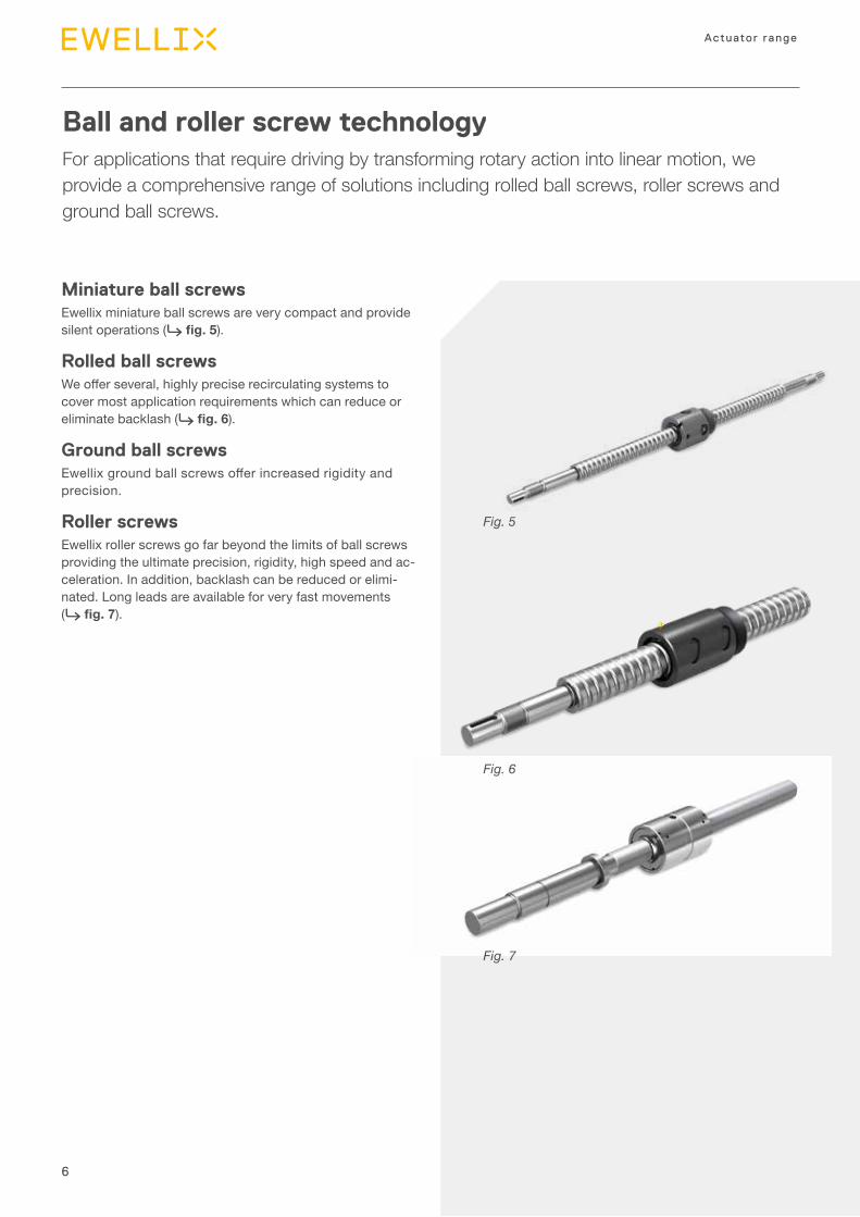
Ball and roller screw technologyFor applications that require driving by transforming rotary action into linear motion, we provide a comprehensive range of solutions including rolled ball screws, roller screws and ground ball screws.
Fig. 5
Fig. 6
Fig. 7
Miniature ball screwsEwellix miniature ball screws are very compact and provide silent operations (⮑ fig. 5).
Rolled ball screwsWe offer several, highly precise recirculating systems to cover most application requirements which can reduce or eliminate backlash (⮑ fig. 6).
Ground ball screwsEwellix ground ball screws offer increased rigidity and precision.
Roller screwsEwellix roller screws go far beyond the limits of ball screws providing the ultimate precision, rigidity, high speed and ac-celeration. In addition, backlash can be reduced or elimi-nated. Long leads are available for very fast movements (⮑ fig. 7).
7
Introduction
1
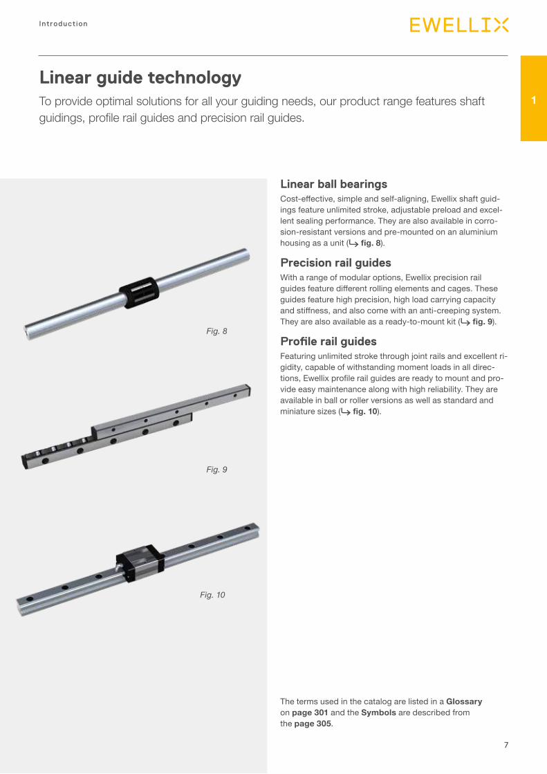
Linear guide technologyTo provide optimal solutions for all your guiding needs, our product range features shaft guidings, profile rail guides and precision rail guides.
Linear ball bearings Cost-effective, simple and self-aligning, Ewellix shaft guid-ings feature unlimited stroke, adjustable preload and excel-lent sealing performance. They are also available in corro-sion-resistant versions and pre-mounted on an aluminium housing as a unit (⮑ fig. 8).
Precision rail guides With a range of modular options, Ewellix precision rail guides feature different rolling elements and cages. These guides feature high precision, high load carrying capacity and stiffness, and also come with an anti-creeping system. They are also available as a ready-to-mount kit (⮑ fig. 9).
Profile rail guidesFeaturing unlimited stroke through joint rails and excellent ri-gidity, capable of withstanding moment loads in all direc-tions, Ewellix profile rail guides are ready to mount and pro-vide easy maintenance along with high reliability. They are available in ball or roller versions as well as standard and miniature sizes (⮑ fig. 10).
Fig. 10
Fig. 8
Fig. 9
The terms used in the catalog are listed in a Glossary on page 301 and the Symbols are described from the page 305.
8
Actuator range
Product overview
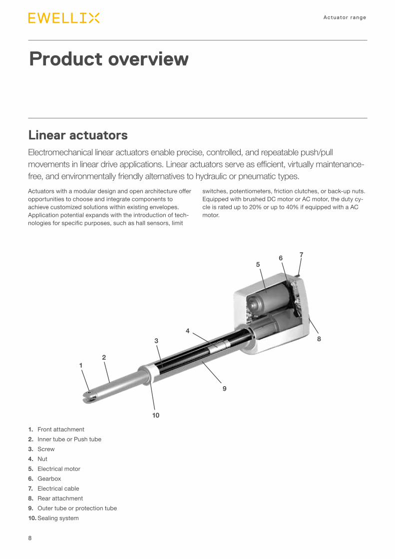
Linear actuatorsElectromechanical linear actuators enable precise, controlled, and repeatable push/pull movements in linear drive applications. Linear actuators serve as efficient, virtually maintenance-free, and environmentally friendly alternatives to hydraulic or pneumatic types.
1. Front attachment2. Inner tube or Push tube3. Screw4. Nut5. Electrical motor6. Gearbox7. Electrical cable8. Rear attachment9. Outer tube or protection tube10. Sealing system
12
34
9
56 7
10
8
Actuators with a modular design and open architecture offer opportunities to choose and integrate components to achieve customized solutions within existing envelopes. Application potential expands with the introduction of tech-nologies for specific purposes, such as hall sensors, limit
switches, potentiometers, friction clutches, or back-up nuts. Equipped with brushed DC motor or AC motor, the duty cy-cle is rated up to 20% or up to 40% if equipped with a AC motor.
9
Introduction
1
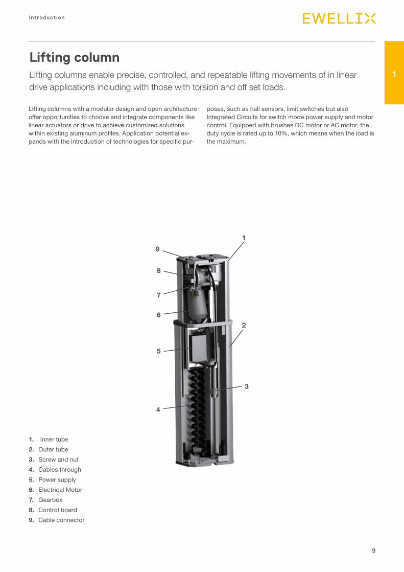
Lifting columnLifting columns enable precise, controlled, and repeatable lifting movements of in linear drive applications including with those with torsion and off set loads.
Lifting columns with a modular design and open architecture offer opportunities to choose and integrate components like linear actuators or drive to achieve customized solutions within existing aluminum profiles. Application potential ex-pands with the introduction of technologies for specific pur-
poses, such as hall sensors, limit switches but also Integrated Circuits for switch mode power supply and motor control. Equipped with brushes DC motor or AC motor, the duty cycle is rated up to 10%, which means when the load is the maximum.
1. Inner tube 2. Outer tube3. Screw and nut4. Cables through5. Power supply6. Electrical Motor7. Gearbox8. Control board9. Cable connector
1
2
3
6
4
7
5
8
9
10
Actuator range
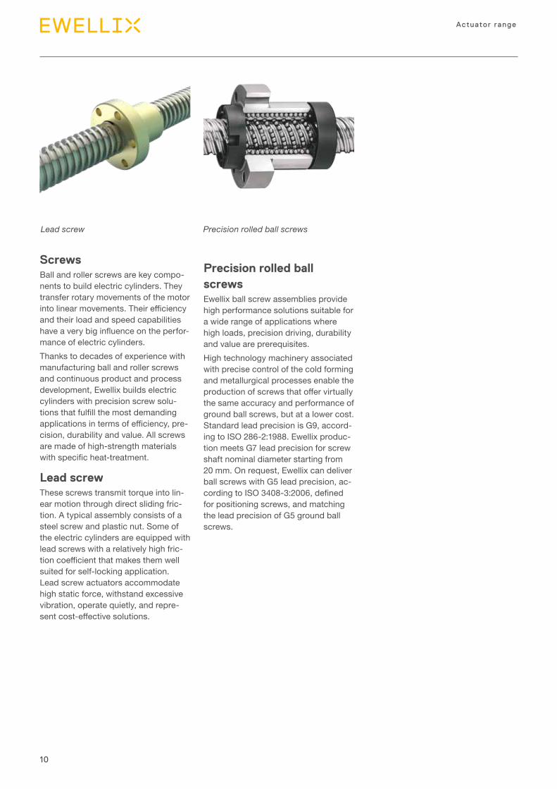
Screws Ball and roller screws are key compo-nents to build electric cylinders. They transfer rotary movements of the motor into linear movements. Their efficiency and their load and speed capabilities have a very big influence on the perfor-mance of electric cylinders.Thanks to decades of experience with manufacturing ball and roller screws and continuous product and process development, Ewellix builds electric cylinders with precision screw solu-tions that fulfill the most demanding applications in terms of efficiency, pre-cision, durability and value. All screws are made of high-strength materials with specific heat-treatment.
Lead screwThese screws transmit torque into lin-ear motion through direct sliding fric-tion. A typical assembly consists of a steel screw and plastic nut. Some of the electric cylinders are equipped with lead screws with a relatively high fric-tion coefficient that makes them well suited for self-locking application. Lead screw actuators accommodate high static force, withstand excessive vibration, operate quietly, and repre-sent cost-effective solutions.
Lead screw Precision rolled ball screws
Precision rolled ball screwsEwellix ball screw assemblies provide high performance solutions suitable for a wide range of applications where high loads, precision driving, durability and value are prerequisites. High technology machinery associated with precise control of the cold forming and metallurgical processes enable the production of screws that offer virtually the same accuracy and performance of ground ball screws, but at a lower cost. Standard lead precision is G9, accord-ing to ISO 286-2:1988. Ewellix produc-tion meets G7 lead precision for screw shaft nominal diameter starting from 20 mm. On request, Ewellix can deliver ball screws with G5 lead precision, ac-cording to ISO 3408-3:2006, defined for positioning screws, and matching the lead precision of G5 ground ball screws.

11
Introduction
1Ewellix engineering tools
Web-based solutionsTo simplify the product selection process, Ewellix offers a set of free Web tools that allow a quick and easy navigation into the complete linear motion offering.
Actuator Select Users can choose the desired product family among Columns, Linear Actuators, Rotary Actuators and Controls. Then, by entering few simple parameters, they will be guided in the product selection.Key features include:
• Four complete product lines • Dynamic filtering of the results • Result ranking by application • Product comparison (up to 3 at time) • Indication of compatible control unit for selected Column
or Actuator • Cost saving calculator• Direct link to product drawing, technical datasheet and
catalogues
A web-based version of the tool is available at ewellix.com/actuator-select
12
Actuator range
Actuation System set-upLinear actuator definition and type
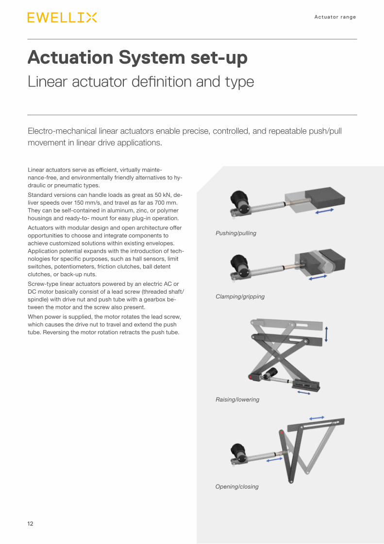
Electro-mechanical linear actuators enable precise, controlled, and repeatable push/pull movement in linear drive applications.
Linear actuators serve as efficient, virtually mainte-nance-free, and environmentally friendly alternatives to hy-draulic or pneumatic types.Standard versions can handle loads as great as 50 kN, de-liver speeds over 150 mm/s, and travel as far as 700 mm. They can be self-contained in aluminum, zinc, or polymer housings and ready-to- mount for easy plug-in operation.Actuators with modular design and open architecture offer opportunities to choose and integrate components to achieve customized solutions within existing envelopes. Application potential expands with the introduction of tech-nologies for specific purposes, such as hall sensors, limit switches, potentiometers, friction clutches, ball detent clutches, or back-up nuts.Screw-type linear actuators powered by an electric AC or DC motor basically consist of a lead screw (threaded shaft/spindle) with drive nut and push tube with a gearbox be-tween the motor and the screw also present.When power is supplied, the motor rotates the lead screw, which causes the drive nut to travel and extend the push tube. Reversing the motor rotation retracts the push tube.
Pushing/pulling
Raising/lowering
Opening/closing
Clamping/gripping
13
Introduction
1
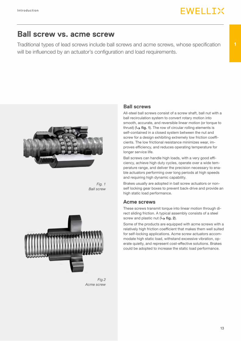
Fig. 1 Ball screw
Fig.2 Acme screw
Ball screws All-steel ball screws consist of a screw shaft, ball nut with a ball recirculation system to convert rotary motion into smooth, accurate, and reversible linear motion (or torque to thrust) (⮑ fig. 1). The row of circular rolling elements is self-contained in a closed system between the nut and screw for a design exhibiting extremely low friction coeffi-cients. The low frictional resistance minimizes wear, im-proves efficiency, and reduces operating temperature for longer service life.Ball screws can handle high loads, with a very good effi-ciency, achieve high duty cycles, operate over a wide tem-perature range, and deliver the precision necessary to ena-ble actuators performing over long periods at high speeds and requiring high dynamic capability.Brakes usually are adopted in ball screw actuators or non-self locking gear boxes to prevent back-drive and provide an high static load performance.
Acme screwsThese screws transmit torque into linear motion through di-rect sliding friction. A typical assembly consists of a steel screw and plastic nut (⮑ fig. 2).Some of the products are equipped with acme screws with a relatively high friction coefficient that makes them well suited for self-locking applications. Acme screw actuators accom-modate high static load, withstand excessive vibration, op-erate quietly, and represent cost-effective solutions. Brakes could be adopted to increase the static load performance.
Ball screw vs. acme screwTraditional types of lead screws include ball screws and acme screws, whose specification will be influenced by an actuator’s configuration and load requirements.
14
Actuator range
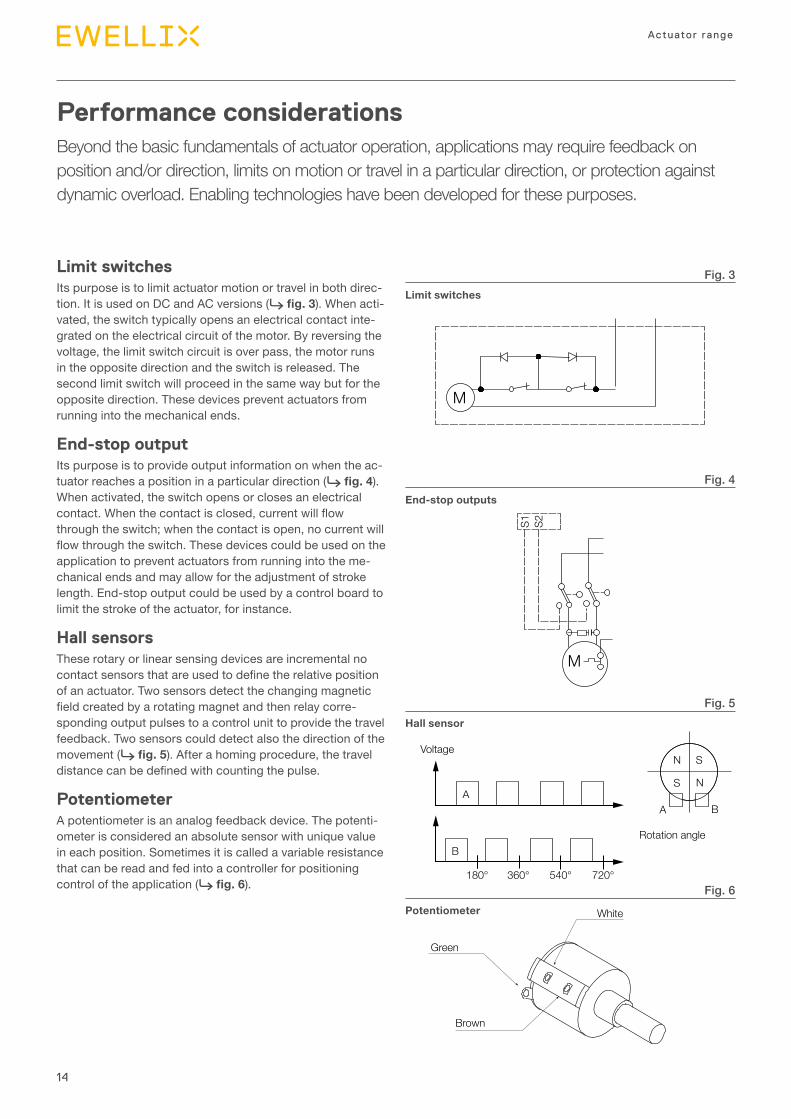
Performance considerationsBeyond the basic fundamentals of actuator operation, applications may require feedback on position and/or direction, limits on motion or travel in a particular direction, or protection against dynamic overload. Enabling technologies have been developed for these purposes.
Limit switchesIts purpose is to limit actuator motion or travel in both direc-tion. It is used on DC and AC versions (⮑ fig. 3). When acti-vated, the switch typically opens an electrical contact inte-grated on the electrical circuit of the motor. By reversing the voltage, the limit switch circuit is over pass, the motor runs in the opposite direction and the switch is released. The second limit switch will proceed in the same way but for the opposite direction. These devices prevent actuators from running into the mechanical ends.
End-stop outputIts purpose is to provide output information on when the ac-tuator reaches a position in a particular direction (⮑ fig. 4). When activated, the switch opens or closes an electrical contact. When the contact is closed, current will flow through the switch; when the contact is open, no current will flow through the switch. These devices could be used on the application to prevent actuators from running into the me-chanical ends and may allow for the adjustment of stroke length. End-stop output could be used by a control board to limit the stroke of the actuator, for instance.
Hall sensorsThese rotary or linear sensing devices are incremental no contact sensors that are used to define the relative position of an actuator. Two sensors detect the changing magnetic field created by a rotating magnet and then relay corre-sponding output pulses to a control unit to provide the travel feedback. Two sensors could detect also the direction of the movement (⮑ fig. 5). After a homing procedure, the travel distance can be defined with counting the pulse.
PotentiometerA potentiometer is an analog feedback device. The potenti-ometer is considered an absolute sensor with unique value in each position. Sometimes it is called a variable resistance that can be read and fed into a controller for positioning control of the application (⮑ fig. 6).
Fig. 3
Fig. 6
Fig. 5
Fig. 4
M
White
White0
Green
GreenCW
Brown10K
Brown
ExtendRetract
POTLimit + POT:
180° 360° 540° 720°
Voltage
A B
N
N
S
S
B
A
Rotation angle
M
S1 S2
Limit switches
Potentiometer
Hall sensor
End-stop outputs
15
Introduction
1
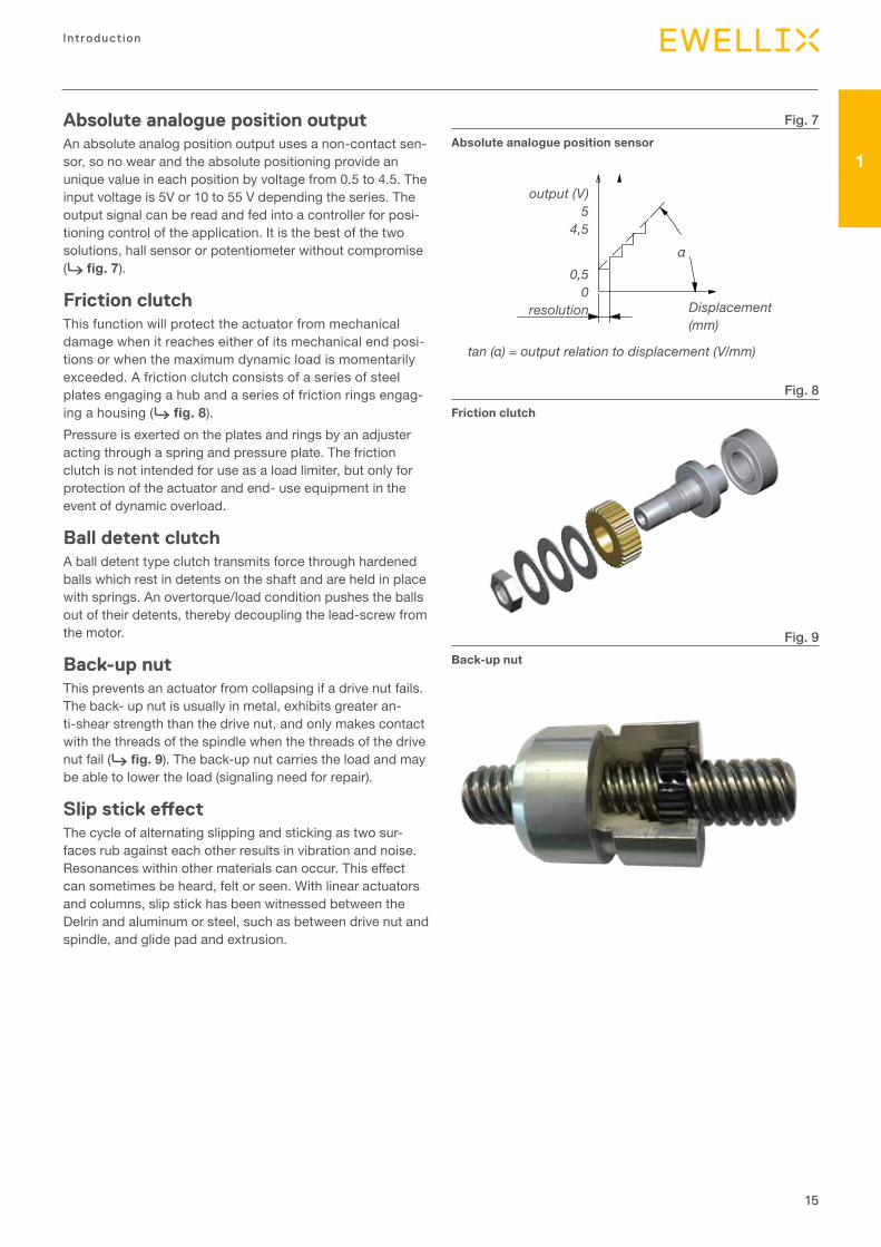
Absolute analogue position outputAn absolute analog position output uses a non-contact sen-sor, so no wear and the absolute positioning provide an unique value in each position by voltage from 0.5 to 4.5. The input voltage is 5V or 10 to 55 V depending the series. The output signal can be read and fed into a controller for posi-tioning control of the application. It is the best of the two solutions, hall sensor or potentiometer without compromise (⮑ fig. 7).
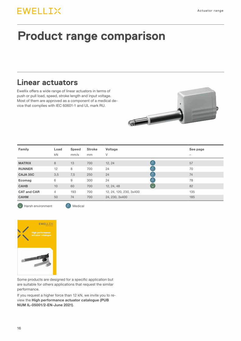
Friction clutchThis function will protect the actuator from mechanical damage when it reaches either of its mechanical end posi-tions or when the maximum dynamic load is momentarily exceeded. A friction clutch consists of a series of steel plates engaging a hub and a series of friction rings engag-ing a housing (⮑ fig. 8).Pressure is exerted on the plates and rings by an adjuster acting through a spring and pressure plate. The friction clutch is not intended for use as a load limiter, but only for protection of the actuator and end- use equipment in the event of dynamic overload.
Ball detent clutchA ball detent type clutch transmits force through hardened balls which rest in detents on the shaft and are held in place with springs. An overtorque/load condition pushes the balls out of their detents, thereby decoupling the lead-screw from the motor.
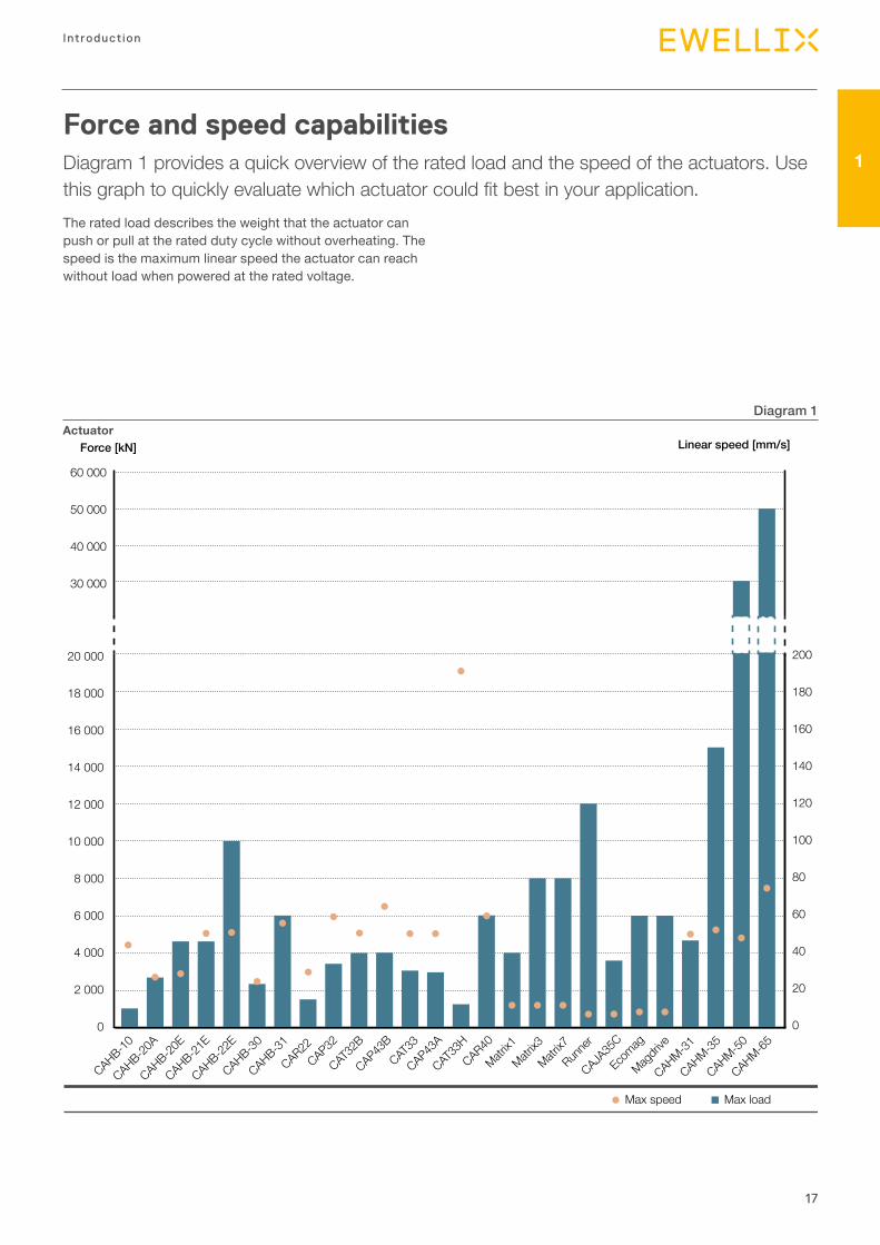
Back-up nutThis prevents an actuator from collapsing if a drive nut fails. The back- up nut is usually in metal, exhibits greater an-ti-shear strength than the drive nut, and only makes contact with the threads of the spindle when the threads of the drive nut fail (⮑ fig. 9). The back-up nut carries the load and may be able to lower the load (signaling need for repair).
Slip stick effectThe cycle of alternating slipping and sticking as two sur-faces rub against each other results in vibration and noise. Resonances within other materials can occur. This effect can sometimes be heard, felt or seen. With linear actuators and columns, slip stick has been witnessed between the Delrin and aluminum or steel, such as between drive nut and spindle, and glide pad and extrusion.
Fig. 7
Fig. 8
Fig. 9
Absolute analogue position sensor
Friction clutch
Back-up nut
output (V)5
4,5
0,50
resolution Displacement (mm)
tan (α) = output relation to displacement (V/mm)
α
16
Actuator range
Product range comparison
Linear actuatorsEwellix offers a wide range of linear actuators in terms of push or pull load, speed, stroke length and input voltage. Most of them are approved as a component of a medical de-vice that complies with IEC 60601-1 and UL mark RU.
MedicalHarsh environment
Family Load Speed Stroke Voltage See page kN mm/s mm V –
MATRIX 8 13 700 12, 24 57RUNNER 12 8 700 24 70CAJA 35C 3,5 7,5 250 24 74Ecomag 6 9 300 24 78CAHB 10 60 700 12, 24, 48 82CAT and CAR 4 193 700 12, 24, 120, 230, 3x400 135CAHM 50 74 700 24, 230, 3x400 185
Some products are designed for a specific application but are suitable for others applications that request the similar performance.If you request a higher force than 12 kN, we invite you to re-view the High performance actuator catalogue (PUB NUM IL-05001/2-EN-June 2021).
High performance actuator catalogue
17
Introduction
1
Linear speed [mm/s]Force [kN]
CAHB-21E
CAHB-22E
CAHB-30
CAHM-35
CAJA35
CCAP32
CAP43A
CAP43B
CAHB-31
CAR22CAR40
CAT32
BCAT
33
CAT33
H
Ecomag
Magdri
ve
Matrix1
Matrix3
Matrix7
Runne
r
CAHB-20E
CAHB-20A
CAHM-31
CAHB-10
CAHM-50
CAHM-65
Max loadMax speed
20 000
18 000
16 000
14 000
12 000
10 000
8 000
6 000
4 000
2 000
0
60 000
50 000
40 000
30 000
200
180
160
140
120
100
80
60
40
20
0
Actuator
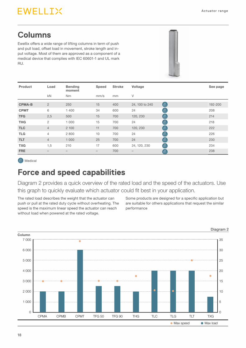
Force and speed capabilitiesDiagram 1 provides a quick overview of the rated load and the speed of the actuators. Use this graph to quickly evaluate which actuator could fit best in your application.The rated load describes the weight that the actuator can push or pull at the rated duty cycle without overheating. The speed is the maximum linear speed the actuator can reach without load when powered at the rated voltage.
Diagram 1
18
Actuator range
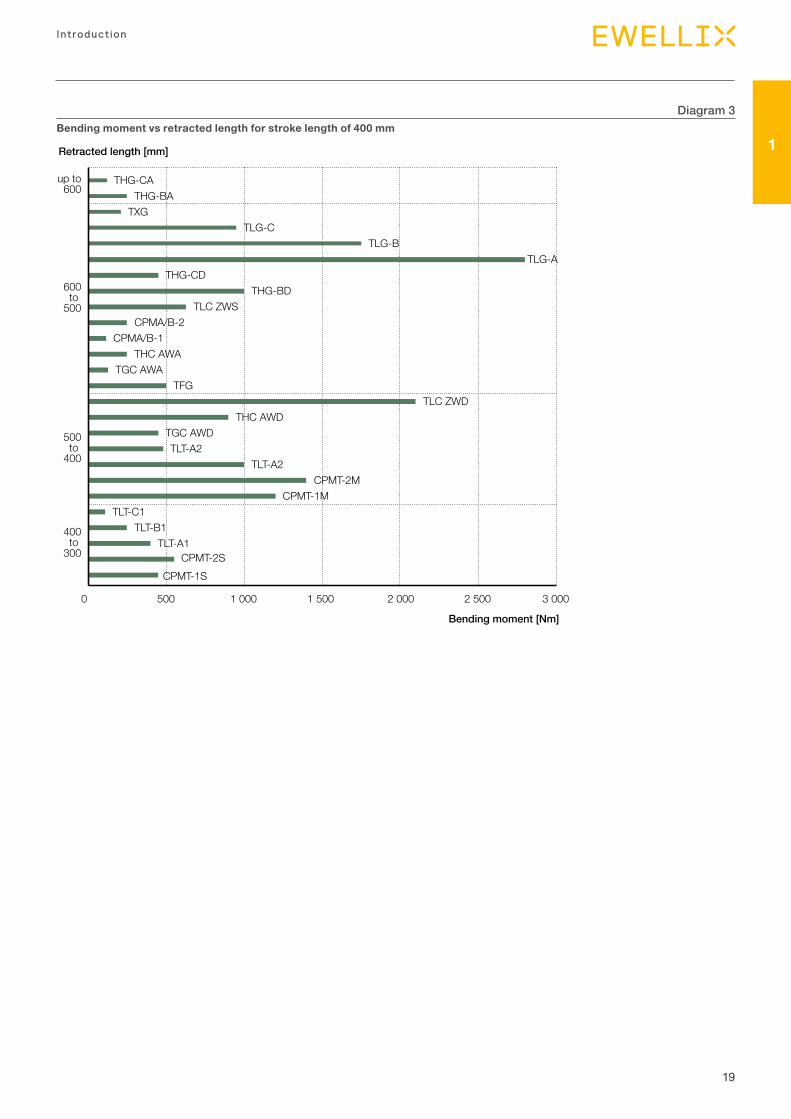
Columns Ewellix offers a wide range of lifting columns in term of push and pull load, offset load in movement, stroke length and in-put voltage. Most of them are approved as a component of a medical device that complies with IEC 60601-1 and UL mark RU.
Product Load Bending moment
Speed Stroke Voltage See page
kN Nm mm/s mm V
CPMA-B 2 250 15 400 24, 100 to 240 192-200CPMT 6 1 400 34 600 24 208TFG 2,5 500 15 700 120, 230 214THG 2 1 000 15 700 24 218TLC 4 2 100 11 700 120, 230 222TLG 4 2 800 10 700 24 226TLT 4 1 000 25 700 24 230TXG 1,5 210 17 600 24, 120, 230 234FRE – – – 700 – 238
Medical
Force and speed capabilitiesDiagram 2 provides a quick overview of the rated load and the speed of the actuators. Use this graph to quickly evaluate which actuator could fit best in your application.The rated load describes the weight that the actuator can push or pull at the rated duty cycle without overheating. The speed is the maximum linear speed the actuator can reach without load when powered at the rated voltage.
Some products are designed for a specific application but are suitable for others applications that request the similar performance
7 000
6 000
5 000
4 000
3 000
2 000
1 000
0
35
30
25
20
15
10
5
0CPMA CPMB CPMT TFG 50 TFG 90
Max loadMax speed
TLC TLG TLT TXGTHG
ColumnDiagram 2
19
Introduction
1
CPMT-2SCPMT-1S
TLT-A1 TLT-B1
TLT-C1 CPMT-1M
CPMT-2MTLT-A2
TGC AWDTHC AWD
TLC ZWDTFG
TGC AWATHC AWA
CPMA/B-1CPMA/B-2
TLC ZWSTHG-BD
THG-CDTLG-A
TLG-BTLG-C
TXGTHG-BA
THG-CA
0 500 1 000 1 500 2 000 2 500 3 000
600to
500
500to
400
400to
300
up to600
Bending moment [Nm]
Retracted length [mm]
TLT-A2
Bending moment vs retracted length for stroke length of 400 mmDiagram 3
20
Actuator range
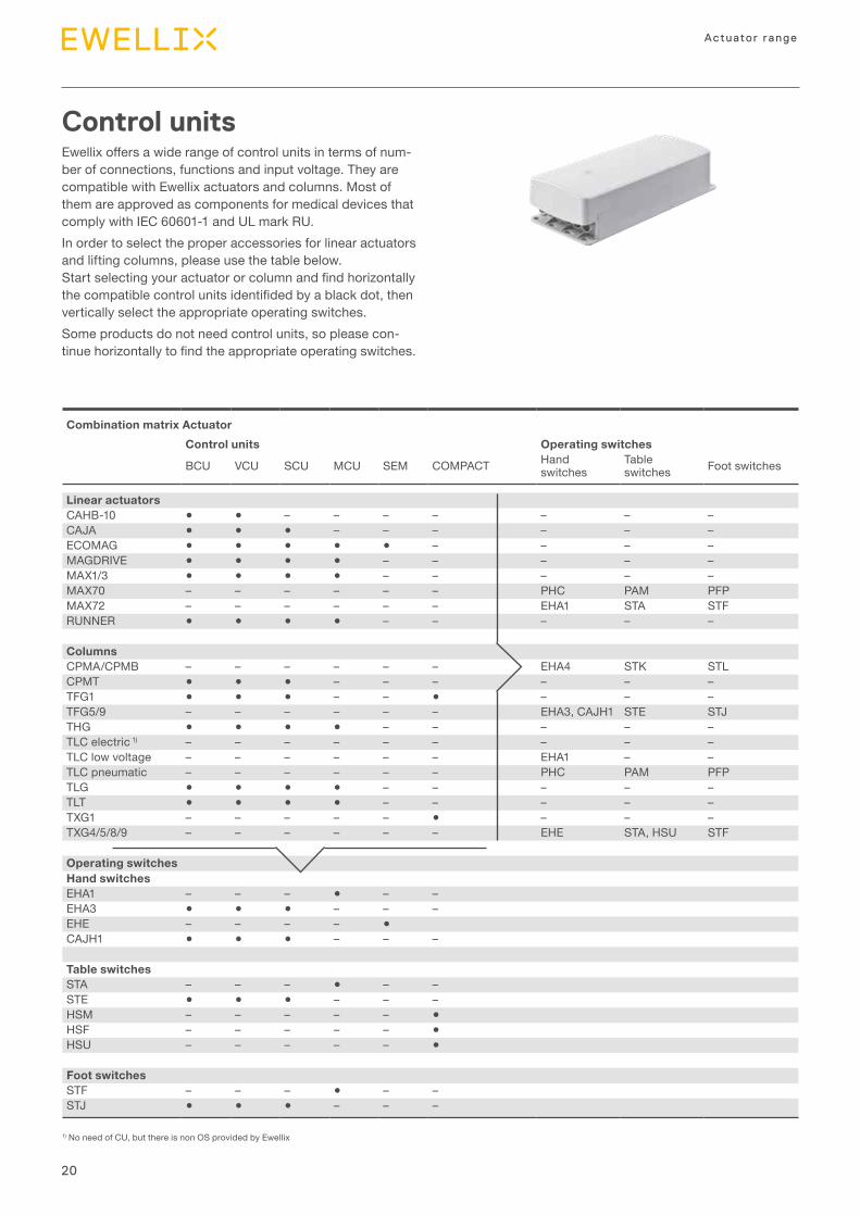
Combination matrix ActuatorControl units Operating switches
BCU VCU SCU MCU SEM COMPACT Hand switches
Table switches Foot switches
Linear actuatorsCAHB-10 ● ● – – – – – – –CAJA ● ● ● – – – – – –ECOMAG ● ● ● ● ● – – – –MAGDRIVE ● ● ● ● – – – – –MAX1/3 ● ● ● ● – – – – –MAX70 – – – – – – PHC PAM PFPMAX72 – – – – – – EHA1 STA STFRUNNER ● ● ● ● – – – – –
ColumnsCPMA/CPMB – – – – – – EHA4 STK STLCPMT ● ● ● – – – – – –TFG1 ● ● ● – – ● – – –TFG5/9 – – – – – – EHA3, CAJH1 STE STJTHG ● ● ● ● – – – – –TLC electric 1) – – – – – – – – –TLC low voltage – – – – – – EHA1 – –TLC pneumatic – – – – – – PHC PAM PFPTLG ● ● ● ● – – – – –TLT ● ● ● ● – – – – –TXG1 – – – – – ● – – –TXG4/5/8/9 – – – – – – EHE STA, HSU STF
Operating switchesHand switchesEHA1 – – – ● – –EHA3 ● ● ● – – –EHE – – – – ●CAJH1 ● ● ● – – –
Table switchesSTA – – – ● – –STE ● ● ● – – –HSM – – – – – ●HSF – – – – – ●HSU – – – – – ●
Foot switchesSTF – – – ● – –STJ ● ● ● – – –
Control unitsEwellix offers a wide range of control units in terms of num-ber of connections, functions and input voltage. They are compatible with Ewellix actuators and columns. Most of them are approved as components for medical devices that comply with IEC 60601-1 and UL mark RU.In order to select the proper accessories for linear actuators and lifting columns, please use the table below. Start selecting your actuator or column and find horizontally the compatible control units identifided by a black dot, then vertically select the appropriate operating switches.Some products do not need control units, so please con-tinue horizontally to find the appropriate operating switches.
1) No need of CU, but there is non OS provided by Ewellix
21
Introduction
1
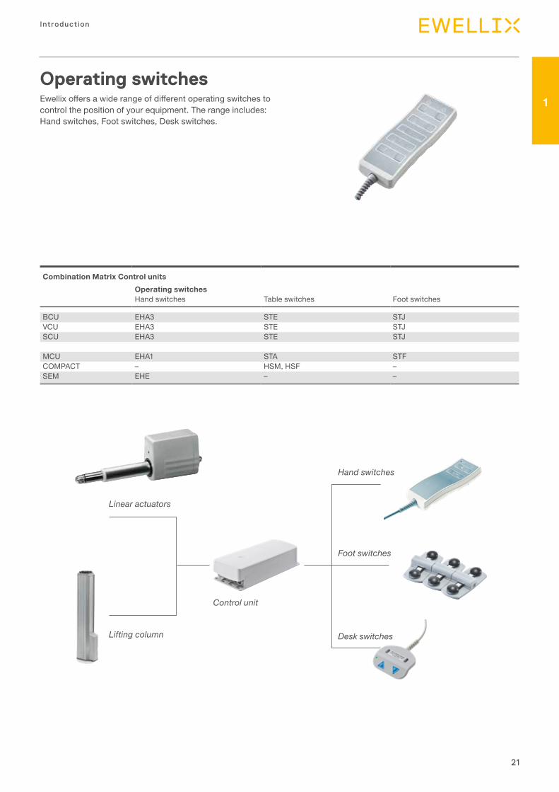
Operating switchesEwellix offers a wide range of different operating switches to control the position of your equipment. The range includes: Hand switches, Foot switches, Desk switches.
Linear actuators
Lifting column
Control unit
Hand switches
Foot switches
Desk switches
Combination Matrix Control unitsOperating switches
Hand switches Table switches Foot switches
BCU EHA3 STE STJVCU EHA3 STE STJSCU EHA3 STE STJ
MCU EHA1 STA STFCOMPACT – HSM, HSF –SEM EHE – –

22
Actuator range
Case of stand alone lifting column with AC motor: TLC
Case of stand alone lifting column with DC motor and built in power supply: CPMA
Case of AC System with DC linear actuator and lifting column: SCU+TLG + Matrix
Case of stand-alone linear actuator with DC motor and built in power supply: MAX7
Input voltageAC or DC, this is the voltage that is used to power the sys-tem or the stand alone linear actuator or lifting column. For instance, a AC system is one powered by a cable con-nected to the mains power that provides alternating voltage, typically 230 V AC in Europe and 120 V AC in USA. AC sys-tem or linear actuator or lifting column doesn't say that the motor is an AC motor. For a linear actuator or a lifting column, the motor voltage could be different than mains power. The control unit that
drives the DC lifting column or linear actuator is equipped with a power supply to convert the voltage. The linear actua-tor and the lifting column could be also equipped with a built-in power supply. In this case, the equipment is powered by the mains power but the motor and other equipment are powered by a DC cable. This is the most convenient system; easy to power and to control.
23
Introduction
1
7 000
6 000
5 000
4 000
3 000
2 000
1 000
0 0 100 200 300 400 500 600
Load [N]
CPMT1-1M, -2M
Load distance from the center of the column [mm]
CPMT1-2M
CPMT1-1M
Overload
ideal Underload
1
2 3
4
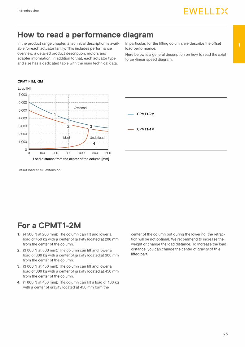
How to read a performance diagramIn the product range chapter, a technical description is avail-able for each actuator family. This includes performance overview, a detailed product description, motors and adapter information. In addition to that, each actuator type and size has a dedicated table with the main technical data.
In particular, for the lifting column, we describe the offset load performance.Here below is a general description on how to read the axial force /linear speed diagram.
Offset load at full extension
For a CPMT1-2M1. (4 500 N at 200 mm): The column can lift and lower a
load of 450 kg with a center of gravity located at 200 mm from the center of the column.
2. (3 000 N at 300 mm): The column can lift and lower a load of 300 kg with a center of gravity located at 300 mm from the center of the column.
3. (3 000 N at 450 mm): The column can lift and lower a load of 300 kg with a center of gravity located at 450 mm from the center of the column.
4. (1 000 N at 450 mm): The column can lift a load of 100 kg with a center of gravity located at 450 mm form the
center of the column but during the lowering, the retrac-tion will be not optimal. We recommend to increase the weight or change the load distance. To Increase the load distance, you can change the center of gravity of th e lifted part.
24
Actuator range
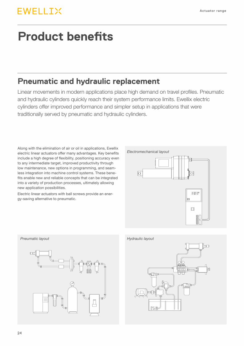
Pneumatic and hydraulic replacementLinear movements in modern applications place high demand on travel profiles. Pneumatic and hydraulic cylinders quickly reach their system performance limits. Ewellix electric cylinders offer improved performance and simpler setup in applications that were traditionally served by pneumatic and hydraulic cylinders.
Product benefits
Pneumatic layout Hydraulic layout
Electromechanical layoutAlong with the elimination of air or oil in applications, Ewellix electric linear actuators offer many advantages. Key benefits include a high degree of flexibility, positioning accuracy even to any intermediate target, improved productivity through low maintenance, new options in programming, and seam-less integration into machine control systems. These bene-fits enable new and reliable concepts that can be integrated into a variety of production processes, ultimately allowing new application possibilities.Electric linear actuators with ball screws provide an ener-gy-saving alternative to pneumatic.
25
Introduction
1
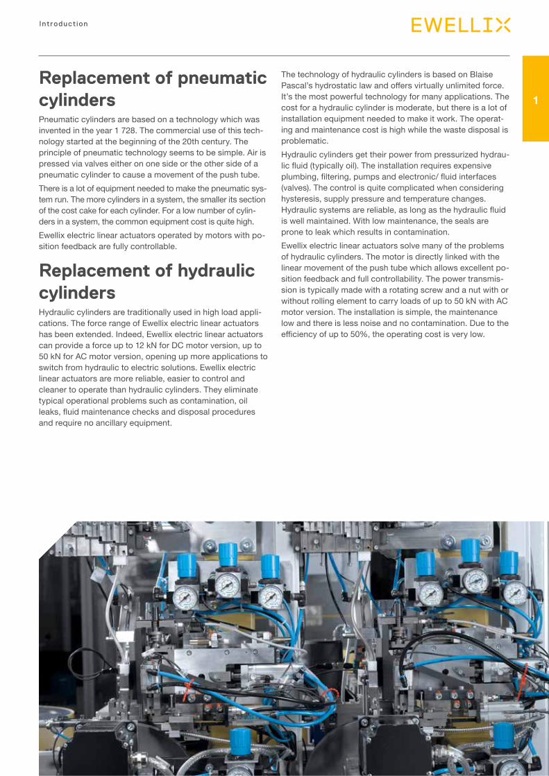
Replacement of pneumatic cylindersPneumatic cylinders are based on a technology which was invented in the year 1 728. The commercial use of this tech-nology started at the beginning of the 20th century. The principle of pneumatic technology seems to be simple. Air is pressed via valves either on one side or the other side of a pneumatic cylinder to cause a movement of the push tube. There is a lot of equipment needed to make the pneumatic sys-tem run. The more cylinders in a system, the smaller its section of the cost cake for each cylinder. For a low number of cylin-ders in a system, the common equipment cost is quite high.Ewellix electric linear actuators operated by motors with po-sition feedback are fully controllable.
Replacement of hydraulic cylindersHydraulic cylinders are traditionally used in high load appli-cations. The force range of Ewellix electric linear actuators has been extended. Indeed, Ewellix electric linear actuators can provide a force up to 12 kN for DC motor version, up to 50 kN for AC motor version, opening up more applications to switch from hydraulic to electric solutions. Ewellix electric linear actuators are more reliable, easier to control and cleaner to operate than hydraulic cylinders. They eliminate typical operational problems such as contamination, oil leaks, fluid maintenance checks and disposal procedures and require no ancillary equipment.
The technology of hydraulic cylinders is based on Blaise Pascal’s hydrostatic law and offers virtually unlimited force. It’s the most powerful technology for many applications. The cost for a hydraulic cylinder is moderate, but there is a lot of installation equipment needed to make it work. The operat-ing and maintenance cost is high while the waste disposal is problematic.Hydraulic cylinders get their power from pressurized hydrau-lic fluid (typically oil). The installation requires expensive plumbing, filtering, pumps and electronic/ fluid interfaces (valves). The control is quite complicated when considering hysteresis, supply pressure and temperature changes. Hydraulic systems are reliable, as long as the hydraulic fluid is well maintained. With low maintenance, the seals are prone to leak which results in contamination.Ewellix electric linear actuators solve many of the problems of hydraulic cylinders. The motor is directly linked with the linear movement of the push tube which allows excellent po-sition feedback and full controllability. The power transmis-sion is typically made with a rotating screw and a nut with or without rolling element to carry loads of up to 50 kN with AC motor version. The installation is simple, the maintenance low and there is less noise and no contamination. Due to the efficiency of up to 50%, the operating cost is very low.
26
Actuator range
ControllabilityElectric drive systems use a screw that offers an easy con-trollability by counting the number of turns of the screw or other elements mechanically connected. You can control the position, the displacement as well as the speed.
Precision The precision depends on the resolution of the position feedback system and how the output is used by the control board. The backlash of the driving mechanism will influence if the direction of the load and movement is changing. The accuracy also depends on the set up and homing procedure of the system.
Holding forceElectric drive systems offer a high stability and self-locking that prevent unplanned movement in case of static overload or shock applied even if not powered. In addition of built-in brake and the short circuit of the brushed DC motor used in the most of the case, all mechanical driving part participates of the stability.
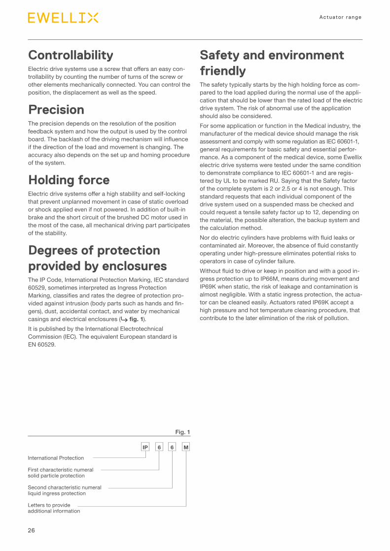
Degrees of protection provided by enclosuresThe IP Code, International Protection Marking, IEC standard 60529, sometimes interpreted as Ingress Protection Marking, classifies and rates the degree of protection pro-vided against intrusion (body parts such as hands and fin-gers), dust, accidental contact, and water by mechanical casings and electrical enclosures (⮑ fig. 1).It is published by the International Electrotechnical Commission (IEC). The equivalent European standard is EN 60529.
Safety and environment friendlyThe safety typically starts by the high holding force as com-pared to the load applied during the normal use of the appli-cation that should be lower than the rated load of the electric drive system. The risk of abnormal use of the application should also be considered. For some application or function in the Medical industry, the manufacturer of the medical device should manage the risk assessment and comply with some regulation as IEC 60601-1, general requirements for basic safety and essential perfor-mance. As a component of the medical device, some Ewellix electric drive systems were tested under the same condition to demonstrate compliance to IEC 60601-1 and are regis-tered by UL to be marked RU. Saying that the Safety factor of the complete system is 2 or 2.5 or 4 is not enough. This standard requests that each individual component of the drive system used on a suspended mass be checked and could request a tensile safety factor up to 12, depending on the material, the possible alteration, the backup system and the calculation method.Nor do electric cylinders have problems with fluid leaks or contaminated air. Moreover, the absence of fluid constantly operating under high-pressure eliminates potential risks to operators in case of cylinder failure.Without fluid to drive or keep in position and with a good in-gress protection up to IP66M, means during movement and IP69K when static, the risk of leakage and contamination is almost negligible. With a static ingress protection, the actua-tor can be cleaned easily. Actuators rated IP69K accept a high pressure and hot temperature cleaning procedure, that contribute to the later elimination of the risk of pollution.
International Protection
First characteristic numeral solid particle protection
Second characteristic numeral liquid ingress protection
Letters to provide additional information
IP 6 6 M
Fig. 1
27
Introduction
1
RoHSOur standard products fall under category 11 in Annex I to Directive 2011/65/EU and therefore do not need to comply with the provisions in the directive before July 22, 2019.Nevertheless, most of our standard products are already mentioned on a list where we declare that the products do not contain any of the restricted substances over the thresh-old values stated in the Annex II to Directive 2011/65/EU in any homogenous part of the product.
REACHEwellix has a policy, process and dedicated resources in or-der to comply with REACH, the Regulation concerning Registration, Evaluation, Authorization and Restriction of Chemicals.
CE markMost of our product have CE mark with a Certificate of Compliance signed by the factory.
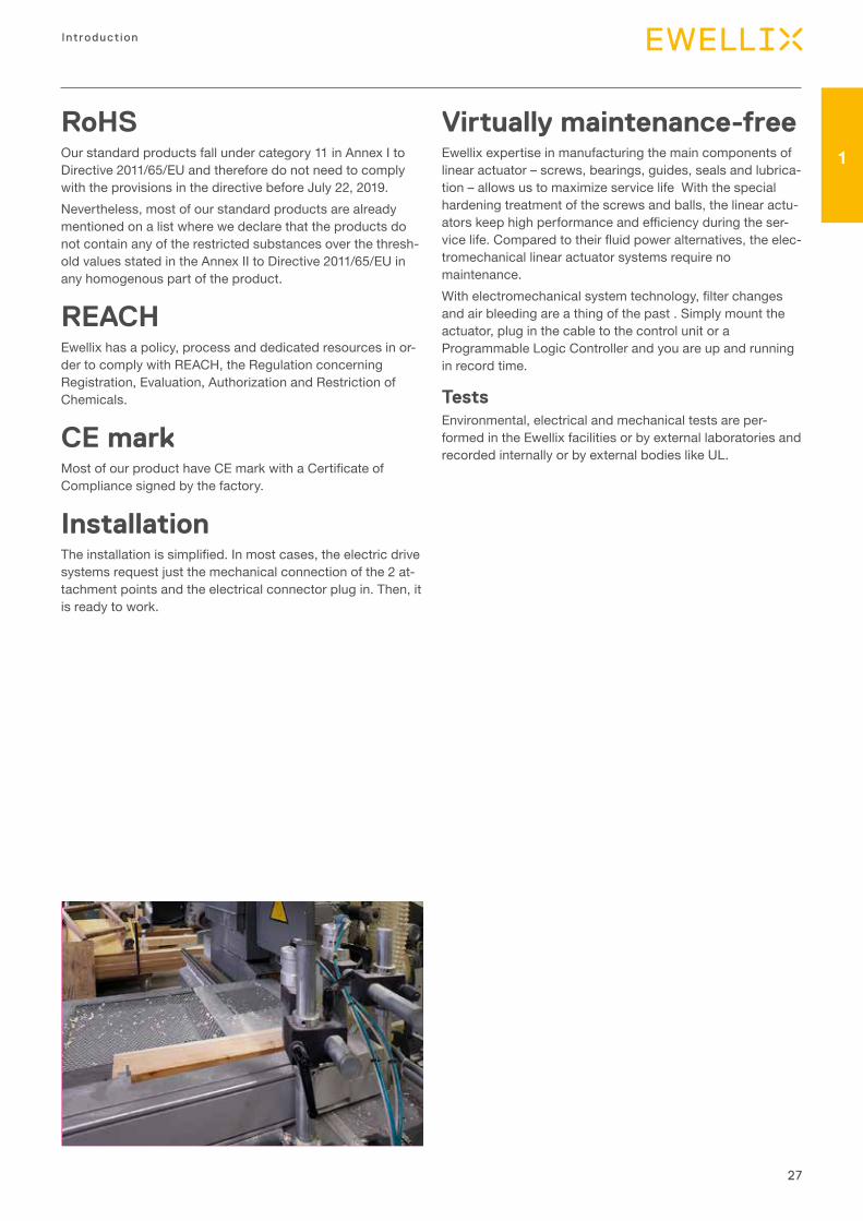
InstallationThe installation is simplified. In most cases, the electric drive systems request just the mechanical connection of the 2 at-tachment points and the electrical connector plug in. Then, it is ready to work.
Virtually maintenance-freeEwellix expertise in manufacturing the main components of linear actuator – screws, bearings, guides, seals and lubrica-tion – allows us to maximize service life With the special hardening treatment of the screws and balls, the linear actu-ators keep high performance and efficiency during the ser-vice life. Compared to their fluid power alternatives, the elec-tromechanical linear actuator systems require no maintenance. With electromechanical system technology, filter changes and air bleeding are a thing of the past . Simply mount the actuator, plug in the cable to the control unit or a Programmable Logic Controller and you are up and running in record time.
Tests Environmental, electrical and mechanical tests are per-formed in the Ewellix facilities or by external laboratories and recorded internally or by external bodies like UL.
28
Actuator range
Customization capabilities
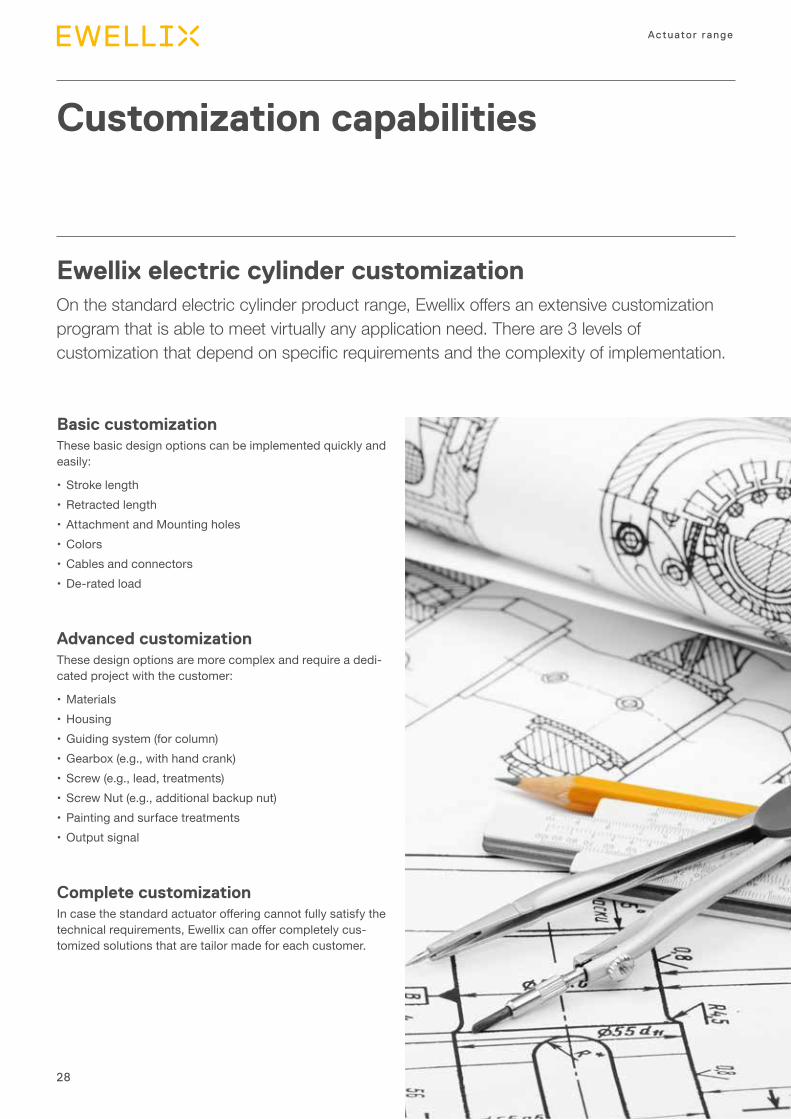
Basic customizationThese basic design options can be implemented quickly and easily:
• Stroke length• Retracted length• Attachment and Mounting holes• Colors• Cables and connectors• De-rated load
Advanced customization These design options are more complex and require a dedi-cated project with the customer:
• Materials• Housing• Guiding system (for column)• Gearbox (e.g., with hand crank)• Screw (e.g., lead, treatments)• Screw Nut (e.g., additional backup nut)• Painting and surface treatments• Output signal
Complete customizationIn case the standard actuator offering cannot fully satisfy the technical requirements, Ewellix can offer completely cus-tomized solutions that are tailor made for each customer.
Ewellix electric cylinder customization On the standard electric cylinder product range, Ewellix offers an extensive customization program that is able to meet virtually any application need. There are 3 levels of customization that depend on specific requirements and the complexity of implementation.
29
Introduction
1
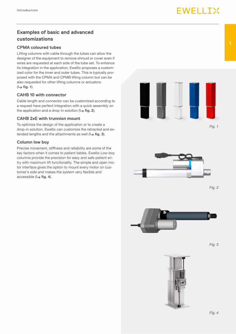
Examples of basic and advanced customizations
CPMA coloured tubes Lifting columns with cable through the tubes can allow the designer of the equipment to remove shroud or cover even if wires are requested at each side of the tube set. To enhance its integration in the application, Ewellix proposes a custom-ized color for the inner and outer tubes. This is typically pro-posed with the CPMA and CPMB lifting column but can be also requested for other lifting columns or actuators (⮑ fig. 1).
CAHB 10 with connectorCable length and connector can be customized according to a request have perfect integration with a quick assembly on the application and a drop-in solution (⮑ fig. 2).
CAHB 2xE with trunnion mountTo optimize the design of the application or to create a drop-in solution, Ewellix can customize the retracted and ex-tended lengths and the attachments as well (⮑ fig. 3).
Column low boyPrecise movement, stiffness and reliability are some of the key factors when it comes to patient tables. Ewellix Low-boy columns provide the precision for easy and safe patient en-try with maximum lift functionality. The simple and open mo-tor interface gives the option to mount every motor on cus-tomer's side and makes the system very flexible and accessible (⮑ fig. 4).
Fig. 2
Fig. 3
Fig. 4
Fig. 1
30
Actuator range
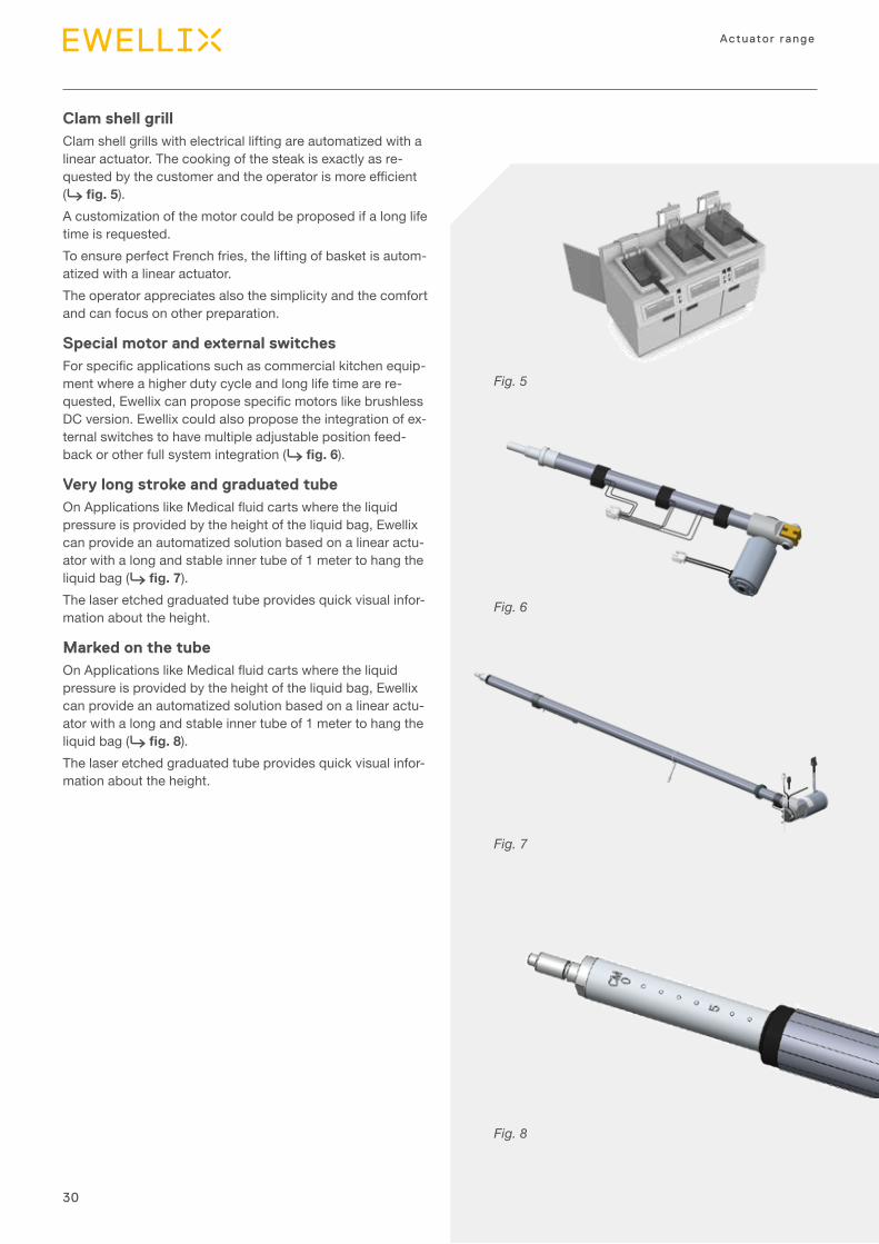
Clam shell grillClam shell grills with electrical lifting are automatized with a linear actuator. The cooking of the steak is exactly as re-quested by the customer and the operator is more efficient (⮑ fig. 5). A customization of the motor could be proposed if a long life time is requested. To ensure perfect French fries, the lifting of basket is autom-atized with a linear actuator. The operator appreciates also the simplicity and the comfort and can focus on other preparation.
Special motor and external switches For specific applications such as commercial kitchen equip-ment where a higher duty cycle and long life time are re-quested, Ewellix can propose specific motors like brushless DC version. Ewellix could also propose the integration of ex-ternal switches to have multiple adjustable position feed-back or other full system integration (⮑ fig. 6).
Very long stroke and graduated tube On Applications like Medical fluid carts where the liquid pressure is provided by the height of the liquid bag, Ewellix can provide an automatized solution based on a linear actu-ator with a long and stable inner tube of 1 meter to hang the liquid bag (⮑ fig. 7). The laser etched graduated tube provides quick visual infor-mation about the height.
Marked on the tube On Applications like Medical fluid carts where the liquid pressure is provided by the height of the liquid bag, Ewellix can provide an automatized solution based on a linear actu-ator with a long and stable inner tube of 1 meter to hang the liquid bag (⮑ fig. 8). The laser etched graduated tube provides quick visual infor-mation about the height.
Fig. 5
Fig. 6
Fig. 7
Fig. 8
31
Introduction
1
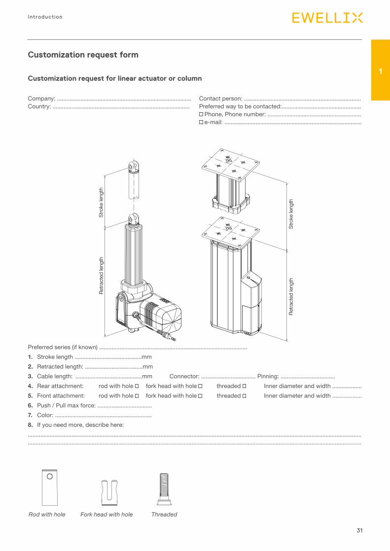
Customization request form
Customization request for linear actuator or column
Company: ...................................................................................... Country: ........................................................................................
Contact person: ........................................................................... Preferred way to be contacted:...................................................
Phone, Phone number: ............................................................ e-mail: ........................................................................................
Preferred series (if known) ............................................................................................... 1. Stroke length ...........................................mm2. Retracted length: .....................................mm3. Cable length: ...........................................mm Connector: ................................... Pinning: ...................................4. Rear attachment: rod with hole fork head with hole threaded Inner diameter and width ...................5. Front attachment: rod with hole fork head with hole threaded Inner diameter and width ...................6. Push / Pull max force: ...................................7. Color: ..............................................................8. If you need more, describe here:...................................................................................................................................................................................................................... ......................................................................................................................................................................................................................
Stro
ke le
ngth
Retra
cted
leng
th
Stro
ke le
ngth
Retra
cted
leng
th
Rod with hole Fork head with hole Threaded
32
Actuator range
Application examples
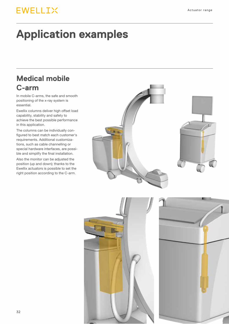
Medical mobile C-arm In mobile C-arms, the safe and smooth positioning of the x-ray system is essential. Ewellix columns deliver high offset load capability, stability and safety to achieve the best possible performance in this application. The columns can be individually con-figured to best match each customer's requirements. Additional customiza-tions, such as cable channelling or special hardware interfaces, are possi-ble and simplify the final installation. Also the monitor can be adjusted the position (up and down); thanks to the Ewellix actuators is possible to set the right position according to the C-arm.
33
Introduction
1
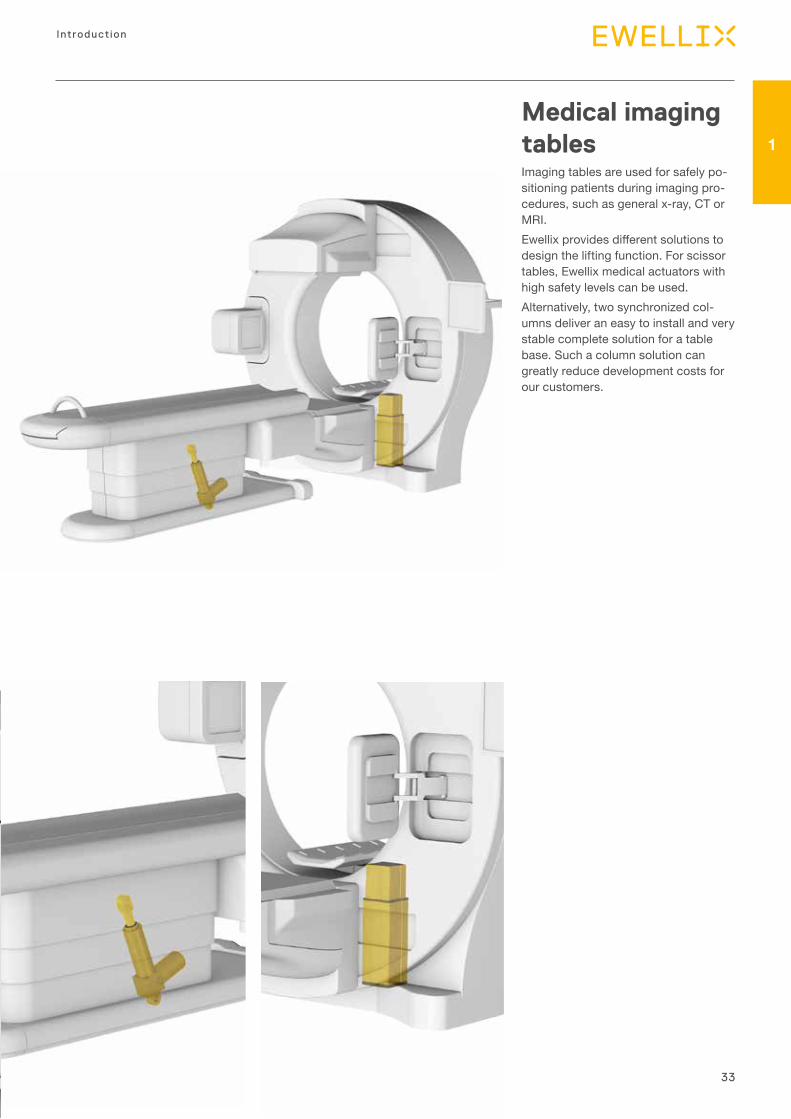
Medical imaging tablesImaging tables are used for safely po-sitioning patients during imaging pro-cedures, such as general x-ray, CT or MRI. Ewellix provides different solutions to design the lifting function. For scissor tables, Ewellix medical actuators with high safety levels can be used. Alternatively, two synchronized col-umns deliver an easy to install and very stable complete solution for a table base. Such a column solution can greatly reduce development costs for our customers.
34
Actuator range
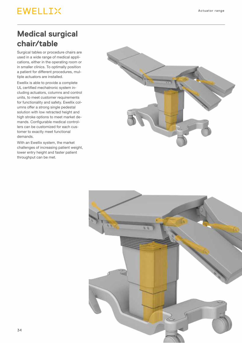
Medical surgical chair/tableSurgical tables or procedure chairs are used in a wide range of medical appli-cations, either in the operating room or in smaller clinics. To optimally position a patient for different procedures, mul-tiple actuators are installed. Ewellix is able to provide a complete UL certified mechatronic system in-cluding actuators, columns and control units, to meet customer requirements for functionality and safety. Ewellix col-umns offer a strong single pedestal solution with low retracted height and high stroke options to meet market de-mands. Configurable medical control-lers can be customized for each cus-tomer to exactly meet functional demands. With an Ewellix system, the market challenges of increasing patient weight, lower entry height and faster patient throughput can be met.
35
Introduction
1
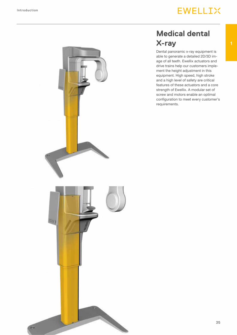
Medical dental X-rayDental panoramic x-ray equipment is able to generate a detailed 2D/3D im-age of all teeth. Ewellix actuators and drive trains help our customers imple-ment the height adjustment in this equipment. High speed, high stroke and a high level of safety are critical features of these actuators and a core strength of Ewellix. A modular set of screw and motors enable an optimal configuration to meet every customer's requirements.
36
Actuator range
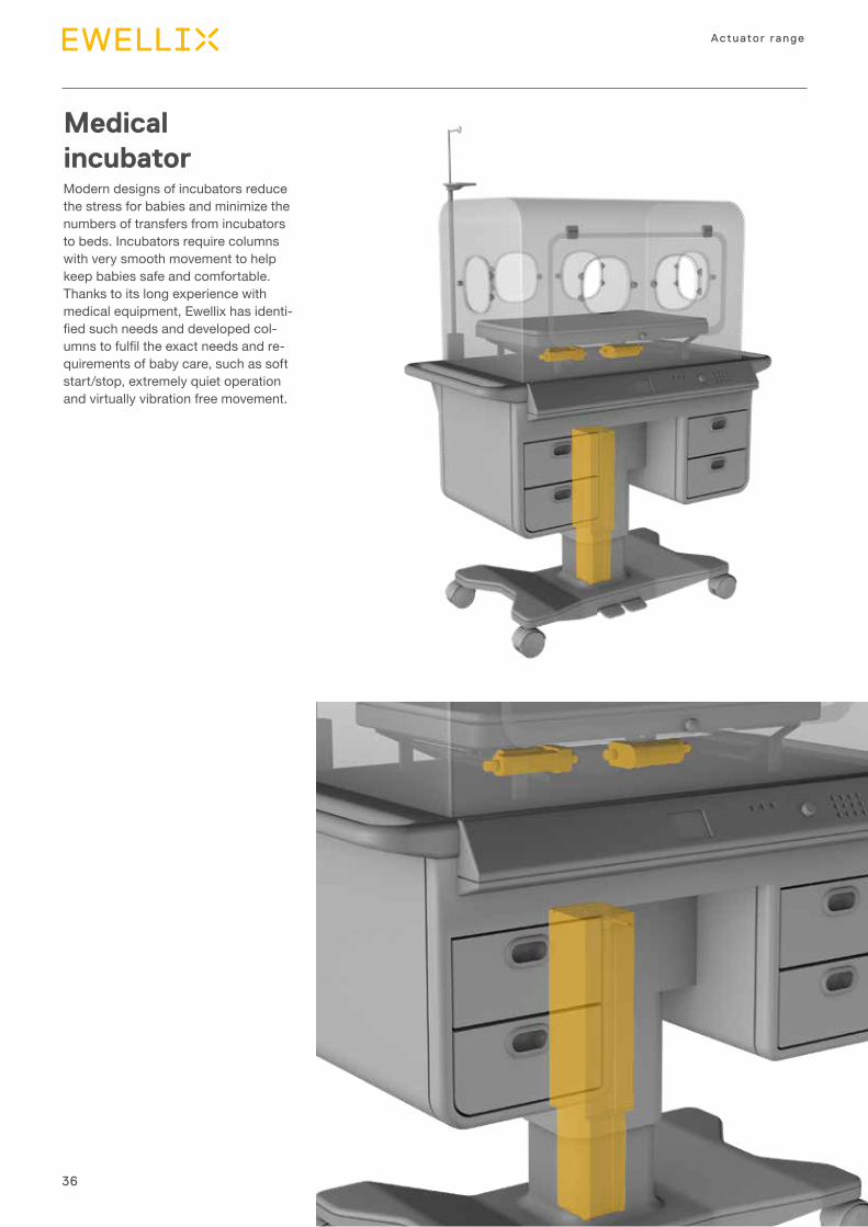
Medical incubator Modern designs of incubators reduce the stress for babies and minimize the numbers of transfers from incubators to beds. Incubators require columns with very smooth movement to help keep babies safe and comfortable. Thanks to its long experience with medical equipment, Ewellix has identi-fied such needs and developed col-umns to fulfil the exact needs and re-quirements of baby care, such as soft start/stop, extremely quiet operation and virtually vibration free movement.
37
Introduction
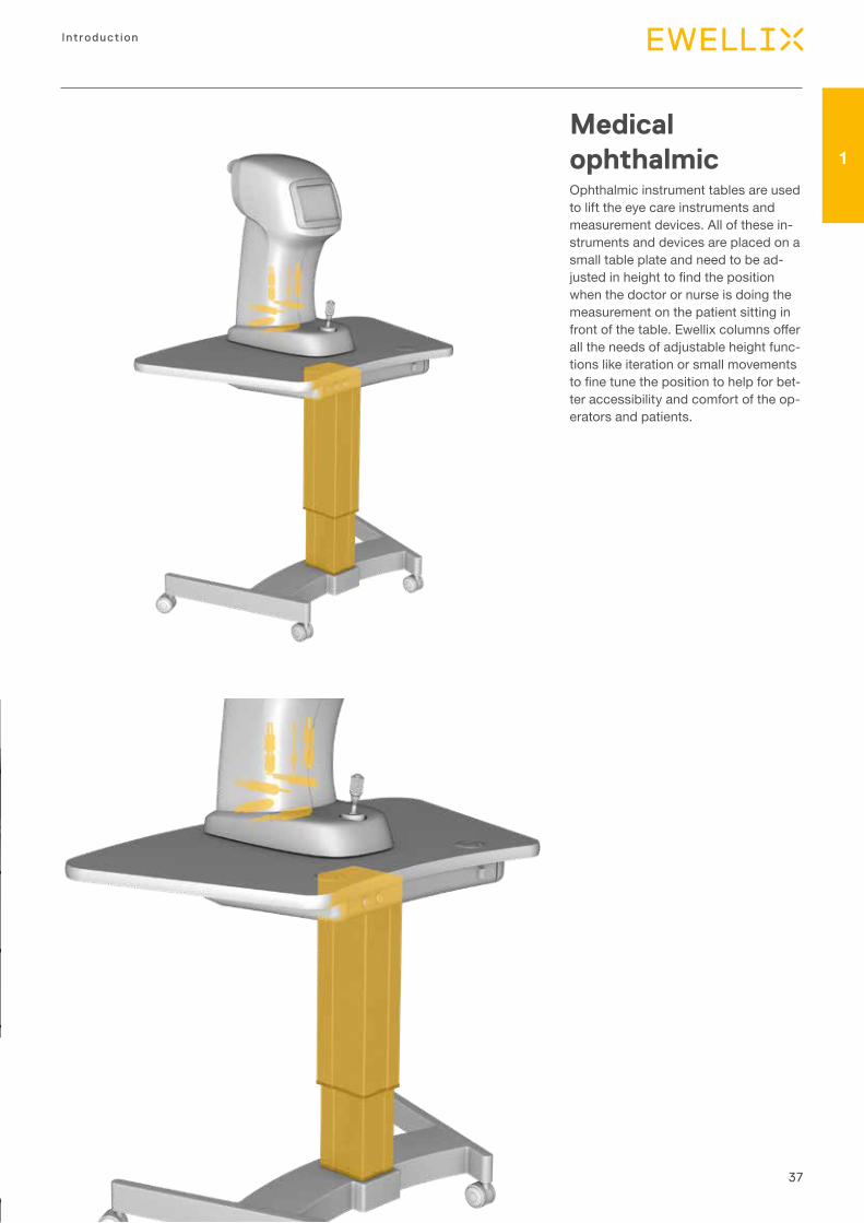
1Medical ophthalmic Ophthalmic instrument tables are used to lift the eye care instruments and measurement devices. All of these in-struments and devices are placed on a small table plate and need to be ad-justed in height to find the position when the doctor or nurse is doing the measurement on the patient sitting in front of the table. Ewellix columns offer all the needs of adjustable height func-tions like iteration or small movements to fine tune the position to help for bet-ter accessibility and comfort of the op-erators and patients.
38
Actuator range
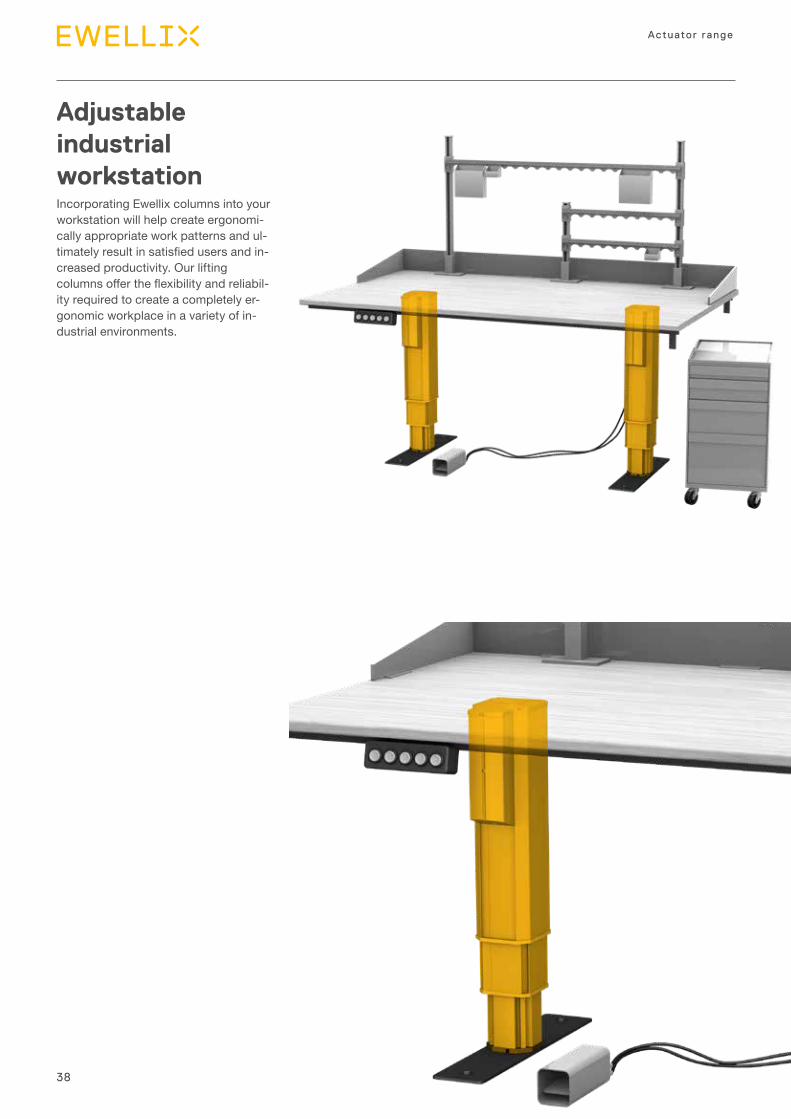
Adjustable industrial workstation Incorporating Ewellix columns into your workstation will help create ergonomi-cally appropriate work patterns and ul-timately result in satisfied users and in-creased productivity. Our lifting columns offer the flexibility and reliabil-ity required to create a completely er-gonomic workplace in a variety of in-dustrial environments.
39
Introduction
1
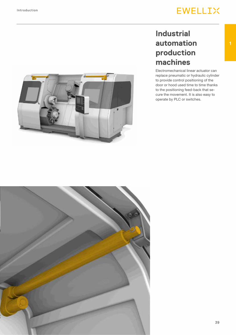
Industrial automation production machines Electromechanical linear actuator can replace pneumatic or hydraulic cylinder to provide control positioning of the door or hood used time to time thanks to the positioning feed-back that se-cure the movement. It is also easy to operate by PLC or switches.
40
Actuator range
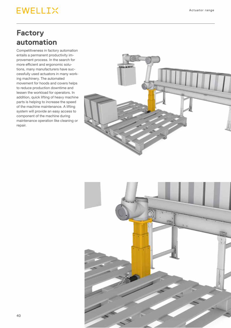
Factory automation Competitiveness in factory automation entails a permanent productivity im-provement process. In the search for more efficient and ergonomic solu-tions, many manufacturers have suc-cessfully used actuators in many work-ing machinery. The automated movement for hoods and covers helps to reduce production downtime and lessen the workload for operators. In addition, quick lifting of heavy machine parts is helping to increase the speed of the machine maintenance. A lifting system will provide an easy access to component of the machine during maintenance operation like cleaning or repair.
41
Introduction
1
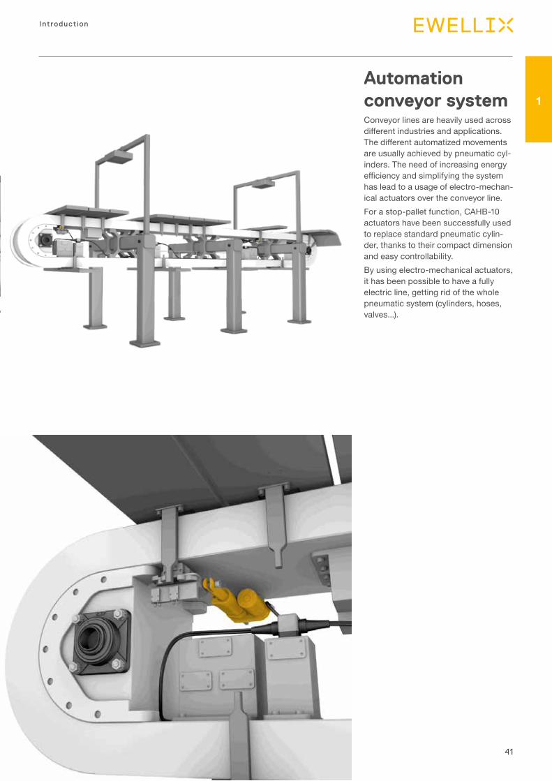
Automation conveyor system Conveyor lines are heavily used across different industries and applications. The different automatized movements are usually achieved by pneumatic cyl-inders. The need of increasing energy efficiency and simplifying the system has lead to a usage of electro-mechan-ical actuators over the conveyor line. For a stop-pallet function, CAHB-10 actuators have been successfully used to replace standard pneumatic cylin-der, thanks to their compact dimension and easy controllability. By using electro-mechanical actuators, it has been possible to have a fully electric line, getting rid of the whole pneumatic system (cylinders, hoses, valves...).
42
Actuator range
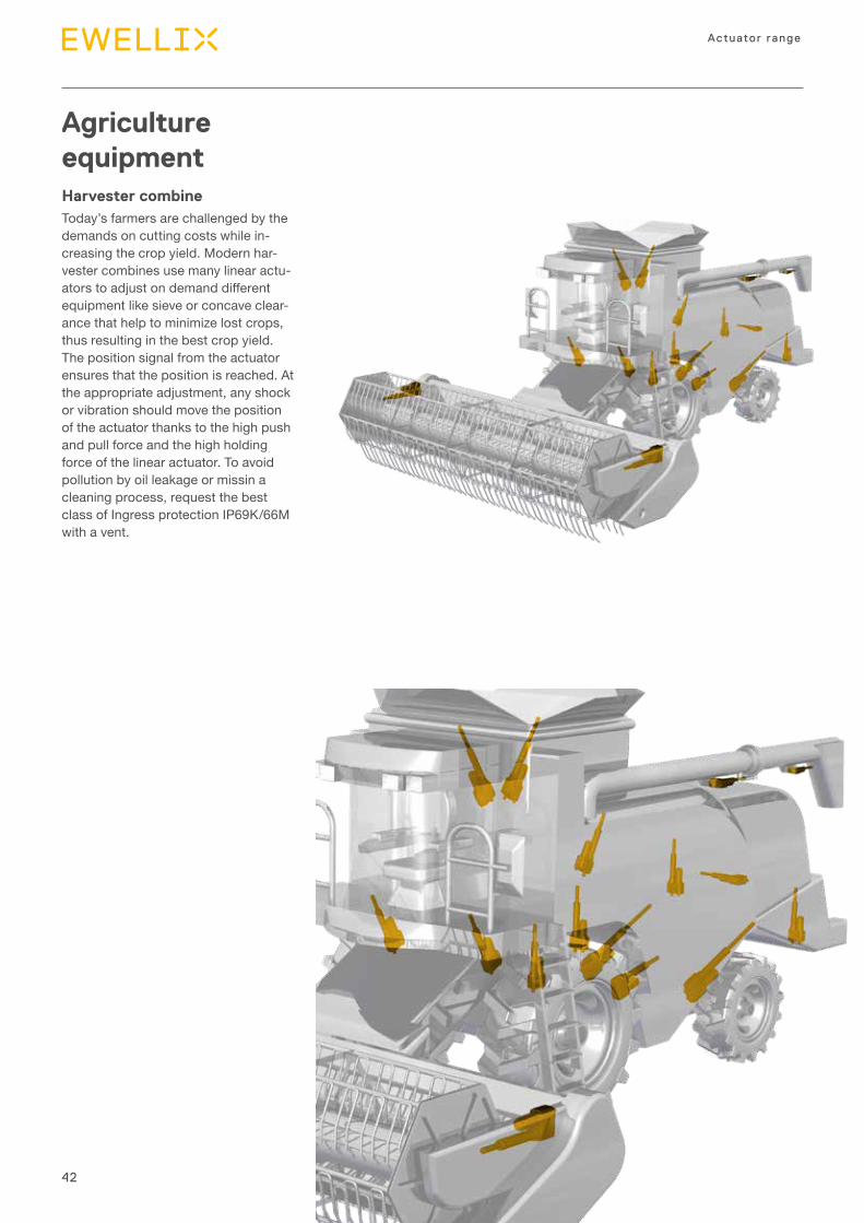
Agriculture equipmentHarvester combineToday’s farmers are challenged by the demands on cutting costs while in-creasing the crop yield. Modern har-vester combines use many linear actu-ators to adjust on demand different equipment like sieve or concave clear-ance that help to minimize lost crops, thus resulting in the best crop yield. The position signal from the actuator ensures that the position is reached. At the appropriate adjustment, any shock or vibration should move the position of the actuator thanks to the high push and pull force and the high holding force of the linear actuator. To avoid pollution by oil leakage or missin a cleaning process, request the best class of Ingress protection IP69K/66M with a vent.
43
Introduction
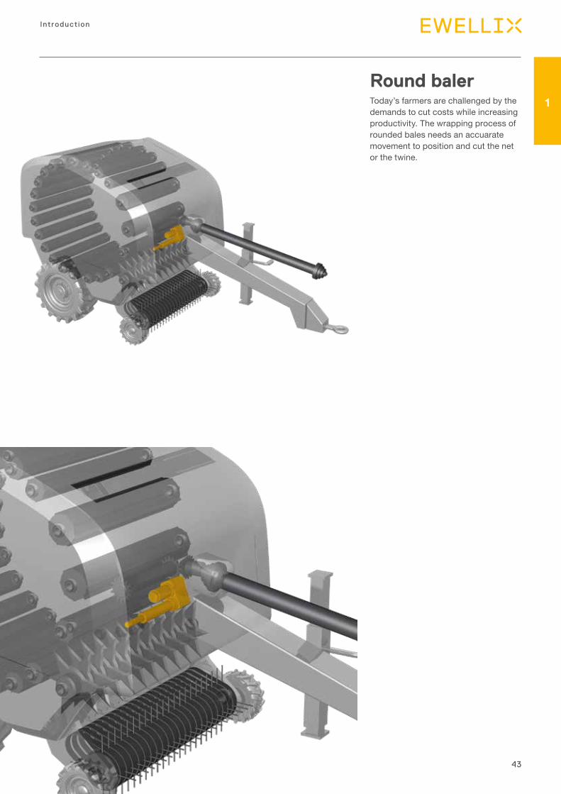
1Round balerToday’s farmers are challenged by the demands to cut costs while increasing productivity. The wrapping process of rounded bales needs an accuarate movement to position and cut the net or the twine.
44
Actuator range
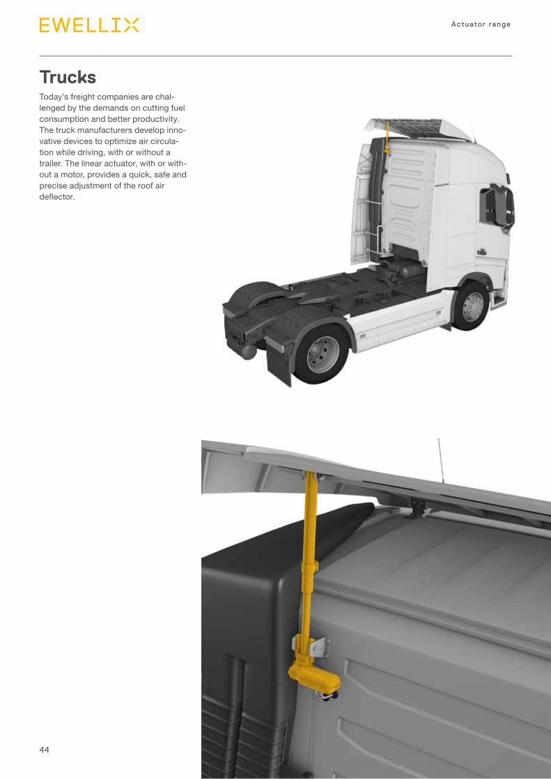
Trucks Today’s freight companies are chal-lenged by the demands on cutting fuel consumption and better productivity. The truck manufacturers develop inno-vative devices to optimize air circula-tion while driving, with or without a trailer. The linear actuator, with or with-out a motor, provides a quick, safe and precise adjustment of the roof air deflector.
45
Introduction
1
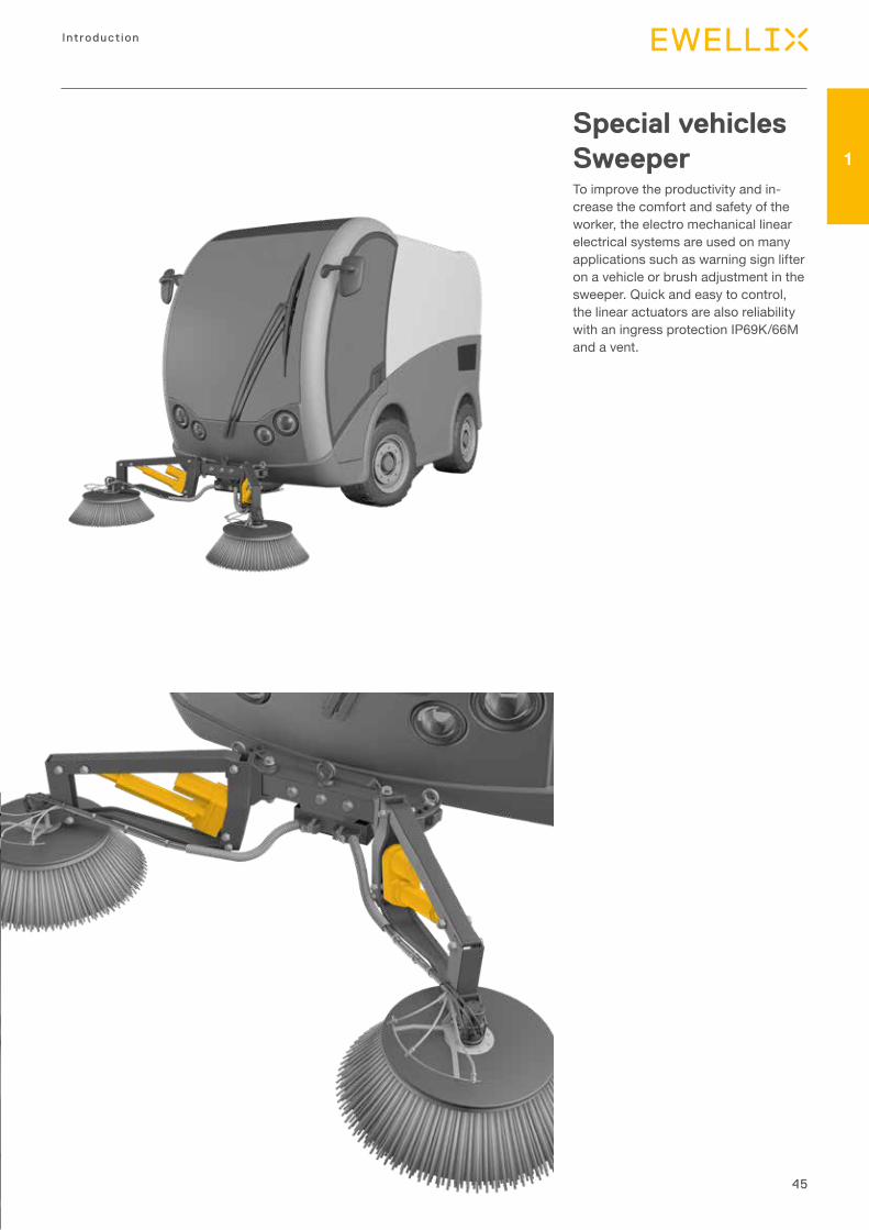
Special vehicles SweeperTo improve the productivity and in-crease the comfort and safety of the worker, the electro mechanical linear electrical systems are used on many applications such as warning sign lifter on a vehicle or brush adjustment in the sweeper. Quick and easy to control, the linear actuators are also reliability with an ingress protection IP69K/66M and a vent.
46
Actuator range
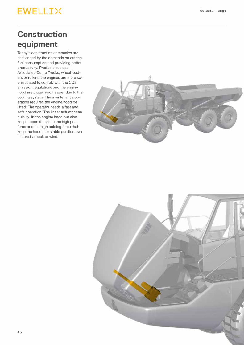
Construction equipment Today’s construction companies are challenged by the demands on cutting fuel consumption and providing better productivity. Products such as Articulated Dump Trucks, wheel load-ers or rollers, the engines are more so-phisticated to comply with the CO2 emission regulations and the engine hood are bigger and heavier due to the cooling system. The maintenance op-eration requires the engine hood be lifted. The operator needs a fast and safe operation. The linear actuator can quickly lift the engine hood but also keep it open thanks to the high push force and the high holding force that keep the hood at a stable position even if there is shock or wind.
47
Introduction
1
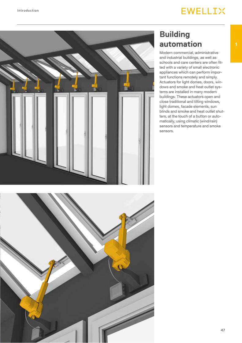
Building automation Modern commercial, administrative and industrial buildings, as well as schools and care centers are often fit-ted with a variety of small electronic appliances which can perform impor-tant functions remotely and simply. Actuators for light domes, doors, win-dows and smoke and heat outlet sys-tems are installed in many modern buildings. These actuators open and close traditional and tilting windows, light domes, facade elements, sun blinds and smoke and heat outlet shut-ters, at the touch of a button or auto-matically, using climatic (wind/rain) sensors and temperature and smoke sensors.
48
Actuator range
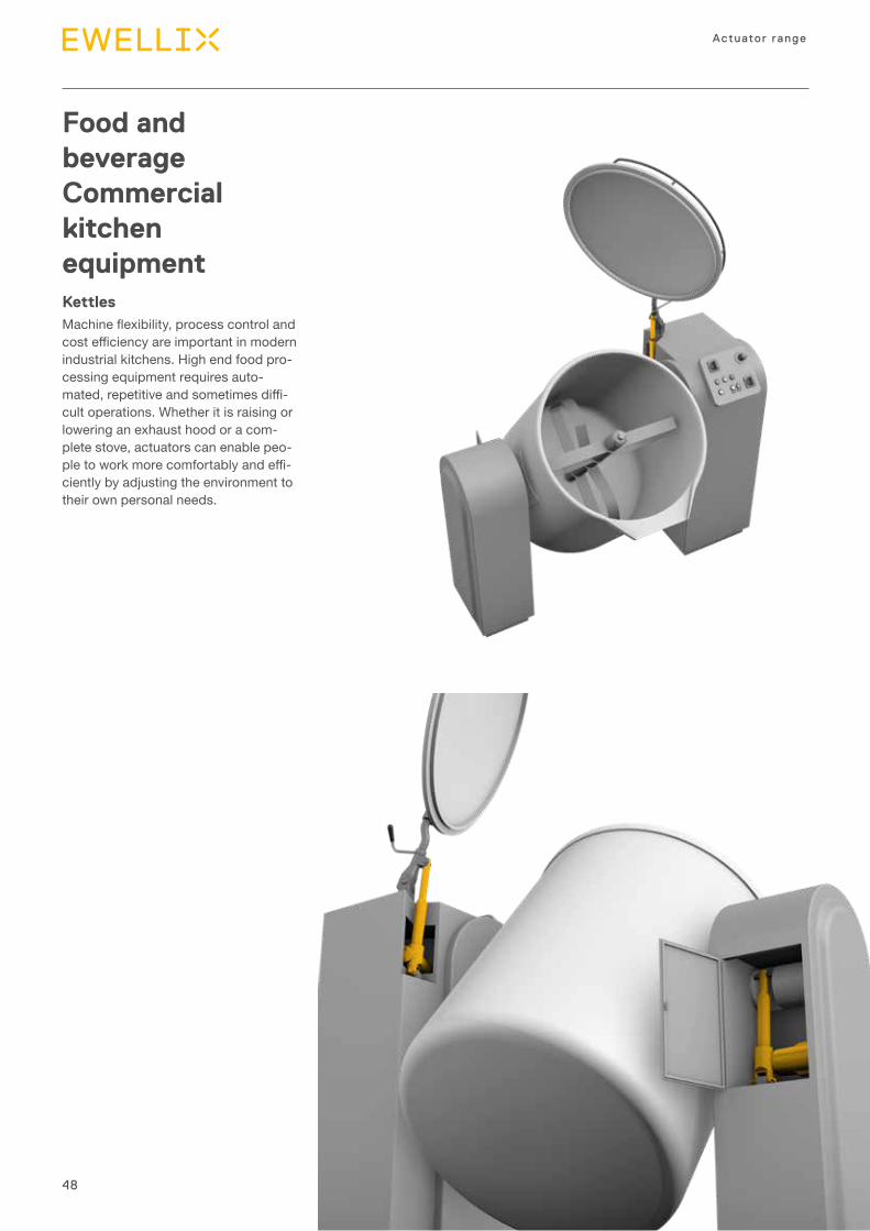
Food and beverage Commercial kitchen equipmentKettles Machine flexibility, process control and cost efficiency are important in modern industrial kitchens. High end food pro-cessing equipment requires auto-mated, repetitive and sometimes diffi-cult operations. Whether it is raising or lowering an exhaust hood or a com-plete stove, actuators can enable peo-ple to work more comfortably and effi-ciently by adjusting the environment to their own personal needs.
49
Introduction
1
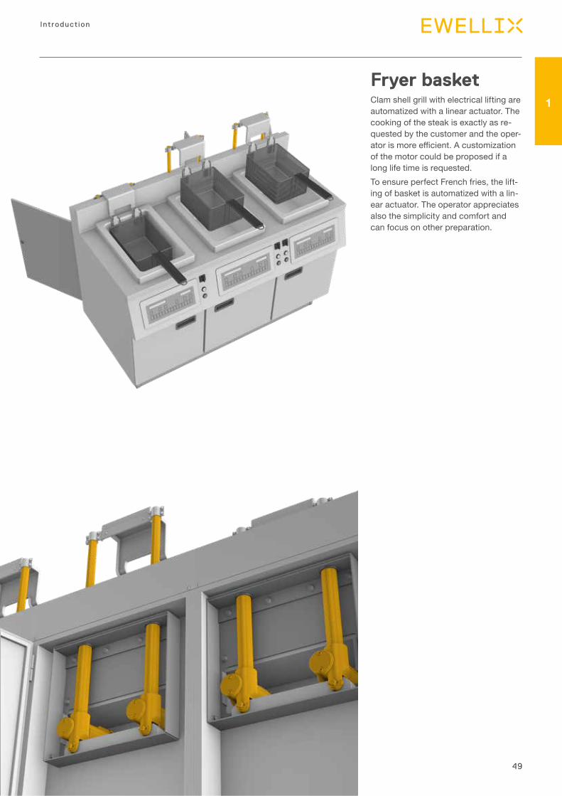
Fryer basket Clam shell grill with electrical lifting are automatized with a linear actuator. The cooking of the steak is exactly as re-quested by the customer and the oper-ator is more efficient. A customization of the motor could be proposed if a long life time is requested.To ensure perfect French fries, the lift-ing of basket is automatized with a lin-ear actuator. The operator appreciates also the simplicity and comfort and can focus on other preparation.

Introduction
Selection process• Medical• Harsh environment• Automation
2
51
Selection process
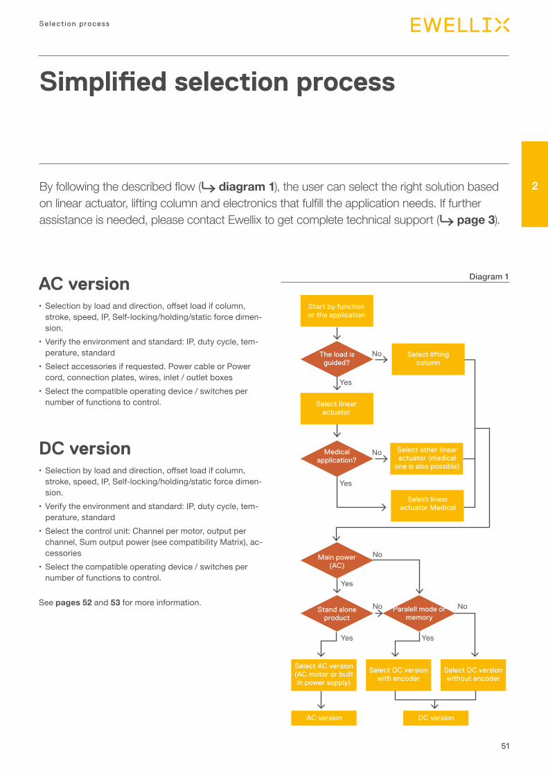
2By following the described flow (⮑ diagram 1), the user can select the right solution based on linear actuator, lifting column and electronics that fulfill the application needs. If further assistance is needed, please contact Ewellix to get complete technical support (⮑ page 3).
Simplified selection process
Diagram 1AC version• Selection by load and direction, offset load if column,
stroke, speed, IP, Self-locking/holding/static force dimen-sion.
• Verify the environment and standard: IP, duty cycle, tem-perature, standard
• Select accessories if requested. Power cable or Power cord, connection plates, wires, inlet / outlet boxes
• Select the compatible operating device / switches per number of functions to control.
DC version• Selection by load and direction, offset load if column,
stroke, speed, IP, Self-locking/holding/static force dimen-sion.
• Verify the environment and standard: IP, duty cycle, tem-perature, standard
• Select the control unit: Channel per motor, output per channel, Sum output power (see compatibility Matrix), ac-cessories
• Select the compatible operating device / switches per number of functions to control.
See pages 52 and 53 for more information.
Start by function or the application
No
No
No
Yes
Yes
Yes
Yes
Yes
No
No
Select linear actuator
Select linear actuator Medical
Select other linear actuator (medical
one is also possible)
Select AC version (AC motor or built in power supply)
AC version DC version
Select lifting column
Stand alone product
Main power (AC)
Paralell mode or memory
The load is guided?
Medical application?
Select DC version with encoder
Select DC version without encoder
52
Actuator range
Selection by load and direction, off set load if column, stroke, speed, Self-locking/holding/static force, dimensions• Rated load should match with the maximum force applied
to the actuator by the application during the movement. Consider the “worst case scenario” and also the direction; push is the extension and pull is the retraction direction.
• For Column, it is the load and offset load / distance that should be considered.
• The static load should match with the force applied on the actuator by the application when the actuator is static. Consider the dynamic effect of vibration or chock on the application.
• The stroke length of the actuator including the tolerance should match with the travel distance of the application. In case of limit switches option, the extra stroke length to reach the mechanical end stop of the actuator could be considered for added safety.
• The speed should match with the expected running time. Consider that the speed will change depending on the load but also depending on the voltage fluctuation in case of a DC motor, except for a Switch Mode Power Supply.
• For some products, you could select the attachment di-mension and retracted length. Consider the tolerance.
Verify the environment and standard: IP, duty cycle, temperature, standard • Each product should have an Environmental and standard
specification that should match the environment of the ap-plication.
• Ingress Protection.• Ambient Temperature during working condition, storage
condition. • Duty cycle % or “Time ON / Time OFF” are specified. • The longest running time should not exceed the Time ON
specified. • The shortest rest time should be longer than the running
time multiplied by the “Time ON / Time OFF” specified, or running time multiplied by (1- Duty cycle specified) and di-vided by duty cycle.
Formula:
Rest time > Running time × Time ON
Time OFF
or
Rest time > Running time × (1-Duty Cycle%)
Duty Cycle%
Example:Time ON / Time OFF = 85 s / 340 s or Duty Cycle 20%; the Running time must be less than 85 seconds. If the running time is 30 seconds, the Rest Time should be more than
30 × 34085
= 120 seconds
or 30 × (1- 20%)20%
Rest time >
so 30 × (1- 0,2)0,2
Rest time >
so at least 120 seconds
Some products are designed for a specific application but are suitable for others applications that request the similar performance.

53
Selection process
2
Select the Control Unit: Channel per motor, output per channel, Sum Output power (see compatibility Matrix)• Select the control unit that is compatible with the actuator
or column selected. Consider the sum of the number of channels requested by each product; some columns could request 2.
• Accessories can be selected: power cable or power cord, extra wires, Inlet and Outlet boxes, Connection plates.
Select the compatible operating device / buttons per number of functions to control• Select the operating device that is compatible with the
control unit.• The type of switch must be selected: the switch can have
different number of buttons according to the numbers of functions to drive (i.e. for only up and down function is nec-essary two buttons); number of buttons increase according to the number of actuators or columns to drive or if mem-ory position or other functions are needed.
IntroductionActuatorsUp to 50 kN rated load
3
55
3
Actuators
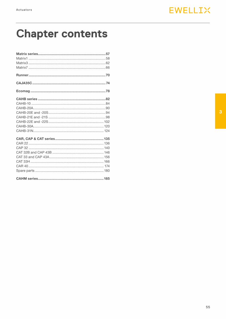
Chapter contents
Matrix series .......................................................................57Matrix1 .................................................................................58Matrix3 .................................................................................62Matrix7 .................................................................................66
Runner .................................................................................70
CAJA35C ............................................................................. 74
Ecomag ...............................................................................78
CAHB series .......................................................................82CAHB-10 ..............................................................................84CAHB-20A ............................................................................90CAHB-20E and -20S ............................................................94CAHB-21E and -21S ............................................................98CAHB-22E and -22S ..........................................................102CAHB-30A .......................................................................... 120CAHB-31N .......................................................................... 124
CAR, CAP & CAT series ...................................................135CAR 22 ...............................................................................136CAP 32 ............................................................................... 140CAT 32B and CAP 43B ...................................................... 146CAT 33 and CAP 43A ......................................................... 156CAT 33H .............................................................................166CAR 40 ............................................................................... 174Spare parts ........................................................................180
CAHM series .....................................................................185
56
Actuator range
57
3
Actuators
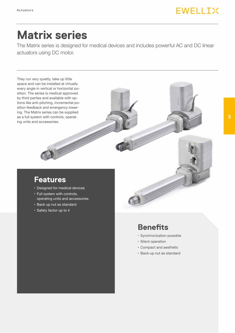
Matrix seriesThe Matrix series is designed for medical devices and includes powerful AC and DC linear actuators using DC motor.
Features•Designed for medical devices•Full system with controls,
operating units and accessories•Back up nut as standard•Safety factor up to 4
Benefits•Synchronization possible•Silent operation•Compact and aesthetic•Back-up nut as standard
They run very quietly, take up little space and can be installed at virtually every angle in vertical or horizontal po-sition. The series is medical approved by third parties and available with op-tions like anti-pitching, incremental po-sition feedback and emergency lower-ing. The Matrix series can be supplied as a full system with controls, operat-ing units and accessories.
58
Actuator range
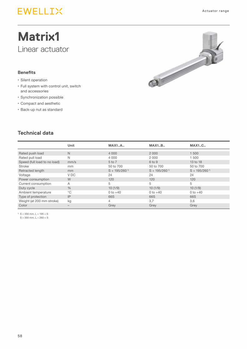
Matrix1Linear actuator
Technical data
Benefits
•Silent operation•Full system with control unit, switch
and accessories•Synchronization possible•Compact and aesthetic•Back-up nut as standard
Unit MAX1..A.. MAX1..B.. MAX1..C..
Rated push load N 4 000 2 000 1 500Rated pull load N 4 000 2 000 1 500Speed (full load to no load) mm/s 5 to 7 6 to 9 13 to 18Stroke mm 50 to 700 50 to 700 50 to 700Retracted length mm S + 195/260 1) S + 195/260 1) S + 195/260 1)
Voltage V DC 24 24 24Power consumption W 120 120 120Current consumption A 5 5 5Duty cycle % 10 (1/9) 10 (1/9) 10 (1/9)Ambient temperature °C 0 to +40 0 to +40 0 to +40Type of protection IP 66S 66S 66SWeight (at 200 mm stroke) kg 4 3,7 3,6Color – Grey Grey Grey
1) S < 350 mm, L = 195 + S S > 350 mm, L = 260 + S
59
3
Actuators
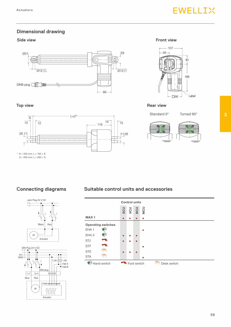
Dimensional drawing
66
48107
169
40
Label
29
Ø12+0,3+0,1Ø12+0,3
+0,15
Ø31
66
DIN8 plug
L±21)S
28 11 2811
1215 1514116
Side view
Top view
1) S < 350 mm; L = 195 + S S > 350 mm; L = 260 + S
Front view
Suitable control units and accessoriesConnecting diagrams
+-
Jack Plug 24 V DC
Black Red
MActuator
DIN Plug 24 V DC
Hall A
DIN plug
Actuator
Blue
1+7 2+4
+-
5V+GND
3 5 6 8
Red
M
Hall B
Hall sensor signal
1,5K 1,5K
Control units
SCU
VCU
BC
U
MC
U
MAX 1 ● ● ● ●
Operating switchesEHA 1 ●EHA 3 ● ● ●STJ ● ● ●STF ●STE ● ● ●STA ●
Desk switchHand switch Foot switch
Rear view
Standard 0° Turned 90°
60
Actuator range
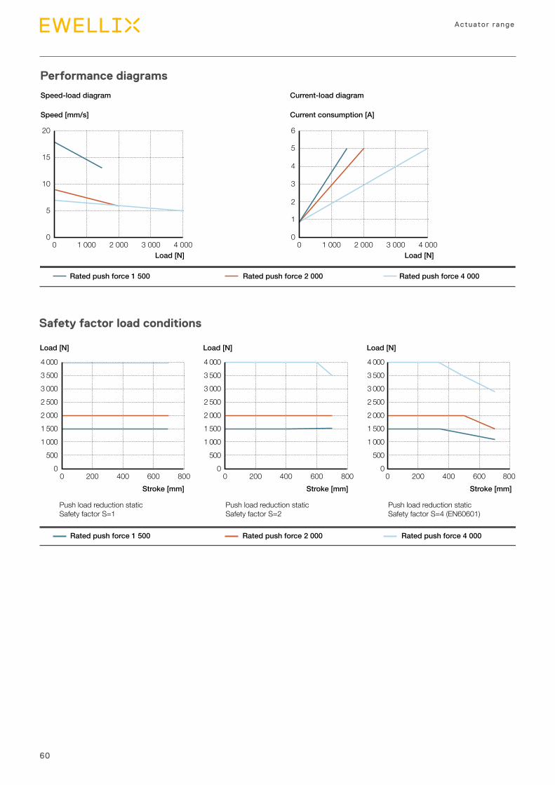
Safety factor load conditions
Stroke [mm]
Load [N]
Stroke [mm]
Load [N]
Stroke [mm]
Load [N]
0
3 5003 000
5001 0001 5002 0002 500
4 000
0 400200 600 8000
3 5003 000
5001 0001 5002 0002 500
4 000
0 400200 600 800
Rated push force 1 500 Rated push force 2 000 Rated push force 4 000
0
3 5003 000
5001 0001 5002 0002 500
4 000
0 400200 600 800
Push load reduction staticSafety factor S=1
Push load reduction staticSafety factor S=2
Push load reduction static Safety factor S=4 (EN60601)
Performance diagrams
0
15
10
5
20
0 2 0001 000 3 000 4 000
Speed [mm/s]
Load [N]
Current consumption [A]
Load [N]
Rated push force 1 500 Rated push force 2 000 Rated push force 4 000
0
5
4
3
2
1
6
0 2 0001 000 3 000 4 000
Speed-load diagram Current-load diagram
61
3
Actuators
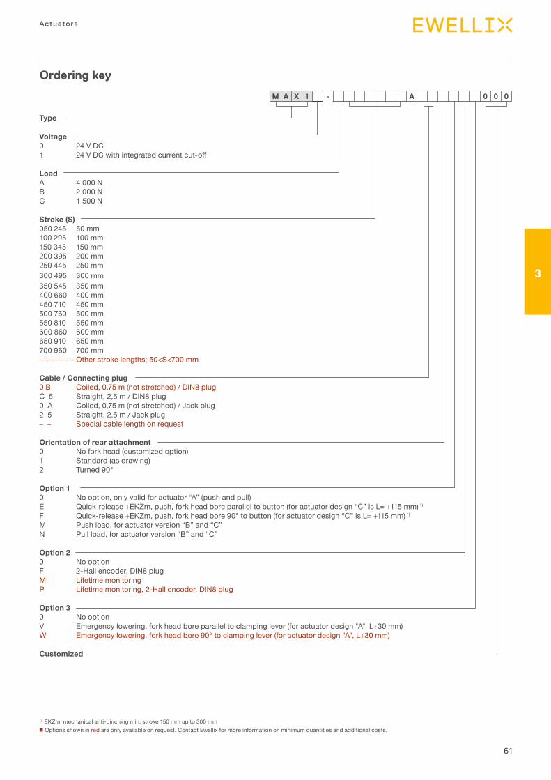
Ordering key
Type
Voltage0 24 V DC 1 24VDCwithintegratedcurrentcut-off
LoadA 4 000 N B 2 000 N C 1 500 N
Stroke (S)050 245 50 mm100 295 100 mm150 345 150 mm200 395 200 mm250 445 250 mm300 495 300 mm350 545 350 mm400 660 400 mm450 710 450 mm500 760 500 mm550 810 550 mm600 860 600 mm650 910 650 mm700 960 700 mm– – – – – – Other stroke lengths; 50<S<700 mm
Cable / Connecting plug0 B Coiled, 0,75 m (not stretched) / DIN8 plugC 5 Straight, 2,5 m / DIN8 plug0 A Coiled, 0,75 m (not stretched) / Jack plug2 5 Straight, 2,5 m / Jack plug– – Special cable length on request
Orientation of rear attachment0 No fork head (customized option) 1 Standard (as drawing)2 Turned 90°
Option 10 No option, only valid for actuator “A” (push and pull)E Quick-release +EKZm, push, fork head bore parallel to button (for actuator design “C” is L= +115 mm) 1)
F Quick-release +EKZm, push, fork head bore 90° to button (for actuator design “C” is L= +115 mm) 1)
M Push load, for actuator version “B” and “C” N Pull load, for actuator version “B” and “C”
Option 20 No option F 2-Hall encoder, DIN8 plug M Lifetime monitoring P Lifetime monitoring, 2-Hall encoder, DIN8 plug
Option 30 No option V Emergency lowering, fork head bore parallel to clamping lever (for actuator design "A", L+30 mm) W Emergency lowering, fork head bore 90° to clamping lever (for actuator design "A", L+30 mm)
Customized
1) EKZm: mechanical anti-pinching min. stroke 150 mm up to 300 mmn Options shown in red are only available on request. Contact Ewellix for more information on minimum quantities and additional costs.
M A X 1 - A 0 0 0
62
Actuator range
Technical data
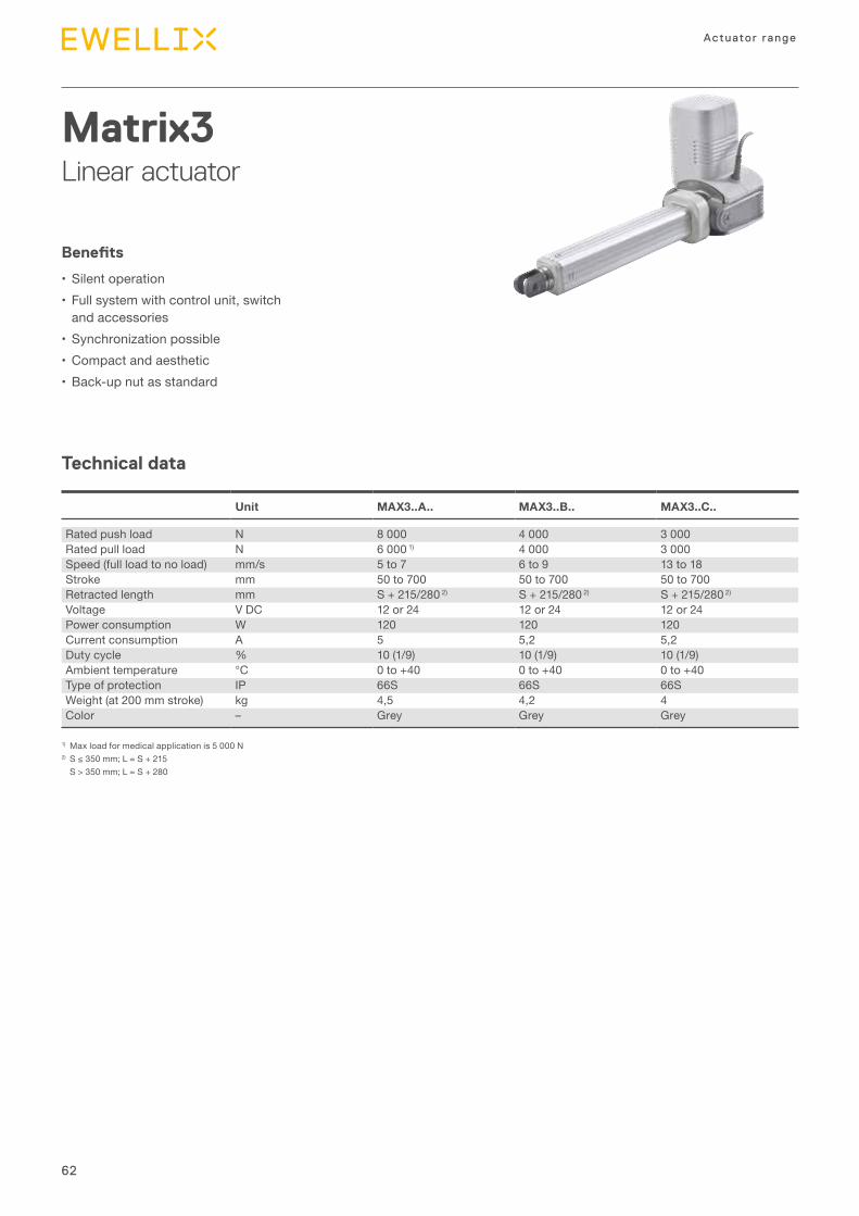
Matrix3Linear actuator
Benefits
•Silent operation•Full system with control unit, switch
and accessories•Synchronization possible•Compact and aesthetic•Back-up nut as standard
Unit MAX3..A.. MAX3..B.. MAX3..C..
Rated push load N 8 000 4 000 3 000Rated pull load N 6 000 1) 4 000 3 000Speed (full load to no load) mm/s 5 to 7 6 to 9 13 to 18Stroke mm 50 to 700 50 to 700 50 to 700Retracted length mm S + 215/280 2) S + 215/280 2) S + 215/280 2)
Voltage V DC 12 or 24 12 or 24 12 or 24Power consumption W 120 120 120Current consumption A 5 5,2 5,2Duty cycle % 10 (1/9) 10 (1/9) 10 (1/9)Ambient temperature °C 0 to +40 0 to +40 0 to +40Type of protection IP 66S 66S 66SWeight (at 200 mm stroke) kg 4,5 4,2 4Color – Grey Grey Grey
1) Max load for medical application is 5 000 N2)S≤350mm;L=S+215
S > 350 mm; L = S + 280
63
3
Actuators
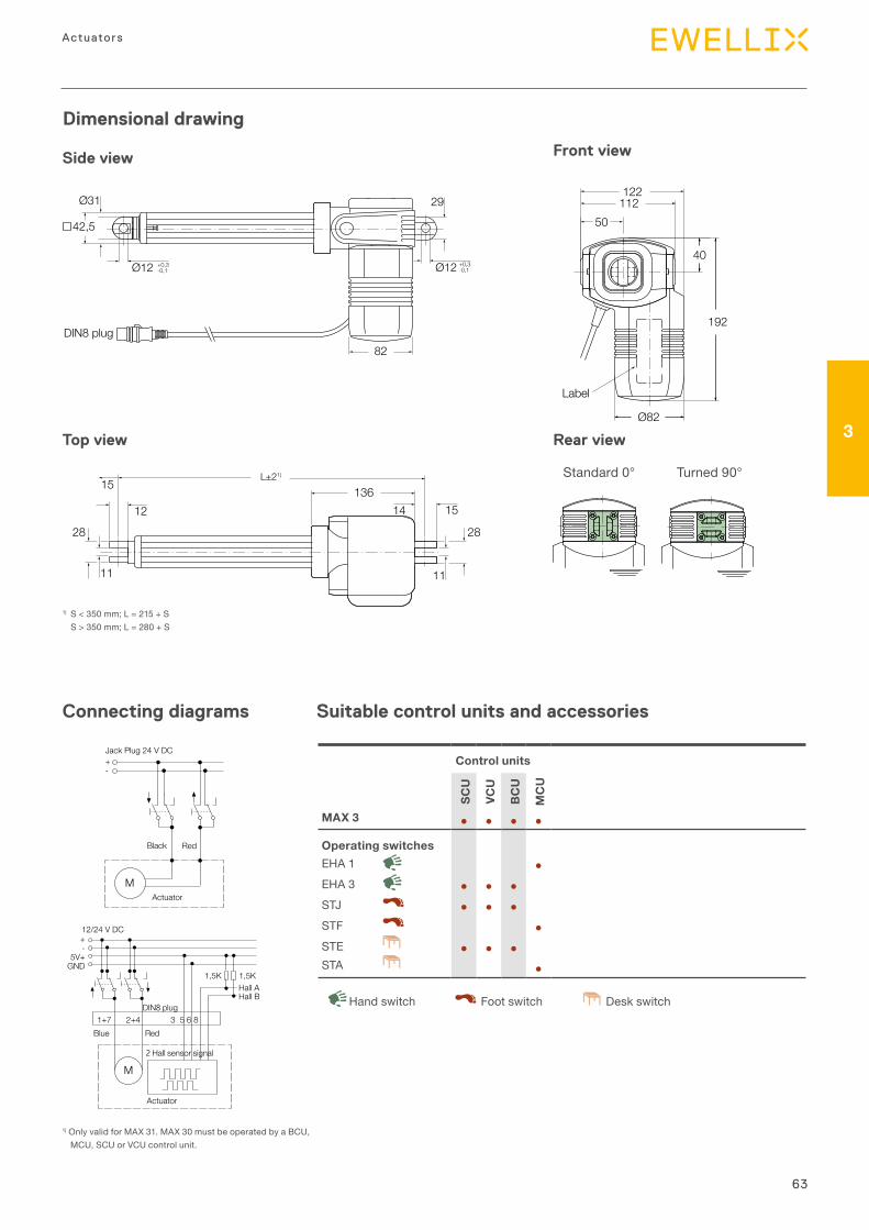
Dimensional drawing
82
42,5
Ø31 29
Ø12 +0,3-0,1 Ø12 +0,3
-0,1
DIN8 plug
50112122
Ø82
40
192
Label
Side view
Top view Rear view
Front view
1) S < 350 mm; L = 215 + S S > 350 mm; L = 280 + S
L±21)
12
11
28
11
28
14 1513615
Suitable control units and accessoriesConnecting diagrams
Control units
SCU
VCU
BC
U
MC
U
MAX 3 ● ● ● ●
Operating switchesEHA 1 ●EHA 3 ● ● ●STJ ● ● ●STF ●STE ● ● ●STA ●
Desk switchHand switch Foot switch
Jack Plug 24 V DC+-
Black Red
MActuator
12/24 V DC +-
5V+GND
M
1+7 2+4Blue Red
Hall sensor signal
Actuator
Hall AHall B
3 5 6 8DIN plug
1,5K 1,5K
1) Only valid for MAX 31. MAX 30 must be operated by a BCU, MCU, SCU or VCU control unit.
Standard 0° Turned 90°
64
Actuator range
Safety factor load conditions
0
2 0001 000
4 0003 000
6 0005 000
8 0007 000
0 200 400 600 800
push
push
pull
pull
Stroke [mm]
Load [N]
Stroke [mm]
Load [N]
Stroke [mm]
Load [N]
Rated push force 3 000 Rated push force 4 000 Rated push force 8 000
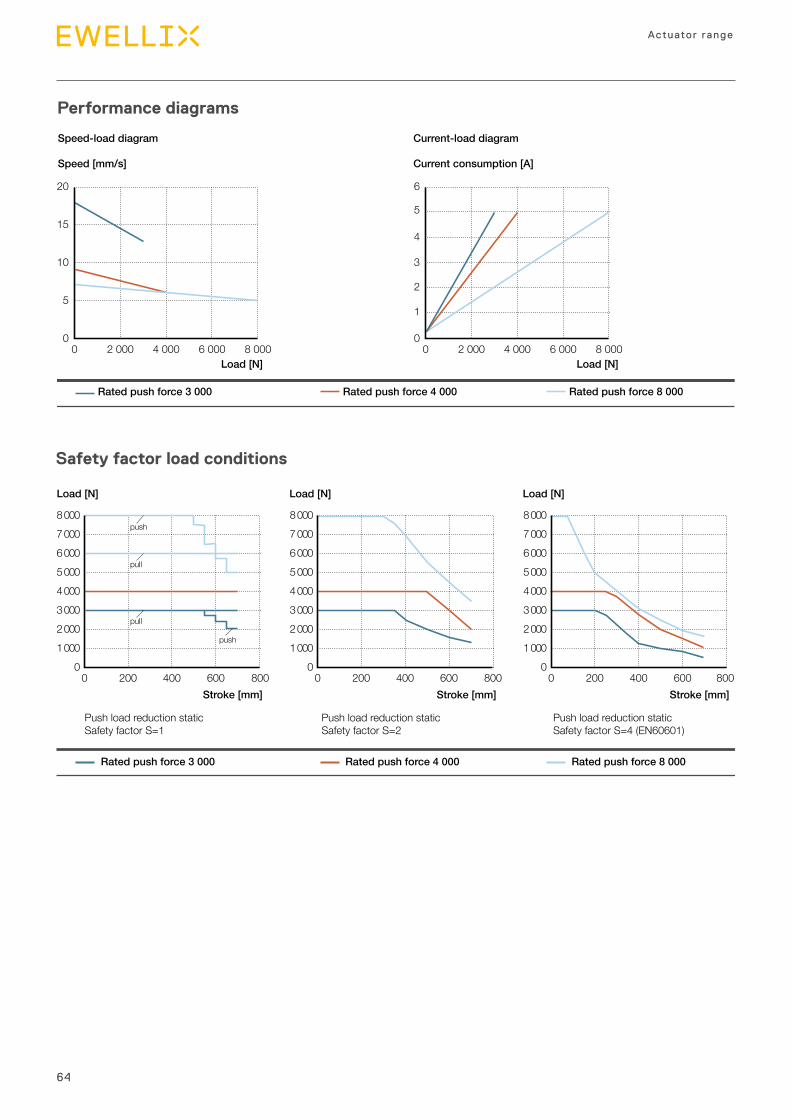
Push load reduction staticSafety factor S=1
Push load reduction staticSafety factor S=2
Push load reduction static Safety factor S=4 (EN60601)
0
2 0001 000
4 0003 000
6 0005 000
8 0007 000
0 200 400 600 8000
2 0001 000
4 0003 000
6 0005 000
8 0007 000
0 200 400 600 800
Performance diagrams
0
15
10
5
20
0 2 000 4 000 6 000 8 000
Speed [mm/s]
Load [N]
Current consumption [A]
Load [N]
Rated push force 3 000 Rated push force 4 000 Rated push force 8 000
Speed-load diagram Current-load diagram
0
5
3
4
2
1
6
0 2 000 4 000 6 000 8 000
65
3
Actuators
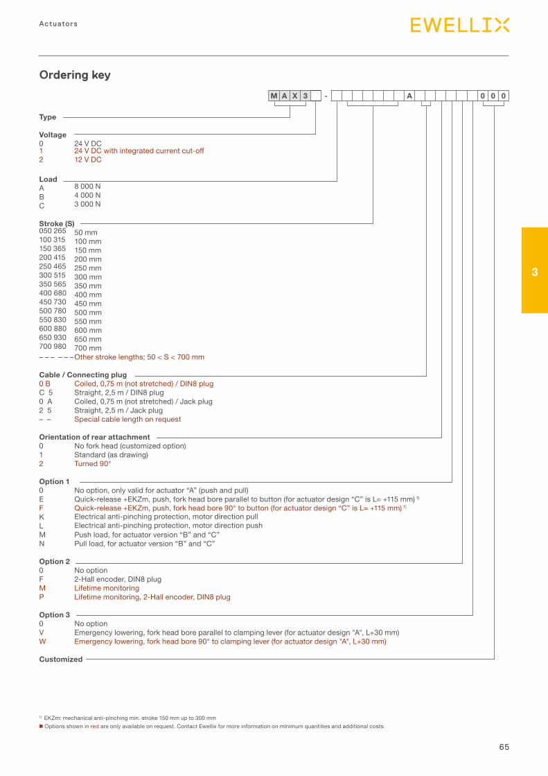
Ordering key
Type
Voltage0 24 V DC 1 24VDCwithintegratedcurrentcut-off2 12 V DC
LoadA 8 000 N B 4 000 N C 3 000 N
Stroke (S)050 265 50 mm100 315 100 mm150 365 150 mm200 415 200 mm250 465 250 mm300 515 300 mm350 565 350 mm400 680 400 mm450 730 450 mm500 780 500 mm550 830 550 mm600 880 600 mm650 930 650 mm700 980 700 mm– – – – – –Other stroke lengths; 50 < S < 700 mm
Cable / Connecting plug0 B Coiled, 0,75 m (not stretched) / DIN8 plugC 5 Straight, 2,5 m / DIN8 plug0 A Coiled, 0,75 m (not stretched) / Jack plug2 5 Straight, 2,5 m / Jack plug– – Special cable length on request
Orientation of rear attachment0 No fork head (customized option) 1 Standard (as drawing)2 Turned 90°
Option 10 No option, only valid for actuator “A” (push and pull)E Quick-release +EKZm, push, fork head bore parallel to button (for actuator design “C” is L= +115 mm) 1)
F Quick-release +EKZm, push, fork head bore 90° to button (for actuator design “C” is L= +115 mm) 1)
K Electrical anti-pinching protection, motor direction pull L Electrical anti-pinching protection, motor direction push M Push load, for actuator version “B” and “C” N Pull load, for actuator version “B” and “C”
Option 20 No option F 2-Hall encoder, DIN8 plug M Lifetime monitoring P Lifetime monitoring, 2-Hall encoder, DIN8 plug
Option 30 No option V Emergency lowering, fork head bore parallel to clamping lever (for actuator design "A", L+30 mm) W Emergency lowering, fork head bore 90° to clamping lever (for actuator design "A", L+30 mm)
Customized
1) EKZm: mechanical anti-pinching min. stroke 150 mm up to 300 mm n Options shown in red are only available on request. Contact Ewellix for more information on minimum quantities and additional costs.
M A X 3 - A 0 0 0
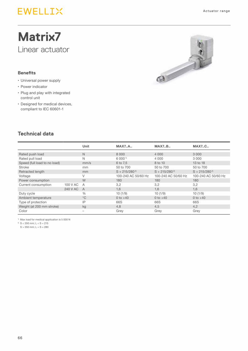
66
Actuator range
Technical data
Matrix7Linear actuator
Benefits
•Universal power supply•Power indicator•Plug and play with integrated
control unit•Designed for medical devices,
compliant to IEC 60601-1
1) Max load for medical application is 5 000 N2) S < 350 mm; L = S + 215
S > 350 mm; L = S + 280
Unit MAX7..A.. MAX7..B.. MAX7..C..
Rated push load N 8 000 4 000 3 000Rated pull load N 6 000 1) 4 000 3 000Speed (full load to no load) mm/s 6 to 7,5 8 to 10 13 to 18Stroke mm 50 to 700 50 to 700 50 to 700Retracted length mm S + 215/280 2) S + 215/280 2) S + 215/280 2)
Voltage V 100-240 AC 50/60 Hz 100-240 AC 50/60 Hz 100-240 AC 50/60 HzPower consumption W 180 180 180Current consumption 100 V AC A 3,2 3,2 3,2
240 V AC A 1,6 1,6 1,6Duty cycle % 10 (1/9) 10 (1/9) 10 (1/9)Ambient temperature °C 0 to +40 0 to +40 0 to +40Type of protection IP 66S 66S 66SWeight (at 200 mm stroke) kg 4,8 4,5 4,2Color – Grey Grey Grey
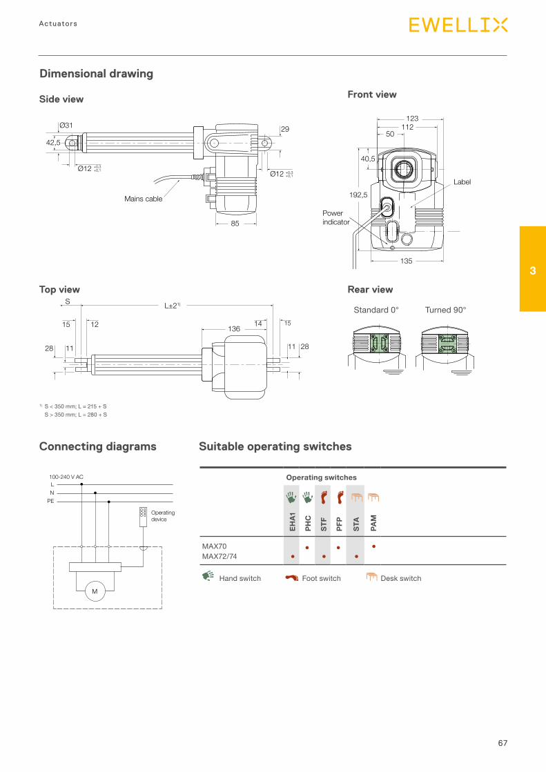
67
3
Actuators
Dimensional drawing
Ø12
85
Ø31 29
42,5
Ø12+0,3+0,1 +0,3
+0,1
Mains cable
1) S < 350 mm; L = 215 + S S > 350 mm; L = 280 + S
50
123
135
112
192,5
Powerindicator
Label
40,5
Side view
Top view
Front view
L±21)S
1128 11 28
136151415 12
Suitable operating switchesConnecting diagrams
Operating switches
EHA1
PHC
STF
PFP
STA
PAM
MAX70 ● ● ●MAX72/74 ● ● ●
Desk switchHand switch Foot switch
LN
PE
M
100-240 V AC
Operatingdevice
Rear view
Standard 0° Turned 90°
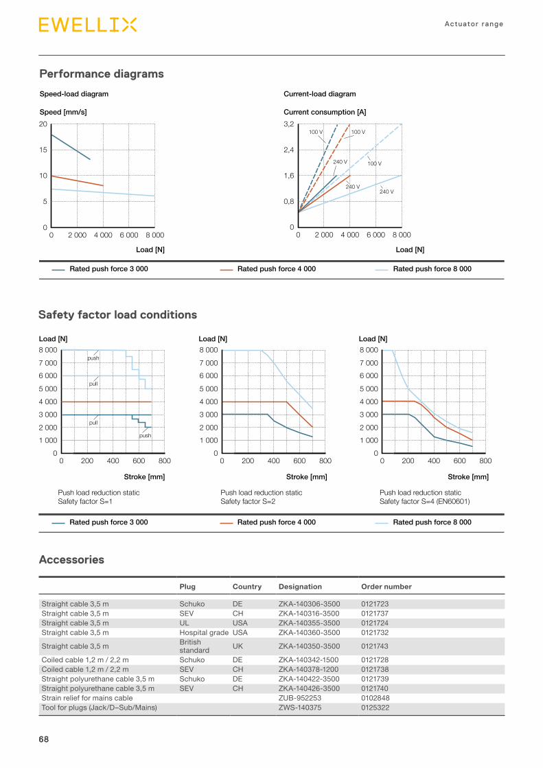
68
Actuator range
6868
Safety factor load conditions
00 200 400 600 800
1 0002 0003 0004 0005 000
6 0007 000
8 000push
push
pull
pull
Stroke [mm]
Load [N]
Stroke [mm]
Load [N]
Stroke [mm]
Load [N]
Push load reduction staticSafety factor S=1
Push load reduction staticSafety factor S=2
Push load reduction static Safety factor S=4 (EN60601)
00 200 400 600 800
1 0002 0003 0004 0005 000
6 0007 000
8 000
00 200 400 600 800
1 0002 0003 0004 0005 000
6 0007 000
8 000
Rated push force 3 000 Rated push force 4 000 Rated push force 8 000
Performance diagrams
00 2 000 4 000 6 000 8 000
5
10
15
20Speed [mm/s]
Load [N]
Current consumption [A]
Load [N]
Rated push force 3 000 Rated push force 4 000 Rated push force 8 000
00 2 000 4 000 6 000 8 000
0,8
1,6
2,4
3,2100 V
240 V
240 V240 V
100 V
100 V
Speed-load diagram Current-load diagram
Plug Country Designation Order number
Straight cable 3,5 m Schuko DE ZKA-140306-3500 0121723Straight cable 3,5 m SEV CH ZKA-140316-3500 0121737Straight cable 3,5 m UL USA ZKA-140355-3500 0121724Straight cable 3,5 m Hospital grade USA ZKA-140360-3500 0121732
Straight cable 3,5 m British standard UK ZKA-140350-3500 0121743
Coiled cable 1,2 m / 2,2 m Schuko DE ZKA-140342-1500 0121728Coiled cable 1,2 m / 2,2 m SEV CH ZKA-140378-1200 0121738Straight polyurethane cable 3,5 m Schuko DE ZKA-140422-3500 0121739Straight polyurethane cable 3,5 m SEV CH ZKA-140426-3500 0121740 Strain relief for mains cable ZUB-952253 0102848Tool for plugs (Jack/D–Sub/Mains) ZWS-140375 0125322
Accessories
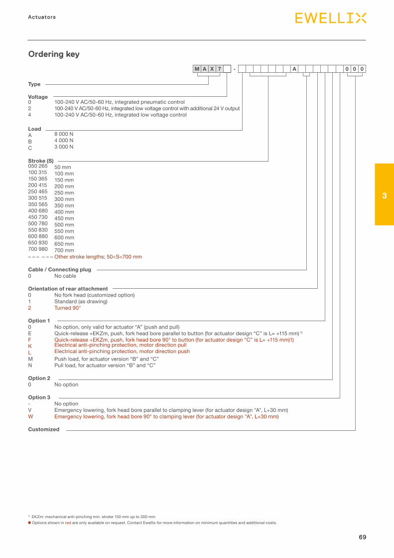
69
3
Actuators
69
Actuators
3
69
Ordering key
Type
Voltage0 100-240 V AC/50-60 Hz, integrated pneumatic control 2 100-240 V AC/50-60 Hz, integrated low voltage control with additional 24 V output4 100-240 V AC/50-60 Hz, integrated low voltage control
LoadA 8 000 N B 4 000 N C 3 000 N
Stroke (S)050 265 50 mm100 315 100 mm150 365 150 mm200 415 200 mm250 465 250 mm300 515 300 mm350 565 350 mm400 680 400 mm450 730 450 mm500 780 500 mm550 830 550 mm600 880 600 mm650 930 650 mm700 980 700 mm– – – – – – Other stroke lengths; 50<S<700 mm
Cable / Connecting plug0 No cable
Orientation of rear attachment0 No fork head (customized option) 1 Standard (as drawing)2 Turned 90°
Option 10 No option, only valid for actuator “A” (push and pull)E Quick-release +EKZm, push, fork head bore parallel to button (for actuator design “C” is L= +115 mm) 1)
F Quick-release +EKZm, push, fork head bore 90° to button (for actuator design “C” is L= +115 mm)1)K Electrical anti-pinching protection, motor direction pull L Electrical anti-pinching protection, motor direction push M Push load, for actuator version “B” and “C” N Pull load, for actuator version “B” and “C”
Option 20 No option
Option 3- No option V Emergency lowering, fork head bore parallel to clamping lever (for actuator design "A", L+30 mm) W Emergency lowering, fork head bore 90° to clamping lever (for actuator design "A", L+30 mm)
Customized
1) EKZm: mechanical anti-pinching min. stroke 150 mm up to 300 mm n Options shown in red are only available on request. Contact Ewellix for more information on minimum quantities and additional costs.
M A X 7 - A 0 0 0
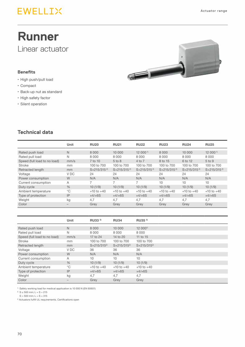
70
Actuator range
Technical data
RunnerLinear actuator
Benefits
•High push/pull load•Compact•Back-up nut as standard•High safety factor•Silent operation
Unit RU20 RU21 RU22 RU23 RU24 RU25
Rated push load N 8 000 10 000 12 000 1) 8 000 10 000 12 000 1)
Rated pull load N 8 000 8 000 8 000 8 000 8 000 8 000Speed (full load to no load) mm/s 7 to 10 5 to 8 4 to 7 8 to 15 6 to 12 5 to 9Stroke mm 100 to 700 100 to 700 100 to 700 100 to 700 100 to 700 100 to 700Retracted length mm S+215/315 2) S+215/315 2) S+215/315 2) S+215/315 2) S+215/315 2) S+215/315 2)
Voltage V DC 24 24 24 24 24 24Power consumption W N/A N/A N/A N/A N/A N/ACurrent consumption A 7 7 7 10 10 10Duty cycle % 10 (1/9) 10 (1/9) 10 (1/9) 10 (1/9) 10 (1/9) 10 (1/9)Ambient temperature °C +10 to +40 +10 to +40 +10 to +40 +10 to +40 +10 to +40 +10 to +40Type of protection IP ×4/×6S ×4/×6S ×4/×6S ×4/×6S ×4/×6S ×4/×6S Weight kg 4,7 4,7 4,7 4,7 4,7 4,7Color – Grey Grey Grey Grey Grey Grey
1) Safety working load for medical application is 10 000 N (EN 60601)2) S≤500mm;L=S+215
S > 500 mm; L = S + 3153)ActuatorsfulfillULrequirements,Certificationsopen
Unit RU33 3) RU34 RU35 3)
Rated push load N 8 000 10 000 12 0001)
Rated pull load N 8 000 8 000 8 000Speed (full load to no load) mm/s 17 to 24 14 to 20 11 to 15Stroke mm 100 to 700 100 to 700 100 to 700Retracted length mm S+215/3152) S+215/3152) S+215/3152)
Voltage V DC 36 36 36Power consumption W N/A N/A N/ACurrent consumption A 10 10 10Duty cycle % 10 (1/9) 10 (1/9) 10 (1/9)Ambient temperature °C +10 to +40 +10 to +40 +10 to +40Type of protection IP ×4/×6S ×4/×6S ×4/×6S Weight kg 4,7 4,7 4,7Color – Grey Grey Grey
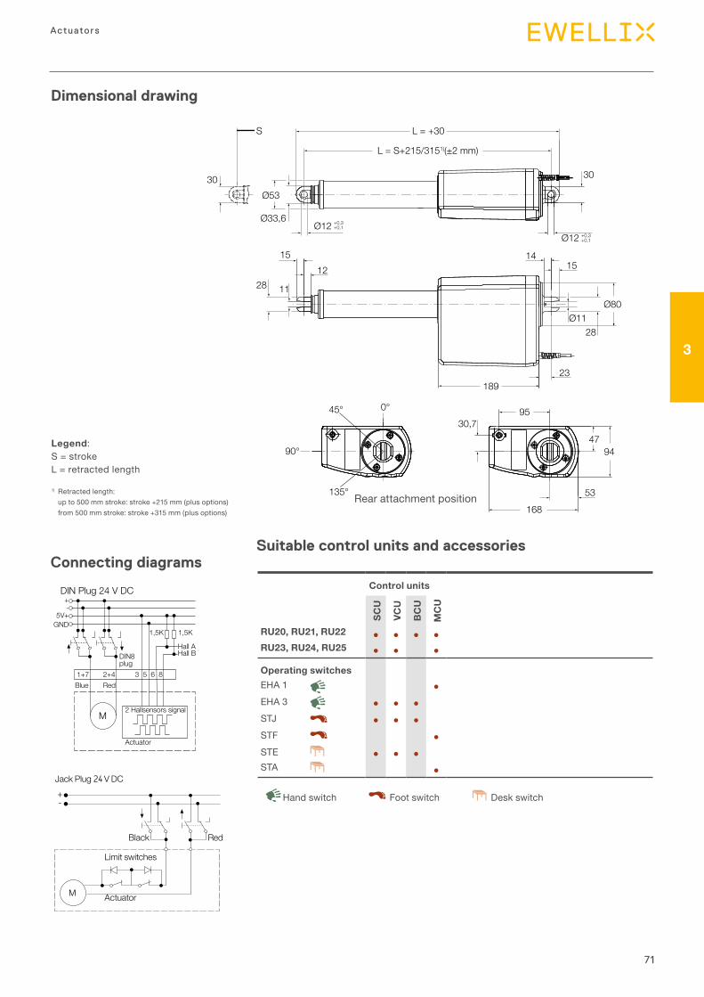
71
3
Actuators
3030Ø53
Ø12 +0,3+0,1
L = S+215/3151)(±2 mm)
L = +30S
Ø12 +0,3+0,1
1415
Ø80Ø11
28
189
168
9545°
135°
90°
0°
23
94
30,747
53
1512
1128
Ø33,6
Dimensional drawing
Connecting diagrams
Legend:S = strokeL = retracted length
1) Retracted length: up to 500 mm stroke: stroke +215 mm (plus options) from 500 mm stroke: stroke +315 mm (plus options)
Rear attachment position
Suitable control units and accessories
Control units
SCU
VCU
BC
U
MC
U
RU20, RU21, RU22 ● ● ● ●RU23, RU24, RU25 ● ● ●
Operating switchesEHA 1 ●EHA 3 ● ● ●STJ ● ● ●STF ●STE ● ● ●STA ●
Desk switchHand switch Foot switch
Black
Jack Plug V DC
Limit switches
Actuator
Red
+-
M
DIN Plug 24 V DC+-
5V+GND
1+7 2+4
1,5K 1,5K
Hall AHall B
3 5 6 8
DIN8 plug
Blue Red
M2 Hallsensors signal
Actuator
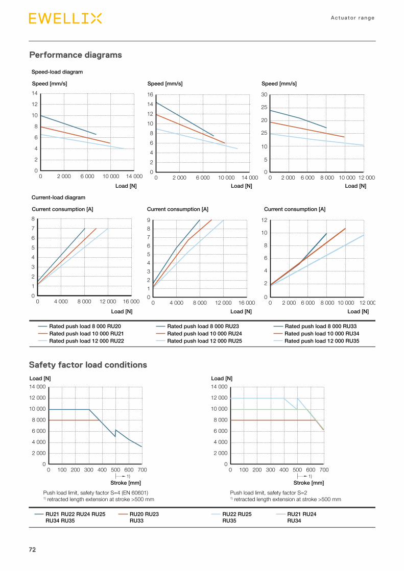
72
Actuator range
7272
Safety factor load conditions
0
6 000
4 000
2 000
10 000
8 000
12 000
14 000
0 100 200 300 400 500 6001)
700
Load [N]
Stroke [mm]
Load [N]
Stroke [mm]
RU22 RU25RU35
RU21 RU24RU34
RU21 RU22 RU24 RU25RU34 RU35
RU20 RU23RU33
0
6 000
4 000
2 000
10 000
8 000
12 000
14 000
0 100 200 300 400 500 6001)
700
Push load limit, safety factor S=4 (EN 60601) 1) retracted length extension at stroke >500 mm
Push load limit, safety factor S=2 1) retracted length extension at stroke >500 mm
Performance diagrams
Rated push load 8 000 RU33Rated push load 10 000 RU34Rated push load 12 000 RU35
0
6
4
2
10
8
12
14
0 2 000 6 000 10 000 14 000
Speed [mm/s]
Load [N]
Speed-load diagram
Current-load diagram
Current consumption [A]
Load [N]
0 4 000 8 000 12 000 16 0000
4321
5678
Rated push load 8 000 RU20Rated push load 10 000 RU21Rated push load 12 000 RU22
0
5
25
10
20
30
25
0 2 000 6 000 8 000 12 00010 000
Speed [mm/s]
Load [N]
Current consumption [A]
Load [N]0 2 000 6 000 8 000 10 000 12 000
0
2
4
6
8
12
10
0
642
108
12
1614
0 2 000 6 000 10 000 14 000
Speed [mm/s]
Load [N]
Current consumption [A]
Load [N]0 4 000 8 000 12 000 16 000
0
4321
567
98
Rated push load 8 000 RU23Rated push load 10 000 RU24Rated push load 12 000 RU25
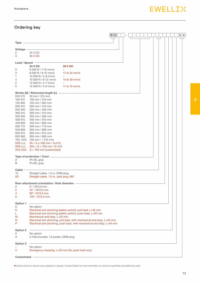
73
3
ActuatorsActuators
Type
Voltage2 24 V DC3 36 V DC
Load / Speed
Stroke (S) / Retracted length (L)050 315 50 mm / 315 mm 100 315 100 mm / 315 mm 150 365 150 mm / 365 mm 200 415 200 mm / 415 mm 250 465 250 mm / 465 mm 300 515 300 mm / 515 mm350 565 350 mm / 565 mm 400 615 400 mm / 615 mm450 665 450 mm / 665 mm 500 715 500 mm / 715 mm 550 865 550 mm / 865 mm 600 915 600 mm / 915 mm 650 965 650 mm / 965 mm 700 XXX 700 mm / 1 015 mm SSS LLL 50<S≤500mm/S+215SSS LLL 500 < S < 700 mm / S+315 XXX XXX S > 700 mm (customized)
Type of protection / ColorA IP×4S, grey B IP×6S, grey
Cable15 Straight cable, 1,5 m, DIN8 plug 0D Straight cable, 1,5 m, Jack plug 180°
Rear attachment orientation / Hole diameter0 0° / Ø12,0 mm 2 45° / Ø12,0 mm 4 90° / Ø12,0 mm6 135° / Ø12,0 mm
Option 10 No optionK Electrical anti-pinching (safety switch), pull load, L+20 mmL Electrical anti-pinching (safety switch), push load, L+20 mmM Mechanical end stop, L+25 mmN Electrical anti-pinching, pull load, with mechanical end stop, L+45 mmP Electrical anti-pinching, push load, with mechanical end stop, L+45 mm
Option 20 No option A 2-Hall encoder, 14 pulses, DIN8 plug
Option 3– No option V Emergency lowering, L+53 mm (for push load only)
Customized
Ordering key
n Options shown in red are only available on request. Contact Ewellix for more information on minimum quantities and additional costs.
R U - 0 0
24 V DC 36 V DC0 8 000 N / 7-10 mm/s –3 8 000 N / 8-15 mm/s 17 to 24 mm/s1 10 000 N / 5-8 mm/s –4 10 000 N / 6-12 mm/s 14 to 20 mm/s2 12 000 N / 4-7 mm/s –5 12 000 N / 5-9 mm/s 11 to 15 mm/s
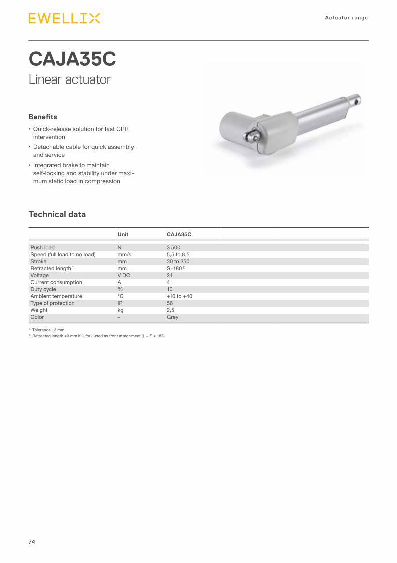
74
Actuator range
Technical data
CAJA35CLinear actuator
Benefits
•Quick-release solution for fast CPR intervention
•Detachable cable for quick assembly and service
• Integrated brake to maintain self-locking and stability under maxi-mum static load in compression
Unit CAJA35C
Push load N 3 500Speed (full load to no load) mm/s 5,5 to 8,5Stroke mm 30 to 250Retracted length 1) mm S+180 2)
Voltage V DC 24Current consumption A 4Duty cycle % 10Ambient temperature °C +10 to +40Type of protection IP 56Weight kg 2,5Color – Grey
1) Tolerance ±3 mm2) Retracted length +3 mm if U fork used as front attachment (L = S + 183)
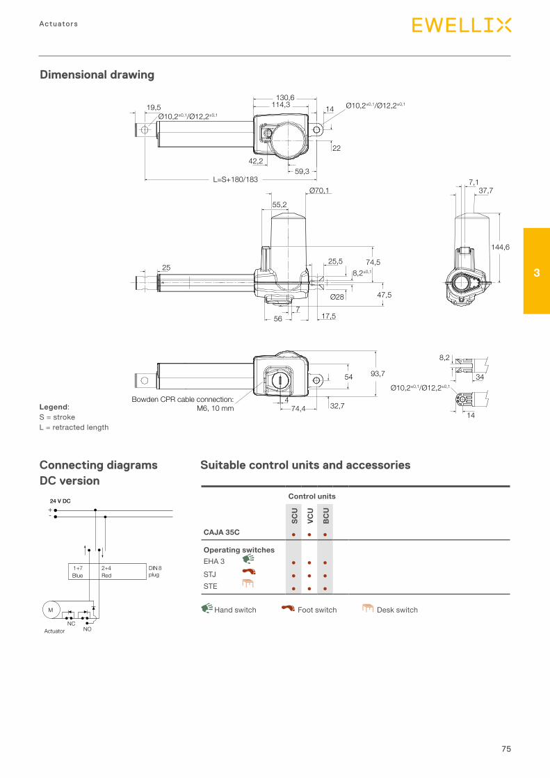
75
3
Actuators
Dimensional drawing
Connecting diagrams DC version
Legend:S = strokeL = retracted length
Suitable control units and accessories
Control units
SCU
VCU
BC
U
CAJA 35C ● ● ●
Operating switchesEHA 3 ● ● ●STJ ● ● ●STE ● ● ●
Desk switchHand switch Foot switch
25,5
19,5
22
Ø10,2±0,1/Ø12,2±0,1
Ø10,2±0,1/Ø12,2±0,1
42,2
130,614114,3
L=S+180/18359,3
Ø28 47,5
Ø70,1
8,2±0,1
56
25
7
55,2
17,5
74,5
8,2
14
34Ø10,2±0,1/Ø12,2±0,1
74,4Bowden CPR cable connection:
M6, 10 mm 32,7
93,754
4
144,6
37,77,1
+-
24 V DC
1+7Blue
2+4Red
DIN 8plug
M
ActuatorNC
NO
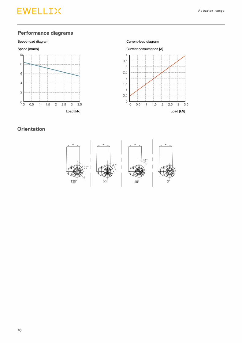
76
Actuator range
7676
Performance diagrams
Speed [mm/s]
Load [kN]
Current consumption [A]
Speed-load diagram Current-load diagram
Load [kN]
10
2
0
4
0 0,5 1 1,5 2 2,5 3 3,5 0 0,5 1 1,5 2 2,5 3 3,5
6
8
0
3
1
2
0,5
3,5
1,5
2,5
4
Orientation
135°
135°
90°
90°
45°
45°
0°
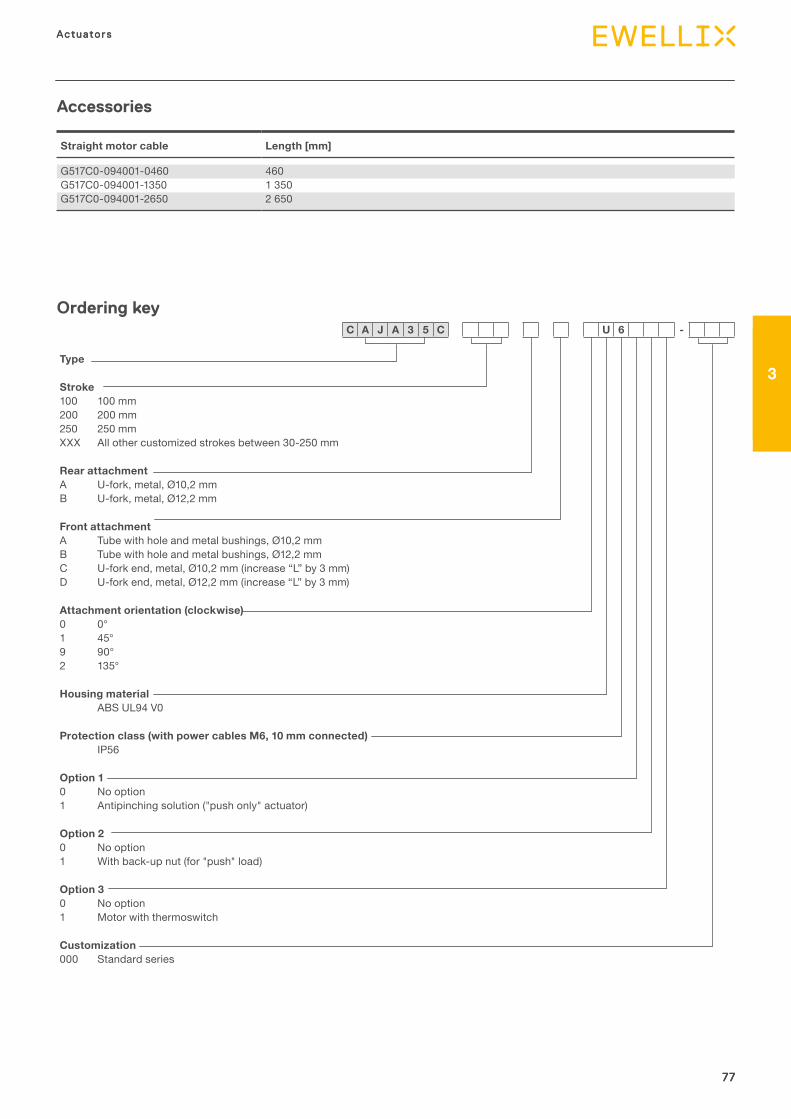
77
3
Actuators
77
Actuators
3
77
Straight motor cable Length [mm]
G517C0-094001-0460 460G517C0-094001-1350 1 350G517C0-094001-2650 2 650
Accessories
Ordering key
Type
Stroke100 100 mm 200 200 mm 250 250 mm XXX All other customized strokes between 30-250 mm
Rear attachmentA U-fork, metal, Ø10,2 mmB U-fork, metal, Ø12,2 mm
Front attachmentA Tube with hole and metal bushings, Ø10,2 mm B Tube with hole and metal bushings, Ø12,2 mm C U-fork end, metal, Ø10,2 mm (increase “L” by 3 mm) D U-fork end, metal, Ø12,2 mm (increase “L” by 3 mm)
Attachment orientation (clockwise)0 0° 1 45° 9 90° 2 135°
Housing materialABS UL94 V0
Protection class (with power cables M6, 10 mm connected)IP56
Option 10 No option1 Antipinching solution ("push only" actuator)
Option 20 No option 1 With back-up nut (for "push" load)
Option 30 No option 1 Motor with thermoswitch
Customization000 Standard series
C A J A 3 5 C U 6 -
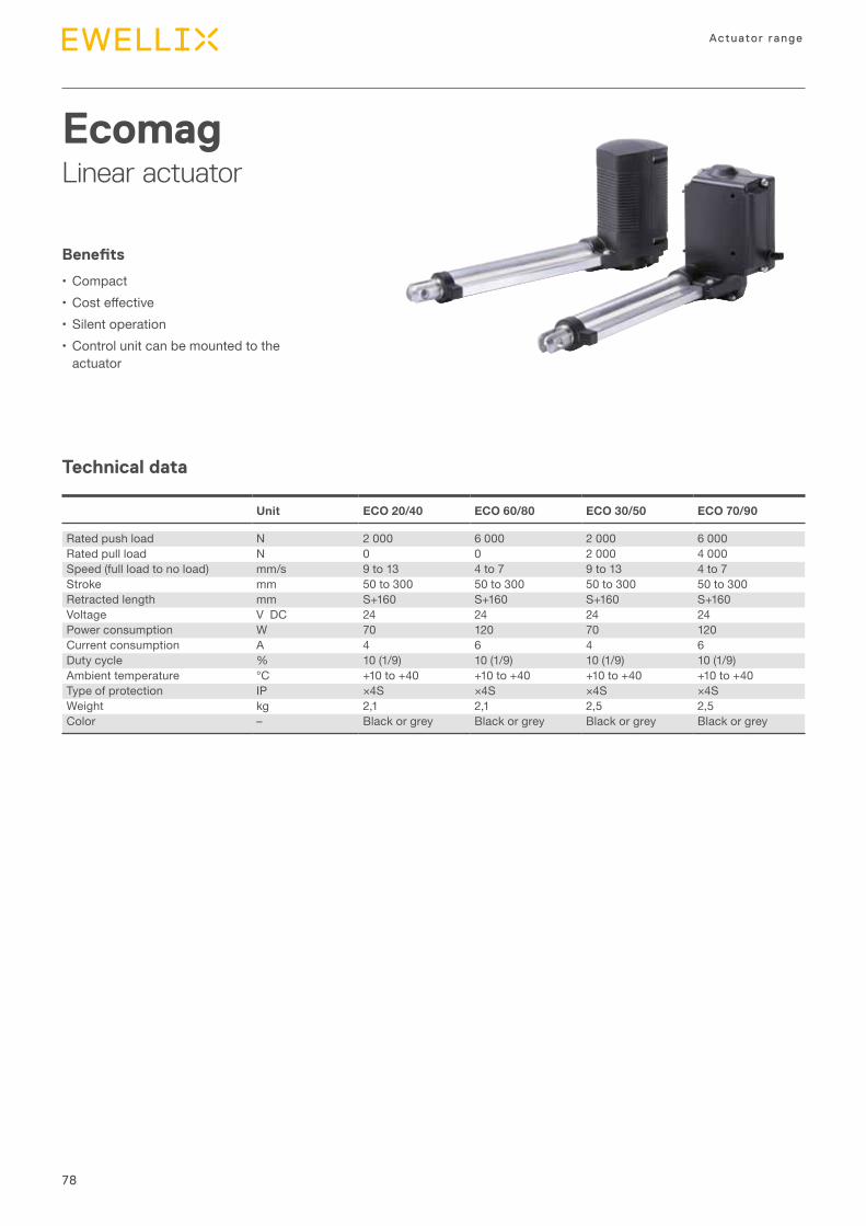
78
Actuator range
Technical data
EcomagLinear actuator
Benefits
•Compact• Costeffective•Silent operation•Control unit can be mounted to the
actuator
Unit ECO 20/40 ECO 60/80 ECO 30/50 ECO 70/90
Rated push load N 2 000 6 000 2 000 6 000Rated pull load N 0 0 2 000 4 000Speed (full load to no load) mm/s 9 to 13 4 to 7 9 to 13 4 to 7Stroke mm 50 to 300 50 to 300 50 to 300 50 to 300Retracted length mm S+160 S+160 S+160 S+160Voltage V DC 24 24 24 24Power consumption W 70 120 70 120Current consumption A 4 6 4 6Duty cycle % 10 (1/9) 10 (1/9) 10 (1/9) 10 (1/9)Ambient temperature °C +10 to +40 +10 to +40 +10 to +40 +10 to +40Type of protection IP ×4S ×4S ×4S ×4SWeight kg 2,1 2,1 2,5 2,5Color – Black or grey Black or grey Black or grey Black or grey
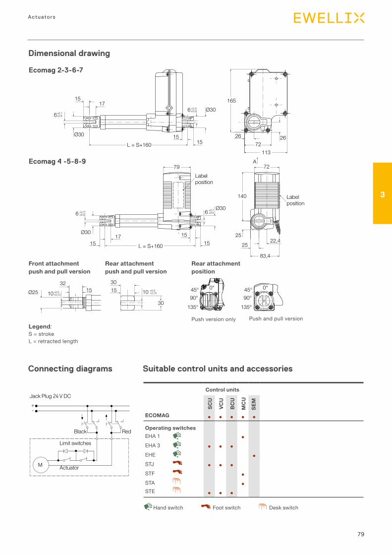
79
3
Actuators
Dimensional drawing
Connecting diagrams
Legend:S = strokeL = retracted length
Suitable control units and accessories
Black
Jack Plug V DC
Limit switches
Actuator
Red
+-
M
1517
L = S+160
165
72113
1515
2626
6+0,7+0,5
6+0,7+0,5
Ø30
Ø30
140
A
25
2522,4
151515
Ø3017
83,4
79Labelposition
Labelposition
72
L = S+160
6 +0,7+0,56 +0,7
+0,5
Ø30
15 153032
30
Ø25 10 +0,3+0,1510+0,3
+0,1545° 0°
90°135°
45° 0°
90°135°
Ecomag 2-3-6-7
Ecomag 4 -5-8-9
Rear attachment position
Front attachment push and pull version
Rear attachment push and pull version
Push version only Push and pull version
Control units
SCU
VCU
BC
U
MC
U
SEM
ECOMAG ● ● ● ● ●
Operating switchesEHA 1 ●EHA 3 ● ● ●EHE ●STJ ● ● ●STF ●STA ●STE ● ● ●
Desk switchHand switch Foot switch
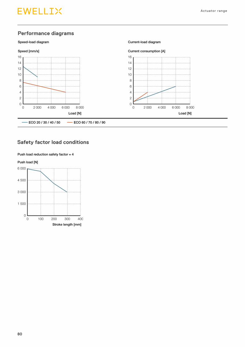
80
Actuator range
8080
Safety factor load conditions
0
1 500
4 500
3 000
6 000
0 100 200 300 400Stroke length [mm]
Push load [N]
Push load reduction safety factor = 4
Performance diagrams
0
1086
24
1412
16
0 2 000 4 000 6 000 8 000
Speed [mm/s]
Load [N]
Current consumption [A]
Load [N]
ECO 20 / 30 / 40 / 50 ECO 60 / 70 / 80 / 90
0
1086
24
1412
16
0 2 000 4 000 6 000 8 000
Speed-load diagram Current-load diagram
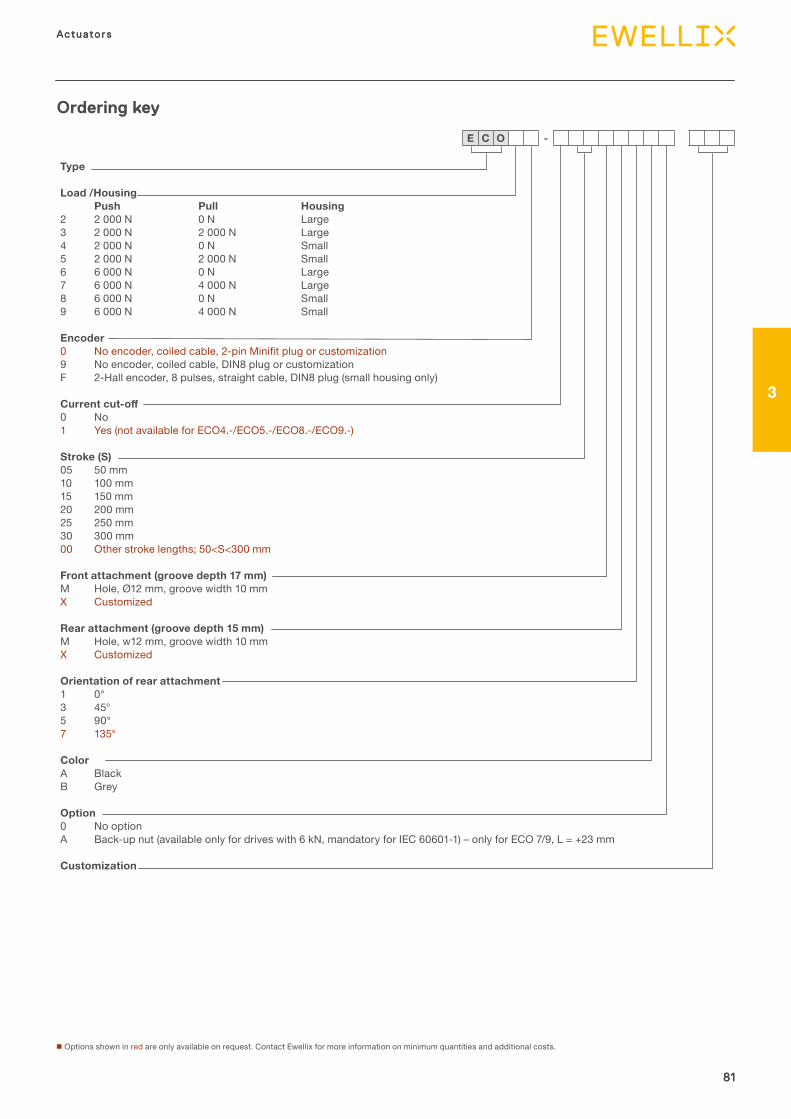
81
3
Actuators
Type
Load /HousingPush Pull Housing
2 2 000 N 0 N Large 3 2 000 N 2 000 N Large 4 2 000 N 0 N Small 5 2 000 N 2 000 N Small 6 6 000 N 0 N Large 7 6 000 N 4 000 N Large 8 6 000 N 0 N Small 9 6 000 N 4 000 N Small
Encoder0 Noencoder,coiledcable,2-pinMinifitplugorcustomization9 No encoder, coiled cable, DIN8 plug or customization F 2-Hall encoder, 8 pulses, straight cable, DIN8 plug (small housing only)
Current cut-off0 No 1 Yes (not available for ECO4.-/ECO5.-/ECO8.-/ECO9.-)
Stroke (S)05 50 mm 10 100 mm 15 150 mm 20 200 mm 25 250 mm 30 300 mm 00 Other stroke lengths; 50<S<300 mm
Front attachment (groove depth 17 mm)M Hole, Ø12 mm, groove width 10 mm X Customized
Rear attachment (groove depth 15 mm)M Hole, w12 mm, groove width 10 mm X Customized
Orientation of rear attachment1 0° 3 45° 5 90° 7 135°
ColorA BlackB Grey
Option0 No option A Back-up nut (available only for drives with 6 kN, mandatory for IEC 60601-1) – only for ECO 7/9, L = +23 mm
Customization
81
Actuators
3
81
Ordering key
n Options shown in red are only available on request. Contact Ewellix for more information on minimum quantities and additional costs.
E C O -
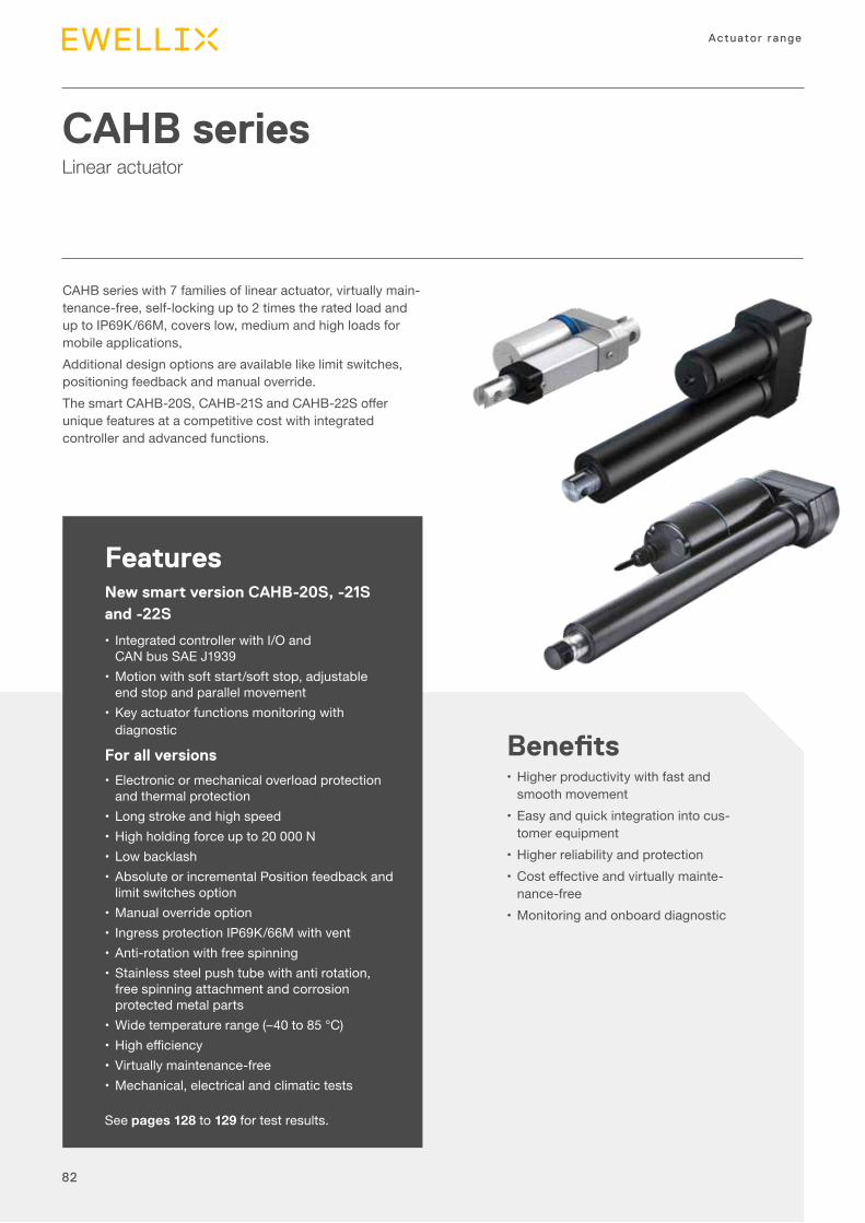
82
Actuator range
CAHB seriesLinear actuator
FeaturesNew smart version CAHB-20S, -21S and -22S
• Integrated controller with I/O and CAN bus SAE J1939
•Motion with soft start/soft stop, adjustable end stop and parallel movement
•Key actuator functions monitoring with diagnostic
For all versions
•Electronic or mechanical overload protection and thermal protection
•Long stroke and high speed•High holding force up to 20 000 N•Low backlash•Absolute or incremental Position feedback and
limit switches option•Manual override option• Ingress protection IP69K/66M with vent•Anti-rotation with free spinning•Stainless steel push tube with anti rotation,
free spinning attachment and corrosion protected metal parts
•Wide temperature range (–40 to 85 °C)• Highefficiency•Virtually maintenance-free•Mechanical, electrical and climatic tests
See pages 128 to 129 for test results.
Benefits•Higher productivity with fast and
smooth movement•Easy and quick integration into cus-
tomer equipment•Higher reliability and protection• Costeffectiveandvirtuallymainte-
nance-free•Monitoring and onboard diagnostic
CAHB series with 7 families of linear actuator, virtually main-tenance-free, self-locking up to 2 times the rated load and up to IP69K/66M, covers low, medium and high loads for mobile applications, Additional design options are available like limit switches, positioning feedback and manual override.ThesmartCAHB-20S,CAHB-21SandCAHB-22Sofferunique features at a competitive cost with integrated controller and advanced functions.
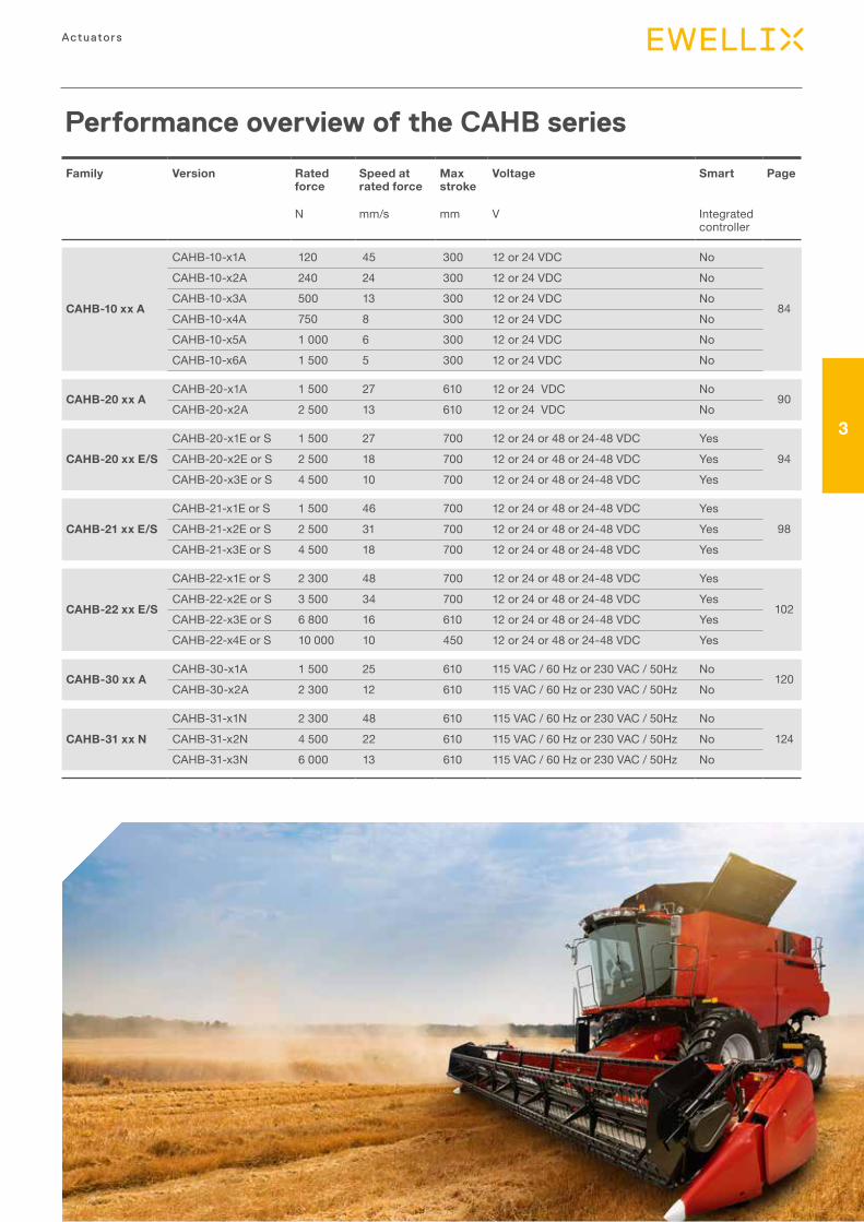
83
3
Actuators
Performance overview of the CAHB series
Family Version Rated force
Speed at rated force
Max stroke
Voltage Smart Page
N mm/s mm V Integrated controller
CAHB-10 xx A
CAHB-10-x1A 120 45 300 12 or 24 VDC No
84
CAHB-10-x2A 240 24 300 12 or 24 VDC NoCAHB-10-x3A 500 13 300 12 or 24 VDC NoCAHB-10-x4A 750 8 300 12 or 24 VDC NoCAHB-10-x5A 1 000 6 300 12 or 24 VDC NoCAHB-10-x6A 1 500 5 300 12 or 24 VDC No
CAHB-20 xx ACAHB-20-x1A 1 500 27 610 12 or 24 VDC No
90CAHB-20-x2A 2 500 13 610 12 or 24 VDC No
CAHB-20 xx E/SCAHB-20-x1E or S 1 500 27 700 12 or 24 or 48 or 24-48 VDC Yes
94CAHB-20-x2E or S 2 500 18 700 12 or 24 or 48 or 24-48 VDC YesCAHB-20-x3E or S 4 500 10 700 12 or 24 or 48 or 24-48 VDC Yes
CAHB-21 xx E/SCAHB-21-x1E or S 1 500 46 700 12 or 24 or 48 or 24-48 VDC Yes
98CAHB-21-x2E or S 2 500 31 700 12 or 24 or 48 or 24-48 VDC YesCAHB-21-x3E or S 4 500 18 700 12 or 24 or 48 or 24-48 VDC Yes
CAHB-22 xx E/S
CAHB-22-x1E or S 2 300 48 700 12 or 24 or 48 or 24-48 VDC Yes
102CAHB-22-x2E or S 3 500 34 700 12 or 24 or 48 or 24-48 VDC YesCAHB-22-x3E or S 6 800 16 610 12 or 24 or 48 or 24-48 VDC YesCAHB-22-x4E or S 10 000 10 450 12 or 24 or 48 or 24-48 VDC Yes
CAHB-30 xx ACAHB-30-x1A 1 500 25 610 115 VAC / 60 Hz or 230 VAC / 50Hz No
120CAHB-30-x2A 2 300 12 610 115 VAC / 60 Hz or 230 VAC / 50Hz No
CAHB-31 xx NCAHB-31-x1N 2 300 48 610 115 VAC / 60 Hz or 230 VAC / 50Hz No
124CAHB-31-x2N 4 500 22 610 115 VAC / 60 Hz or 230 VAC / 50Hz NoCAHB-31-x3N 6 000 13 610 115 VAC / 60 Hz or 230 VAC / 50Hz No
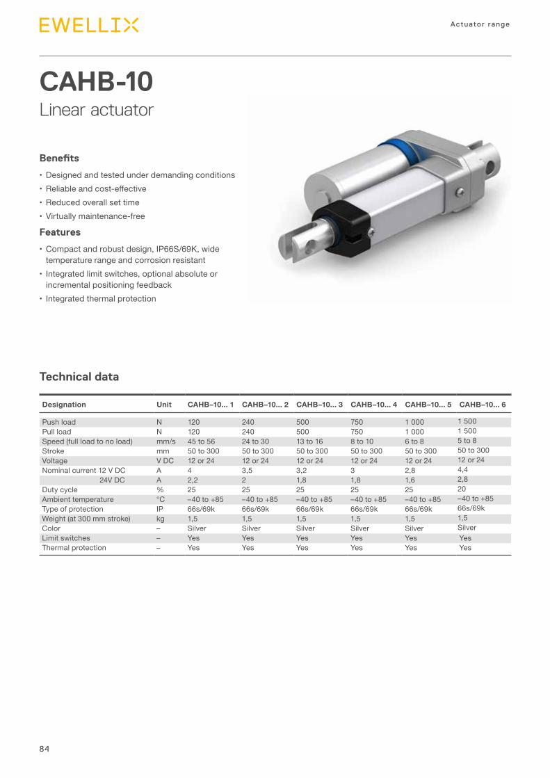
84
Actuator range
Technical data
CAHB-10Linear actuator
Benefits
•Designed and tested under demanding conditions• Reliableandcost-effective•Reduced overall set time•Virtually maintenance-free
Features
•Compact and robust design, IP66S/69K, wide temperature range and corrosion resistant
• Integrated limit switches, optional absolute or incremental positioning feedback
• Integrated thermal protection
Designation Unit CAHB–10... 1 CAHB–10... 2 CAHB–10... 3 CAHB–10... 4 CAHB–10... 5 CAHB–10... 6
Push load N 120 240 500 750 1 000 1 500Pull load N 120 240 500 750 1 000 1 500Speed (full load to no load) mm/s 45 to 56 24 to 30 13 to 16 8 to 10 6 to 8 5 to 8Stroke mm 50 to 300 50 to 300 50 to 300 50 to 300 50 to 300 50 to 300Voltage V DC 12 or 24 12 or 24 12 or 24 12 or 24 12 or 24 12 or 24Nominal current 12 V DC A 4 3,5 3,2 3 2,8 4,4 24V DC A 2,2 2 1,8 1,8 1,6 2,8Duty cycle % 25 25 25 25 25 20Ambient temperature °C –40 to +85 –40 to +85 –40 to +85 –40 to +85 –40 to +85 –40 to +85Type of protection IP 66s/69k 66s/69k 66s/69k 66s/69k 66s/69k 66s/69kWeight (at 300 mm stroke) kg 1,5 1,5 1,5 1,5 1,5 1,5Color – Silver Silver Silver Silver Silver SilverLimit switches – Yes Yes Yes Yes Yes YesThermal protection – Yes Yes Yes Yes Yes Yes
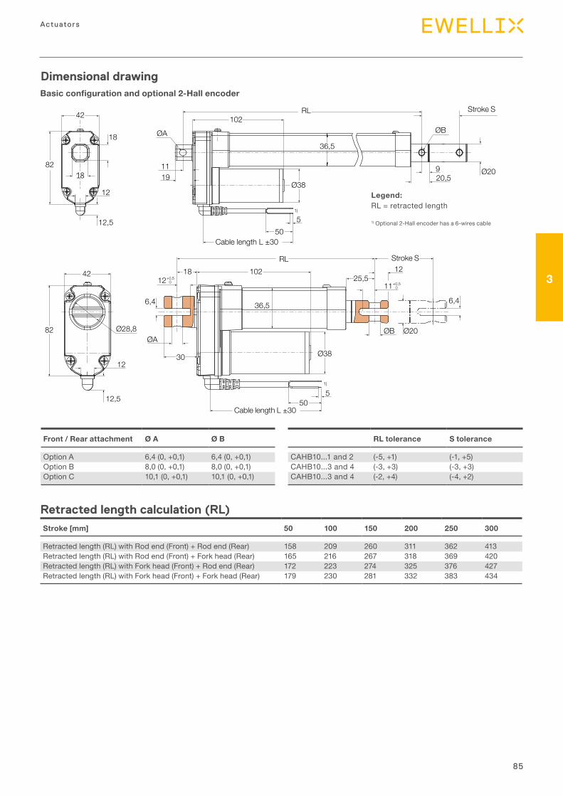
85
3
Actuators
Dimensional drawing
Stroke [mm] 50 100 150 200 250 300
Retracted length (RL) with Rod end (Front) + Rod end (Rear) 158 209 260 311 362 413Retracted length (RL) with Rod end (Front) + Fork head (Rear) 165 216 267 318 369 420Retracted length (RL) with Fork head (Front) + Rod end (Rear) 172 223 274 325 376 427Retracted length (RL) with Fork head (Front) + Fork head (Rear) 179 230 281 332 383 434
42
18
82
12
12,5
ØA
102
1119
36,5
Ø38
51)
1)
50Cable length L ±30
ØB
Ø20920,5
Stroke S
42
12,5
12
82 Ø28,8
Stroke SRL102
36,5
1812+0,5
0 11+0,50
6,4
ØA
30 Ø38
ØB
25,512
Ø20
6,4
550
Cable length L ±30
RL
Basic configuration and optional 2-Hall encoder
Retracted length calculation (RL)
Legend:RL = retracted length
1) Optional 2-Hall encoder has a 6-wires cable
Front / Rear attachment Ø A Ø B
Option A 6,4 (0, +0,1) 6,4 (0, +0,1)Option B 8,0 (0, +0,1) 8,0 (0, +0,1)Option C 10,1 (0, +0,1) 10,1 (0, +0,1)
RL tolerance S tolerance
CAHB10...1 and 2 (-5, +1) (-1, +5)CAHB10...3 and 4 (-3, +3) (-3, +3)CAHB10...3 and 4 (-2, +4) (-4, +2)
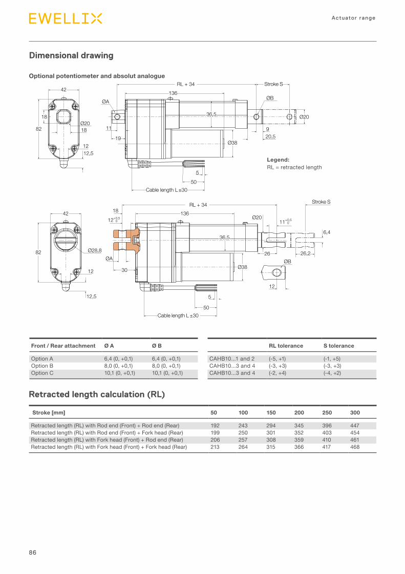
86
Actuator range
42
18Ø20
18
82
12,5
ØA
RL + 34136
Stroke S
ØB
11
19
36,5
Ø38
920,5
Ø20
5
50Cable length L ±30
42
82 Ø28,8
12
12,5
18
12+0,5136
Stroke S
11 0,5+0
Ø20
36,5
Ø3830
ØA
6,4
26,226ØB
12
5
50Cable length L ±30
12
0
RL + 34
Legend:RL = retracted length
Dimensional drawing
Optional potentiometer and absolut analogue
Stroke [mm] 50 100 150 200 250 300
Retracted length (RL) with Rod end (Front) + Rod end (Rear) 192 243 294 345 396 447Retracted length (RL) with Rod end (Front) + Fork head (Rear) 199 250 301 352 403 454Retracted length (RL) with Fork head (Front) + Rod end (Rear) 206 257 308 359 410 461Retracted length (RL) with Fork head (Front) + Fork head (Rear) 213 264 315 366 417 468
Front / Rear attachment Ø A Ø B
Option A 6,4 (0, +0,1) 6,4 (0, +0,1)Option B 8,0 (0, +0,1) 8,0 (0, +0,1)Option C 10,1 (0, +0,1) 10,1 (0, +0,1)
RL tolerance S tolerance
CAHB10...1 and 2 (-5, +1) (-1, +5)CAHB10...3 and 4 (-3, +3) (-3, +3)CAHB10...3 and 4 (-2, +4) (-4, +2)
Retracted length calculation (RL)
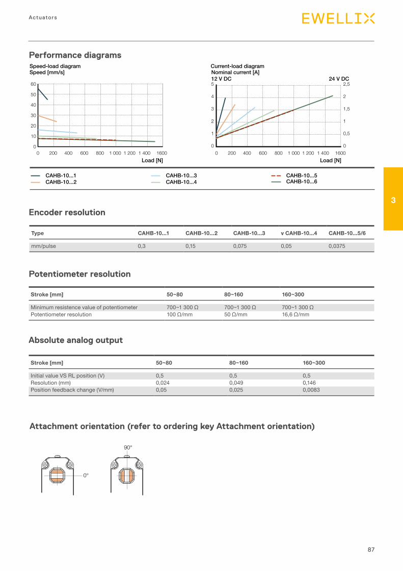
87
3
Actuators
Attachment orientation (refer to ordering key Attachment orientation)
0°
90°
Stroke [mm] 50~80 80~160 160~300
Minimum resistence value of potentiometer 700~1300Ω 700~1300Ω 700~1300ΩPotentiometer resolution 100Ω/mm 50Ω/mm 16,6Ω/mm
Type CAHB-10...1 CAHB-10...2 CAHB-10...3 v CAHB-10...4 CAHB-10...5/6
mm/pulse 0,3 0,15 0,075 0,05 0,0375
Encoder resolution
Potentiometer resolution
Absolute analog output
Stroke [mm] 50~80 80~160 160~300
Initial value VS RL position (V) 0,5 0,5 0,5Resolution (mm) 0,024 0,049 0,146Position feedback change (V/mm) 0,05 0,025 0,0083
Performance diagrams
Speed [mm/s]
Load [N]
Nominal current [A]12 V DC 24 V DC
Load [N]
Speed-load diagram Current-load diagram
5
4
3
2
1
0
2,5
2
1,5
1
0,5
0
CAHB-10...1CAHB-10...2
CAHB-10...3CAHB-10...4
CAHB-10...5CAHB-10...6
60
50
40
30
20
10
00 200 400 600 800 1 000 1 200 1 400 1600 0 200 400 600 800 1 000 1 200 1 400 1600
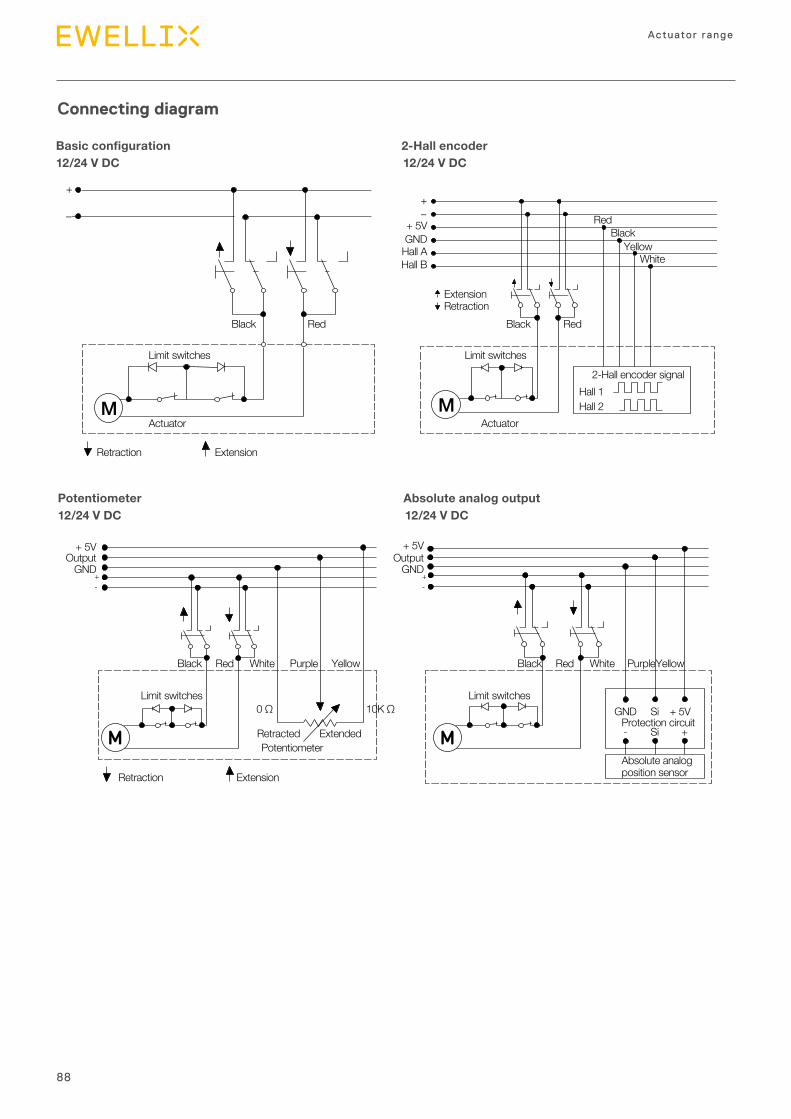
88
Actuator range
Connecting diagram
Potentiometer
Black
Black
Black
RedBlack
YellowWhite
White Purple Yellow
Limit switches
Limit switches Limit switches
Limit switches
Actuator Actuator
Retraction
Retraction
Extension
Retraction
Retracted
0 Ω 10K Ω
Extension
Extended
Extension
+ 5VGND
+ 5V
GND+-
Output+ 5V
GND+-
Output
Hall AHall B
Hall 2
2-Hall encoder signalHall 1
Red
Red Black White PurpleYellowRed
Red
+
–+–
M M
M MGND Si
Si- +
+ 5VProtection circuit
Absolute analogposition sensor
Basic configuration
Potentiometer
2-Hall encoder
Absolute analog output
12/24 V DC
12/24 V DC
12/24 V DC
12/24 V DC
Connecting diagram
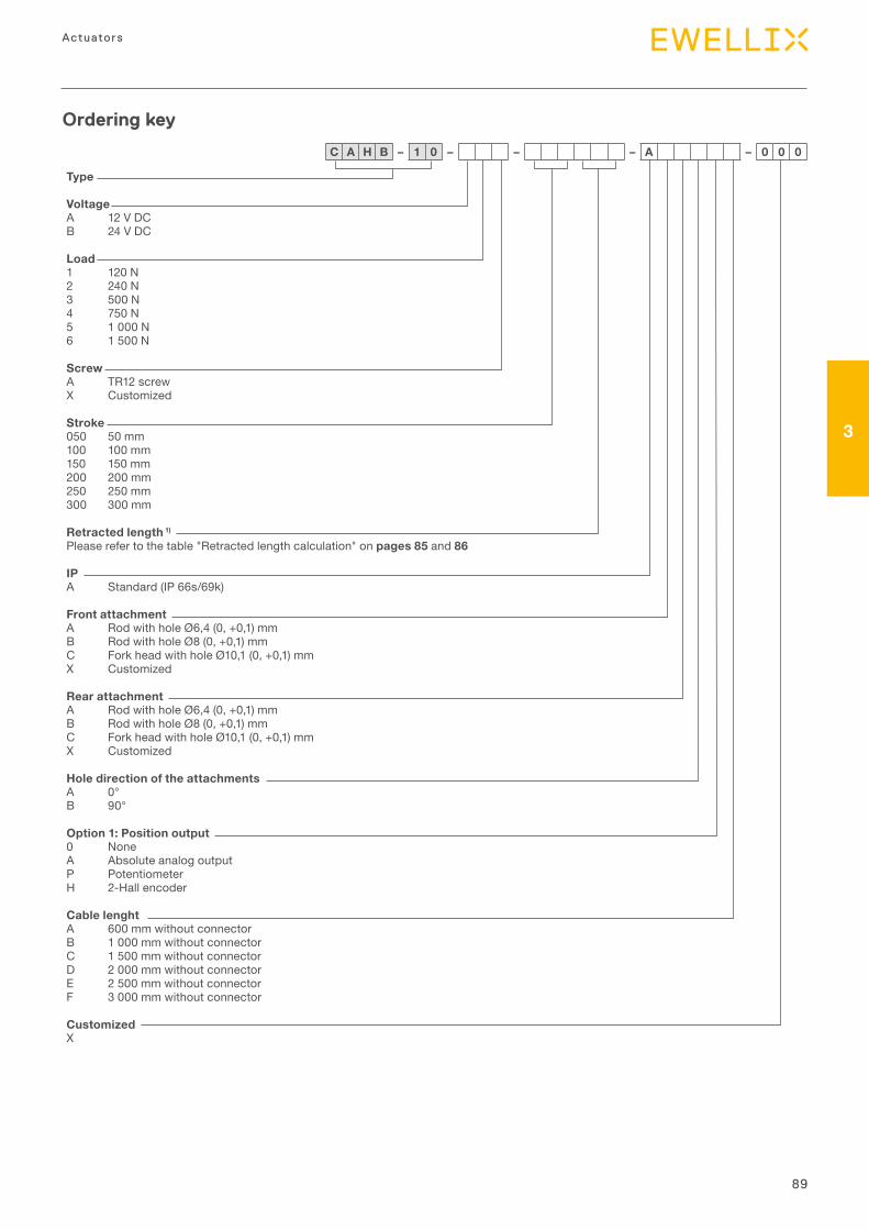
89
3
Actuators
Type
VoltageA 12 V DCB 24 V DC
Load1 120 N2 240 N3 500 N4 750 N5 1 000 N6 1 500 N
ScrewA TR12 screwX Customized
Stroke050 50 mm100 100 mm150 150 mm200 200 mm250 250 mm300 300 mm
Retracted length 1)
Please refer to the table "Retracted length calculation" on pages 85 and 86
IPA Standard (IP 66s/69k)
Front attachmentA Rod with hole Ø6,4 (0, +0,1) mmB Rod with hole Ø8 (0, +0,1) mmC Fork head with hole Ø10,1 (0, +0,1) mmX Customized
Rear attachmentA Rod with hole Ø6,4 (0, +0,1) mmB Rod with hole Ø8 (0, +0,1) mmC Fork head with hole Ø10,1 (0, +0,1) mmX Customized
Hole direction of the attachmentsA 0°B 90°
Option 1: Position output0 NoneA Absolute analog outputP PotentiometerH 2-Hall encoder
Cable lenghtA 600 mm without connectorB 1 000 mm without connectorC 1 500 mm without connectorD 2 000 mm without connectorE 2 500 mm without connectorF 3 000 mm without connector
CustomizedX
C A H B – 1 0 – – – A – 0 0 0
Ordering key
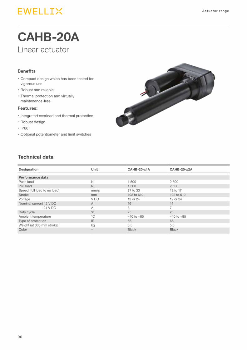
90
Actuator range
Technical data
CAHB-20ALinear actuator
Benefits
•Compact design which has been tested for vigorous use
•Robust and reliable•Thermal protection and virtually
maintenance-free
Features:
• Integrated overload and thermal protection•Robust design• IP66 •Optional potentiometer and limit switches
Designation Unit CAHB-20-x1A CAHB-20-x2A
Performance dataPush load N 1 500 2 500Pull load N 1 500 2 500Speed (full load to no load) mm/s 27 to 33 13 to 17Stroke mm 102 to 610 102 to 610Voltage V DC 12 or 24 12 or 24Nominal current 12 V DC A 16 14 24 V DC A 8 7Duty cycle % 25 25Ambient temperature °C –40 to +85 –40 to +85Type of protection IP 66 66Weight (at 305 mm stroke) kg 5,5 5,5Color – Black Black
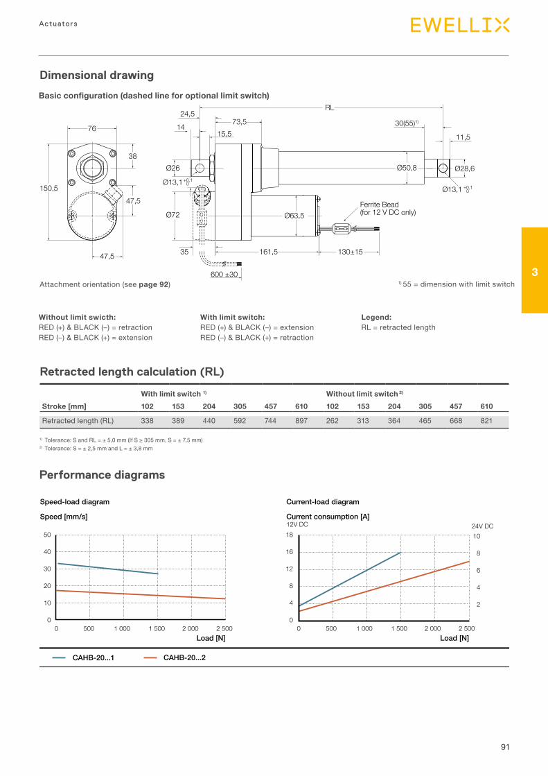
91
3
Actuators
Dimensional drawing
RL24,5
73,5 30(55)1)
11,5
Ø13,1 +0,10
Ø28,6
Ferrite Bead(for 12 V DC only)
161,5 130±15
600 ±30
76
150,5
47,5
15,514
38
47,5
Ø26
Ø13,1
Ø72
Ø50,8
Ø63,5
+0,10
35
Basic configuration (dashed line for optional limit switch)
Without limit swicth:RED (+) & BLACK (–) = retractionRED (–) & BLACK (+) = extension
With limit switch 1) Without limit switch 2)
Stroke [mm] 102 153 204 305 457 610 102 153 204 305 457 610
Retracted length (RL) 338 389 440 592 744 897 262 313 364 465 668 821
1) Tolerance:SandRL=±5,0mm(IfS≥305mm,S=±7,5mm)2) Tolerance: S = ± 2,5 mm and L = ± 3,8 mm
With limit switch:RED (+) & BLACK (–) = extensionRED (–) & BLACK (+) = retraction
Legend:RL = retracted length
1) 55 = dimension with limit switchAttachment orientation (see page 92)
Performance diagrams
Speed [mm/s]
Load [N]
Current consumption [A]
Load [N]
Speed-load diagram Current-load diagram
18
16
12
8
4
0
10
8
6
4
2
0 500 1 000 1 500 2 000 2 500
12V DC 24V DC
CAHB-20...1
50
40
30
20
10
00 500 1 000 1 500 2 000 2 500
CAHB-20...2
Retracted length calculation (RL)
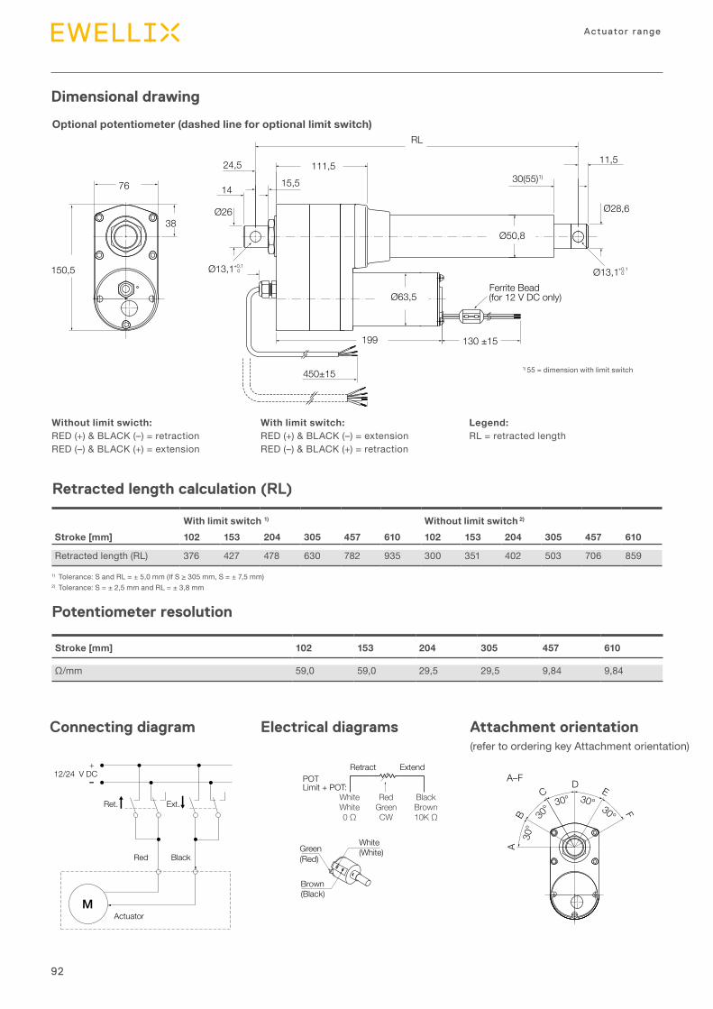
92
Actuator range
Dimensional drawing
Retract Extend
White(White)
POTLimit + POT:
Green(Red)
Brown(Black)
WhiteWhite0 Ω
RedGreenCW
BlackBrown10K Ω
76
38
150,5
Ø26
Ø13,1+0,10
24,5
15,514
111,5
RL
600±30
130 ±15
30(55)1)
11,5
Ferrite Bead(for 12 V DC only)
199
Ø13,1+0,10
Ø28,6
450±15
Ø63,5
Ø50,8
Retract Extend
White(White)
POTLimit + POT:
Green(Red)
Brown(Black)
WhiteWhite0 Ω
RedGreenCW
BlackBrown10K Ω
76
38
150,5
Ø26
Ø13,1+0,10
24,5
15,514
111,5
RL
600±30
130 ±15
30(55)1)
11,5
Ferrite Bead(for 12 V DC only)
199
Ø13,1+0,10
Ø28,6
450±15
Ø63,5
Ø50,8
Optional potentiometer (dashed line for optional limit switch)
Legend:RL = retracted length
1) 55 = dimension with limit switch
Without limit swicth:RED (+) & BLACK (–) = retractionRED (–) & BLACK (+) = extension
With limit switch:RED (+) & BLACK (–) = extensionRED (–) & BLACK (+) = retraction
1) Tolerance:SandRL=±5,0mm(IfS≥305mm,S=±7,5mm)2) Tolerance:S=±2,5mmandRL=±3,8mm
Potentiometer resolution
Stroke [mm] 102 153 204 305 457 610
Ω/mm 59,0 59,0 29,5 29,5 9,84 9,84
Connecting diagram Electrical diagrams Attachment orientation (refer to ordering key Attachment orientation)
+12/24 V DC
MActuator
Red
Ret.
Black
Ext.
Retracted length calculation (RL)
With limit switch 1) Without limit switch 2)
Stroke [mm] 102 153 204 305 457 610 102 153 204 305 457 610
Retracted length (RL) 376 427 478 630 782 935 300 351 402 503 706 859
30°
30° 30°30°
F
EDC
B
A–F
30°
A
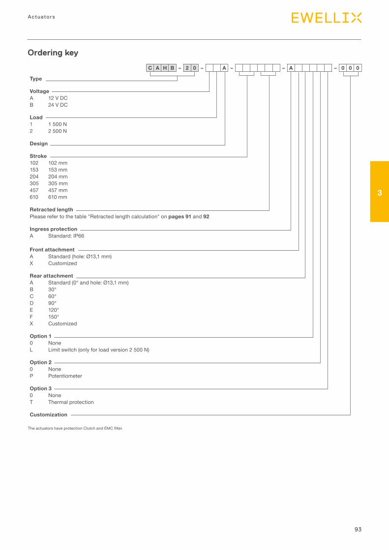
93
3
Actuators
Type
VoltageA 12 V DCB 24 V DC
Load1 1 500 N2 2 500 N
Design
Stroke102 102 mm153 153 mm204 204 mm305 305 mm457 457 mm610 610 mm
Retracted lengthPlease refer to the table "Retracted length calculation" on pages 91 and 92
Ingress protectionA Standard: IP66
Front attachmentA Standard (hole: Ø13,1 mm)X Customized
Rear attachmentA Standard (0° and hole: Ø13,1 mm)B 30°C 60°D 90°E 120°F 150°X Customized
Option 10 NoneL Limit switch (only for load version 2 500 N)
Option 20 NoneP Potentiometer
Option 30 NoneT Thermal protection
Customization
Ordering key
TheactuatorshaveprotectionClutchandEMCfilter.
C A H B – 2 0 – A – – A – 0 0 0

94
Actuator range
Technical data
CAHB-20E and -20SLinear actuator
Benefits
•High productivity•Reliability and safety•Save development time• Costeffectiveness•Quick time to market (for Smart version)
Features:
•Holding force•Overload protection•Corrosion protection and stainless steel tube•Manual override option•Enhanced ingress protection and virtually
maintenance free
Designation Unit CAHB-20E / 12 V CAHB-20E / 24 V
Performance dataRated Push Force N 1 500 2 500 4 500 1 500 2 500 4 500Rated Pull Force N 1 500 2 500 4 500 1 500 2 500 4 500Max pull / push Force 1) N 2 600 3 800 6 300 2 600 3 800 6 300Holding force 2) NSpeed without load 3) mm/s 27,0 23,5 13,5 29,0 22,0 13,0Speed with the rated force 3) mm/s 24,5 17,5 10,5 25,5 19,0 11,0
Electric dataNominal voltage V DC 12 12 12 24 24 24Nominal current @ rated load 3) A 12,5 15 17 5 6,5 8Rated current (clutch activation) A 18,4 21 22,4 6,8 8,8 10,4
Duty cycle % 10 (85/765 s)
10 (85/765 s)
10 (85/765 s)
20 (85/340 s)
20 (85/340 s)
20 (85/340 s)
Mechanical dataStroke mm 50 … 700 50 … 700 50 … 700 50 … 700 50 … 700 50 … 700Backlash mm 0,6 0,6 0,6 0,6 0,6 0,6Weight for 200 mm stroke kg 4,5 4,5 4,5 4,5 4,5 4,5Colour – Black Black Black Black Black Black
Environment and standardsAmbient temperature 4) °C –40 … 85 –40 … 85 –40 … 85 –40 … 85 –40 … 85 –40 … 85Degree of protection – IP 69K/66MStandards / EMC – EN61000-6-2:2005, EN61000-6-4:2007/A1:2011Salt spray test – ISO 9227:2012, 250 hours
1) Upper limit of the pull/push force limited by the clutch. The lower limit is just above the rated force. The limitation of the force will happen between these 2 limits 2) Ultimate Static Load, refer to the “Static load” diagrams3)Thedataofspeedandcurrentonthislistisdefinedat+20°C4) Full performance from 0 °C to +40 °C
Smart version S features
• Integrated controller with complete motion control •True absolute position contactless sensor•Monitoring and onboard diagnostic (force, voltage,
temperature) • I/O and CAN bus SAE J1939 communication
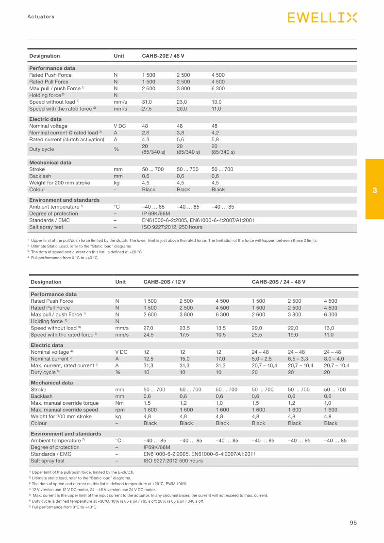
95
3
Actuators
Designation Unit CAHB-20S / 12 V CAHB-20S / 24 – 48 V
Performance dataRated Push Force N 1 500 2 500 4 500 1 500 2 500 4 500Rated Pull Force N 1 500 2 500 4 500 1 500 2 500 4 500Max pull / push Force 1) N 2 600 3 800 6 300 2 600 3 800 6 300Holding force 2) NSpeed without load 3) mm/s 27,0 23,5 13,5 29,0 22,0 13,0Speed with the rated force 3) mm/s 24,5 17,5 10,5 25,5 19,0 11,0
Electric dataNominal voltage 4) V DC 12 12 12 24 – 48 24 – 48 24 – 48Nominal current 3) A 12,5 15,0 17,0 5,0 – 2,5 6,5 – 3,3 8,0 – 4,0Max. current, rated current 5) A 31,3 31,3 31,3 20,7 – 10,4 20,7 – 10,4 20,7 – 10,4Duty cycle 6) % 10 10 10 20 20 20
Mechanical dataStroke mm 50 ... 700 50 ... 700 50 ... 700 50 ... 700 50 ... 700 50 ... 700Backlash mm 0,6 0,6 0,6 0,6 0,6 0,6Max. manual override torque Nm 1,5 1,2 1,0 1,5 1,2 1,0Max. manual override speed rpm 1 600 1 600 1 600 1 600 1 600 1 600Weight for 200 mm stroke kg 4,8 4,8 4,8 4,8 4,8 4,8Colour – Black Black Black Black Black Black
Environment and standardsAmbient temperature 7) °C –40 … 85 –40 … 85 –40 … 85 –40 … 85 –40 … 85 –40 … 85Degree of protection – IP69K/66MStandards / EMC – EN61000-6-2:2005, EN61000-6-4:2007/A1:2011Salt spray test – ISO 9227:2012 500 hours
Designation Unit CAHB-20E / 48 V
Performance dataRated Push Force N 1 500 2 500 4 500Rated Pull Force N 1 500 2 500 4 500Max pull / push Force 1) N 2 600 3 800 6 300Holding force 2) NSpeed without load 3) mm/s 31,0 23,0 13,0Speed with the rated force 3) mm/s 27,5 20,0 11,0
Electric dataNominal voltage V DC 48 48 48Nominal current @ rated load 3) A 2,6 3,8 4,2Rated current (clutch activation) A 4,3 5,6 5,8
Duty cycle % 20 (85/340 s)
20 (85/340 s)
20 (85/340 s)
Mechanical dataStroke mm 50 ... 700 50 ... 700 50 ... 700Backlash mm 0,6 0,6 0,6Weight for 200 mm stroke kg 4,5 4,5 4,5Colour – Black Black Black
Environment and standardsAmbient temperature 4) °C –40 … 85 –40 … 85 –40 … 85Degree of protection – IP 69K/66MStandards / EMC – EN61000-6-2:2005, EN61000-6-4:2007/A1:2001 Salt spray test – ISO 9227:2012, 250 hours
1) Upper limit of the pull/push force limited by the clutch. The lower limit is just above the rated force. The limitation of the force will happen between these 2 limits 2) Ultimate Static Load, refer to the “Static load” diagrams3) Thedataofspeedandcurrentonthislistisdefinedat+20°C4) Full performance from 0 °C to +40 °C
1) Upper limit of the pull/push force, limited by the E-clutch.2) Ultimate static load, refer to the “Static load” diagrams.3)Thedataofspeedandcurrentonthislistisdefinedtemperatureat+20°C,PWM100%4) 12 V version use 12 V DC motor, 24 – 48 V version use 24 V DC motor.5) Max. current is the upper limit of the input current to the actuator. In any circumstances, the current will not exceed to max. current.6)Dutycycleisdefinedtemperatureat+20°C.10%is85son/765soff;20%is85son/340soff.7) Full performance from 0°C to +40°C
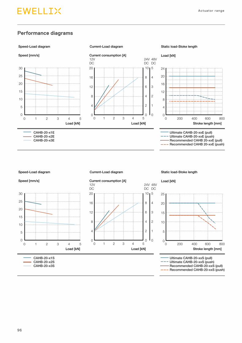
96
Actuator range
Performance diagrams
CAHB-20-x1ECAHB-20-x2ECAHB-20-x3E
Ultimate CAHB-20-xxE (pull)Ultimate CAHB-20-xxE (push)Recommended CAHB 20-xxE (pull)Recommended CAHB 20-xxE (push)
Stroke length [mm]Load [kN]Load [kN]
20
16
12
8
4
00 1 2 3 4 5
10
8
6
4
2
0
5
4
3
2
1
0
24
20
16
12
8
4
00 200 400 600 800
Speed-Load diagram Current-Load diagram Static load-Stoke length
Load [kN]Current consumption [A]12VDC
24VDC
48VDC
Speed [mm/s]
30
25
20
15
10
5
00 1 2 3 4 5
CAHB-20-x1SCAHB-20-x2SCAHB-20-x3S
Ultimate CAHB-20-xxS (pull)Ultimate CAHB-20-xxS (push)Recommended CAHB-20-xxS (pull)Recommended CAHB-20-xxS (push)
Stroke length [mm]Load [kN]Load [kN]
20
16
12
8
4
00 1 2 3 4 5
10
8
6
4
2
0
5
4
3
2
1
0
25
20
15
10
5
00 200 400 600 800
Speed-Load diagram Current-Load diagram Static load-Stoke length
Load [kN]Current consumption [A]12VDC
24VDC
48VDC
Speed [mm/s]
30
25
20
15
10
5
00 1 2 3 4 5
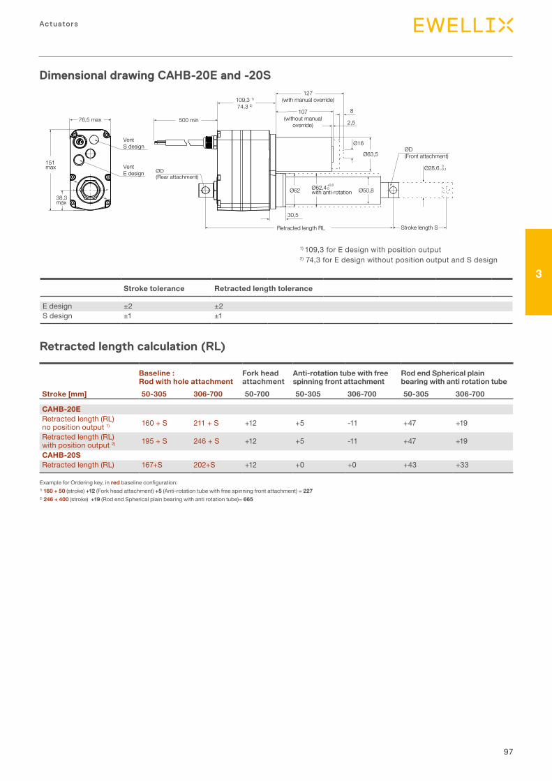
97
3
Actuators
Retracted length calculation (RL)
Dimensional drawing CAHB-20E and -20S
– 30°
– 30°
– 0°– 0°
30,5
500 min76,5 max
38,3max
151max
ØD(Front attachment)
ØD(Rear attachment)
0–0,1
Ø16
Ø63,5
Ø28,6
2,5
8
Retracted length RL
109,3 1)
74,3 2)
VentS design
VentE design
107(without manual
override)
127(with manual override)
Stroke length S
Ø62 Ø50,8Ø62,4with anti-rotation
+0,60
Stroke tolerance Retracted length tolerance
E design ±2 ±2S design ±1 ±1
Baseline :Rod with hole attachment
Fork head attachment
Anti-rotation tube with free spinning front attachment
Rod end Spherical plain bearing with anti rotation tube
Stroke [mm] 50-305 306-700 50-700 50-305 306-700 50-305 306-700
CAHB-20ERetracted length (RL) no position output 1) 160 + S 211 + S +12 +5 -11 +47 +19
Retracted length (RL) with position output 2) 195 + S 246 + S +12 +5 -11 +47 +19
CAHB-20SRetracted length (RL) 167+S 202+S +12 +0 +0 +43 +33
Example for Ordering key, in redbaselineconfiguration:1) 160 + 50 (stroke) +12 (Fork head attachment) +5 (Anti-rotation tube with free spinning front attachment) = 2272) 246 + 400 (stroke) +19 (Rod end Spherical plain bearing with anti rotation tube)= 665
1) 109,3 for E design with position output2) 74,3 for E design without position output and S design
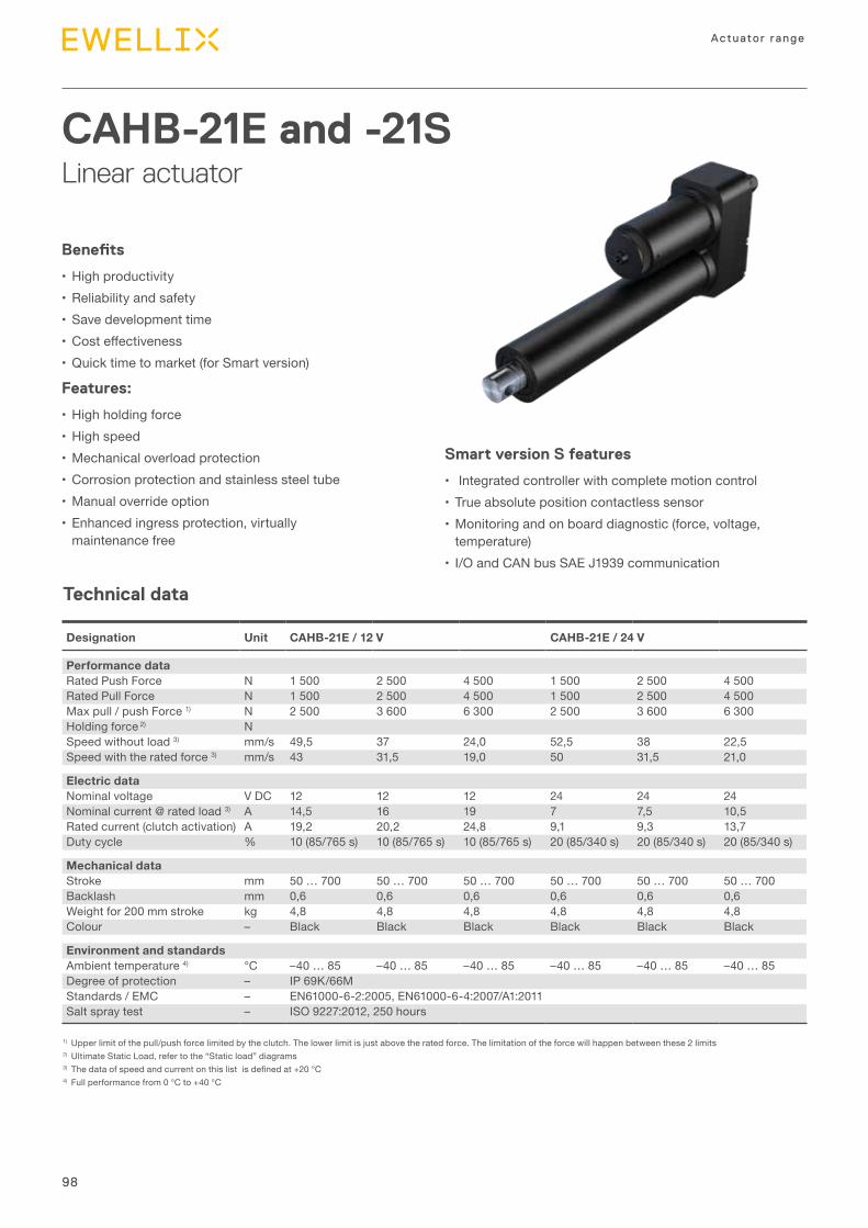
98
Actuator range
Technical data
CAHB-21E and -21SLinear actuator
Benefits
•High productivity•Reliability and safety•Save development time• Costeffectiveness•Quick time to market (for Smart version)
Features:
•High holding force•High speed•Mechanical overload protection•Corrosion protection and stainless steel tube•Manual override option•Enhanced ingress protection, virtually
maintenance free
Designation Unit CAHB-21E / 12 V CAHB-21E / 24 V
Performance dataRated Push Force N 1 500 2 500 4 500 1 500 2 500 4 500Rated Pull Force N 1 500 2 500 4 500 1 500 2 500 4 500Max pull / push Force 1) N 2 500 3 600 6 300 2 500 3 600 6 300Holding force 2) NSpeed without load 3) mm/s 49,5 37 24,0 52,5 38 22,5Speed with the rated force 3) mm/s 43 31,5 19,0 50 31,5 21,0
Electric dataNominal voltage V DC 12 12 12 24 24 24Nominal current @ rated load 3) A 14,5 16 19 7 7,5 10,5Rated current (clutch activation) A 19,2 20,2 24,8 9,1 9,3 13,7Duty cycle % 10 (85/765 s) 10 (85/765 s) 10 (85/765 s) 20 (85/340 s) 20 (85/340 s) 20 (85/340 s)
Mechanical dataStroke mm 50 … 700 50 … 700 50 … 700 50 … 700 50 … 700 50 … 700Backlash mm 0,6 0,6 0,6 0,6 0,6 0,6Weight for 200 mm stroke kg 4,8 4,8 4,8 4,8 4,8 4,8Colour – Black Black Black Black Black Black
Environment and standardsAmbient temperature 4) °C –40 … 85 –40 … 85 –40 … 85 –40 … 85 –40 … 85 –40 … 85Degree of protection – IP 69K/66MStandards / EMC – EN61000-6-2:2005, EN61000-6-4:2007/A1:2011Salt spray test – ISO 9227:2012, 250 hours
1) Upper limit of the pull/push force limited by the clutch. The lower limit is just above the rated force. The limitation of the force will happen between these 2 limits 2) Ultimate Static Load, refer to the “Static load” diagrams3)Thedataofspeedandcurrentonthislistisdefinedat+20°C4) Full performance from 0 °C to +40 °C
Smart version S features
• Integrated controller with complete motion control •True absolute position contactless sensor•Monitoring and on board diagnostic (force, voltage,
temperature) • I/O and CAN bus SAE J1939 communication
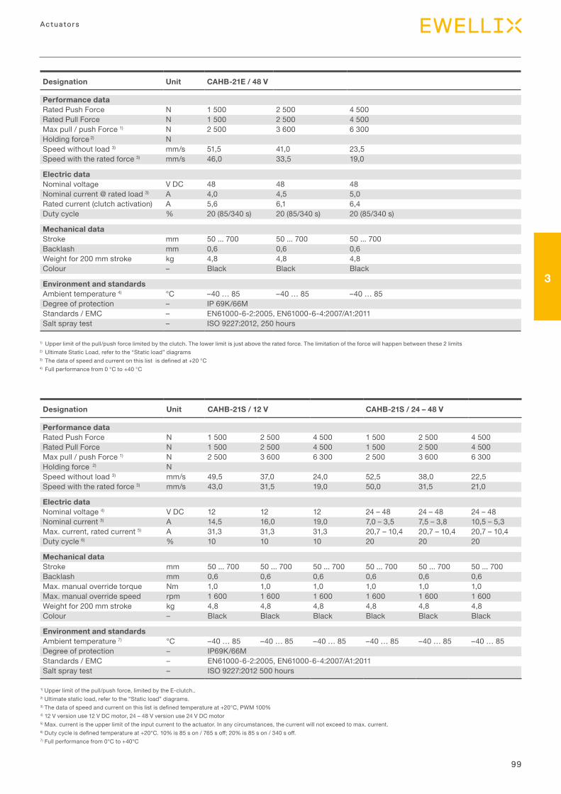
99
3
Actuators
1) Upper limit of the pull/push force limited by the clutch. The lower limit is just above the rated force. The limitation of the force will happen between these 2 limits 2) Ultimate Static Load, refer to the “Static load” diagrams3)Thedataofspeedandcurrentonthislistisdefinedat+20°C4) Full performance from 0 °C to +40 °C
Designation Unit CAHB-21E / 48 V
Performance dataRated Push Force N 1 500 2 500 4 500Rated Pull Force N 1 500 2 500 4 500Max pull / push Force 1) N 2 500 3 600 6 300Holding force 2) NSpeed without load 3) mm/s 51,5 41,0 23,5Speed with the rated force 3) mm/s 46,0 33,5 19,0
Electric dataNominal voltage V DC 48 48 48Nominal current @ rated load 3) A 4,0 4,5 5,0Rated current (clutch activation) A 5,6 6,1 6,4Duty cycle % 20 (85/340 s) 20 (85/340 s) 20 (85/340 s)
Mechanical dataStroke mm 50 ... 700 50 ... 700 50 ... 700Backlash mm 0,6 0,6 0,6Weight for 200 mm stroke kg 4,8 4,8 4,8Colour – Black Black Black
Environment and standardsAmbient temperature 4) °C –40 … 85 –40 … 85 –40 … 85Degree of protection – IP 69K/66MStandards / EMC – EN61000-6-2:2005, EN61000-6-4:2007/A1:2011Salt spray test – ISO 9227:2012, 250 hours
Designation Unit CAHB-21S / 12 V CAHB-21S / 24 – 48 V
Performance dataRated Push Force N 1 500 2 500 4 500 1 500 2 500 4 500Rated Pull Force N 1 500 2 500 4 500 1 500 2 500 4 500Max pull / push Force 1) N 2 500 3 600 6 300 2 500 3 600 6 300Holding force 2) NSpeed without load 3) mm/s 49,5 37,0 24,0 52,5 38,0 22,5Speed with the rated force 3) mm/s 43,0 31,5 19,0 50,0 31,5 21,0
Electric dataNominal voltage 4) V DC 12 12 12 24 – 48 24 – 48 24 – 48Nominal current 3) A 14,5 16,0 19,0 7,0 – 3,5 7,5 – 3,8 10,5 – 5,3Max. current, rated current 5) A 31,3 31,3 31,3 20,7 – 10,4 20,7 – 10,4 20,7 – 10,4Duty cycle 6) % 10 10 10 20 20 20
Mechanical dataStroke mm 50 ... 700 50 ... 700 50 ... 700 50 ... 700 50 ... 700 50 ... 700Backlash mm 0,6 0,6 0,6 0,6 0,6 0,6Max. manual override torque Nm 1,0 1,0 1,0 1,0 1,0 1,0Max. manual override speed rpm 1 600 1 600 1 600 1 600 1 600 1 600Weight for 200 mm stroke kg 4,8 4,8 4,8 4,8 4,8 4,8Colour – Black Black Black Black Black Black
Environment and standardsAmbient temperature 7) °C –40 … 85 –40 … 85 –40 … 85 –40 … 85 –40 … 85 –40 … 85Degree of protection – IP69K/66MStandards / EMC – EN61000-6-2:2005, EN61000-6-4:2007/A1:2011Salt spray test – ISO 9227:2012 500 hours
1) Upper limit of the pull/push force, limited by the E-clutch..2) Ultimate static load, refer to the “Static load” diagrams.3)Thedataofspeedandcurrentonthislistisdefinedtemperatureat+20°C,PWM100%4) 12 V version use 12 V DC motor, 24 – 48 V version use 24 V DC motor5) Max. current is the upper limit of the input current to the actuator. In any circumstances, the current will not exceed to max. current.6)Dutycycleisdefinedtemperatureat+20°C.10%is85son/765soff;20%is85son/340soff.7) Full performance from 0°C to +40°C
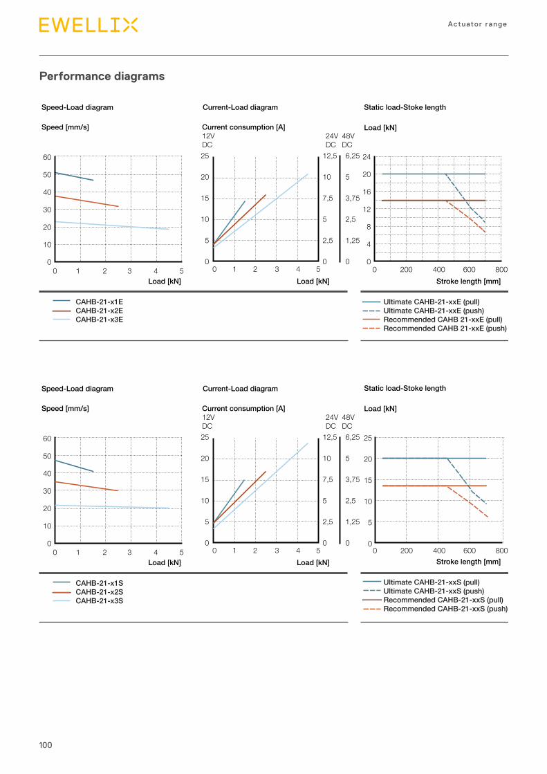
100
Actuator range
Performance diagrams
Speed-Load diagram Current-Load diagram Static load-Stoke length
CAHB-21-x1ECAHB-21-x2ECAHB-21-x3E
Ultimate CAHB-21-xxE (pull)Ultimate CAHB-21-xxE (push)Recommended CAHB 21-xxE (pull)Recommended CAHB 21-xxE (push)
Stroke length [mm]
Load [kN]
Load [kN]Load [kN]
Current consumption [A]12VDC
24VDC
48VDC
Speed [mm/s]
25
20
15
10
5
0
12,5
10
7,5
5
2,5
0
6,25
5
3,75
2,5
1,25
00 1 2 3 4 5 0 200 400 600 800
24
20
16
12
8
4
0
60
50
40
30
20
10
00 1 2 3 4 5
Speed-Load diagram Current-Load diagram
CAHB-21-x1SCAHB-21-x2SCAHB-21-x3S
Load [kN]Load [kN]
Current consumption [A]12VDC
24VDC
48VDC
Speed [mm/s]
25
20
15
10
5
0
12,5
10
7,5
5
2,5
0
6,25
5
3,75
2,5
1,25
00 1 2 3 4 5
60
50
40
30
20
10
00 1 2 3 4 5
Ultimate CAHB-21-xxS (pull)Ultimate CAHB-21-xxS (push)Recommended CAHB-21-xxS (pull)Recommended CAHB-21-xxS (push)
Stroke length [mm]
25
20
15
10
5
00 200 400 600 800
Static load-Stoke length
Load [kN]
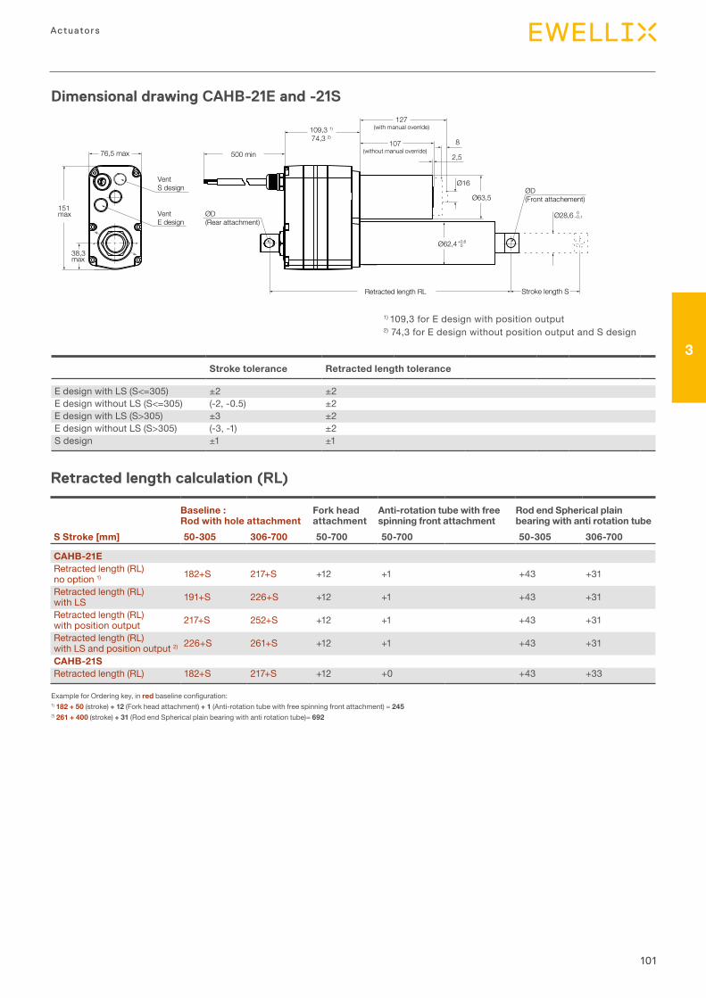
101
3
Actuators
Dimensional drawing CAHB-21E and -21S
– 30°
– 30°
– 0°– 0°
500 min
ØD(Front attachement)
ØD(Rear attachment)
0–0,1
+0,60
Ø16
Ø63,5
Ø28,6
2,5
8
Retracted length RL
109,3 1)
74,3 2)
107(without manual override)
127(with manual override)
Stroke length S
Ø62,4
76,5 max
38,3max
151max
VentS design
VentE design
Retracted length calculation (RL)
Baseline :Rod with hole attachment
Fork head attachment
Anti-rotation tube with free spinning front attachment
Rod end Spherical plain bearing with anti rotation tube
S Stroke [mm] 50-305 306-700 50-700 50-700 50-305 306-700
CAHB-21ERetracted length (RL) no option 1) 182+S 217+S +12 +1 +43 +31
Retracted length (RL) with LS 191+S 226+S +12 +1 +43 +31
Retracted length (RL) with position output 217+S 252+S +12 +1 +43 +31
Retracted length (RL) with LS and position output 2) 226+S 261+S +12 +1 +43 +31
CAHB-21SRetracted length (RL) 182+S 217+S +12 +0 +43 +33
Example for Ordering key, in redbaselineconfiguration:1) 182 + 50 (stroke) + 12 (Fork head attachment) + 1 (Anti-rotation tube with free spinning front attachment) = 2452) 261 + 400 (stroke) + 31 (Rod end Spherical plain bearing with anti rotation tube)= 692
Stroke tolerance Retracted length tolerance
E design with LS (S<=305) ±2 ±2E design without LS (S<=305) (-2, -0.5) ±2E design with LS (S>305) ±3 ±2E design without LS (S>305) (-3, -1) ±2S design ±1 ±1
1) 109,3 for E design with position output2) 74,3 for E design without position output and S design
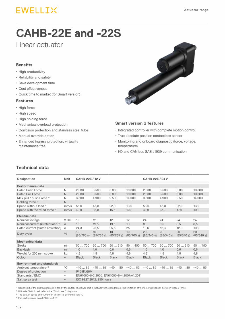
102
Actuator range
CAHB-22E and -22SLinear actuator
Benefits
•High productivity•Reliability and safety•Save development time• Costeffectiveness•Quick time to market (for Smart version)
Features
•High force•High speed•High holding force•Mechanical overload protection•Corrosion protection and stainless steel tube•Manual override option•Enhanced ingress protection, virtuality
maintenance free
Technical data
Designation Unit CAHB-22E / 12 V CAHB-22E / 24 V
Performance dataRated Push Force N 2 300 3 500 6 800 10 000 2 300 3 500 6 800 10 000Rated Pull Force N 2 300 3 500 6 800 10 000 2 300 3 500 6 800 10 000Max pull / push Force 1) N 3 500 4 900 9 500 14 000 3 500 4 900 9 500 14 000Holding force 2) NSpeed without load 3) mm/s 55,0 45,0 22,0 13,0 53,0 45,0 22,0 13,0Speed with the rated force 3) mm/s 42,0 36,0 15,5 10,2 42,0 37,0 17,0 10,2
Electric dataNominal voltage V DC 12 12 12 12 24 24 24 24Nominal current @ rated load 3) A 18 19,5 19,5 19 8 9,5 9,5 8,5Rated current (clutch activation) A 24,3 25,5 25,5 25 10,6 12,3 12,3 10,9
Duty cycle % 10 (85/765 s)
10 (85/765 s)
10(85/765 s)
10(85/765 s)
20(85/340 s)
20(85/340 s)
20(85/340 s)
20(85/340 s)
Mechanical dataStroke mm 50 … 700 50 … 700 50 … 610 50 … 450 50 … 700 50 … 700 50 … 610 50 … 450Backlash mm 1,0 1,0 0,6 0,6 1,0 1,0 0,6 0,6Weight for 200 mm stroke kg 4,8 4,8 4,8 4,8 4,8 4,8 4,8 4,8Colour – Black Black Black Black Black Black Black Black
Environment and standardsAmbient temperature 4) °C –40 … 85 –40 … 85 –40 … 85 –40 … 85 –40 … 85 –40 … 85 –40 … 85 –40 … 85Degree of protection – IP 69K/66MStandards / EMC – EN61000-6-2:2005, EN61000-6-4:2007/A1:2011Salt spray test – ISO 9227:2012, 250 hours
1) Upper limit of the pull/push force limited by the clutch. The lower limit is just above the rated force. The limitation of the force will happen between these 2 limits 2) Ultimate Static Load, refer to the “Static load” diagrams3)Thedataofspeedandcurrentonthislistisdefinedat+20°C4) Full performance from 0 °C to +40 °C
Smart version S features
• Integrated controller with complete motion control •True absolute position contactless sensor•Monitoring and onboard diagnostic (force, voltage,
temperature) • I/O and CAN bus SAE J1939 communication
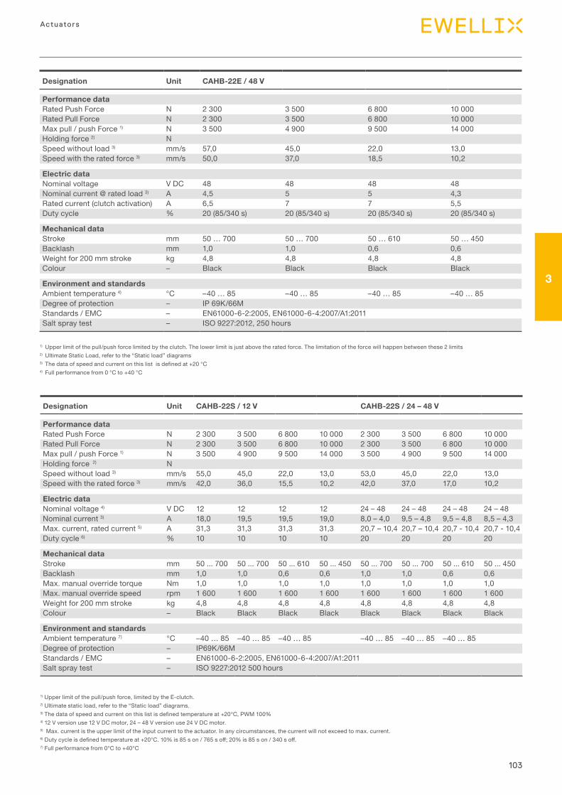
103
3
Actuators
1) Upper limit of the pull/push force limited by the clutch. The lower limit is just above the rated force. The limitation of the force will happen between these 2 limits 2) Ultimate Static Load, refer to the “Static load” diagrams3)Thedataofspeedandcurrentonthislistisdefinedat+20°C4) Full performance from 0 °C to +40 °C
Designation Unit CAHB-22E / 48 V
Performance dataRated Push Force N 2 300 3 500 6 800 10 000Rated Pull Force N 2 300 3 500 6 800 10 000Max pull / push Force 1) N 3 500 4 900 9 500 14 000Holding force 2) NSpeed without load 3) mm/s 57,0 45,0 22,0 13,0Speed with the rated force 3) mm/s 50,0 37,0 18,5 10,2
Electric dataNominal voltage V DC 48 48 48 48Nominal current @ rated load 3) A 4,5 5 5 4,3Rated current (clutch activation) A 6,5 7 7 5,5Duty cycle % 20 (85/340 s) 20 (85/340 s) 20 (85/340 s) 20 (85/340 s)
Mechanical dataStroke mm 50 … 700 50 … 700 50 … 610 50 … 450Backlash mm 1,0 1,0 0,6 0,6Weight for 200 mm stroke kg 4,8 4,8 4,8 4,8Colour – Black Black Black Black
Environment and standardsAmbient temperature 4) °C –40 … 85 –40 … 85 –40 … 85 –40 … 85Degree of protection – IP 69K/66MStandards / EMC – EN61000-6-2:2005, EN61000-6-4:2007/A1:2011Salt spray test – ISO 9227:2012, 250 hours
Designation Unit CAHB-22S / 12 V CAHB-22S / 24 – 48 V
Performance dataRated Push Force N 2 300 3 500 6 800 10 000 2 300 3 500 6 800 10 000Rated Pull Force N 2 300 3 500 6 800 10 000 2 300 3 500 6 800 10 000Max pull / push Force 1) N 3 500 4 900 9 500 14 000 3 500 4 900 9 500 14 000Holding force 2) NSpeed without load 3) mm/s 55,0 45,0 22,0 13,0 53,0 45,0 22,0 13,0Speed with the rated force 3) mm/s 42,0 36,0 15,5 10,2 42,0 37,0 17,0 10,2
Electric dataNominal voltage 4) V DC 12 12 12 12 24 – 48 24 – 48 24 – 48 24 – 48Nominal current 3) A 18,0 19,5 19,5 19,0 8,0 – 4,0 9,5 – 4,8 9,5 – 4,8 8,5 – 4,3Max. current, rated current 5) A 31,3 31,3 31,3 31,3 20,7 – 10,4 20,7 – 10,4 20,7 - 10,4 20,7 - 10,4Duty cycle 6) % 10 10 10 10 20 20 20 20
Mechanical dataStroke mm 50 ... 700 50 ... 700 50 ... 610 50 ... 450 50 ... 700 50 ... 700 50 ... 610 50 ... 450Backlash mm 1,0 1,0 0,6 0,6 1,0 1,0 0,6 0,6Max. manual override torque Nm 1,0 1,0 1,0 1,0 1,0 1,0 1,0 1,0Max. manual override speed rpm 1 600 1 600 1 600 1 600 1 600 1 600 1 600 1 600Weight for 200 mm stroke kg 4,8 4,8 4,8 4,8 4,8 4,8 4,8 4,8Colour – Black Black Black Black Black Black Black Black
Environment and standardsAmbient temperature 7) °C –40 … 85 –40 … 85 –40 … 85 –40 … 85 –40 … 85 –40 … 85Degree of protection – IP69K/66MStandards / EMC – EN61000-6-2:2005, EN61000-6-4:2007/A1:2011Salt spray test – ISO 9227:2012 500 hours
1) Upper limit of the pull/push force, limited by the E-clutch.2) Ultimate static load, refer to the “Static load” diagrams.3)Thedataofspeedandcurrentonthislistisdefinedtemperatureat+20°C,PWM100%4) 12 V version use 12 V DC motor, 24 – 48 V version use 24 V DC motor.5) Max. current is the upper limit of the input current to the actuator. In any circumstances, the current will not exceed to max. current.6)Dutycycleisdefinedtemperatureat+20°C.10%is85son/765soff;20%is85son/340soff.7) Full performance from 0°C to +40°C
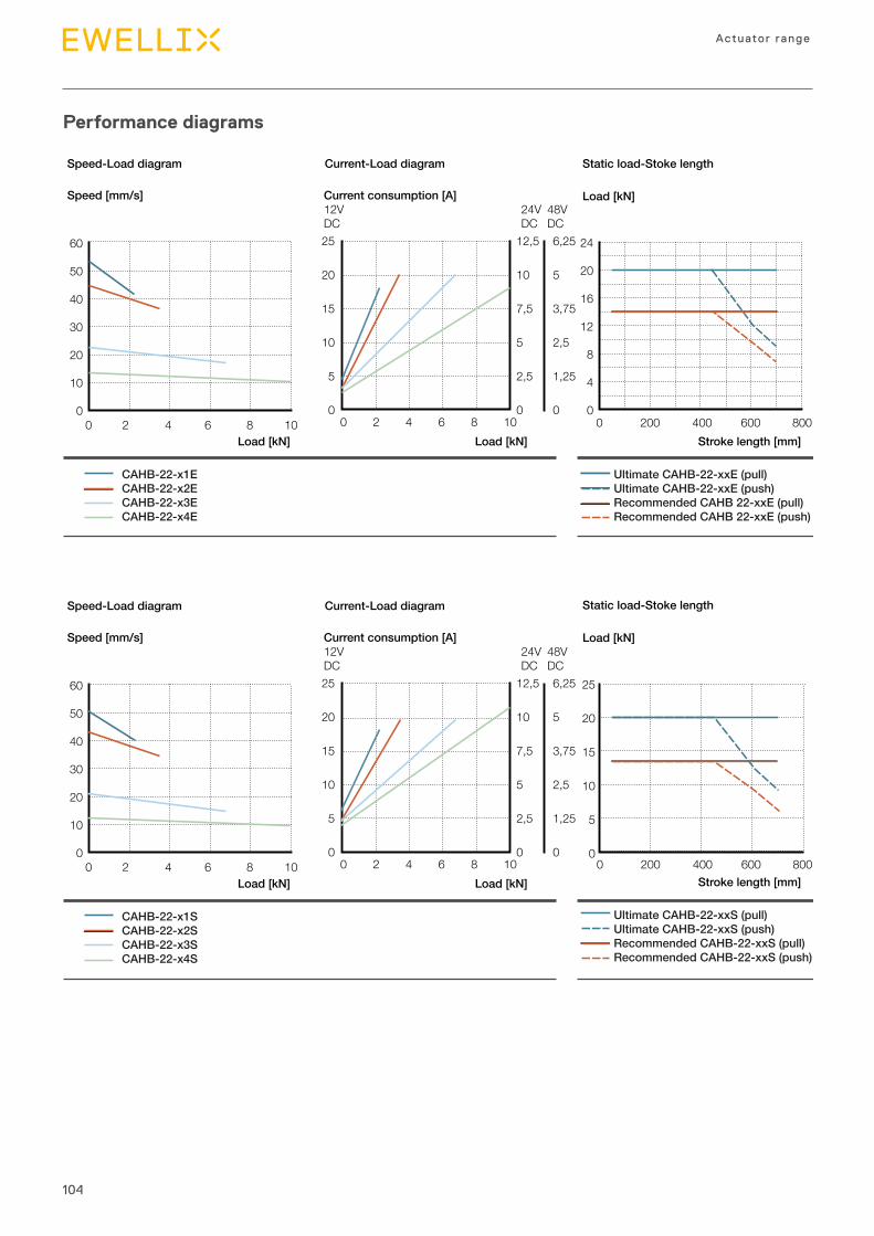
104
Actuator range
Performance diagrams
Speed-Load diagram Current-Load diagram Static load-Stoke length
CAHB-22-x1ECAHB-22-x2ECAHB-22-x3ECAHB-22-x4E
Ultimate CAHB-22-xxE (pull)Ultimate CAHB-22-xxE (push)Recommended CAHB 22-xxE (pull)Recommended CAHB 22-xxE (push)
Stroke length [mm]
Load [kN]
Load [kN]Load [kN]
Current consumption [A]12VDC
24VDC
48VDC
Speed [mm/s]
25
20
15
10
5
0
12,5
10
7,5
5
2,5
00 2 4 6 8 10 0 200 400 600 800
24
20
16
12
8
4
0
6,25
5
3,75
2,5
1,25
0
60
50
40
30
20
10
00 2 4 6 8 10
Speed-Load diagram Current-Load diagram
CAHB-22-x1SCAHB-22-x2SCAHB-22-x3SCAHB-22-x4S
Load [kN]Load [kN]
Current consumption [A]12VDC
24VDC
48VDC
Speed [mm/s]
25
20
15
10
5
0
12,5
10
7,5
5
2,5
00 2 4 6 8 10
6,25
5
3,75
2,5
1,25
0
60
50
40
30
20
10
00 2 4 6 8 10
Ultimate CAHB-22-xxS (pull)Ultimate CAHB-22-xxS (push)Recommended CAHB-22-xxS (pull)Recommended CAHB-22-xxS (push)
Stroke length [mm]
25
20
15
10
5
00 200 400 600 800
Static load-Stoke length
Load [kN]
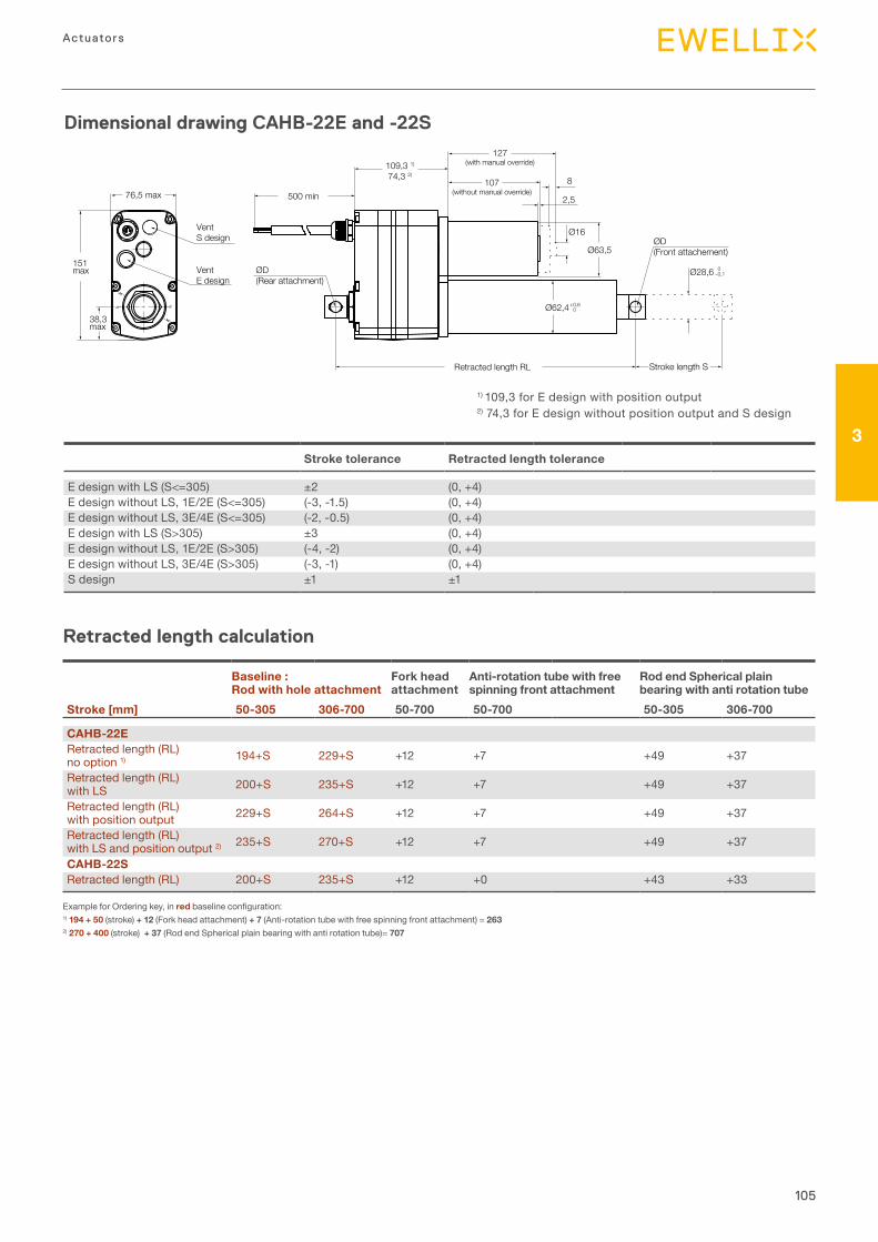
105
3
Actuators
Dimensional drawing CAHB-22E and -22S
– 30°
– 30°
– 0°– 0°
500 min
ØD(Front attachement)
ØD(Rear attachment)
0–0,1
+0,60
Ø16
Ø63,5
Ø28,6
2,5
8
Retracted length RL
109,3 1)
74,3 2)
107(without manual override)
127(with manual override)
Stroke length S
Ø62,4
76,5 max
38,3max
151max
VentS design
VentE design
Retracted length calculation
Baseline :Rod with hole attachment
Fork head attachment
Anti-rotation tube with free spinning front attachment
Rod end Spherical plain bearing with anti rotation tube
Stroke [mm] 50-305 306-700 50-700 50-700 50-305 306-700
CAHB-22ERetracted length (RL) no option 1) 194+S 229+S +12 +7 +49 +37
Retracted length (RL) with LS 200+S 235+S +12 +7 +49 +37
Retracted length (RL) with position output 229+S 264+S +12 +7 +49 +37
Retracted length (RL) with LS and position output 2) 235+S 270+S +12 +7 +49 +37
CAHB-22SRetracted length (RL) 200+S 235+S +12 +0 +43 +33
Example for Ordering key, in redbaselineconfiguration:1) 194 + 50 (stroke) + 12 (Fork head attachment) + 7 (Anti-rotation tube with free spinning front attachment) = 2632) 270 + 400 (stroke) + 37 (Rod end Spherical plain bearing with anti rotation tube)= 707
Stroke tolerance Retracted length tolerance
E design with LS (S<=305) ±2 (0, +4)E design without LS, 1E/2E (S<=305) (-3, -1.5) (0, +4)E design without LS, 3E/4E (S<=305) (-2, -0.5) (0, +4)E design with LS (S>305) ±3 (0, +4)E design without LS, 1E/2E (S>305) (-4, -2) (0, +4)E design without LS, 3E/4E (S>305) (-3, -1) (0, +4)S design ±1 ±1
1) 109,3 for E design with position output2) 74,3 for E design without position output and S design
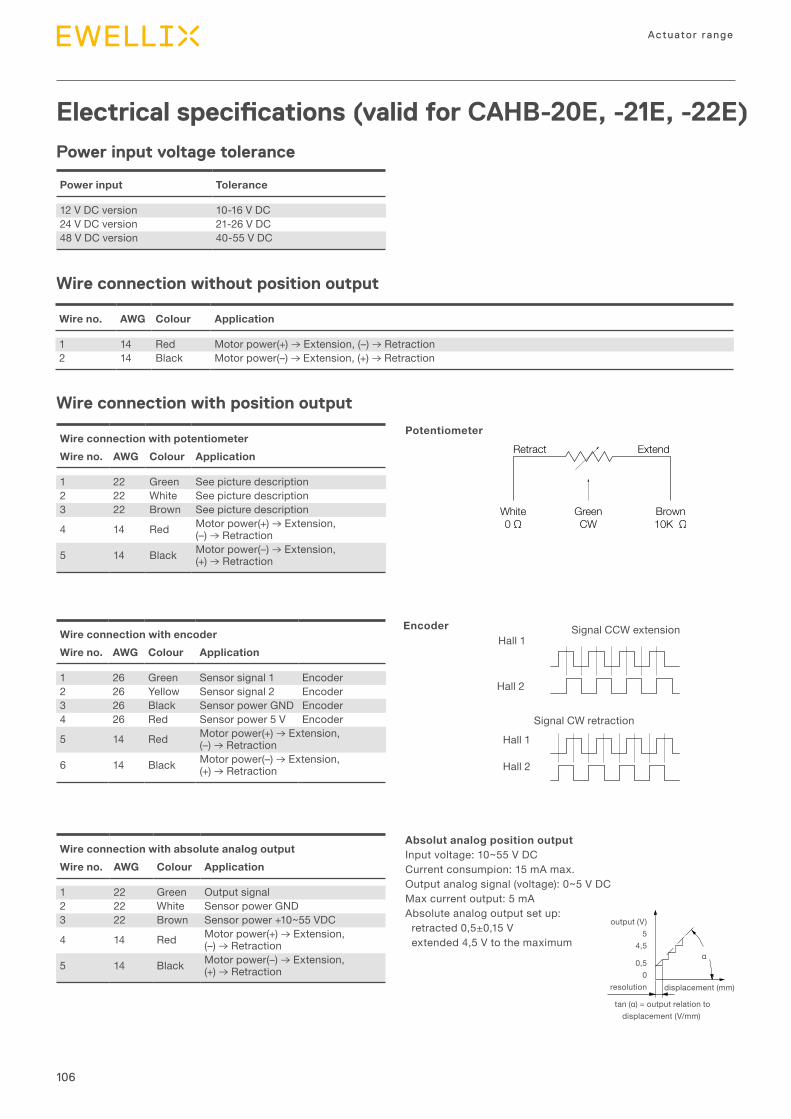
106
Actuator range
Wire no. AWG Colour Application
1 14 Red Motor power(+) → Extension, (–) → Retraction2 14 Black Motor power(–) → Extension, (+) → Retraction
Electrical specifications (valid for CAHB-20E, -21E, -22E)
Wire connection without position output
Power input voltage tolerance
Wire connection with position output
Wire connection with potentiometerWire no. AWG Colour Application
1 22 Green See picture description2 22 White See picture description3 22 Brown See picture description
4 14 Red Motor power(+) → Extension, (–) → Retraction
5 14 Black Motor power(–) → Extension, (+) → Retraction
Power input Tolerance
12 V DC version 10-16 V DC24 V DC version 21-26 V DC48 V DC version 40-55 V DC
Potentiometer
Wire connection with encoderWire no. AWG Colour Application
1 26 Green Sensor signal 1 Encoder2 26 Yellow Sensor signal 2 Encoder3 26 Black Sensor power GND Encoder4 26 Red Sensor power 5 V Encoder
5 14 Red Motor power(+) → Extension, (–) → Retraction
6 14 Black Motor power(–) → Extension, (+) → Retraction
Wire connection with absolute analog outputWire no. AWG Colour Application
1 22 Green Output signal2 22 White Sensor power GND3 22 Brown Sensor power +10~55 VDC
4 14 Red Motor power(+) → Extension, (–) → Retraction
5 14 Black Motor power(–) → Extension, (+) → Retraction
EncoderHall 1
Hall 2
Hall 1
Hall 2
Signal CCW extension
Signal CW retraction
Absolut analog position outputInput voltage: 10~55 V DCCurrent consumpion: 15 mA max.Output analog signal (voltage): 0~5 V DCMax current output: 5 mAAbsolute analog output set up: retracted 0,5±0,15 V extended 4,5 V to the maximum
Retract
White0 Ω
GreenCW
Brown10K Ω
Extend
output (V)5
4,5
0,50
resolution
tan(α)=outputrelationtodisplacement (V/mm)
α
displacement (mm)
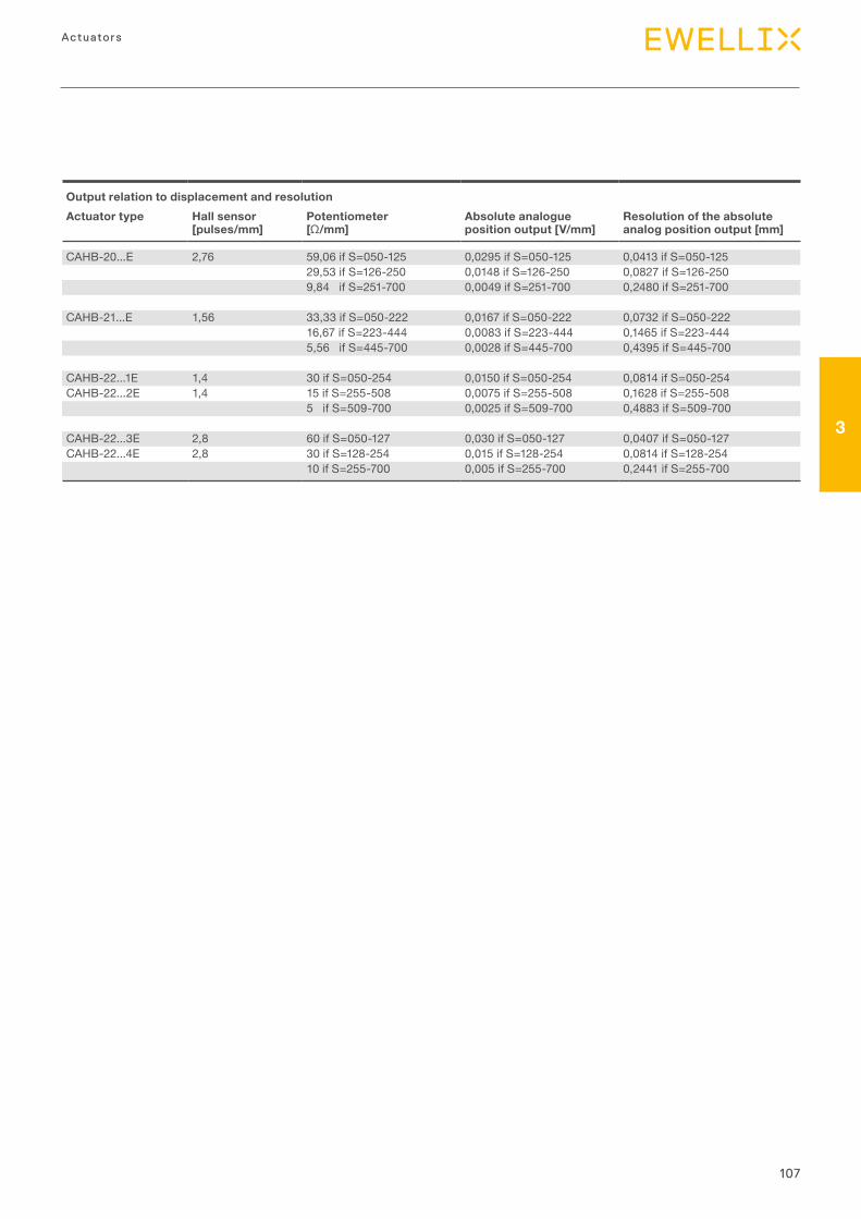
107
3
Actuators
Output relation to displacement and resolutionActuator type Hall sensor
[pulses/mm]Potentiometer [Ω/mm]
Absolute analogue position output [V/mm]
Resolution of the absolute analog position output [mm]
CAHB-20...E 2,76 59,06 if S=050-125 0,0295 if S=050-125 0,0413 if S=050-12529,53 if S=126-250 0,0148 if S=126-250 0,0827 if S=126-2509,84 if S=251-700 0,0049 if S=251-700 0,2480 if S=251-700
CAHB-21...E 1,56 33,33 if S=050-222 0,0167 if S=050-222 0,0732 if S=050-22216,67 if S=223-444 0,0083 if S=223-444 0,1465 if S=223-4445,56 if S=445-700 0,0028 if S=445-700 0,4395 if S=445-700
CAHB-22...1E 1,4 30 if S=050-254 0,0150 if S=050-254 0,0814 if S=050-254CAHB-22...2E 1,4 15 if S=255-508 0,0075 if S=255-508 0,1628 if S=255-508
5 if S=509-700 0,0025 if S=509-700 0,4883 if S=509-700
CAHB-22...3E 2,8 60 if S=050-127 0,030 if S=050-127 0,0407 if S=050-127CAHB-22...4E 2,8 30 if S=128-254 0,015 if S=128-254 0,0814 if S=128-254
10 if S=255-700 0,005 if S=255-700 0,2441 if S=255-700
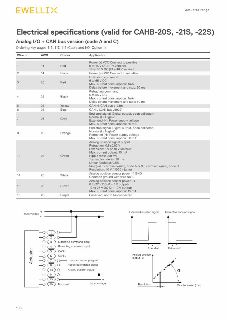
108
Actuator range
Analog I/O + CAN bus version (code A and C)Ordering key pages 115, 117, 119 (Cable and I/O Option 1)
Electrical specifications (valid for CAHB-20S, -21S, -22S)
Wire no. AWG Colour Application
1 14 RedPower (+) VCC Connect to positive9 to 16 V DC (12 V version)18 to 55 V DC (24 – 48 V version)
2 14 Black Power (-) GND Connect to negative
3 26 RedExtending command5 to 55 V DCMax. current consumption: 1mADelay before movement and stop: 50 ms
4 26 BlackRetracting command5 to 55 V DCMax. current consumption: 1mADelay before movement and stop: 50 ms
5 26 Yellow CAN H (CAN bus J1939)6 26 Blue CAN L (CAN bus J1939)
7 26 GreyEnd stop signal (Digital output, open collector)Normal (L): High-ZExtended (H): Power supply voltageMax. current consumption: 50 mA
8 26 OrangeEnd stop signal (Digital output, open collector)Normal (L): High-ZRetracted (H): Power supply voltageMax. current consumption: 50 mA
13 26 Green
Analog position signal outputRetraction: 0,5±0,02 VExtension: 5 V or 10 V (default)Max. current output: 15 mARipple max: 200 mVTransaction delay: 20 msLinear feedback 0,5%tan(α)=4,5/stroke(V/mm),codeAor9,5/stroke(V/mm),codeCResolution:10V/1000/tan(α)
14 26 White Analog position sensor power (-) GNDCommon ground with wire No. 2
15 26 BrownAnalog position sensor power (+)8 to 27 V DC (0 ~ 5 V output)13 to 27 V DC (0 ~ 10 V output)Max. current consumption: 15 mA
16 26 Purple Reserved, not to be connected
!"##"
$%&
'"($)
Not used Input voltage
Actu
ator
Retracted endstop signalExtended endstop signal
Analog position output
CAN HCAN L
Extending command inputRetracting command input
-+
Input voltage +-
1234567813141516
Extended
Desplacement (mm)
Retracted
Resolution
Extended endstop signal Retracted endstop signal
Analog positionoutput (V)
α
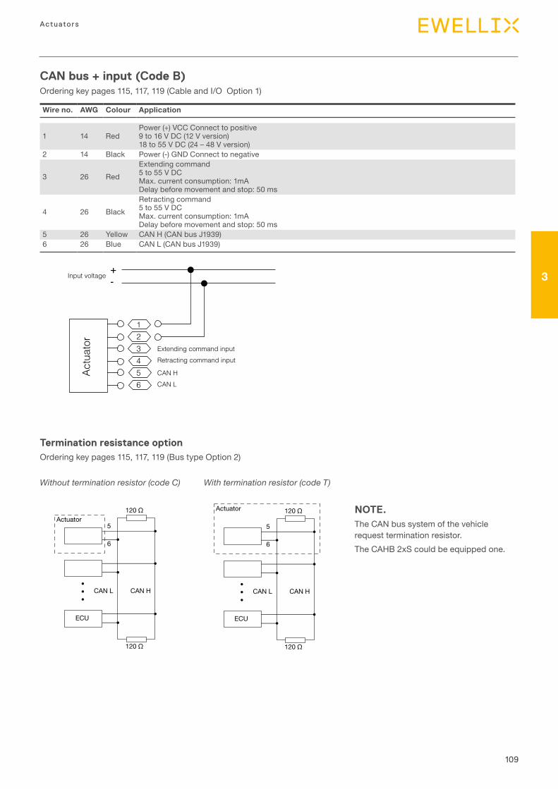
109
3
Actuators
CAN bus + input (Code B)Ordering key pages 115, 117, 119 (Cable and I/O Option 1)
Termination resistance optionOrdering key pages 115, 117, 119 (Bus type Option 2)
NOTE.The CAN bus system of the vehicle request termination resistor.The CAHB 2xS could be equipped one.
Wire no. AWG Colour Application
1 14 RedPower (+) VCC Connect to positive9 to 16 V DC (12 V version)18 to 55 V DC (24 – 48 V version)
2 14 Black Power (-) GND Connect to negative
3 26 RedExtending command5 to 55 V DCMax. current consumption: 1mADelay before movement and stop: 50 ms
4 26 BlackRetracting command5 to 55 V DCMax. current consumption: 1mADelay before movement and stop: 50 ms
5 26 Yellow CAN H (CAN bus J1939)6 26 Blue CAN L (CAN bus J1939)
Actu
ator
CAN HCAN L
Extending command inputRetracting command input
Input voltage+-
123456
Actuator
ECU
120 Ω
120 Ω
CAN HCAN L
5
6
���
Actuator
ECU
120 Ω
120 Ω
CAN HCAN L
5
6
���
Actuator
ECU
120 Ω
120 Ω
CAN HCAN L
5
6
���
Actuator
ECU
120 Ω
120 Ω
CAN HCAN L
5
6
���
Without termination resistor (code C) With termination resistor (code T)
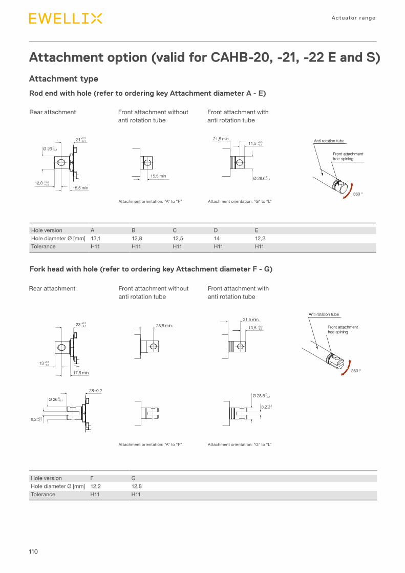
110
Actuator range
Attachment option (valid for CAHB-20, -21, -22 E and S)
Attachment type
Rod end with hole (refer to ordering key Attachment diameter A - E)
Fork head with hole (refer to ordering key Attachment diameter F - G)
15,5 min
52 min. Ø12,7
Ø 28,6 360 °
28±0,2
+0,321–0,1
31,5 min.
+0,28,2–0,1
+0,311,5 –0,7
+0,28,2 –0,1
+0,512,8 –0,4
+0,038 0
0
(33,32)
-0,13
15,5 min
21,5 min
0–0,1
Ø 28,6 0–0,1
Ø 18,8 H11 +0,110
Ø 26 0–0,1
17,5 min
+0,323 –0,1
+0,513 –0,4
Ø 26 0–0,1
+0,313,5 –0,725,5 min.
15,88
Anti rotation tube
Front attachmentfree spining
360 °
Anti rotation tube
Front attachmentfree spining
15,5 min
52 min. Ø12,7
Ø 28,6 360 °
28±0,2
+0,321–0,1
31,5 min.
+0,28,2–0,1
+0,311,5 –0,7
+0,28,2 –0,1
+0,512,8 –0,4
+0,038 0
0
(33,32)
-0,13
15,5 min
21,5 min
0–0,1
Ø 28,6 0–0,1
Ø 18,8 H11 +0,110
Ø 26 0–0,1
17,5 min
+0,323 –0,1
+0,513 –0,4
Ø 26 0–0,1
+0,313,5 –0,725,5 min.
15,88
Anti rotation tube
Front attachmentfree spining
360 °
Anti rotation tube
Front attachmentfree spining
Rear attachment
Rear attachment
Front attachment without anti rotation tube
Attachment orientation: "A" to “F”
Front attachment without anti rotation tube
Attachment orientation: "A" to “F”
Front attachment with anti rotation tube
Attachment orientation: "G" to “L”
Front attachment with anti rotation tube
Attachment orientation: "G" to “L”
Hole version A B C D EHole diameter Ø [mm] 13,1 12,8 12,5 14 12,2Tolerance H11 H11 H11 H11 H11
Hole version F GHole diameter Ø [mm] 12,2 12,8Tolerance H11 H11
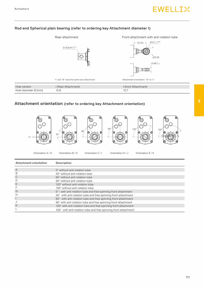
111
3
Actuators
Attachment orientation (refer to ordering key Attachment orientation)
Rod end Spherical plain bearing (refer to ordering key Attachment diameter I)
15,5 min
52 min. Ø12,7
Ø 28,6 360 °
28±0,2
+0,321–0,1
31,5 min.
+0,28,2–0,1
+0,311,5 –0,7
+0,28,2 –0,1
+0,512,8 –0,4
+0,038 0
0
(33,32)
-0,13
15,5 min
21,5 min
0–0,1
Ø 28,6 0–0,1
Ø 18,8 H11 +0,110
Ø 26 0–0,1
17,5 min
+0,323 –0,1
+0,513 –0,4
Ø 26 0–0,1
+0,313,5 –0,725,5 min.
15,88
Anti rotation tube
Front attachmentfree spining
360 °
Anti rotation tube
Front attachmentfree spining
15,5 min
52 min. Ø12,7
Ø 28,6 360 °
28±0,2
+0,321–0,1
31,5 min.
+0,28,2–0,1
+0,311,5 –0,7
+0,28,2 –0,1
+0,512,8 –0,4
+0,038 0
0
(33,32)
-0,13
15,5 min
21,5 min
0–0,1
Ø 28,6 0–0,1
Ø 18,8 H11 +0,110
Ø 26 0–0,1
17,5 min
+0,323 –0,1
+0,513 –0,4
Ø 26 0–0,1
+0,313,5 –0,725,5 min.
15,88
Anti rotation tube
Front attachmentfree spining
360 °
Anti rotation tube
Front attachmentfree spining
0°
03°
06°09°
120°
150°
0°
03°
06° 09
°
120°
150°
0°
03°
06°09°
120°
150°
0°
03°
06° 09
°
120°
150°
0°
03°
06°09°
120°
150°
0°
03°
06° 09
°
120°
150°
0°
03°
06°09°
120°
150°
0°
03°
06° 09
°
120°
150°
0°
03°
06°09°
120°
150°
0°
03°
06° 09
°
120°
150°
03°
06°09°
120°
150°
0°
0°
03°
06° 09
°
120°
150°
0°30°
60°90° 120° 150°
Rear attachment Front attachment with anti rotation tube
"I" and "B" have the same rear attachment Attachment orientation: "G" to "L"
Hole version I (Rear Attachment) I (front Attachment)Hole diameter Ø [mm] 12,8 12,7
Orientation A / G Orientation B / H Orientation C / I Orientation D / J Orientation E / K
Orientation F / L
Attachment orientation Description
A 0° without anti rotation tubeB 30° without anti rotation tubeC 60° without anti rotation tubeD 90° without anti rotation tubeE 120° without anti rotation tubeF 150° without anti rotation tubeG 0° : with anti rotation tube and free spinning front attachmentH 30° with anti rotation tube and free spinning front attachmentI 60° with anti rotation tube and free spinning front attachmentJ 90° with anti rotation tube and free spinning front attachmentK 120° with anti rotation tube and free spinning front attachmentL 150° with anti rotation tube and free spinning front attachment
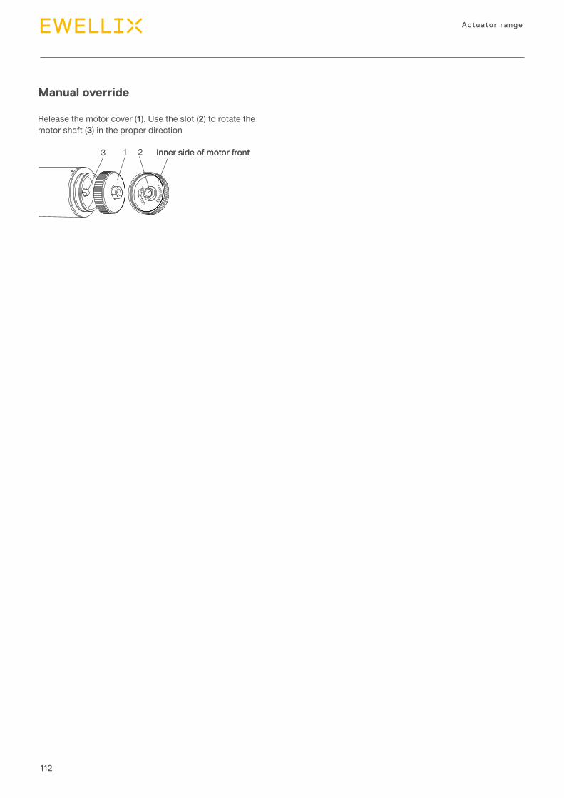
112
Actuator range
Retraction Exte
nsio
n
Release the motor cover (1). Use the slot (2) to rotate the motor shaft (3) in the proper direction
1 23 Inner side of motor frontInner side of motor front
Manual override
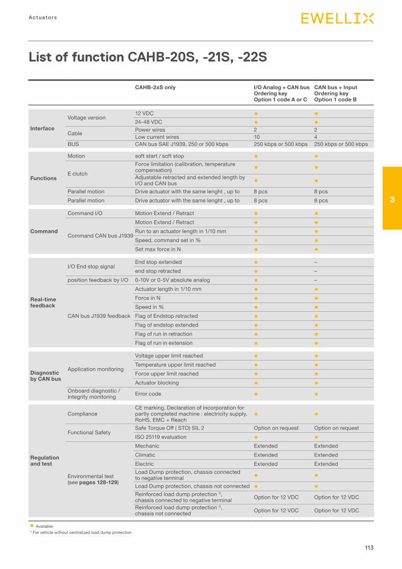
113
3
Actuators
List of function CAHB-20S, -21S, -22S
CAHB-2xS only I/O Analog + CAN busOrdering key Option 1 code A or C
CAN bus + InputOrdering key Option 1 code B
Interface
Voltage version12 VDC ● ●24-48 VDC ● ●
Cable Power wires 2 2Low current wires 10 4
BUS CAN bus SAE J1939, 250 or 500 kbps 250 kbps or 500 kbps 250 kbps or 500 kbps
Functions
Motion soft start / soft stop ● ●
E clutch
Force limitation (calibration, temperature compensation) ● ●Adjustable retracted and extended length by I/O and CAN bus ● ●
Parallel motion Drive actuator with the same lenght , up to 8 pcs 8 pcsParallel motion Drive actuator with the same lenght , up to 8 pcs 8 pcs
Command
Command I/O Motion Extend / Retract ● ●
Command CAN bus J1939
Motion Extend / Retract ● ●Run to an actuator length in 1/10 mm ● ●Speed, command set in % ● ●Set max force in N ● ●
Real-time feedback
I/O End stop signalEnd stop extended ● –end stop retracted ● –
position feedback by I/O 0-10V or 0-5V absolute analog ● –
CAN bus J1939 feedback
Actuator length in 1/10 mm ● ●Force in N ● ●Speed in % ● ●Flag of Endstop retracted ● ●Flag of endstop extended ● ●Flag of run in retraction ● ●Flag of run in extension ● ●
Diagnostic by CAN bus
Application monitoring
Voltage upper limit reached ● ●Temperature upper limit reached ● ●Force upper limit reached ● ●Actuator blocking ● ●
Onboard diagnostic / Integrity monitoring Error code ● ●
Regulation and test
ComplianceCE marking, Declaration of incorporation for partly completed machine : electricity supply, RoHS, EMC + Reach
● ●
Functional SafetySafeTorqueOff(STO)SIL2 Option on request Option on requestISO 25119 evaluation ● ●
Environmental test (see pages 128-129)
Mechanic Extended Extended Climatic Extended Extended Electric Extended Extended Load Dump protection, chassis connected to negative terminal ● ●Load Dump protection, chassis not connected ● ●Reinforced load dump protection 1), chassis connected to negative terminal Option for 12 VDC Option for 12 VDC
Reinforced load dump protection 1), chassis not connected Option for 12 VDC Option for 12 VDC
● Available1) For vehicle without centralized load dump protection
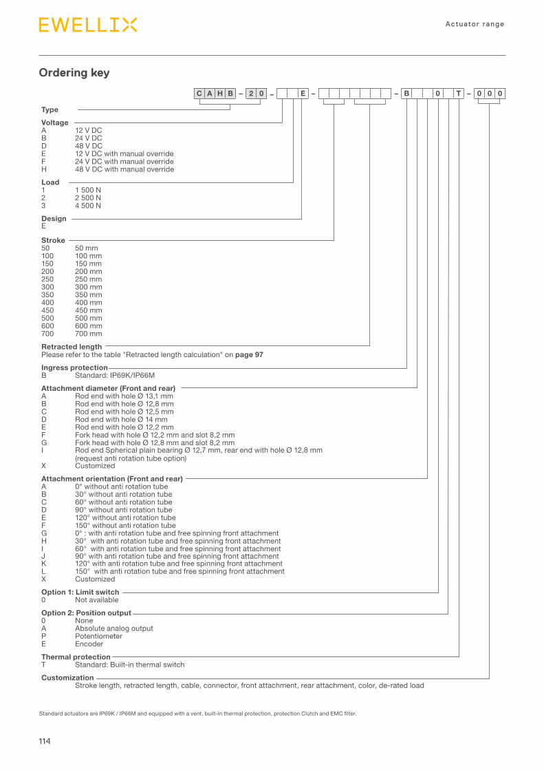
114
Actuator range
TypeVoltageA 12 V DCB 24 V DCD 48 V DCE 12 V DC with manual overrideF 24 V DC with manual overrideH 48 V DC with manual overrideLoad1 1 500 N2 2 500 N3 4 500 NDesignE
Stroke50 50 mm100 100 mm150 150 mm200 200 mm250 250 mm300 300 mm350 350 mm400 400 mm450 450 mm500 500 mm600 600 mm700 700 mm
Retracted lengthPlease refer to the table "Retracted length calculation" on page 97Ingress protectionB Standard: IP69K/IP66MAttachment diameter (Front and rear)A Rod end with hole Ø 13,1 mmB Rod end with hole Ø 12,8 mmC Rod end with hole Ø 12,5 mmD Rod end with hole Ø 14 mmE Rod end with hole Ø 12,2 mmF Fork head with hole Ø 12,2 mm and slot 8,2 mmG Fork head with hole Ø 12,8 mm and slot 8,2 mmI Rod end Spherical plain bearing Ø 12,7 mm, rear end with hole Ø 12,8 mm
(request anti rotation tube option) X CustomizedAttachment orientation (Front and rear)A 0° without anti rotation tubeB 30° without anti rotation tubeC 60° without anti rotation tubeD 90° without anti rotation tubeE 120° without anti rotation tubeF 150° without anti rotation tubeG 0° : with anti rotation tube and free spinning front attachmentH 30° with anti rotation tube and free spinning front attachmentI 60° with anti rotation tube and free spinning front attachmentJ 90° with anti rotation tube and free spinning front attachmentK 120° with anti rotation tube and free spinning front attachmentL 150° with anti rotation tube and free spinning front attachmentX CustomizedOption 1: Limit switch0 Not availableOption 2: Position output0 NoneA Absolute analog outputP PotentiometerE Encoder Thermal protectionT Standard: Built-in thermal switchCustomization
Stroke length, retracted length, cable, connector, front attachment, rear attachment, color, de-rated load
Ordering key
StandardactuatorsareIP69K/IP66Mandequippedwithavent,built-inthermalprotection,protectionClutchandEMCfilter.
C A H B – 2 0 – E – – B 0 T – 0 0 0
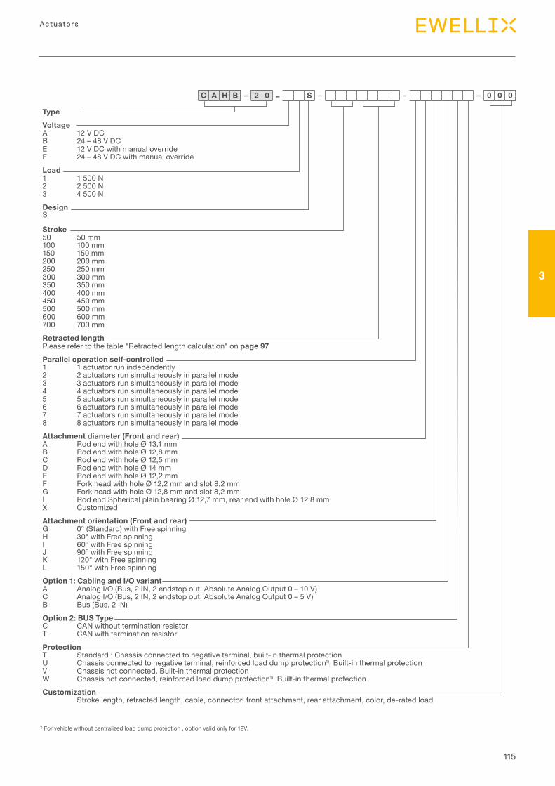
115
3
Actuators
TypeVoltageA 12 V DCB 24 – 48 V DCE 12 V DC with manual overrideF 24 – 48 V DC with manual overrideLoad1 1 500 N2 2 500 N3 4 500 NDesignS
Stroke50 50 mm100 100 mm150 150 mm200 200 mm250 250 mm300 300 mm350 350 mm400 400 mm450 450 mm500 500 mm600 600 mm700 700 mm
Retracted lengthPlease refer to the table "Retracted length calculation" on page 97Parallel operation self-controlled 1 1 actuator run independently2 2 actuators run simultaneously in parallel mode3 3 actuators run simultaneously in parallel mode4 4 actuators run simultaneously in parallel mode 5 5 actuators run simultaneously in parallel mode 6 6 actuators run simultaneously in parallel mode 7 7 actuators run simultaneously in parallel mode 8 8 actuators run simultaneously in parallel mode Attachment diameter (Front and rear)A Rod end with hole Ø 13,1 mmB Rod end with hole Ø 12,8 mmC Rod end with hole Ø 12,5 mmD Rod end with hole Ø 14 mmE Rod end with hole Ø 12,2 mmF Fork head with hole Ø 12,2 mm and slot 8,2 mmG Fork head with hole Ø 12,8 mm and slot 8,2 mmI Rod end Spherical plain bearing Ø 12,7 mm, rear end with hole Ø 12,8 mm X CustomizedAttachment orientation (Front and rear)G 0° (Standard) with Free spinning H 30° with Free spinning I 60° with Free spinning J 90° with Free spinningK 120° with Free spinning L 150° with Free spinning Option 1: Cabling and I/O variantA Analog I/O (Bus, 2 IN, 2 endstop out, Absolute Analog Output 0 – 10 V) C Analog I/O (Bus, 2 IN, 2 endstop out, Absolute Analog Output 0 – 5 V) B Bus (Bus, 2 IN) Option 2: BUS Type C CAN without termination resistorT CAN with termination resistor Protection T Standard : Chassis connected to negative terminal, built-in thermal protection U Chassis connected to negative terminal, reinforced load dump protection1), Built-in thermal protection V Chassis not connected, Built-in thermal protection W Chassis not connected, reinforced load dump protection1), Built-in thermal protectionCustomization
Stroke length, retracted length, cable, connector, front attachment, rear attachment, color, de-rated load
C A H B – 2 0 – S – – – 0 0 0
1) For vehicle without centralized load dump protection , option valid only for 12V.
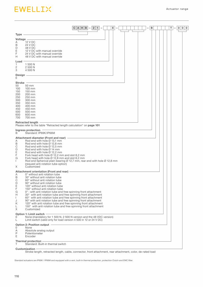
116
Actuator range
TypeVoltageA 12 V DCB 24 V DCD 48 V DCE 12 V DC with manual overrideF 24 V DC with manual overrideH 48 V DC with manual overrideLoad1 1 500 N2 2 500 N3 4 500 NDesignEStroke50 50 mm100 100 mm150 150 mm200 200 mm250 250 mm 300 300 mm350 350 mm 400 400 mm 450 450 mm 500 500 mm600 600 mm 700 700 mm Retracted lengthPlease refer to the table "Retracted length calculation" on page 101Ingress protectionB Standard: IP69K/IP66M Attachment diameter (Front and rear)A Rod end with hole Ø 13,1 mmB Rod end with hole Ø 12,8 mmC Rod end with hole Ø 12,5 mmD Rod end with hole Ø 14 mmE Rod end with hole Ø 12,2 mmF Fork head with hole Ø 12,2 mm and slot 8,2 mmG Fork head with hole Ø 12,8 mm and slot 8,2 mmI Rod end Spherical plain bearing Ø 12,7 mm, rear end with hole Ø 12,8 mm
(request anti rotation tube option) X CustomizedAttachment orientation (Front and rear)A 0° without anti rotation tubeB 30° without anti rotation tubeC 60° without anti rotation tubeD 90° without anti rotation tubeE 120° without anti rotation tubeF 150° without anti rotation tubeG 0° : with anti rotation tube and free spinning front attachmentH 30° with anti rotation tube and free spinning front attachmentI 60° with anti rotation tube and free spinning front attachmentJ 90° with anti rotation tube and free spinning front attachmentK 120° with anti rotation tube and free spinning front attachmentL 150° with anti rotation tube and free spinning front attachmentX CustomizedOption 1: Limit switch0 None (mandatory for 1 500 N, 2 500 N version and the 48 VDC version) L Limit switch (valid only for load version 4 500 in 12 or 24 V DC) Option 2: Position output0 NoneA Absolute analog outputP PotentiometerE Encoder Thermal protectionT Standard: Built-in thermal switchCustomization
Stroke length, retracted length, cable, connector, front attachment, rear attachment, color, de-rated load
C A H B – 2 1 – E – – B T – 0 0 0
StandardactuatorsareIP69K/IP66Mandequippedwithavent,built-inthermalprotection,protectionClutchandEMCfilter.
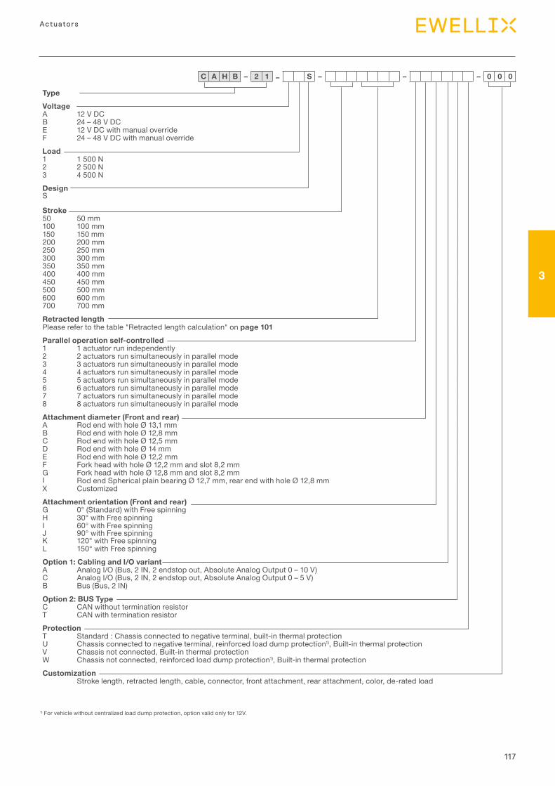
117
3
Actuators
TypeVoltageA 12 V DCB 24 – 48 V DCE 12 V DC with manual overrideF 24 – 48 V DC with manual overrideLoad1 1 500 N2 2 500 N3 4 500 NDesignS
Stroke50 50 mm100 100 mm150 150 mm200 200 mm250 250 mm300 300 mm350 350 mm400 400 mm450 450 mm500 500 mm600 600 mm700 700 mm
Retracted lengthPlease refer to the table "Retracted length calculation" on page 101Parallel operation self-controlled 1 1 actuator run independently2 2 actuators run simultaneously in parallel mode3 3 actuators run simultaneously in parallel mode4 4 actuators run simultaneously in parallel mode 5 5 actuators run simultaneously in parallel mode 6 6 actuators run simultaneously in parallel mode 7 7 actuators run simultaneously in parallel mode 8 8 actuators run simultaneously in parallel mode Attachment diameter (Front and rear)A Rod end with hole Ø 13,1 mmB Rod end with hole Ø 12,8 mmC Rod end with hole Ø 12,5 mmD Rod end with hole Ø 14 mmE Rod end with hole Ø 12,2 mmF Fork head with hole Ø 12,2 mm and slot 8,2 mmG Fork head with hole Ø 12,8 mm and slot 8,2 mmI Rod end Spherical plain bearing Ø 12,7 mm, rear end with hole Ø 12,8 mm X CustomizedAttachment orientation (Front and rear)G 0° (Standard) with Free spinning H 30° with Free spinning I 60° with Free spinning J 90° with Free spinningK 120° with Free spinning L 150° with Free spinning Option 1: Cabling and I/O variantA Analog I/O (Bus, 2 IN, 2 endstop out, Absolute Analog Output 0 – 10 V) C Analog I/O (Bus, 2 IN, 2 endstop out, Absolute Analog Output 0 – 5 V) B Bus (Bus, 2 IN) Option 2: BUS Type C CAN without termination resistorT CAN with termination resistor Protection T Standard : Chassis connected to negative terminal, built-in thermal protection U Chassis connected to negative terminal, reinforced load dump protection1), Built-in thermal protection V Chassis not connected, Built-in thermal protection W Chassis not connected, reinforced load dump protection1), Built-in thermal protectionCustomization
Stroke length, retracted length, cable, connector, front attachment, rear attachment, color, de-rated load
C A H B – 2 1 – S – – – 0 0 0
1) For vehicle without centralized load dump protection, option valid only for 12V.
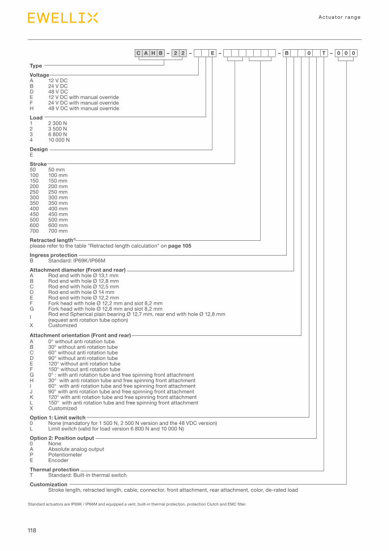
118
Actuator range
TypeVoltageA 12 V DCB 24 V DCD 48 V DCE 12 V DC with manual overrideF 24 V DC with manual overrideH 48 V DC with manual overrideLoad1 2 300 N2 3 500 N3 6 800 N4 10 000 NDesignEStroke50 50 mm100 100 mm150 150 mm200 200 mm250 250 mm300 300 mm350 350 mm400 400 mm450 450 mm500 500 mm600 600 mm700 700 mmRetracted length1)
please refer to the table "Retracted length calculation" on page 105Ingress protectionB Standard: IP69K/IP66M Attachment diameter (Front and rear)A Rod end with hole Ø 13,1 mmB Rod end with hole Ø 12,8 mmC Rod end with hole Ø 12,5 mmD Rod end with hole Ø 14 mmE Rod end with hole Ø 12,2 mmF Fork head with hole Ø 12,2 mm and slot 8,2 mmG Fork head with hole Ø 12,8 mm and slot 8,2 mmI Rod end Spherical plain bearing Ø 12,7 mm, rear end with hole Ø 12,8 mm
(request anti rotation tube option)X Customized
Attachment orientation (Front and rear)A 0° without anti rotation tubeB 30° without anti rotation tubeC 60° without anti rotation tubeD 90° without anti rotation tubeE 120° without anti rotation tubeF 150° without anti rotation tubeG 0° : with anti rotation tube and free spinning front attachmentH 30° with anti rotation tube and free spinning front attachmentI 60° with anti rotation tube and free spinning front attachmentJ 90° with anti rotation tube and free spinning front attachmentK 120° with anti rotation tube and free spinning front attachmentL 150° with anti rotation tube and free spinning front attachmentX CustomizedOption 1: Limit switch0 None (mandatory for 1 500 N, 2 500 N version and the 48 VDC version) L Limit switch (valid for load version 6 800 N and 10 000 N) Option 2: Position output0 NoneA Absolute analog outputP PotentiometerE Encoder Thermal protectionT Standard: Built-in thermal switchCustomization
Stroke length, retracted length, cable, connector, front attachment, rear attachment, color, de-rated load
C A H B – 2 2 – E – – B 0 T – 0 0 0
StandardactuatorsareIP69K/IP66Mandequippedavent,built-inthermalprotection,protectionClutchandEMCfilter.
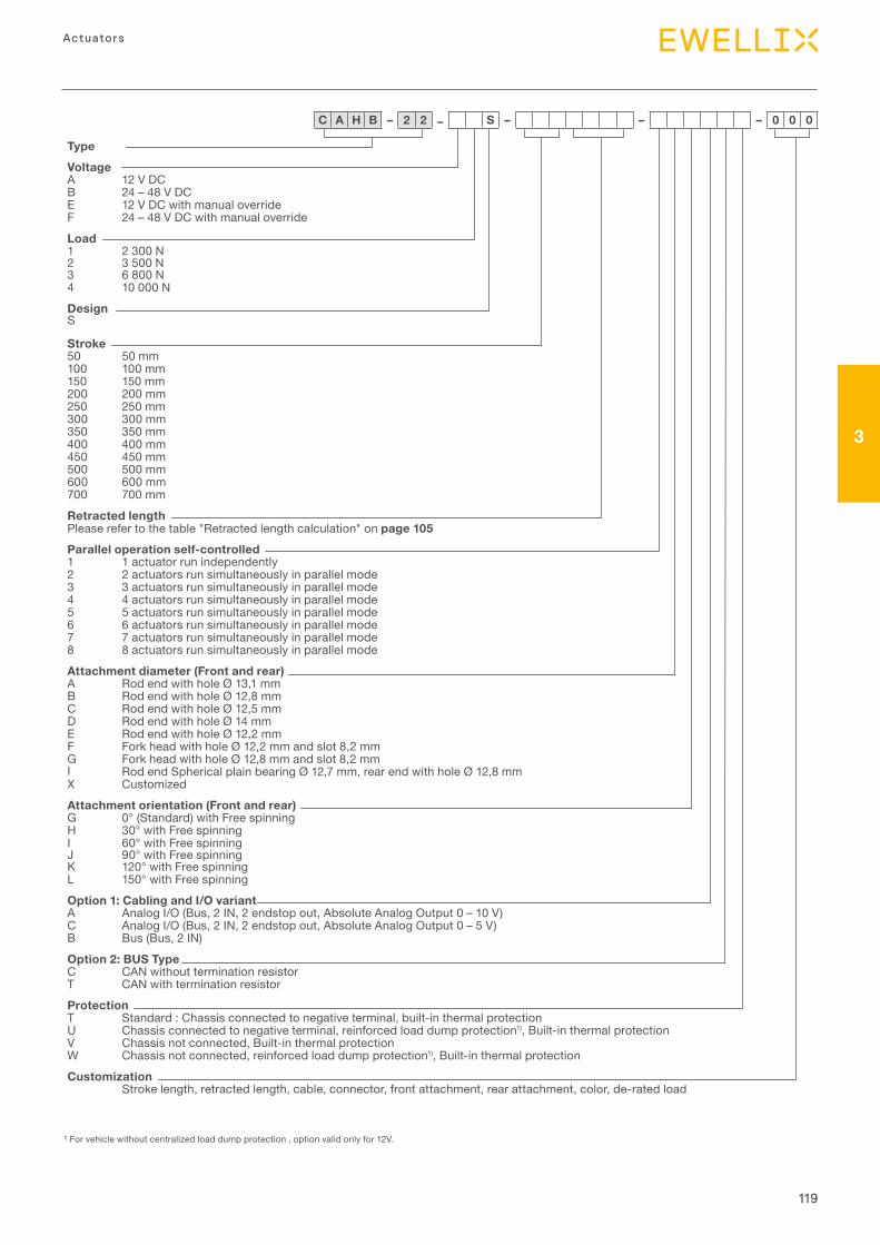
119
3
Actuators
TypeVoltageA 12 V DCB 24 – 48 V DCE 12 V DC with manual overrideF 24 – 48 V DC with manual overrideLoad1 2 300 N2 3 500 N3 6 800 N4 10 000 NDesignS
Stroke50 50 mm100 100 mm150 150 mm200 200 mm250 250 mm300 300 mm350 350 mm400 400 mm450 450 mm500 500 mm600 600 mm700 700 mm
Retracted lengthPlease refer to the table "Retracted length calculation" on page 105Parallel operation self-controlled 1 1 actuator run independently2 2 actuators run simultaneously in parallel mode3 3 actuators run simultaneously in parallel mode4 4 actuators run simultaneously in parallel mode 5 5 actuators run simultaneously in parallel mode 6 6 actuators run simultaneously in parallel mode 7 7 actuators run simultaneously in parallel mode 8 8 actuators run simultaneously in parallel mode Attachment diameter (Front and rear)A Rod end with hole Ø 13,1 mmB Rod end with hole Ø 12,8 mmC Rod end with hole Ø 12,5 mmD Rod end with hole Ø 14 mmE Rod end with hole Ø 12,2 mmF Fork head with hole Ø 12,2 mm and slot 8,2 mmG Fork head with hole Ø 12,8 mm and slot 8,2 mmI Rod end Spherical plain bearing Ø 12,7 mm, rear end with hole Ø 12,8 mm X CustomizedAttachment orientation (Front and rear)G 0° (Standard) with Free spinning H 30° with Free spinning I 60° with Free spinning J 90° with Free spinningK 120° with Free spinning L 150° with Free spinning Option 1: Cabling and I/O variantA Analog I/O (Bus, 2 IN, 2 endstop out, Absolute Analog Output 0 – 10 V) C Analog I/O (Bus, 2 IN, 2 endstop out, Absolute Analog Output 0 – 5 V) B Bus (Bus, 2 IN) Option 2: BUS Type C CAN without termination resistorT CAN with termination resistor Protection T Standard : Chassis connected to negative terminal, built-in thermal protection U Chassis connected to negative terminal, reinforced load dump protection1), Built-in thermal protection V Chassis not connected, Built-in thermal protection W Chassis not connected, reinforced load dump protection1), Built-in thermal protectionCustomization
Stroke length, retracted length, cable, connector, front attachment, rear attachment, color, de-rated load
C A H B – 2 2 – S – – – 0 0 0
1) For vehicle without centralized load dump protection , option valid only for 12V.
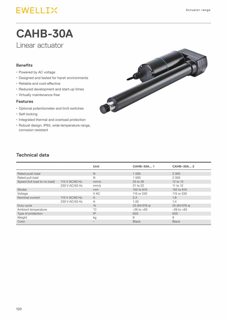
120
Actuator range
CAHB-30ALinear actuator
Benefits
•Powered by AC voltage•Designed and tested for harsh environments• Reliableandcost-effective•Reduced development and start-up times•Virtually maintenance-free
Features
•Optional potentiometer and limit switches•Self-locking• Integrated thermal and overload protection•Robust design, IP65, wide temperature range,
corrosion resistant
Technical data
Unit CAHB–30A... 1 CAHB–30A... 2
Rated push load N 1 500 2 300Rated pull load N 1 500 2 300Speed (full load to no load) 115 V AC/60 Hz mm/s 25 to 26 12 to 13
230 V AC/50 Hz mm/s 21 to 22 11 to 12Stroke mm 102 to 610 102 to 610Voltage V AC 115 or 230 115 or 230Nominal current 115 V AC/60 Hz A 2,3 1,8
230 V AC/50 Hz A 1,35 1,4Duty cycle % 25 (94/376 s) 25 (94/376 s)Ambient temperature °C –26 to +65 –26 to +65Type of protection IP 65S 65SWeight kg 9 9Color – Black Black
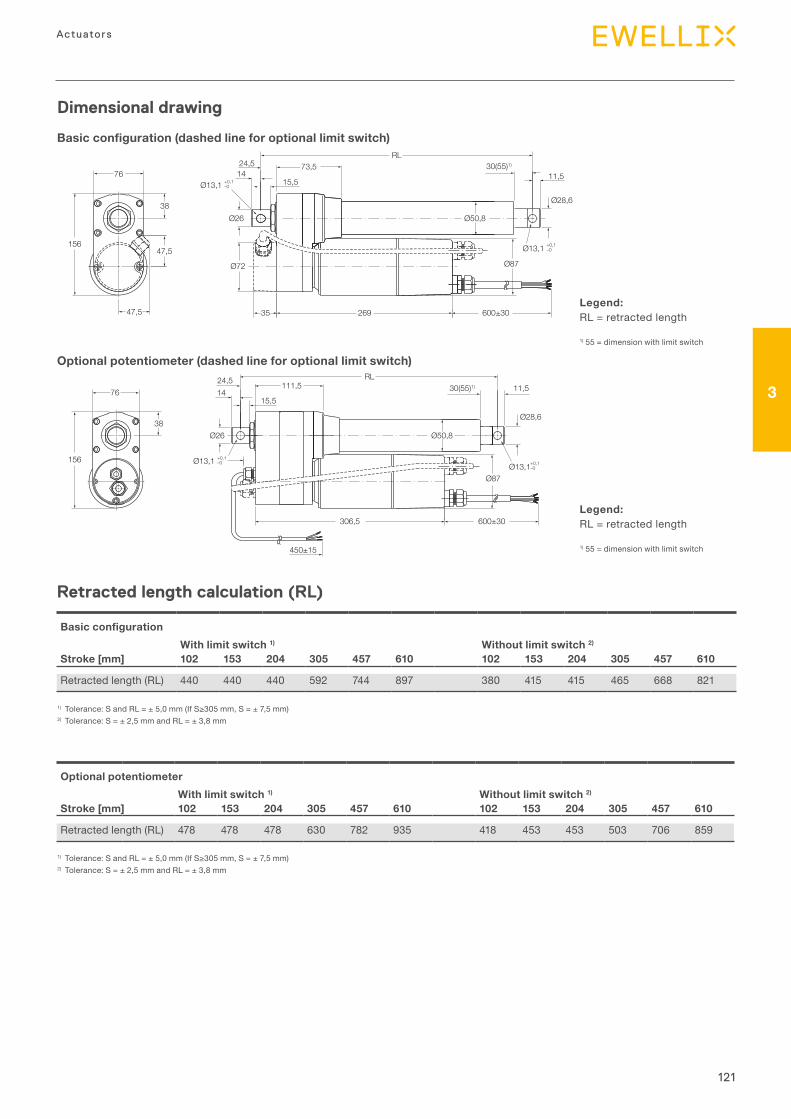
121
3
Actuators
Dimensional drawing
Basic configuration (dashed line for optional limit switch)
Optional potentiometer (dashed line for optional limit switch)
Legend:RL = retracted length
1) 55 = dimension with limit switch
Legend:RL = retracted length
1) 55 = dimension with limit switch
76
RL24,5
1473,5
15,5
600±30269
Ø87
Ø13,1 +0,1–0
Ø28,6
30(55)1)
11,5
47,5
47,5156
38Ø26
Ø72
Ø50,8
35
Ø13,1 +0–0
,1
14
Ø87Ø13,1+0,1
–0
Ø28,6
Ø26 Ø50,838
156
RL24,5 111,5 30(55)1) 11,5
450±15
76
Ø13,1 +0,1–0
306,5 600±30
15,5
White(White)Green
(Red)
Brown(Black)
Retract Extend
WhiteWhite0 Ω
RedGreenCW
BlackBrown10K Ω
POTLimit + POT:
115/230 V AC60/50 Hz
RedBlack
Extension L
NRetraction
White
NCNC
GreenGround
M
115/230 V AC60/50 Hz
RedBlack
Extension L
NRetraction
WhiteGreenGround
M
Basic configurationWith limit switch 1) Without limit switch 2)
Stroke [mm] 102 153 204 305 457 610 102 153 204 305 457 610
Retracted length (RL) 440 440 440 592 744 897 380 415 415 465 668 821
1) Tolerance:SandRL=±5,0mm(IfS≥305mm,S=±7,5mm)2) Tolerance: S = ± 2,5 mm and RL = ± 3,8 mm
Retracted length calculation (RL)
Optional potentiometerWith limit switch 1) Without limit switch 2)
Stroke [mm] 102 153 204 305 457 610 102 153 204 305 457 610
Retracted length (RL) 478 478 478 630 782 935 418 453 453 503 706 859
1) Tolerance:SandRL=±5,0mm(IfS≥305mm,S=±7,5mm)2) Tolerance: S = ± 2,5 mm and RL = ± 3,8 mm
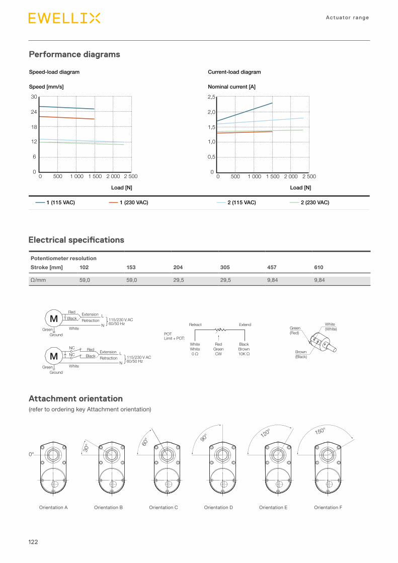
122
Actuator range
Potentiometer resolutionStroke [mm] 102 153 204 305 457 610
Ω/mm 59,0 59,0 29,5 29,5 9,84 9,84
Attachment orientation(refer to ordering key Attachment orientation)
Electrical specifications
76
RL24,5
1473,5
15,5
600±30269
Ø87
Ø13,1 +0,1–0
Ø28,6
30(55)1)
11,5
47,5
47,5156
38Ø26
Ø72
Ø50,8
35
Ø13,1 +0–0
,1
14
Ø87Ø13,1+0,1
–0
Ø28,6
Ø26 Ø50,838
156
RL24,5 111,5 30(55)1) 11,5
450±15
76
Ø13,1 +0,1–0
306,5 600±30
15,5
White(White)Green
(Red)
Brown(Black)
Retract Extend
WhiteWhite0 Ω
RedGreenCW
BlackBrown10K Ω
POTLimit + POT:
115/230 V AC60/50 Hz
RedBlack
Extension L
NRetraction
White
NCNC
GreenGround
M
115/230 V AC60/50 Hz
RedBlack
Extension L
NRetraction
WhiteGreenGround
M
Performance diagrams
Speed [mm/s]
Load [N]
Nominal current [A]
Load [N]
1 (115 VAC) 1 (230 VAC) 2 (115 VAC) 2 (230 VAC)
Speed-load diagram Current-load diagram
0
6
12
18
24
30
0 500 1 000 1 500 2 000 2 5000
0,5
1,0
1,5
2,0
2,5
0 500 1 000 1 500 2 000 2 500
0°
150°120°
90°
60°
30°
Orientation A Orientation B Orientation C Orientation D Orientation E Orientation F
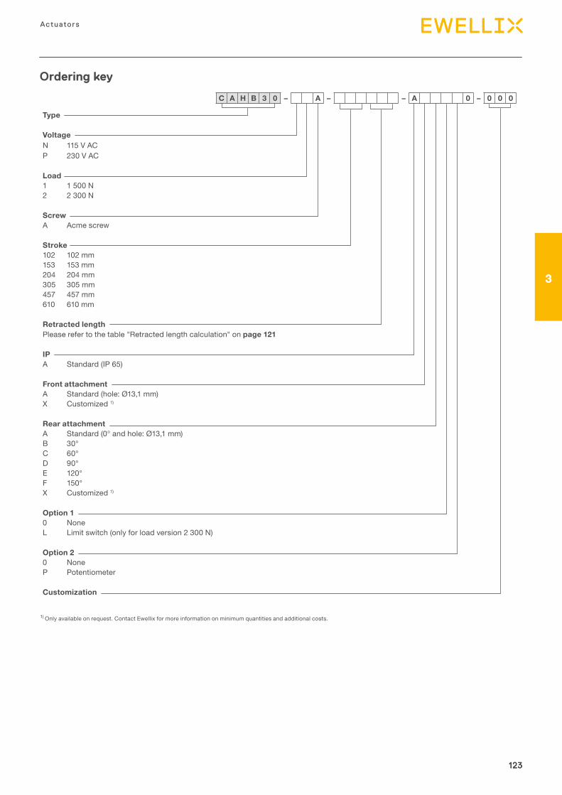
123
3
Actuators
123
3
123
Type
VoltageN 115 V AC P 230 V AC
Load1 1 500 N 2 2 300 N
ScrewA Acme screw
Stroke102 102 mm 153 153 mm 204 204 mm 305 305 mm 457 457 mm 610 610 mm
Retracted lengthPlease refer to the table "Retracted length calculation" on page 121
IPA Standard (IP 65)
Front attachmentA Standard (hole: Ø13,1 mm) X Customized 1)
Rear attachmentA Standard (0° and hole: Ø13,1 mm) B 30° C 60° D 90° E 120° F 150° X Customized 1)
Option 10 NoneL Limit switch (only for load version 2 300 N)
Option 20 None P Potentiometer
Customization
Ordering key
C A H B 3 0 – A – – A 0 – 0 0 0
1) Only available on request. Contact Ewellix for more information on minimum quantities and additional costs.
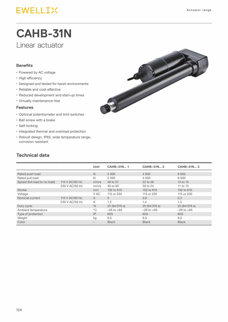
124
Actuator range
CAHB-31NLinear actuator
Benefits
•Powered by AC voltage• Highefficiency•Designed and tested for harsh environments• Reliableandcost-effective•Reduced development and start-up times•Virtually maintenance-free
Features
•Optional potentiometer and limit switches•Ball screw with a brake•Self-locking• Integrated thermal and overload protection•Robust design, IP65, wide temperature range,
corrosion resistant
Technical data
Unit CAHB–31N... 1 CAHB–31N... 2 CAHB–31N... 3
Rated push load N 2 300 4 500 6 000Rated pull load N 2 300 4 500 6 000Speed (full load to no load) 115 V AC/60 Hz mm/s 48 to 57 22 to 28 13 to 15
230 V AC/50 Hz mm/s 40 to 50 20 to 24 11 to 13Stroke mm 102 to 610 102 to 610 102 to 610Voltage V AC 115 or 230 115 or 230 115 or 230Nominal current 115 V AC/60 Hz A 3 2,6 2,2
230 V AC/50 Hz A 1,5 1,4 1,4Duty cycle % 25 (94/376 s) 25 (94/376 s) 25 (94/376 s)Ambient temperature °C –26 to +65 –26 to +65 –26 to +65Type of protection IP 65S 65S 65SWeight kg 9,5 9,5 9,5Color – Black Black Black
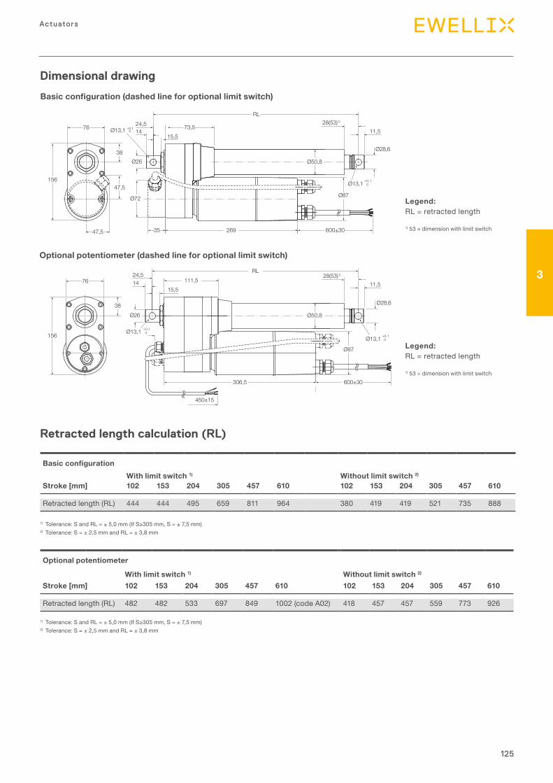
125
3
Actuators
76
76
156
47,5
38
47,5
Ø26
Ø26
Ø13,1 +0,10
35 600±30269
Ø13,1 +0, 10
Ø13,1 +0, 10
Ø87
Ø87
11,5
11,5
Ø28,6
Ø28,6
28(53)1)
RL24,5 73,514
15,5
Ø72
Ø50,8
Ø50,8
Ø13,1 +0,10
RL
450±15
306,5 600±30
156
24,5111,514
15,5
28(53)1)
White(White)Green
(Red)
Brown(Black)
Retract Extend
POTLimit + POT:
38
WhiteWhite0 Ω
RedGreenCW
BlackBrown10K Ω
115/230 V AC60/50 Hz
RedBlack
Extension L
NRetraction
White
NCNC
GreenGround
M
115/230 V AC60/50 Hz
RedBlack
Extension L
NRetraction
WhiteGreenGround
M
Dimensional drawing
Basic configuration (dashed line for optional limit switch)
Optional potentiometer (dashed line for optional limit switch)
Legend:RL = retracted length
1) 53 = dimension with limit switch
Legend:RL = retracted length
1) 53 = dimension with limit switch
Basic configurationWith limit switch 1) Without limit switch 2)
Stroke [mm] 102 153 204 305 457 610 102 153 204 305 457 610
Retracted length (RL) 444 444 495 659 811 964 380 419 419 521 735 888
Optional potentiometer
With limit switch 1) Without limit switch 2)
Stroke [mm] 102 153 204 305 457 610 102 153 204 305 457 610
Retracted length (RL) 482 482 533 697 849 1002 (code A02) 418 457 457 559 773 926
1) Tolerance:SandRL=±5,0mm(IfS≥305mm,S=±7,5mm)2) Tolerance: S = ± 2,5 mm and RL = ± 3,8 mm
1) Tolerance:SandRL=±5,0mm(IfS≥305mm,S=±7,5mm)2) Tolerance: S = ± 2,5 mm and RL = ± 3,8 mm
Retracted length calculation (RL)
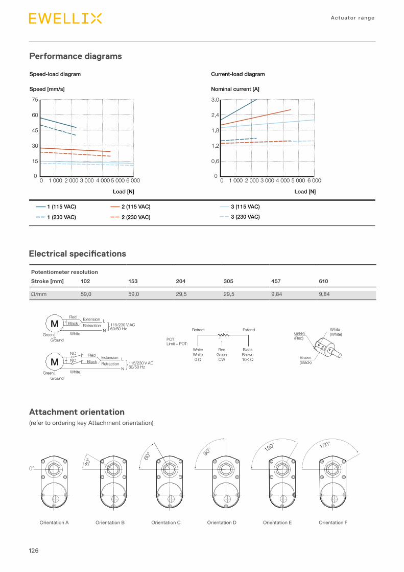
126
Actuator range
Potentiometer resolutionStroke [mm] 102 153 204 305 457 610
Ω/mm 59,0 59,0 29,5 29,5 9,84 9,84
Electrical specifications
Performance diagrams
Speed [mm/s]
Load [N]
Nominal current [A]
Load [N]
1 (115 VAC) 2 (115 VAC)
2 (230 VAC)1 (230 VAC)
3 (115 VAC)
3 (230 VAC)
Speed-load diagram Current-load diagram
0
15
30
45
60
75
0 1 000 2 000 3 000 4 000 5 000 6 000 0
0,6
1,2
1,8
2,4
3,0
0 1 000 2 000 3 000 4 000 5 000 6 000
Attachment orientation(refer to ordering key Attachment orientation)
0°
150°120°
90°
60°
30°
Orientation A Orientation B Orientation C Orientation D Orientation E Orientation F
76
RL24,5
1473,5
15,5
600±30269
Ø87
Ø13,1 +0,1–0
Ø28,6
30(55)1)
11,5
47,5
47,5156
38Ø26
Ø72
Ø50,8
35
Ø13,1 +0–0
,1
14
Ø87Ø13,1+0,1
–0
Ø28,6
Ø26 Ø50,838
156
RL24,5 111,5 30(55)1) 11,5
450±15
76
Ø13,1 +0,1–0
306,5 600±30
15,5
White(White)Green
(Red)
Brown(Black)
Retract Extend
WhiteWhite0 Ω
RedGreenCW
BlackBrown10K Ω
POTLimit + POT:
115/230 V AC60/50 Hz
RedBlack
Extension L
NRetraction
White
NCNC
GreenGround
M
115/230 V AC60/50 Hz
RedBlack
Extension L
NRetraction
WhiteGreenGround
M
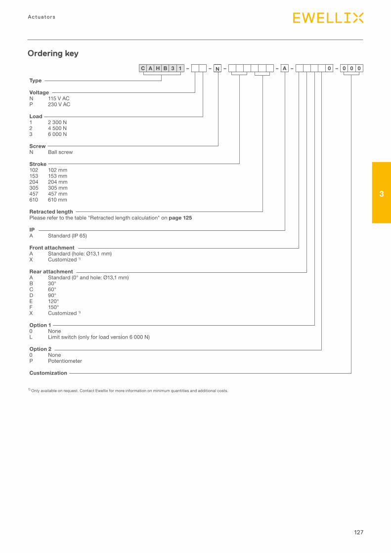
127
3
Actuators
Type
VoltageN 115 V AC P 230 V AC
Load1 2 300 N 2 4 500 N 3 6 000 N
ScrewN Ball screw
Stroke102 102 mm 153 153 mm 204 204 mm 305 305 mm 457 457 mm 610 610 mm
Retracted lengthPlease refer to the table "Retracted length calculation" on page 125
IPA Standard (IP 65)
Front attachmentA Standard (hole: Ø13,1 mm) X Customized 1)
Rear attachmentA Standard (0° and hole: Ø13,1 mm) B 30° C 60° D 90° E 120° F 150° X Customized 1)
Option 10 NoneL Limit switch (only for load version 6 000 N)
Option 20 None P Potentiometer
Customization
Ordering key
C A H B 3 1 – – N – – A – 0 – 0 0 0
1) Only available on request. Contact Ewellix for more information on minimum quantities and additional costs.
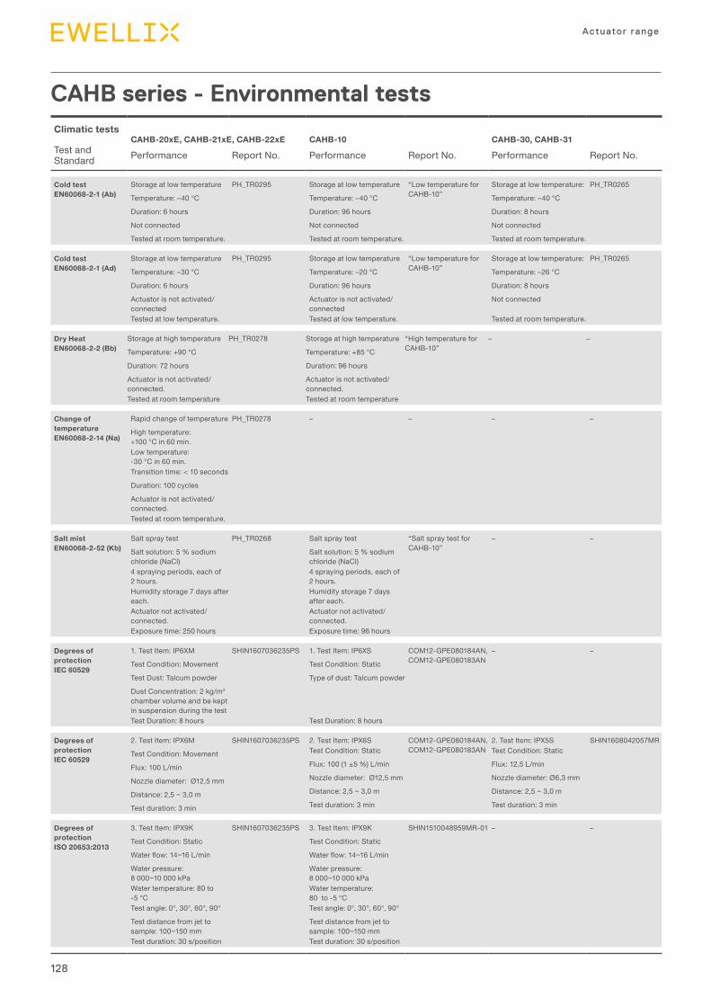
128
Actuator range
CAHB series - Environmental testsClimatic tests CAHB-20xE, CAHB-21xE, CAHB-22xE CAHB-10 CAHB-30, CAHB-31Test and Standard Performance Report No. Performance Report No. Performance Report No.
Cold test EN60068-2-1 (Ab)
Storage at low temperature PH_TR0295 Storage at low temperature “Low temperature for CAHB-10”
Storage at low temperature: PH_TR0265
Temperature: –40 °C Temperature: –40 °C Temperature: –40 °C
Duration: 6 hours Duration: 96 hours Duration: 8 hours
Not connected Not connected Not connected
Tested at room temperature. Tested at room temperature. Tested at room temperature.
Cold test EN60068-2-1 (Ad)
Storage at low temperature PH_TR0295 Storage at low temperature “Low temperature for CAHB-10”
Storage at low temperature: PH_TR0265
Temperature: –30 °C Temperature: –20 °C Temperature: –26 °C
Duration: 6 hours Duration: 96 hours Duration: 8 hours
Actuator is not activated/connected
Actuator is not activated/connected
Not connected
Tested at low temperature. Tested at low temperature. Tested at room temperature.
Dry Heat EN60068-2-2 (Bb)
Storage at high temperature PH_TR0278 Storage at high temperature “High temperature for CAHB-10”
– –
Temperature: +90 °C Temperature: +85 °C
Duration: 72 hours Duration: 96 hours
Actuator is not activated/connected.
Actuator is not activated/connected.
Tested at room temperature Tested at room temperature
Change of temperature EN60068-2-14 (Na)
Rapid change of temperature PH_TR0278 – – – –
High temperature: +100 °C in 60 min.Low temperature: -30 °C in 60 min.Transition time: < 10 seconds
Duration: 100 cycles
Actuator is not activated/connected.Tested at room temperature.
Salt mist EN60068-2-52 (Kb)
Salt spray test PH_TR0268 Salt spray test “Salt spray test for CAHB-10”
– –
Salt solution: 5 % sodium chloride (NaCl)
Salt solution: 5 % sodium chloride (NaCl)
4 spraying periods, each of 2 hours.
4 spraying periods, each of 2 hours.
Humidity storage 7 days after each.
Humidity storage 7 days after each.
Actuator not activated/connected.
Actuator not activated/connected.
Exposure time: 250 hours Exposure time: 96 hours
Degrees of protection IEC 60529
1. Test Item: IP6XM SHIN1607036235PS 1. Test Item: IP6XS COM12-GPE080184AN, COM12-GPE080183AN
– –
Test Condition: Movement Test Condition: Static
Test Dust: Talcum powder Type of dust: Talcum powder
Dust Concentration: 2 kg/m3 chamber volume and be kept in suspension during the test Test Duration: 8 hours Test Duration: 8 hours
Degrees of protection IEC 60529
2. Test Item: IPX6M SHIN1607036235PS 2. Test Item: IPX6S COM12-GPE080184AN, COM12-GPE080183AN
2. Test Item: IPX5S SHIN1608042057MR
Test Condition: Movement Test Condition: Static Test Condition: Static
Flux: 100 L/min Flux: 100 (1 ±5 %) L/min Flux: 12,5 L/min
Nozzle diameter: Ø12,5 mm Nozzle diameter: Ø12,5 mm Nozzle diameter: Ø6,3 mm
Distance: 2,5 ~ 3,0 m Distance: 2,5 ~ 3,0 m Distance: 2,5 ~ 3,0 m
Test duration: 3 min Test duration: 3 min Test duration: 3 min
Degrees of protection ISO 20653:2013
3. Test Item: IPX9K SHIN1607036235PS 3. Test Item: IPX9K SHIN1510048959MR-01 – –
Test Condition: Static Test Condition: Static
Waterflow:14~16L/min Waterflow:14~16L/min
Water pressure: 8 000~10 000 kPa
Water pressure: 8 000~10 000 kPa
Water temperature: 80 to -5 °C
Water temperature: 80 to -5 °C
Test angle: 0°, 30°, 60°, 90° Test angle: 0°, 30°, 60°, 90°
Test distance from jet to sample: 100~150 mm
Test distance from jet to sample: 100~150 mm
Test duration: 30 s/position Test duration: 30 s/position
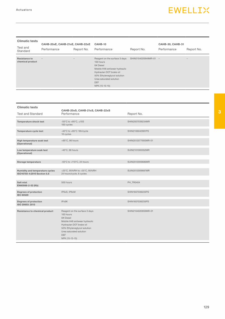
129
3
Actuators
Climatic tests CAHB-20xE, CAHB-21xE, CAHB-22xE CAHB-10 CAHB-30, CAHB-31Test and Standard Performance Report No. Performance Report No. Performance Report No.
Resistance to chemical product
– – Reagent on the surface 3 days100 hours0# DieselMobile H46 antiwear hydraulicHydraulan DOT brake oil50% Ethyleneglycol solutionUrea saturated solutionDEFNPK (15-15-15)
SHIN2104020949MR-01 – –
Climatic tests CAHB-20xS, CAHB-21xS, CAHB-22xSTest and Standard Performance Report No.
Temperature shock test -55°Cto+95°C,≤15S100 cycles
SHIN2007039234MR
Temperature cycle test -40°C to +85°C 18h/cycle10 cycles
SHIN2106042981PS
High temperature soak test (Operational)
+85°C, 96 hours SHIN2012077900MR-01
Low temperature soak test (Operational)
-40°C, 96 hours SUIN2101000352MR
Storage temperature -55°C to +110°C, 24 hours SUIN2012009686MR
Humidity and temperature cycles ISO16750-4:2010 Section 5.6
+25°C, 95%RH to +55°C, 95%RH24 hours/cycle, 6 cycles
SUIN2012009687MR
Salt mistEN60068-2-52 (Kb)
500 hours PH_TR0404
Degrees of protectionIEC 60529
IP6xS, IP6xM SHIN1607036235PS
Degrees of protectionISO 20653: 2013
IPx9K SHIN1607036235PS
Resistance to chemical product Reagent on the surface 3 days100 hours0# DieselMobile H46 antiwear hydraulicHydraulan DOT brake oil50% Ethyleneglycol solutionUrea saturated solutionDEFNPK (15-15-15)
SHIN2104020959MR-01
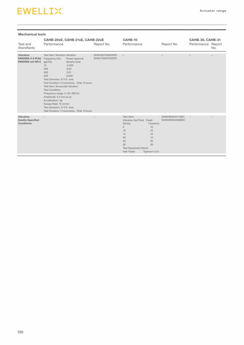
130
Actuator range
Mechanical testsCAHB-20xE, CAHB-21xE, CAHB-22xE CAHB-10 CAHB-30, CAHB-31
Test and Standfards
Performance Report No. Performance Report No. Performance Report No.
Vibration EN60068-2-6 (Fdb) EN60068-w2-6(Fc)
Test Item: Random vibration SHIN1607036235PS SHIN1702007025PS
– – – –Frequency (Hz) Power spectral (g2/Hz) density level10 0,005200 0,02300 0,01350 0,002Test Direction: X/Y/Z axisTest Duration: 2 hours/axis, Total 6 hoursTest Item: Sinusoidal vibrationTest Condition: Frequency range: 5~25~200 HzAmplitude: 3,3 mm (p-p)Acceleration: 4gSweep Rate: 10 ct/minTest Direction: X/Y/Z axisTest Duration: 2 hours/axis, Total 6 hours
Vibration Ewellix Specified Conditions
– – Test Item: SHIN1805034119SC SHIN1805032588SC
– –Vibration Set Point Dwell (Grms) Time(min)5 1010 1015 1020 1020 2020 30Test Equipment NameHalt Tester Typhoon-2,5+
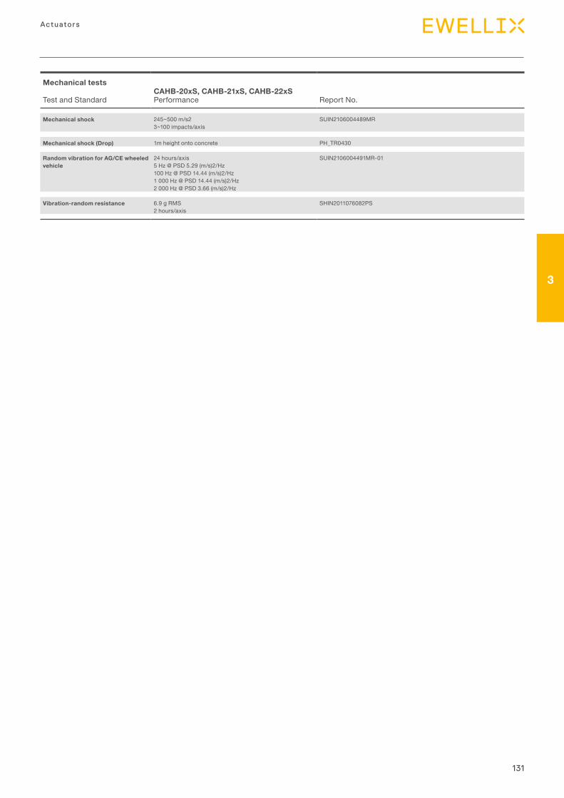
131
3
Actuators
Mechanical tests CAHB-20xS, CAHB-21xS, CAHB-22xSTest and Standard Performance Report No.
Mechanical shock 245~500 m/s23~100 impacts/axis
SUIN2106004489MR
Mechanical shock (Drop) 1m height onto concrete PH_TR0430
Random vibration for AG/CE wheeled vehicle
24 hours/axis5 Hz @ PSD 5.29 (m/s)2/Hz100 Hz @ PSD 14.44 (m/s)2/Hz1 000 Hz @ PSD 14.44 (m/s)2/Hz2 000 Hz @ PSD 3.66 (m/s)2/Hz
SUIN2106004491MR-01
Vibration-random resistance 6.9 g RMS2 hours/axis
SHIN2011076082PS
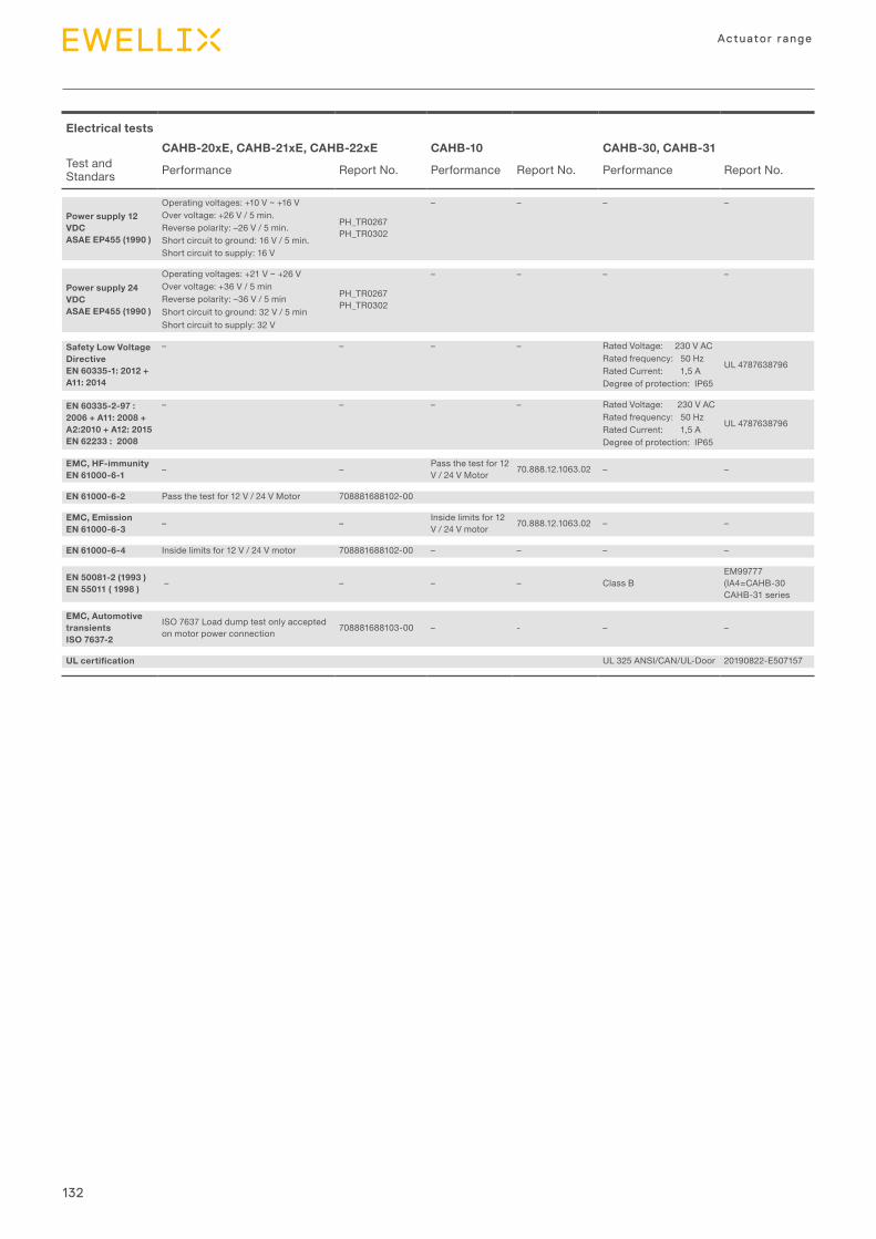
132
Actuator range
Electrical testsCAHB-20xE, CAHB-21xE, CAHB-22xE CAHB-10 CAHB-30, CAHB-31
Test and Standars Performance Report No. Performance Report No. Performance Report No.
Power supply 12 VDC ASAE EP455 (1990 )
Operating voltages: +10 V ~ +16 V
PH_TR0267 PH_TR0302
– – – –Over voltage: +26 V / 5 min.Reverse polarity: –26 V / 5 min.Short circuit to ground: 16 V / 5 min.Short circuit to supply: 16 V
Power supply 24 VDC ASAE EP455 (1990 )
Operating voltages: +21 V ~ +26 V
PH_TR0267 PH_TR0302
– – – –Over voltage: +36 V / 5 minReverse polarity: –36 V / 5 minShort circuit to ground: 32 V / 5 minShort circuit to supply: 32 V
Safety Low Voltage Directive EN 60335-1: 2012 + A11: 2014
– – – – Rated Voltage: 230 V AC
UL 4787638796Rated frequency: 50 HzRated Current: 1,5 ADegree of protection: IP65
EN 60335-2-97 : 2006 + A11: 2008 + A2:2010 + A12: 2015EN 62233 : 2008
– – – – Rated Voltage: 230 V AC
UL 4787638796Rated frequency: 50 HzRated Current: 1,5 ADegree of protection: IP65
EMC, HF-immunity EN 61000-6-1 – – Pass the test for 12
V / 24 V Motor 70.888.12.1063.02 – –
EN 61000-6-2 Pass the test for 12 V / 24 V Motor 708881688102-00
EMC, Emission EN 61000-6-3 – – Inside limits for 12
V / 24 V motor 70.888.12.1063.02 – –
EN 61000-6-4 Inside limits for 12 V / 24 V motor 708881688102-00 – – – –
EN 50081-2 (1993 ) EN 55011 ( 1998 ) – – – – Class B
EM99777 (IA4=CAHB-30 CAHB-31 series
EMC, Automotive transients ISO 7637-2
ISO 7637 Load dump test only accepted on motor power connection 708881688103-00 – - – –
UL certification UL 325 ANSI/CAN/UL-Door 20190822-E507157
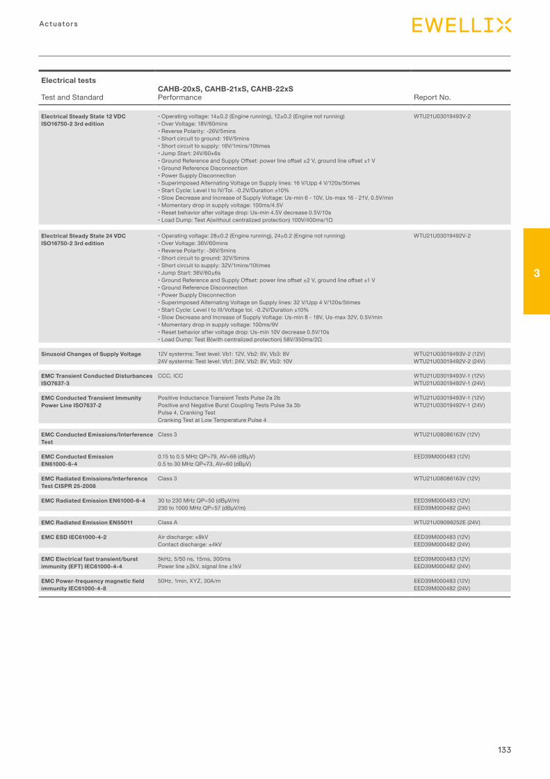
133
3
Actuators
Electrical tests CAHB-20xS, CAHB-21xS, CAHB-22xSTest and Standard Performance Report No.
Electrical Steady State 12 VDCISO16750-2 3rd edition
•Operatingvoltage:14±0.2(Enginerunning),12±0.2(Enginenotrunning)•OverVoltage:18V/60mins•ReversePolarity:-26V/5mins•Shortcircuittoground:16V/5mins•Shortcircuittosupply:16V/1mins/10times•JumpStart:24V/60±6s•GroundReferenceandSupplyOffset:powerlineoffset±2V,groundlineoffset±1V•GroundReferenceDisconnection•PowerSupplyDisconnection•SuperimposedAlternatingVoltageonSupplylines:16V/Upp4V/120s/5times•StartCycle:LevelItoIV/Tol.-0.2V/Duration±10%•SlowDecreaseandIncreaseofSupplyVoltage:Us-min6-10V,Us-max16-21V,0.5V/min•Momentarydropinsupplyvoltage:100ms/4.5V•Resetbehavioraftervoltagedrop:Us-min4.5Vdecrease0.5V/10s•LoadDump:TestA(withoutcentralizedprotection)100V/400ms/1Ω
WTU21U03019493V-2
Electrical Steady State 24 VDCISO16750-2 3rd edition
•Operatingvoltage:28±0.2(Enginerunning),24±0.2(Enginenotrunning)•OverVoltage:36V/60mins•ReversePolarity:-36V/5mins•Shortcircuittoground:32V/5mins•Shortcircuittosupply:32V/1mins/10times•JumpStart:36V/60±6s•GroundReferenceandSupplyOffset:powerlineoffset±2V,groundlineoffset±1V•GroundReferenceDisconnection•PowerSupplyDisconnection•SuperimposedAlternatingVoltageonSupplylines:32V/Upp4V/120s/5times•StartCycle:LevelItoIII/Voltagetol.-0.2V/Duration±10%•SlowDecreaseandIncreaseofSupplyVoltage:Us-min8-18V,Us-max32V,0.5V/min•Momentarydropinsupplyvoltage:100ms/9V•Resetbehavioraftervoltagedrop:Us-min10Vdecrease0.5V/10s•LoadDump:TestB(withcentralizedprotection)58V/350ms/2Ω
WTU21U03019492V-2
Sinusoid Changes of Supply Voltage 12V systerms: Test level: Vb1: 12V, Vb2: 6V, Vb3: 8V24V systerms: Test level: Vb1: 24V, Vb2: 8V, Vb3: 10V
WTU21U03019493V-2 (12V)WTU21U03019492V-2 (24V)
EMC Transient Conducted Disturbances ISO7637-3
CCC, ICC WTU21U03019493V-1 (12V)WTU21U03019492V-1 (24V)
EMC Conducted Transient Immunity Power Line ISO7637-2
Positive Inductance Transient Tests Pulse 2a 2bPositive and Negative Burst Coupling Tests Pulse 3a 3bPulse 4, Cranking TestCranking Test at Low Temperature Pulse 4
WTU21U03019493V-1 (12V)WTU21U03019492V-1 (24V)
EMC Conducted Emissions/Interference Test
Class 3 WTU21U08086163V (12V)
EMC Conducted Emission EN61000-6-4
0.15to0.5MHzQP=79,AV=66(dBμV)0.5to30MHzQP=73,AV=60(dBμV)
EED39M000483 (12V)
EMC Radiated Emissions/Interference Test CISPR 25-2008
Class 3 WTU21U08086163V (12V)
EMC Radiated Emission EN61000-6-4 30to230MHzQP=50(dBμV/m)230to1000MHzQP=57(dBμV/m)
EED39M000483 (12V)EED39M000482 (24V)
EMC Radiated Emission EN55011 Class A WTU21U09098252E (24V)
EMC ESD IEC61000-4-2 Air discharge: ±8kVContact discharge: ±4kV
EED39M000483 (12V)EED39M000482 (24V)
EMC Electrical fast transient/burst immunity (EFT) IEC61000-4-4
5kHz, 5/50 ns, 15ms, 300msPower line ±2kV, signal line ±1kV
EED39M000483 (12V)EED39M000482 (24V)
EMC Power-frequency magnetic field immunity IEC61000-4-8
50Hz, 1min, XYZ, 30A/m EED39M000483 (12V)EED39M000482 (24V)
134
Actuator range
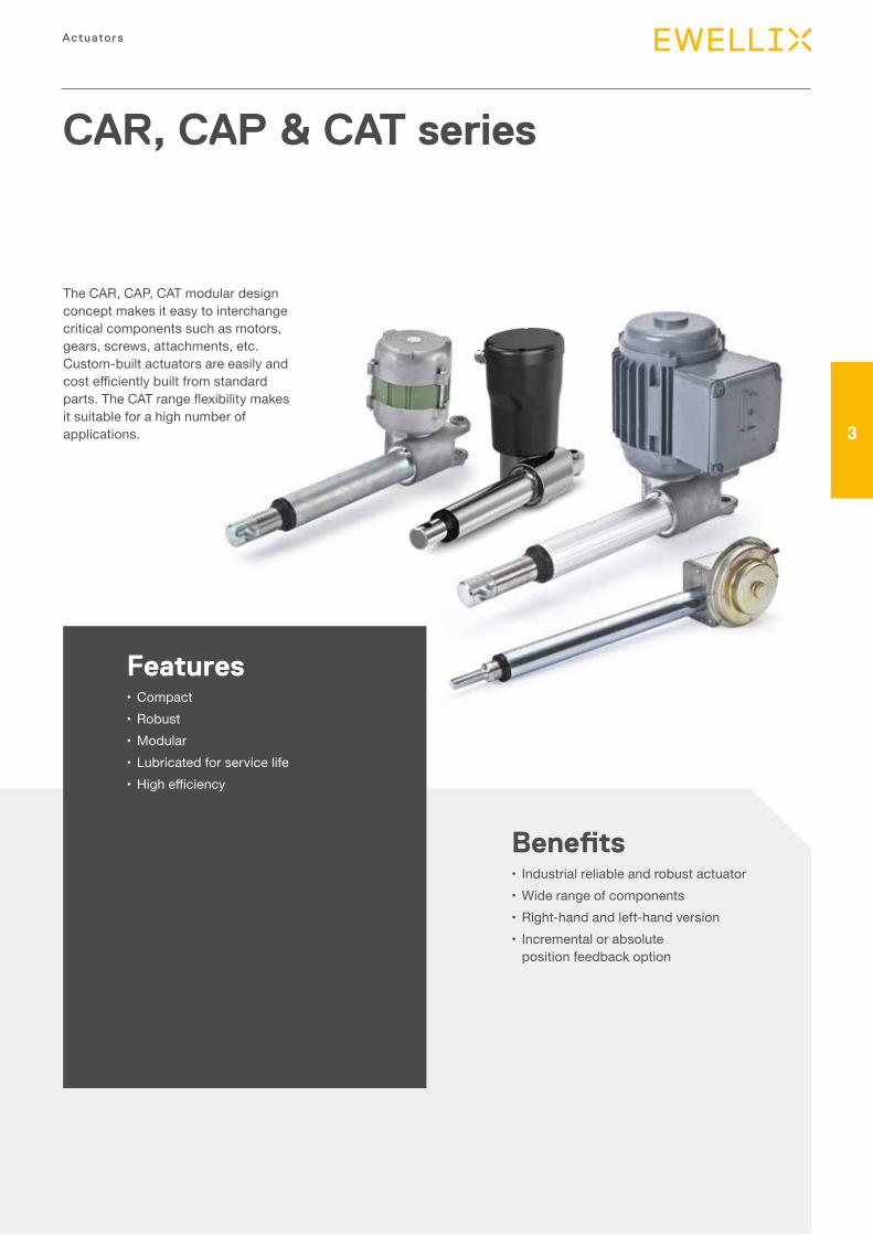
135
3
Actuators
CAR, CAP & CAT series
Features•Compact•Robust•Modular•Lubricated for service life• Highefficiency
Benefits• Industrial reliable and robust actuator•Wide range of components•Right-hand and left-hand version• Incremental or absolute
position feedback option
The CAR, CAP, CAT modular design concept makes it easy to interchange critical components such as motors, gears, screws, attachments, etc. Custom-built actuators are easily and costefficientlybuiltfromstandardparts.TheCATrangeflexibilitymakesit suitable for a high number of applications.
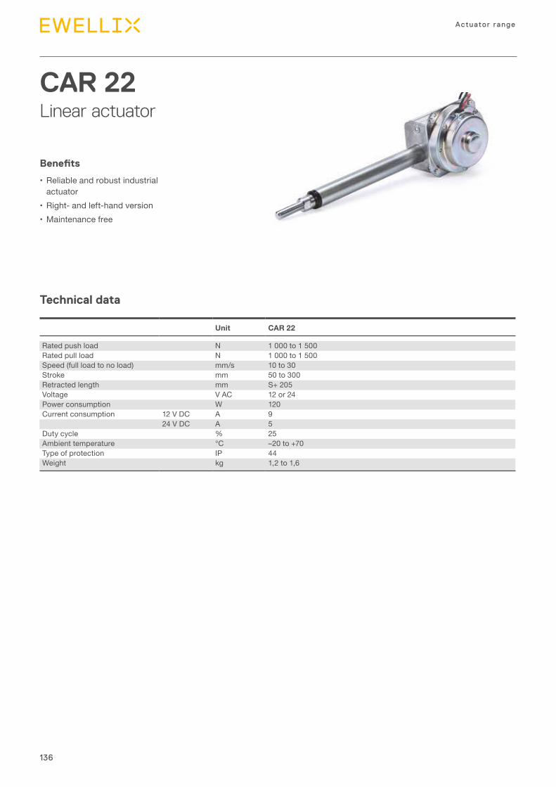
136
Actuator range
Technical data
CAR 22Linear actuator
Benefits
•Reliable and robust industrial actuator
•Right- and left-hand version•Maintenance free
Unit CAR 22
Rated push load N 1 000 to 1 500Rated pull load N 1 000 to 1 500Speed (full load to no load) mm/s 10 to 30Stroke mm 50 to 300Retracted length mm S+ 205Voltage V AC 12 or 24Power consumption W 120Current consumption 12 V DC A 9
24 V DC A 5Duty cycle % 25Ambient temperature °C –20 to +70Type of protection IP 44Weight kg 1,2 to 1,6
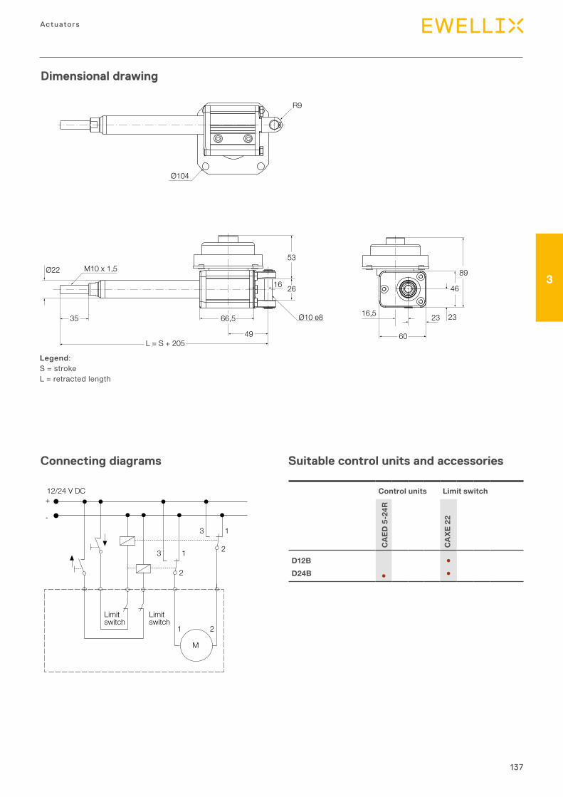
137
3
Actuators
Dimensional drawing
Connecting diagrams
Legend:S = strokeL = retracted length
Suitable control units and accessories
Ø104
M10 x 1,5Ø22
R9
35
L = S + 205
Ø10 e8
16
66,5
49
26
53
89
46
2323
60
16,5
12/24 V DC
Limitswitch
Limitswitch
M
1
2
1 2
13
3
2
+
-
Control units Limit switch
CAE
D 5
-24R
CA
XE 2
2
D12B ●D24B ● ●
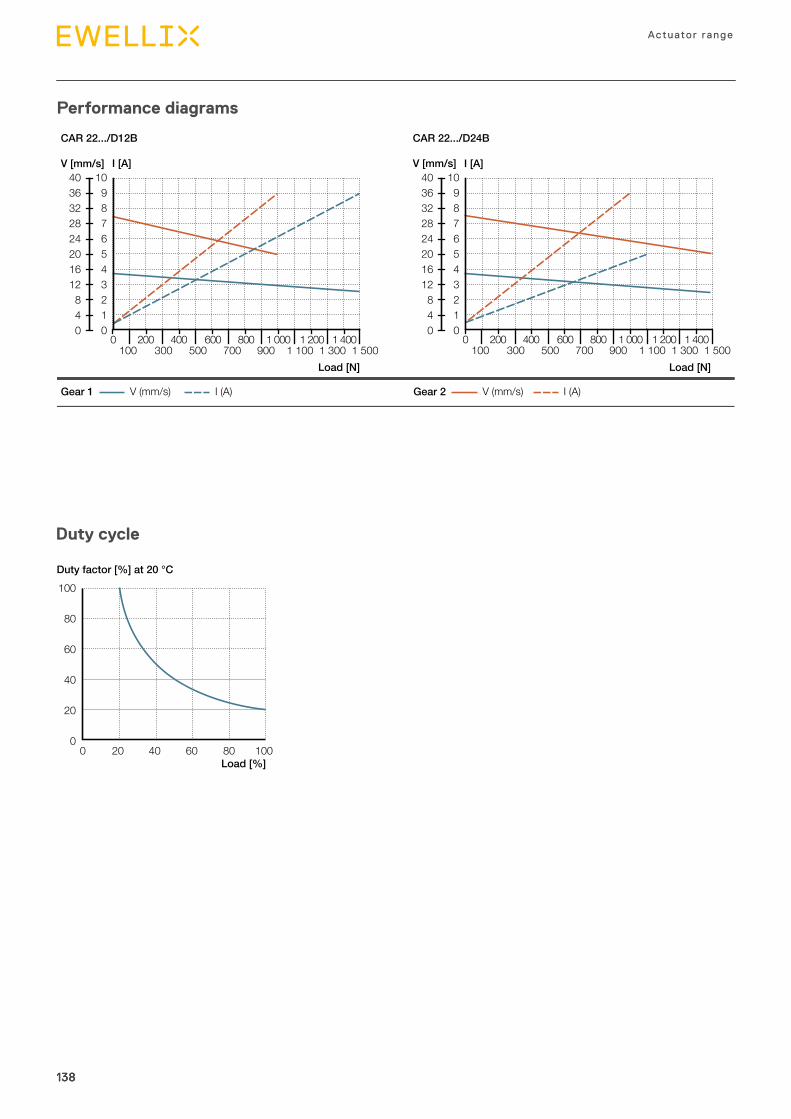
138
Actuator range
138138
Duty cycle
100
80
60
40
20
00 20 40 60 80 100
Duty factor [%] at 20 °C
Load [%]
Performance diagrams
4036322824201612840
109876543210
0 200 400 600 800 1 000 1 200 1 400 100 300 500 700 900 1 100 1 300 1 500
V (mm/s) I (A)Gear 1 V (mm/s) I (A)Gear 2
V [mm/s]4036322824201612840
109876543210
I [A] V [mm/s]
CAR 22.../D12B CAR 22.../D24B
I [A]
0 200 400 600 800 1 000 1 200 1 400 100 300 500 700 900 1 100 1 300 1 500
Load [N] Load [N]
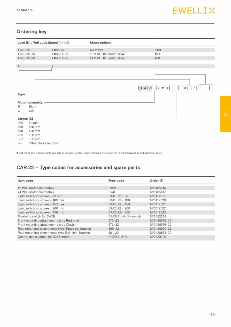
139
3
Actuators
Load [N] / Full Load Speed [mm/s] Motor options
1 500/xx 1 000/xx No motor 00001 500/15–10 1 000/30–20 12VDC,flatmotor,IP44 D12B1 500/15–10 1 000/30–20 24VDC,flatmotor,IP44 D24B
1 2
Ordering key
n Options shown in red are only available on request. Contact Ewellix for more information on minimum quantities and additional costs.
Type
Motor assemblyR RightL Left
Stroke [S]050 50 mm100 100 mm150 150 mm200 200 mm300 300 mm--- Other stroke lengths
C A R 2 2 X X /
CAR 22 – Type codes for accessories and spare parts
Item code Type code Order N°
12VDCmotor(flatmotor) D12B M/040551624VDCmotor(flatmotor) D24B M/0405517Limit switch for stroke = 50 mm CAXE 22 × 50 M/0412019Limit switch for stroke = 100 mm CAXE 22 × 100 M/0412020Limit switch for stroke = 150 mm CAXE 22 × 150 M/0412021Limit switch for stroke = 200 mm CAXE 22 × 200 M/0412022Limit switch for stroke = 300 mm CAXE 22 × 300 M/0412023Proximity switch for CAXE CAXE Proximity switch M/0432369Front mounting attachments type Rod–end 575–22 M/0430575–22Front mounting attachments type Clevis 576–22 M/0430576–22Rear mounting attachments type Single ear bracket 580–22 M/0430580–22Rear mounting attachments type Ball–joint bracket 581–22 M/0430581–22Control unit (suitable for D24B motor) CAED 5–24R M/0420209
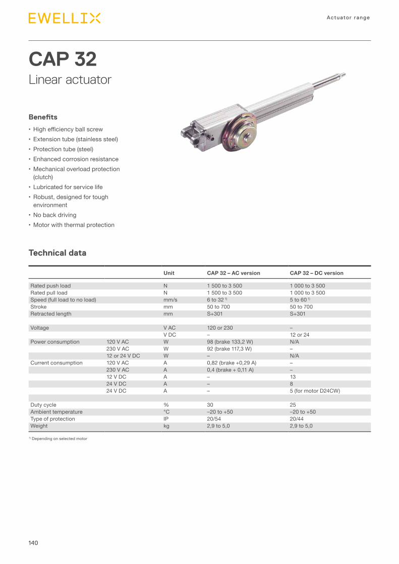
140
Actuator range
Technical data
CAP 32Linear actuator
Benefits
• Highefficiencyballscrew•Extension tube (stainless steel)•Protection tube (steel)•Enhanced corrosion resistance•Mechanical overload protection
(clutch)•Lubricated for service life•Robust, designed for tough
environment•No back driving•Motor with thermal protection
Unit CAP 32 – AC version CAP 32 – DC version
Rated push load N 1 500 to 3 500 1 000 to 3 500Rated pull load N 1 500 to 3 500 1 000 to 3 500Speed (full load to no load) mm/s 6 to 32 1) 5 to 60 1)
Stroke mm 50 to 700 50 to 700Retracted length mm S+301 S+301
Voltage V AC 120 or 230 –V DC – 12 or 24
Power consumption 120 V AC W 98 (brake 133,2 W) N/A230 V AC W 92 (brake 117,3 W) –12 or 24 V DC W – N/A
Current consumption 120 V AC A 0,82 (brake +0,29 A) –230 V AC A 0,4 (brake + 0,11 A) –12 V DC A – 1324 V DC A – 824 V DC A – 5 (for motor D24CW)
Duty cycle % 30 25Ambient temperature °C –20 to +50 –20 to +50Type of protection IP 20/54 20/44Weight kg 2,9 to 5,0 2,9 to 5,0
1) Depending on selected motor
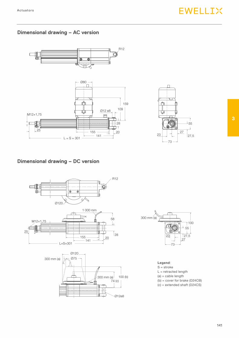
141
3
Actuators
Dimensional drawing – AC version
R12
L = S + 301141
Ø80
15525
28
109159
55
27,527
23
73
Ø12 e8
20
M12×1,75
R12
2820
58
25
L=S+301
155141
M12×1,75
1 000 mm
300 mm (a)
Ø120Ø75
Ø12e8
74 (c)100 (b)
300 mm (a)
Ø120
55
2723
73
100300 mm (a)
27,5
Dimensional drawing – DC version
Legend:S = strokeL = retracted length(a) = cable length(b) = cover for brake (D24CB)(c) = extended shaft (D24CS)
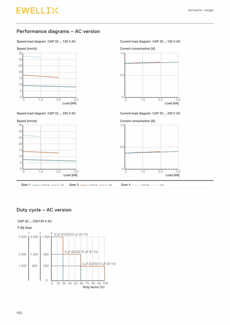
142
Actuator range
Performance diagrams – AC version
Current-load diagram CAP 32 ... 120 V AC
Current-load diagram CAP 32 ... 230 V AC
Speed-load diagram CAP 32 ... 120 V AC
Speed-load diagram CAP 32 ... 230 V AC
0
5
10
15
20
25
30
35
0 1,5 2,5 3,5Load [kN]
Speed [mm/s]
0
5
10
15
20
25
30
35Speed [mm/s]
0
0,5
1,0Current consumption [A]
0
0,5
1,0Current consumption [A]
0 1,5 2,5 3,5Load [kN]
0 1,5 2,5 3,5Load [kN]
0 1,5 2,5 3,5Load [kN]
V (mm/s) I (A)Gear 1 V (mm/s) I (A)Gear 2 V (mm/s) I (A)Gear 4
Duty cycle – AC version
CAP 32 ... 230/120 V AC
0
1 5002 5003 5001 2 4 6 µF (E220)/25 µF (E110)
4 µF (E220)/16 µF (E110)
3 µF (E220)/12 µF (E110)
1 5002 500 900
5009001 500
0 403010 50 60 70 80 90 100Duty factor (%)
F (N) Gear
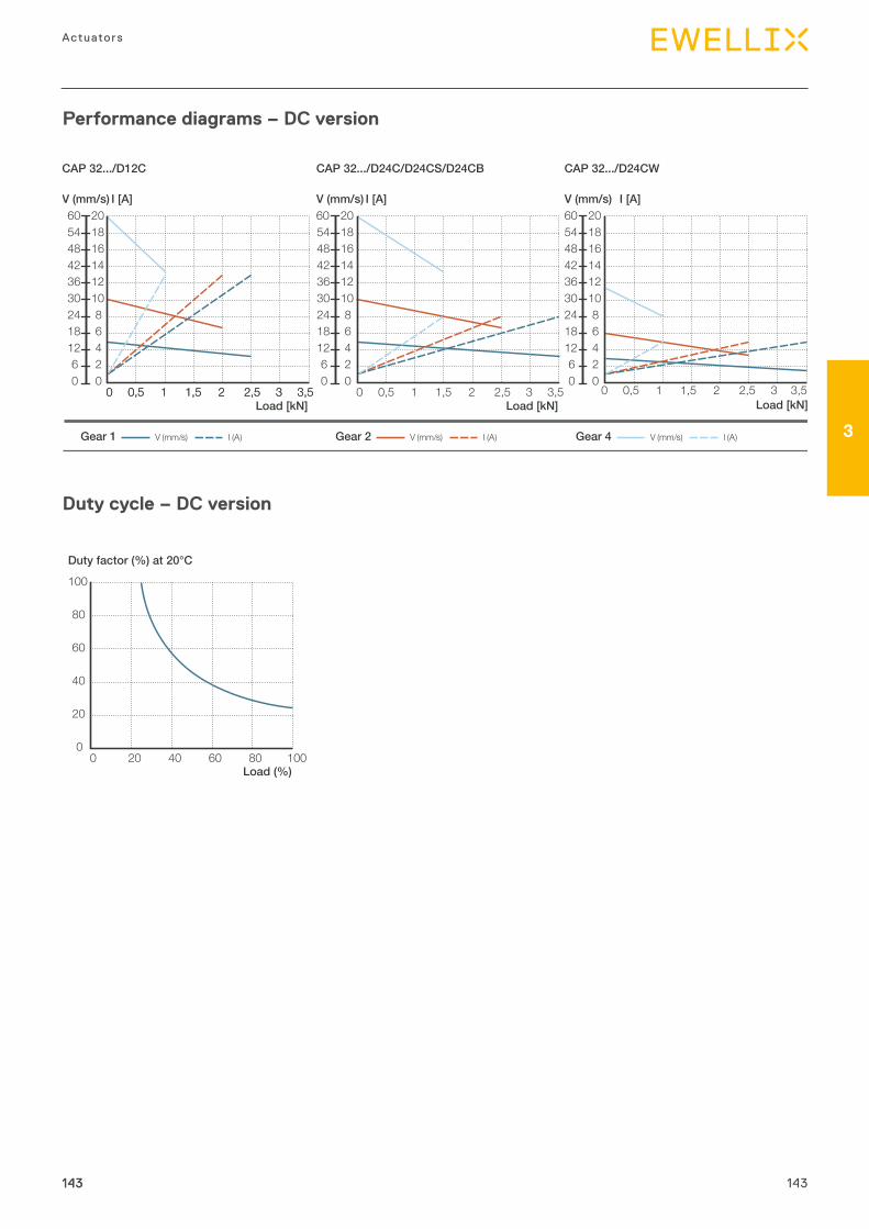
143
3
Actuators
Performance diagrams – DC version
Duty cycle – DC version
0
20
40
60
80
100
0 20 40 60 80 100
Duty factor (%) at 20°C
Load (%)
143143
CAP 32.../D24CWCAP 32.../D12C CAP 32.../D24C/D24CS/D24CB
02468
101214161820
06
121824303642485460
0 0,5 1 1,5 2 2,5 3,5302468
101214161820
06
121824303642485460
V (mm/s) I [A]
Load [kN]
V (mm/s) I [A]
Load [kN]0 0,5 1 1,5 2 2,5 3,53 0 0,5 1 1,5 2 2,5 3,53
V (mm/s) I [A]
Load [kN]0 0,5 1 1,5 2 2,5 3,53
02468
101214161820
06
121824303642485460
V (mm/s) I (A)Gear 1 V (mm/s) I (A)Gear 2 V (mm/s) I (A)Gear 4
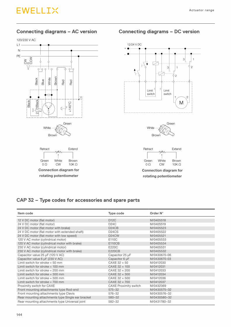
144
Actuator range
Connecting diagrams – AC version Connecting diagrams – DC version
L1
N
PE
CW 0 CCW
120/230 V ACBl
ack
Blac
k
1Blac
k
Blue
Whi
te
Red
Red
Brow
n
+140
°C
2
Retract Extend
Green0 Ω
WhiteCW
Brown10K Ω
Brown
WhiteGreen
Retract Extend
Green0 Ω
WhiteCW
Brown10K Ω
Brown
WhiteGreen
Connection diagram forrotating potentiometer
Connection diagram forrotating potentiometer
M
2
13 2
13
12/24 V DC
Limitswitch
Limitswitch
1 2
+
-
CAP 32 – Type codes for accessories and spare parts
Item code Type code Order N°
12VDCmotor(flatmotor) D12C M/040551824VDCmotor(flatmotor) D24C M/040551924VDCmotor(flatmotorwithbrake) D24CB M/040552324VDCmotor(flatmotorwithextendedshaft) D24CS M/040552224VDCmotor(flatmotorwithlowspeed) D24CW M/0405521120 V AC motor (cylindrical motor) E110C M/0405533120 V AC motor (cylindrical motor with brake) E110CB M/0405534230 V AC motor (cylindrical motor) E220C M/0405531230 V AC motor (cylindrical motor with brake) E220CB M/0405532Capacitorvalue25μF(120VAC) Capacitor25μF M/0430670-06Capacitorvalue6μF(230VAC) Capacitor6μF M/0430670-03Limit switch for stroke = 50 mm CAXE 32 × 50 M/0412030Limit switch for stroke = 100 mm CAXE 32 × 100 M/0412031Limit switch for stroke = 200 mm CAXE 32 × 200 M/0412033Limit switch for stroke = 300 mm CAXE 32 × 300 M/0412034Limit switch for stroke = 500 mm CAXE 32 × 500 M/0412036Limit switch for stroke = 700 mm CAXE 32 × 700 M/0412037Proximity switch for CAXE CAXE Proximity switch M/0432369Front mounting attachments type Rod-end 575–32 M/0430575–32Front mounting attachments type Clevis 576–32 M/0430576–32Rear mounting attachments type Single ear bracket 580–32 M/0430580–32Rear mounting attachments type Universal joint 582–32 M/0431780–32
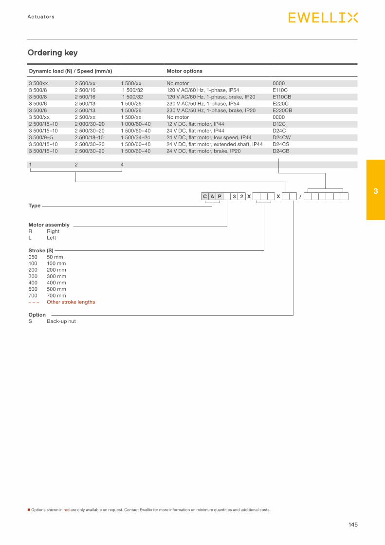
145
3
Actuators
Dynamic load (N) / Speed (mm/s) Motor options
3 500xx 2 500/xx 1 500/xx No motor 00003 500/8 2 500/16 1 500/32 120 V AC/60 Hz, 1-phase, IP54 E110C3 500/8 2 500/16 1 500/32 120 V AC/60 Hz, 1-phase, brake, IP20 E110CB3 500/6 2 500/13 1 500/26 230 V AC/50 Hz, 1-phase, IP54 E220C3 500/6 2 500/13 1 500/26 230 V AC/50 Hz, 1-phase, brake, IP20 E220CB3 500/xx 2 500/xx 1 500/xx No motor 00002 500/15–10 2 000/30–20 1 000/60–40 12VDC,flatmotor,IP44 D12C3 500/15–10 2 500/30–20 1 500/60–40 24VDC,flatmotor,IP44 D24C3 500/9–5 2 500/18–10 1 500/34–24 24VDC,flatmotor,lowspeed,IP44 D24CW3 500/15–10 2 500/30–20 1 500/60–40 24VDC,flatmotor,extendedshaft,IP44 D24CS3 500/15–10 2 500/30–20 1 500/60–40 24VDC,flatmotor,brake,IP20 D24CB
1 2 4
Ordering key
n Options shown in red are only available on request. Contact Ewellix for more information on minimum quantities and additional costs.
Type
Motor assemblyR RightL Left
Stroke (S)050 50 mm100 100 mm200 200 mm300 300 mm400 400 mm500 500 mm700 700 mm– – – Other stroke lengths
OptionS Back-up nut
C A P 3 2 X X /
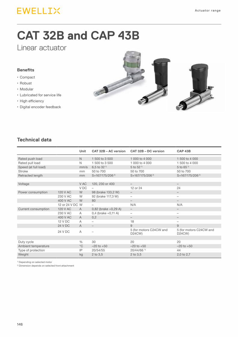
146
Actuator range
Technical data
CAT 32B and CAP 43BLinear actuator
Benefits
•Compact•Robust•Modular•Lubricated for service life• Highefficiency•Digital encoder feedback
1) Depending on selected motor2) Dimension depends on selected front attachment
Unit CAT 32B – AC version CAT 32B – DC version CAP 43B
Rated push load N 1 500 to 3 500 1 000 to 4 000 1 500 to 4 000Rated pull load N 1 500 to 3 500 1 000 to 4 000 1 500 to 4 000Speed (at full load) mm/s 6,5 to 32 1) 5 to 52 1) 5 to 65 1)
Stroke mm 50 to 700 50 to 700 50 to 700Retracted length mm S+167/175/206 2) S+167/175/206 2) S+167/175/206 2)
Voltage V AC 120, 230 or 400 – –V DC – 12 or 24 24
Power consumption 120 V AC W 98 (brake 133,2 W) – –230 V AC W 92 (brake 117,3 W) – –400 V AC W 80 – –12 or 24 V DC W – N/A N/A
Current consumption 120 V AC A 0,82 (brake +0,29 A) – –230 V AC A 0,4 (brake +0,11 A) – –400 V AC A 0,2 – –12 V DC A – 18 –24 V DC A – 9 9
24 V DC A – 5 (for motors C24CW and D24CW)
5 (for motors C24CW and D24CW)
Duty cycle % 30 20 20Ambient temperature °C –20 to +50 –20 to +50 –20 to +50Type of protection IP 20/54/55 20/44/66 1) 44Weight kg 2 to 3,5 2 to 3,5 2,0 to 2,7
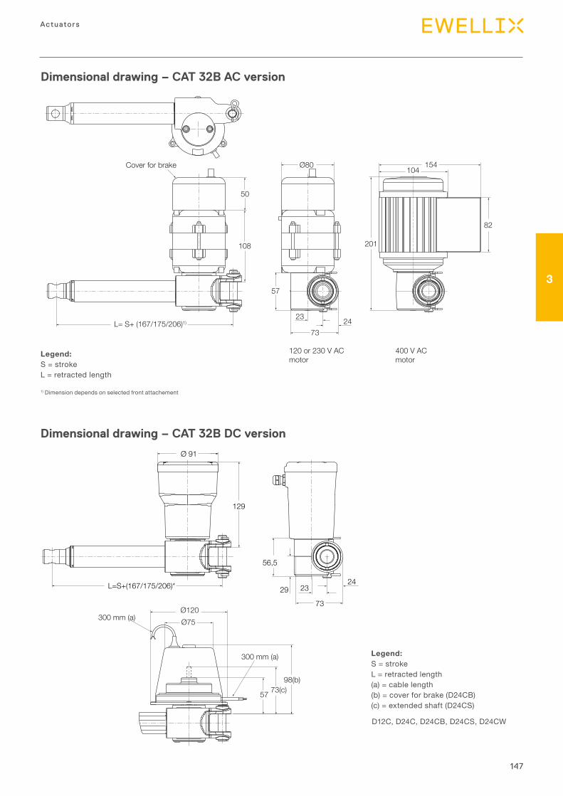
147
3
Actuators
Dimensional drawing – CAT 32B AC version
23 2473
Ø80 154104Cover for brake
L= S+ (167/175/206)1)
108
57
50
201
82
120 or 230 V ACmotor
400 V ACmotor
Legend:S = strokeL = retracted length
1) Dimension depends on selected front attachement
Dimensional drawing – CAT 32B DC version
Legend:S = strokeL = retracted length(a) = cable length(b) = cover for brake (D24CB)(c) = extended shaft (D24CS)
D12C, D24C, D24CB, D24CS, D24CW
300 mm (a)Ø120Ø75
98(b)73(c)57
300 mm (a)
Ø 91
L=S+(167/175/206)*
129
73
2329
56,5
24
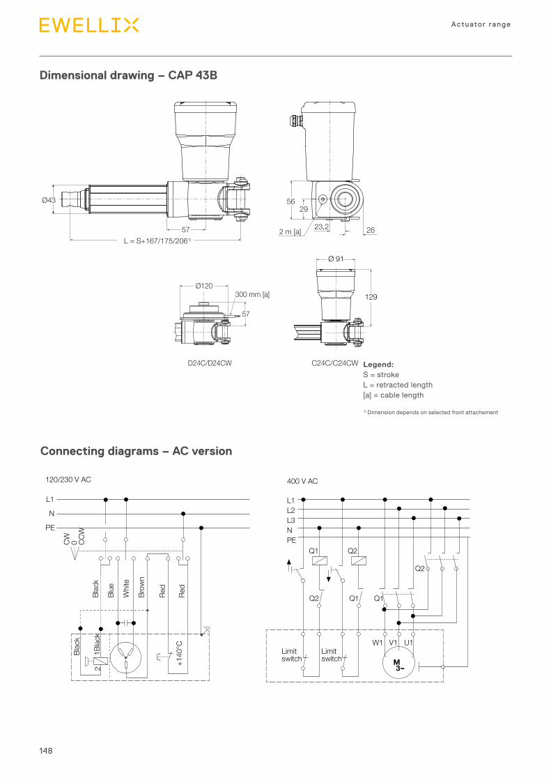
148
Actuator range
Dimensional drawing – CAP 43B
Legend:S = strokeL = retracted length[a] = cable length
1) Dimension depends on selected front attachement
Connecting diagrams – AC version
L1
N
PE
CW 0 CCW
Blac
k
Blue
Whi
te
Brow
n
Blac
k
1Blac
k
+140
°C
Q1 Q2
Q2 Q1 Q1
Q2
2
Red
Red
120/230 V AC
3∼M
L1L2L3N
Limitswitch
Limitswitch
W1 V1 U1
PE
400 V AC
Ø43
D24C/D24CW C24C/C24CW
57L = S+167/175/2061)
2 m [a] 23,2 26
Ø120
57
300 mm [a]
5629
Ø 91
129
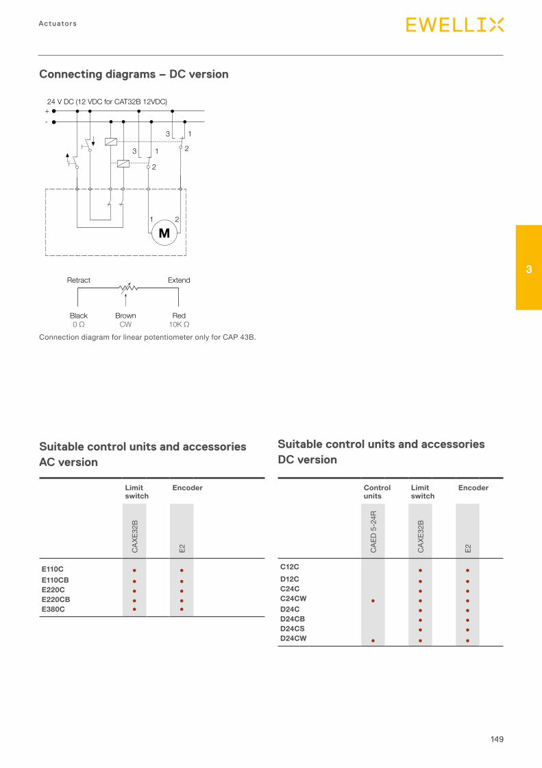
149
3
Actuators
Connecting diagrams – DC version
Connection diagram for linear potentiometer only for CAP 43B.
24 V DC (12 VDC for CAT32B 12VDC)
3 1
213
2
21
M
Retract
Black0 Ω
BrownCW
Red10K Ω
Extend
+-
Suitable control units and accessories AC version
Suitable control units and accessories DC version
Limit switch
Encoder
CAX
E32B
E2
E110C ● ●E110CB ● ●E220C ● ●E220CB ● ●E380C ● ●
Control units
Limit switch
Encoder
CAE
D 5-
24R
CAX
E32B
E2
C12C ● ●D12C ● ●C24C ● ●C24CW ● ● ●D24C ● ●D24CB ● ●D24CS ● ●D24CW ● ● ●
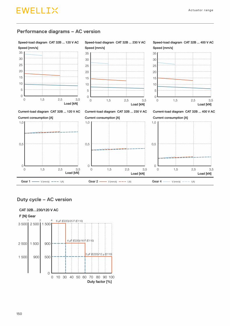
150
Actuator range
Performance diagrams – AC version
Duty cycle – AC version
2 500 1 500 900
5009001 500
0 10 30 40 50 60 70 80 90 1000
1 5002 5003 5001 2 4
Duty factor [%]
F [N] GearCAT 32B…230/120 V AC
6 µF (E220)/25 F (E110)
4 µF (E220)/16 F (E110)
3 µF (E220)/12 µ (E110)
0 1,5 2,5 3,5
35
30
25
20
15
10
5
0
Load [kN]
Load [kN]
Speed [mm/s] Speed [mm/s] Speed [mm/s]
V (mm/s) I (A)Gear 1 V (mm/s) I (A)Gear 2 V (mm/s) I (A)Gear 4
35
30
25
20
15
10
5
00 1,5 2,5 3,5
Load [kN]
35
30
25
20
15
10
5
00 1,5 2,5 3,5
Load [kN]
Load [kN] Load [kN]
Speed-load diagram CAT 32B ... 120 V AC Speed-load diagram CAT 32B ... 230 V AC Speed-load diagram CAT 32B ... 400 V AC
Current-load diagram CAT 32B ... 120 V AC Current-load diagram CAT 32B ... 230 V AC Current-load diagram CAT 32B ... 400 V AC
1,0
0,5
0
Current consumption [A] Current consumption [A] Current consumption [A]
0 1,5 2,5 3,5
1,0
0,5
00 1,5 2,5 3,5
1,0
0,5
00 1,5 2,5 3,5
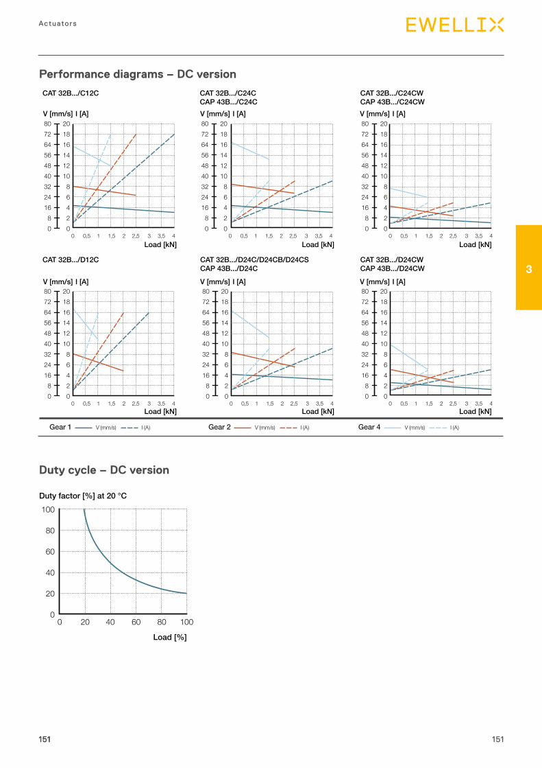
151
3
Actuators
Performance diagrams – DC version
Duty cycle – DC version
Load [%]
Duty factor [%] at 20 °C100
80
60
40
20
00 20 40 60 80 100
151151
Load [kN]
V (mm/s) I (A)Gear 1 V (mm/s) I (A)Gear 2 V (mm/s) I (A)Gear 4
Load [kN] Load [kN]
Load [kN] Load [kN] Load [kN]
CAT 32B.../C12C CAT 32B.../C24CCAP 43B.../C24C
CAT 32B.../C24CWCAP 43B.../C24CW
CAT 32B.../D12C CAT 32B.../D24C/D24CB/D24CSCAP 43B.../D24C
CAT 32B.../D24CWCAP 43B.../D24CW
80726456484032241680
20181614121086420
0 0,5 1 1,5 2 2,5 3 3,5 4
80726456484032241680
20181614121086420
0 0,5 1 1,5 2 2,5 3 3,5 4
0 0,5 1 1,5 2 2,5 3 3,5 4
80726456484032241680
20181614121086420
80726456484032241680
20181614121086420
0 0,5 1 1,5 2 2,5 3 3,5 4
80726456484032241680
20181614121086420
0 0,5 1 1,5 2 2,5 3 3,5 4
V [mm/s] I [A] V [mm/s] I [A] V [mm/s] I [A]
V [mm/s] I [A] V [mm/s] I [A] V [mm/s] I [A]
80726456484032241680
20181614121086420
0 0,5 1 1,5 2 2,5 3 3,5 4
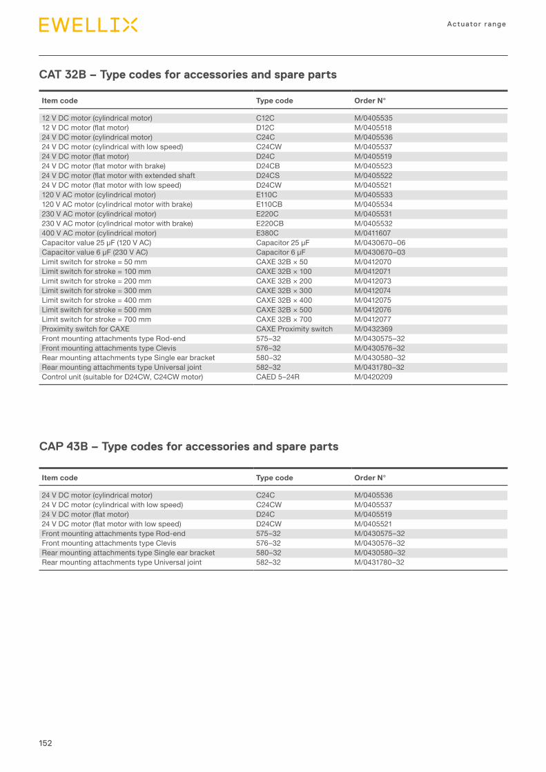
152
Actuator range
CAT 32B – Type codes for accessories and spare parts
Item code Type code Order N°
24 V DC motor (cylindrical motor) C24C M/040553624 V DC motor (cylindrical with low speed) C24CW M/040553724VDCmotor(flatmotor) D24C M/040551924VDCmotor(flatmotorwithlowspeed) D24CW M/0405521Front mounting attachments type Rod-end 575–32 M/0430575–32Front mounting attachments type Clevis 576–32 M/0430576–32Rear mounting attachments type Single ear bracket 580–32 M/0430580–32Rear mounting attachments type Universal joint 582–32 M/0431780–32
CAP 43B – Type codes for accessories and spare parts
Item code Type code Order N°
12 V DC motor (cylindrical motor) C12C M/040553512VDCmotor(flatmotor) D12C M/040551824 V DC motor (cylindrical motor) C24C M/040553624 V DC motor (cylindrical with low speed) C24CW M/040553724VDCmotor(flatmotor) D24C M/040551924VDCmotor(flatmotorwithbrake) D24CB M/040552324VDCmotor(flatmotorwithextendedshaft D24CS M/040552224VDCmotor(flatmotorwithlowspeed) D24CW M/0405521120 V AC motor (cylindrical motor) E110C M/0405533120 V AC motor (cylindrical motor with brake) E110CB M/0405534230 V AC motor (cylindrical motor) E220C M/0405531230 V AC motor (cylindrical motor with brake) E220CB M/0405532400 V AC motor (cylindrical motor) E380C M/0411607Capacitorvalue25μF(120VAC) Capacitor25μF M/0430670–06Capacitorvalue6μF(230VAC) Capacitor6μF M/0430670–03Limit switch for stroke = 50 mm CAXE 32B × 50 M/0412070Limit switch for stroke = 100 mm CAXE 32B × 100 M/0412071Limit switch for stroke = 200 mm CAXE 32B × 200 M/0412073Limit switch for stroke = 300 mm CAXE 32B × 300 M/0412074Limit switch for stroke = 400 mm CAXE 32B × 400 M/0412075Limit switch for stroke = 500 mm CAXE 32B × 500 M/0412076Limit switch for stroke = 700 mm CAXE 32B × 700 M/0412077Proximity switch for CAXE CAXE Proximity switch M/0432369Front mounting attachments type Rod-end 575–32 M/0430575–32Front mounting attachments type Clevis 576–32 M/0430576–32Rear mounting attachments type Single ear bracket 580–32 M/0430580–32Rear mounting attachments type Universal joint 582–32 M/0431780–32Control unit (suitable for D24CW, C24CW motor) CAED 5–24R M/0420209
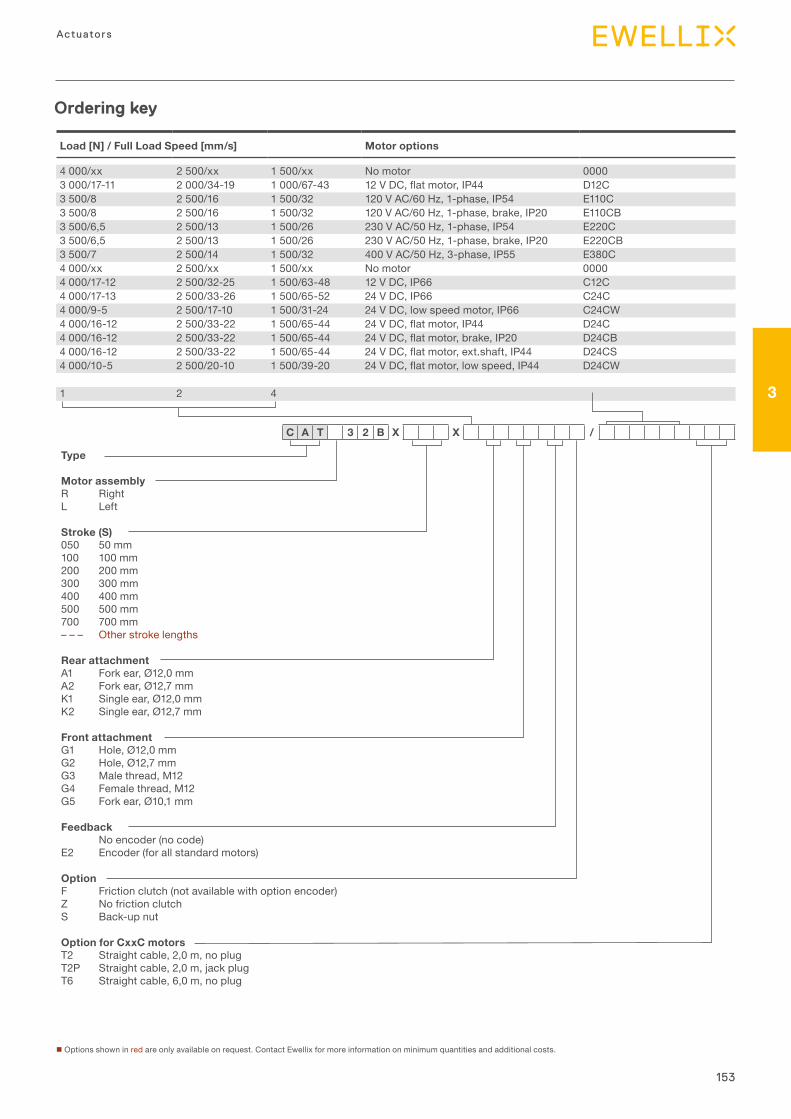
153
3
Actuators
Ordering key
n Options shown in red are only available on request. Contact Ewellix for more information on minimum quantities and additional costs.
Type
Motor assemblyR RightL Left
Stroke (S)050 50 mm100 100 mm200 200 mm300 300 mm400 400 mm500 500 mm700 700 mm– – – Other stroke lengths
Rear attachmentA1 Fork ear, Ø12,0 mmA2 Fork ear, Ø12,7 mmK1 Single ear, Ø12,0 mmK2 Single ear, Ø12,7 mm
Front attachmentG1 Hole, Ø12,0 mmG2 Hole, Ø12,7 mmG3 Male thread, M12G4 Female thread, M12G5 Fork ear, Ø10,1 mm
FeedbackNo encoder (no code)
E2 Encoder (for all standard motors)
OptionF Friction clutch (not available with option encoder)Z No friction clutchS Back-up nut
Option for CxxC motorsT2 Straight cable, 2,0 m, no plug T2P Straight cable, 2,0 m, jack plugT6 Straight cable, 6,0 m, no plug
C A T 3 2 B X X /
Load [N] / Full Load Speed [mm/s] Motor options
4 000/xx 2 500/xx 1 500/xx No motor 00003 000/17-11 2 000/34-19 1 000/67-43 12VDC,flatmotor,IP44 D12C3 500/8 2 500/16 1 500/32 120 V AC/60 Hz, 1-phase, IP54 E110C3 500/8 2 500/16 1 500/32 120 V AC/60 Hz, 1-phase, brake, IP20 E110CB3 500/6,5 2 500/13 1 500/26 230 V AC/50 Hz, 1-phase, IP54 E220C3 500/6,5 2 500/13 1 500/26 230 V AC/50 Hz, 1-phase, brake, IP20 E220CB3 500/7 2 500/14 1 500/32 400 V AC/50 Hz, 3-phase, IP55 E380C4 000/xx 2 500/xx 1 500/xx No motor 00004 000/17-12 2 500/32-25 1 500/63-48 12 V DC, IP66 C12C4 000/17-13 2 500/33-26 1 500/65-52 24 V DC, IP66 C24C4 000/9-5 2 500/17-10 1 500/31-24 24 V DC, low speed motor, IP66 C24CW4 000/16-12 2 500/33-22 1 500/65-44 24VDC,flatmotor,IP44 D24C4 000/16-12 2 500/33-22 1 500/65-44 24VDC,flatmotor,brake,IP20 D24CB4 000/16-12 2 500/33-22 1 500/65-44 24VDC,flatmotor,ext.shaft,IP44 D24CS4 000/10-5 2 500/20-10 1 500/39-20 24VDC,flatmotor,lowspeed,IP44 D24CW
1 2 4
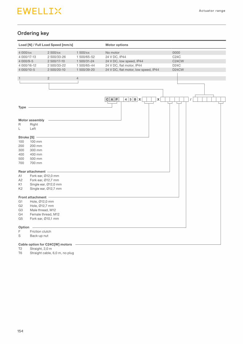
154
Actuator range
Load [N] / Full Load Speed [mm/s] Motor options
4 000/xx 2 500/xx 1 500/xx No motor 00004 000/17-13 2 500/33-26 1 500/65-52 24 V DC, IP44 C24C4 000/9-5 2 500/17-10 1 500/31-24 24 V DC, low speed, IP44 C24CW4 000/16-12 2 500/33-22 1 500/65-44 24VDC,flatmotor,IP44 D24C4 000/10-5 2 500/20-10 1 500/39-20 24VDC,flatmotor,lowspeed,IP44 D24CW
1 2 4
Ordering key
Type
Motor assemblyR RightL Left
Stroke [S]100 100 mm200 200 mm300 300 mm400 400 mm500 500 mm700 700 mm
Rear attachmentA1 Fork ear, Ø12,0 mmA2 Fork ear, Ø12,7 mmK1 Single ear, Ø12,0 mmK2 Single ear, Ø12,7 mm
Front attachmentG1 Hole, Ø12,0 mmG2 Hole, Ø12,7 mmG3 Male thread, M12G4 Female thread, M12G5 Fork ear, Ø10,1 mm
OptionF Friction clutchS Back-up nut
Cable option for C24C[W] motorsT2 Straight, 2,0 mT6 Straight cable, 6,0 m, no plug
C A P 4 3 B X X /

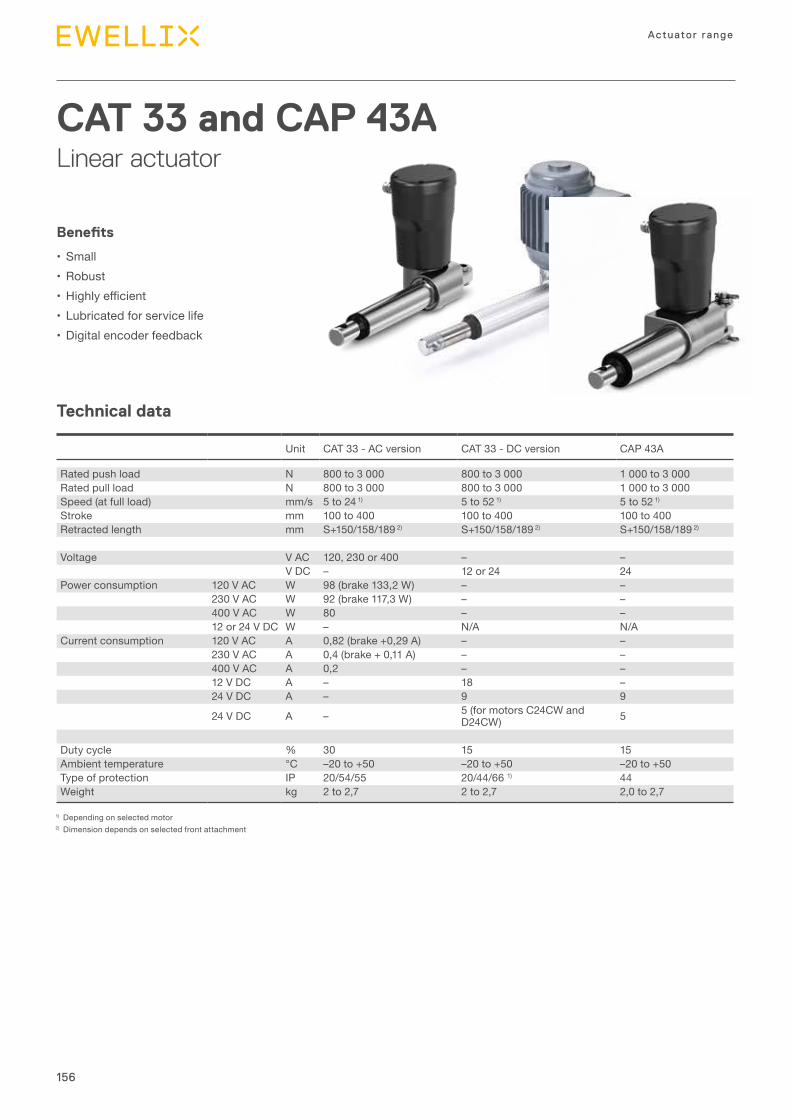
156
Actuator range
Technical data
CAT 33 and CAP 43ALinear actuator
Benefits
•Small•Robust• Highlyefficient•Lubricated for service life•Digital encoder feedback
1) Depending on selected motor2) Dimension depends on selected front attachment
Unit CAT 33 - AC version CAT 33 - DC version CAP 43A
Rated push load N 800 to 3 000 800 to 3 000 1 000 to 3 000Rated pull load N 800 to 3 000 800 to 3 000 1 000 to 3 000Speed (at full load) mm/s 5 to 24 1) 5 to 52 1) 5 to 52 1)
Stroke mm 100 to 400 100 to 400 100 to 400Retracted length mm S+150/158/189 2) S+150/158/189 2) S+150/158/189 2)
Voltage V AC 120, 230 or 400 – –V DC – 12 or 24 24
Power consumption 120 V AC W 98 (brake 133,2 W) – –230 V AC W 92 (brake 117,3 W) – –400 V AC W 80 – –12 or 24 V DC W – N/A N/A
Current consumption 120 V AC A 0,82 (brake +0,29 A) – –230 V AC A 0,4 (brake + 0,11 A) – –400 V AC A 0,2 – –12 V DC A – 18 –24 V DC A – 9 9
24 V DC A – 5 (for motors C24CW and D24CW) 5
Duty cycle % 30 15 15Ambient temperature °C –20 to +50 –20 to +50 –20 to +50Type of protection IP 20/54/55 20/44/66 1) 44Weight kg 2 to 2,7 2 to 2,7 2,0 to 2,7
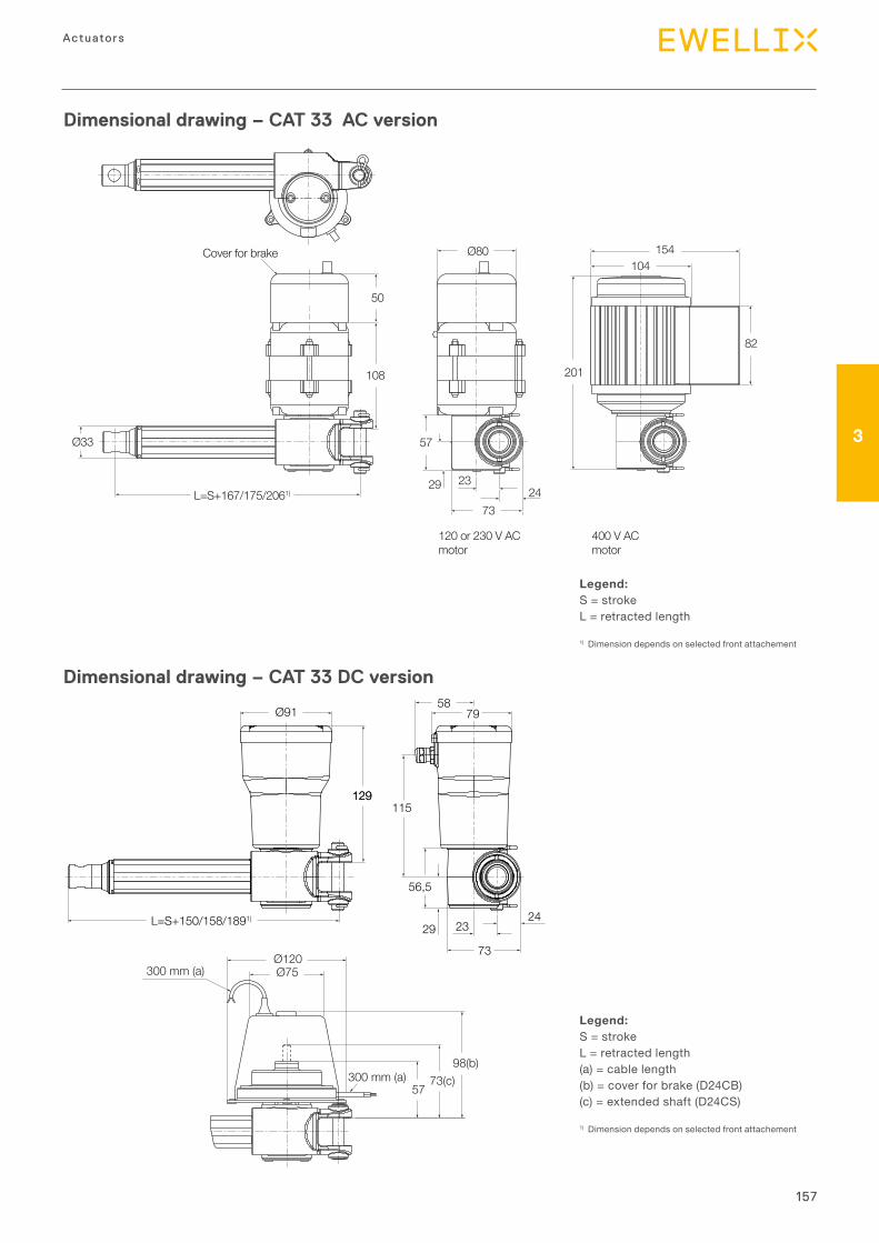
157
3
Actuators
Dimensional drawing – CAT 33 AC version
Legend:S = strokeL = retracted length
1) Dimension depends on selected front attachement
Dimensional drawing – CAT 33 DC version
Legend:S = strokeL = retracted length(a) = cable length(b) = cover for brake (D24CB)(c) = extended shaft (D24CS)
1) Dimension depends on selected front attachement
L=S+167/175/2061)
Cover for brake
Ø33
Ø80
50
108 201
104
82
154
57
29
73
2324
120 or 230 V ACmotor
400 V ACmotor
300 mm (a)
300 mm (a)57
73(c)98(b)
Ø120Ø75
Ø91
L=S+150/158/1891)
129115
73
7958
2329
56,5
24
129
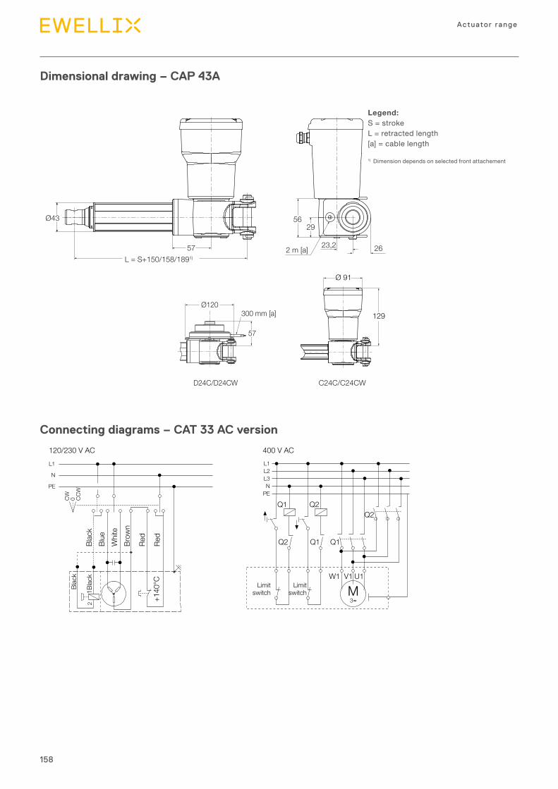
158
Actuator range
Dimensional drawing – CAP 43A
Legend:S = strokeL = retracted length[a] = cable length
1) Dimension depends on selected front attachement
Connecting diagrams – CAT 33 AC version
L1 L1L2L3N
PE
Q1 Q2
Q2
Limitswitch
Limitswitch
Q1 Q1
W1
MV1
3∼
U1
Q2
N
PE
120/230 V AC
CW 0 CCW
400 V AC
Blac
kBl
ueW
hite
Brow
n
Red
Red
Blac
k
1Blac
k
+140
°C
2
Ø43
57L = S+150/158/1891)
2 m [a] 23,2 26
5629
D24C/D24CW C24C/C24CW
Ø120
57
300 mm [a]
Ø 91
129
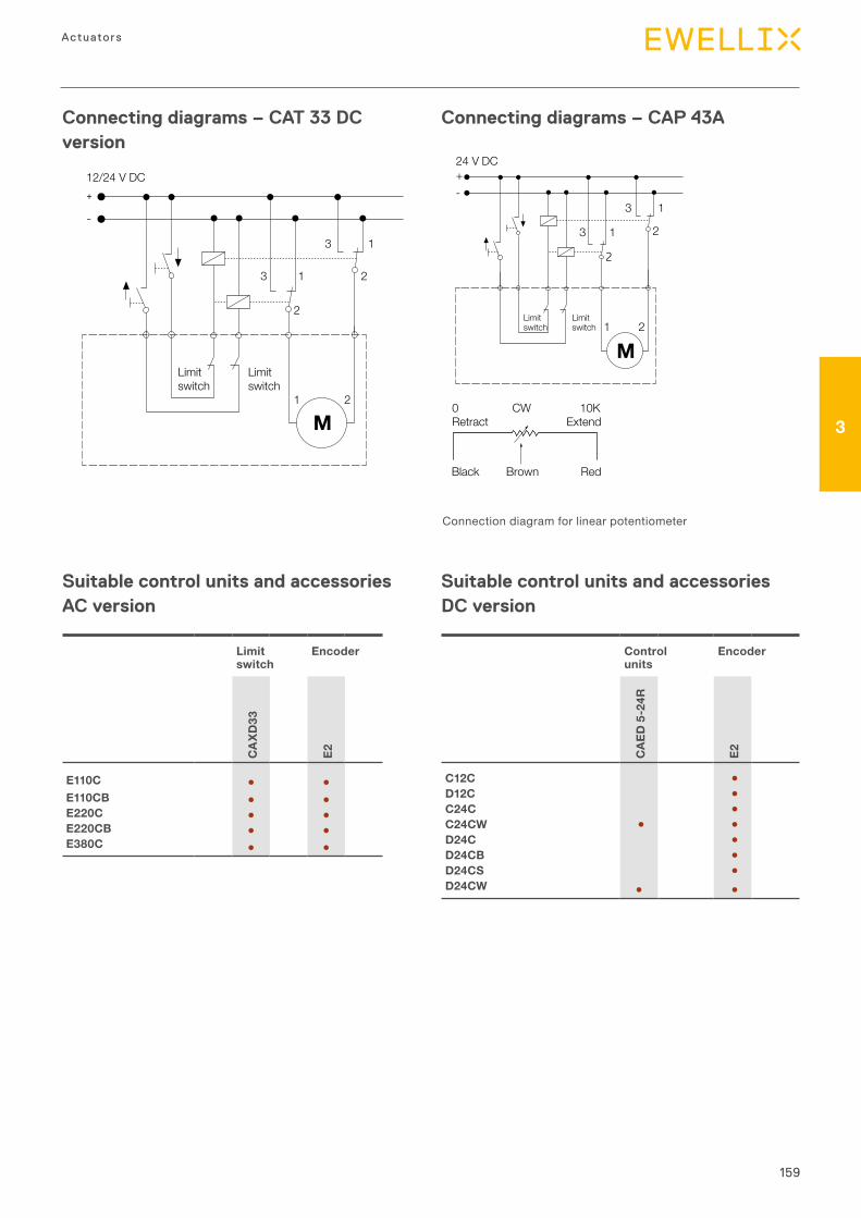
159
3
Actuators
Connecting diagrams – CAT 33 DC version
Connecting diagrams – CAP 43A
Connection diagram for linear potentiometer
12/24 V DC
Limitswitch
Limitswitch
M
3 1
21
1 2
2
3
+
-
Suitable control units and accessories AC version
Suitable control units and accessories DC version
Limitswitch
Limitswitch
+-
24 V DC
M
2
2
1
1
3 2
13
Connection diagram for linear potentiometer
0 CW 10KRetract Extend
Black Brown Red
Limit switch
Encoder
CA
XD33
E2
E110C ● ●E110CB ● ●E220C ● ●E220CB ● ●E380C ● ●
Control units
EncoderC
AED
5-2
4R
E2
C12C ●D12C ●C24C ●C24CW ● ●D24C ●D24CB ●D24CS ●D24CW ● ●
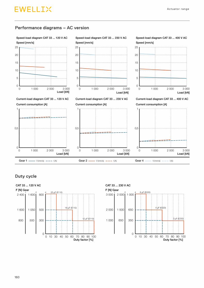
160
Actuator range
Performance diagrams – AC version
Duty cycle
800
0 10 30 40 50 60 70 80 90 100
1 6002 4001 2 4 25 µF (E110)
16 µF (E110)
12 µF (E110)
1 0501 600 500
300
0
500800
Duty factor [%]
F [N] GearCAT 33 ... 120 V AC
1 000
0 10 30 40 50 60 70 80 90 100
2 0003 0001 2 4
1 5002 000 650
350
0
6501 000
6 µF (E220)
4 µF (E220)
3 µF (E220)
Duty factor [%]
F [N] GearCAT 33 ... 230 V AC
Load [kN]
Speed [mm/s] Speed [mm/s] Speed [mm/s]
V (mm/s) I (A)Gear 1 V (mm/s) I (A)Gear 2 V (mm/s) I (A)Gear 4
Load [kN] Load [kN]
Load [kN]
Speed-load diagram CAT 33 ... 120 V AC Speed-load diagram CAT 33 ... 230 V AC Speed-load diagram CAT 33 ... 400 V AC
Current-load diagram CAT 33 ... 120 V AC Current-load diagram CAT 33 ... 230 V AC Current-load diagram CAT 33 ... 400 V AC
Current consumption [A] Current consumption [A] Current consumption [A]
25
20
15
10
5
00 1 000 2 000 3 000
25
20
15
10
5
00 1 000 2 000 3 000
25
20
15
10
5
00 1 000 2 000 3 000
1
0,5
00 1 000 2 000 3 000
Load [kN]
1
0,5
00 1 000 2 000 3 000
Load [kN]
1
0,5
00 1 000 2 000 3 000
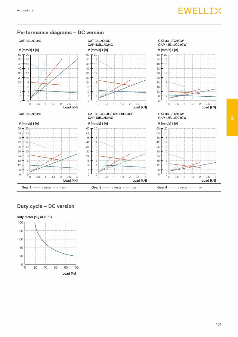
161
3
Actuators
Performance diagrams – DC version
Duty cycle – DC version
Load [%]
Duty factor [%] at 20 °C100
80
60
40
20
00 20 40 60 80 100
Load [kN]
V (mm/s) I (A)Gear 1 V (mm/s) I (A)Gear 2 V (mm/s) I (A)Gear 4
Load [kN] Load [kN]
Load [kN] Load [kN] Load [kN]
CAT 33.../C12C CAT 33.../C24CCAP 43B.../C24C
CAT 33.../C24CWCAP 43B.../C24CW
CAT 33.../D12C CAT 33.../D24C/D24CB/D24CSCAP 43B.../D24C
CAT 33.../D24CWCAP 43B.../D24CW
V [mm/s] I [A] V [mm/s] I [A] V [mm/s] I [A]
0 0,5 1 1,5 2 2,5 3
60544842363024181260
20181614121086420
60544842363024181260
20181614121086420
0 0,5 1 1,5 2 2,5 3
60544842363024181260
20181614121086420
0 0,5 1 1,5 2 2,5 3
60544842363024181260
20181614121086420
0 0,5 1 1,5 2 2,5 3
60544842363024181260
20181614121086420
0 0,5 1 1,5 2 2,5 3
60544842363024181260
20181614121086420
0 0,5 1 1,5 2 2,5 3
V [mm/s] I [A] V [mm/s] I [A] V [mm/s] I [A]
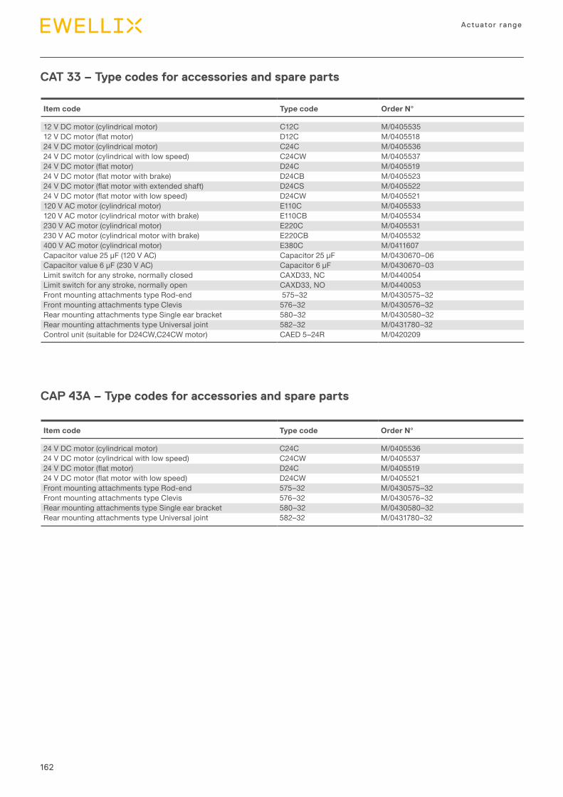
162
Actuator range
CAT 33 – Type codes for accessories and spare parts
CAP 43A – Type codes for accessories and spare parts
Item code Type code Order N°
24 V DC motor (cylindrical motor) C24C M/040553624 V DC motor (cylindrical with low speed) C24CW M/040553724VDCmotor(flatmotor) D24C M/040551924VDCmotor(flatmotorwithlowspeed) D24CW M/0405521Front mounting attachments type Rod-end 575–32 M/0430575–32Front mounting attachments type Clevis 576–32 M/0430576–32Rear mounting attachments type Single ear bracket 580–32 M/0430580–32Rear mounting attachments type Universal joint 582–32 M/0431780–32
Item code Type code Order N°
12 V DC motor (cylindrical motor) C12C M/040553512VDCmotor(flatmotor) D12C M/040551824 V DC motor (cylindrical motor) C24C M/040553624 V DC motor (cylindrical with low speed) C24CW M/040553724VDCmotor(flatmotor) D24C M/040551924VDCmotor(flatmotorwithbrake) D24CB M/040552324VDCmotor(flatmotorwithextendedshaft) D24CS M/040552224VDCmotor(flatmotorwithlowspeed) D24CW M/0405521120 V AC motor (cylindrical motor) E110C M/0405533120 V AC motor (cylindrical motor with brake) E110CB M/0405534230 V AC motor (cylindrical motor) E220C M/0405531230 V AC motor (cylindrical motor with brake) E220CB M/0405532400 V AC motor (cylindrical motor) E380C M/0411607Capacitorvalue25μF(120VAC) Capacitor25μF M/0430670–06Capacitorvalue6μF(230VAC) Capacitor6μF M/0430670–03Limit switch for any stroke, normally closed CAXD33, NC M/0440054Limit switch for any stroke, normally open CAXD33, NO M/0440053Front mounting attachments type Rod-end 575–32 M/0430575–32Front mounting attachments type Clevis 576–32 M/0430576–32Rear mounting attachments type Single ear bracket 580–32 M/0430580–32Rear mounting attachments type Universal joint 582–32 M/0431780–32Control unit (suitable for D24CW,C24CW motor) CAED 5–24R M/0420209
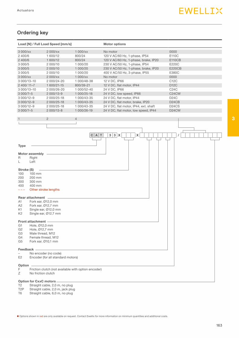
163
3
Actuators
Load [N] / Full Load Speed [mm/s] Motor options
3 000/xx 2 000/xx 1 000/xx No motor 00002 400/6 1 600/12 800/24 120 V AC/60 Hz, 1-phase, IP54 E110C2 400/6 1 600/12 800/24 120 V AC/60 Hz, 1-phase, brake, IP20 E110CB3 000/5 2 000/10 1 000/20 230 V AC/50 Hz, 1-phase, IP54 E220C3 000/5 2 000/10 1 000/20 230 V AC/50 Hz, 1-phase, brake, IP20 E220CB3 000/5 2 000/10 1 000/20 400 V AC/50 Hz, 3-phase, IP55 E380C3 000/xx 2 000/xx 1 000/xx No motor 00003 000/13–10 2 000/24-20 1 000/48-38 12 V DC, IP66 C12C2 400/ 11–7 1 600/21-15 800/39-21 12VDC,flatmotor,IP44 D12C3 000/13–10 2 000/26-20 1 000/52-40 24 V DC, IP66 C24C3 000/7–5 2 000/13-9 1 000/25-18 24 V DC, low speed, IP66 C24CW3 000/12–9 2 000/25-18 1 000/43-35 24VDC,flatmotor,IP44 D24C3 000/12–9 2 000/25-18 1 000/43-35 24VDC,flatmotor,brake,IP20 D24CB3 000/12–9 2 000/25-18 1 000/43-35 24VDC,flatmotor,IP44,ext.shaft D24CS3 000/7–5 2 000/13-8 1 000/26-19 24VDC,flatmotor,lowspeed,IP44 D24CW
1 2 4
Ordering key
n Options shown in red are only available on request. Contact Ewellix for more information on minimum quantities and additional costs.
Type
Motor assemblyR RightL Left
Stroke (S)100 100 mm200 200 mm300 300 mm400 400 mm– – – Other stroke lengths
Rear attachmentA1 Fork ear, Ø12,0 mmA2 Fork ear, Ø12,7 mmK1 Single ear, Ø12,0 mmK2 Single ear, Ø12,7 mm
Front attachmentG1 Hole, Ø12,0 mmG2 Hole, Ø12,7 mmG3 Male thread, M12G4 Female thread, M12G5 Fork ear, Ø10,1 mm
Feedback– No encoder (no code)E2 Encoder (for all standard motors)
OptionF Friction clutch (not available with option encoder)Z No friction clutch
Option for CxxC motorsT2 Straight cable, 2,0 m, no plug T2P Straight cable, 2,0 m, jack plugT6 Straight cable, 6,0 m, no plug
C A T 3 3 X X /
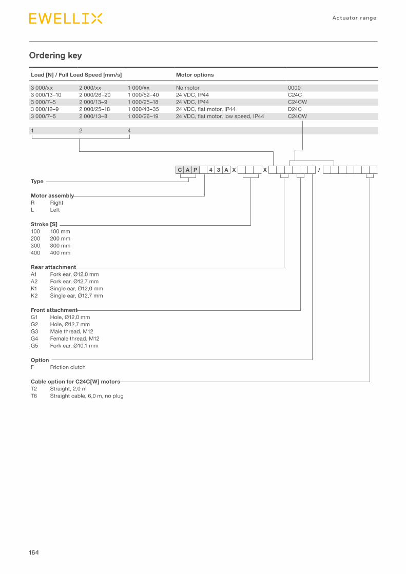
164
Actuator range
Ordering key
Load [N] / Full Load Speed [mm/s] Motor options
3 000/xx 2 000/xx 1 000/xx No motor 00003 000/13–10 2 000/26–20 1 000/52–40 24 VDC, IP44 C24C3 000/7–5 2 000/13–9 1 000/25–18 24 VDC, IP44 C24CW3 000/12–9 2 000/25–18 1 000/43–35 24VDC,flatmotor,IP44 D24C3 000/7–5 2 000/13–8 1 000/26–19 24VDC,flatmotor,lowspeed,IP44 C24CW
1 2 4
Type
Motor assemblyR RightL Left
Stroke [S]100 100 mm200 200 mm300 300 mm400 400 mm
Rear attachmentA1 Fork ear, Ø12,0 mmA2 Fork ear, Ø12,7 mmK1 Single ear, Ø12,0 mmK2 Single ear, Ø12,7 mm
Front attachmentG1 Hole, Ø12,0 mmG2 Hole, Ø12,7 mmG3 Male thread, M12G4 Female thread, M12G5 Fork ear, Ø10,1 mm
OptionF Friction clutch
Cable option for C24C[W] motorsT2 Straight, 2,0 mT6 Straight cable, 6,0 m, no plug
C A P 4 3 A X X /

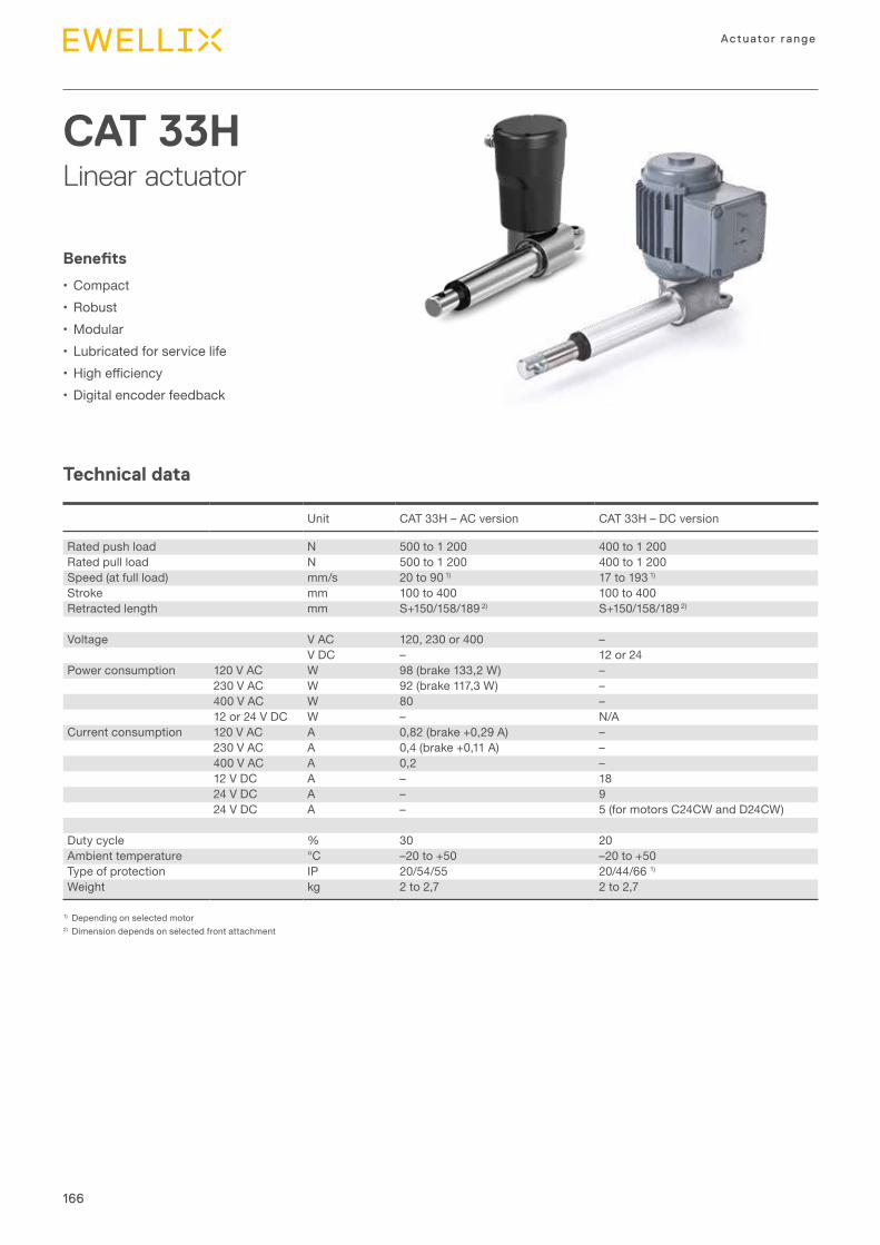
166
Actuator range
Technical data
CAT 33HLinear actuator
Benefits
•Compact•Robust•Modular•Lubricated for service life• Highefficiency•Digital encoder feedback
1) Depending on selected motor2) Dimension depends on selected front attachment
Unit CAT 33H – AC version CAT 33H – DC version
Rated push load N 500 to 1 200 400 to 1 200Rated pull load N 500 to 1 200 400 to 1 200Speed (at full load) mm/s 20 to 90 1) 17 to 193 1)
Stroke mm 100 to 400 100 to 400Retracted length mm S+150/158/189 2) S+150/158/189 2)
Voltage V AC 120, 230 or 400 –V DC – 12 or 24
Power consumption 120 V AC W 98 (brake 133,2 W) –230 V AC W 92 (brake 117,3 W) –400 V AC W 80 –12 or 24 V DC W – N/A
Current consumption 120 V AC A 0,82 (brake +0,29 A) –230 V AC A 0,4 (brake +0,11 A) –400 V AC A 0,2 –12 V DC A – 1824 V DC A – 924 V DC A – 5 (for motors C24CW and D24CW)
Duty cycle % 30 20Ambient temperature °C –20 to +50 –20 to +50Type of protection IP 20/54/55 20/44/66 1)
Weight kg 2 to 2,7 2 to 2,7
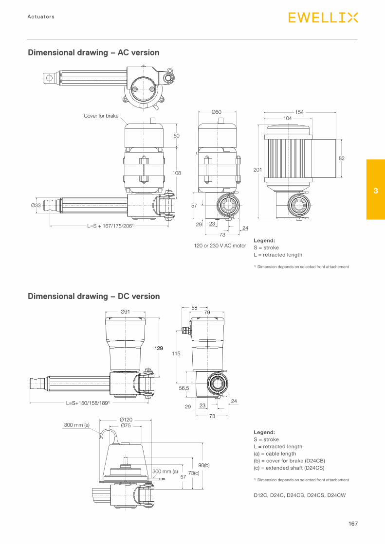
167
3
Actuators
Dimensional drawing – AC version
Legend:S = strokeL = retracted length
1) Dimension depends on selected front attachement
Dimensional drawing – DC version
Legend:S = strokeL = retracted length(a) = cable length(b) = cover for brake (D24CB)(c) = extended shaft (D24CS)
1) Dimension depends on selected front attachement
7324
23
57
29
108
50
L=S + 167/175/2061)
Ø33
Ø80
82
201
154104Cover for brake
120 or 230 V AC motor
D12C, D24C, D24CB, D24CS, D24CW
300 mm (a)
300 mm (a)57
73(c)98(b)
Ø120Ø75
Ø91
L=S+150/158/1891)
129115
73
7958
2329
56,5
24
129
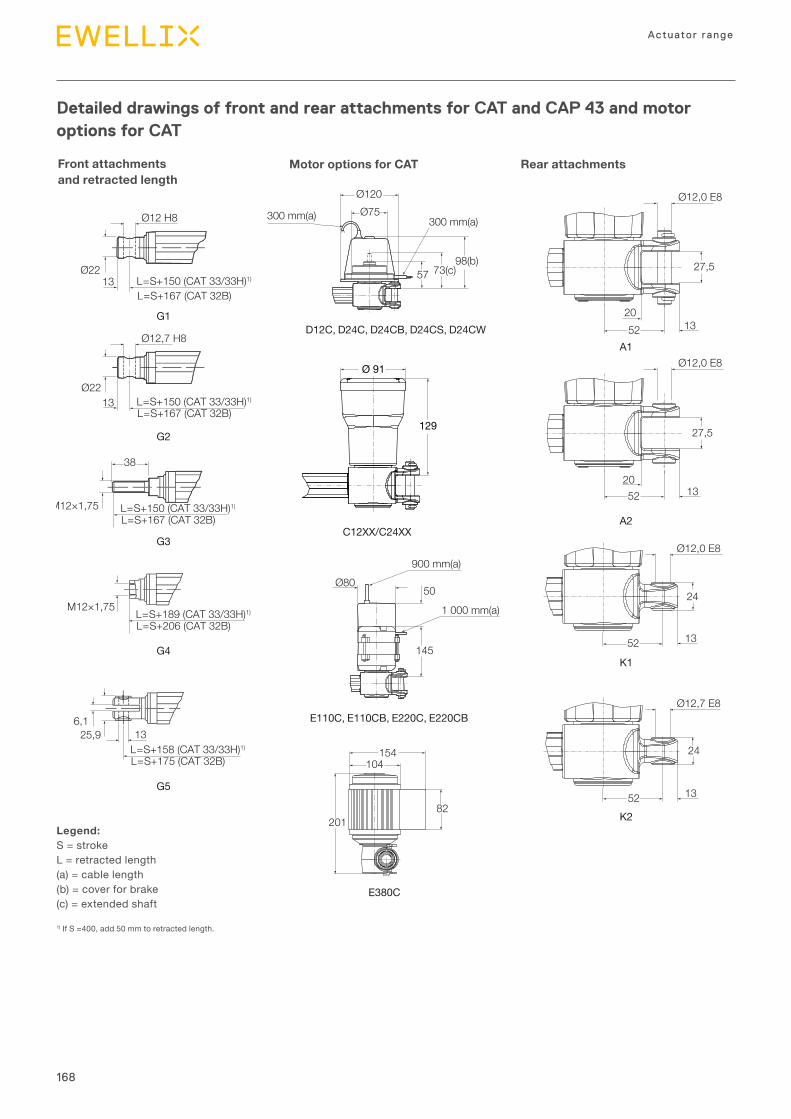
168
Actuator range
Detailed drawings of front and rear attachments for CAT and CAP 43 and motor options for CAT
Front attachments and retracted length
Motor options for CAT Rear attachments
Legend:S = strokeL = retracted length(a) = cable length(b) = cover for brake(c) = extended shaft
1) If S =400, add 50 mm to retracted length.
Ø2213 L=S+150 (CAT 33/33H)1)
L=S+167 (CAT 32B)
Ø12 H8
57
Ø120Ø75
73(c)
300 mm(a) 300 mm(a)
98(b)
Ø12,0 E8
2052 13
27,5
G1
G4
G2
G5
G3
A2
K1
K2
E380C
E110C, E110CB, E220C, E220CB
C12XX/C24XX
M12×1,75 L=S+189 (CAT 33/33H)1)
L=S+206 (CAT 32B)
6,125,9 13
L=S+158 (CAT 33/33H)1)
L=S+175 (CAT 32B)
Ø2213 L=S+150 (CAT 33/33H)1)
L=S+167 (CAT 32B)
Ø12,7 H8
M12×1,75 L=S+150 (CAT 33/33H)1)
L=S+167 (CAT 32B)
38
24
Ø12,0 E8
2052 13
Ø12,0 E8
52 13
24
Ø12,7 E8
52 13
Ø80
145
50
1 000 mm(a)
900 mm(a)
154104
82201
27,5
D12C, D24C, D24CB, D24CS, D24CWA1
Ø 91
129
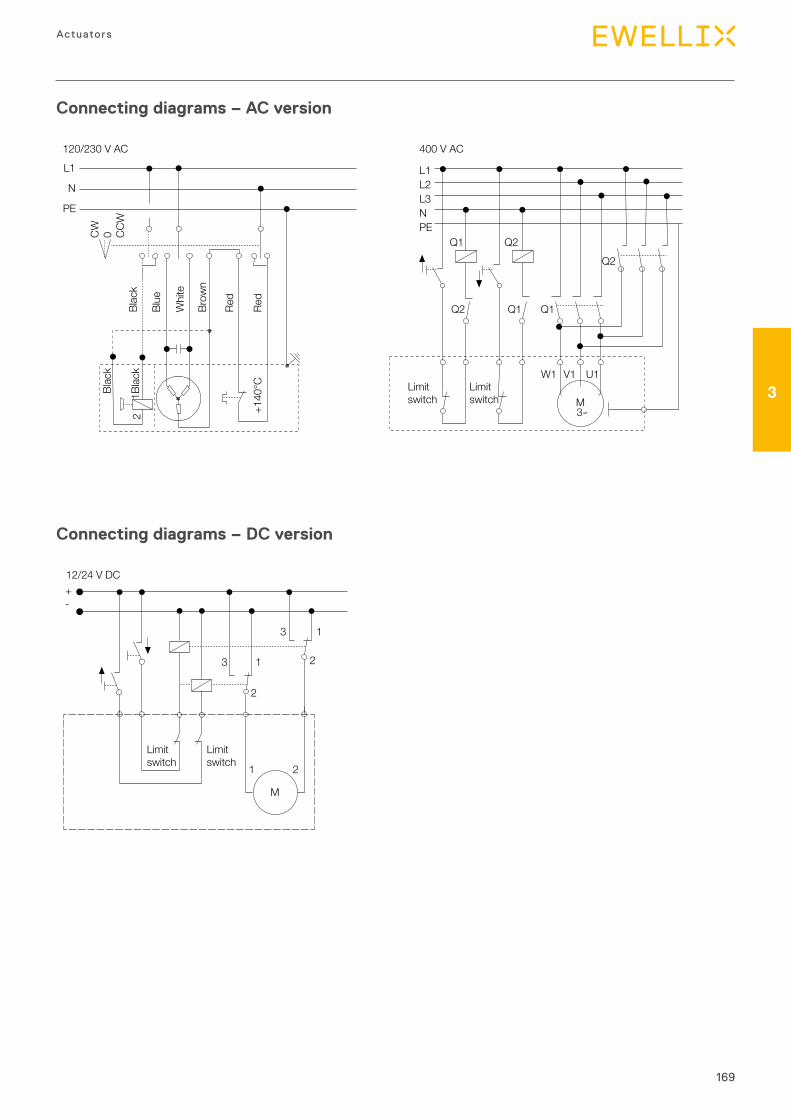
169
3
Actuators
Connecting diagrams – DC version
12/24 V DC
M
1 2
2
13 2
13
+-
Limitswitch
Limitswitch
Connecting diagrams – AC version
L1
N
PE
2
CW 0 CCW
120/230 V ACBl
ack
Blac
k
1Blac
k
Blue
Whi
te
Red
Red
+140
°C
Brow
n
Q1 Q2
Q2 Q1
M
Q1
Q2
W1 V1 U1
3∽
L1L2L3NPE
400 V AC
Limitswitch
Limitswitch
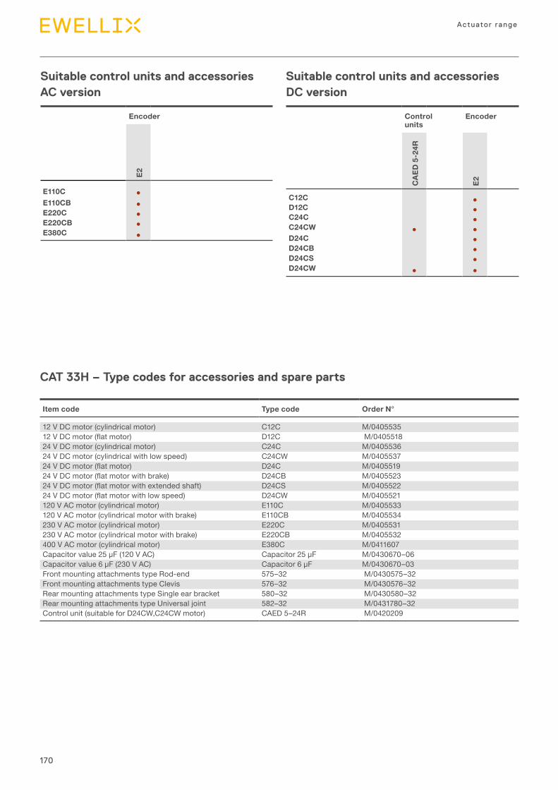
170
Actuator range
Suitable control units and accessories AC version
Suitable control units and accessories DC version
CAT 33H – Type codes for accessories and spare parts
Encoder
E2
E110C ●E110CB ●E220C ●E220CB ●E380C ●
Control units
Encoder
CAE
D 5
-24R
E2
C12C ●D12C ●C24C ●C24CW ● ●D24C ●D24CB ●D24CS ●D24CW ● ●
Item code Type code Order N°
12 V DC motor (cylindrical motor) C12C M/040553512VDCmotor(flatmotor) D12C M/040551824 V DC motor (cylindrical motor) C24C M/040553624 V DC motor (cylindrical with low speed) C24CW M/040553724VDCmotor(flatmotor) D24C M/040551924VDCmotor(flatmotorwithbrake) D24CB M/040552324VDCmotor(flatmotorwithextendedshaft) D24CS M/040552224VDCmotor(flatmotorwithlowspeed) D24CW M/0405521120 V AC motor (cylindrical motor) E110C M/0405533120 V AC motor (cylindrical motor with brake) E110CB M/0405534230 V AC motor (cylindrical motor) E220C M/0405531230 V AC motor (cylindrical motor with brake) E220CB M/0405532400 V AC motor (cylindrical motor) E380C M/0411607Capacitorvalue25μF(120VAC) Capacitor25μF M/0430670–06Capacitorvalue6μF(230VAC) Capacitor6μF M/0430670–03Front mounting attachments type Rod-end 575–32 M/0430575–32Front mounting attachments type Clevis 576–32 M/0430576–32Rear mounting attachments type Single ear bracket 580–32 M/0430580–32Rear mounting attachments type Universal joint 582–32 M/0431780–32Control unit (suitable for D24CW,C24CW motor) CAED 5–24R M/0420209
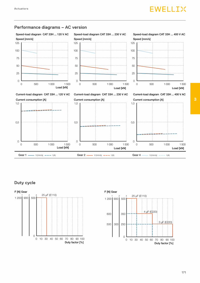
171
3
Actuators
Load [kN]
Load [kN]
Speed [mm/s] Speed [mm/s] Speed [mm/s]
V (mm/s) I (A)Gear 1 V (mm/s) I (A)Gear 2 V (mm/s) I (A)Gear 4
Load [kN] Load [kN]
Load [kN] Load [kN]
Speed-load diagram CAT 33H ... 120 V AC Speed-load diagram CAT 33H ... 230 V AC Speed-load diagram CAT 33H ... 400 V AC
Current-load diagram CAT 33H ... 120 V AC Current-load diagram CAT 33H ... 230 V AC Current-load diagram CAT 33H ... 400 V AC
Current consumption [A] Current consumption [A] Current consumption [A]
125
100
75
50
25
00 500 1 000 1 500
125
100
75
50
25
00 500 1 000 1 500
125
100
75
50
25
00 500 1 000 1 500
1,0
0,5
00 500 1 000 1 500
1,0
0,5
00 500 1 000 1 500
1,0
0,5
00 500 1 000 1 500
Performance diagrams – AC version
Duty cycle
0 10 30 40 50 60 70 80 90 1000
5009001 2001 2 4 25 µF (E110)
Duty factor [%]
F [N] Gear F [N] Gear
4 µF (E220)
3 µF (E220)
600 350
250300500
0 10 30 40 50 60 70 80 90 1000
5009001 2001 2 4 25 µF (E110)
Duty factor [%]
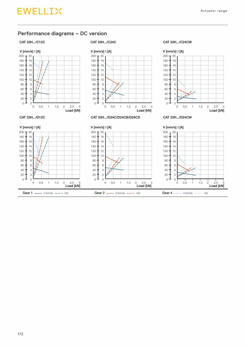
172
Actuator range
Performance diagrams – DC version
Load [kN]
V (mm/s) I (A)Gear 1 V (mm/s) I (A)Gear 2 V (mm/s) I (A)Gear 4
Load [kN] Load [kN]
Load [kN] Load [kN] Load [kN]
CAT 33H.../C12C CAT 33H.../C24C CAT 33H.../C24CW
CAT 33H.../D12C CAT 33H.../D24C/D24CB/D24CS CAT 33H.../D24CW
V [mm/s] I [A] V [mm/s] I [A] V [mm/s] I [A]
V [mm/s] I [A] V [mm/s] I [A] V [mm/s] I [A]
0 0,5 1 1,5 2 2,5 3
200180160140120100806040200
20181614121086420
200180160140120100806040200
20181614121086420
0 0,5 1 1,5 2 2,5 3
200180160140120100806040200
20181614121086420
0 0,5 1 1,5 2 2,5 3
200180160140120100806040200
20181614121086420
0 0,5 1 1,5 2 2,5 3
200180160140120100806040200
20181614121086420
0 0,5 1 1,5 2 2,5 3
200180160140120100806040200
20181614121086420
0 0,5 1 1,5 2 2,5 3
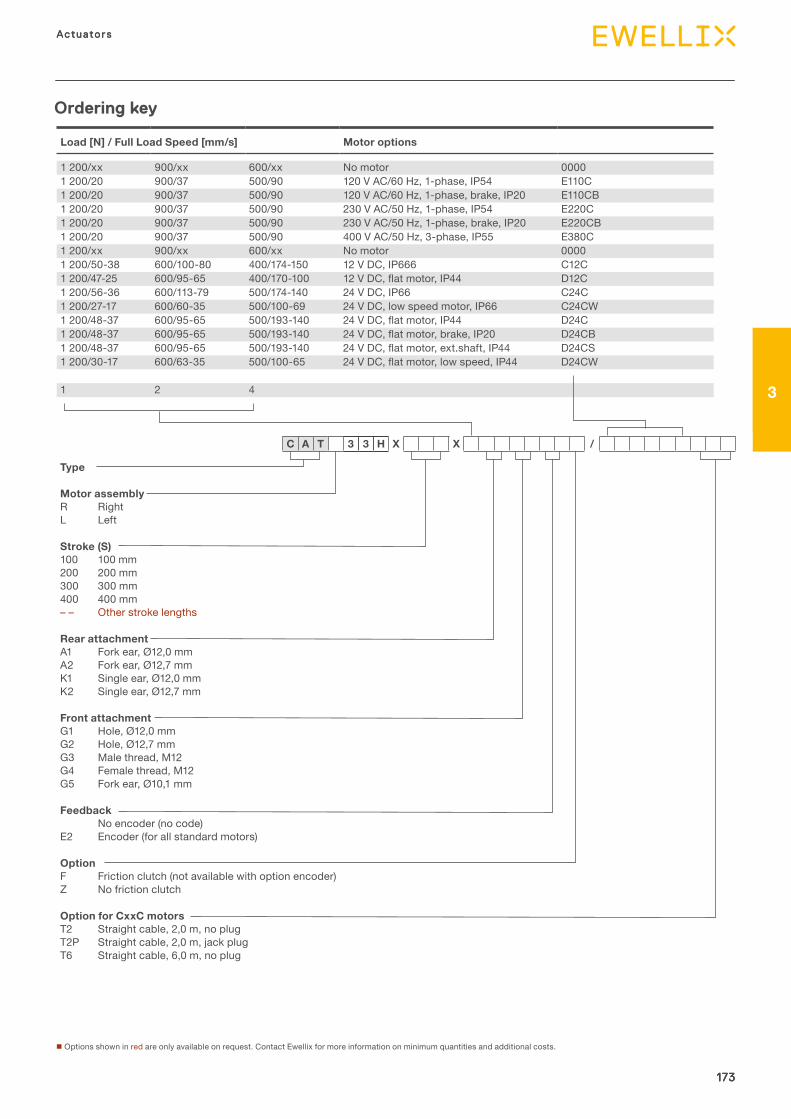
173
3
Actuators
173
Actuators
3
173
Load [N] / Full Load Speed [mm/s] Motor options
1 200/xx 900/xx 600/xx No motor 00001 200/20 900/37 500/90 120 V AC/60 Hz, 1-phase, IP54 E110C1 200/20 900/37 500/90 120 V AC/60 Hz, 1-phase, brake, IP20 E110CB1 200/20 900/37 500/90 230 V AC/50 Hz, 1-phase, IP54 E220C1 200/20 900/37 500/90 230 V AC/50 Hz, 1-phase, brake, IP20 E220CB1 200/20 900/37 500/90 400 V AC/50 Hz, 3-phase, IP55 E380C1 200/xx 900/xx 600/xx No motor 00001 200/50-38 600/100-80 400/174-150 12 V DC, IP666 C12C1 200/47-25 600/95-65 400/170-100 12VDC,flatmotor,IP44 D12C1 200/56-36 600/113-79 500/174-140 24 V DC, IP66 C24C1 200/27-17 600/60-35 500/100-69 24 V DC, low speed motor, IP66 C24CW1 200/48-37 600/95-65 500/193-140 24VDC,flatmotor,IP44 D24C1 200/48-37 600/95-65 500/193-140 24VDC,flatmotor,brake,IP20 D24CB1 200/48-37 600/95-65 500/193-140 24VDC,flatmotor,ext.shaft,IP44 D24CS1 200/30-17 600/63-35 500/100-65 24VDC,flatmotor,lowspeed,IP44 D24CW
1 2 4
Type
Motor assemblyR RightL Left
Stroke (S)100 100 mm200 200 mm300 300 mm400 400 mm– – Other stroke lengths
Rear attachmentA1 Fork ear, Ø12,0 mmA2 Fork ear, Ø12,7 mmK1 Single ear, Ø12,0 mmK2 Single ear, Ø12,7 mm
Front attachmentG1 Hole, Ø12,0 mmG2 Hole, Ø12,7 mmG3 Male thread, M12G4 Female thread, M12G5 Fork ear, Ø10,1 mm
FeedbackNo encoder (no code)
E2 Encoder (for all standard motors)
OptionF Friction clutch (not available with option encoder)Z No friction clutch
Option for CxxC motorsT2 Straight cable, 2,0 m, no plug T2P Straight cable, 2,0 m, jack plugT6 Straight cable, 6,0 m, no plug
C A T 3 3 H X X /
Ordering key
n Options shown in red are only available on request. Contact Ewellix for more information on minimum quantities and additional costs.
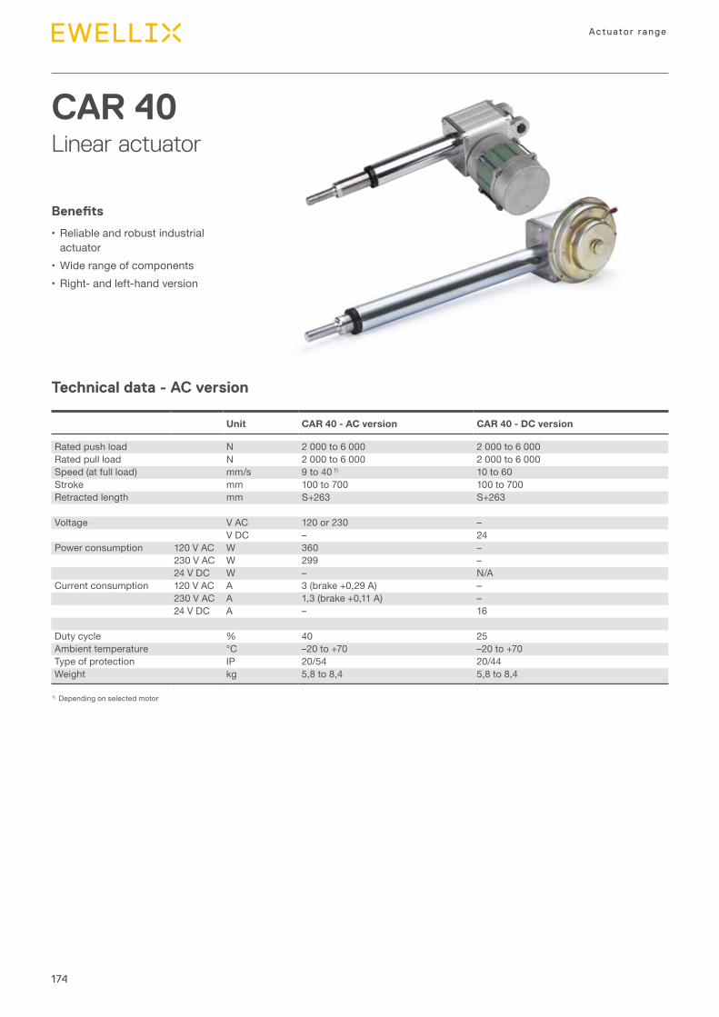
174
Actuator range
Technical data - AC version
CAR 40Linear actuator
Benefits
•Reliable and robust industrial actuator
•Wide range of components•Right- and left-hand version
1) Depending on selected motor
Unit CAR 40 - AC version CAR 40 - DC version
Rated push load N 2 000 to 6 000 2 000 to 6 000Rated pull load N 2 000 to 6 000 2 000 to 6 000Speed (at full load) mm/s 9 to 40 1) 10 to 60Stroke mm 100 to 700 100 to 700Retracted length mm S+263 S+263
Voltage V AC 120 or 230 –V DC – 24
Power consumption 120 V AC W 360 –230 V AC W 299 –24 V DC W – N/A
Current consumption 120 V AC A 3 (brake +0,29 A) –230 V AC A 1,3 (brake +0,11 A) –24 V DC A – 16
Duty cycle % 40 25Ambient temperature °C –20 to +70 –20 to +70Type of protection IP 20/54 20/44Weight kg 5,8 to 8,4 5,8 to 8,4
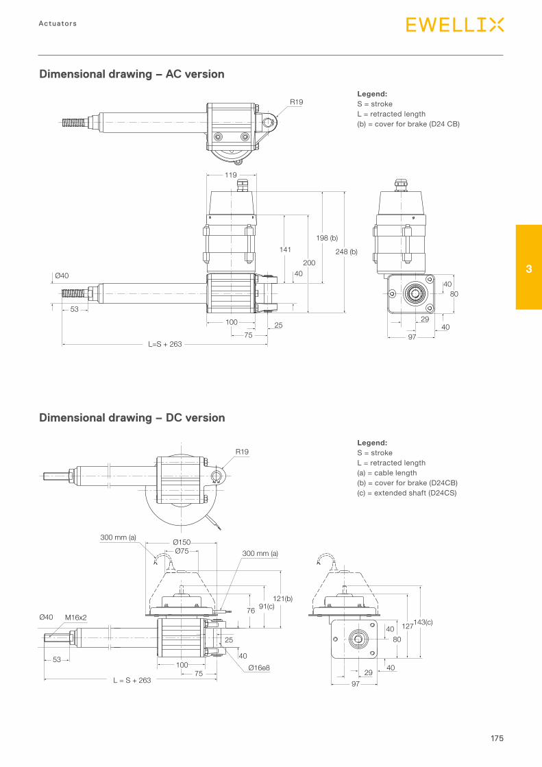
175
3
Actuators
10075
L=S + 263
53
40200
198 (b)
248 (b)
Ø40
R19
119
141
8040
4097
2925
R19
300 mm (a)
10075
Ø16e8
25
L = S + 263
Ø40
40
76 91(c)121(b)
300 mm (a)Ø150Ø75
143(c)127
8040
2997
4053
M16x2
Dimensional drawing – AC version
Legend:S = strokeL = retracted length(b) = cover for brake (D24 CB)
Dimensional drawing – DC version
Legend:S = strokeL = retracted length(a) = cable length(b) = cover for brake (D24CB)(c) = extended shaft (D24CS)
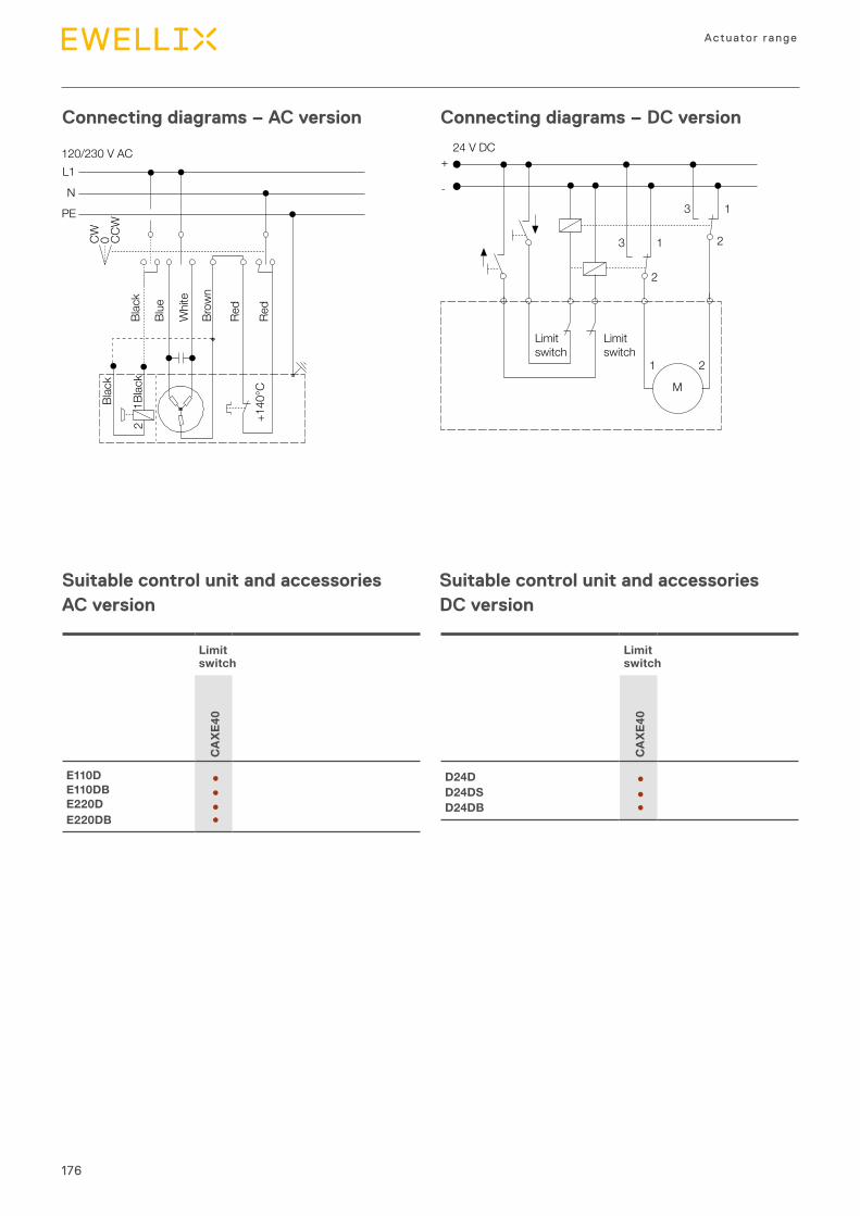
176
Actuator range
Connecting diagrams – DC version
M
2
13 2
13
24 V DC
Limitswitch
Limitswitch
1 2
+
-
Suitable control unit and accessories DC version
Connecting diagrams – AC version
L1
N
PE
CW 0 CCW
120/230 V ACBl
ack
Blac
k
1Blac
k
Blue
Whi
te
Red
Red
Brow
n
+140
°C
2
Suitable control unit and accessories AC version
Limit switch
CA
XE40
D24D ●D24DS ●D24DB ●
Limit switch
CA
XE40
E110D ●E110DB ●E220D ●E220DB ●
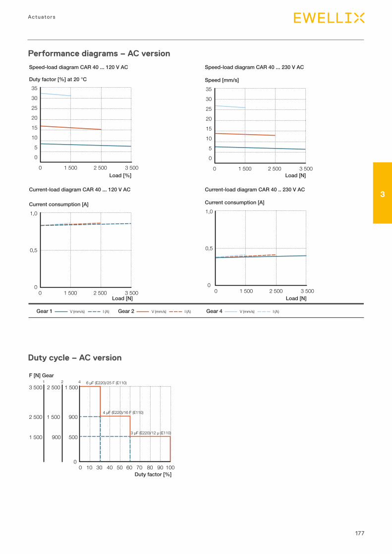
177
3
Actuators
Speed-load diagram CAR 40 ... 230 V AC
Current-load diagram CAR 40 .. 230 V AC
Speed-load diagram CAR 40 ... 120 V AC
Current-load diagram CAR 40 ... 120 V AC
Duty factor [%] at 20 °C
V (mm/s) I (A)Gear 1 V (mm/s) I (A)Gear 2 V (mm/s) I (A)Gear 4
Speed [mm/s]35
30
25
20
15
10
5
0
0 1 500 2 500 3 500Load [N]
Current consumption [A]1,0
0,5
00 1 500 2 500 3 500
Load [N]
Current consumption [A]1,0
0,5
00 1 500 2 500 3 500
Load [N]
35
30
25
20
15
10
5
0
0 1 500 2 500 3 500Load [%]
2 500 1 500 900
5009001 500
0 10 30 40 50 60 70 80 90 1000
1 5002 5003 5001 2 4
Duty factor [%]
F [N] Gear6 µF (E220)/25 F (E110)
4 µF (E220)/16 F (E110)
3 µF (E220)/12 µ (E110)
Performance diagrams – AC version
Duty cycle – AC version
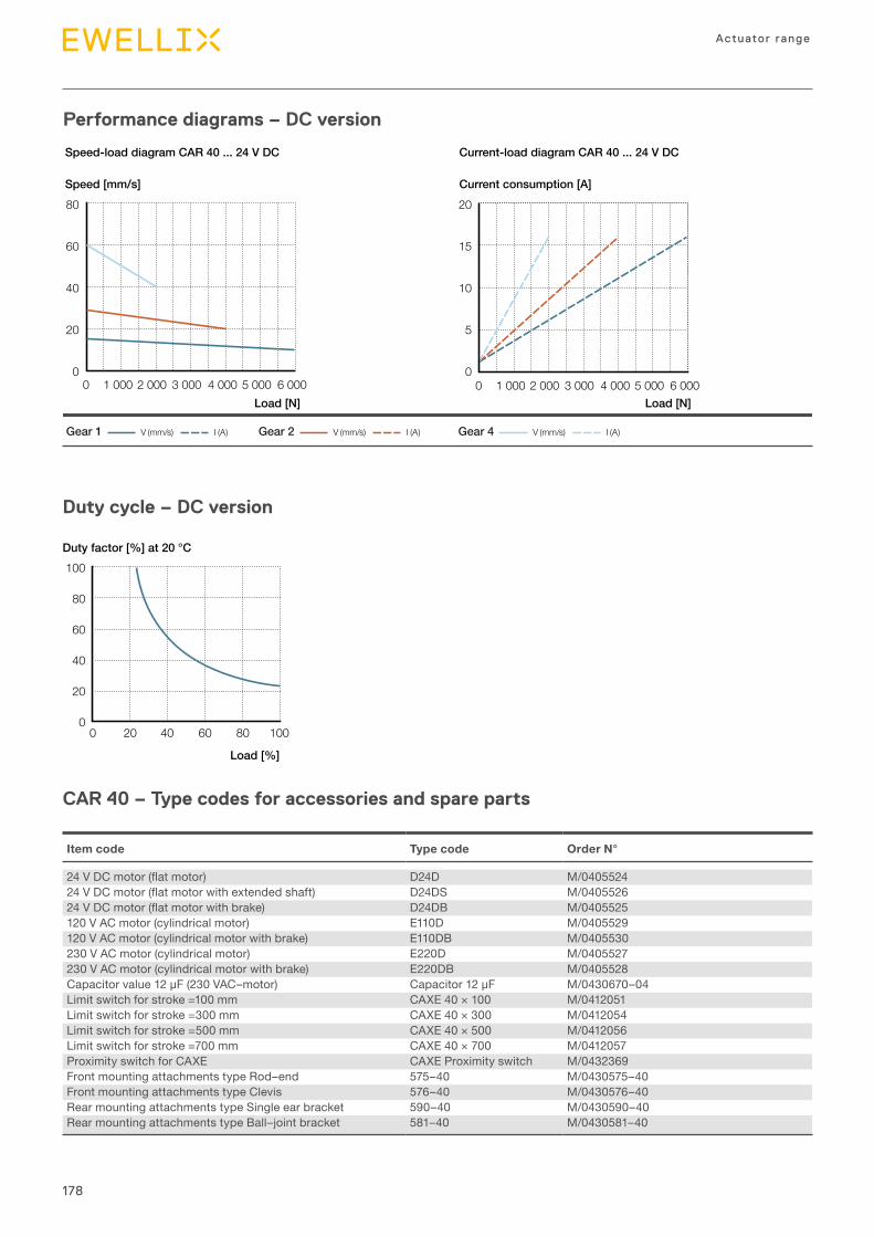
178
Actuator range
Speed [mm/s]
0 1 000 2 000 3 000 4 000 5 000 6 000
80
60
40
20
0
Load [N] Load [N]
Current consumption [A]
Speed-load diagram CAR 40 ... 24 V DC Current-load diagram CAR 40 ... 24 V DC
0 1 000 2 000 3 000 4 000 5 000 6 000
20
15
10
5
0
V (mm/s) I (A)Gear 1 V (mm/s) I (A)Gear 2 V (mm/s) I (A)Gear 4
Performance diagrams – DC version
Duty cycle – DC version
100
80
60
40
20
00 20 40 60 80 100
Load [%]
Duty factor [%] at 20 °C
CAR 40 – Type codes for accessories and spare parts
Item code Type code Order N°
24VDCmotor(flatmotor) D24D M/040552424VDCmotor(flatmotorwithextendedshaft) D24DS M/040552624VDCmotor(flatmotorwithbrake) D24DB M/0405525120 V AC motor (cylindrical motor) E110D M/0405529120 V AC motor (cylindrical motor with brake) E110DB M/0405530230 V AC motor (cylindrical motor) E220D M/0405527230 V AC motor (cylindrical motor with brake) E220DB M/0405528Capacitorvalue12μF(230VAC–motor) Capacitor12μF M/0430670–04Limit switch for stroke =100 mm CAXE 40 × 100 M/0412051Limit switch for stroke =300 mm CAXE 40 × 300 M/0412054Limit switch for stroke =500 mm CAXE 40 × 500 M/0412056Limit switch for stroke =700 mm CAXE 40 × 700 M/0412057Proximity switch for CAXE CAXE Proximity switch M/0432369Front mounting attachments type Rod–end 575–40 M/0430575–40Front mounting attachments type Clevis 576–40 M/0430576–40Rear mounting attachments type Single ear bracket 590–40 M/0430590–40Rear mounting attachments type Ball–joint bracket 581–40 M/0430581–40
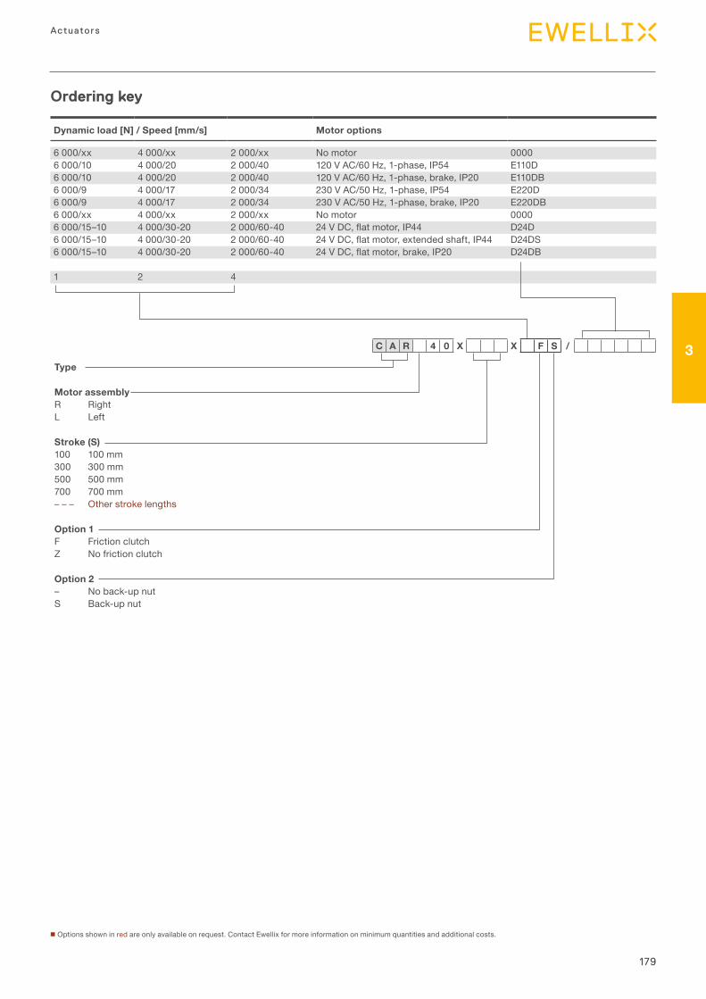
179
3
Actuators
Type
Motor assemblyR RightL Left
Stroke (S)100 100 mm300 300 mm500 500 mm700 700 mm– – – Other stroke lengths
Option 1F Friction clutchZ No friction clutch
Option 2– No back-up nutS Back-up nut
C A R 4 0 X X F S /
Dynamic load [N] / Speed [mm/s] Motor options
6 000/xx 4 000/xx 2 000/xx No motor 00006 000/10 4 000/20 2 000/40 120 V AC/60 Hz, 1-phase, IP54 E110D6 000/10 4 000/20 2 000/40 120 V AC/60 Hz, 1-phase, brake, IP20 E110DB6 000/9 4 000/17 2 000/34 230 V AC/50 Hz, 1-phase, IP54 E220D6 000/9 4 000/17 2 000/34 230 V AC/50 Hz, 1-phase, brake, IP20 E220DB6 000/xx 4 000/xx 2 000/xx No motor 00006 000/15–10 4 000/30-20 2 000/60-40 24VDC,flatmotor,IP44 D24D6 000/15–10 4 000/30-20 2 000/60-40 24VDC,flatmotor,extendedshaft,IP44 D24DS6 000/15–10 4 000/30-20 2 000/60-40 24VDC,flatmotor,brake,IP20 D24DB
1 2 4
Ordering key
n Options shown in red are only available on request. Contact Ewellix for more information on minimum quantities and additional costs.
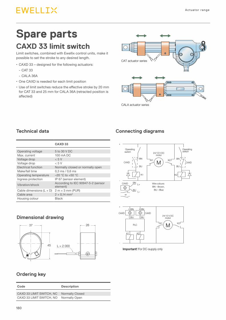
180
Actuator range
Spare partsCAXD 33 limit switchLimit switches, combined with Ewellix control units, make it possible to set the stroke to any desired length.
•CAXD 33 – designed for the following actuators: - CAT 33 - CALA 36A
•One CAXD is needed for each limit position• Useoflimitswitchesreducetheeffectivestrokeby20mm
for CAT 33 and 25 mm for CALA 36A (retracted position is affected)
Connecting diagrams
+
++ +
-
-
––
switch
CAXD
CAXD CAXD
CAXD
CAXD
BN
BN BN
BN
BNL+
L–
BUBU
BU BU
BU
K2
K2
K2M
M
K1
K2K1
K1
K1
PLC
24/12 V DCmotor
24/12 V DCmotor
Wire colours: BN – Brown,
BU – Blue
or
Operating switch
Operating
Important! For DC-supply only
CAT actuator series
CALA actuator series
CARE actuator series
Technical data
37 26
45 L = 2 000
Dimensional drawing
Ordering key
CAXD 33
Operating voltage 5 to 30 V DCMax. current 100 mA DCVoltage drop < 5 VVoltage drop < 5 VElectrical function Normally closed or normally openMake/fall time 0,3 ms / 0,6 msOperating temperature –20 °C to +50 °CIngress protection IP 67 (sensor element)
Vibration/shock According to IEC 90947-5-2 (sensor element)
Cable dimensions (L × D) 2 m × 3 mm (PUR)Cable area 2 × 0,14 mm2
Housing colour Black
Code Description
CAXD 33 LIMIT SWITCH, NC Normally ClosedCAXD 33 LIMIT SWITCH, NO Normally Open
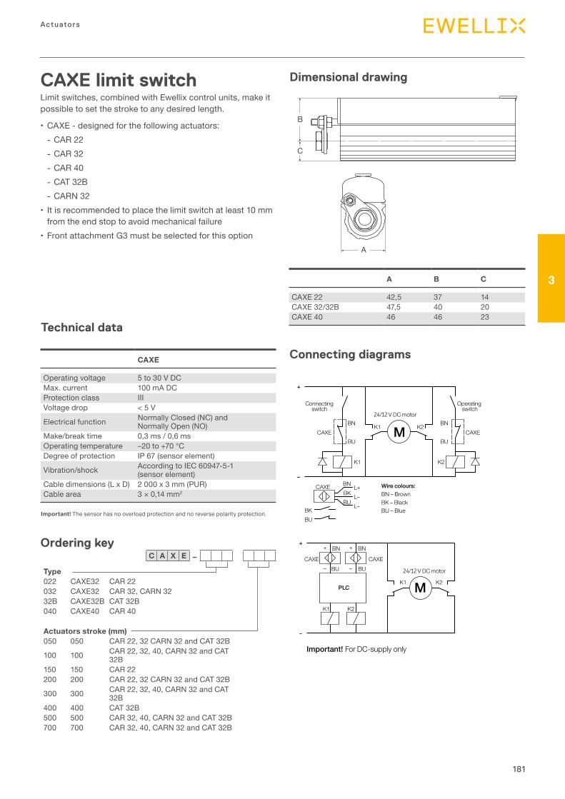
181
3
Actuators
CAXE limit switchLimit switches, combined with Ewellix control units, make it possible to set the stroke to any desired length.
•CAXE - designed for the following actuators: - CAR 22 - CAR 32 - CAR 40 - CAT 32B - CARN 32
• It is recommended to place the limit switch at least 10 mm from the end stop to avoid mechanical failure
•Front attachment G3 must be selected for this option
B
C
A
Technical data
Important! The sensor has no overload protection and no reverse polarity protection.
Ordering key
Type022 CAXE32 CAR 22032 CAXE32 CAR 32, CARN 3232B CAXE32B CAT 32B040 CAXE40 CAR 40
Actuators stroke (mm)050 050 CAR 22, 32 CARN 32 and CAT 32B
100 100 CAR 22, 32, 40, CARN 32 and CAT 32B
150 150 CAR 22 200 200 CAR 22, 32 CARN 32 and CAT 32B
300 300 CAR 22, 32, 40, CARN 32 and CAT 32B
400 400 CAT 32B 500 500 CAR 32, 40, CARN 32 and CAT 32B 700 700 CAR 32, 40, CARN 32 and CAT 32B
C A X E –
–
Important! For DC-supply only
BKBU
BU
BKBU
BN
BN
BU
BN
BU
BNK1
MK1 K2
CAXE
CAXE CAXE
CAXE CAXE
L–L–
L+
PLC
+
–
+
+
–
BU
BN+
– / V DC motor
Connecting switch
Operating switch
Wire colours:BN – BrownBK – BlackBU – Blue
/ V DC motor
K2
K2
K2K1
K1
M
Connecting diagrams
Dimensional drawing
A B C
CAXE 22 42,5 37 14CAXE 32/32B 47,5 40 20CAXE 40 46 46 23
CAXE
Operating voltage 5 to 30 V DCMax. current 100 mA DCProtection class IIIVoltage drop < 5 V
Electrical function Normally Closed (NC) and Normally Open (NO)
Make/break time 0,3 ms / 0,6 msOperating temperature –20 to +70 °CDegree of protection IP 67 (sensor element)
Vibration/shock According to IEC 60947-5-1 (sensor element)
Cable dimensions (L x D) 2 000 x 3 mm (PUR)Cable area 3 × 0,14 mm2
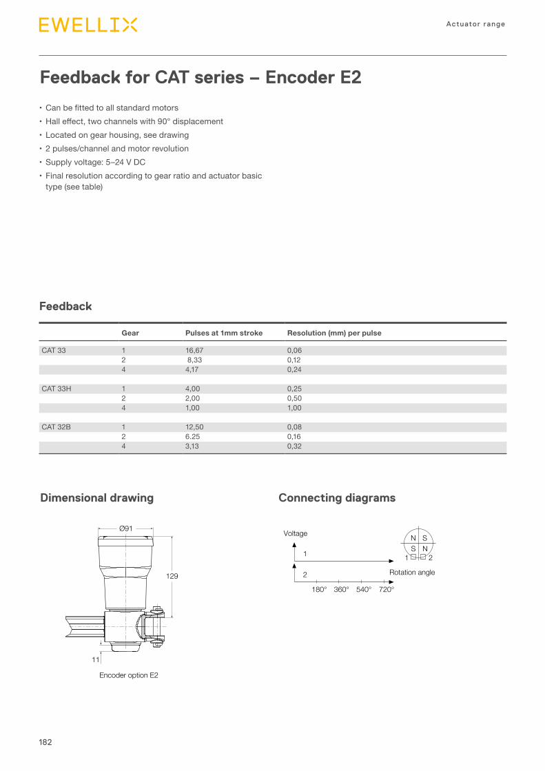
182
Actuator range
Feedback for CAT series – Encoder E2
• Canbefittedtoallstandardmotors•Halleffect,twochannelswith90°displacement•Located on gear housing, see drawing•2 pulses/channel and motor revolution•Supply voltage: 5–24 V DC•Final resolution according to gear ratio and actuator basic
type (see table)
Feedback
Connecting diagrams
1
2
1
180° 360° 540° 720°
2
SSN
N
Rotation angle
Voltage
Dimensional drawing
Gear Pulses at 1mm stroke Resolution (mm) per pulse
CAT 33 1 16,67 0,062 8,33 0,124 4,17 0,24
CAT 33H 1 4,00 0,252 2,00 0,504 1,00 1,00
CAT 32B 1 12,50 0,082 6.25 0,164 3,13 0,32
Encoder option E2
11
Ø91
129
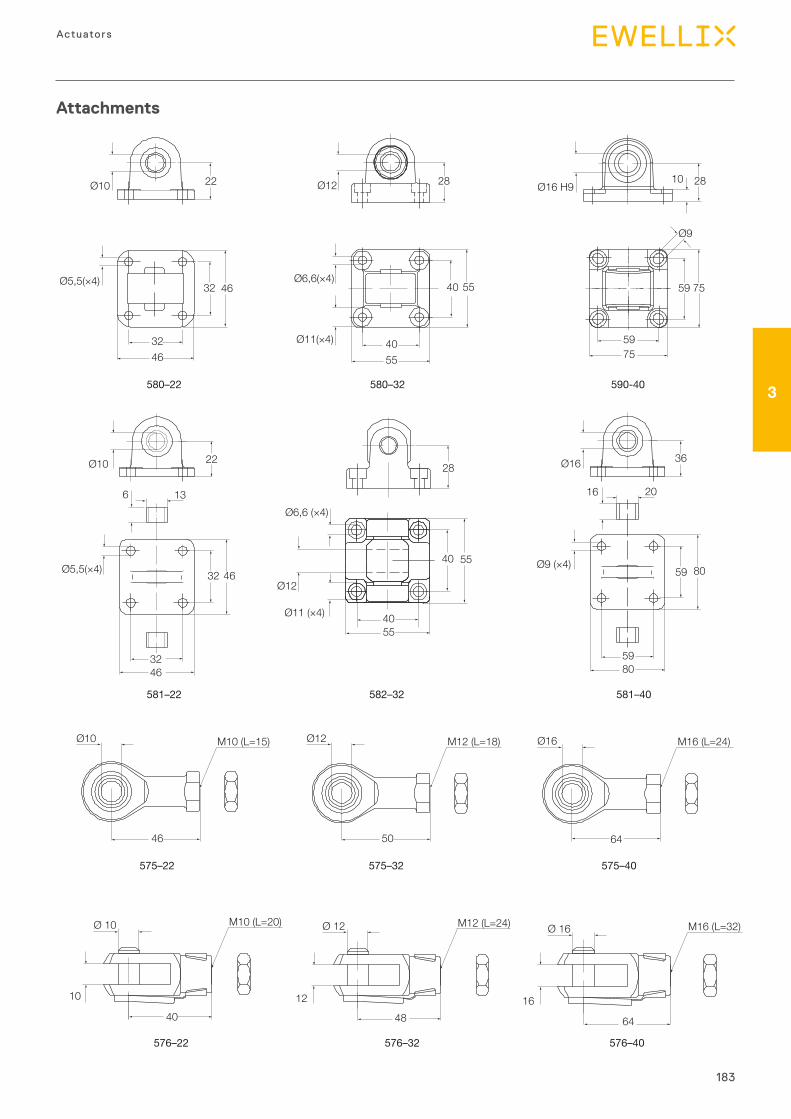
183
3
Actuators
581–40
580–22 580–32 590-40
Ø10
Ø5,5(×4) Ø6,6(×4)
Ø11(×4)
22 Ø12 Ø16 H9
32 46
3246
40 55
4055
5975
59
Ø9
2810
75
581–22
Ø5,5(×4) 32 46
3246
Ø10
6 13
22
Ø9 (×4)59 80
5980
Ø16
16 20
36
28
576–22
575–22
576–32
575–32
576–40
575–40
Ø10 M10 (L=15)
46
Ø12 M12 (L=18)
50
Ø16 M16 (L=24)
64
Ø 10
10
M10 (L=20)
40
Ø 12
12
M12 (L=24)
48
Ø 16
16
M16 (L=32)
64
582–32
Ø6,6 (×4)
Ø11 (×4)
Ø12
40 55
4055
28
Attachments
184
Actuator range
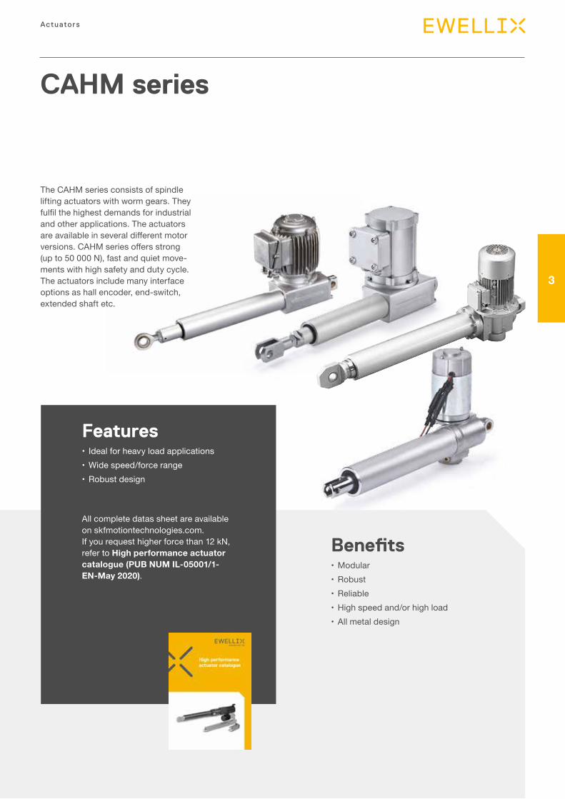
185
3
Actuators
CAHM series
The CAHM series consists of spindle lifting actuators with worm gears. They fulfilthehighestdemandsforindustrialand other applications. The actuators areavailableinseveraldifferentmotorversions.CAHMseriesoffersstrong(up to 50 000 N), fast and quiet move-ments with high safety and duty cycle. The actuators include many interface options as hall encoder, end-switch, extended shaft etc.
Features• Ideal for heavy load applications •Wide speed/force range •Robust design
All complete datas sheet are available on skfmotiontechnologies.com. If you request higher force than 12 kN, refer to High performance actuator catalogue (PUB NUM IL-05001/1-EN-May 2020).
Benefits•Modular•Robust•Reliable•High speed and/or high load•All metal design
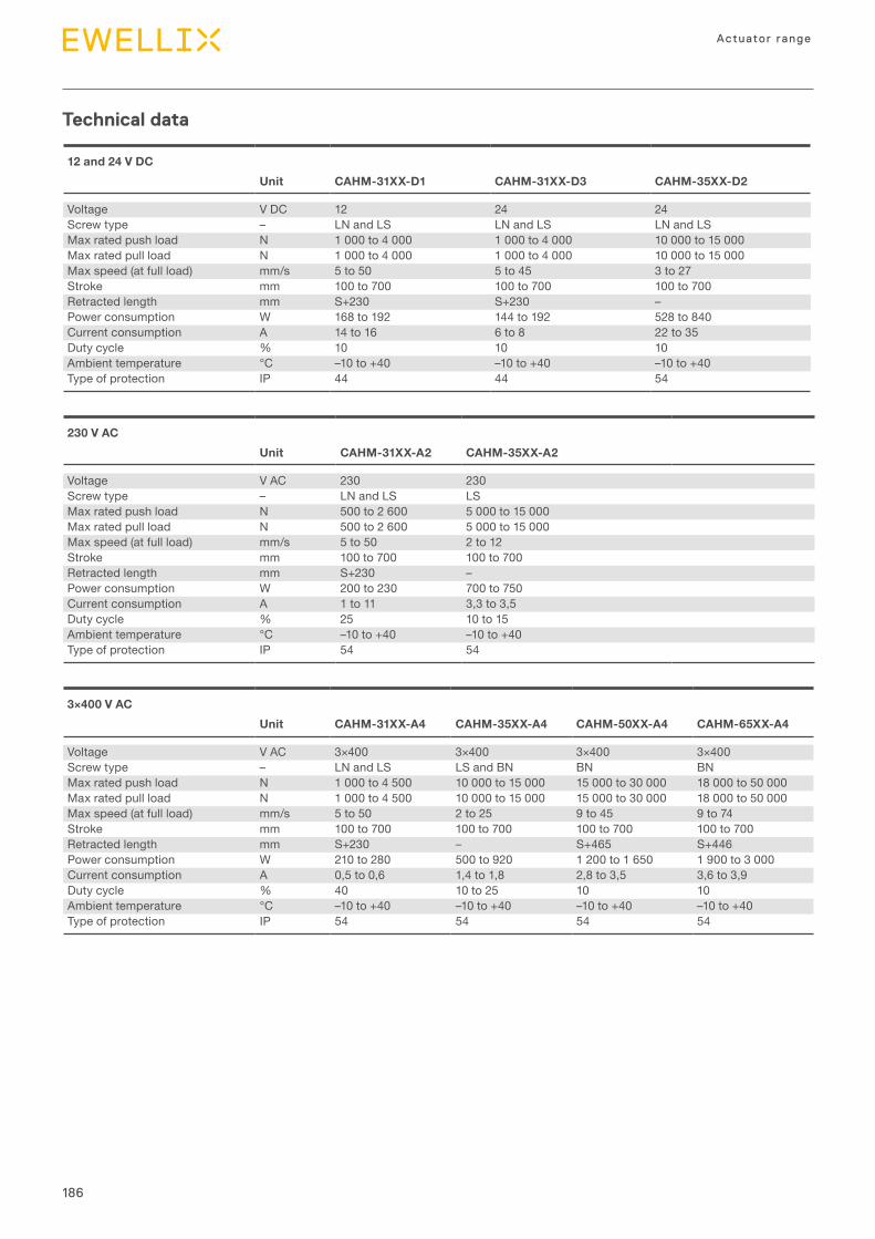
186
Actuator range
Technical data
12 and 24 V DC Unit CAHM-31XX-D1 CAHM-31XX-D3 CAHM-35XX-D2
Voltage V DC 12 24 24Screw type – LN and LS LN and LS LN and LSMax rated push load N 1 000 to 4 000 1 000 to 4 000 10 000 to 15 000Max rated pull load N 1 000 to 4 000 1 000 to 4 000 10 000 to 15 000Max speed (at full load) mm/s 5 to 50 5 to 45 3 to 27Stroke mm 100 to 700 100 to 700 100 to 700Retracted length mm S+230 S+230 –Power consumption W 168 to 192 144 to 192 528 to 840Current consumption A 14 to 16 6 to 8 22 to 35Duty cycle % 10 10 10 Ambient temperature °C –10 to +40 –10 to +40 –10 to +40Type of protection IP 44 44 54
230 V AC Unit CAHM-31XX-A2 CAHM-35XX-A2
Voltage V AC 230 230Screw type – LN and LS LSMax rated push load N 500 to 2 600 5 000 to 15 000Max rated pull load N 500 to 2 600 5 000 to 15 000Max speed (at full load) mm/s 5 to 50 2 to 12Stroke mm 100 to 700 100 to 700Retracted length mm S+230 –Power consumption W 200 to 230 700 to 750Current consumption A 1 to 11 3,3 to 3,5Duty cycle % 25 10 to 15Ambient temperature °C –10 to +40 –10 to +40Type of protection IP 54 54
3×400 V AC Unit CAHM-31XX-A4 CAHM-35XX-A4 CAHM-50XX-A4 CAHM-65XX-A4
Voltage V AC 3×400 3×400 3×400 3×400Screw type – LN and LS LS and BN BN BNMax rated push load N 1 000 to 4 500 10 000 to 15 000 15 000 to 30 000 18 000 to 50 000Max rated pull load N 1 000 to 4 500 10 000 to 15 000 15 000 to 30 000 18 000 to 50 000Max speed (at full load) mm/s 5 to 50 2 to 25 9 to 45 9 to 74Stroke mm 100 to 700 100 to 700 100 to 700 100 to 700Retracted length mm S+230 – S+465 S+446Power consumption W 210 to 280 500 to 920 1 200 to 1 650 1 900 to 3 000Current consumption A 0,5 to 0,6 1,4 to 1,8 2,8 to 3,5 3,6 to 3,9Duty cycle % 40 10 to 25 10 10Ambient temperature °C –10 to +40 –10 to +40 –10 to +40 –10 to +40Type of protection IP 54 54 54 54
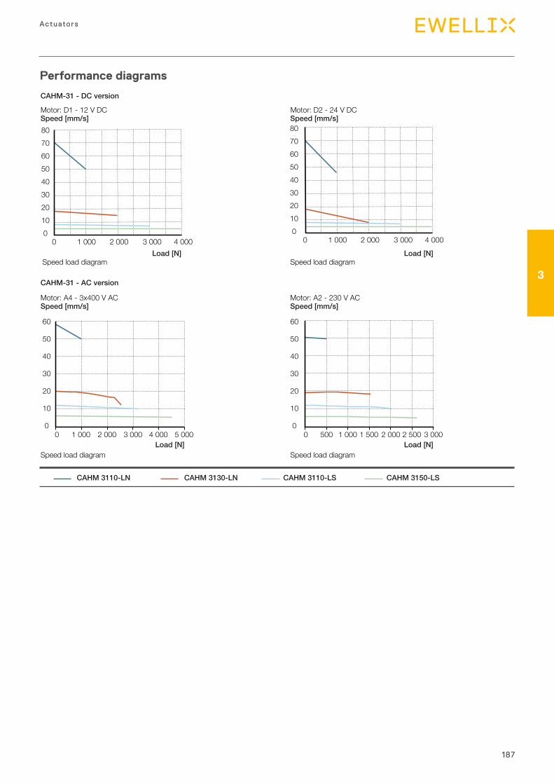
187
3
Actuators
Performance diagrams
CAHM-31 - DC version
CAHM-31 - AC version
Load [N] Load [N]
CAHM 3110-LN CAHM 3130-LN CAHM 3110-LS CAHM 3150-LS
0 1 000 2 000 3 000 4 000 5 000 0 500 1 000 1 500 2 000 2 500 3 000
60
50
40
30
20
10
0
60
50
40
30
20
10
0
Speed [mm/s] Speed [mm/s]
Speed load diagram Speed load diagram
Motor: A4 - 3x400 V AC Motor: A2 - 230 V AC
0 1 000 2 000 3 000 4 0000 1 000 2 000 3 000 4 000
80706050403020100
80706050403020100
Speed [mm/s] Speed [mm/s]
Speed load diagram Speed load diagramLoad [N] Load [N]
Motor: D1 - 12 V DC Motor: D2 - 24 V DC
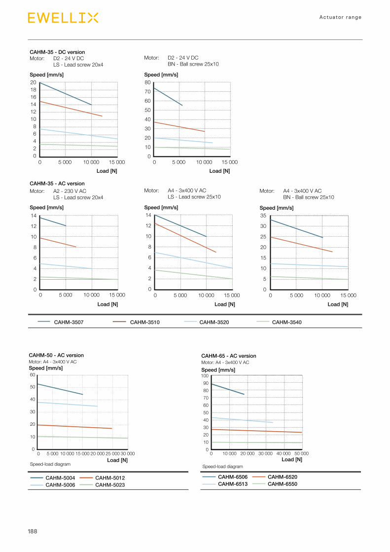
188
Actuator range
CAHM-35 - DC version
CAHM-35 - AC version
CAHM-3507 CAHM-3510 CAHM-3520 CAHM-3540
Motor: A4 - 3x400 V AC BN - Ball screw 25x10
Load [N]0 5 000 10 000 15 000
35
30
25
20
15
10
5
0
Speed [mm/s]
Motor: D2 - 24 V DC BN - Ball screw 25x10
Load [N]0 5 000 10 000 15 000
80706050403020100
Speed [mm/s]
Motor: A4 - 3x400 V AC LS - Lead screw 25x10
Load [N]
14
12
10
8
6
4
2
0
Speed [mm/s]
Motor: A2 - 230 V AC LS - Lead screw 20x4
Load [N]
0 5 000 10 000 15 000 0 5 000 10 000 15 000
Speed [mm/s]14
12
10
8
6
4
2
0
Motor: D2 - 24 V DC LS - Lead screw 20x4
Load [N]0 5 000 10 000 15 000
20181614121086420
Speed [mm/s]
Speed [mm/s]
Load [N]
CAHM-50 - AC versionMotor: A4 - 3x400 V AC
CAHM-5004CAHM-5006
CAHM-5012CAHM-5023
Speed-load diagram
0
10
20
30
40
50
60
0 5 000 10 000 15 000 20 000 25 000 30 000Load [N]
CAHM-6506CAHM-6513
CAHM-6520CAHM-6550
Speed-load diagram
0102030405060708090
100
0 10 000 20 000 30 000 40 000 50 000
Speed [mm/s]
CAHM-65 - AC versionMotor: A4 - 3x400 V AC

IntroductionLifting columnsUp to 2,8 kNm bending load
4

191
Telescopic p i l la rs
4
Chapter contentsCPMA ................................................................................. 192CPMB .................................................................................200CPMT ..................................................................................208TFG ..................................................................................... 214THG .................................................................................... 218TLC .....................................................................................222TLG .....................................................................................226TLT ......................................................................................230TXG .....................................................................................234FRE .....................................................................................238
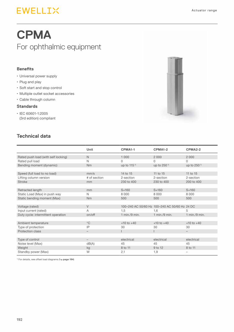
192
Actuator range
CPMAFor ophthalmic equipment
Technical data
Benefits
• Universalpowersupply• Plugandplay• Softstartandstopcontrol•Multipleoutletsocketaccessories•Cablethroughcolumn
Standards
• IEC60601-1:2005(3rdedition)compliant
Unit CPMA1-1 CPMA1-2 CPMA2-2
Ratedpushload(withselflocking) N 1000 2000 2000Ratedpullload N 0 0 0Bendingmoment(dynamic) Nm upto1151) upto2501) upto2501)
Speed(fullloadtonoload) mm/s 14to15 11to15 11to15Liftingcolumnversion #ofsection 2-section 2-section 2-sectionStroke mm 230to400 230to400 200to400
Retractedlength mm S+160 S+160 S+160StaticLoad(Max)inpushway N 8000 8000 8000Staticbendingmoment(Max) Nm 500 500 500
Voltage(rated) V 100–240AC50/60Hz 100–240AC50/60Hz 24DCInputcurrent(rated) A 1,5 1,6 5Dutycycle:intermittentoperation on/off 1min./9min. 1min./9min. 1min./9min.
Ambienttemperature °C +10to+40 +10to+40 +10to+40Typeofprotection IP 30 30 30Protectionclass – I I –
Typeofcontrol – electrical electrical electricalNoiselevel(Max) dB(A) 45 45 45Weight kg 8to11 9to12 8to11Standbypower(Max) W 2,1 1,9 –
1)Fordetails,seeoffsetloaddiagrams(⮑ page 194)
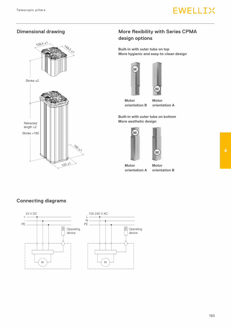
193
Telescopic p i l la rs
4
M
24 V DC 100-240 V AC+-
PE
LN
PE
M
Operatingdevice
Operatingdevice
Dimensional drawing
Connecting diagrams
149,5 ±1
109,5 ±1
165 ±1
125 ±1
Stroke ±2
Stroke +160
Retractedlength ±2
More flexibility with Series CPMA design options
Built-in with outer tube on top More hygienic and easy-to-clean design
Built-in with outer tube on bottom More aesthetic design
Motor orientation B
Motor orientation A
Motor orientation A
Motor orientation B
M
M
M
M
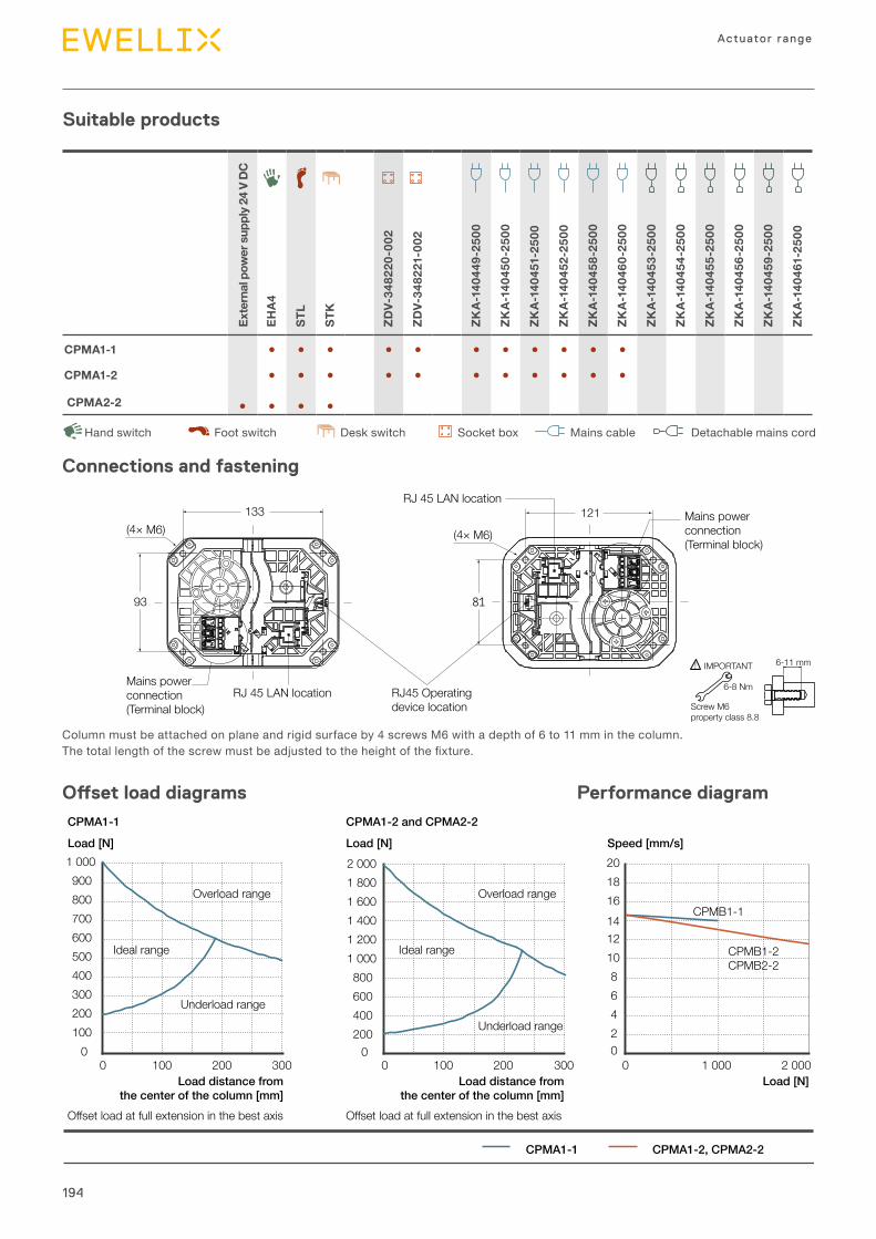
194
Actuator range
External pow
er sup
ply 24 V DC
EHA4
STL
STK
ZDV-34
8220
-002
ZDV-34
8221-002
ZKA-14
0449
-250
0
ZKA-14
0450
-250
0
ZKA-14
0451-250
0
ZKA-14
0452
-250
0
ZKA-14
0458
-250
0
ZKA-14
0460
-250
0
ZKA-14
0453
-250
0
ZKA-14
0454
-250
0
ZKA-14
0455
-250
0
ZKA-14
0456
-250
0
ZKA-14
0459
-250
0
ZKA-14
0461-250
0
CPMA1-1 ● ● ● ● ● ● ● ● ● ● ●
CPMA1-2 ● ● ● ● ● ● ● ● ● ● ●
CPMA2-2 ● ● ● ●
Suitable products
DeskswitchHandswitch Footswitch
(4× M6)
93
121
81
(4× M6)
133 Mains powerconnection(Terminal block)
Mains powerconnection(Terminal block)
RJ 45 LAN location RJ45 Operatingdevice location
RJ 45 LAN location
Columnmustbeattachedonplaneandrigidsurfaceby4screwsM6withadepthof6to11mminthecolumn.Thetotallengthofthescrewmustbeadjustedtotheheightofthefixture.
6-11 mm
6-8 Nm
Screw M6property class 8.8
IMPORTANT!
Connections and fastening
Offset load diagrams Performance diagram
0100200300400500600700800900
1 000
0 100 200 3000
200400600800
1 0001 2001 4001 6001 8002 000
0 100 200 30002468
101214161820
0 1 000 2 000
CPMA1-2, CPMA2-2
CPMA1-1 CPMA1-2 and CPMA2-2
Load [N] Load [N] Speed [mm/s]
Load distance fromthe center of the column [mm]
Load distance fromthe center of the column [mm]
Load [N]
Overload range
Ideal range
Underload range
Overload range
Ideal range
Underload range
Offset load at full extension in the best axis Offset load at full extension in the best axis
CPMB1-1
CPMB1-2CPMB2-2
CPMA1-1
DetachablemainscordMainscableSocketbox
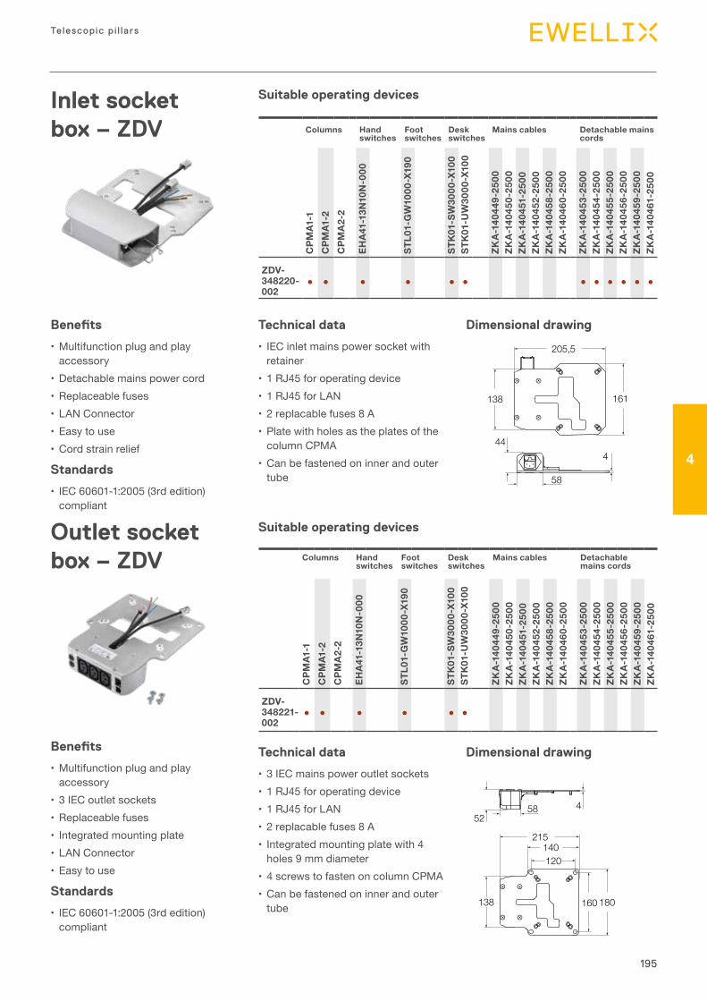
195
Telescopic p i l la rs
4
52458
138
215140120
180160
161
205,5
138
44
58
4
Inlet socket box – ZDV
Benefits
•Multifunctionplugandplayaccessory
• Detachablemainspowercord• Replaceablefuses• LANConnector• Easytouse•Cordstrainrelief
Standards
• IEC60601-1:2005(3rdedition)compliant
Technical data
• IECinletmainspowersocketwithretainer
• 1RJ45foroperatingdevice• 1RJ45forLAN• 2replacablefuses8A• PlatewithholesastheplatesofthecolumnCPMA
•Canbefastenedoninnerandoutertube
Dimensional drawing
Dimensional drawing
Columns Handswitches
Footswitches
Deskswitches
Mains cables Detachable mains cords
CPM
A1-1
CPM
A1-2
CPM
A2-
2
EHA4
1-13
N10
N-000
STL0
1-GW10
00-X19
0
STK01-SW30
00-X10
0ST
K01-U
W30
00-X10
0
ZKA-14
0449
-250
0ZK
A-14
0450
-250
0ZK
A-14
0451-250
0ZK
A-14
0452
-250
0ZK
A-14
0458
-250
0ZK
A-14
0460
-250
0
ZKA-14
0453
-250
0ZK
A-14
0454
-250
0ZK
A-14
0455
-250
0ZK
A-14
0456
-250
0ZK
A-14
0459
-250
0ZK
A-14
0461-250
0
ZDV-348220-002
● ● ● ● ● ● ● ● ● ● ● ●
Outlet socket box – ZDV
Benefits
•Multifunctionplugandplayaccessory
• 3IECoutletsockets• Replaceablefuses• Integratedmountingplate• LANConnector• Easytouse
Standards
• IEC60601-1:2005(3rdedition)compliant
Technical data
• 3IECmainspoweroutletsockets• 1RJ45foroperatingdevice• 1RJ45forLAN• 2replacablefuses8A• Integratedmountingplatewith4holes9mmdiameter
• 4screwstofastenoncolumnCPMA•Canbefastenedoninnerandoutertube
Suitable operating devices
Suitable operating devices
Columns Handswitches
Footswitches
Deskswitches
Mains cables Detachable mains cords
CPM
A1-1
CPM
A1-2
CPM
A2-
2
EHA4
1-13
N10
N-000
STL0
1-GW10
00-X19
0
STK01-SW30
00-X10
0ST
K01-U
W30
00-X10
0
ZKA-14
0449
-250
0ZK
A-14
0450
-250
0ZK
A-14
0451-250
0ZK
A-14
0452
-250
0ZK
A-14
0458
-250
0ZK
A-14
0460
-250
0
ZKA-14
0453
-250
0ZK
A-14
0454
-250
0ZK
A-14
0455
-250
0ZK
A-14
0456
-250
0ZK
A-14
0459
-250
0ZK
A-14
0461-250
0
ZDV-348221-002
● ● ● ● ● ●
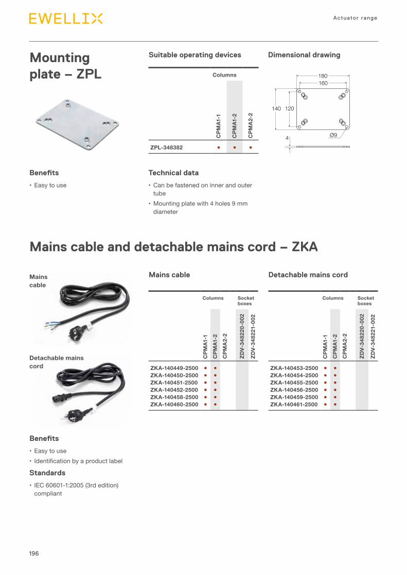
196
Actuator range
Mounting plate – ZPL
Benefits
• Easytouse
Technical data
• Canbefastenedoninnerandoutertube
•Mountingplatewith4holes9mmdiameter
180160
120140
4 Ø9
Dimensional drawingSuitable operating devices
Columns
CPM
A1-1
CPM
A1-2
CPM
A2-
2
ZPL-348382 ● ● ●
Mains cable and detachable mains cord – ZKA
Mains cable
Detachable mains cord
Benefits
• Easytouse• Identificationbyaproductlabel
Standards
• IEC60601-1:2005(3rdedition)compliant
Columns Socketboxes
CPM
A1-1
CPM
A1-2
CPM
A2-
2
ZDV-34
8220
-002
ZDV-34
8221-002
ZKA-140449-2500 ● ●ZKA-140450-2500 ● ●ZKA-140451-2500 ● ●ZKA-140452-2500 ● ●ZKA-140458-2500 ● ●ZKA-140460-2500 ● ●
Columns Socketboxes
CPM
A1-1
CPM
A1-2
CPM
A2-
2
ZDV-34
8220
-002
ZDV-34
8221-002
ZKA-140453-2500 ● ●ZKA-140454-2500 ● ●ZKA-140455-2500 ● ●ZKA-140456-2500 ● ●ZKA-140459-2500 ● ●ZKA-140461-2500 ● ●
Mains cable Detachable mains cord
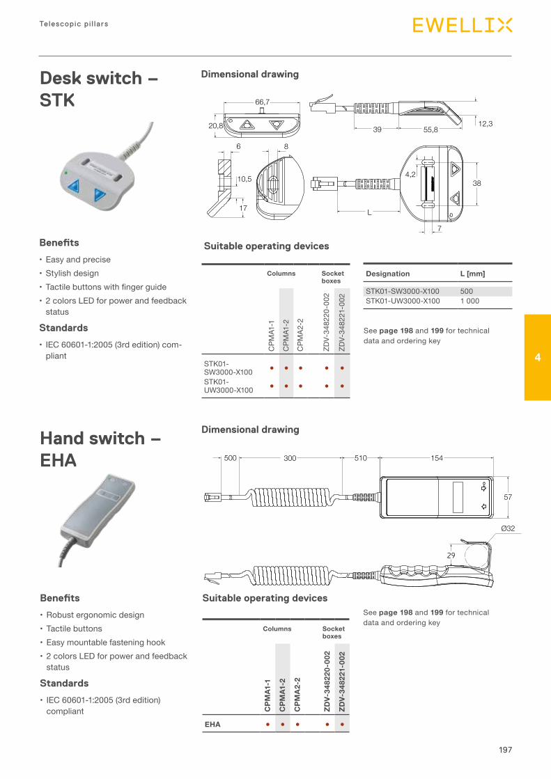
197
Telescopic p i l la rs
4
Hand switch – EHA
Benefits
• Robustergonomicdesign• Tactilebuttons• Easymountablefasteninghook• 2colorsLEDforpowerandfeedbackstatus
Standards
• IEC60601-1:2005(3rdedition)compliant
Columns Socketboxes
CPM
A1-1
CPM
A1-2
CPM
A2-
2
ZDV-34
8220
-002
ZDV-34
8221-002
EHA ● ● ● ● ●
Dimensional drawing
Seepage 198and199 fortechnicaldataandorderingkey
Seepage 198and199 fortechnicaldataandorderingkey
Dimensional drawing
Ø32
500 300 510 154
57
29
Desk switch – STK
Designation L [mm]
STK01-SW3000-X100 500STK01-UW3000-X100 1000
4,2
7
6
10,5
L
55,839
38
17
66,7
20,8
8
12,3
Suitable operating devices
Benefits
• Easyandprecise• Stylishdesign• Tactilebuttonswithfingerguide• 2colorsLEDforpowerandfeedbackstatus
Standards
• IEC60601-1:2005(3rdedition)com-pliant
Columns Socketboxes
CPM
A1-1
CPM
A1-2
CPM
A2-2
ZDV-34
8220
-002
ZDV-34
8221-002
STK01-SW3000-X100 ● ● ● ● ●
STK01-UW3000-X100 ● ● ● ● ●
Suitable operating devices
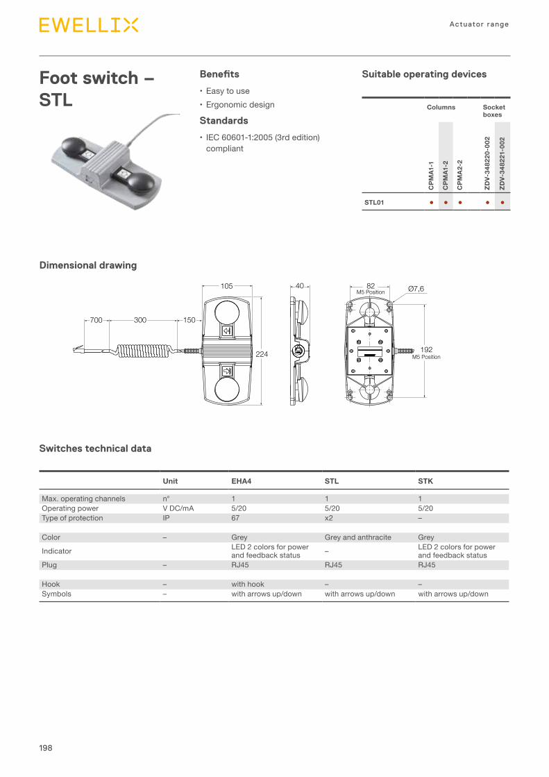
198
Actuator range
Foot switch – STL
Benefits
• Easytouse• Ergonomicdesign
Standards
• IEC60601-1:2005(3rdedition)compliant
Columns Socketboxes
CPM
A1-1
CPM
A1-2
CPM
A2-
2
ZDV-34
8220
-002
ZDV-34
8221-002
STL01 ● ● ● ● ●
Dimensional drawing
82M5 Position Ø7,6
300 150
105
700
224
40
192M5 Position
Switches technical data
Suitable operating devices
Unit EHA4 STL STK
Max.operatingchannels n° 1 1 1Operatingpower VDC/mA 5/20 5/20 5/20Typeofprotection IP 67 x2 –
Color – Grey Greyandanthracite Grey
Indicator LED2colorsforpowerandfeedbackstatus – LED2colorsforpower
andfeedbackstatusPlug – RJ45 RJ45 RJ45
Hook – withhook – –Symbols – witharrowsup/down witharrowsup/down witharrowsup/down
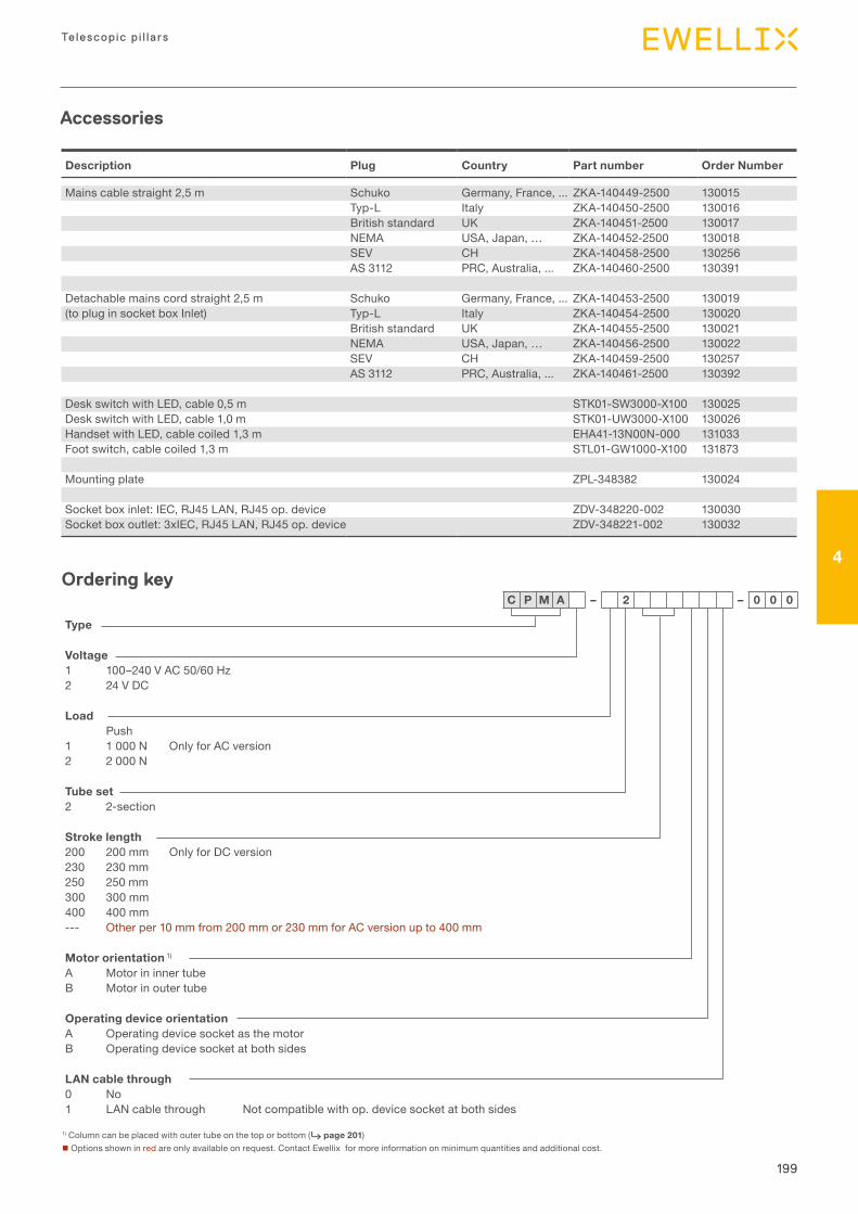
199
Telescopic p i l la rs
4
Description Plug Country Part number Order Number
Mainscablestraight2,5m Schuko Germany,France,... ZKA-140449-2500 130015Typ-L Italy ZKA-140450-2500 130016Britishstandard UK ZKA-140451-2500 130017NEMA USA,Japan,… ZKA-140452-2500 130018SEV CH ZKA-140458-2500 130256AS3112 PRC,Australia,... ZKA-140460-2500 130391
Detachablemainscordstraight2,5m Schuko Germany,France,... ZKA-140453-2500 130019(topluginsocketboxInlet) Typ-L Italy ZKA-140454-2500 130020
Britishstandard UK ZKA-140455-2500 130021NEMA USA,Japan,… ZKA-140456-2500 130022SEV CH ZKA-140459-2500 130257AS3112 PRC,Australia,... ZKA-140461-2500 130392
DeskswitchwithLED,cable0,5m STK01-SW3000-X100 130025DeskswitchwithLED,cable1,0m STK01-UW3000-X100 130026HandsetwithLED,cablecoiled1,3m EHA41-13N00N-000 131033Footswitch,cablecoiled1,3m STL01-GW1000-X100 131873
Mountingplate ZPL-348382 130024
Socketboxinlet:IEC,RJ45LAN,RJ45op.device ZDV-348220-002 130030Socketboxoutlet:3xIEC,RJ45LAN,RJ45op.device ZDV-348221-002 130032
C P M A – 2 – 0 0 0
Type
Voltage1 100–240VAC50/60Hz2 24VDC
LoadPush
1 1000N OnlyforACversion2 2000N
Tube set2 2-section
Stroke length200 200mm OnlyforDCversion230 230mm250 250mm300 300mm400 400mm--- Otherper10mmfrom200mmor230mmforACversionupto400mm
Motor orientation1)
A MotorininnertubeB Motorinoutertube
Operating device orientationA OperatingdevicesocketasthemotorB Operatingdevicesocketatbothsides
LAN cable through0 No1 LANcablethrough Notcompatiblewithop.devicesocketatbothsides
1)Columncanbeplacedwithoutertubeonthetoporbottom(⮑ page 201)nOptionsshowninredareonlyavailableonrequest.ContactEwellixformoreinformationonminimumquantitiesandadditionalcost.
Ordering key
Accessories
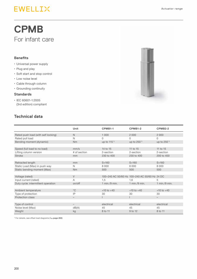
200
Actuator range
CPMBFor infant care
Technical data
Benefits
• Universalpowersupply• Plugandplay• Softstartandstopcontrol• Lownoiselevel• Cablethroughcolumn•Groundingcontinuity
Standards
• IEC60601-1:2005(3rdedition)compliant
1)Fordetails,seeoffsetloaddiagrams(⮑ page 202)
Unit CPMB1-1 CPMB1-2 CPMB2-2
Ratedpushload(withselflocking) N 1000 2000 2000Ratedpullload N 0 0 0Bendingmoment(dynamic) Nm upto1151) upto2501) upto2501)
Speed(fullloadtonoload) mm/s 14to15 11to15 11to15Liftingcolumnversion #ofsection 2-section 2-section 2-sectionStroke mm 230to400 230to400 200to400
Retractedlength mm S+160 S+160 S+160StaticLoad(Max)inpushway N 8000 8000 8000Staticbendingmoment(Max) Nm 500 500 500
Voltage(rated) V 100–240AC50/60Hz 100–240AC50/60Hz 24DCInputcurrent(rated) A 1,5 1,6 5Dutycycle:intermittentoperation on/off 1min./9min. 1min./9min. 1min./9min.
Ambienttemperature °C +10to+40 +10to+40 +10to+40Typeofprotection IP 30 30 30Protectionclass – I I –
Typeofcontrol – electrical electrical electricalNoiselevel(Max) dB(A) 45 45 45Weight kg 8to11 9to12 8to11

201
Telescopic p i l la rs
4
M
24 V DC 100-240 V AC+-
PE
LN
PE
M
Operatingdevice
Operatingdevice
Dimensional drawing
Connecting diagrams
149,5 ±1
109,5 ±1
165 ±1
125 ±1
Stroke ±2
Stroke +160
Retractedlength ±2
More flexibility with Series CPMB design options
Built-in with outer tube on top More hygienic and easy-to-clean design
Built-in with outer tube on bottom More aesthetic design
Motor orientation B
Motor orientation A
Motor orientation A
Motor orientation B
M
M
M
M
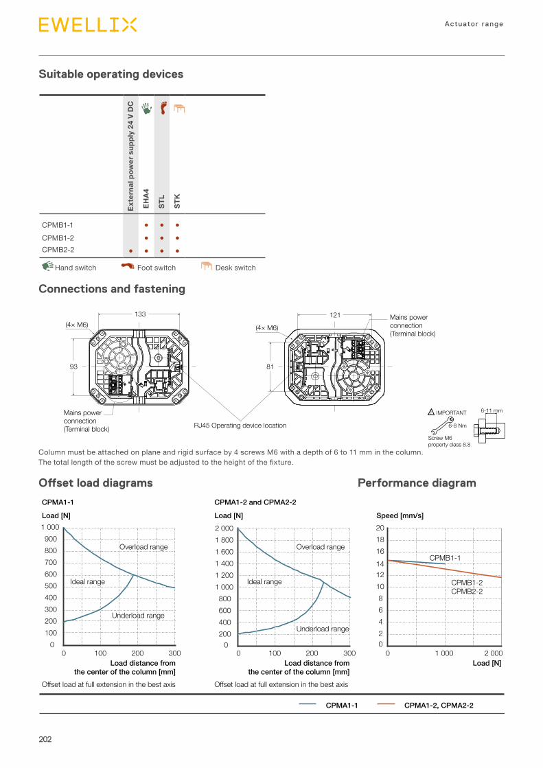
202
Actuator range
Suitable operating devices
93
121
81
(4× M6)
133(4× M6)
Mains powerconnection(Terminal block) RJ45 Operating device location
Mains powerconnection(Terminal block)
Columnmustbeattachedonplaneandrigidsurfaceby4screwsM6withadepthof6to11mminthecolumn.Thetotallengthofthescrewmustbeadjustedtotheheightofthefixture.
6-11 mm
6-8 Nm
Screw M6property class 8.8
IMPORTANT!
Connections and fastening
Offset load diagrams Performance diagram
0100200300400500600700800900
1 000
0 100 200 3000
200400600800
1 0001 2001 4001 6001 8002 000
0 100 200 30002468
101214161820
0 1 000 2 000
CPMA1-2, CPMA2-2
CPMA1-1 CPMA1-2 and CPMA2-2
Load [N] Load [N] Speed [mm/s]
Load distance fromthe center of the column [mm]
Load distance fromthe center of the column [mm]
Load [N]
Overload range
Ideal range
Underload range
Overload range
Ideal range
Underload range
Offset load at full extension in the best axis Offset load at full extension in the best axis
CPMB1-1
CPMB1-2CPMB2-2
CPMA1-1
External pow
er sup
ply 24
V DC
EHA4
STL
STK
CPMB1-1 ● ● ●CPMB1-2 ● ● ●CPMB2-2 ● ● ● ●
DeskswitchHandswitch Footswitch
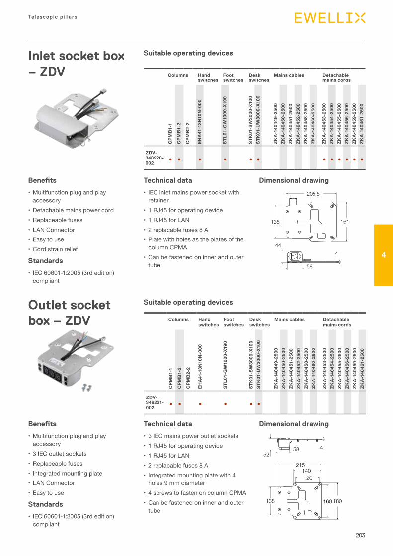
203
Telescopic p i l la rs
4
52458
138
215140120
180160
161
205,5
138
44
58
4
Inlet socket box – ZDV
Benefits
•Multifunctionplugandplayaccessory
• Detachablemainspowercord• Replaceablefuses• LANConnector• Easytouse•Cordstrainrelief
Standards
• IEC60601-1:2005(3rdedition)compliant
Technical data
• IECinletmainspowersocketwithretainer
• 1RJ45foroperatingdevice• 1RJ45forLAN• 2replacablefuses8A• PlatewithholesastheplatesofthecolumnCPMA
•Canbefastenedoninnerandoutertube
Dimensional drawing
Dimensional drawing
Columns Handswitches
Footswitches
Deskswitches
Mains cables Detachable mains cords
CPM
B1-1
CPM
B1-2
CPM
B2-
2
EHA4
1-13
N10
N-000
STL0
1-GW10
00-X19
0
STK01-SW30
00-X10
0ST
K01-U
W30
00-X10
0
ZKA-14
0449
-250
0ZK
A-14
0450
-250
0ZK
A-14
0451-250
0ZK
A-14
0452
-250
0ZK
A-14
0458
-250
0ZK
A-14
0460
-250
0
ZKA-14
0453
-250
0ZK
A-14
0454
-250
0ZK
A-14
0455
-250
0ZK
A-14
0456
-250
0ZK
A-14
0459
-250
0ZK
A-14
0461-250
0
ZDV-348220-002
● ● ● ● ● ● ● ● ● ● ● ●
Columns Handswitches
Footswitches
Deskswitches
Mains cables Detachable mains cords
CPM
B1-1
CPM
B1-2
CPM
B2-
2
EHA4
1-13
N10
N-000
STL0
1-GW10
00-X19
0
STK01-SW30
00-X10
0ST
K01-U
W30
00-X10
0
ZKA-14
0449
-250
0ZK
A-14
0450
-250
0ZK
A-14
0451-250
0ZK
A-14
0452
-250
0ZK
A-14
0458
-250
0ZK
A-14
0460
-250
0
ZKA-14
0453
-250
0ZK
A-14
0454
-250
0ZK
A-14
0455
-250
0ZK
A-14
0456
-250
0ZK
A-14
0459
-250
0ZK
A-14
0461-250
0
ZDV-348221-002
● ● ● ● ● ●
Outlet socket box – ZDV
Benefits
•Multifunctionplugandplayaccessory
• 3IECoutletsockets• Replaceablefuses• Integratedmountingplate• LANConnector• Easytouse
Standards
• IEC60601-1:2005(3rdedition)compliant
Technical data
• 3IECmainspoweroutletsockets• 1RJ45foroperatingdevice• 1RJ45forLAN• 2replacablefuses8A• Integratedmountingplatewith4holes9mmdiameter
• 4screwstofastenoncolumnCPMA•Canbefastenedoninnerandoutertube
Suitable operating devices
Suitable operating devices

204
Actuator range
Mounting plate – ZPL
Benefits
• Easytouse
Technical data
• Canbefastenedoninnerandoutertube
•Mountingplatewith4holes9mmdiameter
180160
120140
4 Ø9
Dimensional drawingSuitable operating devices
Columns
CPM
A1-1
CPM
A1-2
CPM
A2-
2
ZPL-348382 ● ● ●
Mains cable and detachable mains cord – ZKA
Mains cable
Detachable mains cord
Benefits
• Easytouse• Identificationbyaproductlabel
Standards
• IEC60601-1:2005(3rdedition)compliant
Columns Socketboxes
CPM
B1-1
CPM
B1-2
CPM
B2-
2
ZDV-34
8220
-002
ZDV-34
8221-002
ZKA-140449-2500 ● ●ZKA-140450-2500 ● ●ZKA-140451-2500 ● ●ZKA-140452-2500 ● ●ZKA-140458-2500 ● ●ZKA-140460-2500 ● ●
Columns Socketboxes
CPM
B1-1
CPM
B1-2
CPM
B2-
2
ZDV-34
8220
-002
ZDV-34
8221-002
ZKA-140453-2500 ● ●ZKA-140454-2500 ● ●ZKA-140455-2500 ● ●ZKA-140456-2500 ● ●ZKA-140459-2500 ● ●ZKA-140461-2500 ● ●
Mains cable Detachable mains cord
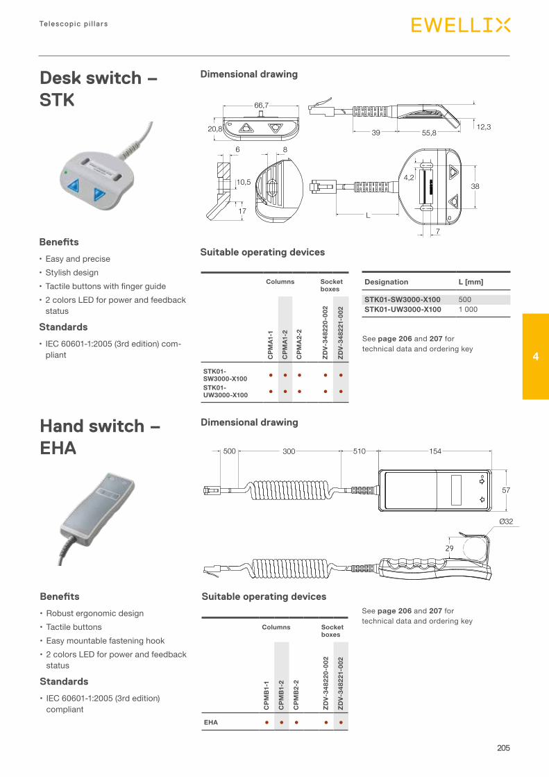
205
Telescopic p i l la rs
4
Hand switch – EHA
Benefits
• Robustergonomicdesign• Tactilebuttons• Easymountablefasteninghook• 2colorsLEDforpowerandfeedbackstatus
Standards
• IEC60601-1:2005(3rdedition)compliant
Columns Socketboxes
CPM
B1-1
CPM
B1-2
CPM
B2-
2
ZDV-34
8220
-002
ZDV-34
8221-002
EHA ● ● ● ● ●
Dimensional drawing
Seepage 206and207 fortechnicaldataandorderingkey
Seepage 206and207 fortechnicaldataandorderingkey
Dimensional drawing
Ø32
500 300 510 154
57
29
Desk switch – STK
Designation L [mm]
STK01-SW3000-X100 500STK01-UW3000-X100 1000
4,2
7
6
10,5
L
55,839
38
17
66,7
20,8
8
12,3
Suitable operating devices
Benefits
• Easyandprecise• Stylishdesign• Tactilebuttonswithfingerguide• 2colorsLEDforpowerandfeedbackstatus
Standards
• IEC60601-1:2005(3rdedition)com-pliant
Columns Socketboxes
CPM
A1-1
CPM
A1-2
CPM
A2-
2
ZDV-34
8220
-002
ZDV-34
8221-002
STK01-SW3000-X100 ● ● ● ● ●STK01-UW3000-X100 ● ● ● ● ●
Suitable operating devices
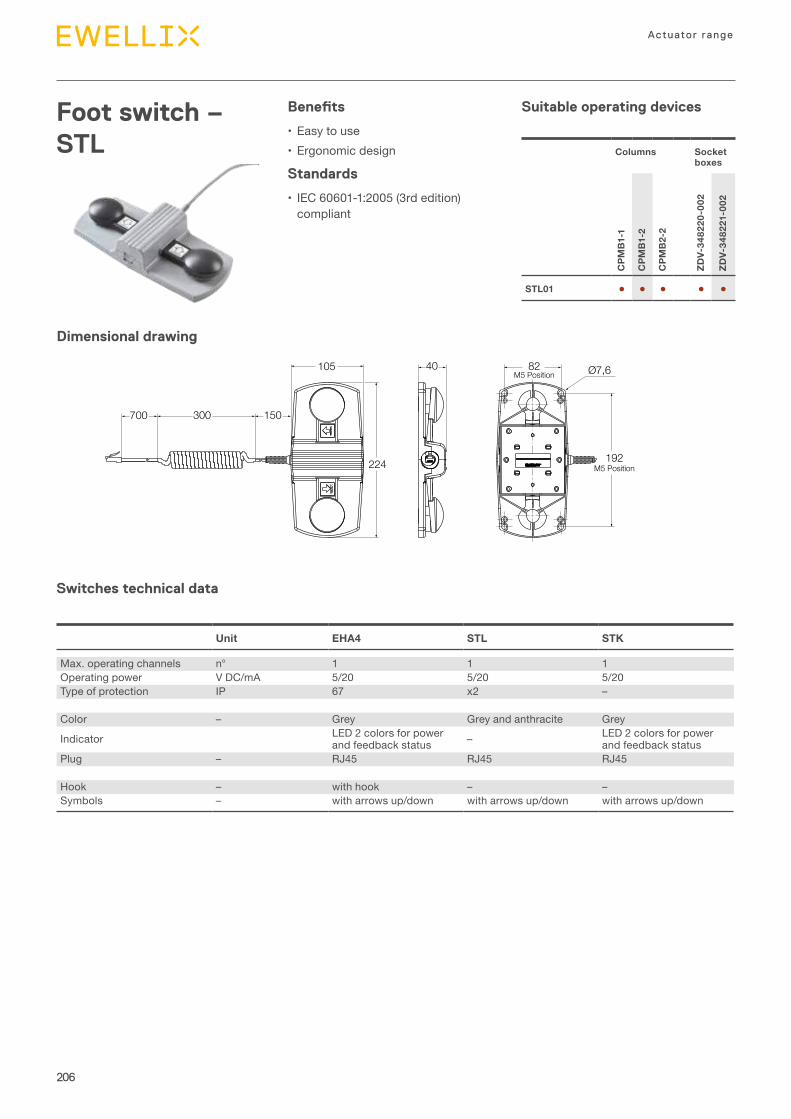
206
Actuator range
Foot switch – STL
Benefits
• Easytouse• Ergonomicdesign
Standards
• IEC60601-1:2005(3rdedition)compliant
Columns Socketboxes
CPM
B1-1
CPM
B1-2
CPM
B2-
2
ZDV-34
8220
-002
ZDV-34
8221-002
STL01 ● ● ● ● ●
Dimensional drawing
82M5 Position Ø7,6
300 150
105
700
224
40
192M5 Position
Switches technical data
Suitable operating devices
Unit EHA4 STL STK
Max.operatingchannels n° 1 1 1Operatingpower VDC/mA 5/20 5/20 5/20Typeofprotection IP 67 x2 –
Color – Grey Greyandanthracite Grey
Indicator LED2colorsforpowerandfeedbackstatus – LED2colorsforpower
andfeedbackstatusPlug – RJ45 RJ45 RJ45
Hook – withhook – –Symbols – witharrowsup/down witharrowsup/down witharrowsup/down
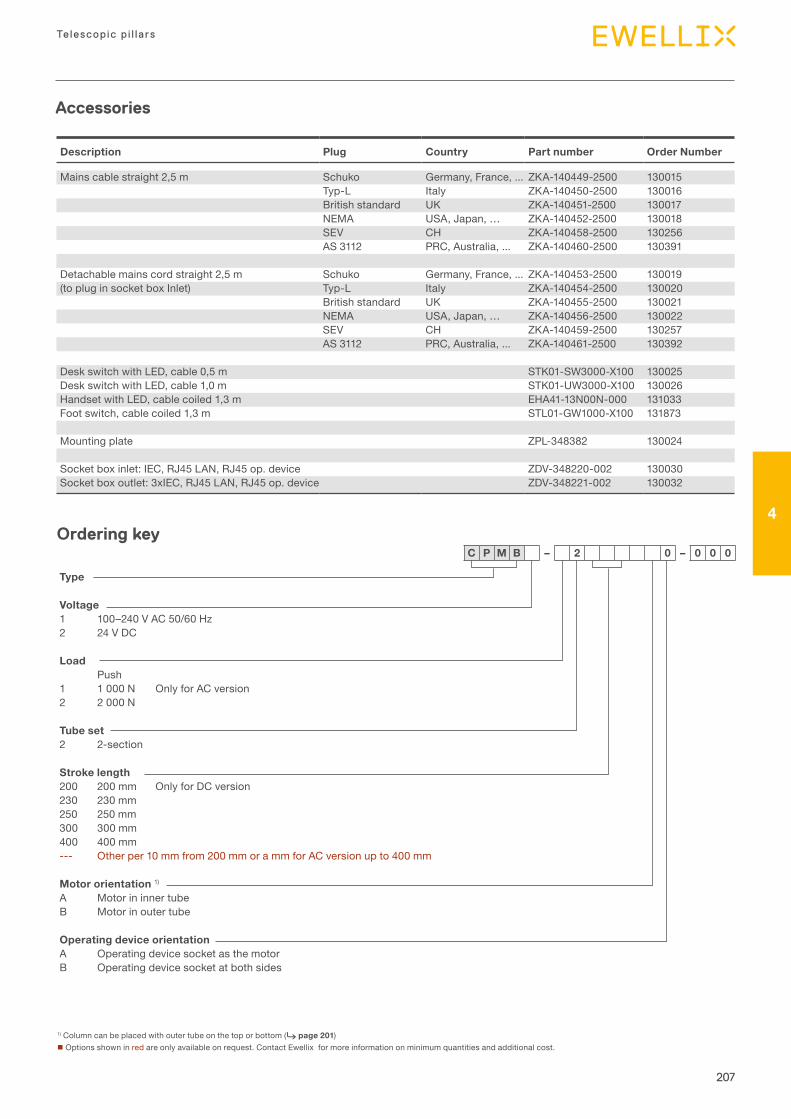
207
Telescopic p i l la rs
4
Type
Voltage1 100–240VAC50/60Hz2 24VDC
LoadPush
1 1000N OnlyforACversion2 2000N
Tube set2 2-section
Stroke length200 200mm OnlyforDCversion230 230mm250 250mm300 300mm400 400mm--- Otherper10mmfrom200mmorammforACversionupto400mm
Motor orientation 1)A MotorininnertubeB Motorinoutertube
Operating device orientationA OperatingdevicesocketasthemotorB Operatingdevicesocketatbothsides
C P M B – 2 0 – 0 0 0
1)Columncanbeplacedwithoutertubeonthetoporbottom(⮑ page 201)nOptionsshowninredareonlyavailableonrequest.ContactEwellixformoreinformationonminimumquantitiesandadditionalcost.
Ordering key
Description Plug Country Part number Order Number
Mainscablestraight2,5m Schuko Germany,France,... ZKA-140449-2500 130015Typ-L Italy ZKA-140450-2500 130016Britishstandard UK ZKA-140451-2500 130017NEMA USA,Japan,… ZKA-140452-2500 130018SEV CH ZKA-140458-2500 130256AS3112 PRC,Australia,... ZKA-140460-2500 130391
Detachablemainscordstraight2,5m Schuko Germany,France,... ZKA-140453-2500 130019(topluginsocketboxInlet) Typ-L Italy ZKA-140454-2500 130020
Britishstandard UK ZKA-140455-2500 130021NEMA USA,Japan,… ZKA-140456-2500 130022SEV CH ZKA-140459-2500 130257AS3112 PRC,Australia,... ZKA-140461-2500 130392
DeskswitchwithLED,cable0,5m STK01-SW3000-X100 130025DeskswitchwithLED,cable1,0m STK01-UW3000-X100 130026HandsetwithLED,cablecoiled1,3m EHA41-13N00N-000 131033Footswitch,cablecoiled1,3m STL01-GW1000-X100 131873
Mountingplate ZPL-348382 130024
Socketboxinlet:IEC,RJ45LAN,RJ45op.device ZDV-348220-002 130030Socketboxoutlet:3xIEC,RJ45LAN,RJ45op.device ZDV-348221-002 130032
Accessories
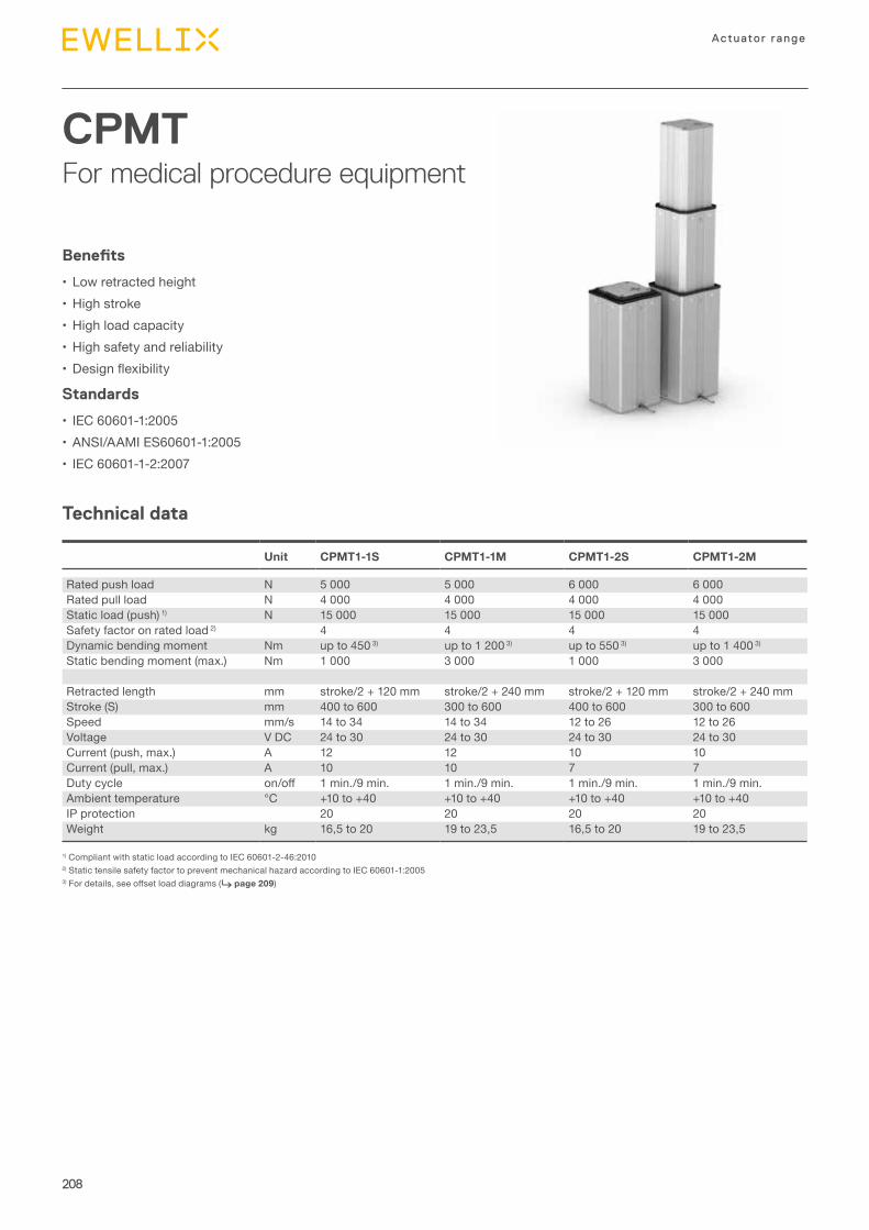
208
Actuator range
CPMTFor medical procedure equipment
Technical data
Benefits
• Lowretractedheight• Highstroke•Highloadcapacity• Highsafetyandreliability• Designflexibility
Standards
• IEC60601-1:2005• ANSI/AAMIES60601-1:2005• IEC60601-1-2:2007
1)CompliantwithstaticloadaccordingtoIEC60601-2-46:20102)StatictensilesafetyfactortopreventmechanicalhazardaccordingtoIEC60601-1:20053)Fordetails,seeoffsetloaddiagrams(⮑ page 209)
Unit CPMT1-1S CPMT1-1M CPMT1-2S CPMT1-2M
Ratedpushload N 5000 5000 6000 6000Ratedpullload N 4000 4000 4000 4000Staticload(push)1) N 15000 15000 15000 15000Safetyfactoronratedload2) 4 4 4 4Dynamicbendingmoment Nm upto4503) upto12003) upto5503) upto14003)
Staticbendingmoment(max.) Nm 1000 3000 1000 3000
Retractedlength mm stroke/2+120mm stroke/2+240mm stroke/2+120mm stroke/2+240mmStroke(S) mm 400to600 300to600 400to600 300to600Speed mm/s 14to34 14to34 12to26 12to26Voltage VDC 24to30 24to30 24to30 24to30Current(push,max.) A 12 12 10 10Current(pull,max.) A 10 10 7 7Dutycycle on/off 1min./9min. 1min./9min. 1min./9min. 1min./9min.Ambienttemperature °C +10to+40 +10to+40 +10to+40 +10to+40IPprotection 20 20 20 20Weight kg 16,5to20 19to23,5 16,5to20 19to23,5
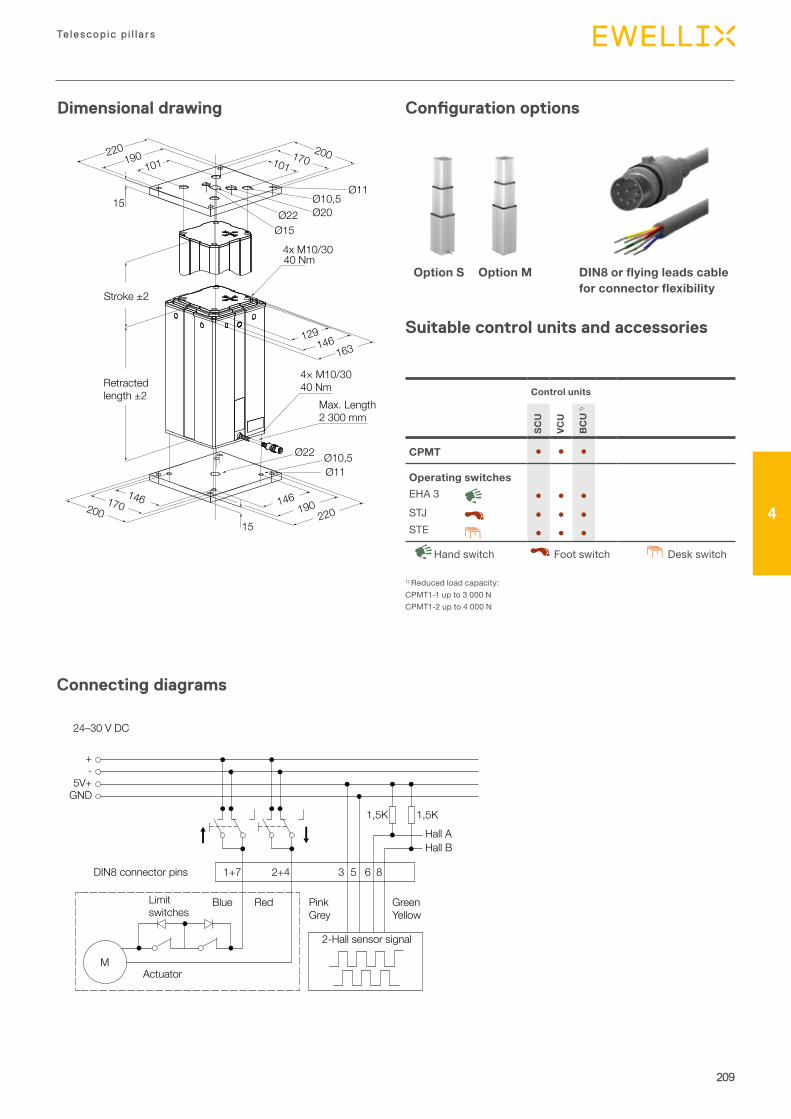
209
Telescopic p i l la rs
4
Dimensional drawing
Connecting diagrams
Configuration options
Suitable control units and accessories
Retractedlength ±2
163146129
146146190170
220200
101 101190 170200220
15
15
Ø22 Ø20
Ø11Ø10,5
Ø15
Ø22 Ø10,5Ø11
4x M10/3040 Nm
4× M10/3040 Nm
Max. Length2 300 mm
Stroke ±2
Option S Option M DIN8 or flying leads cable for connector flexibility
M
1+7 2+4 3 5 6 8
1,5K 1,5KHall AHall B
Blue
2-Hall sensor signal
Actuator
Red GreenYellow
PinkGrey
24–30 V DC
+
5V+GND
-
DIN8 connector pins
Limitswitches
Control units
SCU
VCU
BC
U1)
CPMT ● ● ●
Operating switchesEHA3 ● ● ●STJ ● ● ●STE ● ● ●
DeskswitchHandswitch Footswitch
1)Reducedloadcapacity:CPMT1-1upto3000NCPMT1-2upto4000N
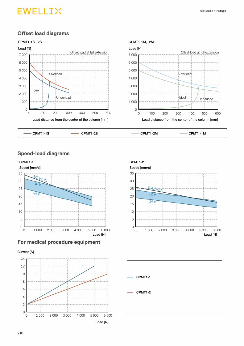
210
Actuator range
Offset load diagrams
Speed-load diagrams
For medical procedure equipment
14
12
10
8
6
4
2
0 0 1 000 2 000 3 000 4 000 5 000 6 000
Current [A]
Load [N]
CPMT1-1
CPMT1-2
7 000
6 000
5 000
4 000
3 000
2 000
1 000
0 0 100 200 300 400 500 600
Load [N]
CPMT1-1S, -2S CPMT1-1M, -2M
0 100 200 300 400 500 600
7 000
6 000
5 000
4 000
3 000
2 000
1 000
0
Offset load at full extensionLoad [N]
Offset load at full extension
Load distance from the center of the column [mm] Load distance from the center of the column [mm]
CPMT1-1S CPMT1-2S CPMT1-2M CPMT1-1M
Overload Overload
Ideal
IdealUnderload Underload
35
30
25
20
15
10
5
0 0 1 000 2 000 3 000 4 000 5 000 6 000
SCU/VCU
24 V
30 V
Speed [mm/s] Speed [mm/s]CPMT1-1 CPMT1-2
Load [N] Load [N]
35
30
25
20
15
10
5
0 0 1 000 2 000 3 000 4 000 5 000 6 000
24 V
SCU/VCU30 V
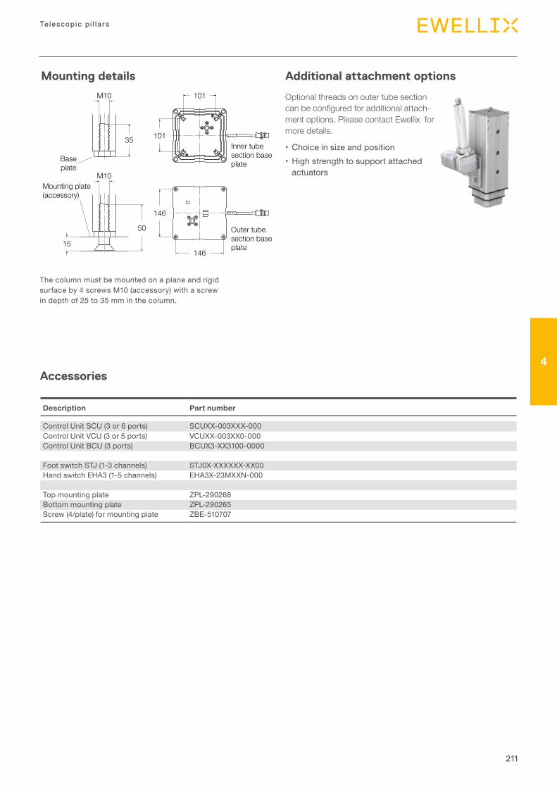
211
Telescopic p i l la rs
4
101
101
146
146
M10
15
50
M10
Baseplate
Mounting plate (accessory)
Outer tubesection baseplate
Inner tubesection baseplate
35
Thecolumnmustbemountedonaplaneandrigidsurfaceby4screwsM10(accessory)withascrewindepthof25to35mminthecolumn.
Optional threads on outer tube section can be configured for additional attach-ment options. Please contact Ewellix for more details.
• Choiceinsizeandposition•Highstrengthtosupportattachedactuators
Description Part number
ControlUnitSCU(3or6ports) SCUXX-003XXX-000ControlUnitVCU(3or5ports) VCUXX-003XX0-000ControlUnitBCU(3ports) BCUX3-XX3100-0000
FootswitchSTJ(1-3channels) STJ0X-XXXXXX-XX00HandswitchEHA3(1-5channels) EHA3X-23MXXN-000
Topmountingplate ZPL-290268Bottommountingplate ZPL-290265Screw(4/plate)formountingplate ZBE-510707
Mounting details Additional attachment options
Accessories
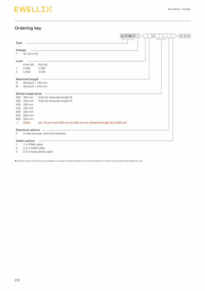
212
Actuator range
Type
Voltage1 24–30VDC
LoadPush(N) Pull(N)
1 5000 40002 6000 4000
Retracted lengthS Stroke/2+120mmM Stroke/2+240mm
Stroke length (mm)300 300mm OnlyforretractedlengthM350 350mm OnlyforretractedlengthM400 400mm450 450mm500 500mm550 550mm600 600mm--- Other per10mmfrom300mm(or400mmforretractedlengthS)to600mm
Electrical optionsF 2-Hallencoder,endlimitswitches
Cable options1 1mDIN8cable2 2,3mDIN8cable3 2,3mflyingleadscable
C P M T 1 – 0 – 0 0 0
nOptionsshowninredareonlyavailableonrequest.ContactEwellixformoreinformationonminimumquantitiesandadditionalcost.
Ordering key

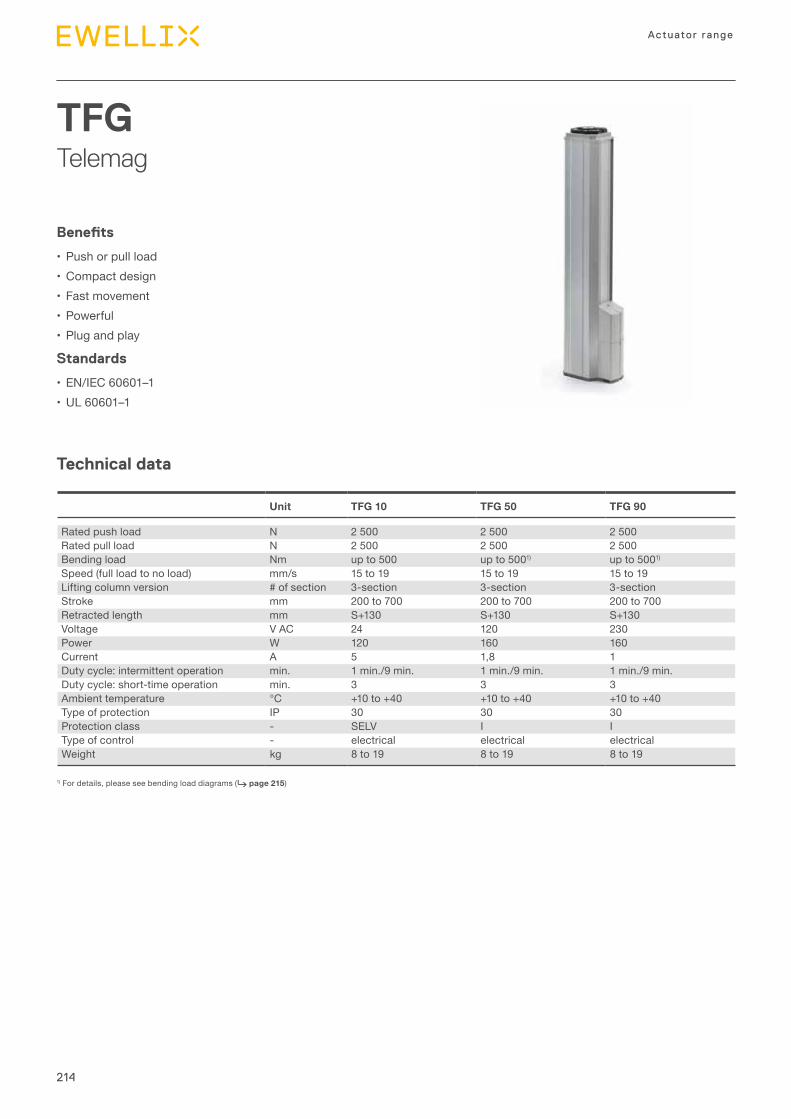
214
Actuator range
TFGTelemag
Technical data
Benefits
• Pushorpullload•Compactdesign• Fastmovement• Powerful• Plugandplay
Standards
• EN/IEC60601–1•UL60601–1
1)Fordetails,pleaseseebendingloaddiagrams(⮑ page 215)
Unit TFG 10 TFG 50 TFG 90
Ratedpushload N 2500 2500 2500Ratedpullload N 2500 2500 2500Bendingload Nm upto500 upto5001) upto5001)Speed(fullloadtonoload) mm/s 15to19 15to19 15to19Liftingcolumnversion #ofsection 3-section 3-section 3-sectionStroke mm 200to700 200to700 200to700Retractedlength mm S+130 S+130 S+130Voltage VAC 24 120 230Power W 120 160 160Current A 5 1,8 1Dutycycle:intermittentoperation min. 1min./9min. 1min./9min. 1min./9min.Dutycycle:short-timeoperation min. 3 3 3Ambienttemperature °C +10to+40 +10to+40 +10to+40Typeofprotection IP 30 30 30Protectionclass - SELV I ITypeofcontrol - electrical electrical electricalWeight kg 8to19 8to19 8to19
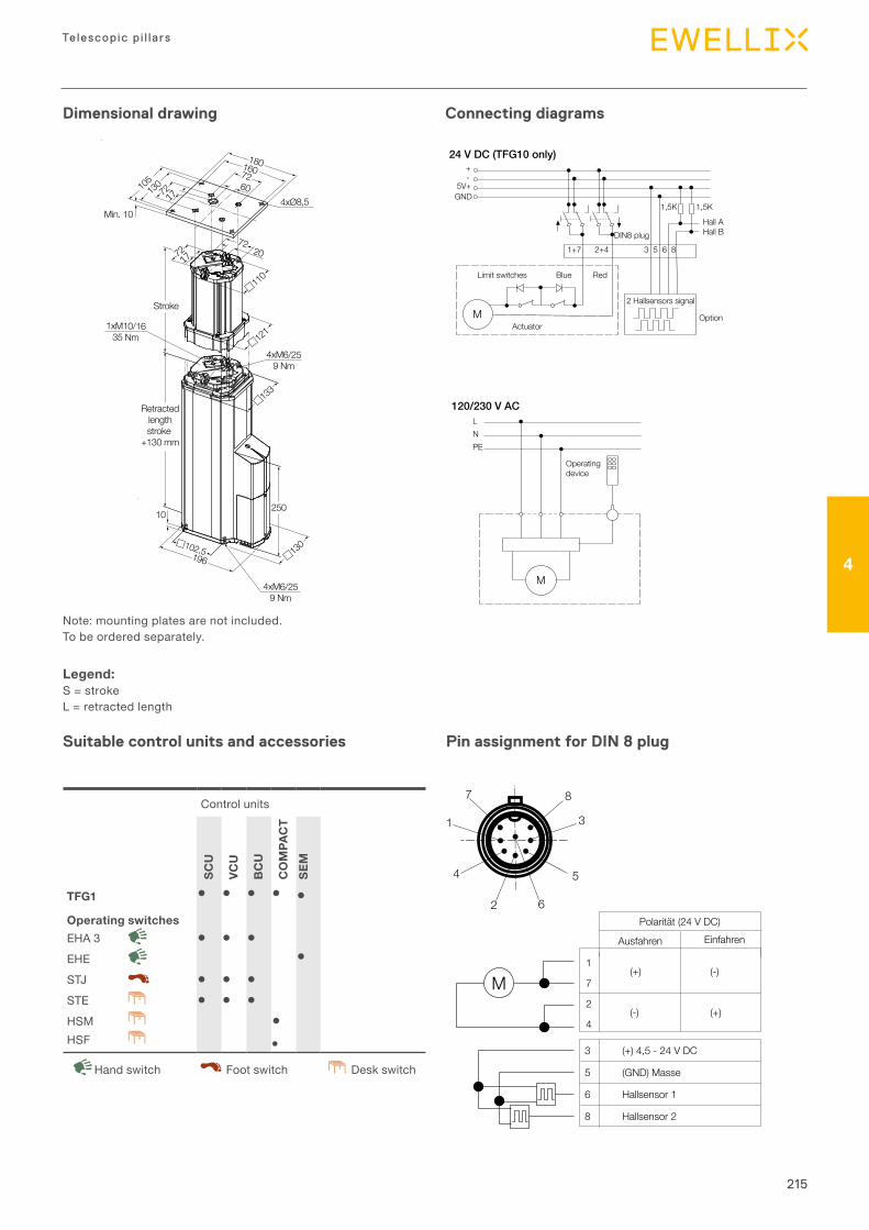
215
Telescopic p i l la rs
4
Dimensional drawing Connecting diagrams
Suitable control units and accessories Pin assignment for DIN 8 plug
Controlunits
SCU
VCU
BC
U
CO
MPA
CT
SEM
TFG1 � � � � �Operating switchesEHA3 � � �EHE �STJ � � �STE � � �HSM �HSF ●
DeskswitchHandswitch Footswitch
Note:mountingplatesarenotincluded.Tobeorderedseparately.
Legend:S=strokeL=retractedlength
1xM10/1635 Nm
Min. 10
10250
7220
4xM6/259 Nm
4xM6/259 Nm
Stroke
Retractedlengthstroke
+130 mm
105
180
4xØ8,5
160726013072
72
110
121
133
130102,5196
17
17
M
24 V DC (TFG10 only) +-
5V+GND
1+7 2+4
1,5K 1,5K
3 5 6 8DIN8 plug
M
LNPE
120/230 V AC
Limit switches Blue Red
Hall AHall B
ActuatorOption
2 Hallsensors signal
Operatingdevice
M
24 V DC (TFG10 only) +-
5V+GND
1+7 2+4
1,5K 1,5K
3 5 6 8DIN8 plug
M
LNPE
120/230 V AC
Limit switches Blue Red
Hall AHall B
ActuatorOption
2 Hallsensors signal
Operatingdevice
1
2
4
6
5
3
87
Polaritӓt (24 V DC)
3 (+) 4,5 - 24 V DC
5 (GND) Masse
6 Hallsensor 1
8 Hallsensor 2
1
7
2
4
(+)
(-)
(-)
(+)
EinfahrenAusfahren
M
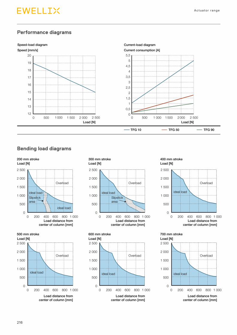
216
Actuator range
Performance diagrams
Bending load diagrams
200 mm stroke 300 mm stroke 400 mm stroke
500 mm stroke 600 mm stroke 700 mm stroke
Load [N] Load [N] Load [N]
Load [N] Load [N] Load [N]
Overload
Overload
Overload
Overload
Overload
Overload
2 500
2 000
1 500
1 000
500
00 200 400 600 800 1 000
2 500
2 000
1 500
1 000
500
00 200 400 600 800 1 000
2 500
2 000
1 500
1 000
500
00 200 400 600 800 1 000
2 500
2 000
1 500
1 000
500
00 200 400 600 800 1 000
2 500
2 000
1 500
1 000
500
00 200 400 600 800 1 000
2 500
2 000
1 500
1 000
500
00 200 400 600 800 1 000
ideal load
ideal load ideal loadideal load
ideal load ideal load ideal load
Slipstickarea
Slipstickarea
Load distance fromcenter of column [mm]
Load distance fromcenter of column [mm]
Load distance fromcenter of column [mm]
Load distance fromcenter of column [mm]
Load distance fromcenter of column [mm]
Load distance fromcenter of column [mm]
Speed [mm/s]
Load [N]
Current consumption [A]Current-load diagram
Load [N]
TFG 10 TFG 50 TFG 90
Speed-load diagram
12
13
14
15
16
17
18
19
20
0 500 1 000 1 500 2 000 2 500
5,55
4,54
3,53
2,52
1,51
0,50
0 500 1 000 1 500 2 000 2 500
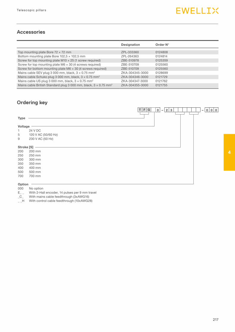
217
Telescopic p i l la rs
4
Designation Order N°
TopmountingplateBore72×72mm ZPL-333360 0124808BottommountingplateBore102,5×102,5mm ZPL-264363 0124814ScrewfortopmountingplateM10×25(1screwrequired) ZBE-510978 0125359ScrewfortopmountingplateM6×30(4screwsrequired) ZBE-510709 0125560ScrewforbottommountingplateM6×30(4screwsrequired) ZBE-510709 0125560MainscableSEVplug3000mm,black,3×0.75mm2 ZKA-304345-3000 0128699MainscableSchukoplug3000mm,black,3×0.75mm2 ZKA-304346-3000 0121729MainscableUSplug3000mm,black,3×0.75mm2 ZKA-304347-3000 0121762MainscableBritishStandardplug3000mm,black,3×0.75mm2 ZKA-304355-3000 0121755
Ordering key
Accessories
T F G 0 – 2 3 – 0 0 0
Type
Voltage1 24VDC5 120VAC(50/60Hz)9 230VAC(50Hz)
Stroke [S]200 200mm250 250mm300 300mm350 350mm400 400mm500 500mm700 700mm
Option000 NooptionE__ With2-Hallencoder,14pulsesper9mmtravel_C_ Withmainscablefeedthrough(3xAWG16)__H Withcontrolcablefeedthrough(10xAWG28)
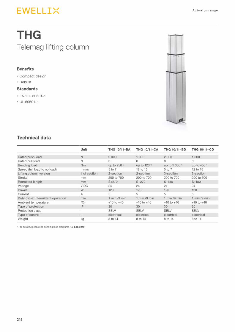
218
Actuator range
THGTelemag lifting column
Technical data
Benefits
• Compactdesign• Robust
Standards
• EN/IEC60601–1•UL60601–1
1)Fordetails,pleaseseebendingloaddiagrams(⮑ page 219)
Unit THG 10/11–BA THG 10/11–CA THG 10/11–BD THG 10/11–CD
Ratedpushload N 2000 1000 2000 1000Ratedpullload N 0 0 0 0Bendingload Nm upto2501) upto1201) upto10001) upto4501)
Speed(fullloadtonoload) mm/s 5to7 12to15 5to7 12to15Liftingcolumnversion #ofsection 2-section 2-section 3-section 3-sectionStroke mm 200to700 200to700 200to700 200to700Retractedlength mm S+270 S+270 S+180 S+180Voltage VDC 24 24 24 24Power W 120 120 120 120Current A 5 5 5 5Dutycycle:intermittentoperation min. 1min./9min 1min./9min 1min./9min 1min./9minAmbienttemperature °C +10to+40 +10to+40 +10to+40 +10to+40Typeofprotection IP 30 30 30 30Protectionclass – SELV SELV SELV SELVTypeofcontrol – electrical electrical electrical electricalWeight kg 8to14 8to14 8to14 8to14
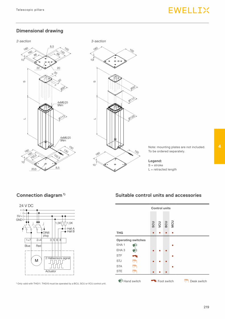
219
Telescopic p i l la rs
4
Dimensional drawing
Suitable control units and accessories
Control units
SCU
VCU
BC
U
MC
U
THG ● ● ● ●
Operating switchesEHA1 ●EHA3 ● ● ●STF ●STJ ● ● ●STA ●STE ● ● ●
DeskswitchHandswitch Footswitch
Note:mountingplatesarenotincluded.Tobeorderedseparately.
Legend:S=strokeL=retractedlength
180160
86
10
8,5
2022
15013086
20
20
4xM6/259Nm
4xM6/259Nm
180160
102,5
10
8,20,
150130102,5
97
113
180
10
150
97
10
180 150
113
129
LS
LS
55
Connection diagram 1)
24 V DC+-
5V+GND
1+7 2+4
1,5K 1,5K
Hall AHall B
Hall AHall B
3 5 6 8 3 5 6 8
DIN8 plug
Blue Red
M2 Hallsensors signal
Actuator
M
1+7 2+4
1,5K 1,5K
Actuator
2 Hallsensors signal
RedBlue
DIN8 plug
Jack Plug 24 V DC+-
5V+GND
Black Red
MActuator
Black Red
MActuator
Only valid with TLT11. TLT10 must be operated by a *BCU, SCU or VCU control unit.
1)OnlyvalidwithTHG11.THG10mustbeoperatedbyaBCU,SCUorVCUcontrolunit.
2-section 3-section
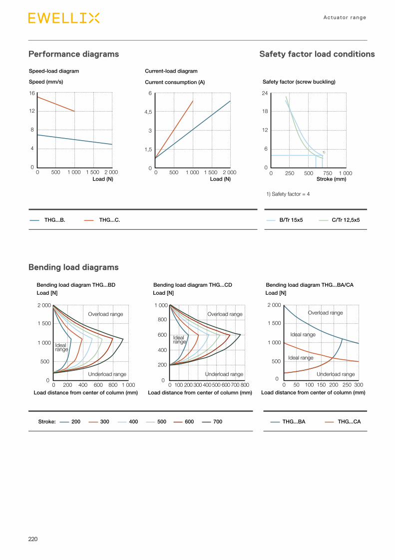
220
Actuator range
Performance diagrams Safety factor load conditions
Bending load diagrams
THG...B. THG...C. B/Tr 15x5 C/Tr 12,5x5
Speed (mm/s) Current consumption (A)
00 500 1 000 1 500 2 000
1,5
3
4,5
6
Speed-load diagram Current-load diagram
1) Safety factor = 4
00 500 1 000 1 500 2 000
4
8
12
16
Load (N) Load (N)
00 250 500 750 1 000
6
12
18
24
1)
Safety factor (screw buckling)
Stroke (mm)
Load [N] Load [N]Load [N]
200Stroke: THG...BA THG...CA300 400 500 600 700
Bending load diagram THG...BD Bending load diagram THG...CD Bending load diagram THG...BA/CA
00 100
200
400
1 000
600
800
200 300 400 500 600 700 800
Overload range
Underload range
Ideal range
Load distance from center of column (mm)
00 200 400 600 1 000
500
1 000
1 500
2 000
800Load distance from center of column (mm)
Overload range
Underload range
Ideal range
00 50 100
500
1 000
1 500
2 000
150 200 300250Load distance from center of column (mm)
Underload range
Ideal range
Ideal range
Overload range
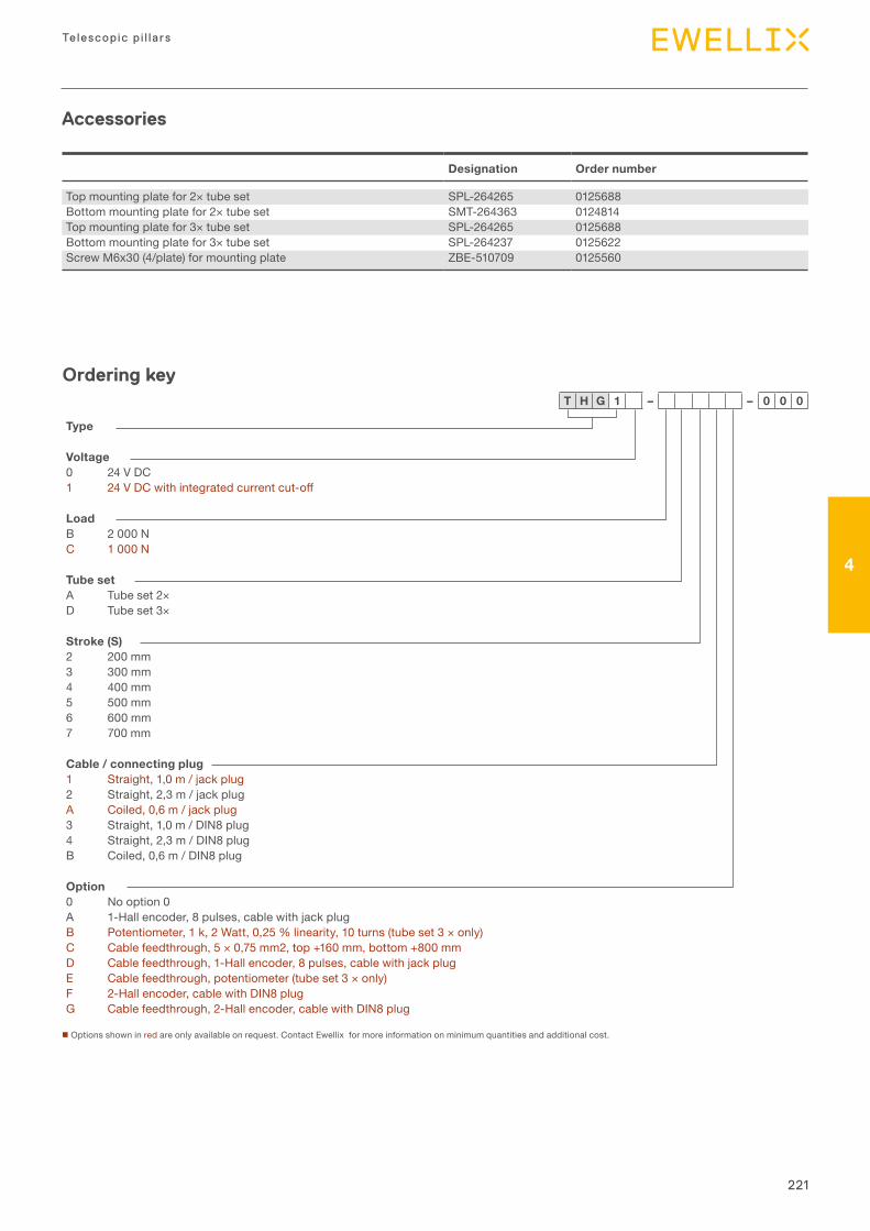
221
Telescopic p i l la rs
4
Safety factor load conditions
Designation Order number
Topmountingplatefor2×tubeset SPL-264265 0125688Bottommountingplatefor2×tubeset SMT-264363 0124814Topmountingplatefor3×tubeset SPL-264265 0125688Bottommountingplatefor3×tubeset SPL-264237 0125622ScrewM6x30(4/plate)formountingplate ZBE-510709 0125560
Accessories
Type
Voltage0 24VDC1 24VDCwithintegratedcurrentcut-off
LoadB 2000NC 1000N
Tube setA Tubeset2×D Tubeset3×
Stroke (S)2 200mm3 300mm4 400mm5 500mm6 600mm7 700mm
Cable / connecting plug1 Straight,1,0m/jackplug2 Straight,2,3m/jackplugA Coiled,0,6m/jackplug3 Straight,1,0m/DIN8plug4 Straight,2,3m/DIN8plugB Coiled,0,6m/DIN8plug
Option0 Nooption0A 1-Hallencoder,8pulses,cablewithjackplugB Potentiometer,1k,2Watt,0,25%linearity,10turns(tubeset3×only)C Cablefeedthrough,5×0,75mm2,top+160mm,bottom+800mmD Cablefeedthrough,1-Hallencoder,8pulses,cablewithjackplugE Cablefeedthrough,potentiometer(tubeset3×only)F 2-Hallencoder,cablewithDIN8plugG Cablefeedthrough,2-Hallencoder,cablewithDIN8plug
Ordering key
nOptionsshowninredareonlyavailableonrequest.ContactEwellixformoreinformationonminimumquantitiesandadditionalcost.
T H G 1 – – 0 0 0
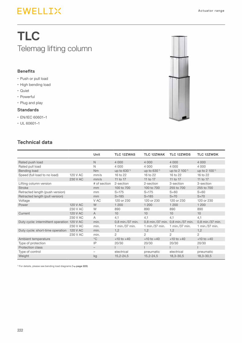
222
Actuator range
TLCTelemag lifting column
Technical data
Benefits
• Pushorpullload•Highbendingload•Quiet• Powerful• Plugandplay
Standards
• EN/IEC60601–1•UL60601–1
1)Fordetails,pleaseseebendingloaddiagrams(⮑ page 223)
Unit TLC 12ZWAS TLC 12ZWAK TLC 12ZWDS TLC 12ZWDK
Ratedpushload N 4000 4000 4000 4000Ratedpullload N 4000 4000 4000 4000Bendingload Nm upto6301) upto6301) upto21001) upto21001)
Speed(fullloadtonoload) 120VAC mm/s 16to22 16to22 16to22 16to22230VAC mm/s 11to17 11to17 11to17 11to17
Liftingcolumnversion #ofsection 2-section 2-section 3-section 3-sectionStroke mm 100to700 100to700 255to700 255to700Retractedlength(pushversion) mm S+175 S+175 S+60 S+60Retractedlength(pullversion) mm S+185 S+185 S+70 S+70Voltage VAC 120or230 120or230 120or230 120or230Power 120VAC W 1200 1200 1200 1200
230VAC W 890 890 890 890Current 120VAC A 10 10 10 10
230VAC A 4,1 4,1 4,1 4,1Dutycycle:intermittentoperation 120VAC min. 0,8min./37min. 0,8min./37min. 0,8min./37min. 0,8min./37min.
230VAC min. 1min./37min. 1min./37min. 1min./37min. 1min./37min.Dutycycle:short-timeoperation 120VAC min. 1,2 1,2 1,2 1,2
230VAC min. 2 2 2 2Ambienttemperature °C +10to+40 +10to+40 +10to+40 +10to+40Typeofprotection IP 20/30 20/30 20/30 20/30Protectionclass – I I I ITypeofcontrol – electrical pneumatic electrical pneumaticWeight kg 15,2-24,5 15,2-24,5 18,3-30,5 18,3-30,5
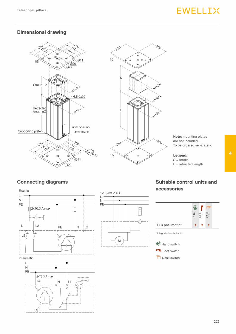
223
Telescopic p i l la rs
4
Dimensional drawing
Connecting diagrams Suitable control units and accessories
PHC
PFP
PAM
TLC pneumatic* ● ● ●
Deskswitch
Handswitch
Footswitch
Note:mountingplatesarenotincluded.Tobeorderedseparately.
Legend:S=strokeL=retractedlength
220190
101
200170101
15 Ø20Ø11
Ø22
Retractedlength ±2
Stroke ±2
4xM10x30
4xM10x30
220190
129
200170129
15 Ø11Ø22
Supporting plateLabel position
220
15
L
S
200
15
220 200
163
146
146
129129
LNPE
L1 L2
LS
N L3PE
2xT6,3 A max
Electric
LNPE
N2xT6,3 A max
L1PE
LS
Pneumatic
LN
M
PE
120-230 V AC
*Integratedcontrolunit
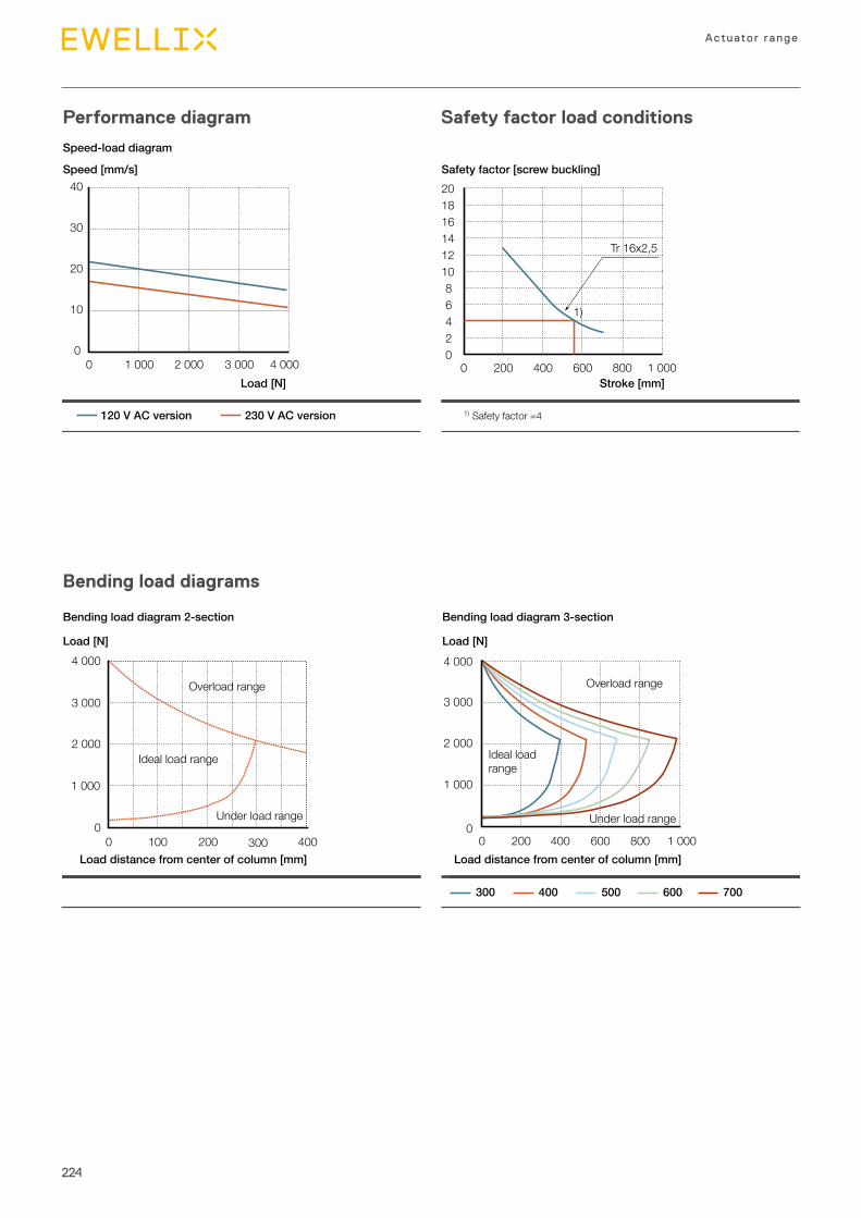
224
Actuator range
Performance diagram
Bending load diagrams
Safety factor load conditions
3 000
4 000
2 000
1 000
00 100 200 300 400
3 000
4 000
2 000
1 000
00 200 400 600 1 000800
Load [N]
Bending load diagram 2-section Bending load diagram 3-section
Load distance from center of column [mm] Load distance from center of column [mm]
Load [N]
300 400 500 600 700
Overload range Overload range
Ideal load range Ideal loadrange
Under load range Under load range
0
10
20
30
40
0 1 000 2 000 3 000 4 000
Speed [mm/s]
Load [N]
Safety factor [screw buckling]
Stroke [mm]
120 V AC version 230 V AC version 1) Safety factor =4
20
0 200
468
101214161820
400 600 800 1 000
1)
Tr 16x2,5
Speed-load diagram
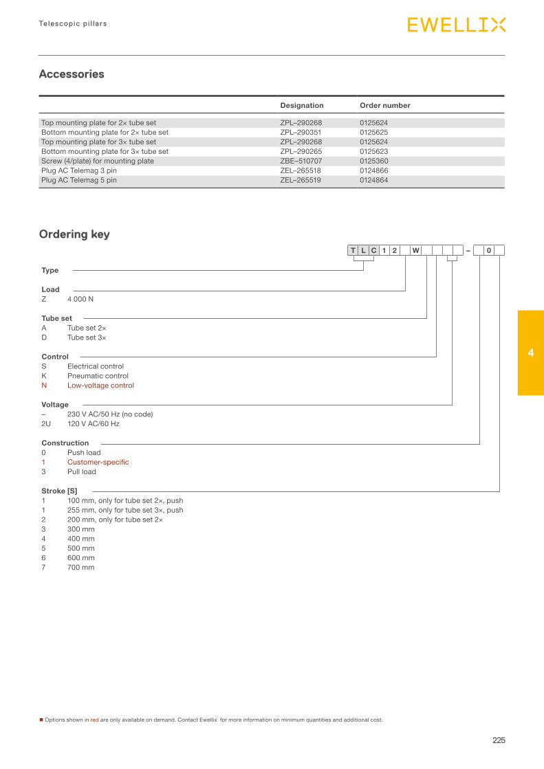
225
Telescopic p i l la rs
4
Type
LoadZ 4000N
Tube setA Tubeset2×D Tubeset3×
ControlS ElectricalcontrolK PneumaticcontrolN Low-voltagecontrol
Voltage– 230VAC/50Hz(nocode)2U 120VAC/60Hz
Construction0 Pushload1 Customer-specific3 Pullload
Stroke [S]1 100mm,onlyfortubeset2×,push1 255mm,onlyfortubeset3×,push2 200mm,onlyfortubeset2×3 300mm4 400mm5 500mm6 600mm7 700mm
T L C 1 2 W – 0
nOptionsshowninredareonlyavailableondemand.ContactEwellixformoreinformationonminimumquantitiesandadditionalcost.
Ordering key
Designation Order number
Topmountingplatefor2×tubeset ZPL–290268 0125624Bottommountingplatefor2×tubeset ZPL–290351 0125625Topmountingplatefor3×tubeset ZPL–290268 0125624Bottommountingplatefor3×tubeset ZPL–290265 0125623Screw(4/plate)formountingplate ZBE–510707 0125360PlugACTelemag3pin ZEL–265518 0124866PlugACTelemag5pin ZEL–265519 0124864
Accessories
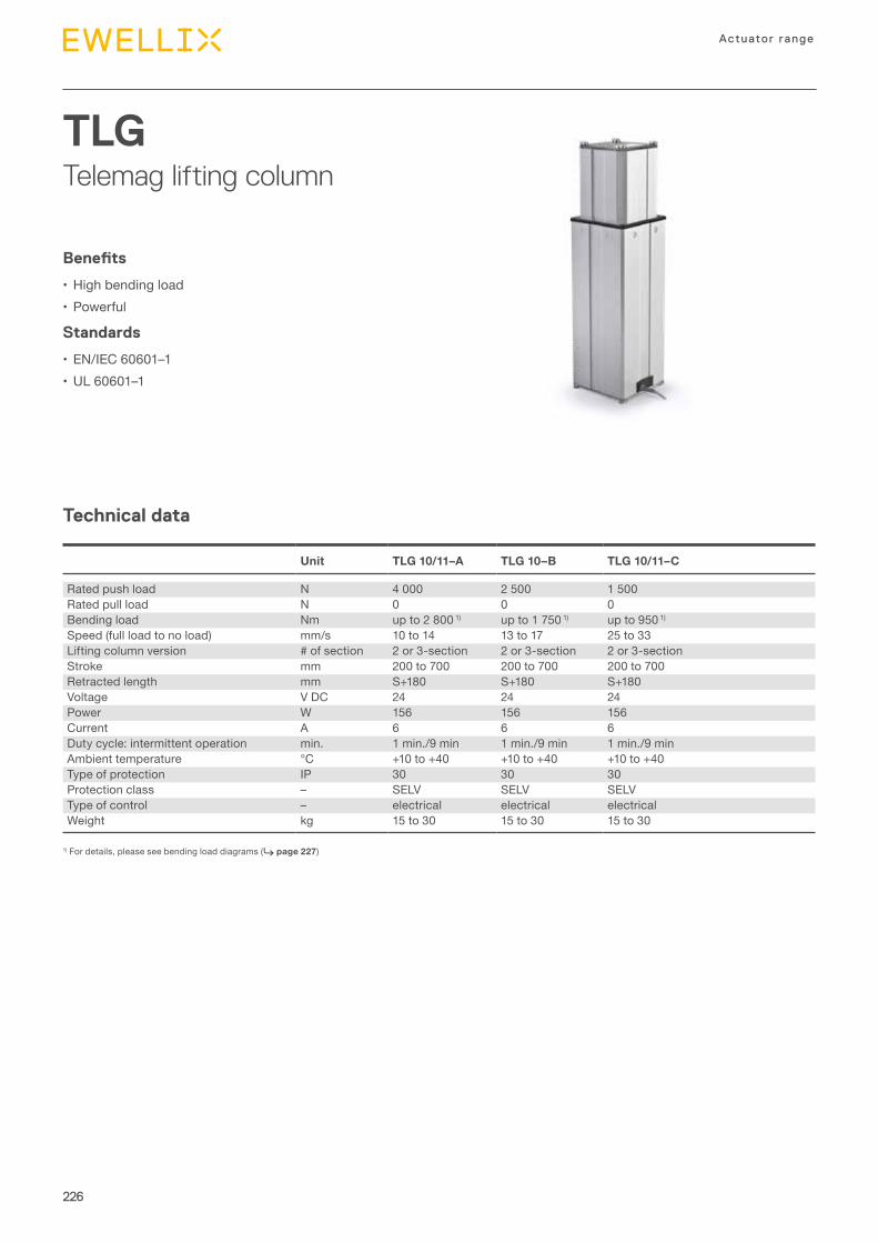
226
Actuator range
TLGTelemag lifting column
Technical data
Benefits
• Highbendingload• Powerful
Standards
• EN/IEC60601–1•UL60601–1
1)Fordetails,pleaseseebendingloaddiagrams(⮑ page 227)
Unit TLG 10/11–A TLG 10–B TLG 10/11–C
Ratedpushload N 4000 2500 1500Ratedpullload N 0 0 0Bendingload Nm upto28001) upto17501) upto9501)
Speed(fullloadtonoload) mm/s 10to14 13to17 25to33Liftingcolumnversion #ofsection 2or3-section 2or3-section 2or3-sectionStroke mm 200to700 200to700 200to700Retractedlength mm S+180 S+180 S+180Voltage VDC 24 24 24Power W 156 156 156Current A 6 6 6Dutycycle:intermittentoperation min. 1min./9min 1min./9min 1min./9minAmbienttemperature °C +10to+40 +10to+40 +10to+40Typeofprotection IP 30 30 30Protectionclass – SELV SELV SELVTypeofcontrol – electrical electrical electricalWeight kg 15to30 15to30 15to30
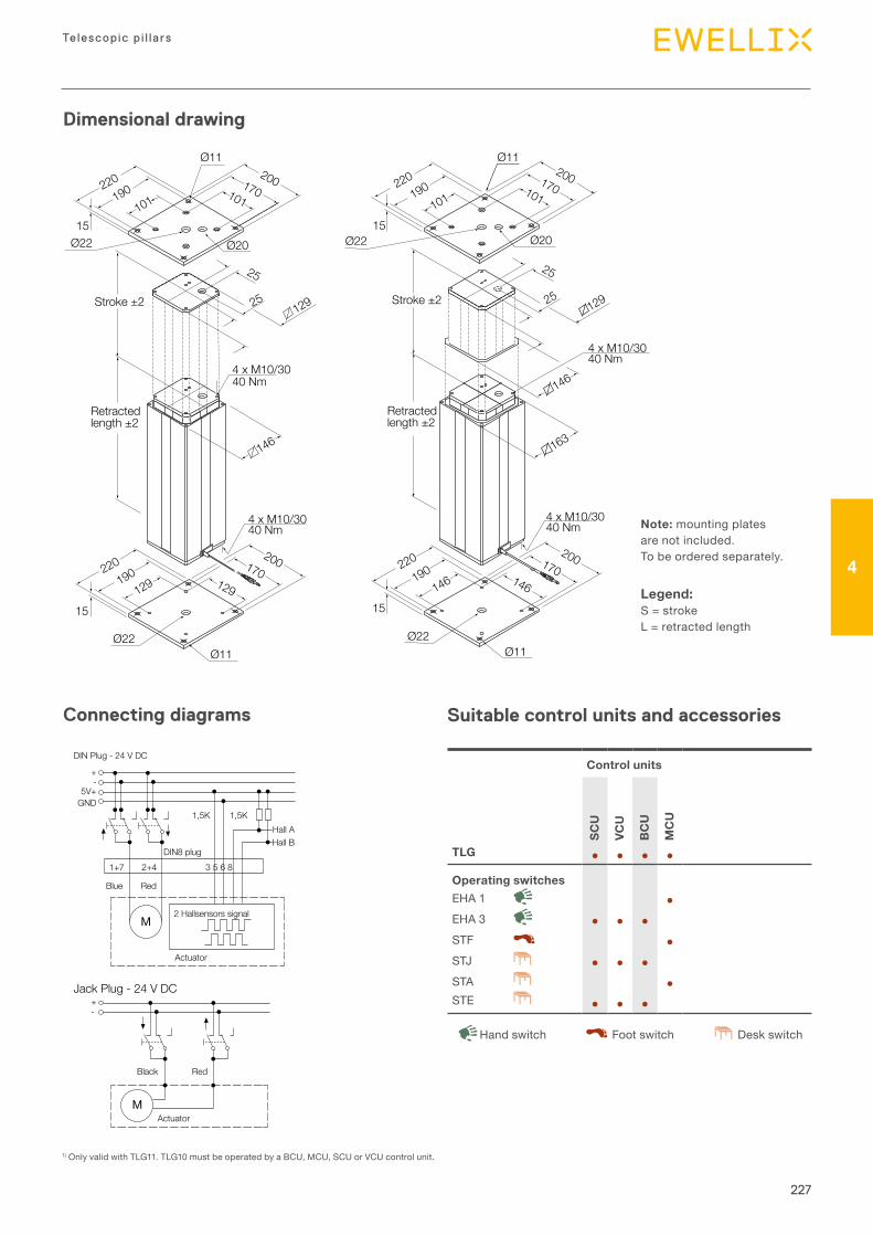
227
Telescopic p i l la rs
4
Dimensional drawing
Connecting diagrams Suitable control units and accessories
Note:mountingplatesarenotincluded.Tobeorderedseparately.
Legend:S=strokeL=retractedlength
220190
101
15Ø22
Ø11200170101
Ø20
25
25
129
146
4 x M10/3040 Nm
4 x M10/3040 Nm
220190
129
15
200170129
Ø11Ø22
Ø11Ø22
Stroke ±2
Retractedlength ±2
220190
101
Ø22
Ø11200170101
Ø20
25
25
129
146
163
4 x M10/3040 Nm
4 x M10/3040 Nm
220190
146
15
200170146
15
Stroke ±2
Retractedlength ±2
1)OnlyvalidwithTLG11.TLG10mustbeoperatedbyaBCU,MCU,SCUorVCUcontrolunit.
DIN Plug - 24 V DC
+-
M
5V+GND
1+7 2+4 3 5 6 8DIN8 plug
Blue
2 Hallsensors signal
Actuator
Red
+-
M
Black
Actuator
Red
Jack Plug - 24 V DC
1,5K 1,5KHall AHall B
Control units
SCU
VCU
BC
U
MC
U
TLG ● ● ● ●
Operating switchesEHA1 ●EHA3 ● ● ●STF ●STJ ● ● ●STA ●STE ● ● ●
DeskswitchHandswitch Footswitch
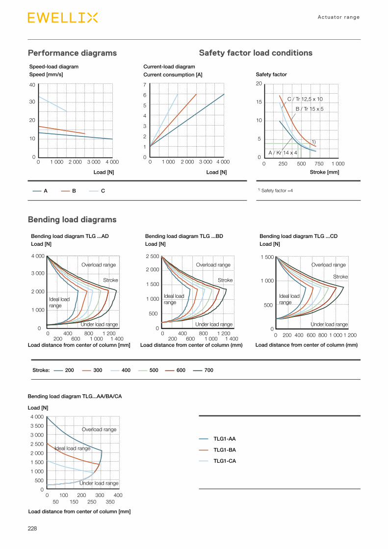
228
Actuator range
Performance diagrams
Bending load diagrams
Safety factor load conditions
40
30
20
10
4 0003 0002 0001 00000
7
5
6
3
4
2
1
4 0003 0002 0001 00000
Current consumption [A] Safety factorSpeed [mm/s]
A B C
Speed-load diagram Current-load diagram
Load [N] Load [N] Stroke [mm]
20
C / Tr 12,5 x 10
B / Tr 15 x 5
A / Kr 14 x 4
15
10
5
1 000750
1)
50025000
1) Safety factor =4
Load [N] Load [N]Load [N]
200Stroke: 300 400 500 600 700
00 400 800 1 200
200 600 1 000 1 400
3 000
4 000
2 000
1 000
Bending load diagram TLG ...AD Bending load diagram TLG ...BD Bending load diagram TLG ...CD
Load distance from center of column (mm)Load distance from center of column [mm]
Overload range
Stroke
Ideal loadrange
Load distance from center of column (mm)
0 400 800 1 200 200 600 1 000 1 400
0
2 500
2 000
1 000
500
1 500
00 200 400 600 800 1 000 1 200
500
1 000
1 500
Under load range
Overload range
Stroke
Ideal loadrange
Under load range
Overload range
Stroke
Ideal loadrange
Under load range
Load [N]
Bending load diagram TLG...AA/BA/CA
Load distance from center of column [mm]
TLG1-AA
TLG1-BA
TLG1-CA
0 100 200 300 40050 150 250 350
1 000
0500
1 5002 0002 5003 0003 5004 000
Overload range
Ideal load range
Under load range
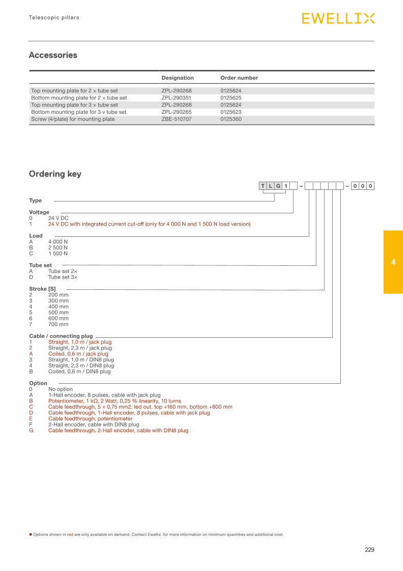
229
Telescopic p i l la rs
4
Accessories
Designation Order number
Topmountingplatefor2×tubeset ZPL-290268 0125624Bottommountingplatefor2×tubeset ZPL-290351 0125625Topmountingplatefor3×tubeset ZPL-290268 0125624Bottommountingplatefor3vtubeset ZPL-290265 0125623Screw(4/plate)formountingplate ZBE-510707 0125360
nOptionsshowninredareonlyavailableondemand.ContactEwellixformoreinformationonminimumquantitiesandadditionalcost.
Ordering key
Type
Voltage0 24VDC1 24VDCwithintegratedcurrentcut-off(onlyfor4000Nand1500Nloadversion)
LoadA 4000NB 2500NC 1500N
Tube setA Tubeset2×D Tubeset3×
Stroke [S]2 200mm3 300mm4 400mm5 500mm6 600mm7 700mm
Cable / connecting plug1 Straight,1,0m/jackplug2 Straight,2,3m/jackplugA Coiled,0,6m/jackplug3 Straight,1,0m/DIN8plug4 Straight,2,3m/DIN8plugB Coiled,0,6m/DIN8plug
Option0 NooptionA 1-Hallencoder,8pulses,cablewithjackplugB Potentiometer,1kΩ,2Watt,0,25%linearity,10turnsC Cablefeedthrough,5×0,75mm2,ledout,top+160mm,bottom+800mmD Cablefeedthrough,1-Hallencoder,8pulses,cablewithjackplugE Cablefeedthrough,potentiometerF 2-Hallencoder,cablewithDIN8plugG Cablefeedthrough,2-Hallencoder,cablewithDIN8plug
T L G 1 – – 0 0 0
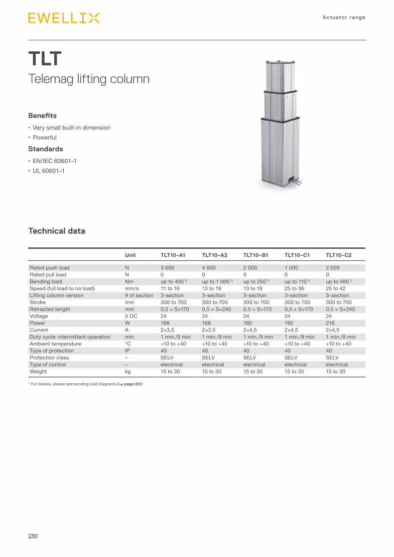
230
Actuator range
TLTTelemag lifting column
Technical data
Benefits
• Verysmallbuilt-indimension• Powerful
Standards
• EN/IEC60601–1•UL60601–1
1)Fordetails,pleaseseebendingloaddiagrams(⮑ page 231)
Unit TLT10–A1 TLT10–A2 TLT10–B1 TLT10–C1 TLT10–C2
Ratedpushload N 3000 4000 2000 1000 2000Ratedpullload N 0 0 0 0 0Bendingload Nm upto4001) upto10001) upto2501) upto1101) upto4801)
Speed(fullloadtonoload) mm/s 11to16 13to19 13to19 25to36 25to42Liftingcolumnversion #ofsection 3-section 3-section 3-section 3-section 3-sectionStroke mm 300to700 300to700 300to700 300to700 300to700Retractedlength mm 0,5×S+170 0,5×S+240 0,5×S+170 0,5×S+170 0,5×S+240Voltage VDC 24 24 24 24 24Power W 168 168 192 192 216Current A 2×3,5 2×3,5 2×4,5 2×4,5 2×4,5Dutycycle:intermittentoperation min. 1min./9min 1min./9min 1min./9min 1min./9min 1min./9minAmbienttemperature °C +10to+40 +10to+40 +10to+40 +10to+40 +10to+40Typeofprotection IP 40 40 40 40 40Protectionclass – SELV SELV SELV SELV SELVTypeofcontrol – electrical electrical electrical electrical electricalWeight kg 15to30 15to30 15to30 15to30 15to30
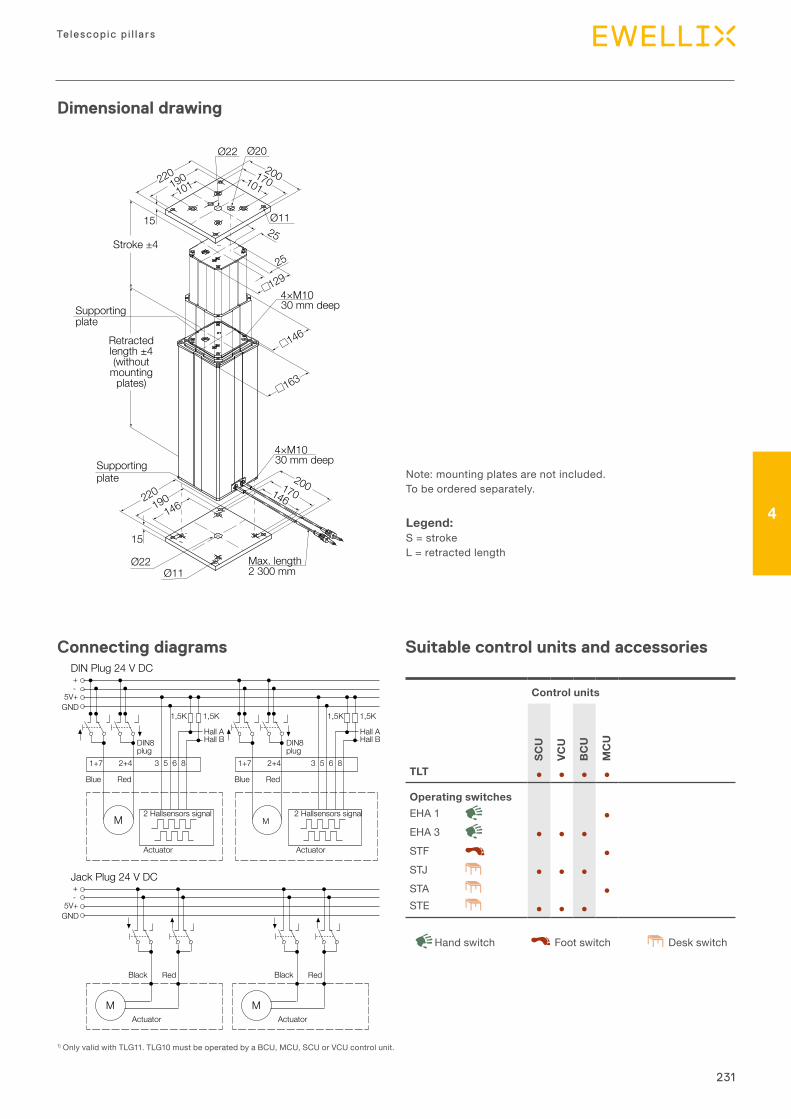
231
Telescopic p i l la rs
4
Dimensional drawing
Connecting diagrams Suitable control units and accessories
Note:mountingplatesarenotincluded.Tobeorderedseparately.
Legend:S=strokeL=retractedlength
1)OnlyvalidwithTLG11.TLG10mustbeoperatedbyaBCU,MCU,SCUorVCUcontrolunit.
Control units
SCU
VCU
BC
U
MC
U
TLT ● ● ● ●
Operating switchesEHA1 ●EHA3 ● ● ●STF ●STJ ● ● ●STA ●STE ● ● ●
DeskswitchHandswitch Footswitch
15 Ø11
Ø22 Ø20
220190
101200
25
170101
Stroke ±425
4×M1030 mm deep
4×M1030 mm deep
129
146
163
Supportingplate
Supportingplate
Retractedlength ±4(without
mountingplates)
200170146
15
220190
146
Ø22Ø11
Max. length2 300 mm
Legend:S = strokeL = retracted length
Note: mounting plates are not included. To be ordered separately.
DIN Plug 24 V DC+-
5V+GND
1+7 2+4
1,5K 1,5K
Hall AHall B
Hall AHall B
3 5 6 8 3 5 6 8
DIN8 plug
Blue Red
M2 Hallsensors signal
Actuator
M
1+7 2+4
1,5K 1,5K
Actuator
2 Hallsensors signal
RedBlue
DIN8 plug
Jack Plug 24 V DC+-
5V+GND
Black Red
MActuator
Black Red
MActuator
Only valid with TLT11. TLT10 must be operated by a *BCU, SCU or VCU control unit.
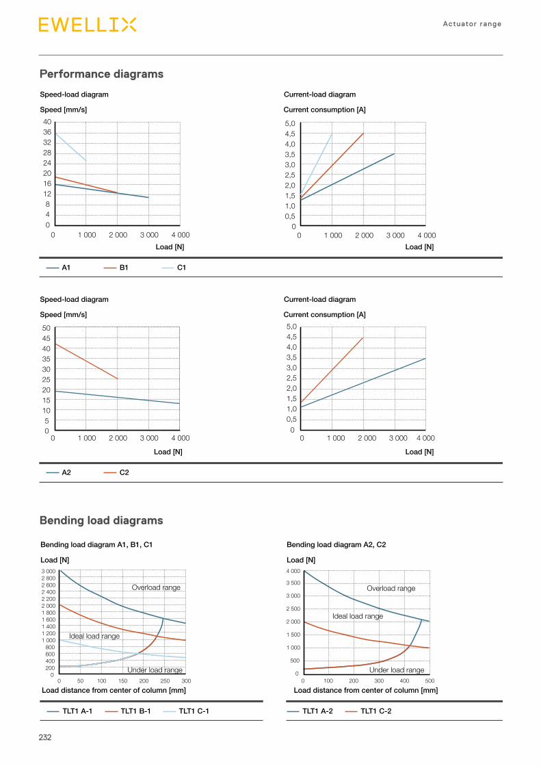
232
Actuator range
Performance diagrams
Bending load diagrams
Load [N]
Bending load diagram A1, B1, C1 Bending load diagram A2, C2
Load distance from center of column [mm]
Load [N]
TLT1 A-1 TLT1 B-1 TLT1 A-2 TLT1 C-2TLT1 C-1
Load distance from center of column [mm]
Overload range Overload range
Ideal load range
Ideal load range
Under load range Under load range0
0 50 100
200400
3 000
150 200 300250
600800
1 0001 2001 4001 6001 8002 0002 2002 4002 6002 800
00 100
500
4 000
200 500
1 000
1 500
2 000
2 500
3 000
3 500
300 400
Speed [mm/s]
Speed-load diagram Current-load diagram
Load [N] Load [N]
Current consumption [A]
A1 B1 C1
40
81216202428323640
0 1 000 2 000 3 000 4 000
0,50
1,01,52,02,53,03,54,04,55,0
0 1 000 2 000 3 000 4 000
Speed [mm/s]
Speed-load diagram Current-load diagram
Load [N] Load [N]
Current consumption [A]
A2 C2
50
101520253035404550
0 1 000 2 000 3 000 4 000
0,50
1,01,52,02,53,03,54,04,55,0
0 1 000 2 000 3 000 4 000
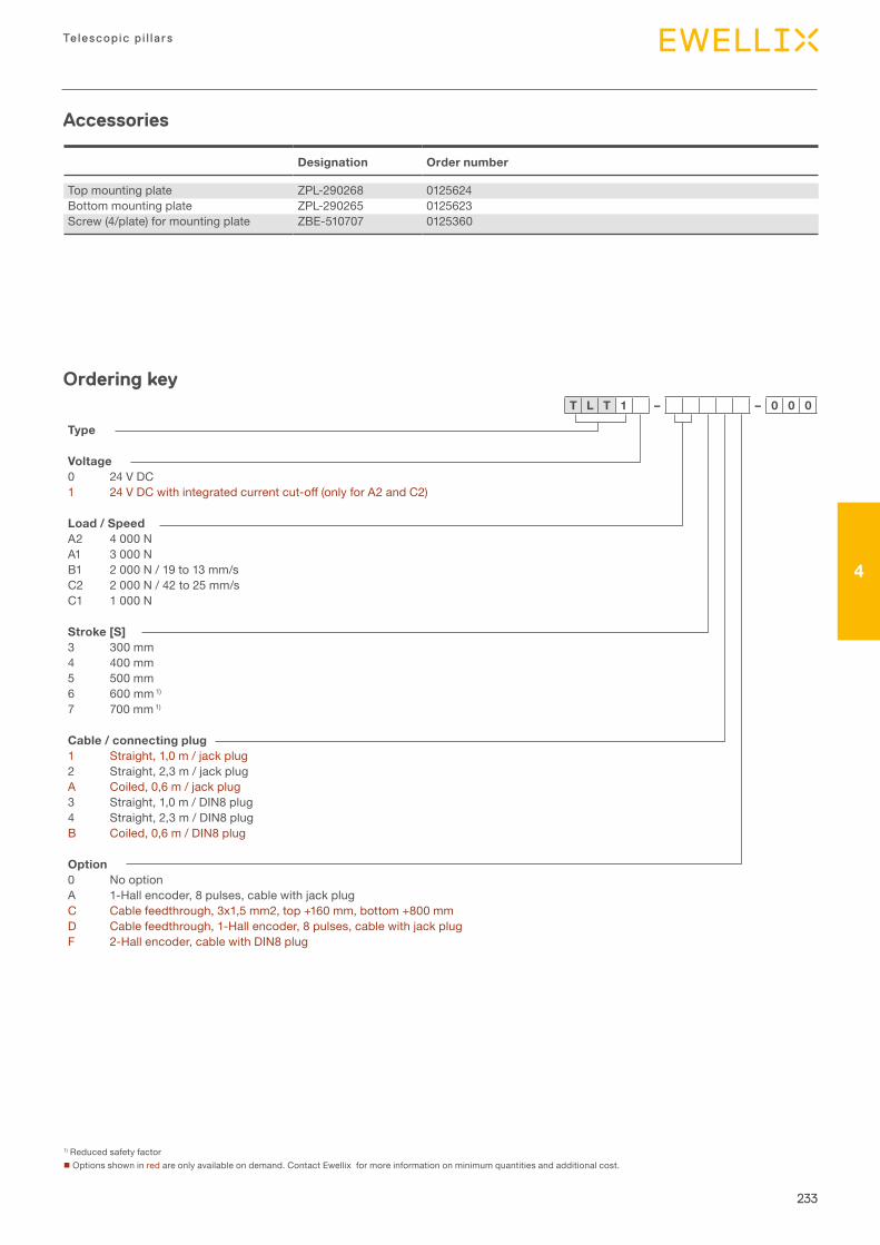
233
Telescopic p i l la rs
4
1)ReducedsafetyfactornOptionsshowninredareonlyavailableondemand.ContactEwellixformoreinformationonminimumquantitiesandadditionalcost.
Ordering key
Accessories
Type
Voltage0 24VDC1 24VDCwithintegratedcurrentcut-off(onlyforA2andC2)
Load / SpeedA2 4000NA1 3000NB1 2000N/19to13mm/sC2 2000N/42to25mm/sC1 1000N
Stroke [S]3 300mm4 400mm5 500mm6 600mm1)
7 700mm1)
Cable / connecting plug1 Straight,1,0m/jackplug2 Straight,2,3m/jackplugA Coiled,0,6m/jackplug3 Straight,1,0m/DIN8plug4 Straight,2,3m/DIN8plugB Coiled,0,6m/DIN8plug
Option0 NooptionA 1-Hallencoder,8pulses,cablewithjackplugC Cablefeedthrough,3x1,5mm2,top+160mm,bottom+800mmD Cablefeedthrough,1-Hallencoder,8pulses,cablewithjackplugF 2-Hallencoder,cablewithDIN8plug
T L T 1 – – 0 0 0
Designation Order number
Topmountingplate ZPL-290268 0125624Bottommountingplate ZPL-290265 0125623Screw(4/plate)formountingplate ZBE-510707 0125360
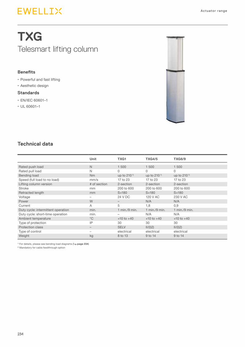
234
Actuator range
TXGTelesmart lifting column
Technical data
Benefits
• Powerfulandfastlifting• Aestheticdesign
Standards
• EN/IEC60601–1•UL60601–1
1)Fordetails,pleaseseebendingloaddiagrams(⮑ page 234)2)Mandatoryforcablefeedthroughoption
Unit TXG1 TXG4/5 TXG8/9
Ratedpushload N 1500 1500 1500Ratedpullload N 0 0 0Bendingload Nm upto2101) upto2101) upto2101)
Speed(fullloadtonoload) mm/s 17to23 17to23 17to23Liftingcolumnversion #ofsection 2-section 2-section 2-sectionStroke mm 200to600 200to600 200to600Retractedlength mm S+180 S+180 S+180Voltage – 24VDC 120VAC 230VACPower W – N/A N/ACurrent A 5 1,8 0,9Dutycycle:intermittentoperation min. 1min./9min. 1min./9min. 1min./9min.Dutycycle:short-timeoperation min. – N/A N/AAmbienttemperature °C +10to+40 +10to+40 +10to+40Typeofprotection IP 30 30 30Protectionclass – SELV II/(I)2) II/(I)2)Typeofcontrol – electrical electrical electricalWeight kg 8to13 9to14 9to14
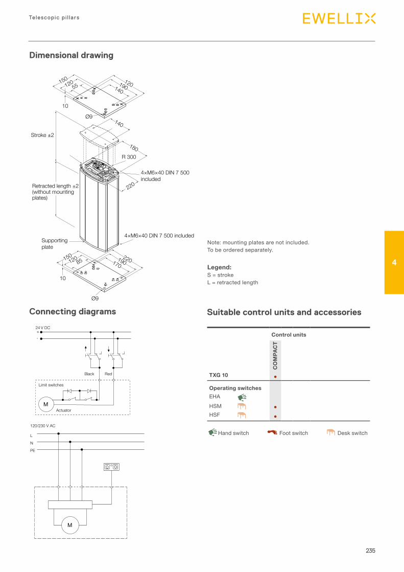
235
Telescopic p i l la rs
4
Dimensional drawing
Connecting diagrams Suitable control units and accessories
Note:mountingplatesarenotincluded.Tobeorderedseparately.
Legend:S=strokeL=retractedlength
Control units
CO
MPA
CT
TXG 10 ●
Operating switchesEHAHSM ●HSF ●
DeskswitchHandswitch Footswitch
120150170
190220
180
140
220
85
R 300
10
10
Ø9
Ø9
12015055 140
190120
Retracted length ±2(without mounting plates)
Stroke ±2
4×M6×40 DIN 7 500included
4×M6×40 DIN 7 500 includedSupportingplate
+
Black Red
-
24 V DC
M
Limit switches
Actuator
L
N
M
PE
120/230 V AC
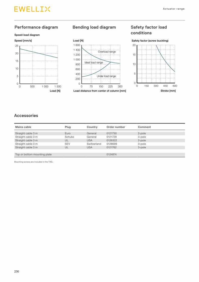
236
Actuator range
Performance diagram
Accessories
Bending load diagram Safety factor load conditions
Load [N] Safety factor (screw buckling)Speed [mm/s]
00 75 150 225 300
200
400
600
800
1 000
1 200
1 400
1 600
Speed-load diagram
Load distance from center of column [mm]Load [N] Stroke [mm]
Overload range
Ideal load range
Under load range
00 500 1 000 1 500
5
10
15
20
25
00 150 300 450 600
5
10
15
20
Mains cable Plug Country Order number Comment
Straightcable3m Euro General 0121730 2-poleStraightcable3m Schuko General 0121729 3-poleStraightcable3m UL USA 0126322 2-poleStraightcable3m SEV Switzerland 0128699 3-poleStraightcable3m UL USA 0121762 3-pole
Toporbottommountingplate 0124874
MountingscrewsareincludedintheTXG.
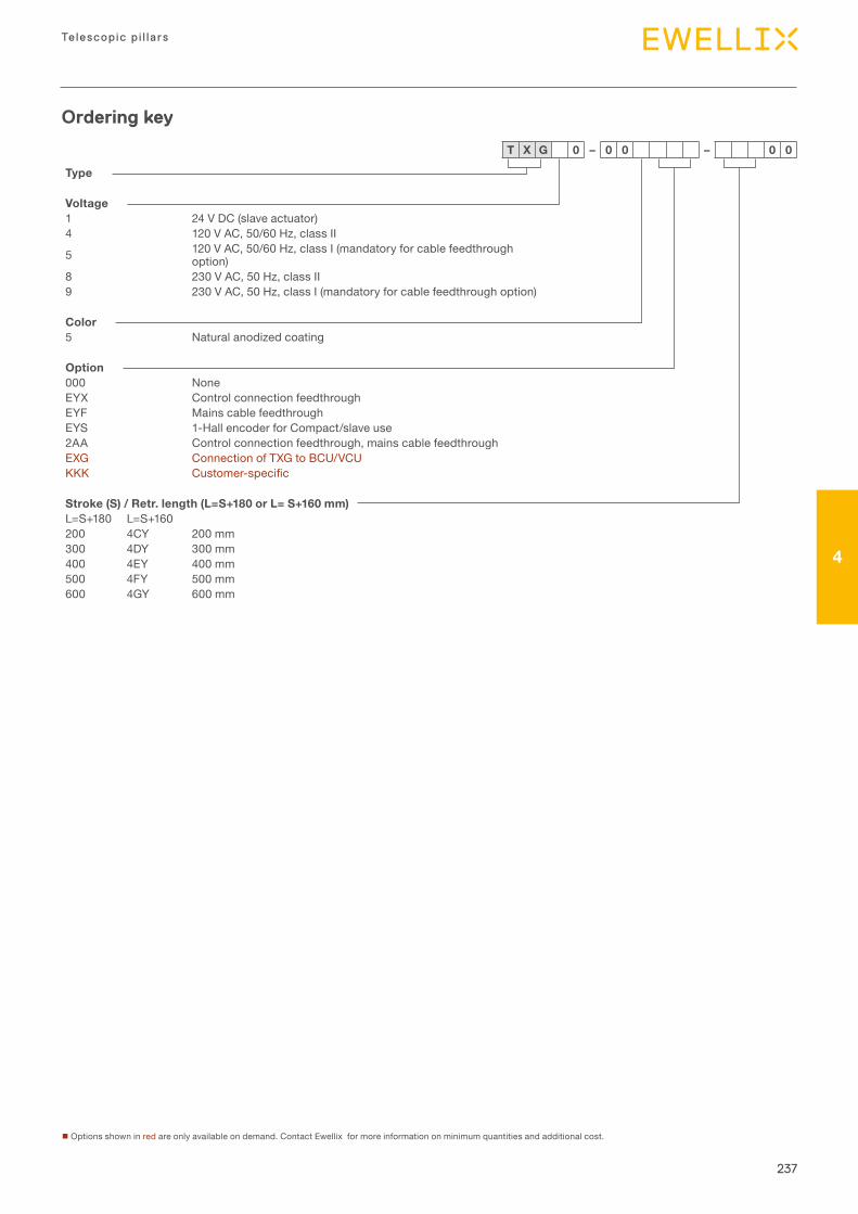
237
Telescopic p i l la rs
4
nOptionsshowninredareonlyavailableondemand.ContactEwellixformoreinformationonminimumquantitiesandadditionalcost.
Ordering key
Type
Voltage1 24VDC(slaveactuator)4 120VAC,50/60Hz,classII
5 120VAC,50/60Hz,classI(mandatoryforcablefeedthroughoption)
8 230VAC,50Hz,classII9 230VAC,50Hz,classI(mandatoryforcablefeedthroughoption)
Color5 Naturalanodizedcoating
Option000 NoneEYX ControlconnectionfeedthroughEYF MainscablefeedthroughEYS 1-HallencoderforCompact/slaveuse2AA Controlconnectionfeedthrough,mainscablefeedthroughEXG ConnectionofTXGtoBCU/VCUKKK Customer-specific
Stroke (S) / Retr. length (L=S+180 or L= S+160 mm)L=S+180 L=S+160200 4CY 200mm300 4DY 300mm400 4EY 400mm500 4FY 500mm600 4GY 600mm
T X G 0 – 0 0 – 0 0
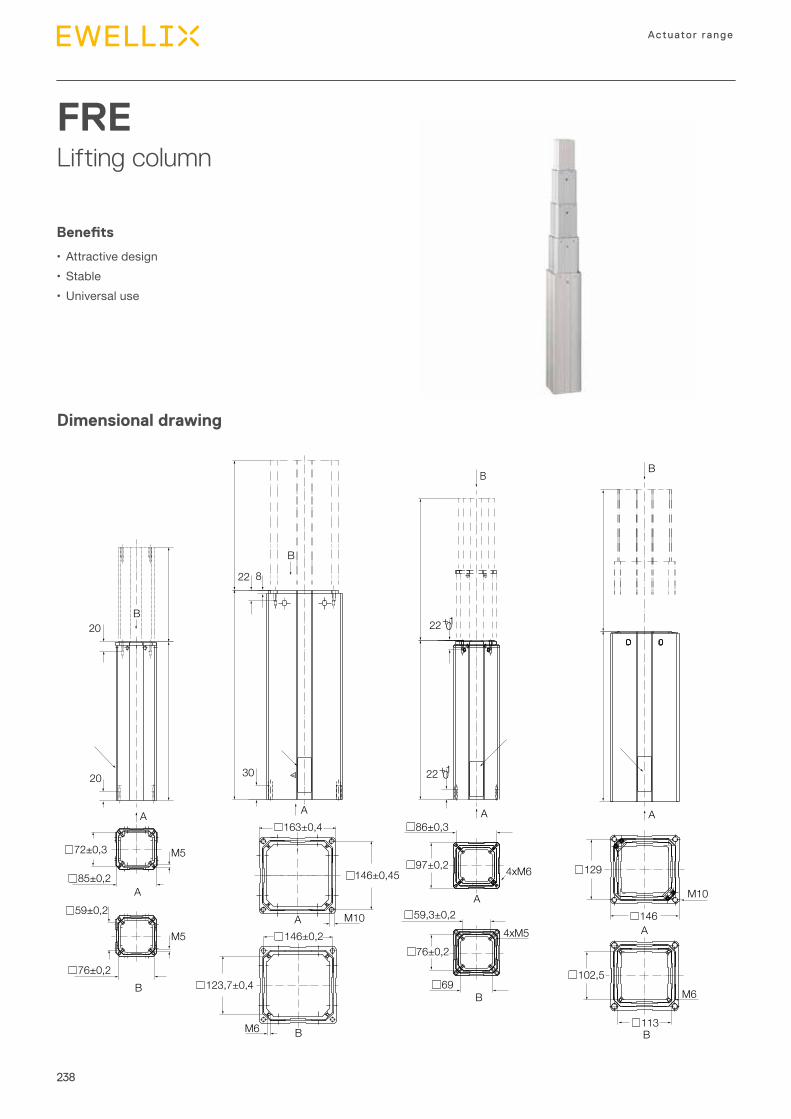
238
Actuator range
FRELifting column
Benefits
• Attractivedesign• Stable•Universaluse
Dimensional drawing
20
20
A
B
A
M5
M5
72±0,3
163±0,4 86±0,3
129
146
102,5
113
97±0,2
59,3±0,2
76±0,2
69
146±0,2
123,7±0,4
146±0,4585±0,2
59±0,2
76±0,2B
30
822
A
B
A M10
BM6
B
22+1 0
22+1 0
A
4xM6
B
M6
A
M10
A
A
4xM5
B
B
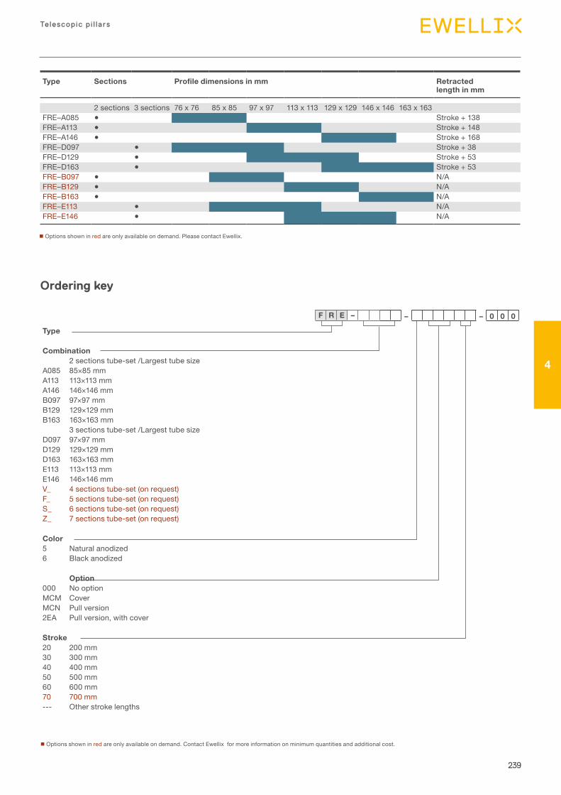
239
Telescopic p i l la rs
4
nOptionsshowninredareonlyavailableondemand.ContactEwellixformoreinformationonminimumquantitiesandadditionalcost.
Ordering key
Type
Combination2sectionstube-set/Largesttubesize
A085 85×85mmA113 113×113mmA146 146×146mmB097 97×97mmB129 129×129mmB163 163×163mm
3sectionstube-set/LargesttubesizeD097 97×97mmD129 129×129mmD163 163×163mmE113 113×113mmE146 146×146mmV_ 4sectionstube-set(onrequest)F_ 5sectionstube-set(onrequest)S_ 6sectionstube-set(onrequest)Z_ 7sectionstube-set(onrequest)
Color5 Naturalanodized6 Blackanodized
Option000 NooptionMCM CoverMCN Pullversion2EA Pullversion,withcover
Stroke20 200mm30 300mm40 400mm50 500mm60 600mm70 700mm--- Otherstrokelengths
F R E – – – 0 0 0
Type Sections Profile dimensions in mm Retracted length in mm
2sections 3sections 76x76 85x85 97x97 113x113 129x129 146x146 163x163 FRE–A085 ● Stroke+138FRE–A113 ● Stroke+148FRE–A146 ● Stroke+168FRE–D097 ● Stroke+38FRE–D129 ● Stroke+53FRE–D163 ● Stroke+53FRE–B097 ● N/AFRE–B129 ● N/AFRE–B163 ● N/AFRE–E113 ● N/AFRE–E146 ● N/A
nOptionsshowninredareonlyavailableondemand.PleasecontactEwellix.

IntroductionControl unitsUp to 6 channels
5
241
Contro l un its
5
Chapter contentsBCU ....................................................................................242VCU ....................................................................................246SCU ....................................................................................250MCU ...................................................................................254COMPACT ..........................................................................258SEM ....................................................................................262
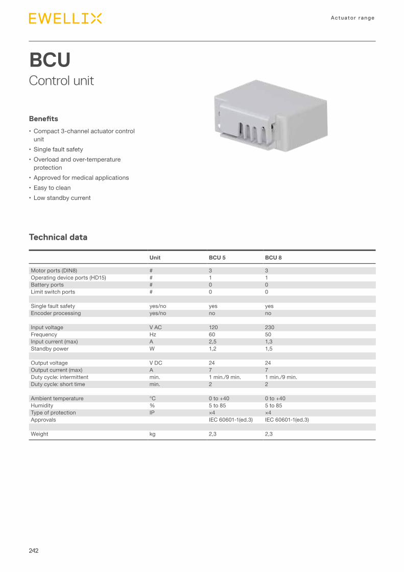
242
Actuator range
BCUControl unit
Technical data
Benefits
•Compact 3-channel actuator control unit
•Single fault safety•Overload and over-temperature
protection•Approved for medical applications•Easy to clean•Low standby current
Unit BCU 5 BCU 8
Motor ports (DIN8) # 3 3Operating device ports (HD15) # 1 1Battery ports # 0 0Limit switch ports # 0 0
Single fault safety yes/no yes yesEncoder processing yes/no no no
Input voltage V AC 120 230Frequency Hz 60 50Input current (max) A 2,5 1,3Standby power W 1,2 1,5
Output voltage V DC 24 24Output current (max) A 7 7Duty cycle: intermittent min. 1 min./9 min. 1 min./9 min.Duty cycle: short time min. 2 2
Ambient temperature °C 0 to +40 0 to +40Humidity % 5 to 85 5 to 85Type of protection IP ×4 ×4Approvals IEC 60601-1(ed.3) IEC 60601-1(ed.3)
Weight kg 2,3 2,3
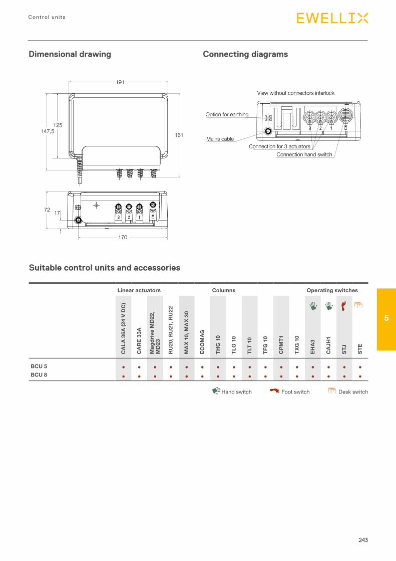
243
Contro l un its
5
Dimensional drawing Connecting diagrams
72 17
170
125
161
191
147,5
Suitable control units and accessories
Linear actuators Columns Operating switches
CAL
A 36
A (2
4 V
DC
)
CAR
E 33
A
Mag
driv
e M
D22
, M
D23
RU
20, R
U21
, RU
22
MA
X 10
, MA
X 30
ECO
MAG
THG
10
TLG
10
TLT
10
TFG
10
CPM
T1
TXG
10
EHA3
CAJ
H1
STJ
STE
BCU 5 ● ● ● ● ● ● ● ● ● ● ● ● ● ● ● ●BCU 8 ● ● ● ● ● ● ● ● ● ● ● ● ● ● ● ●
Desk switchHand switch Foot switch
Option for earthing
Mains cableConnection for 3 actuators
Connection hand switch
View without connectors interlock
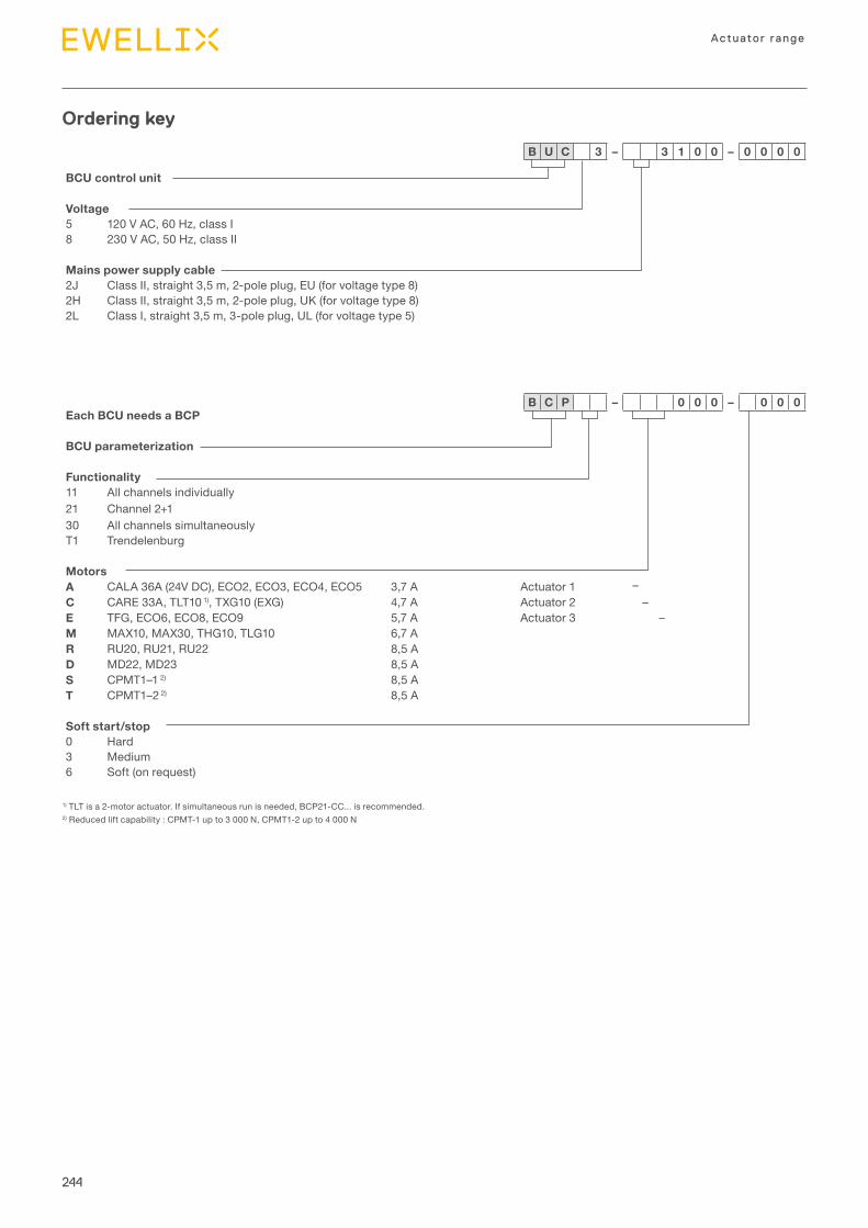
244
Actuator range
Each BCU needs a BCP
BCU parameterization
Functionality11 All channels individually21 Channel 2+130 All channels simultaneouslyT1 Trendelenburg
MotorsA CALA 36A (24V DC), ECO2, ECO3, ECO4, ECO5 3,7 A Actuator 1 –C CARE 33A, TLT10 1), TXG10 (EXG) 4,7 A Actuator 2 –E TFG, ECO6, ECO8, ECO9 5,7 A Actuator 3 –M MAX10, MAX30, THG10, TLG10 6,7 AR RU20, RU21, RU22 8,5 AD MD22, MD23 8,5 AS CPMT1–1 2) 8,5 AT CPMT1–2 2) 8,5 A
Soft start/stop0 Hard3 Medium6 Soft (on request)
Ordering key
BCU control unit
Voltage5 120 V AC, 60 Hz, class I8 230 V AC, 50 Hz, class II
Mains power supply cable2J Class II, straight 3,5 m, 2-pole plug, EU (for voltage type 8)2H Class II, straight 3,5 m, 2-pole plug, UK (for voltage type 8)2L Class I, straight 3,5 m, 3-pole plug, UL (for voltage type 5)
B U C 3 – 3 1 0 0 – 0 0 0 0
B C P – 0 0 0 – 0 0 0
1) TLT is a 2-motor actuator. If simultaneous run is needed, BCP21-CC... is recommended.2) Reduced lift capability : CPMT-1 up to 3 000 N, CPMT1-2 up to 4 000 N


246
Actuator range
VCUControl unit
Technical data
Benefits
•Compact 5-channel actuator control unit
•Single fault safety•Overload and over-temperature
protection•Approved for medical applications•Easy to clean•Low standby current
Unit VCU 5 VCU 8 VCU 9
Motor ports (DIN8) # 3 or 5 3 or 5 3 or 5Operating device ports (HD15) # 2 2 2Battery ports (DSub9) # 1 1 1Limit switch ports (HD15) # 2 2 2
Single fault safety yes/no yes yes yesEncoder processing yes/no no no no
Input voltage V AC 120 230 230Frequency Hz 60 50 50Input current (max) A 2,5 resp. 6,5 1,3 resp. 3,3 1,3 resp. 3,3Standby power W 2,6 resp. 3,9 2,6 resp. 3,9 2,6 resp. 3,9
Output voltage V DC 24 24 24Output current (max) A 7 resp. 18 7 resp. 18 7 resp. 18Duty cycle: intermittent min. 1 min./9 min. 1 min./9 min. 1 min./9 min.Duty cycle: short time min. 2 2 2
Ambient temperature °C +5 to +40 +5 to +40 +5 to +40Humidity % 5 to 85 5 to 85 5 to 85Type of protection IP ×4 ×4 ×4Approvals EN/UL EN 60601–1 EN 60601–1 EN 60601–1
UL 60601–1 UL 60601–1 UL 60601–1Weight without battery kg 2,4 resp. 3,8 2,4 resp. 3,8 2,4 resp. 3,8Weight with battery kg 5,4 resp. 8,8 5,4 resp. 8,8 5,4 resp. 8,8
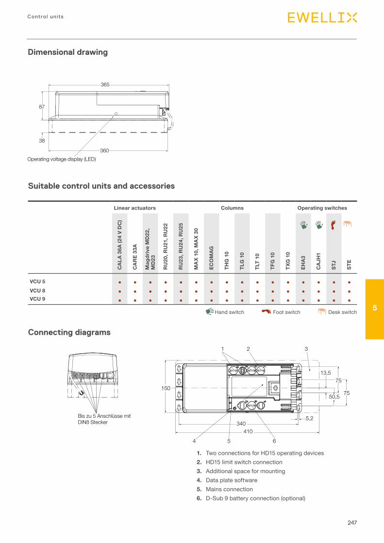
247
Contro l un its
5
Dimensional drawing
360
87
38
365
Operating voltage display (LED)
Suitable control units and accessories
Linear actuators Columns Operating switches
CAL
A 36
A (2
4 V
DC
)
CAR
E 33
A
Mag
driv
e M
D22
, M
D23
RU
20, R
U21
, RU
22
RU
23, R
U24
, RU
25
MA
X 10
, MA
X 30
ECO
MAG
THG
10
TLG
10
TLT
10
TFG
10
TXG
10
EHA3
CAJ
H1
STJ
STE
VCU 5 ● ● ● ● ● ● ● ● ● ● ● ● ● ● ● ●VCU 8 ● ● ● ● ● ● ● ● ● ● ● ● ● ● ● ●VCU 9 ● ● ● ● ● ● ● ● ● ● ● ● ● ● ● ●
Desk switchHand switch Foot switch
Bis zu 5 Anschlüsse mitDIN8 Stecker
340
13,5
4
1 2 3
5 6
50,5
75150
75
5,2
410
1. Two connections for HD15 operating devices2. HD15 limit switch connection3. Additional space for mounting4. Data plate software5. Mains connection6. D-Sub 9 battery connection (optional)
Connecting diagrams
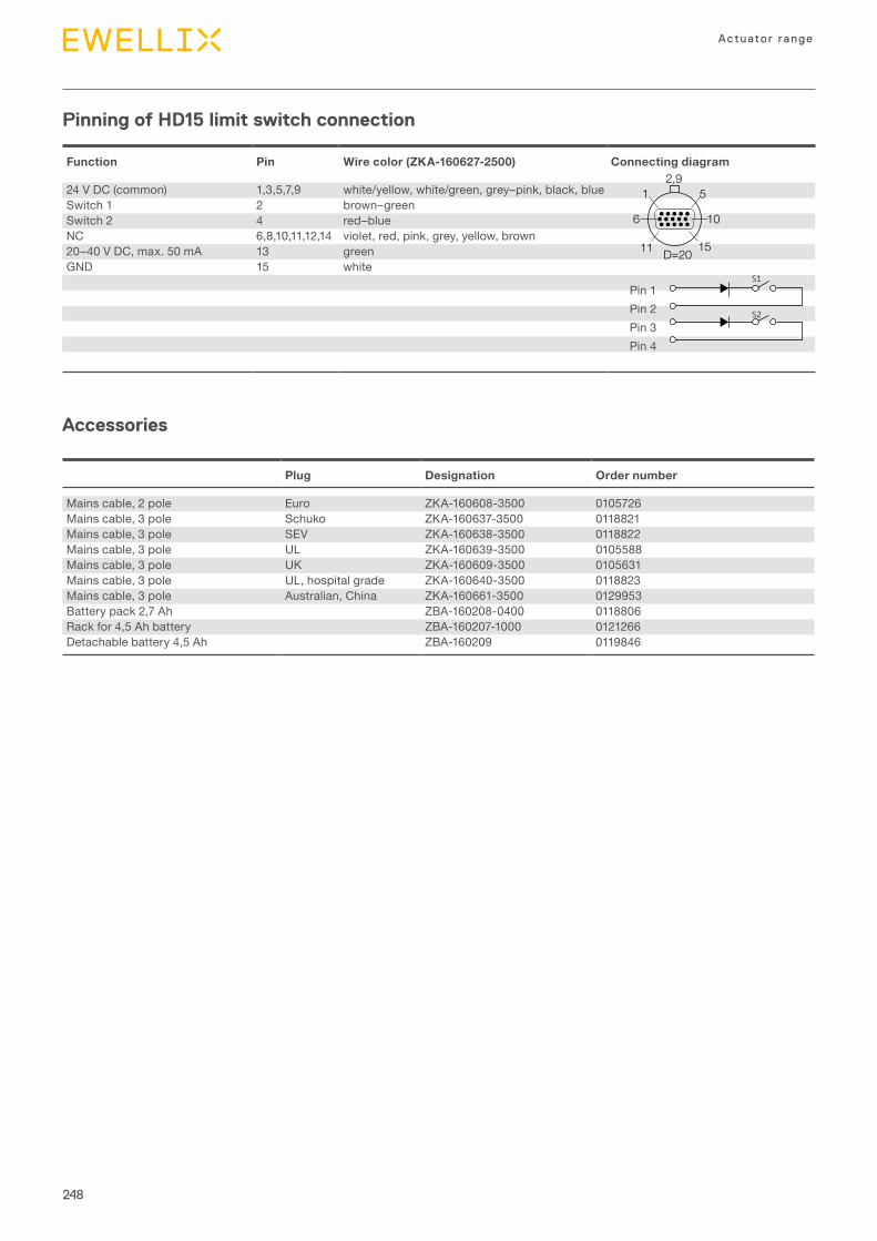
248
Actuator range
Function Pin Wire color (ZKA-160627-2500) Connecting diagram
24 V DC (common) 1,3,5,7,9 white/yellow, white/green, grey–pink, black, blueSwitch 1 2 brown–greenSwitch 2 4 red–blueNC 6,8,10,11,12,14 violet, red, pink, grey, yellow, brown20–40 V DC, max. 50 mA 13 greenGND 15 white
Pin 1Pin 2Pin 3Pin 4
Plug Designation Order number
Mains cable, 2 pole Euro ZKA-160608-3500 0105726Mains cable, 3 pole Schuko ZKA-160637-3500 0118821Mains cable, 3 pole SEV ZKA-160638-3500 0118822Mains cable, 3 pole UL ZKA-160639-3500 0105588Mains cable, 3 pole UK ZKA-160609-3500 0105631Mains cable, 3 pole UL, hospital grade ZKA-160640-3500 0118823Mains cable, 3 pole Australian, China ZKA-160661-3500 0129953Battery pack 2,7 Ah ZBA-160208-0400 0118806Rack for 4,5 Ah battery ZBA-160207-1000 0121266Detachable battery 4,5 Ah ZBA-160209 0119846
D=20
2,91 5
6 10
11 15
S1
S2
S3
S4
Pinning of HD15 limit switch connection
Accessories
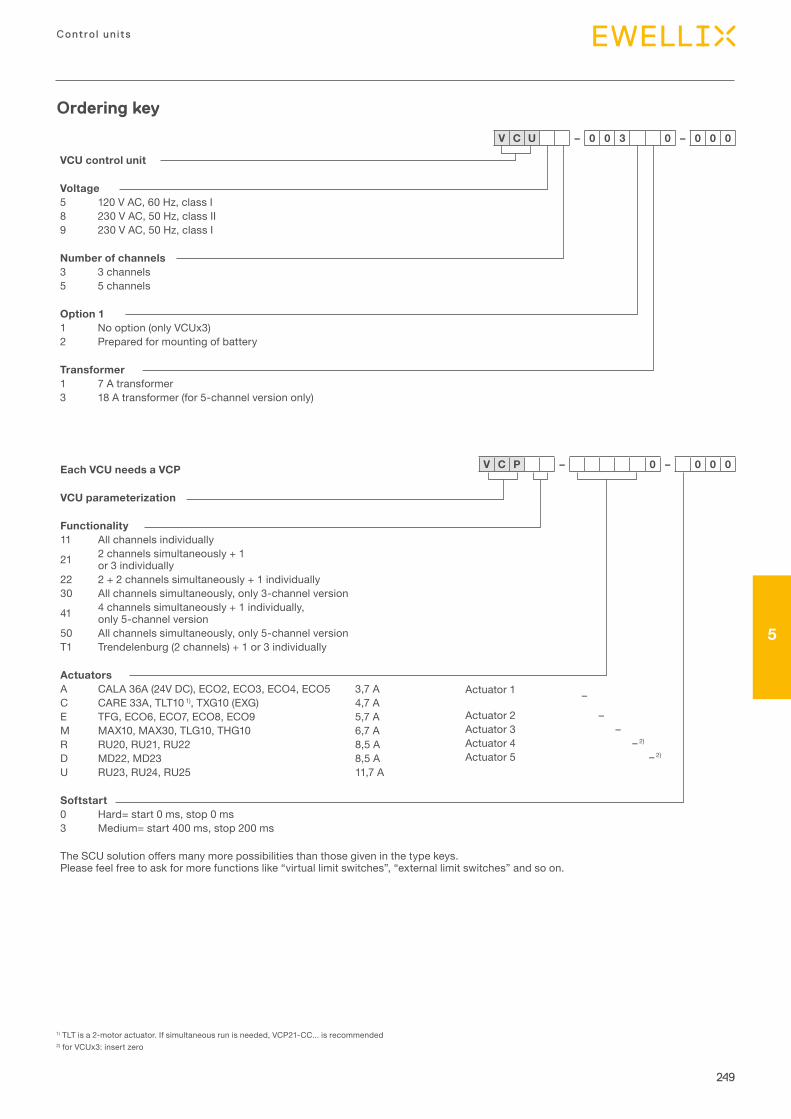
249
Contro l un its
5
Each VCU needs a VCP
VCU parameterization
Functionality11 All channels individually
21 2 channels simultaneously + 1 or 3 individually
22 2 + 2 channels simultaneously + 1 individually30 All channels simultaneously, only 3-channel version
41 4 channels simultaneously + 1 individually, only 5-channel version
50 All channels simultaneously, only 5-channel versionT1 Trendelenburg (2 channels) + 1 or 3 individually
ActuatorsA CALA 36A (24V DC), ECO2, ECO3, ECO4, ECO5 3,7 AC CARE 33A, TLT10 1), TXG10 (EXG) 4,7 AE TFG, ECO6, ECO7, ECO8, ECO9 5,7 AM MAX10, MAX30, TLG10, THG10 6,7 AR RU20, RU21, RU22 8,5 AD MD22, MD23 8,5 AU RU23, RU24, RU25 11,7 A
Softstart0 Hard= start 0 ms, stop 0 ms3 Medium= start 400 ms, stop 200 ms
TheSCUsolutionoffersmanymorepossibilitiesthanthosegiveninthetypekeys.Please feel free to ask for more functions like “virtual limit switches”, “external limit switches” and so on.
Ordering key
1) TLT is a 2-motor actuator. If simultaneous run is needed, VCP21-CC... is recommended2) for VCUx3: insert zero
VCU control unit
Voltage5 120 V AC, 60 Hz, class I 8 230 V AC, 50 Hz, class II 9 230 V AC, 50 Hz, class I
Number of channels3 3 channels5 5 channels
Option 11 No option (only VCUx3)2 Prepared for mounting of battery
Transformer1 7 A transformer3 18 A transformer (for 5-channel version only)
V C U – 0 0 3 0 – 0 0 0
V C P – 0 – 0 0 0
Actuator 1 –
Actuator 2 –Actuator 3 –Actuator 4 – 2)
Actuator 5 – 2)
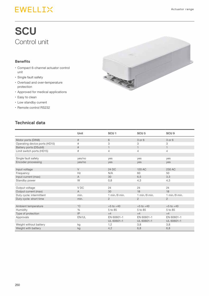
250
Actuator range
SCUControl unit
Technical data
Benefits
•Compact 6-channel actuator control unit
•Single fault safety•Overload and over-temperature
protection•Approved for medical applications•Easy to clean•Low standby current•Remote control RS232
Unit SCU 1 SCU 5 SCU 9
Motor ports (DIN8) # 6 3 or 6 3 or 6Operating device ports (HD15) # 3 3 3Battery ports (DSub9) # 1 1 1Limit switch ports (HD15) # 4 4 4
Single fault safety yes/no yes yes yesEncoder processing yes/no yes yes yes
Input voltage V 24 DC 120 AC 230 ACFrequency Hz N/A 60 50Input current (max) A 30 6,5 3,3Standby power W 0,8 4,3 4,3
Output voltage V DC 24 24 24Output current (max) A 30 18 18Duty cycle: intermittent min. 1 min./9 min. 1 min./9 min. 1 min./9 min.Duty cycle: short time min. 2 2 2
Ambient temperature °C +5 to +40 +5 to +40 +5 to +40Humidity % 5 to 85 5 to 85 5 to 85Type of protection IP ×4 ×4 ×4Approvals EN/UL EN 60601–1 EN 60601–1 EN 60601–1
UL 60601–1 UL 60601–1 UL 60601–1Weight without battery kg 1,2 3,8 3,8Weight with battery kg 4,2 6,8 6,8
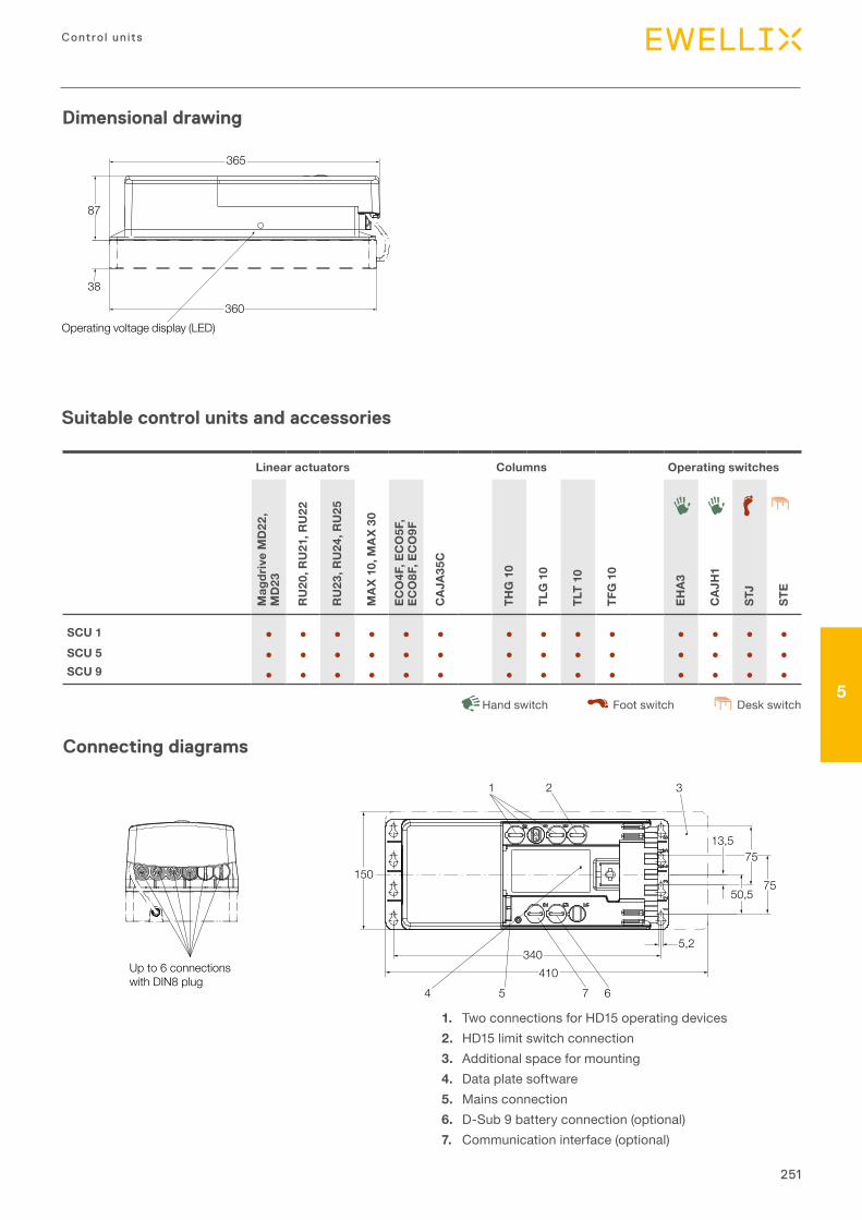
251
Contro l un its
5
Dimensional drawing
360
87
38
365
Operating voltage display (LED)
Suitable control units and accessories
Linear actuators Columns Operating switches
Mag
driv
e M
D22
, M
D23
RU
20, R
U21
, RU
22
RU
23, R
U24
, RU
25
MA
X 10
, MA
X 30
ECO
4F, E
CO
5F,
ECO
8F, E
CO
9F
CAJ
A35C
THG
10
TLG
10
TLT
10
TFG
10
EHA3
CAJ
H1
STJ
STE
SCU 1 ● ● ● ● ● ● ● ● ● ● ● ● ● ●SCU 5 ● ● ● ● ● ● ● ● ● ● ● ● ● ●SCU 9 ● ● ● ● ● ● ● ● ● ● ● ● ● ●
Desk switchHand switch Foot switch
Up to 6 connectionswith DIN8 plug
340
13,5
4
1 2 3
5 7 6
50,5
75150
75
5,2
410
1. Two connections for HD15 operating devices2. HD15 limit switch connection3. Additional space for mounting4. Data plate software5. Mains connection6. D-Sub 9 battery connection (optional)7. Communication interface (optional)
Connecting diagrams
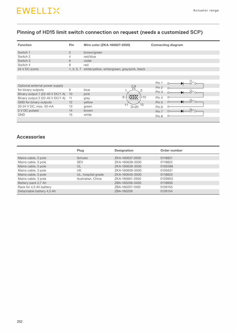
252
Actuator range
Pinning of HD15 limit switch connection on request (needs a customized SCP)
Accessories
Function Pin Wire color (ZKA-160627-2500) Connecting diagram
Switch 1 2 brown/greenSwitch 2 4 red/blueSwitch 3 6 violetSwitch 4 8 red24 V DC (com) 1, 3, 5, 7 white/yellow, white/green, grey/pink, black
Optional external power supplyfor binary outputs 9 blueBinary output 1 (22-40 V DC/1 A) 10 pinkBinary output 2 (22-40 V DC/1 A) 11 greyGND for binary outputs 12 yellow20-24 V DC, max. 50 mA 13 green5 V DC pulsed 14 brownGND 15 white
Pin 1Pin 2Pin 3
Pin 4Pin 5Pin 6Pin 7Pin 8
D=20
2,91 5
6 10
11 15
S1
S2
S3
S4
Plug Designation Order number
Mains cable, 3 pole Schuko ZKA-160637-3500 0118821Mains cable, 3 pole SEV ZKA-160638-3500 0118822Mains cable, 3 pole UL ZKA-160639-3500 0105588Mains cable, 3 pole UK ZKA-160609-3500 0105631Mains cable, 3 pole UL, hospital grade ZKA-160640-3500 0118823Mains cable, 3 pole Australian, China ZKA-160661-3500 0129953Battery pack 2,7 Ah ZBA-160208-0400 0118806Rack for 4,5 Ah battery ZBA-160207-1000 0126155Detachable battery 4,5 Ah ZBA-160209 0126154
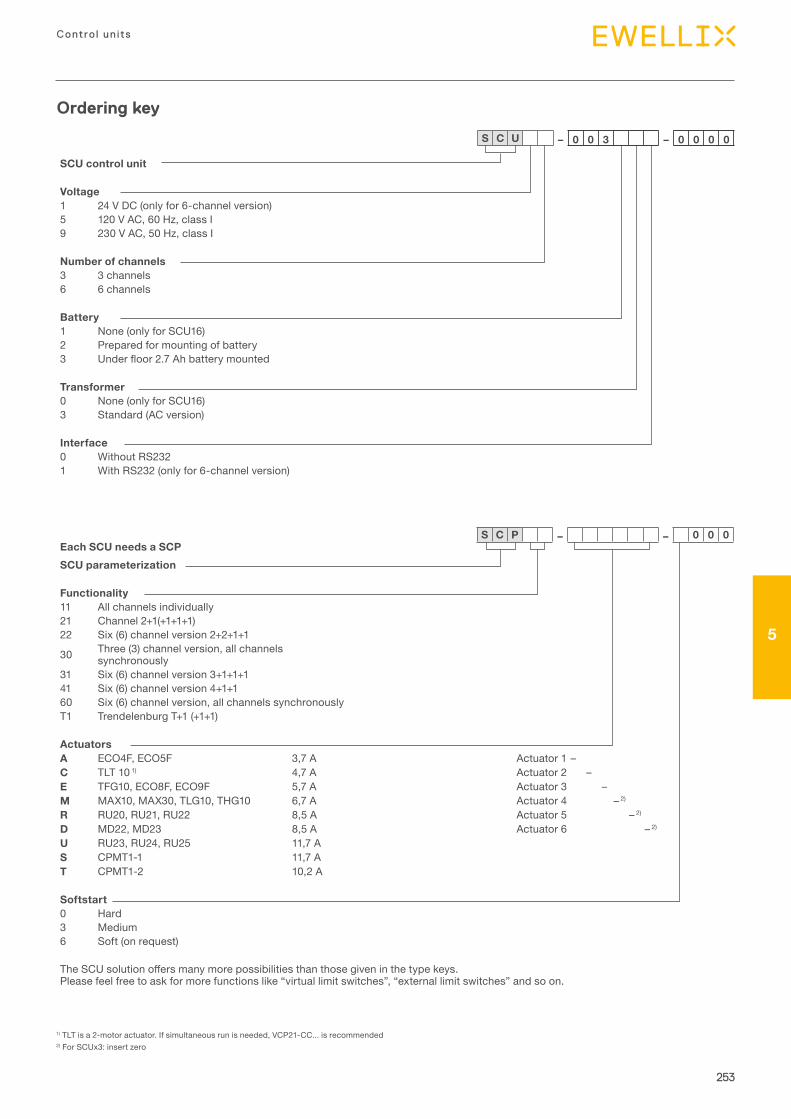
253
Contro l un its
5
Ordering key
1) TLT is a 2-motor actuator. If simultaneous run is needed, VCP21-CC... is recommended2) For SCUx3: insert zero
SCU control unit
Voltage1 24 V DC (only for 6-channel version)5 120 V AC, 60 Hz, class I9 230 V AC, 50 Hz, class I
Number of channels3 3 channels6 6 channels
Battery1 None (only for SCU16)2 Prepared for mounting of battery3 Underfloor2.7Ahbatterymounted
Transformer0 None (only for SCU16)3 Standard (AC version)
Interface0 Without RS2321 With RS232 (only for 6-channel version)
S C U – 0 0 3 – 0 0 0 0
Each SCU needs a SCPSCU parameterization
Functionality11 All channels individually21 Channel 2+1(+1+1+1)22 Six (6) channel version 2+2+1+1
30 Three (3) channel version, all channels synchronously
31 Six (6) channel version 3+1+1+141 Six (6) channel version 4+1+160 Six (6) channel version, all channels synchronouslyT1 Trendelenburg T+1 (+1+1)
ActuatorsA ECO4F, ECO5F 3,7 A Actuator 1 –C TLT 10 1) 4,7 A Actuator 2 –E TFG10, ECO8F, ECO9F 5,7 A Actuator 3 –M MAX10, MAX30, TLG10, THG10 6,7 A Actuator 4 – 2)
R RU20, RU21, RU22 8,5 A Actuator 5 – 2)
D MD22, MD23 8,5 A Actuator 6 – 2)
U RU23, RU24, RU25 11,7 AS CPMT1-1 11,7 AT CPMT1-2 10,2 A
Softstart0 Hard3 Medium6 Soft (on request)
TheSCUsolutionoffersmanymorepossibilitiesthanthosegiveninthetypekeys.Please feel free to ask for more functions like “virtual limit switches”, “external limit switches” and so on.
S C P – – 0 0 0
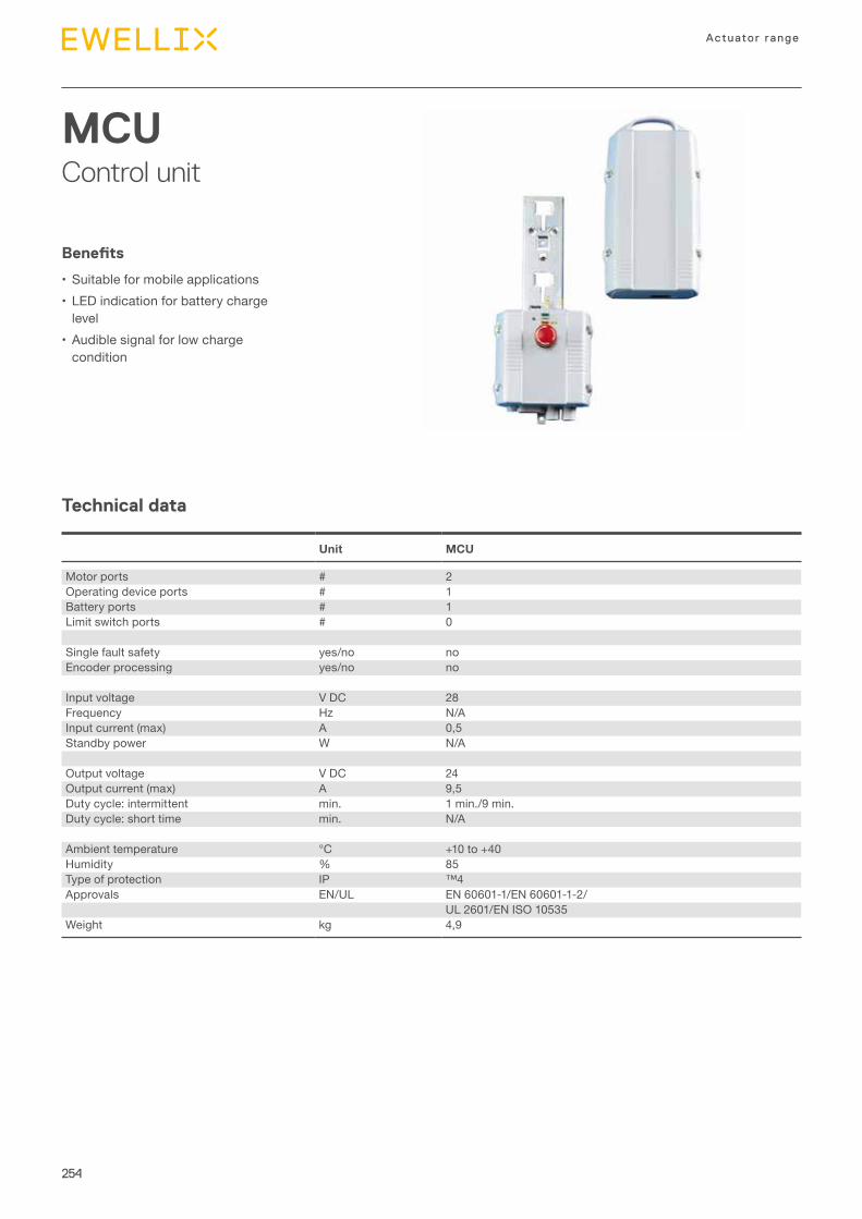
254
Actuator range
MCUControl unit
Technical data
Benefits
•Suitable for mobile applications•LED indication for battery charge
level•Audible signal for low charge
condition
Unit MCU
Motor ports # 2Operating device ports # 1Battery ports # 1Limit switch ports # 0
Single fault safety yes/no noEncoder processing yes/no no
Input voltage V DC 28Frequency Hz N/AInput current (max) A 0,5Standby power W N/A
Output voltage V DC 24Output current (max) A 9,5Duty cycle: intermittent min. 1 min./9 min.Duty cycle: short time min. N/A
Ambient temperature °C +10 to +40Humidity % 85Type of protection IP ™4Approvals EN/UL EN 60601-1/EN 60601-1-2/
UL 2601/EN ISO 10535Weight kg 4,9
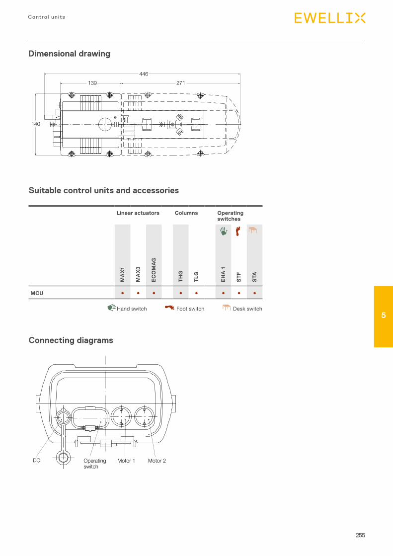
255
Contro l un its
5
Dimensional drawing
Suitable control units and accessories
Linear actuators Columns Operating switches
MA
X1
MA
X3
ECO
MAG
THG
TLG
EHA
1
STF
STA
MCU ● ● ● ● ● ● ● ●
Desk switchHand switch Foot switch
Connecting diagrams
446271139
140
DC Operatingswitch
Motor 1 Motor 2
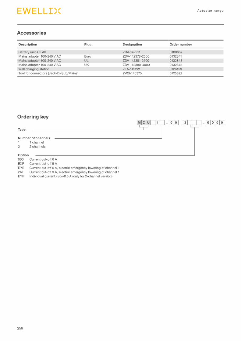
256
Actuator range
Accessories
Description Plug Designation Order number
Battery unit 4,5 Ah ZBA-142211 0100667Mains adapter 100-240 V AC Euro ZDV-142378-2500 0132841Mains adapter 100-240 V AC UL ZDV-142381-2500 0132843Mains adapter 100-240 V AC UK ZDV-142380-4000 0132842Wall charging station ZLA-142221 0126159Tool for connectors (Jack/D–Sub/Mains) ZWS-140375 0125322
Ordering key
Type
Number of channels1 1 channel2 2 channels
Option000 Currentcut-off6AEXP Currentcut-off9AEYE Currentcut-off6A,electricemergencyloweringofchannel12AT Currentcut-off9A,electricemergencyloweringofchannel1EYR Individualcurrentcut-off6A(onlyfor2-channelversion)
M C U 1 – 0 0 3 – 0 0 0 0

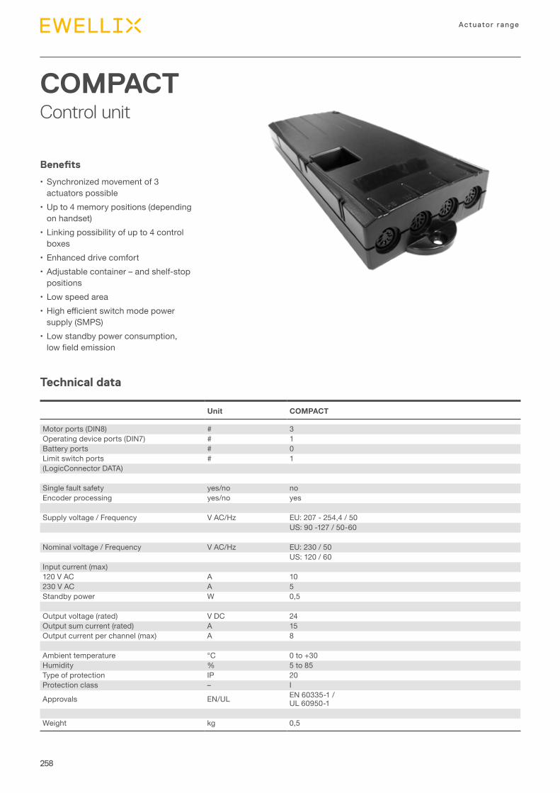
258
Actuator range
COMPACTControl unit
Technical data
Benefits
•Synchronized movement of 3 actuators possible
•Up to 4 memory positions (depending on handset)
•Linking possibility of up to 4 control boxes
•Enhanced drive comfort•Adjustable container – and shelf-stop
positions•Low speed area• Highefficientswitchmodepower
supply (SMPS)•Low standby power consumption, lowfieldemission
Unit COMPACT
Motor ports (DIN8) # 3Operating device ports (DIN7) # 1Battery ports # 0Limit switch ports # 1(LogicConnector DATA)
Single fault safety yes/no noEncoder processing yes/no yes
Supply voltage / Frequency V AC/Hz EU: 207 - 254,4 / 50US: 90 -127 / 50-60
Nominal voltage / Frequency V AC/Hz EU: 230 / 50US: 120 / 60
Input current (max)120 V AC A 10230 V AC A 5Standby power W 0,5
Output voltage (rated) V DC 24Output sum current (rated) A 15Output current per channel (max) A 8
Ambient temperature °C 0 to +30Humidity % 5 to 85Type of protection IP 20Protection class – I
Approvals EN/UL EN 60335-1 / UL 60950-1
Weight kg 0,5
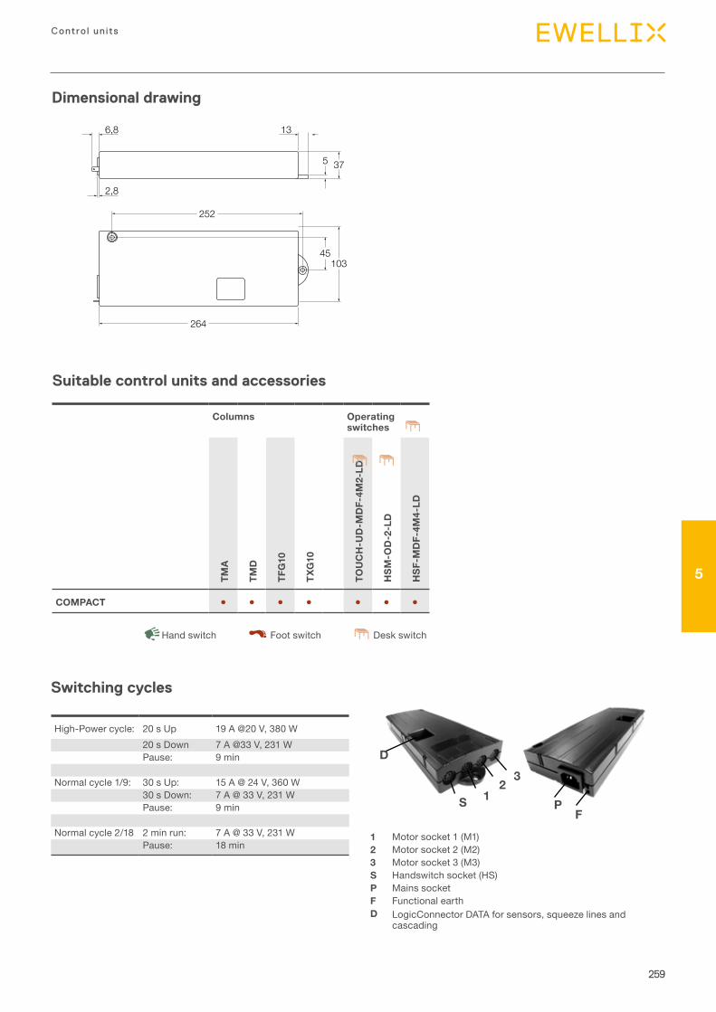
259
Contro l un its
5
Dimensional drawing
Suitable control units and accessories
Columns Operating switches
TMA
TMD
TFG
10
TXG
10
TOU
CH
-UD
-MD
F-4M
2-LD
HSM
-OD
-2-L
D
HSF
-MD
F-4M
4-LD
COMPACT ● ● ● ● ● ● ●
Desk switchHand switch Foot switch
252
264
10345
375
136,8
2,8
1 Motor socket 1 (M1)2 Motor socket 2 (M2)3 Motor socket 3 (M3)S Handswitch socket (HS)P Mains socketF Functional earthD LogicConnector DATA for sensors, squeeze lines and
cascading
D
S 12
3
PF
High-Power cycle: 20 s Up 19 A @20 V, 380 W20 s Down 7 A @33 V, 231 WPause: 9 min
Normal cycle 1/9: 30 s Up: 15 A @ 24 V, 360 W30 s Down: 7 A @ 33 V, 231 WPause: 9 min
Normal cycle 2/18 2 min run: 7 A @ 33 V, 231 WPause: 18 min
Switching cycles
260
Actuator range
Ordering key
Accessories
Description Designation Order number
Mains cable straight 3 m, Schuko plug (Germany, France, ...) LOG-CBL-PWK 131665Mains cable straight 3 m, UK plug (UK) LOG-CBL-PWK-UK 131825Mains cable straight 3 m, UL plug (US) LOG-CBL-PWK-US-SJT 131666
Cascading cable 0,5 m length LOG-CBL-HT-SYNC-500 131678Cascading cable 1,5 m length LOG-CBL-HT-SYNC-1500 132061Split cable for LogicConnector DATA LOG-CBL-HT-LC-DATA-Y 132062Connection cable (squeeze bar to control box) LOG-CBL-HT-MOLEX-RJ45 132063
Description Designation Order number
Extra simple desk switch (up/down) HSM-OD-2-LD 123247Desk switch with display for 2 motorgroups (up/down and memory) HSF-MDF-4M4-LD 123246Desk switch with smart touch display (up/down and memory) TOUCH-UD-MDF-4M2-LD 131740
Desk switches
Type
Number of used motors (optional, depending on parameter)3 motors (no additional designation required)
2 2 motors1 1 motor
Actuator typeTMA TMA10TMD TMD10TFG TFG10TXG TXG10
VoltageUS 120 VAC, 60 Hz, class IEU 230 VAC, 50 Hz, class I
C O M P A C T – E – 3 – – D I N – –

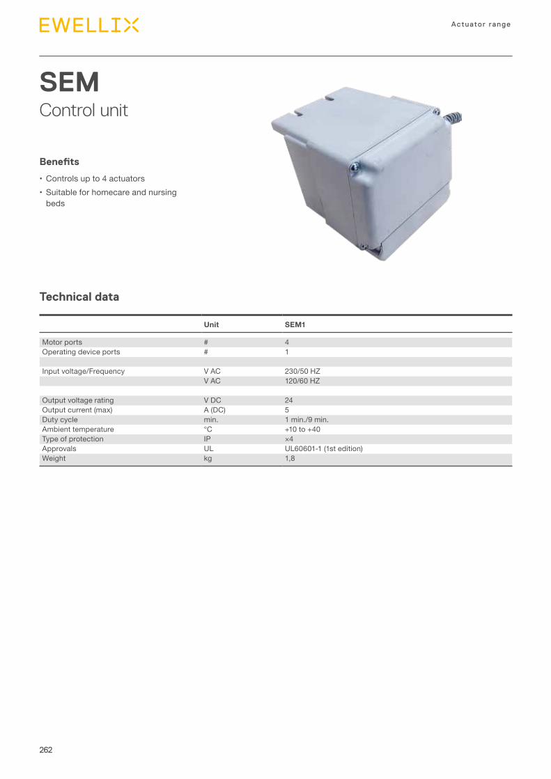
262
Actuator range
SEMControl unit
Technical data
Benefits
•Controls up to 4 actuators•Suitable for homecare and nursing
beds
Unit SEM1
Motor ports # 4Operating device ports # 1
Input voltage/Frequency V AC 230/50 HZV AC 120/60 HZ
Output voltage rating V DC 24Output current (max) A (DC) 5Duty cycle min. 1 min./9 min.Ambient temperature °C +10 to +40 Type of protection IP ×4Approvals UL UL60601-1 (1st edition)Weight kg 1,8
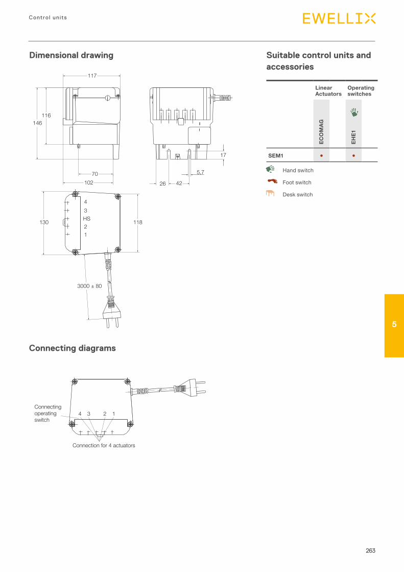
263
Contro l un its
5
Dimensional drawing Suitable control units and accessories
Linear Actuators
Operating switches
ECO
MAG
EHE1
SEM1 ● ●
Desk switch
Hand switch
Foot switch
Connecting diagrams
146
7026 42
5,7
17
102
130
3000 ± 80
43HS21
118
116
117
Connection for 4 actuators
Connectingoperatingswitch
4 3 2 1
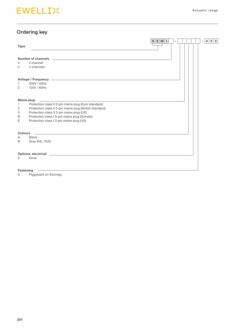
264
Actuator range
Ordering key
Type
Number of channels2 2 channel4 4 channels
Voltage / Frequency1 230V / 50Hz2 120V / 60Hz
Mains plug1 Protection class II 2-pin mains plug (Euro standard)2 Protection class II 2-pin mains plug (British standard)3 Protection class II 2-pin mains plug (US)B Protection class I 3-pin mains plug (Schuko)E Protection class I 3-pin mains plug (US)
ColoursA BlackB Grey RAL 7035
Options, electrical0 None
Fastening0 Piggyback on Ecomag
S E M 1 - - 0 0 0


IntroductionIntroductionOperating switchesUp to 10 keys
6
267
6
Operating switches
6
Chapter contentsCAES ..................................................................................268EHA1 ...................................................................................270EHA3 ..................................................................................272EHE1 ................................................................................... 274HSM, HSF, HSU ................................................................. 276PHC ....................................................................................278PFP .....................................................................................280ST .......................................................................................282ST .......................................................................................284STK .....................................................................................286CAJH1 ................................................................................288PAM ....................................................................................290
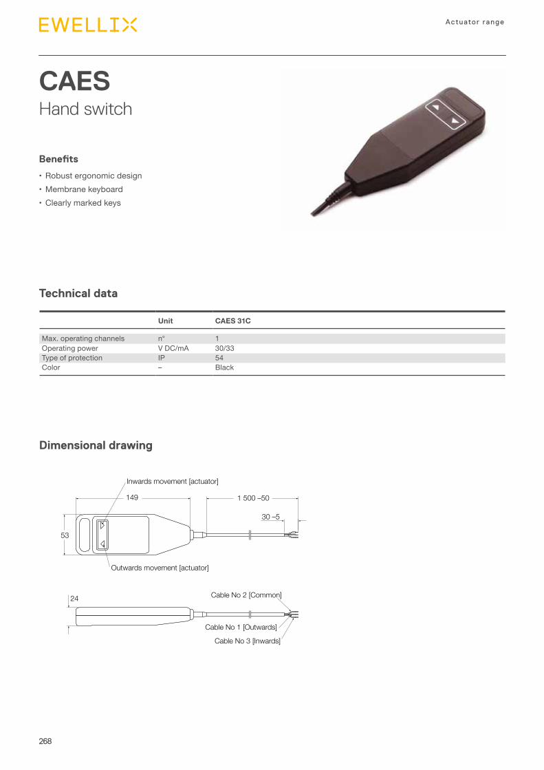
268
Actuator range
CAESHand switch
Technical data
Dimensional drawing
Benefits
•Robust ergonomic design•Membrane keyboard•Clearly marked keys
Unit CAES 31C
Max. operating channels n° 1Operating power V DC/mA 30/33Type of protection IP 54Color – Black
149
30 –5
53
24
1 500 –50
Inwards movement [actuator]
Outwards movement [actuator]
Cable No 2 [Common]
Cable No 1 [Outwards]
Cable No 3 [Inwards]
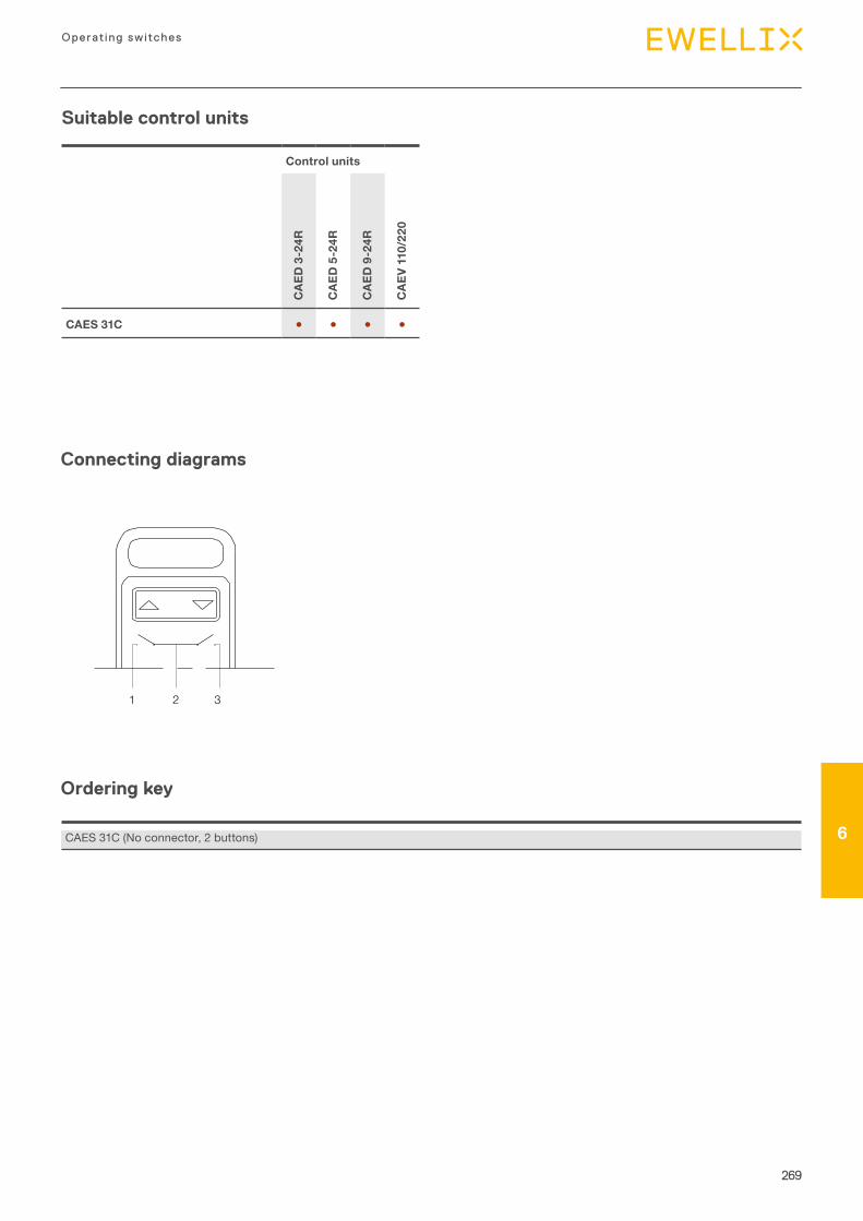
269
6
Operating switches
6
Suitable control units
Control units
CAE
D 3
-24R
CAE
D 5
-24R
CAE
D 9
-24R
CAE
V 11
0/22
0
CAES 31C ● ● ● ●
321
Connecting diagrams
Ordering key
CAES 31C (No connector, 2 buttons)
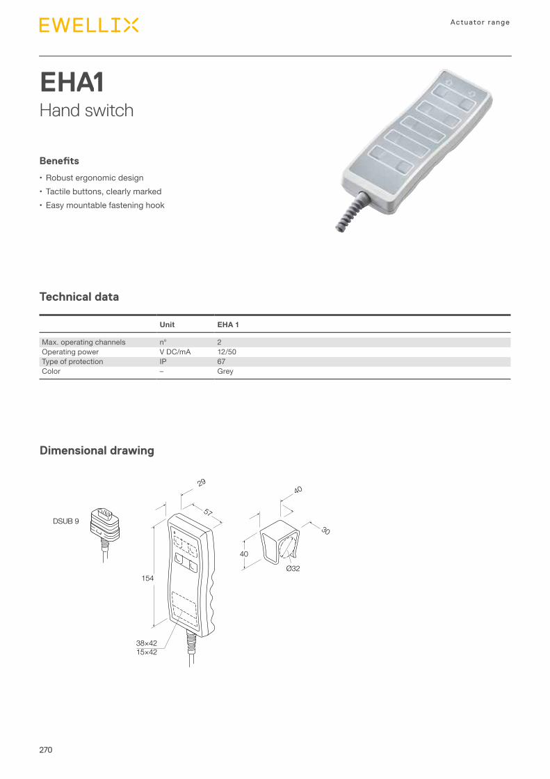
270
Actuator range
EHA1Hand switch
Technical data
Dimensional drawing
Benefits
•Robust ergonomic design•Tactile buttons, clearly marked•Easy mountable fastening hook
Unit EHA 1
Max. operating channels n° 2Operating power V DC/mA 12/50Type of protection IP 67Color – Grey
154
40
2940
57
30
38×4215×42
Ø32
DSUB 9
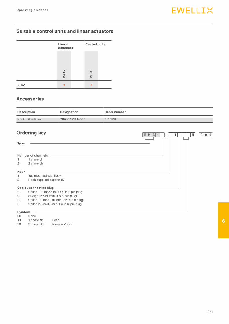
271
6
Operating switches
6
Suitable control units and linear actuators
Linear actuators
Control units
MA
X7
MC
U
EHA1 ● ●
Description Designation Order number
Hook with sticker ZBG–145361–000 0125538
Type
Number of channels1 1 channel 2 2 channels
Hook1 Yes mounted with hook 2 Hook supplied separately
Cable / connecting plugB Coiled, 1,3 m/2,5 m / D-sub 9-pin plug C Straight 2,5 m (min DIN 6-pin plug)D Coiled 1,0 m/2,0 m (min DIN 6-pin plug)F Coiled 2,5 m/3,5 m / D-sub 9-pin plug
Symbols00 None 10 1 channel: Head 20 2 channels: Arrow up/down
Accessories
Ordering key E H A 1 - 1 N - 0 0 0
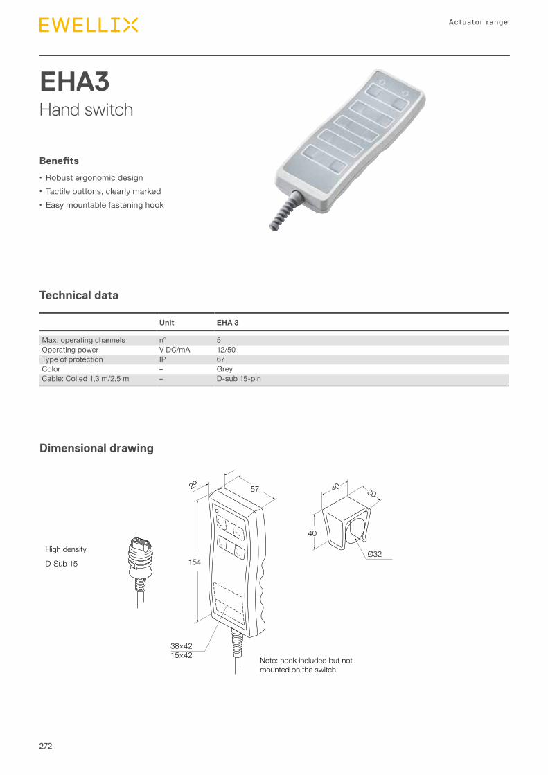
272
Actuator range
EHA3Hand switch
Technical data
Dimensional drawing
Benefits
•Robust ergonomic design•Tactile buttons, clearly marked•Easy mountable fastening hook
Unit EHA 3
Max. operating channels n° 5Operating power V DC/mA 12/50Type of protection IP 67Color – GreyCable: Coiled 1,3 m/2,5 m – D-sub 15-pin
High density
38×4215×42
D-Sub 15 154
40
Ø32
3029 40
Note: hook included but not mounted on the switch.
57
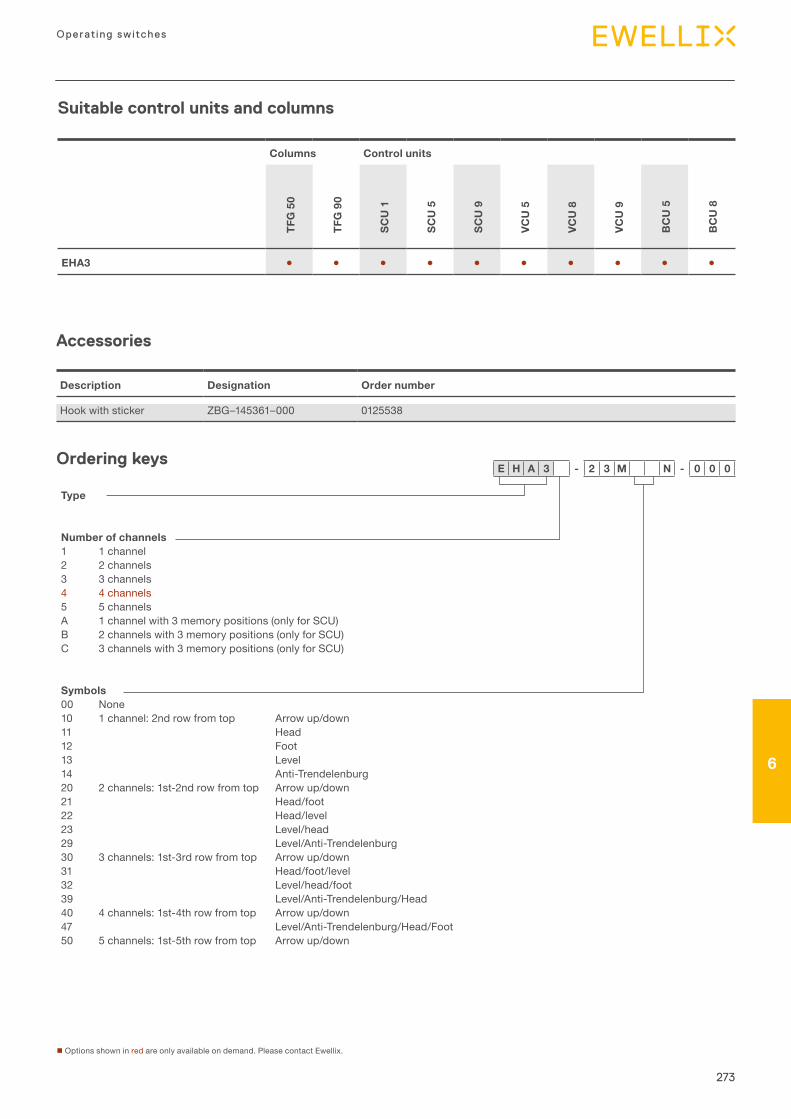
273
6
Operating switches
6
Suitable control units and columns
Columns Control units
TFG
50
TFG
90
SCU
1
SCU
5
SCU
9
VCU
5
VCU
8
VCU
9
BC
U 5
BC
U 8
EHA3 ● ● ● ● ● ● ● ● ● ●
Description Designation Order number
Hook with sticker ZBG–145361–000 0125538
Accessories
Ordering keys
Type
Number of channels1 1 channel2 2 channels3 3 channels4 4 channels5 5 channelsA 1 channel with 3 memory positions (only for SCU)B 2 channels with 3 memory positions (only for SCU)C 3 channels with 3 memory positions (only for SCU)
Symbols00 None10 1 channel: 2nd row from top Arrow up/down11 Head12 Foot13 Level14 Anti-Trendelenburg20 2 channels: 1st-2nd row from top Arrow up/down21 Head/foot22 Head/level23 Level/head29 Level/Anti-Trendelenburg30 3 channels: 1st-3rd row from top Arrow up/down31 Head/foot/level32 Level/head/foot39 Level/Anti-Trendelenburg/Head40 4 channels: 1st-4th row from top Arrow up/down47 Level/Anti-Trendelenburg/Head/Foot50 5 channels: 1st-5th row from top Arrow up/down
n Options shown in red are only available on demand. Please contact Ewellix.
E H A 3 - 2 3 M N - 0 0 0
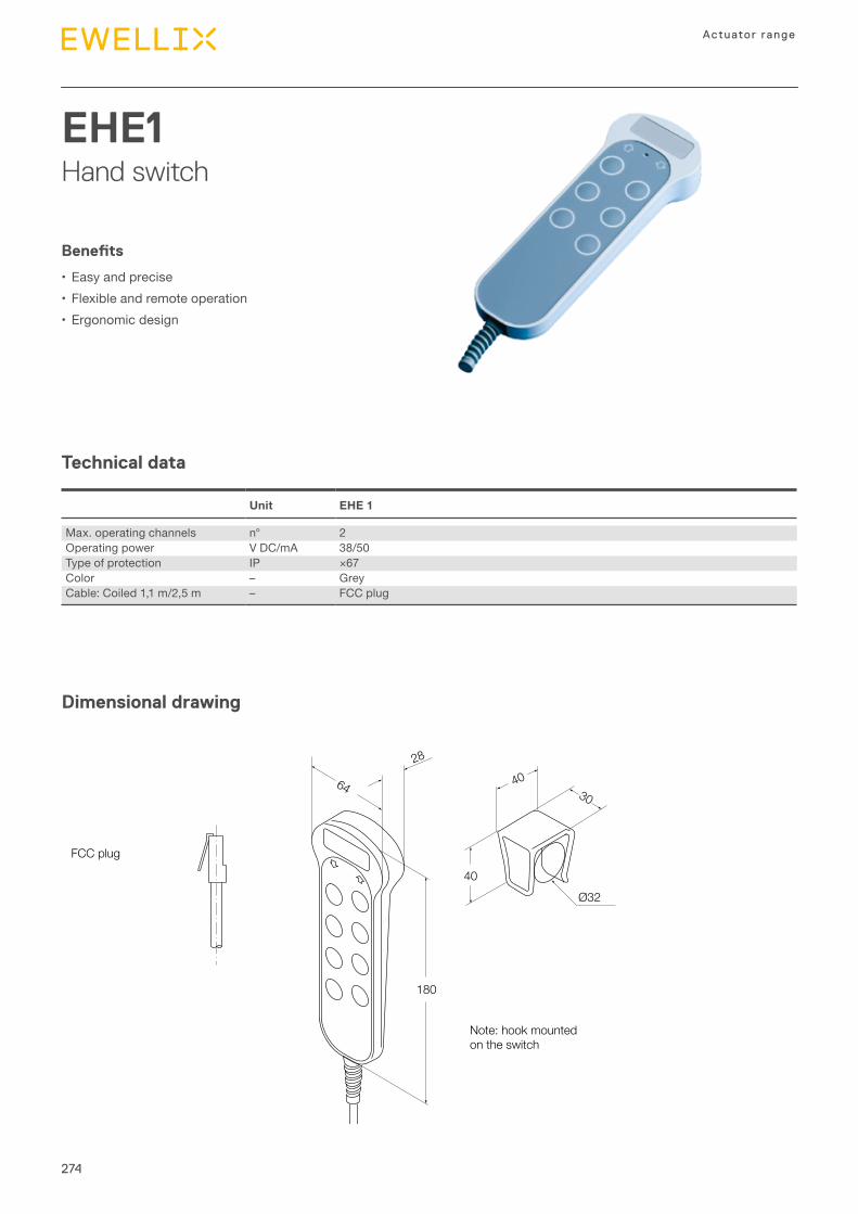
274
Actuator range
EHE1Hand switch
Technical data
Dimensional drawing
Benefits
•Easy and precise•Flexible and remote operation•Ergonomic design
Unit EHE 1
Max. operating channels n° 2Operating power V DC/mA 38/50Type of protection IP ×67Color – GreyCable: Coiled 1,1 m/2,5 m – FCC plug
Ø32
180
40
4064 30
28
FCC plug
Note: hook mounted on the switch
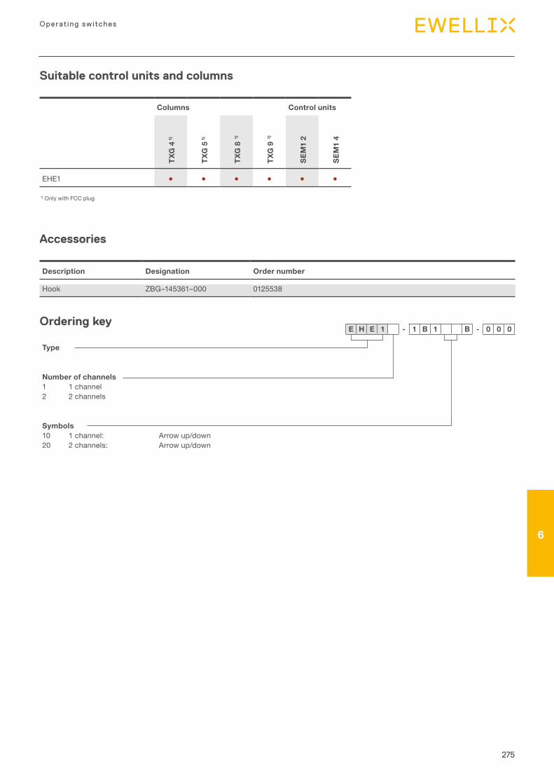
275
6
Operating switches
6
Suitable control units and columns
Columns Control units
TXG
4 1
)
TXG
5 1
)
TXG
8 1
)
TXG
9 1
)
SEM
1 2
SEM
1 4
EHE1 ● ● ● ● ● ●
Description Designation Order number
Hook ZBG–145361–000 0125538
Accessories
Ordering key
1) Only with FCC plug
Type
Number of channels1 1 channel2 2 channels
Symbols10 1 channel: Arrow up/down20 2 channels: Arrow up/down
E H E 1 - 1 B 1 B - 0 0 0
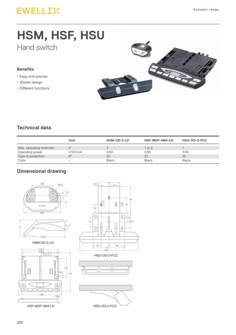
276
Actuator range
HSM, HSF, HSUHand switch
Technical data
Dimensional drawing
Benefits
•Easy and precise•Stylish design• Differentfunctions
Unit HSM-OD-2-LD HSF-MDF-4M4-LD HSU-OD-2-FCC
Max. operating channels n° 1 1 or 2 1Operating power V DC/mA 5/50 5/50 5/50Type of protection IP 32 32 32Color – Black Black Black
66,7
38 Ø4,2
14
45,8
HSM-OD-2-LD
HSF-MDF-4M4-LD
HSU-OD-2-FCC
HSU-OD-2-FCC
11,217
42215,5
21 3672
136
15
28 27
50
29,517,5
27
9,6
110,2105,2
129
119
63
5,227
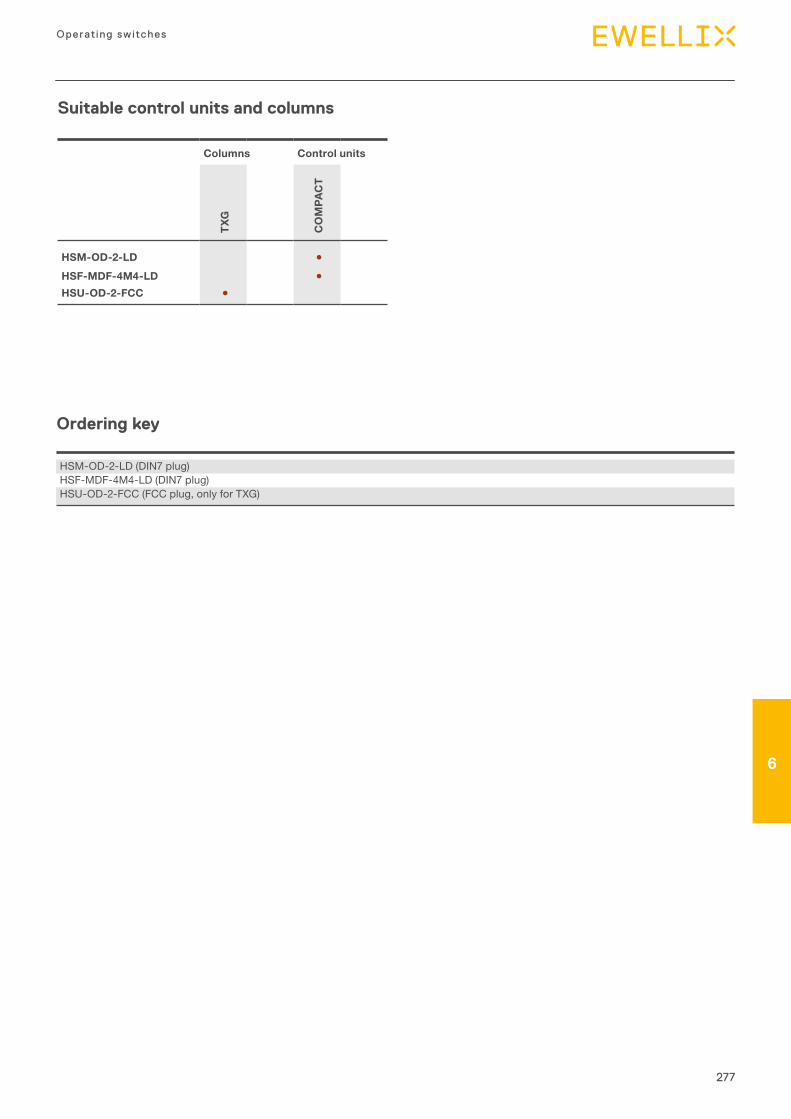
277
6
Operating switches
6
Suitable control units and columns
Columns Control units
TXG
CO
MPA
CT
HSM-OD-2-LD ●HSF-MDF-4M4-LD ●HSU-OD-2-FCC ●
Ordering key
HSM-OD-2-LD (DIN7 plug)HSF-MDF-4M4-LD (DIN7 plug)HSU-OD-2-FCC (FCC plug, only for TXG)
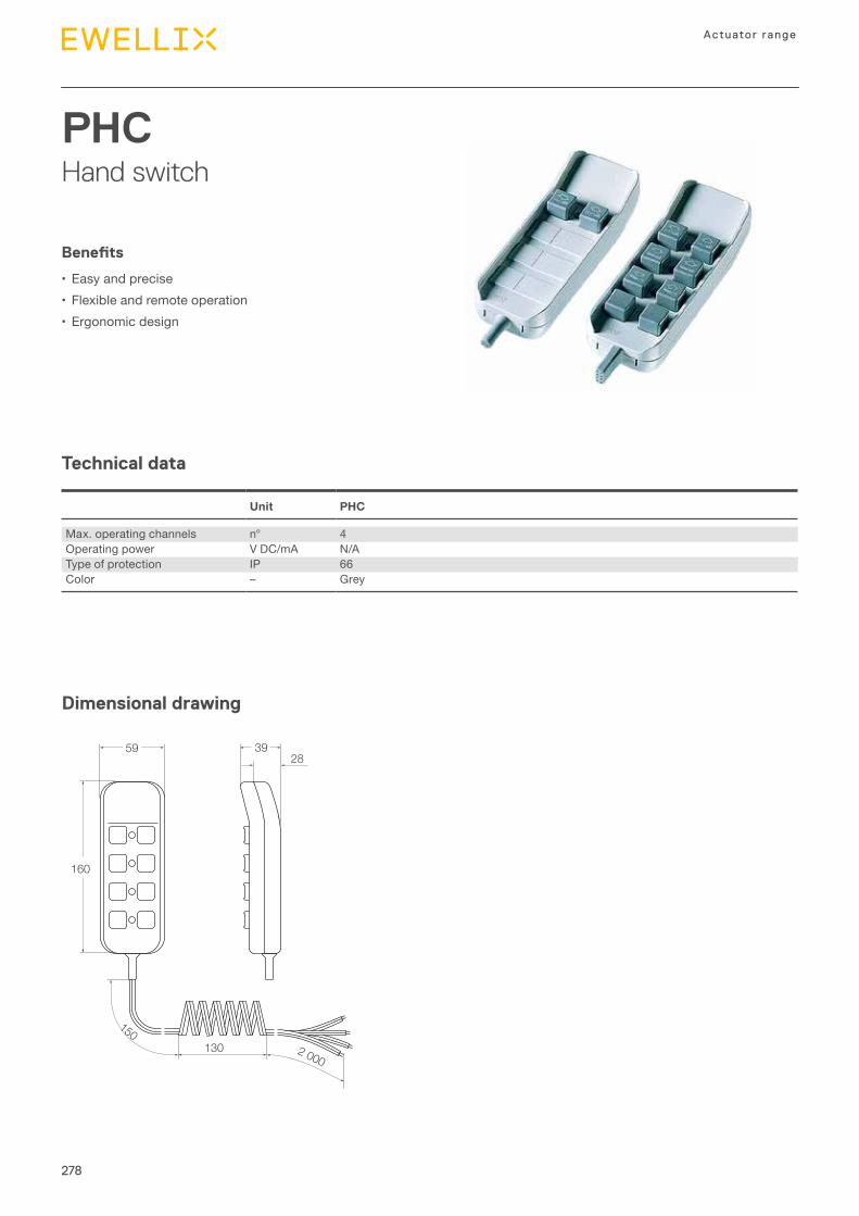
278
Actuator range
PHCHand switch
Technical data
Dimensional drawing
Benefits
•Easy and precise•Flexible and remote operation•Ergonomic design
Unit PHC
Max. operating channels n° 4Operating power V DC/mA N/AType of protection IP 66Color – Grey
59 3928
130
1502 000
160
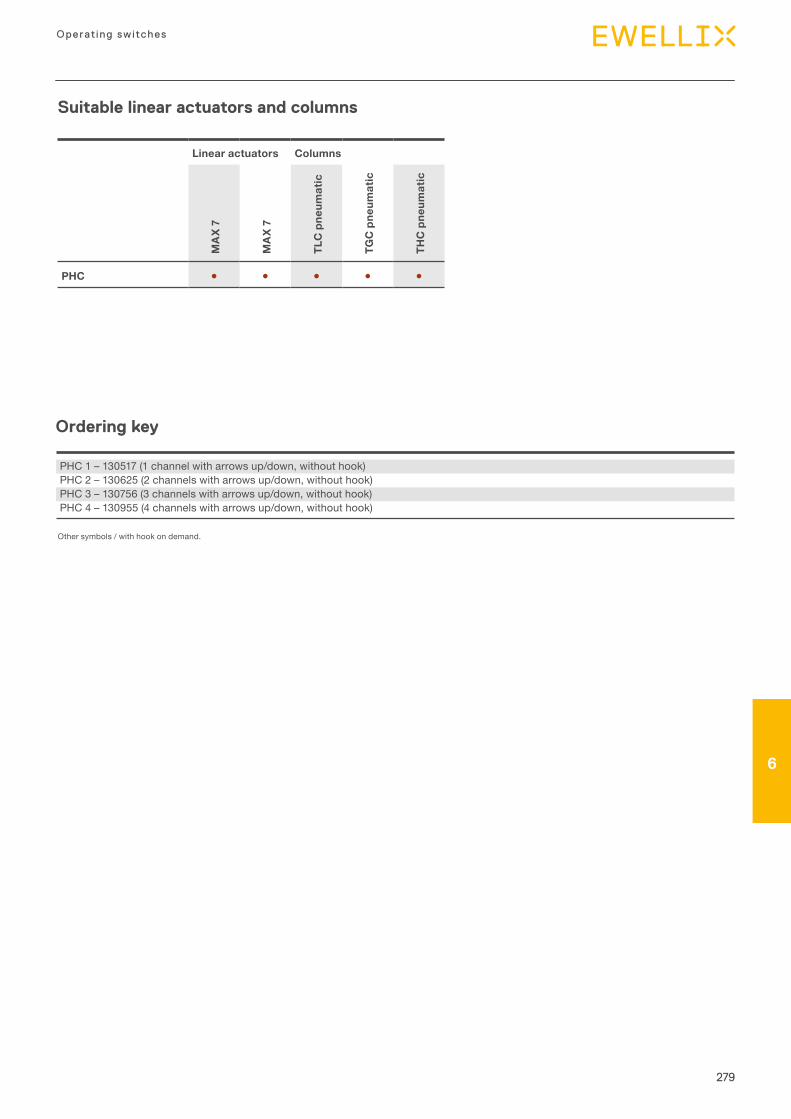
279
6
Operating switches
6
Suitable linear actuators and columns
Linear actuators Columns
MA
X 7
MA
X 7
TLC
pne
umat
ic
TGC
pne
umat
ic
THC
pne
umat
ic
PHC ● ● ● ● ●
Ordering key
PHC 1 – 130517 (1 channel with arrows up/down, without hook)PHC 2 – 130625 (2 channels with arrows up/down, without hook)PHC 3 – 130756 (3 channels with arrows up/down, without hook)PHC 4 – 130955 (4 channels with arrows up/down, without hook)
Other symbols / with hook on demand.
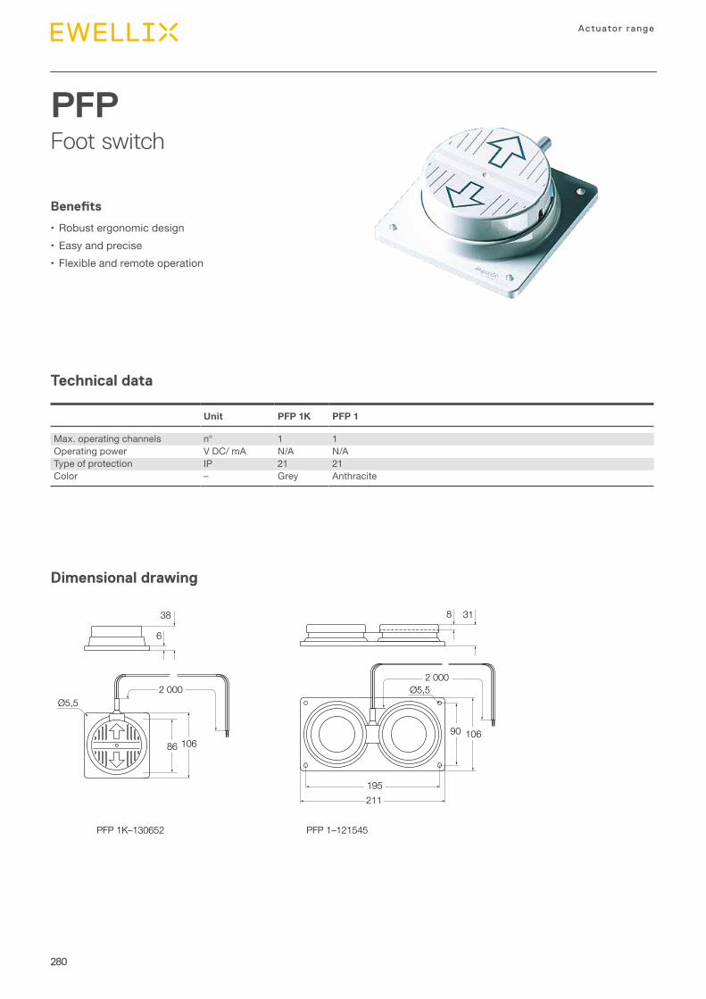
280
Actuator range
PFPFoot switch
Technical data
Dimensional drawing
Benefits
•Robust ergonomic design•Easy and precise•Flexible and remote operation
Unit PFP 1K PFP 1
Max. operating channels n° 1 1Operating power V DC/ mA N/A N/AType of protection IP 21 21Color – Grey Anthracite
86 106
211195
PFP 1–121545
Ø5,5
10690
2 000
PFP 1K–130652
38
6
318
2 000Ø5,5
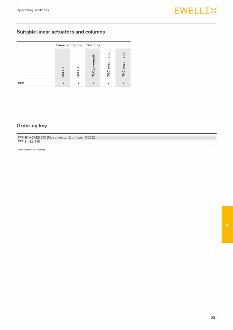
281
6
Operating switches
6
Suitable linear actuators and columns
Linear actuators Columns
MA
X 7
MA
X 7
TLC
pne
umat
ic
TGC
pne
umat
ic
THC
pne
umat
ic
PFP ● ● ● ● ●
Ordering key
PFP 1K – CAES 31C (No connector, 2 buttons) 130652PFP 1 – 121545
Other versions on request.
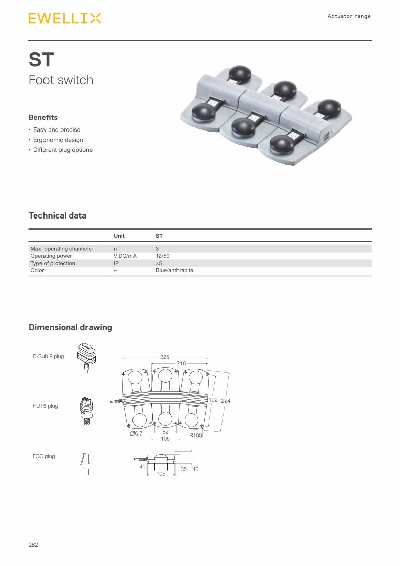
282
Actuator range
STFoot switch
Technical data
Dimensional drawing
Benefits
•Easy and precise•Ergonomic design• Differentplugoptions
Unit ST
Max. operating channels n° 3Operating power V DC/mA 12/50Type of protection IP ×5Color – Blue/anthracite
325216
∅6,7 R100
192 224HD15 plug
D-Sub 9 plug
FCC plug
82105
45 35 40105
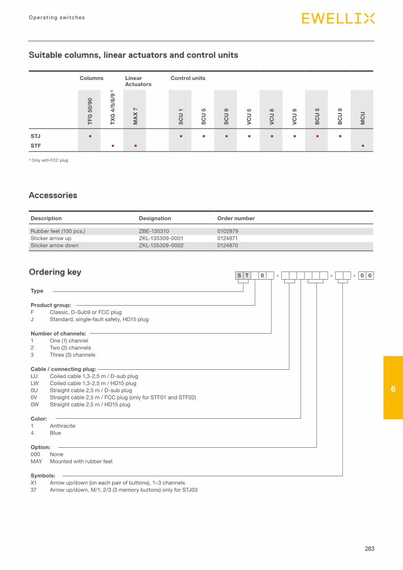
283
6
Operating switches
6
Suitable columns, linear actuators and control units
Columns Linear Actuators
Control units
TFG
50/
90
TXG
4/5
/8/9
1)
MA
X 7
SCU
1
SCU
5
SCU
9
VCU
5
VCU
8
VCU
9
BC
U 5
BC
U 8
MC
U
STJ ● ● ● ● ● ● ● ● ●STF ● ● ●
1) Only with FCC plug
Description Designation Order number
Rubber feet (100 pcs.) ZBE-135310 0102879Sticker arrow up ZKL-135309-0001 0124871Sticker arrow down ZKL-135309-0002 0124870
Accessories
S T 0 - - - 0 0Ordering key
Type
Product group:F Classic, D-Sub9 or FCC plugJ Standard, single-fault safety, HD15 plug
Number of channels:1 One (1) channel2 Two (2) channels3 Three (3) channels
Cable / connecting plug:LU Coiled cable 1,3-2,5 m / D-sub plugLW Coiled cable 1,3-2,5 m / HD15 plug0U Straight cable 2,5 m / D-sub plug0V Straight cable 2,5 m / FCC plug (only for STF01 and STF02)0W Straight cable 2,5 m / HD15 plug
Color:1 Anthracite4 Blue
Option:000 NoneMAY Mounted with rubber feet
Symbols:X1 Arrow up/down (on each pair of buttons), 1–3 channels37 Arrow up/down, M/1, 2/3 (3 memory buttons) only for STJ03
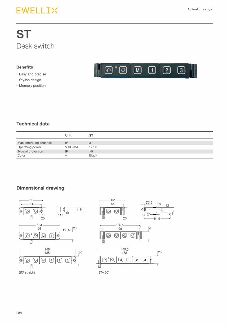
284
Actuator range
STDesk switch
Technical data
Dimensional drawing
Benefits
•Easy and precise•Stylish design•Memory position
Unit ST
Max. operating channels n° 3Operating power V DC/mA 12/50Type of protection IP ×0Color – Black
62
104
146 149,5138 138
96107,5
96 20
546254 Ø3,5
Ø3,5 20
20 20
20 20
18 12
64,511,5
STA 90°STA straight
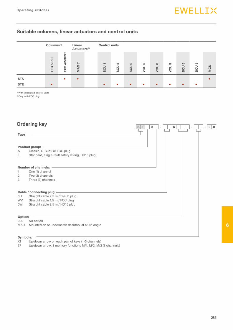
285
6
Operating switches
6
Columns 1) Linear Actuators 1)
Control units
TFG
50/
90
TXG
4/5
/8/9
2)
MA
X 7
SCU
1
SCU
5
SCU
9
VCU
5
VCU
8
VCU
9
BC
U 5
BC
U 8
MC
U
STA ● ● ●STE ● ● ● ● ● ● ● ● ●
1) With integrated control units2) Only with FCC plug
Ordering key
Type
Product group:A Classic, D-Sub9 or FCC plugE Standard, single-fault safety wiring, HD15 plug
Number of channels:1 One (1) channel2 Two (2) channels3 Three (3) channels
Cable / connecting plug:0U Straight cable 2,5 m / D-sub plugWV Straight cable 1,5 m / FCC plug0W Straight cable 2,5 m / HD15 plug
Option:000 No optionMAU Mounted on or underneath desktop, at a 90° angle
Symbols:X1 Up/down arrow on each pair of keys (1-3 channels)37 Up/down arrow, 3 memory functions M/1, M/2, M/3 (3 channels)
S T 0 - 6 - - 0 0
Suitable columns, linear actuators and control units
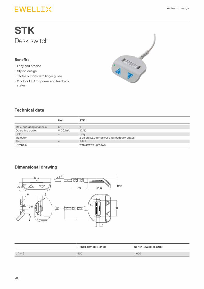
286
Actuator range
STKDesk switch
Technical data
Dimensional drawing
Benefits
•Easy and precise•Stylish design• Tactilebuttonswithfingerguide•2 colors LED for power and feedback
status
Unit STK
Max. operating channels n° 1Operating power V DC/mA 12/50Color – GreyIndicator – 2 colors LED for power and feedback statusPlug – RJ45Symbols – with arrows up/down
4,2
7
6
10,5
L
55,839
38
17
66,7
20,8
8
12,3
STK01-SW3000-X100 STK01-UW3000-X100
L [mm] 500 1 000
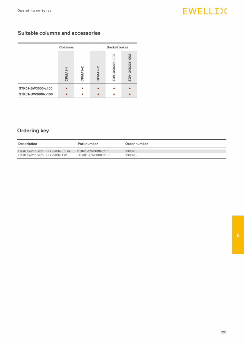
287
6
Operating switches
6
Suitable columns and accessories
Columns Socket boxes
CPM
A1–1
CPM
A1–2
CPM
A2–
2
ZDV–
3482
20–0
02
ZDV–
3482
21–0
02
STK01-SW3000-x100 ● ● ● ● ●STK01-UW3000-x100 ● ● ● ● ●
Ordering key
Description Part number Order number
Desk switch with LED, cable 0,5 m STK01-SW3000-x100 130025Desk switch with LED, cable 1 m STK01-UW3000-x100 130026
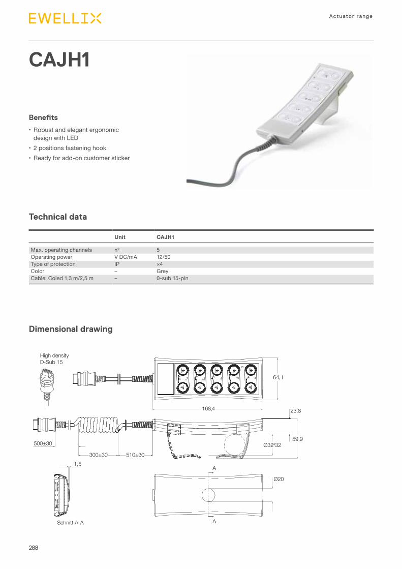
288
Actuator range
CAJH1
Technical data
Dimensional drawing
Benefits
•Robust and elegant ergonomic design with LED
•2 positions fastening hook•Ready for add-on customer sticker
Unit CAJH1
Max. operating channels n° 5Operating power V DC/mA 12/50Type of protection IP ×4Color – GreyCable: Coled 1,3 m/2,5 m – 0-sub 15-pin
500±30
510±30300±30
Schnitt A-A
168,4
A
A
1,5
64,1
59,9
Ø20
23,8
High density D-Sub 15
Ø32a32
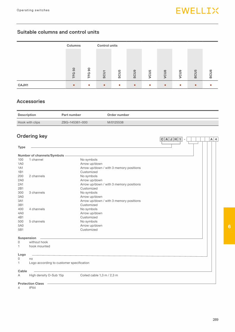
289
6
Operating switches
6
Suitable columns and control units
Columns Control units
TFG
50
TFG
90
SCU
1
SCU
5
SCU
9
VCU
5
VCU
8
VCU
9
BC
U5
BC
U8
CAJH1 ● ● ● ● ● ● ● ● ● ●
Description Part number Order number
Hook with clips ZBG–145361–000 M/0125538
Accessories
Ordering key
Type
Number of channels/Symbols100 1 channel No symbols1A0 Arrow up/down1A1 Arrow up/down / with 3 memory positions1B1 Customized200 2 channels No symbols2A0 Arrow up/down2A1 Arrow up/down / with 3 memory positions2B1 Customized300 3 channels No symbols3A0 Arrow up/down3A1 Arrow up/down / with 3 memory positions3B1 Customized400 4 channels No symbols4A0 Arrow up/down4B1 Customized500 5 channels No symbols5A0 Arrow up/down5B1 Customized
Suspension0 without hook1 hook mounted
Logo0 no1 Logoaccordingtocustomerspecification
CableA High density D-Sub 15p Coiled cable 1,3 m / 2,3 m
Protection Class4 IPX4
C A J H 1 - A 4
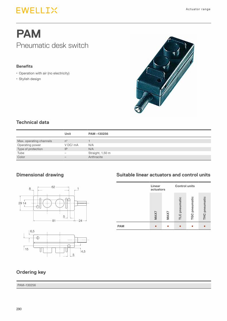
290
Actuator range
PAMPneumatic desk switch
Technical data
Dimensional drawing Suitable linear actuators and control units
Benefits
•Operation with air (no electricity)•Stylish design
Unit PAM –130256
Max. operating channels n° 1Operating power V DC/ mA N/AType of protection IP N/ATube – Straight, 1,50 mColor – Anthracite
14
15
6,5
4,5
8 1
29
62
81 24
5
5
Linear actuators
Control units
MA
X7
MA
X7
TLC
pne
umat
ic
TGC
pne
umat
ic
THC
pne
umat
ic
PAM ● ● ● ● ●
Ordering key
PAM–130256


IntroductionIntroductionNew medical solution
7
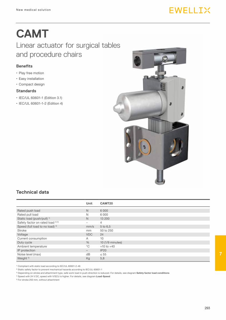
293
New medica l so lut ion
77
CAMTLinear actuator for surgical tables and procedure chairs
Technical data
Benefits
•Play free motion•Easy installation•Compact design
Standards
• IEC/UL 60601-1 (Edition 3.1)• IEC/UL 60601-1-2 (Edition 4)
Unit CAMT20
Rated push load N 6 000Rated pull load N 6 000Static load (push/pull) 1) N 13 200Safety factor on rated load 2) 3) – 4Speed (full load to no load) 4) mm/s 5 to 6,5Stroke mm 50 to 250Voltage VDC 24Current consumption A 10Duty cycle % 10 (1/9 minutes)Ambient temperature °C +10 to +40IP protection – IP20Noise level (max) dB ≤55Weight 5) Kg 5,8
1) Compliant with static load according to IEC/UL 60601-2-462) Static safety factor to prevent mechanical hazards according to IEC/UL 60601-13) Depending on stroke and attachment type, safe work load in push direction is reduced. For details, see diagram Safety factor load conditions4) Speed with 24 V DC, speed with V/SCU is higher. For details, see diagram Load-Speed5) For stroke 250 mm, without attachment
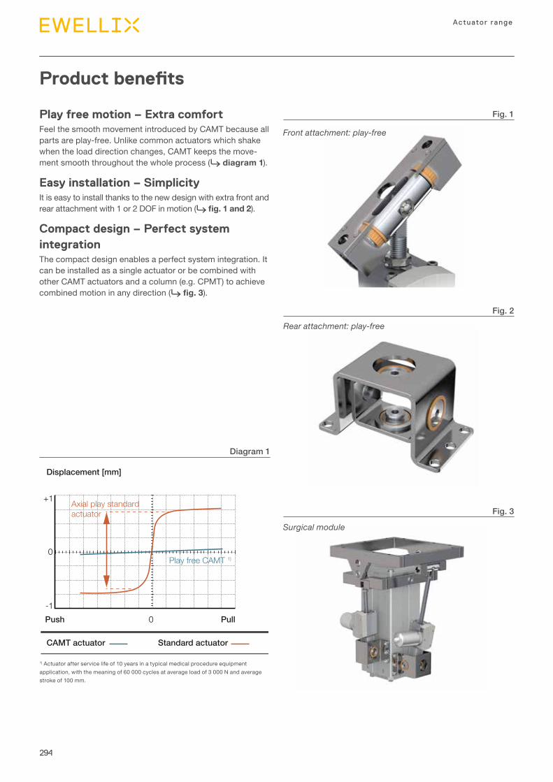
294
Actuator range
0
+1
-1 0 PullPush
Displacement [mm]
CAMT actuator Standard actuator
Axial play standardactuator
Play free CAMT 1)
Product benefits
1) Actuator after service life of 10 years in a typical medical procedure equipment application, with the meaning of 60 000 cycles at average load of 3 000 N and average stroke of 100 mm.
Front attachment: play-free
Rear attachment: play-free
Surgical module
Fig. 3
Fig. 2
Fig. 1
Diagram 1
Play free motion – Extra comfortFeel the smooth movement introduced by CAMT because all parts are play-free. Unlike common actuators which shake when the load direction changes, CAMT keeps the move-ment smooth throughout the whole process (⮑ diagram 1).
Easy installation – SimplicityIt is easy to install thanks to the new design with extra front and rear attachment with 1 or 2 DOF in motion (⮑ fig. 1 and 2).
Compact design – Perfect system integrationThe compact design enables a perfect system integration. It can be installed as a single actuator or be combined with other CAMT actuators and a column (e.g. CPMT) to achieve combined motion in any direction (⮑ fig. 3).
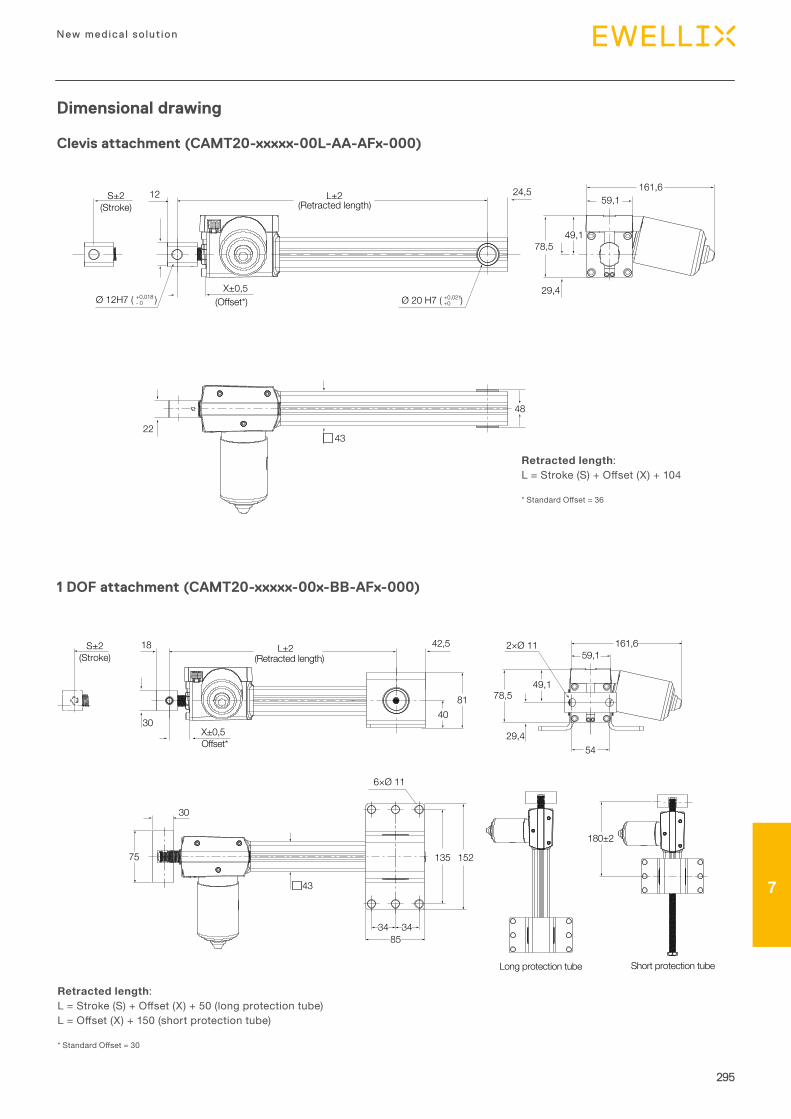
295
New medica l so lut ion
77
L±2(Retracted length)
Offset*
30
18 42,5
X±0,5
59,1161,62×Ø 11
78,549,1
29,4
S±2(Stroke)
54
4081
75
6×Ø 11
135
3485
34
152
Long protection tube Short protection tube
180±2
43
30
Dimensional drawing
Clevis attachment (CAMT20-xxxxx-00L-AA-AFx-000)
Retracted length:L=Stroke(S)+Offset(X)+50(longprotectiontube)L=Offset(X)+150(shortprotectiontube)
*StandardOffset=30
1 DOF attachment (CAMT20-xxxxx-00x-BB-AFx-000)
59,1161,6
S±2(Stroke)
2243
48
Ø 20 H7 ( )+0,021+0
78,5
29,4X±0,5(Offset*)Ø 12H7 ( )+0,018
- 0
49,1
24,512(Retracted length)
L±2
Retracted length:L=Stroke(S)+Offset(X)+104
*StandardOffset=36
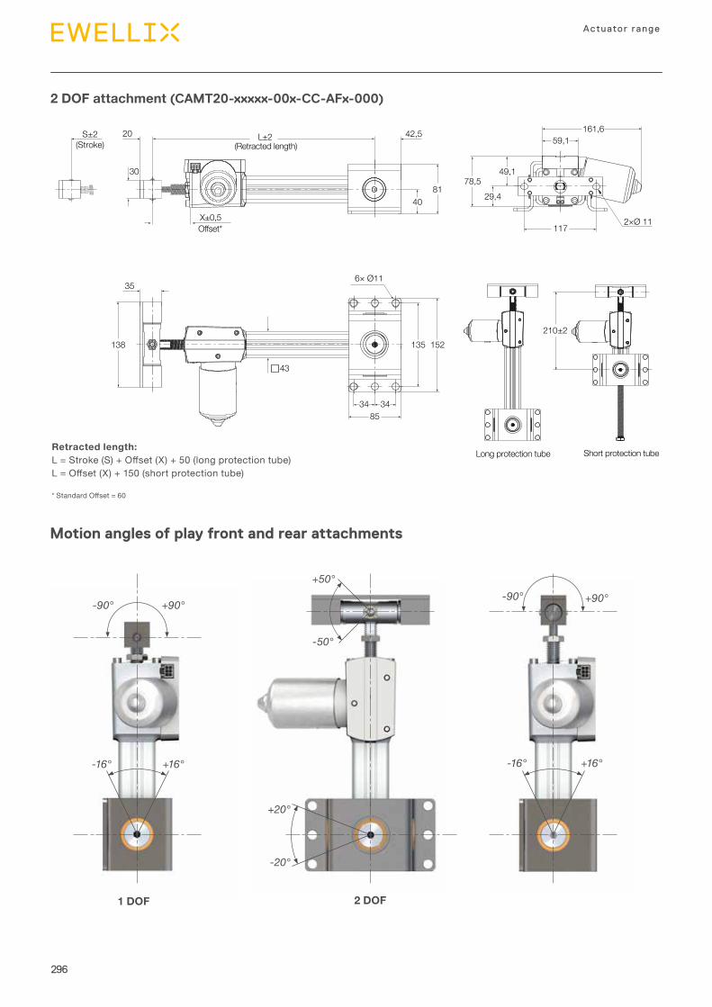
296
Actuator range
2 DOF attachment (CAMT20-xxxxx-00x-CC-AFx-000)
Retracted length:L=Stroke(S)+Offset(X)+50(longprotectiontube)L=Offset(X)+150(shortprotectiontube)
*StandardOffset=60
Motion angles of play front and rear attachments
42,5
8178,5
59,1161,6
117
29,440
30
20 L±2(Retracted length)
Offset*X±0,5 2×Ø 11
S±2(Stroke)
Long protection tube Short protection tube
210±2135 152
34 3485
138
35
43
49,1
6× Ø11
-90°-90°
+90°
-16° +16° -16° +16°
+20°
-20°
+90°+50°
-50°
1 DOF 2 DOF
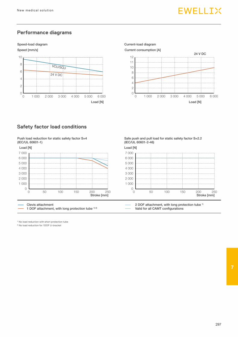
297
New medica l so lut ion
77
0
2
4
6
8
10
0 1 000 2 000 3 000 4 000 5 000 6 000 02468
121110
0 1 000 2 000 3 000 4 000 5 000 6 000
Speed [mm/s]
Load [N]
Current consumption [A]24 V DC
Load [N]
Speed-load diagram Current-load diagram
VCU/SCU
24 V DC
Performance diagrams
Safety factor load conditions
1) No load reduction with short protection tube2) No load reduction for 1DOF U-bracket
0 1 000 2 000 3 000 4 000 5 000
7 000 6 000
250 0
1 000 2 000 3 000 4 000 5 000
7 000 6 000
100 0 50 100 150 200 0 50 150 200 250 Stroke [mm]
Load [N]
Stroke [mm]
Load [N]
Push load reduction for static safety factor S=4(IEC/UL 60601-1)
Safe push and pull load for static safety factor S=2.2(IEC/UL 60601-2-46)
Clevis attachment1 DOF attachment, with long protection tube 1) 2)
2 DOF attachment, with long protection tube 1)
Valid for all CAMT configurations
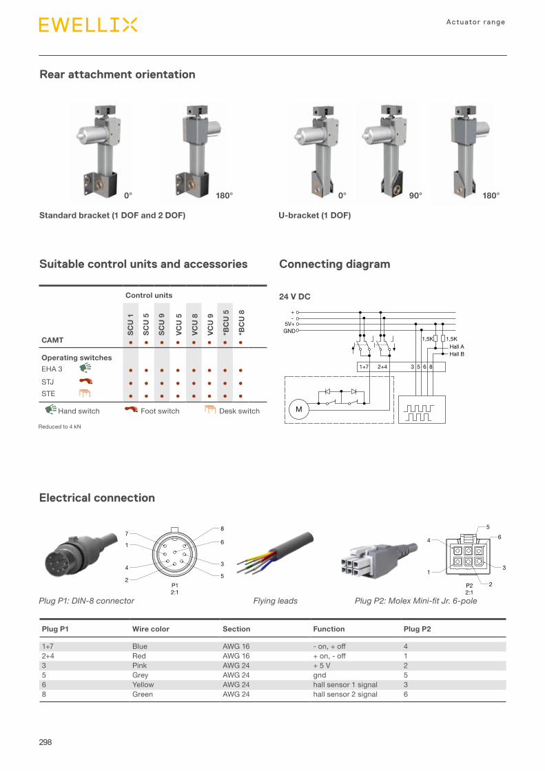
298
Actuator range
Suitable control units and accessories
Rear attachment orientation
Connecting diagram
M
+-
5V+GND
1+7 2+4
1,5K 1,5KHall AHall B
3 5 6 8
24 V DC
Electrical connection
Plug P1 Wire color Section Function Plug P2
1+7 Blue AWG 16 -on,+off 42+4 Red AWG 16 +on,-off 13 Pink AWG 24 + 5 V 25 Grey AWG 24 gnd 56 Yellow AWG 24 hall sensor 1 signal 38 Green AWG 24 hall sensor 2 signal 6
Standard bracket (1 DOF and 2 DOF)
P22:1
4
1
56
2
3
P12:1
8
3
5
67
1
4
2
Plug P1: DIN-8 connector Flying leads
P22:1
4
1
56
2
3
P12:1
8
3
5
67
1
4
2
Plug P2: Molex Mini-fit Jr. 6-pole
0° 0°180° 90° 180°
U-bracket (1 DOF)
Control units
SCU
1
SCU
5
SCU
9
VCU
5
VCU
8
VCU
9
*BC
U 5
*BC
U 8
CAMT ● ● ● ● ● ● ● ●
Operating switchesEHA 3 ● ● ● ● ● ● ● ●STJ ● ● ● ● ● ● ● ●STE ● ● ● ● ● ● ● ●
Desk switchHand switch Foot switch
Reduced to 4 kN
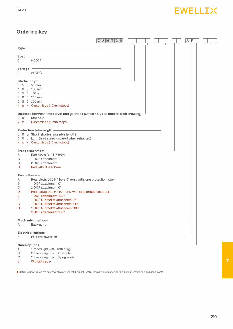
299
7
299
CAMT
7
Type
Load2 6 000 N
Voltage0 24 VDC
Stroke length0 5 0 50 mm1 0 0 100 mm1 5 0 150 mm2 0 0 200 mm2 5 0 250 mmx x x Customised (10 mm steps)
Distance between front pivot and gear box (Offset "X", see dimensional drawing)0 0 Standardx x Customised (1 mm steps)
Protection tube length0 0 S Short (shortest possible length)0 0 L Long (lead screw covered when retracted)x x x Customised (10 mm steps)
Front attachmentA Rod clevis D12 H7 boreB 1 DOF attachmentC 2 DOF attachmentD Rod with D8 H7 bore
Rear attachmentA Rear clevis D20 H7 bore 0° (only with long protection tube)B 1 DOF attachment 0°C 2 DOF attachment 0°D Rear clevis D20 H7 90° (only with long protection tube)E 1 DOF attachment 180°F 1 DOF U-bracket attachment 0°G 1 DOF U-bracket attachment 90°H 1 DOF U-bracket attachment 180°I 2 DOF attachment 180°
Mechanical optionsA Backup nut
Electrical optionsF End limit switches
Cable optionsA 1 m straight with DIN8 plugB 2,3 m straight with DIN8 plugC 2,3mstraightwithflyingleads0 Without cable
n Options shown in red are only available on request. Contact Ewellix for more information on minimum quantities and additional costs.
Ordering key
C A M T 2 0 - – – – A F –

Introduction
1Glossary and symbols
8
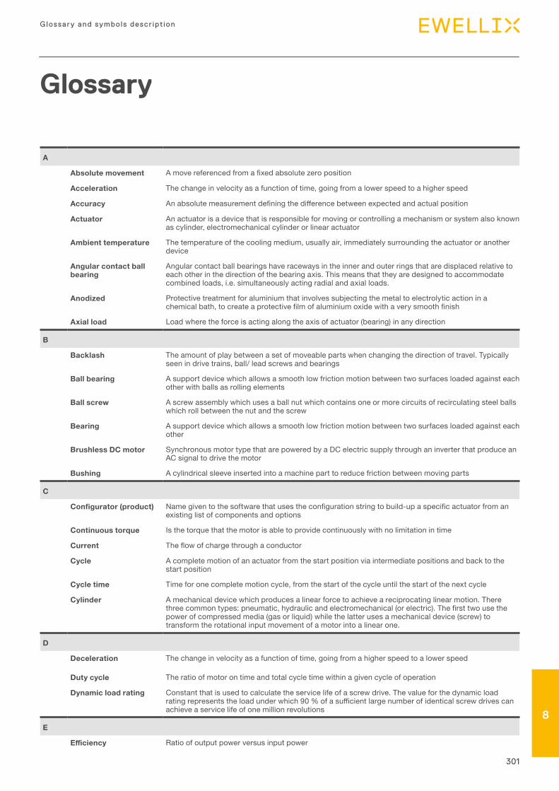
301
Glossary and symbols descr ipt ion
78
A
Absolute movement Amovereferencedfromafixedabsolutezeroposition
Acceleration The change in velocity as a function of time, going from a lower speed to a higher speed
Accuracy Anabsolutemeasurementdefiningthedifferencebetweenexpectedandactualposition
Actuator An actuator is a device that is responsible for moving or controlling a mechanism or system also known as cylinder, electromechanical cylinder or linear actuator
Ambient temperature The temperature of the cooling medium, usually air, immediately surrounding the actuator or another device
Angular contact ball bearing
Angular contact ball bearings have raceways in the inner and outer rings that are displaced relative to each other in the direction of the bearing axis. This means that they are designed to accommodate combined loads, i.e. simultaneously acting radial and axial loads.
Anodized Protective treatment for aluminium that involves subjecting the metal to electrolytic action in a chemicalbath,tocreateaprotectivefilmofaluminiumoxidewithaverysmoothfinish
Axial load Load where the force is acting along the axis of actuator (bearing) in any direction
B
Backlash The amount of play between a set of moveable parts when changing the direction of travel. Typically seen in drive trains, ball/ lead screws and bearings
Ball bearing A support device which allows a smooth low friction motion between two surfaces loaded against each other with balls as rolling elements
Ball screw A screw assembly which uses a ball nut which contains one or more circuits of recirculating steel balls which roll between the nut and the screw
Bearing A support device which allows a smooth low friction motion between two surfaces loaded against each other
Brushless DC motor Synchronous motor type that are powered by a DC electric supply through an inverter that produce an AC signal to drive the motor
Bushing A cylindrical sleeve inserted into a machine part to reduce friction between moving parts
C
Configurator (product) Namegiventothesoftwarethatusestheconfigurationstringtobuild-upaspecificactuatorfromanexisting list of components and options
Continuous torque Is the torque that the motor is able to provide continuously with no limitation in time
Current Theflowofchargethroughaconductor
Cycle A complete motion of an actuator from the start position via intermediate positions and back to the start position
Cycle time Time for one complete motion cycle, from the start of the cycle until the start of the next cycle
Cylinder A mechanical device which produces a linear force to achieve a reciprocating linear motion. There threecommontypes:pneumatic,hydraulicandelectromechanical(orelectric).Thefirsttwousethepower of compressed media (gas or liquid) while the latter uses a mechanical device (screw) to transform the rotational input movement of a motor into a linear one.
D
Deceleration The change in velocity as a function of time, going from a higher speed to a lower speed
Duty cycle The ratio of motor on time and total cycle time within a given cycle of operation
Dynamic load rating Constant that is used to calculate the service life of a screw drive. The value for the dynamic load ratingrepresentstheloadunderwhich90%ofasufficientlargenumberofidenticalscrewdrivescanachieve a service life of one million revolutions
E
Efficiency Ratio of output power versus input power
Glossary
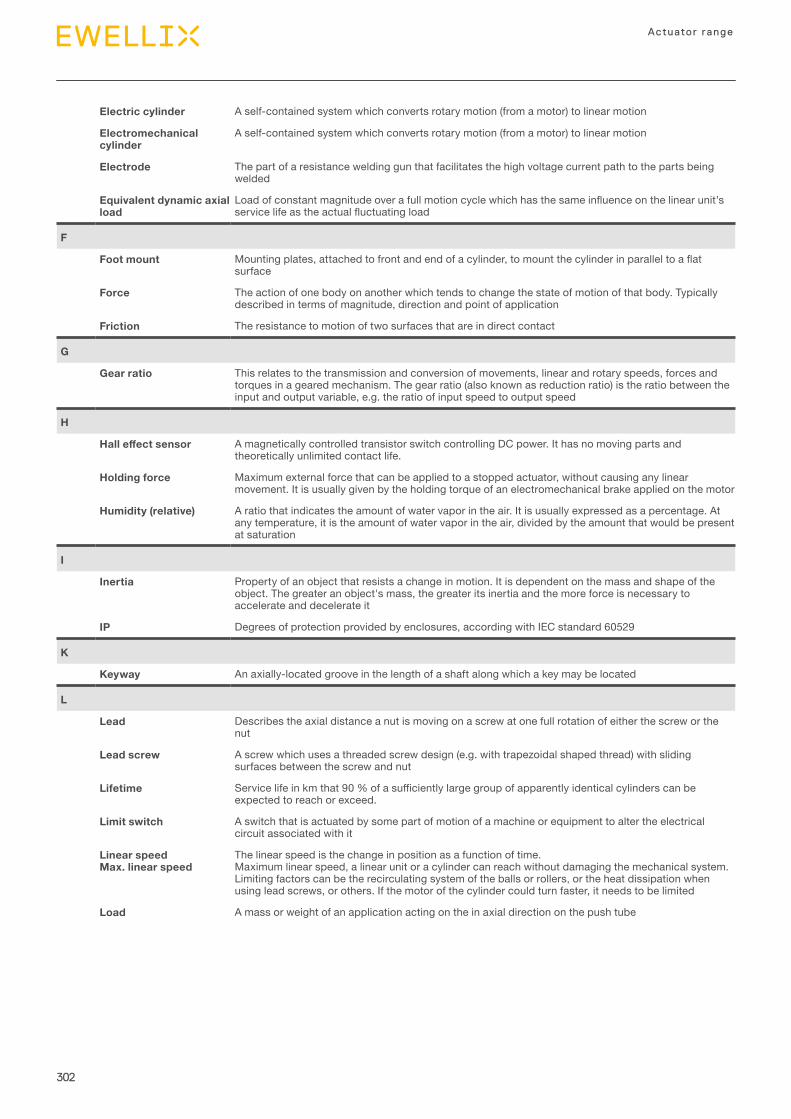
302
Actuator range
Electric cylinder A self-contained system which converts rotary motion (from a motor) to linear motion
Electromechanical cylinder
A self-contained system which converts rotary motion (from a motor) to linear motion
Electrode The part of a resistance welding gun that facilitates the high voltage current path to the parts being welded
Equivalent dynamic axial load
Loadofconstantmagnitudeoverafullmotioncyclewhichhasthesameinfluenceonthelinearunit’sservicelifeastheactualfluctuatingload
F
Foot mount Mountingplates,attachedtofrontandendofacylinder,tomountthecylinderinparalleltoaflatsurface
Force The action of one body on another which tends to change the state of motion of that body. Typically described in terms of magnitude, direction and point of application
Friction The resistance to motion of two surfaces that are in direct contact
G
Gear ratio This relates to the transmission and conversion of movements, linear and rotary speeds, forces and torques in a geared mechanism. The gear ratio (also known as reduction ratio) is the ratio between the input and output variable, e.g. the ratio of input speed to output speed
H
Hall effect sensor A magnetically controlled transistor switch controlling DC power. It has no moving parts and theoretically unlimited contact life.
Holding force Maximum external force that can be applied to a stopped actuator, without causing any linear movement. It is usually given by the holding torque of an electromechanical brake applied on the motor
Humidity (relative) A ratio that indicates the amount of water vapor in the air. It is usually expressed as a percentage. At any temperature, it is the amount of water vapor in the air, divided by the amount that would be present at saturation
I
Inertia Property of an object that resists a change in motion. It is dependent on the mass and shape of the object. The greater an object's mass, the greater its inertia and the more force is necessary to accelerate and decelerate it
IP Degrees of protection provided by enclosures, according with IEC standard 60529
K
Keyway An axially-located groove in the length of a shaft along which a key may be located
L
Lead Describes the axial distance a nut is moving on a screw at one full rotation of either the screw or the nut
Lead screw A screw which uses a threaded screw design (e.g. with trapezoidal shaped thread) with sliding surfaces between the screw and nut
Lifetime Servicelifeinkmthat90%ofasufficientlylargegroupofapparentlyidenticalcylinderscanbeexpected to reach or exceed.
Limit switch A switch that is actuated by some part of motion of a machine or equipment to alter the electrical circuit associated with it
Linear speed Max. linear speed
The linear speed is the change in position as a function of time.Maximum linear speed, a linear unit or a cylinder can reach without damaging the mechanical system. Limiting factors can be the recirculating system of the balls or rollers, or the heat dissipation when using lead screws, or others. If the motor of the cylinder could turn faster, it needs to be limited
Load A mass or weight of an application acting on the in axial direction on the push tube
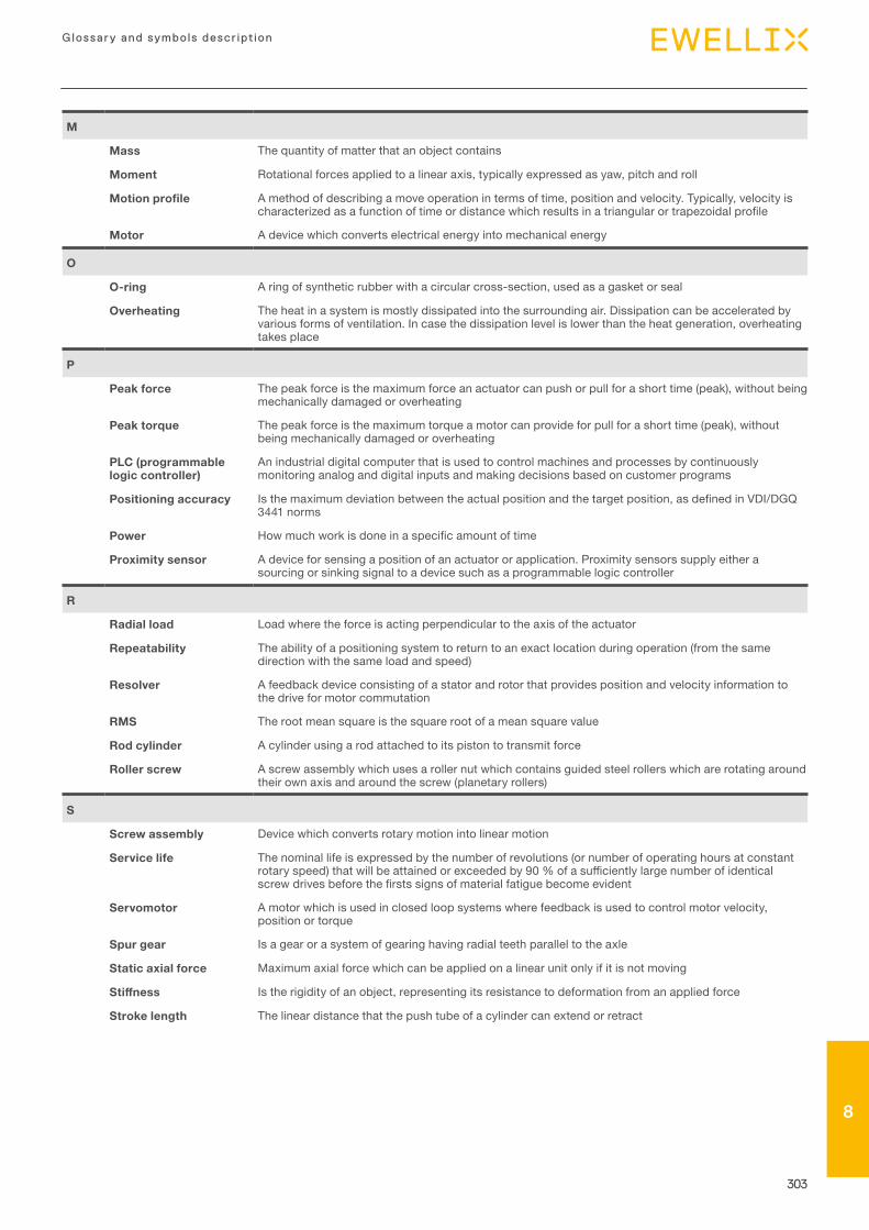
303
Glossary and symbols descr ipt ion
78
M
Mass The quantity of matter that an object contains
Moment Rotational forces applied to a linear axis, typically expressed as yaw, pitch and roll
Motion profile A method of describing a move operation in terms of time, position and velocity. Typically, velocity is characterizedasafunctionoftimeordistancewhichresultsinatriangularortrapezoidalprofile
Motor A device which converts electrical energy into mechanical energy
O
O-ring A ring of synthetic rubber with a circular cross-section, used as a gasket or seal
Overheating The heat in a system is mostly dissipated into the surrounding air. Dissipation can be accelerated by various forms of ventilation. In case the dissipation level is lower than the heat generation, overheating takes place
P
Peak force The peak force is the maximum force an actuator can push or pull for a short time (peak), without being mechanically damaged or overheating
Peak torque The peak force is the maximum torque a motor can provide for pull for a short time (peak), without being mechanically damaged or overheating
PLC (programmable logic controller)
An industrial digital computer that is used to control machines and processes by continuously monitoring analog and digital inputs and making decisions based on customer programs
Positioning accuracy Isthemaximumdeviationbetweentheactualpositionandthetargetposition,asdefinedinVDI/DGQ3441 norms
Power Howmuchworkisdoneinaspecificamountoftime
Proximity sensor A device for sensing a position of an actuator or application. Proximity sensors supply either a sourcing or sinking signal to a device such as a programmable logic controller
R
Radial load Load where the force is acting perpendicular to the axis of the actuator
Repeatability The ability of a positioning system to return to an exact location during operation (from the same direction with the same load and speed)
Resolver A feedback device consisting of a stator and rotor that provides position and velocity information to the drive for motor commutation
RMS The root mean square is the square root of a mean square value
Rod cylinder A cylinder using a rod attached to its piston to transmit force
Roller screw A screw assembly which uses a roller nut which contains guided steel rollers which are rotating around their own axis and around the screw (planetary rollers)
S
Screw assembly Device which converts rotary motion into linear motion
Service life The nominal life is expressed by the number of revolutions (or number of operating hours at constant rotaryspeed)thatwillbeattainedorexceededby90%ofasufficientlylargenumberofidenticalscrewdrivesbeforethefirstssignsofmaterialfatiguebecomeevident
Servomotor A motor which is used in closed loop systems where feedback is used to control motor velocity, position or torque
Spur gear Is a gear or a system of gearing having radial teeth parallel to the axle
Static axial force Maximum axial force which can be applied on a linear unit only if it is not moving
Stiffness Is the rigidity of an object, representing its resistance to deformation from an applied force
Stroke length The linear distance that the push tube of a cylinder can extend or retract

304
Actuator range
T
Thermal load The thermal load describes the force which the actuator can permanently move without overheating. Thethermalloadiscalculatedbyaformulainrespectofchangingloadconditionsoverdifferenttimephases of a full motion cycle.
Torque A measure of angular force which produces rotational motion
U
Units (metric) A decimal system of weights and measures based on the kilogram and meter
V
Volt Differenceinelectricalpotentialbetweentwopoints
W
Watt A unit of power or a rate of doing work. The power dissipated by a one-ohm resistor with one ampere of current is one watt
Weight Force of gravity acting on a body. Determined by multiplying the mass of the object by the acceleration due to gravity
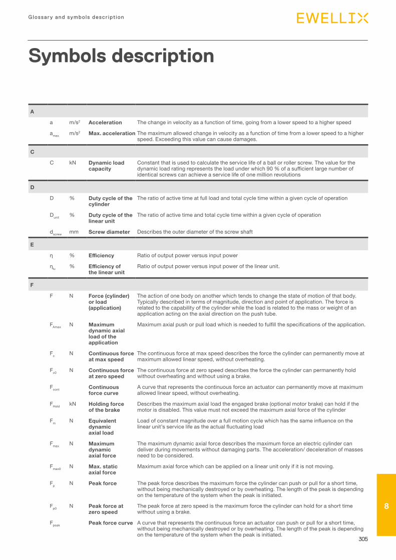
305
Glossary and symbols descr ipt ion
78
A
a m/s2 Acceleration The change in velocity as a function of time, going from a lower speed to a higher speed
amax m/s2 Max. acceleration The maximum allowed change in velocity as a function of time from a lower speed to a higher speed. Exceeding this value can cause damages.
C
C kN Dynamic load capacity
Constant that is used to calculate the service life of a ball or roller screw. The value for the dynamicloadratingrepresentstheloadunderwhich90%ofasufficientlargenumberofidentical screws can achieve a service life of one million revolutions
D
D % Duty cycle of the cylinder
The ratio of active time at full load and total cycle time within a given cycle of operation
Dunit % Duty cycle of the linear unit
The ratio of active time and total cycle time within a given cycle of operation
dscrew mm Screw diameter Describes the outer diameter of the screw shaft
E
η % Efficiency Ratio of output power versus input power
ηlu % Efficiency of the linear unit
Ratio of output power versus input power of the linear unit.
F
F N Force (cylinder) or load (application)
The action of one body on another which tends to change the state of motion of that body. Typically described in terms of magnitude, direction and point of application. The force is related to the capability of the cylinder while the load is related to the mass or weight of an application acting on the axial direction on the push tube.
FAmax N Maximum dynamic axial load of the application
Maximumaxialpushorpullloadwhichisneededtofulfillthespecificationsoftheapplication.
Fc N Continuous force at max speed
The continuous force at max speed describes the force the cylinder can permanently move at maximum allowed linear speed, without overheating.
Fc0 N Continuous force at zero speed
The continuous force at zero speed describes the force the cylinder can permanently hold without overheating and without using a brake.
Fcont Continuous force curve
A curve that represents the continuous force an actuator can permanently move at maximum allowed linear speed, without overheating.
FHold kN Holding force of the brake
Describes the maximum axial load the engaged brake (optional motor brake) can hold if the motor is disabled. This value must not exceed the maximum axial force of the cylinder
Fm N Equivalent dynamic axial load
Loadofconstantmagnitudeoverafullmotioncyclewhichhasthesameinfluenceonthelinearunit’sservicelifeastheactualfluctuatingload
Fmax N Maximum dynamic axial force
The maximum dynamic axial force describes the maximum force an electric cylinder can deliver during movements without damaging parts. The acceleration/ deceleration of masses need to be considered.
Fmax0 N Max. static axial force
Maximum axial force which can be applied on a linear unit only if it is not moving.
Fp N Peak force The peak force describes the maximum force the cylinder can push or pull for a short time, without being mechanically destroyed or by overheating. The length of the peak is depending on the temperature of the system when the peak is initiated.
Fp0 N Peak force at zero speed
The peak force at zero speed is the maximum force the cylinder can hold for a short time without using a brake.
Fpeak Peak force curve A curve that represents the continuous force an actuator can push or pull for a short time, without being mechanically destroyed or by overheating. The length of the peak is depending on the temperature of the system when the peak is initiated.
Symbols description
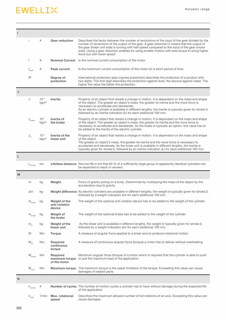
306
Actuator range
I
i # Gear reduction Describes the factor between the number of revolutions of the input of the gear divided by the number of revolutions of the output of the gear. A gear reduction 2 means that the output of the gear (linear unit side) is turning with half speed compared to the input of the gear (motor side). Using a gear reduction enables for using smaller motors with less torque to bring higher force but with lower speed
I A Nominal Current Is the nominal current consumption of the motor
Ipeak A Peak current Is the maximum current consumption of the motor for a short period of time.
IP Degree of protection
International protection (also ingress protection) describes the protection of a product with twodigits.Thefirstdigitdescribestheprotectionagainstdust,thesecondagainstwater.Thehigher the value the better the protection.
J
J 10-4 kgm2
Inertia Property of an object that resists a change in motion. It is dependent on the mass and shape oftheobject.Thegreateranobject’smass,thegreateritsinertiaandthemoreforceisnecessary to accelerate and decelerate.Asanelectriccylinderisavailableindifferentlengths,theinertiaistypicallygivenforstroke0,followedbyaninertiaindicationΔJforeachadditional100mm.
Jbrake 10-4 kgm2
Inertia of the brake
Property of an object that resists a change in motion. It is dependent on the mass and shape oftheobject.Thegreateranobject’smass,thegreateritsinertiaandthemoreforceisnecessary to accelerate and decelerate. As the brake is typically an option, this value has to be added to the Inertia of the electric cylinder.
Jlu 10-4 kgm2
Inertia of the linear unit
Property of an object that resists a change in motion. It is dependent on the mass and shape of the object. Thegreateranobject’smass,thegreateritsinertiaandthemoreforceisnecessarytoaccelerateanddecelerate.Asthelinearunitisavailableindifferentlengths,theinertiaistypicallygivenforstroke0,followedbyaninertiaindicationΔJforeachadditional100mm.
L
L10 dist km Lifetime distance Servicelifeinkmthat90%ofasufficientlylargegroupofapparentlyidenticalcylinderscanbe expected to reach or exceed.
M
m kg Weight Force of gravity acting on a body. Determined by multiplying the mass of the object by the acceleration due to gravity
Δm kg Weight difference Aselectriccylindersareavailableindifferentlengths,theweightistypicallygivenforstroke0,followedbyaweightindicationΔmforeachadditional100mm.
marot0 kg Weight of the anti-rotation device
The weight of the optional anti-rotation device has to be added to the weight of the cylinder.
mbrake kg Weight of the brake
The weight of the optional brake has to be added to the weight of the cylinder
mlu kg Weight of the linear unit
Asthelinearunitisavailableindifferentlengths,theweightistypicallygivenforstroke0,followedbyaweightindicationΔmforeachadditional100mm.
M Nm Torque A measure of angular force applied to a linear axis to produce rotational motion
MAc Nm Required continuous torque
A measure of continuous angular force (torque) a motor has to deliver without overheating
MAmax Nm Required maximum torque of the motor
Maximum angular force (torque) of a motor which is required that the cylinder is able to push or pull the maximum load of the application
Mmax Nm Maximum torque The maximum torque is the upper limitation of the torque. Exceeding this value can cause damages of related parts.
N
ncycles # Number of cycles The number of motion cycles a cylinder has to have without damage during the expected life of the application
nmax 1/min Max. rotational speed
Describes the maximum allowed number of full rotations of an axis. Exceeding this value can cause damages.
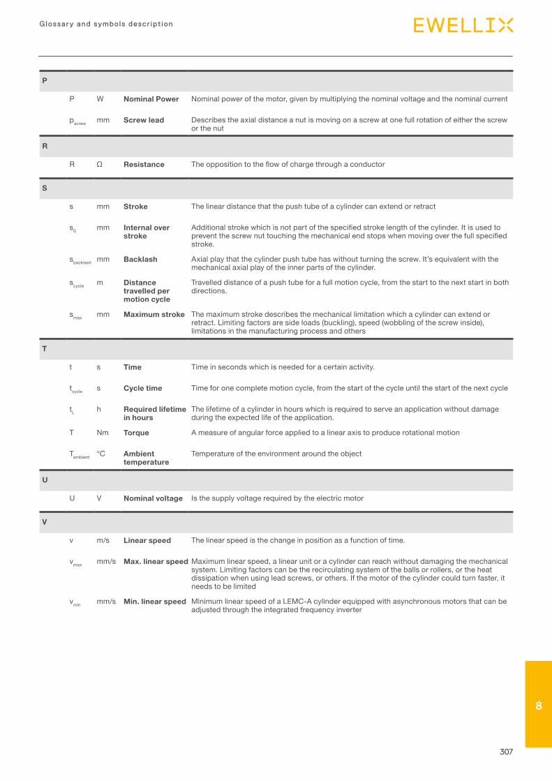
307
Glossary and symbols descr ipt ion
78
P
P W Nominal Power Nominal power of the motor, given by multiplying the nominal voltage and the nominal current
pscrew mm Screw lead Describes the axial distance a nut is moving on a screw at one full rotation of either the screw or the nut
R
R Ω Resistance Theoppositiontotheflowofchargethroughaconductor
S
s mm Stroke The linear distance that the push tube of a cylinder can extend or retract
s0 mm Internal over stroke
Additionalstrokewhichisnotpartofthespecifiedstrokelengthofthecylinder.Itisusedtopreventthescrewnuttouchingthemechanicalendstopswhenmovingoverthefullspecifiedstroke.
sbacklash mm Backlash Axialplaythatthecylinderpushtubehaswithoutturningthescrew.It’sequivalentwiththemechanical axial play of the inner parts of the cylinder.
scycle m Distance travelled per motion cycle
Travelled distance of a push tube for a full motion cycle, from the start to the next start in both directions.
smax mm Maximum stroke The maximum stroke describes the mechanical limitation which a cylinder can extend or retract. Limiting factors are side loads (buckling), speed (wobbling of the screw inside), limitations in the manufacturing process and others
T
t s Time Time in seconds which is needed for a certain activity.
tcycle s Cycle time Time for one complete motion cycle, from the start of the cycle until the start of the next cycle
tL h Required lifetime in hours
The lifetime of a cylinder in hours which is required to serve an application without damage during the expected life of the application.
T Nm Torque A measure of angular force applied to a linear axis to produce rotational motion
Tambient °C Ambient temperature
Temperature of the environment around the object
U
U V Nominal voltage Is the supply voltage required by the electric motor
V
v m/s Linear speed The linear speed is the change in position as a function of time.
vmax mm/s Max. linear speed Maximum linear speed, a linear unit or a cylinder can reach without damaging the mechanical system. Limiting factors can be the recirculating system of the balls or rollers, or the heat dissipation when using lead screws, or others. If the motor of the cylinder could turn faster, it needs to be limited
vmin mm/s Min. linear speed Minimum linear speed of a LEMC-A cylinder equipped with asynchronous motors that can be adjusted through the integrated frequency inverter


ewellix.com
© Ewellix
All contents of this publication are the property of Ewellix, and may not be
reproduced or given to third parties (even extracts) without permission.
Although great care has been taken in the production of this catalog, Ewellix
does not take any responsibility for damage or other loss resulting from
omissions or typographical errors. The photo may differ slightly in appearance
from the actual product. Due to continuous improvements being made in our
products, the product’s appearance and specifications are subject to change
without notice.
PUB NUM IL-05002/3-EN-October 2021
Certain image(s) used under license from Shutterstock.com.
SKF and SKF logo are trademarks of the SKF Group
DETROIT/ GRAND RAPIDS 23409 Industrial Park Court Farmington Hills, MI 48335
248-478-1182
CLEVELAND6750 Arnold Miller Parkway
Solon, OH 44139440-498-8465