


BD16939AEFV-C : Motor / Actuator Drivers - Mouser Electronics
Upload
khangminh22Category
view
0download
0
www.lmotion.ru [email protected] Тел.: (495)-921-34-60

Contents
A Introduction 4
Core technologies 5
Product overview 8
SKF engineering tools 11
Actuation System set-up 12
Product range comparison 16
Product beneits 24
Customization capabilities 28
Application examples 32
B Calculation 50
Simpliied calculation process 51
C Actuators 54
Matrix series 57
Matrix1 58
Matrix3 62
Matrix6 66
Runner 77
CAJA35C 76
Ecomag 80
Magdrive 84
CAHB series 89
CAHB-10 90
CAHB-20A 96
CAHB-20E 100
CAHB-21E 104
CAHB-22E 108
CAHB-30A 112
CAHB-31N 116
CAR,CAP & CAT series 123
CAR 22 124
CAP 32 128
CAT 32B and CAP 43B 134
CAT 33 and CAP 43A 144
CAT 33H 154
CAR 40 162
Spare parts 168
CAHM series 173
D Telescopic pillars 178
CPMA 180
CPMB 188
CPMT 196
TFG 202
THG 206
TLC 210
TLG 214
TLT 218
TXG 222
FRE 226
E Control units 228
BCU 230
VCU 234
SCU 238
MCU 242
COMPACT 246
SEM 250
F Operating switches 254
CAES 256
EHA1 258
EHA3 260
EHE1 262
HSM, HSF, HSU 264
PHC 266
PFP 268
ST Foot switch 270
ST Desk swicth 272
STK 274
CAJH1 276
PAM 278
G Glossary 280
H Symbols description 284
3
www.lmotion.ru [email protected] Тел.: (495)-921-34-60

Introduction • Cost effectiveness
• Controllability
• Stability
www.lmotion.ru [email protected] Тел.: (495)-921-34-60

Core technologies
Actuation technology
Our extensive experience and knowledge of actuation systems
allows us to satisfy the most demanding requirements using
linear actuators, telescopic pillars and control units
Linear actuatorsWe offer a wide range of low- to medium-duty actuator designs and
conigurations for simple industrial, medical or speciic health care applica-
tions. Our versatile range provides everything from low- to high-load
capacities and medium operating speeds to quiet and aesthetically
designed systems.
High-performance actuators Our range of high-duty actuators meets the needs of demanding
industrial applications with high loads and speeds in continuous
operation. These actuators provide the best controllability and relia-
bility for programmable motion cycles.
Telescopic pillarsWith a wide range of options for several applications, our telescopic
pillars are quiet, robust, powerful, resistant to high offset loads and
feature attractive designs.
Control unitsIdeal for applications focused on system control, SKF control units
provide connections for foot and hand or desk switches.
Operating switches SKF offers different operating switches to control the position of your
equipment. The range includes:
• Hand switches
• Foot switches
• Desk switches
These switches can be used with control units to drive linear actua-
tors and telescopic pillars or directly with the devices in AC powered
versions.
Linear actuators
High-performace actuators
Telescopic pillars
Control units
55
A
www.lmotion.ru [email protected] Тел.: (495)-921-34-60

Ball and roller screw technology
Miniature ball screws
Rolled ball screws
Roller screws
For applications that require driving that is accomplished by
transforming rotary action into linear motion, we provide a
comprehensive range of solutions including rolled ball screws,
roller screws and ground ball screws
Miniature ball screwsSKF miniature ball screws are very compact and operate silently
Rolled ball screws
We offer several, highly precise recirculating systems to cover most
application requirements Backlash can be reduced or eliminated
Ground ball screws
SKF ground ball screws offer increased rigidity and precision
Roller screws
SKF roller screws go far beyond the limits of ball screws providing
the ultimate precision, rigidity, high speed and acceleration Backlash
can be reduced or eliminated Long leads are available for very fast
movements
66
www.lmotion.ru [email protected] Тел.: (495)-921-34-60

Linear guide technology
To provide optimal solutions for all your guiding needs, our
product range features shaft guidings, proile rail guides and
precision rail guides
Linear ball bearings Cost-effective, simple and self-aligning, SKF shaft guidings feature
unlimited stroke, adjustable preload and excellent sealing perfor-
mance They are also available in corrosion-resistant versions and
pre-mounted on aluminium housing as a unit
Precision rail guides
With a range of modular options, SKF precision rail guides feature
different rolling elements and cages These guides feature high pre-
cision, high load carrying capacity and stiffness, and also come with
an anti-creeping system They are also available as a ready-to-
mount kit
Proile rail guides
Featuring unlimited stroke through joint rails and excellent rigidity,
capable of withstanding moment loads in all directions, SKF proile
rail guides are ready to mount and provide easy maintenance along
with high reliability They are available in ball or roller versions as well
as standard and miniature sizes
Linear ball bearings
Precision rail guides
Proile rail guides
The terms used in the catalog are listed in a Glossary page 280 and
the Symbols are described from the page 284
77
A
www.lmotion.ru [email protected] Тел.: (495)-921-34-60

Product overview
Linear actuatorsElectromechanical linear actuators enable precise, controlled, and repeatable push/pull movements in linear drive applications
Linear actuators serve as eficient, virtually maintenance-free, and environmentally friendly alternatives to hydraulic or pneumatic
types
Actuators with a modular design and open architecture offer oppor-
tunities to choose and integrate components to achieve customized
solutions within existing envelopes Application potential expands
with the introduction of technologies for speciic purposes, such as
hall sensors, limit switches, potentiometers, friction clutches, or
back-up nuts Equipped with brushed DC motor or AC motor, the
duty cycle is rated up to 20% or up to 40% if equipped with a AC
motor
Front attachment
Inner tube or Push tube
Screw
Nut
Electrical motor
Gearbox
Electrical cable
Rear attachment
Outer tube or protection tube
Sealing system
1
5
2
6
3
7
8
4
12
34
9
56 7
9
10
10
8
88
www.lmotion.ru [email protected] Тел.: (495)-921-34-60

Telescopic pillarTelescopic pillars enable precise, controlled, and repeatable lifting movements of in linear drive applications including with those
with torsion and off set loads
Telescopic pillars with a modular design and open architecture offer
opportunities to choose and integrate components like linear actua-
tors or drive to achieve customized solutions within existing alumi-
num proiles Application potential expands with the introduction of
technologies for speciic purposes, such as hall sensors, limit
switches but also Integrated Circuits for switch mode power supply
and motor control Equipped with brushes DC motor or AC motor, the
duty cycle is rated up to 10%, which means when the load is the
maximum
Inner tube
Outer tube
Screw and nut
Cables through
Power supply
Electrical Motor
Gearbox
Control board
Cable connector
1
5
2
6
3
7
8
4
9
1
3
4
5
6
7
8
9
2
99
A
www.lmotion.ru [email protected] Тел.: (495)-921-34-60

Screws Ball and roller screws are key components to build electric cylinders
They transfer rotary movements of the motor into linear move-
ments Their eficiency and their load and speed capabilities have a
very big inluence on the performance of electric cylinders
Thanks to decades of experience with manufacturing ball and
roller screws and continuous product and process development, SKF
builds electric cylinders with precision screw solutions that fulill the
most demanding applications in terms of eficiency, precision, dura-
bility and value All screws are made of high-strength materials with
speciic heat-treatment
Lead screwThese screws transmit torque into linear motion through direct slid-
ing friction A typical assembly consists of a steel screw and plastic
nut Some of the electric cylinders are equipped with lead screws
with a relatively high friction coeficient that makes them well suited
for self-locking application Lead screw actuators accommodate high
static force, withstand excessive vibration, operate quietly, and rep-
resent cost-effective solutions
Precision rolled ball screwsSKF ball screw assemblies provide high performance solutions suita-
ble for a wide range of applications where high loads, precision driv-
ing, durability and value are prerequisites
High technology machinery associated with precise control of the
cold forming and metallurgical processes enable the production of
screws that offer virtually the same accuracy and performance of
ground ball screws, but at a lower cost Standard lead precision is G9,
according to ISO 286-2:1988 SKF production meets G7 lead preci-
sion for screw shaft nominal diameter starting from 20 mm On
request, SKF can deliver ball screws with G5 lead precision according
to ISO 3408-3:2006, deined for positioning screws, matching the
lead precision of G5 ground ball screws
Lead screw Precision rolled ball screws
1010
www.lmotion.ru [email protected] Тел.: (495)-921-34-60

SKF engineering tools
Apps and web-based solutions To simplify the product selection process, SKF offers a set of free Web tools and Apps that allow a quick and easy navigation into the
complete linear motion offering
Actuator Select Users can choose the desired product family among Pillars, Linear
Actuators, Rotary Actuators and Controls Then, by entering few sim-
ple parameters, they will be guided in the product selection
Key features include:
• Four complete product lines
• Dynamic iltering of the results
• Result ranking by application
• Product comparison (up to 3 at time)
• Indication of compatible control unit for selected Pillar or Actuator
• Cost saving calculator
• Direct link to product drawing, technical datasheet and catalogues
The Actuator Select tool is available for both phones and tablets A
web-based version of the tool is available at www skf com/actuator-
select, while the app can be downloaded at the Apple App Store or
Google Play
Actuator Select
skfmotiontechnologies.com/en/engineering-tools
1111
A
www.lmotion.ru [email protected] Тел.: (495)-921-34-60

Actuation System set-up
Linear actuator deinition and type Electro-mechanical linear actuators enable precise, controlled, and repeatable push/pull movement in linear drive applications
Linear actuators serve as eficient, virtually maintenance-free, and
environmentally friendly alternatives to hydraulic or pneumatic
types
Standard versions can handle loads as great as 50 kN, deliver
speeds over 150 mm/s, and travel as far as 700 mm They can be
self-contained in aluminum, zinc, or polymer housings and
ready-to- mount for easy plug-in operation
Actuators with modular design and open architecture offer oppor-
tunities to choose and integrate components to achieve customized
solutions within existing envelopes Application potential expands
with the introduction of technologies for speciic purposes, such as
hall sensors, limit switches, potentiometers, friction clutches, ball
detent clutches, or back-up nuts
Screw-type linear actuators powered by an electric AC or DC
motor basically consist of a lead screw (threaded shaft/spindle) with
drive nut and push tube with a gearbox between the motor and the
screw also present
When power is supplied, the motor rotates the lead screw, which
causes the drive nut to travel and extend the push tube Reversing
the motor rotation retracts the push tube
Pushing/pulling
Raising/lowering Opening/closing
Clamping/gripping
1212
www.lmotion.ru [email protected] Тел.: (495)-921-34-60

Ball screw vs acme screwTraditional types of lead screws include ball screws and acme
screws, whose speciication will be inluenced by an actuator’s con-
iguration and load requirements
Ball screws
All-steel ball screws consist of a screw shaft, ball nut with a ball
recirculation system to convert rotary motion into smooth, accu-
rate, and reversible linear motion (or torque to thrust) (→ ig 1)
The row of circular rolling elements is self-contained in a closed
system between the nut and screw for a design exhibiting
extremely low friction coeficients The low frictional resistance
minimizes wear, improves eficiency, and reduces operating tem-
perature for longer service life
Ball screws can handle high loads, with a very good eficiency,
achieve high duty cycles, operate over a wide temperature range,
and deliver the precision necessary to enable actuators performing
over long periods at high speeds and requiring high dynamic
capability
Brakes usually are adopted in ball screw actuators or non-self
locking gear boxes to prevent back-drive and provide an high static
load performance
Acme screws
These screws transmit torque into linear motion through direct
sliding friction A typical assembly consists of a steel screw and
plastic nut (→ ig 2)
Some of the products are equipped with acme screws with a
relatively high friction coeficient that makes them well suited for
self-locking applications Acme screw actuators accommodate
high static load, withstand excessive vibration, operate quietly, and
represent cost-effective solutions Brakes could be adopted to
increase the static load performance
Fig 2
Acme screw
Fig 1
Ball screw
1313
A
www.lmotion.ru [email protected] Тел.: (495)-921-34-60

Performance considerations
Beyond the basic fundamentals of actuator operation, applications
may require feedback on position and/or direction, limits on motion or
travel in a particular direction, or protection against dynamic overload
Enabling technologies have been developed for these purposes
Limit switches
Its purpose is to limit actuator motion or travel in both direction It is
used on DC and AC versions (→ ig 3) When activated, the switch
typically opens an electrical contact integrated on the electrical circuit
of the motor By reversing the voltage, the limit switch circuit is over
pass, the motor runs in the opposite direction and the switch is
released The second limit switch will proceed in the same way but for
the opposite direction These devices prevent actuators from running
into the mechanical ends
End-stop output
Its purpose is to provide output information on when the actuator
reaches a position in a particular direction (→ ig 4) When activated,
the switch opens or closes an electrical contact When the contact is
closed, current will low through the switch; when the contact is open,
no current will low through the switch These devices could be used on
the application to prevent actuators from running into the mechanical
ends and may allow for the adjustment of stroke length End-stop out-
put could be used by a control board to limit the stroke of the actuator,
for instance
Hall sensors
These rotary or linear sensing devices are incremental no contact sen-
sors that are used to deine the relative position of an actuator Two
sensors detect the changing magnetic ield created by a rotating mag-
net and then relay corresponding output pulses to a control unit to
provide the travel feedback Two sensors could detect also the direction
of the movement (→ ig 5) After a homing procedure, the travel dis-
tance can be deined with counting the pulse
Potentiometer
A potentiometer is an analog feedback device The potentiometer is
considered an absolute sensor with unique value in each position
Sometimes it is called a variable resistance that can be read and fed
into a controller for positioning control of the application (→ ig 6)
180° 360° 540° 720°
Voltage
A B
N
N
S
S
B
A
Rotation angle
M
S1
S2
Fig 6
Potentiometer
Fig 3
Limit switches
Fig 4
End-stop outputs
Fig 5
Hall sensor
V in
V out
0 V
1414
www.lmotion.ru [email protected] Тел.: (495)-921-34-60

Friction clutch
This function will protect the actuator from mechanical damage
when it reaches either of its mechanical end positions or when the
maximum dynamic load is momentarily exceeded A friction clutch
consists of a series of steel plates engaging a hub and a series of
friction rings engaging a housing (→ ig 7)
Pressure is exerted on the plates and rings by an adjuster acting
through a spring and pressure plate The friction clutch is not
intended for use as a load limiter, but only for protection of the actu-
ator and end- use equipment in the event of dynamic overload
Ball detent clutch
A ball detent type clutch transmits force through hardened balls
which rest in detents on the shaft and are held in place with springs
An overtorque/load condition pushes the balls out of their detents,
thereby decoupling the lead-screw from the motor
Back-up nut
This prevents an actuator from collapsing if a drive nut fails The
back- up nut is usually in metal, exhibits greater anti-shear strength
than the drive nut, and only makes contact with the threads of the
spindle when the threads of the drive nut fail (→ ig 8) The back-up
nut carries the load and may be able to lower the load (signaling
need for repair)
Slip stick effect
The cycle of alternating slipping and sticking as two surfaces rub
against each other results in vibration and noise Resonances within
other materials can occur This effect can sometimes be heard, felt or
seen With linear actuators and pillars, slip stick has been witnessed
between the Delrin and aluminum or steel, such as between drive
nut and spindle, and glide pad and extrusion
Fig 7
Friction clutch
Fig 8
Back-up nut
1515
A
www.lmotion.ru [email protected] Тел.: (495)-921-34-60

Product range comparison
Linear actuators
SKF offers a wide range of linear actuators in terms of push or pull load, speed, stroke length
and input voltage Most of them are approved as a component of a medical device that com-
plies with IEC 60601-1 and UL mark RU
Some products are designed for a speciic application but are suitable for others applications
that request the similar performance
If you request a higher force than 12 kN, we invite you to review the High performance
actuator catalogue (PUB MT/P1 17176 EN)
MedicalHarsh environment
Family Load Speed Stroke Voltage See page
kN mm/s mm V –
MATRIX 8 13 700 12, 24 57
RUNNER 12 8 700 24 72
CAJA 35C 3,5 7,5 250 24 76
Ecomag 6 9 300 24 80
Magdrive 6 8,5 700 24 84
CAHB 10 60 700 12, 24 89
CAT and CAR 4 193 700 12, 24, 120, 230, 3x400 123
CAHM 50 74 700 24, 230, 3x400 173
1616
www.lmotion.ru [email protected] Тел.: (495)-921-34-60

Force and speed capabilitiesDiagram 1 provides a quick overview of the rated load and the speed of the actuators Use this graph to quickly evaluate which actu-
ator could it best in your application
The rated load describes the weight that the actuator can push or
pull at the rated duty cycle without overheating The speed is the
maximum linear speed the actuator can reach without load when
powered at the rated voltage
Diagram 1
Actuator
Linear speed [mm/s]Force [kN]
CAHB-21E
CAHB-22E
CAHB-30
CAHM-3
5
CAJA35C
CAP32
CAP43A
CAP43B
CAHB-31
CAR22
CAR40
CAT32B
CAT33
CAT33H
Ecom
ag
Mag
drive
Mat
rix1
Mat
rix3
Mat
rix6
Runne
r
CAHB-20E
CAHB-20A
CAHM-3
1
CAHB-10
CAHM-5
0
CAHM-6
5
Max loadMax speed
20 000
18 000
16 000
14 000
12 000
10 000
8 000
6 000
4 000
2 000
0
60 000
50 000
40 000
30 000
200
180
160
140
120
100
80
60
40
20
0
1717
A
www.lmotion.ru [email protected] Тел.: (495)-921-34-60

Diagram 2
Pillar
7 000
6 000
5 000
4 000
3 000
2 000
1 000
0
35
30
25
20
15
10
5
0
CPMA CPMB CPMT TFG 50 TFG 90
Max loadMax speed
TLC TLG TLT TXGTHG
Force [kN] Linear speed [mm/s]
Pillars
SKF offers a wide range of telescopic pillars in term of push and pull load, offset load in
movement, stroke length and input voltage Most of them are approved as a component of a
medical device that complies with IEC 60601-1 and UL mark RU
Force and speed capabilitiesDiagram 2 provides a quick overview of the rated load and the speed of the actuators Use this graph to quickly evaluate which actu-
ator could it best in your application
The rated load describes the weight that the actuator can push or
pull at the rated duty cycle without overheating The speed is the
maximum linear speed the actuator can reach without load when
powered at the rated voltage
Some products are designed for a speciic application but are suit-
able for others applications that request the similar performance
Product Load Bending moment Speed Stroke Voltage See page
kN N/m mm/s mm V
CPMA-B 2 250 15 400 24, 100 to 240 180-188
CPMT 6 1 400 34 600 24 196
TFG 2,5 500 15 700 120, 230 202
THG 2 1 000 15 700 24 206
TLC 4 2 100 11 700 120, 230 210
TLG 4 2 800 10 700 24 214
TLT 4 1 000 25 700 24 218
TXG 1,5 210 17 600 24, 120, 230 222
FRE – – – 700 – 226
Medical
1818
www.lmotion.ru [email protected] Тел.: (495)-921-34-60

Diagram 3
Bending moment vs retracted length for stroke length of 400 mm
CPMT-2S
CPMT-1S
TLT-A1
TLT-B1
TLT-C1
CPMT-1M
CPMT-2M
TLT-A2
TGC AWD
THC AWD
TLC ZWD
TFG
TGC AWA
THC AWA
CPMA/B-1
CPMA/B-2
TLC ZWS
THG-BD
THG-CD
TLG-A
TLG-B
TLG-C
TXG
THG-BA
THG-CA
0 500 1 000 1 500 2 000 2 500 3 000
600to
500
500to
400
400to
300
up to600
Bending Moment [Nm]
Retracted length [mm]
TLT-A2
1919
A
www.lmotion.ru [email protected] Тел.: (495)-921-34-60

Combination matrix Actuator
Control units Operating switches BCU VCU SCU MCU SEM COMPACT Hand switches Table switches Foot switches
Linear actuatorsCAHB-10 – – – – – – –CAJA – – – – – –ECOMAG – – – –MAGDRIVE – – – – –MAX1/3 – – – – –MAX60/61 – – – – – – PHC PAM PFPMAX62/63/64/65 – – – – – – EHA1 STA STFRUNNER – – – – –
PillarsCPMA/CPMB – – – – – – EHA4 STK STLCPMT – – – – – –TFG1 – – – – –TFG5/9 – – – – – – EHA3, CAJH1 STE STJTHG – – – – –TLC electric 1) – – – – – – – – –TLC low voltage – – – – – – EHA1 – –TLC pneumatic – – – – – – PHC PAM PFPTLG – – – – –TLT – – – – –TXG1 – – – – – – – –TXG4/5/8/9 – – – – – – EHE STA, HSU STF
Operating switchesHand switchesEHA1 – – – – –EHA3 – – –EHE – – – – CAJH1 – – –
Table switchesSTA – – – – –STE – – –HSM – – – – – HSF – – – – – HSU – – – – –
Foot switchesSTF – – – – –STJ – – –
Control units
SKF offers a wide range of control units in terms of number of con-
nections, functions and input voltage They are compatible with SKF
actuators and pillars Most of them are approved as components for
medical devices that comply with IEC 60601-1 and UL mark RU
In order to select the proper accessories for linear actuators and
telescopic pillars, please use the table below
Start selecting your actuator or pillar and ind horizontally the
compatible control units identiided by a black dot, then vertically
select the appropriate operating switches
Some products do not need control units, so please continue hori-
zontally to ind the appropriate operating switches
1) No need of CU, but there is non OS provided by SKF
2020
www.lmotion.ru [email protected] Тел.: (495)-921-34-60

Combination Matrix Control units
Operating switches Hand switches Table switches Foot switches
BCU EHA3 STE STJVCU EHA3 STE STJSCU EHA3 STE STJ
MCU EHA1 STA STFCOMPACT – HSM, HSF –SEM EHE – –
Operating switches
SKF offers a wide range of different operating switches to control the
position of your equipment The range includes: Hand switches, Foot
switches, Desk switches
Linear actuators
Telescopic pillar
Control unit
Hand switches
Foot switches
Desk switches
2121
A
www.lmotion.ru [email protected] Тел.: (495)-921-34-60

Case of stand alone telescopic pillar with AC motor: TLC
Case of stand alone telescopic pillar with DC motor and built in power supply: CPMA
Case of AC System with DC linear actuator and telescopic pillar: SCU+TLG + Matrix
Case of stand-alone linear actuator with DC motor and built in power supply: MAX6
Input voltage
AC or DC, this is the voltage that is used to power the system or the
stand alone linear actuator or telescopic pillar
For instance, a AC system is one powered by a cable connected to
the mains power that provides alternating voltage, typically 230 V AC
in Europe and 120 V AC in USA AC system or linear actuator or tele-
scopic pillar doesn't say that the motor is an AC motor
For a linear actuator or a telescopic pillar, the motor voltage could be
different than mains power The control unit that drives the DC tele-
scopic pillar or linear actuator is equipped with a power supply to
convert the voltage The linear actuator and the telescopic pillar
could be also equipped with a built-in power supply In this case, the
equipment is powered by the mains power but the motor and other
equipment are powered by a DC cable This is the most convenient
system; easy to power and to control
2222
www.lmotion.ru [email protected] Тел.: (495)-921-34-60

How to read a performance diagram
In the product range chapter, a technical description is available for
each actuator family This includes performance overview, a detailed
product description, motors and adapter information In addition to
that, each actuator type and size has a dedicated table with the main
technical data In particular, for the telescopic pillar, we describe the
offset load performance
Here below is a general description on how to read the axial force /
linear speed diagram
For a CPMT1-2MCase 1 (4 500 N at 200 mm): The pillar can lift and lower a load of
450 kg with a center of gravity located at 200 mm from the center of
the pillar
Case 2 (3 000 N at 300 mm): The pillar can lift and lower a load of
300 kg with a center of gravity located at 300 mm from the center of
the pillar
Case 3 (3 000 N at 450 mm): The pillar can lift and lower a load of
300 kg with a center of gravity located at 450 mm from the center of
the pillar
Case 4 (1 000 N at 450 mm): The pillar can lift a load of 100 kg with a
center of gravity located at 450 mm form the center of the pillar but
during the lowering, the retraction will be not optimal We recom-
mend to increase the weight or change the load distance To Increase
the load distance, you can change the center of gravity of th e lifted
part
7 000
6 000
5 000
4 000
3 000
2 000
1 000
0 0 100 200 300 400 500 600
CPMT1-1M, -2M
Load [N]
Load distance from the center of the pillar [mm]
Offset load at full extension
Underload
Overload
ideal
1
2 3
4CPMT1-2MCPMT1-1M
2323
A
www.lmotion.ru [email protected] Тел.: (495)-921-34-60

Product beneits
Pneumatic and hydraulic replacementLinear movements in modern applications place high demand on travel proiles Pneumatic and hydraulic cylinders quickly reach
their system performance limits SKF electric cylinders offer improved performance and simpler setup in applications that were tra-
ditionally served by pneumatic and hydraulic cylinders
Along with the elimination of air or oil in applications, SKF electric
linear actuators offer many advantages Key beneits include a high
degree of lexibility, positioning accuracy even to any intermediate
target, improved productivity through low maintenance, new options
in programming, and seamless integration into machine control sys-
tems These beneits enable new and reliable concepts that can be
integrated into a variety of production processes, ultimately allowing
new application possibilities
Electric linear actuators with ball screws provide an energy-saving
alternative to pneumatic
Electromechanical layout
Pneumatic layout Hydraulic layout
Electromechanical layout
2424
www.lmotion.ru [email protected] Тел.: (495)-921-34-60
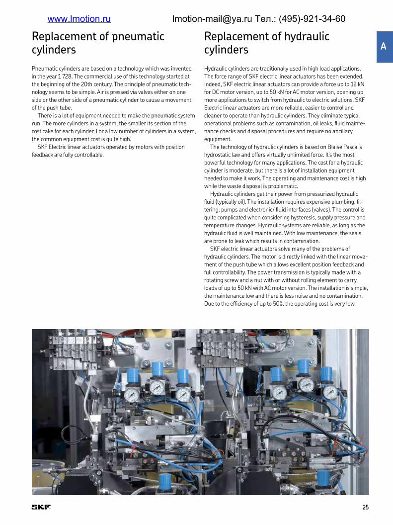
Replacement of pneumatic cylinders
Pneumatic cylinders are based on a technology which was invented
in the year 1 728 The commercial use of this technology started at
the beginning of the 20th century The principle of pneumatic tech-
nology seems to be simple Air is pressed via valves either on one
side or the other side of a pneumatic cylinder to cause a movement
of the push tube
There is a lot of equipment needed to make the pneumatic system
run The more cylinders in a system, the smaller its section of the
cost cake for each cylinder For a low number of cylinders in a system,
the common equipment cost is quite high
SKF Electric linear actuators operated by motors with position
feedback are fully controllable
Replacement of hydraulic cylinders
Hydraulic cylinders are traditionally used in high load applications
The force range of SKF electric linear actuators has been extended
Indeed, SKF electric linear actuators can provide a force up to 12 kN
for DC motor version, up to 50 kN for AC motor version, opening up
more applications to switch from hydraulic to electric solutions SKF
Electric linear actuators are more reliable, easier to control and
cleaner to operate than hydraulic cylinders They eliminate typical
operational problems such as contamination, oil leaks, luid mainte-
nance checks and disposal procedures and require no ancillary
equipment
The technology of hydraulic cylinders is based on Blaise Pascal’s
hydrostatic law and offers virtually unlimited force It’s the most
powerful technology for many applications The cost for a hydraulic
cylinder is moderate, but there is a lot of installation equipment
needed to make it work The operating and maintenance cost is high
while the waste disposal is problematic
Hydraulic cylinders get their power from pressurized hydraulic
luid (typically oil) The installation requires expensive plumbing, il-
tering, pumps and electronic/ luid interfaces (valves) The control is
quite complicated when considering hysteresis, supply pressure and
temperature changes Hydraulic systems are reliable, as long as the
hydraulic luid is well maintained With low maintenance, the seals
are prone to leak which results in contamination
SKF electric linear actuators solve many of the problems of
hydraulic cylinders The motor is directly linked with the linear move-
ment of the push tube which allows excellent position feedback and
full controllability The power transmission is typically made with a
rotating screw and a nut with or without rolling element to carry
loads of up to 50 kN with AC motor version The installation is simple,
the maintenance low and there is less noise and no contamination
Due to the eficiency of up to 50%, the operating cost is very low
2525
A
www.lmotion.ru [email protected] Тел.: (495)-921-34-60

F. 1
ControllabilityElectric drive systems use a screw that offers an easy controllabil-
ity by counting the number of turns of the screw or other elements
mechanically connected You can control the position, the displace-
ment as well as the speed
Precision
The precision depends on the resolution of the position feedback
system and how the output is used by the control board The back-
lash of the driving mechanism will inluence if the direction of the
load and movement is changing The accuracy also depends on the
set up and homing procedure of the system
Holding force
Electric drive systems offer a high stability and self-locking that
prevent unplanned movement in case of static overload or shock
applied even if not powered In addition of built-in brake and the
short circuit of the brushed DC motor used in the most of the case,
all mechanical driving part participates of the stability
Degrees of protection provided by enclosures
The IP Code, International Protection Marking, IEC standard
60529, sometimes interpreted as Ingress Protection Marking,
classiies and rates the degree of protection provided against
intrusion (body parts such as hands and ingers), dust, accidental
contact, and water by mechanical casings and electrical enclosures
(→ ig 1)
It is published by the International Electrotechnical Commission
(IEC) The equivalent European standard is EN 60529
Safety and environment friendlyThe safety typically starts by the high holding force as compared to
the load applied during the normal use of the application that
should be lower than the rated load of the electric drive system
The risk of abnormal use of the application should also be
considered
For some application or function in the Medical industry, the
manufacturer of the medical device should manage the risk
assessment and comply with some regulation as IEC 60601-1,
general requirements for basic safety and essential performance
As a component of the medical device, some SKF electric drive
systems were tested under the same condition to demonstrate
compliance to IEC 60601-1 and are registered by UL to be marked
RU Saying that the Safety factor of the complete system is 2 or 2 5
or 4 is not enough This standard requests that each individual
component of the drive system used on a suspended mass be
checked and could request a tensile safety factor up to 12, depend-
ing on the material, the possible alteration, the backup system and
the calculation method
Nor do electric cylinders have problems with luid leaks or con-
taminated air Moreover, the absence of luid constantly operating
under high-pressure eliminates potential risks to operators in case
of cylinder failure
Without luid to drive or keep in position and with a good ingress
protection up to IP66M, means during movement and IP69K when
static, the risk of leakage and contamination is almost negligible
With a static ingress protection, the actuator can be cleaned easily
Actuators rated IP69K accept a high pressure and hot temperature
cleaning procedure, that contribute to the later elimination of the
risk of pollution
International Protection
First characteristic numeral
solid particle protection
Second characteristic numeral
liquid ingress protection
Letters to provide
additional information
IP 6 6 M
2626
www.lmotion.ru [email protected] Тел.: (495)-921-34-60

RoHSOur standard products fall under category 11 in Annex I to Direc-
tive 2011/65/EU and therefore do not need to comply with the
provisions in the directive before July 22, 2019
Nevertheless, most of our standard products are already men-
tioned on a list where we declare that the products do not contain
any of the restricted substances over the threshold values stated in
the Annex II to Directive 2011/65/EU in any homogenous part of
the product
REACH
SKF has a policy, process and dedicated resources in order to com-
ply with REACH, the Regulation concerning Registration, Evalua-
tion, Authorization and Restriction of Chemicals
CE mark
Most of our product have CE mark with a Certiicate of Compliance
signed by the factory
Installation
The installation is simpliied In most cases, the electric drive sys-
tems request just the mechanical connection of the 2 attachment
points and the electrical connector plug in Then, it is ready to
work
Virtually maintenance-freeSKF’s expertise in manufacturing the main components of linear
actuator – screws, bearings, guides, seals and lubrication – allows us
to maximize service life With the special hardening treatment of the
screws and balls, the linear actuators keep high performance and
eficiency during the service life Compared to their luid power alter-
natives, the electromechanical linear actuator systems require no
maintenance
With electromechanical system technology, ilter changes and air
bleeding are a thing of the past Simply mount the actuator, plug in
the cable to the control unit or a Programmable Logic Controller and
you are up and running in record time
Tests
Environmental, electrical and mechanical tests are performed in the
SKF facilities or by external laboratories and recorded internally or by
external bodies like UL
2727
A
www.lmotion.ru [email protected] Тел.: (495)-921-34-60

Customization capabilities
SKF electric cylinder customization O anard electric cylinder product range, SKF offers an extensive customization program that is able to meet virtually any
application need There are 3 levels of customization that depend on speciic requirements and the complexity of implementation
Basic customization These basic design options can be implemented quickly and easily:
• Stroke length
• Retracted length
• Attachment and Mounting holes
• Colors
• Cables and connectors
• De-rated load
Advanced customization These design options are more complex and require a dedicated pro-
ject with the customer:
• Materials
• Housing
• Guiding system (for pillar)
• Gearbox (e g , with hand crank)
• Screw (e g , lead, treatments)
• Screw Nut (e g , additional backup nut)
• Painting and surface treatments
• Output signal
Complete customizationIn case the standard actuator offering cannot fully satisfy the techni-
cal requirements, SKF can offer completely customized solutions that
are tailor made for each customer
2828
www.lmotion.ru [email protected] Тел.: (495)-921-34-60

Examples of basic and advanced customizations
CPMA coloured tubes
Telescopic pillars with cable through the tubes can allow the
designer of the equipment to remove shroud or cover even if wires
are requested at each side of the tube set To enhance its integra-
tion in the application, SKF proposes a customized color for the
inner and outer tubes This is typically proposed with the CPMA
and CPMB telescopic pillar but can be also requested for other
telescopic pillars or actuators (→ ig 1)
CAHB 10 with connector
Cable length and connector can be customized according to a
request have perfect integration with a quick assembly on the
application and a drop-in solution (→ ig 2)
CAHB 2xE with trunnion mount
To optimize the design of the application or to create a drop-in
solution, SKF can customize the retracted and extended lengths
and the attachments as well (→ ig 3)
Pillar low boy
Precise movement, stiffness and reliability are some of the key
factors when it comes to patient tables SKF Low-boy pillars pro-
vide the precision for easy and safe patient entry with maximum
lift functionality The simple and open motor interface gives the
option to mount every motor on customer's side and makes the
system very lexible and accessible (→ ig 4)
Fig 1
Fig 2
Fig 3
Fig 4
2929
A
www.lmotion.ru [email protected] Тел.: (495)-921-34-60

Cm shell grill
Clam shell grills with electrical lifting are automatized with a linear
actuator The cooking of the steak is exactly as requested by the cus-
tomer and the operator is more eficient (→ ig 5)
A customization of the motor could be proposed if a long life time
is requested
To ensure perfect French fries, the lifting of basket is automatized
with a linear actuator
The operator appreciates also the simplicity and the comfort and
can focus on other preparation
Special motor and external switches
For speciic applications such as commercial kitchen equipment
where a higher duty cycle and long life time are requested, SKF can
propose speciic motors like brushless DC version SKF could also
propose the integration of external switches to have multiple adjust-
able position feedback or other full system integration (→ ig 6)
Very long stroke and graduated tube
On Applications like Medical luid carts where the liquid pressure is
provided by the height of the liquid bag, SKF can provide an automa-
tized solution based on a linear actuator with a long and stable inner
tube of 1 meter to hang the liquid bag (→ ig 7)
The laser etched graduated tube provides quick visual information
about the height
Marked on the tube
On Applications like Medical luid carts where the liquid pressure is
provided by the height of the liquid bag, SKF can provide an automa-
tized solution based on a linear actuator with a long and stable inner
tube of 1 meter to hang the liquid bag (→ ig 8)
The laser etched graduated tube provides quick visual information
about the height
Fig 5
Fig 6
Fig 7
Fig 8
3030
www.lmotion.ru [email protected] Тел.: (495)-921-34-60

Customization request form
Customization request for linear actuator or pillar
Company name:
Country:
Contact person:
Preferred way to be contacted:
N Phone, Phone number:
N e-mail:
Preferred series (if known)
1 Stroke length mm
2 Retracted length: mm
3 Cable length: mm Connector: Pinning:
4 Rear attachment: rod with hole N fork head with hole N threaded N Inner diameter and width
5 Front attachment: rod with hole N fork head with hole N threaded N Inner diameter and width
6 Push / Pull max force:
7 Color:
8 If you need more, describe here:
Stroke length
Retracted length
Stroke length
Retracted length
Rod with hole Fork head with hole ThreadedTo download fillable PDF form go to skfmotiontechnologies.com/DAM/CRF.pdf or scan the QE code
3131
A
www.lmotion.ru [email protected] Тел.: (495)-921-34-60

Application examples
Medical mobile C-arm
In mobile C-arms, the safe and smooth posi-
tioning of the x-ray system is essential
SKF pillars deliver high offset load capa-
bility, stability and safety to achieve the best
possible performance in this application
The pillars can be individually conigured
to best match each customer's require-
ments Additional customizations, such as
cable channelling or special hardware inter-
faces, are possible and simplify the inal
installation
Also the monitor can be adjusted the posi-
tion (up and down); thanks to the SKF actua-
tors is possible to set the right position
according to the C-arm
3232
www.lmotion.ru [email protected] Тел.: (495)-921-34-60

Medical imaging tables
Imaging tables are used for safely position-
ing patients during imaging procedures,
such as general x-ray, CT or MRI
SKF provides different solutions to design
the lifting function For scissor tables, SKF
medical actuators with high safety levels can
be used
Alternatively, two synchronized pillars
deliver an easy to install and very stable
complete solution for a table base Such a
pillar solution can greatly reduce develop-
ment costs for our customers
3333
A
www.lmotion.ru [email protected] Тел.: (495)-921-34-60

Medical surgical chair/table
Surgical tables or procedure chairs are used
in a wide range of medical applications,
either in the operating room or in smaller
clinics To optimally position a patient for
different procedures, multiple actuators are
installed
SKF is able to provide a complete UL
certiied mechatronic system including actu-
ators, pillars and control units, to meet cus-
tomer requirements for functionality and
safety SKF pillars offer a strong single ped-
estal solution with low retracted height and
high stroke options to meet market
demands Conigurable medical controllers
can be customized for each customer to
exactly meet functional demands
With an SKF system, the market chal-
lenges of increasing patient weight, lower
entry height and faster patient throughput
can be met
3434
www.lmotion.ru [email protected] Тел.: (495)-921-34-60

Medical dental X-rayDental panoramic x-ray equipment is able to
generate a detailed 2D/3D image of all teeth
SKF actuators and drive trains help our cus-
tomers implement the height adjustment in
this equipment High speed, high stroke and
a high level of safety are critical features of
these actuators and a core strength of SKF A
modular set of screw and motors enable an
optimal coniguration to meet every custom-
er's requirements
3535
A
www.lmotion.ru [email protected] Тел.: (495)-921-34-60

Medical incubator Modern designs of incubators reduce the
stress for babies and minimize the numbers
of transfers from incubators to beds Incuba-
tors require pillars with very smooth move-
ment to help keep babies safe and comforta-
ble Thanks to its long experience with
medical equipment, SKF has identiied such
needs and developed pillars to fulil the exact
needs and requirements of baby care, such
as soft start/stop, extremely quiet operation
and virtually vibration free movement
3636
www.lmotion.ru [email protected] Тел.: (495)-921-34-60

Medical ophthalmic Ophthalmic instrument tables are used to lift
the eye care instruments and measurement
devices All of these instruments and devices
are placed on a small table plate and need to
be adjusted in height to ind the position
when the doctor or nurse is doing the meas-
urement on the patient sitting in front of the
table SKF pillars offer all the needs of
adjustable height functions like iteration or
small movements to ine tune the position to
help for better accessibility and comfort of
the operators and patients
3737
A
www.lmotion.ru [email protected] Тел.: (495)-921-34-60

Adjustable industrial workstation
Incorporating SKF pillars into your worksta-
tion will help create ergonomically appropri-
ate work patterns and ultimately result in
satisied users and increased productivity
Our lifting pillars offer the lexibility and reli-
ability required to create a completely ergo-
nomic workplace in a variety of industrial
environments
3838
www.lmotion.ru [email protected] Тел.: (495)-921-34-60

Industrial automation Production machines
Electromechanical linear actuator can
replace pneumatic or hydraulic cylinder to
provide control positioning of the door or
hood used time to time thanks to the posi-
tioning feed-back that secure the move-
ment It is also easy to operate by PLC or
switches
3939
A
www.lmotion.ru [email protected] Тел.: (495)-921-34-60
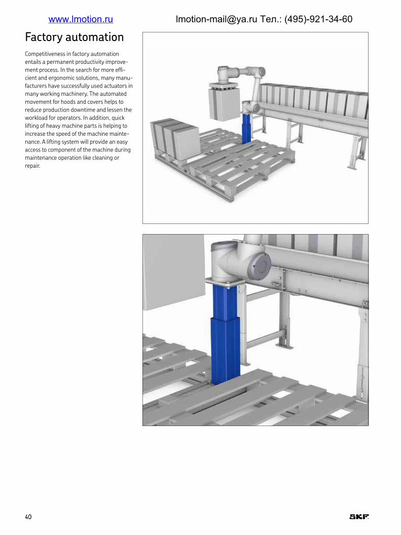
Factory automation Competitiveness in factory automation
entails a permanent productivity improve-
ment process In the search for more efi-
cient and ergonomic solutions, many manu-
facturers have successfully used actuators in
many working machinery The automated
movement for hoods and covers helps to
reduce production downtime and lessen the
workload for operators In addition, quick
lifting of heavy machine parts is helping to
increase the speed of the machine mainte-
nance A lifting system will provide an easy
access to component of the machine during
maintenance operation like cleaning or
repair
4040
www.lmotion.ru [email protected] Тел.: (495)-921-34-60

Automation Conveyor system
Conveyor lines are heavily used across dif-
ferent industries and applications The dif-
ferent automatized movements are usually
achieved by pneumatic cylinders The need
of increasing energy eficiency and simplify-
ing the system has lead to a usage of elec-
tro-mechanical actuators over the conveyor
line
For a stop-pallet function, CAHB-10 actu-
ators have been successfully used to replace
standard pneumatic cylinder, thanks to their
compact dimension and easy controllability
By using electro-mechanical actuators, it
has been possible to have a fully electric line,
getting rid of the whole pneumatic system
(cylinders, hoses, valves )
4141
A
www.lmotion.ru [email protected] Тел.: (495)-921-34-60

Vehicles – agricultural machinery
Combine harvester
Today’s farmers are challenged by the
demands on cutting costs while increasing
the crop yield Modern harvester combines
use many linear actuators to adjust on
demand different equipment like sieve or
concave clearance that help to minimize lost
crops, thus resulting in the best crop yield
The position signal from the actuator
ensures that the position is reached At the
appropriate adjustment, any shock or vibra-
tion should move the position of the actuator
thanks to the high push and pull force and
the high holding force of the linear actuator
To avoid pollution by oil leakage or missin a
cleaning process, request the best class of
Ingress protection IP69K/66M with a vent
4242
www.lmotion.ru [email protected] Тел.: (495)-921-34-60
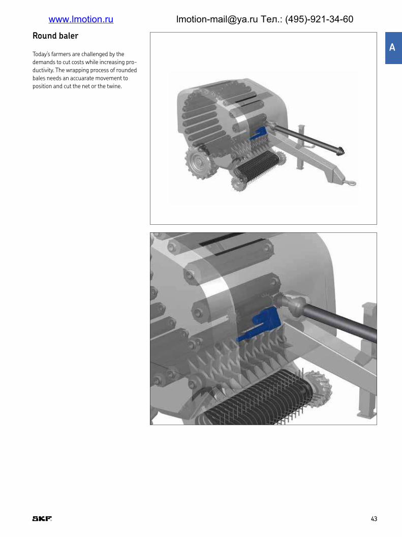
Rond baler
Today’s farmers are challenged by the
demands to cut costs while increasing pro-
ductivity The wrapping process of rounded
bales needs an accuarate movement to
position and cut the net or the twine
4343
A
www.lmotion.ru [email protected] Тел.: (495)-921-34-60

Trucks Today’s freight companies are challenged by
the demands on cutting fuel consumption
and better productivity The truck manufac-
turers develop innovative devices to optimize
air circulation while driving, with or without a
trailer The linear actuator, with or without a
motor, provides a quick, safe and precise
adjustment of the roof air delector
4444
www.lmotion.ru [email protected] Тел.: (495)-921-34-60

Vehicle equipmentTo improve the productivity and increase the
comfort and safety of the worker, the electro
mechanical linear electrical systems are
used on many applications such as warning
sign lifter on a vehicle or brush adjustment
in the sweeper Quick and easy to control, the
linear actuators are also reliability with an
ingress protection IP69K/66M and a vent
4545
A
www.lmotion.ru [email protected] Тел.: (495)-921-34-60

Construction equipment
Today’s construction companies are chal-
lenged by the demands on cutting fuel con-
sumption and providing better productivity
Products such as Articulated Dump Trucks,
wheel loaders or rollers, the engines are
more sophisticated to comply with the CO2
emission regulations and the engine hood
are bigger and heavier due to the cooling
system The maintenance operation requires
the engine hood be lifted The operator
needs a fast and safe operation The linear
actuator can quickly lift the engine hood but
also keep it open thanks to the high push
force and the high holding force that keep
the hood at a stable position even if there is
shock or wind
4646
www.lmotion.ru [email protected] Тел.: (495)-921-34-60

Building automation Modern commercial, administrative and
industrial buildings, as well as schools and
care centers are often itted with a variety of
small electronic appliances which can per-
form important functions remotely and sim-
ply Actuators for light domes, doors, win-
dows and smoke and heat outlet systems
are installed in many modern buildings
These actuators open and close traditional
and tilting windows, light domes, facade
elements, sun blinds and smoke and heat
outlet shutters, at the touch of a button or
automatically, using climatic (wind/rain) sen-
sors and temperature and smoke sensors
4747
A
www.lmotion.ru [email protected] Тел.: (495)-921-34-60

Food and beverage Commercial kitchen equipment
Kete
Machine lexibility, process control and cost
eficiency are important in modern industrial
kitchens High end food processing equip-
ment requires automated, repetitive and
sometimes dificult operations Whether it is
raising or lowering an exhaust hood or a
complete stove, actuators can enable people
to work more comfortably and eficiently by
adjusting the environment to their own per-
sonal needs
4848
www.lmotion.ru [email protected] Тел.: (495)-921-34-60

Fryer basket
Clam shell grill with electrical lifting are
automatized with a linear actuator The
cooking of the steak is exactly as requested
by the customer and the operator is more
eficient A customization of the motor could
be proposed if a long life time is requested
To ensure perfect French fries, the lifting
of basket is automatized with a linear actua-
tor The operator appreciates also the sim-
plicity and comfort and can focus on other
preparation
4949
A
www.lmotion.ru [email protected] Тел.: (495)-921-34-60

Selection process
• Medical
• Harsh environment
• Automation
www.lmotion.ru [email protected] Тел.: (495)-921-34-60

Simpliied selection process
By following the described low (→ diagram 1), the user can select
the right solution based on linear actuator, telescopic pillar and elec-
tronics that fulill the application needs If further assistance is
needed, please contact SKF to get complete technical support
Diagram 1 AC version• Selection by load and direction, offset load if pillar, stroke, speed,
IP, Self-locking/holding/static force dimension
• Verify the environment and standard: IP, duty cycle, temperature,
standard
• Select accessories if requested Power cable or Power cord, con-
nection plates, wires, inlet / outlet boxes
• Select the compatible operating device / switches per number of
functions to control
DC version
• Selection by load and direction, offset load if pillar, stroke, speed,
IP, Self-locking/holding/static force dimension
• Verify the environment and standard: IP, duty cycle, temperature,
standard
• Select the control unit: Channel per motor, output per channel,
Sum output power (see compatibility Matrix), accessories
• Select the compatible operating device / switches per number of
functions to control
See pages 52 and 53 for more information
Start by function or the application
No
No
No
Yes
Yes
Yes
Yes
Yes
No
No
Select linear actuator
Select linear actuator Medical
Select other linear actuator (medical one
is also possible)
Select AC version (AC motor or built in
power supply)
AC version DC version
Select telescopic pillar
Stand alone product
Main power (AC)
Paralell mode or memory
The load is guided?
Medical application?
Select DC version with encoder
Select DC version without encoder
5151
B
www.lmotion.ru [email protected] Тел.: (495)-921-34-60

S y nd direction, off set load if pillar, stroke, speed, Self-locking/holding/static force, dimensions
• Rated load should match with the maximum force applied to the
actuator by the application during the movement Consider the
“worst case scenario” and also the direction; push is the extension
and pull is the retraction direction
• For Pillar, it is the load and offset load / distance that should be
considered
• The static load should match with the force applied on the actuator
by the application when the actuator is static Consider the
dynamic effect of vibration or chock on the application
Verify the environment and standard: IP, duty cycle, temperature, standard
• Each product should have an Environmental and standard specii-
cation that should match the environment of the application
• Ingress Protection
• Ambient Temperature during working condition, storage condition
• Duty cycle % or “Time ON / Time OFF” are speciied
• The longest running time should not exceed the Time ON
speciied
• The shortest rest time should be longer than the running time
multiplied by the “Time ON / Time OFF” speciied, or running time
multiplied by (1- Duty cycle speciied) and divided by duty cycle
Formula:
Running time × Time ON
Rest time > —––––––––––––––––––––––––––– Time OFF
or
Running time × (1-Duty Cycle%) Rest time > ——––––––––––––––––––––––––––––– Duty Cycle%
• The stroke length of the actuator including the tolerance should
match with the travel distance of the application In case of limit
switches option, the extra stroke length to reach the mechanical
end stop of the actuator could be considered for added safety
• The speed should match with the expected running time Consider
that the speed will change depending on the load but also depend-
ing on the voltage luctuation in case of a DC motor, except for a
Switch Mode Power Supply
• For some products, you could select the attachment dimension
and retracted length Consider the tolerance
Example:
Time ON / Time OFF = 85 s / 340 s or Duty Cycle 20%;
the Running time must be less than 85 seconds
If the running time is 30 seconds, the Rest Time should be more than
30 × 340 ——–––––—— = 120 seconds 85
or
30 × (1-20%)Rest time > ——–––––––– 20%
so
30 × (1-0,2)Rest time > ——––––––––– 0,2
so at least 120 seconds
Some products are designed for a speciic application but are suitable
for others applications that request the similar performance
5252
www.lmotion.ru [email protected] Тел.: (495)-921-34-60

Select the Control Unit: Channel per motor, output per channel, Sum Output power (see compatibility Matrix)
• Select the control unit that is compatible with the actuator or pillar
selected Consider the sum of the number of channels requested
by each product; some pillars could request 2
• Accessories can be selected: power cable or power cord, extra
wires, Inlet and Outlet boxes, Connection plates
Select the compatible operating device / buttons per number of functions to control
• Select the operating device that is compatible with the control unit
• The type of switch must be selected: the switch can have different
number of buttons according to the numbers of functions to drive
(i e for only up and down function is necessary two buttons); num-
ber of buttons increase according to the number of actuators or
pillars to drive or if memory position or other functions are
needed
5353
B
www.lmotion.ru [email protected] Тел.: (495)-921-34-60

Chapter contents
50
Matrix series 57
Matrix1 58
Matrix3 62
Matrix6 66
Runner 72
CAJA35C 76
Ecomag 80
Magdrive 84
CAHB series 89
CAHB-10 90
CAHB-20A 96
CAHB-20E 100
CAHB-21E 104
CAHB-22E 108
CAHB-30A 112
CAHB-31N 116
CAR,CAP & CAT series 123
CAR 22 124
CAP 32 128
CAT 32B and CAP 43B 134
CAT 33 and CAP 43A 144
CAT 33H 154
CAR 40 162
Spare parts 168
CAHM series 173
5555
C
www.lmotion.ru [email protected] Тел.: (495)-921-34-60

Matrix seriesThe Matrix series is designed for medical devices and includes pow-
erful AC and DC linear actuators using DC motor They run very qui-
etly, take up little space and can be installed at virtually every angle
in vertical or horizontal position The series is medical approved by
third parties and available with options like anti-pitching, incremen-
tal position feedback and emergency lowering The Matrix series can
be supplied as a full system with controls, operating units and
accessories
Beneits
• Synchronization possible
• Silent operation
• Compact and aesthetic
• Back-up nut as standard
Features
• Designed for medical devices
• Full system with controls,
operating units and accessories
• Back up nut as standard
• Safety factor up to 4
5757
C
www.lmotion.ru [email protected] Тел.: (495)-921-34-60

Matrix1
Linear actuator
Beneits
• Silent operation
• Full system with control unit,
switch and accessories
• Synchronization possible
• Compact and aesthetic
• Back-up nut as standard
Unit MAX1..A.. MAX1..B.. MAX1..C..
Rated push load N 4 000 2 000 1 500Rated pull load N 4 000 2 000 1 500Speed (full load to no load) mm/s 5 to 7 6 to 9 13 to 18Stroke mm 50 to 700 50 to 700 50 to 700Retracted length mm S + 195/2601) S + 195/2601) S + 195/2601)
Voltage V DC 24 24 24Power consumption W 120 120 120Current consumption A 5 5 5Duty cycle % 10 (1/9) 10 (1/9) 10 (1/9)Ambient temperature °C 0 to +40 0 to +40 0 to +40Type of protection IP 66S 66S 66SWeight (at 200 mm stroke) kg 4 3,7 3,6Color – Grey Grey Grey
Technical data
1) S<350 mm, L = 195 + S S>350 mm, L = 260 + S
5858
www.lmotion.ru [email protected] Тел.: (495)-921-34-60

Performance diagrams
0
15
10
5
20
0 2 0001 000 3 000 4 0000
5
4
3
2
1
6
0 2 0001 000 3 000 4 000
Speed [mm/s]
Load [N]
Speed-load diagram
Current consumption [A]
Load [N]
Current-load diagram
Safety factor load conditions
0
3 500
3 000
500
1 000
1 500
2 000
2 500
4 000
0 400200 600 8000
3 500
3 000
500
1 000
1 500
2 000
2 500
4 000
0 400200 600 800
Load [N] Load [N]
Stroke [mm] Stroke [mm]
Push load reduction staticSafety factor S=1
Push load reduction staticSafety factor S=2
0
3 500
3 000
500
1 000
1 500
2 000
2 500
4 000
0 400200 600 800
Load [N]
Stroke [mm]
Push load reduction static Safety factor S=4 (EN60601)
Rated push force 1 500Rated push force 2 000Rated push force 4 000
Rated push force 1 500Rated push force 2 000Rated push force 4 000
5959
C
www.lmotion.ru [email protected] Тел.: (495)-921-34-60

N66
48
107
169
40
29
66
†31
†12+0,3+0,1†12+0,3
+0,15
L±2*S
2811
2811
1215 1514
116
Side view
Top view
DIN8 plug
S < 350 mm; L = 195 + SS > 350 mm; L = 260 + S
Rear view Standard 0° Turned 90°
Top view
Label
D rawing
Suitable control units and accessoriesConnecting diagrams
DIN Plug 24 V DC
Hall A
DIN plug
Actuator
Blue
1+7 2+4
1,5K
+
-
5V+
GND
1,5K
3 5 6 8
Red
M
Hall B
Hall sensor signal
Control units
SCU
VCU
BCU
MCU
MAX 1
Operating switches
EHA 1
EHA 3
STJ
STF
STE
STA
Jack Plug 24 V DC+-
Black Red
M
Actuator
Desk switchHand switch Foot switch
6060
www.lmotion.ru [email protected] Тел.: (495)-921-34-60

Ordering key
Options shown in blue are only available on request Contact SKF for more information on minimum quantities and additional costs
Type
Voltage24 V DC 024 V DC with integrated current cut-off 1
Load4 000 N A2 000 N B1 500 N C
Stroke (S)50 mm 050 245100 mm 100 295150 mm 150 345200 mm 200 395250 mm 250 445300 mm 300 495350 mm 350 545400 mm 400 660450 mm 450 710500 mm 500 760550 mm 550 810600 mm 600 860650 mm 650 910700 mm 700 960Other stroke lengths; 50<S<700 mm – – – – – –
Cable / Connecting plugCoiled, 0,75 m (not stretched) / DIN8 plug 0 BStraight, 2,5 m / DIN8 plug C 5Coiled, 0,75 m (not stretched) / Jack plug 0 AStraight, 2,5 m / Jack plug 2 5Special cable length on request – –
Orientation of rear attachmentNo fork head (customized option) 0Standard (as drawing) 1Turned 90° 2
Option 1No option, only valid for actuator “A” (push and pull) 0Quick-release +EKZm, push, fork head bore parallel to button (for actuator design “C” is L= +115 mm)1) EQuick-release +EKZm, push, fork head bore 90° to button (for actuator design “C” is L= +115 mm)1) FMechanical anti-pinching, motor direction pull, no ixing in term position (for load “A”, L= +45 mm; “B”and “C”, L= +30 mm) IMechanical anti-pinching, motor direction push, no ixing in term position (for load “A”, L= +45 mm; “B”and “C”, L= +30 mm) JPush load, for actuator version “B” and “C” MPull load, for actuator version “B” and “C” N
Option 2No option 02-Hall encoder, DIN8 plug FLifetime monitoring MLifetime monitoring, 2-Hall encoder, DIN8 plug P
Option 3No option 0Emergency lowering, fork head bore parallel to clamping lever (for actuator design "A", L+30 mm) VEmergency lowering, fork head bore 90° to clamping lever (for actuator design "A", L+30 mm) W
Customized
M A X 1 - A 0 0 0
1) EKZm: mechanical anti-pinching min stroke 150 mm up to 300 mm Options shown in blue are only available on request Contact SKF for more information on minimum quantities and additional costs
6161
C
www.lmotion.ru [email protected] Тел.: (495)-921-34-60

Matrix3
Linear actuator
Beneits
• Silent operation
• Full system with control unit,
switch and accessories
• Synchronization possible
• Compact and aesthetic
• Back-up nut as standard
Unit MAX3..A.. MAX3..B.. MAX3..C..
Rated push load N 8 000 4 000 3 000Rated pull load N 6 0001) 4 000 3 000Speed (full load to no load) mm/s 5 to 7 6 to 9 13 to 18Stroke mm 50 to 700 50 to 700 50 to 700Retracted length mm S + 215/2802) S + 215/2802) S + 215/2802)
Voltage V DC 12 or 24 12 or 24 12 or 24Power consumption W 120 120 120Current consumption A 5 5,2 5,2Duty cycle % 10 (1/9) 10 (1/9) 10 (1/9)Ambient temperature °C 0 to +40 0 to +40 0 to +40Type of protection IP 66S 66S 66SWeight (at 200 mm stroke) kg 4,5 4,2 4Color – Grey Grey Grey
Technical data
1) Max load for medical application is 5 000 N2) S ≤ 350 mm; L = S + 215 S > 350 mm; L = S + 280
6262
www.lmotion.ru [email protected] Тел.: (495)-921-34-60

Performance diagrams
0
15
10
5
20
0 2 000 4 000 6 000 8 0000
5
3
4
2
1
6
0 2 000 4 000 6 000 8 000
Speed [mm/s]
Load [N]
Speed-load diagram
Current consumption [A]
Load [N]
Current-load diagram
Safety factor load conditions
0
2 000
1 000
4 000
3 000
6 000
5 000
8 000
7 000
0 200 400 600 800
push
push
pull
pull
0
2 000
1 000
4 000
3 000
6 000
5 000
8 000
7 000
0 200 400 600 800
Load [N] Load [N]
Stroke [mm] Stroke [mm]
Push load reduction staticSafety factor S=1
Push load reduction staticSafety factor S=2
0
2 000
1 000
4 000
3 000
6 000
5 000
8 000
7 000
0 200 400 600 800
Load [N]
Stroke [mm]
Push load reduction staticSafety factor S=4 (EN60601)
Rated push force 3 000Rated push force 4 000Rated push force 8 000
Rated push force 3 000Rated push force 4 000Rated push force 8 000
6363
C
www.lmotion.ru [email protected] Тел.: (495)-921-34-60

Dimensional drawing
82
N42,5
†31 29
†12+0,3-0,1 †12+0,3
-0,1
L±21)
12
11
28
11
28
14 15
136
15
50
112
122
†82
40
192
Side view
Top view
DIN8 plug
Rear viewStandard 0° Turned 90°
Front view
1) S < 350 mm; L = 195 + S S > 350 mm; L = 260 + S
Label
Connecting diagrams
12/24 V DC +-
5V+GND
M
1+7 2+4
1,5K 1,5K
Hall AHall B
3 5 6 8
Blue Red
Hall sensor signal
Actuator
DIN plug
Suitable control units and accessories
1) Only valid for MAX 31 MAX 30 must be operated by a BCU, MCU, SCU or VCU control unit
Jack Plug 24 V DC+-
Black Red
M
Actuator
Control units
SCU
VCU
BCU
MCU
MAX 1
Operating switches
EHA 1
EHA 3
STJ
STF
STE
STA
Desk switchHand switch Foot switch
6464
www.lmotion.ru [email protected] Тел.: (495)-921-34-60

Ordering key
Options shown in blue are only available on request Contact SKF for more information on minimum quantities and additional costs
Type
Voltage24 V DC 024 V DC with integrated current cut-off 112 V DC 2
Load8 000 N A4 000 N B3 000 N C
Stroke (S)50 mm 050 265100 mm 100 315150 mm 150 365200 mm 200 415250 mm 250 465300 mm 300 515350 mm 350 565400 mm 400 680450 mm 450 730500 mm 500 780550 mm 550 830600 mm 600 880650 mm 650 930700 mm 700 980Other stroke lengths; 50<S<700 mm – – – – – –
Cable / Connecting plugCoiled, 0,75 m (not stretched) / DIN8 plug 0 BStraight, 2,5 m / DIN8 plug C 5Coiled, 0,75 m (not stretched) / Jack plug 0 AStraight, 2,5 m / Jack plug 2 5Special cable length on request – –
Orientation of rear attachmentNo fork head (customized option) 0Standard (as drawing) 1Turned 90° 2
Option 1No option, only valid for actuator “A” (push and pull) 0Quick-release +EKZm, push, fork head bore parallel to button (for actuator design “C” is L= +115 mm)1) EQuick-release +EKZm, push, fork head bore 90° to button (for actuator design “C” is L= +115 mm)1) FMechanical anti-pinching, motor direction pull, no ixing in term position (for load “A”, L= +45 mm; “B”and “C”, L= +30 mm) IMechanical anti-pinching, motor direction push, no ixing in term position (for load “A”, L= +45 mm; “B”and “C”, L= +30 mm) JElectrical anti-pinching protection, motor direction pull KElectrical anti-pinching protection, motor direction push LPush load, for actuator version “B” and “C” MPull load, for actuator version “B” and “C” N
Option 2No option 02-Hall encoder, DIN8 plug FLifetime monitoring MLifetime monitoring, 2-Hall encoder, DIN8 plug P
Option 3No option –Emergency lowering, fork head bore parallel to clamping lever (for actuator design "A", L+30 mm) VEmergency lowering, fork head bore 90° to clamping lever (for actuator design "A", L+30 mm) W
Customized
M A X 3 - A 0 0 0
1) EKZm: mechanical anti-pinching min stroke 150 mm up to 300 mm Options shown in blue are only available on request Contact SKF for more information on minimum quantities and additional costs
6565
C
www.lmotion.ru [email protected] Тел.: (495)-921-34-60

Matrix6
Linear actuator
Beneits
• Silent operation
• Full system with integrated
control unit and accessories
• Compact and aesthetic
• Back-up nut as standard
Unit MAX6..A.. MAX6..B.. MAX6..C..
Rated push load N 8 000 4 000 3 000Rated pull load N 6 0001) 4 000 3 000Speed (full load to no load) mm/s 6 to 7,5 8 to 10 13 to 18Stroke mm 50 to 700 50 to 700 50 to 700Retracted length mm S + 215/2802) S + 215/2802) S + 215/2802)
Voltage V AC 120 or 230 120 or 230 120 or 230Power consumption 120 V AC W 150 150 150
230 V AC W 145 145 145Current consumption 120 V AC A 2 2 2
230 V AC A 1 1 1Duty cycle % 10 (1/9) 10 (1/9) 10 (1/9)Ambient temperature °C 0 to +40 0 to +40 0 to +40Type of protection IP 66S 66S 66SWeight (at 200 mm stroke) kg 4,8 4,5 4,2Color – Grey Grey Grey
Technical data
1) Max load for medical application is 5 000 N2) S < 350 mm; L = S + 215
S > 350 mm; L = S + 280
6666
www.lmotion.ru [email protected] Тел.: (495)-921-34-60
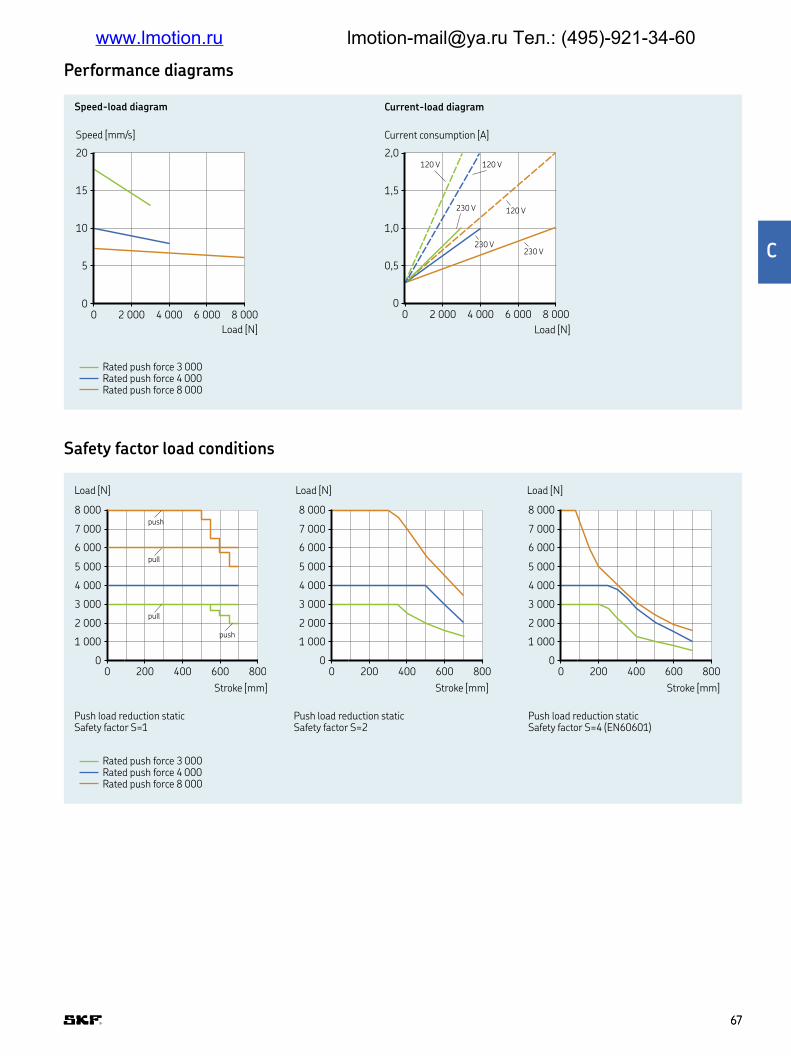
Performance diagrams
Safety factor load conditions
Speed [mm/s]
Load [N]
Speed-load diagram
Current consumption [A]
Load [N]
Current-load diagram
00 2 000 4 000 6 000 8 000
0,5
1,0
1,5
2,0120 V
230 V
230 V230 V
120 V
120 V
00 2 000 4 000 6 000 8 000
5
10
15
20
00 200 400 600 800
1 000
2 000
3 000
4 000
5 000
6 000
7 000
8 000push
push
pull
pull
00 200 400 600 800
1 000
2 000
3 000
4 000
5 000
6 000
7 000
8 000
00 200 400 600 800
1 000
2 000
3 000
4 000
5 000
6 000
7 000
8 000
Load [N]
Stroke [mm]
Load [N]
Stroke [mm]
Load [N]
Stroke [mm]
Push load reduction staticSafety factor S=1
Push load reduction staticSafety factor S=2
Push load reduction staticSafety factor S=4 (EN60601)
Rated push force 3 000Rated push force 4 000Rated push force 8 000
Rated push force 3 000Rated push force 4 000Rated push force 8 000
6767
C
www.lmotion.ru [email protected] Тел.: (495)-921-34-60
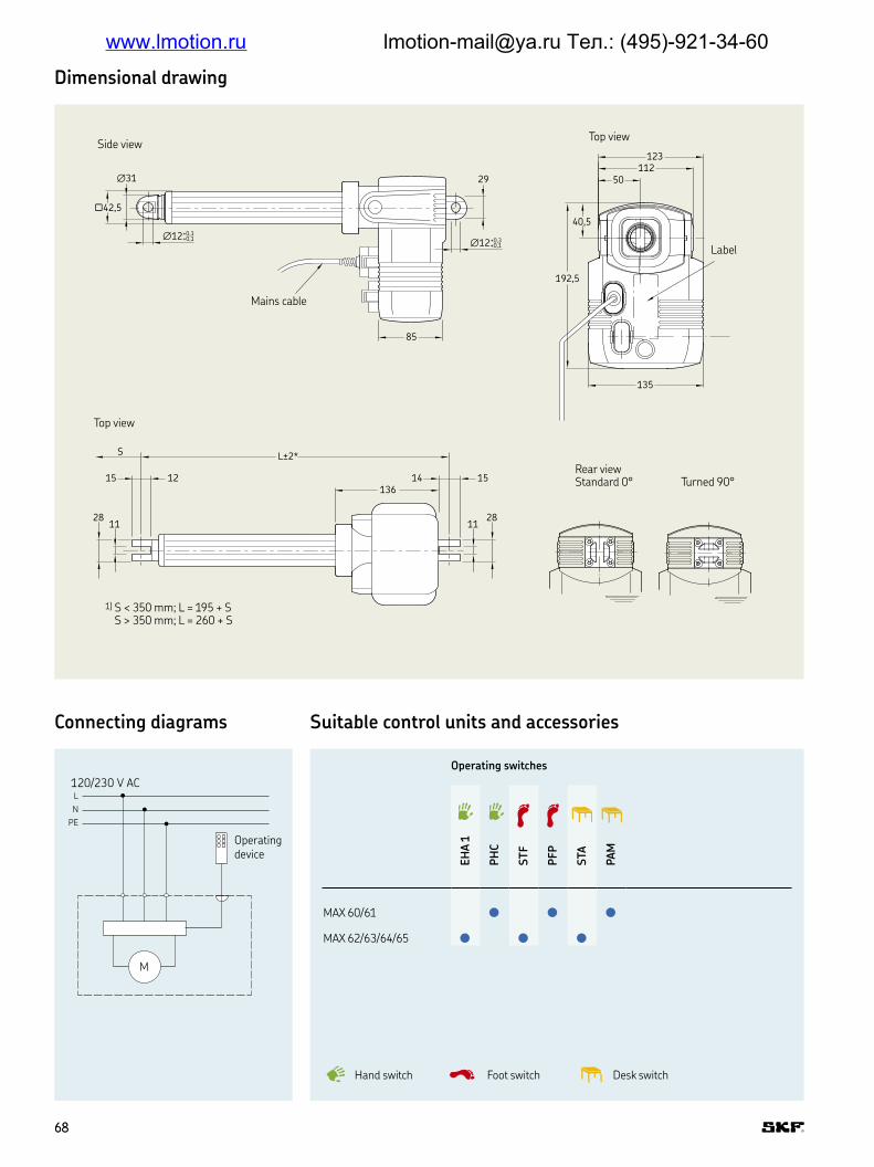
Operating switches
EH
A 1
PH
C
ST
F
PFP
STA
PAM
MAX 60/61
MAX 62/63/64/65
Suitable control units and accessories
L
N
PE
M
120/230 V AC
Operatingdevice
Connecting diagrams
Side view
Top view
Mains cable
1) S < 350 mm; L = 195 + S S > 350 mm; L = 260 + S
Label†12+0,3
+0,1
85
†31 29
N42,5
†12+0,3+0,1
L±2*S
1128
1128
136151415 12
40,5
50
123
135
112
192,5
Dimensional drawing
Rear viewStandard 0° Turned 90°
Top view
Desk switchHand switch Foot switch
6868
www.lmotion.ru [email protected] Тел.: (495)-921-34-60
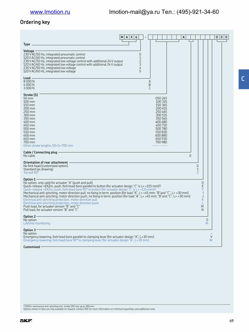
Ordering key
Options shown in blue are only available on request Contact SKF for more information on minimum quantities and additional costs
Type
Voltage230 V AC/50 Hz, integrated pneumatic control 0120 V AC/60 Hz, integrated pneumatic control 1230 V AC/50 Hz, integrated low voltage control with additional 24 V output 2120 V AC/60 Hz, integrated low voltage control with additional 24 V output 3230 V AC/50 Hz, integrated low voltage 4120 V AC/60 Hz, integrated low voltage 5
Load8 000 N A4 000 N B3 000 N C
Stroke (S)50 mm 050 265100 mm 100 315150 mm 150 365200 mm 200 415250 mm 250 465300 mm 300 515350 mm 350 565400 mm 400 680450 mm 450 730500 mm 500 780550 mm 550 830600 mm 600 880650 mm 650 930700 mm 700 980Other stroke lengths; 50<S<700 mm – – – – – –
Cable / Connecting plugNo cable 0
Orientation of rear attachmentNo fork head (customized option) 0Standard (as drawing) 1Turned 90° 2
Option 1No option, only valid for actuator “A” (push and pull) 0Quick-release +EKZm, push, fork head bore parallel to button (for actuator design “C” is L= +115 mm)1) EQuick-release +EKZm, push, fork head bore 90° to button (for actuator design “C” is L= +115 mm)1) FMechanical anti-pinching, motor direction pull, no ixing in term position (for load “A”, L= +45 mm; “B”and “C”, L= +30 mm) IMechanical anti-pinching, motor direction push, no ixing in term position (for load “A”, L= +45 mm; “B”and “C”, L= +30 mm) JElectrical anti-pinching protection, motor direction pull KElectrical anti-pinching protection, motor direction push LPush load, for actuator version “B” and “C” MPull load, for actuator version “B” and “C” N
Option 2No option 0Lifetime monitoring M
Option 3No option –Emergency lowering, fork head bore parallel to clamping lever (for actuator design "A", L+30 mm) VEmergency lowering, fork head bore 90° to clamping lever (for actuator design "A", L+30 mm) W
Customized
M A X 6 - A 0 0 0
1) EKZm: mechanical anti-pinching min stroke 150 mm up to 300 mm Options shown in blue are only available on request Contact SKF for more information on minimum quantities and additional costs
6969
C
www.lmotion.ru [email protected] Тел.: (495)-921-34-60

Plug Country Designation Order number
Straight cable 3,5 m Schuko DE ZKA-140306-3500 0121723Straight cable 3,5 m SEV CH ZKA-140316-3500 0121737Straight cable 3,5 m UL USA ZKA-140355-3500 0121724Straight cable 3,5 m Hospital grade USA ZKA-140360-3500 0121732Straight cable 3,5 m British standard UK ZKA-140350-3500 0121743Coiled cable 1,2 m / 2,2 m Schuko DE ZKA-140342-1500 0121728Coiled cable 1,2 m / 2,2 m SEV CH ZKA-140378-1200 0121738Straight polyurethane cable 3,5 m Schuko DE ZKA-140422-3500 0121739Straight polyurethane cable 3,5 m SEV CH ZKA-140426-3500 0121740 Strain relief for mains cable ZUB-952253 0102848Tool for plugs (Jack/D–Sub/Mains) ZWS-140375 0125322
Accessories
7070
www.lmotion.ru [email protected] Тел.: (495)-921-34-60

Runner
Linear actuator
Beneits
• High push/pull load
• Compact
• Back-up nut as standard
• High safety factor
• Silent operation
Unit RU20 RU21 RU22 RU23 RU24 RU25
Rated push load N 8 000 10 000 12 0001) 8 000 10 000 12 0001)
Rated pull load N 8 000 8 000 8 000 8 000 8 000 8 000Speed (full load to no load) mm/s 7 to 10 5 to 8 4 to 7 8 to 15 6 to 12 5 to 9Stroke mm 100 to 700 100 to 700 100 to 700 100 to 700 100 to 700 100 to 700Retracted length mm S+215/3152) S+215/3152) S+215/3152) S+215/3152) S+215/3152) S+215/3152)
Voltage V DC 24 24 24 24 24 24Power consumption W N/A N/A N/A N/A N/A N/ACurrent consumption A 7 7 7 10 10 10Duty cycle % 10 (1/9) 10 (1/9) 10 (1/9) 10 (1/9) 10 (1/9) 10 (1/9)Ambient temperature °C +10 to +40 +10 to +40 +10 to +40 +10 to +40 +10 to +40 +10 to +40Type of protection IP ×4/×6S ×4/×6S ×4/×6S ×4/×6S ×4/×6S ×4/×6S Weight kg 4,7 4,7 4,7 4,7 4,7 4,7Color – Grey Grey Grey Grey Grey Grey
Technical data
1) Safety working load for medical application is 10 000 N (EN 60601)2) S ≤ 500 mm; L = S + 215 S > 500 mm; L = S + 315
7272
www.lmotion.ru [email protected] Тел.: (495)-921-34-60

Performance diagrams
Safety factor load conditions
Speed-load diagram Current-load diagram
0
6
4
2
10
8
12
14
0 2 000 6 000 10 000 14 000 0 400 800 1 200 1 600
0
4
3
2
1
5
6
7
8
0 400 800 1 200 1 600
0
4
3
2
1
5
6
7
9
8
0
6
4
2
10
8
12
16
14
0 2 000 6 000 10 000 14 000
Speed-load diagram Current-load diagram
Speed [mm/s] Current consumption [A]
Load [N] Load [N]
Speed [mm/s]
Load [N]
Current consumption [A]
Load [N]
0
6 000
4 000
2 000
10 000
8 000
12 000
14 000
0 100 200 300 400 500 6001)
7000
6 000
4 000
2 000
10 000
8 000
12 000
14 000
0 100 200 300 400 500 6001)
700
Load [N] Load [N]
Stroke [mm] Stroke [mm]
Push load limit, safety factor S=4 (EN 60601) 1) retracted length extension at stroke >500 mm
Push load limit, safety factor S=2 1) retracted length extension at stroke >500 mm
Rated push load 8 000 RU20Rated push load 10 000 RU21Rated push load 12 000 RU22
RU21 RU22 RU24 RU25RU20 RU23RU22 RU25RU21 RU24
Rated push load 8 000 RU23Rated push load 10 000 RU24Rated push load 12 000 RU25
7373
C
www.lmotion.ru [email protected] Тел.: (495)-921-34-60

L !"#S = strokeL = retracted length
1) Retracted length: up to 500 mm stroke: stroke +215 mm (plus options)from 500 mm stroke: stroke +315 mm (plus options)
Rear attachment position
30
∅53
∅12+0,3-0,1
L = S+215/315*(±2 mm)
L = +30
∅12+0,3-0,1
1415
∅11
28
∅80
15
12
∅33,6
1128
30
189
168
9545°
135°
90°
0°
23
94
30,7
47
53
Dimensional drawing
Suitable control units and accessoriesConnecting diagram
+-
M
Black
Jack Plug 24 V DC
Limit switches
Actuator
Red
DIN Plug 12/24 V DC+-
5V+
GND
1+7 2+4
1,5K 1,5K
Hall AHall B
3 5 6 8
DIN8 plug
Blue Red
M2 Hallsensors signal
Actuator
Control units
SCU
VCU
BCU
MCU
RU20, RU21, RU22
RU23, RU24, RU25
Operating switches
EHA 1
EHA 3
STJ
STF
STA
STE Desk switch
Hand switch
Foot switch
7474
www.lmotion.ru [email protected] Тел.: (495)-921-34-60

T$%&
V'()*+&24 V DC
Load / Speed8 000 N / 7-10 mm/s 0 8 000 N / 8-15 mm/s 310 000 N / 5-8 mm/s 110 000 N / 6-12 mm/s 412 000 N / 4-7 mm/s 212 000 N / 5-9 mm/s 5
Stroke (S) / Retracted length (L)50 mm / 315 mm 050 315100 mm / 315 mm 100 315150 mm / 365 mm 150 365200 mm / 415 mm 200 415250 mm / 465 mm 250 465300 mm / 515 mm 300 515350 mm / 565 mm 350 565400 mm / 615 mm 400 615450 mm / 665 mm 450 665500 mm / 715 mm 500 715550 mm / 865 mm 550 865600 mm / 915 mm 600 915650 mm / 965 mm 650 965700 mm / 1 015 mm 700 XXX50<S≤500 mm / S+215 – – – – – –500<S<700 mm / S+315 – – – – – –S>700 mm (customized) XXX XXX
Type of protection / ColorIP×4S, grey AIP×6S, grey B
CableStraight cable, 1,5 m, DIN8 plug 15Straight cable, 1,5 m, Jack plug 180° 0D
Rear attachment orientation / Hole diameter0° / ∅ = 12,0 mm 045° / ∅ = 12,0 mm 290° / ∅ = 12,0 mm 4135° / ∅ = 12,0 mm 6
Option 1No option 0Electrical anti-pinching (safety switch), pull load, L+20 mm KElectrical anti-pinching (safety switch), push load, L+20 mm L
Option 2No option 02-Hall encoder, 14 pulses, DIN8 plug ALifetime monitoring M2-Hall encoder, 14 pulses, DIN8 plug, lifetime monitoring N
Option 3No option –Emergency lowering, L+53 mm (for push load only) V
Customized
R U 2 – 0 0
Options shown in blue are only available on request Contact SKF for more information on minimum quantities and additional costs
Ordering key
7575
C
www.lmotion.ru [email protected] Тел.: (495)-921-34-60

CAJA35C
Linear actuator
Beneits
• Quick-release solution for fast CPR
intervention
• Detachable cable for quick assembly and
service
• Integrated brake to maintain self-locking
and stability under maximum static load
in compression
Unit CAJA35C
Push load N 3 500Speed (full load to no load) mm/s 7,5 to 10,5Stroke mm 30 to 250Retracted length1) mm S+1802)
Voltage V DC 24–41Current consumption A 4Duty cycle % 10Ambient temperature °C +10 to +40Type of protection IP 56Weight kg 2,5Color – Grey
Technical data
1) Tolerance ±3 mm2) Retracted length +3 mm if U fork used as front attachment (L= S+183)
7676
www.lmotion.ru [email protected] Тел.: (495)-921-34-60

Performance diagrams
Dimensional drawing
Speed-load diagram Current-load diagram
10
2
0
4
6
8
12Speed [mm/s]
0 1 2 3 3,51,5 2,5Load [kN]
0 1 2 3 3,51,5 2,5Load [kN]
0
3
1
2
4
Current consumption [A]
25,5
144,6
37,7
7,1
19,5
22
∅ 10,2±0,1/∅ 12,2±0,1
∅ 10,2±0,1/∅ 12,2±0,1
42,2
130,6
14114,3
L=S+180/183
59,3
∅2847,5
36
∅ 70,1
8,2±0,1
56
25
7
55,2
17,5
8,2
14
34
∅ 10,2±0,1/∅ 12,2±0,1
74,4Bowden CPR cable connection: M6, 10 mm 32,7
93,7
74,5
54
4
Legend:S = strokeL = retracted length
7777
C
www.lmotion.ru [email protected] Тел.: (495)-921-34-60

Connecting diagram DC version
Suitable control units and accessories
Orientation
135°
135°
90°
90°
45°
45°
0°
Control unit
BCU
VCU
SCU
CAJA 35C
Operating switches
EHA3
STE
STJ
Desk switchHand switch Foot switch
+-
24 V DC
1+7Blue
2+4Red
DIN 8plug
M
Actuator
NCNO
Straight motor cable Length [mm]
G517C0-094001-0460 460G517C0-094001-1350 1 350G517C0-094001-2650 2 650
Accessories
7878
www.lmotion.ru [email protected] Тел.: (495)-921-34-60

Ord,-./0 1ey
Type
Stroke100 mm 100200 mm 200250 mm 250All other customized strokes between 30-250 mm XXX
Retract23 4256thU-fork, metal, ∅ 10,2 mm AU-fork, metal, ∅ 12,2 mm B
Front 7ttachmentTube with hole and metal bushings, ∅ 10,2 mm ATube with hole and metal bushings, ∅ 12,2 mm BU-fork end, metal, ∅ 10,2 mm (increase “L” by 3 mm) CU-fork end, metal, ∅ 12,2 mm (increase “L” by 3 mm) D
Attachment 89:25;a;:85 <=48=>wise)0° 045° 190° 9135° 2
H8?@:56A7terialABS UL94 V0
Protec;:85 =47@@ <s:;B E8wer =ables M6, 10 mm connected)IP56
Option 1:No option 0Antipinching solution ("push only" actuator) 1
Option 2:No option 0With back-up nut (for "push" load) 1
Option 3:No option 0Motor with thermoswitch 1
Customization
C A J A 3 5 C - – – U 6
7979
G
www.lmotion.ru [email protected] Тел.: (495)-921-34-60

Ecomag
Linear actuator
Beneits
• Compact
• Cost effective
• Silent operation
• Control unit can be mounted to the
actuator
Unit ECO 20/40 ECO 60/80 ECO 30/50 ECO 70/90
Rated push load N 2 000 6 000 2 000 6 000Rated pull load N 0 0 2 000 4 000Speed (full load to no load) mm/s 9 to 13 4 to 7 9 to 13 4 to 7Stroke mm 50 to 300 50 to 300 50 to 300 50 to 300Retracted length mm S+160 S+160 S+160 S+160Voltage V DC 24 24 24 24Power consumption W 70 120 70 120Current consumption A 4 6 4 6Duty cycle % 10 (1/9) 10 (1/9) 10 (1/9) 10 (1/9)Ambient temperature °C +10 to +40 +10 to +40 +10 to +40 +10 to +40Type of protection IP ×4S ×4S ×4S ×4SWeight kg 2,1 2,1 2,5 2,5Color – Black or grey Black or grey Black or grey Black or grey
Technical data
8080
www.lmotion.ru [email protected] Тел.: (495)-921-34-60

Performance diagrams
Safety factor load conditions
Speed-load diagram Current-load diagram
0
10
8
6
2
4
14
12
16
0 2 000 4 000 6 000 8 000
0
10
8
6
2
4
14
12
16
0 2 000 4 000 6 000 8 000
Speed [mm/s] Current consumption [A]
Load [N] Load [N]ECO 20 / 30 / 40 / 50ECO 60 / 70 / 80 / 90
ECO 20 / 30 / 40 / 50ECO 60 / 70 / 80 / 90
Push load reduction safety factor = 4
Push load [N]
Stroke length [mm]
0
1 500
4 500
3 000
6 000
0 100 200 300 400
8181
I
www.lmotion.ru [email protected] Тел.: (495)-921-34-60

1517
L = S+160
165
72
113
1515
2626
6+0,7+0,56+0,7+0,5
∅30
∅30
140
A
25
2522,4
15
1515
∅3017
83,4
79
Label
position
Label
position
72
L = S+160
6+0,7+0,56+0,7+0,5∅30
15 15
3032
30
∅25 10 +0,3+0,1510+0,3+0,1545° 0°
90°
135°
45° 0°
90°
135°
24 V DC +
-
M
Black
Limit switches
Actuator
Red
LJKJLMNS = strokeL = retracted length
Pcomag 2-3-6-7
Ecomag 4 -5-8-9
Rear attachment positionFront attachment push and pull version
Rear attachment push and pull version
Push version only Push and pull version
Dimensional drawing
Suitable control units and accessoriesConnecting diagram
Control units
SCU
VCU
BCU
MCU
SEM
ECOMAG
Operating switches
EHA 1
EHA 3
EHE
STJ
STF
STA
STE Desk switch
Hand switch
Foot switch
8282
www.lmotion.ru [email protected] Тел.: (495)-921-34-60
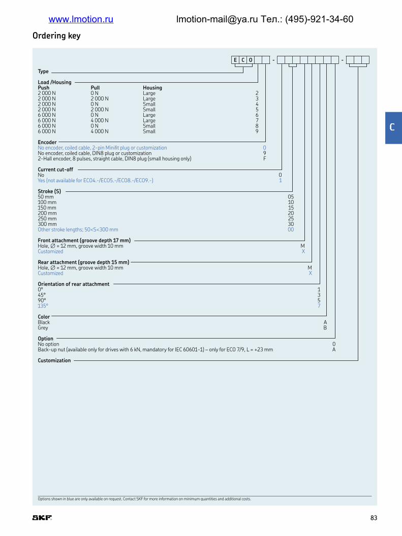
Options shown in blue are only available on request Contact SKF for more information on minimum quantities and additional costs
Ordering key
Type
Load /HousingPush Pull Housing2 000 N 0 N Large 22 000 N 2 000 N Large 32 000 N 0 N Small 42 000 N 2 000 N Small 56 000 N 0 N Large 66 000 N 4 000 N Large 76 000 N 0 N Small 86 000 N 4 000 N Small 9
EncoderNo encoder, coiled cable, 2-pin Miniit plug or customization 0No encoder, coiled cable, DIN8 plug or customization 92-Hall encoder, 8 pulses, straight cable, DIN8 plug (small housing only) F
Current cut-offNo 0Yes (not available for ECO4 -/ECO5 -/ECO8 -/ECO9 -) 1
Stroke (S)50 mm 05100 mm 10150 mm 15200 mm 20250 mm 25300 mm 30Other stroke lengths; 50<S<300 mm 00
Front attachment (groove depth 17 mm)Hole, ∅ = 12 mm, groove width 10 mm MCustomized X
Rear attachment (groove depth 15 mm)Hole, ∅ = 12 mm, groove width 10 mm MCustomized X
Orientation of rear attachment0° 145° 390° 5135° 7
ColorBlack AGrey B
OptionNo option 0Back-up nut (available only for drives with 6 kN, mandatory for IEC 60601-1) – only for ECO 7/9, L = +23 mm A
Customization
E C O - -
Options shown in blue are only available on request Contact SKF for more information on minimum quantities and additional costs
8383
Q
www.lmotion.ru [email protected] Тел.: (495)-921-34-60

Magdrive
Linear actuator
Beneits
• Slim design
• Aluminium proile
• In-line actuator
• Quiet operation
• High push load
Unit MD22/MD24 MD23/MD25
Rated push load N 6 000 6 000Rated pull load N 200* (static only) 6 000Speed (full load to no load) mm/s 8,5 to 15 8,5 to 15Stroke mm 50 to 700 50 to 700Retracted length1) mm S+465 S+465Voltage V DC 24 24Power consumption W N/A N/ACurrent consumption A 7 7Duty cycle % 10 (1/9) 10 (1/9)Ambient temperature °C +10 to +40 +10 to +40Type of protection IP x0/x4S x0/x4SWeight kg 5,0 5,0Color – Colorless anodized Colorless anodized
Technical data
8484
www.lmotion.ru [email protected] Тел.: (495)-921-34-60

Performance diagrams
Safety factor load conditions
Speed-load diagram
0 2 000 4 000 6 0000
2
4
6
8
10
12
14
16
1 000 3 000 5 000 7 000 8 000
Speed (mm/s)
Load (N)
Current-load diagram
0 2 000 4 000 6 0001 000 3 000 5 000 7 000 8 0000
1
2
3
4
5
6
7
8Current consumption (A)
Load (N)
Pull load diagram MD25 (6 000 N)Push load diagram Pull load diagram MD23
0 200 400 6000
100 300 500 700 800
8 000
6 000
4 000
2 000
1 000
3 000
5 000
7 000
MD 22-25
MD 24/25
MD 22/23
Load (N)
Stroke (mm)0 200 400 600
0100 300 500 700 800
8 000
6 000
4 000
2 000
1 000
3 000
5 000
7 000
Load (N)
Stroke (mm)0 200 400 600
0100 300 500 700 800
8 000
6 000
4 000
2 000
1 000
3 000
5 000
7 000
Load (N)
Stroke (mm)
Safety factor S=2Safety factor accordingUL60601–1, IEC60601–1
Safety factor S=4Safety factor accordingUL60601–1, IEC60601–1
Safety factor accordingUL60601–1, IEC60601–1
8585
R
www.lmotion.ru [email protected] Тел.: (495)-921-34-60

TUVWXYUZX[\ ]rawing
Connecting diagram Suitable control units and accessories
Legend:S = strokeL = retracted length
Plastic bushing for forkhead (hinge delivered separately)
Orientation of rear attachment
62
15 12
28
11
†12+0,3+0,1 †12
+0,3+0,1
†3
1
L = S + 465/489± 2
L= 1 500 mm
29
28
151527
11
90° turnedStandard 0°
Stroke ±2
2510
26
8,7
†1 0
† 12
+-
M
24 V DCControl units
SCU
VCU
BCU
MCU
MAGDRIVE
Operating switches
EHA 1
EHA 3
STJ
STF
STA
STE
Black
Limit switches
Actuator
Red
Desk switchHand switch Foot switch
8686
www.lmotion.ru [email protected] Тел.: (495)-921-34-60

Ordering key
Options shown in blue are only available on request Contact SKF for more information on minimum quantities and additional costs
Type
Push/pull force6 000 N/200 N 26 000 N/6 000 N 36 000 N/200 N (recommended for medical applications- with alu rear hinge) 46 000 N/6 000 N (recommended for medical applications- with alu rear hinge) 5
Stroke50 mm 050100 mm 100150 mm 150200 mm 200250 mm 250300 mm 300350 mm 350400 mm 400450 mm 450500 mm 500550 mm 550600 mm 600650 mm 650700 mm 700Other stroke lengths – – –
Retracted lengthMD22/24: S+465 mm – – –MD23/25: S+489 mm – – –Over 1 000 mm assembly length, use customer speciic adaption XXXOthers – – –
Type of protectionIPX0 AIPX4S B
Motor cableStraight, 1,5 m, DIN8 plug 15Straight, 1,5m, jack plug 180° 0D
Rear attachment / Hole diameterStandard 0° / ∅ 12 mm 0Rotated 90° / ∅ 12 mm 4
Option 1No option 0Electrical anti-pinching protection, safety switch, motor direction push LElectrical anti-pinching protection, safety switch, motor direction pull K
Option 2No option 02-Hall encoder (only available with DIN8 plug) 2,15 impulse per turn/sensor (= 5,375 imp per 1 mm) F
Option 3No option –Emergency lowering fork head bore (add 30 mm to retracted length "L") V
M D 2 - 0 0
Options shown in blue are only available on request Contact SKF for more information on minimum quantities and additional costs
8787
^
www.lmotion.ru [email protected] Тел.: (495)-921-34-60

CAHB seriesDesigned to operate in harsh environment with temperatures from
–40 to 85 °C up to 25% duty cycle, SKF electromechanical actuator
CAHB family features robust metal gears and corrosion-resistant
housings Available in 7 series - CAHB-20A/20E/21E/22E for
medium and heavy load applications with an over load protection by
clutch, CAHB-10, a compact solution for low-load applications and
CAHB-30A/31N for AC version- SKF electromechanical actuators,
are virtually maintenance-free, self-locking up to 2 times the rated
load and rated up to IP69K/66M Additional design options are avail-
able like limit switches, positioning feedback and manual over ride
Beneits
• High productivity and usability
of the adjustment
• Reliability and safety
• Save development time
and shorten the time to market
• Cost effectiveness
• Durable
Features
• Long stroke and high speed
• High holding force up to 20 000 N
• Absolute or incremental Position feedback
and limit switches option
• Low basklash
• Manual override option
• Overload and thermal protection
• Ingress protection IP69K/66M with vent
• Stainless steel push tube and Corrosion
protected metal parts
• Wide temperature range (–40 to 85 °C)
• Mechanical, electrical and climatic tests
• High eficiency
• Virtually maintenance-free
See pages 120 and 121 for test results
8989
_
www.lmotion.ru [email protected] Тел.: (495)-921-34-60

CAHB-10
Linear actuator
Beneits
• Compact design
• Designed for harsh environment
• Robust and reliable
• Integrated limit switches
• Quiet operation
• Thermal protection
• Optional potentiometer and
2-Hall encoder available
• Electromagnetic compatibility (EMC)
compliant
Designation Unit CAHB–10 1 CAHB–10 2 CAHB–10 3 CAHB–10 4 CAHB–10 5
Push load N 120 240 500 750 1 000Pull load N 120 240 500 750 1 000Speed (full load to no load) mm/s 45 to 56 24 to 30 13 to 16 8 to 10 6 to 8Stroke mm 50 to 300 50 to 300 50 to 300 50 to 300 50 to 300 Retracted length mm –1) –1) –1) –1) –1)
Voltage V DC 12 or 24 12 or 24 12 or 24 12 or 24 12 or 24Power consumption W N/A N/A N/A N/A N/ACurrent consumption 12 V DC A 4 3,5 3,2 3 2,8
24V DC A 2,2 2 1,8 1,8 1,6
Duty cycle % 25 25 25 25 25 Ambient temperature °C –40 to +85 –40 to +85 –40 to +85 –40 to +85 –40 to +85Type of protection IP 66s 66s 66s 66s 66sWeight (at 300 mm stroke) kg 1,5 1,5 1,5 1,5 1,5Color – Silver Silver Silver Silver SilverLimit switches – Yes Yes Yes Yes YesThermal protection – Yes Yes Yes Yes Yes
Technical data
1) For basic coniguration see dimensional drawing page 91For potentiometer coniguration see dimensional drawing page 92
9090
www.lmotion.ru [email protected] Тел.: (495)-921-34-60

Cut-surface needs to be coloured
`bfghibjhkl mrawing
Performance diagrams
60
50
40
30
20
10
0
0 100 200 300 400 500 600 700 800 900 1 000
Speed and load Current load
Speed [mm/s]
Load [N]
Speed [mm/s]
Load [N]
5
4
3
2
1
0
0 100 200 300 400 500 600 700 800 900 1 000
Stroke [mm] 50 100 150 200 250 300
Retracted length (L1) 158 209 260 311 362 413Retracted length with fork head 179 230 281 332 383 434
,
∅A
L
,
∅
5
50
Cable length L ±30
∅B
∅9
20,5
1Stroke S
,
∅,
Stroke SL1
12±12
0
6,4
∅A
30
,
∅
∅B
,
11±0,50
∅
6,4
5
50Cable length L ±30
Legend:L1 = retracted length* Optional 2-Hall encoder
has a 6-wires cable
Legend:L1 = retracted length* Optional 2-Hall encoder
has a 6-wires cable
L1 tolerance: CAHB10 1 and 2: (-5, +1)CAHB10 3 and 4: (-3, +3)CAHB10 5: (-2, +4)
S tolerance:CAHB10 1 and 2: (-1, +5)CAHB10 3 and 4: (-3, +3)CAHB10 5: (-4, +2)
Basic coniguration and optional 2-Hall encoder
CAHB-10 1CAHB-10 2
CAHB-10 3CAHB-10 4
CAHB-10 5
9191
p
www.lmotion.ru [email protected] Тел.: (495)-921-34-60
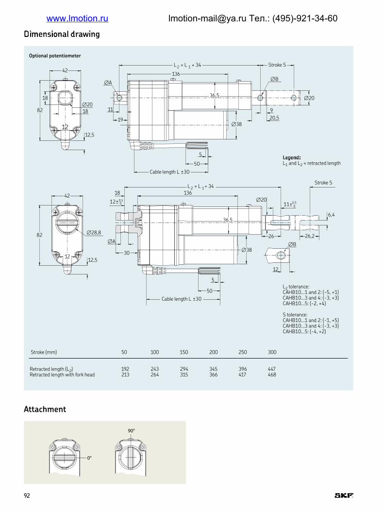
LqrquvwL1 and L2 = retracted length
0
∅
,
∅A
L = L +
Stroke S
∅B
,
∅
,
∅
5
50
Cable length L ±30
L = L +
∅,
,
12±0,5
Stroke S
11±0,50
∅
,
∅
∅A
,
,
∅B
5
50
Cable length L ±30
xz|~z rawing
Attachment
Optional potentiometer
0°
90°
Stroke (mm) 50 100 150 200 250 300
Retracted length (L2) 192 243 294 345 396 447Retracted length with fork head 213 264 315 366 417 468
L2 tolerance: CAHB10 1 and 2: (-5, +1)CAHB10 3 and 4: (-3, +3)CAHB10 5: (-2, +4)
S tolerance:CAHB10 1 and 2: (-1, +5)CAHB10 3 and 4: (-3, +3)CAHB10 5: (-4, +2)
9292
www.lmotion.ru [email protected] Тел.: (495)-921-34-60

White
Green
Brown
Retract Extend
White0
GreenCW
Brown1OK
Stroke [mm] 50~80 80~160 160~300
Minimum resistence value of potentiometer 700~1 300 Ω 700~1 300 Ω 700~1 300 ΩPotentiometer resolution 100 Ω/mm 50 Ω/mm 16,6 Ω/mm
Type CAHB-10 1 CAHB-10 2 CAHB-10 3 v CAHB-10 4 CAHB-10 5
Mm/pulse 0,3 0,15 0,075 0,05 0,038
Eoder resolution
+
–
+
–
Basic coniguration 2-Hall encoder
12/24 V DC 12/24 V DC
Black Red
Limit switches
Actuator
Retraction Extension
ExtensionRetraction
Black Red
Limit switches
Actuator
2-Hall encoder signal
Hall 1
Hall 2
+5 VGND
Hall AHall B
Connecting diagram
Potentiometer resolution
Potentiometer
POTLimit + POT:
9393
www.lmotion.ru [email protected] Тел.: (495)-921-34-60

T
12 V DC A24 V DC B
L120 N 1240 N 2500 N 3750 N 41 000 N 5
ScrewTR12 screw ACustomized X
Stroke50 mm 050100 mm 100150 mm 150200 mm 200250 mm 250300 mm 300
Retracted length1)
Stroke without potentiometer:2)
50 mm100 mm150 mm 200 mm 250 mm 300 mm
IPStandard (IP 66s) A
Front attachmentRod with hole ∅ 6,4 mm ARod with hole ∅ 8 mm BFork head with hole ∅ 10,1 mm CCustomized X
Rear attachmentRod with hole ∅ 6,4 mm ARod with hole ∅ 8 mm BFork head with hole ∅ 10,1 mm CCustomized X
Hole direction of the attachments0° A90° B
Option 1None OPotentiometer P2-Hall encoder H
Cable lenght:600 mm without connector A1 000 mm without connector B1 500 mm without connector C2 000 mm without connector D2 500 mm without connector E3 000 mm without connector FCustomized X
Auxiliary code (Standard products are “000”)
C A H B – 1 0 – – – A – 0 0 0
1) Retracted lenght will be englared 34 mm with Potentiometer option2) Front attachment + Rear attachment; A, B, C mean the attachment types
A(B)+A(B) A(B)+C C+A(B) C+C158 165 172 179209 216 223 230260 267 274 281311 318 325 332362 369 376 383413 420 427 434
Ordering key
9494
www.lmotion.ru [email protected] Тел.: (495)-921-34-60

CAHB-20A
Linear actuator
Beneits
• ACME screw drive
• Extension tube (stainless steel)
• Protection tube (steel)
• Enhanced corrosion resistance
• Mechanical overload protection (clutch)
• Lubricated for service life
• Robust, designed for tough environment
• Self-locking
• Certiied (CE: EN 55011)
Designation Unit CAHB-20 1 CAHB-20 2
Performance dataPush load N 1 500 2 500Pull load N 1 500 2 500Speed (full load to no load) mm/s 27 to 33 13 to 17Stroke mm 102 to 610 102 to 610Retracted length mm –* –* mm –* –*Voltage V DC 12 or 24 12 or 24Power consumption W N/A N/ACurrent consumption 12 V DC A 16 14 24 V DC A 8 7Duty cycle % 25 25Ambient temperature °C –40 to +85 –40 to +85Type of protection IP 66 66Weight (at 305 mm stroke) kg 5,5 5,5Color – Black Black
* see dimensional drawing page 97 and 98
Technical data
9696
www.lmotion.ru [email protected] Тел.: (495)-921-34-60

Current consumption [A]12 V DC 24 V DC
L124,5
73,5 30(55*)
11,5
∅ 13,1 +0,1–0
∅ 28,6
Ferrite Bead(for 12 V DC only)
161,5 130±15
600±30
76
150,5
47,5
15,514
38
47,5
∅ 26
∅ 13,1
∅ 72
†50,8
∅ 63,5
+0,1–0
35
Dimensional drawing
Performance diagrams
50
40
30
20
10
0
0 500 1 000 1 500 2 000 2 500
18
16
12
8
4
0
10
8
6
4
2
0 500 1 000 1 500 2 000 2 500
Speed and load Current load
Speed [mm/s]
Load [N] Load [N]
CAHB-20 1CAHB-20 2
CAHB-20 1CAHB-20 2
Basic coniguration (dashed line for optional limit switch)
Without limit swicth:RED (+) & BLACK (–) = retractionRED (–) & BLACK (+) = extension
With limit switch:RED (+) & BLACK (–) = extensionRED (–) & BLACK (+) = retraction
Legend:L1 = retracted length*55 = dimension with limit switch
With limit switch1) Without limit switch2)
Stroke [mm] 102 153 204 305 457 610 102 153 204 305 457 610L1 Retracted length 338 389 440 592 744 897 262 313 364 465 668 821
1) Tolerance: S and L1 = ± 5,0 mm (If S≥305 mm, S = ± 7,5 mm)2) Tolerance: S = ± 2,5 mm and L = ±3,8 mm
9797
www.lmotion.ru [email protected] Тел.: (495)-921-34-60

Retract Extend
White0
White
POTLimit + POT:
GreenCW
Green
Brown10K
Brown
76
38
150,5
∅ 26
∅ 13,1+0,1–0
24,515,514
111,5
L2
600±30
130±15
30(55*)11,5
Ferrite Bead(for 12 V DC only)
199
∅ 13,1+0,1–0
∅ 28,6
450±15
†63,5
∅ 50,8
Dimensional drawing
Optional potentiometer (dashed line for optional limit switch)
Legend:L2 = retracted length*55 = dimension with limit switch
Without limit swicth:RED (+) & BLACK (–) = retractionRED (–) & BLACK (+) = extension
With limit switch:RED (+) & BLACK (–) = extensionRED (–) & BLACK (+) = retraction
With limit switch1) Without limit switch2)
Stroke [mm] 102 153 204 305 457 610 102 153 204 305 457 610
L1 Retracted length 376 427 478 630 782 935 300 351 402 503 706 859
1) Tolerance: S and L1 = ± 5,0 mm (If S≥305 mm, S = ± 7,5 mm)2) Tolerance: S = ± 2,5 mm and L2 = ± 3,8 mm
Stroke [mm] 102 153 204 305 457 610
Ohm/mm 59,0 59,0 29,5 29,5 9,84 9,84
Potentiometer resolution
Connecting diagram Different rear attachment
+12/24 V DC
MActuator
Red
Ret.
Black
Ext.
30°
30°
30°
30°
F
ED
C
B
A–F
30
°
A
9898
www.lmotion.ru [email protected] Тел.: (495)-921-34-60
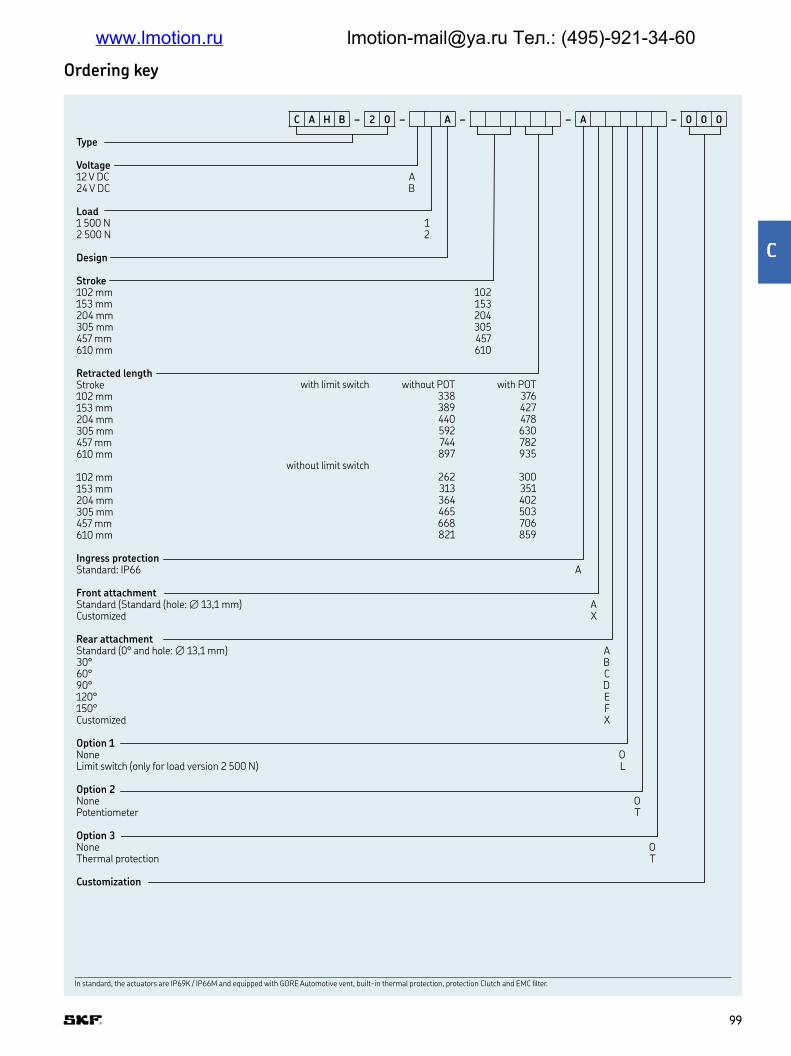
Ordering key
Type
Voltage12 V DC A24 V DC B
Load1 500 N 12 500 N 2
Design
Stroke102 mm 102153 mm 153204 mm 204305 mm 305457 mm 457610 mm 610
Retracted lengthStroke102 mm153 mm204 mm305 mm457 mm610 mm
102 mm153 mm204 mm305 mm457 mm610 mm
Ingress protectionStandard: IP66 A
Front attachmentStandard (Standard (hole: ∅ 13,1 mm) ACustomized X
Rear attachmentStandard (0° and hole: ∅ 13,1 mm) A30° B60° C90° D120° E150° FCustomized X
Option 1None OLimit switch (only for load version 2 500 N) L
Option 2None OPotentiometer T
Option 3None OThermal protection T
Customization
In standard, the actuators are IP69K / IP66M and equipped with GORE Automotive vent, built-in thermal protection, protection Clutch and EMC ilter
with limit switch without POT with POT338 376389 427440 478592 630744 782897 935
without limit switch262 300313 351364 402465 503668 706821 859
C A H B – 2 0 – A – – A – 0 0 0
9999
www.lmotion.ru [email protected] Тел.: (495)-921-34-60
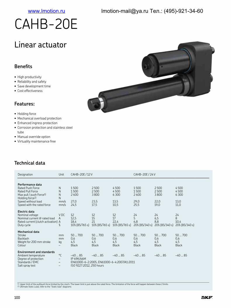
CAHB-20E
Linear actuator
Beneits
• High productivity
• Reliability and safety
• Save development time
• Cost effectiveness
Features:
• Holding force
• Mechanical overload protection
• Enhanced ingress protection
• Corrosion protection and stainless steel
tube
• Manual override option
• Virtuality maintenance free
Designation Unit CAHB-20E / 12 V CAHB-20E / 24 V
Performance dataRated Push Force N 1 500 2 500 4 500 1 500 2 500 4 500Rated Pull Force N 1 500 2 500 4 500 1 500 2 500 4 500Max pull / push Force1) N 2 600 3 800 6 300 2 600 3 800 6 300Holding force2) NSpeed without load mm/s 27,0 23,5 13,5 29,0 22,0 13,0Speed with the rated force mm/s 24,5 17,5 10,5 25,5 19,0 11,0
Electric dataNominal voltage V DC 12 12 12 24 24 24Nominal current @ rated load A 12,5 15 17 5 6,5 8Rated current (clutch activation) A 18,4 21 22,4 6,8 8,8 10,4Duty cycle % 10% (85/765 s) 10% (85/765 s) 10% (85/765 s) 20% (85/340 s) 20% (85/340 s) 20% (85/340 s)
Mechanical dataStroke mm 50 … 700 50 … 700 50 … 700 50 … 700 50 … 700 50 … 700Backlash mm 0,6 0,6 0,6 0,6 0,6 0,6Weight for 200 mm stroke kg 4,5 4,5 4,5 4,5 4,5 4,5Colour – Black Black Black Black Black Black
Environment and standardsAmbient temperature °C –40 … 85 –40 … 85 –40 … 85 –40 … 85 –40 … 85 –40 … 85Degree of protection – IP 69K/66MStandards / EMC – EN61000-6-2:2005, EN61000-6-4:2007/A1:2011Salt spray test – ISO 9227:2012, 250 hours
1) Upper limit of the pull/push force limited by the clutch The lower limit is just above the rated force The limitation of the force will happen between these 2 limits 2) Ultimate Static Load, refer to the “Static load” diagrams
Technical data
100100
www.lmotion.ru [email protected] Тел.: (495)-921-34-60
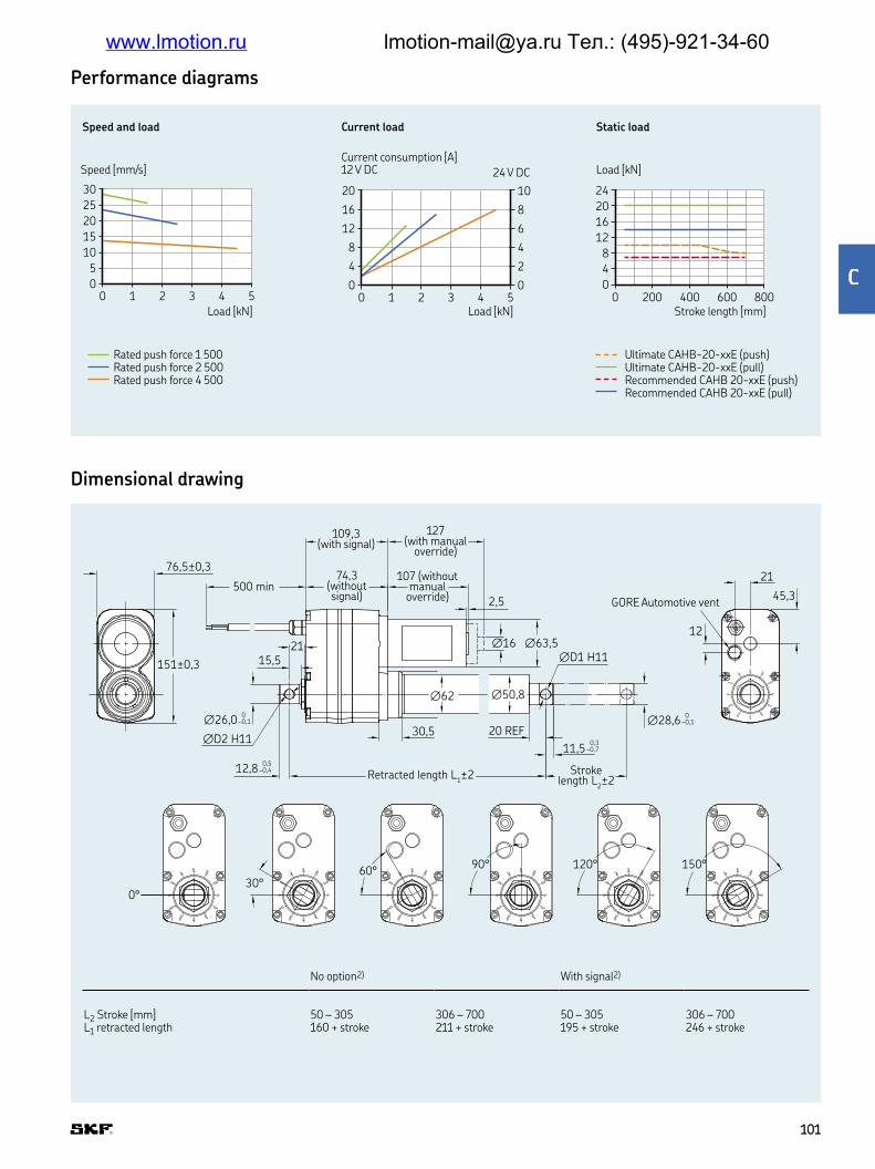
No option2) With signal2)
L2 Stroke [mm] 50 – 305 306 – 700 50 – 305 306 – 700L1 retracted length 160 + stroke 211 + stroke 195 + stroke 246 + stroke
Speed and load Current load Static load
30
25
20
15
10
5
0
0 1 2 3 4 5
20
16
12
8
4
0
0 1 2 3 4 5
10
8
6
4
2
0
24
20
16
12
8
4
0
0 200 400 600 800
Speed [mm/s]
Load [kN] Load [kN]
Current consumption [A]12 V DC 24 V DC Load [kN]
Stroke length [mm]
Ultimate CAHB-20-xxE (push)Ultimate CAHB-20-xxE (pull)Recommended CAHB 20-xxE (push)Recommended CAHB 20-xxE (pull)
Rated push force 1 500Rated push force 2 500Rated push force 4 500
∅62 ∅50,8
0°
03°
06°09°
020°
050°
0°
03°
06° 09°
020°
050°
0°
03°
06°09°
120°
150°
0°
03°
06° 09°
120°
150°
0°
03°
06°09°
120°
150°
0°
03°
06° 09°
120°
150°
0°
03°
06°09°
120°
150°
0°
03°
06° 09°
120°
150°
0°
03°
06°09°
120°
150°
0°
03°
06° 09°
120°
150°
0°
03°
06°09°
120°
150°
0°
03°
06° 09°
120°
150°
0°
03°
06°09°
120°
150°
0°
03°
06° 09°
120°
150°
30,5 20 REF
21
45,3
12
2115,5
500 min
76,5±0,3
151±0,3 ∅D1 H11
∅D2 H11
0∅28,6 –0,1
0∅26,0 –0,1
0,311,5 –0,7
0,512,8 –0,4
∅16 ∅63,5
2,5
0°30°
60°90° 120° 150°
Retracted length L1±
,(with signal)
,(withoutsignal)
(withoutmanual
override) GORE Automotive vent
(with manual
override)
Strokelength L
2±
Dimensional drawing
Performance diagrams
101101
www.lmotion.ru [email protected] Тел.: (495)-921-34-60

Wire connection with no signal
Wire no. AWG Colour Application
1 14 Red Motor power(+)=> Extension, (–)=> Retraction
2 14 Black Motor power(–)=> Extension, (+)=> Retraction
Electrical speciications
Wire connection with potentiometer
Wire no. AWG Colour Application
1 22 Green See picture description2 22 White See picture description3 22 Brown See picture description4 14 Red Motor power(+)=> Extension, (–)=> Retraction5 14 Black Motor power(–)=> Extension, (+)=> Retraction
Potentiometer
Wire connection with encoder
Wire no. AWG Colour Application
1 26 Green Sensor signal 1 Encoder2 26 Yellow Sensor signal 2 Encoder3 26 Black Sensor power GNO Encoder4 26 Red Sensor power 5 V Encoder5 14 Red Motor power(+)=> Extension, (–)=> Retraction6 14 Black Motor power(–)=> Extension, (+)=> Retraction
Encoder
Feedback resolution list
Actuator type Hall sensor resolution [pulses/mm]
POT resolution [ohm/mm]
CAHB-20…E 2,76 59,06 if S = 050-12529,53 if S = 126-2509,84 if S = 251-700
Retract Extend
White 0
Green CW
Brown 10K
POTLimit+POT:
Hall 1
Hall 2
Hall 1
Hall 2
Signal CCW extension
Signal CW retraction
Retractio
n
Extension
Release the motor cover (1) Use the slot (2) to rotate the motor shaft (3) in the proper direction
1 23 Inner side of motor front
102102
www.lmotion.ru [email protected] Тел.: (495)-921-34-60

T
V DC A24 V DC B12 V DC with manual override E24 V DC with manual override F
Load1 500 N 12 500 N 24 500 N 3
DesignE
Stroke100 mm 100150 mm 150 200 mm 200 250 mm 250 300 mm 300 350 mm 350 400 mm 400 450 mm 450 500 mm 500 600 mm 600 700 mm 700
Retracted lengthStroke100 mm150 mm200 mm250 mm300 mm350 mm400 mm450 mm500 mm600 mm700 mm
Ingress protectionStandard: IP69K/IP66M B
Attachment diameter: (Front and rear)Hole Ø13,1 H11 (+0, +0,11 mm) AHole Ø12,8 H11 (0, +0,11 mm) BHole Ø12,5 H11 (+0, +0,11mm) CHole Ø14 H11(+0,+0,11mm) DHole 12.2 H11(+0,+0,11mm) ECustomized X
Attachment orientationStandard (0°) A30° B60° C90° D120° E150° FCustomized X
Option 1: Limit switchNot available 0
Option 2: FeedbackNone 0Potentiometer PEncoder E
Thermal protectionStandard: Built-in thermal switch T
CustomizationStroke length, retracted length, cable, connector, front attachment, rear attachment, color, de-rated load
Ordering key
without POT or encoder with POT or encoder260 295310 345360 395410 445460 495561 596611 646661 696711 746811 846911 946
In standard, the actuators are IP69K / IP66M and equipped with GORE Automotive vent, built-in thermal protection, protection Clutch and EMC ilter.
C A H B 2 0 – E – – B 0 T – 0 0 0
103103
www.lmotion.ru [email protected] Тел.: (495)-921-34-60
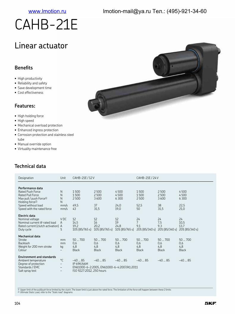
CAHB-21E
Linear actuator
Beneits
• High productivity
• Reliability and safety
• Save development time
• Cost effectiveness
Features:
• High holding force
• High speed
• Mechanical overload protection
• Enhanced ingress protection
• Corrosion protection and stainless steel
tube
• Manual override option
• Virtuality maintenance free
Designation Unit CAHB-21E / 12 V CAHB-21E / 24 V
Performance dataRated Push Force N 1 500 2 500 4 500 1 500 2 500 4 500Rated Pull Force N 1 500 2 500 4 500 1 500 2 500 4 500Max pull / push Force1) N 2 500 3 600 6 300 2 500 3 600 6 300Holding force2) NSpeed without load mm/s 49,5 37 24,0 52,5 38 22,5Speed with the rated force mm/s 43 31,5 19,0 50 31,5 21,0
Electric dataNominal voltage V DC 12 12 12 24 24 24Nominal current @ rated load A 14,5 16 19 7 7,5 10,5Rated current (clutch activation) A 19,2 20,2 24,8 9,1 9,3 13,7Duty cycle % 10% (85/765 s) 10% (85/765 s) 10% (85/765 s) 20% (85/340 s) 20% (85/340 s) 20% (85/340 s)
Mechanical dataStroke mm 50 … 700 50 … 700 50 … 700 50 … 700 50 … 700 50 … 700Backlash mm 0,6 0,6 0,6 0,6 0,6 0,6Weight for 200 mm stroke kg 4,8 4,8 4,8 4,8 4,8 4,8Colour – Black Black Black Black Black Black
Environment and standardsAmbient temperature °C –40 … 85 –40 … 85 –40 … 85 –40 … 85 –40 … 85 –40 … 85Degree of protection – IP 69K/66MStandards / EMC – EN61000-6-2:2005, EN61000-6-4:2007/A1:2011Salt spray test – ISO 9227:2012, 250 hours
Technical data
1) Upper limit of the pull/push force limited by the clutch The lower limit is just above the rated force The limitation of the force will happen between these 2 limits 2) Ultimate Static Load, refer to the “Static load” diagrams
104104
www.lmotion.ru [email protected] Тел.: (495)-921-34-60

Dimensional drawing
No option2) With limit switch1) With signal2) With limit switch and signal1)
L2 Stroke [mm] 100 – 300 301 – 700 100 – 300 301 – 700 100 – 300 301 – 700 100 – 300 301 – 700L1 retracted length 182 +stroke 217 +stroke 191 +stroke 226 +stroke 217 +stroke 252 +stroke 226 +stroke 261 +stroke
Tolerance L2: Stroke S1) Tolerance S, if S ≤300 (∓2); if S >300 (∓3)2) Tolerance S, if S ≤300 (–2, –0,5); if S >300 (–3, –1)
Speed and load Current load Static load
60
50
40
30
20
10
0
0 1 2 3 4 5
25
20
15
10
5
00 1 2 3 4 5
12,5
10
7,5
5
2,5
0
24
20
16
12
8
4
00 200 400 600 800
Speed [mm/s]
Load [kN] Load [kN]
Current consumption [A]12 V DC 24 V DC Load [kN]
Stroke length [mm]
Ultimate CAHB-21-xxE (push)Ultimate CAHB-21-xxE (pull)Recommended CAHB-21-xxE (push)Recommended CAHB-21-xxE (pull)
0°
03°
06°09°
020°
050°
0°
03°
06° 09°
020°
050°
0°
03°
06°09°
120°
150°
0°
03°
06° 09°
120°
150°
0°
03°
06°09°
120°
150°
0°
03°
06° 09°
120°
150°
0°
03°
06°09°
120°
150°
0°
03°
06° 09°
120°
150°
0°
03°
06°09°
120°
150°
0°
03°
06° 09°
120°
150°
0°
03°
06°09°
120°
150°
0°
03°
06° 09°
120°
150°
0°
03°
06°09°
120°
150°
0°
03°
06° 09°
120°
150°
15,5 Min 38,3REF
21
15,5 Min
500 min
76,5 REF
∅63,5
∅D1 H11
∅D2 H11
0∅28,6 –0,1
∅62,4 0,60
0∅26,0 –0,1
0,311,5 –0,7
0,512,8 –0,4
151 REF
∅16
2,5
0°
Retracted length L1± Stroke
length L2
,(with signal)
,(withoutsignal)
(withoutmanual
override) GORE Automotive vent
(with manual
override)
30°60°
90° 120° 150°
Performance diagrams
Rated push force 1 500Rated push force 2 500Rated push force 4 500
105105
www.lmotion.ru [email protected] Тел.: (495)-921-34-60

Wire connection with no signal
Wire no. AWG Colour Application
1 14 Red Motor power(+)=> Extension, (–)=> Retraction
2 14 Black Motor power(–)=> Extension, (+)=> Retraction
Feedback resolution list
Actuator type Hall sensor resolution [pulses/mm]
POT resolution [ohm/mm]
CAHB-21…E 1,56 33,33 if S = 050-22216,67 if S = 223-4445,56 if S = 445-700
Wire connection with potentiometer
Wire no AWG Colour Application
1 22 Green See picture description2 22 White See picture description3 22 Brown See picture description4 14 Red Motor power(+)=> Extension, (–)=> Retraction5 14 Black Motor power(–)=> Extension, (+)=> Retraction
Wire connection with encoder
Wire no AWG Colour Application
1 26 Green Sensor signal 1 Encoder2 26 Yellow Sensor signal 2 Encoder3 26 Black Sensor power GNO Encoder4 26 Red Sensor power 5 V Encoder5 14 Red Motor power(+)=> Extension, (–)=> Retraction6 14 Black Motor power(–)=> Extension, (+)=> Retraction
Potentiometer
Encoder
Hall 1
Hall 2
Hall 1
Hall 2
Signal CCW extension
Signal CW retraction
Electrical speciications
Retractio
n
Extension
1 23 Inner side of motor front
Retract Extend
White 0
Green CW
Brown 10K
POTLimit+POT:
Release the motor cover (1) Use the slot (2) to rotate the motor shaft (3) in the proper direction
106106
www.lmotion.ru [email protected] Тел.: (495)-921-34-60

Type
Voltage12 V DC A24 V DC B12 V DC with manual override E24 V DC with manual override F
Load1 500 N 12 500 N 24 500 N 3
DesignE
Stroke100 mm 100150 mm 150200 mm 200250 mm 250300 mm 300350 mm 350400 mm 400450 mm 450500 mm 500600 mm 600700 mm 700
Retracted lengthStroke100 mm150 mm200 mm250 mm300 mm350 mm400 mm450 mm500 mm600 mm700 mm
100 mm150 mm200 mm250 mm300 mm350 mm400 mm450 mm500 mm600 mm700 mm
Ingress protectionStandard: IP69K/IP66M B
Attachment diameter: (Front and rear)Hole Ø13,1 H11 (+0, +0,11 mm) AHole Ø12,8 H11 (0, +0,11 mm) BHole Ø12,5 H11 (+0, +0,11mm) CHole Ø14 H11(+0,+0,11mm) DHole 12.2 H11(+0,+0,11mm) ECustomized X
Attachment orientationStandard (0°) A30° B60° C90° D120° E150° FCustomized X
Option 1: Limit switchNone (mandatory for 1 500 N and 2 500 N version) 0Limit switch (valid only for load version 4 500) L
Option 2: FeedbackNone 0Potentiometer PEncoder E
Thermal protectionStandard: Built-in thermal switch T
CustomizationStroke length, retracted length, cable, connector, front attachment, rear attachment, color, de-rated load
Ordering key
In standard, the actuators are IP69K / IP66M and equipped with GORE Automotive vent, built-in thermal protection, protection Clutch and EMC ilter.
C A H B 2 1 – E – – B T – 0 0 0
with limith switch without POT or encoder with POT or encoder291 326341 376391 426441 476491 526576 611626 661676 711726 761826 861926 961
without limith switch282 317332 367382 417432 467482 517567 602617 652667 702717 752817 852917 952
107107
www.lmotion.ru [email protected] Тел.: (495)-921-34-60

CAHB-22E
Linear actuator
Beneits
• High productivity
• Reliability and safety
• Save development time
• Cost effectiveness
Features:
• High force
• High speed
• High holding force
• Mechanical overload protection
• Enhanced ingress protection
• Corrosion protection and stainless steel
tube
• Manual override option
• Virtuality maintenance free
Designation Unit CAHB-22E / 12 V CAHB-22E / 24 V
Performance dataRated Push Force N 2 300 3 500 6 800 10 000 2 300 3 500 6 800 10 000Rated Pull Force N 2 300 3 500 6 800 10 000 2 300 3 500 6 800 10 000Max pull / push Force1) N 3 500 4 900 9 500 14 000 3 500 4 900 9 500 14 000Holding force2) NSpeed without load mm/s 55,0 45,0 22,0 13,0 53,0 45,0 22,0 13,0Speed with the rated force mm/s 42,0 36,0 15,5 10,2 42,0 37,0 17,0 10,2
Electric dataNominal voltage V DC 12 12 12 12 24 24 24 24Nominal current @ rated load A 18 19,5 19,5 19 8 9,5 9,5 8,5Rated current (clutch activation) A 24,3 25,5 25,5 25 10,6 12,3 12,3 10,9Duty cycle % 10%
(85/765 s)10% (85/765 s)
10% (85/765 s)
10% (85/765 s)
20% (85/340 s)
20% (85/340 s)
20% (85/340 s)
20% (85/340 s)
Mechanical dataStroke mm 50 … 700 50 … 700 50 … 610 50 … 450 50 … 700 50 … 700 50 … 610 50 … 450Backlash mm 1,0 1,0 0,6 0,6 1,0 1,0 0,6 0,6Weight for 200 mm stroke kg 4,8 4,8 4,8 4,8 4,8 4,8 4,8 4,8Colour – Black Black Black Black Black Black Black Black
Environment and standardsAmbient temperature °C –40 … 85 –40 … 85 –40 … 85 –40 … 85 –40 … 85 –40 … 85 –40 … 85 –40 … 85Degree of protection – IP 69K/66MStandards / EMC – EN61000-6-2:2005, EN61000-6-4:2007/A1:2011Salt spray test – ISO 9227:2012, 250 hours
Technical data
1) Upper limit of the pull/push force limited by the clutch The lower limit is just above the rated force The limitation of the force will happen between these 2 limits 2) Ultimate Static Load, refer to the “Static load” diagrams
108108
www.lmotion.ru [email protected] Тел.: (495)-921-34-60

No option2) With limit switch1) With signal2) With limit switch and signal1)
L2 Stroke [mm] 100 – 305 306 – 700 100 – 305 306 – 700 100 – 305 306 – 700 100 – 305 306 – 700L1 retracted length 194 + stroke 229 + stroke 200 + stroke 235 + stroke 229 + stroke 264 + stroke 235 + stroke 270 + stroke
Tolerance L2: Stroke S1) Tolerance S: if S≤ 305: (±2); if S>305: (±3)2) Tolerance S: for CAHB22 3E/4E if S≤ 305: (–2, –0,5); if S>305: (–3, –1); for CAHB22 1E/2E if S≤ 305: (–3, –1,5); if S>305: (–4, –2)
Speed and load Current load Static load
60
50
40
30
20
10
0
0 2 4 6 8 10
25
20
15
10
5
00 2 4 6 8 10
12,5
10
7,5
5
2,5
0
24
20
16
12
8
4
00 200 400 600 800
Speed [mm/s]
Load [kN] Load [kN]
Current consumption [A]12 V DC 24 V DC Load [kN]
Stroke length [mm]
Ultimate CAHB-22-xxE (push)Ultimate CAHB-22-xxE (pull)Recommended CAHB 22-xxE (push)Recommended CAHB 22-xxE (pull)
12,8
0°
03°
06°09°
020°
050°
0°
03°
06° 09°
020°
050°
0°
03°
06°09°
120°
150°
0°
03°
06° 09°
120°
150°
0°
03°
06°09°
120°
150°
0°
03°
06° 09°
120°
150°
0°
03°
06°09°
120°
150°
0°
03°
06° 09°
120°
150°
0°
03°
06°09°
120°
150°
0°
03°
06° 09°
120°
150°
0°
03°
06°09°
120°
150°
0°
03°
06° 09°
120°
150°
0°
03°
06°09°
120°
150°
0°
03°
06° 09°
120°
150°
15,5 38,3Max
2,5
15,5 Min
500 min
76,5 Max
∅63,5∅D1 H11
∅D2 H11
0∅28,6 –0,1
0,6∅62,4 0
0∅26,0 –0,1
0,321–0,1
0,311,5 –0,7
0,5–0,4
151 Max
∅16
Retracted length L1 (0,+4) Stroke
length L2
,(with signal)
,(withoutsignal)
(no manualoverride)
GORE Automotive vent
(with manual
override)
0°30°
60°90° 120° 150°
Dimensional drawing
Performance diagrams
Rated push force 2 300Rated push force 3 500Rated push force 6 800Rated push force 10 000
109109
www.lmotion.ru [email protected] Тел.: (495)-921-34-60
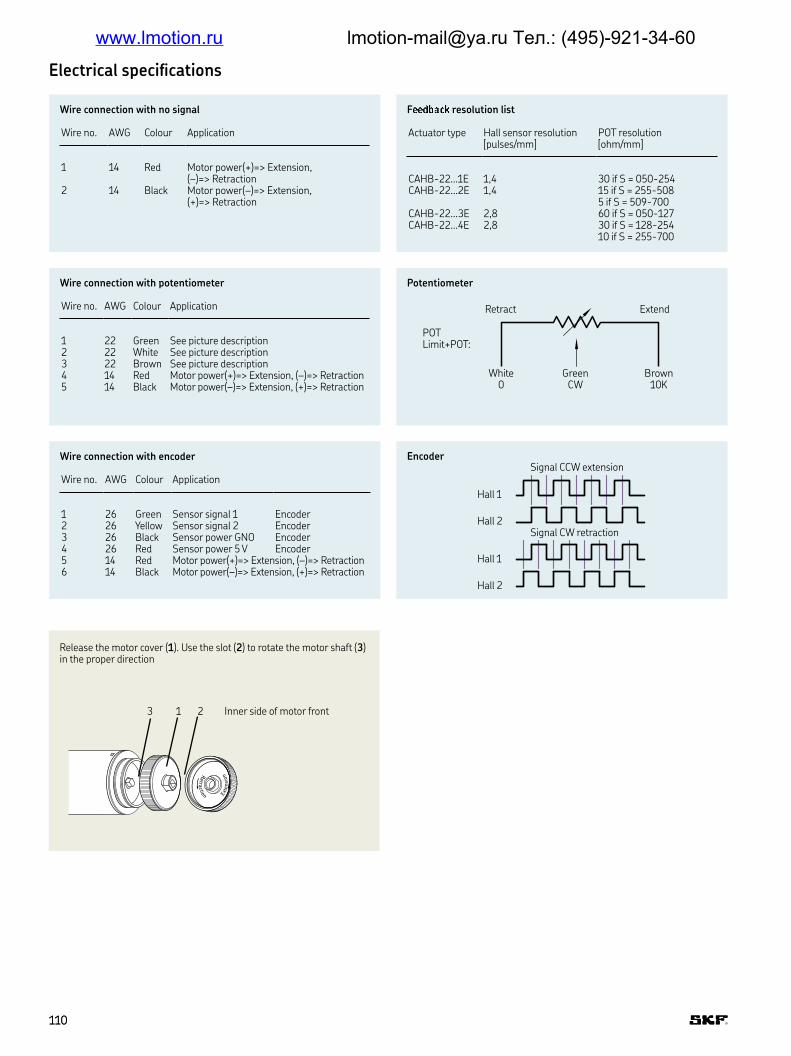
F¡¡¢£¤¥¦ resolution list
Actuator type Hall sensor resolution [pulses/mm]
POT resolution [ohm/mm]
CAHB-22…1E 1,4 30 if S = 050-254CAHB-22…2E 1,4 15 if S = 255-508
5 if S = 509-700CAHB-22…3E 2,8 60 if S = 050-127CAHB-22…4E 2,8 30 if S = 128-254
10 if S = 255-700
Electrical speciications
Retractio
n
Extension
1 23 Inner side of motor front
Wire connection with no signal
Wire no AWG Colour Application
1 14 Red Motor power(+)=> Extension, (–)=> Retraction
2 14 Black Motor power(–)=> Extension, (+)=> Retraction
Potentiometer
Encoder
Hall 1
Hall 2
Hall 1
Hall 2
Signal CCW extension
Signal CW retraction
Wire connection with potentiometer
Wire no AWG Colour Application
1 22 Green See picture description2 22 White See picture description3 22 Brown See picture description4 14 Red Motor power(+)=> Extension, (–)=> Retraction5 14 Black Motor power(–)=> Extension, (+)=> Retraction
Wire connection with encoder
Wire no AWG Colour Application
1 26 Green Sensor signal 1 Encoder2 26 Yellow Sensor signal 2 Encoder3 26 Black Sensor power GNO Encoder4 26 Red Sensor power 5 V Encoder5 14 Red Motor power(+)=> Extension, (–)=> Retraction6 14 Black Motor power(–)=> Extension, (+)=> Retraction
Retract Extend
White 0
Green CW
Brown 10K
POTLimit+POT:
Release the motor cover (1) Use the slot (2) to rotate the motor shaft (3) in the proper direction
110110
www.lmotion.ru [email protected] Тел.: (495)-921-34-60
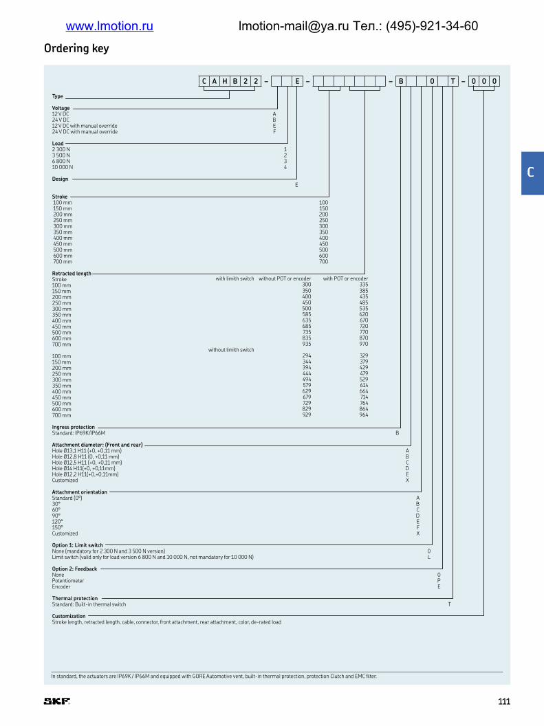
Type
Voltage12 V DC A24 V DC B12 V DC with manual override E24 V DC with manual override F
Load2 300 N 13 500 N 26 800 N 310 000 N 4
DesignE
Stroke 100 mm 100 150 mm 150 200 mm 200 250 mm 250 300 mm 300 350 mm 350 400 mm 400 450 mm 450 500 mm 500 600 mm 600 700 mm 700
Retracted lengthStroke100 mm150 mm200 mm250 mm300 mm350 mm400 mm450 mm500 mm600 mm700 mm
100 mm150 mm200 mm250 mm300 mm350 mm400 mm450 mm500 mm600 mm700 mm
Ingress protectionStandard: IP69K/IP66M B
Attachment diameter: (Front and rear)Hole Ø13,1 H11 (+0, +0,11 mm) AHole Ø12,8 H11 (0, +0,11 mm) BHole Ø12,5 H11 (+0, +0,11 mm) CHole Ø14 H11(+0, +0,11mm) DHole Ø12,2 H11(+0,+0,11mm) ECustomized X
Attachment orientationStandard (0°) A30° B60° C90° D120° E150° FCustomized X
Option 1: Limit switchNone (mandatory for 2 300 N and 3 500 N version) 0Limit switch (valid only for load version 6 800 N and 10 000 N, not mandatory for 10 000 N) L
Option 2: FeedbackNone 0Potentiometer PEncoder E
Thermal protectionStandard: Built-in thermal switch T
CustomizationStroke length, retracted length, cable, connector, front attachment, rear attachment, color, de-rated load
Ordering key
In standard, the actuators are IP69K / IP66M and equipped with GORE Automotive vent, built-in thermal protection, protection Clutch and EMC ilter.
with limith switch without POT or encoder with POT or encoder300 335350 385400 435450 485500 535585 620635 670685 720735 770835 870935 970
without limith switch294 329344 379394 429444 479494 529579 614629 664679 714729 764829 864929 964
C A H B 2 2 – E – – B 0 T – 0 0 0
111111
§
www.lmotion.ru [email protected] Тел.: (495)-921-34-60

CAHB-30A
Linear actuator
Beneits
• ACME screw drive
• Extension tube (stainless steel)
• Protection tube (steel)
• Enhanced corrosion resistance
• Mechanical overload protection (clutch)
• Maintenance free
• Robust, designed for tough environment
• Self-locking
• Motor with thermal protection
Unit CAHB–30A 1 CAHB–30A 2
Rated push load N 1 500 2 300Rated pull load N 1 500 2 300Speed (full load to no load) 115 V AC/60 Hz mm/s 25 to 26 12 to 13
230 V AC/50 Hz mm/s 21 to 22 11 to 12Stroke mm 102 to 610 102 to 610Retracted length mm –1) –1)
Voltage V AC 115 or 230 115 or 230Power consumption W N/A N/ACurrent consumption 115 V AC/60 Hz A 2,3 1,8
230 V AC/50 Hz A 1,35 1,4Duty cycle % 25 (94/376 s) 25 (94/376 s)Ambient temperature °C –26 to +65 –26 to +65Type of protection IP 65S 65SWeight kg 9 9Color – Black Black
Technical data
1) See dimensional drawing page 113For outdoors application, please contact SKF
112112
www.lmotion.ru [email protected] Тел.: (495)-921-34-60

76
L124,5
14
14
73,5
15,5
600±30269
∅87
∅87
∅13,1+0,1–0
∅13,1+0,1–0
∅28,6
∅28,6
30(55)*11,5
47,5
47,5156
38
∅26
∅26
∅72
∅50,8
∅50,8
35
∅13,1+0–0
,1
WhiteGreen
Brown
38
156
L224,5111,5 30(55)* 11,5
450±15
76
∅13,1+0,1–0
306,5 600±30
115/230 V AC60/50 Hz
Red
BlackExtension L
NRetraction
WhiteGreen
Ground
Motor
Legend
L1 = retracted length
* 55 = dimension with limit switch
Legend
L2 = retracted length
* 55 = dimension with limit switch
15,5
Retract Extend
White0
GreenCW
Brown10K
POTLimit + POT:
Dimensional drawing
Performance diagrams
1 (115 VAC)1 (230 VAC)2 (115 VAC)2 (230 VAC)
Speed-load diagram
0
6
12
18
24
30
0 500 1 000 1 500 2 000 2 500
Speed (mm/s)
Load (N)
Current-load diagram
0
0,5
1,0
1,5
2,0
2,5
0 500 1 000 1 500 2 000 2 500
Load (N)
Current consumtion (A)
Basic coniguration (dashed line for optional limit switch)
Optional potentiometer (dashed line for optional limit switch)
113113
¨
www.lmotion.ru [email protected] Тел.: (495)-921-34-60

Basic coniguration
With limit switch1) Without limit switch2)
Stroke (mm) 102 153 204 305 457 610 102 153 204 305 457 610
L1 Retracted length 440 440 440 592 744 897 380 415 415 465 668 821
Optional potentiometer
With limit switch1) Without limit switch2)
Stroke (mm) 102 153 204 305 457 610 102 153 204 305 457 610
L2 Retracted length 478 478 478 630 782 935 418 453 453 503 706 859
Potentiometer resolution
Stroke (mm) 102 153 204 305 457 610
Ohm/mm 59,0 59,0 29,5 29,5 9,84 9,84
Connecting diagram Different rear attachment
LN
115/230 V AC, 50/60 Hz
M
Actuator
Red Black White
PE
Green
30
°30°
30°30°
30°
C0
C5
C4C3
C2
C1
C0–C5
1) Tolerance: S and L1 = ± 5,0 mm (If S≥305 mm, S = ± 7,5 mm)2) Tolerance: S = ± 2,5 mm and L1 = ± 3,8 mm
1) Tolerance: S and L2 = ± 5,0 mm (If S≥305 mm, S = ± 7,5 mm)2) Tolerance: S = ± 2,5 mm and L2 = ± 3,8 mm
114114
www.lmotion.ru [email protected] Тел.: (495)-921-34-60

Type
Voltage115 V AC N230 V AC P
Load1 500 N 12 300 N 2
ScrewAcme screw A
Stroke102 mm 102153 mm 153204 mm 204305 mm 305457 mm 457610 mm 610
Retracted lengthStroke102 mm 153 mm 204 mm 305 mm 457 mm 610 mm
102 mm 153 mm 204 mm 305 mm 457 mm 610 mm
IPStandard (IP 65) A
Front attachmentStandard (hole: ∅ 13,1 mm) ACustomized X
Rear attachmentStandard (0° and hole: ∅ 13,1 mm) A30° B60° C90° D120° E150° FCustomized X
Option 1:None 0Limit switch (only for load version 2 300 N) L
Option 2:None 0Potentiometer P
Customization
Ordering key
C A H B 3 0 – A – – A 0 – 0 0 0
Options shown in blue are only available on request. Contact SKF for more information on minimum quantities and additional costs.
with limith switch1) without POT2) with POT2)
440 478440 478440 478592 630744 782897 935
without limith switch1)
380 418415 453415 453465 503668 706821 859
115115
©
www.lmotion.ru [email protected] Тел.: (495)-921-34-60

CAHB-31N
Linear actuator
Beneits
• High eficiency ball screw
• Extension tube (stainless steel)
• Protection tube (steel)
• Enhanced corrosion resistance
• Mechanical overload protection (clutch)
• Lubricated for service life
• Robust, designed for tough environment
• No back driving
• Motor with thermal protection
Unit CAHB–31N... 1 CAHB–31N... 2 CAHB–31N... 3
Rated push load N 2 300 4 500 6 000Rated pull load N 2 300 4 500 6 000Speed (full load to no load) 115 V AC/60 Hz mm/s 48 to 57 22 to 28 13 to 15
230 V AC/50 Hz mm/s 40 to 50 20 to 24 11 to 13Stroke mm 102 to 610 102 to 610 102 to 610Retracted length mm –1) –1) –1)
Voltage V AC 115 or 230 115 or 230 115 or 230Power consumption W N/A N/A N/ACurrent consumption 115 V AC/60 Hz A 3 2,6 2,2
230 V AC/50 Hz A 1,5 1,4 1,4Duty cycle % 25 (94/376 s) 25 (94/376 s) 25 (94/376 s)Ambient temperature °C –26 to +65 –26 to +65 –26 to +65Type of protection IP 65S 65S 65SWeight kg 9,5 9,5 9,5Color – Black Black Black
Technical data
1) See dimensional drawing page 117For outdoors application, please contact SKF
116116
www.lmotion.ru [email protected] Тел.: (495)-921-34-60

Speed-load diagram
0
15
30
45
60
75
0 1 000 2 000 3 000 4 000 5 000 6 000
Speed [mm/s]
Load [N]
Current-load diagram
0
0,6
1,2
1,8
2,4
3,0
0 1 000 2 000 3 000 4 000 5 000 6 000Load [N]
Current consumtion [A]
WhiteGreen
Brown
Retract Extend
White0
GreenCW
Brown10K
POTLimit + POT:
38
76
76
156
47,5
38
47,5
∅26
∅26
∅13,1 +0,1–0
35 600±30269
∅13,1+0, 1–0
∅13,1+0, 1–0
∅87
∅87
11,5
11,5
∅28,6
∅28,6
28(53)*
L1
24,573,5
1415,5
∅72
∅50,8
∅50,8
∅13,1+0 ,1–0
L2
450±15
306,5 600±30
156
24,5111,514
15,5
28(53)*
Legend
L1 = retracted length
* 53 = dimension with limit switch
Legend
L2 = retracted length
* 53 = dimension with limit switch
115/230 V AC60/50 Hz
Red
BlackExtension L
NRetraction
WhiteGreen
Ground
Motor
Dimensional drawing
Performance diagrams
1 (115 VAC)1 (230 VAC)2 (115 VAC)2 (230 VAC)3 (115 VAC)3 (230 VAC)
Basic coniguration (dashed line for optional limit switch)
Optional potentiometer (dashed line for optional limit switch)
117117
ª
www.lmotion.ru [email protected] Тел.: (495)-921-34-60

«¬® ¯¬°¬ ±²¬³®1) «¬®´µ ¯¬°¬ ±²¬³®2)
Stroke (mm) 102 153 204 305 457 610 102 153 204 305 457 610
L1 Retracted length 444 444 495 659 811 964 380 419 419 521 735 888
Connecting diagram Different rear attachment
LN
115/230 V AC, 50/60 Hz
M
Actuator
Red Black White
PE
Green
30
°30°
30°30°
30°
C0
C5
C4C3
C2
C1
C0–C5
1) Tolerance: S and L1 = ± 5,0 mm (If S≥305 mm, S = ± 7,5 mm)2) Tolerance: S = ± 2,5 mm and L1 = ± 3,8 mm
Optional potentiometer
Potentiometer resolutionStroke (mm) 102 153 204 305 457 610
Ohm/mm 59,0 59,0 29,5 29,5 9,84 9,84
Basic coniguration
With limit switch1) Without limit switch2)
Stroke (mm) 102 153 204 305 457 610 102 153 204 305 457 610
L2 Retracted length 482 482 533 697 849 1 002 418 457 457 559 773 926
1) Tolerance: S, L1 and L2 = ± 5,0 mm (If S≥305 mm, S = ± 7,5 mm)2) Tolerance: S = ± 2,5 mm and L1, L2 = ± 3,8 mm
118118
www.lmotion.ru [email protected] Тел.: (495)-921-34-60

Ordering key
Type
Voltage115 V AC N230 V AC P
Load2 300 N 14 500 N 26 000 N 3
ScrewBall screw N
Stroke102 mm 102153 mm 153204 mm 204305 mm 305457 mm 457610 mm 610
Retracted lengthStrokewith limith switch 102 mm 153 mm 204 mm 305 mm 457 mm 610 mm without limith switch102 mm 153 mm 204 mm 305 mm 457 mm 610 mm
IPStandard (IP 65) A
Front attachmentStandard (hole: ∅ 13,1 mm) ACustomized 4
Rear attachmentStandard (0° and hole: ∅ 13 mm) A30° B60° C90° D120° E150° FCustomized X
Option 1:None 0Limit switch (only for load version 6 000 N) L
Option 2:None 0Potentiometer P
Customization
C A H B 3 1 – – N – – A – 0 – 0 0 0
without POT with POT444 482444 482495 533659 697811 849964 A02 (1 002 mm)
380 418419 457419 457521 559735 773888 926
Options shown in blue are only available on request Contact SKF for more information on minimum quantities and additional costs
119119
¶
www.lmotion.ru [email protected] Тел.: (495)-921-34-60

·AHB series - Environmental tests
Climatic tests
CAHB-20xE, CAHB-21xE, CAHB-22xE CAHB-10 CAHB-30, CAHB-31
Test and Standard Performance Report No Performance Report No Performance Report No
Cold test EN60068-2-1 (Ab)
Storage at low temperature PH_TR0295 Storage at low temperature “Low temperature for CAHB-10”
Storage at low temperature: PH_TR0265Temperature: –40 °C Temperature: –40 °C Temperature: –40 °CDuration: 6 hours Duration: 96 hours Duration: 8 hoursNot connected Not connected Not connectedTested at room temperature Tested at room temperature Tested at room temperature
Cold test EN60068-2-1 (Ad)
Storage at low temperature PH_TR0295 Storage at low temperature “Low temperature for CAHB-10”
Storage at low temperature: PH_TR0265Temperature: –30 °C Temperature: –20 °C Temperature: –26 °CDuration: 6 hours Duration: 96 hours Duration: 8 hoursActuator is not activated/connected Actuator is not activated/connected Not connectedTested at low temperature Tested at low temperature Tested at room temperature
Dry Heat EN60068-2-2 (Bb)
Storage at high temperature PH_TR0278 Storage at high temperature “High temperature for CAHB-10”
– –Temperature: +90 °C Temperature: +85 °CDuration: 72 hours Duration: 96 hoursActuator is not activated/connected Actuator is not activated/connected Tested at room temperature Tested at room temperature
Change of temperature EN60068-2-14 (Na)
Rapid change of temperature PH_TR0278 – – – –High temperature: +100 °C in 60 min Low temperature: –30 in 60 min Transition time: < 10 secondsDuration: 100 cyclesActuator is not activated/connected Tested at room temperature
Salt mist EN60068-2-52 (Kb)
Salt spray test PH_TR0268 Salt spray test “Salt spray test for CAHB-10”
– –Salt solution: 5% sodium chloride (NaCl)
Salt solution: 5% sodium chloride (NaCl)
4 spraying periods, each of 2 hours 4 spraying periods, each of 2 hours Humidity storage 7 days after each Humidity storage 7 days after each Actuator not activated/connected Actuator not activated/connected Exposure time: 250 hours Exposure time: 96 hours
Degrees of protection IEC 60529
1 Test Item: IP6XM SHIN1607036235PS 1 Test Item: IP6XS COM12-GPE080184AN, COM12-GPE080183AN
– –Test Condition: Movement Test Condition: StaticTest Dust: Talcum powder Type of dust: Talcum powderDust Concentration: 2 kg/m3 cham-ber volume and be kept in suspen-sion during the test Test Duration: 8 hours Test Duration: 8 hours
Degrees of protection IEC 60529
2 Test Item: IPX6M SHIN1607036235PS 2 Test Item: IPX6S COM12-GPE080184AN, COM12-GPE080183AN
2 Test Item: IPX5S SHIN1608042057MRTest Condition: Movement Test Condition: Static Test Condition: StaticFlux: 100 L/min Flux: 100 (1 ±5%) L/min Flux: 12,5 L/minNozzle diameter: ∅ 12,5 mm Nozzle diameter: ∅ 12,5 mm Nozzle diameter: ∅ 6,3 mmDistance: 2,5 ~ 3,0 m Distance: 2,5 ~ 3,0 m Distance: 2,5 ~ 3,0 mTest duration: 3 min Test duration: 3 min Test duration: 3 min
Degrees of protection ISO 20653:2013
3 Test Item: IPX9K SHIN1607036235PS 3 Test Item: IPX9K SHIN1510048959MR-01 – –Test Condition: Static Test Condition: StaticJet angle: 2507 Jet angle: 2507Water low: 14~16 L/min Water low: 14~16 L/minWater pressure: 8 000~10 000 kPa Water pressure: 8 000~10 000 kPaWater temperature: 80 to -5 °C Water temperature: 80 to -5 °CTest angle: 0°, 30°, 60°, 90° Test angle: 0°, 30°, 60°, 90°Test distance from jet to sample: 100~150 mm
Test distance from jet to sample: 100~150 mm
Test duration: 30 s/position Test duration: 30 s/position
120120
www.lmotion.ru [email protected] Тел.: (495)-921-34-60
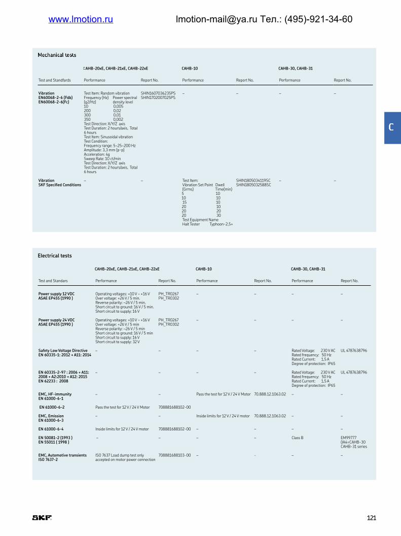
¸¹º»¼½¾º¼¿ À¹ÁÀs
ÂAHB-20xE, CAHB-21xE, CAHB-22xE CAHB-10 CAHB-30, CAHB-31
Test and Standfards Performance Report No Performance Report No Performance Report No
Vibration EN60068-2-6 (Fdb) EN60068-2-6(Fc)
Test Item: Random vibration SHIN1607036235PS SHIN1702007025PS
– – – –Frequency (Hz) Power spectral (g2/Hz) density level10 0,005200 0,02300 0,01350 0,002Test Direction: X/Y/Z axisTest Duration: 2 hours/axis, Total 6 hoursTest Item: Sinusoidal vibrationTest Condition: Frequency range: 5~25~200 HzAmplitude: 3,3 mm (p-p)Acceleration: 4gSweep Rate: 1O ct/minTest Direction: X/Y/Z axisTest Duration: 2 hours/axis, Total 6 hours
Vibration SKF Speciied Conditions
– – Test Item: SHIN1805034119SC SHIN1805032588SC
– –Vibration Set Point Dwell (Grms) Time(min)5 1010 10 15 1020 1020 2020 30Test Equipment NameHalt Tester Typhoon-2,5+
Electrical tests
CAHB-20xE, CAHB-21xE, CAHB-22xE CAHB-10 CAHB-30, CAHB-31
Test and Standars Performance Report No Performance Report No Performance Report No
Power supply 12 VDC ASAE EP455 (1990 )
Operating voltages: +10 V ~ +16 V PH_TR0267 PH_TR0302
– – – –Over voltage: +26 V / 5 min Reverse polarity: –26 V / 5 min Short circuit to ground: 16 V / 5 min Short circuit to supply: 16 V
Power supply 24 VDC ASAE EP455 (1990 )
Operating voltages: +10 V ~ +16 V PH_TR0267 PH_TR0302
– – – –Over voltage: +26 V / 5 minReverse polarity: –26 V / 5 minShort circuit to ground: 16 V / 5 minShort circuit to supply: 16 VShort circuit to supply: 32 V
Safety Low Voltage Directive EN 60335-1: 2012 + A11: 2014
– – – – Rated Voltage: 230 V AC UL 4787638796Rated frequency: 50 HzRated Current: 1,5 ADegree of protection: IP65
EN 60335-2-97 : 2006 + A11: 2008 + A2:2010 + A12: 2015EN 62233 : 2008
– – – – Rated Voltage: 230 V AC UL 4787638796Rated frequency: 50 HzRated Current: 1,5 ADegree of protection: IP65
EMC, HF-immunity EN 61000-6-1
– – Pass the test for 12 V / 24 V Motor 70 888 12 1063 02 – –
EN 61000-6-2 Pass the test for 12 V / 24 V Motor 708881688102-00
EMC, Emission EN 61000-6-3
– – Inside limits for 12 V / 24 V motor 70 888 12 1063 02 – –
EN 61000-6-4 Inside limits for 12 V / 24 V motor 708881688102-00 – – – –
EN 50081-2 (1993 ) EN 55011 ( 1998 )
– – – – Class B EM99777 (IA4=CAHB-30 CAHB-31 series
EMC, Automotive transients ISO 7637-2
ISO 7637 Load dump test only accepted on motor power connection
708881688103-00 – - – –
121121
Ã
www.lmotion.ru [email protected] Тел.: (495)-921-34-60

CAR, CAP & CAT seriesThe CAR, CAP, CAT modular design concept makes it easy to inter-
change critical components such as motors, gears, screws, attach-
ments, etc Custom-built actuators are easily and cost eficiently built
from standard parts The CAT range lexibility makes it suitable for a
high number of applications
Beneits
• Industrial reliable and robust actuator
• Wide range of components
• Right-hand and left-hand version
• Incremental or absolute
position feedback option
Features
• Compact
• Robust
• Modular
• Lubricated for service life
• High eficiency
123123
Ä
www.lmotion.ru [email protected] Тел.: (495)-921-34-60

CAR 22
Linear actuator
Beneits
• Reliable and robust industrial actuator
• Right- and left-hand version
• Maintenance free
Unit CAR 22
Rated push load N 1 000 to 1 500Rated pull load N 1 000 to 1 500Speed (full load to no load) mm/s 10 to 30Stroke mm 50 to 300Retracted length mm S+ 205Voltage V AC 12 or 24Power consumption W N/ACurrent consumption 12 V DC A 9
24 V DC A 5Duty cycle % 25Ambient temperature °C –20 to +70Type of protection IP 44Weight kg 1,2 to 1,6
Technical data
124124
www.lmotion.ru [email protected] Тел.: (495)-921-34-60

Performance diagrams
Duty cycle
CAR 22.../D12B CAR 22.../D24B
V [mm/s]
40
36
32
28
24
20
16
12
8
4
0
10
9
8
7
6
5
4
3
2
1
0
I [A]
0 200 400 600 800 1 000 1 200 1 400 100 300 500 700 900 1 100 1 300 1 500
Load [N]
V [mm/s]
Load [N]
I [A]
40
36
32
28
24
20
16
12
8
4
0
10
9
8
7
6
5
4
3
2
1
00 200 400 600 800 1 000 1 200 1 400
100 300 500 700 900 1 100 1 300 1 500
100
80
60
40
20
00 20 40 60 80 100
Duty factor [%] at 20 °C
Load [%]
V (mm/s)
I (A)
Gear 1 V (mm/s)
I (A)
Gear 2 V (mm/s)
I (A)
Gear 4
125125
Å
www.lmotion.ru [email protected] Тел.: (495)-921-34-60

∅104
M10 x 1,5∅22
R9
35
L = S + 205
∅10 e8
16
66,5
49
26
53
89
46
2323
60
16,5
Legend:S = strokeL = retracted length
Dimensional drawing
Suitable control and accessories
Connecting drawing
12/24 V DC
Limitswitch
Limitswitch
M
1
2
12
13
3
2
+
-
Control unit Limit switch
CAED
5-2
4R
CA
XE 2
2
D12B
D24B
Operating switches
CAES 31C
Hand switch
126126
www.lmotion.ru [email protected] Тел.: (495)-921-34-60

Type
Motor assemblyRight RLeft L
Stroke [S]50 mm 050100 mm 100150 mm 150200 mm 200300 mm 300Other stroke lengths ---
C A R 2 2 X X /
Load [N] / Full Load Speed [mm/s] Motor options
1 500/xx 1 000/xx No motor 01 500/15–10 1 000/30–20 12 V DC, lat motor, IP44 D12B1 500/15–10 1 000/30–20 24 V DC, lat motor, IP44 D24B
1 2
Ordering key
Options shown in blue are only available on request Contact SKF for more information on minimum quantities and additional costs
Item code Type code Order N°
12 VDC motor (lat motor) D12B M/040551624 VDC motor (lat motor) D24B M/0405517Limit switch for stroke =50 mm CAXE 22 × 50 M/0412019Limit switch for stroke =100 mm CAXE 22 × 100 M/0412020Limit switch for stroke =150 mm CAXE 22 × 150 M/0412021Limit switch for stroke =200 mm CAXE 22 × 200 M/0412022Limit switch for stroke =300 mm CAXE 22 × 300 M/0412023Proximity switch for CAXE CAXE Proximity switch M/0432369Front mounting attachments type Rod–end 575–22 M/0430575–22Front mounting attachments type Clevis 576–22 M/0430576–22Rear mounting attachments type Single ear bracket 580–22 M/0430580–22Rear mounting attachments type Ball–joint bracket 581–22 M/0430581–22Control unit (suitable for D24B motor) CAED 5–24R M/0420209Handset matched for CAED CAES 31C M/0420213
CAR 22 – Type codes for accessories and spare parts
127127
Æ
www.lmotion.ru [email protected] Тел.: (495)-921-34-60

CAP 32
Linear actuator
Beneits
• High eficiency ball screw
• Extension tube (stainless steel)
• Protection tube (steel)
• Enhanced corrosion resistance
• Mechanical overload protection (clutch)
• Lubricated for service life
• Robust, designed for tough environment
• No back driving
• Motor with thermal protection
Unit CAP 32 – AC version CAP 32 – DC version
Rated push load N 1 500 to 3 500 1 000 to 3 500Rated pull load N 1 500 to 3 500 1 000 to 3 500Speed (full load to no load) mm/s 6 to 321) 5 to 601)
Stroke mm 50 to 700 50 to 700Retracted length mm S+301 S+301
Voltage V AC 120 or 230 –V DC – 12 or 24
Power consumption 120 V AC W 98 (brake 133,2 W) N/A230 V AC W 92 (brake 117,3 W) –12 or 24 V DC W – N/A
Current consumption 120 V AC A 0,82 (brake +0,29 A) –230 V AC A 0,4 (brake + 0,11 A) –12 V DC A – 1324 V DC A – 824 V DC A – 5 (for motor D24CW)
Duty cycle % 30 25Ambient temperature °C –20 to +50 –20 to +50Type of protection IP 20/54 20/44Weight kg 2,9 to 5,0 2,9 to 5,0
Technical data
1) Depending on selected motor
128128
www.lmotion.ru [email protected] Тел.: (495)-921-34-60

Çerformance diagrams – AC version
Duty cycle – AC version
V (mm/s)
I (A)
Gear 1 V (mm/s)
I (A)
Gear 2 V (mm/s)
I (A)
Gear 4
Current-load diagram CAP 32 ... 120 V ACSpeed-load diagram CAP 32 ... 120 V AC
0
5
10
15
20
25
30
35
0 1,5 2,5 3,5Load [kN]
Speed [mm/s]
0
0,5
1,0
Current consumption [A]
0 1,5 2,5 3,5Load [kN]
Current-load diagram CAP 32 ... 230 V ÈCÉÊeed-load diagram CAP 32 ... 230 V ÈC
0
5
10
15
20
25
30
35
Speed [mm/s]
0
0,5
1,0
Current consumption [A]
0 1,5 2,5 3,5Load [kN]
0 1,5 2,5 3,5Load [kN]
CAP 32 ... 230/120 V AC
0
1 5002 5003 5001 2 4 6 µF (E220)/25 µF (E110)
4 µF (E220)/16 µF (E110)
3 µF (E220)/12 µF (E110)
1 5002 500 900
5009001 500
0 403010 50 60 70 80 90 100Duty factor (%)
F (N) Gear
129129
Ë
www.lmotion.ru [email protected] Тел.: (495)-921-34-60

Ìerformance diagrams – DC version
V (mm/s)
I (A)
Gear 1 V (mm/s)
I (A)
Gear 2 V (mm/s)
I (A)
Gear 4
CAP 32.../D24CW
CAP 32.../D12C CAP 32.../D24C/D24CS/D24CB
0
2
4
6
8
10
12
14
16
18
20
0
6
12
18
24
30
36
42
48
54
60
0 0,5 1 1,5 2 2,5 3,53
V (mm/s) I [A]
Load [kN]
0
2
4
6
8
10
12
14
16
18
20
0
6
12
18
24
30
36
42
48
54
60
V (mm/s) I [A]
Load [kN]
0
2
4
6
8
10
12
14
16
18
20
0
6
12
18
24
30
36
42
48
54
60
V (mm/s) I [A]
Load [kN]0 0,5 1 1,5 2 2,5 3,53 0 0,5 1 1,5 2 2,5 3,53
0 0,5 1 1,5 2 2,5 3,53
Duty cycle – DC version
0
20
40
60
80
100
0 20 40 60 80 100
Duty factor (%) at 20°C
Load (%)
130130
www.lmotion.ru [email protected] Тел.: (495)-921-34-60

R12
L = S + 301141
∅80
15525
28
109
159
55
27,5
2723
73
∅12 e8
20
M12×1,75
R12
28
20
58
25
L=S+301
155
141
M12×1,75
1 000 mm
55
27
23
73
100
300 mm (a)
300 mm (a)
∅ 120
∅ 75
∅ 12e8
74 (c)
100 (b)
27,5
300 mm (a)
∅ 120
ÍÎÏÐÑÒÎÓÑÔÕ Öra×ÎÑØ Ù ÚÛ Üersion
ÍÎÏÐÑÒÎÓÑÔÕ Öra×ÎÑØ Ù ÍÛ Üersion
Legend:S = strokeL = retracted length(a) = cable length(b) = cover for brake (D24CB)(c) = extended shaft (D24CS)
131131
Ý
www.lmotion.ru [email protected] Тел.: (495)-921-34-60

Þßààáâting diagram – AC version
L1
N
PE
CW
0 CC
W
120/230 V AC
Bla
ck
Bla
ck
1B
lack
Blu
e
White
Red
Red
Bro
wn
+1
40
°C
2
0Retract
CW 10K
Extend
White BrownGreen
Brown
White
Green
Connection diagram for
rotating potentiometer
Connecting diagram – DC version
0
Retract
CW 10K
Extend
White BrownGreen
Brown
White
Green
Connection diagram for
rotating potentiometer
M
2
13 2
13
12/24 V DC
Limit
switch
Limit
switch
1 2
+
-
Item code Type code Order N°
12 V DC motor (lat motor) D12C M/040551824 V DC motor (lat motor) D24C M/040551924 V DC motor (lat motor with brake) D24CB M/040552324 V DC motor (lat motor with extended shaft) D24CS M/040552224 V DC motor (lat motor with low speed) D24CW M/0405521120 V AC motor (cylindrical motor) E110C M/0405533120 V AC motor (cylindrical motor with brake) E110CB M/0405534230 V AC motor (cylindrical motor) E220C M/0405531230 V AC motor (cylindrical motor with brake) E220CB M/0405532Capacitor value 25 μF (120 V AC) Capacitor 25 μF M/0430670-06Capacitor value 6 μF (230 V AC) Capacitor 6 μF M/0430670-03Limit switch for stroke =50 mm CAXE 32 × 50 M/0412030Limit switch for stroke =100 mm CAXE 32 × 100 M/0412031Limit switch for stroke =200 mm CAXE 32 × 200 M/0412033Limit switch for stroke =300 mm CAXE 32 × 300 M/0412034Limit switch for stroke =500 mm CAXE 32 × 500 M/0412036Limit switch for stroke =700 mm CAXE 32 × 700 M/0412037Proximity switch for CAXE CAXE Proximity switch M/0432369Front mounting attachments type Rod-end 575–32 M/0430575–32Front mounting attachments type Clevis 576–32 M/0430576–32Rear mounting attachments type Single ear bracket 580–32 M/0430580–32Rear mounting attachments type Universal joint 582–32 M/0431780–32
CAP 32 – Type codes for accessories and spare parts
132132
www.lmotion.ru [email protected] Тел.: (495)-921-34-60

Ordering key
Type
Motor assembly:Right RLeft L
Stroke (S)50 mm 050100 mm 100200 mm 200300 mm 300400 mm 400500 mm 500700 mm 700Other stroke lengths – – –
OptionBack-up nut S
C A P 3 2 X X /
Dynamic load (N) / Speed (mm/s) Motor options
3 500xx 2 500/xx 1 500/xx No motor 00003 500/8 2 500/16 1 500/32 120 V AC/60 Hz, 1-phase, IP54 E110C3 500/8 2 500/16 1 500/32 120 V AC/60 Hz, 1-phase, brake, IP20 E110CB3 500/6 2 500/13 1 500/26 230 V AC/50 Hz, 1-phase, IP54 E220C3 500/6 2 500/13 1 500/26 230 V AC/50 Hz, 1-phase, brake, IP20 E220CB3 500/xx 2 500/xx 1 500/xx No motor 00002 500/15–10 2 000/30–20 1 000/60–40 12 V DC, lat motor, IP44 D12C3 500/15–10 2 500/30–20 1 500/60–40 24 V DC, lat motor, IP44 D24C3 500/9–5 2 500/18–10 1 500/34–24 24 V DC, lat motor, low speed, IP44 D24CW3 500/15–10 2 500/30–20 1 500/60–40 24 V DC, lat motor, extended shaft, IP44 D24CS3 500/15–10 2 500/30–20 1 500/60–40 24 V DC, lat motor, brake, IP20 D24CB
1 2 4
Options shown in blue are only available on request Contact SKF for more information on minimum quantities and additional costs
133133
ã
www.lmotion.ru [email protected] Тел.: (495)-921-34-60

CAT 32B and CAP 43B
Linear actuator
Beneits
• Compact
• Robust
• Modular
• Lubricated for service life
• High eficiency
• Digital encoder feedback
Unit CAT 32B – AC version CAT 32B – DC version CAP 43B
Rated push load N 1 500 to 3 500 1 000 to 4 000 1 500 to 4 000Rated pull load N 1 500 to 3 500 1 000 to 4 000 1 500 to 4 000Speed (at full load) mm/s 6,5 to 321) 5 to 521) 5 to 651)
Stroke mm 50 to 700 50 to 700 50 to 700Retracted length mm S+167/175/2062) S+167/175/2062) S+167/175/2062)
Voltage V AC 120, 230 or 400 – –V DC – 12 or 24 24
Power consumption 120 V AC W 98 (brake 133,2 W) – –230 V AC W 92 (brake 117,3 W) – –400 V AC W 80 – –12 or 24 V DC W – N/A N/A
Current consumption 120 V AC A 0,82 (brake +0,29 A) – –230 V AC A 0,4 (brake +0,11 A) – –400 V AC A 0,2 – –12 V DC A – 18 –24 V DC A – 9 924 V DC A – 5 (for motors C24CW and D24CW) 5 (for motors C24CW and D24CW)
Duty cycle % 30 20 20Ambient temperature °C –20 to +50 –20 to +50 –20 to +50Type of protection IP 20/54/55 20/44/65 44Weight kg 2 to 3,5 2 to 3,5 2,0 to 2,7
Technical data
1) Depending on selected motor2) Dimension depends on selected front attachment
134134
www.lmotion.ru [email protected] Тел.: (495)-921-34-60

äerformance diagrams – AC version
Speed-load diagram CAT 32B ... 120 V AC Speed-load diagram CAT 32B ... 230 V AC Speed-load diagram CAT 32B ... 400 V AC
Current-load diagram CAT 32B ... 120 V AC Current-load diagram CAT 32B ... 230 V AC Current-load diagram CAT 32B ... 400 V AC
0 1,5 2,5 3,5
35
30
25
20
15
10
5
0
Load [kN]
Speed [mm/s]
35
30
25
20
15
10
5
0
Speed [mm/s]
0 1,5 2,5 3,5
Load [kN]
35
30
25
20
15
10
5
0
Speed [mm/s]
0 1,5 2,5 3,5
Load [kN]
1,0
0,5
0
Current consumption [A]
0 1,5 2,5 3,5
Load [kN]
1,0
0,5
0
Current consumption [A]
0 1,5 2,5 3,5
Load [kN]
1,0
0,5
0
Current consumption [A]
0 1,5 2,5 3,5
Load [kN]
CAT 32B…230/120 V AC
2 500 1 500 900
5009001 500
0 10 30 40 50 60 70 80 90 100
CAT 32B ... 230/120 V AC
0
1 5002 5003 5001 2 4
Duty factor [%]
F [N] Gear
6 µF (E220)/25 F (E110)
4 µF (E220)/16 F (E110)
3 µF (E220)/12 µ (E110)
Duty cycle – AC version
V (mm/s)
I (A)
Gear 1 V (mm/s)
I (A)
Gear 2 V (mm/s)
I (A)
Gear 4
135135
å
www.lmotion.ru [email protected] Тел.: (495)-921-34-60

æçT 32B.../C12C
CAT 32B.../D12C
CAT 32B.../C24C CAP 43B.../C24C
CAT 32B.../D24C/D24CB/D24CS CAP 43B.../D24C
CAT 32B.../C24CW CAP 43B.../C24CW
CAT 32B.../D24CW CAP 43B.../D24CW
V [mm/s]
80
72
64
56
48
40
32
24
16
8
0
20
18
16
14
12
10
8
6
4
2
0
I [A]
0 0,5 1 1,5 2 2,5 3 3,5 4
Load [kN]
V [mm/s]
80
72
64
56
48
40
32
24
16
8
0
20
18
16
14
12
10
8
6
4
2
0
I [A]
0 0,5 1 1,5 2 2,5 3 3,5 4
Load [kN]
V [mm/s]
80
72
64
56
48
40
32
24
16
8
0
20
18
16
14
12
10
8
6
4
2
0
I [A]
0 0,5 1 1,5 2 2,5 3 3,5 4
Load [kN]
0 0,5 1 1,5 2 2,5 3 3,5 4
V [mm/s]
Load [kN]
80
72
64
56
48
40
32
24
16
8
0
20
18
16
14
12
10
8
6
4
2
0
I [A]
V [mm/s]
80
72
64
56
48
40
32
24
16
8
0
20
18
16
14
12
10
8
6
4
2
0
I [A]
0 0,5 1 1,5 2 2,5 3 3,5 4
Load [kN]
V [mm/s]
80
72
64
56
48
40
32
24
16
8
0
20
18
16
14
12
10
8
6
4
2
0
I [A]
0 0,5 1 1,5 2 2,5 3 3,5 4
Load [kN]
Performance diagrams – DC version
V (mm/s)
I (A)
Gear 1 V (mm/s)
I (A)
Gear 2 V (mm/s)
I (A)
Gear 4
Duty cycle – DC version
Load [%]
Duty factor [%] at 20 °C
100
80
60
40
20
00 20 40 60 80 100
136136
www.lmotion.ru [email protected] Тел.: (495)-921-34-60

2324
73
∅80 154104
Cover for brake
L= S+ (167/175/206)1)
108
57
50
201
82
LèéèêëìS = strokeL = retracted length
1) Dimension depends on selected front attachement
400 V ACmotor
120 or 230 V ACmotor
íîïðñòîóñôõ örawing – CAT 32B AC version
Dimensional drawing – CAT 32B DC version
L=S+(167/175/206)*
300 mm (a)∅120
∅75
98(b)
73(c)57
300 mm (a)
73
24
55
29
23
∅80 130
∅93
Legend:S = strokeL = retracted length(a) = cable length(b) = cover for brake (D24CB)(c) = extended shaft (D24CS)
D12C, D24C, D24CB, D24CS, D24CW
137137
÷
www.lmotion.ru [email protected] Тел.: (495)-921-34-60

øùúúûüting diagram – AC version
L1
N
PE
CW
0 CC
W
Black
Blue
White
Brown
Black
1B
lack
+1
40
°C
Q1 Q2
Q2 Q1 Q1
Q2
2
Red
Red
120/230 V AC
3∼
L1
L2
L3
N
Limitswitch
Limitswitch
W1
M
V1 U1
PE
400 V AC
∅43
D24C/D24CW C24C/C24CW
57
L = S + 167/175/2061
2 m [a]
29
2326
∅120
57
300 mm [a]
56
130
∅93
130
∅93
Legend:S = strokeL = retracted length[a] = cable length
1) Dimension depends on selected front attachement
Dimensional drawing – CAP 43B
138138
www.lmotion.ru [email protected] Тел.: (495)-921-34-60

ýþÿÿoting diagram – DC version
Connection diagram for linear potentiometer only for CAP 43B.
24 V DC (12 VDC for CAT32B 12VDC)
3 1
213
2
21
M
0Retract
Black Brown Red
CW 10KExtend
+
-
Control units
Limit switch
Encoder
CAED
5-2
4R
CAED
9-2
4R
CA
XE32B
E2
C12C
D12C
C24C
C24CW
D24C
D24CB
D24CS
D24CW
Operating switches
CAES 31C
Hand switchHand switch
Suitable control units and accessories DC version
Suitable control units and accessories AC version
Control units
Limit switch
Encoder
CAEV 1
10/2
20
CA
XE32B
E2
E110C
E110CB
E220C
E220CB
E380C
Operating switches
CAES 31C
139139
C
www.lmotion.ru [email protected] Тел.: (495)-921-34-60

Item code Type code Order N°
12 V DC motor (cylindrical motor) C12C M/040553512 V DC motor (lat motor) D12C M/040551824 V DC motor (cylindrical motor) C24C M/040553624 V DC motor (cylindrical with low speed) C24CW M/040553724 V DC motor (lat motor) D24C M/040551924 V DC motor (lat motor with brake) D24CB M/040552324 V DC motor (lat motor with extended shaft D24CS M/040552224 V DC motor (lat motor with low speed) D24CW M/0405521120 V AC motor (cylindrical motor) E110C M/0405533120 V AC motor (cylindrical motor with brake) E110CB M/0405534230 V AC motor (cylindrical motor) E220C M/0405531230 V AC motor (cylindrical motor with brake) E220CB M/0405532400 V AC motor (cylindrical motor) E380C M/0411607Capacitor value 25 μF (120 V AC) Capacitor 25 μF M/0430670–06Capacitor value 6 μF (230 V AC) Capacitor 6 μF M/0430670–03Limit switch for stroke =50 mm CAXE 32B × 50 M/0412070Limit switch for stroke =100 mm CAXE 32B × 100 M/0412071Limit switch for stroke =200 mm CAXE 32B × 200 M/0412073Limit switch for stroke =300 mm CAXE 32B × 300 M/0412074Limit switch for stroke =400 mm CAXE 32B × 400 M/0412075Limit switch for stroke =500 mm CAXE 32B × 500 M/0412076Limit switch for stroke =700 mm CAXE 32B × 700 M/0412077Proximity switch for CAXE CAXE Proximity switch M/0432369Front mounting attachments type Rod-end 575–32 M/0430575–32Front mounting attachments type Clevis 576–32 M/0430576–32Rear mounting attachments type Single ear bracket 580–32 M/0430580–32Rear mounting attachments type Universal joint 582–32 M/0431780–32Control unit (suitable for E110, E220 motors) CAEV 110/220 M/0420097Control unit (suitable for D24CW, C24CW motor) CAED 5–24R M/0420209Control unit (suitable for D24C/CB/CS, C24C motors) CAED 9–24R M/0420210Handset conigured for CAED and CAEV units CAES 31C M/0420213
Item code Type code Order N°
24 V DC motor (cylindrical motor) C24C M/040553624 V DC motor (cylindrical with low speed) C24CW M/040553724 V DC motor (lat motor) D24C M/040551924 V DC motor (lat motor with low speed) D24CW M/0405521Front mounting attachments type Rod-end 575–32 M/0430575–32Front mounting attachments type Clevis 576–32 M/0430576–32Rear mounting attachments type Single ear bracket 580–32 M/0430580–32Rear mounting attachments type Universal joint 582–32 M/0431780–32
AT 32B – Type codes for accessories and spare parts
CAP 43B – Type codes for accessories and spare parts
140140
www.lmotion.ru [email protected] Тел.: (495)-921-34-60

Type
Motor assemblyRight RLeft L
Stroke (S)50 mm 050100 mm 100200 mm 200300 mm 300400 mm 400500 mm 500700 mm 700Other stroke lengths – – –
Rear attachmentFork ear, ∅=12,0 mm A1Fork ear, ∅=12,7 mm A2Single ear, ∅=12,0 mm K1Single ear, ∅=12,7 mm K2
Front attachmentHole, ∅=12,0 mm G1Hole, ∅=12,7 mm G2Male thread, M12 G3Female thread, M12 G4Fork ear, ∅ =10,1 mm G5
FeedbackNo encoder (no code)Encoder (for all standard motors) E2
OptionFriction clutch (not available with option encoder) FNo friction clutch ZBack-up nut S
Option for CxxC motorsNo cable U EMC ilter MMotor wothout cover NIP65 (mandatory to state type of cable T2 or T2P) IStraight cable, 2,0 m, no plug T2Straight cable, 2,0 m, jack plug T2PStraight cable, 6,0 m, no plug T6
C A T 3 2 B X X /
Load [N] / Full Load Speed [mm/s] Motor options
4 000/xx 2 500/xx 1 500/xx No motor 03 500/8 2 500/16 1 500/32 120 V AC/60 Hz, 1-phase, IP54 E110C3 500/8 2 500/16 1 500/32 120 V AC/60 Hz, 1-phase, brake, IP20 E110CB3 500/6,5 40 6/13 20 3/13 230 V AC/50 Hz, 1-phase, IP54 E220C3 500/6,5 40 6/13 20 3/13 230 V AC/50 Hz, 1-phase, brake, IP20 E220CB3 500/7 2 500/14 1 500/32 400 V AC/50 Hz, 3-phase, IP55 E380C4 000/xx 2 500/xx 1 500/xx No motor 04 000/17-12 2 500/32-25 1 500/63-48 12 V DC, IP44 (65) C12C4 000/17-11 2 500/34-19 1 500/67-43 12 V DC, lat motor, IP44 D12C4 000/17-13 2 500/33-26 1 500/65-52 24 V DC, IP44 (65) C24C4 000/9-5 2 500/17-10 1 500/31-24 24 V DC, low speed motor, IP44 (IP65) C24CW4 000/16-12 2 500/33-22 1 500/65-44 24 V DC, lat motor, IP44 D24C4 000/16-12 2 500/33-22 1 500/65-44 24 V DC, lat motor, brake, IP20 D24CB4 000/16-12 2 500/33-22 1 500/65-44 24 V DC, lat motor, ext shaft, IP44 D24CS4 000/10-5 2 500/20-10 1 500/39-20 24 V DC, lat motor, low speed, IP44 D24CW
1 2 4
Options shown in blue are only available on request Contact SKF for more information on minimum quantities and additional costs
Ordering key
141141
www.lmotion.ru [email protected] Тел.: (495)-921-34-60

Type
Motor assemblyRight RLeft L
Stroke [S]100 mm 100200 mm 200300 mm 300400 mm 400500 mm 500700 mm 700
Rear attachmentFork ear, ∅ = 12,0 mm A1Fork ear, ∅ = 12,7 mm A2Single ear, ∅ = 12,0 mm K1Single ear, ∅ = 12,7 mm K2
Front attachmentHole, ∅ = 12,0 mm G1Hole, ∅ = 12,7 mm G2Male thread, M12 G3Female thread, M12 G4Fork ear, ∅ = 10,1 mm G5
OptionFriction clutch FBack-up nut S
Cable option for C24C[W] motorsNo cable UStraight, 2,0 m T2Straight cable, 6,0 m, no plug T6
EMC ilterM
Motor without coverN
C A P 4 3 B X X /
Load [N] / Full Load Speed [mm/s] Motor options
4 000/xx 2 500/xx 1 500/xx No motor 04 000/17-13 2 500/33-26 1 500/65-52 24 V DC, IP44 C24C4 000/9-5 2 500/17-10 1 500/31-24 24 V DC, low speed, IP44 C24CW4 000/16-12 2 500/33-22 1 500/65-44 24 V DC, lat motor, IP44 D24C4 000/10-5 2 500/20-10 1 500/39-20 24 V DC, lat motor, low speed, IP44 D24CW
1 2 4
Ordering key
142142
www.lmotion.ru [email protected] Тел.: (495)-921-34-60

Unit CAT 33 - AC version CAT 33 - DC version CAP 43A
Rated push load N 800 to 3 000 800 to 3 000 1 000 to 3 000Rated pull load N 800 to 3 000 800 to 3 000 1 000 to 3 000Speed (at full load) mm/s 5 to 241) 5 to 521) 5 to 521)
Stroke mm 100 to 400 100 to 400 100 to 400Retracted length mm S+150/158/1892) S+150/158/1892) S+150/158/1892)
Voltage V AC 120, 230 or 400 – –V DC – 12 or 24 24
Power consumption 120 V AC W 98 (brake 133,2 W) – –230 V AC W 92 (brake 117,3 W) – –400 V AC W 80 – –12 or 24 V DC W – N/A N/A
Current consumption 120 V AC A 0,82 (brake +0,29 A) – –230 V AC A 0,4 (brake + 0,11 A) – –400 V AC A 0,2 – –12 V DC A – 18 –24 V DC A – 9 924 V DC A – 5 (for motors C24CW and D24CW) 5
Duty cycle % 30 15 15Ambient temperature °C –20 to +50 –20 to +50 –20 to +50Type of protection IP 20/54/55 20/44/65 44Weight kg 2 to 2,7 2 to 2,7 2,0 to 2,7
Linear actuator
Beneits
• Small
• Robust
• Highly eficient
• Lubricated for service life
• Digital encoder feedback
Technical data
1) Depending on selected motor2) Dimension depends on selected front attachment
CAT 33 and CAP 43A
144144
www.lmotion.ru [email protected] Тел.: (495)-921-34-60

Speed-load diagram CAT 33 ... 120 V AC Speed-load diagram CAT 33 ... 230 V AC Speed-load diagram CAT 33 ... 400 V AC
Current-load diagram CAT 33 ... 120 V AC Current-load diagram CAT 33 ... 230 V AC Current-load diagram CAT 33 ... 400 V AC
Load [N]
Current consumption [A]1
0,5
00 1 000 2 000 3 000
Load [N]
Current consumption [A]1
0,5
00 1 000 2 000 3 000
Load [N]
Current consumption [A]1
0,5
00 1 000 2 000 3 000
Load [N]
Speed [mm/s]25
20
15
10
5
00 1 000 2 000 3 000
Load [N]
Speed [mm/s]25
20
15
10
5
00 1 000 2 000 3 000
Load [N]
Speed [mm/s]25
20
15
10
5
00 1 000 2 000 3 000
Performance diagrams – AC version
CAT 33 ... 120 V AC CAT 33 ... 230 V AC
800
0 10 30 40 50 60 70 80 90 100
1 6002 4001 2 4 25 µF (E110)
16 µF (E110)
12 µF (E110)
1 0501 600 500
300
0
500800
Duty factor [%]
F [N] Gear
1 000
0 10 30 40 50 60 70 80 90 100
2 0003 0001 2 4
1 5002 000 650
350
0
6501 000
Duty factor [%]
F [N] Gear6 µF (E220)
4 µF (E220)
3 µF (E220)
Duty cycle
V (mm/s)
I (A)
Gear 1 V (mm/s)
I (A)
Gear 2 V (mm/s)
I (A)
Gear 4
145145
www.lmotion.ru [email protected] Тел.: (495)-921-34-60

T 33.../C12C
CAT 33.../D12C
CAT 33.../C24C CAP 43B.../C24C
CAT 33.../D24C/D24CB/D24CS CAP 43B.../D24C
CAT 33.../C24CW CAP 43B.../C24CW
CAT 33.../D24CW CAP 43B.../D24CW
V [mm/s] I [A]
Load [kN]
0 0,5 1 1,5 2 2,5 3
60
54
48
42
36
30
24
18
12
6
0
20
18
16
14
12
10
8
6
4
2
0
V [mm/s] I [A]
60
54
48
42
36
30
24
18
12
6
0
20
18
16
14
12
10
8
6
4
2
0
Load [kN]
0 0,5 1 1,5 2 2,5 3
V [mm/s] I [A]
60
54
48
42
36
30
24
18
12
6
0
20
18
16
14
12
10
8
6
4
2
0
Load [kN]
0 0,5 1 1,5 2 2,5 3
V [mm/s] I [A]
60
54
48
42
36
30
24
18
12
6
0
20
18
16
14
12
10
8
6
4
2
0
Load [kN]
0 0,5 1 1,5 2 2,5 3
V [mm/s] I [A]
60
54
48
42
36
30
24
18
12
6
0
20
18
16
14
12
10
8
6
4
2
0
Load [kN]
0 0,5 1 1,5 2 2,5 3
V [mm/s] I [A]
60
54
48
42
36
30
24
18
12
6
0
20
18
16
14
12
10
8
6
4
2
0
Load [kN]
0 0,5 1 1,5 2 2,5 3
Performance diagrams – DC version
V (mm/s)
I (A)
Gear 1 V (mm/s)
I (A)
Gear 2 V (mm/s)
I (A)
Gear 4
Duty factor [%] at 20 °C
100
80
60
40
20
00 20 40 60 80 100
Duty cycle
146146
www.lmotion.ru [email protected] Тел.: (495)-921-34-60
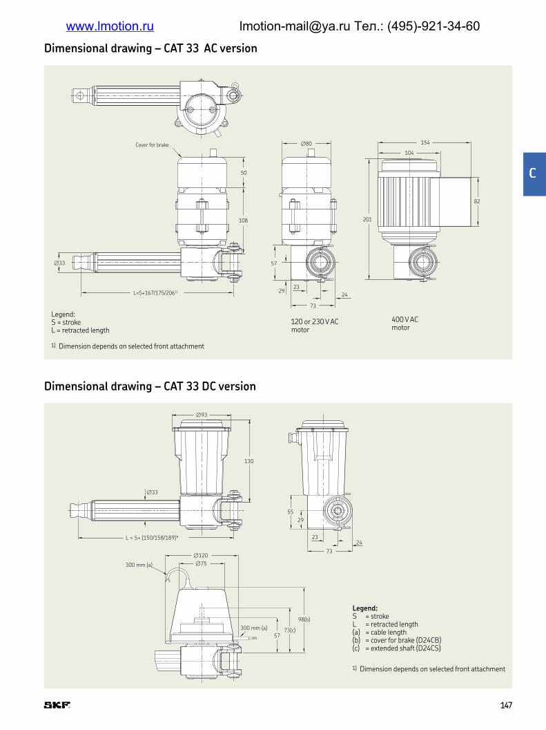
L=S+167/175/2061)
Cover for brake
∅33
∅80
50
108 201
104
82
154
57
29
73
23
24
Legend:S = strokeL = retracted length
1) Dimension depends on selected front attachment
120 or 230 V ACmotor
400 V ACmotor
Dimensional drawing – CAT 33 AC version
Dimensional drawing – CAT 33 DC version
L = S+ (150/158/189)*
55
29
23
73
24
∅33
300 mm (a)
300 mm (a)
5773(c)
98(b)
∅120
∅75
130
∅93
1) Dimension depends on selected front attachment
Legend:S = strokeL = retracted length(a) = cable length(b) = cover for brake (D24CB)(c) = extended shaft (D24CS)
147147
www.lmotion.ru [email protected] Тел.: (495)-921-34-60

ting diagrams – CAT 33 AC version
L1 L1
L2
L3
N
PE
Q1 Q2
Q2
Limitswitch
Limitswitch
Q1 Q1
W1
M
V1
3∼
U1
Q2
N
PE
120/230 V AC
CW
0 CC
W
400 V AC
Bla
ck
Blu
e
Whit
e
Bro
wn
Red
Red
Bla
ck
1B
lack
+1
40
°C
2
C24C, C24CW
∅43
∅120
56
57
L = S + 150/158/1891)
2 m (a)
29
2326
D24C, D24CW
300 mm (a)
57
∅93
130
Legend:S = strokeL = retracted length(a) = cable length
1) Dimension depends on selected front attachement
Dimensional drawing – CAP 43A
148148
www.lmotion.ru [email protected] Тел.: (495)-921-34-60

ting diagrams – CAT 33 DC version
12/24 V DC
Limit
switch
Limit
switch
M
3 1
21
1 2
2
3
+
-
Connecting diagram – CAP 43A
Connection diagram for linear potentiometer
Limit
switch
Limit
switch
+
-
24 V DC
M
2
2
1
1
3 2
13
0 CW 10K
Retract Extend
Black Brown Red
Suitable control units and accessories DC version
Suitable control units and accessories AC version
Control units
Limit switch
Encoder
CAEV 1
10/2
20
CA
XD
33
E2
E110C
E110CB
E220C
E220CB
E380C
Operating switches
CAES 31C
Hand switch
Control units Encoder
CAED
5-2
4R
CAED
9-2
4R
E2
C12C
D12C
C24C
C24CW
D24C
D24CB
D24CS
D24CW
Operating switches
CAES 31C
Hand switch
149149
www.lmotion.ru [email protected] Тел.: (495)-921-34-60

Item code Type code Order N°
12 V DC motor (cylindrical motor) C12C M/040553512 V DC motor (lat motor) D12C M/040551824 V DC motor (cylindrical motor) C24C M/040553624 V DC motor (cylindrical with low speed) C24CW M/040553724 V DC motor (lat motor) D24C M/040551924 V DC motor (lat motor with brake) D24CB M/040552324 V DC motor (lat motor with extended shaft) D24CS M/040552224 V DC motor (lat motor with low speed) D24CW M/0405521120 V AC motor (cylindrical motor) E110C M/0405533120 V AC motor (cylindrical motor with brake) E110CB M/0405534230 V AC motor (cylindrical motor) E220C M/0405531230 V AC motor (cylindrical motor with brake) E220CB M/0405532400 V AC motor (cylindrical motor) E380C M/0411607Capacitor value 25 μF (120 V AC) Capacitor 25 μF M/0430670–06Capacitor value 6 μF (230 V AC) Capacitor 6 μF M/0430670–03Limit switch for any stroke, normally closed CAXD33, NC M/0440054Limit switch for any stroke, normally open CAXD33, NO M/0440053Front mounting attachments type Rod-end 575–32 M/0430575–32Front mounting attachments type Clevis 576–32 M/0430576–32Rear mounting attachments type Single ear bracket 580–32 M/0430580–32Rear mounting attachments type Universal joint 582–32 M/0431780–32Control unit (suitable for E110, E220 motors) CAEV 110/220 M/0420097Control unit (suitable for D24CW,C24CW motor) CAED 5–24R M/0420209Control unit (suitable for D24C/CB/CS motors) CAED 9–24R M/0420210Handset conigured for CAED and CAEV units CAES 31C M/0420213
Item code Type code Order N°
24 V DC motor (cylindrical motor) C24C M/040553624 V DC motor (cylindrical with low speed) C24CW M/040553724 V DC motor (lat motor) D24C M/040551924 V DC motor (lat motor with low speed) D24CW M/0405521Front mounting attachments type Rod-end 575–32 M/0430575–32Front mounting attachments type Clevis 576–32 M/0430576–32Rear mounting attachments type Single ear bracket 580–32 M/0430580–32Rear mounting attachments type Universal joint 582–32 M/0431780–32
T 33 – Type codes for accessories and spare parts
CAP 43A – Type codes for accessories and spare parts
150150
www.lmotion.ru [email protected] Тел.: (495)-921-34-60

Type
Motor assemblyRight RLeft L
Stroke (S)100 mm 100200 mm 200300 mm 300400 mm 400Other stroke lengths – – –
Rear attachmentFork ear, ∅ = 12,0 mm A1Fork ear, ∅ = 12,7 mm A2Single ear, ∅ = 12,0 mm K1Single ear, ∅ = 12,7 mm K2
Front attachmentHole, ∅ = 12,0 mm G1Hole, ∅ = 12,7 mm G2Male thread, M12 G3Female thread, M12 G4Fork ear, ∅ = 10,1 mm G5
FeedbackNo encoder (no code)Encoder (for all standard motors) E2
OptionFriction clutch (not available with option encoder) FNo friction clutch Z
Option for CxxC motorsNo cable U EMC ilter MMotor wothout cover NIP65 (mandatory to state type of cable T2 or T2P) IStraight cable, 2,0 m, no plug T2Straight cable, 2,0 m, jack plug T2PStraight cable, 6,0 m, no plug T6
C A T 3 3 X X /
Load [N] / Full Load Speed [mm/s] Motor options
3 000/xx 2 000/xx 1 000/xx No motor 02 400/6 1 600/12 800/24 120 V AC/60 Hz, 1-phase, IP54 E110C2 400/6 1 600/12 800/24 120 V AC/60 Hz, 1-phase, brake, IP20 E110CB3 000/5 2 000/10 1 000/20 230 V AC/50 Hz, 1-phase, IP54 E220C3 000/5 2 000/10 1 000/20 230 V AC/50 Hz, 1-phase, brake, IP20 E220CB3 000/5 2 000/10 1 000/20 400 V AC/50 Hz, 3-phase, IP55 E380C3 000/xx 2 000/xx 1 000/xx No motor 03 000/13–10 2 000/24-20 1 000/48-38 12 V DC, IP44 (65) C12C2 400/ 11–7 1 600/21-15 800/39-21 12 V DC, lat motor, IP44 D12C3 000/13–10 2 000/26-20 1 000/52-40 24 V DC, IP44 (65) C24C3 000/7–5 2 000/13-9 1 000/25-18 24 V DC, low speed, IP44 (65) C24CW3 000/12–9 2 000/25-18 1 000/43-35 24 V DC, lat motor, IP44 D24C3 000/12–9 2 000/25-18 1 000/43-35 24 V DC, lat motor, brake, IP20 D24CB3 000/12–9 2 000/25-18 1 000/43-35 24 V DC, lat motor, IP44, ext shaft D24CS3 000/7–5 2 000/13-8 1 000/26-19 24 V DC, lat motor, low speed, IP44 D24CW
1 2 4
Options shown in blue are only available on request Contact SKF for more information on minimum quantities and additional costs
Ordering key
151151
www.lmotion.ru [email protected] Тел.: (495)-921-34-60

Type
Motor assemblyRight RLeft L
Stroke [S]100 mm 100200 mm 200300 mm 300400 mm 400
Rear attachmentFork ear, ∅ = 12,0 mm A1Fork ear, ∅ = 12,7 mm A2Single ear, ∅ = 12,0 mm K1Single ear, ∅ = 12,7 mm K2
Front attachmentHole, ∅ = 12,0 mm G1Hole, ∅ = 12,7 mm G2Male thread, M12 G3Female thread, M12 G4Fork ear, ∅ = 10,1 mm G5
OptionFriction clutch F
Cable option for C24C[W] motorsNo cable UStraight, 2,0 m T2Straight cable, 6,0 m, no plug T6
EMC ilterM
Motor without coverN
C A P 4 3 A X X /
Load [N] / Full Load Speed [mm/s] Motor options
3 000/xx 2 000/xx 1 000/xx No motor 03 000/13–10 2 000/26–20 1 000/52–40 24 VDC, IP44 C24C3 000/7–5 2 000/13–9 1 000/25–18 24 VDC, IP44 C24CW3 000/12–9 2 000/25–18 1 000/43–35 24 VDC, lat motor, IP44 D24C3 000/7–5 2 000/13–8 1 000/26–19 24 VDC, lat motor, low speed, IP44 C24CW
1 2 4
Dimensional drawing
152152
www.lmotion.ru [email protected] Тел.: (495)-921-34-60

Linear actuator
Beneits
• Compact
• Robust
• Modular
• Lubricated for service life
• High eficiency
• Digital encoder feedback
Unit CAT 33H – AC version CAT 33H – DC version
Rated push load N 500 to 1 200 400 to 1 200Rated pull load N 500 to 1 200 400 to 1 200Speed (at full load) mm/s 20 to 901) 17 to 1931)
Stroke mm 100 to 400 100 to 400Retracted length mm S+150/158/1892) S+150/158/1892)
Voltage V AC 120, 230 or 400 –V DC – 12 or 24
Power consumption 120 V AC W 98 (brake 133,2 W) –230 V AC W 92 (brake 117,3 W) –400 V AC W 80 –12 or 24 V DC W – N/A
Current consumption 120 V AC A 0,82 (brake +0,29 A) –230 V AC A 0,4 (brake +0,11 A) –400 V AC A 0,2 –12 V DC A – 1824 V DC A – 924 V DC A – 5 (for motors C24CW and D24CW)
Duty cycle % 30 20Ambient temperature °C –20 to +50 –20 to +50Type of protection IP 20/54/55 20/44/65Weight kg 2 to 2,7 2 to 2,7
Technical data
1) Depending on selected motor2) Dimension depends on selected front attachment
CAT 33H
154154
www.lmotion.ru [email protected] Тел.: (495)-921-34-60

Speed-load diagram CAT 33H ... 120 V AC
Load [N]
Speed [mm/s]
125
100
75
50
25
00 500 1 000 1 500
Speed-load diagram CAT 33H ... 230 V AC
Load [N]
Speed [mm/s]
125
100
75
50
25
00 500 1 000 1 500
Speed-load diagram CAT 33H ... 400 V AC
Load [N]
Speed [mm/s]
125
100
75
50
25
00 500 1 000 1 500
Current-load diagram CAT 33H ... 120 V AC
Load [N]
Current consumption [A]
1,0
0,5
00 500 1 000 1 500
Current-load diagram CAT 33H ... 230 V AC
Load [N]
Current consumption [A]
1,0
0,5
00 500 1 000 1 500
Current-load diagram CAT 33H ... 400 V AC
Load [N]
Current consumption [A]
1,0
0,5
00 500 1 000 1 500
Performance diagrams – AC version
CAT 33H...120 V AC CAT 33H...230 V AC
0 10 30 40 50 60 70 80 90 100
CAT 33H ... 120 V AC
0
5009001 2001 2 4 25 µF (E110)
Duty factor [%]
F [N] Gear
4 µF (E220)
3 µF (E220)
600 350
250300500
0 10 30 40 50 60 70 80 90 100
CAT 33H ... 230 V AC
0
5009001 2001 2 4 25 µF (E110)
Duty factor [%]
F [N] Gear
Duty cycle
V (mm/s)
I (A)
Gear 1 V (mm/s)
I (A)
Gear 2 V (mm/s)
I (A)
Gear 4
155155
www.lmotion.ru [email protected] Тел.: (495)-921-34-60

T 33H.../D12C CAT 33H.../D24C/D24CB/D24CS
200
180
160
140
120
100
80
60
40
20
0
20
18
16
14
12
10
8
6
4
2
0
V [mm/s] I [A]
Load [kN]
0 0,5 1 1,5 2 2,5 3
200
180
160
140
120
100
80
60
40
20
0
20
18
16
14
12
10
8
6
4
2
0
V [mm/s] I [A]
Load [kN]
0 0,5 1 1,5 2 2,5 3
Performance diagrams – DC version
CAT 33H.../C24CW
V [mm/s] I [A]
Load [kN]
0 0,5 1 1,5 2 2,5 3
200
180
160
140
120
100
80
60
40
20
0
20
18
16
14
12
10
8
6
4
2
0
CAT 33H.../C12C
200
180
160
140
120
100
80
60
40
20
0
20
18
16
14
12
10
8
6
4
2
0
V [mm/s] I [A]
Load [kN]
0 0,5 1 1,5 2 2,5 3
CAT 33H.../C24C
CAT 33H.../D24CW
200
180
160
140
120
100
80
60
40
20
0
20
18
16
14
12
10
8
6
4
2
0
V [mm/s] I [A]
Load [kN]
0 0,5 1 1,5 2 2,5 3
200
180
160
140
120
100
80
60
40
20
0
20
18
16
14
12
10
8
6
4
2
0
V [mm/s] I [A]
Load [kN]
0 0,5 1 1,5 2 2,5 3
V (mm/s)
I (A)
Gear 1 V (mm/s)
I (A)
Gear 2 V (mm/s)
I (A)
Gear 4
156156
www.lmotion.ru [email protected] Тел.: (495)-921-34-60

Dimensional drawing – AC version
Legend:S = strokeL = retracted length
1) Dimension depends on selected front attachement
73
2423
57
29
108
50
L=S + 167/175/2061)
∅33
∅80
82
201
154
104Cover for brake
120 or 230 V AC motor
D12C, D24C, D24CB, D24CS, D24CW
Legend:S = strokeL = retracted length(a) = cable length(b) = cover for brake (D24CB)(c) = extended shaft (D24CS)
1) Dimension depends on selected front attachement
L=S + 150/158/1891)
∅33
73
24
55
29
23
∅75300 mm (a) ∅120
98(b)
73(c)57
300 mm (a)
130
∅93
Dimensional drawing – DC version
157157
www.lmotion.ru [email protected] Тел.: (495)-921-34-60

ting diagram – DC version
12/24 V DC
M
1 2
2
13 2
13
+
-
Limit
switch
Limit
switch
Connecting diagram – AC version
L1
N
PE
2
CW
0 CC
W120/230 V AC
Bla
ck
Bla
ck
1B
lack
Blu
e
Whit
e
Red
Red
+1
40
°C
Bro
wn
Q1 Q2
Q2 Q1
M
Q1
Q2
W1 V1 U1
3∽
L1
L2
L3
N
PE
400 V AC
Limit
switch
Limit
switch
158158
www.lmotion.ru [email protected] Тел.: (495)-921-34-60

!"#rol units Encoder
CAED
5-2
4R
CAED
9-2
4R
E2
C12C
D12C
C24C
C24CW
D24C
D24CB
D24CS
D24CW
Operating switches
CAES 31C
Suitable control units and accessories AC version
Suitable control units and accessories DC version
Control units
Encoder
CAEV 1
10/2
20
E2
E110C
E110CB
E220C
E220CB
E380C
Operating switches
CAES 31C
Hand switchHand switch
Item code Type code Order N°
12 V DC motor (cylindrical motor) C12C M/040553512 V DC motor (lat motor) D12C M/040551824 V DC motor (cylindrical motor) C24C M/040553624 V DC motor (cylindrical with low speed) C24CW M/040553724 V DC motor (lat motor) D24C M/040551924 V DC motor (lat motor with brake) D24CB M/040552324 V DC motor (lat motor with extended shaft) D24CS M/040552224 V DC motor (lat motor with low speed) D24CW M/0405521120 V AC motor (cylindrical motor) E110C M/0405533120 V AC motor (cylindrical motor with brake) E110CB M/0405534230 V AC motor (cylindrical motor) E220C M/0405531230 V AC motor (cylindrical motor with brake) E220CB M/0405532400 V AC motor (cylindrical motor) E380C M/0411607Capacitor value 25 μF (120 V AC) Capacitor 25 μF M/0430670–06Capacitor value 6 μF (230 V AC) Capacitor 6 μF M/0430670–03Front mounting attachments type Rod-end 575–32 M/0430575–32Front mounting attachments type Clevis 576–32 M/0430576–32Rear mounting attachments type Single ear bracket 580–32 M/0430580–32Rear mounting attachments type Universal joint 582–32 M/0431780–32Control unit (suitable for E110, E220 motors) CAEV 110/220 M/0420097Control unit (suitable for D24CW,C24CW motor) CAED 5–24R M/0420209Control unit (suitable for D24C/CB/CS motors) CAED 9–24R M/0420210Handset conigured for CAED and CAEV units CAES 31C M/0420213
CAT 33H – Type codes for accessories and spare parts
159159
$
www.lmotion.ru [email protected] Тел.: (495)-921-34-60

Type
Motor assemblyRight RLeft L
Stroke (S)100 mm 100200 mm 200300 mm 300400 mm 400Other stroke lengths – –
Rear attachmentFork ear, ∅ = 12,0 mm A1Fork ear, ∅ = 12,7 mm A2Single ear, ∅ = 12,0 mm K1Single ear, ∅ = 12,7 mm K2
Front attachmentHole, ∅ = 12,0 mm G1Hole, ∅ = 12,7 mm G2Male thread, M12 G3Female thread, M12 G4Fork ear, ∅ = 10,1 mm G5
FeedbackNo encoder (no code)Encoder (for all standard motors) E2
OptionFriction clutch (not available with option encoder) FNo friction clutch Z
Option for CxxC motorsNo cable U EMC ilter MMotor wothout cover NIP65 (mandatory to state type of cable T2 or T2P) IStraight cable, 2,0 m, no plug T2Straight cable, 2,0 m, jack plug T2PStraight cable, 6,0 m, no plug T6
C A T 3 3 H X X /
Load [N] / Full Load Speed [mm/s] Motor options
1 200/xx 900/xx 600/xx No motor 01 200/20 900/37 500/90 120 V AC/60 Hz, 1-phase, IP54 E110C1 200/20 900/37 500/90 120 V AC/60 Hz, 1-phase, brake, IP20 E110CB1 200/20 900/37 500/90 230 V AC/50 Hz, 1-phase, IP54 E220C1 200/20 900/37 500/90 230 V AC/50 Hz, 1-phase, brake, IP20 E220CB1 200/20 900/37 500/90 400 V AC/50 Hz, 3-phase, IP55 E380C1 200/xx 900/xx 600/xx No motor 01 200/50-38 600/100-80 400/174-150 12 V DC, IP44 (65) C12C1 200/47-25 600/95-65 400/170-100 12 V DC, lat motor, IP44 D12C1 200/56-36 600/113-79 500/174-140 24 V DC, IP44 (65) C24C1 200/27-17 600/60-35 500/100-69 24 V DC, low speed motor, IP44 (65) C24CW1 200/48-37 600/95-65 500/193-140 24 V DC, lat motor, IP44 D24C1 200/48-37 600/95-65 500/193-140 24 V DC, lat motor, brake, IP20 D24CB1 200/48-37 600/95-65 500/193-140 24 V DC, lat motor, ext shaft, IP44 D24CS1 200/30-17 600/63-35 500/100-65 24 V DC, lat motor, low speed, IP44 D24CW
1 2 4
Options shown in blue are only available on request Contact SKF for more information on minimum quantities and additional costs
Ordering key
160160
www.lmotion.ru [email protected] Тел.: (495)-921-34-60
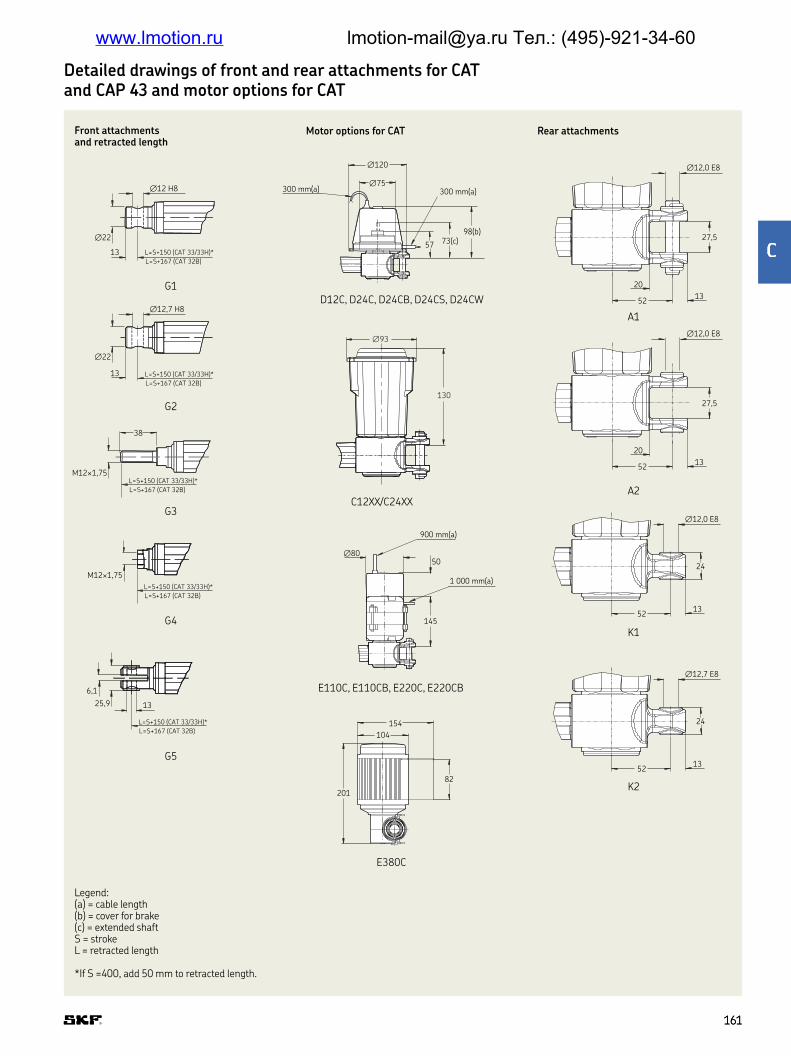
Detailed drawings of front and rear attachments for CAT and CAP 43 and motor options for CAT
G1
G4
G2
G5
G3
D12C, D24C, D24CB, D24CS, D24CW
A1
A2
K1
K2
E380C
E110C, E110CB, E220C, E220CB
C12XX/C24XX
M12×1,75
L=S+150 (CAT 33/33H)*
L=S+167 (CAT 32B)
6,1
25,9 13
L=S+150 (CAT 33/33H)*
L=S+167 (CAT 32B)
∅22
13 L=S+150 (CAT 33/33H)*
L=S+167 (CAT 32B)
∅12,7 H8
M12×1,75L=S+150 (CAT 33/33H)*
L=S+167 (CAT 32B)
38
∅22
13 L=S+150 (CAT 33/33H)*
L=S+167 (CAT 32B)
∅12 H8
57
∅120
∅75
73(c)
300 mm(a) 300 mm(a)
98(b)
24
∅12,0 E8
20
5213
∅12,0 E8
20
5213
∅12,0 E8
5213
24
∅12,7 E8
5213
∅80
145
50
1 000 mm(a)
900 mm(a)
154
104
82
201
27,5
27,5
∅93
130
Front attachments and retracted length
Motor options for CAT Rear attachments
Legend:(a) = cable length(b) = cover for brake(c) = extended shaftS = strokeL = retracted length
*If S =400, add 50 mm to retracted length
161161
%
www.lmotion.ru [email protected] Тел.: (495)-921-34-60

CAR 40
Linear actuator
Beneits
• Reliable and robust industrial actuator
• Wide range of components
• Right- and left-hand version
Unit CAR 40 - AC version CAR 40 - DC version
Rated push load N 2 000 to 6 000 2 000 to 6 000Rated pull load N 2 000 to 6 000 2 000 to 6 000Speed (at full load) mm/s 9 to 401) 10 to 60Stroke mm 100 to 700 100 to 700Retracted length mm S+263 S+263
Voltage V AC 120 or 230 –V DC – 24
Power consumption 120 V AC W 360 –230 V AC W 299 –24 V DC W – N/A
Current consumption 120 V AC A 3 (brake +0,29 A) –230 V AC A 1,3 (brake +0,11 A) –24 V DC A – 16
Duty cycle % 40 25Ambient temperature °C –20 to +70 –20 to +70Type of protection IP 20/54 20/44Weight kg 5,8 to 8,4 5,8 to 8,4
Technical data – AC version
1) Depending on selected motor
162162
www.lmotion.ru [email protected] Тел.: (495)-921-34-60

Performance diagrams – AC version
Duty cycle – AC version
Speed-load diagram CAR 40 ... 120 V AC
Current-load diagram CAR 40 ... 120 V AC
Speed-load diagram CAR 40 ... 230 V AC
Current-load diagram CAR 40 .. 230 V AC
Current consumption [A]
1,0
0,5
00 1 500 2 500 3 500
Load [N]
Current consumption [A]
1,0
0,5
00 1 500 2 500 3 500
Load [N]
Duty factor [%] at 20 °C
35
30
25
20
15
10
5
0
0 1 500 2 500 3 500
Load [%]
Speed [mm/s]
35
30
25
20
15
10
5
0
0 1 500 2 500 3 500
Load [N]
2 500 1 500 900
5009001 500
0 10 30 40 50 60 70 80 90 1000
1 5002 5003 5001 2 4
Duty factor [%]
F [N] Gear
6 µF (E220)/25 F (E110)
4 µF (E220)/16 F (E110)
3 µF (E220)/12 µ (E110)
V (mm/s)
I (A)
Gear 1 V (mm/s)
I (A)
Gear 2 V (mm/s)
I (A)
Gear 4
163163
&
www.lmotion.ru [email protected] Тел.: (495)-921-34-60

Speed-load diagram CAR 40 ... 24 V DC Current-load diagram CAR 40 ... 24 V DC
0 1 000 2 000 3 000 4 000 5 000 6 000
80
60
40
20
0
Load [N]
Speed [mm/s]
0 1 000 2 000 3 000 4 000 5 000 6 000
20
15
10
5
0
Load [N]
Current consumption [A]
Performance diagrams – DC version
Duty cycle – DC version
Load [%]
Duty factor [%] at 20 °C
100
80
60
40
20
00 20 40 60 80 100
V (mm/s)
I (A)
Gear 1 V (mm/s)
I (A)
Gear 2 V (mm/s)
I (A)
Gear 4
164164
www.lmotion.ru [email protected] Тел.: (495)-921-34-60
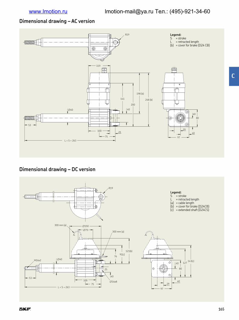
Dimensional drawing – AC version
Legend:S = strokeL = retracted length(b) = cover for brake (D24 CB)
100
75
L = S + 263
53
40
200
198 (b)
248 (b)
∅40
R19
119
141
80
40
40
97
2925
Dimensional drawing – DC version
Legend:S = strokeL = retracted length(a) = cable length(b) = cover for brake (D24CB)(c) = extended shaft (D24CS)
R19
300 mm (a)
M16x2
53100
75∅16e8
25
L = S + 263
∅40
40
7691(c)
121(b)
300 mm (a)
∅150
∅75
143(c)127
80
40
29
97
40
165165
'
www.lmotion.ru [email protected] Тел.: (495)-921-34-60

()**+,ting diagram – DC version
Limit switch
CA
XE40
D24D
D24DS
D24DB
M
2
13 2
13
24 V DC
Limit
switch
Limit
switch
1 2
+
-
Suitable control unit and accessories DC version
Connecting diagram – AC version
L1
N
PE
CW
0 CC
W120/230 V AC
Bla
ck
Bla
ck
1B
lack
Blu
e
White
Red
Red
Bro
wn
+1
40
°C
2
Suitable control unit and accessories AC version
Control unit
Limit switch
CAEV 1
10/2
20
CA
XE40
E110D
E110DB
E220D
E220DB
Operating switches
CAES 31C
Hand switch
166166
www.lmotion.ru [email protected] Тел.: (495)-921-34-60

Type
Motor assemblyRight RLeft L
Stroke (S)100 mm 100300 mm 300500 mm 500700 mm 700Other stroke lengths – – –
OptionFriction clutch FBack-up nut S
C A R 4 0 X X /
Dynamic load [N] / Speed [mm/s] Motor options
6 000/xx 4 000/xx 2 000/xx No motor 06 000/10 4 000/20 2 000/40 120 V AC/60 Hz, 1-phase, IP54 E110C6 000/10 4 000/20 2 000/40 120 V AC/60 Hz, 1-phase, brake, IP20 E110DB6 000/9 4 000/17 2 000/34 230 V AC/50 Hz, 1-phase, IP54 E220D6 000/9 4 000/17 2 000/34 230 V AC/50 Hz, 1-phase, brake, IP20 E220DB6 000/xx 4 000/xx 2 000/xx No motor 06 000/15–10 4 000/30-20 2 000/60-40 24 V DC, lat motor, IP44 D24D6 000/15–10 4 000/30-20 2 000/60-40 24 V DC, lat motor, extended shaft, IP44 D24DS6 000/15–10 4 000/30-20 2 000/60-40 24 V DC, lat motor, brake, IP20 D24DB
1 2 4
Options shown in blue are only available on request Contact SKF for more information on minimum quantities and additional costs
Ordering key
Item code Type code Order N°
24 V DC motor (lat motor) D24D M/040552424 V DC motor (lat motor with extended shaft) D24DS M/040552624 V DC motor (lat motor with brake) D24DB M/0405525120 V AC motor (cylindrical motor) E110D M/0405529120 V AC motor (cylindrical motor with brake) E110DB M/0405530230 V AC motor (cylindrical motor) E220D M/0405527 590–40 M/0430590–40230 V AC motor (cylindrical motor with brake) E220DB M/0405528Capacitor value 12 μF (230 VAC–motor) Capacitor 12 μF M/0430670–04Limit switch for stroke =100 mm CAXE 40 × 100 M/0412051Limit switch for stroke =300 mm CAXE 40 × 300 M/0412054Limit switch for stroke =500 mm CAXE 40 × 500 M/0412056Limit switch for stroke =700 mm CAXE 40 × 700 M/0412057Proximity switch for CAXE CAXE Proximity switch M/0432369Front mounting attachments type Rod–end 575–40 M/0430575–40Front mounting attachments type Clevis 576–40 M/0430576–40Rear mounting attachments type Single ear bracket 590–40 M/0430590–40Rear mounting attachments type Ball–joint bracket 581–40 M/0430581–40
CAR 40 – Type codes for accessories and spare parts
167167
-
www.lmotion.ru [email protected] Тел.: (495)-921-34-60

Spare parts
CAXD 33 limit switchLimit switches, combined with SKF control
units, make it possible to set the stroke to
any desired length
• CAXD 33 – designed for the following
actuators:
– CAT 33
– CALA 36A
• One CAXD is needed for each limit position
• Use of limit switches reduce the effective
stroke by 20 mm for CAT 33 and 25 mm
for CALA 36A (retracted position is
affected)
./0012ting diagram
CAXD
CAXD CAXD
CAXD
+
++ +
-
-
––
CAXD
BN
BN BN
BN
BNL+
L–
BUBU
BU BU
BU
K2
K2
K2
M
M
K1
K2K1
K1
K1
PLC
24/12 V DC
motor
24/12 V DC
motor
Wire colours: BN – Brown,
BU – Blue
or
Operating switch
Operating switch
Important! For DC-supply only
CAT actuator series
CALA actuator series
CARE actuator series
CAXD 33
Operating voltage 5 to 30 V DCMax current 100 mA DCVoltage drop < 5 VVoltage drop < 5 VElectrical function Normally closed or normally openMake/fall time 0,3 ms / 0,6 msOperating temperature –20 °C to +50 °CIngress protection IP 67 (sensor element)Vibration/shock According to IEC 90947-5-2 (sensor element)Cable dimensions (L × D) 2 m × 3 mm (PUR)Cable area 2 × 0,14 mm2
Housing colour Black
Technical data
37 26
45 L = 2 000
Dimensional drawing
Ordering key
Code Description
CAXD 33 LIMIT SWITCH, NC Normally ClosedCAXD 33 LIMIT SWITCH, NO Normally Open
168168
www.lmotion.ru [email protected] Тел.: (495)-921-34-60

CAXE limit switchLimit switches, combined with SKF control
units, make it possible to set the stroke to
any desired length
• CAXE - designed for the following
actuators:
– CAR 22
– CAR 32
– CAR 40
– CAT 32B
– CARN 32
• It is recommended to place the limit switch
at least 10 mm from the end stop to avoid
mechanical failure
• Front attachment G3 must be selected for
this option
B
C
A
CAXE
Operating voltage 5 to 30 V DCMax current 100 mA DCProtection class IIIVoltage drop < 5 VElectrical function Normally Closed (NC) and
Normally Open (NO)Make/break time 0,3 ms / 0,6 msOperating temperature –20 to +70 °CDegree of protection IP 67 (sensor element)Vibration/shock According to IEC 60947-5-1
(sensor element)Cable dimensions (L x D) 2 000 x 3 mm (PUR)Cable area 3 × 0,14 mm2
Technical data
Important! The sensor has no overload protection and no reverse polarity protection
Ordering key
TypeCAXE32 CAR 22 022CAXE32 CAR 32, CARN 32 032CAXE32B CAT 32B 32BCAXE40 CAR 40 040
Actuators stroke (mm)050 CAR 22, 32 CARN 32 and CAT 32B 050100 CAR 22, 32, 40, CARN 32 and CAT 32B 100150 CAR 22 150200 CAR 22, 32 CARN 32 and CAT 32B 200300 CAR 22, 32, 40, CARN 32 and CAT 32B 300400 CAT 32B 400500 CAR 32, 40, CARN 32 and CAT 32B 500700 CAR 32, 40, CARN 32 and CAT 32B 700
C A X E –
Important! For DC-supply only
M
BK
BU
BU
BK
BU
BN
BN
BU
BN
BU
BNK1
M
K1 K2
CAXE
CAXE CAXE
CAXE CAXE
L–
L–
L+
PLC
+
–
+
–
+
–
BU
BN+
–/ V DC motor
Connecting switch
Operating switch
Wire colours:
BN – Brown
BK – Black
BU – Blue
/ V DC motor
K2
K2
K2K1
K1
Connecting diagram
Dimensional drawing
A B C
CAXE 22 42,5 37 14CAXE 32/32B 47,5 40 20CAXE 40 46 46 23
169169
3
www.lmotion.ru [email protected] Тел.: (495)-921-34-60

Feedback for CAT series – Encoder E2• Can be itted to all standard motors
• Hall effect, two channels with 90°
displacement
• Located on gear housing, see drawing
• 2 pulses/channel and motor revolution
• Supply voltage: 5–24 V DC
• Final resolution according to gear ratio
and actuator basic type (see table)
Gear Pulses at 1mm stroke Resolution (mm) per pulse
CAT 33 1 16,67 0,062 8,33 0,124 4,17 0,24
CAT 33H 1 4,00 0,252 2,00 0,504 1,00 1,00
CAT 32B 1 12,50 0,082 6 25 0,164 3,13 0,32
Fee45678
9:;;e7ting diagram
A
B
A
180° 360° 540° 720°
B
S
S
N
N
Rotation angle
Voltage130
∅93
11
Dimensional drawing
Encoder option E2
170170
www.lmotion.ru [email protected] Тел.: (495)-921-34-60
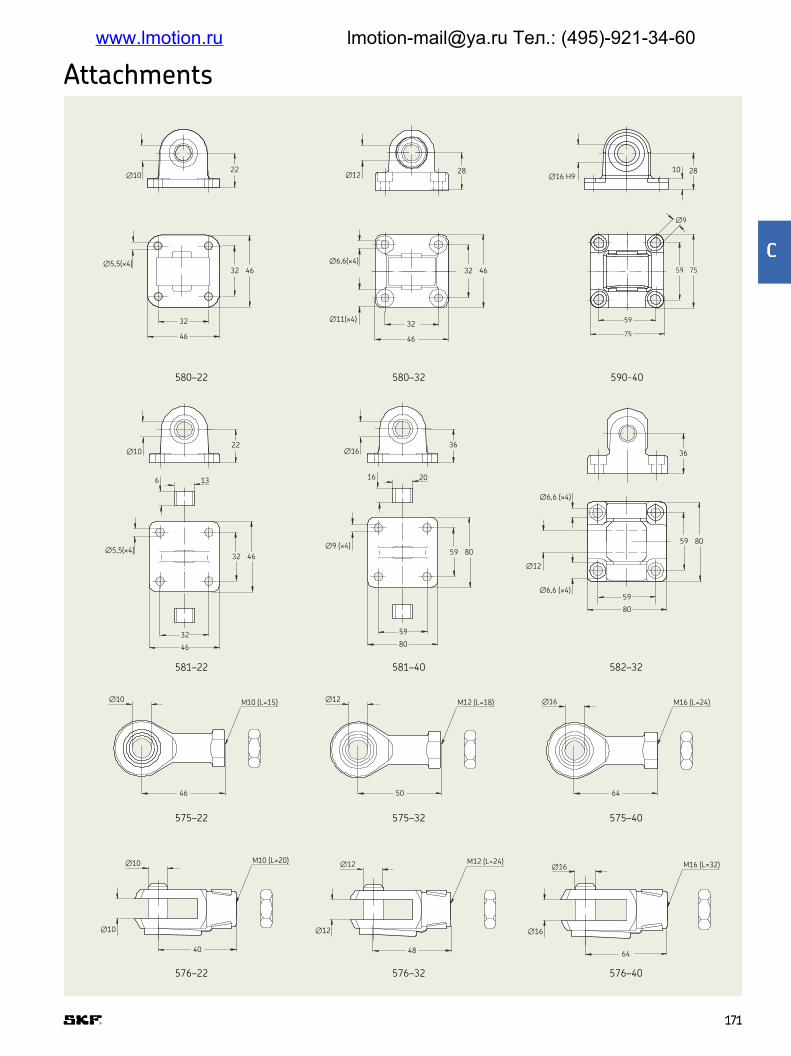
580–22
581–22
576–22
575–22
580–32 590-40
581–40
576–32
575–32
582–32
576–40
575–40
∅10
∅5,5(×4) ∅6,6(×4)
∅11(×4)
22∅12 ∅16 H9
28
32 46
32
46
32 46
32
46
59
75
∅5,5(×4)
∅10 M10 (L=15)
32 46
32
46
46
∅10
6 13
22
∅9 (×4)
∅6,6 (×4)
∅6,6 (×4)
59 80
59
80
∅16
16 20
36
∅12
59 80
59
80
36
∅12 M12 (L=18)
50
∅16 M16 (L=24)
64
∅10
∅10
M10 (L=20)
40
∅12
∅12
M12 (L=24)
48
∅16
∅16
M16 (L=32)
64
59
∅9
75
2810
Attachments
171171
<
www.lmotion.ru [email protected] Тел.: (495)-921-34-60

CAHM series
The CAHM series consists of spindle lifting actuators with worm
gears They fulil the highest demands for industrial and other appli-
cations The actuators are available in several different motor ver-
sions CAHM series offers strong (up to 50 000 N), fast and quiet
movements with high safety and duty cycle The actuators include
many interface options as hall encoder, end-switch, extended shaft
etc
Beneits
• Modular
• Robust
• Reliable
• High speed and/or high load
• All metal design
Features
• Ideal for heavy load applications
• Wide speed/force range
• Robust design
All complete datas sheet are available on SKF com
If you request higher force than 12 kN, refer to High performance
actuator catalogue (PUB MT/P1 17176 EN)
173173
=
www.lmotion.ru [email protected] Тел.: (495)-921-34-60

12 and 24 V DC
Unit CAHM-31XX-D1 CAHM-31XX-D3 CAHM-35XX-D2
Voltage V DC 12 24 24Screw type – LN and LS LN and LS LN and LSMax rated push load N 1 000 to 4 000 1 000 to 4 000 10 000 to 15 000Max rated pull load N 1 000 to 4 000 1 000 to 4 000 10 000 to 15 000Max speed (at full load) mm/s 5 to 50 5 to 45 3 to 27Stroke mm 100 to 700 100 to 700 100 to 700Retracted length mm S+230 S+230 –Power consumption W 168 to 192 144 to 192 528 to 840Current consumption A 14 to 16 6 to 8 22 to 35Duty cycle % 10 10 10 Ambient temperature °C –10 to +40 –10 to +40 –10 to +40Type of protection IP 44 44 54
230 V AC
Unit CAHM-31XX-A2 CAHM-35XX-A2
Voltage V AC 230 230Screw type – LN and LS LSMax rated push load N 500 to 2 600 5 000 to 15 000Max rated pull load N 500 to 2 600 5 000 to 15 000Max speed (at full load) mm/s 5 to 50 2 to 12Stroke mm 100 to 700 100 to 700Retracted length mm S+230 –Power consumption W 200 to 230 700 to 750Current consumption A 1 to 11 3,3 to 3,5Duty cycle % 25 10 to 15Ambient temperature °C –10 to +40 –10 to +40Type of protection IP 54 54
3x400 V AC
Unit CAHM-31XX-A4 CAHM-35XX-A4 CAHM-50XX-A4 CAHM-65XX-A4
Voltage V AC 3×400 3×400 3×400 3×400Screw type – LN and LS LS and BN BN BNMax rated push load N 1 000 to 4 500 10 000 to 15 000 15 000 to 30 000 18 000 to 50 000Max rated pull load N 1 000 to 4 500 10 000 to 15 000 15 000 to 30 000 18 000 to 50 000Max speed (at full load) mm/s 5 to 50 2 to 25 9 to 45 9 to 74Stroke mm 100 to 700 100 to 700 100 to 700 100 to 700Retracted length mm S+230 – S+465 S+446Power consumption W 210 to 280 500 to 920 1 200 to 1 650 1 900 to 3 000Current consumption A 0,5 to 0,6 1,4 to 1,8 2,8 to 3,5 3,6 to 3,9Duty cycle % 40 10 to 25 10 10Ambient temperature °C –10 to +40 –10 to +40 –10 to +40 –10 to +40Type of protection IP 54 54 54 54
Technical data
174174
www.lmotion.ru [email protected] Тел.: (495)-921-34-60

0 1 000 2 000 3 000 4 0000 1 000 2 000 3 000 4 000
80
70
60
50
40
30
20
10
0
80
70
60
50
40
30
20
10
0
Speed [mm/s] Speed [mm/s]
Speed load diagram Speed load diagramLoad [N] Load [N]
Motor: D1 - 12 V DC Motor: D2 - 24 V DC
0 1 000 2 000 3 000 4 000 5 000 0 500 1 000 1 500 2 000 2 500 3 000
60
50
40
30
20
10
0
Load [N] Load [N]
60
50
40
30
20
10
0
Speed [mm/s] Speed [mm/s]
Speed load diagram Speed load diagram
Motor: A4 - 3x400 V AC Motor: A2 - 230 V AC
>erformance diagrams
CAHM 3110-LNCAHM 3130-LNCAHAM 3110-LSCAHAM 3150-LS
CAHM-31 - AC version
CAHM-31 - DC version
175175
?
www.lmotion.ru [email protected] Тел.: (495)-921-34-60

Motor: D2 - 24 V DC BN - Ball screw 25x10
Load [N]
0 5 000 10 000 15 000
80
70
60
50
40
30
20
10
0
Speed [mm/s]
Motor: D2 - 24 V DC LS - Lead screw 20x4
Load [N]
0 5 000 10 000 15 000
20
18
16
14
12
10
8
6
4
2
0
Speed [mm/s]
Motor: A4 - 3x400 V AC BN - Ball screw 25x10
Load [N]
0 5 000 10 000 15 000
35
30
25
20
15
10
5
0
Speed [mm/s]
Motor: A4 - 3x400 V AC LS - Lead screw 25x10
Load [N]
14
12
10
8
6
4
2
0
Speed [mm/s]
Motor: A2 - 230 V AC LS - Lead screw 20x4
Load [N]
0 5 000 10 000 15 000 0 5 000 10 000 15 000
Speed [mm/s]
14
12
10
8
6
4
2
0
CAHM-3507CAHM-3510CAHM-3520CAHM-3540
CAHM-5004CAHM-5006
CAHM-5012CAHM-5023
Speed-load diagram
0
10
20
30
40
50
60
0 5 000 10 000 15 000 20 000 25 000 30 000
Speed (mm/s)
Load (N)
60
50
40
30
20
10
0
Axial force [N]
Load (N)Speed-load diagram
0 5 000 10 000 15 000 20 000 25 000 30 000
CAHM-5004CAHM-5006
CAHM-5012CAHM-5023
@AHM-35 - DC version
CAHM-35 - AC version
CAHM-50 - AC version
Motor: A4 - 3x400 V AC Motor: A4 - 3x400 V AC
CAHM-65 - AC version
176176
www.lmotion.ru [email protected] Тел.: (495)-921-34-60

Telescopic pillars UP TO
2,8 kNm
BENDING LOAD
www.lmotion.ru [email protected] Тел.: (495)-921-34-60

Chapter contents
2,8
CPMA 180
CPMB 188
CPMT 196
TFG 202
THG 206
TLC 210
TLG 214
TLT 218
TXG 222
FRE 226
179179
D
www.lmotion.ru [email protected] Тел.: (495)-921-34-60
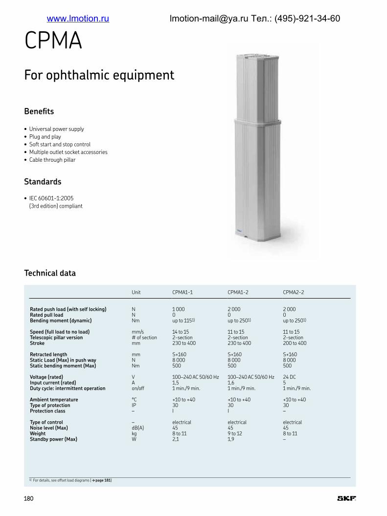
CPMA
For ophthalmic equipment
Beneits
• Universal power supply
• Plug and play
• Soft start and stop control
• Multiple outlet socket accessories
• Cable through pillar
Standards
• IEC 60601-1:2005
(3rd edition) compliant
Unit CPMA1-1 CPMA1-2 CPMA2-2
Rated push load (with self locking) N 1 000 2 000 2 000Rated pull load N 0 0 0Bending moment (dynamic) Nm up to 1151) up to 2501) up to 2501)
Speed (full load to no load) mm/s 14 to 15 11 to 15 11 to 15Telescopic pillar version # of section 2-section 2-section 2-sectionStroke mm 230 to 400 230 to 400 200 to 400
Retracted length mm S+160 S+160 S+160Static Load (Max) in push way N 8 000 8 000 8 000Static bending moment (Max) Nm 500 500 500
Voltage (rated) V 100–240 AC 50/60 Hz 100–240 AC 50/60 Hz 24 DCInput current (rated) A 1,5 1,6 5Duty cycle: intermittent operation on/off 1 min /9 min 1 min /9 min 1 min /9 min
Ambient temperature °C +10 to +40 +10 to +40 +10 to +40Type of protection IP 30 30 30 Protection class – I I –
Type of control – electrical electrical electricalNoise level (Max) dB(A) 45 45 45Weight kg 8 to 11 9 to 12 8 to 11Standby power (Max) W 2,1 1,9 –
Technical data
1) For details, see offset load diagrams († page 181)
180180
www.lmotion.ru [email protected] Тел.: (495)-921-34-60

149,5 ±1
109,5 ±1
165 ±1
125 ±1
Stroke ±2
Stroke +160
Retracted
length ±2
Offset load diagrams
Dimensional drawing
Performance diagram
0
2
4
6
8
10
12
14
16
18
20
0 1 000 2 000
0
200
400
600
800
1 000
1 200
1 400
1 600
1 800
2 000
0 100 200 300
0
100
200
300
400
500
600
700
800
900
1 000
0 100 200 300
CPMA1-1
Load [N]
Load distance from the center of the pillar [mm]
CPMA1-2 and CPMA2-2
Load [N]
Load distance from the center of the pillar [mm]
Speed [mm/s]
Load [N]
Offset load at full extension in the best axis Offset load at full extension in the best axis
Overload range
Ideal range
Underload range
Overload range
Ideal range
Underload range
More lexibility with Series CPMA design options
Built-in with outer tube on top
More hygienic and easy-to-clean design
Built-in with outer tube on bottom
More aesthetic design
M
M
M
M
Motor orientation B Motor orientation A
Motor orientation A Motor orientation B
CPMA1-1CPMA1-2CPMA2-2
181181
E
www.lmotion.ru [email protected] Тел.: (495)-921-34-60

SuFGable products
Ext
ernal p
ow
er s
upply
24 V
DC
EH
A4
ST
L
ST
K
ZD
V-3
48220-0
02
ZD
V-3
48221-0
02
ZK
A-1
40449-2
500
ZK
A-1
40450-2
500
ZK
A-1
40451-2
500
ZK
A-1
40452-2
500
ZK
A-1
40458-2
500
ZK
A-1
40460-2
500
ZK
A-1
40453-2
500
ZK
A-1
40454-2
500
ZK
A-1
40455-2
500
ZK
A-1
40456-2
500
ZK
A-1
40459-2
500
ZK
A-1
40461-2
500
CPMA1-1
CPMA1-2
CPMA2-2
Detachable mains cordMains cableSocket box
Suitable products
Connection diagram
M
24 V DC 100-240 V AC
+
-
PE
L
N
PE
M
Operating device
Operating device
Desk switchHand switch Foot switch
(4× M6)
93
121
81
(4× M6)
133
Pillar must be attached on plane and rigid surface by 4 screws M6 with a depth of 6 to 11 mm in the pillar The total length of the screw must be adjusted to the height of the ixture
RJ 45 LAN location
Mains power connection(Terminal block)
RJ 45 LAN locationMains power connection(Terminal block)
RJ45 Operating device location 6-11 mm
6-8 Nm
Screw M6
property class 8.8
IMPORTANT!
Connections and fastening
182182
www.lmotion.ru [email protected] Тел.: (495)-921-34-60

Inlet socket box – ZDV
Beneits
• Multifunction plug and play accessory
• Detachable mains power cord
• Replaceable fuses
• LAN Connector
• Easy to use
• Cord strain relief
Standards
• IEC 60601-1:2005 (3rd edition) compliant
Technical data
• IEC inlet mains power socket with retainer
• 1 RJ45 for operating device
• 1 RJ45 for LAN
• 2 replacable fuses 8 A
• Plate with holes as the plates of the
pillar CPMA
• Can be fastened on inner and outer tube
Dimensional drawing
Suitable operating devices
Pillars Handswitches
Footswitches
Deskswitches
Mains cables Detachable mains cords
CP
MA1-1
CP
MA1-2
CP
MA2-2
EH
A41-1
3N
10N
-000
ST
L0
1-G
W1000-X
190
ST
K0
1-S
W3000-X
100
ST
K0
1-U
W3000-X
100
ZK
A-1
40449-2
500
ZK
A-1
40450-2
500
ZK
A-1
40451-2
500
ZK
A-1
40452-2
500
ZK
A-1
40458-2
500
ZK
A-1
40460-2
500
ZK
A-1
40453-2
500
ZK
A-1
40454-2
500
ZK
A-1
40455-2
500
ZK
A-1
40456-2
500
ZK
A-1
40459-2
500
ZK
A-1
40461-2
500
ZDV-348220-
002
Outlet socket box – ZDV
Beneits
• Multifunction plug and play accessory
• 3 IEC outlet sockets
• Replaceable fuses
• Integrated mounting plate
• LAN Connector
• Easy to use
Standards
• IEC 60601-1:2005 (3rd edition) compliant
Technical data
• 3 IEC mains power outlet sockets
• 1 RJ45 for operating device
• 1 RJ45 for LAN
• 2 replacable fuses 8 A
• Integrated mounting plate with 4 holes
9 mm diameter
• 4 screws to fasten on pillar CPMA
• Can be fastened on inner and outer tube
Dimensional drawing
Suitable operating devices
Pillars Handswitches
Footswitches
Deskswitches
Mains cables Detachable mains cords
CP
MA1-1
CP
MA1-2
CP
MA2-2
EH
A41-1
3N
10N
-000
ST
L0
1-G
W1000-X
190
ST
K0
1-S
W3000-X
100
ST
K0
1-U
W3000-X
100
ZK
A-1
40449-2
500
ZK
A-1
40450-2
500
ZK
A-1
40451-2
500
ZK
A-1
40452-2
500
ZK
A-1
40458-2
500
ZK
A-1
40460-2
500
ZK
A-1
40453-2
500
ZK
A-1
40454-2
500
ZK
A-1
40455-2
500
ZK
A-1
40456-2
500
ZK
A-1
40459-2
500
ZK
A-1
40461-2
500
ZDV-348221-
002
161
205,5
138
44
58
4
52
458
138
215140
120
180160
183183
H
www.lmotion.ru [email protected] Тел.: (495)-921-34-60

Mounting plate – ZPL
Beneits
• Easy to use
Technical data
• Can be fastened on inner and outer tube
• Mounting plate with 4 holes 9 mm
diameter
Dimensional drawingSuitable operating devices
Pillars
CP
MA1-1
CP
MA1-2
CP
MA2-2
ZPL
180
160
120140
4∅9
Mains cable and detachable mains cord – ZKA
Mains cable
Detachable mains cord
Mains cable
Pillars Socketboxes
CP
MA1-1
CP
MA1-2
CP
MA2-2
ZD
V-3
48220-0
02
ZD
V-3
48221-0
02
ZKA-140449-2500
ZKA-140450-2500
ZKA-140451-2500
ZKA-140452-2500
ZKA-140458-2500
ZKA-140460-2500
Detachable mains cord
Pillars Socketboxes
CP
MA1-1
CP
MA1-2
CP
MA2-2
ZD
V-3
48220-0
02
ZD
V-3
48221-0
02
ZKA-140453-2500
ZKA-140454-2500
ZKA-140455-2500
ZKA-140456-2500
ZKA-140459-2500
ZKA-140461-2500
Beneits
• Easy to use
• Identiication by a product label
Standards
• IEC 60601-1:2005 (3rd edition) compliant
184184
www.lmotion.ru [email protected] Тел.: (495)-921-34-60
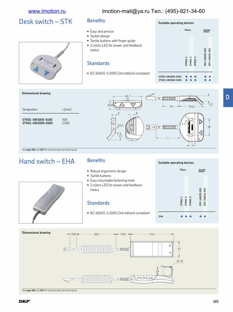
Hand switch – EHA Beneits
• Robust ergonomic design
• Tactile buttons
• Easy mountable fastening hook
• 2 colors LED for power and feedback
status
Standards
• IEC 60601-1:2005 (3rd edition) compliant
Suitable operating devices
Pillars Socketboxes
CP
MA1-1
CP
MA1-2
CP
MA2-2
ZD
V-3
48220-0
02
ZD
V-3
48221-0
02
EHA
Dimensional drawing
See page 186 and 187 for technical data and ordering key
29
∅ 32
500 300 510 154
57
Desk switch – STK Beneits
• Easy and precise
• Stylish design
• Tactile buttons with inger guide
• 2 colors LED for power and feedback
status
Standards
• IEC 60601-1:2005 (3rd edition) compliant
Suitable operating devices
Pillars Socketboxes
CP
MA1-1
CP
MA1-2
CP
MA2-2
ZD
V-3
48220-0
02
ZD
V-3
48221-0
02
STK01-SW3000-X100
STK01-UW3000-X100
Dimensional drawing
Designation L [mm]
STK01-SW3000-X100 500STK01-UW3000-X100 1 000 4,2
7
6
10,5
L
55,839
38
17
66,7
20,8
8
12,3
See page 186 and 187 for technical data and ordering key
185185
I
www.lmotion.ru [email protected] Тел.: (495)-921-34-60

Foot switch – STL Beneits
• Easy to use
• Ergonomic design
Standards
• IEC 60601-1:2005 (3rd edition) compliant
Suitable operating devices
Pillars Socketboxes
CP
MA1-1
CP
MA1-2
CP
MA2-2
ZD
V-3
48220-0
02
ZD
V-3
48221-0
02
STL01
Dimensional drawing82
M5 Position ∅7,6
300 150
105
700
224
40
192M5 Position
Unit EHA4 STL STK
Max. operating channels n° 1 1 1Operating power V DC/mA 5/20 5/20 5/20Type of protection IP 67 x2 –
Color – Grey Grey and anthracite GreyIndicator LED 2 colors for power
and feedback status– LED 2 colors for power and
feedback statusPlug – RJ45 RJ45 RJ45
Hook – with hook – –Symbols – with arrows up/down with arrows up/down with arrows up/down
Switches technical data
186186
www.lmotion.ru [email protected] Тел.: (495)-921-34-60

Ordering key
Type
Voltage100–240 V AC 50/60 Hz 124 V DC 2
Load:Push (N)1 000 Only for AC version 12 000 2
Tube set2-section 2
Stroke length [mm]200 Only for DC version230250300400Other per 10 mm from 200 mm or 230 mm for AC version up to 400 mm
Motor orientation1)
Motor in inner tube AMotor in outer tube B
Operating device orientationOperating device socket as the motor AOperating device socket at both sides B
LAN cable throughNo 0LAN cable through Not compatible with op device socket at both sides 1
C P M A – 2 – 000
1) Pillar can be placed with outer tube on the top or bottom († page 181)
Description Plug Country Part number Order Number
Mains cable straight 2,5 m Schuko Germany, France, ZKA-140449-2500 130015Typ-L Italy ZKA-140450-2500 130016British standard UK ZKA-140451-2500 130017NEMA USA, Japan, … ZKA-140452-2500 130018SEV CH ZKA-140458-2500 130256AS 3112 PRC, Australia, ZKA-140460-2500 130391
Detachable mains cord straight 2,5 m Schuko Germany, France, ZKA-140453-2500 130019(to plug in socket box Inlet) Typ-L Italy ZKA-140454-2500 130020
British standard UK ZKA-140455-2500 130021NEMA USA, Japan, … ZKA-140456-2500 130022SEV CH ZKA-140459-2500 130257AS 3112 PRC, Australia, ZKA-140461-2500 130392
Desk switch with LED, cable 0,5 m STK01-SW3000-X100
130025
Desk switch with LED, cable 1,0 m STK01-UW3000-X100
130026
Handset with LED, cable coiled 1,3 m EHA41-13N00N-000 131033Foot switch, cable coiled 1,3 m STL01-GW1000-X100 131873
Mounting plate ZPL-348382 130024
Socket box inlet: IEC, RJ45 LAN, RJ45 op. device ZDV-348220-002 130030Socket box outlet: 3xIEC, RJ45 LAN, RJ45 op. device ZDV-348221-002 130032
Ordering key
Accessories
187187
J
www.lmotion.ru [email protected] Тел.: (495)-921-34-60

CPMB
For infant care
Beneits
• Universal power supply
• Plug and play
• Soft start and stop control
• Low noise level
• Cable through pillar
• Grounding continuity
Standards
• IEC 60601-1:2005
(3rd edition) compliant
Unit CPMB1-1 CPMB1-2 CPMB2-2
Rated push load (with self locking) N 1 000 2 000 2 000Rated pull load N 0 0 0Bending moment (dynamic) Nm up to 1151) up to 250* up to 2501)
Speed (full load to no load) mm/s 14 to 15 11 to 15 11 to 15Telescopic pillar version # of section 2-section 2-section 2-sectionStroke mm 230 to 400 230 to 400 200 to 400
Retracted length mm S+160 S+160 S+160Static Load (Max) in push way N 8 000 8 000 8 000Static bending moment (Max) Nm 500 500 500
Voltage (rated) V 100–240 AC 50/60 Hz 100–240 AC 50/60 Hz 24 DCInput current (rated) A 1,5 1,6 5Duty cycle: intermittent operation on/off 1 min /9 min 1 min /9 min 1 min /9 min
Ambient temperature °C +10 to +40 +10 to +40 +10 to +40Type of protection IP 30 30 30 Protection class – I I –
Type of control – electrical electrical electricalNoise level (Max) dB(A) 45 45 45Weight kg 8 to 11 9 to 12 8 to 11
Technical data
1) For details, see offset load diagrams († page 189)
188188
www.lmotion.ru [email protected] Тел.: (495)-921-34-60

149,5 ±1
109,5 ±1
165 ±1
125 ±1
Stroke ±2
Stroke +160
Retracted
length ±2
Dimensional drawing
Offset load diagrams Performance diagram
0
2
4
6
8
10
12
14
16
18
20
0 1 000 2 000
0
200
400
600
800
1 000
1 200
1 400
1 600
1 800
2 000
0 100 200 300
0
100
200
300
400
500
600
700
800
900
1 000
0 100 200 300
CPMB1-1
Load [N]
Load distance from the center of the pillar [mm]
CPMB1-2 and CPMB2-2
Load [N]
Load distance from the center of the pillar [mm]
Speed [mm/s]
Load [N]
Offset load at full extension in the best axis Offset load at full extension in the best axis
Overload range
Ideal range
Underload range
Overload range
Ideal range
Underload range
CPMB1-1
CPMB1-2CPMB2-2
Built-in with outer tube on top
More hygienic and easy-to-clean design
Built-in with outer tube on bottom
More aesthetic design
M
M
M
M
Motor orientation B Motor orientation A
Motor orientation A Motor orientation B
More lexibility with Series CPMB design options
CPMA1-1CPMA1-2CPMA2-2
189189
K
www.lmotion.ru [email protected] Тел.: (495)-921-34-60

(4× M6)
93
121
81
(4× M6)
133
Pillar must be attached on plane and rigid surface by 4 screws M6 with a depth of 6 to 11 mm in the pillar The total length of the screw must be adjusted to the height of the ixture
RJ 45 LAN location
Mains power connection(Terminal block)
RJ 45 LAN locationMains power connection(Terminal block)
RJ45 Operating device location6-11 mm
6-8 Nm
Screw M6
property class 8.8
IMPORTANT!
LMNOable operating devices
Connecting diagram
Connections and fastening
Ext
ernal p
ow
er s
upply
24 V
DC
EH
A4
ST
L
ST
K
CPMB1-1
CPMB1-2
CPMB2-2
Hand switch
Foot switch
Desk switch
M
24 V DC 100-240 V AC
+
-
PE
L
N
PE
M
Operating device
Operating device
190190
www.lmotion.ru [email protected] Тел.: (495)-921-34-60

Inlet socket box – ZDV
Beneits
• Multifunction plug and play accessory
• Detachable mains power cord
• Replaceable fuses
• LAN Connector
• Easy to use
• Cord strain relief
Standards
• IEC 60601-1:2005 (3rd edition) compliant
Technical data
• IEC inlet mains power socket with retainer
• 1 RJ45 for operating device
• 1 RJ45 for LAN
• 2 replacable fuses 8 A
• Plate with holes as the plates of the
pillar CPMA
• Can be fastened on inner and outer tube
Dimensional drawing
Suitable operating devices
Pillars Handswitches
Footswitches
Deskswitches
Mains cables Detachable mains cords
CP
MA1-1
CP
MA1-2
CP
MA2-2
EH
A41-1
3N
10N
-000
ST
L0
1-G
W1000-X
190
ST
K0
1-S
W3000-X
100
ST
K0
1-U
W3000-X
100
ZK
A-1
40449-2
500
ZK
A-1
40450-2
500
ZK
A-1
40451-2
500
ZK
A-1
40452-2
500
ZK
A-1
40458-2
500
ZK
A-1
40460-2
500
ZK
A-1
40453-2
500
ZK
A-1
40454-2
500
ZK
A-1
40455-2
500
ZK
A-1
40456-2
500
ZK
A-1
40459-2
500
ZK
A-1
40461-2
500
ZDV-348220-
002
Outlet socket box – ZDV
Beneits
• Multifunction plug and play accessory
• 3 IEC outlet sockets
• Replaceable fuses
• Integrated mounting plate
• LAN Connector
• Easy to use
Standards
• IEC 60601-1:2005 (3rd edition) compliant
Technical data
• 3 IEC mains power outlet sockets
• 1 RJ45 for operating device
• 1 RJ45 for LAN
• 2 replacable fuses 8 A
• Integrated mounting plate with 4 holes
9 mm diameter
• 4 screws to fasten on pillar CPMA
• Can be fastened on inner and outer tube
Dimensional drawing
Suitable operating devices
Pillars Handswitches
Footswitches
Deskswitches
Mains cables Detachable mains cords
CP
MA1-1
CP
MA1-2
CP
MA2-2
EH
A41-1
3N
10N
-000
ST
L0
1-G
W1000-X
190
ST
K0
1-S
W3000-X
100
ST
K0
1-U
W3000-X
100
ZK
A-1
40449-2
500
ZK
A-1
40450-2
500
ZK
A-1
40451-2
500
ZK
A-1
40452-2
500
ZK
A-1
40458-2
500
ZK
A-1
40460-2
500
ZK
A-1
40453-2
500
ZK
A-1
40454-2
500
ZK
A-1
40455-2
500
ZK
A-1
40456-2
500
ZK
A-1
40459-2
500
ZK
A-1
40461-2
500
ZDV-348221-
002
161
205,5
138
44
58
4
52
458
138
215140
120
180160
191191
Q
www.lmotion.ru [email protected] Тел.: (495)-921-34-60

Mounting plate – ZPL
Beneits
• Easy to use
Technical data
• Can be fastened on inner and outer tube
• Mounting plate with 4 holes 9 mm
diameter
Dimensional drawingSuitable operating devices
Pillars
CP
MA1-1
CP
MA1-2
CP
MA2-2
ZPL
180
160
120140
4∅9
Mains cable and detachable mains cord – ZKA
Mains cable
Detachable mains cord
Mains cable
Pillars Socketboxes
CP
MA1-1
CP
MA1-2
CP
MA2-2
ZD
V-3
48220-0
02
ZD
V-3
48221-0
02
ZKA-140449-2500
ZKA-140450-2500
ZKA-140451-2500
ZKA-140452-2500
ZKA-140458-2500
ZKA-140460-2500
Detachable mains cord
Pillars Socketboxes
CP
MA1-1
CP
MA1-2
CP
MA2-2
ZD
V-3
48220-0
02
ZD
V-3
48221-0
02
ZKA-140453-2500
ZKA-140454-2500
ZKA-140455-2500
ZKA-140456-2500
ZKA-140459-2500
ZKA-140461-2500
Beneits
• Easy to use
• Identiication by a product label
Standards
• IEC 60601-1:2005 (3rd edition) compliant
192192
www.lmotion.ru [email protected] Тел.: (495)-921-34-60

Hand switch – EHA Beneits
• Robust ergonomic design
• Tactile buttons
• Easy mountable fastening hook
• 2 colors LED for power and feedback
status
Standards
• IEC 60601-1:2005 (3rd edition) compliant
Suitable operating devices
Pillars Socketboxes
CP
MA1-1
CP
MA1-2
CP
MA2-2
ZD
V-3
48220-0
02
ZD
V-3
48221-0
02
EHA41
Dimensional drawing
29
∅ 32
500 300 510 154
57
Desk switch – STK Beneits
• Easy and precise
• Stylish design
• Tactile buttons with inger guide
• 2 colors LED for power and feedback
status
Standards
• IEC 60601-1:2005 (3rd edition) compliant
Suitable operating devices
Pillars Socketboxes
CP
MA1-1
CP
MA1-2
CP
MA2-2
ZD
V-3
48220-0
02
ZD
V-3
48221-0
02
STK01-SW3000-X100
STK01-UW3000-X100
Dimensional drawing
Designation L [mm]
STK01-SW3000-X100 500STK01-UW3000-X100 1 000 4,2
7
6
10,5
L
55,839
38
17
66,7
20,8
8
12,3
See page 194 and 195 for technical data and ordering key
See page 194 and 195 for technical data and ordering key
193193
R
www.lmotion.ru [email protected] Тел.: (495)-921-34-60

Unit EHA4 STL STK
Max. operating channels n° 1 1 1Operating power V DC/mA 5/20 5/20 5/20Type of protection IP 67 x2 –
Color – Grey Grey and anthracite GreyIndicator LED 2 colors for power
and feedback status– LED 2 colors for power and
feedback statusPlug – RJ45 RJ45 RJ45
Hook – with hook – –Symbols – with arrows up/down with arrows up/down with arrows up/down
Foot switch – STL Beneits
• Easy and precise
• Ergonomic design
Standards
• IEC 60601-1:2005 (3rd edition) compliant
Suitable operating devices
Pillars Socketboxes
CP
MA1-1
CP
MA1-2
CP
MA2-2
ZD
V-3
48220-0
02
ZD
V-3
48221-0
02
STL01
Dimensional drawing
82M5 Position ∅7,6
300 150
105
700
224
40
192M5 Position
Switches technical data
194194
www.lmotion.ru [email protected] Тел.: (495)-921-34-60

Type
Voltage100–240 V AC 50/60 Hz 124 V DC 2
Load:Push (N)1 000 Only for AC version 12 000 2
Tube set2-section 2
Stroke length [mm]200 Only for DC version230250300400Other per 10 mm from 200 mm or 230 mm for AC version up to 400 mm
Motor orientation1)
Motor in inner tube AMotor in outer tube B
Operating device orientationOperating device socket as the motor AOperating device socket at both sides B
1) Pillar can be placed with outer tube on the top or bottom († page 189)
Accessories
Ordering key
Description Plug Country Part number Order Number
Mains cable straight 2,5 m Schuko Germany, France, ZKA-140449-2500 130015Typ-L Italy ZKA-140450-2500 130016British standard UK ZKA-140451-2500 130017NEMA USA, Japan, … ZKA-140452-2500 130018SEV CH ZKA-140458-2500 130256AS 3112 PRC, Australia, ZKA-140460-2500 130391
Detachable mains cord straight 2,5 m Schuko Germany, France, ZKA-140453-2500 130019(to plug in socket box Inlet) Typ-L Italy ZKA-140454-2500 130020
British standard UK ZKA-140455-2500 130021NEMA USA, Japan, … ZKA-140456-2500 130022SEV CH ZKA-140459-2500 130257AS 3112 PRC, Australia, ZKA-140461-2500 130392
Desk switch with LED, cable 0,5 m STK01-SW3000-X100
130025
Desk switch with LED, cable 1,0 m STK01-UW3000-X100
130026
Handset with LED, cable coiled 1,3 m EHA41-13N00N-000 131033Foot switch, cable coiled 1,3 m STL01-GW1000-X100 131873
Mounting plate ZPL-348382 130024
Socket box inlet: IEC, RJ45 LAN, RJ45 op. device ZDV-348220-002 130030Socket box outlet: 3xIEC, RJ45 LAN, RJ45 op. device ZDV-348221-002 130032
C P M B – 2 0 – 0 0 0
195195
T
www.lmotion.ru [email protected] Тел.: (495)-921-34-60

CPMT
For medical procedure equipment
Beneits
• Low retracted height
• High stroke
• High load capacity
• High safety and reliability
• Design lexibility
Standards
• IEC 60601-1:2005
• ANSI/AAMI ES60601-1:2005
• IEC 60601-1-2:2007
Unit CPMT1-1S CPMT1-1M CPMT1-2S CPMT1-2M
Rated push load N 5 000 5 000 6 000 6 000Rated pull load N 4 000 4 000 4 000 4 000Static load (push)1) N 15 000 15 000 15 000 15 000Safety factor on rated load2) 4 4 4 4Dynamic bending moment Nm up to 4503) up to 1 2003) up to 5503) up to 1 4003)
Static bending moment (max.) Nm 1 000 3 000 1 000 3 000
Retracted length mm stroke/2 + 120 mm stroke/2 + 240 mm stroke/2 + 120 mm stroke/2 + 240 mmStroke (S) mm 400 to 600 300 to 600 400 to 600 300 to 600Speed mm/s 14 to 34 14 to 34 12 to 26 12 to 26Voltage V DC 24 to 30 24 to 30 24 to 30 24 to 30Current (push, max.) A 12 12 10 10Current (pull, max.) A 10 10 7 7Duty cycle on/off 1 min /9 min 1 min /9 min 1 min /9 min 1 min /9 min Ambient temperature °C +10 to +40 +10 to +40 +10 to +40 +10 to +40IP protection 20 20 20 20 Weight kg 16,5 to 20 19 to 23,5 16,5 to 20 19 to 23,5
Technical data
1) Compliant with static load according to IEC 60601-2-46:20102) Static tensile safety factor to prevent mechanical hazard according to IEC 60601-1:20053) For details, see offset load diagrams († page 197)
196196
www.lmotion.ru [email protected] Тел.: (495)-921-34-60

Offset load diagrams
Speed-load diagrams
For medical procedure equipment
7 000
6 000
5 000
4 000
3 000
2 000
1 000
0 0 100 200 300 400 500 600
CPMT1-1S, -2S
Load [N]
Load distance from the center of the pillar [mm]
7 000
6 000
5 000
4 000
3 000
2 000
1 000
0 0 100 200 300 400 500 600
Overload
Underload
ideal
CPMT1-1M, -2M
Load [N]
Load distance from the center of the pillar [mm]
Underload
Overload
idealCPMT1-1SCPMT1-2SCPMT1-2MCPMT1-1M
CPMT1-1
Speed [mm/s]
Load [N]
35
30
25
20
15
10
5
0 0 1 000 2 000 3 000 4 000 5 000 6 000
SCU/VCU
24 V
30 V
CPMT1-2
Speed [mm/s]
Load [N]
35
30
25
20
15
10
5
0 0 1 000 2 000 3 000 4 000 5 000 6 000
24 V
SCU/VCU
30 V
14
12
10
8
6
4
2
0 0 1 000 2 000 3 000 4 000 5 000 6 000
Current [A]
Load [N]
CPMT1-1CPMT1-2
Offset load at full extension Offset load at full extension
197197
U
www.lmotion.ru [email protected] Тел.: (495)-921-34-60

Option S Option M DIN8 or lying leads cable for connector lexibility
Dimensional drawing
Suitable control units and operating decives
Coniguration options
Retractedlength ±2
163146129
146146190170
220200
101 101190 170
200220
15
15
∅ 22 ∅ 20
∅ 11∅ 10,5
∅ 15
∅ 22∅ 10,5
∅ 11
4x M10/3040 Nm
4× M10/3040 Nm
Max. Length2 300 mm
Stroke ±2
1) Reduced load capacity: CPMT1-1 up to 3 000 N CPMT1-2 up to 4 000 N
Desk switchHand switch Foot switch
Control unit
SCU
VCU
BCU
1)
CPMT
Operating switches
EHA 3
STJ
STE
198198
www.lmotion.ru [email protected] Тел.: (495)-921-34-60

101
101
146
146
Base plate
M10
15
50
M10
35
Mounting plate (accessory)
Inner tube section base plate
Outer tube section base plate
The pillar must be mounted on a plane and rigid surface by 4 screws M10 (accessory) with a screw in depth of 25 to 35 mm in the pillar
Optional threads on outer tube section
can be conigured for additional attach-
ment options Please contact SKF for
more details
• Choice in size and position
• High strength to support attached
actuators
Description Part number
VWXYrol Unit SCU (3 or 6 ports) SCUXX-003XXX-000Control Unit VCU (3 or 5 ports) VCUXX-003XX0-000 Control Unit BCU (3 ports) BCUX3-XX3100-0000
Foot switch STJ (1-3 channels) STJ0X-XXXXXX-XX00 Hand switch EHA3 (1-5 channels) EHA3X-23MXXN-000
Top mounting plate ZPL-290268Bottom mounting plate ZPL-290265Screw (4/plate) for mounting plate ZBE-510707
Connection diagram
Mounting details Additional attachment options
Accessories
M
1+7 2+4 3 5 6 8
1,5K 1,5K
24–30 V DC+-
5 V+GND
DIN8 connector pins
Limit switches
Blue Red Pink Green
Grey Yellow
Actuator
2-Hall sensor signal
Hall AHall B
199199
Z
www.lmotion.ru [email protected] Тел.: (495)-921-34-60

Type
Voltage24–30 V DC 1
LoadPush (N) Pull (N)5 000 4 000 16 000 4 000 2
Retracted lengthStroke/2 + 120 mm SStroke/2 + 240 mm M
Stroke length (mm)300 mm Only for retracted length M 300350 mm Only for retracted length M 350400 mm 400450 mm 450500 mm 500550 mm 550600 mm 600Other per 10 mm from 300 mm (or 400 mm for retracted length S) to 600 mm
Electrical options2-Hall encoder, end limit switches F
Cable options1 m DIN8 cable 12,3 m DIN8 cable 22,3 m lying leads cable 3
C P M T 1 – 0 – 0 0 0
Type key
200200
www.lmotion.ru [email protected] Тел.: (495)-921-34-60

TFG
Telemag
Beneits
• Push or pull load
• Compact design
• Fast movement
• Powerful
• Plug and play
Standards
• EN/IEC 60601–1
• UL 60601–1
Unit TFG 50 TFG 90
Rated push load N 2 500 2 500Rated pull load N 2 500 2 500Bending load Nm up to 5001) up to 5001)
Speed (full load to no load) mm/s 15 to 19 15 to 19Telescopic pillar version # of section 3-section 3-sectionStroke mm 200 to 700 200 to 700Retracted length mm S+130 S+130Voltage V AC 120 230Power W 160 160Current A 1 8 1Duty cycle: intermittent operation min 1 min /9 min 1 min /9 min Duty cycle: short-time operation min 3 3Ambient temperature °C +10 to +40 +10 to +40Type of protection IP 30 30Protection class - I IType of control - electrical electricalWeight kg 8 to 19 8 to 19
Technical data
1) For details, please see bending load diagrams († page 203)
202202
www.lmotion.ru [email protected] Тел.: (495)-921-34-60

\erformance diagrams
Bending load diagrams
2 500
2 000
1 500
1 000
500
00 200 400 600 800 1 000
2 500
2 000
1 500
1 000
500
0
0 200 400 600 800 1 000
2 500
2 000
1 500
1 000
500
0
0 200 400 600 800 1 000
2 500
2 000
1 500
1 000
500
0
0 200 400 600 800 1 000
2 500
2 000
1 500
1 000
500
0
0 200 400 600 800 1 000
2 500
2 000
1 500
1 000
500
0
0 200 400 600 800 1 000
0
0,5
1
1,5
2
2,5
3
0 500 1 000 1 500 2 000 2 50012
13
14
15
16
17
18
19
20
0 500 1 000 1 500 2 000 2 500
Speed [mm/s]
Load [N]
Current consumption [A]
Load [N]
Speed-load diagram Current-load diagram
Load [N] Load [N] Load [N]
Load [N] Load [N] Load [N]
Load distance from center of pillar [mm] Load distance from center of pillar [mm] Load distance from center of pillar [mm]
Load distance from center of pillar [mm] Load distance from center of pillar [mm] Load distance from center of pillar [mm]
200 mm stroke 300 mm stroke 400 mm stroke
500 mm stroke 600 mm stroke 700 mm stroke
Overload
ideal load
ideal load
Slipstick area
Overload
ideal load
Slipstick area
Overload
ideal load
ideal load
Overload Overload
ideal load ideal load
Overload
TFG 50TFG 90
203203
]
www.lmotion.ru [email protected] Тел.: (495)-921-34-60

Note: mounting plates are not included To be ordered separately
Legend:S = strokeL = retracted length
17
17
1xM10/1635 Nm
Min. 10
10250
7220
4xM6/259 Nm
4xM6/259 Nm
Stroke
Retractedlengthstroke
+130 mm
105
180
4x∅8,5
1607260130
72
72
110
121
133
130102,5196
Dimensional drawing
Suitable control units and accessories
Control unit
SCU
VCU
BCU
CO
MPACT
SEM
TFG1
Operating switches
EHA 3
EHE
STJ
STE
HSM
HSF
Connection diagram
M
+
-
5V+
GND
1+7 2+4
1,5K 1,5K
3 5 6 8
DIN8 plug
1,5K
M
L
N
PE
Operating device
Hall AHall B
2 Hallsensors signal
Option
Actuator
Limit switches Blue Red
24 V DC (TFG10 only)
120/230 V AC
Desk switchHand switch Foot switch
204204
www.lmotion.ru [email protected] Тел.: (495)-921-34-60

Type
Voltage120 V AC (50/60 Hz) 5230 V AC (50 Hz) 9
Stroke [S]200 mm 200250 mm 250300 mm 300350 mm 350400 mm 400500 mm 500700 mm 700
OptionNo option 000With 2-Hall encoder, 14 pulses per 9 mm travel EWith mains cable feedthrough (3xAWG16) CWith control cable feedthrough (10xAWG28) H
T F G 0 – 2 3 – 0 0 0
Designation Order N°
Top mounting plate Bore 72 × 72 mm ZPL-333360 0124808Bottom mounting plate Bore 102,5 × 102,5 mm ZPL-264363 0124814Screw for top mounting plate M10 × 25 (1 screw required) ZBE-510978 0125359Screw for top mounting plate M6 × 30 (4 screws required) ZBE-510709 0125560Screw for bottom mounting plate M6 × 30 (4 screws required) ZBE-510709 0125560Mains cable SEV plug 3 000 mm, black, 3 × 0 75 mm2 ZKA-304345-3000 0128699Mains cable Schuko plug 3 000 mm, black, 3 × 0 75 mm2 ZKA-304346-3000 0121729Mains cable US plug 3 000 mm, black, 3 × 0 75 mm2 ZKA-304347-3000 0121762Mains cable British Standard plug 3 000 mm, black, 3 × 0 75 mm2 ZKA-304355-3000 0121755
Ordering kit
Accessories
205205
^
www.lmotion.ru [email protected] Тел.: (495)-921-34-60

THG
Telemag telescopic pillar
Beneits
• Compact design
• Robust
Standards
• EN/IEC 60601–1
• UL 60601–1
Unit THG 10/11–BA THG 10/11CA THG 10/11–BD THG 10/11–CD
Rated push load N 2 000 1 000 2 000 1 000Rated pull load N 0 0 0 0Bending load Nm up to 2501) up to 1201) up to 1 0001) up to 4501)
Speed (full load to no load) mm/s 5 to 7 12 to 15 5 to 7 12 to 15Telescopic pillar version # of section 2-section 2-section 3-section 3-sectionStroke mm 200 to 700 200 to 700 200 to 700 200 to 700Retracted length mm S+270 S+270 S+180 S+180Voltage V DC 24 24 24 24Power W 120 120 120 120Current A 5 5 5 5Duty cycle: intermittent operation min 1 min /9 min 1 min /9 min 1 min /9 min 1 min /9 minAmbient temperature °C +10 to +40 +10 to +40 +10 to +40 +10 to +40Type of protection IP 30 30 30 30Protection class – SELV SELV SELV SELVType of control – electrical electrical electrical electricalWeight kg 8 to 14 8 to 14 8 to 14 8 to 14
Technical data
1) For details, please see bending load diagrams († page 207)
206206
www.lmotion.ru [email protected] Тел.: (495)-921-34-60

_erformance diagrams Safety factor load conditions
Bending load diagrams
C
200 THG BA
B
300 400 500 600 700
B/Tr 15x5 C/Tr 12,5x5
THG CA
Speed-load diagram
00 500 1 000 1 500 2 000
4
8
12
16
Speed (mm/s)
Load (N)
Current-load diagram
00 500 1 000 1 500 2 000
1,5
3
4,5
6
Current consumption (A)
Load (N)
1) Safety factor = 4
00 250 500 750 1 000
6
12
18
24
1)
Safety factor (screw buckling)
Stroke (mm)
Bending load diagram THG...BD
00 200 400 600 1 000
500
1 000
1 500
2 000
800
Load distance from center of pillar (mm)
Load (N)
Overload range
Underload range
Ideal range
Bending load diagram THG...CD
00 100
200
400
1 000
600
800
200300400500600700800
Overload range
Underload range
Ideal range
Load distance from center of pillar (mm)
Load (N)
Bending load diagram THG...B`ab`
00 50 100
500
1 000
1 500
2 000
150 200 300250
Load distance from center of pillar (mm)
Underload range
Ideal range
Ideal range
Overload range
Load (N)
207207
c
www.lmotion.ru [email protected] Тел.: (495)-921-34-60

180
10
150
97
10
180 150
113
129
LS
180
160
86
10
8,5
2022
150130
86
20
20
4xM6/25
9Nm
4xM6/25
9Nm
180
160
102,5
10
8,520,5
150130
102,5
97
113
Dimensional drawing
Connection diagram1)Suitable control units and accessories
24 V DC+-
5V+
GND
1+7 2+4
1,5K 1,5K
Hall AHall B
3 5 6 8
DIN8 plug
Blue Red
M2 Hallsensors signal
Actuator
1) Only valid with THG11 THG10 must be operated by a BCU, SCU or VCU control unit
Desk switchHand switch Foot switch
Control unit
SCU
VCU
BCU
MCU
THG
Operating switches
EHA 1
EHA 3
STF
STJ
STA
STE
Note: mounting plates are not included To be ordered separately
Legend:S = strokeL = retracted length
2-section 3-section
208208
www.lmotion.ru [email protected] Тел.: (495)-921-34-60

Designation Order number
Top mounting plate for 2× tube set SPL-264265 0125688Bottom mounting plate for 2× tube set SMT-264363 0124814Top mounting plate for 3× tube set SPL-264265 0125688Bottom mounting plate for 3× tube set SPL-264237 0125623Screw (4/plate) for mounting plate ZBE-510707 0125622Plug AC Telemag 3 pin ZBE-510707 0125360
Ordering key
Accessories
Type
Voltage24 V DC 024 V DC with integrated current cut-off 1
Load2 000 N B
1 000 N C
Tube setTube set 2× ATube set 3× D
Stroke (S)200 mm 2300 mm 3400 mm 4500 mm 5600 mm 6700 mm 7
Cable / connecting plugStraight, 1,0 m / jack plug 1Straight, 2,3 m / jack plug 2Coiled, 0,6 m / jack plug AStraight, 1,0 m / DIN8 plug 3Straight, 2,3 m / DIN8 plug 4Coiled, 0,6 m / DIN8 plug B
OptionNo option 01-Hall encoder, 8 pulses, cable with jack plug APotentiometer, 1 kΩ, 2 Watt, 0,25 % linearity, 10 turns (tube set 3 × only) BCable feedthrough, 5 × 0,75 mm2, top +160 mm, bottom +800 mm CCable feedthrough, 1-Hall encoder DCable feedthrough, potentiometer (tube set 3 × only) E2-Hall encoder, cable with DIN8 plug FCable feedthrough, 2-Hall encoder, cable with DIN8 plug G
T H G 1 – – 0 0 0
Options shown in blue are only available on demand. Contact SKF for more information on minimum quantities and additional costs.
209209
d
www.lmotion.ru [email protected] Тел.: (495)-921-34-60

TLC
Telemag telescopic pillar
Beneits
• Push or pull load
• High bending load
• Quiet
• Powerful
• Plug and play
Standards
• EN/IEC 60601–1
• UL 60601–1
Unit TLC 12ZWAS TLC 12ZWAK TLC 12ZWDS TLC 12ZWDK
Rated push load N 4 000 4 000 4 000 4 000Rated pull load N 4 000 4 000 4 000 4 000Bending load Nm up to 6301) up to 6301) up to 2 1001) up to 2 1001)
Speed (full load to no load) 120 V AC mm/s 16 to 22 16 to 22 16 to 22 16 to 22230 V AC mm/s 11 to 17 11 to 17 11 to 17 11 to 17
Telescopic pillar version # of section 2-section 2-section 3-section 3-sectionStroke mm 100 to 700 100 to 700 255 to 700 255 to 700Retracted length (push version) mm S+175 S+175 S+60 S+60Retracted length (pull version) mm S+185 S+185 S+70 S+70Voltage V AC 120 or 230 120 or 230 120 or 230 120 or 230Power 120 V AC W 1 200 1 200 1 200 1 200
230 V AC W 890 890 890 890Current 120 V AC A 10 10 10 10
230 V AC A 4,1 4,1 4,1 4,1Duty cycle: intermittent operation 120 V AC min 0,8 min /37 min 0,8 min /37 min 0,8 min /37 min 0,8 min /37 min
230 V AC min 1 min /37 min 1 min /37 min 1 min /37 min 1 min /37 min Duty cycle: short-time operation 120 V AC min 1,2 1,2 1,2 1,2
230 V AC min 2 2 2 2Ambient temperature °C +10 to +40 +10 to +40 +10 to +40 +10 to +40Type of protection IP 20/30 20/30 20/30 20/30Protection class – I I I IType of control – electrical pneumatic electrical pneumaticWeight kg 15,2-24,5 15,2-24,5 18,3-30,5 18,3-30,5
Technical data
1) For details, please see bending load diagrams († page 211)
210210
www.lmotion.ru [email protected] Тел.: (495)-921-34-60
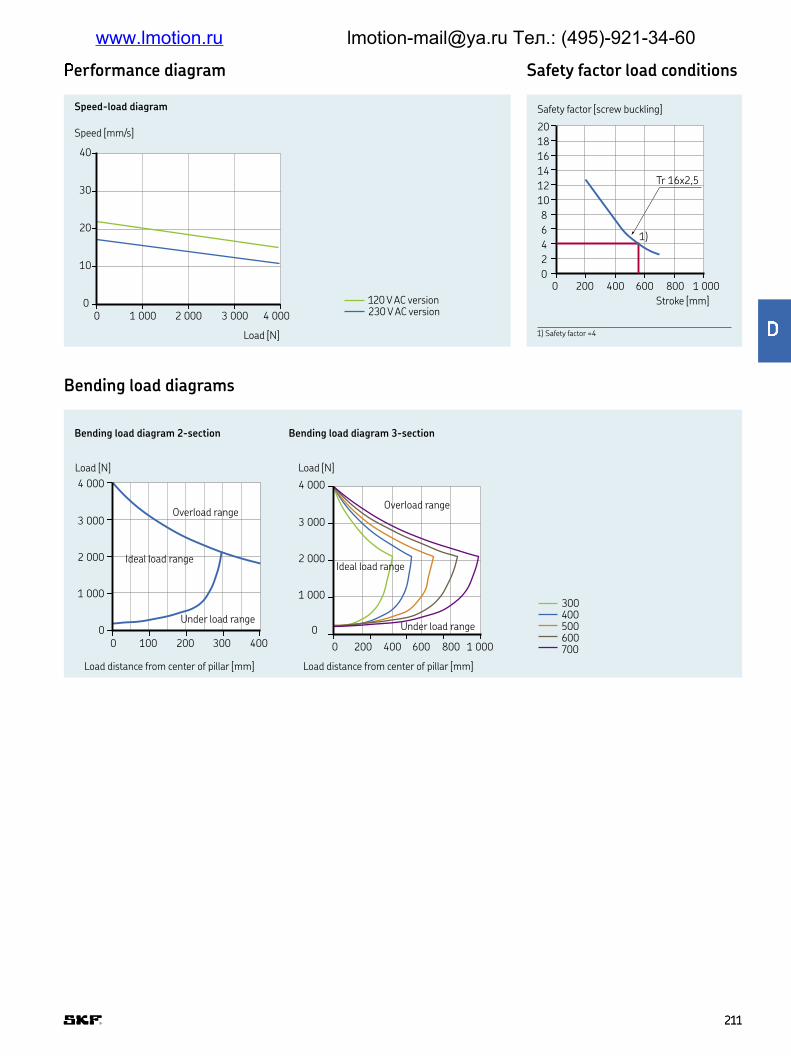
ferformance diagram
Bending load diagrams
Safety factor load conditions
3 000
4 000
2 000
1 000
0
0 100 200 300 400
3 000
4 000
2 000
1 000
0
0 200 400 600 1 000800
Speed [mm/s]
Load [N]
Speed-load diagram
Load distance from center of pillar [mm]
Bending load diagram 2-section Bending load diagram 3-section
Load [N]
Load distance from center of pillar [mm]
Load [N]
Ideal load range
Overload range
Under load range
Ideal load range
Overload range
Under load range
Stroke [mm]
Safety factor [screw buckling]
0
10
20
30
40
0 1 000 2 000 3 000 4 000
2
00 200
4
6
8
10
12
14
16
18
20
400 600 800 1 000
1)
Tr 16x2,5
1) Safety factor =4
120 V AC version230 V AC version
300400500600700
211211
g
www.lmotion.ru [email protected] Тел.: (495)-921-34-60

220
190
101
200170101
15∅20
∅11
∅22
Retracted
length ±2
Stroke ±2
4xM10x30
4xM10x30
220
190
129
200170129
15 ∅11
∅22
Supporting plate
Label position
220
15
L
S
200
15
220200
163
146
146
129
129
hijklminlpq rrawing
Connection diagramSuitable control units and accessories
PH
C
PFP
PAM
TLC pneumatic*
Hand switch
Foot switch
Desk switch
L
N
PE
L1 L2
LS
N L3PE
2xT6,3 A max
Electric
L
NPE
N
2xT6,3 A max
L1PE
LS
Pneumatic
LN
M
PE
120-230 V AC
* Integrated control unit
Note: mounting plates are not included To be ordered separately
Legend:S = strokeL = retracted length
2-section 3-section
212212
www.lmotion.ru [email protected] Тел.: (495)-921-34-60

sytv
wxz4 000 N Z3 000 N X2 000 N S
s|v ~vTube set 2× ATube set 3× B
xrolElectrical control SPneumatic control KLow-voltage control N
Voltage230 V AC/50 Hz (no code) –120 V AC/60 Hz 2Special voltage 9
Type of protection/test:Standard IP30 (no code) –UL approved U
Construction:Push load 0Customer-speciic 1Pull load 3
Stroke [S]:100 mm, only for tube set 2×, push 1255 mm, only for tube set 3×, push 1200 mm, only for tube set 2× 2300 mm 3400 mm 4500 mm 5600 mm 6700 mm 7
T L C 1 2 W – 0
Designation Order number
Top mounting plate for 2× tube set ZPL–290268 0125624Bottom mounting plate for 2× tube set ZPL–290351 0125625Top mounting plate for 3× tube set ZPL–290268 0125624Bottom mounting plate for 3× tube set ZPL–290265 0125623Screw (4/plate) for mounting plate ZBE–510707 0125360Plug AC Telemag 3 pin ZEL–265518 0124866Plug AC Telemag 5 pin ZEL–265519 0124864
Options written in blue are only available on demand Contact SKF for more information on minimum quantities and additional costs
Ordering key
Accessories
213213
www.lmotion.ru [email protected] Тел.: (495)-921-34-60

TLG
Telemag telescopic pillar
Beneits
• High bending load
• Powerful
Standards
• EN/IEC 60601–1
• UL 60601–1
Unit TLG 10/11–A TLG 10–B TLG 10/11–C
Rated push load N 4 000 2 500 1 500Rated pull load N 0 0 0Bending load Nm up to 2 8001) up to 1 7501) up to 9501)
Speed (full load to no load) mm/s 10 to 14 13 to 17 25 to 33Telescopic pillar version # of section 2 or 3-section 2 or 3-section 2 or 3-sectionStroke mm 200 to 700 200 to 700 200 to 700Retracted length mm S+180 S+180 S+180Voltage V DC 24 24 24Power W 156 156 156Current A 6 6 6Duty cycle: intermittent operation min 1 min /9 min 1 min /9 min 1 min /9 minAmbient temperature °C +10 to +40 +10 to +40 +10 to +40Type of protection IP 30 30 30Protection class – SELV SELV SELVType of control – electrical electrical electricalWeight kg 15 to 30 15 to 30 15 to 30
Technical data
1) For details, please see bending load diagrams († page 215)
214214
www.lmotion.ru [email protected] Тел.: (495)-921-34-60

erformance diagrams Safety factor load conditions
7
5
6
3
4
2
1
4 0003 0002 0001 00000
Speed [mm/s] Current consumption [A]
Load [N]
Speed-load diagram Current-load diagram
Load [N]
40
30
20
10
4 0003 0002 0001 00000
Bending load diagrams
0 100 200 300 400
50 150 250 350
1 000
0
500
1 500
2 000
2 500
3 000
3 500
4 000
0
0 400 800 1 200
200 600 1 000 1 400
3 000
4 000
2 000
1 000
Load distance from center of pillar [mm]
Bending load diagram TLG ...AD
Load [N]
Ideal load range
Overload range
Under load range
Stroke
Load distance from center of pillar [mm]
Bending load diagram TLG...AA/BA/CA
Load [N]
Ideal load range
Overload range
Under load range
0 400 800 1 200
200 600 1 000 1 400
0
2 500
2 000
1 000
500
1 500
Bending load diagram TLG ...BD
Load distance from center of pillar [mm]
Load [N]
Ideal load range
Overload range
Under load range
Stroke
Load distance from center of pillar [mm]
Bending load diagram TLG ...CD
Load [N]
0
0 200 400 600 800 1 000 1 200
500
1 000
1 500
Ideal load range
Overload range
Under load range
Stroke
Stroke [mm]
Safety factor
1) Safety factor = 4
20
C / Tr 12,5 x 10
B / Tr 15 x 5
A / Kr 14 x 4
15
10
5
1 000750
1)
50025000
A B C
TLG1-AATLG1-BATLG1-CA
200 300 400 500 600 700
215215
www.lmotion.ru [email protected] Тел.: (495)-921-34-60

220
190
101
15
∅22
∅11
200170101
∅20
25
25
129
146
4 x M10/3040 Nm
4 x M10/3040 Nm
220
190
129
15
200170129
∅11
∅22∅11
∅22
Stroke ±2
Retractedlength ±2
220
190
101
∅22
∅11200170101
∅20
25
25
129
146
163
4 x M10/3040 Nm
4 x M10/3040 Nm
220
190
146
15
200170146
15
Stroke ±2
Retractedlength ±2
2-section 3-section
Dimensional drawing
Suitable control units and accessories Connecting diagram
Control unit
SCU
VCU
BCU
MCU
TLG
Operating switches
EHA 1
EHA 3
STF
STJ
STA
STE
1) Only valid with TLG11 TLG10 must be operated by a BCU, MCU, SCU or VCU control unit
DIN Plugh - 24 V DC
+-
M
5V+
GND
1+7 2+4
1,5K 1,5K
Hall AHall B
3 5 6 8
DIN8 plug
Blue
2 Hallsensors signal
Actuator
Red
+-
M
Black
Actuator
Red
Jack Plugh - 24 V DC
Desk switchHand switch Foot switch
Note: mounting plates are not included To be ordered separately
Legend:S = strokeL = retracted length
216216
www.lmotion.ru [email protected] Тел.: (495)-921-34-60
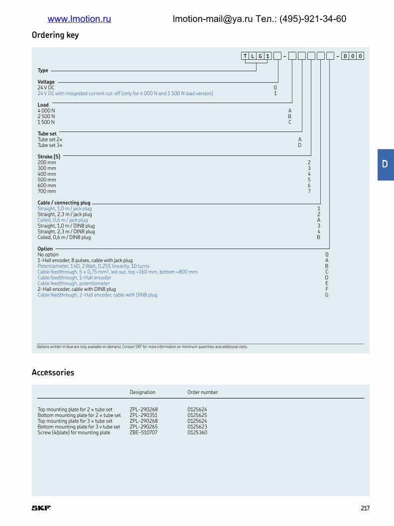
Designation Order number
Top mounting plate for 2 × tube set ZPL-290268 0125624Bottom mounting plate for 2 × tube set ZPL-290351 0125625Top mounting plate for 3 × tube set ZPL-290268 0125624Bottom mounting plate for 3 v tube set ZPL-290265 0125623Screw (4/plate) for mounting plate ZBE-510707 0125360
ccsories
Type
Voltage24 V DC 024 V DC with integrated current cut-off (only for 4 000 N and 1 500 N load version) 1
Load4 000 N A2 500 N B1 500 N C
Tube setTube set 2× ATube set 3× D
Stroke [S]200 mm 2300 mm 3400 mm 4500 mm 5600 mm 6700 mm 7
Cable / connecting plugStraight, 1,0 m / jack plug 1Straight, 2,3 m / jack plug 2Coiled, 0,6 m / jack plug AStraight, 1,0 m / DIN8 plug 3Straight, 2,3 m / DIN8 plug 4Coiled, 0,6 m / DIN8 plug B
OptionNo option 01-Hall encoder, 8 pulses, cable with jack plug APotentiometer, 1 kΩ, 2 Watt, 0,25% linearity, 10 turns BCable feedthrough, 5 × 0,75 mm2, led out, top +160 mm, bottom +800 mm CCable feedthrough, 1-Hall encoder DCable feedthrough, potentiometer E2-Hall encoder, cable with DIN8 plug FCable feedthrough, 2-Hall encoder, cable with DIN8 plug G
T L G 1 – – 0 0 0
Options written in blue are only available on demand Contact SKF for more information on minimum quantities and additional costs
Ordering key
217217
www.lmotion.ru [email protected] Тел.: (495)-921-34-60

TLT
Telemag telescopic pillar
Beneits
• Very small built-in dimension
• Powerful
Standards
• EN/IEC 60601–1
• UL 60601–1
Unit TLT10–A1 TLT10–A2 TLT10–B1 TLT10–C1 TLT10–C2
Rated push load N 3 000 4 000 2 000 1 000 2 000Rated pull load N 0 0 0 0 0Bending load Nm up to 4001) up to 1 0001) up to 2501) up to 1101) up to 4801)
Speed (full load to no load) mm/s 11 to 16 13 to 19 13 to 19 25 to 36 25 to 42Telescopic pillar version # of section 3-section 3-section 3-section 3-section 3-sectionStroke mm 300 to 700 300 to 700 300 to 700 300 to 700 300 to 700Retracted length mm 0,5 × S+170 0,5 × S+240 0,5 × S+170 0,5 × S+170 0,5 × S+240Voltage V DC 24 24 24 24 24Power W 168 168 192 192 216Current A 2×3,5 2×3,5 2×4,5 2×4,5 2×4,5Duty cycle: intermittent operation min 1 min /9 min 1 min /9 min 1 min /9 min 1 min /9 min 1 min /9 minAmbient temperature °C +10 to +40 +10 to +40 +10 to +40 +10 to +40 +10 to +40Type of protection IP 40 40 40 40 40Protection class – SELV SELV SELV SELV SELVType of control – electrical electrical electrical electrical electricalWeight kg 15 to 30 15 to 30 15 to 30 15 to 30 15 to 30
Technical data
1) For details, please see bending load diagrams († page 219)
218218
www.lmotion.ru [email protected] Тел.: (495)-921-34-60

0
0 100
500
4 000
200 500
1 000
1 500
2 000
2 500
3 000
3 500
300 4000
0 50 100
200400
3 000
150 200 300250
600800
1 0001 2001 4001 6001 8002 0002 2002 4002 6002 800
Speed [mm/s] Current consumption [A]
Speed-load diagram Current-load diagram
Speed [mm/s] Current consumption [A]
Load [N] Load [N]
Load [N]Load [N]
Load distance from center of pillar [mm]
Bending load diagram A1, B1, C1
Load [N]
Load distance from center of pillar [mm]
Bending load diagram A2, C2
Load [N]
Ideal load range
Overload range
Under load range
Ideal load range
Overload range
Under load range
4
0
8
12
16
20
24
28
32
36
40
0 1 000 2 000 3 000 4 000
0,5
0
1,0
1,5
2,0
2,5
3,0
3,5
4,0
4,5
5,0
0 1 000 2 000 3 000 4 000
5
0
10
15
20
25
30
35
40
45
50
0 1 000 2 000 3 000 4 000
0,5
0
1,0
1,5
2,0
2,5
3,0
3,5
4,0
4,5
5,0
0 1 000 2 000 3 000 4 000
Performance diagrams
Bending load diagrams
A1B1C1
TLT1 A-1TLT1 B-1TLT1 C-1
A2C2
TLT1 A-2TLT1 C-2
219219
www.lmotion.ru [email protected] Тел.: (495)-921-34-60
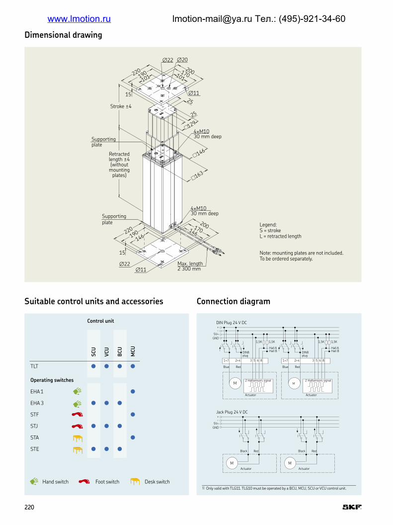
15 ∅11
∅22 ∅20
220190
101
200
25
170101
Stroke ±4
25
4×M1030 mm deep
4×M1030 mm deep
129
146
163
Supportingplate
Supportingplate
Retractedlength ±4(without
mountingplates)
200170146
15
220
190146
∅22∅11
Max. length2 300 mm
Legend:S = strokeL = retracted length
Note: mounting plates are not included To be ordered separately
Dimensional drawing
Connection diagramSuitable control units and accessories
DIN Plug 24 V DC+-
5V+
GND
1+7 2+4
1,5K 1,5K
Hall AHall B
Hall AHall B
3 5 6 8 3 5 6 8
DIN8 plug
Blue Red
M2 Hallsensors signal
Actuator
M
1+7 2+4
1,5K 1,5K
Actuator
2 Hallsensors signal
RedBlue
DIN8 plug
Jack Plug 24 V DC+-
5V+
GND
Black Red
M
Actuator
Black Red
M
Actuator
Desk switchHand switch Foot switch1) Only valid with TLG11 TLG10 must be operated by a BCU, MCU, SCU or VCU control unit
Control unit
SCU
VCU
BCU
MCU
TLT
Operating switches
EHA 1
EHA 3
STF
STJ
STA
STE
220220
www.lmotion.ru [email protected] Тел.: (495)-921-34-60

24 V DC 024 V DC with integrated current cut-off (only for A2 and C2) 1
4 000 N A23 000 N A12 000 N / 19 to 13 mm/s B12 000 N / 42 to 25 mm/s C21 000 N C1
roke [S]300 mm 3400 mm 4500 mm 5600 mm1) 6700 mm1) 7
Cable / connecting plugStraight, 1,0 m / jack plug 1Straight, 2,3 m / jack plug 2Coiled, 0,6 m / jack plug AStraight, 1,0 m / DIN8 plug 3Straight, 2,3 m / DIN8 plug 4Coiled, 0,6 m / DIN8 plug B
OptionNo option 01-Hall encoder, 8 pulses, cable with jack plug ACable feedthrough, 3x1,5 mm2, top +160 mm, bottom +800 mm CCable feedthrough, 1-Hall encoder D2-Hall encoder, cable with DIN8 plug F
T L T 1 – – 0 0 0
1) Reduced safety factorOptions written in blue are only available on demand Contact SKF for more information on minimum quantities and additional costs
Designation Order number
Top mounting plate ZPL-290268 0125624Bottom mounting plate ZPL-290265 0125623Screw (4/plate) for mounting plate ZBE-510707 0125360
Ordering key
Accessories
221221
www.lmotion.ru [email protected] Тел.: (495)-921-34-60

TXG
Telesmart telescopic pillar
Beneits
• Powerful and fast lifting
• Aesthetic design
Standards
• EN/IEC 60601–1
• UL 60601–1
Unit TXG1 TXG4/5 TXG8/9
Rated push load N 1 500 1 500 1 500Rated pull load N 0 0 0Bending load Nm up to 2101) up to 2101) up to 2101)
Speed (full load to no load) mm/s 17 to 23 17 to 23 17 to 23Telescopic pillar version # of section 2-section 2-section 2-sectionStroke mm 200 to 600 200 to 600 200 to 600 Retracted length mm S+180 S+180 S+180Voltage – 24 V DC 120 V AC 230 V ACPower W – N/A N/ACurrent A 5 1,8 0,9Duty cycle: intermittent operation min 1 min /9 min 1 min /9 min 1 min /9 min Duty cycle: short-time operation min – N/A N/AAmbient temperature °C +10 to +40 +10 to +40 +10 to +40Type of protection IP 30 30 30Protection class – SELV II/(I)2) II/(I)2)Type of control – electrical electrical electricalWeight kg 8 to 13 9 to 14 9 to 14
Technical data
1) For details, please see bending load diagrams († page 223)2) Mandatory for cable feedthrough option
222222
www.lmotion.ru [email protected] Тел.: (495)-921-34-60

erformance diagram Bending load diagram Safety factor load conditions
00 75 150 225 300
200
400
600
800
1 000
1 200
1 400
1 600
Speed [mm/s]
Speed-load diagram
Load [N]
00 500 1 000 1 500
5
10
15
20
25
Load distance from center of pillar [mm]
Load [N]
Ideal load range
Overload range
Under load range
Stroke [mm]
Safety factor (screw buckling)
00 150 300 450 600
5
10
15
20
Note: mounting plates are not included To be ordered separately
Legend:S = strokeL = retracted length
120150
170
190220
180
140
220
85
R 300
10
10
†9
†9
120150
55 140
190120
Retracted length ±2(without mounting plates)
Stroke ±2
4×M6×40 DIN 7 500 included
4×M6×40 DIN 7 500 included
Supportingplate
Dimensional drawing
223223
www.lmotion.ru [email protected] Тел.: (495)-921-34-60

¡¢ £¤¥rol units and accessories
Connection diagram
+
24 V DC
M
Black Red
Limit switches
Actuator
L
N
M
PE
120/230 V AC
Desk switchHand switch Foot switch
Control unit
CO
MPACT
TXG 10
Operating switches
EHA
HSM
HSF
224224
www.lmotion.ru [email protected] Тел.: (495)-921-34-60

¦§¨©
ª«¬®¯©24 V DC (slave actuator) 1120 V AC, 50/60 Hz, class II 4120 V AC, 50/60 Hz, class I (mandatory for cable feedthrough option) 5230 V AC, 50 Hz, class II 8230 V AC, 50 Hz, class I (mandatory for cable feedthrough option) 9
°olorNatural anodized coating 5Customer-speciic KPowder-coated white 2Powder-coated grey 3
OptionNone 000Control connection feedthrough EYXMains cable feedthrough EYF1-Hall encoder for Compact/slave use EYSControl connection feedthrough, mains cable feedthrough 2AACustomer-speciic KKK
Stroke (S) / Retr. length (L=S+180 or L= S+160 mm)L=S+180 L=S+160
200 mm 200 4CY300 mm 300 4DY400 mm 400 4EY500 mm 500 4FY600 mm 600 4GY
T X G 0 – 0 0 – 0 0
Mains cable Plug Country Order number Comment
Straight cable 3 m Euro General 0121730 2-poleStraight cable 3 m Schuko General 0121729 3-poleStraight cable 3 m UL USA 0126322 2-poleStraight cable 3 m SEV Switzerland 0128699 3-poleStraight cable 3 m UL USA 0121762 3-pole
Top or bottom mounting plate 0124874
Ordering key
Accessories
Options written in blue are only available on demand Please contact SKF
Mounting screws are included in the TXG
225225
±
www.lmotion.ru [email protected] Тел.: (495)-921-34-60

FRE
Telescopic pillar
Beneits
• Attractive design
• Stable
• Universal use
Dimensional drawings
20
20
A
B
A
M5
M5
72±0,3
163±0,4 86±0,3
129
146
102,5
113
97±0,2
59,3±0,2
76±0,2
69
146±0,2
123,7±0,4
146±0,4585±0,2
59±0,2
76±0,2
B
30
822
A
B
A M10
BM6
B
22 +1 0
22 +1 0
A
4xM6
B
M6
A
M10
A
A
4xM5
B
B
226226
www.lmotion.ru [email protected] Тел.: (495)-921-34-60

²³´µ ¶µ·¸¹º»¼ Proile dimensions in mm Retracted length in mm
2 sections 3 sections 76 x 76 85 x 85 97 x 97 113 x 113 129 x 129 146 x 146 163 x 163
FRE–A085 ◼ Stroke + 138FRE–A113 ◼ Stroke + 148FRE–A146 ◼ Stroke + 168FRE–A097 ◼ Stroke + 38FRE–A129 ◼ Stroke + 53FRE–A163 ◼ Stroke + 53FRE–A097 ◼ N/AFRE–A129 ◼ N/AFRE–A163 ◼ N/AFRE–A113 ◼ N/AFRE–A146 ◼ N/A
Type
Combination:2 sections tube-set /Largest tube size85×85 mm A085113×113 mm A113146×146 mm A14697×97 mm B097129×129 mm B129163×163 mm B1633 sections tube-set /Largest tube size97×97 mm D097129×129 mm D129163×163 mm D163113×113 mm E113146×146 mm E1464 sections tube-set (on request) V_5 sections tube-set (on request) F_6 sections tube-set (on request) S_7 sections tube-set (on request) Z_
Color:Natural anodized 5Black anodized 6
Option:No option 000Cover MCMPull version MCNPull version, with cover 2EA
Stroke:200 mm 20300 mm 30400 mm 40500 mm 50600 mm 60700 mm 70Other stroke lengths ---
F R E – – – 0 0 0
Ordering key
Options written in blue are only available on demand Please contact SKF
Options written in blue are only available on demand Please contact SKF
227227
½
www.lmotion.ru [email protected] Тел.: (495)-921-34-60

Chapter contents
6
BCU 230
VCU 234
SCU 238
MCU 242
COMPACT 246
SEM 250
229229
E
www.lmotion.ru [email protected] Тел.: (495)-921-34-60

BCU
Control unit
Beneits
• Compact 3-channel actuator control unit
• Single fault safety
• Overload and over-temperature
protection
• Approved for medical applications
• Easy to clean
• Low standby current
Unit BCU 5 BCU 8
Motor ports (DIN8) # 3 3Operating device ports (HD15) # 1 1Battery ports # 0 0Limit switch ports # 0 0
Single fault safety yes/no yes yesEncoder processing yes/no no no
Input voltage V AC 120 230Frequency Hz 60 50Input current (max) A 2,5 1,3Standby power W 1,2 1,5
Output voltage V DC 24 24Output current (max) A 7 7Duty cycle: intermittent min 1 min /9 min 1 min /9 min Duty cycle: short time min 2 2
Ambient temperature °C 0 to +40 0 to +40Humidity % 5 to 85 5 to 85Type of protection IP ×4 ×4Approvals IEC 60601-1(ed 3) IEC 60601-1(ed 3)
Weight kg 2,3 2,3
Technical data
230230
www.lmotion.ru [email protected] Тел.: (495)-921-34-60

¾¿ÀÁÂr actuators Pillars Operating switches
CALA 3
6A (24 V
DC)
CAR
E 3
3A
Magdri
ve M
D22, M
D23
RU
20, R
U21, R
U22
MA
X 1
0, M
AX 3
0
ECO
MAG
TH
G 1
0
TLG
10
TLT
10
TFG
10
CP
MT
1
TXG
10
EH
A3
CA
JH1
STJ
ST
E
BCU 5
BCU 8
Hand switch
Foot switch
Desk switch
7217
170
125
161
191
147,5
Dimensional drawing
Suitable control units and accessories
Option for earthing
Mains cable
Connection for 3 actuators
Connection hand switch
View without connectors interlock
Connecting drawing
231231
E
www.lmotion.ru [email protected] Тел.: (495)-921-34-60

ÃÄÅÆ
BCU control unit
Voltage:120 V AC, 60 Hz, class I 5230 V AC, 50 Hz, class II 8
Mains power supply cable:Class II, straight 3,5 m, 2-pole plug, EU (for voltage type 8) 2JClass II, straight 3,5 m, 2-pole plug, UK (for voltage type 8) 2HClass I, straight 3,5 m, 3-pole plug, UL (for voltage type 5) 2L
B C U 3 – 3 1 0 0 – 0 0 0 0
Each BCU needs a BCP
Type
BCU parameterization
Functionality:All channels individually 11Channel 2+1 21All channels simultaneously 30Trendelenburg T1
Motors:A CALA 36A (24V DC), ECO2, ECO3, ECO4, ECO5 3,7 A Actuator 1 –C CARE 33A, TLT101), TXG10 (EXG) 4,7 A Actuator 2 –E TFG, ECO6, ECO8, ECO9 5,7 A Actuator 3 –M MAX10, MAX30, THG10, TLG10 6,7 AR RU20, RU21, RU22 8,5 AD MD22, MD23 8,5 AS CPMT1–12) 8,5 AT CPMT1–22) 8,5 A
Soft start/stop:Hard 0Medium 3Soft (on request) 6
B C P 3 – 0 0 0 – 0 0 0
Ordering keys
1) TLT is a 2-motor actuator If simultaneous run is needed, BCP21-CC is recommended 2) Reduced lift capability : CPMT-1 up to 3 000 N, CPMT1-2 up to 4 000 N
232232
www.lmotion.ru [email protected] Тел.: (495)-921-34-60

VCU
Control unit
Beneits
• Compact 5-channel actuator control unit
• Single fault safety
• Overload and over-temperature
protection
• Approved for medical applications
• Easy to clean
• Low standby current
Unit VCU 5 VCU 8 VCU 9
Motor ports (DIN8) # 3 or 5 3 or 5 3 or 5Operating device ports (HD15) # 2 2 2Battery ports (DSub9) # 1 1 1Limit switch ports (HD15) # 2 2 2
Single fault safety yes/no yes yes yesEncoder processing yes/no no no no
Input voltage V AC 120 230 230Frequency Hz 60 50 50Input current (max) A 2,5 resp 6,5 1,3 resp 3,3 1,3 resp 3,3Standby power W 2,6 resp 3,9 2,6 resp 3,9 2,6 resp 3,9
Output voltage V DC 24 24 24Output current (max) A 7 resp 18 7 resp 18 7 resp 18Duty cycle: intermittent min 1 min /9 min 1 min /9 min 1 min /9 min Duty cycle: short time min 2 2 2
Ambient temperature °C +5 to +40 +5 to +40 +5 to +40Humidity % 5 to 85 5 to 85 5 to 85Type of protection IP ×4 ×4 ×4Approvals EN/UL EN 60601–1 EN 60601–1 EN 60601–1
UL 60601–1 UL 60601–1 UL 60601–1Weight without battery kg 2,4 resp 3,8 2,4 resp 3,8 2,4 resp 3,8Weight with battery kg 5,4 resp 8,8 5,4 resp 8,8 5,4 resp 8,8
Technical data
234234
www.lmotion.ru [email protected] Тел.: (495)-921-34-60

360
87
38
365
Operating voltage display (LED)
Dimensional drawing
Linear actuators Pillars Operating swzitches
CALA 3
6A (24 V
DC)
CAR
E 3
3A
Magdri
ve M
D22,
MD
23
RU
20, R
U21, R
U22
RU
23, R
U24, R
U25
MA
X 1
0, M
AX 3
0
ECO
MAG
TH
G 1
0
TLG
10
TLT
10
TFG
10
TXG
10
EH
A3
CA
JH1
STJ
ST
E
VCU 5
VCU 8
VCU 9
Hand switch
Foot switch
Desk switch
Suitable control units and accessories
340
13,5
4
1 2 3
5 6
50,5
75
15075
5,2
410Up to 5 connections with DIN8 plug
1 Two connections for HD15 operating devices
2 HD15 limit switch connection
3 Additional space for mounting
4 Data plate software
5 Mains connection
6 D-Sub 9 battery connection (optional)
Connecting diagrams
235235
È
www.lmotion.ru [email protected] Тел.: (495)-921-34-60

Function Pin Wire color (ZKA-160627-2500) Connecting diagram
24 V DC (common) 1,3,5,7,9 white/yellow, white/green, grey–pink, black, blueSwitch 1 2 brown–greenSwitch 2 4 red–blueNC 6,8,10,11,12,14 violet, red, pink, grey, yellow, brown20–40 V DC, max 50 mA 13 greenGND 15 white
Pin 1
Pin 2
Pin 3
Pin 4
Plug Designation Order number
Mains cable, 2 pole Euro ZKA-160608-3500 0105726Mains cable, 3 pole Schuko ZKA-160637-3500 0118821Mains cable, 3 pole SEV ZKA-160638-3500 0118822Mains cable, 3 pole UL ZKA-160639-3500 0105588Mains cable, 3 pole UK ZKA-160609-3500 0105631Mains cable, 3 pole UL, hospital grade ZKA-160640-3500 0118823Battery pack 2,7 Ah ZBA-160208-0400 0118806Rack for 4,5 Ah battery ZBA-160207-1000 0121266Detachable battery 4,5 Ah ZBA-160209 0119846
D=20
2,9
1 5
6 10
11 15
S1
S2
S3
Pinning of HD15 limit switch connection
Accessories
236236
www.lmotion.ru [email protected] Тел.: (495)-921-34-60

ÉÊËÌ
ÍÎÏ ÐÑÒÓrol unit
Voltage120 V AC, 60 Hz, class I 5230 V AC, 50 Hz, class II 8230 V AC, 50 Hz, class I 9
Number of channels3 channels 35 channels 6
Option 1No option (only VCUx3) 1Prepared for mounting of battery 2
Transformer7 A transformer 118 A transformer (for 5-channel version only) 3
V C U – 0 0 3 0 – 0 0 0
Each VCU needs a VCP
Type
VCU parameterization
FunctionalityAll channels individually 112 channels simultaneously + 1 or 3 individually
21
2 + 2 channels simultaneously + 1 individually 22All channels simultaneously, only 3-channel version 304 channels simultaneously + 1 individually, only 5-channel version
41
All channels simultaneously, only 5-channel version 50Trendelenburg (2 channels) + 1 or 3 individually T1
ActuatorsA CALA 36A (24V DC), ECO2, ECO3,
ECO4, ECO53,7 A Actuator 1 –
C CARE 33A, TLT10*, TXG10 (EXG) 4,7 A Actuator 2 –E TFG, ECO6, ECO7, ECO8, ECO9 5,7 A Actuator 3 –M MAX10, MAX30, TLG10, THG10 6,7 A Actuator 4 – 1)
R RU20, RU21, RU22 8,5 A Actuator 5 – 1)
D MD22, MD23 8,5 AU RU23, RU24, RU25 11,7 A
1) for VCUx3: insert zero
SoftstartHard= start 0 ms, stop 0 ms 0Medium= start 400 ms, stop 200 ms 3
The SCU solution offers many more possibilities than those given in the type keys Please feel free to ask for more functions like “virtual limit switches”, “external limit switches” and so on
V C P – 0 – 0 0 0
Ordering keys
1) TLT is a 2-motor actuator If simultaneous run is needed, VCP21-CC is recommended
237237
Ô
www.lmotion.ru [email protected] Тел.: (495)-921-34-60

SCU
Control unit
Beneits
• Compact 6-channel actuator control unit
• Single fault safety
• Overload and over-temperature
protection
• Approved for medical applications
• Easy to clean
• Low standby current
• Remote control RS232
Unit SCU 1 SCU 5 SCU 9
Motor ports (DIN8) # 6 3 or 6 3 or 6Operating device ports (HD15) # 3 3 3Battery ports (DSub9) # 1 1 1Limit switch ports (HD15) # 4 4 4
Single fault safety yes/no yes yes yesEncoder processing yes/no yes yes yes
Input voltage V 24 DC 120 AC 230 ACFrequency Hz N/A 60 50Input current (max) A 30 6,5 3,3Standby power W 0,8 4,3 4,3
Output voltage V DC 24 24 24Output current (max) A 30 18 18Duty cycle: intermittent min 1 min /9 min 1 min /9 min 1 min /9 min Duty cycle: short time min 2 2 2
Ambient temperature °C +5 to +40 +5 to +40 +5 to +40Humidity % 5 to 85 5 to 85 5 to 85Type of protection IP ×4 ×4 ×4Approvals EN/UL EN 60601–1 EN 60601–1 EN 60601–1
UL 60601–1 UL 60601–1 UL 60601–1Weight without battery kg 1,2 3,8 3,8Weight with battery kg 4,2 6,8 6,8
Technical data
238238
www.lmotion.ru [email protected] Тел.: (495)-921-34-60

ÕÖ×ØÙr actuators Pillars Operating switches
Magdri
ve M
D22,
MD
23
RU
20, R
U21, R
U22
RU
23, R
U24, R
U25
MA
X 1
0, M
AX 3
0
ECO
4F,
ECO
5F,
ECO
8F,
ECO
9F
CA
JA35C
TH
G 1
0
TLG
10
CP
MT
1
TLT
10
TFG
10
EH
A3
CA
JH1
STJ
ST
E
SCU 1
SCU 5
SCU 9
Hand switch
Foot switch
Desk switch
360
87
38
365
Operating voltage display (LED)
340
13,5
4
1 2 3
5 7 6
50,5
75
15075
5,2
410Up to 6 connections with DIN8 plug
1 Three connections for HD15 operating devices
2 HD15 limit switch connection
3 Additional space for mounting
4 Data plate software
5 Mains connection
6 D-Sub 9 battery connection (optional)
7 Communication interface (optional)
Connecting diagrams
Suitable control units and accessories
Dimensional drawing
239239
Ú
www.lmotion.ru [email protected] Тел.: (495)-921-34-60

Function Pin Wire color (ZKA-160627-2500) Connecting diagram
Switch 1 2 brown/greenSwitch 2 4 red/blueSwitch 3 6 violetSwitch 4 8 red24 V DC (com) 1, 3, 5, 7 white/yellow, white/green, grey/pink, black
Optional external power supplyfor binary outputs 9 blueBinary output 1 (22-40 V DC/1 A) 10 pinkBinary output 2 (22-40 V DC/1 A) 11 greyGND for binary outputs 12 yellow20-24 V DC, max 50 mA 13 green5 V DC pulsed 14 brownGND 15 white
Pin 1
Pin 2
Pin 3
Pin 4
Pin 5
Pin 6
Pin 7
Pin 8
Plug Designation Order number
Mains cable, 3 pole Schuko ZKA-160637-3500 0118821Mains cable, 3 pole SEV ZKA-160638-3500 0118822Mains cable, 3 pole UL ZKA-160639-3500 0105588Mains cable, 3 pole UK ZKA-160609-3500 0105631Mains cable, 3 pole UL, hospital grade ZKA-160640-3500 0118823Battery pack 2,7 Ah ZBA-160208-0400 0118806Rack for 4,5 Ah battery ZBA-160207-1000 0126155Detachable battery 4,5 Ah ZBA-160209 0126154
D=20
2,9
1 5
6 10
11 15
S1
S2
S3
S4
Pinning of HD15 limit switch connection on request (needs a customized SCP)
Accessories
240240
www.lmotion.ru [email protected] Тел.: (495)-921-34-60

ÛÜÝÞ
ßàá âãäårol unit
Voltage24 V DC (only for 6-channel version) 1120 V AC, 60 Hz, class I 5230 V AC, 50 Hz, class I 9
Number of channels3 channels 36 channels 6
BatteryNone (only for SCU16) 1Prepared for mounting of battery 2Under loor 2 7 Ah battery mounted 3
TransformerNone (only for SCU16) 0Standard (AC version) 3
InterfaceWithout RS232 0With RS232 (only for 6-channel version) 1
S C U – 0 0 3 – 0 0 0 0
Each SCU needs a SCP
Type
SCU parameterization
FunctionalityAll channels individually 11Channel 2+1(+1+1+1) 21Six (6) channel version 2+2+1+1 22Three (3) channel version, all channels synchronously 30Six (6) channel version 3+1+1+1 31Six (6) channel version 4+1+1 41Six (6) channel version, all channels synchronously 60Trendelenburg T+1 (+1+1) T1
ActuatorsA ECO4F, ECO5F 3,7 A Actuator 1 –C TLT 10* 4,7 A Actuator 2 –E TFG10, ECO8F, ECO9F 5,7 A Actuator 3 –M MAX10, MAX30, TLG10, THG10 6,7 A Actuator 4 – 1)
R RU20, RU21, RU22 8,5 A Actuator 5 – 1)
D MD22, MD23 8,5 A Actuator 6 – 1)
U RU23, RU24, RU25 11,7 AS CPMT1-1 11,7 AT CPMT1-2 10,2 A1) for SCUx3: insert zero
SoftstartHardMediumSoft (on request)
The SCU solution offers many more possibilities than those given in the type keys Please feel free to ask for more functions like “virtual limit switches”, “external limit switches” and so on
S C P – – 0 0 0
Ordering keys
1) TLT is a 2-motor actuator If simultaneous run is needed, SCP21-CC is recommended
241241
æ
www.lmotion.ru [email protected] Тел.: (495)-921-34-60

MCU
Control unit
Beneits
• Suitable for mobile applications
• LED indication for battery charge level
• Audible signal for low charge condition
Unit MCU
Motor ports # 2Operating device ports # 1Battery ports # 1Limit switch ports # 0
Single fault safety yes/no noEncoder processing yes/no no
Input voltage V DC 28Frequency Hz N/AInput current (max) A 0,5Standby power W N/A
Output voltage V DC 24Output current (max) A 9,5Duty cycle: intermittent min 1 min /9 min Duty cycle: short time min N/A
Ambient temperature °C +10 to +40Humidity % 85Type of protection IP ™4Approvals EN/UL EN 60601-1/EN 60601-1-2/
UL 2601/EN ISO 10535Weight kg 4,9
Technical data
242242
www.lmotion.ru [email protected] Тел.: (495)-921-34-60

çèéêëìíî ïðñêrol units and accessories
Linear actuators Pillars Operating switches
MA
òó
M
ô X 3
ECO
MAG
TH
G
TLG
EH
A 1
ST
F
STA
MCU
Hand switch
Foot switch
Desk switch
446
271139
140
DC Operatingswitch
Motor 1 Motor 2
Dimensional drawing
Suitable control units and accessories
Connecting diagram
243243
õ
www.lmotion.ru [email protected] Тел.: (495)-921-34-60

ö÷÷øùsories
Ordering keys
Description Plug Designation Order number
Battery unit 4,5 Ah ZBA-142211 0100667Mains adapter 100-240 V AC Euro ZDV-142378-2500 0132841Mains adapter 100-240 V AC UL ZDV-142381-2500 0132843Mains adapter 100-240 V AC UK ZDV-142380-4000 0132842Wall charging station ZLA-142221 0126159Tool for connectors (Jack/D–Sub/Mains) ZWS-140375 0125322
Type
Number of channels1 channel 12 channels 2
OptionCurrent cut-off 6 A 000Current cut-off 9 A EXPCurrent cut-off 6 A, electric emergency lowering of channel 1 EYECurrent cut-off 9 A, electric emergency lowering of channel 1 2ATIndividual current cut-off 6 A (only for 2-channel version) EYR
M C L 1 – 0 0 3 – 0 0 0 0
244244
www.lmotion.ru [email protected] Тел.: (495)-921-34-60

COMPACT
Control unit
Beneits
• Synchronized movement of 3 actuators
possible
• Up to 4 memory positions (depending on
handset)
• Linking possibility of up to 4 control boxes
• Enhanced drive comfort
• Adjustable container – and shelf-stop
positions
• Low speed area
• High eficient switch mode power supply
(SMPS)
• Low standby power consumption, low ield
emission
Unit Compact
Motor ports (DIN8) # 3Operating device ports (DIN7) # 1Battery ports # 0Limit switch ports # 1(LogicConnector DATA)
Single fault safety yes/no noEncoder processing yes/no yes
Supply voltage / Frequency V AC/Hz EU: 207 - 254,4 / 50US: 90 -127 / 50-60
Nominal voltage / Frequency V AC/Hz EU: 230 / 50US: 120 / 60
Input current (max)120 V AC A 10230 V AC A 5Standby power W 0,5
Output voltage (rated) V DC 24Output sum current (rated) A 15Output current per channel (max)
A 8
Ambient temperature °C 0 to +30Humidity % 5 to 85Type of protection IP 20Protection class – IApprovals EN/UL EN 60335-1 /
UL 60950-1
Weight kg 0,5
Technical data
246246
www.lmotion.ru [email protected] Тел.: (495)-921-34-60

Pillars Operating switches
TM
A
TM
D
TFG
10
TXG
10
TO
UCH
-UD
-MD
F-4
M2-L
D
HS
M-O
D-2
-LD
HS
F-M
DF-4
M4-L
D
COMPACT
Hand switch
Foot switch
Desk switch
252
264
10345
375
136,8
2,8
1 Motor socket 1 (M1)2 Motor socket 2 (M2)3 Motor socket 3 (M3)S Handswitch socket (HS)P Mains socketF Functional earthD LogicConnector DATA for sensors,
squeeze lines and cascading
D
S1
23
PF
High-Power cycle: 20 s Up 19 A @20 V, 380 W20 s Down 7 A @33 V, 231 WPause: 9 min
Normal cycle 1/9: 30 s Up: 15 A @ 24 V, 360 W30 s Down: 7 A @ 33 V, 231 WPause: 9 min
Normal cycle 2/18 2 min run: 7 A @ 33 V, 231 WPause: 18 min
Dimensional drawing
Suitable control units and accessories
Switching cycles
247247
û
www.lmotion.ru [email protected] Тел.: (495)-921-34-60

üýþÿ
Nmber of used motors (optional, depending on parameter)3 motors (no additional designation required)2 motors 21 motor 1
Actuator typeTMA10 TMATMD10 TMDTFG10 TFGTXG10 TXG
Voltage120 VAC, 60 Hz, class I US230 VAC, 50 Hz, class I EU
C O M P A C T – E – 3 – – D I N – –
Description Designation Order number
Mains cable straight 3 m, Schuko plug (Germany, France, ) LOG-CBL-PWK 131665Mains cable straight 3 m, UK plug (UK) LOG-CBL-PWK-UK 131825Mains cable straight 3 m, UL plug (US) LOG-CBL-PWK-US-SJT 131666
Cascading cable 0,5 m length LOG-CBL-HT-SYNC-500 131678Cascading cable 1,5 m length LOG-CBL-HT-SYNC-1500 132061Split cable for LogicConnector DATA LOG-CBL-HT-LC-DATA-Y 132062Connection cable (squeeze bar to control box) LOG-CBL-HT-MOLEX-RJ45 132063
Description Designation Order number
Extra simple desk switch (up/down) HSM-OD-2-LD 123247Desk switch with display for 2 motorgroups (up/down and memory) HSF-MDF-4M4-LD 123246Desk switch with smart touch display (up/down and memory) TOUCH-UD-MDF-4M2-LD 131740
Accessories
Desk switches
Ordering keys
248248
www.lmotion.ru [email protected] Тел.: (495)-921-34-60

SEM
Control unit
Beneits
• Controls up to 4 actuators
• Suitable for homecare and nursing beds
Unit SEM1
Motor ports # 4Operating device ports # 1
Input voltage/Frequency V AC 230/50 HZV AC 120/60 HZ
Output voltage rating V DC 24Output current (max) A (DC) 5Duty cycle min 1 min /9 min Ambient temperature °C +10 to +40 Type of protection IP ×4Approvals UL UL60601-1 (1st edition)Weight kg 1,8
Technical data
250250
www.lmotion.ru [email protected] Тел.: (495)-921-34-60

Dimensional drawing
Linear actuators
Operating switches
ECO
MAG
EH
E1
SEM1
Hand switch
Foot switch
Desk switch
Suitable control units and accessories
Connecting diagrams
146
70
26 42
5,7
17
102
130
3000 ± 80
4
3
HS
2
1
118
116
117
Connection for 4 actuators
Connecting
operating
switch4 3 2 1
251251
www.lmotion.ru [email protected] Тел.: (495)-921-34-60

Ordering key
Type
Number of channels:2 channel 24 channels 4
Voltage / Frequency230V / 50Hz 1120V / 60Hz 2
Mains plugProtection class II 2-pin mains plug (Euro standard) 1Protection class II 2-pin mains plug (British standard) 2Protection class II 2-pin mains plug (US) 3Protection class I 3-pin mains plug (Schuko) BProtection class I 3-pin mains plug (US) E
ColoursBlack AGrey RAL 7035 B
Options, electricalNone 0
FasteningPiggyback on Ecomag 0
S E M 1 – – 0 0 0
252252
www.lmotion.ru [email protected] Тел.: (495)-921-34-60

Chapter contents
10
CAES 256
EHA1 258
EHA3 260
EHE1 262
HSM, HSF, HSU 264
PHC 266
PFP 268
ST Foot switch 270
ST Desk swicth 272
STK 274
CAJH1 276
PAM 278
255255
F
www.lmotion.ru [email protected] Тел.: (495)-921-34-60

CAES
Hand switch
Beneits
• Robust ergonomic design
• Membrane keyboard
• Clearly marked keys
Unit CAES 31C
Max operating channels n° 1Operating power V DC/mA 30/33Type of protection IP 54Color – Black
149
30 –5
53
24
1 500 –50
Inwards movement [actuator]
Outwards movement [actuator]
Cable No 2 [Common]
Cable No 1 [Outwards]
Cable No 3 [Inwards]
Dimensional drawing
Technical data
256256
www.lmotion.ru [email protected] Тел.: (495)-921-34-60

Corol units
CAED
3-2
4R
CAED
5-2
4R
CAED
9-2
4R
CAEV 1
10/2
20
CAES 31C
CAES 31C (No connector, 2 buttons)
321
Suitable control units
Connecting diagram
Product ordering key
257257
F
www.lmotion.ru [email protected] Тел.: (495)-921-34-60

EHA1
Hand switch
Beneits
• Robust ergonomic design
• Tactile buttons, clearly marked
• Easy mountable fastening hook
15440
29
40
57
30
∅32
38×4215×42
DSUB 9
Unit EHA 1
Max. operating channels n° 2Operating power V DC/mA 12/50Type of protection IP 67Color – Grey
Dimensional drawing
Technical data
258258
www.lmotion.ru [email protected] Тел.: (495)-921-34-60

Lar actuators Control unit
MA
X 6
4, M
AX 6
5
MCU
EHA 1
Designation Order number
Hook with sticker ZBG–145361–000 0125538
Type
Number of channels1 channel 12 channels 2
HookYes mounted with hook 1Hook supplied separately 2
Cable / connecting plugCoiled, 1,3 m/2,5 m / D-sub 9-pin plug BStraight 2,5 m (min DIN 6-pin plug) CCoiled 1,0 m/2,0 m (min DIN 6-pin plug) DCoiled 2,5 m/3,5 m / D-sub 9-pin plug F
SymbolsNone 001 channel: Arrow up/down 10
Head 112 channels: Arrow up/down 20
Head/foot 22Level/head 23
E H A 1 – 1 N – 0 0 0
Suitable control units and pillars
Accessories
Ordering keys
259259
F
www.lmotion.ru [email protected] Тел.: (495)-921-34-60

EHA3
Hand switch
Beneits
• Robust ergonomic design
• Tactile buttons, clearly marked
• Easy mountable fastening hook
Unit EHA3
Max. operating channels n° 5Operating power V DC/mA 12/50Type of protection IP 67Color – GreyCable: Coiled 1,3 m/2,5 m – D-sub 15-pin
High density
38×4215×42
D-Sub 15 154
40
∅32
30
29
40
Note: hook included but not
mounted on the switch.
57
Dimensional drawing
Technical data
260260
www.lmotion.ru [email protected] Тел.: (495)-921-34-60

Pillars Control units
TFG
50
TFG
90
SCU
1
SCU
5
SCU
9
VCU
5
VCU
8
VCU
9
BCU
5
BCU
8
EHA3
Description Designation Order number
Hook with sticker ZGB–145361-000 0125538
Type
Number of channels1 channel 12 channels 23 channels 34 channels 45 channels 51 channel with 3 memory positions (only for SCU) A2 channels with 3 memory positions (only for SCU) B3 channels with 3 memory positions (only for SCU) C
SymbolsNone 001 channel: 2nd row from top Arrow up/down 10
Head 11Foot 12Level 13Anti-Trendelenburg 14
2 channels: 1st-2nd row from top Arrow up/down 20Head/foot 21Head/level 22Level/head 23Level/Anti-Trendelenburg 29
3 channels: 1st-3rd row from top Arrow up/down 30Head/foot/level 31Level/head/foot 32Level/Anti-Trendelenburg/Head 39
4 channels: 1st-4th row from top Arrow up/down 40Level/Anti-Trendelenburg/Head/Foot 47
5 channels: 1st-5th row from top Arrow up/down 50
E H A 3 – 2 3 M N – 0 0 0
Suitable control units and pillars
Accessories
Ordering keys
Options written in blue are only available on demand Please contact SKF
261261
F
www.lmotion.ru [email protected] Тел.: (495)-921-34-60

EHE1
Hand switch
Beneits
• Easy and precise
• Flexible and remote operation
• Ergonomic design
Unit EHE 1
Max. operating channels n° 2Operating power V DC/mA 38/50Type of protection IP ×7Color – GreyCable: Coiled 1,1 m/2,5 m – FCC plug
∅32
180
40
40
64
30
28
FCC plug
Note: hook mounted
on the switch
Dimensional drawing
Technical data
262262
www.lmotion.ru [email protected] Тел.: (495)-921-34-60

Pillars
TXG
41)
TXG
51)
TXG
81)
TXG
91)
EHE 1
1) Only with FCC plug
Description Designation Order number
Hook ZGB-145361-000 0125538
Suitable pillars
Accessories
Type
Number of channels1 channel2 channels
Symbols1 channel: Arrow up/down2 channels: Arrow up/down
E H E 1 – 1 B 1 B – 0 0 0
Ordering keys
263263
F
www.lmotion.ru [email protected] Тел.: (495)-921-34-60

HSM, HSF, HSU
Hand switch
Beneits
• Easy and precise
• Stylish design
• Different functions
Unit HSM-OD-2-LD HSF-MDF-4M4-LD HSU-OD-2-FCC
Max operating channels n° 1 1 or 2 1Operating power V DC/mA 5/50 5/50 5/50Type of protection IP 32 32 32Color – Black Black Black
Dimensional drawing
Technical data
66,7
384,2
14
45,8
11,217
9,6
110,2
105,2
129
119
63
5,2
42
215,5
21 3672
136
15
2
8 27
50
29,5
17,5
27
27
HSU-OD-2-FCC
HSU-OD-2-FCC
264264
www.lmotion.ru [email protected] Тел.: (495)-921-34-60

Pillars Control units
TXG
CO
MPACT
HSM-OD-2-LD
HSF-MDF-4M4-LD
HSU-OD-2-FCC
HSM-OD-2-LD (DIN7 plug)HSF-MDF-4M4-LD (DIN7 plug)HSU-OD-2-FCC (FCC plug, only for TXG)
Suitable control units
Product ordering key
265265
F
www.lmotion.ru [email protected] Тел.: (495)-921-34-60

PHC
Hand switch
Beneits
• Easy and precise
• Flexible and remote operation
• Ergonomic design
Unit PHC
Max operating channels n° 4Operating power V DC/mA N/AType of protection IP 66Color – Grey
59 39
28
130
150
2 000
160
Dimensional drawing
Technical data
266266
www.lmotion.ru [email protected] Тел.: (495)-921-34-60

r actuators
Pillars
MA
X
M X
61
TLC
pneum
ati
c
TG
C p
neum
ati
c
TH
C p
neum
ati
c
PHC
PHC 1 – 130517 (1 channel with arrows up/down, without hook)PHC 2 – 130625 (2 channels with arrows up/down, without hook)PHC 3 – 130756 (3 channels with arrows up/down, without hook)PHC 4 – 130955 (4 channels with arrows up/down, without hook)
Suitable linear actuators and pillars
Product ordering key
Other symbols / with hook on demand
267267
F
www.lmotion.ru [email protected] Тел.: (495)-921-34-60

PFP
Foot switch
Beneits
• Robust ergonomic design
• Easy and precise
• Flexible and remote operation
Unit PFP 1K PFP 1
Max. operating channels n° 1 1Operating power V DC/ mA N/A N/AType of protection IP 21 21Color – Grey Anthracite
86 106
211
195
PFP 1–121545
∅ 5,5
10690
2 000
PFP 1K–130652
38
6
318
2 000
∅ 5,5
Dimensional drawing
Technical data
268268
www.lmotion.ru [email protected] Тел.: (495)-921-34-60

r actuators1)
Pillars
MA
X
MA
X 6
1
TLC
pneum
ati
c
TG
C p
neum
ati
c
TH
C p
neum
ati
c
PFP
PFP 1K – 130652PFP 1 – 121545
Suitable linear actuators and pillars
Product ordering key
Other versions on request
269269
F
www.lmotion.ru [email protected] Тел.: (495)-921-34-60

ST
Foot switch
Beneits
• Easy and precise
• Ergonomic design
• Different plug options
Unit ST
Max operating channels n° 3Operating power V DC/mA 12/50Type of protection IP ×5Color – Blue/anthracite
82
105
4535 40
105
325
216
∅6,7 R100
192 224HD15 plug
D-Sub 9 plug
FCC plug
Technical data
Dimensional drawing
270270
www.lmotion.ru [email protected] Тел.: (495)-921-34-60

Pillars Linear actuators
Control units
TFG
50/9
0
TXG
4/5
/8/9
1)
MA
X 6
SCU
1
SCU
5
SCU
9
VCU
5
VCU
8
VCU
9
BCU
5
BCU
8
MCU
STJ
STF
Suitable control units and accessories
Description Designation Order number
Rubber feet (100 pcs ) ZBE-135310 0102879Sticker arrow up ZKL-135309-0001 0124871Sticker arrow down ZKL-135309-0002 0124870
Type
Product group:Classic, D-Sub9 or FCC plug FStandard, single-fault safety, HD15 plug J
Number of channels:One (1) channel 1Two (2) channels 2Three (3) channels 3
Cable / connecting plug:Coiled cable 1,3-2,5 m / D-sub plug LUCoiled cable 1,3-2,5 m / HD15 plug LWStraight cable 2,5 m / D-sub plug 0UStraight cable 2,5 m / FCC plug (only for STF01 and STF02) 0VStraight cable 2,5 m / HD15 plug 0W
Color:Anthracite 1Blue 4
Option:None 000Mounted with rubber feet MAY
Symbols:Arrow up/down (on each pair of buttons), 1–3 channels X1Arrow up/down, M/1, 2/3 (3 memory buttons) only for STJ03 37
S T 0 – – 0 0
Accessories
Ordering keys
1) Only with FCC plug
271271
F
www.lmotion.ru [email protected] Тел.: (495)-921-34-60

ST
Desk switch
Beneits
• Easy and precise
• Stylish design
• Memory position
STA straight STA 90°
Unit ST
Max operating channels n° 3Operating power V DC/mA 12/50Type of protection IP ×0Color – Black
62
104
146 149,5138 138
96107,596 20
54
62
54 ∅3,5
∅3,520
20 20
20 20
1812
64,511,5
STA 90°STA straight
Technical data
Dimensional drawing
272272
www.lmotion.ru [email protected] Тел.: (495)-921-34-60

Pillars1) Linear actuators1)
Control units
TFG
50/9
0
TXG
4/5
/8/9
2)
MA
X 6
SCU
1
SCU
5
SCU
9
VCU
5
VCU
8
VCU
9
BCU
5
BCU
8
MCU
STA
STE
Suitable control units and accessories
Type
Product group:Classic, D-Sub9 or FCC plug AStandard, single-fault safety wiring, HD15 plug E
Number of channels:One (1) channel 1Two (2) channels 2Three (3) channels 3
Cable / connecting plug:Straight cable 2,5 m / D-sub plug 0UStraight cable 1,5 m / FCC plug WVStraight cable 2,5 m / HD15 plug 0W
Option:No option 000Mounted on or underneath desktop, at a 90° angle MAU
Symbols:Up/down arrow on each pair of keys (1-3 channels) X1Up/down arrow, 3 memory functions M/1, M/2, M/3 (3 channels) 37
S T 0 – 6 – 0 0
Ordering keys
1) With integrated control units 2) Only with FCC plug
273273
F
www.lmotion.ru [email protected] Тел.: (495)-921-34-60

STK
Desk switch
Beneits
• Easy and precise
• Stylish design
• Tactile buttons with inger guide
• 2 colors LED for power and feedback
status
Unit STK
Max operating channels n° 1Operating power V DC/mA 12/50Color – GreyIndicator – 2 colors LED for power and feedback statusPlug – RJ45Symbols – with arrows up/down
Technical data
Dimensional drawing
4,2
7
6
10,5
L
55,839
38
17
66,7
20,8
8
12,3
STK01-SW3000-X100 STK01-UW3000-X100
L [mm] 500 1 000
274274
www.lmotion.ru [email protected] Тел.: (495)-921-34-60

Pillars Socket boxes
CP
MA1–1
CP
MA1–2
CP
MA2–2
ZD
V–348220–002
ZD
V–348221–002
STK01-SW3000-x100
STK01-UW3000-x100
Suitable control units and accessories
Product ordering key
Description Part number Order number
Desk switch with LED, cable 0,5 m STK01-SW3000-x100 130025Desk switch with LED, cable 1 m STK01-UW3000-x100 130026
275275
F
www.lmotion.ru [email protected] Тел.: (495)-921-34-60

CAJH1
Beneits
• Robust and elegant ergonomic
design with LED
• 2 positions fastening hook
• Ready for add-on customer sticker
Unit CAJH1
Max. operating channels n° 5Operating power V DC/mA 12/50Type of protection IP ×4Color – GreyCable: Coled 1,3 m/2,5 m – 0-sub 15-pin
Technical data
Dimensional drawing
500±30
510±30300±30
Section A-A
168,4
A
A
1,5
64,1
59,9
∅ 20
23,8
High density
D-Sub 15
∅ 32a32
276276
www.lmotion.ru [email protected] Тел.: (495)-921-34-60

Pillars Control units
TFG
50
TFG
90
SCU
1
SCU
5
SCU
9
VCU
5
VCU
8
VCU
9
BCU
5
BCU
8
CAJH1
Suitable control units and accessories
Accessories
Description Part number Order number
Hook with clips ZGB-145361-000 M/0125538
Type
Number of channels/Symbols1 channel No symbols 100
Arrow up/down 1A0Arrow up/down / with 3 memory positions 1A1Customized 1B1
2 channels No symbols 200Arrow up/down 2A0Arrow up/down / with 3 memory positions 2A1Customized 2B1
3 channels No symbols 300Arrow up/down 3A0Arrow up/down / with 3 memory positions 3A1Customized 3B1
4 channels No symbols 400Arrow up/down 4A0Customized 4B1
5 channels No symbols 500Arrow up/down 5A0Customized 5B1
Suspensionwithout hook 0hook mounted 1
Logono 0Logo according to customer speciication 1
CableHigh density D-Sub 15p Coiled cable 1,3 m / 2,3 m A
Protection ClassIPX4 4
C A J H 1 – A 4
Ordering keys
277277
F
www.lmotion.ru [email protected] Тел.: (495)-921-34-60

PAM
Pneumatic desk switch
Beneits
• Operation with air (no electricity)
• Stylish design
Unit PAM –130256
Max operating channels n° 1Operating power V DC/ mA N/AType of protection IP N/ATube – Straight, 1,50 mColor – Anthracite
Technical data
Dimensional drawing
14
15
6,5
4,5
8 1
29
62
81 24
5
5
Linear act. Pillars
MA
X
MA
X 6
1
TLC
pneum
ati
c
TG
C p
neum
ati
c
TH
C p
neum
ati
c
PAM
Suitable control units and accessories
Product ordering key
PAM–130256
278278
www.lmotion.ru [email protected] Тел.: (495)-921-34-60

Glossary
AAe vee A move referenced from a ixed absolute zero position
Acceleration The change in velocity as a function of time, going from a lower speed to a higher speed
Accuracy An absolute measurement deining the difference between expected and actual position
Actuator An actuator is a device that is responsible for moving or controlling a mechanism or system also known as cylinder, electromechanical cylinder or linear actuator
Ambient temperature
The temperature of the cooling medium, usually air, immediately surrounding the actuator or another device
Angular contact ball bearing
Angular contact ball bearings have raceways in the inner and outer rings that are displaced relative to each other in the direction of the bearing axis This means that they are designed to accommodate combined loads, i e simultaneously acting radial and axial loads
Anodized Protective treatment for aluminium that involves subjecting the metal to electrolytic action in a chemical bath, to create a protective ilm of aluminium oxide with a very smooth inish
Axial load Load where the force is acting along the axis of actuator (bearing) in any direction
BBacklash The amount of play between a set of moveable parts when changing the direction of travel Typically seen in
drive trains, ball/ lead screws and bearings
Ball bearing A support device which allows a smooth low friction motion between two surfaces loaded against each other with balls as rolling elements
Ball screw A screw assembly which uses a ball nut which contains one or more circuits of recirculating steel balls which roll between the nut and the screw
Bearing A support device which allows a smooth low friction motion between two surfaces loaded against each other
Brushless DC motor Synchronous motor type that are powered by a DC electric supply through an inverter that produce an AC signal to drive the motor
Bushing A cylindrical sleeve inserted into a machine part to reduce friction between moving parts
CConigurator (product)
Name given to the software that uses the coniguration string to build-up a speciic actuator from an existing list of components and options
Continuous torque Is the torque that the motor is able to provide continuously with no limitation in time
Current The low of charge through a conductor
Cycle A complete motion of an actuator from the start position via intermediate positions and back to the start position
Cycle time Time for one complete motion cycle, from the start of the cycle until the start of the next cycle
Cylinder A mechanical device which produces a linear force to achieve a reciprocating linear motion There three com-mon types: pneumatic, hydraulic and electromechanical (or electric) The irst two use the power of com-pressed media (gas or liquid) while the latter uses a mechanical device (screw) to transform the rotational input movement of a motor into a linear one
280280
www.lmotion.ru [email protected] Тел.: (495)-921-34-60

DD!"eleration The change in velocity as a function of time, going from a higher speed to a lower speed
Duty cycle The ratio of motor on time and total cycle time within a given cycle of operation
Dynamic load rating Constant that is used to calculate the service life of a screw drive The value for the dynamic load rating repre-sents the load under which 90% of a suficient large number of identical screw drives can achieve a service life of one million revolutions
EEficiency Ratio of output power versus input power
Electric cylinder A self-contained system which converts rotary motion (from a motor) to linear motion
Electromechanical cylinder
A self-contained system which converts rotary motion (from a motor) to linear motion
Electrode The part of a resistance welding gun that facilitates the high voltage current path to the parts being welded
Equivalent dynamic axial load
Load of constant magnitude over a full motion cycle which has the same inluence on the linear unit’s service life as the actual luctuating load
FFoot mount Mounting plates, attached to front and end of a cylinder, to mount the cylinder in parallel to a lat surface
Force The action of one body on another which tends to change the state of motion of that body Typically described in terms of magnitude, direction and point of application
Friction The resistance to motion of two surfaces that are in direct contact
G
Gear ratio This relates to the transmission and conversion of movements, linear and rotary speeds, forces and torques in a geared mechanism The gear ratio (also known as reduction ratio) is the ratio between the input and output variable, e g the ratio of input speed to output speed
HHall effect sensor A magnetically controlled transistor switch controlling DC power It has no moving parts and theoretically
unlimited contact life
Holding force Maximum external force that can be applied to a stopped actuator, without causing any linear movement It is usually given by the holding torque of an electromechanical brake applied on the motor
Humidity (relative) A ratio that indicates the amount of water vapor in the air It is usually expressed as a percentage At any tem-perature, it is the amount of water vapor in the air, divided by the amount that would be present at saturation
I
Inertia Property of an object that resists a change in motion It is dependent on the mass and shape of the object The greater an object's mass, the greater its inertia and the more force is necessary to accelerate and decelerate it
IP Degrees of protection provided by enclosures, according with IEC standard 60529
KKeyway An axially-located groove in the length of a shaft along which a key may be located
L
Lead Describes the axial distance a nut is moving on a screw at one full rotation of either the screw or the nut
Lead screw A screw which uses a threaded screw design (e g with trapezoidal shaped thread) with sliding surfaces between the screw and nut
Lifetime Service life in km that 90% of a suficiently large group of apparently identical cylinders can be expected to reach or exceed
Limit switch A switch that is actuated by some part of motion of a machine or equipment to alter the electrical circuit asso-ciated with it
281281
G
www.lmotion.ru [email protected] Тел.: (495)-921-34-60
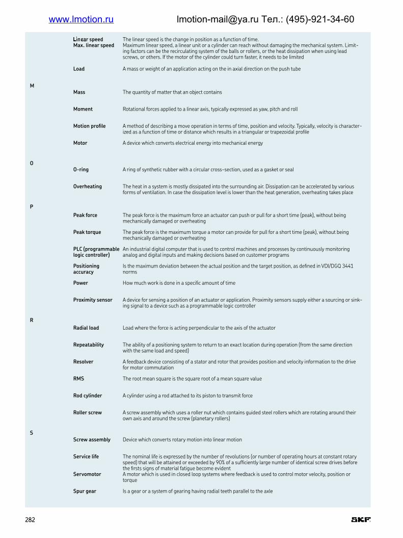
#$%&'r speed Max. linear speed
The linear speed is the change in position as a function of time Maximum linear speed, a linear unit or a cylinder can reach without damaging the mechanical system Limit-ing factors can be the recirculating system of the balls or rollers, or the heat dissipation when using lead screws, or others If the motor of the cylinder could turn faster, it needs to be limited
Load A mass or weight of an application acting on the in axial direction on the push tube
MMass The quantity of matter that an object contains
Moment Rotational forces applied to a linear axis, typically expressed as yaw, pitch and roll
Motion proile A method of describing a move operation in terms of time, position and velocity Typically, velocity is character-ized as a function of time or distance which results in a triangular or trapezoidal proile
Motor A device which converts electrical energy into mechanical energy
OO-ring A ring of synthetic rubber with a circular cross-section, used as a gasket or seal
Overheating The heat in a system is mostly dissipated into the surrounding air Dissipation can be accelerated by various forms of ventilation In case the dissipation level is lower than the heat generation, overheating takes place
P
Peak force The peak force is the maximum force an actuator can push or pull for a short time (peak), without being mechanically damaged or overheating
Peak torque The peak force is the maximum torque a motor can provide for pull for a short time (peak), without being mechanically damaged or overheating
PLC (programmable logic controller)
An industrial digital computer that is used to control machines and processes by continuously monitoring analog and digital inputs and making decisions based on customer programs
Positioning accuracy
Is the maximum deviation between the actual position and the target position, as deined in VDI/DGQ 3441 norms
Power How much work is done in a speciic amount of time
Proximity sensor A device for sensing a position of an actuator or application Proximity sensors supply either a sourcing or sink-ing signal to a device such as a programmable logic controller
R
Radial load Load where the force is acting perpendicular to the axis of the actuator
Repeatability The ability of a positioning system to return to an exact location during operation (from the same direction with the same load and speed)
Resolver A feedback device consisting of a stator and rotor that provides position and velocity information to the drive for motor commutation
RMS The root mean square is the square root of a mean square value
Rod cylinder A cylinder using a rod attached to its piston to transmit force
Roller screw A screw assembly which uses a roller nut which contains guided steel rollers which are rotating around their own axis and around the screw (planetary rollers)
SScrew assembly Device which converts rotary motion into linear motion
Service life The nominal life is expressed by the number of revolutions (or number of operating hours at constant rotary speed) that will be attained or exceeded by 90% of a suficiently large number of identical screw drives before the irsts signs of material fatigue become evident
Servomotor A motor which is used in closed loop systems where feedback is used to control motor velocity, position or torque
Spur gear Is a gear or a system of gearing having radial teeth parallel to the axle
282282
www.lmotion.ru [email protected] Тел.: (495)-921-34-60

St(t)* (+)(, -orce Maximum axial force which can be applied on a linear unit only if it is not moving
Stiffness Is the rigidity of an object, representing its resistance to deformation from an applied force
Stroke length The linear distance that the push tube of a cylinder can extend or retract
TThermal load The thermal load describes the force which the actuator can permanently move without overheating The
thermal load is calculated by a formula in respect of changing load conditions over different time phases of a full motion cycle
Torque A measure of angular force which produces rotational motion
U
Units (metric) A decimal system of weights and measures based on the kilogram and meter
VVolt Difference in electrical potential between two points
W
Watt A unit of power or a rate of doing work The power dissipated by a one-ohm resistor with one ampere of cur-rent is one watt
Weight Force of gravity acting on a body Determined by multiplying the mass of the object by the acceleration due to gravity
283283
G
www.lmotion.ru [email protected] Тел.: (495)-921-34-60

.a m/s2 .//eleration The change in velocity as a function of time, going from a lower speed to a higher speed
amax m/s2 Max. acceleration The maximum allowed change in velocity as a function of time from a lower speed to a higher speed Exceed-ing this value can cause damages
CC kN Dynamic load
capacityConstant that is used to calculate the service life of a ball or roller screw The value for the dynamic load rating represents the load under which 90% of a suficient large number of identical screws can achieve a service life of one million revolutions
DD % Duty cycle of the
cylinderThe ratio of active time at full load and total cycle time within a given cycle of operation
Dunit % Duty cycle of the linear unit
The ratio of active time and total cycle time within a given cycle of operation
dscrew mm Screw diameter Describes the outer diameter of the screw shaft
Eη % Eficiency Ratio of output power versus input power
ηlu % Eficiency of the linear unit
Ratio of output power versus input power of the linear unit
FF N Force (cylinder) or
load (application)The action of one body on another which tends to change the state of motion of that body Typically described in terms of magnitude, direction and point of application The force is related to the capability of the cylinder while the load is related to the mass or weight of an application acting on the axial direction on the push tube
FAmax N Maximum dynamic axial load of the application
Maximum axial push or pull load which is needed to fulill the speciications of the application
Fc N Continuous force at max speed
The continuous force at max speed describes the force the cylinder can permanently move at maximum allowed linear speed, without overheating
Fc0 N Continuous force at zero speed
The continuous force at zero speed describes the force the cylinder can permanently hold without overheating and without using a brake
Fcont Continuous force curve
A curve that represents the continuous force an actuator can permanently move at maximum allowed linear speed, without overheating
FHold kN Holding force of the brake
Describes the maximum axial load the engaged brake (optional motor brake) can hold if the motor is disabled This value must not exceed the maximum axial force of the cylinder
Fm N Equivalent dynamic axial load
Load of constant magnitude over a full motion cycle which has the same inluence on the linear unit’s service life as the actual luctuating load
Fmax N Maximum dynamic axial force
The maximum dynamic axial force describes the maximum force an electric cylinder can deliver during move-ments without damaging parts The acceleration/ deceleration of masses need to be considered
Fmax0 N Max. static axial force
Maximum axial force which can be applied on a linear unit only if it is not moving
Fp N Peak force The peak force describes the maximum force the cylinder can push or pull for a short time, without being mechanically destroyed or by overheating The length of the peak is depending on the temperature of the sys-tem when the peak is initiated
Fp0 N Peak force at zero speed
The peak force at zero speed is the maximum force the cylinder can hold for a short time without using a brake
Symbols description
284284
www.lmotion.ru [email protected] Тел.: (495)-921-34-60

Fpeak P012 3orce curve A curve that represents the continuous force an actuator can push or pull for a short time, without being mechanically destroyed or by overheating The length of the peak is depending on the temperature of the sys-tem when the peak is initiated
Ii # Gear reduction Describes the factor between the number of revolutions of the input of the gear divided by the number of rev-
olutions of the output of the gear A gear reduction 2 means that the output of the gear (linear unit side) is turning with half speed compared to the input of the gear (motor side) Using a gear reduction enables for using smaller motors with less torque to bring higher force but with lower speed
I A Nominal Current Is the nominal current consumption of the motor
Ipeak A Peak current Is the maximum current consumption of the motor for a short period of time
IP Degree of protection
International protection (also ingress protection) describes the protection of a product with two digits The irst digit describes the protection against dust, the second against water The higher the value the better the protection
J
J 10-4 kgm2
Inertia Property of an object that resists a change in motion It is dependent on the mass and shape of the object The greater an object’s mass, the greater its inertia and the more force is necessary to accelerate and decelerate As an electric cylinder is available in different lengths, the inertia is typically given for stroke 0, followed by an inertia indication ΔJ for each additional 100 mm
Jbrake 10-4 kgm2
Inertia of the brake Property of an object that resists a change in motion It is dependent on the mass and shape of the object The greater an object’s mass, the greater its inertia and the more force is necessary to accelerate and decelerate As the brake is typically an option, this value has to be added to the Inertia of the electric cylinder
Jlu 10-4 kgm2
Inertia of the linear unit
Property of an object that resists a change in motion It is dependent on the mass and shape of the object The greater an object’s mass, the greater its inertia and the more force is necessary to accelerate and deceler-ate As the linear unit is available in different lengths, the inertia is typically given for stroke 0, followed by an inertia indication ΔJ for each additional 100 mm
LL10 dist km Lifetime distance Service life in km that 90% of a suficiently large group of apparently identical cylinders can be expected to
reach or exceed
M
m kg Weight Force of gravity acting on a body Determined by multiplying the mass of the object by the acceleration due to gravity
Δm kg Weight difference As electric cylinders are available in different lengths, the weight is typically given for stroke 0, followed by a weight indication Δm for each additional 100 mm
marot0 kg Weight of the anti-rotation device
The weight of the optional anti-rotation device has to be added to the weight of the cylinder
mbrake kg Weight of the brake The weight of the optional brake has to be added to the weight of the cylinder
mlu kg Weight of the linear unit
As the linear unit is available in different lengths, the weight is typically given for stroke 0, followed by a weight indication Δm for each additional 100 mm
M Nm Torque A measure of angular force applied to a linear axis to produce rotational motion
MAc Nm Required continu-ous torque
A measure of continuous angular force (torque) a motor has to deliver without overheating
MAmax Nm Required maximum torque of the motor
Maximum angular force (torque) of a motor which is required that the cylinder is able to push or pull the maxi-mum load of the application
Mmax Nm Maximum torque The maximum torque is the upper limitation of the torque Exceeding this value can cause damages of related parts
N
ncycles # Number of cycles The number of motion cycles a cylinder has to have without damage during the expected life of the application
nmax 1/min Max. rotational speed
Describes the maximum allowed number of full rotations of an axis Exceeding this value can cause damages
PP W Nominal Power Nominal power of the motor, given by multiplying the nominal voltage and the nominal current
pscrew mm Screw lead Describes the axial distance a nut is moving on a screw at one full rotation of either the screw or the nut
285285
H
www.lmotion.ru [email protected] Тел.: (495)-921-34-60
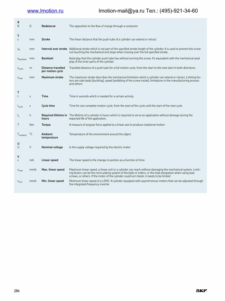
R
R Ω R456578n94 The opposition to the low of charge through a conductor
:s mm :7roke The linear distance that the push tube of a cylinder can extend or retract
s0 mm Internal over stroke Additional stroke which is not part of the speciied stroke length of the cylinder It is used to prevent the screw nut touching the mechanical end stops when moving over the full speciied stroke
sbacklash mm Backlash Axial play that the cylinder push tube has without turning the screw It’s equivalent with the mechanical axial play of the inner parts of the cylinder
scycle m Distance travelled per motion cycle
Travelled distance of a push tube for a full motion cycle, from the start to the next start in both directions
smax mm Maximum stroke The maximum stroke describes the mechanical limitation which a cylinder can extend or retract Limiting fac-tors are side loads (buckling), speed (wobbling of the screw inside), limitations in the manufacturing process and others
Tt s Time Time in seconds which is needed for a certain activity
tcycle s Cycle time Time for one complete motion cycle, from the start of the cycle until the start of the next cycle
tL h Required lifetime in hours
The lifetime of a cylinder in hours which is required to serve an application without damage during the expected life of the application
T Nm Torque A measure of angular force applied to a linear axis to produce rotational motion
Tambient °C Ambient temperature
Temperature of the environment around the object
UU V Nominal voltage Is the supply voltage required by the electric motor
Vv m/s Linear speed The linear speed is the change in position as a function of time
vmax mm/s Max. linear speed Maximum linear speed, a linear unit or a cylinder can reach without damaging the mechanical system Limit-ing factors can be the recirculating system of the balls or rollers, or the heat dissipation when using lead screws, or others If the motor of the cylinder could turn faster, it needs to be limited
vmin mm/s Min. linear speed Minimum linear speed of a LEMC-A cylinder equipped with asynchronous motors that can be adjusted through the integrated frequency inverter
286286
www.lmotion.ru [email protected] Тел.: (495)-921-34-60

www.lmotion.ru [email protected] Тел.: (495)-921-34-60

s;f<=>?
® SKF is registered trademark of the SKF Group
Apple and the Apple logo are trademarks of Apple Inc Google Play and the Google Play logo are trademarks of Google Inc
© SKF Group 2018
The contents of this publication are the copyright of the publisher and may not be reproduced (even extracts) unless prior written permission is granted. Every care has been taken to ensure the accuracy of the information contained in this publication but no liability can be accepted for any loss or damage whether direct, indirect or consequential arising out of the use of the information contained herein.
@UB MT/P1 18098 EN · November 2018
Certain image(s) used under license from Shutterstock.com.
www.lmotion.ru [email protected] Тел.: (495)-921-34-60
Copyright © 2022 FDOKUMEN