Maintenance Guide (Fusion Module Actuator) - Huawei ...
144
FusionModule2000 Smart Modular Data Center V100R021C00 Maintenance Guide (Fusion Module Actuator) Issue 01 Date 2020-12-25 HUAWEI TECHNOLOGIES CO., LTD.
-
Upload
khangminh22 -
Category
Documents
-
view
0 -
download
0
Transcript of Maintenance Guide (Fusion Module Actuator) - Huawei ...
FusionModule2000 Smart Modular Data Center
V100R021C00
Maintenance Guide (Fusion ModuleActuator)
Issue 01
Date 2020-12-25
HUAWEI TECHNOLOGIES CO., LTD.
Copyright © Huawei Technologies Co., Ltd. 2020. All rights reserved.
No part of this document may be reproduced or transmitted in any form or by any means without priorwritten consent of Huawei Technologies Co., Ltd. Trademarks and Permissions
and other Huawei trademarks are trademarks of Huawei Technologies Co., Ltd.All other trademarks and trade names mentioned in this document are the property of their respectiveholders. NoticeThe purchased products, services and features are stipulated by the contract made between Huawei andthe customer. All or part of the products, services and features described in this document may not bewithin the purchase scope or the usage scope. Unless otherwise specified in the contract, all statements,information, and recommendations in this document are provided "AS IS" without warranties, guaranteesor representations of any kind, either express or implied.
The information in this document is subject to change without notice. Every effort has been made in thepreparation of this document to ensure accuracy of the contents, but all statements, information, andrecommendations in this document do not constitute a warranty of any kind, express or implied.
Huawei Technologies Co., Ltd.Address: Huawei Industrial Base
Bantian, LonggangShenzhen 518129People's Republic of China
Website: https://www.huawei.com
Email: [email protected]
Issue 01 (2020-12-25) Copyright © Huawei Technologies Co., Ltd. i
About This Document
PurposeThis document describes FusionModule2000 smart modular data center(FusionModule2000 for short) in terms of routine maintenance, troubleshooting,and parts replacement. It aids regular verification, maintenance and promptsolutions for device potential faults.
Intended AudienceThis document is intended for:
● Technical support engineers● Commissioning engineers● Data configuration engineers● Maintenance engineers● Electrical engineers
Symbol ConventionsThe symbols that may be found in this document are defined as follows.
Symbol Description
Indicates a hazard with a high level of risk which, if notavoided, will result in death or serious injury.
Indicates a hazard with a medium level of risk which, if notavoided, could result in death or serious injury.
Indicates a hazard with a low level of risk which, if notavoided, could result in minor or moderate injury.
Indicates a potentially hazardous situation which, if notavoided, could result in equipment damage, data loss,performance deterioration, or unanticipated results.NOTICE is used to address practices not related to personalinjury.
FusionModule2000 Smart Modular Data CenterMaintenance Guide (Fusion Module Actuator) About This Document
Issue 01 (2020-12-25) Copyright © Huawei Technologies Co., Ltd. ii
Symbol Description
Supplements the important information in the main text.NOTE is used to address information not related topersonal injury, equipment damage, and environmentdeterioration.
Change HistoryChanges between document issues are cumulative. The latest document issuecontains all updates made in previous issues.
Issue 01 (2020-12-25)This issue is the first release.
FusionModule2000 Smart Modular Data CenterMaintenance Guide (Fusion Module Actuator) About This Document
Issue 01 (2020-12-25) Copyright © Huawei Technologies Co., Ltd. iii
Contents
About This Document................................................................................................................ ii
1 Safety Information.................................................................................................................. 11.1 General Safety.......................................................................................................................................................................... 11.2 Personnel Requirements....................................................................................................................................................... 41.3 Electrical Safety........................................................................................................................................................................41.4 Installation Environment Requirements.......................................................................................................................... 61.5 Mechanical Safety................................................................................................................................................................... 81.6 Cooling System Safety.........................................................................................................................................................101.7 Battery Safety......................................................................................................................................................................... 111.8 Others....................................................................................................................................................................................... 14
2 O&M Preparations.................................................................................................................152.1 O&M Personnel Skill Requirements................................................................................................................................152.2 Tools.......................................................................................................................................................................................... 152.3 Reference Documentation................................................................................................................................................. 18
3 Routine Maintenance........................................................................................................... 203.1 Overview.................................................................................................................................................................................. 203.2 Routine Maintenance Checklist....................................................................................................................................... 213.3 Monthly Maintenance......................................................................................................................................................... 233.4 Quarterly Maintenance....................................................................................................................................................... 283.5 Semiannual Maintenance.................................................................................................................................................. 363.6 Annual Maintenance........................................................................................................................................................... 48
4 Alarms and Troubleshooting.............................................................................................. 504.1 Alarm handling flowchart.................................................................................................................................................. 514.2 Viewing and Collecting Alarm Information................................................................................................................. 514.3 Determining the Faulty Area and Alarm Severity..................................................................................................... 524.4 Locating and Rectifying Faults......................................................................................................................................... 52
5 Parts Replacement................................................................................................................ 545.1 CommonECC800-Pro Operations.................................................................................................................................... 545.1.1 Preparations and WebUI Login..................................................................................................................................... 545.1.2 Performing Startup Password Authentication......................................................................................................... 575.1.3 Synchronizing the Configuration Parameters.......................................................................................................... 59
FusionModule2000 Smart Modular Data CenterMaintenance Guide (Fusion Module Actuator) Contents
Issue 01 (2020-12-25) Copyright © Huawei Technologies Co., Ltd. iv
5.2 Replacing Power Supply and Distribution System Components.......................................................................... 605.2.1 Parts Replacement for the Precision PDF..................................................................................................................605.2.2 Parts Replacement for the Integrated PDC.............................................................................................................. 605.2.3 Parts Replacement for the Integrated UPS...............................................................................................................615.2.4 Parts Replacement for the SmartLi............................................................................................................................. 615.2.5 Replacing an rPDU............................................................................................................................................................ 625.2.6 Replacing a Smart rPDU................................................................................................................................................. 625.2.7 Parts Replacement for the New Main Way.............................................................................................................. 635.3 Parts Replacement for the Cooling System................................................................................................................. 645.3.1 Parts Replacement for the NetCol5000 Smart Cooling Product....................................................................... 645.3.2 Parts Replacement for the NetCol500 Variable Speed Outdoor Unit............................................................. 655.4 Parts Replacement for the Management System......................................................................................................655.4.1 Parts Replacement for the ECC800-Pro..................................................................................................................... 655.4.1.1 Replacing an ECC800-Pro Main Control Module................................................................................................ 665.4.1.2 Replacing an ECC800-Pro PSU...................................................................................................................................675.4.1.3 Replacing ECC800-Pro Antennas.............................................................................................................................. 685.4.1.4 Replacing a SIM Card and Micro SD Card............................................................................................................. 685.4.2 Replacing the Management System........................................................................................................................... 705.4.2.1 Replacing a VCN510..................................................................................................................................................... 705.4.2.2 Replacing the VCN510 Hard Disk.............................................................................................................................715.4.2.3 Replacing a VCN520..................................................................................................................................................... 765.4.2.4 Replacing a VCN540..................................................................................................................................................... 775.4.2.5 Replacing the VCN520/VCN540 Hard Disk........................................................................................................... 785.4.2.6 Replacing an IVS1800................................................................................................................................................... 805.4.2.7 Replacing a Hard Disk for the IVS1800.................................................................................................................. 815.4.2.8 Replacing a Camera...................................................................................................................................................... 845.4.3 Parts Replacement for the Access System................................................................................................................ 855.4.3.1 Replacing an Access Actuator.................................................................................................................................... 855.4.3.2 Replacing an Access Control Device........................................................................................................................ 865.4.3.3 Replacing a Button........................................................................................................................................................ 875.4.3.4 Replacing a Sliding Door Magnetic Lock............................................................................................................... 885.4.3.5 Replacing a Double-Door Magnetic Lock..............................................................................................................905.4.3.6 Replacing a Door Status Sensor................................................................................................................................955.4.3.7 Replacing a Cabinet Electronic Lock........................................................................................................................965.4.4 Parts Replacement for the Intelligent Battery Monitoring System.................................................................. 975.4.4.1 Replacing an iBOX......................................................................................................................................................... 975.4.4.2 Replacing an iBAT.......................................................................................................................................................... 995.4.5 Replacing a Smart ETH Gateway...............................................................................................................................1005.4.6 Replacing the WiFi Module......................................................................................................................................... 1015.4.7 Replacing a Multi-Functional Sensor....................................................................................................................... 1025.4.8 Replacing a Smoke Detector....................................................................................................................................... 1035.4.9 Replacing a Cabinet Temperature Sensor...............................................................................................................104
FusionModule2000 Smart Modular Data CenterMaintenance Guide (Fusion Module Actuator) Contents
Issue 01 (2020-12-25) Copyright © Huawei Technologies Co., Ltd. v
5.4.10 Replacing a Temperature and Humidity Sensor................................................................................................ 1055.4.11 Replacing a T/H Sensor (33010516)...................................................................................................................... 1085.4.12 Replacing a Water Sensor..........................................................................................................................................1115.4.13 Replacing an Alarm Beacon...................................................................................................................................... 1135.4.14 Replacing a UIM20A expansion module.............................................................................................................. 1145.4.15 Replacing a FusionModule Actuator...................................................................................................................... 1155.4.16 Replacing the Fuse for a FusionModule Actuator............................................................................................. 1165.4.17 Replacing a Skylight Magnetic Lock...................................................................................................................... 1175.4.18 Replacing a Pad.............................................................................................................................................................1185.4.19 Replacing a PAD Power Connector.........................................................................................................................1195.4.20 Replacing an Aisle LED Light.................................................................................................................................... 1235.4.21 Replacing the Strip Light of an Atmosphere Light........................................................................................... 1255.4.22 Replacing an Atmosphere Light Power Supply.................................................................................................. 1255.4.23 Replacing an eLight Strip Light................................................................................................................................1275.4.24 Replacing an eLight Actuator................................................................................................................................... 1285.4.25 Replacing an eLight Power Supply......................................................................................................................... 1295.4.26 Replacing a Smart U Space Manager (Connected to a UIM20A Expansion Module)..........................1305.5 Common Maintenance Tasks......................................................................................................................................... 1335.5.1 Operating a Hydraulic Circuit breaker (Inside the Smart rPDU).................................................................... 1335.5.2 Handling Long-time Hotspot at the Air Inlet of a Cabinet in iCooling Mode........................................... 134
A Acronyms and Abbreviations........................................................................................... 135
FusionModule2000 Smart Modular Data CenterMaintenance Guide (Fusion Module Actuator) Contents
Issue 01 (2020-12-25) Copyright © Huawei Technologies Co., Ltd. vi
1 Safety Information
1.1 General Safety
StatementBefore installing, operating, and maintaining the equipment, read this documentand observe all the safety instructions on the equipment and in this document.
The "NOTICE", "CAUTION", "WARNING", and "DANGER" statements in thisdocument do not cover all the safety instructions. They are only supplements tothe safety instructions. Huawei will not be liable for any consequence caused bythe violation of general safety requirements or design, production, and usagesafety standards.
Ensure that the equipment is used in environments that meet its designspecifications. Otherwise, the equipment may become faulty, and the resultingequipment malfunction, component damage, personal injuries, or propertydamage are not covered under the warranty.
Follow local laws and regulations when installing, operating, or maintaining theequipment. The safety instructions in this document are only supplements to locallaws and regulations.
Huawei will not be liable for any consequences of the following circumstances:
● Operation beyond the conditions specified in this document● Installation or use in environments which are not specified in relevant
international or national standards● Unauthorized modifications to the product or software code or removal of the
product● Failure to follow the operation instructions and safety precautions on the
product and in this document● Equipment damage due to force majeure, such as earthquakes, fire, and
storms● Damage caused during transportation by the customer● Storage conditions that do not meet the requirements specified in this
document
FusionModule2000 Smart Modular Data CenterMaintenance Guide (Fusion Module Actuator) 1 Safety Information
Issue 01 (2020-12-25) Copyright © Huawei Technologies Co., Ltd. 1
General Requirements● Do not install, use, or operate outdoor equipment and cables (including but
not limited to moving equipment, operating equipment and cables, insertingconnectors to or removing connectors from signal ports connected to outdoorfacilities, working at heights, and performing outdoor installation) in harshweather conditions such as lightning, rain, snow, and level 6 or stronger wind.
● Before installing, operating, or maintaining the equipment, remove anyconductive objects such as watches or metal jewelry like bracelets, bangles,and rings to avoid electric shock.
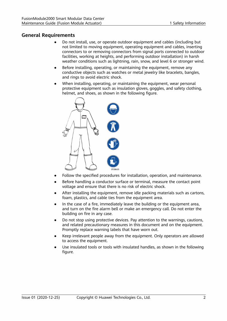
● When installing, operating, or maintaining the equipment, wear personalprotective equipment such as insulation gloves, goggles, and safety clothing,helmet, and shoes, as shown in the following figure.
● Follow the specified procedures for installation, operation, and maintenance.● Before handling a conductor surface or terminal, measure the contact point
voltage and ensure that there is no risk of electric shock.● After installing the equipment, remove idle packing materials such as cartons,
foam, plastics, and cable ties from the equipment area.● In the case of a fire, immediately leave the building or the equipment area,
and turn on the fire alarm bell or make an emergency call. Do not enter thebuilding on fire in any case.
● Do not stop using protective devices. Pay attention to the warnings, cautions,and related precautionary measures in this document and on the equipment.Promptly replace warning labels that have worn out.
● Keep irrelevant people away from the equipment. Only operators are allowedto access the equipment.
● Use insulated tools or tools with insulated handles, as shown in the followingfigure.
FusionModule2000 Smart Modular Data CenterMaintenance Guide (Fusion Module Actuator) 1 Safety Information
Issue 01 (2020-12-25) Copyright © Huawei Technologies Co., Ltd. 2
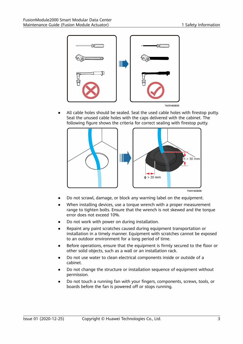
● All cable holes should be sealed. Seal the used cable holes with firestop putty.Seal the unused cable holes with the caps delivered with the cabinet. Thefollowing figure shows the criteria for correct sealing with firestop putty.
● Do not scrawl, damage, or block any warning label on the equipment.● When installing devices, use a torque wrench with a proper measurement
range to tighten bolts. Ensure that the wrench is not skewed and the torqueerror does not exceed 10%.
● Do not work with power on during installation.● Repaint any paint scratches caused during equipment transportation or
installation in a timely manner. Equipment with scratches cannot be exposedto an outdoor environment for a long period of time.
● Before operations, ensure that the equipment is firmly secured to the floor orother solid objects, such as a wall or an installation rack.
● Do not use water to clean electrical components inside or outside of acabinet.
● Do not change the structure or installation sequence of equipment withoutpermission.
● Do not touch a running fan with your fingers, components, screws, tools, orboards before the fan is powered off or stops running.
FusionModule2000 Smart Modular Data CenterMaintenance Guide (Fusion Module Actuator) 1 Safety Information
Issue 01 (2020-12-25) Copyright © Huawei Technologies Co., Ltd. 3
Personal Safety● If there is a probability of personal injury or equipment damage during
operations on the equipment, immediately stop the operations, report thecase to the supervisor, and take feasible protective measures.
● To avoid electric shock, do not connect safety extra-low voltage (SELV) circuitsto telecommunication network voltage (TNV) circuits.
● Do not power on the equipment before it is installed or confirmed byprofessionals.
1.2 Personnel Requirements● Personnel who plan to install or maintain Huawei equipment must receive
thorough training, understand all necessary safety precautions, and be able tocorrectly perform all operations.
● Only qualified professionals or trained personnel are allowed to install,operate, and maintain the equipment.
● Only qualified professionals are allowed to remove safety facilities and inspectthe equipment.
● Personnel who will operate the equipment, including operators, trainedpersonnel, and professionals, should possess the local national requiredqualifications in special operations such as high-voltage operations, workingat heights, and operations of special equipment.
● Professionals: personnel who are trained or experienced in equipmentoperations and are clear of the sources and degree of various potentialhazards in equipment installation, operation, maintenance
● Trained personnel: personnel who are technically trained, have requiredexperience, are aware of possible hazards on themselves in certain operations,and are able to take protective measures to minimize the hazards onthemselves and other people
● Operators: operation personnel who may come in contact with theequipment, except trained personnel and professionals
● Only professionals or authorized personnel are allowed to replace theequipment or components (including software).
1.3 Electrical Safety
Grounding● For the equipment that needs to be grounded, install the ground cable first
when installing the equipment and remove the ground cable last whenremoving the equipment.
● Do not damage the ground conductor.● Do not operate the equipment in the absence of a properly installed ground
conductor.● Ensure that the equipment is connected permanently to the protective
ground. Before operating the equipment, check its electrical connection toensure that it is securely grounded.
FusionModule2000 Smart Modular Data CenterMaintenance Guide (Fusion Module Actuator) 1 Safety Information
Issue 01 (2020-12-25) Copyright © Huawei Technologies Co., Ltd. 4
General RequirementsUse dedicated insulated tools when performing high-voltage operations.
AC and DC Power
D ANGER
Do not connect or disconnect power cables with power on. Transient contactbetween the core of the power cable and the conductor will generate electric arcsor sparks, which may cause fire or personal injury.
● If a "high electricity leakage" tag is attached on the equipment, ground theprotective ground terminal on the equipment enclosure before connecting theAC power supply; otherwise, electric shock as a result of electricity leakagemay occur.
● Before installing or removing a power cable, turn off the power switch.● Before connecting a power cable, check that the label on the power cable is
correct.● If the equipment has multiple inputs, disconnect all the inputs before
operating the equipment.● A circuit breaker equipped with a residual current device (RCD) is not
recommended.● A damaged power cable must be replaced by the manufacturer, service agent,
or professionals to avoid risks.● High voltage operations and installation of AC-powered facilities must be
performed by qualified personnel.
Cabling● When routing cables, ensure that a distance of at least 30 mm exists between
the cables and heat-generating components or areas. This prevents damageto the insulation layer of the cables.
● Do not route cables behind the air intake and exhaust vents of theequipment.
● Ensure that cables meet the VW-1 or ZB flame spread rating requirements orhigher.
● Bind cables of the same type together. When routing cables of different types,ensure that they are at least 30 mm away from each other.
● If an AC input power cable is connected to the cabinet from the top, bend thecable in a U shape outside the cabinet and then route it into the cabinet.
● When the temperature is low, violent impact or vibration may damage theplastic cable sheathing. To ensure safety, comply with the followingrequirements:– Cables can be laid or installed only when the temperature is higher than
0°C. Handle cables with caution, especially at a low temperature.– Cables stored at subzero temperatures must be stored at room
temperature for at least 24 hours before they are laid out.
FusionModule2000 Smart Modular Data CenterMaintenance Guide (Fusion Module Actuator) 1 Safety Information
Issue 01 (2020-12-25) Copyright © Huawei Technologies Co., Ltd. 5
● Do not perform any improper operations, for example, dropping cablesdirectly from a vehicle.
● When selecting, connecting, and routing cables, follow local safety regulationsand rules.
ESD
NO TICE
The static electricity generated by human bodies may damage the electrostatic-sensitive components on boards, for example, the large-scale integrated (LSI)circuits.
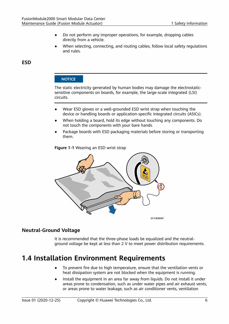
● Wear ESD gloves or a well-grounded ESD wrist strap when touching thedevice or handling boards or application-specific integrated circuits (ASICs).
● When holding a board, hold its edge without touching any components. Donot touch the components with your bare hands.
● Package boards with ESD packaging materials before storing or transportingthem.
Figure 1-1 Wearing an ESD wrist strap
Neutral-Ground VoltageIt is recommended that the three-phase loads be equalized and the neutral-ground voltage be kept at less than 2 V to meet power distribution requirements.
1.4 Installation Environment Requirements● To prevent fire due to high temperature, ensure that the ventilation vents or
heat dissipation system are not blocked when the equipment is running.● Install the equipment in an area far away from liquids. Do not install it under
areas prone to condensation, such as under water pipes and air exhaust vents,or areas prone to water leakage, such as air conditioner vents, ventilation
FusionModule2000 Smart Modular Data CenterMaintenance Guide (Fusion Module Actuator) 1 Safety Information
Issue 01 (2020-12-25) Copyright © Huawei Technologies Co., Ltd. 6
vents, or feeder windows of the equipment room. Ensure that no liquid entersthe equipment to prevent faults or short circuits.
● If any liquid is detected inside the equipment, immediately disconnect thepower supply and contact the administrator.
● Do not expose the equipment to flammable or explosive gas or smoke. Donot perform any operation on the equipment in such environments.
● Ensure that the equipment room provides good heat insulation, and the wallsand floor are dampproof.
● Install a rat guard at the door of the equipment room.
Installation at Heights● Working at heights refers to operations that are performed at least 2 meters
above the ground.
● Do not work at heights if the steel pipes are wet or other potential dangerexists. After the preceding conditions no longer exist, the safety director andrelevant technical personnel need to check the involved equipment. Operatorscan begin working only after obtaining consent.
● When working at heights, comply with local relevant laws and regulations.
● Only trained and qualified personnel are allowed to work at heights.
● Before working at heights, check the climbing tools and safety gears such assafety helmets, safety belts, ladders, springboards, scaffolding, and liftingequipment. If they do not meet the requirements, take corrective measures ordisallow working at heights.
● Wear personal protective equipment such as the safety helmet and safety beltor waist rope and fasten it to a solid structure. Do not mount it on aninsecure moveable object or metal object with sharp edges. Make sure thatthe hooks will not slide off.
● Set a restricted area and eye-catching signs for working at heights to warnaway irrelevant personnel.
● Carry the operation machinery and tools properly to prevent them fromfalling off and causing injuries.
● Personnel involving working at heights are not allowed to throw objects fromthe height to the ground, or vice versa. Objects should be transported bytough slings, hanging baskets, highline trolleys, or cranes.
● Ensure that guard rails and warning signs are set at the edges and openingsof the area involving working at heights to prevent falls.
● Do not pile up scaffolding, springboards, or other sundries on the groundunder the area involving working at heights. Do not allow people to stay orpass under the area involving working at heights.
● Inspect the scaffolding, springboards, and workbenches used for working atheights in advance to ensure that their structures are solid and notoverloaded.
● Any violations must be promptly pointed out by the site manager or safetysupervisor and the involved personnel should be prompted for correction.Personnel who fail to stop violations will be forbidden from working.
FusionModule2000 Smart Modular Data CenterMaintenance Guide (Fusion Module Actuator) 1 Safety Information
Issue 01 (2020-12-25) Copyright © Huawei Technologies Co., Ltd. 7
1.5 Mechanical Safety
Hoisting Devices● Do not walk under hoisted objects.● Only trained and qualified personnel should perform hoisting operations.● Check that hoisting tools are available and in good condition.● Before hoisting objects, ensure that hoisting tools are firmly secured onto a
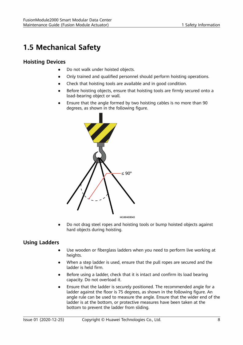
load-bearing object or wall.● Ensure that the angle formed by two hoisting cables is no more than 90
degrees, as shown in the following figure.
● Do not drag steel ropes and hoisting tools or bump hoisted objects againsthard objects during hoisting.
Using Ladders● Use wooden or fiberglass ladders when you need to perform live working at
heights.● When a step ladder is used, ensure that the pull ropes are secured and the
ladder is held firm.● Before using a ladder, check that it is intact and confirm its load bearing
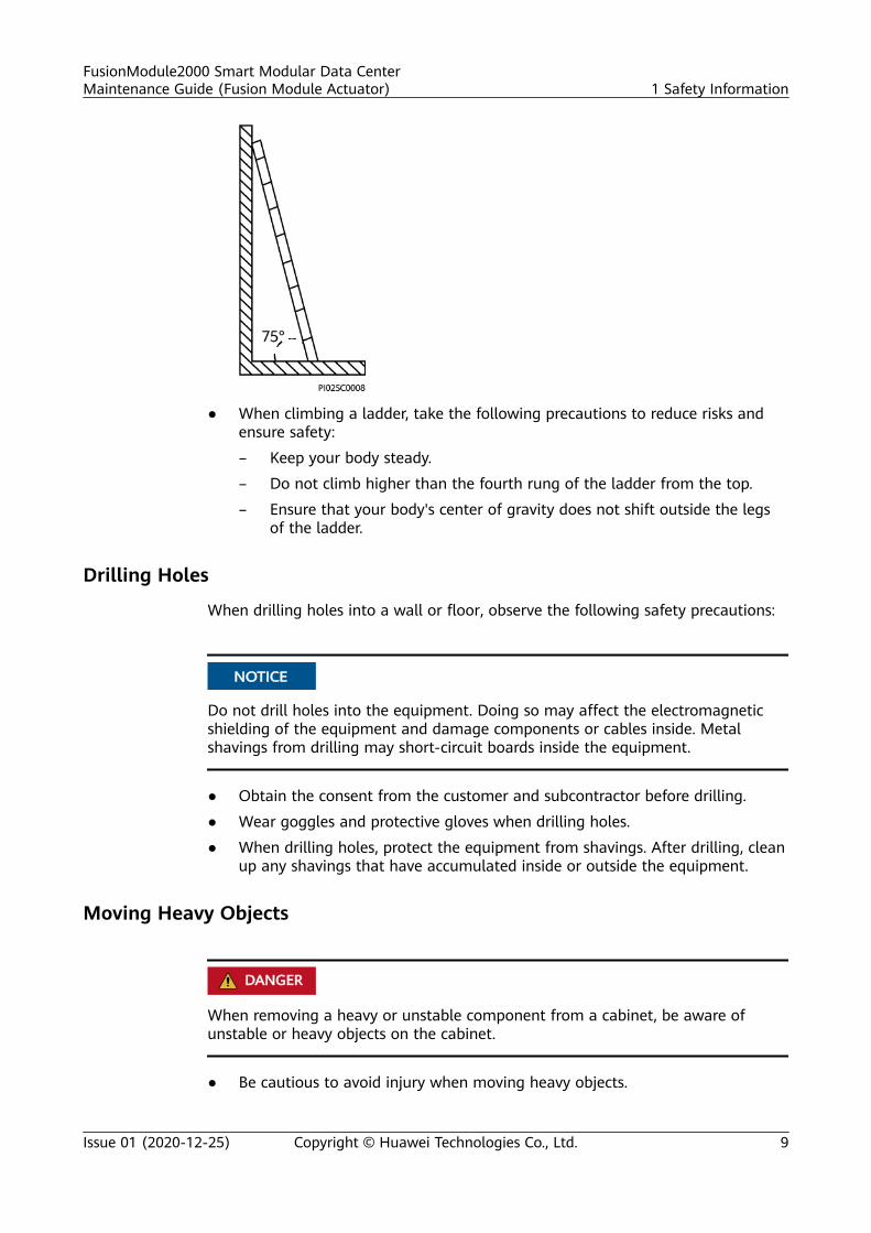
capacity. Do not overload it.● Ensure that the ladder is securely positioned. The recommended angle for a
ladder against the floor is 75 degrees, as shown in the following figure. Anangle rule can be used to measure the angle. Ensure that the wider end of theladder is at the bottom, or protective measures have been taken at thebottom to prevent the ladder from sliding.
FusionModule2000 Smart Modular Data CenterMaintenance Guide (Fusion Module Actuator) 1 Safety Information
Issue 01 (2020-12-25) Copyright © Huawei Technologies Co., Ltd. 8
● When climbing a ladder, take the following precautions to reduce risks andensure safety:
– Keep your body steady.
– Do not climb higher than the fourth rung of the ladder from the top.
– Ensure that your body's center of gravity does not shift outside the legsof the ladder.
Drilling Holes
When drilling holes into a wall or floor, observe the following safety precautions:
NO TICE
Do not drill holes into the equipment. Doing so may affect the electromagneticshielding of the equipment and damage components or cables inside. Metalshavings from drilling may short-circuit boards inside the equipment.
● Obtain the consent from the customer and subcontractor before drilling.
● Wear goggles and protective gloves when drilling holes.
● When drilling holes, protect the equipment from shavings. After drilling, cleanup any shavings that have accumulated inside or outside the equipment.
Moving Heavy Objects
D ANGER
When removing a heavy or unstable component from a cabinet, be aware ofunstable or heavy objects on the cabinet.
● Be cautious to avoid injury when moving heavy objects.
FusionModule2000 Smart Modular Data CenterMaintenance Guide (Fusion Module Actuator) 1 Safety Information
Issue 01 (2020-12-25) Copyright © Huawei Technologies Co., Ltd. 9

● When moving the equipment by hand, wear protective gloves to preventinjuries.
● Move or lift the equipment by holding its handles or lower edges. Do not holdthe handles of modules (such as power supply units, fans, and boards) thatare installed in the equipment because they cannot support the weight of theequipment.
● Avoid scratching the cabinet surface or damaging cabinet components andcables during equipment transportation.
● When transporting the equipment using a forklift truck, ensure that the forksare properly positioned to ensure that the equipment does not topple. Beforemoving the equipment, secure it to the forklift truck using ropes. Whenmoving the equipment, assign dedicated personnel to take care of it.
● Choose railways, sea, or a road with good condition for transportation toensure equipment safety. Avoid tilt or jolt during transportation.
● Move a cabinet with caution. Any bumping or falling may damage theequipment.
1.6 Cooling System Safety
Welding● At least two persons are required on a welding site.
● A welder must have a work permit.
● A welding site must be free from inflammables.
● Ensure that a fire extinguisher, wet wiper, and water container are available.
● A burning welding torch must not be placed on a component or on the floor,and must not be placed in a metal container with acetylene and oxygen.Otherwise, the gas may leak and cause a fire.
● High-temperature pipes after welding must be promptly cooled.
● Do not weld or cut on pressurized containers or pipes. Electric devices must bepowered off before welding.
High Temperature and Pressure● When maintaining or replacing components, pay attention to high-
temperature components (such as the compressor, refrigerant pipe, andelectric heater) to prevent scalds.
● When maintaining or replacing components, pay attention to high-pressurecomponents (such as the compressor and refrigerant pipe) to prevent therefrigerant system from being cracked or exploded due to misoperations.
FusionModule2000 Smart Modular Data CenterMaintenance Guide (Fusion Module Actuator) 1 Safety Information
Issue 01 (2020-12-25) Copyright © Huawei Technologies Co., Ltd. 10
Refrigerant Frostbite
Refrigerant leakage may cause frostbite. Take protective measures (for example,wear antifreeze gloves) when handling refrigerant.
Storage and Recycling● Do not store devices near a heat source or under direct sunshine.● Keep devices away from fire or high-temperature objects, especially devices
injected with pressurized nitrogen or refrigerant; otherwise, explosion orrefrigerant leakage may occur, causing personal injury.
● The sign indicates that the product cannot be disposed of with otherwastes that have a shell in European Union (EU) areas. To avoid environmentpollution and harm to human health, wastes must be classified and recycled.This also promotes resource reuse. When recycling a device, fill in the deviceinformation in the recycling collection system or contact your dealer for help.The dealer can help you recycle devices in a safe and environment-friendlyway.
1.7 Battery Safety
Basic Requirements
Before operating batteries, carefully read the safety precautions for batteryhandling and master the correct battery connection methods.
D ANGER
● Do not expose batteries at high temperatures or around heat-generatingdevices, such as sunlight, fire sources, transformers, and heaters. Excessive heatexposure may cause the batteries to explode.
● Do not burn batteries. Otherwise, the batteries may explode.● To avoid leakage, overheating, fire, or explosions, do not disassemble, alter, or
damage batteries, for example, insert sundries into batteries or immersebatteries in water or other liquids.
● Wear goggles, rubber gloves, and protective clothing to prevent skin contactwith electrolyte in the case of electrolyte overflow. If a battery leaks, protectthe skin or eyes from the leaking liquid. If the skin or eyes come in contactwith the leaking liquid, wash it immediately with clean water and go to thehospital for medical treatment.
● Use dedicated insulated tools.● Move batteries in the required direction. Do not place a battery upside down
or tilt it.● Keep the battery loop disconnected during installation and maintenance.
FusionModule2000 Smart Modular Data CenterMaintenance Guide (Fusion Module Actuator) 1 Safety Information
Issue 01 (2020-12-25) Copyright © Huawei Technologies Co., Ltd. 11
● Use batteries of specified models. Using batteries of other models maydamage the batteries.
● Dispose of waste batteries in accordance with local laws and regulations. Donot dispose of batteries as household waste. If a battery is disposed ofimproperly, it may explode.
● The site must be equipped with qualified fire extinguishing facilities, such asfirefighting sands and powder fire extinguishers.
NO TICE
To ensure battery safety and battery management accuracy, use batteries providedwith the UPS by Huawei. Huawei is not responsible for any battery faults causedby batteries not provided by Huawei.
Battery InstallationBefore installing batteries, observe the following safety precautions:
● Install batteries in a well-ventilated, dry, and cool environment that is faraway from heat sources, flammable materials, moistures, extensive infraredradiation, organic solvents, and corrosive gases. Take fire preventionmeasures.
● Place and secure batteries horizontally.● Note the polarities when installing batteries. Do not short-circuit the positive
and negative poles of the same battery or battery string. Otherwise, thebattery may be short-circuited.
● Check battery connections periodically, ensuring that all bolts are securelytightened.
● When installing batteries, do not place installation tools on the batteries.
Battery Short Circuit
D ANGER
Battery short circuits can generate high instantaneous current and release a greatamount of energy, which may cause equipment damage or personal injury.
To avoid battery short-circuit, do not maintain batteries with power on.
Flammable Gas
NO TICE
● Do not use unsealed lead-acid batteries.● To prevent fire or corrosion, ensure that flammable gas (such as hydrogen) is
properly exhausted for lead-acid batteries.
FusionModule2000 Smart Modular Data CenterMaintenance Guide (Fusion Module Actuator) 1 Safety Information
Issue 01 (2020-12-25) Copyright © Huawei Technologies Co., Ltd. 12
Lead-acid batteries emit flammable gas when used. Ensure that batteries are keptin a well-ventilated area and take preventive measures against fire.
Battery Leakage
NO TICE
Battery overheating causes deformation, damage, and electrolyte spillage.
WARNING
When the electrolyte overflows, absorb and neutralize the electrolyte immediately.When moving or handling a battery whose electrolyte leaks, note that the leakingelectrolyte may hurt human bodies.
● If the battery temperature exceeds 60°C, check for and promptly handle anyleakage.
● Electrolyte overflow may damage the equipment. It will corrode metal partsand boards, and ultimately damage the boards.
● If the electrolyte overflows, follow the instructions of the batterymanufacturer or neutralize the electrolyte by using sodium bicarbonate(NaHCO3) or sodium carbonate (Na2CO3).
Lithium Battery
The safety precautions for lithium batteries are similar to those for lead-acidbatteries except that you also need to note the precautions described in thissection.
WARNING
There is a risk of explosion if a battery is replaced with an incorrect model.
● A battery can be replaced only with a battery of the same or similar modelrecommended by the manufacturer.
● When handling a lithium battery, do not place it upside down, tilt it, or bumpit with other objects.
● Keep the lithium battery loop disconnected during installation andmaintenance.
● Do not charge a battery when the ambient temperature is below the lowerlimit of the operating temperature (charging is forbidden at 0°C). Low-temperature charging may cause crystallization, which will result in a shortcircuit inside the battery.
● Use batteries within the allowed temperature range; otherwise, the batteryperformance and safety will be compromised.
FusionModule2000 Smart Modular Data CenterMaintenance Guide (Fusion Module Actuator) 1 Safety Information
Issue 01 (2020-12-25) Copyright © Huawei Technologies Co., Ltd. 13
● Do not throw a lithium battery in fire.● When maintenance is complete, return the waste lithium battery to the
maintenance office.
1.8 Others● Exercise caution when shutting down the smart cooling product. Doing so
may cause equipment and room overheating, which will damage theequipment.
● Exercise caution when powering off the rPDU or PDU2000. Doing so mayaffect the power supply to equipment, which will interrupt services.
● Exercise caution when manually shutting down the UPS inverter fortransferring to bypass mode, or when adjusting the UPS output voltage levelor frequency. Doing so may affect the power supply to equipment.
● Exercise caution when setting battery parameters. Incorrect settings will affectthe power supply and battery lifespan.
FusionModule2000 Smart Modular Data CenterMaintenance Guide (Fusion Module Actuator) 1 Safety Information
Issue 01 (2020-12-25) Copyright © Huawei Technologies Co., Ltd. 14

2 O&M Preparations
2.1 O&M Personnel Skill Requirements
Table 2-1 Skill requirements for smart module O&M personnel
Field Personnel Skill Requirements
Cabinet system Familiar with the overall configurations and layout of thesmart moduleExperienced in smart module maintenance
Power supply anddistributionsystem
Familiar with the power supply and distribution systemconfigurations and the operations for each core componentin the smart moduleWith power distribution system engineer qualifications
Cooling system Familiar with the cooling system configurations and theoperations for each core component in the smart moduleWith cooling engineer qualifications
Managementsystem
Familiar with the smart module management systemconfigurations and device data upload methods, and able toproficiently operate the management systemWith monitoring engineer qualifications
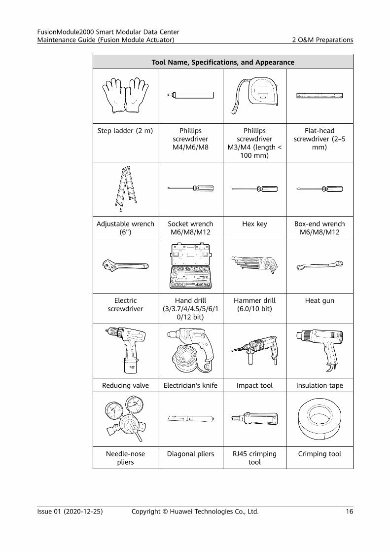
2.2 Tools
Table 2-2 Tools and instruments
Tool Name, Specifications, and Appearance
Protective gloves Marker Measuring tape(5 m)
Level
FusionModule2000 Smart Modular Data CenterMaintenance Guide (Fusion Module Actuator) 2 O&M Preparations
Issue 01 (2020-12-25) Copyright © Huawei Technologies Co., Ltd. 15
Tool Name, Specifications, and Appearance
Step ladder (2 m) PhillipsscrewdriverM4/M6/M8
Phillipsscrewdriver
M3/M4 (length <100 mm)
Flat-headscrewdriver (2–5
mm)
Adjustable wrench(6")
Socket wrenchM6/M8/M12
Hex key Box-end wrenchM6/M8/M12
Electricscrewdriver
Hand drill(3/3.7/4/4.5/5/6/1
0/12 bit)
Hammer drill(6.0/10 bit)
Heat gun
Reducing valve Electrician's knife Impact tool Insulation tape
Needle-nosepliers
Diagonal pliers RJ45 crimpingtool
Crimping tool
FusionModule2000 Smart Modular Data CenterMaintenance Guide (Fusion Module Actuator) 2 O&M Preparations
Issue 01 (2020-12-25) Copyright © Huawei Technologies Co., Ltd. 16
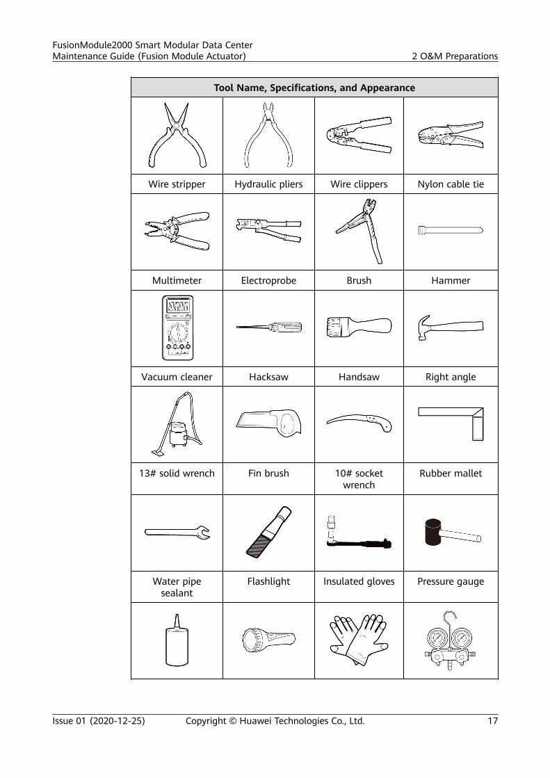
Tool Name, Specifications, and Appearance
Wire stripper Hydraulic pliers Wire clippers Nylon cable tie
Multimeter Electroprobe Brush Hammer
Vacuum cleaner Hacksaw Handsaw Right angle
13# solid wrench Fin brush 10# socketwrench
Rubber mallet
Water pipesealant
Flashlight Insulated gloves Pressure gauge
FusionModule2000 Smart Modular Data CenterMaintenance Guide (Fusion Module Actuator) 2 O&M Preparations
Issue 01 (2020-12-25) Copyright © Huawei Technologies Co., Ltd. 17
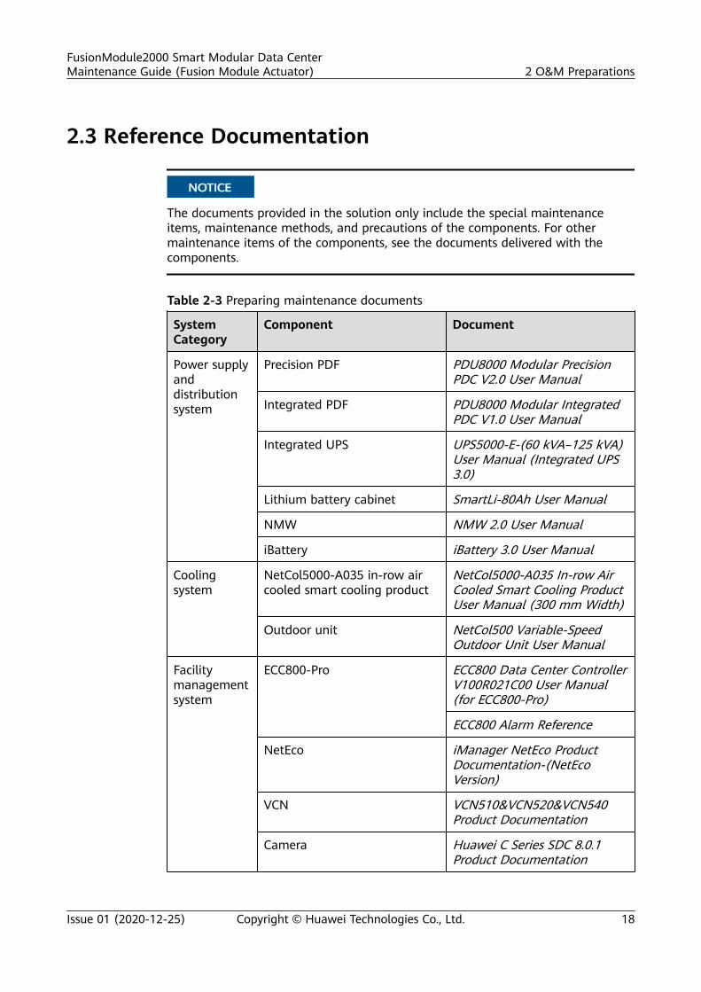
2.3 Reference Documentation
NO TICE
The documents provided in the solution only include the special maintenanceitems, maintenance methods, and precautions of the components. For othermaintenance items of the components, see the documents delivered with thecomponents.
Table 2-3 Preparing maintenance documents
SystemCategory
Component Document
Power supplyanddistributionsystem
Precision PDF PDU8000 Modular PrecisionPDC V2.0 User Manual
Integrated PDF PDU8000 Modular IntegratedPDC V1.0 User Manual
Integrated UPS UPS5000-E-(60 kVA–125 kVA)User Manual (Integrated UPS3.0)
Lithium battery cabinet SmartLi-80Ah User Manual
NMW NMW 2.0 User Manual
iBattery iBattery 3.0 User Manual
Coolingsystem
NetCol5000-A035 in-row aircooled smart cooling product
NetCol5000-A035 In-row AirCooled Smart Cooling ProductUser Manual (300 mm Width)
Outdoor unit NetCol500 Variable-SpeedOutdoor Unit User Manual
Facilitymanagementsystem
ECC800-Pro ECC800 Data Center ControllerV100R021C00 User Manual(for ECC800-Pro)
ECC800 Alarm Reference
NetEco iManager NetEco ProductDocumentation-(NetEcoVersion)
VCN VCN510&VCN520&VCN540Product Documentation
Camera Huawei C Series SDC 8.0.1Product Documentation
FusionModule2000 Smart Modular Data CenterMaintenance Guide (Fusion Module Actuator) 2 O&M Preparations
Issue 01 (2020-12-25) Copyright © Huawei Technologies Co., Ltd. 18
NO TE
● The ECC800/NetEco version depends on the version in use. Click on the ECC800/NetEco WebUI to obtain the current version.
● For NetEco maintenance, see the NetEco documents.
FusionModule2000 Smart Modular Data CenterMaintenance Guide (Fusion Module Actuator) 2 O&M Preparations
Issue 01 (2020-12-25) Copyright © Huawei Technologies Co., Ltd. 19
3 Routine Maintenance
3.1 Overview
OverviewRoutine maintenance is a preventive measure. It refers to periodic checking andmaintenance carried out to promptly identify and handle alarms and potentialfaults during the normal running of the system.
It aims to ensure long-term stable operation of the equipment. Through routinemaintenance, maintenance personnel can:
● Promptly find and handle alarms related to equipment operating and preventfault escalation.
● Promptly identify potential faults before they materialize to prevent economicloss and customer satisfaction degrading.
● Optimize the system according to the findings on operating trends and takemeasures to improve operating efficiency.
Maintenance IntervalThe routine maintenance interval specifies how often a maintenance task isperformed. A maintenance task can be performed on a daily, monthly, quarterly,semi-annual, or annual basis.
FusionModule2000 Smart Modular Data CenterMaintenance Guide (Fusion Module Actuator) 3 Routine Maintenance
Issue 01 (2020-12-25) Copyright © Huawei Technologies Co., Ltd. 20
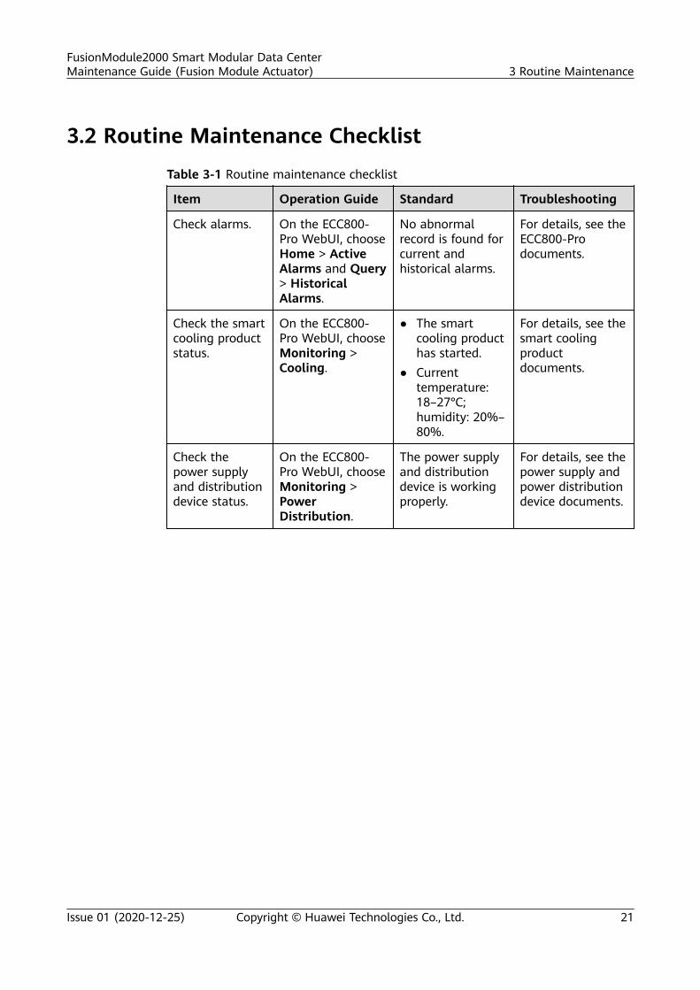
3.2 Routine Maintenance Checklist
Table 3-1 Routine maintenance checklist
Item Operation Guide Standard Troubleshooting
Check alarms. On the ECC800-Pro WebUI, chooseHome > ActiveAlarms and Query> HistoricalAlarms.
No abnormalrecord is found forcurrent andhistorical alarms.
For details, see theECC800-Prodocuments.
Check the smartcooling productstatus.
On the ECC800-Pro WebUI, chooseMonitoring >Cooling.
● The smartcooling producthas started.
● Currenttemperature:18–27°C;humidity: 20%–80%.
For details, see thesmart coolingproductdocuments.
Check thepower supplyand distributiondevice status.
On the ECC800-Pro WebUI, chooseMonitoring >PowerDistribution.
The power supplyand distributiondevice is workingproperly.
For details, see thepower supply andpower distributiondevice documents.
FusionModule2000 Smart Modular Data CenterMaintenance Guide (Fusion Module Actuator) 3 Routine Maintenance
Issue 01 (2020-12-25) Copyright © Huawei Technologies Co., Ltd. 21
Item Operation Guide Standard Troubleshooting
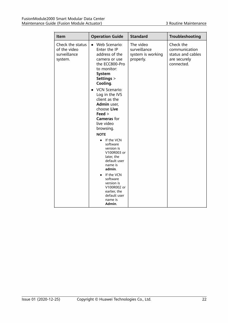
Check the statusof the videosurveillancesystem.
● Web Scenario:Enter the IPaddress of thecamera or usethe ECC800-Proto monitor:SystemSettings >Cooling.
● VCN Scenario:Log in the IVSclient as theAdmin user,choose LiveFeed >Cameras forlive videobrowsing.NOTE
● If the VCNsoftwareversion isV100R003 orlater, thedefault username isadmin.
● If the VCNsoftwareversion isV100R002 orearlier, thedefault username isAdmin.
The videosurveillancesystem is workingproperly.
Check thecommunicationstatus and cablesare securelyconnected.
FusionModule2000 Smart Modular Data CenterMaintenance Guide (Fusion Module Actuator) 3 Routine Maintenance
Issue 01 (2020-12-25) Copyright © Huawei Technologies Co., Ltd. 22
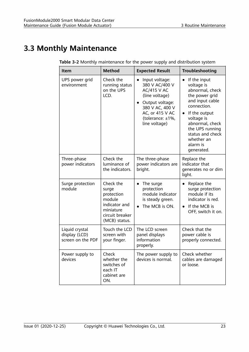
3.3 Monthly Maintenance
Table 3-2 Monthly maintenance for the power supply and distribution system
Item Method Expected Result Troubleshooting
UPS power gridenvironment
Check therunning statuson the UPSLCD.
● Input voltage:380 V AC/400 VAC/415 V AC(line voltage)
● Output voltage:380 V AC, 400 VAC, or 415 V AC(tolerance: ±1%,line voltage)
● If the inputvoltage isabnormal, checkthe power gridand input cableconnection.
● If the outputvoltage isabnormal, checkthe UPS runningstatus and checkwhether analarm isgenerated.
Three-phasepower indicators
Check theluminance ofthe indicators.
The three-phasepower indicators arebright.
Replace theindicator thatgenerates no or dimlight.
Surge protectionmodule
Check thesurgeprotectionmoduleindicator andminiaturecircuit breaker(MCB) status.
● The surgeprotectionmodule indicatoris steady green.
● The MCB is ON.
● Replace thesurge protectionmodule if itsindicator is red.
● If the MCB isOFF, switch it on.
Liquid crystaldisplay (LCD)screen on the PDF
Touch the LCDscreen withyour finger.
The LCD screenpanel displaysinformationproperly.
Check that thepower cable isproperly connected.
Power supply todevices
Checkwhether theswitches ofeach ITcabinet areON.
The power supply todevices is normal.
Check whethercables are damagedor loose.
FusionModule2000 Smart Modular Data CenterMaintenance Guide (Fusion Module Actuator) 3 Routine Maintenance
Issue 01 (2020-12-25) Copyright © Huawei Technologies Co., Ltd. 23
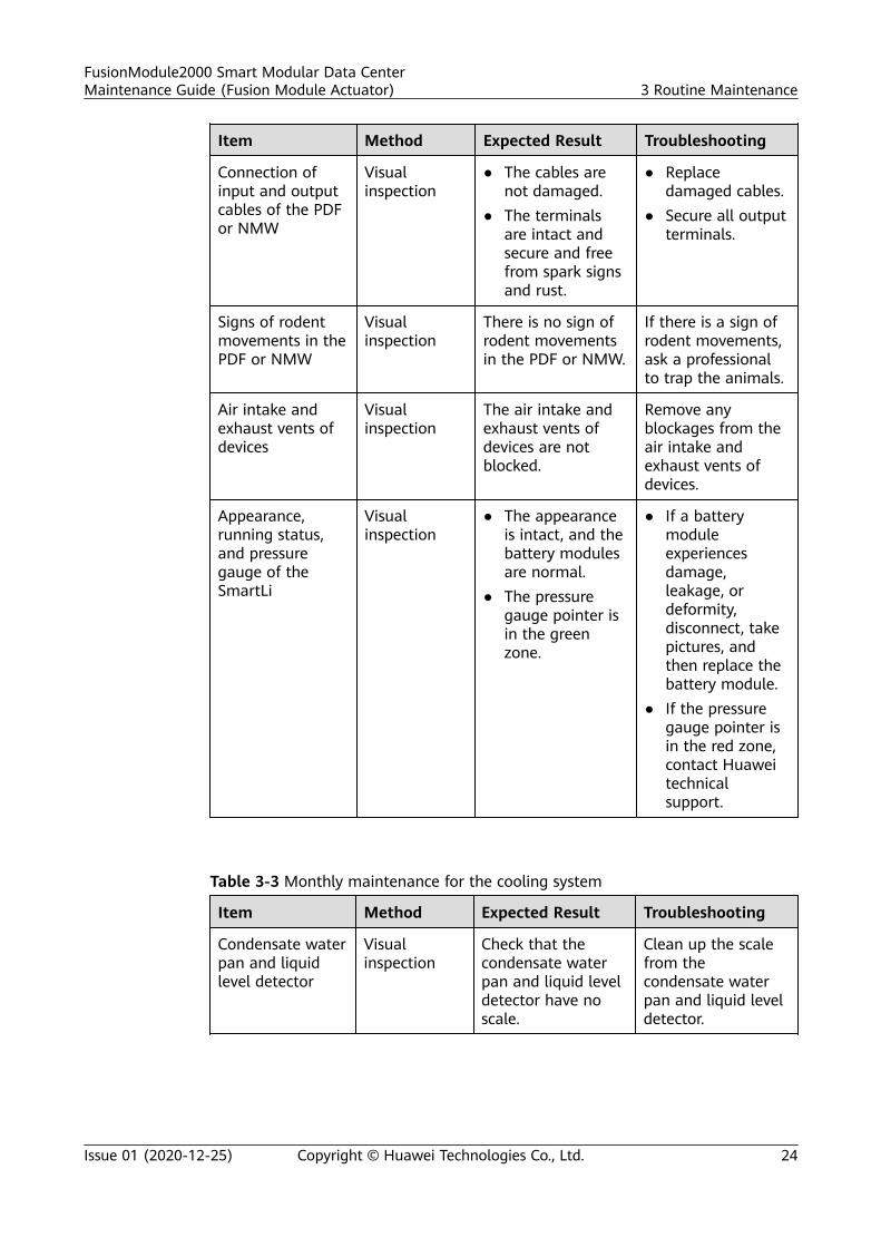
Item Method Expected Result Troubleshooting
Connection ofinput and outputcables of the PDFor NMW
Visualinspection
● The cables arenot damaged.
● The terminalsare intact andsecure and freefrom spark signsand rust.
● Replacedamaged cables.
● Secure all outputterminals.
Signs of rodentmovements in thePDF or NMW
Visualinspection
There is no sign ofrodent movementsin the PDF or NMW.
If there is a sign ofrodent movements,ask a professionalto trap the animals.
Air intake andexhaust vents ofdevices
Visualinspection
The air intake andexhaust vents ofdevices are notblocked.
Remove anyblockages from theair intake andexhaust vents ofdevices.
Appearance,running status,and pressuregauge of theSmartLi
Visualinspection
● The appearanceis intact, and thebattery modulesare normal.
● The pressuregauge pointer isin the greenzone.
● If a batterymoduleexperiencesdamage,leakage, ordeformity,disconnect, takepictures, andthen replace thebattery module.
● If the pressuregauge pointer isin the red zone,contact Huaweitechnicalsupport.
Table 3-3 Monthly maintenance for the cooling system
Item Method Expected Result Troubleshooting
Condensate waterpan and liquidlevel detector
Visualinspection
Check that thecondensate waterpan and liquid leveldetector have noscale.
Clean up the scalefrom thecondensate waterpan and liquid leveldetector.
FusionModule2000 Smart Modular Data CenterMaintenance Guide (Fusion Module Actuator) 3 Routine Maintenance
Issue 01 (2020-12-25) Copyright © Huawei Technologies Co., Ltd. 24
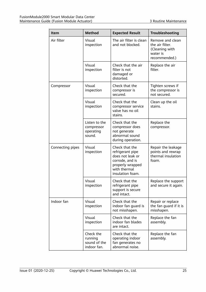
Item Method Expected Result Troubleshooting
Air filter Visualinspection
The air filter is cleanand not blocked.
Remove and cleanthe air filter.(Cleaning withwater isrecommended.)
Visualinspection
Check that the airfilter is notdamaged ordistorted.
Replace the airfilter.
Compressor Visualinspection
Check that thecompressor issecured.
Tighten screws ifthe compressor isnot secured.
Visualinspection
Check that thecompressor servicevalve has no oilstains.
Clean up the oilstains.
Listen to thecompressoroperatingsound.
Check that thecompressor doesnot generateabnormal soundduring operation.
Replace thecompressor.
Connecting pipes Visualinspection
Check that therefrigerant pipedoes not leak orcorrode, and isproperly wrappedwith thermalinsulation foam.
Repair the leakagepoints and rewrapthermal insulationfoam.
Visualinspection
Check that therefrigerant pipesupport is secureand intact.
Replace the supportand secure it again.
Indoor fan Visualinspection
Check that theindoor fan guard isnot misshapen.
Repair or replacethe fan guard if it ismisshapen.
Visualinspection
Check that theindoor fan bladesare intact.
Replace the fanassembly.
Check therunningsound of theindoor fan.
Check that theoperating indoorfan generates noabnormal noise.
Replace the fanassembly.
FusionModule2000 Smart Modular Data CenterMaintenance Guide (Fusion Module Actuator) 3 Routine Maintenance
Issue 01 (2020-12-25) Copyright © Huawei Technologies Co., Ltd. 25
Item Method Expected Result Troubleshooting
Visualinspection
Check that thescrews on theindoor fan are notloose or distorted.
Tighten loosescrews.
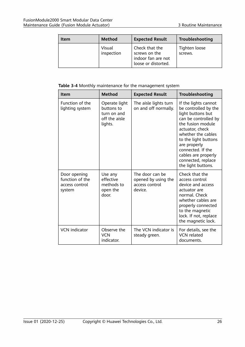
Table 3-4 Monthly maintenance for the management system
Item Method Expected Result Troubleshooting
Function of thelighting system
Operate lightbuttons toturn on andoff the aislelights.
The aisle lights turnon and off normally.
If the lights cannotbe controlled by thelight buttons butcan be controlled bythe fusion moduleactuator, checkwhether the cablesto the light buttonsare properlyconnected. If thecables are properlyconnected, replacethe light buttons.
Door openingfunction of theaccess controlsystem
Use anyeffectivemethods toopen thedoor.
The door can beopened by using theaccess controldevice.
Check that theaccess controldevice and accessactuator arenormal. Checkwhether cables areproperly connectedto the magneticlock. If not, replacethe magnetic lock.
VCN indicator Observe theVCNindicator.
The VCN indicator issteady green.
For details, see theVCN relateddocuments.
FusionModule2000 Smart Modular Data CenterMaintenance Guide (Fusion Module Actuator) 3 Routine Maintenance
Issue 01 (2020-12-25) Copyright © Huawei Technologies Co., Ltd. 26
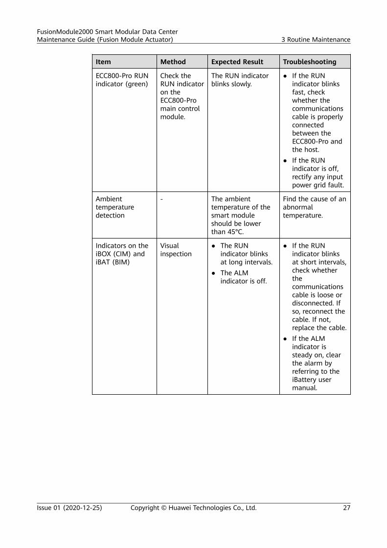
Item Method Expected Result Troubleshooting
ECC800-Pro RUNindicator (green)
Check theRUN indicatoron theECC800-Promain controlmodule.
The RUN indicatorblinks slowly.
● If the RUNindicator blinksfast, checkwhether thecommunicationscable is properlyconnectedbetween theECC800-Pro andthe host.
● If the RUNindicator is off,rectify any inputpower grid fault.
Ambienttemperaturedetection
- The ambienttemperature of thesmart moduleshould be lowerthan 45°C.
Find the cause of anabnormaltemperature.
Indicators on theiBOX (CIM) andiBAT (BIM)
Visualinspection
● The RUNindicator blinksat long intervals.
● The ALMindicator is off.
● If the RUNindicator blinksat short intervals,check whetherthecommunicationscable is loose ordisconnected. Ifso, reconnect thecable. If not,replace the cable.
● If the ALMindicator issteady on, clearthe alarm byreferring to theiBattery usermanual.
FusionModule2000 Smart Modular Data CenterMaintenance Guide (Fusion Module Actuator) 3 Routine Maintenance
Issue 01 (2020-12-25) Copyright © Huawei Technologies Co., Ltd. 27
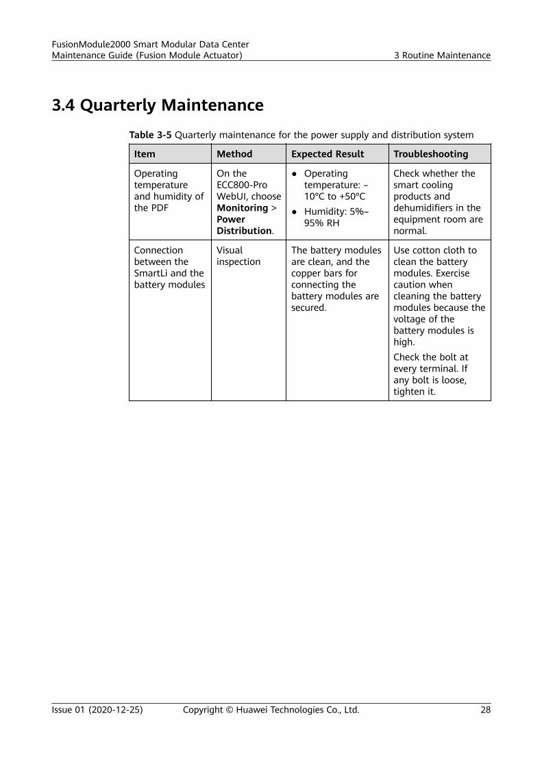
3.4 Quarterly Maintenance
Table 3-5 Quarterly maintenance for the power supply and distribution system
Item Method Expected Result Troubleshooting
Operatingtemperatureand humidity ofthe PDF
On theECC800-ProWebUI, chooseMonitoring >PowerDistribution.
● Operatingtemperature: –10°C to +50°C
● Humidity: 5%–95% RH
Check whether thesmart coolingproducts anddehumidifiers in theequipment room arenormal.
Connectionbetween theSmartLi and thebattery modules
Visualinspection
The battery modulesare clean, and thecopper bars forconnecting thebattery modules aresecured.
Use cotton cloth toclean the batterymodules. Exercisecaution whencleaning the batterymodules because thevoltage of thebattery modules ishigh.Check the bolt atevery terminal. Ifany bolt is loose,tighten it.
FusionModule2000 Smart Modular Data CenterMaintenance Guide (Fusion Module Actuator) 3 Routine Maintenance
Issue 01 (2020-12-25) Copyright © Huawei Technologies Co., Ltd. 28
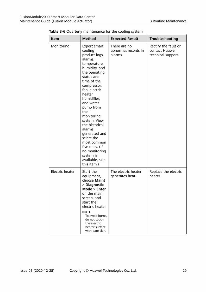
Table 3-6 Quarterly maintenance for the cooling system
Item Method Expected Result Troubleshooting
Monitoring Export smartcoolingproduct logs,alarms,temperature,humidity, andthe operatingstatus andtime of thecompressor,fan, electricheater,humidifier,and waterpump fromthemonitoringsystem. Viewthe historicalalarmsgenerated andselect themost commonfive ones. (Ifno monitoringsystem isavailable, skipthis item.)
There are noabnormal records inalarms.
Rectify the fault orcontact Huaweitechnical support.
Electric heater Start theequipment,choose Maint> DiagnosticMode > Enteron the mainscreen, andstart theelectric heater.NOTE
To avoid burns,do not touchthe electricheater surfacewith bare skin.
The electric heatergenerates heat.
Replace the electricheater.
FusionModule2000 Smart Modular Data CenterMaintenance Guide (Fusion Module Actuator) 3 Routine Maintenance
Issue 01 (2020-12-25) Copyright © Huawei Technologies Co., Ltd. 29
Item Method Expected Result Troubleshooting
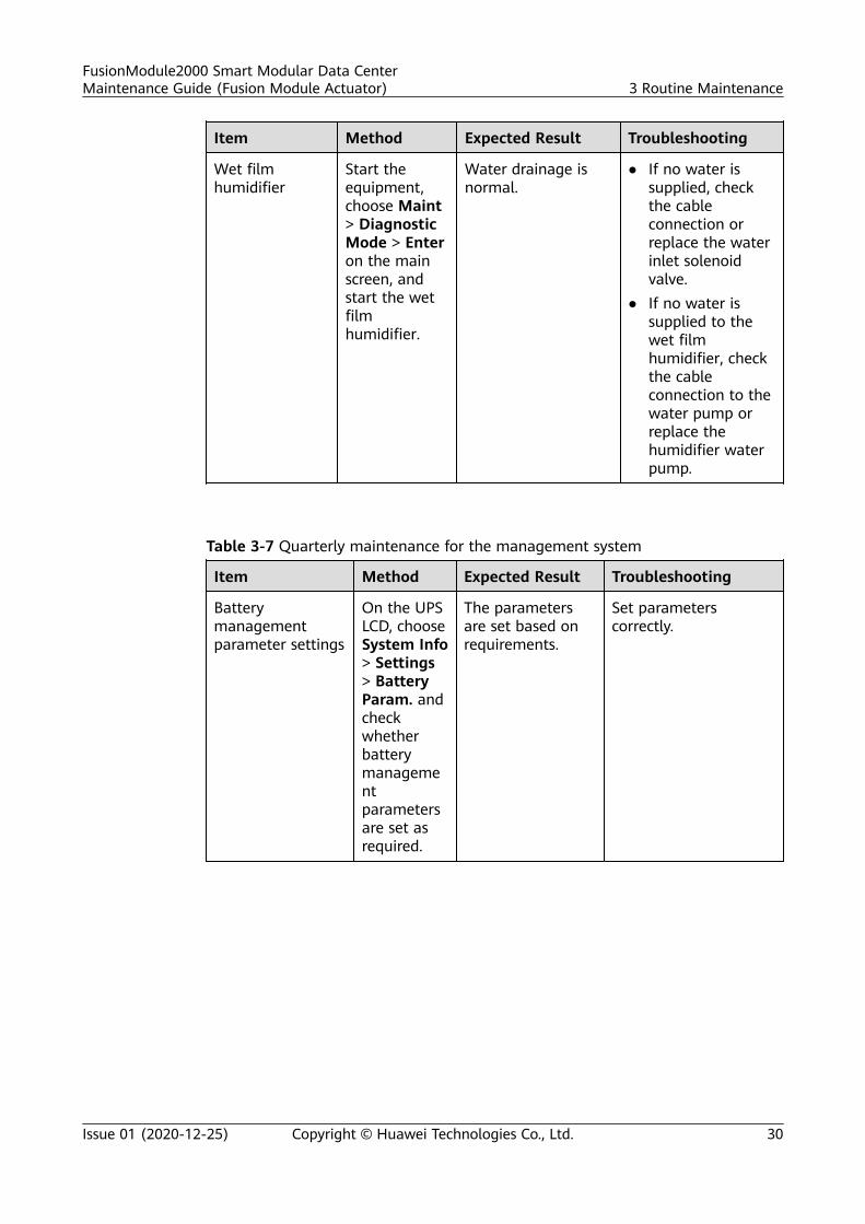
Wet filmhumidifier
Start theequipment,choose Maint> DiagnosticMode > Enteron the mainscreen, andstart the wetfilmhumidifier.
Water drainage isnormal.
● If no water issupplied, checkthe cableconnection orreplace the waterinlet solenoidvalve.
● If no water issupplied to thewet filmhumidifier, checkthe cableconnection to thewater pump orreplace thehumidifier waterpump.
Table 3-7 Quarterly maintenance for the management system
Item Method Expected Result Troubleshooting
Batterymanagementparameter settings
On the UPSLCD, chooseSystem Info> Settings> BatteryParam. andcheckwhetherbatterymanagementparametersare set asrequired.
The parametersare set based onrequirements.
Set parameterscorrectly.
FusionModule2000 Smart Modular Data CenterMaintenance Guide (Fusion Module Actuator) 3 Routine Maintenance
Issue 01 (2020-12-25) Copyright © Huawei Technologies Co., Ltd. 30
Item Method Expected Result Troubleshooting
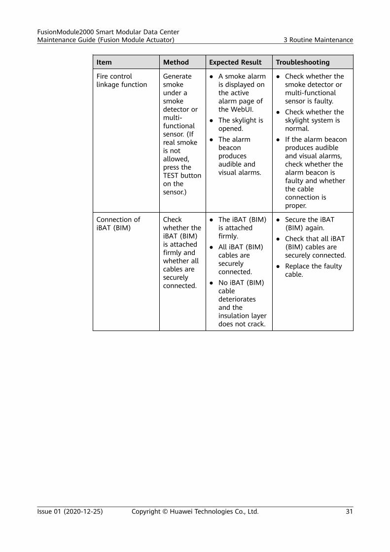
Fire controllinkage function
Generatesmokeunder asmokedetector ormulti-functionalsensor. (Ifreal smokeis notallowed,press theTEST buttonon thesensor.)
● A smoke alarmis displayed onthe activealarm page ofthe WebUI.
● The skylight isopened.
● The alarmbeaconproducesaudible andvisual alarms.
● Check whether thesmoke detector ormulti-functionalsensor is faulty.
● Check whether theskylight system isnormal.
● If the alarm beaconproduces audibleand visual alarms,check whether thealarm beacon isfaulty and whetherthe cableconnection isproper.
Connection ofiBAT (BIM)
Checkwhether theiBAT (BIM)is attachedfirmly andwhether allcables aresecurelyconnected.
● The iBAT (BIM)is attachedfirmly.
● All iBAT (BIM)cables aresecurelyconnected.
● No iBAT (BIM)cabledeterioratesand theinsulation layerdoes not crack.
● Secure the iBAT(BIM) again.
● Check that all iBAT(BIM) cables aresecurely connected.
● Replace the faultycable.
FusionModule2000 Smart Modular Data CenterMaintenance Guide (Fusion Module Actuator) 3 Routine Maintenance
Issue 01 (2020-12-25) Copyright © Huawei Technologies Co., Ltd. 31
Item Method Expected Result Troubleshooting
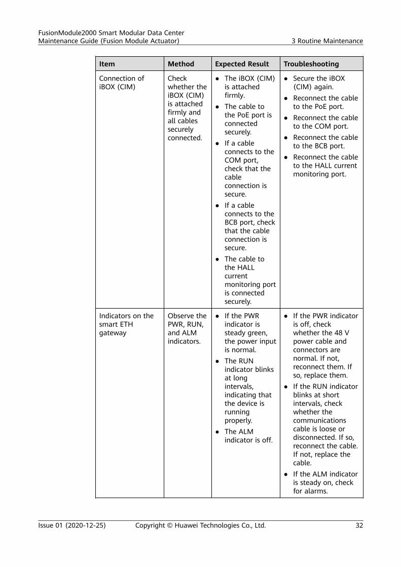
Connection ofiBOX (CIM)
Checkwhether theiBOX (CIM)is attachedfirmly andall cablessecurelyconnected.
● The iBOX (CIM)is attachedfirmly.
● The cable tothe PoE port isconnectedsecurely.
● If a cableconnects to theCOM port,check that thecableconnection issecure.
● If a cableconnects to theBCB port, checkthat the cableconnection issecure.
● The cable tothe HALLcurrentmonitoring portis connectedsecurely.
● Secure the iBOX(CIM) again.
● Reconnect the cableto the PoE port.
● Reconnect the cableto the COM port.
● Reconnect the cableto the BCB port.
● Reconnect the cableto the HALL currentmonitoring port.
Indicators on thesmart ETHgateway
Observe thePWR, RUN,and ALMindicators.
● If the PWRindicator issteady green,the power inputis normal.
● The RUNindicator blinksat longintervals,indicating thatthe device isrunningproperly.
● The ALMindicator is off.
● If the PWR indicatoris off, checkwhether the 48 Vpower cable andconnectors arenormal. If not,reconnect them. Ifso, replace them.
● If the RUN indicatorblinks at shortintervals, checkwhether thecommunicationscable is loose ordisconnected. If so,reconnect the cable.If not, replace thecable.
● If the ALM indicatoris steady on, checkfor alarms.
FusionModule2000 Smart Modular Data CenterMaintenance Guide (Fusion Module Actuator) 3 Routine Maintenance
Issue 01 (2020-12-25) Copyright © Huawei Technologies Co., Ltd. 32
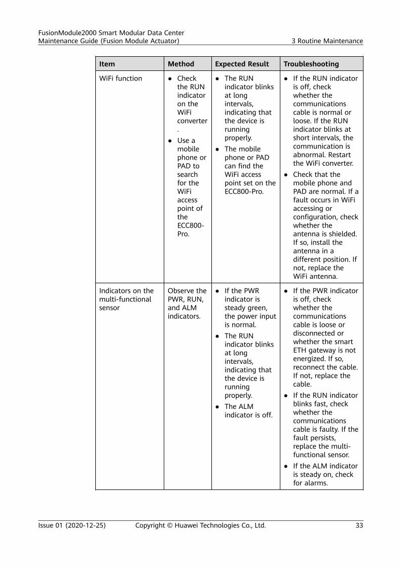
Item Method Expected Result Troubleshooting
WiFi function ● Checkthe RUNindicatoron theWiFiconverter.
● Use amobilephone orPAD tosearchfor theWiFiaccesspoint oftheECC800-Pro.
● The RUNindicator blinksat longintervals,indicating thatthe device isrunningproperly.
● The mobilephone or PADcan find theWiFi accesspoint set on theECC800-Pro.
● If the RUN indicatoris off, checkwhether thecommunicationscable is normal orloose. If the RUNindicator blinks atshort intervals, thecommunication isabnormal. Restartthe WiFi converter.
● Check that themobile phone andPAD are normal. If afault occurs in WiFiaccessing orconfiguration, checkwhether theantenna is shielded.If so, install theantenna in adifferent position. Ifnot, replace theWiFi antenna.
Indicators on themulti-functionalsensor
Observe thePWR, RUN,and ALMindicators.
● If the PWRindicator issteady green,the power inputis normal.
● The RUNindicator blinksat longintervals,indicating thatthe device isrunningproperly.
● The ALMindicator is off.
● If the PWR indicatoris off, checkwhether thecommunicationscable is loose ordisconnected orwhether the smartETH gateway is notenergized. If so,reconnect the cable.If not, replace thecable.
● If the RUN indicatorblinks fast, checkwhether thecommunicationscable is faulty. If thefault persists,replace the multi-functional sensor.
● If the ALM indicatoris steady on, checkfor alarms.
FusionModule2000 Smart Modular Data CenterMaintenance Guide (Fusion Module Actuator) 3 Routine Maintenance
Issue 01 (2020-12-25) Copyright © Huawei Technologies Co., Ltd. 33
Item Method Expected Result Troubleshooting
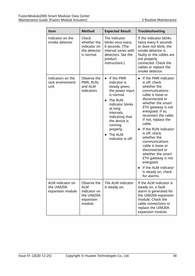
Indicator on thesmoke detector
Checkwhether theindicator onthe detectoris normal.
The indicatorblinks once every6 seconds. (Theinterval varies withdetectors. See theproductinstructions.)
If the indicator blinkstwice every 6 secondsor does not blink, thesmoke detector isfaulty or the cables arenot properlyconnected. Check thecables or replace thesmoke detector.
Indicators on therack environmentunit
Observe thePWR, RUN,and ALMindicators.
● If the PWRindicator issteady green,the power inputis normal.
● The RUNindicator blinksat longintervals,indicating thatthe device isrunningproperly.
● The ALMindicator is off.
● If the PWR indicatoris off, checkwhether thecommunicationscable is loose ordisconnected orwhether the smartETH gateway is notenergized. If so,reconnect the cable.If not, replace thecable.
● If the RUN indicatoris off, checkwhether thecommunicationscable is loose ordisconnected orwhether the smartETH gateway is notenergized.
● If the ALM indicatoris steady on, checkfor alarms.
ALM indicator onthe UIM20Aexpansion module
Observe theALMindicator onthe UIM20Aexpansionmodule.
The ALM indicatoris steady on.
If the ALM indicator issteady on, a faultalarm is generated forthe UIM20A expansionmodule. Check thecable connections orreplace the UIM20Aexpansion module.
FusionModule2000 Smart Modular Data CenterMaintenance Guide (Fusion Module Actuator) 3 Routine Maintenance
Issue 01 (2020-12-25) Copyright © Huawei Technologies Co., Ltd. 34
Item Method Expected Result Troubleshooting
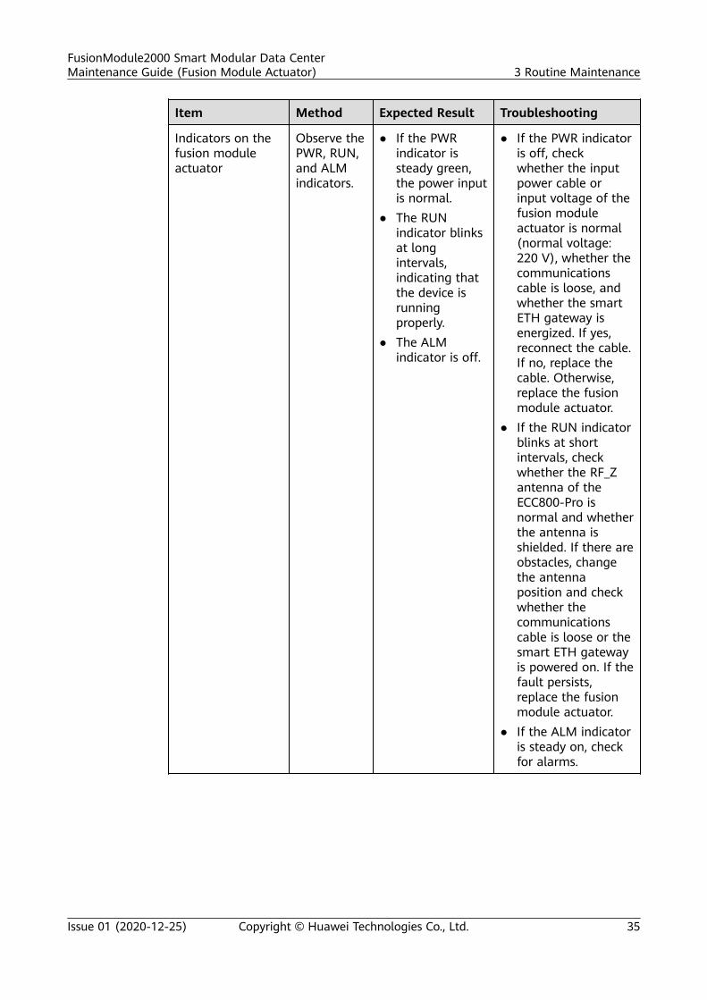
Indicators on thefusion moduleactuator
Observe thePWR, RUN,and ALMindicators.
● If the PWRindicator issteady green,the power inputis normal.
● The RUNindicator blinksat longintervals,indicating thatthe device isrunningproperly.
● The ALMindicator is off.
● If the PWR indicatoris off, checkwhether the inputpower cable orinput voltage of thefusion moduleactuator is normal(normal voltage:220 V), whether thecommunicationscable is loose, andwhether the smartETH gateway isenergized. If yes,reconnect the cable.If no, replace thecable. Otherwise,replace the fusionmodule actuator.
● If the RUN indicatorblinks at shortintervals, checkwhether the RF_Zantenna of theECC800-Pro isnormal and whetherthe antenna isshielded. If there areobstacles, changethe antennaposition and checkwhether thecommunicationscable is loose or thesmart ETH gatewayis powered on. If thefault persists,replace the fusionmodule actuator.
● If the ALM indicatoris steady on, checkfor alarms.
FusionModule2000 Smart Modular Data CenterMaintenance Guide (Fusion Module Actuator) 3 Routine Maintenance
Issue 01 (2020-12-25) Copyright © Huawei Technologies Co., Ltd. 35
Item Method Expected Result Troubleshooting
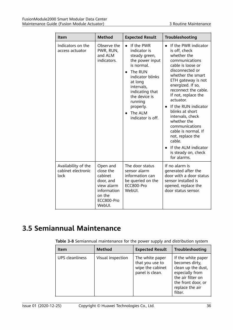
Indicators on theaccess actuator
Observe thePWR, RUN,and ALMindicators.
● If the PWRindicator issteady green,the power inputis normal.
● The RUNindicator blinksat longintervals,indicating thatthe device isrunningproperly.
● The ALMindicator is off.
● If the PWR indicatoris off, checkwhether thecommunicationscable is loose ordisconnected orwhether the smartETH gateway is notenergized. If so,reconnect the cable.If not, replace theactuator.
● If the RUN indicatorblinks at shortintervals, checkwhether thecommunicationscable is normal. Ifnot, replace thecable.
● If the ALM indicatoris steady on, checkfor alarms.
Availability of thecabinet electroniclock
Open andclose thecabinetdoor, andview alarminformationon theECC800-ProWebUI.
The door statussensor alarminformation canbe queried on theECC800-ProWebUI.
If no alarm isgenerated after thedoor with a door statussensor installed isopened, replace thedoor status sensor.
3.5 Semiannual Maintenance
Table 3-8 Semiannual maintenance for the power supply and distribution system
Item Method Expected Result Troubleshooting
UPS cleanliness Visual inspection The white paperthat you use towipe the cabinetpanel is clean.
If the white paperbecomes dirty,clean up the dust,especially fromthe air filter onthe front door, orreplace the airfilter.
FusionModule2000 Smart Modular Data CenterMaintenance Guide (Fusion Module Actuator) 3 Routine Maintenance
Issue 01 (2020-12-25) Copyright © Huawei Technologies Co., Ltd. 36
Item Method Expected Result Troubleshooting
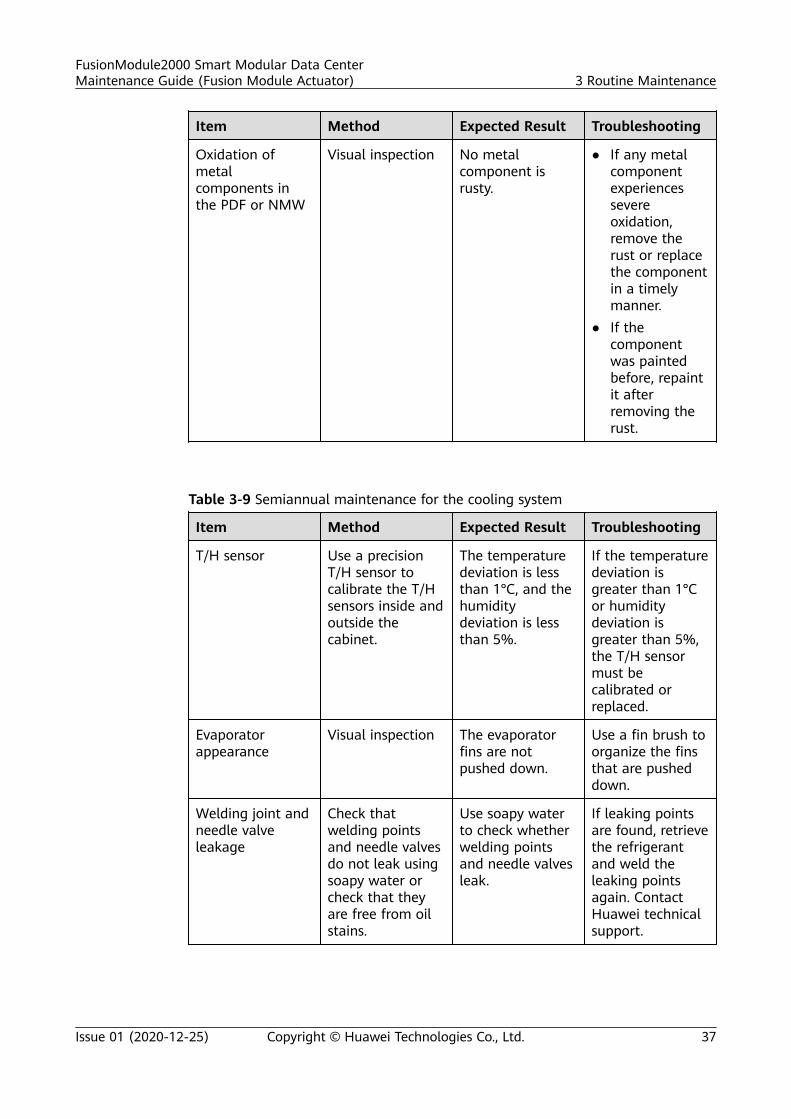
Oxidation ofmetalcomponents inthe PDF or NMW
Visual inspection No metalcomponent isrusty.
● If any metalcomponentexperiencessevereoxidation,remove therust or replacethe componentin a timelymanner.
● If thecomponentwas paintedbefore, repaintit afterremoving therust.
Table 3-9 Semiannual maintenance for the cooling system
Item Method Expected Result Troubleshooting
T/H sensor Use a precisionT/H sensor tocalibrate the T/Hsensors inside andoutside thecabinet.
The temperaturedeviation is lessthan 1°C, and thehumiditydeviation is lessthan 5%.
If the temperaturedeviation isgreater than 1°Cor humiditydeviation isgreater than 5%,the T/H sensormust becalibrated orreplaced.
Evaporatorappearance
Visual inspection The evaporatorfins are notpushed down.
Use a fin brush toorganize the finsthat are pusheddown.
Welding joint andneedle valveleakage
Check thatwelding pointsand needle valvesdo not leak usingsoapy water orcheck that theyare free from oilstains.
Use soapy waterto check whetherwelding pointsand needle valvesleak.
If leaking pointsare found, retrievethe refrigerantand weld theleaking pointsagain. ContactHuawei technicalsupport.
FusionModule2000 Smart Modular Data CenterMaintenance Guide (Fusion Module Actuator) 3 Routine Maintenance
Issue 01 (2020-12-25) Copyright © Huawei Technologies Co., Ltd. 37
Item Method Expected Result Troubleshooting
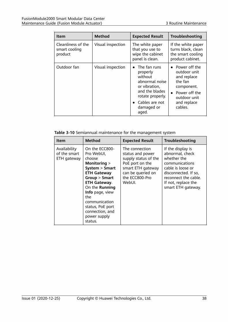
Cleanliness of thesmart coolingproduct
Visual inspection The white paperthat you use towipe the cabinetpanel is clean.
If the white paperturns black, cleanthe smart coolingproduct cabinet.
Outdoor fan Visual inspection ● The fan runsproperlywithoutabnormal noiseor vibration,and the bladesrotate properly.
● Cables are notdamaged oraged.
● Power off theoutdoor unitand replacethe fancomponent.
● Power off theoutdoor unitand replacecables.
Table 3-10 Semiannual maintenance for the management system
Item Method Expected Result Troubleshooting
Availabilityof the smartETH gateway
On the ECC800-Pro WebUI,chooseMonitoring >System > SmartETH GatewayGroup > SmartETH Gateway.On the RunningInfo page, viewthecommunicationstatus, PoE portconnection, andpower supplystatus.
The connectionstatus and powersupply status of thePoE port on thesmart ETH gatewaycan be queried onthe ECC800-ProWebUI.
If the display isabnormal, checkwhether thecommunicationscable is loose ordisconnected. If so,reconnect the cable.If not, replace thesmart ETH gateway.
FusionModule2000 Smart Modular Data CenterMaintenance Guide (Fusion Module Actuator) 3 Routine Maintenance
Issue 01 (2020-12-25) Copyright © Huawei Technologies Co., Ltd. 38
Item Method Expected Result Troubleshooting
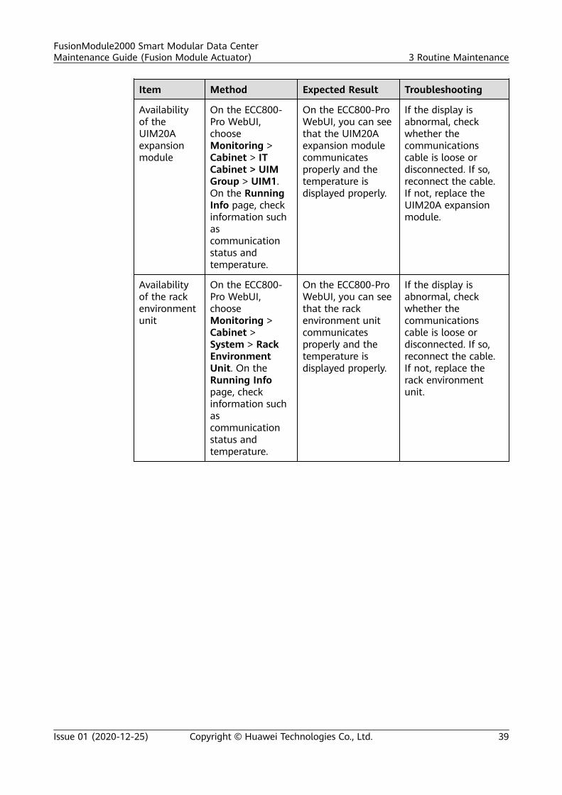
Availabilityof theUIM20Aexpansionmodule
On the ECC800-Pro WebUI,chooseMonitoring >Cabinet > ITCabinet > UIMGroup > UIM1.On the RunningInfo page, checkinformation suchascommunicationstatus andtemperature.
On the ECC800-ProWebUI, you can seethat the UIM20Aexpansion modulecommunicatesproperly and thetemperature isdisplayed properly.
If the display isabnormal, checkwhether thecommunicationscable is loose ordisconnected. If so,reconnect the cable.If not, replace theUIM20A expansionmodule.
Availabilityof the rackenvironmentunit
On the ECC800-Pro WebUI,chooseMonitoring >Cabinet >System > RackEnvironmentUnit. On theRunning Infopage, checkinformation suchascommunicationstatus andtemperature.
On the ECC800-ProWebUI, you can seethat the rackenvironment unitcommunicatesproperly and thetemperature isdisplayed properly.
If the display isabnormal, checkwhether thecommunicationscable is loose ordisconnected. If so,reconnect the cable.If not, replace therack environmentunit.
FusionModule2000 Smart Modular Data CenterMaintenance Guide (Fusion Module Actuator) 3 Routine Maintenance
Issue 01 (2020-12-25) Copyright © Huawei Technologies Co., Ltd. 39
Item Method Expected Result Troubleshooting
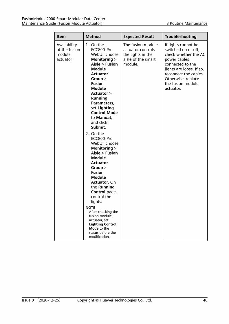
Availabilityof the fusionmoduleactuator
1. On theECC800-ProWebUI, chooseMonitoring >Aisle > FusionModuleActuatorGroup >FusionModuleActuator >RunningParameters,set LightingControl Modeto Manual,and clickSubmit.
2. On theECC800-ProWebUI, chooseMonitoring >Aisle > FusionModuleActuatorGroup >FusionModuleActuator. Onthe RunningControl page,control thelights.
NOTEAfter checking thefusion moduleactuator, setLighting ControlMode to thestatus before themodification.
The fusion moduleactuator controlsthe lights in theaisle of the smartmodule.
If lights cannot beswitched on or off,check whether the ACpower cablesconnected to thelights are loose. If so,reconnect the cables.Otherwise, replacethe fusion moduleactuator.
FusionModule2000 Smart Modular Data CenterMaintenance Guide (Fusion Module Actuator) 3 Routine Maintenance
Issue 01 (2020-12-25) Copyright © Huawei Technologies Co., Ltd. 40
Item Method Expected Result Troubleshooting
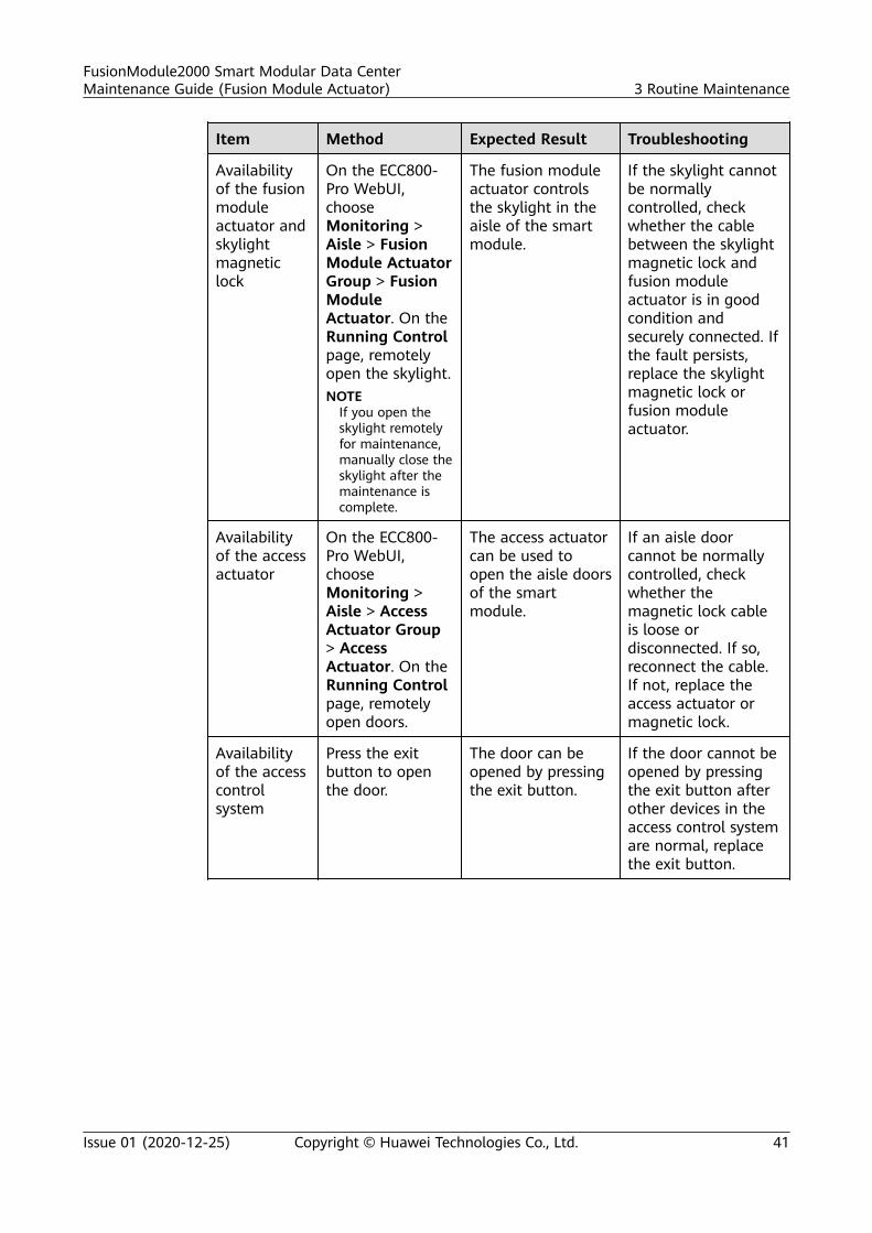
Availabilityof the fusionmoduleactuator andskylightmagneticlock
On the ECC800-Pro WebUI,chooseMonitoring >Aisle > FusionModule ActuatorGroup > FusionModuleActuator. On theRunning Controlpage, remotelyopen the skylight.NOTE
If you open theskylight remotelyfor maintenance,manually close theskylight after themaintenance iscomplete.
The fusion moduleactuator controlsthe skylight in theaisle of the smartmodule.
If the skylight cannotbe normallycontrolled, checkwhether the cablebetween the skylightmagnetic lock andfusion moduleactuator is in goodcondition andsecurely connected. Ifthe fault persists,replace the skylightmagnetic lock orfusion moduleactuator.
Availabilityof the accessactuator
On the ECC800-Pro WebUI,chooseMonitoring >Aisle > AccessActuator Group> AccessActuator. On theRunning Controlpage, remotelyopen doors.
The access actuatorcan be used toopen the aisle doorsof the smartmodule.
If an aisle doorcannot be normallycontrolled, checkwhether themagnetic lock cableis loose ordisconnected. If so,reconnect the cable.If not, replace theaccess actuator ormagnetic lock.
Availabilityof the accesscontrolsystem
Press the exitbutton to openthe door.
The door can beopened by pressingthe exit button.
If the door cannot beopened by pressingthe exit button afterother devices in theaccess control systemare normal, replacethe exit button.
FusionModule2000 Smart Modular Data CenterMaintenance Guide (Fusion Module Actuator) 3 Routine Maintenance
Issue 01 (2020-12-25) Copyright © Huawei Technologies Co., Ltd. 41
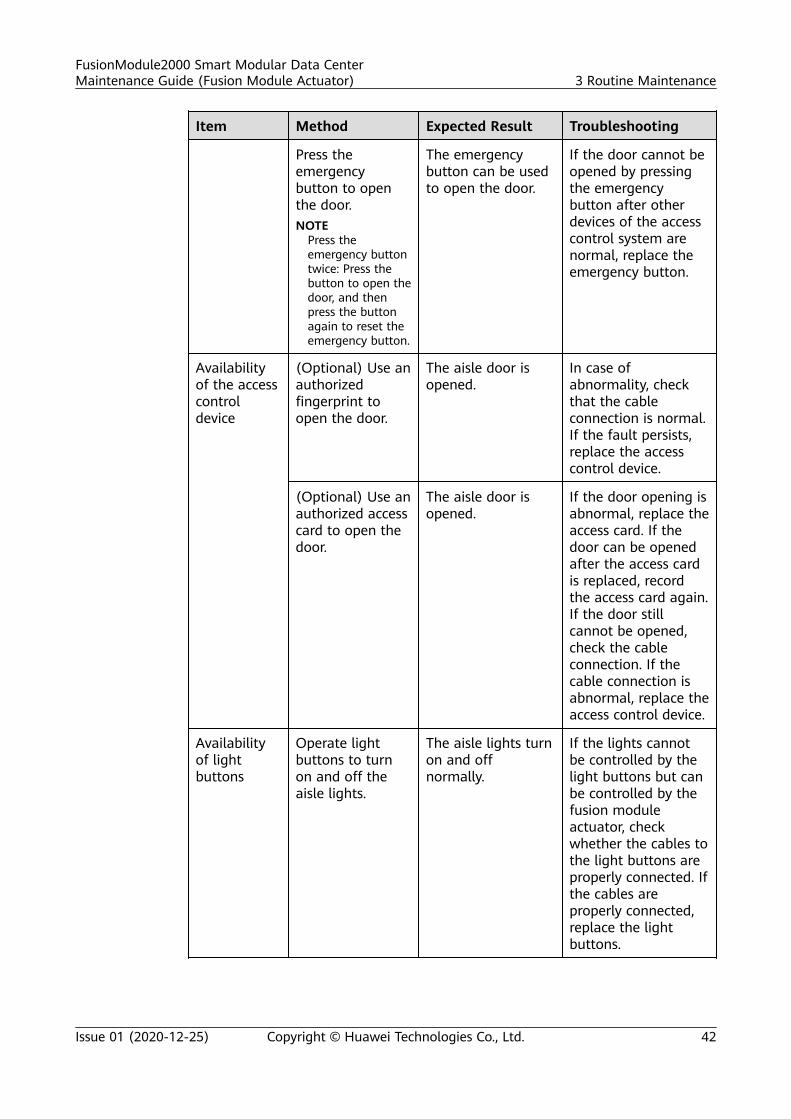
Item Method Expected Result Troubleshooting
Press theemergencybutton to openthe door.NOTE
Press theemergency buttontwice: Press thebutton to open thedoor, and thenpress the buttonagain to reset theemergency button.
The emergencybutton can be usedto open the door.
If the door cannot beopened by pressingthe emergencybutton after otherdevices of the accesscontrol system arenormal, replace theemergency button.
Availabilityof the accesscontroldevice
(Optional) Use anauthorizedfingerprint toopen the door.
The aisle door isopened.
In case ofabnormality, checkthat the cableconnection is normal.If the fault persists,replace the accesscontrol device.
(Optional) Use anauthorized accesscard to open thedoor.
The aisle door isopened.
If the door opening isabnormal, replace theaccess card. If thedoor can be openedafter the access cardis replaced, recordthe access card again.If the door stillcannot be opened,check the cableconnection. If thecable connection isabnormal, replace theaccess control device.
Availabilityof lightbuttons
Operate lightbuttons to turnon and off theaisle lights.
The aisle lights turnon and offnormally.
If the lights cannotbe controlled by thelight buttons but canbe controlled by thefusion moduleactuator, checkwhether the cables tothe light buttons areproperly connected. Ifthe cables areproperly connected,replace the lightbuttons.
FusionModule2000 Smart Modular Data CenterMaintenance Guide (Fusion Module Actuator) 3 Routine Maintenance
Issue 01 (2020-12-25) Copyright © Huawei Technologies Co., Ltd. 42
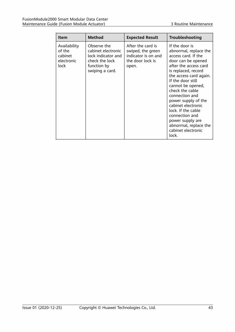
Item Method Expected Result Troubleshooting
Availabilityof thecabinetelectroniclock
Observe thecabinet electroniclock indicator andcheck the lockfunction byswiping a card.
After the card isswiped, the greenindicator is on andthe door lock isopen.
If the door isabnormal, replace theaccess card. If thedoor can be openedafter the access cardis replaced, recordthe access card again.If the door stillcannot be opened,check the cableconnection andpower supply of thecabinet electroniclock. If the cableconnection andpower supply areabnormal, replace thecabinet electroniclock.
FusionModule2000 Smart Modular Data CenterMaintenance Guide (Fusion Module Actuator) 3 Routine Maintenance
Issue 01 (2020-12-25) Copyright © Huawei Technologies Co., Ltd. 43
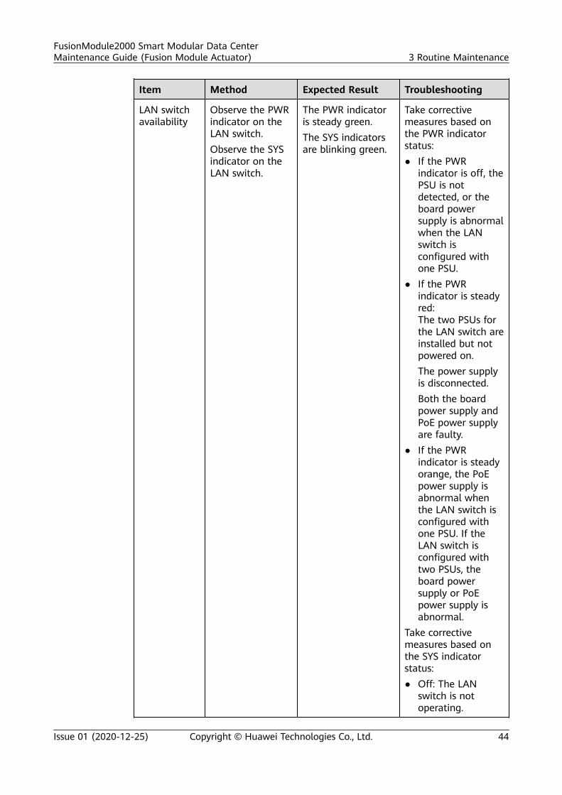
Item Method Expected Result Troubleshooting
LAN switchavailability
Observe the PWRindicator on theLAN switch.Observe the SYSindicator on theLAN switch.
The PWR indicatoris steady green.The SYS indicatorsare blinking green.
Take correctivemeasures based onthe PWR indicatorstatus:● If the PWR
indicator is off, thePSU is notdetected, or theboard powersupply is abnormalwhen the LANswitch isconfigured withone PSU.
● If the PWRindicator is steadyred:The two PSUs forthe LAN switch areinstalled but notpowered on.The power supplyis disconnected.Both the boardpower supply andPoE power supplyare faulty.
● If the PWRindicator is steadyorange, the PoEpower supply isabnormal whenthe LAN switch isconfigured withone PSU. If theLAN switch isconfigured withtwo PSUs, theboard powersupply or PoEpower supply isabnormal.
Take correctivemeasures based onthe SYS indicatorstatus:● Off: The LAN
switch is notoperating.
FusionModule2000 Smart Modular Data CenterMaintenance Guide (Fusion Module Actuator) 3 Routine Maintenance
Issue 01 (2020-12-25) Copyright © Huawei Technologies Co., Ltd. 44
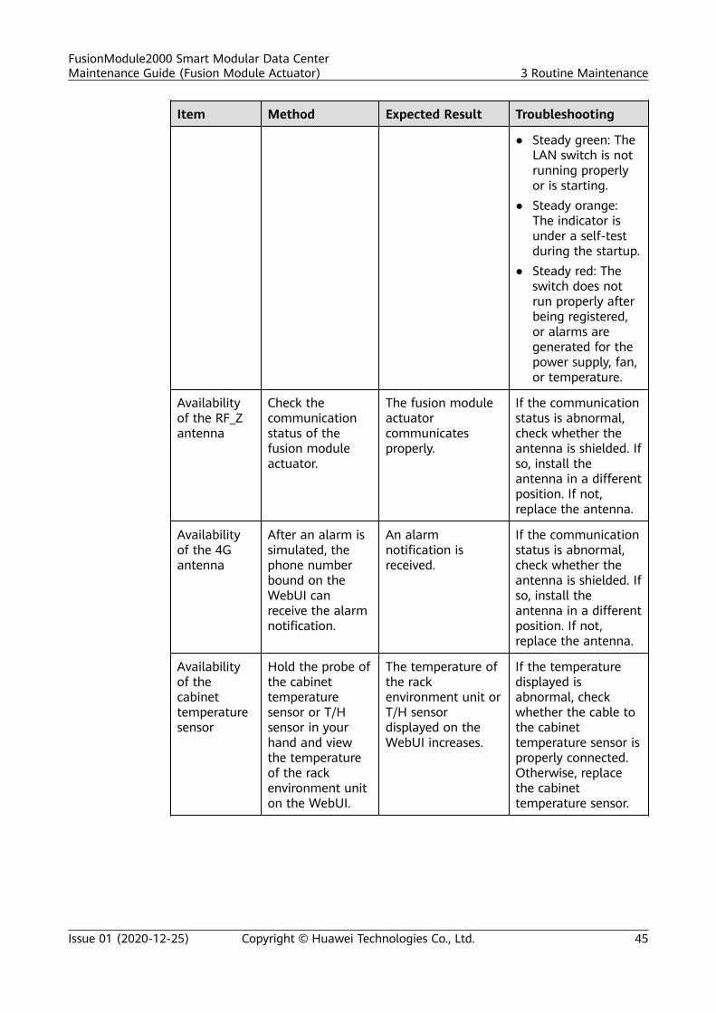
Item Method Expected Result Troubleshooting
● Steady green: TheLAN switch is notrunning properlyor is starting.
● Steady orange:The indicator isunder a self-testduring the startup.
● Steady red: Theswitch does notrun properly afterbeing registered,or alarms aregenerated for thepower supply, fan,or temperature.
Availabilityof the RF_Zantenna
Check thecommunicationstatus of thefusion moduleactuator.
The fusion moduleactuatorcommunicatesproperly.
If the communicationstatus is abnormal,check whether theantenna is shielded. Ifso, install theantenna in a differentposition. If not,replace the antenna.
Availabilityof the 4Gantenna
After an alarm issimulated, thephone numberbound on theWebUI canreceive the alarmnotification.
An alarmnotification isreceived.
If the communicationstatus is abnormal,check whether theantenna is shielded. Ifso, install theantenna in a differentposition. If not,replace the antenna.
Availabilityof thecabinettemperaturesensor
Hold the probe ofthe cabinettemperaturesensor or T/Hsensor in yourhand and viewthe temperatureof the rackenvironment uniton the WebUI.
The temperature ofthe rackenvironment unit orT/H sensordisplayed on theWebUI increases.
If the temperaturedisplayed isabnormal, checkwhether the cable tothe cabinettemperature sensor isproperly connected.Otherwise, replacethe cabinettemperature sensor.
FusionModule2000 Smart Modular Data CenterMaintenance Guide (Fusion Module Actuator) 3 Routine Maintenance
Issue 01 (2020-12-25) Copyright © Huawei Technologies Co., Ltd. 45
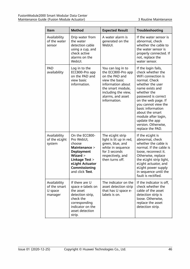
Item Method Expected Result Troubleshooting
Availabilityof the watersensor
Drip water fromthe waterdetection cableusing a cup, andcheck activealarms on theWebUI.
A water alarm isgenerated on theWebUI.
If the water sensor isabnormal, checkwhether the cable tothe water sensor isproperly connected. Ifnot, replace thewater sensor.
PADavailability
Log in to theECC800-Pro appon the PAD andview basicinformation.
You can log in tothe ECC800-Pro appon the PAD andview the basicinformation aboutthe smart module,including the view,alarms, and assetinformation.
If the login fails,check whether theWiFi connection isnormal. Checkwhether the username exists andwhether thepassword is correcton the web page. Ifyou cannot view thebasic informationabout the smartmodule after login,update the appversion. Otherwise,replace the PAD.
Availabilityof the eLightsystem
On the ECC800-Pro WebUI,chooseMaintenance >DeploymentWizard >Linkage Test >eLight ActuatorCommissioningand click Test.
The eLight striplight is lit up in red,green, blue, andwhite in sequencefor 3 secondsrespectively, andthen turns off.
If the eLight isabnormal, checkwhether the cable isnormal. If the cable isloose, reconnect it.Otherwise, replacethe eLight strip light,eLight actuator, andeLight power supplyin sequence until thefault is rectified.
Availabilityof the smartU spacemanager
If there are Uspace e-labels onthe assetdetection strip,check thecorrespondingindicator on theasset detectionstrip.
The indicator on theasset detection stripthat has U space e-labels is on.
If the indicator is off,check whether thecable of the assetdetection strip isloose. Otherwise,replace the assetdetection strip.
FusionModule2000 Smart Modular Data CenterMaintenance Guide (Fusion Module Actuator) 3 Routine Maintenance
Issue 01 (2020-12-25) Copyright © Huawei Technologies Co., Ltd. 46
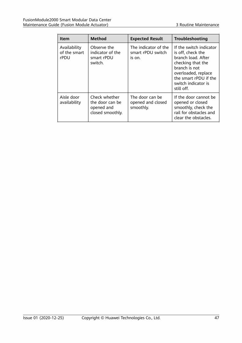
Item Method Expected Result Troubleshooting
Availabilityof the smartrPDU
Observe theindicator of thesmart rPDUswitch.
The indicator of thesmart rPDU switchis on.
If the switch indicatoris off, check thebranch load. Afterchecking that thebranch is notoverloaded, replacethe smart rPDU if theswitch indicator isstill off.
Aisle dooravailability
Check whetherthe door can beopened andclosed smoothly.
The door can beopened and closedsmoothly.
If the door cannot beopened or closedsmoothly, check therail for obstacles andclear the obstacles.
FusionModule2000 Smart Modular Data CenterMaintenance Guide (Fusion Module Actuator) 3 Routine Maintenance
Issue 01 (2020-12-25) Copyright © Huawei Technologies Co., Ltd. 47
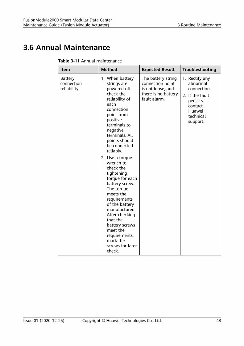
3.6 Annual Maintenance
Table 3-11 Annual maintenance
Item Method Expected Result Troubleshooting
Batteryconnectionreliability
1. When batterystrings arepowered off,check thereliability ofeachconnectionpoint frompositiveterminals tonegativeterminals. Allpoints shouldbe connectedreliably.
2. Use a torquewrench tocheck thetighteningtorque for eachbattery screw.The torquemeets therequirementsof the batterymanufacturer.After checkingthat thebattery screwsmeet therequirements,mark thescrews for latercheck.
The battery stringconnection pointis not loose, andthere is no batteryfault alarm.
1. Rectify anyabnormalconnection.
2. If the faultpersists,contactHuaweitechnicalsupport.
FusionModule2000 Smart Modular Data CenterMaintenance Guide (Fusion Module Actuator) 3 Routine Maintenance
Issue 01 (2020-12-25) Copyright © Huawei Technologies Co., Ltd. 48
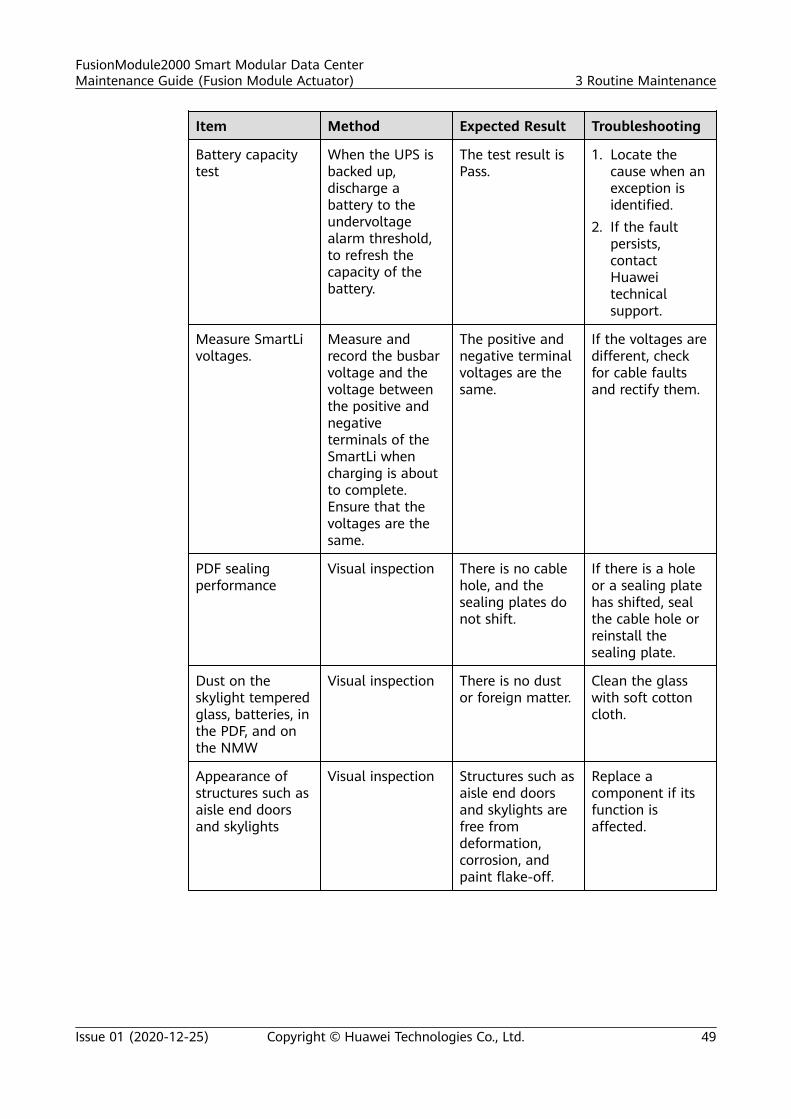
Item Method Expected Result Troubleshooting
Battery capacitytest
When the UPS isbacked up,discharge abattery to theundervoltagealarm threshold,to refresh thecapacity of thebattery.
The test result isPass.
1. Locate thecause when anexception isidentified.
2. If the faultpersists,contactHuaweitechnicalsupport.
Measure SmartLivoltages.
Measure andrecord the busbarvoltage and thevoltage betweenthe positive andnegativeterminals of theSmartLi whencharging is aboutto complete.Ensure that thevoltages are thesame.
The positive andnegative terminalvoltages are thesame.
If the voltages aredifferent, checkfor cable faultsand rectify them.
PDF sealingperformance
Visual inspection There is no cablehole, and thesealing plates donot shift.
If there is a holeor a sealing platehas shifted, sealthe cable hole orreinstall thesealing plate.
Dust on theskylight temperedglass, batteries, inthe PDF, and onthe NMW
Visual inspection There is no dustor foreign matter.
Clean the glasswith soft cottoncloth.
Appearance ofstructures such asaisle end doorsand skylights
Visual inspection Structures such asaisle end doorsand skylights arefree fromdeformation,corrosion, andpaint flake-off.
Replace acomponent if itsfunction isaffected.
FusionModule2000 Smart Modular Data CenterMaintenance Guide (Fusion Module Actuator) 3 Routine Maintenance
Issue 01 (2020-12-25) Copyright © Huawei Technologies Co., Ltd. 49
4 Alarms and Troubleshooting
If an incident occurs and may jeopardize the long-term stable running of theFusionModule2000, the system or a component will generate alarms. O&Mpersonnel or the person on duty must promptly handle any identified alarms.
FusionModule2000 Smart Modular Data CenterMaintenance Guide (Fusion Module Actuator) 4 Alarms and Troubleshooting
Issue 01 (2020-12-25) Copyright © Huawei Technologies Co., Ltd. 50
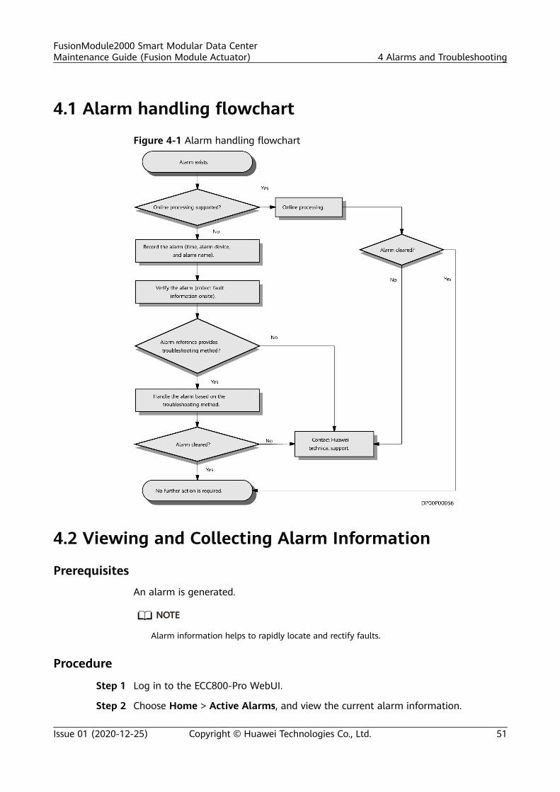
4.1 Alarm handling flowchart
Figure 4-1 Alarm handling flowchart
4.2 Viewing and Collecting Alarm Information
Prerequisites
An alarm is generated.
NO TE
Alarm information helps to rapidly locate and rectify faults.
Procedure
Step 1 Log in to the ECC800-Pro WebUI.
Step 2 Choose Home > Active Alarms, and view the current alarm information.
FusionModule2000 Smart Modular Data CenterMaintenance Guide (Fusion Module Actuator) 4 Alarms and Troubleshooting
Issue 01 (2020-12-25) Copyright © Huawei Technologies Co., Ltd. 51
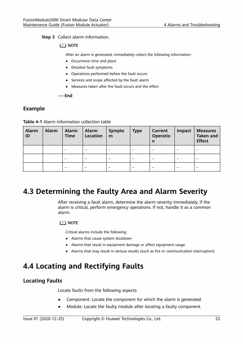
Step 3 Collect alarm information.
NO TE
After an alarm is generated, immediately collect the following information:
● Occurrence time and place
● Detailed fault symptoms
● Operations performed before the fault occurs
● Services and scope affected by the fault alarm
● Measures taken after the fault occurs and the effect
----End
Example
Table 4-1 Alarm information collection table
AlarmID
Alarm AlarmTime
AlarmLocation
Symptom
Type CurrentOperation
Impact MeasuresTaken andEffect
- - - - - - -
- - - - - - -
- - - - - - -
4.3 Determining the Faulty Area and Alarm SeverityAfter receiving a fault alarm, determine the alarm severity immediately. If thealarm is critical, perform emergency operations. If not, handle it as a commonalarm.
NO TE
Critical alarms include the following:
● Alarms that cause system shutdown
● Alarms that result in equipment damage or affect equipment usage
● Alarms that may result in serious results (such as fire or communication interruption)
4.4 Locating and Rectifying Faults
Locating Faults
Locate faults from the following aspects:
● Component: Locate the component for which the alarm is generated.● Module: Locate the faulty module after locating a faulty component.
FusionModule2000 Smart Modular Data CenterMaintenance Guide (Fusion Module Actuator) 4 Alarms and Troubleshooting
Issue 01 (2020-12-25) Copyright © Huawei Technologies Co., Ltd. 52
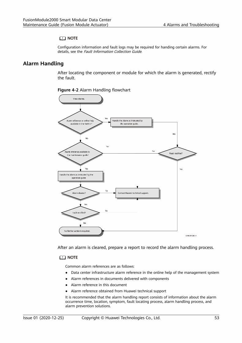
NO TE
Configuration information and fault logs may be required for handing certain alarms. Fordetails, see the Fault Information Collection Guide.
Alarm Handling
After locating the component or module for which the alarm is generated, rectifythe fault.
Figure 4-2 Alarm Handling flowchart
After an alarm is cleared, prepare a report to record the alarm handling process.
NO TE
Common alarm references are as follows:
● Data center infrastructure alarm reference in the online help of the management system
● Alarm references in documents delivered with components
● Alarm reference in this document
● Alarm reference obtained from Huawei technical support
It is recommended that the alarm handling report consists of information about the alarmoccurrence time, location, symptom, fault locating process, alarm handling process, andalarm prevention solutions.
FusionModule2000 Smart Modular Data CenterMaintenance Guide (Fusion Module Actuator) 4 Alarms and Troubleshooting
Issue 01 (2020-12-25) Copyright © Huawei Technologies Co., Ltd. 53
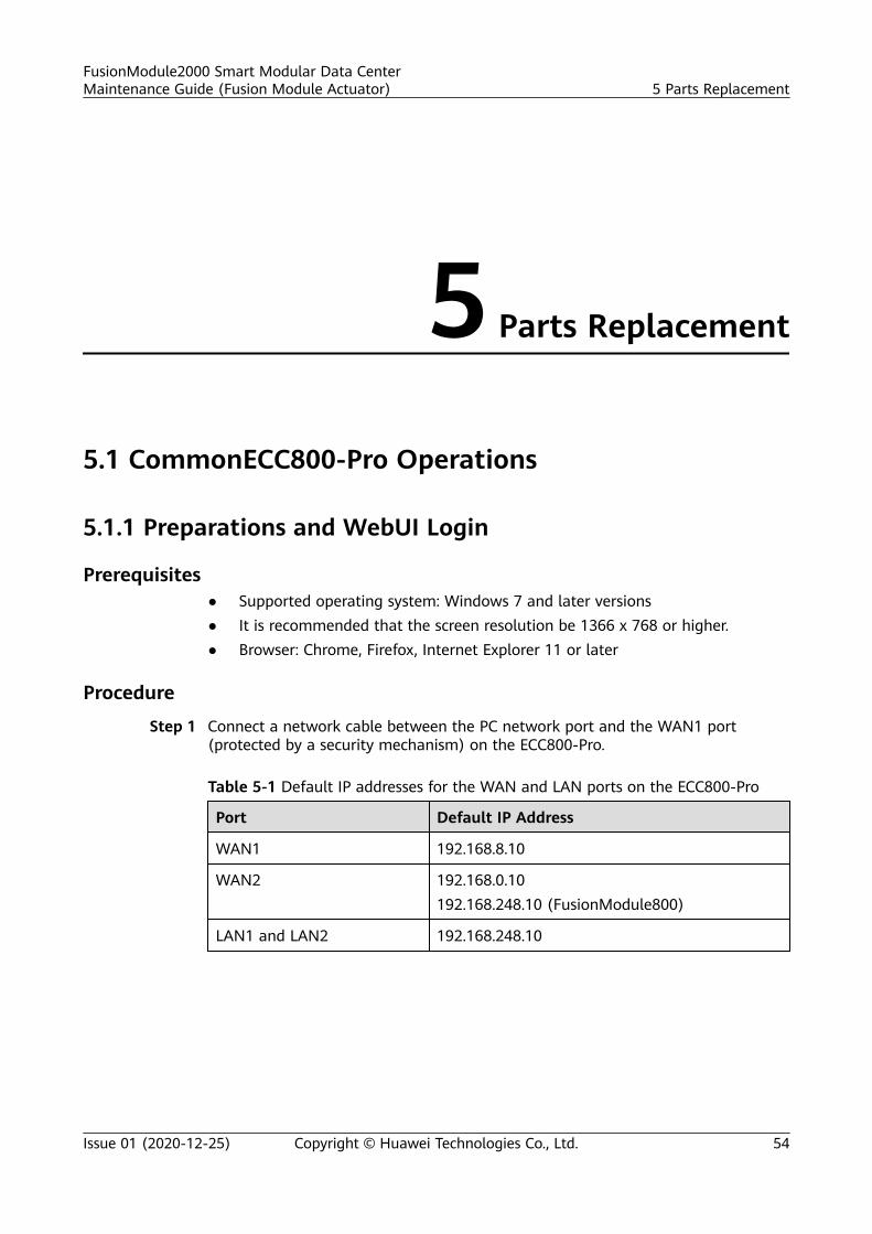
5 Parts Replacement
5.1 CommonECC800-Pro Operations
5.1.1 Preparations and WebUI Login
Prerequisites● Supported operating system: Windows 7 and later versions● It is recommended that the screen resolution be 1366 x 768 or higher.● Browser: Chrome, Firefox, Internet Explorer 11 or later
Procedure
Step 1 Connect a network cable between the PC network port and the WAN1 port(protected by a security mechanism) on the ECC800-Pro.
Table 5-1 Default IP addresses for the WAN and LAN ports on the ECC800-Pro
Port Default IP Address
WAN1 192.168.8.10
WAN2 192.168.0.10192.168.248.10 (FusionModule800)
LAN1 and LAN2 192.168.248.10
FusionModule2000 Smart Modular Data CenterMaintenance Guide (Fusion Module Actuator) 5 Parts Replacement
Issue 01 (2020-12-25) Copyright © Huawei Technologies Co., Ltd. 54
NO TICE
● In ECC800 V100R002C10 and earlier versions, the default IP address of portWAN_1 is 192.168.1.10.
● The WAN1 port IP address cannot be set to an IP address in any of thefollowing network segments: 192.168.0.x, 192.168.245.x, 192.168.246.x and192.168.248.x.
● IP addresses for the WAN1 and WAN2 ports should not be set in the samenetwork segment.
● In some customized scenarios, the default IP address for the WAN_2 port is192.168.248.10. The default value prevails.
● WAN ports support the Internet access and LAN ports support the intranetaccess. Connect the PC network port to the WAN1 port or LAN port on theECC800-Pro based on the access network.
Step 2 Configure the PC IP address and the WAN1 IP address in the same networksegment.
If the WAN1 port IP address is 192.168.8.10, subnet mask is 255.255.255.0, anddefault gateway is 192.168.8.1, set the PC IP address to 192.168.8.12, subnet maskto 255.255.255.0, and default gateway to 192.168.8.1.
Step 3 Set LAN parameters.
NO TE
● If the ECC800-Pro connects to a LAN and a proxy server has been selected, perform Step3.3 and Step 3.4.
● If the ECC800-Pro connects to the Internet, and the PC in a LAN accesses the Internetover a proxy server, do not perform Step 3.3 and Step 3.4. Otherwise, you will fail toaccess the ECC800-Pro.
1. Open the Internet Explorer and choose Tools > Internet Options.2. Click the Advanced tab and select Use TLS1.1 and Use TLS1.2.3. (Optional) Click the Connections tab and select LAN settings.4. (Optional) On Proxy server, clear Use a proxy server for your LAN.5. Click OK.
Step 4 Set Internet Explorer parameters.1. When you use Internet Explorer for access, set Internet Explorer to ensure the
normal display of and operations on the WebUI. Choose Tools >Compatibility View, and add the web access address to the compatibilityview.
2. Choose Tools > Internet options > Security, choose Add the ECC800-Pro IPaddress to the list of trusted sites.
FusionModule2000 Smart Modular Data CenterMaintenance Guide (Fusion Module Actuator) 5 Parts Replacement
Issue 01 (2020-12-25) Copyright © Huawei Technologies Co., Ltd. 55
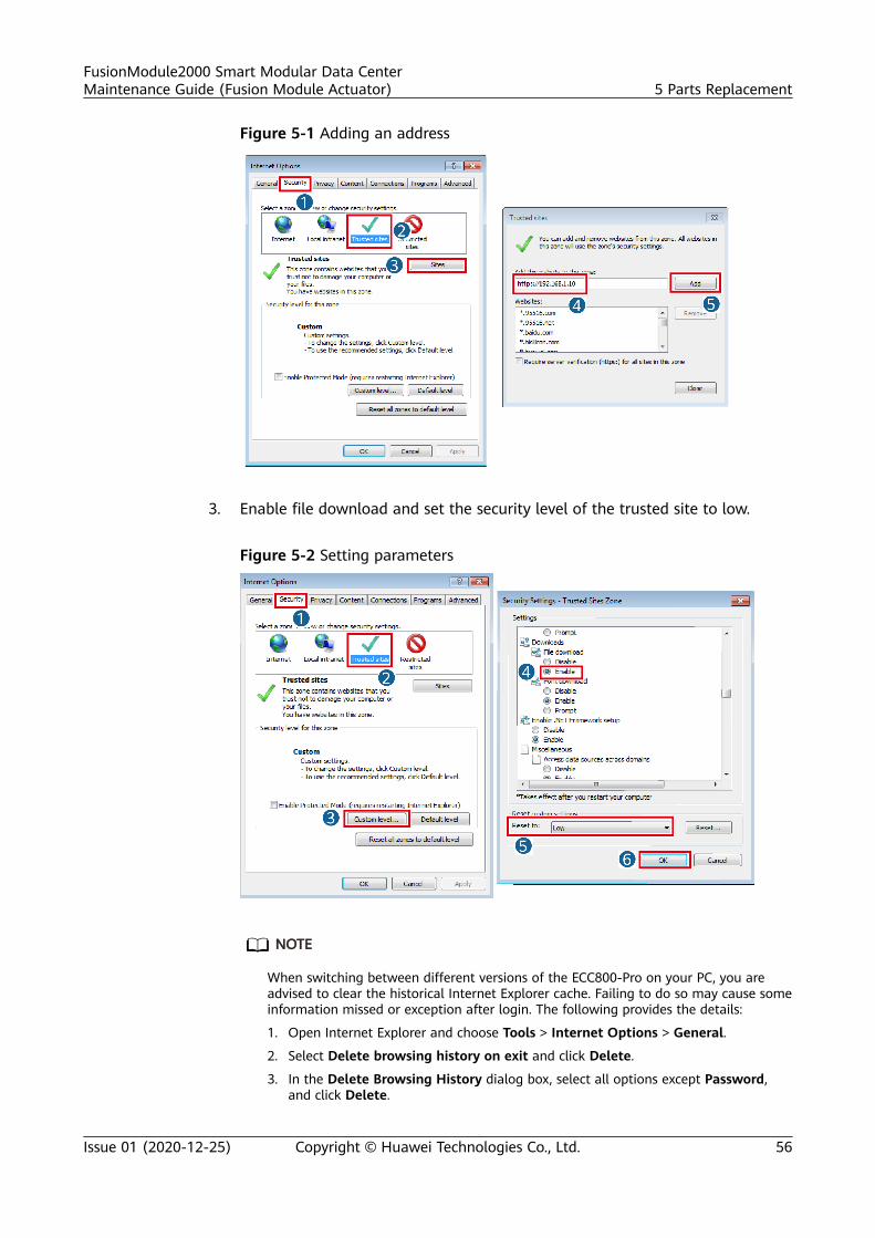
Figure 5-1 Adding an address
3. Enable file download and set the security level of the trusted site to low.
Figure 5-2 Setting parameters
NO TE
When switching between different versions of the ECC800-Pro on your PC, you areadvised to clear the historical Internet Explorer cache. Failing to do so may cause someinformation missed or exception after login. The following provides the details:
1. Open Internet Explorer and choose Tools > Internet Options > General.
2. Select Delete browsing history on exit and click Delete.
3. In the Delete Browsing History dialog box, select all options except Password,and click Delete.
FusionModule2000 Smart Modular Data CenterMaintenance Guide (Fusion Module Actuator) 5 Parts Replacement
Issue 01 (2020-12-25) Copyright © Huawei Technologies Co., Ltd. 56
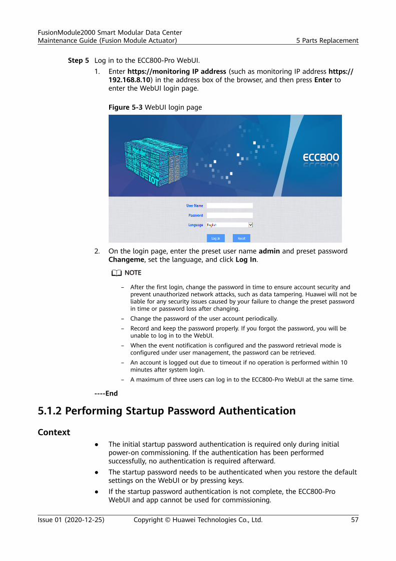
Step 5 Log in to the ECC800-Pro WebUI.1. Enter https://monitoring IP address (such as monitoring IP address https://
192.168.8.10) in the address box of the browser, and then press Enter toenter the WebUI login page.
Figure 5-3 WebUI login page
2. On the login page, enter the preset user name admin and preset passwordChangeme, set the language, and click Log In.
NO TE
– After the first login, change the password in time to ensure account security andprevent unauthorized network attacks, such as data tampering. Huawei will not beliable for any security issues caused by your failure to change the preset passwordin time or password loss after changing.
– Change the password of the user account periodically.– Record and keep the password properly. If you forgot the password, you will be
unable to log in to the WebUI.– When the event notification is configured and the password retrieval mode is
configured under user management, the password can be retrieved.– An account is logged out due to timeout if no operation is performed within 10
minutes after system login.– A maximum of three users can log in to the ECC800-Pro WebUI at the same time.
----End
5.1.2 Performing Startup Password Authentication
Context● The initial startup password authentication is required only during initial
power-on commissioning. If the authentication has been performedsuccessfully, no authentication is required afterward.
● The startup password needs to be authenticated when you restore the defaultsettings on the WebUI or by pressing keys.
● If the startup password authentication is not complete, the ECC800-ProWebUI and app cannot be used for commissioning.
FusionModule2000 Smart Modular Data CenterMaintenance Guide (Fusion Module Actuator) 5 Parts Replacement
Issue 01 (2020-12-25) Copyright © Huawei Technologies Co., Ltd. 57
● When the system type is changed to FusionModule800, the startup passwordneeds to be authenticated again.
Procedure
Step 1 Authenticate the startup password on the WebUI.1. Log in to the ECC800-Pro WebUI as an administrator.2. Record the values of Barcode and Verify Code in the displayed Startup
Password dialog box.3. Within 24 hours, inform Huawei technical support of Barcode and Verify
Code to obtain the password. After obtaining the password, enter thepassword in the Password text box and click Submit to complete theauthentication of the startup password.
NO TE
The verification code is valid for 24 hours by default. After the validity period expires,the verification code is automatically updated. You can also click to update theverification code.
Step 2 Use the Service Expert app to authenticate the startup password.1. Download and obtain the app installation package.
Log in to Huawei AppGallery (https://a.vmall.com/), search for ServiceExpert, and tap Download to obtain the installation package.
a. Open the browser on the pad, enter www.baidu.com in the address box,search for Huawei AppGallery, select Ordinary Download, and tapSave.
b. Install the Huawei AppGallery. If the downloaded file exists in the drop-down list box, tap the file to install the Huawei AppGallery. If thedownloaded file does not exist in the drop-down list box, choose File >Local on the desktop, find the Download folder, and tap the HuaweiAppGallery installation package.
2. Install the app.
By default, the Android operating system forbids the installation of apps notobtained from the Android market. Therefore, before installing the app, setthe mobile phone so that it allows the installation of apps from unknownsources.
Tap the app installation file for installation. After the installation is complete,
check that the app icon is displayed on the home screen of themobile phone or pad.
3. Hold down the SW button on the ECC800-Pro for less than 3s to enable theWiFi function.
FusionModule2000 Smart Modular Data CenterMaintenance Guide (Fusion Module Actuator) 5 Parts Replacement
Issue 01 (2020-12-25) Copyright © Huawei Technologies Co., Ltd. 58
NO TE
– The initial password is Changeme after WiFi is enabled. The initial password isvalid only when you press the button for the first time to enable WiFi afterdelivery. If you enable WiFi on the WebUI, there is no default password.
– After the WiFi function is enabled, the password for a mobile phone to connect tothe WiFi network is Changeme. When you log in to the app using a pad, thesystem prompts you to change the password.
– After you disable the WiFi hotspot function on the WebUI and press the buttonagain, the WiFi function is still enabled. In this case, the WiFi password is the oneyou changed last time.
– The WiFi function is disabled by default. If you need to enable the WiFi function,change the WiFi password to ensure connection security.
– If a password is used for a long time, it may be stolen or cracked. The longer it isused, the higher the risk of theft and cracking. Change the WiFi password once halfa year.
4. Use the Service Expert app to authenticate the startup password.
a. Open the mobile phone app or pad app, and log in to theFusionModule800 device login page using the administrator account.Ensure that the IP address is 192.168.245.10, the default administratorname is admin, and the default password is Changeme.
b. If the message displayed on the page is changed from "Initial startuppassword authentication" to "Activated", the startup passwordauthentication is complete.
NO TE
– After the first login, change the password in time to ensure system access security.
– When the mobile phone app connects to the monitoring system, the WiFi function ofthe monitoring system is disabled by default. Before connecting the mobile phone appto the monitoring system, enable the WiFi function on the WebUI. For security, you areadvised to disable the WiFi function when the app is not in use.
– If a password is used for a long time, it may be stolen or cracked. The longer it is used,the higher the risk of theft and cracking. Change the password once three months.
– You are advised to use a mobile phone that has not been rooted to reduce the risk ofinformation leakage.
– It is recommended that you use different user names to log in to both the ECC800-ProWebUI and app at the same time. If you use the same user name to log in to theWebUI and app at the same time, either of them will be forcibly logged out.
– The iDCService app supports only the Android system.
– The iDCService app is available only in Chinese.
----End
5.1.3 Synchronizing the Configuration Parameters
Procedure
Step 1 After replacing components, log in to the ECC800-Pro WebUI and chooseMaintenance > Parameter Sync to access the parameter synchronization page.
Step 2 Click Device type and select the component type from the drop-down list.
FusionModule2000 Smart Modular Data CenterMaintenance Guide (Fusion Module Actuator) 5 Parts Replacement
Issue 01 (2020-12-25) Copyright © Huawei Technologies Co., Ltd. 59
Step 3 Select the failure device in Source Device, select the reserved device in TargetDevice, and click Submit to synchronize the configuration parameters of thefailure device to the reserved device.
----End
5.2 Replacing Power Supply and Distribution SystemComponents
5.2.1 Parts Replacement for the Precision PDFFor details about parts replacement for the precision PDF, see the "PartsReplacement" section in the corresponding Precision PDC user manual.
Table 5-2 Replaceable parts of the precision PDF
No. Replaceable Part
1 MCB (Miniature circuit breaker)
2 MDU (Monitor display unit)
3 SPD (Surge protective device)
4 Fuse
5 Indicator
6 Power distribution detection module
NO TE
If you need to replace any other parts, contact Huawei technical support.
5.2.2 Parts Replacement for the Integrated PDC
For details about parts replacement for the integrated PDC, see the "PartsReplacement" section in theECC800-Pro user manual.
Table 5-3 Replaceable parts of the integrated PDC
No. Replaceable Part
1 MCB
2 MDU
3 SPD
4 Fuse
FusionModule2000 Smart Modular Data CenterMaintenance Guide (Fusion Module Actuator) 5 Parts Replacement
Issue 01 (2020-12-25) Copyright © Huawei Technologies Co., Ltd. 60
No. Replaceable Part
5 Indicator
6 Power distribution detection module
NO TE
If you need to replace any other parts, contact Huawei technical support.
5.2.3 Parts Replacement for the Integrated UPS
For details about parts replacement for integrated UPS, see the "PartsReplacement" section in the UPS user manual.
Table 5-4 Replaceable parts of the integrated UPS
No. Replaceable Part
1 Fuse
2 Indicator
3 Circuit breaker
NO TE
If you need to replace any other parts, contact Huawei technical support.
5.2.4 Parts Replacement for the SmartLi
For details about parts replacement for the SmartLi, see the "Parts Replacement"section in the SmartLi user manual.
Table 5-5 Replaceable parts of the SmartLi
No. Replaceable Part
1 MDU
2 BCU
3 Battery module
4 Fuse
5 Fire cylinder
FusionModule2000 Smart Modular Data CenterMaintenance Guide (Fusion Module Actuator) 5 Parts Replacement
Issue 01 (2020-12-25) Copyright © Huawei Technologies Co., Ltd. 61
NO TE
If you need to replace any other parts, contact Huawei technical support.
5.2.5 Replacing an rPDU
Impact on the SystemOne power input of the equipment cannot work.
Preparations● Tools: Phillips screwdriver, step ladder● Material: rPDU of the same model that is available and functional● Skill requirement: power distribution engineers
Context● The rPDU is installed near the rear door of the cabinet.● The rPDU has two types: vertical and horizontal. The following describes how
to install a vertical rPDU.
Procedure
Step 1 Open the rear door of the cabinet.
Step 2 Connect the IT load of the faulty rPDU to a normal rPDU.
Step 3 Turn off the upstream power distribution switch for the faulty rPDU. Ensure thatthe rPDU input has no power, and then remove the power cables from theterminal block on the top of the rPDU.
Step 4 Remove the bolts that secure the rPDU using a Phillips screwdriver.
Step 5 Secure the new rPDU in the installation position of the old rPDU.
Step 6 Connect the input power cables to the rPDU.
Step 7 Turn on the upstream power distribution switch for the rPDU and the rPDU inputswitch.
Step 8 Verify that the rPDU power output is normal and then connect the IT load cablesto the rPDU.
----End
5.2.6 Replacing a Smart rPDU
Impact on the SystemOne power input of the equipment cannot work.
Preparations● Tools: Phillips screwdriver, step ladder, label, marker
FusionModule2000 Smart Modular Data CenterMaintenance Guide (Fusion Module Actuator) 5 Parts Replacement
Issue 01 (2020-12-25) Copyright © Huawei Technologies Co., Ltd. 62
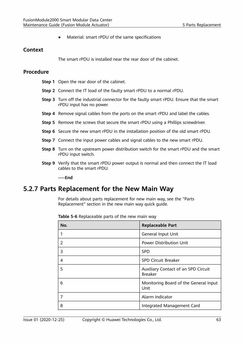
● Material: smart rPDU of the same specifications
Context
The smart rPDU is installed near the rear door of the cabinet.
Procedure
Step 1 Open the rear door of the cabinet.
Step 2 Connect the IT load of the faulty smart rPDU to a normal rPDU.
Step 3 Turn off the industrial connector for the faulty smart rPDU. Ensure that the smartrPDU input has no power.
Step 4 Remove signal cables from the ports on the smart rPDU and label the cables.
Step 5 Remove the screws that secure the smart rPDU using a Phillips screwdriver.
Step 6 Secure the new smart rPDU in the installation position of the old smart rPDU.
Step 7 Connect the input power cables and signal cables to the new smart rPDU.
Step 8 Turn on the upstream power distribution switch for the smart rPDU and the smartrPDU input switch.
Step 9 Verify that the smart rPDU power output is normal and then connect the IT loadcables to the smart rPDU.
----End
5.2.7 Parts Replacement for the New Main WayFor details about parts replacement for new main way, see the "PartsReplacement" section in the new main way quick guide.
Table 5-6 Replaceable parts of the new main way
No. Replaceable Part
1 General Input Unit
2 Power Distribution Unit
3 SPD
4 SPD Circuit Breaker
5 Auxiliary Contact of an SPD CircuitBreaker
6 Monitoring Board of the General InputUnit
7 Alarm Indicator
8 Integrated Management Card
FusionModule2000 Smart Modular Data CenterMaintenance Guide (Fusion Module Actuator) 5 Parts Replacement
Issue 01 (2020-12-25) Copyright © Huawei Technologies Co., Ltd. 63
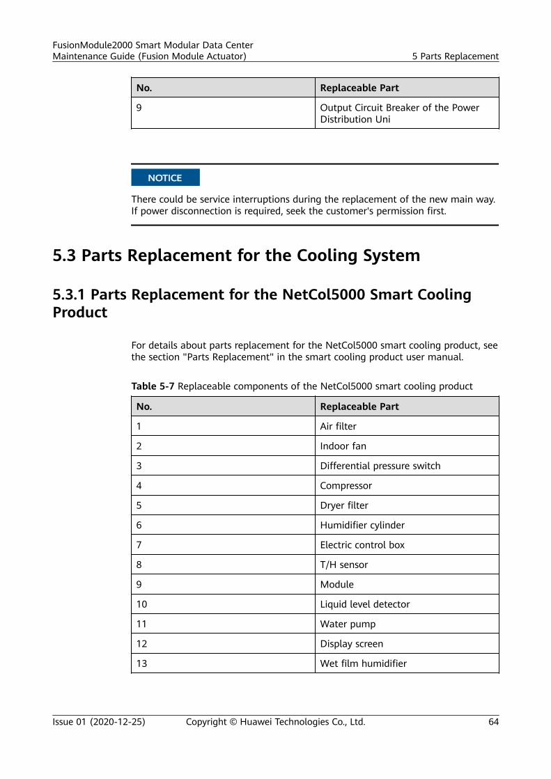
No. Replaceable Part
9 Output Circuit Breaker of the PowerDistribution Uni
NO TICE
There could be service interruptions during the replacement of the new main way.If power disconnection is required, seek the customer's permission first.
5.3 Parts Replacement for the Cooling System
5.3.1 Parts Replacement for the NetCol5000 Smart CoolingProduct
For details about parts replacement for the NetCol5000 smart cooling product, seethe section "Parts Replacement" in the smart cooling product user manual.
Table 5-7 Replaceable components of the NetCol5000 smart cooling product
No. Replaceable Part
1 Air filter
2 Indoor fan
3 Differential pressure switch
4 Compressor
5 Dryer filter
6 Humidifier cylinder
7 Electric control box
8 T/H sensor
9 Module
10 Liquid level detector
11 Water pump
12 Display screen
13 Wet film humidifier
FusionModule2000 Smart Modular Data CenterMaintenance Guide (Fusion Module Actuator) 5 Parts Replacement
Issue 01 (2020-12-25) Copyright © Huawei Technologies Co., Ltd. 64
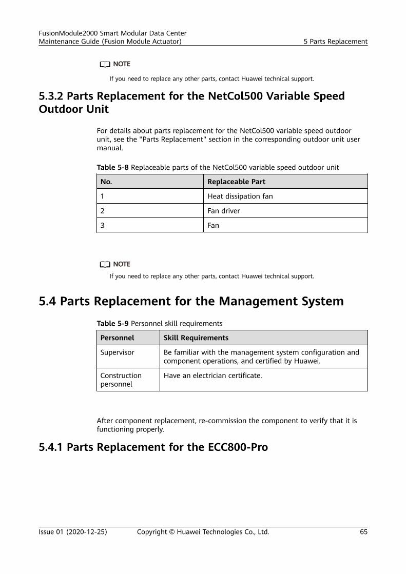
NO TE
If you need to replace any other parts, contact Huawei technical support.
5.3.2 Parts Replacement for the NetCol500 Variable SpeedOutdoor Unit
For details about parts replacement for the NetCol500 variable speed outdoorunit, see the "Parts Replacement" section in the corresponding outdoor unit usermanual.
Table 5-8 Replaceable parts of the NetCol500 variable speed outdoor unit
No. Replaceable Part
1 Heat dissipation fan
2 Fan driver
3 Fan
NO TE
If you need to replace any other parts, contact Huawei technical support.
5.4 Parts Replacement for the Management System
Table 5-9 Personnel skill requirements
Personnel Skill Requirements
Supervisor Be familiar with the management system configuration andcomponent operations, and certified by Huawei.
Constructionpersonnel
Have an electrician certificate.
After component replacement, re-commission the component to verify that it isfunctioning properly.
5.4.1 Parts Replacement for the ECC800-Pro
FusionModule2000 Smart Modular Data CenterMaintenance Guide (Fusion Module Actuator) 5 Parts Replacement
Issue 01 (2020-12-25) Copyright © Huawei Technologies Co., Ltd. 65
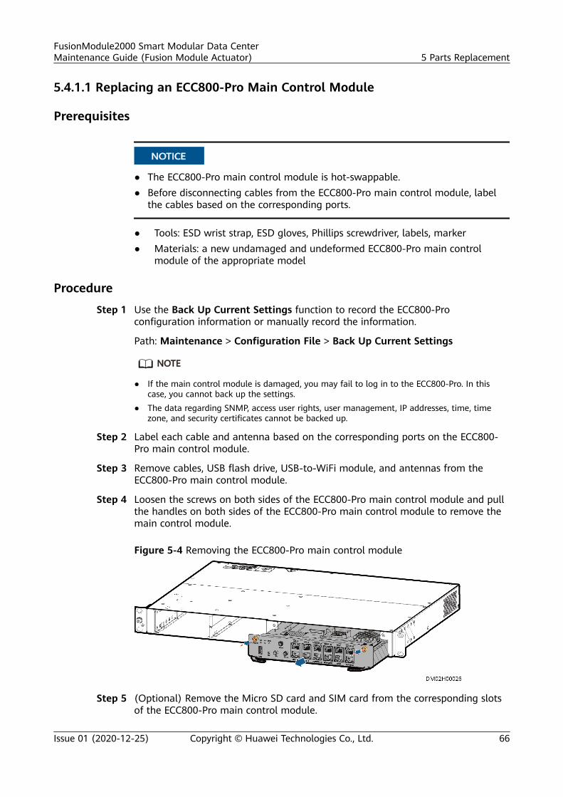
5.4.1.1 Replacing an ECC800-Pro Main Control Module
Prerequisites
NO TICE
● The ECC800-Pro main control module is hot-swappable.● Before disconnecting cables from the ECC800-Pro main control module, label
the cables based on the corresponding ports.
● Tools: ESD wrist strap, ESD gloves, Phillips screwdriver, labels, marker● Materials: a new undamaged and undeformed ECC800-Pro main control
module of the appropriate model
Procedure
Step 1 Use the Back Up Current Settings function to record the ECC800-Proconfiguration information or manually record the information.
Path: Maintenance > Configuration File > Back Up Current Settings
NO TE
● If the main control module is damaged, you may fail to log in to the ECC800-Pro. In thiscase, you cannot back up the settings.
● The data regarding SNMP, access user rights, user management, IP addresses, time, timezone, and security certificates cannot be backed up.
Step 2 Label each cable and antenna based on the corresponding ports on the ECC800-Pro main control module.
Step 3 Remove cables, USB flash drive, USB-to-WiFi module, and antennas from theECC800-Pro main control module.
Step 4 Loosen the screws on both sides of the ECC800-Pro main control module and pullthe handles on both sides of the ECC800-Pro main control module to remove themain control module.
Figure 5-4 Removing the ECC800-Pro main control module
Step 5 (Optional) Remove the Micro SD card and SIM card from the corresponding slotsof the ECC800-Pro main control module.
FusionModule2000 Smart Modular Data CenterMaintenance Guide (Fusion Module Actuator) 5 Parts Replacement
Issue 01 (2020-12-25) Copyright © Huawei Technologies Co., Ltd. 66
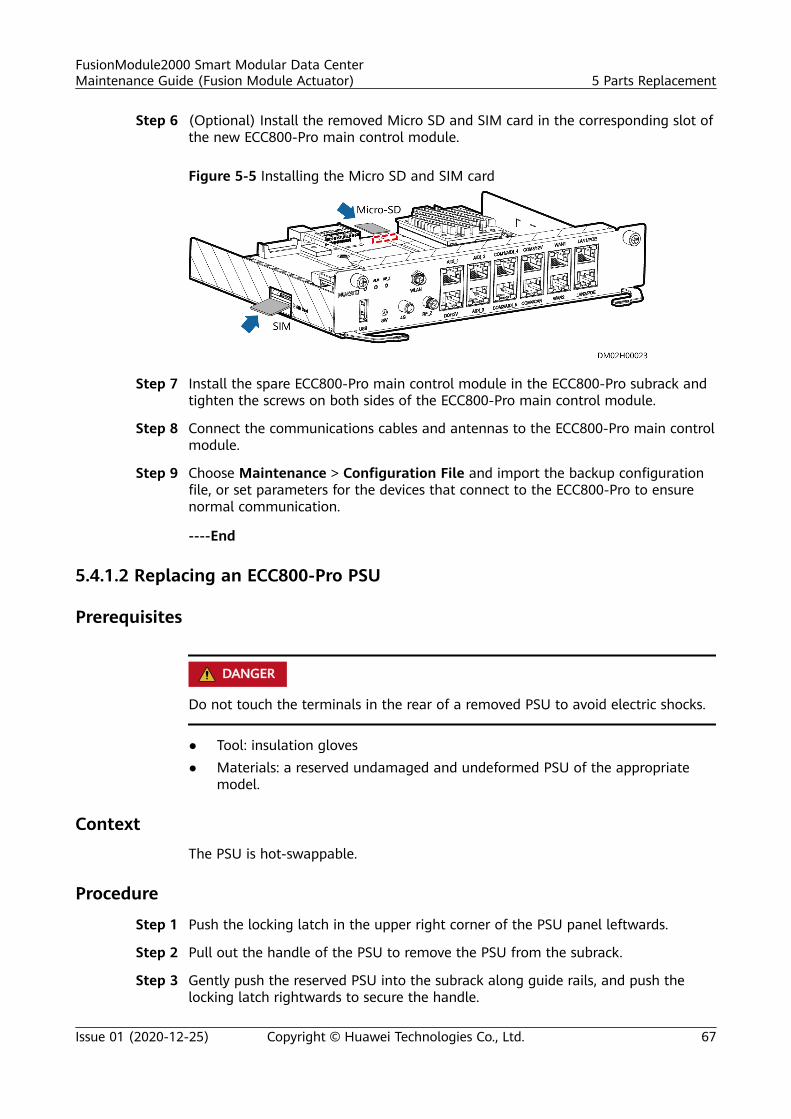
Step 6 (Optional) Install the removed Micro SD and SIM card in the corresponding slot ofthe new ECC800-Pro main control module.
Figure 5-5 Installing the Micro SD and SIM card
Step 7 Install the spare ECC800-Pro main control module in the ECC800-Pro subrack andtighten the screws on both sides of the ECC800-Pro main control module.
Step 8 Connect the communications cables and antennas to the ECC800-Pro main controlmodule.
Step 9 Choose Maintenance > Configuration File and import the backup configurationfile, or set parameters for the devices that connect to the ECC800-Pro to ensurenormal communication.
----End
5.4.1.2 Replacing an ECC800-Pro PSU
Prerequisites
D ANGER
Do not touch the terminals in the rear of a removed PSU to avoid electric shocks.
● Tool: insulation gloves● Materials: a reserved undamaged and undeformed PSU of the appropriate
model.
ContextThe PSU is hot-swappable.
Procedure
Step 1 Push the locking latch in the upper right corner of the PSU panel leftwards.
Step 2 Pull out the handle of the PSU to remove the PSU from the subrack.
Step 3 Gently push the reserved PSU into the subrack along guide rails, and push thelocking latch rightwards to secure the handle.
FusionModule2000 Smart Modular Data CenterMaintenance Guide (Fusion Module Actuator) 5 Parts Replacement
Issue 01 (2020-12-25) Copyright © Huawei Technologies Co., Ltd. 67
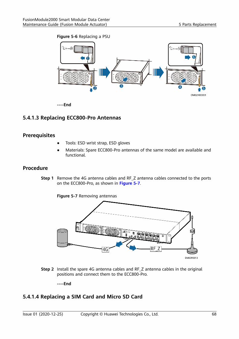
Figure 5-6 Replacing a PSU
----End
5.4.1.3 Replacing ECC800-Pro Antennas
Prerequisites● Tools: ESD wrist strap, ESD gloves
● Materials: Spare ECC800-Pro antennas of the same model are available andfunctional.
Procedure
Step 1 Remove the 4G antenna cables and RF_Z antenna cables connected to the portson the ECC800-Pro, as shown in Figure 5-7.
Figure 5-7 Removing antennas
Step 2 Install the spare 4G antenna cables and RF_Z antenna cables in the originalpositions and connect them to the ECC800-Pro.
----End
5.4.1.4 Replacing a SIM Card and Micro SD Card
FusionModule2000 Smart Modular Data CenterMaintenance Guide (Fusion Module Actuator) 5 Parts Replacement
Issue 01 (2020-12-25) Copyright © Huawei Technologies Co., Ltd. 68
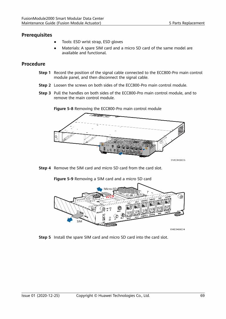
Prerequisites● Tools: ESD wrist strap, ESD gloves● Materials: A spare SIM card and a micro SD card of the same model are
available and functional.
Procedure
Step 1 Record the position of the signal cable connected to the ECC800-Pro main controlmodule panel, and then disconnect the signal cable.
Step 2 Loosen the screws on both sides of the ECC800-Pro main control module.
Step 3 Pull the handles on both sides of the ECC800-Pro main control module, and toremove the main control module.
Figure 5-8 Removing the ECC800-Pro main control module
Step 4 Remove the SIM card and micro SD card from the card slot.
Figure 5-9 Removing a SIM card and a micro SD card
Step 5 Install the spare SIM card and micro SD card into the card slot.
FusionModule2000 Smart Modular Data CenterMaintenance Guide (Fusion Module Actuator) 5 Parts Replacement
Issue 01 (2020-12-25) Copyright © Huawei Technologies Co., Ltd. 69
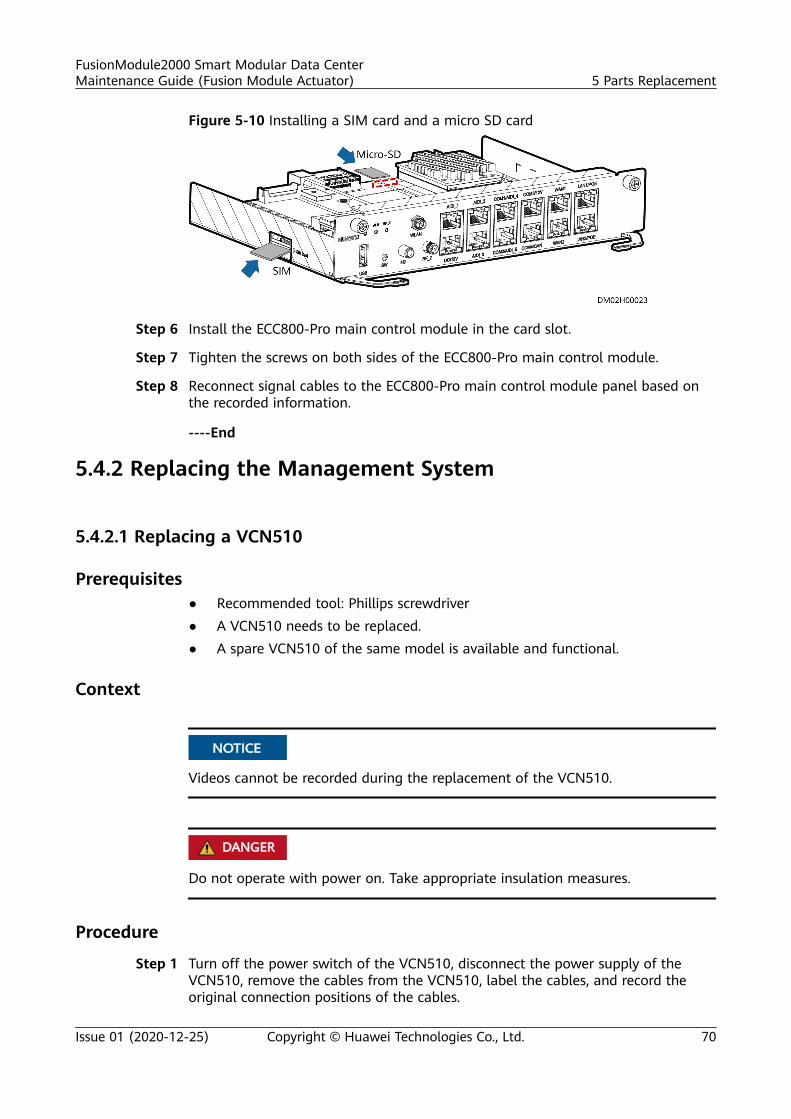
Figure 5-10 Installing a SIM card and a micro SD card
Step 6 Install the ECC800-Pro main control module in the card slot.
Step 7 Tighten the screws on both sides of the ECC800-Pro main control module.
Step 8 Reconnect signal cables to the ECC800-Pro main control module panel based onthe recorded information.
----End
5.4.2 Replacing the Management System
5.4.2.1 Replacing a VCN510
Prerequisites● Recommended tool: Phillips screwdriver● A VCN510 needs to be replaced.● A spare VCN510 of the same model is available and functional.
Context
NO TICE
Videos cannot be recorded during the replacement of the VCN510.
D ANGER
Do not operate with power on. Take appropriate insulation measures.
Procedure
Step 1 Turn off the power switch of the VCN510, disconnect the power supply of theVCN510, remove the cables from the VCN510, label the cables, and record theoriginal connection positions of the cables.
FusionModule2000 Smart Modular Data CenterMaintenance Guide (Fusion Module Actuator) 5 Parts Replacement
Issue 01 (2020-12-25) Copyright © Huawei Technologies Co., Ltd. 70
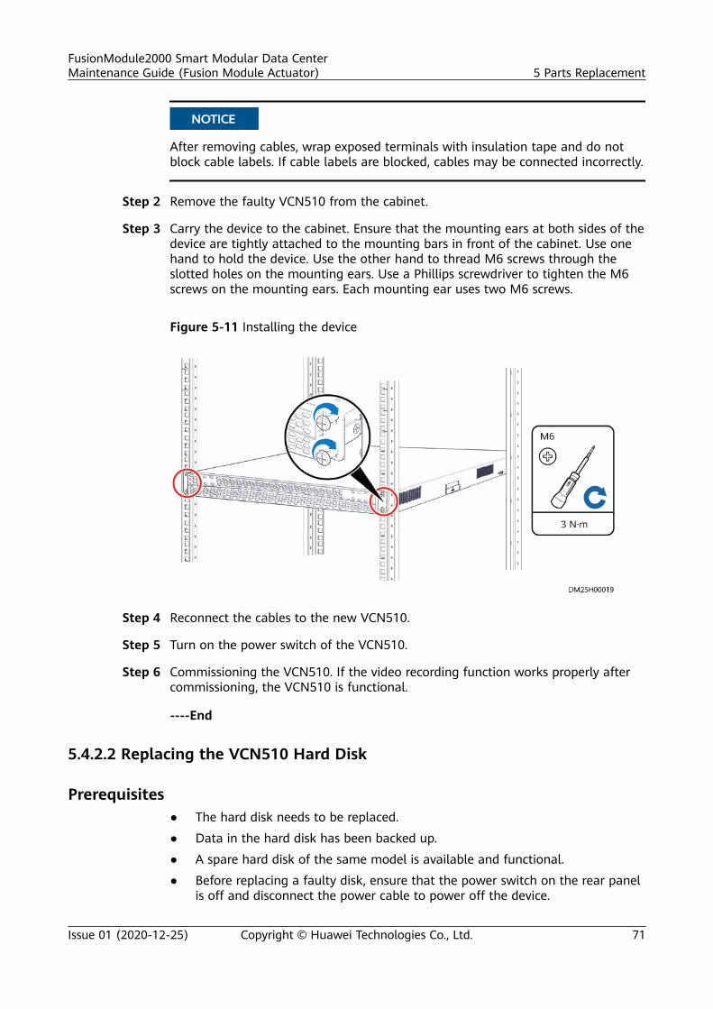
NO TICE
After removing cables, wrap exposed terminals with insulation tape and do notblock cable labels. If cable labels are blocked, cables may be connected incorrectly.
Step 2 Remove the faulty VCN510 from the cabinet.
Step 3 Carry the device to the cabinet. Ensure that the mounting ears at both sides of thedevice are tightly attached to the mounting bars in front of the cabinet. Use onehand to hold the device. Use the other hand to thread M6 screws through theslotted holes on the mounting ears. Use a Phillips screwdriver to tighten the M6screws on the mounting ears. Each mounting ear uses two M6 screws.
Figure 5-11 Installing the device
Step 4 Reconnect the cables to the new VCN510.
Step 5 Turn on the power switch of the VCN510.
Step 6 Commissioning the VCN510. If the video recording function works properly aftercommissioning, the VCN510 is functional.
----End
5.4.2.2 Replacing the VCN510 Hard Disk
Prerequisites● The hard disk needs to be replaced.
● Data in the hard disk has been backed up.
● A spare hard disk of the same model is available and functional.
● Before replacing a faulty disk, ensure that the power switch on the rear panelis off and disconnect the power cable to power off the device.
FusionModule2000 Smart Modular Data CenterMaintenance Guide (Fusion Module Actuator) 5 Parts Replacement
Issue 01 (2020-12-25) Copyright © Huawei Technologies Co., Ltd. 71
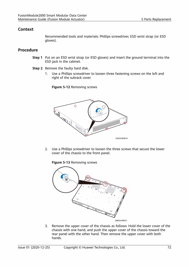
Context
Recommended tools and materials: Phillips screwdriver, ESD wrist strap (or ESDgloves).
Procedure
Step 1 Put on an ESD wrist strap (or ESD gloves) and insert the ground terminal into theESD jack in the cabinet.
Step 2 Remove the faulty hard disk.1. Use a Phillips screwdriver to loosen three fastening screws on the left and
right of the subrack cover.
Figure 5-12 Removing screws
2. Use a Phillips screwdriver to loosen the three screws that secure the lowercover of the chassis to the front panel.
Figure 5-13 Removing screws
3. Remove the upper cover of the chassis as follows: Hold the lower cover of thechassis with one hand, and push the upper cover of the chassis toward therear panel with the other hand. Then remove the upper cover with bothhands.
FusionModule2000 Smart Modular Data CenterMaintenance Guide (Fusion Module Actuator) 5 Parts Replacement
Issue 01 (2020-12-25) Copyright © Huawei Technologies Co., Ltd. 72
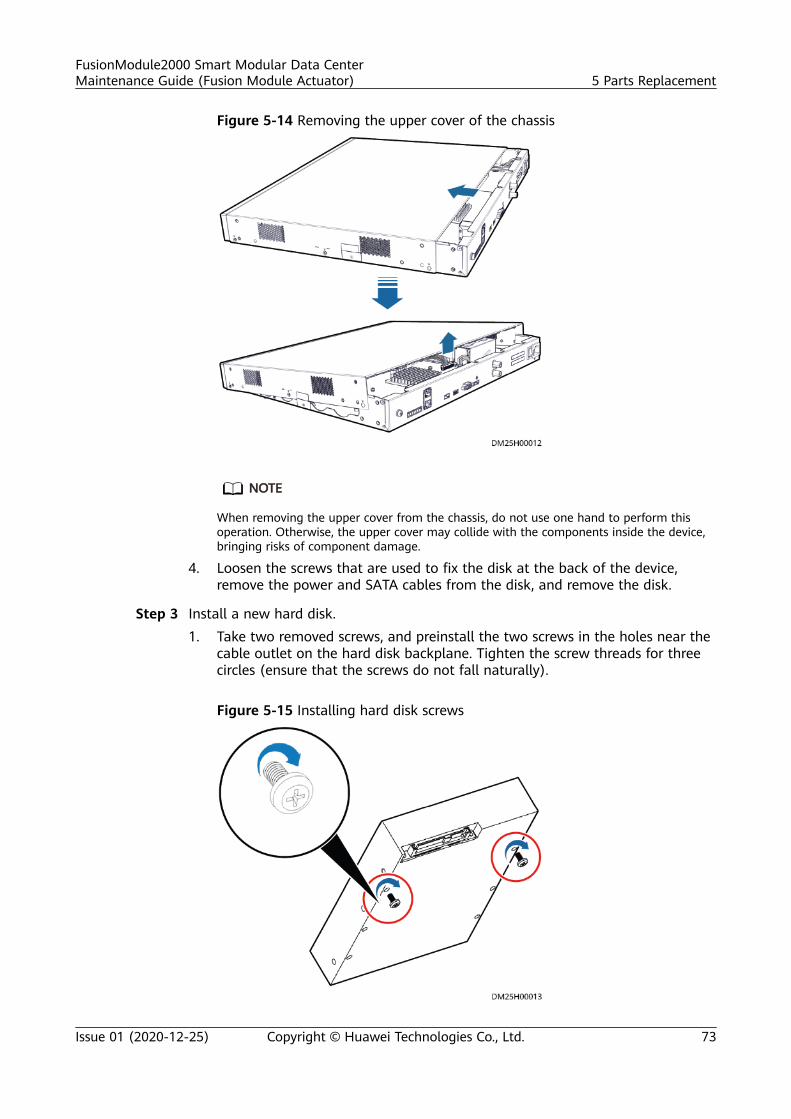
Figure 5-14 Removing the upper cover of the chassis
NO TE
When removing the upper cover from the chassis, do not use one hand to perform thisoperation. Otherwise, the upper cover may collide with the components inside the device,bringing risks of component damage.
4. Loosen the screws that are used to fix the disk at the back of the device,remove the power and SATA cables from the disk, and remove the disk.
Step 3 Install a new hard disk.1. Take two removed screws, and preinstall the two screws in the holes near the
cable outlet on the hard disk backplane. Tighten the screw threads for threecircles (ensure that the screws do not fall naturally).
Figure 5-15 Installing hard disk screws
FusionModule2000 Smart Modular Data CenterMaintenance Guide (Fusion Module Actuator) 5 Parts Replacement
Issue 01 (2020-12-25) Copyright © Huawei Technologies Co., Ltd. 73
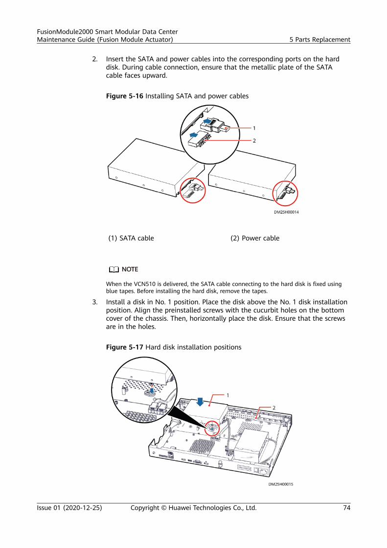
2. Insert the SATA and power cables into the corresponding ports on the harddisk. During cable connection, ensure that the metallic plate of the SATAcable faces upward.
Figure 5-16 Installing SATA and power cables
(1) SATA cable (2) Power cable
NO TE
When the VCN510 is delivered, the SATA cable connecting to the hard disk is fixed usingblue tapes. Before installing the hard disk, remove the tapes.
3. Install a disk in No. 1 position. Place the disk above the No. 1 disk installationposition. Align the preinstalled screws with the cucurbit holes on the bottomcover of the chassis. Then, horizontally place the disk. Ensure that the screwsare in the holes.
Figure 5-17 Hard disk installation positions
FusionModule2000 Smart Modular Data CenterMaintenance Guide (Fusion Module Actuator) 5 Parts Replacement
Issue 01 (2020-12-25) Copyright © Huawei Technologies Co., Ltd. 74
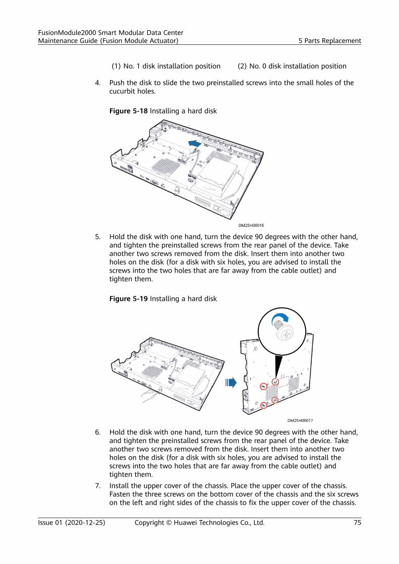
(1) No. 1 disk installation position (2) No. 0 disk installation position
4. Push the disk to slide the two preinstalled screws into the small holes of thecucurbit holes.
Figure 5-18 Installing a hard disk
5. Hold the disk with one hand, turn the device 90 degrees with the other hand,and tighten the preinstalled screws from the rear panel of the device. Takeanother two screws removed from the disk. Insert them into another twoholes on the disk (for a disk with six holes, you are advised to install thescrews into the two holes that are far away from the cable outlet) andtighten them.
Figure 5-19 Installing a hard disk
6. Hold the disk with one hand, turn the device 90 degrees with the other hand,and tighten the preinstalled screws from the rear panel of the device. Takeanother two screws removed from the disk. Insert them into another twoholes on the disk (for a disk with six holes, you are advised to install thescrews into the two holes that are far away from the cable outlet) andtighten them.
7. Install the upper cover of the chassis. Place the upper cover of the chassis.Fasten the three screws on the bottom cover of the chassis and the six screwson the left and right sides of the chassis to fix the upper cover of the chassis.
FusionModule2000 Smart Modular Data CenterMaintenance Guide (Fusion Module Actuator) 5 Parts Replacement
Issue 01 (2020-12-25) Copyright © Huawei Technologies Co., Ltd. 75
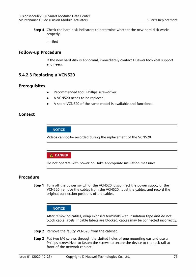
Step 4 Check the hard disk indicators to determine whether the new hard disk worksproperly.
----End
Follow-up Procedure
If the new hard disk is abnormal, immediately contact Huawei technical supportengineers.
5.4.2.3 Replacing a VCN520
Prerequisites● Recommended tool: Phillips screwdriver
● A VCN520 needs to be replaced.
● A spare VCN520 of the same model is available and functional.
Context
NO TICE
Videos cannot be recorded during the replacement of the VCN520.
D ANGER
Do not operate with power on. Take appropriate insulation measures.
Procedure
Step 1 Turn off the power switch of the VCN520, disconnect the power supply of theVCN520, remove the cables from the VCN520, label the cables, and record theoriginal connection positions of the cables.
NO TICE
After removing cables, wrap exposed terminals with insulation tape and do notblock cable labels. If cable labels are blocked, cables may be connected incorrectly.
Step 2 Remove the faulty VCN520 from the cabinet.
Step 3 Put two M6 screws through the slotted holes of one mounting ear and use aPhillips screwdriver to fasten the screws to secure the device to the rack rail atfront of the network cabinet.
FusionModule2000 Smart Modular Data CenterMaintenance Guide (Fusion Module Actuator) 5 Parts Replacement
Issue 01 (2020-12-25) Copyright © Huawei Technologies Co., Ltd. 76
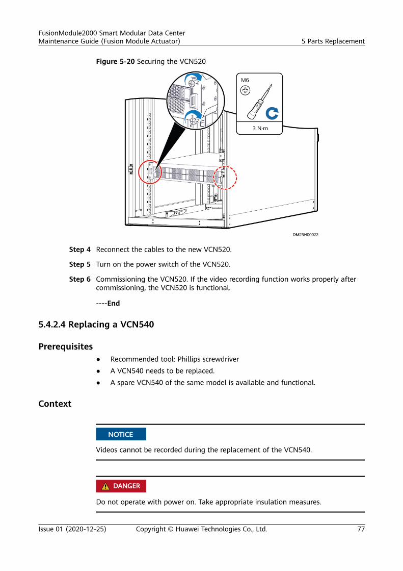
Figure 5-20 Securing the VCN520
Step 4 Reconnect the cables to the new VCN520.
Step 5 Turn on the power switch of the VCN520.
Step 6 Commissioning the VCN520. If the video recording function works properly aftercommissioning, the VCN520 is functional.
----End
5.4.2.4 Replacing a VCN540
Prerequisites● Recommended tool: Phillips screwdriver● A VCN540 needs to be replaced.● A spare VCN540 of the same model is available and functional.
Context
NO TICE
Videos cannot be recorded during the replacement of the VCN540.
D ANGER
Do not operate with power on. Take appropriate insulation measures.
FusionModule2000 Smart Modular Data CenterMaintenance Guide (Fusion Module Actuator) 5 Parts Replacement
Issue 01 (2020-12-25) Copyright © Huawei Technologies Co., Ltd. 77
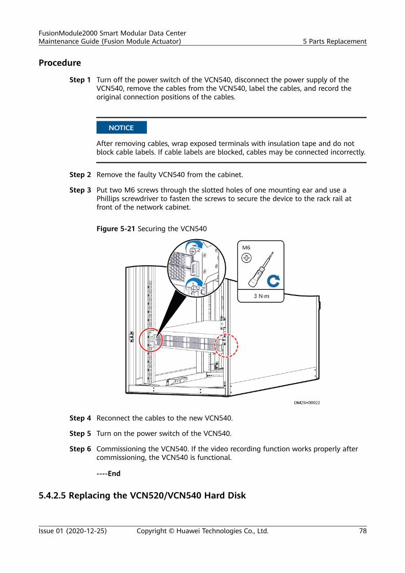
Procedure
Step 1 Turn off the power switch of the VCN540, disconnect the power supply of theVCN540, remove the cables from the VCN540, label the cables, and record theoriginal connection positions of the cables.
NO TICE
After removing cables, wrap exposed terminals with insulation tape and do notblock cable labels. If cable labels are blocked, cables may be connected incorrectly.
Step 2 Remove the faulty VCN540 from the cabinet.
Step 3 Put two M6 screws through the slotted holes of one mounting ear and use aPhillips screwdriver to fasten the screws to secure the device to the rack rail atfront of the network cabinet.
Figure 5-21 Securing the VCN540
Step 4 Reconnect the cables to the new VCN540.
Step 5 Turn on the power switch of the VCN540.
Step 6 Commissioning the VCN540. If the video recording function works properly aftercommissioning, the VCN540 is functional.
----End
5.4.2.5 Replacing the VCN520/VCN540 Hard Disk
FusionModule2000 Smart Modular Data CenterMaintenance Guide (Fusion Module Actuator) 5 Parts Replacement
Issue 01 (2020-12-25) Copyright © Huawei Technologies Co., Ltd. 78
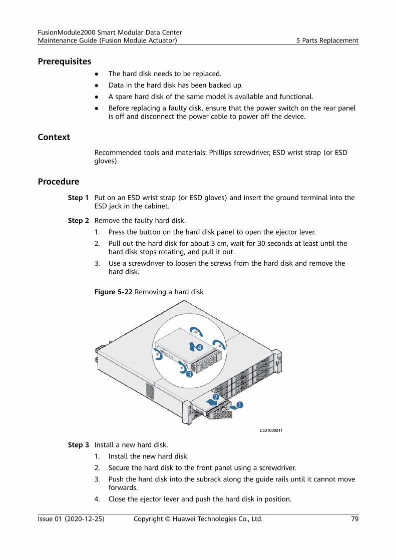
Prerequisites● The hard disk needs to be replaced.● Data in the hard disk has been backed up.● A spare hard disk of the same model is available and functional.● Before replacing a faulty disk, ensure that the power switch on the rear panel
is off and disconnect the power cable to power off the device.
Context
Recommended tools and materials: Phillips screwdriver, ESD wrist strap (or ESDgloves).
Procedure
Step 1 Put on an ESD wrist strap (or ESD gloves) and insert the ground terminal into theESD jack in the cabinet.
Step 2 Remove the faulty hard disk.1. Press the button on the hard disk panel to open the ejector lever.2. Pull out the hard disk for about 3 cm, wait for 30 seconds at least until the
hard disk stops rotating, and pull it out.3. Use a screwdriver to loosen the screws from the hard disk and remove the
hard disk.
Figure 5-22 Removing a hard disk
Step 3 Install a new hard disk.1. Install the new hard disk.2. Secure the hard disk to the front panel using a screwdriver.3. Push the hard disk into the subrack along the guide rails until it cannot move
forwards.4. Close the ejector lever and push the hard disk in position.
FusionModule2000 Smart Modular Data CenterMaintenance Guide (Fusion Module Actuator) 5 Parts Replacement
Issue 01 (2020-12-25) Copyright © Huawei Technologies Co., Ltd. 79
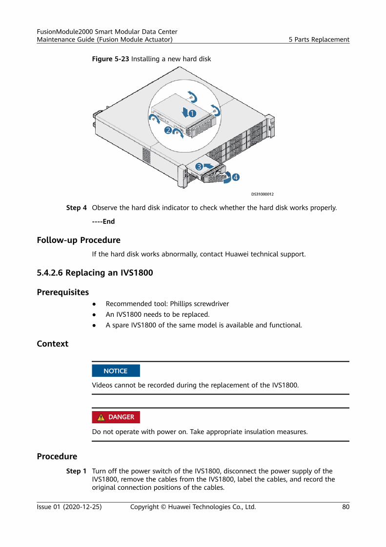
Figure 5-23 Installing a new hard disk
Step 4 Observe the hard disk indicator to check whether the hard disk works properly.
----End
Follow-up ProcedureIf the hard disk works abnormally, contact Huawei technical support.
5.4.2.6 Replacing an IVS1800
Prerequisites● Recommended tool: Phillips screwdriver● An IVS1800 needs to be replaced.● A spare IVS1800 of the same model is available and functional.
Context
NO TICE
Videos cannot be recorded during the replacement of the IVS1800.
D ANGER
Do not operate with power on. Take appropriate insulation measures.
Procedure
Step 1 Turn off the power switch of the IVS1800, disconnect the power supply of theIVS1800, remove the cables from the IVS1800, label the cables, and record theoriginal connection positions of the cables.
FusionModule2000 Smart Modular Data CenterMaintenance Guide (Fusion Module Actuator) 5 Parts Replacement
Issue 01 (2020-12-25) Copyright © Huawei Technologies Co., Ltd. 80
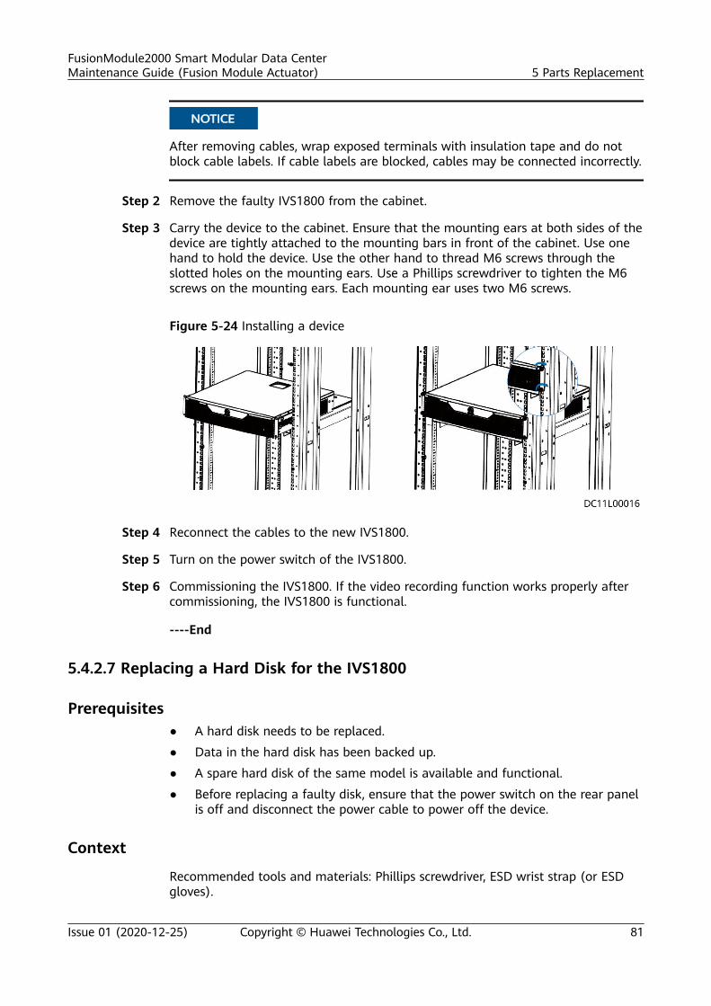
NO TICE
After removing cables, wrap exposed terminals with insulation tape and do notblock cable labels. If cable labels are blocked, cables may be connected incorrectly.
Step 2 Remove the faulty IVS1800 from the cabinet.
Step 3 Carry the device to the cabinet. Ensure that the mounting ears at both sides of thedevice are tightly attached to the mounting bars in front of the cabinet. Use onehand to hold the device. Use the other hand to thread M6 screws through theslotted holes on the mounting ears. Use a Phillips screwdriver to tighten the M6screws on the mounting ears. Each mounting ear uses two M6 screws.
Figure 5-24 Installing a device
Step 4 Reconnect the cables to the new IVS1800.
Step 5 Turn on the power switch of the IVS1800.
Step 6 Commissioning the IVS1800. If the video recording function works properly aftercommissioning, the IVS1800 is functional.
----End
5.4.2.7 Replacing a Hard Disk for the IVS1800
Prerequisites● A hard disk needs to be replaced.
● Data in the hard disk has been backed up.
● A spare hard disk of the same model is available and functional.
● Before replacing a faulty disk, ensure that the power switch on the rear panelis off and disconnect the power cable to power off the device.
Context
Recommended tools and materials: Phillips screwdriver, ESD wrist strap (or ESDgloves).
FusionModule2000 Smart Modular Data CenterMaintenance Guide (Fusion Module Actuator) 5 Parts Replacement
Issue 01 (2020-12-25) Copyright © Huawei Technologies Co., Ltd. 81
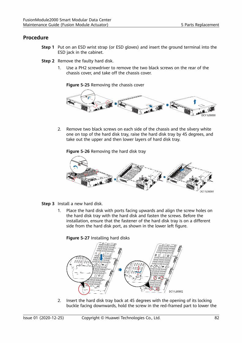
Procedure
Step 1 Put on an ESD wrist strap (or ESD gloves) and insert the ground terminal into theESD jack in the cabinet.
Step 2 Remove the faulty hard disk.1. Use a PH2 screwdriver to remove the two black screws on the rear of the
chassis cover, and take off the chassis cover.
Figure 5-25 Removing the chassis cover
2. Remove two black screws on each side of the chassis and the silvery whiteone on top of the hard disk tray, raise the hard disk tray by 45 degrees, andtake out the upper and then lower layers of hard disk tray.
Figure 5-26 Removing the hard disk tray
Step 3 Install a new hard disk.1. Place the hard disk with ports facing upwards and align the screw holes on
the hard disk tray with the hard disk and fasten the screws. Before theinstallation, ensure that the fastener of the hard disk tray is on a differentside from the hard disk port, as shown in the lower left figure.
Figure 5-27 Installing hard disks
2. Insert the hard disk tray back at 45 degrees with the opening of its lockingbuckle facing downwards, hold the screw in the red-framed part to lower the
FusionModule2000 Smart Modular Data CenterMaintenance Guide (Fusion Module Actuator) 5 Parts Replacement
Issue 01 (2020-12-25) Copyright © Huawei Technologies Co., Ltd. 82
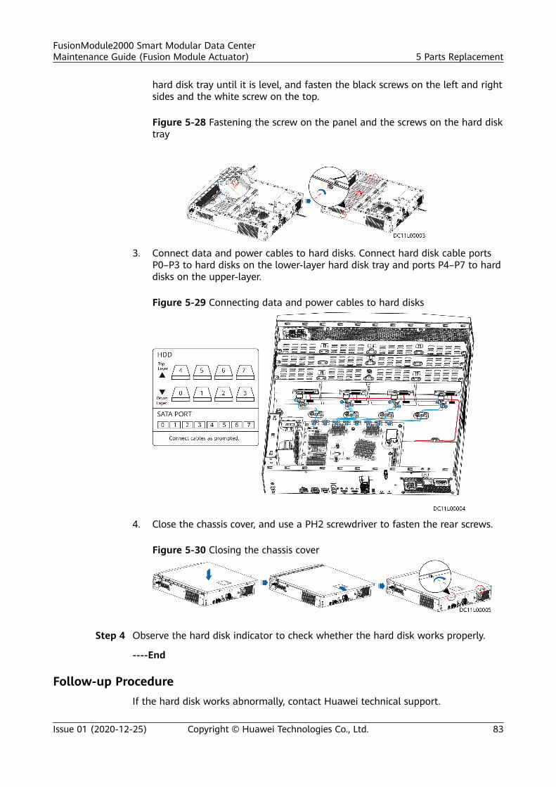
hard disk tray until it is level, and fasten the black screws on the left and rightsides and the white screw on the top.
Figure 5-28 Fastening the screw on the panel and the screws on the hard disktray
3. Connect data and power cables to hard disks. Connect hard disk cable portsP0–P3 to hard disks on the lower-layer hard disk tray and ports P4–P7 to harddisks on the upper-layer.
Figure 5-29 Connecting data and power cables to hard disks
4. Close the chassis cover, and use a PH2 screwdriver to fasten the rear screws.
Figure 5-30 Closing the chassis cover
Step 4 Observe the hard disk indicator to check whether the hard disk works properly.
----End
Follow-up ProcedureIf the hard disk works abnormally, contact Huawei technical support.
FusionModule2000 Smart Modular Data CenterMaintenance Guide (Fusion Module Actuator) 5 Parts Replacement
Issue 01 (2020-12-25) Copyright © Huawei Technologies Co., Ltd. 83
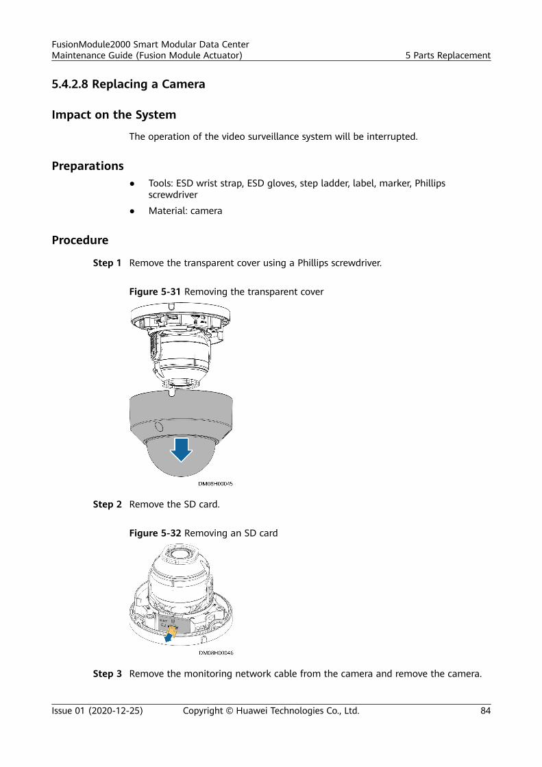
5.4.2.8 Replacing a Camera
Impact on the System
The operation of the video surveillance system will be interrupted.
Preparations● Tools: ESD wrist strap, ESD gloves, step ladder, label, marker, Phillips
screwdriver
● Material: camera
Procedure
Step 1 Remove the transparent cover using a Phillips screwdriver.
Figure 5-31 Removing the transparent cover
Step 2 Remove the SD card.
Figure 5-32 Removing an SD card
Step 3 Remove the monitoring network cable from the camera and remove the camera.
FusionModule2000 Smart Modular Data CenterMaintenance Guide (Fusion Module Actuator) 5 Parts Replacement
Issue 01 (2020-12-25) Copyright © Huawei Technologies Co., Ltd. 84
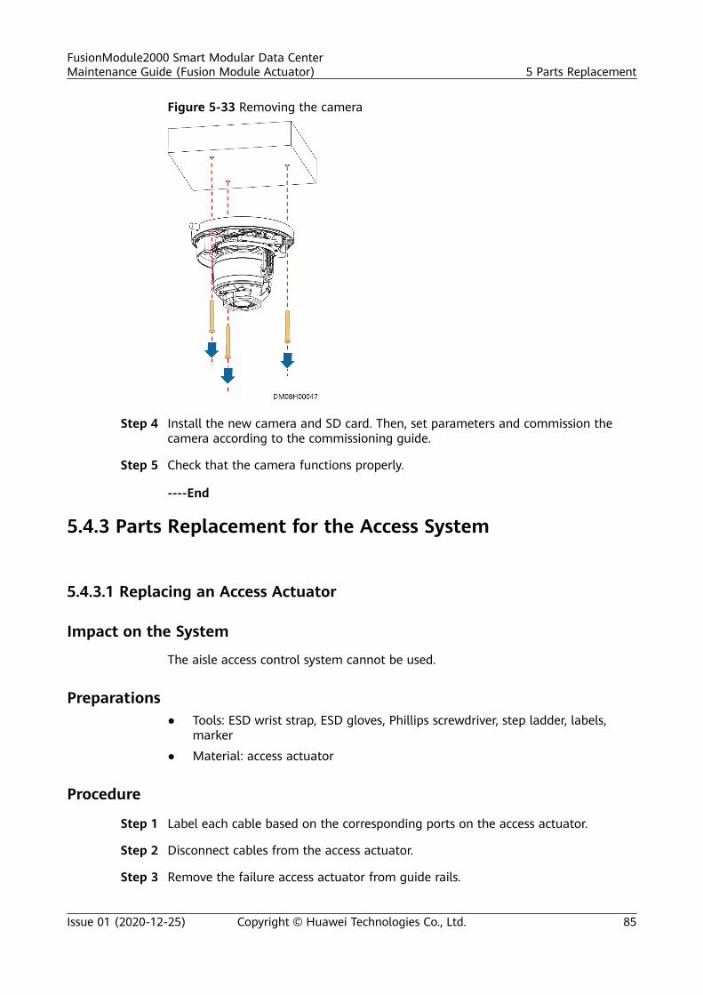
Figure 5-33 Removing the camera
Step 4 Install the new camera and SD card. Then, set parameters and commission thecamera according to the commissioning guide.
Step 5 Check that the camera functions properly.
----End
5.4.3 Parts Replacement for the Access System
5.4.3.1 Replacing an Access Actuator
Impact on the System
The aisle access control system cannot be used.
Preparations● Tools: ESD wrist strap, ESD gloves, Phillips screwdriver, step ladder, labels,
marker
● Material: access actuator
Procedure
Step 1 Label each cable based on the corresponding ports on the access actuator.
Step 2 Disconnect cables from the access actuator.
Step 3 Remove the failure access actuator from guide rails.
FusionModule2000 Smart Modular Data CenterMaintenance Guide (Fusion Module Actuator) 5 Parts Replacement
Issue 01 (2020-12-25) Copyright © Huawei Technologies Co., Ltd. 85
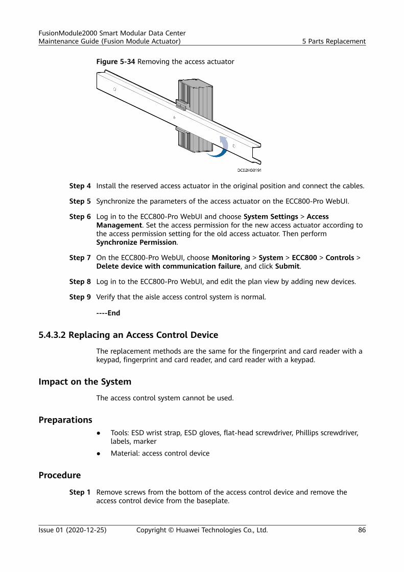
Figure 5-34 Removing the access actuator
Step 4 Install the reserved access actuator in the original position and connect the cables.
Step 5 Synchronize the parameters of the access actuator on the ECC800-Pro WebUI.
Step 6 Log in to the ECC800-Pro WebUI and choose System Settings > AccessManagement. Set the access permission for the new access actuator according tothe access permission setting for the old access actuator. Then performSynchronize Permission.
Step 7 On the ECC800-Pro WebUI, choose Monitoring > System > ECC800 > Controls >Delete device with communication failure, and click Submit.
Step 8 Log in to the ECC800-Pro WebUI, and edit the plan view by adding new devices.
Step 9 Verify that the aisle access control system is normal.
----End
5.4.3.2 Replacing an Access Control Device
The replacement methods are the same for the fingerprint and card reader with akeypad, fingerprint and card reader, and card reader with a keypad.
Impact on the System
The access control system cannot be used.
Preparations● Tools: ESD wrist strap, ESD gloves, flat-head screwdriver, Phillips screwdriver,
labels, marker
● Material: access control device
Procedure
Step 1 Remove screws from the bottom of the access control device and remove theaccess control device from the baseplate.
FusionModule2000 Smart Modular Data CenterMaintenance Guide (Fusion Module Actuator) 5 Parts Replacement
Issue 01 (2020-12-25) Copyright © Huawei Technologies Co., Ltd. 86
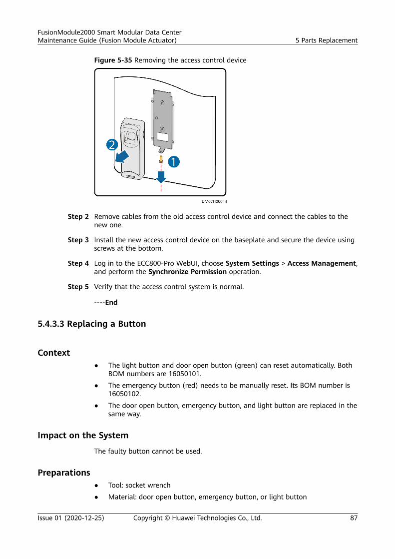
Figure 5-35 Removing the access control device
Step 2 Remove cables from the old access control device and connect the cables to thenew one.
Step 3 Install the new access control device on the baseplate and secure the device usingscrews at the bottom.
Step 4 Log in to the ECC800-Pro WebUI, choose System Settings > Access Management,and perform the Synchronize Permission operation.
Step 5 Verify that the access control system is normal.
----End
5.4.3.3 Replacing a Button
Context● The light button and door open button (green) can reset automatically. Both
BOM numbers are 16050101.
● The emergency button (red) needs to be manually reset. Its BOM number is16050102.
● The door open button, emergency button, and light button are replaced in thesame way.
Impact on the System
The faulty button cannot be used.
Preparations● Tool: socket wrench
● Material: door open button, emergency button, or light button
FusionModule2000 Smart Modular Data CenterMaintenance Guide (Fusion Module Actuator) 5 Parts Replacement
Issue 01 (2020-12-25) Copyright © Huawei Technologies Co., Ltd. 87
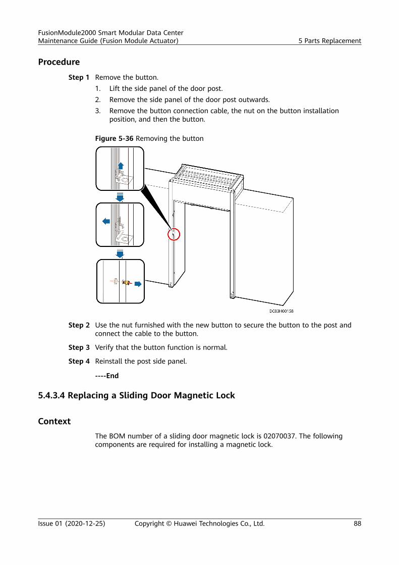
Procedure
Step 1 Remove the button.1. Lift the side panel of the door post.2. Remove the side panel of the door post outwards.3. Remove the button connection cable, the nut on the button installation
position, and then the button.
Figure 5-36 Removing the button
Step 2 Use the nut furnished with the new button to secure the button to the post andconnect the cable to the button.
Step 3 Verify that the button function is normal.
Step 4 Reinstall the post side panel.
----End
5.4.3.4 Replacing a Sliding Door Magnetic Lock
ContextThe BOM number of a sliding door magnetic lock is 02070037. The followingcomponents are required for installing a magnetic lock.
FusionModule2000 Smart Modular Data CenterMaintenance Guide (Fusion Module Actuator) 5 Parts Replacement
Issue 01 (2020-12-25) Copyright © Huawei Technologies Co., Ltd. 88
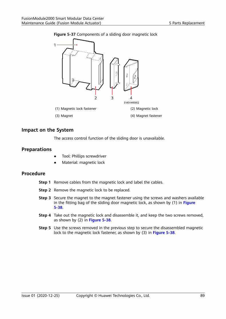
Figure 5-37 Components of a sliding door magnetic lock
(1) Magnetic lock fastener (2) Magnetic lock
(3) Magnet (4) Magnet fastener
Impact on the SystemThe access control function of the sliding door is unavailable.
Preparations● Tool: Phillips screwdriver● Material: magnetic lock
Procedure
Step 1 Remove cables from the magnetic lock and label the cables.
Step 2 Remove the magnetic lock to be replaced.
Step 3 Secure the magnet to the magnet fastener using the screws and washers availablein the fitting bag of the sliding door magnetic lock, as shown by (1) in Figure5-38.
Step 4 Take out the magnetic lock and disassemble it, and keep the two screws removed,as shown by (2) in Figure 5-38.
Step 5 Use the screws removed in the previous step to secure the disassembled magneticlock to the magnetic lock fastener, as shown by (3) in Figure 5-38.
FusionModule2000 Smart Modular Data CenterMaintenance Guide (Fusion Module Actuator) 5 Parts Replacement
Issue 01 (2020-12-25) Copyright © Huawei Technologies Co., Ltd. 89
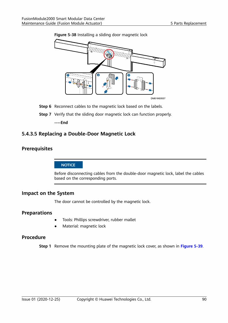
Figure 5-38 Installing a sliding door magnetic lock
Step 6 Reconnect cables to the magnetic lock based on the labels.
Step 7 Verify that the sliding door magnetic lock can function properly.
----End
5.4.3.5 Replacing a Double-Door Magnetic Lock
Prerequisites
NO TICE
Before disconnecting cables from the double-door magnetic lock, label the cablesbased on the corresponding ports.
Impact on the SystemThe door cannot be controlled by the magnetic lock.
Preparations● Tools: Phillips screwdriver, rubber mallet● Material: magnetic lock
Procedure
Step 1 Remove the mounting plate of the magnetic lock cover, as shown in Figure 5-39.
FusionModule2000 Smart Modular Data CenterMaintenance Guide (Fusion Module Actuator) 5 Parts Replacement
Issue 01 (2020-12-25) Copyright © Huawei Technologies Co., Ltd. 90
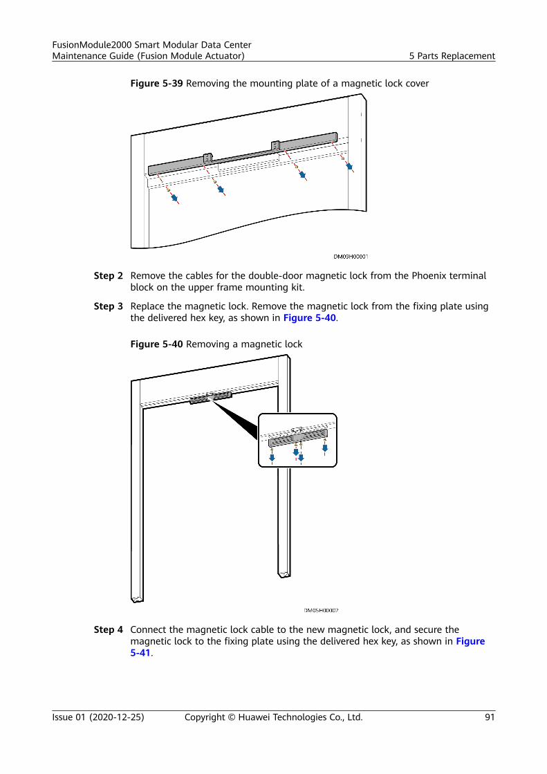
Figure 5-39 Removing the mounting plate of a magnetic lock cover
Step 2 Remove the cables for the double-door magnetic lock from the Phoenix terminalblock on the upper frame mounting kit.
Step 3 Replace the magnetic lock. Remove the magnetic lock from the fixing plate usingthe delivered hex key, as shown in Figure 5-40.
Figure 5-40 Removing a magnetic lock
Step 4 Connect the magnetic lock cable to the new magnetic lock, and secure themagnetic lock to the fixing plate using the delivered hex key, as shown in Figure5-41.
FusionModule2000 Smart Modular Data CenterMaintenance Guide (Fusion Module Actuator) 5 Parts Replacement
Issue 01 (2020-12-25) Copyright © Huawei Technologies Co., Ltd. 91
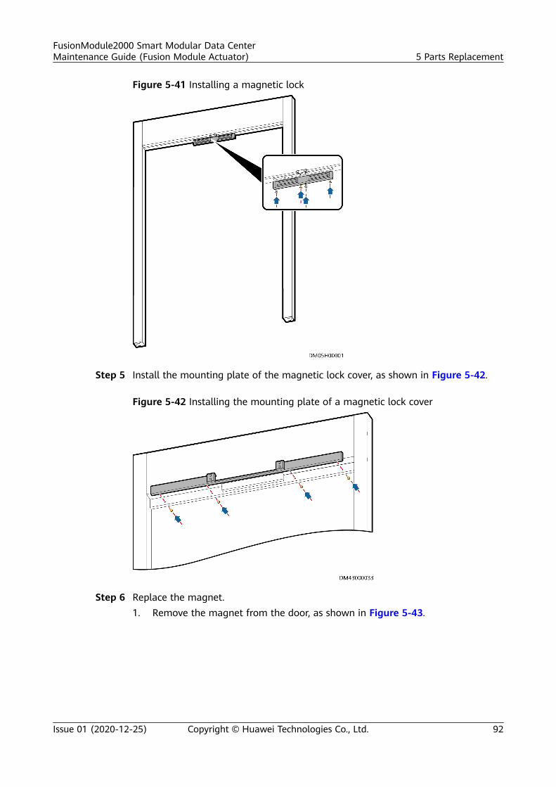
Figure 5-41 Installing a magnetic lock
Step 5 Install the mounting plate of the magnetic lock cover, as shown in Figure 5-42.
Figure 5-42 Installing the mounting plate of a magnetic lock cover
Step 6 Replace the magnet.1. Remove the magnet from the door, as shown in Figure 5-43.
FusionModule2000 Smart Modular Data CenterMaintenance Guide (Fusion Module Actuator) 5 Parts Replacement
Issue 01 (2020-12-25) Copyright © Huawei Technologies Co., Ltd. 92
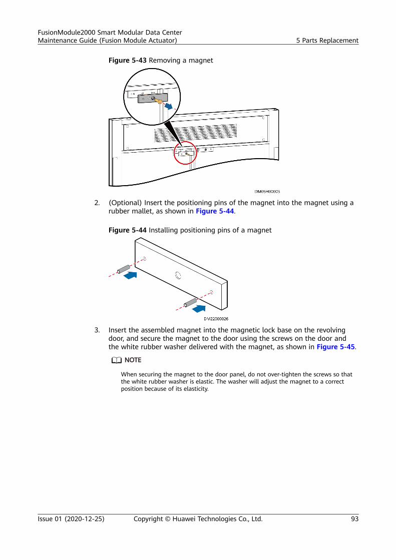
Figure 5-43 Removing a magnet
2. (Optional) Insert the positioning pins of the magnet into the magnet using arubber mallet, as shown in Figure 5-44.
Figure 5-44 Installing positioning pins of a magnet
3. Insert the assembled magnet into the magnetic lock base on the revolvingdoor, and secure the magnet to the door using the screws on the door andthe white rubber washer delivered with the magnet, as shown in Figure 5-45.
NO TE
When securing the magnet to the door panel, do not over-tighten the screws so thatthe white rubber washer is elastic. The washer will adjust the magnet to a correctposition because of its elasticity.
FusionModule2000 Smart Modular Data CenterMaintenance Guide (Fusion Module Actuator) 5 Parts Replacement
Issue 01 (2020-12-25) Copyright © Huawei Technologies Co., Ltd. 93
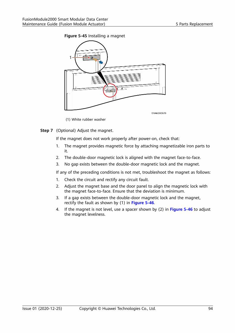
Figure 5-45 Installing a magnet
(1) White rubber washer
Step 7 (Optional) Adjust the magnet.
If the magnet does not work properly after power-on, check that:
1. The magnet provides magnetic force by attaching magnetizable iron parts toit.
2. The double-door magnetic lock is aligned with the magnet face-to-face.3. No gap exists between the double-door magnetic lock and the magnet.
If any of the preceding conditions is not met, troubleshoot the magnet as follows:
1. Check the circuit and rectify any circuit fault.2. Adjust the magnet base and the door panel to align the magnetic lock with
the magnet face-to-face. Ensure that the deviation is minimum.3. If a gap exists between the double-door magnetic lock and the magnet,
rectify the fault as shown by (1) in Figure 5-46.4. If the magnet is not level, use a spacer shown by (2) in Figure 5-46 to adjust
the magnet levelness.
FusionModule2000 Smart Modular Data CenterMaintenance Guide (Fusion Module Actuator) 5 Parts Replacement
Issue 01 (2020-12-25) Copyright © Huawei Technologies Co., Ltd. 94
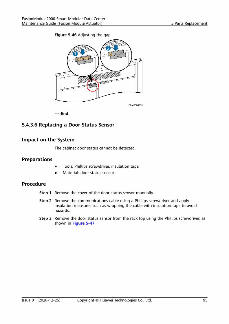
Figure 5-46 Adjusting the gap
----End
5.4.3.6 Replacing a Door Status Sensor
Impact on the SystemThe cabinet door status cannot be detected.
Preparations● Tools: Phillips screwdriver, insulation tape● Material: door status sensor
Procedure
Step 1 Remove the cover of the door status sensor manually.
Step 2 Remove the communications cable using a Phillips screwdriver and applyinsulation measures such as wrapping the cable with insulation tape to avoidhazards.
Step 3 Remove the door status sensor from the rack top using the Phillips screwdriver, asshown in Figure 5-47.
FusionModule2000 Smart Modular Data CenterMaintenance Guide (Fusion Module Actuator) 5 Parts Replacement
Issue 01 (2020-12-25) Copyright © Huawei Technologies Co., Ltd. 95
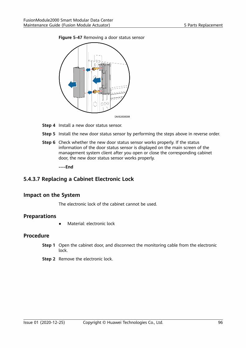
Figure 5-47 Removing a door status sensor
Step 4 Install a new door status sensor.
Step 5 Install the new door status sensor by performing the steps above in reverse order.
Step 6 Check whether the new door status sensor works properly. If the statusinformation of the door status sensor is displayed on the main screen of themanagement system client after you open or close the corresponding cabinetdoor, the new door status sensor works properly.
----End
5.4.3.7 Replacing a Cabinet Electronic Lock
Impact on the SystemThe electronic lock of the cabinet cannot be used.
Preparations● Material: electronic lock
Procedure
Step 1 Open the cabinet door, and disconnect the monitoring cable from the electroniclock.
Step 2 Remove the electronic lock.
FusionModule2000 Smart Modular Data CenterMaintenance Guide (Fusion Module Actuator) 5 Parts Replacement
Issue 01 (2020-12-25) Copyright © Huawei Technologies Co., Ltd. 96
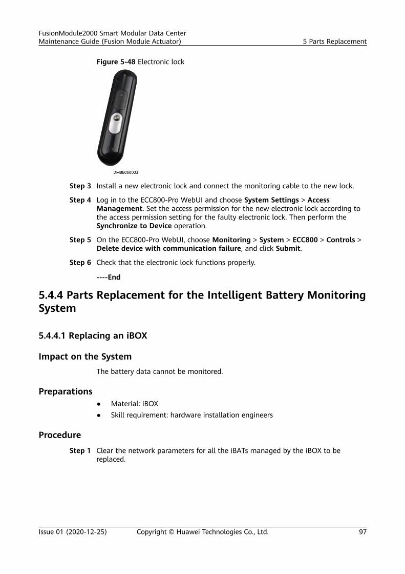
Figure 5-48 Electronic lock
Step 3 Install a new electronic lock and connect the monitoring cable to the new lock.
Step 4 Log in to the ECC800-Pro WebUI and choose System Settings > AccessManagement. Set the access permission for the new electronic lock according tothe access permission setting for the faulty electronic lock. Then perform theSynchronize to Device operation.
Step 5 On the ECC800-Pro WebUI, choose Monitoring > System > ECC800 > Controls >Delete device with communication failure, and click Submit.
Step 6 Check that the electronic lock functions properly.
----End
5.4.4 Parts Replacement for the Intelligent Battery MonitoringSystem
5.4.4.1 Replacing an iBOX
Impact on the SystemThe battery data cannot be monitored.
Preparations● Material: iBOX● Skill requirement: hardware installation engineers
Procedure
Step 1 Clear the network parameters for all the iBATs managed by the iBOX to bereplaced.
FusionModule2000 Smart Modular Data CenterMaintenance Guide (Fusion Module Actuator) 5 Parts Replacement
Issue 01 (2020-12-25) Copyright © Huawei Technologies Co., Ltd. 97
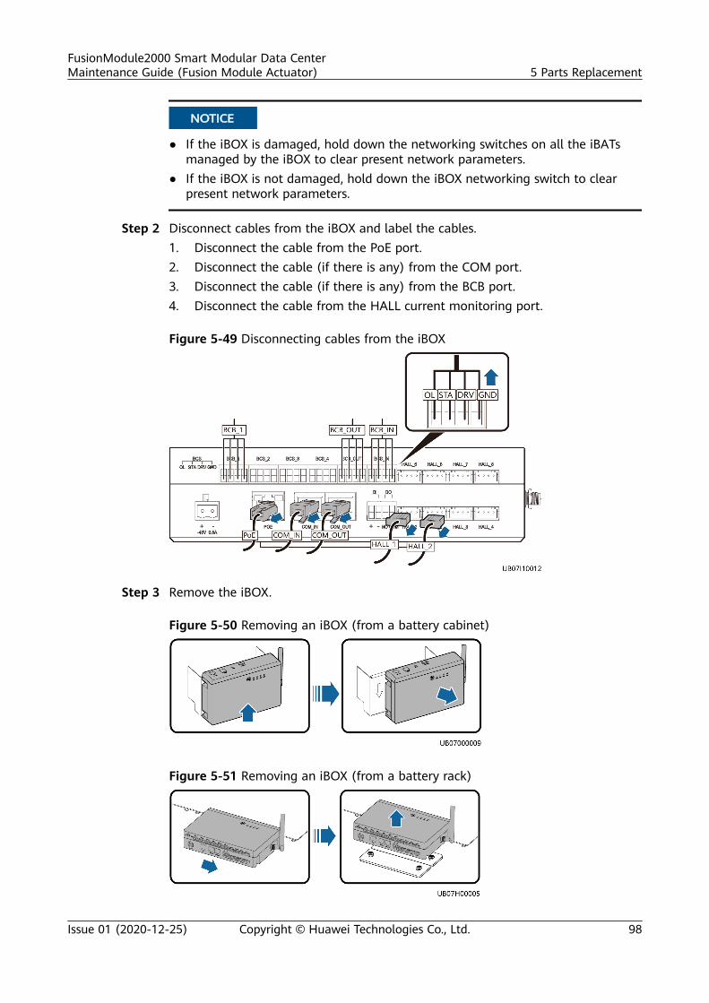
NO TICE
● If the iBOX is damaged, hold down the networking switches on all the iBATsmanaged by the iBOX to clear present network parameters.
● If the iBOX is not damaged, hold down the iBOX networking switch to clearpresent network parameters.
Step 2 Disconnect cables from the iBOX and label the cables.1. Disconnect the cable from the PoE port.2. Disconnect the cable (if there is any) from the COM port.3. Disconnect the cable (if there is any) from the BCB port.4. Disconnect the cable from the HALL current monitoring port.
Figure 5-49 Disconnecting cables from the iBOX
Step 3 Remove the iBOX.
Figure 5-50 Removing an iBOX (from a battery cabinet)
Figure 5-51 Removing an iBOX (from a battery rack)
FusionModule2000 Smart Modular Data CenterMaintenance Guide (Fusion Module Actuator) 5 Parts Replacement
Issue 01 (2020-12-25) Copyright © Huawei Technologies Co., Ltd. 98
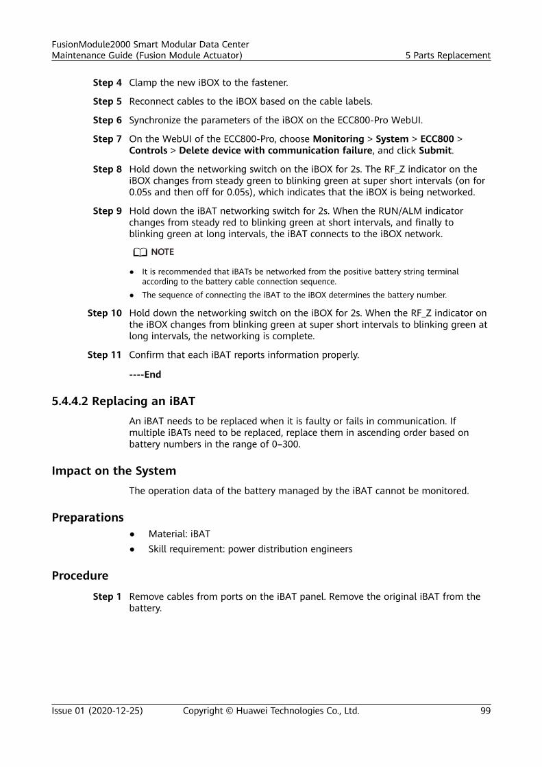
Step 4 Clamp the new iBOX to the fastener.
Step 5 Reconnect cables to the iBOX based on the cable labels.
Step 6 Synchronize the parameters of the iBOX on the ECC800-Pro WebUI.
Step 7 On the WebUI of the ECC800-Pro, choose Monitoring > System > ECC800 >Controls > Delete device with communication failure, and click Submit.
Step 8 Hold down the networking switch on the iBOX for 2s. The RF_Z indicator on theiBOX changes from steady green to blinking green at super short intervals (on for0.05s and then off for 0.05s), which indicates that the iBOX is being networked.
Step 9 Hold down the iBAT networking switch for 2s. When the RUN/ALM indicatorchanges from steady red to blinking green at short intervals, and finally toblinking green at long intervals, the iBAT connects to the iBOX network.
NO TE
● It is recommended that iBATs be networked from the positive battery string terminalaccording to the battery cable connection sequence.
● The sequence of connecting the iBAT to the iBOX determines the battery number.
Step 10 Hold down the networking switch on the iBOX for 2s. When the RF_Z indicator onthe iBOX changes from blinking green at super short intervals to blinking green atlong intervals, the networking is complete.
Step 11 Confirm that each iBAT reports information properly.
----End
5.4.4.2 Replacing an iBATAn iBAT needs to be replaced when it is faulty or fails in communication. Ifmultiple iBATs need to be replaced, replace them in ascending order based onbattery numbers in the range of 0–300.
Impact on the SystemThe operation data of the battery managed by the iBAT cannot be monitored.
Preparations● Material: iBAT● Skill requirement: power distribution engineers
Procedure
Step 1 Remove cables from ports on the iBAT panel. Remove the original iBAT from thebattery.
FusionModule2000 Smart Modular Data CenterMaintenance Guide (Fusion Module Actuator) 5 Parts Replacement
Issue 01 (2020-12-25) Copyright © Huawei Technologies Co., Ltd. 99
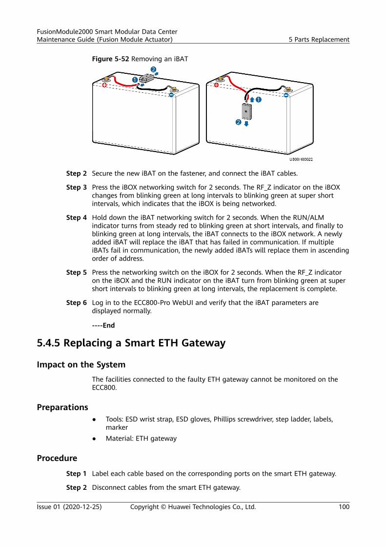
Figure 5-52 Removing an iBAT
Step 2 Secure the new iBAT on the fastener, and connect the iBAT cables.
Step 3 Press the iBOX networking switch for 2 seconds. The RF_Z indicator on the iBOXchanges from blinking green at long intervals to blinking green at super shortintervals, which indicates that the iBOX is being networked.
Step 4 Hold down the iBAT networking switch for 2 seconds. When the RUN/ALMindicator turns from steady red to blinking green at short intervals, and finally toblinking green at long intervals, the iBAT connects to the iBOX network. A newlyadded iBAT will replace the iBAT that has failed in communication. If multipleiBATs fail in communication, the newly added iBATs will replace them in ascendingorder of address.
Step 5 Press the networking switch on the iBOX for 2 seconds. When the RF_Z indicatoron the iBOX and the RUN indicator on the iBAT turn from blinking green at supershort intervals to blinking green at long intervals, the replacement is complete.
Step 6 Log in to the ECC800-Pro WebUI and verify that the iBAT parameters aredisplayed normally.
----End
5.4.5 Replacing a Smart ETH Gateway
Impact on the System
The facilities connected to the faulty ETH gateway cannot be monitored on theECC800.
Preparations● Tools: ESD wrist strap, ESD gloves, Phillips screwdriver, step ladder, labels,
marker● Material: ETH gateway
Procedure
Step 1 Label each cable based on the corresponding ports on the smart ETH gateway.
Step 2 Disconnect cables from the smart ETH gateway.
FusionModule2000 Smart Modular Data CenterMaintenance Guide (Fusion Module Actuator) 5 Parts Replacement
Issue 01 (2020-12-25) Copyright © Huawei Technologies Co., Ltd. 100
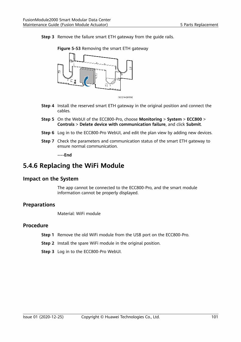
Step 3 Remove the failure smart ETH gateway from the guide rails.
Figure 5-53 Removing the smart ETH gateway
Step 4 Install the reserved smart ETH gateway in the original position and connect thecables.
Step 5 On the WebUI of the ECC800-Pro, choose Monitoring > System > ECC800 >Controls > Delete device with communication failure, and click Submit.
Step 6 Log in to the ECC800-Pro WebUI, and edit the plan view by adding new devices.
Step 7 Check the parameters and communication status of the smart ETH gateway toensure normal communication.
----End
5.4.6 Replacing the WiFi Module
Impact on the SystemThe app cannot be connected to the ECC800-Pro, and the smart moduleinformation cannot be properly displayed.
PreparationsMaterial: WiFi module
Procedure
Step 1 Remove the old WiFi module from the USB port on the ECC800-Pro.
Step 2 Install the spare WiFi module in the original position.
Step 3 Log in to the ECC800-Pro WebUI.
FusionModule2000 Smart Modular Data CenterMaintenance Guide (Fusion Module Actuator) 5 Parts Replacement
Issue 01 (2020-12-25) Copyright © Huawei Technologies Co., Ltd. 101
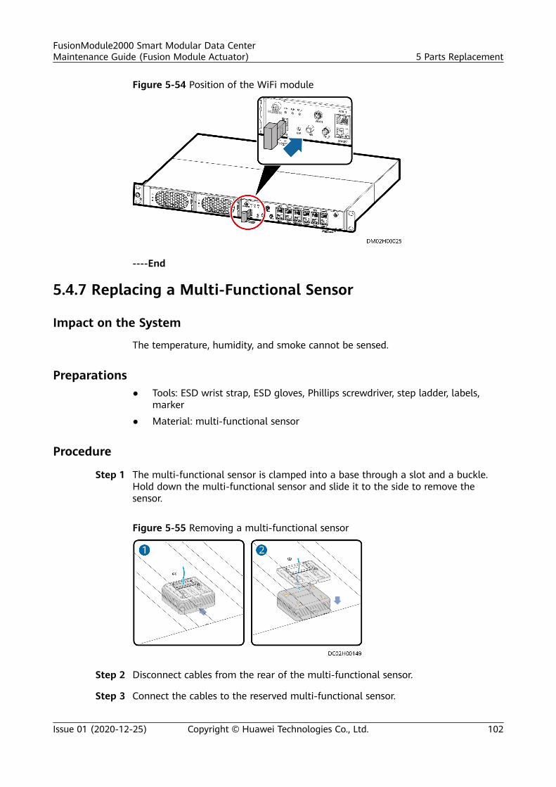
Figure 5-54 Position of the WiFi module
----End
5.4.7 Replacing a Multi-Functional Sensor
Impact on the System
The temperature, humidity, and smoke cannot be sensed.
Preparations● Tools: ESD wrist strap, ESD gloves, Phillips screwdriver, step ladder, labels,
marker
● Material: multi-functional sensor
Procedure
Step 1 The multi-functional sensor is clamped into a base through a slot and a buckle.Hold down the multi-functional sensor and slide it to the side to remove thesensor.
Figure 5-55 Removing a multi-functional sensor
Step 2 Disconnect cables from the rear of the multi-functional sensor.
Step 3 Connect the cables to the reserved multi-functional sensor.
FusionModule2000 Smart Modular Data CenterMaintenance Guide (Fusion Module Actuator) 5 Parts Replacement
Issue 01 (2020-12-25) Copyright © Huawei Technologies Co., Ltd. 102
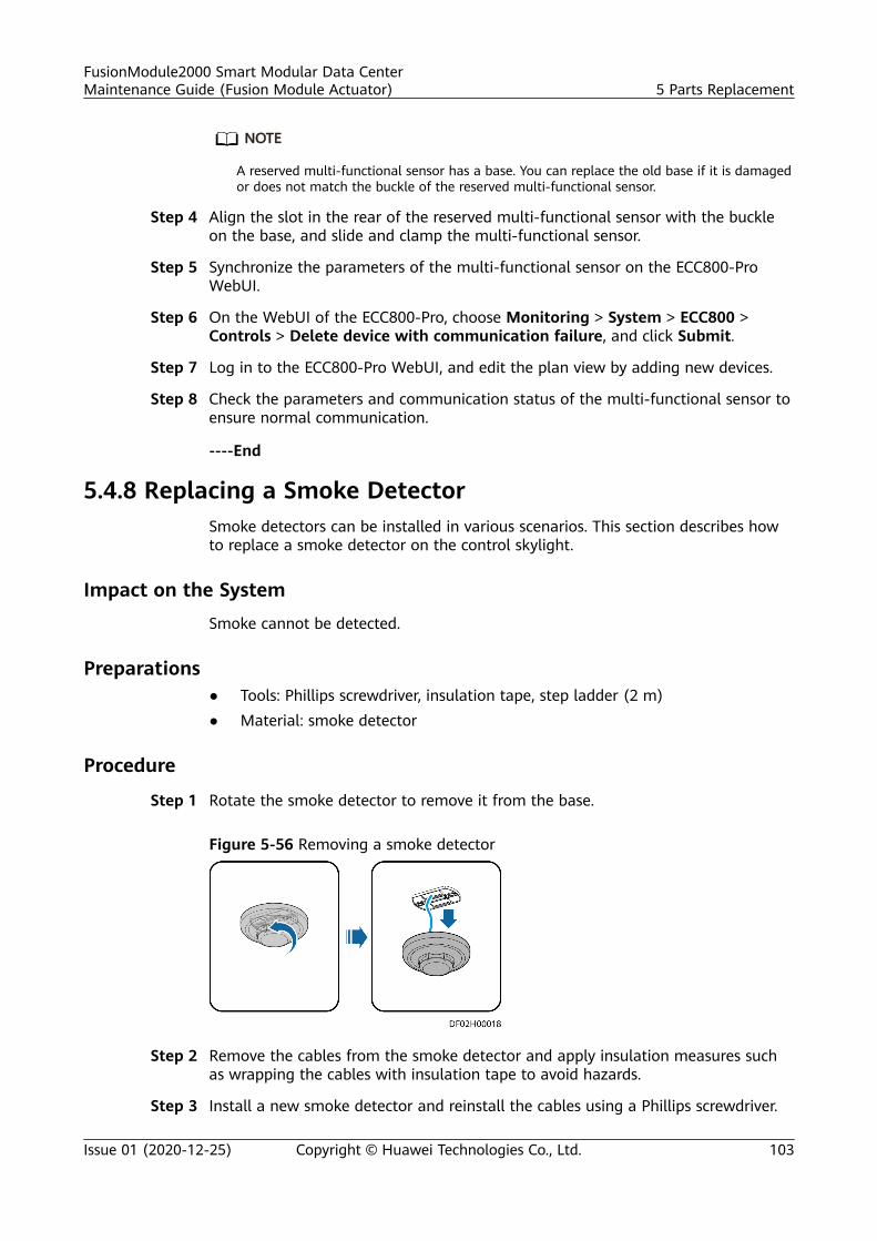
NO TE
A reserved multi-functional sensor has a base. You can replace the old base if it is damagedor does not match the buckle of the reserved multi-functional sensor.
Step 4 Align the slot in the rear of the reserved multi-functional sensor with the buckleon the base, and slide and clamp the multi-functional sensor.
Step 5 Synchronize the parameters of the multi-functional sensor on the ECC800-ProWebUI.
Step 6 On the WebUI of the ECC800-Pro, choose Monitoring > System > ECC800 >Controls > Delete device with communication failure, and click Submit.
Step 7 Log in to the ECC800-Pro WebUI, and edit the plan view by adding new devices.
Step 8 Check the parameters and communication status of the multi-functional sensor toensure normal communication.
----End
5.4.8 Replacing a Smoke DetectorSmoke detectors can be installed in various scenarios. This section describes howto replace a smoke detector on the control skylight.
Impact on the System
Smoke cannot be detected.
Preparations● Tools: Phillips screwdriver, insulation tape, step ladder (2 m)● Material: smoke detector
Procedure
Step 1 Rotate the smoke detector to remove it from the base.
Figure 5-56 Removing a smoke detector
Step 2 Remove the cables from the smoke detector and apply insulation measures suchas wrapping the cables with insulation tape to avoid hazards.
Step 3 Install a new smoke detector and reinstall the cables using a Phillips screwdriver.
FusionModule2000 Smart Modular Data CenterMaintenance Guide (Fusion Module Actuator) 5 Parts Replacement
Issue 01 (2020-12-25) Copyright © Huawei Technologies Co., Ltd. 103

Step 4 Install the smoke detector on the control skylight.
Step 5 Verify that the smoke detector function is normal.
----End
5.4.9 Replacing a Cabinet Temperature Sensor
Impact on the SystemThe cabinet temperature cannot be detected during replacement.
Preparations● Tools: ESD wrist strap, ESD gloves● Material: cabinet temperature sensor
Procedure
Step 1 Remove the temperature sensor cable from the T/H sensor.
Step 2 Remove the fastener that secures the temperature sensor and remove the sensor.
Step 3 Secure the new temperature sensor to the original position in the cabinet usingthe fastener, and reconnect to the T/H sensor.
FusionModule2000 Smart Modular Data CenterMaintenance Guide (Fusion Module Actuator) 5 Parts Replacement
Issue 01 (2020-12-25) Copyright © Huawei Technologies Co., Ltd. 104
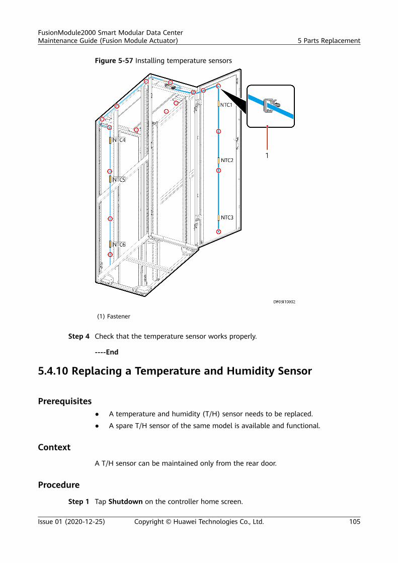
Figure 5-57 Installing temperature sensors
(1) Fastener
Step 4 Check that the temperature sensor works properly.
----End
5.4.10 Replacing a Temperature and Humidity Sensor
Prerequisites● A temperature and humidity (T/H) sensor needs to be replaced.
● A spare T/H sensor of the same model is available and functional.
Context
A T/H sensor can be maintained only from the rear door.
Procedure
Step 1 Tap Shutdown on the controller home screen.
FusionModule2000 Smart Modular Data CenterMaintenance Guide (Fusion Module Actuator) 5 Parts Replacement
Issue 01 (2020-12-25) Copyright © Huawei Technologies Co., Ltd. 105
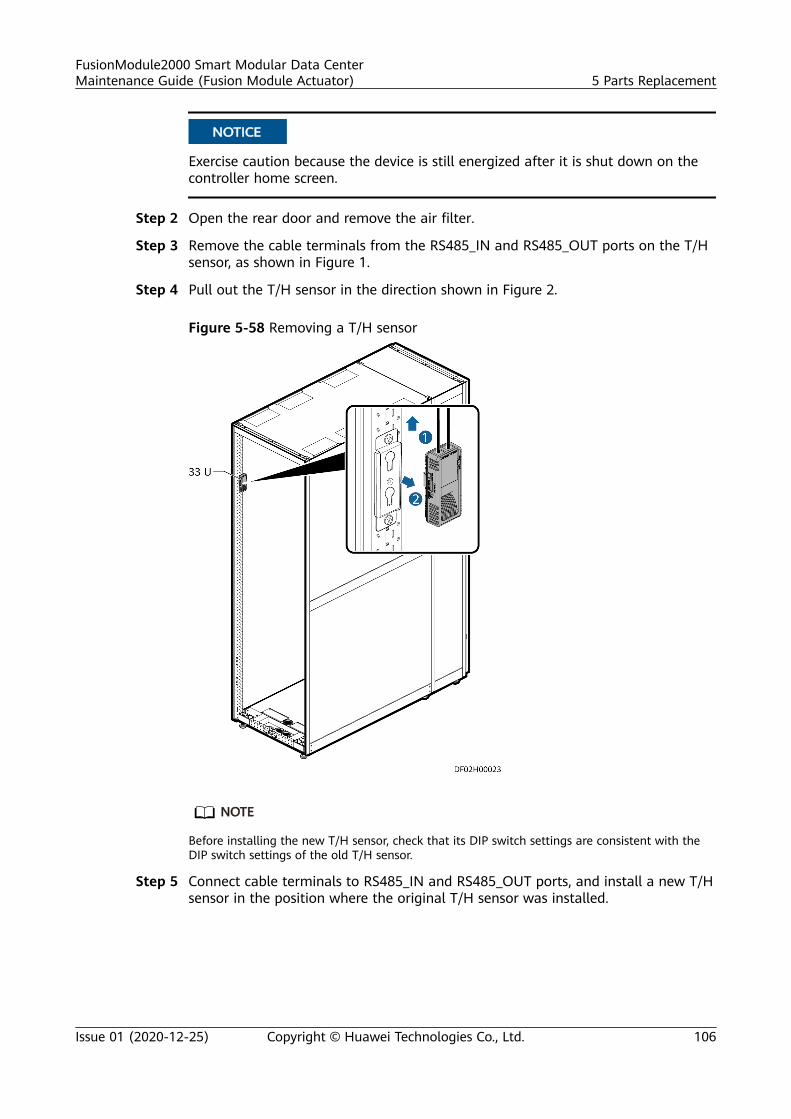
NO TICE
Exercise caution because the device is still energized after it is shut down on thecontroller home screen.
Step 2 Open the rear door and remove the air filter.
Step 3 Remove the cable terminals from the RS485_IN and RS485_OUT ports on the T/Hsensor, as shown in Figure 1.
Step 4 Pull out the T/H sensor in the direction shown in Figure 2.
Figure 5-58 Removing a T/H sensor
NO TE
Before installing the new T/H sensor, check that its DIP switch settings are consistent with theDIP switch settings of the old T/H sensor.
Step 5 Connect cable terminals to RS485_IN and RS485_OUT ports, and install a new T/Hsensor in the position where the original T/H sensor was installed.
FusionModule2000 Smart Modular Data CenterMaintenance Guide (Fusion Module Actuator) 5 Parts Replacement
Issue 01 (2020-12-25) Copyright © Huawei Technologies Co., Ltd. 106
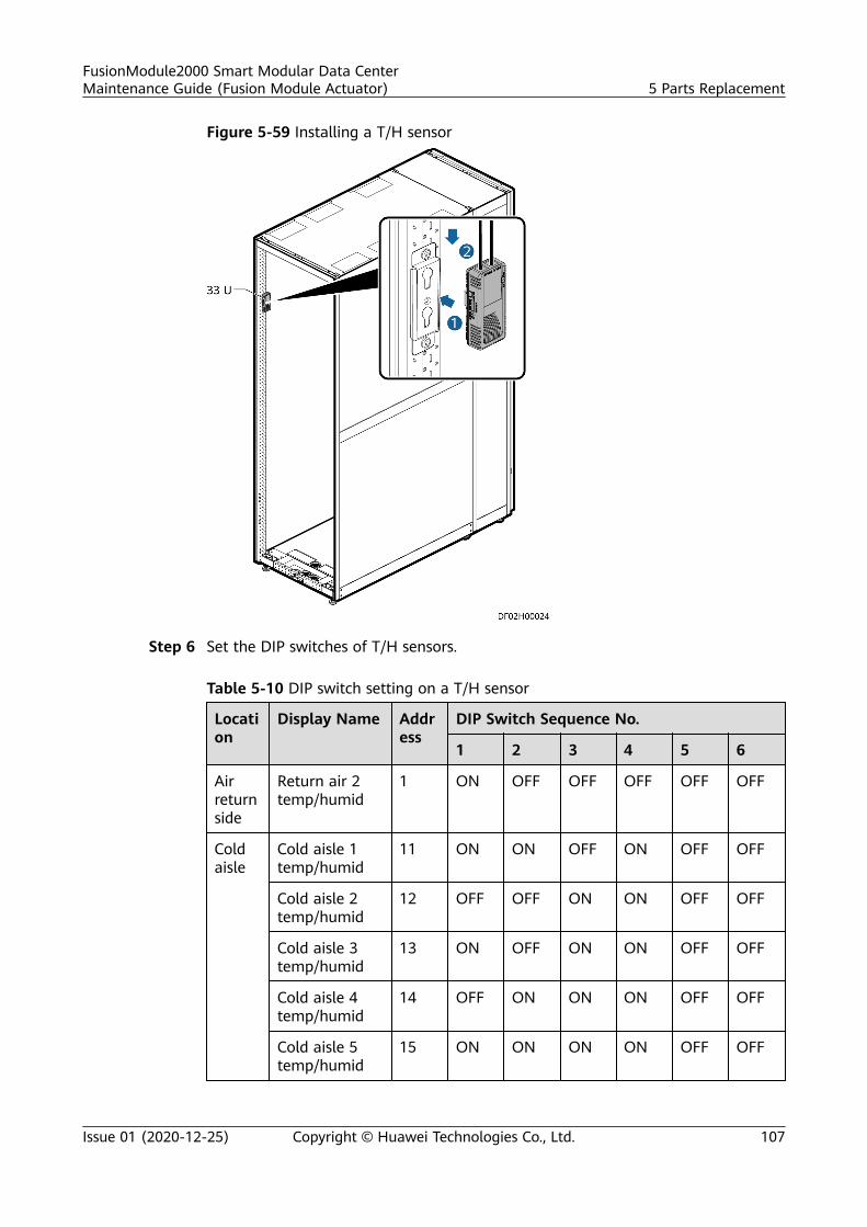
Figure 5-59 Installing a T/H sensor
Step 6 Set the DIP switches of T/H sensors.
Table 5-10 DIP switch setting on a T/H sensor
Location
Display Name Address
DIP Switch Sequence No.
1 2 3 4 5 6
Airreturnside
Return air 2temp/humid
1 ON OFF OFF OFF OFF OFF
Coldaisle
Cold aisle 1temp/humid
11 ON ON OFF ON OFF OFF
Cold aisle 2temp/humid
12 OFF OFF ON ON OFF OFF
Cold aisle 3temp/humid
13 ON OFF ON ON OFF OFF
Cold aisle 4temp/humid
14 OFF ON ON ON OFF OFF
Cold aisle 5temp/humid
15 ON ON ON ON OFF OFF
FusionModule2000 Smart Modular Data CenterMaintenance Guide (Fusion Module Actuator) 5 Parts Replacement
Issue 01 (2020-12-25) Copyright © Huawei Technologies Co., Ltd. 107
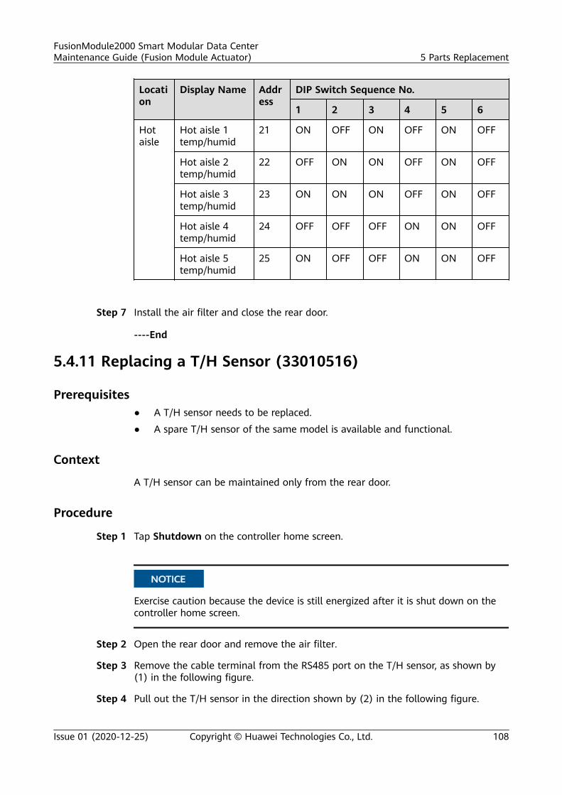
Location
Display Name Address
DIP Switch Sequence No.
1 2 3 4 5 6
Hotaisle
Hot aisle 1temp/humid
21 ON OFF ON OFF ON OFF
Hot aisle 2temp/humid
22 OFF ON ON OFF ON OFF
Hot aisle 3temp/humid
23 ON ON ON OFF ON OFF
Hot aisle 4temp/humid
24 OFF OFF OFF ON ON OFF
Hot aisle 5temp/humid
25 ON OFF OFF ON ON OFF
Step 7 Install the air filter and close the rear door.
----End
5.4.11 Replacing a T/H Sensor (33010516)
Prerequisites● A T/H sensor needs to be replaced.
● A spare T/H sensor of the same model is available and functional.
Context
A T/H sensor can be maintained only from the rear door.
Procedure
Step 1 Tap Shutdown on the controller home screen.
NO TICE
Exercise caution because the device is still energized after it is shut down on thecontroller home screen.
Step 2 Open the rear door and remove the air filter.
Step 3 Remove the cable terminal from the RS485 port on the T/H sensor, as shown by(1) in the following figure.
Step 4 Pull out the T/H sensor in the direction shown by (2) in the following figure.
FusionModule2000 Smart Modular Data CenterMaintenance Guide (Fusion Module Actuator) 5 Parts Replacement
Issue 01 (2020-12-25) Copyright © Huawei Technologies Co., Ltd. 108
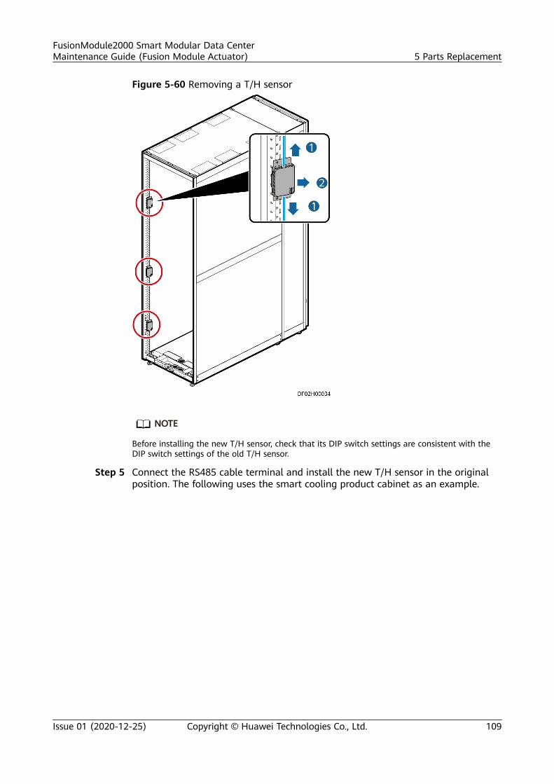
Figure 5-60 Removing a T/H sensor
NO TE
Before installing the new T/H sensor, check that its DIP switch settings are consistent with theDIP switch settings of the old T/H sensor.
Step 5 Connect the RS485 cable terminal and install the new T/H sensor in the originalposition. The following uses the smart cooling product cabinet as an example.
FusionModule2000 Smart Modular Data CenterMaintenance Guide (Fusion Module Actuator) 5 Parts Replacement
Issue 01 (2020-12-25) Copyright © Huawei Technologies Co., Ltd. 109
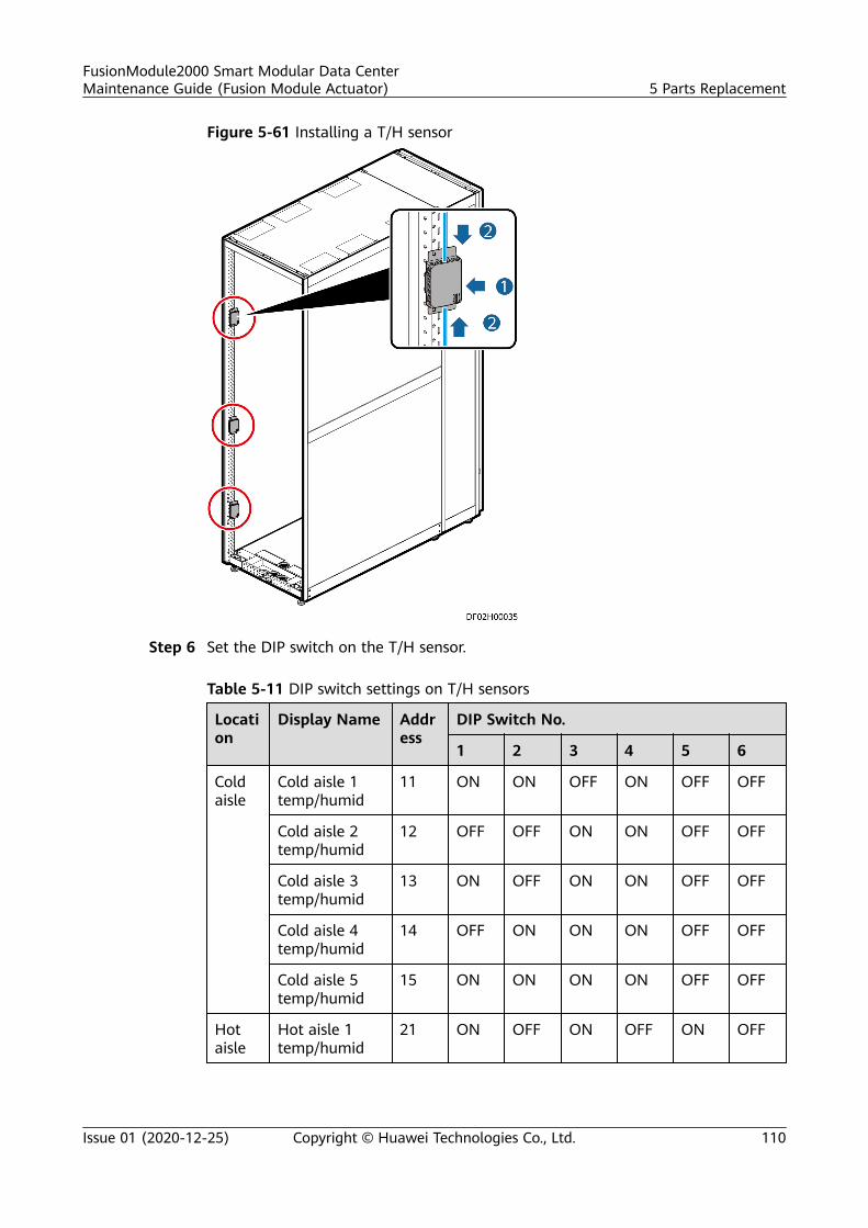
Figure 5-61 Installing a T/H sensor
Step 6 Set the DIP switch on the T/H sensor.
Table 5-11 DIP switch settings on T/H sensors
Location
Display Name Address
DIP Switch No.
1 2 3 4 5 6
Coldaisle
Cold aisle 1temp/humid
11 ON ON OFF ON OFF OFF
Cold aisle 2temp/humid
12 OFF OFF ON ON OFF OFF
Cold aisle 3temp/humid
13 ON OFF ON ON OFF OFF
Cold aisle 4temp/humid
14 OFF ON ON ON OFF OFF
Cold aisle 5temp/humid
15 ON ON ON ON OFF OFF
Hotaisle
Hot aisle 1temp/humid
21 ON OFF ON OFF ON OFF
FusionModule2000 Smart Modular Data CenterMaintenance Guide (Fusion Module Actuator) 5 Parts Replacement
Issue 01 (2020-12-25) Copyright © Huawei Technologies Co., Ltd. 110
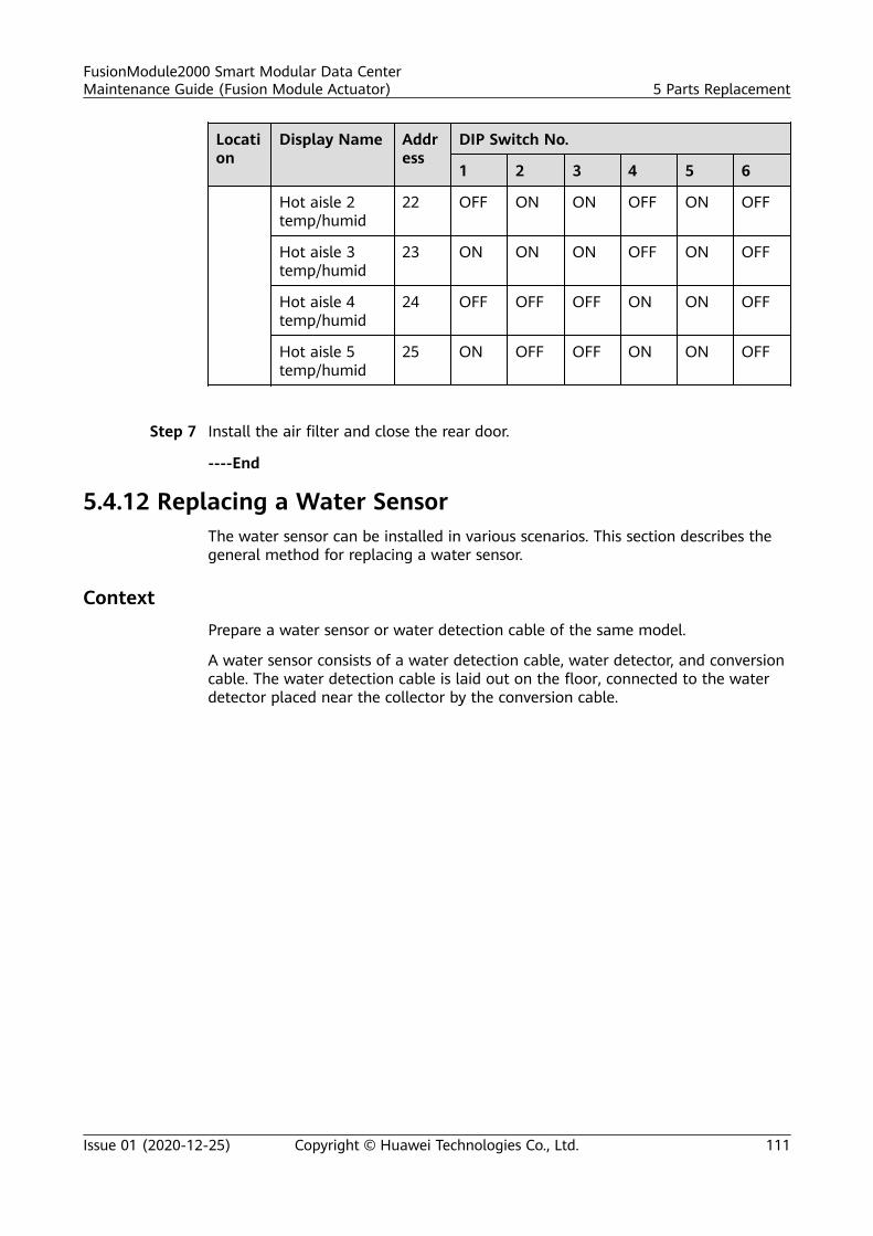
Location
Display Name Address
DIP Switch No.
1 2 3 4 5 6
Hot aisle 2temp/humid
22 OFF ON ON OFF ON OFF
Hot aisle 3temp/humid
23 ON ON ON OFF ON OFF
Hot aisle 4temp/humid
24 OFF OFF OFF ON ON OFF
Hot aisle 5temp/humid
25 ON OFF OFF ON ON OFF
Step 7 Install the air filter and close the rear door.
----End
5.4.12 Replacing a Water SensorThe water sensor can be installed in various scenarios. This section describes thegeneral method for replacing a water sensor.
ContextPrepare a water sensor or water detection cable of the same model.
A water sensor consists of a water detection cable, water detector, and conversioncable. The water detection cable is laid out on the floor, connected to the waterdetector placed near the collector by the conversion cable.
FusionModule2000 Smart Modular Data CenterMaintenance Guide (Fusion Module Actuator) 5 Parts Replacement
Issue 01 (2020-12-25) Copyright © Huawei Technologies Co., Ltd. 111
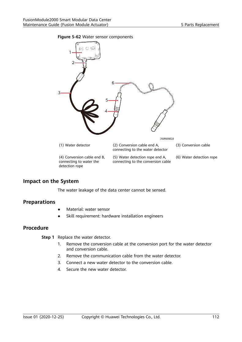
Figure 5-62 Water sensor components
(1) Water detector (2) Conversion cable end A,connecting to the water detector
(3) Conversion cable
(4) Conversion cable end B,connecting to water thedetection rope
(5) Water detection rope end A,connecting to the conversion cable
(6) Water detection rope
Impact on the SystemThe water leakage of the data center cannot be sensed.
Preparations● Material: water sensor● Skill requirement: hardware installation engineers
Procedure
Step 1 Replace the water detector.1. Remove the conversion cable at the conversion port for the water detector
and conversion cable.2. Remove the communication cable from the water detector.3. Connect a new water detector to the conversion cable.4. Secure the new water detector.
FusionModule2000 Smart Modular Data CenterMaintenance Guide (Fusion Module Actuator) 5 Parts Replacement
Issue 01 (2020-12-25) Copyright © Huawei Technologies Co., Ltd. 112
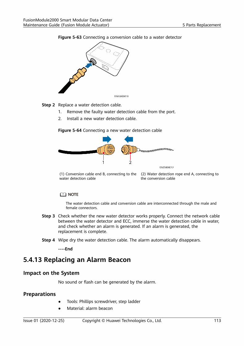
Figure 5-63 Connecting a conversion cable to a water detector
Step 2 Replace a water detection cable.1. Remove the faulty water detection cable from the port.2. Install a new water detection cable.
Figure 5-64 Connecting a new water detection cable
(1) Conversion cable end B, connecting to thewater detection cable
(2) Water detection rope end A, connecting tothe conversion cable
NO TE
The water detection cable and conversion cable are interconnected through the male andfemale connectors.
Step 3 Check whether the new water detector works properly. Connect the network cablebetween the water detector and ECC, immerse the water detection cable in water,and check whether an alarm is generated. If an alarm is generated, thereplacement is complete.
Step 4 Wipe dry the water detection cable. The alarm automatically disappears.
----End
5.4.13 Replacing an Alarm Beacon
Impact on the SystemNo sound or flash can be generated by the alarm.
Preparations● Tools: Phillips screwdriver, step ladder● Material: alarm beacon
FusionModule2000 Smart Modular Data CenterMaintenance Guide (Fusion Module Actuator) 5 Parts Replacement
Issue 01 (2020-12-25) Copyright © Huawei Technologies Co., Ltd. 113
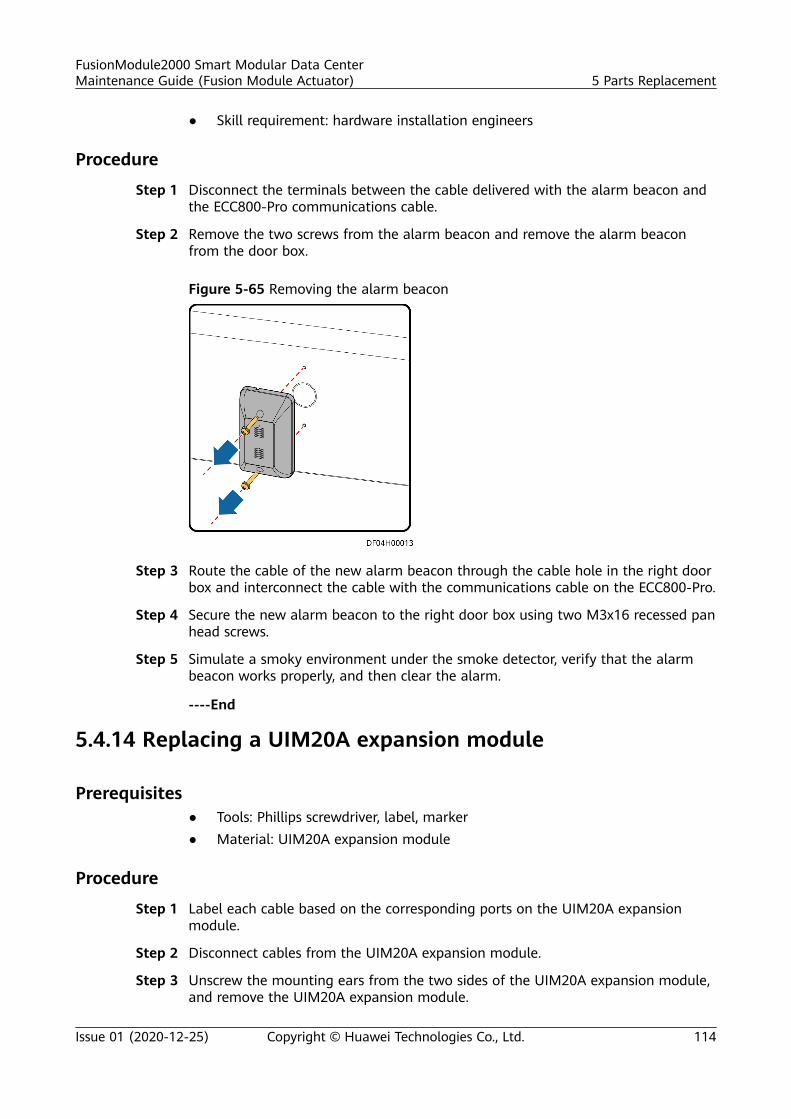
● Skill requirement: hardware installation engineers
Procedure
Step 1 Disconnect the terminals between the cable delivered with the alarm beacon andthe ECC800-Pro communications cable.
Step 2 Remove the two screws from the alarm beacon and remove the alarm beaconfrom the door box.
Figure 5-65 Removing the alarm beacon
Step 3 Route the cable of the new alarm beacon through the cable hole in the right doorbox and interconnect the cable with the communications cable on the ECC800-Pro.
Step 4 Secure the new alarm beacon to the right door box using two M3x16 recessed panhead screws.
Step 5 Simulate a smoky environment under the smoke detector, verify that the alarmbeacon works properly, and then clear the alarm.
----End
5.4.14 Replacing a UIM20A expansion module
Prerequisites● Tools: Phillips screwdriver, label, marker● Material: UIM20A expansion module
Procedure
Step 1 Label each cable based on the corresponding ports on the UIM20A expansionmodule.
Step 2 Disconnect cables from the UIM20A expansion module.
Step 3 Unscrew the mounting ears from the two sides of the UIM20A expansion module,and remove the UIM20A expansion module.
FusionModule2000 Smart Modular Data CenterMaintenance Guide (Fusion Module Actuator) 5 Parts Replacement
Issue 01 (2020-12-25) Copyright © Huawei Technologies Co., Ltd. 114
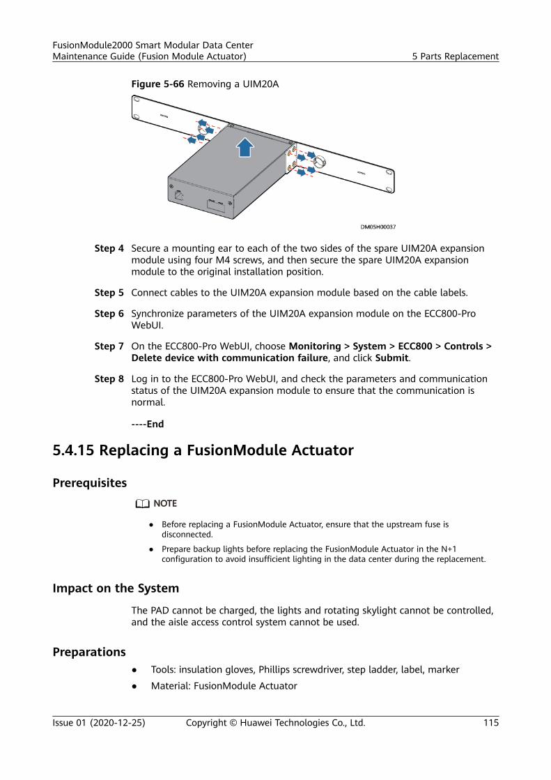
Figure 5-66 Removing a UIM20A
Step 4 Secure a mounting ear to each of the two sides of the spare UIM20A expansionmodule using four M4 screws, and then secure the spare UIM20A expansionmodule to the original installation position.
Step 5 Connect cables to the UIM20A expansion module based on the cable labels.
Step 6 Synchronize parameters of the UIM20A expansion module on the ECC800-ProWebUI.
Step 7 On the ECC800-Pro WebUI, choose Monitoring > System > ECC800 > Controls >Delete device with communication failure, and click Submit.
Step 8 Log in to the ECC800-Pro WebUI, and check the parameters and communicationstatus of the UIM20A expansion module to ensure that the communication isnormal.
----End
5.4.15 Replacing a FusionModule Actuator
PrerequisitesNO TE
● Before replacing a FusionModule Actuator, ensure that the upstream fuse isdisconnected.
● Prepare backup lights before replacing the FusionModule Actuator in the N+1configuration to avoid insufficient lighting in the data center during the replacement.
Impact on the System
The PAD cannot be charged, the lights and rotating skylight cannot be controlled,and the aisle access control system cannot be used.
Preparations● Tools: insulation gloves, Phillips screwdriver, step ladder, label, marker
● Material: FusionModule Actuator
FusionModule2000 Smart Modular Data CenterMaintenance Guide (Fusion Module Actuator) 5 Parts Replacement
Issue 01 (2020-12-25) Copyright © Huawei Technologies Co., Ltd. 115
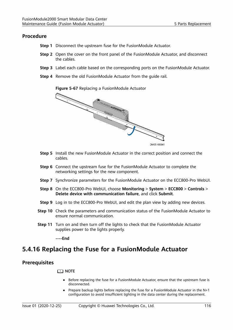
Procedure
Step 1 Disconnect the upstream fuse for the FusionModule Actuator.
Step 2 Open the cover on the front panel of the FusionModule Actuator, and disconnectthe cables.
Step 3 Label each cable based on the corresponding ports on the FusionModule Actuator.
Step 4 Remove the old FusionModule Actuator from the guide rail.
Figure 5-67 Replacing a FusionModule Actuator
Step 5 Install the new FusionModule Actuator in the correct position and connect thecables.
Step 6 Connect the upstream fuse for the FusionModule Actuator to complete thenetworking settings for the new component.
Step 7 Synchronize parameters for the FusionModule Actuator on the ECC800-Pro WebUI.
Step 8 On the ECC800-Pro WebUI, choose Monitoring > System > ECC800 > Controls >Delete device with communication failure, and click Submit.
Step 9 Log in to the ECC800-Pro WebUI, and edit the plan view by adding new devices.
Step 10 Check the parameters and communication status of the FusionModule Actuator toensure normal communication.
Step 11 Turn on and then turn off the lights to check that the FusionModule Actuatorsupplies power to the lights properly.
----End
5.4.16 Replacing the Fuse for a FusionModule Actuator
PrerequisitesNO TE
● Before replacing the fuse for a FusionModule Actuator, ensure that the upstream fuse isdisconnected.
● Prepare backup lights before replacing the fuse for a FusionModule Actuator in the N+1configuration to avoid insufficient lighting in the data center during the replacement.
FusionModule2000 Smart Modular Data CenterMaintenance Guide (Fusion Module Actuator) 5 Parts Replacement
Issue 01 (2020-12-25) Copyright © Huawei Technologies Co., Ltd. 116
Impact on the SystemThe PAD cannot be charged, the lights and rotating skylight cannot be controlled,and the aisle access control system cannot be used.
PreparationsTools: insulation gloves, step ladder
Procedure
Step 1 Disconnect the upstream fuse for the FusionModule Actuator.
Step 2 Open the fuse box and remove the faulty fuse.
Step 3 Open the spare fuse box of the FusionModule Actuator and take out a fuse.
Step 4 Connect the upstream fuse for the FusionModule Actuator to complete thenetworking settings for the new component.
Step 5 Check the parameters and communication status of the FusionModule Actuator toensure normal communication.
Step 6 Turn on and then turn off the lights to check that the FusionModule Actuatorsupplies power to the lights properly.
----End
5.4.17 Replacing a Skylight Magnetic Lock
Impact on the SystemThe rotating skylight cannot be controlled.
Preparations● Tools: Phillips screwdriver, step ladder (2 m)● Material: skylight magnetic lock
Procedure
Step 1 Open the rotating skylight.
Step 2 Disconnect the cable delivered with the skylight magnetic lock from the cascadingterminal of the lock.
Step 3 Remove the skylight magnetic lock to be replaced.
FusionModule2000 Smart Modular Data CenterMaintenance Guide (Fusion Module Actuator) 5 Parts Replacement
Issue 01 (2020-12-25) Copyright © Huawei Technologies Co., Ltd. 117
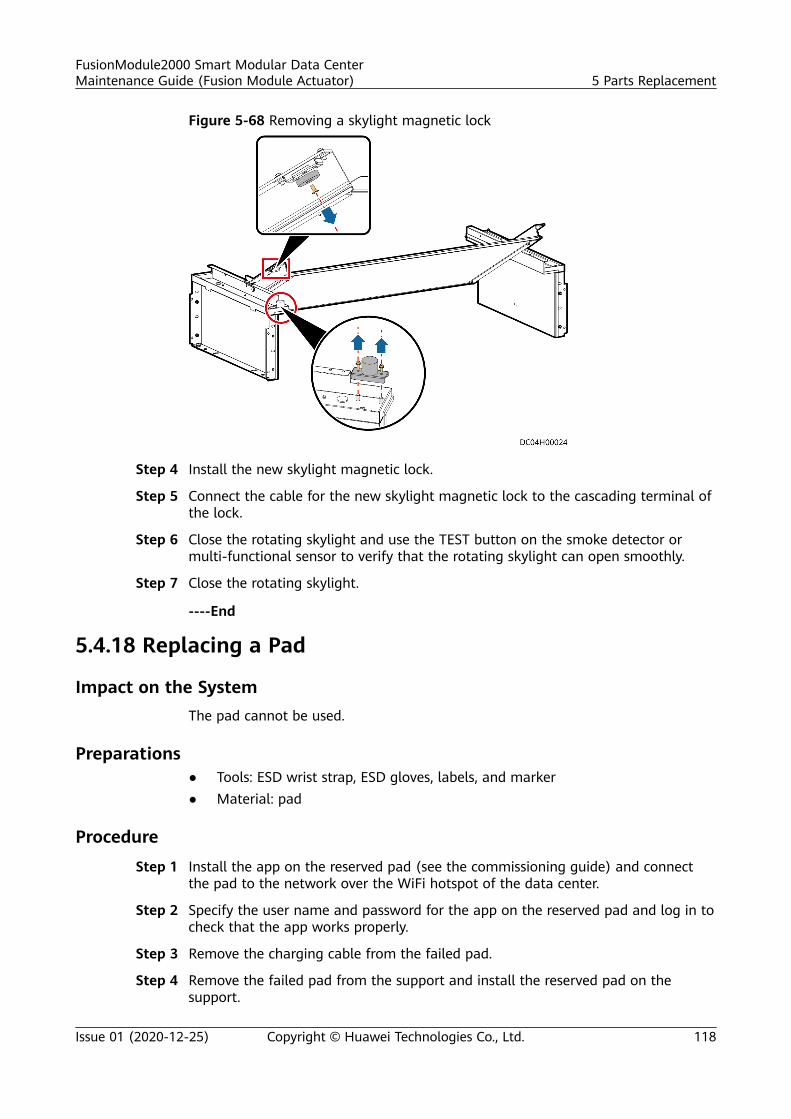
Figure 5-68 Removing a skylight magnetic lock
Step 4 Install the new skylight magnetic lock.
Step 5 Connect the cable for the new skylight magnetic lock to the cascading terminal ofthe lock.
Step 6 Close the rotating skylight and use the TEST button on the smoke detector ormulti-functional sensor to verify that the rotating skylight can open smoothly.
Step 7 Close the rotating skylight.
----End
5.4.18 Replacing a Pad
Impact on the SystemThe pad cannot be used.
Preparations● Tools: ESD wrist strap, ESD gloves, labels, and marker● Material: pad
Procedure
Step 1 Install the app on the reserved pad (see the commissioning guide) and connectthe pad to the network over the WiFi hotspot of the data center.
Step 2 Specify the user name and password for the app on the reserved pad and log in tocheck that the app works properly.
Step 3 Remove the charging cable from the failed pad.
Step 4 Remove the failed pad from the support and install the reserved pad on thesupport.
FusionModule2000 Smart Modular Data CenterMaintenance Guide (Fusion Module Actuator) 5 Parts Replacement
Issue 01 (2020-12-25) Copyright © Huawei Technologies Co., Ltd. 118
Step 5 Connect the charging cable to the reserved pad.
----End
5.4.19 Replacing a PAD Power Connector
Context
Item Appearance Remarks
PAD power connector The BOM number is14190892.
PAD power connector The BOM number is14190242.
PAD power connectorholder
Obtain it from the aisledoor accessories.
Impact on the System
The PAD cannot be charged.
Preparations● Tool: Phillips screwdriver
● Materials: PAD power connector, PAD power connector holder
Procedure
Step 1 Turn off the upstream power switch for the PAD power connector.
Step 2 Remove the baffle plate under the power connector.
Step 3 Remove the charging cable from the power connector.
Step 4 Remove the PAD power connector and its holder from the door box.
FusionModule2000 Smart Modular Data CenterMaintenance Guide (Fusion Module Actuator) 5 Parts Replacement
Issue 01 (2020-12-25) Copyright © Huawei Technologies Co., Ltd. 119
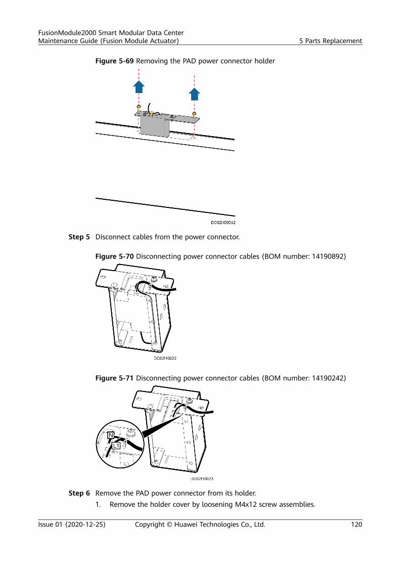
Figure 5-69 Removing the PAD power connector holder
Step 5 Disconnect cables from the power connector.
Figure 5-70 Disconnecting power connector cables (BOM number: 14190892)
Figure 5-71 Disconnecting power connector cables (BOM number: 14190242)
Step 6 Remove the PAD power connector from its holder.1. Remove the holder cover by loosening M4x12 screw assemblies.
FusionModule2000 Smart Modular Data CenterMaintenance Guide (Fusion Module Actuator) 5 Parts Replacement
Issue 01 (2020-12-25) Copyright © Huawei Technologies Co., Ltd. 120
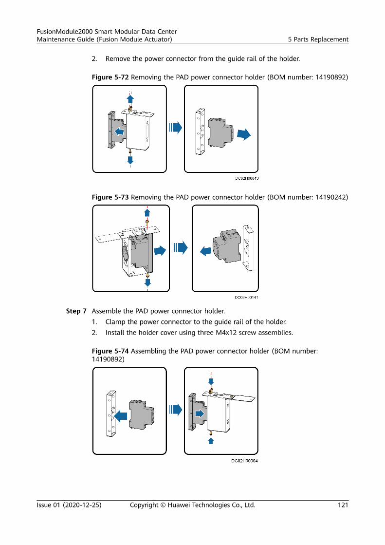
2. Remove the power connector from the guide rail of the holder.
Figure 5-72 Removing the PAD power connector holder (BOM number: 14190892)
Figure 5-73 Removing the PAD power connector holder (BOM number: 14190242)
Step 7 Assemble the PAD power connector holder.1. Clamp the power connector to the guide rail of the holder.2. Install the holder cover using three M4x12 screw assemblies.
Figure 5-74 Assembling the PAD power connector holder (BOM number:14190892)
FusionModule2000 Smart Modular Data CenterMaintenance Guide (Fusion Module Actuator) 5 Parts Replacement
Issue 01 (2020-12-25) Copyright © Huawei Technologies Co., Ltd. 121
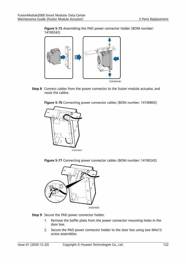
Figure 5-75 Assembling the PAD power connector holder (BOM number:14190242)
Step 8 Connect cables from the power connector to the fusion module actuator, androute the cables.
Figure 5-76 Connecting power connector cables (BOM number: 14190892)
Figure 5-77 Connecting power connector cables (BOM number: 14190242)
Step 9 Secure the PAD power connector holder.
1. Remove the baffle plate from the power connector mounting holes in thedoor box.
2. Secure the PAD power connector holder to the door box using two M4x12screw assemblies.
FusionModule2000 Smart Modular Data CenterMaintenance Guide (Fusion Module Actuator) 5 Parts Replacement
Issue 01 (2020-12-25) Copyright © Huawei Technologies Co., Ltd. 122
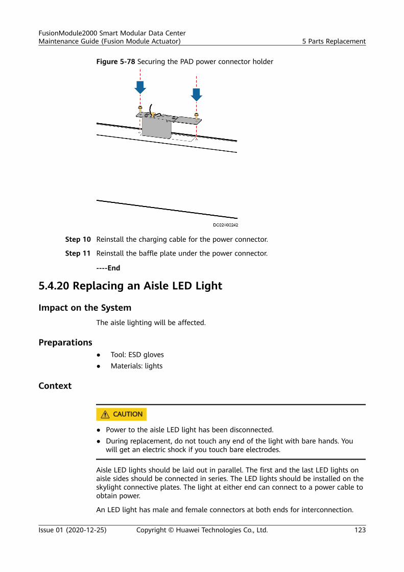
Figure 5-78 Securing the PAD power connector holder
Step 10 Reinstall the charging cable for the power connector.
Step 11 Reinstall the baffle plate under the power connector.
----End
5.4.20 Replacing an Aisle LED Light
Impact on the SystemThe aisle lighting will be affected.
Preparations● Tool: ESD gloves● Materials: lights
Context
CA UTION
● Power to the aisle LED light has been disconnected.● During replacement, do not touch any end of the light with bare hands. You
will get an electric shock if you touch bare electrodes.
Aisle LED lights should be laid out in parallel. The first and the last LED lights onaisle sides should be connected in series. The LED lights should be installed on theskylight connective plates. The light at either end can connect to a power cable toobtain power.
An LED light has male and female connectors at both ends for interconnection.
FusionModule2000 Smart Modular Data CenterMaintenance Guide (Fusion Module Actuator) 5 Parts Replacement
Issue 01 (2020-12-25) Copyright © Huawei Technologies Co., Ltd. 123
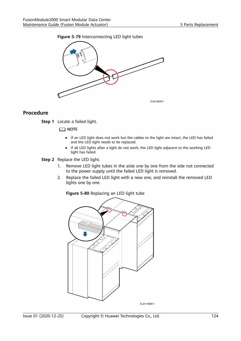
Figure 5-79 Interconnecting LED light tubes
ProcedureStep 1 Locate a failed light.
NO TE
● If an LED light does not work but the cables to the light are intact, the LED has failedand the LED light needs to be replaced.
● If all LED lights after a light do not work, the LED light adjacent to the working LEDlight has failed.
Step 2 Replace the LED light.1. Remove LED light tubes in the aisle one by one from the side not connected
to the power supply until the failed LED light is removed.2. Replace the failed LED light with a new one, and reinstall the removed LED
lights one by one.
Figure 5-80 Replacing an LED light tube
FusionModule2000 Smart Modular Data CenterMaintenance Guide (Fusion Module Actuator) 5 Parts Replacement
Issue 01 (2020-12-25) Copyright © Huawei Technologies Co., Ltd. 124

3. Replace all failed LED light tubes until all LED light tubes in the aisle workproperly.
----End
5.4.21 Replacing the Strip Light of an Atmosphere Light
Impact on the System
The strip light of an atmosphere light is off during replacement.
Preparations● Tool: ESD gloves● Material: atmosphere strip light
Procedure
Step 1 Remove the white rubber panels from the door frame.
Step 2 Remove the side covers from the posts.
Step 3 Cut off the cable tie that binds the strip light extension cable to the top of thepost.
Step 4 Pull out the strip light from the hole at the bottom of the left post.
Step 5 Disconnect the strip light terminal from the strip light extension cable of the doorpost.
Step 6 Pull out the strip light from the fasteners.
Figure 5-81 Removing a strip light
Step 7 Install a new strip light.
Step 8 Install the new strip light by performing the preceding steps in reverse order.
----End
5.4.22 Replacing an Atmosphere Light Power Supply
Impact on the System
The atmosphere light is off during replacement.
FusionModule2000 Smart Modular Data CenterMaintenance Guide (Fusion Module Actuator) 5 Parts Replacement
Issue 01 (2020-12-25) Copyright © Huawei Technologies Co., Ltd. 125
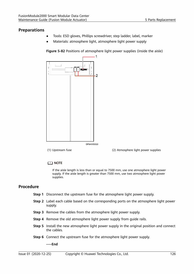
Preparations● Tools: ESD gloves, Phillips screwdriver, step ladder, label, marker● Materials: atmosphere light, atmosphere light power supply
Figure 5-82 Positions of atmosphere light power supplies (inside the aisle)
(1) Upstream fuse (2) Atmosphere light power supplies
NO TE
If the aisle length is less than or equal to 7500 mm, use one atmosphere light powersupply. If the aisle length is greater than 7500 mm, use two atmosphere light powersupplies.
Procedure
Step 1 Disconnect the upstream fuse for the atmosphere light power supply.
Step 2 Label each cable based on the corresponding ports on the atmosphere light powersupply.
Step 3 Remove the cables from the atmosphere light power supply.
Step 4 Remove the old atmosphere light power supply from guide rails.
Step 5 Install the new atmosphere light power supply in the original position and connectthe cables.
Step 6 Connect the upstream fuse for the atmosphere light power supply.
----End
FusionModule2000 Smart Modular Data CenterMaintenance Guide (Fusion Module Actuator) 5 Parts Replacement
Issue 01 (2020-12-25) Copyright © Huawei Technologies Co., Ltd. 126
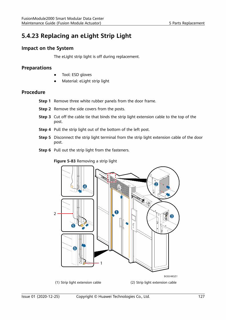
5.4.23 Replacing an eLight Strip Light
Impact on the SystemThe eLight strip light is off during replacement.
Preparations● Tool: ESD gloves● Material: eLight strip light
Procedure
Step 1 Remove three white rubber panels from the door frame.
Step 2 Remove the side covers from the posts.
Step 3 Cut off the cable tie that binds the strip light extension cable to the top of thepost.
Step 4 Pull the strip light out of the bottom of the left post.
Step 5 Disconnect the strip light terminal from the strip light extension cable of the doorpost.
Step 6 Pull out the strip light from the fasteners.
Figure 5-83 Removing a strip light
(1) Strip light extension cable (2) Strip light extension cable
FusionModule2000 Smart Modular Data CenterMaintenance Guide (Fusion Module Actuator) 5 Parts Replacement
Issue 01 (2020-12-25) Copyright © Huawei Technologies Co., Ltd. 127
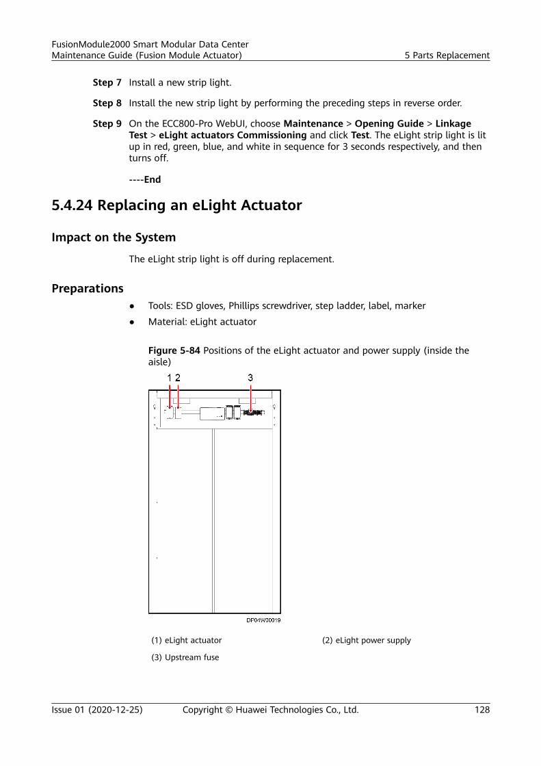
Step 7 Install a new strip light.
Step 8 Install the new strip light by performing the preceding steps in reverse order.
Step 9 On the ECC800-Pro WebUI, choose Maintenance > Opening Guide > LinkageTest > eLight actuators Commissioning and click Test. The eLight strip light is litup in red, green, blue, and white in sequence for 3 seconds respectively, and thenturns off.
----End
5.4.24 Replacing an eLight Actuator
Impact on the System
The eLight strip light is off during replacement.
Preparations● Tools: ESD gloves, Phillips screwdriver, step ladder, label, marker
● Material: eLight actuator
Figure 5-84 Positions of the eLight actuator and power supply (inside theaisle)
(1) eLight actuator (2) eLight power supply
(3) Upstream fuse
FusionModule2000 Smart Modular Data CenterMaintenance Guide (Fusion Module Actuator) 5 Parts Replacement
Issue 01 (2020-12-25) Copyright © Huawei Technologies Co., Ltd. 128
Procedure
Step 1 Label each cable based on the corresponding ports on the eLight actuator.
Step 2 Remove cables from the eLight actuator.
Step 3 Remove the old eLight actuator from guide rails.
Step 4 Install the new eLight actuator in the correct position and connect the cables.
Step 5 Check the parameters and communication status of the eLight actuator to ensurenormal communication.
Step 6 On the ECC800-Pro WebUI, choose Maintenance > Deployment Wizard >Linkage Test > eLight Actuator Commissioning and click Test. The eLight striplight is lit up in red, green, blue, and white in sequence for 3 seconds respectively,and then turns off.
----End
5.4.25 Replacing an eLight Power Supply
Impact on the SystemThe eLight strip light is off during replacement.
Preparations● Tools: ESD gloves, Phillips screwdriver, step ladder, label, marker● Material: eLight power supply
FusionModule2000 Smart Modular Data CenterMaintenance Guide (Fusion Module Actuator) 5 Parts Replacement
Issue 01 (2020-12-25) Copyright © Huawei Technologies Co., Ltd. 129
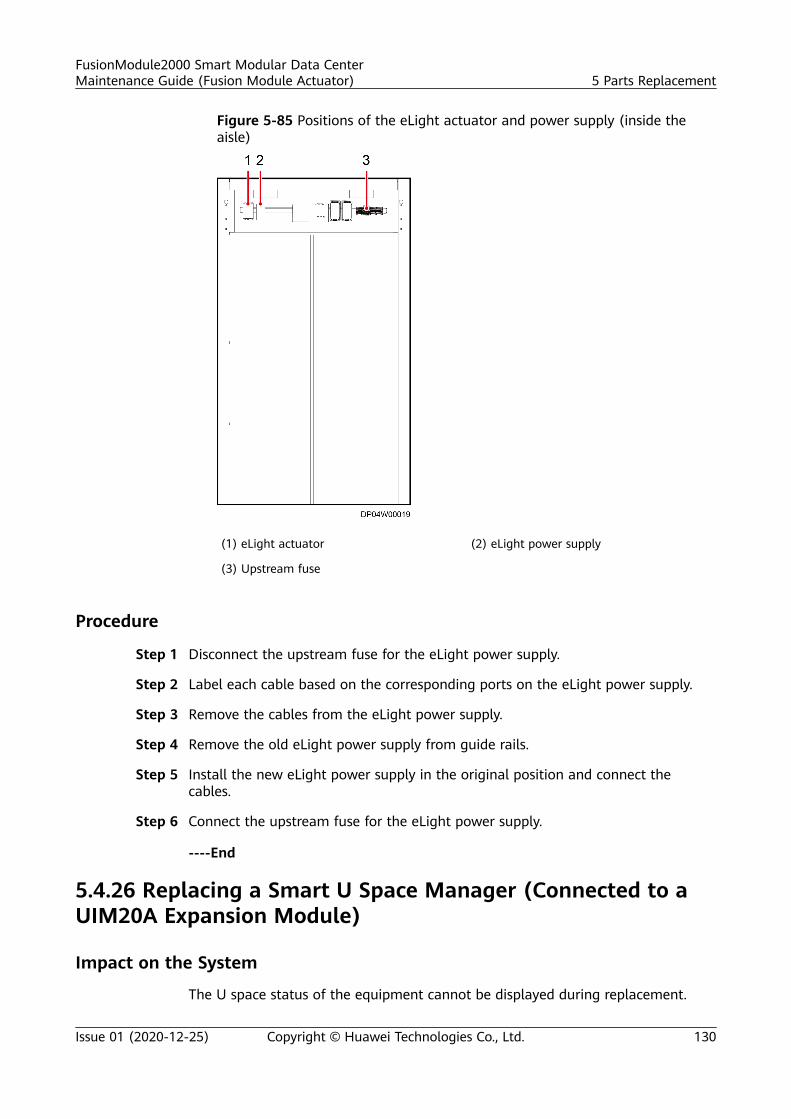
Figure 5-85 Positions of the eLight actuator and power supply (inside theaisle)
(1) eLight actuator (2) eLight power supply
(3) Upstream fuse
Procedure
Step 1 Disconnect the upstream fuse for the eLight power supply.
Step 2 Label each cable based on the corresponding ports on the eLight power supply.
Step 3 Remove the cables from the eLight power supply.
Step 4 Remove the old eLight power supply from guide rails.
Step 5 Install the new eLight power supply in the original position and connect thecables.
Step 6 Connect the upstream fuse for the eLight power supply.
----End
5.4.26 Replacing a Smart U Space Manager (Connected to aUIM20A Expansion Module)
Impact on the System
The U space status of the equipment cannot be displayed during replacement.
FusionModule2000 Smart Modular Data CenterMaintenance Guide (Fusion Module Actuator) 5 Parts Replacement
Issue 01 (2020-12-25) Copyright © Huawei Technologies Co., Ltd. 130
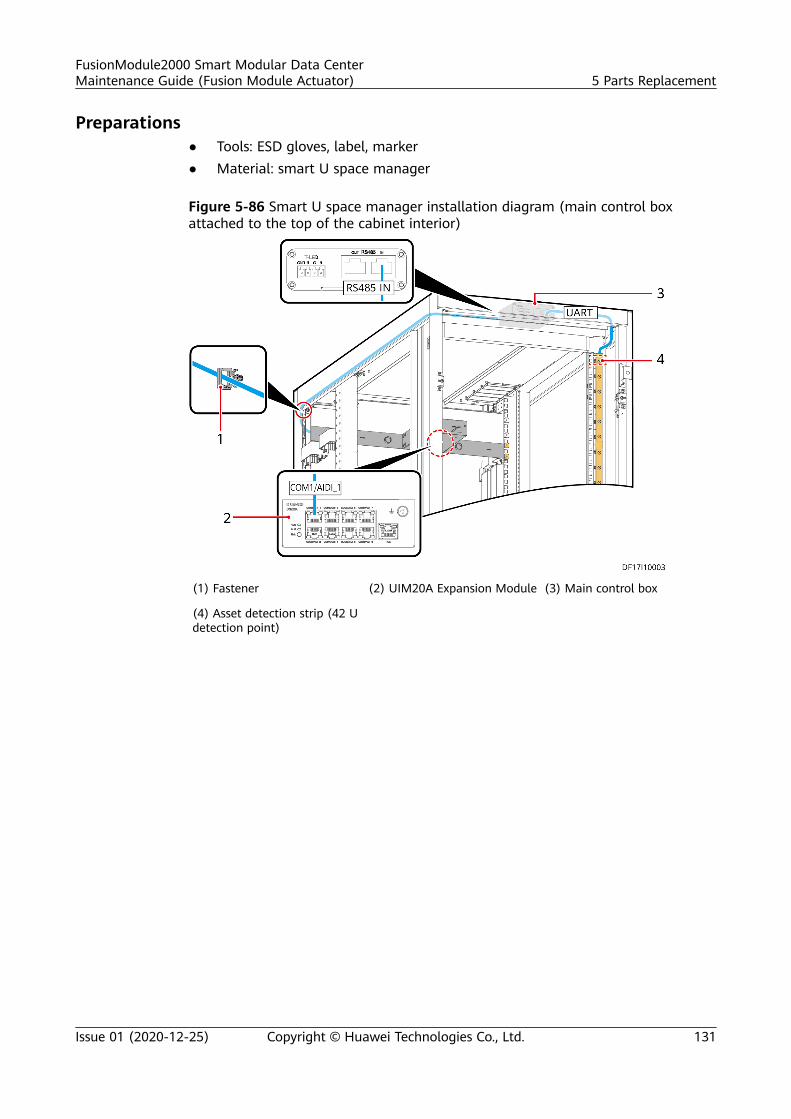
Preparations● Tools: ESD gloves, label, marker● Material: smart U space manager
Figure 5-86 Smart U space manager installation diagram (main control boxattached to the top of the cabinet interior)
(1) Fastener (2) UIM20A Expansion Module (3) Main control box
(4) Asset detection strip (42 Udetection point)
FusionModule2000 Smart Modular Data CenterMaintenance Guide (Fusion Module Actuator) 5 Parts Replacement
Issue 01 (2020-12-25) Copyright © Huawei Technologies Co., Ltd. 131
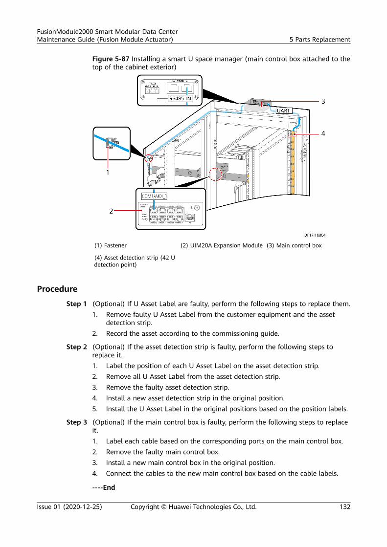
Figure 5-87 Installing a smart U space manager (main control box attached to thetop of the cabinet exterior)
(1) Fastener (2) UIM20A Expansion Module (3) Main control box
(4) Asset detection strip (42 Udetection point)
Procedure
Step 1 (Optional) If U Asset Label are faulty, perform the following steps to replace them.1. Remove faulty U Asset Label from the customer equipment and the asset
detection strip.2. Record the asset according to the commissioning guide.
Step 2 (Optional) If the asset detection strip is faulty, perform the following steps toreplace it.1. Label the position of each U Asset Label on the asset detection strip.2. Remove all U Asset Label from the asset detection strip.3. Remove the faulty asset detection strip.4. Install a new asset detection strip in the original position.5. Install the U Asset Label in the original positions based on the position labels.
Step 3 (Optional) If the main control box is faulty, perform the following steps to replaceit.1. Label each cable based on the corresponding ports on the main control box.2. Remove the faulty main control box.3. Install a new main control box in the original position.4. Connect the cables to the new main control box based on the cable labels.
----End
FusionModule2000 Smart Modular Data CenterMaintenance Guide (Fusion Module Actuator) 5 Parts Replacement
Issue 01 (2020-12-25) Copyright © Huawei Technologies Co., Ltd. 132
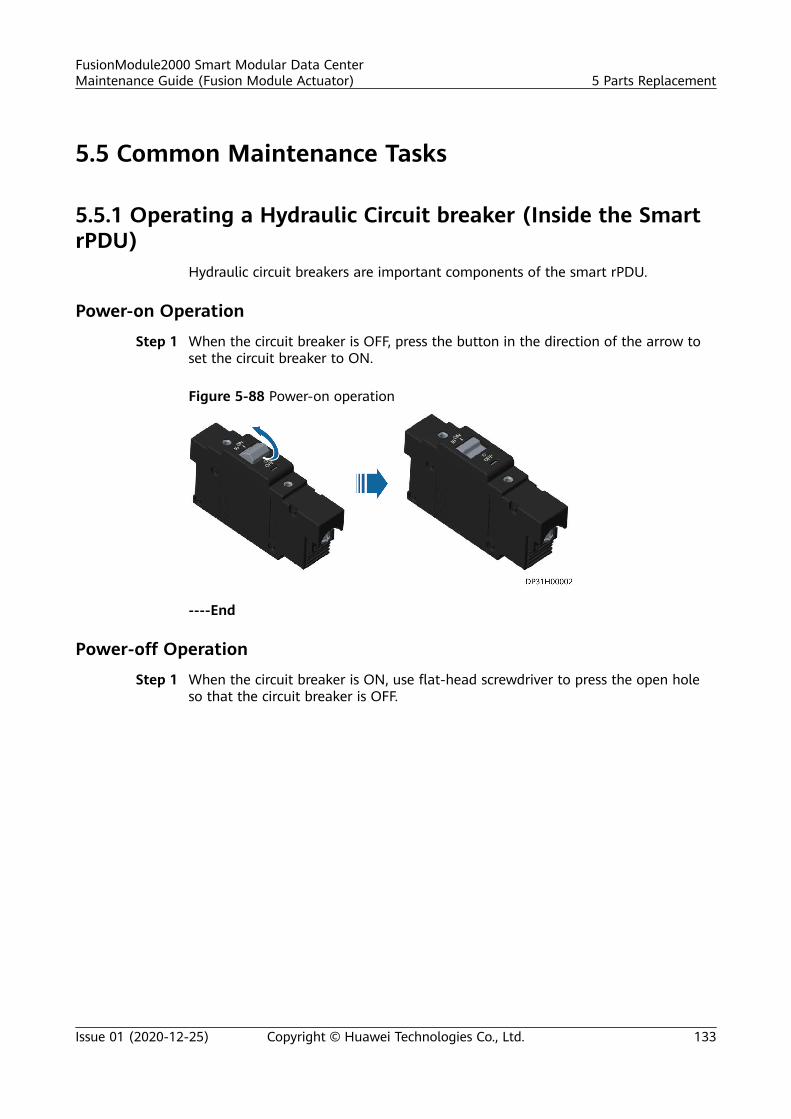
5.5 Common Maintenance Tasks
5.5.1 Operating a Hydraulic Circuit breaker (Inside the SmartrPDU)
Hydraulic circuit breakers are important components of the smart rPDU.
Power-on Operation
Step 1 When the circuit breaker is OFF, press the button in the direction of the arrow toset the circuit breaker to ON.
Figure 5-88 Power-on operation
----End
Power-off Operation
Step 1 When the circuit breaker is ON, use flat-head screwdriver to press the open holeso that the circuit breaker is OFF.
FusionModule2000 Smart Modular Data CenterMaintenance Guide (Fusion Module Actuator) 5 Parts Replacement
Issue 01 (2020-12-25) Copyright © Huawei Technologies Co., Ltd. 133

Figure 5-89 Power-off operation
----End
5.5.2 Handling Long-time Hotspot at the Air Inlet of a Cabinetin iCooling Mode
Symptom
There is a hotspot (higher than 27°C) at the air inlet of a cabinet in iCooling modefor more than 2 hours and the hotspot persists.
Possible Causes● The cabinet temperature sensor is installed at an incorrect position.● No filler panels have been installed for the vacant U spaces in the cabinet.● The cold and hot aisle containments of the smart module are not isolated,
which causes hot air backflow.
Procedure
Step 1 Ensure that the cabinet temperature sensor is installed at the position specified inthe installation guide.
Step 2 Ensure that the equipment in the cabinet is deployed evenly, and all vacant Uspaces are sealed with filler panels.
Step 3 Ensure that the aisle doors and skylights of the smart module are closed to isolatethe cold aisle containment from the hot aisle containment and prevent hot airbackflow.
Step 4 Check whether the cabinet temperature sensor is faulty. If so, replace it.
----End
FusionModule2000 Smart Modular Data CenterMaintenance Guide (Fusion Module Actuator) 5 Parts Replacement
Issue 01 (2020-12-25) Copyright © Huawei Technologies Co., Ltd. 134
A Acronyms and Abbreviations
A
AC alternating current
ATS AC transfer switch
B
BCB-BOX battery circuit breaker box
BIM battery interface module
BPS bypass
BSC bus synchronization controller
C
CIM communication interface module
D
DC direct current
E
ECC energy control center
FusionModule2000 Smart Modular Data CenterMaintenance Guide (Fusion Module Actuator) A Acronyms and Abbreviations
Issue 01 (2020-12-25) Copyright © Huawei Technologies Co., Ltd. 135
ECM energy control module
ECO economy control operation
ETH Ethernet
I
iBAT iBattery
IC integrated circuit
IT Internet technology
L
LCD liquid crystal display
LED light emitting diode
M
MCB miniature circuit breaker
MDU monitor display unit
N
NetEco Network Ecosystem
NTC negative temperature coefficient
P
PDU power distribution unit
PE protective earthing
PoE Power over Ethernet
FusionModule2000 Smart Modular Data CenterMaintenance Guide (Fusion Module Actuator) A Acronyms and Abbreviations
Issue 01 (2020-12-25) Copyright © Huawei Technologies Co., Ltd. 136
S
SD secure digital memory
SIM subscriber identity module
V
VCN video cloud node
U
UPS uninterruptible power system
W
WiFi Wireless Fidelity
FusionModule2000 Smart Modular Data CenterMaintenance Guide (Fusion Module Actuator) A Acronyms and Abbreviations
Issue 01 (2020-12-25) Copyright © Huawei Technologies Co., Ltd. 137