
Huawei Proprietary and Confidential Copyright © Huawei ...
155
Huawei Proprietary and Confidential Copyright © Huawei Technologies Co., Ltd
-
Upload
khangminh22 -
Category
Documents
-
view
5 -
download
0
Transcript of Huawei Proprietary and Confidential Copyright © Huawei ...

Huawei Proprietary and ConfidentialCopyright © Huawei Technologies Co., Ltd

1 About This Document
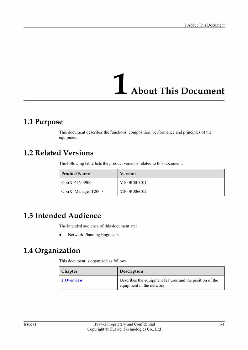
1.1 PurposeThis document describes the functions, composition, performance and principles of theequipment.
1.2 Related VersionsThe following table lists the product versions related to this document.
Product Name Version
OptiX PTN 3900 V100R001C01
OptiX iManager T2000 V200R006C02
1.3 Intended AudienceThe intended audience of this document are:
l Network Planning Engineers
1.4 OrganizationThis document is organized as follows.
Chapter Description
2 Overview Describes the equipment features and the position of theequipment in the network.
1 About This Document
Issue () Huawei Proprietary and ConfidentialCopyright © Huawei Technologies Co., Ltd
1-1
Chapter Description
3 Functions and Features Describes the service types, processing capability, serviceinterfaces, protection capability, QoS, OAM feature, NSFfunction and DCN mode that are supported by theequipment.
4 System Architecture Describes the functional modules, hardware structure andsoftware structure of the equipment.
5 Services Describes the services of the equipment.
6 Key Features Describes the main features of the equipment.
7 Protection Describes the equipment-level protection and network-levelprotection of the equipment.
8 Operation, Administrationand Maintenance
Describes the operation, maintenance and managementcapabilities of the equipment and the T2000 networkmanagement system used for the equipment.
9 Networking Application Describes the application of the equipment on mobileservices , L2VPN services and offload solutions.
10 Technical Specifications Describes the technical specifications of the equipment.
11 Compliant Standards andProtocols
Describes the compliant standards and protocols of theequipment.
12 Glossary Lists the glossary used in this document.
13 Acronyms andAbbreviations
Lists the acronyms and abbreviations used in this document.
1.5 Conventions
Symbol Conventions
The following symbols may be found in this document. They are defined as follows.
Symbol Description
DANGERIndicates a hazard with a high level of risk which, if notavoided, will result in death or serious injury.
WARNINGIndicates a hazard with a medium or low level of risk which,if not avoided, could result in minor or moderate injury.
CAUTIONIndicates a potentially hazardous situation that, if notavoided, could cause equipment damage, data loss, andperformance degradation, or unexpected results.
1 About This Document
1-2 Huawei Proprietary and ConfidentialCopyright © Huawei Technologies Co., Ltd
Issue ()

Symbol Description
NOTE Provides additional information to emphasize orsupplement important points of the main text.
TIP Indicates a tip that may help you solve a problem or saveyour time.
General ConventionsConvention Description
Times New Roman Normal paragraphs are in Times New Roman.
Boldface Names of files, directories, folders, and users are in boldface. Forexample, log in as user root.
Italic Book titles are in italics.
Courier New Terminal display is in Courier New.
Command ConventionsConvention Description
Boldface The keywords of a command line are in boldface.
Italic Command arguments are in italic.
[ ] Items (keywords or arguments) in square brackets [ ] areoptional.
{ x | y | ... } Alternative items are grouped in braces and separated byvertical bars. One is selected.
[ x | y | ... ] Optional alternative items are grouped in square bracketsand separated by vertical bars. One or none is selected.
{ x | y | ... } * Alternative items are grouped in braces and separated byvertical bars. A minimum of one or a maximum of all canbe selected.
GUI ConventionsConvention Description
Boldface Buttons, menus, parameters, tabs, window, and dialog titles are inboldface. For example, click OK.
1 About This Document
Issue () Huawei Proprietary and ConfidentialCopyright © Huawei Technologies Co., Ltd
1-3
Convention Description
> Multi-level menus are in boldface and separated by the ">" signs. Forexample, choose File > Create > Folder.
Keyboard OperationFormat Description
Key Press the key. For example, press Enter and press Tab.
Key 1+Key 2 Press the keys concurrently. For example, pressing Ctrl+Alt+A means thethree keys should be pressed concurrently.
Key 1, Key 2 Press the keys in turn. For example, pressing Alt, A means the two keysshould be pressed in turn.
Mouse OperationAction Description
Click Select and release the primary mouse button without moving the pointer.
Double-click Press the primary mouse button twice continuously and quickly withoutmoving the pointer.
Drag Press and hold the primary mouse button and move the pointer to a certainposition.
1.6 Update HistoryUpdates between document versions are cumulative. Therefore, the latest document versioncontains all updates made to previous versions.
Issue 01 (2008-04-08)This document of the V100R001 version is the first release.
1 About This Document
1-4 Huawei Proprietary and ConfidentialCopyright © Huawei Technologies Co., Ltd
Issue ()

2 Overview
About This Chapter
2.1 Equipment IntroductionThe OptiX PTN 3900 is new generation metropolitan optical transport equipment, which isdeveloped by Huawei for packet transport.
2.2 Network ApplicationThe OptiX PTN 3900 is applied at the convergence layer and the core layer of a metropolitantransport network.
2 Overview
Issue () Huawei Proprietary and ConfidentialCopyright © Huawei Technologies Co., Ltd
2-1
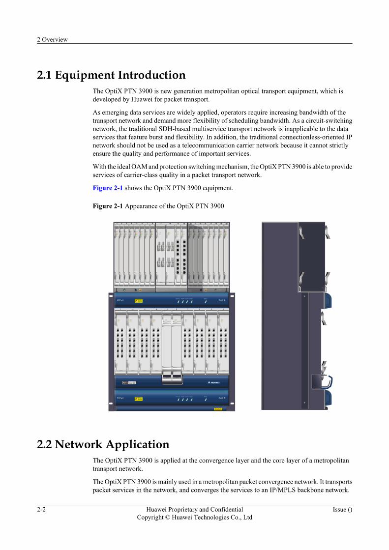
2.1 Equipment IntroductionThe OptiX PTN 3900 is new generation metropolitan optical transport equipment, which isdeveloped by Huawei for packet transport.
As emerging data services are widely applied, operators require increasing bandwidth of thetransport network and demand more flexibility of scheduling bandwidth. As a circuit-switchingnetwork, the traditional SDH-based multiservice transport network is inapplicable to the dataservices that feature burst and flexibility. In addition, the traditional connectionless-oriented IPnetwork should not be used as a telecommunication carrier network because it cannot strictlyensure the quality and performance of important services.
With the ideal OAM and protection switching mechanism, the OptiX PTN 3900 is able to provideservices of carrier-class quality in a packet transport network.
Figure 2-1 shows the OptiX PTN 3900 equipment.
Figure 2-1 Appearance of the OptiX PTN 3900
2.2 Network ApplicationThe OptiX PTN 3900 is applied at the convergence layer and the core layer of a metropolitantransport network.
The OptiX PTN 3900 is mainly used in a metropolitan packet convergence network. It transportspacket services in the network, and converges the services to an IP/MPLS backbone network.
2 Overview
2-2 Huawei Proprietary and ConfidentialCopyright © Huawei Technologies Co., Ltd
Issue ()
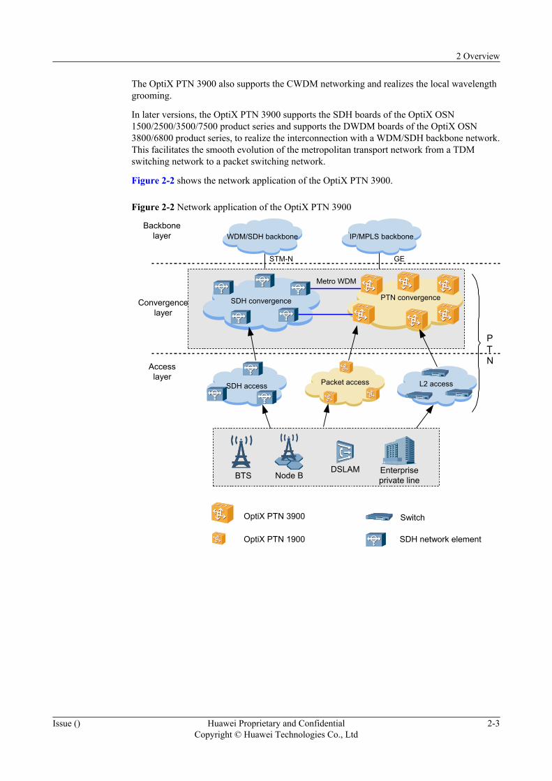
The OptiX PTN 3900 also supports the CWDM networking and realizes the local wavelengthgrooming.
In later versions, the OptiX PTN 3900 supports the SDH boards of the OptiX OSN1500/2500/3500/7500 product series and supports the DWDM boards of the OptiX OSN3800/6800 product series, to realize the interconnection with a WDM/SDH backbone network.This facilitates the smooth evolution of the metropolitan transport network from a TDMswitching network to a packet switching network.
Figure 2-2 shows the network application of the OptiX PTN 3900.
Figure 2-2 Network application of the OptiX PTN 3900
L2 access
SDH convergence
Packet access
PTN convergence
WDM/SDH backbone IP/MPLS backbone
SDH access
Backbonelayer
Accesslayer
Metro WDM
DSLAMNode B Enterprise
private line
PTN
STM-N GE
BTS
OptiX PTN 3900
OptiX PTN 1900
Switch
SDH network element
Convergencelayer
2 Overview
Issue () Huawei Proprietary and ConfidentialCopyright © Huawei Technologies Co., Ltd
2-3

3 Functions and Features
About This Chapter
The OptiX PTN 3900 supports various types of services, and provides abundant functions andfeatures to ensure service transport quality and efficiency.
3.1 Service TypesThe OptiX PTN 3900 supports Ethernet services, asynchronous transfer mode (ATM) services,and circuit emulation services (CES).
3.2 Service Processing CapabilityThe service processing capability of the OptiX PTN 3900 is categorized into the switchingcapability and the service access capability.
3.3 Interface TypesThe external interfaces of the OptiX PTN 3900 are categorized into service interfaces, andadministration and auxiliary interfaces.
3.4 Networking CapabilityThe OptiX PTN 3900 supports various networking modes to apply to different scenarios.
3.5 Protection CapabilityThe OptiX PTN 3900 provides equipment level protection and network level protection.
3.6 QoSThe OptiX PTN 3900 provides hierarchical end-to-end quality of service (QoS) management,and thus provides high quality transports that are differentiated by service.
3.7 OAM FeaturesThe OptiX PTN 3900 supports Ethernet operations, administration and maintenance (OAM) andMPLS OAM, to realize fast defect detection and to trigger protection switching. In this way, thecarrier-class quality of service is guaranteed in the packet switching network.
3.8 NSFWith the non-stop forwarding (NSF) function, data forwarding can be properly performed evenwhen the control plane of the equipment is faulty (for example, the CPU is restarted). In thiscase, key services on the network are protected.
3.9 ClockThe OptiX PTN 3900 supports the extraction of clock signals from the POS signals, channelizedSTM-1 signals, ATM STM-1 signal, E1 signals and synchronous Ethernet signals. The OptiX
3 Functions and Features
Issue () Huawei Proprietary and ConfidentialCopyright © Huawei Technologies Co., Ltd
3-1

PTN 3900 also supports the external clock input/output and provides the equipment internalclock.
3.10 DCN SchemeThe data communication network (DCN) is an integral part of network management, and is usedto transmit the network management information. The OptiX PTN 3900 supports the inbandDCN to ensure the intercommunication of network management information.
3 Functions and Features
3-2 Huawei Proprietary and ConfidentialCopyright © Huawei Technologies Co., Ltd
Issue ()
3.1 Service TypesThe OptiX PTN 3900 supports Ethernet services, asynchronous transfer mode (ATM) services,and circuit emulation services (CES).
The OptiX PTN 3900 processes the following Ethernet services:
l E-Line services
l E-LAN services
l E-Tree services
l E-Aggr services
The OptiX PTN 3900 processes the following ATM services:
l ATM emulation service
l IMA emulation service
The OptiX PTN 3900 processes the TDM CES service.
3.2 Service Processing CapabilityThe service processing capability of the OptiX PTN 3900 is categorized into the switchingcapability and the service access capability.
3.2.1 Switching CapabilityThe OptiX PTN 3900 supports the packet-based service switching.
3.2.2 Maximum Access CapabilityThe OptiX PTN 3900 is able to access services through various interfaces.
3.2.1 Switching CapabilityThe OptiX PTN 3900 supports the packet-based service switching.
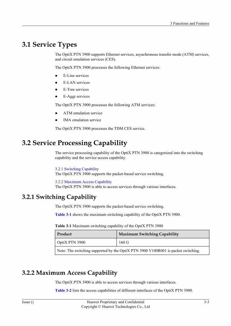
Table 3-1 shows the maximum switching capability of the OptiX PTN 3900.
Table 3-1 Maximum switching capability of the OptiX PTN 3900
Product Maximum Switching Capability
OptiX PTN 3900 160 G
Note: The switching supported by the OptiX PTN 3900 V100R001 is packet switching.
3.2.2 Maximum Access CapabilityThe OptiX PTN 3900 is able to access services through various interfaces.
Table 3-2 lists the access capabilities of different interfaces of the OptiX PTN 3900.
3 Functions and Features
Issue () Huawei Proprietary and ConfidentialCopyright © Huawei Technologies Co., Ltd
3-3
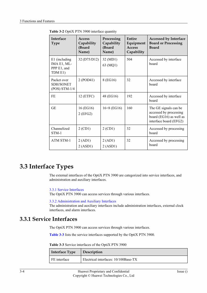
Table 3-2 OptiX PTN 3900 interface quantity
InterfaceType
AccessCapability(BoardName)
ProcessingCapability(BoardName)
EntireEquipmentAccessCapability
Accessed by InterfaceBoard or ProcessingBoard
E1 (includingIMA E1, ML-PPP E1, andTDM E1)
32 (D75/D12) 32 (MD1)63 (MQ1)
504 Accessed by interfaceboard
Packet overSDH/SONET(POS) STM-1/4
2 (POD41) 8 (EG16) 32 Accessed by interfaceboard
FE 12 (ETFC) 48 (EG16) 192 Accessed by interfaceboard
GE 16 (EG16)2 (EFG2)
16+8 (EG16) 160 The GE signals can beaccessed by processingboard (EG16) as well asinterface board (EFG2)
ChannelizedSTM-1
2 (CD1) 2 (CD1) 32 Accessed by processingboard
ATM STM-1 2 (AD1)2 (ASD1)
2 (AD1)2 (ASD1)
32 Accessed by processingboard
3.3 Interface TypesThe external interfaces of the OptiX PTN 3900 are categorized into service interfaces, andadministration and auxiliary interfaces.
3.3.1 Service InterfacesThe OptiX PTN 3900 can access services through various interfaces.
3.3.2 Administration and Auxiliary InterfacesThe administration and auxiliary interfaces include administration interfaces, external clockinterfaces, and alarm interfaces.
3.3.1 Service InterfacesThe OptiX PTN 3900 can access services through various interfaces.
Table 3-3 lists the service interfaces supported by the OptiX PTN 3900.
Table 3-3 Service interfaces of the OptiX PTN 3900
Interface Type Description
FE interface Electrical interfaces: 10/100Base-TX
3 Functions and Features
3-4 Huawei Proprietary and ConfidentialCopyright © Huawei Technologies Co., Ltd
Issue ()
Interface Type Description
GE interface Optical interfaces: 1000BASE-SX, 1000BASE-LX, 1000BASE-ZX(40km), 1000BASE-ZX (70km)
POS interface STM-1 optical interfaces: I-1, S-1.1, L-1.1, L-1.2, Ve-1.2STM-4 optical interfaces: I-4, S-4.1, L-4.1, L-4.2, Ve-4.2
ATM STM-1interface
I-1, S-1.1, L-1.1, L-1.2, Ve-1.2
ChannelizedSTM-1 interface
I-1, S-1.1, L-1.1, L-1.2, Ve-1.2
E1 interface 75-ohm/120-ohm E1 electrical interfaces: DB44 connectors
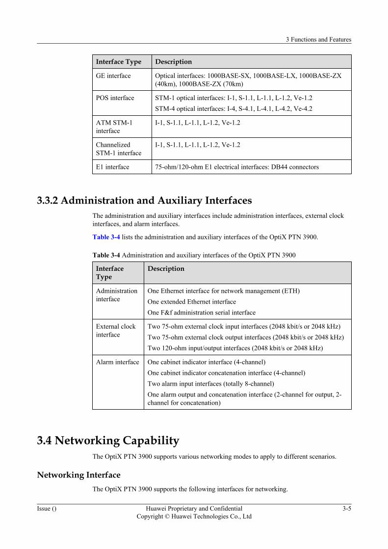
3.3.2 Administration and Auxiliary InterfacesThe administration and auxiliary interfaces include administration interfaces, external clockinterfaces, and alarm interfaces.
Table 3-4 lists the administration and auxiliary interfaces of the OptiX PTN 3900.
Table 3-4 Administration and auxiliary interfaces of the OptiX PTN 3900
InterfaceType
Description
Administrationinterface
One Ethernet interface for network management (ETH)One extended Ethernet interfaceOne F&f administration serial interface
External clockinterface
Two 75-ohm external clock input interfaces (2048 kbit/s or 2048 kHz)Two 75-ohm external clock output interfaces (2048 kbit/s or 2048 kHz)Two 120-ohm input/output interfaces (2048 kbit/s or 2048 kHz)
Alarm interface One cabinet indicator interface (4-channel)One cabinet indicator concatenation interface (4-channel)Two alarm input interfaces (totally 8-channel)One alarm output and concatenation interface (2-channel for output, 2-channel for concatenation)
3.4 Networking CapabilityThe OptiX PTN 3900 supports various networking modes to apply to different scenarios.
Networking InterfaceThe OptiX PTN 3900 supports the following interfaces for networking.
3 Functions and Features
Issue () Huawei Proprietary and ConfidentialCopyright © Huawei Technologies Co., Ltd
3-5
l GEl POS STM-4l POS STM-1l ML-PPP
NOTE
l It is recommended that the ML-PPP should be used to form the chain network.
l The FE interface can be used as networking interface, but the FE interface is not recommended to be usedas networking interface.
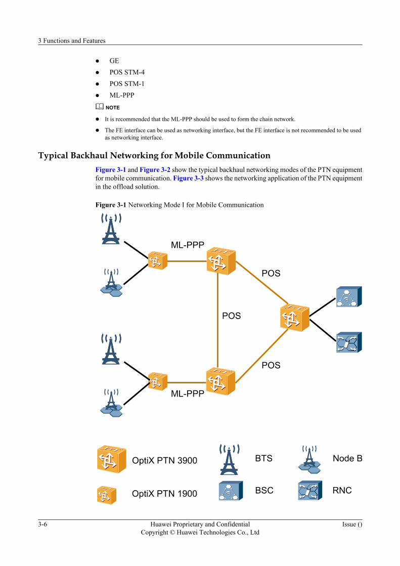
Typical Backhaul Networking for Mobile CommunicationFigure 3-1 and Figure 3-2 show the typical backhaul networking modes of the PTN equipmentfor mobile communication. Figure 3-3 shows the networking application of the PTN equipmentin the offload solution.
Figure 3-1 Networking Mode I for Mobile Communication
POS
OptiX PTN 3900
OptiX PTN 1900 BSC
BTS
ML-PPP
POS
POS
ML-PPP
RNC
Node B
3 Functions and Features
3-6 Huawei Proprietary and ConfidentialCopyright © Huawei Technologies Co., Ltd
Issue ()
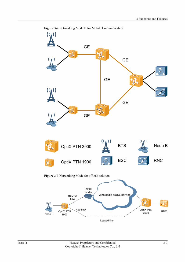
Figure 3-2 Networking Mode II for Mobile Communication
GE
OptiX PTN 3900
OptiX PTN 1900 BSC
BTS
GE
GE
GE
GE
RNC
Node B
Figure 3-3 Networking Mode for offload solution
Wholesale ADSL service
Node BOptiX PTN
1900
ADSLmodem
OptiX PTN3900 RNC
HSDPAflow
R99 flow
Leased line
3 Functions and Features
Issue () Huawei Proprietary and ConfidentialCopyright © Huawei Technologies Co., Ltd
3-7
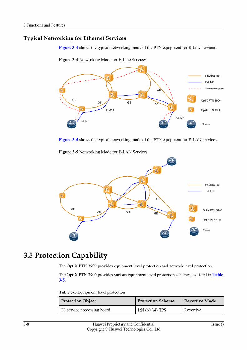
Typical Networking for Ethernet ServicesFigure 3-4 shows the typical networking mode of the PTN equipment for E-Line services.
Figure 3-4 Networking Mode for E-Line Services
GEGE GE GE
GE
E-LINEE-LINE
E-LINE
E-LINE
Physical link
Protection path
OptiX PTN 3900
OptiX PTN 1900
Router
Figure 3-5 shows the typical networking mode of the PTN equipment for E-LAN services.
Figure 3-5 Networking Mode for E-LAN Services
GEGE GE GE
GE
E-LAN
Physical link
Router
OptiX PTN 3900
OptiX PTN 1900
3.5 Protection CapabilityThe OptiX PTN 3900 provides equipment level protection and network level protection.
The OptiX PTN 3900 provides various equipment level protection schemes, as listed in Table3-5.
Table 3-5 Equipment level protection
Protection Object Protection Scheme Revertive Mode
E1 service processing board 1:N (N≤4) TPS Revertive
3 Functions and Features
3-8 Huawei Proprietary and ConfidentialCopyright © Huawei Technologies Co., Ltd
Issue ()
Protection Object Protection Scheme Revertive Mode
Cross-connect and timing board 1+1 hot backup Non-revertive
System control, communication andauxiliary processing board
1+1 hot backup Non-revertive
Power interface unit 1+1 hot backup -
Note: The OptiX PTN 3900 supports the coexistence of two TPS protection groups.
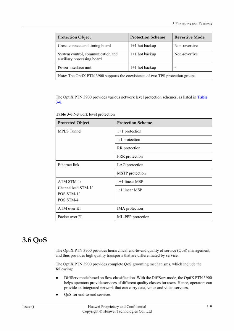
The OptiX PTN 3900 provides various network level protection schemes, as listed in Table3-6.
Table 3-6 Network level protection
Protected Object Protection Scheme
MPLS Tunnel 1+1 protection
1:1 protection
RR protection
FRR protection
Ethernet link LAG protection
MSTP protection
ATM STM-1/Channelized STM-1/POS STM-1/POS STM-4
1+1 linear MSP
1:1 linear MSP
ATM over E1 IMA protection
Packet over E1 ML-PPP protection
3.6 QoSThe OptiX PTN 3900 provides hierarchical end-to-end quality of service (QoS) management,and thus provides high quality transports that are differentiated by service.
The OptiX PTN 3900 provides complete QoS grooming mechanisms, which include thefollowing:
l DiffServ mode based on flow classification. With the DiffServ mode, the OptiX PTN 3900helps operators provide services of different quality classes for users. Hence, operators canprovide an integrated network that can carry data, voice and video services.
l QoS for end-to-end services
3 Functions and Features
Issue () Huawei Proprietary and ConfidentialCopyright © Huawei Technologies Co., Ltd
3-9
– Hierarchical QoS (HQoS) mechanism at the access side. The HQoS mechanism helpscontrol the overall bandwidth for a single service type, a single service access point,multiple service access points, a single service or multiple services.
– Traffic Engineering (TE) mechanism at the network side. The TE mechanism helpsbalance the network traffic to ensure the service quality.
With the complete QoS mechanisms, the OptiX PTN 3900 ensures that the specifications ofdelay, delay variation, and bandwidth are satisfied for different services, and thus guaranteesthe provision of carrier-class services.
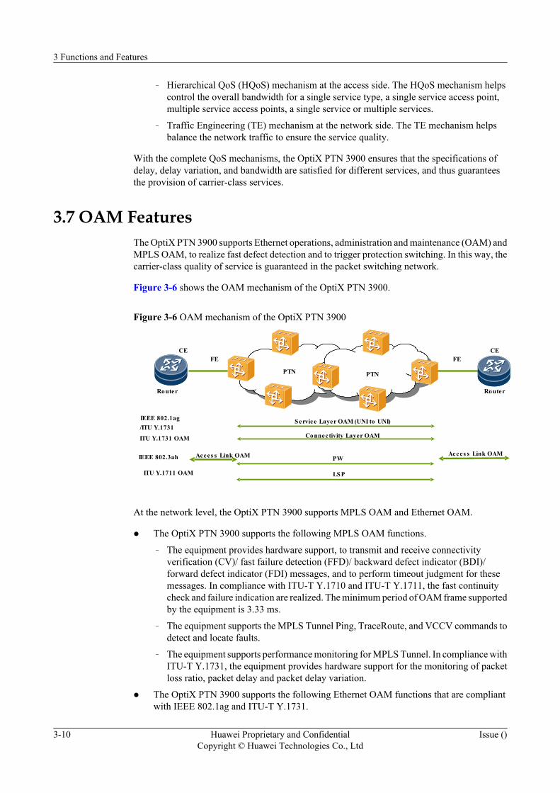
3.7 OAM FeaturesThe OptiX PTN 3900 supports Ethernet operations, administration and maintenance (OAM) andMPLS OAM, to realize fast defect detection and to trigger protection switching. In this way, thecarrier-class quality of service is guaranteed in the packet switching network.
Figure 3-6 shows the OAM mechanism of the OptiX PTN 3900.
Figure 3-6 OAM mechanism of the OptiX PTN 3900
IEEE 802.3ah Acces s Link OAM Acces s Link OAM
ITU Y.1731 OAM Connectivity Layer OAM
FE
PTN
IEEE 802.1ag/ITU Y.1731
Service Layer OAM (UNI to UNI)
ITU Y.1711 OAM LSP
PW
CE CE
PTN
FE
Router Router
At the network level, the OptiX PTN 3900 supports MPLS OAM and Ethernet OAM.
l The OptiX PTN 3900 supports the following MPLS OAM functions.
– The equipment provides hardware support, to transmit and receive connectivityverification (CV)/ fast failure detection (FFD)/ backward defect indicator (BDI)/forward defect indicator (FDI) messages, and to perform timeout judgment for thesemessages. In compliance with ITU-T Y.1710 and ITU-T Y.1711, the fast continuitycheck and failure indication are realized. The minimum period of OAM frame supportedby the equipment is 3.33 ms.
– The equipment supports the MPLS Tunnel Ping, TraceRoute, and VCCV commands todetect and locate faults.
– The equipment supports performance monitoring for MPLS Tunnel. In compliance withITU-T Y.1731, the equipment provides hardware support for the monitoring of packetloss ratio, packet delay and packet delay variation.
l The OptiX PTN 3900 supports the following Ethernet OAM functions that are compliantwith IEEE 802.1ag and ITU-T Y.1731.
3 Functions and Features
3-10 Huawei Proprietary and ConfidentialCopyright © Huawei Technologies Co., Ltd
Issue ()
– The equipment provides hardware support for the continuity check (ETH-CC) and theperformance monitoring. The minimum period of OAM frame supported by theequipment is 3.33 ms.
– The control plane of the equipment supports the loopback (ETH-LB) and link trace(ETH-LT) operations.
At the link layer, the OptiX PTN 3900 supports the following OAM mechanisms.
l The equipment supports Ethernet OAM that is compliant with IEEE 802.3ah. Each Ethernetport supports link discovery, link state monitoring, remote fault detection, and remoteloopback.
l The equipment supports ATM OAM, including F4 OAM and F5 OAM.
l The equipment supports the monitoring of E1 link state, by using PDH signals.
3.8 NSFWith the non-stop forwarding (NSF) function, data forwarding can be properly performed evenwhen the control plane of the equipment is faulty (for example, the CPU is restarted). In thiscase, key services on the network are protected.
The OptiX PTN 3900 supports the protocol level graceful restart (GR) technology. In the caseof a fault, the neighbor nodes do not delete the route information. In this way, services are stillforwarded and the network route oscillation is avoided.
The OptiX PTN 3900 supports the NSF function in the following cases:
l The warm reset of the processing board.
l The warm reset of the XCS board (the XCS board should be configured with 1+1protection).
l The warm reset of the SCA board (the SCA board should be configured with 1+1protection).
3.9 ClockThe OptiX PTN 3900 supports the extraction of clock signals from the POS signals, channelizedSTM-1 signals, ATM STM-1 signal, E1 signals and synchronous Ethernet signals. The OptiXPTN 3900 also supports the external clock input/output and provides the equipment internalclock.
The clock system of the OptiX PTN 3900 supports the following functions:
l Clock synchronization for circuit emulation services
l Extraction of clock signals from POS signals
l Extraction of clock signals from channelized STM-1 signals
l Extraction of clock signals from ATM STM-1 signals
l Extraction of clock signals from E1 signals
l Extraction of clock signals from synchronous Ethernet signals
l Processing and transfer of synchronization status messages (SSM)
l Input/output of two 75-ohm external clock sources
3 Functions and Features
Issue () Huawei Proprietary and ConfidentialCopyright © Huawei Technologies Co., Ltd
3-11
l Input/output of two 120-ohm external clock sources
l Three clock working modes, that is, the locked, hold-over, and free-run modes
NOTE
The synchronous Ethernet is a technology used to synchronize the clock frequencies at the Ethernet physicallayer. Clock signals are extracted directly from the serial bit flow on the Ethernet link. These clock signalsare then used for data transmission. In this way, the clock signals are transferred.
3.10 DCN SchemeThe data communication network (DCN) is an integral part of network management, and is usedto transmit the network management information. The OptiX PTN 3900 supports the inbandDCN to ensure the intercommunication of network management information.
The OptiX PTN 3900 adopts the inband DCN scheme. In this scheme, the setup of dedicatedDCN channels is not required, and hence the network construction cost is greatly lowered.
The OptiX PTN 3900 supports the inband DCN through the following interfaces.
l GE
l FE
l POS STM-4/STM-1
l ML-PPP
CAUTIONThe FE interfaces are not recommended to be used as networking interfaces.
3 Functions and Features
3-12 Huawei Proprietary and ConfidentialCopyright © Huawei Technologies Co., Ltd
Issue ()
4 System Architecture
About This Chapter
This chapter describes the system architecture of the OptiX PTN 3900 in terms of functionalmodule, hardware structure and software architecture.
4.1 Functional ModulesThe functional modules of the OptiX PTN 3900 include the service processing module,management and control module, heat dissipation module and power supply module.
4.2 Hardware StructureThis section describes the configurable cabinets, subrack structure, and boards in the subrack.
4.3 Software ArchitectureThis section describes the architecture of the NE software and board software.
4 System Architecture
Issue () Huawei Proprietary and ConfidentialCopyright © Huawei Technologies Co., Ltd
4-1
4.1 Functional ModulesThe functional modules of the OptiX PTN 3900 include the service processing module,management and control module, heat dissipation module and power supply module.
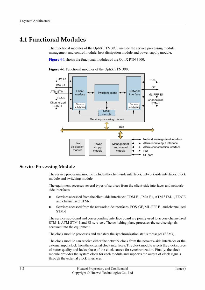
Figure 4-1 shows the functional modules of the OptiX PTN 3900.
Figure 4-1 Functional modules of the OptiX PTN 3900
IMA E1 客户接口
Servicesub-board
Clientinterface
NetworkinterfaceSwitching plane
Service processing module
Clockmodule
TDM E1
ATM STM-1
FE/GEML-PPP E1
GE
POS
Heatdissipation
module
Powersupplymodule
Managementand control
module
Network management interfaceAlarm input/output interfaceAlarm concatenation interfaceF&fCF card
Bus
ChannelizedSTM-1 Service
sub-board
ChannelizedSTM-1
Service Processing ModuleThe service processing module includes the client-side interfaces, network-side interfaces, clockmodule and switching module.
The equipment accesses several types of services from the client-side interfaces and network-side interfaces.
l Services accessed from the client-side interfaces: TDM E1, IMA E1, ATM STM-1, FE/GEand channelized STM-1
l Services accessed from the network-side interfaces: POS, GE, ML-PPP E1 and channelizedSTM-1
The service sub-board and corresponding interface board are jointly used to access channelizedSTM-1, ATM STM-1 and E1 services. The switching plane processes the service signalsaccessed into the equipment.
The clock module processes and transfers the synchronization status messages (SSMs).
The clock module can receive either the network clock from the network-side interfaces or theexternal input clock from the external clock interfaces. The clock module selects the clock sourceof better quality and locks phase of the clock source for synchronization. Finally, the clockmodule provides the system clock for each module and supports the output of clock signalsthrough the external clock interfaces.
4 System Architecture
4-2 Huawei Proprietary and ConfidentialCopyright © Huawei Technologies Co., Ltd
Issue ()
Management and Control ModuleThe management and control module uses the bus inside the system for inter-boardcommunication and communication between the system control board and other boards. Thismodule can also transfer the overhead information and manufacturing information of themanagement board.
This module also supports functions such as inband DCN management and non-stop forwarding(NSF).
In addition, this module provides complete management interfaces and auxiliary interfaces,including the network management interface, alarm input/output interface, alarm concatenationinterface, F&f interface and CF card interface.
Heat Dissipation ModuleThe heat dissipation module dissipates the heat generated by the equipment with flowing air.The heat dissipation module consists of the fan board, fan frame and fans. The fans support theintelligent adjustment of the rotating speed according to the system temperature.
Power Supply ModuleThe power supply module supplies power to the boards and fans of the equipment. The PIUboard supports 1+1 hot backup. The power supply module can detect the power supply.
4.2 Hardware StructureThis section describes the configurable cabinets, subrack structure, and boards in the subrack.
4.2.1 OverviewThe OptiX PTN 3900 equipment consists of the subrack and boards.
4.2.2 CabinetThe OptiX PTN 3900 can be installed in a 300 mm deep ETSI cabinet (N63E cabinet or T63cabinet), or a 600 mm deep ETSI cabinet.
4.2.3 SubrackThe OptiX PTN 3900 subrack is of a dual-layer structure. The subrack consists of processingboard area, interface board area, switching fabric area, system control board area, power supplyboard area, fan area and fiber routing trough.
4.2.4 BoardsBoards of the OptiX PTN 3900 include the processing board, WDM board, service sub-board,interface board, general cross-connect and timing board, system control, communication andauxiliary processing board, fan board and power supply board.
4.2.5 Valid Slots for BoardsThe OptiX PTN 3900 provides 38 slots in total. The EG16 board occupies two slots, and servicesub-boards must be inserted on the MP1 board.
4.2.1 OverviewThe OptiX PTN 3900 equipment consists of the subrack and boards.
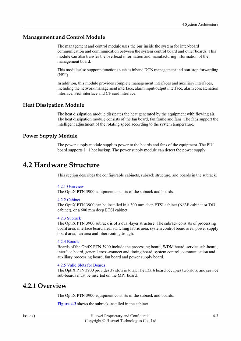
Figure 4-2 shows the subrack installed in the cabinet.
4 System Architecture
Issue () Huawei Proprietary and ConfidentialCopyright © Huawei Technologies Co., Ltd
4-3
Figure 4-2 Hardware structure of the OptiX PTN 3900
Cable distribution plate
Subrack
Cabinet
Power distribution unit
4.2.2 CabinetThe OptiX PTN 3900 can be installed in a 300 mm deep ETSI cabinet (N63E cabinet or T63cabinet), or a 600 mm deep ETSI cabinet.
Figure 4-3 shows the cabinets used to house the OptiX PTN 3900 subrack.
4 System Architecture
4-4 Huawei Proprietary and ConfidentialCopyright © Huawei Technologies Co., Ltd
Issue ()
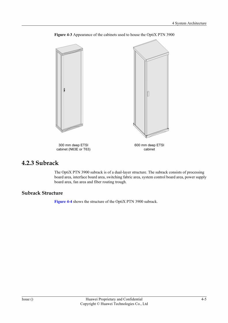
Figure 4-3 Appearance of the cabinets used to house the OptiX PTN 3900
300 mm deep ETSIcabinet (N63E or T63)
600 mm deep ETSIcabinet
4.2.3 SubrackThe OptiX PTN 3900 subrack is of a dual-layer structure. The subrack consists of processingboard area, interface board area, switching fabric area, system control board area, power supplyboard area, fan area and fiber routing trough.
Subrack StructureFigure 4-4 shows the structure of the OptiX PTN 3900 subrack.
4 System Architecture
Issue () Huawei Proprietary and ConfidentialCopyright © Huawei Technologies Co., Ltd
4-5
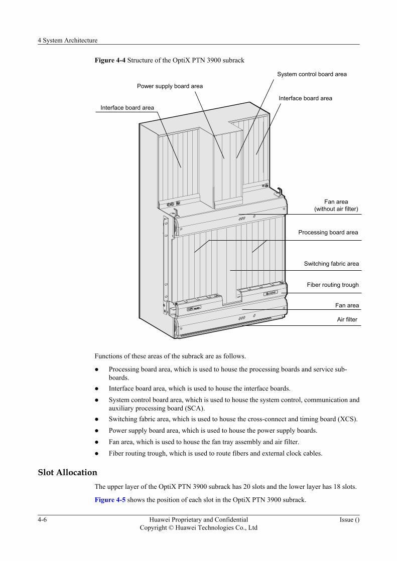
Figure 4-4 Structure of the OptiX PTN 3900 subrack
Processing board area
Interface board area
Power supply board area
System control board area
Fan area(without air filter)
Switching fabric area
Interface board area
Fiber routing trough
Fan area
Air filter
Functions of these areas of the subrack are as follows.
l Processing board area, which is used to house the processing boards and service sub-boards.
l Interface board area, which is used to house the interface boards.l System control board area, which is used to house the system control, communication and
auxiliary processing board (SCA).l Switching fabric area, which is used to house the cross-connect and timing board (XCS).l Power supply board area, which is used to house the power supply boards.l Fan area, which is used to house the fan tray assembly and air filter.l Fiber routing trough, which is used to route fibers and external clock cables.
Slot AllocationThe upper layer of the OptiX PTN 3900 subrack has 20 slots and the lower layer has 18 slots.
Figure 4-5 shows the position of each slot in the OptiX PTN 3900 subrack.
4 System Architecture
4-6 Huawei Proprietary and ConfidentialCopyright © Huawei Technologies Co., Ltd
Issue ()
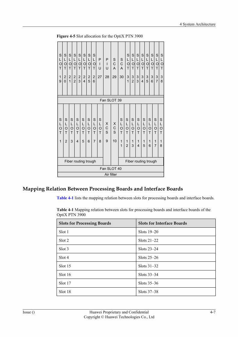
Figure 4-5 Slot allocation for the OptiX PTN 3900
SLOT
1
SLOT
2
SLOT
3
SLOT
4
SLOT
5
SLOT
6
SLOT
7
SLOT
8
SLOT
11
SLOT
12
SLOT
13
SLOT
14
SLOT
15
SLOT
16
SLOT
17
SLOT
18
Fiber routing trough
Fan SLOT 40Air filter
XCS
9
XCS
10
Fan SLOT 39
Fiber routing trough
SLOT
19
SLOT
20
SLOT
21
SLOT
22
SLOT
23
SLOT
24
SLOT
25
SLOT
26
SLOT
31
SLOT
32
SLOT
33
SLOT
34
SLOT
35
SLOT
36
SLOT
37
SLOT
38
PIU
27
PIU
28
SCA
29
SCA
30
Mapping Relation Between Processing Boards and Interface BoardsTable 4-1 lists the mapping relation between slots for processing boards and interface boards.
Table 4-1 Mapping relation between slots for processing boards and interface boards of theOptiX PTN 3900
Slots for Processing Boards Slots for Interface Boards
Slot 1 Slots 19–20
Slot 2 Slots 21–22
Slot 3 Slots 23–24
Slot 4 Slots 25–26
Slot 15 Slots 31–32
Slot 16 Slots 33–34
Slot 17 Slots 35–36
Slot 18 Slots 37–38
4 System Architecture
Issue () Huawei Proprietary and ConfidentialCopyright © Huawei Technologies Co., Ltd
4-7
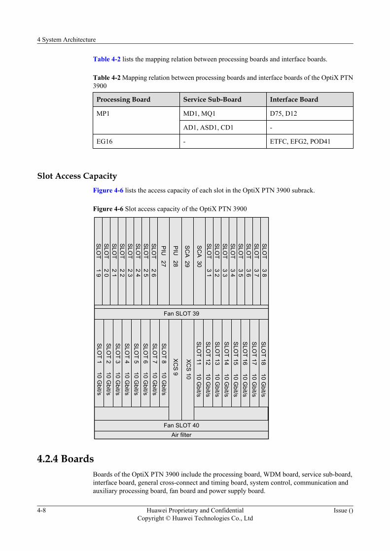
Table 4-2 lists the mapping relation between processing boards and interface boards.
Table 4-2 Mapping relation between processing boards and interface boards of the OptiX PTN3900
Processing Board Service Sub-Board Interface Board
MP1 MD1, MQ1 D75, D12
AD1, ASD1, CD1 -
EG16 - ETFC, EFG2, POD41
Slot Access CapacityFigure 4-6 lists the access capacity of each slot in the OptiX PTN 3900 subrack.
Figure 4-6 Slot access capacity of the OptiX PTN 3900
Fan SLOT 40Air filter
Fan SLOT 39
SLO
T 1 10 Gbit/s
SLO
T 2 10 Gbit/s
SLO
T 3 10 Gbit/s
SLO
T 4 10 Gbit/s
SLO
T 5 10 Gbit/s
SLO
T 6 10 Gbit/s
SLO
T 7 10 Gbit/s
SLO
T 8 10 Gbit/s
SLO
T 11 10 Gbit/s
SLO
T 12 10 Gbit/s
SLO
T 13 10 Gbit/s
SLO
T 14 10 Gbit/s
SLO
T 15 10 Gbit/s
SLO
T 16 10 Gbit/s
SLO
T 17 10 Gbit/s
SLO
T 18 10 Gbit/s
XC
S 9
XC
S 10
SLO
T 1 9
PIU
27
SLO
T 2 0S
LOT 2 1
SLO
T 2 2S
LOT 2 3
SLO
T 2 4S
LOT 2 5
SLO
T 2 6
SLO
T 3 1S
LOT 3 2
SLO
T 3 3S
LOT 3 4
SLO
T 3 5S
LOT 3 6
SLO
T 3 7S
LOT 3 8
PIU
28
SC
A 29
SC
A 30
4.2.4 BoardsBoards of the OptiX PTN 3900 include the processing board, WDM board, service sub-board,interface board, general cross-connect and timing board, system control, communication andauxiliary processing board, fan board and power supply board.
4 System Architecture
4-8 Huawei Proprietary and ConfidentialCopyright © Huawei Technologies Co., Ltd
Issue ()
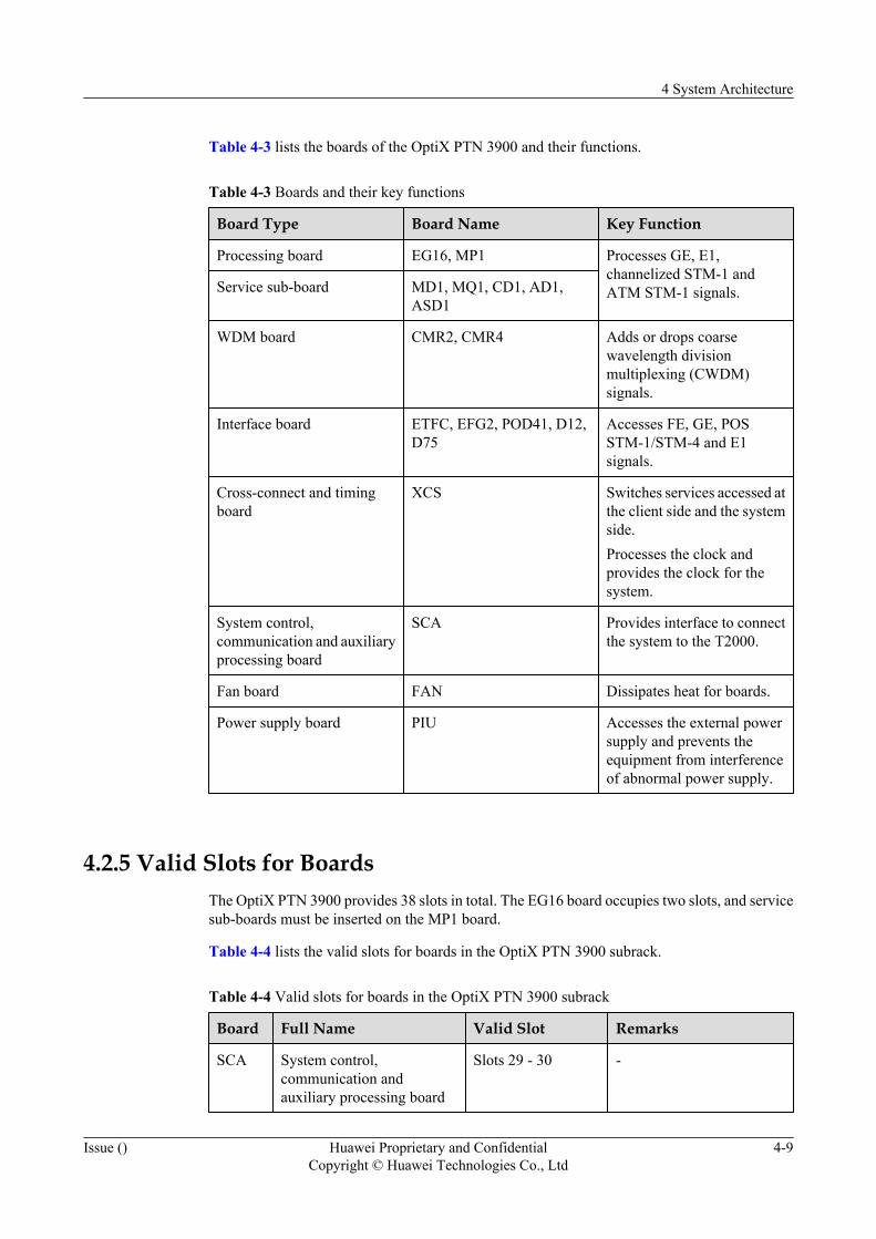
Table 4-3 lists the boards of the OptiX PTN 3900 and their functions.
Table 4-3 Boards and their key functions
Board Type Board Name Key Function
Processing board EG16, MP1 Processes GE, E1,channelized STM-1 andATM STM-1 signals.Service sub-board MD1, MQ1, CD1, AD1,
ASD1
WDM board CMR2, CMR4 Adds or drops coarsewavelength divisionmultiplexing (CWDM)signals.
Interface board ETFC, EFG2, POD41, D12,D75
Accesses FE, GE, POSSTM-1/STM-4 and E1signals.
Cross-connect and timingboard
XCS Switches services accessed atthe client side and the systemside.Processes the clock andprovides the clock for thesystem.
System control,communication and auxiliaryprocessing board
SCA Provides interface to connectthe system to the T2000.
Fan board FAN Dissipates heat for boards.
Power supply board PIU Accesses the external powersupply and prevents theequipment from interferenceof abnormal power supply.
4.2.5 Valid Slots for BoardsThe OptiX PTN 3900 provides 38 slots in total. The EG16 board occupies two slots, and servicesub-boards must be inserted on the MP1 board.
Table 4-4 lists the valid slots for boards in the OptiX PTN 3900 subrack.
Table 4-4 Valid slots for boards in the OptiX PTN 3900 subrack
Board Full Name Valid Slot Remarks
SCA System control,communication andauxiliary processing board
Slots 29 - 30 -
4 System Architecture
Issue () Huawei Proprietary and ConfidentialCopyright © Huawei Technologies Co., Ltd
4-9
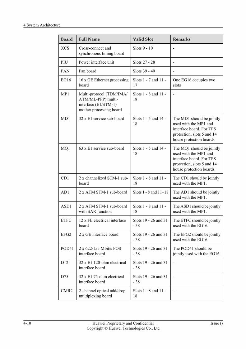
Board Full Name Valid Slot Remarks
XCS Cross-connect andsynchronous timing board
Slots 9 - 10 -
PIU Power interface unit Slots 27 - 28 -
FAN Fan board Slots 39 - 40 -
EG16 16 x GE Ethernet processingboard
Slots 1 - 7 and 11 -17
One EG16 occupies twoslots
MP1 Multi-protocol (TDM/IMA/ATM/ML-PPP) multi-interface (E1/STM-1)mother processing board
Slots 1 - 8 and 11 -18
-
MD1 32 x E1 service sub-board Slots 1 - 5 and 14 -18
The MD1 should be jointlyused with the MP1 andinterface board. For TPSprotection, slots 5 and 14house protection boards.
MQ1 63 x E1 service sub-board Slots 1 - 5 and 14 -18
The MQ1 should be jointlyused with the MP1 andinterface board. For TPSprotection, slots 5 and 14house protection boards.
CD1 2 x channelized STM-1 sub-board
Slots 1 - 8 and 11 -18
The CD1 should be jointlyused with the MP1.
AD1 2 x ATM STM-1 sub-board Slots 1 - 8 and 11–18 The AD1 should be jointlyused with the MP1.
ASD1 2 x ATM STM-1 sub-boardwith SAR function
Slots 1 - 8 and 11 -18
The ASD1 should be jointlyused with the MP1.
ETFC 12 x FE electrical interfaceboard
Slots 19 - 26 and 31- 38
The ETFC should be jointlyused with the EG16.
EFG2 2 x GE interface board Slots 19 - 26 and 31- 38
The EFG2 should be jointlyused with the EG16.
POD41 2 x 622/155 Mbit/s POSinterface board
Slots 19 - 26 and 31- 38
The POD41 should bejointly used with the EG16.
D12 32 x E1 120-ohm electricalinterface board
Slots 19 - 26 and 31- 38
-
D75 32 x E1 75-ohm electricalinterface board
Slots 19 - 26 and 31- 38
-
CMR2 2-channel optical add/dropmultiplexing board
Slots 1 - 8 and 11 -18
-
4 System Architecture
4-10 Huawei Proprietary and ConfidentialCopyright © Huawei Technologies Co., Ltd
Issue ()
Board Full Name Valid Slot Remarks
CMR4 4-channel optical add/dropmultiplexing board
Slots 1 - 8 and 11 -18
-
4.3 Software ArchitectureThis section describes the architecture of the NE software and board software.
4.3.1 OverviewThe software for the OptiX PTN 3900 consists of the management plane, control plane and data/forwarding plane.
4.3.2 NE SoftwareThe NE software manages, monitors and controls the running of boards in the NE. The NEsoftware also functions as the service unit for the communication between the T2000 and boards.In this way, the T2000 can control and manage the NE. In addition, the NE software managesthe software loading, software package loading and fix of the system control board.
4.3.3 Board SoftwareThe board software is responsible for Layer 2 switching, the MPLS packet processing and theQoS. The board software monitors and reports the alarms and performance events of each boardto the NE software.
4.3.1 OverviewThe software for the OptiX PTN 3900 consists of the management plane, control plane and data/forwarding plane.
Figure 4-7 shows the logical block diagram for the software architecture of the OptiX PTN3900.
4 System Architecture
Issue () Huawei Proprietary and ConfidentialCopyright © Huawei Technologies Co., Ltd
4-11

Figure 4-7 Logical block diagram for the software architecture of the OptiX PTN 3900
交换网板
System control, communication andauxiliary processing board
Switchingunit
Systemmanagement unit
System controlunit
General cross-connect and timing
boardProcessing
boardProcessing
board
Processingboard
Processingboard
Managementplane
Controlplane
Dataplane
Forwardingunit
Forwardingunit
Forwardingunit
Forwardingunit
Management PlaneThe management plane performs functions such as performance management, faultmanagement, configuration management, software management, Layer 2 protocol control andsecurity management. The NE software and board software both belong to the managementplane. The board software is used to manage the data/forwarding plane.
Control PlaneThe control plane consists of a group of communication entities and controls the calling andconnection. The control plane uses signaling to set up, release, monitor and maintainconnections, and to recover connections in the case of a fault. Both the NE software and boardsoftware are involved in the functions of the control plane.
Data PlaneThe data plane receives and forwards service data according to the forwarding message generatedby the control plane. This plane also monitors the control packets of services and reports thesepackets to the control plane and the management plane.The processing boards and XCS areresponsible for the provision of the data plane.
4 System Architecture
4-12 Huawei Proprietary and ConfidentialCopyright © Huawei Technologies Co., Ltd
Issue ()
4.3.2 NE SoftwareThe NE software manages, monitors and controls the running of boards in the NE. The NEsoftware also functions as the service unit for the communication between the T2000 and boards.In this way, the T2000 can control and manage the NE. In addition, the NE software managesthe software loading, software package loading and fix of the system control board.
On the element management layer of the telecommunications management network, the NEsoftware has NE functions, partial coordination functions and operating system functions on thenetwork element layer. The NE software uses the data communication function for thecommunication between the NE and other parts, including equipment, the T2000 and other NEs.
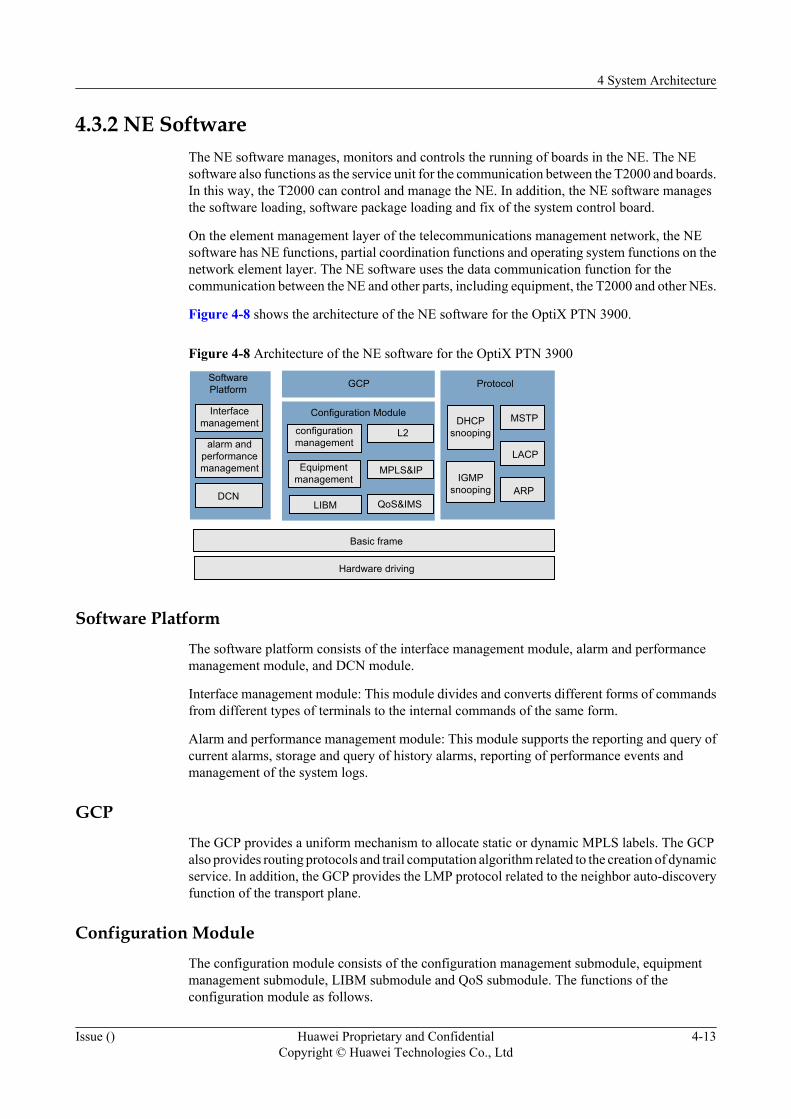
Figure 4-8 shows the architecture of the NE software for the OptiX PTN 3900.
Figure 4-8 Architecture of the NE software for the OptiX PTN 3900
Configuration Module
ProtocolSoftwarePlatform
DHCPsnooping
IGMPsnooping
Basic frame
Hardware driving
GCP
LIBM
configurationmanagement
Equipmentmanagement
L2
MPLS&IP
QoS&IMSDCN
alarm andperformancemanagement
Interfacemanagement MSTP
LACP
ARP
Software PlatformThe software platform consists of the interface management module, alarm and performancemanagement module, and DCN module.
Interface management module: This module divides and converts different forms of commandsfrom different types of terminals to the internal commands of the same form.
Alarm and performance management module: This module supports the reporting and query ofcurrent alarms, storage and query of history alarms, reporting of performance events andmanagement of the system logs.
GCPThe GCP provides a uniform mechanism to allocate static or dynamic MPLS labels. The GCPalso provides routing protocols and trail computation algorithm related to the creation of dynamicservice. In addition, the GCP provides the LMP protocol related to the neighbor auto-discoveryfunction of the transport plane.
Configuration ModuleThe configuration module consists of the configuration management submodule, equipmentmanagement submodule, LIBM submodule and QoS submodule. The functions of theconfiguration module as follows.
4 System Architecture
Issue () Huawei Proprietary and ConfidentialCopyright © Huawei Technologies Co., Ltd
4-13

l Responsible for the management configuration of the entire NE, including servicemanagement for each domain (Packet, TDM and WDM), equipment management, resourcemanagement and protocol configuration agent.
l Responsible for the setting and querying of the attributes of alarms and performance of themanaged objects.
l Responsible for querying and reporting of the performance data.
l Responsible for inter-board alarm suppression and query of alarms of specified objects.
l Responsible for storing configuration data.
l Responsible for providing Layer 2 switching, processing MPLS and IP packets and theQoS function.
ProtocolIGMP Snooping protocol, which is a Layer 2 multicast protocol and provides the Layer 2multicast function.
MSTP protocol, which is a spanning tree protocol used for loop release, link backup and VLAN-based link load balance.
LACP protocol, which is used for linear bandwidth increasing, link backup and load balance.
Basic FrameThe basic frame provides the basic platform kernel and system support. For example, the basicframe realizes the board management, distributed message management and log management.
4.3.3 Board SoftwareThe board software is responsible for Layer 2 switching, the MPLS packet processing and theQoS. The board software monitors and reports the alarms and performance events of each boardto the NE software.
Figure 4-9 shows the architecture of the board software for the OptiX PTN 3900.
Figure 4-9 Architecture of the board software for the OptiX PTN 3900
Alarm/logForwarding plane Performance Softwaremanagement Protocol
Hardware driving
Basic frame
RSTP
LCAS
IGMP
LACP
FTP
LIB
Alarm detection
Statistics ofperformance units
Alarm report/indication
Alarm anti-jitter/inter-board
suppression
15-m/24-hperformancecomputation
Softwareloading
Softwarepackageloading
Fixmanagement
l The forwarding plane monitors alarms and makes performance statistics.
l The alarm/log module reports and suppresses alarms.
l The performance module makes 15-hour and 24-hour performance statistics.
4 System Architecture
4-14 Huawei Proprietary and ConfidentialCopyright © Huawei Technologies Co., Ltd
Issue ()

l The protocol part processes protocols such as IGMP and LACP.
4 System Architecture
Issue () Huawei Proprietary and ConfidentialCopyright © Huawei Technologies Co., Ltd
4-15

5 Services
About This Chapter
This chapter describes the services of the equipment.
5.1 OverviewThe OptiX PTN 3900 supports the Ethernet service, ATM service and CES service. Based onthe service model of the OptiX PTN 3900, this section describes the processing of variousservices in the OptiX PTN 3900.
5.2 Ethernet ServiceThe OptiX PTN 3900 supports various Ethernet services and provides ideal L2VPN solutions.
5.3 ATM ServiceIn the transport network with the packet switching as the core, the OptiX PTN 3900 uses thePW scheme to provide the ATM emulation service.
5.4 Circuit Emulation ServiceIn a packet switching network (PSN), the circuit emulation services are used to transparentlytransmit the TDM circuit. The OptiX PTN 3900 supports TDM CES accessed by the E1 electricalinterfaces and the channelized STM-1 optical interfaces.
5 Services
Issue () Huawei Proprietary and ConfidentialCopyright © Huawei Technologies Co., Ltd
5-1

5.1 OverviewThe OptiX PTN 3900 supports the Ethernet service, ATM service and CES service. Based onthe service model of the OptiX PTN 3900, this section describes the processing of variousservices in the OptiX PTN 3900.
5.1.1 PTN Service ModelAccording to different equipment interconnected, the services of the PTN equipment havedifferent layer models on the UNI side and the NNI side.
5.1.2 Service ProcessingBased on the PTN service model, this section describes the processing of the Ethernet service,ATM service and CES service in the OptiX PTN 3900 and the OptiX PTN .
5.1.1 PTN Service ModelAccording to different equipment interconnected, the services of the PTN equipment havedifferent layer models on the UNI side and the NNI side.
The service model of the OptiX PTN 3900 is as shown in Figure 5-1.
Figure 5-1 Service model of the OptiX PTN 3900
Forwarder
Native serviceprocessing
Serviceinterface
Physical
PWE3 (Encapsulation)
PW Demultiplexer (PW label)
Tunnel (Tunnel label)
Emulatedservice
Psudo wire
PSN (MPLS)tunneling
Data-Linkand
Physical
To CE To PSN
TDMATM
IMA
TDM ATM EthernetEthernetswitch ATM switch TDM
processing
GE E1/cSTM-1STM-1 E1/
cSTM-1 GE
802.2802.3
Ethernet
STM-1/STM-4
PPPHDLC
POSML-PPP
E1/cSTM-1
PPP(MP)
Ethernet
UNI NNI
FE
The UNI side is interconnected to the customer-side equipment (CE), responsible for accessingthe customer-side services to the PSN network. In the service model, the functions of layers onthe UNI side are described as follows.
5 Services
5-2 Huawei Proprietary and ConfidentialCopyright © Huawei Technologies Co., Ltd
Issue ()
l Physical layer
The physical layer provides interfaces between the PTN equipment and the transmissionmedia, such as cables and fibers.
– In the direction from the CE to the PE, the physical layer processes the physical signals(electrical signals or optical signals) transmitted from the customer-side equipment,extracts information from the signals, and transmits the information to the serviceinterface layer.
– In the direction from the PE to the CE, the physical layer receives the informationtransmitted from the service interface layer, converts the information into signalssuitable for the transmission through the transmission medium, and then transmits thesignals to the customer-side equipment through the physical channel.
l Service interface layer
– In the direction from the CE to the PE, the service interface layer receives theinformation transmitted from the physical layer, distinguishes service types, andtransmits the services to the corresponding native service processing (NSP) layer forprocessing.
– In the direction from the PE to the CE, the service interface layer receives the servicesignals transmitted from the NSP layer, selects the proper physical channel type andtransmits the signals to the physical layer.
l NSP layer
According to the customer requirements, the NSP layer performs relevant processing fordifferent services.
The NNI side is interconnected to the PSN equipment, to achieve the transmission of customerservices in the PSN network. In the service model, the functions of layers on the NNI side aredescribed as follows.
l Emulation service layer
The emulation service layer corresponds to the payload that is to be encapsulated into thePW. An emulation service corresponds to a PW. The emulation service layer is an abstractlogical layer. The PTN equipment does not perform any specific operation at this layer.
l PWE3 encapsulation layer
The PWE3 encapsulation layer adopts different encapsulation modes for differentemulation services. It can encapsulate different emulation services into PWE3 protocol dataunits or decapsulate different emulation services from PWE3 protocol data units.
l MPLS layer
The MPLS layer contains the following two MPLS labels:
– Outer label, that is, the tunnel label. It is used to create and maintain a tunnel that crossesthe MPLS network between the PE stations at two ends of a service, for the purpose ofcarrying the PW.
– Inner label, that is, the PW label. It is used to distinguish different PWs in the sametunnel.
l Data link layer and physical layer
As the carrier layers of the MPLS, the data link layer and the physical layer provide linksfor the MPLS layer to transmit data. The OptiX PTN 3900 supports the following network-side link types.
– Ethernet link (GE interface)
5 Services
Issue () Huawei Proprietary and ConfidentialCopyright © Huawei Technologies Co., Ltd
5-3
– POS link (STM-1 or STM-4 interface)
– ML-PPP link (E1 interface or channelized STM-1 interface)
The forwarder located between the UNI and the NNI mutually forwards services processed atthe NSP layer on the UNI side and the emulation services on the NNI side.
NOTE
Do not use the Ethernet link of the FE interface as the network-side link for the OptiX PTN 3900.
5.1.2 Service ProcessingBased on the PTN service model, this section describes the processing of the Ethernet service,ATM service and CES service in the OptiX PTN 3900 and the OptiX PTN .
Ethernet Service Processing
At the physical layer on the UNI side, the OptiX PTN 3900 supports the interconnection to thecustomer-side equipment through the following physical interfaces to access the Ethernetservice.
l FE
l GE
The service interface layer on the UNI side:
l In the direction from the CE to the PE, receives the signals transmitted from the physicallayer, extracts the Ethernet frames, and sends the Ethernet frames to the Ethernet switchmodule at the native service processing (NSP) layer for processing.
l In the direction from the PE to the CE, receives the Ethernet frames transmitted from theEthernet switch module that is at the NSP layer, and sends the Ethernet frames to thecorresponding Ethernet physical channel.
According to the customer requirements, the NSP layer on the UNI side performs the followingprocessing.
l Processes a VLAN tag for the Ethernet frames (adds, strips or exchanges a VLAN tag).
l Performs the QoS processing, such as flow classification and congestion management.
l Controls the access authority by using the access control list (ACL).
l Performs the Ethernet OAM processing according to IEEE 802.1ag or IEEE 802.3ah.
The forwarder located between the UNI and the NNI mutually forwards the Ethernet service atthe NSP layer on the UNI side and the relevant PW on the NNI side. The forwarder can adoptthe following two modes to determine the relevant PW of the Ethernet service.
l Port that accesses the Ethernet service
l Port that accesses the Ethernet service + VLAN ID of the Ethernet frame
The emulation service layer on the NNI side corresponds to the payload that is to be encapsulatedinto the PW. The emulation service layer is an abstract logical layer. The PTN equipment doesnot perform any specific operation at this layer.
The PWE3 encapsulation layer on the NNI side adds the PW header to an Ethernet frame toform a PW protocol data unit (PDU).
5 Services
5-4 Huawei Proprietary and ConfidentialCopyright © Huawei Technologies Co., Ltd
Issue ()
At the MPLS layer on the NNI side, by using two tags, the OptiX PTN 3900 distinguishes thePW that carries the service from the tunnel that carries the PW.
At the data link layer and the physical layer on the NNI side, the OptiX PTN 3900 carries andtransmits the MPLS packet through different links.
NOTE
On the NNI side, the Ethernet service can be directly carried by a physical Ethernet port without using thePWE3 encapsulation and MPLS label technology. In this case, the Ethernet port is fully occupied by theEthernet service.
ATM Service Processing
At the physical layer on the UNI side, the OptiX PTN 3900 supports the interconnection to thecustomer-side equipment through the following physical interfaces to access the ATM service.
l STM-1
l Channelized STM-1 (IMA adaptation is adopted.)
l E1 (IMA adaptation is adopted.)
The service interface layer on the UNI side:
l In the direction from the CE to the PE, receives the signals transmitted from the physicallayer, extracts the ATM cells, and sends the ATM cells to the ATM switch module at theNSP layer for processing.
l In the direction from the PE to the CE, receives the ATM cells transmitted from the ATMswitch module that is at the NSP layer, and sends the ATM cells to the correspondingphysical channel.
According to the customer requirements, the NSP layer on the UNI side performs the followingprocessing.
l Performs the VP switching.
l Performs the VC switching.
l Performs the ATM OAM processing.
The forwarder located between the UNI and the NNI mutually forwards the ATM service at theNSP layer on the UNI side and the relevant PW on the NNI side. The forwarder can adopt thefollowing three modes to determine the relevant PW of the ATM service.
l ATM port
l VCC
l VPC
The emulation service layer on the NNI side corresponds to the payload that is to be encapsulatedinto the PW. The emulation service layer is an abstract logical layer. The PTN equipment doesnot perform any specific operation at this layer.
The PWE3 encapsulation layer on the NNI side can adopt the following two modes to encapsulatethe ATM cells into a PW PDU.
l Encapsulating one ATM cell into a PW PDU.
5 Services
Issue () Huawei Proprietary and ConfidentialCopyright © Huawei Technologies Co., Ltd
5-5
l Encapsulating N (N<=31) ATM cells into a PW PDU. This is also referred to as ATM cellconcatenation.
At the MPLS layer on the NNI side, by using two tags, the OptiX PTN 3900 distinguishes thePW that carries the service from the tunnel that carries the PW.
At the data link layer and the physical layer on the NNI side, the OptiX PTN 3900 carries andtransmits the MPLS packet through different links.
CES Service Processing
At the physical layer on the UNI side, the OptiX PTN 3900 supports the interconnection to thecustomer-side equipment through the following physical interfaces to access the CES service.
l Channelized STM-1
l E1
The service interface layer on the UNI side:
l In the direction from the CE to the PE, receives the signals transmitted from the physicallayer, extracts the TDM services, and sends the TDM services to the TDM processingmodule at the NSP layer for processing.
l In the direction from the PE to the CE, receives the TDM services transmitted from theTDM processing module that is at the NSP layer, and sends the TDM services to thecorresponding physical channel.
According to the customer requirements, the NSP layer on the UNI side performs the followingprocessing
l Performs the multiplexing and demultiplexing for channelized STM-1 signals and E1signals.
l Performs the E1 (VC-12) granularity scheduling for the channelized STM-1 signals.
The forwarder located between the UNI and the NNI mutually forwards the TDM service at theNSP layer on the UNI side and the relevant PW on the NNI side. The forwarder can adopt thefollowing two modes to determine the relevant PW of the TDM service.
l E1 port that accesses the TDM service
l Channelized STM-1 port and VC-12 timeslot that access the TDM service
The emulation service layer on the NNI side corresponds to the payload that is to be encapsulatedinto the PW. The emulation service layer is an abstract logical layer. No specific operation isperformed at this layer.
The PWE3 encapsulation layer on the NNI side can adopt the following two modes to encapsulatethe TDM service into a PW PDU.
l Structure-agnostic encapsulation. In this case, the emulated E1 signals are considered as abit stream. No matter whether the emulated E1 signals have the timeslot structure, the PTNequipment does not recognize the timeslot structure.
l Structure-aware encapsulation. In this case, the emulated E1 signals are considered as astructure-aware bit stream consisting of 64 kbit/s timeslots. The 64 kbit/s timeslots arevisible to the PTN equipment.
At the MPLS layer on the NNI side, by using two tags, the OptiX PTN 3900 distinguishes thePW that carries the service from the tunnel that carries the PW.
5 Services
5-6 Huawei Proprietary and ConfidentialCopyright © Huawei Technologies Co., Ltd
Issue ()
At the data link layer and the physical layer on the NNI side, the OptiX PTN 3900 carries andtransmits the MPLS packet through different links.
5.2 Ethernet ServiceThe OptiX PTN 3900 supports various Ethernet services and provides ideal L2VPN solutions.
A virtual private network (VPN) is a private network constructed on the basis of the publicnetwork. The L2VPN is the VPN based on technologies of the link layer. The VPN constructedon the public network can provide the same security, reliability and manageability as the existingprivate networks.
Service providers can provide the VPN value-added service for enterprises to fully use theexisting network resources and to increase the service volume. In addition, service providerscan consolidate long-term partnership with enterprises.
For VPN users, the cost to lease the network is saved. The flexibility of the VPN networkingmakes the network management easier for enterprises. As the network security and encryptiontechnology develops, the private data can be transmitted over the public network with security.
Service Form
For the OptiX PTN 3900, the Ethernet service has the following forms.
l Point-to-point service: E-Line service
l Multipoint-to-multipoint service: E-LAN service
l Point-to-multipoint service: E-Tree service
l Multipoint-to-point converging service: E-Aggr service
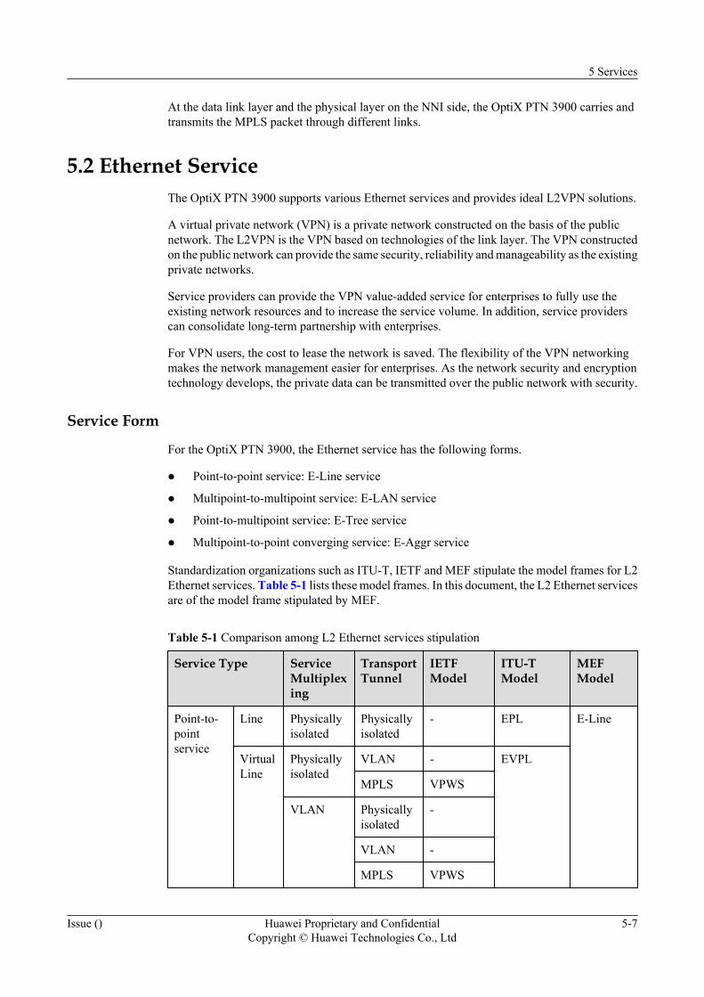
Standardization organizations such as ITU-T, IETF and MEF stipulate the model frames for L2Ethernet services. Table 5-1 lists these model frames. In this document, the L2 Ethernet servicesare of the model frame stipulated by MEF.
Table 5-1 Comparison among L2 Ethernet services stipulation
Service Type ServiceMultiplexing
TransportTunnel
IETFModel
ITU-TModel
MEFModel
Point-to-pointservice
Line Physicallyisolated
Physicallyisolated
- EPL E-Line
VirtualLine
Physicallyisolated
VLAN - EVPL
MPLS VPWS
VLAN Physicallyisolated
-
VLAN -
MPLS VPWS
5 Services
Issue () Huawei Proprietary and ConfidentialCopyright © Huawei Technologies Co., Ltd
5-7
Service Type ServiceMultiplexing
TransportTunnel
IETFModel
ITU-TModel
MEFModel
Multipoint-to-multipointservice
LAN Physicallyisolated
Physicallyisolated
- EPLAN E-LAN
VirtualLAN
VLAN Physicallyisolated
- EVPLAN
S-VLAN -
MPLS VPLS
S-VLAN B-MACB-VLAN
-
Point-to-multipointservice
Tree Physicallyisolated
Physicallyisolated
- - E-Tree
VirtualTree
VLAN MPLS VPLSmulticast
-
E-Line Service Illustration
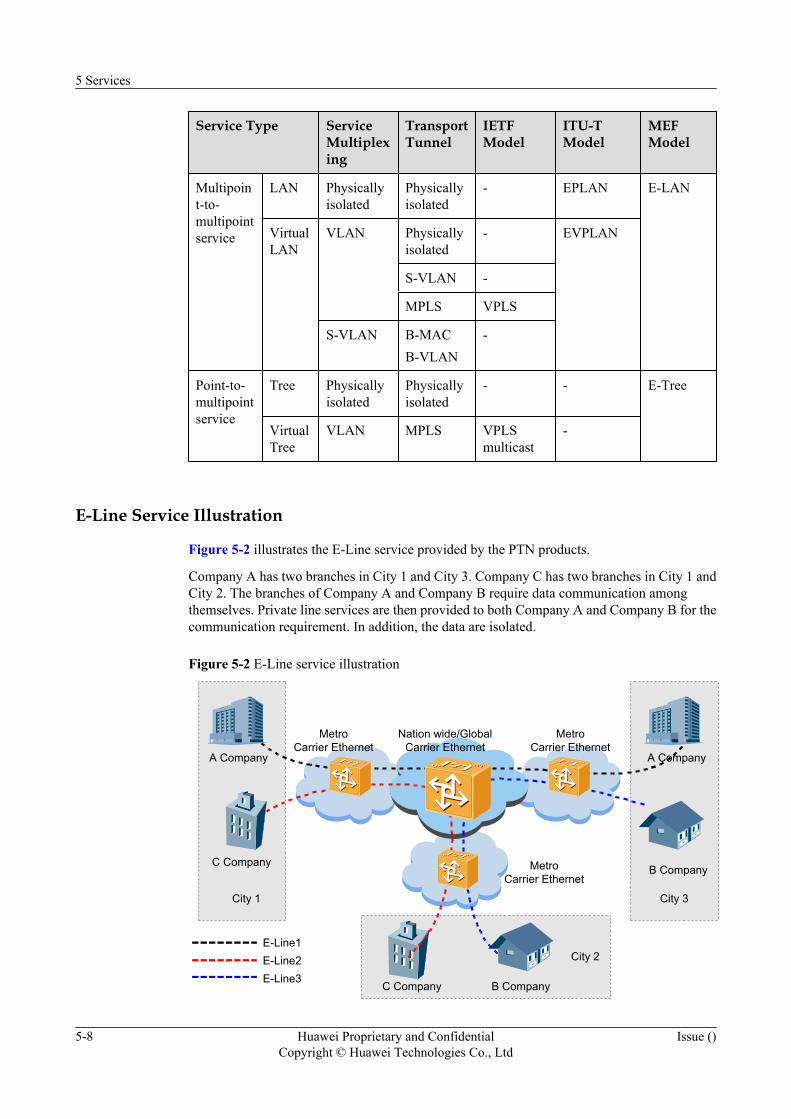
Figure 5-2 illustrates the E-Line service provided by the PTN products.
Company A has two branches in City 1 and City 3. Company C has two branches in City 1 andCity 2. The branches of Company A and Company B require data communication amongthemselves. Private line services are then provided to both Company A and Company B for thecommunication requirement. In addition, the data are isolated.
Figure 5-2 E-Line service illustration
Nation wide/GlobalCarrier Ethernet
MetroCarrier Ethernet
MetroCarrier Ethernet
MetroCarrier Ethernet
A Company
B Company
City 3
C Company
City 1
A Company
C Company B Company
City 2E-Line1E-Line2E-Line3
5 Services
5-8 Huawei Proprietary and ConfidentialCopyright © Huawei Technologies Co., Ltd
Issue ()
E-LAN Service Illustration
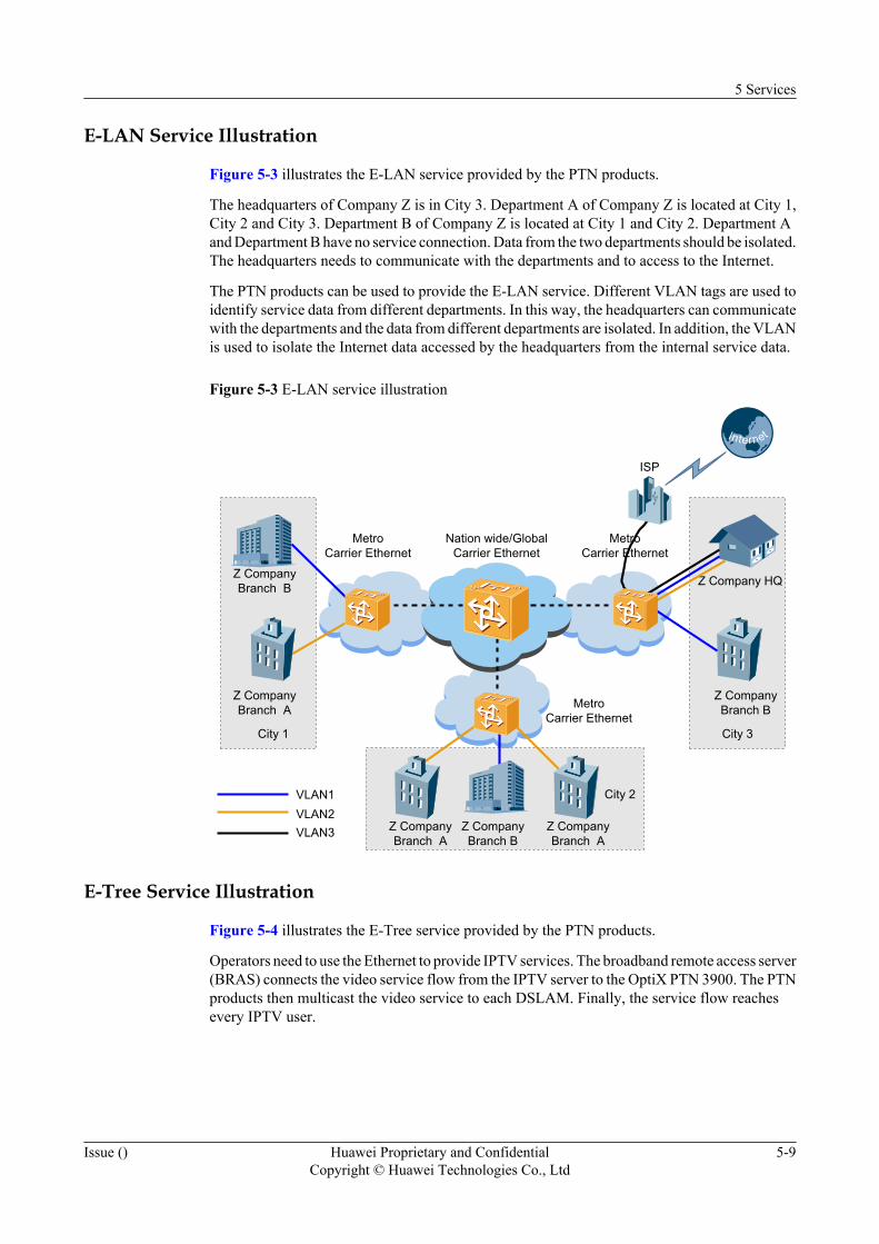
Figure 5-3 illustrates the E-LAN service provided by the PTN products.
The headquarters of Company Z is in City 3. Department A of Company Z is located at City 1,City 2 and City 3. Department B of Company Z is located at City 1 and City 2. Department Aand Department B have no service connection. Data from the two departments should be isolated.The headquarters needs to communicate with the departments and to access to the Internet.
The PTN products can be used to provide the E-LAN service. Different VLAN tags are used toidentify service data from different departments. In this way, the headquarters can communicatewith the departments and the data from different departments are isolated. In addition, the VLANis used to isolate the Internet data accessed by the headquarters from the internal service data.
Figure 5-3 E-LAN service illustration
Nation wide/GlobalCarrier Ethernet
MetroCarrier Ethernet
MetroCarrier Ethernet
MetroCarrier Ethernet
Z Company HQ
Z CompanyBranch B
City 3
Z CompanyBranch A
City 1
Z CompanyBranch B
Z CompanyBranch A
City 2VLAN1VLAN2
Z CompanyBranch B
Z CompanyBranch A
ISP
VLAN3
E-Tree Service Illustration
Figure 5-4 illustrates the E-Tree service provided by the PTN products.
Operators need to use the Ethernet to provide IPTV services. The broadband remote access server(BRAS) connects the video service flow from the IPTV server to the OptiX PTN 3900. The PTNproducts then multicast the video service to each DSLAM. Finally, the service flow reachesevery IPTV user.
5 Services
Issue () Huawei Proprietary and ConfidentialCopyright © Huawei Technologies Co., Ltd
5-9
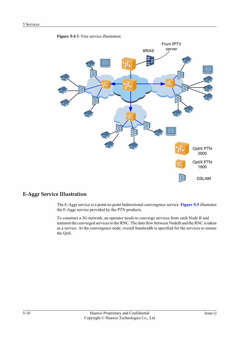
Figure 5-4 E-Tree service illustration
BRASFrom IPTV
server
OptiX PTN3900
OptiX PTN1900
DSLAM
E-Aggr Service Illustration
The E-Aggr service is a point-to-point bidirectional convergence service. Figure 5-5 illustratesthe E-Aggr service provided by the PTN products.
To construct a 3G network, an operator needs to converge services from each Node B andtransmit the converged services to the RNC. The data flow between NodeB and the RNC is takenas a service. At the convergence node, overall bandwidth is specified for the services to ensurethe QoS.
5 Services
5-10 Huawei Proprietary and ConfidentialCopyright © Huawei Technologies Co., Ltd
Issue ()
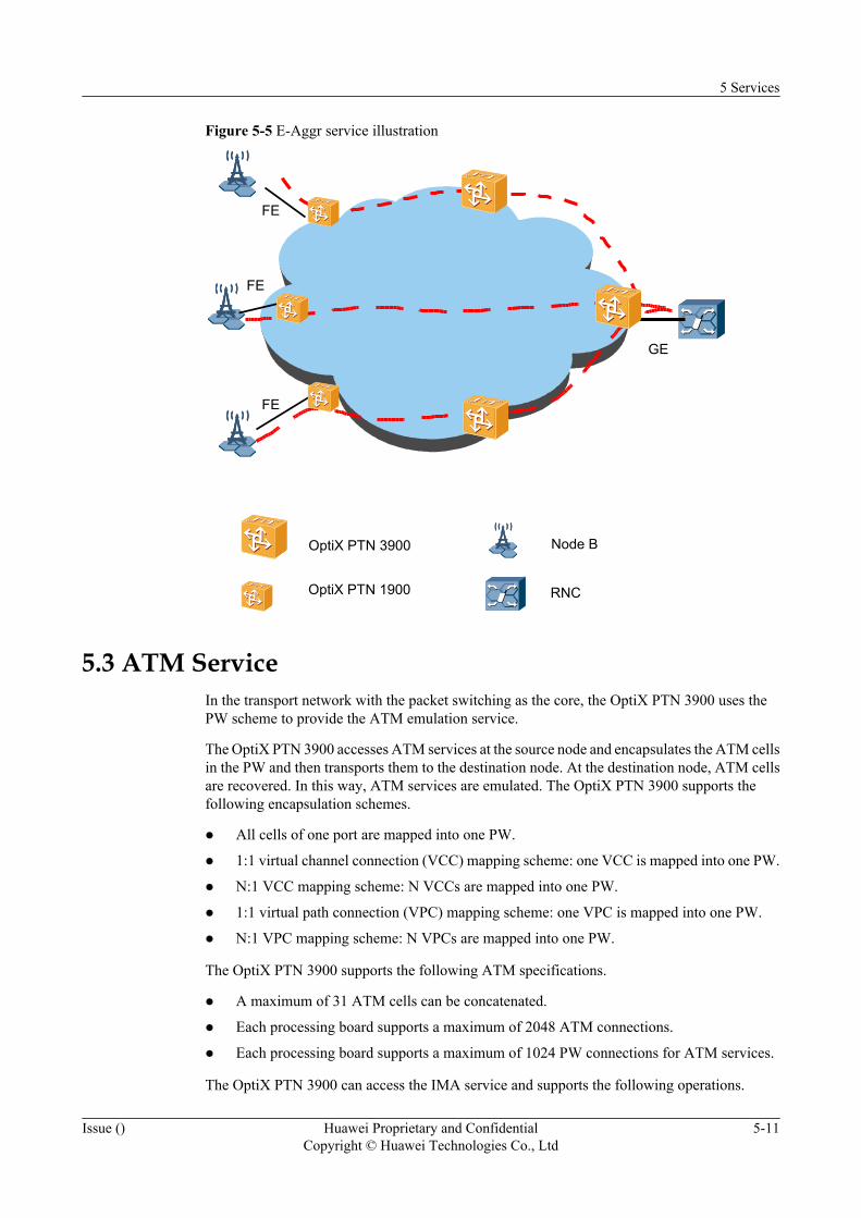
Figure 5-5 E-Aggr service illustration
GE
OptiX PTN 3900
OptiX PTN 1900 RNC
Node B
FE
FE
FE
5.3 ATM ServiceIn the transport network with the packet switching as the core, the OptiX PTN 3900 uses thePW scheme to provide the ATM emulation service.
The OptiX PTN 3900 accesses ATM services at the source node and encapsulates the ATM cellsin the PW and then transports them to the destination node. At the destination node, ATM cellsare recovered. In this way, ATM services are emulated. The OptiX PTN 3900 supports thefollowing encapsulation schemes.
l All cells of one port are mapped into one PW.
l 1:1 virtual channel connection (VCC) mapping scheme: one VCC is mapped into one PW.
l N:1 VCC mapping scheme: N VCCs are mapped into one PW.
l 1:1 virtual path connection (VPC) mapping scheme: one VPC is mapped into one PW.
l N:1 VPC mapping scheme: N VPCs are mapped into one PW.
The OptiX PTN 3900 supports the following ATM specifications.
l A maximum of 31 ATM cells can be concatenated.
l Each processing board supports a maximum of 2048 ATM connections.
l Each processing board supports a maximum of 1024 PW connections for ATM services.
The OptiX PTN 3900 can access the IMA service and supports the following operations.
5 Services
Issue () Huawei Proprietary and ConfidentialCopyright © Huawei Technologies Co., Ltd
5-11
l Query of the IMA link status.
l Addition of E1 links into the IMA group.
l Deletion of E1 links from the IMA group.
The OptiX PTN 3900 supports the following IMA specifications.
l A maximum of 31 ATM cells can be concatenated.
l Each processing board supports a maximum of 63 IMA groups.
l Each IMA group contains a maximum of 32 E1 links.
l Each processing board supports a maximum of 2048 ATM connections.
l Each processing board supports a maximum of 256 PW connections can be used for IMAservices.
5.4 Circuit Emulation ServiceIn a packet switching network (PSN), the circuit emulation services are used to transparentlytransmit the TDM circuit. The OptiX PTN 3900 supports TDM CES accessed by the E1 electricalinterfaces and the channelized STM-1 optical interfaces.
Application ModelThe OptiX PTN 3900 uses the PWE3 technology to provide the CES.
The CES mainly applies to the wireless service and enterprise private line service. For 2G/3Gstations or enterprise private lines, the PTN equipment accesses E1 signals from E1 lines orchannelized STM-1 lines. The PTN equipment then encapsulates the E1 signals into Ethernetframes, which are then transported to the opposite end through the PW. Figure 5-6 shows theprocess.
5 Services
5-12 Huawei Proprietary and ConfidentialCopyright © Huawei Technologies Co., Ltd
Issue ()

Figure 5-6 CES service application model
IP/MPLS backbone
BTSNodeB BTS NodeB
Backbonelayer
Convergencelayer
Accesslayer
BSCRNC
CESOptiXPTN 3900
OptiXPTN 1900
Emulation Mode
The OptiX PTN 3900 supports the CES services in both the structured emulation mode andunstructured emulation mode.
The structured emulation mode is also the structure-aware TDM circuit emulation service overpacket switched network (CESoPSN) mode.
l In this mode, the equipment detects the frame structure, framing scheme and timeslotinformation in the TDM circuit.
l In this mode, the equipment processes the overhead in the TDM frames and extracts thepayload. The equipment then places each channel of timeslots into the packet payload in acertain sequence. In this way, each channel of services are fixed and known.
l In this mode, each Ethernet frame that carries the CES service loads a fixed number ofTDM frames. Generally, the loading time is one to five microseconds.
The unstructured emulation mode is also the structure-agnostic TDM over packet (SAToP)mode.
l In this mode, the equipment does not detect the structure of any TDM signals, but takessignals as bit flow of the fixed rate. In this way, the overall bandwidth for the TDM signalsis emulated.
l In this mode, the overhead and payload in the TDM signals are transparently transmitted.
l Generally, in this mode, the loading time for the Ethernet frames that carry the CES serviceis 1 ms.
5 Services
Issue () Huawei Proprietary and ConfidentialCopyright © Huawei Technologies Co., Ltd
5-13
In the structured emulation mode, the OptiX PTN 3900 provides the idle 64 kbit/s timeslotsuppression function to save the transmission bandwidth.
Service Clock
The TDM service has a high requirement for clock synchronization. The OptiX OSN 3900provides ideal clock synchronization schemes for the CES.
Table 5-2 Clock synchronization schemes for the CES
Synchronization Scheme
AccessPosition ofthePrimaryClock
ClockTransmitted by theCarrierEthernet orNot
Scheme Description
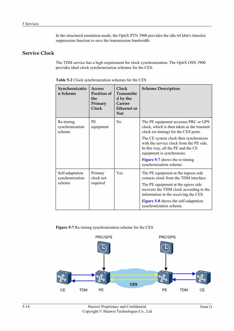
Re-timingsynchronizationscheme
PEequipment
No The PE equipment accesses PRC or GPSclock, which is then taken as the transmitclock (re-timing) for the CES ports.The CE system clock then synchronizeswith the service clock from the PE side.In this way, all the PE and the CEequipment is synchronous.Figure 5-7 shows the re-timingsynchronization scheme.
Self-adaptationsynchronizationscheme
Primaryclock notrequired
Yes The PE equipment at the ingress sideextracts clock from the TDM interface.The PE equipment at the egress siderecovers the TDM clock according to theinformation in the receiving the CES.Figure 5-8 shows the self-adaptationsynchronization scheme.
Figure 5-7 Re-timing synchronization scheme for the CES
CE CEPE PECES
PRC/GPS PRC/GPS
TDM TDM
5 Services
5-14 Huawei Proprietary and ConfidentialCopyright © Huawei Technologies Co., Ltd
Issue ()
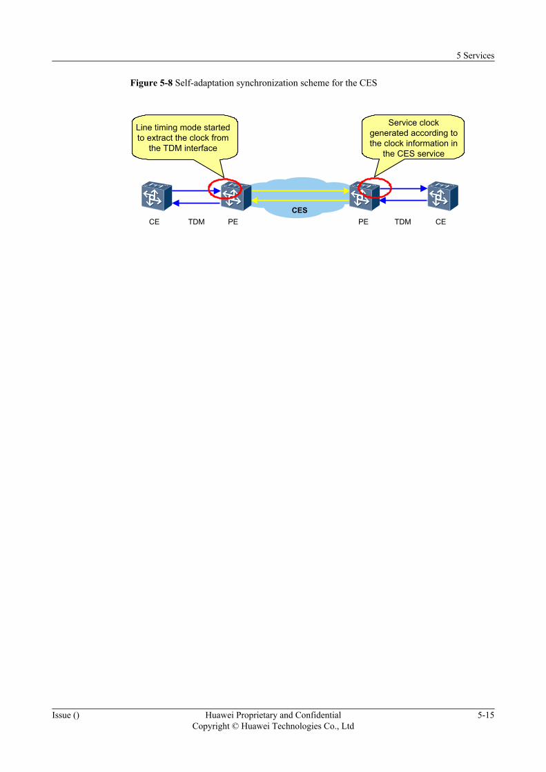
Figure 5-8 Self-adaptation synchronization scheme for the CES
CE CEPE PECES
TDM TDM
Line timing mode startedto extract the clock from
the TDM interface
Service clockgenerated according tothe clock information in
the CES service
5 Services
Issue () Huawei Proprietary and ConfidentialCopyright © Huawei Technologies Co., Ltd
5-15

6 Key Features
About This Chapter
This chapter describes key features of the equipment.
6.1 MPLSThe OptiX PTN 3900 uses the multiprotocol label switching (MPLS) technology to transportmultiple types of services. This section describes the basic concepts related to the MPLS andapplication of the MPLS supported by the OptiX PTN 3900.
6.2 IS-IS Routing ProtocolThe intermediate system to intermediate system (IS-IS) routing protocol, a link state protocol,belongs to the internal gateway protocol and is applicable to the internal of the autonomoussystem. The OptiX PTN 3900 uses the IS-IS routing protocol, which is used with the labeldistribution protocols RSVP-TE and LDP to realize the dynamic creation of the MPLS LSP.
6.3 MPLS SignalingThe MPLS signaling used by the OptiX PTN 3900 includes LSP signaling and PW signaling.The LSP signaling is responsible for distributing LSP labels and the PW signaling is responsiblefor distributing PW labels to establish PW.
6.4 PWE3The pseudo wire emulation edge-to-edge (PWE3) technology is used to provide tunnels on thepacket switching network (IP/MPLS) to emulate the Layer 2 VPN protocol for some services,such as the TDM, ATM and Ethernet services. The emulated VPN protocol is used to connectthe traditional network and packet switching network. In this way, networks are extended andresources can be shared.
6.5 IP Tunnel and GRE TunnelThe OptiX PTN 3900 can use the IP tunnel or GRE tunnel to carry the ATM PWE3 service. Inthis way, ATM emulation services can be transparently transmitted in an IP network.
6.6 QoSThe equipment supports DiffServ based on the standard, including flow classification, flowpolicing, traffic shaping, congestion management and queue scheduling.
6.7 IGMP SnoopingThe Internet group management protocol (IGMP) Snooping function is used to realize multicastdistribution.
6 Key Features
Issue () Huawei Proprietary and ConfidentialCopyright © Huawei Technologies Co., Ltd
6-1
6.8 MSTP/RSTP/STPThe multiple spanning tree protocol (MSTP) is compatible with the spanning tree protocol (STP)and rapid spanning tree protocol (RSTP). In addition, the MSTP rectifies the defects of the STPand RSTP. The MSTP supports fast reconfiguration and provides multiple paths for forwardingdata. During the data forwarding process, the VLAN data is of load balance. The MSTP complieswith IEEE 802.1s.
6.9 ACLTo filter data packets, the access control list (ACL) can be used to stipulate a series rules in order.The equipment classifies the received data packets according to the ACL rules and then forwardsor discards these packets.
6.10 BFDThe OptiX PTN 3900 supports the bidirectional forwarding detection (BFD) function. The Hellomechanism is used to detect states of Ethernet links.
6 Key Features
6-2 Huawei Proprietary and ConfidentialCopyright © Huawei Technologies Co., Ltd
Issue ()

6.1 MPLSThe OptiX PTN 3900 uses the multiprotocol label switching (MPLS) technology to transportmultiple types of services. This section describes the basic concepts related to the MPLS andapplication of the MPLS supported by the OptiX PTN 3900.
6.1.1 MPLS Generation BackgroundThe multiprotocol label switching (MPLS) was originally used to increase the forwarding speedof a router. Currently, the MPLS are evolving to the backbone routing and the VPN solution.
6.1.2 Basic MPLS ConceptsSeveral basic MPLS concepts facilitate the understanding of the MPLS technology. These basicMPLS concepts include forwarding equivalence class (FEC), label, label distribution protocol(LDP) and label switched path (LSP).
6.1.3 MPLS System StructureThe MPLS system consists of the control plane and forwarding plane.
6.1.4 MPLS Features of the EquipmentUsing the MPLS technology, the OptiX PTN 3900 not only greatly increases the packetforwarding speed but also provides the capability of seamlessly connecting to Layer 2 networkssuch as the ATM and Ethernet networks. In addition, the OptiX PTN 3900 provides bettersolutions for application of the TE, VPN and QoS.
6.1.1 MPLS Generation BackgroundThe multiprotocol label switching (MPLS) was originally used to increase the forwarding speedof a router. Currently, the MPLS are evolving to the backbone routing and the VPN solution.
The MPLS is integrated with the Layer 3 routing function of the IP network and the highlyeffective forwarding mechanism of the traditional Layer 2 network. Similar to the forwardingscheme of the existing Layer 2 network, the forwarding plane is connection-oriented. Hence,the MPLS can be seamlessly connected to Layer 2 networks such the ATM and Ethernetnetworks. In addition, the MPLS provides better solutions for the application of the trafficengineering (TE), virtual private network (VPN) and quality of service (QoS). Hence, the MPLSbecomes a criterion for expanding the data network and increasing the network operability.
To better meet the requirements of the transport network for service quality, the connectionlessfeature of the standard MPLS should be simplified, and the OAM and protection capabilitiesshould be enhanced. In compliance with the latest international standards, the OptiX PTN3900 supports a series of MPLS features for the transport network.
6.1.2 Basic MPLS ConceptsSeveral basic MPLS concepts facilitate the understanding of the MPLS technology. These basicMPLS concepts include forwarding equivalence class (FEC), label, label distribution protocol(LDP) and label switched path (LSP).
Forwarding Equivalence ClassAs a classification forwarding technology, the MPLS considers the packets of the sameforwarding scheme as a class, which is called an FEC. In the MPLS network, the packets in theFEC are processed in the same way.
6 Key Features
Issue () Huawei Proprietary and ConfidentialCopyright © Huawei Technologies Co., Ltd
6-3

Label
A label is a short identifier of fixed length and is locally valid (only valid in the MPLS domain).The label is used to identify the FEC that one packet belongs to. On certain conditions, forexample, when load sharing is required, several labels may correspond to one FEC, but one labeljust indicates one FEC.
The packet headers carry labels and the labels do not contain any topology information. Labelsare locally valid. A label has four bytes, which are encapsulated in the way illustrated in Figure6-1.
Figure 6-1 Label encapsulation structure
A label has the following four sections.
l Label: 20 bits. The label section indicates the label value and is used as the forwardingpointer.
l Exp: three bits. The Exp section is reserved for test and currently used for CoS.
l S: 1 bit. The S section is an identifier at the bottom of a stack. The MPLS supports thelayered labels, or multiple labels. If S is 1, it indicates that the label is at the bottom.
l TTL: 8 bits. The TTL section has the same indication as the time to live (TTL) of IP packets.
As a connection identifier, the label is similar to the VPI/VCI for ATM. The labels areencapsulated between the link layer and the network layer in a Ethernet frame. Figure 6-2 showsthe encapsulation location of labels.
Figure 6-2 Encapsulation Location of labels in Ethernet frames
LDP
The LDP is the control protocol for the MPLS. Similar to the signaling protocol of the traditionalnetwork, the LDP is responsible for creation and maintenance of LSP and PW, FECclassification, and label distribution.
The MPLS can use several types of label distribution protocols.
l Some protocols are exclusively stipulated for label distribution, such as LDP and constraint-routing label distribution protocol (CR-LDP). The OptiX PTN 3900 uses the LDP to createand maintain PWs.
l Some exiting protocols can be extended to support the label distribution, such as bordergateway protocol (BGP) and resource reservation protocol (RSVP). The OptiX PTN3900 uses the resource reservation protocol-traffic engineering (RSVP-TE) protocol tocreate and maintain LSPs.
6 Key Features
6-4 Huawei Proprietary and ConfidentialCopyright © Huawei Technologies Co., Ltd
Issue ()

LSP
In an MPLS network, the path involved in an FEC is called an LSP.
The LSP is a unidirectional path from the ingress to egress. Each node on an LSP is a labelswitched router (LSR). According to the data transport direction, adjacent LSRs are upstreamLSR and downstream LSR.
The LSPs are classified into static LSPs and dynamic LSPs. The static LSPs are manuallyconfigured by the administrator. The dynamic LSPs are created dynamically by the RSVP-TEprotocol.
6.1.3 MPLS System StructureThe MPLS system consists of the control plane and forwarding plane.
The control plane of the MPLS system is connectionless. The control plane of the MPLS systemhas powerful and flexible routing function, which meets the network requirements of newapplication.
The forwarding plane is also called a data plane, which is connection-oriented and can use Layer2 networks such as Ethernet. The MPLS uses short labels of fixed length to encapsulate packets.The forwarding plane then quickly forwards the encapsulated packets.
6.1.4 MPLS Features of the EquipmentUsing the MPLS technology, the OptiX PTN 3900 not only greatly increases the packetforwarding speed but also provides the capability of seamlessly connecting to Layer 2 networkssuch as the ATM and Ethernet networks. In addition, the OptiX PTN 3900 provides bettersolutions for application of the TE, VPN and QoS.
To ensure the service quality required in a transport network, the OptiX PTN 3900 simplifiesthe non-connection-oriented feature of the MPLS.
l The OptiX PTN 3900 does not use the penultimate hop popping (PHP), for the PHP maycause the loss of the MPLS OAM information.
l The OptiX PTN 3900 does not support LSP Merge, for the LSP Merge makes the sourceof a data flow unknown. If the source is unknown, the OAM and performance monitoringbecome difficult or unusable.
l The OptiX PTN 3900 does not support the equal cost multiple path (ECMP), for the ECMPmakes the CC of the OAM and performance monitoring complex.
In addition, the OptiX PTN 3900 provides complete OAM support and powerful protectioncapabilities.
l The OptiX PTN 3900 uses the MPLS OAM mechanism compliant with ITU-T Y.1711 tofast check the LSP and PW state.
l The OptiX PTN 3900 uses the protection switching mechanism that complies with ITU-TY.1720 and ITU-T G.8131. The OptiX PTN 3900 not only provides FRR protection forLSPs, but also provides end-to-end transport protection for LSPs and PWs.
The OptiX PTN 3900 supports the MPLS technology and has the following MPLS features.
6 Key Features
Issue () Huawei Proprietary and ConfidentialCopyright © Huawei Technologies Co., Ltd
6-5
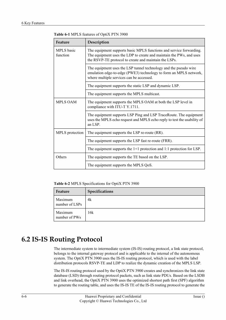
Table 6-1 MPLS features of OptiX PTN 3900
Feature Description
MPLS basicfunction
The equipment supports basic MPLS functions and service forwarding.The equipment uses the LDP to create and maintain the PWs, and usesthe RSVP-TE protocol to create and maintain the LSPs.
The equipment uses the LSP tunnel technology and the pseudo wireemulation edge-to-edge (PWE3) technology to form an MPLS network,where multiple services can be accessed.
The equipment supports the static LSP and dynamic LSP.
The equipment supports the MPLS multicast.
MPLS OAM The equipment supports the MPLS OAM at both the LSP level incompliance with ITU-T Y.1711.
The equipment supports LSP Ping and LSP TraceRoute. The equipmentuses the MPLS echo request and MPLS echo reply to test the usability ofan LSP.
MPLS protection The equipment supports the LSP re-route (RR).
The equipment supports the LSP fast re-route (FRR).
The equipment supports the 1+1 protection and 1:1 protection for LSP.
Others The equipment supports the TE based on the LSP.
The equipment supports the MPLS QoS.
Table 6-2 MPLS Specifications for OptiX PTN 3900
Feature Specifications
Maximumnumber of LSPs
4k
Maximumnumber of PWs
16k
6.2 IS-IS Routing ProtocolThe intermediate system to intermediate system (IS-IS) routing protocol, a link state protocol,belongs to the internal gateway protocol and is applicable to the internal of the autonomoussystem. The OptiX PTN 3900 uses the IS-IS routing protocol, which is used with the labeldistribution protocols RSVP-TE and LDP to realize the dynamic creation of the MPLS LSP.
The IS-IS routing protocol used by the OptiX PTN 3900 creates and synchronizes the link statedatabase (LSD) through routing protocol packets, such as link state PDUs. Based on the LSDBand link overhead, the OptiX PTN 3900 uses the optimized shortest path first (SPF) algorithmto generate the routing table, and uses the IS-IS TE of the IS-IS routing protocol to generate the
6 Key Features
6-6 Huawei Proprietary and ConfidentialCopyright © Huawei Technologies Co., Ltd
Issue ()
traffic engineering database (TEDB). The TEDB and routing table are the bases of creating theMPLS LSP. The TEDB computes the route that the MPLS LSP travels through. The routingtable forwards the RSVP-TE and LDP protocol packets to realize label distribution. In this way,the MPLS LSP is dynamically created.
Three features of the IS-IS routing protocol are supported by the OptiX PTN 3900, that is, threetypes of IS-IS routing protocol packets, optimized SPF algorithm, link overhead, and IS-IS trafficengineering (IS-IS TE).
Three Types of IS-IS Routing Protocol PacketsThe IS-IS routing protocol belongs to the network player of the OSI protocol model. The IS-ISrouting protocol runs directly at the data link layer. When the IS-IS routing protocol is processed,the decapsulation of the network layer is absent. With the preceding feature, the IS-IS routingprotocol is more applicable to the PTN transport network using the MPLS packet switchingtechnology.
The IS-IS routing protocol packets use the uniform encapsulation format. The length of thepackets is changeable and the extensibility is strong. The complexity of the protocol is decreased,because the types of the protocol packets are few. Thus, the running is more reliable and efficient.
The OptiX PTN 3900 realizes the following three types of IS-IS routing protocol packets:l Hello packets
Hello packets are used to construct and maintain neighbor relation between network nodes.Hence, Hello packets are also called IS-to-IS hello (IIH) PDUs.
l Link state PDUsLink state PDUs are used to exchange the link state information. In a network running theIS-IS routing protocol, each network node generates a link state PDU, which contains allthe link state information of this network node. To generate its own LSDB, each networknode collects all the link state PDUs within the local domain and between domains.
l SNP packetsSequence number PDUs (SNP) describe the link state PDUs in all or part of the LSDB.The SNP is used to synchronize and maintain the LSDB of each network node in the PTNnetwork.
Optimized SPF AlgorithmThe IS-IS routing protocol realized by the OptiX PTN 3900 uses the optimized SPF algorithmfor route computation and update. When the topology is changed, the resources (networkbandwidth, processing capability of network nodes, and memory) for updating the new routeare few, and thus the convergence rate of the entire network is improved.
Link OverheadThe OptiX PTN 3900 supports the automatic setting of link overheads, and controls the routethat the MPLS LSP travels through when it is dynamically created.
IS-IS TEWhen the MPLS constructs the LSP, the traffic engineering information of all the links in thelocal domain should be known. The IS-IS TE realized by the OptiX PTN 3900 supports theconstruction of the MPLS LSP. The OptiX PTN 3900 obtains the traffic engineering information
6 Key Features
Issue () Huawei Proprietary and ConfidentialCopyright © Huawei Technologies Co., Ltd
6-7
(link utilization and link overhead) of all the links in the network through the IS-IS routingprotocol. It constructs and synchronizes the TEDB, and uses the constrained shortest path first(CSPF) algorithm used by the TEDB to compute the route that the MPLS LSP travels through.
6.3 MPLS SignalingThe MPLS signaling used by the OptiX PTN 3900 includes LSP signaling and PW signaling.The LSP signaling is responsible for distributing LSP labels and the PW signaling is responsiblefor distributing PW labels to establish PW.
LSP SignalingThe OptiX PTN 3900 uses the RSVP-TE protocol as the LSP signaling.
At first, the RSVP protocol is used to reserve resources for certain services. In this way, the QoScan be guaranteed. As TE comes up lately, the RSVP protocol is extended to create LSP. In thisway, TE is more easily realized.
The RSVP-TE protocol used by the OptiX PTN 3900 has the following functions.
l Supports various messages and objects of standard RSVP-TE protocol.
l Supports the creation of LSPs hop by hop based on the destination address.
l Supports two ways to reserve resources, that is, fixed filter (FF) style and shared-explicit(SE) style. For the FF style, resources are reserved exclusively for the data of eachtransmitter and the reserved resources are not shared with other transmitters of the samesession. For the SE style, resources are reserved for a group of transmitters, which sharethe reserved resources.
l Supports refreshing, fast re-transmission and confirmation of the software status.
PW SignalingThe OptiX PTN 3900 uses the label distribution protocol (LDP) as the PW signaling.
The LDP is a control and signaling protocol for the MPLS.
The LSP protocol used by the OptiX PTN 3900 has the following functions.
l Supports various messages and type length value (TLV) stipulated by the LDP standardprotocol.
l Supports extension of the LDP protocol by the PWE3.
l Supports the extended neighbor discovery mechanism.
l Supports the label distributing scheme of the downstream.
l Supports the strict label control scheme.
l Supports conservative and free label retaining scheme.
6.4 PWE3The pseudo wire emulation edge-to-edge (PWE3) technology is used to provide tunnels on thepacket switching network (IP/MPLS) to emulate the Layer 2 VPN protocol for some services,such as the TDM, ATM and Ethernet services. The emulated VPN protocol is used to connect
6 Key Features
6-8 Huawei Proprietary and ConfidentialCopyright © Huawei Technologies Co., Ltd
Issue ()
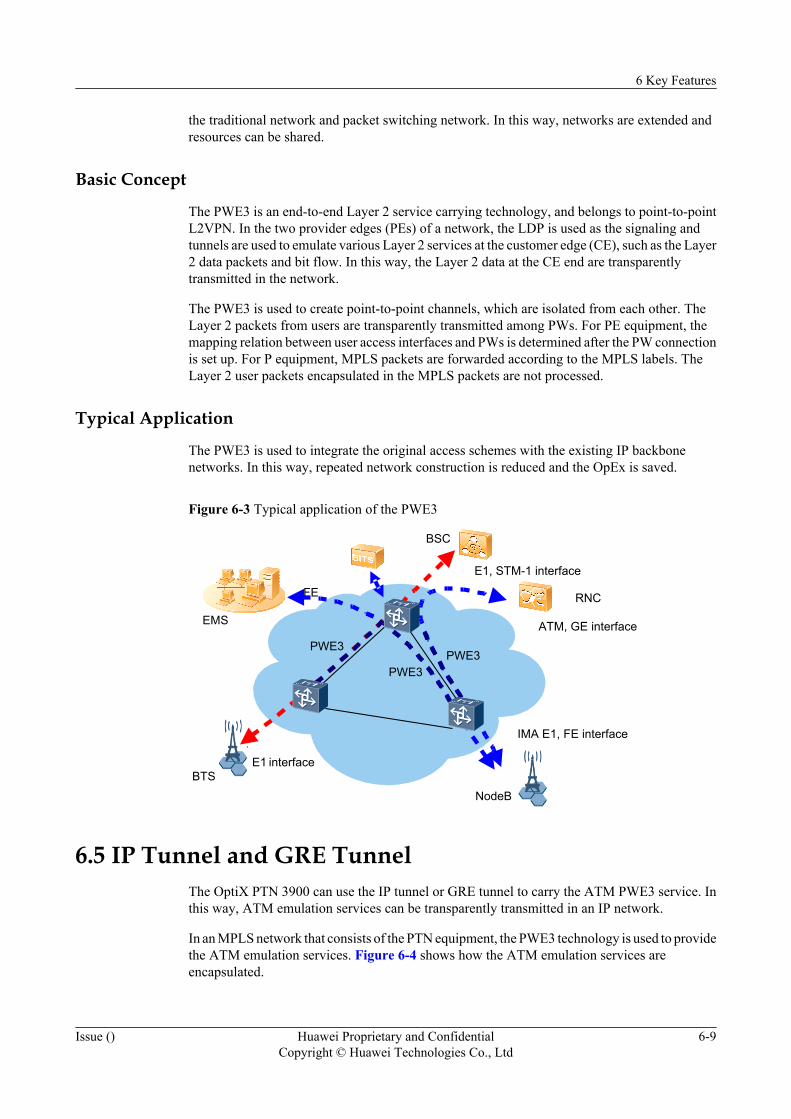
the traditional network and packet switching network. In this way, networks are extended andresources can be shared.
Basic Concept
The PWE3 is an end-to-end Layer 2 service carrying technology, and belongs to point-to-pointL2VPN. In the two provider edges (PEs) of a network, the LDP is used as the signaling andtunnels are used to emulate various Layer 2 services at the customer edge (CE), such as the Layer2 data packets and bit flow. In this way, the Layer 2 data at the CE end are transparentlytransmitted in the network.
The PWE3 is used to create point-to-point channels, which are isolated from each other. TheLayer 2 packets from users are transparently transmitted among PWs. For PE equipment, themapping relation between user access interfaces and PWs is determined after the PW connectionis set up. For P equipment, MPLS packets are forwarded according to the MPLS labels. TheLayer 2 user packets encapsulated in the MPLS packets are not processed.
Typical Application
The PWE3 is used to integrate the original access schemes with the existing IP backbonenetworks. In this way, repeated network construction is reduced and the OpEx is saved.
Figure 6-3 Typical application of the PWE3
E1BTS
NodeB
RNC
BSC
EMS
PWE3PWE3
E1, STM-1 interface
FE
interface
ATM, GE interface
IMA E1, FE interface
PWE3
6.5 IP Tunnel and GRE TunnelThe OptiX PTN 3900 can use the IP tunnel or GRE tunnel to carry the ATM PWE3 service. Inthis way, ATM emulation services can be transparently transmitted in an IP network.
In an MPLS network that consists of the PTN equipment, the PWE3 technology is used to providethe ATM emulation services. Figure 6-4 shows how the ATM emulation services areencapsulated.
6 Key Features
Issue () Huawei Proprietary and ConfidentialCopyright © Huawei Technologies Co., Ltd
6-9
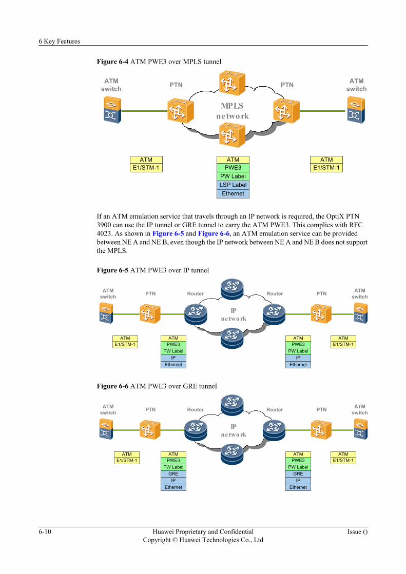
Figure 6-4 ATM PWE3 over MPLS tunnel
ATMswitch
MPLSnetwork
ATME1/STM-1
ATMPWE3
PW LabelLSP LabelEthernet
ATME1/STM-1
ATMswitchPTN PTN
If an ATM emulation service that travels through an IP network is required, the OptiX PTN3900 can use the IP tunnel or GRE tunnel to carry the ATM PWE3. This complies with RFC4023. As shown in Figure 6-5 and Figure 6-6, an ATM emulation service can be providedbetween NE A and NE B, even though the IP network between NE A and NE B does not supportthe MPLS.
Figure 6-5 ATM PWE3 over IP tunnel
ATMswitch
IPnetwork
ATME1/STM-1
ATMPWE3
PW LabelIP
Ethernet
ATME1/STM-1
ATMswitchPTN Router PTN
ATMPWE3
PW LabelIP
Ethernet
Router
Figure 6-6 ATM PWE3 over GRE tunnel
ATMswitch
IPnetwork
ATMPWE3
PW LabelGRE
ATME1/STM-1
ATMswitchPTN Router PTNRouter
IPEthernet
ATMPWE3
PW LabelGRE
IPEthernet
ATME1/STM-1
6 Key Features
6-10 Huawei Proprietary and ConfidentialCopyright © Huawei Technologies Co., Ltd
Issue ()
6.6 QoSThe equipment supports DiffServ based on the standard, including flow classification, flowpolicing, traffic shaping, congestion management and queue scheduling.
The equipment realizes the eight groups of pre-hop behavior (PHB) and services stipulated inthe standard. The eight PHB groups are BE, AF1, AF2, AF3, AF4, EF, CS6 and CS7. With theequipment, the vendors can provide services of different quality classes for users. In this way,an integrated network emerges to carry data, voice and video services at the same time.
When no QoS is needed, packets are forwarded with the best effort (BE).
QoS in the DiffServ Mode
One DiffServ region may contain several types of packets, including VLAN packets and MPLSpackets. To provide a good class of service (CoS) for various packets, at the edge of the DiffServregion, the ingress equipment maps the DSCP/EXP/VLAN Pri into the CoS and the egressequipment maps the QoS into the DSCP/EXP/VLAN Pri.
One DiffServ region may contain several types of packets, including VLAN packets and MPLSpackets. Hence, in actual application, the priority of which layer to be mapped into the forwardingclass should be specified.
The Layer 2 packets include C-VLAN packets and S-VLAN packets . The Layer 3 packetsinclude EXP packets and DSCP packets. By default, the equipment maps the forwarding classaccording to the priorities of Layer 2 packets.
Flow Classification
The flow classification indicates that data packets are classified into several priorities or serviceclasses. For example, if the first six bits of the DSCP ToS field are used for the flow classification,the flow can be classified into a maximum of 64 classes. After the flow is classified, other QoSfeatures then can be used for different classes. In this way, the class-based congestionmanagement and traffic shaping are realized.
The equipment supports the simple flow classification and the complex flow classification.
Simple flow classification:
In the simple flow classification, the priorities of external packets and the priorities of internalpackets are mapped to each other, and the packets are marked with colors, according to the DSCPvalues or IP priorities of IP packets, the EXP values of MPLS packets, and the 802.1p values ofVLAN packets.
Equipment support for the simple flow classification:
The equipment supports the simple flow classification for S-VLAN packets, C-VLAN packets,IP packets, and MPLS packets. The simple flow classification is performed at an Ethernet portor at a POS port.
Purpose of the simple flow classification:
The simple flow classification is effective for an internal node in a DS region. In a DS region,the simple flow classification rules are the same for all nodes. The simple flow classificationmaps the original priorities of packets in the network to the internal priorities of the equipment,
6 Key Features
Issue () Huawei Proprietary and ConfidentialCopyright © Huawei Technologies Co., Ltd
6-11
so that the packets can be transmitted inside the equipment according to the preset priorities.Compared with the complex flow classification, the simple flow classification features a simplexclassification form and easy configuration. In this case, the QoS configuration for each node ina DS region is simplified.
Complex flow classification:
In the complex flow classification, packets are processed according to relatively complex rules.The processing actions include the ACL, the CAR, and the setting of grooming class.
Equipment support for the complex flow classification:
The equipment supports the complex flow classification for S-VLAN packets, C-VLAN packets,and IP packets. The complex flow classification is performed at an Ethernet port.
Purpose of the complex flow classification:
The complex flow classification is effective at the access side of an edge node in a DS region.In the complex flow classification, packets are classified according to complex rules. Furtherprocessing, including the ACL, the CAR, and the setting of grooming class, is also conductedfor the flow bandwidth and for the flow forwarding. The complex flow classification featuresflexible and diversified classification forms. In this case, the user can classify accessed servicesbased on the QoS in a more specific manner.
CAR
The committed access rate (CAR) is a method used to limit the rate of accessed packets accordingto the four preset parameters of the token bucket. The purpose of CAR is to mark accessedpackets with colors (or label the packets), and to limit the rate of accessed packets.
The CAR provides the following two key functions.
l Labeling: Realized by color marking and re-labeling.
l Traffic rate limiting: Realized by the specific action taken on the packets after they aremarked with colors.
There are two color marking modes: color-blind and color-aware. In both modes, the currentrate of packets is compared with the CIR and PIR of the token bucket. The packets that exceedthe PIR are marked in red. The packets that exceed the CIR but are within the PIR are markedin yellow. The packets that are within both the CIR and PIR are marked in green. The differenceis that, in the color-aware mode, if the packets themselves have a color, their own color iscompared with the color that should be marked and then the deeper color is used.
Traffic rate limiting determines whether to discard some colored packets, and thus limits theaccess rate of the traffic.
The default rule is that the red packets are discarded and the yellow and green packets are allowedto pass. The actions can also be manually set for the three-color packets.
NOTE
The token bucket is a technology used to realize the CAR functions. In IETF Recommendations, the singlerate three color marker (srTCM) or two rate three color marker (trTCM) algorithm is used to assess packets.According to the assessment result, the packets are marked with colors and labeled with different discardingpriorities. The PTN equipment adopts the trTCM algorithm.
Queue Scheduling
6 Key Features
6-12 Huawei Proprietary and ConfidentialCopyright © Huawei Technologies Co., Ltd
Issue ()
Packets are sent to queues of different grooming priorities by using different flow classificationmethods. After the flow classification, the equipment adopts a PQ+WFQ (that is, priorityqueuing+weighted fair queuing) method to groom the queues. The PQ method is adopted togroom the CS7, CS6, and EF packets. The WFQ method is adopted to groom the AF packets.The lowest priority is adopted to groom the BE packets.
Congestion Management
In the case of a congestion, the equipment discards packets by using the tail-drop method andthe weighted random early detect (WRED) method. The network congestion can be alleviatedby using these discarding methods.
In the tail-drop method, a buffer queue is used to buffer the packets, and the packet discardingpriorities are not distinguished during the buffering. When the buffer queue is full, packets thatcome thereafter are discarded.
In the WRED method, the discarding priorities (that is, colors) of packets can be detected.According to the discarding priorities, the upper threshold, lower threshold, and probability areset for the purposes of packet discarding. In this case, packets of different discarding prioritieshave different discarding characteristics.
Traffic Shaping
The purpose of traffic shaping is to limit the traffic burst of outgoing packets of a network, andthus to transmit the packets out at a relatively even rate. In this way, congestion is prevented onthe downstream equipment, and fewer packets are discarded.
HQoS
The hierarchical QoS (HQoS) is a QoS technology that can both control the service traffic andgroom services according to their priorities. With the complete traffic statistics functionsprovided by the HQoS, the network administrator can supervise the bandwidth occupied by eachtype of service, and reasonably allocate the bandwidth for services by analyzing the traffic.
The traditional QoS grooms traffic on a port basis, but cannot groom traffic on a multiple-userand multiple-service basis. The HQoS, however, provides the multilevel grooming mode. In thismode, the HQoS provides differentiated QoSs for multiple services of multiple users.
Compared with the traditional QoS, the HQoS has the following advantages:
l The multilevel grooming mechanism provides rich service capabilities.
l Parameters such as the maximum queue length and the WRED can be configured for a flowqueue.
l The CIR and PIR can be configured for each user.
The HQoS can be reflected as the hierarchical service grooming. Based on the HQoS, a networkcarrier can provide further classified service guarantees.
The HQoS function is implemented on the equipment at the network edge. The purpose of suchan implementation is to maintain a simple core network. In this case, not every piece ofequipment in the network is required to conduct the complex QoS processing. At the networkedge, the HQoS is implemented as seven levels of grooming: V-UNI+CoS, V-UNI, V-UNIgroup, PW+CoS, PW, tunnel, and port+CoS. Table 6-3 lists the action points of the HQoS.
6 Key Features
Issue () Huawei Proprietary and ConfidentialCopyright © Huawei Technologies Co., Ltd
6-13
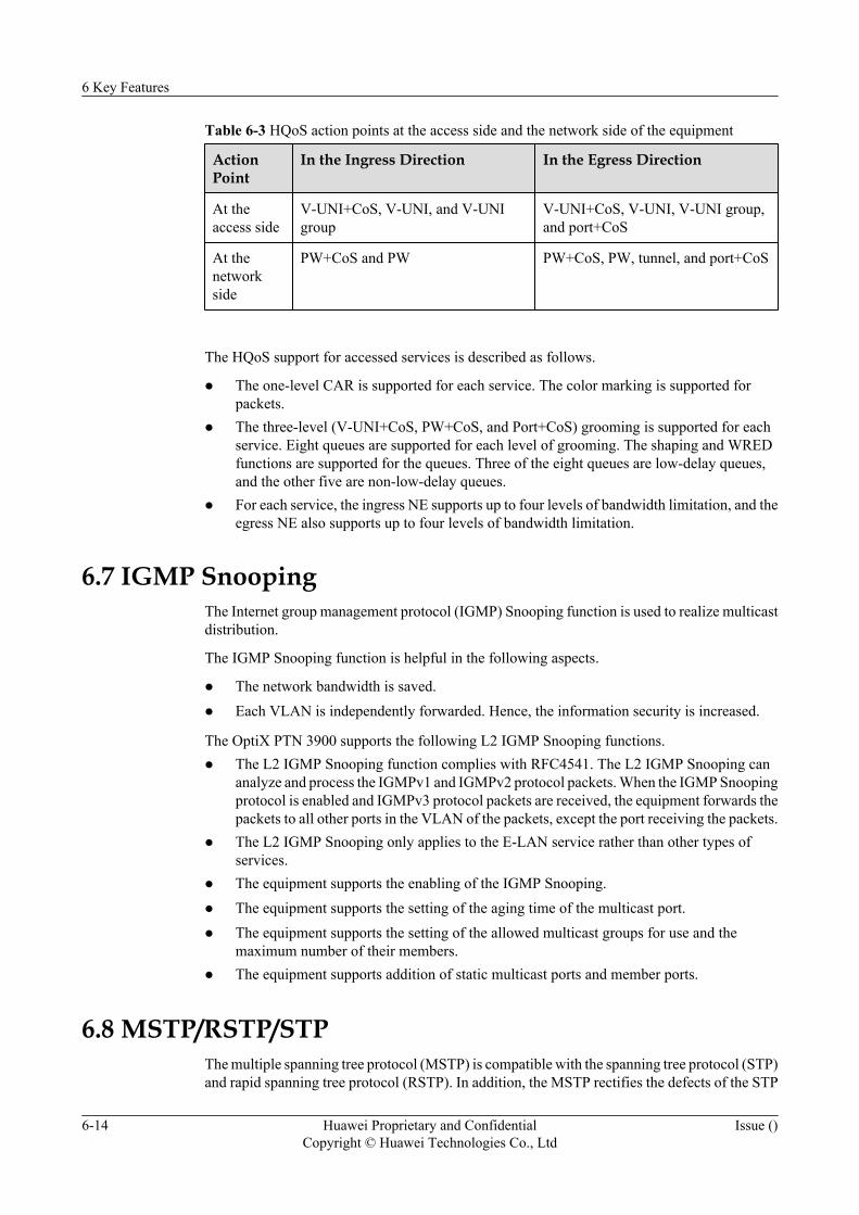
Table 6-3 HQoS action points at the access side and the network side of the equipment
ActionPoint
In the Ingress Direction In the Egress Direction
At theaccess side
V-UNI+CoS, V-UNI, and V-UNIgroup
V-UNI+CoS, V-UNI, V-UNI group,and port+CoS
At thenetworkside
PW+CoS and PW PW+CoS, PW, tunnel, and port+CoS
The HQoS support for accessed services is described as follows.
l The one-level CAR is supported for each service. The color marking is supported forpackets.
l The three-level (V-UNI+CoS, PW+CoS, and Port+CoS) grooming is supported for eachservice. Eight queues are supported for each level of grooming. The shaping and WREDfunctions are supported for the queues. Three of the eight queues are low-delay queues,and the other five are non-low-delay queues.
l For each service, the ingress NE supports up to four levels of bandwidth limitation, and theegress NE also supports up to four levels of bandwidth limitation.
6.7 IGMP SnoopingThe Internet group management protocol (IGMP) Snooping function is used to realize multicastdistribution.
The IGMP Snooping function is helpful in the following aspects.
l The network bandwidth is saved.l Each VLAN is independently forwarded. Hence, the information security is increased.
The OptiX PTN 3900 supports the following L2 IGMP Snooping functions.l The L2 IGMP Snooping function complies with RFC4541. The L2 IGMP Snooping can
analyze and process the IGMPv1 and IGMPv2 protocol packets. When the IGMP Snoopingprotocol is enabled and IGMPv3 protocol packets are received, the equipment forwards thepackets to all other ports in the VLAN of the packets, except the port receiving the packets.
l The L2 IGMP Snooping only applies to the E-LAN service rather than other types ofservices.
l The equipment supports the enabling of the IGMP Snooping.l The equipment supports the setting of the aging time of the multicast port.l The equipment supports the setting of the allowed multicast groups for use and the
maximum number of their members.l The equipment supports addition of static multicast ports and member ports.
6.8 MSTP/RSTP/STPThe multiple spanning tree protocol (MSTP) is compatible with the spanning tree protocol (STP)and rapid spanning tree protocol (RSTP). In addition, the MSTP rectifies the defects of the STP
6 Key Features
6-14 Huawei Proprietary and ConfidentialCopyright © Huawei Technologies Co., Ltd
Issue ()
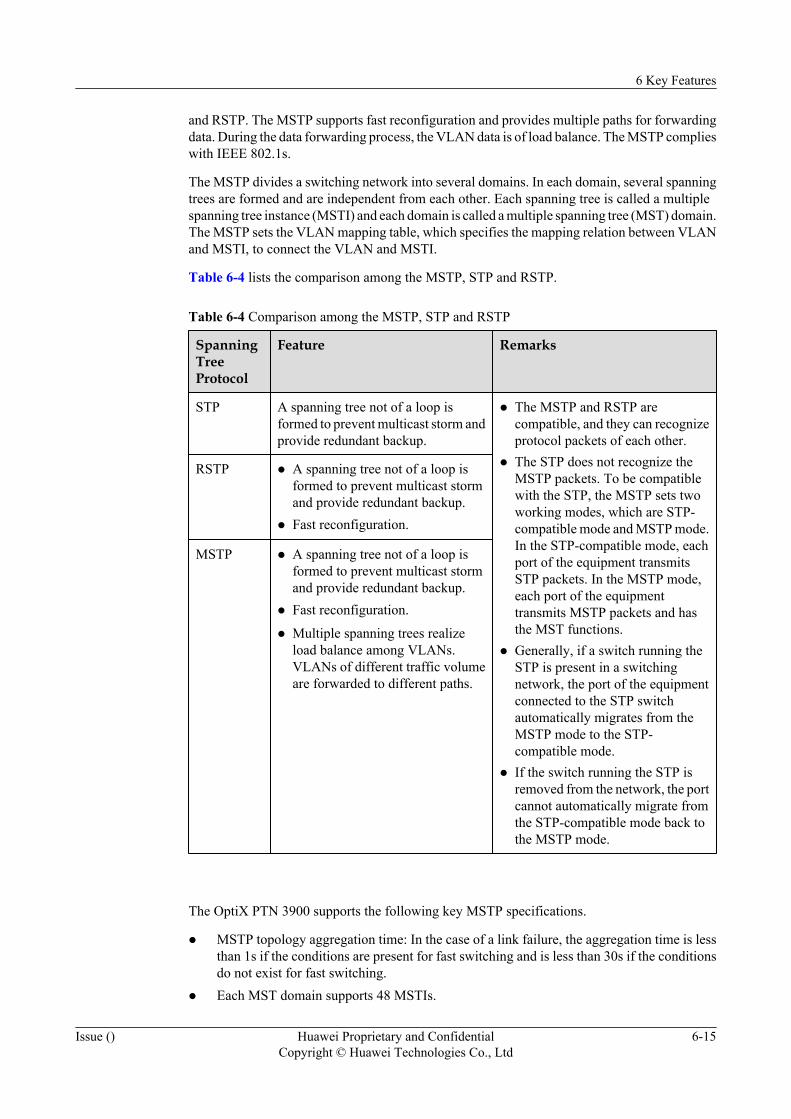
and RSTP. The MSTP supports fast reconfiguration and provides multiple paths for forwardingdata. During the data forwarding process, the VLAN data is of load balance. The MSTP complieswith IEEE 802.1s.
The MSTP divides a switching network into several domains. In each domain, several spanningtrees are formed and are independent from each other. Each spanning tree is called a multiplespanning tree instance (MSTI) and each domain is called a multiple spanning tree (MST) domain.The MSTP sets the VLAN mapping table, which specifies the mapping relation between VLANand MSTI, to connect the VLAN and MSTI.
Table 6-4 lists the comparison among the MSTP, STP and RSTP.
Table 6-4 Comparison among the MSTP, STP and RSTP
SpanningTreeProtocol
Feature Remarks
STP A spanning tree not of a loop isformed to prevent multicast storm andprovide redundant backup.
l The MSTP and RSTP arecompatible, and they can recognizeprotocol packets of each other.
l The STP does not recognize theMSTP packets. To be compatiblewith the STP, the MSTP sets twoworking modes, which are STP-compatible mode and MSTP mode.In the STP-compatible mode, eachport of the equipment transmitsSTP packets. In the MSTP mode,each port of the equipmenttransmits MSTP packets and hasthe MST functions.
l Generally, if a switch running theSTP is present in a switchingnetwork, the port of the equipmentconnected to the STP switchautomatically migrates from theMSTP mode to the STP-compatible mode.
l If the switch running the STP isremoved from the network, the portcannot automatically migrate fromthe STP-compatible mode back tothe MSTP mode.
RSTP l A spanning tree not of a loop isformed to prevent multicast stormand provide redundant backup.
l Fast reconfiguration.
MSTP l A spanning tree not of a loop isformed to prevent multicast stormand provide redundant backup.
l Fast reconfiguration.
l Multiple spanning trees realizeload balance among VLANs.VLANs of different traffic volumeare forwarded to different paths.
The OptiX PTN 3900 supports the following key MSTP specifications.
l MSTP topology aggregation time: In the case of a link failure, the aggregation time is lessthan 1s if the conditions are present for fast switching and is less than 30s if the conditionsdo not exist for fast switching.
l Each MST domain supports 48 MSTIs.
6 Key Features
Issue () Huawei Proprietary and ConfidentialCopyright © Huawei Technologies Co., Ltd
6-15
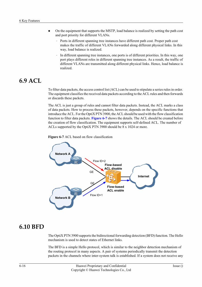
l On the equipment that supports the MSTP, load balance is realized by setting the path costand port priority for different VLANs.– Ports in different spanning tree instances have different path cost. Proper path cost
makes the traffic of different VLANs forwarded along different physical links. In thisway, load balance is realized.
– In different spanning tree instances, one ports is of different priorities. In this way, oneport plays different roles in different spanning tree instances. As a result, the traffic ofdifferent VLANs are transmitted along different physical links. Hence, load balance isrealized.
6.9 ACLTo filter data packets, the access control list (ACL) can be used to stipulate a series rules in order.The equipment classifies the received data packets according to the ACL rules and then forwardsor discards these packets.
The ACL is just a group of rules and cannot filter data packets. Instead, the ACL marks a classof data packets. How to process these packets, however, depends on the specific functions thatintroduce the ACL. For the OptiX PTN 3900, the ACL should be used with the flow classificationfunction to filter data packets. Figure 6-7 shows the details. The ACL should be created beforethe creation of flow classification. The equipment supports self-defined ACL. The number ofACLs supported by the OptiX PTN 3900 should be 8 x 1024 or more.
Figure 6-7 ACL based on flow classification
Network A
Flow ID=2
Flow ID=1Network B
Internet
Flow-basedACL enable
Flow-basedACL disable
GE
GE
6.10 BFDThe OptiX PTN 3900 supports the bidirectional forwarding detection (BFD) function. The Hellomechanism is used to detect states of Ethernet links.
The BFD is a simple Hello protocol, which is similar to the neighbor detection mechanism ofthe routing protocol in many aspects. A pair of systems periodically transmit the detectionpackets in the channels where inter-system talk is established. If a system does not receive any
6 Key Features
6-16 Huawei Proprietary and ConfidentialCopyright © Huawei Technologies Co., Ltd
Issue ()

detection packets in a certain time from the opposite end, it is determined that some part of thebidirectional channel connected to adjacent nodes is faulty.
The OptiX PTN 3900 adopts the asynchronous mode to perform BFD detection for Ethernetlinks. In the asynchronous mode, the equipment at both ends of a link periodically transmits theBFD control packets to each other. If the equipment does not receive any BFD control packetsin a long time from the opposite end, it is determined that the Ethernet link is faulty.
6 Key Features
Issue () Huawei Proprietary and ConfidentialCopyright © Huawei Technologies Co., Ltd
6-17

7 Protection
About This Chapter
The OptiX PTN 3900 provides equipment level protection and network level protection.
7.1 Equipment Level ProtectionThe equipment level protection includes the TPS protection for service boards, the 1+1protection for the system control, communication and auxiliary processing board (SCA), the 1+1 protection for the cross-connect and timing board (XCS), the 1+1 protection for the powersupply, and the protection for fans.
7.2 Network Level ProtectionThe network level protection includes the LSP 1+1 and 1:1 protection, the SDH LMSP 1+1 and1:1 protection, FRR protection, the Ethernet LAG protection, the spanning tree protection, thepacket E1 ML-PPP protection and IMA protection.
7 Protection
Issue () Huawei Proprietary and ConfidentialCopyright © Huawei Technologies Co., Ltd
7-1
7.1 Equipment Level ProtectionThe equipment level protection includes the TPS protection for service boards, the 1+1protection for the system control, communication and auxiliary processing board (SCA), the 1+1 protection for the cross-connect and timing board (XCS), the 1+1 protection for the powersupply, and the protection for fans.
7.1.1 TPS ProtectionThe TPS protection scheme protects the MP1 board and the service sub-board on it. Interfacesfor the service sub-board is only available on the interface boards. When a MP1 board or theservice sub-board on it has a hardware failure, the signal flow from the interface board isswitched, by software and hardware operations, to a normal MP1 board that is specially usedfor protection. In this way, the faulty service sub-board is protected. The TPS protection schemeis able to protect various E1 services, such as CES, IMA, and ML-PPP. The OptiX PTN 3900supports a maximum of two groups of 1: N (N≤4) TPS protection.
7.1.2 1+1 Protection for the SCA BoardThe 1+1 protection for the SCA board is provided when two SCA boards are installed on theequipment. When the software or hardware of the working SCA is faulty, or when the workingand protection SCAs receive a switching command, the SCA working/protection switchingoccurs. In this way, the protection for the SCA is realized.
7.1.3 1+1 Protection for the Cross-Connect and Timing BoardThe 1+1 protection for the cross-connect and timing board is provided when the equipment isinstalled with two cross-connect and timing boards. When the software or hardware of theworking board is faulty, or when the working and protection boards receive a switchingcommand, the working/protection switching occurs. In this way, the protection for the cross-connect and timing board is realized.
7.1.4 1+1 Protection for the PIUTwo power interface units (PIU) that provide hot backup for each other are installed on theequipment. When one PIU fails, the equipment can still function properly.
7.1.1 TPS ProtectionThe TPS protection scheme protects the MP1 board and the service sub-board on it. Interfacesfor the service sub-board is only available on the interface boards. When a MP1 board or theservice sub-board on it has a hardware failure, the signal flow from the interface board isswitched, by software and hardware operations, to a normal MP1 board that is specially usedfor protection. In this way, the faulty service sub-board is protected. The TPS protection schemeis able to protect various E1 services, such as CES, IMA, and ML-PPP. The OptiX PTN 3900supports a maximum of two groups of 1: N (N≤4) TPS protection.
Protection Schemes and Supported BoardsThe equipment supports TPS protection for various E1 services. Table 7-1 lists the TPSprotection schemes and supported boards.
7 Protection
7-2 Huawei Proprietary and ConfidentialCopyright © Huawei Technologies Co., Ltd
Issue ()
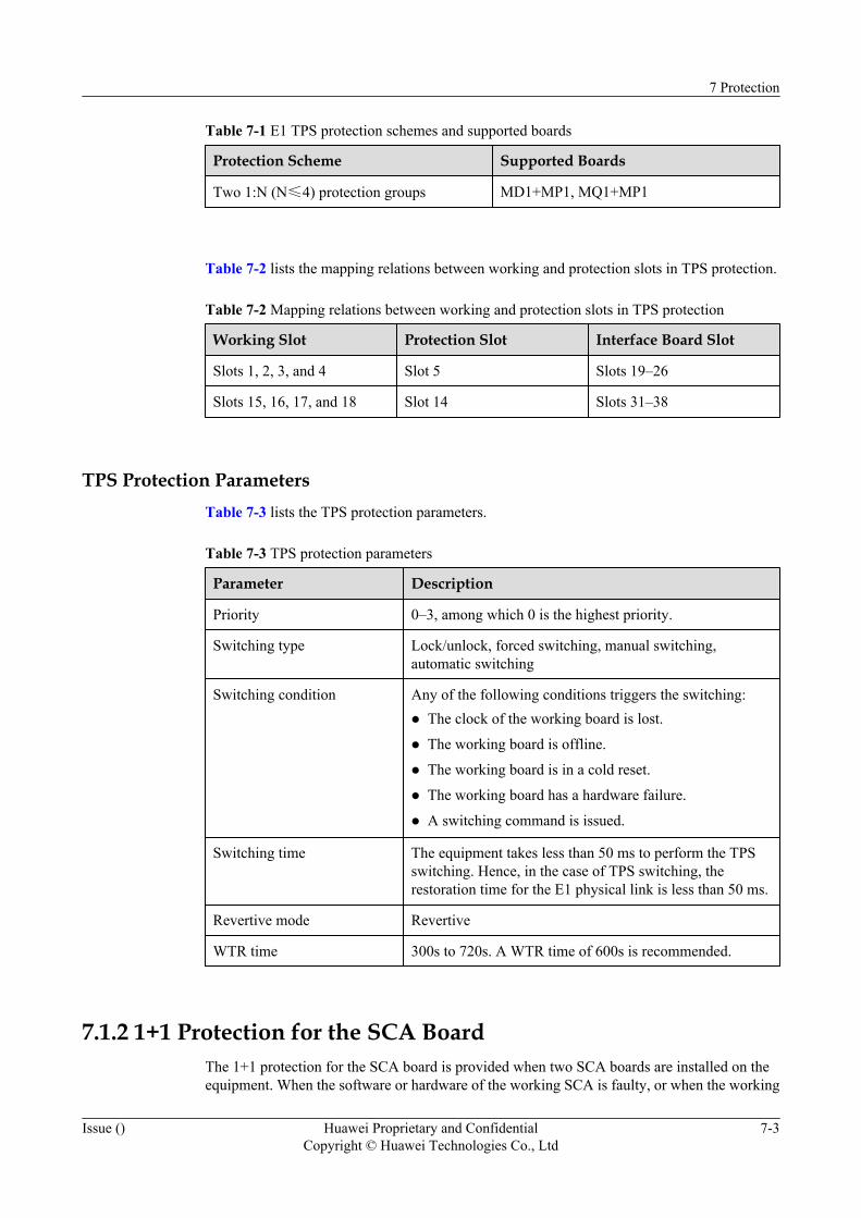
Table 7-1 E1 TPS protection schemes and supported boards
Protection Scheme Supported Boards
Two 1:N (N≤4) protection groups MD1+MP1, MQ1+MP1
Table 7-2 lists the mapping relations between working and protection slots in TPS protection.
Table 7-2 Mapping relations between working and protection slots in TPS protection
Working Slot Protection Slot Interface Board Slot
Slots 1, 2, 3, and 4 Slot 5 Slots 19–26
Slots 15, 16, 17, and 18 Slot 14 Slots 31–38
TPS Protection ParametersTable 7-3 lists the TPS protection parameters.
Table 7-3 TPS protection parameters
Parameter Description
Priority 0–3, among which 0 is the highest priority.
Switching type Lock/unlock, forced switching, manual switching,automatic switching
Switching condition Any of the following conditions triggers the switching:l The clock of the working board is lost.
l The working board is offline.
l The working board is in a cold reset.
l The working board has a hardware failure.
l A switching command is issued.
Switching time The equipment takes less than 50 ms to perform the TPSswitching. Hence, in the case of TPS switching, therestoration time for the E1 physical link is less than 50 ms.
Revertive mode Revertive
WTR time 300s to 720s. A WTR time of 600s is recommended.
7.1.2 1+1 Protection for the SCA BoardThe 1+1 protection for the SCA board is provided when two SCA boards are installed on theequipment. When the software or hardware of the working SCA is faulty, or when the working
7 Protection
Issue () Huawei Proprietary and ConfidentialCopyright © Huawei Technologies Co., Ltd
7-3

and protection SCAs receive a switching command, the SCA working/protection switchingoccurs. In this way, the protection for the SCA is realized.
On the OptiX PTN 3900, the valid slots for the SCA are slots 29 and 30.
Table 7-4 lists the SCA 1+1 protection parameters of the OptiX PTN 3900.
Table 7-4 1+1 protection parameters of the SCA board
Parameter Description
Slots for boards Slots 29 and 30.
Switching condition Any of the following conditions triggers the switching:l The working board has a hardware or software failure.
l A switching command is manually issued.
l The working board is removed.
l The working board is in a cold reset.
Revertive mode Non-revertive
7.1.3 1+1 Protection for the Cross-Connect and Timing BoardThe 1+1 protection for the cross-connect and timing board is provided when the equipment isinstalled with two cross-connect and timing boards. When the software or hardware of theworking board is faulty, or when the working and protection boards receive a switchingcommand, the working/protection switching occurs. In this way, the protection for the cross-connect and timing board is realized.
The cross-connect and timing board for the OptiX PTN 3900 is the XCS, whose valid slots areslots 9 and 10.
Table 7-5 lists the 1+1 protection parameters of the cross-connect and timing board.
Table 7-5 1+1 protection parameters of the cross-connect and timing board
Parameter Description
Slots for working andprotection boards
Slot 9 is for the working board, and slot 10 is for theprotection board.
Switching condition Any of the following conditions triggers the switching:l The working board has a hardware or software failure.
l A switching command is manually issued.
l The working board is removed.
l The working board is in a cold reset.
Revertive mode Non-revertive
7 Protection
7-4 Huawei Proprietary and ConfidentialCopyright © Huawei Technologies Co., Ltd
Issue ()
7.1.4 1+1 Protection for the PIUTwo power interface units (PIU) that provide hot backup for each other are installed on theequipment. When one PIU fails, the equipment can still function properly.
The PIU accesses –48 V or –60 V power supply for the OptiX PTN 3900.
7.2 Network Level ProtectionThe network level protection includes the LSP 1+1 and 1:1 protection, the SDH LMSP 1+1 and1:1 protection, FRR protection, the Ethernet LAG protection, the spanning tree protection, thepacket E1 ML-PPP protection and IMA protection.
7.2.1 LSP 1+1 and 1:1 ProtectionIn the LSP 1+1 and 1:1 protection, the protection path protects the service that is transported inthe working path. When the working path is faulty, the service is switched to the protection path.The 1+1 protection adopts the dual fed and selective receiving mechanism, and the 1:1 protectionadopts the single fed and single receiving mechanism.
7.2.2 FRR ProtectionFast reroute (FRR) is a feature of MPLS TE, and provides fast local protection. FRR is usuallydeployed in a network that requires high reliability. When a local failure occurs in the network,FRR is able to quickly switch the services to a bypass tunnel. In this case, the impact on dataservices is very small.
7.2.3 Ethernet LAG ProtectionLink aggregation means that a group of physical Ethernet ports (a group of FE ports or a groupof GE ports) are bundled together to form a logical port (LAG). In this way, link aggregationincreases the bandwidth and provides link protection.
7.2.4 Ethernet Spanning Tree ProtectionThe multiple spanning tree protocol (MSTP) can be used to prevent a loop. Using an algorithm,the MSTP blocks redundant paths so that the loop network can be trimmed as a tree network. Inthis case, the proliferation and endless cycling of packets, which can cause a broadcast storm,is prevented in the loop network. The major difference between the MSTP and STP/RSTPprotocols is that the MSTP protocol can forward data based on VLAN ID and thus realizes theload balancing.
7.2.5 LMSP 1+1 and 1:1 ProtectionIn the LMSP 1+1 and 1:1 protection, the protection path protects the service that is transportedin the working path. When the working path is faulty, the service is switched to the protectionpath. The 1+1 protection adopts the dual fed and selective receiving mechanism, and the 1:1protection adopts the single fed and single receiving mechanism. The LMSP protection schemeis designed for STM-N interfaces, for examples, the boards that provide channelized STM-1ports and POS ports.
7.2.6 Packet E1 ML-PPP ProtectionMultilink PPP (ML-PPP) indicates that several PPP channels are bundled to increase thebandwidth, to share the loading and to provide backup. The ML-PPP is applicable mainly in thecase of interconnection between the E1 board and mobile equipment. In this way, the load ofthe board ports at the network side can be shared and protected.
7.2.7 IMA ProtectionInverse multiplexing for ATM (IMA) demultiplexes a concentrated flow of ATM cells intomultiple lower-rate links, and at the remote end multiplexes these lower-rate links to recover the
7 Protection
Issue () Huawei Proprietary and ConfidentialCopyright © Huawei Technologies Co., Ltd
7-5
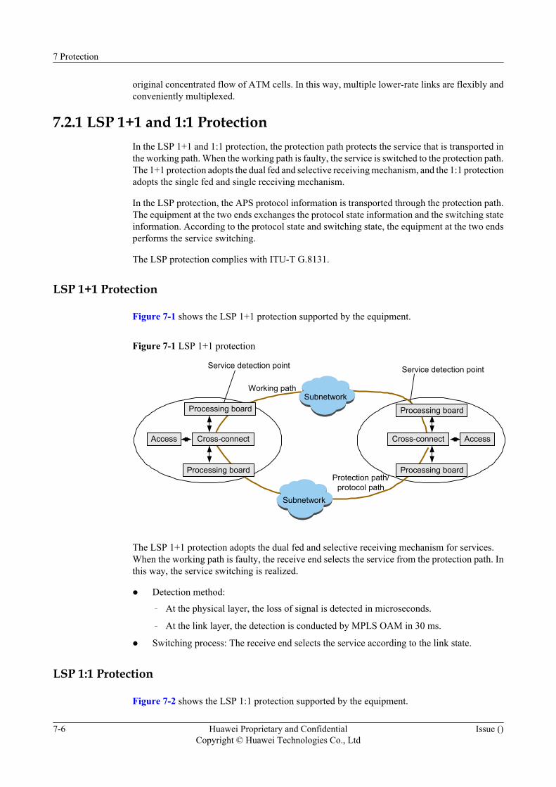
original concentrated flow of ATM cells. In this way, multiple lower-rate links are flexibly andconveniently multiplexed.
7.2.1 LSP 1+1 and 1:1 ProtectionIn the LSP 1+1 and 1:1 protection, the protection path protects the service that is transported inthe working path. When the working path is faulty, the service is switched to the protection path.The 1+1 protection adopts the dual fed and selective receiving mechanism, and the 1:1 protectionadopts the single fed and single receiving mechanism.
In the LSP protection, the APS protocol information is transported through the protection path.The equipment at the two ends exchanges the protocol state information and the switching stateinformation. According to the protocol state and switching state, the equipment at the two endsperforms the service switching.
The LSP protection complies with ITU-T G.8131.
LSP 1+1 Protection
Figure 7-1 shows the LSP 1+1 protection supported by the equipment.
Figure 7-1 LSP 1+1 protection
Subnetwork
Service detection point Service detection point
Working path
Protection path/protocol path
Access Cross-connect
Processing board
Subnetwork
AccessCross-connect
Processing board Processing board
Processing board
The LSP 1+1 protection adopts the dual fed and selective receiving mechanism for services.When the working path is faulty, the receive end selects the service from the protection path. Inthis way, the service switching is realized.
l Detection method:
– At the physical layer, the loss of signal is detected in microseconds.
– At the link layer, the detection is conducted by MPLS OAM in 30 ms.
l Switching process: The receive end selects the service according to the link state.
LSP 1:1 Protection
Figure 7-2 shows the LSP 1:1 protection supported by the equipment.
7 Protection
7-6 Huawei Proprietary and ConfidentialCopyright © Huawei Technologies Co., Ltd
Issue ()
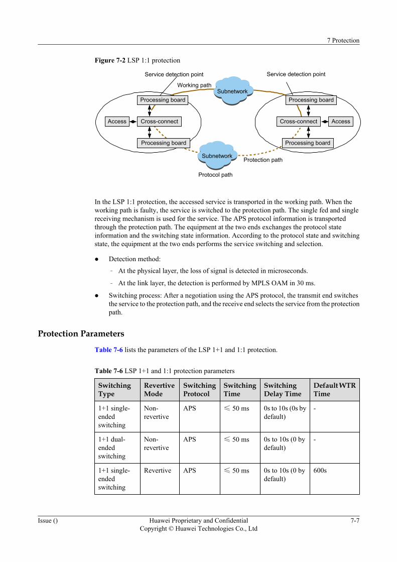
Figure 7-2 LSP 1:1 protection
Subnetwork
Service detection point Service detection point
Working path
Protection path
Access Cross-connect
Processing board
Processing board
Subnetwork
AccessCross-connect
Processing board
Processing board
Protocol path
In the LSP 1:1 protection, the accessed service is transported in the working path. When theworking path is faulty, the service is switched to the protection path. The single fed and singlereceiving mechanism is used for the service. The APS protocol information is transportedthrough the protection path. The equipment at the two ends exchanges the protocol stateinformation and the switching state information. According to the protocol state and switchingstate, the equipment at the two ends performs the service switching and selection.
l Detection method:
– At the physical layer, the loss of signal is detected in microseconds.
– At the link layer, the detection is performed by MPLS OAM in 30 ms.
l Switching process: After a negotiation using the APS protocol, the transmit end switchesthe service to the protection path, and the receive end selects the service from the protectionpath.
Protection Parameters
Table 7-6 lists the parameters of the LSP 1+1 and 1:1 protection.
Table 7-6 LSP 1+1 and 1:1 protection parameters
SwitchingType
RevertiveMode
SwitchingProtocol
SwitchingTime
SwitchingDelay Time
Default WTRTime
1+1 single-endedswitching
Non-revertive
APS ≤ 50 ms 0s to 10s (0s bydefault)
-
1+1 dual-endedswitching
Non-revertive
APS ≤ 50 ms 0s to 10s (0 bydefault)
-
1+1 single-endedswitching
Revertive APS ≤ 50 ms 0s to 10s (0 bydefault)
600s
7 Protection
Issue () Huawei Proprietary and ConfidentialCopyright © Huawei Technologies Co., Ltd
7-7
SwitchingType
RevertiveMode
SwitchingProtocol
SwitchingTime
SwitchingDelay Time
Default WTRTime
1+1 dual-endedswitching
Revertive APS ≤ 50 ms 0s to 10s (0 bydefault)
600s
1:1 dual-endedswitching
Non-revertive
APS ≤ 50 ms 0s to 10s (0 bydefault)
-
1:1 dual-endedswitching
Revertive APS ≤ 50 ms 0s to 10s (0 bydefault)
600s
Any of the following conditions triggers the switching:l The board has a hardware or software failure.
l The board is in a cold reset.
l A switching command is manually issued.
l LSP faulty is detected by MPLS OAM.
7.2.2 FRR ProtectionFast reroute (FRR) is a feature of MPLS TE, and provides fast local protection. FRR is usuallydeployed in a network that requires high reliability. When a local failure occurs in the network,FRR is able to quickly switch the services to a bypass tunnel. In this case, the impact on dataservices is very small.
Basic Concepts of FRRThe basic concepts of FRR are described as follows.
l Detour mode: Refers to one-to-one backup. In the detour mode, LSPs are protectedseparately, that is, one protection LSP is specially created for each protected LSP. Thisprotection LSP is called a detour LSP.
l Bypass mode: Refers to facility backup. In the bypass mode, one protection LSP is used toprotect multiple LSPs. This protection LSP is called a bypass LSP.
l PLR: Refers to point of local repair. The PLR is the ingress node of a detour LSP or bypassLSP. The PLR must be on the route of the working LSP, and cannot be the egress node ofthe working LSP.
l MP: Refers to merge point. The MP is the egress node of a detour LSP or bypass LSP. TheMP must be on the working LSP, and cannot be the ingress node.
l Link protection: In link protection, a direct link connection exists between the PLR and theMP, and the working LSP passes through this link. When this link fails, the services canbe switched to a detour LSP or bypass LSP.
l Node protection: In node protection, the PLR and the MP are connected through anintermediate node, and the working tunnel passes through this node. When this node fails,the services can be switched to a detour LSP or bypass LSP.
FRR protection complies with RFC 4090.
7 Protection
7-8 Huawei Proprietary and ConfidentialCopyright © Huawei Technologies Co., Ltd
Issue ()
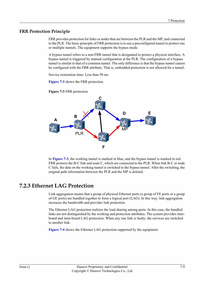
FRR Protection PrincipleFRR provides protection for links or nodes that are between the PLR and the MP, and connectedto the PLR. The basic principle of FRR protection is to use a preconfigured tunnel to protect oneor multiple tunnels. The equipment supports the bypass mode.
A bypass tunnel refers to a non-FRR tunnel that is designated to protect a physical interface. Abypass tunnel is triggered by manual configuration at the PLR. The configuration of a bypasstunnel is similar to that of a common tunnel. The only difference is that the bypass tunnel cannotbe configured with the FRR attribute. That is, embedded protection is not allowed for a tunnel.
Service restoration time: Less than 50 ms
Figure 7-3 shows the FRR protection.
Figure 7-3 FRR protection
AB
C
D E
F
MPPLR
In Figure 7-3, the working tunnel is marked in blue, and the bypass tunnel is marked in red.FRR protects the B-C link and node C, which are connected to the PLR. When link B-C or nodeC fails, the data on the working tunnel is switched to the bypass tunnel. After the switching, theoriginal path information between the PLR and the MP is deleted.
7.2.3 Ethernet LAG ProtectionLink aggregation means that a group of physical Ethernet ports (a group of FE ports or a groupof GE ports) are bundled together to form a logical port (LAG). In this way, link aggregationincreases the bandwidth and provides link protection.
The Ethernet LAG protection realizes the load sharing among ports. In this case, the bundledlinks are not distinguished by the working and protection attributes. The system provides inter-board and intra-board LAG protection. When any one link is faulty, the services are switchedto another link.
Figure 7-4 shows the Ethernet LAG protection supported by the equipment.
7 Protection
Issue () Huawei Proprietary and ConfidentialCopyright © Huawei Technologies Co., Ltd
7-9
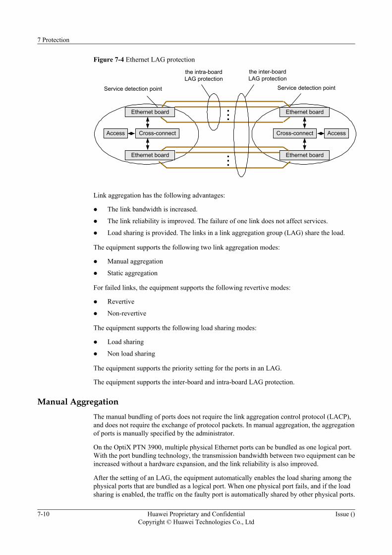
Figure 7-4 Ethernet LAG protection
Service detection point Service detection point
Access Cross-connect
Ethernet board
AccessCross-connect
Ethernet board
Ethernet board
Ethernet board...
...
the intra-boardLAG protection
the inter-boardLAG protection
Link aggregation has the following advantages:
l The link bandwidth is increased.
l The link reliability is improved. The failure of one link does not affect services.
l Load sharing is provided. The links in a link aggregation group (LAG) share the load.
The equipment supports the following two link aggregation modes:
l Manual aggregation
l Static aggregation
For failed links, the equipment supports the following revertive modes:
l Revertive
l Non-revertive
The equipment supports the following load sharing modes:
l Load sharing
l Non load sharing
The equipment supports the priority setting for the ports in an LAG.
The equipment supports the inter-board and intra-board LAG protection.
Manual AggregationThe manual bundling of ports does not require the link aggregation control protocol (LACP),and does not require the exchange of protocol packets. In manual aggregation, the aggregationof ports is manually specified by the administrator.
On the OptiX PTN 3900, multiple physical Ethernet ports can be bundled as one logical port.With the port bundling technology, the transmission bandwidth between two equipment can beincreased without a hardware expansion, and the link reliability is also improved.
After the setting of an LAG, the equipment automatically enables the load sharing among thephysical ports that are bundled as a logical port. When one physical port fails, and if the loadsharing is enabled, the traffic on the faulty port is automatically shared by other physical ports.
7 Protection
7-10 Huawei Proprietary and ConfidentialCopyright © Huawei Technologies Co., Ltd
Issue ()
When the faulty port recovers, the traffic is reallocated to ensure that the load is shared amongall ports.
Static Aggregation
The static aggregation of links requires the LACP protocol. In static aggregation, the automaticmaintenance of aggregated ports is realized through the exchange of protocol packets. Theadministrator, however, is still responsible for creating an LAG and adding member links intothe LAG. Furthermore, the LACP protocol cannot change the configuration information of theadministrator.
The OptiX PTN 3900 supports the LACP protocol that complies with IEEE 802.3ad. Theadministrator creates the bundling of ports on the equipment, adds member ports into the bundledgroup, and enables the LACP function for the bundled ports. By exchanging LACP packets, twointerconnected equipment negotiate which ports can be used to forward data, and thus determinewhether an egress port is in the selected or standby state.
The LACP protocol maintains the link state according to the port state. When aggregationconditions change, the link aggregation is automatically adjusted or dismantled. The membersin an LAG can share the traffic load based on MAC addresses, IP addresses, or MPLS labels.
7.2.4 Ethernet Spanning Tree ProtectionThe multiple spanning tree protocol (MSTP) can be used to prevent a loop. Using an algorithm,the MSTP blocks redundant paths so that the loop network can be trimmed as a tree network. Inthis case, the proliferation and endless cycling of packets, which can cause a broadcast storm,is prevented in the loop network. The major difference between the MSTP and STP/RSTPprotocols is that the MSTP protocol can forward data based on VLAN ID and thus realizes theload balancing.
The MSTP supported by the equipment is compliant with IEEE 802.1s, and is compatible withthe STP and RSTP. For the difference between the MSTP and the STP/RSTP, see Table 6-4.
The MSTP adopts the concepts of region and instance. The MSTP divides a switching networkinto different regions as required. Multiple independent spanning trees are generated in eachregion. Each spanning tree is referred to as a multiple spanning tree instance (MSTI), and eachregion is referred to as an MST region. The MSTP determines the mapping relations betweenVLANs and MSTIs by setting a VLAN mapping table (that is, a VLAN and MSTI mappingrelation table). Each instance is mapped to one VLAN or a group of VLANs.
NOTE
l Instance: Equipment that runs the MSTP may have multiple spanning trees at the same time. Eachspanning tree is referred to as a multiple spanning tree instance. In this way, these spanning trees canbe distinguished.
l Region: A region refers to a group of interconnected switching equipment that have the same VLAN-to-instance mapping relations.
Bridge protocol data units (BPDUs) that carry region and instance information are transmittedamong equipment. According to the BPDU information, the equipment determines whether itbelongs to a specific region. The RSTP based on multiple instances is used within a region, andthe common RSTP is used among different regions.
Figure 7-5 shows a switching network that has multiple VLANs.
7 Protection
Issue () Huawei Proprietary and ConfidentialCopyright © Huawei Technologies Co., Ltd
7-11
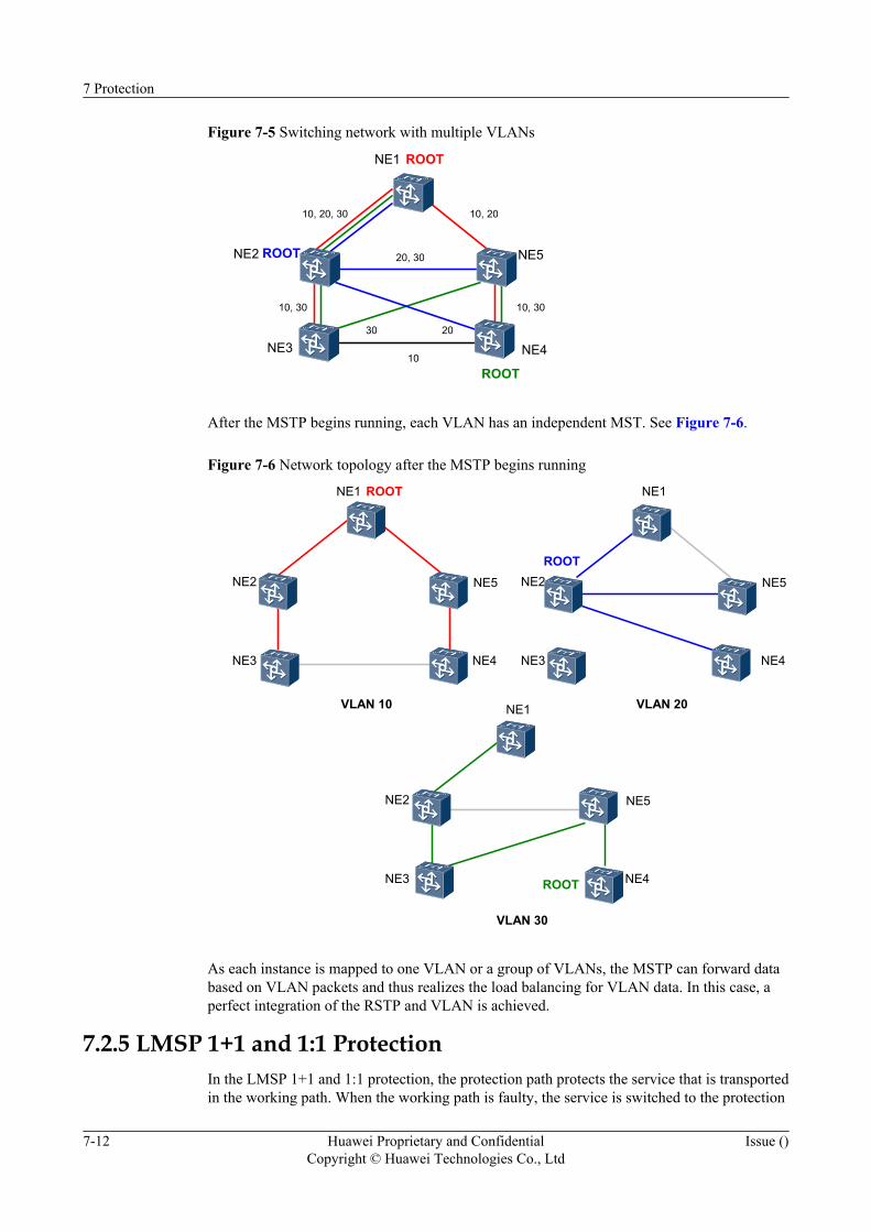
Figure 7-5 Switching network with multiple VLANs
ROOT
ROOT
ROOT
10, 20, 30
10, 30 10, 30
20
10
30
10, 20
20, 30
NE1
NE2
NE3 NE4
NE5
After the MSTP begins running, each VLAN has an independent MST. See Figure 7-6.
Figure 7-6 Network topology after the MSTP begins running
VLAN 10 VLAN 20
ROOT
ROOT
VLAN 30
ROOTNE1
NE2
NE3 NE4
NE5
NE1
NE2
NE3 NE4
NE5
NE1
NE2
NE3 NE4
NE5
As each instance is mapped to one VLAN or a group of VLANs, the MSTP can forward databased on VLAN packets and thus realizes the load balancing for VLAN data. In this case, aperfect integration of the RSTP and VLAN is achieved.
7.2.5 LMSP 1+1 and 1:1 ProtectionIn the LMSP 1+1 and 1:1 protection, the protection path protects the service that is transportedin the working path. When the working path is faulty, the service is switched to the protection
7 Protection
7-12 Huawei Proprietary and ConfidentialCopyright © Huawei Technologies Co., Ltd
Issue ()
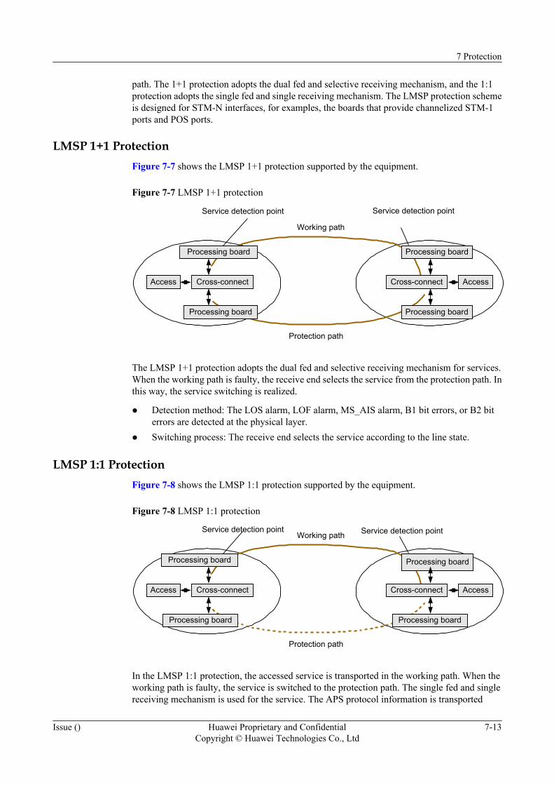
path. The 1+1 protection adopts the dual fed and selective receiving mechanism, and the 1:1protection adopts the single fed and single receiving mechanism. The LMSP protection schemeis designed for STM-N interfaces, for examples, the boards that provide channelized STM-1ports and POS ports.
LMSP 1+1 ProtectionFigure 7-7 shows the LMSP 1+1 protection supported by the equipment.
Figure 7-7 LMSP 1+1 protection
Service detection point Service detection point
Working path
Protection path
Access Cross-connect
Processing board
Processing board
AccessCross-connect
Processing board
Processing board
The LMSP 1+1 protection adopts the dual fed and selective receiving mechanism for services.When the working path is faulty, the receive end selects the service from the protection path. Inthis way, the service switching is realized.
l Detection method: The LOS alarm, LOF alarm, MS_AIS alarm, B1 bit errors, or B2 biterrors are detected at the physical layer.
l Switching process: The receive end selects the service according to the line state.
LMSP 1:1 ProtectionFigure 7-8 shows the LMSP 1:1 protection supported by the equipment.
Figure 7-8 LMSP 1:1 protection
Service detection pointWorking path
Protection path
Access Cross-connect
Processing board
Processing board
AccessCross-connect
Processing board
Processing board
Service detection point
In the LMSP 1:1 protection, the accessed service is transported in the working path. When theworking path is faulty, the service is switched to the protection path. The single fed and singlereceiving mechanism is used for the service. The APS protocol information is transported
7 Protection
Issue () Huawei Proprietary and ConfidentialCopyright © Huawei Technologies Co., Ltd
7-13
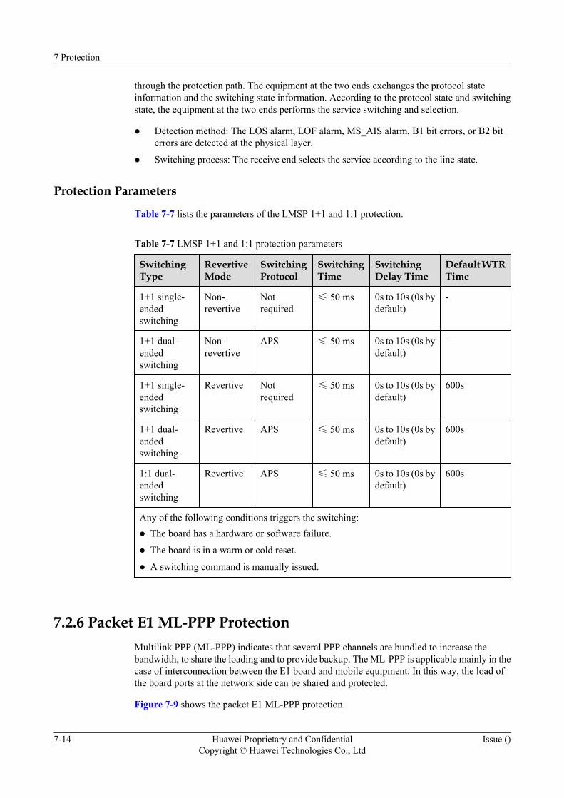
through the protection path. The equipment at the two ends exchanges the protocol stateinformation and the switching state information. According to the protocol state and switchingstate, the equipment at the two ends performs the service switching and selection.
l Detection method: The LOS alarm, LOF alarm, MS_AIS alarm, B1 bit errors, or B2 biterrors are detected at the physical layer.
l Switching process: The receive end selects the service according to the line state.
Protection Parameters
Table 7-7 lists the parameters of the LMSP 1+1 and 1:1 protection.
Table 7-7 LMSP 1+1 and 1:1 protection parameters
SwitchingType
RevertiveMode
SwitchingProtocol
SwitchingTime
SwitchingDelay Time
Default WTRTime
1+1 single-endedswitching
Non-revertive
Notrequired
≤ 50 ms 0s to 10s (0s bydefault)
-
1+1 dual-endedswitching
Non-revertive
APS ≤ 50 ms 0s to 10s (0s bydefault)
-
1+1 single-endedswitching
Revertive Notrequired
≤ 50 ms 0s to 10s (0s bydefault)
600s
1+1 dual-endedswitching
Revertive APS ≤ 50 ms 0s to 10s (0s bydefault)
600s
1:1 dual-endedswitching
Revertive APS ≤ 50 ms 0s to 10s (0s bydefault)
600s
Any of the following conditions triggers the switching:l The board has a hardware or software failure.
l The board is in a warm or cold reset.
l A switching command is manually issued.
7.2.6 Packet E1 ML-PPP ProtectionMultilink PPP (ML-PPP) indicates that several PPP channels are bundled to increase thebandwidth, to share the loading and to provide backup. The ML-PPP is applicable mainly in thecase of interconnection between the E1 board and mobile equipment. In this way, the load ofthe board ports at the network side can be shared and protected.
Figure 7-9 shows the packet E1 ML-PPP protection.
7 Protection
7-14 Huawei Proprietary and ConfidentialCopyright © Huawei Technologies Co., Ltd
Issue ()
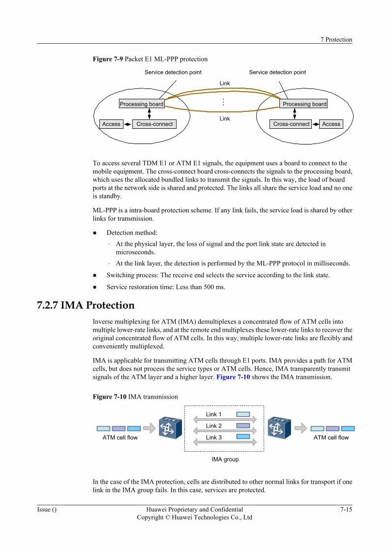
Figure 7-9 Packet E1 ML-PPP protection
Access
Processing board Processing board
Cross-connect Cross-connectAccess
Link
Link
...
Service detection point Service detection point
To access several TDM E1 or ATM E1 signals, the equipment uses a board to connect to themobile equipment. The cross-connect board cross-connects the signals to the processing board,which uses the allocated bundled links to transmit the signals. In this way, the load of boardports at the network side is shared and protected. The links all share the service load and no oneis standby.
ML-PPP is a intra-board protection scheme. If any link fails, the service load is shared by otherlinks for transmission.
l Detection method:– At the physical layer, the loss of signal and the port link state are detected in
microseconds.– At the link layer, the detection is performed by the ML-PPP protocol in milliseconds.
l Switching process: The receive end selects the service according to the link state.
l Service restoration time: Less than 500 ms.
7.2.7 IMA ProtectionInverse multiplexing for ATM (IMA) demultiplexes a concentrated flow of ATM cells intomultiple lower-rate links, and at the remote end multiplexes these lower-rate links to recover theoriginal concentrated flow of ATM cells. In this way, multiple lower-rate links are flexibly andconveniently multiplexed.
IMA is applicable for transmitting ATM cells through E1 ports. IMA provides a path for ATMcells, but does not process the service types or ATM cells. Hence, IMA transparently transmitsignals of the ATM layer and a higher layer. Figure 7-10 shows the IMA transmission.
Figure 7-10 IMA transmission
Link 1
Link 2
Link 3
IMA group
ATM cell flow ATM cell flow
In the case of the IMA protection, cells are distributed to other normal links for transport if onelink in the IMA group fails. In this case, services are protected.
7 Protection
Issue () Huawei Proprietary and ConfidentialCopyright © Huawei Technologies Co., Ltd
7-15

8 Operation, Administration and Maintenance
About This Chapter
The OptiX PTN 3900 provides powerful functions of operation, administration and maintenance.
8.1 OAM CapabilityThe boards and functions of the OptiX PTN 3900 are designed according to customerrequirements for operation and maintenance. Hence, the equipment provides powerfulmaintenance capabilities.
8.2 T2000 Network Management SystemThe T2000 is used to manage the OptiX PTN 3900.
8 Operation, Administration and Maintenance
Issue () Huawei Proprietary and ConfidentialCopyright © Huawei Technologies Co., Ltd
8-1
8.1 OAM CapabilityThe boards and functions of the OptiX PTN 3900 are designed according to customerrequirements for operation and maintenance. Hence, the equipment provides powerfulmaintenance capabilities.
8.1.1 Operation and Configuration ToolsUsers can use the OptiX iManager T2000 to operate and configure the OptiX PTN 3900.
8.1.2 Monitoring and MaintenanceThe OptiX PTN 3900 supports several monitoring and maintenance functions.
8.1.3 Diagnosis and DebuggingThe OptiX PTN 3900 provides the function of diagnosis and debugging of the system hardwareand software faults.
8.1.4 Expansion and UpgradeThe OptiX PTN 3900 supports capacity expansion by adding new boards or replacing boards,and provides several upgrade schemes.
8.1.1 Operation and Configuration ToolsUsers can use the OptiX iManager T2000 to operate and configure the OptiX PTN 3900.
T2000: Users can use the OptiX iManager T2000 transport network management system (T2000for short) to perform network level configuration, especially service configuration. The T2000supports software package loading and collection of information on faults. For details on theT2000, refer to 8.2 T2000 Network Management System.
8.1.2 Monitoring and MaintenanceThe OptiX PTN 3900 supports several monitoring and maintenance functions.
The OptiX PTN 3900 supports the following monitoring and maintenance functions.
l Each board has running status and alarm indicators, which are used for the networkadministrator to locate and handle faults in time.
l The equipment provides functions such as alarm management and alarm filtering.
l The equipment supports automatic laser shutdown.
l The equipment supports software upgrade without affecting services.
l The equipment supports in-service backup and loading of the database.
l The equipment supports restoration of the system configuration from the database.
l The equipment supports MPLS OAM and Ethernet OAM.
l The equipment supports the non-stop forwarding (NSF) function.
l The equipment supports inband management DCN.
l The T2000 can be used to dynamically monitor the running status, alarms and performanceof each NE in the network.
8 Operation, Administration and Maintenance
8-2 Huawei Proprietary and ConfidentialCopyright © Huawei Technologies Co., Ltd
Issue ()
l The equipment supports package loading and remote loading of the board software and NEsoftware, and provides functions of anti-mistake loading and resuming interrupted filetransfer.
l The equipment supports remote maintenance. Accessed by remote equipment, the T2000can also maintain and monitor the equipment. In this way, the equipment security is ensured.
8.1.3 Diagnosis and DebuggingThe OptiX PTN 3900 provides the function of diagnosis and debugging of the system hardwareand software faults.
The OptiX PTN 3900 uses the following network connectivity test schemes to provide thediagnosis and debugging functions.
l MPLS layer connectivity test scheme:– LSP Ping– PW Ping– TraceRoute– MPLS OAM
l ETH layer connectivity test scheme:– Loopback (LB) test– Link trace (LT) test– Continuity check (CC)
8.1.4 Expansion and UpgradeThe OptiX PTN 3900 supports capacity expansion by adding new boards or replacing boards,and provides several upgrade schemes.
The OptiX PTN 3900 supports insertion of new boards or replacement of boards for expansion.
For the upgrade of the OptiX PTN 3900, working and protection SCA boards should be used.The working/protection backup ensures that no services are interrupted during the upgrade.
If the XCS boards are of working/protection backup when the board software is upgraded,services are generally not interrupted or only interrupted for less than 50 ms. After one serviceboard is replaced, as required, with another service board of the same type, the new boardautomatically copies the service configuration of the replaced board. Hence, servicereconfiguration is not necessary.
The OptiX PTN 3900 supports anti-mistake software loading and version rollback in the caseof upgrade failure. The upgrade process is reversible.
NOTE
Rollback indicates that the original software version and service configuration can be recovered in the caseof upgrade failure. The new software covers the original software only after the upgrade succeeds.
8.2 T2000 Network Management SystemThe T2000 is used to manage the OptiX PTN 3900.
In compliance with ITU-T Recommendations, the T2000 applies the standard managementinformation model and object-oriented management technology. The T2000 exchanges
8 Operation, Administration and Maintenance
Issue () Huawei Proprietary and ConfidentialCopyright © Huawei Technologies Co., Ltd
8-3
information with the NE software through the communication module, to implement monitoringand management over the network equipment.
The T2000 software applies Qx5 interfaces for the management of the OptiX PTN 3900.
The T2000 software runs on a workstation or a PC. The T2000 enables the user not only tooperate and maintain transmission equipment, but also to manage the transmission network. TheT2000 software has the following management functions.
Alarm and Performance ManagementThe T2000 realizes the following alarm management functions: real-time collection, prompting,filtering, browsing, acknowledgement, check, clearing, counting, alarm insertion, alarmcorrelation analysis, and fault diagnosis.
l Automatically reports alarms and performs alarm consistency check.
l Checks and deletes alarms.
l Clears and filters current or history alarms of an NE, and filters abnormal performanceevents.
l Stores the alarm data.
Configuration ManagementThe configuration management function enables users to configure and manage interfaces,clock, services, trails, protection and NE time.
l Creates or deletes network entities.
l Creates or changes fibers.
l Sets or modifies NE attributes, and delivers configuration.
l Configures interface attributes.
l Configures tunnels and protection.
l Configures OAM.
l Configures services.
l Configures clock sources.
l Uploads configuration data or checks data consistency.
l Checks NE information.
Maintenance ManagementFor the maintenance management, several schemes are provided to help maintenance personnelto locate and clear equipment faults.
l Sets loopback.
l Sets the NE synchronization scheme.
l Resets boards or NE software.
l Sets automatic laser shutdown.
l Starts performance detection.
l Backs up the NE database.
8 Operation, Administration and Maintenance
8-4 Huawei Proprietary and ConfidentialCopyright © Huawei Technologies Co., Ltd
Issue ()

Security ManagementThe T2000 can use several schemes to manage the NE security.
l NE user management.
l NE login management.
l NE login lockout.
l NE setting lockout.
l NE user group management.
l NE security parameters.
l NE security log.– Queries users logging in to the NE.
– Deletes NE users.
– Forces a user out of the login state.
8 Operation, Administration and Maintenance
Issue () Huawei Proprietary and ConfidentialCopyright © Huawei Technologies Co., Ltd
8-5

9 Networking Application
About This Chapter
The OptiX PTN 3900 is used at the convergence and core layers of the MAN. The equipmentcan transport various services and carry WDM services at the convergence and core layers ofthe MAN.The equipment can be used to transport mobile services, private line services andbroadband services.
9.1 Application of the Equipment for Mobile ServicesThe OptiX PTN 3900 is used at the radio access network (RAN) layer of the mobile network.In other words, the OptiX PTN 3900 is used in the transport network between base stations andbase station controllers.
9.2 Application of the OptiX PTN 3900 for the L2VPN ServiceThe OptiX PTN 3900 can transport private line services, such as L2 private line (private networkincluded), wavelength private line and GE private line services. The L2VPN supports fast servicedelivery, end-to-end OAM, and protection for service reliability.
9.3 Offload SolutionDuring service transmission between the Node B and RNC for 3G mobile communication, thePTN equipment can divert the high speed downlink packet access (HSDPA) service from theservices. The HSDPA service then can be carried by a low-cost network that accesses andforwards packets, such as an ADSL network. In this way, the transmission cost is reduced andthe competitiveness of operators is enhanced.
9 Networking Application
Issue () Huawei Proprietary and ConfidentialCopyright © Huawei Technologies Co., Ltd
9-1
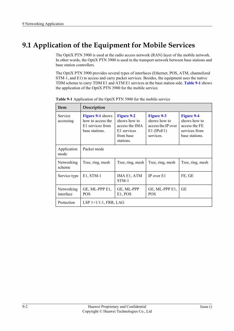
9.1 Application of the Equipment for Mobile ServicesThe OptiX PTN 3900 is used at the radio access network (RAN) layer of the mobile network.In other words, the OptiX PTN 3900 is used in the transport network between base stations andbase station controllers.
The OptiX PTN 3900 provides several types of interfaces (Ethernet, POS, ATM, channelizedSTM-1, and E1) to access and carry packet services. Besides, the equipment uses the nativeTDM scheme to carry TDM E1 and ATM E1 services at the base station side. Table 9-1 showsthe application of the OptiX PTN 3900 for the mobile service.
Table 9-1 Application of the OptiX PTN 3900 for the mobile service
Item Description
Serviceaccessing
Figure 9-1 showshow to access theE1 services frombase stations.
Figure 9-2shows how toaccess the IMAE1 servicesfrom basestations.
Figure 9-3shows how toaccess the IP overE1 (IPoE1)services.
Figure 9-4shows how toaccess the FEservices frombase stations.
Applicationmode
Packet mode
Networkingscheme
Tree, ring, mesh Tree, ring, mesh Tree, ring, mesh Tree, ring, mesh
Service type E1, STM-1 IMA E1, ATMSTM-1
IP over E1 FE, GE
Networkinginterface
GE, ML-PPP E1,POS
GE, ML-PPPE1, POS
GE, ML-PPP E1,POS
GE
Protection LSP 1+1/1:1, FRR, LAG
9 Networking Application
9-2 Huawei Proprietary and ConfidentialCopyright © Huawei Technologies Co., Ltd
Issue ()

Item Description
Servicescenario
l Transport ofCES (PWE3)E1 emulationservice
l Emulation ofE1 services,which areplaced into thechannelizedSTM-1 at theconvergencepoint and thentransported tothe RNC
l At the accesspoint, theIMA E1group isterminatedand PWE3emulation isperformed tothe ATMservices inthe group.
l At theconvergencepoint, theequipmentencapsulatesthe ATMservicesemulated inthe CES/PWE3scheme intonon-channelizedSTM-1, andthentransmitsthem to theRNC.
l The IP over E1interface andlink layertechnologiesare realized.The ML-PPPcan be used tobundle severalE1s.
l Theequipmentrealizes the IP-basedforwarding.The upstreamIP servicesfrom basestations areconverged tothe upstreaminterface.
l Theequipmentcompressesthe IP headerin compliancewith RFC2507.
l The EVPLservices fromFE interfacesare convergedto GEinterfaces onthe basis ofLayer 2switching orVLAN.
l When Layer 2switching isused forconvergenceof servicesfrom FEinterfaces toGE interfaces,servicesbetween basestations areisolated.
l The 3G IPpackets arecompressed atthe TCP/RTP/IP layer tosave thetransportbandwidth.
9 Networking Application
Issue () Huawei Proprietary and ConfidentialCopyright © Huawei Technologies Co., Ltd
9-3
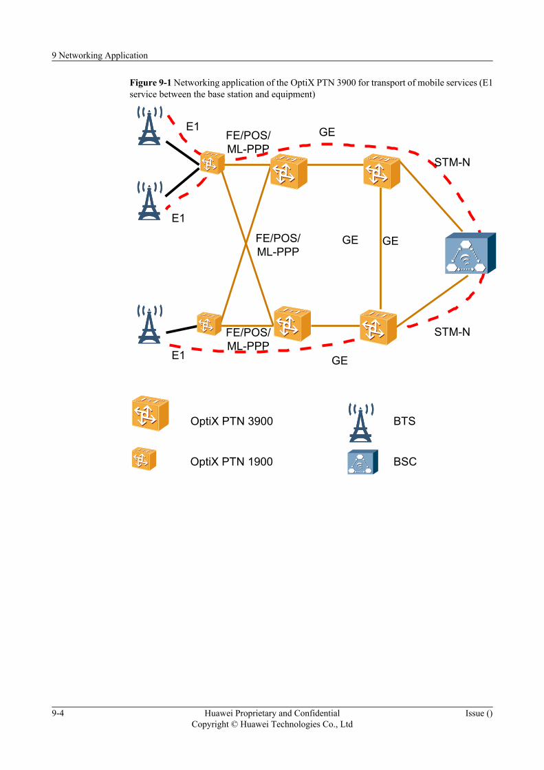
Figure 9-1 Networking application of the OptiX PTN 3900 for transport of mobile services (E1service between the base station and equipment)
GEGE
E1
GE
STM-N
GE
OptiX PTN 3900
OptiX PTN 1900 BSC
BTS
STM-N
E1
E1FE/POS/ML-PPP
FE/POS/ML-PPP
FE/POS/ML-PPP
9 Networking Application
9-4 Huawei Proprietary and ConfidentialCopyright © Huawei Technologies Co., Ltd
Issue ()
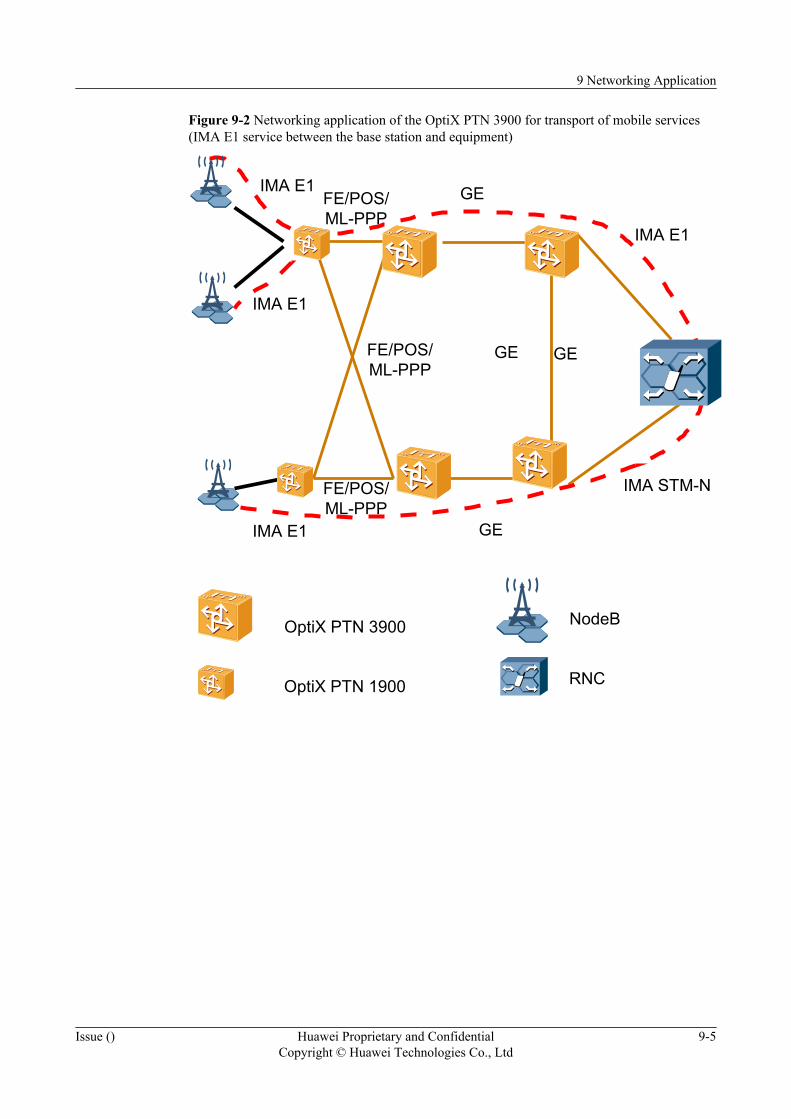
Figure 9-2 Networking application of the OptiX PTN 3900 for transport of mobile services(IMA E1 service between the base station and equipment)
GEGE
IMA E1 GE
GE
RNC
NodeB
IMA E1
IMA E1
IMA E1
IMA STM-N
FE/POS/ML-PPP
FE/POS/ML-PPP
FE/POS/ML-PPP
OptiX PTN 3900
OptiX PTN 1900
9 Networking Application
Issue () Huawei Proprietary and ConfidentialCopyright © Huawei Technologies Co., Ltd
9-5
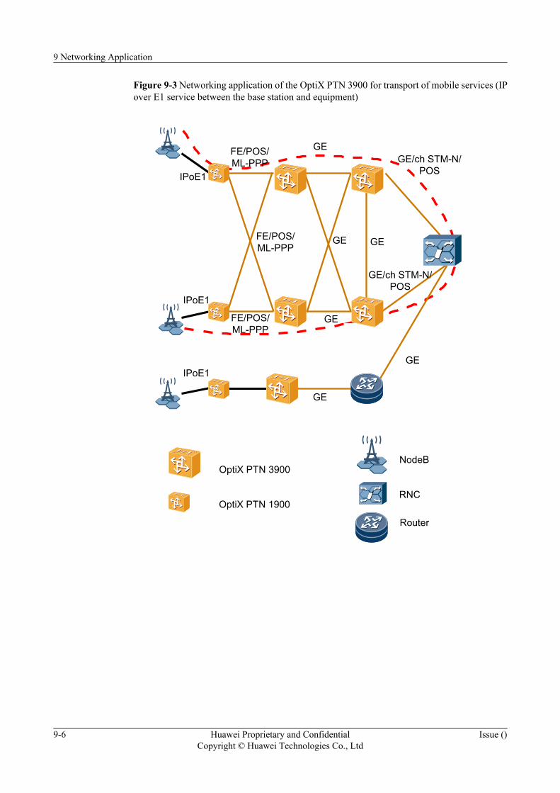
Figure 9-3 Networking application of the OptiX PTN 3900 for transport of mobile services (IPover E1 service between the base station and equipment)
GEGE
IPoE1
GE
GE
GE/ch STM-N/POS
GE
GE
RNC
NodeB
FE/POS/ML-PPP
FE/POS/ML-PPP
FE/POS/ML-PPP
Router
IPoE1
IPoE1
GE/ch STM-N/POS
OptiX PTN 3900
OptiX PTN 1900
9 Networking Application
9-6 Huawei Proprietary and ConfidentialCopyright © Huawei Technologies Co., Ltd
Issue ()
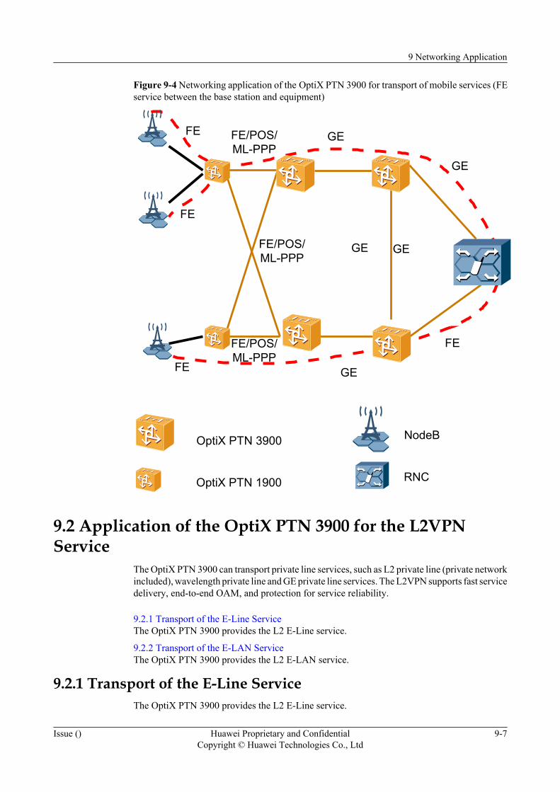
Figure 9-4 Networking application of the OptiX PTN 3900 for transport of mobile services (FEservice between the base station and equipment)
GEGE
FE
FE
FE
GE
GE
FE
GE
RNC
NodeB
FE/POS/ML-PPP
FE/POS/ML-PPP
FE/POS/ML-PPP
OptiX PTN 3900
OptiX PTN 1900
9.2 Application of the OptiX PTN 3900 for the L2VPNService
The OptiX PTN 3900 can transport private line services, such as L2 private line (private networkincluded), wavelength private line and GE private line services. The L2VPN supports fast servicedelivery, end-to-end OAM, and protection for service reliability.
9.2.1 Transport of the E-Line ServiceThe OptiX PTN 3900 provides the L2 E-Line service.
9.2.2 Transport of the E-LAN ServiceThe OptiX PTN 3900 provides the L2 E-LAN service.
9.2.1 Transport of the E-Line ServiceThe OptiX PTN 3900 provides the L2 E-Line service.
9 Networking Application
Issue () Huawei Proprietary and ConfidentialCopyright © Huawei Technologies Co., Ltd
9-7
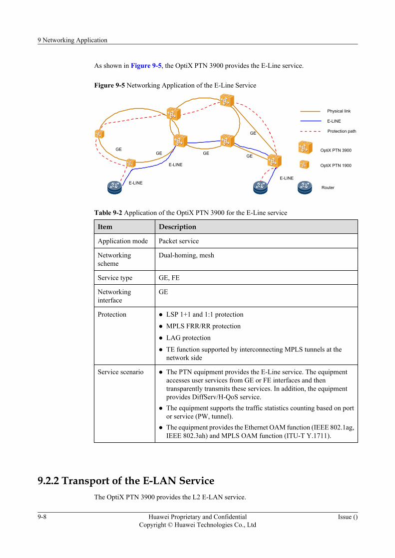
As shown in Figure 9-5, the OptiX PTN 3900 provides the E-Line service.
Figure 9-5 Networking Application of the E-Line Service
GEGE GE GE
GE
E-LINEE-LINE
E-LINE
E-LINE
Physical link
Protection path
OptiX PTN 3900
OptiX PTN 1900
Router
Table 9-2 Application of the OptiX PTN 3900 for the E-Line service
Item Description
Application mode Packet service
Networkingscheme
Dual-homing, mesh
Service type GE, FE
Networkinginterface
GE
Protection l LSP 1+1 and 1:1 protection
l MPLS FRR/RR protection
l LAG protection
l TE function supported by interconnecting MPLS tunnels at thenetwork side
Service scenario l The PTN equipment provides the E-Line service. The equipmentaccesses user services from GE or FE interfaces and thentransparently transmits these services. In addition, the equipmentprovides DiffServ/H-QoS service.
l The equipment supports the traffic statistics counting based on portor service (PW, tunnel).
l The equipment provides the Ethernet OAM function (IEEE 802.1ag,IEEE 802.3ah) and MPLS OAM function (ITU-T Y.1711).
9.2.2 Transport of the E-LAN ServiceThe OptiX PTN 3900 provides the L2 E-LAN service.
9 Networking Application
9-8 Huawei Proprietary and ConfidentialCopyright © Huawei Technologies Co., Ltd
Issue ()
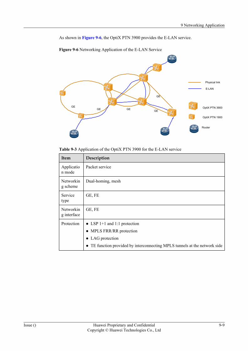
As shown in Figure 9-6, the OptiX PTN 3900 provides the E-LAN service.
Figure 9-6 Networking Application of the E-LAN Service
GEGE GE GE
GE
E-LAN
Physical link
Router
OptiX PTN 3900
OptiX PTN 1900
Table 9-3 Application of the OptiX PTN 3900 for the E-LAN service
Item Description
Application mode
Packet service
Networking scheme
Dual-homing, mesh
Servicetype
GE, FE
Networking interface
GE, FE
Protection l LSP 1+1 and 1:1 protection
l MPLS FRR/RR protection
l LAG protection
l TE function provided by interconnecting MPLS tunnels at the network side
9 Networking Application
Issue () Huawei Proprietary and ConfidentialCopyright © Huawei Technologies Co., Ltd
9-9
Item Description
Servicescenario
l The equipment provides E-LAN services, services stipulated in L2VPN/IEEE 802.1ad/IEEE 802.1ah, and DiffServ/H-QoS service.
l The equipment supports the traffic statistics counting based on port or service(PW, tunnel).
l The equipment provides the Ethernet OAM function (IEEE 802.1ag, IEEE802.3ah) and MPLS-OAM function (ITU-T Y.1711).
l The equipment supports interconnection to the user STP/RSTP/MSTP.
l The equipment supports L2 multicast, and L2 broadcast suppression.
l The equipment supports isolation of user data.
l The equipment supports ACL, DOS-attack prevention and accessauthentication.
9.3 Offload SolutionDuring service transmission between the Node B and RNC for 3G mobile communication, thePTN equipment can divert the high speed downlink packet access (HSDPA) service from theservices. The HSDPA service then can be carried by a low-cost network that accesses andforwards packets, such as an ADSL network. In this way, the transmission cost is reduced andthe competitiveness of operators is enhanced.
Overview of the Offload SolutionThe HSDPA technology greatly increases the data service rate for 3G mobile communication.In addition, Iub interfaces require more and more transmission bandwidth. To reduce thetransmission cost and ensure the QoS of important services, the PTN equipment provides acomplete offload solution.
As shown in Figure 9-7, the services sent by the Node B are accessed to the OptiX PTN 1900at the access node, through the IMA E1. The OptiX PTN 3900 at the convergence node, isconnected to the RNC through the ATM STM-1 interface. The service flow at Iub interfaces canbe classified into the signaling flow, R99 flow and HSDPA flow by VPI/VCI.
l The OptiX PTN 1900 at the access node uses the IMA E1 to transport the signaling flowand R99 flow to the OptiX PTN 3900 at the convergence node.
l The OptiX PTN 1900 at the access node encapsulates the HSDPA flow and sends theencapsulated flow to the ADSL modem through an FE interface. The flow then travelsthrough the ADSL network and finally arrives at the OptiX PTN 3900 at the convergencenode.
According to the forwarding schemes used by the ADSL network, the offload solution can beused on the following three scenarios.
l ATM-forwarding-based ADSL network
l MPLS-forwarding-based ADSL network
l IP-forwarding-based ADSL network
9 Networking Application
9-10 Huawei Proprietary and ConfidentialCopyright © Huawei Technologies Co., Ltd
Issue ()

Figure 9-7 Offload solution
Wholesale ADSL service
Node BOptiX PTN
1900
ADSLmodem
OptiX PTN3900 RNC
HSDPAflow
R99 flow
Leased line
Application in an ATM-Forwarding-Based ADSL Network
For the accessed HSDPA service, the OptiX PTN 1900 at site A supports two encapsulationschemes.
l LSP Tunnel used: ATM/PWE3/PW label/LSP label/ETH, as shown in Figure 9-8.
l IP Tunnel used: ATM/PWE3/PW label/IP/ETH, as shown in Figure 9-9.
Figure 9-8 Application in an ATM-forwarding-based ADSL network (LSP Tunnel used)
Node B OptiX PTN1900
ADSLmodem
ATMNetwork
OptiX PTN3900
RNC
DSLAM
ATME1/STM-1
ATMPWE3
PW LabelLSP LabelEthernet
ATMPWE3
PW LabelLSP LabelEthernet
AAL5ATMADSL
ATMPWE3
PW LabelLSP LabelEthernet
AAL5ATM
STM-1
ATMSTM-1
ATME1
Figure 9-9 Application in an ATM-forwarding-based ADSL network (IP Tunnel used)
Node B OptiX PTN1900
ADSLmodem
ATMNetwork
OptiX PTN3900
RNC
DSLAM
ATME1/STM-1
ATMPWE3
PW LabelIP
Ethernet
ATMPWE3
PW LabelIP
EthernetAAL5ATMADSL
ATMPWE3
PW LabelIP
EthernetAAL5ATM
STM-1
ATMSTM-1
ATME1
The ADSL modem can work in either the bridge or the router mode.
l When working in the bridge mode, the ADSL modem performs EoA encapsulation to theaccessed FE services. The OptiX PTN 1900 at site A can use either the encapsulationscheme I or the encapsulation scheme II.
9 Networking Application
Issue () Huawei Proprietary and ConfidentialCopyright © Huawei Technologies Co., Ltd
9-11

l When working in the router mode, the ADSL modem performs IPoA encapsulation to theaccessed FE services. the OptiX PTN 1900 at site A can use only the encapsulation schemeII.
Services forwarded through the ADSL network are finally converged to the OptiX PTN 3900at site Z through the STM-1 interface. The OptiX PTN 3900 at site Z then rearranges the datapackets that carry the HSDPA services, and forwards the data packets along with the signalingand R99 services to the RNC. The RNC forwards the services to different service networksaccording to service types. In this way, the HSDPA service can be forwarded in the wirelessaccess and transport network in an end-to-end manner.
Application in an MPLS-Forwarding-Based ADSL NetworkFor such application, the ADSL network realizes Layer 2 forwarding of Ethernet packetsaccording to frame headers. In this way, the MPLS tunnel can be used to transport the HSDPAservice, as shown in Figure 9-10.
Figure 9-10 Application in an MPLS-forwarding-based ADSL network
Node B OptiX PTN1900
ADSLmodem
MPLSNetwork
OptiX PTN3900
RNC
DSLAM
ATME1/STM-1
ATMPWE3
PW LabelLSP LabelEthernet
ATMPWE3
PW LabelLSP LabelEthernet
AAL5ATMADSL
ATMSTM-1
ATME1
ATMPWE3
PW LabelLSP LabelEthernet
Application in an IP-Forwarding-Based ADSL NetworkFor such application, the ADSL network forwards the IP packets according to the IP headers.Hence, the IP tunnel or GRE tunnel is required to carry packets, as shown in Figure 9-11 andFigure 9-12.
Figure 9-11 Application in an IP-forwarding-based ADSL network (IP tunnel used)
Node B OptiX PTN1900
ADSLmodem
IP Network
OptiX PTN3900
RNC
DSLAM
ATME1/STM-1
ATMPWE3
PW LabelIP
Ethernet
ATMPWE3
PW LabelIP
EthernetAAL5ATMADSL
ATMSTM-1
ATME1
ATMPWE3
PW LabelIP
Ethernet
9 Networking Application
9-12 Huawei Proprietary and ConfidentialCopyright © Huawei Technologies Co., Ltd
Issue ()
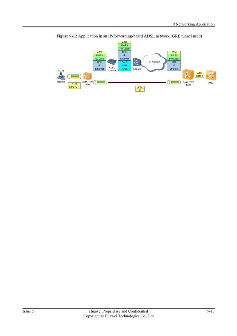
Figure 9-12 Application in an IP-forwarding-based ADSL network (GRE tunnel used)
Node B OptiX PTN1900
ADSLmodem
IP Network
OptiX PTN3900
RNC
DSLAM
ATME1/STM-1
ATMPWE3
PW Label
IPEthernet
IPEthernet
AAL5ATMADSL
ATMSTM-1
ATME1
GRE
ATMPWE3
PW LabelGRE ATM
PWE3PW Label
IPEthernet
GRE
9 Networking Application
Issue () Huawei Proprietary and ConfidentialCopyright © Huawei Technologies Co., Ltd
9-13

10 Technical Specifications
About This Chapter
The technical specifications of the OptiX PTN 3900 are related to several items.
10.1 System SpecificationsThe system specifications of the OptiX PTN 3900 cover the specifications of the cabinets andthe subrack.
10.2 System PerformanceThe OptiX PTN 3900 have different performance specifications for different performance items.
10.3 Technical Specifications of BoardsTechnical specifications of boards cover specifications of interfaces, dimensions, weight andpower consumption of boards.
10.4 Laser ClassLasers are of two classes according to the value of the output optical power.
10.5 Specifications of Clock InterfacesClock interfaces of the OptiX PTN 3900 and synchronization performance of the equipmentcomply with related ITU-T standards.
10.6 Reliability SpecificationsReliability specifications of the OptiX PTN 3900 cover system usability, system mean annualfailure rate, MTTR system mean repair time and MTBF system mean fault interval.
10.7 EMC Performance SpecificationsEMC performance specifications of the OptiX PTN 3900 comply with ETSI EN 300 386 V1.3.3.
10.8 Safety CertificationThe OptiX PTN 3900 is awarded with several safety certificates.
10.9 Environment RequirementsThe OptiX PTN 3900 requires proper environment for storage, transportation and operation.This section describes the environment specifications for storage, transportation and operationseparately.
10 Technical Specifications
Issue () Huawei Proprietary and ConfidentialCopyright © Huawei Technologies Co., Ltd
10-1
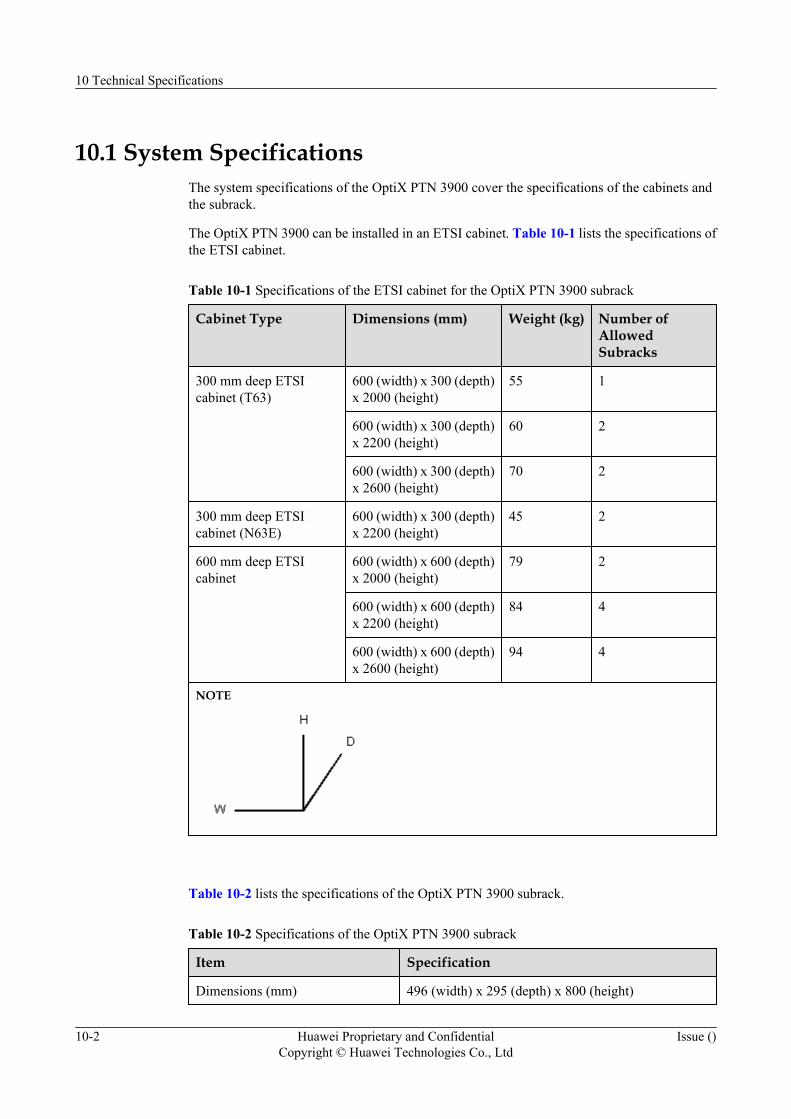
10.1 System SpecificationsThe system specifications of the OptiX PTN 3900 cover the specifications of the cabinets andthe subrack.
The OptiX PTN 3900 can be installed in an ETSI cabinet. Table 10-1 lists the specifications ofthe ETSI cabinet.
Table 10-1 Specifications of the ETSI cabinet for the OptiX PTN 3900 subrack
Cabinet Type Dimensions (mm) Weight (kg) Number ofAllowedSubracks
300 mm deep ETSIcabinet (T63)
600 (width) x 300 (depth)x 2000 (height)
55 1
600 (width) x 300 (depth)x 2200 (height)
60 2
600 (width) x 300 (depth)x 2600 (height)
70 2
300 mm deep ETSIcabinet (N63E)
600 (width) x 300 (depth)x 2200 (height)
45 2
600 mm deep ETSIcabinet
600 (width) x 600 (depth)x 2000 (height)
79 2
600 (width) x 600 (depth)x 2200 (height)
84 4
600 (width) x 600 (depth)x 2600 (height)
94 4
NOTE
Table 10-2 lists the specifications of the OptiX PTN 3900 subrack.
Table 10-2 Specifications of the OptiX PTN 3900 subrack
Item Specification
Dimensions (mm) 496 (width) x 295 (depth) x 800 (height)
10 Technical Specifications
10-2 Huawei Proprietary and ConfidentialCopyright © Huawei Technologies Co., Ltd
Issue ()
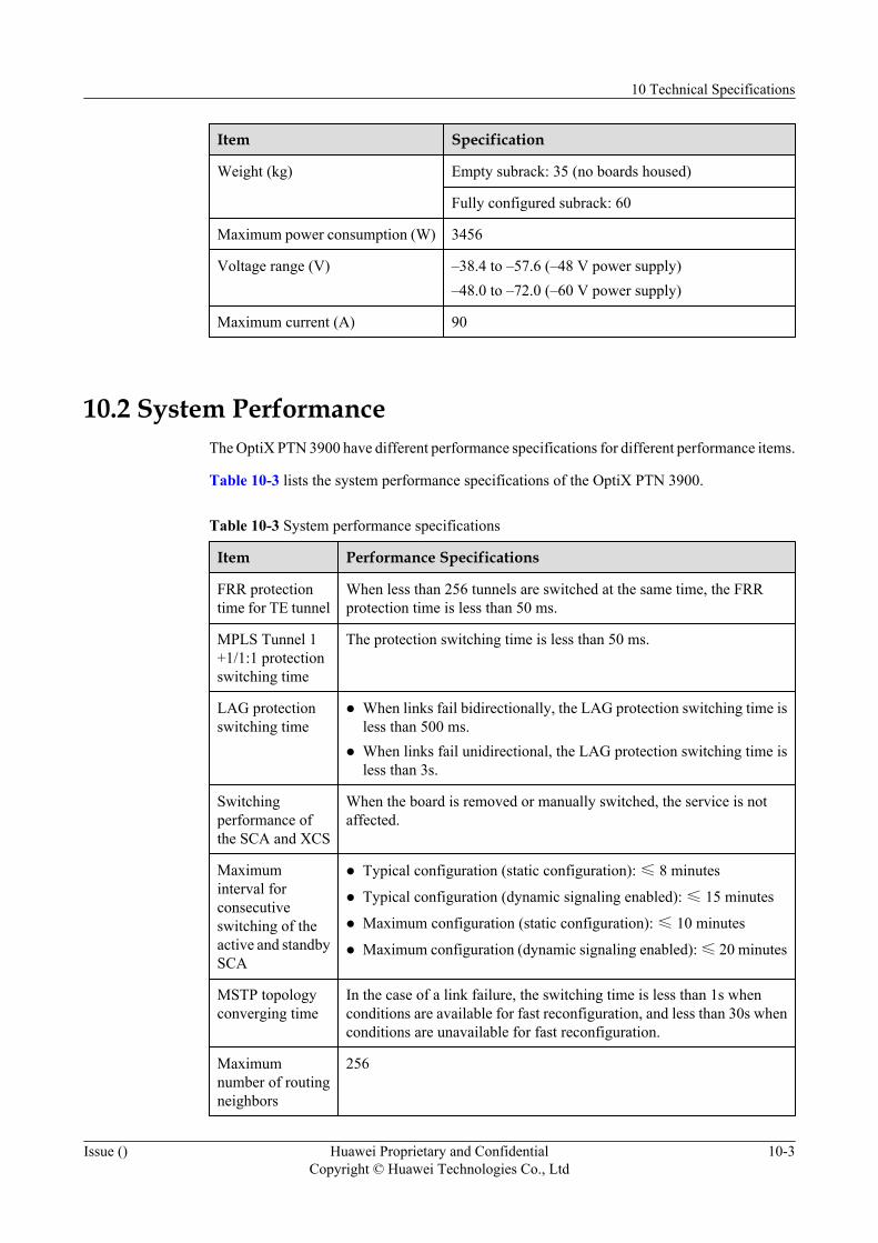
Item Specification
Weight (kg) Empty subrack: 35 (no boards housed)
Fully configured subrack: 60
Maximum power consumption (W) 3456
Voltage range (V) –38.4 to –57.6 (–48 V power supply)–48.0 to –72.0 (–60 V power supply)
Maximum current (A) 90
10.2 System PerformanceThe OptiX PTN 3900 have different performance specifications for different performance items.
Table 10-3 lists the system performance specifications of the OptiX PTN 3900.
Table 10-3 System performance specifications
Item Performance Specifications
FRR protectiontime for TE tunnel
When less than 256 tunnels are switched at the same time, the FRRprotection time is less than 50 ms.
MPLS Tunnel 1+1/1:1 protectionswitching time
The protection switching time is less than 50 ms.
LAG protectionswitching time
l When links fail bidirectionally, the LAG protection switching time isless than 500 ms.
l When links fail unidirectional, the LAG protection switching time isless than 3s.
Switchingperformance ofthe SCA and XCS
When the board is removed or manually switched, the service is notaffected.
Maximuminterval forconsecutiveswitching of theactive and standbySCA
l Typical configuration (static configuration): ≤ 8 minutes
l Typical configuration (dynamic signaling enabled): ≤ 15 minutes
l Maximum configuration (static configuration): ≤ 10 minutes
l Maximum configuration (dynamic signaling enabled): ≤ 20 minutes
MSTP topologyconverging time
In the case of a link failure, the switching time is less than 1s whenconditions are available for fast reconfiguration, and less than 30s whenconditions are unavailable for fast reconfiguration.
Maximumnumber of routingneighbors
256
10 Technical Specifications
Issue () Huawei Proprietary and ConfidentialCopyright © Huawei Technologies Co., Ltd
10-3
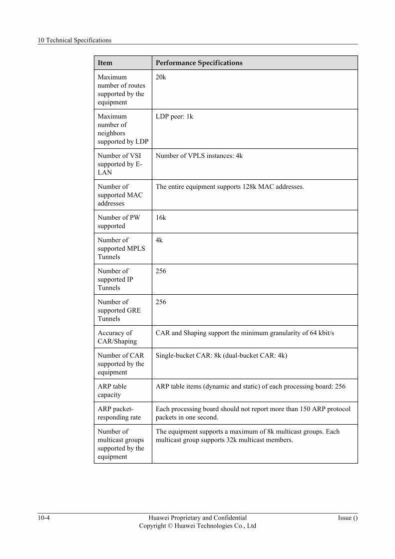
Item Performance Specifications
Maximumnumber of routessupported by theequipment
20k
Maximumnumber ofneighborssupported by LDP
LDP peer: 1k
Number of VSIsupported by E-LAN
Number of VPLS instances: 4k
Number ofsupported MACaddresses
The entire equipment supports 128k MAC addresses.
Number of PWsupported
16k
Number ofsupported MPLSTunnels
4k
Number ofsupported IPTunnels
256
Number ofsupported GRETunnels
256
Accuracy ofCAR/Shaping
CAR and Shaping support the minimum granularity of 64 kbit/s
Number of CARsupported by theequipment
Single-bucket CAR: 8k (dual-bucket CAR: 4k)
ARP tablecapacity
ARP table items (dynamic and static) of each processing board: 256
ARP packet-responding rate
Each processing board should not report more than 150 ARP protocolpackets in one second.
Number ofmulticast groupssupported by theequipment
The equipment supports a maximum of 8k multicast groups. Eachmulticast group supports 32k multicast members.
10 Technical Specifications
10-4 Huawei Proprietary and ConfidentialCopyright © Huawei Technologies Co., Ltd
Issue ()
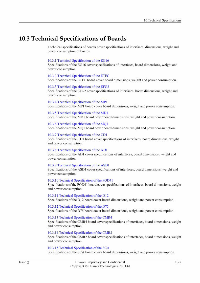
10.3 Technical Specifications of BoardsTechnical specifications of boards cover specifications of interfaces, dimensions, weight andpower consumption of boards.
10.3.1 Technical Specification of the EG16Specifications of the EG16 cover specifications of interfaces, board dimensions, weight andpower consumption.
10.3.2 Technical Specification of the ETFCSpecifications of the ETFC board cover board dimensions, weight and power consumption.
10.3.3 Technical Specification of the EFG2Specifications of the EFG2 cover specifications of interfaces, board dimensions, weight andpower consumption.
10.3.4 Technical Specification of the MP1Specifications of the MP1 board cover board dimensions, weight and power consumption.
10.3.5 Technical Specification of the MD1Specifications of the MD1 board cover board dimensions, weight and power consumption.
10.3.6 Technical Specification of the MQ1Specifications of the MQ1 board cover board dimensions, weight and power consumption.
10.3.7 Technical Specification of the CD1Specifications of the CD1 board cover specifications of interfaces, board dimensions, weightand power consumption.
10.3.8 Technical Specification of the AD1Specifications of the AD1 cover specifications of interfaces, board dimensions, weight andpower consumption.
10.3.9 Technical Specification of the ASD1Specifications of the ASD1 cover specifications of interfaces, board dimensions, weight andpower consumption.
10.3.10 Technical Specification of the POD41Specifications of the POD41 board cover specifications of interfaces, board dimensions, weightand power consumption.
10.3.11 Technical Specification of the D12Specifications of the D12 board cover board dimensions, weight and power consumption.
10.3.12 Technical Specification of the D75Specifications of the D75 board cover board dimensions, weight and power consumption.
10.3.13 Technical Specification of the CMR4Specifications of the CMR4 board cover specifications of interfaces, board dimensions, weightand power consumption.
10.3.14 Technical Specification of the CMR2Specifications of the CMR2 board cover specifications of interfaces, board dimensions, weightand power consumption.
10.3.15 Technical Specification of the SCASpecifications of the SCA board cover board dimensions, weight and power consumption.
10 Technical Specifications
Issue () Huawei Proprietary and ConfidentialCopyright © Huawei Technologies Co., Ltd
10-5
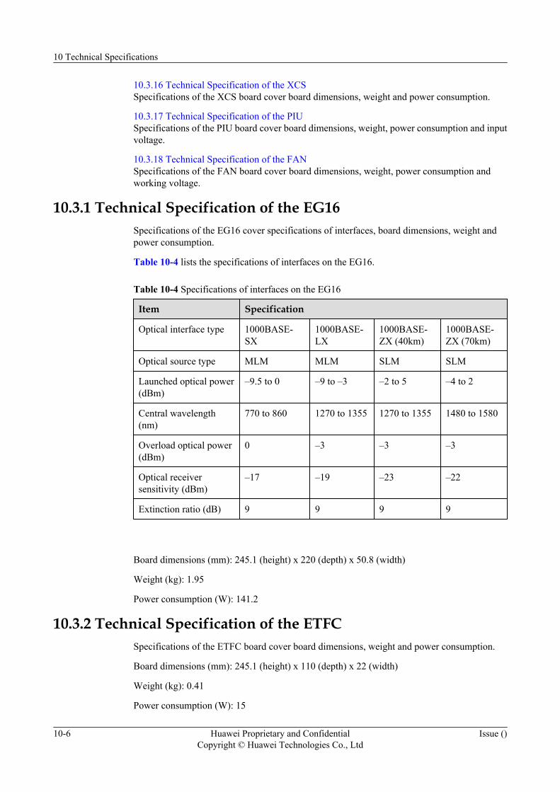
10.3.16 Technical Specification of the XCSSpecifications of the XCS board cover board dimensions, weight and power consumption.
10.3.17 Technical Specification of the PIUSpecifications of the PIU board cover board dimensions, weight, power consumption and inputvoltage.
10.3.18 Technical Specification of the FANSpecifications of the FAN board cover board dimensions, weight, power consumption andworking voltage.
10.3.1 Technical Specification of the EG16Specifications of the EG16 cover specifications of interfaces, board dimensions, weight andpower consumption.
Table 10-4 lists the specifications of interfaces on the EG16.
Table 10-4 Specifications of interfaces on the EG16
Item Specification
Optical interface type 1000BASE-SX
1000BASE-LX
1000BASE-ZX (40km)
1000BASE-ZX (70km)
Optical source type MLM MLM SLM SLM
Launched optical power(dBm)
–9.5 to 0 –9 to –3 –2 to 5 –4 to 2
Central wavelength(nm)
770 to 860 1270 to 1355 1270 to 1355 1480 to 1580
Overload optical power(dBm)
0 –3 –3 –3
Optical receiversensitivity (dBm)
–17 –19 –23 –22
Extinction ratio (dB) 9 9 9 9
Board dimensions (mm): 245.1 (height) x 220 (depth) x 50.8 (width)
Weight (kg): 1.95
Power consumption (W): 141.2
10.3.2 Technical Specification of the ETFCSpecifications of the ETFC board cover board dimensions, weight and power consumption.
Board dimensions (mm): 245.1 (height) x 110 (depth) x 22 (width)
Weight (kg): 0.41
Power consumption (W): 15
10 Technical Specifications
10-6 Huawei Proprietary and ConfidentialCopyright © Huawei Technologies Co., Ltd
Issue ()
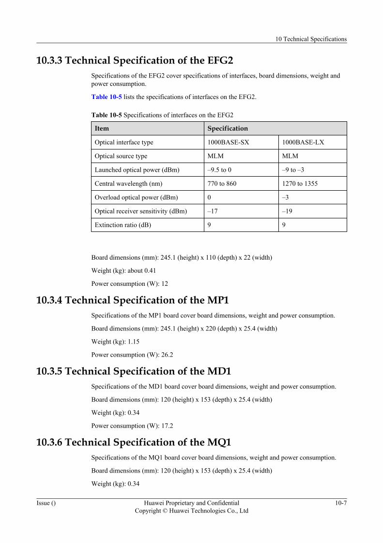
10.3.3 Technical Specification of the EFG2Specifications of the EFG2 cover specifications of interfaces, board dimensions, weight andpower consumption.
Table 10-5 lists the specifications of interfaces on the EFG2.
Table 10-5 Specifications of interfaces on the EFG2
Item Specification
Optical interface type 1000BASE-SX 1000BASE-LX
Optical source type MLM MLM
Launched optical power (dBm) –9.5 to 0 –9 to –3
Central wavelength (nm) 770 to 860 1270 to 1355
Overload optical power (dBm) 0 –3
Optical receiver sensitivity (dBm) –17 –19
Extinction ratio (dB) 9 9
Board dimensions (mm): 245.1 (height) x 110 (depth) x 22 (width)
Weight (kg): about 0.41
Power consumption (W): 12
10.3.4 Technical Specification of the MP1Specifications of the MP1 board cover board dimensions, weight and power consumption.
Board dimensions (mm): 245.1 (height) x 220 (depth) x 25.4 (width)
Weight (kg): 1.15
Power consumption (W): 26.2
10.3.5 Technical Specification of the MD1Specifications of the MD1 board cover board dimensions, weight and power consumption.
Board dimensions (mm): 120 (height) x 153 (depth) x 25.4 (width)
Weight (kg): 0.34
Power consumption (W): 17.2
10.3.6 Technical Specification of the MQ1Specifications of the MQ1 board cover board dimensions, weight and power consumption.
Board dimensions (mm): 120 (height) x 153 (depth) x 25.4 (width)
Weight (kg): 0.34
10 Technical Specifications
Issue () Huawei Proprietary and ConfidentialCopyright © Huawei Technologies Co., Ltd
10-7

Power consumption (W): 17.2
10.3.7 Technical Specification of the CD1Specifications of the CD1 board cover specifications of interfaces, board dimensions, weightand power consumption.
Table 10-6 lists the specifications of interfaces on the CD1.
Table 10-6 Specifications of interfaces on the CD1
Item Specification
Nominal bit rate(Mbit/s)
155.52
Optical interfacetype
I-1 S-1.1 L-1.1 L-1.2 Ve-1.2
Optical source type MLM MLM MLM/SLM
SLM SLM
Launched opticalpower (dBm)
–15 to –8 –15 to –8 –5 to 0 –5 to 0 –3 to 0
Central wavelength(nm)
1260 to1360
1261 to1360
1263 to1360
1480 to1580
1480 to1580
Minimum overload(dBm)
–8 –8 –10 –10 –10
Optical receiversensitivity (dBm)
–23 –28 –34 –34 –34
Extinction ratio(dB)
8.2 8.2 10 10 10
Board dimensions (mm): 120 (height) x 153 (depth) x 25.4 (width)
Weight (kg): 0.33
Power consumption (W): 29.4
10.3.8 Technical Specification of the AD1Specifications of the AD1 cover specifications of interfaces, board dimensions, weight andpower consumption.
Table 10-7 lists the specifications of interfaces on the AD1.
10 Technical Specifications
10-8 Huawei Proprietary and ConfidentialCopyright © Huawei Technologies Co., Ltd
Issue ()

Table 10-7 Specifications of interfaces on the AD1
Item Specification
Nominal bit rate(Mbit/s)
155.52
Optical interfacetype
I-1 S-1.1 L-1.1 L-1.2 Ve-1.2
Optical source type MLM MLM MLM/SLM
SLM SLM
Launched opticalpower (dBm)
–15 to –8 –15 to –8 –5 to 0 –5 to 0 –3 to 0
Central wavelength(nm)
1260 to1360
1261 to1360
1263 to1360
1480 to1580
1480 to1580
Minimum overload(dBm)
–8 –8 –10 –10 –10
Optical receiversensitivity (dBm)
–23 –28 –34 –34 –34
Extinction ratio(dB)
8.2 8.2 10 10 10
Board dimensions (mm): 120 (height) x 153 (depth) x 25.4 (width)
Weight (kg): 0.35
Power consumption (W): 24.1
10.3.9 Technical Specification of the ASD1Specifications of the ASD1 cover specifications of interfaces, board dimensions, weight andpower consumption.
Table 10-8 lists the specifications of interfaces on the AD1.
Table 10-8 Specifications of interfaces on the ASD1
Item Specification
Nominal bitrate (Mbit/s)
155.52
Opticalinterface type
I-1 S-1.1 L-1.1 L-1.2 Ve-1.2
Optical sourcetype
MLM MLM MLM/SLM SLM SLM
10 Technical Specifications
Issue () Huawei Proprietary and ConfidentialCopyright © Huawei Technologies Co., Ltd
10-9
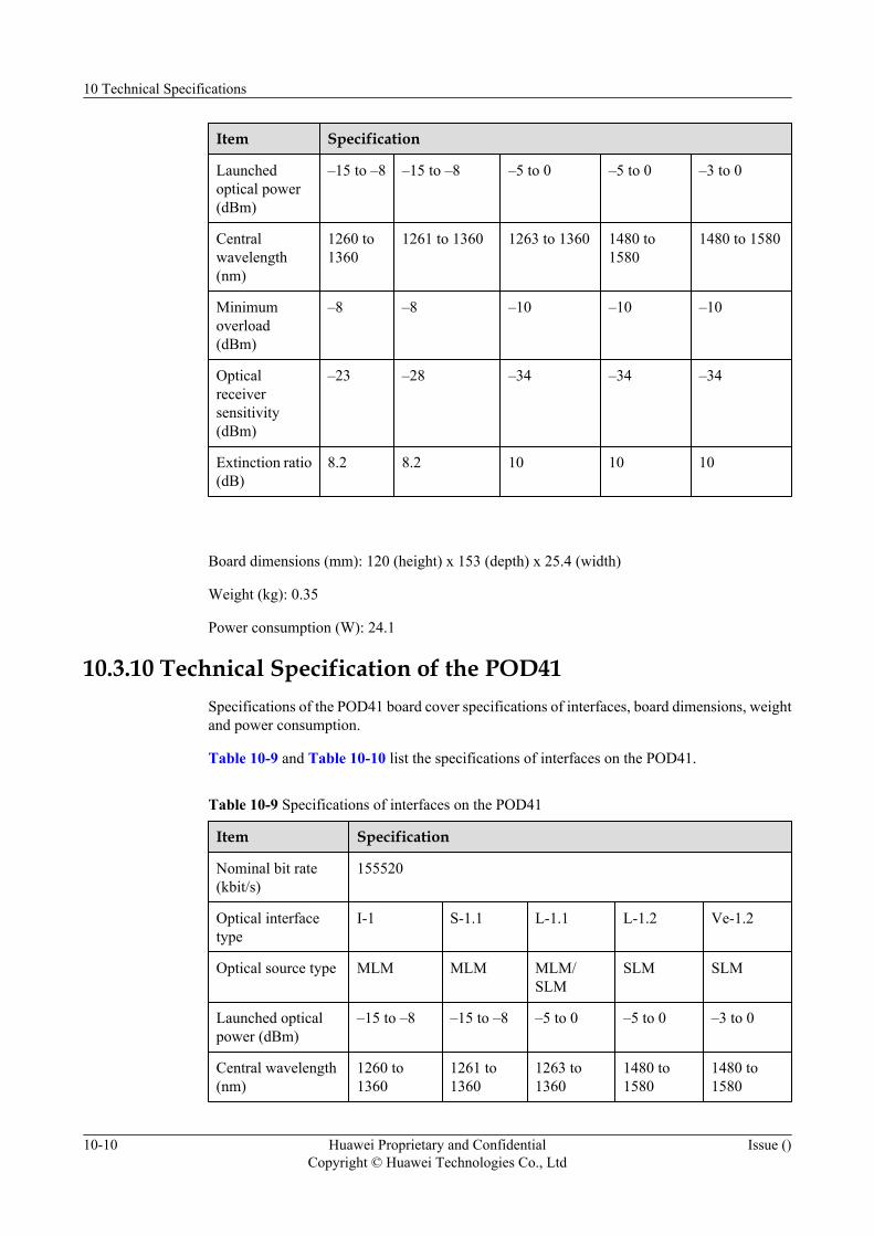
Item Specification
Launchedoptical power(dBm)
–15 to –8 –15 to –8 –5 to 0 –5 to 0 –3 to 0
Centralwavelength(nm)
1260 to1360
1261 to 1360 1263 to 1360 1480 to1580
1480 to 1580
Minimumoverload(dBm)
–8 –8 –10 –10 –10
Opticalreceiversensitivity(dBm)
–23 –28 –34 –34 –34
Extinction ratio(dB)
8.2 8.2 10 10 10
Board dimensions (mm): 120 (height) x 153 (depth) x 25.4 (width)
Weight (kg): 0.35
Power consumption (W): 24.1
10.3.10 Technical Specification of the POD41Specifications of the POD41 board cover specifications of interfaces, board dimensions, weightand power consumption.
Table 10-9 and Table 10-10 list the specifications of interfaces on the POD41.
Table 10-9 Specifications of interfaces on the POD41
Item Specification
Nominal bit rate(kbit/s)
155520
Optical interfacetype
I-1 S-1.1 L-1.1 L-1.2 Ve-1.2
Optical source type MLM MLM MLM/SLM
SLM SLM
Launched opticalpower (dBm)
–15 to –8 –15 to –8 –5 to 0 –5 to 0 –3 to 0
Central wavelength(nm)
1260 to1360
1261 to1360
1263 to1360
1480 to1580
1480 to1580
10 Technical Specifications
10-10 Huawei Proprietary and ConfidentialCopyright © Huawei Technologies Co., Ltd
Issue ()
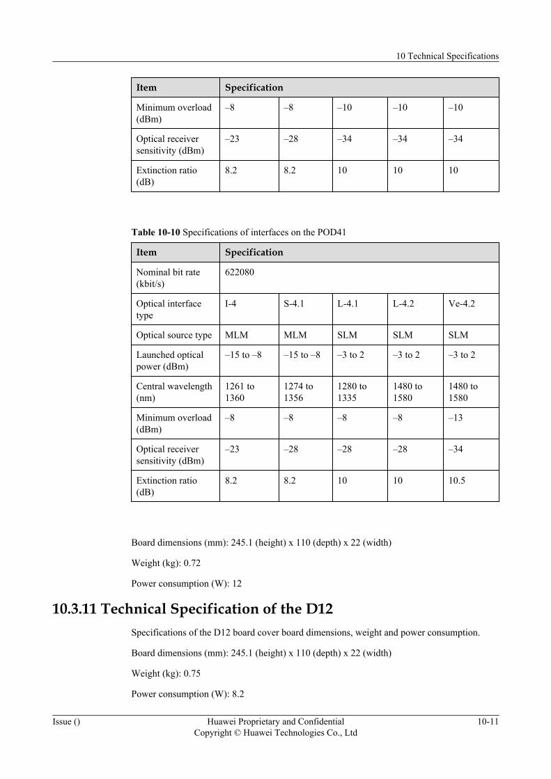
Item Specification
Minimum overload(dBm)
–8 –8 –10 –10 –10
Optical receiversensitivity (dBm)
–23 –28 –34 –34 –34
Extinction ratio(dB)
8.2 8.2 10 10 10
Table 10-10 Specifications of interfaces on the POD41
Item Specification
Nominal bit rate(kbit/s)
622080
Optical interfacetype
I-4 S-4.1 L-4.1 L-4.2 Ve-4.2
Optical source type MLM MLM SLM SLM SLM
Launched opticalpower (dBm)
–15 to –8 –15 to –8 –3 to 2 –3 to 2 –3 to 2
Central wavelength(nm)
1261 to1360
1274 to1356
1280 to1335
1480 to1580
1480 to1580
Minimum overload(dBm)
–8 –8 –8 –8 –13
Optical receiversensitivity (dBm)
–23 –28 –28 –28 –34
Extinction ratio(dB)
8.2 8.2 10 10 10.5
Board dimensions (mm): 245.1 (height) x 110 (depth) x 22 (width)
Weight (kg): 0.72
Power consumption (W): 12
10.3.11 Technical Specification of the D12Specifications of the D12 board cover board dimensions, weight and power consumption.
Board dimensions (mm): 245.1 (height) x 110 (depth) x 22 (width)
Weight (kg): 0.75
Power consumption (W): 8.2
10 Technical Specifications
Issue () Huawei Proprietary and ConfidentialCopyright © Huawei Technologies Co., Ltd
10-11
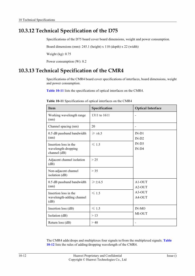
10.3.12 Technical Specification of the D75Specifications of the D75 board cover board dimensions, weight and power consumption.
Board dimensions (mm): 245.1 (height) x 110 (depth) x 22 (width)
Weight (kg): 0.75
Power consumption (W): 8.2
10.3.13 Technical Specification of the CMR4Specifications of the CMR4 board cover specifications of interfaces, board dimensions, weightand power consumption.
Table 10-11 lists the specifications of optical interfaces on the CMR4.
Table 10-11 Specifications of optical interfaces on the CMR4
Item Specification Optical Interface
Working wavelength range(nm)
1311 to 1611 -
Channel spacing (nm) 20 -
0.5 dB passband bandwidth(nm)
≥ ±6.5 IN-D1IN-D2IN-D3IN-D4
Insertion loss in thewavelength-droppingchannel (dB)
≤ 1.5
Adjacent channel isolation(dB)
> 25
Non-adjacent channelisolation (dB)
> 35
0.5 dB passband bandwidth(nm)
≥±6.5 A1-OUTA2-OUTA3-OUTA4-OUT
Insertion loss in thewavelength-adding channel(dB)
≤ 1.5
Insertion loss (dB) ≤ 1.5 IN-MOMI-OUTIsolation (dB) > 13
Return loss (dB) > 40 -
The CMR4 adds/drops and multiplexes four signals to/from the multiplexed signals. Table10-12 lists the rules of adding/dropping wavelength of the CMR4.
10 Technical Specifications
10-12 Huawei Proprietary and ConfidentialCopyright © Huawei Technologies Co., Ltd
Issue ()
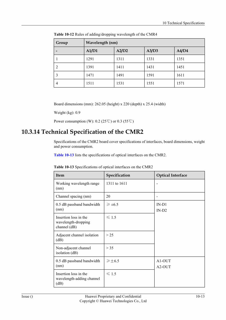
Table 10-12 Rules of adding/dropping wavelength of the CMR4
Group Wavelength (nm)
- A1/D1 A2/D2 A3/D3 A4/D4
1 1291 1311 1331 1351
2 1391 1411 1431 1451
3 1471 1491 1591 1611
4 1511 1531 1551 1571
Board dimensions (mm): 262.05 (height) x 220 (depth) x 25.4 (width)
Weight (kg): 0.9
Power consumption (W): 0.2 (25℃) or 0.3 (55℃)
10.3.14 Technical Specification of the CMR2Specifications of the CMR2 board cover specifications of interfaces, board dimensions, weightand power consumption.
Table 10-13 lists the specifications of optical interfaces on the CMR2.
Table 10-13 Specifications of optical interfaces on the CMR2
Item Specification Optical Interface
Working wavelength range(nm)
1311 to 1611 -
Channel spacing (nm) 20 -
0.5 dB passband bandwidth(nm)
≥ ±6.5 IN-D1IN-D2
Insertion loss in thewavelength-droppingchannel (dB)
≤ 1.5
Adjacent channel isolation(dB)
> 25
Non-adjacent channelisolation (dB)
> 35
0.5 dB passband bandwidth(nm)
≥±6.5 A1-OUTA2-OUT
Insertion loss in thewavelength-adding channel(dB)
≤ 1.5
10 Technical Specifications
Issue () Huawei Proprietary and ConfidentialCopyright © Huawei Technologies Co., Ltd
10-13
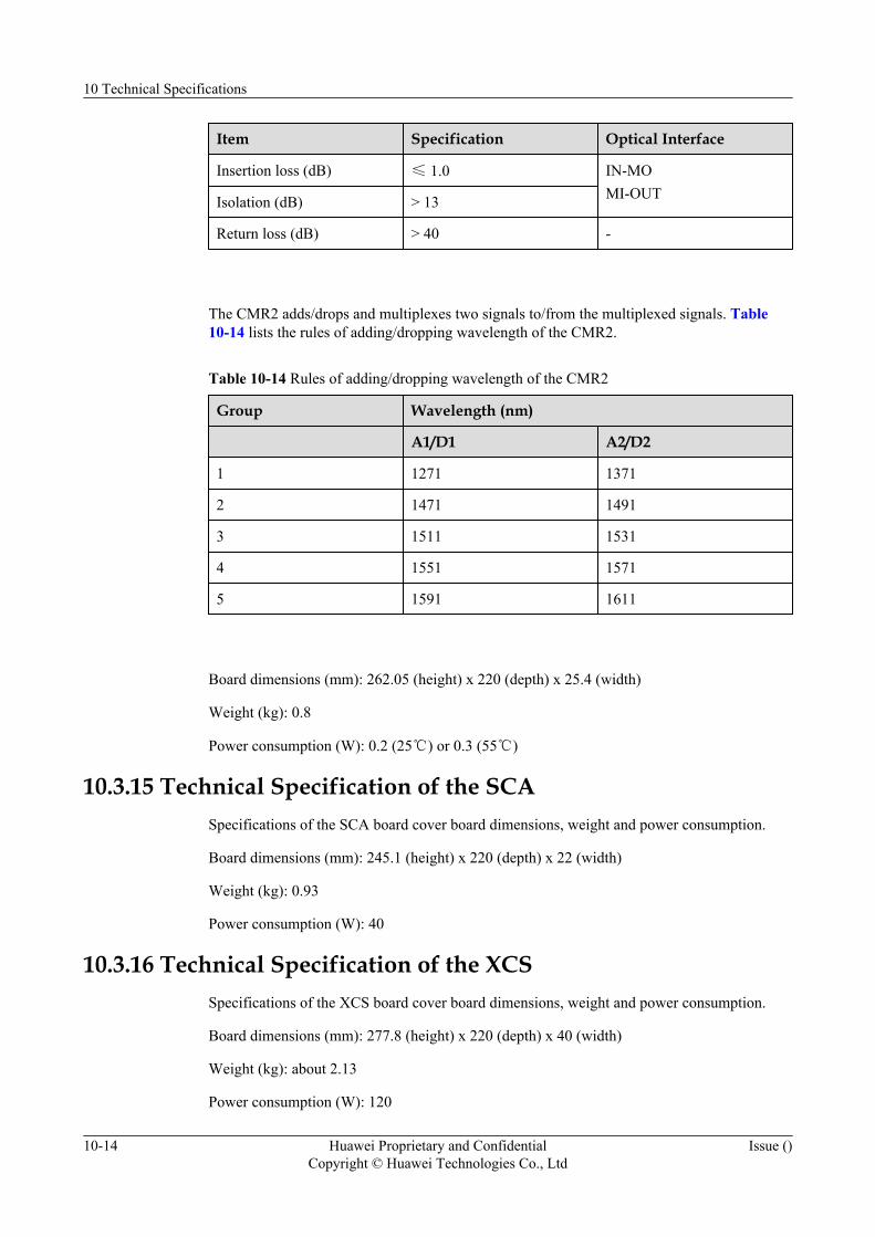
Item Specification Optical Interface
Insertion loss (dB) ≤ 1.0 IN-MOMI-OUTIsolation (dB) > 13
Return loss (dB) > 40 -
The CMR2 adds/drops and multiplexes two signals to/from the multiplexed signals. Table10-14 lists the rules of adding/dropping wavelength of the CMR2.
Table 10-14 Rules of adding/dropping wavelength of the CMR2
Group Wavelength (nm)
A1/D1 A2/D2
1 1271 1371
2 1471 1491
3 1511 1531
4 1551 1571
5 1591 1611
Board dimensions (mm): 262.05 (height) x 220 (depth) x 25.4 (width)
Weight (kg): 0.8
Power consumption (W): 0.2 (25℃) or 0.3 (55℃)
10.3.15 Technical Specification of the SCASpecifications of the SCA board cover board dimensions, weight and power consumption.
Board dimensions (mm): 245.1 (height) x 220 (depth) x 22 (width)
Weight (kg): 0.93
Power consumption (W): 40
10.3.16 Technical Specification of the XCSSpecifications of the XCS board cover board dimensions, weight and power consumption.
Board dimensions (mm): 277.8 (height) x 220 (depth) x 40 (width)
Weight (kg): about 2.13
Power consumption (W): 120
10 Technical Specifications
10-14 Huawei Proprietary and ConfidentialCopyright © Huawei Technologies Co., Ltd
Issue ()

10.3.17 Technical Specification of the PIUSpecifications of the PIU board cover board dimensions, weight, power consumption and inputvoltage.
Board dimensions (mm): 245.1 (height) x 220 (depth) x 40 (width)
Weight (kg): 1.63
Power consumption (W): 130
Input voltage range (V DC):
–38.4 to –57.6 (–48 V power supply)
–48.0 to –72.0 (–60 V power supply)
10.3.18 Technical Specification of the FANSpecifications of the FAN board cover board dimensions, weight, power consumption andworking voltage.
Board dimensions (mm): 60.9 (height) x 241.3 (depth) x 467.9 (width)
Weight (kg): 4.5
Power consumption (W): 97
Working voltage (V):
–38.4 to –57.6 (–48 V power supply)
–48.0 to –72.0 (–60 V power supply)
10.4 Laser ClassLasers are of two classes according to the value of the output optical power.
WARNINGAvoid direct eye exposure to the laser beams launched from the optical interface during theinstallation and maintenance of the fiber. Otherwise, your eyes may be hurt.
Table 10-15 shows the laser classes of the boards.
10 Technical Specifications
Issue () Huawei Proprietary and ConfidentialCopyright © Huawei Technologies Co., Ltd
10-15
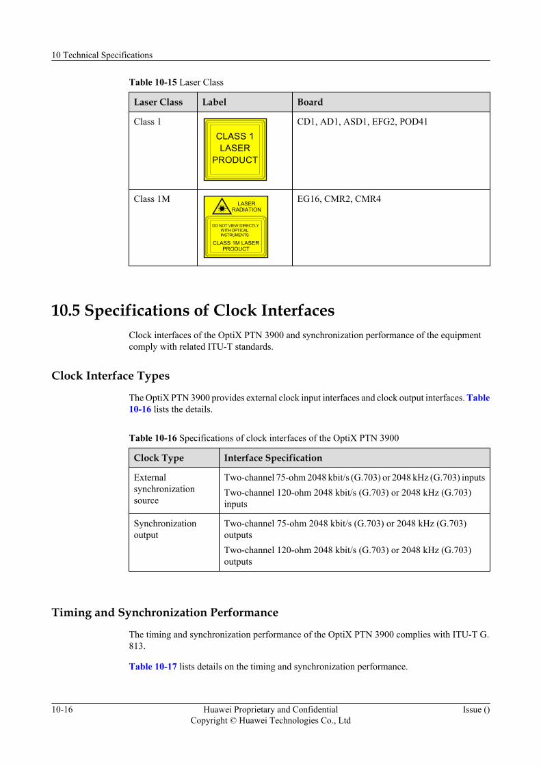
Table 10-15 Laser Class
Laser Class Label Board
Class 1CLASS 1LASER
PRODUCT
CD1, AD1, ASD1, EFG2, POD41
Class 1M
CLASS 1M LASERPRODUCT
LASERRADIATION
DO NOT VIEW DIRECTLYWITH OPTICALINSTRUMENTS
EG16, CMR2, CMR4
10.5 Specifications of Clock InterfacesClock interfaces of the OptiX PTN 3900 and synchronization performance of the equipmentcomply with related ITU-T standards.
Clock Interface Types
The OptiX PTN 3900 provides external clock input interfaces and clock output interfaces. Table10-16 lists the details.
Table 10-16 Specifications of clock interfaces of the OptiX PTN 3900
Clock Type Interface Specification
Externalsynchronizationsource
Two-channel 75-ohm 2048 kbit/s (G.703) or 2048 kHz (G.703) inputsTwo-channel 120-ohm 2048 kbit/s (G.703) or 2048 kHz (G.703)inputs
Synchronizationoutput
Two-channel 75-ohm 2048 kbit/s (G.703) or 2048 kHz (G.703)outputsTwo-channel 120-ohm 2048 kbit/s (G.703) or 2048 kHz (G.703)outputs
Timing and Synchronization Performance
The timing and synchronization performance of the OptiX PTN 3900 complies with ITU-T G.813.
Table 10-17 lists details on the timing and synchronization performance.
10 Technical Specifications
10-16 Huawei Proprietary and ConfidentialCopyright © Huawei Technologies Co., Ltd
Issue ()
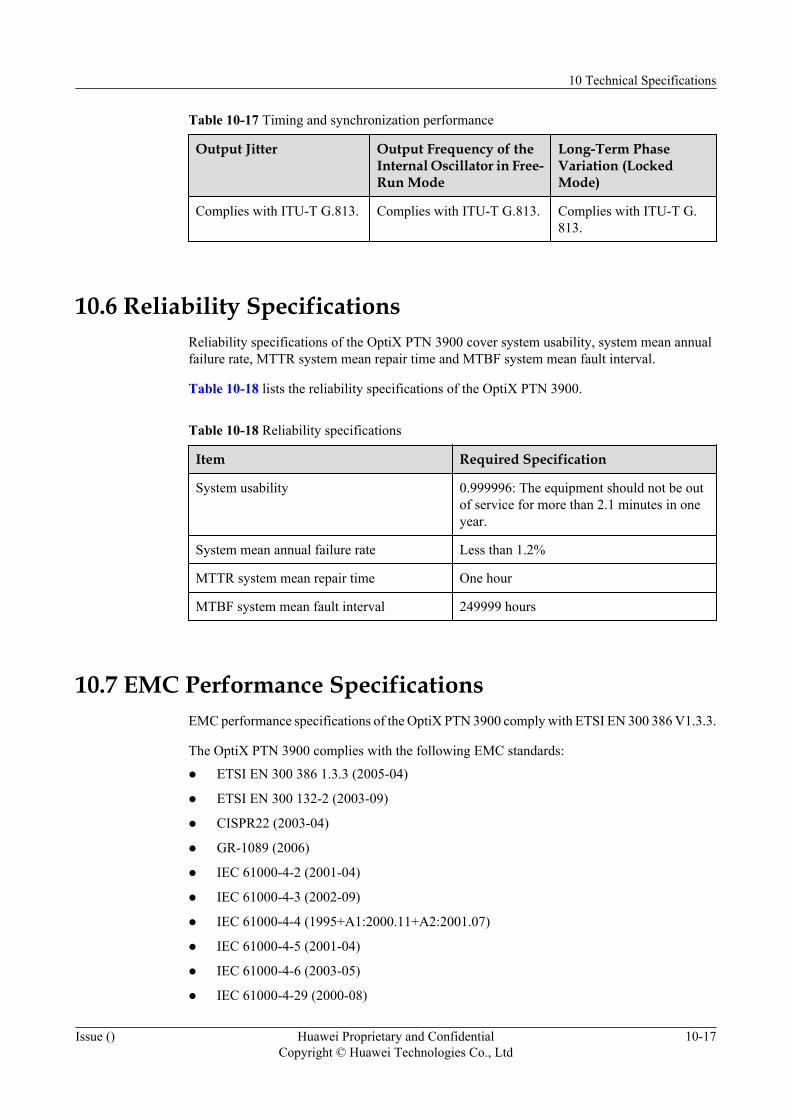
Table 10-17 Timing and synchronization performance
Output Jitter Output Frequency of theInternal Oscillator in Free-Run Mode
Long-Term PhaseVariation (LockedMode)
Complies with ITU-T G.813. Complies with ITU-T G.813. Complies with ITU-T G.813.
10.6 Reliability SpecificationsReliability specifications of the OptiX PTN 3900 cover system usability, system mean annualfailure rate, MTTR system mean repair time and MTBF system mean fault interval.
Table 10-18 lists the reliability specifications of the OptiX PTN 3900.
Table 10-18 Reliability specifications
Item Required Specification
System usability 0.999996: The equipment should not be outof service for more than 2.1 minutes in oneyear.
System mean annual failure rate Less than 1.2%
MTTR system mean repair time One hour
MTBF system mean fault interval 249999 hours
10.7 EMC Performance SpecificationsEMC performance specifications of the OptiX PTN 3900 comply with ETSI EN 300 386 V1.3.3.
The OptiX PTN 3900 complies with the following EMC standards:
l ETSI EN 300 386 1.3.3 (2005-04)
l ETSI EN 300 132-2 (2003-09)
l CISPR22 (2003-04)
l GR-1089 (2006)
l IEC 61000-4-2 (2001-04)
l IEC 61000-4-3 (2002-09)
l IEC 61000-4-4 (1995+A1:2000.11+A2:2001.07)
l IEC 61000-4-5 (2001-04)
l IEC 61000-4-6 (2003-05)
l IEC 61000-4-29 (2000-08)
10 Technical Specifications
Issue () Huawei Proprietary and ConfidentialCopyright © Huawei Technologies Co., Ltd
10-17
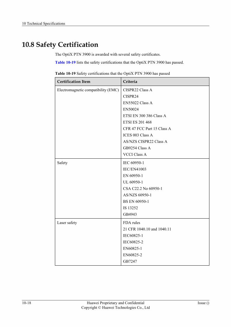
10.8 Safety CertificationThe OptiX PTN 3900 is awarded with several safety certificates.
Table 10-19 lists the safety certifications that the OptiX PTN 3900 has passed.
Table 10-19 Safety certifications that the OptiX PTN 3900 has passed
Certification Item Criteria
Electromagnetic compatibility (EMC) CISPR22 Class ACISPR24EN55022 Class AEN50024ETSI EN 300 386 Class AETSI ES 201 468CFR 47 FCC Part 15 Class AICES 003 Class AAS/NZS CISPR22 Class AGB9254 Class AVCCI Class A
Safety IEC 60950-1IEC/EN41003EN 60950-1UL 60950-1CSA C22.2 No 60950-1AS/NZS 60950-1BS EN 60950-1IS 13252GB4943
Laser safety FDA rules21 CFR 1040.10 and 1040.11IEC60825-1IEC60825-2EN60825-1EN60825-2GB7247
10 Technical Specifications
10-18 Huawei Proprietary and ConfidentialCopyright © Huawei Technologies Co., Ltd
Issue ()
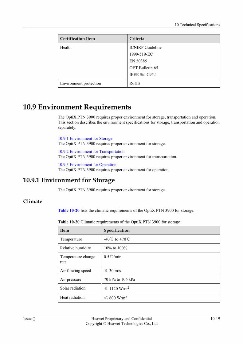
Certification Item Criteria
Health ICNIRP Guideline1999-519-ECEN 50385OET Bulletin 65IEEE Std C95.1
Environment protection RoHS
10.9 Environment RequirementsThe OptiX PTN 3900 requires proper environment for storage, transportation and operation.This section describes the environment specifications for storage, transportation and operationseparately.
10.9.1 Environment for StorageThe OptiX PTN 3900 requires proper environment for storage.
10.9.2 Environment for TransportationThe OptiX PTN 3900 requires proper environment for transportation.
10.9.3 Environment for OperationThe OptiX PTN 3900 requires proper environment for operation.
10.9.1 Environment for StorageThe OptiX PTN 3900 requires proper environment for storage.
ClimateTable 10-20 lists the climatic requirements of the OptiX PTN 3900 for storage.
Table 10-20 Climatic requirements of the OptiX PTN 3900 for storage
Item Specification
Temperature -40℃ to +70℃
Relative humidity 10% to 100%
Temperature changerate
0.5℃/min
Air flowing speed ≤ 30 m/s
Air pressure 70 kPa to 106 kPa
Solar radiation ≤ 1120 W/m2
Heat radiation ≤ 600 W/m2
10 Technical Specifications
Issue () Huawei Proprietary and ConfidentialCopyright © Huawei Technologies Co., Ltd
10-19

Waterproof Requirement
Requirement for storing equipment on the customer site: Generally, the equipment must bestored indoors.
No water should remain on the floor or leak to the equipment carton. The equipment should beplaced away from places where water leakage is possible, such as near the automatic fire-fightingfacilities and heating facilities.
If the equipment is stored outdoors, the following four conditions are required.
l The carton must be intact.
l Required rainproof measures must be taken to prevent water from entering the carton.
l No water is on the ground where the carton is placed.
l The carton must be free from direct exposure to sunshine.
Biological Environmentl Avoid multiplication of microbe, such as eumycete and mycete.
l Keep rodents such as mice away.
Air Cleannessl The air must be free from explosive, electric-conductive, magnetic-conductive or corrosive
dust.
l Table 10-21 lists the density requirements for mechanically active substances duringstorage.
l Table 10-22 lists the density requirements for chemically active substances during storage.
Table 10-21 Density requirements for mechanically active substances during storage
Mechanically Active Substance Content
Suspending dust ≤ 5.00 mg/m3
Precipitable dust ≤ 20.0 mg/m2·h
Gravel ≤ 300 mg/m3
Table 10-22 Density requirements for chemically active substances during storage
Chemically Active Substance Content
SO2 0.30 mg/m3 to 1.0 mg/m3
H2S 0.1 mg/m3 to 0.5 mg/m3
NOx 0.5 mg/m3 to 1.0 mg/m3
NH3 1.0 mg/m3 to 3.0 mg/m3
10 Technical Specifications
10-20 Huawei Proprietary and ConfidentialCopyright © Huawei Technologies Co., Ltd
Issue ()

Chemically Active Substance Content
Cl2 0.1 mg/m3 to 0.3 mg/m3
HCl 0.1 mg/m3 to 0.5 mg/m3
HF 0.01 mg/m3 to 0.03 mg/m3
O3 0.05 mg/m3 to 0.1 mg/m3
Mechanical Stress
Table 10-23 lists the requirements of mechanical stress for storage.
Table 10-23 Requirements of mechanical stress for storage
Item Sub-Item Specification
Random vibration ASD - 0.02m2/s3 -
Frequency range 5 Hz to 10Hz
10 Hz to 50 Hz 50 Hz to 100Hz
dB/oct 12 - -12
Axes of vibration 3
10.9.2 Environment for TransportationThe OptiX PTN 3900 requires proper environment for transportation.
Climate
Table 10-24 lists climatic requirements for transportation.
Table 10-24 Climatic requirements for transportation
Item Specification
Temperature -40℃ to +70℃
Relative humidity 5% RH to 95% RH
Temperature changerate
0.5℃/min
Air following speed ≤ 20 m/s
Air pressure 70 kPa to 106 kPa
Solar radiation ≤ 1120 W/m2
10 Technical Specifications
Issue () Huawei Proprietary and ConfidentialCopyright © Huawei Technologies Co., Ltd
10-21
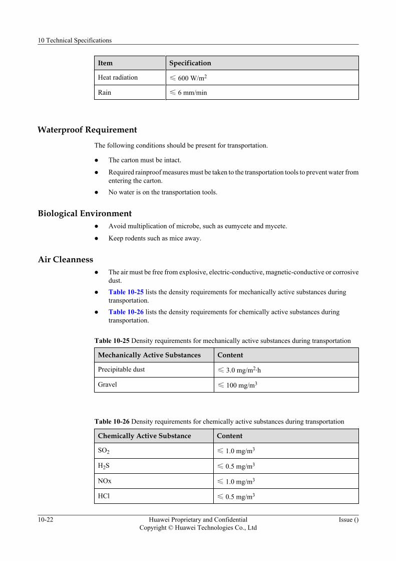
Item Specification
Heat radiation ≤ 600 W/m2
Rain ≤ 6 mm/min
Waterproof Requirement
The following conditions should be present for transportation.
l The carton must be intact.
l Required rainproof measures must be taken to the transportation tools to prevent water fromentering the carton.
l No water is on the transportation tools.
Biological Environmentl Avoid multiplication of microbe, such as eumycete and mycete.
l Keep rodents such as mice away.
Air Cleannessl The air must be free from explosive, electric-conductive, magnetic-conductive or corrosive
dust.
l Table 10-25 lists the density requirements for mechanically active substances duringtransportation.
l Table 10-26 lists the density requirements for chemically active substances duringtransportation.
Table 10-25 Density requirements for mechanically active substances during transportation
Mechanically Active Substances Content
Precipitable dust ≤ 3.0 mg/m2·h
Gravel ≤ 100 mg/m3
Table 10-26 Density requirements for chemically active substances during transportation
Chemically Active Substance Content
SO2 ≤ 1.0 mg/m3
H2S ≤ 0.5 mg/m3
NOx ≤ 1.0 mg/m3
HCl ≤ 0.5 mg/m3
10 Technical Specifications
10-22 Huawei Proprietary and ConfidentialCopyright © Huawei Technologies Co., Ltd
Issue ()
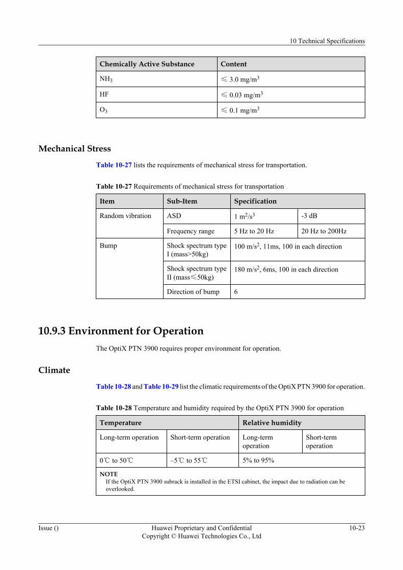
Chemically Active Substance Content
NH3 ≤ 3.0 mg/m3
HF ≤ 0.03 mg/m3
O3 ≤ 0.1 mg/m3
Mechanical Stress
Table 10-27 lists the requirements of mechanical stress for transportation.
Table 10-27 Requirements of mechanical stress for transportation
Item Sub-Item Specification
Random vibration ASD 1 m2/s3 -3 dB
Frequency range 5 Hz to 20 Hz 20 Hz to 200Hz
Bump Shock spectrum typeI (mass>50kg)
100 m/s2, 11ms, 100 in each direction
Shock spectrum typeII (mass≤50kg)
180 m/s2, 6ms, 100 in each direction
Direction of bump 6
10.9.3 Environment for OperationThe OptiX PTN 3900 requires proper environment for operation.
Climate
Table 10-28 and Table 10-29 list the climatic requirements of the OptiX PTN 3900 for operation.
Table 10-28 Temperature and humidity required by the OptiX PTN 3900 for operation
Temperature Relative humidity
Long-term operation Short-term operation Long-termoperation
Short-termoperation
0℃ to 50℃ –5℃ to 55℃ 5% to 95%
NOTEIf the OptiX PTN 3900 subrack is installed in the ETSI cabinet, the impact due to radiation can beoverlooked.
10 Technical Specifications
Issue () Huawei Proprietary and ConfidentialCopyright © Huawei Technologies Co., Ltd
10-23
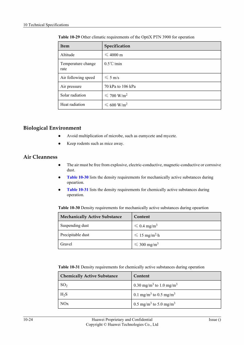
Table 10-29 Other climatic requirements of the OptiX PTN 3900 for operation
Item Specification
Altitude ≤ 4000 m
Temperature changerate
0.5℃/min
Air following speed ≤ 5 m/s
Air pressure 70 kPa to 106 kPa
Solar radiation ≤ 700 W/m2
Heat radiation ≤ 600 W/m2
Biological Environmentl Avoid multiplication of microbe, such as eumycete and mycete.
l Keep rodents such as mice away.
Air Cleannessl The air must be free from explosive, electric-conductive, magnetic-conductive or corrosive
dust.
l Table 10-30 lists the density requirements for mechanically active substances duringopeartion.
l Table 10-31 lists the density requirements for chemically active substances duringoperation.
Table 10-30 Density requirements for mechanically active substances during opeartion
Mechanically Active Substance Content
Suspending dust ≤ 0.4 mg/m3
Precipitable dust ≤ 15 mg/m2·h
Gravel ≤ 300 mg/m3
Table 10-31 Density requirements for chemically active substances during operation
Chemically Active Substance Content
SO2 0.30 mg/m3 to 1.0 mg/m3
H2S 0.1 mg/m3 to 0.5 mg/m3
NOx 0.5 mg/m3 to 5.0 mg/m3
10 Technical Specifications
10-24 Huawei Proprietary and ConfidentialCopyright © Huawei Technologies Co., Ltd
Issue ()
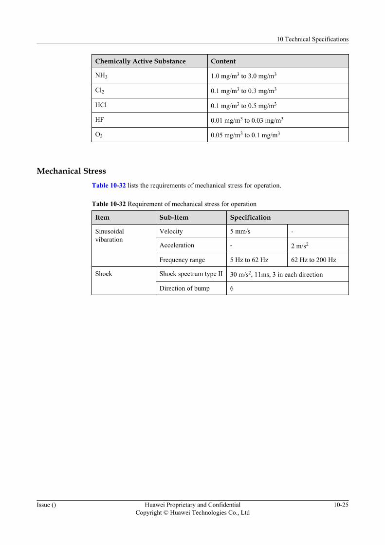
Chemically Active Substance Content
NH3 1.0 mg/m3 to 3.0 mg/m3
Cl2 0.1 mg/m3 to 0.3 mg/m3
HCl 0.1 mg/m3 to 0.5 mg/m3
HF 0.01 mg/m3 to 0.03 mg/m3
O3 0.05 mg/m3 to 0.1 mg/m3
Mechanical StressTable 10-32 lists the requirements of mechanical stress for operation.
Table 10-32 Requirement of mechanical stress for operation
Item Sub-Item Specification
Sinusoidalvibaration
Velocity 5 mm/s -
Acceleration - 2 m/s2
Frequency range 5 Hz to 62 Hz 62 Hz to 200 Hz
Shock Shock spectrum type II 30 m/s2, 11ms, 3 in each direction
Direction of bump 6
10 Technical Specifications
Issue () Huawei Proprietary and ConfidentialCopyright © Huawei Technologies Co., Ltd
10-25


11 Compliant Standards and Protocols
Environment StandardsStandard or Protocol Title
ETSI EN 300 019-1 Environmental Engineering (EE)Environmental conditions and environmentaltests for telecommunications equipmentClassification of environmental conditions
ETSI EN 300 019-2 Environmental Engineering (EE)Environmental conditions and environmentaltests for telecommunications equipmentSpecification of environmental tests
ETSI EN 300 753 Equipment Engineering (EE)Acoustic noise emitted bytelecommunications equipment
IEC 60068-1 Environmental testingPart 1: General and guidance
IEC 60068-2 Basic environmental testing proceduresPart 2: Tests
IEC 600721-1 Classification of environmental conditions-Part 1: Environmental parameters and theirseverities
IEC 600721-2 Classification of environmental conditions-Part 2: Environmental conditions appearingin nature
IEC 600529 Degrees of protection provided by enclosures(IP Code)
11 Compliant Standards and Protocols
Issue () Huawei Proprietary and ConfidentialCopyright © Huawei Technologies Co., Ltd
11-1
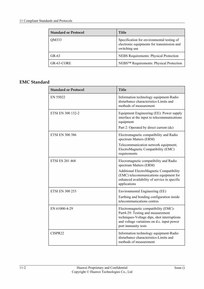
Standard or Protocol Title
QM333 Specification for environmental testing ofelectronic equipments for transmission andswitching use
GR-63 NEBS Requirements: Physical Protection
GR-63-CORE NEBS™ Requirements: Physical Protection
EMC StandardStandard or Protocol Title
EN 55022 Information technology equipment-Radiodisturbance characteristics-Limits andmethods of measurement
ETSI EN 300 132-2 Equipment Engineering (EE): Power supplyinterface at the input to telecommunicationsequipmentPart 2: Operated by direct current (dc)
ETSI EN 300 386 Electromagnetic compatibility and Radiospectrum Matters (ERM)Telecommunication network equipment;ElectroMagnetic Compatibility (EMC)requirements
ETSI ES 201 468 Elecromagnetic compatibility and Radiospectrum Matters (ERM)Additional ElectroMagnetic Compatibility(EMC) telecommunications equipment forenhanced availability of service in specificapplications
ETSI EN 300 253 Environmental Engineering (EE)Earthing and bonding configuration insidetelecommunications centres
EN 61000-4-29 Electromagnetic compatibility (EMC)-Part4-29: Testing and measurementtechniques-Voltage dips, shot interruptionsand voltage variations on d.c. input powerport immunity tests
CISPR22 Information technology equipment-Radiodisturbance characteristics-Limits andmethods of measurement
11 Compliant Standards and Protocols
11-2 Huawei Proprietary and ConfidentialCopyright © Huawei Technologies Co., Ltd
Issue ()

Standard or Protocol Title
IEC 61000-4-29 Electromagnetic compatibility (EMC)-Part4-29: Testing and measurementtechniques-Voltage dips, shot interruptionsand voltage variations on d.c. input powerport immunity tests
ITU-T K.27 Bonding Configurations and Earthing Insidea Telecommunication Building
GR-1089-CORE Electromagnetic Compatibility and ElectricalSafety - Generic Criteria for NetworkTelecommunications Equipment
IEC 61000-4-5 Electromagnetic compatibility (EMC)- Part4: Testing and measurement techniques -Section 5: Surge immunity test
Safety Compliance StandardStandard or Protocol Title
IEC/EN/UL 60950-1 Information technology equipment - Safety -Part 1: General requirements
IEC/EN 60825-1 Safety of laser products - Part 1: Equipmentclassification, requirements and user's guide
IEC/EN 60825-2 Safety of laser products - Part 2: Safety ofoptical fibre communication systems (OFCS)
73/23/EEC Low voltage directive
21 CFR 1040.10/1040.11 Performance standards for light-emitting-products
Ethernet Service StandardStandard or Protocol Title
IEEE802.1D Media access control (MAC) bridges
IEEE802.1Q Virtual bridged local area networks
IEEE802.1ad Provider bridges
IEEE802.1ag Connectivity fault management
IEEE802.1ah Provider backbone bridges
11 Compliant Standards and Protocols
Issue () Huawei Proprietary and ConfidentialCopyright © Huawei Technologies Co., Ltd
11-3
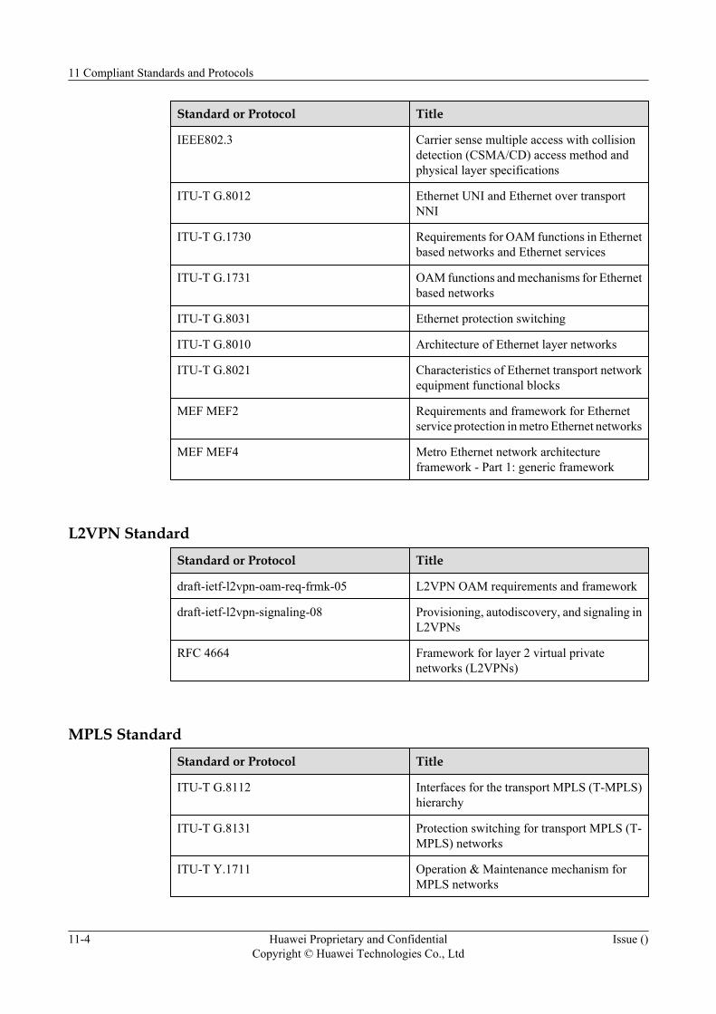
Standard or Protocol Title
IEEE802.3 Carrier sense multiple access with collisiondetection (CSMA/CD) access method andphysical layer specifications
ITU-T G.8012 Ethernet UNI and Ethernet over transportNNI
ITU-T G.1730 Requirements for OAM functions in Ethernetbased networks and Ethernet services
ITU-T G.1731 OAM functions and mechanisms for Ethernetbased networks
ITU-T G.8031 Ethernet protection switching
ITU-T G.8010 Architecture of Ethernet layer networks
ITU-T G.8021 Characteristics of Ethernet transport networkequipment functional blocks
MEF MEF2 Requirements and framework for Ethernetservice protection in metro Ethernet networks
MEF MEF4 Metro Ethernet network architectureframework - Part 1: generic framework
L2VPN StandardStandard or Protocol Title
draft-ietf-l2vpn-oam-req-frmk-05 L2VPN OAM requirements and framework
draft-ietf-l2vpn-signaling-08 Provisioning, autodiscovery, and signaling inL2VPNs
RFC 4664 Framework for layer 2 virtual privatenetworks (L2VPNs)
MPLS StandardStandard or Protocol Title
ITU-T G.8112 Interfaces for the transport MPLS (T-MPLS)hierarchy
ITU-T G.8131 Protection switching for transport MPLS (T-MPLS) networks
ITU-T Y.1711 Operation & Maintenance mechanism forMPLS networks
11 Compliant Standards and Protocols
11-4 Huawei Proprietary and ConfidentialCopyright © Huawei Technologies Co., Ltd
Issue ()
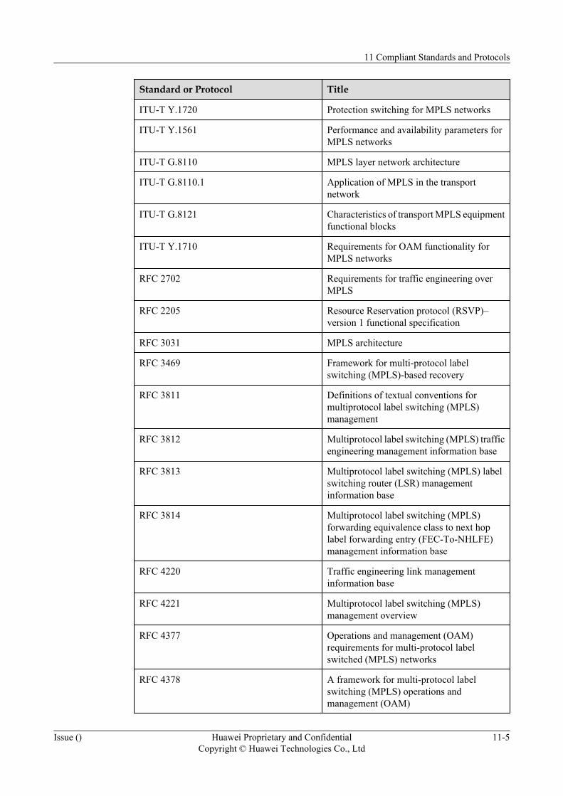
Standard or Protocol Title
ITU-T Y.1720 Protection switching for MPLS networks
ITU-T Y.1561 Performance and availability parameters forMPLS networks
ITU-T G.8110 MPLS layer network architecture
ITU-T G.8110.1 Application of MPLS in the transportnetwork
ITU-T G.8121 Characteristics of transport MPLS equipmentfunctional blocks
ITU-T Y.1710 Requirements for OAM functionality forMPLS networks
RFC 2702 Requirements for traffic engineering overMPLS
RFC 2205 Resource Reservation protocol (RSVP)–version 1 functional specification
RFC 3031 MPLS architecture
RFC 3469 Framework for multi-protocol labelswitching (MPLS)-based recovery
RFC 3811 Definitions of textual conventions formultiprotocol label switching (MPLS)management
RFC 3812 Multiprotocol label switching (MPLS) trafficengineering management information base
RFC 3813 Multiprotocol label switching (MPLS) labelswitching router (LSR) managementinformation base
RFC 3814 Multiprotocol label switching (MPLS)forwarding equivalence class to next hoplabel forwarding entry (FEC-To-NHLFE)management information base
RFC 4220 Traffic engineering link managementinformation base
RFC 4221 Multiprotocol label switching (MPLS)management overview
RFC 4377 Operations and management (OAM)requirements for multi-protocol labelswitched (MPLS) networks
RFC 4378 A framework for multi-protocol labelswitching (MPLS) operations andmanagement (OAM)
11 Compliant Standards and Protocols
Issue () Huawei Proprietary and ConfidentialCopyright © Huawei Technologies Co., Ltd
11-5
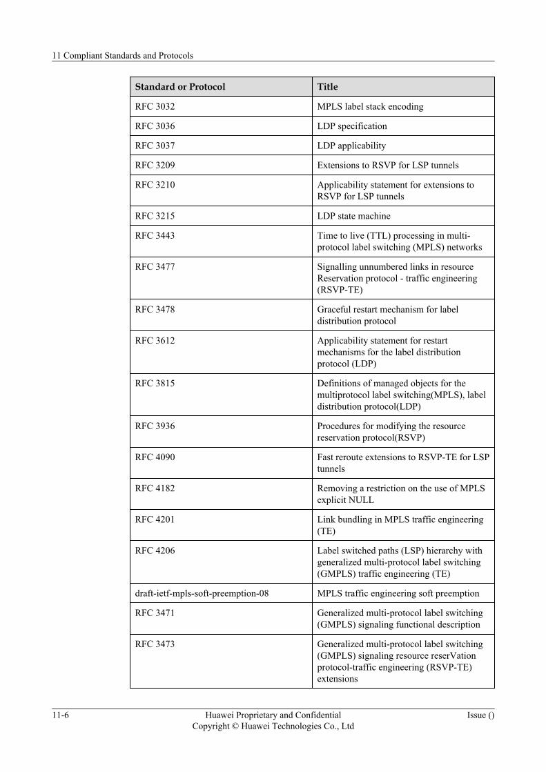
Standard or Protocol Title
RFC 3032 MPLS label stack encoding
RFC 3036 LDP specification
RFC 3037 LDP applicability
RFC 3209 Extensions to RSVP for LSP tunnels
RFC 3210 Applicability statement for extensions toRSVP for LSP tunnels
RFC 3215 LDP state machine
RFC 3443 Time to live (TTL) processing in multi-protocol label switching (MPLS) networks
RFC 3477 Signalling unnumbered links in resourceReservation protocol - traffic engineering(RSVP-TE)
RFC 3478 Graceful restart mechanism for labeldistribution protocol
RFC 3612 Applicability statement for restartmechanisms for the label distributionprotocol (LDP)
RFC 3815 Definitions of managed objects for themultiprotocol label switching(MPLS), labeldistribution protocol(LDP)
RFC 3936 Procedures for modifying the resourcereservation protocol(RSVP)
RFC 4090 Fast reroute extensions to RSVP-TE for LSPtunnels
RFC 4182 Removing a restriction on the use of MPLSexplicit NULL
RFC 4201 Link bundling in MPLS traffic engineering(TE)
RFC 4206 Label switched paths (LSP) hierarchy withgeneralized multi-protocol label switching(GMPLS) traffic engineering (TE)
draft-ietf-mpls-soft-preemption-08 MPLS traffic engineering soft preemption
RFC 3471 Generalized multi-protocol label switching(GMPLS) signaling functional description
RFC 3473 Generalized multi-protocol label switching(GMPLS) signaling resource reserVationprotocol-traffic engineering (RSVP-TE)extensions
11 Compliant Standards and Protocols
11-6 Huawei Proprietary and ConfidentialCopyright © Huawei Technologies Co., Ltd
Issue ()
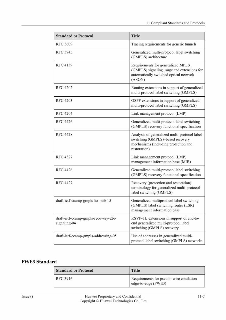
Standard or Protocol Title
RFC 3609 Tracing requirements for generic tunnels
RFC 3945 Generalized multi-protocol label switching(GMPLS) architecture
RFC 4139 Requirements for generalized MPLS(GMPLS) signaling usage and extensions forautomatically switched optical network(ASON)
RFC 4202 Routing extensions in support of generalizedmulti-protocol label switching (GMPLS)
RFC 4203 OSPF extensions in support of generalizedmulti-protocol label switching (GMPLS)
RFC 4204 Link management protocol (LMP)
RFC 4426 Generalized multi-protocol label switching(GMPLS) recovery functional specification
RFC 4428 Analysis of generalized multi-protocol labelswitching (GMPLS)–based recoverymechanisms (including protection andrestoration)
RFC 4327 Link management protocol (LMP)management information base (MIB)
RFC 4426 Generalized multi-protocol label switching(GMPLS) recovery functional specification
RFC 4427 Recovery (protection and restoration)terminology for generalized multi-protocollabel switching (GMPLS)
draft-ietf-ccamp-gmpls-lsr-mib-15 Generalized multiprotocol label switching(GMPLS) label switching router (LSR)management information base
draft-ietf-ccamp-gmpls-recovery-e2e-signaling-04
RSVP-TE extensions in support of end-to-end generalized multi-protocol labelswitching (GMPLS) recovery
draft-ietf-ccamp-gmpls-addressing-05 Use of addresses in generalized multi-protocol label switching (GMPLS) networks
PWE3 StandardStandard or Protocol Title
RFC 3916 Requirements for pseudo-wire emulationedge-to-edge (PWE3)
11 Compliant Standards and Protocols
Issue () Huawei Proprietary and ConfidentialCopyright © Huawei Technologies Co., Ltd
11-7

Standard or Protocol Title
RFC 3985 Pseudo wire emulation edge-to-edge (PWE3)architecture
RFC 4197 Requirements for edge-to-edge emulation oftime division multiplexed (TDM) circuitsover packet switching networks
RFC 4385 Pseudowire emulation edge-to-edge (PWE3)control word for use over an MPLS PSN
RFC 4446 IANA allocations for pseudowire edge toedge emulation (PWE3)
RFC 4447 Pseudowire setup and maintenance using thelabel distribution Protocol (LDP)
RFC 4448 Encapsulation methods for transport ofEthernet over MPLS networks
RFC 4720 Pseudowire emulation edge-to-edge (PWE3)frame check sequence retention
RFC 4553 Structure-agnostic time divisionmultiplexing (TDM) over packet (SAToP)
draft-ietf-pwe3-cesopsn-07 Structure-aware TDM circuit emulationservice over packet switched network(CESoPSN)
raft-ietf-pwe3-vccv-11 Pseudo wire virtual circuit connectivityverification (VCCV)
draft-ietf-pwe3-segmented-pw-03 Segmented pseudo wire
draft-ietf-pwe3-ms-pw-requirements-03 Requirements for inter domain pseudo-wires
draft-ietf-pwe3-ms-pw-arch-02 An architecture for multi-segment pseudowire emulation edge-to-edge
OSPF StandardStandard or Protocol Title
RFC 2328 OSPF Version 2
RFC 2370 The OSPF Opaque LSA Option
RFC 3630 Traffic engineering (TE) extensions to OSPFversion 2
RFC 1850 OSPF V2 MIB
11 Compliant Standards and Protocols
11-8 Huawei Proprietary and ConfidentialCopyright © Huawei Technologies Co., Ltd
Issue ()
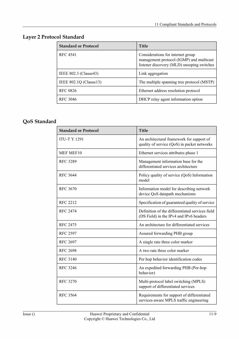
Layer 2 Protocol StandardStandard or Protocol Title
RFC 4541 Considerations for internet groupmanagement protocol (IGMP) and multicastlistener discovery (MLD) snooping switches
IEEE 802.3 (Clause43) Link aggregation
IEEE 802.1Q (Clause13) The multiple spanning tree protocol (MSTP)
RFC 0826 Ethernet address resolution protocol
RFC 3046 DHCP relay agent information option
QoS StandardStandard or Protocol Title
ITU-T Y.1291 An architectural framework for support ofquality of service (QoS) in packet networks
MEF MEF10 Ethernet services attributes phase 1
RFC 3289 Management information base for thedifferentiated services architecture
RFC 3644 Policy quality of service (QoS) Informationmodel
RFC 3670 Information model for describing networkdevice QoS datapath mechanisms
RFC 2212 Specification of guaranteed quality of service
RFC 2474 Definition of the differentiated services field(DS Field) in the IPv4 and IPv6 headers
RFC 2475 An architecture for differentiated services
RFC 2597 Assured forwarding PHB group
RFC 2697 A single rate three color marker
RFC 2698 A two rate three color marker
RFC 3140 Per hop behavior identification codes
RFC 3246 An expedited forwarding PHB (Per-hopbehavior)
RFC 3270 Multi-protocol label switching (MPLS)support of differentiated services
RFC 3564 Requirements for support of differentiatedservices-aware MPLS traffic engineering
11 Compliant Standards and Protocols
Issue () Huawei Proprietary and ConfidentialCopyright © Huawei Technologies Co., Ltd
11-9
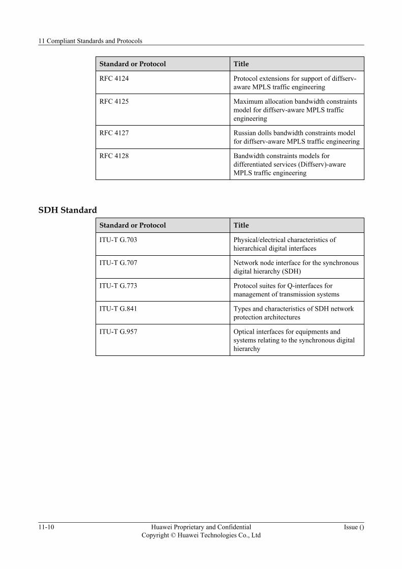
Standard or Protocol Title
RFC 4124 Protocol extensions for support of diffserv-aware MPLS traffic engineering
RFC 4125 Maximum allocation bandwidth constraintsmodel for diffserv-aware MPLS trafficengineering
RFC 4127 Russian dolls bandwidth constraints modelfor diffserv-aware MPLS traffic engineering
RFC 4128 Bandwidth constraints models fordifferentiated services (Diffserv)-awareMPLS traffic engineering
SDH StandardStandard or Protocol Title
ITU-T G.703 Physical/electrical characteristics ofhierarchical digital interfaces
ITU-T G.707 Network node interface for the synchronousdigital hierarchy (SDH)
ITU-T G.773 Protocol suites for Q-interfaces formanagement of transmission systems
ITU-T G.841 Types and characteristics of SDH networkprotection architectures
ITU-T G.957 Optical interfaces for equipments andsystems relating to the synchronous digitalhierarchy
11 Compliant Standards and Protocols
11-10 Huawei Proprietary and ConfidentialCopyright © Huawei Technologies Co., Ltd
Issue ()
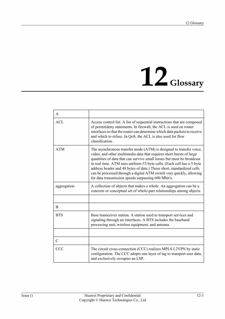
12 Glossary
A
ACL Access control list. A list of sequential instructions that are composedof permit|deny statements. In firewall, the ACL is used on routerinterfaces so that the router can determine which data packets to receiveand which to refuse. In QoS, the ACL is also used for flowclassification.
ATM The asynchronous transfer mode (ATM) is designed to transfer voice,video, and other multimedia data that requires short bursts of largequantities of data that can survive small losses but must be broadcastin real time. ATM uses uniform 53-byte cells. (Each cell has a 5-byteaddress header and 48 bytes of data.) These short, standardized cellscan be processed through a digital ATM switch very quickly, allowingfor data transmission speeds surpassing 600 Mbit/s.
aggregation A collection of objects that makes a whole. An aggregation can be aconcrete or conceptual set of whole-part relationships among objects.
B
BTS Base transceiver station. A station used to transport services andsignaling through air interfaces. A BTS includes the basebandprocessing unit, wireless equipment, and antenna.
C
CCC The circuit cross-connection (CCC) realizes MPLS L2VPN by staticconfiguration. The CCC adopts one layer of tag to transport user data,and exclusively occupies an LSP.
12 Glossary
Issue () Huawei Proprietary and ConfidentialCopyright © Huawei Technologies Co., Ltd
12-1
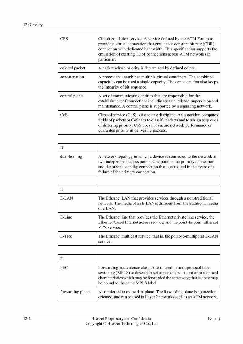
CES Circuit emulation service. A service defined by the ATM Forum toprovide a virtual connection that emulates a constant bit rate (CBR)connection with dedicated bandwidth. This specification supports theemulation of existing TDM connections across ATM networks inparticular.
colored packet A packet whose priority is determined by defined colors.
concatenation A process that combines multiple virtual containers. The combinedcapacities can be used a single capacity. The concatenation also keepsthe integrity of bit sequence.
control plane A set of communicating entities that are responsible for theestablishment of connections including set-up, release, supervision andmaintenance. A control plane is supported by a signaling network.
CoS Class of service (CoS) is a queuing discipline. An algorithm comparesfields of packets or CoS tags to classify packets and to assign to queuesof differing priority. CoS does not ensure network performance orguarantee priority in delivering packets.
D
dual-homing A network topology in which a device is connected to the network attwo independent access points. One point is the primary connectionand the other a standby connection that is activated in the event of afailure of the primary connection.
E
E-LAN The Ethernet LAN that provides services through a non-traditionalnetwork. The media of an E-LAN is different from the traditional mediaof a LAN.
E-Line The Ethernet line that provides the Ethernet private line service, theEthernet-based Internet access service, and the point-to-point EthernetVPN service.
E-Tree The Ethernet multicast service, that is, the point-to-multipoint E-LANservice.
F
FEC Forwarding equivalence class. A term used in multiprotocol labelswitching (MPLS) to describe a set of packets with similar or identicalcharacteristics which may be forwarded the same way; that is, they maybe bound to the same MPLS label.
forwarding plane Also referred to as the data plane. The forwarding plane is connection-oriented, and can be used in Layer 2 networks such as an ATM network.
12 Glossary
12-2 Huawei Proprietary and ConfidentialCopyright © Huawei Technologies Co., Ltd
Issue ()
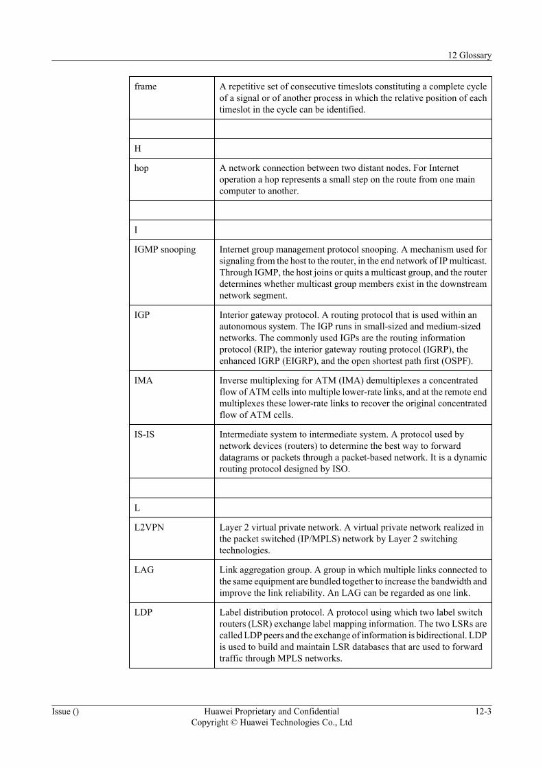
frame A repetitive set of consecutive timeslots constituting a complete cycleof a signal or of another process in which the relative position of eachtimeslot in the cycle can be identified.
H
hop A network connection between two distant nodes. For Internetoperation a hop represents a small step on the route from one maincomputer to another.
I
IGMP snooping Internet group management protocol snooping. A mechanism used forsignaling from the host to the router, in the end network of IP multicast.Through IGMP, the host joins or quits a multicast group, and the routerdetermines whether multicast group members exist in the downstreamnetwork segment.
IGP Interior gateway protocol. A routing protocol that is used within anautonomous system. The IGP runs in small-sized and medium-sizednetworks. The commonly used IGPs are the routing informationprotocol (RIP), the interior gateway routing protocol (IGRP), theenhanced IGRP (EIGRP), and the open shortest path first (OSPF).
IMA Inverse multiplexing for ATM (IMA) demultiplexes a concentratedflow of ATM cells into multiple lower-rate links, and at the remote endmultiplexes these lower-rate links to recover the original concentratedflow of ATM cells.
IS-IS Intermediate system to intermediate system. A protocol used bynetwork devices (routers) to determine the best way to forwarddatagrams or packets through a packet-based network. It is a dynamicrouting protocol designed by ISO.
L
L2VPN Layer 2 virtual private network. A virtual private network realized inthe packet switched (IP/MPLS) network by Layer 2 switchingtechnologies.
LAG Link aggregation group. A group in which multiple links connected tothe same equipment are bundled together to increase the bandwidth andimprove the link reliability. An LAG can be regarded as one link.
LDP Label distribution protocol. A protocol using which two label switchrouters (LSR) exchange label mapping information. The two LSRs arecalled LDP peers and the exchange of information is bidirectional. LDPis used to build and maintain LSR databases that are used to forwardtraffic through MPLS networks.
12 Glossary
Issue () Huawei Proprietary and ConfidentialCopyright © Huawei Technologies Co., Ltd
12-3
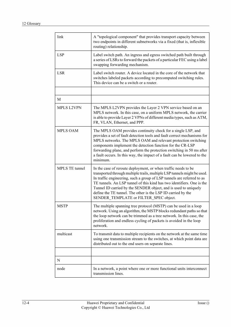
link A "topological component" that provides transport capacity betweentwo endpoints in different subnetworks via a fixed (that is, inflexiblerouting) relationship.
LSP Label switch path. An ingress and egress switched path built througha series of LSRs to forward the packets of a particular FEC using a labelswapping forwarding mechanism.
LSR Label switch router. A device located in the core of the network thatswitches labeled packets according to precomputed switching rules.This device can be a switch or a router.
M
MPLS L2VPN The MPLS L2VPN provides the Layer 2 VPN service based on anMPLS network. In this case, on a uniform MPLS network, the carrieris able to provide Layer 2 VPNs of different media types, such as ATM,FR, VLAN, Ethernet, and PPP.
MPLS OAM The MPLS OAM provides continuity check for a single LSP, andprovides a set of fault detection tools and fault correct mechanisms forMPLS networks. The MPLS OAM and relevant protection switchingcomponents implement the detection function for the CR-LSPforwarding plane, and perform the protection switching in 50 ms aftera fault occurs. In this way, the impact of a fault can be lowered to theminimum.
MPLS TE tunnel In the case of reroute deployment, or when traffic needs to betransported through multiple trails, multiple LSP tunnels might be used.In traffic engineering, such a group of LSP tunnels are referred to asTE tunnels. An LSP tunnel of this kind has two identifiers. One is theTunnel ID carried by the SENDER object, and is used to uniquelydefine the TE tunnel. The other is the LSP ID carried by theSENDER_TEMPLATE or FILTER_SPEC object.
MSTP The multiple spanning tree protocol (MSTP) can be used in a loopnetwork. Using an algorithm, the MSTP blocks redundant paths so thatthe loop network can be trimmed as a tree network. In this case, theproliferation and endless cycling of packets is avoided in the loopnetwork.
multicast To transmit data to multiple recipients on the network at the same timeusing one transmission stream to the switches, at which point data aredistributed out to the end users on separate lines.
N
node In a network, a point where one or more functional units interconnecttransmission lines.
12 Glossary
12-4 Huawei Proprietary and ConfidentialCopyright © Huawei Technologies Co., Ltd
Issue ()

NSAP Network service access point. The point at which the OSI NetworkService is made available to a Transport entity. The NSAPs areidentified by OSI Network Addresses. The NSAP is a generic standardfor a network address consisting of 20 octets. ATM has specified E.164for public network addressing and the NSAP address structure forprivate network addresses.
P
packet The information unit at the network layer.
PDU Packet data unit. The unit that is transported in a local interconnectnetwork (LIN) diagnostic frame. A PDU used for node configurationis a complete message.
POS Packet over SDH/SONET. A MAN and WAN technology that providespoint-to-point data connections. The POS interface uses SDH/SONETas the physical layer protocol, and supports the transport of packet data(such as IP packets) in MAN and WAN.
PSU Power supply unit. A device or architecture that provides electric poweror other forms of energy.
PW A pseudo wire is an emulated point-to-point connection over a packetswitched network that allows the interconnection of two nodes withany L2 technology.
PWE3 Pseudo wire emulation edge to edge. In a packet switched network(PSN), a Layer 2 service bearing technology that emulates as truly aspossible the basic behaviors and characteristics of ATM services, framerelay services, Ethernet services, low speed TDM services, SONET/SDH services, and other services.
Q
QoS Quality of service. The capability of equipment to provide differentlevels of quality for different services.
R
route A path for traffic between two designated points.
S
SVC Static virtual circuit. A static implementation of MPLS L2VPN thattransfers L2VPN information by manual configuration of VC labels,instead of by a signaling protocol.
12 Glossary
Issue () Huawei Proprietary and ConfidentialCopyright © Huawei Technologies Co., Ltd
12-5

switching The process of interconnecting functional units, transmission channelsor telecommunication circuits for as long as is required to conveysignals.
synchronous statusmessage
A message that is used to transmit the quality levels of timing signalson a synchronous timing link. By reading the SSM, a node clock in theSDH network and the synchronization network obtains the upstreamclock information. The SSM performs relevant operations (such astracing, switching, and hold-over) on the clock of the local node, andthen transmits the synchronization information of the local node to thedownstream.
T
traffic engineering Traffic engineering (TE) encompasses traffic management, capacitymanagement, traffic measurement and modelling, network modelling,and performance analysis.
tunnel A information transmission channel that is set up between two entitiesin the application of VPN. A tunnel provides sufficient security toprevent intrusion to the VPN internal information.
V
VLL Virtual leased line. A point-to-point, Layer 2 channel that behaves likea leased line by transparently transporting different protocols with aguaranteed throughput.
V-NNI A virtual network-network interface (V-NNI) is a network-sideinterface.
VPLS Virtual private LAN service. A service that, with the assistance of anIP public network, realizes the interconnection of LANs through aVPN. The VPLS is the extension of a LAN in the IP public network.
VPWS Virtual private wire service. In a packet switched network (PSN), aLayer 2 service bearing technology that emulates as truly as possiblethe basic behaviors and characteristics of ATM services, frame relayservices, Ethernet services, low speed TDM services, SONET/SDHservices, and other services.
V-UNI A virtual user-network interface is a client-side interface.
12 Glossary
12-6 Huawei Proprietary and ConfidentialCopyright © Huawei Technologies Co., Ltd
Issue ()
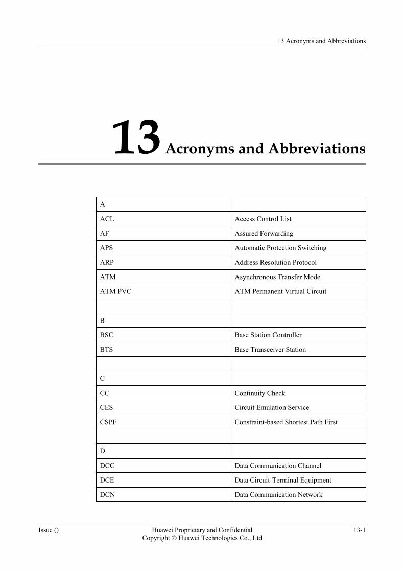
13 Acronyms and Abbreviations
A
ACL Access Control List
AF Assured Forwarding
APS Automatic Protection Switching
ARP Address Resolution Protocol
ATM Asynchronous Transfer Mode
ATM PVC ATM Permanent Virtual Circuit
B
BSC Base Station Controller
BTS Base Transceiver Station
C
CC Continuity Check
CES Circuit Emulation Service
CSPF Constraint-based Shortest Path First
D
DCC Data Communication Channel
DCE Data Circuit-Terminal Equipment
DCN Data Communication Network
13 Acronyms and Abbreviations
Issue () Huawei Proprietary and ConfidentialCopyright © Huawei Technologies Co., Ltd
13-1
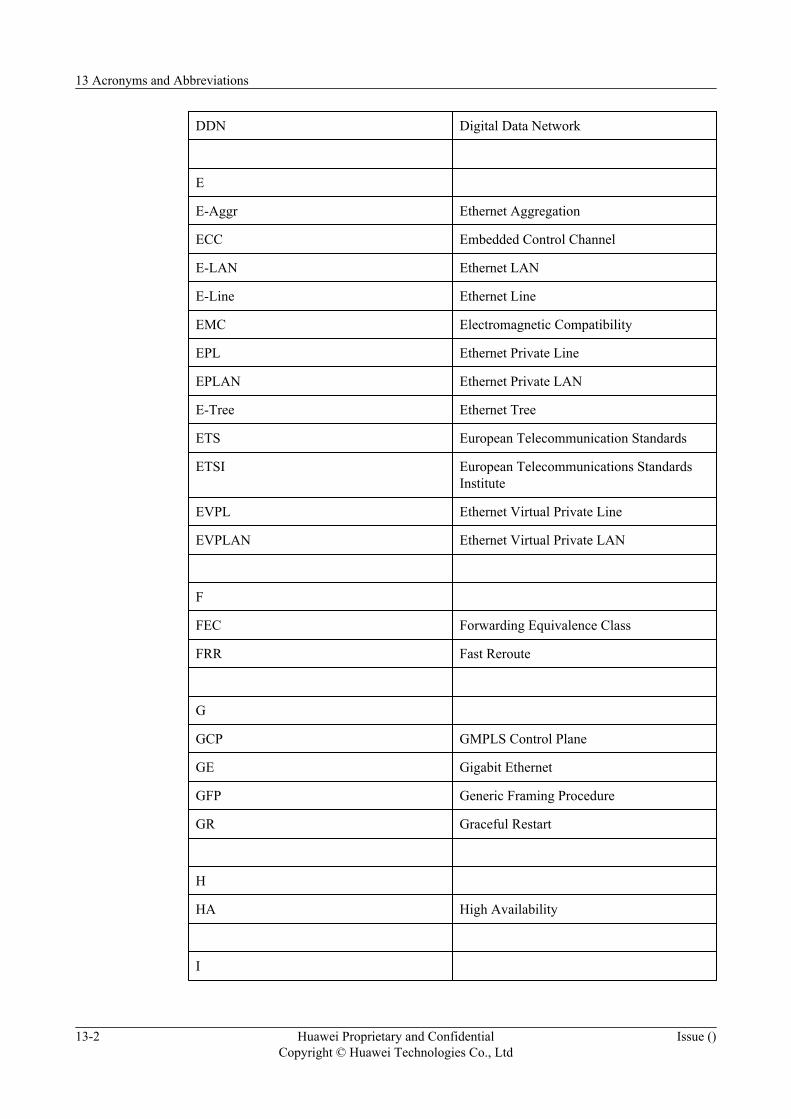
DDN Digital Data Network
E
E-Aggr Ethernet Aggregation
ECC Embedded Control Channel
E-LAN Ethernet LAN
E-Line Ethernet Line
EMC Electromagnetic Compatibility
EPL Ethernet Private Line
EPLAN Ethernet Private LAN
E-Tree Ethernet Tree
ETS European Telecommunication Standards
ETSI European Telecommunications StandardsInstitute
EVPL Ethernet Virtual Private Line
EVPLAN Ethernet Virtual Private LAN
F
FEC Forwarding Equivalence Class
FRR Fast Reroute
G
GCP GMPLS Control Plane
GE Gigabit Ethernet
GFP Generic Framing Procedure
GR Graceful Restart
H
HA High Availability
I
13 Acronyms and Abbreviations
13-2 Huawei Proprietary and ConfidentialCopyright © Huawei Technologies Co., Ltd
Issue ()
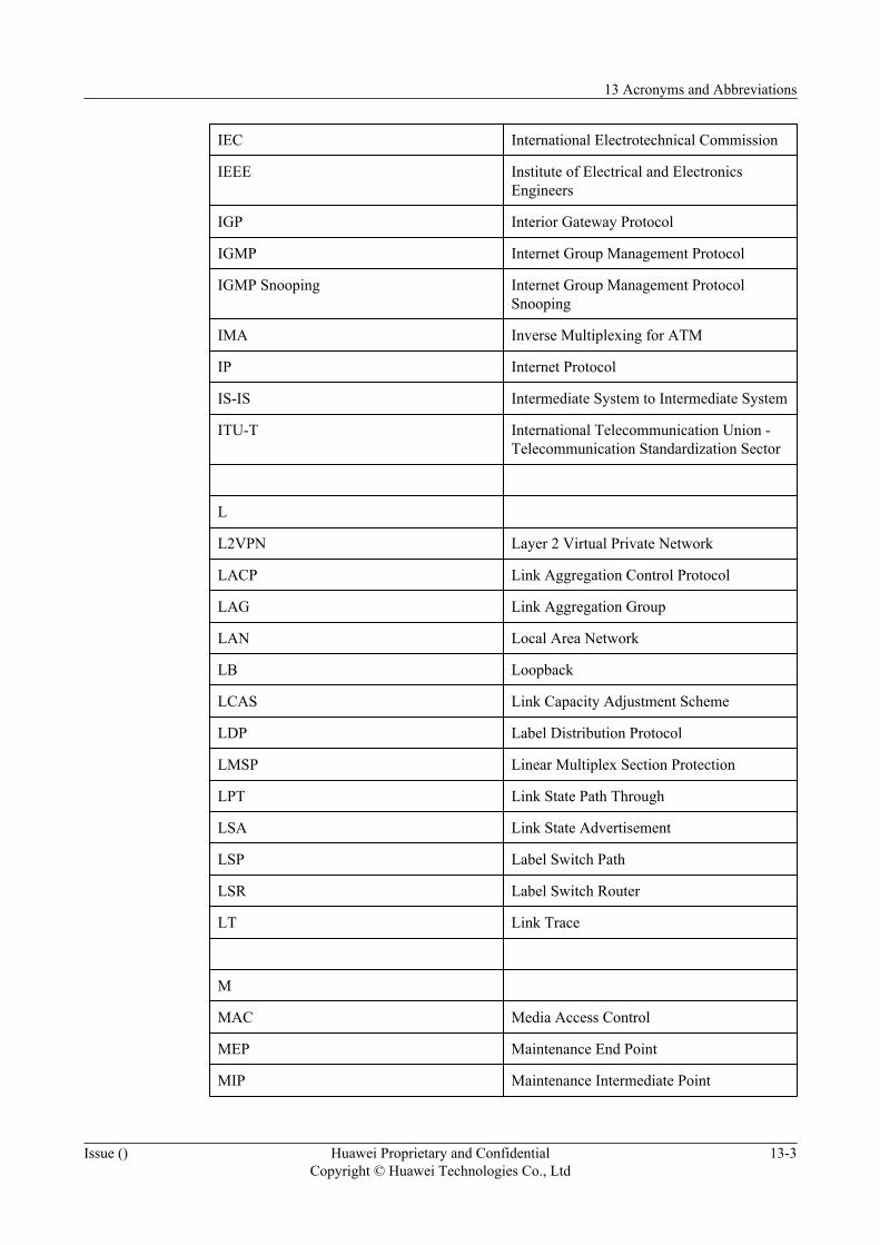
IEC International Electrotechnical Commission
IEEE Institute of Electrical and ElectronicsEngineers
IGP Interior Gateway Protocol
IGMP Internet Group Management Protocol
IGMP Snooping Internet Group Management ProtocolSnooping
IMA Inverse Multiplexing for ATM
IP Internet Protocol
IS-IS Intermediate System to Intermediate System
ITU-T International Telecommunication Union -Telecommunication Standardization Sector
L
L2VPN Layer 2 Virtual Private Network
LACP Link Aggregation Control Protocol
LAG Link Aggregation Group
LAN Local Area Network
LB Loopback
LCAS Link Capacity Adjustment Scheme
LDP Label Distribution Protocol
LMSP Linear Multiplex Section Protection
LPT Link State Path Through
LSA Link State Advertisement
LSP Label Switch Path
LSR Label Switch Router
LT Link Trace
M
MAC Media Access Control
MEP Maintenance End Point
MIP Maintenance Intermediate Point
13 Acronyms and Abbreviations
Issue () Huawei Proprietary and ConfidentialCopyright © Huawei Technologies Co., Ltd
13-3
ML-PPP Multilink Point-to-Point Protocol
MP Merge Point
MPLS Multiprotocol Label Switching
MPLS TE Multiprotocol Label Switching TrafficEngineering
MSP Multiplex Section Protection
MSTP Multiple Spanning Tree Protocol
N
NHOP Next-Hop
NNHOP Next-Next-Hop
NSAP Network Service Access Point
NSF Non-Stop Forwarding
O
OAM Operation, Administration and Maintenance
P
PDH Plesiochronous Digital Hierarchy
PE Provider Edge
PLR Point of Local Repair
POS Packet over SDH/SONET
PPP Point-to-Point Protocol
PTN Packet Transport Network
PW Pseudo Wire
Q
QoS Quality of Service
H-QoS Hierarchical Quality of Service
R
13 Acronyms and Abbreviations
13-4 Huawei Proprietary and ConfidentialCopyright © Huawei Technologies Co., Ltd
Issue ()
RSTP Rapid Spanning Tree Protocol
RSVP Resource Reservation Protocol
S
SDH Synchronous Digital Hierarchy
SLA Service Level Agreement
STP Spanning Tree Protocol
SVC Static Virtual Circuit
T
TE Traffic Engineering
TDM Time Division Multiplexing
T-MPLS Transport Multiprotocol Label Switching
TM+SM Traffic Manager+Switching Memory
TPS Tributary Protection Switching
V
VC Virtual Channel
VLAN Virtual Local Area Network
V-NNI Virtual Network-Network Interface
VP Virtual Path
VPC Virtual Path Connection
VPLS Virtual Private LAN Service
VPN Virtual Private Network
VPWS Virtual Private Wire Service
V-UNI Virtual User-Network Interface
W
WTR Wait to Restore
13 Acronyms and Abbreviations
Issue () Huawei Proprietary and ConfidentialCopyright © Huawei Technologies Co., Ltd
13-5