ROTEX EHF SERIES ACTUATOR
30
ROTEX EHF SERIES ACTUATOR SELF CONTAINED ELECTRO HYDRAULIC ACTUATOR
-
Upload
khangminh22 -
Category
Documents
-
view
3 -
download
0
Transcript of ROTEX EHF SERIES ACTUATOR
ROTEX EHF SERIES ACTUATOR
SELF CONTAINED ELECTROHYDRAULIC ACTUATOR
ROTEX EHF SERIES ACTUATOR
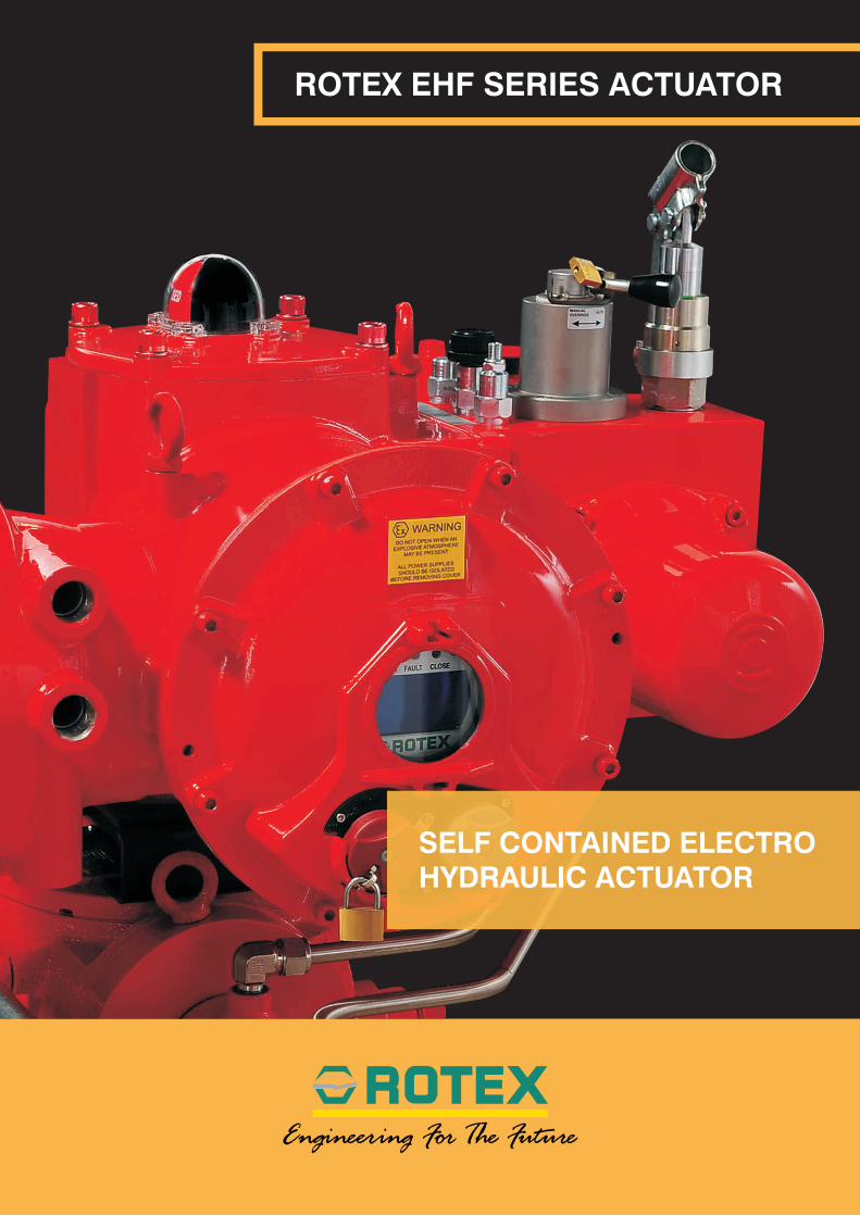
In continuation with the tradition of constant innovation and virtue in engineering, ROTEX, introduces the next generation compact, modular and for precise control,
Self Contained Electro-Hydraulic Actuator series “EHF”
with 360° viewing GLOWDAPT dome indicator
2

WHY ROTEX?
Do you have leakages due to too many piping ?Rotex EHF has no external tubing for interconnecting different blocks, the only tubing is from frame to Actuator.
Do you spend more for modulating system for higher accuracy and lower dead-band ?Rotex EHF has unique PID with ADAPTIVE PID loop, providing accuracy, dead band less than 0.1 % using high performance solenoid valves.
Do you spend time in understanding the abbreviated menu and alarms ?Full featured LCD display, no abbreviations, no operating manual required.
Do you have problem in viewing open close indicators at night ?Special GLOWDAPT dome indicators, suitable for 360° viewing and visible at night.
Do you face operational failures due to moisture, vibration etc ?Rotex EHF is IP 68 and has Remote Mount capability up to 50 m.
ROTEX EHF Series
solves all of the above problems and guarantees
performance!!
3
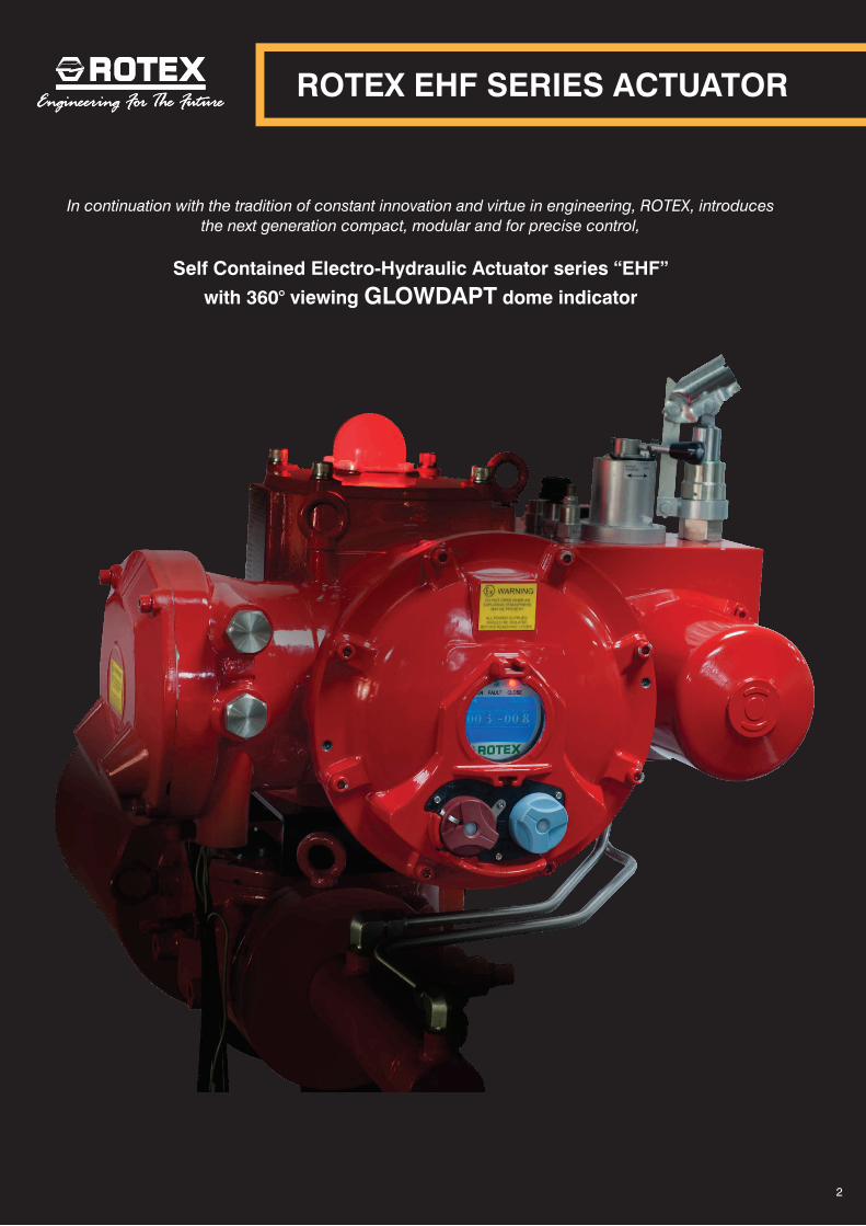
? • Linear ESD speed <1 sec for 50 mm travel
? • Rotary ESD speed <1 sec
? • Rotary system has built in transmitter
? • Records events for 30 years
UNIQUE FEATURES FOR ON-OFF SYSTEM
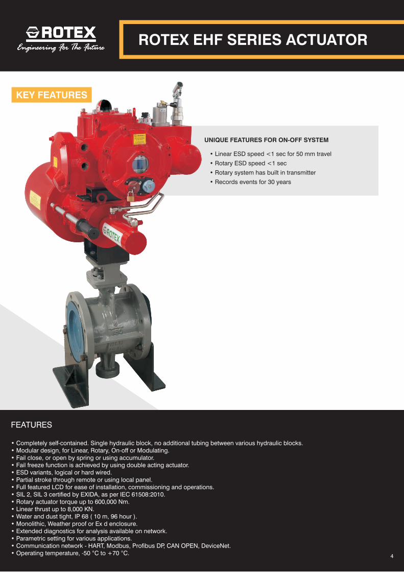
FEATURES
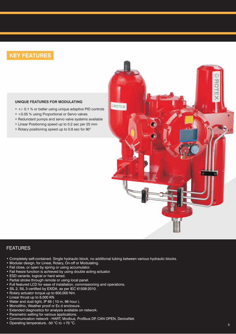
• Completely self-contained. Single hydraulic block, no additional tubing between various hydraulic blocks.• Modular design, for Linear, Rotary, On-off or Modulating.• Fail close, or open by spring or using accumulator.• Fail freeze function is achieved by using double acting actuator.• ESD variants, logical or hard wired.• Partial stroke through remote or using local panel.• Full featured LCD for ease of installation, commissioning and operations.• SIL 2, SIL 3 certified by EXIDA, as per IEC 61508:2010.• Rotary actuator torque up to 600,000 Nm.• Linear thrust up to 8,000 KN.• Water and dust tight, IP 68 ( 10 m, 96 hour ).• Monolithic, Weather proof or Ex d enclosure.• Extended diagnostics for analysis available on network.• Parametric setting for various applications.• Communication network - HART, Modbus, Profibus DP, CAN OPEN, DeviceNet.• Operating temperature, -50 °C to +70 °C.
ROTEX EHF SERIES ACTUATOR
KEY FEATURES
4
KEY FEATURES
• +/- 0.1 % or better using unique adaptive PID controls
• <0.05 % using Proportional or Servo valves
• Redundant pumps and servo valve systems available
• Linear Positioning speed up to 0.2 sec per 25 mm
• Rotary positioning speed up to 0.8 sec for 90°
UNIQUE FEATURES FOR MODULATING
5
FEATURES
• Completely self-contained. Single hydraulic block, no additional tubing between various hydraulic blocks.• Modular design, for Linear, Rotary, On-off or Modulating.• Fail close, or open by spring or using accumulator.• Fail freeze function is achieved by using double acting actuator.• ESD variants, logical or hard wired.• Partial stroke through remote or using local panel.• Full featured LCD for ease of installation, commissioning and operations.• SIL 2, SIL 3 certified by EXIDA, as per IEC 61508:2010.• Rotary actuator torque up to 600,000 Nm.• Linear thrust up to 8,000 KN.• Water and dust tight, IP 68 ( 10 m, 96 hour ).• Monolithic, Weather proof or Ex d enclosure.• Extended diagnostics for analysis available on network.• Parametric setting for various applications.• Communication network - HART, Modbus, Profibus DP, CAN OPEN, DeviceNet.• Operating temperature, -50 °C to +70 °C.
LOCAL CONTROL
Selector to validate choice
Navigate through menu
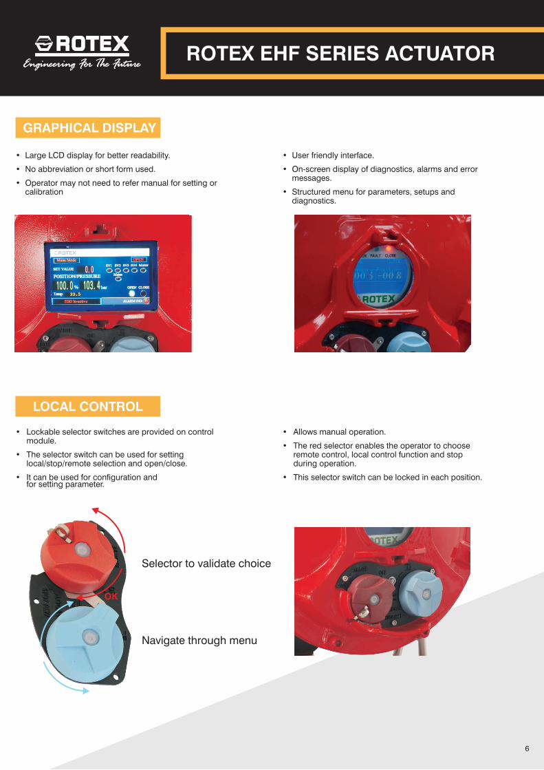
• Large LCD display for better readability.
• No abbreviation or short form used.
• Operator may not need to refer manual for setting or calibration
• Lockable selector switches are provided on control module.
• The selector switch can be used for setting local/stop/remote selection and open/close.
• It can be used for configuration and for setting parameter.
GRAPHICAL DISPLAY
ROTEX EHF SERIES ACTUATOR
6
OK
• User friendly interface.
• On-screen display of diagnostics, alarms and error messages.
• Structured menu for parameters, setups and diagnostics.
• Allows manual operation.
• The red selector enables the operator to choose remote control, local control function and stop during operation.
• This selector switch can be locked in each position.
LOCAL MECHANICAL INDICATOR
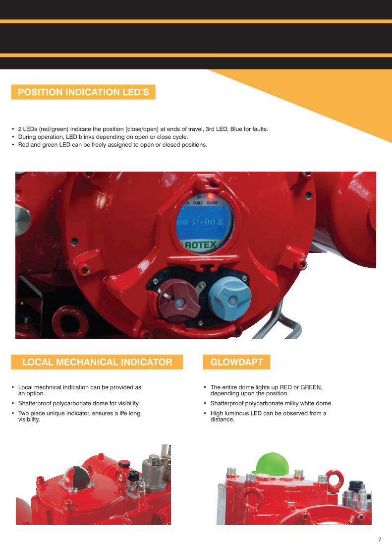
• 2 LEDs (red/green) indicate the position (close/open) at ends of travel, 3rd LED, Blue for faults.
• During operation, LED blinks depending on open or close cycle.
• Red and green LED can be freely assigned to open or closed positions.
GLOWDAPT
• Local mechnical indication can be provided as an option.
• Shatterproof polycarbonate dome for visibility.
• Two piece unique indicator, ensures a life long visibility.
• The entire dome lights up RED or GREEN, depending upon the position.
• Shatterproof polycarbonate milky white dome.
• High luminous LED can be observed from a distance.
POSITION INDICATION LED’S
7
ROTARY
ROTARY
END POSITION FEEDBACK
LINEAR
• ROTEX EHF series actuator are equipped with contactless feedback sensor
• 360° with freely rotating contactless feedback shaft.
• No dead angle. Can start anywhere and end anywhere.
• Contactless, high resolution feedback.
• Position feedback of 4-20 mA output signal, 0-10V optional.
• Contactless feedback device.
• Stroke up to 1m.
• Speed up to 0.2 sec for 25mm..
• Position feedback of 4-20mA, 0-10V optional.
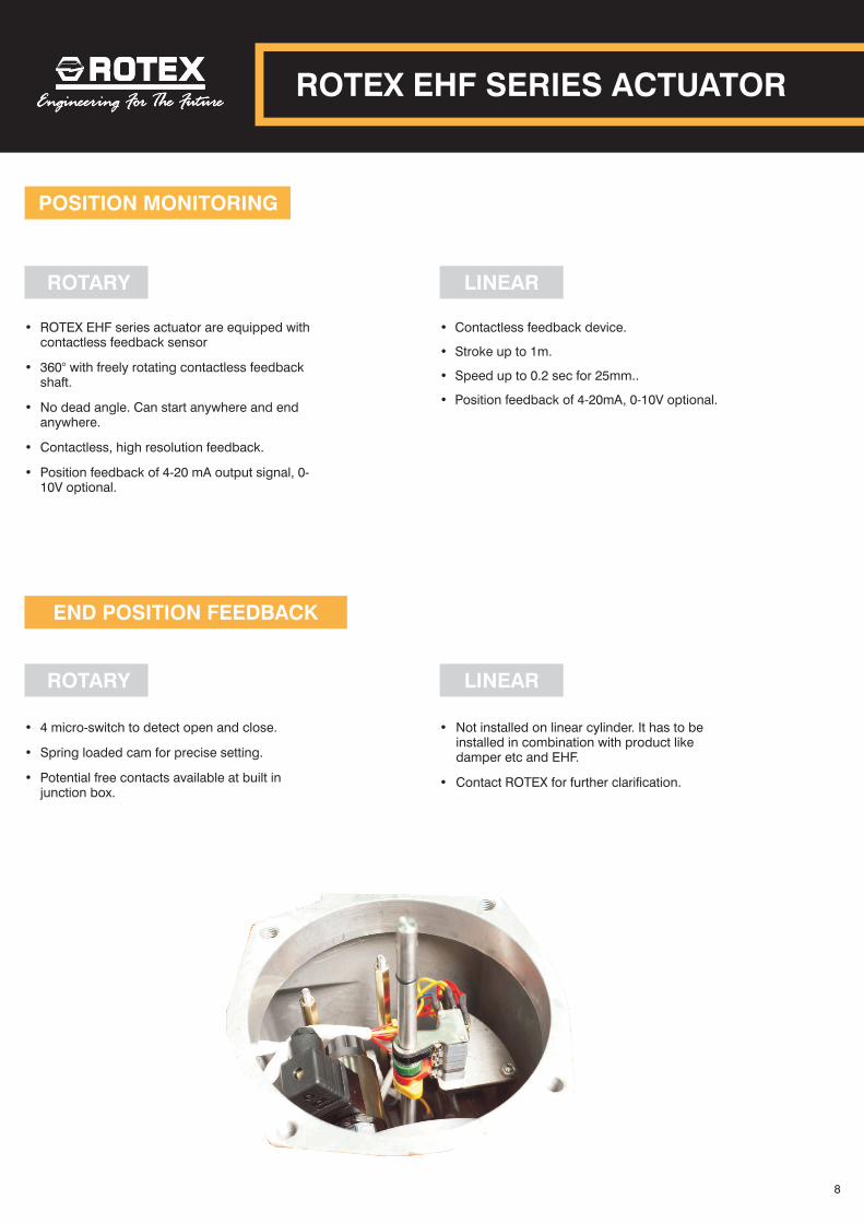
• 4 micro-switch to detect open and close.
• Spring loaded cam for precise setting.
• Potential free contacts available at built in junction box.
• Not installed on linear cylinder. It has to be installed in combination with product like damper etc and EHF.
• Contact ROTEX for further clarification.
POSITION MONITORING
LINEAR
ROTEX EHF SERIES ACTUATOR
8

ESD RESET
FAIL FREEZE OPTION
FAILSAFE OPTION
• Actuator torque/force is measured based on pressure.
• Pressure transducer is integrated inside the hydraulic control system.
• Real time feedback from the pressure transducer is recorded and diagnostics information is generated based on parameterisation.
• It can detect over pressure, low pressure, "valve stuck", hydraulic failure, etc if any.
• 4-20 mA feedback signal proportional to actual torque of the valve is available as an option.
• On demand emergency shutdown is the primary feature.
• ROTEX EHF system is suitable for use in SIS function in accordance to IEC 61508:2010.
• Suitable upto & including SIL 2 & SIL 3 capability.
• Can be configured through hardware for safety function or can be hardwired to perform fail-safe action.
• EHF can be configured to different failure
requirements, please refer to the ordering code.
• On request, additional redundant solenoid
valve can be provided.
EMERGENCY SHUTDOWN
• ROTEX EHF series actuator has safety feature as built in priority.
• Once an ESD demand occurs, the actuator can reinstate only new command to operate or can be configured to manual reset through local
controls via setting menu.
• This increases overall process and personal safety.
• Failsafe action can be performed based on following
- On loss of ESD signal or ESD demand occurs
- On loss of main power supply. In applications where main power is part of SIS.
• In both the above cases, the valve will be driven to its failsafe position in case of failure of main power supply or ESD demand.
• ESD Input signal - 20 to 60 VDC or 60 to 120 VAC, 110 to 220 VAC.
• Main power supply is unreliable and is not part of functional safety.
• On failure of main power supply the operation of the actuator or the valve position is
unaffected.
• ESD solenoid valve is separately powered
through a 24 VDC ESD input signal and is solely responsible for safety function.
PRESSURE MONITORING
9
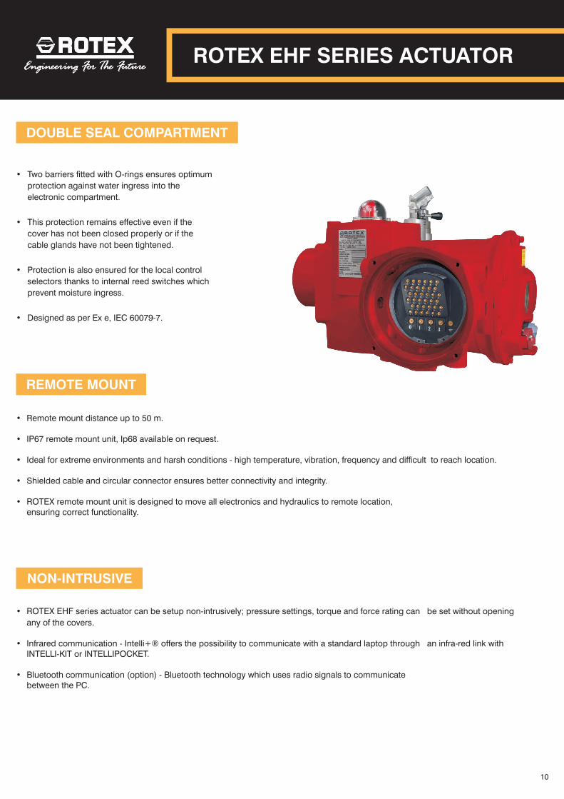
DOUBLE SEAL COMPARTMENT
REMOTE MOUNT
NON-INTRUSIVE
• Two barriers fitted with O-rings ensures optimum
protection against water ingress into the
electronic compartment.
• This protection remains effective even if the
cover has not been closed properly or if the
cable glands have not been tightened.
• Protection is also ensured for the local control
selectors thanks to internal reed switches which
prevent moisture ingress.
• Designed as per Ex e, IEC 60079-7.
• Remote mount distance up to 50 m.
• IP67 remote mount unit, Ip68 available on request.
• Ideal for extreme environments and harsh conditions - high temperature, vibration, frequency and difficult to reach location.
• Shielded cable and circular connector ensures better connectivity and integrity.
• ROTEX remote mount unit is designed to move all electronics and hydraulics to remote location,ensuring correct functionality.
• ROTEX EHF series actuator can be setup non-intrusively; pressure settings, torque and force rating can be set without opening
any of the covers.
• Infrared communication - Intelli+® offers the possibility to communicate with a standard laptop through an infra-red link with INTELLI-KIT or INTELLIPOCKET.
• Bluetooth communication (option) - Bluetooth technology which uses radio signals to communicate between the PC.
ROTEX EHF SERIES ACTUATOR
10
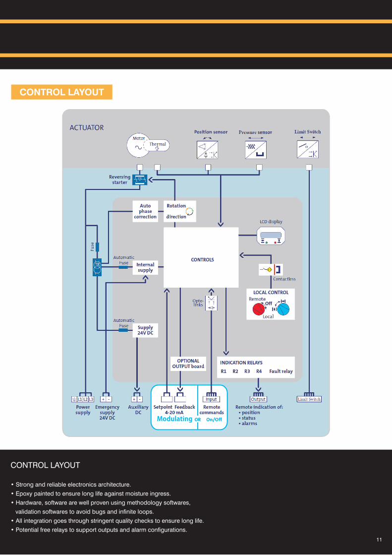
CONTROL LAYOUT
CONTROL LAYOUT?
• Strong and reliable electronics architecture.
• Epoxy painted to ensure long life against moisture ingress.?
• Hardware, software are well proven using methodology softwares,
validation softwares to avoid bugs and infinite loops.
• All integration goes through stringent quality checks to ensure long life.
• Potential free relays to support outputs and alarm configurations.
11
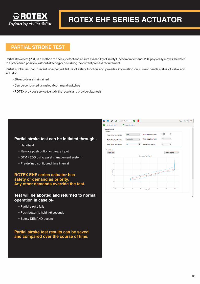
PARTIAL STROKE TEST
Partial stroke test (PST) is a method to check, detect and ensure availability of safety function on demand. PST physically moves the valve
to a predefined position, without affecting or disturbing the current process requirement.
Partial stroke test can prevent unexpected failure of safety function and provides information on current health status of valve and
actuator.
• 30 records are maintained
• Can be conducted using local command switches
• ROTEX provides service to study the results and provide diagnosis
ROTEX EHF series actuator has safety or demand as priority. Any other demands override the test.
Partial stroke test results can be saved and compared over the course of time.
Partial stroke test can be initiated through -
• Handheld
• Remote push button or binary input
• DTM / EDD using asset management system
• Pre-defined configured time interval
Test will be aborted and returned to normal operation in case of-
• Partial stroke fails
• Push button is held >5 seconds
• Safety DEMAND occurs
ROTEX EHF SERIES ACTUATOR
12
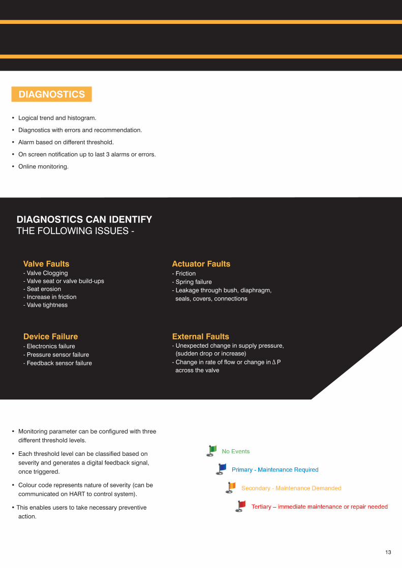
Valve Faults- Valve Clogging
- Valve seat or valve build-ups
- Seat erosion
- Increase in friction
- Valve tightness
Actuator Faults- Friction
- Spring failure
- Leakage through bush, diaphragm,
seals, covers, connections
Device Failure- Electronics failure
- Pressure sensor failure
- Feedback sensor failure
DIAGNOSTICS CAN IDENTIFY THE FOLLOWING ISSUES -
DIAGNOSTICS
• Logical trend and histogram.
• Diagnostics with errors and recommendation.
• Alarm based on different threshold.
• On screen notification up to last 3 alarms or errors.
• Online monitoring.
• Monitoring parameter can be configured with three
different threshold levels.
• Each threshold level can be classified based on
severity and generates a digital feedback signal,
once triggered.
• Colour code represents nature of severity (can be
communicated on HART to control system).
• This enables users to take necessary preventive
action.
13
COMMUNICATION
ROTEX EHF SERIES ACTUATOR
14
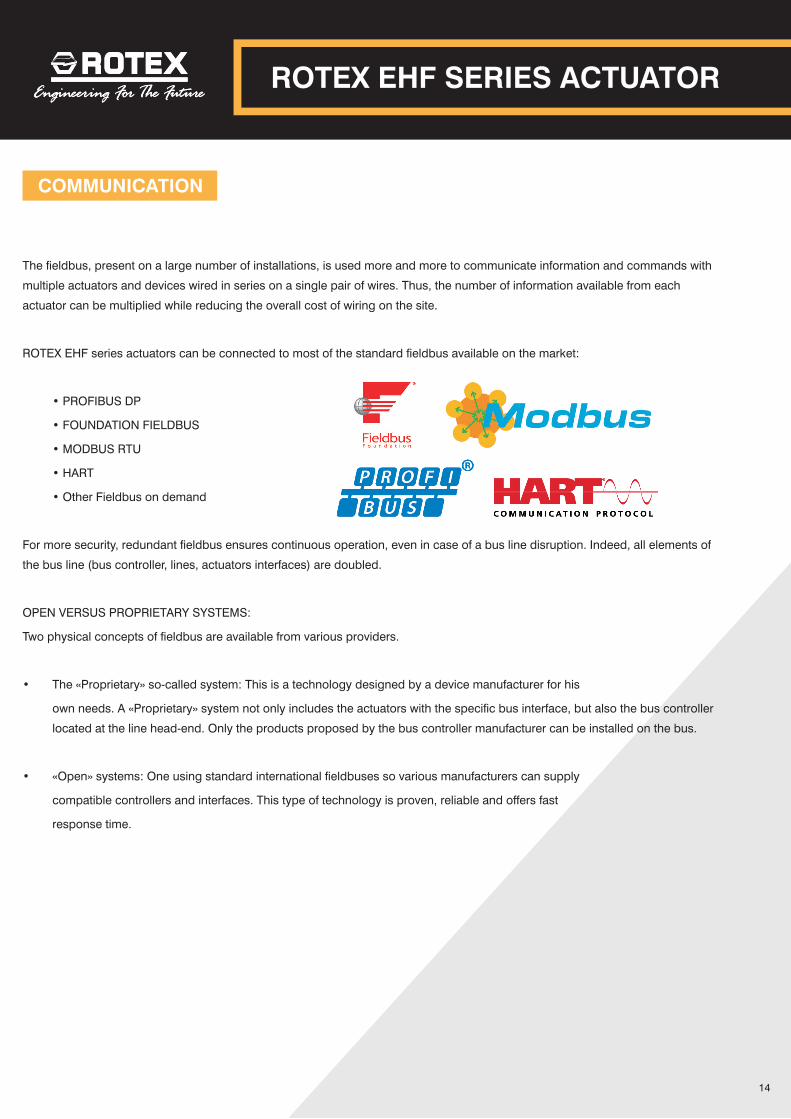
The fieldbus, present on a large number of installations, is used more and more to communicate information and commands with
multiple actuators and devices wired in series on a single pair of wires. Thus, the number of information available from each
actuator can be multiplied while reducing the overall cost of wiring on the site.
ROTEX EHF series actuators can be connected to most of the standard fieldbus available on the market:
• PROFIBUS DP
• FOUNDATION FIELDBUS
• MODBUS RTU
• HART
• Other Fieldbus on demand
For more security, redundant fieldbus ensures continuous operation, even in case of a bus line disruption. Indeed, all elements of
the bus line (bus controller, lines, actuators interfaces) are doubled.
OPEN VERSUS PROPRIETARY SYSTEMS:
Two physical concepts of fieldbus are available from various providers.
• The «Proprietary» so-called system: This is a technology designed by a device manufacturer for his
own needs. A «Proprietary» system not only includes the actuators with the specific bus interface, but also the bus controller
located at the line head-end. Only the products proposed by the bus controller manufacturer can be installed on the bus.
• «Open» systems: One using standard international fieldbuses so various manufacturers can supply
compatible controllers and interfaces. This type of technology is proven, reliable and offers fast
response time.
COMMUNICATION
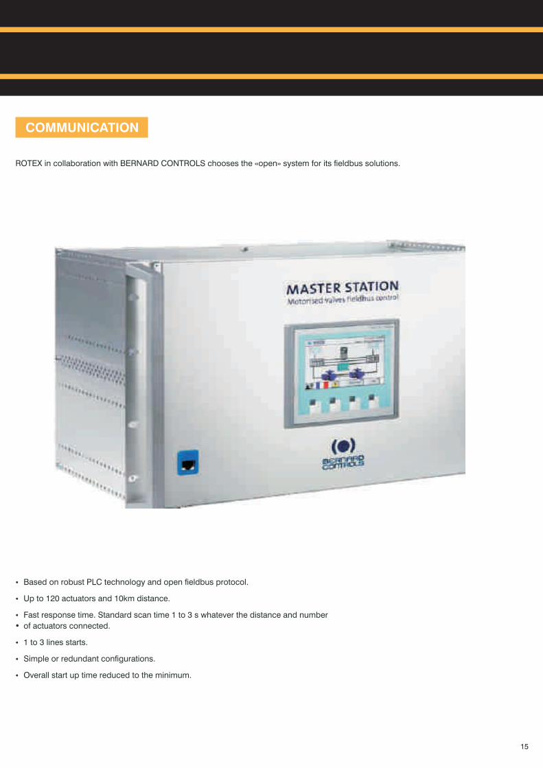
ROTEX in collaboration with BERNARD CONTROLS chooses the «open» system for its fieldbus solutions.
?Based on robust PLC technology and open fieldbus protocol.
?Up to 120 actuators and 10km distance.
?Fast response time. Standard scan time 1 to 3 s whatever the distance and number
?of actuators connected.
?1 to 3 lines starts.
?Simple or redundant configurations.
?Overall start up time reduced to the minimum.
15
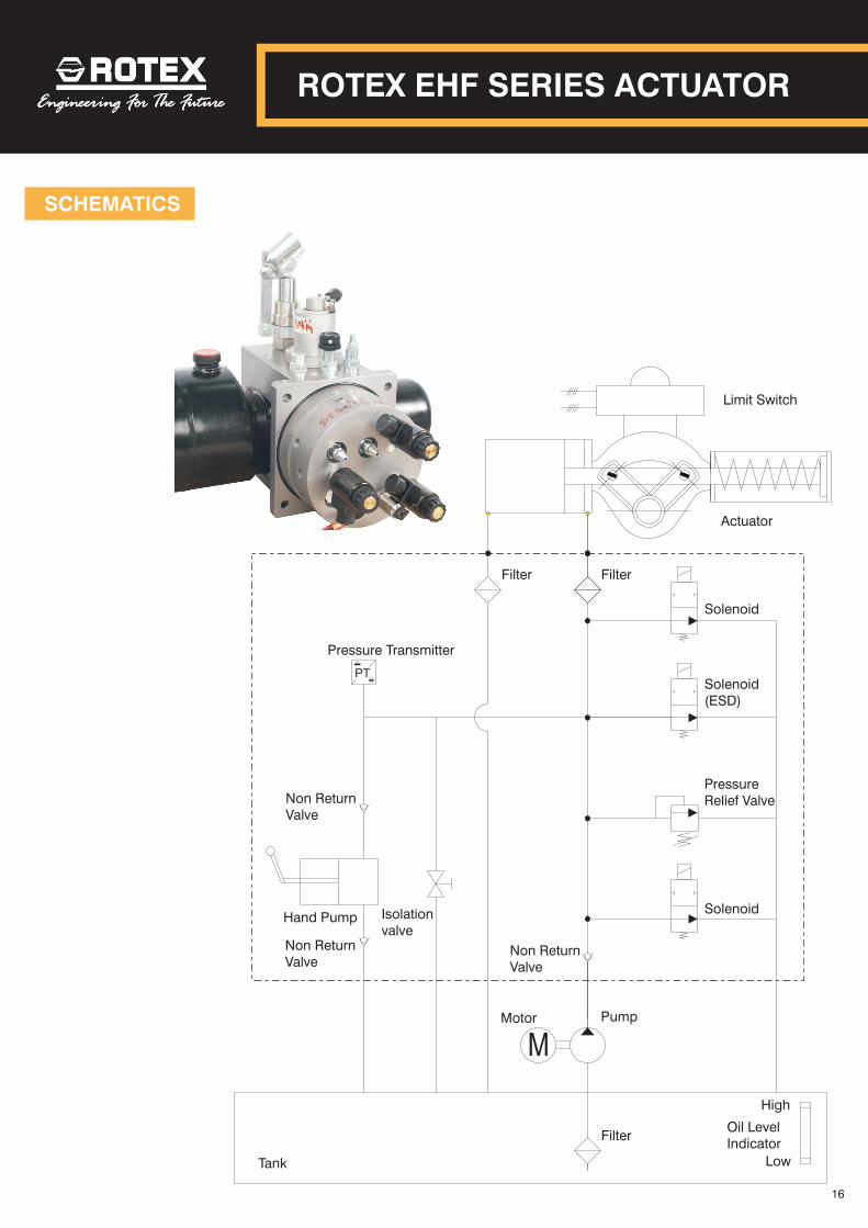
Pressure Transmitter
Hand Pump
Non ReturnValve
Isolationvalve
Motor Pump
Filter
Filter Filter
Actuator
Limit Switch
Tank
High
Low
Oil LevelIndicator
Solenoid
Solenoid(ESD)
Solenoid
PressureRelief Valve
M
PT
Non ReturnValve
Non ReturnValve
SCHEMATICS
ROTEX EHF SERIES ACTUATOR
16
SCHEMATICS
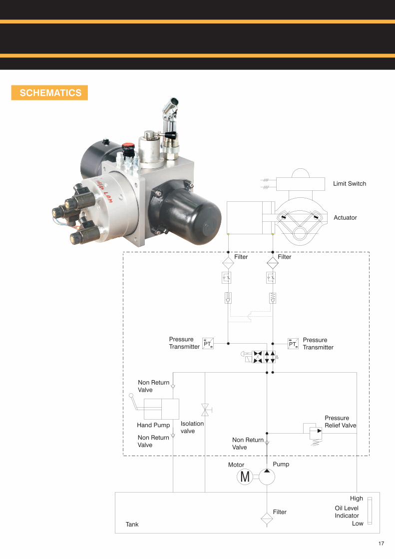
PressureTransmitter
Hand Pump
Non ReturnValve
Isolationvalve
Motor Pump
Filter
Filter Filter
Actuator
Limit Switch
Tank
High
Low
Oil LevelIndicator
PressureRelief Valve
M
PT
Non ReturnValve
Non ReturnValve
PTPressureTransmitter
17
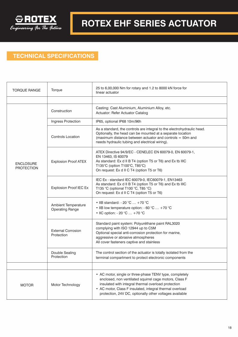
TECHNICAL SPECIFICATIONS
TORQUE RANGE Torque25 to 6,00,000 Nm for rotary and 1.2 to 8000 kN force for linear actuator
ConstructionCasting: Cast Aluminium, Aluminium Alloy, etc.
Actuator: Refer Actuator Catalog
Ingress Protection IP6 5, optional IP68 10m/96h
Controls Location
As a standard, the controls are integral to the electrohydraulic head. Optionally, the head can be mounted at a separate location (maximum distance between actuator and controls = 50m and needs hydraulic tubing and electrical wiring).
Explosion Proof ATEX
ATEX Directive 94/9/EC - CENELEC EN 60079-0, EN 60079-1,
EN 13463, IS 60079
As standard: Ex d II B T4 (option T5 or T6) and Ex tb IIIC
T135°C (option T100°C, T85°C)
On request: Ex d II C T4 (option T5 or T6)
Explosion Proof IEC Ex
IEC Ex - standard IEC 60079-0, IEC60079-1, EN13463As standard: Ex d II B T4 (option T5 or T6) and Ex tb IIIC T135 °C (optional T100 °C, T85 °C)On request: Ex d II C T4 (option T5 or T6)
Ambient TemperatureOperating Range
• IIB standard: - 20 … +70 °C
• IIB low temperature option: - 60 °C … +70 °C
• IIC option: - 20 °C … +70 °C
°C
External CorrosionProtection
Standard paint system: Polyuréthane paint RAL3020
complying with ISO 12944 up to C5M
Optional special anti-corrosion protection for marine,
aggressive or abrasive atmospheres
All cover fasteners captive and stainless
Double SealingProtection
The control section of the actuator is totally isolated from the
terminal compartment to protect electronic components
Motor Technology
?
• AC motor, single or three-phase TENV type, completely
enclosed, non ventilated squirrel cage motors, Class F
insulated with integral thermal overload protection
• AC motor, Class F insulated, integral thermal overload
protection, 24V DC, optionally other voltages available
MOTOR
ENCLOSURE PROTECTION
ROTEX EHF SERIES ACTUATOR
18
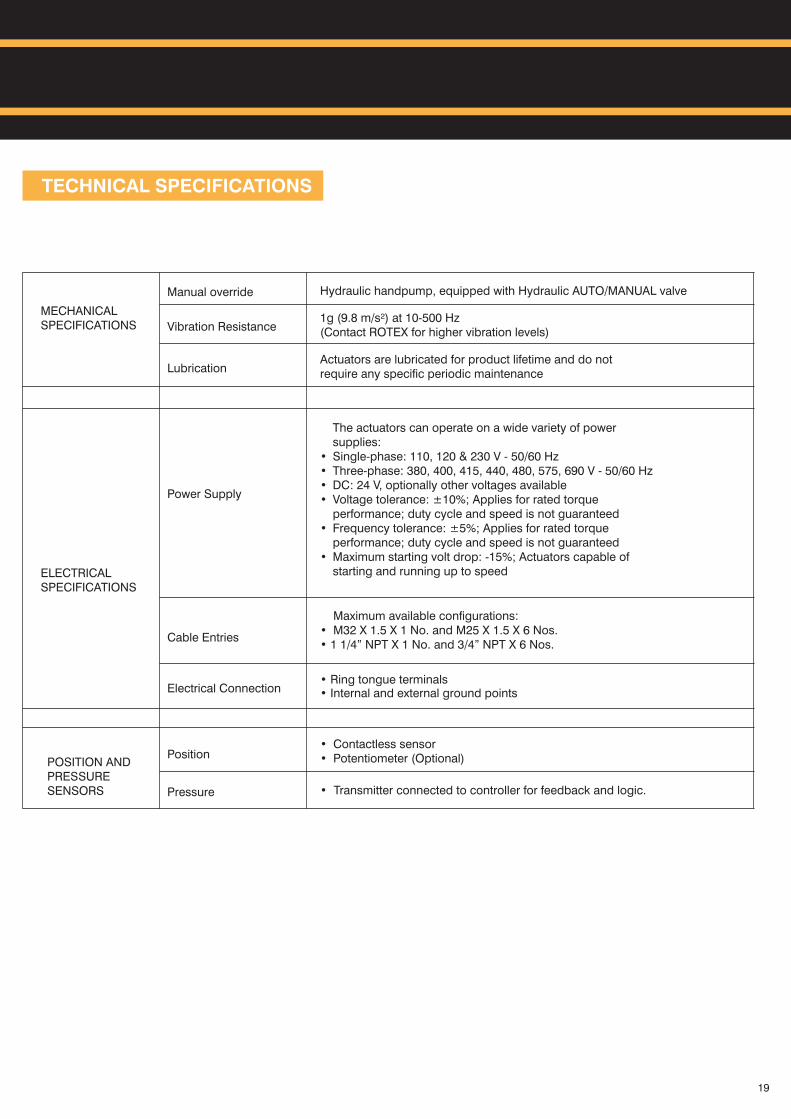
TECHNICAL SPECIFICATIONS
Manual override Hydraulic handpump, equipped with Hydraulic AUTO/MANUAL valve
Vibration Resistance1g (9.8 m/s²) at 10-500 Hz(Contact ROTEX for higher vibration levels)
LubricationActuators are lubricated for product lifetime and do not require any specific periodic maintenance
Power Supply
The actuators can operate on a wide variety of power supplies:
• Single-phase: 110, 120 & 230 V - 50/60 Hz• Three-phase: 380, 400, 415, 440, 480, 575, 690 V - 50/60 Hz• DC: 24 V, optionally other voltages available• Voltage tolerance: ±10%; Applies for rated torque
performance; duty cycle and speed is not guaranteed• Frequency tolerance: ±5%; Applies for rated torque
performance; duty cycle and speed is not guaranteed• Maximum starting volt drop: -15%; Actuators capable of
starting and running up to speed
Cable Entries
Maximum available configurations:• M32 X 1.5 X 1 No. and M25 X 1.5 X 6 Nos.• 1 1/4” NPT X 1 No. and 3/4” NPT X 6 Nos.
Electrical Connection
?• Ring tongue terminals• Internal and external ground points
Position
Pressure • Transmitter connected to controller for feedback and logic.
MECHANICAL SPECIFICATIONS
POSITION AND PRESSURE SENSORS
ELECTRICAL SPECIFICATIONS
• Contactless sensor• Potentiometer (Optional)
19
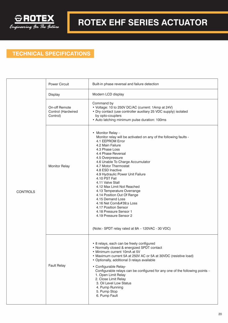
TECHNICAL SPECIFICATIONS
Power Circuit Built-in phase reversal and failure detection
Display Modern LCD display
On-off RemoteControl (Hardwired Control)
Monitor Relay
• 8 relays, each can be freely configured• Normally closed & energized SPDT contact• Minimum current 10mA at 5V • Maximum current 5A at 250V AC or 5A at 30VDC (resistive load)• Optionally, additional 3 relays available
CONTROLS
Command by• Voltage: 10 to 250V DC/AC (current: 1Amp at 24V)• Dry contact (use controller auxiliary 25 VDC supply) isolated by opto-couplers• Auto latching minimum pulse duration: 100ms
ROTEX EHF SERIES ACTUATOR
20
• Monitor Relay –Monitor relay will be activated on any of the following faults -4.1 EEPROM Error4.2 Main Failure4.3 Phase Loss4.4 Phase Reversal4.5 Overpressure4.6 Unable To Charge Accumulator4.7 Motor Thermostat4.8 ESD Inactive4.9 Hydraulic Power Unit Failure4.10 PST Fail4.11 Valve Stall4.12 Max Limit Not Reached4.13 Temperature Overrange4.14 Position Out Of Range4.15 Demand Loss4.16 Net Com's Loss4.17 Position Sensor4.18 Pressure Sensor 14.19 Pressure Sensor 2
(Note:- SPDT relay rated at 8A – 120VAC - 30 VDC)
Fault Relay • Configurable Relay- Configurable relays can be configured for any one of the following points – 1. Open Limit Relay 2. Close Limit Relay
3. Oil Level Low Status4. Pump Running5. Pump Stop6. Pump Fault
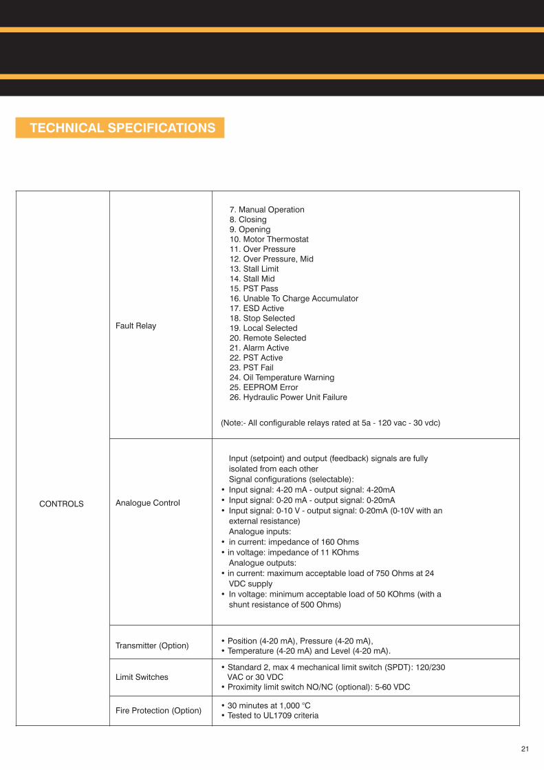
TECHNICAL SPECIFICATIONS
Fault Relay
Analogue Control
Input (setpoint) and output (feedback) signals are fully
isolated from each other
Signal configurations (selectable):
• Input signal: 4-20 mA - output signal: 4-20mA
• Input signal: 0-20 mA - output signal: 0-20mA
• Input signal: 0-10 V - output signal: 0-20mA (0-10V with an
external resistance)
Analogue inputs:
• in current: impedance of 160 Ohms
• in voltage: impedance of 11 KOhms
Analogue outputs:
• in current: maximum acceptable load of 750 Ohms at 24
VDC supply
• In voltage: minimum acceptable load of 50 KOhms (with a
shunt resistance of 500 Ohms)
Transmitter (Option)
Limit Switches• Standard 2, max 4 mechanical limit switch (SPDT): 120/230 VAC or 30 VDC• Proximity limit switch NO/NC (optional): 5-60 VDC
Fire Protection (Option)
CONTROLS
• 30 minutes at 1,000 °C• Tested to UL1709 criteria
• Position (4-20 mA), Pressure (4-20 mA), • Temperature (4-20 mA) and Level (4-20 mA).
21
7. Manual Operation8. Closing9. Opening10. Motor Thermostat11. Over Pressure12. Over Pressure, Mid13. Stall Limit14. Stall Mid15. PST Pass16. Unable To Charge Accumulator17. ESD Active18. Stop Selected19. Local Selected20. Remote Selected21. Alarm Active22. PST Active23. PST Fail24. Oil Temperature Warning25. EEPROM Error26. Hydraulic Power Unit Failure
(Note:- All configurable relays rated at 5a - 120 vac - 30 vdc)
TECHNICAL SPECIFICATIONS
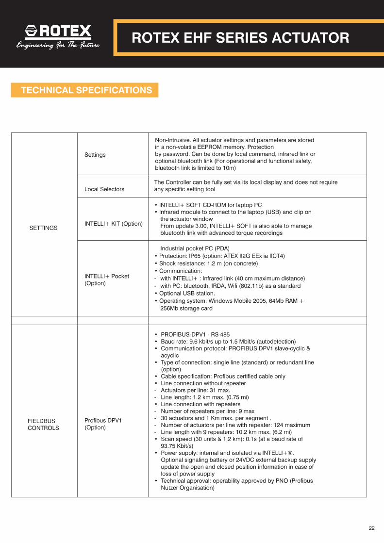
Settings
Non-Intrusive. All actuator settings and parameters are stored in a non-volatile EEPROM memory. Protectionby password. Can be done by local command, infrared link or optional bluetooth link (For operational and functional safety,bluetooth link is limited to 10m)
Local SelectorsThe Controller can be fully set via its local display and does not require any specific setting tool
INTELLI+ KIT (Option)
• INTELLI+ SOFT CD-ROM for laptop PC• Infrared module to connect to the laptop (USB) and clip on
the actuator windowFrom update 3.00, INTELLI+ SOFT is also able to manage bluetooth link with advanced torque recordings
INTELLI+ Pocket(Option)
Industrial pocket PC (PDA)
• Protection: IP65 (option: ATEX II2G EEx ia IICT4)
• Shock resistance: 1.2 m (on concrete)
• Communication:
- with INTELLI+ : Infrared link (40 cm maximum distance)
- with PC: bluetooth, IRDA, Wifi (802.11b) as a standard
• Optional USB station.
• Operating system: Windows Mobile 2005, 64Mb RAM +
256Mb storage card
FIELDBUS CONTROLS
Profibus DPV1 (Option)
• PROFIBUS-DPV1 - RS 485• Baud rate: 9.6 kbit/s up to 1.5 Mbit/s (autodetection)• Communication protocol: PROFIBUS DPV1 slave-cyclic &
acyclic• Type of connection: single line (standard) or redundant line
(option)• Cable specification: Profibus certified cable only• Line connection without repeater- Actuators per line: 31 max.- Line length: 1.2 km max. (0.75 mi)• Line connection with repeaters- Number of repeaters per line: 9 max- 30 actuators and 1 Km max. per segment .- Number of actuators per line with repeater: 124 maximum- Line length with 9 repeaters: 10.2 km max. (6.2 mi)• Scan speed (30 units & 1.2 km): 0.1s (at a baud rate of
93.75 Kbit/s)• Power supply: internal and isolated via INTELLI+®.
Optional signaling battery or 24VDC external backup supplyupdate the open and closed position information in case of loss of power supply
• Technical approval: operability approved by PNO (Profibus Nutzer Organisation)
SETTINGS
22
ROTEX EHF SERIES ACTUATOR
TECHNICAL SPECIFICATIONS
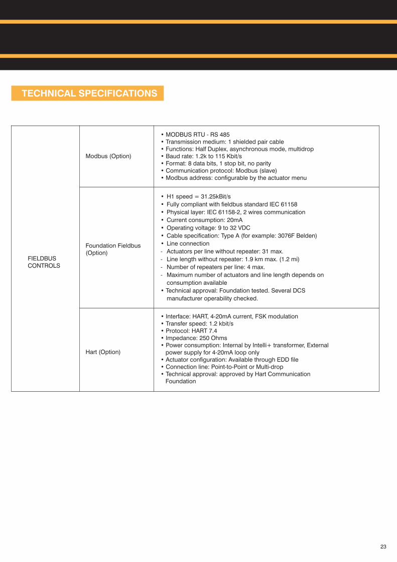
Modbus (Option)
• MODBUS RTU - RS 485• Transmission medium: 1 shielded pair cable• Functions: Half Duplex, asynchronous mode, multidrop• Baud rate: 1.2k to 115 Kbit/s• Format: 8 data bits, 1 stop bit, no parity• Communication protocol: Modbus (slave)• Modbus address: configurable by the actuator menu
Foundation Fieldbus (Option)
• H1 speed = 31.25kBit/s
• Fully compliant with fieldbus standard IEC 61158
• Physical layer: IEC 61158-2, 2 wires communication
• Current consumption: 20mA
• Operating voltage: 9 to 32 VDC
• Cable specification: Type A (for example: 3076F Belden)
• Line connection
- Actuators per line without repeater: 31 max.
- Line length without repeater: 1.9 km max. (1.2 mi)
- Number of repeaters per line: 4 max.
- Maximum number of actuators and line length depends on
consumption available
• Technical approval: Foundation tested. Several DCS
manufacturer operability checked.
Hart (Option)
• Interface: HART, 4-20mA current, FSK modulation• Transfer speed: 1.2 kbit/s• Protocol: HART 7.4• Impedance: 250 Ohms• Power consumption: Internal by Intelli+ transformer, External power supply for 4-20mA loop only• Actuator configuration: Available through EDD file• Connection line: Point-to-Point or Multi-drop• Technical approval: approved by Hart Communication Foundation
FIELDBUSCONTROLS
23

APPLICATIONS
OTHER APPLICATIONS
ON – OFF
Emergency Shutdown:
- Gas gathering stations
- Cross country pipeline
- Pump non return valve
- Coal and ash dampers
MODULATING
- HP and LP bypass valve
- Water spray and main valve
- Control valve for severe service
- Butterfly valve for coke oven batteries
- General purpose modulating valves
24
EHF FOR CROSS COUNTRY PIPELINE.
- 24 VDC generated through solar panel- Solar panel suitable for safe area or for “Ex” classification area.- Unique power pack running on 24 VDC. - Power module with battery charge having back up up to 3 strokes and 8 days working without sunlight- Ranging from 10,000 Nm to 197,500 Nm
ROTEX EHF SERIES ACTUATOR
8
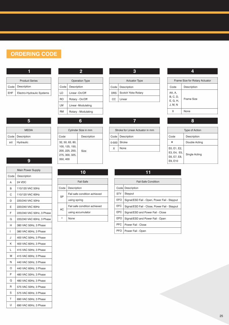
Type of Action
Code Description
* Double Acting
E0, E1, E2,
E3, E4, E5,
E6, E7, E8,
E9, E10
Single Acting
7
Stroke for in mmLinear Actuator
Code Description
0-500 Stroke
X None
6
Cylinder Size in mm
Code Description
32, 50, 63, 80,
100, 125, 150,
200, 225, 250,
275, 300, 325,
350, 400
Size
5
MEDIA
Code Description
HY Hydraulic
4
Frame Size for Rotary Actuator
Code Description
AA, A,
B, C, D,
E, G, H,
J, M, N
Frame Size
NoneX
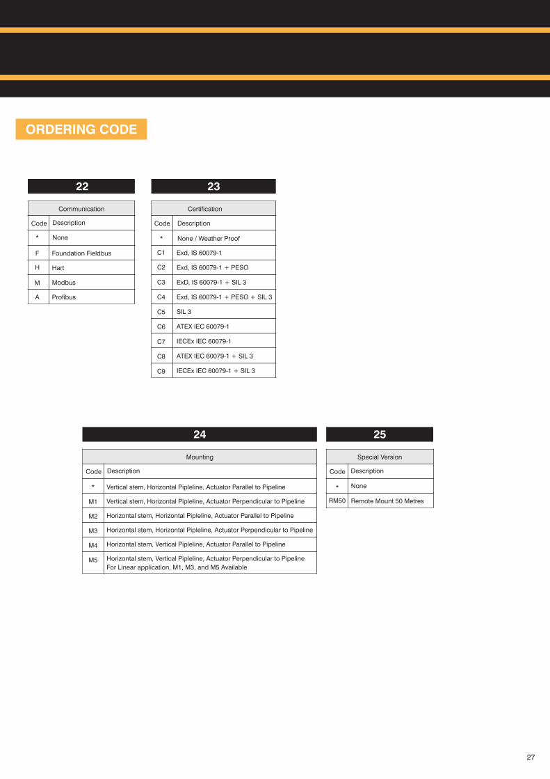
ORDERING CODE
Product Series
Code
EHF Electro-Hydraulic Systems
Description
1 2
Operation Type
Code
LO
RO
LM
RM
Description
Linear -On/Off
Rotary - On/Off
Linear -Modulating
Rotary - Modulating
25
3
Actuator Type
Code Description
DRS Scotch Yoke Rotary
LinearCC
9
Main Power Supply
Code Description
A
B
C
D
E
F
G
H
I
J
K
L
M
N
O
P
Q
R
S
T
U
24 VDC
110/120 VAC 50Hz
110/120 VAC 60Hz
220/240 VAC 50Hz
220/240 VAC 60Hz
220/240 VAC 50Hz, 3 Phase
220/240 VAC 60Hz, 3 Phase
380 VAC 50Hz, 3 Phase
380 VAC 60Hz, 3 Phase
400 VAC 50Hz, 3 Phase
400 VAC 60Hz, 3 Phase
415 VAC 50Hz, 3 Phase
415 VAC 60Hz, 3 Phase
440 VAC 50Hz, 3 Phase
440 VAC 60Hz, 3 Phase
480 VAC 50Hz, 3 Phase
480 VAC 60Hz, 3 Phase
575 VAC 50Hz, 3 Phase
575 VAC 60Hz, 3 Phase
690 VAC 50Hz, 3 Phase
690 VAC 60Hz, 3 Phase
10
Fail-Safe
Code Description
SPFail safe condition achieved
using spring
Fail safe condition achieved
using accumulatorAC
* None
11
Fail-Safe Condition
STY
EFO
EFC
EPC
EPO
PFC
PFO
Stayput
Signal/ESD Fail - Open, Power Fail - Stayput
Signal/ESD Fail - Close, Power Fail - Stayput
Code Description
Signal/ESD and Power Fail - Close
Signal/ESD and Power Fail - Open
Power Fail - Close
Power Fail - Open
ORDERING CODE
19
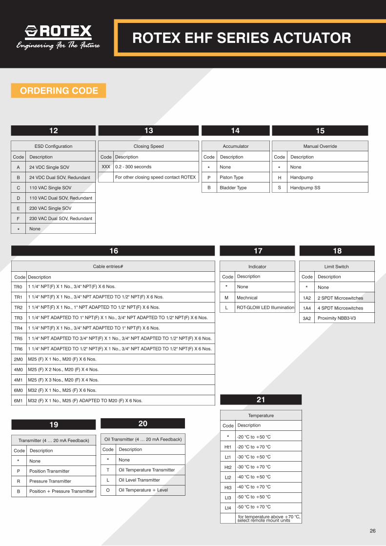
Transmitter (4 … 20 mA Feedback)
Code Description
*
P
R
B
None
Position Transmitter
Pressure Transmitter
Position + Pressure Transmitter
20
Oil Transmitter (4 … 20 mA Feedback)
Code Description
*
T
L
O
None
Oil Temperature Transmitter
Oil Level Transmitter
Oil Temperature + Level
26
ROTEX EHF SERIES ACTUATOR
12
ESD Configuration
A
B
C
D
E
F
Code Description
24 VDC Single SOV
24 VDC Dual SOV, Redundant
110 VAC Single SOV
110 VAC Dual SOV, Redundant
230 VAC Single SOV
230 VAC Dual SOV, Redundant
* None
13
Closing Speed
Code Description
0.2 - 300 seconds
For other closing speed contact ROTEX
XXX
14
Accumulator
Code Description
*
P
B
None
Piston Type
Bladder Type
15
Manual Override
Code Description
*
H
S
None
Handpump
Handpump SS
Temperature
Code Description
21
*
Ht1
Lt1
Ht2
Lt2
Ht3
Lt3
Lt4
-20 °C to +50 °C
-20 °C to +70 °C
-30 °C to +50 °C
-30 °C to +70 °C
-40 °C to +50 °C
-40 °C to +70 °C
-50 °C to +50 °C
-50 °C to +70 °C
for temperature above +70 °C, select remote mount units
16
Cable entries#
Code Description
1 1/4" NPT(F) X 1 No., 3/4" NPT(F) X 6 Nos.
1 1/4" NPT(F) X 1 No., 3/4" NPT ADAPTED TO 1/2" NPT(F) X 6 Nos.
1 1/4" NPT(F) X 1 No., 1" NPT ADAPTED TO 1/2" NPT(F) X 6 Nos.
1 1/4" NPT ADAPTED TO 1" NPT(F) X 1 No., 3/4" NPT ADAPTED TO 1/2" NPT(F) X 6 Nos.
1 1/4" NPT(F) X 1 No., 3/4" NPT ADAPTED TO 1" NPT(F) X 6 Nos.
1 1/4" NPT ADAPTED TO 3/4" NPT(F) X 1 No., 3/4" NPT ADAPTED TO 1/2" NPT(F) X 6 Nos.
1 1/4" NPT ADAPTED TO 1/2" NPT(F) X 1 No., 3/4" NPT ADAPTED TO 1/2" NPT(F) X 6 Nos.
M25 (F) X 1 No., M20 (F) X 6 Nos.
M25 (F) X 2 Nos., M20 (F) X 4 Nos.
M25 (F) X 3 Nos., M20 (F) X 4 Nos.
M32 (F) X 1 No., M25 (F) X 6 Nos.
M32 (F) X 1 No., M25 (F) ADAPTED TO M20 (F) X 6 Nos.
TR 0
TR1
TR2
TR3
TR4
TR5
TR6
2M0
4M0
4M1
6M0
6M1
Indicator
Code
M
Description
17
L
Mechnical
ROT-GLOW LED Illumination
* None
18
Limit Switch
Description
1A2
1A4
3A2
Code
* None
2 SPDT Microswitches
4 SPDT Microswitches
Proximity NBB3-V3
ORDERING CODE
23
Certification
DescriptionCode
* None / Weather Proof
C1
C2
C3
C4
C5
C6
C7
C8
C9
Exd, IS 60079-1
Exd, IS 60079-1 + PESO
ExD, IS 60079-1 + SIL 3
Exd, IS 60079-1 + PESO + SIL 3
SIL 3
ATEX IEC 60079-1
IECEx IEC 60079-1
ATEX IEC 60079-1 + SIL 3
IECEx IEC 60079-1 + SIL 3
Mounting
Code Description
24
*
M1
M2
M3
M4
M5
Vertical stem, Horizontal Pipleline, Actuator Parallel to Pipeline
Vertical stem, Horizontal Pipleline, Actuator Perpendicular to Pipeline
Horizontal stem, Horizontal Pipleline, Actuator Parallel to Pipeline
Horizontal stem, Horizontal Pipleline, Actuator Perpendicular to Pipeline
Horizontal stem, Vertical Pipleline, Actuator Parallel to Pipeline
Horizontal stem, Vertical Pipleline, Actuator Perpendicular to Pipeline
For Linear application, M1, M3, and M5 Available
Special Version
Code Description
25
*
RM50
None
Remote Mount 50 Metres
27
Communication
Code
F
Description
22
H
Foundation Fieldbus
Hart
Modbus
Profibus
* None
M
A

DIMENSIONAL DRAWING
ROTARY
ALL DIMENSIONS ARE IN MM
ROTEX EHF SERIES ACTUATOR
28
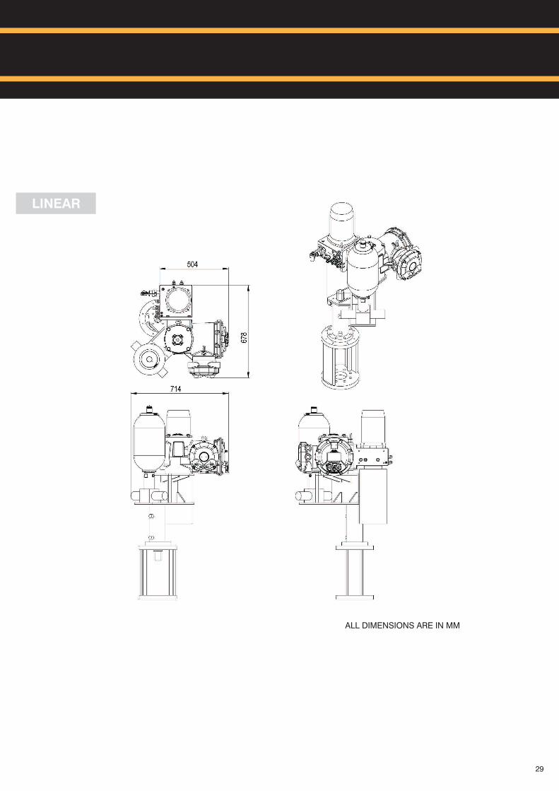
LINEAR
ALL DIMENSIONS ARE IN MM
29

ROTEX GROUP SALES HEAD QUARTERB/703/704, Western Edge-II, Off Western Express Highway,Borivli (East), Mumbai-400066Phone : +91 22 42111444Fax : +91 22 42111400Email : [email protected]
ROTEX AUTOMATION EUROPEBierstraat 1173011 XA RotterdamThe NetherlandsPhone : +31-88-5053505E-mail : [email protected]
ROTEX MANUFACTURERS AND ENGINEERS PRIVATE LIMITED
Plot No. R-852 / 853, TTC Industrial Area, Rabale, Navi Mumbai- 400701
Phone : +91 22-20871065 / 66 / 67 / 68
Email : [email protected]
Ro
tex
: 1
9 :
1M
: 6
/19