Motorized Linear Actuator baelz 373-E07
36
1 | 36 W. Baelz & Sohn GmbH & Co. · Koepffstrasse 5 · 74076 Heilbronn · Germany · www.baelz.de Seite | Page BA_373-E07_02_DEF_MJ_3619 Operating Instructions BA 373-E07 Motorized Linear Actuator baelz 373-E07 Technical specifications subject to change without notice Copyright according to ISO 16016
-
Upload
khangminh22 -
Category
Documents
-
view
4 -
download
0
Transcript of Motorized Linear Actuator baelz 373-E07

1 | 36W. Baelz & Sohn GmbH & Co. · Koepffstrasse 5 · 74076 Heilbronn · Germany · www.baelz.de Seite | Page
BA
_373-E07_02_D
EF_M
J_3619
Operating Instructions BA 373-E07
Motorized Linear Actuator baelz 373-E07
Technical specifications subject to change without notice Copyright according to ISO 16016
2 | 36W. Baelz & Sohn GmbH & Co. · Koepffstrasse 5 · 74076 Heilbronn · Germany · www.baelz.de Seite | Page
Motorized Linear Actuator baelz 373-E07
Table of Contents1. SAFETY 4
1.1 Intended use 4
1.2 Instructions for the operator 4
1.3 Personnel 5
1.4 Before starting work 5
1.5 During operation 51.5.1 Transport, installation and assembly 51.5.2 Maintenance and repair 5
1.6 Working environment 5
2. PRODUCT DESCRIPTION 6
2.1 Identification 6
2.2 Motorized linear actuator 6
2.3 TechnicalSpecifications 7
2.4 Options and Extras 8
2.5 Type name 8
2.6 Operating conditions 9
3. TRANSPORT AND STORAGE 9
4. ASSEMBLY 10
4.1 Fitting position 10
4.2 Assembly with the valve 11
4.3 Principle of operation 124.3.1 Manual adjustment 12
4.4 Electrical connection 13
4.5 Carrying out the electrical connection 13
5. COMMISSIONING 14
5.1 Test run 145.1.1 Checking the direction of rotation 14
6. RETROFITTING OF OPTIONAL EXTRAS 15
6.1 Fitting a potentiometer 15
6.2 Fitting 2 additional, travel-dependent limit switches (2EZ) 166.2.1 Adjusting the switching points 17
6.3 Fitting a potentiometer to the 2EZ assembly 18

BA
_373-E07_02_D
EF_M
J_3619
3 | 36W. Baelz & Sohn GmbH & Co. · Koepffstrasse 5 · 74076 Heilbronn · Germany · www.baelz.de Seite | Page
Motorized Linear Actuator baelz 373-E07
7. DIGITAL POSITIONER 7020 19
7.1 Intended use 19
7.2 Operational modes and operating options 207.2.1 Standard operation using DIP switches 207.2.2 Standard operation using Modbus VT100 or direct addressing 207.2.3 Modbus mode 207.2.4 Normal and safety modes 207.2.5 Safety mode: freeze protection and excessive temperature 207.2.6 3-point control with a continuous output signal 21
7.3 Wiring diagrams and terminal allocation 227.3.1 Wiring diagrams 227.3.2 Terminal allocation 23
7.4 ConfigurationoftheDIPswitches 247.4.1 Details on DIP switches 25
7.5 Commissioning 277.5.1 Quick start guide 277.5.2 Initialization run 277.5.3 Meaning of LED signals 28
7.6 Errors 297.6.1 Errors after an initialization run 297.6.2 Errors during normal positioner operation 30
7.7 TechnicalSpecifications 31
7.8 Accessories and options 31
8. SPARE PARTS 32
9. DECOMMISIONING AND DISPOSAL 34
10. TROUBLESHOOTING 34
10.1 Checklist for operational malfunctions 35
11. DIMENSIONAL DRAWINGS 36

4 | 36W. Baelz & Sohn GmbH & Co. · Koepffstrasse 5 · 74076 Heilbronn · Germany · www.baelz.de Seite | Page
Motorized Linear Actuator baelz 373-E07
1. SAFETY
Read these operating instructions, in particular the following safety instructions, carefully before installation and operation.
Beware Potentially hazardous situation that could result in minor injury. Also indicates a hazard that may result in property damage.Beware
Caution Potentially harmful situation in which the product or an object in its vicinity may be damaged.Caution
Danger Imminent danger of death or serious injury. Danger
Warning Potentially hazardous situation that may result in death or serious injury.Warning
Application instructions and other useful information.
1.1 Intended use
Baelz 373-E07 motorized linear actuators are controlled by three-point control or constant control in combination the digital positioner baelz 7020. The linear actuators of the series described in this document are intended for the stroke adjustment of valves.Toensuretheirintendeduse,makesurethattheabovetypeidentificationcomplieswiththe nameplate of the linear actuators before starting any activities. The actual technical specificationsofthelinearactuatorsandthepowersupplyrequirementsarethespecificationsindicated on the nameplate.Any use other than the intended use mentioned above, different tasks, and operation with other power sources than those permitted, is considered to be improper use. In case of improper use, the operator shall be solely liable for the risk presented to persons and the device as well as other property!Intended use also includes compliance with accident prevention and DIN VDE regulations as well as safe working practices for all measures described in these operating instructions, taking into account the usual technical regulations.
1.2 Instructions for the operator
Always keep the operating instructions available at the place where the actuator is used!During installation, operation and maintenance, observe the applicable occupational safety, accident prevention and DIN VDE regulations. If necessary, observe additional regional, local or internal safety regulations.Make sure that every person entrusted with one of the measures described in these operating instructions has read and understood these instructions.
Tip:

BA
_373-E07_02_D
EF_M
J_3619
5 | 36W. Baelz & Sohn GmbH & Co. · Koepffstrasse 5 · 74076 Heilbronn · Germany · www.baelz.de Seite | Page
Motorized Linear Actuator baelz 373-E07
1.3 Personnel
Onlyqualifiedpersonnelmayworkonthislinearactuatororinitsvicinity.Qualifiedpersonsare deemed to be persons who are familiar with the installation, assembly, commissioning and operationormaintenanceoftheactuatorsandhavetheappropriatequalificationsfortheirjob.Necessaryorprescribedqualificationsinclude,butarenotlimitedto:
● Training / instruction and the authorization to switch electric circuits and devices / systems on and off in accordance with EN 60204 (DIN VDE 0100 / 0113) and the technical safety standards
● Training or instruction in the care and use of appropriate safety and work protection equipmentinaccordancewithsafetytechnologystandards.
● First aid training.
Work in a safe manner and avoid any operation that would endanger the safety of persons or damage the linear actuator or other property in any way.
1.4 Before starting work
Beforecarryingoutanywork,checkwhetherthetypesspecifiedherecorrespondtotheinformation on the name plate of the actuator: baelz 373-E07
1.5 During operation
Safe operation is only possible if transport, storage, assembly, operation and maintenance is carried out in a safe, proper and professional manner.
1.5.1 Transport, installation and assemblyObserve the general installation and safety regulations for heating, ventilation, air conditioning andpipingsystems.Usetoolsonlyfortheirintendedpurpose.Weartherequiredpersonalandotherprotectiveequipment.
1.5.2 Maintenance and repairPrior to maintenance or repair, make sure that the linear actuator is disconnected from power byqualifiedpersonnelinaccordancewithDINVDEstandards.TheE07isalowmaintenancelinear actuator. Depending upon usage, it may be necessary to occasionally grease the actuator spindle with „Gleitmo 805“.
1.6 Working environment
Notetheinformationonworkingenvironmentinthetechnicalspecifications.

6 | 36W. Baelz & Sohn GmbH & Co. · Koepffstrasse 5 · 74076 Heilbronn · Germany · www.baelz.de Seite | Page
Motorized Linear Actuator baelz 373-E07
Eachactuatorhasanameplateshowingspecificationsregardingthemaximumoperatingconditionsofthedeviceandaunique,order-relatedserialnumber.
Fig. 1: Baelz nameplate for motorized actuators
2. PRODUCT DESCRIPTION
2.1 Identification
Table 1. Key to nameplate, baelz 373-E07Serie serial number of actuatorF N actuating forcev mm/min actuator speeds mm stroket s stroke timeU V / Hz supply voltageP VA power consumptionTamb °C ambient temperatureX built-in extras (eg. potentiometer)IP42 ingress protection rating acc. to EN 60529superscript 1 and 2 Actuatorspeedandpowerconsumptiondependonsupplyfrequency(Hz).
2.2 Motorized linear actuator
The baelz 373-E07 is a motorized linear actuator with load-dependent limit switches. The actuators are designed for highly accurate positioning in an industrial environment. They come complete with a manual adjustment device and a wide range of options and additional extras is available.

BA
_373-E07_02_D
EF_M
J_3619
7 | 36W. Baelz & Sohn GmbH & Co. · Koepffstrasse 5 · 74076 Heilbronn · Germany · www.baelz.de Seite | Page
Motorized Linear Actuator baelz 373-E07
2.3 Technical Specifications
1)At60Hzthepositioningspeedandpowerconsumptionbothincreaseby20%.2)Othersupplyvoltagesavailableuponrequest.ConfigurationoptionsareindicatedintheBaelzpricelist.
Table 2. Technical Specifications, baelz 373-E07E07-20-06-S21/L E07-20-18-S21/L E07-07-130-S21/L
Actuating force N 2000 2000 700Positioning speed 1) mm/min 6 18 130Supply voltage 2) 24V/115V/230V50/60Hz±10%Power consumption (230 V) VA 11.7Operating mode acc. to IEC 34-1 S1-100%Type of motor synchronous motor (syn)Motor protection stall-proof motor (B))Maximum stroke mm 44Cable glands 3x M20 x 1,5Electrical connection internal terminal block, see wiring diagram for terminal allocation
Limit switches 2 load-dependent limit switches, max. 250 V AC, max. 6 A
Fitting position asrequired,butnot"headdown"withtheactuatorbelowthevalveAmbient temperature °C 0 to +50Position indicator position of spindle coupling relative to indicator marks on yokeManual adjustment with (yellow) release button and manual adjusterIP-rating according to EN 60529 IP 42Trapezoidal thread Tr 10 x 3Connection type yoke S21 / S21-LWeight, approx. kg 2,2

8 | 36W. Baelz & Sohn GmbH & Co. · Koepffstrasse 5 · 74076 Heilbronn · Germany · www.baelz.de Seite | Page
Motorized Linear Actuator baelz 373-E07
Table 3. Options and Extras, baelz 373-E07
Option / Extra Description Remarks
2EZ-V2 2 limit switches with position indicator
Mf-FgA Multiturn potentiometer А=200Ω,5kΩ,1kΩPleasespecifyresistance when ordering
2EZ-V2-FgA 2 limit switches with position indicator and feedback potentiometer
7164-230
Built-in microprocessor controllerincludingpotentiometer1-5kΩSupply:24V/115V/230V50/60Hzorder to match actuator!
7164-115
7064-24
7020-230
Digital positioner
Input / output signal: 0(2)...10 V / 0(4)...20mAfactory setting 0...10 VIncludes5kΩfeedbackpotentiometerSupply:24V/115V/230V50/60Hz
7020-115
7020-24
MP373-E07-S21-L Ständeraufbau für Armaturen mit Spindel-Ø 16 mm
Surcharge on top of basic price of 373-E07...S21
MP373-E07-Silf Silicone-free version
MP373-E07-KT9992 Mechanical travel limits
MP373-E07-RH Locking manual override
MP373-E07-IP65 Ingress protection rating IP65
MP373-E07-2RC 2 additional RC snubbers Fitted in actuator E07..., 230 V
2.4 Options and Extras
2.5 Type name
baelz 373 - E07 - 20 - 18 - S21
motorized linear actuator actuator type thrust positioning speed yoke type
BA
_373-E07_02_D
EF_M
J_3619
9 | 36W. Baelz & Sohn GmbH & Co. · Koepffstrasse 5 · 74076 Heilbronn · Germany · www.baelz.de Seite | Page
Motorized Linear Actuator baelz 373-E07
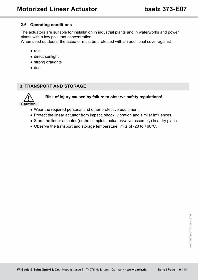
2.6 Operating conditions
The actuators are suitable for installation in industrial plants and in waterworks and power plants with a low pollutant concentration. When used outdoors, the actuator must be protected with an additional cover against
● rain ● direct sunlight ● strong draughts ● dust
3. TRANSPORT AND STORAGE
Risk of injury caused by failure to observe safety regulations!
Caution ● Weartherequiredpersonalandotherprotectiveequipment. ● Protectthelinearactuatorfromimpact,shock,vibrationandsimilarinfluences. ● Store the linear actuator (or the complete actuator/valve assembly) in a dry place. ● Observe the transport and storage temperature limits of -20 to +60°C.

10 | 36W. Baelz & Sohn GmbH & Co. · Koepffstrasse 5 · 74076 Heilbronn · Germany · www.baelz.de Seite | Page
Motorized Linear Actuator baelz 373-E07
4. ASSEMBLY
Make sure that the specifications on the nameplate correspond to those in the order documents!
4.1 Fitting position
Whenfittingwiththeconnectingrodinhorizontalposition,fitthelinearactuatorsuchthatthesides of the yoke are positioned one above the other in the vertical plane.
● Allow for about 140 mm space above the cover at the site of installation. ● Checktheworkenvironmentbeforefittingtheactuatorandputtingitintooperation: ● Make sure that the valve is correctly installed. For detailed information, refer to the valve's installation instructions.
● Determine the mounting position of the linear actuator. Do not mount linear actuators "headdown"belowthevalve.
Attention
Fig. 2: Fitting position
BA
_373-E07_02_D
EF_M
J_3619
11 | 36W. Baelz & Sohn GmbH & Co. · Koepffstrasse 5 · 74076 Heilbronn · Germany · www.baelz.de Seite | Page
Motorized Linear Actuator baelz 373-E07
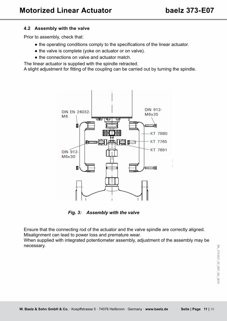
4.2 Assembly with the valve
Prior to assembly, check that: ● theoperatingconditionscomplytothespecificationsofthelinearactuator. ● the valve is complete (yoke on actuator or on valve). ● the connections on valve and actuator match.
The linear actuator is supplied with the spindle retracted.Aslightadjustmentforfittingofthecouplingcanbecarriedoutbyturningthespindle.
Fig. 3: Assembly with the valve
Ensure that the connecting rod of the actuator and the valve spindle are correctly aligned. Misalignment can lead to power loss and premature wear. When supplied with integrated potentiometer assembly, adjustment of the assembly may be necessary.

12 | 36W. Baelz & Sohn GmbH & Co. · Koepffstrasse 5 · 74076 Heilbronn · Germany · www.baelz.de Seite | Page
Motorized Linear Actuator baelz 373-E07
4.3 Principle of operation
Motorizedlinearactuatorstooperatecontrolvalvesforflowregulationapplicationsincontroland process technology. The self-locking threaded spindle/spindle nut is driven by an electric motor via a gearbox. This converts the rotary movement into a linear movement. Load-dependent limit switches dictate the end positions
4.3.1 Manual adjustment
Manual adjustment may only be carried out when the motor is not in motion. To adjust, press and hold the yellow release button and turn the manual adjuster until the desired position is reached. As soon as the yellow release button is no longer depressed, the actuator follow the signal from a control system or a built-in positioner.
Tip: If the manually set position is to be maintained, ensure that the input signal from the control system or positioner is deactivated.
release button
manual adjuster

BA
_373-E07_02_D
EF_M
J_3619
13 | 36W. Baelz & Sohn GmbH & Co. · Koepffstrasse 5 · 74076 Heilbronn · Germany · www.baelz.de Seite | Page
Motorized Linear Actuator baelz 373-E07
4.4 Electrical connection
Risk of electric shock! DangerUse an appropriate power supply to ensure that no hazardous voltage can enter the device during normal operation or in the event of a system failure or defective system components.Failure to heed this warning may result in death, serious injury or substantial material damage.For short-circuit protection and disconnection of the actuator from the power supply, fuses and switch disconnectors must be provided on site. The current values for the rating depend on the operating current of the motor (refer to the nameplate). Theelectricalconnectionshouldonlybecarriedoutbytrained,qualifiedpersonnel.
● Prior to connection, observe the instructions in this chapter. ● After connection, but before applying voltage, observe the instructions in the chapter "Commissioning"(page14).
● When making the electrical connection, be sure that the power supply is turned OFF! Ensure protection against unintentional reconnection to the power supply!
● For wiring and connection, observe the regulations for the construction of electric power installations and the regulations of the local energy supplier!
● Checkcomplianceofthesupplyvoltageandfrequencywiththespecificationsonthenameplate of the actuator and on the nameplate of the actuator motor.
● Always select the cable cross section so as to match the actuator's power consumption andtherequiredcablelength.Minimumcrosssectionofthecableforthislinearactuator: 1 mm²
In case of malfunction: Dangerous voltage if protective earth conductor is NOT connected! Risk of electric shock!→Donotoperatethedeviceiftheprotectiveearthconductorisnotconnected!Trapped wires can lead to short circuiting! Risk of electric shock and malfunction.
4.5 Carrying out the electrical connection
Risk of electric shock! Danger→Disconnectthedevicefromthepowersupplybeforeremovingcover.Always use the wiring diagram on the inside of the cover or supplied with the actuator. Replace the dummy plugs with cable glands.
1. Strip the cable as necessary.2. Strip the ends of the individual wires.3. Forflexiblewires:UsewireendferrulesasspecifiedinDIN46228.4. Connectthewiresasshowninthejob-specificwiringdiagram.
The IP-rating shown on the nameplate is only valid if suitable cable glands are used.

14 | 36W. Baelz & Sohn GmbH & Co. · Koepffstrasse 5 · 74076 Heilbronn · Germany · www.baelz.de Seite | Page
Motorized Linear Actuator baelz 373-E07
5. COMMISSIONING
Actuators which are supplied fitted with a valve are set to the appropriate valve stroke length. When an actuator with a 7020 digital positioner is fitted to a valve, an initialization run must be carried out to set up the actuator according to the valve type.Attention
5.1 Test run
5.1.1 Checking the direction of rotation ● Adjust the actuator manually to roughly the middle position. ● In direction of travel CLOSE, switch the actuator on and watch the direction of rotation. ● If the direction of rotation is wrong, switch off immediately. ● Check wiring (jumpers). ● Repeat the test run.
Risk of electric shock!
Danger
If the switches in the actuator are not factory-wired, check proper switching off in end positions:With the cover removed, the linear actuator may only be operated briefly for test runs or when performing absolutely essential adjustments on electrical components, such as potentiometer, limit switches or positioning electronics. While performing this activity, there is unobstructed access to hazardous, live, exposed, moving and rotating parts. Adjustments performed incorrectly or without exercising the necessary caution may result in death, serious injury or substantial material damage.Any operation of the linear actuator with the cover removed for a purpose other than that described above is prohibited.
Pay attention to moving parts during fitting and adjustment. Risk of injury and substantial material damage.
Warning

BA
_373-E07_02_D
EF_M
J_3619
15 | 36W. Baelz & Sohn GmbH & Co. · Koepffstrasse 5 · 74076 Heilbronn · Germany · www.baelz.de Seite | Page
Motorized Linear Actuator baelz 373-E07
6. RETROFITTING OF OPTIONAL EXTRAS
Disconnect actuator from power supply before starting work!
Danger
6.1 Fitting a potentiometer
Set consists of: ● 1xpotentiometer,200Ω,1kΩor5kΩ
● 1x Torx screw T20.
● Toremovetheactuatorcover,loosenthe2TorxT20flangedbuttonscrewsslightlyandlift off the cover (see Fig. 4, above).
● Setthevalve/actuatortothe50%position(seesection4.3.1 on manual adjustment) ● Setthepotentiometertothe50%position.Todothis,turnthepotentiometershaftuntilan endstop is reached, then turn it back by 5 rotations (of 10 in total).
● Fit the potentiometer spring into the slot in the white plastic insert, so that the potentiometersitsflushontheactuatorandthepotentiometermountingholeisalignedwith the mounting hole in the actuator (see Fig. 5, below.).
white plastic insert with slot
spring fitthespringintotheslot
Fig. 4: E07 actuator with cover removed
mounting holes
Fig. 5: Aligning the potentiometer

16 | 36W. Baelz & Sohn GmbH & Co. · Koepffstrasse 5 · 74076 Heilbronn · Germany · www.baelz.de Seite | Page
Motorized Linear Actuator baelz 373-E07
6.2 Fitting 2 additional, travel-dependent limit switches (2EZ)
Set consists of: ● 1x pinion ● 1x 2EZ assembly ● 3x Torx T10 button screws
● Fit the pinion into the white plastic insert on the actuator so that the raised part in the baseoftheinsertfitsintotheslotonthelowerendofthepinion(Fig. 8).
● Takealookatwherethepinionfitsintotheundersideofthe2EZassembly(Fig. 10).
Table 4. Number of gear teeth in 2EZ assembly depending on valve strokeValve stroke 12 16 22Number of teeth, pinion z=11 z=9 z=7Number of teeth, gear z=65 z=67 z=68
Fig. 6: Fixing the potentiometer
Fig. 7: Wiring the Potentiometer
● Fix the potentiometer with the Torx T20 button screw (Fig. 6, below) ● Lay the wiring between motor and terminal block assembly and wire the potentiometer up:terminal91=red,terminal92=brown,terminal93=blue(Fig. 7, below). Trim the ferrules if necessary.
● Secure the wiring with cable ties.
Fig. 8: Pinion Fig. 9: 2EZ assembly Fig. 10: Pinion fits here

BA
_373-E07_02_D
EF_M
J_3619
17 | 36W. Baelz & Sohn GmbH & Co. · Koepffstrasse 5 · 74076 Heilbronn · Germany · www.baelz.de Seite | Page
Motorized Linear Actuator baelz 373-E07
Fig. 11: Put this screw into place before fitting
Fig. 12: 2EZ assembly on E07 actuator
Fig. 13: Tighten the screws
Fig. 14: Adjusting the switching cams
6.2.1 Adjusting the switching pointsThe 2EZ assembly has two pairs of cams, each of which activates a switch. For each switch, two switching points can be set using its cam pair.Inordertosetthedesiredswitchingpoints,settheactuatortothefirstpositionandadjustoneof the two cams so that it activates the switch in this position (Fig. 14).Ifrequired,thisprocessmay be repeated with a second actuator position and the other cam in the pair.Wire up the outputs E1-E3 or E4-E6 (wiring diagram Fig. 15).
Fig. 15: Wiring diagram baelz 373-E07 with 2EZ and potentiometer
● Putoneofthe3TorxT10buttonscrewsintoplace,asaccesshereisdifficultwhenthe2EZ assembly is in place, see Fig. 11.
● Fit the 2EZ assembly onto the acutator so that the raised lip around the pinion hole sits intheholeontheactuatorandthe3fixingholesinthe2EZassemblyarealignedwiththefixingholesintheactuator(Fig. 12).
● Fix the 2EZ assembly with the 3 Torx T10 button screws (Fig. 13).
18 | 36W. Baelz & Sohn GmbH & Co. · Koepffstrasse 5 · 74076 Heilbronn · Germany · www.baelz.de Seite | Page
Motorized Linear Actuator baelz 373-E07
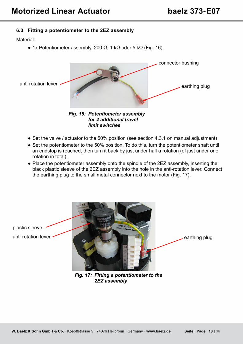
6.3 Fitting a potentiometer to the 2EZ assembly
Material: ● 1xPotentiometerassembly,200Ω,1kΩoder5kΩ(Fig. 16).
Fig. 16: Potentiometer assembly for 2 additional travel limit switches
anti-rotation lever
● Setthevalve/actuatortothe50%position(seesection4.3.1 on manual adjustment) ● Setthepotentiometertothe50%position.Todothis,turnthepotentiometershaftuntilan endstop is reached, then turn it back by just under half a rotation (of just under one rotation in total).
● Place the potentiometer assembly onto the spindle of the 2EZ assembly, inserting the black plastic sleeve of the 2EZ assembly into the hole in the anti-rotation lever. Connect the earthing plug to the small metal connector next to the motor (Fig. 17).
earthing plug
connector bushing
plastic sleeve
earthing plug
Fig. 17: Fitting a potentiometer to the 2EZ assembly
anti-rotation lever

BA
_373-E07_02_D
EF_M
J_3619
19 | 36W. Baelz & Sohn GmbH & Co. · Koepffstrasse 5 · 74076 Heilbronn · Germany · www.baelz.de Seite | Page
Motorized Linear Actuator baelz 373-E07
● Tighten the lower grub screw in the connector bushing with a 1.5 mm Allen key. Check that the top grub screw ist tight. Do not loosen the top grub screw.
● Connect the potentiometer to the terminal block of the actuator: terminal91=red,terminal92=brown,terminal93=blue(Fig. 19, below). Trim the ferrules if necessary.
Fig. 18: Fixing the potentiometer with the lower grub screw
connector bushing
Fig. 19: Wiring the potentiometer
7. DIGITAL POSITIONER 7020
7.1 Intended use
The digital positioner baelz 7020 controls the actuator according to the value of the control signal: 0(2)-10 V, 0(4)-20 mA
Toensureuseforthepurposeintended,checkthattheabovetypeidentificationcorrespondstothenameplateonthepositionerbeforestartinganyactivities.Thetechnicalspecificationsofthepositionerandthepowersupplyrequirementsaretheindicatedonthenameplate.Any use other than the intended use stated above, use for different tasks, and operation with other power sources than those permitted, is considered to be improper use. In case of improper use, the operator shall be solely liable for the risk presented to persons and to the device as well as to other property!
The intended use also comprises compliance with the accident prevention regulations and the DIN VDE standards of the German Institute for Standardization and the Association for Electrical, Electronic & Information Technologies. It also implies working in accordance with the safetyrequirementswhenperformingallactivitiesdescribedintheseoperatinginstructions,under consideration of general technical rules and regulations.

20 | 36W. Baelz & Sohn GmbH & Co. · Koepffstrasse 5 · 74076 Heilbronn · Germany · www.baelz.de Seite | Page
Klemme 12Klemme 14
Motorized Linear Actuator baelz 373-E07
7.2 Operational modes and operating options
For further information and additional functions, see baelz 7020 operating instructions.
7.2.1 Standard operation using DIP switchesTheDIPswitchescanbeusedtocarryoutstandardconfigurationsandoperations(seesection 7.4).When DIP switch 11 is set to 0, the 7020 is in the standard operational mode.In standard mode, all DIP switches are active and the functions of the Baelz 7020 can be individuallyadapted.Functionswhicharepredefinedandunalterableinstandardmodearedescribed in chapter 6.1 of the baelz 7020 operating instructions.
7.2.2 Standard operation using Modbus VT100 or direct addressingIn standard mode, the Baelz 7020 can be operated using Modbus VT100. For this, a virtual 7020 display and a virtual 7020 keypad are transmitted to a user interface. Modbus direct addressing, e.g. from a building automation system, enables access to status information and allowsoperationandconfiguration.(Seebaelz7020operatinginstructions,AppendixA).Thesettings given by the DIP switches remain active. Values which are only relevant in Modbus mode can be adjusted in standard mode, but only take effect in Modbus mode.
7.2.3 Modbus modeWhen DIP switch 11 is set to 1, the Baelz 7020 is in Modbus mode. In Modbus mode, the 7020isatitsmostflexibleandcanbeconfiguredandoperatedusingeitheraModbusVT100or Modbus direct addressing, for example in a building automation system. See separate operatinginstructions"Baelz7020DigitalPositioner-OperatingInstructionsforModbusmode"
7.2.4 Normal and safety modesIn normal mode the position of the valve is controlled by the set value at analogueinputAI2.TheN↔Sswitchshowninthepictureontherightis set to normal mode (N). In normal mode, no external control systems can be connected to terminals 12 and 14.
7.2.5 Safety mode: freeze protection and excessive temperature
In safety mode the actuator can be sent to a safe position (extended / retracted, depending on the direction of action of the valve) in case of failure or malfunctioning of the microcontroller.To operate the Baelz 7020 in connection with an external freeze protection and/or excessive temperaturethermostat,settheN↔Sswitchtosafetymode(S).Connect the freeze protection and/or excessive temperature thermostat according to desired function and priority. Be sure to take the direction of action into account! See wiring diagrams in the baelz 7020 operating instructions.
Tip:
Fig. 20: N↔S-switch
BA
_373-E07_02_D
EF_M
J_3619
21 | 36W. Baelz & Sohn GmbH & Co. · Koepffstrasse 5 · 74076 Heilbronn · Germany · www.baelz.de Seite | Page
1
+ Initialization
After Initialization S1 in Position „S“
2
Feedback 1 U
0/2-10V
Feedback 2 I
0/4-20mA
Open-/Close- Signal
3
Motorized Linear Actuator baelz 373-E07
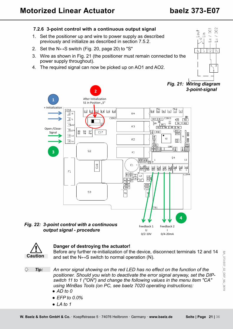
7.2.6 3-point control with a continuous output signal1. Set the positioner up and wire to power supply as described
previously and initialize as described in section 7.5.2.2. SettheN↔Sswitch(Fig. 20, page 20) to"S"3. Wire as shown in Fig. 21 (the positioner must remain connected to the
power supply throughout).4. TherequiredsignalcannowbepickeduponAO1andAO2.
Fig. 21: Wiring diagram 3-point-signal
Fig. 22: 3-point control with a continuous output signal - procedure
Danger of destroying the actuator! Before any further re-initialization of the device, disconnect terminals 12 and 14 andsettheN↔Sswitchtonormaloperation(N).Caution
Tip: An error signal showing on the red LED has no effect on the function of the positioner. Should you wish to deactivate the error signal anyway, set the DIP-switch 11 to 1 ("ON") and change the following values in the menu item "CA" using WinBas Tools (on PC, see baelz 7020 operating instructions): ● AD to 0 ● EFP to 0.0% ● LA to 1
22 | 36W. Baelz & Sohn GmbH & Co. · Koepffstrasse 5 · 74076 Heilbronn · Germany · www.baelz.de Seite | Page
cmo
I
91
6 7 8 9 12
DO4
Switc
h-po
int
set
= 0
-> 1
Split-
rang
e
Split-
rang
e
Split-
rang
e
Char
acte
ristic
for a
ctua
tor
Ope
ratin
g m
ode
0=DI
P / 1
=RS4
85
Initia
lizat
ion
star
t=0-
>1 s
top=
1->0
DO3
Switc
h-po
int
set
= 0
-> 1
AI2
0 =
U /
1 =
I
DIP-Switches
1
A B
RS 485
1 2 3 4 5 6 7 8 9 10
Tel. 07131/1500-0 Fax. 07131/150021Koepffstraße 5. D-74076 Heilbronn
Sohn
VD: A4_EL-AS
Zeichnung:Ursprung:
ASB_7020_V1.3.skf
ÄnderungGepr.Bearb.Datum
TS04 .07 .17 W.Bälz & Anschlussbild baelz 7020 Co.&Gm bH
Blatt
2 3 26 38
Digital Positioner baelz 7020
GND
A
R= 5kOhmPE N L
+
- BlM
Rd Ye
12
Lo/D
O1
14
Lu/D
O2
20
DI
22
24V
23
AO1
(U)
24
GND
25
AO2
(I)
93 92
AI1
Lin
Lout
S1
54 97 98 99
Bl
Bn
Rd
AI2
U 0 I
0/2...10V+ -
0/4...20mA
U 0
- +
39 40
B GND
Ty18Rd
M
Bl Ye
97 98 99
Ty 6 u. Ty 130
+
-
N
Lin
2
AI2
0 =
0V/
0mA
1 =
2V/
4mA
3
AO1/
2 0
= 0V
/0m
A 1
= 2
V/4m
A
4
Actu
ator
-spi
ndle
0=0
V=O
ut/1
=0V=
In
5 10 11
F11,6A T
U+
S = Safety operation
N = Normal operation
Code S1
E4 E5 E6E1 E2 E3
DO3 DO4 DO2
DO1
ASB_7020_V1.3
F20002450
213 mm
98,5 mmFP OT
Motorized Linear Actuator baelz 373-E07
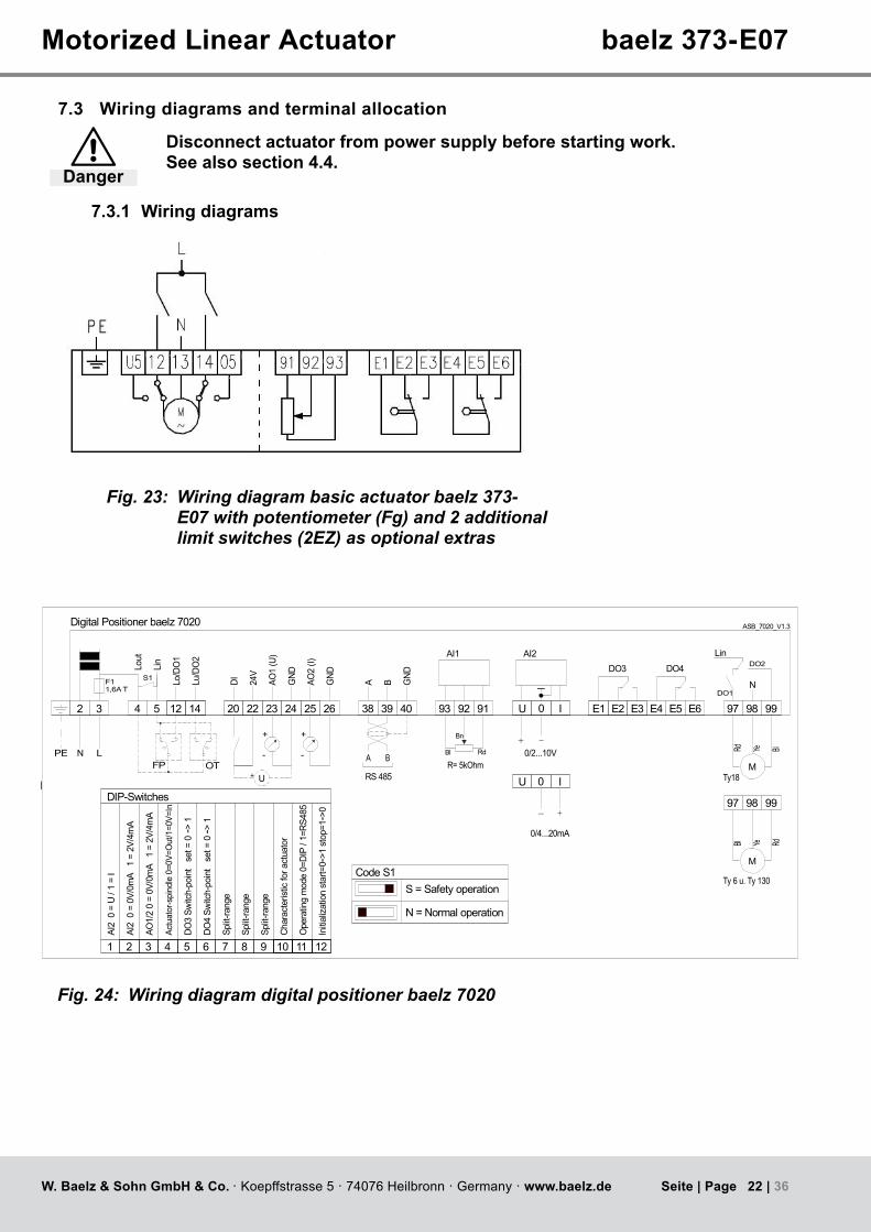
7.3 Wiring diagrams and terminal allocation
Disconnect actuator from power supply before starting work. See also section 4.4. Danger
7.3.1 Wiring diagrams
Fig. 23: Wiring diagram basic actuator baelz 373-E07 with potentiometer (Fg) and 2 additional limit switches (2EZ) as optional extras
Fig. 24: Wiring diagram digital positioner baelz 7020
BA
_373-E07_02_D
EF_M
J_3619
23 | 36W. Baelz & Sohn GmbH & Co. · Koepffstrasse 5 · 74076 Heilbronn · Germany · www.baelz.de Seite | Page
U2
20 38
91E197 98 99
E3 92 93
3
4
5
12
14
E4E2 E5 E6 0 I
22 23 24 25 26 39 40
Motorized Linear Actuator baelz 373-E07
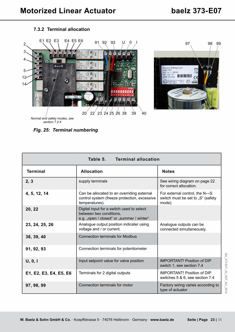
Table 5. Terminal allocation
Terminal Allocation Notes
2, 3 supply terminals See wiring diagram on page 22 for correct allocation.
4, 5, 12, 14 Can be allocated to an overriding external control system (freeze protection, excessive temperatures).
Forexternalcontrol,theN↔Sswitch must be set to „S“ (safety mode).
20, 22 Digital input for a switch used to select between two conditions,e.g. „open / closed“ or „summer / winter“.
23, 24, 25, 26 Analogue output position indicater using voltage and / or current.
Analogue outputs can be connected simultaneously.
38, 39, 40 Connection terminals for Modbus
91, 92, 93 Connection terminals for potentiometer
U, 0, I Input setpoint value for valve position IMPORTANT! Position of DIP switch 1, see section 7.4
E1, E2, E3, E4, E5, E6 Terminals for 2 digital outputs IMPORTANT! Position of DIP switches 5 & 6, see section 7.4
97, 98, 99 Connection terminals for motor Factory wiring varies according to type of actuator
7.3.2 Terminal allocation
Normal and safety modes, see section 7.2.4
Fig. 25: Terminal numbering

24 | 36W. Baelz & Sohn GmbH & Co. · Koepffstrasse 5 · 74076 Heilbronn · Germany · www.baelz.de Seite | Page
Motorized Linear Actuator baelz 373-E07
7.4 Configuration of the DIP switches
=factorysetting
The factory setting of the DIP switches is position 0, as shown.
Fig. 26: Setting the DIP switches
Switch Function Position 1 "ON" Position 0
DIP 1 Set value input: voltage, V or current, mA? current, mA voltage, V
DIP 2 Set value input starting at 0 V / 0 mA or 2 V / 4 mA?
2-10 V / 4-20 mA 0-10 V / 0-20 mA
DIP 3 Analogue output starting at 0 V / 0mA or 2 V / 4 mA?
2-10 V and / or 4-20 mA
0-10 V and / or 0-20 mA
DIP 4 Direction of control action: valve closed with drive spindle extended or retracted?
Drive spindle retracted →valve closed
Drive spindle extended→valve closed
DIP 5 Current position of the actuator is saved as additionalswitchingposition"2EZ-1".Seewiring diagram, page 22.
from0to1→save"2EZ-1" =2%
DIP 6 Current position of the actuator is saved as secondadditionalswitchingposition"2EZ-1".See wiring diagram, page 22.
from0to1→save"2EZ-2" =98%
DIP 7, 8, 9 These3DIPswitchesdefinethefunction:linear / split range / 11-point / inverted
s. Fig. 27, page 26 =linear
DIP 10 Definesvalvecharacteristicusingactuatorcharacteristic, see page 26.
Actuator characteristic inverseequalpercentage, valve action linear
Actuator characteristic linear, valve action equalpercentage
DIP 11 Selects standard or Modbus mode. Modbus mode standard mode
DIP 12 Starts initialization run.Set back to 0 after initialization (s. section 7.5.2)
from0to1→starts initialization run
N↔S Selects normal or safety mode position"S"=safetymode
position"N"=normalmode
BA
_373-E07_02_D
EF_M
J_3619
25 | 36W. Baelz & Sohn GmbH & Co. · Koepffstrasse 5 · 74076 Heilbronn · Germany · www.baelz.de Seite | Page
Motorized Linear Actuator baelz 373-E07
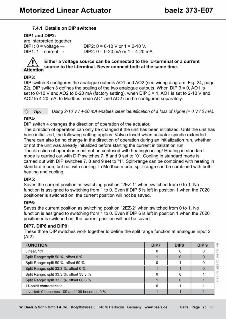
7.4.1 Details on DIP switchesDIP1 and DIP2:are interpreted together:DIP1:0=voltage→ DIP2:0=0-10Vor1=2-10V.DIP1:1=current→ DIP2:0=0-20mAor1=4-20mA.
Attention
Either a voltage source can be connected to the U-terminal or a current source to the I-terminal. Never connect both at the same time.
DIP3:DIPswitch3configurestheanalogueoutputsAO1andAO2(seewiringdiagram,Fig. 24, page 22).DIPswitch3definesthescalingofthetwoanalogueoutputs.WhenDIP3=0,AO1issetto0-10VandAO2to0-20mA(factorysetting),whenDIP3=1,AO1issetto2-10VandAO2to4-20mA.InModbusmodeAO1andAO2canbeconfiguredseparately.
Using 2-10 V / 4-20 mA enables clear identification of a loss of signal (= 0 V / 0 mA).DIP4:DIP switch 4 changes the direction of operation of the actuator.The direction of operation can only be changed if the unit has been initialized. Until the unit has been initialized, the following setting applies: Valve closed when actuator spindle extended.There can also be no change in the direction of operation during an initialization run, whether or not the unit was already initialized before starting the current initialization run.Thedirectionofoperationmustnotbeconfusedwithheating/cooling!HeatinginstandardmodeiscarriedoutwithDIPswitches7,8and9setto"0".CoolinginstandardmodeiscarriedoutwithDIPswitches7,8and9setto"1".Split-rangecanbecombinedwithheatinginstandard mode, but not with cooling. In Modbus mode, split-range can be combined with both heating and cooling.DIP5:Savesthecurrentpositionasswitchingposition"2EZ-1"whenswitchedfrom0to1.Nofunction is assigned to switching from 1 to 0. Even if DIP 5 is left in position 1 when the 7020 positioner is switched on, the current position will not be saved.DIP6:Savesthecurrentpositionasswitchingposition"2EZ-2"whenswitchedfrom0to1.Nofunction is assigned to switching from 1 to 0. Even if DIP 6 is left in position 1 when the 7020 positioner is switched on, the current position will not be saved.DIP7, DIP8 and DIP9:ThesethreeDIPswitchesworktogethertodefinethesplitrangefunctionatanalogueinput2(AI2).
FUNCTION DIP7 DIP8 DIP 9Linear, 1:1 0 0 0SplitRange:split50%,offset0% 1 0 0SplitRange:split50%,offset50% 0 1 0SplitRange:split33.3%,offset0% 1 1 0SplitRange:split33.3%,offset33.3% 0 0 1SplitRange:split33.3%,offset66.6% 1 0 111-point characteristic 0 1 1Inverted:0becomes100and100becomes0% 1 1 1
Tip:

26 | 36W. Baelz & Sohn GmbH & Co. · Koepffstrasse 5 · 74076 Heilbronn · Germany · www.baelz.de Seite | Page
Motorized Linear Actuator baelz 373-E07
DIP10:An actuator characteristic can be used indirectly to change a valve characteristic. If, for example,thevalvehasanequalpercentagecharacteristic,aninverseequalpercentageactuator characteristic can be used to generate a resulting linear characteristic, see illustration below.The actuator characteristic (DIP 10) can also be combined with the characteristics which canbeselectedusingDIPs7,8and9(e.g.splitrange).ThemicrocontrollerfirstprocessesthecharacteristicdefinedbyDIPs7,8and9andsubsequentlythecharacteristicdefinedbyDIP 10.InModbusmode,twofurtheractuatorcharacteristicscanbeselected:equalpercentageandquadraticinverseequalpercentage.
DIP11:DIPswitch11definesthemodeofoperation:1=Modbusmode,0=standardmode.Standardmodeisusedtoapplypredefinednormalsettings.DIP12:Starts an initialization run when switched from 0 to 1. If DIP 12 is left in position 1 when the 7020 positioner is switched on, an initialization run will not be startet.As long as DIP 12 is set to 1, errors and alarms occurring during normal positioner operation will not be shown. This enables errors occurring during initialization to be distinguished from errors during normal positioner operation. Switch DIP 12 back to 0 after the initialization run (after having analysed possible error codes) to show any errors occurring in normal positioner operation on the red LED. See also section 7.5.2"Initializationrun".
shut
valve2,offset50%[010]*
valve1,offset0%[100]*
valve1,offset0%[110]*
valve2,offset33,3%[001]*
valve1,offset66,6%[101]*
input signal
valv
e po
sitio
n
open
shut0% 100%
50%
33,3%
66,6,%
100%
0%
100%0%
shutshut
open open
shut
openopen
0% 100% 0% 100%
Split rangesplit50%
Linear Split rangesplit33%
11-pointcharacteristic
Inverse linear
[000] [011]* [111]*
Fig. 27: Graphical illustration of selection of functions by DIP switches 7, 8 & 9
1
Desired characteristic
Equalpercentage
Quadratic
Linear
Equalpercentage
Linear
DIP-switch 10 Characteristic of the valve
Characteristic of the actuator Effective at valve
=factorysetting
Travel
Travel
Travel
Travel
Travel
Signal
Signal
Signal
Signal
Signal
Signal
Signal
Signal
Signal
Signal
Trav
elTr
avel
Trav
elTr
avel
a
Trav
el
1
0
10
0
10
1
0
10
actuator characteristic only selectable in
Modbus mode
actuator characteristic only selectable in
Modbus mode

BA
_373-E07_02_D
EF_M
J_3619
27 | 36W. Baelz & Sohn GmbH & Co. · Koepffstrasse 5 · 74076 Heilbronn · Germany · www.baelz.de Seite | Page
Motorized Linear Actuator baelz 373-E07
7.5 Commissioning
7.5.1 Quick start guide
12
↑0
1
1. Set DIP switches 2. Connect to supply 3. Start initialization run
7.5.2 Initialization runIftheunitisnotinitialized,thegreenLEDflashes.TheredLEDislitwhenthepositionofthe potentiometer is not ideal for an initialization run. (See section 7.5.3 for meaning of LED signals.) An initialization run can still be carried out, but it will take approx. 1x valve travel time longer. During a successful initialization run, the valve is moved to both of its end positions. The potentiometer and the position of the valve are synchronized and values for valve travel time and switching hysteresis are determined.
Switch DIP switch 12 from 0 to 1 to start an initialization run. The red LED is lit during initialization.
When initialization has been successfully completed, only the green LED is lit. For error signals seetableinsection"Errorsafteraninitilizationrun",page29
As long as DIP switch 12 is set to 1, errors and alarms occurring during normal positioner operation will not be shown. This enables errors occurring during initialization to be distinguished from errors during normal positioner operation.
Switch DIP 12 back to 0 after the initialization run to show any errors occurring in normal positioner operation on the red LED.(Afterthefirstinitializationrun(unitnotpreviouslyinitialized),theunitmovestothe50%position upon completion of initialization. As soon as DIP 12 is set to 0, the baelz 7020 will follow the set value signal at analogue input 2.)
28 | 36W. Baelz & Sohn GmbH & Co. · Koepffstrasse 5 · 74076 Heilbronn · Germany · www.baelz.de Seite | Page
Motorized Linear Actuator baelz 373-E07
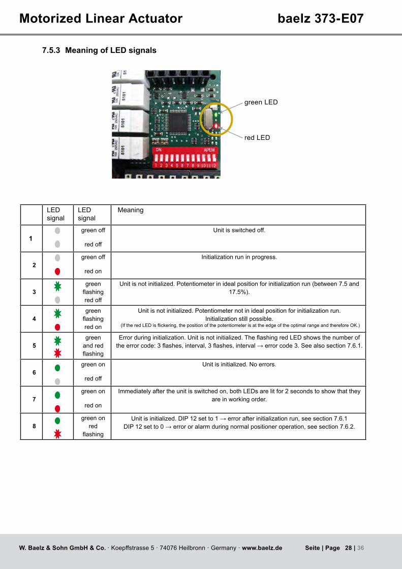
7.5.3 Meaning of LED signals
red LED
green LED
LED signal
LED signal
Meaning
1green off
red off
Unit is switched off.
2green off
red on
Initialization run in progress.
3green flashingred off
Unit is not initialized. Potentiometer in ideal position for initialization run (between 7.5 and 17.5%).
4green flashingred on
Unit is not initialized. Potentiometer not in ideal position for initialization run.Initialization still possible.
(IftheredLEDisflickering,thepositionofthepotentiometerisattheedgeoftheoptimalrangeandthereforeOK.)
5green
and red flashing
Errorduringinitialization.Unitisnotinitialized.TheflashingredLEDshowsthenumberoftheerrorcode:3flashes,interval,3flashes,interval→errorcode3.Seealsosection7.6.1.
6green on
red off
Unit is initialized. No errors.
7green on
red on
Immediately after the unit is switched on, both LEDs are lit for 2 seconds to show that they are in working order.
8green on
red flashing
Unitisinitialized.DIP12setto1→errorafterinitializationrun,seesection7.6.1DIP12setto0→errororalarmduringnormalpositioneroperation,seesection7.6.2.

BA
_373-E07_02_D
EF_M
J_3619
29 | 36W. Baelz & Sohn GmbH & Co. · Koepffstrasse 5 · 74076 Heilbronn · Germany · www.baelz.de Seite | Page
Motorized Linear Actuator baelz 373-E07
7.6 Errors
7.6.1 Errors after an initialization runFollowing a successful initialization run, only the green LED is lit. IftheredLEDisflashing,thisindicatesanerrorfollowinganunsuccessfulinitializationrun.Thefirsterrortooccurduringinitializationisshown.IfthegreenLEDislit,theunithadalreadybeeninitializedbeforethecurrentinitializationrun.IfthegreenLEDisflashing,theunithadnotbeen successfully initialized previously.
The red LED shows errors occuring during initialization as follows:
Error code 1: interval interval etc.
Error code 2: interval interval etc.
etc. up to ...
Error code 8: interval interval etc..
Following an initialization run, the red LED shows only initialization errors as long as DIP switch 12 is set to 1. This enables a clear differentiation between errors occuring during initialization and those occuring during normal positioner operation. Setting DIP switch 12 from 1 back to 0 permits the red LED to show any normal operational errors instead of initialization errors which may have occured.
Error code Error Corrective action
1 → 1 x Invalid status of initialization run. Possible cause: EMI (electromagnetic interference).
Remove source of interference.
2 → 2 x Sensor malfunction at analogue input AI1:No signal from potentiometer.
Check connection terminals 91, 92, 93(see wiring diagram, Fig. 24, page 22).Replace potentiometer if necessary.
3 → 3 x Potentiometer value at AI1 too small.Possible cause: EMI.
Remove source of interference.Replace potentiometer if necessary.
4 → 4 x Potentiometer value at AI1 too large.Possible cause: EMI.
Remove source of interference.Replace potentiometer if necessary.
5 → 5 x Wrong direction of travel Check motor (97, 98, 99) and potentiometer (91, 92, 93) connections (see wiring diagram, Fig. 24, page 22).Remove source of interference.
6 → 6 x Obstruction: potentiometer or motor not moving. Checkconnections,setN↔Sswitchto"N",remove any obstructions.
7 → 7 x Stroke too long. Fit actuator to a valve with nominal stroke length < 22 mm.
8 → 8 x Stroke too short. Fit actuator to a valve with nominal stroke length > 8,7 mm, remove any obstructions.

30 | 36W. Baelz & Sohn GmbH & Co. · Koepffstrasse 5 · 74076 Heilbronn · Germany · www.baelz.de Seite | Page
Motorized Linear Actuator baelz 373-E07
7.6.2 Errors during normal positioner operationThe green LED is lit during normal positioner operation. AflashingredLEDshowsanerrorduringnormalpositioneroperation.Forthis,DIPswitch12must be set to 0.
The red LED indicates errors during normal positioner operation as follows:( =longflash, =shortflash)
Error code 1: interval interval etc.
Error code 2: interval interval etc.
etc. up to ...
Error code 6: interval interval etc.
Multiple error codes can be displayed simultaneously:
Error codes 3 & 5: interval interval
TheredLEDflashes10timesbetweenintervals(1.6s),asamaximumof10errorcodescanbeallocated.The error codes 7 to 10 are not allocated and are reserved for additional alarms.
Error code Error Corrective action
1 Sensor malfunction at analogue input AI1:No signal from potentiometer.
Check connection terminals 91, 92, 93See wiring diagram, Fig. 24, page 22.
2 Sensor malfunction at analogue input AI2:No setpoint signal.
Check connection terminals U, 0, ISee wiring diagram, Fig. 24, page 22.
3 Alarm 1: additional switching position (2EZ-1) or other threshold value reached.
Informational alarm: 2EZ-1 is set using DIP 5.
4 Alarm 2: additional switching position (2EZ-2) or other threshold value reached.
Informational alarm: 2EZ-2 is set using DIP 6.
5 Alarm 3: control deviation too large. Deactivate antifreeze / excessive temp.Re-initialize Baelz 7020.
6 Alarm 4: potentiometer end stops too imprecise or obstruction.
Deactivate antifreeze / excessive temp.Re-initialize Baelz 7020.
7-10 Reservedforasyetundefinedalarms5-8 No error possible.

BA
_373-E07_02_D
EF_M
J_3619
31 | 36W. Baelz & Sohn GmbH & Co. · Koepffstrasse 5 · 74076 Heilbronn · Germany · www.baelz.de Seite | Page
Motorized Linear Actuator baelz 373-E07
Table 6. Technical Specifications, baelz 7020
Supply voltage 230VAC-15%/+10%,50/60Hz,option:115VAC50/60Hz,24VAC50/60Hz
Fuse internal 1.6 A/T (slow-blow)Power consumption approx. 5 VAIP rating IP 42Ambient temperature 0 to 50 °CTransport / storage temp. - 25 to +65 °CAmbient humidity 5to90%relativehumidity.(non-condensing)Dimensions WxHxD approx. 105 x 82 x 32 mmDI suppy voltage 24VDC,Imax=5mA
Digital input 1configurableusingsoftware,Imax5mA,low=0...5VDC,high=9...38VDC,Re=5.5kΩ
Digital outputs 2potentialfreeauxiliarychageoverswitches,configurable,max.250VAC,4Amin. contact load: 10 V / 100 mA
2 output signalsOutput1:0/2...10V/min.ohmicresistance5kΩOutput2:0/4...20mA/max.ohmicresistance300ΩFactory setting: 0...10 V and 0...20 mA
Input signal 0/2...10V/Re63kΩ,0/4...20mA/Re200Ω,measurementaccuracy0.1%Connection PUSHINspringterminals,strippinglength8mm
WiringWire size AWG: min. AWG 24; max. AWG 16solid wire / stranded wire: min. 0.2 mm²; max. 1.5 mm²with wire ferrule according to DIN 46 228/1: min. 0.25 mm²; max. 1.5 mm²with insulated wire ferrule DIN 46 228/4: min. 0.25 mm²; max. 0.75 mm²
Operation 12 DIP switches / optional: advanced operation using RS485 and software
Interface RS485 Modbus RTU, Baud rate 2400...19200, 1 start, 8 pieces of data, 1 stop-bit, no parity
Memory non-volatile semiconductorWeight approx. 0.2 kg
7.7 Technical Specifications
7.8 Accessories and options
● Freeparameterisationsoftware(ModbusRTU)-InterfaceRS485required! ● For laptops with USB we recommend our interface convertor (Order No. 5280-051).

32 | 36W. Baelz & Sohn GmbH & Co. · Koepffstrasse 5 · 74076 Heilbronn · Germany · www.baelz.de Seite | Page
13
12
10
11
1
2
13
12
1
1
2
39
45
6
45
6
1
1
9
3
74
85
45 7
8
Motorized Linear Actuator baelz 373-E07
8. SPARE PARTS
Fig. 28: Spare parts baelz 373-E07 all types
Fig. 29: Spare parts baelz 373-E07 type 6
Fig. 30: Spare parts baelz 373-E07 type 18

BA
_373-E07_02_D
EF_M
J_3619
33 | 36W. Baelz & Sohn GmbH & Co. · Koepffstrasse 5 · 74076 Heilbronn · Germany · www.baelz.de Seite | Page
Tabelle 1. Ersatzteile / Spare parts baelz 373-E07
Pos. Bezeichnung Description Sachnr.part number
Bestellnr.order number
1 Motoreinheit Typ RSM 63/8 SG einschl. motor unit type RSM 63/8 SG incl.
Motorritzel KT 24669 + Kondensator
motor pinion KT 24669 + capacitor
230V,50/60Hz(220-240V) 230V,50/60Hz(220-240V) 99373-051115V,50/60Hz(110-120V) 115V,50/60Hz(110-120V) 99373-05324V,50/60Hz 24V,50/60Hz 99373-055Kondensator capacitor0,36μF/500Veinschl.100Ω/1Wfür115V,50/60Hz(220-240 V)
0,36μF/500Vincl.100Ω/1Wfor115V,50/60Hz(220-240V) 99373-711
1,65μF/250Veinschl.18Ω/0,25Wfür115V,50/60Hz(110-120 V)
1,65μF/250Vincl.18Ω/0,25Wfor115V,50/60Hz(110-120V)
99373-712
36μF/63Vfür24V,50/60Hz 36μF/63Vfor24V,50/60Hz 99373-7132 Endschalter limit switches 99374-0113 O-Ring O-ring Ø120,37x1,784 Zahnradschaft komplett gear shaft unit KS 54405 Trieb 1 gear 1 KS 52176 Trieb 2 (für E07 Typ 18) gear 2 (for E07 type 18) KS 52187 Trieb 3 (für E07 Typ 6) gear 3 (for E07 type 6) KT 266248 Trieb 4 (für E07 Typ 6) gear 4 (for E07 type 6) KT 21635 99373-216359 Kappe cap KT 26624
10 Gewindespindel elevating spindle KT 21635 99373-2163511 Handradkomplett handwheel set 99373-902
Handradsegment(2x) handwheel segment (2x) KT 7691Zylinderschraube (2) socket head cap screw (2x) DIN 912 M6x30 K30000269Sechskantmutter (2x) hexagonal nut (2x) DIN EN 20432 M6 K30000097
12 Kupplung komplett coupling set 99373-901Handradsegment(2x) hand wheel segment (2x) KT 7691Zylinderschrauben (2x) socket head cap screw (2x) DIN 912 M6x30 K30000269Bolzen (2x) pin (2x) KT 7765
13 Ständer S21 komplett yoke set S21 99373-900Ständerelement yoke element (2x) KT 7980Zylinderschraube socket head cap screw (4) DIN 912 M6x35 K30000584Sechskantmutter hexagonal nut (2) DIN EN 20432 M6 K30000097
Motorized Linear Actuator baelz 373-E07
Whenorderingaccessoriesorspareparts,pleasenotethespecificationsontheactuatornameplate for essential information regarding actuator and power supply criteria.
Risk of damage to actuator due to incorrect or defective spare parts!Attention
Allsparepartsmustcomplywiththetechnicalrequirementsasstatedbythemanufacturer.
● Use only original spare parts!

34 | 36W. Baelz & Sohn GmbH & Co. · Koepffstrasse 5 · 74076 Heilbronn · Germany · www.baelz.de Seite | Page
Motorized Linear Actuator baelz 373-E07
9. DECOMMISIONING AND DISPOSAL
Disposeofthedigitalpositionerinaccordancewiththerelevant,country-specificregulationsand laws..
10. TROUBLESHOOTING
If the actuator does not work properly, proceed as follows to correct the problem:
1. Check that the actuator is correctly installed.2. Checktheactuatorsettingsandthespecificationsonthenameplate.3. Correcttheproblemsasspecifiedinthechecklist(page35).4. If the problem cannot be corrected, contact the Baelz service department.5. If, despite consultation, the issue still cannot be resolved, the device can be returned to
Baelz for repair / replacement by arrangement with the service department.
Please give the following information when contacting the manufacturer or sending the device in for repair:
● Serial number ● Type name ● Supplyvoltageandfrequency ● Extrasfitted ● Error report

BA
_373-E07_02_D
EF_M
J_3619
35 | 36W. Baelz & Sohn GmbH & Co. · Koepffstrasse 5 · 74076 Heilbronn · Germany · www.baelz.de Seite | Page
Motorized Linear Actuator baelz 373-E07
Malfunction Cause Action required
Actuator not working
Power failure Determine the cause and correct the problem.
Defective fuse (in control cabinet) Determine the cause and correct the problem, replace the fuse.
Linear actuator incorrectly connected Re-connectasspecifiedoncircuitdiagram (inside cover).
Short circuit caused by humidity Determine the cause, dry the linear actuator; if necessary, replace cover sealandscrewsand/orfitprotectivecover.
Short circuit caused by incorrect connection Connect correctly.
Motor winding damage caused, for example, by high voltage or defective electronics
Determine cause, measure current data, compare with nameplate and specifications,dismantlelinearactuator and return for repair.
Voltage drop due to connecting cables being toolongand/orhavinginsufficientcross-section
Measure current data with linear actuator, recalculate connecting cables and replace as necessary.
Actuator running erratically, constantly opening and closing
Powerfluctuationsexceedpermissibletolerance
Improve power supply conditions.
Loose contact in supply line Check and tighten connections (terminal blocks).
Actuator stops intermittentlyValve jamming Enable smooth valve movement.
Actuator does not move to end position. Valve fails to open / close
System pressure too high Adjust system pressure.
Poor input signal- interfering signals-signalfluctuation
Check input signal at linear actuator, correct the problem causing the malfunction.
Linear actuator fails to move or does not move correctly tothepositiondefinedbythe input signal.
Circuit board defective Replace circuit board, if necessary dismantle actuator and return for repair.
10.1 Checklist for operational malfunctions
36 | 36W. Baelz & Sohn GmbH & Co. · Koepffstrasse 5 · 74076 Heilbronn · Germany · www.baelz.de Seite | Page
Motorized Linear Actuator baelz 373-E07
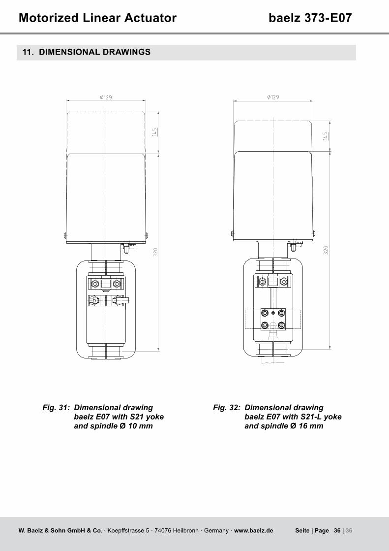
11. DIMENSIONAL DRAWINGS
Fig. 31: Dimensional drawing baelz E07 with S21 yoke and spindle Ø 10 mm
Fig. 32: Dimensional drawing baelz E07 with S21-L yoke and spindle Ø 16 mm