— PME120-AI / PME120-AN (Contrac) Electrical rotary actuator
36
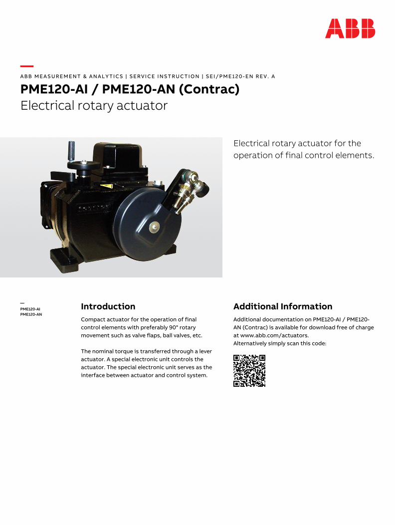
— ABB MEASUREMENT & ANALYTICS | SERVICE INSTRUCTION | SEI/PME120-EN REV. A PME120-AI / PME120-AN (Contrac) Electrical rotary actuator Electrical rotary actuator for the operation of final control elements. — PME120-AI PME120-AN Introduction Compact actuator for the operation of final control elements with preferably 90° rotary movement such as valve flaps, ball valves, etc. The nominal torque is transferred through a lever actuator. A special electronic unit controls the actuator. The special electronic unit serves as the interface between actuator and control system. Additional Information Additional documentation on PME120-AI / PME120- AN (Contrac) is available for download free of charge at www.abb.com/actuators. Alternatively simply scan this code:
-
Upload
khangminh22 -
Category
Documents
-
view
2 -
download
0
Transcript of — PME120-AI / PME120-AN (Contrac) Electrical rotary actuator
— A B B M E A S U R E M E N T & A N A L Y T I C S | S ER V I C E I N ST R U C T I O N | S EI / P M E 1 2 0 - E N R E V . A
PME120-AI / PME120-AN (Contrac) Electrical rotary actuator
— ABB Measurement & Analytics For your local ABB contact, visit: www.abb.com/contacts For more product information, visit: www.abb.com/actuators
Electrical rotary actuator for the operation of final control elements.
SEI/
PME1
20-E
N R
ev. A
0
5.20
20
— PME120-AI PME120-AN
Introduction Compact actuator for the operation of final control elements with preferably 90° rotary movement such as valve flaps, ball valves, etc. The nominal torque is transferred through a lever actuator. A special electronic unit controls the actuator. The special electronic unit serves as the interface between actuator and control system.
Additional Information Additional documentation on PME120-AI / PME120-AN (Contrac) is available for download free of charge at www.abb.com/actuators. Alternatively simply scan this code:
— We reserve the right to make technical changes or modify the contents of this document without prior notice. With regard to purchase orders, the agreed particulars shall prevail. ABB does not accept any responsibility whatsoever for potential errors or possible lack of information in this document. We reserve all rights in this document and in the subject matter and illustrations contained therein. Any reproduction, disclosure to third parties or utilization of its contents – in whole or in parts – is forbidden without prior written consent of ABB. © ABB 2020 3KXE111018R4301
2 PME120-AI / PME120-AN (Contrac) ELECTRICAL ROTARY ACTUATOR | SEI/PME120-EN REV. A
Table of contents
1 Safety .......................................................................... 3 General information and instructions .................................. 3 Warnings .................................................................................... 3 Intended use ............................................................................. 4 Improper use ............................................................................. 4 Notes on data safety ............................................................... 4 Warranty provisions ................................................................. 4 Manufacturer’s address .......................................................... 4
2 Introduction ............................................................... 5 Safety and precautions ........................................................... 5 Tools ........................................................................................... 5
3 Actuator versions ...................................................... 6 PME120-AI .................................................................................. 6 PME120-AN ................................................................................ 6
4 Lubrication ................................................................. 6 Mounting position ................................................................... 6 Oil change .................................................................................. 7 PME oil types ............................................................................. 7
5 Maintenance ............................................................... 8 Safety instructions ................................................................... 8 General ....................................................................................... 8 Lever ........................................................................................... 8
Lever removal ....................................................................... 8 Lever installation ................................................................. 9
Ball-and-socket-joint ............................................................... 9 Removal ................................................................................. 9 Installation ............................................................................ 9
Sealing ring of output drive shaft ....................................... 10 Motor ........................................................................................ 12
Motor removal.................................................................... 12 Motor shaft sealing ring .................................................. 12 Motor installation .............................................................. 13
Brake adjustment ................................................................... 13
6 Electrical connections ............................................. 14 General ..................................................................................... 14 Actuator versions ................................................................... 14
PME120-AI ........................................................................... 14 PME120-AN ......................................................................... 14
Removal of integrated electronic unit ................................ 15 Covers ....................................................................................... 15 Integrated PME120-AI Electronic unit................................. 16
Analog / Digital .................................................................. 16 PROFIBUS DP®.................................................................... 17
Electronic unit EAN823 (Contrac) for PME120-AN ............ 18 Analog / Digital .................................................................. 18 PROFIBUS DP®.................................................................... 19
Electronic unit EAS822 (Contrac) for PME120-AN ............ 20 Analog / Digital .................................................................. 20
Fuses ........................................................................................ 21 Fuse location ...................................................................... 22
7 Exchange of position sensor .................................. 23 Dismounting ........................................................................... 23
PME120-AN (for separate electronic unit) .................... 23 PME120-AI (with integrated electronic unit) ................ 23
Mounting ................................................................................. 24
8 Electrical test values ............................................... 25 Test values (position sensor) .............................................. 25 Test values (Brake and Motor) ............................................ 26
Brake voltage ..................................................................... 26 Motor voltage .................................................................... 26 Winding resistance ........................................................... 26
9 Failure detection ...................................................... 27 LED signals at commissioning and service field .............. 27
10 Troubleshooting ...................................................... 27 General ..................................................................................... 28 Failures at brake, fuse or wiring ......................................... 29 Operation mode (MAN / AUT) ............................................. 30 Input configuration ................................................................ 31 Operation behind step controller ....................................... 32 Failure Diagram ...................................................................... 33 Failure due to response of positioning loop monitoring .............................................................................. 34 General ..................................................................................... 34 User interface menus ............................................................ 35
PME120-AI / PME120-AN (Contrac) ELECTRICAL ROTARY ACTUATOR | SEI/PME120-EN REV. A 3
1 Safety
General information and instructions
These instructions are an important part of the product and must be retained for future reference. Installation, commissioning, and maintenance of the product may only be performed by trained specialist personnel who have been authorized by the plant operator accordingly. The specialist personnel must have read and understood the manual and must comply with its instructions. For additional information or if specific problems occur that are not discussed in these instructions, contact the manufacturer. The content of these instructions is neither part of nor an amendment to any previous or existing agreement, promise or legal relationship. Modifications and repairs to the product may only be performed if expressly permitted by these instructions. Information and symbols on the product must be observed. These may not be removed and must be fully legible at all times. The operating company must strictly observe the applicable national regulations relating to the installation, function testing, repair and maintenance of electrical products.
Warnings
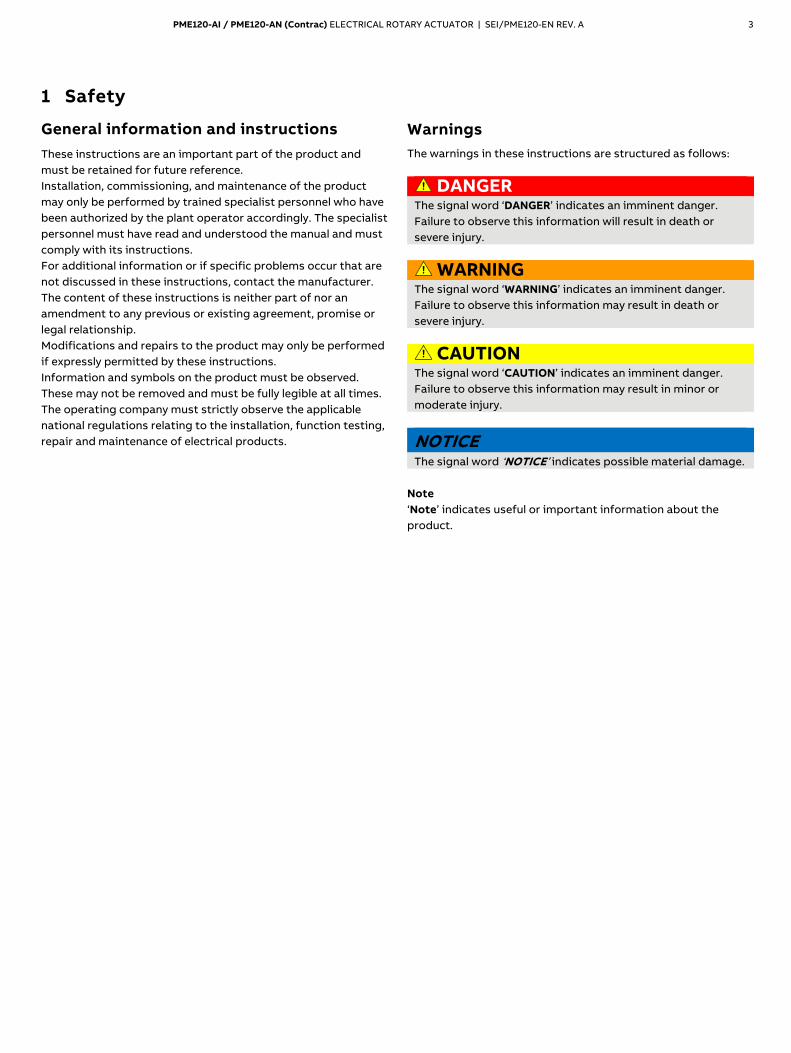
The warnings in these instructions are structured as follows:
DANGER The signal word ‘DANGER’ indicates an imminent danger. Failure to observe this information will result in death or severe injury.
WARNING The signal word ‘WARNING’ indicates an imminent danger. Failure to observe this information may result in death or severe injury.
CAUTION The signal word ‘CAUTION’ indicates an imminent danger. Failure to observe this information may result in minor or moderate injury.
NOTICE The signal word ‘NOTICE’ indicates possible material damage.
Note ‘Note’ indicates useful or important information about the product.
4 PME120-AI / PME120-AN (Contrac) ELECTRICAL ROTARY ACTUATOR | SEI/PME120-EN REV. A
… 1 Safety
Intended use
Control actuators are used exclusively for operating final control elements (valves, valve flaps, etc.). They may only be operated using a suited Contrac electronic unit for field installation or mounting rack installation. In addition to this operating instruction, the relevant documentation for the electronic unit and software tool must be observed.
Improper use
The following are considered to be instances of especially improper use of the device:
• For use as a climbing aid, for example for mounting purposes.
• For use as a bracket for external loads, for example as a support for piping, etc.
• Material application, for example by painting over the housing, name plate or welding/soldering on parts.
• Material removal, for example by spot drilling the housing.
Notes on data safety
This product is designed to be connected to and to communicate information and data via a network interface. It is operator’s sole responsibility to provide and continuously ensure a secure connection between the product and your network or any other network (as the case may be). Operator shall establish and maintain any appropriate measures (such as but not limited to the installation of firewalls, application of authentication measures, encryption of data, installation of anti-virus programs, etc.) to protect the product, the network, its system and the interface against any kind of security breaches, unauthorized access, interference, intrusion, leakage and / or theft of data or information. ABB Automation Products GmbH and its affiliates are not liable for damages and / or losses related to such security breaches, any unauthorized access, interference, intrusion, leakage and / or theft of data or information.
Warranty provisions
Using the device in a manner that does not fall within the scope of its intended use, disregarding this manual, using underqualified personnel, or making unauthorized alterations releases the manufacturer from liability for any resulting damage. This renders the manufacturer's warranty null and void.
Manufacturer’s address
ABB Automation Products GmbH Measurement & Analytics Schillerstr. 72 32425 Minden Germany Tel: +49 571 830-0 Fax: +49 571 830-1806
Customer service center Tel: +49 180 5 222 580 Email: [email protected]
PME120-AI / PME120-AN (Contrac) ELECTRICAL ROTARY ACTUATOR | SEI/PME120-EN REV. A 5
2 Introduction
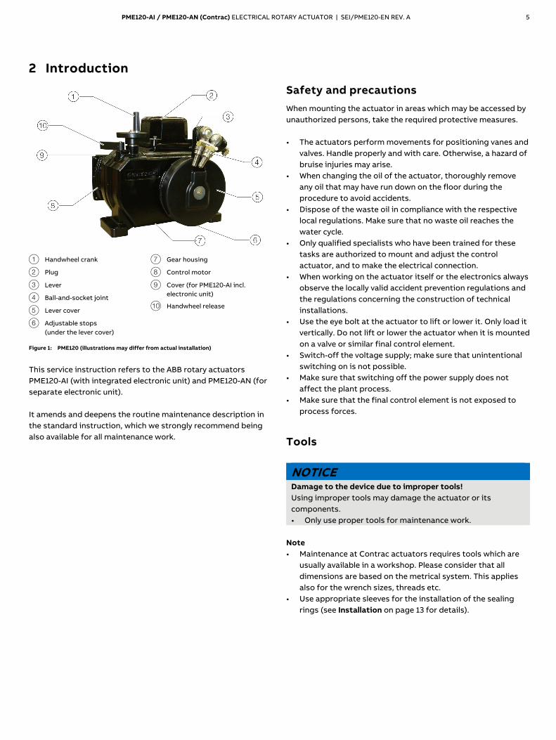
1 Handwheel crank
2 Plug
3 Lever
4 Ball-and-socket joint
5 Lever cover
6 Adjustable stops (under the lever cover)
7 Gear housing
8 Control motor
9 Cover (for PME120-AI incl. electronic unit)
j Handwheel release
Figure 1: PME120 (illustrations may differ from actual installation)
This service instruction refers to the ABB rotary actuators PME120-AI (with integrated electronic unit) and PME120-AN (for separate electronic unit). It amends and deepens the routine maintenance description in the standard instruction, which we strongly recommend being also available for all maintenance work.
Safety and precautions
When mounting the actuator in areas which may be accessed by unauthorized persons, take the required protective measures. • The actuators perform movements for positioning vanes and
valves. Handle properly and with care. Otherwise, a hazard of bruise injuries may arise.
• When changing the oil of the actuator, thoroughly remove any oil that may have run down on the floor during the procedure to avoid accidents.
• Dispose of the waste oil in compliance with the respective local regulations. Make sure that no waste oil reaches the water cycle.
• Only qualified specialists who have been trained for these tasks are authorized to mount and adjust the control actuator, and to make the electrical connection.
• When working on the actuator itself or the electronics always observe the locally valid accident prevention regulations and the regulations concerning the construction of technical installations.
• Use the eye bolt at the actuator to lift or lower it. Only load it vertically. Do not lift or lower the actuator when it is mounted on a valve or similar final control element.
• Switch-off the voltage supply; make sure that unintentional switching on is not possible.
• Make sure that switching off the power supply does not affect the plant process.
• Make sure that the final control element is not exposed to process forces.
Tools
NOTICE Damage to the device due to improper tools! Using improper tools may damage the actuator or its components. • Only use proper tools for maintenance work.
Note • Maintenance at Contrac actuators requires tools which are
usually available in a workshop. Please consider that all dimensions are based on the metrical system. This applies also for the wrench sizes, threads etc.
• Use appropriate sleeves for the installation of the sealing rings (see Installation on page 13 for details).
6 PME120-AI / PME120-AN (Contrac) ELECTRICAL ROTARY ACTUATOR | SEI/PME120-EN REV. A
3 Actuator versions
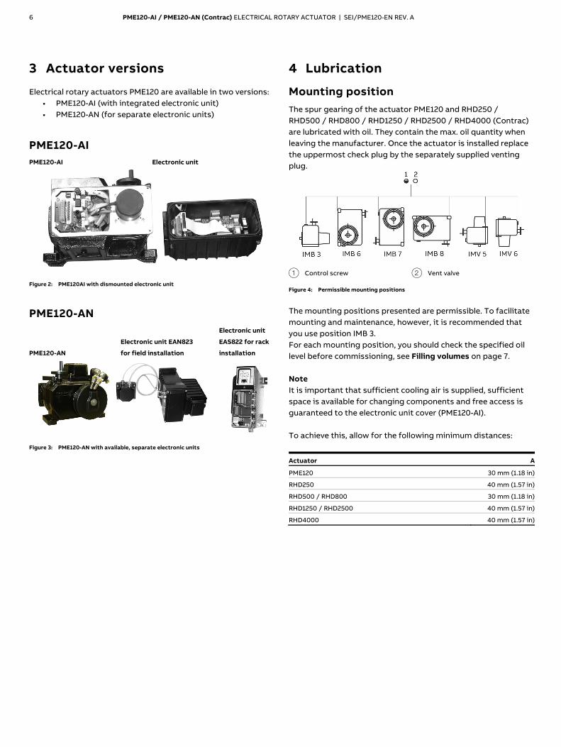
Electrical rotary actuators PME120 are available in two versions: • PME120-AI (with integrated electronic unit) • PME120-AN (for separate electronic units)
PME120-AI PME120-AI Electronic unit
Figure 2: PME120AI with dismounted electronic unit
PME120-AN
PME120-AN
Electronic unit EAN823
for field installation
Electronic unit
EAS822 for rack
installation
Figure 3: PME120-AN with available, separate electronic units
4 Lubrication
Mounting position
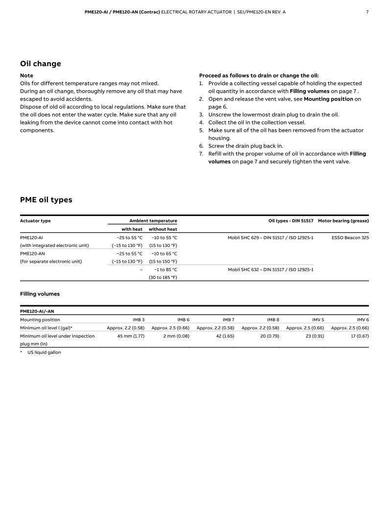
The spur gearing of the actuator PME120 and RHD250 / RHD500 / RHD800 / RHD1250 / RHD2500 / RHD4000 (Contrac) are lubricated with oil. They contain the max. oil quantity when leaving the manufacturer. Once the actuator is installed replace the uppermost check plug by the separately supplied venting plug.
1 Control screw 2 Vent valve
Figure 4: Permissible mounting positions
The mounting positions presented are permissible. To facilitate mounting and maintenance, however, it is recommended that you use position IMB 3. For each mounting position, you should check the specified oil level before commissioning, see Filling volumes on page 7. Note It is important that sufficient cooling air is supplied, sufficient space is available for changing components and free access is guaranteed to the electronic unit cover (PME120-AI). To achieve this, allow for the following minimum distances:
Actuator A
PME120 30 mm (1.18 in)
RHD250 40 mm (1.57 in)
RHD500 / RHD800 30 mm (1.18 in)
RHD1250 / RHD2500 40 mm (1.57 in)
RHD4000 40 mm (1.57 in)
PME120-AI / PME120-AN (Contrac) ELECTRICAL ROTARY ACTUATOR | SEI/PME120-EN REV. A 7
Oil change
Note Oils for different temperature ranges may not mixed. During an oil change, thoroughly remove any oil that may have escaped to avoid accidents. Dispose of old oil according to local regulations. Make sure that the oil does not enter the water cycle. Make sure that any oil leaking from the device cannot come into contact with hot components.
Proceed as follows to drain or change the oil: 1. Provide a collecting vessel capable of holding the expected
oil quantity in accordance with Filling volumes on page 7 . 2. Open and release the vent valve, see Mounting position on
page 6. 3. Unscrew the lowermost drain plug to drain the oil. 4. Collect the oil in the collection vessel. 5. Make sure all of the oil has been removed from the actuator
housing. 6. Screw the drain plug back in. 7. Refill with the proper volume of oil in accordance with Filling
volumes on page 7 and securely tighten the vent valve.
PME oil types
Actuator type Ambient temperature Oil types - DIN 51517 Motor bearing (grease)
with heat without heat
PME120-AI
(with integrated electronic unit)
−25 to 55 °C
(−15 to 130 °F)
−10 to 55 °C
(15 to 130 °F)
Mobil SHC 629 – DIN 51517 / ISO 12925-1 ESSO Beacon 325
PME120-AN
(for separate electronic unit)
−25 to 55 °C
(−15 to 130 °F)
−10 to 65 °C
(15 to 150 °F)
– −1 to 85 °C
(30 to 185 °F)
Mobil SHC 632 – DIN 51517 / ISO 12925-1
Filling volumes
PME120-AI/-AN
Mounting position IMB 3 IMB 6 IMB 7 IMB 8 IMV 5 IMV 6
Minimum oil level l (gal)* Approx. 2.2 (0.58) Approx. 2.5 (0.66) Approx. 2.2 (0.58) Approx. 2.2 (0.58) Approx. 2.5 (0.66) Approx. 2.5 (0.66)
Minimum oil level under inspection
plug mm (in)
45 mm (1.77) 2 mm (0.08) 42 (1.65) 20 (0.79) 23 (0.91) 17 (0.67)
* US liquid gallon
8 PME120-AI / PME120-AN (Contrac) ELECTRICAL ROTARY ACTUATOR | SEI/PME120-EN REV. A
5 Maintenance
Safety instructions
WARNING Risk of injury due to live parts! Risk of death or serious injuries due to electricity and unexpected machine movements. In automatic mode the motor is always under power, even at standstill. • When working on the actuator or the related subassembly,
switch off the supply voltage for the electronic unit and separate anti-condensation heater (option), and take precautions to prevent unintentional switch-on.
Repair and maintenance activities may only be performed by authorized customer service personnel. When replacing or repairing individual components, use original spare parts.
General
Contrac actuators feature a robust construction. As a result, they are highly reliable and require minimal maintenance. The maintenance intervals depend upon the effective load and are therefore not specified here. The built-in microprocessor evaluates the actual load factors (e.g. torques, forces, temperatures, etc.) and derives the remaining operating time until the next routine maintenance is required. Use the configuration program to view this information.
Apart from the load dependent maintenance intervals determined by the microprocessor we recommend routine maintenance at least every 10 years. The following description of the maintenance work provide that the actuator is disconnected from the damper and that all electrical supply is disconnected.
Lever
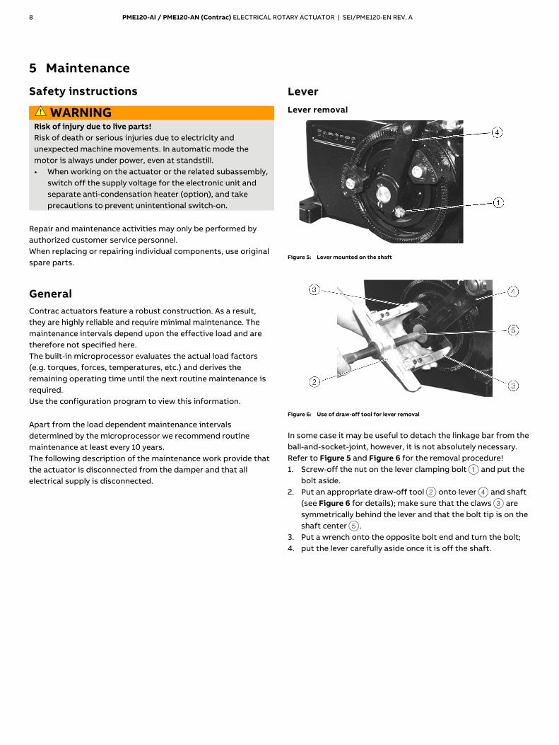
Lever removal
Figure 5: Lever mounted on the shaft
Figure 6: Use of draw-off tool for lever removal
In some case it may be useful to detach the linkage bar from the ball-and-socket-joint, however, it is not absolutely necessary. Refer to Figure 5 and Figure 6 for the removal procedure! 1. Screw-off the nut on the lever clamping bolt 1 and put the
bolt aside. 2. Put an appropriate draw-off tool 2 onto lever 4 and shaft
(see Figure 6 for details); make sure that the claws 3 are symmetrically behind the lever and that the bolt tip is on the shaft center 5.
3. Put a wrench onto the opposite bolt end and turn the bolt; 4. put the lever carefully aside once it is off the shaft.
PME120-AI / PME120-AN (Contrac) ELECTRICAL ROTARY ACTUATOR | SEI/PME120-EN REV. A 9
Lever installation
NOTICE Make sure that the shaft surface and the shaft bore in the ever are clean and free of grease or any other lubricant.
1. Put the appropriate key into the groove in the shaft. 2. Use an expanding screw to spread the lever seat. 3. Push a counterpart (soft metal) into the lever gap in order to
protect the expanding screw thread. 4. Push the lever onto the shaft until it is nearly in the same
position as it was before. 5. Put the lever clamping bolt into the lever and tighten the nut
with a torque of 23 Nm (17 lbf-ft).
Ball-and-socket-joint
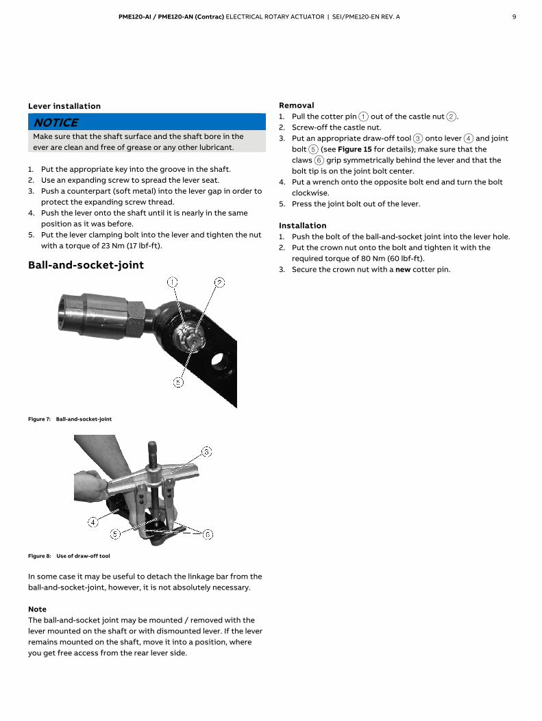
Figure 7: Ball-and-socket-joint
Figure 8: Use of draw-off tool
In some case it may be useful to detach the linkage bar from the ball-and-socket-joint, however, it is not absolutely necessary. Note The ball-and-socket joint may be mounted / removed with the lever mounted on the shaft or with dismounted lever. If the lever remains mounted on the shaft, move it into a position, where you get free access from the rear lever side.
Removal 1. Pull the cotter pin 1 out of the castle nut 2. 2. Screw-off the castle nut. 3. Put an appropriate draw-off tool 3 onto lever 4 and joint
bolt 5 (see Figure 15 for details); make sure that the claws 6 grip symmetrically behind the lever and that the bolt tip is on the joint bolt center.
4. Put a wrench onto the opposite bolt end and turn the bolt clockwise.
5. Press the joint bolt out of the lever. Installation 1. Push the bolt of the ball-and-socket joint into the lever hole. 2. Put the crown nut onto the bolt and tighten it with the
required torque of 80 Nm (60 lbf-ft). 3. Secure the crown nut with a new cotter pin.
10 PME120-AI / PME120-AN (Contrac) ELECTRICAL ROTARY ACTUATOR | SEI/PME120-EN REV. A
… 5 Maintenance
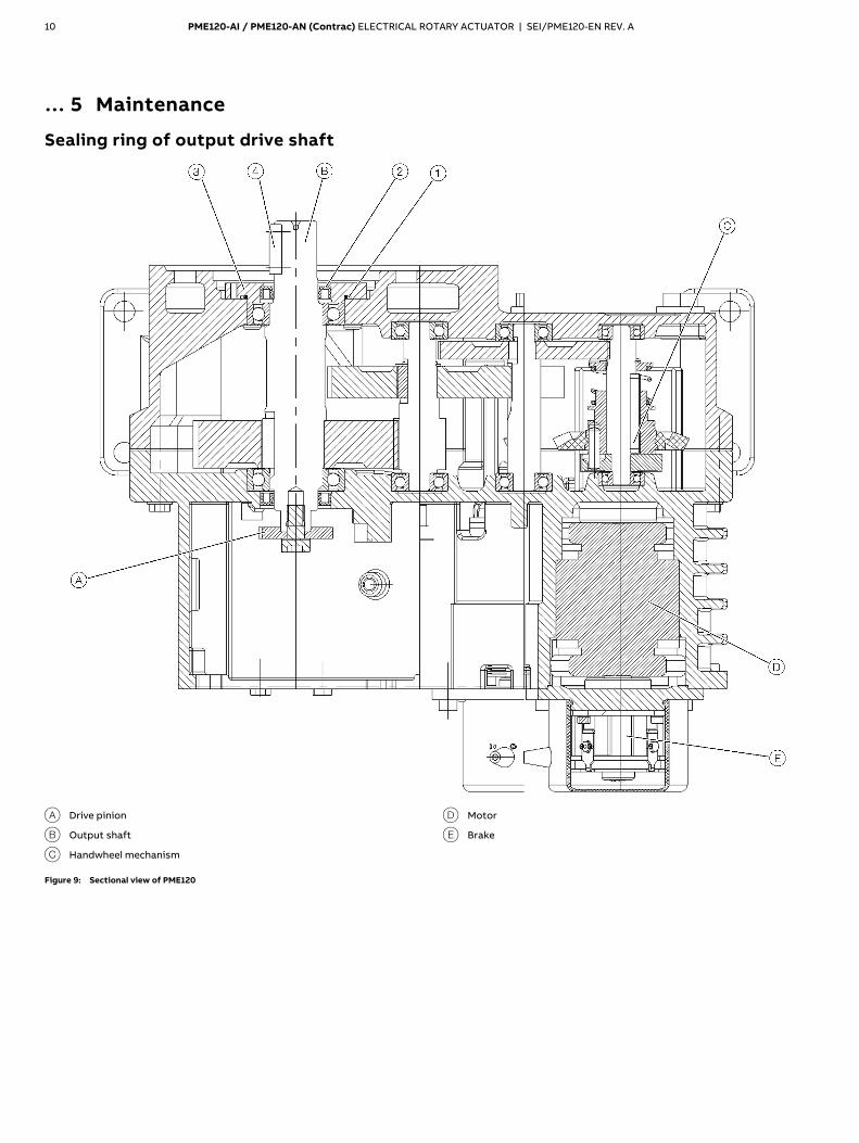
Sealing ring of output drive shaft
A Drive pinion
B Output shaft
C Handwheel mechanism
D Motor
E Brake
Figure 9: Sectional view of PME120
PME120-AI / PME120-AN (Contrac) ELECTRICAL ROTARY ACTUATOR | SEI/PME120-EN REV. A 11
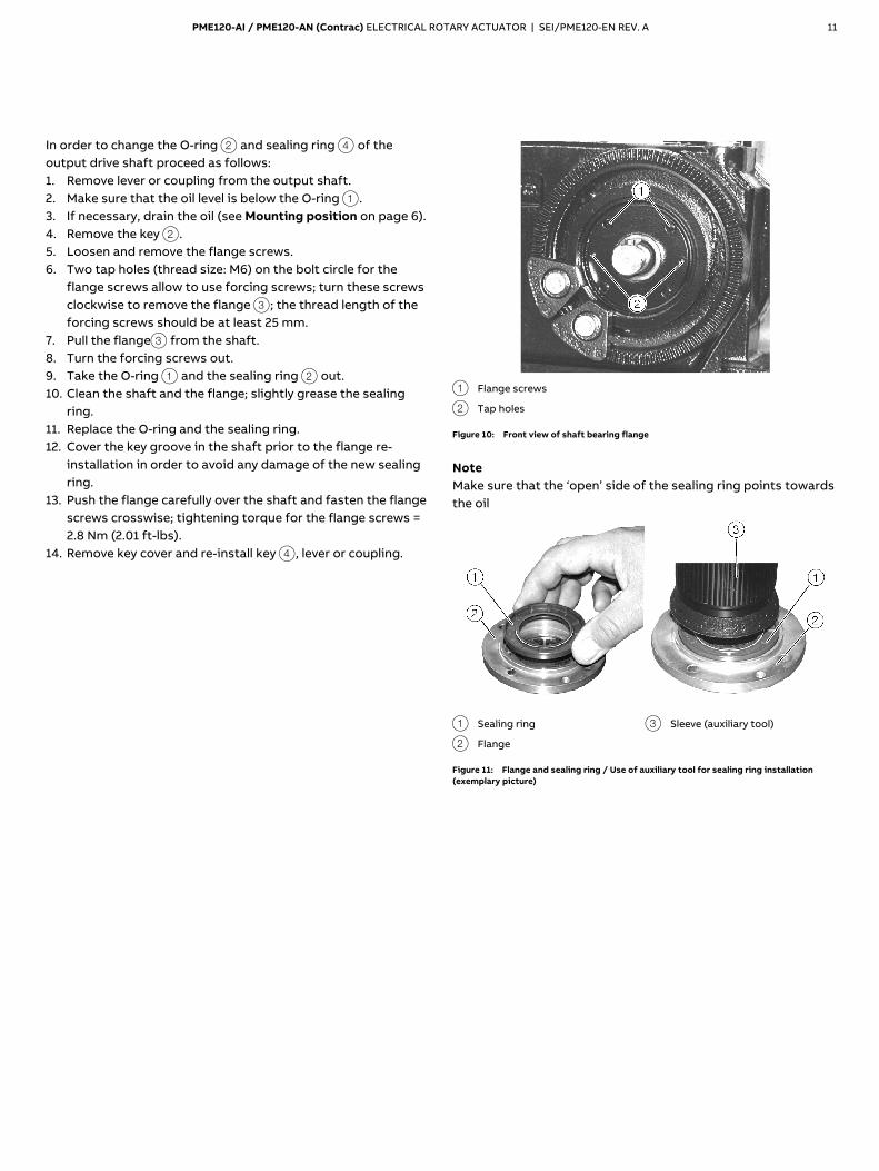
In order to change the O-ring 2 and sealing ring 4 of the output drive shaft proceed as follows: 1. Remove lever or coupling from the output shaft. 2. Make sure that the oil level is below the O-ring 1. 3. If necessary, drain the oil (see Mounting position on page 6). 4. Remove the key 2. 5. Loosen and remove the flange screws. 6. Two tap holes (thread size: M6) on the bolt circle for the
flange screws allow to use forcing screws; turn these screws clockwise to remove the flange 3; the thread length of the forcing screws should be at least 25 mm.
7. Pull the flange3 from the shaft. 8. Turn the forcing screws out. 9. Take the O-ring 1 and the sealing ring 2 out. 10. Clean the shaft and the flange; slightly grease the sealing
ring. 11. Replace the O-ring and the sealing ring. 12. Cover the key groove in the shaft prior to the flange re-
installation in order to avoid any damage of the new sealing ring.
13. Push the flange carefully over the shaft and fasten the flange screws crosswise; tightening torque for the flange screws = 2.8 Nm (2.01 ft-lbs).
14. Remove key cover and re-install key 4, lever or coupling.
1 Flange screws
2 Tap holes
Figure 10: Front view of shaft bearing flange
Note Make sure that the ‘open’ side of the sealing ring points towards the oil
1 Sealing ring
2 Flange
3 Sleeve (auxiliary tool)
Figure 11: Flange and sealing ring / Use of auxiliary tool for sealing ring installation (exemplary picture)
12 PME120-AI / PME120-AN (Contrac) ELECTRICAL ROTARY ACTUATOR | SEI/PME120-EN REV. A
… 5 Maintenance
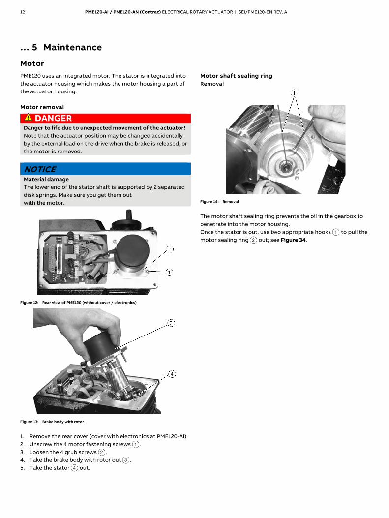
Motor
PME120 uses an integrated motor. The stator is integrated into the actuator housing which makes the motor housing a part of the actuator housing. Motor removal
DANGER Danger to life due to unexpected movement of the actuator! Note that the actuator position may be changed accidentally by the external load on the drive when the brake is released, or the motor is removed.
NOTICE Material damage The lower end of the stator shaft is supported by 2 separated disk springs. Make sure you get them out with the motor.
Figure 12: Rear view of PME120 (without cover / electronics)
Figure 13: Brake body with rotor
1. Remove the rear cover (cover with electronics at PME120-AI). 2. Unscrew the 4 motor fastening screws 1. 3. Loosen the 4 grub screws 2. 4. Take the brake body with rotor out 3. 5. Take the stator 4 out.
Motor shaft sealing ring Removal
Figure 14: Removal
The motor shaft sealing ring prevents the oil in the gearbox to penetrate into the motor housing. Once the stator is out, use two appropriate hooks 1 to pull the motor sealing ring 2 out; see Figure 34.
PME120-AI / PME120-AN (Contrac) ELECTRICAL ROTARY ACTUATOR | SEI/PME120-EN REV. A 13
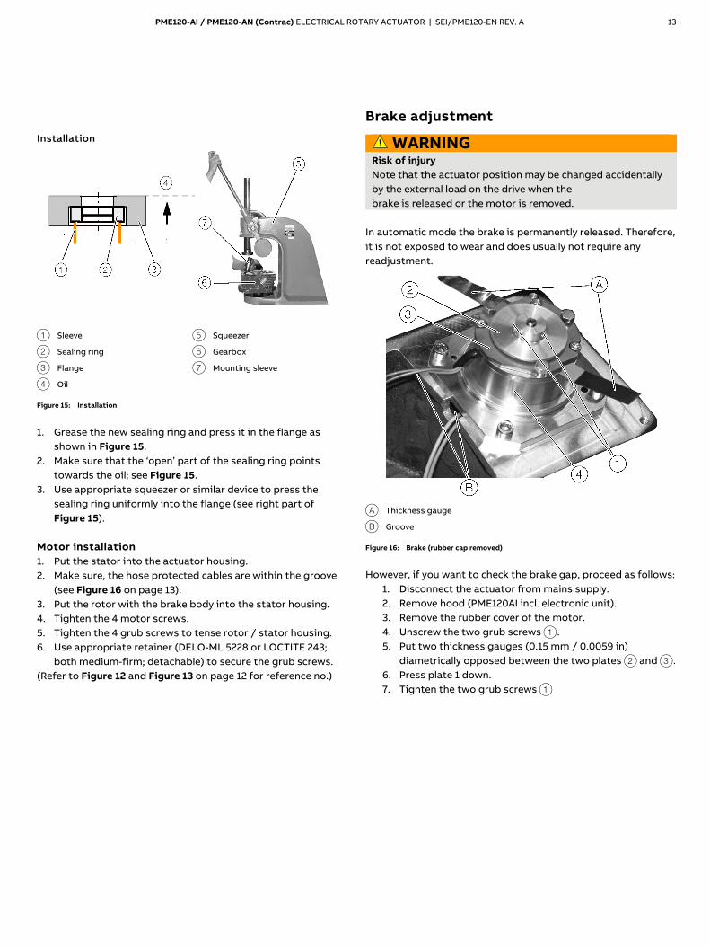
Installation
1 Sleeve
2 Sealing ring
3 Flange
4 Oil
5 Squeezer
6 Gearbox
7 Mounting sleeve
Figure 15: Installation
1. Grease the new sealing ring and press it in the flange as
shown in Figure 15. 2. Make sure that the ‘open’ part of the sealing ring points
towards the oil; see Figure 15. 3. Use appropriate squeezer or similar device to press the
sealing ring uniformly into the flange (see right part of Figure 15).
Motor installation 1. Put the stator into the actuator housing. 2. Make sure, the hose protected cables are within the groove
(see Figure 16 on page 13). 3. Put the rotor with the brake body into the stator housing. 4. Tighten the 4 motor screws. 5. Tighten the 4 grub screws to tense rotor / stator housing. 6. Use appropriate retainer (DELO-ML 5228 or LOCTITE 243;
both medium-firm; detachable) to secure the grub screws. (Refer to Figure 12 and Figure 13 on page 12 for reference no.)
Brake
Brake adjustment
WARNING Risk of injury Note that the actuator position may be changed accidentally by the external load on the drive when the brake is released or the motor is removed.
In automatic mode the brake is permanently released. Therefore, it is not exposed to wear and does usually not require any readjustment.
A Thickness gauge
B Groove
Figure 16: Brake (rubber cap removed)
However, if you want to check the brake gap, proceed as follows:
1. Disconnect the actuator from mains supply. 2. Remove hood (PME120AI incl. electronic unit). 3. Remove the rubber cover of the motor. 4. Unscrew the two grub screws 1. 5. Put two thickness gauges (0.15 mm / 0.0059 in)
diametrically opposed between the two plates 2 and 3. 6. Press plate 1 down. 7. Tighten the two grub screws 1
14 PME120-AI / PME120-AN (Contrac) ELECTRICAL ROTARY ACTUATOR | SEI/PME120-EN REV. A
6 Electrical connections
WARNING Risk of injury due to live parts! Risk of death or serious injuries due to electricity and unexpected machine movements. In automatic mode the motor is always under power, even at standstill. • When working on the actuator or the related subassembly,
switch off the supply voltage for the electronic unit and separate anti-condensation heater (option), and take precautions to prevent unintentional switch-on.
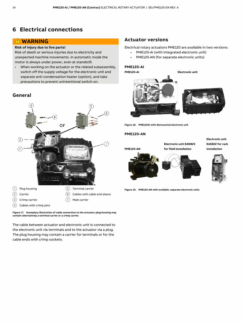
General
1 Plug housing
2 Carrier
3 Crimp carrier
4 Cables with crimp pins
5 Terminal carrier
6 Cables with cable end sleeve
7 Male carrier
Figure 17: Exemplary illustration of cable connection to the actuator; plug housing may contain alternatively a terminal carrier or a crimp carrier.
The cable between actuator and electronic unit is connected to the electronic unit via terminals and to the actuator via a plug. The plug housing may contain a carrier for terminals or for the cable ends with crimp sockets.
Actuator versions
Electrical rotary actuators PME120 are available in two versions: • PME120-AI (with integrated electronic unit) • PME120-AN (for separate electronic units)
PME120-AI PME120-AI Electronic unit
Figure 18: PME120AI with dismounted electronic unit
PME120-AN
PME120-AN
Electronic unit EAN823
for field installation
Electronic unit
EAS822 for rack
installation
Figure 19: PME120-AN with available, separate electronic units
PME120-AI / PME120-AN (Contrac) ELECTRICAL ROTARY ACTUATOR | SEI/PME120-EN REV. A 15
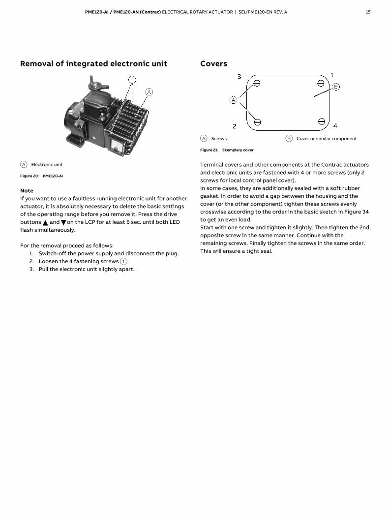
Removal of integrated electronic unit
A Electronic unit
Figure 20: PME120-AI
Note If you want to use a faultless running electronic unit for another actuator, it is absolutely necessary to delete the basic settings of the operating range before you remove it. Press the drive buttons and on the LCP for at least 5 sec. until both LED flash simultaneously. For the removal proceed as follows:
1. Switch-off the power supply and disconnect the plug. 2. Loosen the 4 fastening screws 1. 3. Pull the electronic unit slightly apart.
Covers
A Screws B Cover or similar component
Figure 21: Exemplary cover
Terminal covers and other components at the Contrac actuators and electronic units are fastened with 4 or more screws (only 2 screws for local control panel cover). In some cases, they are additionally sealed with a soft rubber gasket. In order to avoid a gap between the housing and the cover (or the other component) tighten these screws evenly crosswise according to the order in the basic sketch in Figure 34 to get an even load. Start with one screw and tighten it slightly. Then tighten the 2nd, opposite screw in the same manner. Continue with the remaining screws. Finally tighten the screws in the same order. This will ensure a tight seal.
16 PME120-AI / PME120-AN (Contrac) ELECTRICAL ROTARY ACTUATOR | SEI/PME120-EN REV. A
… 6 Electrical connections
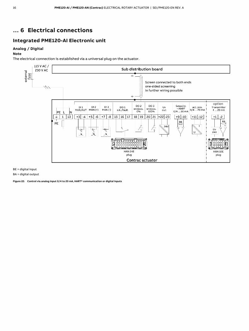
Integrated PME120-AI Electronic unit
Analog / Digital Note The electrical connection is established via a universal plug on the actuator.
BE = digital input
BA = digital output
Figure 22: Control via analog input 0/4 to 20 mA, HART® communication or digital inputs
PME120-AI / PME120-AN (Contrac) ELECTRICAL ROTARY ACTUATOR | SEI/PME120-EN REV. A 17
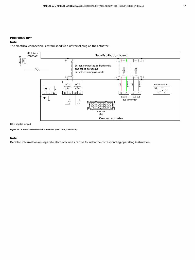
PROFIBUS DP® Note The electrical connection is established via a universal plug on the actuator.
DO = digital output
Figure 23: Control via fieldbus PROFIBUS DP® (PME120-AI, LME620-AI)
Note Detailed information on separate electronic units can be found in the corresponding operating instruction.

18 PME120-AI / PME120-AN (Contrac) ELECTRICAL ROTARY ACTUATOR | SEI/PME120-EN REV. A
… 6 Electrical connections
Electronic unit EAN823 (Contrac) for PME120-AN
Analog / Digital
Note • The electrical connection is provided by a universal plug on the actuator and the screw terminals on the electronic unit. • If you are using a separate heat supply, the heater must be protected with a 2 to 6 A medium time-lag fuse (e.g. NEOZED D01 E14).
BE = digital input
BA = digital output
Figure 24: Control via analog input 0/4 to 20 mA, HART® communication or digital inputs
PME120-AI / PME120-AN (Contrac) ELECTRICAL ROTARY ACTUATOR | SEI/PME120-EN REV. A 19
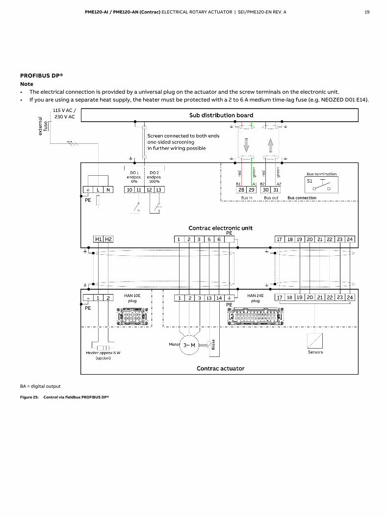
PROFIBUS DP®
Note • The electrical connection is provided by a universal plug on the actuator and the screw terminals on the electronic unit. • If you are using a separate heat supply, the heater must be protected with a 2 to 6 A medium time-lag fuse (e.g. NEOZED D01 E14).
BA = digital output
Figure 25: Control via fieldbus PROFIBUS DP®
20 PME120-AI / PME120-AN (Contrac) ELECTRICAL ROTARY ACTUATOR | SEI/PME120-EN REV. A
… 6 Electrical connections
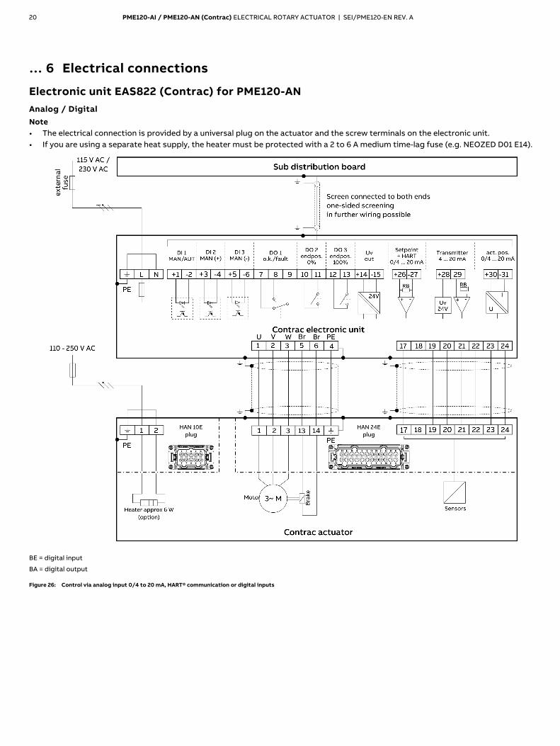
Electronic unit EAS822 (Contrac) for PME120-AN
Analog / Digital
Note • The electrical connection is provided by a universal plug on the actuator and the screw terminals on the electronic unit. • If you are using a separate heat supply, the heater must be protected with a 2 to 6 A medium time-lag fuse (e.g. NEOZED D01 E14).
BE = digital input
BA = digital output
Figure 26: Control via analog input 0/4 to 20 mA, HART® communication or digital inputs
PME120-AI / PME120-AN (Contrac) ELECTRICAL ROTARY ACTUATOR | SEI/PME120-EN REV. A 21
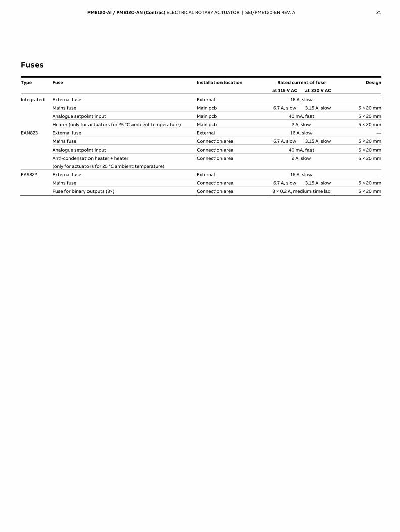
Fuses
Type Fuse Installation location Rated current of fuse Design
at 115 V AC at 230 V AC
Integrated External fuse External 16 A, slow —
Mains fuse Main pcb 6.7 A, slow 3.15 A, slow 5 × 20 mm
Analogue setpoint input Main pcb 40 mA, fast 5 × 20 mm
Heater (only for actuators for 25 °C ambient temperature) Main pcb 2 A, slow 5 × 20 mm
EAN823 External fuse External 16 A, slow —
Mains fuse Connection area 6.7 A, slow 3.15 A, slow 5 × 20 mm
Analogue setpoint input Connection area 40 mA, fast 5 × 20 mm
Anti-condensation heater + heater
(only for actuators for 25 °C ambient temperature)
Connection area 2 A, slow 5 × 20 mm
EAS822 External fuse External 16 A, slow —
Mains fuse Connection area 6.7 A, slow 3.15 A, slow 5 × 20 mm
Fuse for binary outputs (3×) Connection area 3 × 0.2 A, medium time lag 5 × 20 mm

22 PME120-AI / PME120-AN (Contrac) ELECTRICAL ROTARY ACTUATOR | SEI/PME120-EN REV. A
… 6 Electrical connections
… Fuses
Fuse location Integrated electronic unit (PME120-AI)
1 Main pcb
2 Mains fuse
3 Spare fuse for mains supply
4 Fuse for analog setpoint input
5 Heater fuse (only for −25 °C version)
Figure 27: Fuse location PME120-AI
EAN823
NOTICE Remove the cover of the connection chamber carefully in order to avoid any damage
1 Tap holes for cable glands
2 Cable gland
3 Analog input fuse
4 Terminals (signals)
5 Anti-dewing heater fuse
6 Terminals (motor cable)
7 Power supply fuse
8 Terminals (power supply)
Figure 28: Fuse location EAN823
EAS822
1 Digital output fuses 2 Mains fuse
Figure 29: Fuse location EAS822
Details: Digital output fuses
1 Fuse for DO3
2 Fuse for DO2
3 Fuse for DO1
Figure 30: Detail view of output fuses

PME120-AI / PME120-AN (Contrac) ELECTRICAL ROTARY ACTUATOR | SEI/PME120-EN REV. A 23
7 Exchange of position sensor
Dismounting
1. Drive actuator into 50 % position. 2. Delete the current position settings by pressing the drive
buttons on the LCP for at least 5 sec. 3. Switch-off the voltage supply. PME120-AN (for separate electronic unit)
Figure 31: Dismounting PME120-AN
1. Remove the rear actuator cover. 2. Undo the two fastening screws 1 of the position sensor and
pull the sensor out of the gears. 3. Disconnect the plug of the cable 2 on the pcb.
PME120-AI (with integrated electronic unit)
Figure 32: Removal of connection pcb at PME120-AI
Figure 33: Free access to sensor of PME120-AI
1. Remove the electronic unit (see Removal of integrated electronic unit on page 15).
2. Loosen the 4 screws 1 of the connection pcb and push the pcb aside.
3. Undo the two fastening screws 2 of the position sensor and pull the sensor out of the gears.
4. Disconnect the plug of the cable 3 on the pcb.
24 PME120-AI / PME120-AN (Contrac) ELECTRICAL ROTARY ACTUATOR | SEI/PME120-EN REV. A
… 7 Exchange of position sensor
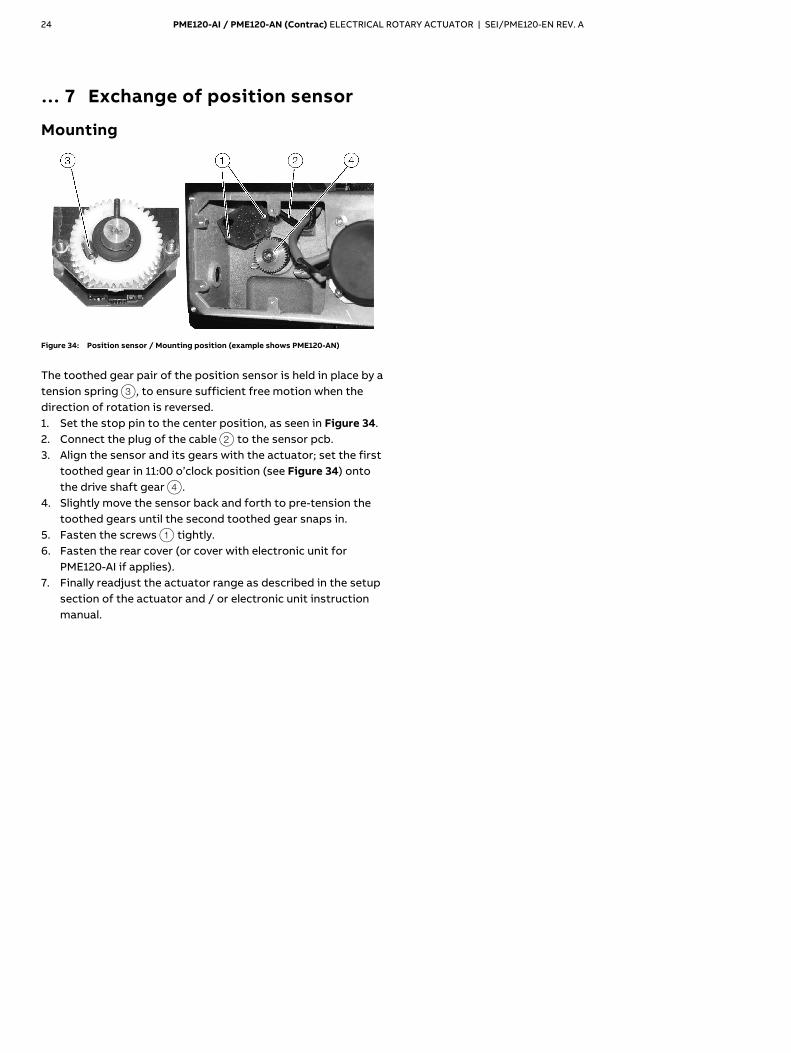
Mounting
Figure 34: Position sensor / Mounting position (example shows PME120-AN)
The toothed gear pair of the position sensor is held in place by a tension spring 3, to ensure sufficient free motion when the direction of rotation is reversed. 1. Set the stop pin to the center position, as seen in Figure 34. 2. Connect the plug of the cable 2 to the sensor pcb. 3. Align the sensor and its gears with the actuator; set the first
toothed gear in 11:00 o’clock position (see Figure 34) onto the drive shaft gear 4.
4. Slightly move the sensor back and forth to pre-tension the toothed gears until the second toothed gear snaps in.
5. Fasten the screws 1 tightly. 6. Fasten the rear cover (or cover with electronic unit for
PME120-AI if applies). 7. Finally readjust the actuator range as described in the setup
section of the actuator and / or electronic unit instruction manual.
PME120-AI / PME120-AN (Contrac) ELECTRICAL ROTARY ACTUATOR | SEI/PME120-EN REV. A 25
8 Electrical test values
DANGER
Danger to life due to unexpected movement of the actuator! Unexpected movement of the actuator may lead to very serious injuries or to death. • Make sure that the actuator can move without posing a
danger to people!
WARNING Risk of injury due to live parts! Risk of death or serious injuries due to electricity and unexpected machine movements. In automatic mode the motor is always under power, even at standstill. • When working on the actuator or the related subassembly,
switch off the supply voltage for the electronic unit and separate anti-condensation heater (option), and take precautions to prevent unintentional switch-on.
Note Check wiring and proper terminal connections before you start the test procedure.
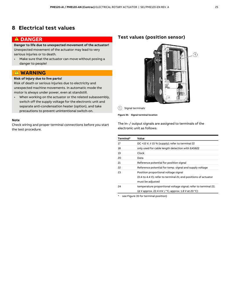
Test values (position sensor)
1 Signal terminals
Figure 35: Signal terminal location
The in- / output signals are assigned to terminals of the electronic unit as follows:
Terminal* Value
17 DC +15 V; ± 15 % (supply); refer to terminal 22
18 only used for cable length detection with EAS822
19 Clock
20 Data
21 Reference potential for position signal
22 Reference potential for temp. signal and supply voltage
23 Position proportional voltage signal
(0.4 to 4.4 V); refer to terminal 21; end positions of actuator
must be adjusted
24 temperature proportional voltage signal; refer to terminal 22;
(Δ V approx. 22.4 mV / °C; approx. 1.8 V at 20 °C)
* see Figure 35 for terminal position)
26 PME120-AI / PME120-AN (Contrac) ELECTRICAL ROTARY ACTUATOR | SEI/PME120-EN REV. A
… 8 Electrical test values
Test values (Brake and Motor)
Brake voltage DC 135 V with AC 115/AC230 V mains supply.
Motor voltage
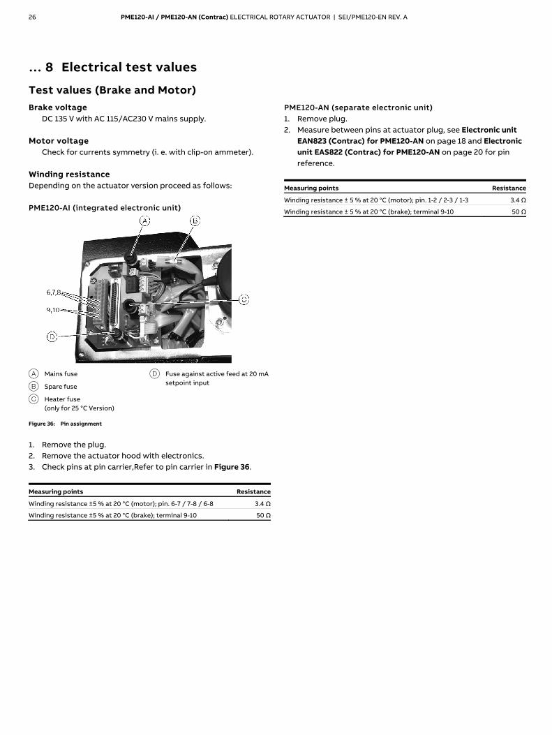
Check for currents symmetry (i. e. with clip-on ammeter). Winding resistance Depending on the actuator version proceed as follows: PME120-AI (integrated electronic unit)
A Mains fuse
B Spare fuse
C Heater fuse (only for 25 °C Version)
D Fuse against active feed at 20 mA setpoint input
Figure 36: Pin assignment
1. Remove the plug. 2. Remove the actuator hood with electronics. 3. Check pins at pin carrier,Refer to pin carrier in Figure 36.
Measuring points Resistance
Winding resistance ±5 % at 20 °C (motor); pin. 6-7 / 7-8 / 6-8 3.4 Ω
Winding resistance ±5 % at 20 °C (brake); terminal 9-10 50 Ω
PME120-AN (separate electronic unit) 1. Remove plug. 2. Measure between pins at actuator plug, see Electronic unit
EAN823 (Contrac) for PME120-AN on page 18 and Electronic unit EAS822 (Contrac) for PME120-AN on page 20 for pin reference.
Measuring points Resistance
Winding resistance ± 5 % at 20 °C (motor); pin. 1-2 / 2-3 / 1-3 3.4 Ω
Winding resistance ± 5 % at 20 °C (brake); terminal 9-10 50 Ω

PME120-AI / PME120-AN (Contrac) ELECTRICAL ROTARY ACTUATOR | SEI/PME120-EN REV. A 27
9 Failure detection
LED signals at commissioning and service field Provided the electronic unit is supplied with voltage (green LED on LCP ‘ON’), the red LED on the commissioning and service field provide some basic status information:
Both LED are ‘OFF’ Actuator is ok
Both LED are ‘ON’ Actuator is in bootstrap mode (e. g. during data
loading procedure); in this case the actuator is not
available for the positioning loop.
Both LED flash
Simultaneously
Actuator end positions are not set; actuator does not
accept commands to the digital inputs and can only be
moved via drive buttons on the local control panel (see
also electronic unit instruction).
Both LED flash
alternatively
Actuator failure (e. g. out of adjusted range); actuator
cannot be moved via command buttons or commands
from the process control system; reset is only possible
once the failure reason is eliminated.
Figure 37: Commissioning and service field
10 Troubleshooting
NOTICE Check wiring, polarity and all plug and terminal connections before you start detailed trouble shooting.
The following chapter specifies various possible failure events or conditions, which should be checked. Follow the block diagrams to find the associated reason, result or measure to solve the malfunction. Example: Condition E6.1 LED signal: Failure Possible failure E6.3 Sensor memory failure One reason / measure to solve the malfunction
R6.2 Replace sensor; see Exchange of position sensor on page 23. (in this case the user will find more detailed information about the sensor replacement in Exchange of position sensor on page 23).

28 PME120-AI / PME120-AN (Contrac) ELECTRICAL ROTARY ACTUATOR | SEI/PME120-EN REV. A
… 10 Troubleshooting
General
Figure 38: General
PME120-AI / PME120-AN (Contrac) ELECTRICAL ROTARY ACTUATOR | SEI/PME120-EN REV. A 29
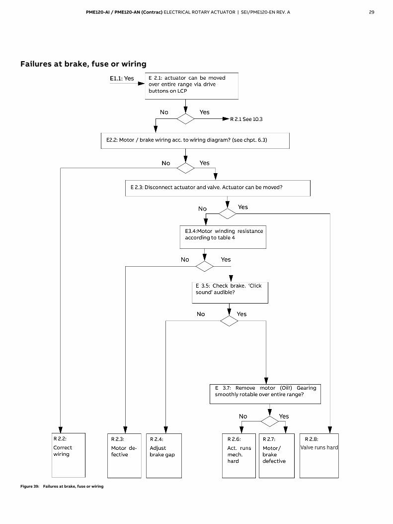
Failures at brake, fuse or wiring
Figure 39: Failures at brake, fuse or wiring

30 PME120-AI / PME120-AN (Contrac) ELECTRICAL ROTARY ACTUATOR | SEI/PME120-EN REV. A
… 10 Troubleshooting
Operation mode (MAN / AUT)
Figure 40: Operation mode (MAN / AUT)
PME120-AI / PME120-AN (Contrac) ELECTRICAL ROTARY ACTUATOR | SEI/PME120-EN REV. A 31
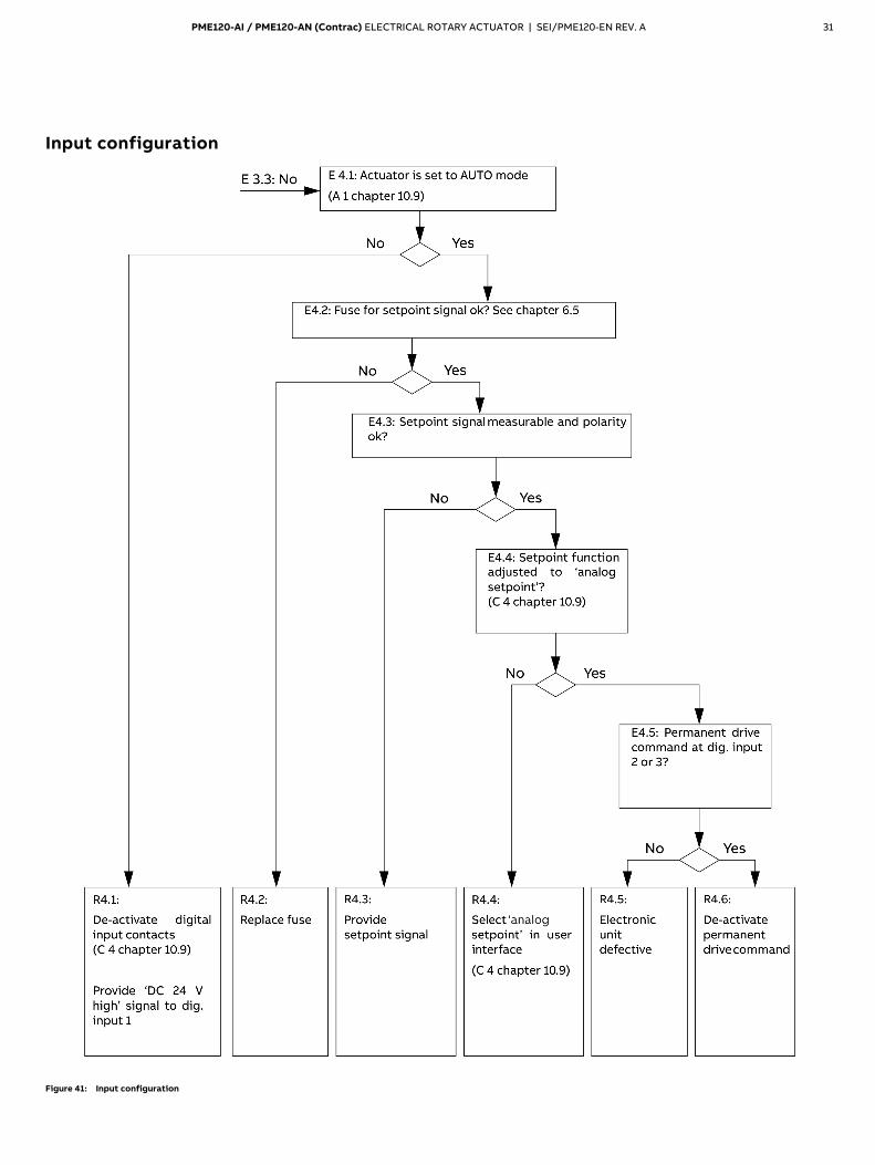
Input configuration
Figure 41: Input configuration

32 PME120-AI / PME120-AN (Contrac) ELECTRICAL ROTARY ACTUATOR | SEI/PME120-EN REV. A
… 10 Troubleshooting
Operation behind step controller
Figure 42: Operation behind step controller
PME120-AI / PME120-AN (Contrac) ELECTRICAL ROTARY ACTUATOR | SEI/PME120-EN REV. A 33
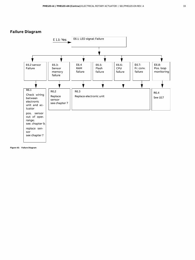
Failure Diagram
Figure 43: Failure Diagram
34 PME120-AI / PME120-AN (Contrac) ELECTRICAL ROTARY ACTUATOR | SEI/PME120-EN REV. A
… 10 Troubleshooting
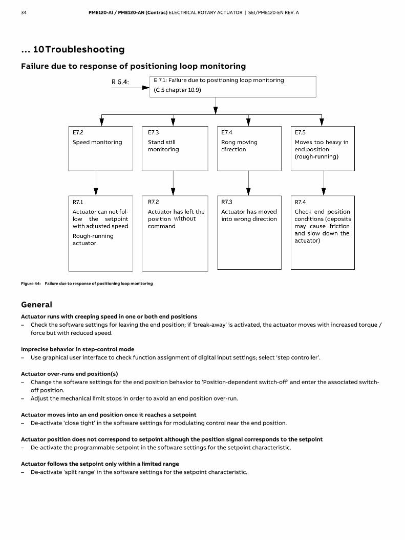
Failure due to response of positioning loop monitoring
Figure 44: Failure due to response of positioning loop monitoring
General Actuator runs with creeping speed in one or both end positions – Check the software settings for leaving the end position; if ‘break-away’ is activated, the actuator moves with increased torque /
force but with reduced speed. Imprecise behavior in step-control mode – Use graphical user interface to check function assignment of digital input settings; select ‘step controller’. Actuator over-runs end position(s) – Change the software settings for the end position behavior to ‘Position-dependent switch-off’ and enter the associated switch-
off position. – Adjust the mechanical limit stops in order to avoid an end position over-run. Actuator moves into an end position once it reaches a setpoint – De-activate ‘close tight’ in the software settings for modulating control near the end position. Actuator position does not correspond to setpoint although the position signal corresponds to the setpoint – De-activate the programmable setpoint in the software settings for the setpoint characteristic. Actuator follows the setpoint only within a limited range – De-activate ‘split range’ in the software settings for the setpoint characteristic.
PME120-AI / PME120-AN (Contrac) ELECTRICAL ROTARY ACTUATOR | SEI/PME120-EN REV. A 35
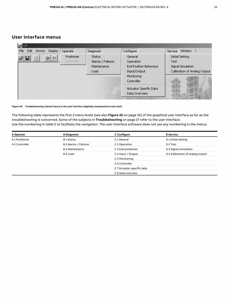
User interface menus
Figure 45: Troubleshooting related menus in the user interface (digitally manipulated screen shot)
The following table represents the first 2 menu levels (see also Figure 45 on page 35) of the graphical user interface as far as the troubleshooting is concerned. Some of the subjects in Troubleshooting on page 27 refer to the user interface. Use the numbering in table 5 to facilitate the navigation. The user interface software does not use any numbering in the menus.
A Operate B Diagnosis C Configure D Service
A 1 Positioner B 1 Status C 1 General D 1 Initial setting
A 2 Controller B 2 Alarms / Failures C 2 Operation D 2 Test
B 3 Maintenance C 3 End positioner D 3 Signal simulation
B 4 Load C 4 Input / Output D 4 Calibration of analog output
C 5 Monitoring
C 6 Controller
C 7 Actuator specific data
C 8 Data overview
— A B B M E A S U R E M E N T & A N A L Y T I C S | S ER V I C E I N ST R U C T I O N | S EI / P M E 1 2 0 - E N R E V . A
PME120-AI / PME120-AN (Contrac) Electrical rotary actuator
— ABB Measurement & Analytics For your local ABB contact, visit: www.abb.com/contacts For more product information, visit: www.abb.com/actuators
Electrical rotary actuator for the operation of final control elements.
SEI/
PME1
20-E
N R
ev. A
0
5.20
20
— PME120-AI PME120-AN
Introduction Compact actuator for the operation of final control elements with preferably 90° rotary movement such as valve flaps, ball valves, etc. The nominal torque is transferred through a lever actuator. A special electronic unit controls the actuator. The special electronic unit serves as the interface between actuator and control system.
Additional Information Additional documentation on PME120-AI / PME120-AN (Contrac) is available for download free of charge at www.abb.com/actuators. Alternatively simply scan this code:
— We reserve the right to make technical changes or modify the contents of this document without prior notice. With regard to purchase orders, the agreed particulars shall prevail. ABB does not accept any responsibility whatsoever for potential errors or possible lack of information in this document. We reserve all rights in this document and in the subject matter and illustrations contained therein. Any reproduction, disclosure to third parties or utilization of its contents – in whole or in parts – is forbidden without prior written consent of ABB. © ABB 2020 3KXE111018R4301