IAI_RCP4-S_24V-stepper-actuator-slede_catalogus.pdf - ATB ...
49
Newest additions to the series! Side-Mounted Motor Type Cleanroom Type RoboCylinder PowerCon www.robocylinder.de RCP4 Series PCON-CA GB Catalogue Slider Type
-
Upload
khangminh22 -
Category
Documents
-
view
1 -
download
0
Transcript of IAI_RCP4-S_24V-stepper-actuator-slede_catalogus.pdf - ATB ...
Newest additions to the series!
Side-Mounted Motor Type Cleanroom Type
RoboCylinder
PowerCon
w w w . r o b o c y l i n d e r . d e
RCP4 SeriesPCON-CA
GB
Catalogue Slider Type
1
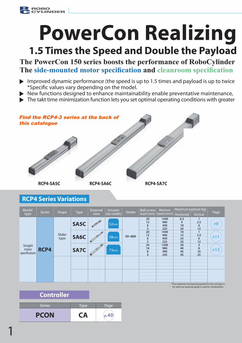
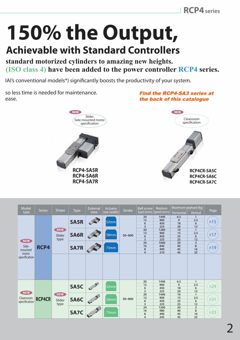
PowerCon Realizing 150% the Output,1.5 Times the Speed and Double the Payload Achievable with Standard Controllers
The PowerCon 150 series boosts the performance of RoboCylinder standard motorized cylinders to amazing new heights. The side mountedmotors ecification and cleanrooms ecification (ISO class 4) have been added to the power controller RCP4 series.
Improved dynamic performance (the speed is up to 1.5 times and payload is up to twice IAI’s conventional models*) signi�cantly boosts the productivity of your system. *Speci�c values vary depending on the model. New functions designed to enhance maintainability enable preventative maintenance, so less time is needed for maintenance.
The takt time minimization function lets you set optimal operating conditions with greater ease.
Controller
RCP4 Series Variations
Series Type Page
PCON CA p.40
RCP4
SA5C
SA6C
SA7C
SeriesModel type Shape Type External
viewActuator
size (width) Stroke PageBall screwlead (mm)
MaximumSpeed (mm/s)
Maximum payload (kg)Horizontal Vertical
201263
201263
241684
1440900450225
1440900450225
1200980490245
6.59
18201015252520404545
12.56
121
2.56
1238
1625
Slidertype
Straightmotor
50~800
52mm
73mm
58mm
P.9
P.11
P.13
*The maximum horizontal payload for the rod type is for when an external guide is used in combination.
Improved dynamic performance (the speed is up to 1.5 times and payload is up to twice
New functions designed to enhance maintainability enable preventative maintenance, The smart tuning function lets you set up the operation of your equipment optimally with ease.
PowerCon Realizing1.5 Times the Speed and Double the Payload
The Power CON 150 series boosts the performance of ROBO CylinderThe and
RCP4-SA5C RCP4-SA6C RCP4-SA7C
RCP4
SA5R
SA6R
SA7R
RA5R
RA6R
SA5C
SA6C
SA7C
201263
201263
241684
201263
241684
201263
201263
241684
1440900450225
1280900450225
1000840490210800700450225800560420175
1440900450225
1440900450225
1200980490245
6.59
182010152525204045456
254060205060806.59
18201015252520404545
12.56
121
2.56
1238
16251.54
102038
18281
2.56
121
2.56
1238
1625
Side-mounted
motor
NEW
Cleanroom NEW
50~800
52mm
73mm
58mm
P.15
P.17
P.19
Rodtype
NEW
Slidertype
NEW
RCP4CR
50~400
50~500
50~800
52mm
61mm
52mm
73mm
58mm
P.25
P.27
P.29
P.31
P.33
Slidertype
NEW
SeriesModel type Type External
viewShape Actuatorsize (width) Stroke PageBall screw
lead (mm)Maximum
Speed (mm/s)Maximum payload (kg)Horizontal Vertical
RCP4 series
so less time is needed for maintenance. The smart tuning function lets you set up the operation of your equipment optimally with ease.
Power CON Realizing 150% the Output,Achievable with Standard Controllersstandard motorized cylinders to amazing new heights.
have been added to the power controller RCP4 series.
RCP4-RA6C
RCP4-SA5RRCP4-SA6RRCP4-SA7R
RCP4CR-SA5CRCP4CR-SA6CRCP4CR-SA7C
RCP4-RA5RRCP4-RA6R
NEWNEWSlider
Side-mounted motor Rod
Side-mounted motor Cleanroom
NEWFind the RCP4-3 series at the back of this catalogue
2
RCP4 series
PowerCon Realizing 150% the Output,1.5 Times the Speed and Double the Payload Achievable with Standard Controllers
The PowerCon 150 series boosts the performance of RoboCylinder standard motorized cylinders to amazing new heights. The side mountedmotors ecification and cleanrooms ecification (ISO class 4) have been added to the power controller RCP4 series.
Improved dynamic performance (the speed is up to 1.5 times and payload is up to twice IAI’s conventional models*) signi�cantly boosts the productivity of your system. *Speci�c values vary depending on the model. New functions designed to enhance maintainability enable preventative maintenance, so less time is needed for maintenance. The takt time minimization function lets you set optimal operating conditions with greater ease.
RCP4
SA5R
SA6R
SA7R
SA5C
SA6C
SA7C
201263
201263
241684
201263
201263
241684
1440900450225
1280900450225
1000840490210
1440900450225
1440900450225
1200980490245
6.59
18201015252520404545
6.59
18201015252520404545
12.56
121
2.56
1238
1625
12.56
121
2.56
1238
1625
Side-mounted
motor
NEW
Cleanroom NEW
50~800
52mm
73mm
58mm
P.15
P.17
P.19
Slidertype
NEW
RCP4CR 50~800
52mm
73mm
58mm
P.29
P.31
P.33
Slidertype
NEW
SeriesModel type Type External
viewShape Actuatorsize (width) Stroke PageBall screw
lead (mm)Maximum
Speed (mm/s)Maximum payload (kg)Horizontal Vertical
RCP4 series
so less time is needed for maintenance. The smart tuning function lets you set up the operation of your equipment optimally with ease.
Power CON Realizing 150% the Output,Achievable with Standard Controllersstandard motorized cylinders to amazing new heights.
have been added to the power controller RCP4 series.
RCP4-SA5RRCP4-SA6RRCP4-SA7R
RCP4CR-SA5CRCP4CR-SA6CRCP4CR-SA7C
NEWSlider
Side-mounted motor Cleanroom
NEW
Find the RCP4-SA3 series at the back of this catalogue
3
Features
ShorterTaktTimeSignificantlyBoosts theProductivityofYourSystem
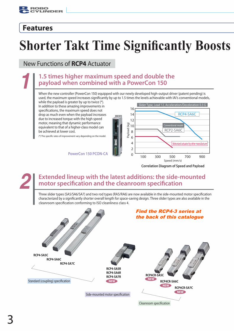
When the new controller (PowerCon 150) equipped with our newly developed high-output driver (patent pending) is
while the payload is greater by up to twice (*). In addition to these amazing improvements in
drop as much even when the payload increases due to increased torque with the high speed motor, meaning that dynamic performance equivalent to that of a higher-class model can be achieved at lower cost.
1 1.5 times higher maximum speed and double the payload when combined with a PowerCon 150
2 Extended lineup with the latest additions: the side-mounted
PowerCon 150 PCON-CA
Speed (mm/s)
Correlation Diagram of Speed and Payload
Slider Type, Lead 12, Acceleration/Deceleration 0.3 G
100 300 500 700 900
1614121086420
Payl
oad
(kg)
RCP4-SA6C
Conventional model
RCP2-SA6C
RCP4-SA6C
Motorized actuator by other manufacturer
RCP4-SA5CRCP4-SA6C
RCP4-SA7CRCP4-SA5RRCP4-SA6RRCP4-SA7R RCP4CR-SA5C
RCP4CR-SA6C
RCP4CR-SA7C
NEWNEW
NEW
NEW
New Functions of RCP4 Actuator
Find the RCP4-3 series at the back of this catalogue
4
RCP4 series
Shorter Takt Time Significantly Boosts theProductivityofYourSystem
RCP4 series
4
5
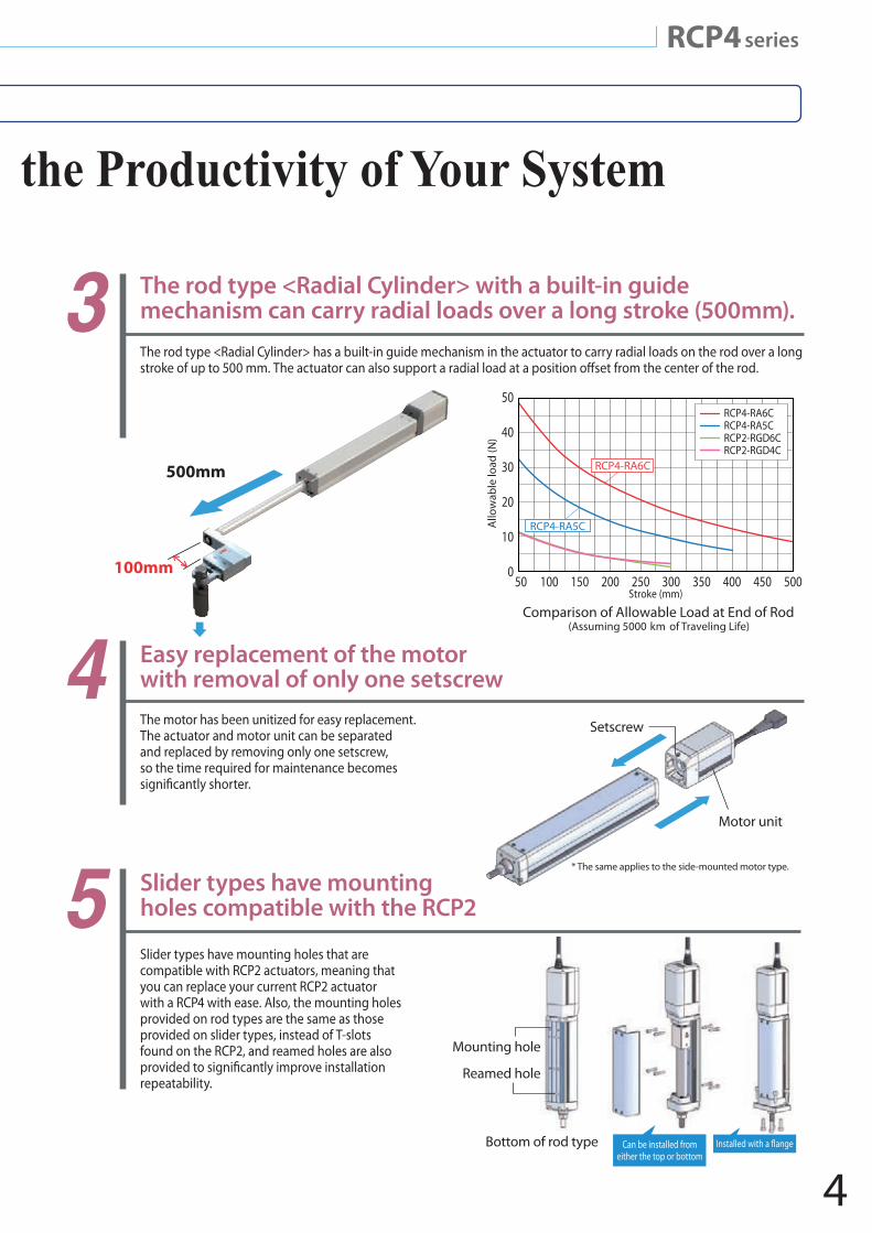
3The rod type <Radial Cylinder> has a built-in guide mechanism in the actuator to carry radial loads on the rod over a long
The motor has been unitized for easy replacement. The actuator and motor unit can be separated and replaced by removing only one setscrew, so the time required for maintenance becomes
Slider types have mounting holes that are compatible with RCP2 actuators, meaning that you can replace your current RCP2 actuator with a RCP4 with ease. Also, the mounting holes provided on rod types are the same as those provided on slider types, instead of T-slots found on the RCP2, and reamed holes are also
repeatability.
The rod type <Radial Cylinder> with a built-in guide mechanism can carry radial loads over a long stroke (500mm).
Easy replacement of the motor with removal of only one setscrew
Slider types have mounting holes compatible with the RCP2
Setscrew
Motor unit
Mounting hole
Reamed hole
Bottom of rod type Can be installed from either the top or bottom
100mm
500mm
* The same applies to the side-mounted motor type.
50
40
30
20
10
050 100 150 200 250 300 350 400 450 500
Stroke (mm)
RCP4-RA6CRCP4-RA5CRCP2-RGD6CRCP2-RGD4C
RCP4-RA5C
RCP4-RA6C
Comparison of Allowable Load at End of Rod (Assuming 5000 km of Traveling Life)
Allo
wab
le lo
ad (N
)
theProductivityofYourSystem
5
Features
New Functions to Enhance MaintainabilityFeatures
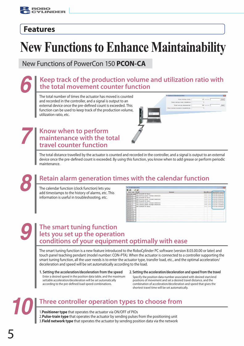
6 Keep track of the production volume and utilization ratio with the total movement counter functionThe total number of times the actuator has moved is counted and recorded in the controller, and a signal is output to an
function can be used to keep track of the production volume, utilization ratio, etc.
Know when to perform maintenance with the total travel counter function7The total distance travelled by the actuator is counted and recorded in the controller, and a signal is output to an external
maintenance.
8 Retain alarm generation times with the calendar functionThe calendar function (clock function) lets you add timestamps to the history of alarms, etc. This information is useful in troubleshooting, etc.
9 The smart tuning function lets you set up the operation conditions of your equipment optimally with easeThe smart tuning function is a new feature introduced to the RoboCylinder PC software (version 8.03.00.00 or later) and touch panel teaching pendant (model number: CON-PTA). When the actuator is connected to a controller supporting the smart tuning function, all the user needs is to enter the actuator type, transfer load, etc., and the optimal acceleration/deceleration and speed will be set automatically according to the load.
1. Setting the acceleration/deceleration from the speedEnter a desired speed in the position data table, and the maximumsettable acceleration/deceleration will be set automatically
2. Setting the acceleration/deceleration and speed from the travel Specify the position data number associated with desired start/endpositions of movement and set a desired travel distance, and thecombination of acceleration/deceleration and speed that gives theshortest travel time will be set automatically.
10 1.Positioner type that operates the actuator via ON/OFF of PIOs 2.Pulse-train type that operates the actuator by sending pulses from the positioning unit 3.Field network type that operates the actuator by sending position data via the network
Three controller operation types to choose from
New Functions of PowerCon 150 PCON-CA
New Functions to Enhance Maintainability
6
RCP4 series
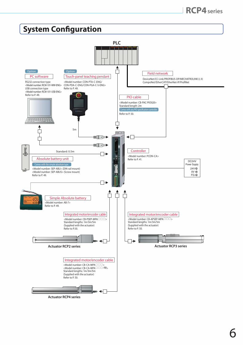
System Con�guration
6
PC software
PIO cable
Absolute battery unit
Simple Absolute battery
Integrated motor/encoder cable
Integrated motor/encoder cable
Integrated motor/encoder cable
Field network
Controller
Touch-panel teaching pendant
Actuator RCP2 series
Actuator RCP4 series
Actuator RCP3 series
RS232 connection type <Model number: RCM-101-MW-ENG>USB connection type <Model number: RCM-101-USB-ENG>Refer to P. 49.
<Model number: SEP-ABU> (DIN rail mount) <Model number: SEP-ABUS> (Screw mount) Refer to P. 49.
<Model number: AB-7>Refer to P. 49.
<Model number: CB-CA-MPA ><Model number: CB-CA-MPA -RB>Standard lengths: 1m/3m/5m(Supplied with the actuator) Refer to P. 50.
<Model number: CB-PSEP-MPA >Standard lengths: 1m/3m/5m(Supplied with the actuator) Refer to P.50.
DeviceNet/CC-Link/PROFIBUS-DP/MECHATROLINK (I, II)CompoNet/EtherCAT/EtherNet-IP/Pro�Net
<Model number: CB-PAC-PIO020>Standard length: 2m
<Model number: CON-PTA-C-ENG/CON-PDA-C-ENG/CON-PGA-C-S-ENG>Refer to P. 49.
Refer to P. 50.
PLC
<Model number: PCON-CA>Refer to P. 41.
5m
Option Option
Comes with the simple absolute type.
Standard: 0.5m
<Model number: CB-APSEP-MPA >Standard lengths: 1m/3m/5m(Supplied with the actuator) Refer to P. 50.
RCP4 series
DC24VPower Supply
24V0VFG
7
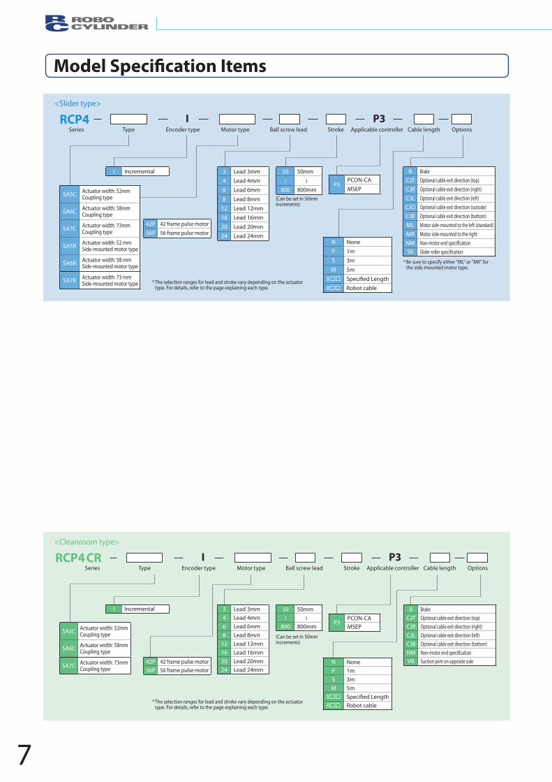
Model Speci�cation Items
I Incremental
42P 42 frame pulse motor56P 56 frame pulse motor
P3PCON-CAMSEP
50 50mm
800 800mm
B Brake CJT Optional cable exit direction (top)CJR Optional cable exit direction (right)CJL Optional cable exit direction (left)CJO Optional cable exit direction (outside)CJB Optional cable exit direction (bottom)ML Motor side-mounted to the left (standard)MR Motor side-mounted to the rightNM Non-motor end speci�cationSR Slider roller speci�cation
3 Lead 3mm4 Lead 4mm
6 Lead 6mm
8 Lead 8mm
12 Lead 12mm
16 Lead 16mm
20 Lead 20mm24 Lead 24mm
SA5C Actuator width: 52mmCoupling type
SA6C Actuator width: 58mmCoupling type
SA7C Actuator width: 73mmCoupling type
SA5R Actuator width: 52 mmSide-mounted motor type
SA6R Actuator width: 58 mmSide-mounted motor type
SA7R Actuator width: 73 mmSide-mounted motor type
N NoneP 1m
S 3m
M 5m
X Speci�ed Length R Robot cable
(Can be set in 50mm increments)
Series Type Encoder type Motor type Ball screw lead Stroke Applicable controller Cable length Options
I P3RCP4<Slider type>
* The selection ranges for lead and stroke vary depending on the actuator type. For details, refer to the page explaining each type.
* Be sure to specify either "ML" or "MR" for the side-mounted motor type.
(Can be set in 50mm increments)
* The selection ranges for lead and stroke vary depending on the actuator type. For details, refer to the page explaining each type.
Series Type Encoder type Motor type Ball screw lead Stroke Applicable controller Cable length Options
I P3RCP4CR<Cleanroom type>
I Incremental
42P 42 frame pulse motor56P 56 frame pulse motor
P3PCON-CAMSEP
50 50mm
800 800mm
B Brake CJT Optional cable exit direction (top)CJR Optional cable exit direction (right)CJL Optional cable exit direction (left)CJB Optional cable exit direction (bottom)NM Non-motor end speci�cationVR Suction joint on opposite side
3 Lead 3mm4 Lead 4mm6 Lead 6mm8 Lead 8mm
12 Lead 12mm16 Lead 16mm20 Lead 20mm24 Lead 24mm
SA5C Actuator width: 52mmCoupling type
SA6C Actuator width: 58mmCoupling type
SA7C Actuator width: 73mmCoupling type
N NoneP 1mS 3mM 5m
X Speci�ed Length R Robot cable
8
RCP4 series
Actuator OptionsRCP4 series
Actuator OptionsApplicable models
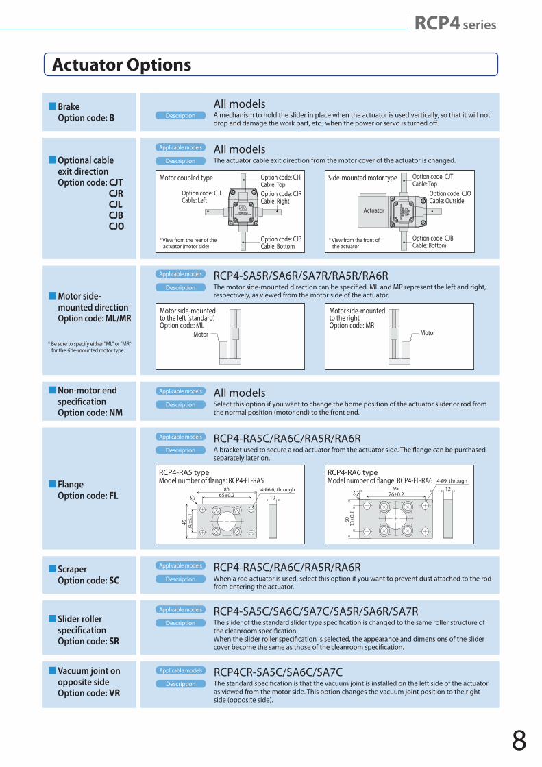
Brake Option code: B
All modelsA mechanism to hold the slider in place when the actuator is used vertically, so that it will not drop and damage the work part, etc., when the power or servo is turned o�.
Description
Non-motor end speci�cationOption code: NM
All modelsSelect this option if you want to change the home position of the actuator slider or rod from the normal position (motor end) to the front end.
Applicable models
Description
Scraper Option code: SC
RCP4-RA5C/RA6C/RA5R/RA6RWhen a rod actuator is used, select this option if you want to prevent dust attached to the rod from entering the actuator.
Applicable models
Description
Slider roller speci�cationOption code: SR
RCP4-SA5C/SA6C/SA7C/SA5R/SA6R/SA7RThe slider of the standard slider type speci�cation is changed to the same roller structure of the cleanroom speci�cation. When the slider roller speci�cation is selected, the appearance and dimensions of the slider cover become the same as those of the cleanroom speci�cation.
Applicable models
Description
Vacuum joint on opposite sideOption code: VR
RCP4CR-SA5C/SA6C/SA7CThe standard speci�cation is that the vacuum joint is installed on the left side of the actuator as viewed from the motor side. This option changes the vacuum joint position to the right side (opposite side).
Applicable models
Description
Motor side- mounted direction
Option code: ML/MR
RCP4-SA5R/SA6R/SA7R/RA5R/RA6RThe motor side-mounted direction can be speci�ed. ML and MR represent the left and right, respectively, as viewed from the motor side of the actuator.
Applicable models
Description
* Be sure to specify either "ML" or "MR" for the side-mounted motor type.
Motor side-mounted to the rightOption code: MR
Motor
Motor side-mounted to the left (standard) Option code: ML
Motor
FlangeOption code: FL
RCP4-RA5C/RA6C/RA5R/RA6RA bracket used to secure a rod actuator from the actuator side. The �ange can be purchased separately later on.
Applicable models
Description
80C1 10
45
65±0.2
30±
0.1
RCP4-RA5 type RCP4-RA6 type
95C112
50
76±0.2
33±
0.1
Optional cable exit directionOption code: CJT
CJRCJLCJBCJO
All modelsThe actuator cable exit direction from the motor cover of the actuator is changed.
Applicable models
Description
Motor coupled type
Option code: CJLCable: Left
Option code: CJTCable: TopOption code: CJRCable: Right
Option code: CJBCable: Bottom
* View from the rear of the actuator (motor side)
Option code: CJTCable: Top
Option code: CJOCable: Outside
Option code: CJBCable: Bottom
* View from the front of the actuator
Side-mounted motor type
Actuator
9
Leads and Payloads Stroke and Maximum Speed
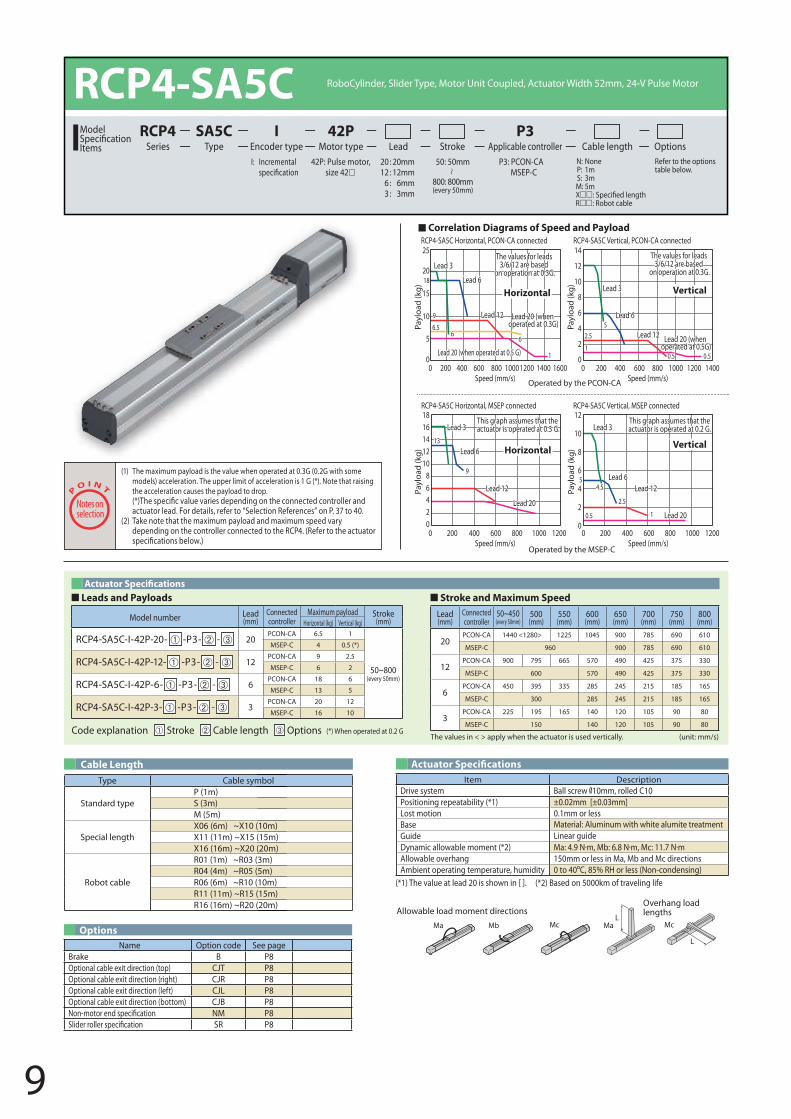
RCP4-SA5C RoboCylinder, Slider Type, Motor Unit Coupled, Actuator Width 52mm, 24-V Pulse Motor
42P: Pulse motor, size 42
I: Incremental P3: PCON-CAMSEP-C
N: None P: 1m S: 3m M: 5mXR: Robot cable
Refer to the options table below.
20 : 20mm 12 : 12mm
6 : 6mm3 : 3mm
Lead Stroke Cable length OptionsTypeSA5C
Encoder typeI
Motor type42P
Applicable controllerP3
SeriesRCP4Model
Items50: 50mm
800: 800mm(every 50mm)
(1) The maximum payload is the value when operated at 0.3G (0.2G with some models) acceleration. The upper limit of acceleration is 1 G (*). Note that raising the acceleration causes the payload to drop.
actuator lead. For details, refer to “Selection References” on P. 37 to 40. (2) Take note that the maximum payload and maximum speed vary
depending on the controller connected to the RCP4. (Refer to the actuator
Type Cable symbol
Standard typeP (1m)S (3m)M (5m)
Special lengthX06 (6m) ~X10 (10m)X11 (11m) ~X15 (15m)X16 (16m) ~X20 (20m)
Robot cable
R01 (1m) ~R03 (3m)R04 (4m) ~R05 (5m)R06 (6m) ~R10 (10m)R11 (11m) ~R15 (15m)R16 (16m) ~R20 (20m)
Cable Length Actuator Speci�cations
Options
(*1) The value at lead 20 is shown in [ ]. (*2) Based on 5000km of traveling life
Code explanation Stroke Cable length Options
Lead (mm)
Connected controller
50~450(every 50mm)
500 (mm)
550 (mm)
600 (mm)
650 (mm)
700 (mm)
750 (mm)
800 (mm)
20PCON-CA 1440 <1280> 1225 1045 900 785 690 610
MSEP-C 960 900 785 690 610
12PCON-CA 900 795 665 570 490 425 375 330
MSEP-C 600 570 490 425 375 330
6PCON-CA 450 395 335 285 245 215 185 165
MSEP-C 300 285 245 215 185 165
3PCON-CA 225 195 165 140 120 105 90 80
MSEP-C 150 140 120 105 90 80(*) When operated at 0.2 G
Model number Lead (mm)
Connected controller
Maximum payload Stroke(mm)Horizontal (kg) Vertical (kg)
RCP4-SA5C-I-42P-20- -P3- - 20PCON-CA 6.5 1
50~800(every 50mm)
MSEP-C 4 0.5 (*)
RCP4-SA5C-I-42P-12- -P3- - 12PCON-CA 9 2.5
MSEP-C 6 2
RCP4-SA5C-I-42P-6- -P3- - 6PCON-CA 18 6
MSEP-C 13 5
RCP4-SA5C-I-42P-3- -P3- - 3PCON-CA 20 12
MSEP-C 16 10
Name Option code See pageBrake B P8Optional cable exit direction (top) CJT P8Optional cable exit direction (right) CJR P8Optional cable exit direction (left) CJL P8Optional cable exit direction (bottom) CJB P8Non-motor end speci�cation NM P8Slider roller speci�cation SR P8
Item DescriptionDrive system Ball screw 10mm, rolled C10Positioning repeatability (*1) ±0.02mm [±0.03mm]Lost motion 0.1mm or lessBase Material: Aluminum with white alumite treatmentGuide Linear guideDynamic allowable moment (*2)Allowable overhang 150mm or less in Ma, Mb and Mc directions Ambient operating temperature, humidity 0 to 40 C, 85% RH or less (Non-condensing)
The values in < > apply when the actuator is used vertically. (unit: mm/s)
RCP4-SA5C Horizontal, PCON-CA connected RCP4-SA5C Vertical, PCON-CA connected
RCP4-SA5C Horizontal, MSEP connected RCP4-SA5C Vertical, MSEP connected
Horizontal
Horizontal Vertical
Vertical
Payl
oad
(kg)
Lead 3
Lead 3 Lead 3
Lead 3Lead 6
Lead 6
Lead 6
Lead 6
6
9
9
13
6.52.5
5
6
11
10.5
2.5
54.5
0.50.5
Lead 12
Lead 12 Lead 12
Lead 20Lead 20
Lead 12
The values for leads 3/6/12 are based
on operation at 0.3G.
This graph assumes that the actuator is operated at 0.3 G.
This graph assumes that theactuator is operated at 0.2 G.
Lead 20 (when operated at 0.3G)
0
5
10
15
1820
25
Payl
oad
(kg)
1816141210
86420
Payl
oad
(kg)
12
10
8
6
4
2
0
14
12
10
8
6
4
2
0
Payl
oad
(kg)
16001400 1400120010008006004002000Speed (mm/s)
120010008006004002000Speed (mm/s)
120010008006004002000Speed (mm/s)
120010008006004002000Speed (mm/s)
Lead 20 (when operated at 0.5G)
The values for leads 3/6/12 are based
on operation at 0.3G.
Lead 20 (when operated at 0.5 G)
Operated by the MSEP-C
Operated by the PCON-CA
Correlation Diagrams of Speed and Payload
L
L
Ma MaMb Mc Mc
Allowable load moment directionsOverhang load lengths
10
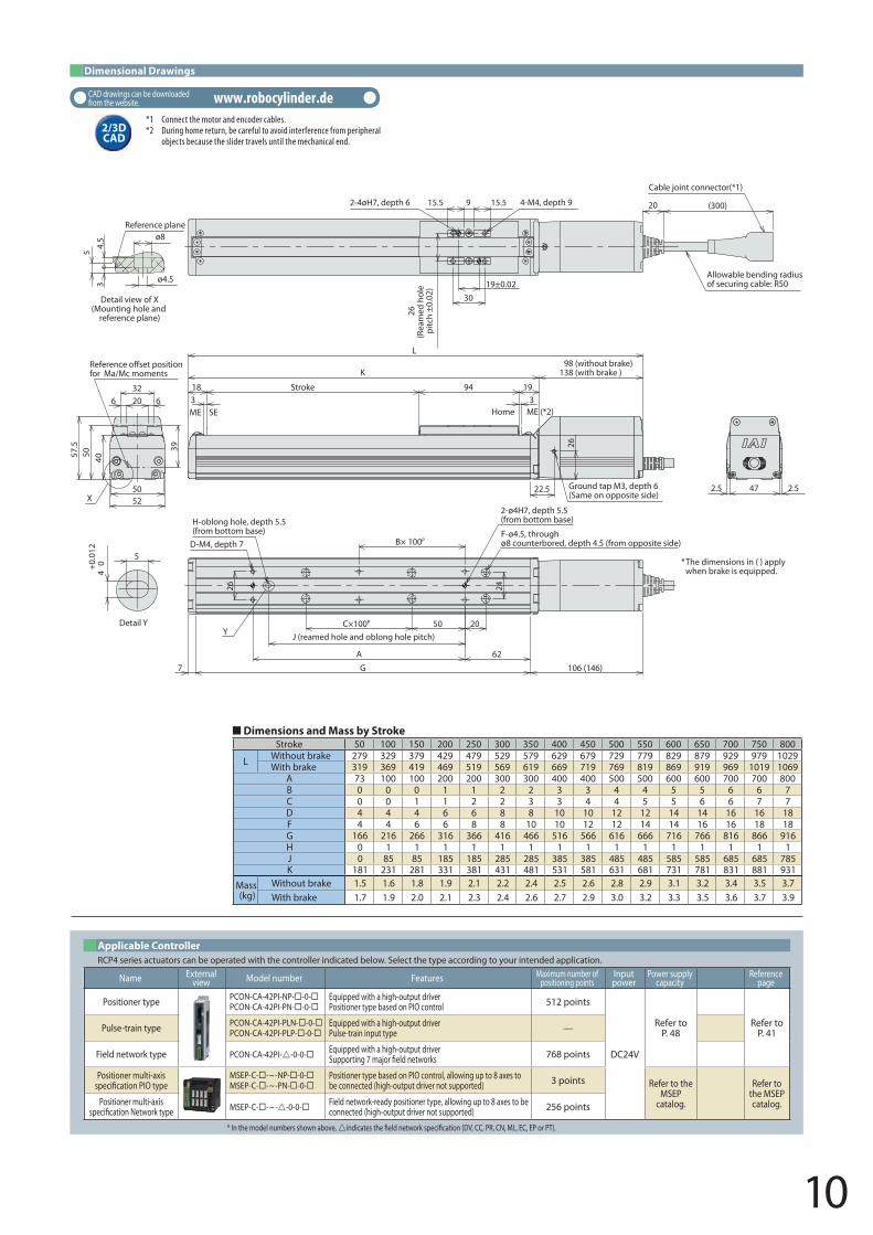
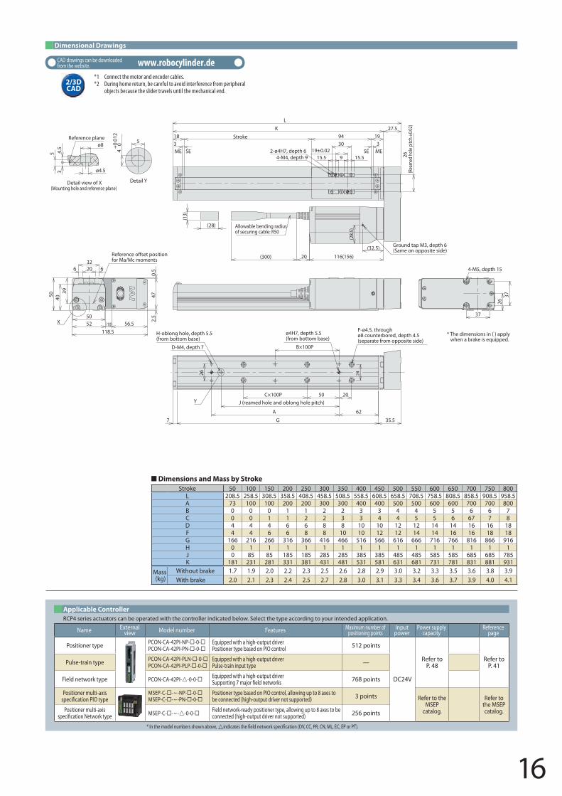
Dimensions and Mass by StrokeStroke 50 100 150 200 250 300 350 400 450 500 550 600 650 700 750 800
L Without brake 279 329 379 429 479 529 579 629 679 729 779 829 879 929 979 1029With brake 319 369 419 469 519 569 619 669 719 769 819 869 919 969 1019 1069
A 73 100 100 200 200 300 300 400 400 500 500 600 600 700 700 800B 0 0 0 1 1 2 2 3 3 4 4 5 5 6 6 7C 0 0 1 1 2 2 3 3 4 4 5 5 6 6 7 7D 4 4 4 6 6 8 8 10 10 12 12 14 14 16 16 18F 4 4 6 6 8 8 10 10 12 12 14 14 16 16 18 18G 166 216 266 316 366 416 466 516 566 616 666 716 766 816 866 916H 0 1 1 1 1 1 1 1 1 1 1 1 1 1 1 1J 0 85 85 185 185 285 285 385 385 485 485 585 585 685 685 785K 181 231 281 331 381 431 481 531 581 631 681 731 781 831 881 931
Mass (kg)
Without brake 1.5 1.6 1.8 1.9 2.1 2.2 2.4 2.5 2.6 2.8 2.9 3.1 3.2 3.4 3.5 3.7With brake 1.7 1.9 2.0 2.1 2.3 2.4 2.6 2.7 2.9 3.0 3.2 3.3 3.5 3.6 3.7 3.9
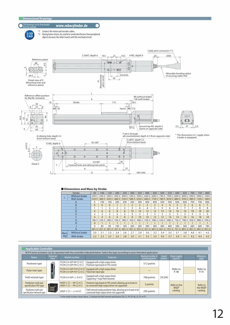
Dimensional Drawings
2/3D CAD
CAD drawings can be downloaded from the website. www.robocylinder.de
*1 Connect the motor and encoder cables.*2 During home return, be careful to avoid interference from peripheral
objects because the slider travels until the mechanical end.
* In the model numbers shown above, indicat twor ation (DV, CC, PR, CN, ML, EC, EP or PT).
RCP4 series actuators can be operated with the controller indicated below. Select the type according to your intended application.Applicable Controller
Name Externalview Model number Features Maximum number of
positioning pointsInputpower
Power supply capacity
Reference page
Positioner type PCON-CA-42PI-NP- -0-PCON-CA-42PI-PN- -0-
Equipped with a high-output driverPositioner type based on PIO control 512 points
DC24V
Refer to P. 48
Refer to P. 41Pulse-train type PCON-CA-42PI-PLN- -0-
PCON-CA-42PI-PLP- -0-Equipped with a high-output driverPulse-train input type —
Field network type PCON-CA-42PI--0-0- Equipped with a high-output driverSuppor tworks 768 points
Positioner multi-axis ation PIO type
MSEP-C- -~-NP- -0-MSEP-C- -~-PN- -0-
Positioner type based on PIO control, allowing up to 8 axes to be connected (high-output driver not supported) 3 points Refer to the
MSEP catalog.
Refer to the MSEP catalog.Positioner multi-axis
ation Network type MSEP-C- -~--0-0- Field network-ready positioner type, allowing up to 8 axes to be connected (high-output driver not supported) 256 points
B×
Y
X
* The dimensions in ( ) apply when brake is equipped.
3Stroke
318 94 19
98 (without brake) 138 (with brake )K
L
22.5
26
Ground tap M3, depth 6(Same on opposite side)
ME ME (*2)SE Home
9 15.515.5
26(R
eam
ed h
ole
pitc
h ±
0.02
) 19±0.0230
4-M4, depth 92-4øH7, depth 6 20 (300)
Allowable bending radiusof securing cable: R50
Cable joint connector(*1)
62
2050C×100P
A
G 106 (146)7
26 24
100PF-ø4.5, throughø8 counterbored, depth 4.5 (from opposite side)
2-ø4H7, depth 5.5(from bottom base)
D-M4, depth 7
H-oblong hole, depth 5.5(from bottom base)
J (reamed hole and oblong hole pitch)
47 2.52.5
39
5052
4057.5
50
20 6632
Refefor Ma/Mc moments
5
ø4.5
ø8
34.
5
Detail view of X(Mounting hole and
reference plane)
Reference plane
5
4+
0.01
2 0
Detail Y
11
Type Cable symbol
Standard typeP (1m)S (3m)M (5m)
Special lengthX06 (6m) ~X10 (10m)X11 (11m) ~X15 (15m)X16 (16m) ~X20 (20m)
Robot cable
R01 (1m) ~R03 (3m)R04 (4m) ~R05 (5m)R06 (6m) ~R10 (10m)R11 (11m) ~R15 (15m)R16 (16m) ~R20 (20m)
Cable Length Actuator Speci�cations
Options
(*1) The value at lead 20 is shown in [ ]. (*2) Based on 5000km of traveling life
Name Option code See pageBrake B P8Optional cable exit direction (top) CJT P8Optional cable exit direction (right) CJR P8Optional cable exit direction (left) CJL P8Optional cable exit direction (bottom) CJB P8Non-motor end speci�cation NM P8Slider roller speci�cation SR P8
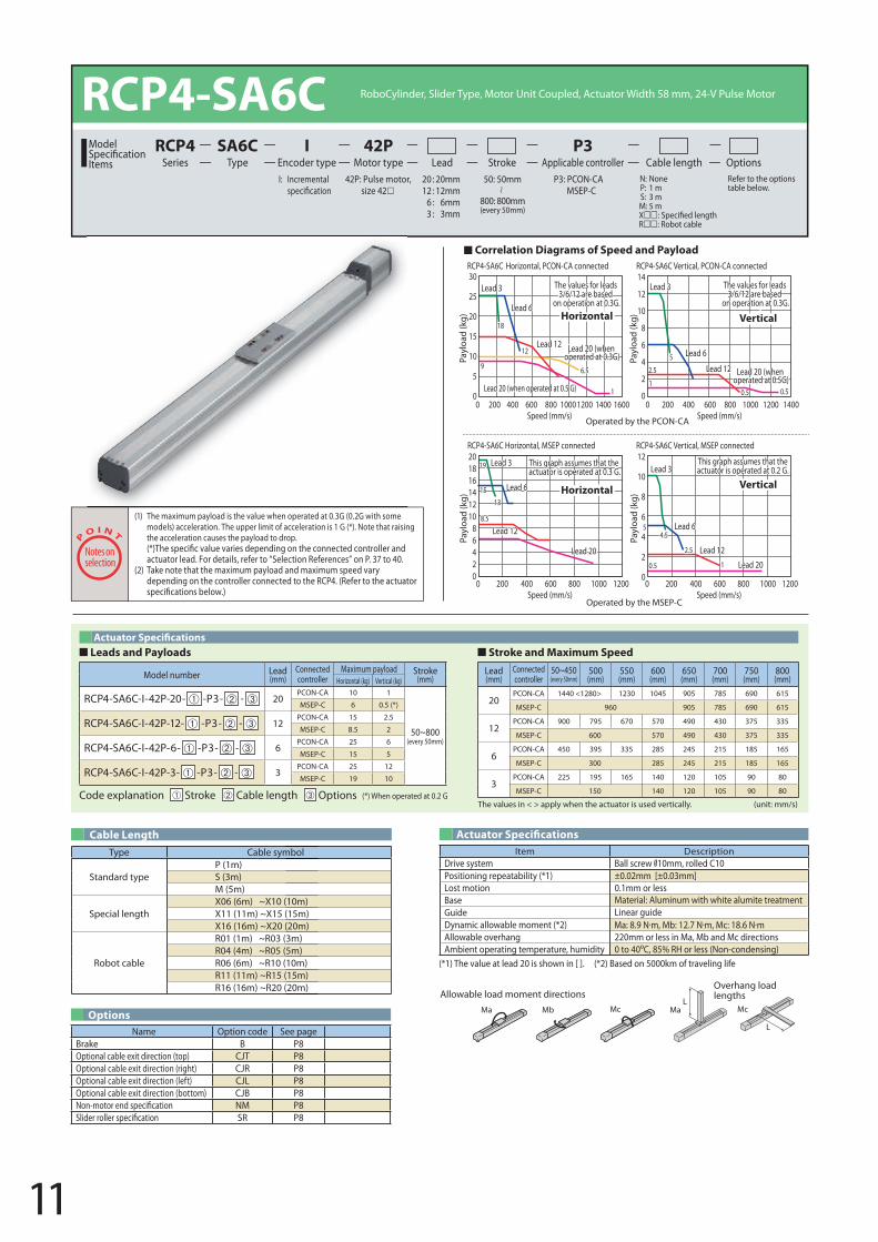
Item DescriptionDrive system Ball screw 10mm, rolled C10Positioning repeatability (*1) ±0.02mm [±0.03mm]Lost motion 0.1mm or lessBase Material: Aluminum with white alumite treatmentGuide Linear guideDynamic allowable moment (*2)Allowable overhang 220mm or less in Ma, Mb and Mc directions Ambient operating temperature, humidity 0 to 40 C, 85% RH or less (Non-condensing)
L
L
Ma MaMb Mc Mc
Allowable load moment directionsOverhang load lengths
RCP4-SA6C Horizontal, PCON-CA connected RCP4-SA6C Vertical, PCON-CA connected
RCP4-SA6C Horizontal, MSEP connected RCP4-SA6C Vertical, MSEP connected
16001400120010008006004002000Speed (mm/s)
1400120010008006004002000Speed (mm/s)
120010008006004002000Speed (mm/s)
120010008006004002000Speed (mm/s)
Payl
oad
(kg)
30
25
20
15
10
5
0
Lead 3
Lead 3Lead 3
Lead 3
Lead 6
Lead 6
Lead 6
Lead 6Lead 12
Lead 12
Lead 12
Lead 20Lead 20
Lead 12
Lead 20 (when operated at 0.3G)
1
6.59
12
18
Lead 20 (when operated at 0.5 G)
14
12
10
8
6
4
2
0
Payl
oad
(kg)
Lead 20 (when operated at 0.5G)
0.5 0.5
2.5
5
1
The values for leads 3/6/12 are based
on operation at 0.3G.
The values for leads 3/6/12 are based
on operation at 0.3G.Horizontal
Horizontal
Vertical
Vertical
This graph assumes that the actuator is operated at 0.3 G.
This graph assumes that theactuator is operated at 0.2 G.
10.5
8.5
15
19
13
4.5
2.5
Payl
oad
(kg)
201816141210
86420
5
Payl
oad
(kg)
12
10
8
6
4
2
0
Leads and Payloads Stroke and Maximum Speed
(1) The maximum payload is the value when operated at 0.3G (0.2G with some models) acceleration. The upper limit of acceleration is 1 G (*). Note that raising the acceleration causes the payload to drop.
actuator lead. For details, refer to “Selection References” on P. 37 to 40. (2) Take note that the maximum payload and maximum speed vary
depending on the controller connected to the RCP4. (Refer to the actuator
Code explanation Stroke Cable length Options
Lead (mm)
Connected controller
50~450(every 50mm)
500 (mm)
550 (mm)
600 (mm)
650 (mm)
700 (mm)
750 (mm)
800 (mm)
20PCON-CA 1440 <1280> 1230 1045 905 785 690 615
MSEP-C 960 905 785 690 615
12PCON-CA 900 795 670 570 490 430 375 335
MSEP-C 600 570 490 430 375 335
6PCON-CA 450 395 335 285 245 215 185 165
MSEP-C 300 285 245 215 185 165
3PCON-CA 225 195 165 140 120 105 90 80
MSEP-C 150 140 120 105 90 80(*) When operated at 0.2 G
Model number Lead (mm)
Connected controller
Maximum payload Stroke(mm)Horizontal (kg) Vertical (kg)
RCP4-SA6C-I-42P-20- -P3- - 20PCON-CA 10 1
50~800(every 50mm)
MSEP-C 6 0.5 (*)
RCP4-SA6C-I-42P-12- -P3- - 12PCON-CA 15 2.5
MSEP-C 8.5 2
RCP4-SA6C-I-42P-6- -P3- - 6PCON-CA 25 6
MSEP-C 15 5
RCP4-SA6C-I-42P-3- -P3- - 3PCON-CA 25 12
MSEP-C 19 10
The values in < > apply when the actuator is used vertically. (unit: mm/s)
Operated by the MSEP-C
Operated by the PCON-CA
Correlation Diagrams of Speed and Payload
RCP4-SA6C RoboCylinder, Slider Type, Motor Unit Coupled, Actuator Width 58 mm, 24-V Pulse Motor
42P: Pulse motor, size 42
I: Incremental P3: PCON-CAMSEP-C
N: None P: 1 m S: 3 m M: 5 mXR: Robot cable
Refer to the options table below.
20 : 20mm 12 : 12mm
6 : 6mm3 : 3mm
Lead Stroke Cable length OptionsTypeSA6C
Encoder typeI
Motor type42P
Applicable controllerP3
SeriesRCP4Model
Items50: 50mm
800: 800mm(every 50mm)
12
Dimensional Drawings
2D CAD2D
CAD*1 Connect the motor and encoder cables.*2 During home return, be careful to avoid interference from peripheral
objects because the slider travels until the mechanical end.
Stroke 50 100 150 200 250 300 350 400 450 500 550 600 650 700 750 800
L Without brake 299.5 349.5 399.5 449.5 499.5 549.5 599.5 649.5 699.5 749.5 799.5 849.5 899.5 949.5 999.5 1049.5 With brake 339.5 389.5 439.5 489.5 539.5 589.5 639.5 689.5 739.5 789.5 839.5 889.5 939.5 989.5 1039.5 1089.5
A 0 100 100 200 200 300 300 400 400 500 500 600 600 700 700 800B 0 0 0 1 1 2 2 3 3 4 4 5 5 6 6 7C 1 1 2 2 3 3 4 4 5 5 6 6 7 7 8 8D 4 6 6 8 8 10 10 12 12 14 14 16 16 18 18 20E 2 3 3 3 3 3 3 3 3 3 3 3 3 3 3 3F 4 4 6 6 8 8 10 10 12 12 14 14 16 16 18 18G 186.5 236.5 286.5 336.5 386.5 436.5 486.5 536.5 586.5 636.5 686.5 736.5 786.5 836.5 886.5 936.5H 0 1 1 1 1 1 1 1 1 1 1 1 1 1 1 1J 0 85 85 185 185 285 285 385 385 485 485 585 585 685 685 785K 201.5 251.5 301.5 351.5 401.5 451.5 501.5 551.5 601.5 651.5 701.5 751.5 801.5 851.5 901.5 951.5
Mass (kg)
Without brake 2.0 2.1 2.3 2.4 2.6 2.7 2.9 3.0 3.2 3.4 3.5 3.7 3.8 4.0 4.1 4.3 With brake 2.2 2.3 2.5 2.6 2.8 3.0 3.1 3.3 3.4 3.6 3.7 3.9 4.1 4.2 4.4 4.5
Dimensions and Mass by Stroke
Detail Y Y
X
* The dimensions in ( ) apply when a brake is equipped.
3Stroke
318
98 (without brake) 138 (with brake)
Ground tap M3, depth 6(Same on opposite side)
115 18.5K
L
22.5
28
ME ME (*2)SE Home
21 19.519.5
32±0.0250
31(R
eam
ed h
ole
pitc
h ±
0.02
)
4-M5, depth 92-5øH7, depth 6 20 (300)
Allowable bending radius of securing cable: R50
25
20
75A
J (reamed hole and oblong hole pitch)
31
G 106 (146)7
B×100PE-ø4H7, depth 5.5(from bottom base)
ø8 counterbored, depth 4.5 (from opposite side) F-ø4.5, through
D-M5, depth 9
H-oblong hole, depth 5.5(from bottom base)
CX100P
47 5.55.5
40
5658
434
5359.5
23 8839
Refefor Ma/Mc moments
ø4.5
ø8
54.
5
5
Detail view of X(Mounting hole and
reference plane)
Reference plane
+0.
012
0
5
Cable joint connector (*1)
* In the model numbers shown above, indicates the �eld network speci�cation (DV, CC, PR, CN, ML, EC, EP or PT).
RCP4 series actuators can be operated with the controller indicated below. Select the type according to your intended application.Applicable Controller
Name Externalview Model number Features Maximum number of
positioning pointsInputpower
Power supply capacity
Reference page
Positioner type PCON-CA-42PI-NP- -0-PCON-CA-42PI-PN- -0-
Equipped with a high-output driverPositioner type based on PIO control 512 points
DC24V
Refer to P. 48
Refer to P. 41Pulse-train type PCON-CA-42PI-PLN- -0-
PCON-CA-42PI-PLP- -0-Equipped with a high-output driverPulse-train input type —
Field network type PCON-CA-42PI--0-0- Equipped with a high-output driverSupporting 7 major �eld networks 768 points
Positioner multi-axis speci�cation PIO type
MSEP-C- -~-NP- -0-MSEP-C- -~-PN- -0-
Positioner type based on PIO control, allowing up to 8 axes to be connected (high-output driver not supported) 3 points Refer to the
MSEP catalog.
Refer to the MSEP catalog.Positioner multi-axis
speci�cation Network type MSEP-C- -~--0-0- Field network-ready positioner type, allowing up to 8 axes to be connected (high-output driver not supported) 256 points
2/3D CAD
CAD drawings can be downloaded from the website. www.robocylinder.de
13
Type Cable symbol
Standard typeP (1m)S (3m)M (5m)
Special lengthX06 (6m) ~X10 (10m)X11 (11m) ~X15 (15m)X16 (16m) ~X20 (20m)
Robot cable
R01 (1m) ~R03 (3m)R04 (4m) ~R05 (5m)R06 (6m) ~R10 (10m)R11 (11m) ~R15 (15m)R16 (16m) ~R20 (20m)
Cable Length Actuator Speci�cations
Options
(*1) The value at lead 24 is shown in [ ]. (*2) Based on 5000km of traveling life
Name Option code See pageBrake B P8Optional cable exit direction (top) CJT P8Optional cable exit direction (right) CJR P8Optional cable exit direction (left) CJL P8Optional cable exit direction (bottom) CJB P8Non-motor end speci�cation NM P8Slider roller speci�cation SR P8
Item DescriptionDrive system Ball screw 12mm, rolled C10Positioning repeatability (*1) ±0.02mm [±0.03mm]Lost motion 0.1mm or lessBase Material: Aluminum with white alumite treatmentGuide Linear guideDynamic allowable moment (*2)Allowable overhang 230mm or less in Ma, Mb and Mc directions Ambient operating temperature, humidity 0 to 40 C, 85% RH or less (Non-condensing)
L
L
Ma MaMb Mc Mc
Allowable load moment directionsOverhang load lengths
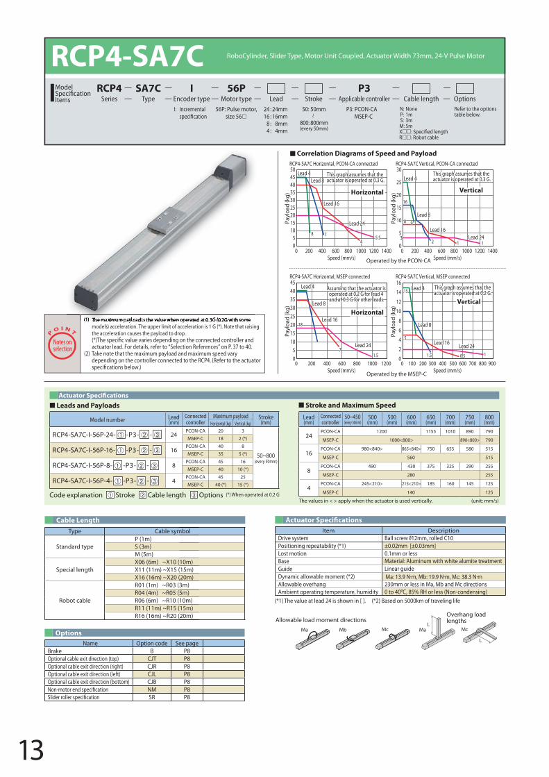
RCP4-SA7C Horizontal, PCON-CA connected RCP4-SA7C Vertical, PCON-CA connected
RCP4-SA7C Horizontal, MSEP connected RCP4-SA7C Vertical, MSEP connected
This graph assumes that the actuator is operated at 0.3 G.
This graph assumes that the actuator is operated at 0.3 G.
Horizontal
Horizontal
Vertical
Vertical
Assuming that the actuator is operated at 0.2 G for lead 4 and at 0.3 G for other leads.
This graph assumes that theactuator is operated at 0.2 G.
120010008006004002000Speed (mm/s)
600 700 800 900500400200 3001000Speed (mm/s)
1400120010008006004002000Speed (mm/s)
1400120010008006004002000Speed (mm/s)
Lead 4Lead 4
Lead 4Lead 4
Lead 8
Lead 8
Lead 8
Lead 8
Lead 16
Lead 16
Lead 16
Lead 16
Lead 24
Lead 24 Lead 24
Lead 248
18
8
3
7
7
9
16
45.5
12 1
10.51.5
5
1.5
15Pa
yloa
d (k
g)
504540353025201510
50
Payl
oad
(kg)
4540353025201510
50
Payl
oad
(kg)
30
25
20
15
10
5
0
Payl
oad
(kg)
16
14
12
10
8
6
4
2
0
RCP4-SA7C RoboCylinder, Slider Type, Motor Unit Coupled, Actuator Width 73mm, 24-V Pulse Motor
56P: Pulse motor, size 56
I: Incremental P3: PCON-CAMSEP-C
N: None P: 1m S: 3m M: 5mXR: Robot cable
Refer to the optionstable below.
24 : 24mm 16 : 16mm
8 : 8mm4 : 4mm
Lead Stroke Cable length OptionsTypeSA7C
Encoder typeI
Motor type56P
Applicable controllerP3
SeriesRCP4Model
Items50: 50mm
800: 800mm(every 50mm)
Leads and Payloads Stroke and Maximum Speed
(1) The maximum payload is the value when operated at 0.3G (0.2G with some models) acceleration. The upper limit of acceleration is 1 G (*). Note that raising the acceleration causes the payload to drop.
actuator lead. For details, refer to “Selection References” on P. 37 to 40. (2) Take note that the maximum payload and maximum speed vary
depending on the controller connected to the RCP4. (Refer to the actuator
Code explanation Stroke Cable length Options (*) When operated at 0.2 G
Model number Lead (mm)
Connected controller
Maximum payload Stroke(mm)Horizontal (kg) Vertical (kg)
RCP4-SA7C-I-56P-24- -P3- - 24PCON-CA 20 3
50~800(every 50mm)
MSEP-C 18 2 (*)
RCP4-SA7C-I-56P-16- -P3- - 16PCON-CA 40 8
MSEP-C 35 5 (*)
RCP4-SA7C-I-56P-8- -P3- - 8PCON-CA 45 16
MSEP-C 40 10 (*)
RCP4-SA7C-I-56P-4- -P3- - 4PCON-CA 45 25
MSEP-C 40 (*) 15 (*)
Lead (mm)
Connected controller
50~450(every 50mm)
500 (mm)
500 (mm)
600 (mm)
650 (mm)
700 (mm)
750 (mm)
800 (mm)
24PCON-CA 1200 1155 1010 890 790
MSEP-C 1000<800> 890<800> 790
16PCON-CA 980<840> 865<840> 750 655 580 515
MSEP-C 560 515
8PCON-CA 490 430 375 325 290 255
MSEP-C 280 255
4PCON-CA 245<210> 215<210> 185 160 145 125
MSEP-C 140 125
The values in < > apply when the actuator is used vertically. (unit: mm/s)
(1) The maximum payload is the value when operated at 0 3G (0 2G with some
Operated by the MSEP-C
Operated by the PCON-CA
Correlation Diagrams of Speed and Payload
14
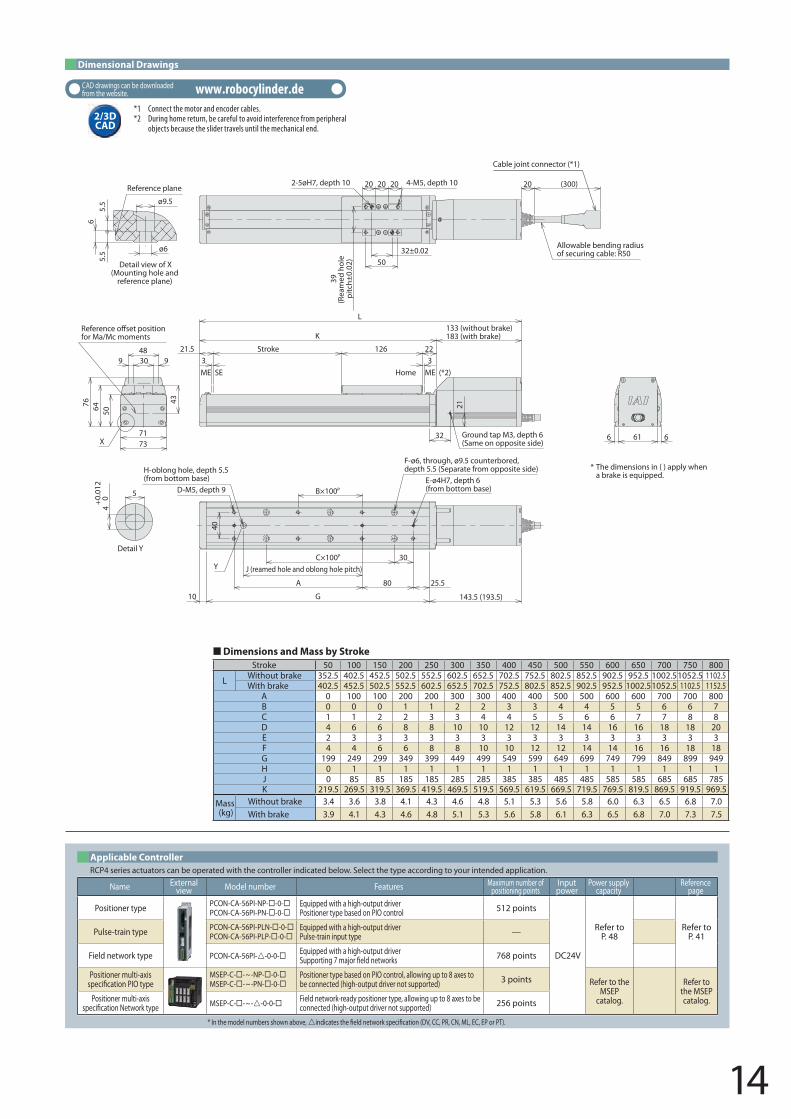
Dimensional Drawings
*1 Connect the motor and encoder cables.*2 During home return, be careful to avoid interference from peripheral
objects because the slider travels until the mechanical end.
Stroke 50 100 150 200 250 300 350 400 450 500 550 600 650 700 750 800
L Without brake 352.5 402.5 452.5 502.5 552.5 602.5 652.5 702.5 752.5 802.5 852.5 902.5 952.5 1002.5 1052.5 1102.5 With brake 402.5 452.5 502.5 552.5 602.5 652.5 702.5 752.5 802.5 852.5 902.5 952.5 1002.5 1052.5 1102.5 1152.5
A 0 100 100 200 200 300 300 400 400 500 500 600 600 700 700 800B 0 0 0 1 1 2 2 3 3 4 4 5 5 6 6 7C 1 1 2 2 3 3 4 4 5 5 6 6 7 7 8 8D 4 6 6 8 8 10 10 12 12 14 14 16 16 18 18 20E 2 3 3 3 3 3 3 3 3 3 3 3 3 3 3 3F 4 4 6 6 8 8 10 10 12 12 14 14 16 16 18 18G 199 249 299 349 399 449 499 549 599 649 699 749 799 849 899 949H 0 1 1 1 1 1 1 1 1 1 1 1 1 1 1 1J 0 85 85 185 185 285 285 385 385 485 485 585 585 685 685 785K 219.5 269.5 319.5 369.5 419.5 469.5 519.5 569.5 619.5 669.5 719.5 769.5 819.5 869.5 919.5 969.5
Mass (kg)
Without brake 3.4 3.6 3.8 4.1 4.3 4.6 4.8 5.1 5.3 5.6 5.8 6.0 6.3 6.5 6.8 7.0 With brake 3.9 4.1 4.3 4.6 4.8 5.1 5.3 5.6 5.8 6.1 6.3 6.5 6.8 7.0 7.3 7.5
Dimensions and Mass by Stroke
* In the model numbers shown above, indicates the �eld network speci�cation (DV, CC, PR, CN, ML, EC, EP or PT).
RCP4 series actuators can be operated with the controller indicated below. Select the type according to your intended application.Applicable Controller
Name Externalview Model number Features Maximum number of
positioning pointsInputpower
Power supply capacity
Reference page
Positioner type PCON-CA-56PI-NP- -0-PCON-CA-56PI-PN- -0-
Equipped with a high-output driverPositioner type based on PIO control 512 points
DC24V
Refer to P. 48
Refer to P. 41Pulse-train type PCON-CA-56PI-PLN- -0-
PCON-CA-56PI-PLP- -0-Equipped with a high-output driverPulse-train input type —
Field network type PCON-CA-56PI--0-0- Equipped with a high-output driverSupporting 7 major �eld networks 768 points
Positioner multi-axis speci�cation PIO type
MSEP-C- -~-NP- -0-MSEP-C- -~-PN- -0-
Positioner type based on PIO control, allowing up to 8 axes to be connected (high-output driver not supported) 3 points Refer to the
MSEP catalog.
Refer to the MSEP catalog.Positioner multi-axis
speci�cation Network type MSEP-C- -~--0-0- Field network-ready positioner type, allowing up to 8 axes to be connected (high-output driver not supported) 256 points
20
Y
X
* The dimensions in ( ) apply when a brake is equipped.
3Stroke
321.5
32
21
22
133 (without brake)183 (with brake)
126
K
L
Ground tap M3, depth 6(Same on opposite side)
ME ME (*2)SE Home
20 20
32±0.0250
39(R
eam
ed h
ole
pitc
h±0.
02)
4-M5, depth 102-5øH7, depth 10 20 (300)
Allowable bending radius of securing cable: R50
25.5
30
G
F-ø6, through, ø9.5 counterbored, depth 5.5 (Separate from opposite side)
C×100P
J (reamed hole and oblong hole pitch)
80A
10 143.5 (193.5)
B×100P
40
D-M5, depth 9
H-oblong hole, depth 5.5(from bottom base) E-ø4H7, depth 6
(from bottom base)
61 66
43
7173
9 30 948
506476
Refefor Ma/Mc moments
40+0.
012
5
Detail Y
5.5
5.5
ø6
ø9.5
6
Detail view of X(Mounting hole and
reference plane)
Reference plane
Cable joint connector (*1)
2/3D CAD
CAD drawings can be downloaded from the website. www.robocylinder.de
15
This graph assumes that the actuator is operated at 0.3 G.
This graph assumes that the actuator is operated at 0.3 G.
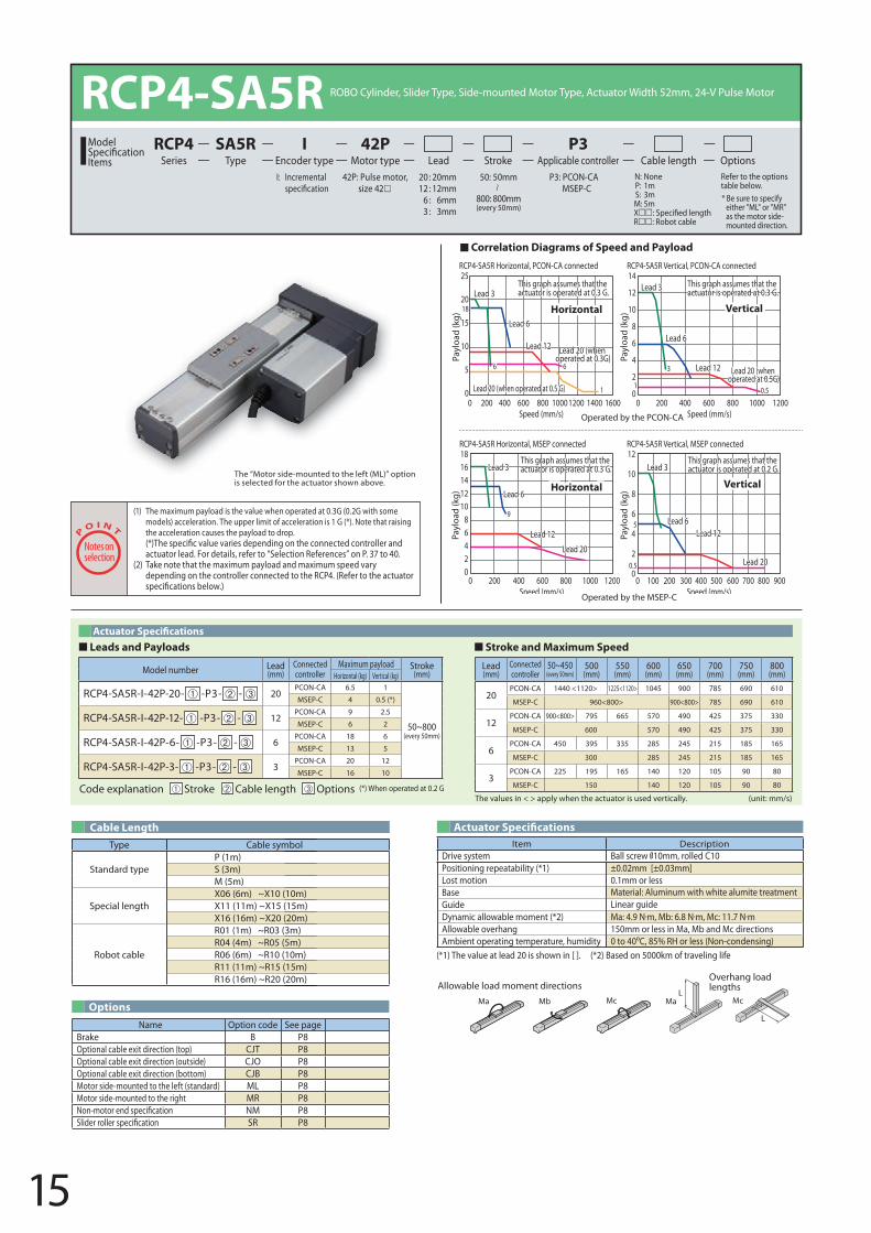
RCP4-SA5R Horizontal, PCON-CA connected RCP4-SA5R Vertical, PCON-CA connected
RCP4-SA5R Horizontal, MSEP connected RCP4-SA5R Vertical, MSEP connected
Horizontal
Horizontal
Vertical
Vertical
Lead 3
Lead 6
Lead 12 Lead 20 (when operated at 0.3G)
6
1
6
Lead 20 (when operated at 0.5 G)
Lead 20 (when operated at 0.5G)
3 Lead 12
Lead 6
Lead 3
0.5
14
12
10
8
6
4
2
0
Payl
oad
(kg)
1
18
16001400120010008006004002000Speed (mm/s)
120010008006004002000Speed (mm/s)
Payl
oad
(kg)
25
20
15
10
5
0
Payl
oad
(kg)
1816141210
86420
120010008006004002000Speed (mm/s)
800 900500300 600 700400100 2000Speed (mm/s)
Lead 20Lead 20
Lead 12Lead 12Lead 6
Lead 6
Lead 3Lead 3This graph assumes that theactuator is operated at 0.2 G.
This graph assumes that the actuator is operated at 0.3 G.
9
0.5
5
Payl
oad
(kg)
12
10
8
6
4
2
0
Leads and Payloads Stroke and Maximum Speed
(1) The maximum payload is the value when operated at 0.3G (0.2G with some models) acceleration. The upper limit of acceleration is 1 G (*). Note that raising the acceleration causes the payload to drop.
actuator lead. For details, refer to “Selection References” on P. 37 to 40. (2) Take note that the maximum payload and maximum speed vary
depending on the controller connected to the RCP4. (Refer to the actuator
Options
Code explanation Stroke Cable length Options (*) When operated at 0.2 G
Model number Lead (mm)
Connected controller
Maximum payload Stroke(mm)Horizontal (kg) Vertical (kg)
RCP4-SA5R-I-42P-20- -P3- - 20PCON-CA 6.5 1
50~800(every 50mm)
MSEP-C 4 0.5 (*)
RCP4-SA5R-I-42P-12- -P3- - 12PCON-CA 9 2.5
MSEP-C 6 2
RCP4-SA5R-I-42P-6- -P3- - 6PCON-CA 18 6
MSEP-C 13 5
RCP4-SA5R-I-42P-3- -P3- - 3PCON-CA 20 12
MSEP-C 16 10
Name Option code See pageBrake B P8Optional cable exit direction (top) CJT P8Optional cable exit direction (outside) CJO P8Optional cable exit direction (bottom) CJB P8Motor side-mounted to the left (standard) ML P8Motor side-mounted to the right MR P8Non-motor end speci�cation NM P8Slider roller speci�cation SR P8
Lead (mm)
Connected controller
50~450(every 50mm)
500 (mm)
550(mm)
600 (mm)
650 (mm)
700 (mm)
750 (mm)
800 (mm)
20PCON-CA 1440 <1120> 1225<1120> 1045 900 785 690 610
MSEP-C 960<800> 900<800> 785 690 610
12PCON-CA 900<800> 795 665 570 490 425 375 330
MSEP-C 600 570 490 425 375 330
6PCON-CA 450 395 335 285 245 215 185 165
MSEP-C 300 285 245 215 185 165
3PCON-CA 225 195 165 140 120 105 90 80
MSEP-C 150 140 120 105 90 80
The values in < > apply when the actuator is used vertically. (unit: mm/s)
The “Motor side-mounted to the left (ML)” option is selected for the actuator shown above.
RCP4-SA5R ROBO Cylinder, Slider Type, Side-mounted Motor Type, Actuator Width 52mm, 24-V Pulse Motor 42P: Pulse motor,
size 42I: Incremental P3: PCON-CA
MSEP-C N: None P: 1m S: 3m M: 5mXR: Robot cable
Refer to the options table below.
20 : 20mm 12 : 12mm
6 : 6mm3 : 3mm
Lead Stroke Cable length OptionsTypeSA5R
Encoder typeI
Motor type42P
Applicable controllerP3
SeriesRCP4Model
Items50: 50mm
800: 800mm(every 50mm)
* Be sure to specify either "ML" or "MR" as the motor side-mounted direction.
Operated by the MSEP-C
Operated by the PCON-CA
Correlation Diagrams of Speed and Payload
Type Cable symbol
Standard typeP (1m)S (3m)M (5m)
Special lengthX06 (6m) ~X10 (10m)X11 (11m) ~X15 (15m)X16 (16m) ~X20 (20m)
Robot cable
R01 (1m) ~R03 (3m)R04 (4m) ~R05 (5m)R06 (6m) ~R10 (10m)R11 (11m) ~R15 (15m)R16 (16m) ~R20 (20m)
Cable Length Actuator Speci�cations
(*1) The value at lead 20 is shown in [ ]. (*2) Based on 5000km of traveling life
Item DescriptionDrive system Ball screw 10mm, rolled C10Positioning repeatability (*1) ±0.02mm [±0.03mm]Lost motion 0.1mm or lessBase Material: Aluminum with white alumite treatmentGuide Linear guideDynamic allowable moment (*2)Allowable overhang 150mm or less in Ma, Mb and Mc directions Ambient operating temperature, humidity 0 to 40 C, 85% RH or less (Non-condensing)
L
L
Ma MaMb Mc Mc
Allowable load moment directionsOverhang load lengths
16
Dimensional Drawings
24
Reference plane
53
4.5
ø4.5
ø8
Detail view of X(Mounting hole and reference plane)
40+0.
012
5
Detail Y
Stroke183
L
4-M4, depth 9ME SE
K
394 19
27.5
30
9 15.515.519±0.02 MESE
26(R
eam
ed h
ole p
itch
±0.02
)
(28)
(13)
(28.
5)
20(300)
(32.5)
116(156)
Ground tap M3, depth 6(Same on opposite side)
Allowable bending radius of securing cable: R50
X
39
5052
4050
20 6632
0.5
472.
5
56.5118.5
Refefor Ma/Mc moments
(10)
Y
* The dimensions in ( ) apply when a brake is equipped.
G7 35.5
D-M4, depth 7
H-oblong hole, depth 5.5(from bottom base)
J (reamed hole and oblong hole pitch)
ø4H7, depth 5.5(from bottom base)
F-ø4.5, throughø8 counterbored, depth 4.5(separate from opposite side)
B×100P
26
C×100P 50 20
62A
37
3726
4-M5, depth 15
2-ø4H7, depth 6
Dimensions and Mass by StrokeStroke 50 100 150 200 250 300 350 400 450 500 550 600 650 700 750 800
L 208.5 258.5 308.5 358.5 408.5 458.5 508.5 558.5 608.5 658.5 708.5 758.5 808.5 858.5 908.5 958.5A 73 100 100 200 200 300 300 400 400 500 500 600 600 700 700 800B 0 0 0 1 1 2 2 3 3 4 4 5 5 6 6 7C 0 0 1 1 2 2 3 3 4 4 5 5 6 67 7 8D 4 4 4 6 6 8 8 10 10 12 12 14 14 16 16 18F 4 4 6 6 8 8 10 10 12 12 14 14 16 16 18 18G 166 216 266 316 366 416 466 516 566 616 666 716 766 816 866 916H 0 1 1 1 1 1 1 1 1 1 1 1 1 1 1 1J 0 85 85 185 185 285 285 385 385 485 485 585 585 685 685 785K 181 231 281 331 381 431 481 531 581 631 681 731 781 831 881 931
Mass (kg)
Without brake 1.7 1.9 2.0 2.2 2.3 2.5 2.6 2.8 2.9 3.0 3.2 3.3 3.5 3.6 3.8 3.9With brake 2.0 2.1 2.3 2.4 2.5 2.7 2.8 3.0 3.1 3.3 3.4 3.6 3.7 3.9 4.0 4.1
* In the model numbers shown above, indicates the �eld network speci�cation (DV, CC, PR, CN, ML, EC, EP or PT).
RCP4 series actuators can be operated with the controller indicated below. Select the type according to your intended application.Applicable Controller
Name Externalview Model number Features Maximum number of
positioning pointsInputpower
Power supply capacity
Reference page
Positioner type PCON-CA-42PI-NP- -0-PCON-CA-42PI-PN- -0-
Equipped with a high-output driverPositioner type based on PIO control 512 points
DC24V
Refer to P. 48
Refer to P. 41Pulse-train type PCON-CA-42PI-PLN- -0-
PCON-CA-42PI-PLP- -0-Equipped with a high-output driverPulse-train input type —
Field network type PCON-CA-42PI--0-0- Equipped with a high-output driverSupporting 7 major �eld networks 768 points
Positioner multi-axis speci�cation PIO type
MSEP-C- -~-NP- -0-MSEP-C- -~-PN- -0-
Positioner type based on PIO control, allowing up to 8 axes to be connected (high-output driver not supported) 3 points Refer to the
MSEP catalog.
Refer to the MSEP catalog.Positioner multi-axis
speci�cation Network type MSEP-C- -~--0-0- Field network-ready positioner type, allowing up to 8 axes to be connected (high-output driver not supported) 256 points
*1 Connect the motor and encoder cables.*2 During home return, be careful to avoid interference from peripheral
objects because the slider travels until the mechanical end. 2/3D CAD
CAD drawings can be downloaded from the website. www.robocylinder.de
17
RCP4-SA6R Horizontal, PCON-CA connected
This graph assumes that the actuator is operated at 0.3 G.
This graph assumes that the actuator is operated at 0.3 G.
This graph assumes that the actuator is operated at 0.2 G.
This graph assumes that the actuator is operated at 0.3 G.
Horizontal
Horizontal
RCP4-SA6R Vertical, PCON-CA connected
Vertical
Vertical
RCP4-SA6R Horizontal, MSEP connected RCP4-SA6R Vertical, MSEP connected
Lead 3
Lead 3 Lead 3
Lead 3
Lead 6
Lead 6
Lead 6
Lead 6Lead 12
Lead 12
Lead 12Lead 12
Lead 20Lead 20
Lead 20 (when operated at 0.5G) Lead 20 (when
operated at 0.5G)
Lead 20 (when operated at 0.3G)
1.5
0.5
13
8.5
0.5
5
19
15
14
6 3
12
18
14
12
10
8
6
4
2
0
Payl
oad
(kg)
120010008006004002000Speed (mm/s)
1400120010008006004002000Speed (mm/s)
Payl
oad
(kg)
30
25
20
15
10
5
0
Payl
oad
(kg)
201816141210
86420
120010008006004002000Speed (mm/s)
800 900500300 600 700400100 2000Speed (mm/s)
Payl
oad
(kg)
12
10
8
6
4
2
0
Operated by the MSEP-C
Operated by the PCON-CA
Correlation Diagrams of Speed and Payload
The values in < > apply when the actuator is used vertically. (unit: mm/s)
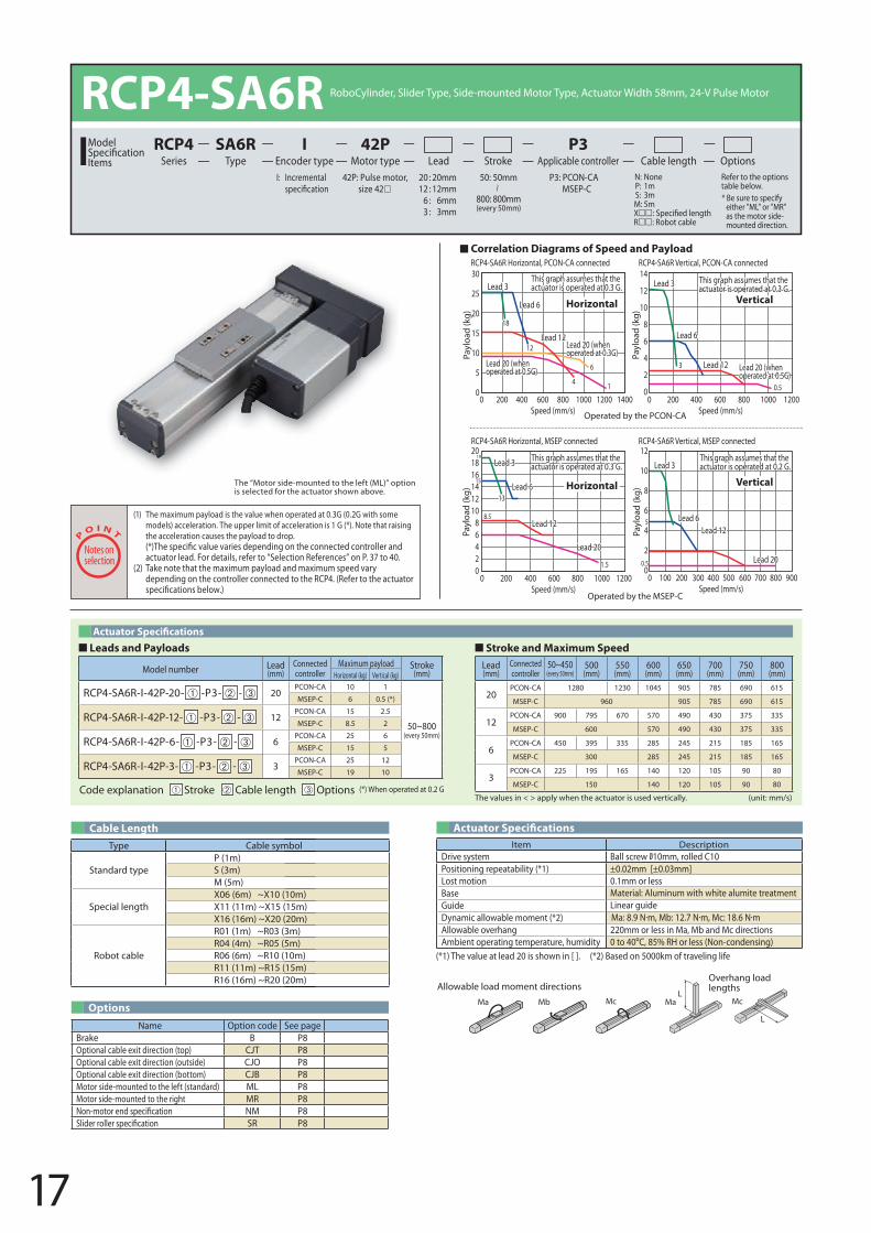
Leads and Payloads Stroke and Maximum Speed
Code explanation Stroke Cable length Options (*) When operated at 0.2 G
Model number Lead (mm)
Connected controller
Maximum payload Stroke(mm)Horizontal (kg) Vertical (kg)
RCP4-SA6R-I-42P-20- -P3- - 20PCON-CA 10 1
50~800(every 50mm)
MSEP-C 6 0.5 (*)
RCP4-SA6R-I-42P-12- -P3- - 12PCON-CA 15 2.5
MSEP-C 8.5 2
RCP4-SA6R-I-42P-6- -P3- - 6PCON-CA 25 6
MSEP-C 15 5
RCP4-SA6R-I-42P-3- -P3- - 3PCON-CA 25 12
MSEP-C 19 10
Lead (mm)
Connected controller
50~450(every 50mm)
500 (mm)
550 (mm)
600 (mm)
650 (mm)
700 (mm)
750 (mm)
800 (mm)
20PCON-CA 1280 1230 1045 905 785 690 615
MSEP-C 960 905 785 690 615
12PCON-CA 900 795 670 570 490 430 375 335
MSEP-C 600 570 490 430 375 335
6PCON-CA 450 395 335 285 245 215 185 165
MSEP-C 300 285 245 215 185 165
3PCON-CA 225 195 165 140 120 105 90 80
MSEP-C 150 140 120 105 90 80
The “Motor side-mounted to the left (ML)” option is selected for the actuator shown above.
RCP4-SA6R RoboCylinder, Slider Type, Side-mounted Motor Type, Actuator Width 58mm, 24-V Pulse Motor
42P: Pulse motor, size 42
I: Incremental P3: PCON-CAMSEP-C
N: None P: 1m S: 3m M: 5mXR: Robot cable
Refer to the options table below.
20 : 20mm 12 : 12mm
6 : 6mm3 : 3mm
Lead Stroke Cable length OptionsTypeSA6R
Encoder typeI
Motor type42P
Applicable controllerP3
SeriesRCP4Model
Items50: 50mm
800: 800mm(every 50mm)
* Be sure to specify either "ML" or "MR" as the motor side-mounted direction.
(1) The maximum payload is the value when operated at 0.3G (0.2G with some models) acceleration. The upper limit of acceleration is 1 G (*). Note that raising the acceleration causes the payload to drop.
actuator lead. For details, refer to “Selection References” on P. 37 to 40. (2) Take note that the maximum payload and maximum speed vary
depending on the controller connected to the RCP4. (Refer to the actuator
OptionsName Option code See page
Brake B P8Optional cable exit direction (top) CJT P8Optional cable exit direction (outside) CJO P8Optional cable exit direction (bottom) CJB P8Motor side-mounted to the left (standard) ML P8Motor side-mounted to the right MR P8Non-motor end speci�cation NM P8Slider roller speci�cation SR P8
Type Cable symbol
Standard typeP (1m)S (3m)M (5m)
Special lengthX06 (6m) ~X10 (10m)X11 (11m) ~X15 (15m)X16 (16m) ~X20 (20m)
Robot cable
R01 (1m) ~R03 (3m)R04 (4m) ~R05 (5m)R06 (6m) ~R10 (10m)R11 (11m) ~R15 (15m)R16 (16m) ~R20 (20m)
Cable Length Actuator Speci�cations
(*1) The value at lead 20 is shown in [ ]. (*2) Based on 5000km of traveling life
Item DescriptionDrive system Ball screw 10mm, rolled C10Positioning repeatability (*1) ±0.02mm [±0.03mm]Lost motion 0.1mm or lessBase Material: Aluminum with white alumite treatmentGuide Linear guideDynamic allowable moment (*2)Allowable overhang 220mm or less in Ma, Mb and Mc directions Ambient operating temperature, humidity 0 to 40 C, 85% RH or less (Non-condensing)
L
L
Ma MaMb Mc Mc
Allowable load moment directionsOverhang load lengths
18
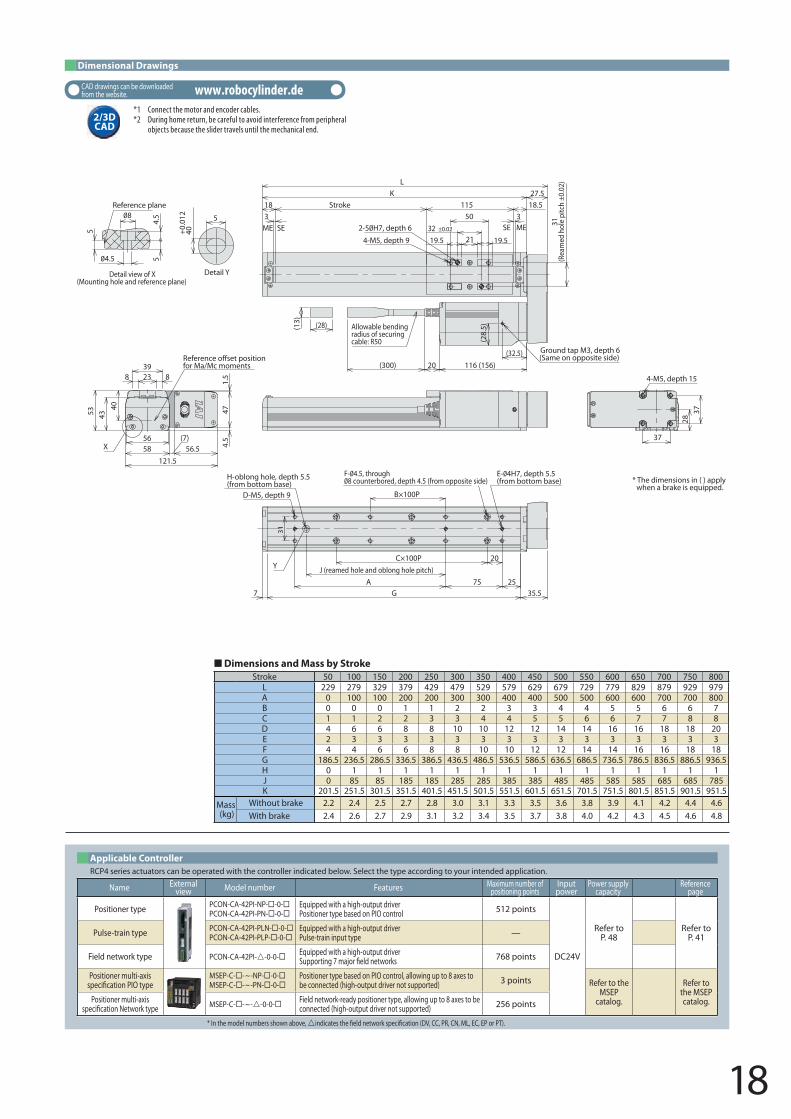
Dimensions and Mass by Stroke
31
54.
5
5
Detail view of X(Mounting hole and reference plane)
40+0.
012
5
Detail Y
Reference plane Stroke3 318
21 19.519.5
50
4-M5, depth 9
115 18.5K 27.5
L
31(R
eam
ed h
ole
pitc
h ±0
.02)
ME SE
Reffor Ma/Mc moments
SE ME
(28)(13)
20(300) 116 (156)
(28.
5)
(32.5) Ground tap M3, depth 6(Same on opposite side)
Allowable bending radius of securing cable: R50
3728
37
4-M5, depth 15
* The dimensions in ( ) apply when a brake is equipped.
E- 4H7, depth 5.5(from bottom base)H-oblong hole, depth 5.5
(from bottom base)D-M5, depth 9
G7 35.5
B×100P
C×100P 20J (reamed hole and oblong hole pitch)
75 25A
Y
40
5658
4353
23 8839
(7)56.5
121.5
4.5
471.
5
X
32 ±0.02±0.02
Stroke 50 100 150 200 250 300 350 400 450 500 550 600 650 700 750 800L 229 279 329 379 429 479 529 579 629 679 729 779 829 879 929 979A 0 100 100 200 200 300 300 400 400 500 500 600 600 700 700 800B 0 0 0 1 1 2 2 3 3 4 4 5 5 6 6 7C 1 1 2 2 3 3 4 4 5 5 6 6 7 7 8 8D 4 6 6 8 8 10 10 12 12 14 14 16 16 18 18 20E 2 3 3 3 3 3 3 3 3 3 3 3 3 3 3 3F 4 4 6 6 8 8 10 10 12 12 14 14 16 16 18 18G 186.5 236.5 286.5 336.5 386.5 436.5 486.5 536.5 586.5 636.5 686.5 736.5 786.5 836.5 886.5 936.5H 0 1 1 1 1 1 1 1 1 1 1 1 1 1 1 1J 0 85 85 185 185 285 285 385 385 485 485 585 585 685 685 785K 201.5 251.5 301.5 351.5 401.5 451.5 501.5 551.5 601.5 651.5 701.5 751.5 801.5 851.5 901.5 951.5
Mass (kg)
Without brake 2.2 2.4 2.5 2.7 2.8 3.0 3.1 3.3 3.5 3.6 3.8 3.9 4.1 4.2 4.4 4.6With brake 2.4 2.6 2.7 2.9 3.1 3.2 3.4 3.5 3.7 3.8 4.0 4.2 4.3 4.5 4.6 4.8
Dimensional Drawings
* In the model numbers shown above, indicates the �eld network speci�cation (DV, CC, PR, CN, ML, EC, EP or PT).
RCP4 series actuators can be operated with the controller indicated below. Select the type according to your intended application.Applicable Controller
Name Externalview Model number Features Maximum number of
positioning pointsInputpower
Power supply capacity
Reference page
Positioner type PCON-CA-42PI-NP- -0-PCON-CA-42PI-PN- -0-
Equipped with a high-output driverPositioner type based on PIO control 512 points
DC24V
Refer to P. 48
Refer to P. 41Pulse-train type PCON-CA-42PI-PLN- -0-
PCON-CA-42PI-PLP- -0-Equipped with a high-output driverPulse-train input type —
Field network type PCON-CA-42PI--0-0- Equipped with a high-output driverSupporting 7 major �eld networks 768 points
Positioner multi-axis speci�cation PIO type
MSEP-C- -~-NP- -0-MSEP-C- -~-PN- -0-
Positioner type based on PIO control, allowing up to 8 axes to be connected (high-output driver not supported) 3 points Refer to the
MSEP catalog.
Refer to the MSEP catalog.Positioner multi-axis
speci�cation Network type MSEP-C- -~--0-0- Field network-ready positioner type, allowing up to 8 axes to be connected (high-output driver not supported) 256 points
*1 Connect the motor and encoder cables.*2 During home return, be careful to avoid interference from peripheral
objects because the slider travels until the mechanical end. 2/3D CAD
CAD drawings can be downloaded from the website. www.robocylinder.de
19
RCP4-SA7R Horizontal, PCON-CA connected RCP4-SA7R Vertical, PCON-CA connected
RCP4-SA7R Horizontal, MSEP connected RCP4-SA7R Vertical, MSEP connected
Lead 12
Lead 8
Lead 8
Lead 8
Lead 16
Lead 16
Lead 16
Lead 8
Lead 24Lead 24
Lead 24
Lead 24
1
1
9
8
18 22
74
4
5.5
16
1400120010008006004002000Speed (mm/s)
Payl
oad
(kg)
30
25
20
15
10
5
0
Payl
oad
(kg)
504540353025201510
50
Payl
oad
(kg)
4540353025201510
50
10008006004002000Speed (mm/s)
500300 600400100 2000Speed (mm/s)
Payl
oad
(kg)
16
14
12
10
8
6
4
2
0 0.5
5
1.5
15
1
3
This graph assumes that the actuator is operated at 0.3 G.
This graph assumes that the actuator is operated at 0.3 G.
This graph assumes that the actuator is operated at 0.2 G.
Assuming that the actuator is operated at 0.2 G for lead 4 and at 0.3 G for other leads.
Horizontal
Horizontal
Vertical
VerticalLead 4
Lead 4
Lead 4
Lead 4
6
1400120010008006004002000Speed (mm/s)
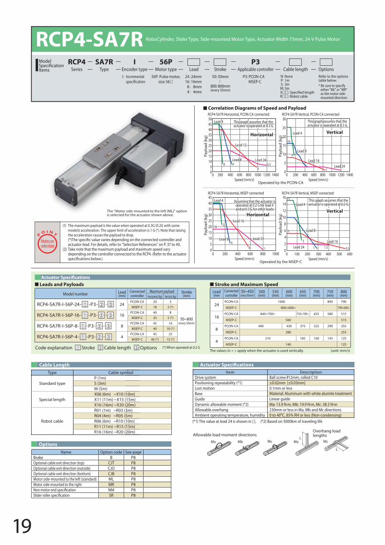
Leads and Payloads Stroke and Maximum Speed
Code explanation Stroke Cable length Options (*) When operated at 0.2 G
Model number Lead (mm)
Connected controller
Maximum payload Stroke(mm)Horizontal (kg) Vertical (kg)
RCP4-SA7R-I-56P-24- -P3- - 24PCON-CA 20 3
50~800(every 50mm)
MSEP-C 18 2 (*)
RCP4-SA7R-I-56P-16- -P3- - 16PCON-CA 40 8
MSEP-C 35 5 (*)
RCP4-SA7R-I-56P-8- -P3- - 8PCON-CA 45 16
MSEP-C 40 10 (*)
RCP4-SA7R-I-56P-4- -P3- - 4PCON-CA 45 25
MSEP-C 40 (*) 15 (*)
Lead (mm
Connected controller
50~450(every 50mm)
500 (mm)
550 (mm)
600 (mm)
650 (mm)
700 (mm)
750 (mm)
800 (mm)
24PCON-CA 1000 890 790
MSEP-C 800<600> 790<600>
16PCON-CA 840<700> 750<700> 655 580 515
MSEP-C 560 515
8PCON-CA 490 430 375 325 290 255
MSEP-C 280 255
4PCON-CA 210 185 160 145 125
MSEP-C 140 125
The values in < > apply when the actuator is used vertically. (unit: mm/s)
The “Motor side-mounted to the left (ML)” option is selected for the actuator shown above.
RCP4-SA7R RoboCylinder, Slider Type, Side-mounted Motor Type, Actuator Width 73mm, 24-V Pulse Motor
56P: Pulse motor, size 56
I: Incremental P3: PCON-CAMSEP-C
N: None P: 1m S: 3m M: 5mXR: Robot cable
Refer to the options table below.
24 : 24mm 16 : 16mm
8 : 8mm4 : 4mm
Lead Stroke Cable length OptionsTypeSA7R
Encoder typeI
Motor type56P
Applicable controllerP3
SeriesRCP4Model
Items50: 50mm
800: 800mm(every 50mm)
* Be sure to specify either "ML" or "MR" as the motor side-mounted direction.
(1) The maximum payload is the value when operated at 0.3G (0.2G with some models) acceleration. The upper limit of acceleration is 1 G (*). Note that raising the acceleration causes the payload to drop.
actuator lead. For details, refer to “Selection References” on P. 37 to 40. (2) Take note that the maximum payload and maximum speed vary
depending on the controller connected to the RCP4. (Refer to the actuator
Operated by the MSEP-C
Operated by the PCON-CA
Correlation Diagrams of Speed and Payload
OptionsName Option code See page
Brake B P8Optional cable exit direction (top) CJT P8Optional cable exit direction (outside) CJO P8Optional cable exit direction (bottom) CJB P8Motor side-mounted to the left (standard) ML P8Motor side-mounted to the right MR P8Non-motor end speci�cation NM P8Slider roller speci�cation SR P8
Type Cable symbol
Standard typeP (1m)S (3m)M (5m)
Special lengthX06 (6m) ~X10 (10m)X11 (11m) ~X15 (15m)X16 (16m) ~X20 (20m)
Robot cable
R01 (1m) ~R03 (3m)R04 (4m) ~R05 (5m)R06 (6m) ~R10 (10m)R11 (11m) ~R15 (15m)R16 (16m) ~R20 (20m)
Cable Length Actuator Speci�cations
(*1) The value at lead 24 is shown in [ ]. (*2) Based on 5000km of traveling life
Item DescriptionDrive system Ball screw 12mm, rolled C10Positioning repeatability (*1) ±0.02mm [±0.03mm]Lost motion 0.1mm or lessBase Material: Aluminum with white alumite treatmentGuide Linear guideDynamic allowable moment (*2)Allowable overhang 230mm or less in Ma, Mb and Mc directions Ambient operating temperature, humidity 0 to 40 C, 85% RH or less (Non-condensing)
L
L
Ma MaMb Mc Mc
Allowable load moment directionsOverhang load lengths
20
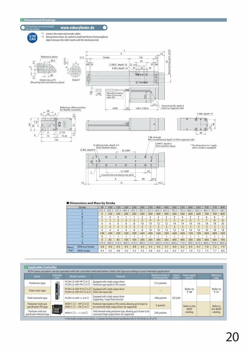
Dimensions and Mass by StrokeStroke 50 100 150 200 250 300 350 400 450 500 550 600 650 700 750 800
L 252.5 302.5 352.5 402.5 452.5 502.5 552.5 602.5 652.5 702.5 752.5 802.5 852.5 902.5 952.5 1002.5A 0 100 100 200 200 300 300 400 400 500 500 600 600 700 700 800B 0 0 0 1 1 2 2 3 3 4 4 5 5 6 6 7C 1 1 2 2 3 3 4 4 5 5 6 6 7 7 8 8D 4 6 6 8 8 10 10 12 12 14 14 16 16 18 18 20E 2 3 3 3 3 3 3 3 3 3 3 3 3 3 3 3F 4 4 6 6 8 8 10 10 12 12 14 14 16 16 18 18G 199 249 299 349 399 449 499 549 599 649 699 749 799 849 899 949H 0 1 1 1 1 1 1 1 1 1 1 1 1 1 1 1J 0 85 85 185 185 285 285 385 385 485 485 585 585 685 685 785K 219.5 269.5 319.5 369.5 419.5 469.5 519.5 569.5 619.5 669.5 719.5 769.5 819.5 869.5 919.5 969.5
Mass (kg)
Without brake 3.8 4.0 4.3 4.5 4.8 5.0 5.3 5.5 5.7 6.0 6.2 6.5 6.7 7.0 7.2 7.4With brake 4.3 4.5 4.8 5.0 5.3 5.5 5.8 6.0 6.2 6.5 6.7 7.0 7.2 7.5 7.7 8.0
Dimensional Drawings
X
Y
21.5
5.5
6
Detail view of X(Mounting hole and reference plane)
4+
0.01
20 5
Detail Y
5.5
3Stroke
3
20 20 2032 ±0.02±0.02
39(R
eam
ed h
ole
pitc
h ±0
.02)
50126 22
K 33L
4-M5, depth 10MESEME SE
(28)(13)
(300)(37) Ground tap M3, depth 6
(Same on opposite side)
(55)
20 148.5 (198.5)
Allowable bending radius of securing cable: R50
* The dimensions in ( ) apply when a brake is equipped.
48
3348
4-M6, depth 14
E- 4H7, depth 6(from bottom base)
D-M5, depth 9
H-oblong hole, depth 5.5(from bottom base)
B×100P
40
30C×100PJ (reamed hole and oblong hole pitch)
A 80 25.5
G10 43.5
43
7173
9 30 948
5064
75.25156
2.5
610.
5
Refefor Ma/Mc moments
(7.75)
Reference plane
* In the model numbers shown above, indicates the �eld network speci�cation (DV, CC, PR, CN, ML, EC, EP or PT).
RCP4 series actuators can be operated with the controller indicated below. Select the type according to your intended application.Applicable Controller
Name Externalview Model number Features Maximum number of
positioning pointsInputpower
Power supply capacity
Reference page
Positioner type PCON-CA-56PI-NP- -0-PCON-CA-56PI-PN- -0-
Equipped with a high-output driverPositioner type based on PIO control 512 points
DC24V
Refer to P. 48
Refer to P. 41Pulse-train type PCON-CA-56PI-PLN- -0-
PCON-CA-56PI-PLP- -0-Equipped with a high-output driverPulse-train input type —
Field network type PCON-CA-56PI--0-0- Equipped with a high-output driverSupporting 7 major �eld networks 768 points
Positioner multi-axis speci�cation PIO type
MSEP-C- -~-NP- -0-MSEP-C- -~-PN- -0-
Positioner type based on PIO control, allowing up to 8 axes to be connected (high-output driver not supported) 3 points Refer to the
MSEP catalog.
Refer to the MSEP catalog.Positioner multi-axis
speci�cation Network type MSEP-C- -~--0-0- Field network-ready positioner type, allowing up to 8 axes to be connected (high-output driver not supported) 256 points
*1 Connect the motor and encoder cables.*2 During home return, be careful to avoid interference from peripheral
objects because the slider travels until the mechanical end. 2/3D CAD
CAD drawings can be downloaded from the website. www.robocylinder.de
29
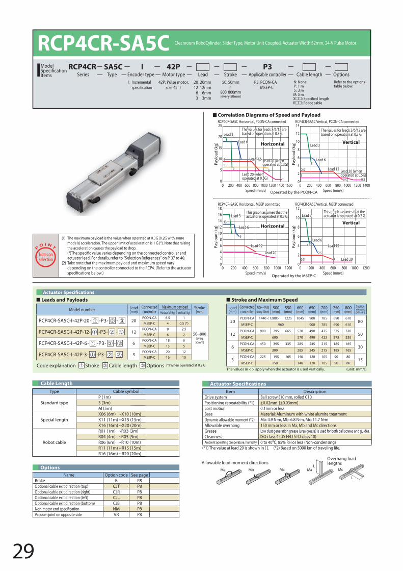
Item DescriptionDrive system Ball screw 10 mm, rolled C10Positioning repeatability (*1) ±0.02mm [±0.03mm]Lost motion 0.1mm or less
ISO class 4 (US FED STD class 10)
Base Material: Aluminum with white alumite treatmentDynamic allowable moment (*2) Ma N•m, b N•m, Mc N•mAllowable overhang 150 mm or less in Ma, Mb and Mc directions Grease Low dust generation grease (urea grease) is used for both ball screws and guides.CleannessAmbient operating temperature, humidity 0 to 40 , H or less (Non-condensing)
P Hori ontal, P ON-CA connected P Vertical, PCON-CA connected
P Hori ontal, P connected P Vertical, MSEP connected
1400120010004002000Speed (mm/s)
1400120010004002000Speed (mm/s)
120010004002000Speed (mm/s)
120010004002000Speed (mm/s)
This graph assumes that the actuator is operated at 0.3 G.
The values for leads are based on operation at 0.3 G.
The values for leads are based on operation at 0.3 G.
This graph assumes that the actuator is operated at 0.2 G.
Horizontal
Horizontal
Vertical
Vertical
Lead 3
Lead 3 Lead 3
Lead 3Lead
Lead
Lead
Lead
Lead 12
Lead 12
Lead 12
Lead 12
Lead 20Lead 201
11
2.5
0.5
0.5
0.5
5
2.5
4.5
9
13
59 Lead 20 (when
operated at 0.3G)
Lead 20 (when operated at 0.5G)Lead 20 (when
operated at 0.5G)
Payl
oad
(kg)
25
20
15
10
5
0
Payl
oad
(kg)
14
12
10
4
2
0
Payl
oad
(kg)
12
10
4
2
0
Payl
oad
(kg)
141210
420
Operated by the MSEP-C
Operated by the PCON-CA
Correlation Diagrams of Speed and Payload
Leads and Payloads Stroke and Maximum Speed
Actuator Speci�cations
Options
(*1) The value at lead 20 is shown in [ ]. (*2) Based on 5000 km of traveling life.
Code explanation Stroke Cable length Options (*) When operated at 0.2 G
RCP4CR-SA5C Cleanroom oboCylinder, Slider Type, Motor Unit Coupled, Actuator Width 52mm, 24-V Pulse Motor
42P: Pulse motor, si e 42
I: Incremental P3: PCON-CAMSEP-C
N: None P: 1 m S: 3 m M: 5 mX: obot cable
efer to the options table below.
20 : 20mm 12 : 12mm
: mm3 : 3mm
Lead Stroke Cable length OptionsTypeSA5C
Encoder typeI
Motor type42P
Applicable controllerP3
SeriesRCP4CRModel
Items50: 50mm
mm(every 50mm)
The values in < > apply when the actuator is used vertically. (unit: mm/s)
Name Option code See pageBrake B POptional cable exit direction (top) CJT POptional cable exit direction (right) CJ POptional cable exit direction (left) CJL POptional cable exit direction (bottom) CJB PNon-motor end speci�cation NM PVacuum joint on opposite side P
Lead (mm)
Connected controller
50~450(every 50mm)
500 (mm)
550 (mm)
(mm)
(mm)
700 (mm)
750 (mm)
(mm)
Suction amount (Nl/min)
20PCON-CA 1225 1045 900
MSEP-C 900
12PCON-CA 900 795 570 490 425 375 330
50MSEP-C 570 490 425 375 330
PCON-CA 450 395 335 245 21530
MSEP-C 300 245 215
3PCON-CA 225 195 140 120 105 90
15MSEP-C 150 140 120 105 90
Model number Lead (mm)
Connected controller
Maximum payload Stroke(mm)Hori ontal (kg) Vertical (kg)
CP4C -SA5C-I-42P-20- -P3- - 20PCON-CA 1
(every 50mm)
MSEP-C 4 0.5 (*)
CP4C -SA5C-I-42P-12- -P3- - 12PCON-CA 9 2.5
MSEP-C 2
CP4C -SA5C-I-42P- - -P3- -PCON-CA
MSEP-C 13 5
CP4C -SA5C-I-42P-3- -P3- - 3PCON-CA 20 12
MSEP-C 10
(1) The maximum payload is the value when operated at 0.3G (0.2G with some models) acceleration. The upper limit of acceleration is 1 G (*). Note that raising the acceleration causes the payload to drop.
actuator lead. For details, refer to “Selection eferences” on P. 37 to 40. (2) Take note that the maximum payload and maximum speed vary
depending on the controller connected to the CP4. ( efer to the actuator
Type Cable symbol
Standard typeP (1m)S (3m)M (5m)
Special length ( m) ( m)
X11 (11m) ~X15 (15m) ( m) ( m)
obot cable
( m) ( m) ( m) ( m) ( m) ( m) ( m) ( m) ( m) ( m)
Cable Length
L
L
Ma MaMb Mc Mc
Allowable load moment directionsOverhang load lengths
30
24
Y
X
53
4.5
Detail view of X(Mounting hole and reference plane)
Reference plane
9 15.515.5
26(R
eam
ed h
ole
pitc
h ±0
.02)
19 ±0.0230
4-M4, depth 9 20
Allowable bending radius of securing cable: R50
(13)
(28)
(300)
* The dimensions in ( ) apply when a brake is equipped.
47 2.52.5
Joint mounting position: Opposite side
Joint mounting position: Standard
* T
3
98 (138)
22.5
26
Ground tap M, 3 depth 6(Same on opposite side)
21
33
MESE
Stroke320
K
L
90
ME SE
32
Joint turning range
62
2050C×100P
A
G 106 (146)7
26
B×100P
F- 4.5, through8 counterbored, depth 4.5 (from opposite side) (from bottom base)D-M4, depth 7
H-oblong hole, depth 5.5(from bottom base)
J (reamed hole and oblong hole pitch)
39
5052
4057.5
50
20 6632
Refefor Ma/Mc moments
5
40+0.
012
Detail Y
(18.9)
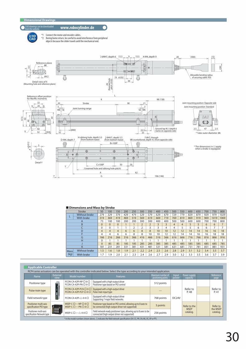
Dimensional Drawings
Dimensions and Mass by StrokeStroke 50 100 150 200 250 300 350 400 450 500 550 600 650 700 750 800
L Without brake 279 329 379 429 479 529 579 629 679 729 779 829 879 929 979 1029With brake 319 369 419 469 519 569 619 669 719 769 819 869 919 969 1019 1069
A 73 100 100 200 200 300 300 400 400 500 500 600 600 700 700 800B 0 0 0 1 1 2 2 3 3 4 4 5 5 6 6 7C 0 0 1 1 2 2 3 3 4 4 5 5 6 6 7 7D 4 4 4 6 6 8 8 10 10 12 12 14 14 16 16 18F 4 4 6 6 8 8 10 10 12 12 14 14 16 16 18 18G 166 216 266 316 366 416 466 516 566 616 666 716 766 816 866 916H 0 1 1 1 1 1 1 1 1 1 1 1 1 1 1 1J 0 85 85 185 185 285 285 385 385 485 485 585 585 685 685 785K 181 231 281 331 381 431 481 531 581 631 681 731 781 831 881 931
Mass (kg)
Without brake 1.5 1.6 1.8 1.9 2.1 2.2 2.4 2.5 2.6 2.8 2.9 3.1 3.2 3.4 3.5 3.7With brake 1.7 1.9 2.0 2.1 2.3 2.4 2.6 2.7 2.9 3.0 3.2 3.3 3.5 3.6 3.7 3.9
* In the model numbers shown above, indicates the �eld network speci�cation (DV, CC, PR, CN, ML, EC, EP or PT).
RCP4 series actuators can be operated with the controller indicated below. Select the type according to your intended application.Applicable Controller
Name Externalview Model number Features Maximum number of
positioning pointsInputpower
Power supply capacity
Reference page
Positioner type PCON-CA-42PI-NP- -0-PCON-CA-42PI-PN- -0-
Equipped with a high-output driverPositioner type based on PIO control 512 points
DC24V
Refer to P. 48
Refer to P. 41Pulse-train type PCON-CA-42PI-PLN- -0-
PCON-CA-42PI-PLP- -0-Equipped with a high-output driverPulse-train input type —
Field network type PCON-CA-42PI--0-0- Equipped with a high-output driverSupporting 7 major �eld networks 768 points
Positioner multi-axis speci�cation PIO type
MSEP-C- -~-NP- -0-MSEP-C- -~-PN- -0-
Positioner type based on PIO control, allowing up to 8 axes to be connected (high-output driver not supported) 3 points Refer to the
MSEP catalog.
Refer to the MSEP catalog.Positioner multi-axis
speci�cation Network type MSEP-C- -~--0-0- Field network-ready positioner type, allowing up to 8 axes to be connected (high-output driver not supported) 256 points
*1 Connect the motor and encoder cables.*2 During home return, be careful to avoid interference from peripheral
objects because the slider travels until the mechanical end.
2/3D CAD
CAD drawings can be downloaded from the website. www.robocylinder.de
31
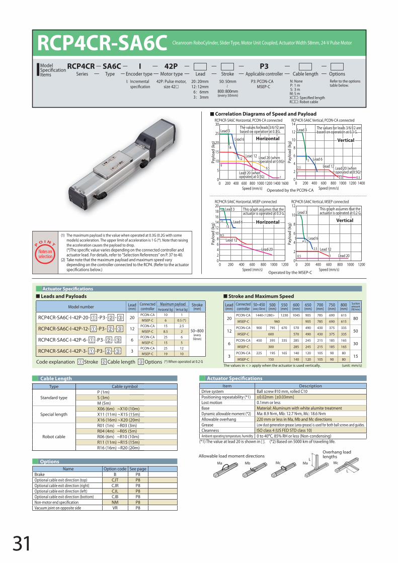
RCP4CR-SA6C Horizontal, PCON-CA connected RCP4CR-SA6C Vertical, PCON-CA connected
RCP4CR-SA6C Horizontal, MSEP connected RCP4CR-SA6C Vertical, MSEP connected
Payl
oad
(kg)
30
25
20
15
10
5
0
Payl
oad
(kg)
14
12
10
8
6
4
2
0
Payl
oad
(kg)
201816141210
86420
Payl
oad
(kg)
12
10
8
6
4
2
0
5
0.5
19
15
8.5
13
4.5
2.5 Lead 12
Lead 12
Lead 12
Lead 12
Lead 20Lead 20
1
Lead 3
Lead 3Lead 3
Lead 3
Lead 6
Lead 6
Lead 6
Lead 6
This graph assumes that the actuator is operated at 0.2 G.
Vertical
This graph assumes that the actuator is operated at 0.3 G.
Horizontal
Horizontal
120010008006004002000Speed (mm/s)
120010008006004002000Speed (mm/s)
The values for leads 3/6/12 are based on operation at 0.3 G.
The values for leads 3/6/12 are based on operation at 0.3 G.
Vertical
Lead 20 (when operated at 0.5G)Lead 20 (when
operated at 0.5G)
Lead 20 (when operated at 0.3G)
0.5
2.56.59
18
12
0.5
5
11
16001400120010008006004002000Speed (mm/s)
1400120010008006004002000Speed (mm/s)
Operated by the MSEP-C
Operated by the PCON-CA
Correlation Diagrams of Speed and Payload
Leads and Payloads Stroke and Maximum Speed
Code explanation Stroke Cable length Options (*) When operated at 0.2 G
RCP4CR-SA6C Cleanroom RoboCylinder, Slider Type, Motor Unit Coupled, Actuator Width 58mm, 24-V Pulse Motor
42P: Pulse motor, size 42
I: Incremental P3: PCON-CAMSEP-C
N: None P: 1 m S: 3 m M: 5 mXR: Robot cable
Refer to the options table below.
20 : 20mm 12 : 12mm
6 : 6mm3 : 3mm
Lead Stroke Cable length OptionsTypeSA6C
Encoder typeI
Motor type42P
Applicable controllerP3
SeriesRCP4CRModel
Items50: 50mm
800: 800mm(every 50mm)
The values in < > apply when the actuator is used vertically. (unit: mm/s)
Model number Lead (mm)
Connected controller
Maximum payload Stroke(mm)Horizontal (kg) Vertical (kg)
RCP4CR-SA6C-I-42P-20- -P3- - 20PCON-CA 10 1
50~800(every 50mm)
MSEP-C 6 0.5 (*)
RCP4CR-SA6C-I-42P-12- -P3- - 12PCON-CA 15 2.5
MSEP-C 8.5 2
RCP4CR-SA6C-I-42P-6- -P3- - 6PCON-CA 25 6
MSEP-C 15 5
RCP4CR-SA6C-I-42P-3- -P3- - 3PCON-CA 25 12
MSEP-C 19 10
Lead (mm)
Connected controller
50~450(every 50mm)
500 (mm)
550 (mm)
600 (mm)
650 (mm)
700 (mm)
750 (mm)
800 (mm)
Suction amount (Nl/min)
20PCON-CA 1440<1280> 1230 1045 905 785 690 615
80MSEP-C 960 905 785 690 615
12PCON-CA 900 795 670 570 490 430 375 335
50MSEP-C 600 570 490 430 375 335
6PCON-CA 450 395 335 285 245 215 185 165
30MSEP-C 300 285 245 215 185 165
3PCON-CA 225 195 165 140 120 105 90 80
15MSEP-C 150 140 120 105 90 80
(1) The maximum payload is the value when operated at 0.3G (0.2G with some models) acceleration. The upper limit of acceleration is 1 G (*). Note that raising the acceleration causes the payload to drop.
actuator lead. For details, refer to “Selection References” on P. 37 to 40. (2) Take note that the maximum payload and maximum speed vary
depending on the controller connected to the RCP4. (Refer to the actuator
Item DescriptionDrive system Ball screw 10 mm, rolled C10Positioning repeatability (*1) ±0.02mm [±0.03mm]Lost motion 0.1mm or less
ISO class 4 (US FED STD class 10)
Base Material: Aluminum with white alumite treatmentDynamic allowable moment (*2) Ma N•m, b N•m, Mc N•mAllowable overhang 220 mm or less in Ma, Mb and Mc directions Grease Low dust generation grease (urea grease) is used for both ball screws and guides.CleannessAmbient operating temperature, humidity 0 to 40 C, 85% RH or less (Non-condensing)
Actuator Speci�cations
Options
(*1) The value at lead 20 is shown in [ ]. (*2) Based on 5000 km of traveling life.
Name Option code See pageBrake B P8Optional cable exit direction (top) CJT P8Optional cable exit direction (right) CJR P8Optional cable exit direction (left) CJL P8Optional cable exit direction (bottom) CJB P8Non-motor end speci�cation NM P8Vacuum joint on opposite side VR P8
Type Cable symbol
Standard typeP (1m)S (3m)M (5m)
Special lengthX06 (6m) ~X10 (10m)X11 (11m) ~X15 (15m)X16 (16m) ~X20 (20m)
Robot cable
R01 (1m) ~R03 (3m)R04 (4m) ~R05 (5m)R06 (6m) ~R10 (10m)R11 (11m) ~R15 (15m)R16 (16m) ~R20 (20m)
Cable Length
L
L
Ma MaMb Mc Mc
Allowable load moment directionsOverhang load lengths
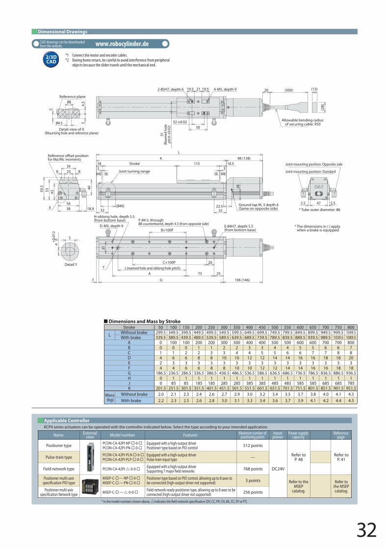
32
54.
5
5
Detail view of X(Mounting hole and reference plane)
Reference plane
21 19.519.5
32 ±0.0250
31(R
eam
ed h
ole
pitc
h ±0
.02)
4-M5, depth 9 20
Allowable bending radius of securing cable: R50
(13)
(28)
* The dimensions in ( ) apply when a brake is equipped.
318
3Stroke
98 (138)
Ground tap M, 3 depth 6(Same on opposite side)
KL
22.5
28
18.5115
33
ME MESE SE
47 5.55.5
* T
Joint mounting position: Standard
Joint mounting position: Opposite side
32
Joint turning range
H-oblong hole, depth 5.5(from bottom base)
40
5658
435359.5
23 8839
18.9
Refefor Ma/Mc moments
X
31
7
B×100PD-M5, depth 9
40+0.
012
5
Detail YY
25
20
75AJ (reamed hole and oblong hole pitch)
G 106 (146)
(from bottom base)
C×100P
(300)
Dimensional Drawings
Dimensions and Mass by StrokeStroke 50 100 150 200 250 300 350 400 450 500 550 600 650 700 750 800
L Without brake 299.5 349.5 399.5 449.5 499.5 549.5 599.5 649.5 699.5 749.5 799.5 849.5 899.5 949.5 999.5 1049.5With brake 339.5 389.5 439.5 489.5 539.5 589.5 639.5 689.5 739.5 789.5 839.5 889.5 939.5 989.5 1039.5 1089.5
A 0 100 100 200 200 300 300 400 400 500 500 600 600 700 700 800B 0 0 0 1 1 2 2 3 3 4 4 5 5 6 6 7C 1 1 2 2 3 3 4 4 5 5 6 6 7 7 8 8D 4 6 6 8 8 10 10 12 12 14 14 16 16 18 18 20E 2 3 3 3 3 3 3 3 3 3 3 3 3 3 3 3F 4 4 6 6 8 8 10 10 12 12 14 14 16 16 18 18G 186.5 236.5 286.5 336.5 386.5 436.5 486.5 536.5 586.5 636.5 686.5 736.5 786.5 836.5 886.5 936.5H 0 1 1 1 1 1 1 1 1 1 1 1 1 1 1 1J 0 85 85 185 185 285 285 385 385 485 485 585 585 685 685 785K 201.5 251.5 301.5 351.5 401.5 451.5 501.5 551.5 601.5 651.5 701.5 751.5 801.5 851.5 901.5 951.5
Mass (kg)
Without brake 2.0 2.1 2.3 2.4 2.6 2.7 2.9 3.0 3.2 3.4 3.5 3.7 3.8 4.0 4.1 4.3With brake 2.2 2.3 2.5 2.6 2.8 3.0 3.1 3.3 3.4 3.6 3.7 3.9 4.1 4.2 4.4 4.5
* In the model numbers shown above, indicates the �eld network speci�cation (DV, CC, PR, CN, ML, EC, EP or PT).
RCP4 series actuators can be operated with the controller indicated below. Select the type according to your intended application.Applicable Controller
Name Externalview Model number Features Maximum number of
positioning pointsInputpower
Power supply capacity
Reference page
Positioner type PCON-CA-42PI-NP- -0-PCON-CA-42PI-PN- -0-
Equipped with a high-output driverPositioner type based on PIO control 512 points
DC24V
Refer to P. 48
Refer to P. 41Pulse-train type PCON-CA-42PI-PLN- -0-
PCON-CA-42PI-PLP- -0-Equipped with a high-output driverPulse-train input type —
Field network type PCON-CA-42PI--0-0- Equipped with a high-output driverSupporting 7 major �eld networks 768 points
Positioner multi-axis speci�cation PIO type
MSEP-C- -~-NP- -0-MSEP-C- -~-PN- -0-
Positioner type based on PIO control, allowing up to 8 axes to be connected (high-output driver not supported) 3 points Refer to the
MSEP catalog.
Refer to the MSEP catalog.Positioner multi-axis
speci�cation Network type MSEP-C- -~--0-0- Field network-ready positioner type, allowing up to 8 axes to be connected (high-output driver not supported) 256 points
*1 Connect the motor and encoder cables.*2 During home return, be careful to avoid interference from peripheral
objects because the slider travels until the mechanical end.
2/3D CAD
CAD drawings can be downloaded from the website. www.robocylinder.de
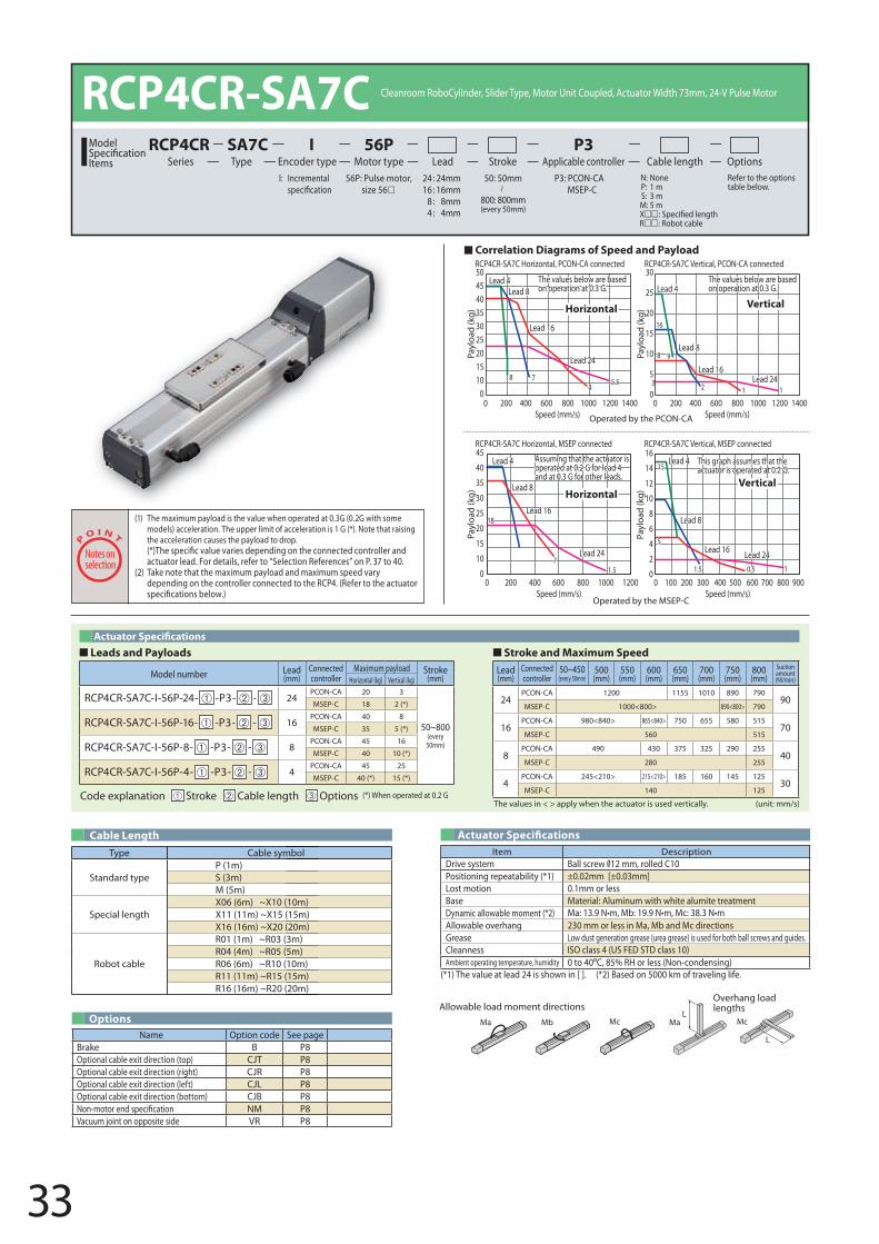
33
RCP4CR-SA7C Horizontal, PCON-CA connected RCP4CR-SA7C Vertical, PCON-CA connected
RCP4CR-SA7C Horizontal, MSEP connected RCP4CR-SA7C Vertical, MSEP connected
The values below are based on operation at 0.3 G.
The values below are based on operation at 0.3 G.
This graph assumes that the actuator is operated at 0.2 G.
Assuming that the actuator is operated at 0.2 G for lead 4 and at 0.3 G for other leads.
Horizontal
Vertical
Vertical
Lead 4 Lead 4
Lead 4Lead 4
Lead 8
Lead 8
Lead 8
Lead 8
Lead 16
Lead 16
Lead 16
Lead 16
Lead 24 Lead 24
Lead 24
Lead 24
15
5
1
1123
0.51.51.57
78
8
16
9
45.5
18
120010008006004002000Speed (mm/s)
600 700 800 9005004003002001000Speed (mm/s)
1400120010008006004002000Speed (mm/s)
1400120010008006004002000Speed (mm/s)
Payl
oad
(kg)
504540353025201510
0
Payl
oad
(kg)
45
40
35
30
25
20
15
10
0
Payl
oad
(kg)
30
25
20
15
10
5
0
Payl
oad
(kg)
16
14
12
10
8
6
4
2
0
Horizontal
Lead (mm)
Connected controller
50~450(every 50mm)
500 (mm)
550 (mm)
600 (mm)
650 (mm)
700 (mm)
750 (mm)
800 (mm)
Suction amount (Nl/min)
24PCON-CA 1200 1155 1010 890 790
90MSEP-C 1000<800> 890<800> 790
16PCON-CA 980<840> 865<840> 750 655 580 515
70MSEP-C 560 515
8PCON-CA 490 430 375 325 290 255
40MSEP-C 280 255
4PCON-CA 245<210> 215<210> 185 160 145 125
30MSEP-C 140 125
Operated by the MSEP-C
Operated by the PCON-CA
Correlation Diagrams of Speed and Payload
Leads and Payloads Stroke and Maximum Speed
Code explanation Stroke Cable length Options (*) When operated at 0.2 G
RCP4CR-SA7C Cleanroom RoboCylinder, Slider Type, Motor Unit Coupled, Actuator Width 73mm, 24-V Pulse Motor
56P: Pulse motor, size 56
I: Incremental P3: PCON-CAMSEP-C
N: None P: 1 m S: 3 m M: 5 mXR: Robot cable
Refer to the options table below.
24 : 24mm 16 : 16mm
8 : 8mm4 : 4mm
Lead Stroke Cable length OptionsTypeSA7C
Encoder typeI
Motor type56P
Applicable controllerP3
SeriesRCP4CRModel
Items50: 50mm
800: 800mm(every 50mm)
The values in < > apply when the actuator is used vertically. (unit: mm/s)
Model number Lead (mm)
Connected controller
Maximum payload Stroke(mm)Horizontal (kg) Vertical (kg)
RCP4CR-SA7C-I-56P-24- -P3- - 24PCON-CA 20 3
50~800(every 50mm)
MSEP-C 18 2 (*)
RCP4CR-SA7C-I-56P-16- -P3- - 16PCON-CA 40 8
MSEP-C 35 5 (*)
RCP4CR-SA7C-I-56P-8- -P3- - 8PCON-CA 45 16
MSEP-C 40 10 (*)
RCP4CR-SA7C-I-56P-4- -P3- - 4PCON-CA 45 25
MSEP-C 40 (*) 15 (*)
(1) The maximum payload is the value when operated at 0.3G (0.2G with some models) acceleration. The upper limit of acceleration is 1 G (*). Note that raising the acceleration causes the payload to drop.
actuator lead. For details, refer to “Selection References” on P. 37 to 40. (2) Take note that the maximum payload and maximum speed vary
depending on the controller connected to the RCP4. (Refer to the actuator
Item DescriptionDrive system Ball screw 12 mm, rolled C10Positioning repeatability (*1) ±0.02mm [±0.03mm]Lost motion 0.1mm or less
ISO class 4 (US FED STD class 10)
Base Material: Aluminum with white alumite treatmentDynamic allowable moment (*2) Ma N•m, b N•m, Mc N•mAllowable overhang 230 mm or less in Ma, Mb and Mc directions Grease Low dust generation grease (urea grease) is used for both ball screws and guides.CleannessAmbient operating temperature, humidity 0 to 40 C, 85% RH or less (Non-condensing)
Actuator Speci�cations
Options
(*1) The value at lead 24 is shown in [ ]. (*2) Based on 5000 km of traveling life.
Name Option code See pageBrake B P8Optional cable exit direction (top) CJT P8Optional cable exit direction (right) CJR P8Optional cable exit direction (left) CJL P8Optional cable exit direction (bottom) CJB P8Non-motor end speci�cation NM P8Vacuum joint on opposite side VR P8
Type Cable symbol
Standard typeP (1m)S (3m)M (5m)
Special lengthX06 (6m) ~X10 (10m)X11 (11m) ~X15 (15m)X16 (16m) ~X20 (20m)
Robot cable
R01 (1m) ~R03 (3m)R04 (4m) ~R05 (5m)R06 (6m) ~R10 (10m)R11 (11m) ~R15 (15m)R16 (16m) ~R20 (20m)
Cable Length
L
L
Ma MaMb Mc Mc
Allowable load moment directionsOverhang load lengths
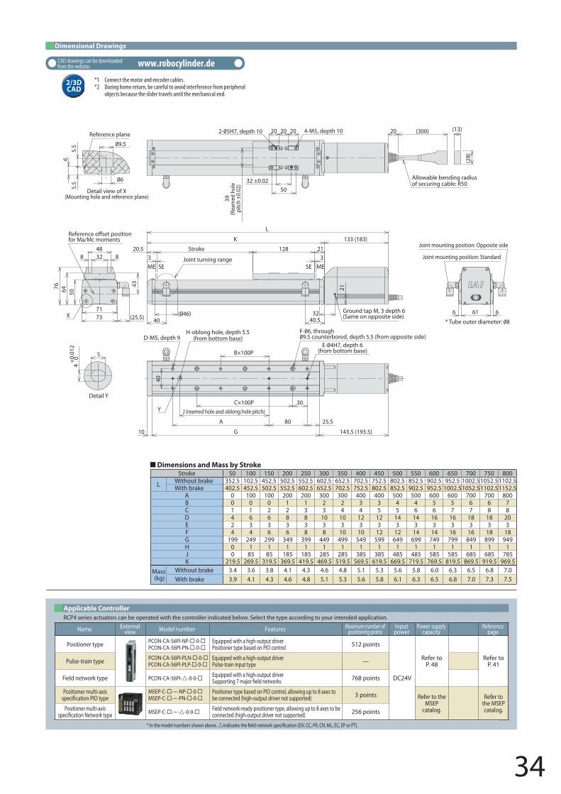
34
40
Y
X
5.5
5.5
6
Detail view of X(Mounting hole and reference plane)
Reference plane 20 20 20
32 ±0.0250
39(R
eam
ed h
ole
pitc
h ±0
.02)
4-M5, depth 10 20
Allowable bending radius of securing cable: R50
(300) (13)
(28)
61 66
* T
Joint mounting position: Standard
Joint mounting position: Opposite side
3 3Stroke20.5
32
21
133 (183)K
L
Ground tap M, 3 depth 6(Same on opposite side)
21128
40.540
ME MESE SEJoint turning range
(from bottom base)
43
7173
48
506476
8 32 8
(25.5)
Refefor Ma/Mc moments
25.5
30
G
C×100PJ (reamed hole and oblong hole pitch)
80A
10 143.5 (193.5)
B×100P
D-M5, depth 9H-oblong hole, depth 5.5
(from bottom base)
40+0.
012
5
Detail Y
Dimensions and Mass by StrokeStroke 50 100 150 200 250 300 350 400 450 500 550 600 650 700 750 800
L Without brake 352.5 102.5 452.5 502.5 552.5 602.5 652.5 702.5 752.5 802.5 852.5 902.5 952.5 1002.51052.51102.5With brake 402.5 452.5 502.5 552.5 602.5 652.5 702.5 752.5 802.5 852.5 902.5 952.5 1002.51052.51102.51152.5
A 0 100 100 200 200 300 300 400 400 500 500 600 600 700 700 800B 0 0 0 1 1 2 2 3 3 4 4 5 5 6 6 7C 1 1 2 2 3 3 4 4 5 5 6 6 7 7 8 8D 4 6 6 8 8 10 10 12 12 14 14 16 16 18 18 20E 2 3 3 3 3 3 3 3 3 3 3 3 3 3 3 3F 4 4 6 6 8 8 10 10 12 12 14 14 16 16 18 18G 199 249 299 349 399 449 499 549 599 649 699 749 799 849 899 949H 0 1 1 1 1 1 1 1 1 1 1 1 1 1 1 1J 0 85 85 185 185 285 285 385 385 485 485 585 585 685 685 785K 219.5 269.5 319.5 369.5 419.5 469.5 519.5 569.5 619.5 669.5 719.5 769.5 819.5 869.5 919.5 969.5
Mass (kg)
Without brake 3.4 3.6 3.8 4.1 4.3 4.6 4.8 5.1 5.3 5.6 5.8 6.0 6.3 6.5 6.8 7.0With brake 3.9 4.1 4.3 4.6 4.8 5.1 5.3 5.6 5.8 6.1 6.3 6.5 6.8 7.0 7.3 7.5
* In the model numbers shown above, indicates the �eld network speci�cation (DV, CC, PR, CN, ML, EC, EP or PT).
RCP4 series actuators can be operated with the controller indicated below. Select the type according to your intended application.Applicable Controller
Name Externalview Model number Features Maximum number of
positioning pointsInputpower
Power supply capacity
Reference page
Positioner type PCON-CA-56PI-NP- -0-PCON-CA-56PI-PN- -0-
Equipped with a high-output driverPositioner type based on PIO control 512 points
DC24V
Refer to P. 48
Refer to P. 41Pulse-train type PCON-CA-56PI-PLN- -0-
PCON-CA-56PI-PLP- -0-Equipped with a high-output driverPulse-train input type —
Field network type PCON-CA-56PI--0-0- Equipped with a high-output driverSupporting 7 major �eld networks 768 points
Positioner multi-axis speci�cation PIO type
MSEP-C- -~-NP- -0-MSEP-C- -~-PN- -0-
Positioner type based on PIO control, allowing up to 8 axes to be connected (high-output driver not supported) 3 points Refer to the
MSEP catalog.
Refer to the MSEP catalog.Positioner multi-axis
speci�cation Network type MSEP-C- -~--0-0- Field network-ready positioner type, allowing up to 8 axes to be connected (high-output driver not supported) 256 points
*1 Connect the motor and encoder cables.*2 During home return, be careful to avoid interference from peripheral
objects because the slider travels until the mechanical end.
2/3D CAD
CAD drawings can be downloaded from the website. www.robocylinder.de
Dimensional Drawings
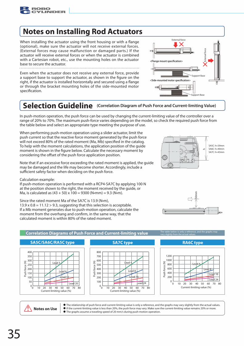
In push-motion operation, the push force can be used by changing the current-limiting value of the controller over a range of 20% to 70%. The maximum push-force varies depending on the model, so check the required push force from the table below and select an appropriate type meeting the purpose of use.
When performing push-motion operation using a slider actuator, limit the push current so that the reactive force moment generated by the push force
To help with the moment calculations, the application position of the guide
Note that if an excessive force exceeding the rated moment is applied, the guide may be damaged and the life may become shorter. Accordingly, include a
Calculation example: If push-motion operation is performed with a RCP4-SA7C by applying 100 N at the position shown to the right, the moment received by the guide, or Ma, is calculated as ( ) (N•mm) (N•m)
Since the rated moment Ma of the is (N•m), 13.9 x 0.8 = 11.12 > 9.3, suggesting that this selection is acceptable. If a Mb moment generates due to push-motion operation, calculate the
calculated moment is within 80% of the rated moment.
Notes on Installing Rod Actuators
Selection Guideline (Correlation Diagram of Push Force and Current-limiting Value)
(optional), make sure the actuator will not receive external forces. (External forces may cause malfunction or damaged parts.) If the actuator will receive external forces or when the actuator is combined with a Cartesian robot, etc., use the mounting holes on the actuator base to secure the actuator.
Even when the actuator does not receive any external force, provide
or through the bracket mounting holes of the side-mounted motor
Correlation Diagrams of Push Force and Current-limiting value The table below is only a reference, and the graphs may vary slightly from the actual values.
h
50m
m
SA5C: h=39mmSA6C: h=40mmSA7C: h=43mm
The relationship of push force and current-limiting value is only a reference, and the graphs may vary slightly from the actual values. If the current-limiting value is less than 20%, the push force may vary. Make sure the current-limiting value remains 20% or more. The graphs assume a traveling speed of 20 mm/s during push-motion operation.
Notes on Use
SA5C/SA6C/RA5C type
0 10 20 30 40 50 60 70 80
400350300250200150100
500
Current-limiting value (%)
Lead 3
Lead 6
Lead 12
Lead 20
Push
forc
e (N
)
SA7C type
0 10 20 30 40 50 60 70 80
800700600500400300200100
0
Current-limiting value (%)
Lead 4
Lead 8
Lead 16
Lead 24
Push
forc
e (N
)
RA6C type
0 10 20 30 40 50 60 70 80
12001000
800600400200
0
Current-limiting value (%)
Lead 4
Lead 8
Lead 16
Lead 24
Push
forc
e (N
)
External force
Exte
rnal
forc
e
Support Base
Support Base
35
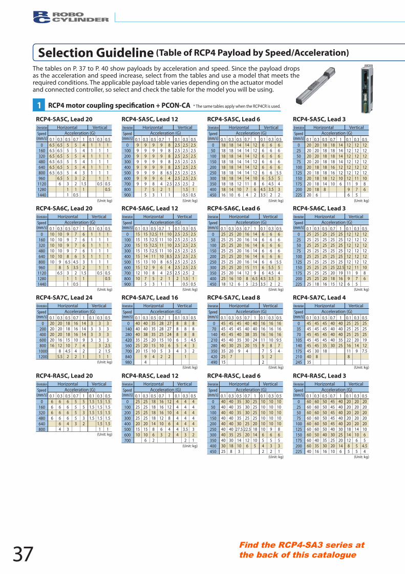
RCP4-SA5C, Lead 20
0160320480640800960
112012801440
050
100150200250300350400450
0100200300400500600700800900
0255075
100125150175200225
0.16.56.56.56.56.56.5
0.36.56.56.56.56.56.56.56
0.55555555311
0.7555554321
0.5
14444432
1.51
0.1111111
0.31111111
0.5
0.51111111
0.50.5
0.199999999
0.39999999975
0.59999999853
0.79999986421
188888
6.54
2.511
0.12.52.52.52.52.52.52.52.5
0.32.52.52.52.52.52.52.52.51.50.5
0.52.52.52.52.52.52.52.521
0.5
0.120202020202020202020
0.32020202018181818186
0.518181818181818148
0.71818181816161210
1141414141212106
0.1121212121212121196
0.312121212121211975
0.51212121212121086
0.118181818181818181816
0.318181818181818181410
0.51414141414141412106
0.7141414141414141174
112121212121210862
0.166666666
4.53.5
0.3666666
5.54.53.52
0.566666
5.55432
0160320480640800960
112012801440
0255075
100125150175200225
050
100150200250300350400450
0100200300400500600700800900
0.1101010101010
0.3101010101098
6.5
0.599998
6.55311
0.777776
4.53.521
0.5
16666532
1.51
0.1111111
0.31111111
0.5
0.51111111
0.50.5
0.125252525252525252525
0.325252525252525252518
0.525252525252525252016
0.725252525252525201815
1252525252525
22.5191612
0.1121212121212121196
0.312121212121211975
0.51212121212121086
0.125252525252525252518
0.325252525252525201612
0.52020202020202014106
0.7161616161616151285
1141414141414119
6.52.5
0.166666666
4.53.5
0.3666666
5.54.53.52
0.566666
5.55432
0.1151515151515151210
0.3151515151413121075
0.512.512.512.512.511109853
0.7111111111086421
1101010108.56.54
2.511
0.12.52.52.52.52.52.52.52.52
0.32.52.52.52.52.52.52.52.51.50.5
0.52.52.52.52.52.52.52.521
0.5
0200400600800
10001200
03570
105140175210245
070
140210280350420490
0140280420560700840980
0.12020202016
0.320202016128
5.5
0.518181815104.52
0.716161610742
11414149421
0.13333
0.33333321
0.53333
2.51.51
0.14545454545454035
0.34545454545308
0.5454545453518
0.74040404030
14040403525
0.12525252216118
0.325252520149
0.525252519127.5
0.14545454540352515
0.34545454030207
0.545454035259
0.740403830204
14040352415
0.1161616119752
0.316161610852
0.51616169.574
0.1404040352520
0.340403825201594
0.53535352015104
0.7282825151052
127272410632
0.1888654
0.38885431
0.5888
4.532
0.16666
0160320480640800
0.3666664
0.5666643
0.755553
155332
0.11.51.51.51.5
0.31.51.51.51.51.51
0.51.51.51.51.51.51
0.125252525201510
0100200300400500600700
0.3252525252015106
0.51818181814862
0.7161616121063
11212108642
0.14444444
0.344444
3.532
0.544444321
0.140404040404040403025
050
100150200250300350400450
0.34040404040403530188
0.53535353530
27.52514103
0.73030302525
22.520126
125252525201814105
0.11010101010106542
0.3101010101096532
0.5101010101086531
0.160606060606060606040
0255075
100125150175200225
0.360606060606050403516
0.550505050505040353016
0.745454545454030252010
14040404040302520146
0.1202020202018141285
0.320202020201410655
0.520202020201065
4.54
RCP4-SA5C, Lead 3RCP4-SA5C, Lead 6RCP4-SA5C, Lead 12
RCP4-SA6C, Lead 20 RCP4-SA6C, Lead 3RCP4-SA6C, Lead 6RCP4-SA6C, Lead 12
RCP4-SA7C, Lead 24 RCP4-SA7C, Lead 4RCP4-SA7C, Lead 8RCP4-SA7C, Lead 16
RCP4-RA5C, Lead 20 RCP4-RA5C, Lead 3RCP4-RA5C, Lead 6RCP4-RA5C, Lead 12
OrientationOrientation Orientation OrientationHorizontal Horizontal Horizontal HorizontalVertical Vertical Vertical VerticalAcceleration (G) Acceleration (G)Acceleration (G)Acceleration (G)Speed
(mm/s)Speed
(mm/s)Speed
(mm/s)Speed
(mm/s)
Orientation
Speed(mm/s)
HorizontalAcceleration (G)
Vertical Orientation
Speed(mm/s)
HorizontalAcceleration (G)
VerticalOrientation
Speed(mm/s)
HorizontalAcceleration (G)
VerticalOrientation
Speed(mm/s)
HorizontalAcceleration (G)
Vertical
(Unit: kg) (Unit: kg) (Unit: kg) (Unit: kg)
(Unit: kg) (Unit: kg) (Unit: kg) (Unit: kg)
(Unit: kg)
(Unit: kg)
(Unit: kg)
(Unit: kg)
(Unit: kg) (Unit: kg)
(Unit: kg) (Unit: kg)
Orientation
Speed(mm/s)
HorizontalAcceleration (G)
Vertical Orientation
Speed(mm/s)
HorizontalAcceleration (G)
Vertical Orientation
Speed(mm/s)
HorizontalAcceleration (G)
Vertical Orientation
Speed(mm/s)
HorizontalAcceleration (G)
Vertical
Orientation
Speed(mm/s)
HorizontalAcceleration (G)
Vertical Orientation
Speed(mm/s)
HorizontalAcceleration (G)
VerticalOrientation
Speed(mm/s)
HorizontalAcceleration (G)
VerticalOrientation
Speed(mm/s)
HorizontalAcceleration (G)
Vertical
Selection Guideline (Table of RCP4 Payload by Speed/Acceleration)
The tables on P. 37 to P. 40 show payloads by acceleration and speed. Since the payload drops as the acceleration and speed increase, select from the tables and use a model that meets the required conditions. The applicable payload table varies depending on the actuator model and connected controller, so select and check the table for the model you will be using.
* The same tables apply when the RCP4CR is used.1
37Find the RCP4-SA3 series at the back of this catalogue
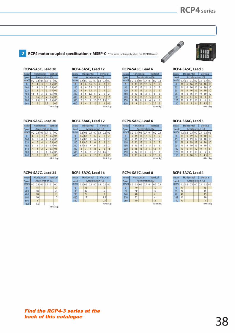
RCP4 series
RCP4-SA5C, Lead 20 RCP4-SA5C, Lead 12 RCP4-SA5C, Lead 3RCP4-SA5C, Lead 6
RCP4-SA6C, Lead 20 RCP4-SA6C, Lead 12 RCP4-SA6C, Lead 3RCP4-SA6C, Lead 6
RCP4-SA7C, Lead 24 RCP4-SA7C, Lead 16 RCP4-SA7C, Lead 4RCP4-SA7C, Lead 8
0.2555
4.5432
0160320480640800960
0.34444
3.52.52
0.53333211
0.7333321
0.5
0.10.50.50.50.50.50.5
0.20.50.50.50.50.50.50.5
Orientation
Speed(mm/s)
HorizontalAcceleration (G)
Vertical
0.28888875
0100200300400500600
0.36666654
0.55.55.55.55.5422
0.75555
3.51.51.5
0.122222
1.51
0.222222
1.51
0.32222
1.51
0.5
Orientation
Speed(mm/s)
HorizontalAcceleration (G)
Vertical
0.213131313131313
050
100150200250300
0.31313131313109
0.5131313131385
0.7121212121274
0.15555543
0.25555
4.54
2.5
0.35555432
Orientation
Speed(mm/s)
HorizontalAcceleration (G)
Vertical
0.216161616161616
0255075
100125150
0.316161616161310
0.51616161614119
0.71616161412108
0.1101010101075
0.21010101096
4.5
0.310101010863
Orientation
Speed(mm/s)
HorizontalAcceleration (G)
Vertical
(Unit: kg) (Unit: kg) (Unit: kg) (Unit: kg)
(Unit: kg)
(Unit: kg)
(Unit: kg) (Unit: kg) (Unit: kg)
(Unit: kg) (Unit: kg) (Unit: kg)
0.26665432
0160320480640800960
0.36665432
0.54443211
0.7444321
0.5
0.10.50.50.50.50.50.5
0.20.50.50.50.50.50.50.5
Orientation
Speed(mm/s)
HorizontalAcceleration (G)
Vertical
0.28.58.58.58.5876
0100200300400500600
0.38.58.58.58.5766
0.57777432
0.76666
3.52
1.5
0.122222
1.51
0.222222
1.51
0.32222
1.51
0.5
Orientation
Speed(mm/s)
HorizontalAcceleration (G)
Vertical
0.219191919191816
0255075
100125150
0.319191919161413
0.519191919141110
0.71919191912109
0.1101010101075
0.21010101096
4.5
0.310101010863
Orientation
Speed(mm/s)
HorizontalAcceleration (G)
Vertical
0.216161616161513
050
100150200250300
0.315151515151212
0.51313131313106
0.7121212121274
0.15555543
0.25555
4.54
2.5
0.35555432
Orientation
Speed(mm/s)
HorizontalAcceleration (G)
Vertical
0.20
200400600800
1000
0.3181818105
1.5
0.5 0.7 0.1 0.2222
1.51
Orientation
Speed(mm/s)
HorizontalAcceleration (G)
Vertical
0.20
140280420560
0.3353525157
0.5 0.7 0.1 0.2553
1.50.5
0.3
Orientation
Speed(mm/s)
HorizontalAcceleration (G)
Vertical
0.20
70140210280
0.34040402510
0.5 0.7 0.1 0.2101074
1.5
0.3
Orientation
Speed(mm/s)
HorizontalAcceleration (G)
Vertical
0.24040404040
03570
105140
0.3 0.5 0.7 0.1 0.2151515105
0.3
Orientation
Speed(mm/s)
HorizontalAcceleration (G)
Vertical
* The same tables apply when the RCP4CR is used.2
RCP4 series
38Find the RCP4-3 series at the back of this catalogue
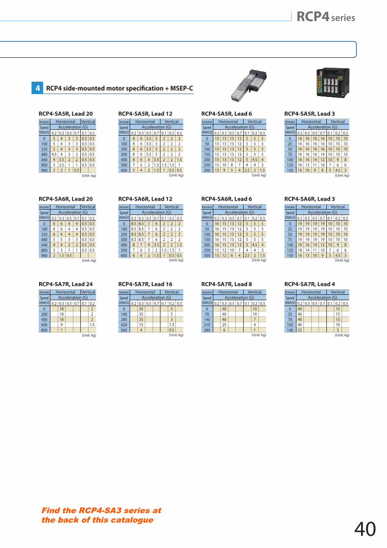
RCP4 series
RCP4-SA5R, Lead 20 RCP4-SA5R, Lead 12 RCP4-SA5R, Lead 3RCP4-SA5R, Lead 6
RCP4-SA6R, Lead 20 RCP4-SA6R, Lead 12 RCP4-SA6R, Lead 3RCP4-SA6R, Lead 6
RCP4-SA7R, Lead 24 RCP4-SA7R, Lead 16 RCP4-SA7R, Lead 4RCP4-SA7R, Lead 8
(Unit: kg) (Unit: kg) (Unit: kg) (Unit: kg)
(Unit: kg) (Unit: kg) (Unit: kg) (Unit: kg)
(Unit: kg) (Unit: kg) (Unit: kg) (Unit: kg)
0.20
200400600800
0.318181891
0.5 0.7 0.1 0.2222
1.5
Orientation
Speed(mm/s)
HorizontalAcceleration (G)
Vertical
0.20
140280420560
0.3353525154
0.5 0.7 0.1 0.2553
1.50.5
0.3
Orientation
Speed(mm/s)
HorizontalAcceleration (G)
Vertical
0.20
70140210280
0.3404040256
0.5 0.7 0.1 0.21010741
0.3
Orientation
Speed(mm/s)
HorizontalAcceleration (G)
Vertical
0.24040404022
03570
105140
0.3 0.5 0.7 0.1 0.2151515103
0.3
Orientation
Speed(mm/s)
HorizontalAcceleration (G)
Vertical
0.219191919191816
0255075
100125150
0.319191919161413
0.519191919141110
0.71919191912109
0.1101010101075
0.21010101096
4.5
0.310101010863
Orientation
Speed(mm/s)
HorizontalAcceleration (G)
Vertical
0.216161616161513
050
100150200250300
0.315151515151212
0.51313131313106
0.7121212121274
0.1555554
2.5
0.25555
4.542
0.3555543
1.5
Orientation
Speed(mm/s)
HorizontalAcceleration (G)
Vertical
0.28.58.58.58.5876
0100200300400500600
0.38.58.58.58.5766
0.57777432
0.76666
3.52
1.5
0.122222
1.51
0.222222
1.50.5
0.32222
1.51
0.5
Orientation
Speed(mm/s)
HorizontalAcceleration (G)
Vertical
0.26665432
0160320480640800960
0.3666543
1.5
0.5444321
0.5
0.7444321
0.10.50.50.50.50.50.5
0.20.50.50.50.50.50.5
Orientation
Speed(mm/s)
HorizontalAcceleration (G)
Vertical
0.2555
4.5432
0160320480640800960
0.34444
3.52.52
0.53333211
0.7333321
0.5
0.10.50.50.50.50.50.5
0.20.50.50.50.50.50.5
Orientation
Speed(mm/s)
HorizontalAcceleration (G)
Vertical
0.28888875
0100200300400500600
0.36666654
0.55.55.55.55.5422
0.75555
3.51.51.5
0.122222
1.51
0.222222
1.50.5
0.32222
1.51
0.5
Orientation
Speed(mm/s)
HorizontalAcceleration (G)
Vertical
0.213131313131313
050
100150200250300
0.31313131313109
0.5131313131385
0.7121212121274
0.1555554
2.5
0.25555
4.542
0.3555543
1.5
Orientation
Speed(mm/s)
HorizontalAcceleration (G)
Vertical
0.216161616161616
0255075
100125150
0.316161616161310
0.51616161614119
0.71616161412108
0.1101010101075
0.21010101096
4.5
0.310101010863
Orientation
Speed(mm/s)
HorizontalAcceleration (G)
Vertical
4
RCP4 series
40Find the RCP4-SA3 series at the back of this catalogue
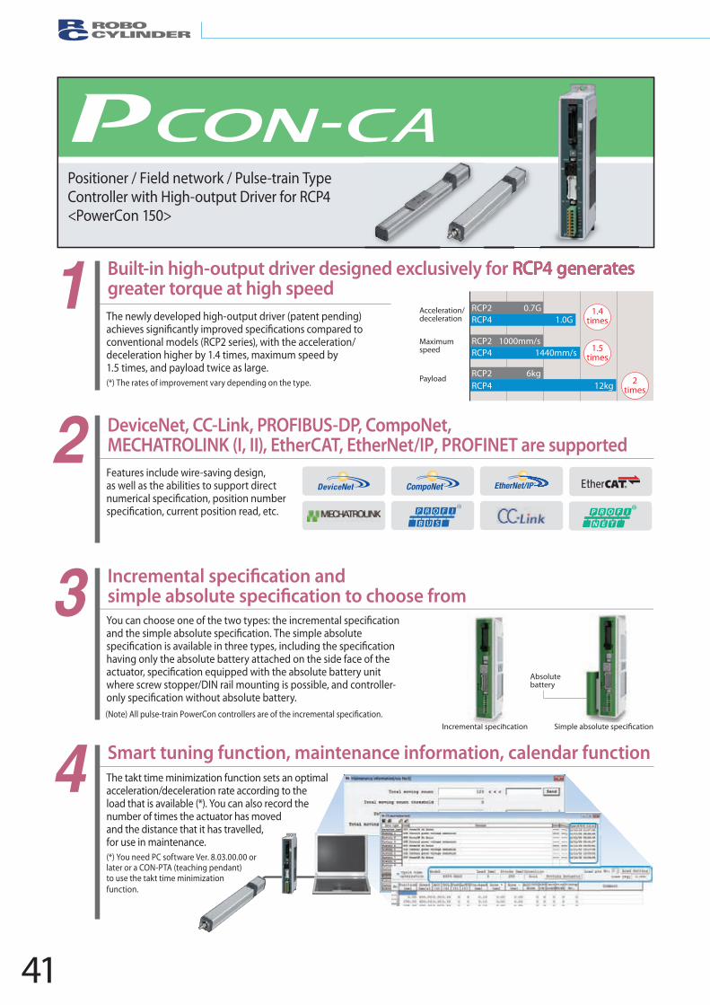
41
DeviceNet, CC-Link, PROFIBUS-DP, CompoNet, MECHATROLINK (I, II), EtherCAT, EtherNet/IP, PROFINET are supported
The takt time minimization function sets an optimal acceleration/deceleration rate according to the load that is available (*). You can also record the number of times the actuator has moved and the distance that it has travelled, for use in maintenance.(*) You need PC software Ver. 8.03.00.00 or
(Note) All pulse-train PowerCon controllers are of the incremental speci�cation.
later or a CON-PTA (teaching pendant) to use the takt time minimization function.
4
1
2
3
The newly developed high-output driver (patent pending)
conventional models (RCP2 series), with the acceleration/deceleration higher by 1.4 times, maximum speed by 1.5 times, and payload twice as large. (*) The rates of improvement vary depending on the type.
Features include wire-saving design, as well as the abilities to support direct
having only the absolute battery attached on the side face of the
where screw stopper/DIN rail mounting is possible, and controller-
Built-in high-output driver designed exclusively for RCP4 generates greater torque at high speed
Smart tuning function, maintenance information, calendar function
Positioner / Field network / Pulse-train Type Controller with High-output Driver for RCP4 <PowerCon 150>
Absolute battery
Acceleration/deceleration
1.4 times
1.5 times
2 times
RCP2 0.7GRCP4 1.0G
RCP2 1000mm/sRCP4 1440mm/s
RCP2 6kgRCP4 12kg
Payload
Maximum speed
RCP4 generates
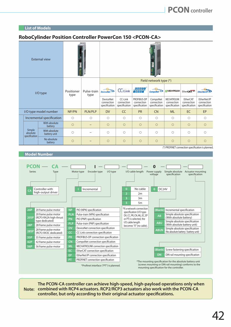
42
External view
I/O type Positionertype
Pulse-traintype
Field network type (*)
DeviceNet connection
CC-Link
(*) PROFINET connection speci�cation is planned.
connectionPROFIBUS-DP connection
CompoNet connection
MECHATROLINK connection
EtherCAT connection
EtherNet/IP connection
I/O type model number NP/PN PLN/PLP DV CC PR CN ML EC EP
Simpleabsolute
With absolutebattery –
With absolutebattery unit –
No absolutebattery –
I Incremental
(Blank) Screw fastening speci�cation
DN DIN rail mounting speci�cation
0 DC24VCA Controller with high-output driver
20P 20 frame pulse motor
20SP20 frame pulse motor (RCP3-RA2A high-thrust type dedicated)
28P 28 frame pulse motor
28SP 28 frame pulse motor(RCP2-RA3C dedicated)
35P 35 frame pulse motor42P 42 frame pulse motor56P 56 frame pulse motor
0 No cable
2 2m
3 3m
5 5m
(Blank) Incremental speci�cation
AB Simple absolute speci�cation(With absolute battery)
ABU Simple absolute speci�cation(With absolute battery unit)
ABUN Simple absolute speci�cation(No absolute battery / battery unit)
NP PIO (NPN) speci�cationPLN Pulse-train (NPN) speci�cationPN PIO (PNP) speci�cationPLP Pulse-train (PNP) speci�cationDV DeviceNet connection speci�cationCC CC-Link connection speci�cationPR PROFIBUS-DP connection speci�cationCN CompoNet connection speci�cationML MECHATROLINK connection speci�cationEC EtherCAT connection speci�cationEP EtherNet/IP connection speci�cationPT PROFINET connection speci�cation
Series Type Motor type Encoder type I/O type I/O cable length Power supply voltage
Simple absolute speci�cation
Actuator mounting speci�cation
I 0PCON CA
*The mounting speci�cation for the absolute battery unit
*Pro�net interface (“PT“) is planned. (screws mounting or DIN rail mounting) conforms to the mounting speci�cation for the controller.
*If a network connectionspeci�cation (I/O type-DV, CC, PR, CN, ML, EC, EP or PT) is selected, the I/O cable length becomes "0" (no cable).
List of Models
Model Number
Note:The PCON-CA controller can achieve high-speed, high-payload operations only when
combined with RCP4 actuators. RCP2/RCP3 actuators also work with the PCON-CA
RoboCylinder Position Controller PowerCon 150 <PCON-CA>
PCON controller
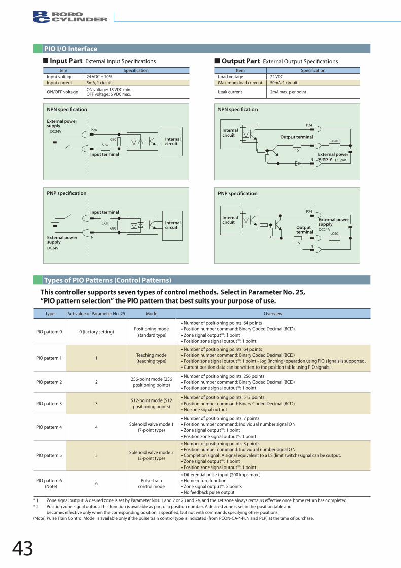
43
Item Speci�cationInput voltage 24 VDC ± 10%Input current 5mA, 1 circuit
ON/OFF voltage ON voltage: 18 VDC min.OFF voltage: 6 VDC max.
Item Speci�cationLoad voltage 24 VDCMaximum load current 50mA, 1 circuit
Leak current 2mA max. per point
Type Set value of Parameter No. 25 Mode Overview
PIO pattern 0 0 (factory setting) Positioning mode (standard type)
• Number of positioning points: 64 points• Position number command: Binary Coded Decimal (BCD)• Zone signal output*1: 1 point • Position zone signal output*2: 1 point
PIO pattern 1 1 Teaching mode (teaching type)
• Number of positioning points: 64 points• Position number command: Binary Coded Decimal (BCD) • Position zone signal output*2: 1 point • Jog (inching) operation using PIO signals is supported.• Current position data can be written to the position table using PIO signals.
PIO pattern 2 2 256-point mode (256 positioning points)
• Number of positioning points: 256 points • Position number command: Binary Coded Decimal (BCD) • Position zone signal output*2: 1 point
PIO pattern 3 3 512-point mode (512 positioning points)
• Number of positioning points: 512 points • Position number command: Binary Coded Decimal (BCD) • No zone signal output
PIO pattern 4 4 Solenoid valve mode 1 (7-point type)
• Number of positioning points: 7 points• Position number command: Individual number signal ON • Zone signal output*1: 1 point • Position zone signal output*2: 1 point
PIO pattern 5 5 Solenoid valve mode 2 (3-point type)
• Number of positioning points: 3 points• Position number command: Individual number signal ON • Completion signal: A signal equivalent to a LS (limit switch) signal can be output.• Zone signal output*1: 1 point • Position zone signal output*2: 1 point
PIO pattern 6(Note) 6 Pulse-train
control mode
• Differential pulse input (200 kpps max.)• Home return function • Zone signal output*1: 2 points• No feedback pulse output
External power supply
Input terminal
P24DC24V
6805.6k
Internal circuit
DC24V
External power supply
Input terminal
6805.6k Internal
circuit
N
NExternal power supply
Output terminal
15
P24Internal circuit
DC24V
Load
Outputterminal
Internal circuit
15N
P24
DC24V
External power supply
Load
PIO I/O Interface
Types of PIO Patterns (Control Patterns)
Input Part Output Part
This controller supports seven types of control methods. Select in Parameter No. 25, “PIO pattern selection” the PIO pattern that best suits your purpose of use.
* 1 Zone signal output: A desired zone is set by Parameter Nos. 1 and 2 or 23 and 24, and the set zone always remains effective once home return has completed. * 2 Position zone signal output: This function is available as part of a position number. A desired zone is set in the position table and
becomes effective only when the corresponding position is speci�ed, but not with commands specifying other positions.(Note) Pulse Train Control Model is available only if the pulse train control type is indicated (from PCON-CA-*-PLN and PLP) at the time of purchase.
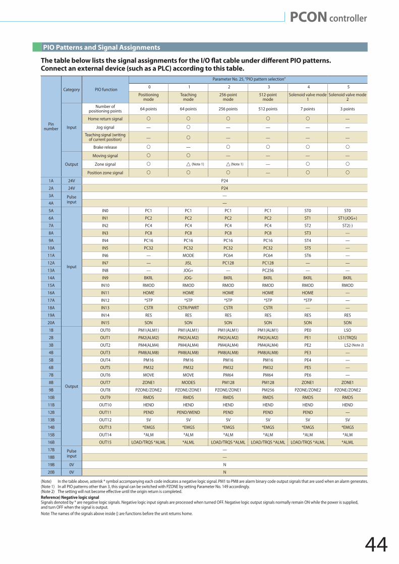
44
PCON controller
Pin number
Category PIO function
Parameter No. 25, “PIO pattern selection”
0 1 2 3 4 5
Positioning mode
Teaching mode
256-point mode
512-point mode
Solenoid valve mode 1
Solenoid valve mode 2
Input
Number of positioning points 64 points 64 points 256 points 512 points 7 points 3 points
Home return signal —
Jog signal — — — — —
Teaching signal (writing of current position) — — — — —
Brake release —
Output
Moving signal — — — —
Zone signal —
Position zone signal —
1A 24V P24
2A 24V P24
3A Pulse input
—
4A —
5A
Input
IN0 PC1 PC1 PC1 PC1 ST0 ST0
6A IN1 PC2 PC2 PC2 PC2 ST1 ST1(JOG+)
7A IN2 PC4 PC4 PC4 PC4 ST2 ST2(-)
8A IN3 PC8 PC8 PC8 PC8 ST3 —
9A IN4 PC16 PC16 PC16 PC16 ST4 —
10A IN5 PC32 PC32 PC32 PC32 ST5 —
11A IN6 — MODE PC64 PC64 ST6 —
12A IN7 — JISL PC128 PC128 — —
13A IN8 — JOG+ — PC256 — —
14A IN9 BKRL JOG- BKRL BKRL BKRL BKRL
15A IN10 RMOD RMOD RMOD RMOD RMOD RMOD
16A IN11 HOME HOME HOME HOME HOME —
17A IN12 *STP *STP *STP *STP *STP —
18A IN13 CSTR CSTR/PWRT CSTR CSTR — —
19A IN14 RES RES RES RES RES RES
20A IN15 SON SON SON SON SON SON
1B
Output
OUT0 PM1(ALM1) PM1(ALM1) PM1(ALM1) PM1(ALM1) PE0 LSO
2B OUT1 PM2(ALM2) PM2(ALM2) PM2(ALM2) PM2(ALM2) PE1 LS1(TRQS)
3B OUT2 PM4(ALM4) PM4(ALM4) PM4(ALM4) PM4(ALM4) PE2 LS2
4B OUT3 PM8(ALM8) PM8(ALM8) PM8(ALM8) PM8(ALM8) PE3 —
5B OUT4 PM16 PM16 PM16 PM16 PE4 —
6B OUT5 PM32 PM32 PM32 PM32 PE5 —
7B OUT6 MOVE MOVE PM64 PM64 PE6 —
8B OUT7 ZONE1 MODES PM128 PM128 ZONE1 ZONE1
9B OUT8 PZONE/ZONE2 PZONE/ZONE1 PZONE/ZONE1 PM256 PZONE/ZONE2 PZONE/ZONE2
10B OUT9 RMDS RMDS RMDS RMDS RMDS RMDS
11B OUT10 HEND HEND HEND HEND HEND HEND
12B OUT11 PEND PEND/WEND PEND PEND PEND —
13B OUT12 SV SV SV SV SV SV
14B OUT13 *EMGS *EMGS *EMGS *EMGS *EMGS *EMGS
15B OUT14 *ALM *ALM *ALM *ALM *ALM *ALM
16B OUT15 LOAD/TRQS *ALML *ALML LOAD/TRQS *ALML LOAD/TRQS *ALML LOAD/TRQS *ALML *ALML
17B Pulse input
—
18B —
19B 0V N
20B 0V N
(Note 2)
(Note 1) (Note 1)
PIO Patterns and Signal Assignments
Connect an external device (such as a PLC) according to this table.
(Note) In the table above, asterisk * symbol accompanying each code indicates a negative logic signal. PM1 to PM8 are alarm binary code output signals that are used when an alarm generates. (Note 1) In all PIO patterns other than 3, this signal can be switched with PZONE by setting Parameter No. 149 accordingly.(Note 2) The setting will not become e�ective until the origin return is completed.Reference) Negative logic signal Signals denoted by * are negative logic signals. Negative logic input signals are processed when turned OFF. Negative logic output signals normally remain ON while the power is supplied, and turn OFF when the signal is output.Note: The names of the signals above inside () are functions before the unit returns home.
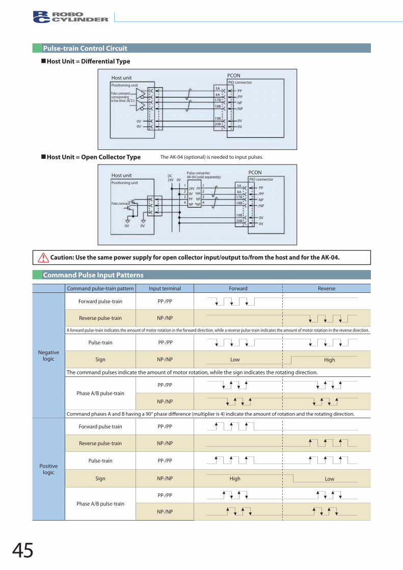
45
Host unit PCON
Positioning unitPIO connector
Pulse command (corresponding to line driver 26C31)
0V
PP/PPNP/NP
0V0V
3A
4A17B
18B
19B20B0V
Host unitPositioning unit
PCONPIO connector
Pulse command
PP/PPNP/NP
0V0V
24V0VPPNP
1234
1234
PP*PPNP
*NP
3A
4A17B
18B
19B20B
0V 0V
DC24V
Pulse converter AK-04 (sold separately)
0V
Command pulse-train pattern Input terminal Forward Reverse
Negative logic
Forward pulse-train PP·/PP
Reverse pulse-train NP·/NP
A forward pulse-train indicates the amount of motor rotation in the forward direction, while a reverse pulse-train indicates the amount of motor rotation in the reverse direction.
Pulse-train PP·/PP
Sign NP·/NP
The command pulses indicate the amount of motor rotation, while the sign indicates the rotating direction.
Phase A/B pulse-train PP·/PP
NP·/NP
Command phases A and B having a 90° phase di�erence (multiplier is 4) indicate the amount of rotation and the rotating direction.
Positivelogic
Forward pulse train PP·/PP
Reverse pulse-train NP·/NP
Pulse-train PP·/PP
Sign NP·/NP
Phase A/B pulse-train PP·/PP
NP·/NP
Low High
High Low
Host unit PCON
Positioning unitPIO connector
Pulse command (corresponding to line driver 26C31)
0V
PP/PPNP/NP
0V0V
3A
4A17B
18B
19B20B0V
Host unitPositioning unit
PCONPIO connector
Pulse command
PP/PPNP/NP
0V0V
24V0VPPNP
1234
1234
PP*PPNP
*NP
3A
4A17B
18B
19B20B
0V 0V
DC24V
Pulse converterAK-04 (sold separately)
0V
Pulse-train Control Circuit
Command Pulse Input Patterns
Host Unit = Di�erential Type
Host Unit = Open Collector Type The AK-04 (optional) is needed to input pulses.
Caution: Use the same power supply for open collector input/output to/from the host and for the AK-04.
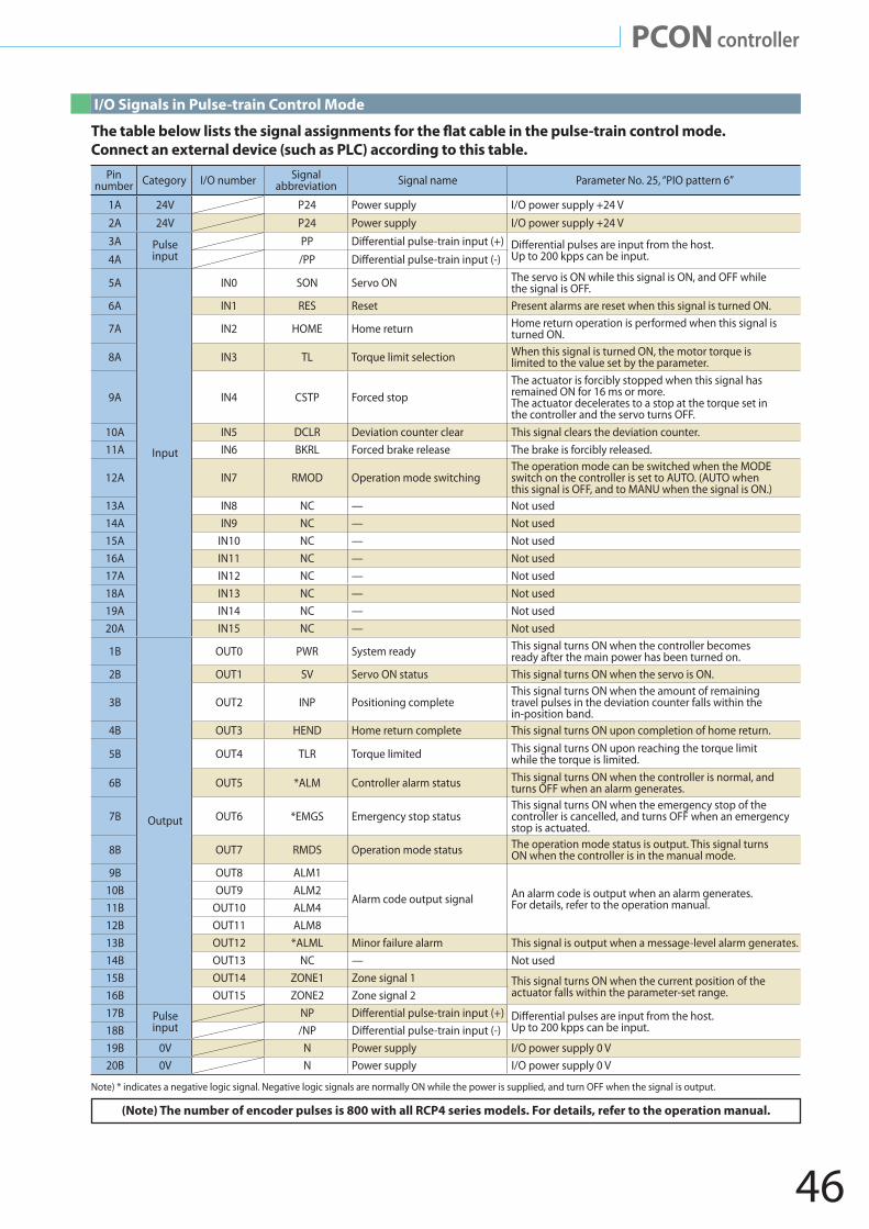
46
PCON controller
I/O Signals in Pulse-train Control Mode
(Note) The number of encoder pulses is 800 with all RCP4 series models. For details, refer to the operation manual.
Connect an external device (such as PLC) according to this table. Pin
number Category I/O number Signal abbreviation Signal name Parameter No. 25, “PIO pattern 6”
1A 24V P24 Power supply I/O power supply +24 V2A 24V P24 Power supply I/O power supply +24 V3A Pulse
inputPP Di�erential pulse-train input (+) Di�erential pulses are input from the host.
Up to 200 kpps can be input.4A /PP Di�erential pulse-train input (-)
5A
Input
IN0 SON Servo ON The servo is ON while this signal is ON, and OFF while the signal is OFF.
6A IN1 RES Reset Present alarms are reset when this signal is turned ON.
7A IN2 HOME Home return Home return operation is performed when this signal is turned ON.
8A IN3 TL Torque limit selection When this signal is turned ON, the motor torque is limited to the value set by the parameter.
9A IN4 CSTP Forced stopThe actuator is forcibly stopped when this signal has remained ON for 16 ms or more. The actuator decelerates to a stop at the torque set in the controller and the servo turns OFF.
10A IN5 DCLR Deviation counter clear This signal clears the deviation counter.11A IN6 BKRL Forced brake release The brake is forcibly released.
12A IN7 RMOD Operation mode switchingThe operation mode can be switched when the MODE switch on the controller is set to AUTO. (AUTO when this signal is OFF, and to MANU when the signal is ON.)
13A IN8 NC — Not used14A IN9 NC — Not used15A IN10 NC — Not used16A IN11 NC — Not used17A IN12 NC — Not used18A IN13 NC — Not used19A IN14 NC — Not used20A IN15 NC — Not used
1B
Output
OUT0 PWR System ready This signal turns ON when the controller becomes ready after the main power has been turned on.
2B OUT1 SV Servo ON status This signal turns ON when the servo is ON.
3B OUT2 INP Positioning completeThis signal turns ON when the amount of remaining travel pulses in the deviation counter falls within the in-position band.
4B OUT3 HEND Home return complete This signal turns ON upon completion of home return.
5B OUT4 TLR Torque limited This signal turns ON upon reaching the torque limit while the torque is limited.
6B OUT5 *ALM Controller alarm status This signal turns ON when the controller is normal, and turns OFF when an alarm generates.
7B OUT6 *EMGS Emergency stop status This signal turns ON when the emergency stop of the controller is cancelled, and turns OFF when an emergency stop is actuated.
8B OUT7 RMDS Operation mode status The operation mode status is output. This signal turns ON when the controller is in the manual mode.
9B OUT8 ALM1
Alarm code output signal An alarm code is output when an alarm generates. For details, refer to the operation manual.
10B OUT9 ALM211B OUT10 ALM412B OUT11 ALM813B OUT12 *ALML Minor failure alarm This signal is output when a message-level alarm generates. 14B OUT13 NC — Not used15B OUT14 ZONE1 Zone signal 1 This signal turns ON when the current position of the
actuator falls within the parameter-set range.16B OUT15 ZONE2 Zone signal 217B Pulse
inputNP Di�erential pulse-train input (+) Di�erential pulses are input from the host.
Up to 200 kpps can be input. 18B /NP Di�erential pulse-train input (-)19B 0V N Power supply I/O power supply 0 V20B 0V N Power supply I/O power supply 0 V
Note) * indicates a negative logic signal. Negative logic signals are normally ON while the power is supplied, and turn OFF when the signal is output.
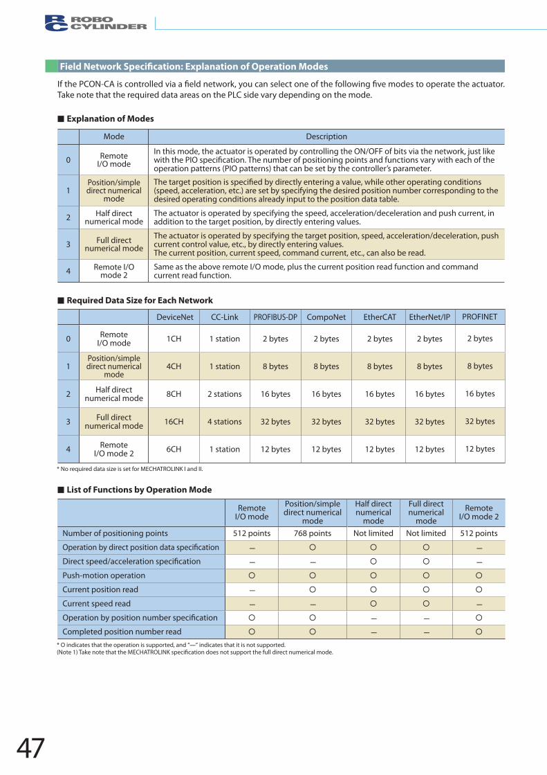
47
Take note that the required data areas on the PLC side vary depending on the mode.
Explanation of Modes
List of Functions by Operation Mode
Required Data Size for Each Network
DeviceNet CC-Link PROFIBUS-DP CompoNet EtherCAT EtherNet/IP
0 Remote I/O mode 1CH 1 station 2 bytes 2 bytes 2 bytes 2 bytes
1Position/simple direct numerical
mode4CH 1 station 8 bytes 8 bytes 8 bytes 8 bytes
2 Half direct numerical mode 8CH 2 stations 16 bytes 16 bytes 16 bytes 16 bytes
3 Full direct numerical mode 16CH 4 stations 32 bytes 32 bytes 32 bytes 32 bytes
4 Remote I/O mode 2 6CH 1 station 12 bytes 12 bytes 12 bytes 12 bytes
PROFINET
2 bytes
8 bytes
16 bytes
32 bytes
12 bytes
Remote I/O mode
Position/simple direct numerical
mode
Half direct numerical
mode
Full direct numerical
modeRemote
I/O mode 2
Number of positioning points 512 points 768 points Not limited Not limited 512 points
— —
— — —
Push-motion operation
Current position read —
Current speed read — — —
— —
Completed position number read — —
Mode Description
0 Remote I/O mode
In this mode, the actuator is operated by controlling the ON/OFF of bits via the network, just like
operation patterns (PIO patterns) that can be set by the controller’s parameter.
1Position/simple direct numerical
mode(speed, acceleration, etc.) are set by specifying the desired position number corresponding to the desired operating conditions already input to the position data table.
2 Half direct numerical mode
The actuator is operated by specifying the speed, acceleration/deceleration and push current, in addition to the target position, by directly entering values.
3 Full direct numerical mode
The actuator is operated by specifying the target position, speed, acceleration/deceleration, push current control value, etc., by directly entering values.The current position, current speed, command current, etc., can also be read.
4 Remote I/Omode 2
Same as the above remote I/O mode, plus the current position read function and command current read function.
* O indicates that the operation is supported, and “—“ indicates that it is not supported. (Note 1)
* No required data size is set for MECHATROLINK I and II.
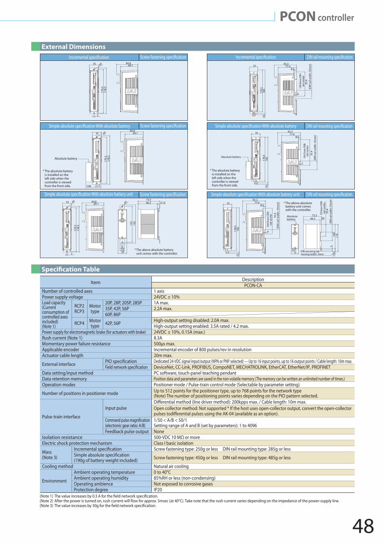
48
PCON controller
Item DescriptionPCON-CA
Number of controlled axes 1 axisPower supply voltage 24VDC ± 10%Load capacity (Current consumption of controlled axes included)(Note 1)
RCP2RCP3
Motor type
20P, 28P, 20SP, 28SP 1A max.35P, 42P, 56P 2.2A max.60P, 86P
RCP4 Motor type 42P, 56P High-output setting disabled: 2.0A max.
High-output setting enabled: 3.5A rated / 4.2 max.Power supply for electromagnetic brake (for actuators with brake) 24VDC ± 10%, 0.15A (max.)Rush current (Note 1) 8.3AMomentary power failure resistance 500µs max.Applicable encoder Incremental encoder of 800 pulses/rev in resolutionActuator cable length 20m max.
External interface Dedicated 24-VDC signal input/output (NPN or PNP selected) --- Up to 16 input points, up to 16 output points / Cable length: 10m max.DeviceNet, CC-Link, PROFIBUS, CompoNET, MECHATROLINK, EtherCAT, EtherNet/IP, PROFINET
Data setting/input method PC software, touch-panel teaching pendantData retention memory Position data and parameters are saved in the non-volatile memory (The memory can be written an unlimited number of times.)Operation modes Positioner mode / Pulse-train control mode (Selectable by parameter setting)
Number of positions in positioner mode Up to 512 points for the positioner type, up to 768 points for the network type(Note) The number of positioning points varies depending on the PIO pattern selected.
Pulse-train interface
Input pulse Open collector method: Not supported * If the host uses open-collector output, convert the open-collector
(electronic gear ratio: A/B)1/50 < A/B < 50/1Setting range of A and B (set by parameters): 1 to 4096
Feedback pulse output NoneIsolation resistance 500-VDC 10 MΩ or moreElectric shock protection mechanism Class I basic isolation
Mass(Note 3)
Screw fastening type: 250g or less DIN rail mounting type: 285g or less
(190g of battery weight included) Screw fastening type: 450g or less DIN rail mounting type: 485g or less
Cooling method Natural air cooling
Environment
Ambient operating temperature 0 to 40°CAmbient operating humidity 85%RH or less (non-condensing)Operating ambience Not exposed to corrosive gasesProtection degree IP20
(Note 1) (Note 2) (Note 3)
Scr
Scr
Scr
With absolute battery
With absolute battery unit With absolute battery unit
With absolute battery
* The above absolute battery unit comes with the controller.
122
51530
66.273.5
(7.3)
130
178.
517
0.5
35
5
84.869.1
ø5ø5
178.
517
0.5
35
Absolute battery
* The absolute batteryis installed on the left side when the controller is viewed from the front side.
* The absolute batteryis installed on the left side when the controller is viewed from the front side.5
84.869.1ø5
(58)
178.
517
0.5
35
5
84.869.1ø5
* The above absolute battery unit comes with the controller.
35
(5)
185
178.
5
93.377.6
8.5
4
104
from
DIN
rail
cent
er
(DIN
rail
wid
th: 3
5mm
)
(DIN
rail
wid
th: 3
5mm
)
50 fr
om D
INra
il ce
nter
104
from
DIN
rail
cent
er
104
from
DIN
rail
cent
er
35.4
(DIN
rail
wid
th: 3
5mm
)
DIN securing tabmoving width: 5mm
Absolute battery
Absolute battery
(10)
100
110
35.4
35.4
(DIN
rail
wid
th: 3
5mm
)35
.4
5
72.2
30
66.2 (6)
35
185
178.
5(5
)
93.377.6
8.5
35
(5)
93.377.6
8.5
185
178.
5
4
4
External DimensionsScr
Scr
Scr
With absolute battery
With absolute battery unit With absolute battery unit
With absolute battery
* The above absolute batteryunit comes with the controller.
122
51530
66.273.5
(7.3)
130
178.
517
0.5
35
5
84.869.1
ø5ø5
178.
517
0.5
35
Absolute battery
* The absolute batteryis installed on the left side when the controller is viewed from the front side.
* The absolute battery is installed on the left side when the controller is viewed from the front side.5
84.869.1ø5
(58)
178.
517
0.5
35
5
84.869.1ø5
* The above absolute battery unit comes with the controller.
35
(5)
185
178.
5
93.377.6
8.5
4
104
from
DIN
rail
cent
er
(DIN
rail
wid
th: 3
5mm
)
(DIN
rail
wid
th: 3
5mm
)
50 fr
om D
INra
il ce
nter
104
from
DIN
rail
cent
er
104
from
DIN
rail
cent
er
35.4
(DIN
rail
wid
th: 3
5mm
)
DIN securing tabmoving width: 5mm
Absolute battery
Absolute battery
(10)
100
110
35.4
35.4
(DIN
rail
wid
th: 3
5mm
)35
.4
5
72.2
30
66.2 (6)
35
185
178.
5(5
)
93.377.6
8.5
35
(5)
93.377.6
8.5
185
178.
5
4
4
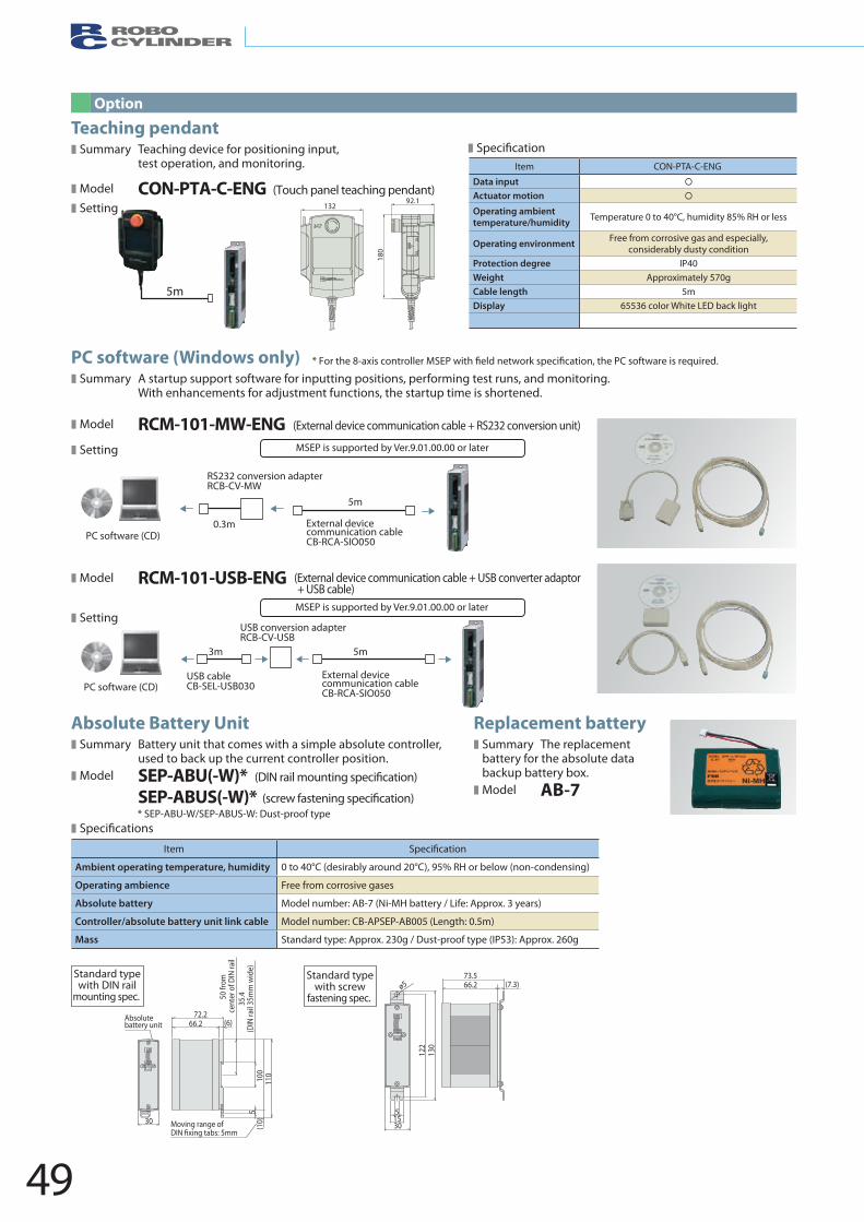
49
ø5
122
51530
66.273.5
(7.3)
130
(10)
100
110
50 fr
om
cent
er o
f DIN
rail
35.4
(DIN
rail
35m
m w
ide)
5
72.2
30 Moving range of m
Absolute battery unit 66.2 (6)
Standard typewith DIN rail
mounting spec.
Standard typewith screw
fastening spec.
Item Speci�cation
Ambient operating temperature, humidity 0 to 40°C (desirably around 20°C), 95% RH or below (non-condensing)
Operating ambience Free from corrosive gases
Absolute battery Model number: AB-7 (Ni-MH battery / Life: Approx. 3 years)
Controller/absolute battery unit link cable Model number: CB-APSEP-AB005 (Length: 0.5m)
Mass Standard type: Approx. 230g / Dust-proof type (IP53): Approx. 260g
Absolute Battery Unit❚ Summary Battery unit that comes with a simple absolute controller,
used to back up the current controller position. ❚ Model SEP-ABU(-W)*
SEP-ABUS(-W)*
❚ Speci�cations
Replacement battery❚ Summary
(DIN rail mounting speci�cation)
(screw fastening speci�cation)* SEP-ABU-W/SEP-ABUS-W: Dust-proof type
The replacement battery for the absolute databackup battery box.
❚ Model AB-7
Option
13292.1
180
Item CON-PTA-C-ENG
Data input Actuator motion
Operating ambienttemperature/humidity Temperature 0 to 40°C, humidity 85% RH or less
Operating environment Free from corrosive gas and especially,considerably dusty condition
Protection degree IP40Weight Approximately 570gCable length 5mDisplay 65536 color White LED back light
5m
Teaching pendant❚ Summary Teaching device for positioning input,
test operation, and monitoring.
❚ Model CON-PTA-C-ENG (Touch panel teaching pendant)❚ Setting
❚ Speci�cation
PC software (Windows only)❚ Summary A startup support software for inputting positions, performing test runs, and monitoring.
With enhancements for adjustment functions, the startup time is shortened.
❚ Model RCM-101-MW-ENG (External device communication cable + RS232 conversion unit)
❚ Setting
❚ Model RCM-101-USB-ENG (External device communication cable + USB converter adaptor+ USB cable)
❚ Setting
External device communication cable CB-RCA-SIO050
USB conversion adapter RCB-CV-USB
USB cable CB-SEL-USB030
3m 5m
PC software (CD)
MSEP is supported by Ver.9.01.00.00 or later
MSEP is supported by Ver.9.01.00.00 or later
RS232 conversion adapter RCB-CV-MW
External device communication cable CB-RCA-SIO050
0.3m
5m
PC software (CD)
* For the 8-axis controller MSEP with �eld network speci�cation, the PC software is required.
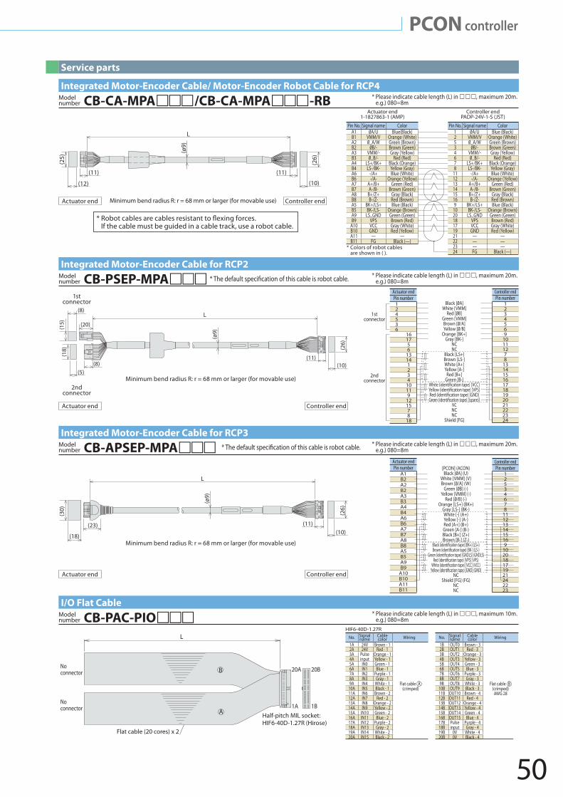
50
PCON controller
Integrated Motor-Encoder Cable/ Motor-Encoder Robot Cable for RCP4* Please indicate cable length (L) in , maximum 20m.
e.g.) 080=8mCB-CA-MPA/CB-CA-MPA-RBModel number
I/O Flat Cable* Please indicate cable length (L) in , maximum 10m.
e.g.) 080=8mCB-PAC-PIOModel number
Integrated Motor-Encoder Cable for RCP2* Please indicate cable length (L) in , maximum 20m.
e.g.) 080=8mCB-PSEP-MPAModel number *
Integrated Motor-Encoder Cable for RCP3* Please indicate cable length (L) in , maximum 20m.
e.g.) 080=8mCB-APSEP-MPAModel number *
* Colors of robot cables are shown in ( ).
Actuator end1-1827863-1 (AMP)
Controller endPADP-24V-1-S (JST)
Pin No. Signal name Color1 Blue (Black)2 VMM/V Orange (White)5 _A/W Green (Brown)3 Brown (Green)4 VMM/- Gray (Yellow)6 _B/- Red (Red)7 LS+/BK+ Black (Orange)8 LS-/BK- Yellow (Gray)
11 -/A+ Blue (White)12 -/A- Orange (Yellow)13 A+/B+ Green (Red)14 A-/B- Brown (Green)15 B+/Z+ Gray (Black)16 B-/Z- Red (Brown)9 BK+/LS+ Blue (Black)
10 BK-/LS- Orange (Brown)20 LS_GND Green (Green)18 VPS Brown (Red)17 VCC Gray (White)19 GND Red (Yellow)21 — —22 — —23 — —24 FG Black (—)
Pin No. Signal name ColorA1 Blue(Black)B1 VMM/V Orange (White)A2 _A/W Green (Brown)B2 Brown (Green)A3 VMM/- Gray (Yellow)B3 _B/- Red (Red)A4 LS+/BK+ Black (Orange)B4 LS-/BK- Yellow (Gray)A6 -/A+ Blue (White)B6 -/A- Orange (Yellow)A7 A+/B+ Green (Red)B7 A-/B- Brown (Green)A8 B+/Z+ Gray (Black)B8 B-/Z- Red (Brown)A5 BK+/LS+ Blue (Black)B5 BK-/LS- Orange (Brown)A9 LS_GND Green (Green)B9 VPS Brown (Red)
A10 VCC Gray (White)B10 GND Red (Yellow)A11 — —B11 FG Black (—)
Service parts
* If the cable must be guided in a cable track, use a robot cable.
L
(11) (11)
(12) (10)
(25)
(26)
(ø9)
Minimum bend radius R: r = 68 mm or larger (for movable use)Actuator end Controller end
Actuator endPin number124536
161756
13141234
10119
121578
18
Black [ A]White [VMM]
Red [ B]Green [VMM]Brown [ /A]Yellow [ /B]
Orange [BK+]Gray [BK-]
NCNC
Black [LS+]Brown [LS-]White [A+]Yellow [A-]
Red [B+]Green [B-]
NCNCNC
Shield [FG]
Controller endPin number
1234569
10111278
131415161718192021222324
1stconnector
2ndconnector
(10)
L
(8)
(8)
(18)
(15)
(5)
(20)
(11)
(26)
(ø9)
Minimum bend radius R: r = 68 mm or larger (for movable use)
1stconnector
2ndconnector
Actuator end Controller end
L
(10)
(26)
(11)
(18)
(23)
(30)
(ø9)
Minimum bend radius R: r = 68 mm or larger (for movable use)
Actuator end Controller end
Flat cable (crimped)
Flat cable (crimped) AWG 28
No. Signal Cable Wiring name color 1A 24V Brown - 1 2A 24V Red - 13A Pulse Orange - 1 4A input Yellow - 15A IN0 Green - 16A IN1 Blue - 17A IN2 Purple - 18A IN3 Gray - 19A IN4 White - 1
10A IN5 Black - 111A IN6 Brown - 212A IN7 Red - 213A IN8 Orange - 214A IN9 Yellow - 215A IN10 Green - 216A IN11 Blue - 217A IN12 Purple - 218A IN13 Gray - 219A IN14 White - 220A IN15 Black - 2
HIF6-40D-1.27R
No. Signal Cable Wiring name color 1B OUT0 Brown - 3 2B OUT1 Red - 33B OUT2 Orange - 3 4B OUT3 Yellow - 35B OUT4 Green - 36B OUT5 Blue - 37B OUT6 Purple - 38B OUT7 Gray - 39B OUT8 White - 3
10B OUT9 Black - 311B OUT10 Brown - 412B OUT11 Red - 413B OUT12 Orange - 414B OUT13 Yellow - 415B OUT14 Green - 416B OUT15 Blue - 417B Pulse Purple - 418B input Gray - 419B 0V White - 420B 0V Black - 4
L
Half-pitch MIL socket: HIF6-40D-1.27R (Hirose)
Flat cable (20 cores) x 2
20B20A
1B1A
No connector
No connector
B
A
Actuator endPin number
A1B2A2B2A3B3A4B4A6B6A7B7A8B8A5B5A9B9
A10B10A11B11
Controller endPin number
12534678
1112131415169
102018171921242223
[PCON] (ACON)Black [ A] (U)
White [VMM] (V)Brown [ ] (W)
Green [ ] (-)Yellow [VMM] (-)
Red [ /B] (-)Orange [LS+] (BK+)
Gray [LS-] (BK-)White [-] (A+)Yellow [-] (A-)Red [A+] (B+)Green [A-] (B-)Black [B+] (Z+)Brown [B-] (Z-)
NCShield [FG] (FG)
NCNC
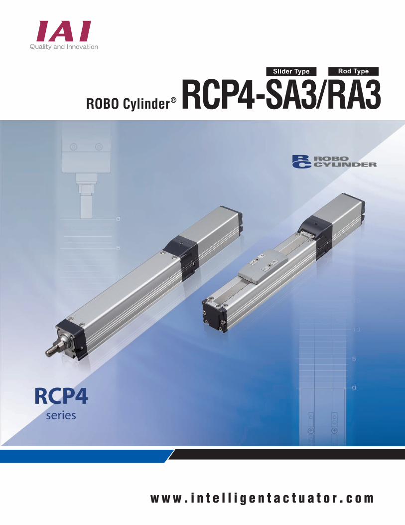
w w w . i n t e l l i g e n t a c t u a t o r . c o m
Slider Type
RCP4-SA3/RA3Rod Type
RCP4series
ROBO Cylinder®
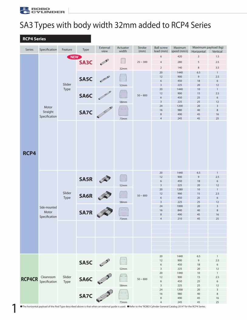
Battery-less Absolute Encoder Installed as Standard
1440900450225
1440900450225
1200980490245
1440900450225
1280900450225
1000840490210
1440900450225
1440900450225
1200980490245
6.59
18201015252520404545
6.59
18201015252520404545
6.59
18201015252520404545
12.56
121
2.56
1238
1625
12.56
121
2.56
1238
1625
12.56
121
2.56
1238
1625
SA3 Types with body width 32mm added to RCP4 Series
The horizontal payload of the Rod Type described above is that when an external guide is used. Refer to the “ROBO Cylinder General Catalog 2014” for the RCP4 Series.
Refer to the individual catalog for the RCP5 Series.
NameExternal
view Model number FeaturesMax. numberof positioning
points
Inputpower
Powersupply
capacity
Standardprice
Referencepage
Positioner typeEquipped with a high-output driverPositioner type based on PIO control
512points
24V DC
Refer to ROBO
Cylinder GeneralCatalog
Refer to ROBO
Cylinder GeneralCatalog
Pulse-train typePCON-CA-28PWAI-PLN-2-0PCON-CA-28PWAI-PLP-2-0
Equipped with a high-output driverPulse-train input type
Equipped with a high-output driverApplicable for 7 types of principal �eld networks
768points
Positioner Multiple AxesSpeci�cation PIO type
Positioner type with PIO control available to connect 8 axes at maximum
3points
Positioner Multiple AxesSpeci�cation network type
Positioner type applicable for �eld network available to connect 8 axes at maximum
256points
201263
201263
241684
201263
201263
241684
201263
201263
241684
32mm
52mm
58mm
73mm
52mm
58mm
73mm
52mm
58mm
73mm
Speci�cationSeries Feature Type Externalview
Actuatorwidth
Stroke(mm)
Ball screwlead (mm)
Maximumspeed (mm/s)
Maximum payload (kg)Horizontal Vertical
Speci�cationSeries Feature Type Externalview
Actuatorwidth
Stroke(mm)
Ball screwlead (mm)
Maximumspeed (mm/s)
Maximum payload (kg)Horizontal Vertical
RCP4
SliderType
MotorStraight
Speci�cation
Side-mountedMotor
Speci�cation
CleanroomSpeci�cation
SliderType
RCP4CR SliderType
SA3C
SA5C
SA6C
SA7C
SA5R
SA6R
SA7R
SA5C
SA6C
SA7C
50 ~ 800
25 ~ 300
6
4
2
420
280
140
3
5
8
1.5
2.5
3.5
50 ~ 800
50 ~ 800
16
10
5
2.5
20
12
6
3
24
16
8
4
16
10
5
2.5
20
12
6
3
24
16
8
4
20
10
5
10
5
2.5
20
10
5
10
5
2.5
600<450>
300<250>
150
250<167>
125
63
400
200
100
200<140>
100
50
30
60
100
80
150
300
30
60
100
80
150
300
5
40
70
80
100
150
5
40
70
80
100
150
1260
785
390
195
1440<1280>
900
450
225
1200
980<840>
490
245<210>
1120<840>
700
350
175
800
700
450
225
800<600>
700<560>
420
210
4
10
12
12
10
15
25
25
20
40
45
45
6
15
28
40
6
25
40
60
20
50
60
80
1
2.25
4.5
9
1
2.5
6
16
3
8
16
25
1.5
2.5
5
10
1.5
4
10
20
3
8
18
28
40mm
58mm
73mm
40mm
58mm
73mm
88mm
108mm
88mm
108mm
50 ~ 500
50 ~ 800
50 ~ 800
60 ~ 410
65 ~ 415
70 ~ 520
50 ~ 700
50 ~ 800
50 ~ 700
50 ~ 800
RCP5
SliderType
MotorStraight
Speci�cation
Side-mountedMotor
Speci�cation
SA4C
SA6C
SA7C
RA4C
RA6C
RA7C
RA8C
RA10C
RA8R
RA10R
Field network type
RCP4 Series
RCP5 Series
RCP4-SA3/RA3 Applicable Controllers
NEW
RodType
( )RadialCylinder
RodType
( )RadialCylinder
PCON-CA-28P -NP-2-0PCON-CA-28P -PN-2-0
PCON-CA-28P - -0-0
MSEP- - - ~ -NP-2-0MSEP- - - ~ -PN-2-0
MSEP- - - ~ - -0-0
1
1
*The encoder type comes in . Incremental Type is “WAI” and Simple Absolute is “SA”. *Either Type C or LC comes in . 6 axes are available to connect at the maximum if LC.*The number of axes (1 to 8) comes in . *The symbol (DV, CC, PR, CN, EC or EP) for the �eld network types comes in .1
RCP4/RCP5series
1 2
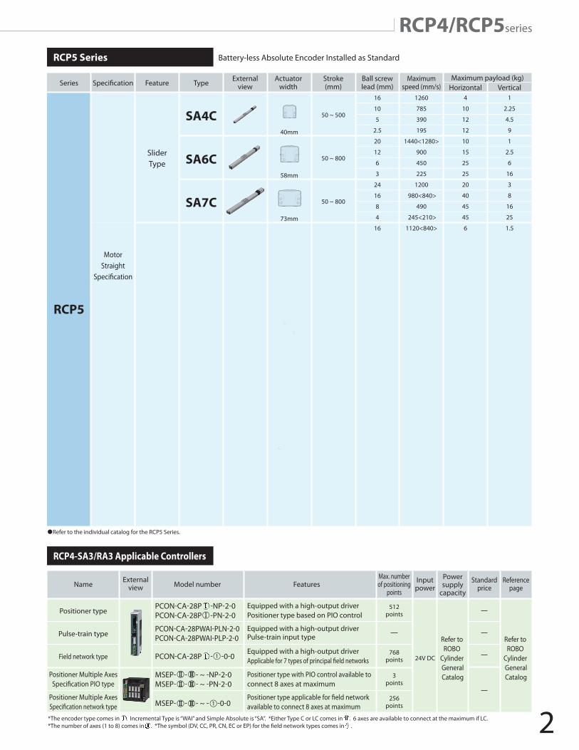
Battery-less Absolute Encoder Installed as Standard
1440900450225
1440900450225
1200980490245
1120700350175800700450225800700420210
1440900450225
1280900450225
1000840490210800700450225800560420175
1440900450225
1440900450225
1200980490245
6.59
182010152525204045456
1224366
254060205060806.59
182010152525204045456
254060205060806.59
18201015252520404545
12.56
121
2.56
1238
16251.52.55
101.54
102038
18281
2.56
121
2.56
1238
16251.54
102038
18281
2.56
121
2.56
1238
1625
SA3/RA3 Types with body width 32mm added to RCP4 Series
The horizontal payload of the Rod Type described above is that when an external guide is used. Refer to the “ROBO Cylinder General Catalog 2014” for the RCP4 Series.
Refer to the individual catalog for the RCP5 Series.
NameExternal
view Model number FeaturesMax. numberof positioning
points
Inputpower
Powersupply
capacity
Standardprice
Referencepage
Positioner typeEquipped with a high-output driverPositioner type based on PIO control
512points
24V DC
Refer to ROBO
Cylinder GeneralCatalog
Refer to ROBO
Cylinder GeneralCatalog
Pulse-train typePCON-CA-28PWAI-PLN-2-0PCON-CA-28PWAI-PLP-2-0
Equipped with a high-output driverPulse-train input type
Equipped with a high-output driverApplicable for 7 types of principal �eld networks
768points
Positioner Multiple AxesSpeci�cation PIO type
Positioner type with PIO control available to connect 8 axes at maximum
3points
Positioner Multiple AxesSpeci�cation network type
Positioner type applicable for �eld network available to connect 8 axes at maximum
256points
201263
201263
241684
16105
2.5201263
241684
201263
201263
241684
201263
241684
201263
201263
241684
32mm
52mm
58mm
73mm
32mm
52mm
61mm
52mm
58mm
73mm
52mm
61mm
52mm
58mm
73mm
Speci�cationSeries Feature Type Externalview
Actuatorwidth
Stroke(mm)
Ball screwlead (mm)
Maximumspeed (mm/s)
Maximum payload (kg)Horizontal Vertical
Speci�cationSeries Feature Type Externalview
Actuatorwidth
Stroke(mm)
Ball screwlead (mm)
Maximumspeed (mm/s)
Maximum payload (kg)Horizontal Vertical
RCP4
SliderType
MotorStraight
Speci�cation
Side-mountedMotor
Speci�cation
CleanroomSpeci�cation
SliderType
RCP4CR SliderType
SA3C
SA5C
SA6C
SA7C
RA3C
RA5C
RA6C
SA5R
SA6R
SA7R
RA5R
RA6R
SA5C
SA6C
SA7C
50 ~ 800
25 ~ 300
25 ~ 300
50 ~ 400
50 ~ 500
6
4
2
420
280
140
3
5
8
1.5
2.5
3.5
50 ~ 800
50 ~ 400
50 ~ 500
50 ~ 800
16
10
5
2.5
20
12
6
3
24
16
8
4
16
1260
785
390
195
1440<1280>
900
450
225
1200
980<840>
490
245<210>
1120<840>
4
10
12
12
10
15
25
25
20
40
45
45
6
1
2.25
4.5
9
1
2.5
6
16
3
8
16
25
1.5
40mm
58mm
73mm
50 ~ 500
50 ~ 800
50 ~ 800
RCP5
SliderType
MotorStraight
Speci�cation
SA4C
SA6C
SA7C
Field network type
RCP4 Series
RCP5 Series
RCP4-SA3/RA3 Applicable Controllers
NEW
NEW
RodType
( )
RadialCylinder
RodTypeRadial
Cylinder
PCON-CA-28P -NP-2-0PCON-CA-28P -PN-2-0
PCON-CA-28P - -0-0
MSEP- - - ~ -NP-2-0MSEP- - - ~ -PN-2-0
MSEP- - - ~ - -0-0
28P
P
1
1
( )
*The encoder type comes in . Incremental Type is “WAI” and Simple Absolute is “SA”. *Either Type C or LC comes in . 6 axes are available to connect at the maximum if LC.*The number of axes (1 to 8) comes in . *The symbol (DV, CC, PR, CN, EC or EP) for the �eld network types comes in .*The encoder type comes in . Incremental Type is “WAI” and Simple Absolute is “SA”. *Either Type C or LC comes in . 6 axes are available to connect at the maximum if LC.*The number of axes (1 to 8) comes in . *The symbol (DV, CC, PR, CN, EC or EP) for the �eld network types comes in .*The number of axes (1 to 8) comes in . *The symbol (DV, CC, PR, CN, EC or EP) for the �eld network types comes in .*The number of axes (1 to 8) comes in . *The symbol (DV, CC, PR, CN, EC or EP) for the �eld network types comes in .*The number of axes (1 to 8) comes in . *The symbol (DV, CC, PR, CN, EC or EP) for the �eld network types comes in .*The number of axes (1 to 8) comes in . *The symbol (DV, CC, PR, CN, EC or EP) for the �eld network types comes in .*The number of axes (1 to 8) comes in . *The symbol (DV, CC, PR, CN, EC or EP) for the �eld network types comes in .*The number of axes (1 to 8) comes in . *The symbol (DV, CC, PR, CN, EC or EP) for the �eld network types comes in .*The number of axes (1 to 8) comes in . *The symbol (DV, CC, PR, CN, EC or EP) for the �eld network types comes in .*The encoder type comes in . Incremental Type is “WAI” and Simple Absolute is “SA”. *Either Type C or LC comes in . 6 axes are available to connect at the maximum if LC.*The encoder type comes in . Incremental Type is “WAI” and Simple Absolute is “SA”. *Either Type C or LC comes in . 6 axes are available to connect at the maximum if LC.*The encoder type comes in . Incremental Type is “WAI” and Simple Absolute is “SA”. *Either Type C or LC comes in . 6 axes are available to connect at the maximum if LC.*The number of axes (1 to 8) comes in . *The symbol (DV, CC, PR, CN, EC or EP) for the �eld network types comes in .1
RCP4/RCP5series
1 2
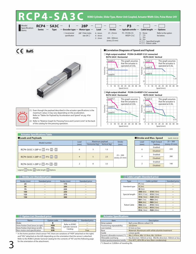
3
R C P 4 - S A 3 C ROBO Cylinder, Slider Type, Motor Unit Coupled, Actuator Width 32m, Pulse Motor 24V
RCP4-SA3C Vertical
0150 200100 30025050 350 400 4500
0150 200100 30025050 350 400 4500
0150 200100 30025050 350 400 4500
0150 200100 30025050 350 400 4500
RCP4-SA3C HorizontalHigh output enabled PCON-CA•MSEP-C/LC connected
RCP4-SA3C Horizontal
21
9876543
RCP4-SA3C Vertical
Speed (mm/s)
This graph assumes that the actuator is operated at 0.3G.
10.5
43.5
32.5
21.5
Speed (mm/s)
21
3.53.5
9876543
10.5
43.5
32.5
21.5
0.750.75
1.251.25
Lead 2
Lead 4
Lead 6
Lead 2
Lead 4
Lead 6
Lead 2
Lead 4
Lead 6
Lead 2
Lead 4
Lead 6
Lead 2
Lead 4
Lead 6
Lead 2
Lead 4
Lead 6
Lead 2
Lead 4
Lead 6
Lead 2
Lead 4
Lead 6Payl
oad
(kg)
Payl
oad
(kg)
Speed (mm/s) Speed (mm/s)
Payl
oad
(kg)
Payl
oad
(kg)
1
High output disabled PCON-CA•MSEP-C/LC connected2
This graph assumes that the actuator is operated at 0.3G.
This graph assumes that the actuator is operated at 0.3G.
This graph assumes that the actuator is operated at 0.3G.
28P : Pulse motor,size 28
I : Incremental specification
P3 : PCON-CAMSEP-C/LC
Refer to the optionlist below.
25 : 25mm
~
300 : 300mm(every 25 mm)
RCP4 SA3C I 28P P3 Series Type Encoder type Motor type Lead Stroke Applicable controller Cable length Options
P
O I N T
Note onselection
(1) Even though the payload described in the actuator specifications is the maximum value, it may vary depending on the acceleration. Refer to “Tables for Payload by Acceleration and Speed” on pg. 4 for details.
(2) Refer to “Relative Graph for Pressing Force and Current Limit” at the back of the catalog for the pressing operation.
N : NoneP : 1mS : 3mM : 5mX : Specified lengthR : Robot cable
6 : 6mm4 : 4mm2 : 2mm
¢Correlation Diagrams of Speed and Payload
1 Stroke List (Standard price) 2 Cable Length (Standard price)
3 Option List (Standard price) Actuator Specifications
Legend 1 Stroke 2 Cable length 3 Options
Actuator Specifications Table¢Leads and Payloads ¢Stroke and Max. Speed
Lead(mm)
High-Output Setting
25 ~ 300(every 25 mm)
6Enabled
420Disabled
4Enabled
280Disabled
2Enabled
140Disabled
Item DescriptionDrive system Ball screw Ø6mm rolled C10Positioning repeatability ±0.02mmLost motion 0.1mm or lessBase Material: Aluminum with white alumite treatmentGuide Linear guideDynamic allowable moment (*1) Ma: 2.4 N•m, Mb: 3.5 N•m, Mc: 3.8 N•mAllowable overhang Ma direction: 100mm or less Mb•Mc direction: 100mm or lessAmbient operating temperature, humidity 0 to 40°C, 85% RH or less (Non-condensing)
Type Cable symbol Standard price
Standard typeP (1m) -S (3m) -M (5m) -
Special lengthX06 (6m) ~ X10 (10m) -X11 (11m) ~ X15 (15m) -X16 (16m) ~ X20 (20m) -
Robot Cable
R01 (1m) ~ R03 (3m) -R04 (4m) ~ R05 (5m) -R06 (6m) ~ R10 (10m) -R11 (11m) ~ R15 (15m) -R16 (16m) ~ R20 (20m) -
Name Option code Reference page Standard priceBrake B
Refer to ROBO Cylinder General
Catalog
-Home-Position Check Sensor (on right) HSR -Home-Position Check Sensor (on left) HSL -Non-motor end specification NM Free
* In the home-position check sensor “HS”, there are variations of “HSR” (attached on the right) and “HSL” (attached on the left) depending on the orientation that the sensor is attached. Refer to the ROBO Cylinder General Catalog for the contents of “HS” and the following page for the orientation of the attachment.
(*1) Based on 5,000km of traveling life.
Model number Lead(mm)
Maximum payload Stroke(mm)Horizontal (kg) Vertical (kg)
RCP4-SA3C-I-28P-6- 1 -P3- 2 - 3 6 3 1.5
25 ~ 300(every 25 mm)RCP4-SA3C-I-28P-4- 1 -P3- 2 - 3 4 5 2.5
RCP4-SA3C-I-28P-2- 1 -P3- 2 - 3 2 8 3.5
Stroke (mm) Standard price Stroke (mm) Standard price25 - 175 -50 - 200 -75 - 225 -
100 - 250 -125 - 275 -150 - 300 -
ModelSpecifi cationItems
(unit: mm/s)
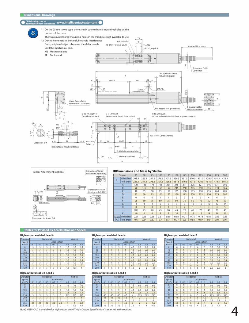
4
CAD drawings can be downloaded from the website. www.intelligentactuator.com
Dimensional Drawings
Sensor Attachment (options)
Orientation of SensorAttachment: Left (HSL)
Orientation of Sensor Attachment: Right (HSR)
1921
23.8 (0.5)
Sensor Rail 328.3
1410
16
7.8
0.5
32
1410
16
7.8
1
7.2
10
6.3
Dimensions for Sensor Rail
4.5
+0.0
100
(R1.5)
(16.
4)
T-shaped Slot forM3 (1pc) Insertion
Stroke
X
ME SE Home ME (*2)
10.5
29.5
40
32
17.531
Guide Datum Point for Moment Calculation
2
2.5
L
A
2.5606 25
Must be 100 or more.11±0.0218 (Ø2 H7 interval ±0.02)
24
18
23
4-M3, depth 6
2-Ø2 H7, depth 3
(17.
6)
Removable CableConnector
32.5 (Slider Center (Home))
25
F
D (Ø3 hole - Ø3 hole)(40)
C (Ø3 hole - oblong hole)
E×50
JH×503025 15
B
1012
310.
5
Base DatumSurface
39
32
3
4
Detail view of X31(0.5) (0.5)
4
10
Ø3.4
Ø6
23
4.8
Detail of Base Attachment Holes
80.5 (without brake)105.5 (with brake)
M3, depth 5 (For ground line)
K-Ø3.4, throughØ6 counterbored, depth 3 (from opposite side) (*1)
G-M4, through(Bolt screw-in depth: 5mm or less)
2
2-Ø3 H7, depth 4(from base bottom)
4.5
*1 On the 25mm stroke type, there are six counterbored mounting holes on the bottom of the base. The two counterbored mounting holes in the middle are not available to use.
*2 During home return, be careful to avoid interference from peripheral objects because the slider travels until the mechanical end.ME : Mechanical endSE : Stroke end
¢Dimensions and Mass by StrokeStroke 25 50 75 100 125 150 175 200 225 250 275 300
Lwithout brake 201.5 226.5 251.5 276.5 301.5 326.5 351.5 376.5 401.5 426.5 451.5 476.5with brake 226.5 251.5 276.5 301.5 326.5 351.5 376.5 401.5 426.5 451.5 476.5 501.5A 121 146 171 196 221 246 271 296 321 346 371 396B 90 115 140 165 190 215 240 265 290 315 340 365C 10 35 60 85 110 135 160 185 210 235 260 285D 25 50 75 100 125 150 175 200 225 250 275 300E 0 0 0 1 1 2 2 3 3 4 4 5F 25 50 75 50 75 50 75 50 75 50 75 50G 4 4 4 6 6 8 8 10 10 12 12 14H 0 0 0 1 1 2 2 3 3 4 4 5J (20) 45 70 45 70 45 70 45 70 45 70 45K (6) 6 6 8 8 10 10 12 12 14 14 16
Mass (kg)
without brake 0.51 0.55 0.58 0.61 0.65 0.68 0.71 0.75 0.78 0.81 0.85 0.88with brake 0.6 0.64 0.67 0.7 0.74 0.77 0.8 0.84 0.87 0.9 0.94 0.97
Tables for Payload by Acceleration and Speed
High output enabled Lead 6Orientation Horizontal Vertical
Speed(mm/s)
Acceleration0.1 0.3 0.5 0.7 1 0.1 0.3 0.5
0 3 3 3 3 3 1.5 1.5 1.550 3 3 3 3 3 1.5 1.5 1.5
105 3 3 3 3 3 1.5 1.5 1.5155 3 3 3 3 3 1.5 1.5 1.5210 3 3 3 3 3 1.5 1.5 1.5260 3 3 3 3 3 1.5 1.5 1.5315 3 3 3 3 3 1.5 1.5 1.5365 3 3 3 3 3 1.5 1.5 1.25420 3 3 3 3 3 1.5 1.25 1
High output disabled Lead 6Orientation Horizontal Vertical
Speed(mm/s)
Acceleration0.1 0.3 0.5 0.7 1 0.1 0.3 0.5
0 3 3 3 3 3 1.5 1.5 1.550 3 3 3 3 3 1.5 1.5 1.5
105 3 3 3 3 3 1.5 1.5 1.5155 3 3 3 3 3 1.5 1.5 1.5210 3 3 3 3 3 1.25 1.25 1.25260 3 3 3 3 3 1 1 1315 3 3 3 3 3 1 1 1365 2.5 2.5 2.5 2.5 2.5 1 1 0.75420 2 2 2 2 2 1 0.75 0.5
High output enabled Lead 4Orientation Horizontal Vertical
Speed(mm/s)
Acceleration0.1 0.3 0.5 0.7 1 0.1 0.3 0.5
0 5 5 5 5 4.5 2.5 2.5 2.535 5 5 5 5 4.5 2.5 2.5 2.570 5 5 5 5 4.5 2.5 2.5 2.5
105 5 5 5 5 4.5 2.5 2.5 2.5140 5 5 5 5 4.5 2.5 2.5 2.5175 5 5 5 5 4.5 2.5 2.5 2.5210 5 5 5 5 4.5 2.5 2.5 2.5245 5 5 5 5 4.5 2.5 2.5 2280 5 5 5 5 4.5 2 2 1.75
High output disabled Lead 4Orientation Horizontal Vertical
Speed(mm/s)
Acceleration0.1 0.3 0.5 0.7 1 0.1 0.3 0.5
0 5 5 5 5 4.5 2.5 2.5 2.535 5 5 5 5 4.5 2.5 2.5 2.570 5 5 5 5 4.5 2.5 2.5 2.5
105 5 5 5 5 4.5 2.5 2.5 2.5140 4.5 4.5 4.5 4.5 4 2.25 2.25 2.25175 4.5 4.5 4.5 4.5 4 2 2 2210 4 4 4 4 3.5 2 2 2245 4 4 4 3.5 3 2 2 1.5280 3.5 3.5 3.5 3 2.5 1 1 0.75
High output enabled Lead 2Orientation Horizontal Vertical
Speed(mm/s)
Acceleration0.1 0.3 0.5 0.7 1 0.1 0.3 0.5
0 8 8 7 6 5 3.5 3.5 3.515 8 8 7 6 5 3.5 3.5 3.535 8 8 7 6 5 3.5 3.5 3.550 8 8 7 6 5 3.5 3.5 3.570 8 8 7 6 5 3.5 3.5 3.585 8 8 7 6 5 3.5 3.5 3.5
105 8 8 7 6 5 3.5 3.5 3.5120 7 7 6 6 5 3 3 2.5140 6 6 6 5 5 2.5 2.5 2
High output disabled Lead 2Orientation Horizontal Vertical
Speed(mm/s)
Acceleration0.1 0.3 0.5 0.7 1 0.1 0.3 0.5
0 8 8 7 6 5 3.5 3.5 3.515 8 8 7 6 5 3.5 3.5 3.535 8 8 7 6 5 3.5 3.5 3.550 8 8 7 6 5 3.5 3.5 3.570 7.5 7 6 5 4.5 3.25 3.25 3.2585 7.5 7 6 5 4.5 3 3 3
105 7 6.5 6 5 4.5 2.5 2.5 2120 6.5 6 5 4.5 4 2 2 1.5140 5.5 5 4.5 4 3.5 1.5 1.5 1
Note) MSEP-C/LC is available for high output only if “High-Output Specification” is selected in the options.
2DCAD2D
CAD
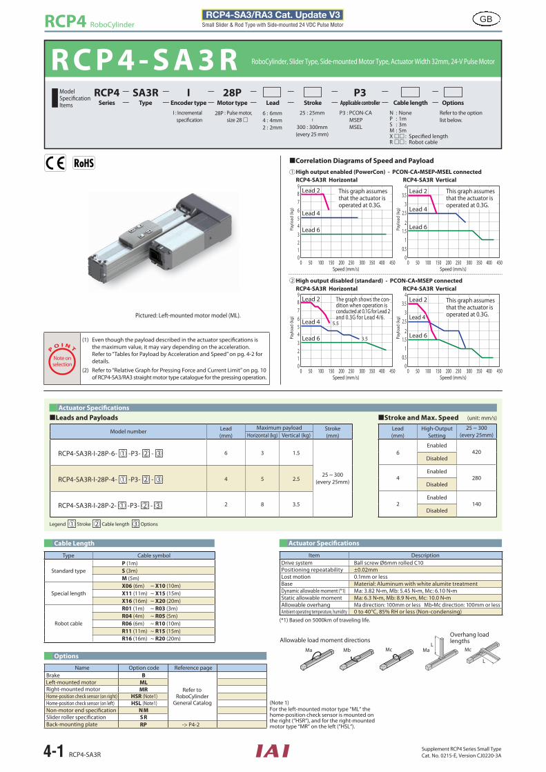
RCP4 RoboCylinder
4-1 RCP4-SA3RSupplement RCP4 Series Small TypeCat. No. 0215-E, Version CJ0220-3A
GB RCP4-SA3/RA3 Cat. Update V3Small Slider & Rod Type with Side-mounted 24 VDC Pulse Motor
R C P 4 - S A 3 R RoboCylinder, Slider Type, Side-mounted Motor Type, Actuator Width 32mm, 24-V Pulse Motor
RCP4-SA3R Vertical
0150 200100 30025050 350 400 4500
0150 200100 30025050 350 400 4500
0150 200100 30025050 350 400 4500
0150 200100 30025050 350 400 4500
RCP4-SA3R HorizontalHigh output enabled (PowerCon) - PCON-CA•MSEP•MSEL connected
RCP4-SA3R Horizontal
21
9876543
RCP4-SA3R Vertical
Speed (mm/s)
This graph assumes that the actuator is operated at 0.3G.
10.5
43.5
32.5
21.5
Speed (mm/s)
21
3.53.5
9876543
10.5
43.5
32.5
21.5
Lead 2
Lead 4
Lead 6
Lead 2
Lead 4
Lead 6
Lead 2
Lead 4
Lead 6
Lead 2
Lead 4
Lead 6
Lead 2
Lead 4
Lead 6
Lead 2
Lead 4
Lead 6
Lead 2
Lead 4
Lead 6
Lead 2
Lead 4
Lead 6Payl
oad
(kg)
Payl
oad
(kg)
Speed (mm/s) Speed (mm/s)
Payl
oad
(kg)
Payl
oad
(kg)
1
High output disabled (standard) - PCON-CA•MSEP connected2
This graph assumes that the actuator is operated at 0.3G.
This graph assumes that the actuator is operated at 0.3G.
28P : Pulse motor,size 28
I : Incremental speci�cation
P3 : PCON-CAMSEP
MSEL
Refer to the optionlist below.
25 : 25mm
~
300 : 300mm(every 25 mm)
RCP4 SA3R I 28P P3Series Type Encoder type Motor type Lead Stroke Applicable controller Cable length Options
P
O I N T
Note onselection
(1) Even though the payload described in the actuator speci�cations is the maximum value, it may vary depending on the acceleration. Refer to “Tables for Payload by Acceleration and Speed” on pg. 4-2 for details.
(2) Refer to “Relative Graph for Pressing Force and Current Limit” on pg. 10 of RCP4-SA3/RA3 straight motor type catalogue for the pressing operation.
N : NoneP : 1mS : 3mM : 5mX : Speci�ed lengthR : Robot cable
6 : 6mm4 : 4mm2 : 2mm
Correlation Diagrams of Speed and Payload
Cable Length
Options
Actuator Speci�cations
Legend 1 Stroke 2 Cable length 3 Options
Actuator Speci�cationsLeads and Payloads Stroke and Max. Speed
Lead(mm)
High-Output Setting
25 ~ 300(every 25mm)
6Enabled
420Disabled
4Enabled
280Disabled
2Enabled
140Disabled
Item DescriptionDrive system Ball screw Ø6mm rolled C10Positioning repeatability ±0.02mmLost motion 0.1mm or lessBase Material: Aluminum with white alumite treatmentDynamic allowable moment (*1) Ma: 3.82 N•m, Mb: 5.45 N•m, Mc: 6.10 N•mStatic allowable moment Ma: 6.3 N•m, Mb: 8.9 N•m, Mc: 10.0 N•mAllowable overhang Ma direction: 100mm or less Mb•Mc direction: 100mm or lessAmbient operating temperature, humidity 0 to 40°C, 85% RH or less (Non-condensing)
Type Cable symbol
Standard typeP (1m)S (3m)M (5m)
Special lengthX06 (6m) ~ X10 (10m)X11 (11m) ~ X15 (15m)X16 (16m) ~ X20 (20m)
Robot cable
R01 (1m) ~ R03 (3m)R04 (4m) ~ R05 (5m)R06 (6m) ~ R10 (10m)R11 (11m) ~ R15 (15m)R16 (16m) ~ R20 (20m)
(*1) Based on 5000km of traveling life.
Model number Lead(mm)
Maximum payload Stroke(mm)Horizontal (kg) Vertical (kg)
RCP4-SA3R-I-28P-6- 1 -P3- 2 - 3 6 3 1.5
25 ~ 300(every 25mm)RCP4-SA3R-I-28P-4- 1 -P3- 2 - 3 4 5 2.5
RCP4-SA3R-I-28P-2- 1 -P3- 2 - 3 2 8 3.5
Model
Items
(unit: mm/s)
L
L
Ma MaMb Mc Mc
Allowable load moment directionsOverhang load lengths
The graph shows the con-dition when operation isconducted at 0.1G for Lead 2and 0.3G for Lead 4/6.
(Note 1)For the left-mounted motor type “ML“ thehome-position check sensor is mounted onthe right (“HSR“), and for the right-mountedmotor type “MR“ on the left (“HSL“).
Brake B
Refer toRoboCylinder
General Catalog
MLMR
RP -> P4-2
Name Option code Reference page
Home-position check sensor (on right) HSR (Note1) Home-position check sensor (on left) HSL (Note1)Non-motor end speci�cation NMSlider roller speci�cationBack-mounting plate
SR
Left-mounted motorRight-mounted motor
Pictured: Left-mounted motor model (ML).5.5
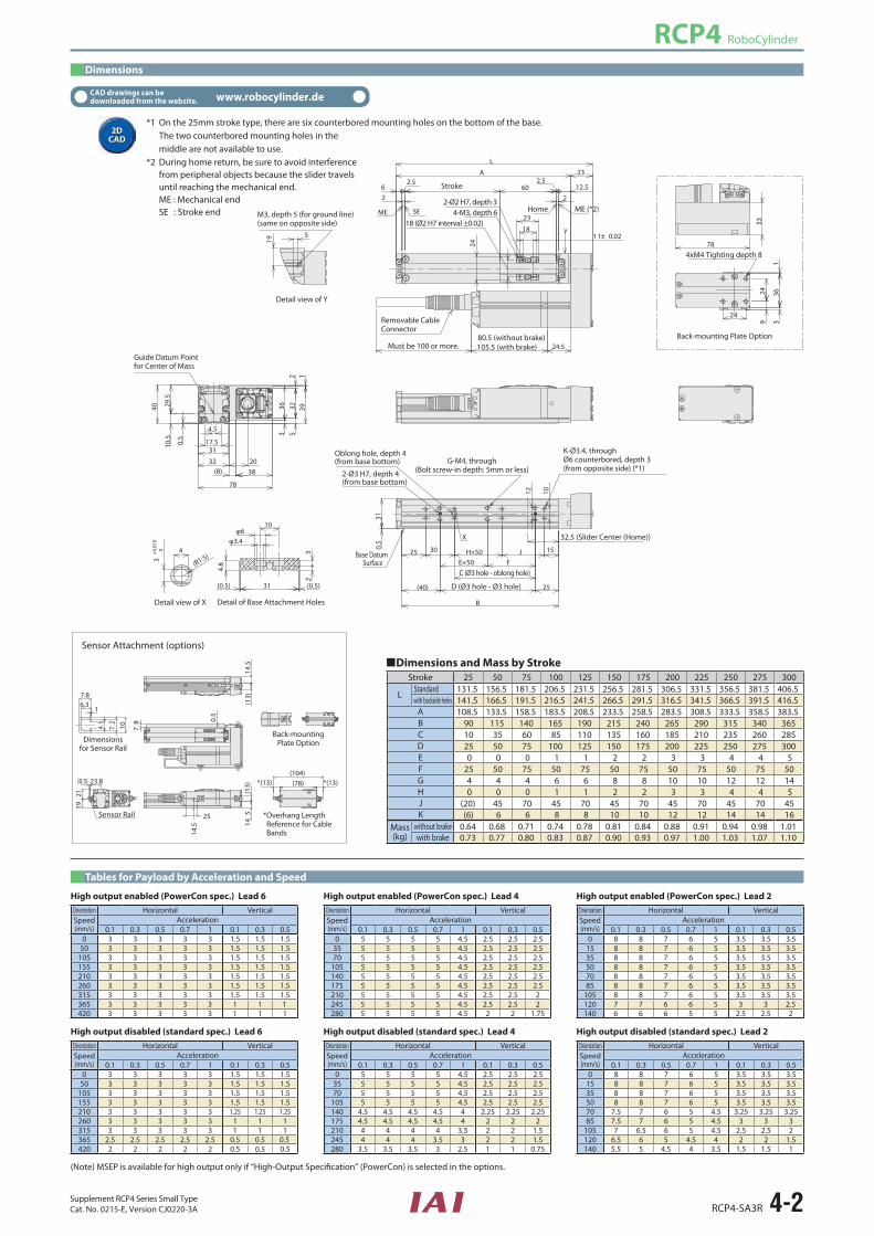
RCP4 RoboCylinder
RCP4-SA3R 4-2Supplement RCP4 Series Small TypeCat. No. 0215-E, Version CJ0220-3A
CAD drawings can be downloaded from the website. www.robocylinder.de
Dimensions
*1 On the 25mm stroke type, there are six counterbored mounting holes on the bottom of the base. The two counterbored mounting holes in themiddle are not available to use.
*2 During home return, be sure to avoid interferencefrom peripheral objects because the slider travelsuntil reaching the mechanical end.ME : Mechanical endSE : Stroke end
Dimensions and Mass by StrokeStroke 25 50 75 100 125 150 175 200 225 250 275 300
LStandardwith backside holes
ABCDEFGHJK
Mass (kg)
without brakewith brake
2DCAD2D
CAD
131.5 156.5 181.5 206.5 231.5 256.5 281.5 306.5 331.5 356.5 381.5 406.5141.5 166.5 191.5 216.5 241.5 266.5 291.5 316.5 341.5 366.5 391.5 416.5108.5 133.5 158.5 183.5 208.5 233.5 258.5 283.5 308.5 333.5 358.5 383.5
90 115 140 165 190 215 240 265 290 315 340 36510 35 60 85 110 135 160 185 210 235 260 28525 50 75 100 125 150 175 200 225 250 275 3000 0 0 1 1 2 2 3 3 4 4 5
25 50 75 50 75 50 75 50 75 50 75 504 4 4 6 6 8 8 10 10 12 12 140 0 0 1 1 2 2 3 3 4 4 5
(20) 45 70 45 70 45 70 45 70 45 70 45(6) 6 6 8 8 10 10 12 12 14 14 16
0.64 0.68 0.71 0.74 0.78 0.81 0.84 0.88 0.91 0.94 0.98 1.010.73 0.77 0.80 0.83 0.87 0.90 0.93 0.97 1.00 1.03 1.07 1.10
Sensor Attachment (options)
Back-mountingPlate Option
Sensor Rail *Overhang LengthReference for CableBands
Dimensionsfor Sensor Rail
Stroke
Home ME (*2)
Guide Datum Pointfor Center of Mass
M3, depth 5 (for ground line)(same on opposite side)
4xM4 Tighting depth 8
Must be 100 or more.
18 (Ø2 H7 interval ±0.02)4-M3, depth 6
2-Ø2 H7, depth 3
Removable CableConnector
32.5 (Slider Center (Home))
D (Ø3 hole - Ø3 hole)
C (Ø3 hole - oblong hole)
Base DatumSurface
Detail view of X
Detail view of Y
Back-mounting Plate Option
Detail of Base Attachment Holes
80.5 (without brake)105.5 (with brake)
K-Ø3.4, throughØ6 counterbored, depth 3(from opposite side) (*1)
G-M4, through(Bolt screw-in depth: 5mm or less)2-Ø3 H7, depth 4
(from base bottom)
Oblong hole, depth 4 (from base bottom)
Tables for Payload by Acceleration and Speed
High output enabled (PowerCon spec.) Lead 6Orientation Horizontal VerticalSpeed(mm/s)
Acceleration0.1 0.3 0.5 0.7 1 0.1 0.3 0.5
0 3 3 3 3 3 1.5 1.5 1.550 3 3 3 3 3 1.5 1.5 1.5
105 3 3 3 3 3 1.5 1.5 1.5155 3 3 3 3 3 1.5 1.5 1.5210 3 3 3 3 3 1.5 1.5 1.5260 3 3 3 3 3 1.5 1.5 1.5315 3 3 3 3 3 1.5 1.5 1.5365 3 3 3 3 3 1 1 1420 3 3 3 3 3 1 1 1
High output disabled (standard spec.) Lead 6Orientation Horizontal VerticalSpeed(mm/s)
Acceleration0.1 0.3 0.5 0.7 1 0.1 0.3 0.5
0 3 3 3 3 3 1.5 1.5 1.550 3 3 3 3 3 1.5 1.5 1.5
105 3 3 3 3 3 1.5 1.5 1.5155 3 3 3 3 3 1.5 1.5 1.5210 3 3 3 3 3 1.25 1.25 1.25260 3 3 3 3 3 1 1 1315 3 3 3 3 3 1 1 1365 2.5 2.5 2.5 2.5 2.5 0.5 0.5 0.5420 2 2 2 2 2 0.5 0.5 0.5
High output enabled (PowerCon spec.) Lead 4Orientation Horizontal VerticalSpeed(mm/s)
Acceleration0.1 0.3 0.5 0.7 1 0.1 0.3 0.5
0 5 5 5 5 4.5 2.5 2.5 2.535 5 5 5 5 4.5 2.5 2.5 2.570 5 5 5 5 4.5 2.5 2.5 2.5
105 5 5 5 5 4.5 2.5 2.5 2.5140 5 5 5 5 4.5 2.5 2.5 2.5175 5 5 5 5 4.5 2.5 2.5 2.5210 5 5 5 5 4.5 2.5 2.5 2245 5 5 5 5 4.5 2.5 2.5 2280 5 5 5 5 4.5 2 2 1.75
High output disabled (standard spec.) Lead 4Orientation Horizontal VerticalSpeed(mm/s)
Acceleration0.1 0.3 0.5 0.7 1 0.1 0.3 0.5
0 5 5 5 5 4.5 2.5 2.5 2.535 5 5 5 5 4.5 2.5 2.5 2.570 5 5 5 5 4.5 2.5 2.5 2.5
105 5 5 5 5 4.5 2.5 2.5 2.5140 4.5 4.5 4.5 4.5 4 2.25 2.25 2.25175 4.5 4.5 4.5 4.5 4 2 2 2210 4 4 4 4 3.5 2 2 1.5245 4 4 4 3.5 3 2 2 1.5280 3.5 3.5 3.5 3 2.5 1 1 0.75
High output enabled (PowerCon spec.) Lead 2Orientation Horizontal VerticalSpeed(mm/s)
Acceleration0.1 0.3 0.5 0.7 1 0.1 0.3 0.5
0 8 8 7 6 5 3.5 3.5 3.515 8 8 7 6 5 3.5 3.5 3.535 8 8 7 6 5 3.5 3.5 3.550 8 8 7 6 5 3.5 3.5 3.570 8 8 7 6 5 3.5 3.5 3.585 8 8 7 6 5 3.5 3.5 3.5
105 8 8 7 6 5 3.5 3.5 3.5120 7 7 6 6 5 3 3 2.5140 6 6 6 5 5 2.5 2.5 2
High output disabled (standard spec.) Lead 2Orientation Horizontal VerticalSpeed(mm/s)
Acceleration0.1 0.3 0.5 0.7 1 0.1 0.3 0.5
0 8 8 7 6 5 3.5 3.5 3.515 8 8 7 6 5 3.5 3.5 3.535 8 8 7 6 5 3.5 3.5 3.550 8 8 7 6 5 3.5 3.5 3.570 7.5 7 6 5 4.5 3.25 3.25 3.2585 7.5 7 6 5 4.5 3 3 3
105 7 6.5 6 5 4.5 2.5 2.5 2120 6.5 6 5 4.5 4 2 2 1.5140 5.5 5 4.5 4 3.5 1.5 1.5 1
(Note) MSEP is available for high output only if “High-Output Speci�cation” (PowerCon) is selected in the options.
X
10.5
29.5
78
38
40
0.5
4.5
17.531
32
363 5
322
391
20
2
2.5
2
23
24
1 1± 0.02 18
L
60
A
12.52.5
6
24.5
23
ME SE
Y
25
15JH×5030
F25
(40)
B
1012
E×50
310.
5
4
(R1.5)
4.8
31 (0.5)(0.5)
φ3.4φ6
10
23
24
24
9
363
1
78
33
5
19
(8)
+0.0
100
3
7.8
1
7.2
10
6.3
4.5
1921
23.8
14.5 14
.5(1
3)
25
*(13) *(13)(104)(78)(0.5)
7.8 0.
5
14.5
(13)
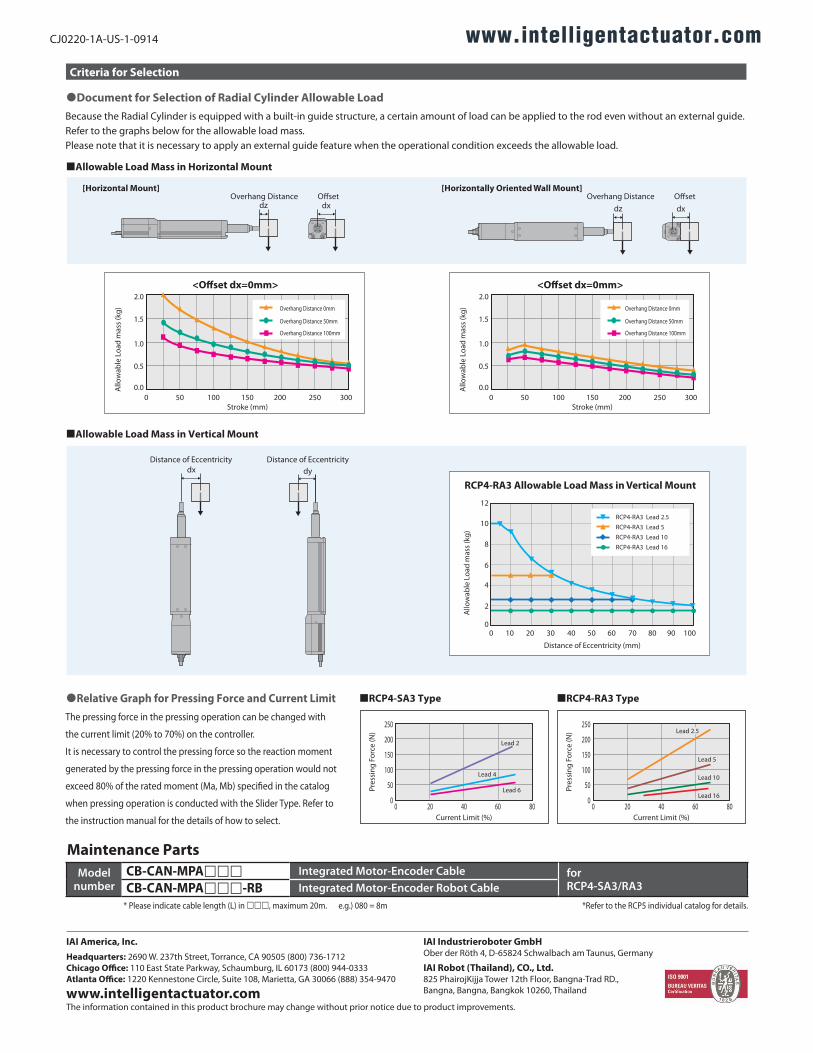
[Horizontal Mount] [Horizontally Oriented Wall Mount]
dz dx dz dxOverhang Distance O�set Overhang Distance O�set
�RCP4-SA3 Type
0
50
250
200
150
100
8020 40 600Current Limit (%)
�RCP4-RA3 Type
0
50
250
200
150
100
8020 40 600Current Limit (%)
Pres
sing
For
ce (N
)
Pres
sing
For
ce (N
)
CJ0220-1A-US-1-0914
Criteria for Selection
Maintenance Parts
�Document for Selection of Radial Cylinder Allowable Load
�Allowable Load Mass in Horizontal Mount
Because the Radial Cylinder is equipped with a built-in guide structure, a certain amount of load can be applied to the rod even without an external guide.Refer to the graphs below for the allowable load mass.Please note that it is necessary to apply an external guide feature when the operational condition exceeds the allowable load.
�Relative Graph for Pressing Force and Current LimitThe pressing force in the pressing operation can be changed with
the current limit (20% to 70%) on the controller.
It is necessary to control the pressing force so the reaction moment
generated by the pressing force in the pressing operation would not
exceed 80% of the rated moment (Ma, Mb) speci�ed in the catalog
when pressing operation is conducted with the Slider Type. Refer to
the instruction manual for the details of how to select.
2.0
1.5
1.0
0.5
0.00 50 100 150 200 250 300
Stroke (mm)
<O�set dx=0mm>
Overhang Distance 0mm
Overhang Distance 50mm
Overhang Distance 100mm
2.0
1.5
1.0
0.5
0.00 50 100 150 200 250 300
Stroke (mm)
<O�set dx=0mm>
Overhang Distance 0mm
Overhang Distance 50mm
Overhang Distance 100mm
RCP4-RA3 Allowable Load Mass in Vertical Mount
12
10
8
6
4
2
0
Distance of Eccentricity (mm)
0 10 20 30 40 50 60 70 80 90 100
dxDistance of Eccentricity Distance of Eccentricity
dy
Allo
wab
le L
oad
mas
s (k
g)
Allo
wab
le L
oad
mas
s (k
g)A
llow
able
Loa
d m
ass
(kg)
�Allowable Load Mass in Vertical Mount
RCP4-RA3 Lead 2.5
RCP4-RA3 Lead 5
RCP4-RA3 Lead 10
RCP4-RA3 Lead 16
Lead 2
Lead 4
Lead 6
Lead 2.5
Lead 5
Lead 10
Lead 16
www.intelligentactuator.com
IAI America, Inc.Headquarters: 2690 W. 237th Street, Torrance, CA 90505 (800) 736-1712Chicago Office: 110 East State Parkway, Schaumburg, IL 60173 (800) 944-0333Atlanta Office: 1220 Kennestone Circle, Suite 108, Marietta, GA 30066 (888) 354-9470
www.intelligentactuator.com
IAI Industrieroboter GmbHOber der Röth 4, D-65824 Schwalbach am Taunus, Germany
IAI Robot (Thailand), CO., Ltd.825 PhairojKijja Tower 12th Floor, Bangna-Trad RD.,Bangna, Bangna, Bangkok 10260, Thailand
The information contained in this product brochure may change without prior notice due to product improvements.
Modelnumber
CB-CAN-MPA Integrated Motor-Encoder Cable for RCP4-SA3/RA3CB-CAN-MPA-RB Integrated Motor-Encoder Robot Cable
* Please indicate cable length (L) in , maximum 20m. e.g.) 080 = 8m *Refer to the RCP5 individual catalog for details.