Variable Displacement Vane Pumps VVA 10/20/40, 20 series ...
Upload
khangminh22Category
view
0download
0
®
High-Performance
Quarter-Turn
Solutions
Version: January 2021
Solving
Problems
No One Else Can
Table of Contents Page
Easytork Vane Actuator 3
Easytork Solenoid Valve 21
Easytork Pilot Valve 29
Namur Trip Valve 33
Lockout Device 37
Declutchable Gearbox 41
Limit Switch 45
Positioner 49
Hardware 53
We believe in selling “easy”. Easytork brings
differentiating features and benefits to the process
control industry through our focus on innovation and
quality.
Easytork has been awarded numerous awards
including:
2013 – Arch Grants Recipient
2015 – Accelerate St. Louis
2017 – Frost & Sullivan New Product Innovation Award
Aerospace & defense: Fuel feed for rockets,
deluge valve actuators, portable launch fuel and
water control valves, fast acting control for
aerospace engine systems.
Chemical: Filling and feed valves, transfer valves,
mixed liquor valves, waste valves on batch mixing
tanks.
Dampers: Flue gas dampers, furnace fuel feed,
radial vane air control dampers.
Power generation: Steam turbine control, boiler
and water feed.
Energy: Natural gas control valves, natural gas
controlled dump valves, isolation ball valves for
skid mounted compressor stations.
Food processing: Enzymatic interesterification
(EIE), sorting, diverting, conveying, filter systems.
General industrial: Skid manufacturing.
Mining: Cyanide dosing circuits, lime dosing
circuits, underground dewatering valves,
underground pastefill distribution valves, acid
valves, high pressure water isolation valves.
Pulp and paper: Dewatering valves, skids,
bleaching.
Water systems / municipal: Digester gas valves,
filter control, aeration control, odor control, high
service pump control, flocculate waste drain valves.
Steel: Cooling spray valve.
Select Industries and Select Applications
Easytork Vane Actuator
Springless-Return Actuator
Compact, Efficient, Fast, and
Tough against BAD environment and air
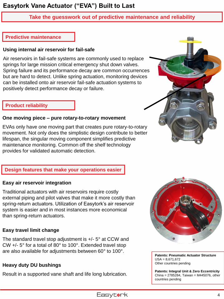
Easy air reservoir integration
Traditional actuators with air reservoirs require costly
external piping and pilot valves that make it more costly than
spring-return actuators. Utilization of Easytork’s air reservoir
system is easier and in most instances more economical
than spring-return actuators.
Easytork Vane Actuator (“EVA”) Built to Last
Take the guesswork out of predictive maintenance and reliability
Using internal air reservoir for fail-safe
Air reservoirs in fail-safe systems are commonly used to replace
springs for large mission critical emergency shut down valves.
Spring failure and its performance decay are common occurrences
but are hard to detect. Unlike spring actuation, monitoring devices
can be installed onto air reservoir fail-safe actuation systems to
positively detect performance decay or failure.
Easy travel limit change
The standard travel stop adjustment is +/- 5° at CCW and
CW +/- 5° for a total of 80° to 100°. Extended travel stop
are also available for adjustments between 60° to 100°.
Heavy duty DU bushings
Result in a supported vane shaft and life long lubrication.
One moving piece – pure rotary-to-rotary movement
EVAs only have one moving part that creates pure rotary-to-rotary
movement. Not only does the simplistic design contribute to better
lifespan, the singular moving component simplifies predictive
maintenance monitoring. Common off the shelf technology
provides for validated automatic detection.
Patents: Pneumatic Actuator Structure
USA = 8,671,672
Other countries pending
Patents: Integral Unit & Zero Eccentricity
China = 2785284, Taiwan = M445076, other
countries pending
4
Predictive maintenance
Product reliability
Design features that make your operations easier
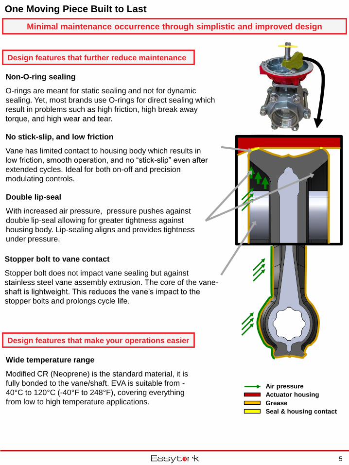
Non-O-ring sealing
O-rings are meant for static sealing and not for dynamic
sealing. Yet, most brands use O-rings for direct sealing which
result in problems such as high friction, high break away
torque, and high wear and tear.
Double lip-seal
With increased air pressure, pressure pushes against
double lip-seal allowing for greater tightness against
housing body. Lip-sealing aligns and provides tightness
under pressure.
No stick-slip, and low friction
Vane has limited contact to housing body which results in
low friction, smooth operation, and no “stick-slip” even after
extended cycles. Ideal for both on-off and precision
modulating controls.
Stopper bolt to vane contact
Stopper bolt does not impact vane sealing but against
stainless steel vane assembly extrusion. The core of the vane-
shaft is lightweight. This reduces the vane’s impact to the
stopper bolts and prolongs cycle life.
Air pressure
Actuator housing
Grease
Seal & housing contact
Wide temperature range
Modified CR (Neoprene) is the standard material, it is
fully bonded to the vane/shaft. EVA is suitable from -
40°C to 120°C (-40°F to 248°F), covering everything
from low to high temperature applications.
5
Minimal maintenance occurrence through simplistic and improved design
Design features that further reduce maintenance
Design features that make your operations easier
One Moving Piece Built to Last
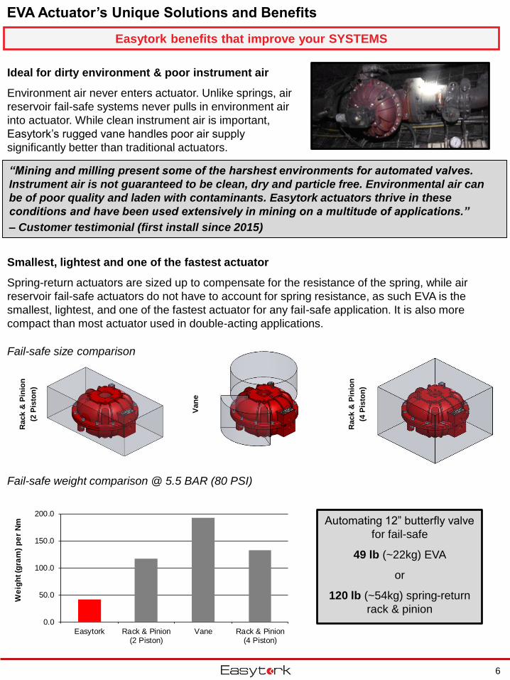
EVA Actuator’s Unique Solutions and Benefits
Ideal for dirty environment & poor instrument air
Environment air never enters actuator. Unlike springs, air
reservoir fail-safe systems never pulls in environment air
into actuator. While clean instrument air is important,
Easytork’s rugged vane handles poor air supply
significantly better than traditional actuators.
6
Easytork benefits that improve your SYSTEMS
Fail-safe size comparison
Rack &
Pin
ion
(2 P
isto
n)
Van
e
Rack &
Pin
ion
(4 P
isto
n)
Smallest, lightest and one of the fastest actuator
Spring-return actuators are sized up to compensate for the resistance of the spring, while air
reservoir fail-safe actuators do not have to account for spring resistance, as such EVA is the
smallest, lightest, and one of the fastest actuator for any fail-safe application. It is also more
compact than most actuator used in double-acting applications.
Fail-safe weight comparison @ 5.5 BAR (80 PSI)
0.0
50.0
100.0
150.0
200.0
Easytork Rack & Pinion(2 Piston)
Vane Rack & Pinion(4 Piston)
We
igh
t (g
ram
) p
er
Nm
“Mining and milling present some of the harshest environments for automated valves.
Instrument air is not guaranteed to be clean, dry and particle free. Environmental air can
be of poor quality and laden with contaminants. Easytork actuators thrive in these
conditions and have been used extensively in mining on a multitude of applications.”
– Customer testimonial (first install since 2015)
Automating 12” butterfly valve
for fail-safe
49 lb (~22kg) EVA
or
120 lb (~54kg) spring-return
rack & pinion
EVA Actuator’s Unique Solutions and Benefits
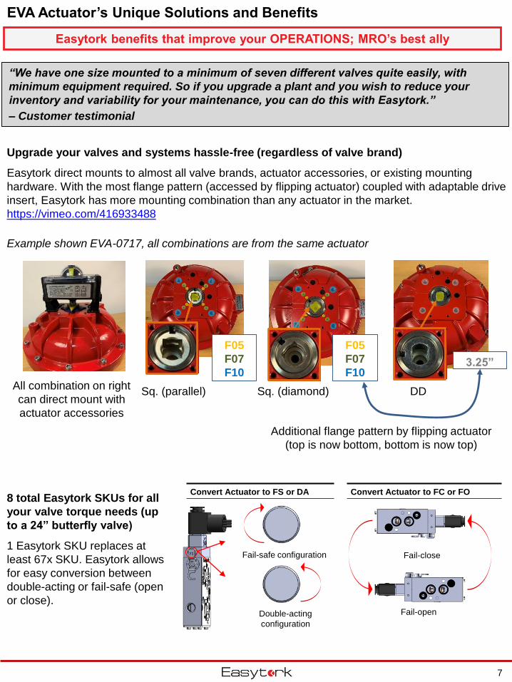
Upgrade your valves and systems hassle-free (regardless of valve brand)
Easytork direct mounts to almost all valve brands, actuator accessories, or existing mounting
hardware. With the most flange pattern (accessed by flipping actuator) coupled with adaptable drive
insert, Easytork has more mounting combination than any actuator in the market.
https://vimeo.com/416933488
8 total Easytork SKUs for all
your valve torque needs (up
to a 24” butterfly valve)
1 Easytork SKU replaces at
least 67x SKU. Easytork allows
for easy conversion between
double-acting or fail-safe (open
or close).
Convert Actuator to FS or DA Convert Actuator to FC or FO
Double-acting
configuration
Fail-safe configuration Fail-close
Fail-open
7
Easytork benefits that improve your OPERATIONS; MRO’s best ally
“We have one size mounted to a minimum of seven different valves quite easily, with
minimum equipment required. So if you upgrade a plant and you wish to reduce your
inventory and variability for your maintenance, you can do this with Easytork.”
– Customer testimonial
Sq. (parallel)
F05
F07
F10
Sq. (diamond)
F05
F07
F10
DD
3.25”
Example shown EVA-0717, all combinations are from the same actuator
All combination on right
can direct mount with
actuator accessories
Additional flange pattern by flipping actuator
(top is now bottom, bottom is now top)
Without air supply
With electricity
With air supply
With electricity
With air supply
With electricity
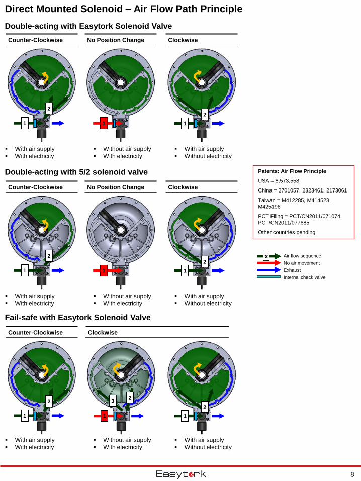
Direct Mounted Solenoid – Air Flow Path Principle
Double-acting with Easytork Solenoid Valve
Double-acting with 5/2 solenoid valve
Fail-safe with Easytork Solenoid Valve
Counter-Clockwise No Position Change Clockwise
Counter-Clockwise No Position Change Clockwise
Counter-Clockwise Clockwise
Without air supply
With electricity
With air supply
Without electricity
With air supply
With electricity
Without air supply
With electricity
With air supply
Without electricity
With air supply
Without electricity
Air flow sequence
No air movement
Exhaust
Internal check valve
xxxx
Patents: Air Flow Principle
USA = 8,573,558
China = 2701057, 2323461, 2173061
Taiwan = M412285, M414523,
M425196
PCT Filing = PCT/CN2011/071074,
PCT/CN2011/077685
Other countries pending
1
2
1 1
2
1
2
1
2
1
32
1
2
1 1
2
8
Without air supply
With electricity
1
3 2
1
2
3
1
3 2
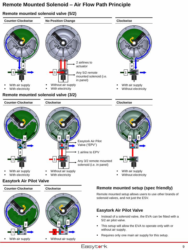
Remote Mounted Solenoid – Air Flow Path Principle
Remote mounted solenoid valve (5/2)
Remote mounted solenoid valve (3/2)
Easytork Air Pilot Valve
Counter-Clockwise No Position Change Clockwise
Counter-Clockwise Clockwise Clockwise
Without air supply With air supply
Without air supply
With electricity
With air supply
Without electricity
With air supply
Without electricity
Any 3/2 remote mounted
solenoid (i.e. in panel)
1 airline to EPV
Easytork Air Pilot
Valve (“EPV”)
Counter-Clockwise Clockwise
With air supply
With electricity
Remote mounted setup (spec friendly)
Remote mounted setup allows users to use other brands of
solenoid valves, and not just the ESV.
Easytork Air Pilot Valve
Instead of a solenoid valve, the EVA can be fitted with a
5/2 air pilot valve.
This setup will allow the EVA to operate only with or
without air supply.
Requires only one main air supply for this setup.
With air supply
With electricity
1
22 airlines to
actuator
1
2
1
2
1
32
1 Any 5/2 remote
mounted solenoid (i.e.
in panel)
9
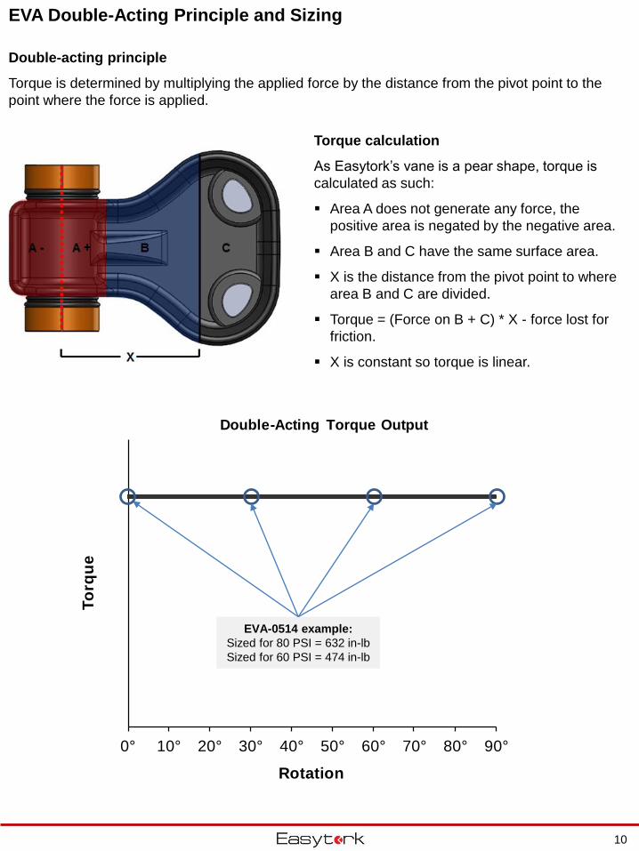
EVA Double-Acting Principle and Sizing
Double-acting principle
Torque is determined by multiplying the applied force by the distance from the pivot point to the
point where the force is applied.
Torque calculation
As Easytork’s vane is a pear shape, torque is
calculated as such:
Area A does not generate any force, the
positive area is negated by the negative area.
Area B and C have the same surface area.
X is the distance from the pivot point to where
area B and C are divided.
Torque = (Force on B + C) * X - force lost for
friction.
X is constant so torque is linear.
0° 10° 20° 30° 40° 50° 60° 70° 80° 90°
To
rqu
e
Rotation
Double-Acting Torque Output
10
EVA-0514 example:
Sized for 80 PSI = 632 in-lb
Sized for 60 PSI = 474 in-lb
0%
10%
20%
30%
40%
50%
60%
70%
80%
90%
100%
0° 10° 20° 30° 40° 50° 60° 70° 80° 90°
% o
f D
ou
ble
-Acti
ng
To
rqu
e
Rotation
Fail-Safe Torque Output
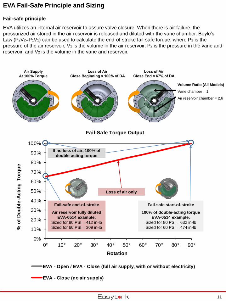
EVA - Open / EVA - Close (full air supply, with or without electricity)
EVA - Close (no air supply)
Fail-safe end-of-stroke
Air reservoir fully diluted
EVA-0514 example:
Sized for 80 PSI = 412 in-lb
Sized for 60 PSI = 309 in-lb
EVA Fail-Safe Principle and Sizing
Fail-safe principle
EVA utilizes an internal air reservoir to assure valve closure. When there is air failure, the
pressurized air stored in the air reservoir is released and diluted with the vane chamber. Boyle’s
Law (P2V2=P1V1) can be used to calculate the end-of-stroke fail-safe torque, where P1 is the
pressure of the air reservoir, V1 is the volume in the air reservoir, P2 is the pressure in the vane and
reservoir, and V2 is the volume in the vane and reservoir.
Air Supply
At 100% Torque
Loss of Air
Close Beginning ≈ 100% of DA
Loss of Air
Close End ≈ 67% of DA
Volume Ratio (All Models)
Vane chamber = 1
Air reservoir chamber = 2.6
11
Loss of air only
Fail-safe start-of-stroke
100% of double-acting torque
EVA-0514 example:
Sized for 80 PSI = 632 in-lb
Sized for 60 PSI = 474 in-lb
If no loss of air, 100% of
double-acting torque
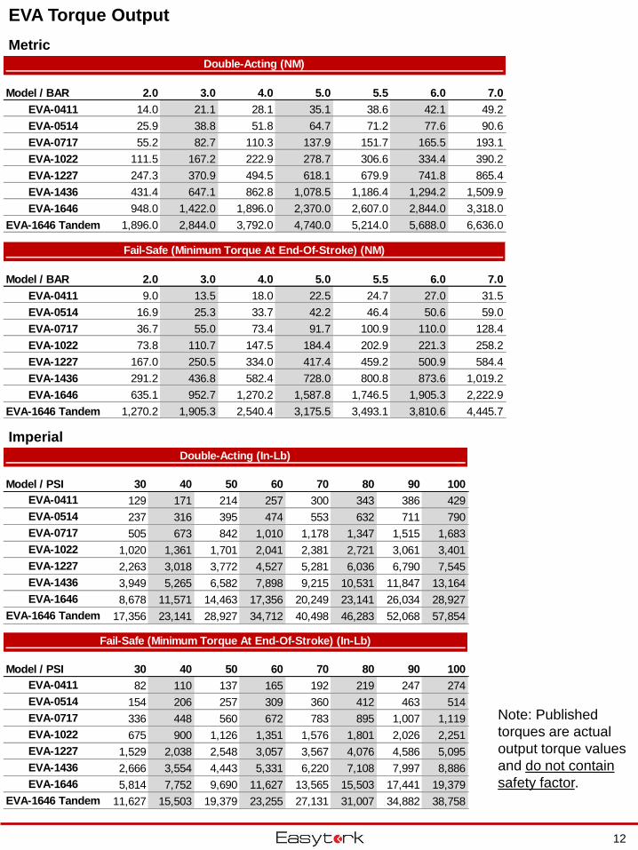
EVA Torque Output
Metric
Imperial
12
Double-Acting (NM)
Model / BAR 2.0 3.0 4.0 5.0 5.5 6.0 7.0
EVA-0411 14.0 21.1 28.1 35.1 38.6 42.1 49.2
EVA-0514 25.9 38.8 51.8 64.7 71.2 77.6 90.6
EVA-0717 55.2 82.7 110.3 137.9 151.7 165.5 193.1
EVA-1022 111.5 167.2 222.9 278.7 306.6 334.4 390.2
EVA-1227 247.3 370.9 494.5 618.1 679.9 741.8 865.4
EVA-1436 431.4 647.1 862.8 1,078.5 1,186.4 1,294.2 1,509.9
EVA-1646 948.0 1,422.0 1,896.0 2,370.0 2,607.0 2,844.0 3,318.0
EVA-1646 Tandem 1,896.0 2,844.0 3,792.0 4,740.0 5,214.0 5,688.0 6,636.0
Fail-Safe (Minimum Torque At End-Of-Stroke) (NM)
Model / BAR 2.0 3.0 4.0 5.0 5.5 6.0 7.0
EVA-0411 9.0 13.5 18.0 22.5 24.7 27.0 31.5
EVA-0514 16.9 25.3 33.7 42.2 46.4 50.6 59.0
EVA-0717 36.7 55.0 73.4 91.7 100.9 110.0 128.4
EVA-1022 73.8 110.7 147.5 184.4 202.9 221.3 258.2
EVA-1227 167.0 250.5 334.0 417.4 459.2 500.9 584.4
EVA-1436 291.2 436.8 582.4 728.0 800.8 873.6 1,019.2
EVA-1646 635.1 952.7 1,270.2 1,587.8 1,746.5 1,905.3 2,222.9
EVA-1646 Tandem 1,270.2 1,905.3 2,540.4 3,175.5 3,493.1 3,810.6 4,445.7
Double-Acting (In-Lb)
Model / PSI 30 40 50 60 70 80 90 100
EVA-0411 129 171 214 257 300 343 386 429
EVA-0514 237 316 395 474 553 632 711 790
EVA-0717 505 673 842 1,010 1,178 1,347 1,515 1,683
EVA-1022 1,020 1,361 1,701 2,041 2,381 2,721 3,061 3,401
EVA-1227 2,263 3,018 3,772 4,527 5,281 6,036 6,790 7,545
EVA-1436 3,949 5,265 6,582 7,898 9,215 10,531 11,847 13,164
EVA-1646 8,678 11,571 14,463 17,356 20,249 23,141 26,034 28,927
EVA-1646 Tandem 17,356 23,141 28,927 34,712 40,498 46,283 52,068 57,854
Fail-Safe (Minimum Torque At End-Of-Stroke) (In-Lb)
Model / PSI 30 40 50 60 70 80 90 100
EVA-0411 82 110 137 165 192 219 247 274
EVA-0514 154 206 257 309 360 412 463 514
EVA-0717 336 448 560 672 783 895 1,007 1,119
EVA-1022 675 900 1,126 1,351 1,576 1,801 2,026 2,251
EVA-1227 1,529 2,038 2,548 3,057 3,567 4,076 4,586 5,095
EVA-1436 2,666 3,554 4,443 5,331 6,220 7,108 7,997 8,886
EVA-1646 5,814 7,752 9,690 11,627 13,565 15,503 17,441 19,379
EVA-1646 Tandem 11,627 15,503 19,379 23,255 27,131 31,007 34,882 38,758
Note: Published
torques are actual
output torque values
and do not contain
safety factor.
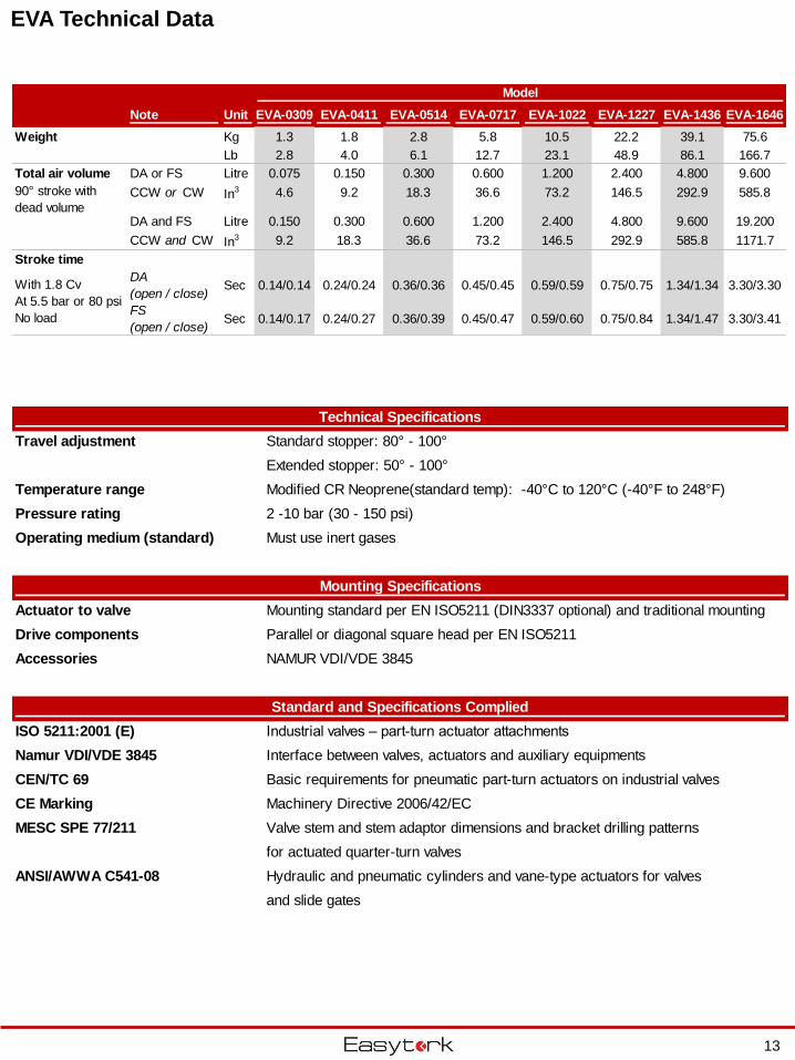
EVA Technical Data
Technical Specifications
Travel adjustment Standard stopper: 80° - 100°
Extended stopper: 50° - 100°
Temperature range Modified CR Neoprene(standard temp): -40°C to 120°C (-40°F to 248°F)
Pressure rating 2 -10 bar (30 - 150 psi)
Operating medium (standard) Must use inert gases
Mounting Specifications
Actuator to valve Mounting standard per EN ISO5211 (DIN3337 optional) and traditional mounting
Drive components Parallel or diagonal square head per EN ISO5211
Accessories NAMUR VDI/VDE 3845
Standard and Specifications Complied
ISO 5211:2001 (E) Industrial valves – part-turn actuator attachments
Namur VDI/VDE 3845 Interface between valves, actuators and auxiliary equipments
CEN/TC 69 Basic requirements for pneumatic part-turn actuators on industrial valves
CE Marking Machinery Directive 2006/42/EC
MESC SPE 77/211 Valve stem and stem adaptor dimensions and bracket drilling patterns
for actuated quarter-turn valves
ANSI/AWWA C541-08 Hydraulic and pneumatic cylinders and vane-type actuators for valves
and slide gates
Model
Note Unit EVA-0309 EVA-0411 EVA-0514 EVA-0717 EVA-1022 EVA-1227 EVA-1436 EVA-1646
Weight Kg 1.3 1.8 2.8 5.8 10.5 22.2 39.1 75.6
Lb 2.8 4.0 6.1 12.7 23.1 48.9 86.1 166.7
Total air volume DA or FS Litre 0.075 0.150 0.300 0.600 1.200 2.400 4.800 9.600
CCW or CW In3 4.6 9.2 18.3 36.6 73.2 146.5 292.9 585.8
DA and FS Litre 0.150 0.300 0.600 1.200 2.400 4.800 9.600 19.200
CCW and CW In3 9.2 18.3 36.6 73.2 146.5 292.9 585.8 1171.7
Stroke time
DA
(open / close)Sec 0.14/0.14 0.24/0.24 0.36/0.36 0.45/0.45 0.59/0.59 0.75/0.75 1.34/1.34 3.30/3.30
FS
(open / close)Sec 0.14/0.17 0.24/0.27 0.36/0.39 0.45/0.47 0.59/0.60 0.75/0.84 1.34/1.47 3.30/3.41
90° stroke with
dead volume
With 1.8 Cv
At 5.5 bar or 80 psi
No load
13
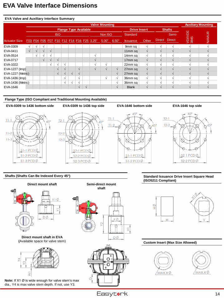
EVA-0309 to 1436 bottom side
EVA Valve Interface Dimensions
Shafts (Shafts Can Be Indexed Every 45°)
Flange Type (ISO Compliant and Traditional Mounting Available)
Standard Issuance Drive Insert Square Head
(ISO5211 Compliant)Semi-direct mount
shaft
Direct mount shaft
EVA-0309 to 1436 top side
Direct mount shaft in EVA
(Available space for valve stem)
Note: If X1 Ø is wide enough for valve stem’s max
dia., Y4 is max valve stem depth. If not, use Y3.
EVA-1646 bottom side EVA-1646 top side
Custom Insert (Max Size Allowed)
EVA Valve and Auxiliary Interface Summary
Valve Mounting Auxiliary Mounting
Flange Type Available Drive Insert Shafts
ISO Non ISO Standard Semi-
Actuator Size F03 F04 F05 F07 F10 F12 F14 F16 F25 3.25" 5.00" 6.50" Issuance Other Direct Direct
EVA-0309 √ √ √ 9mm sq √ √ √ √ √
EVA-0411 √ √ √ √ 11mm sq √ √ √ √ √
EVA-0514 √ √ √ √ 14mm sq √ √ √ √ √
EVA-0717 √ √ √ √ 17mm sq √ √ √ √ √
EVA-1022 √ √ √ √ √ 22mm sq √ √ √ √ √
EVA-1227 (Imp) √ √ √ √ √ √ 27mm sq √ √ √ √ √
EVA-1227 (Metric) √ √ √ √ √ 27mm sq √ √ √ √ √
EVA-1436 (Imp) √ √ √ √ 36mm sq √ √ √ √ √
EVA-1436 (Metric) √ √ √ √ 36mm sq √ √ √ √ √
EVA-1646 √ √ √ Blank √ √ √ √ √
VD
I/V
DE
3845
NA
MU
R
14
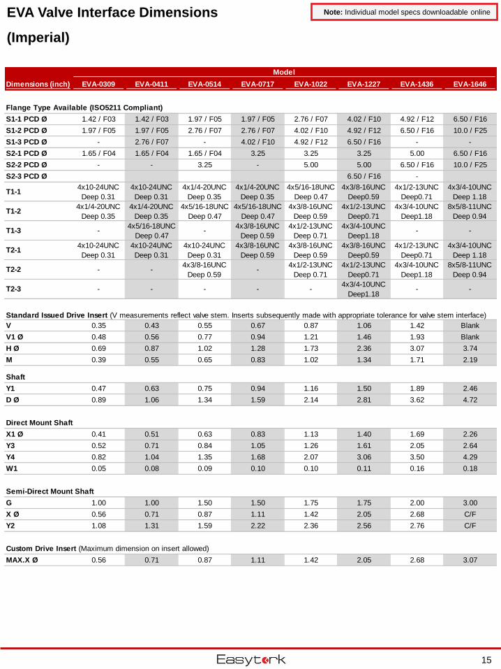
EVA Valve Interface Dimensions
(Imperial)
Note: Individual model specs downloadable online
Dimensions (inch) EVA-0309 EVA-0411 EVA-0514 EVA-0717 EVA-1022 EVA-1227 EVA-1436 EVA-1646
Flange Type Available (ISO5211 Compliant)
S1-1 PCD Ø 1.42 / F03 1.42 / F03 1.97 / F05 1.97 / F05 2.76 / F07 4.02 / F10 4.92 / F12 6.50 / F16
S1-2 PCD Ø 1.97 / F05 1.97 / F05 2.76 / F07 2.76 / F07 4.02 / F10 4.92 / F12 6.50 / F16 10.0 / F25
S1-3 PCD Ø - 2.76 / F07 - 4.02 / F10 4.92 / F12 6.50 / F16 - -
S2-1 PCD Ø 1.65 / F04 1.65 / F04 1.65 / F04 3.25 3.25 3.25 5.00 6.50 / F16
S2-2 PCD Ø - - 3.25 - 5.00 5.00 6.50 / F16 10.0 / F25
S2-3 PCD Ø 6.50 / F16 -
T1-1 4x10-24UNC
Deep 0.31
4x10-24UNC
Deep 0.31
4x1/4-20UNC
Deep 0.35
4x1/4-20UNC
Deep 0.35
4x5/16-18UNC
Deep 0.47
4x3/8-16UNC
Deep0.59
4x1/2-13UNC
Deep0.71
4x3/4-10UNC
Deep 1.18
T1-2 4x1/4-20UNC
Deep 0.35
4x1/4-20UNC
Deep 0.35
4x5/16-18UNC
Deep 0.47
4x5/16-18UNC
Deep 0.47
4x3/8-16UNC
Deep 0.59
4x1/2-13UNC
Deep0.71
4x3/4-10UNC
Deep1.18
8x5/8-11UNC
Deep 0.94
T1-3 -4x5/16-18UNC
Deep 0.47-
4x3/8-16UNC
Deep 0.59
4x1/2-13UNC
Deep 0.71
4x3/4-10UNC
Deep1.18- -
T2-1 4x10-24UNC
Deep 0.31
4x10-24UNC
Deep 0.31
4x10-24UNC
Deep 0.31
4x3/8-16UNC
Deep 0.59
4x3/8-16UNC
Deep 0.59
4x3/8-16UNC
Deep0.59
4x1/2-13UNC
Deep0.71
4x3/4-10UNC
Deep 1.18
T2-2 - -4x3/8-16UNC
Deep 0.59-
4x1/2-13UNC
Deep 0.71
4x1/2-13UNC
Deep0.71
4x3/4-10UNC
Deep1.18
8x5/8-11UNC
Deep 0.94
T2-3 - - - - -4x3/4-10UNC
Deep1.18- -
Standard Issued Drive Insert (V measurements reflect valve stem. Inserts subsequently made with appropriate tolerance for valve stem interface)
V 0.35 0.43 0.55 0.67 0.87 1.06 1.42 Blank
V1 Ø 0.48 0.56 0.77 0.94 1.21 1.46 1.93 Blank
H Ø 0.69 0.87 1.02 1.28 1.73 2.36 3.07 3.74
M 0.39 0.55 0.65 0.83 1.02 1.34 1.71 2.19
Shaft
Y1 0.47 0.63 0.75 0.94 1.16 1.50 1.89 2.46
D Ø 0.89 1.06 1.34 1.59 2.14 2.81 3.62 4.72
Direct Mount Shaft
X1 Ø 0.41 0.51 0.63 0.83 1.13 1.40 1.69 2.26
Y3 0.52 0.71 0.84 1.05 1.26 1.61 2.05 2.64
Y4 0.82 1.04 1.35 1.68 2.07 3.06 3.50 4.29
W1 0.05 0.08 0.09 0.10 0.10 0.11 0.16 0.18
Semi-Direct Mount Shaft
G 1.00 1.00 1.50 1.50 1.75 1.75 2.00 3.00
X Ø 0.56 0.71 0.87 1.11 1.42 2.05 2.68 C/F
Y2 1.08 1.31 1.59 2.22 2.36 2.56 2.76 C/F
Custom Drive Insert (Maximum dimension on insert allowed)
MAX.X Ø 0.56 0.71 0.87 1.11 1.42 2.05 2.68 3.07
Model
15
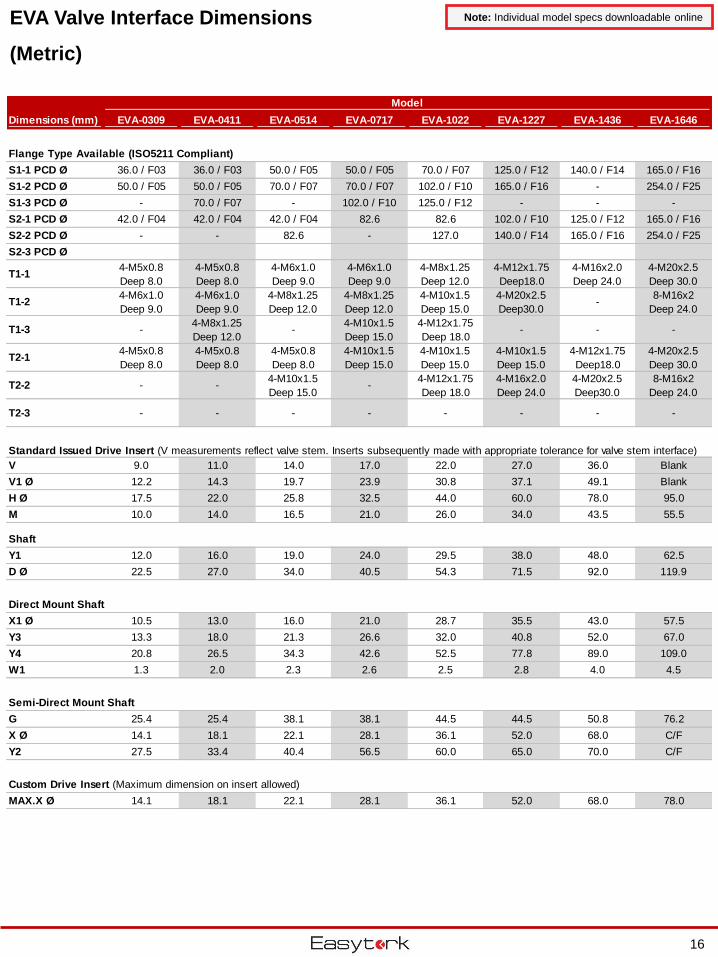
EVA Valve Interface Dimensions
(Metric)
Note: Individual model specs downloadable online
Dimensions (mm) EVA-0309 EVA-0411 EVA-0514 EVA-0717 EVA-1022 EVA-1227 EVA-1436 EVA-1646
Flange Type Available (ISO5211 Compliant)
S1-1 PCD Ø 36.0 / F03 36.0 / F03 50.0 / F05 50.0 / F05 70.0 / F07 125.0 / F12 140.0 / F14 165.0 / F16
S1-2 PCD Ø 50.0 / F05 50.0 / F05 70.0 / F07 70.0 / F07 102.0 / F10 165.0 / F16 - 254.0 / F25
S1-3 PCD Ø - 70.0 / F07 - 102.0 / F10 125.0 / F12 - - -
S2-1 PCD Ø 42.0 / F04 42.0 / F04 42.0 / F04 82.6 82.6 102.0 / F10 125.0 / F12 165.0 / F16
S2-2 PCD Ø - - 82.6 - 127.0 140.0 / F14 165.0 / F16 254.0 / F25
S2-3 PCD Ø
T1-1 4-M5x0.8
Deep 8.0
4-M5x0.8
Deep 8.0
4-M6x1.0
Deep 9.0
4-M6x1.0
Deep 9.0
4-M8x1.25
Deep 12.0
4-M12x1.75
Deep18.0
4-M16x2.0
Deep 24.0
4-M20x2.5
Deep 30.0
T1-2 4-M6x1.0
Deep 9.0
4-M6x1.0
Deep 9.0
4-M8x1.25
Deep 12.0
4-M8x1.25
Deep 12.0
4-M10x1.5
Deep 15.0
4-M20x2.5
Deep30.0-
8-M16x2
Deep 24.0
T1-3 -4-M8x1.25
Deep 12.0-
4-M10x1.5
Deep 15.0
4-M12x1.75
Deep 18.0- - -
T2-1 4-M5x0.8
Deep 8.0
4-M5x0.8
Deep 8.0
4-M5x0.8
Deep 8.0
4-M10x1.5
Deep 15.0
4-M10x1.5
Deep 15.0
4-M10x1.5
Deep 15.0
4-M12x1.75
Deep18.0
4-M20x2.5
Deep 30.0
T2-2 - -4-M10x1.5
Deep 15.0-
4-M12x1.75
Deep 18.0
4-M16x2.0
Deep 24.0
4-M20x2.5
Deep30.0
8-M16x2
Deep 24.0
T2-3 - - - - - - - -
Standard Issued Drive Insert (V measurements reflect valve stem. Inserts subsequently made with appropriate tolerance for valve stem interface)
V 9.0 11.0 14.0 17.0 22.0 27.0 36.0 Blank
V1 Ø 12.2 14.3 19.7 23.9 30.8 37.1 49.1 Blank
H Ø 17.5 22.0 25.8 32.5 44.0 60.0 78.0 95.0
M 10.0 14.0 16.5 21.0 26.0 34.0 43.5 55.5
Shaft
Y1 12.0 16.0 19.0 24.0 29.5 38.0 48.0 62.5
D Ø 22.5 27.0 34.0 40.5 54.3 71.5 92.0 119.9
Direct Mount Shaft
X1 Ø 10.5 13.0 16.0 21.0 28.7 35.5 43.0 57.5
Y3 13.3 18.0 21.3 26.6 32.0 40.8 52.0 67.0
Y4 20.8 26.5 34.3 42.6 52.5 77.8 89.0 109.0
W1 1.3 2.0 2.3 2.6 2.5 2.8 4.0 4.5
Semi-Direct Mount Shaft
G 25.4 25.4 38.1 38.1 44.5 44.5 50.8 76.2
X Ø 14.1 18.1 22.1 28.1 36.1 52.0 68.0 C/F
Y2 27.5 33.4 40.4 56.5 60.0 65.0 70.0 C/F
Custom Drive Insert (Maximum dimension on insert allowed)
MAX.X Ø 14.1 18.1 22.1 28.1 36.1 52.0 68.0 78.0
Model
16
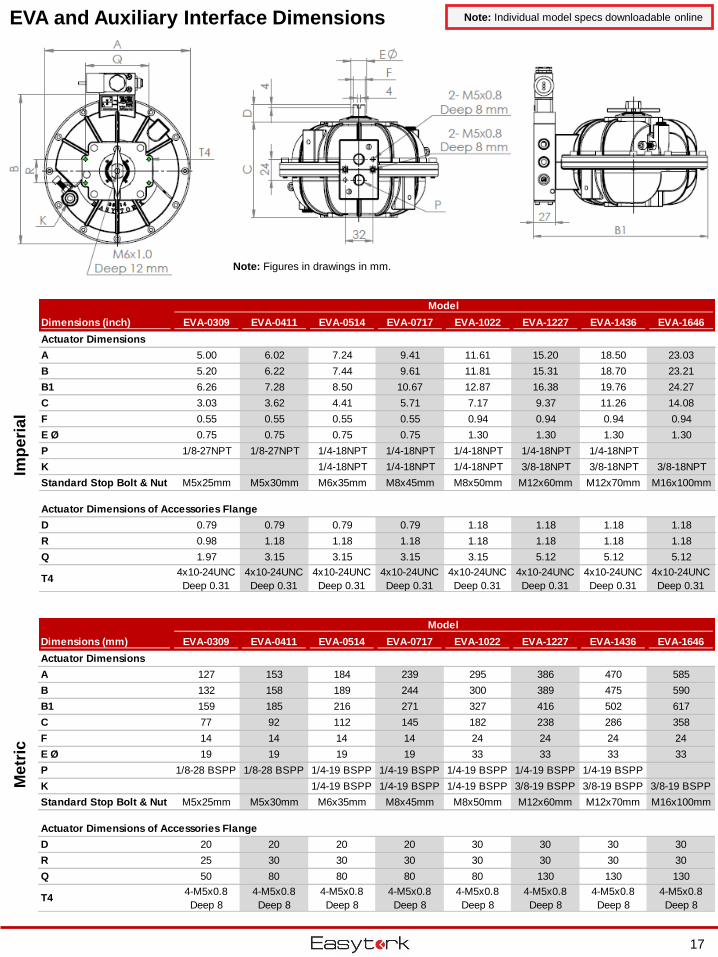
EVA and Auxiliary Interface DimensionsM
etr
icIm
pe
ria
lNote: Individual model specs downloadable online
Note: Figures in drawings in mm.
Dimensions (mm) EVA-0309 EVA-0411 EVA-0514 EVA-0717 EVA-1022 EVA-1227 EVA-1436 EVA-1646
Actuator Dimensions
A 127 153 184 239 295 386 470 585
B 132 158 189 244 300 389 475 590
B1 159 185 216 271 327 416 502 617
C 77 92 112 145 182 238 286 358
F 14 14 14 14 24 24 24 24
E Ø 19 19 19 19 33 33 33 33
P 1/8-28 BSPP 1/8-28 BSPP 1/4-19 BSPP 1/4-19 BSPP 1/4-19 BSPP 1/4-19 BSPP 1/4-19 BSPP
K 1/4-19 BSPP 1/4-19 BSPP 1/4-19 BSPP 3/8-19 BSPP 3/8-19 BSPP 3/8-19 BSPP
Standard Stop Bolt & Nut M5x25mm M5x30mm M6x35mm M8x45mm M8x50mm M12x60mm M12x70mm M16x100mm
Actuator Dimensions of Accessories Flange
D 20 20 20 20 30 30 30 30
R 25 30 30 30 30 30 30 30
Q 50 80 80 80 80 130 130 130
T44-M5x0.8
Deep 8
4-M5x0.8
Deep 8
4-M5x0.8
Deep 8
4-M5x0.8
Deep 8
4-M5x0.8
Deep 8
4-M5x0.8
Deep 8
4-M5x0.8
Deep 8
4-M5x0.8
Deep 8
Model
Dimensions (inch) EVA-0309 EVA-0411 EVA-0514 EVA-0717 EVA-1022 EVA-1227 EVA-1436 EVA-1646
Actuator Dimensions
A 5.00 6.02 7.24 9.41 11.61 15.20 18.50 23.03
B 5.20 6.22 7.44 9.61 11.81 15.31 18.70 23.21
B1 6.26 7.28 8.50 10.67 12.87 16.38 19.76 24.27
C 3.03 3.62 4.41 5.71 7.17 9.37 11.26 14.08
F 0.55 0.55 0.55 0.55 0.94 0.94 0.94 0.94
E Ø 0.75 0.75 0.75 0.75 1.30 1.30 1.30 1.30
P 1/8-27NPT 1/8-27NPT 1/4-18NPT 1/4-18NPT 1/4-18NPT 1/4-18NPT 1/4-18NPT
K 1/4-18NPT 1/4-18NPT 1/4-18NPT 3/8-18NPT 3/8-18NPT 3/8-18NPT
Standard Stop Bolt & Nut M5x25mm M5x30mm M6x35mm M8x45mm M8x50mm M12x60mm M12x70mm M16x100mm
Actuator Dimensions of Accessories Flange
D 0.79 0.79 0.79 0.79 1.18 1.18 1.18 1.18
R 0.98 1.18 1.18 1.18 1.18 1.18 1.18 1.18
Q 1.97 3.15 3.15 3.15 3.15 5.12 5.12 5.12
T44x10-24UNC
Deep 0.31
4x10-24UNC
Deep 0.31
4x10-24UNC
Deep 0.31
4x10-24UNC
Deep 0.31
4x10-24UNC
Deep 0.31
4x10-24UNC
Deep 0.31
4x10-24UNC
Deep 0.31
4x10-24UNC
Deep 0.31
Model
17
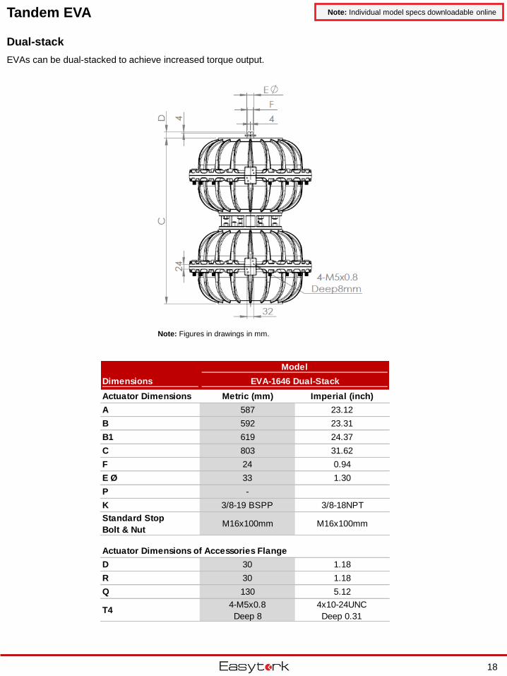
Tandem EVA Note: Individual model specs downloadable online
Note: Figures in drawings in mm.
Dual-stack
EVAs can be dual-stacked to achieve increased torque output.
Dimensions
Actuator Dimensions Metric (mm) Imperial (inch)
A 587 23.12
B 592 23.31
B1 619 24.37
C 803 31.62
F 24 0.94
E Ø 33 1.30
P -
K 3/8-19 BSPP 3/8-18NPT
Standard Stop
Bolt & NutM16x100mm M16x100mm
Actuator Dimensions of Accessories Flange
D 30 1.18
R 30 1.18
Q 130 5.12
T44-M5x0.8
Deep 8
4x10-24UNC
Deep 0.31
Model
EVA-1646 Dual-Stack
18
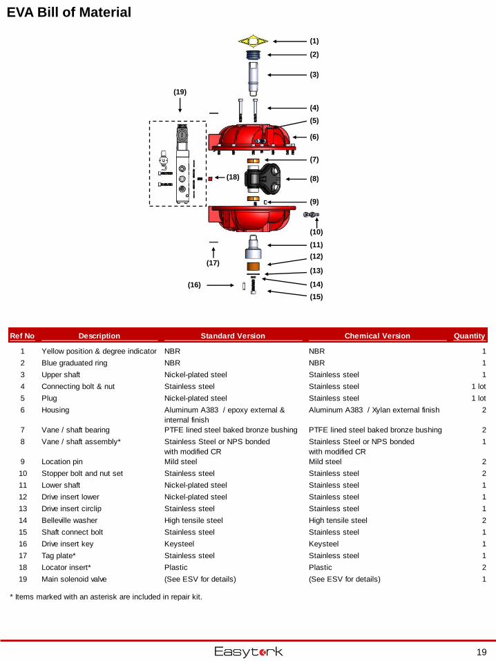
EVA Bill of Material
Ref No Description Standard Version Chemical Version Quantity
1 Yellow position & degree indicator NBR NBR 1
2 Blue graduated ring NBR NBR 1
3 Upper shaft Nickel-plated steel Stainless steel 1
4 Connecting bolt & nut Stainless steel Stainless steel 1 lot
5 Plug Nickel-plated steel Stainless steel 1 lot
6 Housing Aluminum A383 / epoxy external &
internal finish
Aluminum A383 / Xylan external finish 2
7 Vane / shaft bearing PTFE lined steel baked bronze bushing PTFE lined steel baked bronze bushing 2
8 Vane / shaft assembly* Stainless Steel or NPS bonded
with modified CR
Stainless Steel or NPS bonded
with modified CR
1
9 Location pin Mild steel Mild steel 2
10 Stopper bolt and nut set Stainless steel Stainless steel 2
11 Lower shaft Nickel-plated steel Stainless steel 1
12 Drive insert lower Nickel-plated steel Stainless steel 1
13 Drive insert circlip Stainless steel Stainless steel 1
14 Belleville washer High tensile steel High tensile steel 2
15 Shaft connect bolt Stainless steel Stainless steel 1
16 Drive insert key Keysteel Keysteel 1
17 Tag plate* Stainless steel Stainless steel 1
18 Locator insert* Plastic Plastic 2
19 Main solenoid valve (See ESV for details) (See ESV for details) 1
* Items marked with an asterisk are included in repair kit.
(1)
(2)
(3)
(4)
(5)
(6)
(7)
(8)
(9)
(10)
(11)
(12)
(13)
(14)
(15)
(16)
(17)
(18)
(19)
19
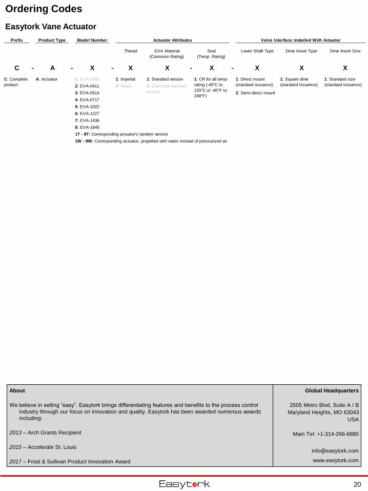
Ordering Codes
Easytork Vane Actuator
Prefix Product Type Model Number Actuator Attributes Valve Interface Installed With Actuator
Thread EVA Material
(Corrosion Rating)
Seal
(Temp. Rating)
Lower Shaft Type Drive Insert Type Drive Insert Size
C - A - X - X X - X - X X X
A: Actuator 1: EVA-0309 1: Imperial 1: Standard version
2: EVA-0411 2: Metric
3: EVA-0514 2: Semi-direct mount
4: EVA-0717
5: EVA-1022
6: EVA-1227
7: EVA-1436
8: EVA-1646
1T - 8T: Corresponding actuator's tandem version
1W - 8W: Corresponding actuator, propelled with water instead of pressurized air
C: Complete
product 2: Chemical resistant
version
1: CR for all temp
rating (-40°C to
120°C or -40°F to
248°F)
1: Direct mount
(standard issuance)
1: Square drive
(standard issuance)
1: Standard size
(standard issuance)
20
Global Headquarters
2505 Metro Blvd, Suite A / B
Maryland Heights, MO 63043
USA
Main Tel: +1-314-266-6880
www.easytork.com
About
We believe in selling “easy”. Easytork brings differentiating features and benefits to the process control
industry through our focus on innovation and quality. Easytork has been awarded numerous awards
including:
2013 – Arch Grants Recipient
2015 – Accelerate St. Louis
2017 – Frost & Sullivan Product Innovation Award
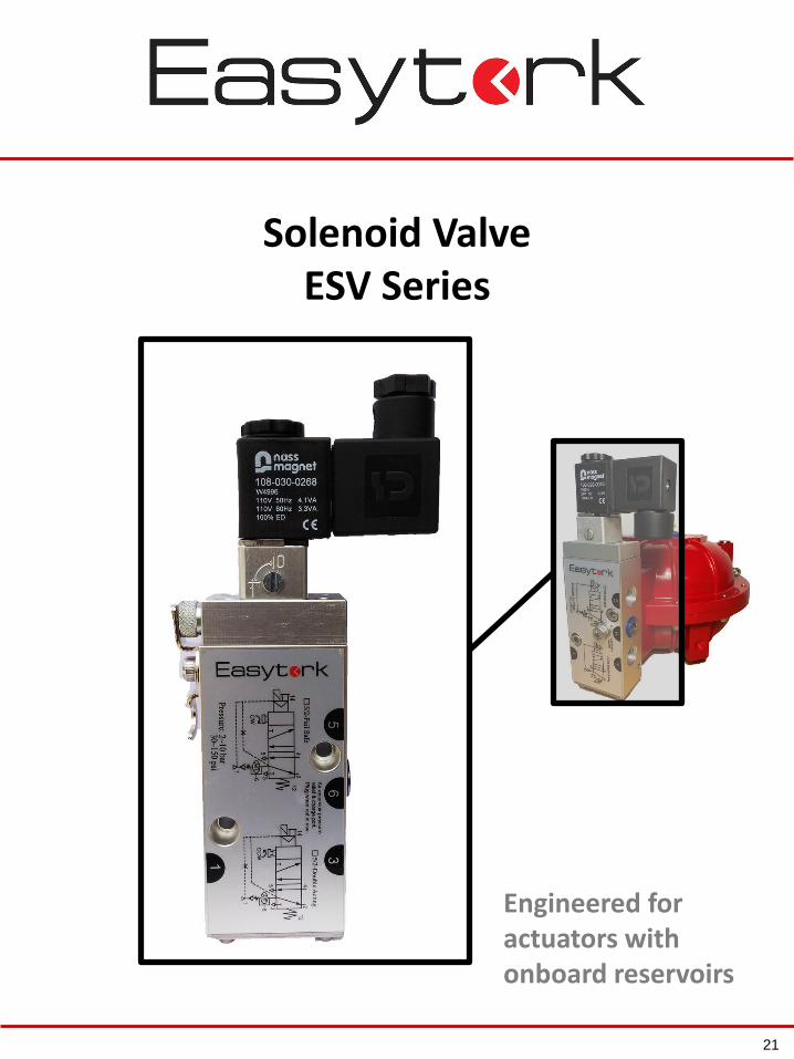
Solenoid ValveESV Series
Engineered for actuators with onboard reservoirs
21
Easytork Solenoid Valve (“ESV”)
22
ESV benefits that improve your OPERATIONS
ESV + Easytork actuator
reduces your SKU by a
factor of 67x
A singular ESV alters the
function of an Easytork
actuator between double-
acting or fail-safe (open or
close). In addition, all coil and
conduit types are modular to
the ESV.
ESV is Easytork’s NAMUR compliant solenoid valve to allow users to easily integrate air reservoir
fail-safe systems. ESV complies with almost all any electrical specification requirement and is a
5/2 design valve (four-way, two-position).
Fail-safe or double-acting
Double-acting
Fail-safe Fail-close
Fail-open
Fail-close or fail-open
ESV benefits that improve your SYSTEMS
Specification friendly
Compliant with nearly all electrical specification and conduit requirement. NEMA 4, Ex-Proof
and ATEX EX from ¼” NPT conduit to strain relief among many other options are available.
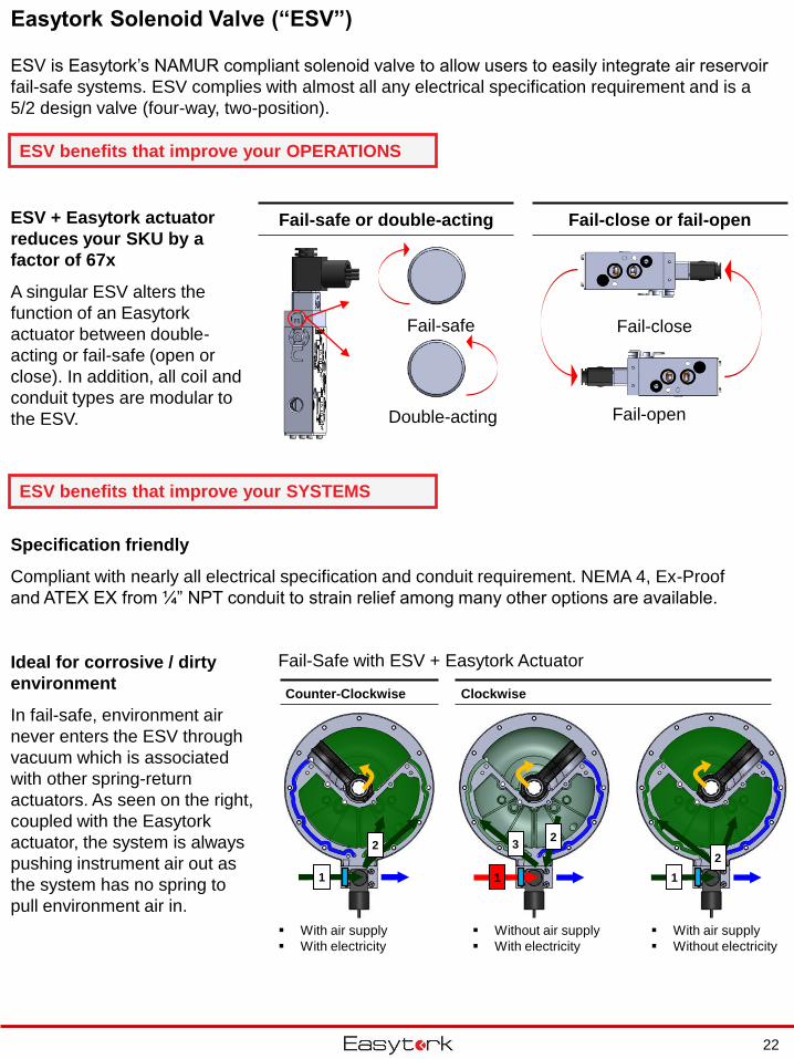
Ideal for corrosive / dirty
environment
In fail-safe, environment air
never enters the ESV through
vacuum which is associated
with other spring-return
actuators. As seen on the right,
coupled with the Easytork
actuator, the system is always
pushing instrument air out as
the system has no spring to
pull environment air in.
Fail-Safe with ESV + Easytork Actuator
Counter-Clockwise Clockwise
Without air supply
With electricity
With air supply
Without electricity
With air supply
With electricity
1
2
1
2
1
32
Easytork Solenoid Valve (“ESV”)
23
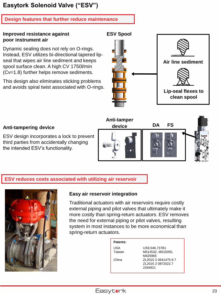
Design features that further reduce maintenance
Air line sediment
Lip-seal flexes to
clean spool
ESV Spool
Anti-tampering device
ESV design incorporates a lock to prevent
third parties from accidentally changing
the intended ESV’s functionality.
Improved resistance against
poor instrument air
Dynamic sealing does not rely on O-rings.
Instead, ESV utilizes bi-directional tapered lip-
seal that wipes air line sediment and keeps
spool surface clean. A high CV 1750l/min
(Cv=1.8) further helps remove sediments.
This design also eliminates sticking problems
and avoids spiral twist associated with O-rings.
ESV reduces costs associated with utilizing air reservoir
Anti-tamper
device DA FS
Patents:
USA US9,546,737B1
Taiwan M514532, M515055,
M425965
China ZL2015 2 0641475.9.7
ZL2015 2 0872022.7
2264921
Easy air reservoir integration
Traditional actuators with air reservoirs require costly
external piping and pilot valves that ultimately make it
more costly than spring-return actuators. ESV removes
the need for external piping or pilot valves, resulting
system in most instances to be more economical than
spring-return actuators.
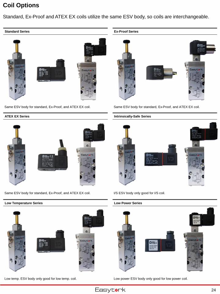
Coil Options
Standard Series Ex-Proof Series
Low Temperature Series
ATEX EX Series
Low Power Series
Intrinsically-Safe Series
Standard, Ex-Proof and ATEX EX coils utilize the same ESV body, so coils are interchangeable.
Same ESV body for standard, Ex-Proof, and ATEX EX coil. Same ESV body for standard, Ex-Proof, and ATEX EX coil.
Same ESV body for standard, Ex-Proof, and ATEX EX coil. I/S ESV body only good for I/S coil.
Low temp. ESV body only good for low temp. coil. Low power ESV body only good for low power coil.
24
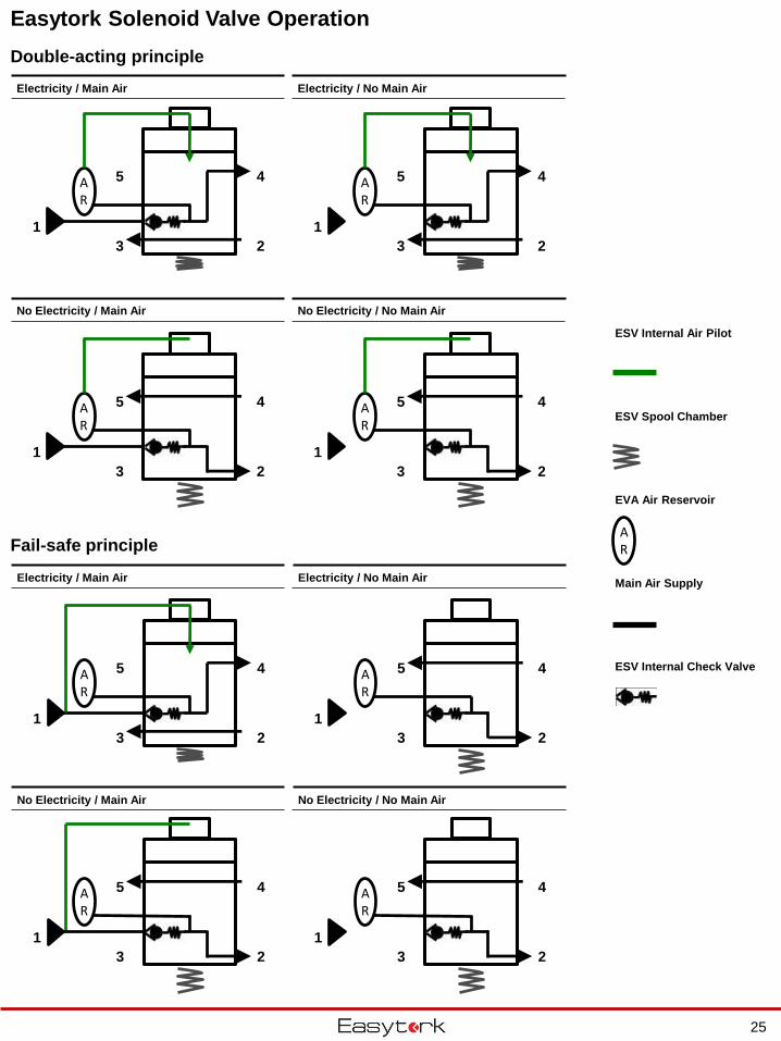
Easytork Solenoid Valve Operation
Double-acting principle
Fail-safe principle
Electricity / Main Air Electricity / No Main Air
No Electricity / Main Air No Electricity / No Main Air
Electricity / Main Air Electricity / No Main Air
No Electricity / Main Air No Electricity / No Main Air
AR
ESV Internal Air Pilot
ESV Spool Chamber
EVA Air Reservoir
Main Air Supply
ESV Internal Check Valve
2
AR
1
45
3 2
AR
1
45
3
2
AR
1
45
3 2
AR
1
45
3
2
AR
1
45
3 2
AR
1
45
3
2
AR
1
45
3 2
AR
1
45
3
25
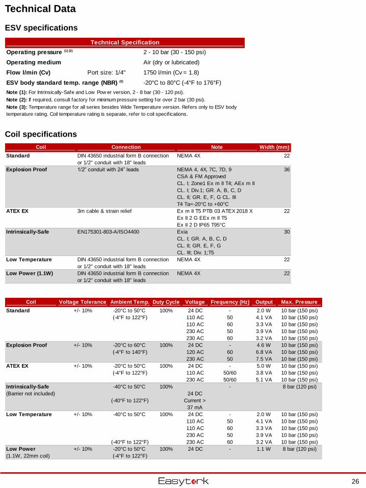
Technical Data
ESV specifications
Coil specifications
Coil Connection Note Width (mm)
Standard DIN 43650 industrial form B connection
or 1/2" conduit with 18" leads
NEMA 4X 22
Explosion Proof 1/2” conduit with 24” leads NEMA 4, 4X, 7C, 7D, 9
CSA & FM Approved
CL. I; Zone1 Ex m II T4; AEx m II
CL. I; Div.1; GR. A, B, C, D
CL. II; GR. E, F, G CL. III
T4 Ta=-20°C to +60°C
36
ATEX EX 3m cable & strain relief Ex m II T5 PTB 03 ATEX 2018 X
Ex II 2 G EEx m II T5
Ex II 2 D IP65 T95°C
22
Intrinsically-Safe EN175301-803-A/ISO4400 Exia
CL. I; GR. A, B, C, D
CL. II; GR. E, F, G
CL. III; Div. 1;T5
30
Low Temperature DIN 43650 industrial form B connection
or 1/2" conduit with 18" leads
NEMA 4X 22
Low Power (1.1W) DIN 43650 industrial form B connection
or 1/2" conduit with 18" leads
NEMA 4X 22
Coil Voltage Tolerance Ambient Temp. Duty Cycle Voltage Frequency (Hz) Output Max. Pressure
Standard +/- 10% -20°C to 50°C 100% 24 DC - 2.0 W 10 bar (150 psi)
(-4°F to 122°F) 110 AC 50 4.1 VA 10 bar (150 psi)
110 AC 60 3.3 VA 10 bar (150 psi)
230 AC 50 3.9 VA 10 bar (150 psi)
230 AC 60 3.2 VA 10 bar (150 psi)
Explosion Proof +/- 10% -20°C to 60°C 100% 24 DC - 4.6 W 10 bar (150 psi)
(-4°F to 140°F) 120 AC 60 6.8 VA 10 bar (150 psi)
230 AC 50 7.5 VA 10 bar (150 psi)
ATEX EX +/- 10% -20°C to 50°C 100% 24 DC - 5.0 W 10 bar (150 psi)
(-4°F to 122°F) 110 AC 50/60 3.8 VA 10 bar (150 psi)
230 AC 50/60 5.1 VA 10 bar (150 psi)
Intrinsically-Safe -40°C to 50°C 100% - 8 bar (120 psi)
(Barrier not included)
(-40°F to 122°F)
Low Temperature +/- 10% -40°C to 50°C 100% 24 DC - 2.0 W 10 bar (150 psi)
110 AC 50 4.1 VA 10 bar (150 psi)
110 AC 60 3.3 VA 10 bar (150 psi)
230 AC 50 3.9 VA 10 bar (150 psi)
(-40°F to 122°F) 230 AC 60 3.2 VA 10 bar (150 psi)
Low Power +/- 10% -20°C to 50°C 100% 24 DC - 1.1 W 8 bar (120 psi)
(1.1W, 22mm coil) (-4°F to 122°F)
24 DC
Current >
37 mA
Technical Specification
Operating pressure (1) (2) 2 - 10 bar (30 - 150 psi)
Operating medium Air (dry or lubricated)
Flow l/min (Cv) Port size: 1/4" 1750 l/min (Cv = 1.8)
ESV body standard temp. range (NBR) (3) -20°C to 80°C (-4°F to 176°F)
Note (1): For Intrinsically-Safe and Low Pow er version, 2 - 8 bar (30 - 120 psi).
Note (2): If required, consult factory for minimum pressure setting for over 2 bar (30 psi).
Note (3): Temperature range for all series besides Wide Temperature version. Refers only to ESV body
temperature rating. Coil temperature rating is separate, refer to coil specif ications.
26
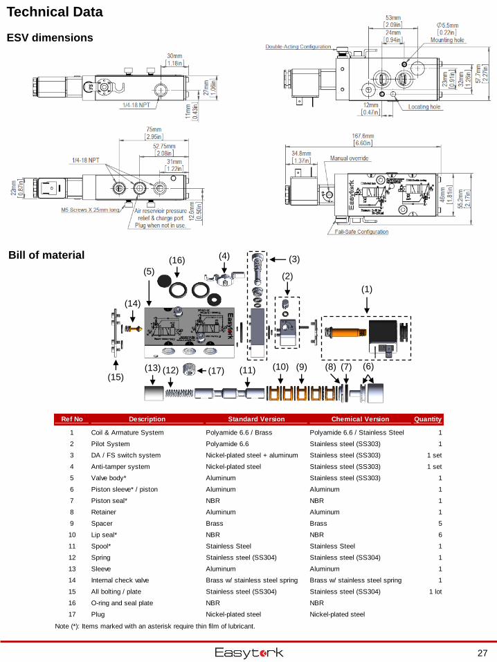
Technical Data
ESV dimensions
Bill of material
(1)
(3)
(2)(5)
(4)
(6)(7)
(14)
(15)(8)(9)(10)(11)(12)(13)
Ref No Description Standard Version Chemical Version Quantity
1 Coil & Armature System Polyamide 6.6 / Brass Polyamide 6.6 / Stainless Steel 1
2 Pilot System Polyamide 6.6 Stainless steel (SS303) 1
3 DA / FS switch system Nickel-plated steel + aluminum Stainless steel (SS303) 1 set
4 Anti-tamper system Nickel-plated steel Stainless steel (SS303) 1 set
5 Valve body* Aluminum Stainless steel (SS303) 1
6 Piston sleeve* / piston Aluminum Aluminum 1
7 Piston seal* NBR NBR 1
8 Retainer Aluminum Aluminum 1
9 Spacer Brass Brass 5
10 Lip seal* NBR NBR 6
11 Spool* Stainless Steel Stainless Steel 1
12 Spring Stainless steel (SS304) Stainless steel (SS304) 1
13 Sleeve Aluminum Aluminum 1
14 Internal check valve Brass w/ stainless steel spring Brass w/ stainless steel spring 1
15 All bolting / plate Stainless steel (SS304) Stainless steel (SS304) 1 lot
16 O-ring and seal plate NBR NBR
17 Plug Nickel-plated steel Nickel-plated steel
Note (*): Items marked with an asterisk require thin film of lubricant.
(16)
(17)
27
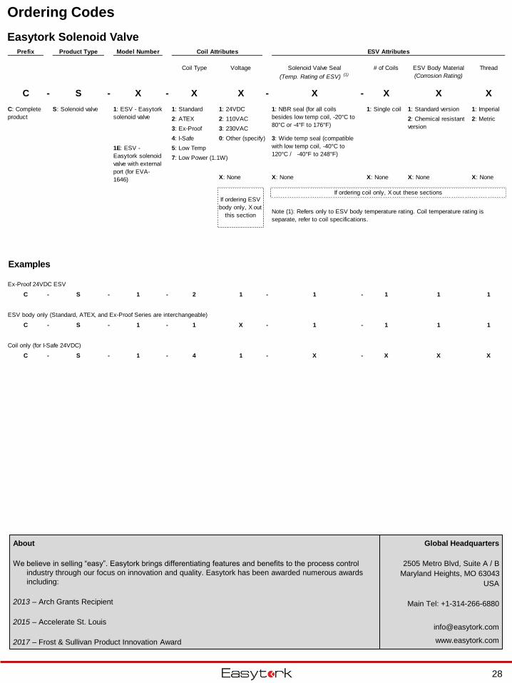
Ordering Codes
Easytork Solenoid Valve
28
Global Headquarters
2505 Metro Blvd, Suite A / B
Maryland Heights, MO 63043
USA
Main Tel: +1-314-266-6880
www.easytork.com
About
We believe in selling “easy”. Easytork brings differentiating features and benefits to the process control
industry through our focus on innovation and quality. Easytork has been awarded numerous awards
including:
2013 – Arch Grants Recipient
2015 – Accelerate St. Louis
2017 – Frost & Sullivan Product Innovation Award
Prefix Product Type Model Number Coil Attributes ESV Attributes
Coil Type Voltage Solenoid Valve Seal
(Temp. Rating of ESV) (1)
# of Coils ESV Body Material
(Corrosion Rating)
Thread
C - S - X - X X - X - X X X
1: Standard 1: 24VDC 1: Single coil 1: Standard version 1: Imperial
2: ATEX 2: 110VAC 2: Metric
3: Ex-Proof 3: 230VAC
4: I-Safe 0: Other (specify)
5: Low Temp
7: Low Power (1.1W)
X: None X: None X: None X: None X: None
Examples
Ex-Proof 24VDC ESV
C - S - 1 - 2 1 - 1 - 1 1 1
ESV body only (Standard, ATEX, and Ex-Proof Series are interchangeable)
C - S - 1 - 1 X - 1 - 1 1 1
Coil only (for I-Safe 24VDC)
C - S - 1 - 4 1 - X - X X X
C: Complete
product
1: NBR seal (for all coils
besides low temp coil, -20°C to
80°C or -4°F to 176°F)
If ordering coil only, X out these sections
2: Chemical resistant
version
S: Solenoid valve
If ordering ESV
body only, X out
this sectionNote (1): Refers only to ESV body temperature rating. Coil temperature rating is
separate, refer to coil specifications.
3: Wide temp seal (compatible
with low temp coil, -40°C to
120°C / -40°F to 248°F)
1: ESV - Easytork
solenoid valve
1E: ESV -
Easytork solenoid
valve with external
port (for EVA-
1646)
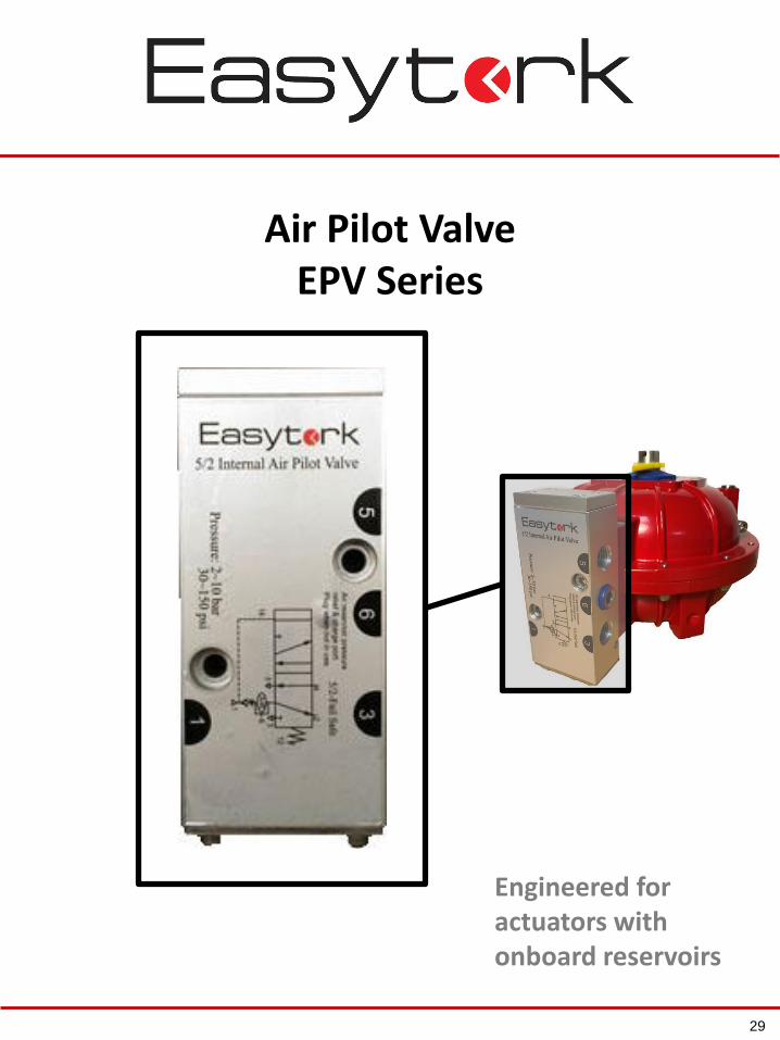
Air Pilot ValveEPV Series
Engineered for actuators with onboard reservoirs
29
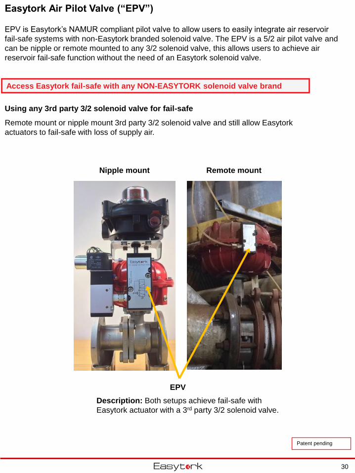
Easytork Air Pilot Valve (“EPV”)
30
Access Easytork fail-safe with any NON-EASYTORK solenoid valve brand
Using any 3rd party 3/2 solenoid valve for fail-safe
Remote mount or nipple mount 3rd party 3/2 solenoid valve and still allow Easytork
actuators to fail-safe with loss of supply air.
Nipple mount
EPV
Remote mount
Description: Both setups achieve fail-safe with
Easytork actuator with a 3rd party 3/2 solenoid valve.
EPV is Easytork’s NAMUR compliant pilot valve to allow users to easily integrate air reservoir
fail-safe systems with non-Easytork branded solenoid valve. The EPV is a 5/2 air pilot valve and
can be nipple or remote mounted to any 3/2 solenoid valve, this allows users to achieve air
reservoir fail-safe function without the need of an Easytork solenoid valve.
Patent pending
Easytork Air Pilot Valve (“EPV”)
31
Without air supply With air supply
Counter-Clockwise Clockwise
Note: Figures in mm
1
2
1
32
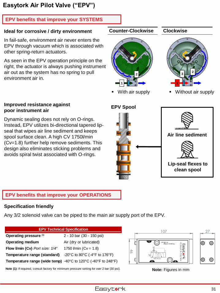
EPV Technical Specification
Operating pressure (1) 2 - 10 bar (30 - 150 psi)
Operating medium Air (dry or lubricated)
Flow l/min (Cv) Port size: 1/4" 1750 l/min (Cv = 1.8)
Temperature range (standard) -20°C to 80°C (-4°F to 176°F)
Temperature range (wide temp) -40°C to 120°C (-40°F to 248°F)
Note (1): If required, consult factory for minimum pressure setting for over 2 bar (30 psi).
Ideal for corrosive / dirty environment
In fail-safe, environment air never enters the
EPV through vacuum which is associated with
other spring-return actuators.
As seen in the EPV operation principle on the
right, the actuator is always pushing instrument
air out as the system has no spring to pull
environment air in.
Specification friendly
Any 3/2 solenoid valve can be piped to the main air supply port of the EPV.
Improved resistance against
poor instrument air
Dynamic sealing does not rely on O-rings.
Instead, EPV utilizes bi-directional tapered lip-
seal that wipes air line sediment and keeps
spool surface clean. A high CV 1750l/min
(Cv=1.8) further help remove sediments. This
design also eliminates sticking problems and
avoids spiral twist associated with O-rings.
Air line sediment
Lip-seal flexes to
clean spool
EPV Spool
EPV benefits that improve your OPERATIONS
EPV benefits that improve your SYSTEMS
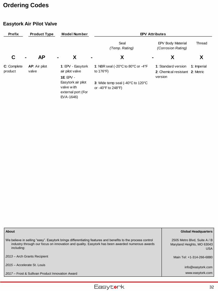
Ordering Codes
Easytork Air Pilot Valve
Prefix Product Type Model Number EPV Attributes
Seal
(Temp. Rating)
EPV Body Material
(Corrosion Rating)
Thread
C - AP - X - X - X X
1: Standard version 1: Imperial
2: Metric
3: Wide temp seal (-40°C to 120°C
or -40°F to 248°F)
1: NBR seal (-20°C to 80°C or -4°F
to 176°F) 2: Chemical resistant
version
C: Complete
product
AP: Air pilot
valve
1: EPV - Easytork
air pilot valve
1E: EPV -
Easytork air pilot
valve w ith
external port (For
EVA-1646)
32
Global Headquarters
2505 Metro Blvd, Suite A / B
Maryland Heights, MO 63043
USA
Main Tel: +1-314-266-6880
www.easytork.com
About
We believe in selling “easy”. Easytork brings differentiating features and benefits to the process control
industry through our focus on innovation and quality. Easytork has been awarded numerous awards
including:
2013 – Arch Grants Recipient
2015 – Accelerate St. Louis
2017 – Frost & Sullivan Product Innovation Award
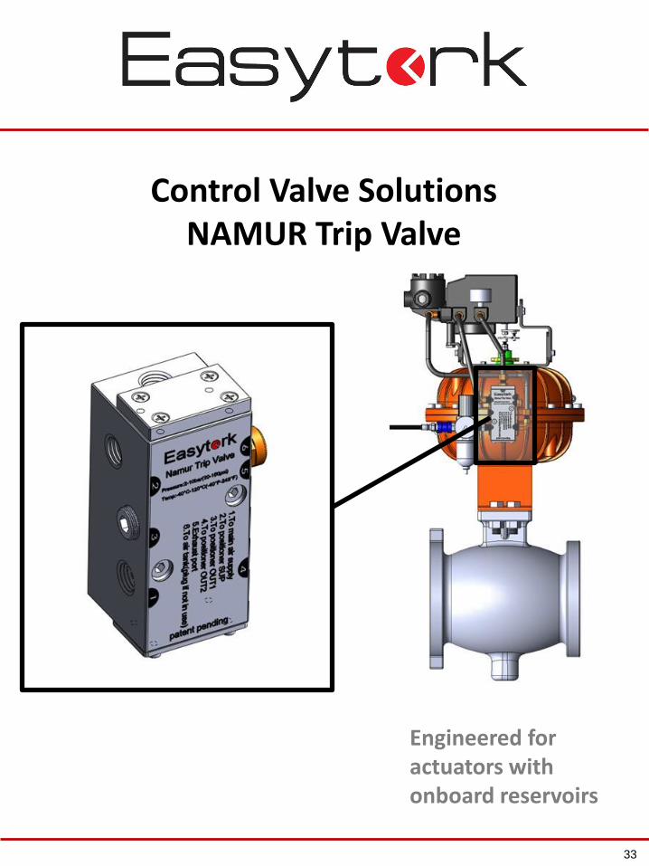
Control Valve SolutionsNAMUR Trip Valve
Engineered for actuators with onboard reservoirs
33
Namur Trip Valve (“NTV”)
34
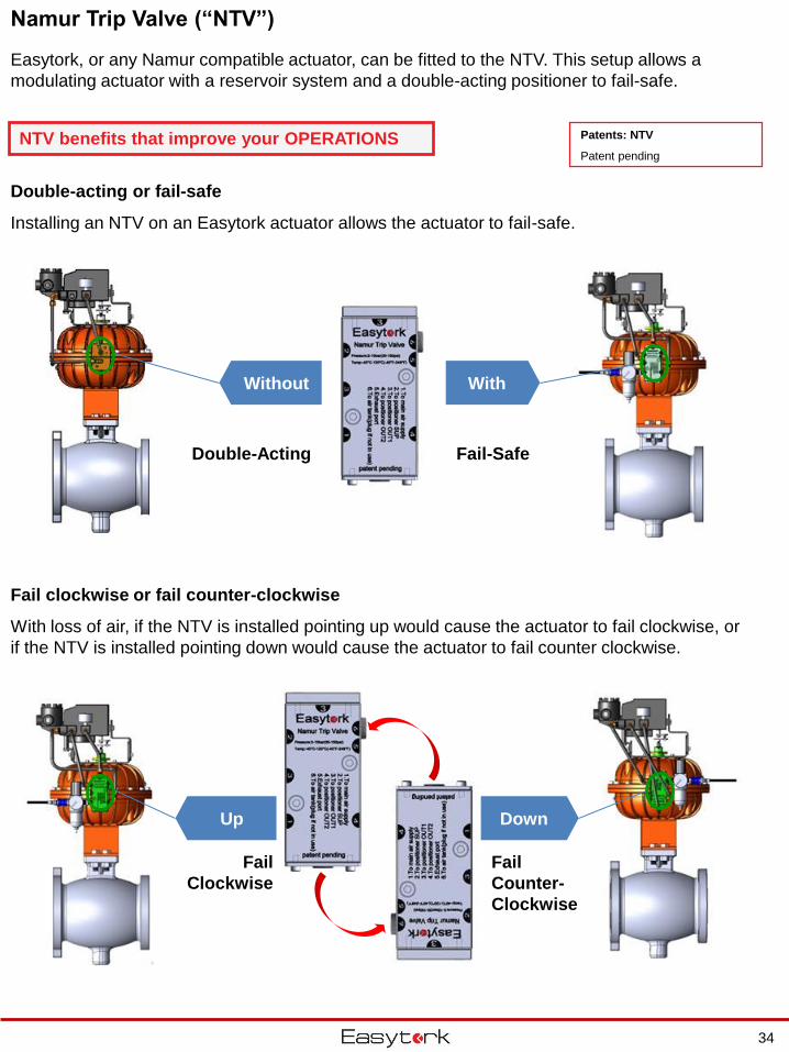
Easytork, or any Namur compatible actuator, can be fitted to the NTV. This setup allows a
modulating actuator with a reservoir system and a double-acting positioner to fail-safe.
Double-Acting Fail-Safe
WithWithout
Fail
Clockwise
Fail
Counter-
Clockwise
DownUp
Double-acting or fail-safe
Installing an NTV on an Easytork actuator allows the actuator to fail-safe.
Fail clockwise or fail counter-clockwise
With loss of air, if the NTV is installed pointing up would cause the actuator to fail clockwise, or
if the NTV is installed pointing down would cause the actuator to fail counter clockwise.
NTV benefits that improve your OPERATIONS Patents: NTV
Patent pending
35
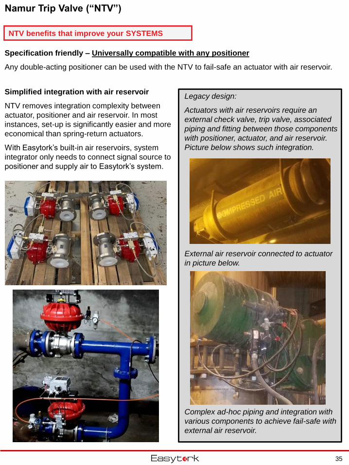
Simplified integration with air reservoir
NTV removes integration complexity between
actuator, positioner and air reservoir. In most
instances, set-up is significantly easier and more
economical than spring-return actuators.
With Easytork’s built-in air reservoirs, system
integrator only needs to connect signal source to
positioner and supply air to Easytork’s system.
Specification friendly – Universally compatible with any positioner
Any double-acting positioner can be used with the NTV to fail-safe an actuator with air reservoir.
Namur Trip Valve (“NTV”)
Legacy design:
Actuators with air reservoirs require an
external check valve, trip valve, associated
piping and fitting between those components
with positioner, actuator, and air reservoir.
Picture below shows such integration.
External air reservoir connected to actuator
in picture below.
Complex ad-hoc piping and integration with
various components to achieve fail-safe with
external air reservoir.
NTV benefits that improve your SYSTEMS
Ordering Codes
Easytork Namur Trip Valve
36
Global Headquarters
2505 Metro Blvd, Suite A / B
Maryland Heights, MO 63043
USA
Main Tel: +1-314-266-6880
www.easytork.com
About
We believe in selling “easy”. Easytork brings differentiating features and benefits to the process control
industry through our focus on innovation and quality. Easytork has been awarded numerous awards
including:
2013 – Arch Grants Recipient
2015 – Accelerate St. Louis
2017 – Frost & Sullivan Product Innovation Award
Prefix Product Type Model Number NTV Attributes
Seal
(Temp. Rating)
NTV Body Material
(Corrosion Rating)
Thread
C - PV - X - X - X X
1: Standard version 1: Imperial
2: Metric
C: Complete
product
PV: Universal
positioner valve
1: NTV - Easytork
Namur trip valve
1: Standard seal (for all temp
-20°C to 80°C or -4°F to 176°F) 2: Chemical resistant
version
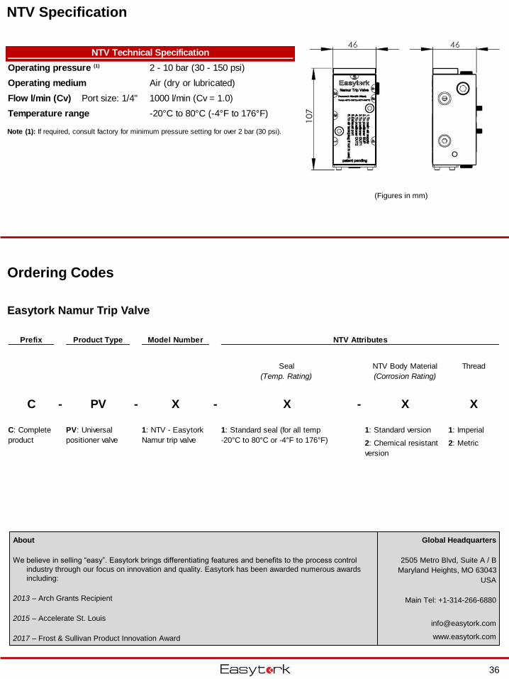
NTV Technical Specification
Operating pressure (1) 2 - 10 bar (30 - 150 psi)
Operating medium Air (dry or lubricated)
Flow l/min (Cv) Port size: 1/4" 1000 l/min (Cv = 1.0)
Temperature range -20°C to 80°C (-4°F to 176°F)
Note (1): If required, consult factory for minimum pressure setting for over 2 bar (30 psi).
(Figures in mm)
NTV Specification
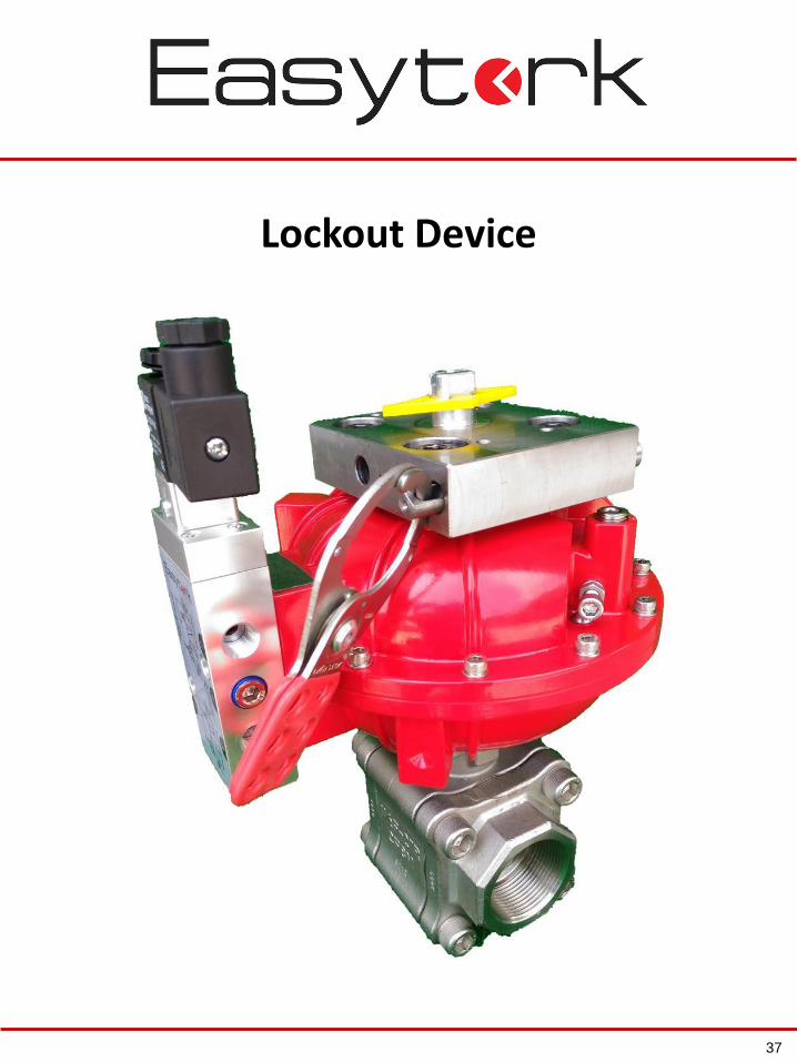
Lockout Device
37
Lockout Device
38
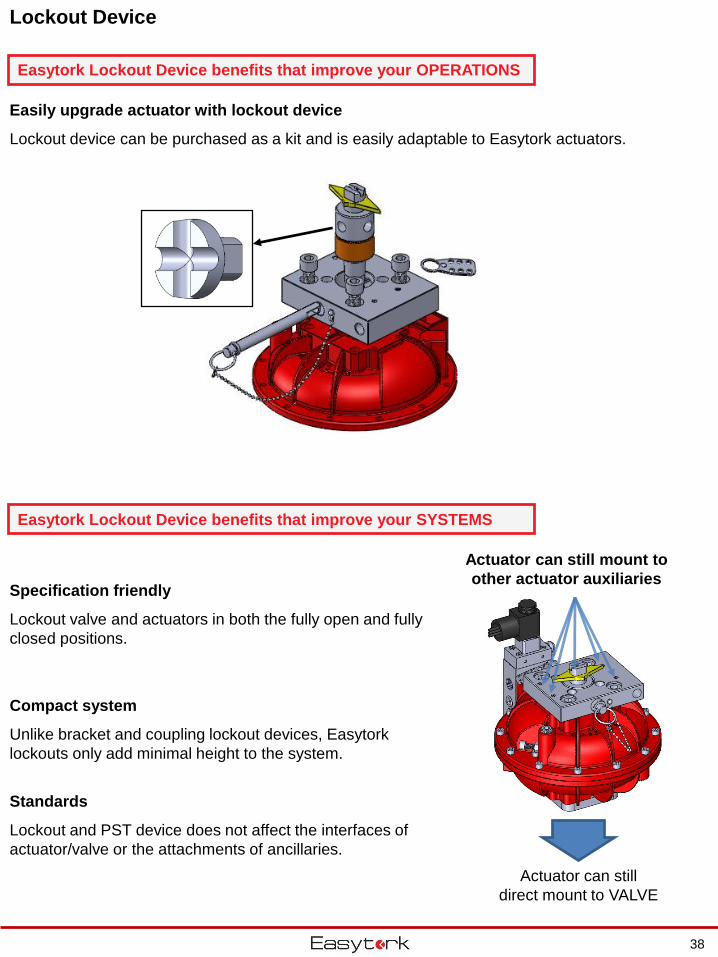
Actuator can still
direct mount to VALVE
Specification friendly
Lockout valve and actuators in both the fully open and fully
closed positions.
Compact system
Unlike bracket and coupling lockout devices, Easytork
lockouts only add minimal height to the system.
Standards
Lockout and PST device does not affect the interfaces of
actuator/valve or the attachments of ancillaries.
Easily upgrade actuator with lockout device
Lockout device can be purchased as a kit and is easily adaptable to Easytork actuators.
Actuator can still mount to
other actuator auxiliaries
Easytork Lockout Device benefits that improve your SYSTEMS
Easytork Lockout Device benefits that improve your OPERATIONS
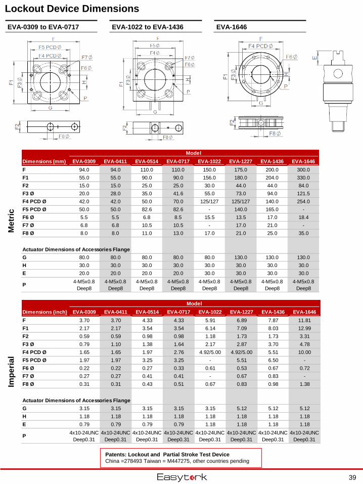
Lockout Device DimensionsM
etr
icIm
pe
ria
l
EVA-0309 to EVA-0717 EVA-1022 to EVA-1436 EVA-1646
Patents: Lockout and Partial Stroke Test Device
China =278493 Taiwan = M447275, other countries pending
39
Dimensions (mm) EVA-0309 EVA-0411 EVA-0514 EVA-0717 EVA-1022 EVA-1227 EVA-1436 EVA-1646
F 94.0 94.0 110.0 110.0 150.0 175.0 200.0 300.0
F1 55.0 55.0 90.0 90.0 156.0 180.0 204.0 330.0
F2 15.0 15.0 25.0 25.0 30.0 44.0 44.0 84.0
F3 Ø 20.0 28.0 35.0 41.6 55.0 73.0 94.0 121.5
F4 PCD Ø 42.0 42.0 50.0 70.0 125/127 125/127 140.0 254.0
F5 PCD Ø 50.0 50.0 82.6 82.6 - 140.0 165.0 -
F6 Ø 5.5 5.5 6.8 8.5 15.5 13.5 17.0 18.4
F7 Ø 6.8 6.8 10.5 10.5 - 17.0 21.0 -
F8 Ø 8.0 8.0 11.0 13.0 17.0 21.0 25.0 35.0
Actuator Dimensions of Accessories Flange
G 80.0 80.0 80.0 80.0 80.0 130.0 130.0 130.0
H 30.0 30.0 30.0 30.0 30.0 30.0 30.0 30.0
E 20.0 20.0 20.0 20.0 30.0 30.0 30.0 30.0
P4-M5x0.8
Deep8
4-M5x0.8
Deep8
4-M5x0.8
Deep8
4-M5x0.8
Deep8
4-M5x0.8
Deep8
4-M5x0.8
Deep8
4-M5x0.8
Deep8
4-M5x0.8
Deep8
Model
Dimensions (inch) EVA-0309 EVA-0411 EVA-0514 EVA-0717 EVA-1022 EVA-1227 EVA-1436 EVA-1646
F 3.70 3.70 4.33 4.33 5.91 6.89 7.87 11.81
F1 2.17 2.17 3.54 3.54 6.14 7.09 8.03 12.99
F2 0.59 0.59 0.98 0.98 1.18 1.73 1.73 3.31
F3 Ø 0.79 1.10 1.38 1.64 2.17 2.87 3.70 4.78
F4 PCD Ø 1.65 1.65 1.97 2.76 4.92/5.00 4.92/5.00 5.51 10.00
F5 PCD Ø 1.97 1.97 3.25 3.25 - 5.51 6.50 -
F6 Ø 0.22 0.22 0.27 0.33 0.61 0.53 0.67 0.72
F7 Ø 0.27 0.27 0.41 0.41 - 0.67 0.83 -
F8 Ø 0.31 0.31 0.43 0.51 0.67 0.83 0.98 1.38
Actuator Dimensions of Accessories Flange
G 3.15 3.15 3.15 3.15 3.15 5.12 5.12 5.12
H 1.18 1.18 1.18 1.18 1.18 1.18 1.18 1.18
E 0.79 0.79 0.79 0.79 1.18 1.18 1.18 1.18
P4x10-24UNC
Deep0.31
4x10-24UNC
Deep0.31
4x10-24UNC
Deep0.31
4x10-24UNC
Deep0.31
4x10-24UNC
Deep0.31
4x10-24UNC
Deep0.31
4x10-24UNC
Deep0.31
4x10-24UNC
Deep0.31
Model
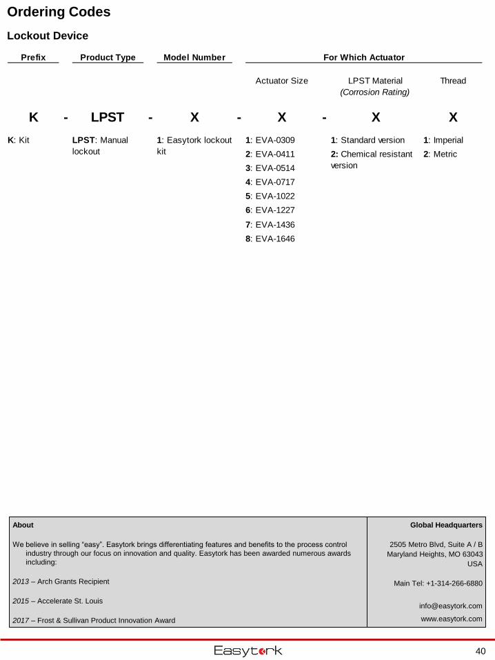
Ordering Codes
Lockout Device
Prefix Product Type Model Number For Which Actuator
Actuator Size LPST Material
(Corrosion Rating)
Thread
K - LPST - X - X - X X
1: EVA-0309 1: Standard version 1: Imperial
2: EVA-0411 2: Metric
3: EVA-0514
4: EVA-0717
5: EVA-1022
6: EVA-1227
7: EVA-1436
8: EVA-1646
2: Chemical resistant
version
K: Kit 1: Easytork lockout
kit
LPST: Manual
lockout
40
Global Headquarters
2505 Metro Blvd, Suite A / B
Maryland Heights, MO 63043
USA
Main Tel: +1-314-266-6880
www.easytork.com
About
We believe in selling “easy”. Easytork brings differentiating features and benefits to the process control
industry through our focus on innovation and quality. Easytork has been awarded numerous awards
including:
2013 – Arch Grants Recipient
2015 – Accelerate St. Louis
2017 – Frost & Sullivan Product Innovation Award
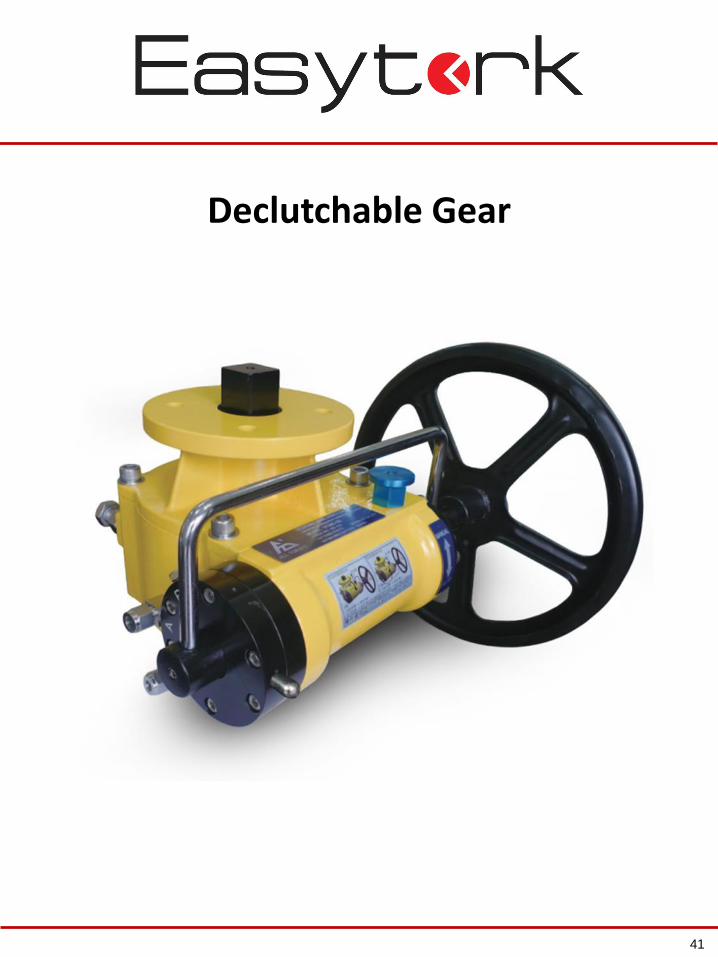
Declutchable Gear
41
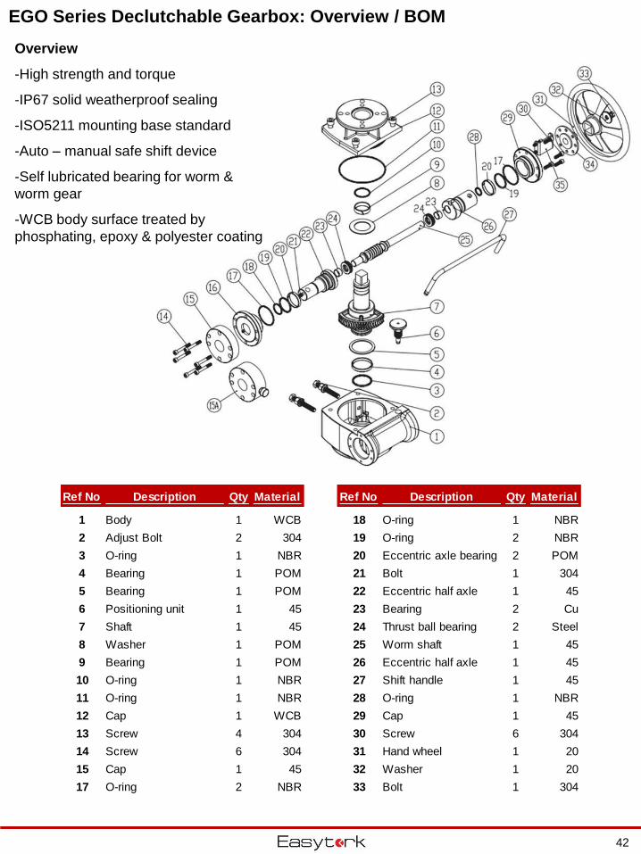
EGO Series Declutchable Gearbox: Overview / BOM
42
Ref No Description Qty Material Ref No Description Qty Material
1 Body 1 WCB 18 O-ring 1 NBR
2 Adjust Bolt 2 304 19 O-ring 2 NBR
3 O-ring 1 NBR 20 Eccentric axle bearing 2 POM
4 Bearing 1 POM 21 Bolt 1 304
5 Bearing 1 POM 22 Eccentric half axle 1 45
6 Positioning unit 1 45 23 Bearing 2 Cu
7 Shaft 1 45 24 Thrust ball bearing 2 Steel
8 Washer 1 POM 25 Worm shaft 1 45
9 Bearing 1 POM 26 Eccentric half axle 1 45
10 O-ring 1 NBR 27 Shift handle 1 45
11 O-ring 1 NBR 28 O-ring 1 NBR
12 Cap 1 WCB 29 Cap 1 45
13 Screw 4 304 30 Screw 6 304
14 Screw 6 304 31 Hand wheel 1 20
15 Cap 1 45 32 Washer 1 20
17 O-ring 2 NBR 33 Bolt 1 304
Overview
-High strength and torque
-IP67 solid weatherproof sealing
-ISO5211 mounting base standard
-Auto – manual safe shift device
-Self lubricated bearing for worm &
worm gear
-WCB body surface treated by
phosphating, epoxy & polyester coating
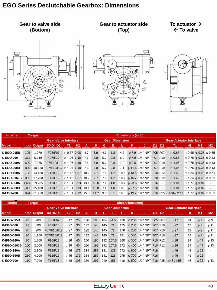
EGO Series Declutchable Gearbox: Dimensions
43
Imperial Torque Dimensions (inch)
Gear-Valve Interface Gear Dimension Gear-Actuator Interface
Model Input Output D3.D4.D5 T2 H2 A B C E L K J D1 D2 T1 H1 M1 M2
K-EGO-015B 195 1,770 F05/F07 □ 0.67 0.98 4.7 3.9 4.1 1.8 4.7 φ 7.9 1/4" NPT F05 F07 □ 0.67 □ 0.55 φ 0.28 φ 0.35
K-EGO-060 372 5,310 F07/F10 □ 1.06 1.18 7.6 5.8 5.7 2.8 6.9 φ 7.9 1/4" NPT F07 F10 □ 0.87 □ 0.75 φ 0.35 φ 0.43
K-EGO-090A 620 7,965 F07/F10/F12 □ 1.06 1.18 7.6 5.8 5.7 2.8 7.0 φ 9.8 1/4" NPT F07 F10 □ 1.06 □ 0.75 φ 0.35 φ 0.43
K-EGO-090B 850 10,620 F07/F10/F12 □ 1.06 1.18 7.6 5.8 5.7 2.8 7.1 φ 11.8 1/4" NPT F07 F10 □ 1.06 □ 0.75 φ 0.35 φ 0.43
K-EGO-160A 708 14,160 F10/F12 □ 1.42 1.57 10.2 7.7 7.5 4.2 10.6 φ 13.8 1/4" NPT F10 F12 □ 1.42 □ 1.34 φ 0.43 φ 0.51
K-EGO-0160B 885 17,700 F10/F12 □ 1.42 1.57 10.2 7.7 7.5 4.2 10.7 φ 15.7 1/4" NPT F10 F12 □ 1.42 □ 1.34 φ 0.43 φ 0.51
K-EGO-350A 1,682 29,205 F12/F16 □ 1.81 6.93 13.1 10.0 7.1 4.8 10.7 φ 23.6 1/4" NPT F16 - □ 1.81 □ 1.77 φ 0.87 -
K-EGO-350B 2,036 35,400 F12/F16 □ 1.81 6.93 13.1 10.0 7.1 4.8 10.8 φ 27.6 1/4" NPT F16 - □ 1.81 □ 1.77 φ 0.87 -
K-EGO-700 974 61,950 F16/F25 □ 1.81 7.72 15.3 11.7 9.8 6.1 16.5 φ 19.7 1/2" NPT F16 F25 □1.81/□2.17 □ 1.77 φ 0.87 φ 0.51
Metric Torque Dimensions (mm)
Gear-Valve Interface Gear Dimension Gear-Actuator Interface
Model Input Output D3.D4.D5 T2 H2 A B C E L K J D1 D2 T1 H1 M1 M2
K-EGO-015B 22 200 F05/F07 □ 17 25 120 100 104 44.5 120 φ 200 1/4" NPT F05 F07 □ 17 14 φ 7 φ 9
K-EGO-060 42 600 F07/F10 □ 27 30 192 148 145 71 175 φ 200 1/4" NPT F07 F10 □ 22 19 φ 9 φ 11
K-EGO-090A 70 900 F07/F10/F12 □ 27 30 192 148 145 71 178 φ 250 1/4" NPT F07 F10 □ 27 19 φ 9 φ 11
K-EGO-090B 96 1,200 F07/F10/F12 □ 27 30 192 148 145 71 181 φ 300 1/4" NPT F07 F10 □ 27 19 φ 9 φ 11
K-EGO-160A 80 1,600 F10/F12 □ 36 40 260 196 192 107.5 268 φ 350 1/4" NPT F10 F12 □ 36 34 φ 11 φ 13
K-EGO-0160B 100 2,000 F10/F12 □ 36 40 260 196 192 107.5 272 φ 400 1/4" NPT F10 F12 □ 36 34 φ 11 φ 13
K-EGO-350A 190 3,300 F12/F16 □ 46 176 334 255 181 123 272 φ 600 1/4" NPT F16 - □ 46 45 φ 22 -
K-EGO-350B 230 4,000 F12/F16 □ 46 176 334 255 181 123 275 φ 700 1/4" NPT F16 - □ 46 45 φ 22 -
K-EGO-700 110 7,000 F16/F25 □ 46 196 389 297 249 156 418 φ 500 1/2" NPT F16 F25 □46 / □55 45 φ 22 φ 13
Gear to actuator side
(Top)
Gear to valve side
(Bottom)
To actuator
To valve
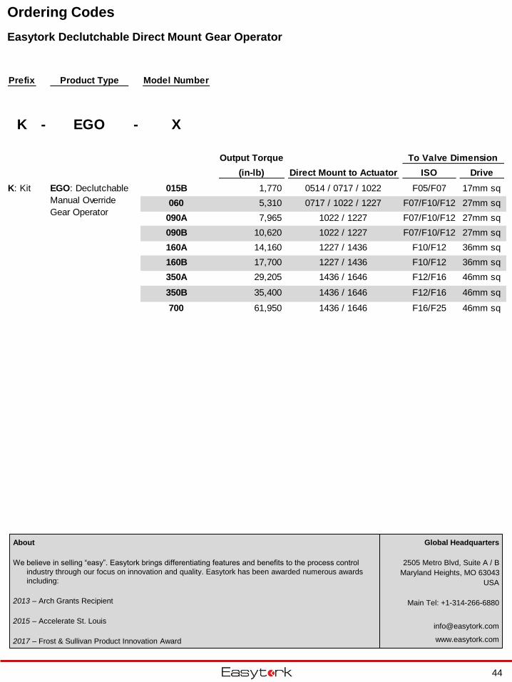
Ordering Codes
Easytork Declutchable Direct Mount Gear Operator
44
Global Headquarters
2505 Metro Blvd, Suite A / B
Maryland Heights, MO 63043
USA
Main Tel: +1-314-266-6880
www.easytork.com
About
We believe in selling “easy”. Easytork brings differentiating features and benefits to the process control
industry through our focus on innovation and quality. Easytork has been awarded numerous awards
including:
2013 – Arch Grants Recipient
2015 – Accelerate St. Louis
2017 – Frost & Sullivan Product Innovation Award
Prefix Product Type Model Number
K - EGO - X
Output Torque To Valve Dimension
(in-lb) Direct Mount to Actuator ISO Drive
015B 1,770 0514 / 0717 / 1022 F05/F07 17mm sq
060 5,310 0717 / 1022 / 1227 F07/F10/F12 27mm sq
090A 7,965 1022 / 1227 F07/F10/F12 27mm sq
090B 10,620 1022 / 1227 F07/F10/F12 27mm sq
160A 14,160 1227 / 1436 F10/F12 36mm sq
160B 17,700 1227 / 1436 F10/F12 36mm sq
350A 29,205 1436 / 1646 F12/F16 46mm sq
350B 35,400 1436 / 1646 F12/F16 46mm sq
700 61,950 1436 / 1646 F16/F25 46mm sq
EGO: Declutchable
Manual Override
Gear Operator
K: Kit
Limit Switch
45
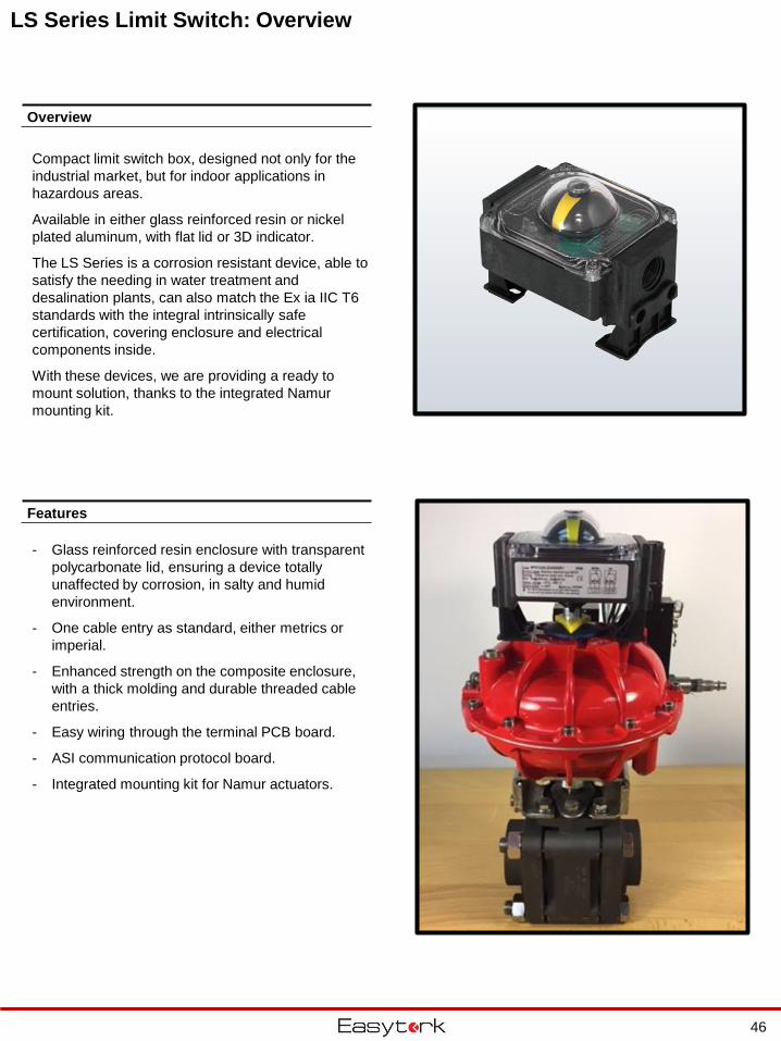
LS Series Limit Switch: Overview
- Glass reinforced resin enclosure with transparent
polycarbonate lid, ensuring a device totally
unaffected by corrosion, in salty and humid
environment.
- One cable entry as standard, either metrics or
imperial.
- Enhanced strength on the composite enclosure,
with a thick molding and durable threaded cable
entries.
- Easy wiring through the terminal PCB board.
- ASI communication protocol board.
- Integrated mounting kit for Namur actuators.
Overview
Features
Compact limit switch box, designed not only for the
industrial market, but for indoor applications in
hazardous areas.
Available in either glass reinforced resin or nickel
plated aluminum, with flat lid or 3D indicator.
The LS Series is a corrosion resistant device, able to
satisfy the needing in water treatment and
desalination plants, can also match the Ex ia IIC T6
standards with the integral intrinsically safe
certification, covering enclosure and electrical
components inside.
With these devices, we are providing a ready to
mount solution, thanks to the integrated Namur
mounting kit.
46
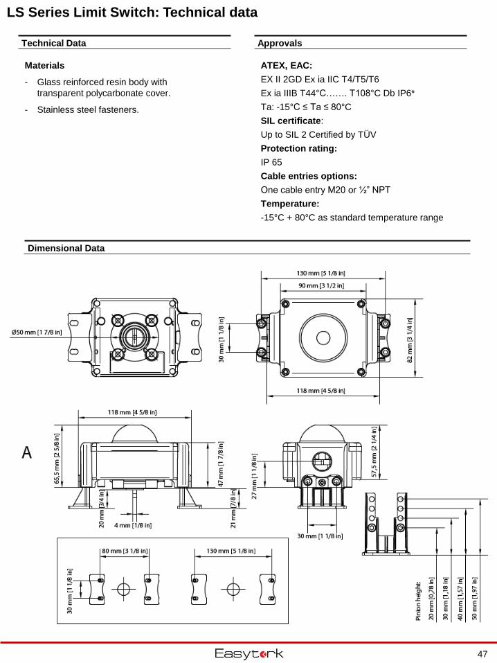
LS Series Limit Switch: Technical data
ATEX, EAC:
EX II 2GD Ex ia IIC T4/T5/T6
Ex ia IIIB T44°C……. T108°C Db IP6*
Ta: -15°C ≤ Ta ≤ 80°C
SIL certificate:
Up to SIL 2 Certified by TÜV
Protection rating:
IP 65
Cable entries options:
One cable entry M20 or ½” NPT
Temperature:
-15°C + 80°C as standard temperature range
Technical Data
Dimensional Data
Materials
- Glass reinforced resin body with
transparent polycarbonate cover.
- Stainless steel fasteners.
Approvals
47
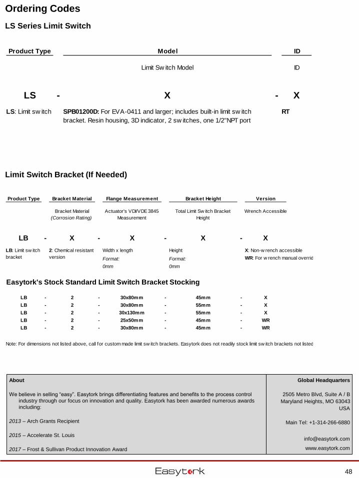
Ordering Codes
LS Series Limit Switch
Limit Switch Bracket (If Needed)
Product Type Bracket Material Flange Measurement Bracket Height Version
Bracket Material
(Corrosion Rating)
Actuator's VDI/VDE 3845
Measurement
Total Limit Sw itch Bracket
Height
Wrench Accessible
LB - X - X - X - X
Width x length Height X: Non-w rench accessible
Format: Format: WR: For w rench manual override version
0mm 0mm
Easytork's Stock Standard Limit Switch Bracket Stocking
LB - 2 - 30x80mm - 45mm - X
LB - 2 - 30x80mm - 55mm - X
LB - 2 - 30x130mm - 55mm - X
LB - 2 - 25x50mm - 45mm - WR
LB - 2 - 30x80mm - 45mm - WR
Note: For dimensions not listed above, call for custom made limit sw itch brackets. Easytork does not readily stock limit sw itch brackets not listed above.
LB: Limit sw itch
bracket
2: Chemical resistant
version
Product Type Model ID
Limit Sw itch Model ID
LS - X - X
RTLS: Limit sw itch SPB01200D: For EVA-0411 and larger; includes built-in limit sw itch
bracket. Resin housing, 3D indicator, 2 sw itches, one 1/2"NPT port
48
Global Headquarters
2505 Metro Blvd, Suite A / B
Maryland Heights, MO 63043
USA
Main Tel: +1-314-266-6880
www.easytork.com
About
We believe in selling “easy”. Easytork brings differentiating features and benefits to the process control
industry through our focus on innovation and quality. Easytork has been awarded numerous awards
including:
2013 – Arch Grants Recipient
2015 – Accelerate St. Louis
2017 – Frost & Sullivan Product Innovation Award
Positioner
49
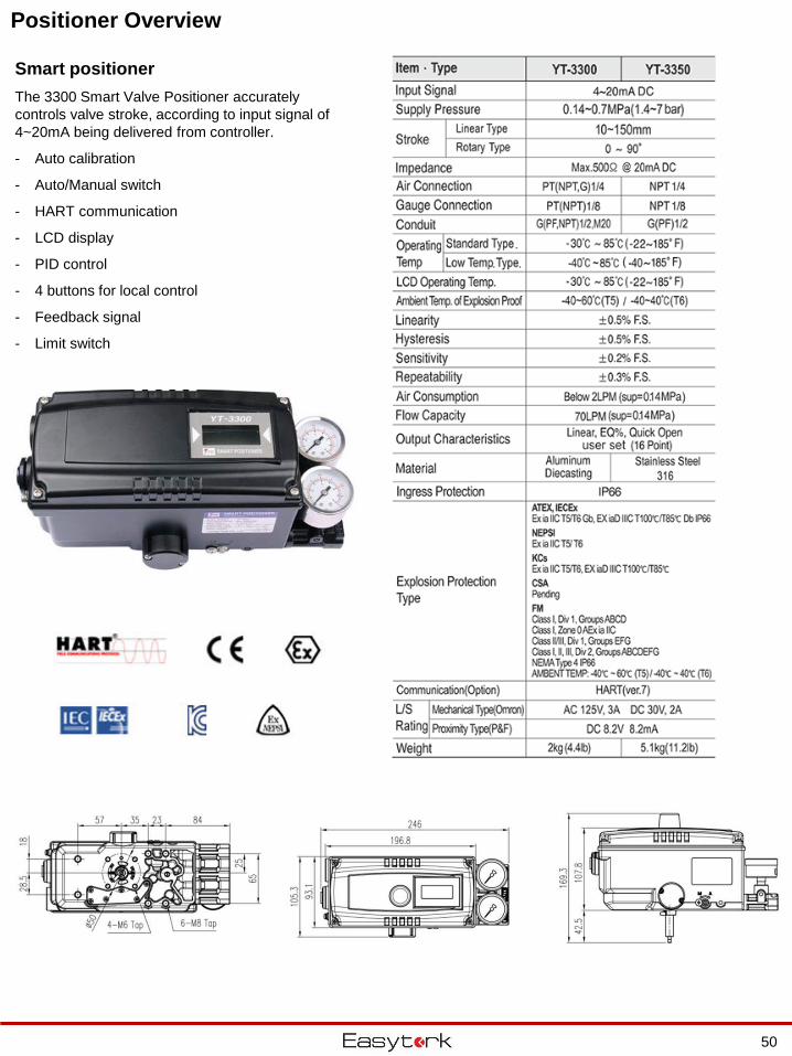
Positioner Overview
Smart positioner
The 3300 Smart Valve Positioner accurately
controls valve stroke, according to input signal of
4~20mA being delivered from controller.
- Auto calibration
- Auto/Manual switch
- HART communication
- LCD display
- PID control
- 4 buttons for local control
- Feedback signal
- Limit switch
50
Positioner Overview
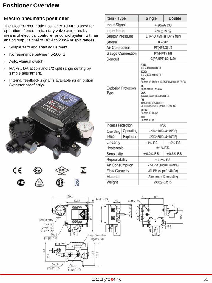
Electro pneumatic positioner
The Electro-Pneumatic Positioner 1000R is used for
operation of pneumatic rotary valve actuators by
means of electrical controller or control system with an
analog output signal of DC 4 to 20mA or split ranges.
- Simple zero and span adjustment
- No resonance between 5-200Hz
- Auto/Manual switch
- RA vs.. DA action and 1/2 split range setting by
simple adjustment.
- Internal feedback signal is available as an option
(weather proof only)
51
Ordering Codes
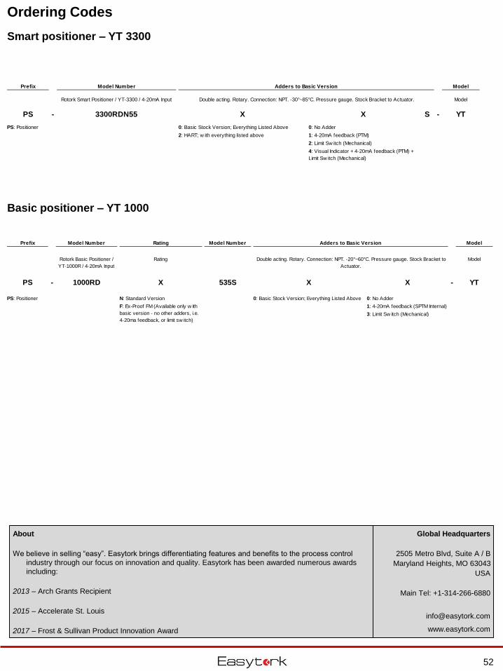
Smart positioner – YT 3300
Prefix Model Number Adders to Basic Version Model
Rotork Smart Positioner / YT-3300 / 4-20mA Input Model
PS - 3300RDN55 X X S - YT
0: Basic Stock Version; Everything Listed Above 0: No Adder
2: HART; w ith everything listed above 1: 4-20mA feedback (PTM)
2: Limit Sw itch (Mechanical)
4: Visual Indicator + 4-20mA feedback (PTM) +
Limit Sw itch (Mechanical)
Double acting. Rotary. Connection: NPT. -30°~85°C. Pressure gauge. Stock Bracket to Actuator.
PS: Positioner
Basic positioner – YT 1000
Prefix Model Number Rating Model Number Adders to Basic Version Model
Rotork Basic Positioner /
YT-1000R / 4-20mA Input
Rating Model
PS - 1000RD X 535S X X - YT
N: Standard Version 0: Basic Stock Version; Everything Listed Above 0: No Adder
1: 4-20mA feedback (SPTM Internal)
3: Limit Sw itch (Mechanical)
PS: Positioner
Double acting. Rotary. Connection: NPT. -20°~60°C. Pressure gauge. Stock Bracket to
Actuator.
F: Ex-Proof FM (Available only w ith
basic version - no other adders, i.e.
4-20ma feedback, or limit sw itch)
52
Global Headquarters
2505 Metro Blvd, Suite A / B
Maryland Heights, MO 63043
USA
Main Tel: +1-314-266-6880
www.easytork.com
About
We believe in selling “easy”. Easytork brings differentiating features and benefits to the process control
industry through our focus on innovation and quality. Easytork has been awarded numerous awards
including:
2013 – Arch Grants Recipient
2015 – Accelerate St. Louis
2017 – Frost & Sullivan Product Innovation Award
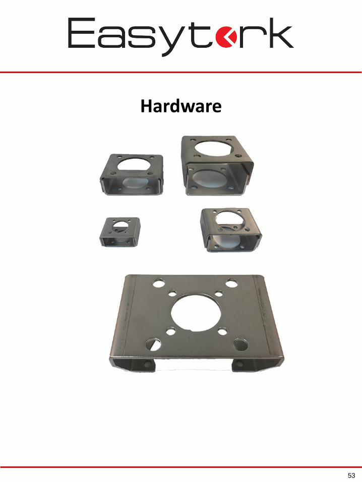
Hardware
53
Bottom Side Top Side Dimensions (mm)
(ie. Valve Pattern) (ie. Actuator Pattern) Top & Bottom Joint Dimension Bottom Dimension Top Dimension
Availability Availability A B C F MIN.D MAX.E Ød1 Ød2 Ød3 Ød4 Ød5 Ød6
S Series Bracket 50 66 60 3 30 50
F03S F03S 5.3 25 36 5.3 25 36
F04S F04S 5.3 30 42 5.3 30 42
F05S F05S 6.4 35 50 6.4 35 50
M Series Bracket 70 100 92 4 42 62
F03M F03M 5.3 25 36 5.3 25 36
F04M F04M 5.3 30 42 5.3 30 42
F05M F05M 6.4 35 50 6.4 35 50
F07M F07M 8.4 55 70 8.4 55 70
L Series Bracket 120 150 140 5 52 80
F07L 8.4 55 70
F10L F10L 10.5 70 102 10.5 70 102
F12L F12L 13.0 85 125 13.0 85 125
XL Series Bracket 160 160 150 5 70 100
F10XL 10.5 70 102
F12XL 13.0 85 125
F14XL F14XL 17.0 100 140 17.0 100 140
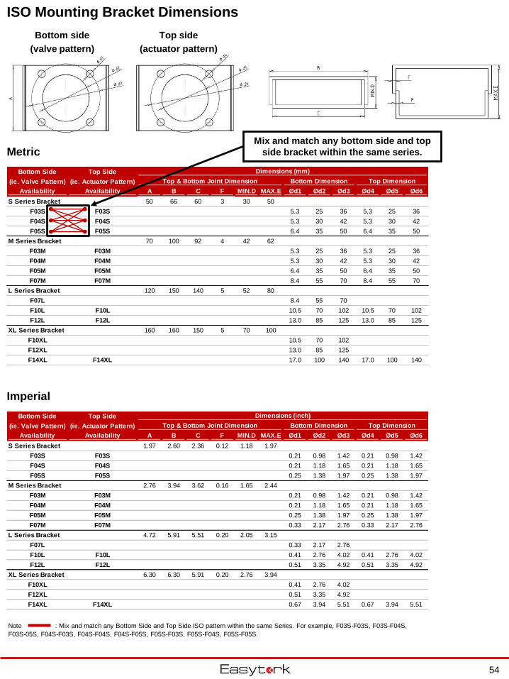
ISO Mounting Bracket Dimensions
Bottom side
(valve pattern)
Top side
(actuator pattern)
Metric
Imperial
Bottom Side Top Side Dimensions (inch)
(ie. Valve Pattern) (ie. Actuator Pattern) Top & Bottom Joint Dimension Bottom Dimension Top Dimension
Availability Availability A B C F MIN.D MAX.E Ød1 Ød2 Ød3 Ød4 Ød5 Ød6
S Series Bracket 1.97 2.60 2.36 0.12 1.18 1.97
F03S F03S 0.21 0.98 1.42 0.21 0.98 1.42
F04S F04S 0.21 1.18 1.65 0.21 1.18 1.65
F05S F05S 0.25 1.38 1.97 0.25 1.38 1.97
M Series Bracket 2.76 3.94 3.62 0.16 1.65 2.44
F03M F03M 0.21 0.98 1.42 0.21 0.98 1.42
F04M F04M 0.21 1.18 1.65 0.21 1.18 1.65
F05M F05M 0.25 1.38 1.97 0.25 1.38 1.97
F07M F07M 0.33 2.17 2.76 0.33 2.17 2.76
L Series Bracket 4.72 5.91 5.51 0.20 2.05 3.15
F07L 0.33 2.17 2.76
F10L F10L 0.41 2.76 4.02 0.41 2.76 4.02
F12L F12L 0.51 3.35 4.92 0.51 3.35 4.92
XL Series Bracket 6.30 6.30 5.91 0.20 2.76 3.94
F10XL 0.41 2.76 4.02
F12XL 0.51 3.35 4.92
F14XL F14XL 0.67 3.94 5.51 0.67 3.94 5.51
Note : Mix and match any Bottom Side and Top Side ISO pattern within the same Series. For example, F03S-F03S, F03S-F04S,
F03S-05S, F04S-F03S, F04S-F04S, F04S-F05S, F05S-F03S, F05S-F04S, F05S-F05S.
Mix and match any bottom side and top
side bracket within the same series.
54
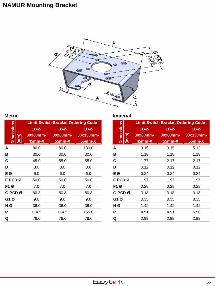
NAMUR Mounting Bracket
Metric Imperial
Limit Switch Bracket Ordering Code
LB-2-
30x80mm-
45mm-X
LB-2-
30x80mm-
55mm-X
LB-2-
30x130mm-
55mm-X
A 80.0 80.0 130.0
B 30.0 30.0 30.0
C 45.0 55.0 55.0
D 3.0 3.0 3.0
E Ø 6.0 6.0 6.0
F PCD Ø 50.0 50.0 50.0
F1 Ø 7.0 7.0 7.0
G PCD Ø 80.8 80.8 80.8
G1 Ø 9.0 9.0 9.0
H Ø 36.0 36.0 36.0
P 114.5 114.5 165.0
Q 76.0 76.0 76.0
Dim
en
sio
ns
(mm
)
Limit Switch Bracket Ordering Code
LB-2-
30x80mm-
45mm-X
LB-2-
30x80mm-
55mm-X
LB-2-
30x130mm-
55mm-X
A 3.15 3.15 5.12
B 1.18 1.18 1.18
C 1.77 2.17 2.17
D 0.12 0.12 0.12
E Ø 0.24 0.24 0.24
F PCD Ø 1.97 1.97 1.97
F1 Ø 0.28 0.28 0.28
G PCD Ø 3.18 3.18 3.18
G1 Ø 0.35 0.35 0.35
H Ø 1.42 1.42 1.42
P 4.51 4.51 6.50
Q 2.99 2.99 2.99
Dim
en
sio
ns
(in
ch
)
55
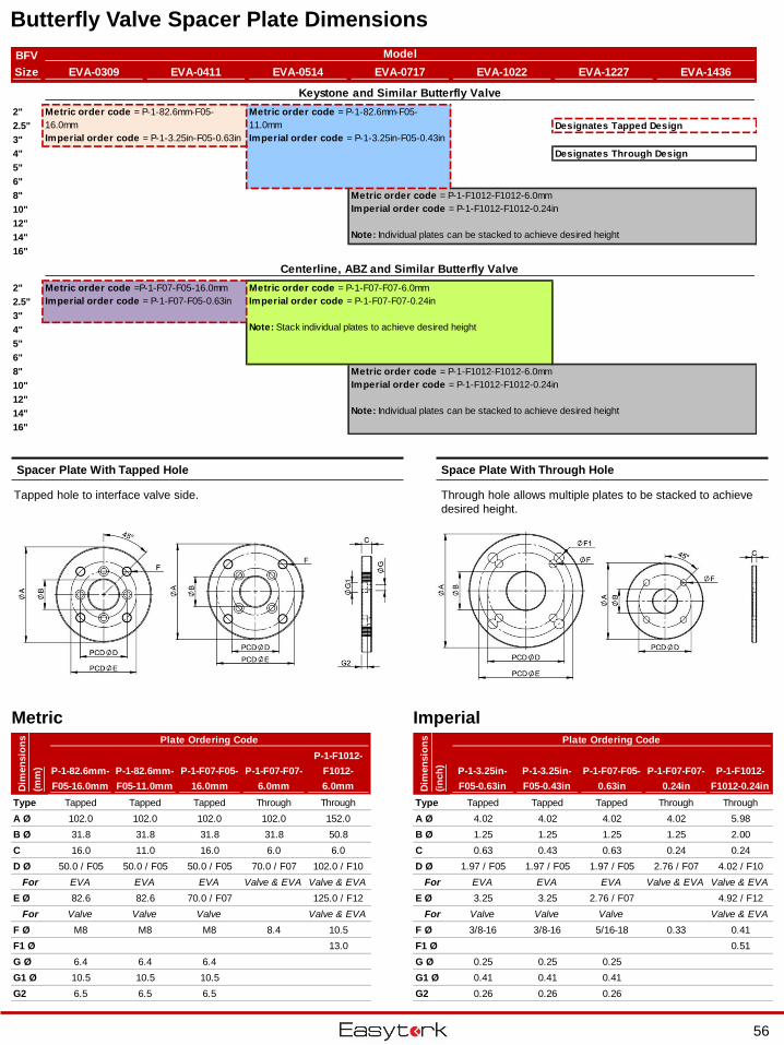
Butterfly Valve Spacer Plate Dimensions
Metric Imperial
Space Plate With Through HoleSpacer Plate With Tapped Hole
Tapped hole to interface valve side. Through hole allows multiple plates to be stacked to achieve
desired height.
BFV
Size EVA-0309 EVA-0411 EVA-0514 EVA-0717 EVA-1022 EVA-1227 EVA-1436
Keystone and Similar Butterfly Valve
2"
2.5" Designates Tapped Design
3"
4" Designates Through Design
5"
6"
8"
10"
12"
14"
16"
Centerline, ABZ and Similar Butterfly Valve
2"
2.5"
3"
4"
5"
6"
8"
10"
12"
14"
16"
Model
Metric order code = P-1-82.6mm-F05-
16.0mm
Imperial order code = P-1-3.25in-F05-0.63in
Metric order code = P-1-82.6mm-F05-
11.0mm
Imperial order code = P-1-3.25in-F05-0.43in
Metric order code = P-1-F1012-F1012-6.0mm
Imperial order code = P-1-F1012-F1012-0.24in
Note: Individual plates can be stacked to achieve desired height
Metric order code = P-1-F07-F07-6.0mm
Imperial order code = P-1-F07-F07-0.24in
Note: Stack individual plates to achieve desired height
Metric order code = P-1-F1012-F1012-6.0mm
Imperial order code = P-1-F1012-F1012-0.24in
Note: Individual plates can be stacked to achieve desired height
Metric order code =P-1-F07-F05-16.0mm
Imperial order code = P-1-F07-F05-0.63in
Plate Ordering Code Plate Ordering Code
P-1-82.6mm-
F05-16.0mm
P-1-82.6mm-
F05-11.0mm
P-1-F07-F05-
16.0mm
P-1-F07-F07-
6.0mm
P-1-F1012-
F1012-
6.0mm
P-1-3.25in-
F05-0.63in
P-1-3.25in-
F05-0.43in
P-1-F07-F05-
0.63in
P-1-F07-F07-
0.24in
P-1-F1012-
F1012-0.24in
Type Tapped Tapped Tapped Through Through Type Tapped Tapped Tapped Through Through
A Ø 102.0 102.0 102.0 102.0 152.0 A Ø 4.02 4.02 4.02 4.02 5.98
B Ø 31.8 31.8 31.8 31.8 50.8 B Ø 1.25 1.25 1.25 1.25 2.00
C 16.0 11.0 16.0 6.0 6.0 C 0.63 0.43 0.63 0.24 0.24
D Ø 50.0 / F05 50.0 / F05 50.0 / F05 70.0 / F07 102.0 / F10 D Ø 1.97 / F05 1.97 / F05 1.97 / F05 2.76 / F07 4.02 / F10
For EVA EVA EVA Valve & EVA Valve & EVA For EVA EVA EVA Valve & EVA Valve & EVA
E Ø 82.6 82.6 70.0 / F07 125.0 / F12 E Ø 3.25 3.25 2.76 / F07 4.92 / F12
For Valve Valve Valve Valve & EVA For Valve Valve Valve Valve & EVA
F Ø M8 M8 M8 8.4 10.5 F Ø 3/8-16 3/8-16 5/16-18 0.33 0.41
F1 Ø 13.0 F1 Ø 0.51
G Ø 6.4 6.4 6.4 G Ø 0.25 0.25 0.25
G1 Ø 10.5 10.5 10.5 G1 Ø 0.41 0.41 0.41
G2 6.5 6.5 6.5 G2 0.26 0.26 0.26
Dim
en
sio
ns
(mm
)
Dim
en
sio
ns
(in
ch
)
56
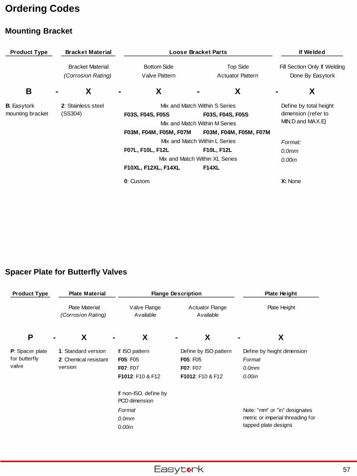
Ordering Codes
Spacer Plate for Butterfly Valves
Product Type Plate Material Flange Description Plate Height
Plate Material
(Corrosion Rating)
Valve Flange
Available
Actuator Flange
Available
Plate Height
P - X - X - X - X
1: Standard version If ISO pattern Define by ISO pattern Define by height dimension
F05: F05 F05: F05 Format
F07: F07 F07: F07 0.0mm
F1012: F10 & F12 F1012: F10 & F12 0.00in
Format
0.0mm
0.00in
If non-ISO, define by
PCD dimension
2: Chemical resistant
version
P: Spacer plate
for butterf ly
valve
Note: "mm" or "in" designates
metric or imperial threading for
tapped plate designs
57
Mounting Bracket
Product Type Bracket Material Loose Bracket Parts If Welded
Bracket Material Bottom Side Top Side Fill Section Only If Welding
(Corrosion Rating) Valve Pattern Actuator Pattern Done By Easytork
B - X - X - X - X
Mix and Match Within S Series
F03S, F04S, F05S F03S, F04S, F05S
Mix and Match Within M Series
F03M, F04M, F05M, F07M F03M, F04M, F05M, F07M
Mix and Match Within L Series Format:
F07L, F10L, F12L F10L, F12L 0.0mm
Mix and Match Within XL Series 0.00in
F10XL, F12XL, F14XL F14XL
0: Custom X: None
B: Easytork
mounting bracket
Define by total height
dimension (refer to
MIN.D and MAX.E)
2: Stainless steel
(SS304)
Ordering Codes
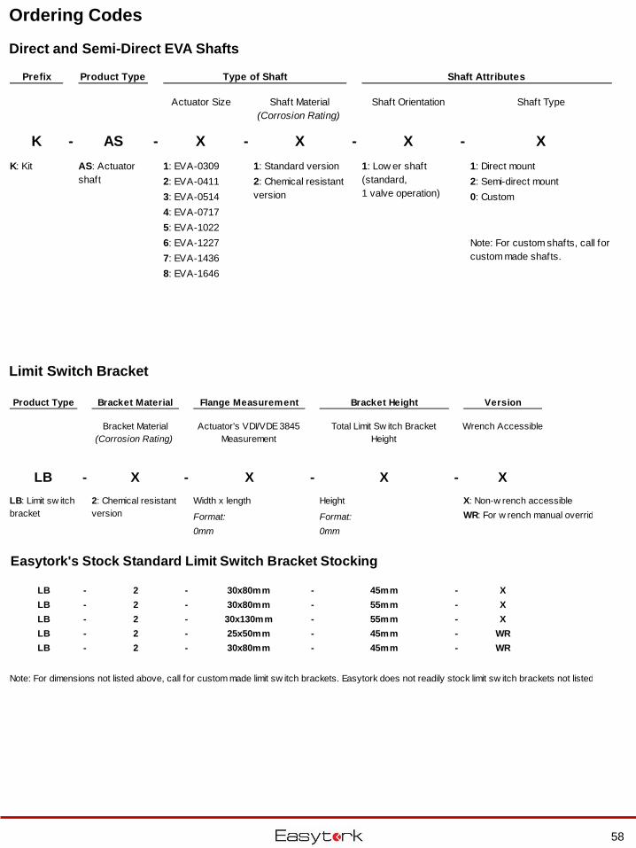
Limit Switch Bracket
Direct and Semi-Direct EVA Shafts
Prefix Product Type Type of Shaft Shaft Attributes
Actuator Size Shaft Material
(Corrosion Rating)
Shaft Orientation Shaft Type
K - AS - X - X - X - X
K: Kit 1: EVA-0309 1: Standard version 1: Direct mount
2: EVA-0411 2: Semi-direct mount
3: EVA-0514 0: Custom
4: EVA-0717
5: EVA-1022
6: EVA-1227
7: EVA-1436
8: EVA-1646
Note: For custom shafts, call for
custom made shafts.
2: Chemical resistant
version
AS: Actuator
shaft
1: Low er shaft
(standard,
1 valve operation)
58
Product Type Bracket Material Flange Measurement Bracket Height Version
Bracket Material
(Corrosion Rating)
Actuator's VDI/VDE 3845
Measurement
Total Limit Sw itch Bracket
Height
Wrench Accessible
LB - X - X - X - X
Width x length Height X: Non-w rench accessible
Format: Format: WR: For w rench manual override version
0mm 0mm
Easytork's Stock Standard Limit Switch Bracket Stocking
LB - 2 - 30x80mm - 45mm - X
LB - 2 - 30x80mm - 55mm - X
LB - 2 - 30x130mm - 55mm - X
LB - 2 - 25x50mm - 45mm - WR
LB - 2 - 30x80mm - 45mm - WR
Note: For dimensions not listed above, call for custom made limit sw itch brackets. Easytork does not readily stock limit sw itch brackets not listed above.
LB: Limit sw itch
bracket
2: Chemical resistant
version
Ordering Codes
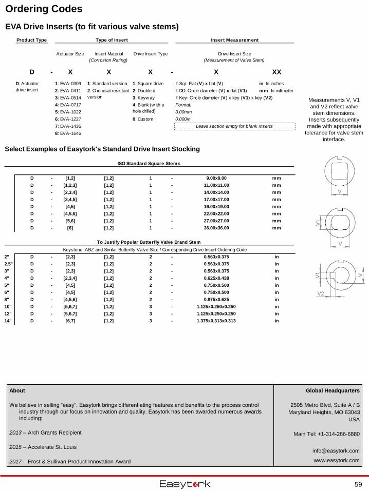
EVA Drive Inserts (to fit various valve stems)
Measurements V, V1
and V2 reflect valve
stem dimensions.
Inserts subsequently
made with appropriate
tolerance for valve stem
interface.
Global Headquarters
2505 Metro Blvd, Suite A / B
Maryland Heights, MO 63043
USA
Main Tel: +1-314-266-6880
www.easytork.com
About
We believe in selling “easy”. Easytork brings differentiating features and benefits to the process control
industry through our focus on innovation and quality. Easytork has been awarded numerous awards
including:
2013 – Arch Grants Recipient
2015 – Accelerate St. Louis
2017 – Frost & Sullivan Product Innovation Award
Product Type Type of Insert Insert Measurement
Actuator Size Insert Material
(Corrosion Rating)
Drive Insert Type
D - X X X - X XX
1: EVA-0309 1: Standard version 1: Square drive If Sqr: Flat (V) x f lat (V) in: In inches
2: EVA-0411 2: Double d If DD: Circle diameter (V) x f lat (V1) mm : In millimeter
3: EVA-0514 3: Keyw ay If Key: Circle diameter (V) x key (V1) x key (V2)
4: EVA-0717 Format:
5: EVA-1022 0.00mm
6: EVA-1227 0: Custom 0.000in
7: EVA-1436
8: EVA-1646
Select Examples of Easytork's Standard Drive Insert Stocking
ISO Standard Square Stems
D - [1,2] [1,2] 1 - 9.00x9.00 mm
D - [1,2,3] [1,2] 1 - 11.00x11.00 mm
D - [2,3,4] [1,2] 1 - 14.00x14.00 mm
D - [3,4,5] [1,2] 1 - 17.00x17.00 mm
D - [4,5] [1,2] 1 - 19.00x19.00 mm
D - [4,5,6] [1,2] 1 - 22.00x22.00 mm
D - [5,6] [1,2] 1 - 27.00x27.00 mm
D - [6] [1,2] 1 - 36.00x36.00 mm
To Justify Popular Butterfly Valve Brand Stem
Keystone, ABZ and Similar Butterf ly Valve Size / Corresponding Drive Insert Ordering Code
2" D - [2,3] [1,2] 2 - 0.563x0.375 in
2.5" D - [2,3] [1,2] 2 - 0.563x0.375 in
3" D - [2,3] [1,2] 2 - 0.563x0.375 in
4" D - [2,3,4] [1,2] 2 - 0.625x0.438 in
5" D - [4,5] [1,2] 2 - 0.750x0.500 in
6" D - [4,5] [1,2] 2 - 0.750x0.500 in
8" D - [4,5,6] [1,2] 2 - 0.875x0.625 in
10" D - [5,6,7] [1,2] 3 - 1.125x0.250x0.250 in
12" D - [5,6,7] [1,2] 3 - 1.125x0.250x0.250 in
14" D - [6,7] [1,2] 3 - 1.375x0.313x0.313 in
Drive Insert Size
(Measurement of Valve Stem)
Leave section empty for blank inserts
D: Actuator
drive insert 2: Chemical resistant
version
4: Blank (w ith a
hole drilled)
59
Global Headquarters
2505 Metro Blvd, Suite A / B
Maryland Heights, MO 63043
USA
Main Tel: +1-314-266-6880
www.easytork.com
Copyright © 2022 FDOKUMEN


![2-[Eva Fedi]-Formazione “Aree Comuni” Operatori Sportivi [Eva Fedi]](https://static.fdokumen.com/doc/165x107/63209e83c5de3ed8a70dcef1/2-eva-fedi-formazione-aree-comuni-operatori-sportivi-eva-fedi.jpg)